
Руководство по эксплуатации Хонда Стрим второго поколения с 2009 года в кузове RN6 — RN9 передний или полный привод с двигателем R18A и 2 литра R20A
Характеристики Хонда Стрим 2
Тип привода Полный (4WD) — передний
Тип трансмиссии АКПП 5
Клиренс (высота дорожного просвета), мм 150
Габариты кузова (Д x Ш x В), мм 4570 x 1695 x 1545
Габариты салона (Д x Ш x В), мм 2605 x 1460 x 1250
Колесная база, мм 2740
Минимальный радиус разворота, м 5.6
Ширина передней колеи, мм 1470
Ширина задней колеи, мм 1470
Масса, кг 1480
Расход топлива в режиме 10/15, л/100км 6.8
Передняя подвеска Независимая, амортизационная стойка типа МакФерсон
Задняя подвеска Независимая, на двойных поперечных рычагах
Передние тормоза Дисковые вентилируемые
Задние тормоза Дисковые
Заправочные объемы Хонда Стрим 2
Топливный бак 55л
Моторное масло 3,7л 0W20
Охлаждающая жидкость
АКПП 7,1л
CVT 7,0л
Жидкость автоматической трансмиссии
АКПП 5,9л
CVT 7,5л
Свечи зажигания
NGK ZFR6K-11S
Denso KJ20DR-M11S
Лампы Хонда Стрим 2
Передние фары
Ближний дальний — H4 — галоген
ксенон
Ближний d2r
Дальний HB3
Поворотники w21W
Габариты W5W
туманки ПТФ — H11
Задние фары
Габариты W5W
Поворотники w21W
Стоп сигнал и габариты w21/5W
Задний ход W21W
номерной знак W5W
Руководство Хонда Стрим
Комментарии
5
Войдите или зарегистрируйтесь, чтобы писать комментарии, задавать вопросы и участвовать в обсуждении.
Войти
Зарегистрироваться

timmykill
Без машины
У меня другой мануал. Этот по интересней будет
1 год

SEV42ru
Я езжу на Honda Stream (RN)
проще кинуть в облако и сделать пост с сылкой на адрес.
1 год

Dimon24081982
Автор
Я езжу на Honda Stream (RN)
Вот дополнил теперь все страницы, сразу что-то не посмотрел
1 год

verevkin1979
Я езжу на Honda Fit (3G)
Во елки.так там же около 200 страниц.
Этож сколько нужно постов сделать?🤣
1 год

Viacheslav480
Я езжу на Honda Stream (RN)
Каких 200? Там 489 вроде
1 год
Locations
Knock Sensor: Locations
18. Front Middle Of Engine
Locations
Crankshaft Position Sensor: Locations
134. Under Right Side Of Engine
Page 2041
3. Check the difference between the piston pin diameter and the piston pin hole diameter on the
piston.
4. Check the difference between the piston pin diameter and the connecting rod small end
diameter.
Reassembly
1. Assemble the piston with the arrow (A) pointing up and the connecting rod with the embossed
marks (B) on the same side.
Page 1126
9. Disconnect the connectors, remove the shift solenoid harness connector (E), and replace it.
10. Install the new O-ring (F) on the new shift solenoid harness connector, and install the connector
in the transmission housing. 11. Connect the WHT and ORN wires connector to shift solenoid valve
B. The ATF temperature sensor is assembled in the WHT wires connector. 12. Connect the
harness terminals to the solenoids:
^ BLU wire connector to shift solenoid valve A.
^ GRN wire connector to shift solenoid valve C.
^ YEL wire connector to shift solenoid valve D.
13. Install the shift solenoid valve cover, dowel pins, and a new gasket. 14. Check the connector for
rust, dirt, or oil, then connect it securely. 15. Refill the transmission with ATF. 16. Install the splash
shield.
Page 490
Relay And Control Unit Locations Dashboard
Tire Monitor System — Usage of TPMS Sensor Tools
Tire Pressure Sensor: All Technical Service Bulletins Tire Monitor System — Usage of TPMS
Sensor Tools
06-072
October 19, 2007
Applies To: See VEHICLES AFFECTED
TPMS Sensor Tool Usage
(Supersedes 06-072, dated January 5, 2007, to update the information marked by the black bars
and asterisks)
*VEHICLES AFFECTED
2008 Accord — ALL
2008 Civic — ALL
2007-08 CR-V — ALL
2007-08 Element — ALL
2008 Fit — ALL
2007-08 Odyssey — ALL except Touring
2008 S2000 — ALL*
INTRODUCTION
Beginning with some 2007 models, Honda is using a second type of TPMS (tire pressure
monitoring system) that does not use initiators like the 2006 and earlier
TPMS.
All TPMS sensors:
^ Are mounted on the inside of the rim, connected to the valve stem.
^ Use a wireless transmission to send tire pressure and temperature information to the TPMS unit.
^ Use non-replaceable batteries. To save battery life, the sensors turn on only when the vehicle is
being used.
Initiator-Type TPMS (Location-Type TPMS)
*The first type of TPMS (all vehicles through 2006) uses initiators mounted above each wheel.
When you turn the ignition switch to ON (II), the initiators send out a low frequency signal to turn on
the TPMS sensors. The initiator, in conjunction with the TPMS control unit, determines the tire
location. For example, if the right front tire is low on air, the customer sees the low tire pressure
indicator and an indiction that the right front tire is low on pressure. The initiator-type TPMS, or
location-type TPMS (in the HDS), is used on the 2005-08 Pilot, the 2006-08 Ridgeline, and the
2005-08 Odyssey Touring models.*
Initiator-less TPMS (No Location-Type TPMS)
The new TPMS does not use initiators. The TPMS sensors have a built-in acceleration sensor that
turns on the TPMS sensors when the vehicle speed reaches about 25 mph. Without an initiator, the
TPMS control unit cannot determine tire location. For example, if the right front tire is low on air, the
customer sees only the low pressure indicator and must check all four tires to find the problem tire.
During diagnosis, the TPMS control unit provides a code for each tire.
NOTE:
^ During diagnosis, the TPMS control unit gives a tire number, but you need to do the sensor
position check to find the location of the tire number.
^ Use with HDS software version 2.011.010 or later. The initiator-less TPMS, or no location-type
TPMS, is used on vehicles affected by this bulletin.
Page 2603
PGM-FI System Component Location Index
Page 1490
Engine Controls — MIL ON/DTC P0420 Set
Catalytic Converter: Customer Interest Engine Controls — MIL ON/DTC P0420 Set
10-015
March 23, 2010
Applies To: 2007-08 Fit — ALL
2007-08 Fit: MIL Comes On With DTC P0420
SYMPTOM
The MIL is on, and DIG P0420 (catalyst system efficiency below threshold) is stored.
PROBABLE CAUSE
The ECM/PCM misinterprets engine idle conditions, resulting in inaccurate control of the fuel and
ignition.
CORRECTIVE ACTION
Replace the catalytic converter, and update the PGM-FI software with the HDS.
PARTS INFORMATION
Catalytic Converter:
A/T models — P/N 18160-RME-A50 M/T models — P/N 18160-RME-A00
Pre-Chamber Gasket:
P/N 18393-SH3-S00
Flexible Gasket:
P/N 18229-SAA-J01
Flexible Joint Bolt (two required):
P/N 18231-SR3-A22
Self-Locking Nut (three required):
P/N 90212-SA5-003
TOOL INFORMATION
02 Sensor Wrench: Snap-on YA8875 or equivalent
SOFTWARE INFORMATION
HDS Software Version:
2.021.016 (March 2010) or later.
Control Module (CM) Update:
Database Update 12-FEB-2010 or later.
Page 1911
8. Inspect the quality of the wire crimp. If it has any of the shown NO GOOD crimps, cut it off and
start over. 9. Insert the terminal into the connector. Make sure the wire seals are pushed all the
way into the connector. Lightly pull on the wires to make sure
the terminal is locked into place.
10. Close or insert the secondary terminal lock, if applicable, and reconnect the connector.
How to Install Pigtail Terminals
HOW TO INSTALL PIGTAIL TERMINALS
Pigtail terminals (short pieces of wire with a factory crimped terminal) are used when the wire is too
short or when access to the connector is too restricted to make a terminal repair.
NOTE: To replace just a connector terminal, go to How to Replace Connector Terminals.
IMPORTANT SAFETY INFORMATION: On some models, the SRS wires are in a separate
harness. If the SRS harness is damaged, replace the harness; do not repair it. On other models,
wire harnesses include yellow SRS wires. If any SRS wire is damaged, replace the entire harness;
do not repair it.
1. Remove the damaged or faulty terminal from the connector. Use the proper removal tool from
Pin Tool Set.
Page 623
Air Conditioning Switch: Service and Repair
A/C Switch Test/Replacement
1. Remove the center panel. 2. Disconnect the 13P connector (A) and push out the rear window
defogger and A/C switch (B) from behind the center panel (C).
3. Check for continuity between the terminals in each switch position according to the table. 4. If
the continuity is not as specified, replace the bulbs (D) or the switch.
Locations
Air Bag Control Module: Locations
71. Under Middle Of Dash
105. Left Side Of Front Passneger’s Seat
Page 1024
Steering Angle Sensor: Diagrams
107. EPS Torque Sensor
164. EPS Motor Angle Sensor
Locations
Combination Switch: Locations
41. In Steering Column Cover
Page 594
Cruise Control Switch: Service and Repair
Cruise Control Combination Switch Test/Replacement
SRS components are located in this area. Review the SRS component locations and precautions
and procedures before performing repairs or service.
1. Remove the driver’s airbag. 2. Remove the three screws, then disconnect the connector (A), and
remove the cruise control combination switch (B).
3. Check for continuity between the terminals in each switch position according to the table.
— If there is continuity, and it matches the table, but switch failure occurred on the cruise control
input test, check and repair the wire harness on the switch circuit.
— If there is no continuity in one or both positions, replace the switch.
4. Check for continuity between the terminals in according to the table.
— If there is continuity, and it matches the table, check and repair the wire harness on the switch
circuit.
— If there is no continuity in one or more positions, replace the switch.
Locations
Headlamp Relay: Locations
11. Left Side Of Engine Compartment
Page 281
— Most circuits include solid-state devices. Test the voltages in these circuits only with a 10-mega
ohm or higher impedance digital multimeter. Never use a test light or analog meter on circuits that
contain solid-state devices. Damage to the devices may result.
Troubleshooting Tests
Troubleshooting Tests
Testing for Voltage
When testing for voltage at a connector without wire seals, you do not have to separate the two
halves of the connector. Instead, probe the connector from the back. Always check both sides of
the connector because dirty, corroded, and bent terminals can cause problems (no electrical
contact = an open).
1. Connect one lead of the test light to a known good ground, or, if you’re using a digital volt
ohmmeter (DVOM), place it in the appropriate DC
volts range, and connect its negative lead to ground.
2. Connect the other lead of the test light or DVOM to the point you want to check. 3. If the test light
glows, there is voltage present. If you’re using a DVOM, note the voltage reading. It should be
within one volt of measured battery
voltage. A loss of more than one volt indicates a problem.
NOTE: Always use a DVOM on high impedance circuits. A test light may not glow (even with
battery voltage present).
Testing for Continuity
When testing for continuity at a connector without wire seals, you do not have to separate the two
halves of the connector. Instead, probe the connector from the back. Always check both sides of
the connector because dirty, corroded, and bent terminals can cause problems (no electrical
contact = an open).
1. Disconnect the negative cable from the car battery. If you’re using a DVOM, place it in the lowest
«OHMS» range.
2. Connect one lead of a self-powered test light or DVOM to one end of the part of the circuit you
want to test. 3. Connect the other lead to the other end.
Page 2010
Crankshaft Main Bearing: Service and Repair
Crankshaft Main Bearing Replacement
Main Bearing Clearance Inspection
1. To check main bearing-to-journal oil clearance, remove the bearing cap bridge and bearing
halves. 2. Clean each main journal and bearing half with a clean shop towel. 3. Place one strip of
plastigage across each main journal. 4. Reinstall the bearings and bearing cap bridge, then torque
the bolts to 25 Nm (2.5 kgf-m, 18 lbf-ft) +40°.
NOTE: Do not rotate the crankshaft during inspection.
5. Remove the bearing cap bridge and bearings again, and measure the widest part of the
plastigage.
6. If the plastigage measures too wide or too narrow, remove the crankshaft, and remove the upper
half of the bearing. Install a new, complete
bearing with the same color code(s), and recheck the clearance. Do not file, shim, or scrape the
bearings or the caps to adjust clearance.
7. If the plastigage shows the clearance is still incorrect, try the next larger or smaller bearing (the
color listed above or below the current one), and
check again. If the proper clearance cannot be obtained by using the appropriate larger or smaller
bearings, replace the crankshaft and start over.
Main Bearing Selection
Crankshaft Bore Code Location
1. Letters have been stamped on the end of the block as a code for the size of each of the five
main journal bores. Write down the crank bore codes.
If you can’t read the codes because of accumulated dirt and dust, do not scrub them with a wire
brush or scraper. Clean them only with solvent or detergent.
Main Journal Code Location
Page 1242
NOTE:
Do this repair procedure if, after doing step 10 of the test-drive, the vehicle pulled in the opposite
direction after you swapped the front tires.
1. Swap wheels 2 and 4 on the passenger’s side of the vehicle, and test-drive again.
^ If the pull goes away, replace the tire on wheel 2, then go to step 3.
^ If the pull does not go away, put wheels 2 and 4 back to their original positions, and go to step 2.
2. Swap wheels 1 and 3 on the driver’s side of the vehicle, and test-drive again.
^ If the pull goes away, replace the tire on wheel 1, then go to step 3.
^ If the pull does not go away, use a known-good tire in position 1 and continue diagnosis.
3. Use your diagnosis worksheet to fill in the following table and build your 15-digit DTC.
REPAIR PROCEDURE B
Page 1280
15. Disconnect the quick-connect fitting (A): Hold the connector (B) with one hand, and squeeze
the retainer tabs (C) with the other hand to release
them from the locking tabs (D). Pull the connector off.
NOTE: Be careful not to damage the line (E) or other parts.
— Do not use tools.
— If the connector does not move, keep the retainer tabs pressed down, and alternately pull and
push the connector until it comes off easily.
— Do not remove the retainer from the line; once removed, the retainer must be replaced with a new
one.
16. After disconnecting the quick-connect fitting, check it for dirt or damage (see step 4). 17.
Reconnect the negative cable to the battery, then do this:
— Enter the anti-theft code for the audio system.
— Set the clock.
Without the HDS
1. Make sure you have the anti-theft code for the audio system. 2. Remove PGM-FI main relay 2
(FUEL PUMP) (A) from the under-dash fuse/relay box.
3. Start the engine, and let it idle until it stalls.
NOTE: If any DTCs are stored, clear and ignore them.
Page 150
Horns Component Location Index
Specifications
Intake Manifold: Specifications
Intake manifold
Install the intake manifold (B) and tighten the bolts and nuts in a crisscross pattern in three steps,
beginning with the inner bolt.
Page 893
Crankshaft Position Sensor: Service and Repair
CKP Sensor Replacement
1. Disconnect the CKP sensor connector (A).
2. Remove the CKT sensor (B). 3. Install the parts in the reverse order of removal with a new
O-ring (C). 4. Do the CKP pattern clear/pattern learn procedure below.
Crank (CKP) Pattern Clear/Crank (CKP) Pattern Learn
Clear/Learn Procedure (with the HDS)
1. Connect the HDS to the data link connector (DLC) (A) located under the driver’s side of the
dashboard.
2. Turn the ignition switch ON (II). 3. Make sure the HDS communicates with the ECM/PCM and
other vehicle systems. If it doesn’t, go to the DLC circuit troubleshooting. See:
Powertrain Management/Computers and Control Systems/Testing and Inspection/Component
Tests and General Diagnostics/DLC Circuit Troubleshooting
4. Select CRANK PATTERN in the ADJUSTMENT MENU with the HDS. 5. Select CRANK
PATTERN LEARNING with the HDS, and follow the screen prompts.
Learn Procedure (without the HDS)
1. Start the engine. Hold the engine speed at 3,000 rpm without load (in Park or neutral) until the
radiator fan comes on. 2. Test-drive the vehicle on a level road: Decelerate (with the throttle fully
closed) from an engine speed of 2,500 rpm down to 1,000 rpm with the
A/T in 2 position, or M/T in 1st gear.
3. Repeat step 2 several times. 4. Turn the ignition switch OFF. 5. Turn the ignition switch ON (II),
and wait 30 seconds.
Page 1823
A TPMS sensor tool is used for troubleshooting and replacing the TPMS sensors. See TOOL
DESCRIPTION for more information.
WARRANTY CLAIM INFORMATION
None.
TOOL INFORMATION
TOOL DESCRIPTION
TPMS Sensor Tool
The TPMS sensor tool is a wireless tool that is used with the HDS for troubleshooting (sensor
position check) and for replacing TPMS sensors or the control unit (sensor ID learning).
General use:
^ Always make sure the TPMS sensor tool is set to low power unless otherwise instructed.
*^ Make sure there are no vehicles or other wheels with TPMS sensors within 10 feet of the vehicle
you are working on.
^ Make sure the batteries are in good condition and secure in the case. Refer to ServiceNews
article A07050D, Keep Those TPMS Sensor Tool Batteries From Popping Loose, for more
information.*
^ Turn on the TPMS sensor tool by following the HDS instructions. There are two different
wavelengths used, and there are two ways to turn on the TPMS sensor tool. If the TPMS sensor
tool is not turned on correctly, you won’t be able to troubleshoot the vehicle or do the sensor ID
learning procedure.
Page 1970
How to Identify Connector Terminals
How to Identify Connector Terminals
Connector terminals are numbered according to the cavities they are in. The cavities are numbered
starting from the upper left, looking at the male terminals from the terminal side or looking at the
female terminals from the wire side. Both views are in the same direction so the numbers are the
same. All actual cavities are numbered, even if they have no wire terminals in them.
NOTE: Data Link Connector (DLC) terminals are numbered according to SAE standard J1962, not
the Honda standard. The numbers of the four end terminals are molded into the corners of the
connector face.
Page 2512
DTC P0A94 thru P0157
Page 874
Electronic Throttle Control System Component Location Index
Page 839
9. If the transmission range switch continuity check is OK, replace the faulty transmission range
switch harness.
10. If there is no continuity between any terminals, remove the transmission range switch, and
check the end of the selector control shaft (A).
11. If the measurement of the selector control shaft end is within the standard, replace the
transmission range switch. If the measurement is out of the
standard, repair the selector control shaft end, and recheck the transmission range switch
continuity.
Page 1348
Page 2302
Coolant: Fluid Type Specifications
ENGINE COOLANT TYPE
Always use Honda All Season Antifreeze/Coolant Type 2. Using a non-Honda coolant can result in
corrosion, causing the cooling system to malfunction or fail. Honda All Season Antifreeze/Coolant
Type 2 is a mixture of 50 % antifreeze and 50 % water. Premixing is not required.
Page 1692
^ When the LEDs turn green, the batteries are charged, and the battery charger automatically
switches to trickle charge mode.
^ Remove the batteries from the charger when it is not plugged in.
SENSOR POSITION CHECK
When the TPMS sets a DTC, it refers to Tire 1, Tire 2, Tire 3, or Tire 4. In the service manual, the
tire number is the sensor number. For example, Tire 2 is sensor 2.
However, the tire number is not the tire position. To diagnose or repair the vehicle, do the sensor
position check to find the location of the problem tire (or sensor) on the vehicle.
1. Turn the ignition switch to ON (II).
2. Connect the HDS to the vehicle.
3. On the HDS main screen, select the HDS icon.
4. On the HDS version screen, select the cars icon.
Page 2545
1. Remove the terminal. 2. Go to HOW TO INSTALL NEW TERMINALS.
EXAMPLE C:
1. Remove the terminal. 2. Go to HOW TO INSTALL NEW TERMINALS.
EXAMPLE D:
Page 654
Parking Brake Warning Switch: Testing and Inspection
Parking Brake Switch Test
NOTE: If both the ABS indicator and the brake system indicator come on at the same time, check
the ABS first.
1. Remove the center console. 2. Disconnect the parking brake switch connector (A) from the
parking brake switch (B).
3. Check for continuity between the positive terminal (C) and body ground.
^ With the parking brake lever pulled, there should be continuity.
^ With the parking brake lever released, there should be no continuity.
NOTE: If the parking brake switch and fluid level switch are OK, but the brake system indicator
does not function, check the ABS.
Page 2789
PGM-FI System Component Location Index
Page 193
NOTE:
To avoid an incorrect repair that would not be covered under warranty, use the software version
listed above or a later version.
The updated PGM-FI software program IDs and P/Ns are shown below. If the HDS is loaded with
the latest software, and it displays No Update Needed during the update, the software for this
service bulletin is already installed.
WARRANTY CLAIM INFORMATION
The normal warranty applies.
Failed Part: P/N 18160-RME-A00
Defect Code: 01102
Symptom Code: 03203
Skill Level: Repair Technician
DIAGNOSIS
Use the HDS to read the stored DTC(s):
^ If P0420 is the only DIG, go to REPAIR PROCEDURE.
^ If other DTCs are stored along with P0420, troubleshoot the other DTCs first. Failure of other
parts can contribute to catalytic converter problems and cause it to fail again. After you
troubleshoot the other DTCs, go to REPAIR PROCEDURE.
REPAIR PROCEDURE
NOTE:
The illustrations for center console removal show the M/T model; the A/T model is similar.
Page 921
8. Inspect the quality of the wire crimp. If it has any of the shown NO GOOD crimps, cut it off and
start over. 9. Insert the terminal into the connector. Make sure the wire seals are pushed all the
way into the connector. Lightly pull on the wires to make sure
the terminal is locked into place.
10. Close or insert the secondary terminal lock, if applicable, and reconnect the connector.
How to Install Pigtail Terminals
HOW TO INSTALL PIGTAIL TERMINALS
Pigtail terminals (short pieces of wire with a factory crimped terminal) are used when the wire is too
short or when access to the connector is too restricted to make a terminal repair.
NOTE: To replace just a connector terminal, go to How to Replace Connector Terminals.
IMPORTANT SAFETY INFORMATION: On some models, the SRS wires are in a separate
harness. If the SRS harness is damaged, replace the harness; do not repair it. On other models,
wire harnesses include yellow SRS wires. If any SRS wire is damaged, replace the entire harness;
do not repair it.
1. Remove the damaged or faulty terminal from the connector. Use the proper removal tool from
Pin Tool Set.
Page 2221
1. Remove the secondary locks.
2. Remove the terminal (same procedure for male and female). 3. Go to HOW TO INSTALL NEW
TERMINALS.
EXAMPLE F:
1. Remove the secondary locks.
Page 1312
3. Turn the adjusting bolt (C) to obtain the proper belt tension, then retighten the lock bolt and the
mounting bolt. 4. Recheck the belt tension.
Deflection Method
Inspection
1. Apply a force of 98 N (10 kgf, 22 lbf), and measure the deflection at the mid-point (A) between
the A/C compressor (alternator for without A/C
compressor) and crankshaft pulley. If the belt is worn or damaged, replace it. If the belt needs
adjustment, go to step 2.
Adjustment
Locations
Door Switch: Locations
91. Left B-pillar (Right Similar)
96. Left C-pillar (Right Similar)
Page 2689
Knock Sensor: Service and Repair
Knock Sensor Replacement
1. Remove the intake manifold. 2. Disconnect the knock sensor connector (A).
3. Remove the knock sensor (B). 4. Install the parts in the reverse order of removal.
Page 446
22. The sensor ID learning procedure is complete. Select the Enter button to continue to register
the TPMS sensor IDs in the TPMS unit.
23. The low tire pressure indicator is flashing and requires road-testing the vehicle. On the TPMS
Sensor ID Learning screen, select the Enter button.
24. Drive the vehicle for 2 minutes above 30 mph, or until the low tire pressure indicator goes off.
Once the indicator goes off, stop the vehicle.
25. In the Mode Menu, select the Data List, and then select the Enter button. Check the tire
pressure at all four tires to confirm that the TPMS control unit is reading the correct tire pressures.
Page 2060
15. Disconnect the quick-connect fitting (A): Hold the connector (B) with one hand, and squeeze
the retainer tabs (C) with the other hand to release
them from the locking tabs (D). Pull the connector off.
NOTE: Be careful not to damage the line (E) or other parts.
— Do not use tools.
— If the connector does not move, keep the retainer tabs pressed down, and alternately pull and
push the connector until it comes off easily.
— Do not remove the retainer from the line; once removed, the retainer must be replaced with a new
one.
16. After disconnecting the quick-connect fitting, check it for dirt or damage (see step 4). 17.
Reconnect the negative cable to the battery, then do this:
— Enter the anti-theft code for the audio system.
— Set the clock.
Without the HDS
1. Make sure you have the anti-theft code for the audio system. 2. Remove PGM-FI main relay 2
(FUEL PUMP) (A) from the under-dash fuse/relay box.
3. Start the engine, and let it idle until it stalls.
NOTE: If any DTCs are stored, clear and ignore them.
Page 2518
DTC P1253 thru P1459
Page 525
Keyless/Power Door Locks/Security System Component Location Index
Page 1514
Fuse Block: Connector Views
199. Auxiliary Under-dash Fuse/Relay Box
Page 1240
The steering wheel offset gauge is a sticker that attaches to the steering wheel and the steering
column cover. Place the sticker on the steering wheel when the steering wheel is straight. When
you test-drive the vehicle, you can read how many millimeters the steering wheel is off-center.
NOTE:
If the vehicle is pulling, repairing the pull may correct the steering wheel offset.
A/F Sensor Replacement
Oxygen Sensor: Service and Repair A/F Sensor Replacement
A/F Sensor Replacement
Special Tools Required
O2 sensor wrench. Snap-on YA8875, or SWR2, or equivalent, commercially available
1. Disconnect the A/F sensor connector (A), then remove the A/F sensor (B).
2. Install the parts in the reverse order of removal.
Page 2897
Accelerator Pedal Position Sensor: Service and Repair
Accelerator Pedal Module Removal/Installation
1. Disconnect the accelerator pedal module connector (A).
2. Remove the accelerator pedal module (B).
NOTE: The APP sensor is not available separately. Do not disassemble the accelerator pedal
module.
3. Install the parts in the reverse order of removal.
Page 2485
DTC P0750 thru P0977
Page 467
NOTE:
If the sensor does not respond (no sensor IDs are displayed), rotate the tire one-quarter turn and
try again. If the TPMS sensor does not respond after one full rotation of the tire, switch the tire to a
known-good location and try again. If the TPMS sensor still does not respond after one full rotation
of the tire, replace the TPMS sensor.
16. When prompted, go to the left rear wheel, then select the Enter button.
17. The TPMS sensor ID learning procedure goes through the same steps as the left front wheel
(see steps 12 thru 15). When the timer starts (the blue bar appears), point and hold the TPMS
sensor tool 10 to 20 inches from the left rear wheel valve stem. Press and hold the large transmit
button for up to 1 minute. The button should flash red. The TPMS sensor tool sends a signal to the
TPMS sensor to turn on and broadcast the TPMS sensor ID to the TPMS control unit.
NOTE:
^ If the sensor IDs appear without the TPMS sensor tool button being pushed, a TPMS sensor is
transmitting. Select the Exit button, wait 5 minutes for the sensor to go to sleep, then follow the
on-screen prompts.
^ If the sensor does not respond (no sensor IDs are displayed), rotate the tire one-quarter turn and
try again. If the TPMS sensor does not respond after one full rotation of the tire, switch the tire to a
known-good location and try again. If the TPMS sensor still does not respond after one full rotation
of the tire, replace the TPMS sensor.
Page 181
Electronic Throttle Control System Component Location Index
Page 160
208. Under-dash Fuse/Relay Box
Page 286
PCM Inputs And Outputs At Connector C (22P) (Part 2)
Page 2035
7. Calculate the difference between the cylinder bore diameter and the piston diameter. If the
clearance is near or exceeds the service limit, inspect
the piston and engine block for excessive wear.
Locations
Main Relay (Computer/Fuel System): Locations
52. Under Left Side Of Dash
53. Under Left Side Of Dash
Page 1413
— Be sure to install the harness wires so they do not get pinched or interfere with other parts.
— Make sure all SRS ground locations are clean, and grounds are securely fastened for optimum
metal-to-metal contact. Poor grounds can cause intermittent problems that are difficult to diagnose.
Precautions for Electrical Inspections
— When using electrical test equipment, insert the probe of the tester into the wire side of the
connector. Do not insert the probe of the tester into the terminal side of the connector, and do not
tamper with the connector.
— Use a U-shaped probe. Do not insert the probe forcibly.
— Use specified service connectors in troubleshooting. Using improper tools could cause an error in
inspection due to poor metal-to-metal contact.
Procedures
Page 2977
14. Check for continuity between ECM/PCM connector terminal E9 and body ground.
Is there continuity?
YES — Go to step 15.
NO — Replace the No. 11 IG FUEL PUMP (15 A) fuse, and update the ECM/PCM if it does not have
the latest software, or substitute a known-good ECM/PCM, then recheck. If the symptom/indication
goes away with a known-good ECM/PCM, replace the original ECM/PCM.
15. Remove PGM-FI main relay 2 (FUEL PUMP) (A) from the under-dash fuse/relay box.
16. Check for continuity between ECM/PCM connector terminal E9 and body ground.
Is there continuity?
YES — Repair short in the wire between the No. 11 IG FUEL PUMP (15 A) fuse and the ECM/PCM
(E9), between the No. 11 IG FUEL PUMP (15 A) fuse and PGM-FI main relay 2 (FUEL PUMP), or
between the No. 11 IG FUEL PUMP (15 A) fuse and the immobilizer control unit. Also replace the
No. 11 IG FUEL PUMP (15 A) fuse.
NO — Go to step 17.
17. Remove the center console. 18. Remove the access panel from the floor (see step 4). 19.
Disconnect the fuel pump 4P connector. 20. Check for continuity between fuel pump 4P connector
terminal No. 2 and body ground.
Page 216
DTC P1679 thru P1860
Page 2960
8. Put the splice connector in the proper size slot in the Crimper Tool, slide it to one end (where the
flare begins), and close the crimper handles far
enough to hold it in place. To release the ratchet mechanism at any point after the first click,
squeeze the handles slightly and push the release lever, then let the handles open.
9. Insert one of the bare wires into the splice connector end that is in the crimper jaws. Push the
wire all the way into the splice connector, and
squeeze the crimper handles. Keep squeezing until the jaws touch, and hold it at that position until
the ratchet clicks again.
10. Crimp the other wire in the same way into the other end of the splice connector. 11. After
crimping, gently pull on the wires in the opposite directions to make sure they are secure in the
connector.
12. Separate the other wires in the harness from the repaired wire(s), and shield them with
nonflammable material.
Page 973
Clutch Component Location Index
Page 1620
8. In the Mode menu, select Functional Tests, then select the Enter button.
9. In the Functional Test menu, select Sensor Position Check, then select the Enter button.
*10. On the Sensor Position Check screen, turn on the TPMS sensor tool by following the
on-screen instructions. (The Accord is shown on the sample
screen.)*
NOTE:
Each model is different. Turning on the TPMS sensor tool incorrectly could lead to incorrect
diagnosis and repair.
Once the TPMS sensor tool is turned on, select the YES button.
Page 920
3. Strip the insulation off the end of the wire so the wire fits in the new terminal as shown. (If the
wire has a wire seal, replace it with a new one from
the kit.)
NOTE: After stripping the end of the wire, make sure you did not cut any wire strands. If you did,
cut the wire off even with the insulation, and strip it again.
4. Position the terminal in the crimping tool slot with the solid portion of the terminal toward the
anvil and the open section toward the former. 5. Insert the wire in the terminal to the position shown
in step 3.
6. Squeeze the tool with both hands until the stops make contact.
7. Crimp the insulation crimp.
— If you do not have a wire seal, then use the next larger size crimp slot. Position the crimping tool
over the insulation crimp section of the terminal, then squeeze the tool with both hands until the
stops make contact.
— If you have a wire seal, position the insulation crimp in the 5.5 crimping slot, then carefully
squeeze the crimp closed until its ends are touching and making a full-circle shape.
Page 1654
18. When prompted, go to the right rear wheel, then select the Enter button.
19. The TPMS sensor ID learning procedure goes through the same steps as the left front wheel
(see steps 12 thru 15). When the timer starts (the blue bar appears), point and hold the TPMS
sensor tool 10 to 20 inches from the right rear wheel valve stem. Press and hold the large transmit
button for up to 1 minute. The button should flash red. The TPMS sensor tool sends a signal to the
TPMS sensor to turn on and broadcast the TPMS sensor ID to the TPMS control unit.
NOTE:
^ If the sensor IDs appear without the TPMS sensor tool button being pushed, a TPMS sensor is
transmitting. Select the Exit button, wait 5 minutes for the sensor to go to sleep, then follow the
on-screen prompts.
^ If the sensor does not respond (no sensor IDs are displayed), rotate the tire one-quarter turn and
try again. If the TPMS sensor does not respond after one full rotation of the tire, switch the tire to a
known-good location and try again. If the TPMS sensor still does not respond after one full rotation
of the tire, replace the TPMS sensor.
20. When prompted, go to the right front wheel, then select the Enter button.
21. The TPMS sensor ID learning procedure goes through the same steps as the left front wheel
(see steps 12 thru 15). When the timer starts (the blue bar appears), point and hold the TPMS
sensor tool 10 to 20 inches from the right front wheel valve stem. Press and hold the large transmit
button for up to 1 minute. The button should flash red. The TPMS sensor tool sends a signal to the
TPMS sensor to turn on and broadcast the TPMS sensor ID to the TPMS control unit.
NOTE:
^ If the sensor IDs appear without the TPMS sensor tool button being pushed, a TPMS sensor is
transmitting. Select the Exit button, wait 5 minutes for the sensor to go to sleep, then follow the
on-screen prompts.
^ If the sensor does not respond (no sensor IDs are displayed), rotate the tire one-quarter turn and
try again. If the TPMS sensor does not respond after one full rotation of the tire, switch the tire to a
known-good location and try again. If the TPMS sensor still does not respond after one full rotation
of the tire, replace the TPMS sensor.
Page 1717
5. With a dry air source, inflate the tire to 300 kPa (3.1 kgf/cm2, 44 psi) to seat the tire bead to the
rim, then adjust the tire pressure.
NOTE: Make sure the tire bead is seated on both sides of the rim uniformly.
6. Check and adjust the wheel balance, then install the wheels on the vehicle. Torque the wheels to
specifications. 7. Remove the jack stands, and lower the jack. 8. Connect the HDS, and memorize
the pressure sensor ID(s) using the TPMS sensor initializer tool.
Page 2029
4. Install the drive belt and adjust it. 5. Install the splash shield. 6. Install front wheels.
Service and Repair
Evaporative Canister Filter: Service and Repair
EVAP Canister Filter Replacement
1. Remove the air cleaner. 2. Disconnect the hoses (A).
3. Remove the EVAP canister filter (B). 4. Install the parts in the reverse order of removal.
Page 263
How to Identify Connector Terminals
How to Identify Connector Terminals
Connector terminals are numbered according to the cavities they are in. The cavities are numbered
starting from the upper left, looking at the male terminals from the terminal side or looking at the
female terminals from the wire side. Both views are in the same direction so the numbers are the
same. All actual cavities are numbered, even if they have no wire terminals in them.
NOTE: Data Link Connector (DLC) terminals are numbered according to SAE standard J1962, not
the Honda standard. The numbers of the four end terminals are molded into the corners of the
connector face.
Page 2557
Engine Control Module: Connector Views
PCM Inputs And Outputs At Connector A (31P) (Part 1)
PCM Inputs And Outputs At Connector A (31P) (Part 2)
Page 1764
5. The VIN information appears automatically, but you must enter the mileage, and select the Enter
button.
6. In the Select Mode menu, select Honda Systems, then select the Enter button.
7. In the System Selection Menu, select TPMS, then select the Enter button.
Page 571
3. Remove the clips, the bolt, and the wheel speed sensor (C). 4. Install the wheel speed sensor in
the reverse order of removal, and note these items:
^ Install the sensor carefully to avoid twisting the wires.
^ If the wheel speed sensor comes in contact with the hub bearing unit, it is faulty.
5. Start the engine, and check that the ABS indicator goes off. 6. Test-drive the vehicle, and check
that the ABS indicator does not come on.
Page 1341
7. After installation, fill the engine with oil up to the specified level, run the engine for more than 3
minutes, then check for oil leakage.
Page 2212
Page 1081
7. Remove and discard the valve stem grommet (A) from the tire pressure sensor (B).
NOTE: ^
The valve stem grommet might stay in the wheel; make sure you remove it.
^ Always use anew valve stem grommet whenever the tire pressure sensor has been removed
from the wheel. When only removing a tire from the wheel, replace the valve stem grommet.
Installation
NOTE: ^
Use only wheels that have a «TPMS» stamp (A) on them.
^ This vehicle may be equipped with either type 1 or type 2 aluminum wheels, or steel wheels.
Locations
Trunk / Liftgate Switch: Locations
116. Behind Tailgate Trim Panel
117. Behind Tailgate Trim Panel
Page 1904
3. Remove the terminal from the male half. 4. Go to HOW TO INSTALL NEW TERMINALS.
EXAMPLE D:
1. Remove the secondary locks.
2. Remove the terminal (same procedure for male and female). 3. Go to HOW TO INSTALL NEW
TERMINALS.
EXAMPLE E:
Page 1461
Under-dash Fuse/Relay Box Part 2
Locations
Camshaft Position Sensor: Locations
21. Middle Of Engine
Specifications
Ignition Timing: Specifications
Ignition Timing
M/T:……………………………………………………………………………………………………………………………………
….. 8° ± 2 ° BTDC (RED mark (B)) at idle in Neutral A/T:…………………………………………………………..
…………………………………………………………………………….. 8° ± 2 ° BTDC (RED mark (B)) at idle in P
or N
Tire Monitor System — Warning Lamp ON/Pressures OK
Tire Pressure Monitor Receiver / Transponder: Customer Interest Tire Monitor System — Warning
Lamp ON/Pressures OK
07-007
November 30, 2007
Applies To: See VEHICLES AFFECTED
Low Tire Pressure Indicator Stays On, But All Tire Pressures Are OK (Supersedes 07-007, dated
October 30, 2007, to update the information marked by the black bars and asterisks)
SYMPTOM
The low tire pressure indicator stays on, but all the tire pressures are OK.
PROBABLE CAUSE
The TPMS sensor indicates a lower pressure than the actual tire pressure.
VEHICLES AFFECTED
Tire Monitor System — Warning Lamp ON/Pressures OK
Tire Pressure Monitor Receiver / Transponder: All Technical Service Bulletins Tire Monitor System
— Warning Lamp ON/Pressures OK
07-007
November 30, 2007
Applies To: See VEHICLES AFFECTED
Low Tire Pressure Indicator Stays On, But All Tire Pressures Are OK (Supersedes 07-007, dated
October 30, 2007, to update the information marked by the black bars and asterisks)
SYMPTOM
The low tire pressure indicator stays on, but all the tire pressures are OK.
PROBABLE CAUSE
The TPMS sensor indicates a lower pressure than the actual tire pressure.
VEHICLES AFFECTED
Recall 10V624000: Headlamp Low-Beam Terminal
Corrosion
Headlamp Dimmer Switch: Recalls Recall 10V624000: Headlamp Low-Beam Terminal Corrosion
VEHICLE MAKE/MODEL: MODEL YEAR(S): Honda/Fit 2007-2008 MANUFACTURER: Honda
(American Honda Motor Co.)
MFR’S REPORT DATE: December 15, 2010
NHTSA CAMPAIGN ID NUMBER: 10V624000
NHTSA ACTION NUMBER: PE10037
COMPONENT: Exterior Lighting: Headlights: High/Low Beam Dimmer Switch
POTENTIAL NUMBER OF UNITS AFFECTED: 143,083
SUMMARY: Honda is recalling model year 2007-2008 Honda Fit vehicles. Due to an error during
installation of the wiring harness for the combination switch that controls low head beam function,
the wires for the lower beam circuit were pulled tighter than intended. After repeated use of the
headlight switch, the electrical connector terminal for the low beam headlight circuit can become
worn as a result of this tension, which can result in low conductivity and cause an accumulation of
copper oxide in the area of the contacts.
CONSEQUENCE: The low beam headlights can become inoperative decreasing the driver’s
visibility as well as the vehicle’s visibility to other drivers, increasing the risk of a crash.
REMEDY: Dealers will inspect the low beam terminal and perform necessary repairs free of
charge. The safety recall is expected to begin on or before January 21, 2011. Owners may contact
Honda at 1-800-999-1009.
NOTES: Honda’s safety recall No. R58. Owners may also contact The National Highway Traffic
Safety Administration’s Vehicle Safety Hotline at 1-888-327-4236 (TTY 1-800-424-9153), or go to
http://www.safercar.gov.
Page 775
Fuel Tank Pressure Sensor: Description and Operation
Fuel Tank Pressure (FTP) Sensor
The FTP sensor converts fuel tank absolute pressure into an electrical input to the ECM/PCM.
Specifications
Engine Assembly
Page 1494
How to Identify Connector Terminals
How to Identify Connector Terminals
Connector terminals are numbered according to the cavities they are in. The cavities are numbered
starting from the upper left, looking at the male terminals from the terminal side or looking at the
female terminals from the wire side. Both views are in the same direction so the numbers are the
same. All actual cavities are numbered, even if they have no wire terminals in them.
NOTE: Data Link Connector (DLC) terminals are numbered according to SAE standard J1962, not
the Honda standard. The numbers of the four end terminals are molded into the corners of the
connector face.
Page 562
Parking Brake Warning Switch: Testing and Inspection
Parking Brake Switch Test
NOTE: If both the ABS indicator and the brake system indicator come on at the same time, check
the ABS first.
1. Remove the center console. 2. Disconnect the parking brake switch connector (A) from the
parking brake switch (B).
3. Check for continuity between the positive terminal (C) and body ground.
^ With the parking brake lever pulled, there should be continuity.
^ With the parking brake lever released, there should be no continuity.
NOTE: If the parking brake switch and fluid level switch are OK, but the brake system indicator
does not function, check the ABS.
Page 1731
9. The InstallShield Wizard asks you to select a destination for the VT55 files. Select Next.
10. The InstallShield Wizard asks if you want to automatically start the WebVT application when
you start your computer. Select Yes.
11. The InstallShield Wizard will prompt you when WebVT is installed on your computer. Select
Finish.
12. The serial emulation port driver installer screen appears. Connect your VT55, and turn it on.
Select Next.
Page 114
3. Strip the insulation off the end of the wire so the wire fits in the new terminal as shown. (If the
wire has a wire seal, replace it with a new one from
the kit.)
NOTE: After stripping the end of the wire, make sure you did not cut any wire strands. If you did,
cut the wire off even with the insulation, and strip it again.
4. Position the terminal in the crimping tool slot with the solid portion of the terminal toward the
anvil and the open section toward the former. 5. Insert the wire in the terminal to the position shown
in step 3.
6. Squeeze the tool with both hands until the stops make contact.
7. Crimp the insulation crimp.
— If you do not have a wire seal, then use the next larger size crimp slot. Position the crimping tool
over the insulation crimp section of the terminal, then squeeze the tool with both hands until the
stops make contact.
— If you have a wire seal, position the insulation crimp in the 5.5 crimping slot, then carefully
squeeze the crimp closed until its ends are touching and making a full-circle shape.
Page 1774
12. Wait about 5 seconds, and the TPMS Sensor ID Learning screen should change to an
operation progress bar.
NOTE:
^ Wait for the timer to start. When you see the blue bar, use the TPMS sensor tool.
^ If the sensor IDs appear without the TPMS sensor tool button being pushed, a TPMS sensor is
transmitting. Select the Exit button, wait 5 minutes for the sensor to go to sleep, then follow the
on-screen prompts.
13. Point and hold the TPMS sensor tool 10 to 20 inches from the left front wheel valve stem. Press
and hold the large transmit button for up to 1 minute. The button should flash red. The TPMS
sensor tool sends a signal to the TPMS sensor to turn on and broadcast the TPMS sensor ID to the
TPMS control unit.
14. Watch for the TPMS sensor IDs to appear on the HDS screen The TPMS control unit must read
the sensor ID five times to complete the learning procedure.
NOTE:
Only four TPMS sensor IDs are shown below.
15. The TPMS sensor ID learning changes to the following screen once the procedure is complete.
Select the Enter button.
Recall 10V033000: Driver Door Window Switch
Modiciation
Power Window Switch: Recalls Recall 10V033000: Driver Door Window Switch Modiciation
VEHICLE MAKE/MODEL: MODEL YEAR(S): Honda/Fit 2007-2008 MANUFACTURER: Honda
(American Honda Motor Co.)
MFR’S REPORT DATE: January 27, 2010
NHTSA CAMPAIGN ID NUMBER: 10V033000
NHTSA ACTION NUMBER: N/A COMPONENT: Visibility: Power Window Devices and Controls
POTENTIAL NUMBER OF UNITS AFFECTED: 141000
SUMMARY: Honda is recalling certain model year 2007-2008 Fit vehicles. Under severe
conditions, water may enter the driver’s window and reach the master power window switch. If the
master power window switch is damaged as a result of the water intrusion, overheating and failure
of the switch may result.
CONSEQUENCE: An overheated switch can cause smoke, melting and fire.
REMEDY: Dealers will inspect the switch and install a cover around the switch housing to prevent
water from entering the switch. If the switch is damaged, the switch will be replaced and a cover
will be installed. This service will be performed free of charge. The manufacturer has not yet
provided an owner notification schedule. Owners may contact Honda at 1-800-999-1009.
NOTES: Owners may also contact The National Highway Traffic Safety Administration’s Vehicle
Safety Hotline at 1-888-327-4236 (TTY 1-800-424-9153), or go to http://www.safercar.gov.
Page 1290
Ignition Timing: Testing and Inspection
Ignition Timing Inspection
1. Connect the Honda Diagnostic System (HDS) to the data link connector (DLC). 2. Turn the
ignition switch ON (II). 3. Make sure the HDS communicates with the vehicle and the engine control
module (ECM)/powertrain control module (PCM). If it doesn’t,
troubleshoot the DLC circuit.
4. Start the engine. Hold the engine speed at 3,000 rpm with no load (M/T in Neutral, or A/T in P or
N position) until the radiator fan comes on, then
let it idle.
5. Check the idle speed. 6. Jump the SCS line with the HDS. 7. Connect the timing light to the No.
1 ignition coil harness.
8. Aim the light toward the pointer (A) on the cam chain case. Check the ignition timing under a no
load condition (headlights, blower fan, rear
window defogger, and air conditioner are turned off).
9. If the ignition timing differs from the specification, check the cam timing. If the cam timing is OK,
update the ECM/PCM if it does not have the
latest software, or substitute a known-good ECM/PCM, then recheck. If the system works properly,
and the ECM/PCM was substituted, replace the original ECM/PCM.
10. Disconnect the HDS and the timing light.
Page 153
Power Windows Component Location Index
Page 1785
^ Turn off the TPMS sensor tool by pressing and holding the small button as shown until the green
light in the button turns off. The tool will also turn off after 5 minutes of inactivity.
NOTE:
Offset your finger, or use just your nail to push the buttons, so you can see the light in the buttons.
AC Adapters for the TPMS Sensor Tool
Two AC adapters are included in the TPMS sensor tool kit. The 900 AC adapter is for the battery
charger. Use the straight AC adapter to power the TPMS sensor tool when charged batteries are
not available.
NOTE:
^ The AC adapter does not charge the batteries in the TPMS sensor tool.
^ Remove the batteries from the TPMS sensor tool when using the AC adapter.
Using the Battery Charger
There are two ways to charge the batteries. The method to use depends on the batteries’ state of
charge. For brand new or fully discharged batteries:
1. Connect the AC adapter to the charger (make sure you use the AC adapter with the 90° bend).
2. Insert the batteries into the charger. Make sure you note the polarity (direction) of the batteries.
3. Plug the charger into a power outlet. The LEDs turn red, and quick charging begins.
NOTE:
^ If the LEDs do not come on, check that the batteries are properly installed. If the LEDs still do not
come on, replace the batteries.
^ If you press the red button while the batteries are charging, the battery discharge mode begins.
Press the red button again within 30 seconds, and the charger switches back to its quick charge
mode.
^ When the LEDs turn green, the batteries are charged, and the battery charger automatically
switches to trickle charge mode.
^ Remove the batteries from the charger when it is not plugged in.
For charging batteries when you don’t know the state of charge:
1. Connect the AC adapter to the charger (make sure you use the AC adapter with the 90° bend).
2. Insert the batteries into the charger. Make sure you note the polarity (direction) of the batteries.
3. Plug the charger into a power outlet.
4. Press the red button once to start the discharge mode. The LEDs blink red.
NOTE:
^ If the LEDs do not come on, check that the batteries are properly installed. If the LEDs still do not
come on, replace the batteries.
^ If you press the red button a second time within 30 seconds, the battery quick charge mode
begins.
^ Once the batteries are discharged, the LEDs turn solid red and the battery quick charge mode
begins.
Page 2126
7. After installation, fill the engine with oil up to the specified level, run the engine for more than 3
minutes, then check for oil leakage.
Page 882
Camshaft Position Sensor: Description and Operation
Camshaft Position (CMP) Sensor
The CMP sensor detects the position of the No. 1 cylinder as a reference for sequential fuel
injection to each cylinder.
Page 1617
^ Turn off the TPMS sensor tool by pressing and holding the small button as shown until the green
light in the button turns off. The tool will also turn off after 5 minutes of inactivity.
NOTE:
Offset your finger, or use just your nail to push the buttons, so you can see the light in the buttons.
AC Adapters for the TPMS Sensor Tool
Two AC adapters are included in the TPMS sensor tool kit. The 900 AC adapter is for the battery
charger. Use the straight AC adapter to power the TPMS sensor tool when charged batteries are
not available.
NOTE:
^ The AC adapter does not charge the batteries in the TPMS sensor tool.
^ Remove the batteries from the TPMS sensor tool when using the AC adapter.
Using the Battery Charger
There are two ways to charge the batteries. The method to use depends on the batteries’ state of
charge. For brand new or fully discharged batteries:
1. Connect the AC adapter to the charger (make sure you use the AC adapter with the 90° bend).
2. Insert the batteries into the charger. Make sure you note the polarity (direction) of the batteries.
3. Plug the charger into a power outlet. The LEDs turn red, and quick charging begins.
NOTE:
^ If the LEDs do not come on, check that the batteries are properly installed. If the LEDs still do not
come on, replace the batteries.
^ If you press the red button while the batteries are charging, the battery discharge mode begins.
Press the red button again within 30 seconds, and the charger switches back to its quick charge
mode.
^ When the LEDs turn green, the batteries are charged, and the battery charger automatically
switches to trickle charge mode.
^ Remove the batteries from the charger when it is not plugged in.
For charging batteries when you don’t know the state of charge:
1. Connect the AC adapter to the charger (make sure you use the AC adapter with the 90° bend).
2. Insert the batteries into the charger. Make sure you note the polarity (direction) of the batteries.
3. Plug the charger into a power outlet.
4. Press the red button once to start the discharge mode. The LEDs blink red.
NOTE:
^ If the LEDs do not come on, check that the batteries are properly installed. If the LEDs still do not
come on, replace the batteries.
^ If you press the red button a second time within 30 seconds, the battery quick charge mode
begins.
^ Once the batteries are discharged, the LEDs turn solid red and the battery quick charge mode
begins.
Page 600
Gauges Component Location Index
Page 2758
163. EGR Valve And EGR Valve Position Sensor
Page 789
Knock Sensor: Description and Operation
Knock Sensor
The knock control system adjusts the ignition timing to minimize knock.
Page 2018
Service Limit: 0.010 mm (0.0004 in.)
Page 2956
1. Remove the terminal. 2. Go to HOW TO INSTALL NEW TERMINALS.
EXAMPLE G:
1. Remove the terminal. 2. Go to HOW TO INSTALL NEW TERMINALS.
How to Install New Terminals
HOW TO INSTALL NEW TERMINALS
1. Carefully match the old terminal with a new one from the terminal repair kit. Choose the correct
replacement terminal based on the wire size range
the terminal will accommodate.
NOTE: If the replacement terminal quantities are low, reorder them by using the terminal part
number listed on the inside lid of the terminal repair kit. Replacement terminals are available
through your parts department using normal parts ordering procedures.
2. Depending on the size of the wire you are repairing, use the proper size slot in the crimping tool.
Page 1479
Power Windows Component Location Index
Page 2281
Spark Plug: Testing and Inspection
Spark Plug Inspection
1. Remove the spark plugs and inspect the electrodes and the ceramic insulator.
— Burned or worn electrodes may be caused by:
— Advanced ignition timing
— Loose spark plug
— Plug heat range too hot
— Insufficient cooling
— Fouled plugs may be caused by:
— Retarded ignition timing
— Oil in combustion chamber
— Incorrect spark plug gap
— Plug heat range too cold
— Excessive idling/low speed running
— Clogged air cleaner element
— Deteriorated ignition coils
2. If the spark plug electrode is dirty or contaminated, clean the electrode with a plug cleaner.
NOTE: Do not use a wire brush or scrape the iridium electrode since this will damage the electrode.
— When using a sand blaster spark plug cleaner, do not clean for more than 20 seconds to avoid
damaging the electrode.
3. Do not adjust the gap (A) of iridium tip plugs; replace the spark plug if the gap is out of
specification.
4. Replace the plug at the specified interval, or when the center electrode is rounded (A). Use only
the listed spark plugs.
Page 1501
2. Remove the terminal from the female half.
3. Remove the terminal from the male half. 4. Go to HOW TO INSTALL NEW TERMINALS.
Connectors Without a Secondary Lock
All examples are shown with the connector lock facing up. The illustrations are examples of
connector terminals without a secondary lock; however, the connector you are repairing may vary
in size and shape.
EXAMPLE A:
1. Remove the terminal. 2. Go to HOW TO INSTALL NEW TERMINALS.
EXAMPLE B:
Page 1569
Maintenance Required Lamp/Indicator: Service and Repair
Resetting the Engine Oil Life Display
Reference:
— For information regarding interpreting the maintenance minder display refer to Maintenance
Required Lamp/Indicator / Description and Operation / «Reading the Maintenance Minder».
Reset the display after completing the required maintenance service. You will see «OIL LIFE 100%»
on the information display the next time you turn the ignition switch to the ON (II) position.
Once the maintenance service has been performed, reset the maintenance minder as follows:
1. Turn the ignition switch to the ON (II) position
2. Press the Select/Reset knob repeatedly until the engine oil life is displayed.
3. Press the Select/Reset knob for about 10 seconds, The engine oil life and the maintenance item
code(s) will blink.
4. Press the Select/Reset knob for another 5 seconds. The maintenance item code(s) will
disappear, and the engine oil life will reset to «100».
Important Maintenance Precautions
If you perform the required service but do not reset the display, or reset the display without doing
the service, the system will not show the proper maintenance intervals. This can lead to serious
mechanical problems because there will not be an accurate record of when maintenance is
needed.
Locations
19. Middle Of Engine
Page 141
Fan Controls Component Location Index
Page 2816
1. Remove the terminal. 2. Go to HOW TO INSTALL NEW TERMINALS.
EXAMPLE C:
1. Remove the terminal. 2. Go to HOW TO INSTALL NEW TERMINALS.
EXAMPLE D:
Page 1924
Variable Valve Timing Solenoid: Service and Repair
Rocker Arm Oil Control Valve Removal/Installation
1. Disconnect the rocker arm oil control valve connector (A), rocker arm oil pressure switch
connector (B), and the bolts (C).
2. Remove the rocker arm oil control valve (D). 3. Install the parts in the reverse order of removal
with a new rocker arm oil control valve filter (E).
Page 1313
2. Loosen the lock bolt (A) and the mounting bolt (B).
3. Turn the adjusting bolt (C) to obtain the proper belt tension, then retighten the lock bolt and the
mounting bolt. 4. Recheck the belt tension.
Page 2829
Ignition Switch: Testing and Inspection
Test
SRS components are located in this area. Review the SRS component locations, and precautions
and procedures before performing repairs or servicing.
1. Make sure you have the anti-theft codes for the audio system. Make sure the ignition switch is
OFF. 2. Disconnect the battery negative cable. 3. Remove the steering column covers. 4.
Disconnect the 7P connector (A) from the ignition switch (B).
5. Check for continuity between the terminals in each switch position according to the table.
6. If the continuity checks do not agree with the table, replace the ignition switch. 7. After
reconnecting the battery. Enter the anti-theft codes for the audio system. Set the clock.
Page 3003
Electronic Throttle Actuator: Description and Operation
Electronic Throttle Control System
The throttle is electronically controlled by the electronic throttle control system. Refer to the system
diagram to see a functional layout of the system.
Idle control: When the engine is idling, the ECM/PCM controls the throttle actuator to maintain the
proper idle speed according to engine loads.
Acceleration control: When the accelerator pedal is pressed, the ECM/PCM opens the throttle
valve depending on the accelerator pedal position (APP) sensor signal.
Cruise control: The ECM/PCM controls the throttle actuator to maintain set speed when the cruise
control is operating. The throttle actuator takes the place of the cruise control actuator.
Specifications
Engine Assembly
Diagram Information and Instructions
Engine Control Module: Diagram Information and Instructions
Circuit Schematics
Page 1204
93. Washer Fluid Level Switch (Canada)
Capacity Specifications
Engine Oil: Capacity Specifications
Engine Oil At Oil Change ………………………………………………………………………………………………………
………………………………………………………………….. 3.4L (3.6 Qt)
At Oil Change including Filter ………………………………………………………………………………………………..
…………………………………………………… 3.6L (3.8 Qt)
After Engine Overhaul ………………………………………………………………………………………………………….
……………………………………………………. 4.2L (4.4 Qt)
Page 11
222. Security Control Unit (Honda Accessory) (USA: Fit; Canada: DX, LX)
Page 1713
6. Check the HDS screen, and note the active sensor reception order of the tire pressure sensor 1,
2, 3, 4.
NOTE: If the sensor does not respond to the TPMS initializer, rotate the tire 1/4 turn and retry. If
the sensor still does not respond after one full rotation of the tire, swap the tire to a known-good
location and retry. If the sensor still does not respond after one full rotation of the tire, replace the
TPMS sensor.
7. Note the sensor location for reference. 8. Turn the ignition switch OFF.
Page 2797
Entry Lights Control System Component Location Index
Diagram Information and Instructions
Variable Valve Timing Actuator: Diagram Information and Instructions
Circuit Schematics
Page 2569
ECM/PCM Inputs And Outputs Connector B (24P)
Page 2102
Drive Belt: Service and Repair
Drive Belt Replacement
1. Loosen the lock bolt (A), the mounting bolt (B), and the adjusting bolt (C), then remove the drive
belt (D).
2. Install the drive belt in the reverse order of removal. 3. Adjust the drive belt tension.
Component Locations
Keyless/Power Door Locks/Security System Component Location Index
Locations
Accelerator Pedal Position Sensor: Locations
63. Under Left Side Of Dash
Page 2122
Engine Oil: Service and Repair
Engine Oil Replacement
1. Warm up the engine. 2. Remove the drain bolt (A), and drain the engine oil.
3. Reinstall the drain bolt with a new washer (B). 4. Refill with the recommended oil.
Capacity At Oil Change: 3.4 L (3.6 US qt) At Oil Change Including Filter: 3.6 L (3.8 US qt) After
Engine Overhaul: 4.2 L (4.4 US qt)
5. Run the engine for more than 3 minutes, then check for oil leakage. 6. Connect the Honda
Diagnostic System (HDS) to the data link connector (DLC). 7. Turn the ignition switch ON (II). 8.
Make sure the HDS communicates with the vehicle and the engine control module
(ECM)/powertrain control module (PCM). If it doesn’t
communicate, troubleshoot the DLC circuit.
9. Select BODY ELECTRICAL with the HDS.
10. Select ADJUSTMENT in the GAUGES MENU with the HDS. 11. Select RESET in the
MAINTENANCE MINDER with the HDS. 12. Select RESETTING THE ENGINE OIL LIFE with the
HDS.
NOTE: If you changed the ATF at the same time with the engine oil, select RESETTING THE
ENGINE OIL LIFE AND ATF with the HDS instead.
13. Run the engine for more than 3 minutes, then check for oil leakage. 14. Reset the
multi-information display.
Page 2958
8. Inspect the quality of the wire crimp. If it has any of the shown NO GOOD crimps, cut it off and
start over. 9. Insert the terminal into the connector. Make sure the wire seals are pushed all the
way into the connector. Lightly pull on the wires to make sure
the terminal is locked into place.
10. Close or insert the secondary terminal lock, if applicable, and reconnect the connector.
How to Install Pigtail Terminals
HOW TO INSTALL PIGTAIL TERMINALS
Pigtail terminals (short pieces of wire with a factory crimped terminal) are used when the wire is too
short or when access to the connector is too restricted to make a terminal repair.
NOTE: To replace just a connector terminal, go to How to Replace Connector Terminals.
IMPORTANT SAFETY INFORMATION: On some models, the SRS wires are in a separate
harness. If the SRS harness is damaged, replace the harness; do not repair it. On other models,
wire harnesses include yellow SRS wires. If any SRS wire is damaged, replace the entire harness;
do not repair it.
1. Remove the damaged or faulty terminal from the connector. Use the proper removal tool from
Pin Tool Set.
Page 880
PGM-FI System Component Location Index
Page 391
EPS Control Unit Inputs And Outputs For Connector D (28P)
Page 835
Automatic Transmission Component Location Index
Tire Monitor System — Usage of TPMS Sensor Tools
Tire Pressure Monitor Receiver / Transponder: All Technical Service Bulletins Tire Monitor System
— Usage of TPMS Sensor Tools
06-072
October 19, 2007
Applies To: See VEHICLES AFFECTED
TPMS Sensor Tool Usage
(Supersedes 06-072, dated January 5, 2007, to update the information marked by the black bars
and asterisks)
*VEHICLES AFFECTED
2008 Accord — ALL
2008 Civic — ALL
2007-08 CR-V — ALL
2007-08 Element — ALL
2008 Fit — ALL
2007-08 Odyssey — ALL except Touring
2008 S2000 — ALL*
INTRODUCTION
Beginning with some 2007 models, Honda is using a second type of TPMS (tire pressure
monitoring system) that does not use initiators like the 2006 and earlier
TPMS.
All TPMS sensors:
^ Are mounted on the inside of the rim, connected to the valve stem.
^ Use a wireless transmission to send tire pressure and temperature information to the TPMS unit.
^ Use non-replaceable batteries. To save battery life, the sensors turn on only when the vehicle is
being used.
Initiator-Type TPMS (Location-Type TPMS)
*The first type of TPMS (all vehicles through 2006) uses initiators mounted above each wheel.
When you turn the ignition switch to ON (II), the initiators send out a low frequency signal to turn on
the TPMS sensors. The initiator, in conjunction with the TPMS control unit, determines the tire
location. For example, if the right front tire is low on air, the customer sees the low tire pressure
indicator and an indiction that the right front tire is low on pressure. The initiator-type TPMS, or
location-type TPMS (in the HDS), is used on the 2005-08 Pilot, the 2006-08 Ridgeline, and the
2005-08 Odyssey Touring models.*
Initiator-less TPMS (No Location-Type TPMS)
The new TPMS does not use initiators. The TPMS sensors have a built-in acceleration sensor that
turns on the TPMS sensors when the vehicle speed reaches about 25 mph. Without an initiator, the
TPMS control unit cannot determine tire location. For example, if the right front tire is low on air, the
customer sees only the low pressure indicator and must check all four tires to find the problem tire.
During diagnosis, the TPMS control unit provides a code for each tire.
NOTE:
^ During diagnosis, the TPMS control unit gives a tire number, but you need to do the sensor
position check to find the location of the tire number.
^ Use with HDS software version 2.011.010 or later. The initiator-less TPMS, or no location-type
TPMS, is used on vehicles affected by this bulletin.
CMP Sensor Replacement
Camshaft Position Sensor: Service and Repair CMP Sensor Replacement
CMP Sensor Replacement
1. Remove the air cleaner. 2. Disconnect the CMP sensor connector (A).
3. Remove the CMP sensor (B). 4. Install the parts in the reverse order of removal with a new
O-ring (C).
Page 1052
DTC 11-1: Sensor (Tire) 1 DTC 13-1: Sensor (Tire) 2 DTC 15-1: Sensor (Tire) 3 DTC 17-1: Sensor
(Tire) 4
NOTE:
^ If another DTC is found, refer to ISIS or the appropriate service manual to troubleshoot that DTC
first.
^ The sensor number does not indicate the location of the faulty sensor.
3. Use the TPMS sensor tool and the HDS to determine the location of the faulty sensor. On the
HDS, go to the TPMS screen. Select Functional Test, then select Sensor Position Check. Follow
the onscreen instructions, then go to REPAIR PROCEDURE to replace the faulty sensor.
* NOTE:
For more information on using the TPMS sensor tool with the HDS, refer to Service Bulletin 06-072,
TPMS Sensor Tool Usage or training module SSC15, Initiator-less and Initiator Type TPMS.*
REPAIR PROCEDURE
Replace the faulty sensor:
^ Refer to the appropriate service manual, or
^ Online, enter keywords TIRE SENSOR, and select Tire Pressure Sensor Replacement from the
list.
This procedure also includes the tire pressure sensor ID learn procedure. Make sure to do this
procedure for all four sensors, even if you replace only one sensor.
Disclaimer
Page 1985
13. Plug in the heat gun, and turn it on. Start at the middle of the splice connector, and move the
gun toward the ends as the tube shrinks. Apply heat
evenly by rotating the curved heat spreader around the splice connector. Shrinking is complete
when a small amount of sealant appears at each end of the tube.
NOTE: Be careful when working with the high heat produced by the heat gun.
Pigtail Terminal Selection Chart
PIGTAIL TERMINAL SELECTION CHART
Select the proper size pigtail terminal by matching the replacement terminal part number and the
wire size being repaired to the corresponding pigtail terminal part number. Then use the color (size)
splice connector listed. In some instances you may also have to match the wire seal style to select
the proper pigtail terminal. Pigtail terminals are available through your parts department, in
quantities of 10, using normal parts ordering procedures.
Checking For Poor Fit of Terminals
CHECKING FOR POOR FIT OF TERMINALS
Loose terminal fit can cause a number of intermittent problems in electrical circuits. By using the
Terminal Inspection Feeler Tool Set you can inspect the terminal fit between the two matching
connectors without removing the terminals from the connector body.
1. Find the terminal tool that best matches the male terminal in the mating connector.
Page 2062
— Set the clock.
Page 347
Relay And Control Unit Locations Dashboard
Page 2877
Compression Check: Testing and Inspection
Engine Compression Inspection
NOTE: After this inspection, you must reset the engine control module (ECM)/powertrain control
module (PCM), otherwise the ECM/PCM will continue to stop the injectors from functioning. Select
ECM/PCM reset using the Honda Diagnostic System (HDS).
1. Warm up the engine to normal operating temperature (cooling fan comes on). 2. Turn the ignition
switch OFF. 3. Connect the HDS to the data link connector (DLC). 4. Turn the ignition switch ON
(II). 5. Make sure the HDS communicates with the vehicle and the ECM/PCM. If it doesn’t,
troubleshoot the DLC circuit. 6. Select PGM-FI, INSPECTION, then ALL INJECTORS OFF function
on the HDS. 7. Remove the four ignition coils. 8. Remove the four spark plugs. 9. Attach the
compression gauge to the spark plug hole.
10. Open the throttle fully, then crank the engine with the starter motor and measure the
compression.
Compression Pressure: Above 980 kPa (110.0 kgf/cm2, 142 psi)
11. Measure the compression on the remaining cylinders.
Maximum variation: Within 200 kPa (2.0 kgf/cm2, 28 psi)
12. If the compression is not within specifications, check the following items, then remeasure the
compression.
^ Damaged or worn valves and seats
^ Damaged cylinder head gasket
^ Damaged or worn piston rings
^ Damaged or worn piston and cylinder bore
13. Select ECM/PCM reset to cancel the ALL INJECTORS OFF function on the HDS.
Page 1467
Fan Controls Component Location Index
Page 1540
Power Windows Component Location Index
Page 1108
7. Disconnect the transmission range switch connector.
8. Check for continuity between terminals at the switch connector. There should be continuity
between the terminals in the following table for each
switch position.
Page 2328
1. Remove the terminal. 2. Go to HOW TO INSTALL NEW TERMINALS.
EXAMPLE C:
1. Remove the terminal. 2. Go to HOW TO INSTALL NEW TERMINALS.
EXAMPLE D:
Page 917
1. Remove the terminal. 2. Go to HOW TO INSTALL NEW TERMINALS.
EXAMPLE C:
1. Remove the terminal. 2. Go to HOW TO INSTALL NEW TERMINALS.
EXAMPLE D:
Page 77
Relay And Control Unit Locations Dashboard
Page 274
3. Strip the insulation off the end of the wire so the wire fits in the new terminal as shown. (If the
wire has a wire seal, replace it with a new one from
the kit.)
NOTE: After stripping the end of the wire, make sure you did not cut any wire strands. If you did,
cut the wire off even with the insulation, and strip it again.
4. Position the terminal in the crimping tool slot with the solid portion of the terminal toward the
anvil and the open section toward the former. 5. Insert the wire in the terminal to the position shown
in step 3.
6. Squeeze the tool with both hands until the stops make contact.
7. Crimp the insulation crimp.
— If you do not have a wire seal, then use the next larger size crimp slot. Position the crimping tool
over the insulation crimp section of the terminal, then squeeze the tool with both hands until the
stops make contact.
— If you have a wire seal, position the insulation crimp in the 5.5 crimping slot, then carefully
squeeze the crimp closed until its ends are touching and making a full-circle shape.
Page 1014
Ignition Switch: Testing and Inspection
Test
SRS components are located in this area. Review the SRS component locations, and precautions
and procedures before performing repairs or servicing.
1. Make sure you have the anti-theft codes for the audio system. Make sure the ignition switch is
OFF. 2. Disconnect the battery negative cable. 3. Remove the steering column covers. 4.
Disconnect the 7P connector (A) from the ignition switch (B).
5. Check for continuity between the terminals in each switch position according to the table.
6. If the continuity checks do not agree with the table, replace the ignition switch. 7. After
reconnecting the battery. Enter the anti-theft codes for the audio system. Set the clock.
Page 2647
Coolant Temperature Sensor/Switch (For Computer): Service and Repair ECT Sensor 2
Replacement
ECT Sensor 2 Replacement
1. Drain the engine coolant. 2. Remove the splash shield. 3. Disconnect the ECT sensor 2
connector (A).
4. Remove ECT sensor 2 (B). 5. Install the parts in the reverse order of removal with a new O-ring
(C), then refill the radiator with engine coolant.
Page 586
33. Clutch Pedal Position Switch (USA M/T: Fit Sport; Canada M/T: ’08, LX, Sport)
Locations
Vehicle Speed Sensor: Locations
27. Transmission Housing (M/T)
Page 1518
208. Under-dash Fuse/Relay Box
Page 491
Rear Window Defogger Component Location Index
Page 1894
Page 2553
2. Insert the terminal tool into the female terminal, and then remove the terminal tool.
NOTE: Make sure you do not select a terminal tool that is larger than the mating male terminal
because it would spread the female terminal and cause a loose fit.
3. Compare the drag to the other terminals in the connector. If the drag is less, replace the terminal
with a replacement terminal from the appropriate
terminal repair kit.
Five-Step Troubleshooting
Five-Step Troubleshooting
1. Verify The Complaint
Turn on all the components in the problem circuit to check the accuracy of the customer complaint.
Note the symptoms. Do not begin disassembly or testing until you have narrowed down the
problem area.
2. Analyze The Schematic
Look up the schematic for the problem circuit. Determine how the circuit is supposed to work by
tracing the current paths from the power source through the circuit components to ground (certain
circuits contain a «How the Circuit Works» Diagram set). Also, trace circuits that share wiring with
the problem circuit. The names of circuits that share the same fuse, ground, or switch, and so on,
are referred to in each circuit schematic. Try to operate any shared circuits you didn’t check in step
1. If the shared circuits work, the shared wiring is OK, and the cause must be in the wiring used
only by the problem circuit. If several circuits fail at the same time, the fuse or ground is a likely
cause.
Based on the symptoms and your understanding of the circuit’s operation, identify one or more
possible causes.
3. Isolate The Problem By Testing The Circuit
Make circuit tests to check the diagnosis you made in step 2. Keep in mind that a logical, simple
procedure is the key to efficient troubleshooting. Test for the most likely cause of failure first. Try to
make tests at points that are easily accessible.
4. Fix The Problem
Once the specific problem is identified, make the repair. Be sure to use proper tools and safe
procedures.
5. Make Sure The Circuit Works
Turn on all components in the repaired circuit in all modes to make sure you’ve fixed the entire
problem. If the problem was a blown fuse, be sure to test all of the circuits on that fuse. Make sure
no new problems turn up and the original problem does not recur.
Test Equipment
Test Equipment
CAUTION: Most circuits include solid-state devices. Test the voltages in these circuits only with a
1O-megaohm or higher impedance digital multimeter. Never use a test light or analog meter on
circuits that contain solid-state devices. Damage to the devices may result.
Test Light and DVOM
On circuits without solid-state devices, use a test light to check for voltage. A test light is made up
of a 12 volt bulb with a pair of leads attached. After grounding one lead, touch the other lead to
various points along the circuit where voltage should be present. The bulb will go on if there is
voltage at the point being tested. If you need to know how much voltage is present, use a digital
volt/ohmmeter (DVOM). If, in addition, you need to know exactly how much resistance there is
between two points, use a digital volt/ohmmeter (DVOM).
In the «OHMS» range, the DVOM will measure resistance between two points along a circuit. Low
resistance means good continuity.
CMP Sensor Replacement
Camshaft Position Sensor: Service and Repair CMP Sensor Replacement
CMP Sensor Replacement
1. Remove the air cleaner. 2. Disconnect the CMP sensor connector (A).
3. Remove the CMP sensor (B). 4. Install the parts in the reverse order of removal with a new
O-ring (C).
Page 1516
208. Under-dash Fuse/Relay Box
Page 102
Specifications
Fuel Pressure: Specifications
Fuel Pressure should be
……………………………………………………………………………………………………………….. 320 — 370 kPa
(3.3 — 3.8 kgf/sq.cm, 47 — 54 psi)
Locations
Manifold Pressure/Vacuum Sensor: Locations
24. Rear Middle Of Engine
Component Locations
Relay Box: Component Locations
8. Left Side Of Engine Compartment
49. Under Left Side Of Dash
51. Under Left Side Of Dash
Page 346
Relay And Control Unit Locations Front Passenger’s Seat
Locations
Power Trunk / Liftgate Lock Switch: Locations
Keyless/Power Door Locks/Security System Component Location Index
Page 1245
6. Test-drive the vehicle to make sure it no longer pulls. If the steering wheel is now off-center by
more than 2 mm, go to REPAIR PROCEDURE C.
7. Use your diagnosis worksheet to fill in the following table and build your 15-digit DTC.
NOTE:
Enter each reading in decimal degrees. Example 30′ = 0.50.
REPAIR PROCEDURE C
1. Make sure the steering wheel is centered.
^ Turn the steering wheel all the way to the right until it stops.
^ Turn the steering wheel all the way to the left, and count the number of revolutions until it stops.
^ Divide the number of revolutions in half, and turn the steering wheel until it is centered. For
example, if it takes four revolutions of the steering wheel to go from lock to lock, then two turns is
centered.
^ If the steering wheel is off-center by a large amount (20 mm or more), it may not be centered on
the steering column shaft. Reinstall the steering wheel before going to step 2.
2. Place the vehicle on a lift, turn the steering wheel until it is centered, and then raise the vehicle.
3. Adjust the tie-rods. Use your measurements from question 13 of the test-drive to make your
adjustment.
Locations
Blower Motor Relay: Locations
Heating/Air Conditioning Component Location Index
Locations
Relay And Control Unit Locations Dashboard
Page 1761
A TPMS sensor tool is used for troubleshooting and replacing the TPMS sensors. See TOOL
DESCRIPTION for more information.
WARRANTY CLAIM INFORMATION
None.
TOOL INFORMATION
TOOL DESCRIPTION
TPMS Sensor Tool
The TPMS sensor tool is a wireless tool that is used with the HDS for troubleshooting (sensor
position check) and for replacing TPMS sensors or the control unit (sensor ID learning).
General use:
^ Always make sure the TPMS sensor tool is set to low power unless otherwise instructed.
*^ Make sure there are no vehicles or other wheels with TPMS sensors within 10 feet of the vehicle
you are working on.
^ Make sure the batteries are in good condition and secure in the case. Refer to ServiceNews
article A07050D, Keep Those TPMS Sensor Tool Batteries From Popping Loose, for more
information.*
^ Turn on the TPMS sensor tool by following the HDS instructions. There are two different
wavelengths used, and there are two ways to turn on the TPMS sensor tool. If the TPMS sensor
tool is not turned on correctly, you won’t be able to troubleshoot the vehicle or do the sensor ID
learning procedure.
Page 840
Transmission Position Switch/Sensor: Service and Repair
Transmission Range Switch Replacement
1. Raise the vehicle on a lift, or apply the parking brake, block the rear wheels, and raise the front
of the vehicle. Make sure it is securely supported. 2. Shift to N. 3. Remove the transmission range
switch cover.
4. Remove the transmission range switch.
5. Make sure the shift lever is in N. 6. Align the cutouts (A) on the rotary-frame with the neutral
positioning cutouts (B) on the transmission range switch (C), then put a 2.0 mm (0.08
in.) feeler gauge blade (D) in the cutouts to hold the switch in the N position.
NOTE: Be sure to use a 2.0 mm (0.08 in.) blade or equivalent to hold the switch in the N position.
7. Install the transmission range switch (A) gently on the selector control shaft (B) while holding it in
the N position with the 2.0 mm (0.08 in.) blade
(C).
Page 1452
8. Put the splice connector in the proper size slot in the Crimper Tool, slide it to one end (where the
flare begins), and close the crimper handles far
enough to hold it in place. To release the ratchet mechanism at any point after the first click,
squeeze the handles slightly and push the release lever, then let the handles open.
9. Insert one of the bare wires into the splice connector end that is in the crimper jaws. Push the
wire all the way into the splice connector, and
squeeze the crimper handles. Keep squeezing until the jaws touch, and hold it at that position until
the ratchet clicks again.
10. Crimp the other wire in the same way into the other end of the splice connector. 11. After
crimping, gently pull on the wires in the opposite directions to make sure they are secure in the
connector.
12. Separate the other wires in the harness from the repaired wire(s), and shield them with
nonflammable material.
Page 3013
Electronic Throttle Control System Component Location Index
Page 1044
CORRECTIVE ACTION
Replace the faulty TPMS sensor.
PARTS INFORMATION
TPMS Sensor: * CR-V with aluminum wheels, Accord, and Fit P/N 42753-SWA-306, H/C 8516890*
CR-V with steel wheels P/N 42753-SWA-305, H/C 8516882
TOOL INFORMATION
TPMS Sensor Tool Kit:
T/N AKS062006
Tire Pressure Gauge:
TIN 07AAJ-000A100
SOFTWARE INFORMATION
HDS Software Version 2.011.010 (or later)
WARRANTY CLAIM INFORMATION
In warranty: The normal warranty applies.
Out of warranty: Any repair performed after warranty expiration may be eligible for goodwill
consideration by the District Parts and Service Manager or your Zone Office. You must request
consideration, and get a decision, before starting work.
DIAGNOSIS
1. Inflate all of the tires to the pressures listed in the doorjamb.
Did the low tire pressure indicator turn off? Yes — You’re finished.
NOTE:
This is not a warrantable repair if the low tire pressure indicator goes off with proper air pressure.
No — Go to step 2.
2. Connect the HDS to the DLC, and clear the DTCs. Recheck the TPMS DTCs.
Page 30
Electronic Brake Control Module: Testing and Inspection
ABS Modulator-Control Unit Inputs and Outputs for 25P Connector
ABS Modulator-Control Unit Inputs And Outputs For 25P Connector (Part 1)
ABS Modulator-Control Unit Inputs And Outputs For 25P Connector (Part 2)
Recall 10V624000: Headlamp Low-Beam Terminal
Corrosion
Headlamp Dimmer Switch: All Technical Service Bulletins Recall 10V624000: Headlamp
Low-Beam Terminal Corrosion
VEHICLE MAKE/MODEL: MODEL YEAR(S): Honda/Fit 2007-2008 MANUFACTURER: Honda
(American Honda Motor Co.)
MFR’S REPORT DATE: December 15, 2010
NHTSA CAMPAIGN ID NUMBER: 10V624000
NHTSA ACTION NUMBER: PE10037
COMPONENT: Exterior Lighting: Headlights: High/Low Beam Dimmer Switch
POTENTIAL NUMBER OF UNITS AFFECTED: 143,083
SUMMARY: Honda is recalling model year 2007-2008 Honda Fit vehicles. Due to an error during
installation of the wiring harness for the combination switch that controls low head beam function,
the wires for the lower beam circuit were pulled tighter than intended. After repeated use of the
headlight switch, the electrical connector terminal for the low beam headlight circuit can become
worn as a result of this tension, which can result in low conductivity and cause an accumulation of
copper oxide in the area of the contacts.
CONSEQUENCE: The low beam headlights can become inoperative decreasing the driver’s
visibility as well as the vehicle’s visibility to other drivers, increasing the risk of a crash.
REMEDY: Dealers will inspect the low beam terminal and perform necessary repairs free of
charge. The safety recall is expected to begin on or before January 21, 2011. Owners may contact
Honda at 1-800-999-1009.
NOTES: Honda’s safety recall No. R58. Owners may also contact The National Highway Traffic
Safety Administration’s Vehicle Safety Hotline at 1-888-327-4236 (TTY 1-800-424-9153), or go to
http://www.safercar.gov.
Page 62
Gauges Component Location Index
Page 2327
2. Remove the terminal from the female half.
3. Remove the terminal from the male half. 4. Go to HOW TO INSTALL NEW TERMINALS.
Connectors Without a Secondary Lock
All examples are shown with the connector lock facing up. The illustrations are examples of
connector terminals without a secondary lock; however, the connector you are repairing may vary
in size and shape.
EXAMPLE A:
1. Remove the terminal. 2. Go to HOW TO INSTALL NEW TERMINALS.
EXAMPLE B:
Page 2828
172. Ignition Switch
Page 831
166. TP Sensor/Throttle Actuator
Locations
15. Right Side Of Engine
Page 2675
Fuel Tank Pressure Sensor: Service and Repair
FTP Sensor Replacement
1. Remove the EVAP canister. 2. Disconnect the FTP sensor connector (A).
3. Disconnect the hose (B), remove the retainer (C), and remove the FTP sensor (D). 4. Install the
parts in the reverse order of removal with a new O-ring (E).
Specifications
Page 1694
8. In the Mode menu, select Functional Tests, then select the Enter button.
9. In the Functional Test menu, select Sensor Position Check, then select the Enter button.
*10. On the Sensor Position Check screen, turn on the TPMS sensor tool by following the
on-screen instructions. (The Accord is shown on the sample
screen.)*
NOTE:
Each model is different. Turning on the TPMS sensor tool incorrectly could lead to incorrect
diagnosis and repair.
Once the TPMS sensor tool is turned on, select the YES button.
Diagram Information and Instructions
Radiator Cooling Fan Motor: Diagram Information and Instructions
Circuit Schematics
Page 2955
1. Remove the terminal. 2. Go to HOW TO INSTALL NEW TERMINALS.
EXAMPLE E:
1. Remove the terminal. 2. Go to HOW TO INSTALL NEW TERMINALS.
EXAMPLE F:
Locations
Camshaft Position Sensor: Locations
21. Middle Of Engine
Page 891
100. CKP Sensor
Page 2722
Oxygen Sensor: Description and Operation Secondary Heated Oxygen Sensor
Secondary Heated Oxygen Sensor (Secondary HO2S)
The secondary HO2S detects the oxygen content in the exhaust gas downstream of the three way
catalytic converter (TWC), and sends signals to the ECM/PCM which varies the duration of fuel
injection accordingly. To stabilize its output, the sensor has an internal heater. The ECM/PCM
compares the HO2S output with the A/F sensor output to determine catalyst efficiency. The
secondary HO2S is located on the TWC.
Page 2800
Circuit Schematics
Each schematic represents one circuit. A circuit’s wires and components are arranged to show
current flow, from power at the top of the diagram, to ground at the bottom.
Shared Circuits
Other circuits may share power or ground terminals or wiring with the circuit shown. A wire that
connects one circuit to another, for example, is cut short and has an arrowhead at the end of it
pointing in the direction of current flow. Next to the arrowhead is the name of the circuit or
component which shares that wiring. To quickly check shared wiring, check the operation of a
component it serves. If that component works, you know the shared wiring is OK.
Connectors
Specifications
Wheel Fastener: Specifications
Wheel Nut
Torque ……………………………………………………………………………………………………………………………….
…………………….. 108 Nm (11.0 kgf-m, 79.6 lbf-ft)
Page 1372
9. Insert the dipstick back into the transmission.
Page 2622
161. APP Sensor
Page 1801
26. Return to the Mode Menu, select DTCs, then select the Enter button.
27. Clear any DTCs set by selecting the DTCs icon.
Disclaimer
Steering/Suspension — Vehicle Pulls Left/Right
Alignment: All Technical Service Bulletins Steering/Suspension — Vehicle Pulls Left/Right
06-068
May 2, 2009
Applies To: ALL
*Vehicle Pulls or Drifts, and/or Steering Wheel Is Off-Center (Supersedes 06-068, Vehicle Pulling
or Drifting, dated October 4, 2007, to revise the information marked by asterisks) (Replaces
90-011, Steering Wheel Off-Center Adjustment at PDI)*
*REVISION SUMMARY
The title description was revised.*
SYMPTOM
While driving on a straight road, the vehicle pulls or drifts to the right or left.
BACKGROUND
New tools were developed to help you diagnose and correct a pulling and/or steering wheel
off-center issue. There is a diagnosis worksheet included to take on your test-drive and record your
findings. These values are used to build the 15-digit DTC (diagnostic trouble code) that is required
for your warranty claim. The last step in each repair procedure helps you create the correct code.
In the rare case that you have to repair a vehicle that pulls and has the steering wheel off-center,
use REPAIR PROCEDURE B to file your warranty claim.
For more information, refer to Training Module SSC 44 — Steering Drift or Pull Interactive Service
Bulletin.
PROBABLE CAUSES
Several conditions can cause the vehicle to pull or drift:
^ Wheel alignment
^ Tires
^ Off-center steering wheel (no pulling or drifting, but a customer may believe this is the case)
CORRECTIVE ACTION
Diagnose the problem using the special tools and the worksheet on page 4 that guides you to one
of four repair procedures.
TOOL INFORMATION
Centering Tape (enough to diagnose 240 vehicles):
T/N O7AAJ-001A300
Steering Drift Set Level: T/N 07AAJ-00100
Steering Drift Set: T/N O7MJ-001A140
Replacement Weight for Steering Drift Set:
T/N 07AAJ-001A400
WARRANTY CLAIM INFORMATION
In warranty: The normal warranty applies.
Failed Part: P/N 53560-SDA-AO1 H/C 7139652
Page 2571
ECM/PCM Inputs And Outputs Connector C (22P) Part 2
Page 18
Door Lock Relay: Testing and Inspection
Power Relay Test
Use this chart to identify the type of relay, then do the test listed for it.
Five-terminal type B
Check for continuity between the terminals.
— There should be continuity between the No. 1 and No. 2 terminals when battery positive terminal
is connected to the No. 5 terminal, and battery negative terminal is connected to the No. 3 terminal.
— There should be continuity between the No. 1 and No. 4 terminals when power is disconnected.
Locations
Crankshaft Position Sensor: Locations
134. Under Right Side Of Engine
Page 2040
4. With the arrow on top of the piston pointing up, place the piston assembly (A) on the special tool
(B). Be sure you position the recessed flat area
of the piston against the piston base head inserts (C) as shown.
5. Press the pin (D) out with the pin driver (E), the pilot collar (F), and a hydraulic press.
Inspection
1. Measure the diameter of the piston pin.
NOTE: Inspect the piston, piston pin, and connecting rod when they are at room temperature.
2. Zero the dial indicator to the piston pin diameter.
Page 907
Locations
Transmission Position Switch/Sensor: Locations
36. Transmission Housing (A/T)
Page 436
procedure.
NOTE:
Only four TPMS sensor IDs are shown.
15. The TPMS sensor ID learning changes to the following screen once the procedure is complete.
Select the Enter button.
NOTE:
If the sensor does not respond (no sensor IDs are displayed), rotate the tire one-quarter turn and
try again. If the TPMS sensor does not respond after one full rotation of the tire, switch the tire to a
known-good location and try again. If the TPMS sensor still does not respond after one full rotation
of the tire, replace the TPMS sensor.
16. When prompted, go to the left rear wheel, then select the Enter button.
17. The TPMS sensor ID learning procedure goes through the same steps as the left front wheel
(see steps 12 thru 15). When the timer starts (the blue bar appears), point and hold the TPMS
sensor tool 10 to 20 inches from the left rear wheel valve stem. Press and hold the large transmit
button for up to 1 minute. The button should flash red. The TPMS sensor tool sends a signal to the
TPMS sensor to turn on and broadcast the TPMS sensor
Tire Monitor System — Warning Lamp ON/Pressures OK
Tire Pressure Sensor: Customer Interest Tire Monitor System — Warning Lamp ON/Pressures OK
07-007
November 30, 2007
Applies To: See VEHICLES AFFECTED
Low Tire Pressure Indicator Stays On, But All Tire Pressures Are OK (Supersedes 07-007, dated
October 30, 2007, to update the information marked by the black bars and asterisks)
SYMPTOM
The low tire pressure indicator stays on, but all the tire pressures are OK.
PROBABLE CAUSE
The TPMS sensor indicates a lower pressure than the actual tire pressure.
VEHICLES AFFECTED
Page 2664
Electric Load Sensor: Service and Repair
ELD Replacement
USA, ’08 Canada (M/T) models
1. Make sure you have the anti-theft code for the audio system. 2. Remove the battery. 3. Remove
the under-hood fuse/relay box. 4. Remove the under-hood fuse/relay box lower cover (A) from the
fuse/relay box.
5. Remove the No. 3 IG (50 A) fuse (A) and the No. 1 BATTERY (80 A) fuse (B).
6. Disconnect the ELD 3P connector (A), then remove the ELD (B).
Page 2346
Radiator Cooling Fan Motor Relay: Testing and Inspection
Power Relay Test
Use this chart to identify the type of relay, then do the test listed for it.
Normally-open type
Check for continuity between the terminals.
— There should be continuity between the No. 1 and No. 2 terminals when battery positive terminal
is connected to the No. 4 terminal, and battery negative terminal is connected to the No. 3 terminal.
— There should be no continuity between the No. 1 and No. 2 terminals when power is
disconnected.
Page 1107
Transmission Position Switch/Sensor: Testing and Inspection
Transmission Range Switch Test
1. Remove the air cleaner assembly. 2. Disconnect the transmission range switch harness
connector (A).
3. Check for continuity between terminals at the harness connector. There should be continuity
between the terminals indicated in the following table
for each switch position.
4. The transmission range switch test is finished if the test results are OK. If there is no continuity
between any terminals, go to step 5. 5. Raise the vehicle on a lift, or apply the parking brake, block
the rear wheels, and raise the front of the vehicle. Make sure it is securely supported. 6. Remove
the transmission range switch cover.
Specifications
Engine Assembly
Page 673
Keyless/Power Door Locks/Security System Component Location Index
Page 1248
Failed Part: P/N 53560-SDA-AO1 H/C 7139652
Defect Code: 07406
Symptom Code: 03602
Skill Level: Repair Technician
Diagnostic Trouble Code:
To create the 15-digit DTC, see the applicable repair procedure.
Out of warranty: Any repair performed after warranty expiration may be eligible for goodwill
consideration by the District Parts and Service Manager or your Zone Office. You must request
consideration, and get a decision, before starting work.
TOOL DESCRIPTIONS
The holding force gauge measures the amount of pull on the vehicle. It is a bracket that counts as
one weight, plus five removable weights.
During the test-drive, attach the bracket and the weights to the steering wheel on the side opposite
the pulling direction. For example, if the vehicle pulls to the right, attach the bracket and weights to
the left side of the steering wheel. Start with the maximum amount of weight on the steering wheel,
and remove the weights until the vehicle drives in a straight line.
When recording the pull on the worksheet, write down the direction of the pull (lefi or right) and the
number of weights required to balance the pull (one through six). For example, if you have the
bracket and two weights on the steering wheel, then record this as three weights.
NOTE:
The bracket counts as one weight.
Page 1673
CORRECTIVE ACTION
Replace the faulty TPMS sensor.
PARTS INFORMATION
TPMS Sensor: * CR-V with aluminum wheels, Accord, and Fit P/N 42753-SWA-306, H/C 8516890*
CR-V with steel wheels P/N 42753-SWA-305, H/C 8516882
TOOL INFORMATION
TPMS Sensor Tool Kit:
T/N AKS062006
Tire Pressure Gauge:
TIN 07AAJ-000A100
SOFTWARE INFORMATION
HDS Software Version 2.011.010 (or later)
WARRANTY CLAIM INFORMATION
In warranty: The normal warranty applies.
Out of warranty: Any repair performed after warranty expiration may be eligible for goodwill
consideration by the District Parts and Service Manager or your Zone Office. You must request
consideration, and get a decision, before starting work.
DIAGNOSIS
1. Inflate all of the tires to the pressures listed in the doorjamb.
Did the low tire pressure indicator turn off? Yes — You’re finished.
NOTE:
This is not a warrantable repair if the low tire pressure indicator goes off with proper air pressure.
No — Go to step 2.
2. Connect the HDS to the DLC, and clear the DTCs. Recheck the TPMS DTCs.
Page 297
ECM/PCM Inputs And Outputs Connector C (22P) Part 2
Page 2531
Power Distribution schematics show how power is supplied from the positive battery terminal to
various circuits in the vehicle. Refer to the Power Distribution Diagram Set to get a more detailed
understanding of how power is supplied to the circuit you’re working on. Individual circuit
schematics begin with a fuse. So if Power Distribution shows that an inoperative circuit and another
circuit share a fuse, check a component in the other circuit. If it works, you know the fuse is good
and power is available to the inoperative circuit.
Ground Distribution Schematics
Ground Distribution Schematics
This sample Ground Distribution schematic shows all of the components that share the same
ground point.
Page 2520
DTC P1586 thru P1678
Page 1784
A TPMS sensor tool is used for troubleshooting and replacing the TPMS sensors. See TOOL
DESCRIPTION for more information.
WARRANTY CLAIM INFORMATION
None.
TOOL INFORMATION
TOOL DESCRIPTION
TPMS Sensor Tool
The TPMS sensor tool is a wireless tool that is used with the HDS for troubleshooting (sensor
position check) and for replacing TPMS sensors or the control unit (sensor ID learning).
General use:
^ Always make sure the TPMS sensor tool is set to low power unless otherwise instructed.
*^ Make sure there are no vehicles or other wheels with TPMS sensors within 10 feet of the vehicle
you are working on.
^ Make sure the batteries are in good condition and secure in the case. Refer to ServiceNews
article A07050D, Keep Those TPMS Sensor Tool Batteries From Popping Loose, for more
information.*
^ Turn on the TPMS sensor tool by following the HDS instructions. There are two different
wavelengths used, and there are two ways to turn on the TPMS sensor tool. If the TPMS sensor
tool is not turned on correctly, you won’t be able to troubleshoot the vehicle or do the sensor ID
learning procedure.
Page 1445
2. Remove the terminal from the female half.
3. Remove the terminal from the male half. 4. Go to HOW TO INSTALL NEW TERMINALS.
Connectors Without a Secondary Lock
All examples are shown with the connector lock facing up. The illustrations are examples of
connector terminals without a secondary lock; however, the connector you are repairing may vary
in size and shape.
EXAMPLE A:
1. Remove the terminal. 2. Go to HOW TO INSTALL NEW TERMINALS.
EXAMPLE B:
Page 1471
Heating Component Location Index
Page 312
PGM-FI System Component Location Index
Page 1486
Circuit Schematics
Each schematic represents one circuit. A circuit’s wires and components are arranged to show
current flow, from power at the top of the diagram, to ground at the bottom.
Shared Circuits
Other circuits may share power or ground terminals or wiring with the circuit shown. A wire that
connects one circuit to another, for example, is cut short and has an arrowhead at the end of it
pointing in the direction of current flow. Next to the arrowhead is the name of the circuit or
component which shares that wiring. To quickly check shared wiring, check the operation of a
component it serves. If that component works, you know the shared wiring is OK.
Connectors
Page 2901
PGM-FI System Component Location Index
Page 845
VTEC Component Location Index
Page 306
9. Install the ECM/PCM in the reverse order of removal.
10. Open the SCS with the HDS. 11. Turn the ignition switch ON (II).
NOTE: DTC P0630 «VIN Not Programmed or Mismatch» may be stored because the VIN has not
been programmed into the ECM/PCM; ignore it, and continue this procedure.
12. Manually input the VIN to the ECM/PCM with the HDS. 13. Update the ECM/PCM if it does not
have the latest software. 14. Select the IMMOBI SYSTEM with the HDS. 15. Enter the immobilizer
code with the ECM/PCM replacement procedure in the HDS; it allows you to start the engine. 16.
Reset the ECM/PCM with the HDS. 17. If the TP POSITION CHECK failed in step 5, clean the
throttle body. 18. Do the ECM/PCM idle learn procedure. 19. Do the CKP pattern learn procedure.
Idle Learn Procedure
ECM/PCM Idle Learn Procedure
The idle learn procedure must be done so the ECM/PCM can learn the engine idle characteristics.
Do the idle learn procedure whenever you do any of these actions:
— Replace the ECM/PCM.
— Reset the ECM/PCM.
— Update the ECM/PCM.
— Replace or clean the throttle body.
— When the engine or transmission is disassembled.
NOTE: Clearing the DTCs with the HDS does not require you to do the idle learn procedure.
Procedure
1. Make sure all electrical items (A/C, audio, lights, etc.) are off. 2. Reset the ECM/PCM with the
HDS. 3. Turn the ignition switch ON (II), and wait 2 seconds. 4. Start the engine. Hold the engine
speed at 3,000 rpm without load (in Park or neutral) until the radiator fan comes on, or until the
engine coolant
temperature reaches 194 °F (90 °C).
5. Let the engine idle for about 5 minutes with the throttle fully closed.
NOTE: If the radiator fan comes on, do not include its running time in the 5 minutes.
6. Verify on the HDS data list that the idle learn procedure is complete.
Page 1789
11. Follow the instructions on the Sensor Position Check screen. When prompted, go to the left
front wheel, then select the Enter button.
12. Wait about 5 seconds, and the Sensor Position Check screen changes to an operation
progress bar.
* NOTE:
^ Wait for the timer to start. When the blue bar appears, use the TPMS sensor tool.*
^ If the sensor IDs appear without the TPMS sensor tool button being pushed, a TPMS sensor is
transmitting. Select the Exit button, wait 5 minutes for the sensor to go to sleep, then follow the
on-screen prompts.
13. Point and hold the TPMS sensor tool 10 to 20 inches from the left front wheel valve stem. Press
and hold the large transmit button for up to 1 minute. The button should flash red. The TPMS
sensor tool sends a signal to the TPMS sensor to turn on and broadcast the TPMS sensor ID to the
TPMS control unit.
14. Watch for the TPMS sensor IDs to appear on the HDS screen. The TPMS control unit must
read the sensor ID five times to complete the learning
Page 1972
Variable Valve Timing Actuator: Diagnostic Aids
How to Replace Connector Terminals
HOW TO REPLACE CONNECTOR TERMINALS
The terminal repair kits provide necessary tools and materials (terminals, wire seals, and splice
connectors) to repair many damaged or faulty connector terminals. However, not all terminals for
all connectors are available. Refer to the labels on the lids of the repair kits for replacement
terminal availability.
IMPORTANT SAFETY INFORMATION On some models, the SRS wires are in a separate
harness. If the SRS harness is damaged, replace the harness; do not repair it. On other models,
wire harnesses include yellow SRS wires. If any SRS wire is damaged, replace the entire harness;
do not repair it.
Before you begin, inspect the wire you are about to repair for damage and length. Make sure the
wire will be long enough to make a terminal repair without stretching it when you reinstall the
terminal in the connector. If the wire is too short, or if access to the connector is too restricted to
make a terminal repair, you may need to install a pigtail terminal (a short length of wire with a
factory-crimped terminal on it). Refer to HOW TO INSTALL PIGTAIL TERMINALS.
Removing the Terminal
Use the tools from Pin Tool Set. First, check the connector that you are about to repair.
— If it has a secondary terminal lock, go to Connectors With a Secondary Lock. A secondary lock,
found on most connectors on some models, is an additional locking device on the connector
housing as a backup for the primary lock on the terminal.
— If the connector does not have a secondary lock, go to Connectors Without a Secondary Lock.
Connectors With a Secondary Lock
All examples are shown with the connector lock facing up. The illustrations are examples of the
secondary terminal locks; however, the connector you are repairing may vary in size. Identify the
connector by the type of secondary lock, not by the number of terminal cavities.
EXAMPLE A:
1. Release the secondary lock.
Page 283
Engine Control Module: Connector Views
PCM Inputs And Outputs At Connector A (31P) (Part 1)
PCM Inputs And Outputs At Connector A (31P) (Part 2)
Page 406
TPMS (Tire Pressure Monitoring System) Component Location Index
Page 385
Disclaimer
Page 2218
2. Remove the terminal. 3. Go to HOW TO INSTALL NEW TERMINALS.
EXAMPLE B:
1. Remove the secondary lock from the male terminal half.
2. Remove the secondary lock from the female terminal half.
Description and Operation
Hose/Line HVAC: Description and Operation
System Description
The air conditioning system removes heat from the passenger compartment by circulating
refrigerant through the system as shown below.
This vehicle uses HFC-134a (R-134a) refrigerant which does not contain chlorofluorocarbons. Pay
attention to the following service items:
— Do not mix refrigerants CFC-12 (R-12) and HFC-134a (R-134a). They are not compatible.
— Use only the recommended polyalkyleneglycol (PAG) refrigerant oil (SP-10) designed for the
R-134a A/C compressor. Intermixing the recommended (PAG) refrigerant oil with any other
refrigerant oil will result in A/C compressor failure.
— All A/C system parts (A/C compressor, discharge line, suction line, evaporator, A/C condenser,
receiver/dryer, expansion valve, O-rings for joints) have to be proper for refrigerant R-134a. Do not
confuse with R-12 parts.
— Use a halogen gas leak detector designed for refrigerant R-134a.
— R-12 and R-134a refrigerant servicing equipment are not interchangeable. Use only a
recovery/recycling/charging station for refrigerant R-134a to service R-134a air conditioning
system.
— Always recover the refrigerant R-134a with an approved recovery/recycling/charging station
before disconnecting any A/C fitting.
Oil Separator
Oil emission from the A/C compressor to the A/C line is reduced by placing the oil separator in the
A/C compressor. This results in a thinner oil film inside of the heat exchanger (A/C condenser and
evaporator). Air conditioning efficiency is increased without sacrificing engine performance.
Page 3014
Relay And Control Unit Locations Dashboard
Page 1683
8. In the Mode menu, select Functional Tests, then select the Enter button.
Page 2524
DTC U0100 thru U1288
Disclaimer
Page 2282
5. Apply a small amount of anti-seize compound to the plug threads, and screw the plugs into the
cylinder head, finger-tight. Torque them to 18 Nm
(1.8kgfm, 13 lbf-ft).
Page 2779
PGM-FI System Component Location Index
Page 2116
Engine Oil Pressure: Testing and Inspection
Oil Pressure Test
If the low oil pressure indicator stays on with the engine running, check the engine oil level. If the oil
level is correct:
1. Remove the engine oil pressure switch, and install an oil pressure gauge (A).
2. Start the engine. Shut it off immediately if the gauge registers no oil pressure. Repair the
problem before continuing.
3. Allow the engine to reach operating temperature (fan comes on at least twice). The pressure
should be:
Engine Oil Temperature: 176° F (80° C) Engine Oil Pressure: At Idle: 70 kPa (0.7 kgf/cm2, 10 psi)
min. At 3,000 rpm: 340 kPa (3.5 kgf/cm2, 50 psi) min.
4. If the oil pressure is NOT within specification, inspect these items.
^ Replace the oil filter.
^ Inspect the oil pressure relief valve.
^ Check the oil screen for clogging.
^ Inspect the pump.
Page 1472
Heating/Air Conditioning Component Location Index
Page 129
Low Beam Relay: Testing and Inspection
Power Relay Test
Use this chart to identify the type of relay, then do the test listed for it.
Five-terminal type B
Check for continuity between the terminals.
— There should be continuity between the No. 1 and No. 2 terminals when battery positive terminal
is connected to the No. 5 terminal, and battery negative terminal is connected to the No. 3 terminal.
— There should be continuity between the No. 1 and No. 4 terminals when power is disconnected.
Page 1749
DTC 11-1: Sensor (Tire) 1 DTC 13-1: Sensor (Tire) 2 DTC 15-1: Sensor (Tire) 3 DTC 17-1: Sensor
(Tire) 4
NOTE:
^ If another DTC is found, refer to ISIS or the appropriate service manual to troubleshoot that DTC
first.
^ The sensor number does not indicate the location of the faulty sensor.
3. Use the TPMS sensor tool and the HDS to determine the location of the faulty sensor. On the
HDS, go to the TPMS screen. Select Functional Test, then select Sensor Position Check. Follow
the onscreen instructions, then go to REPAIR PROCEDURE to replace the faulty sensor.
* NOTE:
For more information on using the TPMS sensor tool with the HDS, refer to Service Bulletin 06-072,
TPMS Sensor Tool Usage or training module SSC15, Initiator-less and Initiator Type TPMS.*
REPAIR PROCEDURE
Replace the faulty sensor:
^ Refer to the appropriate service manual, or
^ Online, enter keywords TIRE SENSOR, and select Tire Pressure Sensor Replacement from the
list.
This procedure also includes the tire pressure sensor ID learn procedure. Make sure to do this
procedure for all four sensors, even if you replace only one sensor.
Disclaimer
Page 1702
NOTE:
Each model is different. Turning on the TPMS sensor tool incorrectly could lead to incorrect
diagnosis and repair.
Once the TPMS sensor tool is turned on, select the YES button.
11. Follow the instructions on the TPMS Sensor ID Learning screen. When prompted, go to the left
front wheel, then select the Enter button.
Locations
Radiator Cooling Fan Motor Relay: Locations
Fan Controls Component Location Index
Page 157
Under-dash Fuse/Relay Box And Subfuse Box Part 2
Under-hood Fuse/Relay Box
Page 1912
2. Cut off the wire about an inch back from where it connects to the damaged or faulty terminal,
then strip about half of the insulation off that piece.
This will be used to size the wire end of the replacement pigtail terminal.
NOTE: If you are not sure of the wire size, start with a large enough hole on the stripper that will
not nick or cut off any strands of wires.
3. Select a pigtail terminal that matches the original wire at both ends (same kind of terminal and
same diameter bare wire). 4. Select the smallest splice connector (yellow, pink, or blue) that will fit
onto the stripped end of the original wire.
5. Insert the pigtail terminal into the connector cavity; push it in until it locks in place. 6. Lay the
pigtail and the original wire side-by-side, and cut off both ends at once. If you are making more
than one splice, do not cut each pigtail at
the same location; the resulting «lump» of splice connectors would interfere with rewrapping the
harness. Instead, cut the first pigtail close enough to the terminal so you will have room to make
each remaining cut about 20 mm (3/4 inch) farther down on the next pigtail.
7. If you are using a yellow splice connector, strip about 6 mm (1/4 inch) of insulation off the ends
of both wires. If you are using a pink or blue
splice connector, strip off about 8 mm (5/16 inch) of insulation.
NOTE: If you nick or cut off any strands of wire, try again with the next larger size hole on the
stripper.
Specifications
Crankshaft: Specifications
Crankshaft
Main journal diameter
Standard or new
……………………………………………………………………………………………………………………………
49.976-50.000 mm (1.9676-1.9685 in.)
Rod journal diameter
Standard or new
……………………………………………………………………………………………………………………………
39.976-40.000 mm (1.5739-1.5748 in.)
Rod/main journal taper
Standard or new ………………………………………………………………………………………………………………….
……………………………….. 0.005 mm (0.0002 in.) Service limit ……………………………………………………..
………………………………………………………………………………………………… 0.010 mm (0.0004 in.)
Rod/main journal out-of-round
Standard or new ………………………………………………………………………………………………………………….
……………………………….. 0.005 mm (0.0002 in.) Service limit ……………………………………………………..
………………………………………………………………………………………………….. 0.010 mm (0.004 in.)
End play
Standard or new
………………………………………………………………………………………………………………………………………
0.10-0.35 mm (0.004-0.014 in.) Service limit ……………………………………………………………………………
……………………………………………………………………………… 0.45 mm (0.018 in.)
Runout
Standard or new ………………………………………………………………………………………………………………….
…………………………. 0.03 mm (0.0012 in.) max. Service limit ……………………………………………………..
………………………………………………………………………………………………….. 0.04 mm (0.0016 in.)
Page 647
11. Reconnect the fuel tank unit 4P connector. 12. Remove the No. 8 BACK UP (10 A) fuse from
the under-hood fuse/relay box for at least 10 seconds, then reinstall it. 13. Turn the ignition switch
ON (II). 14. Check that the pointer of the fuel gauge indicates «F» with the float at F.
— If the pointer of the fuel gauge does not indicate «F», replace the gauge control module.
— If the gauge is OK, the test is complete.
NOTE: The pointer of the fuel gauge returns to the bottom of the gauge dial when the ignition switch is
OFF, regardless of the fuel level.
— Remove the No. 8 BACK UP (10 A) fuse from the under-hood fuse/relay box for at least 10
seconds after completing troubleshooting, otherwise it may take up to 20 minutes for the fuel gauge
to indicate the correct fuel level.
Page 797
Manifold Pressure/Vacuum Sensor: Service and Repair
MAP Sensor Replacement
1. Disconnect the MAP sensor connector (A). 2. Remove the screw (B).
3. Remove the MAP sensor (C). 4. Install the parts in the reverse order of removal with a new
O-ring (D).
Locations
Ignition Relay: Locations
52. Under Left Side Of Dash
Page 441
7. In the System Selection Menu, select TPMS, then select the Enter button.
8. In the Mode Menu, select Sensor ID Learning, then select the Enter button.
9. In the TPMS Sensor ID Learning screen, select the Enter button.
NOTE:
Make sure there are no other vehicles or other wheels with TPMS sensors within 10 feet of the
vehicle you are working on.
10. On the TPMS Sensor ID Learning screen, turn on the TPMS sensor tool by following the
on-screen instructions. The Accord is shown on the sample screen.
Page 1369
Fluid — A/T: Fluid Type Specifications
A/T Fluid
Type ……………………………………………………………………………………………………………… Honda
Automatic Transmission Fluid (ATF)-Z1, P/N 08200-9001
Always use Honda ATF-Z1. Using a non-Honda ATF can affect shift quality.
Locations
Main Relay (Computer/Fuel System): Locations
52. Under Left Side Of Dash
53. Under Left Side Of Dash
TPMS Indicator Reset
Low Tire Pressure Indicator: Service and Repair TPMS Indicator Reset
System Indicator Locations
The system has two indicators. The low tire pressure indicator (A)
— The TPMS indicator (B)
How TPMS Works
The TPMS (tire pressure monitoring system) has a low tire pressure indicator, and a TPMS
indicator. When the TPMS control unit detects low pressure in a tire, or a problem in the system, it
turns on the appropriate indicator. If low tire pressure is detected in one or more tires, the low tire pressure indicator comes on.
— If a problem in the system is detected, the TPMS indicator comes on.
— If low tire pressure and a problem in the system are detected, only the TPMS indicator comes on.
If the system is OK, the TPMS indicator and the low tire pressure indicator should come on when
you turn the ignition switch ON (II), and then go off 2 seconds later. If they don’t, there is a problem
with the system.
If the system detects low pressure in any of the four tires, the low tire pressure indicator comes on,
and the control unit will sets one or more of these codes: DTC 11, 13, 15, 17. When the tire
pressure returns to normal, the control unit turns off the indicators and stores the DTC(s). However,
if the control unit detects a problem in the system during an indication of low tire pressure, it turns
off the low tire pressure indicator, stores the DTC(s), and turns on the TPMS indicator(s).
NOTE: Tire pressure increases slightly as the temperature in the tires rises during driving at
highway speeds. Pressure also increases or decreases slightly with changes in outside air
temperature. A temperature change of about 18°F (10°C) changes tire pressure by about 10 kPa
(0.1 kgf/cm2, 1.5 psi). If the temperature drops, tire pressure could decrease just enough to turn on
the low tire pressure indicator, but later, the tire temperature could increase enough to turn the
indicator off. To resolve a complaint of such intermittent indications, confirm and clear the stored
DTC(s) and check the tire pressures. Then explain to the customer how temperature changes can
affect the system, especially when tire pressures are near the low end of the TPMS normal range 175 to 220 kPa (11.8 to 2.2 kgf/cm2, 25 to 32 psi).
If a problem is detected in the system, the TPMS indicator comes on and stays on until the system
returns to normal with most DTCs. If DTC 81, 83, or 85 is set, the TPMS indicator goes off only
when the ignition switch is turned off.
When a flat tire is replaced with the spare tire, the TPMS indicator comes on (DTC 32, 34, 36, or
38) because the system is no longer receiving the signal from the flat tire’s transmitter. This is not a
problem with the spare tire.
Page 460
ID to the TPMS control unit.
NOTE:
^ If the sensor IDs appear without the TPMS sensor tool button being pushed, a TPMS sensor is
transmitting. Select the Exit button, wait 5 minutes for the sensors to go to sleep, then follow the
on-screen prompts.
^ If the sensor does not respond (no sensor IDs are displayed), rotate the tire one-quarter turn and
try again. If the TPMS sensor does not respond after one full rotation of the tire, switch the tire to a
known-good location and try again. If the TPMS sensor still does not respond after one full rotation
of the tire, replace the TPMS sensor.
18. When prompted, go to the right rear wheel, then select the Enter button.
19. The TPMS sensor ID learning procedure goes through the same steps as the left front wheel
(see steps 12 thru 15). When the timer starts (the blue bar appears), point and hold the TPMS
sensor tool 10 to 20 inches from the right rear wheel valve stem. Press and hold the large transmit
button for up to 1 minute. The button should flash red. The TPMS sensor tool sends a signal to the
TPMS sensor to turn on and broadcast the TPMS sensor ID to the TPMS control unit.
NOTE:
^ If the sensor IDs appear without the TPMS sensor tool button being pushed, a TPMS sensor is
transmitting. Select the Exit button, wait 5 minutes for the sensors to go to sleep, then follow the
on-screen prompts.
^ If the sensor does not respond (no sensor IDs are displayed), rotate the tire one-quarter turn and
try again. If the TPMS sensor does not respond after one full rotation of the tire, switch the tire to a
known-good location and try again. If the TPMS sensor still does not respond after one full rotation
of the tire, replace the TPMS sensor.
20. When prompted, go to the right front wheel, then select the Enter button.
21. The TPMS sensor ID learning procedure goes through the same steps as the left front wheel
(see steps 12 thru 15). When the timer starts (the blue bar appears), point and hold the TPMS
sensor tool 10 to 20 inches from the right front wheel valve stem. Press and hold the large transmit
button for up to 1 minute. The button should flash red. The TPMS sensor tool sends a signal to the
TPMS sensor to turn on and broadcast the TPMS
Page 885
Camshaft Position Sensor: Service and Repair CMP Pulse Plate Removal and Installation
CMP Pulse Plate Removal and Installation
Removal
1. Remove the air cleaner assembly. 2. Remove the air cleaner housing bracket, ground cable and
harness clamps, then remove the harness holder from the bracket. 3. Remove the cylinder head
cover. 4. Disconnect the camshaft position (CMP) sensor connector, then remove the CMP sensor.
5. Remove the camshaft thrust cover.
6. Hold the camshaft with a 27 mm open-end wrench.
7. Remove the CMP pulse plate mounting bolt (A) and CMP pulse plate (B) from the camshaft.
Installation
Page 2634
PGM-FI System Component Location Index
Page 2556
4. If the self-powered test light glows, there is continuity. If you’re using a DVOM, a low reading or
no reading (zero), means good continuity.
Testing for Voltage Drop
Wires, connectors, and switches are designed to conduct current with a minimum loss of voltage. A
voltage drop of more than one volt indicates a problem. Circuits must be operating when checking
voltage drop.
1. Place the digital volt/ohmmeter (DVOM) in the appropriate DC volts range. Connect the positive
lead to the end of the wire (or to the connector or
switch) closest to the battery.
2. Connect the negative lead to the other end of the wire (or the other side of the connector or
switch). 3. Turn on the components in the circuit. 4. The DVOM will show the difference in voltage
between the two points. A difference, or drop, of more than one volt indicates a problem. Check
the circuit for loose, dirty, or bent terminals.
Testing for a Short with a Test Light or DVOM
1. Remove the blown fuse and disconnect the load.
2. Connect a test light or digital volt/ohmmeter (DVOM), switched to the appropriate DC volts
range, across the fuse terminals to make sure voltage
is present. You might have to turn the ignition switch to ON; check the schematic to see.
3. Beginning near the fuse box, wiggle the harness. Continue this at convenient points about six
inches apart while watching the test light or DVOM. 4. Where the test light goes off, or the DVOM
voltage drops to zero, there is a short to ground in the wiring near that point.
NOTE: Always use a DVOM on high impedance circuits. A test light may not glow (even with
battery voltage present).
Page 2315
Page 350
207. SRS Unit
Page 1181
NOTE: The moisture damage or corrosion can be on any part of the PCB.
Do you see moisture damage or corrosion on any part of the PCB?
Yes — The power window master switch will not be reused. Get a power window master switch kit,
and go to step 13.
No — Go to step 11.
11. On the PCB, make sure the poles for the two lighted switches are centered as shown.
12. Insert the PCB into the top half of the switch case, then reassemble the switch case, making
sure that all eight clips are secure. Reattach the main
switch button.
13. Using a dry paper towel, remove any oil or dust from the sides of the switch. Do not use water
or solvents.
14. Apply a protective skirt to the sides of the switch. NOTE: The skirt prevents moisture from
entering the switch by sealing the tab slots in the sides
of the switch case and by surrounding the switch with a moisture barrier.
^ Starting in the middle of the switch case, attach the skirt by firmly pressing its sealant onto the
case.
^ Continue applying the skirt around the entire case. To firmly attach the skirt sealant, press down
on the entire length of it with the flat side of a flat-tip screwdriver. Make sure there are no gaps
between the sealant and the case, especially in the corner areas.
Page 22
54. Under Left Side Of Dash
Specifications
Harmonic Balancer — Crankshaft Pulley: Specifications
Crankshaft Pulley
-1 Hold the pulley with the holder handle (A) and pulley holder attachment (B), then tighten the bolt
to 37 Nm (3.8 kgf-m, 27 lbf-ft) with a torque
wrench and a heavy duty 19 mm socket (C). If the pulley bolt or crankshaft are new, tighten the bolt
to 177 Nm (18.0 kgf-m, 130 lbf-ft), then remove the bolt and tighten it to 37 Nm (3.8 kgf-m, 27
lbf-ft).
-2 Mark the bolt head (D) and the crankshaft pulley (E) as shown, then tighten the bolt an additional
90° (The mark on the bolt head should line up
with the mark on the crankshaft pulley).
Page 1618
^ When the LEDs turn green, the batteries are charged, and the battery charger automatically
switches to trickle charge mode.
^ Remove the batteries from the charger when it is not plugged in.
SENSOR POSITION CHECK
When the TPMS sets a DTC, it refers to Tire 1, Tire 2, Tire 3, or Tire 4. In the service manual, the
tire number is the sensor number. For example, Tire 2 is sensor 2.
However, the tire number is not the tire position. To diagnose or repair the vehicle, do the sensor
position check to find the location of the problem tire (or sensor) on the vehicle.
1. Turn the ignition switch to ON (II).
2. Connect the HDS to the vehicle.
3. On the HDS main screen, select the HDS icon.
4. On the HDS version screen, select the cars icon.
Locations
Heated Glass Element Switch: Locations
66. Middle Of Dash
Page 1739
Tire Pressure Module: Service and Repair
TPMS Control Unit Replacement
NOTE: Make sure the TPMS control unit mounting bracket is not bent or twisted as this may affect
its communication with the tire pressure sensors.
1. Make sure the ignition switch is OFF. 2. Remove the driver’s dashboard undercover. 3.
Disconnect the TPMS control unit connector (A) and clip (B).
4. Remove the TPMS control unit (C) from the bracket (D).
NOTE: While separating the TPMS control unit from the bracket, release the hook (E) on the TPMS
control unit using a flat-tipped screwdriver (F), and push up to release it from the bracket.
5. Install the TPMS control unit in the reverse order of removal.
NOTE: Make sure the TPMS control unit is properly installed. You will hear a click when the TPMS
control unit is securely mounted on the bracket.
6. Connect the HDS, and memorize the pressure sensor IDs using the TPMS sensor initializer tool.
Page 2055
Valve Clearance: Adjustments
Valve Clearance Adjustment
NOTE: Valves should be adjusted only when the cylinder head temperature is less than 100° F
(38° C).
1. Remove the cylinder head cover. 2. Set the No. 1 piston at top dead center (TDC). The «UP»
mark (A) on the camshaft sprocket should be at the top, and the TDC grooves (B) on the
camshaft sprocket should line up with the top edge of the head.
3. Select the correct thickness feeler gauge for the valves you’re going to check.
4. Insert the feeler gauge (A) between the adjusting screw and the end of the valve stem and slide
it back and forth; you should feel a slight amount of
drag.
5. If you feel too much or too little drag, loosen the locknut (A), and turn the adjusting screw (B)
until the drag on the feeler gauge is correct.
Page 211
DTC P0750 thru P0977
Page 1241
DIAGNOSTIC WORKSHEET
REPAIR PROCEDURE A
Locations
Power Door Lock Relay: Locations
Relay And Control Unit Locations Dashboard
Page 196
^ Remove the catalytic converter along with its front gasket (flexible gasket) and its rear gasket
(pre-chamber gasket). The gaskets will not be reused.
7. Transfer the covers from the original catalytic converter to the new one. Torque the cover bolts
to 9.8 N.m (7.2 lb-ft).
8. Install the new catalytic converter with new front and rear gaskets, new self-locking nuts, and
new flexible joint bolts. Torque the self-locking nuts to
33 N.m (24 lb-ft); torque the flexible joint bolts to 22 N.m (16 lb-ft).
9. Reinstall the secondary H028, and torque it to 44 N.m (33 lb-ft).
10. Reconnect the secondary H028 connector.
11. Reinstall the passenger’s heater duct.
12. Reinstall the center console. Make sure that the wire harness is not pinched, all the connectors
are reconnected, and the console is properly installed
onto the parking lever bracket. Replace any damaged trim clips.
13. Reinstall the parking brake cover lid and the shift knob (M/T models).
14. Update the PGM-FI software with the HDS. Refer to Service Bulletin 01-023, Updating Control
Units/ Modules.
Under-Hood Fuse/Relay Box
Under-hood Fuse/Relay Box
Page 2943
Page 2931
Crankshaft Position Sensor: Service and Repair
CKP Sensor Replacement
1. Disconnect the CKP sensor connector (A).
2. Remove the CKT sensor (B). 3. Install the parts in the reverse order of removal with a new
O-ring (C). 4. Do the CKP pattern clear/pattern learn procedure below.
Crank (CKP) Pattern Clear/Crank (CKP) Pattern Learn
Clear/Learn Procedure (with the HDS)
1. Connect the HDS to the data link connector (DLC) (A) located under the driver’s side of the
dashboard.
2. Turn the ignition switch ON (II). 3. Make sure the HDS communicates with the ECM/PCM and
other vehicle systems. If it doesn’t, go to the DLC circuit troubleshooting. See:
Testing and Inspection/Component Tests and General Diagnostics/DLC Circuit Troubleshooting
4. Select CRANK PATTERN in the ADJUSTMENT MENU with the HDS. 5. Select CRANK
PATTERN LEARNING with the HDS, and follow the screen prompts.
Learn Procedure (without the HDS)
1. Start the engine. Hold the engine speed at 3,000 rpm without load (in Park or neutral) until the
radiator fan comes on. 2. Test-drive the vehicle on a level road: Decelerate (with the throttle fully
closed) from an engine speed of 2,500 rpm down to 1,000 rpm with the
A/T in 2 position, or M/T in 1st gear.
3. Repeat step 2 several times. 4. Turn the ignition switch OFF. 5. Turn the ignition switch ON (II),
and wait 30 seconds.
Locations
Backup Lamp Switch: Locations
34. Transmission Housing (M/T)
Page 1734
7. If a new software version is available, you’ll see a message asking if you want to update the
VT55. Select Yes.
NOTE:
Do not disconnect the VT55 during the update procedure, as you may permanently damage the
tool.
If no new software version is available, you’ll see a message asking if you want to overwrite the
existing software. Select No.
8. The Dealer Identification screen appears. Enter your 6-digit dealer number, then select Apply.
9. If the dealer number is valid, your dealership’s name and address appears in the dealer
information box. Select NEXT.
If the dealership number is not valid, call the American Honda Special Tools Hotline for assistance.
Page 851
PGM-FI System Component Location Index
Testing and Inspection
Drive Belt: Testing and Inspection
Drive Belt Inspection and Adjustment
Special Tools Required
Belt tension gauge 07JGG-0010100
Inspection
Belt Tension Gauge Method Inspection
1. Attach the belt tension gauge to the belt and measure the tension. Follow the gauge
manufacturer’s instructions. If the belt is worn or damaged,
replace it. If the belt needs adjustment, go to step 2.
Adjustment
2. Loosen the lock bolt (A) and the mounting bolt (B).
Locations
15. Right Side Of Engine
Page 1587
13. After a few seconds, the serial emulation port driver installer prompts you when it is finished.
Select Finish.
14. If you have any problems installing the VT55 update software, call ATEQ at 734-838-3100, and
select option 2 for service.
VT55 UPDATE INSTRUCTIONS
NOTE:
^ Some screens may list the tool as VT5O or VT55. This is OK; it will not affect updating the tool.
^ If at any time during the update an error message appears, or the VT55 is not detected, see the
Standard User Guide that is on the ATEQ CD that came with the tool, or call ATEQ at
734-838-3100, and select option 2 for service.
1. Go to your desktop, and double-click the WebVT icon to launch the VT55 update software.
2. Connect the VT55 to your PC with the USB cable, then turn it on. The serial number and current
software version automatically display.
Specifications
Water Pump: Specifications
Water pump
Page 2881
Valve Clearance: Adjustments
Valve Clearance Adjustment
NOTE: Valves should be adjusted only when the cylinder head temperature is less than 100° F
(38° C).
1. Remove the cylinder head cover. 2. Set the No. 1 piston at top dead center (TDC). The «UP»
mark (A) on the camshaft sprocket should be at the top, and the TDC grooves (B) on the
camshaft sprocket should line up with the top edge of the head.
3. Select the correct thickness feeler gauge for the valves you’re going to check.
4. Insert the feeler gauge (A) between the adjusting screw and the end of the valve stem and slide
it back and forth; you should feel a slight amount of
drag.
5. If you feel too much or too little drag, loosen the locknut (A), and turn the adjusting screw (B)
until the drag on the feeler gauge is correct.
A/C — A/C/Defogger Switches Inoperative/Fuse 22 Blown
Rear Defogger Switch: Customer Interest A/C — A/C/Defogger Switches Inoperative/Fuse 22 Blown
09-088
January 22, 2010
Applies To: 2007-08 Fit — ALL
A/C Switch or Rear Window Defogger Switch Does Not Work; Fuse 22 Is Blown
SYMPTOM
One or more of these symptoms are possible:
^ The A/C switch button does not stay on or does not turn off.
^ The rear window defogger switch button does not stay on or does not turn off.
^ The indicators in the A/C or the rear window defogger switch buttons do not come on.
^ The No.22 (10 A) fuse in the under-dash fuse/relay box is blown.
PROBABLE CAUSE
The A/C and rear window defogger switch is faulty, or one or more indicator bulbs in the switch are
loose.
CORRECTIVE ACTION
Replace the A/C and rear window defogger switch.
PARTS INFORMATION
A/C and Rear Window Defogger Switch:
P/N 35500-SLN-305ZA
WARRANTY CLAIM INFORMATION
The normal warranty applies.
Operation Number: 6181B1
Flat Rate Time: 0.4 hour
Failed Part: P/N 35500-SLN-AO1ZC
Defect Code: 03217
Symptom Code: 03220
Skill Level: Repair Technician
REPAIR PROCEDURE
NOTE:
This procedure is in an outline form that you can also use as a checklist for the repair. If you need
more details, bookmark the following procedures in the 2007-2008 Fit Service Manual, or view
them online:
^ Glove Box Removal/Installation
^ Passenger’s Dashboard Undercover Removal/ Installation
^ Dashboard Center Panel Removal/Installation
^ Recirculation Control Cable Adjustment
Page 289
PCM Inputs And Outputs At Connector E (31P) (Part 2)
Page 2672
EVAP System Component Location Index
Page 2468
1. Remove the parking brake cover lid. On M/T models, remove the shift knob.
2. Remove the center console:
^ Remove the screws and the front clips.
^ Lift up the rear of the console to detach the middle clip, and pull the console rearward to release
the front hook from the heater unit.
^ Disconnect the accessory socket connector and the auxiliary jack connector (if equipped).
Page 432
^ When the LEDs turn green, the batteries are charged, and the battery charger automatically
switches to trickle charge mode.
^ Remove the batteries from the charger when it is not plugged in.
SENSOR POSITION CHECK
When the TPMS sets a DTC, it refers to Tire 1, Tire 2, Tire 3, or Tire 4. In the service manual, the
tire number is the sensor number. For example, Tire 2 is sensor 2.
However, the tire number is not the tire position. To diagnose or repair the vehicle, do the sensor
position check to find the location of the problem tire (or sensor) on the vehicle.
1. Turn the ignition switch to ON (II).
2. Connect the HDS to the vehicle.
3. On the HDS main screen, select the HDS icon.
4. On the HDS version screen, select the cars icon.
Page 371
*Flat Rate Time: Civic Hybrid — 0.5 hour Fit — 0.5 hour*
Failed Part: P/N 39980-SLN-A32 H/C 8643025
Defect Code: 03214
Symptom Code: 03203
Skill Level: Repair Technician
Out of warranty: Any repair performed after warranty expiration may be eligible for goodwill
consideration by the District Parts and Service Manager or your Zone Office. You must request
consideration, and get a decision, before starting work.
DIAGNOSIS
Diagnose the cause of the DTC with the appropriate troubleshooting procedure from the
appropriate service manual.
Is the cause of the DTC a faulty EPS control unit?
Yes — Go to REPAIR PROCEDURE A — CIVIC HYBRID or REPAIR PROCEDURE B — FIT.
No — Repair the vehicle as indicated by the troubleshooting procedure.
REPAIR PROCEDURE A — CIVIC HYBRID
NOTE:
Make sure you have the anti-theft code for the audio system. Write down the audio presets (AM
and FM) and the XM audio presets (if equipped).
1. Make sure the ignition switch is turned to LOCK (0), then disconnect the negative cable from the
12 V battery.
2. Remove the passenger’s dashboard undercover:
^ Gently pull out the rear edge to detach the clips.
^ Pull the undercover away to release the pins from the holders.
^ For some models: Disconnect the footwell light connector.
Page 2004
of the piston against the piston base head inserts (C) as shown.
5. Press the pin (D) out with the pin driver (E), the pilot collar (F), and a hydraulic press.
Inspection
1. Measure the diameter of the piston pin.
NOTE: Inspect the piston, piston pin, and connecting rod when they are at room temperature.
2. Zero the dial indicator to the piston pin diameter.
3. Check the difference between the piston pin diameter and the piston pin hole diameter on the
piston.
Page 100
Engine Controls — MIL ON/DTC P0420 Set
Engine Control Module: Customer Interest Engine Controls — MIL ON/DTC P0420 Set
10-015
March 23, 2010
Applies To: 2007-08 Fit — ALL
2007-08 Fit: MIL Comes On With DTC P0420
SYMPTOM
The MIL is on, and DIG P0420 (catalyst system efficiency below threshold) is stored.
PROBABLE CAUSE
The ECM/PCM misinterprets engine idle conditions, resulting in inaccurate control of the fuel and
ignition.
CORRECTIVE ACTION
Replace the catalytic converter, and update the PGM-FI software with the HDS.
PARTS INFORMATION
Catalytic Converter:
A/T models — P/N 18160-RME-A50 M/T models — P/N 18160-RME-A00
Pre-Chamber Gasket:
P/N 18393-SH3-S00
Flexible Gasket:
P/N 18229-SAA-J01
Flexible Joint Bolt (two required):
P/N 18231-SR3-A22
Self-Locking Nut (three required):
P/N 90212-SA5-003
TOOL INFORMATION
02 Sensor Wrench: Snap-on YA8875 or equivalent
SOFTWARE INFORMATION
HDS Software Version:
2.021.016 (March 2010) or later.
Control Module (CM) Update:
Database Update 12-FEB-2010 or later.
Page 2842
Fuel Pressure: Service Precautions
WARNING: Adhere to the following procedures any time the fuel system is being worked on in
order to reduce the risk of fire and personal injury:
— Keep a dry chemical (Class B) fire extinguisher near the work area.
— Place a «CAUTION FLAMMABLE» sign in the work area.
— Work in a well-ventilated area. Do not smoke, and keep sparks and open flames away.
— Wear eye protection.
— Use caution when working near the catalytic converter to prevent the possibility of burns or fire.
(The temperatures within the converter can exceed 537 °C (1000 °F).
— Relieve the fuel system pressure prior to disconnecting fuel system components.
— Disconnect the negative battery cable except for tests where battery voltage is required.
— Use a suitable container to store or catch fuel.
— Do not replace fuel pipe with fuel hose.
— Plug all disconnected fuel line fittings and hoses.
— After making any fuel system repairs ALWAYS inspect for fuel leaks.
Page 438
sensor ID to the TPMS control unit.
NOTE:
^ If the sensor IDs appear without the TPMS sensor tool button being pushed, a TPMS sensor is
transmitting. Select the Exit button, wait 5 minutes for the sensors to go to sleep, then follow the
on-screen prompts.
^ If the sensor does not respond (no sensor IDs are displayed), rotate the tire one-quarter turn and
try again. If the TPMS sensor does not respond after one full rotation of the tire, switch the tire to a
known-good location and try again. If the TPMS sensor still does not respond after one full rotation
of the tire, replace the TPMS sensor.
22. The sensor position check is complete. Using the DTC(s) and the information on the Sensor
Position Check screen, locate the problem tire.
The following table and screen are examples only.
If the vehicle has DTC 22-1,this means that the problem is in tire 2 (sensor 2).
Page 1133
Rear Window Defogger Component Location Index
Page 1650
7. In the System Selection Menu, select TPMS, then select the Enter button.
8. In the Mode Menu, select Sensor ID Learning, then select the Enter button.
9. In the TPMS Sensor ID Learning screen, select the Enter button.
NOTE:
Make sure there are no other vehicles or other wheels with TPMS sensors within 10 feet of the
vehicle you are working on.
10. On the TPMS Sensor ID Learning screen, turn on the TPMS sensor tool by following the
on-screen instructions. The Accord is shown on the sample screen.
Page 2529
Circuit Schematics
Each schematic represents one circuit. A circuit’s wires and components are arranged to show
current flow, from power at the top of the diagram, to ground at the bottom.
Shared Circuits
Other circuits may share power or ground terminals or wiring with the circuit shown. A wire that
connects one circuit to another, for example, is cut short and has an arrowhead at the end of it
pointing in the direction of current flow. Next to the arrowhead is the name of the circuit or
component which shares that wiring. To quickly check shared wiring, check the operation of a
component it serves. If that component works, you know the shared wiring is OK.
Connectors
Page 1682
5. The VIN information appears automatically, but you must enter the mileage, and select the Enter
button.
6. In the Select Mode menu, select Honda Systems, then select the Enter button.
7. In the System Selection Menu, select TPMS, then select the Enter button.
Page 497
Power Windows Component Location Index
Page 2688
Knock Sensor: Description and Operation
Knock Sensor
The knock control system adjusts the ignition timing to minimize knock.
Page 3027
3. Remove the passenger’s heater duct from the heater unit.
4. Disconnect the secondary H028 connector; it’s located under the center console, above the shift
lever.
5. Remove the secondary H028 from the catalytic converter.
6. Remove the catalytic converter:
^ Disconnect the front pipe by removing the two flexible joint bolts. The bolts will not be reused; the
bolt springs will be reused.
^ Disconnect exhaust pipe B from the catalytic converter by removing the three self-locking nuts.
The nuts will not be reused.
Page 1592
TPMS (Tire Pressure Monitoring System) Component Location Index
Page 722
Electronic Throttle Control System Component Location Index
Page 1567
The 15 and 10 percent oil life indicator reminds you that the time is coming soon to perform the
required maintenance.
When the remaining engine oil life is 5 to 1 percent, you will see a «SERVICE» message along with
the same maintenance item code(s), every time you turn the ignition switch to the ON (II) position.
The maintenance item code or codes indicate the main and sub items required at time time of the
oil change.
You can switch the information display from the engine oil life display to the odometer or the trip
meter, press and release the Select/ Reset knob on the instrument panel.
When the engine oil life is 15 to 1 percent, the maintenance minder indicator (Wrench icon) comes
on every time you turn the ignition switch to the ON (II) position, then it goes out if you switch the
information display.
When you see this message, the indicated maintenance should be performed as soon as possible.
When the remaining engine oil life is 0 percent, the engine oil life indicator will blink. The display
comes on every time you turn the ignition switch to the ON (II) position. The maintenance minder
indicator (Wrench icon) also comes on and remains on in the instrument panel. When you see this
message, the indicated maintenance should be performed.
Service and Repair
Oil Filter: Service and Repair
Engine Oil Filter Replacement
Special Tools Required
Oil filter wrench 07AAA-PLCA100
1. Remove the oil filter with the oil filter wrench. 2. Make sure all of the rubber seal was removed
from the oil filter seating surface. 3. Inspect the threads (A) and rubber seal (B) on the new filter.
Wipe off the seat on the oil pan, then apply a light coat of oil to the new filter rubber
seal. Use only filters with a built-in bypass system.
4. Install the new oil filter by hand. 5. After the rubber seal seats, tighten the oil filter clockwise with
the oil filter wrench.
6. If 4 numbers or marks (1 to 4 or V to VVVV) are printed around the outside of the filter, use the
following procedure to tighten the filter.
^ Spin the filter on until its seal lightly seats against the oil pan, and note which number or mark is
at the bottom.
^ Tighten the filter by turning it clockwise 3 numbers or marks from the one you noted. For
example, if number 2 is at the bottom when the seal is seated, tighten the filter until the number 1
comes around the bottom.
Page 2653
Crankshaft Position Sensor: Description and Operation
Crankshaft Position (CKP) Sensor
The CKP sensor detects crankshaft speed and is used by the ECM/PCM to determine ignition
timing and timing for fuel injection of each cylinder as well as detecting engine misfire.
Page 1180
^ If you touch the surface of the PCB, it cannot be reused.
10. Holding the PCB by its edges, check the top and bottom surfaces for moisture damage or
corrosion.
Tire Monitor System — Usage of TPMS Sensor Tools
Tire Pressure Sensor: All Technical Service Bulletins Tire Monitor System — Usage of TPMS
Sensor Tools
06-072
October 19, 2007
Applies To: See VEHICLES AFFECTED
TPMS Sensor Tool Usage
(Supersedes 06-072, dated January 5, 2007, to update the information marked by the black bars
and asterisks)
*VEHICLES AFFECTED
2008 Accord — ALL
2008 Civic — ALL
2007-08 CR-V — ALL
2007-08 Element — ALL
2008 Fit — ALL
2007-08 Odyssey — ALL except Touring
2008 S2000 — ALL*
INTRODUCTION
Beginning with some 2007 models, Honda is using a second type of TPMS (tire pressure
monitoring system) that does not use initiators like the 2006 and earlier
TPMS.
All TPMS sensors:
^ Are mounted on the inside of the rim, connected to the valve stem.
^ Use a wireless transmission to send tire pressure and temperature information to the TPMS unit.
^ Use non-replaceable batteries. To save battery life, the sensors turn on only when the vehicle is
being used.
Initiator-Type TPMS (Location-Type TPMS)
*The first type of TPMS (all vehicles through 2006) uses initiators mounted above each wheel.
When you turn the ignition switch to ON (II), the initiators send out a low frequency signal to turn on
the TPMS sensors. The initiator, in conjunction with the TPMS control unit, determines the tire
location. For example, if the right front tire is low on air, the customer sees the low tire pressure
indicator and an indiction that the right front tire is low on pressure. The initiator-type TPMS, or
location-type TPMS (in the HDS), is used on the 2005-08 Pilot, the 2006-08 Ridgeline, and the
2005-08 Odyssey Touring models.*
Initiator-less TPMS (No Location-Type TPMS)
The new TPMS does not use initiators. The TPMS sensors have a built-in acceleration sensor that
turns on the TPMS sensors when the vehicle speed reaches about 25 mph. Without an initiator, the
TPMS control unit cannot determine tire location. For example, if the right front tire is low on air, the
customer sees only the low pressure indicator and must check all four tires to find the problem tire.
During diagnosis, the TPMS control unit provides a code for each tire.
NOTE:
^ During diagnosis, the TPMS control unit gives a tire number, but you need to do the sensor
position check to find the location of the tire number.
^ Use with HDS software version 2.011.010 or later. The initiator-less TPMS, or no location-type
TPMS, is used on vehicles affected by this bulletin.
Page 2550
2. Cut off the wire about an inch back from where it connects to the damaged or faulty terminal,
then strip about half of the insulation off that piece.
This will be used to size the wire end of the replacement pigtail terminal.
NOTE: If you are not sure of the wire size, start with a large enough hole on the stripper that will
not nick or cut off any strands of wires.
3. Select a pigtail terminal that matches the original wire at both ends (same kind of terminal and
same diameter bare wire). 4. Select the smallest splice connector (yellow, pink, or blue) that will fit
onto the stripped end of the original wire.
5. Insert the pigtail terminal into the connector cavity; push it in until it locks in place. 6. Lay the
pigtail and the original wire side-by-side, and cut off both ends at once. If you are making more
than one splice, do not cut each pigtail at
the same location; the resulting «lump» of splice connectors would interfere with rewrapping the
harness. Instead, cut the first pigtail close enough to the terminal so you will have room to make
each remaining cut about 20 mm (3/4 inch) farther down on the next pigtail.
7. If you are using a yellow splice connector, strip about 6 mm (1/4 inch) of insulation off the ends
of both wires. If you are using a pink or blue
splice connector, strip off about 8 mm (5/16 inch) of insulation.
NOTE: If you nick or cut off any strands of wire, try again with the next larger size hole on the
stripper.
Page 1773
NOTE:
Each model is different. Turning on the TPMS sensor tool incorrectly could lead to incorrect
diagnosis and repair.
Once the TPMS sensor tool is turned on, select the YES button.
11. Follow the instructions on the TPMS Sensor ID Learning screen. When prompted, go to the left
front wheel, then select the Enter button.
Locations
Oxygen Sensor Relay: Locations
50. Under Left Side Of Dash
Page 1649
4. On the HDS version screen, select the cars icon.
5. The VIN information appears automatically, but you must enter the mileage, and select the Enter
button.
6. In the Select Mode menu, select Honda Systems, and select the Enter button.
Page 1093
Fluid Pressure Sensor/Switch: Service and Repair 3rd Clutch Transmission Fluid Pressure Switch
Replacement
3rd Clutch Transmission Fluid Pressure Switch Replacement
1. Raise the vehicle on a lift, or apply the parking brake, block the rear wheels, and raise the front
of the vehicle. Make sure it is securely supported. 2. Remove the splash shield. 3. Disconnect the
3rd clutch transmission fluid pressure switch connector, then remove the 3rd clutch transmission
fluid pressure switch (A).
4. Install the new 3rd clutch transmission fluid pressure switch with a new sealing washer (B), and
tighten the metal part of the switch. 5. Check the connector for rust, dirt, or oil, then connect the
connector securely. 6. Install the splash shield.
Page 2972
20. Connect DLC terminals No. 1 and No. 7 to body ground with a jumper wire.
21. Check for continuity between body ground and these connector terminals:
Is there continuity between the DLC terminal and each of the terminals in the chart?
YES — Replace the unit that does not communicate with the HDS.
NO — Repair open in the wire between the DLC (K-line or DIAG-H line) and the appropriate
connector.
22. Do the gauge self-diagnostic function. 23. Check the odometer/tripmeter for «Error 1» message.
Is Error 1 displayed?
YES — Go to step 37.
NO — Go to step 24.
24. Turn the ignition switch OFF. 25. Disconnect the HDS from the DLC. 26. Measure voltage
between DLC terminal No. 16 and body ground.
Is there battery voltage?
Page 285
PCM Inputs And Outputs At Connector C (22P) (Part 1)
A/F Sensor Replacement
Oxygen Sensor: Service and Repair A/F Sensor Replacement
A/F Sensor Replacement
Special Tools Required
O2 sensor wrench. Snap-on YA8875, or SWR2, or equivalent, commercially available
1. Disconnect the A/F sensor connector (A), then remove the A/F sensor (B).
2. Install the parts in the reverse order of removal.
Page 537
Interior Lights Component Location Index
Page 1069
^ Turn off the TPMS sensor tool by pressing and holding the small button as shown until the green
light in the button turns off. The tool will also turn off after 5 minutes of inactivity.
NOTE:
Offset your finger, or use just your nail to push the buttons, so you can see the light in the buttons.
AC Adapters for the TPMS Sensor Tool
Two AC adapters are included in the TPMS sensor tool kit. The 900 AC adapter is for the battery
charger. Use the straight AC adapter to power the TPMS sensor tool when charged batteries are
not available.
NOTE:
^ The AC adapter does not charge the batteries in the TPMS sensor tool.
^ Remove the batteries from the TPMS sensor tool when using the AC adapter.
Using the Battery Charger
There are two ways to charge the batteries. The method to use depends on the batteries’ state of
charge. For brand new or fully discharged batteries:
1. Connect the AC adapter to the charger (make sure you use the AC adapter with the 90° bend).
2. Insert the batteries into the charger. Make sure you note the polarity (direction) of the batteries.
3. Plug the charger into a power outlet. The LEDs turn red, and quick charging begins.
NOTE:
^ If the LEDs do not come on, check that the batteries are properly installed. If the LEDs still do not
come on, replace the batteries.
^ If you press the red button while the batteries are charging, the battery discharge mode begins.
Press the red button again within 30 seconds, and the charger switches back to its quick charge
mode.
^ When the LEDs turn green, the batteries are charged, and the battery charger automatically
switches to trickle charge mode.
^ Remove the batteries from the charger when it is not plugged in.
For charging batteries when you don’t know the state of charge:
1. Connect the AC adapter to the charger (make sure you use the AC adapter with the 90° bend).
2. Insert the batteries into the charger. Make sure you note the polarity (direction) of the batteries.
3. Plug the charger into a power outlet.
4. Press the red button once to start the discharge mode. The LEDs blink red.
NOTE:
^ If the LEDs do not come on, check that the batteries are properly installed. If the LEDs still do not
come on, replace the batteries.
^ If you press the red button a second time within 30 seconds, the battery quick charge mode
begins.
^ Once the batteries are discharged, the LEDs turn solid red and the battery quick charge mode
begins.
Page 1724
Low Tire Pressure Indicator: Service and Repair TPMS Reset After Tire Rotation or Sensor
Replacement
Memorizing a Sensor ID Automatically
After rotating the tires or replacing a tire pressure sensor, drive the vehicle for at least 40 seconds
at a speed of 15 mph (24 km/h) or more, and all the sensor IDs are memorized automatically.
Page 1767
procedure.
NOTE:
Only four TPMS sensor IDs are shown.
15. The TPMS sensor ID learning changes to the following screen once the procedure is complete.
Select the Enter button.
NOTE:
If the sensor does not respond (no sensor IDs are displayed), rotate the tire one-quarter turn and
try again. If the TPMS sensor does not respond after one full rotation of the tire, switch the tire to a
known-good location and try again. If the TPMS sensor still does not respond after one full rotation
of the tire, replace the TPMS sensor.
16. When prompted, go to the left rear wheel, then select the Enter button.
17. The TPMS sensor ID learning procedure goes through the same steps as the left front wheel
(see steps 12 thru 15). When the timer starts (the blue bar appears), point and hold the TPMS
sensor tool 10 to 20 inches from the left rear wheel valve stem. Press and hold the large transmit
button for up to 1 minute. The button should flash red. The TPMS sensor tool sends a signal to the
TPMS sensor to turn on and broadcast the TPMS sensor
Page 2715
Any repair performed after warranty expiration may be eligible for goodwill consideration by the
District Parts and Service Manager or your Zone Office. You must request consideration, and get a
decision, before starting work.
REPAIR PROCEDURE
Disclaimer
Tire Monitor System — VT55 TPMS Update Information
Tire Pressure Module: Technical Service Bulletins Tire Monitor System — VT55 TPMS Update
Information
09-070
October 30, 2009
Applies To: ALL Vehicles with TPMS
ATEQ VT55 TPMS Update Information
INTRODUCTION
The software for the VT55 TPMS tool is updated periodically to add new vehicles, fix software
bugs, and enhance the tool’s function. You can use the ATEQ update wizard to download software
and firmware to your VT55 using a PC and the Internet. It is extremely important to use the latest
VT55 software to ensure that the current TPMS initialization and diagnostic procedures are used.
American Honda is also introducing a new policy to ensure that VT55 tools are updated promptly.
The VT55 software must now be updated within 3 days of receiving notification of an available
update from an iN message or other Honda communication. If an out-of-date version is used, any
TPMS replacements may not be covered under warranty.
VT55 UPDATE REQUIREMENTS
^ VT55 Tool Kit (includes VT55, AC adapter, USB cable and CD): P/N AEQVT55
^ USB Cable (this cable came with the VT55):
P/N AEQVT555
^ Internet access
^ An IBM-compatible PC with Windows 95 operating system or higher (Windows 2000 or XP is
preferred).
To order the VT55, or the USB connector, go to the Honda Tool and Equipment catalog on the iN
(select Service > Service Bay > Tool and Equipment > Online Catalog), or call.
SOFTWARE VERSION
The new software version is CH1-09.
To check the VT55 version software, turn on the unit and the version number appears for about 2
seconds during the startup process. If you miss it, turn the VT55 off by pressing and holding the
power switch for about 2 seconds, then turn it back on.
WARRANTY CLAIM INFORMATION
None. This service bulletin is for information only.
INSTALLING THE VT55 UPDATE SOFTWARE ON YOUR COMPUTER
1. Go online to
update.ateq.com/software/webvt/update_webvt.zip
Service and Repair
Vehicle Lifting: Service and Repair
Lift and Support Points
NOTE: If you are going to remove heavy components such as the suspension or the fuel tank from
the rear of the vehicle, first support the front of the vehicle with tall safety stands. When substantial
weight is removed from the rear of the vehicle, the center of gravity can change, causing the
vehicle to tip forward on the lift.
Vehicle Lift
1. Position the lift blocks (A), under the vehicle’s front support points (B) and rear support points
(C).
2. Raise the lift a few inches, and rock the vehicle gently to be sure it is firmly supported. 3. Raise
the lift to its full height, and inspect the vehicle support points for solid contact with the lift blocks.
Safety Stands
To support the vehicle on safety stands, use the same support points (B and C) as for a vehicle lift.
Always use safety stands when working on or under any vehicle that is supported only by a jack.
Floor Jack
1. When lifting the front of the vehicle, set the parking brake. When lifting the rear of the vehicle,
put the shift lever in reverse for manual
transmission, or in the P position for automatic transmission.
2. Block the wheels that are not being lifted. 3. Position the floor jack under the front jacking
bracket (A) or the rear jacking bracket (B). Center the jacking bracket on the jack lift platform (C),
and jack up the vehicle high enough to fit the safety stands under it.
4. Position the safety stands under the support points, and adjust them so the vehicle is level.
Page 498
Power Window Relay: Testing and Inspection
Power Relay Test
Use this chart to identify the type of relay, then do the test listed for it.
Normally-open type
Check for continuity between the terminals.
— There should be continuity between the No. 1 and No. 2 terminals when battery positive terminal
is connected to the No. 4 terminal, and battery negative terminal is connected to the No. 3 terminal.
— There should be no continuity between the No. 1 and No. 2 terminals when power is
disconnected.
Page 1176
Driver’s Door Wire Harness:
Base Model — P/N 32751-SLN-A00 Sport Model- P/N 32751-SLN-A10
TOOL INFORMATION
KTC Trim Tool Set: T/N SOJATP2O14
WARRANTY CLAIM INFORMATION
The normal warranty applies.
Failed Part: P/N 35750-SLN-A01ZA
Defect Code: 5W500
Symptom Code: R2800
Skill Level: Repair Technician
REPAIR PROCEDURE
1. Check the operation of all switches on the power window master switch:
^ If all the switches are working, go to step 2.
^ If any of the switches don’t work, troubleshoot that function, repair the problem, then go to step 2.
If the problem is in the power window master switch, get a power window master switch kit, then do
steps 2 thru 6 and steps 13 thru 23.
2. Remove the driver’s door grip cover:
^ Using the appropriate trim tool, pry out the front bottom edge of the grip cover while pushing up
the clips.
^ Release the clips from the power window switch panel.
^ From front to rear, pry out along the edge of the cover to release the hooks.
^ Release the rear hook, while pulling the cover forward.
Page 2439
Exhaust Manifold: Service and Repair
Exhaust Manifold Removal and Installation
1. Remove the cover and exhaust manifold bracket, then remove the exhaust manifold.
2. Install the exhaust manifold and tighten the bolts/nuts in a crisscross pattern in three steps,
beginning with the inner bolt.
3. Install the other parts in the reverse order of removal.
Service and Repair
Exhaust Pipe: Service and Repair
Exhaust Pipe and Muffler Replacement
NOTE: Use new gaskets and self-locking nuts when reassembling.
Page 1794
4. On the HDS version screen, select the cars icon.
5. The VIN information appears automatically, but you must enter the mileage, and select the Enter
button.
6. In the Select Mode menu, select Honda Systems, and select the Enter button.
Page 2994
Relay And Control Unit Locations Engine Compartment
Page 2038
10. Remove the bearing cap bridge. 11. Remove the rod caps/bearings. Keep all caps/bearings in
order. 12. Lift crankshaft out of the engine block, be careful not to damage the journals.
13. Remove the upper bearing halves from the connecting rods, and set them aside with their
respective caps. 14. Use the wooden handle of a hammer (A) to drive out the pistons (B).
15. Reinstall the bearing cap bridge and the bearings on the engine block. 16. Reinstall the
connecting rod bearings and caps after removing each piston/connecting rod assembly. 17. To
avoid mix-up on reassembly, mark each piston/connecting rod assembly with its cylinder number.
NOTE: The existing number on the connecting rod does not indicate its position in the engine
block, it indicates the rod bore size.
Page 2109
Page 2377
16. A/T model: Disconnect the automatic transmission fluid (ATF) cooler hoses (B). 17. With A/C:
Disconnect the A/C compressor clutch connector (C), then loosen the A/C condenser fan shroud
mounting bolt (D). 18. Without A/C: Disconnect the radiator fan motor connector (A).
With A/C: Disconnect the radiator fan motor connector (A) and A/C condenser fan motor connector
(B).
19. Without A/C: Remove the radiator fan shroud (C).
With A/C: Remove the radiator fan shroud (C), then remove the A/C condenser fan shroud (D).
NOTE: Move the A/C condenser fan shroud toward the left side of the vehicle to allow for enough
space to lift it up and away from the A/C condenser fan assembly.
20. Move the A/C condenser towards the front of the vehicle to allow for removal of the radiator.
Then carefully pull the radiator forward and upward
until it is completely removed.
21. Remove the remaining fan shroud components and hardware from the radiator.
Specifications
Spark Plug: Specifications
Electrode Gap Standard (New)
…………………………………………………………………………………………………………………………… 1.2 — 1.3
mm (0.042 — 0.051 in.)
Torque ……………………………………………………………………………………………………………………………….
……………………………….. 18 N.m (1.8 kgf.m, 13 lbf.ft)
Page 268
3. Remove the terminal from the male half. 4. Go to HOW TO INSTALL NEW TERMINALS.
EXAMPLE D:
1. Remove the secondary locks.
2. Remove the terminal (same procedure for male and female). 3. Go to HOW TO INSTALL NEW
TERMINALS.
EXAMPLE E:
Locations
Radiator Cooling Fan Motor Relay: Locations
Fan Controls Component Location Index
Page 2940
Power Distribution schematics show how power is supplied from the positive battery terminal to
various circuits in the vehicle. Refer to the Power Distribution Diagram Set to get a more detailed
understanding of how power is supplied to the circuit you’re working on. Individual circuit
schematics begin with a fuse. So if Power Distribution shows that an inoperative circuit and another
circuit share a fuse, check a component in the other circuit. If it works, you know the fuse is good
and power is available to the inoperative circuit.
Ground Distribution Schematics
Ground Distribution Schematics
This sample Ground Distribution schematic shows all of the components that share the same
ground point.
Tire Monitor System — Usage of TPMS Sensor Tools
Tire Pressure Monitor Receiver / Transponder: All Technical Service Bulletins Tire Monitor System
— Usage of TPMS Sensor Tools
06-072
October 19, 2007
Applies To: See VEHICLES AFFECTED
TPMS Sensor Tool Usage
(Supersedes 06-072, dated January 5, 2007, to update the information marked by the black bars
and asterisks)
*VEHICLES AFFECTED
2008 Accord — ALL
2008 Civic — ALL
2007-08 CR-V — ALL
2007-08 Element — ALL
2008 Fit — ALL
2007-08 Odyssey — ALL except Touring
2008 S2000 — ALL*
INTRODUCTION
Beginning with some 2007 models, Honda is using a second type of TPMS (tire pressure
monitoring system) that does not use initiators like the 2006 and earlier
TPMS.
All TPMS sensors:
^ Are mounted on the inside of the rim, connected to the valve stem.
^ Use a wireless transmission to send tire pressure and temperature information to the TPMS unit.
^ Use non-replaceable batteries. To save battery life, the sensors turn on only when the vehicle is
being used.
Initiator-Type TPMS (Location-Type TPMS)
*The first type of TPMS (all vehicles through 2006) uses initiators mounted above each wheel.
When you turn the ignition switch to ON (II), the initiators send out a low frequency signal to turn on
the TPMS sensors. The initiator, in conjunction with the TPMS control unit, determines the tire
location. For example, if the right front tire is low on air, the customer sees the low tire pressure
indicator and an indiction that the right front tire is low on pressure. The initiator-type TPMS, or
location-type TPMS (in the HDS), is used on the 2005-08 Pilot, the 2006-08 Ridgeline, and the
2005-08 Odyssey Touring models.*
Initiator-less TPMS (No Location-Type TPMS)
The new TPMS does not use initiators. The TPMS sensors have a built-in acceleration sensor that
turns on the TPMS sensors when the vehicle speed reaches about 25 mph. Without an initiator, the
TPMS control unit cannot determine tire location. For example, if the right front tire is low on air, the
customer sees only the low pressure indicator and must check all four tires to find the problem tire.
During diagnosis, the TPMS control unit provides a code for each tire.
NOTE:
^ During diagnosis, the TPMS control unit gives a tire number, but you need to do the sensor
position check to find the location of the tire number.
^ Use with HDS software version 2.011.010 or later. The initiator-less TPMS, or no location-type
TPMS, is used on vehicles affected by this bulletin.
Page 2214
Specifications
Connecting Rod: Specifications
Connecting rod
Pin-to-rod interference
Standard or new
……………………………………………………………………………………………………………………………….
0.020-0.036 mm (0.0008-0.0014 in.)
Small-end bore diameter
Standard or new
……………………………………………………………………………………………………………………………….
17.964-17.977 mm (0.707-0.708 in.)
Large-end bore diameter
Standard or new ………………………………………………………………………………………………………………….
…………………………………….. 43.0 mm (1.69 in.)
End play installed on crankshaft
Standard or new
………………………………………………………………………………………………………………………………………
0.15-0.30 mm (0.006-0.012 in.) Service limit ……………………………………………………………………………
……………………………………………………………………………… 0.40 mm (0.016 in.)
Connecting rod bolts
Tighten ……………………………………………………………………………………………………………………………….
…………………………. 9.8 Nm (1.0 kgf-m, 7.2 lbf-ft) Tighten ………………………………………………………….
…………………………………………………………………………………………………………………….. additional 90°
Page 2872
Spark Plug: Testing and Inspection
Spark Plug Inspection
1. Remove the spark plugs and inspect the electrodes and the ceramic insulator.
— Burned or worn electrodes may be caused by:
— Advanced ignition timing
— Loose spark plug
— Plug heat range too hot
— Insufficient cooling
— Fouled plugs may be caused by:
— Retarded ignition timing
— Oil in combustion chamber
— Incorrect spark plug gap
— Plug heat range too cold
— Excessive idling/low speed running
— Clogged air cleaner element
— Deteriorated ignition coils
2. If the spark plug electrode is dirty or contaminated, clean the electrode with a plug cleaner.
NOTE: Do not use a wire brush or scrape the iridium electrode since this will damage the electrode.
— When using a sand blaster spark plug cleaner, do not clean for more than 20 seconds to avoid
damaging the electrode.
3. Do not adjust the gap (A) of iridium tip plugs; replace the spark plug if the gap is out of
specification.
4. Replace the plug at the specified interval, or when the center electrode is rounded (A). Use only
the listed spark plugs.
Page 1336
4. Turn the ignition switch OFF. 5. Remove the fuel fill cap to relieve the pressure in the fuel tank.
6. Disconnect the negative cable from the battery. 7. Remove the quick-connect fitting cover (A).
8. Check the fuel quick-connect fitting for dirt, and clean it if needed. 9. Place a rag or shop towel
over the quick-connect fitting (A).
10. Disconnect the quick-connect fitting (A): Hold the connector (B) with one hand, and squeeze
the retainer tabs (C) with the other hand to release
them from the locking tabs (D). Pull the conn6ctor off.
NOTE: Be careful not to damage the line (E) or other parts.
— Do not use tools.
— If the connector does not move, keep the retainer tabs pressed down, and alternately pull and
push the connector until it comes off easily.
— Do not remove the retainer from the line; once removed, the retainer must be replaced with a new
one.
11. After disconnecting the quick-connect fitting, check it for dirt or damage (see step 4 on page
11-291). 12. Reconnect the negative cable to the battery, then do this:
— Enter the anti-theft code for the audio system.
Page 1446
1. Remove the terminal. 2. Go to HOW TO INSTALL NEW TERMINALS.
EXAMPLE C:
1. Remove the terminal. 2. Go to HOW TO INSTALL NEW TERMINALS.
EXAMPLE D:
Page 319
Relay And Control Unit Locations Dashboard
Capacity Specifications
Fluid — M/T: Capacity Specifications
M/T Fluid Change ………………………………………………………………………………………………………………..
……………………………………………………………………. 1.6 Qt (1.5L) Overhaul …………………………………..
…………………………………………………………………………………………………………………………………………..
…… 1.7 Qt (1.6L)
Page 2484
DTC P0563 thru P0748
Page 1007
8. Put the splice connector in the proper size slot in the Crimper Tool, slide it to one end (where the
flare begins), and close the crimper handles far
enough to hold it in place. To release the ratchet mechanism at any point after the first click,
squeeze the handles slightly and push the release lever, then let the handles open.
9. Insert one of the bare wires into the splice connector end that is in the crimper jaws. Push the
wire all the way into the splice connector, and
squeeze the crimper handles. Keep squeezing until the jaws touch, and hold it at that position until
the ratchet clicks again.
10. Crimp the other wire in the same way into the other end of the splice connector. 11. After
crimping, gently pull on the wires in the opposite directions to make sure they are secure in the
connector.
12. Separate the other wires in the harness from the repaired wire(s), and shield them with
nonflammable material.
Locations
19. Middle Of Engine
Page 1589
7. If a new software version is available, you’ll see a message asking if you want to update the
VT55. Select Yes.
NOTE:
Do not disconnect the VT55 during the update procedure, as you may permanently damage the
tool.
If no new software version is available, you’ll see a message asking if you want to overwrite the
existing software. Select No.
8. The Dealer Identification screen appears. Enter your 6-digit dealer number, then select Apply.
9. If the dealer number is valid, your dealership’s name and address appears in the dealer
information box. Select NEXT.
If the dealership number is not valid, call the American Honda Special Tools Hotline for assistance.
Page 1433
Page 2101
2. Loosen the lock bolt (A) and the mounting bolt (B).
3. Turn the adjusting bolt (C) to obtain the proper belt tension, then retighten the lock bolt and the
mounting bolt. 4. Recheck the belt tension.
Page 541
Trunk / Liftgate Switch: Diagrams
91. Tailgate Latch Switch
127. Tailgate Lock Knob Switch (USA: Fit Sport; Canada: Sport)
Page 2687
7. Knock Sensor
Engine Controls — MIL ON/DTC P1172 Or P2A00 Set
Oxygen Sensor: All Technical Service Bulletins Engine Controls — MIL ON/DTC P1172 Or P2A00
Set
07-006
April 3, 2009
Applies To: See VEHICLES AFFECTED
MIL Is On With DTC P1172 or P2A00
(Supersedes 07-006, dated August 4, 2007, to revise the information marked by the black bars)
REVISION SUMMARY
SYMPTOM
The MIL is on with PGM-FI DTC P1172 (air fuel sensor [sensor 1] circuit out of range, high) and/or
P2A00 (air fuel sensor [sensor 1] circuit range/performance problem).
PROBABLE CAUSE
The air/fuel sensor is damaged by moisture in the exhaust system during engine warm-up.
Page 2644
Coolant Temperature Sensor/Switch (For Computer): Description and Operation
Engine Coolant Temperature (ECT) Sensor 1 and 2
ECT sensors 1 and 2 are temperature dependent resistors (thermistors). The resistance decreases
as the engine coolant temperature increases.
Page 904
Page 2313
All in-line and junction connectors are numbered (C725, C416, etc.). Component connectors are
not numbered but are identified either by the name of the component if the component only has
one connector, or by a capital letter (A, B, C, etc.) if the component has more than one connector.
Below most connector numbers and component names are PHOTO and VIEW numbers. The
PHOTO number refers to a photo at Vehicle Level Locations that shows the connector’s location on
the car. The VIEW number refers to an connector view at the Vehicle Level Connector Views that
shows the connector terminals, wire colors, connector cavity numbers, and other details.
The connector cavity numbering sequence begins at the top left corner of the connector as seen
from either of the viewpoints. Except for the DLC (data link connector), disregard any numbers
molded into the connector housing.
Wires
Wires are identified by the abbreviated names of their colors; the second color is the color of the
stripe. Wires are also identified by their location in a connector. The number «2» next to the male
and female wire terminals at C554, for example, means those terminals join in cavity 2 of connector
C554.
Power Distribution Schematics
Power Distribution Schematics
Pinout Values and Diagnostic Parameters
Control Module: Pinout Values and Diagnostic Parameters
PCM A/T Control System Input and Output
PCM A/T Control System Input and Output (Part 1)
Page 1448
1. Remove the terminal. 2. Go to HOW TO INSTALL NEW TERMINALS.
EXAMPLE G:
1. Remove the terminal. 2. Go to HOW TO INSTALL NEW TERMINALS.
How to Install New Terminals
HOW TO INSTALL NEW TERMINALS
1. Carefully match the old terminal with a new one from the terminal repair kit. Choose the correct
replacement terminal based on the wire size range
the terminal will accommodate.
NOTE: If the replacement terminal quantities are low, reorder them by using the terminal part
number listed on the inside lid of the terminal repair kit. Replacement terminals are available
through your parts department using normal parts ordering procedures.
2. Depending on the size of the wire you are repairing, use the proper size slot in the crimping tool.
Page 447
26. Return to the Mode Menu, select DTCs, then select the Enter button.
27. Clear any DTCs set by selecting the DTCs icon.
Disclaimer
ECT Sensor 1 Replacement
Coolant Temperature Sensor/Switch (For Computer): Service and Repair ECT Sensor 1
Replacement
ECT Sensor 1 Replacement
1. Drain the engine coolant. 2. Remove the air cleaner. 3. Disconnect the ECT sensor 1 connector
(A).
4. Remove the ECT sensor 1 (B). 5. Install the parts in the reverse order of removal with a new
O-ring (C), then refill the radiator with engine coolant.
Electronic Throttle Control System
Accelerator Pedal Position Sensor: Description and Operation Electronic Throttle Control System
Electronic Throttle Control System
The throttle is electronically controlled by the electronic throttle control system. Refer to the system
diagram to see a functional layout of the system.
Idle control: When the engine is idling, the ECM/PCM controls the throttle actuator to maintain the
proper idle speed according to engine loads.
Acceleration control: When the accelerator pedal is pressed, the ECM/PCM opens the throttle
valve depending on the accelerator pedal position (APP) sensor signal.
Cruise control: The ECM/PCM controls the throttle actuator to maintain set speed when the cruise
control is operating. The throttle actuator takes the place of the cruise control actuator.
Page 392
Steering Control Module: Service and Repair
EPS Control Unit Removal/Installation
1. Make sure you have the anti-theft code for the audio system. 2. Make sure the ignition switch is
OFF, then disconnect the negative cable from the battery. 3. Remove the driver’s dashboard
undercover. 4. Remove the under-dash fuse/relay box). 5. Disconnect EPS control unit connector A
(2P), connector B (2P), connector C (2P), and connector D (28P).
6. Remove the nuts (E) from the EPS control unit (F). 7. Remove the EPS control unit. 8. Install the
EPS control unit in the reverse order of removal.
NOTE: The EPS control unit has three 2P connectors; make sure they are correctly reconnected.
The locations of the three 2P connectors are the top: connector C (RED, WHT/RED wires), the
middle: connector B (GRN wire), the lower: connector A (BLK, WHT/BLU wires).
9. Reconnect the negative cable to the battery, and do the following items:
^ Enter the anti-theft code for the audio system.
^ Set the clock.
^ If the EPS control unit is replaced, the EPS control unit must memorize the torque sensor neutral
position.
10. After installation, start the engine, allow it to idle, and turn the steering wheel from lock-to-lock
several times. Check that the EPS indicator does
not come on.
Page 2824
2. Insert the terminal tool into the female terminal, and then remove the terminal tool.
NOTE: Make sure you do not select a terminal tool that is larger than the mating male terminal
because it would spread the female terminal and cause a loose fit.
3. Compare the drag to the other terminals in the connector. If the drag is less, replace the terminal
with a replacement terminal from the appropriate
terminal repair kit.
Five-Step Troubleshooting
Five-Step Troubleshooting
1. Verify The Complaint
Turn on all the components in the problem circuit to check the accuracy of the customer complaint.
Note the symptoms. Do not begin disassembly or testing until you have narrowed down the
problem area.
2. Analyze The Schematic
Look up the schematic for the problem circuit. Determine how the circuit is supposed to work by
tracing the current paths from the power source through the circuit components to ground (certain
circuits contain a «How the Circuit Works» Diagram set). Also, trace circuits that share wiring with
the problem circuit. The names of circuits that share the same fuse, ground, or switch, and so on,
are referred to in each circuit schematic. Try to operate any shared circuits you didn’t check in step
1. If the shared circuits work, the shared wiring is OK, and the cause must be in the wiring used
only by the problem circuit. If several circuits fail at the same time, the fuse or ground is a likely
cause.
Based on the symptoms and your understanding of the circuit’s operation, identify one or more
possible causes.
3. Isolate The Problem By Testing The Circuit
Make circuit tests to check the diagnosis you made in step 2. Keep in mind that a logical, simple
procedure is the key to efficient troubleshooting. Test for the most likely cause of failure first. Try to
make tests at points that are easily accessible.
4. Fix The Problem
Once the specific problem is identified, make the repair. Be sure to use proper tools and safe
procedures.
5. Make Sure The Circuit Works
Turn on all components in the repaired circuit in all modes to make sure you’ve fixed the entire
problem. If the problem was a blown fuse, be sure to test all of the circuits on that fuse. Make sure
no new problems turn up and the original problem does not recur.
Test Equipment
Test Equipment
CAUTION: Most circuits include solid-state devices. Test the voltages in these circuits only with a
1O-megaohm or higher impedance digital multimeter. Never use a test light or analog meter on
circuits that contain solid-state devices. Damage to the devices may result.
Test Light and DVOM
On circuits without solid-state devices, use a test light to check for voltage. A test light is made up
of a 12 volt bulb with a pair of leads attached. After grounding one lead, touch the other lead to
various points along the circuit where voltage should be present. The bulb will go on if there is
voltage at the point being tested. If you need to know how much voltage is present, use a digital
volt/ohmmeter (DVOM). If, in addition, you need to know exactly how much resistance there is
between two points, use a digital volt/ohmmeter (DVOM).
In the «OHMS» range, the DVOM will measure resistance between two points along a circuit. Low
resistance means good continuity.
Page 2433
Catalytic Converter System Component Location Index
Page 2588
Main Relay (Computer/Fuel System): Description and Operation
PGM-FI Main Relay 1 (FI MAIN) and 2 (FUEL PUMP)
PGM-FI main relay 1 (FI MAIN) is energized whenever the ignition switch is ON (II) to supply
battery voltage to the ECM/PCM, power to the injectors, and power for PGM-FI main relay 2 (FUEL
PUMP). PGM-FI main relay 2 (FUEL PUMP) is energized to supply power to the fuel pump for 2
seconds when the ignition switch is turned ON (II), and when the engine is cranking or running.
Page 737
Camshaft Position Sensor: Description and Operation
Camshaft Position (CMP) Sensor
The CMP sensor detects the position of the No. 1 cylinder as a reference for sequential fuel
injection to each cylinder.
Page 492
131. A/F Sensor Relay/Rear Window Defogger Relay
Page 1419
Lap Belt Tensioner
9. For driver’s side. Remove the front and rear door sill trim.
10. Remove the B-pillar lower trim, then disconnect the floor wire harness 2P connector (A) from
the lap belt tensioner.
11. Under the front passenger’s seat, disconnect the floor wire harness 2P connector (A) from the
lap belt tensioner.
SRS Unit
12. Remove the center console. 13. Disconnect SRS unit connector A (28P), SRS unit connector B
(28P), and SRS unit connector C (28P) from the SRS unit.
Page 1828
ERROR: stackunderflow
OFFENDING COMMAND: ~
STACK:
Page 1227
DIAGNOSTIC WORKSHEET
REPAIR PROCEDURE A
Description and Operation
Barometric Pressure Sensor: Description and Operation
Barometric Pressure (BARO) Sensor
The BARO sensor is inside the ECM/PCM. It converts atmospheric pressure into a voltage signal
that modifies the basic duration of the fuel injection discharge.
Page 1836
^ When the LEDs turn green, the batteries are charged, and the battery charger automatically
switches to trickle charge mode.
^ Remove the batteries from the charger when it is not plugged in.
SENSOR POSITION CHECK
When the TPMS sets a DTC, it refers to Tire 1, Tire 2, Tire 3, or Tire 4. In the service manual, the
tire number is the sensor number. For example, Tire 2 is sensor 2.
However, the tire number is not the tire position. To diagnose or repair the vehicle, do the sensor
position check to find the location of the problem tire (or sensor) on the vehicle.
1. Turn the ignition switch to ON (II).
2. Connect the HDS to the vehicle.
3. On the HDS main screen, select the HDS icon.
4. On the HDS version screen, select the cars icon.
Page 108
3. Remove the terminal from the male half. 4. Go to HOW TO INSTALL NEW TERMINALS.
EXAMPLE D:
1. Remove the secondary locks.
2. Remove the terminal (same procedure for male and female). 3. Go to HOW TO INSTALL NEW
TERMINALS.
EXAMPLE E:
Specifications
Valve Clearance: Specifications
Valve Clearance
NOTE: Valves should be adjusted only when the cylinder head temperature is less than 100° F
(38° C).
Valve
Clearance (cold)
Intake
Standard or new
…………………………………………………………………………………………………………………………. 0.15-0.19
mm (0.006-0.0007 in.)
Exhaust
Standard or new
…………………………………………………………………………………………………………………………… 0.26-0.30
mm (0.010-0.012 in.)
Stem O.D.
Intake
Standard or new
……………………………………………………………………………………………………………………….. 5.48-5.49
mm (0.2157-0.2161 in.) Service limit ………………………………………………………………………………………
………………………………………………………… 5.45 mm (0.215 in.)
Exhaust
Standard or new
……………………………………………………………………………………………………………………….. 5.45-5.46
mm (0.2146-0.2150 in.) Service limit ………………………………………………………………………………………
………………………………………………………… 5.42 mm (0.213 in.)
Stem-to-guide clearance
Intake
Standard or new
……………………………………………………………………………………………………………………. 0.020-0.050
mm (0.0008-0.0020 in.) Service limit ………………………………………………………………………………………
………………………………………………………… 0.08 mm (0.003 in.)
Exhaust
Standard or new
……………………………………………………………………………………………………………………. 0.050-0.080
mm (0.0020-0.0031 in.) Service limit ………………………………………………………………………………………
………………………………………………………… 0.11 mm (0.004 in.)
Page 1478
Exterior Lights Component Location Index
Page 1967
Page 1642
5. The VIN information appears automatically, but you must enter the mileage, and select the Enter
button.
6. In the Select Mode menu, select Honda Systems, then select the Enter button.
7. In the System Selection Menu, select TPMS, then select the Enter button.
Page 741
1. Hold the camshaft with a 27 mm open-end wrench.
2. Apply new engine oil to the threads of the CMP pulse plate mounting bolt (A), then install the
CMP pulse plate (B).
3. Install the camshaft thrust cover (A) with new O-ring (B).
4. Install the CMP sensor with new O-ring, then connect the CMP sensor connector. 5. Install the
cylinder head cover. 6. Install the harness holder, then install harness clamps, ground cable and air
cleaner housing bracket. 7. Install the air cleaner assembly.
Page 1475
Keyless/Power Door Locks/Security System Component Location Index
Page 115
8. Inspect the quality of the wire crimp. If it has any of the shown NO GOOD crimps, cut it off and
start over. 9. Insert the terminal into the connector. Make sure the wire seals are pushed all the
way into the connector. Lightly pull on the wires to make sure
the terminal is locked into place.
10. Close or insert the secondary terminal lock, if applicable, and reconnect the connector.
How to Install Pigtail Terminals
HOW TO INSTALL PIGTAIL TERMINALS
Pigtail terminals (short pieces of wire with a factory crimped terminal) are used when the wire is too
short or when access to the connector is too restricted to make a terminal repair.
NOTE: To replace just a connector terminal, go to How to Replace Connector Terminals.
IMPORTANT SAFETY INFORMATION: On some models, the SRS wires are in a separate
harness. If the SRS harness is damaged, replace the harness; do not repair it. On other models,
wire harnesses include yellow SRS wires. If any SRS wire is damaged, replace the entire harness;
do not repair it.
1. Remove the damaged or faulty terminal from the connector. Use the proper removal tool from
Pin Tool Set.
Tire Monitor System — Usage of TPMS Sensor Tools
Tire Pressure Sensor: All Technical Service Bulletins Tire Monitor System — Usage of TPMS
Sensor Tools
06-072
October 19, 2007
Applies To: See VEHICLES AFFECTED
TPMS Sensor Tool Usage
(Supersedes 06-072, dated January 5, 2007, to update the information marked by the black bars
and asterisks)
*VEHICLES AFFECTED
2008 Accord — ALL
2008 Civic — ALL
2007-08 CR-V — ALL
2007-08 Element — ALL
2008 Fit — ALL
2007-08 Odyssey — ALL except Touring
2008 S2000 — ALL*
INTRODUCTION
Beginning with some 2007 models, Honda is using a second type of TPMS (tire pressure
monitoring system) that does not use initiators like the 2006 and earlier
TPMS.
All TPMS sensors:
^ Are mounted on the inside of the rim, connected to the valve stem.
^ Use a wireless transmission to send tire pressure and temperature information to the TPMS unit.
^ Use non-replaceable batteries. To save battery life, the sensors turn on only when the vehicle is
being used.
Initiator-Type TPMS (Location-Type TPMS)
*The first type of TPMS (all vehicles through 2006) uses initiators mounted above each wheel.
When you turn the ignition switch to ON (II), the initiators send out a low frequency signal to turn on
the TPMS sensors. The initiator, in conjunction with the TPMS control unit, determines the tire
location. For example, if the right front tire is low on air, the customer sees the low tire pressure
indicator and an indiction that the right front tire is low on pressure. The initiator-type TPMS, or
location-type TPMS (in the HDS), is used on the 2005-08 Pilot, the 2006-08 Ridgeline, and the
2005-08 Odyssey Touring models.*
Initiator-less TPMS (No Location-Type TPMS)
The new TPMS does not use initiators. The TPMS sensors have a built-in acceleration sensor that
turns on the TPMS sensors when the vehicle speed reaches about 25 mph. Without an initiator, the
TPMS control unit cannot determine tire location. For example, if the right front tire is low on air, the
customer sees only the low pressure indicator and must check all four tires to find the problem tire.
During diagnosis, the TPMS control unit provides a code for each tire.
NOTE:
^ During diagnosis, the TPMS control unit gives a tire number, but you need to do the sensor
position check to find the location of the tire number.
^ Use with HDS software version 2.011.010 or later. The initiator-less TPMS, or no location-type
TPMS, is used on vehicles affected by this bulletin.
Page 49
Relay And Control Unit Locations Engine Compartment
Page 2673
110. FTP Sensor
Page 468
18. When prompted, go to the right rear wheel, then select the Enter button.
19. The TPMS sensor ID learning procedure goes through the same steps as the left front wheel
(see steps 12 thru 15). When the timer starts (the blue bar appears), point and hold the TPMS
sensor tool 10 to 20 inches from the right rear wheel valve stem. Press and hold the large transmit
button for up to 1 minute. The button should flash red. The TPMS sensor tool sends a signal to the
TPMS sensor to turn on and broadcast the TPMS sensor ID to the TPMS control unit.
NOTE:
^ If the sensor IDs appear without the TPMS sensor tool button being pushed, a TPMS sensor is
transmitting. Select the Exit button, wait 5 minutes for the sensor to go to sleep, then follow the
on-screen prompts.
^ If the sensor does not respond (no sensor IDs are displayed), rotate the tire one-quarter turn and
try again. If the TPMS sensor does not respond after one full rotation of the tire, switch the tire to a
known-good location and try again. If the TPMS sensor still does not respond after one full rotation
of the tire, replace the TPMS sensor.
20. When prompted, go to the right front wheel, then select the Enter button.
21. The TPMS sensor ID learning procedure goes through the same steps as the left front wheel
(see steps 12 thru 15). When the timer starts (the blue bar appears), point and hold the TPMS
sensor tool 10 to 20 inches from the right front wheel valve stem. Press and hold the large transmit
button for up to 1 minute. The button should flash red. The TPMS sensor tool sends a signal to the
TPMS sensor to turn on and broadcast the TPMS sensor ID to the TPMS control unit.
NOTE:
^ If the sensor IDs appear without the TPMS sensor tool button being pushed, a TPMS sensor is
transmitting. Select the Exit button, wait 5 minutes for the sensor to go to sleep, then follow the
on-screen prompts.
^ If the sensor does not respond (no sensor IDs are displayed), rotate the tire one-quarter turn and
try again. If the TPMS sensor does not respond after one full rotation of the tire, switch the tire to a
known-good location and try again. If the TPMS sensor still does not respond after one full rotation
of the tire, replace the TPMS sensor.
Page 284
PCM Inputs And Outputs At Connector B (24P)
Page 1584
2. Depending on your Internet connection, the Connect to update screen may appear. If so, enter
the login and password.
Login: webvt
Password: update
3. The File Download screen appears. Select Save. The Zip file will be saved to your computer.
4. After the Zip file finishes downloading, open the update — webvt.zip file by double-clicking on it.
5. The WinZip — update — webvt.zip screen appears. Double-click the WebVT55_V4_2.exe file.
NOTE:
If you see a Compressed (Zipped) Folders Error, contact your IT person because there is a
permissions issue with your firewall.
Page 1099
Shift Interlock Switch: Connector Locations
73. Under Center Console (A/T)
74. Under Center Console (A/T)
Page 1633
26. Return to the Mode Menu, select DTCs, then select the Enter button.
27. Clear any DTCs set by selecting the DTCs icon.
Disclaimer
Page 1875
Wheel Fastener: Service and Repair
Wheel Bolt Replacement
NOTICE ^
Do not use a hammer or air or electric impact tools to remove and install the wheel bolts.
^ Be careful not to damage the threads of the wheel bolts.
1. Remove the front hub or rear hub bearing unit: front, rear. 2. Separate the wheel bolt (A) from
the hub (B) using a hydraulic press. Support the hub with hydraulic press attachments (C) or
equivalent tools.
NOTE: ^
Before installing the new wheel bolt, clean the mating surface on the bolt and the hub.
^ The illustration shows a front hub.
3. Insert the new wheel bolt (A) into the hub (B) while aligning the splined surfaces (C) on the hub
hole with the wheel bolt. Adjust the measurement
(D) with washers (P/N 94101-12800 or equivalent) (E), then install a nut (P/N 90304-SC2-000 or
equivalent) (F) hand-tight.
NOTE: ^
Degrease all around the wheel bolt and the threaded section of the nut.
^ Make sure the wheel bolt is installed vertically in relation to the hub disc surface.
^ Do not install the nut and washers that have been used as tools on a vehicle.
4. Tighten the nut until the wheel bolt is drawn fully into the hub. Don’t exceed the maximum torque
limit. Make sure there is no gap (G) between the
bolt and the hub.
Limited torque: 108 Nm (11.0 kgf-m, 79.6 lbf-ft) max.
5. Install the front hub or rear hub bearing unit: front, rear.
NOTE: If you cannot tighten the wheel nut to the specified torque value when installing the wheel,
replace the front hub or rear hub bearing unit as an assembly.
Page 225
1. Remove the parking brake cover lid. On M/T models, remove the shift knob.
2. Remove the center console:
^ Remove the screws and the front clips.
^ Lift up the rear of the console to detach the middle clip, and pull the console rearward to release
the front hook from the heater unit.
^ Disconnect the accessory socket connector and the auxiliary jack connector (if equipped).
Page 601
9. Oil Pressure Switch
Page 459
procedure.
NOTE:
Only four TPMS sensor IDs are shown.
15. The TPMS sensor ID learning changes to the following screen once the procedure is complete.
Select the Enter button.
NOTE:
If the sensor does not respond (no sensor IDs are displayed), rotate the tire one-quarter turn and
try again. If the TPMS sensor does not respond after one full rotation of the tire, switch the tire to a
known-good location and try again. If the TPMS sensor still does not respond after one full rotation
of the tire, replace the TPMS sensor.
16. When prompted, go to the left rear wheel, then select the Enter button.
17. The TPMS sensor ID learning procedure goes through the same steps as the left front wheel
(see steps 12 thru 15). When the timer starts (the blue bar appears), point and hold the TPMS
sensor tool 10 to 20 inches from the left rear wheel valve stem. Press and hold the large transmit
button for up to 1 minute. The button should flash red. The TPMS sensor tool sends a signal to the
TPMS sensor to turn on and broadcast the TPMS sensor
Page 1908
1. Remove the terminal. 2. Go to HOW TO INSTALL NEW TERMINALS.
EXAMPLE E:
1. Remove the terminal. 2. Go to HOW TO INSTALL NEW TERMINALS.
EXAMPLE F:
Tire Monitor System — Usage of TPMS Sensor Tools
Tire Pressure Monitor Receiver / Transponder: All Technical Service Bulletins Tire Monitor System
— Usage of TPMS Sensor Tools
06-072
October 19, 2007
Applies To: See VEHICLES AFFECTED
TPMS Sensor Tool Usage
(Supersedes 06-072, dated January 5, 2007, to update the information marked by the black bars
and asterisks)
*VEHICLES AFFECTED
2008 Accord — ALL
2008 Civic — ALL
2007-08 CR-V — ALL
2007-08 Element — ALL
2008 Fit — ALL
2007-08 Odyssey — ALL except Touring
2008 S2000 — ALL*
INTRODUCTION
Beginning with some 2007 models, Honda is using a second type of TPMS (tire pressure
monitoring system) that does not use initiators like the 2006 and earlier
TPMS.
All TPMS sensors:
^ Are mounted on the inside of the rim, connected to the valve stem.
^ Use a wireless transmission to send tire pressure and temperature information to the TPMS unit.
^ Use non-replaceable batteries. To save battery life, the sensors turn on only when the vehicle is
being used.
Initiator-Type TPMS (Location-Type TPMS)
*The first type of TPMS (all vehicles through 2006) uses initiators mounted above each wheel.
When you turn the ignition switch to ON (II), the initiators send out a low frequency signal to turn on
the TPMS sensors. The initiator, in conjunction with the TPMS control unit, determines the tire
location. For example, if the right front tire is low on air, the customer sees the low tire pressure
indicator and an indiction that the right front tire is low on pressure. The initiator-type TPMS, or
location-type TPMS (in the HDS), is used on the 2005-08 Pilot, the 2006-08 Ridgeline, and the
2005-08 Odyssey Touring models.*
Initiator-less TPMS (No Location-Type TPMS)
The new TPMS does not use initiators. The TPMS sensors have a built-in acceleration sensor that
turns on the TPMS sensors when the vehicle speed reaches about 25 mph. Without an initiator, the
TPMS control unit cannot determine tire location. For example, if the right front tire is low on air, the
customer sees only the low pressure indicator and must check all four tires to find the problem tire.
During diagnosis, the TPMS control unit provides a code for each tire.
NOTE:
^ During diagnosis, the TPMS control unit gives a tire number, but you need to do the sensor
position check to find the location of the tire number.
^ Use with HDS software version 2.011.010 or later. The initiator-less TPMS, or no location-type
TPMS, is used on vehicles affected by this bulletin.
Diagram Information and Instructions
Fuse: Diagram Information and Instructions
Circuit Schematics
Page 2582
14. Install the ECM/PCM in the reverse order of removal. 15. Turn the ignition switch ON (II). 16.
Manually input the VIN to the ECM/PCM with the HDS.
NOTE: DTC P0630 «VIN Not Programmed or Mismatch» may be stored because the VIN has not
been programmed into the ECM/PCM; ignore it, and continue this procedure.
17. If the READ DATA (engine oil life) failed in step 7, go to step 20 (A/T) or step 23 (M/T).
Otherwise, go to step 18. 18. Select the PGM-FI system with the HDS. 19. Select the REPLACE
ECM/PCM MENU, then select WRITE DATA and follow the screen prompts.
NOTE: If the WRITE DATA indicates FAILED, continue with this procedure.
20. A/T: If the READ DATA (ATF life) failed in step 9, go to step 23. Otherwise go to step 21. 21.
A/T: Select the A/T SYSTEM with the HDS. 22. A/T: Select the REPLACE TCM/PCM MENU, then
select WRITE DATA and follow the screen prompts.
NOTE: If the WRITE DATA indicates FAILED, continue with this procedure.
23. Select IMMOBI system with the HDS. 24. Enter the immobilizer code with the ECM/PCM
replacement procedure in the HDS; it allows you to start the engine. 25. If the TP POSITION
CHECK failed in step 6 clean the throttle body, then go to step 26. 26. If the READ DATA failed in
step 7 or the WRITE DATA failed in step 19, replace the engine oil and engine oil filter, then go to
step 27 (A/T) or
step 28 (M/T).
27. If the READ DATA failed in step 9 or the WRITE DATA failed in step 22, replace the ATF, then
go to step 28. 28. Select PGM-FI system, and reset the ECM/PCM with the HDS. 29. Update the
ECM/PCM if it does not have the latest software. 30. Do the ECM/PCM idle learn procedure. 31.
Do the CKP pattern learn procedure.
Page 968
Seat Position Sensor: Service and Repair
Driver’s Seat Position Sensor Replacement
Removal
NOTE:
— Removal of the driver’s seat position sensor must be performed according to the
precautions/procedures described at the beginning of Restraint Systems.
— Do not turn the ignition switch ON (II), and do not connect the battery cable while removing the
driver’s seat position sensor.
1. Disconnect the negative cable from the battery, then wait for 3 minutes before starting work. 2.
Disconnect the driver’s airbag 4P connector. 3. Remove the driver’s seat assembly. 4. Disconnect
the seat position sensor harness 2P connector (A) from the driver’s seat position sensor.
5. Using a TORX T30 bit, remove the TORX bolt (B), then remove the driver’s seat position sensor.
Installation
NOTE:
— Be sure to install the harness so it does not pinched or interfere with other parts.
— Do not turn the ignition switch ON (II), and do not connect the battery cable while installing the
driver’s seat position sensor.
— After installing the driver’s seat position sensor, make sure it is clean. Keep it away from dust.
1. Install the new driver’s seat position sensor with a TORX bolt (A), then connect the seat position
sensor harness 2P connector to the driver’s seat
position sensor (B).
2. Install the driver’s seat assembly. 3. Reconnect the negative cable to the battery. 4. Check the
operation of the driver’s seat position sensor with the HDS.
Page 277
8. Put the splice connector in the proper size slot in the Crimper Tool, slide it to one end (where the
flare begins), and close the crimper handles far
enough to hold it in place. To release the ratchet mechanism at any point after the first click,
squeeze the handles slightly and push the release lever, then let the handles open.
9. Insert one of the bare wires into the splice connector end that is in the crimper jaws. Push the
wire all the way into the splice connector, and
squeeze the crimper handles. Keep squeezing until the jaws touch, and hold it at that position until
the ratchet clicks again.
10. Crimp the other wire in the same way into the other end of the splice connector. 11. After
crimping, gently pull on the wires in the opposite directions to make sure they are secure in the
connector.
12. Separate the other wires in the harness from the repaired wire(s), and shield them with
nonflammable material.
Service and Repair
Valve Seat: Service and Repair
Valve Seat Reconditioning
1. Inspect valve stem-to-guide clearance. If the valve guides are worn, replace them before cutting
the valve seats. 2. Renew the valve seats in the cylinder head using a valve seat cutter.
3. Carefully cut a 45° seat removing only enough material to ensure a smooth and concentric seat.
4. Bevel the upper and lower edges at the angles shown in the illustration.
Check the width of the seat and adjust accordingly.
5. Make one more very light pass with the 45° cutter to remove any possible burrs caused by the
other cutters.
Valve Seat Width Intake: Standard (New): 0.850-1.150 mm (0.0335-0.0453 in.) Service Limit: 1.60
mm (0.063 in.)
Exhaust: Standard (New): 1.250-1.550 mm (0.0492-0.0610 in.) Service Limit: 2.00 mm (0.079 in.)
6. After resurfacing the seat, inspect for even valve seating: Apply Prussian Blue compound (A) to
the valve face. Insert the valve in its original
location in the head, then lift it and snap it closed against the seat several times.
7. The actual valve seating surface (B), as shown by the blue compound, should be centered on
the seat.
Page 2773
Electronic Throttle Control System Component Location Index
Page 2964
— Most circuits include solid-state devices. Test the voltages in these circuits only with a 10-mega
ohm or higher impedance digital multimeter. Never use a test light or analog meter on circuits that
contain solid-state devices. Damage to the devices may result.
Troubleshooting Tests
Troubleshooting Tests
Testing for Voltage
When testing for voltage at a connector without wire seals, you do not have to separate the two
halves of the connector. Instead, probe the connector from the back. Always check both sides of
the connector because dirty, corroded, and bent terminals can cause problems (no electrical
contact = an open).
1. Connect one lead of the test light to a known good ground, or, if you’re using a digital volt
ohmmeter (DVOM), place it in the appropriate DC
volts range, and connect its negative lead to ground.
2. Connect the other lead of the test light or DVOM to the point you want to check. 3. If the test light
glows, there is voltage present. If you’re using a DVOM, note the voltage reading. It should be
within one volt of measured battery
voltage. A loss of more than one volt indicates a problem.
NOTE: Always use a DVOM on high impedance circuits. A test light may not glow (even with
battery voltage present).
Testing for Continuity
When testing for continuity at a connector without wire seals, you do not have to separate the two
halves of the connector. Instead, probe the connector from the back. Always check both sides of
the connector because dirty, corroded, and bent terminals can cause problems (no electrical
contact = an open).
1. Disconnect the negative cable from the car battery. If you’re using a DVOM, place it in the lowest
«OHMS» range.
2. Connect one lead of a self-powered test light or DVOM to one end of the part of the circuit you
want to test. 3. Connect the other lead to the other end.
Page 906
Page 1205
Washer Fluid Level Switch: Service and Repair
Washer Fluid Level Switch Test/Replacement
Canada models
1. Partially remove the left inner fender. 2. Disconnect the 2P connector (A) from the washer fluid
level switch (B).
3. Remove the washer fluid level switch from the washer reservoir.
NOTE: Fluid may flow out of the opening.
4. Check for continuity between the No. 1 and No. 2 terminals in each float position.
— There should be continuity when the float is down.
— There should be no continuity when the float is up.
5. If the continuity is not as specified, replace the switch.
If the continuity is as specified, go to step 5 on the gauge control module input test, See:
Instrument Panel, Gauges and Warning Indicators/Testing and Inspection/Component Tests and
General Diagnostics do the test for terminal C18.
Page 2686
PGM-FI System Component Location Index
Page 439
You must refer to the Sensor Position Check screen to see what location tire 2 is in. Do not
assume it is in position 2 (left rear tire).
According to the Sensor Position Check screen tire 2 is in position 1, the left front tire.
SENSOR ID LEARNING
NOTE:
Even if you replace only one sensor, the Sensor ID Learning procedure must be done to all four
wheels.
1. Turn the ignition switch to ON (II).
2. Connect the HDS.
3. On the HDS main screen, select the HDS icon.
Page 2966
188. DLC
Page 955
Seat Belt Buckle Switch: Diagrams
109. Front Passenger’s Seat Belt Switch
105. Driver’s Seat Belt Switch
Page 2024
23. Install the dowel pins (A) and new O-ring (B) on the oil pump (C), then align the inner rotor with
crankshaft, and install the oil pump.
24. Install the oil screen (D) with new gasket (E). 25. Install the cylinder head. 26. Install the cam
chain. 27. M/T model: install the flywheel, clutch disc, and pressure plate. 28. A/T model: Install the
drive plate. 29. Install the transmission:
^ Manual transmission.
^ Automatic transmission.
30. Install the engine assembly.
NOTE: Whenever any crankshaft or connecting rod bearing is replaced, it is necessary after
reassembly to run the engine at idle speed until it reaches normal operating temperature, then
continue running it for about 15 minutes.
Page 1443
3. Remove the terminal from the male half. 4. Go to HOW TO INSTALL NEW TERMINALS.
EXAMPLE D:
1. Remove the secondary locks.
2. Remove the terminal (same procedure for male and female). 3. Go to HOW TO INSTALL NEW
TERMINALS.
EXAMPLE E:
Page 868
Accelerator Pedal Position Sensor: Description and Operation Accelerator Pedal Position (APP)
Sensor
Accelerator Pedal Position (APP) Sensor
As the accelerator pedal position changes, the sensor varies the signal voltage to the ECM/PCM.
Page 2316
Page 2370
air can get into the system.
^ Do not loosen the radiator cap when the engine and radiator are hot, or hot coolant may spray
out. Allow the engine and radiator to cool before loosening the radiator cap.
1. With the engine and radiator cool, open the radiator cap, and place the cap loosely on the filler
neck, but do not tighten it.
2. Start the engine, and let the vehicle idle until the engine is warm and the cooling fan has cycled
on and off twice.
3. Turn the ignition switch to LOCK (0), and remove the radiator cap.
4. Fill the radiator with coolant to the base of the filler neck, and fill the coolant reservoir to the MAX
mark.
NOTE:
^ Use only Honda Long Life Antifreeze/Coolant Type 2.
^ Do not add water to Honda Long Life Antifreeze / Coolant Type 2.
5. Install and tighten the radiator cap, then let the engine cool to ambient temperature.
NOTE:
^ Blow air over the engine with an electric fan to cool it more quickly.
^ The coolant level in the reservoir should drop from the MAX mark and approach the MIN mark as
the engine cools. If the coolant level does
not drop, check for cooling system leaks or a faulty radiator cap. A leak between the hose fitting on
the filler neck and the hose inside the coolant reservoir will cause the same condition.
6. When the engine is cool, fill the coolant reservoir to the MAX mark.
NOTE:
Page 1440
Fuse: Diagnostic Aids
How to Replace Connector Terminals
HOW TO REPLACE CONNECTOR TERMINALS
The terminal repair kits provide necessary tools and materials (terminals, wire seals, and splice
connectors) to repair many damaged or faulty connector terminals. However, not all terminals for
all connectors are available. Refer to the labels on the lids of the repair kits for replacement
terminal availability.
IMPORTANT SAFETY INFORMATION On some models, the SRS wires are in a separate
harness. If the SRS harness is damaged, replace the harness; do not repair it. On other models,
wire harnesses include yellow SRS wires. If any SRS wire is damaged, replace the entire harness;
do not repair it.
Before you begin, inspect the wire you are about to repair for damage and length. Make sure the
wire will be long enough to make a terminal repair without stretching it when you reinstall the
terminal in the connector. If the wire is too short, or if access to the connector is too restricted to
make a terminal repair, you may need to install a pigtail terminal (a short length of wire with a
factory-crimped terminal on it). Refer to HOW TO INSTALL PIGTAIL TERMINALS.
Removing the Terminal
Use the tools from Pin Tool Set. First, check the connector that you are about to repair.
— If it has a secondary terminal lock, go to Connectors With a Secondary Lock. A secondary lock,
found on most connectors on some models, is an additional locking device on the connector
housing as a backup for the primary lock on the terminal.
— If the connector does not have a secondary lock, go to Connectors Without a Secondary Lock.
Connectors With a Secondary Lock
All examples are shown with the connector lock facing up. The illustrations are examples of the
secondary terminal locks; however, the connector you are repairing may vary in size. Identify the
connector by the type of secondary lock, not by the number of terminal cavities.
EXAMPLE A:
1. Release the secondary lock.
Page 1973
2. Remove the terminal. 3. Go to HOW TO INSTALL NEW TERMINALS.
EXAMPLE B:
1. Remove the secondary lock from the male terminal half.
2. Remove the secondary lock from the female terminal half.
Locations
Parking Brake Warning Switch: Locations
76. Under Center Console
Page 908
Page 2913
Camshaft Position Sensor: Description and Operation
Camshaft Position (CMP) Sensor
The CMP sensor detects the position of the No. 1 cylinder as a reference for sequential fuel
injection to each cylinder.
Page 1827
8. In the Mode menu, select Functional Tests, then select the Enter button.
Locations
Hazard Warning Switch: Locations
65. Middle Of Dash
Turn Signal/Hazard Warning Lights Component Location Index
Page 2979
Is there battery voltage?
YES — Go to step 27.
NO — Repair open in the wire between the No. 11 IG FUEL PUMP (15 A) fuse and the ECM/PCM
(E9).
27. Measure voltage between ECM/PCM connector terminal E7 and body ground.
Is there battery voltage
YES — Go to step 32.
NO — Go to step 28.
28. Turn the ignition switch OFF. 29. Remove PGM-FI main relay 1 (FI MAIN) (A) from the
under-hood fuse/relay box.
30. Measure voltage between PGM-FI main relay 1 (FI MAIN) 4P connector terminal No. 4 and
body ground.
Page 443
12. Wait about 5 seconds, and the TPMS Sensor ID Learning screen should change to an
operation progress bar.
NOTE:
^ Wait for the timer to start. When you see the blue bar, use the TPMS sensor tool.
^ If the sensor IDs appear without the TPMS sensor tool button being pushed, a TPMS sensor is
transmitting. Select the Exit button, wait 5 minutes for the sensor to go to sleep, then follow the
on-screen prompts.
13. Point and hold the TPMS sensor tool 10 to 20 inches from the left front wheel valve stem. Press
and hold the large transmit button for up to 1 minute. The button should flash red. The TPMS
sensor tool sends a signal to the TPMS sensor to turn on and broadcast the TPMS sensor ID to the
TPMS control unit.
14. Watch for the TPMS sensor IDs to appear on the HDS screen The TPMS control unit must read
the sensor ID five times to complete the learning procedure.
NOTE:
Only four TPMS sensor IDs are shown below.
15. The TPMS sensor ID learning changes to the following screen once the procedure is complete.
Select the Enter button.
Page 931
Ignition Switch: Service and Repair
Replacement
SRS components are located in the area. Review the SRS component locations, and precautions
and procedures before performing repairs or servicing.
1. Make sure you have the anti-theft codes for the audio system. Make sure the ignition switch is
OFF. 2. Disconnect the negative battery cable. 3. Remove the steering column covers. 4.
Disconnect the 7P connector (A) from the ignition switch (B).
5. Remove the two screws and the ignition switch. 6. Install in the reverse order of removal. 7. After
reconnecting the battery. Enter the anti-theft codes for the audio system. Set the clock.
Page 1909
1. Remove the terminal. 2. Go to HOW TO INSTALL NEW TERMINALS.
EXAMPLE G:
1. Remove the terminal. 2. Go to HOW TO INSTALL NEW TERMINALS.
How to Install New Terminals
HOW TO INSTALL NEW TERMINALS
1. Carefully match the old terminal with a new one from the terminal repair kit. Choose the correct
replacement terminal based on the wire size range
the terminal will accommodate.
NOTE: If the replacement terminal quantities are low, reorder them by using the terminal part
number listed on the inside lid of the terminal repair kit. Replacement terminals are available
through your parts department using normal parts ordering procedures.
2. Depending on the size of the wire you are repairing, use the proper size slot in the crimping tool.
Page 2705
VEHICLES AFFECTED
CORRECTIVE ACTION
PARTS INFORMATION
Page 244
DTC P1253 thru P1459
Page 1182
15. Install the switch on the switch cover (three screws).
16. Reinstall the switch cover to the switch panel.
17. Connect the 3P and 20P connectors to the switch.
18. Reinstall the driver’s door grip cover in the reverse order of removal. NOTE: When you reinstall
the cover, insert the rear hook first, then work
forward to secure the remaining hooks.
19. Turn the ignition switch to ON (II).
20. Open the driver’s window all the way. When the window reaches the bottom, hold the switch in
the DOWN position for 2 seconds.
21. Close the driver’s window all the way. When the window reaches the top, hold the switch in the
UP position for 2 seconds.
22. Make sure the door lock switch works. If it doesn’t, recheck your work.
23. Center-punch a completion mark above the fifth character of the engine compartment VIN:
Disclaimer
Page 1629
12. Wait about 5 seconds, and the TPMS Sensor ID Learning screen should change to an
operation progress bar.
NOTE:
^ Wait for the timer to start. When you see the blue bar, use the TPMS sensor tool.
^ If the sensor IDs appear without the TPMS sensor tool button being pushed, a TPMS sensor is
transmitting. Select the Exit button, wait 5 minutes for the sensor to go to sleep, then follow the
on-screen prompts.
13. Point and hold the TPMS sensor tool 10 to 20 inches from the left front wheel valve stem. Press
and hold the large transmit button for up to 1 minute. The button should flash red. The TPMS
sensor tool sends a signal to the TPMS sensor to turn on and broadcast the TPMS sensor ID to the
TPMS control unit.
14. Watch for the TPMS sensor IDs to appear on the HDS screen The TPMS control unit must read
the sensor ID five times to complete the learning procedure.
NOTE:
Only four TPMS sensor IDs are shown below.
15. The TPMS sensor ID learning changes to the following screen once the procedure is complete.
Select the Enter button.
Page 2895
Accelerator Pedal Position Sensor: Description and Operation Accelerator Pedal Position (APP)
Sensor
Accelerator Pedal Position (APP) Sensor
As the accelerator pedal position changes, the sensor varies the signal voltage to the ECM/PCM.
Locations
Horn Relay: Locations
11. Left Side Of Engine Compartment
Page 532
181. Power Mirror Switch (USA: Fit, Fit Sport; Canada: LX, Sport)
Page 294
ECM/PCM Inputs And Outputs Connector A (31P) Part 2
Page 332
Main Relay (Computer/Fuel System): Testing and Inspection
Power Relay Test
Use this chart to identify the type of relay, then do the test listed for it.
Normally-open type
Check for continuity between the terminals.
— There should be continuity between the No. 1 and No. 2 terminals when battery positive terminal
is connected to the No. 4 terminal, and battery negative terminal is connected to the No. 3 terminal.
— There should be no continuity between the No. 1 and No. 2 terminals when power is
disconnected.
Locations
Crankshaft Position Sensor: Locations
134. Under Right Side Of Engine
Page 2866
Ignition Timing: Description and Operation
Ignition Timing Control
The ECM/PCM contains the memory for basic ignition timing at various engine speeds and
manifold absolute pressures. It also adjusts the timing according to engine coolant temperature and
intake air temperature.
Page 28
Electronic Brake Control Module: Diagrams
ABS Modulator-Control Unit Inputs And Outputs For 25P Connector (Part 1)
ABS Modulator-Control Unit Inputs And Outputs For 25P Connector (Part 2)
Page 2575
Engine Control Module: Testing and Inspection How to Troubleshoot Circuits At the ECM/PCM
How to Troubleshoot Circuits at the ECM/PCM
Special Tools Required
— Digital multimeter KS-AHM-32-003 (1) or a commercially available digital multimeter
— Backprobe set 07SAZ-001000A (2)
NOTE: The ECM/PCM overwrites data and monitors the EVAP system for up to about 30 minutes
after the ignition switch is turned OFF. Jumping the SCS line after turning the ignition switch OFF
cancels this function. Disconnecting the ECM/PCM during this function, without jumping the SCS
line first, can damage the ECM/PCM.
1. Connect the backprobe adapters (A) to the stacking patch cords (B), and connect the cords to a
digital multimeter (C).
2. Using the wire insulation as a guide for the contoured tip of the backprobe adapter, gently slide
the tip into the connector from the wire side until it
touches the end of the wire terminal.
3. If you cannot get to the wire side of the connector or the wire side is sealed (A), disconnect the
connector and probe the terminals (B) from the
terminal side. Do not force the probe into the connector.
NOTE: Do not puncture the insulation on a wire. Punctures can cause poor or intermittent electrical
connections.
Locations
Engine Mount: Locations
Engine Mount Replacement
Page 375
Disclaimer
Page 1080
Tire Pressure Sensor: Service and Repair
Tire Pressure Sensor Replacement
Removal
1. Raise the vehicle, and support it with safety stands in the proper locations. 2. Remove the wheel
with the faulty sensor. 3. Remove the tire valve cap and the valve core, and let the tire deflate. 4.
Remove any balance weights, and then break the bead loose from the wheel with a commercially
available tire changer (A).
NOTICE: Note these items to avoid damaging the tire pressure sensor: ^
Do the outside of the wheel first.
^ Position the wheel as shown so the valve stem (B) is 90 degrees from the bead breaker (C) as
shown.
^ Do not position the bead breaker of the tire changer too close to the rim.
5. Position the wheel so the tire machine (A) and tire iron (B) are next to the valve stem (C) and will
move away from it when the machine starts.
Then remove the tire from the wheel.
6. Remove the valve stem nut (A) and washer (B), then remove the tire pressure sensor with valve
stem (C) from the wheel.
Page 1769
sensor ID to the TPMS control unit.
NOTE:
^ If the sensor IDs appear without the TPMS sensor tool button being pushed, a TPMS sensor is
transmitting. Select the Exit button, wait 5 minutes for the sensors to go to sleep, then follow the
on-screen prompts.
^ If the sensor does not respond (no sensor IDs are displayed), rotate the tire one-quarter turn and
try again. If the TPMS sensor does not respond after one full rotation of the tire, switch the tire to a
known-good location and try again. If the TPMS sensor still does not respond after one full rotation
of the tire, replace the TPMS sensor.
22. The sensor position check is complete. Using the DTC(s) and the information on the Sensor
Position Check screen, locate the problem tire.
The following table and screen are examples only.
If the vehicle has DTC 22-1,this means that the problem is in tire 2 (sensor 2).
A/C — A/C/Defogger Switches Inoperative/Fuse 22 Blown
Air Conditioning Switch: Customer Interest A/C — A/C/Defogger Switches Inoperative/Fuse 22
Blown
09-088
January 22, 2010
Applies To: 2007-08 Fit — ALL
A/C Switch or Rear Window Defogger Switch Does Not Work; Fuse 22 Is Blown
SYMPTOM
One or more of these symptoms are possible:
^ The A/C switch button does not stay on or does not turn off.
^ The rear window defogger switch button does not stay on or does not turn off.
^ The indicators in the A/C or the rear window defogger switch buttons do not come on.
^ The No.22 (10 A) fuse in the under-dash fuse/relay box is blown.
PROBABLE CAUSE
The A/C and rear window defogger switch is faulty, or one or more indicator bulbs in the switch are
loose.
CORRECTIVE ACTION
Replace the A/C and rear window defogger switch.
PARTS INFORMATION
A/C and Rear Window Defogger Switch:
P/N 35500-SLN-305ZA
WARRANTY CLAIM INFORMATION
The normal warranty applies.
Operation Number: 6181B1
Flat Rate Time: 0.4 hour
Failed Part: P/N 35500-SLN-AO1ZC
Defect Code: 03217
Symptom Code: 03220
Skill Level: Repair Technician
REPAIR PROCEDURE
NOTE:
This procedure is in an outline form that you can also use as a checklist for the repair. If you need
more details, bookmark the following procedures in the 2007-2008 Fit Service Manual, or view
them online:
^ Glove Box Removal/Installation
^ Passenger’s Dashboard Undercover Removal/ Installation
^ Dashboard Center Panel Removal/Installation
^ Recirculation Control Cable Adjustment
Page 1860
13. Remove the driveshaft outboard joint (C) from the knuckle (D) by tapping the driveshaft end (E)
with a soft face hammer while drawing the hub
outward, then remove the knuckle.
NOTE: ^
Do not pull the driveshaft end outward. The inner driveshaft joint may come apart.
^ During installation, apply grease to the mating surface of the wheel bearing and driveshaft
outboard joint: M/T model, A/T model.
14. Install the knuckle/hub in the reverse order of removal, and note these items:
^ Be careful not to damage the ball joint boot when installing the knuckle.
^ Before connecting the lower ball joint to the knuckle, degrease the threaded section and tapered
portion of the ball joint pin, the lower arm connecting hole, the threaded section and mating surface
of the castle nut.
^ First install all the components and lightly tighten the bolts and nuts, then raise the suspension to
load it with the vehicle’s weight before fully tightening to the specified torque values.
^ Tighten all mounting hardware to the specified torque values.
^ Torque the castle nut to the lower torque specification, then tighten it only far enough to align the
slot with the ball joint pin hole. Do not align the castle nut by loosening it.
^ Use a new spindle nut on reassembly.
^ Before installing the spindle nut, apply a small amount of engine oil to the seating surface of the
nut. After tightening, use a drift to stake the spindle nut shoulder against the driveshaft.
^ Before installing the brake disc, clean the mating surface of the front hub and the inside of the
brake disc.
^ Before installing the wheel, clean the mating surface of the brake disc and the inside of the
wheel.
^ Check the wheel alignment, and adjust it if necessary.
Wheel Bearing Replacement
1. Separate the hub (A) from the knuckle (B) using the special tool and a hydraulic press. Hold the
knuckle with the attachment (C) of the hydraulic
press or equivalent tool. Be careful not to deform the splash guard. Hold onto the hub to keep it
from failing when pressed clear.
2. Press the wheel bearing inner race (A) off of the hub (B) using the special tool, a commercially
available bearing separator (C), and a press.
Page 988
Page 1012
4. If the self-powered test light glows, there is continuity. If you’re using a DVOM, a low reading or
no reading (zero), means good continuity.
Testing for Voltage Drop
Wires, connectors, and switches are designed to conduct current with a minimum loss of voltage. A
voltage drop of more than one volt indicates a problem. Circuits must be operating when checking
voltage drop.
1. Place the digital volt/ohmmeter (DVOM) in the appropriate DC volts range. Connect the positive
lead to the end of the wire (or to the connector or
switch) closest to the battery.
2. Connect the negative lead to the other end of the wire (or the other side of the connector or
switch). 3. Turn on the components in the circuit. 4. The DVOM will show the difference in voltage
between the two points. A difference, or drop, of more than one volt indicates a problem. Check
the circuit for loose, dirty, or bent terminals.
Testing for a Short with a Test Light or DVOM
1. Remove the blown fuse and disconnect the load.
2. Connect a test light or digital volt/ohmmeter (DVOM), switched to the appropriate DC volts
range, across the fuse terminals to make sure voltage
is present. You might have to turn the ignition switch to ON; check the schematic to see.
3. Beginning near the fuse box, wiggle the harness. Continue this at convenient points about six
inches apart while watching the test light or DVOM. 4. Where the test light goes off, or the DVOM
voltage drops to zero, there is a short to ground in the wiring near that point.
NOTE: Always use a DVOM on high impedance circuits. A test light may not glow (even with
battery voltage present).
Input Shaft (Mainshaft) Speed Sensor Replacement
Transmission Speed Sensor: Service and Repair Input Shaft (Mainshaft) Speed Sensor
Replacement
Input Shaft (Mainshaft) Speed Sensor Replacement
1. Make sure you have anti-theft code for the audio system. 2. Remove the air cleaner assembly. 3.
Disconnect the negative cable from the battery, then disconnect the positive cable. 4. Remove the
battery hold-down bracket, and remove the battery and the battery tray. 5. Remove the harness
clamps from the battery base, then remove the battery base. 6. Remove the ATF filter holder (A),
then move the ATF filter (B) aside, leaving it connected to the ATF hoses.
7. Disconnect the input shaft (mainshaft) speed sensor connector (A).
8. Remove the input shaft (mainshaft) speed sensor (B). 9. Install the new O-ring (C) on the new
input shaft (mainshaft) speed sensor, then install the input shaft (mainshaft) speed sensor in the
transmission
housing.
10. Check the connector for rust, dirt, or oil, then connect the connector securely. 11. Install the
ATF filter. 12. Install the battery base, then install the harness clamps. 13. Install the battery tray
and the battery, then secure the battery with its hold-down bracket. 14. Connect the battery
terminals, and apply grease around the battery terminals. 15. Install the air cleaner assembly. 16.
Enter the anti-theft code for the audio system. Set the clock.
Page 2532
Page 2750
PGM-FI System Component Location Index
Page 1611
DTC 11-1: Sensor (Tire) 1 DTC 13-1: Sensor (Tire) 2 DTC 15-1: Sensor (Tire) 3 DTC 17-1: Sensor
(Tire) 4
NOTE:
^ If another DTC is found, refer to ISIS or the appropriate service manual to troubleshoot that DTC
first.
^ The sensor number does not indicate the location of the faulty sensor.
3. Use the TPMS sensor tool and the HDS to determine the location of the faulty sensor. On the
HDS, go to the TPMS screen. Select Functional Test, then select Sensor Position Check. Follow
the onscreen instructions, then go to REPAIR PROCEDURE to replace the faulty sensor.
* NOTE:
For more information on using the TPMS sensor tool with the HDS, refer to Service Bulletin 06-072,
TPMS Sensor Tool Usage or training module SSC15, Initiator-less and Initiator Type TPMS.*
REPAIR PROCEDURE
Replace the faulty sensor:
^ Refer to the appropriate service manual, or
^ Online, enter keywords TIRE SENSOR, and select Tire Pressure Sensor Replacement from the
list.
This procedure also includes the tire pressure sensor ID learn procedure. Make sure to do this
procedure for all four sensors, even if you replace only one sensor.
Disclaimer
Locations
Electronic Throttle Actuator: Locations
23. Left Rear Of Engine
Page 1730
6. The WinZip Caution screen appears. Select Yes.
7. If you have a previous version of the WebVT software installed on your computer, the
InstallShield Wizard gives you the option to modify, repair, or
remove the software. If you do not have a previous version, go to step 8.
If you have a previous software version, select Modify, then Next. After the software is modified
select Finish.
8. The InstallShield Wizard screen appears. Select Next.
Page 2493
DTC U0100 thru U1288
Disclaimer
Page 480
How to Substitute the PCM
Substituting the PCM
Special Tools Required
^ Honda diagnostic system (HDS) tablet tester
^ Honda interface module (HIM) and an iN workstation with HDS and CM update software
^ HDS pocket tester
^ GNA600 and an iN workstation with HDS and CM update software
NOTE: Use this procedure when you need to substitute a known-good PCM during troubleshooting
procedures.
1. Connect the HDS to the DLC (A).
2. Turn the ignition switch to ON (II). 3. Make sure the HDS communicates with the PCM. If it
doesn’t, go to the DLC circuit troubleshooting. If you are returning from DLC circuit
troubleshooting, skip steps 4 and 5, then clean the throttle body after substituting the PCM.
4. Select the INSPECTION MENU with the HDS. 5. Select the ETCS TEST, then select the TP
POSITION CHECK and follow the HDS screen prompts.
NOTE: If the TP POSITION CHECK indicates FAILED, continue to the end of this procedure.
6. Jump the SCS line with the HDS. 7. Remove the passenger’s dashboard under cover, the side
kick panel, and the glove box. 8. Disconnect the connectors (A), and remove the bolts (B), then
remove the PCM (C).
9. Install the PCM in the reverse order of removal.
10. Turn the ignition switch to ON (II).
Component Locations
Shift Interlock Switch: Component Locations
Automatic Transmission Component Location Index
Page 305
NOTE: If the TP POSITION CHECK indicates FAILED, continue this procedure.
6. Exit the HDS diagnostic system, then select the update mode, and follow the screen prompts to
update the ECM/PCM. 7. If the software in the ECM/PCM is the latest, disconnect the HDS/HIM
from the DLC, and go back to the procedure that you were doing. If the
software in the ECM/PCM is not the latest, follow the instructions on the screen. If prompted to
choose the PGM-FI system or the A/T system, make sure you update both.
NOTE: If the ECM/PCM update system requires you to cool the ECM/PCM, follow the instructions
on screen. If you run into a problem during the update procedure (programming takes over 15
minutes, status bar goes over 100 %, D or immobilizer indicator flashes, HDS tablet freezes, etc.),
follow these steps to minimize the chance of damaging the ECM/PCM:
— Leave the ignition switch in the «ON (II)» position.
— Connect a jumper battery (do not connect a battery charger).
— Shut down the HDS.
— Disconnect the HDS from the DLC.
— Reboot the HDS.
— Reconnect the HDS to the DLC, and try the update procedure again.
8. If the TP POSITION CHECK failed in step 6, clean the throttle body. 9. Do the ECM/PCM idle
learn procedure.
10. Do the CKP learn procedure.
Substituting the ECM/PCM
Special Tools Required
— Honda diagnostic system (HDS) tablet tester
— Honda interface module (HIM) and an iN workstation with HDS and CM update software
— HDS pocket tester
— GNA600 and an in workstation with HDS and CM update software
NOTE: Use this procedure when you have to substitute a known-good ECM/PCM during
troubleshooting procedures.
1. Connect the HDS to the data link connector (DLC) (A) located under the driver’s side of the
dashboard.
2. Turn the ignition switch ON (II). 3. Make sure the HDS communicates with the ECM/PCM and
the vehicle systems. If it doesn’t, go to the DLC circuit troubleshooting. See:
Powertrain Management/Computers and Control Systems/Testing and Inspection/Component
Tests and General Diagnostics/DLC Circuit Troubleshooting If you are returning from DLC circuit
troubleshooting, skip steps 4 thru 5, then clean the throttle body after substituting the ECM/PCM.
4. Select the INSPECTION MENU with the HDS. 5. Select the ETCS TEST, then select the TP
POSITION CHECK and follow the screen prompts.
NOTE: If the TP POSITION CHECK indicates FAILED, continue this procedure.
6. Jump the SCS line with the HDS. 7. Remove the passenger’s dashboard under cover, the side
kick panel, and the glove box. 8. Disconnect the connectors (A), and remove the bolts (B), then
remove the ECM/PCM (C).
Page 2811
2. Remove the terminal. 3. Go to HOW TO INSTALL NEW TERMINALS.
EXAMPLE B:
1. Remove the secondary lock from the male terminal half.
2. Remove the secondary lock from the female terminal half.
Testing and Inspection
Drive Belt: Testing and Inspection
Drive Belt Inspection and Adjustment
Special Tools Required
Belt tension gauge 07JGG-0010100
Inspection
Belt Tension Gauge Method Inspection
1. Attach the belt tension gauge to the belt and measure the tension. Follow the gauge
manufacturer’s instructions. If the belt is worn or damaged,
replace it. If the belt needs adjustment, go to step 2.
Adjustment
2. Loosen the lock bolt (A) and the mounting bolt (B).
Page 1928
Compression Check: Testing and Inspection
Engine Compression Inspection
NOTE: After this inspection, you must reset the engine control module (ECM)/powertrain control
module (PCM), otherwise the ECM/PCM will continue to stop the injectors from functioning. Select
ECM/PCM reset using the Honda Diagnostic System (HDS).
1. Warm up the engine to normal operating temperature (cooling fan comes on). 2. Turn the ignition
switch OFF. 3. Connect the HDS to the data link connector (DLC). 4. Turn the ignition switch ON
(II). 5. Make sure the HDS communicates with the vehicle and the ECM/PCM. If it doesn’t,
troubleshoot the DLC circuit. 6. Select PGM-FI, INSPECTION, then ALL INJECTORS OFF function
on the HDS. 7. Remove the four ignition coils. 8. Remove the four spark plugs. 9. Attach the
compression gauge to the spark plug hole.
10. Open the throttle fully, then crank the engine with the starter motor and measure the
compression.
Compression Pressure: Above 980 kPa (110.0 kgf/cm2, 142 psi)
11. Measure the compression on the remaining cylinders.
Maximum variation: Within 200 kPa (2.0 kgf/cm2, 28 psi)
12. If the compression is not within specifications, check the following items, then remeasure the
compression.
^ Damaged or worn valves and seats
^ Damaged cylinder head gasket
^ Damaged or worn piston rings
^ Damaged or worn piston and cylinder bore
13. Select ECM/PCM reset to cancel the ALL INJECTORS OFF function on the HDS.
Page 2594
131. A/F Sensor Relay/Rear Window Defogger Relay
Page 1679
A TPMS sensor tool is used for troubleshooting and replacing the TPMS sensors. See TOOL
DESCRIPTION for more information.
WARRANTY CLAIM INFORMATION
None.
TOOL INFORMATION
TOOL DESCRIPTION
TPMS Sensor Tool
The TPMS sensor tool is a wireless tool that is used with the HDS for troubleshooting (sensor
position check) and for replacing TPMS sensors or the control unit (sensor ID learning).
General use:
^ Always make sure the TPMS sensor tool is set to low power unless otherwise instructed.
*^ Make sure there are no vehicles or other wheels with TPMS sensors within 10 feet of the vehicle
you are working on.
^ Make sure the batteries are in good condition and secure in the case. Refer to ServiceNews
article A07050D, Keep Those TPMS Sensor Tool Batteries From Popping Loose, for more
information.*
^ Turn on the TPMS sensor tool by following the HDS instructions. There are two different
wavelengths used, and there are two ways to turn on the TPMS sensor tool. If the TPMS sensor
tool is not turned on correctly, you won’t be able to troubleshoot the vehicle or do the sensor ID
learning procedure.
Page 962
Seat Occupant Sensor: Service and Repair
Front Passenger’s Weight Sensor Replacement
Removal
NOTE: Removal of the front passenger’s weight sensors must be performed according to the
precautions/procedures described at the beginning of the Restraint Systems.
1. Disconnect the negative cable from the battery, then wait for 3 minutes before starting work. 2.
Remove the front passenger’s seat assembly. 3. Remove the cushion cover/pad from the seat
cushion frame. 4. Using a TORX T27 bit, remove the tamper-resistant TORX bolts (A) that attach
the seat track (B) to the weight sensors (C).
5. Disconnect the sensor connectors (D) from the ODS unit harness, then remove the front
passenger’s weight sensors.
Installation
NOTE:
— Be sure to install the harness wires so they are not pinched or interfere with other parts.
— Make sure both of the hooks (A) on the seat track are properly secured to the front bracket (B). If
the hooks are not properly secured, the weight sensors will not function properly.
1. Install the new front passenger’s weight sensors with tamper-resistant TORX bolts (C) under the
seat track.
2. Reassemble the front passenger’s seat cushion cover/pad. 3. Reinstall the front passenger’s
seat. 4. Reconnect the negative cable to the battery. 5. Calibrate the ODS unit. 6. After installing
the front passenger’s weight sensors, confirm proper system operation: Turn the ignition switch ON
(II); the SRS indicator should
come ON for about 6 seconds and then go off.
Page 2924
Coolant Temperature Sensor/Switch (For Computer): Service and Repair ECT Sensor 2
Replacement
ECT Sensor 2 Replacement
1. Drain the engine coolant. 2. Remove the splash shield. 3. Disconnect the ECT sensor 2
connector (A).
4. Remove ECT sensor 2 (B). 5. Install the parts in the reverse order of removal with a new O-ring
(C), then refill the radiator with engine coolant.
Page 1698
sensor ID to the TPMS control unit.
NOTE:
^ If the sensor IDs appear without the TPMS sensor tool button being pushed, a TPMS sensor is
transmitting. Select the Exit button, wait 5 minutes for the sensors to go to sleep, then follow the
on-screen prompts.
^ If the sensor does not respond (no sensor IDs are displayed), rotate the tire one-quarter turn and
try again. If the TPMS sensor does not respond after one full rotation of the tire, switch the tire to a
known-good location and try again. If the TPMS sensor still does not respond after one full rotation
of the tire, replace the TPMS sensor.
22. The sensor position check is complete. Using the DTC(s) and the information on the Sensor
Position Check screen, locate the problem tire.
The following table and screen are examples only.
If the vehicle has DTC 22-1,this means that the problem is in tire 2 (sensor 2).
Page 2978
Is there continuity?
YES — Repair short in the wire between the fuel pump and PGM-FI main relay 2 (FUEL PUMP).
Also replace the No. 11 IG FUEL PUMP (15 A) fuse.
NO — Go to step 21.
21. Reinstall PGM-FI main relay 2 (FUEL PUMP) (A).
22. Check for continuity between fuel pump 4P connector terminal No. 2 and body ground.
Is there continuity?
YES — Replace PGM-FI main relay 2 (FUEL PUMP). Also replace the No. 11 IG FUEL PUMP (15
A) fuse.
NO — Check the fuel pump, and replace it if necessary. Also replace the No. 11 IG FUEL PUMP (15
A) fuse.
23. Jump the SCS line with the HDS. 24. Disconnect ECM/PCM Connectors E (31P). 25. Turn the
ignition switch ON (II). 26. Measure voltage between ECM/PCM connector terminal E9 and body
ground.
Page 1232
^ If the wheels are pointed to the right, shorten the driver’s side tie-rod, and lengthen the
passenger’s side.
^ If the wheels are pointed to the left, shorten the passenger’s side tie-rod, and lengthen the
driver’s side.
^ Each 360° turn of the tie-rod equals about 8 mm of steering wheel adjustment. For example, a
steering wheel is off-center by 4 mm with the front wheels pointed right (when the steering wheel is
centered). To correct the off-center, shorten the driver’s side tie-rod by a half-turn, and lengthen the
passenger’s side tie-rod by a half-turn.
4. Use your diagnosis worksheet to fill in the following table and build your 15-digit DTC.
Page 2951
3. Remove the terminal from the male half. 4. Go to HOW TO INSTALL NEW TERMINALS.
EXAMPLE D:
1. Remove the secondary locks.
2. Remove the terminal (same procedure for male and female). 3. Go to HOW TO INSTALL NEW
TERMINALS.
EXAMPLE E:
Page 1062
ERROR: stackunderflow
OFFENDING COMMAND: ~
STACK:
Page 2892
161. APP Sensor
Page 2501
^ Remove the catalytic converter along with its front gasket (flexible gasket) and its rear gasket
(pre-chamber gasket). The gaskets will not be reused.
7. Transfer the covers from the original catalytic converter to the new one. Torque the cover bolts
to 9.8 N.m (7.2 lb-ft).
8. Install the new catalytic converter with new front and rear gaskets, new self-locking nuts, and
new flexible joint bolts. Torque the self-locking nuts to
33 N.m (24 lb-ft); torque the flexible joint bolts to 22 N.m (16 lb-ft).
9. Reinstall the secondary H028, and torque it to 44 N.m (33 lb-ft).
10. Reconnect the secondary H028 connector.
11. Reinstall the passenger’s heater duct.
12. Reinstall the center console. Make sure that the wire harness is not pinched, all the connectors
are reconnected, and the console is properly installed
onto the parking lever bracket. Replace any damaged trim clips.
13. Reinstall the parking brake cover lid and the shift knob (M/T models).
14. Update the PGM-FI software with the HDS. Refer to Service Bulletin 01-023, Updating Control
Units/ Modules.
Page 2179
Camshaft Gear/Sprocket: Service and Repair Camshaft Sprocket Installation
Camshaft Sprocket Installation
NOTE: Keep the cam chain away from magnetic fields.
1. Install the cam chain to the camshaft sprocket by alignment the reference mark (A), then install
the camshaft sprocket on the camshaft.
2. Hold the camshaft with a 27 mm open-end wrench, then tighten the bolt.
3. Apply new engine oil to the slider surface of the cam chain tensioner slider through the oil return
hole in the cylinder head.
4. Hold the crankshaft pulley and set the socket wrench (A) on the camshaft sprocket bolt.
Page 1942
12. Measure cam lobe height.
Page 2393
Coolant Temperature Sensor/Switch (For Computer): Description and Operation
Engine Coolant Temperature (ECT) Sensor 1 and 2
ECT sensors 1 and 2 are temperature dependent resistors (thermistors). The resistance decreases
as the engine coolant temperature increases.
Page 134
Exterior Lights Component Location Index
Engine Controls — MIL ON/DTC P0420 Set
Engine Control Module: All Technical Service Bulletins Engine Controls — MIL ON/DTC P0420 Set
10-015
March 23, 2010
Applies To: 2007-08 Fit — ALL
2007-08 Fit: MIL Comes On With DTC P0420
SYMPTOM
The MIL is on, and DIG P0420 (catalyst system efficiency below threshold) is stored.
PROBABLE CAUSE
The ECM/PCM misinterprets engine idle conditions, resulting in inaccurate control of the fuel and
ignition.
CORRECTIVE ACTION
Replace the catalytic converter, and update the PGM-FI software with the HDS.
PARTS INFORMATION
Catalytic Converter:
A/T models — P/N 18160-RME-A50 M/T models — P/N 18160-RME-A00
Pre-Chamber Gasket:
P/N 18393-SH3-S00
Flexible Gasket:
P/N 18229-SAA-J01
Flexible Joint Bolt (two required):
P/N 18231-SR3-A22
Self-Locking Nut (three required):
P/N 90212-SA5-003
TOOL INFORMATION
02 Sensor Wrench: Snap-on YA8875 or equivalent
SOFTWARE INFORMATION
HDS Software Version:
2.021.016 (March 2010) or later.
Control Module (CM) Update:
Database Update 12-FEB-2010 or later.
Page 1010
Diodes and solid-state devices in a circuit can make a DVOM give a false reading. To check a
reading, reverse the leads, and take a second reading. If the readings differ, the component is
affecting the measurement.
To order any test equipment shown, contact your local tool supplier. For a list of suppliers and tool
numbers, refer to Honda Required Special Tools and Equipment Service Bulletin.
Jumper Wire
Use a jumper wire to bypass an open circuit. A jumper wire is made up of an in-line fuse holder
connected to a set of test leads. It should have a five ampere fuse. Never connect a jumper wire
across a short circuit. The direct battery short will blow the fuse.
To order any test equipment shown, contact your local tool supplier. For a list of suppliers and tool
numbers, refer to Honda Required Special Tools and Equipment Service Bulletin.
Troubleshooting Precautions
Troubleshooting Precautions
Before Troubleshooting
1. Check the main fuse and the fuse box. 2. Check the battery for damage, state of charge, and
clean and tight connections.
CAUTION: Do not quick-charge a battery unless the battery ground cable has been disconnected, or you will
damage the alternator diodes.
— Do not attempt to crank the engine with the ground cable disconnected or you will severely
damage the wiring.
While You’re Working
1. Make sure connectors are clean, and have no loose terminals or receptacles.
2. Make sure that connectors without wire seals are packed with dielectric (silicone) grease. Part
Number: 08798-9001. 3. When connecting a connector, push it until it «clicks» into place.
CAUTION: Do not pull on the wires when disconnecting a connector. Pull only on the connector housings.
Page 2542
3. Remove the terminal from the male half. 4. Go to HOW TO INSTALL NEW TERMINALS.
EXAMPLE D:
1. Remove the secondary locks.
2. Remove the terminal (same procedure for male and female). 3. Go to HOW TO INSTALL NEW
TERMINALS.
EXAMPLE E:
Page 642
Keyless/Power Door Locks/Security System Component Location Index
Page 1300
Compression Check: Testing and Inspection
Engine Compression Inspection
NOTE: After this inspection, you must reset the engine control module (ECM)/powertrain control
module (PCM), otherwise the ECM/PCM will continue to stop the injectors from functioning. Select
ECM/PCM reset using the Honda Diagnostic System (HDS).
1. Warm up the engine to normal operating temperature (cooling fan comes on). 2. Turn the ignition
switch OFF. 3. Connect the HDS to the data link connector (DLC). 4. Turn the ignition switch ON
(II). 5. Make sure the HDS communicates with the vehicle and the ECM/PCM. If it doesn’t,
troubleshoot the DLC circuit. 6. Select PGM-FI, INSPECTION, then ALL INJECTORS OFF function
on the HDS. 7. Remove the four ignition coils. 8. Remove the four spark plugs. 9. Attach the
compression gauge to the spark plug hole.
10. Open the throttle fully, then crank the engine with the starter motor and measure the
compression.
Compression Pressure: Above 980 kPa (110.0 kgf/cm2, 142 psi)
11. Measure the compression on the remaining cylinders.
Maximum variation: Within 200 kPa (2.0 kgf/cm2, 28 psi)
12. If the compression is not within specifications, check the following items, then remeasure the
compression.
^ Damaged or worn valves and seats
^ Damaged cylinder head gasket
^ Damaged or worn piston rings
^ Damaged or worn piston and cylinder bore
13. Select ECM/PCM reset to cancel the ALL INJECTORS OFF function on the HDS.
Page 1004
3. Strip the insulation off the end of the wire so the wire fits in the new terminal as shown. (If the
wire has a wire seal, replace it with a new one from
the kit.)
NOTE: After stripping the end of the wire, make sure you did not cut any wire strands. If you did,
cut the wire off even with the insulation, and strip it again.
4. Position the terminal in the crimping tool slot with the solid portion of the terminal toward the
anvil and the open section toward the former. 5. Insert the wire in the terminal to the position shown
in step 3.
6. Squeeze the tool with both hands until the stops make contact.
7. Crimp the insulation crimp.
— If you do not have a wire seal, then use the next larger size crimp slot. Position the crimping tool
over the insulation crimp section of the terminal, then squeeze the tool with both hands until the
stops make contact.
— If you have a wire seal, position the insulation crimp in the 5.5 crimping slot, then carefully
squeeze the crimp closed until its ends are touching and making a full-circle shape.
Page 1545
Relay Box: Diagrams
199. Auxiliary Under-dash Fuse/Relay Box
Page 2780
101. CMP Sensor
Page 967
37. Driver’s Seat Position Sensor
Page 1457
4. If the self-powered test light glows, there is continuity. If you’re using a DVOM, a low reading or
no reading (zero), means good continuity.
Testing for Voltage Drop
Wires, connectors, and switches are designed to conduct current with a minimum loss of voltage. A
voltage drop of more than one volt indicates a problem. Circuits must be operating when checking
voltage drop.
1. Place the digital volt/ohmmeter (DVOM) in the appropriate DC volts range. Connect the positive
lead to the end of the wire (or to the connector or
switch) closest to the battery.
2. Connect the negative lead to the other end of the wire (or the other side of the connector or
switch). 3. Turn on the components in the circuit. 4. The DVOM will show the difference in voltage
between the two points. A difference, or drop, of more than one volt indicates a problem. Check
the circuit for loose, dirty, or bent terminals.
Testing for a Short with a Test Light or DVOM
1. Remove the blown fuse and disconnect the load.
2. Connect a test light or digital volt/ohmmeter (DVOM), switched to the appropriate DC volts
range, across the fuse terminals to make sure voltage
is present. You might have to turn the ignition switch to ON; check the schematic to see.
3. Beginning near the fuse box, wiggle the harness. Continue this at convenient points about six
inches apart while watching the test light or DVOM. 4. Where the test light goes off, or the DVOM
voltage drops to zero, there is a short to ground in the wiring near that point.
NOTE: Always use a DVOM on high impedance circuits. A test light may not glow (even with
battery voltage present).
Page 2764
161. APP Sensor
Service and Repair
Air Filter Element: Service and Repair
Air Cleaner Element Inspection/Replacement
1. Remove the air cleaner housing cover (A).
2. Remove the air cleaner element (B) from the air cleaner housing (C). 3. Check the air cleaner
element for damage or clogging. If there is damage or clogging, replace the air cleaner element.
NOTE: Do not use compressed air to clean the air cleaner element.
4. Clean and remove any debris from inside the air cleaner housing. 5. Install the parts in the
reverse order of removal.
Page 1690
A TPMS sensor tool is used for troubleshooting and replacing the TPMS sensors. See TOOL
DESCRIPTION for more information.
WARRANTY CLAIM INFORMATION
None.
TOOL INFORMATION
TOOL DESCRIPTION
TPMS Sensor Tool
The TPMS sensor tool is a wireless tool that is used with the HDS for troubleshooting (sensor
position check) and for replacing TPMS sensors or the control unit (sensor ID learning).
General use:
^ Always make sure the TPMS sensor tool is set to low power unless otherwise instructed.
*^ Make sure there are no vehicles or other wheels with TPMS sensors within 10 feet of the vehicle
you are working on.
^ Make sure the batteries are in good condition and secure in the case. Refer to ServiceNews
article A07050D, Keep Those TPMS Sensor Tool Batteries From Popping Loose, for more
information.*
^ Turn on the TPMS sensor tool by following the HDS instructions. There are two different
wavelengths used, and there are two ways to turn on the TPMS sensor tool. If the TPMS sensor
tool is not turned on correctly, you won’t be able to troubleshoot the vehicle or do the sensor ID
learning procedure.
Page 212
DTC P0979 thru P1193
Page 924
13. Plug in the heat gun, and turn it on. Start at the middle of the splice connector, and move the
gun toward the ends as the tube shrinks. Apply heat
evenly by rotating the curved heat spreader around the splice connector. Shrinking is complete
when a small amount of sealant appears at each end of the tube.
NOTE: Be careful when working with the high heat produced by the heat gun.
Pigtail Terminal Selection Chart
PIGTAIL TERMINAL SELECTION CHART
Select the proper size pigtail terminal by matching the replacement terminal part number and the
wire size being repaired to the corresponding pigtail terminal part number. Then use the color (size)
splice connector listed. In some instances you may also have to match the wire seal style to select
the proper pigtail terminal. Pigtail terminals are available through your parts department, in
quantities of 10, using normal parts ordering procedures.
Checking For Poor Fit of Terminals
CHECKING FOR POOR FIT OF TERMINALS
Loose terminal fit can cause a number of intermittent problems in electrical circuits. By using the
Terminal Inspection Feeler Tool Set you can inspect the terminal fit between the two matching
connectors without removing the terminals from the connector body.
1. Find the terminal tool that best matches the male terminal in the mating connector.
Page 847
Variable Valve Timing Pressure Switch: Service and Repair
Rocker Arm Oil Pressure Switch Removal/Installation
1. Remove the rocker arm oil control valve. 2. Remove the rocker arm oil pressure switch (A).
3. Install the parts in the reverse order of removal with a new O-ring (B).
Service and Repair
Fuel Pressure Release: Service and Repair
Fuel Pressure Relieving
Before disconnecting fuel lines or hoses, relieve pressure from the system by disabling the fuel
pump and then disconnecting the fuel tube/quick connect fitting in the engine compartment.
With the HDS
1. Make sure you have the anti-theft code for the audio system. 2. Turn the ignition switch OFF. 3.
Connect the HDS to the data link connector (DLC) (A) located under the driver’s side of the
dashboard.
4. Turn the ignition switch ON (II). 5. Make sure the HDS communicates with the ECM/PCM. If it
doesn’t, go to the DLC circuit troubleshooting. See: Powertrain
Management/Computers and Control Systems/Testing and Inspection/Component Tests and
General Diagnostics/DLC Circuit Troubleshooting
6. Turn the ignition switch OFF. 7. Remove the fuel fill cap to relieve the pressure in the fuel tank.
8. Turn the ignition switch ON (II). 9. From the INSPECTION MENU of the HDS, select Fuel Pump
OFF, then start the engine, and let it idle until it stalls.
NOTE: Do not allow the engine to idle above 1,000 rpm or the ECM/PCM will continue to operate the fuel
pump.
— A DTC or a Temporary DTC may be set during this procedure. Check for DTCs, and clear them
as needed.
10. Turn the ignition switch OFF. 11. Disconnect the negative cable from the battery. 12. Remove
the quick-connect fitting cover (A).
13. Check the fuel quick-connect fitting for dirt, and clean it if needed. 14. Place a rag or shop towel
over the quick-connect fitting (A).
Locations
Manifold Pressure/Vacuum Sensor: Locations
24. Rear Middle Of Engine
Locations
Intake Air Temperature Sensor: Locations
23. Left Rear Of Engine
Page 2487
DTC P1253 thru P1459
Page 2251
Fuel Pressure: Service Precautions
WARNING: Adhere to the following procedures any time the fuel system is being worked on in
order to reduce the risk of fire and personal injury:
— Keep a dry chemical (Class B) fire extinguisher near the work area.
— Place a «CAUTION FLAMMABLE» sign in the work area.
— Work in a well-ventilated area. Do not smoke, and keep sparks and open flames away.
— Wear eye protection.
— Use caution when working near the catalytic converter to prevent the possibility of burns or fire.
(The temperatures within the converter can exceed 537 °C (1000 °F).
— Relieve the fuel system pressure prior to disconnecting fuel system components.
— Disconnect the negative battery cable except for tests where battery voltage is required.
— Use a suitable container to store or catch fuel.
— Do not replace fuel pipe with fuel hose.
— Plug all disconnected fuel line fittings and hoses.
— After making any fuel system repairs ALWAYS inspect for fuel leaks.
Service and Repair
Fuel Pressure Release: Service and Repair
Fuel Pressure Relieving
Before disconnecting fuel lines or hoses, relieve pressure from the system by disabling the fuel
pump and then disconnecting the fuel tube/quick connect fitting in the engine compartment.
With the HDS
1. Make sure you have the anti-theft code for the audio system. 2. Turn the ignition switch OFF. 3.
Connect the HDS to the data link connector (DLC) (A) located under the driver’s side of the
dashboard.
4. Turn the ignition switch ON (II). 5. Make sure the HDS communicates with the ECM/PCM. If it
doesn’t, go to the DLC circuit troubleshooting. See: Powertrain
Management/Computers and Control Systems/Testing and Inspection/Component Tests and
General Diagnostics/DLC Circuit Troubleshooting
6. Turn the ignition switch OFF. 7. Remove the fuel fill cap to relieve the pressure in the fuel tank.
8. Turn the ignition switch ON (II). 9. From the INSPECTION MENU of the HDS, select Fuel Pump
OFF, then start the engine, and let it idle until it stalls.
NOTE: Do not allow the engine to idle above 1,000 rpm or the ECM/PCM will continue to operate the fuel
pump.
— A DTC or a Temporary DTC may be set during this procedure. Check for DTCs, and clear them
as needed.
10. Turn the ignition switch OFF. 11. Disconnect the negative cable from the battery. 12. Remove
the quick-connect fitting cover (A).
13. Check the fuel quick-connect fitting for dirt, and clean it if needed. 14. Place a rag or shop towel
over the quick-connect fitting (A).
Locations
Electronic Throttle Actuator Relay: Locations
51. Under Left Side Of Dash
Page 110
2. Remove the terminal from the female half.
3. Remove the terminal from the male half. 4. Go to HOW TO INSTALL NEW TERMINALS.
Connectors Without a Secondary Lock
All examples are shown with the connector lock facing up. The illustrations are examples of
connector terminals without a secondary lock; however, the connector you are repairing may vary
in size and shape.
EXAMPLE A:
1. Remove the terminal. 2. Go to HOW TO INSTALL NEW TERMINALS.
EXAMPLE B:
Page 1032
127. Under Left Side Of Engine Compartment
Page 1225
The road crown gauge measures the amount of road crown. Almost all roads have a crown to help
drain water during rainstorms. Use the suction cup to attach the road crown gauge bracket to the
vehicle in a vertical position. If necessary, bend the bracket until the gauge is vertical. Once you
attach and align the road crown gauge, calibrate the gauge to zero. There are two ways to calibrate
the gauge:
^ Park the vehicle on a level surface, such as an alignment rack, and calibrate the gauge by
moving the gauge until the ball is on the zero mark.
^ If you do not have a perfectly flat surface, park the vehicle on a reasonably flat surface and note
the gauge reading. Turn the vehicle 1800 and, with the tires in the same spot, note the new gauge
reading. Then move the gauge half of the difference. For example, if your first reading is +3 and,
after moving the vehicle, the gauge reads -1, then the difference is 4 degrees. Position the gauge
to read +1.
NOTE:
You must calibrate the gauge with the same weight in the vehicle that you will use for the test-drive.
If you plan to have an assistant help you during the test-drive, calibrate the gauge while both of you
are sitting in the vehicle.
Page 1622
procedure.
NOTE:
Only four TPMS sensor IDs are shown.
15. The TPMS sensor ID learning changes to the following screen once the procedure is complete.
Select the Enter button.
NOTE:
If the sensor does not respond (no sensor IDs are displayed), rotate the tire one-quarter turn and
try again. If the TPMS sensor does not respond after one full rotation of the tire, switch the tire to a
known-good location and try again. If the TPMS sensor still does not respond after one full rotation
of the tire, replace the TPMS sensor.
16. When prompted, go to the left rear wheel, then select the Enter button.
17. The TPMS sensor ID learning procedure goes through the same steps as the left front wheel
(see steps 12 thru 15). When the timer starts (the blue bar appears), point and hold the TPMS
sensor tool 10 to 20 inches from the left rear wheel valve stem. Press and hold the large transmit
button for up to 1 minute. The button should flash red. The TPMS sensor tool sends a signal to the
TPMS sensor to turn on and broadcast the TPMS sensor
Page 417
CORRECTIVE ACTION
Replace the faulty TPMS sensor.
PARTS INFORMATION
TPMS Sensor: * CR-V with aluminum wheels, Accord, and Fit P/N 42753-SWA-306, H/C 8516890*
CR-V with steel wheels P/N 42753-SWA-305, H/C 8516882
TOOL INFORMATION
TPMS Sensor Tool Kit:
T/N AKS062006
Tire Pressure Gauge:
TIN 07AAJ-000A100
SOFTWARE INFORMATION
HDS Software Version 2.011.010 (or later)
WARRANTY CLAIM INFORMATION
In warranty: The normal warranty applies.
Out of warranty: Any repair performed after warranty expiration may be eligible for goodwill
consideration by the District Parts and Service Manager or your Zone Office. You must request
consideration, and get a decision, before starting work.
DIAGNOSIS
1. Inflate all of the tires to the pressures listed in the doorjamb.
Did the low tire pressure indicator turn off? Yes — You’re finished.
NOTE:
This is not a warrantable repair if the low tire pressure indicator goes off with proper air pressure.
No — Go to step 2.
2. Connect the HDS to the DLC, and clear the DTCs. Recheck the TPMS DTCs.
Page 1508
8. Put the splice connector in the proper size slot in the Crimper Tool, slide it to one end (where the
flare begins), and close the crimper handles far
enough to hold it in place. To release the ratchet mechanism at any point after the first click,
squeeze the handles slightly and push the release lever, then let the handles open.
9. Insert one of the bare wires into the splice connector end that is in the crimper jaws. Push the
wire all the way into the splice connector, and
squeeze the crimper handles. Keep squeezing until the jaws touch, and hold it at that position until
the ratchet clicks again.
10. Crimp the other wire in the same way into the other end of the splice connector. 11. After
crimping, gently pull on the wires in the opposite directions to make sure they are secure in the
connector.
12. Separate the other wires in the harness from the repaired wire(s), and shield them with
nonflammable material.
Page 1861
3. Remove the splash guard (A) and the snap ring (B) from the knuckle (C).
4. Check the knuckle ring (A) for damage or deformation, and replace it if necessary.
NOTE: ^
During installation, install the new knuckle ring.
^ Before installing the knuckle ring, clean the mating surface of the knuckle.
^ Make sure to align the cutout portion (B) on the knuckle ring with the cutout portion (C) on the
knuckle when installing it.
^ Be careful not to damage or deform the ring when installing it.
^ Make sure there is no gap between the mating surfaces of the knuckle ring and the knuckle.
5. Press the wheel bearing (A) out of the knuckle (B) using the special tools and a press.
Page 2548
3. Strip the insulation off the end of the wire so the wire fits in the new terminal as shown. (If the
wire has a wire seal, replace it with a new one from
the kit.)
NOTE: After stripping the end of the wire, make sure you did not cut any wire strands. If you did,
cut the wire off even with the insulation, and strip it again.
4. Position the terminal in the crimping tool slot with the solid portion of the terminal toward the
anvil and the open section toward the former. 5. Insert the wire in the terminal to the position shown
in step 3.
6. Squeeze the tool with both hands until the stops make contact.
7. Crimp the insulation crimp.
— If you do not have a wire seal, then use the next larger size crimp slot. Position the crimping tool
over the insulation crimp section of the terminal, then squeeze the tool with both hands until the
stops make contact.
— If you have a wire seal, position the insulation crimp in the 5.5 crimping slot, then carefully
squeeze the crimp closed until its ends are touching and making a full-circle shape.
Page 1212
Wipers/Washers Component Location Index
Page 329
PGM-FI System Component Location Index
Page 740
Camshaft Position Sensor: Service and Repair CMP Pulse Plate Removal and Installation
CMP Pulse Plate Removal and Installation
Removal
1. Remove the air cleaner assembly. 2. Remove the air cleaner housing bracket, ground cable and
harness clamps, then remove the harness holder from the bracket. 3. Remove the cylinder head
cover. 4. Disconnect the camshaft position (CMP) sensor connector, then remove the CMP sensor.
5. Remove the camshaft thrust cover.
6. Hold the camshaft with a 27 mm open-end wrench.
7. Remove the CMP pulse plate mounting bolt (A) and CMP pulse plate (B) from the camshaft.
Installation
Page 2674
Fuel Tank Pressure Sensor: Description and Operation
Fuel Tank Pressure (FTP) Sensor
The FTP sensor converts fuel tank absolute pressure into an electrical input to the ECM/PCM.
Page 169
Under-hood Fuse/Relay Box
Page 142
Electrical Power Steering (EPS) Component Location Index
Page 382
3. Remove the passenger’s front door sill trim by detaching the hooks and tabs from the front
passenger’s side kick panel and the B-pillar lower trim.
Then remove the door sill trim by pulling it up to detach its clips.
4. Pull the door opening seal away as needed, pull the passenger’s kick panel back by hand to
detach its clips, then remove the kick panel.
5. Disconnect the EPS control unit connectors.
Page 2422
3. Remove the passenger’s heater duct from the heater unit.
4. Disconnect the secondary H028 connector; it’s located under the center console, above the shift
lever.
5. Remove the secondary H028 from the catalytic converter.
6. Remove the catalytic converter:
^ Disconnect the front pipe by removing the two flexible joint bolts. The bolts will not be reused; the
bolt springs will be reused.
^ Disconnect exhaust pipe B from the catalytic converter by removing the three self-locking nuts.
The nuts will not be reused.
Page 1034
Steering Angle Sensor: Testing and Inspection
Torque Sensor Neutral Position
The EPS control unit stores the torque sensor neutral position in the EEPROM. The torque sensor
neutral position must be memorized whenever the gearbox, the motor, or the EPS control unit is
replaced.
NOTE: The torque sensor neutral position is not affected when erasing the DTCs.
Page 925
2. Insert the terminal tool into the female terminal, and then remove the terminal tool.
NOTE: Make sure you do not select a terminal tool that is larger than the mating male terminal
because it would spread the female terminal and cause a loose fit.
3. Compare the drag to the other terminals in the connector. If the drag is less, replace the terminal
with a replacement terminal from the appropriate
terminal repair kit.
Five-Step Troubleshooting
Five-Step Troubleshooting
1. Verify The Complaint
Turn on all the components in the problem circuit to check the accuracy of the customer complaint.
Note the symptoms. Do not begin disassembly or testing until you have narrowed down the
problem area.
2. Analyze The Schematic
Look up the schematic for the problem circuit. Determine how the circuit is supposed to work by
tracing the current paths from the power source through the circuit components to ground (certain
circuits contain a «How the Circuit Works» Diagram set). Also, trace circuits that share wiring with
the problem circuit. The names of circuits that share the same fuse, ground, or switch, and so on,
are referred to in each circuit schematic. Try to operate any shared circuits you didn’t check in step
1. If the shared circuits work, the shared wiring is OK, and the cause must be in the wiring used
only by the problem circuit. If several circuits fail at the same time, the fuse or ground is a likely
cause.
Based on the symptoms and your understanding of the circuit’s operation, identify one or more
possible causes.
3. Isolate The Problem By Testing The Circuit
Make circuit tests to check the diagnosis you made in step 2. Keep in mind that a logical, simple
procedure is the key to efficient troubleshooting. Test for the most likely cause of failure first. Try to
make tests at points that are easily accessible.
4. Fix The Problem
Once the specific problem is identified, make the repair. Be sure to use proper tools and safe
procedures.
5. Make Sure The Circuit Works
Turn on all components in the repaired circuit in all modes to make sure you’ve fixed the entire
problem. If the problem was a blown fuse, be sure to test all of the circuits on that fuse. Make sure
no new problems turn up and the original problem does not recur.
Test Equipment
Test Equipment
CAUTION: Most circuits include solid-state devices. Test the voltages in these circuits only with a
1O-megaohm or higher impedance digital multimeter. Never use a test light or analog meter on
circuits that contain solid-state devices. Damage to the devices may result.
Test Light and DVOM
On circuits without solid-state devices, use a test light to check for voltage. A test light is made up
of a 12 volt bulb with a pair of leads attached. After grounding one lead, touch the other lead to
various points along the circuit where voltage should be present. The bulb will go on if there is
voltage at the point being tested. If you need to know how much voltage is present, use a digital
volt/ohmmeter (DVOM). If, in addition, you need to know exactly how much resistance there is
between two points, use a digital volt/ohmmeter (DVOM).
In the «OHMS» range, the DVOM will measure resistance between two points along a circuit. Low
resistance means good continuity.
Page 2973
YES — Go to step 27.
NO — Repair open in the wire between DLC terminal No. 8 and the No. 8 BACK UP (10 A) fuse in
the under-hood fuse/relay box.
27. Measure voltage between DLC terminals No. 4 and No. 16.
Is there battery voltage?
YES — Go to step 28.
NO — Repair open in the wire between DLC terminal No. 4 and G403.
28. Connect the HDS to the DLC. 29. Jump the SCS line with the HDS. 30. Disconnect ECM/PCM
connector E (31P). 31. Disconnect the HDS from the DLC. 32. Connect DLC terminal No. 6 to body
ground with a jumper wire.
33. Check for continuity between ECM/PCM connector terminal E11 and body ground.
Is there continuity?
YES — Go to step 34.
NO — Repair open in the wire between the ECM/PCM (E11) and DLC terminal No. 6.1
34. Disconnect the jumper wire. 35. Connect DLC terminal No. 14 to body ground with a jumper
wire.
Page 1451
2. Cut off the wire about an inch back from where it connects to the damaged or faulty terminal,
then strip about half of the insulation off that piece.
This will be used to size the wire end of the replacement pigtail terminal.
NOTE: If you are not sure of the wire size, start with a large enough hole on the stripper that will
not nick or cut off any strands of wires.
3. Select a pigtail terminal that matches the original wire at both ends (same kind of terminal and
same diameter bare wire). 4. Select the smallest splice connector (yellow, pink, or blue) that will fit
onto the stripped end of the original wire.
5. Insert the pigtail terminal into the connector cavity; push it in until it locks in place. 6. Lay the
pigtail and the original wire side-by-side, and cut off both ends at once. If you are making more
than one splice, do not cut each pigtail at
the same location; the resulting «lump» of splice connectors would interfere with rewrapping the
harness. Instead, cut the first pigtail close enough to the terminal so you will have room to make
each remaining cut about 20 mm (3/4 inch) farther down on the next pigtail.
7. If you are using a yellow splice connector, strip about 6 mm (1/4 inch) of insulation off the ends
of both wires. If you are using a pink or blue
splice connector, strip off about 8 mm (5/16 inch) of insulation.
NOTE: If you nick or cut off any strands of wire, try again with the next larger size hole on the
stripper.
Specifications
Power Steering Fluid: Specifications
Power Steering Fluid Type
Honda power steering fluid preferred, or another brand of fluid as a temporary replacement. Do not
use ATF.
Page 2275
Ignition Timing: Description and Operation
Ignition Timing Control
The ECM/PCM contains the memory for basic ignition timing at various engine speeds and
manifold absolute pressures. It also adjusts the timing according to engine coolant temperature and
intake air temperature.
Page 2043
Piston: Service and Repair Piston Installation
Piston Installation
If the crankshaft is already installed
1. Set the crankshaft to bottom dead center (BDC) for each cylinder. 2. Remove the connecting rod
caps, then install the ring compressor, and check that the bearing is securely in place. 3. Position
the arrow (A) facing the timing chain side of the engine.
4. Position the piston in the cylinder, and tap it in using the wooden handle of a hammer (A).
Maintain downward force on the ring compressor (B) to
prevent the rings from expanding before entering the cylinder bore.
5. Stop after the ring compressor pops free, and check the connecting rod-to-crank journal
alignment before pushing the piston into place. 6. Check the connecting rod bearing clearance with
plastigage. 7. Inspect the connecting rod bolts. 8. Apply new engine oil to the bolt threads, then
install the rod caps with bearings. Torque the bolts to 9.8 Nm (1.0 kgf-m, 7.2 lbf-ft) +90°.
If the crankshaft is not installed
1. Remove the connecting rod caps, then install the ring compressor, and check that the bearing is
securely in place. 2. Position the arrow (A) facing the timing chain side of the engine.
3. Position the piston in the cylinder, and tap it in using the wooden handle of a hammer (A).
Maintain downward force on the ring compressor (B) to
prevent the rings from expanding before entering the cylinder bore.
Description and Operation
Fuel Pump Relay: Description and Operation
PGM-FI Main Relay 1 (FI MAIN) and 2 (FUEL PUMP)
PGM-FI main relay 1 (FI MAIN) is energized whenever the ignition switch is ON (II) to supply
battery voltage to the ECM/PCM, power to the injectors, and power for PGM-FI main relay 2 (FUEL
PUMP). PGM-FI main relay 2 (FUEL PUMP) is energized to supply power to the fuel pump for 2
seconds when the ignition switch is turned ON (II), and when the engine is cranking or running.
Page 264
The connector cavity number is listed next to each terminal on the circuit schematic. The
cavity/terminal shown above is #6.
Page 98
Page 2785
1. Hold the camshaft with a 27 mm open-end wrench.
2. Apply new engine oil to the threads of the CMP pulse plate mounting bolt (A), then install the
CMP pulse plate (B).
3. Install the camshaft thrust cover (A) with new O-ring (B).
4. Install the CMP sensor with new O-ring, then connect the CMP sensor connector. 5. Install the
cylinder head cover. 6. Install the harness holder, then install harness clamps, ground cable and air
cleaner housing bracket. 7. Install the air cleaner assembly.
Page 320
131. A/F Sensor Relay/Rear Window Defogger Relay
Page 1610
CORRECTIVE ACTION
Replace the faulty TPMS sensor.
PARTS INFORMATION
TPMS Sensor: * CR-V with aluminum wheels, Accord, and Fit P/N 42753-SWA-306, H/C 8516890*
CR-V with steel wheels P/N 42753-SWA-305, H/C 8516882
TOOL INFORMATION
TPMS Sensor Tool Kit:
T/N AKS062006
Tire Pressure Gauge:
TIN 07AAJ-000A100
SOFTWARE INFORMATION
HDS Software Version 2.011.010 (or later)
WARRANTY CLAIM INFORMATION
In warranty: The normal warranty applies.
Out of warranty: Any repair performed after warranty expiration may be eligible for goodwill
consideration by the District Parts and Service Manager or your Zone Office. You must request
consideration, and get a decision, before starting work.
DIAGNOSIS
1. Inflate all of the tires to the pressures listed in the doorjamb.
Did the low tire pressure indicator turn off? Yes — You’re finished.
NOTE:
This is not a warrantable repair if the low tire pressure indicator goes off with proper air pressure.
No — Go to step 2.
2. Connect the HDS to the DLC, and clear the DTCs. Recheck the TPMS DTCs.
Capacity Specifications
Refrigerant: Capacity Specifications
Refrigerant Capacity: 400 to 450 g 0.40 to 0.45 kg 0.9 to 1.0 lbs 14.1 to 15.9 oz
Page 2521
DTC P1679 thru P1860
Page 1919
Variable Valve Timing Actuator: Electrical Diagrams
Diagram 31
Diagrams: Other diagrams referred to by number (See Diagram ##-#, etc.) within these diagrams
can be found at Diagrams by Number. See: Diagrams/Electrical Diagrams/Diagrams By Number
Locations: Location photographs (references to PHOTOS) referred to within these diagrams can be
found at Locations by Photo Number. See: Locations/Component Locations/Locations By Photo
Number
Connector Views: Connector terminal views (references to VIEWS) referred to within these
diagrams can be found at Connector Views by View Number. See: Diagrams/Connector
Views/Connector Views By View Number
Specifications
Piston Ring: Specifications
Piston ring
Ring-to-groove clearance
Top
Standard or new
………………………………………………………………………………………………………………………….
0.065-0.090 mm (0.0026-0.0035 in.) Service limit …………………………………………………………………….
……………………………………………………………………………….. 0.15 mm (0.006 in.)
Second
Standard or new
………………………………………………………………………………………………………………………….
0.030-0.055 mm (0.0012-0.0022 in.) Service limit …………………………………………………………………….
……………………………………………………………………………….. 0.13 mm (0.005 in.)
Ring end gap
Top
Standard or new
…………………………………………………………………………………………………………………………………
0.15-0.30 mm (0.006-0.012 in.) Service limit ……………………………………………………………………………
………………………………………………………………………… 0.60 mm (0.024 in.)
Second
Standard or new
…………………………………………………………………………………………………………………………………
0.35-0.50 mm (0.014-0.020 in.) Service limit ……………………………………………………………………………
………………………………………………………………………… 0.65 mm (0.026 in.)
Oil
Standard or new
…………………………………………………………………………………………………………………………………
0.20-0.70 mm (0.008-0.028 in.) Service limit ……………………………………………………………………………
………………………………………………………………………… 0.80 mm (0.031 in.)
Specifications
Oil Pan: Specifications
Oil pan
Tighten the bolts in three steps.
Tire Monitor System — Warning Lamp ON/Pressures OK
Tire Pressure Monitor Receiver / Transponder: Customer Interest Tire Monitor System — Warning
Lamp ON/Pressures OK
07-007
November 30, 2007
Applies To: See VEHICLES AFFECTED
Low Tire Pressure Indicator Stays On, But All Tire Pressures Are OK (Supersedes 07-007, dated
October 30, 2007, to update the information marked by the black bars and asterisks)
SYMPTOM
The low tire pressure indicator stays on, but all the tire pressures are OK.
PROBABLE CAUSE
The TPMS sensor indicates a lower pressure than the actual tire pressure.
VEHICLES AFFECTED
Diagram Information and Instructions
Data Link Connector: Diagram Information and Instructions
Circuit Schematics
Page 2228
2. Cut off the wire about an inch back from where it connects to the damaged or faulty terminal,
then strip about half of the insulation off that piece.
This will be used to size the wire end of the replacement pigtail terminal.
NOTE: If you are not sure of the wire size, start with a large enough hole on the stripper that will
not nick or cut off any strands of wires.
3. Select a pigtail terminal that matches the original wire at both ends (same kind of terminal and
same diameter bare wire). 4. Select the smallest splice connector (yellow, pink, or blue) that will fit
onto the stripped end of the original wire.
5. Insert the pigtail terminal into the connector cavity; push it in until it locks in place. 6. Lay the
pigtail and the original wire side-by-side, and cut off both ends at once. If you are making more
than one splice, do not cut each pigtail at
the same location; the resulting «lump» of splice connectors would interfere with rewrapping the
harness. Instead, cut the first pigtail close enough to the terminal so you will have room to make
each remaining cut about 20 mm (3/4 inch) farther down on the next pigtail.
7. If you are using a yellow splice connector, strip about 6 mm (1/4 inch) of insulation off the ends
of both wires. If you are using a pink or blue
splice connector, strip off about 8 mm (5/16 inch) of insulation.
NOTE: If you nick or cut off any strands of wire, try again with the next larger size hole on the
stripper.
Engine Mount Replacement
Engine Mount: Service and Repair Engine Mount Replacement
Engine Mount Replacement
Page 143
TPMS (Tire Pressure Monitoring System) Component Location Index
Page 2965
4. If the self-powered test light glows, there is continuity. If you’re using a DVOM, a low reading or
no reading (zero), means good continuity.
Testing for Voltage Drop
Wires, connectors, and switches are designed to conduct current with a minimum loss of voltage. A
voltage drop of more than one volt indicates a problem. Circuits must be operating when checking
voltage drop.
1. Place the digital volt/ohmmeter (DVOM) in the appropriate DC volts range. Connect the positive
lead to the end of the wire (or to the connector or
switch) closest to the battery.
2. Connect the negative lead to the other end of the wire (or the other side of the connector or
switch). 3. Turn on the components in the circuit. 4. The DVOM will show the difference in voltage
between the two points. A difference, or drop, of more than one volt indicates a problem. Check
the circuit for loose, dirty, or bent terminals.
Testing for a Short with a Test Light or DVOM
1. Remove the blown fuse and disconnect the load.
2. Connect a test light or digital volt/ohmmeter (DVOM), switched to the appropriate DC volts
range, across the fuse terminals to make sure voltage
is present. You might have to turn the ignition switch to ON; check the schematic to see.
3. Beginning near the fuse box, wiggle the harness. Continue this at convenient points about six
inches apart while watching the test light or DVOM. 4. Where the test light goes off, or the DVOM
voltage drops to zero, there is a short to ground in the wiring near that point.
NOTE: Always use a DVOM on high impedance circuits. A test light may not glow (even with
battery voltage present).
Page 982
Entry Lights Control System Component Location Index
Page 2962
2. Insert the terminal tool into the female terminal, and then remove the terminal tool.
NOTE: Make sure you do not select a terminal tool that is larger than the mating male terminal
because it would spread the female terminal and cause a loose fit.
3. Compare the drag to the other terminals in the connector. If the drag is less, replace the terminal
with a replacement terminal from the appropriate
terminal repair kit.
Five-Step Troubleshooting
Five-Step Troubleshooting
1. Verify The Complaint
Turn on all the components in the problem circuit to check the accuracy of the customer complaint.
Note the symptoms. Do not begin disassembly or testing until you have narrowed down the
problem area.
2. Analyze The Schematic
Look up the schematic for the problem circuit. Determine how the circuit is supposed to work by
tracing the current paths from the power source through the circuit components to ground (certain
circuits contain a «How the Circuit Works» Diagram set). Also, trace circuits that share wiring with
the problem circuit. The names of circuits that share the same fuse, ground, or switch, and so on,
are referred to in each circuit schematic. Try to operate any shared circuits you didn’t check in step
1. If the shared circuits work, the shared wiring is OK, and the cause must be in the wiring used
only by the problem circuit. If several circuits fail at the same time, the fuse or ground is a likely
cause.
Based on the symptoms and your understanding of the circuit’s operation, identify one or more
possible causes.
3. Isolate The Problem By Testing The Circuit
Make circuit tests to check the diagnosis you made in step 2. Keep in mind that a logical, simple
procedure is the key to efficient troubleshooting. Test for the most likely cause of failure first. Try to
make tests at points that are easily accessible.
4. Fix The Problem
Once the specific problem is identified, make the repair. Be sure to use proper tools and safe
procedures.
5. Make Sure The Circuit Works
Turn on all components in the repaired circuit in all modes to make sure you’ve fixed the entire
problem. If the problem was a blown fuse, be sure to test all of the circuits on that fuse. Make sure
no new problems turn up and the original problem does not recur.
Test Equipment
Test Equipment
CAUTION: Most circuits include solid-state devices. Test the voltages in these circuits only with a
1O-megaohm or higher impedance digital multimeter. Never use a test light or analog meter on
circuits that contain solid-state devices. Damage to the devices may result.
Test Light and DVOM
On circuits without solid-state devices, use a test light to check for voltage. A test light is made up
of a 12 volt bulb with a pair of leads attached. After grounding one lead, touch the other lead to
various points along the circuit where voltage should be present. The bulb will go on if there is
voltage at the point being tested. If you need to know how much voltage is present, use a digital
volt/ohmmeter (DVOM). If, in addition, you need to know exactly how much resistance there is
between two points, use a digital volt/ohmmeter (DVOM).
In the «OHMS» range, the DVOM will measure resistance between two points along a circuit. Low
resistance means good continuity.
Page 2084
12. Continue to rotate the reamer clockwise while removing it from the bore. 13. Thoroughly wash
the guide in detergent and water to remove any cutting residue. 14. Check the clearances with a
valve. Verify that a valve slides in the intake and exhaust valve guides without sticking. 15. Inspect
the valve seat. If necessary renew the valve seat using a valve seat cutter.
Page 247
DTC P1679 thru P1860
Page 2954
1. Remove the terminal. 2. Go to HOW TO INSTALL NEW TERMINALS.
EXAMPLE C:
1. Remove the terminal. 2. Go to HOW TO INSTALL NEW TERMINALS.
EXAMPLE D:
Page 621
Rear Window Defogger Component Location Index
Locations
Electric Load Sensor: Locations
9. Left Side Of Engine Compartment
Page 2790
100. CKP Sensor
Locations
Throttle Position Sensor: Locations
23. Left Rear Of Engine
Page 232
The updated PGM-FI software program IDs and P/Ns are shown below. If the HDS is loaded with
the latest software, and it displays No Update Needed during the update, the software for this
service bulletin is already installed.
REPAIR PROCEDURE
Update the PGM-FI software with the HDS. Refer to Service Bulletin 01-023, Updating Control
Units/Modules.
Disclaimer
Page 1835
^ Turn off the TPMS sensor tool by pressing and holding the small button as shown until the green
light in the button turns off. The tool will also turn off after 5 minutes of inactivity.
NOTE:
Offset your finger, or use just your nail to push the buttons, so you can see the light in the buttons.
AC Adapters for the TPMS Sensor Tool
Two AC adapters are included in the TPMS sensor tool kit. The 900 AC adapter is for the battery
charger. Use the straight AC adapter to power the TPMS sensor tool when charged batteries are
not available.
NOTE:
^ The AC adapter does not charge the batteries in the TPMS sensor tool.
^ Remove the batteries from the TPMS sensor tool when using the AC adapter.
Using the Battery Charger
There are two ways to charge the batteries. The method to use depends on the batteries’ state of
charge. For brand new or fully discharged batteries:
1. Connect the AC adapter to the charger (make sure you use the AC adapter with the 90° bend).
2. Insert the batteries into the charger. Make sure you note the polarity (direction) of the batteries.
3. Plug the charger into a power outlet. The LEDs turn red, and quick charging begins.
NOTE:
^ If the LEDs do not come on, check that the batteries are properly installed. If the LEDs still do not
come on, replace the batteries.
^ If you press the red button while the batteries are charging, the battery discharge mode begins.
Press the red button again within 30 seconds, and the charger switches back to its quick charge
mode.
^ When the LEDs turn green, the batteries are charged, and the battery charger automatically
switches to trickle charge mode.
^ Remove the batteries from the charger when it is not plugged in.
For charging batteries when you don’t know the state of charge:
1. Connect the AC adapter to the charger (make sure you use the AC adapter with the 90° bend).
2. Insert the batteries into the charger. Make sure you note the polarity (direction) of the batteries.
3. Plug the charger into a power outlet.
4. Press the red button once to start the discharge mode. The LEDs blink red.
NOTE:
^ If the LEDs do not come on, check that the batteries are properly installed. If the LEDs still do not
come on, replace the batteries.
^ If you press the red button a second time within 30 seconds, the battery quick charge mode
begins.
^ Once the batteries are discharged, the LEDs turn solid red and the battery quick charge mode
begins.
Page 2420
NOTE:
To avoid an incorrect repair that would not be covered under warranty, use the software version
listed above or a later version.
The updated PGM-FI software program IDs and P/Ns are shown below. If the HDS is loaded with
the latest software, and it displays No Update Needed during the update, the software for this
service bulletin is already installed.
WARRANTY CLAIM INFORMATION
The normal warranty applies.
Failed Part: P/N 18160-RME-A00
Defect Code: 01102
Symptom Code: 03203
Skill Level: Repair Technician
DIAGNOSIS
Use the HDS to read the stored DTC(s):
^ If P0420 is the only DIG, go to REPAIR PROCEDURE.
^ If other DTCs are stored along with P0420, troubleshoot the other DTCs first. Failure of other
parts can contribute to catalytic converter problems and cause it to fail again. After you
troubleshoot the other DTCs, go to REPAIR PROCEDURE.
REPAIR PROCEDURE
NOTE:
The illustrations for center console removal show the M/T model; the A/T model is similar.
Page 981
Keyless/Power Door Locks/Security System Component Location Index
Page 1257
Alignment: Service and Repair
Wheel Alignment
The suspension can be adjusted for front camber and front toe. However, each of these
adjustments are related to each other. For example, when you adjust camber, the toe will change.
Therefore, you must adjust the front wheel alignment whenever you adjust camber or toe.
Pre-Alignment Checks
For proper inspection and adjustment of the wheel alignment, do these checks:
1. Release the parking brake to avoid an incorrect measurement. 2. Make sure the suspension is
not modified. 3. Check the tire size and tire pressure.
Tire size:
Front/Rear:
Except Sport models: P175/65R14 81S Sport model: P195/55R15 84H
Tire Pressure (at cold):
Front/Rear: 220 kPa (2.2 kgf/cm2, 32 psi)
4. Check the runout of the wheels and tires. 5. Check the suspension ball joints. (Hold a tire with
your hands, and move it up and down and right and left to check for wobbling.)
6. Check that the steering column is set at the center tilt position.
Caster Inspection
Use commercially available computerized four wheel alignment equipment to measure wheel
alignment (caster, camber, toe, and turning angle). Follow the equipment manufacturer’s
instructions.
Check the caster angle.
Caster angle: 3° 45′ ± 1°
^ If the measurement is within specifications, measure the camber angle.
^ If the measurement is not within specifications, check for bent or damaged suspension
components.
Camber Inspection
Use commercially available computerized four wheel alignment equipment to measure wheel
alignment (caster, camber, toe, and turning angle). Follow the equipment manufacturer’s
instructions.
Check the camber angle.
Camber angle:
Front: 0° 00′ ± 1°
(Maximum difference between the front left and right side: 1°00′)
Rear: -1° 30′ ± 1°
Page 1398
Refrigerant: Fluid Type Specifications
Refrigerant Type: R-134a refrigerant
Page 401
13. After a few seconds, the serial emulation port driver installer prompts you when it is finished.
Select Finish.
14. If you have any problems installing the VT55 update software, call ATEQ at 734-838-3100, and
select option 2 for service.
VT55 UPDATE INSTRUCTIONS
NOTE:
^ Some screens may list the tool as VT5O or VT55. This is OK; it will not affect updating the tool.
^ If at any time during the update an error message appears, or the VT55 is not detected, see the
Standard User Guide that is on the ATEQ CD that came with the tool, or call ATEQ at
734-838-3100, and select option 2 for service.
1. Go to your desktop, and double-click the WebVT icon to launch the VT55 update software.
2. Connect the VT55 to your PC with the USB cable, then turn it on. The serial number and current
software version automatically display.
Page 993
How to Identify Connector Terminals
How to Identify Connector Terminals
Connector terminals are numbered according to the cavities they are in. The cavities are numbered
starting from the upper left, looking at the male terminals from the terminal side or looking at the
female terminals from the wire side. Both views are in the same direction so the numbers are the
same. All actual cavities are numbered, even if they have no wire terminals in them.
NOTE: Data Link Connector (DLC) terminals are numbered according to SAE standard J1962, not
the Honda standard. The numbers of the four end terminals are molded into the corners of the
connector face.
Page 424
CORRECTIVE ACTION
Replace the faulty TPMS sensor.
PARTS INFORMATION
TPMS Sensor: * CR-V with aluminum wheels, Accord, and Fit P/N 42753-SWA-306, H/C 8516890*
CR-V with steel wheels P/N 42753-SWA-305, H/C 8516882
TOOL INFORMATION
TPMS Sensor Tool Kit:
T/N AKS062006
Tire Pressure Gauge:
TIN 07AAJ-000A100
SOFTWARE INFORMATION
HDS Software Version 2.011.010 (or later)
WARRANTY CLAIM INFORMATION
In warranty: The normal warranty applies.
Out of warranty: Any repair performed after warranty expiration may be eligible for goodwill
consideration by the District Parts and Service Manager or your Zone Office. You must request
consideration, and get a decision, before starting work.
DIAGNOSIS
1. Inflate all of the tires to the pressures listed in the doorjamb.
Did the low tire pressure indicator turn off? Yes — You’re finished.
NOTE:
This is not a warrantable repair if the low tire pressure indicator goes off with proper air pressure.
No — Go to step 2.
2. Connect the HDS to the DLC, and clear the DTCs. Recheck the TPMS DTCs.
Memorizing the Tire Pressure Sensor ID
Tire Pressure Sensor: Testing and Inspection Memorizing the Tire Pressure Sensor ID
Memorizing the Tire Pressure Sensor ID
Special Tools Required
TPMS sensor initializer tool AKS0620006 Available through the American Honda Tool and
Equipment Program; call 888-424-6857
All four tire pressure sensor IDs must be memorized to the TPMS control unit whenever you do any
of these actions:
^ Replace the TPMS control unit.
^ Replace the tire pressure sensor.
^ Substitute a known-good wheel with tire pressure sensor.
NOTE: ^
To ensure the control unit memorizes the correct ID, the vehicle with the new sensor must be at
least 10 ft (3 m) away from other vehicles have that tire pressure sensors.
^ When rotating the wheels on a vehicle, memorizing the sensors in not needed.
1. With the ignition switch OFF, and wait 5 minutes for the TPMS sensors to go to sleep mode.
Connect the HDS to the data link connector (DLC)
(A) located under the driver’s side of the dashboard.
2. Turn the ignition switch ON (II). 3. Make sure the HDS communicates with the vehicle and the
TPMS control unit. If it doesn’t, troubleshoot the DLC circuit. 4. Select Sensor ID Learning from the
mode menu on the HDS. 5. Turn on the TPMS sensor initializer tool (A) by pressing the power
button (B).
6. Hold the TPMS sensor initializer tool near one wheel, memorize the pressure sensor ID by
following the screen prompts on the HDS.
NOTE: ^
If you turn the ignition switch OFF before memorizing all four sensor IDs, the memorizing ID is
canceled.
^ See the HDS Help menu for specific instructions.
Page 592
171. Cruise Control Combination Switch (USA: Fit Sport; Canada: ’08 LX, Sport)
Page 273
1. Remove the terminal. 2. Go to HOW TO INSTALL NEW TERMINALS.
EXAMPLE G:
1. Remove the terminal. 2. Go to HOW TO INSTALL NEW TERMINALS.
How to Install New Terminals
HOW TO INSTALL NEW TERMINALS
1. Carefully match the old terminal with a new one from the terminal repair kit. Choose the correct
replacement terminal based on the wire size range
the terminal will accommodate.
NOTE: If the replacement terminal quantities are low, reorder them by using the terminal part
number listed on the inside lid of the terminal repair kit. Replacement terminals are available
through your parts department using normal parts ordering procedures.
2. Depending on the size of the wire you are repairing, use the proper size slot in the crimping tool.
Page 2589
Main Relay (Computer/Fuel System): Testing and Inspection
Power Relay Test
Use this chart to identify the type of relay, then do the test listed for it.
Normally-open type
Check for continuity between the terminals.
— There should be continuity between the No. 1 and No. 2 terminals when battery positive terminal
is connected to the No. 4 terminal, and battery negative terminal is connected to the No. 3 terminal.
— There should be no continuity between the No. 1 and No. 2 terminals when power is
disconnected.
Page 2061
4. Turn the ignition switch OFF. 5. Remove the fuel fill cap to relieve the pressure in the fuel tank.
6. Disconnect the negative cable from the battery. 7. Remove the quick-connect fitting cover (A).
8. Check the fuel quick-connect fitting for dirt, and clean it if needed. 9. Place a rag or shop towel
over the quick-connect fitting (A).
10. Disconnect the quick-connect fitting (A): Hold the connector (B) with one hand, and squeeze
the retainer tabs (C) with the other hand to release
them from the locking tabs (D). Pull the conn6ctor off.
NOTE: Be careful not to damage the line (E) or other parts.
— Do not use tools.
— If the connector does not move, keep the retainer tabs pressed down, and alternately pull and
push the connector until it comes off easily.
— Do not remove the retainer from the line; once removed, the retainer must be replaced with a new
one.
11. After disconnecting the quick-connect fitting, check it for dirt or damage (see step 4 on page
11-291). 12. Reconnect the negative cable to the battery, then do this:
— Enter the anti-theft code for the audio system.
Page 278
13. Plug in the heat gun, and turn it on. Start at the middle of the splice connector, and move the
gun toward the ends as the tube shrinks. Apply heat
evenly by rotating the curved heat spreader around the splice connector. Shrinking is complete
when a small amount of sealant appears at each end of the tube.
NOTE: Be careful when working with the high heat produced by the heat gun.
Pigtail Terminal Selection Chart
PIGTAIL TERMINAL SELECTION CHART
Select the proper size pigtail terminal by matching the replacement terminal part number and the
wire size being repaired to the corresponding pigtail terminal part number. Then use the color (size)
splice connector listed. In some instances you may also have to match the wire seal style to select
the proper pigtail terminal. Pigtail terminals are available through your parts department, in
quantities of 10, using normal parts ordering procedures.
Checking For Poor Fit of Terminals
CHECKING FOR POOR FIT OF TERMINALS
Loose terminal fit can cause a number of intermittent problems in electrical circuits. By using the
Terminal Inspection Feeler Tool Set you can inspect the terminal fit between the two matching
connectors without removing the terminals from the connector body.
1. Find the terminal tool that best matches the male terminal in the mating connector.
Page 1708
TPMS (Tire Pressure Monitoring System) Component Location Index
Page 2231
2. Insert the terminal tool into the female terminal, and then remove the terminal tool.
NOTE: Make sure you do not select a terminal tool that is larger than the mating male terminal
because it would spread the female terminal and cause a loose fit.
3. Compare the drag to the other terminals in the connector. If the drag is less, replace the terminal
with a replacement terminal from the appropriate
terminal repair kit.
Five-Step Troubleshooting
Five-Step Troubleshooting
1. Verify The Complaint
Turn on all the components in the problem circuit to check the accuracy of the customer complaint.
Note the symptoms. Do not begin disassembly or testing until you have narrowed down the
problem area.
2. Analyze The Schematic
Look up the schematic for the problem circuit. Determine how the circuit is supposed to work by
tracing the current paths from the power source through the circuit components to ground (certain
circuits contain a «How the Circuit Works» Diagram set). Also, trace circuits that share wiring with
the problem circuit. The names of circuits that share the same fuse, ground, or switch, and so on,
are referred to in each circuit schematic. Try to operate any shared circuits you didn’t check in step
1. If the shared circuits work, the shared wiring is OK, and the cause must be in the wiring used
only by the problem circuit. If several circuits fail at the same time, the fuse or ground is a likely
cause.
Based on the symptoms and your understanding of the circuit’s operation, identify one or more
possible causes.
3. Isolate The Problem By Testing The Circuit
Make circuit tests to check the diagnosis you made in step 2. Keep in mind that a logical, simple
procedure is the key to efficient troubleshooting. Test for the most likely cause of failure first. Try to
make tests at points that are easily accessible.
4. Fix The Problem
Once the specific problem is identified, make the repair. Be sure to use proper tools and safe
procedures.
5. Make Sure The Circuit Works
Turn on all components in the repaired circuit in all modes to make sure you’ve fixed the entire
problem. If the problem was a blown fuse, be sure to test all of the circuits on that fuse. Make sure
no new problems turn up and the original problem does not recur.
Test Equipment
Test Equipment
CAUTION: Most circuits include solid-state devices. Test the voltages in these circuits only with a
1O-megaohm or higher impedance digital multimeter. Never use a test light or analog meter on
circuits that contain solid-state devices. Damage to the devices may result.
Test Light and DVOM
On circuits without solid-state devices, use a test light to check for voltage. A test light is made up
of a 12 volt bulb with a pair of leads attached. After grounding one lead, touch the other lead to
various points along the circuit where voltage should be present. The bulb will go on if there is
voltage at the point being tested. If you need to know how much voltage is present, use a digital
volt/ohmmeter (DVOM). If, in addition, you need to know exactly how much resistance there is
between two points, use a digital volt/ohmmeter (DVOM).
In the «OHMS» range, the DVOM will measure resistance between two points along a circuit. Low
resistance means good continuity.
Locations
Clutch Switch: Locations
60. Under Left Side Of Dash (M/T)
Page 1511
Diodes and solid-state devices in a circuit can make a DVOM give a false reading. To check a
reading, reverse the leads, and take a second reading. If the readings differ, the component is
affecting the measurement.
To order any test equipment shown, contact your local tool supplier. For a list of suppliers and tool
numbers, refer to Honda Required Special Tools and Equipment Service Bulletin.
Jumper Wire
Use a jumper wire to bypass an open circuit. A jumper wire is made up of an in-line fuse holder
connected to a set of test leads. It should have a five ampere fuse. Never connect a jumper wire
across a short circuit. The direct battery short will blow the fuse.
To order any test equipment shown, contact your local tool supplier. For a list of suppliers and tool
numbers, refer to Honda Required Special Tools and Equipment Service Bulletin.
Troubleshooting Precautions
Troubleshooting Precautions
Before Troubleshooting
1. Check the main fuse and the fuse box. 2. Check the battery for damage, state of charge, and
clean and tight connections.
CAUTION: Do not quick-charge a battery unless the battery ground cable has been disconnected, or you will
damage the alternator diodes.
— Do not attempt to crank the engine with the ground cable disconnected or you will severely
damage the wiring.
While You’re Working
1. Make sure connectors are clean, and have no loose terminals or receptacles.
2. Make sure that connectors without wire seals are packed with dielectric (silicone) grease. Part
Number: 08798-9001. 3. When connecting a connector, push it until it «clicks» into place.
CAUTION: Do not pull on the wires when disconnecting a connector. Pull only on the connector housings.
Page 445
18. When prompted, go to the right rear wheel, then select the Enter button.
19. The TPMS sensor ID learning procedure goes through the same steps as the left front wheel
(see steps 12 thru 15). When the timer starts (the blue bar appears), point and hold the TPMS
sensor tool 10 to 20 inches from the right rear wheel valve stem. Press and hold the large transmit
button for up to 1 minute. The button should flash red. The TPMS sensor tool sends a signal to the
TPMS sensor to turn on and broadcast the TPMS sensor ID to the TPMS control unit.
NOTE:
^ If the sensor IDs appear without the TPMS sensor tool button being pushed, a TPMS sensor is
transmitting. Select the Exit button, wait 5 minutes for the sensor to go to sleep, then follow the
on-screen prompts.
^ If the sensor does not respond (no sensor IDs are displayed), rotate the tire one-quarter turn and
try again. If the TPMS sensor does not respond after one full rotation of the tire, switch the tire to a
known-good location and try again. If the TPMS sensor still does not respond after one full rotation
of the tire, replace the TPMS sensor.
20. When prompted, go to the right front wheel, then select the Enter button.
21. The TPMS sensor ID learning procedure goes through the same steps as the left front wheel
(see steps 12 thru 15). When the timer starts (the blue bar appears), point and hold the TPMS
sensor tool 10 to 20 inches from the right front wheel valve stem. Press and hold the large transmit
button for up to 1 minute. The button should flash red. The TPMS sensor tool sends a signal to the
TPMS sensor to turn on and broadcast the TPMS sensor ID to the TPMS control unit.
NOTE:
^ If the sensor IDs appear without the TPMS sensor tool button being pushed, a TPMS sensor is
transmitting. Select the Exit button, wait 5 minutes for the sensor to go to sleep, then follow the
on-screen prompts.
^ If the sensor does not respond (no sensor IDs are displayed), rotate the tire one-quarter turn and
try again. If the TPMS sensor does not respond after one full rotation of the tire, switch the tire to a
known-good location and try again. If the TPMS sensor still does not respond after one full rotation
of the tire, replace the TPMS sensor.
Page 1166
Page 2519
DTC P1486 thru P1585
Page 1255
ERROR: stackunderflow
OFFENDING COMMAND: ~
STACK:
Page 2256
Idle Speed: Description and Operation
Idle Control System
When the engine is cold, the A/C compressor is on, the transmission is in gear, the brake pedal is
pressed, or the alternator is charging, the ECM/PCM sends signals or communicates with the
throttle actuator to maintain the correct idle speed.
Brake Pedal Position Switch
The brake pedal position switch signals the ECM/PCM when the brake pedal is pressed.
Page 457
8. In the Mode menu, select Functional Tests, then select the Enter button.
9. In the Functional Test menu, select Sensor Position Check, then select the Enter button.
*10. On the Sensor Position Check screen, turn on the TPMS sensor tool by following the
on-screen instructions. (The Accord is shown on the sample
screen.)*
NOTE:
Each model is different. Turning on the TPMS sensor tool incorrectly could lead to incorrect
diagnosis and repair.
Once the TPMS sensor tool is turned on, select the YES button.
Page 2515
DTC P0563 thru P0748
Page 3070
DTC P0A94 thru P0157
Page 1811
DTC 11-1: Sensor (Tire) 1 DTC 13-1: Sensor (Tire) 2 DTC 15-1: Sensor (Tire) 3 DTC 17-1: Sensor
(Tire) 4
NOTE:
^ If another DTC is found, refer to ISIS or the appropriate service manual to troubleshoot that DTC
first.
^ The sensor number does not indicate the location of the faulty sensor.
3. Use the TPMS sensor tool and the HDS to determine the location of the faulty sensor. On the
HDS, go to the TPMS screen. Select Functional Test, then select Sensor Position Check. Follow
the onscreen instructions, then go to REPAIR PROCEDURE to replace the faulty sensor.
* NOTE:
For more information on using the TPMS sensor tool with the HDS, refer to Service Bulletin 06-072,
TPMS Sensor Tool Usage or training module SSC15, Initiator-less and Initiator Type TPMS.*
REPAIR PROCEDURE
Replace the faulty sensor:
^ Refer to the appropriate service manual, or
^ Online, enter keywords TIRE SENSOR, and select Tire Pressure Sensor Replacement from the
list.
This procedure also includes the tire pressure sensor ID learn procedure. Make sure to do this
procedure for all four sensors, even if you replace only one sensor.
Disclaimer
Page 2706
SOFTWARE INFORMATION
WARRANTY CLAIM INFORMATION
In warranty: The normal warranty applies.
Out of warranty:
Page 2209
Power Distribution schematics show how power is supplied from the positive battery terminal to
various circuits in the vehicle. Refer to the Power Distribution Diagram Set to get a more detailed
understanding of how power is supplied to the circuit you’re working on. Individual circuit
schematics begin with a fuse. So if Power Distribution shows that an inoperative circuit and another
circuit share a fuse, check a component in the other circuit. If it works, you know the fuse is good
and power is available to the inoperative circuit.
Ground Distribution Schematics
Ground Distribution Schematics
This sample Ground Distribution schematic shows all of the components that share the same
ground point.
A/C — Refrigerant Leak Detection
Refrigerant: Technical Service Bulletins A/C — Refrigerant Leak Detection
07-030
October 12, 2007
Applies To: ALL Vehicles With Conventional A/C Compressors
A/C Leak Detection
(Supersedes 07-030, dated June 15, 2007, to update the information marked by asterisks)
The OPTIMAX Jr. (TM)A/C Leak Detection Kit for Honda vehicles, P/N TRP124893, is a new
required tool. The kit is used to add small amounts of dye to A/C systems to help locate smaller
leaks that an electronic leak detector might not find.
When searching for leaks, always begin by using an electronic leak detector. Refer to Service
Bulletin 97-027, Denso HLD-100 Halogen Leak Detector; for tips on using this tool, then follow up
with the OPTIMAX Jr.
This new detection kit complements but does not replace the electronic detector.
The kit contains:
^ TRP8640CS, OPTIMAX Jr. (TM) cordless, fluorescent leak detection flashlight lamp (includes 3
standard AA batteries)
^ TRP38600601, (6) 0.06 oz. (1.7 g) Tracer-Stick(R) R134a/PAG A/C dye capsules with ID labels
^ TRP3887, R-134a Universal Connect Set(TM)
^ TRP120884, GLO-AWAY(TM) dye cleaner
^ TRP9940, fluorescence-enhancing glasses
^ TRP1143, (1) empty Tracer-Stick dye capsule
ORDERING INFO
*One OPTIMAX Jr. A/C Leak Detection Kit was shipped to each current dealer as a required
special tool. Additional kits and replacement capsules may be ordered through the Honda Tool and
Equipment Program. On the iN, click on Service, Service Bay, Tool and Equipment Program,
Online Catalog tab, and Air Conditioning Equipment, or call.*
NOTICE
^ Do not use leak-trace dye in any Honda hybrid vehicle equipped with a dual-scroll compressor
This can increase the chance of electric shock. The compressor is easily identified by the orange
high-voltage cable that is connected to the compressor body.
^ Only Tracer-Stick single-dose fluorescent dye capsules from Tracer Products (Tracerline(R)) are
approved for use in Honda vehicles. Other dyes contain solvents that may contaminate the
system’s refrigerant oil, leading to component failure.
^ Adding excessive amounts of dye can lead to compressor damage and failure.
USING THE OPTIMAX JR.
Page 3015
189. Throttle Actuator Control Module
A/C, Cooling System — Gurgling Noise From Dash Area
Heater Core: All Technical Service Bulletins A/C, Cooling System — Gurgling Noise From Dash
Area
08-096
July 14, 2009
Applies To: 2007-08 Fit — ALL
Gurgle From Behind or Under the Dashboard
(Supersedes 08-096, dated December 12, 2008, to revise the information marked by the black bars
and asterisks)
*REVISION SUMMARY Under WARRANTY CLAIM INFORMATION, the Defect Code was
changed.*
SYMPTOM
A gurgling noise occurs behind or underneath the dashboard at idle, under light acceleration, or
during deceleration.
PROBABLE CAUSE
Air is trapped in the heater core.
CORRECTIVE ACTION
Bleed the air from the cooling system.
REQUIRED MATERIALS
Honda Long Life Antifreeze/Coolant Type 2:
P/N 0L999-9011, H/C 7792401 (One bottle repairs about four vehicles.)
WARRANTY CLAIM INFORMATION
In warranty: The normal warranty applies.
Operation Number: 1140A2
Flat Rate Time: 0.3 hour
Failed Part: P/N 79110-TF0-G01 H/C 9102922
Defect Code: 03217
Symptom Code: 04201
Template ID: 08-096A
Skill Level: Repair Technician
Out of warranty: Any repair performed after warranty expiration may be eligible for goodwill
consideration by the District Parts and Service Manager or your Zone Office. You must request
consideration, and get a decision, before starting work.
REPAIR PROCEDURE
NOTE:
^ Make sure there are no cooling system leaks, and make sure the radiator cap is OK. Leaks or a
faulty cap can let air into the cooling system. A leak between the hose fitting on the filler neck and
the hose inside the coolant reservoir will cause the same condition. The radiator cap seals to build
pressure, and is vented to allow coolant to be drawn out of the reservoir into the radiator. If the
hose to the reservoir or the reservoir leaks,
Specifications
Thermostat: Specifications
Standard Thermostat
Lift Height …………………………………………………………………………………………………………………………..
………………………………… Above 8.0 mm (0.31 in.) Starts Opening ……………………………………………..
…………………………………………………………………………………………………………… 176-183 °F (80-84
°C) Fully Open …………………………………………………………………………………………………………………….
……………………………………………………. 203 °F (95 °C)
Page 1990
Variable Valve Timing Actuator: Electrical Diagrams
Diagram 31
Diagrams: Other diagrams referred to by number (See Diagram ##-#, etc.) within these diagrams
can be found at Diagrams by Number. See: Diagrams/Electrical Diagrams/Diagrams By Number
Locations: Location photographs (references to PHOTOS) referred to within these diagrams can be
found at Locations by Photo Number. See: Locations/Component Locations/Locations By Photo
Number
Connector Views: Connector terminal views (references to VIEWS) referred to within these
diagrams can be found at Connector Views by View Number. See: Diagrams/Connector
Views/Connector Views By View Number
Page 288
PCM Inputs And Outputs At Connector E (31P) (Part 1)
Description and Operation
Maintenance Required Lamp/Indicator: Description and Operation
Maintenance Minder
References:
— For an explanation of Maintenance Minder Codes and what service should be performed, refer to
Maintenance / Service Intervals / Maintenance Minder Service Codes See: Service
Intervals/Condition/Indicator Based Maintenance Services/Indicator Based Service
— For information on how to reset the display, refer to the article under Instrument Panel, Gauges
and Warning Indicators / Maintenance Required Lamp/Indicator / Service and Repair / «Resetting
the Maintenance Minder» See: Service and Repair.
Your vehicle displays engine oil life and maintenance service items on the information display to
show you when engine oil replacement and indicated maintenance service should be performed.
Based on the engine operating conditions and accumulated engine revolutions, the onboard
computer in your vehicle calculates the remaining engine oil life and displays it as a percentage.
Engine Oil Life Display
To see the current engine oil life, turn the ignition switch to the ON (II) position, then press and
release the Select/Reset knob repeatedly until the engine oil life indicator appears.
The remaining engine oil life is displayed (In the engine oil life display according to the table above.
If the remaining engine oil life is 15 to 6 percent, you will see the engine oil life indicator every time
you turn the ignition switch to the ON (II) position. The maintenance minder indicator will also come
on, and the maintenance item code(s) for other scheduled maintenance items needing service will
be displayed below the «OIL LIFE» message.
Page 175
Electronic Throttle Control System Component Location Index
Page 37
Radiator Cooling Fan Motor Relay: Testing and Inspection
Power Relay Test
Use this chart to identify the type of relay, then do the test listed for it.
Normally-open type
Check for continuity between the terminals.
— There should be continuity between the No. 1 and No. 2 terminals when battery positive terminal
is connected to the No. 4 terminal, and battery negative terminal is connected to the No. 3 terminal.
— There should be no continuity between the No. 1 and No. 2 terminals when power is
disconnected.
Specifications
Fuel Pressure: Specifications
Fuel Pressure should be
……………………………………………………………………………………………………………….. 320 — 370 kPa
(3.3 — 3.8 kgf/sq.cm, 47 — 54 psi)
Page 213
DTC P1253 thru P1459
Page 465
NOTE:
Each model is different. Turning on the TPMS sensor tool incorrectly could lead to incorrect
diagnosis and repair.
Once the TPMS sensor tool is turned on, select the YES button.
11. Follow the instructions on the TPMS Sensor ID Learning screen. When prompted, go to the left
front wheel, then select the Enter button.
Page 462
You must refer to the Sensor Position Check screen to see what location tire 2 is in. Do not
assume it is in position 2 (left rear tire).
According to the Sensor Position Check screen tire 2 is in position 1, the left front tire.
SENSOR ID LEARNING
NOTE:
Even if you replace only one sensor, the Sensor ID Learning procedure must be done to all four
wheels.
1. Turn the ignition switch to ON (II).
2. Connect the HDS.
3. On the HDS main screen, select the HDS icon.
Page 2595
Oxygen Sensor Relay: Testing and Inspection
Power Relay Test
Use this chart to identify the type of relay, then do the test listed for it.
Normally-open type
Check for continuity between the terminals.
— There should be continuity between the No. 1 and No. 2 terminals when battery positive terminal
is connected to the No. 4 terminal, and battery negative terminal is connected to the No. 3 terminal.
— There should be no continuity between the No. 1 and No. 2 terminals when power is
disconnected.
Page 1444
1. Remove the secondary locks.
2. Remove the terminal (same procedure for male and female). 3. Go to HOW TO INSTALL NEW
TERMINALS.
EXAMPLE F:
1. Remove the secondary locks.
Page 620
Air Conditioning Switch: Locations
66. Middle Of Dash
Heating/Air Conditioning Component Location Index
Page 1706
22. The sensor ID learning procedure is complete. Select the Enter button to continue to register
the TPMS sensor IDs in the TPMS unit.
23. The low tire pressure indicator is flashing and requires road-testing the vehicle. On the TPMS
Sensor ID Learning screen, select the Enter button.
24. Drive the vehicle for 2 minutes above 30 mph, or until the low tire pressure indicator goes off.
Once the indicator goes off, stop the vehicle.
25. In the Mode Menu, select the Data List, and then select the Enter button. Check the tire
pressure at all four tires to confirm that the TPMS control unit is reading the correct tire pressures.
Page 1935
6. Remove the maintenance bolt (B), and turn the camshaft clockwise to compress the cam chain
tensioner, then install the 6 x 1.0 mm bolt (C) in the
bolt hole (D) on the engine block through the maintenance hole and cam chain tensioner (E).
NOTE: ^
Turning torque should not exceed 56 Nm (5.7 kgf-m, 41 lbf-ft), when turning the camshaft.
^ Do not turn the camshaft counterclockwise.
7. Hold the camshaft with a 27 mm open-end wrench, then remove the camshaft sprocket.
NOTE: Hang the cam chain with a wire.
Page 763
Relay And Control Unit Locations Engine Compartment
Page 2155
Intake Manifold: Service and Repair
Intake Manifold Removal and Installation
Intake Manifold
Removal
1. Remove the engine cover.
2. Remove the air cleaner assembly.
Specifications
Clutch Fluid: Specifications
CLUTCH LINE FLUID TYPE
Honda Heavy Duty Brake Fluid DOT 3 Always use Honda DOT 3 Brake Fluid. Using a non-Honda
brake fluid can cause corrosion and decrease the life of the system.
Page 384
3. Remove the under-dash fuse/relay box.
4. Disconnect the EPS control unit connectors.
5. Remove the three mounting nuts from the EPS control unit, then remove the EPS control unit.
6. Install the new EPS control unit, torque the three mounting nuts to 9.8 N.m (7.2 lb-ft), and
reconnect the connectors.
7. Reconnect the negative cable to the battery.
8. Enter the audio system anti-theft code, then enter the customer’s radio presets.
9. With the ignition switch in LOCK (0), connect the HDS to the vehicle’s DLC.
10. Turn the ignition switch to ON (II).
11. Make sure the HDS communicates with the vehicle and the EPS control unit. If it doesn’t,
troubleshoot the DLC circuit.
12. From the EPS MENU, select MISCELLANEOUS TEST, then TORQUE SENSOR LEARN, and
follow the screen prompts.
NOTE:
The torque sensor is temperature sensitive. When memorizing the torque sensor neutral position,
the ambient temperature must be above 68 degrees F (20 degrees C). If the torque sensor learn is
not done correctly, the steering effort will not be equal in both directions.
13. Turn the ignition switch to LOCK (0).
14. Reinstall the under-dash fuse/relay box.
15. Reinstall the driver’s dashboard undercover.
Page 1913
8. Put the splice connector in the proper size slot in the Crimper Tool, slide it to one end (where the
flare begins), and close the crimper handles far
enough to hold it in place. To release the ratchet mechanism at any point after the first click,
squeeze the handles slightly and push the release lever, then let the handles open.
9. Insert one of the bare wires into the splice connector end that is in the crimper jaws. Push the
wire all the way into the splice connector, and
squeeze the crimper handles. Keep squeezing until the jaws touch, and hold it at that position until
the ratchet clicks again.
10. Crimp the other wire in the same way into the other end of the splice connector. 11. After
crimping, gently pull on the wires in the opposite directions to make sure they are secure in the
connector.
12. Separate the other wires in the harness from the repaired wire(s), and shield them with
nonflammable material.
Page 2483
DTC P0401 thru P0562
Page 1538
Exterior Lights Component Location Index
Page 405
Tire Pressure Module: Locations
Relay And Control Unit Locations Dashboard
Page 337
Ignition System Component Location Index
Page 1519
208. Under-dash Fuse/Relay Box
Locations
Throttle Position Sensor: Locations
23. Left Rear Of Engine
Page 838
7. Disconnect the transmission range switch connector.
8. Check for continuity between terminals at the switch connector. There should be continuity
between the terminals in the following table for each
switch position.
Page 1865
3. Remove the brake drum. 4. Remove the hub cap (A). Raise the stake (B), then remove the
spindle nut (C).
5. Remove the hub bearing unit (A) from the spindle.
6. Install the hub bearing unit in the reverse order of removal, and note these items:
^ Tighten all mounting hardware to the specified torque values.
^ Use new spindle nut and hub cap on reassembly.
^ Before installing the spindle nut, apply a small amount of engine oil to the seating surface of the
nut. After tightening, use a drift to stake the spindle nut shoulder against the spindle.
^ Before installing the brake drum, clean the mating surface of the hub bearing unit and the inside
of the brake drum.
^ Before installing the wheel, clean the mating surface of the brake drum and the inside of the
wheel.
^ Check the wheel alignment.
Page 1506
8. Inspect the quality of the wire crimp. If it has any of the shown NO GOOD crimps, cut it off and
start over. 9. Insert the terminal into the connector. Make sure the wire seals are pushed all the
way into the connector. Lightly pull on the wires to make sure
the terminal is locked into place.
10. Close or insert the secondary terminal lock, if applicable, and reconnect the connector.
How to Install Pigtail Terminals
HOW TO INSTALL PIGTAIL TERMINALS
Pigtail terminals (short pieces of wire with a factory crimped terminal) are used when the wire is too
short or when access to the connector is too restricted to make a terminal repair.
NOTE: To replace just a connector terminal, go to How to Replace Connector Terminals.
IMPORTANT SAFETY INFORMATION: On some models, the SRS wires are in a separate
harness. If the SRS harness is damaged, replace the harness; do not repair it. On other models,
wire harnesses include yellow SRS wires. If any SRS wire is damaged, replace the entire harness;
do not repair it.
1. Remove the damaged or faulty terminal from the connector. Use the proper removal tool from
Pin Tool Set.
Page 1776
18. When prompted, go to the right rear wheel, then select the Enter button.
19. The TPMS sensor ID learning procedure goes through the same steps as the left front wheel
(see steps 12 thru 15). When the timer starts (the blue bar appears), point and hold the TPMS
sensor tool 10 to 20 inches from the right rear wheel valve stem. Press and hold the large transmit
button for up to 1 minute. The button should flash red. The TPMS sensor tool sends a signal to the
TPMS sensor to turn on and broadcast the TPMS sensor ID to the TPMS control unit.
NOTE:
^ If the sensor IDs appear without the TPMS sensor tool button being pushed, a TPMS sensor is
transmitting. Select the Exit button, wait 5 minutes for the sensor to go to sleep, then follow the
on-screen prompts.
^ If the sensor does not respond (no sensor IDs are displayed), rotate the tire one-quarter turn and
try again. If the TPMS sensor does not respond after one full rotation of the tire, switch the tire to a
known-good location and try again. If the TPMS sensor still does not respond after one full rotation
of the tire, replace the TPMS sensor.
20. When prompted, go to the right front wheel, then select the Enter button.
21. The TPMS sensor ID learning procedure goes through the same steps as the left front wheel
(see steps 12 thru 15). When the timer starts (the blue bar appears), point and hold the TPMS
sensor tool 10 to 20 inches from the right front wheel valve stem. Press and hold the large transmit
button for up to 1 minute. The button should flash red. The TPMS sensor tool sends a signal to the
TPMS sensor to turn on and broadcast the TPMS sensor ID to the TPMS control unit.
NOTE:
^ If the sensor IDs appear without the TPMS sensor tool button being pushed, a TPMS sensor is
transmitting. Select the Exit button, wait 5 minutes for the sensor to go to sleep, then follow the
on-screen prompts.
^ If the sensor does not respond (no sensor IDs are displayed), rotate the tire one-quarter turn and
try again. If the TPMS sensor does not respond after one full rotation of the tire, switch the tire to a
known-good location and try again. If the TPMS sensor still does not respond after one full rotation
of the tire, replace the TPMS sensor.
Page 928
4. If the self-powered test light glows, there is continuity. If you’re using a DVOM, a low reading or
no reading (zero), means good continuity.
Testing for Voltage Drop
Wires, connectors, and switches are designed to conduct current with a minimum loss of voltage. A
voltage drop of more than one volt indicates a problem. Circuits must be operating when checking
voltage drop.
1. Place the digital volt/ohmmeter (DVOM) in the appropriate DC volts range. Connect the positive
lead to the end of the wire (or to the connector or
switch) closest to the battery.
2. Connect the negative lead to the other end of the wire (or the other side of the connector or
switch). 3. Turn on the components in the circuit. 4. The DVOM will show the difference in voltage
between the two points. A difference, or drop, of more than one volt indicates a problem. Check
the circuit for loose, dirty, or bent terminals.
Testing for a Short with a Test Light or DVOM
1. Remove the blown fuse and disconnect the load.
2. Connect a test light or digital volt/ohmmeter (DVOM), switched to the appropriate DC volts
range, across the fuse terminals to make sure voltage
is present. You might have to turn the ignition switch to ON; check the schematic to see.
3. Beginning near the fuse box, wiggle the harness. Continue this at convenient points about six
inches apart while watching the test light or DVOM. 4. Where the test light goes off, or the DVOM
voltage drops to zero, there is a short to ground in the wiring near that point.
NOTE: Always use a DVOM on high impedance circuits. A test light may not glow (even with
battery voltage present).
Page 2827
4. If the self-powered test light glows, there is continuity. If you’re using a DVOM, a low reading or
no reading (zero), means good continuity.
Testing for Voltage Drop
Wires, connectors, and switches are designed to conduct current with a minimum loss of voltage. A
voltage drop of more than one volt indicates a problem. Circuits must be operating when checking
voltage drop.
1. Place the digital volt/ohmmeter (DVOM) in the appropriate DC volts range. Connect the positive
lead to the end of the wire (or to the connector or
switch) closest to the battery.
2. Connect the negative lead to the other end of the wire (or the other side of the connector or
switch). 3. Turn on the components in the circuit. 4. The DVOM will show the difference in voltage
between the two points. A difference, or drop, of more than one volt indicates a problem. Check
the circuit for loose, dirty, or bent terminals.
Testing for a Short with a Test Light or DVOM
1. Remove the blown fuse and disconnect the load.
2. Connect a test light or digital volt/ohmmeter (DVOM), switched to the appropriate DC volts
range, across the fuse terminals to make sure voltage
is present. You might have to turn the ignition switch to ON; check the schematic to see.
3. Beginning near the fuse box, wiggle the harness. Continue this at convenient points about six
inches apart while watching the test light or DVOM. 4. Where the test light goes off, or the DVOM
voltage drops to zero, there is a short to ground in the wiring near that point.
NOTE: Always use a DVOM on high impedance circuits. A test light may not glow (even with
battery voltage present).
Page 1437
Page 469
22. The sensor ID learning procedure is complete. Select the Enter button to continue to register
the TPMS sensor IDs in the TPMS unit.
23. The low tire pressure indicator is flashing and requires road-testing the vehicle. On the TPMS
Sensor ID Learning screen, select the Enter button.
24. Drive the vehicle for 2 minutes above 30 mph, or until the low tire pressure indicator goes off.
Once the indicator goes off, stop the vehicle.
25. In the Mode Menu, select the Data List, and then select the Enter button. Check the tire
pressure at all four tires to confirm that the TPMS control unit is reading the correct tire pressures.
Page 796
Manifold Pressure/Vacuum Sensor: Description and Operation
Manifold Absolute Pressure (MAP) Sensor
The MAP sensor converts manifold absolute pressures into electrical signals to the ECM/PCM.
Page 163
208. Under-dash Fuse/Relay Box
Page 2304
Coolant: Service and Repair
Coolant Replacement
1. Start the engine. Set the heater temperature control dial to maximum heat, then turn off the
ignition switch. Make sure the engine and radiator are
cool to the touch.
2. Remove the radiator cap. 3. Loosen the drain plug (A) and drain the coolant.
4. Remove the drain bolt (A) from the front side of the engine block.
5. After the coolant has drained, reinstall the drain bolt with a new washer. 6. Tighten the radiator
drain plug securely. 7. Fill the coolant reservoir to the MAX mark (A) with Honda Long Life
Antifreeze/Coolant Type 2.
8. Pour Honda Long Life Antifreeze/Coolant Type 2 into the radiator up to the base of the filler
neck.
NOTE: ^
Always use Honda Long Life Antifreeze/Coolant Type 2. Using a non-Honda coolant can result in
corrosion, causing the cooling system to malfunction or fail.
^ Honda Long Life Antifreeze/Coolant Type 2 is a mixture of 50 % antifreeze and 50 % water. Do
not add water.
Page 338
PGM-FI System Component Location Index
Page 1796
NOTE:
Each model is different. Turning on the TPMS sensor tool incorrectly could lead to incorrect
diagnosis and repair.
Once the TPMS sensor tool is turned on, select the YES button.
11. Follow the instructions on the TPMS Sensor ID Learning screen. When prompted, go to the left
front wheel, then select the Enter button.
Locations
Heated Glass Element Relay: Locations
50. Under Left Side Of Dash
Page 3026
1. Remove the parking brake cover lid. On M/T models, remove the shift knob.
2. Remove the center console:
^ Remove the screws and the front clips.
^ Lift up the rear of the console to detach the middle clip, and pull the console rearward to release
the front hook from the heater unit.
^ Disconnect the accessory socket connector and the auxiliary jack connector (if equipped).
Page 201
The updated PGM-FI software program IDs and P/Ns are shown below. If the HDS is loaded with
the latest software, and it displays No Update Needed during the update, the software for this
service bulletin is already installed.
REPAIR PROCEDURE
Update the PGM-FI software with the HDS. Refer to Service Bulletin 01-023, Updating Control
Units/Modules.
Disclaimer
Page 1892
All in-line and junction connectors are numbered (C725, C416, etc.). Component connectors are
not numbered but are identified either by the name of the component if the component only has
one connector, or by a capital letter (A, B, C, etc.) if the component has more than one connector.
Below most connector numbers and component names are PHOTO and VIEW numbers. The
PHOTO number refers to a photo at Vehicle Level Locations that shows the connector’s location on
the car. The VIEW number refers to an connector view at the Vehicle Level Connector Views that
shows the connector terminals, wire colors, connector cavity numbers, and other details.
The connector cavity numbering sequence begins at the top left corner of the connector as seen
from either of the viewpoints. Except for the DLC (data link connector), disregard any numbers
molded into the connector housing.
Wires
Wires are identified by the abbreviated names of their colors; the second color is the color of the
stripe. Wires are also identified by their location in a connector. The number «2» next to the male
and female wire terminals at C554, for example, means those terminals join in cavity 2 of connector
C554.
Power Distribution Schematics
Power Distribution Schematics
Page 892
Crankshaft Position Sensor: Description and Operation
Crankshaft Position (CKP) Sensor
The CKP sensor detects crankshaft speed and is used by the ECM/PCM to determine ignition
timing and timing for fuel injection of each cylinder as well as detecting engine misfire.
Recall 10V624000: Headlamp Low-Beam Terminal
Corrosion
Headlamp Switch: All Technical Service Bulletins Recall 10V624000: Headlamp Low-Beam
Terminal Corrosion
VEHICLE MAKE/MODEL: MODEL YEAR(S): Honda/Fit 2007-2008 MANUFACTURER: Honda
(American Honda Motor Co.)
MFR’S REPORT DATE: December 15, 2010
NHTSA CAMPAIGN ID NUMBER: 10V624000
NHTSA ACTION NUMBER: PE10037
COMPONENT: Exterior Lighting: Headlights: High/Low Beam Dimmer Switch
POTENTIAL NUMBER OF UNITS AFFECTED: 143,083
SUMMARY: Honda is recalling model year 2007-2008 Honda Fit vehicles. Due to an error during
installation of the wiring harness for the combination switch that controls low head beam function,
the wires for the lower beam circuit were pulled tighter than intended. After repeated use of the
headlight switch, the electrical connector terminal for the low beam headlight circuit can become
worn as a result of this tension, which can result in low conductivity and cause an accumulation of
copper oxide in the area of the contacts.
CONSEQUENCE: The low beam headlights can become inoperative decreasing the driver’s
visibility as well as the vehicle’s visibility to other drivers, increasing the risk of a crash.
REMEDY: Dealers will inspect the low beam terminal and perform necessary repairs free of
charge. The safety recall is expected to begin on or before January 21, 2011. Owners may contact
Honda at 1-800-999-1009.
NOTES: Honda’s safety recall No. R58. Owners may also contact The National Highway Traffic
Safety Administration’s Vehicle Safety Hotline at 1-888-327-4236 (TTY 1-800-424-9153), or go to
http://www.safercar.gov.
Page 938
Knock Sensor: Service and Repair
Knock Sensor Replacement
1. Remove the intake manifold. 2. Disconnect the knock sensor connector (A).
3. Remove the knock sensor (B). 4. Install the parts in the reverse order of removal.
Service and Repair
Front Crankshaft Seal: Service and Repair
Chain Case Oil Seal Installation
Special Tools Required
^ Handle driver 07749-0010000
^ Attachment, 52 x 55 mm 07746-0010400
1. Use the handle driver and attachment to drive a new oil seal squarely into the chain case to the
specified installed height.
2. Measure the distance between the chain case surface and oil seal.
Page 1160
3. Disconnect the 3P and 20P connectors from the switch.
4. Remove the power window master switch cover from the switch panel.
5. Remove the power window master switch from the switch cover (three screws).
6. Check for corrosion or melting on the switch side and the harness side of the 3P and 20P
connectors:
^ If there is no corrosion on the terminals and no melting on the connectors, go to step 7.
Page 2887
Is there about 5 V?
YES — Repair open in the wire between the ECM/PCM (E28) and the A/C pressure switch.
— Go to the A/C pressure switch circuit troubleshooting.
NO — Go to step 18.
18. Turn the ignition switch OFF. 19. Jump the SCS line with the HDS. 20. Disconnect ECM/PCM
connector E (31P). 21. Check for continuity between ECM/PCM connector terminal E28 and body
ground.
Is there continuity?
YES — Repair short in the wire between the ECM/PCM (E28) and the A/C pressure switch.
NO — Update the ECM/PCM if it does not have the latest software, or substitute a known-good
ECM/PCM, then recheck. If the symptom/indication goes away with a known-good ECM/PCM,
replace the original ECM/PCM.
Locations
2. Right Side Of Engine Compartment
Page 1497
2. Remove the terminal. 3. Go to HOW TO INSTALL NEW TERMINALS.
EXAMPLE B:
1. Remove the secondary lock from the male terminal half.
2. Remove the secondary lock from the female terminal half.
Page 1529
Electrical Power Steering (EPS) Component Location Index
Page 2729
Electronic Throttle Control System Component Location Index
Page 2042
2. Insert the pilot collar (A) into the piston and the connecting rod.
3. With the arrow on top of the piston and the embossed mark on the connecting rod facing up,
place the piston assembly (B) on the special tool (C).
Be sure you position the recessed flat area of the piston against the piston base head inserts (D)
as shown.
4. Press the pin (E) in with the pin driver (F) and a hydraulic press.
Page 1515
208. Under-dash Fuse/Relay Box
Page 989
Page 176
Relay And Control Unit Locations Dashboard
Page 1178
^ If any of the terminals have corrosion, or if any of the connectors are melted, replace the driver’s
door wire harness, then get a power window master switch kit, and go to step 13.
7. Remove the main switch button from the power window master switch body.
8. Using a small, flat-tip screwdriver, separate the two halves of the switch case:
^ Insert the screwdriver into the clip slots in the bottom edge of the switch case to release the eight
clips in the order shown below (A, B, C, D, E, F, G, and H).
^ Remove the bottom half of the switch case.
Page 2681
Intake Air Temperature Sensor: Description and Operation
Intake Air Temperature (IAT) Sensor
The IAT sensor is a temperature dependent resistor (thermistor). The resistance of the thermistor
decreases as the intake air temperature increases.
Page 1481
Charging System Component Location Index
Page 912
2. Remove the terminal. 3. Go to HOW TO INSTALL NEW TERMINALS.
EXAMPLE B:
1. Remove the secondary lock from the male terminal half.
2. Remove the secondary lock from the female terminal half.
Procedures
Engine Control Module: Procedures
ECM/PCM Reset
HDS Clear Command
The ECM/PCM stores various specific data to correct the system even if there is no electrical
power such as when the battery negative terminal is disconnected. Stored data based on failed
parts should be cleared by using the «CLEAR COMMAND» of the HDS, if parts are replaced.
The HDS has three kinds of clear commands to meet this purpose. They are DTC clear, ECM/PCM
reset, and crank (CKP) pattern clear. DTC clear command erases all stored DTC codes, freeze
data, on-board snapshot, and readiness codes. This must be done with the HDS after reproducing
the DTC during troubleshooting. The ECM/PCM reset command erases all stored DTC codes,
freeze data, on-board snapshot, readiness codes, and all specific data to correct the system except
crank (CKP) pattern. If the crank (CKP) pattern data in the ECM/PCM was cleared, you must do
the crank (CKP) pattern learn procedure. The crank (CKP) pattern clear command erases only
crank (CKP) pattern data. This command is for repair of a misfire or the CKP sensor.
Scan Tool Clear Command
If you are using a generic scan tool to clear commands, be aware that there is only one setting for
clearing the ECM/PCM, and it clears all commands at the same time (crank (CKP) pattern learn,
idle learn, readiness codes, freeze data, on-board snapshot, and DTCs). After you clear all
commands, you then need to do these procedures, in this order: ECM/PCM idle learn procedure;
crank (CKP) pattern learn procedure; Test-drive to set readiness codes to complete.
DTC Clear
1. Clear the DTC with the HDS while the engine is stopped. 2. Turn the ignition switch OFF. 3. Turn
the ignition switch ON (II), and wait 30 seconds. 4. Turn the ignition switch OFF, and disconnect
the HDS from the DLC.
ECM/PCM Reset
1. Reset the ECM/PCM with the HDS while the engine is stopped. 2. Turn the ignition switch OFF.
3. Turn the ignition switch ON (II), and wait 30 seconds. 4. Turn the ignition switch OFF, and
disconnect the HDS from the DLC. 5. Do the ECM/PCM idle learn procedure.
Crank (CKP) Pattern Clear/Crank (CKP) Pattern Learn
Clear/Learn Procedure (with the HDS)
1. Connect the HDS to the data link connector (DLC) (A) located under the driver’s side of the
dashboard.
2. Turn the ignition switch ON (II). 3. Make sure the HDS communicates with the ECM/PCM and
other vehicle systems. If it doesn’t, go to the DLC circuit troubleshooting. See:
Powertrain Management/Computers and Control Systems/Testing and Inspection/Component
Tests and General Diagnostics/DLC Circuit Troubleshooting
4. Select CRANK PATTERN in the ADJUSTMENT MENU with the HDS. 5. Select CRANK
PATTERN LEARNING with the HDS, and follow the screen prompts.
Page 1059
^ When the LEDs turn green, the batteries are charged, and the battery charger automatically
switches to trickle charge mode.
^ Remove the batteries from the charger when it is not plugged in.
SENSOR POSITION CHECK
When the TPMS sets a DTC, it refers to Tire 1, Tire 2, Tire 3, or Tire 4. In the service manual, the
tire number is the sensor number. For example, Tire 2 is sensor 2.
However, the tire number is not the tire position. To diagnose or repair the vehicle, do the sensor
position check to find the location of the problem tire (or sensor) on the vehicle.
1. Turn the ignition switch to ON (II).
2. Connect the HDS to the vehicle.
3. On the HDS main screen, select the HDS icon.
4. On the HDS version screen, select the cars icon.
Page 2071
1. Install the rocker arm assembly (A) with dowel pin (B).
NOTE: When reassembling the rocker arms, Install the rocker arm from cam chain side on the
rocker shaft.
2. Tighten each bolts two turns at a time in sequence below.
3. Remove the rubber bands (A) from the intake rocker arms. 4. Adjust the valve clearance. 5.
Install the cylinder head cover.
Page 349
Air Bag Control Module: Diagrams
205. ODS Unit
Page 2458
Electronic Throttle Control Module: Service and Repair
Throttle Actuator Control Module Replacement
1. Remove the passenger’s dashboard under cover, the side kick panel, and the glove box. 2. Push
the tab (A), and disconnect the throttle actuator control module connector (B).
3. Remove the bolts (C), and the throttle actuator control module (D). 4. Install the parts in the
reverse order of removal.
Page 2819
3. Strip the insulation off the end of the wire so the wire fits in the new terminal as shown. (If the
wire has a wire seal, replace it with a new one from
the kit.)
NOTE: After stripping the end of the wire, make sure you did not cut any wire strands. If you did,
cut the wire off even with the insulation, and strip it again.
4. Position the terminal in the crimping tool slot with the solid portion of the terminal toward the
anvil and the open section toward the former. 5. Insert the wire in the terminal to the position shown
in step 3.
6. Squeeze the tool with both hands until the stops make contact.
7. Crimp the insulation crimp.
— If you do not have a wire seal, then use the next larger size crimp slot. Position the crimping tool
over the insulation crimp section of the terminal, then squeeze the tool with both hands until the
stops make contact.
— If you have a wire seal, position the insulation crimp in the 5.5 crimping slot, then carefully
squeeze the crimp closed until its ends are touching and making a full-circle shape.
Page 3056
NOTE:
To avoid an incorrect repair that would not be covered under warranty, use the software version
listed above or a later version.
The updated PGM-FI software program IDs and P/Ns are shown below. If the HDS is loaded with
the latest software, and it displays No Update Needed during the update, the software for this
service bulletin is already installed.
WARRANTY CLAIM INFORMATION
The normal warranty applies.
Failed Part: P/N 18160-RME-A00
Defect Code: 01102
Symptom Code: 03203
Skill Level: Repair Technician
DIAGNOSIS
Use the HDS to read the stored DTC(s):
^ If P0420 is the only DIG, go to REPAIR PROCEDURE.
^ If other DTCs are stored along with P0420, troubleshoot the other DTCs first. Failure of other
parts can contribute to catalytic converter problems and cause it to fail again. After you
troubleshoot the other DTCs, go to REPAIR PROCEDURE.
REPAIR PROCEDURE
NOTE:
The illustrations for center console removal show the M/T model; the A/T model is similar.
Page 80
Fog/Driving Lamp Relay: Testing and Inspection
Power Relay Test
Use this chart to identify the type of relay, then do the test listed for it.
Normally-open type
Check for continuity between the terminals.
— There should be continuity between the No. 1 and No. 2 terminals when battery positive terminal
is connected to the No. 4 terminal, and battery negative terminal is connected to the No. 3 terminal.
— There should be no continuity between the No. 1 and No. 2 terminals when power is
disconnected.
Page 587
Clutch Switch: Testing and Inspection
Clutch Pedal Position Switch Test
M/T model
1. Disconnect the 2P connector from the clutch pedal position switch.
2. Remove the clutch pedal position switch. 3. Check for continuity between the terminals
according to the table.
— If the continuity is not as specified, replace the clutch pedal position switch.
— If OK, install the clutch pedal position switch and adjust the pedal height.
Page 1226
The steering wheel offset gauge is a sticker that attaches to the steering wheel and the steering
column cover. Place the sticker on the steering wheel when the steering wheel is straight. When
you test-drive the vehicle, you can read how many millimeters the steering wheel is off-center.
NOTE:
If the vehicle is pulling, repairing the pull may correct the steering wheel offset.
Page 1507
2. Cut off the wire about an inch back from where it connects to the damaged or faulty terminal,
then strip about half of the insulation off that piece.
This will be used to size the wire end of the replacement pigtail terminal.
NOTE: If you are not sure of the wire size, start with a large enough hole on the stripper that will
not nick or cut off any strands of wires.
3. Select a pigtail terminal that matches the original wire at both ends (same kind of terminal and
same diameter bare wire). 4. Select the smallest splice connector (yellow, pink, or blue) that will fit
onto the stripped end of the original wire.
5. Insert the pigtail terminal into the connector cavity; push it in until it locks in place. 6. Lay the
pigtail and the original wire side-by-side, and cut off both ends at once. If you are making more
than one splice, do not cut each pigtail at
the same location; the resulting «lump» of splice connectors would interfere with rewrapping the
harness. Instead, cut the first pigtail close enough to the terminal so you will have room to make
each remaining cut about 20 mm (3/4 inch) farther down on the next pigtail.
7. If you are using a yellow splice connector, strip about 6 mm (1/4 inch) of insulation off the ends
of both wires. If you are using a pink or blue
splice connector, strip off about 8 mm (5/16 inch) of insulation.
NOTE: If you nick or cut off any strands of wire, try again with the next larger size hole on the
stripper.
Diagram Information and Instructions
Ignition Switch: Diagram Information and Instructions
Circuit Schematics
Page 2142
128. Middle Of Engine
Page 548
Brake Fluid Level Sensor/Switch: Testing and Inspection
Brake Fluid Level Switch Test
Check for continuity between the terminals (1) and (2) with the float in the down position and in the
up position.
NOTE: ^
Remove the brake fluid completely from the reservoir. With the float down, there should be
continuity.
^ Fill the reservoir with brake fluid to the MAX (upper) level (A). With the float up, there should be
no continuity.
^ If both the ABS indicator and the brake system indicator come on at same time, check the ABS
first.
^ If the parking brake switch and fluid level switch are OK, but the brake system indicator does not
function, check the ABS.
Locations
Oil Pressure Sender: Locations
Engine Lubrication Component Location Index
Specifications
Valve Clearance: Specifications
Valve Clearance
NOTE: Valves should be adjusted only when the cylinder head temperature is less than 100° F
(38° C).
Valve
Clearance (cold)
Intake
Standard or new
…………………………………………………………………………………………………………………………. 0.15-0.19
mm (0.006-0.0007 in.)
Exhaust
Standard or new
…………………………………………………………………………………………………………………………… 0.26-0.30
mm (0.010-0.012 in.)
Stem O.D.
Intake
Standard or new
……………………………………………………………………………………………………………………….. 5.48-5.49
mm (0.2157-0.2161 in.) Service limit ………………………………………………………………………………………
………………………………………………………… 5.45 mm (0.215 in.)
Exhaust
Standard or new
……………………………………………………………………………………………………………………….. 5.45-5.46
mm (0.2146-0.2150 in.) Service limit ………………………………………………………………………………………
………………………………………………………… 5.42 mm (0.213 in.)
Stem-to-guide clearance
Intake
Standard or new
……………………………………………………………………………………………………………………. 0.020-0.050
mm (0.0008-0.0020 in.) Service limit ………………………………………………………………………………………
………………………………………………………… 0.08 mm (0.003 in.)
Exhaust
Standard or new
……………………………………………………………………………………………………………………. 0.050-0.080
mm (0.0020-0.0031 in.) Service limit ………………………………………………………………………………………
………………………………………………………… 0.11 mm (0.004 in.)
Page 1120
Transmission Speed Sensor: Service and Repair Output Shaft (Countershaft) Speed Sensor
Replacement
Output Shaft (Countershaft) Speed Sensor Replacement
1. Remove the air cleaner assembly. 2. Disconnect the output shaft (countershaft) speed sensor
connector (A).
3. Remove the output shaft (countershaft) speed sensor(B). 4. Install the new O-ring (C) on the
new output shaft (countershaft) speed sensor, then install the output shaft (countershaft) speed
sensor in the
transmission housing.
5. Check the connector for rust, dirt, or oil, then connect the connector securely. 6. Install the air
cleaner assembly.
Page 977
Clutch Switch: Adjustments
Clutch Pedal, Clutch Pedal Position Switch, and Clutch Interlock Switch Adjustment
NOTE: ^
Check the clutch pedal position switch.
^ Check the clutch interlock switch.
^ Remove the driver’s side floor mat before adjusting the clutch pedal.
^ The clutch is self-adjusting to compensate for wear.
^ If there is no clearance between the master cylinder piston and pushrod, the release bearing will
be held against the diaphragm spring, which can result in clutch slippage or other clutch problems.
1. Loosen the clutch pedal position switch locknut (A), and back off the clutch pedal position switch
(B) (or adjusting bolt; without cruise control
model) until it no longer touches the clutch pedal (C).
2. Loosen the clutch pushrod locknut (D), and turn the pushrod (E) in or out to get the specified
height (F), stroke (G), free play (H) and
disengagement height (I) at the clutch pedal.
F Clutch Pedal Height: 163 mm (6.42 in.) G Clutch Pedal Stroke: 130 — 140 mm (5.12 — 5.51 in.) H
Clutch Pedal Free Play: 6 — 20 mm (0.24 — 0.79 in.) I Clutch Pedal Disengagement Height: 72 mm
(2.76 in.)
3. Tighten the clutch pushrod locknut. 4. With the clutch pedal released, turn in the clutch pedal
position switch until it contacts the clutch pedal. 5. Turn in the clutch pedal position switch an
additional 3/4 to 1 turn. 6. Tighten the clutch pedal position switch locknut. 7. Loosen the clutch
interlock switch locknut (J) and the clutch interlock switch (K). 8. Press the clutch pedal to the floor.
9. Release the clutch pedal 67 — 72 mm (2.64 — 2.83 in.) from the floor, and hold it there. Adjust the
position of the clutch interlock switch so the
engine will start with the clutch pedal in this position.
10. Tighten the clutch interlock switch locknut.
Locations
Starter Relay: Locations
Starting System Component Location Index
Locations
Fuel Tank Pressure Sensor: Locations
137. Under Left Side Of Floor
Page 257
Power Distribution schematics show how power is supplied from the positive battery terminal to
various circuits in the vehicle. Refer to the Power Distribution Diagram Set to get a more detailed
understanding of how power is supplied to the circuit you’re working on. Individual circuit
schematics begin with a fuse. So if Power Distribution shows that an inoperative circuit and another
circuit share a fuse, check a component in the other circuit. If it works, you know the fuse is good
and power is available to the inoperative circuit.
Ground Distribution Schematics
Ground Distribution Schematics
This sample Ground Distribution schematic shows all of the components that share the same
ground point.
Page 2974
36. Check for continuity between ECM/PCM connector terminal E24 and body ground.
Is there continuity?
YES — Update the ECM/PCM if it does not have the latest software, or substitute a known-good
ECM/PCM, then recheck. If the symptom/indication goes away with a known-good ECM/PCM,
replace the original ECM/PCM.
NO — Repair open in the wire between the ECM/PCM (E24) and DLC terminal No. 14.
37. Try to start the engine.
Does the engine start and idle smoothly?
YES — Go to the F-CAN circuit troubleshooting.
NO — Go to the DLC circuit troubleshooting (Part 2).
Page 859
163. EGR Valve And EGR Valve Position Sensor
Page 1590
10. The VT55 begins updating. When the VT55 is finished updating, you’ll see a message stating
the update is done. Disconnect the VT55, then select
OK.
11. Let the VT55 turn off (for about 1 minute). Turn it on, and confirm that the software is updated
to the software version listed under SOFTWARE
VERSION.
12. If you have more than one VT55, repeat the update procedure for each unit.
13. Once all VT55s are updated, select EXIT, and store the USB cable in a safe location for future
updates.
Disclaimer
Page 2809
The connector cavity number is listed next to each terminal on the circuit schematic. The
cavity/terminal shown above is #6.
Page 636
Heating/Air Conditioning Component Location Index
Specifications
Engine Oil Pressure: Specifications
Engine oil pressure
Engine Oil Temperature ……………………………………………………………………………………………………….
………………………………………………. 176° F (80° C) Engine Oil Pressure:
At Idle ………………………………………………………………………………………………………………………………..
………………. 70 kPa (0.7 kgf/cm2, 10 psi) min. At 3,000 rpm
………………………………………………………………………………………………………………………………………
340 kPa (3.5 kgf/cm2, 50 psi) min.
Page 1504
1. Remove the terminal. 2. Go to HOW TO INSTALL NEW TERMINALS.
EXAMPLE G:
1. Remove the terminal. 2. Go to HOW TO INSTALL NEW TERMINALS.
How to Install New Terminals
HOW TO INSTALL NEW TERMINALS
1. Carefully match the old terminal with a new one from the terminal repair kit. Choose the correct
replacement terminal based on the wire size range
the terminal will accommodate.
NOTE: If the replacement terminal quantities are low, reorder them by using the terminal part
number listed on the inside lid of the terminal repair kit. Replacement terminals are available
through your parts department using normal parts ordering procedures.
2. Depending on the size of the wire you are repairing, use the proper size slot in the crimping tool.
Page 2050
Page 2022
Crankshaft: Service and Repair Crankshaft Installation
Crankshaft Installation
Special Tools Required
^ Handle driver 07749-0010000
^ Oil seal driver attachment 07ZAD-PNAA100
1. Check the connecting rod bearing clearance with plastigage. 2. Check the main bearing
clearance with plastigage. 3. Install the bearing halves in the engine block and connecting rods. 4.
Apply a coat of new engine oil to the main bearings and rod bearings. 5. Hold the crankshaft so rod
journal No. 2 and rod journal No. 3 are straight up, and lower the crankshaft into the engine block.
6. Install the thrust washers (A) in the No. 4 journal of the engine block.
7. Inspect the connecting rod bolts. 8. Apply new engine oil to the threads and flange of the
connecting rod bolts. 9. Seating the rod journals into connecting rod No. 1 and connecting rod
No.4. Line up the mark (B) on the connecting rod and cap, then install the
caps and bolts finger-tight.
10. Rotate the crankshaft clockwise, and seat the journals into connecting rod No. 2 and
connecting rod No. 3. Line up the mark on the connecting rod
and cap, then install the caps and bolts finger-tight.
11. Tighten the connecting rod bolts to 9.8 Nm (1.0 kgf-m, 7.2 lbf-ft). 12. Tighten the connecting rod
bolts an additional 90°.
NOTE: Remove the connecting rod bolt if you tightened it beyond the specified angle, and go back
to step 7 of the procedure. Do not loosen it back to the specified angle.
13. Remove old liquid gasket from the bearing cap bridge mating surfaces. 14. Clean and dry the
bearing cap bridge mating surfaces. 15. Apply a 1.5 mm wide bead of the liquid gasket, P/N
08717-0004, 08718-0001, 08718-0003, or 08718-0009, along the broken lines (A). Install the
component within 5 minutes of applying the liquid gasket.
NOTE: ^
If you apply liquid gasket P/N 08718-0012, the component must be installed within 4 minutes.
^ If too much time has passed after applying the liquid gasket, remove the old liquid gasket and
residue, then reapply new liquid gasket.
Page 2078
6. Inspect the cover washer (B). Replace any washer that is damaged or deteriorated. 7. Tighten
the bolts in three steps. In the final step tighten all bolts, in sequence, 12 Nm (1.2 kgf-m, 8.8 lbf-ft).
NOTE: ^
Wait at least 30 minutes to allow liquid gasket to cure before filling the engine with oil.
^ Do not run the engine for at least 3 hours after installing the head cover.
8. Install the harness bracket mounting bolt (A) and breather hose (B).
9. Install the four ignition coils.
10. Install the intake manifold. 11. Check that all tubes, hoses, and connectors are installed
correctly.
Page 301
Engine Control Module: Testing and Inspection How to Troubleshoot Circuits At the ECM/PCM
How to Troubleshoot Circuits at the ECM/PCM
Special Tools Required
— Digital multimeter KS-AHM-32-003 (1) or a commercially available digital multimeter
— Backprobe set 07SAZ-001000A (2)
NOTE: The ECM/PCM overwrites data and monitors the EVAP system for up to about 30 minutes
after the ignition switch is turned OFF. Jumping the SCS line after turning the ignition switch OFF
cancels this function. Disconnecting the ECM/PCM during this function, without jumping the SCS
line first, can damage the ECM/PCM.
1. Connect the backprobe adapters (A) to the stacking patch cords (B), and connect the cords to a
digital multimeter (C).
2. Using the wire insulation as a guide for the contoured tip of the backprobe adapter, gently slide
the tip into the connector from the wire side until it
touches the end of the wire terminal.
3. If you cannot get to the wire side of the connector or the wire side is sealed (A), disconnect the
connector and probe the terminals (B) from the
terminal side. Do not force the probe into the connector.
NOTE: Do not puncture the insulation on a wire. Punctures can cause poor or intermittent electrical
connections.
Page 985
Circuit Schematics
Each schematic represents one circuit. A circuit’s wires and components are arranged to show
current flow, from power at the top of the diagram, to ground at the bottom.
Shared Circuits
Other circuits may share power or ground terminals or wiring with the circuit shown. A wire that
connects one circuit to another, for example, is cut short and has an arrowhead at the end of it
pointing in the direction of current flow. Next to the arrowhead is the name of the circuit or
component which shares that wiring. To quickly check shared wiring, check the operation of a
component it serves. If that component works, you know the shared wiring is OK.
Connectors
Page 1946
Camshaft: Service and Repair CKP Pulse Plate Replacement
CKP Pulse Plate Replacement
1. Remove the front wheels. 2. Remove the splash shield. 3. Remove the drive belt. 4. Remove the
alternator bracket mounting bolts and loosen the alternator mounting bolt. 5. With A/C: Remove the
idler pulley. 6. Turn the crankshaft pulley so its top dead center (TDC) mark lines up with the
pointer. 7. Remove the water pump pulley. 8. Remove the cylinder head cover. 9. Remove the
crankshaft pulley.
10. Remove the oil pan. 11. Disconnect the crankshaft position (CKP) sensor connector, then
remove the harness clamps. 12. Support the engine with a jack and wood block under the engine
block.
NOTE: Do not hit the oil strainer when placing the jack on the edge of the engine block.
13. Remove the ground cable, then remove the side engine mount/bracket assembly. 14. Remove
the chain case. 15. Remove the CKP pulse plate (A).
16. Install the CKP pulse plate. 17. Check the chain case oil seal for damage. If the oil seal is
damaged, replace the chain case oil seal. 18. Remove all of the old liquid gasket from the chain
case mating surfaces, bolt, and bolt holes. 19. Clean and dry the chain case mating surfaces. 20.
Apply liquid gasket, P/N 08717-0004, 08718-0001, 08718-0003, or 08718-0009, evenly to the
engine block mating surface of the chain case.
Install the component within 5 minutes of applying the liquid gasket.
NOTE: ^
Apply a 1.5 mm wide bead of liquid gasket along the broken lines.
^ Apply a 3.0 mm wide bead of liquid gasket to the engine block upper surface contact areas on the
chain case.
^ If you apply liquid gasket P/N 08718-0012, the component must be installed within 4 minutes.
^ If too much time has passed after applying the liquid gasket, remove the old liquid gasket and
residue, then reapply new liquid gasket.
21. Install the chain case.
NOTE: ^
Wait at least 30 minutes to allow liquid gasket to cure before filling the engine with oil.
^ Do not run the engine for at least 3 hours after installing the chain case.
22. Install the side engine mount/bracket assembly, then install the ground cable. 23. Remove the
jack and the wood block. 24. Connect the CKP sensor connector, then install the harness clamps.
25. Install the oil pan. 26. Install the crankshaft pulley. 27. Install the cylinder head cover. 28. Install
the water pump pulley.
Page 3008
Relay And Control Unit Locations Dashboard
Page 2095
Page 2959
2. Cut off the wire about an inch back from where it connects to the damaged or faulty terminal,
then strip about half of the insulation off that piece.
This will be used to size the wire end of the replacement pigtail terminal.
NOTE: If you are not sure of the wire size, start with a large enough hole on the stripper that will
not nick or cut off any strands of wires.
3. Select a pigtail terminal that matches the original wire at both ends (same kind of terminal and
same diameter bare wire). 4. Select the smallest splice connector (yellow, pink, or blue) that will fit
onto the stripped end of the original wire.
5. Insert the pigtail terminal into the connector cavity; push it in until it locks in place. 6. Lay the
pigtail and the original wire side-by-side, and cut off both ends at once. If you are making more
than one splice, do not cut each pigtail at
the same location; the resulting «lump» of splice connectors would interfere with rewrapping the
harness. Instead, cut the first pigtail close enough to the terminal so you will have room to make
each remaining cut about 20 mm (3/4 inch) farther down on the next pigtail.
7. If you are using a yellow splice connector, strip about 6 mm (1/4 inch) of insulation off the ends
of both wires. If you are using a pink or blue
splice connector, strip off about 8 mm (5/16 inch) of insulation.
NOTE: If you nick or cut off any strands of wire, try again with the next larger size hole on the
stripper.
Page 2752
Vehicle Speed Sensor: Description and Operation
Vehicle Speed Sensor (VSS) (M/T)
The VSS is driven by the differential. It generates a pulsed signal from an input of 5 volts. The
number of pulses per minute increases/decreases with the speed of the vehicle.
Page 2572
ECM/PCM Inputs And Outputs Connector D (17P)
Page 526
Power Door Lock Switch: Diagrams
103. Driver’s Door Lock Knob Switch (USA: Fit, Fit Sport; Canada: LX, Sport)
104. Driver’s Door Lock Switch (USA: Fit, Fit Sport; Canada: LX, Sport)
108. Front Passenger’s Door Lock Knob Switch (USA: Fit Sport; Canada: Sport)
Page 1586
9. The InstallShield Wizard asks you to select a destination for the VT55 files. Select Next.
10. The InstallShield Wizard asks if you want to automatically start the WebVT application when
you start your computer. Select Yes.
11. The InstallShield Wizard will prompt you when WebVT is installed on your computer. Select
Finish.
12. The serial emulation port driver installer screen appears. Connect your VT55, and turn it on.
Select Next.
Page 1844
Tire Pressure Sensor: Testing and Inspection Tire Pressure Sensor Location
Tire Pressure Sensor Location
Special Tools Required
TPMS sensor initializer tool AKS0620006 Available through the American Honda Tool and
Equipment Program; call 888-424-6857
NOTE: This procedure locates where the tire pressure sensors number 1, 2, 3, 4 are mounted.
When activated by the TPMS sensor initializer. Sensors 1, 2, 3, 4 location will change in these
cases:
^ Memorizing tire pressure sensor IDs (including replacing the TPMS control unit, or the tire
pressure sensors).
^ Wheel rotation.
1. With the ignition switch OFF, connect the HDS to the data link connector (DLC) (A) located
under the driver’s side of the dashboard.
2. Turn the ignition switch ON (II). 3. Make sure the HDS communicates with the vehicle and the
TPMS control unit. If it doesn’t, troubleshoot the DLC circuit. 4. Select Function test from the mode
menu, then select Sensor Position check on the HDS. 5. Follow the prompts on the HDS to active
the tire pressure sensors using the TPMS sensor initializer tool. Start with the left-front (LF) wheel.
NOTE: ^
See the HDS Help menu for specific instructions.
^ Initialize the wheel in the sequence shown.
Locations
Door Switch: Locations
91. Left B-pillar (Right Similar)
96. Left C-pillar (Right Similar)
Emissions — OBD II DTC’s And Associated Monitors
Engine Control Module: All Technical Service Bulletins Emissions — OBD II DTC’s And Associated
Monitors
03-020
April 2, 2010
Applies To: All OBD II-equipped models except Passport
OBD II DTCs and Their Associated Monitors
(Supersedes 03-020, dated March 29, 2003, to revise the information marked by the black bars
and asterisks)
*REVISION SUMMARY
Numerous DTCs were added. Refer to the list for details.*
Following is a list of all OBD II DTCs and their associated monitors for all Honda automobiles with
OBD II. No one model has every DTC in the list.
DTC P0AA6 thru P0A9E
Electronic Throttle Control System
Accelerator Pedal Position Sensor: Description and Operation Electronic Throttle Control System
Electronic Throttle Control System
The throttle is electronically controlled by the electronic throttle control system. Refer to the system
diagram to see a functional layout of the system.
Idle control: When the engine is idling, the ECM/PCM controls the throttle actuator to maintain the
proper idle speed according to engine loads.
Acceleration control: When the accelerator pedal is pressed, the ECM/PCM opens the throttle
valve depending on the accelerator pedal position (APP) sensor signal.
Cruise control: The ECM/PCM controls the throttle actuator to maintain set speed when the cruise
control is operating. The throttle actuator takes the place of the cruise control actuator.
Page 2871
Spark Plug: Application and ID
Spark Plugs
NGK: ………………………………………………………………………………………………………………………………….
……………………………………………………….. IZFR6K13 DENSO: …………………………………………………..
…………………………………………………………………………………………………………………………….
SKJ20DR-M13
Removal and Replacement
Rocker Arm Assembly: Removal and Replacement
Rocker Arm Assembly Removal
Rocker Arm Assembly Removal
1. Remove the cylinder head cover. 2. Loosen the rocker arm adjusting screws (A).
3. Bundle the intake rocker arms with rubber bands (A) to keep them together as a set. Unscrew
the rocker shaft mounting bolts two turns at a time,
in sequence below.
4. Remove the rocker shaft mounting bolts, then remove the rocker arm assembly (A).
NOTE: When disassembling the rocker arms, remove the dowel pin (B), then remove the rocker
arm from cam chain side on the rocker shaft.
Rocker Arm Assembly Installation
Rocker Arm Assembly Installation
Locations
Accelerator Pedal Position Sensor: Locations
63. Under Left Side Of Dash
Page 914
3. Remove the terminal from the male half. 4. Go to HOW TO INSTALL NEW TERMINALS.
EXAMPLE D:
1. Remove the secondary locks.
2. Remove the terminal (same procedure for male and female). 3. Go to HOW TO INSTALL NEW
TERMINALS.
EXAMPLE E:
Page 546
Gauges Component Location Index
Specifications
Idle Speed: Specifications
Idle speed shoulb be
USA models M/T………………………………………………………………………………………………………………….
…………………………………………………………………………750 ± 50 rpm A/T……………………………………….
………………………………………………………………………………………………………………………..750 ± 50
rpm (In Park or neutral)
Canada models M/T……………………………………………………………………………………………………………..
……………………………………………………………………………..850 ± 50 rpm A/T…………………………………..
…………………………………………………………………………………………………………………………….850 ± 50
rpm (In Park or neutral)
Page 1643
8. In the Mode menu, select Functional Tests, then select the Enter button.
9. In the Functional Test menu, select Sensor Position Check, then select the Enter button.
*10. On the Sensor Position Check screen, turn on the TPMS sensor tool by following the
on-screen instructions. (The Accord is shown on the sample
screen.)*
NOTE:
Each model is different. Turning on the TPMS sensor tool incorrectly could lead to incorrect
diagnosis and repair.
Once the TPMS sensor tool is turned on, select the YES button.
Locations
Brake Fluid Level Sensor/Switch: Locations
14. Left Side Of Engine Compartment
Page 1469
TPMS (Tire Pressure Monitoring System) Component Location Index
Page 1057
A TPMS sensor tool is used for troubleshooting and replacing the TPMS sensors. See TOOL
DESCRIPTION for more information.
WARRANTY CLAIM INFORMATION
None.
TOOL INFORMATION
TOOL DESCRIPTION
TPMS Sensor Tool
The TPMS sensor tool is a wireless tool that is used with the HDS for troubleshooting (sensor
position check) and for replacing TPMS sensors or the control unit (sensor ID learning).
General use:
^ Always make sure the TPMS sensor tool is set to low power unless otherwise instructed.
*^ Make sure there are no vehicles or other wheels with TPMS sensors within 10 feet of the vehicle
you are working on.
^ Make sure the batteries are in good condition and secure in the case. Refer to ServiceNews
article A07050D, Keep Those TPMS Sensor Tool Batteries From Popping Loose, for more
information.*
^ Turn on the TPMS sensor tool by following the HDS instructions. There are two different
wavelengths used, and there are two ways to turn on the TPMS sensor tool. If the TPMS sensor
tool is not turned on correctly, you won’t be able to troubleshoot the vehicle or do the sensor ID
learning procedure.
Page 147
Relay And Control Unit Locations Engine Compartment
Page 145
Heating Component Location Index
Page 1003
1. Remove the terminal. 2. Go to HOW TO INSTALL NEW TERMINALS.
EXAMPLE G:
1. Remove the terminal. 2. Go to HOW TO INSTALL NEW TERMINALS.
How to Install New Terminals
HOW TO INSTALL NEW TERMINALS
1. Carefully match the old terminal with a new one from the terminal repair kit. Choose the correct
replacement terminal based on the wire size range
the terminal will accommodate.
NOTE: If the replacement terminal quantities are low, reorder them by using the terminal part
number listed on the inside lid of the terminal repair kit. Replacement terminals are available
through your parts department using normal parts ordering procedures.
2. Depending on the size of the wire you are repairing, use the proper size slot in the crimping tool.
Page 3039
DTC P0A94 thru P0157
Locations
PGM-FI System Component Location Index
Page 2002
Connecting Rod: Testing and Inspection Connecting Rod Bolt Inspection
Connecting Rod Bolt Inspection
1. Measure the diameter of each connecting rod bolt at point A and point B with a micrometer.
2. Calculate the difference in diameter between point A and point B.
Point A-Point B = Difference in Diameter
Difference in Diameter: Specification: 0-0.05 mm (0-0.002 in.)
3. If the difference in diameter is out of tolerance, replace the connecting rod bolt.
Page 2950
3. Remove the terminal (same procedure for male and female). 4. Go to HOW TO INSTALL NEW
TERMINALS.
EXAMPLE C:
1. Remove the secondary lock.
2. Remove the terminal from the female half.
Page 2725
Oxygen Sensor: Service and Repair Secondary HO2S Replacement
Secondary HO2S Replacement
Special Tools Required
O2 sensor wrench, Snap-on YA8875, or SWR2, or equivalent, commercially available
1. Remove the center console, and the rear heater upper duct. 2. Disconnect the secondary HO2S
connector (A).
3. Remove the secondary HO2S (A).
4. Install the parts in the reverse order of removal.
Page 1863
Page 2330
1. Remove the terminal. 2. Go to HOW TO INSTALL NEW TERMINALS.
EXAMPLE G:
1. Remove the terminal. 2. Go to HOW TO INSTALL NEW TERMINALS.
How to Install New Terminals
HOW TO INSTALL NEW TERMINALS
1. Carefully match the old terminal with a new one from the terminal repair kit. Choose the correct
replacement terminal based on the wire size range
the terminal will accommodate.
NOTE: If the replacement terminal quantities are low, reorder them by using the terminal part
number listed on the inside lid of the terminal repair kit. Replacement terminals are available
through your parts department using normal parts ordering procedures.
2. Depending on the size of the wire you are repairing, use the proper size slot in the crimping tool.
Page 1703
12. Wait about 5 seconds, and the TPMS Sensor ID Learning screen should change to an
operation progress bar.
NOTE:
^ Wait for the timer to start. When you see the blue bar, use the TPMS sensor tool.
^ If the sensor IDs appear without the TPMS sensor tool button being pushed, a TPMS sensor is
transmitting. Select the Exit button, wait 5 minutes for the sensor to go to sleep, then follow the
on-screen prompts.
13. Point and hold the TPMS sensor tool 10 to 20 inches from the left front wheel valve stem. Press
and hold the large transmit button for up to 1 minute. The button should flash red. The TPMS
sensor tool sends a signal to the TPMS sensor to turn on and broadcast the TPMS sensor ID to the
TPMS control unit.
14. Watch for the TPMS sensor IDs to appear on the HDS screen The TPMS control unit must read
the sensor ID five times to complete the learning procedure.
NOTE:
Only four TPMS sensor IDs are shown below.
15. The TPMS sensor ID learning changes to the following screen once the procedure is complete.
Select the Enter button.
Page 224
NOTE:
To avoid an incorrect repair that would not be covered under warranty, use the software version
listed above or a later version.
The updated PGM-FI software program IDs and P/Ns are shown below. If the HDS is loaded with
the latest software, and it displays No Update Needed during the update, the software for this
service bulletin is already installed.
WARRANTY CLAIM INFORMATION
The normal warranty applies.
Failed Part: P/N 18160-RME-A00
Defect Code: 01102
Symptom Code: 03203
Skill Level: Repair Technician
DIAGNOSIS
Use the HDS to read the stored DTC(s):
^ If P0420 is the only DIG, go to REPAIR PROCEDURE.
^ If other DTCs are stored along with P0420, troubleshoot the other DTCs first. Failure of other
parts can contribute to catalytic converter problems and cause it to fail again. After you
troubleshoot the other DTCs, go to REPAIR PROCEDURE.
REPAIR PROCEDURE
NOTE:
The illustrations for center console removal show the M/T model; the A/T model is similar.
Locations
Ignition Relay: Locations
52. Under Left Side Of Dash
Page 298
ECM/PCM Inputs And Outputs Connector D (17P)
Page 194
1. Remove the parking brake cover lid. On M/T models, remove the shift knob.
2. Remove the center console:
^ Remove the screws and the front clips.
^ Lift up the rear of the console to detach the middle clip, and pull the console rearward to release
the front hook from the heater unit.
^ Disconnect the accessory socket connector and the auxiliary jack connector (if equipped).
Page 788
7. Knock Sensor
Description and Operation
Malfunction Indicator Lamp: Description and Operation
Malfunction Indicator Lamp (MIL) Indication (In relation to Readiness Codes)
The vehicle has certain «readiness codes» that are part of the on-board diagnostics for the
emissions systems. If the vehicle’s battery has been disconnected or gone dead, if the DTCs have
been cleared, or if the ECM/PCM has been reset, these codes are reset. In some states, part of the
emissions testing is to make sure these codes are set to complete. If all of them are not set to
complete, the vehicle may fail the test, or the test cannot be finished.
To check if the readiness codes are set to complete, turn the ignition switch ON (II), but do not start
the engine. The MIL will come on for 15 — 20 seconds. If it then goes off, the readiness codes are
complete. If it flashes five times, one or more readiness codes are not complete. To set each code,
drive the vehicle or run the engine as described in the procedures.
Locations
Oil Pressure Sender: Locations
Engine Lubrication Component Location Index
Page 766
7. Install the parts in the reverse order of removal. 8. Reinstall the battery. 9. Enter the anti-theft
code for the audio system.
10. Set the clock.
Locations
Electric Load Sensor: Locations
9. Left Side Of Engine Compartment
Page 159
208. Under-dash Fuse/Relay Box
Page 2335
13. Plug in the heat gun, and turn it on. Start at the middle of the splice connector, and move the
gun toward the ends as the tube shrinks. Apply heat
evenly by rotating the curved heat spreader around the splice connector. Shrinking is complete
when a small amount of sealant appears at each end of the tube.
NOTE: Be careful when working with the high heat produced by the heat gun.
Pigtail Terminal Selection Chart
PIGTAIL TERMINAL SELECTION CHART
Select the proper size pigtail terminal by matching the replacement terminal part number and the
wire size being repaired to the corresponding pigtail terminal part number. Then use the color (size)
splice connector listed. In some instances you may also have to match the wire seal style to select
the proper pigtail terminal. Pigtail terminals are available through your parts department, in
quantities of 10, using normal parts ordering procedures.
Checking For Poor Fit of Terminals
CHECKING FOR POOR FIT OF TERMINALS
Loose terminal fit can cause a number of intermittent problems in electrical circuits. By using the
Terminal Inspection Feeler Tool Set you can inspect the terminal fit between the two matching
connectors without removing the terminals from the connector body.
1. Find the terminal tool that best matches the male terminal in the mating connector.
Page 2137
NOTE: ^
Wait at least 30 minutes to allow liquid gasket to cure before filling the engine with oil.
^ Do not run the engine for at least 3 hours after installing the oil pan.
7. Install the clutch cover/torque converter cover (A), and tighten the bolts (B) securing the
transmission.
Page 745
Coolant Temperature Sensor/Switch (For Computer): Description and Operation
Engine Coolant Temperature (ECT) Sensor 1 and 2
ECT sensors 1 and 2 are temperature dependent resistors (thermistors). The resistance decreases
as the engine coolant temperature increases.
Page 1656
26. Return to the Mode Menu, select DTCs, then select the Enter button.
27. Clear any DTCs set by selecting the DTCs icon.
Disclaimer
Page 2326
1. Remove the secondary locks.
2. Remove the terminal (same procedure for male and female). 3. Go to HOW TO INSTALL NEW
TERMINALS.
EXAMPLE F:
1. Remove the secondary locks.
Engine Controls — MIL ON/DTC P1172 Or P2A00 Set
Oxygen Sensor: Customer Interest Engine Controls — MIL ON/DTC P1172 Or P2A00 Set
07-006
April 3, 2009
Applies To: See VEHICLES AFFECTED
MIL Is On With DTC P1172 or P2A00
(Supersedes 07-006, dated August 4, 2007, to revise the information marked by the black bars)
REVISION SUMMARY
SYMPTOM
The MIL is on with PGM-FI DTC P1172 (air fuel sensor [sensor 1] circuit out of range, high) and/or
P2A00 (air fuel sensor [sensor 1] circuit range/performance problem).
PROBABLE CAUSE
The air/fuel sensor is damaged by moisture in the exhaust system during engine warm-up.
Page 2941
Page 1488
Power Distribution schematics show how power is supplied from the positive battery terminal to
various circuits in the vehicle. Refer to the Power Distribution Diagram Set to get a more detailed
understanding of how power is supplied to the circuit you’re working on. Individual circuit
schematics begin with a fuse. So if Power Distribution shows that an inoperative circuit and another
circuit share a fuse, check a component in the other circuit. If it works, you know the fuse is good
and power is available to the inoperative circuit.
Ground Distribution Schematics
Ground Distribution Schematics
This sample Ground Distribution schematic shows all of the components that share the same
ground point.
Page 2151
Engine Oil Pressure: Testing and Inspection
Oil Pressure Test
If the low oil pressure indicator stays on with the engine running, check the engine oil level. If the oil
level is correct:
1. Remove the engine oil pressure switch, and install an oil pressure gauge (A).
2. Start the engine. Shut it off immediately if the gauge registers no oil pressure. Repair the
problem before continuing.
3. Allow the engine to reach operating temperature (fan comes on at least twice). The pressure
should be:
Engine Oil Temperature: 176° F (80° C) Engine Oil Pressure: At Idle: 70 kPa (0.7 kgf/cm2, 10 psi)
min. At 3,000 rpm: 340 kPa (3.5 kgf/cm2, 50 psi) min.
4. If the oil pressure is NOT within specification, inspect these items.
^ Replace the oil filter.
^ Inspect the oil pressure relief valve.
^ Check the oil screen for clogging.
^ Inspect the pump.
Capacity Specifications
Coolant: Capacity Specifications
ENGINE COOLANT CAPACITIES
AFTER COOLANT CHANGE *
M/T ……………………………………………………………………………………………………………………………………
……………………………… 3.8 liters (1.00 US gal) A/T …………………………………………………………………..
……………………………………………………………………………………………….. 3.7 liters (0.98 US gal)
AFTER ENGINE OVERHAUL
M/T ……………………………………………………………………………………………………………………………………
……………………………… 5.4 liters (1.43 US gal) A/T …………………………………………………………………..
……………………………………………………………………………………………….. 5.3 liters (1.40 US gal)
* Including the coolant in the reserve tank and that remaining in the engine. Reserve Tank capacity
= 0.4 L (0.11 US gal)
Page 1621
11. Follow the instructions on the Sensor Position Check screen. When prompted, go to the left
front wheel, then select the Enter button.
12. Wait about 5 seconds, and the Sensor Position Check screen changes to an operation
progress bar.
* NOTE:
^ Wait for the timer to start. When the blue bar appears, use the TPMS sensor tool.*
^ If the sensor IDs appear without the TPMS sensor tool button being pushed, a TPMS sensor is
transmitting. Select the Exit button, wait 5 minutes for the sensor to go to sleep, then follow the
on-screen prompts.
13. Point and hold the TPMS sensor tool 10 to 20 inches from the left front wheel valve stem. Press
and hold the large transmit button for up to 1 minute. The button should flash red. The TPMS
sensor tool sends a signal to the TPMS sensor to turn on and broadcast the TPMS sensor ID to the
TPMS control unit.
14. Watch for the TPMS sensor IDs to appear on the HDS screen. The TPMS control unit must
read the sensor ID five times to complete the learning
Page 1420
Page 2939
All in-line and junction connectors are numbered (C725, C416, etc.). Component connectors are
not numbered but are identified either by the name of the component if the component only has
one connector, or by a capital letter (A, B, C, etc.) if the component has more than one connector.
Below most connector numbers and component names are PHOTO and VIEW numbers. The
PHOTO number refers to a photo at Vehicle Level Locations that shows the connector’s location on
the car. The VIEW number refers to an connector view at the Vehicle Level Connector Views that
shows the connector terminals, wire colors, connector cavity numbers, and other details.
The connector cavity numbering sequence begins at the top left corner of the connector as seen
from either of the viewpoints. Except for the DLC (data link connector), disregard any numbers
molded into the connector housing.
Wires
Wires are identified by the abbreviated names of their colors; the second color is the color of the
stripe. Wires are also identified by their location in a connector. The number «2» next to the male
and female wire terminals at C554, for example, means those terminals join in cavity 2 of connector
C554.
Power Distribution Schematics
Power Distribution Schematics
Page 2232
Diodes and solid-state devices in a circuit can make a DVOM give a false reading. To check a
reading, reverse the leads, and take a second reading. If the readings differ, the component is
affecting the measurement.
To order any test equipment shown, contact your local tool supplier. For a list of suppliers and tool
numbers, refer to Honda Required Special Tools and Equipment Service Bulletin.
Jumper Wire
Use a jumper wire to bypass an open circuit. A jumper wire is made up of an in-line fuse holder
connected to a set of test leads. It should have a five ampere fuse. Never connect a jumper wire
across a short circuit. The direct battery short will blow the fuse.
To order any test equipment shown, contact your local tool supplier. For a list of suppliers and tool
numbers, refer to Honda Required Special Tools and Equipment Service Bulletin.
Troubleshooting Precautions
Troubleshooting Precautions
Before Troubleshooting
1. Check the main fuse and the fuse box. 2. Check the battery for damage, state of charge, and
clean and tight connections.
CAUTION: Do not quick-charge a battery unless the battery ground cable has been disconnected, or you will
damage the alternator diodes.
— Do not attempt to crank the engine with the ground cable disconnected or you will severely
damage the wiring.
While You’re Working
1. Make sure connectors are clean, and have no loose terminals or receptacles.
2. Make sure that connectors without wire seals are packed with dielectric (silicone) grease. Part
Number: 08798-9001. 3. When connecting a connector, push it until it «clicks» into place.
CAUTION: Do not pull on the wires when disconnecting a connector. Pull only on the connector housings.
Page 2562
PCM Inputs And Outputs At Connector E (31P) (Part 1)
Page 51
Compressor Clutch Relay: Testing and Inspection
Power Relay Test
Use this chart to identify the type of relay, then do the test listed for it.
Normally-open type
Check for continuity between the terminals.
— There should be continuity between the No. 1 and No. 2 terminals when battery positive terminal
is connected to the No. 4 terminal, and battery negative terminal is connected to the No. 3 terminal.
— There should be no continuity between the No. 1 and No. 2 terminals when power is
disconnected.
Locations
Wipers/Washers Component Location Index
Page 1134
Heated Glass Element Switch: Diagrams
182. Rear Window Defogger Switch (Canada: DX)
183. Rear Window Defogger Switch And A/C Switch (USA: Fit, Fit Sport; Canada: LX, Sport)
Page 2423
^ Remove the catalytic converter along with its front gasket (flexible gasket) and its rear gasket
(pre-chamber gasket). The gaskets will not be reused.
7. Transfer the covers from the original catalytic converter to the new one. Torque the cover bolts
to 9.8 N.m (7.2 lb-ft).
8. Install the new catalytic converter with new front and rear gaskets, new self-locking nuts, and
new flexible joint bolts. Torque the self-locking nuts to
33 N.m (24 lb-ft); torque the flexible joint bolts to 22 N.m (16 lb-ft).
9. Reinstall the secondary H028, and torque it to 44 N.m (33 lb-ft).
10. Reconnect the secondary H028 connector.
11. Reinstall the passenger’s heater duct.
12. Reinstall the center console. Make sure that the wire harness is not pinched, all the connectors
are reconnected, and the console is properly installed
onto the parking lever bracket. Replace any damaged trim clips.
13. Reinstall the parking brake cover lid and the shift knob (M/T models).
14. Update the PGM-FI software with the HDS. Refer to Service Bulletin 01-023, Updating Control
Units/ Modules.
Page 922
2. Cut off the wire about an inch back from where it connects to the damaged or faulty terminal,
then strip about half of the insulation off that piece.
This will be used to size the wire end of the replacement pigtail terminal.
NOTE: If you are not sure of the wire size, start with a large enough hole on the stripper that will
not nick or cut off any strands of wires.
3. Select a pigtail terminal that matches the original wire at both ends (same kind of terminal and
same diameter bare wire). 4. Select the smallest splice connector (yellow, pink, or blue) that will fit
onto the stripped end of the original wire.
5. Insert the pigtail terminal into the connector cavity; push it in until it locks in place. 6. Lay the
pigtail and the original wire side-by-side, and cut off both ends at once. If you are making more
than one splice, do not cut each pigtail at
the same location; the resulting «lump» of splice connectors would interfere with rewrapping the
harness. Instead, cut the first pigtail close enough to the terminal so you will have room to make
each remaining cut about 20 mm (3/4 inch) farther down on the next pigtail.
7. If you are using a yellow splice connector, strip about 6 mm (1/4 inch) of insulation off the ends
of both wires. If you are using a pink or blue
splice connector, strip off about 8 mm (5/16 inch) of insulation.
NOTE: If you nick or cut off any strands of wire, try again with the next larger size hole on the
stripper.
Page 2431
3. Remove the passenger’s heater duct from the heater unit.
4. Disconnect the secondary H028 connector; it’s located under the center console, above the shift
lever.
5. Remove the secondary H028 from the catalytic converter.
6. Remove the catalytic converter:
^ Disconnect the front pipe by removing the two flexible joint bolts. The bolts will not be reused; the
bolt springs will be reused.
^ Disconnect exhaust pipe B from the catalytic converter by removing the three self-locking nuts.
The nuts will not be reused.
Page 272
1. Remove the terminal. 2. Go to HOW TO INSTALL NEW TERMINALS.
EXAMPLE E:
1. Remove the terminal. 2. Go to HOW TO INSTALL NEW TERMINALS.
EXAMPLE F:
Page 2564
201. ECM/PCM
Page 2984
Is there about 5 V?
YES — Replace the sensor that restored 5 V when disconnected.
NO — Go to step 49.
49. Turn the ignition switch OFF. 50. Disconnect ECM/PCM connector A (31P). 51. Check for
continuity between ECM/PCM connector terminal A20 and body ground.
Is there continuity?
YES — Repair short in the wire between the ECM/PCM (A20) the EGR valve position sensor or the
input shaft (mainshaft) speed sensor.
NO — Update the ECM/PCM if it does not have the latest software, or substitute a known-good
ECM/PCM, then recheck. If the symptom/indication goes away with a known-good ECM/PCM,
replace the original ECM/PCM.
52. Measure voltage between body ground and ECM/PCM connector terminal D12.
Is there about 5 V?
YES — Go to step 58.
NO — Go to step 53.
53. Turn the ignition switch OFF. 54. Disconnect the accelerator pedal position (APP) sensor 6P
connector, then measure voltage between body ground and ECM/PCM connector
terminal D12 with the ignition switch ON (II).
Page 2227
8. Inspect the quality of the wire crimp. If it has any of the shown NO GOOD crimps, cut it off and
start over. 9. Insert the terminal into the connector. Make sure the wire seals are pushed all the
way into the connector. Lightly pull on the wires to make sure
the terminal is locked into place.
10. Close or insert the secondary terminal lock, if applicable, and reconnect the connector.
How to Install Pigtail Terminals
HOW TO INSTALL PIGTAIL TERMINALS
Pigtail terminals (short pieces of wire with a factory crimped terminal) are used when the wire is too
short or when access to the connector is too restricted to make a terminal repair.
NOTE: To replace just a connector terminal, go to How to Replace Connector Terminals.
IMPORTANT SAFETY INFORMATION: On some models, the SRS wires are in a separate
harness. If the SRS harness is damaged, replace the harness; do not repair it. On other models,
wire harnesses include yellow SRS wires. If any SRS wire is damaged, replace the entire harness;
do not repair it.
1. Remove the damaged or faulty terminal from the connector. Use the proper removal tool from
Pin Tool Set.
Engine Controls — MIL ON/DTC P0128 Set
Engine Control Module: Customer Interest Engine Controls — MIL ON/DTC P0128 Set
10-010
March 12, 2010
Applies To: 2007-08 Fit — ALL
2007-08 Fit: MIL Comes On with DTC P0128
SYMPTOM
The MIL comes on with DTC P0128 (cooling system malfunction).
PROBABLE CAUSE
The PGM-FI software misinterprets sensor inputs as a cooling system malfunction, causing DTC
P0128 to be set.
CORRECTIVE ACTION
Update the PGM-FI software with the HDS.
WARRANTY CLAIM INFORMATION
The normal warranty applies.
Operation Number: 1810B1
Flat Rate Time: 0.3 hour
Failed Part: P/N 37820-RME-A71
Defect Code: 03214
Symptom Code: 03203
Skill Level: Repair Technician
SOFTWARE INFORMATION
HDS Software Version:
2.021.016 or later.
Control Module (CM) Update:
Database Update 12-FEB-2010 or later.
NOTE:
To avoid an incorrect repair that would not be covered under warranty, use the software version
listed above or a later version.
Page 1864
Wheel Bearing: Service and Repair Rear Suspension
Hub Bearing Unit Replacement
Hub Bearing
1. Raise the rear of the vehicle, and support it with safety stands in the proper locations. 2. Remove
the wheel nuts (A) and the rear wheel.
Page 1684
ERROR: stackunderflow
OFFENDING COMMAND: ~
STACK:
Page 226
3. Remove the passenger’s heater duct from the heater unit.
4. Disconnect the secondary H028 connector; it’s located under the center console, above the shift
lever.
5. Remove the secondary H028 from the catalytic converter.
6. Remove the catalytic converter:
^ Disconnect the front pipe by removing the two flexible joint bolts. The bolts will not be reused; the
bolt springs will be reused.
^ Disconnect exhaust pipe B from the catalytic converter by removing the three self-locking nuts.
The nuts will not be reused.
Locations
PGM-FI System Component Location Index
Page 1468
Electrical Power Steering (EPS) Component Location Index
Page 807
SOFTWARE INFORMATION
WARRANTY CLAIM INFORMATION
In warranty: The normal warranty applies.
Out of warranty:
Page 435
11. Follow the instructions on the Sensor Position Check screen. When prompted, go to the left
front wheel, then select the Enter button.
12. Wait about 5 seconds, and the Sensor Position Check screen changes to an operation
progress bar.
* NOTE:
^ Wait for the timer to start. When the blue bar appears, use the TPMS sensor tool.*
^ If the sensor IDs appear without the TPMS sensor tool button being pushed, a TPMS sensor is
transmitting. Select the Exit button, wait 5 minutes for the sensor to go to sleep, then follow the
on-screen prompts.
13. Point and hold the TPMS sensor tool 10 to 20 inches from the left front wheel valve stem. Press
and hold the large transmit button for up to 1 minute. The button should flash red. The TPMS
sensor tool sends a signal to the TPMS sensor to turn on and broadcast the TPMS sensor ID to the
TPMS control unit.
14. Watch for the TPMS sensor IDs to appear on the HDS screen. The TPMS control unit must
read the sensor ID five times to complete the learning
Page 2822
8. Put the splice connector in the proper size slot in the Crimper Tool, slide it to one end (where the
flare begins), and close the crimper handles far
enough to hold it in place. To release the ratchet mechanism at any point after the first click,
squeeze the handles slightly and push the release lever, then let the handles open.
9. Insert one of the bare wires into the splice connector end that is in the crimper jaws. Push the
wire all the way into the splice connector, and
squeeze the crimper handles. Keep squeezing until the jaws touch, and hold it at that position until
the ratchet clicks again.
10. Crimp the other wire in the same way into the other end of the splice connector. 11. After
crimping, gently pull on the wires in the opposite directions to make sure they are secure in the
connector.
12. Separate the other wires in the harness from the repaired wire(s), and shield them with
nonflammable material.
Page 2980
Is there battery voltage?
YES — Go to step 31.
NO — Repair open in the wire between the No. 14 IGP (15 A) fuse and PGM-FI main relay 1 (FI
MAIN). If the wire is OK, replace the dashboard wire harness (under-dash fuse/relay box).
31. Check for continuity between PGM-FI main relay 1 (FI MAIN) 4P connector terminal No. 3 and
ECM/PCM connector terminal E7.
Is there continuity?
YES — Test PGM-FI main relay 1 (FI MAIN). If the relay is OK, update the ECM/PCM if it does not
have the latest software, or substitute a known-good ECM/PCM, then recheck. If the
symptom/indication goes away with a known-good ECM/PCM, replace the original ECM/PCM.
NO — Repair open in the wire between the ECM/PCM (E7) and PGM-FI main relay 1 (FI MAIN).
32. Reconnect ECM/PCM connector E (31P). 33. Turn the ignition switch ON (II). 34. Measure
voltage between body ground and ECM/PCM connector terminals A2 and A3 individually.
Is there battery voltage?
YES — Go to step 39.
NO — Go to step 35.
35. Turn the ignition switch OFF. 36. Remove PGM-FI main relay 1 (FI MAIN) (A).
Page 2323
2. Remove the terminal. 3. Go to HOW TO INSTALL NEW TERMINALS.
EXAMPLE B:
1. Remove the secondary lock from the male terminal half.
2. Remove the secondary lock from the female terminal half.
Page 678
219. Fog Light Switch (Honda Accessory) (USA: Fit; Canada: DX, LX)
Page 1101
Shift Interlock Switch: Service and Repair
Park Pin Switch Replacement
NOTE: The park pin switch is installed in the shift lever bracket base, and not available separately
from the shift lever bracket base; replace the park pin switch and the shift lever bracket base as an
assembly.
1. Remove the shift lever. 2. Disassemble the shift lever. 3. Replace the park pin switch and shift
lever bracket base assembly. 4. Assemble the shift lever. 5. Install the shift lever.
Page 2189
5. Apply new engine oil to the threads of the cam chain tensioner mounting bolt (A).
6. Install the cam chain tensioner (B) and cam chain guide (C). 7. Install the cam chain tensioner
slider, and tighten the bolt loosely.
8. Apply new engine oil to the sliding surface of the cam chain tensioner slider (A).
Locations
Power Window Relay: Locations
Relay And Control Unit Locations Dashboard
Component Locations
Steering Angle Sensor: Component Locations
29. Under Left Side Of Engine Compartment
Page 1704
NOTE:
If the sensor does not respond (no sensor IDs are displayed), rotate the tire one-quarter turn and
try again. If the TPMS sensor does not respond after one full rotation of the tire, switch the tire to a
known-good location and try again. If the TPMS sensor still does not respond after one full rotation
of the tire, replace the TPMS sensor.
16. When prompted, go to the left rear wheel, then select the Enter button.
17. The TPMS sensor ID learning procedure goes through the same steps as the left front wheel
(see steps 12 thru 15). When the timer starts (the blue bar appears), point and hold the TPMS
sensor tool 10 to 20 inches from the left rear wheel valve stem. Press and hold the large transmit
button for up to 1 minute. The button should flash red. The TPMS sensor tool sends a signal to the
TPMS sensor to turn on and broadcast the TPMS sensor ID to the TPMS control unit.
NOTE:
^ If the sensor IDs appear without the TPMS sensor tool button being pushed, a TPMS sensor is
transmitting. Select the Exit button, wait 5 minutes for the sensor to go to sleep, then follow the
on-screen prompts.
^ If the sensor does not respond (no sensor IDs are displayed), rotate the tire one-quarter turn and
try again. If the TPMS sensor does not respond after one full rotation of the tire, switch the tire to a
known-good location and try again. If the TPMS sensor still does not respond after one full rotation
of the tire, replace the TPMS sensor.
Page 2345
10. Left Side Of Engine Compartment
Heating/Air Conditioning Component Location Index
Service and Repair
Air Filter Element: Service and Repair
Air Cleaner Element Inspection/Replacement
1. Remove the air cleaner housing cover (A).
2. Remove the air cleaner element (B) from the air cleaner housing (C). 3. Check the air cleaner
element for damage or clogging. If there is damage or clogging, replace the air cleaner element.
NOTE: Do not use compressed air to clean the air cleaner element.
4. Clean and remove any debris from inside the air cleaner housing. 5. Install the parts in the
reverse order of removal.
Page 2707
Any repair performed after warranty expiration may be eligible for goodwill consideration by the
District Parts and Service Manager or your Zone Office. You must request consideration, and get a
decision, before starting work.
REPAIR PROCEDURE
Disclaimer
Page 1547
208. Under-dash Fuse/Relay Box
Page 2210
Locations
Automatic Transmission Component Location Index
Page 162
208. Under-dash Fuse/Relay Box
Tire Monitor System — Usage of TPMS Sensor Tools
Tire Pressure Monitor Receiver / Transponder: All Technical Service Bulletins Tire Monitor System
— Usage of TPMS Sensor Tools
06-072
October 19, 2007
Applies To: See VEHICLES AFFECTED
TPMS Sensor Tool Usage
(Supersedes 06-072, dated January 5, 2007, to update the information marked by the black bars
and asterisks)
*VEHICLES AFFECTED
2008 Accord — ALL
2008 Civic — ALL
2007-08 CR-V — ALL
2007-08 Element — ALL
2008 Fit — ALL
2007-08 Odyssey — ALL except Touring
2008 S2000 — ALL*
INTRODUCTION
Beginning with some 2007 models, Honda is using a second type of TPMS (tire pressure
monitoring system) that does not use initiators like the 2006 and earlier
TPMS.
All TPMS sensors:
^ Are mounted on the inside of the rim, connected to the valve stem.
^ Use a wireless transmission to send tire pressure and temperature information to the TPMS unit.
^ Use non-replaceable batteries. To save battery life, the sensors turn on only when the vehicle is
being used.
Initiator-Type TPMS (Location-Type TPMS)
*The first type of TPMS (all vehicles through 2006) uses initiators mounted above each wheel.
When you turn the ignition switch to ON (II), the initiators send out a low frequency signal to turn on
the TPMS sensors. The initiator, in conjunction with the TPMS control unit, determines the tire
location. For example, if the right front tire is low on air, the customer sees the low tire pressure
indicator and an indiction that the right front tire is low on pressure. The initiator-type TPMS, or
location-type TPMS (in the HDS), is used on the 2005-08 Pilot, the 2006-08 Ridgeline, and the
2005-08 Odyssey Touring models.*
Initiator-less TPMS (No Location-Type TPMS)
The new TPMS does not use initiators. The TPMS sensors have a built-in acceleration sensor that
turns on the TPMS sensors when the vehicle speed reaches about 25 mph. Without an initiator, the
TPMS control unit cannot determine tire location. For example, if the right front tire is low on air, the
customer sees only the low pressure indicator and must check all four tires to find the problem tire.
During diagnosis, the TPMS control unit provides a code for each tire.
NOTE:
^ During diagnosis, the TPMS control unit gives a tire number, but you need to do the sensor
position check to find the location of the tire number.
^ Use with HDS software version 2.011.010 or later. The initiator-less TPMS, or no location-type
TPMS, is used on vehicles affected by this bulletin.
Page 2455
Electronic Throttle Control System Component Location Index
Page 1862
6. Wash the knuckle and hub thoroughly in high flash point solvent before reassembly. 7. Press a
new wheel bearing (A) into the knuckle (B) using the old bearing (C), a steel plate (D), the special
tools, and a press.
NOTE: ^
Install the wheel bearing with the wheel sensor magnetic encoder (E) (brown color), toward the
inside of the knuckle.
^ Remove any oil, grease, dust, metal debris, and other foreign material from the encoder surface.
^ Keep all magnetic tools away from the encoder surface.
^ Be careful not to damage the magnetic encoder surface when you insert the wheel bearing.
8. Install the snap ring (A) securely in the knuckle (B).
9. Install the splash guard (C), and tighten the screws (D) to the specified torque value.
10. Install the hub (A) onto the knuckle (B) using the special tools shown and a hydraulic press. Be
careful not to distort the splash guard (C).
Page 78
Exterior Lights Component Location Index
Page 1556
Under-hood Fuse/Relay Box
Page 282
4. If the self-powered test light glows, there is continuity. If you’re using a DVOM, a low reading or
no reading (zero), means good continuity.
Testing for Voltage Drop
Wires, connectors, and switches are designed to conduct current with a minimum loss of voltage. A
voltage drop of more than one volt indicates a problem. Circuits must be operating when checking
voltage drop.
1. Place the digital volt/ohmmeter (DVOM) in the appropriate DC volts range. Connect the positive
lead to the end of the wire (or to the connector or
switch) closest to the battery.
2. Connect the negative lead to the other end of the wire (or the other side of the connector or
switch). 3. Turn on the components in the circuit. 4. The DVOM will show the difference in voltage
between the two points. A difference, or drop, of more than one volt indicates a problem. Check
the circuit for loose, dirty, or bent terminals.
Testing for a Short with a Test Light or DVOM
1. Remove the blown fuse and disconnect the load.
2. Connect a test light or digital volt/ohmmeter (DVOM), switched to the appropriate DC volts
range, across the fuse terminals to make sure voltage
is present. You might have to turn the ignition switch to ON; check the schematic to see.
3. Beginning near the fuse box, wiggle the harness. Continue this at convenient points about six
inches apart while watching the test light or DVOM. 4. Where the test light goes off, or the DVOM
voltage drops to zero, there is a short to ground in the wiring near that point.
NOTE: Always use a DVOM on high impedance circuits. A test light may not glow (even with
battery voltage present).
Page 1631
18. When prompted, go to the right rear wheel, then select the Enter button.
19. The TPMS sensor ID learning procedure goes through the same steps as the left front wheel
(see steps 12 thru 15). When the timer starts (the blue bar appears), point and hold the TPMS
sensor tool 10 to 20 inches from the right rear wheel valve stem. Press and hold the large transmit
button for up to 1 minute. The button should flash red. The TPMS sensor tool sends a signal to the
TPMS sensor to turn on and broadcast the TPMS sensor ID to the TPMS control unit.
NOTE:
^ If the sensor IDs appear without the TPMS sensor tool button being pushed, a TPMS sensor is
transmitting. Select the Exit button, wait 5 minutes for the sensor to go to sleep, then follow the
on-screen prompts.
^ If the sensor does not respond (no sensor IDs are displayed), rotate the tire one-quarter turn and
try again. If the TPMS sensor does not respond after one full rotation of the tire, switch the tire to a
known-good location and try again. If the TPMS sensor still does not respond after one full rotation
of the tire, replace the TPMS sensor.
20. When prompted, go to the right front wheel, then select the Enter button.
21. The TPMS sensor ID learning procedure goes through the same steps as the left front wheel
(see steps 12 thru 15). When the timer starts (the blue bar appears), point and hold the TPMS
sensor tool 10 to 20 inches from the right front wheel valve stem. Press and hold the large transmit
button for up to 1 minute. The button should flash red. The TPMS sensor tool sends a signal to the
TPMS sensor to turn on and broadcast the TPMS sensor ID to the TPMS control unit.
NOTE:
^ If the sensor IDs appear without the TPMS sensor tool button being pushed, a TPMS sensor is
transmitting. Select the Exit button, wait 5 minutes for the sensor to go to sleep, then follow the
on-screen prompts.
^ If the sensor does not respond (no sensor IDs are displayed), rotate the tire one-quarter turn and
try again. If the TPMS sensor does not respond after one full rotation of the tire, switch the tire to a
known-good location and try again. If the TPMS sensor still does not respond after one full rotation
of the tire, replace the TPMS sensor.
Page 2067
If it does not move smoothly, replace the rocker arm set.
NOTE: Apply oil to the pistons when reassembling.
Page 2268
— Set the clock.
Page 2229
8. Put the splice connector in the proper size slot in the Crimper Tool, slide it to one end (where the
flare begins), and close the crimper handles far
enough to hold it in place. To release the ratchet mechanism at any point after the first click,
squeeze the handles slightly and push the release lever, then let the handles open.
9. Insert one of the bare wires into the splice connector end that is in the crimper jaws. Push the
wire all the way into the splice connector, and
squeeze the crimper handles. Keep squeezing until the jaws touch, and hold it at that position until
the ratchet clicks again.
10. Crimp the other wire in the same way into the other end of the splice connector. 11. After
crimping, gently pull on the wires in the opposite directions to make sure they are secure in the
connector.
12. Separate the other wires in the harness from the repaired wire(s), and shield them with
nonflammable material.
Page 271
1. Remove the terminal. 2. Go to HOW TO INSTALL NEW TERMINALS.
EXAMPLE C:
1. Remove the terminal. 2. Go to HOW TO INSTALL NEW TERMINALS.
EXAMPLE D:
Page 1179
^ Be careful not to damage the clips or the switch case.
9. Remove the lower half of the switch case, then remove the printed circuit board (PCB) from the
top half of the switch case by pushing the main
switch area with a flat-tip screwdriver.
NOTE:
^ Handle the PCB only by its edges, and only with clean hands.
Page 960
104. Under Front Passenger’s Seat
Page 1768
ID to the TPMS control unit.
NOTE:
^ If the sensor IDs appear without the TPMS sensor tool button being pushed, a TPMS sensor is
transmitting. Select the Exit button, wait 5 minutes for the sensors to go to sleep, then follow the
on-screen prompts.
^ If the sensor does not respond (no sensor IDs are displayed), rotate the tire one-quarter turn and
try again. If the TPMS sensor does not respond after one full rotation of the tire, switch the tire to a
known-good location and try again. If the TPMS sensor still does not respond after one full rotation
of the tire, replace the TPMS sensor.
18. When prompted, go to the right rear wheel, then select the Enter button.
19. The TPMS sensor ID learning procedure goes through the same steps as the left front wheel
(see steps 12 thru 15). When the timer starts (the blue bar appears), point and hold the TPMS
sensor tool 10 to 20 inches from the right rear wheel valve stem. Press and hold the large transmit
button for up to 1 minute. The button should flash red. The TPMS sensor tool sends a signal to the
TPMS sensor to turn on and broadcast the TPMS sensor ID to the TPMS control unit.
NOTE:
^ If the sensor IDs appear without the TPMS sensor tool button being pushed, a TPMS sensor is
transmitting. Select the Exit button, wait 5 minutes for the sensors to go to sleep, then follow the
on-screen prompts.
^ If the sensor does not respond (no sensor IDs are displayed), rotate the tire one-quarter turn and
try again. If the TPMS sensor does not respond after one full rotation of the tire, switch the tire to a
known-good location and try again. If the TPMS sensor still does not respond after one full rotation
of the tire, replace the TPMS sensor.
20. When prompted, go to the right front wheel, then select the Enter button.
21. The TPMS sensor ID learning procedure goes through the same steps as the left front wheel
(see steps 12 thru 15). When the timer starts (the blue bar appears), point and hold the TPMS
sensor tool 10 to 20 inches from the right front wheel valve stem. Press and hold the large transmit
button for up to 1 minute. The button should flash red. The TPMS sensor tool sends a signal to the
TPMS sensor to turn on and broadcast the TPMS
Page 1902
2. Remove the terminal. 3. Go to HOW TO INSTALL NEW TERMINALS.
EXAMPLE B:
1. Remove the secondary lock from the male terminal half.
2. Remove the secondary lock from the female terminal half.
Page 2995
106. ELD Unit (USA)
Page 485
Transmission Position Relay: Testing and Inspection
Power Relay Test
Use this chart to identify the type of relay, then do the test listed for it.
Normally-open type
Check for continuity between the terminals.
— There should be continuity between the No. 1 and No. 2 terminals when battery positive terminal
is connected to the No. 4 terminal, and battery negative terminal is connected to the No. 3 terminal.
— There should be no continuity between the No. 1 and No. 2 terminals when power is
disconnected.
Page 2808
How to Identify Connector Terminals
How to Identify Connector Terminals
Connector terminals are numbered according to the cavities they are in. The cavities are numbered
starting from the upper left, looking at the male terminals from the terminal side or looking at the
female terminals from the wire side. Both views are in the same direction so the numbers are the
same. All actual cavities are numbered, even if they have no wire terminals in them.
NOTE: Data Link Connector (DLC) terminals are numbered according to SAE standard J1962, not
the Honda standard. The numbers of the four end terminals are molded into the corners of the
connector face.
Page 1531
Antilock Brake System Components Component Location Index
Description and Operation
Barometric Pressure Sensor: Description and Operation
Barometric Pressure (BARO) Sensor
The BARO sensor is inside the ECM/PCM. It converts atmospheric pressure into a voltage signal
that modifies the basic duration of the fuel injection discharge.
Page 905
Page 1655
22. The sensor ID learning procedure is complete. Select the Enter button to continue to register
the TPMS sensor IDs in the TPMS unit.
23. The low tire pressure indicator is flashing and requires road-testing the vehicle. On the TPMS
Sensor ID Learning screen, select the Enter button.
24. Drive the vehicle for 2 minutes above 30 mph, or until the low tire pressure indicator goes off.
Once the indicator goes off, stop the vehicle.
25. In the Mode Menu, select the Data List, and then select the Enter button. Check the tire
pressure at all four tires to confirm that the TPMS control unit is reading the correct tire pressures.
Page 107
3. Remove the terminal (same procedure for male and female). 4. Go to HOW TO INSTALL NEW
TERMINALS.
EXAMPLE C:
1. Remove the secondary lock.
2. Remove the terminal from the female half.
Page 1427
Under-hood Fuse/Relay Box
Page 2482
DTC P0158 thru P0400
Page 388
Relay And Control Unit Locations Dashboard
Page 164
209. Under-hood Fuse/Relay Box
Page 2402
4. Install the thermostat housing (D).
NOTE: ^
Wait at least 30 minutes to allow liquid gasket to cure before filling the engine with engine coolant.
^ Do not run the engine for at least 3 hours after installing the thermostat housing.
5. Install the harness holder (A), ground cable (B), harness clamps (C) water bypass hose (D) and
engine junction connector clamp (E).
6. Install the radiator hoses. 7. Install the air cleaner assembly.
Page 387
Electrical Power Steering (EPS) Component Location Index
Front Suspension
Knuckle/Hub/Wheel Bearing
Specifications
Timing Cover: Specifications
Chain Case
Page 1417
1. Disconnect the negative cable from the battery, then wait for 3 minutes before starting work.
Driver’s Airbag
2. Remove the access panel (A) from the steering wheel, then disconnect the driver’s airbag 4P
connector (B) from the cable reel.
Front Passenger’s Airbag
3. Remove the lower glove box, then disconnect the front passenger’s airbag 4P connector (A)
from the dashboard wire harness.
Page 2817
1. Remove the terminal. 2. Go to HOW TO INSTALL NEW TERMINALS.
EXAMPLE E:
1. Remove the terminal. 2. Go to HOW TO INSTALL NEW TERMINALS.
EXAMPLE F:
Page 1530
TPMS (Tire Pressure Monitoring System) Component Location Index
Page 1646
ID to the TPMS control unit.
NOTE:
^ If the sensor IDs appear without the TPMS sensor tool button being pushed, a TPMS sensor is
transmitting. Select the Exit button, wait 5 minutes for the sensors to go to sleep, then follow the
on-screen prompts.
^ If the sensor does not respond (no sensor IDs are displayed), rotate the tire one-quarter turn and
try again. If the TPMS sensor does not respond after one full rotation of the tire, switch the tire to a
known-good location and try again. If the TPMS sensor still does not respond after one full rotation
of the tire, replace the TPMS sensor.
18. When prompted, go to the right rear wheel, then select the Enter button.
19. The TPMS sensor ID learning procedure goes through the same steps as the left front wheel
(see steps 12 thru 15). When the timer starts (the blue bar appears), point and hold the TPMS
sensor tool 10 to 20 inches from the right rear wheel valve stem. Press and hold the large transmit
button for up to 1 minute. The button should flash red. The TPMS sensor tool sends a signal to the
TPMS sensor to turn on and broadcast the TPMS sensor ID to the TPMS control unit.
NOTE:
^ If the sensor IDs appear without the TPMS sensor tool button being pushed, a TPMS sensor is
transmitting. Select the Exit button, wait 5 minutes for the sensors to go to sleep, then follow the
on-screen prompts.
^ If the sensor does not respond (no sensor IDs are displayed), rotate the tire one-quarter turn and
try again. If the TPMS sensor does not respond after one full rotation of the tire, switch the tire to a
known-good location and try again. If the TPMS sensor still does not respond after one full rotation
of the tire, replace the TPMS sensor.
20. When prompted, go to the right front wheel, then select the Enter button.
21. The TPMS sensor ID learning procedure goes through the same steps as the left front wheel
(see steps 12 thru 15). When the timer starts (the blue bar appears), point and hold the TPMS
sensor tool 10 to 20 inches from the right front wheel valve stem. Press and hold the large transmit
button for up to 1 minute. The button should flash red. The TPMS sensor tool sends a signal to the
TPMS sensor to turn on and broadcast the TPMS
Tire Monitor System — Usage of TPMS Sensor Tools
Tire Pressure Monitor Receiver / Transponder: All Technical Service Bulletins Tire Monitor System
— Usage of TPMS Sensor Tools
06-072
October 19, 2007
Applies To: See VEHICLES AFFECTED
TPMS Sensor Tool Usage
(Supersedes 06-072, dated January 5, 2007, to update the information marked by the black bars
and asterisks)
*VEHICLES AFFECTED
2008 Accord — ALL
2008 Civic — ALL
2007-08 CR-V — ALL
2007-08 Element — ALL
2008 Fit — ALL
2007-08 Odyssey — ALL except Touring
2008 S2000 — ALL*
INTRODUCTION
Beginning with some 2007 models, Honda is using a second type of TPMS (tire pressure
monitoring system) that does not use initiators like the 2006 and earlier
TPMS.
All TPMS sensors:
^ Are mounted on the inside of the rim, connected to the valve stem.
^ Use a wireless transmission to send tire pressure and temperature information to the TPMS unit.
^ Use non-replaceable batteries. To save battery life, the sensors turn on only when the vehicle is
being used.
Initiator-Type TPMS (Location-Type TPMS)
*The first type of TPMS (all vehicles through 2006) uses initiators mounted above each wheel.
When you turn the ignition switch to ON (II), the initiators send out a low frequency signal to turn on
the TPMS sensors. The initiator, in conjunction with the TPMS control unit, determines the tire
location. For example, if the right front tire is low on air, the customer sees the low tire pressure
indicator and an indiction that the right front tire is low on pressure. The initiator-type TPMS, or
location-type TPMS (in the HDS), is used on the 2005-08 Pilot, the 2006-08 Ridgeline, and the
2005-08 Odyssey Touring models.*
Initiator-less TPMS (No Location-Type TPMS)
The new TPMS does not use initiators. The TPMS sensors have a built-in acceleration sensor that
turns on the TPMS sensors when the vehicle speed reaches about 25 mph. Without an initiator, the
TPMS control unit cannot determine tire location. For example, if the right front tire is low on air, the
customer sees only the low pressure indicator and must check all four tires to find the problem tire.
During diagnosis, the TPMS control unit provides a code for each tire.
NOTE:
^ During diagnosis, the TPMS control unit gives a tire number, but you need to do the sensor
position check to find the location of the tire number.
^ Use with HDS software version 2.011.010 or later. The initiator-less TPMS, or no location-type
TPMS, is used on vehicles affected by this bulletin.
Page 1539
Exterior Lights Component Location Index
Page 1788
8. In the Mode menu, select Functional Tests, then select the Enter button.
9. In the Functional Test menu, select Sensor Position Check, then select the Enter button.
*10. On the Sensor Position Check screen, turn on the TPMS sensor tool by following the
on-screen instructions. (The Accord is shown on the sample
screen.)*
NOTE:
Each model is different. Turning on the TPMS sensor tool incorrectly could lead to incorrect
diagnosis and repair.
Once the TPMS sensor tool is turned on, select the YES button.
Page 2587
Relay And Control Unit Locations Dashboard
Page 552
Idle Control System Component Location Index
Page 765
Electric Load Sensor: Service and Repair
ELD Replacement
USA, ’08 Canada (M/T) models
1. Make sure you have the anti-theft code for the audio system. 2. Remove the battery. 3. Remove
the under-hood fuse/relay box. 4. Remove the under-hood fuse/relay box lower cover (A) from the
fuse/relay box.
5. Remove the No. 3 IG (50 A) fuse (A) and the No. 1 BATTERY (80 A) fuse (B).
6. Disconnect the ELD 3P connector (A), then remove the ELD (B).
Tire Monitor System — Usage of TPMS Sensor Tools
Tire Pressure Sensor: All Technical Service Bulletins Tire Monitor System — Usage of TPMS
Sensor Tools
06-072
October 19, 2007
Applies To: See VEHICLES AFFECTED
TPMS Sensor Tool Usage
(Supersedes 06-072, dated January 5, 2007, to update the information marked by the black bars
and asterisks)
*VEHICLES AFFECTED
2008 Accord — ALL
2008 Civic — ALL
2007-08 CR-V — ALL
2007-08 Element — ALL
2008 Fit — ALL
2007-08 Odyssey — ALL except Touring
2008 S2000 — ALL*
INTRODUCTION
Beginning with some 2007 models, Honda is using a second type of TPMS (tire pressure
monitoring system) that does not use initiators like the 2006 and earlier
TPMS.
All TPMS sensors:
^ Are mounted on the inside of the rim, connected to the valve stem.
^ Use a wireless transmission to send tire pressure and temperature information to the TPMS unit.
^ Use non-replaceable batteries. To save battery life, the sensors turn on only when the vehicle is
being used.
Initiator-Type TPMS (Location-Type TPMS)
*The first type of TPMS (all vehicles through 2006) uses initiators mounted above each wheel.
When you turn the ignition switch to ON (II), the initiators send out a low frequency signal to turn on
the TPMS sensors. The initiator, in conjunction with the TPMS control unit, determines the tire
location. For example, if the right front tire is low on air, the customer sees the low tire pressure
indicator and an indiction that the right front tire is low on pressure. The initiator-type TPMS, or
location-type TPMS (in the HDS), is used on the 2005-08 Pilot, the 2006-08 Ridgeline, and the
2005-08 Odyssey Touring models.*
Initiator-less TPMS (No Location-Type TPMS)
The new TPMS does not use initiators. The TPMS sensors have a built-in acceleration sensor that
turns on the TPMS sensors when the vehicle speed reaches about 25 mph. Without an initiator, the
TPMS control unit cannot determine tire location. For example, if the right front tire is low on air, the
customer sees only the low pressure indicator and must check all four tires to find the problem tire.
During diagnosis, the TPMS control unit provides a code for each tire.
NOTE:
^ During diagnosis, the TPMS control unit gives a tire number, but you need to do the sensor
position check to find the location of the tire number.
^ Use with HDS software version 2.011.010 or later. The initiator-less TPMS, or no location-type
TPMS, is used on vehicles affected by this bulletin.
Page 374
3. Remove the under-dash fuse/relay box.
4. Disconnect the EPS control unit connectors.
5. Remove the three mounting nuts from the EPS control unit, then remove the EPS control unit.
6. Install the new EPS control unit, torque the three mounting nuts to 9.8 N.m (7.2 lb-ft), and
reconnect the connectors.
7. Reconnect the negative cable to the battery.
8. Enter the audio system anti-theft code, then enter the customer’s radio presets.
9. With the ignition switch in LOCK (0), connect the HDS to the vehicle’s DLC.
10. Turn the ignition switch to ON (II).
11. Make sure the HDS communicates with the vehicle and the EPS control unit. If it doesn’t,
troubleshoot the DLC circuit.
12. From the EPS MENU, select MISCELLANEOUS TEST, then TORQUE SENSOR LEARN, and
follow the screen prompts.
NOTE:
The torque sensor is temperature sensitive. When memorizing the torque sensor neutral position,
the ambient temperature must be above 68 degrees F (20 degrees C). If the torque sensor learn is
not done correctly, the steering effort will not be equal in both directions.
13. Turn the ignition switch to LOCK (0).
14. Reinstall the under-dash fuse/relay box.
15. Reinstall the driver’s dashboard undercover.
Locations
Compressor Clutch Relay: Locations
10. Left Side Of Engine Compartment
Page 1891
Circuit Schematics
Each schematic represents one circuit. A circuit’s wires and components are arranged to show
current flow, from power at the top of the diagram, to ground at the bottom.
Shared Circuits
Other circuits may share power or ground terminals or wiring with the circuit shown. A wire that
connects one circuit to another, for example, is cut short and has an arrowhead at the end of it
pointing in the direction of current flow. Next to the arrowhead is the name of the circuit or
component which shares that wiring. To quickly check shared wiring, check the operation of a
component it serves. If that component works, you know the shared wiring is OK.
Connectors
Page 2135
6. Remove the oil pan.
Page 2077
Valve Cover: Service and Repair Cylinder Head Cover Installation
Cylinder Head Cover Installation
1. Thoroughly clean the head cover gasket and the groove. 2. Install the head cover gasket (A) in
the groove of the cylinder head cover (B).
3. Check that the mating surfaces are clean and dry. 4. Apply a 3.0 mm wide bead of the liquid
gasket, P/N 08717-0004, 08718-0001, 08718-0003, or 08718-0009, on the chain case mating
areas (A).
Install the component within 5 minutes of applying the liquid gasket.
NOTE: ^
If you apply liquid gasket P/N 08718-0012, the component must be installed within 4 minutes.
^ If too much time has passed after applying the liquid gasket, remove the old liquid gasket and
residue, then reapply new liquid gasket.
5. Install the cylinder head cover (A) on the cylinder head, slide the cover slightly back and forth to
seat the head cover gasket.
Page 1715
7. Remove and discard the valve stem grommet (A) from the tire pressure sensor (B).
NOTE: ^
The valve stem grommet might stay in the wheel; make sure you remove it.
^ Always use anew valve stem grommet whenever the tire pressure sensor has been removed
from the wheel. When only removing a tire from the wheel, replace the valve stem grommet.
Installation
NOTE: ^
Use only wheels that have a «TPMS» stamp (A) on them.
^ This vehicle may be equipped with either type 1 or type 2 aluminum wheels, or steel wheels.
Page 85
Headlamp Relay: Testing and Inspection
Power Relay Test
Use this chart to identify the type of relay, then do the test listed for it.
Normally-open type
Check for continuity between the terminals.
— There should be continuity between the No. 1 and No. 2 terminals when battery positive terminal
is connected to the No. 4 terminal, and battery negative terminal is connected to the No. 3 terminal.
— There should be no continuity between the No. 1 and No. 2 terminals when power is
disconnected.
Steering — EPS Indicator ON/DTC 32-09 Or 61-04 Set
Steering Control Module: All Technical Service Bulletins Steering — EPS Indicator ON/DTC 32-09
Or 61-04 Set
09-043
July 7, 2009
Applies To: 2006-07 Civic Hybrid — ALL
2007-08 Fit — ALL
Steering Feels Heavy; EPS Indicator Comes On With DTC 32-09 or 61-04 (Supersedes 09-043,
dated June 23, 2009, to revise the information marked by the black bars and asterisks)
*REVISION SUMMARY
Under WARRANTY CLAIM IN FORMATION, the Operation Number and Flat Rate Times were
changed.*
SYMPTOM
The steering feels heavier than normal, and the EPS indicator comes on with DTC 32-09 (current
sensor [initial diagnosis]) or DTC 61-04 (open/short in the EPS motor harness [steering diagnosis]).
These symptoms may be intermittent.
PROBABLE CAUSE
The EPS control unit has malfunctioned.
CORRECTIVE ACTION
Replace the EPS control unit.
PARTS INFORMATION
WARRANTY CLAIM INFORMATION
In warranty: The normal warranty applies.
Operation Number: 513130
Page 2663
106. ELD Unit (USA)
Page 56
Condenser Fan Motor Relay: Testing and Inspection
Power Relay Test
Use this chart to identify the type of relay, then do the test listed for it.
Normally-open type
Check for continuity between the terminals.
— There should be continuity between the No. 1 and No. 2 terminals when battery positive terminal
is connected to the No. 4 terminal, and battery negative terminal is connected to the No. 3 terminal.
— There should be no continuity between the No. 1 and No. 2 terminals when power is
disconnected.
Page 161
208. Under-dash Fuse/Relay Box
Page 1006
2. Cut off the wire about an inch back from where it connects to the damaged or faulty terminal,
then strip about half of the insulation off that piece.
This will be used to size the wire end of the replacement pigtail terminal.
NOTE: If you are not sure of the wire size, start with a large enough hole on the stripper that will
not nick or cut off any strands of wires.
3. Select a pigtail terminal that matches the original wire at both ends (same kind of terminal and
same diameter bare wire). 4. Select the smallest splice connector (yellow, pink, or blue) that will fit
onto the stripped end of the original wire.
5. Insert the pigtail terminal into the connector cavity; push it in until it locks in place. 6. Lay the
pigtail and the original wire side-by-side, and cut off both ends at once. If you are making more
than one splice, do not cut each pigtail at
the same location; the resulting «lump» of splice connectors would interfere with rewrapping the
harness. Instead, cut the first pigtail close enough to the terminal so you will have room to make
each remaining cut about 20 mm (3/4 inch) farther down on the next pigtail.
7. If you are using a yellow splice connector, strip about 6 mm (1/4 inch) of insulation off the ends
of both wires. If you are using a pink or blue
splice connector, strip off about 8 mm (5/16 inch) of insulation.
NOTE: If you nick or cut off any strands of wire, try again with the next larger size hole on the
stripper.
Page 2430
1. Remove the parking brake cover lid. On M/T models, remove the shift knob.
2. Remove the center console:
^ Remove the screws and the front clips.
^ Lift up the rear of the console to detach the middle clip, and pull the console rearward to release
the front hook from the heater unit.
^ Disconnect the accessory socket connector and the auxiliary jack connector (if equipped).
Page 2094
Valve: Service and Repair Valve, Spring, and Valve Seal Installation
Valve, Spring, and Valve Seal Installation
Special Tools Required
^ Stem seal driver 07PAD-0010000
^ Valve spring compressor attachment 07757-PJ1010A
1. Coat the valve stems with new engine oil. Install the valves in the valve guides. 2. Check that the
valves move up and down smoothly. 3. Install the spring seats on the cylinder head. 4. Install the
new valve seals (A) using the valve guide seal installer (B).
NOTE: The exhaust valve seal (C) has a black spring (D), and the intake valve seal (E) has a white
spring (F). They are not interchangeable.
5. Install the valve spring. Place the end of the valve spring with closely wound coils toward the
cylinder head. 6. Install the valve retainer. 7. Install the valve spring compressor. Compress the
spring, and install the valve cotters.
8. Lightly tap the end of each valve stem three times with a plastic mallet (A) to ensure proper
seating of the valve and valve cotters. Tap the valve
stem only along its axis so you do not bend the stem.
Page 2500
3. Remove the passenger’s heater duct from the heater unit.
4. Disconnect the secondary H028 connector; it’s located under the center console, above the shift
lever.
5. Remove the secondary H028 from the catalytic converter.
6. Remove the catalytic converter:
^ Disconnect the front pipe by removing the two flexible joint bolts. The bolts will not be reused; the
bolt springs will be reused.
^ Disconnect exhaust pipe B from the catalytic converter by removing the three self-locking nuts.
The nuts will not be reused.
Page 430
A TPMS sensor tool is used for troubleshooting and replacing the TPMS sensors. See TOOL
DESCRIPTION for more information.
WARRANTY CLAIM INFORMATION
None.
TOOL INFORMATION
TOOL DESCRIPTION
TPMS Sensor Tool
The TPMS sensor tool is a wireless tool that is used with the HDS for troubleshooting (sensor
position check) and for replacing TPMS sensors or the control unit (sensor ID learning).
General use:
^ Always make sure the TPMS sensor tool is set to low power unless otherwise instructed.
*^ Make sure there are no vehicles or other wheels with TPMS sensors within 10 feet of the vehicle
you are working on.
^ Make sure the batteries are in good condition and secure in the case. Refer to ServiceNews
article A07050D, Keep Those TPMS Sensor Tool Batteries From Popping Loose, for more
information.*
^ Turn on the TPMS sensor tool by following the HDS instructions. There are two different
wavelengths used, and there are two ways to turn on the TPMS sensor tool. If the TPMS sensor
tool is not turned on correctly, you won’t be able to troubleshoot the vehicle or do the sensor ID
learning procedure.
Page 359
Relay And Control Unit Locations Dashboard
Page 1770
You must refer to the Sensor Position Check screen to see what location tire 2 is in. Do not
assume it is in position 2 (left rear tire).
According to the Sensor Position Check screen tire 2 is in position 1, the left front tire.
SENSOR ID LEARNING
NOTE:
Even if you replace only one sensor, the Sensor ID Learning procedure must be done to all four
wheels.
1. Turn the ignition switch to ON (II).
2. Connect the HDS.
3. On the HDS main screen, select the HDS icon.
Page 669
Combination Switch: Service and Repair
Combination Light Switch Test/Replacement
1. Remove the steering column covers 2. Disconnect the 16P connector (A) from the combination
light switch (B).
3. Remove the two screws, then slide out the combination light switch. 4. Inspect the connector
terminals to be sure they are all making good contact.
— If the terminals are bent, loose or corroded, repair them as necessary, and recheck the system.
— If the terminals look OK, check for continuity between the terminals in each switch position
according to the tables.
— If there is no continuity, replace the switch.
Crankshaft and Piston Removal
Piston: Service and Repair Crankshaft and Piston Removal
Crankshaft and Piston Removal
1. Remove the engine assembly. 2. Remove the transmission:
^ Manual transmission
^ Automatic transmission
3. M/T model: Remove the pressure plate, clutch disc, and flywheel. 4. A/T model: Remove the
drive plate. 5. Remove the cam chain. 6. Remove the cylinder head. 7. Remove the oil screen (A),
then remove the oil pump (B).
8. If you can feel a ridge of metal or hard carbon around the top of each cylinder, remove it with a
ridge reamer (A). Follow the reamer
manufacturer’s instructions. If the ridge is not removed, it may damage the pistons as they are
pushed out.
9. Remove the bearing cap bolts. To prevent warpage, unscrew the bolts in sequence 1/3 turn at a
time: repeat the sequence until all bolts are
loosened.
Specifications
Crankshaft Main Bearing: Specifications
Main bearing cap
Tighten the bearing cap bolts in sequence
…………………………………………………………………………………………………………….. 25 Nm (2.5 kgf-m,
18 lbf-ft)
Tighten the bearing cap bolts an additional 40°
Crankshaft bearing
Main bearing-to-journal oil clearance
Standard or new
……………………………………………………………………………………………………………………………….
0.018-0.036 mm (0.0007-0.0014 in.) Service limit …………………………………………………………………….
…………………………………………………………………………………. 0.050 mm (0.0020 in.)
Main bearing size codes
Page 1648
You must refer to the Sensor Position Check screen to see what location tire 2 is in. Do not
assume it is in position 2 (left rear tire).
According to the Sensor Position Check screen tire 2 is in position 1, the left front tire.
SENSOR ID LEARNING
NOTE:
Even if you replace only one sensor, the Sensor ID Learning procedure must be done to all four
wheels.
1. Turn the ignition switch to ON (II).
2. Connect the HDS.
3. On the HDS main screen, select the HDS icon.
Page 1945
Camshaft: Service and Repair Camshaft Installation
Camshaft Installation
1. Install the camshaft (A) into the cylinder head, then install the camshaft thrust cover (B) with new
O-ring (C).
2. Install the camshaft position (CMP) sensor with new O-ring, then connect the CMP sensor
connector. 3. Install the harness holder, then install harness clamps, ground cable and air cleaner
housing bracket. 4. Install the camshaft sprocket. 5. Install the rocker arm assembly. 6. Install the
air cleaner assembly.
Page 826
Oxygen Sensor: Service and Repair Secondary HO2S Replacement
Secondary HO2S Replacement
Special Tools Required
O2 sensor wrench, Snap-on YA8875, or SWR2, or equivalent, commercially available
1. Remove the center console, and the rear heater upper duct. 2. Disconnect the secondary HO2S
connector (A).
3. Remove the secondary HO2S (A).
4. Install the parts in the reverse order of removal.
Locations
Camshaft Position Sensor: Locations
21. Middle Of Engine
Page 2734
Automatic Transmission Component Location Index
Page 84
Relay And Control Unit Locations Engine Compartment
Page 1193
Power Window Switch: Diagrams
152. Front Passenger’s Power Window Switch
154. Left Rear Power Window Switch
156. Right Rear Power Window Switch
Page 2146
Oil Pressure Sender: Service and Repair
Oil Pressure Switch Replacement
1. Disconnect the oil pressure switch connector (A), then remove the oil pressure switch (B).
2. Apply liquid gasket to the oil pressure switch threads, then install the oil pressure switch.
NOTE: Using too much liquid gasket may cause liquid gasket to enter the oil passage, or to plug
the end of the new oil pressure switch.
Service and Repair
Vehicle Lifting: Service and Repair
Lift and Support Points
NOTE: If you are going to remove heavy components such as the suspension or the fuel tank from
the rear of the vehicle, first support the front of the vehicle with tall safety stands. When substantial
weight is removed from the rear of the vehicle, the center of gravity can change, causing the
vehicle to tip forward on the lift.
Vehicle Lift
1. Position the lift blocks (A), under the vehicle’s front support points (B) and rear support points
(C).
2. Raise the lift a few inches, and rock the vehicle gently to be sure it is firmly supported. 3. Raise
the lift to its full height, and inspect the vehicle support points for solid contact with the lift blocks.
Safety Stands
To support the vehicle on safety stands, use the same support points (B and C) as for a vehicle lift.
Always use safety stands when working on or under any vehicle that is supported only by a jack.
Floor Jack
1. When lifting the front of the vehicle, set the parking brake. When lifting the rear of the vehicle,
put the shift lever in reverse for manual
transmission, or in the P position for automatic transmission.
2. Block the wheels that are not being lifted. 3. Position the floor jack under the front jacking
bracket (A) or the rear jacking bracket (B). Center the jacking bracket on the jack lift platform (C),
and jack up the vehicle high enough to fit the safety stands under it.
4. Position the safety stands under the support points, and adjust them so the vehicle is level.
Page 2475
The updated PGM-FI software program IDs and P/Ns are shown below. If the HDS is loaded with
the latest software, and it displays No Update Needed during the update, the software for this
service bulletin is already installed.
REPAIR PROCEDURE
Update the PGM-FI software with the HDS. Refer to Service Bulletin 01-023, Updating Control
Units/Modules.
Disclaimer
Page 1243
1. Place the vehicle on a commercially available, computerized, four-wheel alignment rack, and
record the following measurements. Follow the
equipment manufacturer’s instructions.
NOTE:
Enter each reading in decimal degrees. Example 30′ = 0.50.
2. If any measurement is out of specification, inspect the front suspension for any damage. Repair
any damaged parts before continuing your diagnosis.
3. Determine how the front wheel camber is affecting the pull. Pick the combination of left- and
right-front camber that best matches the vehicle you are
repairing, then note the camber thrust direction for that combination:
NOTE:
^ If the camber of both front wheels is negative, but one wheel is grossly more negative than the
other, the camber thrust direction will be opposite the wheel with more negative camber (for
example, if the left-front wheel is more negative, the camber thrust direction is right).
^ If the camber of both front wheels is positive, but one wheel is grossly more positive than the
other, the camber thrust direction will be the same as the wheel with more positive camber (for
example, if the left-front wheel is more positive, the camber thrust direction is left).
4. Determine how the camber needs to be adjusted.
5. Adjust the camber as needed.
Front Camber Adjustment, Double Wishbone Suspension
Page 1001
1. Remove the terminal. 2. Go to HOW TO INSTALL NEW TERMINALS.
EXAMPLE C:
1. Remove the terminal. 2. Go to HOW TO INSTALL NEW TERMINALS.
EXAMPLE D:
Page 603
Oil Pressure Sender: Service and Repair
Oil Pressure Switch Replacement
1. Disconnect the oil pressure switch connector (A), then remove the oil pressure switch (B).
2. Apply liquid gasket to the oil pressure switch threads, then install the oil pressure switch.
NOTE: Using too much liquid gasket may cause liquid gasket to enter the oil passage, or to plug
the end of the new oil pressure switch.
Page 2551
8. Put the splice connector in the proper size slot in the Crimper Tool, slide it to one end (where the
flare begins), and close the crimper handles far
enough to hold it in place. To release the ratchet mechanism at any point after the first click,
squeeze the handles slightly and push the release lever, then let the handles open.
9. Insert one of the bare wires into the splice connector end that is in the crimper jaws. Push the
wire all the way into the splice connector, and
squeeze the crimper handles. Keep squeezing until the jaws touch, and hold it at that position until
the ratchet clicks again.
10. Crimp the other wire in the same way into the other end of the splice connector. 11. After
crimping, gently pull on the wires in the opposite directions to make sure they are secure in the
connector.
12. Separate the other wires in the harness from the repaired wire(s), and shield them with
nonflammable material.
Service and Repair
Fuel Pressure Release: Service and Repair
Fuel Pressure Relieving
Before disconnecting fuel lines or hoses, relieve pressure from the system by disabling the fuel
pump and then disconnecting the fuel tube/quick connect fitting in the engine compartment.
With the HDS
1. Make sure you have the anti-theft code for the audio system. 2. Turn the ignition switch OFF. 3.
Connect the HDS to the data link connector (DLC) (A) located under the driver’s side of the
dashboard.
4. Turn the ignition switch ON (II). 5. Make sure the HDS communicates with the ECM/PCM. If it
doesn’t, go to the DLC circuit troubleshooting. See: Computers and Control
Systems/Testing and Inspection/Component Tests and General Diagnostics/DLC Circuit
Troubleshooting
6. Turn the ignition switch OFF. 7. Remove the fuel fill cap to relieve the pressure in the fuel tank.
8. Turn the ignition switch ON (II). 9. From the INSPECTION MENU of the HDS, select Fuel Pump
OFF, then start the engine, and let it idle until it stalls.
NOTE: Do not allow the engine to idle above 1,000 rpm or the ECM/PCM will continue to operate the fuel
pump.
— A DTC or a Temporary DTC may be set during this procedure. Check for DTCs, and clear them
as needed.
10. Turn the ignition switch OFF. 11. Disconnect the negative cable from the battery. 12. Remove
the quick-connect fitting cover (A).
13. Check the fuel quick-connect fitting for dirt, and clean it if needed. 14. Place a rag or shop towel
over the quick-connect fitting (A).
Page 1988
— Most circuits include solid-state devices. Test the voltages in these circuits only with a 10-mega
ohm or higher impedance digital multimeter. Never use a test light or analog meter on circuits that
contain solid-state devices. Damage to the devices may result.
Troubleshooting Tests
Troubleshooting Tests
Testing for Voltage
When testing for voltage at a connector without wire seals, you do not have to separate the two
halves of the connector. Instead, probe the connector from the back. Always check both sides of
the connector because dirty, corroded, and bent terminals can cause problems (no electrical
contact = an open).
1. Connect one lead of the test light to a known good ground, or, if you’re using a digital volt
ohmmeter (DVOM), place it in the appropriate DC
volts range, and connect its negative lead to ground.
2. Connect the other lead of the test light or DVOM to the point you want to check. 3. If the test light
glows, there is voltage present. If you’re using a DVOM, note the voltage reading. It should be
within one volt of measured battery
voltage. A loss of more than one volt indicates a problem.
NOTE: Always use a DVOM on high impedance circuits. A test light may not glow (even with
battery voltage present).
Testing for Continuity
When testing for continuity at a connector without wire seals, you do not have to separate the two
halves of the connector. Instead, probe the connector from the back. Always check both sides of
the connector because dirty, corroded, and bent terminals can cause problems (no electrical
contact = an open).
1. Disconnect the negative cable from the car battery. If you’re using a DVOM, place it in the lowest
«OHMS» range.
2. Connect one lead of a self-powered test light or DVOM to one end of the part of the circuit you
want to test. 3. Connect the other lead to the other end.
Diagram Information and Instructions
Variable Valve Timing Actuator: Diagram Information and Instructions
Circuit Schematics
Page 2682
Intake Air Temperature Sensor: Service and Repair
IAT Sensor Replacement
1. Disconnect the IAT sensor connector (A).
2. Pull the IAT sensor (B) out of its grommet (C). 3. Install the parts in the reverse order of removal.
Diagram Information and Instructions
Engine Control Module: Diagram Information and Instructions
Circuit Schematics
Page 2295
Water Pump: Testing and Inspection
Water Pump Inspection
1. Remove the drive belt. 2. Remove the water pump pulley and idler pulley.
3. Turn the water pump counterclockwise, and make sure that it turns freely. If doesn’t turn
smoothly, replace the water pump.
NOTE: When you check the water pump, you may see a small amount of «weeping» from the bleed
holes (A). This is normal.
4. Install the water pump pulley and idler pulley. 5. Install the drive belt and adjust it.
Page 2826
— Most circuits include solid-state devices. Test the voltages in these circuits only with a 10-mega
ohm or higher impedance digital multimeter. Never use a test light or analog meter on circuits that
contain solid-state devices. Damage to the devices may result.
Troubleshooting Tests
Troubleshooting Tests
Testing for Voltage
When testing for voltage at a connector without wire seals, you do not have to separate the two
halves of the connector. Instead, probe the connector from the back. Always check both sides of
the connector because dirty, corroded, and bent terminals can cause problems (no electrical
contact = an open).
1. Connect one lead of the test light to a known good ground, or, if you’re using a digital volt
ohmmeter (DVOM), place it in the appropriate DC
volts range, and connect its negative lead to ground.
2. Connect the other lead of the test light or DVOM to the point you want to check. 3. If the test light
glows, there is voltage present. If you’re using a DVOM, note the voltage reading. It should be
within one volt of measured battery
voltage. A loss of more than one volt indicates a problem.
NOTE: Always use a DVOM on high impedance circuits. A test light may not glow (even with
battery voltage present).
Testing for Continuity
When testing for continuity at a connector without wire seals, you do not have to separate the two
halves of the connector. Instead, probe the connector from the back. Always check both sides of
the connector because dirty, corroded, and bent terminals can cause problems (no electrical
contact = an open).
1. Disconnect the negative cable from the car battery. If you’re using a DVOM, place it in the lowest
«OHMS» range.
2. Connect one lead of a self-powered test light or DVOM to one end of the part of the circuit you
want to test. 3. Connect the other lead to the other end.
Recall — Power Window Master Switch Short Circuit
Technical Service Bulletin # 10-008 Date: 100430
Recall — Power Window Master Switch Short Circuit
10-008
April 30, 2010
Applies To: 2007-08 Fit — ALL
Safety Recall: Power Window Master Switch May Not Work (Supersedes 10-008, dated March 15,
2010, to revise the information marked by the black bars and asterisks)
*REVISION SUMMARY
Under REPAIR PROCEDURE, step 10 now shows more examples of PCB moisture damage and
corrosion.*
BACKGROUND
Under severe conditions, water or other liquid may enter the drive’s window and reach the power
window master switch on the door panel. Liquid in the switch can damage the switch’s printed
circuit board (PCB), causing the switch to fail. In rare cases, the damaged PCB creates a short
circuit that overheats the switch connectors and melts them, leading to a possible fire.
CUSTOMER NOTIFICATION
Owners of affected vehicles will receive a notification of this campaign. An example of the customer
notification is at the end of this service bulletin.
To verify vehicle eligibility, you must check at least one of these items:
^ The customer has a notification letter.
^ The vehicle is shown as eligible on a VIN status inquiry.
In addition, check for a punch mark above the fifth character of the engine compartment VIN. A
punch mark in that location means this campaign has already been completed.
Some vehicles affected by this campaign may be in your used vehicle inventory. As a matter of
federal law, these vehicles must be repaired before they are sold.
Should an unrepaired vehicle cause an injury or damage because of the recalled item, the
dealership will be solely responsible to the damaged party, and will be required to defend and
indemnify American Honda for any resulting claims. To see if a vehicle is affected by this
campaign, do a VIN status inquiry before selling it.
CORRECTIVE ACTION
Inspect the power window master switch. Depending on what you find, do one of these actions:
^ Apply a protective skirt to the original switch.
^ Install a new switch with a protective skirt.
^ Replace the driver’s door wire harness, and install a new switch with a protective skirt.
PARTS INFORMATION
NOTE:
Most affected vehicles will only require a protective skirt for the power window master switch. Less
than 10 percent of affected vehicles will require a power window master switch kit. And less than 1
percent of affected vehicles will require a drivers door wire harness.
Power Window Master Switch Protective Skirt:
P/N 35751-SAA-305
Power Window Master Switch Kit:
P/N 35752-SAA-406ZA (Includes switch and switch protective skirt)
Page 1456
— Most circuits include solid-state devices. Test the voltages in these circuits only with a 10-mega
ohm or higher impedance digital multimeter. Never use a test light or analog meter on circuits that
contain solid-state devices. Damage to the devices may result.
Troubleshooting Tests
Troubleshooting Tests
Testing for Voltage
When testing for voltage at a connector without wire seals, you do not have to separate the two
halves of the connector. Instead, probe the connector from the back. Always check both sides of
the connector because dirty, corroded, and bent terminals can cause problems (no electrical
contact = an open).
1. Connect one lead of the test light to a known good ground, or, if you’re using a digital volt
ohmmeter (DVOM), place it in the appropriate DC
volts range, and connect its negative lead to ground.
2. Connect the other lead of the test light or DVOM to the point you want to check. 3. If the test light
glows, there is voltage present. If you’re using a DVOM, note the voltage reading. It should be
within one volt of measured battery
voltage. A loss of more than one volt indicates a problem.
NOTE: Always use a DVOM on high impedance circuits. A test light may not glow (even with
battery voltage present).
Testing for Continuity
When testing for continuity at a connector without wire seals, you do not have to separate the two
halves of the connector. Instead, probe the connector from the back. Always check both sides of
the connector because dirty, corroded, and bent terminals can cause problems (no electrical
contact = an open).
1. Disconnect the negative cable from the car battery. If you’re using a DVOM, place it in the lowest
«OHMS» range.
2. Connect one lead of a self-powered test light or DVOM to one end of the part of the circuit you
want to test. 3. Connect the other lead to the other end.
Page 1996
Connecting Rod Journal Code Location
3. The connecting rod journal codes are stamped on the crankshaft.
4. Use the big end bore codes and rod journal codes to select appropriate replacement bearings
from the following table.
NOTE: Color code is on the edge of the bearing.
Page 1230
^ Loosen the front subframe bolts. See the applicable service manual for more information.
NOTE:
The front wheels are being viewed from the rear of the vehicle.
^ Depending which way you need to shift the subframe, insert a pry bar between the subframe and
body at both the front and rear positions of the subframe.
NOTE:
Be careful not to damage the vehicle. You could bend and damage the frame and/or body if you
apply too much pressure.
^ Press on both pry bars to shift the subframe. It will move only a few millimeters. This should
adjust the camber about 0.2-0.5°.
^ While holding the subframe in place, have an assistant torque the subframe bolts to their proper
torque.
Front Camber Adjustment, Strut Suspension
^ Raise the vehicle, and remove the front tires.
^ Loosen the damper pinch bolts and the flange nuts.
^ Adjust the camber by moving the bottom of the damper within the range of the damper pinch bolt
free play.
NOTE:
Some vehicles have special pinch bolts that allow more adjustment. For more information, refer to
the parts catalog.
^ Tighten the damper pinch bolts to the specified torque.
^ Reinstall the front wheels and lower the vehicle. Bounce the front of the vehicle several times to
stabilize the suspension.
Page 2387
Radiator Cooling Fan Motor Relay: Testing and Inspection
Power Relay Test
Use this chart to identify the type of relay, then do the test listed for it.
Normally-open type
Check for continuity between the terminals.
— There should be continuity between the No. 1 and No. 2 terminals when battery positive terminal
is connected to the No. 4 terminal, and battery negative terminal is connected to the No. 3 terminal.
— There should be no continuity between the No. 1 and No. 2 terminals when power is
disconnected.
Page 270
2. Remove the terminal from the female half.
3. Remove the terminal from the male half. 4. Go to HOW TO INSTALL NEW TERMINALS.
Connectors Without a Secondary Lock
All examples are shown with the connector lock facing up. The illustrations are examples of
connector terminals without a secondary lock; however, the connector you are repairing may vary
in size and shape.
EXAMPLE A:
1. Remove the terminal. 2. Go to HOW TO INSTALL NEW TERMINALS.
EXAMPLE B:
Specifications
Side Impact Sensor (First) Replacement
Impact Sensor: Service and Repair Side Impact Sensor (First) Replacement
Side Impact Sensor (First) Replacement
NOTE: Review the seat replacement procedure before doing repairs or service.
Removal
1. Disconnect the negative cable from the battery, then wait for 3 minutes before starting work. 2.
Disconnect the appropriate side airbag 2P connector. 3. Remove the front seat assembly. 4.
Remove the front door sill inner trim. 5. Remove the lower B-pillar lower trim panel. 6. Remove the
lap belt tensioner. 7. Disconnect the floor wire harness 2P connector from the side impact sensor
(first). 8. Using a TORX T30 bit, remove the TORX bolt (A), then remove the side impact sensor
(first) (B).
Installation
1. Install the new side impact sensor (first) with the TORX bolt (A), then connect the floor wire
harness 2P connector (B) to the side impact sensor
(first).
2. Reconnect the negative cable to the battery. 3. After installing the side impact sensor (first)
confirm proper system operation: Turn the ignition switch ON (II); the SRS indicator should come
on
for about 6 seconds and then go off.
4. Reinstall all removed parts.
Page 2192
18. Install the ground cable (B). 19. Install the oil pan. 20. Install the crankshaft pulley. 21. Install
the cylinder head cover. 22. Install the water pump pulley. 23. With A/C: Install the idler pulley.
24. Install the alternator bracket mounting bolts.
25. Install the drive belt and adjust it. 26. Install the splash shield. 27. Install the front wheels. 28.
Do the crankshaft position (CKP) pattern clear/CKP pattern learn procedure.
Component Locations
Keyless/Power Door Locks/Security System Component Location Index
Page 927
— Most circuits include solid-state devices. Test the voltages in these circuits only with a 10-mega
ohm or higher impedance digital multimeter. Never use a test light or analog meter on circuits that
contain solid-state devices. Damage to the devices may result.
Troubleshooting Tests
Troubleshooting Tests
Testing for Voltage
When testing for voltage at a connector without wire seals, you do not have to separate the two
halves of the connector. Instead, probe the connector from the back. Always check both sides of
the connector because dirty, corroded, and bent terminals can cause problems (no electrical
contact = an open).
1. Connect one lead of the test light to a known good ground, or, if you’re using a digital volt
ohmmeter (DVOM), place it in the appropriate DC
volts range, and connect its negative lead to ground.
2. Connect the other lead of the test light or DVOM to the point you want to check. 3. If the test light
glows, there is voltage present. If you’re using a DVOM, note the voltage reading. It should be
within one volt of measured battery
voltage. A loss of more than one volt indicates a problem.
NOTE: Always use a DVOM on high impedance circuits. A test light may not glow (even with
battery voltage present).
Testing for Continuity
When testing for continuity at a connector without wire seals, you do not have to separate the two
halves of the connector. Instead, probe the connector from the back. Always check both sides of
the connector because dirty, corroded, and bent terminals can cause problems (no electrical
contact = an open).
1. Disconnect the negative cable from the car battery. If you’re using a DVOM, place it in the lowest
«OHMS» range.
2. Connect one lead of a self-powered test light or DVOM to one end of the part of the circuit you
want to test. 3. Connect the other lead to the other end.
Page 252
Electronic Throttle Control System Component Location Index
Page 1189
Rear Door Component Location Index
86. Driver’s Door
Page 1666
CORRECTIVE ACTION
Replace the faulty TPMS sensor.
PARTS INFORMATION
TPMS Sensor: * CR-V with aluminum wheels, Accord, and Fit P/N 42753-SWA-306, H/C 8516890*
CR-V with steel wheels P/N 42753-SWA-305, H/C 8516882
TOOL INFORMATION
TPMS Sensor Tool Kit:
T/N AKS062006
Tire Pressure Gauge:
TIN 07AAJ-000A100
SOFTWARE INFORMATION
HDS Software Version 2.011.010 (or later)
WARRANTY CLAIM INFORMATION
In warranty: The normal warranty applies.
Out of warranty: Any repair performed after warranty expiration may be eligible for goodwill
consideration by the District Parts and Service Manager or your Zone Office. You must request
consideration, and get a decision, before starting work.
DIAGNOSIS
1. Inflate all of the tires to the pressures listed in the doorjamb.
Did the low tire pressure indicator turn off? Yes — You’re finished.
NOTE:
This is not a warrantable repair if the low tire pressure indicator goes off with proper air pressure.
No — Go to step 2.
2. Connect the HDS to the DLC, and clear the DTCs. Recheck the TPMS DTCs.
Page 2563
PCM Inputs And Outputs At Connector E (31P) (Part 2)
Page 602
Oil Pressure Sender: Testing and Inspection
Oil Pressure Switch Test
1. Remove the oil pressure switch connector (A) from the engine oil pressure switch (B).
2. Check for continuity between the positive terminal (C) and the engine (ground). There should be
continuity with the engine stopped. There should
be no continuity with the engine running.
3. If the switch fails to operate, check the engine oil level. If the engine oil level is OK, check the
engine oil pressure. If the oil pressure is OK,
replace the oil pressure switch.
Page 2246
Variable Valve Timing Solenoid: Service and Repair
Rocker Arm Oil Control Valve Removal/Installation
1. Disconnect the rocker arm oil control valve connector (A), rocker arm oil pressure switch
connector (B), and the bolts (C).
2. Remove the rocker arm oil control valve (D). 3. Install the parts in the reverse order of removal
with a new rocker arm oil control valve filter (E).
Page 2334
8. Put the splice connector in the proper size slot in the Crimper Tool, slide it to one end (where the
flare begins), and close the crimper handles far
enough to hold it in place. To release the ratchet mechanism at any point after the first click,
squeeze the handles slightly and push the release lever, then let the handles open.
9. Insert one of the bare wires into the splice connector end that is in the crimper jaws. Push the
wire all the way into the splice connector, and
squeeze the crimper handles. Keep squeezing until the jaws touch, and hold it at that position until
the ratchet clicks again.
10. Crimp the other wire in the same way into the other end of the splice connector. 11. After
crimping, gently pull on the wires in the opposite directions to make sure they are secure in the
connector.
12. Separate the other wires in the harness from the repaired wire(s), and shield them with
nonflammable material.
Page 1438
How to Identify Connector Terminals
How to Identify Connector Terminals
Connector terminals are numbered according to the cavities they are in. The cavities are numbered
starting from the upper left, looking at the male terminals from the terminal side or looking at the
female terminals from the wire side. Both views are in the same direction so the numbers are the
same. All actual cavities are numbered, even if they have no wire terminals in them.
NOTE: Data Link Connector (DLC) terminals are numbered according to SAE standard J1962, not
the Honda standard. The numbers of the four end terminals are molded into the corners of the
connector face.
Page 2570
ECM/PCM Inputs And Outputs Connector C (22P) Part 1
Page 593
Cruise Control Switch: Testing and Inspection
Cruise Control Combination Switch Test/Replacement
SRS components are located in this area. Review the SRS component locations and precautions
and procedures before performing repairs or service.
1. Remove the driver’s airbag. 2. Remove the three screws, then disconnect the connector (A), and
remove the cruise control combination switch (B).
3. Check for continuity between the terminals in each switch position according to the table.
— If there is continuity, and it matches the table, but switch failure occurred on the cruise control
input test, check and repair the wire harness on the switch circuit.
— If there is no continuity in one or both positions, replace the switch.
4. Check for continuity between the terminals in according to the table.
— If there is continuity, and it matches the table, check and repair the wire harness on the switch
circuit.
— If there is no continuity in one or more positions, replace the switch.
Page 945
SRS Component Location Index
Page 637
22. A/C Pressure Switch (USA: Fit, Fit Sport; Canada: LX, Sport)
Page 568
Wheel Speed Sensor: Diagrams
57. Left Front Wheel Speed Sensor
63. Left Rear Wheel Speed Sensor
75. Right Front Wheel Speed Sensor
Page 2039
Piston: Service and Repair Piston, Pin, and Connecting Rod Replacement
Piston, Pin, and Connecting Rod Replacement
Special Tools Required
^ Piston base 07973-6570500
^ Piston base spring 07973-6570600
^ Piston pin base insert 07973-6890400
^ Piston base head 07PAF-0010400
^ Pilot collar 07973-6890300
^ Adjustable piston pin driver shaft 07973-6890200
^ Adjustable piston pin driver head 07973-6570201
^ Piston base head insert (2) 07PAF-0010500
Disassembly
1. Assemble the special tool as shown.
2. Temporarily install the pilot collar over the piston pin base insert (A), and adjust the piston base
head inserts as shown, then tighten the screws (B).
Remove the pilot collar.
3. Assemble and adjust the length of the piston pin driver head and shaft to 57 mm (2.2 in.).
Page 120
Diodes and solid-state devices in a circuit can make a DVOM give a false reading. To check a
reading, reverse the leads, and take a second reading. If the readings differ, the component is
affecting the measurement.
To order any test equipment shown, contact your local tool supplier. For a list of suppliers and tool
numbers, refer to Honda Required Special Tools and Equipment Service Bulletin.
Jumper Wire
Use a jumper wire to bypass an open circuit. A jumper wire is made up of an in-line fuse holder
connected to a set of test leads. It should have a five ampere fuse. Never connect a jumper wire
across a short circuit. The direct battery short will blow the fuse.
To order any test equipment shown, contact your local tool supplier. For a list of suppliers and tool
numbers, refer to Honda Required Special Tools and Equipment Service Bulletin.
Troubleshooting Precautions
Troubleshooting Precautions
Before Troubleshooting
1. Check the main fuse and the fuse box. 2. Check the battery for damage, state of charge, and
clean and tight connections.
CAUTION: Do not quick-charge a battery unless the battery ground cable has been disconnected, or you will
damage the alternator diodes.
— Do not attempt to crank the engine with the ground cable disconnected or you will severely
damage the wiring.
While You’re Working
1. Make sure connectors are clean, and have no loose terminals or receptacles.
2. Make sure that connectors without wire seals are packed with dielectric (silicone) grease. Part
Number: 08798-9001. 3. When connecting a connector, push it until it «clicks» into place.
CAUTION: Do not pull on the wires when disconnecting a connector. Pull only on the connector housings.
Page 2858
4. Turn the ignition switch OFF. 5. Remove the fuel fill cap to relieve the pressure in the fuel tank.
6. Disconnect the negative cable from the battery. 7. Remove the quick-connect fitting cover (A).
8. Check the fuel quick-connect fitting for dirt, and clean it if needed. 9. Place a rag or shop towel
over the quick-connect fitting (A).
10. Disconnect the quick-connect fitting (A): Hold the connector (B) with one hand, and squeeze
the retainer tabs (C) with the other hand to release
them from the locking tabs (D). Pull the conn6ctor off.
NOTE: Be careful not to damage the line (E) or other parts.
— Do not use tools.
— If the connector does not move, keep the retainer tabs pressed down, and alternately pull and
push the connector until it comes off easily.
— Do not remove the retainer from the line; once removed, the retainer must be replaced with a new
one.
11. After disconnecting the quick-connect fitting, check it for dirt or damage (see step 4 on page
11-291). 12. Reconnect the negative cable to the battery, then do this:
— Enter the anti-theft code for the audio system.
Page 2049
Service Limit: 0.80 mm (0.031 in.)
6. Install the top ring and second ring as shown. The top ring (A) has a R1 mark and the second
ring (B) has a R mark. The manufacturing marks (C)
must face up.
7. Rotate the rings in their grooves to make sure they do not bind. 8. Position the ring end gaps as
shown:
9. After installing a new set of rings, measure the ring-to-groove clearances:
Page 2011
2. The main journal codes are stamped on the crankshaft.
3. Use the crank bore codes and crank journal codes to select the appropriate replacement
bearings from the following table.
NOTE: Color code is on the edge of the bearing.
Component Locations
Fuse Block: Component Locations
8. Left Side Of Engine Compartment
49. Under Left Side Of Dash
51. Under Left Side Of Dash
Page 1947
29. With A/C: Install the idler pulley. 30. Install the alternator bracket mounting bolts. 31. Install the
drive belt and adjust it. 32. Install the splash shield. 33. Install the front wheels. 34. Do the
crankshaft position (CKP) pattern clear/CKP pattern learn procedure.
Page 96
All in-line and junction connectors are numbered (C725, C416, etc.). Component connectors are
not numbered but are identified either by the name of the component if the component only has
one connector, or by a capital letter (A, B, C, etc.) if the component has more than one connector.
Below most connector numbers and component names are PHOTO and VIEW numbers. The
PHOTO number refers to a photo at Vehicle Level Locations that shows the connector’s location on
the car. The VIEW number refers to an connector view at the Vehicle Level Connector Views that
shows the connector terminals, wire colors, connector cavity numbers, and other details.
The connector cavity numbering sequence begins at the top left corner of the connector as seen
from either of the viewpoints. Except for the DLC (data link connector), disregard any numbers
molded into the connector housing.
Wires
Wires are identified by the abbreviated names of their colors; the second color is the color of the
stripe. Wires are also identified by their location in a connector. The number «2» next to the male
and female wire terminals at C554, for example, means those terminals join in cavity 2 of connector
C554.
Power Distribution Schematics
Power Distribution Schematics
Locations
Camshaft Position Sensor: Locations
21. Middle Of Engine
Page 2450
Relay And Control Unit Locations Dashboard
Page 2537
How to Identify Connector Terminals
How to Identify Connector Terminals
Connector terminals are numbered according to the cavities they are in. The cavities are numbered
starting from the upper left, looking at the male terminals from the terminal side or looking at the
female terminals from the wire side. Both views are in the same direction so the numbers are the
same. All actual cavities are numbered, even if they have no wire terminals in them.
NOTE: Data Link Connector (DLC) terminals are numbered according to SAE standard J1962, not
the Honda standard. The numbers of the four end terminals are molded into the corners of the
connector face.
Page 1229
1. Place the vehicle on a commercially available, computerized, four-wheel alignment rack, and
record the following measurements. Follow the
equipment manufacturer’s instructions.
NOTE:
Enter each reading in decimal degrees. Example 30′ = 0.50.
2. If any measurement is out of specification, inspect the front suspension for any damage. Repair
any damaged parts before continuing your diagnosis.
3. Determine how the front wheel camber is affecting the pull. Pick the combination of left- and
right-front camber that best matches the vehicle you are
repairing, then note the camber thrust direction for that combination:
NOTE:
^ If the camber of both front wheels is negative, but one wheel is grossly more negative than the
other, the camber thrust direction will be opposite the wheel with more negative camber (for
example, if the left-front wheel is more negative, the camber thrust direction is right).
^ If the camber of both front wheels is positive, but one wheel is grossly more positive than the
other, the camber thrust direction will be the same as the wheel with more positive camber (for
example, if the left-front wheel is more positive, the camber thrust direction is left).
4. Determine how the camber needs to be adjusted.
5. Adjust the camber as needed.
Front Camber Adjustment, Double Wishbone Suspension
Page 152
Exterior Lights Component Location Index
Page 296
ECM/PCM Inputs And Outputs Connector C (22P) Part 1
Page 1914
13. Plug in the heat gun, and turn it on. Start at the middle of the splice connector, and move the
gun toward the ends as the tube shrinks. Apply heat
evenly by rotating the curved heat spreader around the splice connector. Shrinking is complete
when a small amount of sealant appears at each end of the tube.
NOTE: Be careful when working with the high heat produced by the heat gun.
Pigtail Terminal Selection Chart
PIGTAIL TERMINAL SELECTION CHART
Select the proper size pigtail terminal by matching the replacement terminal part number and the
wire size being repaired to the corresponding pigtail terminal part number. Then use the color (size)
splice connector listed. In some instances you may also have to match the wire seal style to select
the proper pigtail terminal. Pigtail terminals are available through your parts department, in
quantities of 10, using normal parts ordering procedures.
Checking For Poor Fit of Terminals
CHECKING FOR POOR FIT OF TERMINALS
Loose terminal fit can cause a number of intermittent problems in electrical circuits. By using the
Terminal Inspection Feeler Tool Set you can inspect the terminal fit between the two matching
connectors without removing the terminals from the connector body.
1. Find the terminal tool that best matches the male terminal in the mating connector.
Memorizing the Tire Pressure Sensor ID
Tire Pressure Sensor: Testing and Inspection Memorizing the Tire Pressure Sensor ID
Memorizing the Tire Pressure Sensor ID
Special Tools Required
TPMS sensor initializer tool AKS0620006 Available through the American Honda Tool and
Equipment Program; call 888-424-6857
All four tire pressure sensor IDs must be memorized to the TPMS control unit whenever you do any
of these actions:
^ Replace the TPMS control unit.
^ Replace the tire pressure sensor.
^ Substitute a known-good wheel with tire pressure sensor.
NOTE: ^
To ensure the control unit memorizes the correct ID, the vehicle with the new sensor must be at
least 10 ft (3 m) away from other vehicles have that tire pressure sensors.
^ When rotating the wheels on a vehicle, memorizing the sensors in not needed.
1. With the ignition switch OFF, and wait 5 minutes for the TPMS sensors to go to sleep mode.
Connect the HDS to the data link connector (DLC)
(A) located under the driver’s side of the dashboard.
2. Turn the ignition switch ON (II). 3. Make sure the HDS communicates with the vehicle and the
TPMS control unit. If it doesn’t, troubleshoot the DLC circuit. 4. Select Sensor ID Learning from the
mode menu on the HDS. 5. Turn on the TPMS sensor initializer tool (A) by pressing the power
button (B).
6. Hold the TPMS sensor initializer tool near one wheel, memorize the pressure sensor ID by
following the screen prompts on the HDS.
NOTE: ^
If you turn the ignition switch OFF before memorizing all four sensor IDs, the memorizing ID is
canceled.
^ See the HDS Help menu for specific instructions.
Page 280
Diodes and solid-state devices in a circuit can make a DVOM give a false reading. To check a
reading, reverse the leads, and take a second reading. If the readings differ, the component is
affecting the measurement.
To order any test equipment shown, contact your local tool supplier. For a list of suppliers and tool
numbers, refer to Honda Required Special Tools and Equipment Service Bulletin.
Jumper Wire
Use a jumper wire to bypass an open circuit. A jumper wire is made up of an in-line fuse holder
connected to a set of test leads. It should have a five ampere fuse. Never connect a jumper wire
across a short circuit. The direct battery short will blow the fuse.
To order any test equipment shown, contact your local tool supplier. For a list of suppliers and tool
numbers, refer to Honda Required Special Tools and Equipment Service Bulletin.
Troubleshooting Precautions
Troubleshooting Precautions
Before Troubleshooting
1. Check the main fuse and the fuse box. 2. Check the battery for damage, state of charge, and
clean and tight connections.
CAUTION: Do not quick-charge a battery unless the battery ground cable has been disconnected, or you will
damage the alternator diodes.
— Do not attempt to crank the engine with the ground cable disconnected or you will severely
damage the wiring.
While You’re Working
1. Make sure connectors are clean, and have no loose terminals or receptacles.
2. Make sure that connectors without wire seals are packed with dielectric (silicone) grease. Part
Number: 08798-9001. 3. When connecting a connector, push it until it «clicks» into place.
CAUTION: Do not pull on the wires when disconnecting a connector. Pull only on the connector housings.
Page 2961
13. Plug in the heat gun, and turn it on. Start at the middle of the splice connector, and move the
gun toward the ends as the tube shrinks. Apply heat
evenly by rotating the curved heat spreader around the splice connector. Shrinking is complete
when a small amount of sealant appears at each end of the tube.
NOTE: Be careful when working with the high heat produced by the heat gun.
Pigtail Terminal Selection Chart
PIGTAIL TERMINAL SELECTION CHART
Select the proper size pigtail terminal by matching the replacement terminal part number and the
wire size being repaired to the corresponding pigtail terminal part number. Then use the color (size)
splice connector listed. In some instances you may also have to match the wire seal style to select
the proper pigtail terminal. Pigtail terminals are available through your parts department, in
quantities of 10, using normal parts ordering procedures.
Checking For Poor Fit of Terminals
CHECKING FOR POOR FIT OF TERMINALS
Loose terminal fit can cause a number of intermittent problems in electrical circuits. By using the
Terminal Inspection Feeler Tool Set you can inspect the terminal fit between the two matching
connectors without removing the terminals from the connector body.
1. Find the terminal tool that best matches the male terminal in the mating connector.
Page 881
101. CMP Sensor
Page 321
Oxygen Sensor Relay: Testing and Inspection
Power Relay Test
Use this chart to identify the type of relay, then do the test listed for it.
Normally-open type
Check for continuity between the terminals.
— There should be continuity between the No. 1 and No. 2 terminals when battery positive terminal
is connected to the No. 4 terminal, and battery negative terminal is connected to the No. 3 terminal.
— There should be no continuity between the No. 1 and No. 2 terminals when power is
disconnected.
Page 119
2. Insert the terminal tool into the female terminal, and then remove the terminal tool.
NOTE: Make sure you do not select a terminal tool that is larger than the mating male terminal
because it would spread the female terminal and cause a loose fit.
3. Compare the drag to the other terminals in the connector. If the drag is less, replace the terminal
with a replacement terminal from the appropriate
terminal repair kit.
Five-Step Troubleshooting
Five-Step Troubleshooting
1. Verify The Complaint
Turn on all the components in the problem circuit to check the accuracy of the customer complaint.
Note the symptoms. Do not begin disassembly or testing until you have narrowed down the
problem area.
2. Analyze The Schematic
Look up the schematic for the problem circuit. Determine how the circuit is supposed to work by
tracing the current paths from the power source through the circuit components to ground (certain
circuits contain a «How the Circuit Works» Diagram set). Also, trace circuits that share wiring with
the problem circuit. The names of circuits that share the same fuse, ground, or switch, and so on,
are referred to in each circuit schematic. Try to operate any shared circuits you didn’t check in step
1. If the shared circuits work, the shared wiring is OK, and the cause must be in the wiring used
only by the problem circuit. If several circuits fail at the same time, the fuse or ground is a likely
cause.
Based on the symptoms and your understanding of the circuit’s operation, identify one or more
possible causes.
3. Isolate The Problem By Testing The Circuit
Make circuit tests to check the diagnosis you made in step 2. Keep in mind that a logical, simple
procedure is the key to efficient troubleshooting. Test for the most likely cause of failure first. Try to
make tests at points that are easily accessible.
4. Fix The Problem
Once the specific problem is identified, make the repair. Be sure to use proper tools and safe
procedures.
5. Make Sure The Circuit Works
Turn on all components in the repaired circuit in all modes to make sure you’ve fixed the entire
problem. If the problem was a blown fuse, be sure to test all of the circuits on that fuse. Make sure
no new problems turn up and the original problem does not recur.
Test Equipment
Test Equipment
CAUTION: Most circuits include solid-state devices. Test the voltages in these circuits only with a
1O-megaohm or higher impedance digital multimeter. Never use a test light or analog meter on
circuits that contain solid-state devices. Damage to the devices may result.
Test Light and DVOM
On circuits without solid-state devices, use a test light to check for voltage. A test light is made up
of a 12 volt bulb with a pair of leads attached. After grounding one lead, touch the other lead to
various points along the circuit where voltage should be present. The bulb will go on if there is
voltage at the point being tested. If you need to know how much voltage is present, use a digital
volt/ohmmeter (DVOM). If, in addition, you need to know exactly how much resistance there is
between two points, use a digital volt/ohmmeter (DVOM).
In the «OHMS» range, the DVOM will measure resistance between two points along a circuit. Low
resistance means good continuity.
Locations
Power Door Lock Switch: Locations
86. Driver’s Door
90. Driver’s Door (Front Passenger’s Similar)
95. Left Rear Door (Right Similar)
Page 2157
Installation
1. Install a new EGR plate gasket (A).
2. Install the intake manifold (B) and tighten the bolts and nuts in a crisscross pattern in three
steps, beginning with the inner bolt. 3. Install the dipstick (A), PCV hose (B) and harness holder
(C).
4. Install the bolts (A).
Page 1632
22. The sensor ID learning procedure is complete. Select the Enter button to continue to register
the TPMS sensor IDs in the TPMS unit.
23. The low tire pressure indicator is flashing and requires road-testing the vehicle. On the TPMS
Sensor ID Learning screen, select the Enter button.
24. Drive the vehicle for 2 minutes above 30 mph, or until the low tire pressure indicator goes off.
Once the indicator goes off, stop the vehicle.
25. In the Mode Menu, select the Data List, and then select the Enter button. Check the tire
pressure at all four tires to confirm that the TPMS control unit is reading the correct tire pressures.
Oil Pan Removal
Oil Pan: Service and Repair Oil Pan Removal
Oil Pan Removal
1. M/T model: Remove the heat shield. 2. Remove the dipstick tube.
3. Remove the clutch cover/torque converter cover (A), and remove the bolts (B) securing the
transmission.
4. Remove the bolts/nuts securing the oil pan. 5. Set the flat blade screwdriver as shown, and
separate the oil pan from the engine block.
Page 2290
Valve Clearance: Adjustments
Valve Clearance Adjustment
NOTE: Valves should be adjusted only when the cylinder head temperature is less than 100° F
(38° C).
1. Remove the cylinder head cover. 2. Set the No. 1 piston at top dead center (TDC). The «UP»
mark (A) on the camshaft sprocket should be at the top, and the TDC grooves (B) on the
camshaft sprocket should line up with the top edge of the head.
3. Select the correct thickness feeler gauge for the valves you’re going to check.
4. Insert the feeler gauge (A) between the adjusting screw and the end of the valve stem and slide
it back and forth; you should feel a slight amount of
drag.
5. If you feel too much or too little drag, loosen the locknut (A), and turn the adjusting screw (B)
until the drag on the feeler gauge is correct.
Specifications
Timing Chain Tensioner: Specifications
Cam Chain Tensioner
Bolt 8 x 1.25 mm ………………………………………………………………………………………………………………….
…………………………… 22 Nm (2.2 kgf-m, 16 lbf-ft) Bolt 6 x 1.00 mm …………………………………………….
……………………………………………………………………………………………….. 12 Nm (1.2 kgf-m, 8.8 lbf-ft)
Page 128
155. Low Beam Cut Relay/DRL Relay (Canada)
Page 1847
7. Remove and discard the valve stem grommet (A) from the tire pressure sensor (B).
NOTE: ^
The valve stem grommet might stay in the wheel; make sure you remove it.
^ Always use anew valve stem grommet whenever the tire pressure sensor has been removed
from the wheel. When only removing a tire from the wheel, replace the valve stem grommet.
Installation
NOTE: ^
Use only wheels that have a «TPMS» stamp (A) on them.
^ This vehicle may be equipped with either type 1 or type 2 aluminum wheels, or steel wheels.
Locations
Variable Valve Timing Pressure Switch: Locations
19. Middle Of Engine
Page 275
8. Inspect the quality of the wire crimp. If it has any of the shown NO GOOD crimps, cut it off and
start over. 9. Insert the terminal into the connector. Make sure the wire seals are pushed all the
way into the connector. Lightly pull on the wires to make sure
the terminal is locked into place.
10. Close or insert the secondary terminal lock, if applicable, and reconnect the connector.
How to Install Pigtail Terminals
HOW TO INSTALL PIGTAIL TERMINALS
Pigtail terminals (short pieces of wire with a factory crimped terminal) are used when the wire is too
short or when access to the connector is too restricted to make a terminal repair.
NOTE: To replace just a connector terminal, go to How to Replace Connector Terminals.
IMPORTANT SAFETY INFORMATION: On some models, the SRS wires are in a separate
harness. If the SRS harness is damaged, replace the harness; do not repair it. On other models,
wire harnesses include yellow SRS wires. If any SRS wire is damaged, replace the entire harness;
do not repair it.
1. Remove the damaged or faulty terminal from the connector. Use the proper removal tool from
Pin Tool Set.
Page 1639
A TPMS sensor tool is used for troubleshooting and replacing the TPMS sensors. See TOOL
DESCRIPTION for more information.
WARRANTY CLAIM INFORMATION
None.
TOOL INFORMATION
TOOL DESCRIPTION
TPMS Sensor Tool
The TPMS sensor tool is a wireless tool that is used with the HDS for troubleshooting (sensor
position check) and for replacing TPMS sensors or the control unit (sensor ID learning).
General use:
^ Always make sure the TPMS sensor tool is set to low power unless otherwise instructed.
*^ Make sure there are no vehicles or other wheels with TPMS sensors within 10 feet of the vehicle
you are working on.
^ Make sure the batteries are in good condition and secure in the case. Refer to ServiceNews
article A07050D, Keep Those TPMS Sensor Tool Batteries From Popping Loose, for more
information.*
^ Turn on the TPMS sensor tool by following the HDS instructions. There are two different
wavelengths used, and there are two ways to turn on the TPMS sensor tool. If the TPMS sensor
tool is not turned on correctly, you won’t be able to troubleshoot the vehicle or do the sensor ID
learning procedure.
Service and Repair
Air Bag(s) Arming and Disarming: Service and Repair
Precautions and Procedures
General Precautions
Please read the following precautions carefully before performing the airbag system service.
Observe the instructions or the airbags could accidentally deploy and cause damage or injuries.
— Except when performing electrical inspections, always turn the ignition switch OFF, then
disconnect the negative cable from the battery, then wait for 3 minutes before starting work.
NOTE: The SRS memory is not erased even if the ignition switch is turned OFF or the battery
cables are disconnected from the battery.
— Use replacement parts which are manufactured to the same standards and quality as the original
parts. Do not install used SRS parts. Use only new parts when making SRS repairs.
— Carefully inspect any SRS part before you install it. Do not install any part that shows signs of
being dropped or improperly handled, such as dents/cracks, or deformation.
— Before disconnecting the SRS unit connectors, always disconnect the appropriate SRS parts
connectors.
— Use only a digital multimeter to check the system. If it is not a Honda multimeter, make sure its
output is 10 mA (0.01 A) or less when switched to the lowest value in the ohmmeter range. A tester
with a higher output could cause accidental deployment and possible injury.
— Do not put objects on the front passenger’s airbag.
— The original audio system has a coded theft protection circuit. Make sure you have the anti-theft
codes for the audio system.
— Before returning the vehicle to the customer, enter the anti-theft cedes for the audio system. Set
the clock.
Steering-related Precautions
Cable Reel Alignment
— Misalignment of the cable reel could cause an open in the wiring, making the SRS system, remote
steering wheel controls, and the horn inoperative. Center the cable reel whenever the following is
performed. Installation of the steering wheel
— Installation of the cable reel
— Installation of the steering column
— Other steering-related adjustment or installation
— Do not disassemble the cable reel.
— Do not apply grease to the cable reel.
— If the cable reel shows any signs of damage, replace it with a new one. For example, if it does not
rotate smoothly, replace the cable reel.
Airbag Handling and Storage
Do not disassemble an airbag. It has no serviceable parts. Once an airbag has been deployed, it
cannot be repaired or reused.
For temporary storage of an airbag during service, observe the following precautions.
— Store the removed airbag with the pad surface up. Never put anything on the airbag.
Page 2813
3. Remove the terminal from the male half. 4. Go to HOW TO INSTALL NEW TERMINALS.
EXAMPLE D:
1. Remove the secondary locks.
2. Remove the terminal (same procedure for male and female). 3. Go to HOW TO INSTALL NEW
TERMINALS.
EXAMPLE E:
Electronic Throttle Control System
Accelerator Pedal Position Sensor: Description and Operation Electronic Throttle Control System
Electronic Throttle Control System
The throttle is electronically controlled by the electronic throttle control system. Refer to the system
diagram to see a functional layout of the system.
Idle control: When the engine is idling, the ECM/PCM controls the throttle actuator to maintain the
proper idle speed according to engine loads.
Acceleration control: When the accelerator pedal is pressed, the ECM/PCM opens the throttle
valve depending on the accelerator pedal position (APP) sensor signal.
Cruise control: The ECM/PCM controls the throttle actuator to maintain set speed when the cruise
control is operating. The throttle actuator takes the place of the cruise control actuator.
Locations
Horn Switch: Locations
44. Inside Steering Wheel
Page 2654
Crankshaft Position Sensor: Service and Repair
CKP Sensor Replacement
1. Disconnect the CKP sensor connector (A).
2. Remove the CKT sensor (B). 3. Install the parts in the reverse order of removal with a new
O-ring (C). 4. Do the CKP pattern clear/pattern learn procedure below.
Crank (CKP) Pattern Clear/Crank (CKP) Pattern Learn
Clear/Learn Procedure (with the HDS)
1. Connect the HDS to the data link connector (DLC) (A) located under the driver’s side of the
dashboard.
2. Turn the ignition switch ON (II). 3. Make sure the HDS communicates with the ECM/PCM and
other vehicle systems. If it doesn’t, go to the DLC circuit troubleshooting. See:
Computers and Control Systems/Testing and Inspection/Component Tests and General
Diagnostics/DLC Circuit Troubleshooting
4. Select CRANK PATTERN in the ADJUSTMENT MENU with the HDS. 5. Select CRANK
PATTERN LEARNING with the HDS, and follow the screen prompts.
Learn Procedure (without the HDS)
1. Start the engine. Hold the engine speed at 3,000 rpm without load (in Park or neutral) until the
radiator fan comes on. 2. Test-drive the vehicle on a level road: Decelerate (with the throttle fully
closed) from an engine speed of 2,500 rpm down to 1,000 rpm with the
A/T in 2 position, or M/T in 1st gear.
3. Repeat step 2 several times. 4. Turn the ignition switch OFF. 5. Turn the ignition switch ON (II),
and wait 30 seconds.
Page 1025
Steering Angle Sensor: Testing and Inspection
Torque Sensor Neutral Position
The EPS control unit stores the torque sensor neutral position in the EEPROM. The torque sensor
neutral position must be memorized whenever the gearbox, the motor, or the EPS control unit is
replaced.
NOTE: The torque sensor neutral position is not affected when erasing the DTCs.
Page 2774
166. TP Sensor/Throttle Actuator
Page 986
All in-line and junction connectors are numbered (C725, C416, etc.). Component connectors are
not numbered but are identified either by the name of the component if the component only has
one connector, or by a capital letter (A, B, C, etc.) if the component has more than one connector.
Below most connector numbers and component names are PHOTO and VIEW numbers. The
PHOTO number refers to a photo at Vehicle Level Locations that shows the connector’s location on
the car. The VIEW number refers to an connector view at the Vehicle Level Connector Views that
shows the connector terminals, wire colors, connector cavity numbers, and other details.
The connector cavity numbering sequence begins at the top left corner of the connector as seen
from either of the viewpoints. Except for the DLC (data link connector), disregard any numbers
molded into the connector housing.
Wires
Wires are identified by the abbreviated names of their colors; the second color is the color of the
stripe. Wires are also identified by their location in a connector. The number «2» next to the male
and female wire terminals at C554, for example, means those terminals join in cavity 2 of connector
C554.
Power Distribution Schematics
Power Distribution Schematics
Locations
15. Right Side Of Engine
Page 2578
1. Start the engine. Hold the engine speed at 3,000 rpm without load (in Park or neutral) until the
radiator fan comes on. 2. Test-drive the vehicle on a level road: Decelerate (with the throttle fully
closed) from an engine speed of 2,500 rpm down to 1,000 rpm with the
A/T in 2 position, or M/T in 1st gear.
3. Repeat step 2 several times. 4. Turn the ignition switch OFF. 5. Turn the ignition switch ON (II),
and wait 30 seconds.
How to End a Troubleshooting Session (required after any troubleshooting)
1. Reset the ECM/PCM with the HDS. 2. Do the ECM/PCM idle learn procedure. 3. Turn the
ignition switch OFF. 4. Disconnect the HDS from the DLC.
NOTE: The ECM/PCM is part of the immobilizer system. If you replace the ECM/PCM, it will have a
different immobilizer code. In order for the engine to start, you must rewrite the immobilizer code
with the HDS (immobilizer system section).
Updating the ECM/PCM
Updating the ECM/PCM
Special Tools Required
— Honda diagnostic system (HDS) tablet tester
— Honda interface module (HIM) and an iN workstation with HDS and CM update software
— HDS pocket tester
— GNA600 and an iN workstation with HDS and CM update software
NOTE:
— Use this procedure when you need to update the ECM/PCM during troubleshooting procedures.
— Make sure the HDS/HIM has the latest software version downloaded from the iN (interactive
network).
— Before you update the ECM/PCM, make sure the battery in the vehicle is fully changed and
connect a jumper battery (not a battery charger) to maintain system voltage.
— Never turn the ignition switch OFF during the update. If there is a problem with the update, leave
the ignition switch ON (II).
— To prevent ECM/PCM damage, do not operate anything electrical (headlights, audio system,
brakes, A/C, power windows, door locks, etc.) during the update.
— To ensure the latest program is installed, do an ECM/PCM update whenever the ECM/PCM is
substituted or replaced.
— You cannot update an ECM/PCM with a program it already has. It will only accept a new program.
— If you need to diagnose the Honda interface module (HIM) because the HIM’s red (#3) light came
on or was flashing during the update, leave the ignition switch in the ON (II) position when you
disconnect the HIM from the data link connector (DLC). This will prevent ECM/PCM damage.
1. Turn the ignition switch ON (II), but do not start the engine. 2. Connect the HDS to the data link
connector (DLC) (A) located under the driver’s side of the dashboard.
3. Make sure the HDS communicates with the ECM/PCM and other vehicle systems. If it doesn’t,
go to the DLC circuit troubleshooting. See:
Computers and Control Systems/Testing and Inspection/Component Tests and General
Diagnostics/DLC Circuit Troubleshooting. If you are returning from the DLC circuit troubleshooting,
skip steps 4 and 5, then clean the throttle body after updating the ECM/PCM
4. Select the INSPECTION MENU with the HDS. 5. Select the ETCS TEST, then select the TP
POSITION CHECK, and follow the HDS screen prompts.
NOTE: If the TP POSITION CHECK indicates FAILED, continue this procedure.
Page 1449
3. Strip the insulation off the end of the wire so the wire fits in the new terminal as shown. (If the
wire has a wire seal, replace it with a new one from
the kit.)
NOTE: After stripping the end of the wire, make sure you did not cut any wire strands. If you did,
cut the wire off even with the insulation, and strip it again.
4. Position the terminal in the crimping tool slot with the solid portion of the terminal toward the
anvil and the open section toward the former. 5. Insert the wire in the terminal to the position shown
in step 3.
6. Squeeze the tool with both hands until the stops make contact.
7. Crimp the insulation crimp.
— If you do not have a wire seal, then use the next larger size crimp slot. Position the crimping tool
over the insulation crimp section of the terminal, then squeeze the tool with both hands until the
stops make contact.
— If you have a wire seal, position the insulation crimp in the 5.5 crimping slot, then carefully
squeeze the crimp closed until its ends are touching and making a full-circle shape.
Page 727
Accelerator Pedal Position Sensor: Testing and Inspection
APP Sensor Signal Inspection
NOTE:
— This procedure checks the APP sensor in its fully closed position. In any other position, the APP
sensor stores DTCs which are covered in other troubleshooting procedures.
— Check for Temporary DTCs or DTCs with the HDS before doing this procedure. If any DTCs are
indicated, troubleshoot them first, then do this procedure.
— Press the accelerator pedal several times to check its operation. If it does not operate smoothly,
check the pedal. If you find a problem, replace the accelerator pedal module.
1. Connect the HDS to the data link connector (DLC) (A) located under the driver’s side of the
dashboard.
2. Turn the ignition switch ON (II). 3. Make sure the HDS communicates with the vehicle and the
ECM/PCM. If it doesn’t, go to the DLC circuit troubleshooting. See: Powertrain
Management/Computers and Control Systems/Testing and Inspection/Component Tests and
General Diagnostics/DLC Circuit Troubleshooting
4. Make sure the accelerator pedal is not pressed, then check the APP SENSOR in the DATA LIST
with the HDS.
— If it is 0 %, the APP sensor is OK.
— If it is not 0 %, update the ECM/PCM if it does not have the latest software, or substitute a
known-good ECM/PCM, then go to step 5.
5. Make sure the accelerator pedal is not pressed, then check the APP SENSOR in the DATA LIST
with the HDS.
— If it is 0 %, the APP sensor is OK.
— If it is not 0 %, replace the accelerator pedal module, then go to step 1.
Component Locations
Steering Angle Sensor: Component Locations
29. Under Left Side Of Engine Compartment
Page 2540
2. Remove the terminal. 3. Go to HOW TO INSTALL NEW TERMINALS.
EXAMPLE B:
1. Remove the secondary lock from the male terminal half.
2. Remove the secondary lock from the female terminal half.
Page 218
DTC P2240 thru U0073
Page 454
^ Turn off the TPMS sensor tool by pressing and holding the small button as shown until the green
light in the button turns off. The tool will also turn off after 5 minutes of inactivity.
NOTE:
Offset your finger, or use just your nail to push the buttons, so you can see the light in the buttons.
AC Adapters for the TPMS Sensor Tool
Two AC adapters are included in the TPMS sensor tool kit. The 900 AC adapter is for the battery
charger. Use the straight AC adapter to power the TPMS sensor tool when charged batteries are
not available.
NOTE:
^ The AC adapter does not charge the batteries in the TPMS sensor tool.
^ Remove the batteries from the TPMS sensor tool when using the AC adapter.
Using the Battery Charger
There are two ways to charge the batteries. The method to use depends on the batteries’ state of
charge. For brand new or fully discharged batteries:
1. Connect the AC adapter to the charger (make sure you use the AC adapter with the 90° bend).
2. Insert the batteries into the charger. Make sure you note the polarity (direction) of the batteries.
3. Plug the charger into a power outlet. The LEDs turn red, and quick charging begins.
NOTE:
^ If the LEDs do not come on, check that the batteries are properly installed. If the LEDs still do not
come on, replace the batteries.
^ If you press the red button while the batteries are charging, the battery discharge mode begins.
Press the red button again within 30 seconds, and the charger switches back to its quick charge
mode.
^ When the LEDs turn green, the batteries are charged, and the battery charger automatically
switches to trickle charge mode.
^ Remove the batteries from the charger when it is not plugged in.
For charging batteries when you don’t know the state of charge:
1. Connect the AC adapter to the charger (make sure you use the AC adapter with the 90° bend).
2. Insert the batteries into the charger. Make sure you note the polarity (direction) of the batteries.
3. Plug the charger into a power outlet.
4. Press the red button once to start the discharge mode. The LEDs blink red.
NOTE:
^ If the LEDs do not come on, check that the batteries are properly installed. If the LEDs still do not
come on, replace the batteries.
^ If you press the red button a second time within 30 seconds, the battery quick charge mode
begins.
^ Once the batteries are discharged, the LEDs turn solid red and the battery quick charge mode
begins.
Page 506
88. Security Hood Switch (USA: Fit Sport; Canada: Sport)
Page 184
Electronic Throttle Control Module: Service and Repair
Throttle Actuator Control Module Replacement
1. Remove the passenger’s dashboard under cover, the side kick panel, and the glove box. 2. Push
the tab (A), and disconnect the throttle actuator control module connector (B).
3. Remove the bolts (C), and the throttle actuator control module (D). 4. Install the parts in the
reverse order of removal.
Page 2662
Relay And Control Unit Locations Engine Compartment
Testing and Inspection
Valve Guide: Testing and Inspection
Valve Stem-to-Guide Clearance Inspection
1. Remove the valves. 2. Slide the valve out of its guide about 10 mm, then measure the
guide-to-stem clearance with a dial indicator while rocking the stem in the direction
of normal thrust (wobble method).
^ If the measurement exceeds the service limit, recheck it using a new valve.
^ If the measurement is now within the service limit, reassemble using a new valve.
^ If the measurement with a new valve still exceeds the service limit, go to step 3.
3. Subtract the O.D. of the valve stem, measured with a micrometer, from the I.D. of the valve
guide, measured with an inside micrometer or ball
gauge. Take the measurements in three places along the valve stem and three places inside the
valve guide. The difference between the largest guide measurement and the smallest stem
measurement should not exceed the service limit.
Intake Valve Stem-to-Guide Clearance Standard (New): 0.020-0.050 mm (0.0008-0.0020 in.)
Service Limit: 0.08 mm (0.003 in.)
Exhaust Valve Stem-to-Guide Clearance Standard (New): 0.050-0.080 mm (0.0020-0.0031 in.)
Service Limit: 0.11 mm (0.004 in.)
Page 782
Intake Air Temperature Sensor: Description and Operation
Intake Air Temperature (IAT) Sensor
The IAT sensor is a temperature dependent resistor (thermistor). The resistance of the thermistor
decreases as the intake air temperature increases.
Page 340
Ignition Relay: Testing and Inspection
Ignition Coil Relay Circuit Troubleshooting
1. Check the No.33 (15 A) fuse in the subfuse box.
Is the fuse OK?
YES — Reinstall the fuse, then go to step 2.
NO — Replace the fuse. If the fuse continues to blow, locate and repair the short in the circuit
between the subfuse box and the ignition coils.
2. Remove the ignition coil relay from the under-dash fuse/relay box, and test it.
Is the relay OK?
YES — Go to step 3.
NO — Replace the ignition coil relay.
3. Measure the voltage between ignition coil relay 4P socket terminal No.1 and body ground, then
terminal No.4 and body ground.
Is there battery voltage?
YES — Go to step 4.
NO — Replace the under-dash fuse/relay box.
4. Check for continuity between ignition coil relay 4P socket terminal No. 2 and the No. 1 ignition
coil 3P connector terminal No. 3.
Is there continuity?
YES — Go to step 5.
NO — Repair open in the wire between ignition coil relay 4P socket terminal No. 2 and ignition coil
3P connector terminal No. 3.
5. Connect the Honda Diagnostic System (HDS) to the data link connector (DLC) (see step 2). 6.
Turn the ignition switch ON (II). 7. Make sure the HDS communicates with the vehicle and the
engine control module (ECMV powertrain control module (PCM). If it does not,
troubleshoot the DLC circuit
8. Jump the SCS line with the HDS, then turn the ignition switch OFF.
Testing and Inspection
Fuel Gauge Sender: Testing and Inspection
Fuel Gauge Sending Unit Test
NOTE: For the fuel gauge system circuit diagram, refer to the Gauges Circuit Diagram.
1. Check the No. 3 IG METER (10 A) fuse in the under-dash fuse/relay box before testing. 2.
Check for body electrical system DTCs.
— If no problem is found, go to step 3.
— If DTC B1175 or B1176 is indicated, go to the indicated DTCs troubleshooting.
3. Turn the ignition switch OFF. 4. Remove the center console. 5. Remove the access panel (A)
from the floor.
6. Disconnect the fuel tank unit 4P connector (B). 7. Measure voltage between fuel tank unit 4P
connector terminals No. 1 and No. 3 with the ignition switch ON (II). There should be battery
voltage.
— If the voltage is OK, go to step 8.
— If the voltage is not as specified, check for:
— a short in the YEL/BLK wire to ground.
— an open in the YEL/BLK or BLK wire.
8. Turn the ignition switch OFF. 9. Remove the fuel tank unit from the fuel tank.
10. Measure resistance between fuel tank unit 4P connector terminals No. 1 and No. 3 with the
float at E (EMPTY), LOW (LOW FUEL
INDICATOR), 1/2 (HALF FULL), and F (FULL) positions. If you do not get the following readings,
replace the fuel gauge sending unit.
Page 1755
CORRECTIVE ACTION
Replace the faulty TPMS sensor.
PARTS INFORMATION
TPMS Sensor: * CR-V with aluminum wheels, Accord, and Fit P/N 42753-SWA-306, H/C 8516890*
CR-V with steel wheels P/N 42753-SWA-305, H/C 8516882
TOOL INFORMATION
TPMS Sensor Tool Kit:
T/N AKS062006
Tire Pressure Gauge:
TIN 07AAJ-000A100
SOFTWARE INFORMATION
HDS Software Version 2.011.010 (or later)
WARRANTY CLAIM INFORMATION
In warranty: The normal warranty applies.
Out of warranty: Any repair performed after warranty expiration may be eligible for goodwill
consideration by the District Parts and Service Manager or your Zone Office. You must request
consideration, and get a decision, before starting work.
DIAGNOSIS
1. Inflate all of the tires to the pressures listed in the doorjamb.
Did the low tire pressure indicator turn off? Yes — You’re finished.
NOTE:
This is not a warrantable repair if the low tire pressure indicator goes off with proper air pressure.
No — Go to step 2.
2. Connect the HDS to the DLC, and clear the DTCs. Recheck the TPMS DTCs.
Page 1271
Idle Speed: Testing and Inspection
Idle Speed Inspection
NOTE:
— Before checking the idle speed, check these items: The malfunction indicator lamp (MIL) has not been reported on, and there are no DTCs.
— Ignition timing
— Sparkplugs
— Air cleaner
— PCV system
— Apply the parking brake, and make sure the headlights are off.
1. Disconnect the evaporative emission (EVAP) canister purge valve connector. 2. Connect the
HDS to the data link connector (DLC) (A) located under the driver’s side of the dashboard.
3. Turn the ignition switch ON (II). 4. Make sure the HDS communicates with the ECM/PCM. If it
doesn’t, go to the DLC circuit troubleshooting. See: Powertrain
Management/Computers and Control Systems/Testing and Inspection/Component Tests and
General Diagnostics/DLC Circuit Troubleshooting
5. Start the engine. Hold the engine speed at 3,000 rpm without load (in Park or neutral) until the
radiator fan comes on, then let it idle. 6. Check the idle speed without load conditions: headlights,
blower fan, radiator fan, and air conditioner off.
7. Let the engine idle for 1 minute with high electric load (A/C switch on, temperature set to max
cool, blower fan on high, and headlights on high
beam).
NOTE: If the idle speed is not within specification, do the ECM/PCM idle learn procedure. If the idle
speed is still not within specification, go to symptom troubleshooting.
8. Reconnect the EVAP canister purge valve connector.
Locations
Radiator Cooling Fan Motor Relay: Locations
Fan Controls Component Location Index
Page 1441
2. Remove the terminal. 3. Go to HOW TO INSTALL NEW TERMINALS.
EXAMPLE B:
1. Remove the secondary lock from the male terminal half.
2. Remove the secondary lock from the female terminal half.
Page 2333
2. Cut off the wire about an inch back from where it connects to the damaged or faulty terminal,
then strip about half of the insulation off that piece.
This will be used to size the wire end of the replacement pigtail terminal.
NOTE: If you are not sure of the wire size, start with a large enough hole on the stripper that will
not nick or cut off any strands of wires.
3. Select a pigtail terminal that matches the original wire at both ends (same kind of terminal and
same diameter bare wire). 4. Select the smallest splice connector (yellow, pink, or blue) that will fit
onto the stripped end of the original wire.
5. Insert the pigtail terminal into the connector cavity; push it in until it locks in place. 6. Lay the
pigtail and the original wire side-by-side, and cut off both ends at once. If you are making more
than one splice, do not cut each pigtail at
the same location; the resulting «lump» of splice connectors would interfere with rewrapping the
harness. Instead, cut the first pigtail close enough to the terminal so you will have room to make
each remaining cut about 20 mm (3/4 inch) farther down on the next pigtail.
7. If you are using a yellow splice connector, strip about 6 mm (1/4 inch) of insulation off the ends
of both wires. If you are using a pink or blue
splice connector, strip off about 8 mm (5/16 inch) of insulation.
NOTE: If you nick or cut off any strands of wire, try again with the next larger size hole on the
stripper.
Specifications
Engine Assembly
Tire Monitor System — VT55 TPMS Update Information
Tire Pressure Module: Technical Service Bulletins Tire Monitor System — VT55 TPMS Update
Information
09-070
October 30, 2009
Applies To: ALL Vehicles with TPMS
ATEQ VT55 TPMS Update Information
INTRODUCTION
The software for the VT55 TPMS tool is updated periodically to add new vehicles, fix software
bugs, and enhance the tool’s function. You can use the ATEQ update wizard to download software
and firmware to your VT55 using a PC and the Internet. It is extremely important to use the latest
VT55 software to ensure that the current TPMS initialization and diagnostic procedures are used.
American Honda is also introducing a new policy to ensure that VT55 tools are updated promptly.
The VT55 software must now be updated within 3 days of receiving notification of an available
update from an iN message or other Honda communication. If an out-of-date version is used, any
TPMS replacements may not be covered under warranty.
VT55 UPDATE REQUIREMENTS
^ VT55 Tool Kit (includes VT55, AC adapter, USB cable and CD): P/N AEQVT55
^ USB Cable (this cable came with the VT55):
P/N AEQVT555
^ Internet access
^ An IBM-compatible PC with Windows 95 operating system or higher (Windows 2000 or XP is
preferred).
To order the VT55, or the USB connector, go to the Honda Tool and Equipment catalog on the iN
(select Service > Service Bay > Tool and Equipment > Online Catalog), or call.
SOFTWARE VERSION
The new software version is CH1-09.
To check the VT55 version software, turn on the unit and the version number appears for about 2
seconds during the startup process. If you miss it, turn the VT55 off by pressing and holding the
power switch for about 2 seconds, then turn it back on.
WARRANTY CLAIM INFORMATION
None. This service bulletin is for information only.
INSTALLING THE VT55 UPDATE SOFTWARE ON YOUR COMPUTER
1. Go online to
update.ateq.com/software/webvt/update_webvt.zip
Tire Monitor System — Warning Lamp ON/Pressures OK
Tire Pressure Monitor Receiver / Transponder: Customer Interest Tire Monitor System — Warning
Lamp ON/Pressures OK
07-007
November 30, 2007
Applies To: See VEHICLES AFFECTED
Low Tire Pressure Indicator Stays On, But All Tire Pressures Are OK (Supersedes 07-007, dated
October 30, 2007, to update the information marked by the black bars and asterisks)
SYMPTOM
The low tire pressure indicator stays on, but all the tire pressures are OK.
PROBABLE CAUSE
The TPMS sensor indicates a lower pressure than the actual tire pressure.
VEHICLES AFFECTED
Page 2680
50. IAT Sensor
Page 1893
Power Distribution schematics show how power is supplied from the positive battery terminal to
various circuits in the vehicle. Refer to the Power Distribution Diagram Set to get a more detailed
understanding of how power is supplied to the circuit you’re working on. Individual circuit
schematics begin with a fuse. So if Power Distribution shows that an inoperative circuit and another
circuit share a fuse, check a component in the other circuit. If it works, you know the fuse is good
and power is available to the inoperative circuit.
Ground Distribution Schematics
Ground Distribution Schematics
This sample Ground Distribution schematic shows all of the components that share the same
ground point.
Page 1439
The connector cavity number is listed next to each terminal on the circuit schematic. The
cavity/terminal shown above is #6.
Page 1005
8. Inspect the quality of the wire crimp. If it has any of the shown NO GOOD crimps, cut it off and
start over. 9. Insert the terminal into the connector. Make sure the wire seals are pushed all the
way into the connector. Lightly pull on the wires to make sure
the terminal is locked into place.
10. Close or insert the secondary terminal lock, if applicable, and reconnect the connector.
How to Install Pigtail Terminals
HOW TO INSTALL PIGTAIL TERMINALS
Pigtail terminals (short pieces of wire with a factory crimped terminal) are used when the wire is too
short or when access to the connector is too restricted to make a terminal repair.
NOTE: To replace just a connector terminal, go to How to Replace Connector Terminals.
IMPORTANT SAFETY INFORMATION: On some models, the SRS wires are in a separate
harness. If the SRS harness is damaged, replace the harness; do not repair it. On other models,
wire harnesses include yellow SRS wires. If any SRS wire is damaged, replace the entire harness;
do not repair it.
1. Remove the damaged or faulty terminal from the connector. Use the proper removal tool from
Pin Tool Set.
Page 2818
1. Remove the terminal. 2. Go to HOW TO INSTALL NEW TERMINALS.
EXAMPLE G:
1. Remove the terminal. 2. Go to HOW TO INSTALL NEW TERMINALS.
How to Install New Terminals
HOW TO INSTALL NEW TERMINALS
1. Carefully match the old terminal with a new one from the terminal repair kit. Choose the correct
replacement terminal based on the wire size range
the terminal will accommodate.
NOTE: If the replacement terminal quantities are low, reorder them by using the terminal part
number listed on the inside lid of the terminal repair kit. Replacement terminals are available
through your parts department using normal parts ordering procedures.
2. Depending on the size of the wire you are repairing, use the proper size slot in the crimping tool.
Page 726
Accelerator Pedal Position Sensor: Description and Operation Accelerator Pedal Position (APP)
Sensor
Accelerator Pedal Position (APP) Sensor
As the accelerator pedal position changes, the sensor varies the signal voltage to the ECM/PCM.
Page 2902
50. IAT Sensor
Locations
Electronic Throttle Control Module: Locations
83. Under Right Side Of Dash
Locations
PGM-FI System Component Location Index
Page 1022
Electrical Power Steering (EPS) Component Location Index
Page 1083
5. With a dry air source, inflate the tire to 300 kPa (3.1 kgf/cm2, 44 psi) to seat the tire bead to the
rim, then adjust the tire pressure.
NOTE: Make sure the tire bead is seated on both sides of the rim uniformly.
6. Check and adjust the wheel balance, then install the wheels on the vehicle. Torque the wheels to
specifications. 7. Remove the jack stands, and lower the jack. 8. Connect the HDS, and memorize
the pressure sensor ID(s) using the TPMS sensor initializer tool.
Page 1135
Heated Glass Element Switch: Service and Repair
Switch Test/Replacement
1. Remove the center panel. 2. Disconnect the 13P connector (A) and push out the rear window
defogger switch (without A/C) or the rear window defogger and A/C switch (with
A/C) (B) from behind the center panel (C).
3. Check for continuity between the terminals in each switch position according to the table.
4. If the continuity is not as specified, replace the bulb (D) or the switch.
Page 2929
100. CKP Sensor
Tire Monitor System — Warning Lamp ON/Pressures OK
Tire Pressure Sensor: All Technical Service Bulletins Tire Monitor System — Warning Lamp
ON/Pressures OK
07-007
November 30, 2007
Applies To: See VEHICLES AFFECTED
Low Tire Pressure Indicator Stays On, But All Tire Pressures Are OK (Supersedes 07-007, dated
October 30, 2007, to update the information marked by the black bars and asterisks)
SYMPTOM
The low tire pressure indicator stays on, but all the tire pressures are OK.
PROBABLE CAUSE
The TPMS sensor indicates a lower pressure than the actual tire pressure.
VEHICLES AFFECTED
Page 2082
Valve Guide: Service and Repair
Valve Guide Replacement
Special Tools Required
^ Valve guide driver, 5.5 mm 07742-0010100
^ Valve guide reamer, 5.5 mm 07HAH-PJ7A100
1. Inspect valve stem-to-guide clearance. 2. As illustrated below, use a commercially available air
impact valve guide driver (A) modified to fit the diameter of the valve guides. In most cases,
the same procedure can be done using the valve guide driver and a conventional hammer.
3. Select the proper replacement guides, and chill them in the freezer section of a refrigerator for
about an hour. 4. Use a hot plate or oven to evenly heat the cylinder head to 300° F (150° C).
Monitor the temperature with a cooking thermometer. Do not get the
head hotter than 300° F (150° C); excessive heat may loosen the valve seats.
5. Working from the camshaft side, use the valve guide driver and an air hammer to drive the guide
about 2 mm (0.1 in.) towards the combustion
chamber. This will knock off some of the carbon and make removal easier. Hold the air hammer
directly in line with the valve guide to prevent damaging the driver.
6. Turn the head over, and drive the guide out toward the camshaft side of the head.
Page 1493
Page 2217
Variable Valve Timing Actuator: Diagnostic Aids
How to Replace Connector Terminals
HOW TO REPLACE CONNECTOR TERMINALS
The terminal repair kits provide necessary tools and materials (terminals, wire seals, and splice
connectors) to repair many damaged or faulty connector terminals. However, not all terminals for
all connectors are available. Refer to the labels on the lids of the repair kits for replacement
terminal availability.
IMPORTANT SAFETY INFORMATION On some models, the SRS wires are in a separate
harness. If the SRS harness is damaged, replace the harness; do not repair it. On other models,
wire harnesses include yellow SRS wires. If any SRS wire is damaged, replace the entire harness;
do not repair it.
Before you begin, inspect the wire you are about to repair for damage and length. Make sure the
wire will be long enough to make a terminal repair without stretching it when you reinstall the
terminal in the connector. If the wire is too short, or if access to the connector is too restricted to
make a terminal repair, you may need to install a pigtail terminal (a short length of wire with a
factory-crimped terminal on it). Refer to HOW TO INSTALL PIGTAIL TERMINALS.
Removing the Terminal
Use the tools from Pin Tool Set. First, check the connector that you are about to repair.
— If it has a secondary terminal lock, go to Connectors With a Secondary Lock. A secondary lock,
found on most connectors on some models, is an additional locking device on the connector
housing as a backup for the primary lock on the terminal.
— If the connector does not have a secondary lock, go to Connectors Without a Secondary Lock.
Connectors With a Secondary Lock
All examples are shown with the connector lock facing up. The illustrations are examples of the
secondary terminal locks; however, the connector you are repairing may vary in size. Identify the
connector by the type of secondary lock, not by the number of terminal cavities.
EXAMPLE A:
1. Release the secondary lock.
Page 869
Accelerator Pedal Position Sensor: Testing and Inspection
APP Sensor Signal Inspection
NOTE:
— This procedure checks the APP sensor in its fully closed position. In any other position, the APP
sensor stores DTCs which are covered in other troubleshooting procedures.
— Check for Temporary DTCs or DTCs with the HDS before doing this procedure. If any DTCs are
indicated, troubleshoot them first, then do this procedure.
— Press the accelerator pedal several times to check its operation. If it does not operate smoothly,
check the pedal. If you find a problem, replace the accelerator pedal module.
1. Connect the HDS to the data link connector (DLC) (A) located under the driver’s side of the
dashboard.
2. Turn the ignition switch ON (II). 3. Make sure the HDS communicates with the vehicle and the
ECM/PCM. If it doesn’t, go to the DLC circuit troubleshooting. See: Powertrain
Management/Computers and Control Systems/Testing and Inspection/Component Tests and
General Diagnostics/DLC Circuit Troubleshooting
4. Make sure the accelerator pedal is not pressed, then check the APP SENSOR in the DATA LIST
with the HDS.
— If it is 0 %, the APP sensor is OK.
— If it is not 0 %, update the ECM/PCM if it does not have the latest software, or substitute a
known-good ECM/PCM, then go to step 5.
5. Make sure the accelerator pedal is not pressed, then check the APP SENSOR in the DATA LIST
with the HDS.
— If it is 0 %, the APP sensor is OK.
— If it is not 0 %, replace the accelerator pedal module, then go to step 1.
Page 123
Interior Lighting Module: Electrical Diagrams
Diagram 115-0
Page 1491
Crankshaft and Piston Removal
Crankshaft: Service and Repair Crankshaft and Piston Removal
Crankshaft and Piston Removal
1. Remove the engine assembly. 2. Remove the transmission:
^ Manual transmission
^ Automatic transmission
3. M/T model: Remove the pressure plate, clutch disc, and flywheel. 4. A/T model: Remove the
drive plate. 5. Remove the cam chain. 6. Remove the cylinder head. 7. Remove the oil screen (A),
then remove the oil pump (B).
8. If you can feel a ridge of metal or hard carbon around the top of each cylinder, remove it with a
ridge reamer (A). Follow the reamer
manufacturer’s instructions. If the ridge is not removed, it may damage the pistons as they are
pushed out.
9. Remove the bearing cap bolts. To prevent warpage, unscrew the bolts in sequence 1/3 turn at a
time: repeat the sequence until all bolts are
loosened.
Engine Controls — MIL ON/DTC P1172 Or P2A00 Set
Oxygen Sensor: Customer Interest Engine Controls — MIL ON/DTC P1172 Or P2A00 Set
07-006
April 3, 2009
Applies To: See VEHICLES AFFECTED
MIL Is On With DTC P1172 or P2A00
(Supersedes 07-006, dated August 4, 2007, to revise the information marked by the black bars)
REVISION SUMMARY
SYMPTOM
The MIL is on with PGM-FI DTC P1172 (air fuel sensor [sensor 1] circuit out of range, high) and/or
P2A00 (air fuel sensor [sensor 1] circuit range/performance problem).
PROBABLE CAUSE
The air/fuel sensor is damaged by moisture in the exhaust system during engine warm-up.
Page 875
166. TP Sensor/Throttle Actuator
Camshaft Removal
Camshaft: Service and Repair Camshaft Removal
Camshaft Removal
1. Remove the air cleaner assembly. 2. Remove the camshaft sprocket. 3. Remove the rocker arm
assembly. 4. Remove the air cleaner housing bracket, ground cable and harness clamps, then
remove the harness holder from the bracket. 5. Disconnect the camshaft position (CMP) sensor
connector, then remove the CMP sensor. 6. Remove the camshaft thrust cover (A), then pull out
the camshaft (B).
Page 816
Any repair performed after warranty expiration may be eligible for goodwill consideration by the
District Parts and Service Manager or your Zone Office. You must request consideration, and get a
decision, before starting work.
REPAIR PROCEDURE
Disclaimer
Page 2517
DTC P0979 thru P1193
Page 2806
Diagram Information and Instructions
Ignition Switch: Diagram Information and Instructions
Circuit Schematics
Page 852
128. VSS (M/T)
Page 2191
15. Install the chain case (A).
NOTE: ^
Wait at least 30 minutes to allow liquid gasket to cure before filling the engine with oil.
^ Do not run the engine for at least 3 hours after installing the chain case.
16. Install the harness clamps (A), and connect the crankshaft position (CKP) sensor connector
(B).
17. Install the side engine mount/bracket assembly (A), then tighten the mounting bolts and support
nuts in the numbered sequence shown.
Page 2568
ECM/PCM Inputs And Outputs Connector A (31P) Part 2
Page 2769
Accelerator Pedal Position Sensor: Service and Repair
Accelerator Pedal Module Removal/Installation
1. Disconnect the accelerator pedal module connector (A).
2. Remove the accelerator pedal module (B).
NOTE: The APP sensor is not available separately. Do not disassemble the accelerator pedal
module.
3. Install the parts in the reverse order of removal.
Page 2180
5. Turn the camshaft clockwise to compress the cam chain tensioner, then remove the 6 x 1.0 mm
bolt (B).
NOTE: ^
Turning torque should not exceed 56 Nm (5.7 kgf-m, 41 lbf-ft), when turning the camshaft.
^ Do not turn the camshaft counterclockwise.
6. Install the maintenance bolt (C) with a new washer (D). 7. Install the new cylinder head plug.
8. Install the cylinder head cover.
Page 295
ECM/PCM Inputs And Outputs Connector B (24P)
Page 2953
2. Remove the terminal from the female half.
3. Remove the terminal from the male half. 4. Go to HOW TO INSTALL NEW TERMINALS.
Connectors Without a Secondary Lock
All examples are shown with the connector lock facing up. The illustrations are examples of
connector terminals without a secondary lock; however, the connector you are repairing may vary
in size and shape.
EXAMPLE A:
1. Remove the terminal. 2. Go to HOW TO INSTALL NEW TERMINALS.
EXAMPLE B:
Page 1787
5. The VIN information appears automatically, but you must enter the mileage, and select the Enter
button.
6. In the Select Mode menu, select Honda Systems, then select the Enter button.
7. In the System Selection Menu, select TPMS, then select the Enter button.
Service and Repair
Air Filter Element: Service and Repair
Air Cleaner Element Inspection/Replacement
1. Remove the air cleaner housing cover (A).
2. Remove the air cleaner element (B) from the air cleaner housing (C). 3. Check the air cleaner
element for damage or clogging. If there is damage or clogging, replace the air cleaner element.
NOTE: Do not use compressed air to clean the air cleaner element.
4. Clean and remove any debris from inside the air cleaner housing. 5. Install the parts in the
reverse order of removal.
Engine Controls — MIL ON/DTC P1172 Or P2A00 Set
Oxygen Sensor: All Technical Service Bulletins Engine Controls — MIL ON/DTC P1172 Or P2A00
Set
07-006
April 3, 2009
Applies To: See VEHICLES AFFECTED
MIL Is On With DTC P1172 or P2A00
(Supersedes 07-006, dated August 4, 2007, to revise the information marked by the black bars)
REVISION SUMMARY
SYMPTOM
The MIL is on with PGM-FI DTC P1172 (air fuel sensor [sensor 1] circuit out of range, high) and/or
P2A00 (air fuel sensor [sensor 1] circuit range/performance problem).
PROBABLE CAUSE
The air/fuel sensor is damaged by moisture in the exhaust system during engine warm-up.
Page 918
1. Remove the terminal. 2. Go to HOW TO INSTALL NEW TERMINALS.
EXAMPLE E:
1. Remove the terminal. 2. Go to HOW TO INSTALL NEW TERMINALS.
EXAMPLE F:
Page 2100
3. Turn the adjusting bolt (C) to obtain the proper belt tension, then retighten the lock bolt and the
mounting bolt. 4. Recheck the belt tension.
Deflection Method
Inspection
1. Apply a force of 98 N (10 kgf, 22 lbf), and measure the deflection at the mid-point (A) between
the A/C compressor (alternator for without A/C
compressor) and crankshaft pulley. If the belt is worn or damaged, replace it. If the belt needs
adjustment, go to step 2.
Adjustment
Page 381
*Flat Rate Time: Civic Hybrid — 0.5 hour Fit — 0.5 hour*
Failed Part: P/N 39980-SLN-A32 H/C 8643025
Defect Code: 03214
Symptom Code: 03203
Skill Level: Repair Technician
Out of warranty: Any repair performed after warranty expiration may be eligible for goodwill
consideration by the District Parts and Service Manager or your Zone Office. You must request
consideration, and get a decision, before starting work.
DIAGNOSIS
Diagnose the cause of the DTC with the appropriate troubleshooting procedure from the
appropriate service manual.
Is the cause of the DTC a faulty EPS control unit?
Yes — Go to REPAIR PROCEDURE A — CIVIC HYBRID or REPAIR PROCEDURE B — FIT.
No — Repair the vehicle as indicated by the troubleshooting procedure.
REPAIR PROCEDURE A — CIVIC HYBRID
NOTE:
Make sure you have the anti-theft code for the audio system. Write down the audio presets (AM
and FM) and the XM audio presets (if equipped).
1. Make sure the ignition switch is turned to LOCK (0), then disconnect the negative cable from the
12 V battery.
2. Remove the passenger’s dashboard undercover:
^ Gently pull out the rear edge to detach the clips.
^ Pull the undercover away to release the pins from the holders.
^ For some models: Disconnect the footwell light connector.
Page 1164
NOTE: The moisture damage or corrosion can be on any part of the PCB.
Do you see moisture damage or corrosion on any part of the PCB?
Yes — The power window master switch will not be reused. Get a power window master switch kit,
and go to step 13.
No — Go to step 11.
11. On the PCB, make sure the poles for the two lighted switches are centered as shown.
12. Insert the PCB into the top half of the switch case, then reassemble the switch case, making
sure that all eight clips are secure. Reattach the main
switch button.
13. Using a dry paper towel, remove any oil or dust from the sides of the switch. Do not use water
or solvents.
14. Apply a protective skirt to the sides of the switch. NOTE: The skirt prevents moisture from
entering the switch by sealing the tab slots in the sides
of the switch case and by surrounding the switch with a moisture barrier.
^ Starting in the middle of the switch case, attach the skirt by firmly pressing its sealant onto the
case.
^ Continue applying the skirt around the entire case. To firmly attach the skirt sealant, press down
on the entire length of it with the flat side of a flat-tip screwdriver. Make sure there are no gaps
between the sealant and the case, especially in the corner areas.
Service and Repair
Fuel Level Sensor: Service and Repair
Fuel Pump/Fuel Gauge Sending Unit Replacement
1. Remove the fuel tank unit. 2. Remove the fuel level sensor (fuel sending unit) (A) from the fuel
tank unit (B).
3. Check these items before installing the fuel tank unit:
— When connecting the wire harness, make sure the connection is secure and the connector (C) is
firmly locked into place.
— When installing the fuel gauge sending unit, make sure the connection is secure and the
connector is firmly locked into place. Be careful not to bend or twist it excessively.
4. Install the parts in the reverse order of removal. When installing the fuel tank unit, align the
marks on the unit and the fuel tank.
Page 2213
Page 951
Impact Sensor: Service and Repair Front Impact Sensor Replacement
Front Impact Sensor Replacement
Removal
1. Disconnect the negative cable from the battery, then wait for 3 minutes before starting work. 2.
Disconnect the driver’s airbag 4P connector, the front passenger’s airbag 4P connector, both seat
belt tensioner 4P connectors, and both lap belt
tensioner 2P connectors.
3. Remove the front bumper. 4. Disconnect the engine compartment wire harness 2P connector
(A). Using a TORX T30 bit, remove the TORX bolts (B), then remove the front
impact sensor (C).
Installation
1. Install the new front impact sensor with new TORX bolts (A), then connect the engine
compartment wire harness 2P connector (B) to the front
impact sensor (C).
2. Reconnect the negative cable to the battery. 3. After installing the front impact sensor, confirm
proper system operation: Turn the ignition switch ON (II); the SRS indicator should come on for
about 6 seconds and then go off.
4. Reinstall all removed parts.
Page 2225
1. Remove the terminal. 2. Go to HOW TO INSTALL NEW TERMINALS.
EXAMPLE G:
1. Remove the terminal. 2. Go to HOW TO INSTALL NEW TERMINALS.
How to Install New Terminals
HOW TO INSTALL NEW TERMINALS
1. Carefully match the old terminal with a new one from the terminal repair kit. Choose the correct
replacement terminal based on the wire size range
the terminal will accommodate.
NOTE: If the replacement terminal quantities are low, reorder them by using the terminal part
number listed on the inside lid of the terminal repair kit. Replacement terminals are available
through your parts department using normal parts ordering procedures.
2. Depending on the size of the wire you are repairing, use the proper size slot in the crimping tool.
Page 1644
11. Follow the instructions on the Sensor Position Check screen. When prompted, go to the left
front wheel, then select the Enter button.
12. Wait about 5 seconds, and the Sensor Position Check screen changes to an operation
progress bar.
* NOTE:
^ Wait for the timer to start. When the blue bar appears, use the TPMS sensor tool.*
^ If the sensor IDs appear without the TPMS sensor tool button being pushed, a TPMS sensor is
transmitting. Select the Exit button, wait 5 minutes for the sensor to go to sleep, then follow the
on-screen prompts.
13. Point and hold the TPMS sensor tool 10 to 20 inches from the left front wheel valve stem. Press
and hold the large transmit button for up to 1 minute. The button should flash red. The TPMS
sensor tool sends a signal to the TPMS sensor to turn on and broadcast the TPMS sensor ID to the
TPMS control unit.
14. Watch for the TPMS sensor IDs to appear on the HDS screen. The TPMS control unit must
read the sensor ID five times to complete the learning
Page 2470
^ Remove the catalytic converter along with its front gasket (flexible gasket) and its rear gasket
(pre-chamber gasket). The gaskets will not be reused.
7. Transfer the covers from the original catalytic converter to the new one. Torque the cover bolts
to 9.8 N.m (7.2 lb-ft).
8. Install the new catalytic converter with new front and rear gaskets, new self-locking nuts, and
new flexible joint bolts. Torque the self-locking nuts to
33 N.m (24 lb-ft); torque the flexible joint bolts to 22 N.m (16 lb-ft).
9. Reinstall the secondary H028, and torque it to 44 N.m (33 lb-ft).
10. Reconnect the secondary H028 connector.
11. Reinstall the passenger’s heater duct.
12. Reinstall the center console. Make sure that the wire harness is not pinched, all the connectors
are reconnected, and the console is properly installed
onto the parking lever bracket. Replace any damaged trim clips.
13. Reinstall the parking brake cover lid and the shift knob (M/T models).
14. Update the PGM-FI software with the HDS. Refer to Service Bulletin 01-023, Updating Control
Units/ Modules.
Page 910
The connector cavity number is listed next to each terminal on the circuit schematic. The
cavity/terminal shown above is #6.
Page 2110
Engine Mount: Service and Repair Side Engine Mount Replacement
Side Engine Mount Replacement
Removal
1. Remove the side engine mount/bracket assembly (A).
Installation
1. Install the side engine mount/bracket assembly (A), then tighten the mounting bolts and nuts in
the numbered sequence shown.
2. With the nut (A) loosened, move the upper bracket (B) to the side engine mount (C) until the
upper bracket contacts the stud bolt, then tighten the
nut. Check mount-to-bracket clearance. They should be 6 mm (0.2 in.) and more. If the clearance
out of tolerance, adjust the clearance.
Page 668
187. Combination Light Switch
Page 820
Oxygen Sensor: Diagrams
130. A/F Sensor
145. Secondary HO2S
Page 619
^ Mode Control Cable Adjustment
^ Air Mix Control Cable Adjustment
1. Remove the glove box.
2. Remove the passenger’s dashboard undercover.
3. Remove the dashboard center panel.
NOTE:
^ Be careful not to scratch the dashboard or any other parts.
^ Do not use tools to remove the center panel.
4. Remove the A/C and rear window defogger switch from the center panel by pushing it out from
the back of the panel.
5. Install a new A/C and rear window defogger switch into the center panel by pressing it in from
the front of the panel.
6. Reinstall the dashboard center panel:
^ Make sure to securely reconnect all connectors, including the 13P connector for the A/C and rear
window defogger switch.
^ Replace any damaged trim clips.
^ Torque the two center panel bolts to 5 N.m (4 lb-ft).
^ Adjust the recirculation control cable, the mode control cable, and the air mix cable.
7. Reinstall the passenger’s dashboard undercover. Replace any damaged trim clips.
8. Reinstall the glove box. Torque the two glove box bolts to 5 N.m (4 lb-ft).
9. Check the No.22 fuse in the under-dash fuse/relay box. If the fuse is blown, replace it.
Disclaimer
Page 2640
1. Hold the camshaft with a 27 mm open-end wrench.
2. Apply new engine oil to the threads of the CMP pulse plate mounting bolt (A), then install the
CMP pulse plate (B).
3. Install the camshaft thrust cover (A) with new O-ring (B).
4. Install the CMP sensor with new O-ring, then connect the CMP sensor connector. 5. Install the
cylinder head cover. 6. Install the harness holder, then install harness clamps, ground cable and air
cleaner housing bracket. 7. Install the air cleaner assembly.
Page 1499
3. Remove the terminal from the male half. 4. Go to HOW TO INSTALL NEW TERMINALS.
EXAMPLE D:
1. Remove the secondary locks.
2. Remove the terminal (same procedure for male and female). 3. Go to HOW TO INSTALL NEW
TERMINALS.
EXAMPLE E:
Page 1246
^ If the wheels are pointed to the right, shorten the driver’s side tie-rod, and lengthen the
passenger’s side.
^ If the wheels are pointed to the left, shorten the passenger’s side tie-rod, and lengthen the
driver’s side.
^ Each 360° turn of the tie-rod equals about 8 mm of steering wheel adjustment. For example, a
steering wheel is off-center by 4 mm with the front wheels pointed right (when the steering wheel is
centered). To correct the off-center, shorten the driver’s side tie-rod by a half-turn, and lengthen the
passenger’s side tie-rod by a half-turn.
4. Use your diagnosis worksheet to fill in the following table and build your 15-digit DTC.
Page 781
50. IAT Sensor
Locations
PGM-FI System Component Location Index
Locations
Door Lock Relay: Locations
52. Under Left Side Of Dash
54. Under Left Side Of Dash
Page 1474
Relay And Control Unit Locations Dashboard
Page 151
Exterior Lights Component Location Index
Connecting Rod and Crankshaft End Play Inspection
Connecting Rod: Testing and Inspection Connecting Rod and Crankshaft End Play Inspection
Connecting Rod and Crankshaft End Play Inspection
1. Remove the oil pump. 2. Measure the connecting rod end play with a feeler gauge between the
connecting rod and the crankshaft.
3. If the connecting rod end play is out-of-tolerance, install a new connecting rod, and recheck. If it
is still out-of-tolerance; replace the crankshaft. 4. Push the crankshaft firmly away from the dial
indicator, and zero the dial against the end of the crankshaft. Then pull the crankshaft firmly back
toward the indicator; the dial reading should not exceed the service limit.
5. If the end play is out-of-tolerance, replace the thrust washers and recheck, if it is still
out-of-tolerance, replace the crankshaft.
Page 2581
Engine Control Module: Removal and Replacement
ECM/PCM Replacement
Special Tools Required
— Honda diagnostic system (HDS) tablet tester
— Honda interface module (HIM) and an iN workstation with HDS and CM update software
— HDS pocket tester
— GNA600 and an iN workstation with HDS and CM update software
NOTE:
— Make sure the HDS is loaded with the latest software version.
— If you are replacing the ECM/PCM after substituting a known-good ECM/PCM, reinstall the
original ECM/PCM, then do this procedure.
— During the procedure, if any READ DATA, WRITE DATA, or other data checks fail, note the
failure, then continue.
1. Connect the HDS to the data link connector (DLC) (A) located under the driver’s side of the
dashboard.
2. Turn the ignition switch ON (II). 3. Make sure the HDS communicates with the ECM/PCM and
other vehicle systems. If it doesn’t, go to the DLC circuit troubleshooting. See:
Computers and Control Systems/Testing and Inspection/Component Tests and General
Diagnostics/DLC Circuit Troubleshooting If you are returning from DLC circuit troubleshooting, skip
steps 4 through 9,17 through 22, and 25 through 27, and do this after replacing the ECM/PCM:
— Replace the engine oil and the engine oil filter.
— Replace the ATF (A/T).
— Clean the throttle body.
4. Select the PGM-FI system with the HDS. 5. Select the INSPECTION MENU with the HDS. 6.
Select the ETCS TEST, then select the TP POSITION CHECK, and follow the screen prompts.
NOTE: If the TP POSITION CHECK indicates FAILED, continue with this procedure.
7. Select the REPLACE ECM/PCM MENU, then select READ DATA and follow the screen
prompts.
NOTE: Doing this step copies (READS) the engine oil life data from the original ECM/PCM so you can
later download (WRITE) it into the new ECM/PCM.
— If READ DATA indicates FAILED, continue with this procedure.
8. A/T: Select the A/T system with the HDS. 9. A/T: Select the REPLACE TCM/PCM MENU, then
select READ DATA and follow the screen prompts.
NOTE: Doing this step copies (READS) the ATF life data from the original PCM so you can later download
(WRITE) it into the new PCM.
— If READ DATA indicates FAILED, continue with this procedure.
10. Turn the ignition switch OFF. 11. Jump the SCS line with the HDS. 12. Remove the
passenger’s dashboard under cover, the side kick panel, and the glove box. 13. Disconnect the
connectors (A), and remove the bolts (B) then remove the ECM/PCM (C).
Page 1645
procedure.
NOTE:
Only four TPMS sensor IDs are shown.
15. The TPMS sensor ID learning changes to the following screen once the procedure is complete.
Select the Enter button.
NOTE:
If the sensor does not respond (no sensor IDs are displayed), rotate the tire one-quarter turn and
try again. If the TPMS sensor does not respond after one full rotation of the tire, switch the tire to a
known-good location and try again. If the TPMS sensor still does not respond after one full rotation
of the tire, replace the TPMS sensor.
16. When prompted, go to the left rear wheel, then select the Enter button.
17. The TPMS sensor ID learning procedure goes through the same steps as the left front wheel
(see steps 12 thru 15). When the timer starts (the blue bar appears), point and hold the TPMS
sensor tool 10 to 20 inches from the left rear wheel valve stem. Press and hold the large transmit
button for up to 1 minute. The button should flash red. The TPMS sensor tool sends a signal to the
TPMS sensor to turn on and broadcast the TPMS sensor
Page 998
3. Remove the terminal from the male half. 4. Go to HOW TO INSTALL NEW TERMINALS.
EXAMPLE D:
1. Remove the secondary locks.
2. Remove the terminal (same procedure for male and female). 3. Go to HOW TO INSTALL NEW
TERMINALS.
EXAMPLE E:
Page 1510
2. Insert the terminal tool into the female terminal, and then remove the terminal tool.
NOTE: Make sure you do not select a terminal tool that is larger than the mating male terminal
because it would spread the female terminal and cause a loose fit.
3. Compare the drag to the other terminals in the connector. If the drag is less, replace the terminal
with a replacement terminal from the appropriate
terminal repair kit.
Five-Step Troubleshooting
Five-Step Troubleshooting
1. Verify The Complaint
Turn on all the components in the problem circuit to check the accuracy of the customer complaint.
Note the symptoms. Do not begin disassembly or testing until you have narrowed down the
problem area.
2. Analyze The Schematic
Look up the schematic for the problem circuit. Determine how the circuit is supposed to work by
tracing the current paths from the power source through the circuit components to ground (certain
circuits contain a «How the Circuit Works» Diagram set). Also, trace circuits that share wiring with
the problem circuit. The names of circuits that share the same fuse, ground, or switch, and so on,
are referred to in each circuit schematic. Try to operate any shared circuits you didn’t check in step
1. If the shared circuits work, the shared wiring is OK, and the cause must be in the wiring used
only by the problem circuit. If several circuits fail at the same time, the fuse or ground is a likely
cause.
Based on the symptoms and your understanding of the circuit’s operation, identify one or more
possible causes.
3. Isolate The Problem By Testing The Circuit
Make circuit tests to check the diagnosis you made in step 2. Keep in mind that a logical, simple
procedure is the key to efficient troubleshooting. Test for the most likely cause of failure first. Try to
make tests at points that are easily accessible.
4. Fix The Problem
Once the specific problem is identified, make the repair. Be sure to use proper tools and safe
procedures.
5. Make Sure The Circuit Works
Turn on all components in the repaired circuit in all modes to make sure you’ve fixed the entire
problem. If the problem was a blown fuse, be sure to test all of the circuits on that fuse. Make sure
no new problems turn up and the original problem does not recur.
Test Equipment
Test Equipment
CAUTION: Most circuits include solid-state devices. Test the voltages in these circuits only with a
1O-megaohm or higher impedance digital multimeter. Never use a test light or analog meter on
circuits that contain solid-state devices. Damage to the devices may result.
Test Light and DVOM
On circuits without solid-state devices, use a test light to check for voltage. A test light is made up
of a 12 volt bulb with a pair of leads attached. After grounding one lead, touch the other lead to
various points along the circuit where voltage should be present. The bulb will go on if there is
voltage at the point being tested. If you need to know how much voltage is present, use a digital
volt/ohmmeter (DVOM). If, in addition, you need to know exactly how much resistance there is
between two points, use a digital volt/ohmmeter (DVOM).
In the «OHMS» range, the DVOM will measure resistance between two points along a circuit. Low
resistance means good continuity.
Page 241
DTC P0563 thru P0748
Page 1239
The road crown gauge measures the amount of road crown. Almost all roads have a crown to help
drain water during rainstorms. Use the suction cup to attach the road crown gauge bracket to the
vehicle in a vertical position. If necessary, bend the bracket until the gauge is vertical. Once you
attach and align the road crown gauge, calibrate the gauge to zero. There are two ways to calibrate
the gauge:
^ Park the vehicle on a level surface, such as an alignment rack, and calibrate the gauge by
moving the gauge until the ball is on the zero mark.
^ If you do not have a perfectly flat surface, park the vehicle on a reasonably flat surface and note
the gauge reading. Turn the vehicle 1800 and, with the tires in the same spot, note the new gauge
reading. Then move the gauge half of the difference. For example, if your first reading is +3 and,
after moving the vehicle, the gauge reads -1, then the difference is 4 degrees. Position the gauge
to read +1.
NOTE:
You must calibrate the gauge with the same weight in the vehicle that you will use for the test-drive.
If you plan to have an assistant help you during the test-drive, calibrate the gauge while both of you
are sitting in the vehicle.
Emissions — OBD II DTC’s And Associated Monitors
Engine Control Module: All Technical Service Bulletins Emissions — OBD II DTC’s And Associated
Monitors
03-020
April 2, 2010
Applies To: All OBD II-equipped models except Passport
OBD II DTCs and Their Associated Monitors
(Supersedes 03-020, dated March 29, 2003, to revise the information marked by the black bars
and asterisks)
*REVISION SUMMARY
Numerous DTCs were added. Refer to the list for details.*
Following is a list of all OBD II DTCs and their associated monitors for all Honda automobiles with
OBD II. No one model has every DTC in the list.
DTC P0AA6 thru P0A9E
Page 2859
— Set the clock.
Page 1962
Circuit Schematics
Each schematic represents one circuit. A circuit’s wires and components are arranged to show
current flow, from power at the top of the diagram, to ground at the bottom.
Shared Circuits
Other circuits may share power or ground terminals or wiring with the circuit shown. A wire that
connects one circuit to another, for example, is cut short and has an arrowhead at the end of it
pointing in the direction of current flow. Next to the arrowhead is the name of the circuit or
component which shares that wiring. To quickly check shared wiring, check the operation of a
component it serves. If that component works, you know the shared wiring is OK.
Connectors
Page 1918
4. If the self-powered test light glows, there is continuity. If you’re using a DVOM, a low reading or
no reading (zero), means good continuity.
Testing for Voltage Drop
Wires, connectors, and switches are designed to conduct current with a minimum loss of voltage. A
voltage drop of more than one volt indicates a problem. Circuits must be operating when checking
voltage drop.
1. Place the digital volt/ohmmeter (DVOM) in the appropriate DC volts range. Connect the positive
lead to the end of the wire (or to the connector or
switch) closest to the battery.
2. Connect the negative lead to the other end of the wire (or the other side of the connector or
switch). 3. Turn on the components in the circuit. 4. The DVOM will show the difference in voltage
between the two points. A difference, or drop, of more than one volt indicates a problem. Check
the circuit for loose, dirty, or bent terminals.
Testing for a Short with a Test Light or DVOM
1. Remove the blown fuse and disconnect the load.
2. Connect a test light or digital volt/ohmmeter (DVOM), switched to the appropriate DC volts
range, across the fuse terminals to make sure voltage
is present. You might have to turn the ignition switch to ON; check the schematic to see.
3. Beginning near the fuse box, wiggle the harness. Continue this at convenient points about six
inches apart while watching the test light or DVOM. 4. Where the test light goes off, or the DVOM
voltage drops to zero, there is a short to ground in the wiring near that point.
NOTE: Always use a DVOM on high impedance circuits. A test light may not glow (even with
battery voltage present).
Page 2535
Page 1100
Shift Interlock Switch: Diagrams
167. Shift Lock Solenoid/Park Pin Switch/A/T Gear Position Indicator Panel Light (A/T)
68. Park Pin Switch (A/T)
Specifications
Page 29
197. ABS Modulator-Control Unit
Service and Repair
Fuel Pressure Release: Service and Repair
Fuel Pressure Relieving
Before disconnecting fuel lines or hoses, relieve pressure from the system by disabling the fuel
pump and then disconnecting the fuel tube/quick connect fitting in the engine compartment.
With the HDS
1. Make sure you have the anti-theft code for the audio system. 2. Turn the ignition switch OFF. 3.
Connect the HDS to the data link connector (DLC) (A) located under the driver’s side of the
dashboard.
4. Turn the ignition switch ON (II). 5. Make sure the HDS communicates with the ECM/PCM. If it
doesn’t, go to the DLC circuit troubleshooting. See: Powertrain
Management/Computers and Control Systems/Testing and Inspection/Component Tests and
General Diagnostics/DLC Circuit Troubleshooting
6. Turn the ignition switch OFF. 7. Remove the fuel fill cap to relieve the pressure in the fuel tank.
8. Turn the ignition switch ON (II). 9. From the INSPECTION MENU of the HDS, select Fuel Pump
OFF, then start the engine, and let it idle until it stalls.
NOTE: Do not allow the engine to idle above 1,000 rpm or the ECM/PCM will continue to operate the fuel
pump.
— A DTC or a Temporary DTC may be set during this procedure. Check for DTCs, and clear them
as needed.
10. Turn the ignition switch OFF. 11. Disconnect the negative cable from the battery. 12. Remove
the quick-connect fitting cover (A).
13. Check the fuel quick-connect fitting for dirt, and clean it if needed. 14. Place a rag or shop towel
over the quick-connect fitting (A).
Page 117
8. Put the splice connector in the proper size slot in the Crimper Tool, slide it to one end (where the
flare begins), and close the crimper handles far
enough to hold it in place. To release the ratchet mechanism at any point after the first click,
squeeze the handles slightly and push the release lever, then let the handles open.
9. Insert one of the bare wires into the splice connector end that is in the crimper jaws. Push the
wire all the way into the splice connector, and
squeeze the crimper handles. Keep squeezing until the jaws touch, and hold it at that position until
the ratchet clicks again.
10. Crimp the other wire in the same way into the other end of the splice connector. 11. After
crimping, gently pull on the wires in the opposite directions to make sure they are secure in the
connector.
12. Separate the other wires in the harness from the repaired wire(s), and shield them with
nonflammable material.
Page 390
Steering Control Module: Testing and Inspection
System Description
EPS Control Unit Inputs And Outputs For Connector A (2P)
EPS Control Unit Inputs And Outputs For Connector B (2P)
EPS Control Unit Inputs And Outputs For Connector C (2P)
Page 1963
All in-line and junction connectors are numbered (C725, C416, etc.). Component connectors are
not numbered but are identified either by the name of the component if the component only has
one connector, or by a capital letter (A, B, C, etc.) if the component has more than one connector.
Below most connector numbers and component names are PHOTO and VIEW numbers. The
PHOTO number refers to a photo at Vehicle Level Locations that shows the connector’s location on
the car. The VIEW number refers to an connector view at the Vehicle Level Connector Views that
shows the connector terminals, wire colors, connector cavity numbers, and other details.
The connector cavity numbering sequence begins at the top left corner of the connector as seen
from either of the viewpoints. Except for the DLC (data link connector), disregard any numbers
molded into the connector housing.
Wires
Wires are identified by the abbreviated names of their colors; the second color is the color of the
stripe. Wires are also identified by their location in a connector. The number «2» next to the male
and female wire terminals at C554, for example, means those terminals join in cavity 2 of connector
C554.
Power Distribution Schematics
Power Distribution Schematics
Page 3044
DTC P0979 thru P1193
Page 400
9. The InstallShield Wizard asks you to select a destination for the VT55 files. Select Next.
10. The InstallShield Wizard asks if you want to automatically start the WebVT application when
you start your computer. Select Yes.
11. The InstallShield Wizard will prompt you when WebVT is installed on your computer. Select
Finish.
12. The serial emulation port driver installer screen appears. Connect your VT55, and turn it on.
Select Next.
Page 2434
Catalytic Converter: Description and Operation
Catalytic Converter System
Three Way Catalytic Converter (TWC)
The TWC converts hydrocarbons (HC), carbon monoxide (CO), and oxides of nitrogen (NOx) in the
exhaust gas to carbon dioxide (CO2), nitrogen (N2), and water vapor.
Page 2400
Thermostat: Testing and Inspection
Thermostat Test
Replace the thermostat if it is stuck open at room temperature.
To test a closed thermostat:
1. Suspend the thermostat (A) in a container of water. Do not let the thermometer (B) touch the
bottom of the hot container.
2. Heat the water and check the temperature with a thermometer. Check the temperature when the
thermostat first opens, and when it is fully open. 3. Measure the lift height of the thermostat when it
is fully open.
Standard Thermostat Lift Height: Above 8.0 mm (0.31 in.) Starts Opening: 176-183 °F (80-84 °C)
Fully Open: 203 °F (95 °C)
Page 1015
Ignition Switch: Service and Repair
Replacement
SRS components are located in the area. Review the SRS component locations, and precautions
and procedures before performing repairs or servicing.
1. Make sure you have the anti-theft codes for the audio system. Make sure the ignition switch is
OFF. 2. Disconnect the negative battery cable. 3. Remove the steering column covers. 4.
Disconnect the 7P connector (A) from the ignition switch (B).
5. Remove the two screws and the ignition switch. 6. Install in the reverse order of removal. 7. After
reconnecting the battery. Enter the anti-theft codes for the audio system. Set the clock.
Page 1442
3. Remove the terminal (same procedure for male and female). 4. Go to HOW TO INSTALL NEW
TERMINALS.
EXAMPLE C:
1. Remove the secondary lock.
2. Remove the terminal from the female half.
Page 1871
Hub Bearing
Page 919
1. Remove the terminal. 2. Go to HOW TO INSTALL NEW TERMINALS.
EXAMPLE G:
1. Remove the terminal. 2. Go to HOW TO INSTALL NEW TERMINALS.
How to Install New Terminals
HOW TO INSTALL NEW TERMINALS
1. Carefully match the old terminal with a new one from the terminal repair kit. Choose the correct
replacement terminal based on the wire size range
the terminal will accommodate.
NOTE: If the replacement terminal quantities are low, reorder them by using the terminal part
number listed on the inside lid of the terminal repair kit. Replacement terminals are available
through your parts department using normal parts ordering procedures.
2. Depending on the size of the wire you are repairing, use the proper size slot in the crimping tool.
Page 2375
Radiator: Service and Repair
Radiator and Fan Replacement
1. Make sure you have the anti-theft code for the audio system. Make sure the ignition switch is
OFF. 2. Disconnect the negative cable from the battery, then disconnect the positive cable. 3.
Remove the battery. 4. Drain the engine coolant. 5. Remove the front bumper. 6. Remove the air
cleaner assembly. 7. Remove the air cleaner housing bracket (A) and reserve tank (B).
8. Remove the hood latch cover (A) and connector (B).
9. Remove the front bulkhead center bracket (A).
10. With A/C: Remove the A/C condenser upper brackets (A) and clip (B).
Locations
5. Front Of Engine Compartment
Recall 10V624000: Headlamp Low-Beam Terminal
Corrosion
Headlamp Switch: Recalls Recall 10V624000: Headlamp Low-Beam Terminal Corrosion
VEHICLE MAKE/MODEL: MODEL YEAR(S): Honda/Fit 2007-2008 MANUFACTURER: Honda
(American Honda Motor Co.)
MFR’S REPORT DATE: December 15, 2010
NHTSA CAMPAIGN ID NUMBER: 10V624000
NHTSA ACTION NUMBER: PE10037
COMPONENT: Exterior Lighting: Headlights: High/Low Beam Dimmer Switch
POTENTIAL NUMBER OF UNITS AFFECTED: 143,083
SUMMARY: Honda is recalling model year 2007-2008 Honda Fit vehicles. Due to an error during
installation of the wiring harness for the combination switch that controls low head beam function,
the wires for the lower beam circuit were pulled tighter than intended. After repeated use of the
headlight switch, the electrical connector terminal for the low beam headlight circuit can become
worn as a result of this tension, which can result in low conductivity and cause an accumulation of
copper oxide in the area of the contacts.
CONSEQUENCE: The low beam headlights can become inoperative decreasing the driver’s
visibility as well as the vehicle’s visibility to other drivers, increasing the risk of a crash.
REMEDY: Dealers will inspect the low beam terminal and perform necessary repairs free of
charge. The safety recall is expected to begin on or before January 21, 2011. Owners may contact
Honda at 1-800-999-1009.
NOTES: Honda’s safety recall No. R58. Owners may also contact The National Highway Traffic
Safety Administration’s Vehicle Safety Hotline at 1-888-327-4236 (TTY 1-800-424-9153), or go to
http://www.safercar.gov.
Page 1492
Page 266
2. Remove the terminal. 3. Go to HOW TO INSTALL NEW TERMINALS.
EXAMPLE B:
1. Remove the secondary lock from the male terminal half.
2. Remove the secondary lock from the female terminal half.
Locations
Electronic Throttle Actuator Relay: Locations
51. Under Left Side Of Dash
Page 2523
DTC P2240 thru U0073
Page 1249
The road crown gauge measures the amount of road crown. Almost all roads have a crown to help
drain water during rainstorms. Use the suction cup to attach the road crown gauge bracket to the
vehicle in a vertical position. If necessary, bend the bracket until the gauge is vertical. Once you
attach and align the road crown gauge, calibrate the gauge to zero. There are two ways to calibrate
the gauge:
^ Park the vehicle on a level surface, such as an alignment rack, and calibrate the gauge by
moving the gauge until the ball is on the zero mark.
^ If you do not have a perfectly flat surface, park the vehicle on a reasonably flat surface and note
the gauge reading. Turn the vehicle 1800 and, with the tires in the same spot, note the new gauge
reading. Then move the gauge half of the difference. For example, if your first reading is +3 and,
after moving the vehicle, the gauge reads -1, then the difference is 4 degrees. Position the gauge
to read +1.
NOTE:
You must calibrate the gauge with the same weight in the vehicle that you will use for the test-drive.
If you plan to have an assistant help you during the test-drive, calibrate the gauge while both of you
are sitting in the vehicle.
Specifications
Connecting Rod Bearing: Specifications
Connecting rod bearing clearance
Page 2942
Page 1214
Wiper Switch: Service and Repair
Wiper/Washer Switch Test/Replacement
1. Remove the steering column covers. 2. Disconnect the 14P connector (A) from the wiper/washer
switch (B).
3. Remove the two screws, then pull out the wiper/washer switch. 4. Inspect the connector
terminals to be sure they are all making good contact.
— If the terminals are bent, loose or corroded, repair them as necessary, and recheck the system.
— If the terminals look OK, check for continuity between the terminals in each switch position
according to the tables.
— If there is no continuity, replace the switch.
— If the input test proves OK, go to the wiper motor test. See: Wiper and Washer Systems/Testing
and Inspection/Wiper Motor Test
Page 814
VEHICLES AFFECTED
CORRECTIVE ACTION
PARTS INFORMATION
ECM/PCM Terminal Values
Engine Control Module: Testing and Inspection ECM/PCM Terminal Values
ECM/PCM Inputs And Outputs Connector A(31P) Part 1
Page 1680
^ Turn off the TPMS sensor tool by pressing and holding the small button as shown until the green
light in the button turns off. The tool will also turn off after 5 minutes of inactivity.
NOTE:
Offset your finger, or use just your nail to push the buttons, so you can see the light in the buttons.
AC Adapters for the TPMS Sensor Tool
Two AC adapters are included in the TPMS sensor tool kit. The 900 AC adapter is for the battery
charger. Use the straight AC adapter to power the TPMS sensor tool when charged batteries are
not available.
NOTE:
^ The AC adapter does not charge the batteries in the TPMS sensor tool.
^ Remove the batteries from the TPMS sensor tool when using the AC adapter.
Using the Battery Charger
There are two ways to charge the batteries. The method to use depends on the batteries’ state of
charge. For brand new or fully discharged batteries:
1. Connect the AC adapter to the charger (make sure you use the AC adapter with the 90° bend).
2. Insert the batteries into the charger. Make sure you note the polarity (direction) of the batteries.
3. Plug the charger into a power outlet. The LEDs turn red, and quick charging begins.
NOTE:
^ If the LEDs do not come on, check that the batteries are properly installed. If the LEDs still do not
come on, replace the batteries.
^ If you press the red button while the batteries are charging, the battery discharge mode begins.
Press the red button again within 30 seconds, and the charger switches back to its quick charge
mode.
^ When the LEDs turn green, the batteries are charged, and the battery charger automatically
switches to trickle charge mode.
^ Remove the batteries from the charger when it is not plugged in.
For charging batteries when you don’t know the state of charge:
1. Connect the AC adapter to the charger (make sure you use the AC adapter with the 90° bend).
2. Insert the batteries into the charger. Make sure you note the polarity (direction) of the batteries.
3. Plug the charger into a power outlet.
4. Press the red button once to start the discharge mode. The LEDs blink red.
NOTE:
^ If the LEDs do not come on, check that the batteries are properly installed. If the LEDs still do not
come on, replace the batteries.
^ If you press the red button a second time within 30 seconds, the battery quick charge mode
begins.
^ Once the batteries are discharged, the LEDs turn solid red and the battery quick charge mode
begins.
Tire Monitor System — Warning Lamp ON/Pressures OK
Tire Pressure Monitor Receiver / Transponder: All Technical Service Bulletins Tire Monitor System
— Warning Lamp ON/Pressures OK
07-007
November 30, 2007
Applies To: See VEHICLES AFFECTED
Low Tire Pressure Indicator Stays On, But All Tire Pressures Are OK (Supersedes 07-007, dated
October 30, 2007, to update the information marked by the black bars and asterisks)
SYMPTOM
The low tire pressure indicator stays on, but all the tire pressures are OK.
PROBABLE CAUSE
The TPMS sensor indicates a lower pressure than the actual tire pressure.
VEHICLES AFFECTED
Page 2807
Page 2815
2. Remove the terminal from the female half.
3. Remove the terminal from the male half. 4. Go to HOW TO INSTALL NEW TERMINALS.
Connectors Without a Secondary Lock
All examples are shown with the connector lock facing up. The illustrations are examples of
connector terminals without a secondary lock; however, the connector you are repairing may vary
in size and shape.
EXAMPLE A:
1. Remove the terminal. 2. Go to HOW TO INSTALL NEW TERMINALS.
EXAMPLE B:
Page 315
Main Relay (Computer/Fuel System): Testing and Inspection
Power Relay Test
Use this chart to identify the type of relay, then do the test listed for it.
Normally-open type
Check for continuity between the terminals.
— There should be continuity between the No. 1 and No. 2 terminals when battery positive terminal
is connected to the No. 4 terminal, and battery negative terminal is connected to the No. 3 terminal.
— There should be no continuity between the No. 1 and No. 2 terminals when power is
disconnected.
Page 269
1. Remove the secondary locks.
2. Remove the terminal (same procedure for male and female). 3. Go to HOW TO INSTALL NEW
TERMINALS.
EXAMPLE F:
1. Remove the secondary locks.
Page 1051
CORRECTIVE ACTION
Replace the faulty TPMS sensor.
PARTS INFORMATION
TPMS Sensor: * CR-V with aluminum wheels, Accord, and Fit P/N 42753-SWA-306, H/C 8516890*
CR-V with steel wheels P/N 42753-SWA-305, H/C 8516882
TOOL INFORMATION
TPMS Sensor Tool Kit:
T/N AKS062006
Tire Pressure Gauge:
TIN 07AAJ-000A100
SOFTWARE INFORMATION
HDS Software Version 2.011.010 (or later)
WARRANTY CLAIM INFORMATION
In warranty: The normal warranty applies.
Out of warranty: Any repair performed after warranty expiration may be eligible for goodwill
consideration by the District Parts and Service Manager or your Zone Office. You must request
consideration, and get a decision, before starting work.
DIAGNOSIS
1. Inflate all of the tires to the pressures listed in the doorjamb.
Did the low tire pressure indicator turn off? Yes — You’re finished.
NOTE:
This is not a warrantable repair if the low tire pressure indicator goes off with proper air pressure.
No — Go to step 2.
2. Connect the HDS to the DLC, and clear the DTCs. Recheck the TPMS DTCs.
Page 935
PGM-FI System Component Location Index
Page 1505
3. Strip the insulation off the end of the wire so the wire fits in the new terminal as shown. (If the
wire has a wire seal, replace it with a new one from
the kit.)
NOTE: After stripping the end of the wire, make sure you did not cut any wire strands. If you did,
cut the wire off even with the insulation, and strip it again.
4. Position the terminal in the crimping tool slot with the solid portion of the terminal toward the
anvil and the open section toward the former. 5. Insert the wire in the terminal to the position shown
in step 3.
6. Squeeze the tool with both hands until the stops make contact.
7. Crimp the insulation crimp.
— If you do not have a wire seal, then use the next larger size crimp slot. Position the crimping tool
over the insulation crimp section of the terminal, then squeeze the tool with both hands until the
stops make contact.
— If you have a wire seal, position the insulation crimp in the 5.5 crimping slot, then carefully
squeeze the crimp closed until its ends are touching and making a full-circle shape.
Page 1487
All in-line and junction connectors are numbered (C725, C416, etc.). Component connectors are
not numbered but are identified either by the name of the component if the component only has
one connector, or by a capital letter (A, B, C, etc.) if the component has more than one connector.
Below most connector numbers and component names are PHOTO and VIEW numbers. The
PHOTO number refers to a photo at Vehicle Level Locations that shows the connector’s location on
the car. The VIEW number refers to an connector view at the Vehicle Level Connector Views that
shows the connector terminals, wire colors, connector cavity numbers, and other details.
The connector cavity numbering sequence begins at the top left corner of the connector as seen
from either of the viewpoints. Except for the DLC (data link connector), disregard any numbers
molded into the connector housing.
Wires
Wires are identified by the abbreviated names of their colors; the second color is the color of the
stripe. Wires are also identified by their location in a connector. The number «2» next to the male
and female wire terminals at C554, for example, means those terminals join in cavity 2 of connector
C554.
Power Distribution Schematics
Power Distribution Schematics
Page 144
Antilock Brake System Components Component Location Index
Page 1792
sensor ID to the TPMS control unit.
NOTE:
^ If the sensor IDs appear without the TPMS sensor tool button being pushed, a TPMS sensor is
transmitting. Select the Exit button, wait 5 minutes for the sensors to go to sleep, then follow the
on-screen prompts.
^ If the sensor does not respond (no sensor IDs are displayed), rotate the tire one-quarter turn and
try again. If the TPMS sensor does not respond after one full rotation of the tire, switch the tire to a
known-good location and try again. If the TPMS sensor still does not respond after one full rotation
of the tire, replace the TPMS sensor.
22. The sensor position check is complete. Using the DTC(s) and the information on the Sensor
Position Check screen, locate the problem tire.
The following table and screen are examples only.
If the vehicle has DTC 22-1,this means that the problem is in tire 2 (sensor 2).
Page 653
10. Parking Brake Switch
Page 1458
Fuse: Connector Views
214. Keyless Entry In-line Fuse 1 (Honda Accessory) (USA: Fit; Canada: DX, LX)
215. Keyless Entry In-line Fuse 2 (Honda Accessory) (USA: Fit; Canada: DX, LX)
Page 1995
Connecting Rod Bearing: Service and Repair
Connecting Rod Bearing Replacement
Rod Bearing Clearance Inspection
1. To check rod bearing-to-journal oil clearance, remove the bearing cap bridge. 2. Remove the
connecting rod cap and bearing half. 3. Clean the crankshaft rod journal and bearing half with a
clean shop towel. 4. Place plastigage across the rod journal. 5. Reinstall the bearing half and cap,
and torque the bolts to 9.8 Nm (1.0 kgf-m, 7.2 lbf-ft) +90°.
NOTE: Do not rotate the crankshaft during inspection.
6. Remove the rod cap and bearing half, and measure the widest part of the plastigage.
7. If the plastigage measures too wide or too narrow, remove the upper half of the bearing, install a
new, complete bearing with the same color
code(s), and recheck the clearance. Do not file, shim, or scrape the bearings or the caps to adjust
clearance.
8. If the plastigage shows the clearance is still incorrect, try the next larger or smaller bearing (the
color listed above or below the current one), and
check clearance again. If the proper clearance cannot be obtained by using the appropriate larger
or smaller bearing, replace the crankshaft and start over.
Rod Bearing Selection
1. Inspect each connecting rod for cracks and heat damage.
Connecting Rod Big End Bore Code Locations
2. Each rod falls into one of four tolerance ranges (from 0 to 0.024 mm (0.0009 in.), in 0.006 mm
(0.0002 in.) increments) depending on the size of
its big end bore. It’s then stamped with a number (1, 2, 3, or 4) indicating the range. You may find
any combination of 1, 2, 3, or 4 in any engine. If the codes are indecipherable because of an
accumulation of dirt and dust, do not scrub them with a wire brush or scraper. Clean them only with
solvent or detergent.
Page 512
Keyless/Power Door Locks/Security System Component Location Index
Page 314
Main Relay (Computer/Fuel System): Description and Operation
PGM-FI Main Relay 1 (FI MAIN) and 2 (FUEL PUMP)
PGM-FI main relay 1 (FI MAIN) is energized whenever the ignition switch is ON (II) to supply
battery voltage to the ECM/PCM, power to the injectors, and power for PGM-FI main relay 2 (FUEL
PUMP). PGM-FI main relay 2 (FUEL PUMP) is energized to supply power to the fuel pump for 2
seconds when the ignition switch is turned ON (II), and when the engine is cranking or running.
Service and Repair
Brake Bleeding: Service and Repair
Brake System Bleeding
NOTE: ^
Do not reuse the drained fluid. Use only clean Honda DOT 3 Brake Fluid from an unopened
container. Using a non-Honda brake fluid can cause corrosion and shorten the life of the system.
^ Do not mix different brands of brake fluid; they may not be compatible.
6 Make sure no dirt or other foreign matter is allowed to contaminate the brake fluid.
^ Do not spill brake fluid on the vehicle, it may damage the paint; if brake fluid does contact the
paint, wash it off immediately with water.
^ The reservoir connected to the master cylinder must be at the MAX (upper) level mark at the start
of the bleeding procedure and checked after bleeding each brake system. Add fluid as required.
1. Make sure the brake fluid level in the reservoir (A) is at the MAX (upper) level line (B).
2. Have someone slowly pump the brake pedal several times, then apply steady pressure. 3. Start
the bleeding at the driver’s side of the front brake system.
NOTE: Bleed the calipers or the wheel cylinders in the sequence shown.
4. Attach a length of clear drain tube (A) to the bleed screw (B), then, loosen the bleed screw to
allow air to escape from the system. Then tighten the
bleed screw securely.
Page 2751
128. VSS (M/T)
Page 2023
16. Put the bearing cap bridge on the engine block. 17. Apply new engine oil to the threads and
flange of the bearing cap bolts. 18. Tighten the bearing cap bolts in sequence to 25 Nm (2.5 kgf-m,
18 lbf-ft).
19. Tighten the bearing cap bolts an additional 40°. 20. Clean the excess liquid gasket off the
engine block. 21. Use the handle driver and oil seal driver attachment to drive a new oil seal
squarely into the engine block to the specified installed height.
22. Measure the distance between the crankshaft and oil seal.
Page 815
SOFTWARE INFORMATION
WARRANTY CLAIM INFORMATION
In warranty: The normal warranty applies.
Out of warranty:
Page 2280
Spark Plug: Application and ID
Spark Plugs
NGK: ………………………………………………………………………………………………………………………………….
……………………………………………………….. IZFR6K13 DENSO: …………………………………………………..
…………………………………………………………………………………………………………………………….
SKJ20DR-M13
Page 1361
Coolant: Fluid Type Specifications
ENGINE COOLANT TYPE
Always use Honda All Season Antifreeze/Coolant Type 2. Using a non-Honda coolant can result in
corrosion, causing the cooling system to malfunction or fail. Honda All Season Antifreeze/Coolant
Type 2 is a mixture of 50 % antifreeze and 50 % water. Premixing is not required.
Page 1848
1. Before installing the tire pressure sensor, clean the mating surfaces on the sensor and the
wheel. 2. Install the tire pressure sensor (A) and the washer (B) to the wheel (C), and tighten the
valve stem nut (D) finger tight. Make sure the pressure
sensor is resting on the wheel.
NOTE: Install the tire pressure sensor so that sensor housing surface (E) should not exceed
protrusion of wheel (F) to prevent the sensor housing caught to the bead of the tire when assemble
the tire.
3. Tighten the valve stem nut to the specified torque while holding the tire pressure sensor.
NOTE: Do not use air or electric impact tools to tighten a valve stem nut.
4. Lube the tire bead sparingly, and position the wheel so the tire machine (A) and tire iron (B) are
next to the valve stem (C) and will move away
from it when the machine starts. Then install the tire onto the wheel.
Locations
Throttle Position Sensor: Locations
23. Left Rear Of Engine
Page 1194
191. Power Window Master Switch
Page 2963
Diodes and solid-state devices in a circuit can make a DVOM give a false reading. To check a
reading, reverse the leads, and take a second reading. If the readings differ, the component is
affecting the measurement.
To order any test equipment shown, contact your local tool supplier. For a list of suppliers and tool
numbers, refer to Honda Required Special Tools and Equipment Service Bulletin.
Jumper Wire
Use a jumper wire to bypass an open circuit. A jumper wire is made up of an in-line fuse holder
connected to a set of test leads. It should have a five ampere fuse. Never connect a jumper wire
across a short circuit. The direct battery short will blow the fuse.
To order any test equipment shown, contact your local tool supplier. For a list of suppliers and tool
numbers, refer to Honda Required Special Tools and Equipment Service Bulletin.
Troubleshooting Precautions
Troubleshooting Precautions
Before Troubleshooting
1. Check the main fuse and the fuse box. 2. Check the battery for damage, state of charge, and
clean and tight connections.
CAUTION: Do not quick-charge a battery unless the battery ground cable has been disconnected, or you will
damage the alternator diodes.
— Do not attempt to crank the engine with the ground cable disconnected or you will severely
damage the wiring.
While You’re Working
1. Make sure connectors are clean, and have no loose terminals or receptacles.
2. Make sure that connectors without wire seals are packed with dielectric (silicone) grease. Part
Number: 08798-9001. 3. When connecting a connector, push it until it «clicks» into place.
CAUTION: Do not pull on the wires when disconnecting a connector. Pull only on the connector housings.
Page 527
116. Left Rear Door Lock Knob Switch (USA: Fit Sport; Canada: Sport)
125. Right Rear Door Lock Knob Switch (USA: Fit Sport; Canada: Sport)
Page 2615
NOTE: This step must be done to protect the ECM/PCM from damage.
9. Disconnect ECM/PCM connector E (31P).
10. Check for continuity between ignition coil relay 4P socket terminal No. 3 and body ground.
Is there continuity?
YES — Repair short in the wire between ignition coil relay 4P socket terminal No. 3 and the
ECM/PCM (E7).
NO — Go to step 11.
11. Check for continuity between ignition coil relay 4P socket terminal No. 3 and ECM/PCM
connector terminal E7.
Is there continuity?
YES — The system is OK at this time. Check for loose or poor connections at the ignition coil relay
and the ECM/PCM (E7).
NO — Repair open in the wire between ignition coil relay 4P socket terminal No. 3 and the
ECM/PCM (E7).
Page 1364
9. Install the radiator cap loosely.
10. Start the engine and let it run until it warms up (the radiator fan comes on at least twice). 11.
Turn off the engine. Check the level in the radiator and add Honda Long Life Antifreeze/Coolant
Type 2 if needed.
NOTE: Removing the radiator cap while the engine is hot can cause the coolant to spray out.
Always let the engine and radiator cool before removing the cap.
12. Put the radiator cap on tightly, then run the engine again and check for leaks. 13. Clean up any
spilled engine coolant. 14. If the maintenance minder required engine coolant replacement, reset
the maintenance minder, and this procedure is complete. If the maintenance
minder did not require engine coolant replacement, go to step 15.
15. Connect the Honda Diagnostic System (HDS) to the data link connector (DLC). 16. Make sure
the HDS communicates with the vehicle and the engine control module (ECM)/powertrain control
module (PCM). If it doesn’t
communicate, troubleshoot the DLC circuit.
17. Turn the ignition switch ON (II). 18. Select BODY ELECTRICAL with the HDS. 19. Select
ADJUSTMENT in the GAUGE MENU with the HDS. 20. Select RESET in the MAINTENANCE
MINDER with the HDS. 21. Select MAINTENANCE SUB ITEM 5 RESET with the HDS.
Page 2971
Does the immobilizer indicator stay on or flash?
YES — Go to the immobilizer system’s troubleshooting.
NO — Go to step 15.
15. Do the gauge self-diagnostic function without the HDS.
Are any indicators flashing?
YES — Go to step 16.
NO — Troubleshoot the gauge control module.
16. Turn the ignition switch OFF. 17. Disconnect the HDS from the DLC. 18. Check for continuity
between body ground and DLC terminals No. 1 and No. 7 individually.
Is there continuity?
YES — Go to step 19.
NO — Go to step 20.
19. Continue to check for continuity between DLC terminals No. 1 and No. 7 and body ground
individually, while disconnecting these parts, one at a
time:
— Gauge control module 40P connector
— SRS unit connector A (28P)
— ABS modulator-control unit 25P connector
— Immobilizer control unit 7P connector
— Audio unit 17P connector
— EPS control unit connector D (28P)
— TPMS control unit 20P connector (with TMPS)
Does continuity go away when one of the above components is disconnected?
YES — Replace the part that caused an open when it was disconnected.
NO — Repair short in the wire between the DLC No. 7 (K-line) and the ABS modulator-control unit,
the SRS unit, the audio unit, the EPS control unit, the TPMS control unit (with TMPS), or the gauge
control module, or DLC No. 1 (DIAG-H line) and the immobilizer control unit.
Testing and Inspection
Radiator Cap: Testing and Inspection
Radiator Cap Test
1. Remove the radiator cap (A), wet its seal with engine coolant, then install it on a commercially
available pressure tester (B).
2. Apply a pressure of 93-123 kPa (0.95-1.25 kgf/cm2, 14-18 psi). 3. Check for a drop in pressure.
4. If the pressure drops, replace the cap.
Page 1838
8. In the Mode menu, select Functional Tests, then select the Enter button.
Memorizing the Tire Pressure Sensor ID
Tire Pressure Sensor: Testing and Inspection Memorizing the Tire Pressure Sensor ID
Memorizing the Tire Pressure Sensor ID
Special Tools Required
TPMS sensor initializer tool AKS0620006 Available through the American Honda Tool and
Equipment Program; call 888-424-6857
All four tire pressure sensor IDs must be memorized to the TPMS control unit whenever you do any
of these actions:
^ Replace the TPMS control unit.
^ Replace the tire pressure sensor.
^ Substitute a known-good wheel with tire pressure sensor.
NOTE: ^
To ensure the control unit memorizes the correct ID, the vehicle with the new sensor must be at
least 10 ft (3 m) away from other vehicles have that tire pressure sensors.
^ When rotating the wheels on a vehicle, memorizing the sensors in not needed.
1. With the ignition switch OFF, and wait 5 minutes for the TPMS sensors to go to sleep mode.
Connect the HDS to the data link connector (DLC)
(A) located under the driver’s side of the dashboard.
2. Turn the ignition switch ON (II). 3. Make sure the HDS communicates with the vehicle and the
TPMS control unit. If it doesn’t, troubleshoot the DLC circuit. 4. Select Sensor ID Learning from the
mode menu on the HDS. 5. Turn on the TPMS sensor initializer tool (A) by pressing the power
button (B).
6. Hold the TPMS sensor initializer tool near one wheel, memorize the pressure sensor ID by
following the screen prompts on the HDS.
NOTE: ^
If you turn the ignition switch OFF before memorizing all four sensor IDs, the memorizing ID is
canceled.
^ See the HDS Help menu for specific instructions.
Page 2541
3. Remove the terminal (same procedure for male and female). 4. Go to HOW TO INSTALL NEW
TERMINALS.
EXAMPLE C:
1. Remove the secondary lock.
2. Remove the terminal from the female half.
Valve, Spring, and Valve Seal Removal
Valve: Service and Repair Valve, Spring, and Valve Seal Removal
Valve, Spring, and Valve Seal Removal
Special Tools Required
Valve spring compressor attachment 07757-PJ1010A
Identify the valves and valve springs as they are removed so that each item can be reinstalled in its
original position.
1. Remove the cylinder head. 2. Remove the camshaft. 3. Using an appropriate-sized socket (A)
and plastic mallet (B), lightly tap the valve retainer to loosen the valve cotters.
4. Install the spring compressor. Compress the spring, and remove the valve cotters.
Page 1258
^ If the measurement for the front camber is outside the specification, go to front camber
adjustment.
^ If the measurement for the rear camber is outside the specification, check for bent or damaged
suspension components.
Front Camber Adjustment
The front camber can be adjusted by exchanging one or both of the damper pinch bolts with a
smaller diameter adjusting bolt. The difference between the adjusting bolt diameter and the pinch
bolt hole diameter allows for a small range of adjustment.
1. Raise the front of the vehicle, and support it with safety stands in the proper locations. 2.
Remove the front wheels. 3. Loosen the flange bolts (A), and adjust the camber by moving the
bottom of the damper within the range of the damper pinch bolt free play.
4. Tighten the flange nuts to the specified torque. 5. Reinstall the front wheels. Lower the front of
the vehicle to the ground, and bounce the front of the vehicle up and down several times to settle
the
suspension.
6. Measure the camber angle.
^ If the measurement is within specification, measure the toe-in.
^ If the measurement is not within specification, go to step 7.
7. Raise the front of the vehicle, and support it with safety stands in the proper locations. 8.
Remove the front wheels. 9. Replace the damper pinch bolts with the adjusting bolts (A), and
adjust the camber angle.
NOTE: ^
The camber angle can be adjusted up to ±20′ (center of tolerance) by replacing one damper pinch
bolt with the adjusting bolt.
^ The camber angle can be adjusted up to 40′ by replacing both damper pinch bolts with the
adjusting bolts.
Page 3059
^ Remove the catalytic converter along with its front gasket (flexible gasket) and its rear gasket
(pre-chamber gasket). The gaskets will not be reused.
7. Transfer the covers from the original catalytic converter to the new one. Torque the cover bolts
to 9.8 N.m (7.2 lb-ft).
8. Install the new catalytic converter with new front and rear gaskets, new self-locking nuts, and
new flexible joint bolts. Torque the self-locking nuts to
33 N.m (24 lb-ft); torque the flexible joint bolts to 22 N.m (16 lb-ft).
9. Reinstall the secondary H028, and torque it to 44 N.m (33 lb-ft).
10. Reconnect the secondary H028 connector.
11. Reinstall the passenger’s heater duct.
12. Reinstall the center console. Make sure that the wire harness is not pinched, all the connectors
are reconnected, and the console is properly installed
onto the parking lever bracket. Replace any damaged trim clips.
13. Reinstall the parking brake cover lid and the shift knob (M/T models).
14. Update the PGM-FI software with the HDS. Refer to Service Bulletin 01-023, Updating Control
Units/ Modules.
Page 1568
If you do not perform the indicated maintenance, negative mileage is displayed and begins to blink
after the vehicle has been driven over 10 miles (10 km).
Negative mileage means your vehicle has passed the maintenance required point. The indicated
maintenance should be performed immediately.
To change the information display from the engine oil life display to the odometer or the trip meter,
press and release the Select/Reset knob.
When the engine oil life is 0 percent or negative mileage, the maintenance minder indicator
(Wrench icon) remains on even if you change the information display.
Perform the service immediately, and make sure to reset the display.
Maintenance Main Items and Sub Items
All maintenance items displayed in tile information display are in code.
Important Maintenance Precautions
If you perform the required service but do not reset the display, or reset the display without doing
the service, the system will not show the proper maintenance intervals. This can lead to serious
mechanical problems because there will not be an accurate record of when maintenance is
needed.
Page 1106
176. Transmission Range Switch (A/T)
Page 477
PCM A/T Control System Input and Output (Part 2)
Page 276
2. Cut off the wire about an inch back from where it connects to the damaged or faulty terminal,
then strip about half of the insulation off that piece.
This will be used to size the wire end of the replacement pigtail terminal.
NOTE: If you are not sure of the wire size, start with a large enough hole on the stripper that will
not nick or cut off any strands of wires.
3. Select a pigtail terminal that matches the original wire at both ends (same kind of terminal and
same diameter bare wire). 4. Select the smallest splice connector (yellow, pink, or blue) that will fit
onto the stripped end of the original wire.
5. Insert the pigtail terminal into the connector cavity; push it in until it locks in place. 6. Lay the
pigtail and the original wire side-by-side, and cut off both ends at once. If you are making more
than one splice, do not cut each pigtail at
the same location; the resulting «lump» of splice connectors would interfere with rewrapping the
harness. Instead, cut the first pigtail close enough to the terminal so you will have room to make
each remaining cut about 20 mm (3/4 inch) farther down on the next pigtail.
7. If you are using a yellow splice connector, strip about 6 mm (1/4 inch) of insulation off the ends
of both wires. If you are using a pink or blue
splice connector, strip off about 8 mm (5/16 inch) of insulation.
NOTE: If you nick or cut off any strands of wire, try again with the next larger size hole on the
stripper.
Page 2190
9. Rotate the cam chain tensioner slider clockwise to compress the cam chain tensioner, and install
the remaining bolt, then tighten the bolts.
10. Check the chain case oil seal for damage. If the oil seal is damaged, replace the chain case oil
seal. 11. Remove old liquid gasket from the chain case mating surfaces, bolts, and bolt holes. 12.
Clean and dry the chain case mating surfaces. 13. Install the CKP pulse plate (A) on the crankshaft
(B).
14. Apply liquid gasket, P/N 08717-0004, 08718-0001, 08718-0003, or 08718-0009, evenly to the
engine block mating surface of the chain case.
Install the component within 5 minutes of applying the liquid gasket.
NOTE: ^
Apply a 1.5 mm wide bead of liquid gasket along the broken lines (A).
^ Apply a 3.0 mm wide bead of liquid gasket to the engine block upper surface contact areas (B) on
the chain case.
^ If you apply liquid gasket P/N 08718-0012, the component must be installed within 4 minutes.
^ If too much time has passed after applying the liquid gasket, remove the old liquid gasket and
residue, then reapply new liquid gasket.
Page 2136
Oil Pan: Service and Repair Oil Pan Installation
Oil Pan Installation
1. Remove old liquid gasket from the oil pan mating surfaces, bolts, and bolt holes. 2. Clean and
dry the oil pan mating surfaces. 3. Install the new oil pan gasket on the oil pan.
4. Apply liquid gasket, P/N 08718-0001 or 08718-0009, to the engine block mating surface of the oil
pan. Install the component within 5 minutes of
applying the liquid gasket.
NOTE: ^
Apply a 1.5 mm wide bead of the liquid gasket along the broken line (A).
^ Apply a 5.0 mm wide bead of the liquid gasket to the shaded area (B).
^ If you apply liquid gasket P/N 08718-0012, the component must be installed within 4 minutes.
^ If too much time has passed after applying the liquid gasket, remove the old liquid gasket and
residue, then reapply new liquid gasket.
5. Install the oil pan (A) with dowel pin (B) and new O-ring (C).
6. Tighten the bolts in three steps.
Page 660
28. Back-up Light Switch (M/T)
Page 2976
— Camshaft position (CMP) sensor 3P connector
— Crankshaft position (CKP) sensor 3P connector
— No. 31 LAF (7.5 A) fuse in the under-dash fuse/relay box
— Throttle actuator control module relay.
Does continuity go away when one of the above components is disconnected?
YES — Replace the component that made the short to body ground go away when disconnected. If
the item is the ECM/PCM, update the ECM/PCM if it does not have the latest software, or
substitute a known-good ECM/PCM, then recheck. If the symptom/indication goes away with a
known-good ECM/PCM, replace the original ECM/PCM. Also replace the No. 14 IGP (15 A) fuse.
NO — Go to step 8.
8. Disconnect the connectors from these components:
— PGM-FI main relay 2 (FUEL PUMP)
— ECM/PCM connector A (44P)
— Injectors
— Camshaft position (CMP) sensor
— Crankshaft position (CKP) sensor
— No. 31 LAF (7.5 A) fuse in the under-dash fuse/relay box
— Throttle actuator control module relay
9. Check for continuity between PGM-FI main relay 1 (FI MAIN) 4P connector terminal No. 1 and
body ground.
Is there continuity?
YES — Repair short in the wire between PGM-FI main relay 1 (FI MAIN) and each item. Also
replace the No. 14IGP (15 A) fuse.
NO — Replace PGM-FI main relay 1 (FI MAIN). Also replace the No. 14 IGP (15 A) fuse.
10. Inspect the No. 11 IG FUEL PUMP (15 A) fuse in the under-dash fuse/relay box.
Is the fuse OK?
YES — Go to step 23.
NO — Go to step 11.
11. Remove the blown No. 11 IG FUEL PUMP (15 A) fuse from the under-dash fuse/relay box. 12.
Jump the SCS line with the HDS. 13. Disconnect ECM/PCM connector E (31P).
Page 1161
^ If any of the terminals have corrosion, or if any of the connectors are melted, replace the driver’s
door wire harness, then get a power window master switch kit, and go to step 13.
7. Remove the main switch button from the power window master switch body.
8. Using a small, flat-tip screwdriver, separate the two halves of the switch case:
^ Insert the screwdriver into the clip slots in the bottom edge of the switch case to release the eight
clips in the order shown below (A, B, C, D, E, F, G, and H).
^ Remove the bottom half of the switch case.
Page 330
Relay And Control Unit Locations Dashboard
Page 2744
VTEC Component Location Index
Page 836
176. Transmission Range Switch (A/T)
Page 531
Power Mirrors Component Location Index
Page 290
201. ECM/PCM
Page 2821
2. Cut off the wire about an inch back from where it connects to the damaged or faulty terminal,
then strip about half of the insulation off that piece.
This will be used to size the wire end of the replacement pigtail terminal.
NOTE: If you are not sure of the wire size, start with a large enough hole on the stripper that will
not nick or cut off any strands of wires.
3. Select a pigtail terminal that matches the original wire at both ends (same kind of terminal and
same diameter bare wire). 4. Select the smallest splice connector (yellow, pink, or blue) that will fit
onto the stripped end of the original wire.
5. Insert the pigtail terminal into the connector cavity; push it in until it locks in place. 6. Lay the
pigtail and the original wire side-by-side, and cut off both ends at once. If you are making more
than one splice, do not cut each pigtail at
the same location; the resulting «lump» of splice connectors would interfere with rewrapping the
harness. Instead, cut the first pigtail close enough to the terminal so you will have room to make
each remaining cut about 20 mm (3/4 inch) farther down on the next pigtail.
7. If you are using a yellow splice connector, strip about 6 mm (1/4 inch) of insulation off the ends
of both wires. If you are using a pink or blue
splice connector, strip off about 8 mm (5/16 inch) of insulation.
NOTE: If you nick or cut off any strands of wire, try again with the next larger size hole on the
stripper.
Tire Monitor System — Warning Lamp ON/Pressures OK
Tire Pressure Monitor Receiver / Transponder: All Technical Service Bulletins Tire Monitor System
— Warning Lamp ON/Pressures OK
07-007
November 30, 2007
Applies To: See VEHICLES AFFECTED
Low Tire Pressure Indicator Stays On, But All Tire Pressures Are OK (Supersedes 07-007, dated
October 30, 2007, to update the information marked by the black bars and asterisks)
SYMPTOM
The low tire pressure indicator stays on, but all the tire pressures are OK.
PROBABLE CAUSE
The TPMS sensor indicates a lower pressure than the actual tire pressure.
VEHICLES AFFECTED
Page 267
3. Remove the terminal (same procedure for male and female). 4. Go to HOW TO INSTALL NEW
TERMINALS.
EXAMPLE C:
1. Remove the secondary lock.
2. Remove the terminal from the female half.
Page 1483
Under-dash Fuse/Relay Box And Subfuse Box Part 1
Under-dash Fuse/Relay Box And Subfuse Box Part 2
Page 455
^ When the LEDs turn green, the batteries are charged, and the battery charger automatically
switches to trickle charge mode.
^ Remove the batteries from the charger when it is not plugged in.
SENSOR POSITION CHECK
When the TPMS sets a DTC, it refers to Tire 1, Tire 2, Tire 3, or Tire 4. In the service manual, the
tire number is the sensor number. For example, Tire 2 is sensor 2.
However, the tire number is not the tire position. To diagnose or repair the vehicle, do the sensor
position check to find the location of the problem tire (or sensor) on the vehicle.
1. Turn the ignition switch to ON (II).
2. Connect the HDS to the vehicle.
3. On the HDS main screen, select the HDS icon.
4. On the HDS version screen, select the cars icon.
Page 2457
189. Throttle Actuator Control Module
Page 1407
5. Refill the master cylinder reservoir to the MAX (upper) level line. 6. Repeat the procedure for
each brake circuit until no air bubbles are in the fluid.
Page 219
DTC U0100 thru U1288
Disclaimer
Page 2580
9. Install the ECM/PCM in the reverse order of removal.
10. Open the SCS with the HDS. 11. Turn the ignition switch ON (II).
NOTE: DTC P0630 «VIN Not Programmed or Mismatch» may be stored because the VIN has not
been programmed into the ECM/PCM; ignore it, and continue this procedure.
12. Manually input the VIN to the ECM/PCM with the HDS. 13. Update the ECM/PCM if it does not
have the latest software. 14. Select the IMMOBI SYSTEM with the HDS. 15. Enter the immobilizer
code with the ECM/PCM replacement procedure in the HDS; it allows you to start the engine. 16.
Reset the ECM/PCM with the HDS. 17. If the TP POSITION CHECK failed in step 5, clean the
throttle body. 18. Do the ECM/PCM idle learn procedure. 19. Do the CKP pattern learn procedure.
Idle Learn Procedure
ECM/PCM Idle Learn Procedure
The idle learn procedure must be done so the ECM/PCM can learn the engine idle characteristics.
Do the idle learn procedure whenever you do any of these actions:
— Replace the ECM/PCM.
— Reset the ECM/PCM.
— Update the ECM/PCM.
— Replace or clean the throttle body.
— When the engine or transmission is disassembled.
NOTE: Clearing the DTCs with the HDS does not require you to do the idle learn procedure.
Procedure
1. Make sure all electrical items (A/C, audio, lights, etc.) are off. 2. Reset the ECM/PCM with the
HDS. 3. Turn the ignition switch ON (II), and wait 2 seconds. 4. Start the engine. Hold the engine
speed at 3,000 rpm without load (in Park or neutral) until the radiator fan comes on, or until the
engine coolant
temperature reaches 194 °F (90 °C).
5. Let the engine idle for about 5 minutes with the throttle fully closed.
NOTE: If the radiator fan comes on, do not include its running time in the 5 minutes.
6. Verify on the HDS data list that the idle learn procedure is complete.
Page 493
Heated Glass Element Relay: Testing and Inspection
Power Relay Test
Use this chart to identify the type of relay, then do the test listed for it.
Normally-open type
Check for continuity between the terminals.
— There should be continuity between the No. 1 and No. 2 terminals when battery positive terminal
is connected to the No. 4 terminal, and battery negative terminal is connected to the No. 3 terminal.
— There should be no continuity between the No. 1 and No. 2 terminals when power is
disconnected.
Page 1624
sensor ID to the TPMS control unit.
NOTE:
^ If the sensor IDs appear without the TPMS sensor tool button being pushed, a TPMS sensor is
transmitting. Select the Exit button, wait 5 minutes for the sensors to go to sleep, then follow the
on-screen prompts.
^ If the sensor does not respond (no sensor IDs are displayed), rotate the tire one-quarter turn and
try again. If the TPMS sensor does not respond after one full rotation of the tire, switch the tire to a
known-good location and try again. If the TPMS sensor still does not respond after one full rotation
of the tire, replace the TPMS sensor.
22. The sensor position check is complete. Using the DTC(s) and the information on the Sensor
Position Check screen, locate the problem tire.
The following table and screen are examples only.
If the vehicle has DTC 22-1,this means that the problem is in tire 2 (sensor 2).
Page 1455
Diodes and solid-state devices in a circuit can make a DVOM give a false reading. To check a
reading, reverse the leads, and take a second reading. If the readings differ, the component is
affecting the measurement.
To order any test equipment shown, contact your local tool supplier. For a list of suppliers and tool
numbers, refer to Honda Required Special Tools and Equipment Service Bulletin.
Jumper Wire
Use a jumper wire to bypass an open circuit. A jumper wire is made up of an in-line fuse holder
connected to a set of test leads. It should have a five ampere fuse. Never connect a jumper wire
across a short circuit. The direct battery short will blow the fuse.
To order any test equipment shown, contact your local tool supplier. For a list of suppliers and tool
numbers, refer to Honda Required Special Tools and Equipment Service Bulletin.
Troubleshooting Precautions
Troubleshooting Precautions
Before Troubleshooting
1. Check the main fuse and the fuse box. 2. Check the battery for damage, state of charge, and
clean and tight connections.
CAUTION: Do not quick-charge a battery unless the battery ground cable has been disconnected, or you will
damage the alternator diodes.
— Do not attempt to crank the engine with the ground cable disconnected or you will severely
damage the wiring.
While You’re Working
1. Make sure connectors are clean, and have no loose terminals or receptacles.
2. Make sure that connectors without wire seals are packed with dielectric (silicone) grease. Part
Number: 08798-9001. 3. When connecting a connector, push it until it «clicks» into place.
CAUTION: Do not pull on the wires when disconnecting a connector. Pull only on the connector housings.
Page 195
3. Remove the passenger’s heater duct from the heater unit.
4. Disconnect the secondary H028 connector; it’s located under the center console, above the shift
lever.
5. Remove the secondary H028 from the catalytic converter.
6. Remove the catalytic converter:
^ Disconnect the front pipe by removing the two flexible joint bolts. The bolts will not be reused; the
bolt springs will be reused.
^ Disconnect exhaust pipe B from the catalytic converter by removing the three self-locking nuts.
The nuts will not be reused.
Description and Operation
Fuel Pump Relay: Description and Operation
PGM-FI Main Relay 1 (FI MAIN) and 2 (FUEL PUMP)
PGM-FI main relay 1 (FI MAIN) is energized whenever the ignition switch is ON (II) to supply
battery voltage to the ECM/PCM, power to the injectors, and power for PGM-FI main relay 2 (FUEL
PUMP). PGM-FI main relay 2 (FUEL PUMP) is energized to supply power to the fuel pump for 2
seconds when the ignition switch is turned ON (II), and when the engine is cranking or running.
Page 2558
PCM Inputs And Outputs At Connector B (24P)
Page 2224
1. Remove the terminal. 2. Go to HOW TO INSTALL NEW TERMINALS.
EXAMPLE E:
1. Remove the terminal. 2. Go to HOW TO INSTALL NEW TERMINALS.
EXAMPLE F:
Page 1349
Page 2611
Ignition System Component Location Index
Page 2233
— Most circuits include solid-state devices. Test the voltages in these circuits only with a 10-mega
ohm or higher impedance digital multimeter. Never use a test light or analog meter on circuits that
contain solid-state devices. Damage to the devices may result.
Troubleshooting Tests
Troubleshooting Tests
Testing for Voltage
When testing for voltage at a connector without wire seals, you do not have to separate the two
halves of the connector. Instead, probe the connector from the back. Always check both sides of
the connector because dirty, corroded, and bent terminals can cause problems (no electrical
contact = an open).
1. Connect one lead of the test light to a known good ground, or, if you’re using a digital volt
ohmmeter (DVOM), place it in the appropriate DC
volts range, and connect its negative lead to ground.
2. Connect the other lead of the test light or DVOM to the point you want to check. 3. If the test light
glows, there is voltage present. If you’re using a DVOM, note the voltage reading. It should be
within one volt of measured battery
voltage. A loss of more than one volt indicates a problem.
NOTE: Always use a DVOM on high impedance circuits. A test light may not glow (even with
battery voltage present).
Testing for Continuity
When testing for continuity at a connector without wire seals, you do not have to separate the two
halves of the connector. Instead, probe the connector from the back. Always check both sides of
the connector because dirty, corroded, and bent terminals can cause problems (no electrical
contact = an open).
1. Disconnect the negative cable from the car battery. If you’re using a DVOM, place it in the lowest
«OHMS» range.
2. Connect one lead of a self-powered test light or DVOM to one end of the part of the circuit you
want to test. 3. Connect the other lead to the other end.
Page 111
1. Remove the terminal. 2. Go to HOW TO INSTALL NEW TERMINALS.
EXAMPLE C:
1. Remove the terminal. 2. Go to HOW TO INSTALL NEW TERMINALS.
EXAMPLE D:
Page 48
Heating/Air Conditioning Component Location Index
Page 1125
Transmission Temperature Sensor/Switch: Testing and Inspection
ATF Temperature Sensor Test/Replacement
1. Raise the vehicle on a lift, or apply the parking brake, block both rear wheels, and raise the front
of the vehicle. Make sure it is securely supported. 2. Remove the splash shield. 3. Disconnect the
shift solenoid harness connector.
4. Measure the ATF temperature sensor resistance between shift solenoid harness connector
terminals No. 6 and No. 7.
Standard: 50 ohms — 25 Kohms
5. If the resistance is out of standard, replace the ATF temperature sensor and the solenoid
harness; go to step 6. The ATF temperature sensor is not
available separately from the shift solenoid harness. If the resistance is within the standard,
connect the connector securely, and install the splash shield.
6. Remove the drain plug (A), and drain the automatic transmission fluid (ATF).
7. Reinstall the drain plug with a new sealing washer (B). 8. Remove the shift solenoid valve cover
(A), dowel pins (B), and gasket (C).
Page 1541
Starting System Component Location Index
Page 3045
DTC P1253 thru P1459
Page 1495
The connector cavity number is listed next to each terminal on the circuit schematic. The
cavity/terminal shown above is #6.
Page 1778
26. Return to the Mode Menu, select DTCs, then select the Enter button.
27. Clear any DTCs set by selecting the DTCs icon.
Disclaimer
Page 2017
Crankshaft: Testing and Inspection Crankshaft Inspection
Crankshaft Inspection
Straightness
1. Remove the crankshaft from the engine block. 2. Clean the crankshaft oil passages with pipe
cleaners or a suitable brush. 3. Check the keyway and thread; repair or replace it if necessary. 4.
Support the crankshaft with V-blocks. 5. Measure runout on all main journals to make sure the
crank is not bent. Rotate the crankshaft two complete revolutions. The difference between
measurements on each journal must not be more than the service limit.
Out-of-Round and Taper
6. Measure out-of-round at the middle of each rod and main journal in two places. The difference
between measurements on each journal must not be
more than the service limit.
7. Measure taper at the edge of each rod and main journal. The difference between measurements
on each journal must not be more than the service
limit.
Journal Taper Standard (New): 0.005 mm (0.0002 in.) max.
Page 599
128. Middle Of Engine
Emissions — OBD II DTC’s And Associated Monitors
Engine Control Module: All Technical Service Bulletins Emissions — OBD II DTC’s And Associated
Monitors
03-020
April 2, 2010
Applies To: All OBD II-equipped models except Passport
OBD II DTCs and Their Associated Monitors
(Supersedes 03-020, dated March 29, 2003, to revise the information marked by the black bars
and asterisks)
*REVISION SUMMARY
Numerous DTCs were added. Refer to the list for details.*
Following is a list of all OBD II DTCs and their associated monitors for all Honda automobiles with
OBD II. No one model has every DTC in the list.
DTC P0AA6 thru P0A9E
Page 1810
CORRECTIVE ACTION
Replace the faulty TPMS sensor.
PARTS INFORMATION
TPMS Sensor: * CR-V with aluminum wheels, Accord, and Fit P/N 42753-SWA-306, H/C 8516890*
CR-V with steel wheels P/N 42753-SWA-305, H/C 8516882
TOOL INFORMATION
TPMS Sensor Tool Kit:
T/N AKS062006
Tire Pressure Gauge:
TIN 07AAJ-000A100
SOFTWARE INFORMATION
HDS Software Version 2.011.010 (or later)
WARRANTY CLAIM INFORMATION
In warranty: The normal warranty applies.
Out of warranty: Any repair performed after warranty expiration may be eligible for goodwill
consideration by the District Parts and Service Manager or your Zone Office. You must request
consideration, and get a decision, before starting work.
DIAGNOSIS
1. Inflate all of the tires to the pressures listed in the doorjamb.
Did the low tire pressure indicator turn off? Yes — You’re finished.
NOTE:
This is not a warrantable repair if the low tire pressure indicator goes off with proper air pressure.
No — Go to step 2.
2. Connect the HDS to the DLC, and clear the DTCs. Recheck the TPMS DTCs.
Page 2825
Diodes and solid-state devices in a circuit can make a DVOM give a false reading. To check a
reading, reverse the leads, and take a second reading. If the readings differ, the component is
affecting the measurement.
To order any test equipment shown, contact your local tool supplier. For a list of suppliers and tool
numbers, refer to Honda Required Special Tools and Equipment Service Bulletin.
Jumper Wire
Use a jumper wire to bypass an open circuit. A jumper wire is made up of an in-line fuse holder
connected to a set of test leads. It should have a five ampere fuse. Never connect a jumper wire
across a short circuit. The direct battery short will blow the fuse.
To order any test equipment shown, contact your local tool supplier. For a list of suppliers and tool
numbers, refer to Honda Required Special Tools and Equipment Service Bulletin.
Troubleshooting Precautions
Troubleshooting Precautions
Before Troubleshooting
1. Check the main fuse and the fuse box. 2. Check the battery for damage, state of charge, and
clean and tight connections.
CAUTION: Do not quick-charge a battery unless the battery ground cable has been disconnected, or you will
damage the alternator diodes.
— Do not attempt to crank the engine with the ground cable disconnected or you will severely
damage the wiring.
While You’re Working
1. Make sure connectors are clean, and have no loose terminals or receptacles.
2. Make sure that connectors without wire seals are packed with dielectric (silicone) grease. Part
Number: 08798-9001. 3. When connecting a connector, push it until it «clicks» into place.
CAUTION: Do not pull on the wires when disconnecting a connector. Pull only on the connector housings.
Page 2658
163. EGR Valve And EGR Valve Position Sensor
Page 2847
Idle Speed: Description and Operation
Idle Control System
When the engine is cold, the A/C compressor is on, the transmission is in gear, the brake pedal is
pressed, or the alternator is charging, the ECM/PCM sends signals or communicates with the
throttle actuator to maintain the correct idle speed.
Brake Pedal Position Switch
The brake pedal position switch signals the ECM/PCM when the brake pedal is pressed.
Page 2968
Diagram 16-1
Diagrams: Other diagrams referred to by number (See Diagram ##-#, etc.) within these diagrams
can be found at Diagrams by Number. See: Diagrams/Electrical Diagrams/Diagrams By Number
Locations: Location photographs (references to PHOTOS) referred to within these diagrams can be
found at Locations by Photo Number. See: Locations/Component Locations/Locations By Photo
Number
Connector Views: Connector terminal views (references to VIEWS) referred to within these
diagrams can be found at Connector Views by View Number. See: Diagrams/Connector
Views/Connector Views By View Number
Emissions — OBD II DTC’s And Associated Monitors
Engine Control Module: All Technical Service Bulletins Emissions — OBD II DTC’s And Associated
Monitors
03-020
April 2, 2010
Applies To: All OBD II-equipped models except Passport
OBD II DTCs and Their Associated Monitors
(Supersedes 03-020, dated March 29, 2003, to revise the information marked by the black bars
and asterisks)
*REVISION SUMMARY
Numerous DTCs were added. Refer to the list for details.*
Following is a list of all OBD II DTCs and their associated monitors for all Honda automobiles with
OBD II. No one model has every DTC in the list.
DTC P0AA6 thru P0A9E
Page 1989
4. If the self-powered test light glows, there is continuity. If you’re using a DVOM, a low reading or
no reading (zero), means good continuity.
Testing for Voltage Drop
Wires, connectors, and switches are designed to conduct current with a minimum loss of voltage. A
voltage drop of more than one volt indicates a problem. Circuits must be operating when checking
voltage drop.
1. Place the digital volt/ohmmeter (DVOM) in the appropriate DC volts range. Connect the positive
lead to the end of the wire (or to the connector or
switch) closest to the battery.
2. Connect the negative lead to the other end of the wire (or the other side of the connector or
switch). 3. Turn on the components in the circuit. 4. The DVOM will show the difference in voltage
between the two points. A difference, or drop, of more than one volt indicates a problem. Check
the circuit for loose, dirty, or bent terminals.
Testing for a Short with a Test Light or DVOM
1. Remove the blown fuse and disconnect the load.
2. Connect a test light or digital volt/ohmmeter (DVOM), switched to the appropriate DC volts
range, across the fuse terminals to make sure voltage
is present. You might have to turn the ignition switch to ON; check the schematic to see.
3. Beginning near the fuse box, wiggle the harness. Continue this at convenient points about six
inches apart while watching the test light or DVOM. 4. Where the test light goes off, or the DVOM
voltage drops to zero, there is a short to ground in the wiring near that point.
NOTE: Always use a DVOM on high impedance circuits. A test light may not glow (even with
battery voltage present).
Locations
Electronic Throttle Control Module: Locations
83. Under Right Side Of Dash
Page 3025
NOTE:
To avoid an incorrect repair that would not be covered under warranty, use the software version
listed above or a later version.
The updated PGM-FI software program IDs and P/Ns are shown below. If the HDS is loaded with
the latest software, and it displays No Update Needed during the update, the software for this
service bulletin is already installed.
WARRANTY CLAIM INFORMATION
The normal warranty applies.
Failed Part: P/N 18160-RME-A00
Defect Code: 01102
Symptom Code: 03203
Skill Level: Repair Technician
DIAGNOSIS
Use the HDS to read the stored DTC(s):
^ If P0420 is the only DIG, go to REPAIR PROCEDURE.
^ If other DTCs are stored along with P0420, troubleshoot the other DTCs first. Failure of other
parts can contribute to catalytic converter problems and cause it to fail again. After you
troubleshoot the other DTCs, go to REPAIR PROCEDURE.
REPAIR PROCEDURE
NOTE:
The illustrations for center console removal show the M/T model; the A/T model is similar.
Page 776
Fuel Tank Pressure Sensor: Service and Repair
FTP Sensor Replacement
1. Remove the EVAP canister. 2. Disconnect the FTP sensor connector (A).
3. Disconnect the hose (B), remove the retainer (C), and remove the FTP sensor (D). 4. Install the
parts in the reverse order of removal with a new O-ring (E).
Page 773
EVAP System Component Location Index
Page 2481
DTC P0A94 thru P0157
Page 1594
Tire Pressure Module: Service and Repair
TPMS Control Unit Replacement
NOTE: Make sure the TPMS control unit mounting bracket is not bent or twisted as this may affect
its communication with the tire pressure sensors.
1. Make sure the ignition switch is OFF. 2. Remove the driver’s dashboard undercover. 3.
Disconnect the TPMS control unit connector (A) and clip (B).
4. Remove the TPMS control unit (C) from the bracket (D).
NOTE: While separating the TPMS control unit from the bracket, release the hook (E) on the TPMS
control unit using a flat-tipped screwdriver (F), and push up to release it from the bracket.
5. Install the TPMS control unit in the reverse order of removal.
NOTE: Make sure the TPMS control unit is properly installed. You will hear a click when the TPMS
control unit is securely mounted on the bracket.
6. Connect the HDS, and memorize the pressure sensor IDs using the TPMS sensor initializer tool.
Page 1735
10. The VT55 begins updating. When the VT55 is finished updating, you’ll see a message stating
the update is done. Disconnect the VT55, then select
OK.
11. Let the VT55 turn off (for about 1 minute). Turn it on, and confirm that the software is updated
to the software version listed under SOFTWARE
VERSION.
12. If you have more than one VT55, repeat the update procedure for each unit.
13. Once all VT55s are updated, select EXIT, and store the USB cable in a safe location for future
updates.
Disclaimer
Page 148
Relay And Control Unit Locations Dashboard
Page 2679
PGM-FI System Component Location Index
Page 3040
DTC P0158 thru P0400
Page 1604
DTC 11-1: Sensor (Tire) 1 DTC 13-1: Sensor (Tire) 2 DTC 15-1: Sensor (Tire) 3 DTC 17-1: Sensor
(Tire) 4
NOTE:
^ If another DTC is found, refer to ISIS or the appropriate service manual to troubleshoot that DTC
first.
^ The sensor number does not indicate the location of the faulty sensor.
3. Use the TPMS sensor tool and the HDS to determine the location of the faulty sensor. On the
HDS, go to the TPMS screen. Select Functional Test, then select Sensor Position Check. Follow
the onscreen instructions, then go to REPAIR PROCEDURE to replace the faulty sensor.
* NOTE:
For more information on using the TPMS sensor tool with the HDS, refer to Service Bulletin 06-072,
TPMS Sensor Tool Usage or training module SSC15, Initiator-less and Initiator Type TPMS.*
REPAIR PROCEDURE
Replace the faulty sensor:
^ Refer to the appropriate service manual, or
^ Online, enter keywords TIRE SENSOR, and select Tire Pressure Sensor Replacement from the
list.
This procedure also includes the tire pressure sensor ID learn procedure. Make sure to do this
procedure for all four sensors, even if you replace only one sensor.
Disclaimer
Service and Repair
Towing Information: Service and Repair
Towing
If the vehicle needs to be towed, call a professional towing service. Never tow the vehicle behind
another vehicle with a rope or chain. It is very dangerous.
Emergency Towing
There are three popular methods of towing a vehicle.
Flat-bed Equipment — The operator loads the vehicle on the back of a truck. This is the best way of
transporting the vehicle.
To accommodate flat-bed equipment, the vehicle is equipped with a front tie down hook slots (A),
rear towing hook (B), and rear tie down hook slots (C).
The towing hook can be used with a winch to pull the vehicle onto the truck, and the tie down hook
slots can be used to secure the vehicle to the truck.
Front Towing Hook Installation
The detachable front towing hook is only for towing a very short distance, such as freeing the car.
The hook mounts to the anchor in the front bumper.
NOTE:
— To avoid damage to the vehicle, use the towing hook for straight flat ground towing only. Do not
tow on an angle.
— The tow hook should not be used to tow the vehicle onto a flat-bed. Do not use it as a tie down.
Page 1165
15. Install the switch on the switch cover (three screws).
16. Reinstall the switch cover to the switch panel.
17. Connect the 3P and 20P connectors to the switch.
18. Reinstall the driver’s door grip cover in the reverse order of removal. NOTE: When you reinstall
the cover, insert the rear hook first, then work
forward to secure the remaining hooks.
19. Turn the ignition switch to ON (II).
20. Open the driver’s window all the way. When the window reaches the bottom, hold the switch in
the DOWN position for 2 seconds.
21. Close the driver’s window all the way. When the window reaches the top, hold the switch in the
UP position for 2 seconds.
22. Make sure the door lock switch works. If it doesn’t, recheck your work.
23. Center-punch a completion mark above the fifth character of the engine compartment VIN:
Disclaimer
ECT Sensor 1 Replacement
Coolant Temperature Sensor/Switch (For Computer): Service and Repair ECT Sensor 1
Replacement
ECT Sensor 1 Replacement
1. Drain the engine coolant. 2. Remove the air cleaner. 3. Disconnect the ECT sensor 1 connector
(A).
4. Remove the ECT sensor 1 (B). 5. Install the parts in the reverse order of removal with a new
O-ring (C), then refill the radiator with engine coolant.
Tire Monitor System — Usage of TPMS Sensor Tools
Tire Pressure Monitor Receiver / Transponder: All Technical Service Bulletins Tire Monitor System
— Usage of TPMS Sensor Tools
06-072
October 19, 2007
Applies To: See VEHICLES AFFECTED
TPMS Sensor Tool Usage
(Supersedes 06-072, dated January 5, 2007, to update the information marked by the black bars
and asterisks)
*VEHICLES AFFECTED
2008 Accord — ALL
2008 Civic — ALL
2007-08 CR-V — ALL
2007-08 Element — ALL
2008 Fit — ALL
2007-08 Odyssey — ALL except Touring
2008 S2000 — ALL*
INTRODUCTION
Beginning with some 2007 models, Honda is using a second type of TPMS (tire pressure
monitoring system) that does not use initiators like the 2006 and earlier
TPMS.
All TPMS sensors:
^ Are mounted on the inside of the rim, connected to the valve stem.
^ Use a wireless transmission to send tire pressure and temperature information to the TPMS unit.
^ Use non-replaceable batteries. To save battery life, the sensors turn on only when the vehicle is
being used.
Initiator-Type TPMS (Location-Type TPMS)
*The first type of TPMS (all vehicles through 2006) uses initiators mounted above each wheel.
When you turn the ignition switch to ON (II), the initiators send out a low frequency signal to turn on
the TPMS sensors. The initiator, in conjunction with the TPMS control unit, determines the tire
location. For example, if the right front tire is low on air, the customer sees the low tire pressure
indicator and an indiction that the right front tire is low on pressure. The initiator-type TPMS, or
location-type TPMS (in the HDS), is used on the 2005-08 Pilot, the 2006-08 Ridgeline, and the
2005-08 Odyssey Touring models.*
Initiator-less TPMS (No Location-Type TPMS)
The new TPMS does not use initiators. The TPMS sensors have a built-in acceleration sensor that
turns on the TPMS sensors when the vehicle speed reaches about 25 mph. Without an initiator, the
TPMS control unit cannot determine tire location. For example, if the right front tire is low on air, the
customer sees only the low pressure indicator and must check all four tires to find the problem tire.
During diagnosis, the TPMS control unit provides a code for each tire.
NOTE:
^ During diagnosis, the TPMS control unit gives a tire number, but you need to do the sensor
position check to find the location of the tire number.
^ Use with HDS software version 2.011.010 or later. The initiator-less TPMS, or no location-type
TPMS, is used on vehicles affected by this bulletin.
Page 2652
100. CKP Sensor
Page 2222
2. Remove the terminal from the female half.
3. Remove the terminal from the male half. 4. Go to HOW TO INSTALL NEW TERMINALS.
Connectors Without a Secondary Lock
All examples are shown with the connector lock facing up. The illustrations are examples of
connector terminals without a secondary lock; however, the connector you are repairing may vary
in size and shape.
EXAMPLE A:
1. Remove the terminal. 2. Go to HOW TO INSTALL NEW TERMINALS.
EXAMPLE B:
Component Locations
PGM-FI System Component Location Index
Page 304
Learn Procedure (without the HDS)
1. Start the engine. Hold the engine speed at 3,000 rpm without load (in Park or neutral) until the
radiator fan comes on. 2. Test-drive the vehicle on a level road: Decelerate (with the throttle fully
closed) from an engine speed of 2,500 rpm down to 1,000 rpm with the
A/T in 2 position, or M/T in 1st gear.
3. Repeat step 2 several times. 4. Turn the ignition switch OFF. 5. Turn the ignition switch ON (II),
and wait 30 seconds.
How to End a Troubleshooting Session (required after any troubleshooting)
1. Reset the ECM/PCM with the HDS. 2. Do the ECM/PCM idle learn procedure. 3. Turn the
ignition switch OFF. 4. Disconnect the HDS from the DLC.
NOTE: The ECM/PCM is part of the immobilizer system. If you replace the ECM/PCM, it will have a
different immobilizer code. In order for the engine to start, you must rewrite the immobilizer code
with the HDS (immobilizer system section).
Updating the ECM/PCM
Updating the ECM/PCM
Special Tools Required
— Honda diagnostic system (HDS) tablet tester
— Honda interface module (HIM) and an iN workstation with HDS and CM update software
— HDS pocket tester
— GNA600 and an iN workstation with HDS and CM update software
NOTE:
— Use this procedure when you need to update the ECM/PCM during troubleshooting procedures.
— Make sure the HDS/HIM has the latest software version downloaded from the iN (interactive
network).
— Before you update the ECM/PCM, make sure the battery in the vehicle is fully changed and
connect a jumper battery (not a battery charger) to maintain system voltage.
— Never turn the ignition switch OFF during the update. If there is a problem with the update, leave
the ignition switch ON (II).
— To prevent ECM/PCM damage, do not operate anything electrical (headlights, audio system,
brakes, A/C, power windows, door locks, etc.) during the update.
— To ensure the latest program is installed, do an ECM/PCM update whenever the ECM/PCM is
substituted or replaced.
— You cannot update an ECM/PCM with a program it already has. It will only accept a new program.
— If you need to diagnose the Honda interface module (HIM) because the HIM’s red (#3) light came
on or was flashing during the update, leave the ignition switch in the ON (II) position when you
disconnect the HIM from the data link connector (DLC). This will prevent ECM/PCM damage.
1. Turn the ignition switch ON (II), but do not start the engine. 2. Connect the HDS to the data link
connector (DLC) (A) located under the driver’s side of the dashboard.
3. Make sure the HDS communicates with the ECM/PCM and other vehicle systems. If it doesn’t,
go to the DLC circuit troubleshooting. See:
Powertrain Management/Computers and Control Systems/Testing and Inspection/Component
Tests and General Diagnostics/DLC Circuit Troubleshooting. If you are returning from the DLC
circuit troubleshooting, skip steps 4 and 5, then clean the throttle body after updating the
ECM/PCM
4. Select the INSPECTION MENU with the HDS. 5. Select the ETCS TEST, then select the TP
POSITION CHECK, and follow the HDS screen prompts.
Page 1079
6. Check the HDS screen, and note the active sensor reception order of the tire pressure sensor 1,
2, 3, 4.
NOTE: If the sensor does not respond to the TPMS initializer, rotate the tire 1/4 turn and retry. If
the sensor still does not respond after one full rotation of the tire, swap the tire to a known-good
location and retry. If the sensor still does not respond after one full rotation of the tire, replace the
TPMS sensor.
7. Note the sensor location for reference. 8. Turn the ignition switch OFF.
Page 404
10. The VT55 begins updating. When the VT55 is finished updating, you’ll see a message stating
the update is done. Disconnect the VT55, then select
OK.
11. Let the VT55 turn off (for about 1 minute). Turn it on, and confirm that the software is updated
to the software version listed under SOFTWARE
VERSION.
12. If you have more than one VT55, repeat the update procedure for each unit.
13. Once all VT55s are updated, select EXIT, and store the USB cable in a safe location for future
updates.
Disclaimer
Page 72
155. Low Beam Cut Relay/DRL Relay (Canada)
Page 177
Electronic Throttle Actuator Relay: Testing and Inspection
Power Relay Test
Use this chart to identify the type of relay, then do the test listed for it.
Normally-open type
Check for continuity between the terminals.
— There should be continuity between the No. 1 and No. 2 terminals when battery positive terminal
is connected to the No. 4 terminal, and battery negative terminal is connected to the No. 3 terminal.
— There should be no continuity between the No. 1 and No. 2 terminals when power is
disconnected.
Page 112
1. Remove the terminal. 2. Go to HOW TO INSTALL NEW TERMINALS.
EXAMPLE E:
1. Remove the terminal. 2. Go to HOW TO INSTALL NEW TERMINALS.
EXAMPLE F:
Cylinder Head Cover Removal
Valve Cover: Service and Repair Cylinder Head Cover Removal
Cylinder Head Cover Removal
1. Remove the intake manifold. 2. Remove the ignition coils. 3. Remove the harness bracket
mounting bolt (A) and disconnect breather hose (B).
4. Remove the cylinder head cover.
Page 1651
NOTE:
Each model is different. Turning on the TPMS sensor tool incorrectly could lead to incorrect
diagnosis and repair.
Once the TPMS sensor tool is turned on, select the YES button.
11. Follow the instructions on the TPMS Sensor ID Learning screen. When prompted, go to the left
front wheel, then select the Enter button.
Page 1544
Under-dash Fuse/Relay Box And Subfuse Box Part 2
Under-hood Fuse/Relay Box
Page 3050
DTC P2240 thru U0073
Page 2792
Crankshaft Position Sensor: Service and Repair
CKP Sensor Replacement
1. Disconnect the CKP sensor connector (A).
2. Remove the CKT sensor (B). 3. Install the parts in the reverse order of removal with a new
O-ring (C). 4. Do the CKP pattern clear/pattern learn procedure below.
Crank (CKP) Pattern Clear/Crank (CKP) Pattern Learn
Clear/Learn Procedure (with the HDS)
1. Connect the HDS to the data link connector (DLC) (A) located under the driver’s side of the
dashboard.
2. Turn the ignition switch ON (II). 3. Make sure the HDS communicates with the ECM/PCM and
other vehicle systems. If it doesn’t, go to the DLC circuit troubleshooting. See:
Computers and Control Systems/Testing and Inspection/Component Tests and General
Diagnostics/DLC Circuit Troubleshooting
4. Select CRANK PATTERN in the ADJUSTMENT MENU with the HDS. 5. Select CRANK
PATTERN LEARNING with the HDS, and follow the screen prompts.
Learn Procedure (without the HDS)
1. Start the engine. Hold the engine speed at 3,000 rpm without load (in Park or neutral) until the
radiator fan comes on. 2. Test-drive the vehicle on a level road: Decelerate (with the throttle fully
closed) from an engine speed of 2,500 rpm down to 1,000 rpm with the
A/T in 2 position, or M/T in 1st gear.
3. Repeat step 2 several times. 4. Turn the ignition switch OFF. 5. Turn the ignition switch ON (II),
and wait 30 seconds.
Page 1896
Page 2739
Transmission Position Switch/Sensor: Service and Repair
Transmission Range Switch Replacement
1. Raise the vehicle on a lift, or apply the parking brake, block the rear wheels, and raise the front
of the vehicle. Make sure it is securely supported. 2. Shift to N. 3. Remove the transmission range
switch cover.
4. Remove the transmission range switch.
5. Make sure the shift lever is in N. 6. Align the cutouts (A) on the rotary-frame with the neutral
positioning cutouts (B) on the transmission range switch (C), then put a 2.0 mm (0.08
in.) feeler gauge blade (D) in the cutouts to hold the switch in the N position.
NOTE: Be sure to use a 2.0 mm (0.08 in.) blade or equivalent to hold the switch in the N position.
7. Install the transmission range switch (A) gently on the selector control shaft (B) while holding it in
the N position with the 2.0 mm (0.08 in.) blade
(C).
Specifications
Exhaust Manifold: Specifications
Exhaust manifold
10 x 1.25 mm
………………………………………………………………………………………………………………………………………..
44 Nm (4.5 kgf-m, 33 lbf-ft) Replace
Page 936
7. Knock Sensor
Page 1060
5. The VIN information appears automatically, but you must enter the mileage, and select the Enter
button.
6. In the Select Mode menu, select Honda Systems, then select the Enter button.
7. In the System Selection Menu, select TPMS, then select the Enter button.
Page 1653
NOTE:
If the sensor does not respond (no sensor IDs are displayed), rotate the tire one-quarter turn and
try again. If the TPMS sensor does not respond after one full rotation of the tire, switch the tire to a
known-good location and try again. If the TPMS sensor still does not respond after one full rotation
of the tire, replace the TPMS sensor.
16. When prompted, go to the left rear wheel, then select the Enter button.
17. The TPMS sensor ID learning procedure goes through the same steps as the left front wheel
(see steps 12 thru 15). When the timer starts (the blue bar appears), point and hold the TPMS
sensor tool 10 to 20 inches from the left rear wheel valve stem. Press and hold the large transmit
button for up to 1 minute. The button should flash red. The TPMS sensor tool sends a signal to the
TPMS sensor to turn on and broadcast the TPMS sensor ID to the TPMS control unit.
NOTE:
^ If the sensor IDs appear without the TPMS sensor tool button being pushed, a TPMS sensor is
transmitting. Select the Exit button, wait 5 minutes for the sensor to go to sleep, then follow the
on-screen prompts.
^ If the sensor does not respond (no sensor IDs are displayed), rotate the tire one-quarter turn and
try again. If the TPMS sensor does not respond after one full rotation of the tire, switch the tire to a
known-good location and try again. If the TPMS sensor still does not respond after one full rotation
of the tire, replace the TPMS sensor.
Page 43
Blower Motor Relay: Testing and Inspection
Power Relay Test
Use this chart to identify the type of relay, then do the test listed for it.
Normally-open type
Check for continuity between the terminals.
— There should be continuity between the No. 1 and No. 2 terminals when battery positive terminal
is connected to the No. 4 terminal, and battery negative terminal is connected to the No. 3 terminal.
— There should be no continuity between the No. 1 and No. 2 terminals when power is
disconnected.
Page 2034
5. Scored or scratched cylinder bores must be honed. 6. Check the top of the engine block for
warpage. Measure along the edges and across the center as shown.
Page 2276
Ignition Timing: Testing and Inspection
Ignition Timing Inspection
1. Connect the Honda Diagnostic System (HDS) to the data link connector (DLC). 2. Turn the
ignition switch ON (II). 3. Make sure the HDS communicates with the vehicle and the engine control
module (ECM)/powertrain control module (PCM). If it doesn’t,
troubleshoot the DLC circuit.
4. Start the engine. Hold the engine speed at 3,000 rpm with no load (M/T in Neutral, or A/T in P or
N position) until the radiator fan comes on, then
let it idle.
5. Check the idle speed. 6. Jump the SCS line with the HDS. 7. Connect the timing light to the No.
1 ignition coil harness.
8. Aim the light toward the pointer (A) on the cam chain case. Check the ignition timing under a no
load condition (headlights, blower fan, rear
window defogger, and air conditioner are turned off).
9. If the ignition timing differs from the specification, check the cam timing. If the cam timing is OK,
update the ECM/PCM if it does not have the
latest software, or substitute a known-good ECM/PCM, then recheck. If the system works properly,
and the ECM/PCM was substituted, replace the original ECM/PCM.
10. Disconnect the HDS and the timing light.
Page 1228
NOTE:
Do this repair procedure if, after doing step 10 of the test-drive, the vehicle pulled in the opposite
direction after you swapped the front tires.
1. Swap wheels 2 and 4 on the passenger’s side of the vehicle, and test-drive again.
^ If the pull goes away, replace the tire on wheel 2, then go to step 3.
^ If the pull does not go away, put wheels 2 and 4 back to their original positions, and go to step 2.
2. Swap wheels 1 and 3 on the driver’s side of the vehicle, and test-drive again.
^ If the pull goes away, replace the tire on wheel 1, then go to step 3.
^ If the pull does not go away, use a known-good tire in position 1 and continue diagnosis.
3. Use your diagnosis worksheet to fill in the following table and build your 15-digit DTC.
REPAIR PROCEDURE B
Page 1072
8. In the Mode menu, select Functional Tests, then select the Enter button.
Page 2928
PGM-FI System Component Location Index
Page 1231
6. Test-drive the vehicle to make sure it no longer pulls. If the steering wheel is now off-center by
more than 2 mm, go to REPAIR PROCEDURE C.
7. Use your diagnosis worksheet to fill in the following table and build your 15-digit DTC.
NOTE:
Enter each reading in decimal degrees. Example 30′ = 0.50.
REPAIR PROCEDURE C
1. Make sure the steering wheel is centered.
^ Turn the steering wheel all the way to the right until it stops.
^ Turn the steering wheel all the way to the left, and count the number of revolutions until it stops.
^ Divide the number of revolutions in half, and turn the steering wheel until it is centered. For
example, if it takes four revolutions of the steering wheel to go from lock to lock, then two turns is
centered.
^ If the steering wheel is off-center by a large amount (20 mm or more), it may not be centered on
the steering column shaft. Reinstall the steering wheel before going to step 2.
2. Place the vehicle on a lift, turn the steering wheel until it is centered, and then raise the vehicle.
3. Adjust the tie-rods. Use your measurements from question 13 of the test-drive to make your
adjustment.
Page 865
161. APP Sensor
Page 1771
4. On the HDS version screen, select the cars icon.
5. The VIN information appears automatically, but you must enter the mileage, and select the Enter
button.
6. In the Select Mode menu, select Honda Systems, and select the Enter button.
Locations
Low Tire Pressure Indicator: Locations
System Indicator Locations
The system has two indicators. The low tire pressure indicator (A)
— The TPMS indicator (B)
Locations
Condenser Fan Motor Relay: Locations
Fan Controls Component Location Index
Page 2234
4. If the self-powered test light glows, there is continuity. If you’re using a DVOM, a low reading or
no reading (zero), means good continuity.
Testing for Voltage Drop
Wires, connectors, and switches are designed to conduct current with a minimum loss of voltage. A
voltage drop of more than one volt indicates a problem. Circuits must be operating when checking
voltage drop.
1. Place the digital volt/ohmmeter (DVOM) in the appropriate DC volts range. Connect the positive
lead to the end of the wire (or to the connector or
switch) closest to the battery.
2. Connect the negative lead to the other end of the wire (or the other side of the connector or
switch). 3. Turn on the components in the circuit. 4. The DVOM will show the difference in voltage
between the two points. A difference, or drop, of more than one volt indicates a problem. Check
the circuit for loose, dirty, or bent terminals.
Testing for a Short with a Test Light or DVOM
1. Remove the blown fuse and disconnect the load.
2. Connect a test light or digital volt/ohmmeter (DVOM), switched to the appropriate DC volts
range, across the fuse terminals to make sure voltage
is present. You might have to turn the ignition switch to ON; check the schematic to see.
3. Beginning near the fuse box, wiggle the harness. Continue this at convenient points about six
inches apart while watching the test light or DVOM. 4. Where the test light goes off, or the DVOM
voltage drops to zero, there is a short to ground in the wiring near that point.
NOTE: Always use a DVOM on high impedance circuits. A test light may not glow (even with
battery voltage present).
Page 210
DTC P0563 thru P0748
Page 1384
Engine Oil: Fluid Type Specifications
Engine Oil
Honda Motor Oil: P/N 08798-9023
API Classification
…………………………………………………………………………………………………………………… Make sure the
label says «For Gasoline Engines». SAE Viscosity ……………………………………………………………………
………………………………………………………………………………………………………………. 5W-20
Page 1435
Page 2267
4. Turn the ignition switch OFF. 5. Remove the fuel fill cap to relieve the pressure in the fuel tank.
6. Disconnect the negative cable from the battery. 7. Remove the quick-connect fitting cover (A).
8. Check the fuel quick-connect fitting for dirt, and clean it if needed. 9. Place a rag or shop towel
over the quick-connect fitting (A).
10. Disconnect the quick-connect fitting (A): Hold the connector (B) with one hand, and squeeze
the retainer tabs (C) with the other hand to release
them from the locking tabs (D). Pull the conn6ctor off.
NOTE: Be careful not to damage the line (E) or other parts.
— Do not use tools.
— If the connector does not move, keep the retainer tabs pressed down, and alternately pull and
push the connector until it comes off easily.
— Do not remove the retainer from the line; once removed, the retainer must be replaced with a new
one.
11. After disconnecting the quick-connect fitting, check it for dirt or damage (see step 4 on page
11-291). 12. Reconnect the negative cable to the battery, then do this:
— Enter the anti-theft code for the audio system.
Page 1061
8. In the Mode menu, select Functional Tests, then select the Enter button.
Page 3042
DTC P0563 thru P0748
Page 1700
4. On the HDS version screen, select the cars icon.
5. The VIN information appears automatically, but you must enter the mileage, and select the Enter
button.
6. In the Select Mode menu, select Honda Systems, and select the Enter button.
Page 806
VEHICLES AFFECTED
CORRECTIVE ACTION
PARTS INFORMATION
Page 299
ECM/PCM Inputs And Outputs Connector E (31P) Part 1
Page 1845
6. Check the HDS screen, and note the active sensor reception order of the tire pressure sensor 1,
2, 3, 4.
NOTE: If the sensor does not respond to the TPMS initializer, rotate the tire 1/4 turn and retry. If
the sensor still does not respond after one full rotation of the tire, swap the tire to a known-good
location and retry. If the sensor still does not respond after one full rotation of the tire, replace the
TPMS sensor.
7. Note the sensor location for reference. 8. Turn the ignition switch OFF.
Page 2006
3. With the arrow on top of the piston and the embossed mark on the connecting rod facing up,
place the piston assembly (B) on the special tool (C).
Be sure you position the recessed flat area of the piston against the piston base head inserts (D)
as shown.
4. Press the pin (E) in with the pin driver (F) and a hydraulic press.
Page 1528
Fan Controls Component Location Index
Cam Chain Removal
Timing Chain: Service and Repair Cam Chain Removal
Cam Chain Removal
NOTE: Keep the cam chain away from magnetic fields.
1. Remove the front wheels. 2. Remove the splash shield. 3. Remove the drive belt. 4. Remove the
alternator bracket mounting bolts (A) and loosen the alternator mounting bolt (B).
5. With A/C: Remove the idler pulley.
6. Remove the cylinder head cover. 7. Set the No. 1 piston at top dead center (TDC). The «UP»
mark (A) on the camshaft sprocket should be at the top, and the TDC grooves (B) on the
camshaft sprocket should line up with the top edge of the head.
8. Check that the TDC mark (A) on the crankshaft pulley lines up with the pointer (B).
Page 1837
5. The VIN information appears automatically, but you must enter the mileage, and select the Enter
button.
6. In the Select Mode menu, select Honda Systems, then select the Enter button.
7. In the System Selection Menu, select TPMS, then select the Enter button.
Page 2338
— Most circuits include solid-state devices. Test the voltages in these circuits only with a 10-mega
ohm or higher impedance digital multimeter. Never use a test light or analog meter on circuits that
contain solid-state devices. Damage to the devices may result.
Troubleshooting Tests
Troubleshooting Tests
Testing for Voltage
When testing for voltage at a connector without wire seals, you do not have to separate the two
halves of the connector. Instead, probe the connector from the back. Always check both sides of
the connector because dirty, corroded, and bent terminals can cause problems (no electrical
contact = an open).
1. Connect one lead of the test light to a known good ground, or, if you’re using a digital volt
ohmmeter (DVOM), place it in the appropriate DC
volts range, and connect its negative lead to ground.
2. Connect the other lead of the test light or DVOM to the point you want to check. 3. If the test light
glows, there is voltage present. If you’re using a DVOM, note the voltage reading. It should be
within one volt of measured battery
voltage. A loss of more than one volt indicates a problem.
NOTE: Always use a DVOM on high impedance circuits. A test light may not glow (even with
battery voltage present).
Testing for Continuity
When testing for continuity at a connector without wire seals, you do not have to separate the two
halves of the connector. Instead, probe the connector from the back. Always check both sides of
the connector because dirty, corroded, and bent terminals can cause problems (no electrical
contact = an open).
1. Disconnect the negative cable from the car battery. If you’re using a DVOM, place it in the lowest
«OHMS» range.
2. Connect one lead of a self-powered test light or DVOM to one end of the part of the circuit you
want to test. 3. Connect the other lead to the other end.
Locations
Intake Air Temperature Sensor: Locations
23. Left Rear Of Engine
Part 1
Data Link Connector: Testing and Inspection Part 1
DLC Circuit Troubleshooting (Part 1)
NOTE: Before you begin, make sure the HDS and its DLC cable are working properly.
1. Turn the ignition switch OFF. 2. Connect the HDS to the DLC. 3. Turn the ignition switch ON (II),
and read the HDS.
Does the HDS identify the vehicle?
YES — Go to step 4.
NO — Go to step 22.
4. Check for Temporary DTCs or DTCs in the PGM-FI system with the HDS.
Are any Temporary DTCs or DTCs indicated?
YES — Go to the indicated DTCs troubleshooting.
NO — Go to step 5.
5. Turn the ignition switch OFF. 6. Turn the ignition switch ON (II), and watch the SRS indicator.
Does the SRS indicator stay on?
YES — Go to the SRS system’s general troubleshooting information.
NO — Go to step 7.
7. Turn the ignition switch OFF. 8. Start the engine, and watch the EPS indicator.
Does the EPS indicator stay on?
YES — Go to the EPS system’s general troubleshooting information.
NO — Go to step 9.
9. Turn the ignition switch OFF.
10. Turn the ignition switch ON (II), and watch the ABS indicator.
Does the ABS indicator stay on?
YES — Go to the ABS system’s general troubleshooting information.
NO With TPMS: Go to step 11.
— Without TPMS: Go to step 13.
11. Turn the ignition switch OFF. 12. Turn the ignition switch ON (II), and watch the TMPS
indicator.
Does the TMPS indicator stay on?
YES — Go to the TMPS system’s general troubleshooting information.
NO — Go to step 13.
13. Turn the ignition switch OFF. 14. Turn the ignition switch ON (II), and watch the immobilizer
indicator.
Locations
Data Link Connector: Locations
64. Under Left Side Of Dash
Page 1447
1. Remove the terminal. 2. Go to HOW TO INSTALL NEW TERMINALS.
EXAMPLE E:
1. Remove the terminal. 2. Go to HOW TO INSTALL NEW TERMINALS.
EXAMPLE F:
Page 830
Electronic Throttle Control System Component Location Index
Page 2178
6. Remove the maintenance bolt (B), and turn the camshaft clockwise to compress the cam chain
tensioner, then install the 6 x 1.0 mm bolt (C) in the
bolt hole (D) on the engine block through the maintenance hole and cam chain tensioner (E).
NOTE: ^
Turning torque should not exceed 56 Nm (5.7 kgf-m, 41 lbf-ft), when turning the camshaft.
^ Do not turn the camshaft counterclockwise.
7. Hold the camshaft with a 27 mm open-end wrench, then remove the camshaft sprocket.
NOTE: Hang the cam chain with a wire.
Page 2605
Main Relay (Computer/Fuel System): Description and Operation
PGM-FI Main Relay 1 (FI MAIN) and 2 (FUEL PUMP)
PGM-FI main relay 1 (FI MAIN) is energized whenever the ignition switch is ON (II) to supply
battery voltage to the ECM/PCM, power to the injectors, and power for PGM-FI main relay 2 (FUEL
PUMP). PGM-FI main relay 2 (FUEL PUMP) is energized to supply power to the fuel pump for 2
seconds when the ignition switch is turned ON (II), and when the engine is cranking or running.
Page 2746
Variable Valve Timing Pressure Switch: Service and Repair
Rocker Arm Oil Pressure Switch Removal/Installation
1. Remove the rocker arm oil control valve. 2. Remove the rocker arm oil pressure switch (A).
3. Install the parts in the reverse order of removal with a new O-ring (B).
Locations
Fluid Pressure Sensor/Switch: Locations
31. Transmission Housing (A/T)
35. Transmission Housing (A/T)
Page 2763
Electronic Throttle Control System Component Location Index
Page 561
10. Parking Brake Switch
Page 2220
3. Remove the terminal from the male half. 4. Go to HOW TO INSTALL NEW TERMINALS.
EXAMPLE D:
1. Remove the secondary locks.
2. Remove the terminal (same procedure for male and female). 3. Go to HOW TO INSTALL NEW
TERMINALS.
EXAMPLE E:
Locations
Blower Motor Switch: Locations
69. Behind Heater — A/C Control Panel
Heating/Air Conditioning Component Location Index
Locations
Variable Valve Timing Pressure Switch: Locations
19. Middle Of Engine
Page 2801
All in-line and junction connectors are numbered (C725, C416, etc.). Component connectors are
not numbered but are identified either by the name of the component if the component only has
one connector, or by a capital letter (A, B, C, etc.) if the component has more than one connector.
Below most connector numbers and component names are PHOTO and VIEW numbers. The
PHOTO number refers to a photo at Vehicle Level Locations that shows the connector’s location on
the car. The VIEW number refers to an connector view at the Vehicle Level Connector Views that
shows the connector terminals, wire colors, connector cavity numbers, and other details.
The connector cavity numbering sequence begins at the top left corner of the connector as seen
from either of the viewpoints. Except for the DLC (data link connector), disregard any numbers
molded into the connector housing.
Wires
Wires are identified by the abbreviated names of their colors; the second color is the color of the
stripe. Wires are also identified by their location in a connector. The number «2» next to the male
and female wire terminals at C554, for example, means those terminals join in cavity 2 of connector
C554.
Power Distribution Schematics
Power Distribution Schematics
Page 124
Diagram 115-1
Diagrams: Other diagrams referred to by number (See Diagram ##-#, etc.) within these diagrams
can be found at Diagrams by Number. See: Diagrams/Electrical Diagrams/Diagrams By Number
Locations: Location photographs (references to PHOTOS) referred to within these diagrams can be
found at Locations by Photo Number. See: Locations/Component Locations/Locations By Photo
Number
Connector Views: Connector terminal views (references to VIEWS) referred to within these
diagrams can be found at Connector Views by View Number. See: Diagrams/Connector
Views/Connector Views By View Number
Page 1337
— Set the clock.
Page 1071
5. The VIN information appears automatically, but you must enter the mileage, and select the Enter
button.
6. In the Select Mode menu, select Honda Systems, then select the Enter button.
7. In the System Selection Menu, select TPMS, then select the Enter button.
Page 808
Any repair performed after warranty expiration may be eligible for goodwill consideration by the
District Parts and Service Manager or your Zone Office. You must request consideration, and get a
decision, before starting work.
REPAIR PROCEDURE
Disclaimer
Page 1150
^ Mode Control Cable Adjustment
^ Air Mix Control Cable Adjustment
1. Remove the glove box.
2. Remove the passenger’s dashboard undercover.
3. Remove the dashboard center panel.
NOTE:
^ Be careful not to scratch the dashboard or any other parts.
^ Do not use tools to remove the center panel.
4. Remove the A/C and rear window defogger switch from the center panel by pushing it out from
the back of the panel.
5. Install a new A/C and rear window defogger switch into the center panel by pressing it in from
the front of the panel.
6. Reinstall the dashboard center panel:
^ Make sure to securely reconnect all connectors, including the 13P connector for the A/C and rear
window defogger switch.
^ Replace any damaged trim clips.
^ Torque the two center panel bolts to 5 N.m (4 lb-ft).
^ Adjust the recirculation control cable, the mode control cable, and the air mix cable.
7. Reinstall the passenger’s dashboard undercover. Replace any damaged trim clips.
8. Reinstall the glove box. Torque the two glove box bolts to 5 N.m (4 lb-ft).
9. Check the No.22 fuse in the under-dash fuse/relay box. If the fuse is blown, replace it.
Disclaimer
Page 556
adjusted to 0.7 mm (0.028 in.) by locking the switch. Make sure the brake lights go off when the
pedal is released.
5. Check the brake pedal free play.
Pedal Free Play
1. With the engine off, inspect the pedal free play (A) on the pedal pad (B) by pushing the pedal by
hand.
2. If the pedal free play is out of specification, adjust the brake pedal position switch (C). If the
pedal free play is insufficient, it may result in brake
drag.
Page 2106
Page 2606
Main Relay (Computer/Fuel System): Testing and Inspection
Power Relay Test
Use this chart to identify the type of relay, then do the test listed for it.
Normally-open type
Check for continuity between the terminals.
— There should be continuity between the No. 1 and No. 2 terminals when battery positive terminal
is connected to the No. 4 terminal, and battery negative terminal is connected to the No. 3 terminal.
— There should be no continuity between the No. 1 and No. 2 terminals when power is
disconnected.
Page 961
Seat Occupant Sensor: Diagrams
52. Inner Side Front Passenger’s Weight Sensor
120. Outer Side Front Passenger’s Weight Sensor
Page 1000
2. Remove the terminal from the female half.
3. Remove the terminal from the male half. 4. Go to HOW TO INSTALL NEW TERMINALS.
Connectors Without a Secondary Lock
All examples are shown with the connector lock facing up. The illustrations are examples of
connector terminals without a secondary lock; however, the connector you are repairing may vary
in size and shape.
EXAMPLE A:
1. Remove the terminal. 2. Go to HOW TO INSTALL NEW TERMINALS.
EXAMPLE B:
Page 3071
DTC P0158 thru P0400
Page 2144
9. Oil Pressure Switch
Page 434
8. In the Mode menu, select Functional Tests, then select the Enter button.
9. In the Functional Test menu, select Sensor Position Check, then select the Enter button.
*10. On the Sensor Position Check screen, turn on the TPMS sensor tool by following the
on-screen instructions. (The Accord is shown on the sample
screen.)*
NOTE:
Each model is different. Turning on the TPMS sensor tool incorrectly could lead to incorrect
diagnosis and repair.
Once the TPMS sensor tool is turned on, select the YES button.
Page 122
4. If the self-powered test light glows, there is continuity. If you’re using a DVOM, a low reading or
no reading (zero), means good continuity.
Testing for Voltage Drop
Wires, connectors, and switches are designed to conduct current with a minimum loss of voltage. A
voltage drop of more than one volt indicates a problem. Circuits must be operating when checking
voltage drop.
1. Place the digital volt/ohmmeter (DVOM) in the appropriate DC volts range. Connect the positive
lead to the end of the wire (or to the connector or
switch) closest to the battery.
2. Connect the negative lead to the other end of the wire (or the other side of the connector or
switch). 3. Turn on the components in the circuit. 4. The DVOM will show the difference in voltage
between the two points. A difference, or drop, of more than one volt indicates a problem. Check
the circuit for loose, dirty, or bent terminals.
Testing for a Short with a Test Light or DVOM
1. Remove the blown fuse and disconnect the load.
2. Connect a test light or digital volt/ohmmeter (DVOM), switched to the appropriate DC volts
range, across the fuse terminals to make sure voltage
is present. You might have to turn the ignition switch to ON; check the schematic to see.
3. Beginning near the fuse box, wiggle the harness. Continue this at convenient points about six
inches apart while watching the test light or DVOM. 4. Where the test light goes off, or the DVOM
voltage drops to zero, there is a short to ground in the wiring near that point.
NOTE: Always use a DVOM on high impedance circuits. A test light may not glow (even with
battery voltage present).
Page 1591
Tire Pressure Module: Locations
Relay And Control Unit Locations Dashboard
Page 1824
^ Turn off the TPMS sensor tool by pressing and holding the small button as shown until the green
light in the button turns off. The tool will also turn off after 5 minutes of inactivity.
NOTE:
Offset your finger, or use just your nail to push the buttons, so you can see the light in the buttons.
AC Adapters for the TPMS Sensor Tool
Two AC adapters are included in the TPMS sensor tool kit. The 900 AC adapter is for the battery
charger. Use the straight AC adapter to power the TPMS sensor tool when charged batteries are
not available.
NOTE:
^ The AC adapter does not charge the batteries in the TPMS sensor tool.
^ Remove the batteries from the TPMS sensor tool when using the AC adapter.
Using the Battery Charger
There are two ways to charge the batteries. The method to use depends on the batteries’ state of
charge. For brand new or fully discharged batteries:
1. Connect the AC adapter to the charger (make sure you use the AC adapter with the 90° bend).
2. Insert the batteries into the charger. Make sure you note the polarity (direction) of the batteries.
3. Plug the charger into a power outlet. The LEDs turn red, and quick charging begins.
NOTE:
^ If the LEDs do not come on, check that the batteries are properly installed. If the LEDs still do not
come on, replace the batteries.
^ If you press the red button while the batteries are charging, the battery discharge mode begins.
Press the red button again within 30 seconds, and the charger switches back to its quick charge
mode.
^ When the LEDs turn green, the batteries are charged, and the battery charger automatically
switches to trickle charge mode.
^ Remove the batteries from the charger when it is not plugged in.
For charging batteries when you don’t know the state of charge:
1. Connect the AC adapter to the charger (make sure you use the AC adapter with the 90° bend).
2. Insert the batteries into the charger. Make sure you note the polarity (direction) of the batteries.
3. Plug the charger into a power outlet.
4. Press the red button once to start the discharge mode. The LEDs blink red.
NOTE:
^ If the LEDs do not come on, check that the batteries are properly installed. If the LEDs still do not
come on, replace the batteries.
^ If you press the red button a second time within 30 seconds, the battery quick charge mode
begins.
^ Once the batteries are discharged, the LEDs turn solid red and the battery quick charge mode
begins.
Page 1766
11. Follow the instructions on the Sensor Position Check screen. When prompted, go to the left
front wheel, then select the Enter button.
12. Wait about 5 seconds, and the Sensor Position Check screen changes to an operation
progress bar.
* NOTE:
^ Wait for the timer to start. When the blue bar appears, use the TPMS sensor tool.*
^ If the sensor IDs appear without the TPMS sensor tool button being pushed, a TPMS sensor is
transmitting. Select the Exit button, wait 5 minutes for the sensor to go to sleep, then follow the
on-screen prompts.
13. Point and hold the TPMS sensor tool 10 to 20 inches from the left front wheel valve stem. Press
and hold the large transmit button for up to 1 minute. The button should flash red. The TPMS
sensor tool sends a signal to the TPMS sensor to turn on and broadcast the TPMS sensor ID to the
TPMS control unit.
14. Watch for the TPMS sensor IDs to appear on the HDS screen. The TPMS control unit must
read the sensor ID five times to complete the learning
Page 1509
13. Plug in the heat gun, and turn it on. Start at the middle of the splice connector, and move the
gun toward the ends as the tube shrinks. Apply heat
evenly by rotating the curved heat spreader around the splice connector. Shrinking is complete
when a small amount of sealant appears at each end of the tube.
NOTE: Be careful when working with the high heat produced by the heat gun.
Pigtail Terminal Selection Chart
PIGTAIL TERMINAL SELECTION CHART
Select the proper size pigtail terminal by matching the replacement terminal part number and the
wire size being repaired to the corresponding pigtail terminal part number. Then use the color (size)
splice connector listed. In some instances you may also have to match the wire seal style to select
the proper pigtail terminal. Pigtail terminals are available through your parts department, in
quantities of 10, using normal parts ordering procedures.
Checking For Poor Fit of Terminals
CHECKING FOR POOR FIT OF TERMINALS
Loose terminal fit can cause a number of intermittent problems in electrical circuits. By using the
Terminal Inspection Feeler Tool Set you can inspect the terminal fit between the two matching
connectors without removing the terminals from the connector body.
1. Find the terminal tool that best matches the male terminal in the mating connector.
Page 360
Starter Relay: Testing and Inspection
Power Relay Test
Use this chart to identify the type of relay, then do the test listed for it.
Normally-open type
Check for continuity between the terminals.
— There should be continuity between the No. 1 and No. 2 terminals when battery positive terminal
is connected to the No. 4 terminal, and battery negative terminal is connected to the No. 3 terminal.
— There should be no continuity between the No. 1 and No. 2 terminals when power is
disconnected.
Page 1839
ERROR: stackunderflow
OFFENDING COMMAND: ~
STACK:
Page 2456
Relay And Control Unit Locations Dashboard
Page 2986
— Accelerator pedal position (APP) sensor B.
Is there about 5 V?
YES — Replace the sensor that restored 5 V when disconnected.
NO — Go to step 61.
61. Turn the ignition switch OFF. 62. Disconnect ECM/PCM connector E (31P). 63. Check for
continuity between ECM/PCM connector terminal E5 and body ground.
Is there continuity?
YES — Repair short in the wire between the ECM/PCM (E5) and the FTP sensor or APP sensor B.
NO — Update the ECM/PCM if it does not have the latest software, or substitute a known-good
ECM/PCM, then recheck. If the symptom/indication goes away with a known-good ECM/PCM,
replace the original ECM/PCM.
Page 453
A TPMS sensor tool is used for troubleshooting and replacing the TPMS sensors. See TOOL
DESCRIPTION for more information.
WARRANTY CLAIM INFORMATION
None.
TOOL INFORMATION
TOOL DESCRIPTION
TPMS Sensor Tool
The TPMS sensor tool is a wireless tool that is used with the HDS for troubleshooting (sensor
position check) and for replacing TPMS sensors or the control unit (sensor ID learning).
General use:
^ Always make sure the TPMS sensor tool is set to low power unless otherwise instructed.
*^ Make sure there are no vehicles or other wheels with TPMS sensors within 10 feet of the vehicle
you are working on.
^ Make sure the batteries are in good condition and secure in the case. Refer to ServiceNews
article A07050D, Keep Those TPMS Sensor Tool Batteries From Popping Loose, for more
information.*
^ Turn on the TPMS sensor tool by following the HDS instructions. There are two different
wavelengths used, and there are two ways to turn on the TPMS sensor tool. If the TPMS sensor
tool is not turned on correctly, you won’t be able to troubleshoot the vehicle or do the sensor ID
learning procedure.
Page 116
2. Cut off the wire about an inch back from where it connects to the damaged or faulty terminal,
then strip about half of the insulation off that piece.
This will be used to size the wire end of the replacement pigtail terminal.
NOTE: If you are not sure of the wire size, start with a large enough hole on the stripper that will
not nick or cut off any strands of wires.
3. Select a pigtail terminal that matches the original wire at both ends (same kind of terminal and
same diameter bare wire). 4. Select the smallest splice connector (yellow, pink, or blue) that will fit
onto the stripped end of the original wire.
5. Insert the pigtail terminal into the connector cavity; push it in until it locks in place. 6. Lay the
pigtail and the original wire side-by-side, and cut off both ends at once. If you are making more
than one splice, do not cut each pigtail at
the same location; the resulting «lump» of splice connectors would interfere with rewrapping the
harness. Instead, cut the first pigtail close enough to the terminal so you will have room to make
each remaining cut about 20 mm (3/4 inch) farther down on the next pigtail.
7. If you are using a yellow splice connector, strip about 6 mm (1/4 inch) of insulation off the ends
of both wires. If you are using a pink or blue
splice connector, strip off about 8 mm (5/16 inch) of insulation.
NOTE: If you nick or cut off any strands of wire, try again with the next larger size hole on the
stripper.
Page 2421
1. Remove the parking brake cover lid. On M/T models, remove the shift knob.
2. Remove the center console:
^ Remove the screws and the front clips.
^ Lift up the rear of the console to detach the middle clip, and pull the console rearward to release
the front hook from the heater unit.
^ Disconnect the accessory socket connector and the auxiliary jack connector (if equipped).
Engine Controls — MIL ON/DTC P0128 Set
Engine Control Module: All Technical Service Bulletins Engine Controls — MIL ON/DTC P0128 Set
10-010
March 12, 2010
Applies To: 2007-08 Fit — ALL
2007-08 Fit: MIL Comes On with DTC P0128
SYMPTOM
The MIL comes on with DTC P0128 (cooling system malfunction).
PROBABLE CAUSE
The PGM-FI software misinterprets sensor inputs as a cooling system malfunction, causing DTC
P0128 to be set.
CORRECTIVE ACTION
Update the PGM-FI software with the HDS.
WARRANTY CLAIM INFORMATION
The normal warranty applies.
Operation Number: 1810B1
Flat Rate Time: 0.3 hour
Failed Part: P/N 37820-RME-A71
Defect Code: 03214
Symptom Code: 03203
Skill Level: Repair Technician
SOFTWARE INFORMATION
HDS Software Version:
2.021.016 or later.
Control Module (CM) Update:
Database Update 12-FEB-2010 or later.
NOTE:
To avoid an incorrect repair that would not be covered under warranty, use the software version
listed above or a later version.
Page 2730
166. TP Sensor/Throttle Actuator
Diagram Information and Instructions
Variable Valve Timing Actuator: Diagram Information and Instructions
Circuit Schematics
Camshaft Sprocket Removal
Camshaft Gear/Sprocket: Service and Repair Camshaft Sprocket Removal
Camshaft Sprocket Removal
NOTE: Keep the cam chain away from magnetic fields.
1. Remove the cylinder head cover. 2. Make a reference mark (A) across the camshaft sprocket
and cam chain.
3. Apply new engine oil to the slider surface of the cam chain tensioner slider through the oil return
hole in the cylinder head.
4. Remove the cylinder head plug.
5. Hold the crankshaft pulley and set the socket wrench (A) on the camshaft sprocket bolt.
Page 1979
1. Remove the terminal. 2. Go to HOW TO INSTALL NEW TERMINALS.
EXAMPLE E:
1. Remove the terminal. 2. Go to HOW TO INSTALL NEW TERMINALS.
EXAMPLE F:
Page 2983
Is there about 5 V?
YES — Replace the sensor that restored 5 V when disconnected.
NO — Go to step 43.
43. Turn the ignition switch OFF. 44. Disconnect ECM/PCM connector A (31P). 45. Check for
continuity between ECM/PCM connector terminal A21 and body ground.
Is there continuity?
YES — Repair short in the wire between the ECM/PCM (A21) and the MAP sensor or the output
shaft (countershaft) speed sensor (A/T model).
NO — Update the ECM/PCM if it does not have the latest software, or substitute a known-good
ECM/PCM, then recheck. If the symptom/indication goes away with a known-good ECM/PCM,
replace the original ECM/PCM.
46. Measure voltage between body ground and ECM/PCM connector terminal A20.
Is there about 5 V?
YES — Go to step 52.
NO — Go to step 47.
47. Turn the ignition switch OFF. 48. Disconnect the connector from each of these sensors, one at
a time, while measuring voltage between body ground and ECM/PCM connector
terminal A20 with the ignition switch ON (II).
— EGR valve position sensor
— A/T model: Input shaft (mainshaft) speed sensor.
Page 622
183. Rear Window Defogger Switch And A/C Switch (USA: Fit, Fit Sport; Canada: LX, Sport)
Page 569
81. Right Rear Wheel Speed Sensor
Page 2498
NOTE:
To avoid an incorrect repair that would not be covered under warranty, use the software version
listed above or a later version.
The updated PGM-FI software program IDs and P/Ns are shown below. If the HDS is loaded with
the latest software, and it displays No Update Needed during the update, the software for this
service bulletin is already installed.
WARRANTY CLAIM INFORMATION
The normal warranty applies.
Failed Part: P/N 18160-RME-A00
Defect Code: 01102
Symptom Code: 03203
Skill Level: Repair Technician
DIAGNOSIS
Use the HDS to read the stored DTC(s):
^ If P0420 is the only DIG, go to REPAIR PROCEDURE.
^ If other DTCs are stored along with P0420, troubleshoot the other DTCs first. Failure of other
parts can contribute to catalytic converter problems and cause it to fail again. After you
troubleshoot the other DTCs, go to REPAIR PROCEDURE.
REPAIR PROCEDURE
NOTE:
The illustrations for center console removal show the M/T model; the A/T model is similar.
Page 2530
All in-line and junction connectors are numbered (C725, C416, etc.). Component connectors are
not numbered but are identified either by the name of the component if the component only has
one connector, or by a capital letter (A, B, C, etc.) if the component has more than one connector.
Below most connector numbers and component names are PHOTO and VIEW numbers. The
PHOTO number refers to a photo at Vehicle Level Locations that shows the connector’s location on
the car. The VIEW number refers to an connector view at the Vehicle Level Connector Views that
shows the connector terminals, wire colors, connector cavity numbers, and other details.
The connector cavity numbering sequence begins at the top left corner of the connector as seen
from either of the viewpoints. Except for the DLC (data link connector), disregard any numbers
molded into the connector housing.
Wires
Wires are identified by the abbreviated names of their colors; the second color is the color of the
stripe. Wires are also identified by their location in a connector. The number «2» next to the male
and female wire terminals at C554, for example, means those terminals join in cavity 2 of connector
C554.
Power Distribution Schematics
Power Distribution Schematics
Page 1696
procedure.
NOTE:
Only four TPMS sensor IDs are shown.
15. The TPMS sensor ID learning changes to the following screen once the procedure is complete.
Select the Enter button.
NOTE:
If the sensor does not respond (no sensor IDs are displayed), rotate the tire one-quarter turn and
try again. If the TPMS sensor does not respond after one full rotation of the tire, switch the tire to a
known-good location and try again. If the TPMS sensor still does not respond after one full rotation
of the tire, replace the TPMS sensor.
16. When prompted, go to the left rear wheel, then select the Enter button.
17. The TPMS sensor ID learning procedure goes through the same steps as the left front wheel
(see steps 12 thru 15). When the timer starts (the blue bar appears), point and hold the TPMS
sensor tool 10 to 20 inches from the left rear wheel valve stem. Press and hold the large transmit
button for up to 1 minute. The button should flash red. The TPMS sensor tool sends a signal to the
TPMS sensor to turn on and broadcast the TPMS sensor
Page 2245
86. Rocker Arm Oil Control Solenoid
Page 2257
Idle Speed: Testing and Inspection
Idle Speed Inspection
NOTE:
— Before checking the idle speed, check these items: The malfunction indicator lamp (MIL) has not been reported on, and there are no DTCs.
— Ignition timing
— Sparkplugs
— Air cleaner
— PCV system
— Apply the parking brake, and make sure the headlights are off.
1. Disconnect the evaporative emission (EVAP) canister purge valve connector. 2. Connect the
HDS to the data link connector (DLC) (A) located under the driver’s side of the dashboard.
3. Turn the ignition switch ON (II). 4. Make sure the HDS communicates with the ECM/PCM. If it
doesn’t, go to the DLC circuit troubleshooting. See: Powertrain
Management/Computers and Control Systems/Testing and Inspection/Component Tests and
General Diagnostics/DLC Circuit Troubleshooting
5. Start the engine. Hold the engine speed at 3,000 rpm without load (in Park or neutral) until the
radiator fan comes on, then let it idle. 6. Check the idle speed without load conditions: headlights,
blower fan, radiator fan, and air conditioner off.
7. Let the engine idle for 1 minute with high electric load (A/C switch on, temperature set to max
cool, blower fan on high, and headlights on high
beam).
NOTE: If the idle speed is not within specification, do the ECM/PCM idle learn procedure. If the idle
speed is still not within specification, go to symptom troubleshooting.
8. Reconnect the EVAP canister purge valve connector.
Page 240
DTC P0401 thru P0562
Page 3051
DTC U0100 thru U1288
Disclaimer
Page 1009
2. Insert the terminal tool into the female terminal, and then remove the terminal tool.
NOTE: Make sure you do not select a terminal tool that is larger than the mating male terminal
because it would spread the female terminal and cause a loose fit.
3. Compare the drag to the other terminals in the connector. If the drag is less, replace the terminal
with a replacement terminal from the appropriate
terminal repair kit.
Five-Step Troubleshooting
Five-Step Troubleshooting
1. Verify The Complaint
Turn on all the components in the problem circuit to check the accuracy of the customer complaint.
Note the symptoms. Do not begin disassembly or testing until you have narrowed down the
problem area.
2. Analyze The Schematic
Look up the schematic for the problem circuit. Determine how the circuit is supposed to work by
tracing the current paths from the power source through the circuit components to ground (certain
circuits contain a «How the Circuit Works» Diagram set). Also, trace circuits that share wiring with
the problem circuit. The names of circuits that share the same fuse, ground, or switch, and so on,
are referred to in each circuit schematic. Try to operate any shared circuits you didn’t check in step
1. If the shared circuits work, the shared wiring is OK, and the cause must be in the wiring used
only by the problem circuit. If several circuits fail at the same time, the fuse or ground is a likely
cause.
Based on the symptoms and your understanding of the circuit’s operation, identify one or more
possible causes.
3. Isolate The Problem By Testing The Circuit
Make circuit tests to check the diagnosis you made in step 2. Keep in mind that a logical, simple
procedure is the key to efficient troubleshooting. Test for the most likely cause of failure first. Try to
make tests at points that are easily accessible.
4. Fix The Problem
Once the specific problem is identified, make the repair. Be sure to use proper tools and safe
procedures.
5. Make Sure The Circuit Works
Turn on all components in the repaired circuit in all modes to make sure you’ve fixed the entire
problem. If the problem was a blown fuse, be sure to test all of the circuits on that fuse. Make sure
no new problems turn up and the original problem does not recur.
Test Equipment
Test Equipment
CAUTION: Most circuits include solid-state devices. Test the voltages in these circuits only with a
1O-megaohm or higher impedance digital multimeter. Never use a test light or analog meter on
circuits that contain solid-state devices. Damage to the devices may result.
Test Light and DVOM
On circuits without solid-state devices, use a test light to check for voltage. A test light is made up
of a 12 volt bulb with a pair of leads attached. After grounding one lead, touch the other lead to
various points along the circuit where voltage should be present. The bulb will go on if there is
voltage at the point being tested. If you need to know how much voltage is present, use a digital
volt/ohmmeter (DVOM). If, in addition, you need to know exactly how much resistance there is
between two points, use a digital volt/ohmmeter (DVOM).
In the «OHMS» range, the DVOM will measure resistance between two points along a circuit. Low
resistance means good continuity.
Page 2805
Page 864
Electronic Throttle Control System Component Location Index
Locations
Oxygen Sensor Relay: Locations
50. Under Left Side Of Dash
Page 2718
Oxygen Sensor: Connector Locations
26. Transmission Housing (A/T)
27. Transmission Housing (M/T)
72. Under Center Console
Page 2230
13. Plug in the heat gun, and turn it on. Start at the middle of the splice connector, and move the
gun toward the ends as the tube shrinks. Apply heat
evenly by rotating the curved heat spreader around the splice connector. Shrinking is complete
when a small amount of sealant appears at each end of the tube.
NOTE: Be careful when working with the high heat produced by the heat gun.
Pigtail Terminal Selection Chart
PIGTAIL TERMINAL SELECTION CHART
Select the proper size pigtail terminal by matching the replacement terminal part number and the
wire size being repaired to the corresponding pigtail terminal part number. Then use the color (size)
splice connector listed. In some instances you may also have to match the wire seal style to select
the proper pigtail terminal. Pigtail terminals are available through your parts department, in
quantities of 10, using normal parts ordering procedures.
Checking For Poor Fit of Terminals
CHECKING FOR POOR FIT OF TERMINALS
Loose terminal fit can cause a number of intermittent problems in electrical circuits. By using the
Terminal Inspection Feeler Tool Set you can inspect the terminal fit between the two matching
connectors without removing the terminals from the connector body.
1. Find the terminal tool that best matches the male terminal in the mating connector.
Page 1897
Page 2033
Piston: Testing and Inspection
Block and Piston Inspection
1. Remove the crankshaft and the pistons. 2. Check the piston for distortion or cracks. 3. Measure
the piston diameter (A) at a point 16 mm (0.6 in.) from the bottom of the skirt.
4. Measure wear and taper in direction X and Y at three levels in each cylinder as shown. If
measurements in any cylinder are beyond the Oversize
Bore Service Limit, replace the engine block. If the engine block is to be rebored, refer to step 7
after reboring.
Locations
Turn Signal/Hazard Warning Lights Component Location Index
ATF Level Check
Fluid — A/T: Service and Repair ATF Level Check
ATF Level Check
NOTE: Keep all foreign particles out of the transmission.
1. Park the vehicle on the level ground. 2. Warm up the engine to normal operating temperature
(the radiator fan comes on), then turn the engine off. Do not allow the engine to warm up
longer than the time it takes for the radiator fan to come on twice.
NOTE: Check the fluid level within 60 — 90 seconds after turning the engine off. Higher fluid level
may be indicated if the radiator fan comes on twice or more.
3. Remove the dipstick (yellow loop) (A), and wipe it with a clean cloth.
4. Insert the dipstick into the transmission. 5. Remove the dipstick (A) and check the fluid level. It
should be between the upper mark (B) and lower mark (C).
6. If the level is below the lower mark, check for fluid leaks at the transmission, and hose and line
joints. If a problem is found, fix it before filling the
transmission.
NOTE: If the vehicle is driven when the ATF level is below the lower mark, one or more of these
symptoms may occur: ^
Transmission damage.
^ Vehicle does not move in any gear.
^ Vehicle accelerates poorly, and flares when starting off in the forward and reverse positions.
^ The engine vibrates at idle.
7. If the level is above the upper mark, drain the ATF to proper level.
NOTE: If the vehicle is driven when the ATF level is above the upper mark, the vehicle may creep
forward while in N, or have shifting problems.
8. If necessary, fill the transmission with the ATF through the dipstick guide opening (A) to bring the
fluid level midway between the upper mark and
lower mark of the dipstick. Do not fill past the upper mark. Always use Honda ATF-Z1 Automatic
Transmission Fluid ATF). Using a non-Honda ATF can affect shift quality.
Page 1790
procedure.
NOTE:
Only four TPMS sensor IDs are shown.
15. The TPMS sensor ID learning changes to the following screen once the procedure is complete.
Select the Enter button.
NOTE:
If the sensor does not respond (no sensor IDs are displayed), rotate the tire one-quarter turn and
try again. If the TPMS sensor does not respond after one full rotation of the tire, switch the tire to a
known-good location and try again. If the TPMS sensor still does not respond after one full rotation
of the tire, replace the TPMS sensor.
16. When prompted, go to the left rear wheel, then select the Enter button.
17. The TPMS sensor ID learning procedure goes through the same steps as the left front wheel
(see steps 12 thru 15). When the timer starts (the blue bar appears), point and hold the TPMS
sensor tool 10 to 20 inches from the left rear wheel valve stem. Press and hold the large transmit
button for up to 1 minute. The button should flash red. The TPMS sensor tool sends a signal to the
TPMS sensor to turn on and broadcast the TPMS sensor
Page 591
Cruise Control Component Location Index
Page 383
6. Remove the three mounting nuts from the EPS control unit, then remove the control unit.
7. Install the new EPS control unit, torque the three mounting nuts to 9.8 N.m (7.2 lb-ft), and
reconnect the connectors.
8. Reconnect the negative cable to the 12 V battery.
9. Enter the audio system anti-theft code, then enter the customer’s radio presets.
10. With the ignition switch in LOCK (0), connect the HDS to the vehicle’s DLC.
11. Turn the ignition switch to ON (II).
12. Make sure the HDS communicates with the vehicle and the EPS control unit. If it doesn’t,
troubleshoot the DLC circuit.
13. From the EPS MENU, select MISCELLANEOUS TEST, then TORQUE SENSOR LEARN, and
follow the screen prompts.
NOTE:
The torque sensor is temperature sensitive. When memorizing the torque sensor neutral position,
the ambient temperature must be above 68 degrees F (20 degrees C). If the torque sensor learn is
not done correctly, the steering effort will not be equal in both directions.
14. Turn the ignition switch to LOCK (0).
15. Reattach the passenger’s kick panel, then reattach the door opening seal.
16. Reattach the passenger’s door sill trim.
17. Reattach the passenger’s dashboard undercover.
REPAIR PROCEDURE B — FIT
NOTE:
Make sure you have the anti-theft code for the audio system. Write down the audio presets (AM
and FM) and the XM audio presets (if equipped).
1. Make sure the ignition switch is turned to LOCK (0), then disconnect the negative cable from the
battery.
2. Remove the driver’s dashboard undercover:
^ Turn the lock knob.
^ Gently pull down the rear edge to detach the clip.
^ Pull the undercover away to release it from the clip on the body and to release its pin from the
kick panel.
Page 2489
DTC P1586 thru P1678
Page 1941
10. Clean the camshaft bearing surfaces in the cylinder head. Measure the inside diameter of each
camshaft bearing surface, and check for an out-of
round condition.
^ If the camshaft-to-holder clearance is within limits, go to step 12.
^ If the camshaft-to-holder clearance is beyond the service limit and the camshaft has been
replaced, replace the cylinder head.
^ If the camshaft-to-holder clearance is beyond the service limit and the camshaft has not been
replaced, go to step 11.
11. Check the total runout with the camshaft supported on V-blocks.
^ If the total runout of the camshaft is within the service limit, replace the cylinder head.
^ If the total runout is beyond the service limit, replace the camshaft and recheck the
camshaft-to-holder oil clearance. If the oil clearance is still beyond the service limit, replace the
cylinder head.
Page 748
Coolant Temperature Sensor/Switch (For Computer): Service and Repair ECT Sensor 2
Replacement
ECT Sensor 2 Replacement
1. Drain the engine coolant. 2. Remove the splash shield. 3. Disconnect the ECT sensor 2
connector (A).
4. Remove ECT sensor 2 (B). 5. Install the parts in the reverse order of removal with a new O-ring
(C), then refill the radiator with engine coolant.
Page 3072
DTC P0401 thru P0562
Page 1980
1. Remove the terminal. 2. Go to HOW TO INSTALL NEW TERMINALS.
EXAMPLE G:
1. Remove the terminal. 2. Go to HOW TO INSTALL NEW TERMINALS.
How to Install New Terminals
HOW TO INSTALL NEW TERMINALS
1. Carefully match the old terminal with a new one from the terminal repair kit. Choose the correct
replacement terminal based on the wire size range
the terminal will accommodate.
NOTE: If the replacement terminal quantities are low, reorder them by using the terminal part
number listed on the inside lid of the terminal repair kit. Replacement terminals are available
through your parts department using normal parts ordering procedures.
2. Depending on the size of the wire you are repairing, use the proper size slot in the crimping tool.
Page 1982
8. Inspect the quality of the wire crimp. If it has any of the shown NO GOOD crimps, cut it off and
start over. 9. Insert the terminal into the connector. Make sure the wire seals are pushed all the
way into the connector. Lightly pull on the wires to make sure
the terminal is locked into place.
10. Close or insert the secondary terminal lock, if applicable, and reconnect the connector.
How to Install Pigtail Terminals
HOW TO INSTALL PIGTAIL TERMINALS
Pigtail terminals (short pieces of wire with a factory crimped terminal) are used when the wire is too
short or when access to the connector is too restricted to make a terminal repair.
NOTE: To replace just a connector terminal, go to How to Replace Connector Terminals.
IMPORTANT SAFETY INFORMATION: On some models, the SRS wires are in a separate
harness. If the SRS harness is damaged, replace the harness; do not repair it. On other models,
wire harnesses include yellow SRS wires. If any SRS wire is damaged, replace the entire harness;
do not repair it.
1. Remove the damaged or faulty terminal from the connector. Use the proper removal tool from
Pin Tool Set.
Page 2947
The connector cavity number is listed next to each terminal on the circuit schematic. The
cavity/terminal shown above is #6.
Page 1705
18. When prompted, go to the right rear wheel, then select the Enter button.
19. The TPMS sensor ID learning procedure goes through the same steps as the left front wheel
(see steps 12 thru 15). When the timer starts (the blue bar appears), point and hold the TPMS
sensor tool 10 to 20 inches from the right rear wheel valve stem. Press and hold the large transmit
button for up to 1 minute. The button should flash red. The TPMS sensor tool sends a signal to the
TPMS sensor to turn on and broadcast the TPMS sensor ID to the TPMS control unit.
NOTE:
^ If the sensor IDs appear without the TPMS sensor tool button being pushed, a TPMS sensor is
transmitting. Select the Exit button, wait 5 minutes for the sensor to go to sleep, then follow the
on-screen prompts.
^ If the sensor does not respond (no sensor IDs are displayed), rotate the tire one-quarter turn and
try again. If the TPMS sensor does not respond after one full rotation of the tire, switch the tire to a
known-good location and try again. If the TPMS sensor still does not respond after one full rotation
of the tire, replace the TPMS sensor.
20. When prompted, go to the right front wheel, then select the Enter button.
21. The TPMS sensor ID learning procedure goes through the same steps as the left front wheel
(see steps 12 thru 15). When the timer starts (the blue bar appears), point and hold the TPMS
sensor tool 10 to 20 inches from the right front wheel valve stem. Press and hold the large transmit
button for up to 1 minute. The button should flash red. The TPMS sensor tool sends a signal to the
TPMS sensor to turn on and broadcast the TPMS sensor ID to the TPMS control unit.
NOTE:
^ If the sensor IDs appear without the TPMS sensor tool button being pushed, a TPMS sensor is
transmitting. Select the Exit button, wait 5 minutes for the sensor to go to sleep, then follow the
on-screen prompts.
^ If the sensor does not respond (no sensor IDs are displayed), rotate the tire one-quarter turn and
try again. If the TPMS sensor does not respond after one full rotation of the tire, switch the tire to a
known-good location and try again. If the TPMS sensor still does not respond after one full rotation
of the tire, replace the TPMS sensor.
Page 2386
10. Left Side Of Engine Compartment
Heating/Air Conditioning Component Location Index
CMP Sensor Replacement
Camshaft Position Sensor: Service and Repair CMP Sensor Replacement
CMP Sensor Replacement
1. Remove the air cleaner. 2. Disconnect the CMP sensor connector (A).
3. Remove the CMP sensor (B). 4. Install the parts in the reverse order of removal with a new
O-ring (C).
Page 1462
Under-hood Fuse/Relay Box
Page 1628
NOTE:
Each model is different. Turning on the TPMS sensor tool incorrectly could lead to incorrect
diagnosis and repair.
Once the TPMS sensor tool is turned on, select the YES button.
11. Follow the instructions on the TPMS Sensor ID Learning screen. When prompted, go to the left
front wheel, then select the Enter button.
Locations
PGM-FI System Component Location Index
Page 1254
Under-Dash Fuse/Relay Box
Fuse: Application and ID Under-Dash Fuse/Relay Box
Under-dash Fuse/Relay Box Part 1
Page 3043
DTC P0750 thru P0977
Page 1707
26. Return to the Mode Menu, select DTCs, then select the Enter button.
27. Clear any DTCs set by selecting the DTCs icon.
Disclaimer
Page 466
12. Wait about 5 seconds, and the TPMS Sensor ID Learning screen should change to an
operation progress bar.
NOTE:
^ Wait for the timer to start. When you see the blue bar, use the TPMS sensor tool.
^ If the sensor IDs appear without the TPMS sensor tool button being pushed, a TPMS sensor is
transmitting. Select the Exit button, wait 5 minutes for the sensor to go to sleep, then follow the
on-screen prompts.
13. Point and hold the TPMS sensor tool 10 to 20 inches from the left front wheel valve stem. Press
and hold the large transmit button for up to 1 minute. The button should flash red. The TPMS
sensor tool sends a signal to the TPMS sensor to turn on and broadcast the TPMS sensor ID to the
TPMS control unit.
14. Watch for the TPMS sensor IDs to appear on the HDS screen The TPMS control unit must read
the sensor ID five times to complete the learning procedure.
NOTE:
Only four TPMS sensor IDs are shown below.
15. The TPMS sensor ID learning changes to the following screen once the procedure is complete.
Select the Enter button.
Page 389
202. EPS Control Unit
Page 2143
Gauges Component Location Index
2nd Clutch Transmission Fluid Pressure Switch
Replacement
Fluid Pressure Sensor/Switch: Service and Repair 2nd Clutch Transmission Fluid Pressure Switch
Replacement
2nd Clutch Transmission Fluid Pressure Switch Replacement
1. Make sure you have anti-theft code for the audio system. 2. Remove the air cleaner assembly. 3.
Disconnect the negative cable from the battery, then disconnect the positive cable. 4. Remove the
battery hold-down bracket, and remove the battery and the battery tray. 5. Remove the harness
clamps from the battery base, then remove the battery base. 6. Remove the ATF filter holder (A),
then move the ATF filter (B) aside, leaving it connected to the ATF hoses.
7. Disconnect the 2nd clutch transmission fluid pressure switch connector, and remove the 2nd
clutch transmission fluid pressure switch (A).
8. Install the new 2nd clutch transmission fluid pressure switch with a new sealing washer (B), and
tighten the metal part of the switch. 9. Check the connector for rust, dirt, or oil, then connect the
connector securely.
10. Install the ATF filter. 11. Install the battery base, then install the harness clamps. 12. Install the
battery tray and the battery, then secure the battery with its hold-down bracket. 13. Connect the
battery terminals, and apply grease around the battery terminals. 14. Install the air cleaner
assembly. 15. Enter the anti-theft code for the audio system. Set the clock.
Page 754
Crankshaft Position Sensor: Description and Operation
Crankshaft Position (CKP) Sensor
The CKP sensor detects crankshaft speed and is used by the ECM/PCM to determine ignition
timing and timing for fuel injection of each cylinder as well as detecting engine misfire.
Page 2219
3. Remove the terminal (same procedure for male and female). 4. Go to HOW TO INSTALL NEW
TERMINALS.
EXAMPLE C:
1. Remove the secondary lock.
2. Remove the terminal from the female half.
Page 909
How to Identify Connector Terminals
How to Identify Connector Terminals
Connector terminals are numbered according to the cavities they are in. The cavities are numbered
starting from the upper left, looking at the male terminals from the terminal side or looking at the
female terminals from the wire side. Both views are in the same direction so the numbers are the
same. All actual cavities are numbered, even if they have no wire terminals in them.
NOTE: Data Link Connector (DLC) terminals are numbered according to SAE standard J1962, not
the Honda standard. The numbers of the four end terminals are molded into the corners of the
connector face.
Page 3028
^ Remove the catalytic converter along with its front gasket (flexible gasket) and its rear gasket
(pre-chamber gasket). The gaskets will not be reused.
7. Transfer the covers from the original catalytic converter to the new one. Torque the cover bolts
to 9.8 N.m (7.2 lb-ft).
8. Install the new catalytic converter with new front and rear gaskets, new self-locking nuts, and
new flexible joint bolts. Torque the self-locking nuts to
33 N.m (24 lb-ft); torque the flexible joint bolts to 22 N.m (16 lb-ft).
9. Reinstall the secondary H028, and torque it to 44 N.m (33 lb-ft).
10. Reconnect the secondary H028 connector.
11. Reinstall the passenger’s heater duct.
12. Reinstall the center console. Make sure that the wire harness is not pinched, all the connectors
are reconnected, and the console is properly installed
onto the parking lever bracket. Replace any damaged trim clips.
13. Reinstall the parking brake cover lid and the shift knob (M/T models).
14. Update the PGM-FI software with the HDS. Refer to Service Bulletin 01-023, Updating Control
Units/ Modules.
Page 1124
27. ATF Temperature Sensor (A/T)
Page 2410
Water Pump: Service and Repair
Water Pump Replacement
1. Drain the engine coolant. 2. Remove the drive belt. 3. Remove the water pump pulley and idler
pulley.
4. Remove the five bolts securing the water pump, then remove the water pump (A).
5. Inspect and clean the O-ring groove and mating surface with the engine block. 6. Install the
water pump with new O-ring (B) in the reverse order of removal. 7. Clean up any spilled engine
coolant. 8. Install the water pump pulley and idler pulley. 9. Install the drive belt and adjust it.
10. Refill the radiator with engine coolant, and bleed air from the cooling system with the heater
valve open.
Page 2145
Oil Pressure Sender: Testing and Inspection
Oil Pressure Switch Test
1. Remove the oil pressure switch connector (A) from the engine oil pressure switch (B).
2. Check for continuity between the positive terminal (C) and the engine (ground). There should be
continuity with the engine stopped. There should
be no continuity with the engine running.
3. If the switch fails to operate, check the engine oil level. If the engine oil level is OK, check the
engine oil pressure. If the oil pressure is OK,
replace the oil pressure switch.
Page 1906
2. Remove the terminal from the female half.
3. Remove the terminal from the male half. 4. Go to HOW TO INSTALL NEW TERMINALS.
Connectors Without a Secondary Lock
All examples are shown with the connector lock facing up. The illustrations are examples of
connector terminals without a secondary lock; however, the connector you are repairing may vary
in size and shape.
EXAMPLE A:
1. Remove the terminal. 2. Go to HOW TO INSTALL NEW TERMINALS.
EXAMPLE B:
Page 2499
1. Remove the parking brake cover lid. On M/T models, remove the shift knob.
2. Remove the center console:
^ Remove the screws and the front clips.
^ Lift up the rear of the console to detach the middle clip, and pull the console rearward to release
the front hook from the heater unit.
^ Disconnect the accessory socket connector and the auxiliary jack connector (if equipped).
Locations
Oil Pressure Sender: Locations
Engine Lubrication Component Location Index
Page 215
DTC P1586 thru P1678
Locations
Crankshaft Position Sensor: Locations
134. Under Right Side Of Engine
Page 2554
Diodes and solid-state devices in a circuit can make a DVOM give a false reading. To check a
reading, reverse the leads, and take a second reading. If the readings differ, the component is
affecting the measurement.
To order any test equipment shown, contact your local tool supplier. For a list of suppliers and tool
numbers, refer to Honda Required Special Tools and Equipment Service Bulletin.
Jumper Wire
Use a jumper wire to bypass an open circuit. A jumper wire is made up of an in-line fuse holder
connected to a set of test leads. It should have a five ampere fuse. Never connect a jumper wire
across a short circuit. The direct battery short will blow the fuse.
To order any test equipment shown, contact your local tool supplier. For a list of suppliers and tool
numbers, refer to Honda Required Special Tools and Equipment Service Bulletin.
Troubleshooting Precautions
Troubleshooting Precautions
Before Troubleshooting
1. Check the main fuse and the fuse box. 2. Check the battery for damage, state of charge, and
clean and tight connections.
CAUTION: Do not quick-charge a battery unless the battery ground cable has been disconnected, or you will
damage the alternator diodes.
— Do not attempt to crank the engine with the ground cable disconnected or you will severely
damage the wiring.
While You’re Working
1. Make sure connectors are clean, and have no loose terminals or receptacles.
2. Make sure that connectors without wire seals are packed with dielectric (silicone) grease. Part
Number: 08798-9001. 3. When connecting a connector, push it until it «clicks» into place.
CAUTION: Do not pull on the wires when disconnecting a connector. Pull only on the connector housings.
Page 2171
Oil Pressure Sender: Service and Repair
Oil Pressure Switch Replacement
1. Disconnect the oil pressure switch connector (A), then remove the oil pressure switch (B).
2. Apply liquid gasket to the oil pressure switch threads, then install the oil pressure switch.
NOTE: Using too much liquid gasket may cause liquid gasket to enter the oil passage, or to plug
the end of the new oil pressure switch.
Page 2848
Idle Speed: Testing and Inspection
Idle Speed Inspection
NOTE:
— Before checking the idle speed, check these items: The malfunction indicator lamp (MIL) has not been reported on, and there are no DTCs.
— Ignition timing
— Sparkplugs
— Air cleaner
— PCV system
— Apply the parking brake, and make sure the headlights are off.
1. Disconnect the evaporative emission (EVAP) canister purge valve connector. 2. Connect the
HDS to the data link connector (DLC) (A) located under the driver’s side of the dashboard.
3. Turn the ignition switch ON (II). 4. Make sure the HDS communicates with the ECM/PCM. If it
doesn’t, go to the DLC circuit troubleshooting. See: Computers and Control
Systems/Testing and Inspection/Component Tests and General Diagnostics/DLC Circuit
Troubleshooting
5. Start the engine. Hold the engine speed at 3,000 rpm without load (in Park or neutral) until the
radiator fan comes on, then let it idle. 6. Check the idle speed without load conditions: headlights,
blower fan, radiator fan, and air conditioner off.
7. Let the engine idle for 1 minute with high electric load (A/C switch on, temperature set to max
cool, blower fan on high, and headlights on high
beam).
NOTE: If the idle speed is not within specification, do the ECM/PCM idle learn procedure. If the idle
speed is still not within specification, go to symptom troubleshooting.
8. Reconnect the EVAP canister purge valve connector.
Page 1191
Relay And Control Unit Locations Driver’s Door
Page 1251
DIAGNOSTIC WORKSHEET
REPAIR PROCEDURE A
Page 440
4. On the HDS version screen, select the cars icon.
5. The VIN information appears automatically, but you must enter the mileage, and select the Enter
button.
6. In the Select Mode menu, select Honda Systems, and select the Enter button.
Page 1957
Rocker Arm Assembly: Overhaul
Rocker Arm and Shaft Disassembly/Reassembly
NOTE: ^
Identify parts as they are removed to ensure reinstallation in original location.
^ When disassembling or reassembling the rocker arms, remove or install the rocker arm from cam
chain side on the rocker shaft.
^ Inspect the rocker arm shaft and rocker arms.
^ If reused the rocker arms must be installed in the same positions.
^ Prior to reassembling, clean all the parts in solvent, dry them, and apply lubricant to any contact
points.
A/C — A/C/Defogger Switches Inoperative/Fuse 22 Blown
Air Conditioning Switch: All Technical Service Bulletins A/C — A/C/Defogger Switches
Inoperative/Fuse 22 Blown
09-088
January 22, 2010
Applies To: 2007-08 Fit — ALL
A/C Switch or Rear Window Defogger Switch Does Not Work; Fuse 22 Is Blown
SYMPTOM
One or more of these symptoms are possible:
^ The A/C switch button does not stay on or does not turn off.
^ The rear window defogger switch button does not stay on or does not turn off.
^ The indicators in the A/C or the rear window defogger switch buttons do not come on.
^ The No.22 (10 A) fuse in the under-dash fuse/relay box is blown.
PROBABLE CAUSE
The A/C and rear window defogger switch is faulty, or one or more indicator bulbs in the switch are
loose.
CORRECTIVE ACTION
Replace the A/C and rear window defogger switch.
PARTS INFORMATION
A/C and Rear Window Defogger Switch:
P/N 35500-SLN-305ZA
WARRANTY CLAIM INFORMATION
The normal warranty applies.
Operation Number: 6181B1
Flat Rate Time: 0.4 hour
Failed Part: P/N 35500-SLN-AO1ZC
Defect Code: 03217
Symptom Code: 03220
Skill Level: Repair Technician
REPAIR PROCEDURE
NOTE:
This procedure is in an outline form that you can also use as a checklist for the repair. If you need
more details, bookmark the following procedures in the 2007-2008 Fit Service Manual, or view
them online:
^ Glove Box Removal/Installation
^ Passenger’s Dashboard Undercover Removal/ Installation
^ Dashboard Center Panel Removal/Installation
^ Recirculation Control Cable Adjustment
Page 2239
VTEC Component Location Index
Page 1756
DTC 11-1: Sensor (Tire) 1 DTC 13-1: Sensor (Tire) 2 DTC 15-1: Sensor (Tire) 3 DTC 17-1: Sensor
(Tire) 4
NOTE:
^ If another DTC is found, refer to ISIS or the appropriate service manual to troubleshoot that DTC
first.
^ The sensor number does not indicate the location of the faulty sensor.
3. Use the TPMS sensor tool and the HDS to determine the location of the faulty sensor. On the
HDS, go to the TPMS screen. Select Functional Test, then select Sensor Position Check. Follow
the onscreen instructions, then go to REPAIR PROCEDURE to replace the faulty sensor.
* NOTE:
For more information on using the TPMS sensor tool with the HDS, refer to Service Bulletin 06-072,
TPMS Sensor Tool Usage or training module SSC15, Initiator-less and Initiator Type TPMS.*
REPAIR PROCEDURE
Replace the faulty sensor:
^ Refer to the appropriate service manual, or
^ Online, enter keywords TIRE SENSOR, and select Tire Pressure Sensor Replacement from the
list.
This procedure also includes the tire pressure sensor ID learn procedure. Make sure to do this
procedure for all four sensors, even if you replace only one sensor.
Disclaimer
Page 1965
Page 260
Page 1314
Drive Belt: Service and Repair
Drive Belt Replacement
1. Loosen the lock bolt (A), the mounting bolt (B), and the adjusting bolt (C), then remove the drive
belt (D).
2. Install the drive belt in the reverse order of removal. 3. Adjust the drive belt tension.
Page 1058
^ Turn off the TPMS sensor tool by pressing and holding the small button as shown until the green
light in the button turns off. The tool will also turn off after 5 minutes of inactivity.
NOTE:
Offset your finger, or use just your nail to push the buttons, so you can see the light in the buttons.
AC Adapters for the TPMS Sensor Tool
Two AC adapters are included in the TPMS sensor tool kit. The 900 AC adapter is for the battery
charger. Use the straight AC adapter to power the TPMS sensor tool when charged batteries are
not available.
NOTE:
^ The AC adapter does not charge the batteries in the TPMS sensor tool.
^ Remove the batteries from the TPMS sensor tool when using the AC adapter.
Using the Battery Charger
There are two ways to charge the batteries. The method to use depends on the batteries’ state of
charge. For brand new or fully discharged batteries:
1. Connect the AC adapter to the charger (make sure you use the AC adapter with the 90° bend).
2. Insert the batteries into the charger. Make sure you note the polarity (direction) of the batteries.
3. Plug the charger into a power outlet. The LEDs turn red, and quick charging begins.
NOTE:
^ If the LEDs do not come on, check that the batteries are properly installed. If the LEDs still do not
come on, replace the batteries.
^ If you press the red button while the batteries are charging, the battery discharge mode begins.
Press the red button again within 30 seconds, and the charger switches back to its quick charge
mode.
^ When the LEDs turn green, the batteries are charged, and the battery charger automatically
switches to trickle charge mode.
^ Remove the batteries from the charger when it is not plugged in.
For charging batteries when you don’t know the state of charge:
1. Connect the AC adapter to the charger (make sure you use the AC adapter with the 90° bend).
2. Insert the batteries into the charger. Make sure you note the polarity (direction) of the batteries.
3. Plug the charger into a power outlet.
4. Press the red button once to start the discharge mode. The LEDs blink red.
NOTE:
^ If the LEDs do not come on, check that the batteries are properly installed. If the LEDs still do not
come on, replace the batteries.
^ If you press the red button a second time within 30 seconds, the battery quick charge mode
begins.
^ Once the batteries are discharged, the LEDs turn solid red and the battery quick charge mode
begins.
Page 841
8. Tighten the bolts on the transmission range switch while you continue to hold the N position. Do
not move the transmission range switch when
tightening the bolts. Remove the feeler gauge.
9. Check the connectors for rust, dirt, or oil, clean or repair if necessary, then connect the
connector securely.
10. Turn the ignition switch to ON (II). Move the shift lever through all positions, and check the
transmission range switch synchronization with the
A/T gear position indicator.
11. Check that the engine starts in P and N, and does not start in any other shift lever position. 12.
Check that the back-up lights come on when the shift lever is in R. 13. Allow the front wheels to
rotate freely, then start the engine, and check the shift lever operation. 14. Install the transmission
range switch cover.
Page 2997
7. Install the parts in the reverse order of removal. 8. Reinstall the battery. 9. Enter the anti-theft
code for the audio system.
10. Set the clock.
Page 992
Page 2337
Diodes and solid-state devices in a circuit can make a DVOM give a false reading. To check a
reading, reverse the leads, and take a second reading. If the readings differ, the component is
affecting the measurement.
To order any test equipment shown, contact your local tool supplier. For a list of suppliers and tool
numbers, refer to Honda Required Special Tools and Equipment Service Bulletin.
Jumper Wire
Use a jumper wire to bypass an open circuit. A jumper wire is made up of an in-line fuse holder
connected to a set of test leads. It should have a five ampere fuse. Never connect a jumper wire
across a short circuit. The direct battery short will blow the fuse.
To order any test equipment shown, contact your local tool supplier. For a list of suppliers and tool
numbers, refer to Honda Required Special Tools and Equipment Service Bulletin.
Troubleshooting Precautions
Troubleshooting Precautions
Before Troubleshooting
1. Check the main fuse and the fuse box. 2. Check the battery for damage, state of charge, and
clean and tight connections.
CAUTION: Do not quick-charge a battery unless the battery ground cable has been disconnected, or you will
damage the alternator diodes.
— Do not attempt to crank the engine with the ground cable disconnected or you will severely
damage the wiring.
While You’re Working
1. Make sure connectors are clean, and have no loose terminals or receptacles.
2. Make sure that connectors without wire seals are packed with dielectric (silicone) grease. Part
Number: 08798-9001. 3. When connecting a connector, push it until it «clicks» into place.
CAUTION: Do not pull on the wires when disconnecting a connector. Pull only on the connector housings.
Specifications
Ignition Timing: Specifications
Ignition Timing
M/T:……………………………………………………………………………………………………………………………………
….. 8° ± 2 ° BTDC (RED mark (B)) at idle in Neutral A/T:…………………………………………………………..
…………………………………………………………………………….. 8° ± 2 ° BTDC (RED mark (B)) at idle in P
or N
Page 444
NOTE:
If the sensor does not respond (no sensor IDs are displayed), rotate the tire one-quarter turn and
try again. If the TPMS sensor does not respond after one full rotation of the tire, switch the tire to a
known-good location and try again. If the TPMS sensor still does not respond after one full rotation
of the tire, replace the TPMS sensor.
16. When prompted, go to the left rear wheel, then select the Enter button.
17. The TPMS sensor ID learning procedure goes through the same steps as the left front wheel
(see steps 12 thru 15). When the timer starts (the blue bar appears), point and hold the TPMS
sensor tool 10 to 20 inches from the left rear wheel valve stem. Press and hold the large transmit
button for up to 1 minute. The button should flash red. The TPMS sensor tool sends a signal to the
TPMS sensor to turn on and broadcast the TPMS sensor ID to the TPMS control unit.
NOTE:
^ If the sensor IDs appear without the TPMS sensor tool button being pushed, a TPMS sensor is
transmitting. Select the Exit button, wait 5 minutes for the sensor to go to sleep, then follow the
on-screen prompts.
^ If the sensor does not respond (no sensor IDs are displayed), rotate the tire one-quarter turn and
try again. If the TPMS sensor does not respond after one full rotation of the tire, switch the tire to a
known-good location and try again. If the TPMS sensor still does not respond after one full rotation
of the tire, replace the TPMS sensor.
Page 759
163. EGR Valve And EGR Valve Position Sensor
Page 1840
TPMS (Tire Pressure Monitoring System) Component Location Index
Page 1966
Page 2216
The connector cavity number is listed next to each terminal on the circuit schematic. The
cavity/terminal shown above is #6.
Page 2903
Intake Air Temperature Sensor: Description and Operation
Intake Air Temperature (IAT) Sensor
The IAT sensor is a temperature dependent resistor (thermistor). The resistance of the thermistor
decreases as the intake air temperature increases.
Page 1549
208. Under-dash Fuse/Relay Box
Page 2736
Transmission Position Switch/Sensor: Testing and Inspection
Transmission Range Switch Test
1. Remove the air cleaner assembly. 2. Disconnect the transmission range switch harness
connector (A).
3. Check for continuity between terminals at the harness connector. There should be continuity
between the terminals indicated in the following table
for each switch position.
4. The transmission range switch test is finished if the test results are OK. If there is no continuity
between any terminals, go to step 5. 5. Raise the vehicle on a lift, or apply the parking brake, block
the rear wheels, and raise the front of the vehicle. Make sure it is securely supported. 6. Remove
the transmission range switch cover.
Page 1536
Keyless/Power Door Locks/Security System Component Location Index
Page 2812
3. Remove the terminal (same procedure for male and female). 4. Go to HOW TO INSTALL NEW
TERMINALS.
EXAMPLE C:
1. Remove the secondary lock.
2. Remove the terminal from the female half.
Page 1826
5. The VIN information appears automatically, but you must enter the mileage, and select the Enter
button.
6. In the Select Mode menu, select Honda Systems, then select the Enter button.
7. In the System Selection Menu, select TPMS, then select the Enter button.
Page 1923
86. Rocker Arm Oil Control Solenoid
Testing and Inspection
Radiator: Testing and Inspection
Radiator Test
1. Wait until the engine is cool, then carefully remove the radiator cap and fill the radiator with
engine coolant to the top of the filler neck. 2. Attach commercially available pressure tester (A) to
the radiator, and apply a pressure of 93-123 kPa (0.95-1.25 kgf/cm2, 14-18 psi).
3. Inspect for engine coolant leaks and a drop in pressure. 4. Remove the tester, and reinstall the
radiator cap.
Page 736
101. CMP Sensor
Page 104
The connector cavity number is listed next to each terminal on the circuit schematic. The
cavity/terminal shown above is #6.
Page 1289
Ignition Timing: Description and Operation
Ignition Timing Control
The ECM/PCM contains the memory for basic ignition timing at various engine speeds and
manifold absolute pressures. It also adjusts the timing according to engine coolant temperature and
intake air temperature.
Page 916
2. Remove the terminal from the female half.
3. Remove the terminal from the male half. 4. Go to HOW TO INSTALL NEW TERMINALS.
Connectors Without a Secondary Lock
All examples are shown with the connector lock facing up. The illustrations are examples of
connector terminals without a secondary lock; however, the connector you are repairing may vary
in size and shape.
EXAMPLE A:
1. Remove the terminal. 2. Go to HOW TO INSTALL NEW TERMINALS.
EXAMPLE B:
Page 2314
Power Distribution schematics show how power is supplied from the positive battery terminal to
various circuits in the vehicle. Refer to the Power Distribution Diagram Set to get a more detailed
understanding of how power is supplied to the circuit you’re working on. Individual circuit
schematics begin with a fuse. So if Power Distribution shows that an inoperative circuit and another
circuit share a fuse, check a component in the other circuit. If it works, you know the fuse is good
and power is available to the inoperative circuit.
Ground Distribution Schematics
Ground Distribution Schematics
This sample Ground Distribution schematic shows all of the components that share the same
ground point.
Page 2604
Relay And Control Unit Locations Dashboard
Locations
Ignition Switch: Locations
45. In Steering Column Cover
Page 433
5. The VIN information appears automatically, but you must enter the mileage, and select the Enter
button.
6. In the Select Mode menu, select Honda Systems, then select the Enter button.
7. In the System Selection Menu, select TPMS, then select the Enter button.
Page 2321
The connector cavity number is listed next to each terminal on the circuit schematic. The
cavity/terminal shown above is #6.
Page 1625
You must refer to the Sensor Position Check screen to see what location tire 2 is in. Do not
assume it is in position 2 (left rear tire).
According to the Sensor Position Check screen tire 2 is in position 1, the left front tire.
SENSOR ID LEARNING
NOTE:
Even if you replace only one sensor, the Sensor ID Learning procedure must be done to all four
wheels.
1. Turn the ignition switch to ON (II).
2. Connect the HDS.
3. On the HDS main screen, select the HDS icon.
Page 854
Vehicle Speed Sensor: Service and Repair
VSS Replacement
M/T
1. Remove the air cleaner. 2. Disconnect the VSS connector (A).
3. Remove the VSS (B). 4. Install the parts in the reverse order removal with new O-ring (C).
Testing and Inspection
Wheel Bearing: Testing and Inspection
Wheel Bearing End Play Inspection
1. Raise the vehicle, and support it with safety stands in the proper locations. 2. Remove the
wheels. 3. Install suitable flat washers (A) and the wheel nuts. Tighten the nuts to the specified
torque to hold the brake disc or brake drum securely against
the hub.
4. Attach the dial gauge. Place the dial gauge against the hub flange or the hub cap as shown. 5.
Measure the bearing end play by moving the brake disc or the brake drum inward and outward.
Front/Rear: Standard: 0 — 0.05 mm (0 — 0.002 in.)
6. If the bearing end play measurement is more than the standard, replace the front wheel bearing
or the rear hub bearing unit.
Page 68
184. DRL Control Unit (Canada)
Page 1259
10. Tighten the new flange nuts to the specified torque value. 11. Install the front wheels. 12. Lower
the vehicle to the ground, and bounce the front of the vehicle up and down several times to settle
the suspension. 13. Measure the camber angle. If the camber angle is not within specification,
check for damaged or bent suspension components. If the camber
measurement is correct, measure toe-in, and adjust it if necessary.
Front Toe Inspection/Adjustment
Use commercially available computerized four wheel alignment equipment to measure wheel
alignment (caster, camber, toe, and turning angle). Follow the equipment manufacturer’s
instructions.
1. Center the steering wheel spokes, and install a steering wheel holder tool. 2. Check the toe with
the wheels pointed straight ahead.
Front toe-in: 0 ± 3 mm (0 ± 0.12 in.)
^ If adjustment is required, go to step 3.
^ If no adjustment is required, go to rear toe inspection.
3. Loosen the tie-rod locknuts; (A) while holding the flat surface sections (B) of the tie-rod end with
a wrench, and turn both tie-rods (C) until the
front toe is within specifications.
4. After adjusting, tighten the tie-rod locknuts. Reposition the rack-end boot if it is twisted or
displaced. 5. Do the memorizing for the torque sensor neutral position. 6. Go to rear toe inspection.
Rear Toe Inspection
Use commercially available computerized four wheel alignment equipment to measure wheel
alignment (caster, camber, toe, and turning angle). Follow the equipment manufacturer’s
instructions.
1. Release the parking brake to avoid an incorrect measurement. 2. Check the toe. If it is not within
the specification, check for bent or damaged suspension components.
Page 2525
Engine Control Module: Locations
84. Under Right Side Of Dash
Page 1090
Fluid Pressure Sensor/Switch: Diagrams
1. 2nd Clutch Transmission Fluid Pressure Switch (A/T)
2. 3rd Clutch Transmission Fluid Pressure Switch (A/T)
Page 2882
6. Tighten the locknut and recheck the clearance. Repeat the adjustment if necessary. 7. Rotate
the crankshaft clockwise. Align the No. 3 piston TDC groove (A) on the camshaft sprocket with the
top edge of the head.
8. Check and if necessary, adjust the valve clearance on No. 3 cylinder. 9. Rotate the crankshaft
clockwise. Align the No. 4 piston TDC groove (A) on the camshaft sprocket with the top edge of the
head.
10. Check and if necessary, adjust the valve clearance on No. 4 cylinder. 11. Rotate the crankshaft
clockwise. Align the No. 2 piston TDC groove (A) on the camshaft sprocket with the top edge of the
head.
12. Check and if necessary, adjust the valve clearance on No. 2 cylinder. 13. Install the cylinder
head cover.
Page 2586
PGM-FI System Component Location Index
Page 1699
You must refer to the Sensor Position Check screen to see what location tire 2 is in. Do not
assume it is in position 2 (left rear tire).
According to the Sensor Position Check screen tire 2 is in position 1, the left front tire.
SENSOR ID LEARNING
NOTE:
Even if you replace only one sensor, the Sensor ID Learning procedure must be done to all four
wheels.
1. Turn the ignition switch to ON (II).
2. Connect the HDS.
3. On the HDS main screen, select the HDS icon.
Page 2945
Page 2435
Catalytic Converter: Service and Repair
Catalytic Converter Removal/Installation
1. Remove the secondary HO2S. 2. Remove the TWC (A).
3. Remove the converter covers (B). 4. Install the parts in the reverse order of removal with new
gaskets (C), new self-locking nuts (D), and new bolts (E).
Locations
Electronic Throttle Actuator Relay: Locations
51. Under Left Side Of Dash
Page 1403
Refrigerant Oil: Fluid Type Specifications
Recommended PAG oil: SP-10
— P/N 38897-P13-A01AH ………………………………………………………………………………………………………
………………………………………… 120 mL (4 fl-oz)
— P/N 38899-P13-A01 …………………………………………………………………………………………………………..
……………………………………… 40 mL (1 1/3 fl-oz)
Page 1937
5. Turn the camshaft clockwise to compress the cam chain tensioner, then remove the 6 x 1.0 mm
bolt (B).
NOTE: ^
Turning torque should not exceed 56 Nm (5.7 kgf-m, 41 lbf-ft), when turning the camshaft.
^ Do not turn the camshaft counterclockwise.
6. Install the maintenance bolt (C) with a new washer (D). 7. Install the new cylinder head plug.
8. Install the cylinder head cover.
Page 1748
CORRECTIVE ACTION
Replace the faulty TPMS sensor.
PARTS INFORMATION
TPMS Sensor: * CR-V with aluminum wheels, Accord, and Fit P/N 42753-SWA-306, H/C 8516890*
CR-V with steel wheels P/N 42753-SWA-305, H/C 8516882
TOOL INFORMATION
TPMS Sensor Tool Kit:
T/N AKS062006
Tire Pressure Gauge:
TIN 07AAJ-000A100
SOFTWARE INFORMATION
HDS Software Version 2.011.010 (or later)
WARRANTY CLAIM INFORMATION
In warranty: The normal warranty applies.
Out of warranty: Any repair performed after warranty expiration may be eligible for goodwill
consideration by the District Parts and Service Manager or your Zone Office. You must request
consideration, and get a decision, before starting work.
DIAGNOSIS
1. Inflate all of the tires to the pressures listed in the doorjamb.
Did the low tire pressure indicator turn off? Yes — You’re finished.
NOTE:
This is not a warrantable repair if the low tire pressure indicator goes off with proper air pressure.
No — Go to step 2.
2. Connect the HDS to the DLC, and clear the DTCs. Recheck the TPMS DTCs.
Page 258
Page 755
Crankshaft Position Sensor: Service and Repair
CKP Sensor Replacement
1. Disconnect the CKP sensor connector (A).
2. Remove the CKT sensor (B). 3. Install the parts in the reverse order of removal with a new
O-ring (C). 4. Do the CKP pattern clear/pattern learn procedure below.
Crank (CKP) Pattern Clear/Crank (CKP) Pattern Learn
Clear/Learn Procedure (with the HDS)
1. Connect the HDS to the data link connector (DLC) (A) located under the driver’s side of the
dashboard.
2. Turn the ignition switch ON (II). 3. Make sure the HDS communicates with the ECM/PCM and
other vehicle systems. If it doesn’t, go to the DLC circuit troubleshooting. See:
Powertrain Management/Computers and Control Systems/Testing and Inspection/Component
Tests and General Diagnostics/DLC Circuit Troubleshooting
4. Select CRANK PATTERN in the ADJUSTMENT MENU with the HDS. 5. Select CRANK
PATTERN LEARNING with the HDS, and follow the screen prompts.
Learn Procedure (without the HDS)
1. Start the engine. Hold the engine speed at 3,000 rpm without load (in Park or neutral) until the
radiator fan comes on. 2. Test-drive the vehicle on a level road: Decelerate (with the throttle fully
closed) from an engine speed of 2,500 rpm down to 1,000 rpm with the
A/T in 2 position, or M/T in 1st gear.
3. Repeat step 2 several times. 4. Turn the ignition switch OFF. 5. Turn the ignition switch ON (II),
and wait 30 seconds.
Page 1537
Horns Component Location Index
Page 1729
2. Depending on your Internet connection, the Connect to update screen may appear. If so, enter
the login and password.
Login: webvt
Password: update
3. The File Download screen appears. Select Save. The Zip file will be saved to your computer.
4. After the Zip file finishes downloading, open the update — webvt.zip file by double-clicking on it.
5. The WinZip — update — webvt.zip screen appears. Double-click the WebVT55_V4_2.exe file.
NOTE:
If you see a Compressed (Zipped) Folders Error, contact your IT person because there is a
permissions issue with your firewall.
Page 712
Horns Component Location Index
Page 1627
7. In the System Selection Menu, select TPMS, then select the Enter button.
8. In the Mode Menu, select Sensor ID Learning, then select the Enter button.
9. In the TPMS Sensor ID Learning screen, select the Enter button.
NOTE:
Make sure there are no other vehicles or other wheels with TPMS sensors within 10 feet of the
vehicle you are working on.
10. On the TPMS Sensor ID Learning screen, turn on the TPMS sensor tool by following the
on-screen instructions. The Accord is shown on the sample screen.
Page 2516
DTC P0750 thru P0977
Page 783
Intake Air Temperature Sensor: Service and Repair
IAT Sensor Replacement
1. Disconnect the IAT sensor connector (A).
2. Pull the IAT sensor (B) out of its grommet (C). 3. Install the parts in the reverse order of removal.
Page 974
Cruise Control Component Location Index
Page 613
^ Mode Control Cable Adjustment
^ Air Mix Control Cable Adjustment
1. Remove the glove box.
2. Remove the passenger’s dashboard undercover.
3. Remove the dashboard center panel.
NOTE:
^ Be careful not to scratch the dashboard or any other parts.
^ Do not use tools to remove the center panel.
4. Remove the A/C and rear window defogger switch from the center panel by pushing it out from
the back of the panel.
5. Install a new A/C and rear window defogger switch into the center panel by pressing it in from
the front of the panel.
6. Reinstall the dashboard center panel:
^ Make sure to securely reconnect all connectors, including the 13P connector for the A/C and rear
window defogger switch.
^ Replace any damaged trim clips.
^ Torque the two center panel bolts to 5 N.m (4 lb-ft).
^ Adjust the recirculation control cable, the mode control cable, and the air mix cable.
7. Reinstall the passenger’s dashboard undercover. Replace any damaged trim clips.
8. Reinstall the glove box. Torque the two glove box bolts to 5 N.m (4 lb-ft).
9. Check the No.22 fuse in the under-dash fuse/relay box. If the fuse is blown, replace it.
Disclaimer
Page 903
Power Distribution schematics show how power is supplied from the positive battery terminal to
various circuits in the vehicle. Refer to the Power Distribution Diagram Set to get a more detailed
understanding of how power is supplied to the circuit you’re working on. Individual circuit
schematics begin with a fuse. So if Power Distribution shows that an inoperative circuit and another
circuit share a fuse, check a component in the other circuit. If it works, you know the fuse is good
and power is available to the inoperative circuit.
Ground Distribution Schematics
Ground Distribution Schematics
This sample Ground Distribution schematic shows all of the components that share the same
ground point.
Locations
Ignition Switch: Locations
45. In Steering Column Cover
Locations
Intake Air Temperature Sensor: Locations
23. Left Rear Of Engine
Page 2626
Accelerator Pedal Position Sensor: Testing and Inspection
APP Sensor Signal Inspection
NOTE:
— This procedure checks the APP sensor in its fully closed position. In any other position, the APP
sensor stores DTCs which are covered in other troubleshooting procedures.
— Check for Temporary DTCs or DTCs with the HDS before doing this procedure. If any DTCs are
indicated, troubleshoot them first, then do this procedure.
— Press the accelerator pedal several times to check its operation. If it does not operate smoothly,
check the pedal. If you find a problem, replace the accelerator pedal module.
1. Connect the HDS to the data link connector (DLC) (A) located under the driver’s side of the
dashboard.
2. Turn the ignition switch ON (II). 3. Make sure the HDS communicates with the vehicle and the
ECM/PCM. If it doesn’t, go to the DLC circuit troubleshooting. See: Testing and
Inspection/Component Tests and General Diagnostics/DLC Circuit Troubleshooting
4. Make sure the accelerator pedal is not pressed, then check the APP SENSOR in the DATA LIST
with the HDS.
— If it is 0 %, the APP sensor is OK.
— If it is not 0 %, update the ECM/PCM if it does not have the latest software, or substitute a
known-good ECM/PCM, then go to step 5.
5. Make sure the accelerator pedal is not pressed, then check the APP SENSOR in the DATA LIST
with the HDS.
— If it is 0 %, the APP sensor is OK.
— If it is not 0 %, replace the accelerator pedal module, then go to step 1.
Page 1470
Antilock Brake System Components Component Location Index
Tire Monitor System — Warning Lamp ON/Pressures OK
Tire Pressure Sensor: All Technical Service Bulletins Tire Monitor System — Warning Lamp
ON/Pressures OK
07-007
November 30, 2007
Applies To: See VEHICLES AFFECTED
Low Tire Pressure Indicator Stays On, But All Tire Pressures Are OK (Supersedes 07-007, dated
October 30, 2007, to update the information marked by the black bars and asterisks)
SYMPTOM
The low tire pressure indicator stays on, but all the tire pressures are OK.
PROBABLE CAUSE
The TPMS sensor indicates a lower pressure than the actual tire pressure.
VEHICLES AFFECTED
Page 2534
Page 1418
Side Airbag
4. Disconnect the side airbag 2P connector (A) from the floor wire harness.
Side Curtain Airbag
5. Remove the headliner. 6. Disconnect the both floor wire harness 2P connector (A) from the side
curtain airbags.
Seat Belt Tensioner
7. Remove the front and rear door sill trim. 8. Remove the B-pillar lower trim, then disconnect both
floor wire harness 4P connectors (A) from the seat belt tensioners.
Locations
Alarm Module: Locations
45. In Steering Column Cover
62. Under Left Side Of Dash
Page 923
8. Put the splice connector in the proper size slot in the Crimper Tool, slide it to one end (where the
flare begins), and close the crimper handles far
enough to hold it in place. To release the ratchet mechanism at any point after the first click,
squeeze the handles slightly and push the release lever, then let the handles open.
9. Insert one of the bare wires into the splice connector end that is in the crimper jaws. Push the
wire all the way into the splice connector, and
squeeze the crimper handles. Keep squeezing until the jaws touch, and hold it at that position until
the ratchet clicks again.
10. Crimp the other wire in the same way into the other end of the splice connector. 11. After
crimping, gently pull on the wires in the opposite directions to make sure they are secure in the
connector.
12. Separate the other wires in the harness from the repaired wire(s), and shield them with
nonflammable material.
Page 402
3. The Found New Hardware Wizard may appear. If it does, select Yes, now and every time I
connect a device, then select Next.
4. The Found New Hardware Wizard prompts you to install the ATEQ R5232 Emulation software.
Select Install the software automatically
(Recommended), then select Next.
5. The Found New Hardware Wizard will prompt you when the software is installed. Select Finish.
6. Select UPDATE DEVICE. Depending on your Internet connection, you may be prompted for a
login and password. If you know your login and
password, enter them, otherwise, contact your administrator or internet service provider for the
login and password.
Service and Repair
Thermostat Housing: Service and Repair
EGR Passage Removal and Installation
1. Drain the engine coolant. 2. Remove the exhaust gas recirculation (EGR) passage (A).
3. Be sure the mounting surface is completely clean, then install the EGR passage, using the new
gasket (B).
Page 2492
DTC P2240 thru U0073
Page 106
2. Remove the terminal. 3. Go to HOW TO INSTALL NEW TERMINALS.
EXAMPLE B:
1. Remove the secondary lock from the male terminal half.
2. Remove the secondary lock from the female terminal half.
Page 1082
1. Before installing the tire pressure sensor, clean the mating surfaces on the sensor and the
wheel. 2. Install the tire pressure sensor (A) and the washer (B) to the wheel (C), and tighten the
valve stem nut (D) finger tight. Make sure the pressure
sensor is resting on the wheel.
NOTE: Install the tire pressure sensor so that sensor housing surface (E) should not exceed
protrusion of wheel (F) to prevent the sensor housing caught to the bead of the tire when assemble
the tire.
3. Tighten the valve stem nut to the specified torque while holding the tire pressure sensor.
NOTE: Do not use air or electric impact tools to tighten a valve stem nut.
4. Lube the tire bead sparingly, and position the wheel so the tire machine (A) and tire iron (B) are
next to the valve stem (C) and will move away
from it when the machine starts. Then install the tire onto the wheel.
Engine Controls — MIL ON/DTC P0128 Set
Engine Control Module: Customer Interest Engine Controls — MIL ON/DTC P0128 Set
10-010
March 12, 2010
Applies To: 2007-08 Fit — ALL
2007-08 Fit: MIL Comes On with DTC P0128
SYMPTOM
The MIL comes on with DTC P0128 (cooling system malfunction).
PROBABLE CAUSE
The PGM-FI software misinterprets sensor inputs as a cooling system malfunction, causing DTC
P0128 to be set.
CORRECTIVE ACTION
Update the PGM-FI software with the HDS.
WARRANTY CLAIM INFORMATION
The normal warranty applies.
Operation Number: 1810B1
Flat Rate Time: 0.3 hour
Failed Part: P/N 37820-RME-A71
Defect Code: 03214
Symptom Code: 03203
Skill Level: Repair Technician
SOFTWARE INFORMATION
HDS Software Version:
2.021.016 or later.
Control Module (CM) Update:
Database Update 12-FEB-2010 or later.
NOTE:
To avoid an incorrect repair that would not be covered under warranty, use the software version
listed above or a later version.
Page 990
Page 2921
Coolant Temperature Sensor/Switch (For Computer): Description and Operation
Engine Coolant Temperature (ECT) Sensor 1 and 2
ECT sensors 1 and 2 are temperature dependent resistors (thermistors). The resistance decreases
as the engine coolant temperature increases.
Page 1244
^ Loosen the front subframe bolts. See the applicable service manual for more information.
NOTE:
The front wheels are being viewed from the rear of the vehicle.
^ Depending which way you need to shift the subframe, insert a pry bar between the subframe and
body at both the front and rear positions of the subframe.
NOTE:
Be careful not to damage the vehicle. You could bend and damage the frame and/or body if you
apply too much pressure.
^ Press on both pry bars to shift the subframe. It will move only a few millimeters. This should
adjust the camber about 0.2-0.5°.
^ While holding the subframe in place, have an assistant torque the subframe bolts to their proper
torque.
Front Camber Adjustment, Strut Suspension
^ Raise the vehicle, and remove the front tires.
^ Loosen the damper pinch bolts and the flange nuts.
^ Adjust the camber by moving the bottom of the damper within the range of the damper pinch bolt
free play.
NOTE:
Some vehicles have special pinch bolts that allow more adjustment. For more information, refer to
the parts catalog.
^ Tighten the damper pinch bolts to the specified torque.
^ Reinstall the front wheels and lower the vehicle. Bounce the front of the vehicle several times to
stabilize the suspension.
Page 1517
208. Under-dash Fuse/Relay Box
Page 7
Relay And Control Unit Locations Dashboard
Page 1430
Circuit Schematics
Each schematic represents one circuit. A circuit’s wires and components are arranged to show
current flow, from power at the top of the diagram, to ground at the bottom.
Shared Circuits
Other circuits may share power or ground terminals or wiring with the circuit shown. A wire that
connects one circuit to another, for example, is cut short and has an arrowhead at the end of it
pointing in the direction of current flow. Next to the arrowhead is the name of the circuit or
component which shares that wiring. To quickly check shared wiring, check the operation of a
component it serves. If that component works, you know the shared wiring is OK.
Connectors
Page 158
Relay Box: Diagrams
199. Auxiliary Under-dash Fuse/Relay Box
Page 2738
9. If the transmission range switch continuity check is OK, replace the faulty transmission range
switch harness.
10. If there is no continuity between any terminals, remove the transmission range switch, and
check the end of the selector control shaft (A).
11. If the measurement of the selector control shaft end is within the standard, replace the
transmission range switch. If the measurement is out of the
standard, repair the selector control shaft end, and recheck the transmission range switch
continuity.
Page 2121
Engine Oil: Fluid Type Specifications
Engine Oil
Honda Motor Oil: P/N 08798-9023
API Classification
…………………………………………………………………………………………………………………… Make sure the
label says «For Gasoline Engines». SAE Viscosity ……………………………………………………………………
………………………………………………………………………………………………………………. 5W-20
A/C, Cooling System — Gurgling Noise From Dash Area
Heater Core: Customer Interest A/C, Cooling System — Gurgling Noise From Dash Area
08-096
July 14, 2009
Applies To: 2007-08 Fit — ALL
Gurgle From Behind or Under the Dashboard
(Supersedes 08-096, dated December 12, 2008, to revise the information marked by the black bars
and asterisks)
*REVISION SUMMARY Under WARRANTY CLAIM INFORMATION, the Defect Code was
changed.*
SYMPTOM
A gurgling noise occurs behind or underneath the dashboard at idle, under light acceleration, or
during deceleration.
PROBABLE CAUSE
Air is trapped in the heater core.
CORRECTIVE ACTION
Bleed the air from the cooling system.
REQUIRED MATERIALS
Honda Long Life Antifreeze/Coolant Type 2:
P/N 0L999-9011, H/C 7792401 (One bottle repairs about four vehicles.)
WARRANTY CLAIM INFORMATION
In warranty: The normal warranty applies.
Operation Number: 1140A2
Flat Rate Time: 0.3 hour
Failed Part: P/N 79110-TF0-G01 H/C 9102922
Defect Code: 03217
Symptom Code: 04201
Template ID: 08-096A
Skill Level: Repair Technician
Out of warranty: Any repair performed after warranty expiration may be eligible for goodwill
consideration by the District Parts and Service Manager or your Zone Office. You must request
consideration, and get a decision, before starting work.
REPAIR PROCEDURE
NOTE:
^ Make sure there are no cooling system leaks, and make sure the radiator cap is OK. Leaks or a
faulty cap can let air into the cooling system. A leak between the hose fitting on the filler neck and
the hose inside the coolant reservoir will cause the same condition. The radiator cap seals to build
pressure, and is vented to allow coolant to be drawn out of the reservoir into the radiator. If the
hose to the reservoir or the reservoir leaks,
Page 461
sensor ID to the TPMS control unit.
NOTE:
^ If the sensor IDs appear without the TPMS sensor tool button being pushed, a TPMS sensor is
transmitting. Select the Exit button, wait 5 minutes for the sensors to go to sleep, then follow the
on-screen prompts.
^ If the sensor does not respond (no sensor IDs are displayed), rotate the tire one-quarter turn and
try again. If the TPMS sensor does not respond after one full rotation of the tire, switch the tire to a
known-good location and try again. If the TPMS sensor still does not respond after one full rotation
of the tire, replace the TPMS sensor.
22. The sensor position check is complete. Using the DTC(s) and the information on the Sensor
Position Check screen, locate the problem tire.
The following table and screen are examples only.
If the vehicle has DTC 22-1,this means that the problem is in tire 2 (sensor 2).
Page 3007
Electronic Throttle Control System Component Location Index
Page 1964
Power Distribution schematics show how power is supplied from the positive battery terminal to
various circuits in the vehicle. Refer to the Power Distribution Diagram Set to get a more detailed
understanding of how power is supplied to the circuit you’re working on. Individual circuit
schematics begin with a fuse. So if Power Distribution shows that an inoperative circuit and another
circuit share a fuse, check a component in the other circuit. If it works, you know the fuse is good
and power is available to the inoperative circuit.
Ground Distribution Schematics
Ground Distribution Schematics
This sample Ground Distribution schematic shows all of the components that share the same
ground point.
Page 1489
ECT Sensor 1 Replacement
Coolant Temperature Sensor/Switch (For Computer): Service and Repair ECT Sensor 1
Replacement
ECT Sensor 1 Replacement
1. Drain the engine coolant. 2. Remove the air cleaner. 3. Disconnect the ECT sensor 1 connector
(A).
4. Remove the ECT sensor 1 (B). 5. Install the parts in the reverse order of removal with a new
O-ring (C), then refill the radiator with engine coolant.
Page 2555
— Most circuits include solid-state devices. Test the voltages in these circuits only with a 10-mega
ohm or higher impedance digital multimeter. Never use a test light or analog meter on circuits that
contain solid-state devices. Damage to the devices may result.
Troubleshooting Tests
Troubleshooting Tests
Testing for Voltage
When testing for voltage at a connector without wire seals, you do not have to separate the two
halves of the connector. Instead, probe the connector from the back. Always check both sides of
the connector because dirty, corroded, and bent terminals can cause problems (no electrical
contact = an open).
1. Connect one lead of the test light to a known good ground, or, if you’re using a digital volt
ohmmeter (DVOM), place it in the appropriate DC
volts range, and connect its negative lead to ground.
2. Connect the other lead of the test light or DVOM to the point you want to check. 3. If the test light
glows, there is voltage present. If you’re using a DVOM, note the voltage reading. It should be
within one volt of measured battery
voltage. A loss of more than one volt indicates a problem.
NOTE: Always use a DVOM on high impedance circuits. A test light may not glow (even with
battery voltage present).
Testing for Continuity
When testing for continuity at a connector without wire seals, you do not have to separate the two
halves of the connector. Instead, probe the connector from the back. Always check both sides of
the connector because dirty, corroded, and bent terminals can cause problems (no electrical
contact = an open).
1. Disconnect the negative cable from the car battery. If you’re using a DVOM, place it in the lowest
«OHMS» range.
2. Connect one lead of a self-powered test light or DVOM to one end of the part of the circuit you
want to test. 3. Connect the other lead to the other end.
Page 1111
8. Tighten the bolts on the transmission range switch while you continue to hold the N position. Do
not move the transmission range switch when
tightening the bolts. Remove the feeler gauge.
9. Check the connectors for rust, dirt, or oil, clean or repair if necessary, then connect the
connector securely.
10. Turn the ignition switch to ON (II). Move the shift lever through all positions, and check the
transmission range switch synchronization with the
A/T gear position indicator.
11. Check that the engine starts in P and N, and does not start in any other shift lever position. 12.
Check that the back-up lights come on when the shift lever is in R. 13. Allow the front wheels to
rotate freely, then start the engine, and check the shift lever operation. 14. Install the transmission
range switch cover.
Page 1450
8. Inspect the quality of the wire crimp. If it has any of the shown NO GOOD crimps, cut it off and
start over. 9. Insert the terminal into the connector. Make sure the wire seals are pushed all the
way into the connector. Lightly pull on the wires to make sure
the terminal is locked into place.
10. Close or insert the secondary terminal lock, if applicable, and reconnect the connector.
How to Install Pigtail Terminals
HOW TO INSTALL PIGTAIL TERMINALS
Pigtail terminals (short pieces of wire with a factory crimped terminal) are used when the wire is too
short or when access to the connector is too restricted to make a terminal repair.
NOTE: To replace just a connector terminal, go to How to Replace Connector Terminals.
IMPORTANT SAFETY INFORMATION: On some models, the SRS wires are in a separate
harness. If the SRS harness is damaged, replace the harness; do not repair it. On other models,
wire harnesses include yellow SRS wires. If any SRS wire is damaged, replace the entire harness;
do not repair it.
1. Remove the damaged or faulty terminal from the connector. Use the proper removal tool from
Pin Tool Set.
Page 937
Knock Sensor: Description and Operation
Knock Sensor
The knock control system adjusts the ignition timing to minimize knock.
Page 2975
Data Link Connector: Testing and Inspection Part 2
DLC Circuit Troubleshooting (Part 2)
1. Turn the ignition switch OFF. 2. Check the No. 3 IG (50 A) fuse in the under-hood fuse/relay box.
Is the fuse OK?
YES — Repair open in the wire between the No. 3 IG (50 A) fuse and the ignition switch. If the wire
is OK, go to step 3.
NO — Repair short in the wire between the No. 3 IG (50 A) fuse and the under-hood fuse/relay box.
Also replace the No. 3 IG (50 A) fuse.
3. Inspect the No. 14 IGP (15 A) fuse in the under-dash fuse/relay box.
Is the fuse OK?
YES — Go to step 10.
NO — Go to step 4.
4. Remove the blown No. 14IGP (15 A) fuse from the under-dash fuse/relay box. 5. Remove
PGM-FI main relay 1 (FI MAIN) (A) from the under-dash fuse/relay box.
6. Check for continuity between body ground and PGM-FI main relay 1 (FI MAIN) 4P connector
terminals No. 2 and No. 4 individually.
Is there continuity?
YES — Repair short in the wire between the No. 14 IGP (15 A) fuse and PGM-FI main relay 1 (FI
MAIN). If the wire OK, replace the dashboard wire harness (under-dash fuse/relay box). Also
replace the No. 14 IGP (15 A) fuse.
NO — Go to step 7.
7. Disconnect each of the components or connectors below, one at a time, and check for continuity
between PGM-FI main relay 1 (FI MAIN) 4P
connector terminal No. 1 and body ground.
— PGM-FI main relay 2 (FUEL PUMP)
— ECM/PCM connector A (31P)
— Each injector 2P connector
Page 2364
Do not loosen or remove the radiator cap.
7. Test-drive the vehicle, and make sure the noise is gone. If the heater core still gurgles, repeat
steps 1-6.
Disclaimer
Page 902
All in-line and junction connectors are numbered (C725, C416, etc.). Component connectors are
not numbered but are identified either by the name of the component if the component only has
one connector, or by a capital letter (A, B, C, etc.) if the component has more than one connector.
Below most connector numbers and component names are PHOTO and VIEW numbers. The
PHOTO number refers to a photo at Vehicle Level Locations that shows the connector’s location on
the car. The VIEW number refers to an connector view at the Vehicle Level Connector Views that
shows the connector terminals, wire colors, connector cavity numbers, and other details.
The connector cavity numbering sequence begins at the top left corner of the connector as seen
from either of the viewpoints. Except for the DLC (data link connector), disregard any numbers
molded into the connector housing.
Wires
Wires are identified by the abbreviated names of their colors; the second color is the color of the
stripe. Wires are also identified by their location in a connector. The number «2» next to the male
and female wire terminals at C554, for example, means those terminals join in cavity 2 of connector
C554.
Power Distribution Schematics
Power Distribution Schematics
Page 2916
Camshaft Position Sensor: Service and Repair CMP Pulse Plate Removal and Installation
CMP Pulse Plate Removal and Installation
Removal
1. Remove the air cleaner assembly. 2. Remove the air cleaner housing bracket, ground cable and
harness clamps, then remove the harness holder from the bracket. 3. Remove the cylinder head
cover. 4. Disconnect the camshaft position (CMP) sensor connector, then remove the CMP sensor.
5. Remove the camshaft thrust cover.
6. Hold the camshaft with a 27 mm open-end wrench.
7. Remove the CMP pulse plate mounting bolt (A) and CMP pulse plate (B) from the camshaft.
Installation
Page 373
6. Remove the three mounting nuts from the EPS control unit, then remove the control unit.
7. Install the new EPS control unit, torque the three mounting nuts to 9.8 N.m (7.2 lb-ft), and
reconnect the connectors.
8. Reconnect the negative cable to the 12 V battery.
9. Enter the audio system anti-theft code, then enter the customer’s radio presets.
10. With the ignition switch in LOCK (0), connect the HDS to the vehicle’s DLC.
11. Turn the ignition switch to ON (II).
12. Make sure the HDS communicates with the vehicle and the EPS control unit. If it doesn’t,
troubleshoot the DLC circuit.
13. From the EPS MENU, select MISCELLANEOUS TEST, then TORQUE SENSOR LEARN, and
follow the screen prompts.
NOTE:
The torque sensor is temperature sensitive. When memorizing the torque sensor neutral position,
the ambient temperature must be above 68 degrees F (20 degrees C). If the torque sensor learn is
not done correctly, the steering effort will not be equal in both directions.
14. Turn the ignition switch to LOCK (0).
15. Reattach the passenger’s kick panel, then reattach the door opening seal.
16. Reattach the passenger’s door sill trim.
17. Reattach the passenger’s dashboard undercover.
REPAIR PROCEDURE B — FIT
NOTE:
Make sure you have the anti-theft code for the audio system. Write down the audio presets (AM
and FM) and the XM audio presets (if equipped).
1. Make sure the ignition switch is turned to LOCK (0), then disconnect the negative cable from the
battery.
2. Remove the driver’s dashboard undercover:
^ Turn the lock knob.
^ Gently pull down the rear edge to detach the clip.
^ Pull the undercover away to release it from the clip on the body and to release its pin from the
kick panel.
Page 1786
^ When the LEDs turn green, the batteries are charged, and the battery charger automatically
switches to trickle charge mode.
^ Remove the batteries from the charger when it is not plugged in.
SENSOR POSITION CHECK
When the TPMS sets a DTC, it refers to Tire 1, Tire 2, Tire 3, or Tire 4. In the service manual, the
tire number is the sensor number. For example, Tire 2 is sensor 2.
However, the tire number is not the tire position. To diagnose or repair the vehicle, do the sensor
position check to find the location of the problem tire (or sensor) on the vehicle.
1. Turn the ignition switch to ON (II).
2. Connect the HDS to the vehicle.
3. On the HDS main screen, select the HDS icon.
4. On the HDS version screen, select the cars icon.
Capacity Specifications
Refrigerant Oil: Capacity Specifications
A/C condenser …………………………………………………………………………………………………………………….
……………………………………………….. 25 mL (5/6 fl-oz) Evaporator ……………………………………………….
……………………………………………………………………………………………………………………….. 35 mL (1
1/6 fl-oz) Line or hose …………………………………………………………………………………………………………..
…………………………………………………………….. 10 mL (1/3 fl-oz) Leakage repair…………………………….
…………………………………………………………………………………………………………………………………………
25 mL (5/6 fl-oz) A/C compressor : Since the oil separator is equipped inside the A/C compressor
for this vehicle, oil drainage is unnecessary at the time of A/C compressor replacement.
Page 1188
Power Window Switch: Locations
Front Door Component Location Index
Page 631
43. Evaporator Temperature Sensor (USA: Fit, Fit Sport; Canada: LX, Sport)
Page 353
4. After installing the SRS unit, confirm proper system operation: Turn the ignition switch ON (II);
the SRS indicator should come on for about 6
seconds and then go off.
5. Reinstall all removed parts. 6. Calibrate the ODS unit. 7. Do the ODS unit operation check.
Page 1117
Transmission Speed Sensor: Description and Operation
Output Shaft (Countershaft) Speed Sensor (A/T)
This sensor detects countershaft speed.
Page 577
Coolant Temperature Sensor/Switch (For Computer): Description and Operation
Engine Coolant Temperature (ECT) Sensor 1 and 2
ECT sensors 1 and 2 are temperature dependent resistors (thermistors). The resistance decreases
as the engine coolant temperature increases.
Page 2949
2. Remove the terminal. 3. Go to HOW TO INSTALL NEW TERMINALS.
EXAMPLE B:
1. Remove the secondary lock from the male terminal half.
2. Remove the secondary lock from the female terminal half.
Page 2138
8. Install the dipstick tube (A) with new O-ring (B).
9. M/T model: Install the heat shield.
Page 1616
A TPMS sensor tool is used for troubleshooting and replacing the TPMS sensors. See TOOL
DESCRIPTION for more information.
WARRANTY CLAIM INFORMATION
None.
TOOL INFORMATION
TOOL DESCRIPTION
TPMS Sensor Tool
The TPMS sensor tool is a wireless tool that is used with the HDS for troubleshooting (sensor
position check) and for replacing TPMS sensors or the control unit (sensor ID learning).
General use:
^ Always make sure the TPMS sensor tool is set to low power unless otherwise instructed.
*^ Make sure there are no vehicles or other wheels with TPMS sensors within 10 feet of the vehicle
you are working on.
^ Make sure the batteries are in good condition and secure in the case. Refer to ServiceNews
article A07050D, Keep Those TPMS Sensor Tool Batteries From Popping Loose, for more
information.*
^ Turn on the TPMS sensor tool by following the HDS instructions. There are two different
wavelengths used, and there are two ways to turn on the TPMS sensor tool. If the TPMS sensor
tool is not turned on correctly, you won’t be able to troubleshoot the vehicle or do the sensor ID
learning procedure.
Page 90
Horn Relay: Testing and Inspection
Power Relay Test
Use this chart to identify the type of relay, then do the test listed for it.
Normally-open type
Check for continuity between the terminals.
— There should be continuity between the No. 1 and No. 2 terminals when battery positive terminal
is connected to the No. 4 terminal, and battery negative terminal is connected to the No. 3 terminal.
— There should be no continuity between the No. 1 and No. 2 terminals when power is
disconnected.
Page 1296
5. Apply a small amount of anti-seize compound to the plug threads, and screw the plugs into the
cylinder head, finger-tight. Torque them to 18 Nm
(1.8kgfm, 13 lbf-ft).
Page 79
Fog/Driving Lamp Relay: Diagrams
217. Fog Light Relay (Honda Accessory) (USA: Fit; Canada: DX, LX)
137. Fog Light Relay (USA: Fit Sport; Canada: Sport)
Page 2538
The connector cavity number is listed next to each terminal on the circuit schematic. The
cavity/terminal shown above is #6.
Page 61
Keyless/Power Door Locks/Security System Component Location Index
Page 819
Oxygen Sensor: Connector Locations
26. Transmission Housing (A/T)
27. Transmission Housing (M/T)
72. Under Center Console
Page 1281
4. Turn the ignition switch OFF. 5. Remove the fuel fill cap to relieve the pressure in the fuel tank.
6. Disconnect the negative cable from the battery. 7. Remove the quick-connect fitting cover (A).
8. Check the fuel quick-connect fitting for dirt, and clean it if needed. 9. Place a rag or shop towel
over the quick-connect fitting (A).
10. Disconnect the quick-connect fitting (A): Hold the connector (B) with one hand, and squeeze
the retainer tabs (C) with the other hand to release
them from the locking tabs (D). Pull the conn6ctor off.
NOTE: Be careful not to damage the line (E) or other parts.
— Do not use tools.
— If the connector does not move, keep the retainer tabs pressed down, and alternately pull and
push the connector until it comes off easily.
— Do not remove the retainer from the line; once removed, the retainer must be replaced with a new
one.
11. After disconnecting the quick-connect fitting, check it for dirt or damage (see step 4 on page
11-291). 12. Reconnect the negative cable to the battery, then do this:
— Enter the anti-theft code for the audio system.
Specifications
Valve Clearance: Specifications
Valve Clearance
NOTE: Valves should be adjusted only when the cylinder head temperature is less than 100° F
(38° C).
Valve
Clearance (cold)
Intake
Standard or new
…………………………………………………………………………………………………………………………. 0.15-0.19
mm (0.006-0.0007 in.)
Exhaust
Standard or new
…………………………………………………………………………………………………………………………… 0.26-0.30
mm (0.010-0.012 in.)
Stem O.D.
Intake
Standard or new
……………………………………………………………………………………………………………………….. 5.48-5.49
mm (0.2157-0.2161 in.) Service limit ………………………………………………………………………………………
………………………………………………………… 5.45 mm (0.215 in.)
Exhaust
Standard or new
……………………………………………………………………………………………………………………….. 5.45-5.46
mm (0.2146-0.2150 in.) Service limit ………………………………………………………………………………………
………………………………………………………… 5.42 mm (0.213 in.)
Stem-to-guide clearance
Intake
Standard or new
……………………………………………………………………………………………………………………. 0.020-0.050
mm (0.0008-0.0020 in.) Service limit ………………………………………………………………………………………
………………………………………………………… 0.08 mm (0.003 in.)
Exhaust
Standard or new
……………………………………………………………………………………………………………………. 0.050-0.080
mm (0.0020-0.0031 in.) Service limit ………………………………………………………………………………………
………………………………………………………… 0.11 mm (0.004 in.)
Page 2574
ECM/PCM Inputs And Outputs Connector E (31P) Part 2
Page 853
Vehicle Speed Sensor: Description and Operation
Vehicle Speed Sensor (VSS) (M/T)
The VSS is driven by the differential. It generates a pulsed signal from an input of 5 volts. The
number of pulses per minute increases/decreases with the speed of the vehicle.
Page 1986
2. Insert the terminal tool into the female terminal, and then remove the terminal tool.
NOTE: Make sure you do not select a terminal tool that is larger than the mating male terminal
because it would spread the female terminal and cause a loose fit.
3. Compare the drag to the other terminals in the connector. If the drag is less, replace the terminal
with a replacement terminal from the appropriate
terminal repair kit.
Five-Step Troubleshooting
Five-Step Troubleshooting
1. Verify The Complaint
Turn on all the components in the problem circuit to check the accuracy of the customer complaint.
Note the symptoms. Do not begin disassembly or testing until you have narrowed down the
problem area.
2. Analyze The Schematic
Look up the schematic for the problem circuit. Determine how the circuit is supposed to work by
tracing the current paths from the power source through the circuit components to ground (certain
circuits contain a «How the Circuit Works» Diagram set). Also, trace circuits that share wiring with
the problem circuit. The names of circuits that share the same fuse, ground, or switch, and so on,
are referred to in each circuit schematic. Try to operate any shared circuits you didn’t check in step
1. If the shared circuits work, the shared wiring is OK, and the cause must be in the wiring used
only by the problem circuit. If several circuits fail at the same time, the fuse or ground is a likely
cause.
Based on the symptoms and your understanding of the circuit’s operation, identify one or more
possible causes.
3. Isolate The Problem By Testing The Circuit
Make circuit tests to check the diagnosis you made in step 2. Keep in mind that a logical, simple
procedure is the key to efficient troubleshooting. Test for the most likely cause of failure first. Try to
make tests at points that are easily accessible.
4. Fix The Problem
Once the specific problem is identified, make the repair. Be sure to use proper tools and safe
procedures.
5. Make Sure The Circuit Works
Turn on all components in the repaired circuit in all modes to make sure you’ve fixed the entire
problem. If the problem was a blown fuse, be sure to test all of the circuits on that fuse. Make sure
no new problems turn up and the original problem does not recur.
Test Equipment
Test Equipment
CAUTION: Most circuits include solid-state devices. Test the voltages in these circuits only with a
1O-megaohm or higher impedance digital multimeter. Never use a test light or analog meter on
circuits that contain solid-state devices. Damage to the devices may result.
Test Light and DVOM
On circuits without solid-state devices, use a test light to check for voltage. A test light is made up
of a 12 volt bulb with a pair of leads attached. After grounding one lead, touch the other lead to
various points along the circuit where voltage should be present. The bulb will go on if there is
voltage at the point being tested. If you need to know how much voltage is present, use a digital
volt/ohmmeter (DVOM). If, in addition, you need to know exactly how much resistance there is
between two points, use a digital volt/ohmmeter (DVOM).
In the «OHMS» range, the DVOM will measure resistance between two points along a circuit. Low
resistance means good continuity.
Page 1373
Fluid — A/T: Service and Repair ATF Replacement
ATF Replacement
NOTE: Keep all foreign particles out of the transmission.
1. Warm up the engine to normal operating temperature (the radiator fan comes on), and turn the
engine off. 2. Raise the vehicle on a lift, or apply the parking brake, block both rear wheels, and
raise the front of the vehicle. Make sure it is securely supported. 3. Remove the splash shield. 4.
Remove the ATF filler bolt and drain plug (A), and drain the automatic transmission fluid (ATF).
NOTE: If a cooler cleaning is done, refer to ATF Cooler Cleaning.
5. Reinstall the drain plug with a new sealing washer (B). 6. Refill the transmission with the
recommended fluid into the filler hole (A). Always use Honda ATF-Z1 Automatic Transmission Fluid
(ATF).
Using a nonHonda ATF can affect shift quality.
7. Install the ATF filler bolt (B) and a new sealing washer (C). 8. Check the ATF level.
Page 2486
DTC P0979 thru P1193
Page 1910
3. Strip the insulation off the end of the wire so the wire fits in the new terminal as shown. (If the
wire has a wire seal, replace it with a new one from
the kit.)
NOTE: After stripping the end of the wire, make sure you did not cut any wire strands. If you did,
cut the wire off even with the insulation, and strip it again.
4. Position the terminal in the crimping tool slot with the solid portion of the terminal toward the
anvil and the open section toward the former. 5. Insert the wire in the terminal to the position shown
in step 3.
6. Squeeze the tool with both hands until the stops make contact.
7. Crimp the insulation crimp.
— If you do not have a wire seal, then use the next larger size crimp slot. Position the crimping tool
over the insulation crimp section of the terminal, then squeeze the tool with both hands until the
stops make contact.
— If you have a wire seal, position the insulation crimp in the 5.5 crimping slot, then carefully
squeeze the crimp closed until its ends are touching and making a full-circle shape.
Page 2028
Harmonic Balancer — Crankshaft Pulley: Service and Repair
Crankshaft Pulley Removal and Installation
Special Tools Required
^ Holder handle 07JAB-001020B
^ Crankshaft pulley holder 07AAB-RJAA100
^ Socket wrench, 19 mm 07JAA-001020A
Removal
1. Remove the front wheels. 2. Remove the splash shield. 3. Remove the drive belt. 4. Hold the
pulley with handle (A) and holder attachment (B).
5. Remove the bolt with a 19 mm socket (C) and breaker bar.
Installation
1. Clean the crankshaft pulley (A), crankshaft (B), bolt (C), and washer (D). Lubricate as shown
below.
2. Install the crankshaft pulley. 3. Tighten the crankshaft pulley bolt. Do not use an impact wrench.
-1 Hold the pulley with the holder handle (A) and pulley holder attachment (B), then tighten the bolt
to 37 Nm (3.8 kgf-m, 27 lbf-ft) with a torque
wrench and a heavy duty 19 mm socket (C). If the pulley bolt or crankshaft are new, tighten the bolt
to 177 Nm (18.0 kgf-m, 130 lbf-ft), then remove the bolt and tighten it to 37 Nm (3.8 kgf-m, 27
lbf-ft).
-2 Mark the bolt head (D) and the crankshaft pulley (E) as shown, then tighten the bolt an additional
90° (The mark on the bolt head should line
up with the mark on the crankshaft pulley).
Locations
PGM-FI System Component Location Index
Electronic Throttle Control System
Accelerator Pedal Position Sensor: Description and Operation Electronic Throttle Control System
Electronic Throttle Control System
The throttle is electronically controlled by the electronic throttle control system. Refer to the system
diagram to see a functional layout of the system.
Idle control: When the engine is idling, the ECM/PCM controls the throttle actuator to maintain the
proper idle speed according to engine loads.
Acceleration control: When the accelerator pedal is pressed, the ECM/PCM opens the throttle
valve depending on the accelerator pedal position (APP) sensor signal.
Cruise control: The ECM/PCM controls the throttle actuator to maintain set speed when the cruise
control is operating. The throttle actuator takes the place of the cruise control actuator.
Page 2303
Coolant: Testing and Inspection
Coolant Check
1. Look at the coolant level in the coolant reservoir. Make sure it is between the MAX mark (A) and
MIN mark (B).
2. If the coolant level in the coolant reservoir is at or below the MIN mark, add coolant to bring it up
to the MAX mark. Inspect the cooling system
for leaks.
Page 1183
Page 995
Ignition Switch: Diagnostic Aids
How to Replace Connector Terminals
HOW TO REPLACE CONNECTOR TERMINALS
The terminal repair kits provide necessary tools and materials (terminals, wire seals, and splice
connectors) to repair many damaged or faulty connector terminals. However, not all terminals for
all connectors are available. Refer to the labels on the lids of the repair kits for replacement
terminal availability.
IMPORTANT SAFETY INFORMATION On some models, the SRS wires are in a separate
harness. If the SRS harness is damaged, replace the harness; do not repair it. On other models,
wire harnesses include yellow SRS wires. If any SRS wire is damaged, replace the entire harness;
do not repair it.
Before you begin, inspect the wire you are about to repair for damage and length. Make sure the
wire will be long enough to make a terminal repair without stretching it when you reinstall the
terminal in the connector. If the wire is too short, or if access to the connector is too restricted to
make a terminal repair, you may need to install a pigtail terminal (a short length of wire with a
factory-crimped terminal on it). Refer to HOW TO INSTALL PIGTAIL TERMINALS.
Removing the Terminal
Use the tools from Pin Tool Set. First, check the connector that you are about to repair.
— If it has a secondary terminal lock, go to Connectors With a Secondary Lock. A secondary lock,
found on most connectors on some models, is an additional locking device on the connector
housing as a backup for the primary lock on the terminal.
— If the connector does not have a secondary lock, go to Connectors Without a Secondary Lock.
Connectors With a Secondary Lock
All examples are shown with the connector lock facing up. The illustrations are examples of the
secondary terminal locks; however, the connector you are repairing may vary in size. Identify the
connector by the type of secondary lock, not by the number of terminal cavities.
EXAMPLE A:
1. Release the secondary lock.
Page 2286
Compression Check: Testing and Inspection
Engine Compression Inspection
NOTE: After this inspection, you must reset the engine control module (ECM)/powertrain control
module (PCM), otherwise the ECM/PCM will continue to stop the injectors from functioning. Select
ECM/PCM reset using the Honda Diagnostic System (HDS).
1. Warm up the engine to normal operating temperature (cooling fan comes on). 2. Turn the ignition
switch OFF. 3. Connect the HDS to the data link connector (DLC). 4. Turn the ignition switch ON
(II). 5. Make sure the HDS communicates with the vehicle and the ECM/PCM. If it doesn’t,
troubleshoot the DLC circuit. 6. Select PGM-FI, INSPECTION, then ALL INJECTORS OFF function
on the HDS. 7. Remove the four ignition coils. 8. Remove the four spark plugs. 9. Attach the
compression gauge to the spark plug hole.
10. Open the throttle fully, then crank the engine with the starter motor and measure the
compression.
Compression Pressure: Above 980 kPa (110.0 kgf/cm2, 142 psi)
11. Measure the compression on the remaining cylinders.
Maximum variation: Within 200 kPa (2.0 kgf/cm2, 28 psi)
12. If the compression is not within specifications, check the following items, then remeasure the
compression.
^ Damaged or worn valves and seats
^ Damaged cylinder head gasket
^ Damaged or worn piston rings
^ Damaged or worn piston and cylinder bore
13. Select ECM/PCM reset to cancel the ALL INJECTORS OFF function on the HDS.
Page 2021
10. Remove the bearing cap bridge. 11. Remove the rod caps/bearings. Keep all caps/bearings in
order. 12. Lift crankshaft out of the engine block, be careful not to damage the journals.
13. Remove the upper bearing halves from the connecting rods, and set them aside with their
respective caps. 14. Use the wooden handle of a hammer (A) to drive out the pistons (B).
15. Reinstall the bearing cap bridge and the bearings on the engine block. 16. Reinstall the
connecting rod bearings and caps after removing each piston/connecting rod assembly. 17. To
avoid mix-up on reassembly, mark each piston/connecting rod assembly with its cylinder number.
NOTE: The existing number on the connecting rod does not indicate its position in the engine
block, it indicates the rod bore size.
Page 2911
PGM-FI System Component Location Index
Component Locations
Relay Box: Component Locations
8. Left Side Of Engine Compartment
49. Under Left Side Of Dash
51. Under Left Side Of Dash
Page 2056
6. Tighten the locknut and recheck the clearance. Repeat the adjustment if necessary. 7. Rotate
the crankshaft clockwise. Align the No. 3 piston TDC groove (A) on the camshaft sprocket with the
top edge of the head.
8. Check and if necessary, adjust the valve clearance on No. 3 cylinder. 9. Rotate the crankshaft
clockwise. Align the No. 4 piston TDC groove (A) on the camshaft sprocket with the top edge of the
head.
10. Check and if necessary, adjust the valve clearance on No. 4 cylinder. 11. Rotate the crankshaft
clockwise. Align the No. 2 piston TDC groove (A) on the camshaft sprocket with the top edge of the
head.
12. Check and if necessary, adjust the valve clearance on No. 2 cylinder. 13. Install the cylinder
head cover.
Page 2912
101. CMP Sensor
Engine Controls — MIL ON/DTC P0128 Set
Engine Control Module: All Technical Service Bulletins Engine Controls — MIL ON/DTC P0128 Set
10-010
March 12, 2010
Applies To: 2007-08 Fit — ALL
2007-08 Fit: MIL Comes On with DTC P0128
SYMPTOM
The MIL comes on with DTC P0128 (cooling system malfunction).
PROBABLE CAUSE
The PGM-FI software misinterprets sensor inputs as a cooling system malfunction, causing DTC
P0128 to be set.
CORRECTIVE ACTION
Update the PGM-FI software with the HDS.
WARRANTY CLAIM INFORMATION
The normal warranty applies.
Operation Number: 1810B1
Flat Rate Time: 0.3 hour
Failed Part: P/N 37820-RME-A71
Defect Code: 03214
Symptom Code: 03203
Skill Level: Repair Technician
SOFTWARE INFORMATION
HDS Software Version:
2.021.016 or later.
Control Module (CM) Update:
Database Update 12-FEB-2010 or later.
NOTE:
To avoid an incorrect repair that would not be covered under warranty, use the software version
listed above or a later version.
Page 2252
Fuel Pressure: Testing and Inspection
Fuel Pressure Test
Special Tools Required
— Fuel pressure gauge 07406-004000B
— Fuel pressure gauge attachment set 07AAJ-S6MA150
1. Relieve the fuel pressure. 2. Disconnect the quick-connect fitting. Attach the fuel pressure gauge
set and the fuel pressure gauge.
3. Start the engine, and let it idle.
— If the engine starts, go to step 5.
— If the engine does not start, go to step 4.
4. Check to see if the fuel pump is running: Listen to the fuel filler port with the fuel fill cap removed.
The fuel pump should run for 2 seconds when
the ignition switch is first turned on.
— If the pump runs, go to step 5.
— If the pump does not run, do the fuel pump circuit troubleshooting.
5. Read the fuel pressure gauge. The pressure should be 320-370 kPa (3.3-3.8 kgf/sq.cm, 47-54
psi).
— If the pressure is OK, the test is complete.
— If the pressure is out of specification, replace the fuel pressure regulator and the fuel filter, then
recheck the fuel pressure.
Page 1116
Transmission Speed Sensor: Diagrams
112. Input Shaft (Mainshaft) Speed Sensor (A/T)
121. Output Shaft (Countershaft) Speed Sensor (A/T)
Page 2810
Ignition Switch: Diagnostic Aids
How to Replace Connector Terminals
HOW TO REPLACE CONNECTOR TERMINALS
The terminal repair kits provide necessary tools and materials (terminals, wire seals, and splice
connectors) to repair many damaged or faulty connector terminals. However, not all terminals for
all connectors are available. Refer to the labels on the lids of the repair kits for replacement
terminal availability.
IMPORTANT SAFETY INFORMATION On some models, the SRS wires are in a separate
harness. If the SRS harness is damaged, replace the harness; do not repair it. On other models,
wire harnesses include yellow SRS wires. If any SRS wire is damaged, replace the entire harness;
do not repair it.
Before you begin, inspect the wire you are about to repair for damage and length. Make sure the
wire will be long enough to make a terminal repair without stretching it when you reinstall the
terminal in the connector. If the wire is too short, or if access to the connector is too restricted to
make a terminal repair, you may need to install a pigtail terminal (a short length of wire with a
factory-crimped terminal on it). Refer to HOW TO INSTALL PIGTAIL TERMINALS.
Removing the Terminal
Use the tools from Pin Tool Set. First, check the connector that you are about to repair.
— If it has a secondary terminal lock, go to Connectors With a Secondary Lock. A secondary lock,
found on most connectors on some models, is an additional locking device on the connector
housing as a backup for the primary lock on the terminal.
— If the connector does not have a secondary lock, go to Connectors Without a Secondary Lock.
Connectors With a Secondary Lock
All examples are shown with the connector lock facing up. The illustrations are examples of the
secondary terminal locks; however, the connector you are repairing may vary in size. Identify the
connector by the type of secondary lock, not by the number of terminal cavities.
EXAMPLE A:
1. Release the secondary lock.
Page 1716
1. Before installing the tire pressure sensor, clean the mating surfaces on the sensor and the
wheel. 2. Install the tire pressure sensor (A) and the washer (B) to the wheel (C), and tighten the
valve stem nut (D) finger tight. Make sure the pressure
sensor is resting on the wheel.
NOTE: Install the tire pressure sensor so that sensor housing surface (E) should not exceed
protrusion of wheel (F) to prevent the sensor housing caught to the bead of the tire when assemble
the tire.
3. Tighten the valve stem nut to the specified torque while holding the tire pressure sensor.
NOTE: Do not use air or electric impact tools to tighten a valve stem nut.
4. Lube the tire bead sparingly, and position the wheel so the tire machine (A) and tire iron (B) are
next to the valve stem (C) and will move away
from it when the machine starts. Then install the tire onto the wheel.
Page 1363
Coolant: Service and Repair
Coolant Replacement
1. Start the engine. Set the heater temperature control dial to maximum heat, then turn off the
ignition switch. Make sure the engine and radiator are
cool to the touch.
2. Remove the radiator cap. 3. Loosen the drain plug (A) and drain the coolant.
4. Remove the drain bolt (A) from the front side of the engine block.
5. After the coolant has drained, reinstall the drain bolt with a new washer. 6. Tighten the radiator
drain plug securely. 7. Fill the coolant reservoir to the MAX mark (A) with Honda Long Life
Antifreeze/Coolant Type 2.
8. Pour Honda Long Life Antifreeze/Coolant Type 2 into the radiator up to the base of the filler
neck.
NOTE: ^
Always use Honda Long Life Antifreeze/Coolant Type 2. Using a non-Honda coolant can result in
corrosion, causing the cooling system to malfunction or fail.
^ Honda Long Life Antifreeze/Coolant Type 2 is a mixture of 50 % antifreeze and 50 % water. Do
not add water.
Page 1192
Power Windows Component Location Index
Page 915
1. Remove the secondary locks.
2. Remove the terminal (same procedure for male and female). 3. Go to HOW TO INSTALL NEW
TERMINALS.
EXAMPLE F:
1. Remove the secondary locks.
Page 1555
Relay Box: Application and ID Under-Hood Fuse/Relay Box
Under-hood Fuse/Relay Box
Page 1266
Fuel Pressure: Testing and Inspection
Fuel Pressure Test
Special Tools Required
— Fuel pressure gauge 07406-004000B
— Fuel pressure gauge attachment set 07AAJ-S6MA150
1. Relieve the fuel pressure. 2. Disconnect the quick-connect fitting. Attach the fuel pressure gauge
set and the fuel pressure gauge.
3. Start the engine, and let it idle.
— If the engine starts, go to step 5.
— If the engine does not start, go to step 4.
4. Check to see if the fuel pump is running: Listen to the fuel filler port with the fuel fill cap removed.
The fuel pump should run for 2 seconds when
the ignition switch is first turned on.
— If the pump runs, go to step 5.
— If the pump does not run, do the fuel pump circuit troubleshooting.
5. Read the fuel pressure gauge. The pressure should be 320-370 kPa (3.3-3.8 kgf/sq.cm, 47-54
psi).
— If the pressure is OK, the test is complete.
— If the pressure is out of specification, replace the fuel pressure regulator and the fuel filter, then
recheck the fuel pressure.
Page 1977
2. Remove the terminal from the female half.
3. Remove the terminal from the male half. 4. Go to HOW TO INSTALL NEW TERMINALS.
Connectors Without a Secondary Lock
All examples are shown with the connector lock facing up. The illustrations are examples of
connector terminals without a secondary lock; however, the connector you are repairing may vary
in size and shape.
EXAMPLE A:
1. Remove the terminal. 2. Go to HOW TO INSTALL NEW TERMINALS.
EXAMPLE B:
Page 3047
DTC P1586 thru P1678
Page 2331
3. Strip the insulation off the end of the wire so the wire fits in the new terminal as shown. (If the
wire has a wire seal, replace it with a new one from
the kit.)
NOTE: After stripping the end of the wire, make sure you did not cut any wire strands. If you did,
cut the wire off even with the insulation, and strip it again.
4. Position the terminal in the crimping tool slot with the solid portion of the terminal toward the
anvil and the open section toward the former. 5. Insert the wire in the terminal to the position shown
in step 3.
6. Squeeze the tool with both hands until the stops make contact.
7. Crimp the insulation crimp.
— If you do not have a wire seal, then use the next larger size crimp slot. Position the crimping tool
over the insulation crimp section of the terminal, then squeeze the tool with both hands until the
stops make contact.
— If you have a wire seal, position the insulation crimp in the 5.5 crimping slot, then carefully
squeeze the crimp closed until its ends are touching and making a full-circle shape.
Page 2735
176. Transmission Range Switch (A/T)
Page 643
Door Switch: Diagrams
3. Driver’s Door Switch
4. Front Passenger’s Door Switch
8. Left Rear Door Switch
12. Right Rear Door Switch
Page 3057
1. Remove the parking brake cover lid. On M/T models, remove the shift knob.
2. Remove the center console:
^ Remove the screws and the front clips.
^ Lift up the rear of the console to detach the middle clip, and pull the console rearward to release
the front hook from the heater unit.
^ Disconnect the accessory socket connector and the auxiliary jack connector (if equipped).
Page 1224
Defect Code: 07406
Symptom Code: 03602
Skill Level: Repair Technician
Diagnostic Trouble Code:
To create the 15-digit DTC, see the applicable repair procedure.
Out of warranty: Any repair performed after warranty expiration may be eligible for goodwill
consideration by the District Parts and Service Manager or your Zone Office. You must request
consideration, and get a decision, before starting work.
TOOL DESCRIPTIONS
The holding force gauge measures the amount of pull on the vehicle. It is a bracket that counts as
one weight, plus five removable weights.
During the test-drive, attach the bracket and the weights to the steering wheel on the side opposite
the pulling direction. For example, if the vehicle pulls to the right, attach the bracket and weights to
the left side of the steering wheel. Start with the maximum amount of weight on the steering wheel,
and remove the weights until the vehicle drives in a straight line.
When recording the pull on the worksheet, write down the direction of the pull (lefi or right) and the
number of weights required to balance the pull (one through six). For example, if you have the
bracket and two weights on the steering wheel, then record this as three weights.
NOTE:
The bracket counts as one weight.
Page 2695
Manifold Pressure/Vacuum Sensor: Description and Operation
Manifold Absolute Pressure (MAP) Sensor
The MAP sensor converts manifold absolute pressures into electrical signals to the ECM/PCM.
Page 209
DTC P0401 thru P0562
Page 339
Relay And Control Unit Locations Dashboard
Page 521
88. Security Hood Switch (USA: Fit Sport; Canada: Sport)
Page 1415
Opening the SRS Unit Shorting Connectors for Diagnosis
Special Tools Required
SRS short canceller 070AZ-SAA0100
NOTE:
— To prevent damage of the connector cavity, insert the short canceller straight into the cavity from
the terminal side.
— Before installing the short canceller, wash it with electrical contact cleaner, then dry it with
compressed air.
— Do not use the short canceller if it is damaged.
— Make sure to remove the short canceller before reconnection.
When SRS unit connectors A (28P) or C (28P) are disconnected, a short circuit is created in the
connector by its own function to prevent an airbag deployment. The circuit may need to be open
sometimes when diagnosis is performed on the system. Insert the short canceller (No.
070AZ-SAA0100) in the specified cavities when it is necessary to keep the circuit open for
diagnosis.
Terminal numbers are shown from the wire side of the female terminals. Insert the short canceller
(s) into the cavities on the terminals side of the connector.
CMP Sensor Replacement
Camshaft Position Sensor: Service and Repair CMP Sensor Replacement
CMP Sensor Replacement
1. Remove the air cleaner. 2. Disconnect the CMP sensor connector (A).
3. Remove the CMP sensor (B). 4. Install the parts in the reverse order of removal with a new
O-ring (C).
Page 2320
How to Identify Connector Terminals
How to Identify Connector Terminals
Connector terminals are numbered according to the cavities they are in. The cavities are numbered
starting from the upper left, looking at the male terminals from the terminal side or looking at the
female terminals from the wire side. Both views are in the same direction so the numbers are the
same. All actual cavities are numbered, even if they have no wire terminals in them.
NOTE: Data Link Connector (DLC) terminals are numbered according to SAE standard J1962, not
the Honda standard. The numbers of the four end terminals are molded into the corners of the
connector face.
Page 2957
3. Strip the insulation off the end of the wire so the wire fits in the new terminal as shown. (If the
wire has a wire seal, replace it with a new one from
the kit.)
NOTE: After stripping the end of the wire, make sure you did not cut any wire strands. If you did,
cut the wire off even with the insulation, and strip it again.
4. Position the terminal in the crimping tool slot with the solid portion of the terminal toward the
anvil and the open section toward the former. 5. Insert the wire in the terminal to the position shown
in step 3.
6. Squeeze the tool with both hands until the stops make contact.
7. Crimp the insulation crimp.
— If you do not have a wire seal, then use the next larger size crimp slot. Position the crimping tool
over the insulation crimp section of the terminal, then squeeze the tool with both hands until the
stops make contact.
— If you have a wire seal, position the insulation crimp in the 5.5 crimping slot, then carefully
squeeze the crimp closed until its ends are touching and making a full-circle shape.
Locations
Ignition Switch: Locations
45. In Steering Column Cover
Page 947
72. Right Front Impact Sensor
83. Right Side Impact Sensor (1st)
84. Right Side Impact Sensor (2nd)
Page 463
4. On the HDS version screen, select the cars icon.
5. The VIN information appears automatically, but you must enter the mileage, and select the Enter
button.
6. In the Select Mode menu, select Honda Systems, and select the Enter button.
Page 1981
3. Strip the insulation off the end of the wire so the wire fits in the new terminal as shown. (If the
wire has a wire seal, replace it with a new one from
the kit.)
NOTE: After stripping the end of the wire, make sure you did not cut any wire strands. If you did,
cut the wire off even with the insulation, and strip it again.
4. Position the terminal in the crimping tool slot with the solid portion of the terminal toward the
anvil and the open section toward the former. 5. Insert the wire in the terminal to the position shown
in step 3.
6. Squeeze the tool with both hands until the stops make contact.
7. Crimp the insulation crimp.
— If you do not have a wire seal, then use the next larger size crimp slot. Position the crimping tool
over the insulation crimp section of the terminal, then squeeze the tool with both hands until the
stops make contact.
— If you have a wire seal, position the insulation crimp in the 5.5 crimping slot, then carefully
squeeze the crimp closed until its ends are touching and making a full-circle shape.
Page 1335
15. Disconnect the quick-connect fitting (A): Hold the connector (B) with one hand, and squeeze
the retainer tabs (C) with the other hand to release
them from the locking tabs (D). Pull the connector off.
NOTE: Be careful not to damage the line (E) or other parts.
— Do not use tools.
— If the connector does not move, keep the retainer tabs pressed down, and alternately pull and
push the connector until it comes off easily.
— Do not remove the retainer from the line; once removed, the retainer must be replaced with a new
one.
16. After disconnecting the quick-connect fitting, check it for dirt or damage (see step 4). 17.
Reconnect the negative cable to the battery, then do this:
— Enter the anti-theft code for the audio system.
— Set the clock.
Without the HDS
1. Make sure you have the anti-theft code for the audio system. 2. Remove PGM-FI main relay 2
(FUEL PUMP) (A) from the under-dash fuse/relay box.
3. Start the engine, and let it idle until it stalls.
NOTE: If any DTCs are stored, clear and ignore them.
Page 1247
Alignment: By Symptom
Technical Service Bulletin # 06-068 Date: 090502
Steering/Suspension — Vehicle Pulls Left/Right
06-068
May 2, 2009
Applies To: ALL
*Vehicle Pulls or Drifts, and/or Steering Wheel Is Off-Center (Supersedes 06-068, Vehicle Pulling
or Drifting, dated October 4, 2007, to revise the information marked by asterisks) (Replaces
90-011, Steering Wheel Off-Center Adjustment at PDI)*
*REVISION SUMMARY
The title description was revised.*
SYMPTOM
While driving on a straight road, the vehicle pulls or drifts to the right or left.
BACKGROUND
New tools were developed to help you diagnose and correct a pulling and/or steering wheel
off-center issue. There is a diagnosis worksheet included to take on your test-drive and record your
findings. These values are used to build the 15-digit DTC (diagnostic trouble code) that is required
for your warranty claim. The last step in each repair procedure helps you create the correct code.
In the rare case that you have to repair a vehicle that pulls and has the steering wheel off-center,
use REPAIR PROCEDURE B to file your warranty claim.
For more information, refer to Training Module SSC 44 — Steering Drift or Pull Interactive Service
Bulletin.
PROBABLE CAUSES
Several conditions can cause the vehicle to pull or drift:
^ Wheel alignment
^ Tires
^ Off-center steering wheel (no pulling or drifting, but a customer may believe this is the case)
CORRECTIVE ACTION
Diagnose the problem using the special tools and the worksheet on page 4 that guides you to one
of four repair procedures.
TOOL INFORMATION
Centering Tape (enough to diagnose 240 vehicles):
T/N O7AAJ-001A300
Steering Drift Set Level: T/N 07AAJ-00100
Steering Drift Set: T/N O7MJ-001A140
Replacement Weight for Steering Drift Set:
T/N 07AAJ-001A400
WARRANTY CLAIM INFORMATION
In warranty: The normal warranty applies.
Page 897
Keyless/Power Door Locks/Security System Component Location Index
Page 1551
209. Under-hood Fuse/Relay Box
Page 182
Relay And Control Unit Locations Dashboard
Page 2896
Accelerator Pedal Position Sensor: Testing and Inspection
APP Sensor Signal Inspection
NOTE:
— This procedure checks the APP sensor in its fully closed position. In any other position, the APP
sensor stores DTCs which are covered in other troubleshooting procedures.
— Check for Temporary DTCs or DTCs with the HDS before doing this procedure. If any DTCs are
indicated, troubleshoot them first, then do this procedure.
— Press the accelerator pedal several times to check its operation. If it does not operate smoothly,
check the pedal. If you find a problem, replace the accelerator pedal module.
1. Connect the HDS to the data link connector (DLC) (A) located under the driver’s side of the
dashboard.
2. Turn the ignition switch ON (II). 3. Make sure the HDS communicates with the vehicle and the
ECM/PCM. If it doesn’t, go to the DLC circuit troubleshooting. See: Testing and
Inspection/Component Tests and General Diagnostics/DLC Circuit Troubleshooting
4. Make sure the accelerator pedal is not pressed, then check the APP SENSOR in the DATA LIST
with the HDS.
— If it is 0 %, the APP sensor is OK.
— If it is not 0 %, update the ECM/PCM if it does not have the latest software, or substitute a
known-good ECM/PCM, then go to step 5.
5. Make sure the accelerator pedal is not pressed, then check the APP SENSOR in the DATA LIST
with the HDS.
— If it is 0 %, the APP sensor is OK.
— If it is not 0 %, replace the accelerator pedal module, then go to step 1.
Locations
Parking Brake Warning Switch: Locations
76. Under Center Console
Page 1394
3. Connect the universal connect set and the Tracer- Stick dye capsule:
(a) Be sure the quick coupler and control valves on the set are closed.
(b) Remove the low-side service port sealing cap, and connect the set to the low-side service port
using the quick coupler.
(c) Hold a new dye capsule so that the embossed arrow is pointing up. Remove the black end cap,
and carefully attach the capsule to the control valve fitting.
NOTE:
The capsule must be held with the embossed arrow pointing up or the dye will leak out of the
capsule.
(d) Turn the capsule so the embossed arrow is pointing down. Remove the orange end cap, and
carefully attach the service valve fitting provided in the kit (finger tight).
NOTE:
The capsule must be held with the embossed arrow pointing down or the dye will leak out.
4. Connect the NC service equipment:
With the universal connect set and dye capsule attached to the vehicle’s low-side service port,
connect the A/C refrigerant recovery and charging station’s low-side hose quick coupler to the
service valve fitting. Open the blue hand-wheel valves on both quick couplers. Leave the control
valve (black knob) on the universal connect set closed.
NOTE:
* ^ If you have recovered refrigerant to weigh it as part of your diagnostics, or if there is a low
charge, it is more efficient to recharge the system using normal procedures before installing the
universal connect set. Dye can then be added using approximately 0.05 lb (0.02 kg) of refrigerant.*
^ You do not need to connect the service equipment’s high-side hose to the vehicle to install the
dye. If the high-side hose is connected, make sure its coupler valve is closed before proceeding.
^ Do not use the A/C recovery and charging station to recover or evacuate the A/C system when a
full dye capsule is attached. The dye will be drawn into the service equipment instead of being
added to the vehicle’s A/C system.
5. Inspect the A/C system for leaks:
(a) Run the A/C system for at least 15 minutes to circulate the dye through the system. Large leaks
will be seen immediately as a fluorescent yellow glow. Smaller leaks may require at least 24 hours
of vehicle operation before they become visible. Operate the A/C system as much as possible
during this time to keep the dye circulating.
(b) Stop the vehicle’s engine and inspect the system for leaks using the ultraviolet (UV) lamp and
fluorescence-enhancing glasses from the kit.
Page 2625
Accelerator Pedal Position Sensor: Description and Operation Accelerator Pedal Position (APP)
Sensor
Accelerator Pedal Position (APP) Sensor
As the accelerator pedal position changes, the sensor varies the signal voltage to the ECM/PCM.
Testing and Inspection
Valve: Testing and Inspection
Valve Inspection
1. Remove the valves.
2. Measure the valve in these areas.
Page 1115
Automatic Transmission Component Location Index
Page 1476
Horns Component Location Index
Page 987
Power Distribution schematics show how power is supplied from the positive battery terminal to
various circuits in the vehicle. Refer to the Power Distribution Diagram Set to get a more detailed
understanding of how power is supplied to the circuit you’re working on. Individual circuit
schematics begin with a fuse. So if Power Distribution shows that an inoperative circuit and another
circuit share a fuse, check a component in the other circuit. If it works, you know the fuse is good
and power is available to the inoperative circuit.
Ground Distribution Schematics
Ground Distribution Schematics
This sample Ground Distribution schematic shows all of the components that share the same
ground point.
Page 1711
7. Repeat step 6 for each wheel until all four sensor IDs are memorized. When all four IDs are
memorized, the low tire pressure indicator blinks. 8. Turn the ignition switch OFF. 9. Disconnect the
HDS from the DLC.
10. Test-drive the vehicle at 28 mph (45 km/h) or more for at least 1 minute. 11. Make sure the low
tire pressure indicator does not blink. 12. Turn the ignition switch OFF. 13. Reduce the pressure in
one tire until it is less than the appropriate specification. 14. Turn the ignition switch ON (II). 15.
Test-drive the vehicle at 28 mph (45 km/h) or more for at least 1 minute. 16. Make sure the low tire
pressure indicator turns on, then inflate the tire. 17. Repeat step 12 to 16 for all the other tires. 18.
Clear any DTCs with the HDS.
Page 2635
101. CMP Sensor
Locations
Camshaft Position Sensor: Locations
21. Middle Of Engine
Page 560
Gauges Component Location Index
Page 2837
Knock Sensor: Service and Repair
Knock Sensor Replacement
1. Remove the intake manifold. 2. Disconnect the knock sensor connector (A).
3. Remove the knock sensor (B). 4. Install the parts in the reverse order of removal.
ECT Sensor 1 Replacement
Coolant Temperature Sensor/Switch (For Computer): Service and Repair ECT Sensor 1
Replacement
ECT Sensor 1 Replacement
1. Drain the engine coolant. 2. Remove the air cleaner. 3. Disconnect the ECT sensor 1 connector
(A).
4. Remove the ECT sensor 1 (B). 5. Install the parts in the reverse order of removal with a new
O-ring (C), then refill the radiator with engine coolant.
Page 10
Alarm Module: Diagrams
173. Immobilizer Control Unit-Receiver
206. Security Control Unit (USA: Fit Sport; Canada: Sport)
Page 890
PGM-FI System Component Location Index
Page 2981
37. Measure voltage between PGM-FI main relay 1 (FI MAIN) 4P connector terminal No. 2 and
body ground.
Is there battery voltage?
YES — Go to step 38.
NO — Repair open in the wire between the No. 14 IGP (15 A) fuse and PGM-FI main relay 1 (FI
MAIN).
38. Check for continuity between PGM-FI main relay 1 (FI MAIN) 4P connector terminal No. 1 and
ECM/PCM connector terminals A2 and A3
individually.
Is there continuity?
YES — Replace PGM-FI main relay 1 (FI MAIN).
NO — Repair open in the wire between PGM-FI main relay 1 (FI MAIN) and the ECM/PCM (A2, A3).
39. Measure voltage between body ground and ECM/PCM connector terminals A4, A5, A8, A9,
and E3 individually.
Service and Repair
Oil Filter: Service and Repair
Engine Oil Filter Replacement
Special Tools Required
Oil filter wrench 07AAA-PLCA100
1. Remove the oil filter with the oil filter wrench. 2. Make sure all of the rubber seal was removed
from the oil filter seating surface. 3. Inspect the threads (A) and rubber seal (B) on the new filter.
Wipe off the seat on the oil pan, then apply a light coat of oil to the new filter rubber
seal. Use only filters with a built-in bypass system.
4. Install the new oil filter by hand. 5. After the rubber seal seats, tighten the oil filter clockwise with
the oil filter wrench.
6. If 4 numbers or marks (1 to 4 or V to VVVV) are printed around the outside of the filter, use the
following procedure to tighten the filter.
^ Spin the filter on until its seal lightly seats against the oil pan, and note which number or mark is
at the bottom.
^ Tighten the filter by turning it clockwise 3 numbers or marks from the one you noted. For
example, if number 2 is at the bottom when the seal is seated, tighten the filter until the number 1
comes around the bottom.
Page 2156
3. Disconnect the brake booster vacuum hose (A), harness holder (B), manifold absolute pressure
(MAP) sensor connector (C) and bolt (D).
4. Remove the bolts (A).
5. Remove the harness holder (A), PCV hose (B), and dipstick (C).
6. Remove the intake manifold (A) and exhaust gas recirculation (EGR) plate gasket (B).
Page 787
PGM-FI System Component Location Index
Page 520
4. Front Of Engine Compartment
Page 249
DTC P2240 thru U0073
Page 1324
Cabin Air Filter: Removal and Replacement
Dust and Pollen Filter Replacement
1. Remove the glove box. 2. Remove the filter lid (A) from the blower unit.
3. Remove the filter (A) from the filter lid (B), and replace it.
4. Install the filter in the reverse order of removal.
Page 481
NOTE: DTC P0630 «VIN Not Programmed or Mismatch» may be stored because the VIN has not
been programmed into the PCM; ignore it, and continue this procedure.
11. Manually input the VIN to the PCM with the HDS. 12. Update the PCM if it does not have the
latest software. 13. Select the IMMOBI SYSTEM with the HDS. 14. Enter the immobilizer code with
the PCM replacement procedure in the HDS; it allows you to start the engine. 15. Reset the PCM
with the HDS. 16. If the TP POSITION CHECK failed in step 5, clean the throttle body. 17. Do the
PCM idle learn procedure. 18. Do the CKP pattern learn procedure.
Page 1834
A TPMS sensor tool is used for troubleshooting and replacing the TPMS sensors. See TOOL
DESCRIPTION for more information.
WARRANTY CLAIM INFORMATION
None.
TOOL INFORMATION
TOOL DESCRIPTION
TPMS Sensor Tool
The TPMS sensor tool is a wireless tool that is used with the HDS for troubleshooting (sensor
position check) and for replacing TPMS sensors or the control unit (sensor ID learning).
General use:
^ Always make sure the TPMS sensor tool is set to low power unless otherwise instructed.
*^ Make sure there are no vehicles or other wheels with TPMS sensors within 10 feet of the vehicle
you are working on.
^ Make sure the batteries are in good condition and secure in the case. Refer to ServiceNews
article A07050D, Keep Those TPMS Sensor Tool Batteries From Popping Loose, for more
information.*
^ Turn on the TPMS sensor tool by following the HDS instructions. There are two different
wavelengths used, and there are two ways to turn on the TPMS sensor tool. If the TPMS sensor
tool is not turned on correctly, you won’t be able to troubleshoot the vehicle or do the sensor ID
learning procedure.
Specifications
Fuel Pressure: Specifications
Fuel Pressure should be
……………………………………………………………………………………………………………….. 320 — 370 kPa
(3.3 — 3.8 kgf/sq.cm, 47 — 54 psi)
Page 2835
7. Knock Sensor
Page 1520
209. Under-hood Fuse/Relay Box
Page 944
SRS Component Location Index
Page 256
All in-line and junction connectors are numbered (C725, C416, etc.). Component connectors are
not numbered but are identified either by the name of the component if the component only has
one connector, or by a capital letter (A, B, C, etc.) if the component has more than one connector.
Below most connector numbers and component names are PHOTO and VIEW numbers. The
PHOTO number refers to a photo at Vehicle Level Locations that shows the connector’s location on
the car. The VIEW number refers to an connector view at the Vehicle Level Connector Views that
shows the connector terminals, wire colors, connector cavity numbers, and other details.
The connector cavity numbering sequence begins at the top left corner of the connector as seen
from either of the viewpoints. Except for the DLC (data link connector), disregard any numbers
molded into the connector housing.
Wires
Wires are identified by the abbreviated names of their colors; the second color is the color of the
stripe. Wires are also identified by their location in a connector. The number «2» next to the male
and female wire terminals at C554, for example, means those terminals join in cavity 2 of connector
C554.
Power Distribution Schematics
Power Distribution Schematics
Page 154
Starting System Component Location Index
Specifications
Engine Oil Pressure: Specifications
Engine oil pressure
Engine Oil Temperature ……………………………………………………………………………………………………….
………………………………………………. 176° F (80° C) Engine Oil Pressure:
At Idle ………………………………………………………………………………………………………………………………..
………………. 70 kPa (0.7 kgf/cm2, 10 psi) min. At 3,000 rpm
………………………………………………………………………………………………………………………………………
340 kPa (3.5 kgf/cm2, 50 psi) min.
Page 1110
Transmission Position Switch/Sensor: Service and Repair
Transmission Range Switch Replacement
1. Raise the vehicle on a lift, or apply the parking brake, block the rear wheels, and raise the front
of the vehicle. Make sure it is securely supported. 2. Shift to N. 3. Remove the transmission range
switch cover.
4. Remove the transmission range switch.
5. Make sure the shift lever is in N. 6. Align the cutouts (A) on the rotary-frame with the neutral
positioning cutouts (B) on the transmission range switch (C), then put a 2.0 mm (0.08
in.) feeler gauge blade (D) in the cutouts to hold the switch in the N position.
NOTE: Be sure to use a 2.0 mm (0.08 in.) blade or equivalent to hold the switch in the N position.
7. Install the transmission range switch (A) gently on the selector control shaft (B) while holding it in
the N position with the 2.0 mm (0.08 in.) blade
(C).
Page 2745
87. Rocker Arm Oil Pressure Switch
Page 1693
5. The VIN information appears automatically, but you must enter the mileage, and select the Enter
button.
6. In the Select Mode menu, select Honda Systems, then select the Enter button.
7. In the System Selection Menu, select TPMS, then select the Enter button.
Locations
Power Mirror Switch: Locations
38. Left Side Of Dash
Page 2867
Ignition Timing: Testing and Inspection
Ignition Timing Inspection
1. Connect the Honda Diagnostic System (HDS) to the data link connector (DLC). 2. Turn the
ignition switch ON (II). 3. Make sure the HDS communicates with the vehicle and the engine control
module (ECM)/powertrain control module (PCM). If it doesn’t,
troubleshoot the DLC circuit.
4. Start the engine. Hold the engine speed at 3,000 rpm with no load (M/T in Neutral, or A/T in P or
N position) until the radiator fan comes on, then
let it idle.
5. Check the idle speed. 6. Jump the SCS line with the HDS. 7. Connect the timing light to the No.
1 ignition coil harness.
8. Aim the light toward the pointer (A) on the cam chain case. Check the ignition timing under a no
load condition (headlights, blower fan, rear
window defogger, and air conditioner are turned off).
9. If the ignition timing differs from the specification, check the cam timing. If the cam timing is OK,
update the ECM/PCM if it does not have the
latest software, or substitute a known-good ECM/PCM, then recheck. If the system works properly,
and the ECM/PCM was substituted, replace the original ECM/PCM.
10. Disconnect the HDS and the timing light.
Page 1253
1. Place the vehicle on a commercially available, computerized, four-wheel alignment rack, and
record the following measurements. Follow the
equipment manufacturer’s instructions.
NOTE:
Enter each reading in decimal degrees. Example 30′ = 0.50.
2. If any measurement is out of specification, inspect the front suspension for any damage. Repair
any damaged parts before continuing your diagnosis.
3. Determine how the front wheel camber is affecting the pull. Pick the combination of left- and
right-front camber that best matches the vehicle you are
repairing, then note the camber thrust direction for that combination:
NOTE:
^ If the camber of both front wheels is negative, but one wheel is grossly more negative than the
other, the camber thrust direction will be opposite the wheel with more negative camber (for
example, if the left-front wheel is more negative, the camber thrust direction is right).
^ If the camber of both front wheels is positive, but one wheel is grossly more positive than the
other, the camber thrust direction will be the same as the wheel with more positive camber (for
example, if the left-front wheel is more positive, the camber thrust direction is left).
4. Determine how the camber needs to be adjusted.
5. Adjust the camber as needed.
Front Camber Adjustment, Double Wishbone Suspension
Locations
15. Right Side Of Engine
Page 1800
22. The sensor ID learning procedure is complete. Select the Enter button to continue to register
the TPMS sensor IDs in the TPMS unit.
23. The low tire pressure indicator is flashing and requires road-testing the vehicle. On the TPMS
Sensor ID Learning screen, select the Enter button.
24. Drive the vehicle for 2 minutes above 30 mph, or until the low tire pressure indicator goes off.
Once the indicator goes off, stop the vehicle.
25. In the Mode Menu, select the Data List, and then select the Enter button. Check the tire
pressure at all four tires to confirm that the TPMS control unit is reading the correct tire pressures.
Page 2565
201. ECM/PCM
Page 1198
Power Window Switch: Service and Repair Power Window Master Switch Test/Replacement
Power Window Master Switch Test/Replacement
1. Remove the switch cover from the door panel. 2. Disconnect the 20P connector (A) from the
master switch (B).
3. Check for continuity between the terminals in each switch position according to the tables.
Driver’s Switch The driver’s switch is combined with the control unit so you cannot isolate the
switch to test it. Instead, run the master switch input test procedures. If the tests are normal, the
driver’s switch must be faulty.
Locations
Cruise Control Switch: Locations
43. Inside Steering Wheel
Locations
Impact Sensor: Locations
107. Left Side Of Floor
108. Right Side Of Floor
109. Left Side Of Floor (Right Similar)
Page 246
DTC P1586 thru P1678
Page 239
DTC P0158 thru P0400
Page 1426
Under-dash Fuse/Relay Box Part 2
Page 2451
Electronic Throttle Actuator Relay: Testing and Inspection
Power Relay Test
Use this chart to identify the type of relay, then do the test listed for it.
Normally-open type
Check for continuity between the terminals.
— There should be continuity between the No. 1 and No. 2 terminals when battery positive terminal
is connected to the No. 4 terminal, and battery negative terminal is connected to the No. 3 terminal.
— There should be no continuity between the No. 1 and No. 2 terminals when power is
disconnected.
Page 1984
8. Put the splice connector in the proper size slot in the Crimper Tool, slide it to one end (where the
flare begins), and close the crimper handles far
enough to hold it in place. To release the ratchet mechanism at any point after the first click,
squeeze the handles slightly and push the release lever, then let the handles open.
9. Insert one of the bare wires into the splice connector end that is in the crimper jaws. Push the
wire all the way into the splice connector, and
squeeze the crimper handles. Keep squeezing until the jaws touch, and hold it at that position until
the ratchet clicks again.
10. Crimp the other wire in the same way into the other end of the splice connector. 11. After
crimping, gently pull on the wires in the opposite directions to make sure they are secure in the
connector.
12. Separate the other wires in the harness from the repaired wire(s), and shield them with
nonflammable material.
Page 250
DTC U0100 thru U1288
Disclaimer
Page 2952
1. Remove the secondary locks.
2. Remove the terminal (same procedure for male and female). 3. Go to HOW TO INSTALL NEW
TERMINALS.
EXAMPLE F:
1. Remove the secondary locks.
Page 1695
11. Follow the instructions on the Sensor Position Check screen. When prompted, go to the left
front wheel, then select the Enter button.
12. Wait about 5 seconds, and the Sensor Position Check screen changes to an operation
progress bar.
* NOTE:
^ Wait for the timer to start. When the blue bar appears, use the TPMS sensor tool.*
^ If the sensor IDs appear without the TPMS sensor tool button being pushed, a TPMS sensor is
transmitting. Select the Exit button, wait 5 minutes for the sensor to go to sleep, then follow the
on-screen prompts.
13. Point and hold the TPMS sensor tool 10 to 20 inches from the left front wheel valve stem. Press
and hold the large transmit button for up to 1 minute. The button should flash red. The TPMS
sensor tool sends a signal to the TPMS sensor to turn on and broadcast the TPMS sensor ID to the
TPMS control unit.
14. Watch for the TPMS sensor IDs to appear on the HDS screen. The TPMS control unit must
read the sensor ID five times to complete the learning
Page 1434
Front Suspension
Wheel Bearing: Service and Repair Front Suspension
Knuckle/Hub/Wheel Bearing Replacement
Knuckle/Hub/Wheel Bearing
Special Tools Required
^ Ball joint thread protector, 12 mm 07AAF-SDAA100
^ Ball joint remover, 28 mm 07MAC-SL0A202
^ Driver 07749-0010000
^ Attachment, 62 x 64 mm 07947-6340400
^ Hub dis/assembly tool 07965-SA70100
^ Support base 07965-SD90100
Knuckle/Hub Replacement
1. Raise the front of the vehicle, and support it with safety stands in the proper locations. 2.
Remove the wheel nuts (A) and front wheel.
Tire Monitor System — Warning Lamp ON/Pressures OK
Tire Pressure Sensor: Customer Interest Tire Monitor System — Warning Lamp ON/Pressures OK
07-007
November 30, 2007
Applies To: See VEHICLES AFFECTED
Low Tire Pressure Indicator Stays On, But All Tire Pressures Are OK (Supersedes 07-007, dated
October 30, 2007, to update the information marked by the black bars and asterisks)
SYMPTOM
The low tire pressure indicator stays on, but all the tire pressures are OK.
PROBABLE CAUSE
The TPMS sensor indicates a lower pressure than the actual tire pressure.
VEHICLES AFFECTED
Page 1712
Tire Pressure Sensor: Testing and Inspection Tire Pressure Sensor Location
Tire Pressure Sensor Location
Special Tools Required
TPMS sensor initializer tool AKS0620006 Available through the American Honda Tool and
Equipment Program; call 888-424-6857
NOTE: This procedure locates where the tire pressure sensors number 1, 2, 3, 4 are mounted.
When activated by the TPMS sensor initializer. Sensors 1, 2, 3, 4 location will change in these
cases:
^ Memorizing tire pressure sensor IDs (including replacing the TPMS control unit, or the tire
pressure sensors).
^ Wheel rotation.
1. With the ignition switch OFF, connect the HDS to the data link connector (DLC) (A) located
under the driver’s side of the dashboard.
2. Turn the ignition switch ON (II). 3. Make sure the HDS communicates with the vehicle and the
TPMS control unit. If it doesn’t, troubleshoot the DLC circuit. 4. Select Function test from the mode
menu, then select Sensor Position check on the HDS. 5. Follow the prompts on the HDS to active
the tire pressure sensors using the TPMS sensor initializer tool. Start with the left-front (LF) wheel.
NOTE: ^
See the HDS Help menu for specific instructions.
^ Initialize the wheel in the sequence shown.
ECT Sensor 1 Replacement
Coolant Temperature Sensor/Switch (For Computer): Service and Repair ECT Sensor 1
Replacement
ECT Sensor 1 Replacement
1. Drain the engine coolant. 2. Remove the air cleaner. 3. Disconnect the ECT sensor 1 connector
(A).
4. Remove the ECT sensor 1 (B). 5. Install the parts in the reverse order of removal with a new
O-ring (C), then refill the radiator with engine coolant.
Page 2211
Page 2938
Circuit Schematics
Each schematic represents one circuit. A circuit’s wires and components are arranged to show
current flow, from power at the top of the diagram, to ground at the bottom.
Shared Circuits
Other circuits may share power or ground terminals or wiring with the circuit shown. A wire that
connects one circuit to another, for example, is cut short and has an arrowhead at the end of it
pointing in the direction of current flow. Next to the arrowhead is the name of the circuit or
component which shares that wiring. To quickly check shared wiring, check the operation of a
component it serves. If that component works, you know the shared wiring is OK.
Connectors
Page 1588
3. The Found New Hardware Wizard may appear. If it does, select Yes, now and every time I
connect a device, then select Next.
4. The Found New Hardware Wizard prompts you to install the ATEQ R5232 Emulation software.
Select Install the software automatically
(Recommended), then select Next.
5. The Found New Hardware Wizard will prompt you when the software is installed. Select Finish.
6. Select UPDATE DEVICE. Depending on your Internet connection, you may be prompted for a
login and password. If you know your login and
password, enter them, otherwise, contact your administrator or internet service provider for the
login and password.
Page 1578
5. Lower the vehicle onto the stands.
Specifications
Idle Speed: Specifications
Idle speed shoulb be
USA models M/T………………………………………………………………………………………………………………….
…………………………………………………………………………750 ± 50 rpm A/T……………………………………….
………………………………………………………………………………………………………………………..750 ± 50
rpm (In Park or neutral)
Canada models M/T……………………………………………………………………………………………………………..
……………………………………………………………………………..850 ± 50 rpm A/T…………………………………..
…………………………………………………………………………………………………………………………….850 ± 50
rpm (In Park or neutral)
Page 2226
3. Strip the insulation off the end of the wire so the wire fits in the new terminal as shown. (If the
wire has a wire seal, replace it with a new one from
the kit.)
NOTE: After stripping the end of the wire, make sure you did not cut any wire strands. If you did,
cut the wire off even with the insulation, and strip it again.
4. Position the terminal in the crimping tool slot with the solid portion of the terminal toward the
anvil and the open section toward the former. 5. Insert the wire in the terminal to the position shown
in step 3.
6. Squeeze the tool with both hands until the stops make contact.
7. Crimp the insulation crimp.
— If you do not have a wire seal, then use the next larger size crimp slot. Position the crimping tool
over the insulation crimp section of the terminal, then squeeze the tool with both hands until the
stops make contact.
— If you have a wire seal, position the insulation crimp in the 5.5 crimping slot, then carefully
squeeze the crimp closed until its ends are touching and making a full-circle shape.
Page 2593
Relay And Control Unit Locations Dashboard
Page 149
Keyless/Power Door Locks/Security System Component Location Index
Page 1498
3. Remove the terminal (same procedure for male and female). 4. Go to HOW TO INSTALL NEW
TERMINALS.
EXAMPLE C:
1. Remove the secondary lock.
2. Remove the terminal from the female half.
Page 1859
8. Remove the cotter pin (A) from the tie-rod end ball joint, then remove the nut (B).
NOTE: During installation, install the new cotter pin after tightening the nut, and bend its end as
shown.
9. Disconnect the tie-rod ball joint from the knuckle using the ball joint remover.
10. Remove the lock pin (A) from the lower arm ball joint, then remove the nut.
NOTE: During installation, install the new lock pin after tightening the new castle nut.
11. Disconnect the lower ball joint from the knuckle using the ball joint remover. 12. Remove the
damper pinch bolts (A) and flange nuts (B) while holding the damper pinch bolt with a wrench.
NOTE: During installation, install new damper pinch bolts and new flange nuts.
Page 2188
Timing Chain: Service and Repair Cam Chain Installation
Cam Chain Installation
NOTE: Keep the cam chain away from magnetic fields.
1. Set the crankshaft to top dead center (TDC). Align the TDC mark (A) on the crankshaft sprocket
with the pointer (B) on the oil pump.
2. Set the No. 1 piston at TDC. The «UP» mark (A) on the camshaft sprocket should be at the top,
and the TDC grooves (B) on the camshaft sprocket
should line up with the top edge of the head.
3. Install the cam chain on the crankshaft sprocket with the colored piece (A) aligned with the TDC
mark (B) on the crankshaft sprocket.
4. Install the cam chain on the camshaft sprocket with the pointers (A) aligned with the three
colored pieces (B) as shown.
Page 1978
1. Remove the terminal. 2. Go to HOW TO INSTALL NEW TERMINALS.
EXAMPLE C:
1. Remove the terminal. 2. Go to HOW TO INSTALL NEW TERMINALS.
EXAMPLE D:
Page 1346
Page 1971
The connector cavity number is listed next to each terminal on the circuit schematic. The
cavity/terminal shown above is #6.
Emissions — OBD II DTC’s And Associated Monitors
Engine Control Module: All Technical Service Bulletins Emissions — OBD II DTC’s And Associated
Monitors
03-020
April 2, 2010
Applies To: All OBD II-equipped models except Passport
OBD II DTCs and Their Associated Monitors
(Supersedes 03-020, dated March 29, 2003, to revise the information marked by the black bars
and asterisks)
*REVISION SUMMARY
Numerous DTCs were added. Refer to the list for details.*
Following is a list of all OBD II DTCs and their associated monitors for all Honda automobiles with
OBD II. No one model has every DTC in the list.
DTC P0AA6 thru P0A9E
Page 259
Page 837
Transmission Position Switch/Sensor: Testing and Inspection
Transmission Range Switch Test
1. Remove the air cleaner assembly. 2. Disconnect the transmission range switch harness
connector (A).
3. Check for continuity between terminals at the harness connector. There should be continuity
between the terminals indicated in the following table
for each switch position.
4. The transmission range switch test is finished if the test results are OK. If there is no continuity
between any terminals, go to step 5. 5. Raise the vehicle on a lift, or apply the parking brake, block
the rear wheels, and raise the front of the vehicle. Make sure it is securely supported. 6. Remove
the transmission range switch cover.
Locations
Knock Sensor: Locations
18. Front Middle Of Engine
Page 1641
^ When the LEDs turn green, the batteries are charged, and the battery charger automatically
switches to trickle charge mode.
^ Remove the batteries from the charger when it is not plugged in.
SENSOR POSITION CHECK
When the TPMS sets a DTC, it refers to Tire 1, Tire 2, Tire 3, or Tire 4. In the service manual, the
tire number is the sensor number. For example, Tire 2 is sensor 2.
However, the tire number is not the tire position. To diagnose or repair the vehicle, do the sensor
position check to find the location of the problem tire (or sensor) on the vehicle.
1. Turn the ignition switch to ON (II).
2. Connect the HDS to the vehicle.
3. On the HDS main screen, select the HDS icon.
4. On the HDS version screen, select the cars icon.
Page 2490
DTC P1679 thru P1860
Page 1502
1. Remove the terminal. 2. Go to HOW TO INSTALL NEW TERMINALS.
EXAMPLE C:
1. Remove the terminal. 2. Go to HOW TO INSTALL NEW TERMINALS.
EXAMPLE D:
Page 2339
4. If the self-powered test light glows, there is continuity. If you’re using a DVOM, a low reading or
no reading (zero), means good continuity.
Testing for Voltage Drop
Wires, connectors, and switches are designed to conduct current with a minimum loss of voltage. A
voltage drop of more than one volt indicates a problem. Circuits must be operating when checking
voltage drop.
1. Place the digital volt/ohmmeter (DVOM) in the appropriate DC volts range. Connect the positive
lead to the end of the wire (or to the connector or
switch) closest to the battery.
2. Connect the negative lead to the other end of the wire (or the other side of the connector or
switch). 3. Turn on the components in the circuit. 4. The DVOM will show the difference in voltage
between the two points. A difference, or drop, of more than one volt indicates a problem. Check
the circuit for loose, dirty, or bent terminals.
Testing for a Short with a Test Light or DVOM
1. Remove the blown fuse and disconnect the load.
2. Connect a test light or digital volt/ohmmeter (DVOM), switched to the appropriate DC volts
range, across the fuse terminals to make sure voltage
is present. You might have to turn the ignition switch to ON; check the schematic to see.
3. Beginning near the fuse box, wiggle the harness. Continue this at convenient points about six
inches apart while watching the test light or DVOM. 4. Where the test light goes off, or the DVOM
voltage drops to zero, there is a short to ground in the wiring near that point.
NOTE: Always use a DVOM on high impedance circuits. A test light may not glow (even with
battery voltage present).
Engine Controls — MIL ON/DTC P0128 Set
Engine Control Module: All Technical Service Bulletins Engine Controls — MIL ON/DTC P0128 Set
10-010
March 12, 2010
Applies To: 2007-08 Fit — ALL
2007-08 Fit: MIL Comes On with DTC P0128
SYMPTOM
The MIL comes on with DTC P0128 (cooling system malfunction).
PROBABLE CAUSE
The PGM-FI software misinterprets sensor inputs as a cooling system malfunction, causing DTC
P0128 to be set.
CORRECTIVE ACTION
Update the PGM-FI software with the HDS.
WARRANTY CLAIM INFORMATION
The normal warranty applies.
Operation Number: 1810B1
Flat Rate Time: 0.3 hour
Failed Part: P/N 37820-RME-A71
Defect Code: 03214
Symptom Code: 03203
Skill Level: Repair Technician
SOFTWARE INFORMATION
HDS Software Version:
2.021.016 or later.
Control Module (CM) Update:
Database Update 12-FEB-2010 or later.
NOTE:
To avoid an incorrect repair that would not be covered under warranty, use the software version
listed above or a later version.
Page 1077
7. Repeat step 6 for each wheel until all four sensor IDs are memorized. When all four IDs are
memorized, the low tire pressure indicator blinks. 8. Turn the ignition switch OFF. 9. Disconnect the
HDS from the DLC.
10. Test-drive the vehicle at 28 mph (45 km/h) or more for at least 1 minute. 11. Make sure the low
tire pressure indicator does not blink. 12. Turn the ignition switch OFF. 13. Reduce the pressure in
one tire until it is less than the appropriate specification. 14. Turn the ignition switch ON (II). 15.
Test-drive the vehicle at 28 mph (45 km/h) or more for at least 1 minute. 16. Make sure the low tire
pressure indicator turns on, then inflate the tire. 17. Repeat step 12 to 16 for all the other tires. 18.
Clear any DTCs with the HDS.
Page 2639
Camshaft Position Sensor: Service and Repair CMP Pulse Plate Removal and Installation
CMP Pulse Plate Removal and Installation
Removal
1. Remove the air cleaner assembly. 2. Remove the air cleaner housing bracket, ground cable and
harness clamps, then remove the harness holder from the bracket. 3. Remove the cylinder head
cover. 4. Disconnect the camshaft position (CMP) sensor connector, then remove the CMP sensor.
5. Remove the camshaft thrust cover.
6. Hold the camshaft with a 27 mm open-end wrench.
7. Remove the CMP pulse plate mounting bolt (A) and CMP pulse plate (B) from the camshaft.
Installation
Page 3016
Electronic Throttle Control Module: Service and Repair
Throttle Actuator Control Module Replacement
1. Remove the passenger’s dashboard under cover, the side kick panel, and the glove box. 2. Push
the tab (A), and disconnect the throttle actuator control module connector (B).
3. Remove the bolts (C), and the throttle actuator control module (D). 4. Install the parts in the
reverse order of removal.
Page 1002
1. Remove the terminal. 2. Go to HOW TO INSTALL NEW TERMINALS.
EXAMPLE E:
1. Remove the terminal. 2. Go to HOW TO INSTALL NEW TERMINALS.
EXAMPLE F:
Page 2169
9. Oil Pressure Switch
Component Locations
SRS Component Location Index
Page 2048
Piston Ring: Service and Repair
Piston Ring Replacement
1. Remove the piston from the engine block. 2. Using a ring expander (A), remove the old piston
rings (B).
3. Clean all the ring grooves thoroughly with a squared-off broken ring, or a ring groove cleaner
with a blade to fit the piston grooves. File down the
blade, if necessary. The top ring grooves are 1.0 mm (0.04 in.) wide, the second ring groove is 1.2
mm (0.05 in.) wide, and the oil ring groove is 2.0 mm (0.08 in.) wide. Do not use a wire brush to
clean the ring grooves, or cut the ring grooves deeper with the cleaning tool.
NOTE: If the piston is to be separated from the connecting rod, do not install new rings yet.
4. Using a piston, push anew ring (A) into the cylinder bore 15-20 mm (0.6-0.8 in.) from the bottom.
5. Measure the piston ring end-gap (B) with a feeler gauge:
^ If the gap is too small, check to see if you have the proper rings for your engine.
^ If the gap is too large, recheck the cylinder bore diameter against the wear limits. If the bore is
over the service limit, the engine block must be rebored.
Piston Ring End-Gap
Top Ring: Standard (New): 0.15-0.30 mm (0.006-0.012 in.) Service Limit: 0.60 mm (0.024 in.)
Second Ring: Standard (New): 0.35-0.50 mm (0.014-0.020 in.) Service Limit: 0.65 mm (0.026 in.)
Oil Ring: Standard (New): 0.20-0.70 mm (0.008-0.028 in.)
Page 976
Clutch Switch: Testing and Inspection
Clutch Interlock Switch Test
M/T model
1. Disconnect the clutch interlock switch 2P connector (A).
2. Remove the clutch interlock switch (B). 3. Check for continuity between the terminals according
to the table.
— If the continuity is not as specified, replace the clutch interlock switch.
— If OK, install the clutch interlock switch, and adjust the pedal height.
Page 1362
Coolant: Testing and Inspection
Coolant Check
1. Look at the coolant level in the coolant reservoir. Make sure it is between the MAX mark (A) and
MIN mark (B).
2. If the coolant level in the coolant reservoir is at or below the MIN mark, add coolant to bring it up
to the MAX mark. Inspect the cooling system
for leaks.
Page 735
PGM-FI System Component Location Index
Page 227
^ Remove the catalytic converter along with its front gasket (flexible gasket) and its rear gasket
(pre-chamber gasket). The gaskets will not be reused.
7. Transfer the covers from the original catalytic converter to the new one. Torque the cover bolts
to 9.8 N.m (7.2 lb-ft).
8. Install the new catalytic converter with new front and rear gaskets, new self-locking nuts, and
new flexible joint bolts. Torque the self-locking nuts to
33 N.m (24 lb-ft); torque the flexible joint bolts to 22 N.m (16 lb-ft).
9. Reinstall the secondary H028, and torque it to 44 N.m (33 lb-ft).
10. Reconnect the secondary H028 connector.
11. Reinstall the passenger’s heater duct.
12. Reinstall the center console. Make sure that the wire harness is not pinched, all the connectors
are reconnected, and the console is properly installed
onto the parking lever bracket. Replace any damaged trim clips.
13. Reinstall the parking brake cover lid and the shift knob (M/T models).
14. Update the PGM-FI software with the HDS. Refer to Service Bulletin 01-023, Updating Control
Units/ Modules.
Page 1952
If it does not move smoothly, replace the rocker arm set.
NOTE: Apply oil to the pistons when reassembling.
Page 31
Electronic Brake Control Module: Service and Repair
ABS Modulator-Control Unit Removal and Installation
NOTE: ^
Do not spill brake fluid on the vehicle; it may damage the paint; if brake fluid gets on the paint,
wash it off immediately with water.
^ Be careful not to damage or deform the brake lines during removal and installation.
^ To prevent the brake fluid from flowing, plug and cover the hose ends and joints with a shop
towel or equivalent material.
Removal
1. Make sure the ignition switch is OFF. 2. Disconnect the ABS modulator-control unit 25P
connector (A) by pulling up the lock (B); the connector disconnects itself.
3. Disconnect the six brake lines from the ABS modulator-control unit.
NOTE: Brake lines are connected to the master cylinder (C) and to the right-front (D), the left-rear
(E), the right-rear (F), and the left-front (G) brake systems.
4. Remove the ABS modulator-control unit (H) with the brackets (I) from the body. 5. Remove the
ABS modulator-control unit from the bracket.
Installation
1. Install the ABS modulator-control unit on the bracket. 2. Install the bracket with the ABS
modulator-control-unit to the body. 3. Reconnect the six brake lines, then tighten the flare nuts to
the specified torque. 4. Align the connecting surface of the ABS modulator-control unit 25P
connector to the ABS modulator-control unit. 5. Lower the lock of the ABS modulator-control unit
25P connector, then confirm the connector is fully seated. 6. Bleed the brake system. 7. Start the
engine, and check that the ABS indicator goes off. 8. Test-drive the vehicle, and check that the
ABS indicator does not come on.
NOTE: If the brake pedal is spongy, there may be air trapped in the modulator and then induced
into the normal brake system during modulation. Bleed the brake system again.
Page 386
Steering Control Module: Locations
61. Under Left Side Of Dash
Locations
Electronic Throttle Control Module: Locations
83. Under Right Side Of Dash
Page 2982
Is there less than 1.0 V?
YES — Go to step 40.
NO — Repair open in the wire(s) that had more than 1.0 V between G101 and the ECM/PCM (A4,
A5, A8, A9, E3).
40. Turn the ignition switch ON (II). 41. Measure voltage between body ground and ECM/PCM
connector terminal A21.
Is there about 5 V?
YES — Go to step 46.
NO — Go to step 42.
42. Disconnect the connector from each of these sensors, one at a time, while measuring voltage
between body ground and ECM/PCM connector
terminal A21 with the ignition switch ON (II).
— MAP sensor
— A/T model: Output shaft (countershaft) speed sensor
Page 1252
NOTE:
Do this repair procedure if, after doing step 10 of the test-drive, the vehicle pulled in the opposite
direction after you swapped the front tires.
1. Swap wheels 2 and 4 on the passenger’s side of the vehicle, and test-drive again.
^ If the pull goes away, replace the tire on wheel 2, then go to step 3.
^ If the pull does not go away, put wheels 2 and 4 back to their original positions, and go to step 2.
2. Swap wheels 1 and 3 on the driver’s side of the vehicle, and test-drive again.
^ If the pull goes away, replace the tire on wheel 1, then go to step 3.
^ If the pull does not go away, use a known-good tire in position 1 and continue diagnosis.
3. Use your diagnosis worksheet to fill in the following table and build your 15-digit DTC.
REPAIR PROCEDURE B
Under-Dash Fuse/Relay Box
Relay Box: Application and ID Under-Dash Fuse/Relay Box
Under-dash Fuse/Relay Box Part 1
Under-dash Fuse/Relay Box Part 2
Page 1563
Low Tire Pressure Indicator: Service and Repair TPMS Reset After Tire Rotation or Sensor
Replacement
Memorizing a Sensor ID Automatically
After rotating the tires or replacing a tire pressure sensor, drive the vehicle for at least 40 seconds
at a speed of 15 mph (24 km/h) or more, and all the sensor IDs are memorized automatically.
Page 2319
Page 2506
The updated PGM-FI software program IDs and P/Ns are shown below. If the HDS is loaded with
the latest software, and it displays No Update Needed during the update, the software for this
service bulletin is already installed.
REPAIR PROCEDURE
Update the PGM-FI software with the HDS. Refer to Service Bulletin 01-023, Updating Control
Units/Modules.
Disclaimer
Page 2324
3. Remove the terminal (same procedure for male and female). 4. Go to HOW TO INSTALL NEW
TERMINALS.
EXAMPLE C:
1. Remove the secondary lock.
2. Remove the terminal from the female half.
Page 2005
4. Check the difference between the piston pin diameter and the connecting rod small end
diameter.
Reassembly
1. Assemble the piston with the arrow (A) pointing up and the connecting rod with the embossed
marks (B) on the same side.
2. Insert the pilot collar (A) into the piston and the connecting rod.
Page 1199
4. If the continuity is not as specified, replace the switch. 5. If the switch is faulty, replace the switch
by removing the three mounting screws and the switch (A).
Page 2561
PCM Inputs And Outputs At Connector D (17P)
Engine Controls — MIL ON/DTC P0420 Set
Engine Control Module: All Technical Service Bulletins Engine Controls — MIL ON/DTC P0420 Set
10-015
March 23, 2010
Applies To: 2007-08 Fit — ALL
2007-08 Fit: MIL Comes On With DTC P0420
SYMPTOM
The MIL is on, and DIG P0420 (catalyst system efficiency below threshold) is stored.
PROBABLE CAUSE
The ECM/PCM misinterprets engine idle conditions, resulting in inaccurate control of the fuel and
ignition.
CORRECTIVE ACTION
Replace the catalytic converter, and update the PGM-FI software with the HDS.
PARTS INFORMATION
Catalytic Converter:
A/T models — P/N 18160-RME-A50 M/T models — P/N 18160-RME-A00
Pre-Chamber Gasket:
P/N 18393-SH3-S00
Flexible Gasket:
P/N 18229-SAA-J01
Flexible Joint Bolt (two required):
P/N 18231-SR3-A22
Self-Locking Nut (three required):
P/N 90212-SA5-003
TOOL INFORMATION
02 Sensor Wrench: Snap-on YA8875 or equivalent
SOFTWARE INFORMATION
HDS Software Version:
2.021.016 (March 2010) or later.
Control Module (CM) Update:
Database Update 12-FEB-2010 or later.
Page 372
3. Remove the passenger’s front door sill trim by detaching the hooks and tabs from the front
passenger’s side kick panel and the B-pillar lower trim.
Then remove the door sill trim by pulling it up to detach its clips.
4. Pull the door opening seal away as needed, pull the passenger’s kick panel back by hand to
detach its clips, then remove the kick panel.
5. Disconnect the EPS control unit connectors.
Page 2491
DTC P1861 thru P2238
Page 2803
Page 2291
6. Tighten the locknut and recheck the clearance. Repeat the adjustment if necessary. 7. Rotate
the crankshaft clockwise. Align the No. 3 piston TDC groove (A) on the camshaft sprocket with the
top edge of the head.
8. Check and if necessary, adjust the valve clearance on No. 3 cylinder. 9. Rotate the crankshaft
clockwise. Align the No. 4 piston TDC groove (A) on the camshaft sprocket with the top edge of the
head.
10. Check and if necessary, adjust the valve clearance on No. 4 cylinder. 11. Rotate the crankshaft
clockwise. Align the No. 2 piston TDC groove (A) on the camshaft sprocket with the top edge of the
head.
12. Check and if necessary, adjust the valve clearance on No. 2 cylinder. 13. Install the cylinder
head cover.
Page 2944
Service and Repair
Fuel Level Sensor: Service and Repair
Fuel Pump/Fuel Gauge Sending Unit Replacement
1. Remove the fuel tank unit. 2. Remove the fuel level sensor (fuel sending unit) (A) from the fuel
tank unit (B).
3. Check these items before installing the fuel tank unit:
— When connecting the wire harness, make sure the connection is secure and the connector (C) is
firmly locked into place.
— When installing the fuel gauge sending unit, make sure the connection is secure and the
connector is firmly locked into place. Be careful not to bend or twist it excessively.
4. Install the parts in the reverse order of removal. When installing the fuel tank unit, align the
marks on the unit and the fuel tank.
Page 1825
^ When the LEDs turn green, the batteries are charged, and the battery charger automatically
switches to trickle charge mode.
^ Remove the batteries from the charger when it is not plugged in.
SENSOR POSITION CHECK
When the TPMS sets a DTC, it refers to Tire 1, Tire 2, Tire 3, or Tire 4. In the service manual, the
tire number is the sensor number. For example, Tire 2 is sensor 2.
However, the tire number is not the tire position. To diagnose or repair the vehicle, do the sensor
position check to find the location of the problem tire (or sensor) on the vehicle.
1. Turn the ignition switch to ON (II).
2. Connect the HDS to the vehicle.
3. On the HDS main screen, select the HDS icon.
4. On the HDS version screen, select the cars icon.
Page 2432
^ Remove the catalytic converter along with its front gasket (flexible gasket) and its rear gasket
(pre-chamber gasket). The gaskets will not be reused.
7. Transfer the covers from the original catalytic converter to the new one. Torque the cover bolts
to 9.8 N.m (7.2 lb-ft).
8. Install the new catalytic converter with new front and rear gaskets, new self-locking nuts, and
new flexible joint bolts. Torque the self-locking nuts to
33 N.m (24 lb-ft); torque the flexible joint bolts to 22 N.m (16 lb-ft).
9. Reinstall the secondary H028, and torque it to 44 N.m (33 lb-ft).
10. Reconnect the secondary H028 connector.
11. Reinstall the passenger’s heater duct.
12. Reinstall the center console. Make sure that the wire harness is not pinched, all the connectors
are reconnected, and the console is properly installed
onto the parking lever bracket. Replace any damaged trim clips.
13. Reinstall the parking brake cover lid and the shift knob (M/T models).
14. Update the PGM-FI software with the HDS. Refer to Service Bulletin 01-023, Updating Control
Units/ Modules.
Page 1956
1. Install the rocker arm assembly (A) with dowel pin (B).
NOTE: When reassembling the rocker arms, Install the rocker arm from cam chain side on the
rocker shaft.
2. Tighten each bolts two turns at a time in sequence below.
3. Remove the rubber bands (A) from the intake rocker arms. 4. Adjust the valve clearance. 5.
Install the cylinder head cover.
Page 133
Relay And Control Unit Locations Dashboard
Page 1905
1. Remove the secondary locks.
2. Remove the terminal (same procedure for male and female). 3. Go to HOW TO INSTALL NEW
TERMINALS.
EXAMPLE F:
1. Remove the secondary locks.
Page 313
Relay And Control Unit Locations Dashboard
Locations
Clutch Switch: Locations
60. Under Left Side Of Dash (M/T)
Page 2223
1. Remove the terminal. 2. Go to HOW TO INSTALL NEW TERMINALS.
EXAMPLE C:
1. Remove the terminal. 2. Go to HOW TO INSTALL NEW TERMINALS.
EXAMPLE D:
Page 1900
The connector cavity number is listed next to each terminal on the circuit schematic. The
cavity/terminal shown above is #6.
ECT Sensor 1 Replacement
Coolant Temperature Sensor/Switch (For Computer): Service and Repair ECT Sensor 1
Replacement
ECT Sensor 1 Replacement
1. Drain the engine coolant. 2. Remove the air cleaner. 3. Disconnect the ECT sensor 1 connector
(A).
4. Remove the ECT sensor 1 (B). 5. Install the parts in the reverse order of removal with a new
O-ring (C), then refill the radiator with engine coolant.
Page 1691
^ Turn off the TPMS sensor tool by pressing and holding the small button as shown until the green
light in the button turns off. The tool will also turn off after 5 minutes of inactivity.
NOTE:
Offset your finger, or use just your nail to push the buttons, so you can see the light in the buttons.
AC Adapters for the TPMS Sensor Tool
Two AC adapters are included in the TPMS sensor tool kit. The 900 AC adapter is for the battery
charger. Use the straight AC adapter to power the TPMS sensor tool when charged batteries are
not available.
NOTE:
^ The AC adapter does not charge the batteries in the TPMS sensor tool.
^ Remove the batteries from the TPMS sensor tool when using the AC adapter.
Using the Battery Charger
There are two ways to charge the batteries. The method to use depends on the batteries’ state of
charge. For brand new or fully discharged batteries:
1. Connect the AC adapter to the charger (make sure you use the AC adapter with the 90° bend).
2. Insert the batteries into the charger. Make sure you note the polarity (direction) of the batteries.
3. Plug the charger into a power outlet. The LEDs turn red, and quick charging begins.
NOTE:
^ If the LEDs do not come on, check that the batteries are properly installed. If the LEDs still do not
come on, replace the batteries.
^ If you press the red button while the batteries are charging, the battery discharge mode begins.
Press the red button again within 30 seconds, and the charger switches back to its quick charge
mode.
^ When the LEDs turn green, the batteries are charged, and the battery charger automatically
switches to trickle charge mode.
^ Remove the batteries from the charger when it is not plugged in.
For charging batteries when you don’t know the state of charge:
1. Connect the AC adapter to the charger (make sure you use the AC adapter with the 90° bend).
2. Insert the batteries into the charger. Make sure you note the polarity (direction) of the batteries.
3. Plug the charger into a power outlet.
4. Press the red button once to start the discharge mode. The LEDs blink red.
NOTE:
^ If the LEDs do not come on, check that the batteries are properly installed. If the LEDs still do not
come on, replace the batteries.
^ If you press the red button a second time within 30 seconds, the battery quick charge mode
begins.
^ Once the batteries are discharged, the LEDs turn solid red and the battery quick charge mode
begins.
Locations
Relay And Control Unit Locations Dashboard
Page 3009
Electronic Throttle Actuator Relay: Testing and Inspection
Power Relay Test
Use this chart to identify the type of relay, then do the test listed for it.
Normally-open type
Check for continuity between the terminals.
— There should be continuity between the No. 1 and No. 2 terminals when battery positive terminal
is connected to the No. 4 terminal, and battery negative terminal is connected to the No. 3 terminal.
— There should be no continuity between the No. 1 and No. 2 terminals when power is
disconnected.
Page 1454
2. Insert the terminal tool into the female terminal, and then remove the terminal tool.
NOTE: Make sure you do not select a terminal tool that is larger than the mating male terminal
because it would spread the female terminal and cause a loose fit.
3. Compare the drag to the other terminals in the connector. If the drag is less, replace the terminal
with a replacement terminal from the appropriate
terminal repair kit.
Five-Step Troubleshooting
Five-Step Troubleshooting
1. Verify The Complaint
Turn on all the components in the problem circuit to check the accuracy of the customer complaint.
Note the symptoms. Do not begin disassembly or testing until you have narrowed down the
problem area.
2. Analyze The Schematic
Look up the schematic for the problem circuit. Determine how the circuit is supposed to work by
tracing the current paths from the power source through the circuit components to ground (certain
circuits contain a «How the Circuit Works» Diagram set). Also, trace circuits that share wiring with
the problem circuit. The names of circuits that share the same fuse, ground, or switch, and so on,
are referred to in each circuit schematic. Try to operate any shared circuits you didn’t check in step
1. If the shared circuits work, the shared wiring is OK, and the cause must be in the wiring used
only by the problem circuit. If several circuits fail at the same time, the fuse or ground is a likely
cause.
Based on the symptoms and your understanding of the circuit’s operation, identify one or more
possible causes.
3. Isolate The Problem By Testing The Circuit
Make circuit tests to check the diagnosis you made in step 2. Keep in mind that a logical, simple
procedure is the key to efficient troubleshooting. Test for the most likely cause of failure first. Try to
make tests at points that are easily accessible.
4. Fix The Problem
Once the specific problem is identified, make the repair. Be sure to use proper tools and safe
procedures.
5. Make Sure The Circuit Works
Turn on all components in the repaired circuit in all modes to make sure you’ve fixed the entire
problem. If the problem was a blown fuse, be sure to test all of the circuits on that fuse. Make sure
no new problems turn up and the original problem does not recur.
Test Equipment
Test Equipment
CAUTION: Most circuits include solid-state devices. Test the voltages in these circuits only with a
1O-megaohm or higher impedance digital multimeter. Never use a test light or analog meter on
circuits that contain solid-state devices. Damage to the devices may result.
Test Light and DVOM
On circuits without solid-state devices, use a test light to check for voltage. A test light is made up
of a 12 volt bulb with a pair of leads attached. After grounding one lead, touch the other lead to
various points along the circuit where voltage should be present. The bulb will go on if there is
voltage at the point being tested. If you need to know how much voltage is present, use a digital
volt/ohmmeter (DVOM). If, in addition, you need to know exactly how much resistance there is
between two points, use a digital volt/ohmmeter (DVOM).
In the «OHMS» range, the DVOM will measure resistance between two points along a circuit. Low
resistance means good continuity.
Page 2514
DTC P0401 thru P0562
Page 713
6. Horn Switch
Procedures
Engine Control Module: Procedures
ECM/PCM Reset
HDS Clear Command
The ECM/PCM stores various specific data to correct the system even if there is no electrical
power such as when the battery negative terminal is disconnected. Stored data based on failed
parts should be cleared by using the «CLEAR COMMAND» of the HDS, if parts are replaced.
The HDS has three kinds of clear commands to meet this purpose. They are DTC clear, ECM/PCM
reset, and crank (CKP) pattern clear. DTC clear command erases all stored DTC codes, freeze
data, on-board snapshot, and readiness codes. This must be done with the HDS after reproducing
the DTC during troubleshooting. The ECM/PCM reset command erases all stored DTC codes,
freeze data, on-board snapshot, readiness codes, and all specific data to correct the system except
crank (CKP) pattern. If the crank (CKP) pattern data in the ECM/PCM was cleared, you must do
the crank (CKP) pattern learn procedure. The crank (CKP) pattern clear command erases only
crank (CKP) pattern data. This command is for repair of a misfire or the CKP sensor.
Scan Tool Clear Command
If you are using a generic scan tool to clear commands, be aware that there is only one setting for
clearing the ECM/PCM, and it clears all commands at the same time (crank (CKP) pattern learn,
idle learn, readiness codes, freeze data, on-board snapshot, and DTCs). After you clear all
commands, you then need to do these procedures, in this order: ECM/PCM idle learn procedure;
crank (CKP) pattern learn procedure; Test-drive to set readiness codes to complete.
DTC Clear
1. Clear the DTC with the HDS while the engine is stopped. 2. Turn the ignition switch OFF. 3. Turn
the ignition switch ON (II), and wait 30 seconds. 4. Turn the ignition switch OFF, and disconnect
the HDS from the DLC.
ECM/PCM Reset
1. Reset the ECM/PCM with the HDS while the engine is stopped. 2. Turn the ignition switch OFF.
3. Turn the ignition switch ON (II), and wait 30 seconds. 4. Turn the ignition switch OFF, and
disconnect the HDS from the DLC. 5. Do the ECM/PCM idle learn procedure.
Crank (CKP) Pattern Clear/Crank (CKP) Pattern Learn
Clear/Learn Procedure (with the HDS)
1. Connect the HDS to the data link connector (DLC) (A) located under the driver’s side of the
dashboard.
2. Turn the ignition switch ON (II). 3. Make sure the HDS communicates with the ECM/PCM and
other vehicle systems. If it doesn’t, go to the DLC circuit troubleshooting. See:
Computers and Control Systems/Testing and Inspection/Component Tests and General
Diagnostics/DLC Circuit Troubleshooting
4. Select CRANK PATTERN in the ADJUSTMENT MENU with the HDS. 5. Select CRANK
PATTERN LEARNING with the HDS, and follow the screen prompts.
Learn Procedure (without the HDS)
Page 2802
Power Distribution schematics show how power is supplied from the positive battery terminal to
various circuits in the vehicle. Refer to the Power Distribution Diagram Set to get a more detailed
understanding of how power is supplied to the circuit you’re working on. Individual circuit
schematics begin with a fuse. So if Power Distribution shows that an inoperative circuit and another
circuit share a fuse, check a component in the other circuit. If it works, you know the fuse is good
and power is available to the inoperative circuit.
Ground Distribution Schematics
Ground Distribution Schematics
This sample Ground Distribution schematic shows all of the components that share the same
ground point.
Page 794
PGM-FI System Component Location Index
Page 2614
Ignition Relay: Testing and Inspection
Ignition Coil Relay Circuit Troubleshooting
1. Check the No.33 (15 A) fuse in the subfuse box.
Is the fuse OK?
YES — Reinstall the fuse, then go to step 2.
NO — Replace the fuse. If the fuse continues to blow, locate and repair the short in the circuit
between the subfuse box and the ignition coils.
2. Remove the ignition coil relay from the under-dash fuse/relay box, and test it.
Is the relay OK?
YES — Go to step 3.
NO — Replace the ignition coil relay.
3. Measure the voltage between ignition coil relay 4P socket terminal No.1 and body ground, then
terminal No.4 and body ground.
Is there battery voltage?
YES — Go to step 4.
NO — Replace the under-dash fuse/relay box.
4. Check for continuity between ignition coil relay 4P socket terminal No. 2 and the No. 1 ignition
coil 3P connector terminal No. 3.
Is there continuity?
YES — Go to step 5.
NO — Repair open in the wire between ignition coil relay 4P socket terminal No. 2 and ignition coil
3P connector terminal No. 3.
5. Connect the Honda Diagnostic System (HDS) to the data link connector (DLC) (see step 2). 6.
Turn the ignition switch ON (II). 7. Make sure the HDS communicates with the vehicle and the
engine control module (ECMV powertrain control module (PCM). If it does not,
troubleshoot the DLC circuit
8. Jump the SCS line with the HDS, then turn the ignition switch OFF.
Locations
Knock Sensor: Locations
18. Front Middle Of Engine
Page 1395
Low ambient light conditions (a dark work area) will aid in locating the leak.
NOTE:
Not all UV lamps work well with all types of fluorescent dye. Use only the lamp provided in the kit to
inspect for leaks.
(c) Inspect the entire system. Be sure to check these locations:
^ damaged and corroded areas
^ fittings
^ hose-to-line couplings
^ refrigerant controls
^ service ports
^ brazed or welded areas
^ areas near attachment points
(d) Check for evaporator leaks by illuminating the evaporator drain tube area with the UV lamp and
glasses.
(e) After repairing a leak, remove any fluorescent residue using the GLO-AWAY dye cleaner from
the kit and hot water (follow the instructions on the bottle).
Disclaimer
Page 1533
Heating/Air Conditioning Component Location Index
Page 8
Relay And Control Unit Locations Dashboard
Page 1023
127. Under Left Side Of Engine Compartment
Tire Monitor System — Warning Lamp ON/Pressures OK
Tire Pressure Sensor: All Technical Service Bulletins Tire Monitor System — Warning Lamp
ON/Pressures OK
07-007
November 30, 2007
Applies To: See VEHICLES AFFECTED
Low Tire Pressure Indicator Stays On, But All Tire Pressures Are OK (Supersedes 07-007, dated
October 30, 2007, to update the information marked by the black bars and asterisks)
SYMPTOM
The low tire pressure indicator stays on, but all the tire pressures are OK.
PROBABLE CAUSE
The TPMS sensor indicates a lower pressure than the actual tire pressure.
VEHICLES AFFECTED
Page 2488
DTC P1486 thru P1585
Page 156
Relay Box: Connector Locations
53. Under Left Side Of Dash
Under-dash Fuse/Relay Box And Subfuse Box Part 1
Page 1936
Camshaft Gear/Sprocket: Service and Repair Camshaft Sprocket Installation
Camshaft Sprocket Installation
NOTE: Keep the cam chain away from magnetic fields.
1. Install the cam chain to the camshaft sprocket by alignment the reference mark (A), then install
the camshaft sprocket on the camshaft.
2. Hold the camshaft with a 27 mm open-end wrench, then tighten the bolt.
3. Apply new engine oil to the slider surface of the cam chain tensioner slider through the oil return
hole in the cylinder head.
4. Hold the crankshaft pulley and set the socket wrench (A) on the camshaft sprocket bolt.
Page 1378
Fluid — M/T: Fluid Type Specifications
M/T Fluid
Type ………………………………………………………………………………………………………………………. Honda
Manual Transmission Fluid (MTF): P/N 08798-9016
Always use Honda MTF. Using motor oil can cause stiffer shifting because it does not contain the
proper additives.
Page 2830
Ignition Switch: Service and Repair
Replacement
SRS components are located in the area. Review the SRS component locations, and precautions
and procedures before performing repairs or servicing.
1. Make sure you have the anti-theft codes for the audio system. Make sure the ignition switch is
OFF. 2. Disconnect the negative battery cable. 3. Remove the steering column covers. 4.
Disconnect the 7P connector (A) from the ignition switch (B).
5. Remove the two screws and the ignition switch. 6. Install in the reverse order of removal. 7. After
reconnecting the battery. Enter the anti-theft codes for the audio system. Set the clock.
Page 2168
Gauges Component Location Index
Page 2740
8. Tighten the bolts on the transmission range switch while you continue to hold the N position. Do
not move the transmission range switch when
tightening the bolts. Remove the feeler gauge.
9. Check the connectors for rust, dirt, or oil, clean or repair if necessary, then connect the
connector securely.
10. Turn the ignition switch to ON (II). Move the shift lever through all positions, and check the
transmission range switch synchronization with the
A/T gear position indicator.
11. Check that the engine starts in P and N, and does not start in any other shift lever position. 12.
Check that the back-up lights come on when the shift lever is in R. 13. Allow the front wheels to
rotate freely, then start the engine, and check the shift lever operation. 14. Install the transmission
range switch cover.
Page 1899
How to Identify Connector Terminals
How to Identify Connector Terminals
Connector terminals are numbered according to the cavities they are in. The cavities are numbered
starting from the upper left, looking at the male terminals from the terminal side or looking at the
female terminals from the wire side. Both views are in the same direction so the numbers are the
same. All actual cavities are numbered, even if they have no wire terminals in them.
NOTE: Data Link Connector (DLC) terminals are numbered according to SAE standard J1962, not
the Honda standard. The numbers of the four end terminals are molded into the corners of the
connector face.
Page 2396
Coolant Temperature Sensor/Switch (For Computer): Service and Repair ECT Sensor 2
Replacement
ECT Sensor 2 Replacement
1. Drain the engine coolant. 2. Remove the splash shield. 3. Disconnect the ECT sensor 2
connector (A).
4. Remove ECT sensor 2 (B). 5. Install the parts in the reverse order of removal with a new O-ring
(C), then refill the radiator with engine coolant.
Page 674
Door Switch: Diagrams
3. Driver’s Door Switch
4. Front Passenger’s Door Switch
8. Left Rear Door Switch
12. Right Rear Door Switch
Page 2325
3. Remove the terminal from the male half. 4. Go to HOW TO INSTALL NEW TERMINALS.
EXAMPLE D:
1. Remove the secondary locks.
2. Remove the terminal (same procedure for male and female). 3. Go to HOW TO INSTALL NEW
TERMINALS.
EXAMPLE E:
Service and Repair
Fluid Filter — A/T: Service and Repair
ATF Filter Replacement
1. Make sure you have the anti-theft code for the audio system. 2. Remove the air cleaner
assembly. 3. Disconnect the negative cable from the battery, then disconnect the positive cable. 4.
Remove the battery hold-down bracket, and remove the battery and battery tray. 5. Remove the
harness clamps from the battery base, then remove the battery base. 6. Disconnect the ATF cooler
hoses (A) from the ATF filter (B).
7. Remove the ATF filter holder (C). 8. Remove the ATF filter, and replace it. 9. Install the new ATF
filter on the filter mounting bracket (D), and secure it with its holder and bolt.
10. Slide the ATF cooler hose on the ATF filter until the hose end contacts the filter housing, and
secure the hose with the clip (E) at 6-8 mm
(0.24-0.31 in.) (F) from the filter housing. Install the cooler hose on the other side of the ATF filter in
the same manner.
11. Install the battery base, then install the harness clamps on the battery base. 12. Install the
battery tray and the battery, then secure the battery with its hold-down bracket. 13. Connect the
battery terminals, and apply grease around the battery terminals. 14. install the air cleaner
assembly. 15. Enter the anti-theft code for the audio system. Set the clock.
Page 1762
^ Turn off the TPMS sensor tool by pressing and holding the small button as shown until the green
light in the button turns off. The tool will also turn off after 5 minutes of inactivity.
NOTE:
Offset your finger, or use just your nail to push the buttons, so you can see the light in the buttons.
AC Adapters for the TPMS Sensor Tool
Two AC adapters are included in the TPMS sensor tool kit. The 900 AC adapter is for the battery
charger. Use the straight AC adapter to power the TPMS sensor tool when charged batteries are
not available.
NOTE:
^ The AC adapter does not charge the batteries in the TPMS sensor tool.
^ Remove the batteries from the TPMS sensor tool when using the AC adapter.
Using the Battery Charger
There are two ways to charge the batteries. The method to use depends on the batteries’ state of
charge. For brand new or fully discharged batteries:
1. Connect the AC adapter to the charger (make sure you use the AC adapter with the 90° bend).
2. Insert the batteries into the charger. Make sure you note the polarity (direction) of the batteries.
3. Plug the charger into a power outlet. The LEDs turn red, and quick charging begins.
NOTE:
^ If the LEDs do not come on, check that the batteries are properly installed. If the LEDs still do not
come on, replace the batteries.
^ If you press the red button while the batteries are charging, the battery discharge mode begins.
Press the red button again within 30 seconds, and the charger switches back to its quick charge
mode.
^ When the LEDs turn green, the batteries are charged, and the battery charger automatically
switches to trickle charge mode.
^ Remove the batteries from the charger when it is not plugged in.
For charging batteries when you don’t know the state of charge:
1. Connect the AC adapter to the charger (make sure you use the AC adapter with the 90° bend).
2. Insert the batteries into the charger. Make sure you note the polarity (direction) of the batteries.
3. Plug the charger into a power outlet.
4. Press the red button once to start the discharge mode. The LEDs blink red.
NOTE:
^ If the LEDs do not come on, check that the batteries are properly installed. If the LEDs still do not
come on, replace the batteries.
^ If you press the red button a second time within 30 seconds, the battery quick charge mode
begins.
^ Once the batteries are discharged, the LEDs turn solid red and the battery quick charge mode
begins.
Page 47
Idle Control System Component Location Index
Page 2714
SOFTWARE INFORMATION
WARRANTY CLAIM INFORMATION
In warranty: The normal warranty applies.
Out of warranty:
Page 2814
1. Remove the secondary locks.
2. Remove the terminal (same procedure for male and female). 3. Go to HOW TO INSTALL NEW
TERMINALS.
EXAMPLE F:
1. Remove the secondary locks.
Page 146
Heating/Air Conditioning Component Location Index
Page 1304
Valve Clearance: Adjustments
Valve Clearance Adjustment
NOTE: Valves should be adjusted only when the cylinder head temperature is less than 100° F
(38° C).
1. Remove the cylinder head cover. 2. Set the No. 1 piston at top dead center (TDC). The «UP»
mark (A) on the camshaft sprocket should be at the top, and the TDC grooves (B) on the
camshaft sprocket should line up with the top edge of the head.
3. Select the correct thickness feeler gauge for the valves you’re going to check.
4. Insert the feeler gauge (A) between the adjusting screw and the end of the valve stem and slide
it back and forth; you should feel a slight amount of
drag.
5. If you feel too much or too little drag, loosen the locknut (A), and turn the adjusting screw (B)
until the drag on the feeler gauge is correct.
Page 567
Wheel Speed Sensor: Connector Locations
1. Right Side Of Engine Compartment
30. Left Rear Of Engine Compartment
110. Left Rear Of Floor (Right Similar)
Page 1667
DTC 11-1: Sensor (Tire) 1 DTC 13-1: Sensor (Tire) 2 DTC 15-1: Sensor (Tire) 3 DTC 17-1: Sensor
(Tire) 4
NOTE:
^ If another DTC is found, refer to ISIS or the appropriate service manual to troubleshoot that DTC
first.
^ The sensor number does not indicate the location of the faulty sensor.
3. Use the TPMS sensor tool and the HDS to determine the location of the faulty sensor. On the
HDS, go to the TPMS screen. Select Functional Test, then select Sensor Position Check. Follow
the onscreen instructions, then go to REPAIR PROCEDURE to replace the faulty sensor.
* NOTE:
For more information on using the TPMS sensor tool with the HDS, refer to Service Bulletin 06-072,
TPMS Sensor Tool Usage or training module SSC15, Initiator-less and Initiator Type TPMS.*
REPAIR PROCEDURE
Replace the faulty sensor:
^ Refer to the appropriate service manual, or
^ Online, enter keywords TIRE SENSOR, and select Tire Pressure Sensor Replacement from the
list.
This procedure also includes the tire pressure sensor ID learn procedure. Make sure to do this
procedure for all four sensors, even if you replace only one sensor.
Disclaimer
Page 255
Circuit Schematics
Each schematic represents one circuit. A circuit’s wires and components are arranged to show
current flow, from power at the top of the diagram, to ground at the bottom.
Shared Circuits
Other circuits may share power or ground terminals or wiring with the circuit shown. A wire that
connects one circuit to another, for example, is cut short and has an arrowhead at the end of it
pointing in the direction of current flow. Next to the arrowhead is the name of the circuit or
component which shares that wiring. To quickly check shared wiring, check the operation of a
component it serves. If that component works, you know the shared wiring is OK.
Connectors
Page 1777
22. The sensor ID learning procedure is complete. Select the Enter button to continue to register
the TPMS sensor IDs in the TPMS unit.
23. The low tire pressure indicator is flashing and requires road-testing the vehicle. On the TPMS
Sensor ID Learning screen, select the Enter button.
24. Drive the vehicle for 2 minutes above 30 mph, or until the low tire pressure indicator goes off.
Once the indicator goes off, stop the vehicle.
25. In the Mode Menu, select the Data List, and then select the Enter button. Check the tire
pressure at all four tires to confirm that the TPMS control unit is reading the correct tire pressures.
Page 2948
Data Link Connector: Diagnostic Aids
How to Replace Connector Terminals
HOW TO REPLACE CONNECTOR TERMINALS
The terminal repair kits provide necessary tools and materials (terminals, wire seals, and splice
connectors) to repair many damaged or faulty connector terminals. However, not all terminals for
all connectors are available. Refer to the labels on the lids of the repair kits for replacement
terminal availability.
IMPORTANT SAFETY INFORMATION On some models, the SRS wires are in a separate
harness. If the SRS harness is damaged, replace the harness; do not repair it. On other models,
wire harnesses include yellow SRS wires. If any SRS wire is damaged, replace the entire harness;
do not repair it.
Before you begin, inspect the wire you are about to repair for damage and length. Make sure the
wire will be long enough to make a terminal repair without stretching it when you reinstall the
terminal in the connector. If the wire is too short, or if access to the connector is too restricted to
make a terminal repair, you may need to install a pigtail terminal (a short length of wire with a
factory-crimped terminal on it). Refer to HOW TO INSTALL PIGTAIL TERMINALS.
Removing the Terminal
Use the tools from Pin Tool Set. First, check the connector that you are about to repair.
— If it has a secondary terminal lock, go to Connectors With a Secondary Lock. A secondary lock,
found on most connectors on some models, is an additional locking device on the connector
housing as a backup for the primary lock on the terminal.
— If the connector does not have a secondary lock, go to Connectors Without a Secondary Lock.
Connectors With a Secondary Lock
All examples are shown with the connector lock facing up. The illustrations are examples of the
secondary terminal locks; however, the connector you are repairing may vary in size. Identify the
connector by the type of secondary lock, not by the number of terminal cavities.
EXAMPLE A:
1. Release the secondary lock.
Page 2235
Variable Valve Timing Actuator: Electrical Diagrams
Diagram 31
Diagrams: Other diagrams referred to by number (See Diagram ##-#, etc.) within these diagrams
can be found at Diagrams by Number. See: Diagrams/Electrical Diagrams/Diagrams By Number
Locations: Location photographs (references to PHOTOS) referred to within these diagrams can be
found at Locations by Photo Number. See: Locations/Component Locations/Locations By Photo
Number
Connector Views: Connector terminal views (references to VIEWS) referred to within these
diagrams can be found at Connector Views by View Number. See: Diagrams/Connector
Views/Connector Views By View Number
Page 1496
Fuse Block: Diagnostic Aids
How to Replace Connector Terminals
HOW TO REPLACE CONNECTOR TERMINALS
The terminal repair kits provide necessary tools and materials (terminals, wire seals, and splice
connectors) to repair many damaged or faulty connector terminals. However, not all terminals for
all connectors are available. Refer to the labels on the lids of the repair kits for replacement
terminal availability.
IMPORTANT SAFETY INFORMATION On some models, the SRS wires are in a separate
harness. If the SRS harness is damaged, replace the harness; do not repair it. On other models,
wire harnesses include yellow SRS wires. If any SRS wire is damaged, replace the entire harness;
do not repair it.
Before you begin, inspect the wire you are about to repair for damage and length. Make sure the
wire will be long enough to make a terminal repair without stretching it when you reinstall the
terminal in the connector. If the wire is too short, or if access to the connector is too restricted to
make a terminal repair, you may need to install a pigtail terminal (a short length of wire with a
factory-crimped terminal on it). Refer to HOW TO INSTALL PIGTAIL TERMINALS.
Removing the Terminal
Use the tools from Pin Tool Set. First, check the connector that you are about to repair.
— If it has a secondary terminal lock, go to Connectors With a Secondary Lock. A secondary lock,
found on most connectors on some models, is an additional locking device on the connector
housing as a backup for the primary lock on the terminal.
— If the connector does not have a secondary lock, go to Connectors Without a Secondary Lock.
Connectors With a Secondary Lock
All examples are shown with the connector lock facing up. The illustrations are examples of the
secondary terminal locks; however, the connector you are repairing may vary in size. Identify the
connector by the type of secondary lock, not by the number of terminal cavities.
EXAMPLE A:
1. Release the secondary lock.
Page 2469
3. Remove the passenger’s heater duct from the heater unit.
4. Disconnect the secondary H028 connector; it’s located under the center console, above the shift
lever.
5. Remove the secondary H028 from the catalytic converter.
6. Remove the catalytic converter:
^ Disconnect the front pipe by removing the two flexible joint bolts. The bolts will not be reused; the
bolt springs will be reused.
^ Disconnect exhaust pipe B from the catalytic converter by removing the three self-locking nuts.
The nuts will not be reused.
Locations
Transmission Speed Sensor: Locations
28. Transmission Housing (A/T)
31. Transmission Housing (A/T)
Page 1534
Relay And Control Unit Locations Engine Compartment
Page 307
Engine Control Module: Removal and Replacement
ECM/PCM Replacement
Special Tools Required
— Honda diagnostic system (HDS) tablet tester
— Honda interface module (HIM) and an iN workstation with HDS and CM update software
— HDS pocket tester
— GNA600 and an iN workstation with HDS and CM update software
NOTE:
— Make sure the HDS is loaded with the latest software version.
— If you are replacing the ECM/PCM after substituting a known-good ECM/PCM, reinstall the
original ECM/PCM, then do this procedure.
— During the procedure, if any READ DATA, WRITE DATA, or other data checks fail, note the
failure, then continue.
1. Connect the HDS to the data link connector (DLC) (A) located under the driver’s side of the
dashboard.
2. Turn the ignition switch ON (II). 3. Make sure the HDS communicates with the ECM/PCM and
other vehicle systems. If it doesn’t, go to the DLC circuit troubleshooting. See:
Powertrain Management/Computers and Control Systems/Testing and Inspection/Component
Tests and General Diagnostics/DLC Circuit Troubleshooting If you are returning from DLC circuit
troubleshooting, skip steps 4 through 9,17 through 22, and 25 through 27, and do this after
replacing the ECM/PCM:
— Replace the engine oil and the engine oil filter.
— Replace the ATF (A/T).
— Clean the throttle body.
4. Select the PGM-FI system with the HDS. 5. Select the INSPECTION MENU with the HDS. 6.
Select the ETCS TEST, then select the TP POSITION CHECK, and follow the screen prompts.
NOTE: If the TP POSITION CHECK indicates FAILED, continue with this procedure.
7. Select the REPLACE ECM/PCM MENU, then select READ DATA and follow the screen
prompts.
NOTE: Doing this step copies (READS) the engine oil life data from the original ECM/PCM so you can
later download (WRITE) it into the new ECM/PCM.
— If READ DATA indicates FAILED, continue with this procedure.
8. A/T: Select the A/T system with the HDS. 9. A/T: Select the REPLACE TCM/PCM MENU, then
select READ DATA and follow the screen prompts.
NOTE: Doing this step copies (READS) the ATF life data from the original PCM so you can later download
(WRITE) it into the new PCM.
— If READ DATA indicates FAILED, continue with this procedure.
10. Turn the ignition switch OFF. 11. Jump the SCS line with the HDS. 12. Remove the
passenger’s dashboard under cover, the side kick panel, and the glove box. 13. Disconnect the
connectors (A), and remove the bolts (B) then remove the ECM/PCM (C).
Page 1031
Electrical Power Steering (EPS) Component Location Index
Page 1907
1. Remove the terminal. 2. Go to HOW TO INSTALL NEW TERMINALS.
EXAMPLE C:
1. Remove the terminal. 2. Go to HOW TO INSTALL NEW TERMINALS.
EXAMPLE D:
Page 1432
Power Distribution schematics show how power is supplied from the positive battery terminal to
various circuits in the vehicle. Refer to the Power Distribution Diagram Set to get a more detailed
understanding of how power is supplied to the circuit you’re working on. Individual circuit
schematics begin with a fuse. So if Power Distribution shows that an inoperative circuit and another
circuit share a fuse, check a component in the other circuit. If it works, you know the fuse is good
and power is available to the inoperative circuit.
Ground Distribution Schematics
Ground Distribution Schematics
This sample Ground Distribution schematic shows all of the components that share the same
ground point.
Page 1436
Page 1008
13. Plug in the heat gun, and turn it on. Start at the middle of the splice connector, and move the
gun toward the ends as the tube shrinks. Apply heat
evenly by rotating the curved heat spreader around the splice connector. Shrinking is complete
when a small amount of sealant appears at each end of the tube.
NOTE: Be careful when working with the high heat produced by the heat gun.
Pigtail Terminal Selection Chart
PIGTAIL TERMINAL SELECTION CHART
Select the proper size pigtail terminal by matching the replacement terminal part number and the
wire size being repaired to the corresponding pigtail terminal part number. Then use the color (size)
splice connector listed. In some instances you may also have to match the wire seal style to select
the proper pigtail terminal. Pigtail terminals are available through your parts department, in
quantities of 10, using normal parts ordering procedures.
Checking For Poor Fit of Terminals
CHECKING FOR POOR FIT OF TERMINALS
Loose terminal fit can cause a number of intermittent problems in electrical circuits. By using the
Terminal Inspection Feeler Tool Set you can inspect the terminal fit between the two matching
connectors without removing the terminals from the connector body.
1. Find the terminal tool that best matches the male terminal in the mating connector.
Page 1916
Diodes and solid-state devices in a circuit can make a DVOM give a false reading. To check a
reading, reverse the leads, and take a second reading. If the readings differ, the component is
affecting the measurement.
To order any test equipment shown, contact your local tool supplier. For a list of suppliers and tool
numbers, refer to Honda Required Special Tools and Equipment Service Bulletin.
Jumper Wire
Use a jumper wire to bypass an open circuit. A jumper wire is made up of an in-line fuse holder
connected to a set of test leads. It should have a five ampere fuse. Never connect a jumper wire
across a short circuit. The direct battery short will blow the fuse.
To order any test equipment shown, contact your local tool supplier. For a list of suppliers and tool
numbers, refer to Honda Required Special Tools and Equipment Service Bulletin.
Troubleshooting Precautions
Troubleshooting Precautions
Before Troubleshooting
1. Check the main fuse and the fuse box. 2. Check the battery for damage, state of charge, and
clean and tight connections.
CAUTION: Do not quick-charge a battery unless the battery ground cable has been disconnected, or you will
damage the alternator diodes.
— Do not attempt to crank the engine with the ground cable disconnected or you will severely
damage the wiring.
While You’re Working
1. Make sure connectors are clean, and have no loose terminals or receptacles.
2. Make sure that connectors without wire seals are packed with dielectric (silicone) grease. Part
Number: 08798-9001. 3. When connecting a connector, push it until it «clicks» into place.
CAUTION: Do not pull on the wires when disconnecting a connector. Pull only on the connector housings.
Page 1294
Spark Plug: Application and ID
Spark Plugs
NGK: ………………………………………………………………………………………………………………………………….
……………………………………………………….. IZFR6K13 DENSO: …………………………………………………..
…………………………………………………………………………………………………………………………….
SKJ20DR-M13
Page 2167
128. Middle Of Engine
Page 1416
Seats with Side Airbags
Seats with side airbags have a «SIDE AIRBAG» label on the seat-back.
— When cleaning, use a damp cloth to clean the seat. Do not soak the seat with liquid, and do not
spray steam on the seat.
— Do not repair a torn or frayed seat-back cover. Replace the seat-back cover.
— After a collision where the side airbag was deployed, replace the side airbag and seat frame with
new parts. If the seat-back cushion is split, it must be replaced.
— Never put aftermarket accessories on the seat (covers, pads, seat heaters, lights, etc.).
Disconnecting System Connectors
Turn the ignition switch OFF disconnect the negative cable from the battery, then wait for 3 minutes
before beginning the following procedures.
— Before disconnecting the cable reel 4P connector (1), disconnect the driver’s airbag 4P connector
(2).
— Before disconnecting SRS unit connector B from the SRS unit, disconnect both seat belt
tensioner 4P connectors and both lap belt tensioner 2P connectors (3, 4, 5, 6).
Page 1619
5. The VIN information appears automatically, but you must enter the mileage, and select the Enter
button.
6. In the Select Mode menu, select Honda Systems, then select the Enter button.
7. In the System Selection Menu, select TPMS, then select the Enter button.
Page 2522
DTC P1861 thru P2238
Page 464
7. In the System Selection Menu, select TPMS, then select the Enter button.
8. In the Mode Menu, select Sensor ID Learning, then select the Enter button.
9. In the TPMS Sensor ID Learning screen, select the Enter button.
NOTE:
Make sure there are no other vehicles or other wheels with TPMS sensors within 10 feet of the
vehicle you are working on.
10. On the TPMS Sensor ID Learning screen, turn on the TPMS sensor tool by following the
on-screen instructions. The Accord is shown on the sample screen.
Description and Operation
Barometric Pressure Sensor: Description and Operation
Barometric Pressure (BARO) Sensor
The BARO sensor is inside the ECM/PCM. It converts atmospheric pressure into a voltage signal
that modifies the basic duration of the fuel injection discharge.
Locations
Vehicle Speed Sensor: Locations
27. Transmission Housing (M/T)
Page 2820
8. Inspect the quality of the wire crimp. If it has any of the shown NO GOOD crimps, cut it off and
start over. 9. Insert the terminal into the connector. Make sure the wire seals are pushed all the
way into the connector. Lightly pull on the wires to make sure
the terminal is locked into place.
10. Close or insert the secondary terminal lock, if applicable, and reconnect the connector.
How to Install Pigtail Terminals
HOW TO INSTALL PIGTAIL TERMINALS
Pigtail terminals (short pieces of wire with a factory crimped terminal) are used when the wire is too
short or when access to the connector is too restricted to make a terminal repair.
NOTE: To replace just a connector terminal, go to How to Replace Connector Terminals.
IMPORTANT SAFETY INFORMATION: On some models, the SRS wires are in a separate
harness. If the SRS harness is damaged, replace the harness; do not repair it. On other models,
wire harnesses include yellow SRS wires. If any SRS wire is damaged, replace the entire harness;
do not repair it.
1. Remove the damaged or faulty terminal from the connector. Use the proper removal tool from
Pin Tool Set.
Page 1197
Page 2305
9. Install the radiator cap loosely.
10. Start the engine and let it run until it warms up (the radiator fan comes on at least twice). 11.
Turn off the engine. Check the level in the radiator and add Honda Long Life Antifreeze/Coolant
Type 2 if needed.
NOTE: Removing the radiator cap while the engine is hot can cause the coolant to spray out.
Always let the engine and radiator cool before removing the cap.
12. Put the radiator cap on tightly, then run the engine again and check for leaks. 13. Clean up any
spilled engine coolant. 14. If the maintenance minder required engine coolant replacement, reset
the maintenance minder, and this procedure is complete. If the maintenance
minder did not require engine coolant replacement, go to step 15.
15. Connect the Honda Diagnostic System (HDS) to the data link connector (DLC). 16. Make sure
the HDS communicates with the vehicle and the engine control module (ECM)/powertrain control
module (PCM). If it doesn’t
communicate, troubleshoot the DLC circuit.
17. Turn the ignition switch ON (II). 18. Select BODY ELECTRICAL with the HDS. 19. Select
ADJUSTMENT in the GAUGE MENU with the HDS. 20. Select RESET in the MAINTENANCE
MINDER with the HDS. 21. Select MAINTENANCE SUB ITEM 5 RESET with the HDS.
Page 1412
— When removing or installing the side curtain airbag inflator assembly, never handle the flexible
bag (B).
SRS Unit, Impact Sensors, Driver’s Seat Position Sensor, and Front Passenger’s Weight Sensors
— Be careful not to bump or impact the SRS unit, front impact sensors, or side impact sensors
whenever the ignition switch is ON (II), or for at least 3 minutes after the ignition switch is turned
OFF.
— During installation or replacement, be careful not to bump (by impact wrench, hammer, etc.) the
area around the SRS unit, front impact sensors, or the side impact sensors. The airbags could
accidentally deploy and cause damage or injury.
— After a collision where the airbags the side airbags, the side curtain airbags, or seat belt
tensioners were deployed, many components must be inspected. After a collision where the
airbags, the side airbags, or the side curtain airbags did not deploy, inspect for any damage or any
deformation on the SRS unit, front impact sensors, and the side impact sensors. If there is any
damage, replace the SRS unit and/or the sensors.
— Do not disassemble the SRS unit, front impact sensors, side impact sensors, driver’s seat position
sensor, or front passenger’s weight sensors.
— Turn the ignition switch OFF, disconnect the negative cable from the battery, then wait for 3
minutes before starting installation or replacement of the SRS unit, or disconnecting the connectors
from the SRS unit.
— Be sure the SRS unit, front impact sensors, and side impact sensors are installed securely with
the mounting bolts torqued to 9.8 Nm (1.0 kgf.m, 7.2 lbf.ft)
— Do not spill water or oil on the SRS unit or the side impact sensors, and keep them away from
dust.
— Store the SRS unit, front impact sensors, and side impact sensors in a cool (less than 104 °F/40
°C) and dry (less than 80 % relative humidity, no moisture) area.
Wiring Precautions
Some of the SRS wiring can be identified by special yellow outer covering, and the SRS
connectors can be identified by their yellow color. Observe the instructions.
— Never attempt to modify, splice, or repair SRS wiring. If there is an open or damage in SRS
wiring, replace the harness.
Page 1190
92. Left Rear Door (Right Similar)
97. Front Passenger’s Door
Page 3048
DTC P1679 thru P1860
Page 1681
^ When the LEDs turn green, the batteries are charged, and the battery charger automatically
switches to trickle charge mode.
^ Remove the batteries from the charger when it is not plugged in.
SENSOR POSITION CHECK
When the TPMS sets a DTC, it refers to Tire 1, Tire 2, Tire 3, or Tire 4. In the service manual, the
tire number is the sensor number. For example, Tire 2 is sensor 2.
However, the tire number is not the tire position. To diagnose or repair the vehicle, do the sensor
position check to find the location of the problem tire (or sensor) on the vehicle.
1. Turn the ignition switch to ON (II).
2. Connect the HDS to the vehicle.
3. On the HDS main screen, select the HDS icon.
4. On the HDS version screen, select the cars icon.
Connecting Rod and Crankshaft End Play Inspection
Crankshaft: Testing and Inspection Connecting Rod and Crankshaft End Play Inspection
Connecting Rod and Crankshaft End Play Inspection
1. Remove the oil pump. 2. Measure the connecting rod end play with a feeler gauge between the
connecting rod and the crankshaft.
3. If the connecting rod end play is out-of-tolerance, install a new connecting rod, and recheck. If it
is still out-of-tolerance; replace the crankshaft. 4. Push the crankshaft firmly away from the dial
indicator, and zero the dial against the end of the crankshaft. Then pull the crankshaft firmly back
toward the indicator; the dial reading should not exceed the service limit.
5. If the end play is out-of-tolerance, replace the thrust washers and recheck, if it is still
out-of-tolerance, replace the crankshaft.
Page 930
Ignition Switch: Testing and Inspection
Test
SRS components are located in this area. Review the SRS component locations, and precautions
and procedures before performing repairs or servicing.
1. Make sure you have the anti-theft codes for the audio system. Make sure the ignition switch is
OFF. 2. Disconnect the battery negative cable. 3. Remove the steering column covers. 4.
Disconnect the 7P connector (A) from the ignition switch (B).
5. Check for continuity between the terminals in each switch position according to the table.
6. If the continuity checks do not agree with the table, replace the ignition switch. 7. After
reconnecting the battery. Enter the anti-theft codes for the audio system. Set the clock.
Page 2371
Do not loosen or remove the radiator cap.
7. Test-drive the vehicle, and make sure the noise is gone. If the heater core still gurgles, repeat
steps 1-6.
Disclaimer
Specifications
Idle Speed: Specifications
Idle speed shoulb be
USA models M/T………………………………………………………………………………………………………………….
…………………………………………………………………………750 ± 50 rpm A/T……………………………………….
………………………………………………………………………………………………………………………..750 ± 50
rpm (In Park or neutral)
Canada models M/T……………………………………………………………………………………………………………..
……………………………………………………………………………..850 ± 50 rpm A/T…………………………………..
…………………………………………………………………………………………………………………………….850 ± 50
rpm (In Park or neutral)
Page 2322
Radiator Cooling Fan Motor: Diagnostic Aids
How to Replace Connector Terminals
HOW TO REPLACE CONNECTOR TERMINALS
The terminal repair kits provide necessary tools and materials (terminals, wire seals, and splice
connectors) to repair many damaged or faulty connector terminals. However, not all terminals for
all connectors are available. Refer to the labels on the lids of the repair kits for replacement
terminal availability.
IMPORTANT SAFETY INFORMATION On some models, the SRS wires are in a separate
harness. If the SRS harness is damaged, replace the harness; do not repair it. On other models,
wire harnesses include yellow SRS wires. If any SRS wire is damaged, replace the entire harness;
do not repair it.
Before you begin, inspect the wire you are about to repair for damage and length. Make sure the
wire will be long enough to make a terminal repair without stretching it when you reinstall the
terminal in the connector. If the wire is too short, or if access to the connector is too restricted to
make a terminal repair, you may need to install a pigtail terminal (a short length of wire with a
factory-crimped terminal on it). Refer to HOW TO INSTALL PIGTAIL TERMINALS.
Removing the Terminal
Use the tools from Pin Tool Set. First, check the connector that you are about to repair.
— If it has a secondary terminal lock, go to Connectors With a Secondary Lock. A secondary lock,
found on most connectors on some models, is an additional locking device on the connector
housing as a backup for the primary lock on the terminal.
— If the connector does not have a secondary lock, go to Connectors Without a Secondary Lock.
Connectors With a Secondary Lock
All examples are shown with the connector lock facing up. The illustrations are examples of the
secondary terminal locks; however, the connector you are repairing may vary in size. Identify the
connector by the type of secondary lock, not by the number of terminal cavities.
EXAMPLE A:
1. Release the secondary lock.
Page 251
Engine Control Module: Locations
84. Under Right Side Of Dash
Locations
Relay And Control Unit Locations Dashboard
Locations
Timing Component Alignment Marks: Locations
Caution: Incorrect removal or installation of the timing chain can result in damage to internal engine
components.
For complete Timing Chain Removal and Installation information, please refer to Timing Chain;
Service and Repair.
Page 2768
Accelerator Pedal Position Sensor: Testing and Inspection
APP Sensor Signal Inspection
NOTE:
— This procedure checks the APP sensor in its fully closed position. In any other position, the APP
sensor stores DTCs which are covered in other troubleshooting procedures.
— Check for Temporary DTCs or DTCs with the HDS before doing this procedure. If any DTCs are
indicated, troubleshoot them first, then do this procedure.
— Press the accelerator pedal several times to check its operation. If it does not operate smoothly,
check the pedal. If you find a problem, replace the accelerator pedal module.
1. Connect the HDS to the data link connector (DLC) (A) located under the driver’s side of the
dashboard.
2. Turn the ignition switch ON (II). 3. Make sure the HDS communicates with the vehicle and the
ECM/PCM. If it doesn’t, go to the DLC circuit troubleshooting. See: Computers and
Control Systems/Testing and Inspection/Component Tests and General Diagnostics/DLC Circuit
Troubleshooting
4. Make sure the accelerator pedal is not pressed, then check the APP SENSOR in the DATA LIST
with the HDS.
— If it is 0 %, the APP sensor is OK.
— If it is not 0 %, update the ECM/PCM if it does not have the latest software, or substitute a
known-good ECM/PCM, then go to step 5.
5. Make sure the accelerator pedal is not pressed, then check the APP SENSOR in the DATA LIST
with the HDS.
— If it is 0 %, the APP sensor is OK.
— If it is not 0 %, replace the accelerator pedal module, then go to step 1.
Tire Monitor System — Warning Lamp ON/Pressures OK
Tire Pressure Sensor: Customer Interest Tire Monitor System — Warning Lamp ON/Pressures OK
07-007
November 30, 2007
Applies To: See VEHICLES AFFECTED
Low Tire Pressure Indicator Stays On, But All Tire Pressures Are OK (Supersedes 07-007, dated
October 30, 2007, to update the information marked by the black bars and asterisks)
SYMPTOM
The low tire pressure indicator stays on, but all the tire pressures are OK.
PROBABLE CAUSE
The TPMS sensor indicates a lower pressure than the actual tire pressure.
VEHICLES AFFECTED
Page 103
How to Identify Connector Terminals
How to Identify Connector Terminals
Connector terminals are numbered according to the cavities they are in. The cavities are numbered
starting from the upper left, looking at the male terminals from the terminal side or looking at the
female terminals from the wire side. Both views are in the same direction so the numbers are the
same. All actual cavities are numbered, even if they have no wire terminals in them.
NOTE: Data Link Connector (DLC) terminals are numbered according to SAE standard J1962, not
the Honda standard. The numbers of the four end terminals are molded into the corners of the
connector face.
Page 2158
5. Install the brake booster vacuum hose (A), harness holder (B), MAP sensor connector (C) and
bolt (D).
6. Install the air cleaner assembly. 7. Install the engine cover.
8. After installation, check that all tubes, hoses, and connectors are installed correctly.
Page 217
DTC P1861 thru P2238
Page 1414
Spring-loaded Lock Connector
Some SRS system connectors have a spring-loaded lock.
Front Airbag Connectors
Disconnecting
To release the lock, pull the spring-loaded sleeve (A) toward the stop (B) while holding the opposite
half of the connector. Then pull the connector halves apart. Be sure to pull on the sleeve and not
on the connector.
Connecting
To reconnect, hold the pawl-side connector, and press on the back of the sleeve-side connector in
the direction shown. As the two connector halves are pressed together, the sleeve (A) is pushed
back by the pawl (C). Do not touch the sleeve.
Side Airbag Connector
Disconnecting
To release the lock, pull the spring-loaded sleeve (A) toward the stop (B) while holding the opposite
half of the connector. Then pull the connector halves apart. Be sure to pull on the sleeve and not
on the connector half.
Connecting
Hold both connector halves, and press them firmly together until the projection (C) of the
sleeve-side connector clicks.
Page 997
3. Remove the terminal (same procedure for male and female). 4. Go to HOW TO INSTALL NEW
TERMINALS.
EXAMPLE C:
1. Remove the secondary lock.
2. Remove the terminal from the female half.
Emissions — OBD II DTC’s And Associated Monitors
Engine Control Module: All Technical Service Bulletins Emissions — OBD II DTC’s And Associated
Monitors
03-020
April 2, 2010
Applies To: All OBD II-equipped models except Passport
OBD II DTCs and Their Associated Monitors
(Supersedes 03-020, dated March 29, 2003, to revise the information marked by the black bars
and asterisks)
*REVISION SUMMARY
Numerous DTCs were added. Refer to the list for details.*
Following is a list of all OBD II DTCs and their associated monitors for all Honda automobiles with
OBD II. No one model has every DTC in the list.
DTC P0AA6 thru P0A9E
Recall — Power Window Master Switch Short Circuit
Technical Service Bulletin # 10-008 Date: 100430
Recall — Power Window Master Switch Short Circuit
10-008
April 30, 2010
Applies To: 2007-08 Fit — ALL
Safety Recall: Power Window Master Switch May Not Work (Supersedes 10-008, dated March 15,
2010, to revise the information marked by the black bars and asterisks)
*REVISION SUMMARY
Under REPAIR PROCEDURE, step 10 now shows more examples of PCB moisture damage and
corrosion.*
BACKGROUND
Under severe conditions, water or other liquid may enter the drive’s window and reach the power
window master switch on the door panel. Liquid in the switch can damage the switch’s printed
circuit board (PCB), causing the switch to fail. In rare cases, the damaged PCB creates a short
circuit that overheats the switch connectors and melts them, leading to a possible fire.
CUSTOMER NOTIFICATION
Owners of affected vehicles will receive a notification of this campaign. An example of the customer
notification is at the end of this service bulletin.
To verify vehicle eligibility, you must check at least one of these items:
^ The customer has a notification letter.
^ The vehicle is shown as eligible on a VIN status inquiry.
In addition, check for a punch mark above the fifth character of the engine compartment VIN. A
punch mark in that location means this campaign has already been completed.
Some vehicles affected by this campaign may be in your used vehicle inventory. As a matter of
federal law, these vehicles must be repaired before they are sold.
Should an unrepaired vehicle cause an injury or damage because of the recalled item, the
dealership will be solely responsible to the damaged party, and will be required to defend and
indemnify American Honda for any resulting claims. To see if a vehicle is affected by this
campaign, do a VIN status inquiry before selling it.
CORRECTIVE ACTION
Inspect the power window master switch. Depending on what you find, do one of these actions:
^ Apply a protective skirt to the original switch.
^ Install a new switch with a protective skirt.
^ Replace the driver’s door wire harness, and install a new switch with a protective skirt.
PARTS INFORMATION
NOTE:
Most affected vehicles will only require a protective skirt for the power window master switch. Less
than 10 percent of affected vehicles will require a power window master switch kit. And less than 1
percent of affected vehicles will require a drivers door wire harness.
Power Window Master Switch Protective Skirt:
P/N 35751-SAA-305
Power Window Master Switch Kit:
P/N 35752-SAA-406ZA (Includes switch and switch protective skirt)
Page 437
ID to the TPMS control unit.
NOTE:
^ If the sensor IDs appear without the TPMS sensor tool button being pushed, a TPMS sensor is
transmitting. Select the Exit button, wait 5 minutes for the sensors to go to sleep, then follow the
on-screen prompts.
^ If the sensor does not respond (no sensor IDs are displayed), rotate the tire one-quarter turn and
try again. If the TPMS sensor does not respond after one full rotation of the tire, switch the tire to a
known-good location and try again. If the TPMS sensor still does not respond after one full rotation
of the tire, replace the TPMS sensor.
18. When prompted, go to the right rear wheel, then select the Enter button.
19. The TPMS sensor ID learning procedure goes through the same steps as the left front wheel
(see steps 12 thru 15). When the timer starts (the blue bar appears), point and hold the TPMS
sensor tool 10 to 20 inches from the right rear wheel valve stem. Press and hold the large transmit
button for up to 1 minute. The button should flash red. The TPMS sensor tool sends a signal to the
TPMS sensor to turn on and broadcast the TPMS sensor ID to the TPMS control unit.
NOTE:
^ If the sensor IDs appear without the TPMS sensor tool button being pushed, a TPMS sensor is
transmitting. Select the Exit button, wait 5 minutes for the sensors to go to sleep, then follow the
on-screen prompts.
^ If the sensor does not respond (no sensor IDs are displayed), rotate the tire one-quarter turn and
try again. If the TPMS sensor does not respond after one full rotation of the tire, switch the tire to a
known-good location and try again. If the TPMS sensor still does not respond after one full rotation
of the tire, replace the TPMS sensor.
20. When prompted, go to the right front wheel, then select the Enter button.
21. The TPMS sensor ID learning procedure goes through the same steps as the left front wheel
(see steps 12 thru 15). When the timer starts (the blue bar appears), point and hold the TPMS
sensor tool 10 to 20 inches from the right front wheel valve stem. Press and hold the large transmit
button for up to 1 minute. The button should flash red. The TPMS sensor tool sends a signal to the
TPMS sensor to turn on and broadcast the TPMS
Locations
Accelerator Pedal Position Sensor: Locations
63. Under Left Side Of Dash
Page 1011
— Most circuits include solid-state devices. Test the voltages in these circuits only with a 10-mega
ohm or higher impedance digital multimeter. Never use a test light or analog meter on circuits that
contain solid-state devices. Damage to the devices may result.
Troubleshooting Tests
Troubleshooting Tests
Testing for Voltage
When testing for voltage at a connector without wire seals, you do not have to separate the two
halves of the connector. Instead, probe the connector from the back. Always check both sides of
the connector because dirty, corroded, and bent terminals can cause problems (no electrical
contact = an open).
1. Connect one lead of the test light to a known good ground, or, if you’re using a digital volt
ohmmeter (DVOM), place it in the appropriate DC
volts range, and connect its negative lead to ground.
2. Connect the other lead of the test light or DVOM to the point you want to check. 3. If the test light
glows, there is voltage present. If you’re using a DVOM, note the voltage reading. It should be
within one volt of measured battery
voltage. A loss of more than one volt indicates a problem.
NOTE: Always use a DVOM on high impedance circuits. A test light may not glow (even with
battery voltage present).
Testing for Continuity
When testing for continuity at a connector without wire seals, you do not have to separate the two
halves of the connector. Instead, probe the connector from the back. Always check both sides of
the connector because dirty, corroded, and bent terminals can cause problems (no electrical
contact = an open).
1. Disconnect the negative cable from the car battery. If you’re using a DVOM, place it in the lowest
«OHMS» range.
2. Connect one lead of a self-powered test light or DVOM to one end of the part of the circuit you
want to test. 3. Connect the other lead to the other end.
Page 300
ECM/PCM Inputs And Outputs Connector E (31P) Part 2
Page 1162
^ Be careful not to damage the clips or the switch case.
9. Remove the lower half of the switch case, then remove the printed circuit board (PCB) from the
top half of the switch case by pushing the main
switch area with a flat-tip screwdriver.
NOTE:
^ Handle the PCB only by its edges, and only with clean hands.
Page 728
Accelerator Pedal Position Sensor: Service and Repair
Accelerator Pedal Module Removal/Installation
1. Disconnect the accelerator pedal module connector (A).
2. Remove the accelerator pedal module (B).
NOTE: The APP sensor is not available separately. Do not disassemble the accelerator pedal
module.
3. Install the parts in the reverse order of removal.
Page 2185
9. Remove the water pump pulley.
10. Remove the crankshaft pulley. 11. Remove the oil pan. 12. Disconnect the crankshaft position
(CKP) sensor connector (A), then remove the harness clamps (B).
13. Support the engine with a jack and wood block under the engine block.
NOTE: Do not hit the oil strainer when placing the jack on the edge of the engine block.
14. Remove the ground cable (A), then remove the side engine mount/bracket assembly (B).
15. Keep alternator away of the chain case. Remove the chain case (A), then remove the CKP
pulse plate (B).
Page 1270
Idle Speed: Description and Operation
Idle Control System
When the engine is cold, the A/C compressor is on, the transmission is in gear, the brake pedal is
pressed, or the alternator is charging, the ECM/PCM sends signals or communicates with the
throttle actuator to maintain the correct idle speed.
Brake Pedal Position Switch
The brake pedal position switch signals the ECM/PCM when the brake pedal is pressed.
Page 135
Tail Lamp Relay: Testing and Inspection
Power Relay Test
Use this chart to identify the type of relay, then do the test listed for it.
Normally-open type
Check for continuity between the terminals.
— There should be continuity between the No. 1 and No. 2 terminals when battery positive terminal
is connected to the No. 4 terminal, and battery negative terminal is connected to the No. 3 terminal.
— There should be no continuity between the No. 1 and No. 2 terminals when power is
disconnected.
Page 1843
7. Repeat step 6 for each wheel until all four sensor IDs are memorized. When all four IDs are
memorized, the low tire pressure indicator blinks. 8. Turn the ignition switch OFF. 9. Disconnect the
HDS from the DLC.
10. Test-drive the vehicle at 28 mph (45 km/h) or more for at least 1 minute. 11. Make sure the low
tire pressure indicator does not blink. 12. Turn the ignition switch OFF. 13. Reduce the pressure in
one tire until it is less than the appropriate specification. 14. Turn the ignition switch ON (II). 15.
Test-drive the vehicle at 28 mph (45 km/h) or more for at least 1 minute. 16. Make sure the low tire
pressure indicator turns on, then inflate the tire. 17. Repeat step 12 to 16 for all the other tires. 18.
Clear any DTCs with the HDS.
Page 418
DTC 11-1: Sensor (Tire) 1 DTC 13-1: Sensor (Tire) 2 DTC 15-1: Sensor (Tire) 3 DTC 17-1: Sensor
(Tire) 4
NOTE:
^ If another DTC is found, refer to ISIS or the appropriate service manual to troubleshoot that DTC
first.
^ The sensor number does not indicate the location of the faulty sensor.
3. Use the TPMS sensor tool and the HDS to determine the location of the faulty sensor. On the
HDS, go to the TPMS screen. Select Functional Test, then select Sensor Position Check. Follow
the onscreen instructions, then go to REPAIR PROCEDURE to replace the faulty sensor.
* NOTE:
For more information on using the TPMS sensor tool with the HDS, refer to Service Bulletin 06-072,
TPMS Sensor Tool Usage or training module SSC15, Initiator-less and Initiator Type TPMS.*
REPAIR PROCEDURE
Replace the faulty sensor:
^ Refer to the appropriate service manual, or
^ Online, enter keywords TIRE SENSOR, and select Tire Pressure Sensor Replacement from the
list.
This procedure also includes the tire pressure sensor ID learn procedure. Make sure to do this
procedure for all four sensors, even if you replace only one sensor.
Disclaimer
Page 2767
Accelerator Pedal Position Sensor: Description and Operation Accelerator Pedal Position (APP)
Sensor
Accelerator Pedal Position (APP) Sensor
As the accelerator pedal position changes, the sensor varies the signal voltage to the ECM/PCM.
Page 2467
NOTE:
To avoid an incorrect repair that would not be covered under warranty, use the software version
listed above or a later version.
The updated PGM-FI software program IDs and P/Ns are shown below. If the HDS is loaded with
the latest software, and it displays No Update Needed during the update, the software for this
service bulletin is already installed.
WARRANTY CLAIM INFORMATION
The normal warranty applies.
Failed Part: P/N 18160-RME-A00
Defect Code: 01102
Symptom Code: 03203
Skill Level: Repair Technician
DIAGNOSIS
Use the HDS to read the stored DTC(s):
^ If P0420 is the only DIG, go to REPAIR PROCEDURE.
^ If other DTCs are stored along with P0420, troubleshoot the other DTCs first. Failure of other
parts can contribute to catalytic converter problems and cause it to fail again. After you
troubleshoot the other DTCs, go to REPAIR PROCEDURE.
REPAIR PROCEDURE
NOTE:
The illustrations for center console removal show the M/T model; the A/T model is similar.
Page 479
Control Module: Programming and Relearning
How to Update the PCM
Updating the PCM
Special Tools Required
^ Honda diagnostic system (HDS) tablet tester
^ Honda interface module (HIM) and an iN workstation with HDS and CM update software
^ HDS pocket tester
^ GNA600 and an iN workstation with HDS and CM update software
NOTE: ^
Use this procedure when you have to update the PCM during troubleshooting procedures.
^ Make sure the HDS/HIM has the latest software version.
^ Before you update the PCM, make sure the battery in the vehicle is fully charged.
^ Never turn the ignition switch to LOCK (0) during the update. If there is a problem with the
update, leave the ignition switch ON.
^ To prevent PCM damage, do not operate anything electrical (headlights, audio system, brakes,
A/C, power windows, door locks, etc.) during the update.
^ To ensure the latest program is installed, do a PCM update whenever the PCM is substituted or
replaced.
^ You cannot update a PCM with a program it already has. It will only accept a new program.
^ If you need to diagnose the Honda interface module (HIM) because the HIM’s red (#3) lamp
came on or was flashed during the update, leave the ignition switch in the ON (II) position when
you disconnect the HIM from the data link connector (DLC). This will prevent PCM damage.
1. Turn the ignition switch ON to (II), but do not start the engine. 2. Connect the HDS to the DLC
(A).
3. Make sure the HDS communicates with the PCM. If it doesn’t, go to the DLC circuit
troubleshooting. If you are returning from the DLC circuit
troubleshooting, skip steps 4 and 5, then clean the throttle body after updating the PCM.
4. Select the INSPECTION MENU with the HDS. 5. Select the ETCS TEST, then select the TP
POSITION CHECK, and follow the HDS screen prompts.
NOTE: If the TP POSITION CHECK indicates FAILED, continue this procedure.
6. Exit the HDS, then select the CM update, and follow the screen prompts to update the PCM. 7. If
the PCM has the latest software, disconnect the HDS/HIM from the DLC, and go back to the
procedure that you were doing. If the software in
the PCM is not the latest, follow the instructions on the screen. If prompted to choose the PGM-FI
system or the A/T system, make sure you update both.
NOTE: If the PCM update system requires you to cool the PCM, follow the screen prompts. If you
run into a problem during the update procedure (programming takes over 15 minutes, status bar
goes over 100%, D or immobilizer indicator flashes, HDS tablet freezes, etc.), follow these steps to
minimize the chance of damaging the PCM: ^
Leave the ignition switch in the ON (II) position.
^ Connect a jumper battery (do not connect a battery charger).
^ Shut down the HDS.
^ Disconnect the HDS from the DLC.
^ Reboot the HDS.
^ Reconnect the HDS to the DLC, and try the update procedure again.
8. If the TP POSITION CHECK failed in step 6, clean the throttle body. 9. Do the PCM idle learn
procedure.
10. Do the CKP learn procedure.
Page 513
88. Driver’s Door
Page 635
Idle Control System Component Location Index
Specifications
Ignition Timing: Specifications
Ignition Timing
M/T:……………………………………………………………………………………………………………………………………
….. 8° ± 2 ° BTDC (RED mark (B)) at idle in Neutral A/T:…………………………………………………………..
…………………………………………………………………………….. 8° ± 2 ° BTDC (RED mark (B)) at idle in P
or N
Page 1482
Fuse Block: Connector Locations
Under-hood Fuse/Relay Box
53. Under Left Side Of Dash
Page 99
Page 1603
CORRECTIVE ACTION
Replace the faulty TPMS sensor.
PARTS INFORMATION
TPMS Sensor: * CR-V with aluminum wheels, Accord, and Fit P/N 42753-SWA-306, H/C 8516890*
CR-V with steel wheels P/N 42753-SWA-305, H/C 8516882
TOOL INFORMATION
TPMS Sensor Tool Kit:
T/N AKS062006
Tire Pressure Gauge:
TIN 07AAJ-000A100
SOFTWARE INFORMATION
HDS Software Version 2.011.010 (or later)
WARRANTY CLAIM INFORMATION
In warranty: The normal warranty applies.
Out of warranty: Any repair performed after warranty expiration may be eligible for goodwill
consideration by the District Parts and Service Manager or your Zone Office. You must request
consideration, and get a decision, before starting work.
DIAGNOSIS
1. Inflate all of the tires to the pressures listed in the doorjamb.
Did the low tire pressure indicator turn off? Yes — You’re finished.
NOTE:
This is not a warrantable repair if the low tire pressure indicator goes off with proper air pressure.
No — Go to step 2.
2. Connect the HDS to the DLC, and clear the DTCs. Recheck the TPMS DTCs.
Page 1795
7. In the System Selection Menu, select TPMS, then select the Enter button.
8. In the Mode Menu, select Sensor ID Learning, then select the Enter button.
9. In the TPMS Sensor ID Learning screen, select the Enter button.
NOTE:
Make sure there are no other vehicles or other wheels with TPMS sensors within 10 feet of the
vehicle you are working on.
10. On the TPMS Sensor ID Learning screen, turn on the TPMS sensor tool by following the
on-screen instructions. The Accord is shown on the sample screen.
Page 1473
Relay And Control Unit Locations Engine Compartment
Page 946
Impact Sensor: Diagrams
54. Left Front Impact Sensor
65. Left Side Impact Sensor (1st)
66. Left Side Impact Sensor (2nd)
Page 442
NOTE:
Each model is different. Turning on the TPMS sensor tool incorrectly could lead to incorrect
diagnosis and repair.
Once the TPMS sensor tool is turned on, select the YES button.
11. Follow the instructions on the TPMS Sensor ID Learning screen. When prompted, go to the left
front wheel, then select the Enter button.
Page 1523
Fuse Block: Application and ID Under-Dash Fuse/Relay Box
Under-dash Fuse/Relay Box Part 1
Under-dash Fuse/Relay Box Part 2
Page 155
Charging System Component Location Index
CMP Sensor Replacement
Camshaft Position Sensor: Service and Repair CMP Sensor Replacement
CMP Sensor Replacement
1. Remove the air cleaner. 2. Disconnect the CMP sensor connector (A).
3. Remove the CMP sensor (B). 4. Install the parts in the reverse order of removal with a new
O-ring (C).
Page 2088
^ If it is too high (closer to the valve stem), you must make a second cut with the 67.5° cutter
(intake) or 60° cutter (exhaust) to move it down, then one more cut with the 45° cutter to restore
seat width.
^ If it is too low (close to the valve edge), you must make a second cut with the 30° cutter to move it
up, then make one more cut with the 45° cutter to restore seat width.
NOTE: The final cut should always be made with the 45° cutter.
8. Insert the intake and exhaust valves in the head, and measure valve stem installed height (A).
9. If valve stem installed height is over the service limit, replace the valve and recheck. If it is still
over the service limit, replace the cylinder head;
the valve seat in the head is too deep.
Page 95
Circuit Schematics
Each schematic represents one circuit. A circuit’s wires and components are arranged to show
current flow, from power at the top of the diagram, to ground at the bottom.
Shared Circuits
Other circuits may share power or ground terminals or wiring with the circuit shown. A wire that
connects one circuit to another, for example, is cut short and has an arrowhead at the end of it
pointing in the direction of current flow. Next to the arrowhead is the name of the circuit or
component which shares that wiring. To quickly check shared wiring, check the operation of a
component it serves. If that component works, you know the shared wiring is OK.
Connectors
Page 1917
— Most circuits include solid-state devices. Test the voltages in these circuits only with a 10-mega
ohm or higher impedance digital multimeter. Never use a test light or analog meter on circuits that
contain solid-state devices. Damage to the devices may result.
Troubleshooting Tests
Troubleshooting Tests
Testing for Voltage
When testing for voltage at a connector without wire seals, you do not have to separate the two
halves of the connector. Instead, probe the connector from the back. Always check both sides of
the connector because dirty, corroded, and bent terminals can cause problems (no electrical
contact = an open).
1. Connect one lead of the test light to a known good ground, or, if you’re using a digital volt
ohmmeter (DVOM), place it in the appropriate DC
volts range, and connect its negative lead to ground.
2. Connect the other lead of the test light or DVOM to the point you want to check. 3. If the test light
glows, there is voltage present. If you’re using a DVOM, note the voltage reading. It should be
within one volt of measured battery
voltage. A loss of more than one volt indicates a problem.
NOTE: Always use a DVOM on high impedance circuits. A test light may not glow (even with
battery voltage present).
Testing for Continuity
When testing for continuity at a connector without wire seals, you do not have to separate the two
halves of the connector. Instead, probe the connector from the back. Always check both sides of
the connector because dirty, corroded, and bent terminals can cause problems (no electrical
contact = an open).
1. Disconnect the negative cable from the car battery. If you’re using a DVOM, place it in the lowest
«OHMS» range.
2. Connect one lead of a self-powered test light or DVOM to one end of the part of the circuit you
want to test. 3. Connect the other lead to the other end.
Page 1265
Fuel Pressure: Service Precautions
WARNING: Adhere to the following procedures any time the fuel system is being worked on in
order to reduce the risk of fire and personal injury:
— Keep a dry chemical (Class B) fire extinguisher near the work area.
— Place a «CAUTION FLAMMABLE» sign in the work area.
— Work in a well-ventilated area. Do not smoke, and keep sparks and open flames away.
— Wear eye protection.
— Use caution when working near the catalytic converter to prevent the possibility of burns or fire.
(The temperatures within the converter can exceed 537 °C (1000 °F).
— Relieve the fuel system pressure prior to disconnecting fuel system components.
— Disconnect the negative battery cable except for tests where battery voltage is required.
— Use a suitable container to store or catch fuel.
— Do not replace fuel pipe with fuel hose.
— Plug all disconnected fuel line fittings and hoses.
— After making any fuel system repairs ALWAYS inspect for fuel leaks.
Locations
Knock Sensor: Locations
18. Front Middle Of Engine
Page 109
1. Remove the secondary locks.
2. Remove the terminal (same procedure for male and female). 3. Go to HOW TO INSTALL NEW
TERMINALS.
EXAMPLE F:
1. Remove the secondary locks.
Page 1256
Alignment: Specifications
Caster
Caster angle ……………………………………………………………………………………………………………………….
…………………………………………………….. 3° 45′ ± 1°
Camber
Camber angle:
Front ………………………………………………………………………………………………………………………………….
………………………………………………. 0° 00′ ± 1°
(Maximum difference between the front left and right side: 1° 00′)
Rear …………………………………………………………………………………………………………………………………..
……………………………………………… -1° 30′ ± 1°
Toe-in
Front toe-in …………………………………………………………………………………………………………………………
………………………………….. 0 ± 3 mm (0 ± 0.12 in.) Rear toe-in …………………………………………………..
……………………………………………………………………………………………….. 2.5 ± 2.5 mm (0.10 ± 0.10
in.)
Turning Angle
Page 2579
6. Exit the HDS diagnostic system, then select the update mode, and follow the screen prompts to
update the ECM/PCM. 7. If the software in the ECM/PCM is the latest, disconnect the HDS/HIM
from the DLC, and go back to the procedure that you were doing. If the
software in the ECM/PCM is not the latest, follow the instructions on the screen. If prompted to
choose the PGM-FI system or the A/T system, make sure you update both.
NOTE: If the ECM/PCM update system requires you to cool the ECM/PCM, follow the instructions
on screen. If you run into a problem during the update procedure (programming takes over 15
minutes, status bar goes over 100 %, D or immobilizer indicator flashes, HDS tablet freezes, etc.),
follow these steps to minimize the chance of damaging the ECM/PCM:
— Leave the ignition switch in the «ON (II)» position.
— Connect a jumper battery (do not connect a battery charger).
— Shut down the HDS.
— Disconnect the HDS from the DLC.
— Reboot the HDS.
— Reconnect the HDS to the DLC, and try the update procedure again.
8. If the TP POSITION CHECK failed in step 6, clean the throttle body. 9. Do the ECM/PCM idle
learn procedure.
10. Do the CKP learn procedure.
Substituting the ECM/PCM
Special Tools Required
— Honda diagnostic system (HDS) tablet tester
— Honda interface module (HIM) and an iN workstation with HDS and CM update software
— HDS pocket tester
— GNA600 and an in workstation with HDS and CM update software
NOTE: Use this procedure when you have to substitute a known-good ECM/PCM during
troubleshooting procedures.
1. Connect the HDS to the data link connector (DLC) (A) located under the driver’s side of the
dashboard.
2. Turn the ignition switch ON (II). 3. Make sure the HDS communicates with the ECM/PCM and
the vehicle systems. If it doesn’t, go to the DLC circuit troubleshooting. See:
Computers and Control Systems/Testing and Inspection/Component Tests and General
Diagnostics/DLC Circuit Troubleshooting If you are returning from DLC circuit troubleshooting, skip
steps 4 thru 5, then clean the throttle body after substituting the ECM/PCM.
4. Select the INSPECTION MENU with the HDS. 5. Select the ETCS TEST, then select the TP
POSITION CHECK and follow the screen prompts.
NOTE: If the TP POSITION CHECK indicates FAILED, continue this procedure.
6. Jump the SCS line with the HDS. 7. Remove the passenger’s dashboard under cover, the side
kick panel, and the glove box. 8. Disconnect the connectors (A), and remove the bolts (B), then
remove the ECM/PCM (C).
Page 627
170. Blower Switch
Page 1915
2. Insert the terminal tool into the female terminal, and then remove the terminal tool.
NOTE: Make sure you do not select a terminal tool that is larger than the mating male terminal
because it would spread the female terminal and cause a loose fit.
3. Compare the drag to the other terminals in the connector. If the drag is less, replace the terminal
with a replacement terminal from the appropriate
terminal repair kit.
Five-Step Troubleshooting
Five-Step Troubleshooting
1. Verify The Complaint
Turn on all the components in the problem circuit to check the accuracy of the customer complaint.
Note the symptoms. Do not begin disassembly or testing until you have narrowed down the
problem area.
2. Analyze The Schematic
Look up the schematic for the problem circuit. Determine how the circuit is supposed to work by
tracing the current paths from the power source through the circuit components to ground (certain
circuits contain a «How the Circuit Works» Diagram set). Also, trace circuits that share wiring with
the problem circuit. The names of circuits that share the same fuse, ground, or switch, and so on,
are referred to in each circuit schematic. Try to operate any shared circuits you didn’t check in step
1. If the shared circuits work, the shared wiring is OK, and the cause must be in the wiring used
only by the problem circuit. If several circuits fail at the same time, the fuse or ground is a likely
cause.
Based on the symptoms and your understanding of the circuit’s operation, identify one or more
possible causes.
3. Isolate The Problem By Testing The Circuit
Make circuit tests to check the diagnosis you made in step 2. Keep in mind that a logical, simple
procedure is the key to efficient troubleshooting. Test for the most likely cause of failure first. Try to
make tests at points that are easily accessible.
4. Fix The Problem
Once the specific problem is identified, make the repair. Be sure to use proper tools and safe
procedures.
5. Make Sure The Circuit Works
Turn on all components in the repaired circuit in all modes to make sure you’ve fixed the entire
problem. If the problem was a blown fuse, be sure to test all of the circuits on that fuse. Make sure
no new problems turn up and the original problem does not recur.
Test Equipment
Test Equipment
CAUTION: Most circuits include solid-state devices. Test the voltages in these circuits only with a
1O-megaohm or higher impedance digital multimeter. Never use a test light or analog meter on
circuits that contain solid-state devices. Damage to the devices may result.
Test Light and DVOM
On circuits without solid-state devices, use a test light to check for voltage. A test light is made up
of a 12 volt bulb with a pair of leads attached. After grounding one lead, touch the other lead to
various points along the circuit where voltage should be present. The bulb will go on if there is
voltage at the point being tested. If you need to know how much voltage is present, use a digital
volt/ohmmeter (DVOM). If, in addition, you need to know exactly how much resistance there is
between two points, use a digital volt/ohmmeter (DVOM).
In the «OHMS» range, the DVOM will measure resistance between two points along a circuit. Low
resistance means good continuity.
Capacity Specifications
Coolant: Capacity Specifications
ENGINE COOLANT CAPACITIES
AFTER COOLANT CHANGE *
M/T ……………………………………………………………………………………………………………………………………
……………………………… 3.8 liters (1.00 US gal) A/T …………………………………………………………………..
……………………………………………………………………………………………….. 3.7 liters (0.98 US gal)
AFTER ENGINE OVERHAUL
M/T ……………………………………………………………………………………………………………………………………
……………………………… 5.4 liters (1.43 US gal) A/T …………………………………………………………………..
……………………………………………………………………………………………….. 5.3 liters (1.40 US gal)
* Including the coolant in the reserve tank and that remaining in the engine. Reserve Tank capacity
= 0.4 L (0.11 US gal)
Page 1797
12. Wait about 5 seconds, and the TPMS Sensor ID Learning screen should change to an
operation progress bar.
NOTE:
^ Wait for the timer to start. When you see the blue bar, use the TPMS sensor tool.
^ If the sensor IDs appear without the TPMS sensor tool button being pushed, a TPMS sensor is
transmitting. Select the Exit button, wait 5 minutes for the sensor to go to sleep, then follow the
on-screen prompts.
13. Point and hold the TPMS sensor tool 10 to 20 inches from the left front wheel valve stem. Press
and hold the large transmit button for up to 1 minute. The button should flash red. The TPMS
sensor tool sends a signal to the TPMS sensor to turn on and broadcast the TPMS sensor ID to the
TPMS control unit.
14. Watch for the TPMS sensor IDs to appear on the HDS screen The TPMS control unit must read
the sensor ID five times to complete the learning procedure.
NOTE:
Only four TPMS sensor IDs are shown below.
15. The TPMS sensor ID learning changes to the following screen once the procedure is complete.
Select the Enter button.
Locations
Transmission Position Switch/Sensor: Locations
36. Transmission Housing (A/T)
Page 1987
Diodes and solid-state devices in a circuit can make a DVOM give a false reading. To check a
reading, reverse the leads, and take a second reading. If the readings differ, the component is
affecting the measurement.
To order any test equipment shown, contact your local tool supplier. For a list of suppliers and tool
numbers, refer to Honda Required Special Tools and Equipment Service Bulletin.
Jumper Wire
Use a jumper wire to bypass an open circuit. A jumper wire is made up of an in-line fuse holder
connected to a set of test leads. It should have a five ampere fuse. Never connect a jumper wire
across a short circuit. The direct battery short will blow the fuse.
To order any test equipment shown, contact your local tool supplier. For a list of suppliers and tool
numbers, refer to Honda Required Special Tools and Equipment Service Bulletin.
Troubleshooting Precautions
Troubleshooting Precautions
Before Troubleshooting
1. Check the main fuse and the fuse box. 2. Check the battery for damage, state of charge, and
clean and tight connections.
CAUTION: Do not quick-charge a battery unless the battery ground cable has been disconnected, or you will
damage the alternator diodes.
— Do not attempt to crank the engine with the ground cable disconnected or you will severely
damage the wiring.
While You’re Working
1. Make sure connectors are clean, and have no loose terminals or receptacles.
2. Make sure that connectors without wire seals are packed with dielectric (silicone) grease. Part
Number: 08798-9001. 3. When connecting a connector, push it until it «clicks» into place.
CAUTION: Do not pull on the wires when disconnecting a connector. Pull only on the connector housings.
Page 3046
DTC P1486 thru P1585
Page 1431
All in-line and junction connectors are numbered (C725, C416, etc.). Component connectors are
not numbered but are identified either by the name of the component if the component only has
one connector, or by a capital letter (A, B, C, etc.) if the component has more than one connector.
Below most connector numbers and component names are PHOTO and VIEW numbers. The
PHOTO number refers to a photo at Vehicle Level Locations that shows the connector’s location on
the car. The VIEW number refers to an connector view at the Vehicle Level Connector Views that
shows the connector terminals, wire colors, connector cavity numbers, and other details.
The connector cavity numbering sequence begins at the top left corner of the connector as seen
from either of the viewpoints. Except for the DLC (data link connector), disregard any numbers
molded into the connector housing.
Wires
Wires are identified by the abbreviated names of their colors; the second color is the color of the
stripe. Wires are also identified by their location in a connector. The number «2» next to the male
and female wire terminals at C554, for example, means those terminals join in cavity 2 of connector
C554.
Power Distribution Schematics
Power Distribution Schematics
Locations
Variable Valve Timing Pressure Switch: Locations
19. Middle Of Engine
Page 2378
22. Install the radiator in the reverse order of removal. Make sure the upper and lower cushions are
set securely. 23. Install the bulkhead in the reverse order of removal. Apply body paint to the
bulkhead mounting bolts. 24. Fill the radiator with engine coolant and bleed the air.
Page 2266
15. Disconnect the quick-connect fitting (A): Hold the connector (B) with one hand, and squeeze
the retainer tabs (C) with the other hand to release
them from the locking tabs (D). Pull the connector off.
NOTE: Be careful not to damage the line (E) or other parts.
— Do not use tools.
— If the connector does not move, keep the retainer tabs pressed down, and alternately pull and
push the connector until it comes off easily.
— Do not remove the retainer from the line; once removed, the retainer must be replaced with a new
one.
16. After disconnecting the quick-connect fitting, check it for dirt or damage (see step 4). 17.
Reconnect the negative cable to the battery, then do this:
— Enter the anti-theft code for the audio system.
— Set the clock.
Without the HDS
1. Make sure you have the anti-theft code for the audio system. 2. Remove PGM-FI main relay 2
(FUEL PUMP) (A) from the under-dash fuse/relay box.
3. Start the engine, and let it idle until it stalls.
NOTE: If any DTCs are stored, clear and ignore them.
Page 2791
Crankshaft Position Sensor: Description and Operation
Crankshaft Position (CKP) Sensor
The CKP sensor detects crankshaft speed and is used by the ECM/PCM to determine ignition
timing and timing for fuel injection of each cylinder as well as detecting engine misfire.
Specifications
Water Pump: Specifications
Water pump
Page 1542
Charging System Component Location Index
Page 1763
^ When the LEDs turn green, the batteries are charged, and the battery charger automatically
switches to trickle charge mode.
^ Remove the batteries from the charger when it is not plugged in.
SENSOR POSITION CHECK
When the TPMS sets a DTC, it refers to Tire 1, Tire 2, Tire 3, or Tire 4. In the service manual, the
tire number is the sensor number. For example, Tire 2 is sensor 2.
However, the tire number is not the tire position. To diagnose or repair the vehicle, do the sensor
position check to find the location of the problem tire (or sensor) on the vehicle.
1. Turn the ignition switch to ON (II).
2. Connect the HDS to the vehicle.
3. On the HDS main screen, select the HDS icon.
4. On the HDS version screen, select the cars icon.
Page 3049
DTC P1861 thru P2238
Page 121
— Most circuits include solid-state devices. Test the voltages in these circuits only with a 10-mega
ohm or higher impedance digital multimeter. Never use a test light or analog meter on circuits that
contain solid-state devices. Damage to the devices may result.
Troubleshooting Tests
Troubleshooting Tests
Testing for Voltage
When testing for voltage at a connector without wire seals, you do not have to separate the two
halves of the connector. Instead, probe the connector from the back. Always check both sides of
the connector because dirty, corroded, and bent terminals can cause problems (no electrical
contact = an open).
1. Connect one lead of the test light to a known good ground, or, if you’re using a digital volt
ohmmeter (DVOM), place it in the appropriate DC
volts range, and connect its negative lead to ground.
2. Connect the other lead of the test light or DVOM to the point you want to check. 3. If the test light
glows, there is voltage present. If you’re using a DVOM, note the voltage reading. It should be
within one volt of measured battery
voltage. A loss of more than one volt indicates a problem.
NOTE: Always use a DVOM on high impedance circuits. A test light may not glow (even with
battery voltage present).
Testing for Continuity
When testing for continuity at a connector without wire seals, you do not have to separate the two
halves of the connector. Instead, probe the connector from the back. Always check both sides of
the connector because dirty, corroded, and bent terminals can cause problems (no electrical
contact = an open).
1. Disconnect the negative cable from the car battery. If you’re using a DVOM, place it in the lowest
«OHMS» range.
2. Connect one lead of a self-powered test light or DVOM to one end of the part of the circuit you
want to test. 3. Connect the other lead to the other end.
Page 2208
All in-line and junction connectors are numbered (C725, C416, etc.). Component connectors are
not numbered but are identified either by the name of the component if the component only has
one connector, or by a capital letter (A, B, C, etc.) if the component has more than one connector.
Below most connector numbers and component names are PHOTO and VIEW numbers. The
PHOTO number refers to a photo at Vehicle Level Locations that shows the connector’s location on
the car. The VIEW number refers to an connector view at the Vehicle Level Connector Views that
shows the connector terminals, wire colors, connector cavity numbers, and other details.
The connector cavity numbering sequence begins at the top left corner of the connector as seen
from either of the viewpoints. Except for the DLC (data link connector), disregard any numbers
molded into the connector housing.
Wires
Wires are identified by the abbreviated names of their colors; the second color is the color of the
stripe. Wires are also identified by their location in a connector. The number «2» next to the male
and female wire terminals at C554, for example, means those terminals join in cavity 2 of connector
C554.
Power Distribution Schematics
Power Distribution Schematics
Page 1818
DTC 11-1: Sensor (Tire) 1 DTC 13-1: Sensor (Tire) 2 DTC 15-1: Sensor (Tire) 3 DTC 17-1: Sensor
(Tire) 4
NOTE:
^ If another DTC is found, refer to ISIS or the appropriate service manual to troubleshoot that DTC
first.
^ The sensor number does not indicate the location of the faulty sensor.
3. Use the TPMS sensor tool and the HDS to determine the location of the faulty sensor. On the
HDS, go to the TPMS screen. Select Functional Test, then select Sensor Position Check. Follow
the onscreen instructions, then go to REPAIR PROCEDURE to replace the faulty sensor.
* NOTE:
For more information on using the TPMS sensor tool with the HDS, refer to Service Bulletin 06-072,
TPMS Sensor Tool Usage or training module SSC15, Initiator-less and Initiator Type TPMS.*
REPAIR PROCEDURE
Replace the faulty sensor:
^ Refer to the appropriate service manual, or
^ Online, enter keywords TIRE SENSOR, and select Tire Pressure Sensor Replacement from the
list.
This procedure also includes the tire pressure sensor ID learn procedure. Make sure to do this
procedure for all four sensors, even if you replace only one sensor.
Disclaimer
Page 183
189. Throttle Actuator Control Module
Locations
Accelerator Pedal Position Sensor: Locations
63. Under Left Side Of Dash
Engine Controls — MIL ON/DTC P0420 Set
Engine Control Module: Customer Interest Engine Controls — MIL ON/DTC P0420 Set
10-015
March 23, 2010
Applies To: 2007-08 Fit — ALL
2007-08 Fit: MIL Comes On With DTC P0420
SYMPTOM
The MIL is on, and DIG P0420 (catalyst system efficiency below threshold) is stored.
PROBABLE CAUSE
The ECM/PCM misinterprets engine idle conditions, resulting in inaccurate control of the fuel and
ignition.
CORRECTIVE ACTION
Replace the catalytic converter, and update the PGM-FI software with the HDS.
PARTS INFORMATION
Catalytic Converter:
A/T models — P/N 18160-RME-A50 M/T models — P/N 18160-RME-A00
Pre-Chamber Gasket:
P/N 18393-SH3-S00
Flexible Gasket:
P/N 18229-SAA-J01
Flexible Joint Bolt (two required):
P/N 18231-SR3-A22
Self-Locking Nut (three required):
P/N 90212-SA5-003
TOOL INFORMATION
02 Sensor Wrench: Snap-on YA8875 or equivalent
SOFTWARE INFORMATION
HDS Software Version:
2.021.016 (March 2010) or later.
Control Module (CM) Update:
Database Update 12-FEB-2010 or later.
Page 2376
11. Remove the radiator upper brackets (A).
12. Remove the air guide plate (A).
13. Disconnect the radiator upper hose (A) and the lower radiator hose (B).
14. Remove the splash shield. 15. Disconnect the engine coolant temperature (ETC) sensor 2
connector (A).
Page 898
Entry Lights Control System Component Location Index
Component Locations
PGM-FI System Component Location Index
Page 533
Power Mirror Switch: Service and Repair
Power Mirror Switch Test/Replacement
1. Remove the driver’s side dashboard side cover (A).
2. Push the power mirror switch (B) out from the dashboard. 3. Disconnect the 13P connector (C)
from the switch. 4. Check for continuity between the terminals in each switch position according to
the table.
5. If the continuity is not as specified, replace the switch.
Page 458
11. Follow the instructions on the Sensor Position Check screen. When prompted, go to the left
front wheel, then select the Enter button.
12. Wait about 5 seconds, and the Sensor Position Check screen changes to an operation
progress bar.
* NOTE:
^ Wait for the timer to start. When the blue bar appears, use the TPMS sensor tool.*
^ If the sensor IDs appear without the TPMS sensor tool button being pushed, a TPMS sensor is
transmitting. Select the Exit button, wait 5 minutes for the sensor to go to sleep, then follow the
on-screen prompts.
13. Point and hold the TPMS sensor tool 10 to 20 inches from the left front wheel valve stem. Press
and hold the large transmit button for up to 1 minute. The button should flash red. The TPMS
sensor tool sends a signal to the TPMS sensor to turn on and broadcast the TPMS sensor ID to the
TPMS control unit.
14. Watch for the TPMS sensor IDs to appear on the HDS screen. The TPMS control unit must
read the sensor ID five times to complete the learning
Page 1073
ERROR: stackunderflow
OFFENDING COMMAND: ~
STACK:
Page 886
1. Hold the camshaft with a 27 mm open-end wrench.
2. Apply new engine oil to the threads of the CMP pulse plate mounting bolt (A), then install the
CMP pulse plate (B).
3. Install the camshaft thrust cover (A) with new O-ring (B).
4. Install the CMP sensor with new O-ring, then connect the CMP sensor connector. 5. Install the
cylinder head cover. 6. Install the harness holder, then install harness clamps, ground cable and air
cleaner housing bracket. 7. Install the air cleaner assembly.
Page 23
Power Door Lock Relay: Testing and Inspection
Power Relay Test
Use this chart to identify the type of relay, then do the test listed for it.
Five-terminal type B
Check for continuity between the terminals.
— There should be continuity between the No. 1 and No. 2 terminals when battery positive terminal
is connected to the No. 5 terminal, and battery negative terminal is connected to the No. 3 terminal.
— There should be continuity between the No. 1 and No. 4 terminals when power is disconnected.
Page 2612
PGM-FI System Component Location Index
Electronic Throttle Control System
Accelerator Pedal Position Sensor: Description and Operation Electronic Throttle Control System
Electronic Throttle Control System
The throttle is electronically controlled by the electronic throttle control system. Refer to the system
diagram to see a functional layout of the system.
Idle control: When the engine is idling, the ECM/PCM controls the throttle actuator to maintain the
proper idle speed according to engine loads.
Acceleration control: When the accelerator pedal is pressed, the ECM/PCM opens the throttle
valve depending on the accelerator pedal position (APP) sensor signal.
Cruise control: The ECM/PCM controls the throttle actuator to maintain set speed when the cruise
control is operating. The throttle actuator takes the place of the cruise control actuator.
Page 999
1. Remove the secondary locks.
2. Remove the terminal (same procedure for male and female). 3. Go to HOW TO INSTALL NEW
TERMINALS.
EXAMPLE F:
1. Remove the secondary locks.
Page 118
13. Plug in the heat gun, and turn it on. Start at the middle of the splice connector, and move the
gun toward the ends as the tube shrinks. Apply heat
evenly by rotating the curved heat spreader around the splice connector. Shrinking is complete
when a small amount of sealant appears at each end of the tube.
NOTE: Be careful when working with the high heat produced by the heat gun.
Pigtail Terminal Selection Chart
PIGTAIL TERMINAL SELECTION CHART
Select the proper size pigtail terminal by matching the replacement terminal part number and the
wire size being repaired to the corresponding pigtail terminal part number. Then use the color (size)
splice connector listed. In some instances you may also have to match the wire seal style to select
the proper pigtail terminal. Pigtail terminals are available through your parts department, in
quantities of 10, using normal parts ordering procedures.
Checking For Poor Fit of Terminals
CHECKING FOR POOR FIT OF TERMINALS
Loose terminal fit can cause a number of intermittent problems in electrical circuits. By using the
Terminal Inspection Feeler Tool Set you can inspect the terminal fit between the two matching
connectors without removing the terminals from the connector body.
1. Find the terminal tool that best matches the male terminal in the mating connector.
Page 1901
Variable Valve Timing Actuator: Diagnostic Aids
How to Replace Connector Terminals
HOW TO REPLACE CONNECTOR TERMINALS
The terminal repair kits provide necessary tools and materials (terminals, wire seals, and splice
connectors) to repair many damaged or faulty connector terminals. However, not all terminals for
all connectors are available. Refer to the labels on the lids of the repair kits for replacement
terminal availability.
IMPORTANT SAFETY INFORMATION On some models, the SRS wires are in a separate
harness. If the SRS harness is damaged, replace the harness; do not repair it. On other models,
wire harnesses include yellow SRS wires. If any SRS wire is damaged, replace the entire harness;
do not repair it.
Before you begin, inspect the wire you are about to repair for damage and length. Make sure the
wire will be long enough to make a terminal repair without stretching it when you reinstall the
terminal in the connector. If the wire is too short, or if access to the connector is too restricted to
make a terminal repair, you may need to install a pigtail terminal (a short length of wire with a
factory-crimped terminal on it). Refer to HOW TO INSTALL PIGTAIL TERMINALS.
Removing the Terminal
Use the tools from Pin Tool Set. First, check the connector that you are about to repair.
— If it has a secondary terminal lock, go to Connectors With a Secondary Lock. A secondary lock,
found on most connectors on some models, is an additional locking device on the connector
housing as a backup for the primary lock on the terminal.
— If the connector does not have a secondary lock, go to Connectors Without a Secondary Lock.
Connectors With a Secondary Lock
All examples are shown with the connector lock facing up. The illustrations are examples of the
secondary terminal locks; however, the connector you are repairing may vary in size. Identify the
connector by the type of secondary lock, not by the number of terminal cavities.
EXAMPLE A:
1. Release the secondary lock.
Description and Operation
Brake Light Switch: Description and Operation
Brake Pedal Position Switch
The brake pedal position switch signals the ECM/PCM when the brake pedal is pressed.
Page 911
Ignition Switch: Diagnostic Aids
How to Replace Connector Terminals
HOW TO REPLACE CONNECTOR TERMINALS
The terminal repair kits provide necessary tools and materials (terminals, wire seals, and splice
connectors) to repair many damaged or faulty connector terminals. However, not all terminals for
all connectors are available. Refer to the labels on the lids of the repair kits for replacement
terminal availability.
IMPORTANT SAFETY INFORMATION On some models, the SRS wires are in a separate
harness. If the SRS harness is damaged, replace the harness; do not repair it. On other models,
wire harnesses include yellow SRS wires. If any SRS wire is damaged, replace the entire harness;
do not repair it.
Before you begin, inspect the wire you are about to repair for damage and length. Make sure the
wire will be long enough to make a terminal repair without stretching it when you reinstall the
terminal in the connector. If the wire is too short, or if access to the connector is too restricted to
make a terminal repair, you may need to install a pigtail terminal (a short length of wire with a
factory-crimped terminal on it). Refer to HOW TO INSTALL PIGTAIL TERMINALS.
Removing the Terminal
Use the tools from Pin Tool Set. First, check the connector that you are about to repair.
— If it has a secondary terminal lock, go to Connectors With a Secondary Lock. A secondary lock,
found on most connectors on some models, is an additional locking device on the connector
housing as a backup for the primary lock on the terminal.
— If the connector does not have a secondary lock, go to Connectors Without a Secondary Lock.
Connectors With a Secondary Lock
All examples are shown with the connector lock facing up. The illustrations are examples of the
secondary terminal locks; however, the connector you are repairing may vary in size. Identify the
connector by the type of secondary lock, not by the number of terminal cavities.
EXAMPLE A:
1. Release the secondary lock.
Page 2781
Camshaft Position Sensor: Description and Operation
Camshaft Position (CMP) Sensor
The CMP sensor detects the position of the No. 1 cylinder as a reference for sequential fuel
injection to each cylinder.
Page 1858
3. Remove the brake hose mounting bolt (A).
4. Remove the brake caliper bracket mounting bolts (B), and remove the caliper assembly (C) from
the knuckle. To prevent damage to the caliper
assembly or brake hose, use a short piece of wire to hang the caliper assembly from the
undercarriage. Do not twist the brake hose excessively.
5. Raise the stake (A), then remove the spindle nut (B).
6. Remove the brake disc. 7. Remove the wheel sensor (A) from the knuckle (B). Do not
disconnect the wheel sensor connector.
Page 2930
Crankshaft Position Sensor: Description and Operation
Crankshaft Position (CKP) Sensor
The CKP sensor detects crankshaft speed and is used by the ECM/PCM to determine ignition
timing and timing for fuel injection of each cylinder as well as detecting engine misfire.
Page 2621
Electronic Throttle Control System Component Location Index
Page 2296
Water Pump: Service and Repair
Water Pump Replacement
1. Drain the engine coolant. 2. Remove the drive belt. 3. Remove the water pump pulley and idler
pulley.
4. Remove the five bolts securing the water pump, then remove the water pump (A).
5. Inspect and clean the O-ring groove and mating surface with the engine block. 6. Install the
water pump with new O-ring (B) in the reverse order of removal. 7. Clean up any spilled engine
coolant. 8. Install the water pump pulley and idler pulley. 9. Install the drive belt and adjust it.
10. Refill the radiator with engine coolant, and bleed air from the cooling system with the heater
valve open.
Page 774
110. FTP Sensor
Page 2552
13. Plug in the heat gun, and turn it on. Start at the middle of the splice connector, and move the
gun toward the ends as the tube shrinks. Apply heat
evenly by rotating the curved heat spreader around the splice connector. Shrinking is complete
when a small amount of sealant appears at each end of the tube.
NOTE: Be careful when working with the high heat produced by the heat gun.
Pigtail Terminal Selection Chart
PIGTAIL TERMINAL SELECTION CHART
Select the proper size pigtail terminal by matching the replacement terminal part number and the
wire size being repaired to the corresponding pigtail terminal part number. Then use the color (size)
splice connector listed. In some instances you may also have to match the wire seal style to select
the proper pigtail terminal. Pigtail terminals are available through your parts department, in
quantities of 10, using normal parts ordering procedures.
Checking For Poor Fit of Terminals
CHECKING FOR POOR FIT OF TERMINALS
Loose terminal fit can cause a number of intermittent problems in electrical circuits. By using the
Terminal Inspection Feeler Tool Set you can inspect the terminal fit between the two matching
connectors without removing the terminals from the connector body.
1. Find the terminal tool that best matches the male terminal in the mating connector.
Page 926
Diodes and solid-state devices in a circuit can make a DVOM give a false reading. To check a
reading, reverse the leads, and take a second reading. If the readings differ, the component is
affecting the measurement.
To order any test equipment shown, contact your local tool supplier. For a list of suppliers and tool
numbers, refer to Honda Required Special Tools and Equipment Service Bulletin.
Jumper Wire
Use a jumper wire to bypass an open circuit. A jumper wire is made up of an in-line fuse holder
connected to a set of test leads. It should have a five ampere fuse. Never connect a jumper wire
across a short circuit. The direct battery short will blow the fuse.
To order any test equipment shown, contact your local tool supplier. For a list of suppliers and tool
numbers, refer to Honda Required Special Tools and Equipment Service Bulletin.
Troubleshooting Precautions
Troubleshooting Precautions
Before Troubleshooting
1. Check the main fuse and the fuse box. 2. Check the battery for damage, state of charge, and
clean and tight connections.
CAUTION: Do not quick-charge a battery unless the battery ground cable has been disconnected, or you will
damage the alternator diodes.
— Do not attempt to crank the engine with the ground cable disconnected or you will severely
damage the wiring.
While You’re Working
1. Make sure connectors are clean, and have no loose terminals or receptacles.
2. Make sure that connectors without wire seals are packed with dielectric (silicone) grease. Part
Number: 08798-9001. 3. When connecting a connector, push it until it «clicks» into place.
CAUTION: Do not pull on the wires when disconnecting a connector. Pull only on the connector housings.
Page 2544
2. Remove the terminal from the female half.
3. Remove the terminal from the male half. 4. Go to HOW TO INSTALL NEW TERMINALS.
Connectors Without a Secondary Lock
All examples are shown with the connector lock facing up. The illustrations are examples of
connector terminals without a secondary lock; however, the connector you are repairing may vary
in size and shape.
EXAMPLE A:
1. Remove the terminal. 2. Go to HOW TO INSTALL NEW TERMINALS.
EXAMPLE B:
Locations
Instrument Panel Control Module: Locations
39. Behind Gauge Control Module
Page 1974
3. Remove the terminal (same procedure for male and female). 4. Go to HOW TO INSTALL NEW
TERMINALS.
EXAMPLE C:
1. Remove the secondary lock.
2. Remove the terminal from the female half.
Component Locations
Wheel Speed Sensor: Component Locations
Component Location Index
Antilock Brake System Components Component Location Index
Capacity Specifications
Engine Oil: Capacity Specifications
Engine Oil At Oil Change ………………………………………………………………………………………………………
………………………………………………………………….. 3.4L (3.6 Qt)
At Oil Change including Filter ………………………………………………………………………………………………..
…………………………………………………… 3.6L (3.8 Qt)
After Engine Overhaul ………………………………………………………………………………………………………….
……………………………………………………. 4.2L (4.4 Qt)
Page 2539
Engine Control Module: Diagnostic Aids
How to Replace Connector Terminals
HOW TO REPLACE CONNECTOR TERMINALS
The terminal repair kits provide necessary tools and materials (terminals, wire seals, and splice
connectors) to repair many damaged or faulty connector terminals. However, not all terminals for
all connectors are available. Refer to the labels on the lids of the repair kits for replacement
terminal availability.
IMPORTANT SAFETY INFORMATION On some models, the SRS wires are in a separate
harness. If the SRS harness is damaged, replace the harness; do not repair it. On other models,
wire harnesses include yellow SRS wires. If any SRS wire is damaged, replace the entire harness;
do not repair it.
Before you begin, inspect the wire you are about to repair for damage and length. Make sure the
wire will be long enough to make a terminal repair without stretching it when you reinstall the
terminal in the connector. If the wire is too short, or if access to the connector is too restricted to
make a terminal repair, you may need to install a pigtail terminal (a short length of wire with a
factory-crimped terminal on it). Refer to HOW TO INSTALL PIGTAIL TERMINALS.
Removing the Terminal
Use the tools from Pin Tool Set. First, check the connector that you are about to repair.
— If it has a secondary terminal lock, go to Connectors With a Secondary Lock. A secondary lock,
found on most connectors on some models, is an additional locking device on the connector
housing as a backup for the primary lock on the terminal.
— If the connector does not have a secondary lock, go to Connectors Without a Secondary Lock.
Connectors With a Secondary Lock
All examples are shown with the connector lock facing up. The illustrations are examples of the
secondary terminal locks; however, the connector you are repairing may vary in size. Identify the
connector by the type of secondary lock, not by the number of terminal cavities.
EXAMPLE A:
1. Release the secondary lock.
Page 2651
PGM-FI System Component Location Index
Page 2072
Rocker Arm Assembly: Overhaul
Rocker Arm and Shaft Disassembly/Reassembly
NOTE: ^
Identify parts as they are removed to ensure reinstallation in original location.
^ When disassembling or reassembling the rocker arms, remove or install the rocker arm from cam
chain side on the rocker shaft.
^ Inspect the rocker arm shaft and rocker arms.
^ If reused the rocker arms must be installed in the same positions.
^ Prior to reassembling, clean all the parts in solvent, dry them, and apply lubricant to any contact
points.
Page 570
Wheel Speed Sensor: Service and Repair
Wheel Speed Sensor Replacement
Front
1. Make sure the ignition switch is OFF. 2. Release the connector holding clamps (A), then
disconnect the wheel speed sensor connector (B).
3. Remove the clips, the bolt, and the wheel speed sensor (C). 4. Install the wheel speed sensor in
the reverse order of removal, and note these items:
^ Install the sensor carefully to avoid twisting the wires.
^ If the wheel speed sensor comes in contact with the wheel bearing, it is faulty.
5. Start the engine, and check that the ABS indicator goes off. 6. Test-drive the vehicle, and check
that the ABS indicator does not come on.
Rear
1. Make sure the ignition switch is OFF. 2. Release the connector holding clamps (A), then
disconnect the wheel speed sensor connector (B).
Page 101
Page 1295
Spark Plug: Testing and Inspection
Spark Plug Inspection
1. Remove the spark plugs and inspect the electrodes and the ceramic insulator.
— Burned or worn electrodes may be caused by:
— Advanced ignition timing
— Loose spark plug
— Plug heat range too hot
— Insufficient cooling
— Fouled plugs may be caused by:
— Retarded ignition timing
— Oil in combustion chamber
— Incorrect spark plug gap
— Plug heat range too cold
— Excessive idling/low speed running
— Clogged air cleaner element
— Deteriorated ignition coils
2. If the spark plug electrode is dirty or contaminated, clean the electrode with a plug cleaner.
NOTE: Do not use a wire brush or scrape the iridium electrode since this will damage the electrode.
— When using a sand blaster spark plug cleaner, do not clean for more than 20 seconds to avoid
damaging the electrode.
3. Do not adjust the gap (A) of iridium tip plugs; replace the spark plug if the gap is out of
specification.
4. Replace the plug at the specified interval, or when the center electrode is rounded (A). Use only
the listed spark plugs.
Page 1105
Automatic Transmission Component Location Index
Page 2990
163. EGR Valve And EGR Valve Position Sensor
Page 3041
DTC P0401 thru P0562
Service and Repair
Air Filter Element: Service and Repair
Air Cleaner Element Inspection/Replacement
1. Remove the air cleaner housing cover (A).
2. Remove the air cleaner element (B) from the air cleaner housing (C). 3. Check the air cleaner
element for damage or clogging. If there is damage or clogging, replace the air cleaner element.
NOTE: Do not use compressed air to clean the air cleaner element.
4. Clean and remove any debris from inside the air cleaner housing. 5. Install the parts in the
reverse order of removal.
Passenger’s Power Window Switch Test/Replacement
Power Window Switch: Service and Repair Passenger’s Power Window Switch Test/Replacement
Passenger’s Power Window Switch Test/Replacement
1. Remove the switch cover from the door panel. 2. Disconnect the 5P connector (A) from the
switch (B).
3. Check for continuity between the terminals in each switch position according to the table.
4. If the continuity is not as specified, replace the switch. 5. If the switch is faulty, replace it by
removing the two mounting screws and the switch (A).
Page 2873
5. Apply a small amount of anti-seize compound to the plug threads, and screw the plugs into the
cylinder head, finger-tight. Torque them to 18 Nm
(1.8kgfm, 13 lbf-ft).
Page 261
Page 505
4. Front Of Engine Compartment
Page 2843
Fuel Pressure: Testing and Inspection
Fuel Pressure Test
Special Tools Required
— Fuel pressure gauge 07406-004000B
— Fuel pressure gauge attachment set 07AAJ-S6MA150
1. Relieve the fuel pressure. 2. Disconnect the quick-connect fitting. Attach the fuel pressure gauge
set and the fuel pressure gauge.
3. Start the engine, and let it idle.
— If the engine starts, go to step 5.
— If the engine does not start, go to step 4.
4. Check to see if the fuel pump is running: Listen to the fuel filler port with the fuel fill cap removed.
The fuel pump should run for 2 seconds when
the ignition switch is first turned on.
— If the pump runs, go to step 5.
— If the pump does not run, do the fuel pump circuit troubleshooting.
5. Read the fuel pressure gauge. The pressure should be 320-370 kPa (3.3-3.8 kgf/sq.cm, 47-54
psi).
— If the pressure is OK, the test is complete.
— If the pressure is out of specification, replace the fuel pressure regulator and the fuel filter, then
recheck the fuel pressure.
Page 407
TPMS Control Unit Inputs and Outputs for 20P Connector
Page 105
Interior Lighting Module: Diagnostic Aids
How to Replace Connector Terminals
HOW TO REPLACE CONNECTOR TERMINALS
The terminal repair kits provide necessary tools and materials (terminals, wire seals, and splice
connectors) to repair many damaged or faulty connector terminals. However, not all terminals for
all connectors are available. Refer to the labels on the lids of the repair kits for replacement
terminal availability.
IMPORTANT SAFETY INFORMATION On some models, the SRS wires are in a separate
harness. If the SRS harness is damaged, replace the harness; do not repair it. On other models,
wire harnesses include yellow SRS wires. If any SRS wire is damaged, replace the entire harness;
do not repair it.
Before you begin, inspect the wire you are about to repair for damage and length. Make sure the
wire will be long enough to make a terminal repair without stretching it when you reinstall the
terminal in the connector. If the wire is too short, or if access to the connector is too restricted to
make a terminal repair, you may need to install a pigtail terminal (a short length of wire with a
factory-crimped terminal on it). Refer to HOW TO INSTALL PIGTAIL TERMINALS.
Removing the Terminal
Use the tools from Pin Tool Set. First, check the connector that you are about to repair.
— If it has a secondary terminal lock, go to Connectors With a Secondary Lock. A secondary lock,
found on most connectors on some models, is an additional locking device on the connector
housing as a backup for the primary lock on the terminal.
— If the connector does not have a secondary lock, go to Connectors Without a Secondary Lock.
Connectors With a Secondary Lock
All examples are shown with the connector lock facing up. The illustrations are examples of the
secondary terminal locks; however, the connector you are repairing may vary in size. Identify the
connector by the type of secondary lock, not by the number of terminal cavities.
EXAMPLE A:
1. Release the secondary lock.
Page 2613
Relay And Control Unit Locations Dashboard
Page 1736
Tire Pressure Module: Locations
Relay And Control Unit Locations Dashboard
Page 1282
— Set the clock.
Page 9
Keyless/Power Door Locks/Security System Component Location Index
Page 1033
Steering Angle Sensor: Diagrams
107. EPS Torque Sensor
164. EPS Motor Angle Sensor
Page 3058
3. Remove the passenger’s heater duct from the heater unit.
4. Disconnect the secondary H028 connector; it’s located under the center console, above the shift
lever.
5. Remove the secondary H028 from the catalytic converter.
6. Remove the catalytic converter:
^ Disconnect the front pipe by removing the two flexible joint bolts. The bolts will not be reused; the
bolt springs will be reused.
^ Disconnect exhaust pipe B from the catalytic converter by removing the three self-locking nuts.
The nuts will not be reused.
Component Locations
Door Lock Cylinder Switch: Component Locations
Front Door Component Location Index
Page 2526
Electronic Throttle Control System Component Location Index
Page 991
Locations
Main Relay (Computer/Fuel System): Locations
52. Under Left Side Of Dash
53. Under Left Side Of Dash
Page 1652
12. Wait about 5 seconds, and the TPMS Sensor ID Learning screen should change to an
operation progress bar.
NOTE:
^ Wait for the timer to start. When you see the blue bar, use the TPMS sensor tool.
^ If the sensor IDs appear without the TPMS sensor tool button being pushed, a TPMS sensor is
transmitting. Select the Exit button, wait 5 minutes for the sensor to go to sleep, then follow the
on-screen prompts.
13. Point and hold the TPMS sensor tool 10 to 20 inches from the left front wheel valve stem. Press
and hold the large transmit button for up to 1 minute. The button should flash red. The TPMS
sensor tool sends a signal to the TPMS sensor to turn on and broadcast the TPMS sensor ID to the
TPMS control unit.
14. Watch for the TPMS sensor IDs to appear on the HDS screen The TPMS control unit must read
the sensor ID five times to complete the learning procedure.
NOTE:
Only four TPMS sensor IDs are shown below.
15. The TPMS sensor ID learning changes to the following screen once the procedure is complete.
Select the Enter button.
Engine Controls — MIL ON/DTC P0420 Set
Engine Control Module: Customer Interest Engine Controls — MIL ON/DTC P0420 Set
10-015
March 23, 2010
Applies To: 2007-08 Fit — ALL
2007-08 Fit: MIL Comes On With DTC P0420
SYMPTOM
The MIL is on, and DIG P0420 (catalyst system efficiency below threshold) is stored.
PROBABLE CAUSE
The ECM/PCM misinterprets engine idle conditions, resulting in inaccurate control of the fuel and
ignition.
CORRECTIVE ACTION
Replace the catalytic converter, and update the PGM-FI software with the HDS.
PARTS INFORMATION
Catalytic Converter:
A/T models — P/N 18160-RME-A50 M/T models — P/N 18160-RME-A00
Pre-Chamber Gasket:
P/N 18393-SH3-S00
Flexible Gasket:
P/N 18229-SAA-J01
Flexible Joint Bolt (two required):
P/N 18231-SR3-A22
Self-Locking Nut (three required):
P/N 90212-SA5-003
TOOL INFORMATION
02 Sensor Wrench: Snap-on YA8875 or equivalent
SOFTWARE INFORMATION
HDS Software Version:
2.021.016 (March 2010) or later.
Control Module (CM) Update:
Database Update 12-FEB-2010 or later.
Page 1849
5. With a dry air source, inflate the tire to 300 kPa (3.1 kgf/cm2, 44 psi) to seat the tire bead to the
rim, then adjust the tire pressure.
NOTE: Make sure the tire bead is seated on both sides of the rim uniformly.
6. Check and adjust the wheel balance, then install the wheels on the vehicle. Torque the wheels to
specifications. 7. Remove the jack stands, and lower the jack. 8. Connect the HDS, and memorize
the pressure sensor ID(s) using the TPMS sensor initializer tool.
Page 3033
The updated PGM-FI software program IDs and P/Ns are shown below. If the HDS is loaded with
the latest software, and it displays No Update Needed during the update, the software for this
service bulletin is already installed.
REPAIR PROCEDURE
Update the PGM-FI software with the HDS. Refer to Service Bulletin 01-023, Updating Control
Units/Modules.
Disclaimer
Page 723
161. APP Sensor
Page 2207
Circuit Schematics
Each schematic represents one circuit. A circuit’s wires and components are arranged to show
current flow, from power at the top of the diagram, to ground at the bottom.
Shared Circuits
Other circuits may share power or ground terminals or wiring with the circuit shown. A wire that
connects one circuit to another, for example, is cut short and has an arrowhead at the end of it
pointing in the direction of current flow. Next to the arrowhead is the name of the circuit or
component which shares that wiring. To quickly check shared wiring, check the operation of a
component it serves. If that component works, you know the shared wiring is OK.
Connectors
ECM/PCM Terminal Values
Engine Control Module: Testing and Inspection ECM/PCM Terminal Values
ECM/PCM Inputs And Outputs Connector A(31P) Part 1
Tire Monitor System — Usage of TPMS Sensor Tools
Tire Pressure Sensor: All Technical Service Bulletins Tire Monitor System — Usage of TPMS
Sensor Tools
06-072
October 19, 2007
Applies To: See VEHICLES AFFECTED
TPMS Sensor Tool Usage
(Supersedes 06-072, dated January 5, 2007, to update the information marked by the black bars
and asterisks)
*VEHICLES AFFECTED
2008 Accord — ALL
2008 Civic — ALL
2007-08 CR-V — ALL
2007-08 Element — ALL
2008 Fit — ALL
2007-08 Odyssey — ALL except Touring
2008 S2000 — ALL*
INTRODUCTION
Beginning with some 2007 models, Honda is using a second type of TPMS (tire pressure
monitoring system) that does not use initiators like the 2006 and earlier
TPMS.
All TPMS sensors:
^ Are mounted on the inside of the rim, connected to the valve stem.
^ Use a wireless transmission to send tire pressure and temperature information to the TPMS unit.
^ Use non-replaceable batteries. To save battery life, the sensors turn on only when the vehicle is
being used.
Initiator-Type TPMS (Location-Type TPMS)
*The first type of TPMS (all vehicles through 2006) uses initiators mounted above each wheel.
When you turn the ignition switch to ON (II), the initiators send out a low frequency signal to turn on
the TPMS sensors. The initiator, in conjunction with the TPMS control unit, determines the tire
location. For example, if the right front tire is low on air, the customer sees the low tire pressure
indicator and an indiction that the right front tire is low on pressure. The initiator-type TPMS, or
location-type TPMS (in the HDS), is used on the 2005-08 Pilot, the 2006-08 Ridgeline, and the
2005-08 Odyssey Touring models.*
Initiator-less TPMS (No Location-Type TPMS)
The new TPMS does not use initiators. The TPMS sensors have a built-in acceleration sensor that
turns on the TPMS sensors when the vehicle speed reaches about 25 mph. Without an initiator, the
TPMS control unit cannot determine tire location. For example, if the right front tire is low on air, the
customer sees only the low pressure indicator and must check all four tires to find the problem tire.
During diagnosis, the TPMS control unit provides a code for each tire.
NOTE:
^ During diagnosis, the TPMS control unit gives a tire number, but you need to do the sensor
position check to find the location of the tire number.
^ Use with HDS software version 2.011.010 or later. The initiator-less TPMS, or no location-type
TPMS, is used on vehicles affected by this bulletin.
Page 2573
ECM/PCM Inputs And Outputs Connector E (31P) Part 1
Page 1238
Defect Code: 07406
Symptom Code: 03602
Skill Level: Repair Technician
Diagnostic Trouble Code:
To create the 15-digit DTC, see the applicable repair procedure.
Out of warranty: Any repair performed after warranty expiration may be eligible for goodwill
consideration by the District Parts and Service Manager or your Zone Office. You must request
consideration, and get a decision, before starting work.
TOOL DESCRIPTIONS
The holding force gauge measures the amount of pull on the vehicle. It is a bracket that counts as
one weight, plus five removable weights.
During the test-drive, attach the bracket and the weights to the steering wheel on the side opposite
the pulling direction. For example, if the vehicle pulls to the right, attach the bracket and weights to
the left side of the steering wheel. Start with the maximum amount of weight on the steering wheel,
and remove the weights until the vehicle drives in a straight line.
When recording the pull on the worksheet, write down the direction of the pull (lefi or right) and the
number of weights required to balance the pull (one through six). For example, if you have the
bracket and two weights on the steering wheel, then record this as three weights.
NOTE:
The bracket counts as one weight.
Page 431
^ Turn off the TPMS sensor tool by pressing and holding the small button as shown until the green
light in the button turns off. The tool will also turn off after 5 minutes of inactivity.
NOTE:
Offset your finger, or use just your nail to push the buttons, so you can see the light in the buttons.
AC Adapters for the TPMS Sensor Tool
Two AC adapters are included in the TPMS sensor tool kit. The 900 AC adapter is for the battery
charger. Use the straight AC adapter to power the TPMS sensor tool when charged batteries are
not available.
NOTE:
^ The AC adapter does not charge the batteries in the TPMS sensor tool.
^ Remove the batteries from the TPMS sensor tool when using the AC adapter.
Using the Battery Charger
There are two ways to charge the batteries. The method to use depends on the batteries’ state of
charge. For brand new or fully discharged batteries:
1. Connect the AC adapter to the charger (make sure you use the AC adapter with the 90° bend).
2. Insert the batteries into the charger. Make sure you note the polarity (direction) of the batteries.
3. Plug the charger into a power outlet. The LEDs turn red, and quick charging begins.
NOTE:
^ If the LEDs do not come on, check that the batteries are properly installed. If the LEDs still do not
come on, replace the batteries.
^ If you press the red button while the batteries are charging, the battery discharge mode begins.
Press the red button again within 30 seconds, and the charger switches back to its quick charge
mode.
^ When the LEDs turn green, the batteries are charged, and the battery charger automatically
switches to trickle charge mode.
^ Remove the batteries from the charger when it is not plugged in.
For charging batteries when you don’t know the state of charge:
1. Connect the AC adapter to the charger (make sure you use the AC adapter with the 90° bend).
2. Insert the batteries into the charger. Make sure you note the polarity (direction) of the batteries.
3. Plug the charger into a power outlet.
4. Press the red button once to start the discharge mode. The LEDs blink red.
NOTE:
^ If the LEDs do not come on, check that the batteries are properly installed. If the LEDs still do not
come on, replace the batteries.
^ If you press the red button a second time within 30 seconds, the battery quick charge mode
begins.
^ Once the batteries are discharged, the LEDs turn solid red and the battery quick charge mode
begins.
Page 846
87. Rocker Arm Oil Pressure Switch
Page 1791
ID to the TPMS control unit.
NOTE:
^ If the sensor IDs appear without the TPMS sensor tool button being pushed, a TPMS sensor is
transmitting. Select the Exit button, wait 5 minutes for the sensors to go to sleep, then follow the
on-screen prompts.
^ If the sensor does not respond (no sensor IDs are displayed), rotate the tire one-quarter turn and
try again. If the TPMS sensor does not respond after one full rotation of the tire, switch the tire to a
known-good location and try again. If the TPMS sensor still does not respond after one full rotation
of the tire, replace the TPMS sensor.
18. When prompted, go to the right rear wheel, then select the Enter button.
19. The TPMS sensor ID learning procedure goes through the same steps as the left front wheel
(see steps 12 thru 15). When the timer starts (the blue bar appears), point and hold the TPMS
sensor tool 10 to 20 inches from the right rear wheel valve stem. Press and hold the large transmit
button for up to 1 minute. The button should flash red. The TPMS sensor tool sends a signal to the
TPMS sensor to turn on and broadcast the TPMS sensor ID to the TPMS control unit.
NOTE:
^ If the sensor IDs appear without the TPMS sensor tool button being pushed, a TPMS sensor is
transmitting. Select the Exit button, wait 5 minutes for the sensors to go to sleep, then follow the
on-screen prompts.
^ If the sensor does not respond (no sensor IDs are displayed), rotate the tire one-quarter turn and
try again. If the TPMS sensor does not respond after one full rotation of the tire, switch the tire to a
known-good location and try again. If the TPMS sensor still does not respond after one full rotation
of the tire, replace the TPMS sensor.
20. When prompted, go to the right front wheel, then select the Enter button.
21. The TPMS sensor ID learning procedure goes through the same steps as the left front wheel
(see steps 12 thru 15). When the timer starts (the blue bar appears), point and hold the TPMS
sensor tool 10 to 20 inches from the right front wheel valve stem. Press and hold the large transmit
button for up to 1 minute. The button should flash red. The TPMS sensor tool sends a signal to the
TPMS sensor to turn on and broadcast the TPMS
Page 2409
Water Pump: Testing and Inspection
Water Pump Inspection
1. Remove the drive belt. 2. Remove the water pump pulley and idler pulley.
3. Turn the water pump counterclockwise, and make sure that it turns freely. If doesn’t turn
smoothly, replace the water pump.
NOTE: When you check the water pump, you may see a small amount of «weeping» from the bleed
holes (A). This is normal.
4. Install the water pump pulley and idler pulley. 5. Install the drive belt and adjust it.
Steering — EPS Indicator ON/DTC 32-09 Or 61-04 Set
Steering Control Module: Customer Interest Steering — EPS Indicator ON/DTC 32-09 Or 61-04 Set
09-043
July 7, 2009
Applies To: 2006-07 Civic Hybrid — ALL
2007-08 Fit — ALL
Steering Feels Heavy; EPS Indicator Comes On With DTC 32-09 or 61-04 (Supersedes 09-043,
dated June 23, 2009, to revise the information marked by the black bars and asterisks)
*REVISION SUMMARY
Under WARRANTY CLAIM IN FORMATION, the Operation Number and Flat Rate Times were
changed.*
SYMPTOM
The steering feels heavier than normal, and the EPS indicator comes on with DTC 32-09 (current
sensor [initial diagnosis]) or DTC 61-04 (open/short in the EPS motor harness [steering diagnosis]).
These symptoms may be intermittent.
PROBABLE CAUSE
The EPS control unit has malfunctioned.
CORRECTIVE ACTION
Replace the EPS control unit.
PARTS INFORMATION
WARRANTY CLAIM INFORMATION
In warranty: The normal warranty applies.
Operation Number: 513130
Page 648
Fuel Gauge Sender: Service and Repair
Fuel Pump/Fuel Gauge Sending Unit Replacement
1. Remove the fuel tank unit. 2. Remove the fuel level sensor (fuel sending unit) (A) from the fuel
tank unit (B).
3. Check these items before installing the fuel tank unit:
— When connecting the wire harness, make sure the connection is secure and the connector (C) is
firmly locked into place.
— When installing the fuel gauge sending unit, make sure the connection is secure and the
connector is firmly locked into place. Be careful not to bend or twist it excessively.
4. Install the parts in the reverse order of removal. When installing the fuel tank unit, align the
marks on the unit and the fuel tank.
Page 1674
DTC 11-1: Sensor (Tire) 1 DTC 13-1: Sensor (Tire) 2 DTC 15-1: Sensor (Tire) 3 DTC 17-1: Sensor
(Tire) 4
NOTE:
^ If another DTC is found, refer to ISIS or the appropriate service manual to troubleshoot that DTC
first.
^ The sensor number does not indicate the location of the faulty sensor.
3. Use the TPMS sensor tool and the HDS to determine the location of the faulty sensor. On the
HDS, go to the TPMS screen. Select Functional Test, then select Sensor Position Check. Follow
the onscreen instructions, then go to REPAIR PROCEDURE to replace the faulty sensor.
* NOTE:
For more information on using the TPMS sensor tool with the HDS, refer to Service Bulletin 06-072,
TPMS Sensor Tool Usage or training module SSC15, Initiator-less and Initiator Type TPMS.*
REPAIR PROCEDURE
Replace the faulty sensor:
^ Refer to the appropriate service manual, or
^ Online, enter keywords TIRE SENSOR, and select Tire Pressure Sensor Replacement from the
list.
This procedure also includes the tire pressure sensor ID learn procedure. Make sure to do this
procedure for all four sensors, even if you replace only one sensor.
Disclaimer
Air Fuel Ratio (A/F) Sensor
Oxygen Sensor: Description and Operation Air Fuel Ratio (A/F) Sensor
Air Fuel Ratio (A/F) Sensor
The A/F sensor operates over a wide air/fuel range. The A/F sensor is installed the exhaust
manifold, and sends signals to the ECM/PCM which varies the duration of fuel injection
accordingly.
Page 36
10. Left Side Of Engine Compartment
Heating/Air Conditioning Component Location Index
Page 1089
Automatic Transmission Component Location Index
Page 1550
208. Under-dash Fuse/Relay Box
Page 2627
Accelerator Pedal Position Sensor: Service and Repair
Accelerator Pedal Module Removal/Installation
1. Disconnect the accelerator pedal module connector (A).
2. Remove the accelerator pedal module (B).
NOTE: The APP sensor is not available separately. Do not disassemble the accelerator pedal
module.
3. Install the parts in the reverse order of removal.
Page 753
100. CKP Sensor
Page 2713
VEHICLES AFFECTED
CORRECTIVE ACTION
PARTS INFORMATION
Page 17
Relay And Control Unit Locations Dashboard
Page 1976
1. Remove the secondary locks.
2. Remove the terminal (same procedure for male and female). 3. Go to HOW TO INSTALL NEW
TERMINALS.
EXAMPLE F:
1. Remove the secondary locks.
Locations
15. Right Side Of Engine
Rocker Arm and Shaft Inspection
Rocker Arm Assembly: Testing and Inspection Rocker Arm and Shaft Inspection
Rocker Arm and Shaft Inspection
1. Remove the rocker arm assembly. 2. Measure the diameter of the shaft at the first rocker
location.
3. Zero the gauge (A) to the shaft diameter.
4. Measure the inside diameter of the rocker arm, and check it for an out-of-round condition.
5. Repeat for all rocker arms and shaft. If the clearance is over the limit, replace the rocker shaft
and all overtolerance rocker arms. If any VTEC
rocker arm needs replacement, replace the rocker arms (primary and secondary) as a set.
6. Inspect the rocker arm pistons (A). Push each piston manually.
Page 242
DTC P0750 thru P0977
Page 2340
69. Radiator Fan Motor
Page 341
NOTE: This step must be done to protect the ECM/PCM from damage.
9. Disconnect ECM/PCM connector E (31P).
10. Check for continuity between ignition coil relay 4P socket terminal No. 3 and body ground.
Is there continuity?
YES — Repair short in the wire between ignition coil relay 4P socket terminal No. 3 and the
ECM/PCM (E7).
NO — Go to step 11.
11. Check for continuity between ignition coil relay 4P socket terminal No. 3 and ECM/PCM
connector terminal E7.
Is there continuity?
YES — The system is OK at this time. Check for loose or poor connections at the ignition coil relay
and the ECM/PCM (E7).
NO — Repair open in the wire between ignition coil relay 4P socket terminal No. 3 and the
ECM/PCM (E7).
Page 2796
Keyless/Power Door Locks/Security System Component Location Index
Page 1070
^ When the LEDs turn green, the batteries are charged, and the battery charger automatically
switches to trickle charge mode.
^ Remove the batteries from the charger when it is not plugged in.
SENSOR POSITION CHECK
When the TPMS sets a DTC, it refers to Tire 1, Tire 2, Tire 3, or Tire 4. In the service manual, the
tire number is the sensor number. For example, Tire 2 is sensor 2.
However, the tire number is not the tire position. To diagnose or repair the vehicle, do the sensor
position check to find the location of the problem tire (or sensor) on the vehicle.
1. Turn the ignition switch to ON (II).
2. Connect the HDS to the vehicle.
3. On the HDS main screen, select the HDS icon.
4. On the HDS version screen, select the cars icon.
Page 2935
PGM-FI System Component Location Index
Page 1477
Exterior Lights Component Location Index
Page 1513
4. If the self-powered test light glows, there is continuity. If you’re using a DVOM, a low reading or
no reading (zero), means good continuity.
Testing for Voltage Drop
Wires, connectors, and switches are designed to conduct current with a minimum loss of voltage. A
voltage drop of more than one volt indicates a problem. Circuits must be operating when checking
voltage drop.
1. Place the digital volt/ohmmeter (DVOM) in the appropriate DC volts range. Connect the positive
lead to the end of the wire (or to the connector or
switch) closest to the battery.
2. Connect the negative lead to the other end of the wire (or the other side of the connector or
switch). 3. Turn on the components in the circuit. 4. The DVOM will show the difference in voltage
between the two points. A difference, or drop, of more than one volt indicates a problem. Check
the circuit for loose, dirty, or bent terminals.
Testing for a Short with a Test Light or DVOM
1. Remove the blown fuse and disconnect the load.
2. Connect a test light or digital volt/ohmmeter (DVOM), switched to the appropriate DC volts
range, across the fuse terminals to make sure voltage
is present. You might have to turn the ignition switch to ON; check the schematic to see.
3. Beginning near the fuse box, wiggle the harness. Continue this at convenient points about six
inches apart while watching the test light or DVOM. 4. Where the test light goes off, or the DVOM
voltage drops to zero, there is a short to ground in the wiring near that point.
NOTE: Always use a DVOM on high impedance circuits. A test light may not glow (even with
battery voltage present).
Page 996
2. Remove the terminal. 3. Go to HOW TO INSTALL NEW TERMINALS.
EXAMPLE B:
1. Remove the secondary lock from the male terminal half.
2. Remove the secondary lock from the female terminal half.
Page 1260
Rear toe-in: 2.5 ± 2.5 mm (0.10 ± 0.10 in.)
Turning Angle Inspection
Use commercially available computerized four wheel alignment equipment to measure wheel
alignment (caster, camber, toe, and turning angle). Follow the equipment manufacturer’s
instructions.
1. Turn the wheel right and left while applying the brake, and measure the turning angle of both
wheels.
2. If the turning angle is not within the specifications, check for bent or damaged suspension
components.
Locations
Throttle Position Sensor: Locations
23. Left Rear Of Engine
Page 262
Tire Monitor System — VT55 TPMS Update Information
Tire Pressure Module: Technical Service Bulletins Tire Monitor System — VT55 TPMS Update
Information
09-070
October 30, 2009
Applies To: ALL Vehicles with TPMS
ATEQ VT55 TPMS Update Information
INTRODUCTION
The software for the VT55 TPMS tool is updated periodically to add new vehicles, fix software
bugs, and enhance the tool’s function. You can use the ATEQ update wizard to download software
and firmware to your VT55 using a PC and the Internet. It is extremely important to use the latest
VT55 software to ensure that the current TPMS initialization and diagnostic procedures are used.
American Honda is also introducing a new policy to ensure that VT55 tools are updated promptly.
The VT55 software must now be updated within 3 days of receiving notification of an available
update from an iN message or other Honda communication. If an out-of-date version is used, any
TPMS replacements may not be covered under warranty.
VT55 UPDATE REQUIREMENTS
^ VT55 Tool Kit (includes VT55, AC adapter, USB cable and CD): P/N AEQVT55
^ USB Cable (this cable came with the VT55):
P/N AEQVT555
^ Internet access
^ An IBM-compatible PC with Windows 95 operating system or higher (Windows 2000 or XP is
preferred).
To order the VT55, or the USB connector, go to the Honda Tool and Equipment catalog on the iN
(select Service > Service Bay > Tool and Equipment > Online Catalog), or call.
SOFTWARE VERSION
The new software version is CH1-09.
To check the VT55 version software, turn on the unit and the version number appears for about 2
seconds during the startup process. If you miss it, turn the VT55 off by pressing and holding the
power switch for about 2 seconds, then turn it back on.
WARRANTY CLAIM INFORMATION
None. This service bulletin is for information only.
INSTALLING THE VT55 UPDATE SOFTWARE ON YOUR COMPUTER
1. Go online to
update.ateq.com/software/webvt/update_webvt.zip
Page 2719
Oxygen Sensor: Diagrams
130. A/F Sensor
145. Secondary HO2S
Page 1772
7. In the System Selection Menu, select TPMS, then select the Enter button.
8. In the Mode Menu, select Sensor ID Learning, then select the Enter button.
9. In the TPMS Sensor ID Learning screen, select the Enter button.
NOTE:
Make sure there are no other vehicles or other wheels with TPMS sensors within 10 feet of the
vehicle you are working on.
10. On the TPMS Sensor ID Learning screen, turn on the TPMS sensor tool by following the
on-screen instructions. The Accord is shown on the sample screen.
Locations
Fuel Tank Pressure Sensor: Locations
137. Under Left Side Of Floor
Page 966
SRS Component Location Index
Page 1013
172. Ignition Switch
Page 975
32. Clutch Interlock Switch (M/T)
Page 667
Exterior Lights Component Location Index
Page 554
134. Brake Pedal Position Switch
Page 3001
Electronic Throttle Control System Component Location Index
Page 403
7. If a new software version is available, you’ll see a message asking if you want to update the
VT55. Select Yes.
NOTE:
Do not disconnect the VT55 during the update procedure, as you may permanently damage the
tool.
If no new software version is available, you’ll see a message asking if you want to overwrite the
existing software. Select No.
8. The Dealer Identification screen appears. Enter your 6-digit dealer number, then select Apply.
9. If the dealer number is valid, your dealership’s name and address appears in the dealer
information box. Select NEXT.
If the dealership number is not valid, call the American Honda Special Tools Hotline for assistance.
Locations
Accelerator Pedal Position Sensor: Locations
63. Under Left Side Of Dash
Locations
Exterior Lights Component Location Index
Page 1879
1. Remove the cover (A) from the front bumper.
2. Remove the towing hook (B) from the tool kit. 3. Screw the towing hook into the bolt hole (C) in
the bumper and tighten it securely by hand.
Wheel Lift Equipment — The tow truck uses two pivoting arms that go under the tires (front or rear)
and lifts them off the ground. The other two wheels remain on the ground. This is an acceptable
way of towing the vehicle.
Sling-type Equipment — The tow truck uses metal cables with hooks on the ends. These hooks go
around parts of the frame or suspension and the cables lift that end of the vehicle off the ground.
The vehicle’s suspension and body can be seriously damaged if this method of towing is
attempted. This method of towing the vehicle is unacceptable.
If the vehicle cannot be transported by a flat-bed, it should be towed with the front wheels off the
ground. If the vehicle is damaged, and must be towed with the front wheels on the ground, or with
all four wheels on the ground, do this:
Manual Transmission
— Release the parking brake.
— Shift the transmission to neutral.
— Leave the ignition switch in the ACCESSORY (I) position so the steering wheel does not lock.
Automatic Transmission
— Release the parking brake.
— Start the engine.
— Shift to the D position, then to the N position.
— Turn off the engine.
— Leave the ignition switch in the ACCESSORY (I) position so the steering wheel does not lock.
It is best to tow the vehicle no farther than 50 miles (80 km), and keep the speed below 35 mph (55
km/h).
NOTE:
— Improper towing preparation will damage the transmission. Follow the above procedure exactly. If
you cannot shift the transmission or start the engine (automatic transmission), the vehicle must be
transported on a flat-bed.
— Trying to lift or tow the vehicle by the bumpers will cause serious damage. The bumpers are not
designed to support the vehicle’s weight.
Locations
Refrigerant Pressure Sensor / Switch: Locations
130. Under Right Front Of Engine Compartment
Page 1177
3. Disconnect the 3P and 20P connectors from the switch.
4. Remove the power window master switch cover from the switch panel.
5. Remove the power window master switch from the switch cover (three screws).
6. Check for corrosion or melting on the switch side and the harness side of the 3P and 20P
connectors:
^ If there is no corrosion on the terminals and no melting on the connectors, go to step 7.
Page 265
Engine Control Module: Diagnostic Aids
How to Replace Connector Terminals
HOW TO REPLACE CONNECTOR TERMINALS
The terminal repair kits provide necessary tools and materials (terminals, wire seals, and splice
connectors) to repair many damaged or faulty connector terminals. However, not all terminals for
all connectors are available. Refer to the labels on the lids of the repair kits for replacement
terminal availability.
IMPORTANT SAFETY INFORMATION On some models, the SRS wires are in a separate
harness. If the SRS harness is damaged, replace the harness; do not repair it. On other models,
wire harnesses include yellow SRS wires. If any SRS wire is damaged, replace the entire harness;
do not repair it.
Before you begin, inspect the wire you are about to repair for damage and length. Make sure the
wire will be long enough to make a terminal repair without stretching it when you reinstall the
terminal in the connector. If the wire is too short, or if access to the connector is too restricted to
make a terminal repair, you may need to install a pigtail terminal (a short length of wire with a
factory-crimped terminal on it). Refer to HOW TO INSTALL PIGTAIL TERMINALS.
Removing the Terminal
Use the tools from Pin Tool Set. First, check the connector that you are about to repair.
— If it has a secondary terminal lock, go to Connectors With a Secondary Lock. A secondary lock,
found on most connectors on some models, is an additional locking device on the connector
housing as a backup for the primary lock on the terminal.
— If the connector does not have a secondary lock, go to Connectors Without a Secondary Lock.
Connectors With a Secondary Lock
All examples are shown with the connector lock facing up. The illustrations are examples of the
secondary terminal locks; however, the connector you are repairing may vary in size. Identify the
connector by the type of secondary lock, not by the number of terminal cavities.
EXAMPLE A:
1. Release the secondary lock.
Page 994
The connector cavity number is listed next to each terminal on the circuit schematic. The
cavity/terminal shown above is #6.
Page 478
PCM A/T Control System Input and Output (Part 3)
PCM A/T Control System Input and Output (Part 4)
Page 1385
Engine Oil: Service and Repair
Engine Oil Replacement
1. Warm up the engine. 2. Remove the drain bolt (A), and drain the engine oil.
3. Reinstall the drain bolt with a new washer (B). 4. Refill with the recommended oil.
Capacity At Oil Change: 3.4 L (3.6 US qt) At Oil Change Including Filter: 3.6 L (3.8 US qt) After
Engine Overhaul: 4.2 L (4.4 US qt)
5. Run the engine for more than 3 minutes, then check for oil leakage. 6. Connect the Honda
Diagnostic System (HDS) to the data link connector (DLC). 7. Turn the ignition switch ON (II). 8.
Make sure the HDS communicates with the vehicle and the engine control module
(ECM)/powertrain control module (PCM). If it doesn’t
communicate, troubleshoot the DLC circuit.
9. Select BODY ELECTRICAL with the HDS.
10. Select ADJUSTMENT in the GAUGES MENU with the HDS. 11. Select RESET in the
MAINTENANCE MINDER with the HDS. 12. Select RESETTING THE ENGINE OIL LIFE with the
HDS.
NOTE: If you changed the ATF at the same time with the engine oil, select RESETTING THE
ENGINE OIL LIFE AND ATF with the HDS instead.
13. Run the engine for more than 3 minutes, then check for oil leakage. 14. Reset the
multi-information display.
Locations
Seat Position Sensor: Locations
101. Under Driver’s Seat
Page 331
Main Relay (Computer/Fuel System): Description and Operation
PGM-FI Main Relay 1 (FI MAIN) and 2 (FUEL PUMP)
PGM-FI main relay 1 (FI MAIN) is energized whenever the ignition switch is ON (II) to supply
battery voltage to the ECM/PCM, power to the injectors, and power for PGM-FI main relay 2 (FUEL
PUMP). PGM-FI main relay 2 (FUEL PUMP) is energized to supply power to the fuel pump for 2
seconds when the ignition switch is turned ON (II), and when the engine is cranking or running.
Page 950
Impact Sensor: Service and Repair Side Impact Sensor (Second) Replacement
Side Impact Sensor (Second) Replacement
Removal
1. Disconnect the negative cable from the battery, then wait for 3 minutes before starting work. 2.
Disconnect the appropriate side curtain airbag 2P connector. 3. Remove the rear seat. 4.
Disconnect the floor wire harness 2P connector from the side impact sensor (second). 5. Remove
the TORX bolt (A) using a TORX T30 bit, then remove the side impact sensor (second) (B).
Installation
1. Install the new side impact sensor (second) with the TORX bolt (A), then connect floor wire
harness 2P connector (B) to the side impact sensor
(second).
2. Reconnect the negative cable to the battery. 3. After installing the side impact sensor (second),
confirm proper system operation: Turn the ignition switch ON (II); the SRS indicator should come
on for about 6 seconds and then go off.
4. Reinstall all removed parts.
Page 752
PGM-FI System Component Location Index
Page 2312
Circuit Schematics
Each schematic represents one circuit. A circuit’s wires and components are arranged to show
current flow, from power at the top of the diagram, to ground at the bottom.
Shared Circuits
Other circuits may share power or ground terminals or wiring with the circuit shown. A wire that
connects one circuit to another, for example, is cut short and has an arrowhead at the end of it
pointing in the direction of current flow. Next to the arrowhead is the name of the circuit or
component which shares that wiring. To quickly check shared wiring, check the operation of a
component it serves. If that component works, you know the shared wiring is OK.
Connectors
Page 1640
^ Turn off the TPMS sensor tool by pressing and holding the small button as shown until the green
light in the button turns off. The tool will also turn off after 5 minutes of inactivity.
NOTE:
Offset your finger, or use just your nail to push the buttons, so you can see the light in the buttons.
AC Adapters for the TPMS Sensor Tool
Two AC adapters are included in the TPMS sensor tool kit. The 900 AC adapter is for the battery
charger. Use the straight AC adapter to power the TPMS sensor tool when charged batteries are
not available.
NOTE:
^ The AC adapter does not charge the batteries in the TPMS sensor tool.
^ Remove the batteries from the TPMS sensor tool when using the AC adapter.
Using the Battery Charger
There are two ways to charge the batteries. The method to use depends on the batteries’ state of
charge. For brand new or fully discharged batteries:
1. Connect the AC adapter to the charger (make sure you use the AC adapter with the 90° bend).
2. Insert the batteries into the charger. Make sure you note the polarity (direction) of the batteries.
3. Plug the charger into a power outlet. The LEDs turn red, and quick charging begins.
NOTE:
^ If the LEDs do not come on, check that the batteries are properly installed. If the LEDs still do not
come on, replace the batteries.
^ If you press the red button while the batteries are charging, the battery discharge mode begins.
Press the red button again within 30 seconds, and the charger switches back to its quick charge
mode.
^ When the LEDs turn green, the batteries are charged, and the battery charger automatically
switches to trickle charge mode.
^ Remove the batteries from the charger when it is not plugged in.
For charging batteries when you don’t know the state of charge:
1. Connect the AC adapter to the charger (make sure you use the AC adapter with the 90° bend).
2. Insert the batteries into the charger. Make sure you note the polarity (direction) of the batteries.
3. Plug the charger into a power outlet.
4. Press the red button once to start the discharge mode. The LEDs blink red.
NOTE:
^ If the LEDs do not come on, check that the batteries are properly installed. If the LEDs still do not
come on, replace the batteries.
^ If you press the red button a second time within 30 seconds, the battery quick charge mode
begins.
^ Once the batteries are discharged, the LEDs turn solid red and the battery quick charge mode
begins.
Specifications
Spark Plug: Specifications
Electrode Gap Standard (New)
…………………………………………………………………………………………………………………………… 1.2 — 1.3
mm (0.042 — 0.051 in.)
Torque ……………………………………………………………………………………………………………………………….
……………………………….. 18 N.m (1.8 kgf.m, 13 lbf.ft)
Page 659
Exterior Lights Component Location Index
Testing and Inspection
A/C Signal: Testing and Inspection
A/C Signal Circuit Troubleshooting
1. Start the engine, and let it idle. 2. Turn the blower switch on. 3. Turn the A/C switch on. 4. Check
the A/C CLUTCH in the DATA LIST with the HDS.
Does it indicate ON?
YES — Go to step 5.
NO — Go to step 14.
5. Check the A/C system.
Does the A/C system operate?
YES — The air conditioning system circuit is OK.
NO — Go to step 6.
6. Turn the ignition switch OFF. 7. Turn the ignition switch ON (II). 8. Activate the A/C CLUTCH in
the INSPECTION MENU with the HDS.
Is there a clicking noise from the A/C compressor clutch?
YES — Do the A/C system test.
NO — Go to step 9.
9. Turn the ignition switch OFF.
10. Jump the SCS line with the HDS. 11. Disconnect ECM/PCM connector E (31P). 12. Turn the
ignition switch ON (II). 13. Momentarily connect ECM/PCM connector terminal E18 to body ground
with a jumper wire several times.
Is there a clicking noise from the A/C compressor clutch?
YES — Update the ECM/PCM if it does not have the latest software, or substitute a known-good
ECM/PCM, then recheck. If the symptom/indication goes away with a known-good ECM/PCM,
replace the original ECM/PCM.
NO — Check for poor connections or loose terminals at the A/C clutch relay and the ECM/PCM. If
the connections and terminals are OK, check the A/C clutch relay, also repair open in the wire
between the ECM/PCM (E18) and the A/C clutch relay and the other A/C systems.
14. Turn the ignition switch OFF. 15. Disconnect the A/C pressure switch 2P connector. 16. Turn
the ignition switch ON (II). 17. Measure voltage between ECM/PCM connector terminals A9 and
E28.
Page 50
Compressor Clutch Relay: Description and Operation
Air Conditioning (A/C) Compressor Clutch Relay (With A/C model)
When the ECM/PCM receives a demand for cooling from the A/C system, it delays the compressor
from being energized, and enriches the mixture to assure smooth transition to the A/C mode.
Page 308
14. Install the ECM/PCM in the reverse order of removal. 15. Turn the ignition switch ON (II). 16.
Manually input the VIN to the ECM/PCM with the HDS.
NOTE: DTC P0630 «VIN Not Programmed or Mismatch» may be stored because the VIN has not
been programmed into the ECM/PCM; ignore it, and continue this procedure.
17. If the READ DATA (engine oil life) failed in step 7, go to step 20 (A/T) or step 23 (M/T).
Otherwise, go to step 18. 18. Select the PGM-FI system with the HDS. 19. Select the REPLACE
ECM/PCM MENU, then select WRITE DATA and follow the screen prompts.
NOTE: If the WRITE DATA indicates FAILED, continue with this procedure.
20. A/T: If the READ DATA (ATF life) failed in step 9, go to step 23. Otherwise go to step 21. 21.
A/T: Select the A/T SYSTEM with the HDS. 22. A/T: Select the REPLACE TCM/PCM MENU, then
select WRITE DATA and follow the screen prompts.
NOTE: If the WRITE DATA indicates FAILED, continue with this procedure.
23. Select IMMOBI system with the HDS. 24. Enter the immobilizer code with the ECM/PCM
replacement procedure in the HDS; it allows you to start the engine. 25. If the TP POSITION
CHECK failed in step 6 clean the throttle body, then go to step 26. 26. If the READ DATA failed in
step 7 or the WRITE DATA failed in step 19, replace the engine oil and engine oil filter, then go to
step 27 (A/T) or
step 28 (M/T).
27. If the READ DATA failed in step 9 or the WRITE DATA failed in step 22, replace the ATF, then
go to step 28. 28. Select PGM-FI system, and reset the ECM/PCM with the HDS. 29. Update the
ECM/PCM if it does not have the latest software. 30. Do the ECM/PCM idle learn procedure. 31.
Do the CKP pattern learn procedure.
Page 1883
5. Lower the vehicle onto the stands.
Page 12
Alarm Module: Service and Repair
Immobilizer Control Unit-Receiver Replacement
1. Remove the dashboard lower cover. 2. Remove the steering column covers. 3. Disconnect the
connectors (A) from the immobilizer control unit-receiver (B).
4. Remove the two screws and the immobilizer control unit-receiver from the ignition key cylinder 5.
Install the immobilizer control unit-receiver in the reverse order of removal. 6. Connect the HDS to
the data link connector, then turn the ignition switch ON (II). 7. Using the HDS, select «Immobilizer
Setup» from the «Honda System» menu, then select «Immobilizer control unit/receiver replacement».
8. Rewrite the immobilizer control unit-receiver by following the instructions on the HDS, then check
the immobilizer system.
Page 555
Braking Sensor/Switch: Adjustments
Brake Pedal and Brake Pedal Position Switch Adjustment
Pedal Height
1. Turn the brake pedal position switch (A) counterclockwise, and pull it back until it is no longer
touching the brake pedal,
2. Pull back the carpet and find the cutout in the insulator. Lift up the insulator cutout and measure
the pedal height (B) at the middle of the left side
center of the pedal pad (C) to the floor.
Standard pedal height (with carpet removed): M/T model: 141 mm (5 9/16 in.) A/T model: 145 mm
(5 11/16 in.)
3. Loosen the pushrod locknut (A), and screw the pushrod (B) in or out with pliers until the standard
pedal height from the floor is reached. After
adjustment, tighten the locknut firmly. Do not adjust the pedal height with the pushrod pressed.
Brake Pedal Position Switch Clearance
4. Lift up on the brake pedal by hand. Push in the brake pedal position switch until its plunger is
fully pressed (threaded end (A) touching the pad (B)
on the pedal arm). Then, turn the switch 45° clockwise to lock it. The gap between the brake pedal
position switch and the pad is automatically
Testing and Inspection
Camshaft: Testing and Inspection
Camshaft Inspection
1. Remove the camshaft sprocket. 2. Remove the rocker arm assembly. 3. Put the rocker shaft on
the cylinder head, then tighten the bolts to the specified torque.
4. Seat the camshaft by pushing it toward the rear of the cylinder head. 5. Zero the dial indicator
against the end of the camshaft. Push the camshaft back and forth and read the end play. If the
end play is beyond the
service limit, replace the thrust cover and recheck. If it is still beyond the service limit replace the
camshaft.
6. Remove the camshaft. 7. Wipe the camshaft clean, then inspect the lift ramps. Replace the
camshaft it any lobes are pitted, scored or excessively worn. 8. Measure the diameter of each
camshaft journal.
9. Zero the gauge (A) to the journal diameter.
Page 2536
Page 97
Power Distribution schematics show how power is supplied from the positive battery terminal to
various circuits in the vehicle. Refer to the Power Distribution Diagram Set to get a more detailed
understanding of how power is supplied to the circuit you’re working on. Individual circuit
schematics begin with a fuse. So if Power Distribution shows that an inoperative circuit and another
circuit share a fuse, check a component in the other circuit. If it works, you know the fuse is good
and power is available to the inoperative circuit.
Ground Distribution Schematics
Ground Distribution Schematics
This sample Ground Distribution schematic shows all of the components that share the same
ground point.
Page 2560
PCM Inputs And Outputs At Connector C (22P) (Part 2)
Page 1903
3. Remove the terminal (same procedure for male and female). 4. Go to HOW TO INSTALL NEW
TERMINALS.
EXAMPLE C:
1. Remove the secondary lock.
2. Remove the terminal from the female half.
Locations
81. Under Right Side Of Dash
Page 2317
Page 547
30. Brake Fluid Level Switch
Page 287
PCM Inputs And Outputs At Connector D (17P)
Page 2946
How to Identify Connector Terminals
How to Identify Connector Terminals
Connector terminals are numbered according to the cavities they are in. The cavities are numbered
starting from the upper left, looking at the male terminals from the terminal side or looking at the
female terminals from the wire side. Both views are in the same direction so the numbers are the
same. All actual cavities are numbered, even if they have no wire terminals in them.
NOTE: Data Link Connector (DLC) terminals are numbered according to SAE standard J1962, not
the Honda standard. The numbers of the four end terminals are molded into the corners of the
connector face.
Page 2336
2. Insert the terminal tool into the female terminal, and then remove the terminal tool.
NOTE: Make sure you do not select a terminal tool that is larger than the mating male terminal
because it would spread the female terminal and cause a loose fit.
3. Compare the drag to the other terminals in the connector. If the drag is less, replace the terminal
with a replacement terminal from the appropriate
terminal repair kit.
Five-Step Troubleshooting
Five-Step Troubleshooting
1. Verify The Complaint
Turn on all the components in the problem circuit to check the accuracy of the customer complaint.
Note the symptoms. Do not begin disassembly or testing until you have narrowed down the
problem area.
2. Analyze The Schematic
Look up the schematic for the problem circuit. Determine how the circuit is supposed to work by
tracing the current paths from the power source through the circuit components to ground (certain
circuits contain a «How the Circuit Works» Diagram set). Also, trace circuits that share wiring with
the problem circuit. The names of circuits that share the same fuse, ground, or switch, and so on,
are referred to in each circuit schematic. Try to operate any shared circuits you didn’t check in step
1. If the shared circuits work, the shared wiring is OK, and the cause must be in the wiring used
only by the problem circuit. If several circuits fail at the same time, the fuse or ground is a likely
cause.
Based on the symptoms and your understanding of the circuit’s operation, identify one or more
possible causes.
3. Isolate The Problem By Testing The Circuit
Make circuit tests to check the diagnosis you made in step 2. Keep in mind that a logical, simple
procedure is the key to efficient troubleshooting. Test for the most likely cause of failure first. Try to
make tests at points that are easily accessible.
4. Fix The Problem
Once the specific problem is identified, make the repair. Be sure to use proper tools and safe
procedures.
5. Make Sure The Circuit Works
Turn on all components in the repaired circuit in all modes to make sure you’ve fixed the entire
problem. If the problem was a blown fuse, be sure to test all of the circuits on that fuse. Make sure
no new problems turn up and the original problem does not recur.
Test Equipment
Test Equipment
CAUTION: Most circuits include solid-state devices. Test the voltages in these circuits only with a
1O-megaohm or higher impedance digital multimeter. Never use a test light or analog meter on
circuits that contain solid-state devices. Damage to the devices may result.
Test Light and DVOM
On circuits without solid-state devices, use a test light to check for voltage. A test light is made up
of a 12 volt bulb with a pair of leads attached. After grounding one lead, touch the other lead to
various points along the circuit where voltage should be present. The bulb will go on if there is
voltage at the point being tested. If you need to know how much voltage is present, use a digital
volt/ohmmeter (DVOM). If, in addition, you need to know exactly how much resistance there is
between two points, use a digital volt/ohmmeter (DVOM).
In the «OHMS» range, the DVOM will measure resistance between two points along a circuit. Low
resistance means good continuity.
Page 1411
— To prevent damage to the airbag, keep it away from any oil, grease, detergent, or water.
— Store the removed airbag on a secure, flat surface away from any high heat source (exceeding
200 °F/93 °C).
— Never perform electrical inspections to the airbags, such as measuring resistance.
— Do not position yourself in front of the airbag during removal, inspection, or replacement.
— For proper disposal of a damaged airbag, refer to airbag disposal.
— The side curtain airbag inflator assembly is a long, jointed part containing an inflator (A), a flexible
bag (B), and brackets (C).
Page 1969
Specifications
Page 1714
Tire Pressure Sensor: Service and Repair
Tire Pressure Sensor Replacement
Removal
1. Raise the vehicle, and support it with safety stands in the proper locations. 2. Remove the wheel
with the faulty sensor. 3. Remove the tire valve cap and the valve core, and let the tire deflate. 4.
Remove any balance weights, and then break the bead loose from the wheel with a commercially
available tire changer (A).
NOTICE: Note these items to avoid damaging the tire pressure sensor: ^
Do the outside of the wheel first.
^ Position the wheel as shown so the valve stem (B) is 90 degrees from the bead breaker (C) as
shown.
^ Do not position the bead breaker of the tire changer too close to the rim.
5. Position the wheel so the tire machine (A) and tire iron (B) are next to the valve stem (C) and will
move away from it when the machine starts.
Then remove the tire from the wheel.
6. Remove the valve stem nut (A) and washer (B), then remove the tire pressure sensor with valve
stem (C) from the wheel.
Page 2904
Intake Air Temperature Sensor: Service and Repair
IAT Sensor Replacement
1. Disconnect the IAT sensor connector (A).
2. Pull the IAT sensor (B) out of its grommet (C). 3. Install the parts in the reverse order of removal.
Engine Controls — MIL ON/DTC P0420 Set
Catalytic Converter: All Technical Service Bulletins Engine Controls — MIL ON/DTC P0420 Set
10-015
March 23, 2010
Applies To: 2007-08 Fit — ALL
2007-08 Fit: MIL Comes On With DTC P0420
SYMPTOM
The MIL is on, and DIG P0420 (catalyst system efficiency below threshold) is stored.
PROBABLE CAUSE
The ECM/PCM misinterprets engine idle conditions, resulting in inaccurate control of the fuel and
ignition.
CORRECTIVE ACTION
Replace the catalytic converter, and update the PGM-FI software with the HDS.
PARTS INFORMATION
Catalytic Converter:
A/T models — P/N 18160-RME-A50 M/T models — P/N 18160-RME-A00
Pre-Chamber Gasket:
P/N 18393-SH3-S00
Flexible Gasket:
P/N 18229-SAA-J01
Flexible Joint Bolt (two required):
P/N 18231-SR3-A22
Self-Locking Nut (three required):
P/N 90212-SA5-003
TOOL INFORMATION
02 Sensor Wrench: Snap-on YA8875 or equivalent
SOFTWARE INFORMATION
HDS Software Version:
2.021.016 (March 2010) or later.
Control Module (CM) Update:
Database Update 12-FEB-2010 or later.
Page 1535
Relay And Control Unit Locations Dashboard
Specifications
Valve Clearance: Specifications
Valve Clearance
NOTE: Valves should be adjusted only when the cylinder head temperature is less than 100° F
(38° C).
Valve
Clearance (cold)
Intake
Standard or new
…………………………………………………………………………………………………………………………. 0.15-0.19
mm (0.006-0.0007 in.)
Exhaust
Standard or new
…………………………………………………………………………………………………………………………… 0.26-0.30
mm (0.010-0.012 in.)
Stem O.D.
Intake
Standard or new
……………………………………………………………………………………………………………………….. 5.48-5.49
mm (0.2157-0.2161 in.) Service limit ………………………………………………………………………………………
………………………………………………………… 5.45 mm (0.215 in.)
Exhaust
Standard or new
……………………………………………………………………………………………………………………….. 5.45-5.46
mm (0.2146-0.2150 in.) Service limit ………………………………………………………………………………………
………………………………………………………… 5.42 mm (0.213 in.)
Stem-to-guide clearance
Intake
Standard or new
……………………………………………………………………………………………………………………. 0.020-0.050
mm (0.0008-0.0020 in.) Service limit ………………………………………………………………………………………
………………………………………………………… 0.08 mm (0.003 in.)
Exhaust
Standard or new
……………………………………………………………………………………………………………………. 0.050-0.080
mm (0.0020-0.0031 in.) Service limit ………………………………………………………………………………………
………………………………………………………… 0.11 mm (0.004 in.)
Page 1127
Transmission Temperature Sensor/Switch: Service and Repair
ATF Temperature Sensor Test/Replacement
1. Raise the vehicle on a lift, or apply the parking brake, block both rear wheels, and raise the front
of the vehicle. Make sure it is securely supported. 2. Remove the splash shield. 3. Disconnect the
shift solenoid harness connector.
4. Measure the ATF temperature sensor resistance between shift solenoid harness connector
terminals No. 6 and No. 7.
Standard: 50 ohms — 25 Kohms
5. If the resistance is out of standard, replace the ATF temperature sensor and the solenoid
harness; go to step 6. The ATF temperature sensor is not
available separately from the shift solenoid harness. If the resistance is within the standard,
connect the connector securely, and install the splash shield.
6. Remove the drain plug (A), and drain the automatic transmission fluid (ATF).
7. Reinstall the drain plug with a new sealing washer (B). 8. Remove the shift solenoid valve cover
(A), dowel pins (B), and gasket (C).
Engine Controls — MIL ON/DTC P0128 Set
Engine Control Module: Customer Interest Engine Controls — MIL ON/DTC P0128 Set
10-010
March 12, 2010
Applies To: 2007-08 Fit — ALL
2007-08 Fit: MIL Comes On with DTC P0128
SYMPTOM
The MIL comes on with DTC P0128 (cooling system malfunction).
PROBABLE CAUSE
The PGM-FI software misinterprets sensor inputs as a cooling system malfunction, causing DTC
P0128 to be set.
CORRECTIVE ACTION
Update the PGM-FI software with the HDS.
WARRANTY CLAIM INFORMATION
The normal warranty applies.
Operation Number: 1810B1
Flat Rate Time: 0.3 hour
Failed Part: P/N 37820-RME-A71
Defect Code: 03214
Symptom Code: 03203
Skill Level: Repair Technician
SOFTWARE INFORMATION
HDS Software Version:
2.021.016 or later.
Control Module (CM) Update:
Database Update 12-FEB-2010 or later.
NOTE:
To avoid an incorrect repair that would not be covered under warranty, use the software version
listed above or a later version.
Page 652
Gauges Component Location Index
Page 1480
Starting System Component Location Index
Page 514
102. Driver’s Door Key Cylinder Switch (USA: Fit, Fit Sport; Canada: LX, Sport)
SRS Unit Replacement
Air Bag Control Module: Service and Repair SRS Unit Replacement
SRS Unit Replacement
Removal
NOTE: If you are only disconnecting SRS unit connector A, skip step 2.
1. Disconnect the negative cable from the battery, then wait for 3 minutes before starting work. 2.
Disconnect both seat belt tensioner connectors and both lap belt tensioner connectors. 3. Remove
the center console. 4. Disconnect SRS unit connector A (28P), SRS unit connector B (28P), and
SRS unit connector C (28P) from the SRS unit.
5. Remove the TORX bolts (D), then remove the SRS unit.
Installation
1. Install the new SRS unit (A) with new TORX bolts (B), then connect the connectors (C) to the
SRS unit; push them into position until they click.
NOTE: Be sure the SRS unit is sitting squarely against it’s bracket before torquing the TORX bolts.
2. Reconnect both seat belt tensioner connectors and lap belt tensioner connector. 3. Reconnect
the negative cable to the battery.
Page 795
118. MAP Sensor
Page 2429
NOTE:
To avoid an incorrect repair that would not be covered under warranty, use the software version
listed above or a later version.
The updated PGM-FI software program IDs and P/Ns are shown below. If the HDS is loaded with
the latest software, and it displays No Update Needed during the update, the software for this
service bulletin is already installed.
WARRANTY CLAIM INFORMATION
The normal warranty applies.
Failed Part: P/N 18160-RME-A00
Defect Code: 01102
Symptom Code: 03203
Skill Level: Repair Technician
DIAGNOSIS
Use the HDS to read the stored DTC(s):
^ If P0420 is the only DIG, go to REPAIR PROCEDURE.
^ If other DTCs are stored along with P0420, troubleshoot the other DTCs first. Failure of other
parts can contribute to catalytic converter problems and cause it to fail again. After you
troubleshoot the other DTCs, go to REPAIR PROCEDURE.
REPAIR PROCEDURE
NOTE:
The illustrations for center console removal show the M/T model; the A/T model is similar.
Page 580
Coolant Temperature Sensor/Switch (For Computer): Service and Repair ECT Sensor 2
Replacement
ECT Sensor 2 Replacement
1. Drain the engine coolant. 2. Remove the splash shield. 3. Disconnect the ECT sensor 2
connector (A).
4. Remove ECT sensor 2 (B). 5. Install the parts in the reverse order of removal with a new O-ring
(C), then refill the radiator with engine coolant.
Page 1626
4. On the HDS version screen, select the cars icon.
5. The VIN information appears automatically, but you must enter the mileage, and select the Enter
button.
6. In the Select Mode menu, select Honda Systems, and select the Enter button.
Air Fuel Ratio (A/F) Sensor
Oxygen Sensor: Description and Operation Air Fuel Ratio (A/F) Sensor
Air Fuel Ratio (A/F) Sensor
The A/F sensor operates over a wide air/fuel range. The A/F sensor is installed the exhaust
manifold, and sends signals to the ECM/PCM which varies the duration of fuel injection
accordingly.
Page 1078
Tire Pressure Sensor: Testing and Inspection Tire Pressure Sensor Location
Tire Pressure Sensor Location
Special Tools Required
TPMS sensor initializer tool AKS0620006 Available through the American Honda Tool and
Equipment Program; call 888-424-6857
NOTE: This procedure locates where the tire pressure sensors number 1, 2, 3, 4 are mounted.
When activated by the TPMS sensor initializer. Sensors 1, 2, 3, 4 location will change in these
cases:
^ Memorizing tire pressure sensor IDs (including replacing the TPMS control unit, or the tire
pressure sensors).
^ Wheel rotation.
1. With the ignition switch OFF, connect the HDS to the data link connector (DLC) (A) located
under the driver’s side of the dashboard.
2. Turn the ignition switch ON (II). 3. Make sure the HDS communicates with the vehicle and the
TPMS control unit. If it doesn’t, troubleshoot the DLC circuit. 4. Select Function test from the mode
menu, then select Sensor Position check on the HDS. 5. Follow the prompts on the HDS to active
the tire pressure sensors using the TPMS sensor initializer tool. Start with the left-front (LF) wheel.
NOTE: ^
See the HDS Help menu for specific instructions.
^ Initialize the wheel in the sequence shown.
Page 1546
208. Under-dash Fuse/Relay Box
Page 2449
Electronic Throttle Control System Component Location Index
Specifications
Piston: Specifications
Piston
Skirt O.D. at 16 mm (0.6 in.) from bottom of skirt
Standard or new
……………………………………………………………………………………………………………………………….
72.98-72.99 mm (2.8732-2.8736 in.) Service limit …………………………………………………………………….
…………………………………………………………………………………. 72.97 mm (2.8728 in.)
Clearance in cylinder
Standard or new
……………………………………………………………………………………………………………………………….
0.010-0.040 mm (0.0004-0.0016 in.) Service limit …………………………………………………………………….
…………………………………………………………………………………….. 0.05 mm (0.002 in.)
Ring groove width
Top
Standard or new
………………………………………………………………………………………………………………………….
1.050-1.060 mm (0.0413-0.0417 in.) Service limit …………………………………………………………………….
……………………………………………………………………………….. 1.08 mm (0.043 in.)
Second
Standard or new
………………………………………………………………………………………………………………………….
1.220-1.230 mm (0.0481-0.0484 in.) Service limit …………………………………………………………………….
……………………………………………………………………………. 1.250 mm (0.0492 in.)
Oil
Standard or new
………………………………………………………………………………………………………………………….
2.005-2.020 mm (0.0789-0.0795 in.) Service limit …………………………………………………………………….
……………………………………………………………………………. 2.050 mm (0.0807 in.)
Piston pin
O.D.
Standard or new
……………………………………………………………………………………………………………………………
17.996-18.000 mm (0.7085-0.7087 in.)
Pin-to-piston clearance
Standard or new
……………………………………………………………………………………………………………………………….
0.010-0.018 mm (0.0004-0.0007 in.)
Service and Repair
Fuel Pressure Release: Service and Repair
Fuel Pressure Relieving
Before disconnecting fuel lines or hoses, relieve pressure from the system by disabling the fuel
pump and then disconnecting the fuel tube/quick connect fitting in the engine compartment.
With the HDS
1. Make sure you have the anti-theft code for the audio system. 2. Turn the ignition switch OFF. 3.
Connect the HDS to the data link connector (DLC) (A) located under the driver’s side of the
dashboard.
4. Turn the ignition switch ON (II). 5. Make sure the HDS communicates with the ECM/PCM. If it
doesn’t, go to the DLC circuit troubleshooting. See: Powertrain
Management/Computers and Control Systems/Testing and Inspection/Component Tests and
General Diagnostics/DLC Circuit Troubleshooting
6. Turn the ignition switch OFF. 7. Remove the fuel fill cap to relieve the pressure in the fuel tank.
8. Turn the ignition switch ON (II). 9. From the INSPECTION MENU of the HDS, select Fuel Pump
OFF, then start the engine, and let it idle until it stalls.
NOTE: Do not allow the engine to idle above 1,000 rpm or the ECM/PCM will continue to operate the fuel
pump.
— A DTC or a Temporary DTC may be set during this procedure. Check for DTCs, and clear them
as needed.
10. Turn the ignition switch OFF. 11. Disconnect the negative cable from the battery. 12. Remove
the quick-connect fitting cover (A).
13. Check the fuel quick-connect fitting for dirt, and clean it if needed. 14. Place a rag or shop towel
over the quick-connect fitting (A).
Page 1697
ID to the TPMS control unit.
NOTE:
^ If the sensor IDs appear without the TPMS sensor tool button being pushed, a TPMS sensor is
transmitting. Select the Exit button, wait 5 minutes for the sensors to go to sleep, then follow the
on-screen prompts.
^ If the sensor does not respond (no sensor IDs are displayed), rotate the tire one-quarter turn and
try again. If the TPMS sensor does not respond after one full rotation of the tire, switch the tire to a
known-good location and try again. If the TPMS sensor still does not respond after one full rotation
of the tire, replace the TPMS sensor.
18. When prompted, go to the right rear wheel, then select the Enter button.
19. The TPMS sensor ID learning procedure goes through the same steps as the left front wheel
(see steps 12 thru 15). When the timer starts (the blue bar appears), point and hold the TPMS
sensor tool 10 to 20 inches from the right rear wheel valve stem. Press and hold the large transmit
button for up to 1 minute. The button should flash red. The TPMS sensor tool sends a signal to the
TPMS sensor to turn on and broadcast the TPMS sensor ID to the TPMS control unit.
NOTE:
^ If the sensor IDs appear without the TPMS sensor tool button being pushed, a TPMS sensor is
transmitting. Select the Exit button, wait 5 minutes for the sensors to go to sleep, then follow the
on-screen prompts.
^ If the sensor does not respond (no sensor IDs are displayed), rotate the tire one-quarter turn and
try again. If the TPMS sensor does not respond after one full rotation of the tire, switch the tire to a
known-good location and try again. If the TPMS sensor still does not respond after one full rotation
of the tire, replace the TPMS sensor.
20. When prompted, go to the right front wheel, then select the Enter button.
21. The TPMS sensor ID learning procedure goes through the same steps as the left front wheel
(see steps 12 thru 15). When the timer starts (the blue bar appears), point and hold the TPMS
sensor tool 10 to 20 inches from the right front wheel valve stem. Press and hold the large transmit
button for up to 1 minute. The button should flash red. The TPMS sensor tool sends a signal to the
TPMS sensor to turn on and broadcast the TPMS
Camshaft Sprocket Removal
Camshaft Gear/Sprocket: Service and Repair Camshaft Sprocket Removal
Camshaft Sprocket Removal
NOTE: Keep the cam chain away from magnetic fields.
1. Remove the cylinder head cover. 2. Make a reference mark (A) across the camshaft sprocket
and cam chain.
3. Apply new engine oil to the slider surface of the cam chain tensioner slider through the oil return
hole in the cylinder head.
4. Remove the cylinder head plug.
5. Hold the crankshaft pulley and set the socket wrench (A) on the camshaft sprocket bolt.
Recall 10V033000: Driver Door Window Switch
Modiciation
Power Window Switch: All Technical Service Bulletins Recall 10V033000: Driver Door Window
Switch Modiciation
VEHICLE MAKE/MODEL: MODEL YEAR(S): Honda/Fit 2007-2008 MANUFACTURER: Honda
(American Honda Motor Co.)
MFR’S REPORT DATE: January 27, 2010
NHTSA CAMPAIGN ID NUMBER: 10V033000
NHTSA ACTION NUMBER: N/A COMPONENT: Visibility: Power Window Devices and Controls
POTENTIAL NUMBER OF UNITS AFFECTED: 141000
SUMMARY: Honda is recalling certain model year 2007-2008 Fit vehicles. Under severe
conditions, water may enter the driver’s window and reach the master power window switch. If the
master power window switch is damaged as a result of the water intrusion, overheating and failure
of the switch may result.
CONSEQUENCE: An overheated switch can cause smoke, melting and fire.
REMEDY: Dealers will inspect the switch and install a cover around the switch housing to prevent
water from entering the switch. If the switch is damaged, the switch will be replaced and a cover
will be installed. This service will be performed free of charge. The manufacturer has not yet
provided an owner notification schedule. Owners may contact Honda at 1-800-999-1009.
NOTES: Owners may also contact The National Highway Traffic Safety Administration’s Vehicle
Safety Hotline at 1-888-327-4236 (TTY 1-800-424-9153), or go to http://www.safercar.gov.
Page 2693
PGM-FI System Component Location Index
Page 2996
Electric Load Sensor: Service and Repair
ELD Replacement
USA, ’08 Canada (M/T) models
1. Make sure you have the anti-theft code for the audio system. 2. Remove the battery. 3. Remove
the under-hood fuse/relay box. 4. Remove the under-hood fuse/relay box lower cover (A) from the
fuse/relay box.
5. Remove the No. 3 IG (50 A) fuse (A) and the No. 1 BATTERY (80 A) fuse (B).
6. Disconnect the ELD 3P connector (A), then remove the ELD (B).
Under-Dash Fuse/Relay Box
Relay Box: Application and ID Under-Dash Fuse/Relay Box
Under-dash Fuse/Relay Box Part 1
Under-dash Fuse/Relay Box Part 2
Page 1500
1. Remove the secondary locks.
2. Remove the terminal (same procedure for male and female). 3. Go to HOW TO INSTALL NEW
TERMINALS.
EXAMPLE F:
1. Remove the secondary locks.
Page 408
Tire Pressure Module: Service and Repair
TPMS Control Unit Replacement
NOTE: Make sure the TPMS control unit mounting bracket is not bent or twisted as this may affect
its communication with the tire pressure sensors.
1. Make sure the ignition switch is OFF. 2. Remove the driver’s dashboard undercover. 3.
Disconnect the TPMS control unit connector (A) and clip (B).
4. Remove the TPMS control unit (C) from the bracket (D).
NOTE: While separating the TPMS control unit from the bracket, release the hook (E) on the TPMS
control unit using a flat-tipped screwdriver (F), and push up to release it from the bracket.
5. Install the TPMS control unit in the reverse order of removal.
NOTE: Make sure the TPMS control unit is properly installed. You will hear a click when the TPMS
control unit is securely mounted on the bracket.
6. Connect the HDS, and memorize the pressure sensor IDs using the TPMS sensor initializer tool.
Page 1630
NOTE:
If the sensor does not respond (no sensor IDs are displayed), rotate the tire one-quarter turn and
try again. If the TPMS sensor does not respond after one full rotation of the tire, switch the tire to a
known-good location and try again. If the TPMS sensor still does not respond after one full rotation
of the tire, replace the TPMS sensor.
16. When prompted, go to the left rear wheel, then select the Enter button.
17. The TPMS sensor ID learning procedure goes through the same steps as the left front wheel
(see steps 12 thru 15). When the timer starts (the blue bar appears), point and hold the TPMS
sensor tool 10 to 20 inches from the left rear wheel valve stem. Press and hold the large transmit
button for up to 1 minute. The button should flash red. The TPMS sensor tool sends a signal to the
TPMS sensor to turn on and broadcast the TPMS sensor ID to the TPMS control unit.
NOTE:
^ If the sensor IDs appear without the TPMS sensor tool button being pushed, a TPMS sensor is
transmitting. Select the Exit button, wait 5 minutes for the sensor to go to sleep, then follow the
on-screen prompts.
^ If the sensor does not respond (no sensor IDs are displayed), rotate the tire one-quarter turn and
try again. If the TPMS sensor does not respond after one full rotation of the tire, switch the tire to a
known-good location and try again. If the TPMS sensor still does not respond after one full rotation
of the tire, replace the TPMS sensor.
Page 1548
208. Under-dash Fuse/Relay Box
Page 1163
^ If you touch the surface of the PCB, it cannot be reused.
10. Holding the PCB by its edges, check the top and bottom surfaces for moisture damage or
corrosion.
Page 2170
Oil Pressure Sender: Testing and Inspection
Oil Pressure Switch Test
1. Remove the oil pressure switch connector (A) from the engine oil pressure switch (B).
2. Check for continuity between the positive terminal (C) and the engine (ground). There should be
continuity with the engine stopped. There should
be no continuity with the engine running.
3. If the switch fails to operate, check the engine oil level. If the engine oil level is OK, check the
engine oil pressure. If the oil pressure is OK,
replace the oil pressure switch.
Page 1968
Page 2665
7. Install the parts in the reverse order of removal. 8. Reinstall the battery. 9. Enter the anti-theft
code for the audio system.
10. Set the clock.
Page 354
Air Bag Control Module: Service and Repair ODS Unit Replacement
ODS Unit Replacement
NOTE: Review the seat replacement procedure before doing repairs or service.
Removal
1. Disconnect the negative cable from the battery, then wait for 3 minutes before starting work. 2.
Disconnect the front passenger’s side airbag 2P connector. 3. Remove the passenger’s seat
assembly and seat-back cover. 4. Disconnect the ODS unit 18P connector (A) and sensor
connectors (B) from the ODS unit (C).
5. Remove the two screws (D) and the ODS unit.
Installation
1. Place the new ODS unit (A) on the seat-back frame. Tighten the two screws (B), and connect the
ODS unit harness 18P connector (C) and sensor
connectors (D) to the ODS unit.
2. Install the seat-back cover in the reverse order of removal. 3. Install the seat assembly, then
connect the side airbag 2P connector. 4. Reconnect the negative cable to the battery. 5. Set the
seat-back in the normal position, and make sure there is nothing on the front passenger’s seat. 6.
Initialize the ODS unit. 7. After installing the ODS unit, confirm proper system operation: Turn the
ignition switch ON (II); the SRS indicator should come on for about 6
seconds and then go off.
Page 63
204. Gauge Control Module
Page 2241
Variable Valve Timing Pressure Switch: Service and Repair
Rocker Arm Oil Pressure Switch Removal/Installation
1. Remove the rocker arm oil control valve. 2. Remove the rocker arm oil pressure switch (A).
3. Install the parts in the reverse order of removal with a new O-ring (B).
Tire Monitor System — Usage of TPMS Sensor Tools
Tire Pressure Monitor Receiver / Transponder: All Technical Service Bulletins Tire Monitor System
— Usage of TPMS Sensor Tools
06-072
October 19, 2007
Applies To: See VEHICLES AFFECTED
TPMS Sensor Tool Usage
(Supersedes 06-072, dated January 5, 2007, to update the information marked by the black bars
and asterisks)
*VEHICLES AFFECTED
2008 Accord — ALL
2008 Civic — ALL
2007-08 CR-V — ALL
2007-08 Element — ALL
2008 Fit — ALL
2007-08 Odyssey — ALL except Touring
2008 S2000 — ALL*
INTRODUCTION
Beginning with some 2007 models, Honda is using a second type of TPMS (tire pressure
monitoring system) that does not use initiators like the 2006 and earlier
TPMS.
All TPMS sensors:
^ Are mounted on the inside of the rim, connected to the valve stem.
^ Use a wireless transmission to send tire pressure and temperature information to the TPMS unit.
^ Use non-replaceable batteries. To save battery life, the sensors turn on only when the vehicle is
being used.
Initiator-Type TPMS (Location-Type TPMS)
*The first type of TPMS (all vehicles through 2006) uses initiators mounted above each wheel.
When you turn the ignition switch to ON (II), the initiators send out a low frequency signal to turn on
the TPMS sensors. The initiator, in conjunction with the TPMS control unit, determines the tire
location. For example, if the right front tire is low on air, the customer sees the low tire pressure
indicator and an indiction that the right front tire is low on pressure. The initiator-type TPMS, or
location-type TPMS (in the HDS), is used on the 2005-08 Pilot, the 2006-08 Ridgeline, and the
2005-08 Odyssey Touring models.*
Initiator-less TPMS (No Location-Type TPMS)
The new TPMS does not use initiators. The TPMS sensors have a built-in acceleration sensor that
turns on the TPMS sensors when the vehicle speed reaches about 25 mph. Without an initiator, the
TPMS control unit cannot determine tire location. For example, if the right front tire is low on air, the
customer sees only the low pressure indicator and must check all four tires to find the problem tire.
During diagnosis, the TPMS control unit provides a code for each tire.
NOTE:
^ During diagnosis, the TPMS control unit gives a tire number, but you need to do the sensor
position check to find the location of the tire number.
^ Use with HDS software version 2.011.010 or later. The initiator-less TPMS, or no location-type
TPMS, is used on vehicles affected by this bulletin.
Page 1898
Page 2044
4. Position all pistons at top dead center.
Page 3064
The updated PGM-FI software program IDs and P/Ns are shown below. If the HDS is loaded with
the latest software, and it displays No Update Needed during the update, the software for this
service bulletin is already installed.
REPAIR PROCEDURE
Update the PGM-FI software with the HDS. Refer to Service Bulletin 01-023, Updating Control
Units/Modules.
Disclaimer
Page 823
Oxygen Sensor: Description and Operation Secondary Heated Oxygen Sensor
Secondary Heated Oxygen Sensor (Secondary HO2S)
The secondary HO2S detects the oxygen content in the exhaust gas downstream of the three way
catalytic converter (TWC), and sends signals to the ECM/PCM which varies the duration of fuel
injection accordingly. To stabilize its output, the sensor has an internal heater. The ECM/PCM
compares the HO2S output with the A/F sensor output to determine catalyst efficiency. The
secondary HO2S is located on the TWC.
Page 2363
air can get into the system.
^ Do not loosen the radiator cap when the engine and radiator are hot, or hot coolant may spray
out. Allow the engine and radiator to cool before loosening the radiator cap.
1. With the engine and radiator cool, open the radiator cap, and place the cap loosely on the filler
neck, but do not tighten it.
2. Start the engine, and let the vehicle idle until the engine is warm and the cooling fan has cycled
on and off twice.
3. Turn the ignition switch to LOCK (0), and remove the radiator cap.
4. Fill the radiator with coolant to the base of the filler neck, and fill the coolant reservoir to the MAX
mark.
NOTE:
^ Use only Honda Long Life Antifreeze/Coolant Type 2.
^ Do not add water to Honda Long Life Antifreeze / Coolant Type 2.
5. Install and tighten the radiator cap, then let the engine cool to ambient temperature.
NOTE:
^ Blow air over the engine with an electric fan to cool it more quickly.
^ The coolant level in the reservoir should drop from the MAX mark and approach the MIN mark as
the engine cools. If the coolant level does
not drop, check for cooling system leaks or a faulty radiator cap. A leak between the hose fitting on
the filler neck and the hose inside the coolant reservoir will cause the same condition.
6. When the engine is cool, fill the coolant reservoir to the MAX mark.
NOTE:
Page 1765
8. In the Mode menu, select Functional Tests, then select the Enter button.
9. In the Functional Test menu, select Sensor Position Check, then select the Enter button.
*10. On the Sensor Position Check screen, turn on the TPMS sensor tool by following the
on-screen instructions. (The Accord is shown on the sample
screen.)*
NOTE:
Each model is different. Turning on the TPMS sensor tool incorrectly could lead to incorrect
diagnosis and repair.
Once the TPMS sensor tool is turned on, select the YES button.
Page 1068
A TPMS sensor tool is used for troubleshooting and replacing the TPMS sensors. See TOOL
DESCRIPTION for more information.
WARRANTY CLAIM INFORMATION
None.
TOOL INFORMATION
TOOL DESCRIPTION
TPMS Sensor Tool
The TPMS sensor tool is a wireless tool that is used with the HDS for troubleshooting (sensor
position check) and for replacing TPMS sensors or the control unit (sensor ID learning).
General use:
^ Always make sure the TPMS sensor tool is set to low power unless otherwise instructed.
*^ Make sure there are no vehicles or other wheels with TPMS sensors within 10 feet of the vehicle
you are working on.
^ Make sure the batteries are in good condition and secure in the case. Refer to ServiceNews
article A07050D, Keep Those TPMS Sensor Tool Batteries From Popping Loose, for more
information.*
^ Turn on the TPMS sensor tool by following the HDS instructions. There are two different
wavelengths used, and there are two ways to turn on the TPMS sensor tool. If the TPMS sensor
tool is not turned on correctly, you won’t be able to troubleshoot the vehicle or do the sensor ID
learning procedure.
Page 1737
TPMS (Tire Pressure Monitoring System) Component Location Index
Page 425
DTC 11-1: Sensor (Tire) 1 DTC 13-1: Sensor (Tire) 2 DTC 15-1: Sensor (Tire) 3 DTC 17-1: Sensor
(Tire) 4
NOTE:
^ If another DTC is found, refer to ISIS or the appropriate service manual to troubleshoot that DTC
first.
^ The sensor number does not indicate the location of the faulty sensor.
3. Use the TPMS sensor tool and the HDS to determine the location of the faulty sensor. On the
HDS, go to the TPMS screen. Select Functional Test, then select Sensor Position Check. Follow
the onscreen instructions, then go to REPAIR PROCEDURE to replace the faulty sensor.
* NOTE:
For more information on using the TPMS sensor tool with the HDS, refer to Service Bulletin 06-072,
TPMS Sensor Tool Usage or training module SSC15, Initiator-less and Initiator Type TPMS.*
REPAIR PROCEDURE
Replace the faulty sensor:
^ Refer to the appropriate service manual, or
^ Online, enter keywords TIRE SENSOR, and select Tire Pressure Sensor Replacement from the
list.
This procedure also includes the tire pressure sensor ID learn procedure. Make sure to do this
procedure for all four sensors, even if you replace only one sensor.
Disclaimer
Page 2546
1. Remove the terminal. 2. Go to HOW TO INSTALL NEW TERMINALS.
EXAMPLE E:
1. Remove the terminal. 2. Go to HOW TO INSTALL NEW TERMINALS.
EXAMPLE F:
Page 553
Exterior Lights Component Location Index
Page 1593
TPMS Control Unit Inputs and Outputs for 20P Connector
Page 2111
Locations
Wiper Switch: Locations
41. In Steering Column Cover
Specifications
Spark Plug: Specifications
Electrode Gap Standard (New)
…………………………………………………………………………………………………………………………… 1.2 — 1.3
mm (0.042 — 0.051 in.)
Torque ……………………………………………………………………………………………………………………………….
……………………………….. 18 N.m (1.8 kgf.m, 13 lbf.ft)
Page 2967
Data Link Connector: Electrical Diagrams
Diagram 16-0
Page 2753
Vehicle Speed Sensor: Service and Repair
VSS Replacement
M/T
1. Remove the air cleaner. 2. Disconnect the VSS connector (A).
3. Remove the VSS (B). 4. Install the parts in the reverse order removal with new O-ring (C).
Page 764
106. ELD Unit (USA)
Page 214
DTC P1486 thru P1585
Page 2332
8. Inspect the quality of the wire crimp. If it has any of the shown NO GOOD crimps, cut it off and
start over. 9. Insert the terminal into the connector. Make sure the wire seals are pushed all the
way into the connector. Lightly pull on the wires to make sure
the terminal is locked into place.
10. Close or insert the secondary terminal lock, if applicable, and reconnect the connector.
How to Install Pigtail Terminals
HOW TO INSTALL PIGTAIL TERMINALS
Pigtail terminals (short pieces of wire with a factory crimped terminal) are used when the wire is too
short or when access to the connector is too restricted to make a terminal repair.
NOTE: To replace just a connector terminal, go to How to Replace Connector Terminals.
IMPORTANT SAFETY INFORMATION: On some models, the SRS wires are in a separate
harness. If the SRS harness is damaged, replace the harness; do not repair it. On other models,
wire harnesses include yellow SRS wires. If any SRS wire is damaged, replace the entire harness;
do not repair it.
1. Remove the damaged or faulty terminal from the connector. Use the proper removal tool from
Pin Tool Set.
Page 2636
Camshaft Position Sensor: Description and Operation
Camshaft Position (CMP) Sensor
The CMP sensor detects the position of the No. 1 cylinder as a reference for sequential fuel
injection to each cylinder.
Testing and Inspection
Wheels: Testing and Inspection
Wheel Runout Inspection
1. Raise the vehicle, and support it with safety stands in the proper locations. 2. Check for bent or
deformed wheels. 3. Set up the dial gauge as shown, and measure axial runout by turning the
wheel.
4. Reset the dial gauge to the position shown, and measure the radial runout.
5. If the wheel runout is not within the specification, check the wheel bearing end play, and make
sure the mating surfaces on the brake disc or brake
drum and the inside of the wheel are clean.
6. If the bearing end play is within the specification but the wheel runout is more than the service
limit, replace the wheel.
Page 2549
8. Inspect the quality of the wire crimp. If it has any of the shown NO GOOD crimps, cut it off and
start over. 9. Insert the terminal into the connector. Make sure the wire seals are pushed all the
way into the connector. Lightly pull on the wires to make sure
the terminal is locked into place.
10. Close or insert the secondary terminal lock, if applicable, and reconnect the connector.
How to Install Pigtail Terminals
HOW TO INSTALL PIGTAIL TERMINALS
Pigtail terminals (short pieces of wire with a factory crimped terminal) are used when the wire is too
short or when access to the connector is too restricted to make a terminal repair.
NOTE: To replace just a connector terminal, go to How to Replace Connector Terminals.
IMPORTANT SAFETY INFORMATION: On some models, the SRS wires are in a separate
harness. If the SRS harness is damaged, replace the harness; do not repair it. On other models,
wire harnesses include yellow SRS wires. If any SRS wire is damaged, replace the entire harness;
do not repair it.
1. Remove the damaged or faulty terminal from the connector. Use the proper removal tool from
Pin Tool Set.
Page 1573
Malfunction Indicator Lamp: Testing and Inspection
MIL Circuit Troubleshooting
1. Turn the ignition switch ON (II). 2. Do the gauge self-diagnostic function.
Does the MIL indicator flash?
YES — Go to step 3.
NO — Substitute a known-good gauge control module, and recheck. If the MIL circuit is OK, replace
the original gauge control module.
3. Connect the HDS to the DLC. 4. Check the SCS in the DATA LIST with the HDS.
Is a short indicated?
YES — Go to step 5.
NO — Update the ECM/PCM if it does not have the latest software, or substitute a known-good
ECM/PCM, then recheck. If the symptom/indication goes away with a known-good ECM/PCM,
replace the original ECM/PCM.
5. Turn the ignition switch OFF. 6. Disconnect ECM/PCM connector E (31P), then disconnect the
HDS. 7. Check for continuity between ECM/PCM connector terminal E29 and body ground.
Is there continuity?
YES — Repair short in the wire between the ECM/PCM (A31) and the SRS unit, the EPS control
unit, or the DLC.
NO — Update the ECM/PCM if it does not have the latest software, or substitute a known-good
ECM/PCM, then recheck. If the symptom/indication goes away with a known-good ECM/PCM,
replace the original ECM/PCM.
Page 2694
118. MAP Sensor
Page 1701
7. In the System Selection Menu, select TPMS, then select the Enter button.
8. In the Mode Menu, select Sensor ID Learning, then select the Enter button.
9. In the TPMS Sensor ID Learning screen, select the Enter button.
NOTE:
Make sure there are no other vehicles or other wheels with TPMS sensors within 10 feet of the
vehicle you are working on.
10. On the TPMS Sensor ID Learning screen, turn on the TPMS sensor tool by following the
on-screen instructions. The Accord is shown on the sample screen.
Page 2784
Camshaft Position Sensor: Service and Repair CMP Pulse Plate Removal and Installation
CMP Pulse Plate Removal and Installation
Removal
1. Remove the air cleaner assembly. 2. Remove the air cleaner housing bracket, ground cable and
harness clamps, then remove the harness holder from the bracket. 3. Remove the cylinder head
cover. 4. Disconnect the camshaft position (CMP) sensor connector, then remove the CMP sensor.
5. Remove the camshaft thrust cover.
6. Hold the camshaft with a 27 mm open-end wrench.
7. Remove the CMP pulse plate mounting bolt (A) and CMP pulse plate (B) from the camshaft.
Installation
Page 2857
15. Disconnect the quick-connect fitting (A): Hold the connector (B) with one hand, and squeeze
the retainer tabs (C) with the other hand to release
them from the locking tabs (D). Pull the connector off.
NOTE: Be careful not to damage the line (E) or other parts.
— Do not use tools.
— If the connector does not move, keep the retainer tabs pressed down, and alternately pull and
push the connector until it comes off easily.
— Do not remove the retainer from the line; once removed, the retainer must be replaced with a new
one.
16. After disconnecting the quick-connect fitting, check it for dirt or damage (see step 4). 17.
Reconnect the negative cable to the battery, then do this:
— Enter the anti-theft code for the audio system.
— Set the clock.
Without the HDS
1. Make sure you have the anti-theft code for the audio system. 2. Remove PGM-FI main relay 2
(FUEL PUMP) (A) from the under-dash fuse/relay box.
3. Start the engine, and let it idle until it stalls.
NOTE: If any DTCs are stored, clear and ignore them.
Page 2559
PCM Inputs And Outputs At Connector C (22P) (Part 1)
Page 399
6. The WinZip Caution screen appears. Select Yes.
7. If you have a previous version of the WebVT software installed on your computer, the
InstallShield Wizard gives you the option to modify, repair, or
remove the software. If you do not have a previous version, go to step 8.
If you have a previous software version, select Modify, then Next. After the software is modified
select Finish.
8. The InstallShield Wizard screen appears. Select Next.
Page 1585
6. The WinZip Caution screen appears. Select Yes.
7. If you have a previous version of the WebVT software installed on your computer, the
InstallShield Wizard gives you the option to modify, repair, or
remove the software. If you do not have a previous version, go to step 8.
If you have a previous software version, select Modify, then Next. After the software is modified
select Finish.
8. The InstallShield Wizard screen appears. Select Next.
Rocker Arm and Shaft Inspection
Rocker Arm Assembly: Testing and Inspection Rocker Arm and Shaft Inspection
Rocker Arm and Shaft Inspection
1. Remove the rocker arm assembly. 2. Measure the diameter of the shaft at the first rocker
location.
3. Zero the gauge (A) to the shaft diameter.
4. Measure the inside diameter of the rocker arm, and check it for an out-of-round condition.
5. Repeat for all rocker arms and shaft. If the clearance is over the limit, replace the rocker shaft
and all overtolerance rocker arms. If any VTEC
rocker arm needs replacement, replace the rocker arms (primary and secondary) as a set.
6. Inspect the rocker arm pistons (A). Push each piston manually.
Specifications
Locations
Fog/Driving Lamp Relay: Locations
50. Under Left Side Of Dash
Page 1347
Page 1554
Under-dash Fuse/Relay Box
Page 2804
Page 2341
Radiator Cooling Fan Motor: Testing and Inspection
Fan Motor Test
1. Disconnect the 2P connectors from the radiator fan motor and condenser fan motor.
2. Test the motor by connecting battery power to terminal No. 2 and ground to terminal No. 1 3. If
either motor fails to run or does not run smoothly, replace it.
Page 1159
Driver’s Door Wire Harness:
Base Model — P/N 32751-SLN-A00 Sport Model- P/N 32751-SLN-A10
TOOL INFORMATION
KTC Trim Tool Set: T/N SOJATP2O14
WARRANTY CLAIM INFORMATION
The normal warranty applies.
Failed Part: P/N 35750-SLN-A01ZA
Defect Code: 5W500
Symptom Code: R2800
Skill Level: Repair Technician
REPAIR PROCEDURE
1. Check the operation of all switches on the power window master switch:
^ If all the switches are working, go to step 2.
^ If any of the switches don’t work, troubleshoot that function, repair the problem, then go to step 2.
If the problem is in the power window master switch, get a power window master switch kit, then do
steps 2 thru 6 and steps 13 thru 23.
2. Remove the driver’s door grip cover:
^ Using the appropriate trim tool, pry out the front bottom edge of the grip cover while pushing up
the clips.
^ Release the clips from the power window switch panel.
^ From front to rear, pry out along the edge of the cover to release the hooks.
^ Release the rear hook, while pulling the cover forward.
Page 1213
185. Wiper/Washer Switch
Page 238
DTC P0A94 thru P0157
Diagram Information and Instructions
Ignition Switch: Diagram Information and Instructions
Circuit Schematics
Page 1975
3. Remove the terminal from the male half. 4. Go to HOW TO INSTALL NEW TERMINALS.
EXAMPLE D:
1. Remove the secondary locks.
2. Remove the terminal (same procedure for male and female). 3. Go to HOW TO INSTALL NEW
TERMINALS.
EXAMPLE E:
TPMS Indicator Reset
Low Tire Pressure Indicator: Service and Repair TPMS Indicator Reset
System Indicator Locations
The system has two indicators. The low tire pressure indicator (A)
— The TPMS indicator (B)
How TPMS Works
The TPMS (tire pressure monitoring system) has a low tire pressure indicator, and a TPMS
indicator. When the TPMS control unit detects low pressure in a tire, or a problem in the system, it
turns on the appropriate indicator. If low tire pressure is detected in one or more tires, the low tire pressure indicator comes on.
— If a problem in the system is detected, the TPMS indicator comes on.
— If low tire pressure and a problem in the system are detected, only the TPMS indicator comes on.
If the system is OK, the TPMS indicator and the low tire pressure indicator should come on when
you turn the ignition switch ON (II), and then go off 2 seconds later. If they don’t, there is a problem
with the system.
If the system detects low pressure in any of the four tires, the low tire pressure indicator comes on,
and the control unit will sets one or more of these codes: DTC 11, 13, 15, 17. When the tire
pressure returns to normal, the control unit turns off the indicators and stores the DTC(s). However,
if the control unit detects a problem in the system during an indication of low tire pressure, it turns
off the low tire pressure indicator, stores the DTC(s), and turns on the TPMS indicator(s).
NOTE: Tire pressure increases slightly as the temperature in the tires rises during driving at
highway speeds. Pressure also increases or decreases slightly with changes in outside air
temperature. A temperature change of about 18°F (10°C) changes tire pressure by about 10 kPa
(0.1 kgf/cm2, 1.5 psi). If the temperature drops, tire pressure could decrease just enough to turn on
the low tire pressure indicator, but later, the tire temperature could increase enough to turn the
indicator off. To resolve a complaint of such intermittent indications, confirm and clear the stored
DTC(s) and check the tire pressures. Then explain to the customer how temperature changes can
affect the system, especially when tire pressures are near the low end of the TPMS normal range 175 to 220 kPa (11.8 to 2.2 kgf/cm2, 25 to 32 psi).
If a problem is detected in the system, the TPMS indicator comes on and stays on until the system
returns to normal with most DTCs. If DTC 81, 83, or 85 is set, the TPMS indicator goes off only
when the ignition switch is turned off.
When a flat tire is replaced with the spare tire, the TPMS indicator comes on (DTC 32, 34, 36, or
38) because the system is no longer receiving the signal from the flat tire’s transmitter. This is not a
problem with the spare tire.
Page 1817
CORRECTIVE ACTION
Replace the faulty TPMS sensor.
PARTS INFORMATION
TPMS Sensor: * CR-V with aluminum wheels, Accord, and Fit P/N 42753-SWA-306, H/C 8516890*
CR-V with steel wheels P/N 42753-SWA-305, H/C 8516882
TOOL INFORMATION
TPMS Sensor Tool Kit:
T/N AKS062006
Tire Pressure Gauge:
TIN 07AAJ-000A100
SOFTWARE INFORMATION
HDS Software Version 2.011.010 (or later)
WARRANTY CLAIM INFORMATION
In warranty: The normal warranty applies.
Out of warranty: Any repair performed after warranty expiration may be eligible for goodwill
consideration by the District Parts and Service Manager or your Zone Office. You must request
consideration, and get a decision, before starting work.
DIAGNOSIS
1. Inflate all of the tires to the pressures listed in the doorjamb.
Did the low tire pressure indicator turn off? Yes — You’re finished.
NOTE:
This is not a warrantable repair if the low tire pressure indicator goes off with proper air pressure.
No — Go to step 2.
2. Connect the HDS to the DLC, and clear the DTCs. Recheck the TPMS DTCs.
Page 2187
20. Remove the cam chain tensioner (A) and cam chain guide (B).
21. Remove the cam chain.
Page 901
Circuit Schematics
Each schematic represents one circuit. A circuit’s wires and components are arranged to show
current flow, from power at the top of the diagram, to ground at the bottom.
Shared Circuits
Other circuits may share power or ground terminals or wiring with the circuit shown. A wire that
connects one circuit to another, for example, is cut short and has an arrowhead at the end of it
pointing in the direction of current flow. Next to the arrowhead is the name of the circuit or
component which shares that wiring. To quickly check shared wiring, check the operation of a
component it serves. If that component works, you know the shared wiring is OK.
Connectors
Page 2823
13. Plug in the heat gun, and turn it on. Start at the middle of the splice connector, and move the
gun toward the ends as the tube shrinks. Apply heat
evenly by rotating the curved heat spreader around the splice connector. Shrinking is complete
when a small amount of sealant appears at each end of the tube.
NOTE: Be careful when working with the high heat produced by the heat gun.
Pigtail Terminal Selection Chart
PIGTAIL TERMINAL SELECTION CHART
Select the proper size pigtail terminal by matching the replacement terminal part number and the
wire size being repaired to the corresponding pigtail terminal part number. Then use the color (size)
splice connector listed. In some instances you may also have to match the wire seal style to select
the proper pigtail terminal. Pigtail terminals are available through your parts department, in
quantities of 10, using normal parts ordering procedures.
Checking For Poor Fit of Terminals
CHECKING FOR POOR FIT OF TERMINALS
Loose terminal fit can cause a number of intermittent problems in electrical circuits. By using the
Terminal Inspection Feeler Tool Set you can inspect the terminal fit between the two matching
connectors without removing the terminals from the connector body.
1. Find the terminal tool that best matches the male terminal in the mating connector.
Page 682
175. Hazard Warning Switch
Locations
Braking Sensor/Switch: Locations
59. Under Left Side Of Dash
Locations
Main Relay (Computer/Fuel System): Locations
52. Under Left Side Of Dash
53. Under Left Side Of Dash
Page 1953
Rocker Arm Assembly: Testing and Inspection VTEC Rocker Arm Test
VTEC Rocker Arm Test
Special Tools Required
^ Air Pressure Regulator 07AAJ-PNAA101
^ VTEC air adapter 07AAK-RMEA100
^ VTEC air stopper 07AAK-RMEA200
1. Warm up the engine for 5 minutes. 2. Remove the cylinder head cover. 3. Rotate the crankshaft
clockwise, and visually check that all the primary rocker arms and secondary rocker arms move
freely.
^ If the primary rocker arm and secondary rocker arm move together, remove the primary and
secondary rocker arms as an assembly, and check that the pistons in the primary and secondary
rocker arms move smoothly. If any rocker arm needs replacing, replace the primary and secondary
rocker arms as an assembly, then retest.
^ If all the primary rocker arms and secondary rocker arms move freely, go to step 4.
4. Check that the air pressure on the shop air compressor gauge indicates over 400 kPa (4
kgf/cm2, 57 psi). 5. Inspect the valve clearance. 6. Remove the No. 3 rocker shaft mounting bolt,
then install the VTEC air adapter (A) with a washer (thickness about 1.5 mm (0.06 in.)).
7. Remove the No. 5 rocker shaft mounting bolt, then install VTEC air stopper (B). 8. Connect the
air pressure regulator (C). 9. Loosen the valve on the regulator, and apply the specified air
pressure.
Specified Air Pressure: 340 kPa (3.5 kgf/m2, 50 psi)
10. With the specified air pressure applied, rotate the crankshaft clockwise, and visually check that
all the primary rocker arms and secondary rocker
arms move together.
If the primary rocker arm and secondary rocker arm move freely and independently of each other,
remove the primary and secondary rocker arms as an assembly, and check that the pistons in the
primary and secondary rocker arms move smoothly. If any rocker arm needs replacing, replace the
primary and secondary rocker arms as an assembly, and test.
11. Remove the special tools. 12. Apply new engine oil to the threads and flange of the rocker shaft
mounting bolts, then tighten the bolts to 29 Nm (3.0 kgf-m, 22 lbf-ft). 13. Install the cylinder head
cover.
Page 2891
Electronic Throttle Control System Component Location Index
Locations
Relay And Control Unit Locations Dashboard
Locations
Seat Belt Buckle Switch: Locations
103. Under Front Passenger’s Seat
102. Under Driver’s Seat
Page 1738
TPMS Control Unit Inputs and Outputs for 20P Connector
Page 2186
16. Measure the cam chain separation. If the distance is less than the service limit, replace the cam
chain and cam chain tensioner.
17. Apply new engine oil to the sliding surface of the cam chain tensioner slider (A).
18. Hold the cam chain tensioner slider with the screwdriver, then remove the bolt (B), and loosen
the bolt (C). 19. Remove the cam chain tensioner slider.
Page 2547
1. Remove the terminal. 2. Go to HOW TO INSTALL NEW TERMINALS.
EXAMPLE G:
1. Remove the terminal. 2. Go to HOW TO INSTALL NEW TERMINALS.
How to Install New Terminals
HOW TO INSTALL NEW TERMINALS
1. Carefully match the old terminal with a new one from the terminal repair kit. Choose the correct
replacement terminal based on the wire size range
the terminal will accommodate.
NOTE: If the replacement terminal quantities are low, reorder them by using the terminal part
number listed on the inside lid of the terminal repair kit. Replacement terminals are available
through your parts department using normal parts ordering procedures.
2. Depending on the size of the wire you are repairing, use the proper size slot in the crimping tool.
Page 348
SRS Component Location Index
Page 73
Daytime Running Lamp Relay: Testing and Inspection
Power Relay Test
Use this chart to identify the type of relay, then do the test listed for it.
Normally-open type
Check for continuity between the terminals.
— There should be continuity between the No. 1 and No. 2 terminals when battery positive terminal
is connected to the No. 4 terminal, and battery negative terminal is connected to the No. 3 terminal.
— There should be no continuity between the No. 1 and No. 2 terminals when power is
disconnected.
Steering/Suspension — Vehicle Pulls Left/Right
Alignment: Customer Interest Steering/Suspension — Vehicle Pulls Left/Right
06-068
May 2, 2009
Applies To: ALL
*Vehicle Pulls or Drifts, and/or Steering Wheel Is Off-Center (Supersedes 06-068, Vehicle Pulling
or Drifting, dated October 4, 2007, to revise the information marked by asterisks) (Replaces
90-011, Steering Wheel Off-Center Adjustment at PDI)*
*REVISION SUMMARY
The title description was revised.*
SYMPTOM
While driving on a straight road, the vehicle pulls or drifts to the right or left.
BACKGROUND
New tools were developed to help you diagnose and correct a pulling and/or steering wheel
off-center issue. There is a diagnosis worksheet included to take on your test-drive and record your
findings. These values are used to build the 15-digit DTC (diagnostic trouble code) that is required
for your warranty claim. The last step in each repair procedure helps you create the correct code.
In the rare case that you have to repair a vehicle that pulls and has the steering wheel off-center,
use REPAIR PROCEDURE B to file your warranty claim.
For more information, refer to Training Module SSC 44 — Steering Drift or Pull Interactive Service
Bulletin.
PROBABLE CAUSES
Several conditions can cause the vehicle to pull or drift:
^ Wheel alignment
^ Tires
^ Off-center steering wheel (no pulling or drifting, but a customer may believe this is the case)
CORRECTIVE ACTION
Diagnose the problem using the special tools and the worksheet on page 4 that guides you to one
of four repair procedures.
TOOL INFORMATION
Centering Tape (enough to diagnose 240 vehicles):
T/N O7AAJ-001A300
Steering Drift Set Level: T/N 07AAJ-00100
Steering Drift Set: T/N O7MJ-001A140
Replacement Weight for Steering Drift Set:
T/N 07AAJ-001A400
WARRANTY CLAIM INFORMATION
In warranty: The normal warranty applies.
Failed Part: P/N 53560-SDA-AO1 H/C 7139652
Service and Repair
Oil Filter Adapter: Service and Repair
Oil Filter Feed Pipe Replacement
1. Remove the oil filter. 2. Remove the oil filter feed pipe.
3. Install the two 20 x 1.5 mm nuts (A) onto the new oil filter feed pipe. Hold the nut with a wrench,
then tighten the other nut.
4. Tighten the oil filter feed pipe to 74 Nm (7.5 kgf-m, 54 lbf-ft), then remove the nuts from the oil
filter feed pipe. 5. Install the oil filter.
Page 168
Relay Box: Application and ID Under-Hood Fuse/Relay Box
Under-hood Fuse/Relay Box
Page 1543
Relay Box: Connector Locations
53. Under Left Side Of Dash
Under-dash Fuse/Relay Box And Subfuse Box Part 1
Page 2215
How to Identify Connector Terminals
How to Identify Connector Terminals
Connector terminals are numbered according to the cavities they are in. The cavities are numbered
starting from the upper left, looking at the male terminals from the terminal side or looking at the
female terminals from the wire side. Both views are in the same direction so the numbers are the
same. All actual cavities are numbered, even if they have no wire terminals in them.
NOTE: Data Link Connector (DLC) terminals are numbered according to SAE standard J1962, not
the Honda standard. The numbers of the four end terminals are molded into the corners of the
connector face.
Page 113
1. Remove the terminal. 2. Go to HOW TO INSTALL NEW TERMINALS.
EXAMPLE G:
1. Remove the terminal. 2. Go to HOW TO INSTALL NEW TERMINALS.
How to Install New Terminals
HOW TO INSTALL NEW TERMINALS
1. Carefully match the old terminal with a new one from the terminal repair kit. Choose the correct
replacement terminal based on the wire size range
the terminal will accommodate.
NOTE: If the replacement terminal quantities are low, reorder them by using the terminal part
number listed on the inside lid of the terminal repair kit. Replacement terminals are available
through your parts department using normal parts ordering procedures.
2. Depending on the size of the wire you are repairing, use the proper size slot in the crimping tool.
Page 1109
9. If the transmission range switch continuity check is OK, replace the faulty transmission range
switch harness.
10. If there is no continuity between any terminals, remove the transmission range switch, and
check the end of the selector control shaft (A).
11. If the measurement of the selector control shaft end is within the standard, replace the
transmission range switch. If the measurement is out of the
standard, repair the selector control shaft end, and recheck the transmission range switch
continuity.
Page 1045
DTC 11-1: Sensor (Tire) 1 DTC 13-1: Sensor (Tire) 2 DTC 15-1: Sensor (Tire) 3 DTC 17-1: Sensor
(Tire) 4
NOTE:
^ If another DTC is found, refer to ISIS or the appropriate service manual to troubleshoot that DTC
first.
^ The sensor number does not indicate the location of the faulty sensor.
3. Use the TPMS sensor tool and the HDS to determine the location of the faulty sensor. On the
HDS, go to the TPMS screen. Select Functional Test, then select Sensor Position Check. Follow
the onscreen instructions, then go to REPAIR PROCEDURE to replace the faulty sensor.
* NOTE:
For more information on using the TPMS sensor tool with the HDS, refer to Service Bulletin 06-072,
TPMS Sensor Tool Usage or training module SSC15, Initiator-less and Initiator Type TPMS.*
REPAIR PROCEDURE
Replace the faulty sensor:
^ Refer to the appropriate service manual, or
^ Online, enter keywords TIRE SENSOR, and select Tire Pressure Sensor Replacement from the
list.
This procedure also includes the tire pressure sensor ID learn procedure. Make sure to do this
procedure for all four sensors, even if you replace only one sensor.
Disclaimer
Locations
Crankshaft Position Sensor: Locations
134. Under Right Side Of Engine
Page 279
2. Insert the terminal tool into the female terminal, and then remove the terminal tool.
NOTE: Make sure you do not select a terminal tool that is larger than the mating male terminal
because it would spread the female terminal and cause a loose fit.
3. Compare the drag to the other terminals in the connector. If the drag is less, replace the terminal
with a replacement terminal from the appropriate
terminal repair kit.
Five-Step Troubleshooting
Five-Step Troubleshooting
1. Verify The Complaint
Turn on all the components in the problem circuit to check the accuracy of the customer complaint.
Note the symptoms. Do not begin disassembly or testing until you have narrowed down the
problem area.
2. Analyze The Schematic
Look up the schematic for the problem circuit. Determine how the circuit is supposed to work by
tracing the current paths from the power source through the circuit components to ground (certain
circuits contain a «How the Circuit Works» Diagram set). Also, trace circuits that share wiring with
the problem circuit. The names of circuits that share the same fuse, ground, or switch, and so on,
are referred to in each circuit schematic. Try to operate any shared circuits you didn’t check in step
1. If the shared circuits work, the shared wiring is OK, and the cause must be in the wiring used
only by the problem circuit. If several circuits fail at the same time, the fuse or ground is a likely
cause.
Based on the symptoms and your understanding of the circuit’s operation, identify one or more
possible causes.
3. Isolate The Problem By Testing The Circuit
Make circuit tests to check the diagnosis you made in step 2. Keep in mind that a logical, simple
procedure is the key to efficient troubleshooting. Test for the most likely cause of failure first. Try to
make tests at points that are easily accessible.
4. Fix The Problem
Once the specific problem is identified, make the repair. Be sure to use proper tools and safe
procedures.
5. Make Sure The Circuit Works
Turn on all components in the repaired circuit in all modes to make sure you’ve fixed the entire
problem. If the problem was a blown fuse, be sure to test all of the circuits on that fuse. Make sure
no new problems turn up and the original problem does not recur.
Test Equipment
Test Equipment
CAUTION: Most circuits include solid-state devices. Test the voltages in these circuits only with a
1O-megaohm or higher impedance digital multimeter. Never use a test light or analog meter on
circuits that contain solid-state devices. Damage to the devices may result.
Test Light and DVOM
On circuits without solid-state devices, use a test light to check for voltage. A test light is made up
of a 12 volt bulb with a pair of leads attached. After grounding one lead, touch the other lead to
various points along the circuit where voltage should be present. The bulb will go on if there is
voltage at the point being tested. If you need to know how much voltage is present, use a digital
volt/ohmmeter (DVOM). If, in addition, you need to know exactly how much resistance there is
between two points, use a digital volt/ohmmeter (DVOM).
In the «OHMS» range, the DVOM will measure resistance between two points along a circuit. Low
resistance means good continuity.
Page 2834
PGM-FI System Component Location Index
Page 1846
Tire Pressure Sensor: Service and Repair
Tire Pressure Sensor Replacement
Removal
1. Raise the vehicle, and support it with safety stands in the proper locations. 2. Remove the wheel
with the faulty sensor. 3. Remove the tire valve cap and the valve core, and let the tire deflate. 4.
Remove any balance weights, and then break the bead loose from the wheel with a commercially
available tire changer (A).
NOTICE: Note these items to avoid damaging the tire pressure sensor: ^
Do the outside of the wheel first.
^ Position the wheel as shown so the valve stem (B) is 90 degrees from the bead breaker (C) as
shown.
^ Do not position the bead breaker of the tire changer too close to the rim.
5. Position the wheel so the tire machine (A) and tire iron (B) are next to the valve stem (C) and will
move away from it when the machine starts.
Then remove the tire from the wheel.
6. Remove the valve stem nut (A) and washer (B), then remove the tire pressure sensor with valve
stem (C) from the wheel.
Page 2318
Engine Controls — MIL ON/DTC P0420 Set
Engine Control Module: All Technical Service Bulletins Engine Controls — MIL ON/DTC P0420 Set
10-015
March 23, 2010
Applies To: 2007-08 Fit — ALL
2007-08 Fit: MIL Comes On With DTC P0420
SYMPTOM
The MIL is on, and DIG P0420 (catalyst system efficiency below threshold) is stored.
PROBABLE CAUSE
The ECM/PCM misinterprets engine idle conditions, resulting in inaccurate control of the fuel and
ignition.
CORRECTIVE ACTION
Replace the catalytic converter, and update the PGM-FI software with the HDS.
PARTS INFORMATION
Catalytic Converter:
A/T models — P/N 18160-RME-A50 M/T models — P/N 18160-RME-A00
Pre-Chamber Gasket:
P/N 18393-SH3-S00
Flexible Gasket:
P/N 18229-SAA-J01
Flexible Joint Bolt (two required):
P/N 18231-SR3-A22
Self-Locking Nut (three required):
P/N 90212-SA5-003
TOOL INFORMATION
02 Sensor Wrench: Snap-on YA8875 or equivalent
SOFTWARE INFORMATION
HDS Software Version:
2.021.016 (March 2010) or later.
Control Module (CM) Update:
Database Update 12-FEB-2010 or later.
Page 1379
Fluid — M/T: Service and Repair
Transmission Fluid Inspection and Replacement
1. Park the vehicle on level ground, and turn the ignition switch to LOCK (0). 2. Remove the oil filler
plug (A) and washer (B), check the condition of the fluid, and make sure the fluid is at the proper
level (C).
3. If the fluid is dirty, remove the drain plug (A) and drain the fluid.
4. Reinstall the drain plug with a new washer, and refill the transmission fluid to the proper level.
Fluid Capacity 1.5 L (1.6 US qt) at fluid change 1.6 L (1.7 US qt) at overhaul
Always use Honda Manual Transmission Fluid (MTF). Using engine oil can cause stiffer shifting
because it does not contain the proper additives.
5. Reinstall the oil filler plug (B) with a new washer.
Page 1532
Heating Component Location Index
Diagram Information and Instructions
Fuse Block: Diagram Information and Instructions
Circuit Schematics
Page 1250
The steering wheel offset gauge is a sticker that attaches to the steering wheel and the steering
column cover. Place the sticker on the steering wheel when the steering wheel is straight. When
you test-drive the vehicle, you can read how many millimeters the steering wheel is off-center.
NOTE:
If the vehicle is pulling, repairing the pull may correct the steering wheel offset.
Page 1799
18. When prompted, go to the right rear wheel, then select the Enter button.
19. The TPMS sensor ID learning procedure goes through the same steps as the left front wheel
(see steps 12 thru 15). When the timer starts (the blue bar appears), point and hold the TPMS
sensor tool 10 to 20 inches from the right rear wheel valve stem. Press and hold the large transmit
button for up to 1 minute. The button should flash red. The TPMS sensor tool sends a signal to the
TPMS sensor to turn on and broadcast the TPMS sensor ID to the TPMS control unit.
NOTE:
^ If the sensor IDs appear without the TPMS sensor tool button being pushed, a TPMS sensor is
transmitting. Select the Exit button, wait 5 minutes for the sensor to go to sleep, then follow the
on-screen prompts.
^ If the sensor does not respond (no sensor IDs are displayed), rotate the tire one-quarter turn and
try again. If the TPMS sensor does not respond after one full rotation of the tire, switch the tire to a
known-good location and try again. If the TPMS sensor still does not respond after one full rotation
of the tire, replace the TPMS sensor.
20. When prompted, go to the right front wheel, then select the Enter button.
21. The TPMS sensor ID learning procedure goes through the same steps as the left front wheel
(see steps 12 thru 15). When the timer starts (the blue bar appears), point and hold the TPMS
sensor tool 10 to 20 inches from the right front wheel valve stem. Press and hold the large transmit
button for up to 1 minute. The button should flash red. The TPMS sensor tool sends a signal to the
TPMS sensor to turn on and broadcast the TPMS sensor ID to the TPMS control unit.
NOTE:
^ If the sensor IDs appear without the TPMS sensor tool button being pushed, a TPMS sensor is
transmitting. Select the Exit button, wait 5 minutes for the sensor to go to sleep, then follow the
on-screen prompts.
^ If the sensor does not respond (no sensor IDs are displayed), rotate the tire one-quarter turn and
try again. If the TPMS sensor does not respond after one full rotation of the tire, switch the tire to a
known-good location and try again. If the TPMS sensor still does not respond after one full rotation
of the tire, replace the TPMS sensor.
Page 1775
NOTE:
If the sensor does not respond (no sensor IDs are displayed), rotate the tire one-quarter turn and
try again. If the TPMS sensor does not respond after one full rotation of the tire, switch the tire to a
known-good location and try again. If the TPMS sensor still does not respond after one full rotation
of the tire, replace the TPMS sensor.
16. When prompted, go to the left rear wheel, then select the Enter button.
17. The TPMS sensor ID learning procedure goes through the same steps as the left front wheel
(see steps 12 thru 15). When the timer starts (the blue bar appears), point and hold the TPMS
sensor tool 10 to 20 inches from the left rear wheel valve stem. Press and hold the large transmit
button for up to 1 minute. The button should flash red. The TPMS sensor tool sends a signal to the
TPMS sensor to turn on and broadcast the TPMS sensor ID to the TPMS control unit.
NOTE:
^ If the sensor IDs appear without the TPMS sensor tool button being pushed, a TPMS sensor is
transmitting. Select the Exit button, wait 5 minutes for the sensor to go to sleep, then follow the
on-screen prompts.
^ If the sensor does not respond (no sensor IDs are displayed), rotate the tire one-quarter turn and
try again. If the TPMS sensor does not respond after one full rotation of the tire, switch the tire to a
known-good location and try again. If the TPMS sensor still does not respond after one full rotation
of the tire, replace the TPMS sensor.
Locations
Electric Load Sensor: Locations
9. Left Side Of Engine Compartment
Page 2533
Page 2513
DTC P0158 thru P0400
Page 2696
Manifold Pressure/Vacuum Sensor: Service and Repair
MAP Sensor Replacement
1. Disconnect the MAP sensor connector (A). 2. Remove the screw (B).
3. Remove the MAP sensor (C). 4. Install the parts in the reverse order of removal with a new
O-ring (D).
Page 1647
sensor ID to the TPMS control unit.
NOTE:
^ If the sensor IDs appear without the TPMS sensor tool button being pushed, a TPMS sensor is
transmitting. Select the Exit button, wait 5 minutes for the sensors to go to sleep, then follow the
on-screen prompts.
^ If the sensor does not respond (no sensor IDs are displayed), rotate the tire one-quarter turn and
try again. If the TPMS sensor does not respond after one full rotation of the tire, switch the tire to a
known-good location and try again. If the TPMS sensor still does not respond after one full rotation
of the tire, replace the TPMS sensor.
22. The sensor position check is complete. Using the DTC(s) and the information on the Sensor
Position Check screen, locate the problem tire.
The following table and screen are examples only.
If the vehicle has DTC 22-1,this means that the problem is in tire 2 (sensor 2).
Page 167
Under-dash Fuse/Relay Box
Locations
Timing Component Alignment Marks: Locations
Caution: Incorrect removal or installation of the timing chain can result in damage to internal engine
components.
For complete Timing Chain Removal and Installation information, please refer to Timing Chain;
Service and Repair.
Locations
Transmission Position Switch/Sensor: Locations
36. Transmission Housing (A/T)
Page 291
201. ECM/PCM
Page 1453
13. Plug in the heat gun, and turn it on. Start at the middle of the splice connector, and move the
gun toward the ends as the tube shrinks. Apply heat
evenly by rotating the curved heat spreader around the splice connector. Shrinking is complete
when a small amount of sealant appears at each end of the tube.
NOTE: Be careful when working with the high heat produced by the heat gun.
Pigtail Terminal Selection Chart
PIGTAIL TERMINAL SELECTION CHART
Select the proper size pigtail terminal by matching the replacement terminal part number and the
wire size being repaired to the corresponding pigtail terminal part number. Then use the color (size)
splice connector listed. In some instances you may also have to match the wire seal style to select
the proper pigtail terminal. Pigtail terminals are available through your parts department, in
quantities of 10, using normal parts ordering procedures.
Checking For Poor Fit of Terminals
CHECKING FOR POOR FIT OF TERMINALS
Loose terminal fit can cause a number of intermittent problems in electrical circuits. By using the
Terminal Inspection Feeler Tool Set you can inspect the terminal fit between the two matching
connectors without removing the terminals from the connector body.
1. Find the terminal tool that best matches the male terminal in the mating connector.
Page 1732
13. After a few seconds, the serial emulation port driver installer prompts you when it is finished.
Select Finish.
14. If you have any problems installing the VT55 update software, call ATEQ at 734-838-3100, and
select option 2 for service.
VT55 UPDATE INSTRUCTIONS
NOTE:
^ Some screens may list the tool as VT5O or VT55. This is OK; it will not affect updating the tool.
^ If at any time during the update an error message appears, or the VT55 is not detected, see the
Standard User Guide that is on the ATEQ CD that came with the tool, or call ATEQ at
734-838-3100, and select option 2 for service.
1. Go to your desktop, and double-click the WebVT icon to launch the VT55 update software.
2. Connect the VT55 to your PC with the USB cable, then turn it on. The serial number and current
software version automatically display.
Page 2083
7. If a valve guide won’t move, drill it out with a 8 mm (5/16 in.) bit, then try again. Drill guides only
in extreme cases; you could damage the
cylinder head if the guide breaks.
8. Remove the new guide(s) from the freezer, one at a time, as you need them. 9. Apply a thin coat
of new engine oil to the outside of the new valve guide. Install the guide from the camshaft side of
the head; use the valve guide
driver to drive the guide in to the specified installed height (A) of the guide (B). If you have all 16
guides to do, you may have to reheat the head.
10. Coat both reamer and valve guide with cutting oil. 11. Rotate the reamer clockwise the full
length of the valve guide bore.
Page 1144
^ Mode Control Cable Adjustment
^ Air Mix Control Cable Adjustment
1. Remove the glove box.
2. Remove the passenger’s dashboard undercover.
3. Remove the dashboard center panel.
NOTE:
^ Be careful not to scratch the dashboard or any other parts.
^ Do not use tools to remove the center panel.
4. Remove the A/C and rear window defogger switch from the center panel by pushing it out from
the back of the panel.
5. Install a new A/C and rear window defogger switch into the center panel by pressing it in from
the front of the panel.
6. Reinstall the dashboard center panel:
^ Make sure to securely reconnect all connectors, including the 13P connector for the A/C and rear
window defogger switch.
^ Replace any damaged trim clips.
^ Torque the two center panel bolts to 5 N.m (4 lb-ft).
^ Adjust the recirculation control cable, the mode control cable, and the air mix cable.
7. Reinstall the passenger’s dashboard undercover. Replace any damaged trim clips.
8. Reinstall the glove box. Torque the two glove box bolts to 5 N.m (4 lb-ft).
9. Check the No.22 fuse in the under-dash fuse/relay box. If the fuse is blown, replace it.
Disclaimer
Page 780
PGM-FI System Component Location Index
Page 398
2. Depending on your Internet connection, the Connect to update screen may appear. If so, enter
the login and password.
Login: webvt
Password: update
3. The File Download screen appears. Select Save. The Zip file will be saved to your computer.
4. After the Zip file finishes downloading, open the update — webvt.zip file by double-clicking on it.
5. The WinZip — update — webvt.zip screen appears. Double-click the WebVT55_V4_2.exe file.
NOTE:
If you see a Compressed (Zipped) Folders Error, contact your IT person because there is a
permissions issue with your firewall.
A/C — A/C/Defogger Switches Inoperative/Fuse 22 Blown
Rear Defogger Switch: All Technical Service Bulletins A/C — A/C/Defogger Switches
Inoperative/Fuse 22 Blown
09-088
January 22, 2010
Applies To: 2007-08 Fit — ALL
A/C Switch or Rear Window Defogger Switch Does Not Work; Fuse 22 Is Blown
SYMPTOM
One or more of these symptoms are possible:
^ The A/C switch button does not stay on or does not turn off.
^ The rear window defogger switch button does not stay on or does not turn off.
^ The indicators in the A/C or the rear window defogger switch buttons do not come on.
^ The No.22 (10 A) fuse in the under-dash fuse/relay box is blown.
PROBABLE CAUSE
The A/C and rear window defogger switch is faulty, or one or more indicator bulbs in the switch are
loose.
CORRECTIVE ACTION
Replace the A/C and rear window defogger switch.
PARTS INFORMATION
A/C and Rear Window Defogger Switch:
P/N 35500-SLN-305ZA
WARRANTY CLAIM INFORMATION
The normal warranty applies.
Operation Number: 6181B1
Flat Rate Time: 0.4 hour
Failed Part: P/N 35500-SLN-AO1ZC
Defect Code: 03217
Symptom Code: 03220
Skill Level: Repair Technician
REPAIR PROCEDURE
NOTE:
This procedure is in an outline form that you can also use as a checklist for the repair. If you need
more details, bookmark the following procedures in the 2007-2008 Fit Service Manual, or view
them online:
^ Glove Box Removal/Installation
^ Passenger’s Dashboard Undercover Removal/ Installation
^ Dashboard Center Panel Removal/Installation
^ Recirculation Control Cable Adjustment
Page 1074
TPMS (Tire Pressure Monitoring System) Component Location Index
Page 207
DTC P0A94 thru P0157
Page 2003
Connecting Rod: Service and Repair
Piston, Pin, and Connecting Rod Replacement
Special Tools Required
^ Piston base 07973-6570500
^ Piston base spring 07973-6570600
^ Piston pin base insert 07973-6890400
^ Piston base head 07PAF-0010400
^ Pilot collar 07973-6890300
^ Adjustable piston pin driver shaft 07973-6890200
^ Adjustable piston pin driver head 07973-6570201
^ Piston base head insert (2) 07PAF-0010500
Disassembly
1. Assemble the special tool as shown.
2. Temporarily install the pilot collar over the piston pin base insert (A), and adjust the piston base
head inserts as shown, then tighten the screws (B).
Remove the pilot collar.
3. Assemble and adjust the length of the piston pin driver head and shaft to 57 mm (2.2 in.).
4. With the arrow on top of the piston pointing up, place the piston assembly (A) on the special tool
(B). Be sure you position the recessed flat area
Diagram Information and Instructions
Interior Lighting Module: Diagram Information and Instructions
Circuit Schematics
Page 913
3. Remove the terminal (same procedure for male and female). 4. Go to HOW TO INSTALL NEW
TERMINALS.
EXAMPLE C:
1. Remove the secondary lock.
2. Remove the terminal from the female half.
Page 1098
A/T Interlock System Component Location Index
Page 1128
9. Disconnect the connectors, remove the shift solenoid harness connector (E), and replace it.
10. Install the new O-ring (F) on the new shift solenoid harness connector, and install the connector
in the transmission housing. 11. Connect the WHT and ORN wires connector to shift solenoid valve
B. The ATF temperature sensor is assembled in the WHT wires connector. 12. Connect the
harness terminals to the solenoids:
^ BLU wire connector to shift solenoid valve A.
^ GRN wire connector to shift solenoid valve C.
^ YEL wire connector to shift solenoid valve D.
13. Install the shift solenoid valve cover, dowel pins, and a new gasket. 14. Check the connector for
rust, dirt, or oil, then connect it securely. 15. Refill the transmission with ATF. 16. Install the splash
shield.
Service and Repair
Windshield Washer Switch: Service and Repair
Wiper/Washer Switch Test/Replacement
1. Remove the steering column covers. 2. Disconnect the 14P connector (A) from the wiper/washer
switch (B).
3. Remove the two screws, then pull out the wiper/washer switch. 4. Inspect the connector
terminals to be sure they are all making good contact.
— If the terminals are bent, loose or corroded, repair them as necessary, and recheck the system.
— If the terminals look OK, check for continuity between the terminals in each switch position
according to the tables.
— If there is no continuity, replace the switch.
— If the input test proves OK, go to the wiper motor test. See: Wiper and Washer Systems/Testing
and Inspection/Wiper Motor Test
Page 1623
ID to the TPMS control unit.
NOTE:
^ If the sensor IDs appear without the TPMS sensor tool button being pushed, a TPMS sensor is
transmitting. Select the Exit button, wait 5 minutes for the sensors to go to sleep, then follow the
on-screen prompts.
^ If the sensor does not respond (no sensor IDs are displayed), rotate the tire one-quarter turn and
try again. If the TPMS sensor does not respond after one full rotation of the tire, switch the tire to a
known-good location and try again. If the TPMS sensor still does not respond after one full rotation
of the tire, replace the TPMS sensor.
18. When prompted, go to the right rear wheel, then select the Enter button.
19. The TPMS sensor ID learning procedure goes through the same steps as the left front wheel
(see steps 12 thru 15). When the timer starts (the blue bar appears), point and hold the TPMS
sensor tool 10 to 20 inches from the right rear wheel valve stem. Press and hold the large transmit
button for up to 1 minute. The button should flash red. The TPMS sensor tool sends a signal to the
TPMS sensor to turn on and broadcast the TPMS sensor ID to the TPMS control unit.
NOTE:
^ If the sensor IDs appear without the TPMS sensor tool button being pushed, a TPMS sensor is
transmitting. Select the Exit button, wait 5 minutes for the sensors to go to sleep, then follow the
on-screen prompts.
^ If the sensor does not respond (no sensor IDs are displayed), rotate the tire one-quarter turn and
try again. If the TPMS sensor does not respond after one full rotation of the tire, switch the tire to a
known-good location and try again. If the TPMS sensor still does not respond after one full rotation
of the tire, replace the TPMS sensor.
20. When prompted, go to the right front wheel, then select the Enter button.
21. The TPMS sensor ID learning procedure goes through the same steps as the left front wheel
(see steps 12 thru 15). When the timer starts (the blue bar appears), point and hold the TPMS
sensor tool 10 to 20 inches from the right front wheel valve stem. Press and hold the large transmit
button for up to 1 minute. The button should flash red. The TPMS sensor tool sends a signal to the
TPMS sensor to turn on and broadcast the TPMS
Page 2836
Knock Sensor: Description and Operation
Knock Sensor
The knock control system adjusts the ignition timing to minimize knock.
Page 1793
You must refer to the Sensor Position Check screen to see what location tire 2 is in. Do not
assume it is in position 2 (left rear tire).
According to the Sensor Position Check screen tire 2 is in position 1, the left front tire.
SENSOR ID LEARNING
NOTE:
Even if you replace only one sensor, the Sensor ID Learning procedure must be done to all four
wheels.
1. Turn the ignition switch to ON (II).
2. Connect the HDS.
3. On the HDS main screen, select the HDS icon.
Capacity Specifications
Fluid — A/T: Capacity Specifications
A/T Fluid
Change ………………………………………………………………………………………………………………………………
……………………………………………………. 2.4L (2.5 Qt) Overhaul …………………………………………………..
……………………………………………………………………………………………………………………………… 6.0L
(6.3 Qt)
Page 1983
2. Cut off the wire about an inch back from where it connects to the damaged or faulty terminal,
then strip about half of the insulation off that piece.
This will be used to size the wire end of the replacement pigtail terminal.
NOTE: If you are not sure of the wire size, start with a large enough hole on the stripper that will
not nick or cut off any strands of wires.
3. Select a pigtail terminal that matches the original wire at both ends (same kind of terminal and
same diameter bare wire). 4. Select the smallest splice connector (yellow, pink, or blue) that will fit
onto the stripped end of the original wire.
5. Insert the pigtail terminal into the connector cavity; push it in until it locks in place. 6. Lay the
pigtail and the original wire side-by-side, and cut off both ends at once. If you are making more
than one splice, do not cut each pigtail at
the same location; the resulting «lump» of splice connectors would interfere with rewrapping the
harness. Instead, cut the first pigtail close enough to the terminal so you will have room to make
each remaining cut about 20 mm (3/4 inch) farther down on the next pigtail.
7. If you are using a yellow splice connector, strip about 6 mm (1/4 inch) of insulation off the ends
of both wires. If you are using a pink or blue
splice connector, strip off about 8 mm (5/16 inch) of insulation.
NOTE: If you nick or cut off any strands of wire, try again with the next larger size hole on the
stripper.
Page 2068
Rocker Arm Assembly: Testing and Inspection VTEC Rocker Arm Test
VTEC Rocker Arm Test
Special Tools Required
^ Air Pressure Regulator 07AAJ-PNAA101
^ VTEC air adapter 07AAK-RMEA100
^ VTEC air stopper 07AAK-RMEA200
1. Warm up the engine for 5 minutes. 2. Remove the cylinder head cover. 3. Rotate the crankshaft
clockwise, and visually check that all the primary rocker arms and secondary rocker arms move
freely.
^ If the primary rocker arm and secondary rocker arm move together, remove the primary and
secondary rocker arms as an assembly, and check that the pistons in the primary and secondary
rocker arms move smoothly. If any rocker arm needs replacing, replace the primary and secondary
rocker arms as an assembly, then retest.
^ If all the primary rocker arms and secondary rocker arms move freely, go to step 4.
4. Check that the air pressure on the shop air compressor gauge indicates over 400 kPa (4
kgf/cm2, 57 psi). 5. Inspect the valve clearance. 6. Remove the No. 3 rocker shaft mounting bolt,
then install the VTEC air adapter (A) with a washer (thickness about 1.5 mm (0.06 in.)).
7. Remove the No. 5 rocker shaft mounting bolt, then install VTEC air stopper (B). 8. Connect the
air pressure regulator (C). 9. Loosen the valve on the regulator, and apply the specified air
pressure.
Specified Air Pressure: 340 kPa (3.5 kgf/m2, 50 psi)
10. With the specified air pressure applied, rotate the crankshaft clockwise, and visually check that
all the primary rocker arms and secondary rocker
arms move together.
If the primary rocker arm and secondary rocker arm move freely and independently of each other,
remove the primary and secondary rocker arms as an assembly, and check that the pistons in the
primary and secondary rocker arms move smoothly. If any rocker arm needs replacing, replace the
primary and secondary rocker arms as an assembly, and test.
11. Remove the special tools. 12. Apply new engine oil to the threads and flange of the rocker shaft
mounting bolts, then tighten the bolts to 29 Nm (3.0 kgf-m, 22 lbf-ft). 13. Install the cylinder head
cover.
Specifications
Brake Fluid: Specifications
Brake Fluid Type
Honda heavy duty brake fluid DOT 3 preferred, or a DOT 3 or DOT 4 brake fluid as a temporary
replacement.
Page 2985
Is there about 5 V?
YES — Replace the accelerator pedal module.
NO — Go to step 55.
55. Turn the ignition switch OFF. 56. Disconnect ECM/PCM connector D (17P). 57. Check for
continuity between ECM/PCM connector terminal D12 and body ground.
Is there continuity?
YES — Repair short in the wire between the ECM/PCM (D12) and APP sensor A.
NO — Update the ECM/PCM if it does not have the latest software, or substitute a known-good
ECM/PCM, then recheck. If the symptom/indication goes away with a known-good ECM/PCM,
replace the original ECM/PCM.
58. Measure voltage between body ground and ECM/PCM connector terminal E5.
Is there about 5 V?
YES — Update the ECM/PCM if it does not have the latest software, or substitute a known-good
ECM/PCM, then recheck. If the symptom/indication goes away with a known-good ECM/PCM,
replace the original ECM/PCM.
NO — Go to step 59.
59. Turn the ignition switch OFF. 60. Disconnect the connector from each of these sensors, one at
time, while measuring voltage between body ground and ECM/PCM connector
terminal E5 with the ignition switch ON (II).
— Fuel tank pressure (FTP) sensor
Page 42
Relay And Control Unit Locations Dashboard
Page 929
172. Ignition Switch
Page 2917
1. Hold the camshaft with a 27 mm open-end wrench.
2. Apply new engine oil to the threads of the CMP pulse plate mounting bolt (A), then install the
CMP pulse plate (B).
3. Install the camshaft thrust cover (A) with new O-ring (B).
4. Install the CMP sensor with new O-ring, then connect the CMP sensor connector. 5. Install the
cylinder head cover. 6. Install the harness holder, then install harness clamps, ground cable and air
cleaner housing bracket. 7. Install the air cleaner assembly.
Page 248
DTC P1861 thru P2238
Page 2401
Thermostat: Service and Repair
Thermostat Replacement
Removal
1. Drain the engine coolant. 2. Remove the air cleaner assembly. 3. Disconnect the radiator hoses.
4. Remove the harness holder (A), ground cable (B), harness clamps (C) water bypass hose (D)
and engine junction connector clamp (E).
5. Remove the thermostat housing (A), then remove the thermostat (B).
Installation
1. Remove old liquid gasket from the thermostat housing mating surfaces, bolts and bolt holes. 2.
Apply 1.5 mm wide bead of the liquid gasket, P/N 08717-0004, 08718-0001, 08718-0003, or
08718-0009, along the broken lines. Install the
component within 5 minutes of applying the liquid gasket.
NOTE: ^
If you apply liquid gasket P/N 08718-0012, the component must be installed within 4 minutes.
^ If too much time has passed after applying the liquid gasket, remove the old liquid gasket and
residue, then reapply new liquid gasket.
3. Install the rubber seal (A) on the thermostat (B), then install the thermostat with the pin (C) on
the top side.
Page 456
5. The VIN information appears automatically, but you must enter the mileage, and select the Enter
button.
6. In the Select Mode menu, select Honda Systems, then select the Enter button.
7. In the System Selection Menu, select TPMS, then select the Enter button.
Page 1733
3. The Found New Hardware Wizard may appear. If it does, select Yes, now and every time I
connect a device, then select Next.
4. The Found New Hardware Wizard prompts you to install the ATEQ R5232 Emulation software.
Select Install the software automatically
(Recommended), then select Next.
5. The Found New Hardware Wizard will prompt you when the software is installed. Select Finish.
6. Select UPDATE DEVICE. Depending on your Internet connection, you may be prompted for a
login and password. If you know your login and
password, enter them, otherwise, contact your administrator or internet service provider for the
login and password.
Page 2543
1. Remove the secondary locks.
2. Remove the terminal (same procedure for male and female). 3. Go to HOW TO INSTALL NEW
TERMINALS.
EXAMPLE F:
1. Remove the secondary locks.
Locations
Low Tire Pressure Indicator: Locations
System Indicator Locations
The system has two indicators. The low tire pressure indicator (A)
— The TPMS indicator (B)
Page 585
Clutch Component Location Index
Page 208
DTC P0158 thru P0400
Page 243
DTC P0979 thru P1193
Locations
Tail Lamp Relay: Locations
54. Under Left Side Of Dash
Page 89
Relay And Control Unit Locations Engine Compartment
Page 2351
Coolant Temperature Sensor/Switch (For Computer): Description and Operation
Engine Coolant Temperature (ECT) Sensor 1 and 2
ECT sensors 1 and 2 are temperature dependent resistors (thermistors). The resistance decreases
as the engine coolant temperature increases.
Page 943
125. Behind Left Side Of Front Bumper (Right Similar)
Page 1503
1. Remove the terminal. 2. Go to HOW TO INSTALL NEW TERMINALS.
EXAMPLE E:
1. Remove the terminal. 2. Go to HOW TO INSTALL NEW TERMINALS.
EXAMPLE F:
Page 55
10. Left Side Of Engine Compartment
Heating/Air Conditioning Component Location Index
Page 790
Knock Sensor: Service and Repair
Knock Sensor Replacement
1. Remove the intake manifold. 2. Disconnect the knock sensor connector (A).
3. Remove the knock sensor (B). 4. Install the parts in the reverse order of removal.
Page 3002
166. TP Sensor/Throttle Actuator
Under-Dash Fuse/Relay Box
Fuse: Locations Under-Dash Fuse/Relay Box
Under-dash Fuse/Relay Box Part 1
Page 2240
87. Rocker Arm Oil Pressure Switch
Page 1393
1. Before adding any leak-detection dye, check to see if there is dye in the system now.
^ Check for a label in the engine compartment indicating that fluorescent leak-detection dye has
been added to the system.
^ Dye may have been added even though no label is present. To confirm this:
— Put on the fluorescence-enhancing glasses, and remove the low-side service port sealing cap.
— Direct the ultraviolet lamp into the valve stem area. If dye has been previously added, the
lubricant traces will have a bright yellow fluorescent glow. You may need to press the port’s valve
stem briefly to release some lubricant and dye from the system.
^ If there is no dye in the system, go to step 2.
^ If there is dye in the system, go to step 5. Do not add more dye.
2. Add the dye.
NOTE:
Air and moisture must be evacuated from the universal connect set if it is being used for the first
time, or if it has been stored with the control valve open. If the air and moisture have been
evacuated, go to step 3; otherwise do the following:
(a) Attach the empty dye capsule (provided in the dye kit) to the control valve fitting.
(b) Attach the service valve fitting (provided in the kit) to the empty dye capsule.
(c) Attach the low-side hose of the A/C recovery and charging station, and open the quick coupler’s
hand-wheel valve. Then open the control valve (black knob) on the universal connect set.
(d) Following the manufacturer’s instructions for your recovery and charging station, evacuate the
universal connect set for approximately 3 minutes.
(e) When evacuation is complete, be sure the set’s control valve is closed (finger tight), and
disconnect the NC recovery and charging station.
(f) Remove the service valve fitting and the empty dye capsule from the set, and store them for
future use.
NOTE:
^ Check the refrigerant charge level. There must be enough refrigerant in the system to operate the
A/C compressor and to circulate refrigerant oil.
^ If the refrigerant charge is too low, recover the remaining amount and recharge the system before
adding any dye.
(g) Start the vehicle and operate the A/C system. Follow your A/C refrigerant recovery and
charging station’s operating instructions for low-side charging to install the dye.
* NOTE:
Only 0.05 lb (0.02 kg) of refrigerant is needed to push the dye into the A/C system.*
(h) Once the refrigerant charge is programmed, open the control valve on the set to allow the dye
to enter the system.
(i) After the dye capsule clears, allow the low-side of the A/C system to reach its lowest operating
pressure, then quickly close both the service equipment’s low-side coupler valve and the control
valve on the set.
(j) Remove the set from the vehicle by releasing its quick coupler. Remove the empty dye capsule
from the service valve fitting. Return the hose, control valve, and service-valve fitting to the storage
case.
* NOTE:
Store the hose with the control valve closed. This will retain a small amount of refrigerant in the
hose so it does not have to be evacuated the next time you use it.*
(k) Fill out an identification label (provided in the kit), and attach it to a location near the A/C charge
label.
Page 2329
1. Remove the terminal. 2. Go to HOW TO INSTALL NEW TERMINALS.
EXAMPLE E:
1. Remove the terminal. 2. Go to HOW TO INSTALL NEW TERMINALS.
EXAMPLE F:
Page 245
DTC P1486 thru P1585
Page 870
Accelerator Pedal Position Sensor: Service and Repair
Accelerator Pedal Module Removal/Installation
1. Disconnect the accelerator pedal module connector (A).
2. Remove the accelerator pedal module (B).
NOTE: The APP sensor is not available separately. Do not disassemble the accelerator pedal
module.
3. Install the parts in the reverse order of removal.
Page 1305
6. Tighten the locknut and recheck the clearance. Repeat the adjustment if necessary. 7. Rotate
the crankshaft clockwise. Align the No. 3 piston TDC groove (A) on the camshaft sprocket with the
top edge of the head.
8. Check and if necessary, adjust the valve clearance on No. 3 cylinder. 9. Rotate the crankshaft
clockwise. Align the No. 4 piston TDC groove (A) on the camshaft sprocket with the top edge of the
head.
10. Check and if necessary, adjust the valve clearance on No. 4 cylinder. 11. Rotate the crankshaft
clockwise. Align the No. 2 piston TDC groove (A) on the camshaft sprocket with the top edge of the
head.
12. Check and if necessary, adjust the valve clearance on No. 2 cylinder. 13. Install the cylinder
head cover.
Page 1512
— Most circuits include solid-state devices. Test the voltages in these circuits only with a 10-mega
ohm or higher impedance digital multimeter. Never use a test light or analog meter on circuits that
contain solid-state devices. Damage to the devices may result.
Troubleshooting Tests
Troubleshooting Tests
Testing for Voltage
When testing for voltage at a connector without wire seals, you do not have to separate the two
halves of the connector. Instead, probe the connector from the back. Always check both sides of
the connector because dirty, corroded, and bent terminals can cause problems (no electrical
contact = an open).
1. Connect one lead of the test light to a known good ground, or, if you’re using a digital volt
ohmmeter (DVOM), place it in the appropriate DC
volts range, and connect its negative lead to ground.
2. Connect the other lead of the test light or DVOM to the point you want to check. 3. If the test light
glows, there is voltage present. If you’re using a DVOM, note the voltage reading. It should be
within one volt of measured battery
voltage. A loss of more than one volt indicates a problem.
NOTE: Always use a DVOM on high impedance circuits. A test light may not glow (even with
battery voltage present).
Testing for Continuity
When testing for continuity at a connector without wire seals, you do not have to separate the two
halves of the connector. Instead, probe the connector from the back. Always check both sides of
the connector because dirty, corroded, and bent terminals can cause problems (no electrical
contact = an open).
1. Disconnect the negative cable from the car battery. If you’re using a DVOM, place it in the lowest
«OHMS» range.
2. Connect one lead of a self-powered test light or DVOM to one end of the part of the circuit you
want to test. 3. Connect the other lead to the other end.
Page 2354
Coolant Temperature Sensor/Switch (For Computer): Service and Repair ECT Sensor 2
Replacement
ECT Sensor 2 Replacement
1. Drain the engine coolant. 2. Remove the splash shield. 3. Disconnect the ECT sensor 2
connector (A).
4. Remove ECT sensor 2 (B). 5. Install the parts in the reverse order of removal with a new O-ring
(C), then refill the radiator with engine coolant.
Removal and Replacement
Rocker Arm Assembly: Removal and Replacement
Rocker Arm Assembly Removal
Rocker Arm Assembly Removal
1. Remove the cylinder head cover. 2. Loosen the rocker arm adjusting screws (A).
3. Bundle the intake rocker arms with rubber bands (A) to keep them together as a set. Unscrew
the rocker shaft mounting bolts two turns at a time,
in sequence below.
4. Remove the rocker shaft mounting bolts, then remove the rocker arm assembly (A).
NOTE: When disassembling the rocker arms, remove the dowel pin (B), then remove the rocker
arm from cam chain side on the rocker shaft.
Rocker Arm Assembly Installation
Rocker Arm Assembly Installation
Page 2737
7. Disconnect the transmission range switch connector.
8. Check for continuity between terminals at the switch connector. There should be continuity
between the terminals in the following table for each
switch position.
Page 1798
NOTE:
If the sensor does not respond (no sensor IDs are displayed), rotate the tire one-quarter turn and
try again. If the TPMS sensor does not respond after one full rotation of the tire, switch the tire to a
known-good location and try again. If the TPMS sensor still does not respond after one full rotation
of the tire, replace the TPMS sensor.
16. When prompted, go to the left rear wheel, then select the Enter button.
17. The TPMS sensor ID learning procedure goes through the same steps as the left front wheel
(see steps 12 thru 15). When the timer starts (the blue bar appears), point and hold the TPMS
sensor tool 10 to 20 inches from the left rear wheel valve stem. Press and hold the large transmit
button for up to 1 minute. The button should flash red. The TPMS sensor tool sends a signal to the
TPMS sensor to turn on and broadcast the TPMS sensor ID to the TPMS control unit.
NOTE:
^ If the sensor IDs appear without the TPMS sensor tool button being pushed, a TPMS sensor is
transmitting. Select the Exit button, wait 5 minutes for the sensor to go to sleep, then follow the
on-screen prompts.
^ If the sensor does not respond (no sensor IDs are displayed), rotate the tire one-quarter turn and
try again. If the TPMS sensor does not respond after one full rotation of the tire, switch the tire to a
known-good location and try again. If the TPMS sensor still does not respond after one full rotation
of the tire, replace the TPMS sensor.
Page 1895
Page 470
26. Return to the Mode Menu, select DTCs, then select the Enter button.
27. Clear any DTCs set by selecting the DTCs icon.
Disclaimer
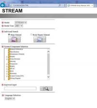
Мультимедийное руководство на английском языке по техническому обслуживанию и ремонту Honda Stream 2001-2004 годов выпуска.
- Автор: —
- Издательство: Honda Motor Co., Ltd.
- Год издания: —
- Страниц: —
- Формат: —
- Размер: 23,4 Mb

Руководство по эксплуатации Honda Stream 2001-2005 года выпуска.
- Автор: —
- Издательство: Honda Motor Co., Ltd.
- Год издания: —
- Страниц: 388
- Формат: PDF
- Размер: 2,3 Mb

Руководство по эксплуатации, техническому обслуживанию и ремонту Honda Stream с 2000 года выпуска с бензиновыми двигателями объемом 1,7/2,0 л.
- Автор: —
- Издательство: Легион-Автодата
- Год издания: —
- Страниц: 410
- Формат: —
- Размер: —

Руководство по эксплуатации и ремонту Honda Stream с 2000 года выпуска с бензиновыми двигателями объемом 1,7/2,0 л.
- Автор: —
- Издательство: Монолит
- Год издания: —
- Страниц: 308
- Формат: —
- Размер: —

|
Интернет-магазин Масла и смазки для автомобилей и мотоциклов, автохимия, расходные материалы, запчасти. |
Воскресенье, 21.05.2023, 21:11 Приветствую Вас Гость
|
|||||||||
|
Honda Stream RN5-RN8 User Guide (Руководство по эксплуатации)
СЕГОДНЯ В НАШЕМ МАГАЗИНЕ МОЖНО ЗАКАЗАТЬ ТОВАРЫ СО СКИДКОЙ…
|
