- Manuals
- Brands
- Isuzu Manuals
- Engine
- 4HK-1
- Manual
-
Bookmarks
Quick Links
Isuzu
4HK-1 and 6HK-1
ENGINE
FUEL SYSTEM
CE APPLICATIONS
Revised 8/29/06
Form Number 5137
1
Related Manuals for Isuzu 4HK-1
Summary of Contents for Isuzu 4HK-1
-
Page 1
Isuzu 4HK-1 and 6HK-1 ENGINE FUEL SYSTEM CE APPLICATIONS Revised 8/29/06 Form Number 5137… -
Page 2
Table Of Contents… -
Page 3
These engines also use an air to air aftercooling intake air system. The air to air intake system ports pressurized air flow between the turbocharger and the intake manifold through an air to air heat exchanger in front of the radiator. The 4HK-1 model has a displacement of 317 cubic inches (in ) or 5193 cubic centimeters (cc). -
Page 4
Isuzu 4HK-1 and 6HK-1 Engine Overview The electronic control system for the Isuzu 4HK-1 and 6HK-1 Engines use input information from a number of sensors and from the Excavator controller to determine the quantity and timing of the fuel delivery to the engine. -
Page 5
Isuzu 6HK1 Common Rail Engine Fuel System Common Fuel Temp Coolant Intake Air Boost Temp Barometric ENG Oil Engine Stop Rail Fuel PSI Sensor Temperature Temp. Sensor Sensor AMB PSI Switch Sensor Sensor Sensor Sensor Boost PSI Crankshaft Camshaft Sensor… -
Page 6
90° on the gear and one reference hole) on the camshaft gear flange surface on the 4HK-1 Engine. Seven through holes (six holes arranged equally every 60° on the gear and one reference hole) on the camshaft gear flange surface on the 6HK-1 Engine. -
Page 7
Isuzu 6HK1 Common Rail Engine Fuel System Common Fuel Temp Coolant Intake Air Boost Temp Barometric ENG Oil Engine Stop Rail Fuel PSI Sensor Temperature Temp. Sensor Sensor AMB PSI Switch Sensor Sensor Sensor Sensor Boost PSI Crankshaft Camshaft Sensor… -
Page 8
Isuzu 4HK-1 and 6HK-1 Engine Overview (continued) Inputs to 81 pin engine harness connector: • The 2 wire intake air temperature (IAT) sensor is installed on intake air tube and detects the temperature of intake air for optimum fuel injection control. -
Page 9
Isuzu 6HK1 Common Rail Engine Fuel System Common Fuel Temp Coolant Intake Air Boost Temp Barometric ENG Oil Engine Stop Rail Fuel PSI Sensor Temperature Temp. Sensor Sensor AMB PSI Switch Sensor Sensor Sensor Sensor Boost PSI Crankshaft Camshaft Sensor… -
Page 10
Isuzu 4HK-1 and 6HK-1 Engine Overview (continued) Inputs to 81 pin engine harness connector: (continued) • The CAN (Controller Area Network) Data Bus Connector transmits communication between the engine controller and the Excavator controller. This connector transmits throttle, idle up/down, work mode, breaker mode, tachometer, instrumentation and fault code information. -
Page 11
Isuzu 6HK1 Common Rail Engine Fuel System Common Fuel Temp Coolant Intake Air Boost Temp Barometric ENG Oil Engine Stop Rail Fuel PSI Sensor Temperature Temp. Sensor Sensor AMB PSI Switch Sensor Sensor Sensor Sensor Boost PSI Crankshaft Camshaft Sensor… -
Page 12
Isuzu 4HK-1 and 6HK-1 Engine Overview (continued) Outputs from 40 pin engine harness connector: (continued) • The injectors are controlled by the engine control module (ECM). The ECM sends a common power supply to injectors 1, 3 and 5. The ECM also sends a common power supply to injectors 2, 4 and 6. -
Page 13
Isuzu 6HK1 Common Rail Engine Fuel System Common Fuel Temp Coolant Intake Air Boost Temp Barometric ENG Oil Engine Stop Rail Fuel PSI Sensor Temperature Temp. Sensor Sensor AMB PSI Switch Sensor Sensor Sensor Sensor Boost PSI Crankshaft Camshaft Sensor… -
Page 14
Isuzu 4HK-1 and 6HK-1 Engine Fuel Schematic Overview Fuel System Hydraulic Function Fuel comes from the tank and typically will go through a prefilter assembly. From the prefilter, the fuel then flows to an electric fuel pump, located in the hydraulic pump compartment. -
Page 16
Isuzu 4HK-1 and 6HK-1 Engine Fuel Schematic Overview The common rail system stores high pressure fuel between the supply pump and the injectors. The common rail also serves as an accumulator to dampen the fuel pulsations from the pump. Flow dampers are located at the outlet of the common rail to the lines to the injectors. -
Page 19
Isuzu 4HK-1 and 6HK-1 Engine Sensor Locations… -
Page 20
Exhaust gas Recirculation (EGR) System Exhaust Gas Recirculation system is abbreviated to EGR system. It recirculates part of exhaust gas into intake manifold to mix an inert gas with intake air. This leads to lower the combustion temperature to limit emissions of nitrogen oxide (NOx). It controls amount of EGR by opening/closing the EGR valve installed between exhaust manifold and intake manifold. -
Page 23: Engine Control System
Engine Control System 42 Installation of ECM Install the ECM in the reverse order of removal. EGR valve position learning is required after replacing the ECM. 1. Turn the key switch to “ON”. 2. Turn the key switch to “OFF”. 3.
-
Page 24
Engine Control System 56 Senser and actuator *Refer at last page.(About wiring diagrams) -
Page 25
57 Engine Control System Circuit diagram (Refer to “Wiring diagrams” for a way to read the diagram.) Main relay circuit TSWG0027… -
Page 26
Engine Control System 58 Starter for safety relay, glow circuit TSWG0068… -
Page 27
59 Engine Control System CAN, GND, DLC circuits TSHK0013… -
Page 28
Engine Control System 60 Injector circuit TSWG0031… -
Page 29
61 Engine Control System SCV circuit TSHK0016… -
Page 30
Engine Control System 62 CKP sensor, fuel temperature sensor, engine coolant temperature sensor, engine oil pressure sensor circuit TSHK0017… -
Page 31
63 Engine Control System Boost temperature sensor, boost pressure sensor circuit TSWG0034… -
Page 32
Engine Control System 64 CMP sensor, common rail pressure sensor, EGR circuit TSHK0018… -
Page 33
65 Engine Control System Memory clear switch, engine stop switch circuit TSWG0038… -
Page 34
This page Is Intentionally Left Blank. -
Page 35
67 Engine Control System TSHK0035… -
Page 36
Engine Control System 68 Terminal Terminal Number Number Boost pressure sensor GND CKP + Boost pressure sensor Vout CKP GND Boost pressure sensor Vcc E112 Terminal Number Terminal Number CMP shield Engine oil pressure sensor GND CMP GND Engine oil pressure sensor Vout CMP + Engine oil pressure sensor Vcc E113… -
Page 37
69 Engine Control System Terminal Terminal Number Number SCV−Lo CKP + SCV−Hi CKP GND Fuel temperature sensor + CKP shield ECT meter CMP + — CMP GND Overheating switch CMP shield ECT + Boost pressure sensor Vcc Terminal Engine oil pressure sensor Vcc Number Engine oil pressure sensor Vout EGR hall sensor U… -
Page 38
Engine Control System 70 Terminal Number — OS−INJ6 signal Injector power supply 2 Injector power supply 1 — OS−INJ4 signal OS−INJ2 signal — (Female connector on injector side) In cylinder head (Female connector on injector side) (Male connector on ECM side) (Male connector on ECM side) TSWG0041… -
Page 39
71 Engine Control System Connector list Connector Face Connector Face E-27 E-75 003-501 #1 injector (Silver) E-29 E-76 003-501 #2 injector (Silver) (Black) E-31 E-80 #3 injector (Silver) (Black) E-33 E-90 003-500 #4 injector (Silver) (Blue) E-35 E-93 #5 injector (Silver) (Gray) E-37 E-98… -
Page 40
Engine Control System 72 Connector Face Connector Face E-114 (Black) (Black) E-161 (Brown) (Gray) E-162 (Dark gray) (Gray) E-163 (Gray) (Black) E-164 (Black) FB-124 H-12 (Black) (Gray) FL-150 H-12 016-500 (Gray) 9 10 11 12 FL-269 H-20 13 14 15 16 17 18 19 20 020-500 003-502… -
Page 41
73 Engine Control System Connector Face Connector Face H-95 12 11 10 9 H-20 (ECM 16 15 14 13 side) 20 19 18 17 020-501 (Gray) H-95 (Injector side) (White) (Gray) H-95 (Injector side) (White) (Gray) H-94 (ECM side) (Gray) H-94 (ECM side) -
Page 42
This page Is Intentionally Left Blank. -
Page 43
103 Trouble Shooting — EXAMPLE From Service Manual Error Code: 0088 Common rail pressure is abnormally high (1st or 2nd stage). TSHK0041 Name 1. Common rail 5. Fuel tank 2. Fuel filter 6. Supply pump 3. Electromagnetic Pump 7. Injector 4. -
Page 44: Trouble Shooting 104
Trouble Shooting 104 Engine control module (ECM) CMP sensor EGR position EGR position EGR position Common rail pressure signal sensor signal sensor signal sensor signal sensor signal 99 E-56 98 E-56 E-56 E-56 E-56 E-56 E-56 E-56 E-56 E-56 E-56 E-56 E-56 H-20…
-
Page 45
105 Trouble Shooting — EXAMPLE From Service Manual Error Code set condition Back-up mode 1st step • L mode fixed. • Rail pressure is more than 185MPa for 5 seconds • Limited injection amount 3 (multi-injection stopped) or more. • Target RP upper limit (80MPa) •… -
Page 46: Trouble Shooting 106
Trouble Shooting 106 Step Action Value Check the fuel return pipe between the supply pump and the fuel tank for breakage, twist, etc. Check for clogging or twisting in the vent hose of the fuel tank. — Check for foreign matter in the fuel tank. If the trouble is detected, repair as required.
-
Page 47
107 Trouble Shooting — EXAMPLE From Service Manual About common rail pressure sensor TSWG0055 Name 1. Sensor ground 2. Sensor signal 3. Sensor power supply Characteristics of common rail pressure sensor (MPa) TSWG0201… -
Page 48
5. 380002726 EMPS/EST ECM Cable 6. 380002728 EMPS/EST RS232 Null Modem Cable Start the Engine Download Tool — Isuzu EMPS The Additional Tools screen provides a button linking the Electronic Service Tool to: • Engine Diagnostic Tool — Isuzu EMPS… -
Page 49: Process Menu
Preliminary ELECTRONIC SERVICE TOOL (EST) Engine Module Programming System (EMPS) — Summary Selecting an EMPS Process Process Menu Select an EMPS operation from the Process Menu Process Menu. • ECM Reflash — Select when the ECM control program is suspected to have ECM Reflash damaged/corrupted files.
-
Page 50
This page Is Intentionally Left Blank.
This manual is also suitable for:
6hk-1
Ваша заявка успешно отправлена!
Необходимо принять условия соглашения
Вы заполнили не все обязательные поля
Произошла ошибка, попробуйте ещё раз
Ваше имя:
*
Телефон:
*
|
Title |
File Size |
Download Links |
|
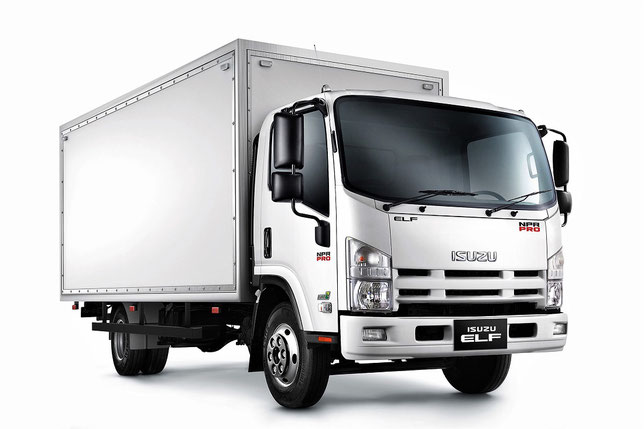
Isuzu Elf 2000 Workshop Manual [RAR] |
53Mb |
Download |
|
Isuzu Elf N-series starting schematic wiring diagram.png |
45.8kb |
Download |
|
Isuzu N-Series Workshop Manual [RAR] |
131.7Mb |
Download |
|
Isuzu NPR_NPR HD_NQR Commercial Truck Tiltmaster Service Manual |
4.7Mb |
Download |
|
ISUZU ELF NKR71HD 2012 Technical Specifications [PDF] |
407.3kb |
Download |
|
Isuzu Elf NPS75 Technical Specifications [PDF] |
590.2kb |
Download |
|
Isuzu ELF NPS81 2020 Technical Specifications [PDF] |
601.6kb |
Download |
|
Isuzu N Series 2008 Owner’s Manual [PDF] |
19.6Mb |
Download |
|
Isuzu N Series Manual [PDF] |
17.4Mb |
Download |
|
Isuzu N-Series Owner’s Manual rus [PDF] |
28.6Mb |
Download |
|
ISUZU N-series Truck Owner’s and Maintenance Manual rus [PDF] |
33Mb |
Download |
|
ISUZU N-Series Truck Service Manual [PDF] |
36.5Mb |
Download |
|
Isuzu N-series Workshop Manual — Engine Control System (4HK1) |
2.3Mb |
Download |
|
Isuzu NKR-NPR-NQR — Workshop Manual ABS [PDF] |
618kb |
Download |
|
ISUZU NKR55 Truck Service Manual [PDF] |
33Mb |
Download |
|
Isuzu NQR 2006 PDF Manual [PDF] |
10.7Mb |
Download |
|
ISUZU NQR71 Truck Service Manual [PDF] |
33Mb |
Download |
|
ISUZU NQR75 Truck Service Manual [PDF] |
33Mb |
Download |
|
Isuzu Q Series QKR55E, QKR55F, QKR55H, QKR77E, QKR77F, QKR77H Manual |
3.6Mb |
Download |
|
Title |
File Size |
Download Links |
|
Isuzu FTR Wiring Diagram [JPG] |
82.4kb |
Download |
|
Isuzu FTR 3102 Wiring Diagram [GIF] |
20kb |
Download |
|
Isuzu FTR Engine wiring84 / PMGR Wiring Diagram [JPG] |
70.4kb |
Download |
|
Isuzu FTR Map sensor wiring diagram 202 [JPG] |
39.6kb |
Download |
|
Isuzu FTR Schnematic Wiring Diagram [JPG] |
42.3kb |
Download |
|
Isuzu Euro VI Forward F120-240E Technical Specifications [PDF] |
643.5kb |
Download |
|
ISUZU F-series Truck Maintenance Manual [PDF] |
12.2Mb |
Download |
|
ISUZU Forward Service Manual [PDF] |
6.3Mb |
Download |
|
Isuzu Forward 2000 Technical Specifications [PDF] |
165.6kb |
Download |
|
ISUZU Forward F-Series Workshop Manual — General information |
5.6Mb |
Download |
|
ISUZU Forward Service Manual [PDF] |
6.3Mb |
Download |
|
Isuzu FRR-series truck Parts Catalog [PDF] |
14.8Mb |
Download |
|
Isuzu FSR / FTR / FVR with 6 HK1 engine Service Manual (1998) |
21.6Mb |
Download |
|
ISUZU FSR90 Truck Owner’s Manual rus [PDF] |
12.2Mb |
Download |
|
Isuzu FTR, FVR, FVM, FVZ, GVR, GVZ, FSS, FTS Manual [PDF] |
22.3Mb |
Download |
|
ISUZU FVR34 Owner’s and Maintenance Manual rus [PDF] |
12.2Mb |
Download |
![]()
Isuzu FTR Wiring Diagram
3102 Isuzu Ftr Wiring Diagram.gif
Graphic Interchange format
20.0 KB
![]()
ISUZU Common Rail System for 4HK1-6HK1 Type Engine Service Manual
ISUZU Common Rail System for 4HK1-6HK1 T
Adobe Acrobat Document
661.3 KB
![]()
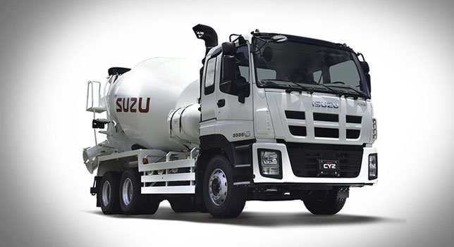
ISUZU CYZ/EXR models Service Manual
ISUZU cyz-exr Service Manual.pdf
Adobe Acrobat Document
8.8 MB
![]()
Isuzu Engine wiring diagrams 84_PMGR
Engine wiring84_PMGR Isuzu Ftr Wiring Di
JPG Image
70.4 KB
![]()
ISUZU C-series Truck Service Manual
ISUZU C-series Truck Service Manual.pdf
Adobe Acrobat Document
6.1 MB
![]()
Isuzu Elf N-series starting schematic wiring diagram
Isuzu Elf N-series starting schematic wi
Portable Network Image Format
45.8 KB
![]()
Isuzu Elf Service Manual
Isuzu Elf Service Manual.pdf
Adobe Acrobat Document
44.5 MB
![]()
ISUZU Forward Service Manual
ISUZU Forward Service Manual.pdf
Adobe Acrobat Document
6.5 MB
![]()
ISUZU FSR90 Truck Service Manual
ISUZU FSR90 Truck Service Manual.pdf
Adobe Acrobat Document
13.2 MB
![]()
ISUZU NKR55 Truck Service Manual
ISUZU NKR55 Truck Service Manual.pdf
Adobe Acrobat Document
33.4 MB
![]()
ISUZU E-series Truck Service Manual
ISUZU E-series Truck Service Manual.pdf
Adobe Acrobat Document
6.1 MB
![]()
ISUZU F-series Truck Service Manual
ISUZU F-series Truck Service Manual.pdf
Adobe Acrobat Document
13.2 MB
![]()
ISUZU FVR34 Truck Service Manual
ISUZU FVR34 Truck Service Manual.pdf
Adobe Acrobat Document
13.2 MB
![]()
ISUZU NQR71 Truck Service Manual
ISUZU NQR71 Truck Service Manual.pdf
Adobe Acrobat Document
33.4 MB
![]()
ISUZU N-series Truck Service Manual
ISUZU N-series Truck Service Manual.pdf
Adobe Acrobat Document
33.4 MB
![]()
ISUZU Truck Body Builder Guide
ISUZU Truck Body Builder Guide.pdf
Adobe Acrobat Document
47.5 MB
![]()
Map sensor wire diagram 202 Isuzu Ftr Wiring Diagram
Map_sensor_wire_diagram%202 Isuzu Ftr Wi
JPG Image
39.6 KB
![]()
ISUZU NQR75 Truck Service Manual
ISUZU NQR75 Truck Service Manual.pdf
Adobe Acrobat Document
33.4 MB
![]()
ISUZU Truck Body Builder Guide 2003
ISUZU Truck Body Builder Guide 2003.pdf
Adobe Acrobat Document
6.0 MB
![]()
ISUZU Truck Service Manual
ISUZU Truck Service Manual.pdf
Adobe Acrobat Document
36.9 MB
![]()
Qu83668_800 Isuzu Ftr Wiring Diagram
Qu83668_800 Isuzu Ftr Wiring Diagram.jpg
JPG Image
82.4 KB
It is not for nothing that the founder of the automobile company Isuzu named the leadership of one of the most powerful industrial enterprises of Japan in the early 20th century
— Tokyo Ishikawajima Shipbuilding and Engineering. It was under the auspices of this organization that a company was established whose specialization was the production of heavy automotive
equipment using mainly diesel engines, the history of which by that time was only a few dozen years old.

The debut step made by representatives of the company, which in the future became known as Isuzu, was the signing in 1918 of an agreement with the British company Wolseley Motors on the assembly
of trucks by the Japanese under license from the British. Already four years later, in 1922, a truck of the A-9 model was presented. And the first own development, made at the Ishikawajima
Automotive Works corporation, representatives of the future Isuzu was demonstrated in 1928. In 1933 Ishikawajima Automotive Works merged with another successful automotive company from Japan —
Dot Automobile Manufacturing.
As a result of the transformation, the organization was named Automobile Industries. The following year became even more important for the formation of future success. Having received an order
from the Ministry of Trade and Industry, the company within its framework produced and produced the Isuzu model, named after one of the Japanese rivers. In the same year, the young corporation
created a unit, which was to deal with research in the field of diesel engines. Three years later, after another restructuring, a new name for the firm was announced — Tokyo Automobile
Industries. And in 1938, the first two trucks of the TX40 model came off the production line in Kawasaki.

40th years of the twentieth century became no less successful than the previous decade. Already in 1941, Tokyo Automobile Industries received permission from the Japanese government to
manufacture cars equipped with diesel power units, becoming the only such company throughout the country. In 1945, the postwar production of the TX40 truck was resumed, and the active sales of
the TU60 also began. And in 1949 the company was renamed to Isuzu Motors Limited. The only negative factor was the separation of Hino Works, one of the parts of the corporation,
and the subsequent establishment of an independent company Hino Heavy Industries in 1942.
The beginning of the next decade was marked by the successful development of the diesel V-shaped 8-cylinder engine with water cooling, which received the index DA80. In early 1953, Isuzu
Corporation presented the first ever company, made in cooperation with the British firm Rootes, a Hillman car, which became a copy of the British car of the same name. By October of the same
year, Hillman entered the conveyor production. And in October 1959 was marked by the beginning of the conveyor assembly of the truck Elf LT, equipped with an extremely economical diesel engine
DA640.
In the early 60’s, a real production boom occurred, as a result of which representatives of the Isuzu company were presented to the public by a diesel engine for a DL201 car, the volume of which
was 2 liters. Approximately at the same time, a new plant was opened in the city of Fujisawa, and new models of cars, the WASP truck and the Bellel and Bellet cars, were also on sale. In the
second half of the decade, the new products were a large truck TM, as well as passenger cars 117 Coupe and Florian.

The next decade also began with major presentations: in 1970, the Isuzu Forward cargo models were presented, as well as the Isuzu Elf 350 (KS). One of the most important events
in the history of Isuzu was the signing of an agreement on cooperation with the American automobile magnate General Motors, which in 1971 became the owner of 35% of the shares of the Japanese
company. The results of joint labor did not take long. Already in 1974, the assembly line for a Gemini passenger car developed within the framework of cooperation between Isuzu and General Motors
began. Over the next few years, the company’s lineup was also updated.
So in 1977, the production of Isuzu Florian started with a diesel engine, and in 1979 debuted the diesel version of Gemini. A few years earlier, in 1975, the Isuzu North American division, Isuzu
Motors America, was opened, whose prospects, in view of cooperation with General Motors, looked extremely serious. And in the very end of the 70s, the construction of a testing range for the
Japanese automaker in Hokkaido was completed. Later, in May 1984, in the same Hokkaido, a new plant was opened. The beginning of the 80s of the 20th century foreshadowed new successes. The main
confirmation of this is the rapid upgrade of the lineup.
First, in 1980, a series of commercial Fargo minibuses entered the conveyor assembly, which were almost immediately widely used in Japan. Almost immediately, in the first half of 1981, the
passenger car Piazza and SUV Rodeo Bighorn debuted, in 1983 Florian Aska model was put on the conveyor, after half a year celebrating the victory in the British RAC rally. And already in 1985
they introduced the FF Gemini car. In the same year 1985, the first representative office of Isuzu in China was opened, which was originally considered as the most important market.
1987 was a landmark in the history of the company in connection with the founding of the joint venture Isuzu Motors and General Motors, which was named IBC Vehicles. Two years later, the fruit of
common labor was presented — the debut SUV MU (Amigo), which launched a new class of «heavy passenger cars». At the same time, a joint venture with Subaru was founded. In the same year 1989,
Isuzu became the world leader in the production of medium and heavy trucks. After the successful development in 1990 of the world’s first electromagnetic brake in cooperation with Sumitomo Metal
Industries, a joint venture with Subaru launched a new model of the Rodeo SUV, which in early 1991 was already in the US.
A very important role in the history of development of Isuzu was played by the Charter of Environmental Protection, which was adopted in mid-1992, and according to which the company carried out
its further activities. All decade passed under the sign of new developments and improvements. In 1991, debuted an updated SUV Trooper. In 1993, the first representative of the Isuzu N series of
commercial vehicles came off the assembly line. Next year, a series of commercial cars F, C and E were presented. In 1997, Isuzu showed the public another novelty developed specifically for
off-road — VehiCross, and in 1998 it was marked The release of a truck Elf CNG, working on gas.
At the same time, the 90s were remembered by the fans of Isuzu’s developments and major successes at various competitions. So in 1994, the car Trooper won in two races Paris-Dakar rally, and two
years later, the first place in the Australian safari took the model Holden Jackaroo. In addition, the organization received many awards for its innovative developments. And in 1999, the fate
again brought Isuzu Motors with the company Hino, as a result of which was established joint production of buses. The beginning
of the XXI century marked the receipt by the company representatives of new awards for successful development.
In particular, 2001 was marked by the presentation of the diesel engine Duramax 6600, which was called one of the best powertrains in the history of the automotive industry. At the same time, the
Japanese actively worked in foreign markets. At the same time, not only the USA and Asian countries, such as Indonesia, Thailand or Japan, received dividends from this work. The company Isuzu
Motors gradually entered the European market. In 2002, a 3-year business plan of the Japanese automaker was adopted, which was supposed to minimize costs and make the company’s revenue more
solid. According to this plan, by January 2003 the share of ownership of Isuzu shares by the automobile giant General Motors had decreased to 12%.
At the same time, these companies continued active cooperation. It should be noted the establishment of another joint venture, whose goal was the development of transmissions. According to the
new business plan of the company, calculated from April 2005 to March 2008, Isuzu was to become the world leader in the production of diesel engines, as well as commercial vehicles and buses. It
should be noted that the company did it. An important role in the development of Isuzu Motors as a world giant was played by the company’s unique developments. In particular, debuted in mid-2005
truck Elf Hybrid with a mixed engine.
After the introduction of new environmental standards in Japan in the same year of 2005, the very important step was the development of the Isuzu Giga truck, which became the first Japanese car
in its class to meet these standards. After the dissolution of the alliance between Isuzu Motors and General Motors in 2006, these companies have set up a joint venture, which is already
preparing for the presentation its new products, which, according to the plan, will pleasantly surprise the whole world.
- Brands:
Isuzu - File Size:
3.2MB - Total Pages:
121 - File Type:
PDF
INTRODUCTION & ENGINE MECHANICAL FEATURES
The 2005 model year NPR/NQR truck, the 4HK1-TC inline 4 cylinder engine replaces the 4HE1-TC engine for advanced exhaust emission countries. The 4HK1-TC engine has been newly developed on the basis of previous 4HE1-TC engine, with additional features including the employment of four valve mechanism per a cylinder that are operated via a single camshaft, common rail fuel injection system, water-cooled exhaust gas re-circulation (EGR) system, and the change of combustion chamber form. The larger engine displacement and the common rail fuel injection system have resulted in an increase both in maximum output and torque, and met Euro 3 emission regulation standard. Most conspicuous items are listed below.
- Multi fuel injection type high-pressure common rail system and is made with Denso.
- Single overhead camshaft (OHC) with 4 valves per a cylinder.
- Electrical control EGR valve, water-cooled EGRcooler.
- Turbocharger with intercooler.
The base transmission is MYY for 4HK1-TCN low output engine, MZZ for 4HK1-TCS high output engine. The Smoother system is available for only MYY transmission.
GEAR TRAIN
To rotate the fuel supply pump with engine speed, idle gear has changed with three steps. The crankshaft gear (42 teeth) corresponds with the large diameter of idle gear A (72 teeth). The fuel supply pump gear (35 teeth) corresponds with the middle diameter of idle gear A (60 teeth). The idle gear B (61 teeth) corresponds with the small diameter of idle gear A (30 teeth).
Valve Train
To improve exhaust emission and engine output performance, four valve mechanism is newly adopted for 4HK1-TC engine. Note that the adjustment method of valve clearance has been changed from 4HK1-TC engine as following steps:
- Rotate the crankshaft to make the No.1 cylinder meet the compression top dead center (TDC). There are 2 marks stamped on the crank pulley. The mark (1) is used to bring the engine No.1 or No. 4 cylinder to TDC. The mark (2) is irrelevant. Do not use the mark (2).
- Loosen fully each adjusting screw (8) & (2) of the bridge and the rocker arm.
- Insert a 0.4mm (0.016in) thickness gauge between the tip of the rocker arm and bridge cap (5), and adjust the clearance with the adjusting screw (3) on the rocker arm, and then fix it with a lock nut (4).
- With a thickness gauge kept inserted, check that the adjusting screw (6) contacts the valve shaft end and the movement of the thickness gauge has become tight when the adjusting screw (6) on the bridge is tightened lightly.
- Check the valve shaft end on the opposite side floats or it contacts obliquely. In case of a floating or oblique contact, loosen a little the adjusting screw (6) on the bridge side and adjust so that the valve shaft ends on both sides get in contact properly. Bridge (8) & valve shaft end clearance less than 0.1 mm (0.004in).
- After the adjustment so that the end of the valves on both sides touch properly, tighten up the lock nut (7) on the bridge (8).
CYLINDER HEAD COVER & HEAD COVER CASE
Along with the employment of a common rail type fuel injection system, the head cover is split and housed in a newly introduced head cover case attached with an intermediate connector for the injector. The head cover case is so designed that it is secured individually to the cylinder head with four bolts, and further it is tightened together with the head cover with nine bolts. Accordingly, the head cover is removable individually regardless of the injector harness, thus enabling easy inspection and service including the valve clearance adjustment.
ENGINE CONTROL MODULE (ECM)
The engine control module (ECM) is located at inside of engine-side cover on the left via mounting bracket and is beside the engine. The ECM is made by Transtron. The ECM mainly controls the following:
- Fuel injection control
- Fuel timing control
- Exhaust gas recirculation (EGR) system control
- Preheating system control
- Exhaust brake control
- Power take off (PTO) control
- On-board diagnostics for engine control
The ECM constantly observes the information from various sensors. The ECM controls the systems that affect vehicle performance. The ECM performs the diagnostic function of the system. The ECM can recognize operational problems, alert the driver through the malfunction indicator lamp (MIL), and store diagnostic trouble code (DTC). DTC identify the system faults to aid the technician in making repair.
This diagnostic applies to internal microprocessor integrity conditions within the ECM. The electronically erasable programmable read only memory (EEPROM) memorize learning data and injector ID code data for engine control and communication with other control module.
Symbol “!” warns you of an electric shock hazard. To avoid shock and possible serious injury, DO NOT touch the terminals. When disconnecting the harness connector, always turn OFF the ignition switch or disconnect the battery cable.

Download or Read Online Isuzu 4HK-1 Engine Service Manual
Save PDF/Read Online
Isuzu
4HK-1 and 6HK-1
ENGINE
FUEL SYSTEM
CE APPLICATIONS
|
Revised 8/29/06 |
Form Number 5137 |
1
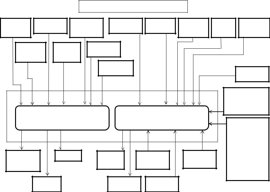
Isuzu 4HK-1 and 6HK-1 Engine Overview
The Tier III CX330 Excavators are equipped with an Isuzu 6HK-1 model common rail fuel system Engine. The Isuzu 4HK-1 model will be used in at least one other
Excavator model. These engines have 4 valves per cylinder, operated by a single overhead cam to optimize air flow, fuel economy and emissions. The injector is now located at the center of the piston under the valve cover. The fuel system is now totally electronically controlled. These engines use an water cooled Exhaust Gas Recirculation, (EGR) system, which allows a controlled amount of exhaust gas to return back to the intake. This EGR system is used to reduce the emissions level of the engine. These engines also use an air to air aftercooling intake air system. The air to air intake system ports pressurized air flow between the turbocharger and the intake manifold through an air to air heat exchanger in front of the radiator. The 4HK-1 model has a displacement of 317 cubic inches (in3) or 5193 cubic centimeters (cc). The 6HK-1 model has a displacement of 475 cubic inches (in3) or 7790cubic centimeters (cc).
The ECM calculates the basic injection amount based on the signals from throttle position sensor, boost pressure sensor, crank position sensor, cam position sensor, etc.
It regulates the opening/closing period of common rail pressure control valve and the electric activation of each injector according to the common rail pressure, engine coolant temperature, etc. at this time, to correct the optimum injection timing and injection amount.
At engine start (after the key switch is turned to the START position to start the engine, and until the return of the key switch to the ON position), the fuel injection quantity is controlled based on information from the start signal, engine speed, and engine coolant temperature. At low temperature, the fuel injection quantity increases. When the engine starts completely, this boosted quantity mode at starting is cancelled and normal running mode is restored.
The ECM calculates the current altitude based on the barometric pressure sensor signal. It corrects the fuel flow according to the altitude etc. at this time.
The Excavator machine controller communicates with the engine controller (ECM) via the CAN Data Bus system to control engine speed, return to idle command, activate the work modes and also to set the engine speed required for the breaker mode.
Engine Performance Needs
1.Air
2.Compression
3.Fuel
3

Isuzu 4HK-1 and 6HK-1 Engine Overview
The electronic control system for the Isuzu 4HK-1 and 6HK-1 Engines use input information from a number of sensors and from the Excavator controller to determine the quantity and timing of the fuel delivery to the engine.
The engine control module (ECM), is located on the inside rear of the cab. The ECM has two connectors, one an 81 pin and one 40 pin, for inputs and outputs. The engine control module requires downloading of control software to give it the ability to control all functions.
Inputs to 40 pin engine harness connector:
•The common rail fuel pressure sensor has 3 wires and is located on the common rail. This sensor detects the fuel pressure in the common rail, converts the pressure into a voltage signal, and sends the signal to the ECM. Higher common rail pressure provides higher fuel pressure sensor voltage while lower pressure provides lower fuel pressure sensor voltage.
•The 2 wire variable resistor fuel temperature sensor is installed on the fuel supply pump. The fuel temperature sensor measures the temperature of the drain fuel from the pump. When the fuel temperature sensor is cold, the sensor resistance is high.
When the fuel temperature increases, the sensor resistance decreases. With high sensor resistance, the ECM detects a high voltage on the signal circuit. With lower sensor resistance, the ECM detects a lower voltage on the signal circuit.
|
Fuel Temp. |
Fuel Temp. |
Ohms |
Fuel Temp. |
Fuel |
Ohms Ω |
|
|
(°C) |
(°F) |
Ω |
(°C) |
Temp. (°F) |
||
|
140 |
284 |
75 |
40 |
104 |
1,150 |
|
|
120 |
248 |
111 |
20 |
68 |
2,450 |
|
|
100 |
212 |
184 |
0 |
32 |
5,740 |
|
|
80 |
176 |
318 |
-20 |
-4 |
15,000 |
|
|
60 |
140 |
584 |
-40 |
-40 |
45,770 |
•The 2 wire engine coolant temperature sensor is located on the thermostat housing at the right front corner of the engine. The coolant sensor’s temperature detection component uses a thermistor. A 5 volt reference voltage is applied at all times to the sensor from the ECM. The ECM detects a voltage change due to a resistance value change in the sensor caused by the coolant temperature change.
|
Coolant |
Coolant |
Ohms |
Coolant |
Coolant |
Ohms Ω |
|
Temp. (°C) |
Temp. (°F) |
Ω |
Temp. (°C) |
Temp. (°F) |
|
|
140 |
284 |
76 |
40 |
104 |
1,161 |
|
120 |
248 |
118 |
20 |
68 |
2,500 |
|
100 |
212 |
190 |
0 |
32 |
5,773 |
|
80 |
176 |
325 |
-20 |
-4 |
15,216 |
|
60 |
140 |
591 |
-40 |
-40 |
47,365 |
4

Isuzu 6HK1 Common Rail Engine Fuel System
|
Common |
Fuel Temp |
Coolant |
Intake Air |
Boost Temp |
Barometric |
ENG Oil |
Engine Stop |
|||
|
Rail Fuel PSI |
Sensor |
Temperature |
Temp. Sensor |
Sensor |
AMB PSI |
PSI |
Switch |
|||
|
Sensor |
Sensor |
Sensor |
Sensor |
|||||||
|
Crankshaft |
Camshaft |
Boost PSI |
||||||||
|
Position |
Position |
Sensor |
||||||||
|
Sensor |
Sensor |
EGR Position |
||||||||
|
Sensor |
Start Signal |
|||||||||
|
(Fuel Boost) |
||||||||||
|
Power Supply |
||||||||||
|
1 Ignition Wire |
||||||||||
|
2 Positive Wires |
||||||||||
|
Engine Harness 40 Pin |
Engine Harness 81 Pin |
6 Ground Wires |
||||||||
|
Connector A1 |
||||||||||
|
Connector A0 |
CAN Data Bus |
|||||||||
|
Engine Control Module |
||||||||||
|
Connector |
||||||||||
|
Throttle, |
||||||||||
|
Idle Up/Down, |
||||||||||
|
Pump PSI |
Injectors |
Main ECM |
Diagnostic |
Memory Clear |
Work Modes, |
|||||
|
Breaker Mode, |
||||||||||
|
Control Valve |
Power |
Switch X24 |
Switch X23 |
|||||||
|
Tach, |
||||||||||
|
(SCV) |
Relay |
|||||||||
|
(Instrumentation |
||||||||||
|
EGR DC |
Glow |
Data Link |
& Faults) |
|||||||
|
Motor |
Relay |
Diag Conn X4 |
||||||||
|
5 |
Isuzu 4HK-1 and 6HK-1 Engine Overview (continued)
Inputs to 40 pin engine harness connector(continued):
•The 2 wire crankshaft position sensor (CKP) is located on the flywheel housing at the left rear corner of the engine. The CKP sensor detects 45 projections equally spaced every 7.5° around the flywheel periphery. There is also a space (equal to 3 projections) to act as a top dead center (TDC) reference signal for the engine control module (ECM). With these 45 pulses and the TDC reference signal, the ECM calculates the engine speed and exact position of the crankshaft.
•The 2 wire camshaft position sensor (CMP) is located on the cylinder head at the rear of the camshaft gear. The camshaft position sensor detects a total of the number of the cylinders in the engine plus an extra one. The extra hole indicates the top dead center position of number 1 cylinder. Five through holes (four holes arranged equally every 90° on the gear and one reference hole) on the camshaft gear flange surface on the 4HK-1 Engine. Seven through holes (six holes arranged equally every 60° on the gear and one reference hole) on the camshaft gear flange surface on the 6HK-1 Engine. The camshaft position sensor indicates the rotational position of the camshaft to the ECM. The CMP signal input, determines the crank angle and the ECM can use it to control fuel injection and calculate the engine speed. The crankshaft position sensor (CKP) typically controls these functions, however it is done by CMP sensor if the CKP sensor is faulty.
Diagnostic aid
If there is relevant Error Code to the crankshaft (CKP) sensor and Camshaft (CMP) sensor, the engine will not start until memory clear is performed.
If an intermittent trouble is suspected, the following may be the cause:
•Improper connection of harness connector
•Defective harness routing
•Worn harness cover
•Wire disconnection inside harness cover
•The 3 wire boost pressure sensor is located in the piping to the intake manifold of the engine. The sensor converts the boost pressure into the voltage signal and sends it to engine control module (ECM). The ECM should detect a higher signal voltage at a high boost pressure.
•The 4 wire Exhaust Gas Recirculation (EGR) position sensor is installed in EGR valve and detects the valve lift amount of EGR.
Note:
Do not disassemble the EGR position sensor. If it is faulty, replace it as EGR valve assembly.
6

Isuzu 6HK1 Common Rail Engine Fuel System
|
Common |
Fuel Temp |
Coolant |
Intake Air |
Boost Temp |
Barometric |
ENG Oil |
Engine Stop |
|||
|
Rail Fuel PSI |
Sensor |
Temperature |
Temp. Sensor |
Sensor |
AMB PSI |
PSI |
Switch |
|||
|
Sensor |
Sensor |
Sensor |
Sensor |
|||||||
|
Crankshaft |
Camshaft |
Boost PSI |
||||||||
|
Position |
Position |
Sensor |
||||||||
|
Sensor |
Sensor |
EGR Position |
||||||||
|
Sensor |
Start Signal |
|||||||||
|
(Fuel Boost) |
||||||||||
|
Power Supply |
||||||||||
|
1 Ignition Wire |
||||||||||
|
2 Positive Wires |
||||||||||
|
Engine Harness 40 Pin |
Engine Harness 81 Pin |
6 Ground Wires |
||||||||
|
Connector A1 |
||||||||||
|
Connector A0 |
CAN Data Bus |
|||||||||
|
Engine Control Module |
||||||||||
|
Connector |
||||||||||
|
Throttle, |
||||||||||
|
Idle Up/Down, |
||||||||||
|
Pump PSI |
Injectors |
Main ECM |
Diagnostic |
Memory Clear |
Work Modes, |
|||||
|
Breaker Mode, |
||||||||||
|
Control Valve |
Power |
Switch X24 |
Switch X23 |
|||||||
|
Tach, |
||||||||||
|
(SCV) |
Relay |
|||||||||
|
(Instrumentation |
||||||||||
|
EGR DC |
Glow |
Data Link |
& Faults) |
|||||||
|
Motor |
Relay |
Diag Conn X4 |
||||||||
|
7 |
Isuzu 4HK-1 and 6HK-1 Engine Overview (continued)
Inputs to 81 pin engine harness connector:
•The 2 wire intake air temperature (IAT) sensor is installed on intake air tube and detects the temperature of intake air for optimum fuel injection control.
•The 2 wire boost temperature sensor is installed onto the EGR valve on the upstream side of intake manifold. The sensor is a thermistor type. The resistance in the sensor changes as the temperature changes. When the intake temperature sensor is cold, the sensor resistance is high. When the intake temperature increases, the sensor resistance decreases. With high sensor resistance, the ECM detects a high voltage on the signal circuit. With lower sensor resistance, the ECM detects a lower voltage on the signal circuit.
•The 3 wire barometric pressure sensor is installed on the machine and converts the ambient barometric pressure into a voltage signal. The ECM calculates barometric pressure by this voltage signal and corrects the fuel injection amount (high-altitude correction) as the machine works at a higher elevation.
•The 3 wire engine oil pressure sensor is located on the left side of the engine just below and forward of the high pressure injection pump.
•An engine emergency stop signal is sent from the machine controller to the engine controller. The machine controller receives an engine stop signal from the stop switch located in the instrument cluster.
•As the engine is started (after the key switch is turned to the START position to start the engine, and until the return of the key switch to the ON position), optimum fuel injection quantity is delivered based on information from the starter switch signal, engine speed, and the engine coolant temperature sensor (ECT). At low temperature, the fuel injection quantity increases. As the engine starts completely, this boosted quantity mode at starting is cancelled and normal running mode is restored.
•Power Supply – Ignition power is sent to the engine control module (ECM) any time that the key switch is in the run position. When the ignition signal is present, the ECM activates the main relay. Once the Main Relay (K33 on machine schematic) is activated, battery power is fed to the ECM through the relay normally open (NO) contact to pins number 2 and 6. When the key switch is turned to the off position, the ECM continues to hold the main relay activated for a period of time to allow the ECM to power down safely. This delay is about 10 seconds. The ECM has six ground connections in total.
8
Isuzu 6HK1 Common Rail Engine Fuel System
|
Common |
Fuel Temp |
Coolant |
Intake Air |
Boost Temp |
Barometric |
ENG Oil |
Engine Stop |
|||
|
Rail Fuel PSI |
Sensor |
Temperature |
Temp. Sensor |
Sensor |
AMB PSI |
PSI |
Switch |
|||
|
Sensor |
Sensor |
Sensor |
Sensor |
|||||||
|
Crankshaft |
Camshaft |
Boost PSI |
||||||||
|
Position |
Position |
Sensor |
||||||||
|
Sensor |
Sensor |
EGR Position |
||||||||
|
Sensor |
Start Signal |
|||||||||
|
(Fuel Boost) |
||||||||||
|
Power Supply |
||||||||||
|
1 Ignition Wire |
||||||||||
|
2 Positive Wires |
||||||||||
|
Engine Harness 40 Pin |
Engine Harness 81 Pin |
6 Ground Wires |
||||||||
|
Connector A1 |
||||||||||
|
Connector A0 |
CAN Data Bus |
|||||||||
|
Engine Control Module |
||||||||||
|
Connector |
||||||||||
|
Throttle, |
||||||||||
|
Idle Up/Down, |
||||||||||
|
Pump PSI |
Injectors |
Main ECM |
Diagnostic |
Memory Clear |
Work Modes, |
|||||
|
Breaker Mode, |
||||||||||
|
Control Valve |
Power |
Switch X24 |
Switch X23 |
|||||||
|
Tach, |
||||||||||
|
(SCV) |
Relay |
|||||||||
|
(Instrumentation |
||||||||||
|
EGR DC |
Glow |
Data Link |
& Faults) |
|||||||
|
Motor |
Relay |
Diag Conn X4 |
||||||||
|
9 |
Isuzu 4HK-1 and 6HK-1 Engine Overview (continued)
Inputs to 81 pin engine harness connector: (continued)
•The CAN (Controller Area Network) Data Bus Connector transmits communication between the engine controller and the Excavator controller. This connector transmits throttle, idle up/down, work mode, breaker mode, tachometer, instrumentation and fault code information.
•The memory clear (X23), diagnostic switch (X24) and data link (X4) connectors are not used with the Case Electronic Service Tool (EST) diagnostic system. They are required when using the Tech 2 Diagnostic Tool.
Outputs from 81 pin engine harness connector:
•When the ignition signal is present from the keyswitch, the ECM activates the main relay. Once the Main Relay (K33 on machine schematic) is activated, battery power is fed to the ECM through the relay normally open (NO) contacts to pins number 2 and 6. When the key switch is turned to the off position, the ECM continues to hold the main relay activated for a period of time to allow the ECM to power down safely. This delay is about 10 seconds.
•The glow control relay system consists of the ECM, glow relay, glow plug. When the key switch is turned ON with low engine coolant temperatures, the ECM determines the glow time and operates the glow relay (K2). After a certain time has elapsed, the ECM will turn the glow relay to “OFF”. Also, after-glow function allows to stabilize idling immediately after starting.
Outputs from 40 pin engine harness connector:
•The engine driven high pressure injection pump pressurizes fuel to feed to the common rail. The injection pump has a suction control valve (SCV), and a fuel temperature (FT) sensor. The suction control valve (SCV) is installed onto high pressure pump section and controls supply of fuel (discharge amount) to common rail. The engine control module (ECM) regulates period of electrical activation time of the SCV to regulate the fuel discharge amount.
Do not replace the SCV. If it is faulty, replace it as supply pump ASM.
•The exhaust gas recirculation (EGR) system recirculates a part of the exhaust gas to the engine intake to reduce the combustion temperature inside the cylinders to reduce NOx (nitrogen oxides) in the exhaust gas. The EGR valve opening is calculated according to the engine coolant temperature (ECT), the engine speed, and the target fuel injection quantity. The EGR motor is the brushless DC motor, and is driven by three phases. The ECM drives the EGR motor through the EGR motor drive circuits U, V, and W. The motor rotates with a combination of the threephase signals. The ECM sets the Error Code when the EGR motor drive duty is high and the difference between the target EGR position and actual EGR position is large.
10
![]()
Isuzu 6HK1 Common Rail Engine Fuel System
|
Common |
Fuel Temp |
Coolant |
Intake Air |
Boost Temp |
Barometric |
ENG Oil |
Engine Stop |
|||
|
Rail Fuel PSI |
Sensor |
Temperature |
Temp. Sensor |
Sensor |
AMB PSI |
PSI |
Switch |
|||
|
Sensor |
Sensor |
Sensor |
Sensor |
|||||||
|
Crankshaft |
Camshaft |
Boost PSI |
||||||||
|
Position |
Position |
Sensor |
||||||||
|
Sensor |
Sensor |
EGR Position |
||||||||
|
Sensor |
Start Signal |
|||||||||
|
(Fuel Boost) |
||||||||||
|
Power Supply |
||||||||||
|
1 Ignition Wire |
||||||||||
|
2 Positive Wires |
||||||||||
|
Engine Harness 40 Pin |
Engine Harness 81 Pin |
6 Ground Wires |
||||||||
|
Connector A1 |
||||||||||
|
Connector A0 |
CAN Data Bus |
|||||||||
|
Engine Control Module |
||||||||||
|
Connector |
||||||||||
|
Throttle, |
||||||||||
|
Idle Up/Down, |
||||||||||
|
Pump PSI |
Injectors |
Main ECM |
Diagnostic |
Memory Clear |
Work Modes, |
|||||
|
Breaker Mode, |
||||||||||
|
Control Valve |
Power |
Switch X24 |
Switch X23 |
|||||||
|
Tach, |
||||||||||
|
(SCV) |
Relay |
|||||||||
|
(Instrumentation |
||||||||||
|
EGR DC |
Glow |
Data Link |
& Faults) |
|||||||
|
Motor |
Relay |
Diag Conn X4 |
||||||||
|
11 |
Isuzu 4HK-1 and 6HK-1 Engine Overview (continued)
Outputs from 40 pin engine harness connector: (continued)
•The injectors are controlled by the engine control module (ECM). The ECM sends a common power supply to injectors 1, 3 and 5. The ECM also sends a common power supply to injectors 2, 4 and 6. The ECM fires the injectors by controlling the ground of the individual injectors. The ECM calculates the basic injection amount and timing based on the signals from throttle position sensor, boost pressure sensor, crankshaft (CKP) sensor, camshaft (CMP) sensor, etc. The timing of the injection is controlled by when the injector activates. The fuel quantity delivered is based upon the amount of time that the injector is open and also the pressure supplied by the common rail. To improve combustion in cylinders, the system injects a little fuel (preinjection or pilot injection) and ignites it at the beginning of the cycle. A second injection (main injection) delivers the fuel required deliver the horsepower needed.
12

Isuzu 6HK1 Common Rail Engine Fuel System
|
Common |
Fuel Temp |
Coolant |
Intake Air |
Boost Temp |
Barometric |
ENG Oil |
Engine Stop |
|||
|
Rail Fuel PSI |
Sensor |
Temperature |
Temp. Sensor |
Sensor |
AMB PSI |
PSI |
Switch |
|||
|
Sensor |
Sensor |
Sensor |
Sensor |
|||||||
|
Crankshaft |
Camshaft |
Boost PSI |
||||||||
|
Position |
Position |
Sensor |
||||||||
|
Sensor |
Sensor |
EGR Position |
||||||||
|
Sensor |
Start Signal |
|||||||||
|
(Fuel Boost) |
||||||||||
|
Power Supply |
||||||||||
|
1 Ignition Wire |
||||||||||
|
2 Positive Wires |
||||||||||
|
Engine Harness 40 Pin |
Engine Harness 81 Pin |
6 Ground Wires |
||||||||
|
Connector A1 |
||||||||||
|
Connector A0 |
CAN Data Bus |
|||||||||
|
Engine Control Module |
||||||||||
|
Connector |
||||||||||
|
Throttle, |
||||||||||
|
Idle Up/Down, |
||||||||||
|
Pump PSI |
Injectors |
Main ECM |
Diagnostic |
Memory Clear |
Work Modes, |
|||||
|
Breaker Mode, |
||||||||||
|
Control Valve |
Power |
Switch X24 |
Switch X23 |
|||||||
|
Tach, |
||||||||||
|
(SCV) |
Relay |
|||||||||
|
(Instrumentation |
||||||||||
|
EGR DC |
Glow |
Data Link |
& Faults) |
|||||||
|
Motor |
Relay |
Diag Conn X4 |
||||||||
|
13 |
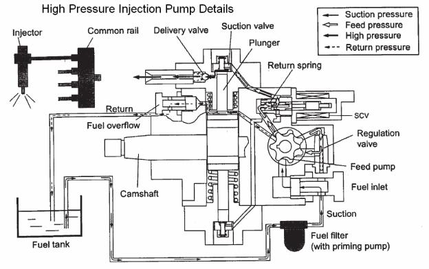
Isuzu 4HK-1 and 6HK-1 Engine Fuel Schematic Overview
Fuel System Hydraulic Function
Fuel comes from the tank and typically will go through a prefilter assembly. From the prefilter, the fuel then flows to an electric fuel pump, located in the hydraulic pump compartment. The 24 volt electric fuel pump is powered directly by the battery relay, through the 65 amp fuse (F23) and the 10 amp electrical fuel pump fuse (F8) in the fuse box. The electric fuel pump then sends the fuel through the fuel filter also located hydraulic pump compartment to the inlet port of the high pressure injection pump.
The high pressure injection pump is mounted at the left rear of the engine. This pump needs to be timed to the engine. To install the pump, bring the engine to TDC and then align the mark on the pump drive gear to the mark on the front face of the high pressure pump. Once these conditions are met, install the injection pump. The high pressure injection pump has a shaft driven gerotor feed (charge) pump which provides fuel to the pump pressure control valve (Suction Control Valve SCV). The gerotor pump outlet pressure is controlled by the regulation valve to provide a constant pressure at the inlet of the high pressure pumping pistons. The high pressurepump PSI regulator (SCV), located in the injection pump, controls the flow output of the high pressure pump. The high pressure pump supplies the quantity of fuel to the common rail required to maintain the pressure dictated by the engine control unit (ECM). This assures that only the required amount of fuel is pressurized, improving energy efficiency and limiting heating of fuel in the system. The common rail pressure will range from 3625 to 29,000 PSI (25 to 200 MPa). Excess flow from the feed pump and internal leakage from the injection pump returns to the tank. The fuel temperature sensor (FT) monitors the temperature of this fuel.
14

15
 Loading…