Материал из BikesWiki — энциклопедия японских мотоциклов
Перейти к: навигация, поиск

Kawasaki VN1600 Vulcan Classic
Ниже представлены прямые ссылки на скачку сервисной документации.
Для Kawasaki VN1600 Vulcan
- Сервисный мануал (Service Manual) на Kawasaki VN1600 Vulcan Classic
- Сервисный мануал (Service Manual) на Kawasaki VN1600 Vulcan Classic Tourer / Nomad
- Сервисный мануал (Service Manual) на Kawasaki VN1600 Vulcan Mean Streak
Обзор модели
- Kawasaki VN1600 Vulcan
Источник — «https://bikeswiki.ru/index.php?title=Kawasaki_VN1600_Vulcan:_мануалы&oldid=12680»
Категория:
- Сервисная документация

VULCAN 1600 MEAN STREAK
VN1600 MEAN STREAK
Motorcycle
Service Manual

Quick Reference Guide
General Information 1 j
Periodic Maintenance 2 j
Fuel System (DFI) 3 j
Cooling System 4 j
Engine Top End 5 j
Clutch 6 j
Engine Lubrication System 7 j
Engine Removal/Installation 8 j
This quick reference guide w ill assist
you in locating a desired topic or procedure.
Bend the pages back to match the
•
black tab of the desired chapter number with the black tab on the edge at
each table of contents page.
Refer to the sectional table of con-
•
tents for the exact pages to locate
the specific topic required.
Crankshaft/Transmission 9 j
Wheels/Tires 10 j
Final Drive 11 j
Brakes 12 j
Suspension 13 j
Steering 14 j
Frame 15 j
Electrical System 16 j
Appendix 17 j

VULCAN 1600 MEAN STREAK
VN1600 MEAN STREAK
All rights reserved. No parts of this publication may be reproduced, stored in a retrieval system, or
transmitted in any form or by any means, electronic mechanical photocopying, recording or otherwise,
without the prior written permission of Quality Assurance Department/Consumer Products & Machinery
Company/Kawasaki Heavy Industries, Ltd., Japan.
No liability can be accepted for any inaccuracies or omissions in this publication, although every possible
care has been taken to make it as complete and accurate as possible.
The right is reserved to make changes at any time without prior notice and without incurring an obligation
to make such changes to products manufactured previously. See your Motorcycle dealer f or the latest
information on product improvements incorporated after this publication.
All information contained in this publication is based on the latest product information available at the time
of publication. Illustrations and photographs in this publication are intended for reference use only and may
not depict actual model component parts.
© 2003 Kawasaki Heavy Industries, Ltd. First Edition (1) : Jul. 1, 2003 (M)

LIST OF ABBREVIATIONS
A
ABDC after bottom dead center m meter(s)
AC
ATDC after top dead center N newton(s)
BBDC before bottom dead center
BDC bottom dead center PS horsepower
BTDC before top dead center
°C degree(s) Celsius r revolution
DC
F farad(s) TDC top dead center
°F degree(s) Fahrenheit
ft foot, feet V volt(s)
g
h hour(s) Ω ohm(s)
kg
kgf (force)
L
ampere(s)
alternating current min
direct current
gram(s) (mass)
(mass)
liter(s)
lb
Pa
psi
r/min, rpm revolution(s) per minute
TIR total indicator reading
W
pound(s)
minute(s)
pascal(s)
pound(s) per square inch
watt(s)
Read OWNER’S MANUAL before operating.

EMISSION CONTROL INFORMATION
To protect the environment in which we all live, Kawasaki has incorporated crankcase emission (1) and exhaust emission (2) control systems in compliance with applicable regulations of
the United States Environmental Protection Agency and California Air Resources Board. Additionally, Kawasaki has incorporated an evaporative emission control system (3) in compliance
with applicable regulations of the California Air Resources Board on vehicles sold in California
only.
1. Crankcase Emission Control System
This system eliminates the release of crankcase vapors into the atmosphere. Instead, the vapors
are routed through an oil separator to the inlet side of the engine. While the engine is operating,
the vapors are drawn into combustion chamber, where they are burned along with the fuel and air
supplied by the fuel injection system.
2. Exhaust Emission Control System
This system reduces the amount of pollutants discharged into the atmosphere by the exhaust
of this motorcycle. The fuel, ignition, and exhaust systems of this motorcycle have been carefully
designed and constructed to ensure an efficient engine with low exhaust pollutant levels.
The exhaust system of this model motorcycle manufactured primarily for sale in California in-
cludes a catalytic converter system.
3. Evaporative Emission Control System
Vapors caused by fuel evaporation in the fuel system are not vented into the atmosphere. In-
stead, fuel vapors are routed into the running engine to be burned, or stored in a canister when
the engine is stopped. Liquid fuel is caught by a vapor separator and returned to the fuel tank.
The Clean Air Act, which is the Federal law covering motor vehicle pollution, contains what is
commonly referred to as the Act’s «tampering provisions.»
«Sec. 203(a) The following acts and the causing thereof are prohibited…
(3)(A) for any person to remove or render inoperative any device or element of design installed
on or in a motor vehicle or m otor vehicle engine in compliance with regulations under this
title prior to its sale and delivery to the ultimate purchaser, or for any manufacturer or dealer
knowingly to remove or render inoperative any such device or element of design after such
sale and delivery to the ultimate purchaser.
(3)(B) for any person engaged in the business of repairing, servicing, selling, leasing, or trading
motor vehicles or motor vehicle engines, or who operates a fleet of motor vehicles knowingly to remove or render inoperative any device or element of design installed on or in a
motor vehicle or motor vehicle engine in compliance with regulations under this title following its sale and delivery to the ultimate purchaser…»
NOTE
The phrase «remove or render inoperative any device or element of design» has been generally
○
interpreted as follows:
1. Tampering does not include the temporary removal or rendering inoperative of devices or elements of design in order to perform maintenance.
2. Tampering could include:
a.Maladjustment of vehicle components such that the emission standards are ex-
ceeded.
b.Use of replacement parts or accessories which adversely affect the performance
or durability of the motorcycle.
c.Addition of components or accessories that result in the vehicle exceeding the stan-
dards.
d.Permanently removing, disconnecting, or rendering inoperative any component or
element of design of the emission control systems.

WE R ECOMMEND THAT ALL DEALERS OBSERVE THESE PROVISIONS OF F EDERAL LAW,
THEVIOLATIONOFWHICHISPUNISHABLEBYCIVILPENALTIESNOTEXCEEDING
$10,000 PER VIOLATION.
TAMPERING WITH NOISE CONTROL SYSTEM PROHIBITED
Federal law prohibits the following acts or the causing thereof: (1) The removal or rendering
inoperative by any person other than for purposes of maintenance, repair, or replacement, of any
device or element of design i ncorporated into any new vehicle for the purpose of noise control
prior to its sale or delivery to the ultimate purchaser or while it is in use, or (2) the use of the
vehicle after such device or element of design has been removed or rendered inoperative by
any person.
Among those acts presumed to constitute tampering are the acts listed below:
Replacement of the original exhaust system or muffler with a component not in compliance
•
with Federal regulations.
Removal of the muffler(s) or any internal portion of the muffler(s).
•
Removal of the air box or air box cover.
•
Modifications to the muffler(s) or air inlet system by cutting, drilling, or other means if such
•
modifications result in increased noise levels.
Foreword
This manual is designed primarily for use by
trained mechanics in a properly equipped shop.
However, it contains enough detail and basic information to make it useful to the owner who desires to perform his own basic maintenance and
repair work. A basic knowledge of mechanics,
the proper use of tools, and workshop procedures must be understood in order to carry out
maintenance and repair satisfactorily. Whenever the owner has insufficient experience or
doubts his ability to do the work, all adjustments, maintenance, and repair should be carried out only by qualified mechanics.
In order to perform the work efficiently and
to avoid costly mistakes, read the text, thoroughly familiarize yourself with the procedures
before starting work, and then do the work carefully in a clean area. Whenever special tools or
equipment are specified, do not use makeshift
tools or equipment. Precision measurements
can only be made if the proper instruments are
used, and the use of substitute tools may adversely affect safe operation.
For the duration of the warranty period,
we recommend that all repairs and scheduled
maintenance be performed in accordance with
this service manual. Any owner maintenance or
repair procedure not performed in accordance
with this manual may void the warranty.
To get the longest life out of your vehicle:
Follow the Periodic M aintenance Chart in the
•
Service Manual.
Be alert for problems and non-scheduled
•
maintenance.
Use proper tools and genuine Kawasaki Mo-
•
torcycle parts. Special tools, gauges, and
testers that are necessary when servicing
Kawasaki motorcycles are introduced by the
Special Tool Catalog or Manual. Genuine
parts provided as spare parts are listed in the
Parts Catalog.
Follow the procedures in this manual care-
•
fully. Don’t take shortcuts.
Remember to keep complete records of main-
•
tenance and repair with dates and any new
parts installed.
How to Use This Manual
In this manual, the product is divided into
its major systems and these systems make up
the manual’s chapters. The Quick Reference
Guide shows you all of the product’s system
and assists in locating their chapters. Each
chapter in turn has its own comprehensive Table of Contents.
For example, if you want ignition coil information, use the Quick Reference Guide to locate
the Electrical System chapter. Then, use t he
Table of Contents on the first page of the chapter to find the Ignition Coil section.
Whenever you see these WARNING and
CAUTION symbols, heed their instructions!
Always follow safe operating and maintenance
practices.
WARNING
This warning symbol identifies special
instructions or procedures which, if not
correctly followed, could result in per-
sonal injury or loss of life.
CAUTION
This caution symbol identifies special
instructions or procedures which, if not
strictly observed, could result in dam-
age to or destruction of equipment.
This manual contains four more symbols (in
addition to WARNING and CAUTION) which will
help you distinguish different types of information.
NOTE
This note symbol indicates points of par-
○
ticular interest for more efficient and con-
venient operation.
Indicates a procedural step or work to be
•
done.
Indicates a procedural sub-step or how to do
○
the work of the procedural step it follows. It
also precedes the text of a NOTE.
Indicates a conditional step or what action to
take based on the results of the test or inspec-
tion in the procedural step or sub-step it fol-
lows.
In most chapters an exploded view illustration
of the system components follows the Table of
Contents. In these illustrations you will find the
instructions indicating which parts require specified tightening torque, oil, grease or a locking
agent during assembly.


GENERAL INFORMATION 1-1
General Information
Table of Contents
Before Servicing ……………………………………………………………………………………………………… 1-2
Model Identification………………………………………………………………………………………………….. 1-7
General Specifications……………………………………………………………………………………………… 1-9
Unit Conversion Table ……………………………………………………………………………………………… 1-12
1
1-2 G ENERAL INFORMATION
Before Servicing
Before starting to perform an inspection service or carry out a disassembly and reassembly operation on a motorcycle, read the precautions given below. To facilitate actual operations, notes, illustrations, photographs, cautions, and detailed descriptions have been included in each chapter wherever
necessary. This section explains the items that require particular attention during the removal and
reinstallation or disassembly and reassembly of general parts.
Especially note the following:
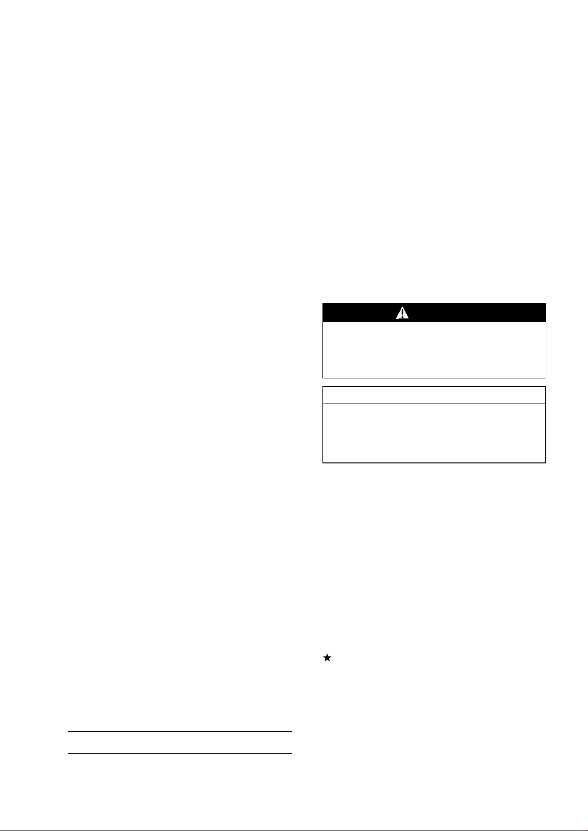
Battery Ground
Before completing any service on the motorcycle, disconnect the battery wires from the battery to prevent the engine
from accidentally turning over. Disconnect the ground wire
(-) first and then the positive (+). When completed with the
service, first connect the positive (+) wire to the positive (+)
terminal of the battery then the negative (-) wire to the negative terminal.
Edges of Parts
Lift large or heavy parts wearing gloves to prevent injury
from possible sharp edges on the parts.
Solvent
Use a high flush point solvent when cleaning parts. High
flush point solvent should be used according to directions
of the solvent manufacturer.
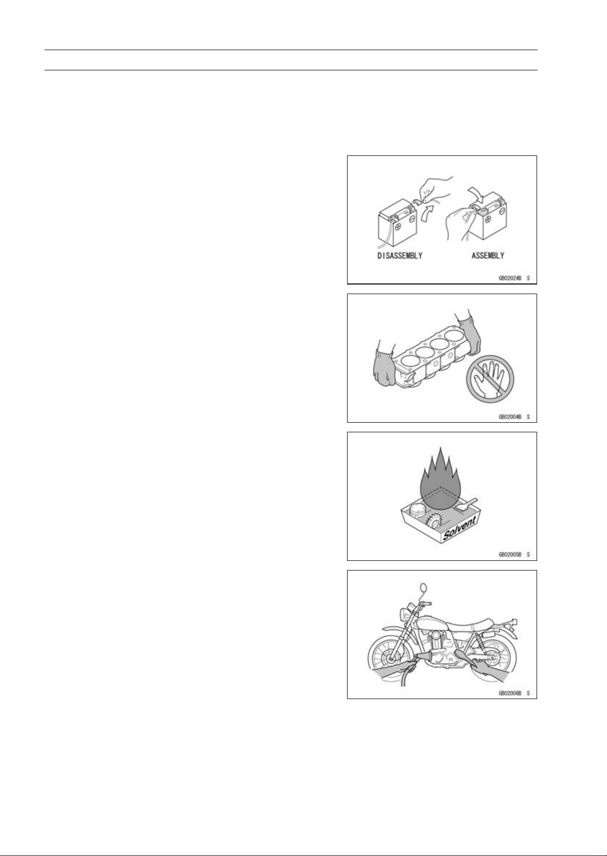
Cleaning vehicle before disassembly
Clean the vehicle thoroughly before disassembly. Dirt or
other foreign materials entering into sealed areas during vehicle disassembly can cause excessive wear and decrease
performance of the vehicle.
Before Servicing
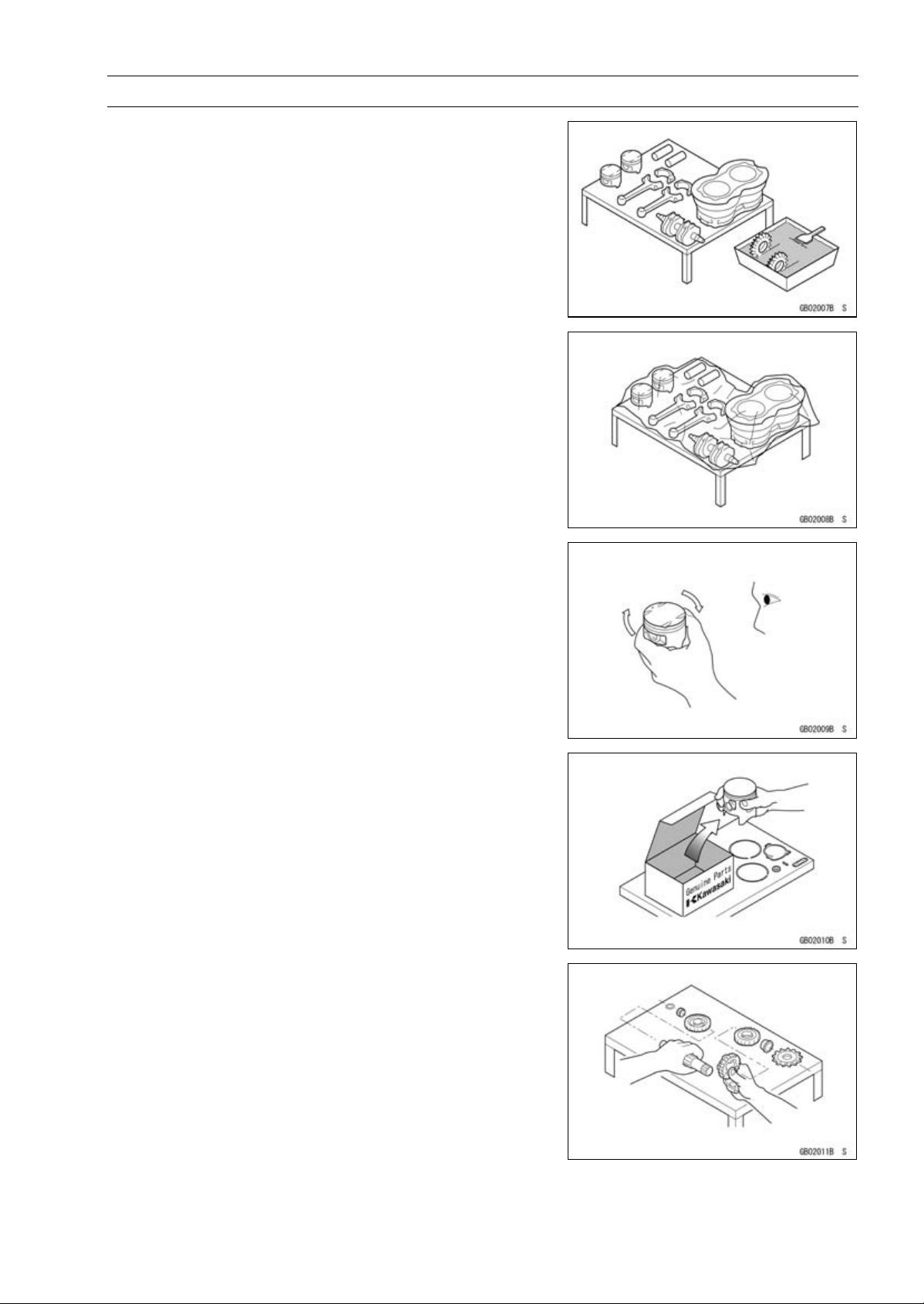
Arrangement and Cleaning of Removed Parts
Disassembled parts are easy to confuse. Arrange the
parts according to the order the parts were disassembled
and clean the parts in order prior to assembly.
Storage of Removed Parts
After all the parts including subassembly parts have been
cleaned, store the parts in a clean area. Put a clean cloth
or plastic sheet over the parts to protect from any foreign
materials that may collect before re-assembly.
GENERAL INFORMATION 1-3
Inspection
Reuse of worn or damaged parts may lead to serious accident. Visually inspect removed parts for corrosion, discoloration, or other damage. Refer to the appropriate sections
of this manual for service limits on individual parts. Replace
the parts if any damage has been found or if the part is beyond its service limit.
Replacement Parts
Replacement Parts must be KAWASAKI genuine or
recommended by KAWASAKI. Gaskets, O-rings, Oil seals,
Grease seals, circlips or cotter pins must be replaced with
new ones whenever disassembled.
Assembly Order
In most cases assembly order is the reverse of disassembly, however, if assembly order is provided in this Service
Manual, follow the procedures given.
1-4 G ENERAL INFORMATION
Before Servicing
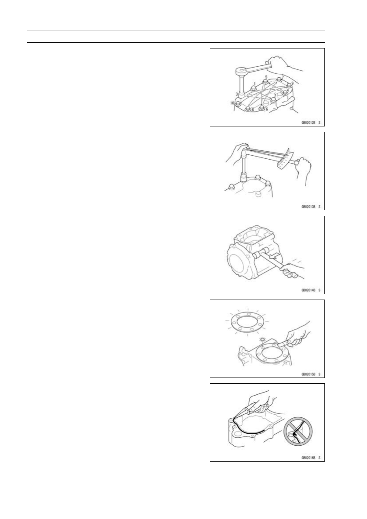
Tightening Sequence
Bolts, nuts, or screws must be tightened according to the
specified sequence to prevent case warpage or deformation
which can lead to malfunction. If the specified tightening
sequence is not indicated, tighten the fasteners alternating
diagonally.
Tightening Torque
Incorrect torque applied to a bolt, nut, or screw may
lead to serious damage. Tighten fasteners to the specified
torque using a good quality torque wrench. Often, the
tightening sequence is followed twice-initial tightening and
final tightening with torque wrench.
Force
Use common sense during disassembly and assembly,
excessive force c an cause expensive or hard to repair damage. When necessary, remove screws that have a non
-permanent locking agent applied using an impact driver.
Use a plastic-faced mallet whenever tapping is necessary.
Gasket, O-ring
Hardening, shrinkage, or damage of both gaskets
and O -rings after disassembly can reduce sealing performance. Rem ove old gaskets and clean the sealing
surfaces thoroughly so that no gasket material or other
material remains. Install new gaskets and replace used
O-rings when re-assembling
Liquid Gasket, Locking Agent
For applications that require Liquid G asket or a Locking
Agent, clean the surfaces so that no oil residue remains before applying liquid gasket or locking agent. Do not apply
them excessively. Excessive application can clog oil passages and cause serious damage.
Before Servicing
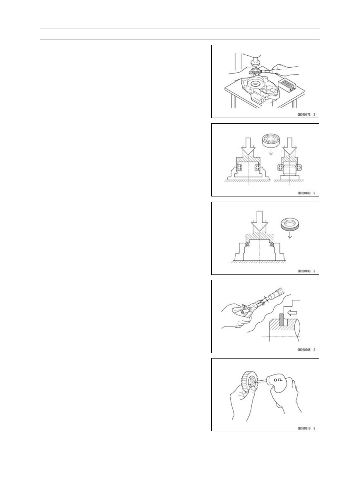
Press
For items such as bearings or oil seals that must be
pressed into place, apply small amount of oil to the contact area. Be sure to maintain proper alignment and use
smooth movements when installing.
Ball Bearing and Needle Bearing
Do not remove pressed ball or needle unless removal is
absolutely necessary. Replace with new ones whenever
removed. Press bearings with the manufacturer and size
marks facing out. Press the bearing into place by putting
pressure on the correct bearing race as shown.
Pressing the incorrect race can cause pressure between
the inner and outer race and result in bearing damage.
GENERAL INFORMATION 1-5
Oil Seal, Grease Seal
Do not remove pressed oil or grease seals unless removal
is necessary. Replace with new ones w henever removed.
Press new oil seals with manufacture and size marks facing
out. Make sure the seal is aligned properly when installing.
Circlips, Cotter Pins
Replace circlips or cotter pins that were removed with new
ones. Install the circlip with its sharp edge facing outward
and its chamfered side facing inward to prevent the clip from
being pushed out of its groove when loaded. Take care
not to open the clip excessively when installing to prevent
deformation.
Lubrication
It is important to lubricate rotating or sliding parts during
assembly to minimize wear during initial operation. Lubrication points are called out throughout this manual, apply
the specific oil or grease as specified.
1-6 G ENERAL INFORMATION
Before Servicing
Direction o f Engine Rotation
When rotating the crankshaft by hand, the free play
amount of rotating direction will affect the adjustment. Rotate the crankshaft to positive direction (clockwise viewed
from output side).
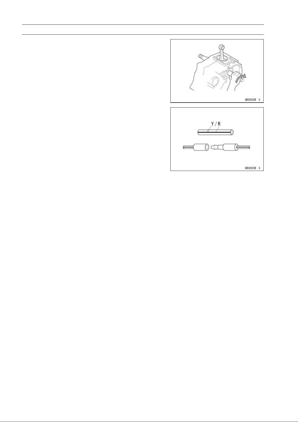
Electrical Wires
A two-color wire is identified first by the primary color and
then the stripe color. Unless instructed otherwise, electrical
wires must be connected to those of the same color.
Model Identification
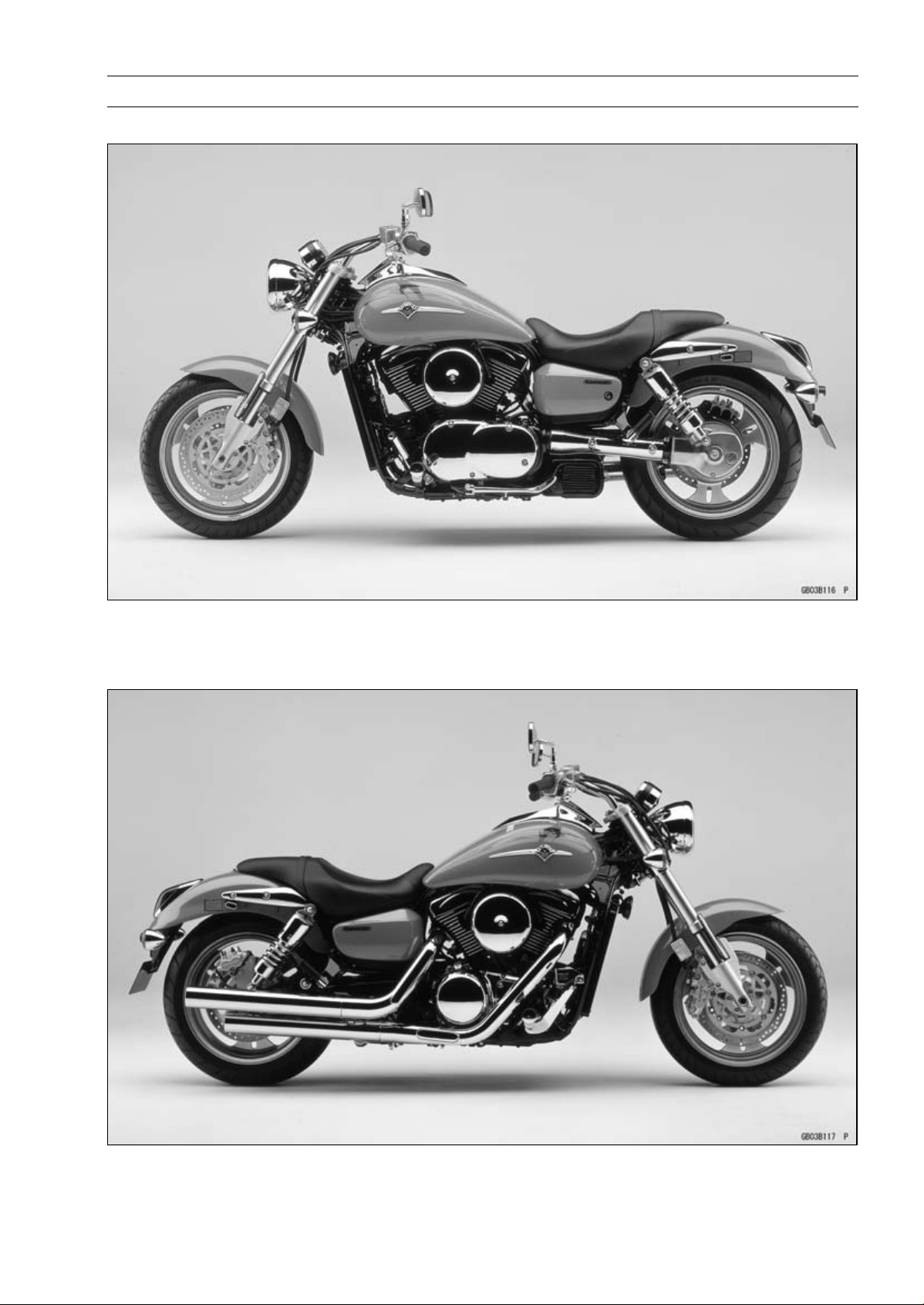
VN1600-B1 (US, and Canada) Left Side View:
GENERAL INFORMATION 1-7
VN1600-B1 (US, and Canada) Right Side View:
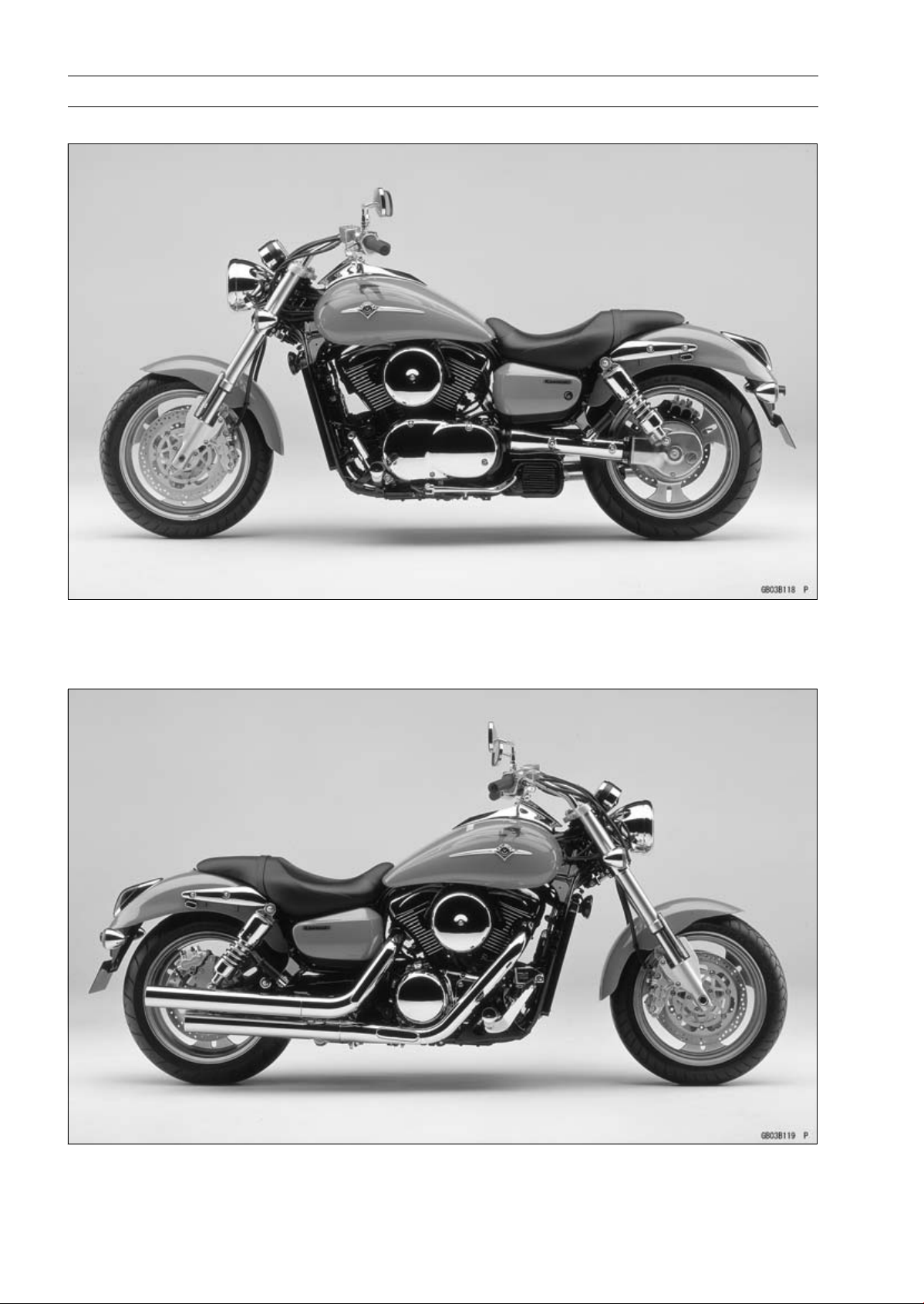
1-8 G ENERAL INFORMATION
Model Identification
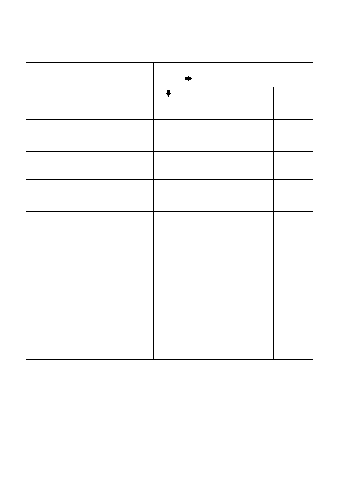
VN1600-B1 (Europe) Left Side View:
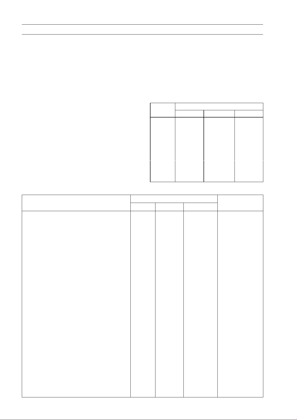
VN1600-B1 (Europe) Right Side View:

GENERAL INFORMATION 1-9
General Specifications
Items VN1600–B1
Dimensions:
Overall length 2 410 mm (94.9 in.)
Overall width 850 mm (33.5 in.)
Overall height 1 100 mm (43.3 in.)
Wheelbase
Road clearance 125 mm (4.92 in.)
Seat height 700 mm (27.6 in.)
Dry mass 290 kg (639 lb)
Curb mass:
Fuel tank capacity
Fuel Unleaded and high-octane gasoline
Performance:
Minimum turning radius
Engine:
Type
Cooling system Liquid-cooled
Bore and stroke
Displacement 1 552 mL (94.70 cu in.)
Compression ratio
Maximum horsepower 54 kW (74 PS) @5 300 r/min (rpm),
Maximum torque 125 N·m (12.7 kgf·m, 92.2 ft·lb) @2 800 r/min (rpm),
Carburetion system DFI (Digital Fuel Injection) System
Starting system
Ignition system Battery and coil (transistorized)
Timing advance
Ignition timing From 5° BTDC @950 r/min (rpm) ∼
Spark plugs NGK DPR6EA-9 or ND X20EPR-U9
Cylinder numbering method
Firing order 1-2
Valve timing:
Inlet Open 22° BTDC
Exhaust
Lubrication system Forced lubrication (wet sump)
Engine oil: Type
Front
Rear 172 kg (379 lb)
Close 66° ABDC
Duration 268°
Open
Close 26° ATDC
Duration
Viscosity
1 705 mm (67.1 in.)
145 kg (320 lb)
17.0 L (4.49 US gal)
(see Owner’s Manual)
3.1 m (10.2 ft)
4-stroke, SOHC, V2-cylinder
102 × 95 mm (4.02 × 3.74 in.)
9.0 : 1
(CAL)(CA)(US)–
(CAL)(CA)(US)–
Electric starter
Electronically advanced (digital)
25° BTDC @4 500 r/min (rpm)
Front to Rear, 1-2
66° BBDC
272°
API SE, SF or SG class
API SH or SJ class with JASO M A
SAE10W-40

1-10 GENERAL INFORMATION
General S pecifications
Items VN1600–B1
Capacity 3.5 L (3.7US qt, when engine is completely
disassembled and dry)
Drive Train:
Primary reduction system:
Type Gear
Reduction ratio 1.517 (85/56)
Clutch type Wet multi disc
Transmission:
Type 5-speed, constant mesh, return shift
Gear ratios: (CAL, CA, US)
1st 2.500 (40/16)
2nd 1.750 (35/20)
3rd 1.333 (32/24)
4th 1.074 (29/27)
5th 0.867 (26/30)
(other than CAL, CA, US)
1st 2.500 (40/16)
2nd 1.590 (35/22)
3rd 1.192 (31/26)
4th 0.965 (28/29)
5th 0.781 (25/32)
Final drive system:
Type Shaft
Reduction ratio 2.619 (15/21 × 33/9)
Overall drive ratio (CAL, CA, US) 3.445 @ Top gear
(other than CAL, CA, US) 3.105 @ Top gear
Final gear case oil:
Grade API Service Classification: GL-5 Hypoid gear oil
Viscosity SAE90 (above 5°C), SAE80 (below 5°C)
Capacity 200 mL (12.2 cu in.)
Frame:
Type Tubular, double cradle
Caster (rake angel) 32°
Trail 144 mm (5.67 in.)
Front tire: Type Tubeless
Size 130/70R17 M/C 62H
Rear tire: Type Tubeless
Size 170/60R17 M/C 72H
Front suspension: Type Telescopic fork (upside-down)
Wheel travel 150 mm (5.91 in.)
Rear suspension: Type Swingarm, air oil shock absorber
Wheel travel 87 mm (3.43 in.)
Brake Type: Front Dual disc
Rear Single disc

GENERAL INFORMATION 1-11
General Specifications
Items VN1600–B1
Electrical Equipment:
Battery Capacity 12 V 18 A h
Headlight: Type
Bulb 12 V 60/55 W (quartz-halogen)
Tail/brake light 12 V 5/21 W
Alternator: Type Three-phase AC
Rated output
Specifications subject to change without notice, and m ay not apply to every country.
CAL: California Model
CA: Canadian Model
US: United States of America Model
Semi-sealed beam
23 A × 14 V @6 000 r/min (rpm)

1-12 GENERAL INFORMATION
Unit Conversion Table
Prefixes for Units:
Prefix Symbol Power
mega M × 1 000 000
kilo k × 1 000
centi c ×0.01
milli m × 0.001
micro µ × 0.000001
Units of Mass:
kg × 2.205 = lb
g × 0.03527 = oz
Units of Volume:
L × 0.2642 = gal (US)
L × 0.2200 = gal (imp)
L × 1.057 =
L × 0.8799 = qt (imp)
L×2.113=
L × 1.816 = pint (imp)
mL × 0.03381 = oz (US)
mL × 0.02816 = oz (imp)
mL × 0.06102 = cu in.
qt (US)
pint (US)
Units of Length:
km × 0.6214 = mile
m × 3.281 = ft
mm × 0.03937 = in.
Units of Torque:
N·m × 0.1020 = kgf·m
N·m × 0.7376 = ft·lb
N·m × 8.851 = in·lb
kgf·m × 9.807 = N·m
kgf·m
kgf·m × 86.80 = in·lb
× 7.233 =
ft·lb
Units of Pressure:
kPa × 0.01020 =
kPa × 0.1450 = psi
kPa × 0.7501 = cm Hg
kgf/cm² × 98.07 = kPa
kgf/cm² × 14.22 = psi
cmHg×1.333=kPa
kgf/cm²
Units of Speed:
km/h × 0.6214 = m ph
Units of Force:
N × 0.1020 =
N × 0.2248 = lb
kg × 9.807 = N
kg × 2.205 = lb
Units of Temperature:
kgf
Units of Power:
kW ×1.360=PS
kW ×1.341=HP
PS × 0.7355 = kW
PS
× 0.9863 = HP

PERIODIC MAINTENANCE 2-1
Periodic Maintenance
Table of Contents
Periodic Maintenance Chart ………….. 2-2
Torque and Locking Agent …………….. 2-4
Specifications ……………………………… 2-10
Special Tools ………………………………. 2-12
Periodic Maintenance Procedures….. 2-13
Fuel System (DFI)……………………… 2-13
Fuel Hose and Connection
Inspection ……………………………. 2-13
Throttle Control System
Inspection ……………………………. 2-13
Idle Speed Inspection ……………… 2-14
Air Cleaner Element Cleaning…… 2-14
Evaporative Emission Control
System Inspection(CAL) ……….. 2-15
Cooling System…………………………. 2-16
Radiator Hose and Connection
Inspection ……………………………. 2-16
Coolant Change ……………………… 2-16
Engine Top End ………………………… 2-18
Air Suction Valve Inspection …….. 2-18
Clutch………………………………………. 2-19
Clutch Hose and Connection
Inspection ……………………………. 2-19
Clutch Fluid Level Inspection ……. 2-19
Clutch Fluid Change ……………….. 2-20
Clutch Master Cylinder Cup and
Dust SealReplacement …………. 2-21
Clutch Slave Cylinder Piston Seal
Replacement ………………………. 2-22
Engine Lubrication System …………. 2-22
Engine Oil Change………………….. 2-22
Oil Filter Replacement …………….. 2-24
Wheels/Tires…………………………….. 2-24
2
Tire Inspection ……………………….. 2-24
Final Drive………………………………… 2-25
Oil Level Inspection…………………. 2-25
Oil Change …………………………….. 2-26
Brakes……………………………………… 2-27
Brake Pad Wear Inspection ……… 2-27
Brake Hose and Connection
Inspection……………………………. 2-27
Brake Fluid Level Inspection …….. 2-28
Brake Fluid Change ………………… 2-29
Brake Master Cylinder Cup and
Dust Seal Replacement . ……….. 2-30
Caliper Piston/Dust Seals
Replacement……………………….. 2-30
Front Brake Light Switch
Inspection……………………………. 2-30
Rear Brake Light Switch
Check/Adjustment………………… 2-30
Suspension………………………………. 2-31
Front Fork Oil Leak Inspection….. 2-31
Rear Shock Absorber Oil Leak
Inspection …………………………… 2-31
Swingarm Pivot Lubrication ……… 2-31
Steering …………………………………… 2-32
Stem Bearing Lubrication…………. 2-32
Steering Check ………………………. 2-32
Steering Adjustment………………… 2-32
Electrical System ………………………. 2-33
Spark Plug Cleaning/Inspection… 2-33
General Lubrication …………………… 2-33
Lubrication …………………………….. 2-33
Nut, Bolt, and Fastener Tightness .. 2-34
Tightness Inspection ……………….. 2-34
2-2 P ERIODIC M AINTENANCE
Periodic Maintenance Chart
The scheduled maintenance must be done in accordance with this chart to keep the motorcycle in
good running condition.The initial m aintenance is vitally important and must not be neglected.
FREQUENCY Whichever
comes
first
1 6 12 18 24 30 36 See
INSPECTION Every (0.6) (4) (7.5) (12) (15) (20) (24) Page
Air suction valve (e) — inspect †
Air cleaner element (e) — clean†#
Throttle control system (e) — inspect †
Idle speed (e) — inspect †
Fuel hoses, connections — inspect †
Evaporative emission control system (e)
(CAL) — inspect †
Final gear case oil level — inspect †
Brake pad wear — inspect † #
Brake light switch — inspect †
Steering — inspect † year
Tire damage and wear — inspect † #
Tire air pressure — inspect year
Wheel damage — inspect year
Wheel bearing wear and damage — inspect
Front fork and rear shock absorber operation
• • • •
• • • •
• • • •
• • • • • • •
• • • •
• • •
• • • • • •
• • •
• • • • • •
• • •
• • •
• • •
• • •
• • •
* ODOMETER READING
km × 1000 (mile × 1000)
2–18
• •
2–14
2-13
2-14
2-13
2-15
2–25
2–27
2–30
2–32
2–24
2–24
–
–
–
General lubrication — perform year
Nut, bolt, and fastener tightness — inspect †
Brake/clutch hoses, connections — inspect †
Brake/clutch fluid level — inspect † month
Coolant hoses, connections — inspect † year
Steering stem bearing — lubricate 2 years
• • •
• • • •
• • • • • • •
• • • • • • •
• • • •
•
2–33
2–34
2–19,
2–27
2–19,
2–28
2–16
2–32

Periodic Maintenance Chart
PERIODIC MAINTENANCE 2-3
FREQUENCY Whichever
comes
first
1 12 24 36 48 See
CHANGE/REPLACE ITEM Every (0.6) (7.5) (15) (24) (30) Page
Spark plug (e)
Engine oil # year
Oil filter year
Coolant 3 years
Brake/clutch master cylinder cup and dust seal 4 years
Caliper piston seal and dust seal 4 years 2–30
Clutch slave cylinder position seal 4 years 2–22
Brake/clutch fluid 2 years
Final gear case oil
Fuel hose 4 years
# : Service more frequently when operating in severe conditions; dusty, wet, muddy, high speed or
frequent starting/stopping.
* : For higher odometer readings, repeat at the frequency interval established here.
† : Replace, add, adjust, clean, or torque if necessary.
• • • •
• • • •
• •
* ODOMETER READING
km × 1000 (mile × 1000)
• • •
•
•
•
2–33
2–22
2–24
2–16
2–21,
2–30
2–20,
2–29
2–25
–
Throttle control system inspection: Inspection of throttle grip play and throttle bore cleanliness.
(CAL): California
(e): Emission Related Items
2-4 P ERIODIC M AINTENANCE
Torque and Locking Agent
The following tables list the tightening torque
for the major fasteners requiring use of a non
-permanent locking agent or liquid gasket.
Letters used in the “Remarks” column mean:
G: Apply grease to the threads.
EO: Apply engine oil to the threads and the
seating surface.
L: Apply a non-permanent locking agent to
the threads.
Lh: Left-hand threads.
MO: Apply molybdenum disulfide oil to the
threads and the seating surface. The
molybdenum disulfide oil is a mixture
of engine oil and molybdenum disulfide
grease w ith a w eight ratio (10 : 1).
S: Tighten the fasteners following the speci-
fied sequence.
SS: Apply silicone sealant.
St: Stake the fasteners to prevent loosening.
R: Replacement parts
AL: Tighten the two clamp bolts alternately
two times to ensure even tightening
torque.
WL: Apply a soap and water solution or rubber
lubricant.
The table below, relating tightening torque to
thread diameter, lists the basic torque for the
bolts and nuts. Use this table for only the bolts
and nuts which do not require a specific torque
value. All of the values are f or use with dry
solvent-cleaned threads.
Basic Torque for General Fasteners
Threads Torque
dia. (mm) N·m
5 3.4 ∼ 4.9 0.35 ∼ 0.50 30 ∼ 43 in·lb
6 5.9 ∼ 7.8 0.60 ∼ 0.80 52 ∼ 69 in·lb
8 14 ∼19 1.4 ∼1.9 10.0 ∼ 13.5
10 25 ∼ 34 2.6 ∼ 3.5 19.0 ∼ 25
12 44 ∼ 61 4.5 ∼ 6.2 33 ∼ 45
14 73 ∼ 98 7.4 ∼ 10.0 54 ∼ 72
16 115 ∼ 155 11 .5 ∼ 16.0 83 ∼ 115
18 165 ∼ 225 17.0 ∼ 23.0 125 ∼ 165
20 225 ∼ 325 23 ∼ 33 165 ∼ 240
kgf·m ft·lb
Fastener
N·m kgf·m ft·lb
Fuel System:
High pressure fuel hose clamp screws 1.5 0.15 13 in·lb
Pressure regulator screws 4.9 0.50 43 in·lb
Delivery joint screws 3.4 0.35 30 in·lb Throttle Body
Throttle body flange bolts 4.9 0.50 43 in·lb
Throttle body assy holder bolts 11 1.1 97 in·lb Right Side
Inlet manifold bolts 12 1.2 106 in·lb on Cyl. Head
Spark plug lead holder bolts 11 1.1 97 in·lb Right Side
ISC pipe bolts 11 1.1 97 in·lb
Air cleaner duct holder bolts 11 1.1 97 in·lb Left Side
Right and left air cleaner base bolts 11 1.1 97 in·lb
Right and left air cleaner base screws 2.2 0.22 19 in·lb L, Lower Duct
Left air cleaner cover Allen bolt 16 1.6 12
Right air cleaner cover Allen bolt 16 1.6 12
Right air cleaner Allen bolts 11 1.1 97 in·lb Throttle Body
Choke cable plate screw 2.9 0.30 26 in·lb L, Throttle Body
Inlet air temperature sensor nut (DFI) 7.8 0.80 69 in·lb
Water temperature sensor (DFI) 18 1.8 13 SS
Fuel pump bolts 6.9 0.70 61 in·lb S, L
Return fuel check valve 20 2.0 15
Cooling System:
Radiator hose clamp screws 2.5 0.25 22 in·lb
Thermostat air bleeder bolt 7.8 0.80 69 in·lb
Torque
Remarks
Torque and Locking Agent
PERIODIC MAINTENANCE 2-5
Fastener
Radiator fan switch
Radiator fan bolts
Water temperature switch 7.8 0.80 69 in·lb SS
Water pump impeller bolt 8.8 0.90 78 in·lb Lh
Water pump cover bolts 11 1.1 97 in·lb
Water pump air bleeder bolt 11 1.1 97 in·lb
Water pump drain bolt 11 1.1 97 in·lb
Water pipe bolts 11 1.1 97 in·lb
Radiator drain Bolt 2.2 0.22 19 in·lb
Engine Top End:
Spark plugs 18 1.8 13
Spark plug retainers 12 1.2 106 in·lb
Air suction valve cover bolts 7.4 0.75 65 in·lb
Chain tensioner mounting bolts 11 1.1 97 in·lb S
Chain tensioner cap 20 2.0 15 S
Chain tensioner lockbolt 4.9 0.50 43 in·lb S
Timing inspection cap 1.5 0.15 13 in·lb
Rotor bolt cap 1.5 0.15 13 in·lb
Camshaft sprocket bolts 15 1.5 11 L
Oil hose flange bolts 9.8 1.0 87 in·lb
Rocker shafts 25 2.5 18
Rocker case nuts 12 mm 78 8.0 58 MO, S
8mm 25 2.5 18 S
Rocker case bolts 6 mm 8.8 0.90 78 in·lb S
Cylinder head nuts 25 2.5 18 S
Cylinder head jacket plugs 20 2.0 15 L
Rocker case cover bolts 8.8 0.90 78 in·lb S
Camshaft chain guide bolts 11 1.1 97 in·lb L
Cylinder nuts 25 2.5 18 S
Inlet manifold bolts 12 1.2 106 in·lb on Cyl. Head
Exhaust pipe cover clamp bolts 6.9 0.70 61 in·lb
Premuffler chamber bolts
Muffler stay mounting bolts, 8 25 2.5 18 Lower Muffler
Upper muffler mounting nuts 25 2.5 18
Upper muffler bracket nut 29 3.0 21
Clutch:
Clutch lever pivot bolt 1.0 0.10 8.9 in·lb
Clutch lever pivot bolt locknut 5.9 0.60 52 in·lb Si
Clutch reservoir cap screws 1.5 0.15 13 in·lb
Clutch slave cylinder bleed valve 7.8 0.80 69 in·lb
Clutch slave cylinder bolts 6.9 0.70 61 in·lb L
Clutch hose banjo bolts 25 2.5 18
Clutch master cylinder clamp bolts 9.8 1.0 87 in·lb S
N·m
18 1.8 13
8.3 0.85 74 in·lb
29 3.0 21
Torque
Remarks
kgf·m ft·lb

2-6 P ERIODIC M AINTENANCE
Torque and Locking Agent
Fastener
Starter lockout switch screws
Push rod guide bolts 11 1.1 95 in·lb L
Clutch cover bolts 11 1.1 95 in·lb
Clutch damper cover bolts 9.8 1.0 87 in·lb L
Clutch damper plate bolts 9.8 1.0 87 in·lb EO
Clutch cover damper screws 4.9 0.50 43 in·lb L
Clutch hub nut 147 15 108 MO
Engine Lubrication System:
Oil filler cap 1.5 0.15 13 in·lb
Oil screen plug 20 2.0 15
Engine oil drain plug 20 2.0 15
Oil filter (cartridge type)
Oil filter pipe
Oil pressure relief valve
Oil pressure switch terminal screw 1.5 0.15 13 in·lb
Oil pressure switch 15 1.5 11 SS
Oil pump mounting bolts 11 1.1 97 in·lb
Oil hose banjo bolts 9.8 1.0 87 in·lb
Oil hose flange bolt (outside) 9.8 1.0 87 in·lb
Oil pipe holder bolts (inside) 11 1.1 97 in·lb L
Oil pipe clamp bolts (inside) 11 1.1 97 in·lb L
Right & left crankcase oil nozzles 2.9 0.30 26 in·lb ×3
Right crankcase oil nozzle 2.9 0.30 26 in·lb ×1,Lh
Oil pipe nozzle (left side) 2.9 0.30 26 in·lb
Oil baffle bolt 11 1.1 97 in·lb L
Engine Removal/Installation:
Downtube bolts and nuts 44 4.5 32
Engine mounting bolts and nuts 44 4.5 32
Engine mounting bracket bolts 25 2.5 18
Engine ground terminal bolt 7.8 0.80 69 in·lb
Crankshaft/Transmission:
Crankcase bolts
Frame ground bracket bolt 11 1.1 97 in·lb Left Crankcase
Crankcase bearing retainer bolts 11 1.1 97 in·lb L
Camshaft chain guide bolts 11 1.1 97 in·lb L
Right, l eft crankcase oil nozzles 2.9 0.30 26 in·lb ×3
Right crankcase oil nozzles 2.9 0.30 26 in·lb ×1,Lh
Oil baffle bolt 11 1.1 97 in·lb L
Connecting rod big end nuts 59 6.0 44 MO
Oil pressure relief valve 15 1.5 11 L
Oil filter pipe 25 2.5 18 SS
10 mm
8mm 21 2.1 15 S
6mm 11 1.1 97 in·lb S
N·m
1.2 0.12 10 in·lb
18 1.8 13
25 2.5 18
15 1.5 11 L
39 4.0 29
Torque
Remarks
kgf·m ft·lb
R, EO
SS
S

Torque and Locking Agent
PERIODIC MAINTENANCE 2-7
Fastener
Oil hose banjo bolts
Primary gear bolt 147 15 108
Water pump chain guide spring hook bolt 2.9 0.30 26 in·lb
Water pump chain guide bolt 8.3 0.85 73 in·lb
Idle shaft holder bolts 8.3 0.85 73 in·lb
Oil pressure switch terminal screw 1.5 0.15 13 in·lb
Oil pressure switch 15 1.5 11 SS
Oil return pipe bolts (inside) 11 1.1 97 in·lb L
Oil pipe holder bolts (inside) 11 1.1 97 in·lb L
Oil pipe clamp bolts (inside) 11 1.1 97 in·lb L
Left balancer gear bolt 85 8.7 63 MO
Starter clutch bolt
Starter clutch coupling bolts
Gear set lever bolt
Shift shaft return spring pin (bolt) 39 4.0 29 L
Shift pedal clamp bolt 30 3.1 22
Rear shift lever clamp bolt 12 1.2 106 in·lb
Shift rod locknuts 9.8 1.0 87 in·lb (Rear: Lh)
Shift drum cam bolt 15 1.5 11 in·lb L
Damper cam nut (front gear) 195 20 144 MO (threads)
Clutch push rod guide bolts 11 1.1 97 in·lb L
Wheels/Tires:
Front axle clamp bolts 29 3.0 21 AL
Front axle 108 11 79.6
Rear axle nut 108 11 79.6
Tire air valve nuts 1.5 0.15 13 in·lb
Tire air valve caps 0.15 0.015 1.3 in·lb
Air valve cores 0.30 0.030 2.6 in·lb
Final Drive:
Oil pipe banjo bolts (front gear) 12 1.2 106 in·lb
Oil nozzle (front gear) 2.9 0.30 26 in·lb
Oil nozzle (front gear) 18 1.8 13
Neutral switch 15 1.5 11
Front gear case bolts: 6 mm 12 1.2 106 in·lb S
8mm 29 3.0 21 S
Speed sensor bolt
Damper cam nut (front gear)
Drive gear nut (front gear)
Driven gear assy mounting bolts 25 2.5 18
Driven gear bolt (front gear) 120 12 89 MO, St
Bearing retainer bolts (front gear) 8.8 0.90 78 in·lb L
Final gear case drain plug 8.8 0.90 78 in·lb
Final gear case mounting nuts 34 3.5 25
N·m
9.8 1.0 87 in·lb
85 8.7 63
15 1.5 11 L
11 1.1 97 in·lb L
9.8 1.0 87 in·lb L
195 20 144
265 27 195
Torque
Remarks
kgf·m ft·lb
MO
MO
MO (threads)
MO, St
2-8 P ERIODIC M AINTENANCE
Torque and Locking Agent
Fastener
Final gear case Studs
Final gear case cover bolts: 8 mm 23 2.3 17 L
10 mm 34 3.5 25 L
Pinion gear nut (final gear) 127 13 93 MO, St
Bearing retainer bolt 6.9 0.70 61 in·lb L
Brakes:
Caliper bleed valves 7.8 0.80 69 in·lb
Brake hose banjo bolts 25 2.5 18
Brake lever pivot bolt 1.0 0.10 8.9 in·lb Si
Brake lever pivot bolt locknut 5.9 0.60 52 in·lb
Front brake reservoir cap screws 1.5 0.15 13 in·lb
Front brake light switch screw 1.2 0.12 11 in·lb
Front master cylinder clamp bolts 8.8 0.90 78 in·lb S
Front brake pad spring bolts 2.9 0.30 26 in·lb
Front caliper mounting bolts 34 3.5 25
Front caliper assembly bolts 21 2.1 15
Rear caliper mounting bolts 34 3.5 25
Rear caliper holder bolt 64 6.5 47
Brake disc bolts 27 2.8 20 L
Rear master cylinder mounting bolts 25 2.5 18
Rear m aster cylinder push rod locknut 18 1.8 13
Brake pedal clamp bolt 25 2.5 18
Suspension:
Upper front fork clamp bolts 29 3.0 21
Lower front fork clamp bolts 29 3.0 21
Front fork top plugs 34 3.5 25
Piston rod nuts or joint rod nut 20 2.0 15
Inner fork bolt (left) 98 10 72
Front fork bottom Allen bolt (right) 20 2.0 15 L
Front axle clamp bolts 29 3.0 21 AL
Protector screws 5.9 0.60 52 in·lb
Rear shock absorber nuts 34 3.5 25
Shock absorber air valves 5.4 0.55 48 in·lb
Swingarm pivot shaft 108 11 79.6 G
Steering:
Steering stem head nut 88 9.0 65
Steering stem nut 4.9 0.50 43 in·lb S
Handlebar nuts 34 3.5 25
Upper front fork clamp bolts 29 3.0 21
Lower front fork clamp bolts 29 3.0 21 AL
Frame:
Downtube bolts and nuts 44 4.5 32
Rear footpeg bracket bolts 25 2.5 18 L
N·m
– – – L
Torque
Remarks
kgf·m ft·lb
Torque and Locking Agent
PERIODIC MAINTENANCE 2-9
Fastener
Sidestand nut
Electrical System:
Spark plugs 18 1.8 13
Crankshaft sensor screws 2.9 0.30 26 in·lb
Stator lead holder screw 9.8 1.0 87 in·lb L
Crankshaft sensor lead holder bolt 2.9 0.30 26 in·lb L
Alternator outer cover bolts 6.9 0.70 61 in·lb WL
Alternator outer cover joint bolts 6.9 0.70 61 in·lb L
Alternator outer cover damper bolts 6.9 0.70 61 in·lb L
Alternator outer cover assembly bolts 6.9 0.70 61 in·lb
Alternator cover bolts 11 1.1 97 in·lb
Alternator inner cover bolts 11 1.1 97 in·lb
Alternator rotor bolt 78 8.0 58
Alternator stator bolts 13 1.3 115 i n·lb L
Regulator/rectifier bolts 6.5 0.66 58 in·lb
Timing inspection cap 1.5 0.15 13 in·lb
Rotor bolt cap 1.5 0.15 13 in·lb
Starter motor terminal locknut
Starter motor terminal nut
Starter motor assembly bolts
Starter motor mounting bolts 11 1.1 97 in·lb
Headlight body mounting nuts 7.8 0.80 69 in·lb
Headlight rim screws 1.4 0.14 12 in·lb
Headlight mounting screws 2.9 0.30 26 in·lb
Headlight body bracket screws 1.2 0.12 11 i n·lb
Starter lockout switch screw 1.2 0.12 11 in·lb
Front brake light switch screw 1.2 0.12 11 in·lb
Sidestand switch bolt 8.8 0.90 78 in·lb L
Radiator fan switch 18 1.8 13
Water temperature switch 7.8 0.80 69 in·lb SS
Oil pressure switch terminal screw 1.5 0.15 13 in·lb
Oil pressure switch 15 1.5 11 SS
Neutral switch 15 1.5 11
Speed sensor mounting bolt 9.8 1.0 87 in·lb
Turn signal light mounting nuts
Front 5.9 0.60 52 in·lb
Rear 6.9 0.70 61 in·lb
License plate lens screws 1.0 0.10 8.9 in·lb
License plate light m ounting screw 1.2 0.12 11 in· lb
N·m
44 4.5 32
11 1.1 97 in·lb
4.9 0.50 43 in·lb
4.9 0.50 43 in·lb
Torque
Remarks
kgf·m ft·lb
MO

2-10 PERIODIC MA INTENANCE
Specifications
Item Standard Service Limit
Fuel System (DFI):
Throttle grip free play 2 ∼ 3 mm (0.08 ∼ 0.12 in.) –––
Idle speed 950 ±50 r/min (rpm) –––
Air cleaner element Paper filter –––
Cooling System:
Coolant:
Type (recommended) Permanent type antifreeze –––
Color Green
Mixed ratio
Freezing point
Total amount 2.3L(2.4USqt) –––
Engine Top End:
Valve clearance
Clutch:
Clutch fluid:
Grade DOT4 –––
Clutch lever free play Non-adjustable –––
Engine Lubrication System:
Engine oil:
Type API SE, SF or SG –––
Viscosity SAE 10W-40 –––
Capacity 2.9 L (3.1 US qt, when filter is not removed) –––
Level Between upper and lower level lines (Wait
Tires:
Tread depth:
Front DUNLOP D220F STG: 4.4 mm (0.17 in.) 1 mm (0.04 in.),
Rear DUNLOP D220 STG: 6.9 mm (0.27 in.) Up to
Air pressure: (when cold)
Front Up to 184 kg (405 lb) load: –––
Rear Up to 184 kg (405 lb) load: –––
Soft water 50%, Coolant 50% –––
– 35°C (– 31°F) –––
Non-adjustable (hydraulic lash adjusters) –––
API SH or S J with JASO MA
3.1 L (3.3 US qt, when filter is removed) –––
3.5 L (3.7 US qt, when engine is completely
disassembled and dry)
2 ∼ 3 minutes after idling or running)
1.6 mm (0.063 in.)
130 km/h (80 mph):
130 km/h (80 mph):
250 kPa (2.5 kgf/cm², 36 psi)
250 kPa (2.5 kgf/cm², 36 psi)
–––
–––
–––
(DE, AT, CH):
2 mm (0.08 in.)
3mm(0.1in.)
Over
PERIODIC MAINTENANCE 2-11
Specifications
Item Standard Service Limit
Final Drive:
Final gear case oil:
Grade API Service Classification: GL-5 –––
hypoid gear oil
Viscosity when above 5°C (41°F) SAE90 –––
when below 5°C (41°F) SAE80
Oil level Filler opening bottom –––
Amount 200 mL (6.76 US oz) –––
Propeller shaft joint grease 20 mL (0.68 US oz), –––
high-temperature grease
Brakes:
Brake fluid
Grade DOT4 –––
Brake pad lining thickness:
Front 4.0 mm (0.12 in.) 1 mm (0.04 in.)
Rear 7.5 mm (0.295 in.) 1 mm (0.04 in.)
Brake light timing:
Front Pulled ON –––
Rear ON after about 10 mm (0.39 in.) of pedal
travel
–––
Electrical System:
Spark plug gap 0.8 ∼ 0.9 mm (0.031 ∼ 0.035 in.) –––
AT: Republic of Austria
CH: Swiss Confederation
DE: Federal Republic of Germany
2-12 PERIODIC MA INTENANCE
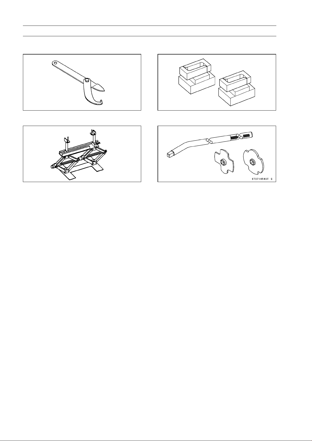
Special Tools
Steering Stem Nut Wrench:
57001–1100
Jack:
57001–1238
Attachment Jack:
57001–1398
Driver-Filler Cap:
57001–1454
Periodic Ma intenance Proce dures
Fuel System (DFI)
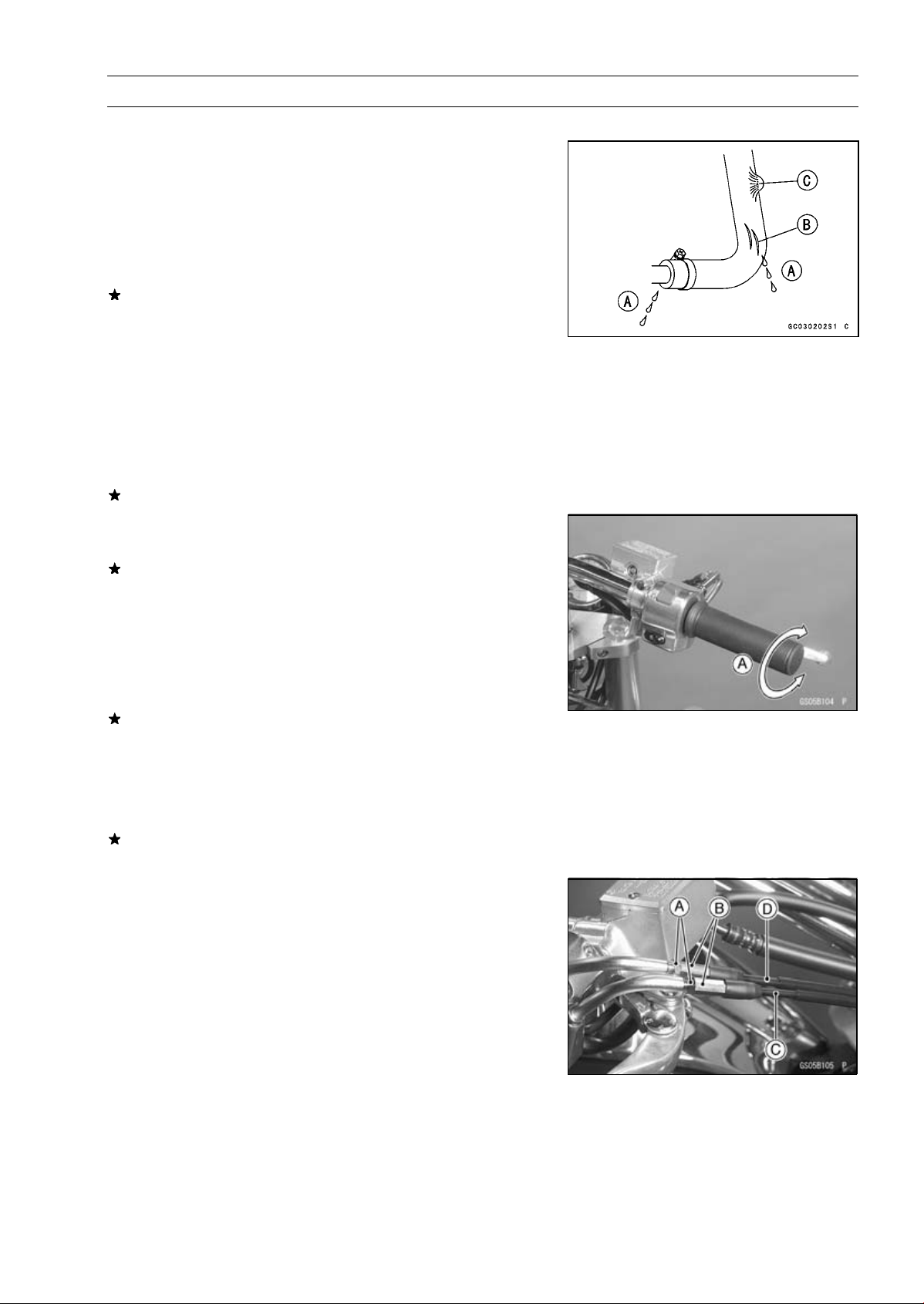
Fuel Hose and Connection Inspection
The fuel hoses are designed to be used throughout the
○
motorcycle’s life without any maintenance, however, if the
motorcycle is not properly handled, the high pressure inside the fuel line can cause fuel to leak [A] or the hose to
burst. Remove the fuel tank (see Fuel System chapter)
and check the fuel hose.
Replace the fuel hose if any fraying, cracks [B] or bulges
[C] are noticed.
Check that the hoses are securely connected and clamps
•
are tightened correctly.
When installing, route the hoses according to Cable,
•
Wire, and Hose Routing section in the Appendix chapter.
When installing the fuel hoses, avoid sharp bending, kink-
•
ing, flattening or twisting, and route the fuel hoses with a
minimum of bending so that the fuel flow will not be obstructed.
Replace the hose if it has been sharply bent or kinked.
PERIODIC M AINTENANCE 2-13
Throttle Control System Inspection
Check the throttle grip free play [A].
•
If the free play is incorrect, adjust the throttle cable (see
below).
Throttle Grip Free Play
Standard: 2 ∼ 3 mm (0.08 ∼ 0.12 in.)
Check that the throttle grip moves smoothly from close to
•
full open, and the throttle closes quickly and completely
in all steering positions by the return spring.
If the throttle grip doesn’t return properly, check the throttle cable routing, grip free play, and cable damage. Then
lubricate the throttle cable.
Run the engine at the idle speed, and turn the handlebar
•
all the way to the right and left to ensure that the idle speed
doesn’t change.
If the idle speed increases, check the throttle grip free play
and the cable routing.
If necessary, adjust the throttle cable as follows:
•
Loosen the locknuts [A] and screw the adjusters [B] all the
○
way in so as to give the throttle grip plenty of play (rear
view).
Turn out the adjuster of the decelerator cable [C] until
○
thereisnoplay.
Tighten the locknut against the adjuster.
○
Turn the adjuster of the accelerator c able [D] until the
○
proper amount of throttle grip free play is obtained and
tighten the locknut against the adjuster.
2-14 PERIODIC MA INTENANCE
Periodic Maintenance Procedures
Idle Speed Inspection
Start t he engine and warm it up thoroughly.
•
At first the engine will run fast to decrease warm up time
○
(fast idle).
Gradually the fast idle will lower to a certain RPM auto-
○
matically. This is the idle speed.
Check the idle speed.
•
Idle Speed
Standard: 950 ±50 r/min (rpm)
With the engine idling, turn the handlebar to both sides.
•
If handlebar movement changes the idle speed, the
throttle cables may be improperly adjusted or incorrectly
routed or damaged. Be sure to correct any of these
conditions before riding (see Cable, Wire, and Hose
Routing section in the Appendix chapter).
WARNING
Operation with improperly adjusted, incorrectly
routed or damaged cables could result in an unsafe
riding condition.
If the idle speed is out of the specified range, adjust it.
Start t he engine and warm it up thoroughly.
•
Wait until fast idle speed lowers to a certain value.
○
Turn the adjusting screw [A] until the idle speed is correct.
•
Open and close the throttle a few times to make sure that
○
the idle speed is within the specified range. Readjust if
necessary.
Front [B]
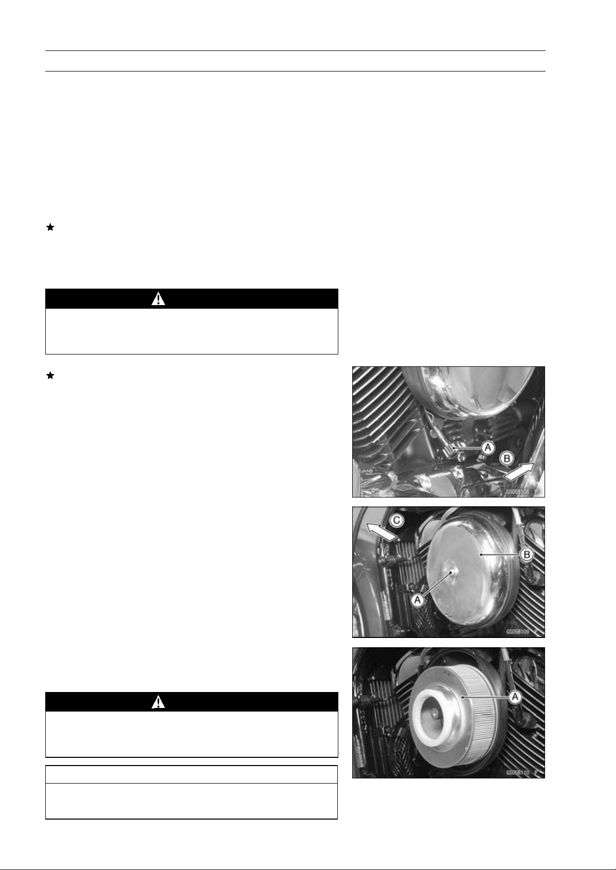
Air Cleaner Element Cleaning
NOTE
In dusty areas, the element should be cleaned more
○
frequently than the recommended interval.
After riding through rain or on muddy roads, the element
○
should be cleaned immediately.
Remove:
•
Allen Bolt [A] and Washer and Left Air Cleaner Cover [B]
Front [C]
Remove the element [A].
•
Push a clean, lint-free towel into the lower air cleaner duct
•
to keep dirt or other foreign material from entering.
WARNING
If dirt or dust is allowed to pass through into the
throttle body assy, the throttle m ay become stuck,
possibly causing accident.
CAUTION
If dirt gets through into the engine, excessive engine wear and possibly engine damage will occur.
Periodic Ma intenance Proce dures
Clean the element by tapping it lightly to loosen dust.
•
Blow away the remaining dust by applying compressed
•
air [A] from the inside to the outside (from the clean side
to the dirty side).
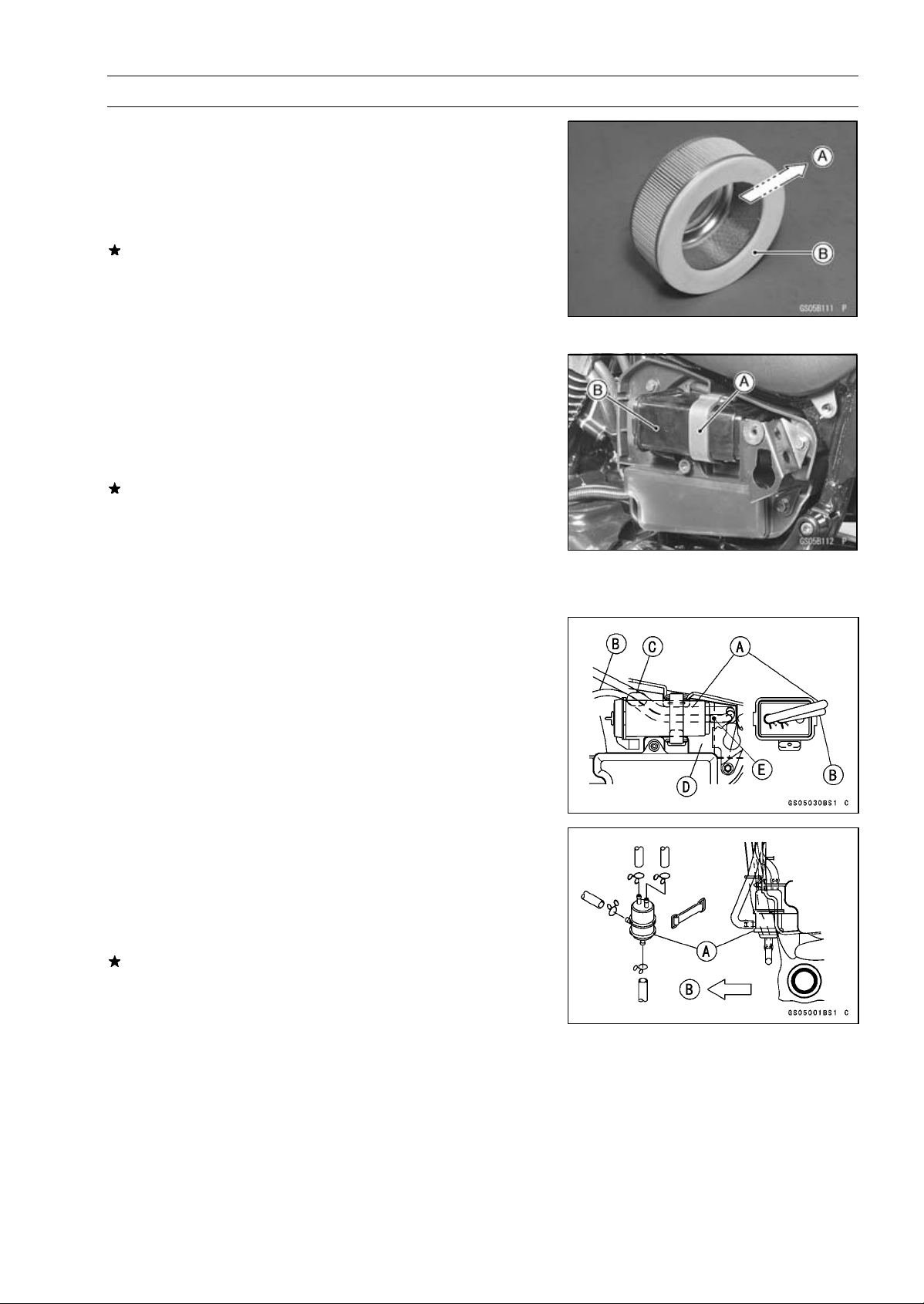
Visually check the element for no tears or no breaks and
•
check the sponge gasket [B] also.
If the element or gasket has any tears or breaks, replace
the element.
Install the left air cleaner cover.
•
Torque — Left Air Cleaner Cover Allen Bolt: 16 N·m (1.6
kgf·m, 12 ft·lb)
Evaporative Emission Control System Inspection
(CAL)
Inspect the canister as follows:
•
Remove the left side cover (see Frame chapter).
○
Remove the band [A] and take out the canister [B].
○
Visually inspect the canister for cracks and other damage.
○
If the canister has any cracks or bad damage, replace it
with a new one.
PERIODIC M AINTENANCE 2-15
NOTE
The canister is designed to work well through the motor-
○
cycle’s life without any maintenance if it is used under
normal conditions.
Run the purge hose (green) [A] above the canister
○
breather hose (blue) [B] through the hole [C] into the tool
case [D].
Do not run these hoses side by side on the battery side
○
of the canister. This prevents hoses from being flattened
when installing the left side cover.
Install the canister and the left side cover (see Frame
○
chapter).
Face the white mark [E] left as shown.
○
Check the liquid/vapor separator as follows:
•
Disconnect the hoses from the separator, and remove the
○
separator [A] from the motorcycle right side.
Front [B]
Visually inspect the separator for cracks and other dam-
○
age.
If the separator has any cracks or damage, replace it with
a new one.
To prevent the gasoline from flowing into or out of the
○
canister, hold the separator perpendicular to the ground.
Check the hoses of the evaporative emission control sys-
•
tem as follows:
Check that the hoses are securely connected and clips
○
are in position.
Replace any kinked, deteriorated or damaged hoses.
○
Route the hoses according to Cable, Wire, and Hose
○
Routing section in the Appendix chapter. Refer to the diagram of the evaporative emission control system in the
Fuel System chapter too.
When installing the hoses, avoid sharp bending, kinking,
○
flattening or twisting, and route the hoses with a minimum
of bending so that the emission flow will not be obstructed.
2-16 PERIODIC MA INTENANCE
Periodic Maintenance Procedures
Cooling System
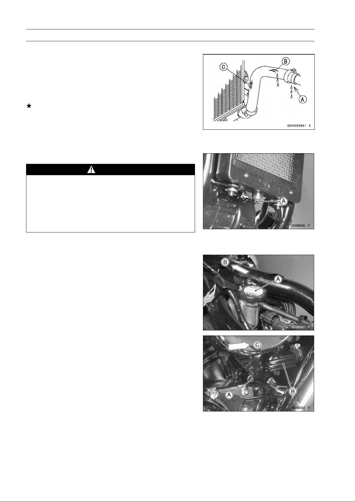
Radiator Hose and Connection Inspection
The high pressure inside the radiator hose can cause
○
coolant to leak [A] or the hose to burst if the line is not
properly maintained. Visually inspect the hoses for signs
of deterioration. Squeeze the hoses. A hose should not
be hard and brittle, nor should i t be soft or swollen.
Replace the hose if any fraying, cracks [B] or bulges [C]
are noticed.
Check that the hoses are securely connected and clamps
•
are tightened correctly.
Torque — Radiator Hose Clamp Screws: 2.5 N·m (0.25 kgf·m,
22 in·lb)
Coolant Change
WARNING
To avoid burns, do not remove the radiator cap or
try to change the coolant when the engine is still
hot. Wait until it cools down.
Coolant on tires will make them slippery, and can
cause an accident and injury.
Since coolant is harmful to the human body, do not
use for drinking.
Place a container under the radiator drain bolt [A], then
•
remove the drain bolt (front view).
Remove the fuel tank (see Fuel System (DFI) chapter).
•
Remove the radiator cap [A] in two steps. First turn the
•
cap counterclockwise to the first stop. Then push and turn
it further in the same direction and remove the cap.
The coolant will drain from the radiator and engine.
○
Front [B]
Remove the water pump drain bolt [A]. The remaining
•
coolant will drain from the water pump [B].
Place a conduit under the drain hole of the pump cover.
○
The conduit leads to a container.
Front [C]
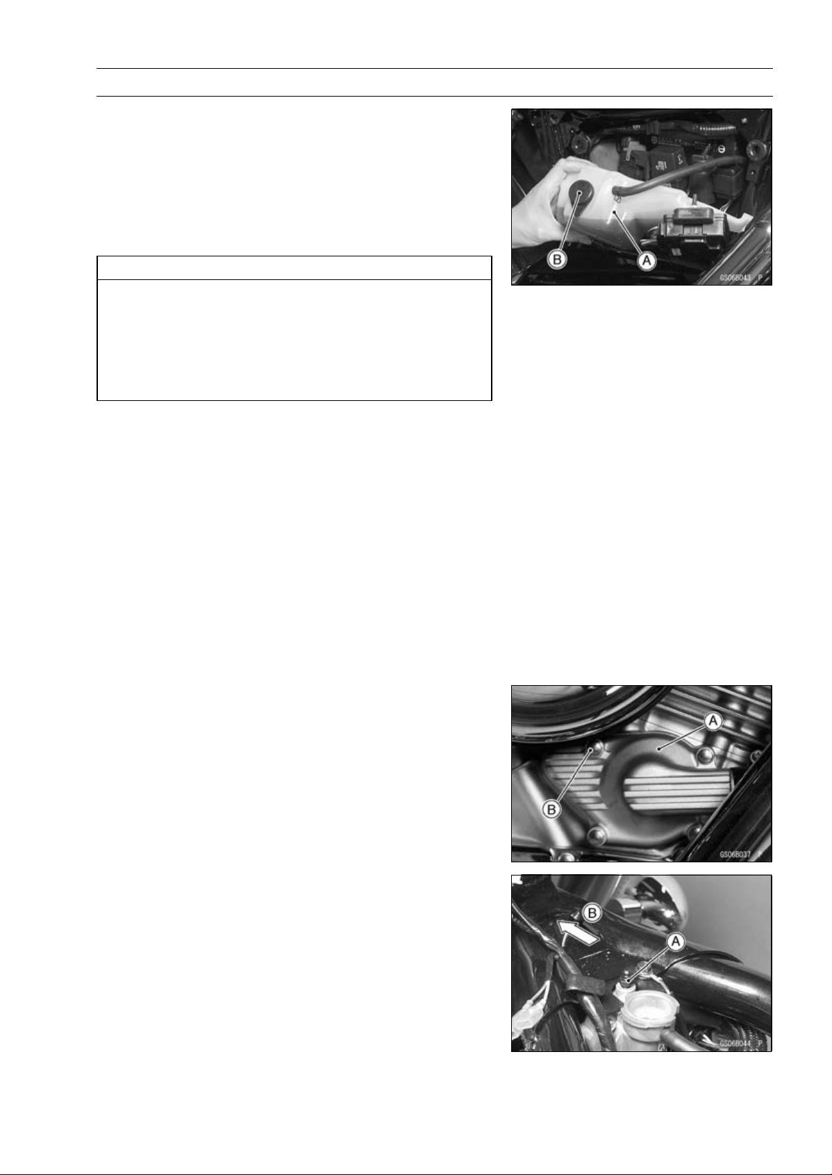
Periodic Ma intenance Proce dures
Remove :
•
Right Side Cover (see Frame chapter)
Reserve Tank Bolts
Turn over the reserve tank [A], remove the cap [B], and
•
pour the coolant into a suitable container.
Install the reserve tank.
•
When filling the coolant, choose a suitable mixture ratio
•
by referring to the coolant manufacturer’s directions.
CAUTION
Soft or distilled water must be used with the antifreeze (see Specifications in this chapter) in the
cooling system.
If hard water is used in the system, it causes scale
accumulation in the water passages, and considerably reduces the efficiency of the cooling system.
Water and Coolant Mixture Ratio ( when shipping)
Soft Water
Coolant
Freezing Point
Total Amount
Tighten the drain bolts.
•
Torque — Radiator Drain Bolt: 2.2 N·m (0.22 kgf·m, 19 in·lb)
Water Pump Drain Bolt: 11 N·m (1.1 kgf·m, 97 in·lb)
Fill the coolant into the radiator.
•
Fill in the coolant slowly so that it can expel the air from
○
the engine and radiator.
:
50 %
:
50 %
:
− 35°C (− 31°F)
:
2.3 L (2.4 US qt)
NOTE
PERIODIC M AINTENANCE 2-17
Check the cooling system for leaks.
•
Bleed the air from the water pump [A].
•
Loosen the air bleeder bolt [B] until the coolant seeps out
○
around the bolt, then tighten it.
Torque — Water Pump Air Bleeder Bolt: 11 N·m (1.1 kgf·m,
97 in·lb)
Next, loosen the air bleeder bolt [A] on the thermostat
•
housing.
Front [B]
Replenish the coolant into the radiator until the coolant
•
begins to flow out the air bleeder bolt hole (that is, all the
remaining air is forced out).
Tap the radiator hoses to force any air bubbles caught
•
inside.
2-18 PERIODIC MA INTENANCE
Periodic Maintenance Procedures
Fill the radiator up to the filler neck [A] with coolant.
•
Install the radiator cap.
•
Tighten the air bleeder bolt [B].
•
Torque — Thermostat Air Bleeder Bolt: 7.8 N·m (0.80 kgf·m,
69 in·lb)
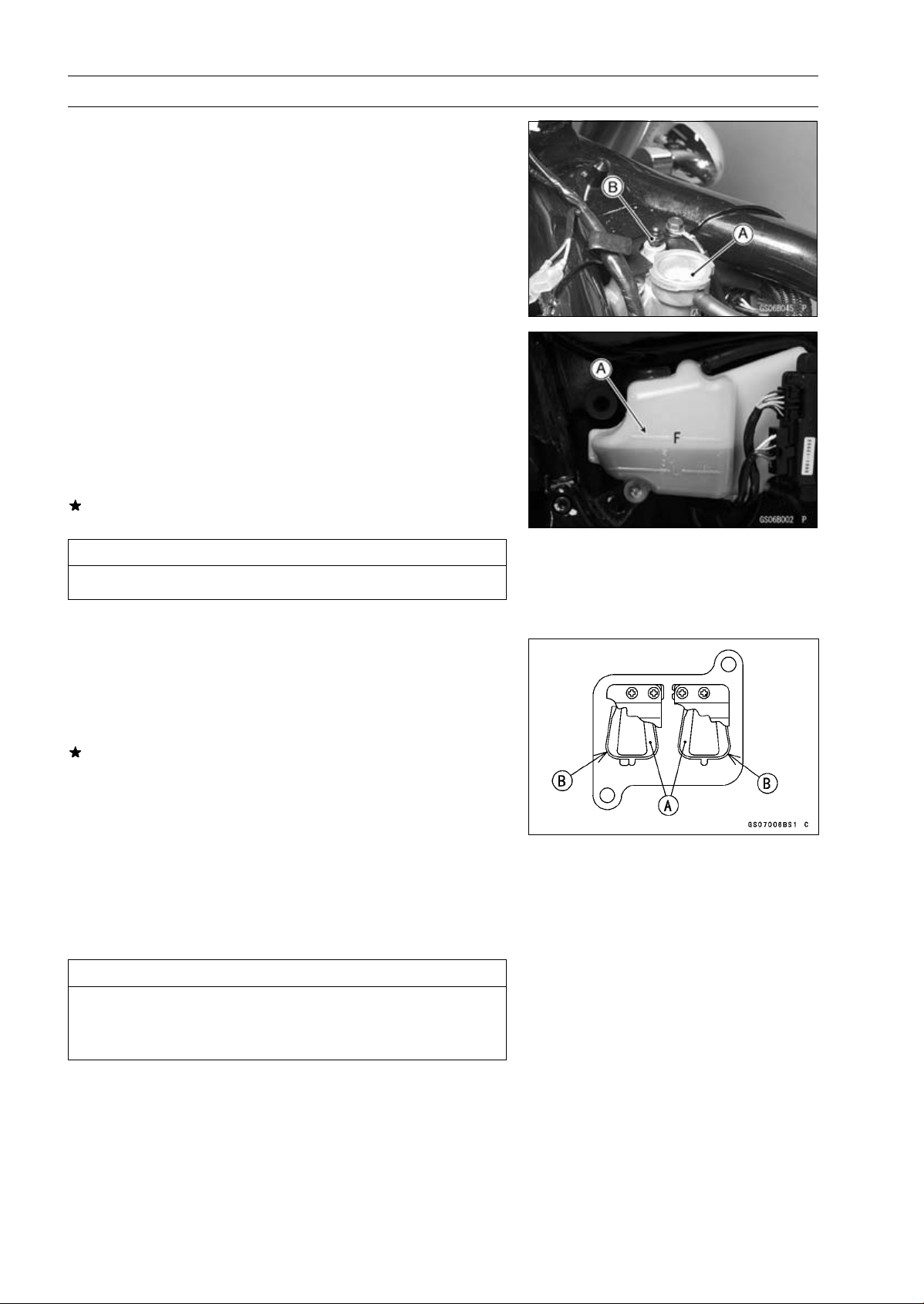
Fill the reserve tank up to the “F” (full) level line [A] with
•
coolant and install the cap.
Install the fuel tank (see Fuel System (DFI) chapter).
•
Start the engine and warm it up thoroughly until the radi-
•
ator fan turns on and then stop the engine.
Check the coolant level in the reserve tank several times
•
while the engine is cooling down, and replenish as necessary.
If the coolant level is lower than the “L” level line, add
coolant to the “F” level line.
CAUTION
Do not add more coolant above the “F” level line.
Engine Top End
Air Suction Valve Inspection
Remove the air suction valve (see Engine Top End chap-
•
ter).
Visually inspect the reeds for cracks, folds, warps, heat
•
damage or other damage.
If there i s any doubt as to the condition of the reeds [A],
replace the air suction valve as an assembly.
Check the reed contact areas [B] of the valve holder for
•
grooves, scratches, any signs of separation from the
holder or heat damage.
If there is any doubt as to the condition of the reed contact
•
areas, replace the air suction valve as an assembly.
If any carbon or other foreign particles have accumulated
•
between the reed and the reed contact area, wash the
valve assembly clean with a high-flash point solvent.
CAUTION
Do not scrape off the deposits with a scraper as this
could damage the rubber, requiring replacement of
the suction valve assembly.
Periodic Ma intenance Proce dures
Clutch
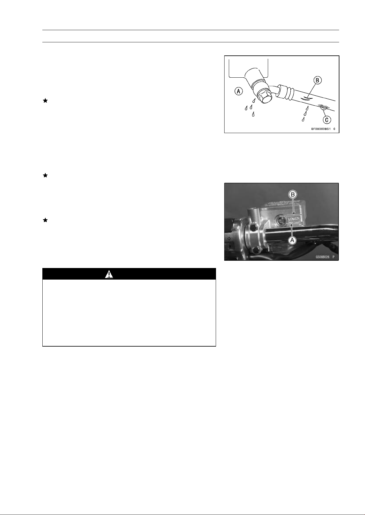
Clutch Hose and Connection Inspection
Thehighpressureinsidetheclutchlinecancausefluid
•
to leak [A] or the hose to burst if the line is not properly
maintained. Bend and twist the rubber hose while examining it.
Replace it if any fraying, cracks [B] or bulges [C] are noticed.
Check that the hoses are securely connected and banjo
•
bolts are tightened correctly.
Torque — Clutch Hose Banjo Bolts: 25 N·m (2.5 kgf·m, 18
ft·lb)
When installing the clutch hose, route the hoses accord-
•
ing to Cable, Wire, and Hose Routing s ection in the Appendix chapter.
Replace the hose if it has been sharply bent or kinked.
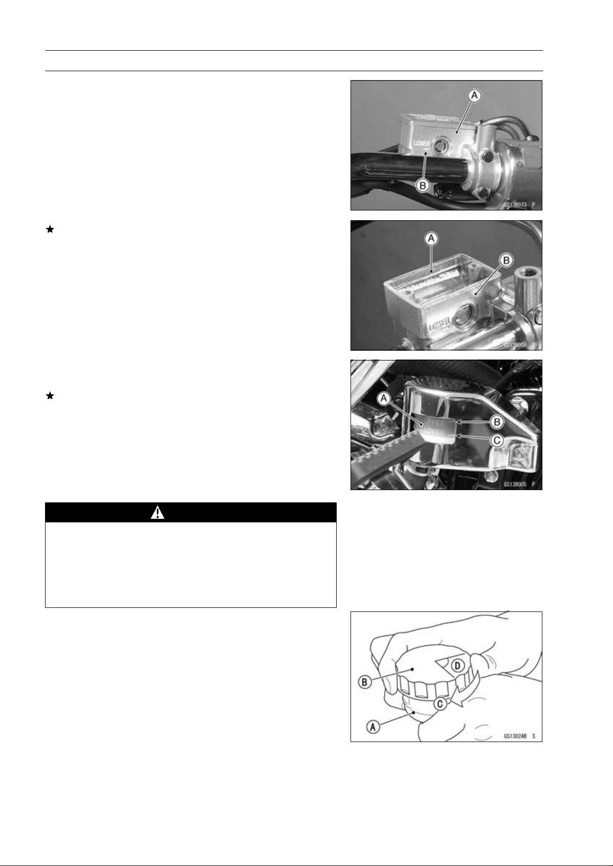
Clutch Fluid Level Inspection
Hold the clutch fluid reservoir horizontal.
•
Check that the clutch fluid level of the clutch reservoir is
•
between the lower [A] and the upper [B] level lines.
If the fluid level is lower than the lower level line, fill the
reservoir to t he upper level line i n the reservoir.
Since the clutch fluid is the same as the brake fluid, refer
○
to Brakes Section in the this chapter for further details.
T orque — Clutch Reservoir Cap Screws: 1.5 N·m (0.15
kgf·m, 13 in·lb)
PERIODIC M AINTENANCE 2-19
WARNING
Change the fluid in the clutch line completely if the
fluid must be refilled but the type and brand of the
fluid that already is in the reservoir are unidentified.
After changing the fluid, use only the same type and
brand of fluid thereafter. Mixing different types and
brands of fluid lowers the fluid boiling point and
could cause the clutch to be ineffective. It may also
cause the rubber clutch parts to deteriorate.
2-20 PERIODIC MA INTENANCE
Periodic Maintenance Procedures
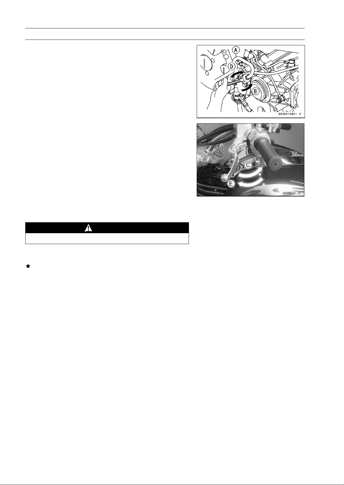
Clutch Fluid Change
Level the clutch fluid reservoir and remove the reservoir
•
cap.
Remove the alternator outer cover (see Electrical System
•
chapter.) and the rubber cap from the bleed valve on the
clutch slave cylinder.
Attach a clear plastic hose [A] to the bleed valve and run
•
the other end of the hose into a container.
Fill the reservoir with fresh fluid.
•
Change the clutch fluid as follows.
•
Open [B] the bleed valve, using a wrench.
Pump the clutch lever and hold [C] it.
Close [D] the bleed valve.
Release [E] the clutch lever.
Repeat this operation until fresh fluid comes out from the
○
plastic hose or the color of the fluid changes.
Check the fluid level in the reservoir often, replenishing it
○
as necessary.
NOTE
If the fluid in the reservoir runs completely out any time
○
during fluid changing, the bleeding operation must be
done over again from the beginning since air will have
entered the line.
WARNING
Do not mix two brands of fluid.
After changing the fluid, check the clutch for good clutch
•
power and no fluid leakage.
If necessary, bleed the air from the lines (see Clutch Line
Bleeding in the Clutch chapter).
Remove the clear plastic hose.
•
Install the reservoir cap.
•
Tighten the bleed valve, and install the rubber cap.
•
T orque — Clutch Reservoir Cap Screws: 1.5 N·m (0.15
kgf·m, 13 in·lb)
Clutch Slave Cylinder Bleed Valve: 7.8 N·m (0.80
kgf·m, 69 in·lb)
Periodic Ma intenance Proce dures
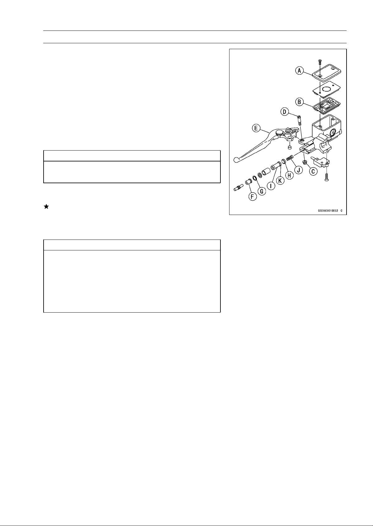
Clutch Master Cylinder Cup and Dust Seal
Replacement
Remove the clutch master cylinder (see Clutch chapter).
•
Remove the reservoir cap [A] and diaphragm [B], and
•
pour the clutch fluid into a container.
Unscrew the locknut [C] and pivot bolt [D], and remove
•
the clutch lever [E].
Pull the dust cover [F] out of place, and remove the circlip
•
[G].
Special Tool — Inside Circlip Pliers: 57001-143
Pullouttheprimarycup[H],pistonassembly[I],andre-
•
turn spring [J].
CAUTION
Do not remove the secondary cup [K] from the piston since removal will damage it.
Check the parts of the clutch master cylinder (see Clutch
•
chapter).
If any part shows signs of damage, replace it.
PERIODIC M AINTENANCE 2-21
Before assembly, clean all parts including the master
•
cylinder with clutch fluid or alcohol.
CAUTION
Use only disc brake fluid, isopropyl alcohol or ethyl
alcohol, for cleaning parts. Do not use any other
fluid for cleaning these parts. Gasoline, motor oil
or any other petroleum distillate will cause deterioration of the rubber parts. Oil spilled on any part will
be difficult to wash off completely, and will eventually deteriorate the rubber used in the cylinder.
Apply clutch fluid to the parts removed and to the i nner
•
wall of the cylinder.
Take care not to scratch the piston or the inner wall of the
•
cylinder.
Install the push rod with the dust seal fitted into the
•
groove.
The push rod round end must be faced inwards.
○
Torque — Clutch Lever Pivot Bolt: 1 .0 N·m (0.10 kgf·m, 8.9
in·lb)
Clutch Lever Pivot Bolt Locknut: 5.9 N·m (0.60
kgf·m, 52 in·lb)
Install the clutch master cylinder (see Clutch chapter).
•
2-22 PERIODIC MA INTENANCE
Periodic Maintenance Procedures
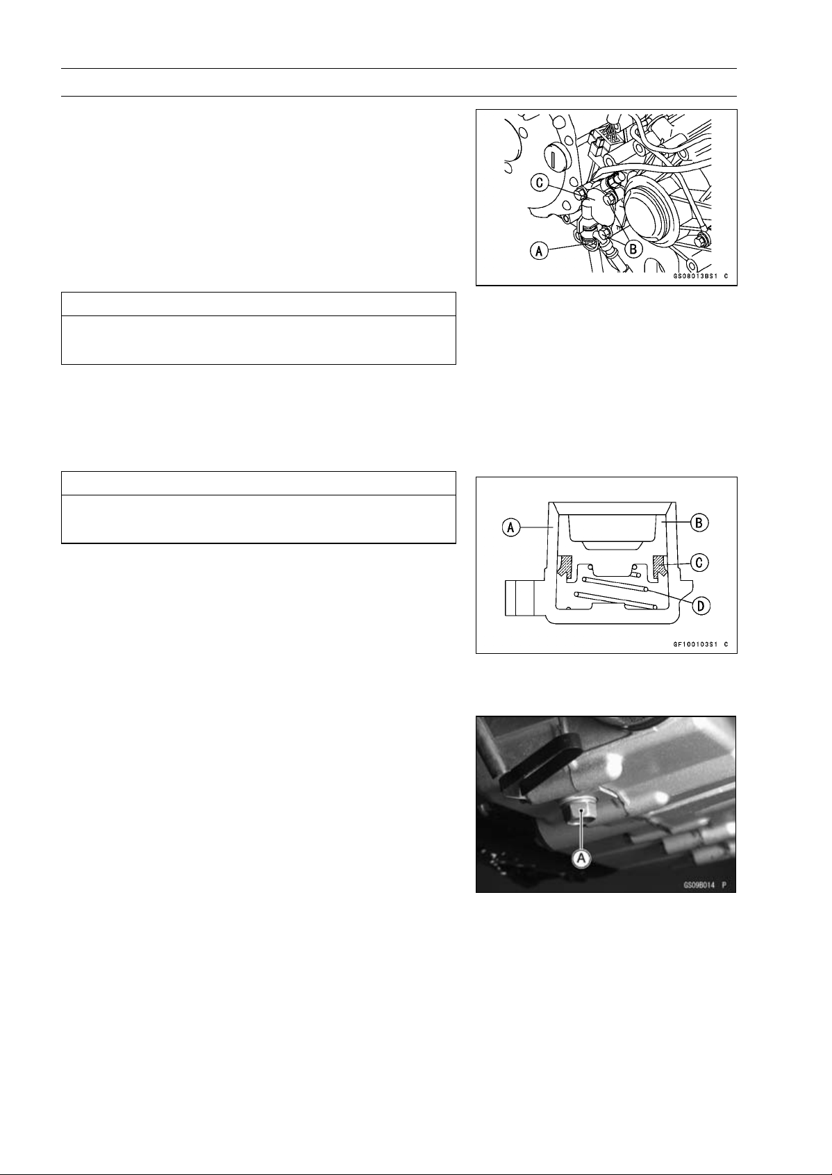
Clutch Slave Cylinder Piston Seal Replacement
Remove the alternator outer cover (see Electrical System
•
chapter)
Loosen the banjo bolt [A] at the clutch pipe lower end, and
•
tighten it loosely.
Unscrew the slave cylinder bolts [B] and detach the slave
•
cylinder with the pipe installed from the engine.
Pump the clutch lever until the piston comes out of the
•
cylinder.
Unscrew the banjo bolt and remove the slave cylinder [C].
•
CAUTION
Immediately wash away any clutch fluid that spills.
It may damage painted surfaces.
NOTE
If the clutch slave cylinder is removed and left alone, the
○
piston will be pushed out by spring force.
Remove the spring and piston seal.
•
CAUTION
Replace the piston seal with a new one if it was removed from the piston.
Before assembly, apply clutch fluid to the outside of the
•
piston and the piston seal.
Install the piston seal as shown.
•
Cylinder [A]
Piston [B]
Piston Seal [C]
Spring [D]
Engine Lubrication System
Engine Oil Change
Situate the motorcycle so that it is vertical after warming
•
up the engine.
Remove the engine oil drain plug [A] and drain the oil.
•
Periodic Ma intenance Proce dures
Remove:
•
Oil Screen Plug [A]
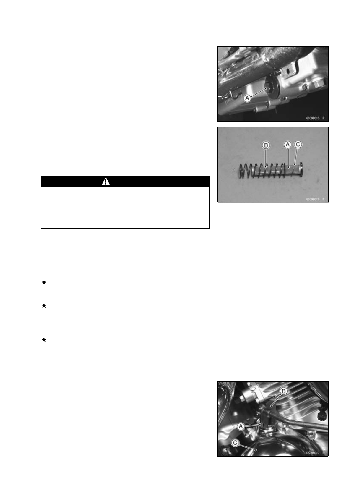
Remove the oil screen [A], the spring [B], and the washer
•
[C].
Clean the oil screen with a high-flash point solvent and
•
remove any particles stuck to it.
Clean the screen thoroughly whenever the engine oil is
•
changed.
WARNING
Clean the screen in a well-ventilated area, and take
care that there is no spark or flame anywhere near
the working area. Because of the danger of highly
flammable liquids, do not use gasoline or low-flash
point solvents.
PERIODIC M AINTENANCE 2-23
NOTE
While cleaning the screen, check for any metal particles
○
that might indicate internal engine damage.
Check the screen carefully for any damage of holes, bro-
•
ken wires, and so on.
If the screen is damaged, replace it.
Be sure to put in the oil screen with the rubber gasket end
•
inside.
Replace the screen plug O-ring with new one.
Torque — Oil Scre en Plug: 20 N·m (2.0 kgf·m, 15 ft·lb)
The oil in the filter can be drained by removing the filter
○
(see Oil Filter Change in this section).
Replace the drain plug gasket with a new one if it is damaged.
Torque — Engine Oil Drain Plug , Oil Screen Plug: 20 N·m
(2.0 kgf·m, 15 ft·lb)
Oil Filter: 18 N·m (1.8 kgf·m, 13 ft·lb)
Remove the oil filler cap [A] with the driver-filler cap [B]
•
and pour in the specified type and amount of oil.
Clutch Cover [C]
Special Tool — Driver-Filler Cap: 57001–1454
Torque — Oil Filler Cap: 1.5 N·m (0.15 kgf·m, 13 in·lb)
2-24 PERIODIC MA INTENANCE
Periodic Maintenance Procedures
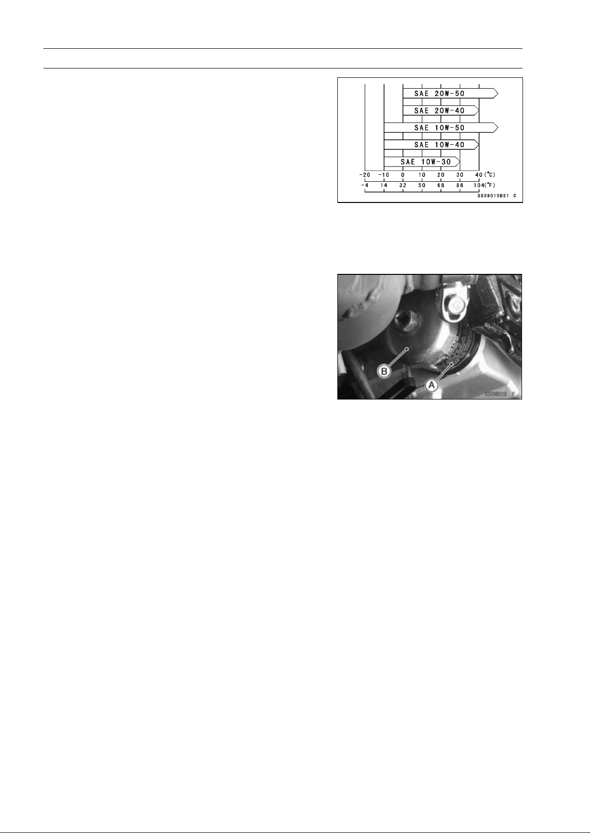
Engine Oil
Typ e:
Viscosity:
Amount:
Although 10W-40 engine oil is the recommended oil
○
for most conditions, the oil viscosity may need to be
changed to accommodate atmospheric conditions in
your riding area.
Oil Filter Replacement
Drain the engine oil (see Engine Oil Change in this sec-
•
tion).
Remove the oil filter [A] with the oil filter wrench [B] and
•
discard the oil filter.
Special Tool — Oil Filter Wrench: 57001-1249
API SE, SF or SG class
API SH or SJ class with JASO MA
SAE 10W-40
2.9 L (3.1 US qt, when filter is not removed)
3.1 L (3.3 US qt, when filter is removed)
3.5 L (3.7 US qt, when engine is completely
disassembled and dry)
NOTE
NOTE
The filter has an oil filter bypass valve which can not be
○
removed.
Replace the oil filter with the new one.
•
Apply oil to the gasket of the new filter before installation.
•
Tighten the filter with the oil filter wrench.
•
Pour in the specified type and amount of oil.
•
Torque — Oil Filter: 18 N·m (1.8 kgf·m, 13 ft·lb)
Wheels/Tires
Tire Inspection
As the tire tread wears down, the tire becomes more susceptible to puncture and failure. An accepted estimate is
that 90% of all tire failures occur during the last 10% of tread
life (90% worn). So it is false economy and unsafe to use
the tires until they are bald.
Remove any imbedded stones or other foreign particles
•
from the tread.
Visually inspect the tire for cracks and cuts, replacing the
•
tire in case of damage. Swelling or high spots indicate
internal damage, requiring tire replacement.
Periodic Ma intenance Proce dures
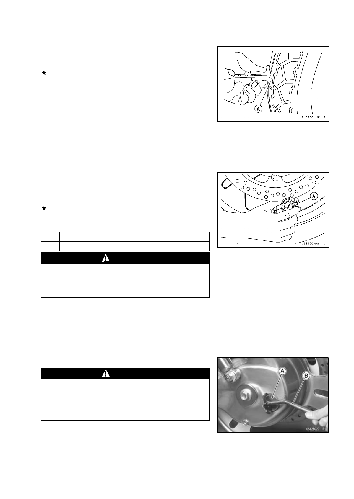
Measure the tread depth at the center of the tread with a
•
depth gauge [A]. Since the tire may wear unevenly, take
measurement at several places.
If any measurement is less than the service limit, replace
the tire (see Wheels/Tires chapter).
Tread Depth
Front:
Standard: 4.4 mm (0.17 in.)
Service Limit: 1 mm (0.04 in.)
(DE, AT, CH) 1.6 mm (0.063 in.)
Rear:
Standard: 6.9 mm (0.27 in.)
Service Limit: 2 mm (0.08 in.):
Up to 130 km/h (80 mph)
3mm(0.1in.):
Over to 130 km/h (80 mph)
Measure the tire air pressure with an air pressure gauge
•
[A] when the tires are cold (that is, when the motorcycle
has not been ridden m ore than a mile during the past 3
hours.)
Adjust the tire air pressure according to the specifications
if necessary.
PERIODIC M AINTENANCE 2-25
Air Pressure (when cold)
Front
Rear
Up to 184 kg (405 lb) 250 kPa (2.5 kgf/cm², 36 psi)
Up to 184 kg (405 lb) 250 kPa (2.5 kgf/cm², 36 psi)
WARNING
To ensure safe handling and stability, use only the
recommended standard tires for replacement, inflated to the standard pressure. Use the same manufacture’s tires on both front and rear wheels.
NOTE
Most countries may have their own regulations requiring
○
a minimum tire tread depth; be sure to follow them.
Check and balance the wheel when a tire is replaced
○
with a new one (see Wheels/Tires chapter).
Final Drive
Oil Level Inspection
WARNING
Motorcycle operation with insufficient, deteriorated, or contaminated oil causes accelerated wear
and may result in seizure of the pinion and ring
gears. Seizure can lock the rear wheel and skid the
rear tire, with consequent less of control.
Support the motorcycle perpendicular to the ground.
•
Unscrew the filler plug [A], using the driver-filler cap [B].
•
Special Tool — Driver-Filler Cap: 57001–1454
2-26 PERIODIC MA INTENANCE
Periodic Maintenance Procedures
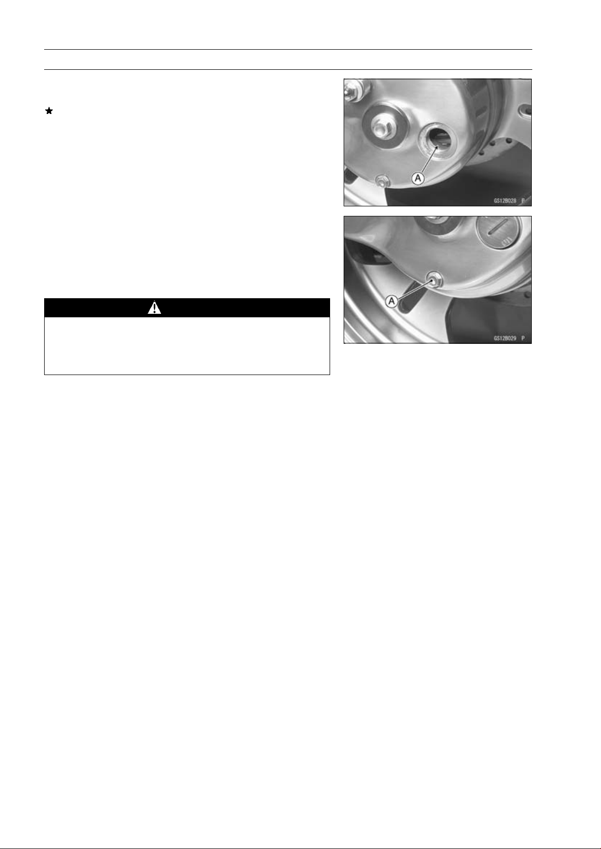
The oil level [A] should com e to the bottom of the filler
•
opening.
If it is low, first check the final gear case for oil leakage,
remedy it if necessary, and add oil through the filler open-
ing. Use the same type and brand of oil that is already in
the final gear case.
Install the filler plug.
•
Oil Change
Warm up the oil by running the m otorcycle so that the
•
oil will pick up any sediment and drain easily. Stop the
motorcycle and turn the ignition switch OFF.
Place an oil pan beneath the final gear case, and remove
•
the filler cap and drain plug [A].
WARNING
When draining or filling the final gear case, be care-
ful that no oil gets on the tire, spoke, or rim. Clean
off any oil that inadvertently gets on them with a
high-flash point solvent.
After the oil has completely drained out, install the drain
•
plug with a new gasket.
Torque — Final Gear Case Drain Plug: 8.8 N·m (0.90 kgf·m,
78 in·lb)
Fill the final gear case with the specified oil and quantity.
•
Final Gear Case Oil:
Amount: 200 mL (6.76 US oz)
Grade: API GL-5 hypoid gear oil
Viscosity: When above 5°C (41°F) SAE 90
When below 5°C (41°F) SAE 80
NOTE
The term “GL-5” indicates a quality and additive rating.
○
A “GL-6” rated hypoid gear oil can also be used.
Be sure the O-ring is in place, and install the filler plug.
•
Periodic Ma intenance Proce dures
Brakes
Brake Pad Wear Inspection
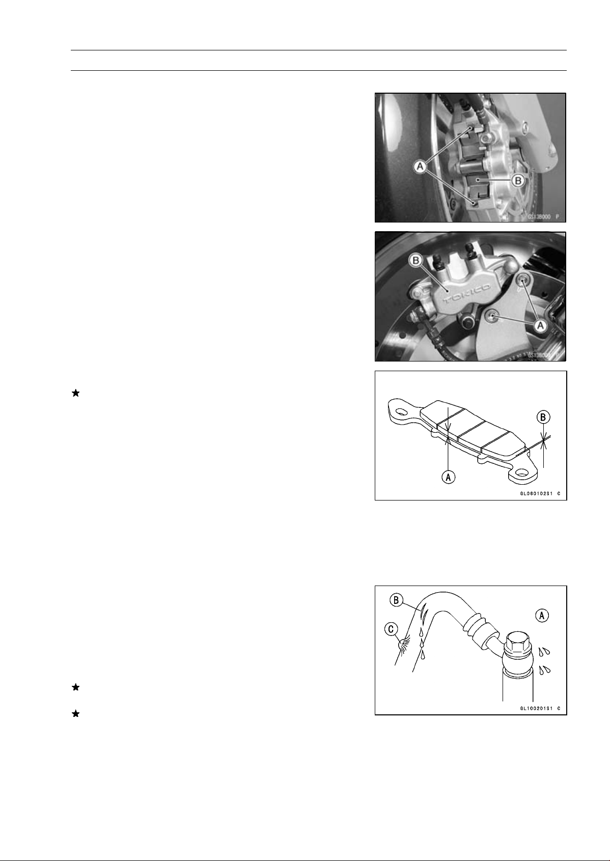
Unscrew the bolts [A] and remove the pad spring [B]
•
(Front Brake Caliper)
Unscrew the bolts [A] and remove the caliper [B] (Rear
•
Brake Caliper).
PERIODIC M AINTENANCE 2-27
Check the lining thickness [A] of the pads in each caliper.
•
If the lining thickness of either pad is less than the service
limit [B], replace both pads in the caliper as a set (see
Brakes chapter).
Pad Lining Thickness
Standard:
Front:
Rear:
Service Limit: 1 mm (0.04 in.)
Install the pad spring or caliper.
•
Tighten the bolts.
•
Torque — Front Brake Pad Spring Bolts: 2.9 N·m (0.30 kgf·m,
26 in·lb)
Rear C aliper Mounting Bolts: 34 N·m (3.5 kgf·m,
25 ft·lb)
Brake Hose and Connection Inspection
Inspect the brake hose and fittings for deterioration,
•
cracks and signs of leakage.
Thehighpressureinsidethebrakelinecancausefluidto
○
leak [A] or the hose to burst if the line is not properly maintained. Bend and twist the rubber hose while examining
it.
Replace the hose if any cracks [B] or bulges [C] are noticed.
Tighten any loose fittings.
4.0 mm (0.157 in.)
7.5 mm (0.295 in.)
2-28 PERIODIC MA INTENANCE
Periodic Maintenance Procedures
Brake Fluid Level Inspection
Check that the brake fluid level in the front brake reservoir
•
[A] is above the lower [B] level line.
NOTE
Hold the reservoir horizontal by turning the handlebar
○
when checking brake fluid level.
If the fluid level is lower than the lower level line, fill the
reservoir to the upper level line [A] in the reservoir [B].
Check that the brake fluid level in the rear brake reservoir
•
[A] is between the upper [B] and the lower [C] level lines.
If the fluid level is lower than the lower level line, fill the
reservoir to the upper level line.
Use extra heavy-duty brake fluid only from a container
○
marked DOT4.
Brake fluid of DOT4 is installed in t he brake system when
○
shipped.
T orque — Front Brake Reservoir Cap Screws: 1.5 N·m (0.15
kgf·m, 13 in·lb)
WARNING
Do not mix two brands of fluid. Change the brake
fluid in the brake line completely if the brake fluid
must be refilled but the type and brand of the brake
fluid that is already in the reservoir are unidentified.
After changing the fluid, use only the same type and
brand of fluid thereafter.
Follow the procedure below to install the rear brake fluid
•
reservoir cap correctly.
First, tighten the rear brake fluid reservoir cap [B] clock-
○
wise [C] by hand until the resistance is f elt indicating that
the cap is seated on the reservoir body, then tighten the
cap an additional 1/6 turn [D] while holding the brake fluid
reservoir body [A].
 Loading…
|
Detail Specifications: 1166/1166616-vulcan_1600_nomad.pdf file (25 Nov 2022) |
Accompanying Data:
Kawasaki Vulcan 1600 Nomad Motorcycle PDF Service Manual (Updated: Friday 25th of November 2022 06:54:33 AM)
Rating: 4.6 (rated by 57 users)
Compatible devices: 1994 Ninja ZX-6R, Ninja ZX-10R ABS, ZX250-C6, VERSYS 650 ABS, KZ650F1, KZ400-H1 LTD, Ninja ZX-6R 2012, ZX400-L1.
Recommended Documentation:
Text Version of Service Manual
(Ocr-Read Summary of Contents, UPD: 25 November 2022)
-
171, Kawasaki Vulcan 1600 Nomad FUEL SYSTEM (DFI) 3-89 ISC Valves 1. ECU 2. Junction Box 3. Ignition Fuse 10 A 4. Ignition Switch 5. Starter Relay 6. Main Fuse 30 A 7. Battery 8. ISC Valve #2 9. ISC Valve #1 10. DFI Main Relay 11. DFI Fuse 15 A
… -
492, Kawasaki Vulcan 1600 Nomad 15-26 FRAME Rear View Mirrors Rear View Mirror Removal (Other than European Model) • Loosen the locknut [A]. • Turn the rear view mirror stay [B] counterclockwise to re- move the rear view mirror from the holder [C]. Rear View Mirror Removal (European Model) • Loosen the lower hexagonal area [A]. • Turn the rear view mirror stay [B] counterclockwise to re- move the rear view mirror f…
-
477, FRAME 15-11 Fenders Front Fender Removal CAUTION Be careful not to scratch the painted surface during removal or installation. • Remove the mounting bolts [A] on both sides to separate the fender from the front fork. • Move the fender forwards with the wheel installed and remove it. Rear Fender Removal CAUTION Be careful not to scratch the painted surface du…
-
149, FUEL SYSTEM (DFI) 3-67 Fuel Injectors (#1, #2: Service Code 4 1, 42) Fuel Injector #1: Front Fuel Injector for Front Cylinder (Service Code 41) Fuel Injector #2: Rear Fuel Injector for Rear Cylinder (Service Code 42) CAUTION Never drop the injector, especially on a hard sur- face. Such a shock to the injector can damage it. Injector Removal WARNING Gasoline is extre…
-
49, PERIODIC MAINTENANCE 2-27 Periodic Maintenance Procedures • Check that the brake fluid level in the rear brake reservoir [A] is between the upper [B] and the lower [C] level lines. If the fluid level is lower than the lower level line, fill the reservoir to the upper level line. ○ Use extra heavy-duty brake fluid only from a container marked DOT4. ○ Brake fluid of DOT4 is installed i…
-
138, 3-56 FUEL SYSTEM (DFI) Water Temperature Sensor (Service Code 14) Removal/Installation CAUTION Never drop the sensor, especially on a hard surface. Such a shock to the sensor can damage it. • Remove the thermostat housing [A] (see Thermostat Re- moval in the Cooling System chapter). • Disconnect the sensor connector [B], and unscrew the water temperature sensor [C]…
-
8, TAMPERING WITH NOISE CONTROL SYSTEM PROHIBITED Federal law prohibits the following acts or the causing thereof: (1) The removal or rendering inoperative by any person other than for purposes of maintenance, repair, or replacement, of any device or element of design incorporated into any new vehicle for the purpose of noise control prior to its sale or delivery to the ultimate purchaser …
-
338, Kawasaki Vulcan 1600 Nomad 9-30 CRANKSHAFT/TRANSMISSION Transmission Shift Pedal Remo v al • Remove the left front footboard (see Front Footboard Re- moval/Installation in the Frame chapter). • Unscrew the rear shift pedal clamp bolt [A] and take off the rear shift pedal [B]. • Unscrew the front shift pedal clamp bolt [C] and pull out the front shift pedal [D]. Shift Pedal Installation • For the front s…
-
182, 3-100 FUEL SYSTEM (DFI) Throttle Body Assy • Split the throttle body assy into the throttle body [A] and the inlet manifold [B]. The gasket [C] comes off. • Discard the gasket. ○ Do not remove or adjust the following parts. These parts are set at the factory and cannot be readjusted. CAUTION Adjustment of some of these parts could result in poor performance, requiri…
-
238, 5-24 ENGINE TOP END Rocker Case • Replace the HLA oil filters [A] with new ones. • After installing the rocker case, fill the oil reservoir [B] with engine oil. • Tighten: Torque — Oil Hose Flange Bolts: 9.8 N·m (1.0 kgf·m, 87 in·lb) • Tighten the cylinder head nuts [A] and cylinder nuts [B] to the specified torque. Torque — Cylinder Head Nuts: 25 N·m (2.5 kgf·m, 18 ft…
-
387, FINAL DRIVE 11-19 Final Gear Case and Oil Backlash-Related Parts 1. Pinion Gear Bearing Housing 2. Pinion Gear Shim(s) 3. Pinion Gear Assy 4. Ring Gear Assy 5. Ring Gear Shim(s) 6. Final Gear Case Ring Gear Shims for Backlash Adjustment Pinion Gear Shims for Tooth Contact Adjustment Thickness (mm) Part Number Thickness (mm) Part Number 0.15 (0.006 in.) 92025…
Recommended Instructions:
TBC-4001, Myers HPL Series, 318 200 937 (0411) Rev. A, DR-MX1S


-
MV AGUSTA MOTORCYCLES S.P.A.Servizio Assistenza Tecnica Via Nino Bixio, 821024 Cassinetta di Biandronno(Varese) — Italytel. ++39 0332 25.41.11fax ++39 0332 75.65.09www.husqvarna.itDUAL PURPOSEWRE 125SM 125 S — 2005Libretto usoe manutenzioneOwner’s manualLivret d’utilisation et d’entretienBetriebsanleitungManual de usoy mantenimientousq v rnPart. n. 8000 A4653DUAL PURPOSE WRE 125 SM 125 …
2005 WRE 125 162
-
PREFACEThank you for selecting a Hero MotoCorp XPULSE 200 PROGRAMMED FI. We wish you many miles of continued riding pleasure in the years ahead.This booklet is your guide to the basic operation and maintenance of your new Hero MotoCorp XPULSE 200 PROGRAMMED FI. Please take time to read it carefully. As with any fine machine, proper care and ma …
XPULSE 200 PROGRAMMED FI 92
-
APRILIA WOULD LIKE TO THANK YOUfor choosing one of its products. Please read this manual carefully before riding your motorcycle for the first time. It contains information, tips andprecautions for using your vehicle and will help familiarize you with all of its different features. It will also help you attain maximum value and enjoymentand will reassure you that you have made the right choice. T …
RSV4 FACTORY 239
Popular Right Now:
Operating Impressions, Questions and Answers:
Kawasaki Manuals and Guides:
The main types of Kawasaki Vulcan 1600 Nomad instructions: user guide — rules of useing and characteristics, service manual — repair, diagnostics, maintenance, operation manual — description of the main functions of Kawasaki Vulcan 1600 Nomad equipment, etc.
Most of the instructions, that you can see on the site are uploaded by our users. If you have available a manual or document for Kawasaki Vulcan 1600 Nomad, which is currently not on the site or present in a different language version, we ask you to upload your document on website, using the «uploading form» available to all registered users.


Item # 99987-1346
MSRP
$18.15
Kawasaki Owner’s Manuals include Important Safety Information, Operating Instructions, and Maintenance and Storage Information.
Most items ship to dealer within 5-7 business days for free. Special dealer only items may be excluded.
Additional shipping charges apply to qualified ship to home orders.
Price and specifications are subject to change without notice or liability. Availability is subject to production, stocking and demand. Manufacturers suggested retail prices shown.
 WARNING: Cancer and reproductive harm www.P65Warnings.ca.gov
- WARRANTY INFORMATION