Материал из BikesWiki — энциклопедия японских мотоциклов
Перейти к: навигация, поиск

Kawasaki Ninja ZX-6R 636
Ниже представлены прямые ссылки на скачку сервисной документации.
Для Kawasaki ZX-6R
- Сервисный мануал (Service Manual) на Kawasaki ZX-6R (1995-1997)
- Сервисный мануал (Service Manual) на Kawasaki ZX-6R (1998-1999)
- Сервисный мануал (Service Manual) на Kawasaki ZX-6R (2001-2002)
- Сервисный мануал (Service Manual) на Kawasaki ZX-6R, ZX-6RR (2003-2004)
- Сервисный мануал (Service Manual) на Kawasaki ZX-6R (2005-2006)
- Сервисный мануал (Service Manual) на Kawasaki ZX-6R (2007-2008)
- Сервисный мануал (Service Manual) на Kawasaki ZX-6R (2009-2011)
- Сервисный мануал (Service Manual) на Kawasaki ZX-6R 636 (2013), оригинал англ.
- Сервисный мануал (Service Manual) на Kawasaki ZX-6R 636 (2013), русский перевод
Обзор модели
- Kawasaki ZX-6R
Источник — «https://bikeswiki.ru/index.php?title=Kawasaki_ZX-6R:_мануалы&oldid=9740»
Категория:
- Сервисная документация

Руководство на английском языке по техническому обслуживанию и ремонту мотоциклов Kawasaki серий KZ, ZX и ZN 1981-2002 годов выпуска с двигателями объемом 1000-1100 cc.
- Издательство: Clymer
- Год издания: 2003
- Страниц: 378
- Формат: PDF
- Размер: 43,5 Mb
Руководство на английском языке по техническому обслуживанию и ремонту мотоциклов Kawasaki Ninja ZX-6R.
- Издательство: Kawasaki Heavy Industries, Ltd.
- Год издания: 1997
- Страниц: 370
- Формат: PDF
- Размер: 64,3 Mb

Руководство на английском языке по техническому обслуживанию и ремонту мотоциклов Kawasaki Ninja ZX-6R 2000-2002 годов выпуска.
- Издательство: Kawasaki Heavy Industries, Ltd.
- Год издания: —
- Страниц: 332
- Формат: PDF
- Размер: 19,1 Mb

Руководство на английском языке по техническому обслуживанию и ремонту мотоциклов Kawasaki Ninja ZX-6R.
- Издательство: Kawasaki Heavy Industries, Ltd.
- Год издания: 2007
- Страниц: 663
- Формат: PDF
- Размер: 12,0 Mb
Руководство на английском языке по техническому обслуживанию и ремонту мотоциклов Kawasaki Ninja ZX-6R и ZX-6RR 2003-2004 годов выпуска.
- Издательство: Kawasaki Heavy Industries, Ltd.
- Год издания: —
- Страниц: 514
- Формат: PDF
- Размер: 42,5 Mb

Руководство на английском языке по техническому обслуживанию и ремонту мотоциклов Kawasaki Ninja ZX-6RR.
- Издательство: Kawasaki Heavy Industries, Ltd.
- Год издания: 2004
- Страниц: 519
- Формат: PDF
- Размер: 10,1 Mb

Руководство на английском языке по подготовке к гонкам мотоциклов Kawasaki ZX-6RR.
- Издательство: Kawasaki Heavy Industries, Ltd.
- Год издания: 2005
- Страниц: 63
- Формат: PDF
- Размер: 7,5 Mb
Руководство на английском языке по техническому обслуживанию и ремонту мотоциклов Kawasaki Ninja ZX-7R и ZX-7RR.
- Издательство: Kawasaki Heavy Industries, Ltd.
- Год издания: —
- Страниц: 364
- Формат: PDF
- Размер: 38,7 Mb
Руководство на английском языке по подготовке к гонкам мотоциклов Kawasaki ZX-7R м ZXR750R 1992 года выпуска.
- Издательство: Kawasaki Heavy Industries, Ltd.
- Год издания: 1991
- Страниц: 69
- Формат: PDF
- Размер: 148,4 Mb
Руководство на английском языке по подготовке к гонкам мотоциклов Kawasaki ZX-7RR 1998 года выпуска.
- Издательство: Kawasaki Heavy Industries, Ltd.
- Год издания: 1997
- Страниц: 107
- Формат: PDF
- Размер: 138,0 Mb

Руководство на испанском языке по эксплуатации и техническому обслуживанию мотоциклов Kawasaki Ninja ZX-9R.
- Издательство: —
- Год издания: —
- Страниц: 174
- Формат: PDF
- Размер: 3,3 Mb
Сборник руководств на английском языке по техническому обслуживанию и ремонту мотоциклов Kawasaki Ninja ZX-9R.
- Издательство: Kawasaki Heavy Industries, Ltd.
- Год издания: —
- Страниц: 307/322
- Формат: PDF
- Размер: 161,3 Mb

Руководство на английском языке по техническому обслуживанию и ремонту мотоциклов Kawasaki ZX-10 и Ninja ZX-10.
- Издательство: Kawasaki Heavy Industries, Ltd.
- Год издания: 1989
- Страниц: 231
- Формат: PDF
- Размер: 162,0 Mb

Руководство на английском языке по техническому обслуживанию и ремонту мотоциклов Kawasaki Ninja ZX-10R.
- Издательство: Kawasaki Heavy Industries, Ltd.
- Год издания: 2008
- Страниц: 694
- Формат: PDF
- Размер: 14,7 Mb

Руководство на английском языке по подготовке к гонкам мотоциклов Kawasaki ZX-10R 2006 года выпуска.
- Издательство: Kawasaki Heavy Industries, Ltd.
- Год издания: 2006
- Страниц: 82
- Формат: PDF
- Размер: 2,5 Mb

Руководство по эксплуатации и техническому обслуживанию мотоциклов Kawasaki Ninja ZX-10R.
- Издательство: Kawasaki Heavy Industries, Ltd.
- Год издания: 2011
- Страниц: 207
- Формат: PDF
- Размер: 6,4 Mb

Руководство на английском языке по техническому обслуживанию и ремонту мотоциклов Kawasaki Ninja ZX-11 и ZZ-R1100 1993-2001 годов выпуска.
- Издательство: Kawasaki Heavy Industries, Ltd.
- Год издания: —
- Страниц: —
- Формат: JPG
- Размер: 62,4 Mb

Руководство на английском языке по техническому обслуживанию и ремонту мотоциклов Kawasaki Ninja ZX-12R.
- Издательство: Kawasaki Heavy Industries, Ltd.
- Год издания: 2004
- Страниц: 613
- Формат: PDF
- Размер: 11,3 Mb

Руководство на немецком языке по техническому обслуживанию и ремонту мотоциклов Kawasaki Ninja ZX-12R (ZX1200-A).
- Издательство: Kawasaki Motoren GmbH
- Год издания: 2000
- Страниц: 431
- Формат: PDF
- Размер: 149,8 Mb

Руководство на немецком языке по техническому обслуживанию и ремонту мотоциклов Kawasaki ZX-12R (ZX1200B).
- Издательство: Kawasaki Motors Europe
- Год издания: 2002
- Страниц: 451
- Формат: PDF
- Размер: 38,7 Mb

Руководство на английском языке по техническому обслуживанию и ремонту мотоциклов Kawasaki Ninja ZX-14 и ZZR1400.
- Издательство: Kawasaki Heavy Industries, Ltd.
- Год издания: 2006
- Страниц: 703
- Формат: PDF
- Размер: 13,6 Mb
Руководство на английском языке по техническому обслуживанию и ремонту мотоциклов Kawasaki ZX400-H2
- Издательство: Kawasaki Heavy Industries, Ltd.
- Год издания: —
- Страниц: —
- Формат: PDF
- Размер: 46,6 Mb

Руководство на немецком языке по техническому обслуживанию и ремонту мотоциклов Kawasaki ZX500-A1 и ZX600-A1.
- Издательство: —
- Год издания: —
- Страниц: 234
- Формат: PDF
- Размер: 19,9 Mb

Руководство на английском языке по техническому обслуживанию и ремонту мотоциклов Kawasaki KZ500/KZ550/ZX550 1979-1985 годов выпуска.
- Издательство: Clymer
- Год издания: —
- Страниц: 341
- Формат: PDF
- Размер: 12,0 Mb
Руководство на английском языке по техническому обслуживанию и ремонту мотоциклов Kawasaki ZX600/ZZR600/Ninja ZX-6 1990-2000 годов выпуска.
- Издательство: Haynes Publishing
- Год издания: 2001
- Страниц: —
- Формат: JPG
- Размер: 57,7 Mb

Руководство на английском языке по техническому обслуживанию и ремонту мотоциклов Kawasaki ZX600/ZX636 (ZX-6R) 1995-2002 годов выпуска.
- Издательство: Haynes Publishing
- Год издания: 2003
- Страниц: 272
- Формат: PDF
- Размер: 171,0 Mb
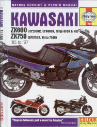
Руководство на английском языке по техническому обслуживанию и ремонту мотоциклов Kawasaki GPX600R/GPX750R/GPZ600R/Ninja 600R/Ninja 600RX/Ninja 750R/ZX600/ZX750 1985-1987 годов выпуска.
- Издательство: Haynes Publishing
- Год издания: 1999
- Страниц: 265
- Формат: PDF
- Размер: 77,0 Mb

Руководство на английском языке по техническому обслуживанию и ремонту мотоциклов Kawasaki ZX750 (ZXR750) 1989-1996 и ZX750 (Ninja ZX-7) 1989-1995 годов выпуска.
- Издательство: Haynes Publishing
- Год издания: 1998
- Страниц: 341
- Формат: PDF
- Размер: 36,7 Mb

Руководство на немецком языке по техническому обслуживанию и ремонту мотоциклов Kawasaki ZX750J/ZX750K/ZXR750/ZXR750R.
- Издательство: —
- Год издания: —
- Страниц: 282
- Формат: PDF
- Размер: 23,4 Mb
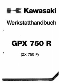
Руководство на немецком языке по техническому обслуживанию и ремонту мотоциклов Kawasaki GPX750R/ZX750F.
- Издательство: Kawasaki Heavy Industries, Ltd.
- Год издания: —
- Страниц: 192
- Формат: PDF
- Размер: 11,4 Mb
Руководство на английском языке по техническому обслуживанию и ремонту мотоциклов Kawasaki ZX900-A1.
- Издательство: Kawasaki Heavy Industries, Ltd.
- Год издания: —
- Страниц: 293
- Формат: PDF
- Размер: 22,9 Mb
Руководство на английском языке по техническому обслуживанию и ремонту мотоциклов Kawasaki ZX900-C1 и ZX900-D1.
- Издательство: Kawasaki Heavy Industries, Ltd.
- Год издания: —
- Страниц: 307
- Формат: PDF
- Размер: 27,9 Mb
Руководство на немецком языке по техническому обслуживанию и ремонту мотоциклов Kawasaki GPZ1000RX (ZX1000-A1).
- Издательство: Kawasaki Heavy Industries, Ltd.
- Год издания: —
- Страниц: 130
- Формат: PDF
- Размер: 20,8 Mb

Руководство на немецком языке по техническому обслуживанию и ремонту мотоциклов Kawasaki GPZ1100 (ZX1100E).
- Издательство: Kawasaki Heavy Industries, Ltd.
- Год издания: —
- Страниц: 327
- Формат: PDF
- Размер: 10,9 Mb


Kawasaki
Ninja ZX-6R
Motorcycle
Service Manual
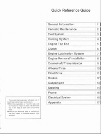
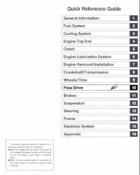
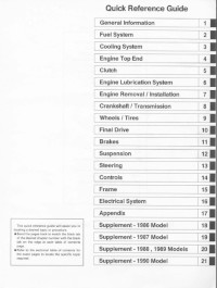
Quick Reference Guide
Brakes
1
2 1
3 1
4 1
5 1
6 1
7 1
8 1
9 1
10 1
11 1
Suspension
121
Steering
131
Frame
141
Electrical System
151
Appendix
161
General Information
Fuel System
Cooling System
Engine Top End
Clutch
Engine Lubrication System
Engine Removal/Installation
Crankshaft/Transmission
Wheels/Tires
Final Drive
This quick reference guide will assist you in
locating a desired topic or procedure .
• Bend the pages back to match the black tab
of the desired chapter number with the black
tab on the edge at each table of contents
page .
• Refer to the sectional table of contents for
the exact pages to locate the specific topic
required.
1
Ninja ZX-6R
Motorcycle
Service Manual
LIST OF ABBREVIATIONS
A
ampere(s)
Ib
pound(s)
ABDC
after bottom dead center
alternating current
after top dead center
before bottom dead center
bottom dead center
m
meler(s)
min
N
minute(s)
newton(s)
pascal(s)
horsepower
pound{s) per square inch
revolution
revolution(s) per minute
top dead center
total indicator read ing
volt(s)
watt(s)
ohm(s)
AC
ATDe
BBDC
BDC
BTOC
before top dead center
'c
degree(s) Celsius
DC
F
'F
direct current
ft
Q
h
L
farad (s)
degree(s) Fahrenheit
foot, feet
gram(s)
hour(s)
liter(s)
P,
PS
psi
r
rpm
TDC
TIR
V
W
n
Read OWNER'S MANUAL before operating.
EMISSION CONTROL INFORMATION
To protect the environment in which we all live, Kawasaki has incorporated crankcase emission (1) and exhaust emission
(2) control systems in compliance with applicable regulations of the United States Environmental Protection Agency and
California Air Resources Board. Additionally, Kawasaki has incorporated an evaporative emission control system (3) in
compliance with applicable regulations of the California Air Resources Board on vehicles sold in California only.
1. Crankcase Emission Control System
This system eliminates the release of crankcase vapors into the atmosphere. Instead, the vapors are
routed through an oil separator to the intake side of the engine. While the engine is operating, the
vapors are drawn into combustion chamber, where they are burned along with the fuel and air supplied
by the carburetion system.
2. Exhaust Emission Control System
This system reduces the amount of pollutants discharged into the atmosphere by the exhaust of this
motorcycle. The fuel, ignition, and exhaust systems of this motorcycle have been carefully designed
and constructed to ensure an efficient engine with low exhaust pollutant levels.
3. Evaporative Emission Control System
Vapors caused by fuel evaporation in the fuel system are not vented into the atmosphere. Instead,
fuel vapors are routed into the running engine to be burned, or stored in a canister when the engine
is stopped. Liquid fuel is caught by a vapor separator and returned to the fuel tank.
The Clean Air Act, which is the Federal law covering motor vehicle pollution, contains what is commonly referred to as
the Act's "tampering prOvisions.·
·Sec. 203{a) The following acts and the causing thereof are prohibited ...
(3)(A) for any person to remove or render inoperative any device or element of design installed on or
in a motor vehicle or motor vehicle engine In compliance with regulations under this title prior to
its sale and delivery to the ultimate purchaser, or for any manufacturer or dealer knowingly to
remove or render inoperative any such device or element of design after such sale and delivery
to the ultimate purchaser.
(3)(8 ) for any person engaged in the business of repairing, servicing , selling, leasing, or trading motor
vehicles or motor vehicle engines, or who operates a fleet of motor vehicles knowingly to remove
or render inoperative any device or element of design installed on or in a motor vehicle or motor
vehicle engine in compliance with regulations under this title follOWing its sale and delivery to the
ultimate purchaser... •
NOTE
o The phrase "remove or render inoperative any device or element of design" has been generally
interpreted as follows:
1. Tampering does not include the temporary removal or rendering inoperative of devices or
elements of design in order to perform maintenance.
2. Tampering could include:
a. Maladjustment of vehicle components such that the emission standards are exceeded.
b. Use of replacement parts or accessories which adversely affect the performance or
durability of the motorcycle.
c. Addition of components or accessories that result in the vehicle exceeding the standards.
d. Permanently removing, disconnecting, or rendering inoperative any component or element
of design of the emission control systems.
WE RECOMMEND THAT ALL DEALERS OBSERVE THESE PROVISIONS OF FEDERAL LAW, THE VIOLATION OF
WHICH IS PUNISHABLE BY CIVIL PENALTIES NOT EXCEEDING $10,000 PER VIOLATION .
TAMPERING WITH NOISE CONTROL SYSTEM PROHIBITED
Federal law prohibits the following acts or the causing thereof: (1) The removal or rendering inoperative by any person
other than for purposes of maintenance, repair, or replacement, of any device or element of design incorporated into any
new vehicle for the purpose of noise control prior to its sale or delivery to the ultimate purchaser or while it is in use, or (2)
the use of the vehicle after such device or element of design has been removed or rendered inoperative by any person.
Among those acts presumed to constitute tampering are the acts listed below:
• Replacement of the original exhaust system or muffler with a component not in compliance with Federal
regulations.
• Removal of the muffler(s) or any internal portion of the muffler{s).
• Removal of the air box or air box cover.
• Modifications to the mutfler(s) or air intake system by cutting, drilling, or other means if such modifications
result in increased noise levels.
Foreword
This manual is designed primarily for use by trained
mechanics in a properly equipped shop. However, it
contains enough detail and basic information to make
it useful to the owner who desires to pertorm his own
basic maintenance and repair work. A basic knowledge
of mechanics, the proper use of tools, and workshop
procedures must be understood in order to carry out
maintenance and repair satisfactorily. Whenever the
owner has insufficient experience or doubts his ability to
do the work, all adjustments, maintenance, and repair
should be carried Qut only by qualified mechanics.
In order to pertorm the work efficiently and to avoid
costly mistakes, read the text, thoroughly fam iliarize
yourself with the procedures before starting work, and
then do the work carefully in a clean area. Whenever
special tools or equipment are specified, do not use
makeshift tools or equipment. Precision measurements
can only be made if the proper instruments are used,
and the use of substitute tools may adversely affect safe
operation.
For the duration of the warranty period, we recommend that all repairs and scheduled maintenance be
performed in accordance with this service manual. Any
owner maintenance or repair procedure not periormed in
accordance with this manual may void the warranty.
To get the longest life out of your vehicle:
• Follow the Periodic Maintenance Chart in the Service
Manual.
• Be alert for problems and non-scheduled maintenance.
• Use proper tools and genuine Kawasaki Motorcycle
parts. Special tools, gauges, and testers that are
necessary when servicing Kawasaki motorcycles are
introduced by the Special Tool Catalog or Manual.
Genuine parts provided as spare parts are listed in the
Parts Catalog.
• Follow the procedures in this manual carefully. Don't
take shortcuts.
• Remember to keep complete records of maintenance
and repair with dates and any new parts installed.
How to Use This Manual
In preparing this manual, we divided the product into
its major systems. These systems became the manual's
chapters. All information for a particular system from
adjustment through disassembly and inspectfon is located
in a single chapter.
The Quick Reference Guide shows you all of the
product's system and assists in locating their chapters.
Each chapter in turn has its own comprehensive Table of
Contents.
The Periodic Maintenance Chart is located in the
General Information chapter. The chart gives a time
schedule for required maintenance operations.
If you want spark plug information, for example, go to
the Periodic Maintenance Chart first. The chart tells you
how frequently to clean and gap the plug. Next, use the
Quick Reference Guide to locate the Electrical System
chapter. Then, use the Table of Contents on the first page
of the chapter to find the Spark Plug section.
Whenever you see these WARNING and CAUTION
symbols, heed their instructions! Always follow safe
operating and maintenance practices.
..WARNING
This warning symbol identifies special instructions or procedures which, if not correctly followed, could result in personal injury, or loss of
life.
CAUTION
This caution symbol identifies special instructions or procedures which, if not strictly observ ed, could result in damage to or destruction
of equipment.
This manual contains four more symbols (in addition to
WARNING and CAUTION) which will help you distinguish
different types of information.
NOTE
o This note symbol indicates points of particular interest for more efficient and convenient operation.
• Indicates a procedural step or work to be done.
o Indicates a procedural sub-step or how to do the work
of the procedural step it follows. It also precedes the
text of a NOTE.
Indicates a conditional step or what action to take based
on the results of the test or inspection in the procedural
step or sub-step it follows.
*
In most chapters an exploded view illustration of the
system components follows the Table of Contents. In
these illustrations you will find the instructions indicating
which parts require specified tightening torque, oil, grease
or a locking agent during assembly.
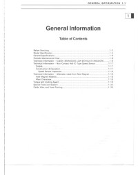
GENERAL INFORMATION 1-1
General Information
Table of Contents
Before Servicing ...... "
Model Identification ..... .
General Specifications .
Periodic Maintenance Chart. .
........ ... ....
.... .. .... .................... ... ... .. .... .. ...
.... .. 1-2
... 1-4
... ... ......... 1-5
... ..... ................................................................................ .................. ...... . ' -7
Technicallnformalion - KLEEN (KAWASAKI LOW EXHAUST EMISSION) ...............
Technicallnformalion · Non-Contact Hall ie-Type Speed
... .. ... ... ..... ...... .......... ...
Sensor...................................... .........................
.1-8
.....1-17
Technical Information - Alternator Made from Rare Magne!... ...... .................................. ... ... .... .... ........ ....... ...
.... 1~19
Torque and locking Agent ..... ... ....
...... ............. .. ........................................................................................................ 1·20
Special Tools and Sealant ............ ........................................................................................
...... .............. ................ 1-24
.. ......... .. ... .... ....................................................................... ... .. ...... .. ... .... .......... 1·30
Cable , W ire, and Hose Routing ....
1-2 GENERAL INFORMATION
Before Servicing
Before starting to service a motorcycle, careful reading of the applicable section is recommended to eliminate
unnecessary work. Photographs, diagrams, notes, cautions, warnings, and detailed descriptions have been included
wherever necessary. Nevertheless, even a detailed account has limitations, a certain amount of basic knowledge is also
required for successful work.
Especially note the following :
(1) Dirt
Before removal and disassembly, clean the motorcycle. Any dirt entering the engine or other parts will work as an
abrasive and shorten the life of the motorcycle. For the same reason, before installing a new part, clean off any dust
or metal filings.
(2) Battery Leads
Remove the ground (- ) lead from the battery before pertorming any disassembly operations on the motorcycle.
When installing, connect the positive (+) lead first, then the negative H lead to the battery. This prevents: (a) the
possibility of accidentally turning the engine over while partially disassembled. (b) sparks at electrical connections
which wilt occur when they are disconnected. (c) damage to electrical parts.
(3) Installation, Assembly
Generally, installation or assembly is the reverse of removal or disassembly. But if this Service Manual has
installation or assembly procedures, follow them. Note parts locations and cable, wire, and hose routing during
removal or disassembly so they can be installed or assembled in the same way. It is preferable to mark and record
the locations and routing as much as possible.
(4) Tightening Sequence
Generally, when installing a part with several bolts, nuts, or screws, start them all in their holes and tighten them to
a snug fit. Then tighten them evenly in a cross pattern. This is to avoid distortion of the part and/or causing gas or
oil leakage. Conversely when loosening the bolts, nuts, or screws, first loosen all of them by about a quarter turn and
then remove them. Where there is a tightening sequence indication in this Service Manual, the bolts, nuts, or screws
must be tightened in the order and method indicated.
(5) Torque
When torque values are given in this Service Manual, use them. Either too little or too much torque may lead to
serious damage. Use a good quality, reliable torque wrench.
(6) Force
Common sense should dictate how much force is necessary in assembly and disassembly. If a part seems especially
difficult to remove or install, stop and examine what may be causing the problem. Whenever tapping is necessary, tap
lightly using a wooden or plastic-faced mallet. Use an impact driver for screws (particularly for the removal of screws
held by a locking agent) in order to avoid damaging the screw heads.
(7) Edges
Watch for sharp edges, especially during major engine disassembly and assembly. Protect your hands with gloves
or a piece of thick cloth when lifting the engine or turning it over.
(8) High-Flash Point Solvent
A high-flash point solvent is recommended to reduce fire danger. A commercial solvent commonly available in North
America is Standard solvent (generic name). Always follow manufacturer and container directions regarding the use
of any solvent.
(9) Gasket, C-Ring
Do not reuse a gasket or a -ring once it has been in service. The mating surfaces around the gasket should be
free of foreign matter and perfectly smooth to avoid oil or compression leakage.
(10) Liquid Gasket, Non-Permanent Locking Agent
Follow manufacturer's directions for cleaning and preparing surfaces where these compounds will be used. Apply
sparingly. Excessive amounts may block engine oil passages and cause serious damage. An example of a nonpermanent locking agent commonly available in North America is Loctite Lock'n Seal (Blue).
(11) Press
A part installed using a press or driver, such as a wheel bearing, should first be coated with oil on its outer or inner
circumference so that it will go into place smoothly.
(12) Ball Bearing and Needle Bearing
Do not remove a ball bearing or a needle bearing unless it is absolutely necessary. Replace any ball or need le
bearings that were removed with new ones, as removal generally damages bearings. Install bearings with the marked
side facing out applying pressure evenly with a suitable driver. Only press on the race that forms the press fit with
the base component to avoid damaging the bearings. This prevents severe stress on the balls or needles and races,
and prevent races and balls or needles from being dented. Press a ball bearing until it stops at the stops in the hole
or on the shaft,
(13) Oil Seal and Grease Seal
Replace any oil or grease seals that were removed with new ones, as removal generally damages seals. When
pressing in a seal which has manufacturer's marks, press it in with the marks facing out. Seals should be pressed
into place using a suitable driver, which contacts evenly with the side of seal, until the face of the seal is even with
the end of the hole. Before a shaft passes through a seal, apply a little high temperature grease on the lips to reduce
rubber to metal friction.
GENERAL INFORMATION 1-3
Before Servicing
(14) Circlip, Retaining Ring, and Coner Pin
Replace any circlips and retaining rings, and cotter pins that were removed with new ones, as removal weakens
and deforms them. When installing circlips and retaining rings, lake care to compress or expand them only enough
to install them and no more.
(15) Lubrication
Engine wear is generally at its maximum while the engine is warming up and before all the rubbing surfaces have
an adequate lubricative film. During assembly, oil or grease (whichever is more suitable) should be applied to any
rubbing surlace which has lost its lubricative film. Old grease and dirty oil should be cleaned off. Deteriorated grease
has lost its lubricative quality and may contain abrasive foreign particles.
Oon' use just any oil or grease. Some oils and greases in particular should be used only in certain applications
and may be harmful if used in an application for which they are not intended. This manual makes reference to
molybdenum disulfide grease (MoS 2 ) in the assembly of certain engine and chassis parts. Always check manufacturer
recommendations before using such special lubricants.
(16) Electrical Wires
All the electrical wires are either single-color or two-color and, with only a few exceptions, must be connected to
wires of the same color. On any of the two-color wires there is a greater amount of one color and a lesser amount of
a second color. so a two-color wire is ident ified by first the primary color and then the secondary color. For example,
a yellow wire with thin red stripes is referred to as a "yellow/red " wire; it would be a "red/yellow" wire if the colors were
reversed to make red the main color.
Wire (cross-section)
Name of Wire Color
Red
Wire Strands
Yellow/Red
Yellow
Red
(17) Replacement PariS
When there is a replacement instruction. replace Ihese parts with new ones every time they are removed. These
replacement parts will be damaged or lose their original function once removed.
(18) Inspection
When parts have been disassembled, visually inspect these parts for the following conditions Of other damage. If
there is any doubt as to the condition of them, replace them with new ones.
Abrasion
Bent
Color change
Crack
Dent
Deterioration
Hardening
Scratch
Seizure
Warp
Wear
(19) Specifications
Specification terms are defined as follows:
"Standards" show dimensions or performances which brand-new parts or systems have.
"Service Limits" indicate the usable limits. If the measurement shows excessive wear or deteriorated per1ormance,
replace the damaged parts.
1-4 GENERAL INFORMATION
Model Identification
ZX6OO-J1 Left Side View:
ZX60Q-J1 Right Side View:
GENERAL INFORMATION 1-5
General Specifications
Items
ZX600-Jl
Dimensions:
2030 mm, (PN) 2 060 mm
Overall length
Overall width
Overall height
Wheelbase
Road clearance
730 mm
1 175 mm
1 400 mm
Seal height
820 mm
Dry mass
Curb mass:
145 mm
Front
Rear
Fuel tank capacity
171 kg, (CA) 173 kg, (H) t 72 kg
100 kg
96 kg, (CA) 98 kg, (H) 97 kg
18 L
Performance:
Minimum turning radius
Engine:
Type
4-stroke, DOHC, 4-cylinder
Liquid-cooled
Cooling system
Bore and stroke
Displacement
Compression ratio
Maximum horsepower
66 x 43.8 mm
599 mL
12.8
Maximum torque
Carburetion system
Starting system
Ignition system
TIming advance
Ignition liming
Spark plug
Cylinder numbering method
Firing order
Valve timing:
Inlet
Open
Close
Exhaust
Duration
Open
Close
Duration
Lubrication system
Engine oil:
Grade
Viscosity
Capacity
Drive Train :
Primary reduction system:
Type
Gear ratios:
8 1.6 kW (111 PS) @12S00r/min(rpm),
(AS) 80.6 kW (109.6 PS) @12 500 rl min (rpm),
(PRl 78.2 kW (106.3 PS) @12 500 rl min (rpm),
(US) •••
65.6 N'm (6.7 kg·m, 48 ft·lb) @10000r/min(rpm),
(AS) 64.6 N·m (6.6 kg·m, 48 ft·lb) @10ooo rlmin (rpm)
(FA}(US) •..
Carburetors, Mikuni SOSR 36R x 4
Electric starter
Battery and coil (transistorized)
Electronically advanced(digital igniter)
From 12.5" BTDC @1 300 rl min (rpm)
to 42.5° BTDC @5 000 rlmin (rpm)
NGK CA9E
Left to right, 1-2-3-4
1·2·4·3
56° BTDC
80° ABOC
316°
61 ° BBDC
33° ATOC
0
274
Forced lubrication (wet sump with cooler)
SE, SF or SG class
SAE10W·40, 10W·SO, 20W·40, or 20W·SO
3.8 L
Gear
2.022 (89/44)
Reduction ratio
Clutch type
Transmission:
Type
3.2 m
Wet multi disc
6·speed, cOflstant mesh, return shift
,.(
2nd
3,d
4th
2.923 (38/13)
2.062 (33116)
1.631 (3 1/19)
1.380 (29121)
1-6 GENERAL INFORMATION
General Specifications
Items
5th
6th
Final drive system:
Type
ZX60Q-J 1
1.217 (28123)
1.083 (2612 4)
Chain drive
2.666 (40/1S)
5.843 @lop ear
Reduction ratio
Overall drive ratio
Frame :
Type
Tubular, diamond
Caster (rake angle)
23.5°
95 mm
Tubeless
120165 ZRt7 (S6W)
Trail
Front tire:
Type
Rear tire:
Size
Type
Size
Tubeless
180155 ZR17 (73W)
Front suspension:
Type
Telescopic fork
Wheel travel
120 mm
Type
Wheel travel
Front
Swingarm (uni-Irak)
135 mm
Dual discs
Rear
Sin Ie disc
Rear suspension:
Brake Type:
Electrical Equ ipment :
Battery
Type
Headlight
Bulb
Tail/brake light
Alternator:
Type
Raled output
12 V 8 Ah
Semi-sealed beam
12 V 60155 W (quartz-halogen) x 2
12 V 5121 W x 2
Three-phase AC
22 A / 14 V @5 000 rlmin (rpm)
Specifications are subjecllo change without notice, and may not apply to every country.
(AS): Australia Model
(CA): California Model
(FA): France Model
(US): U.S.A. Model
H: with Honeycomb CatalytiC Converter Model
PN: with Pipe Catalytic Converter (Norway) Model
PR: with Pipe Catalytic Converter (France) Model
GENERAL INFORMATION 1-7
Periodic Maintenance Chart
The scheduled maintenance must be done in accordance with this chart to keep the motorcycle in good running condition.
The Initial maintenance is v itallv Important and must not be neglected.
FREQUENCY
Whichever
comes
first
1
1 000 km
• ODOMETER READING
isoo mil~l
-
6000 km
(4000 mile)
12000 km
500 milel
18000 km
(12000 mile)
24000 km
i'7
(15 000 mile)
30000 km
(20 000 mile)
36 000 km
124 000 milel
Eve",
OPERATION
Spark plug· clean and gap t
Valve clearance - check t
Air suction vaJve • check t
Air Cleaner element and air vent filler· cleant II
Throttle grip play - check
t
Idle speed - check t
Carburetor synchronization - check t
Engine oil - change II
all filter - replace
Evaporative emission control system {CAl - check
Drive chain wear - check til
Brake pad wear· check tit
Brake light switch - check t
Steering - check t
Front fork oil - change
Rear shock absorber oil leak - check t
Front fork oil leak - check t
Tire wear - check t
Swingarm pivot, Unit-trak linkage - lubricate
General lubrication - perform
Nut, bolts, and fas teners tighlIless - check t
Drive chain - lubricate II
Drive chain slack - check t#
Brake fluid level - check t
Clutch adjust - check t
Radiator hoses, connection - check t
Brake fluid - change
Brake master cylinder cup and dust seal - replace
Coolant - change
Caliper piston seal and dust seal - replace
Steering stem bearing - lubricate
Coolant filter - clean
6 months
t
2 years
600 km
1000 km
month
month
2 years
•
•
•
•
•
•
•
•
•
•
•
•
• • •
•
• • •
•
•
•
•
• • •
•
• • •
• • •
• • •
• • •
• • •
•
•
• • •
•
•
•
• • •
• • •
• • •
• • •
4 years
2 years
4 years
2 years
yeM
• • •
•
•
•
•
•
•
•
•
•
•
•
•
•
•
•
•
•
•
•
•
•
•
•
•
•
•
•
•
•
•
•
•
•
•
•
•
•
•
•
•
•
•
•
•
•
•
•
•
•
• •
•
•
•
•
•
•
•
•
•
•
•
/I : Service more frequently when operating In severe conditions; dusty, wet, muddy, hIgh speed, or frequent starting I
stopping.
* : For higher odometer readings, repeat at the frequency interval established here.
t : Replace, add, adjust, clean , or torque if necessary.
(CA): California Model only
1-8 GENERAL INFORMATION
Technical Information
KLEEN (KAWASAKI LOW EXHAUST EMISSION)
The ZXSOOJ have catalytic converters.
The secondary air injection system [A] helps Kawasaki keep motorcycle exhaust gases below the established emission
regulation limits. This system draws air into the exhaust ports, dilutes and burns harmful ingredients in the exhaust gas
in order to reduce them. This allows the carburetor to be set at a reasonable setting position without adjusting it much
leaner, so engine performance and actual riding performance are not spoiled.
But, under the trend thai the emission regulation becomes more severe, Kawasaki has adopted two catalytic converters
[BJ in addition to the secondary air injection system. Moreover, a BD$R 36-type carburetor has been adopted because
of its good balance between cost and pertormance. As a result, we can reduce the exhaust gas emission below the
current standards without hurting the output performance and the actual riding feeling at all. The harmful ingredients in
the exhaust gas are reduced considerably under running performance of emission regulation like LA4 or EC mode. As
actual examples, carbon monoxide (CO) is reduced about 70% , hydrocarbons (He) about 60%, nitrogen oxides (NOx)
about 10%.
Moreover, in order to improve the reliability of the system , we install fuel cut valves [C] as a catalyst protection system.
Exhaust Gas after Purification
exhlust GI. Ifter lIIuff l er
1 OO~
",
-~1
0
0
• •
---j0
"')./
0
-
/
•'w
"
Air / Fuel
12
13
14
IS
U
17
Rltio aftll. III lin Cltalytie Converter
....... .. , c
Kawasaki Low Exhaust Emission System
.... 01.102
~
GENERAL INFORMATION 1-9
Technical Information - KLEEN (KAWASAKI LOW EXHAUST EMISSION)
1. Exhaust Purification System
The burned gas, which goes out from the combustion chamber, is injected with secondary air (adding necessary oxygen),
and is cleaned up while passing through two small catalytic converters in the joint pipe and the main catalytic converter in
the silencer, and then goes out to the atmosphere.
Secondary A ir Injection System
1) In order to oxidize CO, and He by the catalysts, the proper amount of oxygen is necessary. As original combustion gas
has little remaining oxygen, air is injected in the exhaust ports by the secondary air injection system in order to supply
enough oxygen to the combustion gas to purify CO, and He to a certain extent as well as prepare for activation of the
catalysts. Since the carburetor is set at richer level [A], and airjfuel mixture (NF) is about 11 "" 14, NOx is at lower level
from the beginning as shown in the figure. And, NF becomes lean (about 13.5 ,..., 15) after the combustion chambers
owing to secondary air injection and combustion.
Ex hau s t Gas before Purification
®
1011
.,
121310
15
1817
1111
2) Precatalytic Converters [AJ
A small-size three-way catalytic converter (precatalytic converter) is installed in the pipe ahead at the joint [BI of the
silencer. A precatalytic converter is made of a punched metal pipe [C] of stainless steel, and its surface is covered with
alumina upon which platinum and rhodium as catalysts are applied . Generally, the temperature of the exhaust gas must
be higher than the activation temperature, so we set this precatalytic converter at the upper portion of the main catalytic
converter where the temperature of exhaust gas is high. Accordingly, the precatalytic converter will be activated even
under low load conditions. Activation of the precataJytic converter raises the exhaust gas temperature by the catalyst
reaction , which helps the main catalytic converter operate more efficiently. The precatalytic converter purifies CO, HC,
and NOx to a certain extent.
3) Main Catalytic Converters (OJ
The converter is a three-way catalytic converter upon which platinum and rhodium are applied, and has a cylindrical
metallic honeycomb structure IE) made by bending a corrugated sheet and a flat sheet of stainless steel into a spiral of
increasing diameter. The main catalytic converter is installed in the first expansion chamber of the silencer. When the
exhaust gas passes through the upper portion of the secondary air injection system, the precatalytic converter, and the
inside of the honeycomb, the main catalytic converter works efficienlly to reduce CO, HC, and NOx. So, we can keep it
within regulation.
The honeycomb structure is convenient for Ihe catalytic converter because il has a farge surface area bul small size to
react effectively and has low exhaust resistance. In addition, its inherent strength helps resist vibration, and has simple
structure welded directly on the silencer.
1-10 GENERAL INFORMATION
Technical Information - KLEEN (KAWASAKI LOW EXHAUST EMISSION)
Catalytic Converters
o
A
(
0 000000 0
0 0000000
0 000 00 0 0
1
c
Catalyst
( Pt. Rh )
Alu min a
E
(s up po r t)
•
ho n eycom b
2. Catalyst Protection System
When excessive unburned gasoline flows more than the allowable amount into the exhaust gas during running, the
temperature of the catalysts rises abnormally because the unburned gasoline reacts with heated catalysts (at the activation
temperature or higher). In an excessive case, the problem such as melting-down occurs. Moreover, there is a possibility
that the purification performance becomes poorer when it is cool (below the activation temperature). So, the fuel cut valve
[AI as a catalyst protection system is installed on each carburetor float bowl [BJ . It runs by the Ie Igniter and opens and
closes the fuel passage toward a main jet [C). A catalys t protection system works in the following cases.
1) Prevention of unburned gasoline from flowing when overs peed limiter works.
The limiter has fuel cut-off and ignition cut·off operations.
2) Prevention of unburned gasoline from flowing when the engine stop switch is turned off during running.
When the engine stop switch is turned off while coasting the motorcycle, fuel is cut off. For example, fuel is cut off under
the abnormal running condition that you go down the slope with the engine stop switch OFF.
3) Prevention of unburned gasoline from flowing when misfire occurs by a cutoff of a primary coil in a stick coil.
Fuel is cut off when an electric current of a primary coil becomes abnormal because of a cutoff of the primary coil when
the engine is running.
4) Prevention of solenoid valve lock
If a driver always runs the engine under the red zone in the tachometer, the IC igniter doesn't operate overs peed limiter
and the catalyst protection system doesn't have a chance to work. The old fuel may gum up the fuel cut valves which
remain seated in the float bowls. To cope with, the IC igniter test-operates the fuel cut valves when starting the engine
and prevents lock of the valves.
5) Usage of leaded gasoline is prohibited completely.
leaded gasoline harms the purification efficiency of the catalysts.
The performance of the catalyst protection system is summed up as follows.
GENERAL INFORMATION 1-11
Technical Information - KLEEN (KAWASAKI LOW EXHAUST EMISSION)
Fuel Cut Valve
1I0" ","I, j
[Performance of Catalyst Protection System1
Running condition
Ignition
No
Engine
switch
stop
Protection
system
switch
Fuel
1
Normal
ON
ON
OFF
valve
OPEN
2
Overspeed performance
Abnormal (misfire)
• Defects at the stick coil
primary-side
Abnormal (misfire)
• Defects at the stick coil
ON
ON
ON
ON
ON
ON
CLOSE
CLOSE
3
4
Remedy (Action)
cuI
• Not necessary
(Normal condition)
• Not necessary
• Inspect the connection al the
primary-side of the stick coil.
ON
ON
OFF
OPEN
• Inspect the stick coil.
secondary-side
• Battery is dead.
• Spark plug fouling
• Charge the battery.
• Clean the spark plug and adjust the gap.
• Defects of the pickup
coil
• Defects of the Ie igniter
• Inspect and replace the
pickup coil.
o
• Inspect and replace the Ie igniter.
• Inspect and adjust the carboretor.
Defects 01 the carbure-
10'
S
6
Abnormal (no spark)
• Short of the engine stop
switch
• While coasting the motorcycle, do not turn the
engine stop switch OFF.
ON
Abnormal (no spark)
OFF
• Short of the ignition
switch
• While coasting the motorcycle, do not turn the
ignition switch OFF.
OFF
ON
CLOSE
• Inspect and repair the engine
stop switch.
• Turn the engine stop switch
ON , and ru n.
ON
0'
OFF
OFF
OPEN
• Inspect and replace the igni.
tion switch.
• Turn the ignition switch and
the engine stop switch ON,
and run.
1-12 GENERAL INFORMATION
Technical Information - KLEEN (KAWASAKI LOW EXHAUST EMISSION)
3. Ma intenance
Special maintenance is not necessary except for the inspection of the air suction valve (which has been described in
this manual).
1) Replacement of Muffler Assy
It is impossible 10 replace only catalytic converters because they are welded in the muffler. So, in the following case,
the replacement of the muffler assy is also necessary.
• In case of using not-appointed fuel (leaded gasoline, etc.):
Purification efficiency decreases in a very short period because lead poisons the catalytic converters. Although the
appearance of the converter and engine performance are not effected, the replacement of a muffler assy is necessary
to secure the purification efficiency of exhaust gas.
• In case catalytic converters melt down by overheating:
Especially in the case that a 101 of unburned gasoline flows into the catalytic converters under the extreme running
condition far beyond common sense, there is a possibility that the catalysis overreact and that catalytic converters
overheat severely. If they melt down, it causes poor engine performance, deterioration of emission noise level, and
purification efficiency. So, the muffler assy must be replaced
2) Durability
It has the same durability as a conventional muffler.
3) Disposal to Waste
As any harmful toxic substance is not used especially, it can be disposed as usual industrial wastes. The body of the
muffler is made of aluminum steel. The catalytic converter is also made of stainless steel which has alumina on its
surface, and the main ingredients of catalysts are platinum and rhodium.
4. Handling Precautions
Catalyst protection system against mishandling is applied to a vehicle with catalysts. But, we prohibit depending on the
system too much when running.
1) Use only unleaded gasoline:
usage of leaded gasoline is prohibited completely. Only fue l and additives which are specified in the Owner's Manual
can be used.
2) Use specified engine oil which is described in the Owner's Manual:
In case of some ingredients which give bad effects to the catalysts (such as phosphorus 'P', lead ' Pb", sulfur'S") are
included, the purification efficiency decreases.
3) Coasting (such as cranking while going down a slope) is prohibited with the ign ition system OFF:
The engine running without ignit ing causes a great flow of unburned gasoline and the decreasing of purification efficiency,
and melting down of catalysts at the activation temperature or higher.
• When the ignition switch [A] is turned off, the fuel cut valves [B] do not work . So, avoid coasting with the ignition switch
OFF.
• Do not run the engine nor coast the motorcycle under the misfire which occurs by defects such as a bad connection
with the spark plug at the secondary wiring of the slick coil [C].
• Do not coast too much WIth the engine stop switch {D] OFF. Under the condition that the engine stop switch is turned
off during running, the IC igniter [E] closes the fuel cut valves to shut off fuel.
• Do not run the engine nor coast the motorcycle too much under the condition that the primary wiring of the stick coil
does not connect completely (misfire). Incomplete connection or cut-off of the primary coil makes the fuel cut valves
start to cut fuel. In this case, from the standpoint to prolect the catalysts, the fue l for all cylinders is cut off even if one
cylinder has been affected.
GENERAL INFORMATION 1-13
Technicallnformaiion - KLEEN (KAWASAKI LOW EXHAUST EMISSION)
Kawasaki l ow Exhau st Emission System
o
i I e ne er
II . . . . . .. ~ C
• Do nol run overs peed limiter too much from the standpoint to protect the engine. (Overs peed limiter has a protection
system thaI applies ignition cui method and fuel cut method together. Conventional system applies fuel-on method.)
• Do not run the engine even jf only one cylinder has a misfire or has unstable running. In this case, request the nearest
service facility to correct it. If you have no choice but running by yourself, keep engine rpm as low as possible and try
to fi nish running at the shortest period.
• When the battery is dead, do nol push-start. Connect another full-charged battery with jumper cables, and start the
engine.
1-14 GENERAL INFORMATION
Technical Information - KLEEN (KAWASAKI LOW EXHAUST EMISSION)
5. Additional Information
1) Secondary Air Injection System
The mechanism is simple and power loss is minimum because the system uses the vacuum pressure created by exhaust
pulses.
The secondary injection air helps the fueVair mixture burn more completely (Primary air means air which flows through
the Inlet pipe). As the exhaust valve opens, and the burned fuel passes the exhaust valve, a stream of fresh air is
introduced through the air suction valve. This fresh air burns the unburned gas and converts the carbon monoxide (CO)
and hydrocarbons (HC) into harmless carbon dioxide (C02) and water (H2O).
CO + 1/2 02 - C02
HC+02-CQ2+H20
The secondary air injection system consists of a vacuum switch valve, and two air suction valves. Without using an air
pump, the air suction valve can draw fresh air into the exhaust passage near the exhaust valves by vacuum that exhaust
pulses generate.
Air Suction Val ves
The air suction valves is a check valve which allows fresh air to flow only from the air cleaner via air hoses into the
exhaust port and prevents return flow, Remove and inspect the air suction valves periodically (see Engine Top End chapter
in this Service Manua l), Also, remove and inspect the air suction valves whenever the idle speed is unstable, engine power
is greatly reduced, or there are abnormal engine noises.
Vacuum Switch Valve
Although the vacuum switch valve usually permits secondary air flow, it closes when a high vacuum (lOW pressure) is
developed at the inlet pipe during engine braking. This is to shul off secondary air flow and prevent explosions in the
exhaust ports which mighl be caused by extra unburned fuel in the exhaust during deceleration. These explosions, or
backfiring in the exhaust system could damage the air suction valves.
Regular inspection of the vacuum switch valve is not needed. If backfiring occurs frequently in the exhaust system
during engine braking or if there are abnormal engine noises, check the vacuum switch valve as described in the text (see
Engine Top End chapter in this Service Manual).
Secondary Air Injection System
ClO'o ... OI C
I . Air Cleaner Housing
2. Air Hose
3. Inlet Silencer
4. Vacuum Switch Valve
5. Air Suction Valve
6. Exhaust Valve
7. Carburetors
8. Inlet Pipe
9. Inlet Valve
2) Operation of Three-way CatalytiC Converter
The three-way catalysts are used for the catalytic converters and the main catalytic converter. These converters can
clean up carbon monoxide (CO), hydrocarbons (HC), and nitrogen oxides (NOx) at the same time.
CO and HC are oxidized (0 is added) by platinum (Pt) and converted to harmless carbon dioxide gas (CCh) and water
(H 20), and then the exhaust gas is cleaned up:
CO + 1/2 02 - C02
HC + 0 2"'" C02 + H20
GENERAL INFORMATION 1-15
Technical Information - KLEEN (KAWASAKI LOW EXHAUST EMISSION)
NOx is reduced (0 is removed) by rhodium (Rh) and converted to harmless nitrogen (N2) and oxygen (02), and the
exhaust gas is cleaned up.
NOx - N2 + O:!
Ma in Catalytic Converter
CO
HC~
0 2 NOx
3) Property of Catalyst
Most catalysts are powders 01 metal or of metallic compounds, and they increase the rate of a chemical reaction.
Catalysts are supposed to act in some way to loosen the bonds of the reacting substances. In other words, they lower
the energy of activation, thus allowing the reaction to proceed more rapidly. To activate catalysts, the temperature of the
exhaust gas must be higher than the activation temperature tha t is 220· ...., 230' C lor new catalysts, and 270' ...., 280 G C
for used catalysts (after 10000 ..... 20000 km ride)
r
Energy of ACtIVation (bonc:!s)
r
~
'"
/
:/
/
"
'/ '
~
w
Catalyst lowers
the energy
- - - --
,-
~ ~nergy of
Energy of
Reactant
~
;.a~ri~ ~I~e _
Compound
~~
The catalyst itself undergoes no permanenl chemical change, or can be recovered when the chemical reaction IS
completed. So, the muff!er with bullt·in catalyst has the same durability as the conventional muffler.
The mechanism of catalytic action is supposed to be a surface phenomenon in which reactants are absorbed onto a
small portion of the surface of the catalyst. The ca talytic converter is made of stainless steel and the surface is applied by
alumina (aluminum oxide AI20J). The alumina adheres to the stainless sleel wall and the catalyst adheres to the alumina
very well. The alumina surface is not uniform and there are corners, edges, dislocations, and grain boundaries. Catalyst
is applied on the alumina and this makes the catalyst surface rough. The rougher the surface is, the more actively the
catalyst adsorbs the reactants.
If various impurities like lead are adsorbed, they block the small portion of the catalyst surface, preventing absorption 01
CO, HC, and NOx. This is the reason why leaded fuel poisons the catalyst without any break on the surface or generation
of heat.
Catalysts are generally efficient in small quantities. A catalyst can catalyze the reaction of several thousand to a million
times its weight in reactants. The three-way catalyst is a blend of platinum (Pt) and rhodium (Rh) which are expensive.
But a converter uses only about 0.05 gram of Pt and 0.0 1 gram 01 Rh and a main catalytic converter uses only about 0.4
gram 01 Pt and 0.1 gram of Rh.
1-16 GENERAL INFORMATION
Technical Information - KLEEN (KAWASAKI LOW EXHAUST EMISSION)
Catalyst (RI , Rh)
Alumina (support)
c•
.~.
Stainless Steel (support)
GENERAL INFORMATION 1-17
Technical Information - Non-Contact Hall Ie-Type Speed Sensor
Details:
The electronic combination meter unit, superior to the conventional
type in weight and durability is installed on the ZX60Q---J. T he hall ICtype speed sensor is installed on the ZX60O-J together with ii, which
needs no cable and speedometer gears. Its construction and operation
are described as follows;
Construction & Operation:
• The speed sensor [AJ consists of a magnet IB] and the Hall
Ie (C).
A
N
c
S
B
. . 0'0110.,
C
11 0," ' " ' '
0
• The Hall Ie consists of Hall element [A], the differential amplifier [B],
the high pass filter [C], the comparator {OJ and the output transistor
IE]·
HaJi Element;
The semi-conductors (e.g. eaAs, InAs, InSb) are called as mentioned
above. The magnetic induction applied on the two (2) Hall elements will
be converted into the voltage, and outputted.
Differential Amplifier;
This can output the difference between output powers of the two (2)
Hall elements.
High Pass Filter;
Sensitivity of the two (2) Hall elements.
Surface magnetic induction of a magnet.
Relative positions of the Hall element, magnet, and detector gear.
JJ
Able to cancel the DC off-set because of scattering of differential
output.
Comparator & Output Transistor;
Able to output the square wave in accordance with the magnetic
induction alternation with the transistor turning on or off.
• The magnetic induction passing through the Hall element will be
changed in accordance with the relative position of the sensor and
the rotor nut [AJ installed on the engine sprocket will be rotated.
amount of magnetic induction
when large [B]
when small [C]
A
1-18 GENERAL INFORMATION
Technical Information - Non-Contact Hall Ie-Type Speed Sensor
• In the internal system of the Hall Ie, the switch is operated in
accordance with the magnetic induction alternator. This makes the
square wave equal to the pulse of the rotor nut output
Amount of magnetic induction when large (AI
Amount of magnetic induction when small {SI
Operating point [C]
Returning point [OJ
When high voltage IE]
When low voltage IF]
• The vehicle speed is indicated in the speedometer, altering the pulse
of this square wave.
Speed Sensor Inspection
• Refer to the Electrical System chapter 15.
CD
f"
f"
f"
If 10 10
®
I
I
I
IV
I
I
I
I
I
IV
I
I
I
I
I
®
rL~rCD o
©
®
, •• • • ,Ull
~
-
GENERAL INFORMATION 1-19
Technical Information - Alternator Made from Rare Magnet
Rare Magnet Material:
$intered metal made from mainly neodium (Nd), ferric magnet (Fe),
and boron (8).
Main Characters:
Rare magnet used and assembled in the alternator for the ZX600-J
model has six (6) times higher performance than that of the traditional
use ferrite magnet.
This allows the alternator to reduce its mass and weight to the large
extent. In addition to above mentioned, there's no use to worry about
the future lackage of rare magnetic resources such as samarium cobalt.
1-20 GENERAL INFORMATION
Torque an d Locking Agent
The following tables list the tightening torque for the
The table below, relating tightening torque to thread
major fasteners requiring use of a non-permanent locking
agent or liquid gasket.
diameter, lists the basic torque for the bolls and nuls. Use
this lable for only the bolts and nuts wt1ich do not requ ire
a specific torque value. All of the values are for use with
Leners used in the "Remarks· column mean:
L : Apply a non-permanent locking agent to the
'h read s.
dry solvent-cleaned threads.
Basic Torque for General Fasteners
Torque
Threads
LG : Apply grease to the threads.
lh : l eft-hand threads.
M: Apply molybdenum disulfide grease.
0 : Apply oil to the threads and seating surface.
S: Tighten the fasteners following the specified sequence.
SS: Apply silicone sealant.
St: Stake the fasteners to prevent loosening.
R: Replacement parts
dia. (mm)
N·m
kg-m
ft·lb
5
6
8
'0
'2
'4
16
'8
20
3.4 ...., 4.9
0.35 '" 0.50
30 ..... 43 in-Ib
5.9 ..... 7.8
14 ..... 19
25 ..... 34
44 ..... 61
73 ..... 98
115 ..... 155
165 ..... 225
0.60 '" 0.80
1.4 ....... 1.9
2.6 ,,", 3.5
4.5 ..... 6.2
7.4 ..... 10.0
11.5 ", 16.0
17.0 ..... 23.0
23 ...... 33
52 ..... 69 in·tb
10.0 ..... 13.5
19.0 ", 25
225 '""" 325
Torque
Fastener
33 ..... 45
54 ..... 72
83 '"" 115
125 ..... 165
165 ..... 240
Remarks
N·m
kg·m
tt·lb
1.0
0.10
9 in·lb
0.20
17 in·lb
1.0
1.0
1.0
1.8
87 in·lb
0.80
69 in·lb
1.0
1.2
87 in·lb
104 in·lb
Thermostat Housing Cover Bolts
2.0
9.8
9.8
9.8
18
7.8
9.8
12
5.9
0.60
52 in·lb
Water Hose Fitting Bolts
11
1.1
95 in·lb
13
13
9.8
10
12
12
49
12
15
20
12
1.3
1.3
1.0
113 in·lb
Fuel System:
Vacuum Valve Drain Screw
Cooling System:
Water Hose Clamp Screws
Coolant By-pass Fitting
Coolant Drain Plug (Water Pump)
Coolant Drain Plugs (Cylinder)
Radiator Fan Switch
Water Temperature Sensor
Impeller Bolt
Water Pump Cover Boits
L
87 in·lb
87 in·Jb
13.0
SS
L
Engine Top End :
Spark Plugs
Air Suction Valve Cover Bolts
Cylinder Head Cover Bolts
Camshaft Chain Tensioner Mounting Bolts
Camshaft Cap Bolts
Camshaft Chain Guide Bolts (Upper)
Cylinder Head Bolts;
. '0
¢6
Cylinder Head Jacket Plugs (Right)
Cylinder Head Jacket Plugs (Upper, left)
Engine Side Cover Bolts
Camshaft Chain Guide Bolt (Cran kcase)
Carburetor Holder Bolts
Baffle Plate Bolts
Muffler and Exhaust Pipe Connection Nuts
Exhaust Pipe Clamp Bolts
25
12
5.9
34
34
1.0
1.2
1.2
5.0
1.2
1.5
2.0
1.2
2.5
1.2
0.60
3.5
3.5
113 in·lb
87 in·lb
87 in·lb
104 in·lb
104 in·lb
36
S, 0 (Washer)
104 in·lb
S
11.0
L
14.5
L
104 in·lb
18.0
104 in·lb
52 in·lb
25
25
GENERAL INFORMATION 1-21
Torque and Locking Agent
•
Fastener
Torque
Remarks
N·m
kg·m
tHb
12
5.9
8.8
130
1.2
104 in·lb
L(2, Front)
0.60
52 in·lb
L
0.90
78 in·rb
13.5
9B
Clutch :
Clutch Cover Bolts
Clutch Cover Damper Bolts
Clutch Spring Bolts
Clutch Hub Nut
R
Engine lubrication System:
1.5 or
a.ISor
13 in·lb or
Hand-Tight
Hand-Tight
Hand-Tight
Engine Drain Plug
29
21
Oil Filter (Cartridge type)
27
78
19.5
R,O
Oil Cooler Mounting Bolt
3.0
2.7
8.0
58
0
Oil Pan Bolts
11
1.1
95 in·lb
Oil Pipe Holder Bolts
13
15
15
1.5
9.8
15
25
1.3
1.5
1.5
113 in·rb
0.15
13 in·rb
1.0
1.5
2.5
87 in·r b
44
49
25
4.5
5.0
2.5
33
18.0
Breather Plate Bolts
9.8
1.0
87 in·lb
Breather Tube Bracket Bolts
11
1.1
95 in·tb
30
20
18
12
20
15
3.0
2.0
1.8
1.2
2.0
1.5
Oil Filler Plug
Oil Pressure Relief Valve
Oil Pressure Switch
Oil Pressure Switch Terminal Bolt
Impeller Bolt
Oil Passage Plug (Righi)
Oil Hose Banjo Bolts
11.0
L
11.0
SS
11 .0
18.0
Engine Removal/Installation:
Engine Mounting Bolts and Nuts
Engine Mounting Loci<nuts
Engine Mounting Bracket Bolts
36
Crankshaft/Transml sslon :
Crankcase Bolts
, 8
, 7
rP 6, L38 (Front, 6)
, 6
Oil Passage Plug (Left)
Oil Passage Plug (Right)
Connecting Rod Big End Nuts
in the text
-
22
S
14.5
S
13.0
104 in·lb
S
S
14.5
L
11.0
-
Oil Pipe Holder Bolts
9.8
40
15
13
28
15
13
5.4
12
13
Pickup Coil Cover Bolts
11
1.1
95 in·lb
Oil Nozzles
6.9
0.70
81 in·lb
Engine Ground Lead Terminal Bolt
Timing ROIor Bolt
Oil Pressure Switch
Gear Positioning Lever Bolt
Shift Shaft Return Spring Pin (Bolt)
Neutral Switch
Shift Drum Bearing Holder Bolt
Shift Drum Bearing Holder Screw
Shift Drum Cam Bolt
L
1.0
4.0
1.5
1.3
2.9
1.5
1.3
113 in·lb
0.55
48 in·lb
1.2
1.3
104 in·lb
87 in·lb
-
29
11.0
21
SS
L
11.0
113 in·lb
L
L
113 in·lb
L (1)
L
1-22 GENERAL INFORMATION
Torque and Locking Agent
•
Torque
Fastener
Remarks
N·m
kg ·m
ft·lb
20
125
125
2.0
14.5
13.0
92
92
Wheels/Ti res:
Front Axle Clamp Bolts
Front Axle Nut
Rear Axle Nut
13.0
Final Drive:
13.0
92
1.2
0.70
6.0
104 in·lb
Rear Sprocket Nuts
125
12
6.9
59
Rear Sprocket Studs
.
.
.
Bleed Valves
7.8
0.80
69 in·lb
Brake Hose Banjo Bolts
25
1.0
5.9
1.5
6.9
1.0
11
2.9
34
21
27
27
Engine Sprocket Nul
Engine Sprocket Cover Bolts
Speed Sensor Mounting Bolt
61 in·lb
0
L
43
L
Brakes :
Brake lever Pivot 8011
Brake Lever Pivot Bolt Locknut
Front Brake Reservoir Cap Stopper Screws
Front Brake Reservoir Bracket Bolt
Front Brake Light Switch Screws
Front Master Cylinder Clamp Bolts
Pad Spring Screws (Front Caliper)
Caliper Mounting Bolts (Front)
Caliper Assembly Bolts (Front)
Front Brake Disc Mounting Bolts
Rear Brake Disc Mounting Bolts
Caliper Mounting Bolts (Rear)
Rear Master Cylinder Guard Bolts
Rear Master Cylinder Push Rod locknut
25
25
18
2.5
18.0
0.10
9 in·lb
0.60
52 in·lb
0.15
13 in·lb
0.70
61 in·lb
0.10
9 in·lb
1.1
95 in·lb
0.30
26 in·lb
3.5
2.1
2.8
2.8
2.5
2.5
1.8
25
S
15.0
20
L
20
L
18.0
18.0
13.0
Suspension :
Front Fork Clamp Bolts (Upper)
Front Fork Clamp Bolts (lower)
Front Fork Top Plugs
Piston Rod Nut
Front Fork Bottom Allen Bolts
Front Axle Clamp Bolts
Rear Shock Absorber Nuts (Upper and lower)
Rear Shock Absorber Upper Bracket Nut
Swing arm Pivot Shaft Nut
20
20
23
28
39
20
34
59
110
2.0
2.0
2.3
2.9
4.0
2.0
3.5
6.0
14.5
11.0
80
14.5
16.5
21
29
L
14.5
25
43
Uni-Trak
Rocker Arm Nut
34
ne-Aod Nuts
59
3.5
6.0
25
43
49
15
34
23
9.8
5.0
1.5
3.5
2.3
1.0
36
11
25
Steeri ng:
Steering Stem Head Nut
Steering Slem Nul
Handlebar Bolls
Handlebar Holder Bolts
Handlebar Holder Position Bolls
L
16.5
87 in·lb
L
GENERAL INFORMATION 1-23
Torque and Locking Agent
Fastener
Torque
N·m
kg·m
Remarks
tUb
-
-
-
3.5
0.35
30 in-Ib
Footpeg Holder Bolts
34
3.5
25
Side Stand Mounting Bolt
44
4.5
33
Grab Rail Bolts
25
2.5
18.0
Footpeg Stay Bolts
25
2.5
18.0
Side Stand Bracket Bolts
49
44
5.0
36
Rear Frame Bolts and Nuts
Rear Shock Absorber Upper Bracket Nut
59
4.5
6.0
33
43
Spark Plugs
13
1.3
t 13 in·lb
Alternator Rotor Bolt
120
12.0
B7
Handlebar Weight Screws
Handlebar Switch Housing Screws
L
Frame:
L
Electrical System :
Stator Coil Bolts
12
1.2
104 in·lb
L
Alternator Lead Holding Plate Bolts
7
0.7
62 in·lb
L
Engine Ground Lead Terminal Bolt
9.B
87 in· lb
Alternator Cover Bolts
104 in·tb
Pickup Coil Cover Bolts
12
11
1.0
1.2
1.1
95 in· lb
Pickup Coil Bolts
5.9
0.60
52 in·lb
Timing Rotor Bolt
40
4.0
29
Starter Motor Mounting Bolts
11
1.1
95 in·lb
Starter Motor Clutch Bolts
33
3.4
2'
Handlebar Switch Housing Screws
0.35
30 in·lb
Water Temperature Sensor
3.'
lB
7.B
I.B
0.60
69 in·lb
Oil Pressure Switch
15
1.5
11 .0
Radiator Fan Switch
L (1)
L
13.0
Oil Pressure Switch Terminal Bolt
1.5
0. 15
13 in·lb
Neutral Switch
15
1.5
11
Starter Lockout Switch Screws
1.0
0.10
9 in·lb
Front Brake Ught Switch Screws
1.0
0.10
9 in·lb
Throttle Sensor Mounting Screws
3.4
0.35
30 in·lb
Side Stand Switch Bolt
B.B
0.9
78 in·lb
55
55
1-24 GENERAL INFORMATION
Special Tool s and Sealant
Bearing Puller: 57001-135
Valve Spring Compressor Assembly : 57001-241
Inside Clrclip Pllen! : 57001-143
Bearing Puller Adapter : 57001-317
Outside Circlip Pliers: 57001 - 144
Piston Pin Puller Assembly : 57001-910
o
o
o
Oil Pressure Gauge, 10 kg/cm 2
:
Compression Gauge : 57001 - 221
57001-164
Fuel level Gauge : 57001-'017
011 Seal & Bearing Remover : 57001 - 1058
GENERAL INFORMATION 1-25
Special Tools and Sealant
Rim Protector : 57001-1063
Valve Seat Cutter, 45" - 4>27.5 : 57001-1114
Bead Breaker Assembly: 57001-1072
Valve Seat Cutter, 32° - 0 25 : 57001-1118
Head Pipe Outer Race Press Shaft : 57001-1075
Va lve Seat Cutter, 32° - ';"28 : 57001-1119
Steering Stem Nut Wrench: 57001 - 1100
Valve Seat Cutter Holder Bar : 57001-1128
Valve Seat Cutter, 45
g
-
4>24.5 : 57001 - 1113
Bearing Orlver Set: 57001-1129
1-26 GENERAL INFORMATION
Speci al Tools and Sea lant
Valve Spring Compressor Adapter, 4020 : 51001 - 1154
Pilot Screw Adj u ster, A : 57001 - 1239
Valve Spring Compressor Adapter, 4>22 : 57001-1202
Clutch Holder : 57001-1243
Fork Outer Tube Weight : 57001-1218
Oil Filter Wrench: 57001- 1249
Front Fork Oil Seal Driver : 57001-1219
Carburetor Drain Plu g Wrench, Hex 3 : 57001- 1269
Jack : 57001-1238
Valve Guide Arbor, ¢>4 : 57001-1273
GENERAL INFORMATION 1-27
Special Tools and Sea lant
Valve Gu ide Reamer, .,,4 : 57001-1274
Valve Seat Cutter Ho lder,
<P4 : 57001-1275
Flywheel Holder: 57001-1313
Compression Gauge Adapter, Ml0 x 1.0: 57001-1317
Oil Pressure Gauge Adapter, MIS x 1.5: 57001-1278
Valve Seat Cutter, 60° - .,,25 : 57001-1328
Fork Piston Rod Pulier, M12 x 1.25: 57001-1289
Flywheel & Pu lley Holder: 57001-1343
Fork Oil Level Gauge: 57001-1290
Steer ing Stem Bearing Driver: 57001 - 1344
1-28 GENERAL INFORMATION
Special Tools and Sealant
Steering Stem Bearing Driver Adapter : 57001- 1345
Fork Cylinder Holder : 57001-1406
Bearing Remover Head, d>25 x 1/>28 : 57001 - 1346
Throttle Sensor Setting Adapter 12 : 57001-1408
Bearing Remover Shaft, 4113 : 57001 - 13n
Velve Seat Cutter, 50" - 1/>27 : 57001 - 1409
Hand Tesler : 57001-1394
Head Pipe Ouler Race Driver : 57001-1446
Flywheel Puller Assembly : 57001-1405
Head Pipe Outer Race Driver: 57001 - 1441
In" ... "
<
11111 .. 111
<
I
GENERAL INFORMATION 1-29
Special Tools and Sealant
Lead Wire - Peak Voltage Adapter: 57001-1449
Kawasaki Bond (Silicone Sealant) : 56019-120
"II" .."
<
Engine Mount Nut Wrench: 57001-1450
Kawasa ki Bond (Silicone Sealant) : 92104-1063
... .
""" ,
1-30 GENERAL INFORMATION
Cable , Wire , and Hose Routing
... . .. , ,,. 0
1. Choke Cable
2. Clutch Cahle
3. Throttle Cables
4 , Front Fork
5. Coolant Reserve Tank Hose
6. Coolant By-pass Hose
7. To Main Harness
8. Air Intake Duct
9. Turn Signal Ught Lead
10. Run the clutch cable over
the coolant hoses.
, 1. Clamp
12. City Light lead
13. Brake Hose
GENERAL INFORMATION 1-31
Cable, Wire, and Hose Routing
18
2
/
/
o
110 •• ' . .. '
1.
2.
3.
4.
5.
6.
7.
8.
9.
10.
11.
Meter Lead
Headlight/Turn Signal Light Lead
Headlight Relay Lead
Left Handlebar Switch Lead
Righi Handlebar Switch Lead
Ignitlon Switch Lead
Front Fork
Radiator Fan Motor Lead
Radiator Fan Switch Lead
Stick Coil Lead
Main Harness
12. Alternator Lead
13. Throttle Sensor Lead
14. Speed Sensor Lead
15. Engine Ground
16. Frame Ground
17. Fuel Pump
18. Regulator/Rectifier Lead
19. Clamp
20 . Band (Main Harness, Battery Lead
Coolant Reserve Overflow Hose)
C
1-32 GENERAL INFORMATION
Cable, Wire , and Hose Routing
o
o
o
1. Rear Brake Switch Lead
2, Battery
3. Alternator Lead Connector
4. Battery H lead
5. Starter Relay
6. Junction Box
7. Ie Igniter
8.
9.
10.
11.
12,
13,
14.
Fuel Pump Relay
Headlight Fuse Lead
Turn Signal Relay
TaiVSrake Ught Lead
Left Turn Signal Ught Lead
Right Turn Signal Ught Lead
Clamp
GENERAL INFORMATION 1-33
Cable, Wire , and Hose Routing
...... , ... c
1.
2.
3.
4.
5.
6.
7.
8.
9.
10.
11.
12.
HeadlighVTurn Signal Ught Lead
Headlight Relay Lead
Horn
Radiator Fan Switch
Alternator
Neutral Switch
Speed Sensor
Side Stand Switch Lead
Speed Sensor Lead
Junction Box
Ie Igniter
Fuel Pump Relay
13.
14.
15.
16.
Regulator/Rectifier
Rear Brake Ugh! Switch
Starter Relay
Aun the speed sensor lead under
the clamp.
17. Clamp (Speed Sensor Lead, Side
Stand Switch Lead, Neutral Switch
Lead, Alternator Lead)
1 Clamp (Main Harness, Regulator Lead,
Oil Pressure Switch Lead)
19. Engine (Battery) Ground Lead
20. Clamp
a.
1-34 GENERAL INFORMATION
Cable, Wire , and Hose Routing
...... " . .
,
1. Radiator
2. Radiator Fan Switch
3. Coolant Reserve Tank
4. Reserve Tank Overflow Hose
5. Reserve Tank Cap
6. Rubber Seal
7. Oil Cooler
8. Water Pump
9. Coolant By-pass Hose
10. Reserve Tank Hose
11. Face the white mark outward.
12. Face the while mark forward.
13. Align the marks.
14. Drain Hose (California model only)
GENERAL INFORMATION 1-35
Cable, Wire, and Hose Routing
~"'C>i
o~"'C>i,. @~ ""'------'~~u
......,...
1. Coolant By-pass Hose
2. Align the mark on the hose with the
projection on the thermostat cover.
3. Cylinder Fitting
4. Align the mark on the hose with
the projection on the fitting.
5. Align the mark on the hose with
the projection on the water pump cover
6. Drain Plug
7. Water Pump
8. Oil Cooler Hose {Face the
white mark forward.}
9. Other than US, CN Models
10, To #4 Carburetor
11. To #1 Carburetor
12. Coolant Valve
13. Coolant Filler
14. Thin Side
15. Thick Side
US: U.S.A.
eN: Canada
~
1-36 GENERAL INFORMATION
Cable , Wire , and Hose Routing
~:
o
5
17
tlUOI" .. C
1. Air Vent Filter
2. Align the mark on the hose
with the mark on the fi lter
3. To Carburetors
4. Air Cleaner Housing
5. Fit the projection of the housing
in the recess of the air duct.
6. Vacuum Switch Valve
7. Through the stick coil lead
8. Stick Coil Lead
9. Coolant Reserve Tank Hose
10. To Coolant Reserve Tank
11. To Radiator
12. Instali lhe clamps with the baffle plate.
13. Baffle Plate
14. Vacuum Hose
15. Vacuum Hose Fitting
16. Plug
17. Fuel Tank Drain Hose
1a. Clamp (Air Vent Fitter Hose)
19. Cylinder Head Cover Ground Lead
20. Run the hose through the hole of
the fender.
GENERAL INFORMATION 1-37
Cable, Wire , and Hose Routing
Front Brake System
~2
o
.
•
•
3
Rear Brake System
..........
1. Brake Hose Joint
2. Front Brake Reservoir
3. Front Brake Master Cylinder
4. Clamp (Installed to the front fende r)
5 . Front Brake Caliper
6.
7.
8.
9.
10.
Clamp
Clamp
Rear Brake Caliper
Rear Brake Master Cylinder
Rear Brake Reservoir
~
1-38 GENERAL INFORMATION
Cable, Wire, and Hose Routing
Evaporative Emission Control
System(Cali f ornia Mode l )
8
7
0<
14
#1
#2
"000"' '''
1.
2.
3.
4.
5.
6.
Vacuum Valve
To Air Vent Filter
Carburetor Vent Hose
Carburetor Vent Hoses
Filling (3 Way)
Carburetor Vent Hose
(To 3 Way Fitting)
7. Fitting
8. Carburetor Vent Hose
(To Canister, Yellow)
9. Vacuum Switch Valve
10. Vacuum Hose
11. Vacuum Hose
12. Vacuum Hoses (To #2, #3
Carburetor Holder)
13. Fitting (4 Way)
14. Vacuum Hose (To #1 Carburetor Holder)
15. Separator
16. Band
17. Purge Hose (3 Way Fitting to
Canister, Green)
18. Fitting (3 Way)
~
19. Return Hose (To Fuel Tank)
20. Breather Hose (To Canister,
Blue)
21. Breather Hose (To Fuel Tank)
22. Drain Hose
23. Clamp
24. Air Cleaner
25. Clamp
26. Pickup Coil Cover
27. Clamp
28. Plug
29. Clamp
GENERAL INFORMATION 1-39
Cable, Wire , and Hose Routing
4
5
I
ll!-..,._-I-,J
o
11010" , . , C
1.
2.
3.
4.
Fuel Tank
Return Hose (To Fuel Tank, Red)
Breather Hose (To Fuel Tank, Blue)
Through the cut portion of
Rear Fender
5. Band
6.
7.
8.
9.
10.
Band
Canister
Carburetor Vent Hose (Yellow)
Breather Hose (Blue)
Purge Hose (Green)
FUEL SYSTEM 2-1
Fuel System
Table of Contents
Exploded View .......................................................... 2-2
Specifications................ .... .............
................ 2·5
Throttle Grip and Cables ............................................ 2-6
Free Play Inspection ............................................ 2-6
Free Play Adjustment .......................................... 2·6
Throttle Cable Installation ...................
...... 2·6
Throttle Cable Lubrication and Inspection ............ 2-6
Choke Cable ....................................................... "" ... 2-7
Free Play Inspection ............................................ 2·7
Free Play Adjustment ........................................... 2-7
Choke Cable Instal1ation ....................................... 2-7
Choke Cable Lubrication and Inspection ............. 2-7
Carburetors ..................................................................2-8
Idle Speed Inspection...........................
.. .... 2·8
Idle Speed Adjustmenl.. ..................................... 2·8
Synchronization Inspection.......................
..... 2·8
Synchronization Adjustment ................................. 2·9
Service Fuel Levellnspeclion .............................. 2·9
Service Fuel Level Adjustment...........
........ 2-10
Fuel System Cleanliness Inspection ................. 2-1t
Carburelor Removal.................................
..... 2· I 1
Carburetor Installation ...........................
.. .. 2·12
Carburetor Disassembly.. ....................
'" 2· I 2
.. .... 2-13
Carburetor Assembly.. .........................
Carburetor Separation ...... ................... .......... 2- I 3
Carburetor Joining ............................................ 2- I 4
Carburetor Cleaning ......................................... 2- I 4
Carburel0r Inspection...... .......................
... 2- I 5
Coolant Filter Cleaning ....................................... 2-16
Coolant Valve Inspection ... .
................... 2·16
Air Cleaner. ............................... ...
................... 2-17
Element Removal ................ ..
.................. 2·17
Element Installation ............................................ 2·17
Element Cleaning and Inspection ...................... 2· 17
Air Cleaner Housing Removal
................. 2·18
Air Cleaner Housing Installation...
............. 2-18
......... 2-18
Air Ven t Filter Cleaning
Fuel Tank..............
...................... 2·19
Fuel Tank Removal......
....... 2·19
Fuel Tank Installation ........................................ 2-19
Fuel Tank Inspection.... .......................
....... 2·19
Fuel Tank Cleaning......
................................. 2·20
Fuel Tap Removal............................
........ 2·20
Fuel Tap Installation ........................................... 2·20
Fuel Tap Inspection .......................................... 2·20
Fuel Pump, Fuel Fitter..............................
........ 2·21
Fuel Pump. Fuel Filler Removal......
......... 2·21
Fuel Pump, Fuel Filter Installation.......
.. ...... 2-21
Fuel Pump Inspection ......................................... 2-21
Fuel Filler Inspeclion .......................................... 2-21
Evaporative Emission Control System (California Model
Only) ............................... ........................................ 2·22
Parts RemovaVlnsta!lation ................................ 2·22
Hose Inspection......... ...............
.. ..... 2·22
Separator Inspection........ ................................. 2-22
Separator Operation Test ................................. .. 2·23
Canister Inspection..................
................. 2·23
Vacuum Valve Inspection ... ............................... 2·23
2-2 FUEL SYSTEM
Exploded View
'CO lO . . . . . ~
1. Air Cleaner Housing
2. Air Cleaner Element
3.
4.
5.
6.
7.
Air Vent Filter
Vacuum Switch Valve
Silencer Ass'y (CA Model)
Vacuum Hose Ass 'y (CA Model)
Carburetor Vent Hose (GA Model)
AO: Apply high-quality·form-air-filter oil
CA: California
FUEL SYSTEM 2-3
Exploded View
4
I
t
Ii
11
,
Ii
Ii
14
.,.""n. e
1. Throttle Cable (accelerator)
2. Throttle Cable (decelerator)
3. Choke Cable
4. Pilot Soew
S. Pilot (Slow) Jet
6. Pilot (Slow) Air Jet
7. Needle Jet Holder
8. Main Jet
9. Plug (US, eN Models)
10. Jet Needle
11. Throttle Sensor
12. Fuel Cui Valve
(CA, H Models)
13. Cooling Hose Ass'y
14. Vent Hose Ass'y (eA Model)
G: Apply grease.
Cl: Apply cable lubricant.
US: U.S.A.
CA: California
eN: Canada
H: with Honeycomb Catalytic Converter
2-4 FUEL SYSTEM
Exploded View
4
'COIOI. '"
1.
2.
3.
4.
5.
6.
7.
Fuel Pump
Fuel Filter
Seal (CA Model)
Evaporative Emission Control System (eA Model)
Vacuum Valve
Separator
Canister
T1: 2.5 N·m (0.25 kg·m. 22 in·lb)
CA: California
0
FUEL SYSTEM 2-5
Specifications
Item
Throttle Grip and Cables:
Throttle grip free play
Standard
2
~ 3
mm
Choke Cable:
Free Play
2 ", 3 mm
Carburetors:
Make, type
MIKUNI, BDSA-36 x 4
Main jet
#1 , 4: #155, #2, 3: #157.5
Main air jet
#45
Jet needle
SEIIO-54-1,
(Other than US, eN) #1,4; SE18-3, #2,3: 45E19-3
Pilot jet (slow jet)
#12.5
Pilol air jet (slow air jet)
#125
Pilot screw (turns out)
3 turns out
Starter jet
#35
Idle speed
1300 ± 50 r/min (rpm)
Carburetor synchronization vacuum
less than 2.7 kPa (2 cmHg) difference
between any two carburetors
Service fuel level
20.2 ± 1 mm below the mark on the carburetor body
Float height
7 ± 2 mm
us: U.S.A.
eN: Canada
Special Tools - Carburetor Drain Plug Wrench, Hex 3: 57001-1269
Fuel Level Gauge: 57001-1017
Fork Oil level Gauge: 5700'-1290
(as required)
Pilot Screw Adjuster, A: 57001-1239
2-6 FUEL SYSTEM
Throttle Grip and Cables
Free Play Inspection
• Check the throttle grip free play IA].
If the free play is incorrect, adjust the throttle cable.
*
Throttle Grip Free Play
Standard :
2 .... 3 mm
• Check that the throttle grip moves smoothly from full open to close,
and the throttle closes quickly and completely in all steering positions
by the return spring.
If the throttle grip does not return properly, check the throttle cable
rouling, grip free play, and cable damage. Then lubricate the throttle
cable.
• Run the engine at the idle speed, and turn the handlebar all the way
to the right and left to ensure that the idle speed does not change.
If the idle speed increase, check the throttle cable free play and the
*
*
cable routing.
Free Play Adjustment
• Loosen the locknuts [AI. and screw both throttle cable adjusters in
completely so as to give the throttle grip plenty of play.
• Turn out the decelerator cable adjuster [SI until there is no play when
the throttle grip is completely closed.
• T ighten the locknut.
Turn the accelerator cable adjuster [CJ until 2,... 3 mm of throttle grip
play is obtained.
• Tighten the locknut.
*
Throttle Cable Installation
• Install the throttle cables in accordance with Cable, Wire, and Hose
Routing section in General Information chapter.
• Install the lower ends of the throttle cables in the cable bracket on t he
carburetor after installing the upper ends of the throttle cables in t he
grip.
• After installation, adjust each cable properly.
Operation with incorrectly routed or improperly adjusted cables could result in an unsafe
condition.
Throttle Cable Lubrication and Inspection
• Whenever the cables are removed, or in accordance with the
Periodic Maintenance Chart, lubricate the throttle cables (see Gene ral
Lubrication in the Appedix chapter).
o Apply a thin coating of grease to the cable upper ends.
o Use a commercially available pressure cable lubricator to lubricate
the cables.
o Wi th the cable disconnected at both ends, the cable should move
freely in the cable housing.
ICOOO"'"
t
FUEL SYSTEM 2-7
Choke Cable
Free Play Inspection
• Push the choke lever [AJ all the way to the front.
• Check choke cable free play [B].
C Determine the amount of choke cable play at the choke lever. Pull
the choke lever until the starter plunger lever (C) at the carburetor
touches the starter plunger [DI; the amount of choke lever lower end
travel is the amount of choke cable play.
If the free play is incorrect, adjust the choke cable.
*
Choke Cable Free Play
Standard:
2 .... 3 mm
Free Play Adjustment
• Loosen the locknut (Aj, and turn the adjuster [B] until the cable has
the proper amount of free play.
• T tghten the locknut securely.
Choke Cable Installation
• Install the choke cable in accordance with the Cable, Wire, and Hose
Routing section in General Information chapter.
• After installation, adjust the cable properly.
AWARNING
Operation with an Incorrectly routed or improperly adjusted
cable could re sult In an unsafe riding condition.
Choke Cable Lubrication and Inspection
• Whenever the cable is removed, or in accordance with the Periodic
Maintenance Chart, lubricate the choke cable (see General Lubrication in the Appendix chapter).
o Apply a thin coating of grease to the cable lower end.
a Use a commercially available pressure cable lubricator to lubricate
the cable.
o With the cable disconnected at both ends, the cable should move
freely in the cable housing.
'004011'"
,
2-8 FUEL SYSTEM
Carburetors
(dIe Speed Inspection
• Start the engine and warm it up thoroughly.
• With the engine idling, turn the handlebar to both sides.
If handlebar movement changes the idle speed. the throttle cables
may be improperly adjusted or incorrectly rOUled , or damaged. Be
sure to correct any of these conditions before riding (see Cable, Wire,
and Hose Routing section in the General Information chapter).
*
Operation with Improperly adjusted, Incorrectly routed , or
damaged cables could result in an unsafe riding condition.
• Check idle speed.
* If the idle speed is out of the specified range, adjust it.
Idle Speed
Standard:
1,300
:I:
50 rlmln (rpm)
Idle Speed Adjustment
• Slart the engine and warm it up thoroughly.
• Turn the adjusting screw jA] until the idle speed is correct,
o Open and close the throttle a few times to make sure that the idle
speed is within the specified range. Readjust if necessary.
Synchronization Inspection
• Start the engine and warm it up thoroughly.
• Check idle speed (see Idle Speed Inspection).
• Remove the fuel tank and air cleaner housing (see Fuel Tank Removal
and Air Cleaner Housing Removal).
• Supply fuel to the carburetors with an auxiliary fuel tank ,
• For the models other than the California model, remove the #1 , 4
carburetor vacuum hose plugs and #2, 3 carburetor vacuum hose
fitting.
• Connect the suitable pipe joints fA) to the carbure tor vacuum hoses
IB) and vacuum gauge hoses IC].
• Install the air cleaner housing.
• Connect the vacuum gauge hoses to a vacuum gauge {AI.
• Start the engine and let it idle to measure the carburetor intake
vacuum.
If the vacuum is incorrect, adjust the synchronization.
*
Carburetor Synchronization Vacuum
Standard :
Less than 2.7 kPa (2 cmHg) difference between any
two carburetors.
FUEL SYSTEM 2-9
Carburetors
Synchronization Adjustment
• Turn the adjusting screw to synchronize the carburetors.
o Apply grease to the tip of the adjusting screw threads.
o First synchronize the left two and then the right two carburetors by
means of the left and right adjusting screws [A, GJ. Then synchronize
the left two carburetors and the right two carburetors using the center
adjusting screw [B].
If the carburetor synchronization cannot be obtained by using the
adjusting screws, check for dirt or blockage, and then check the pilot
screw settings.
*
Special Tool -
Pilot Screw Adjuster, A : 57001-1239
• Check the carburetor synchronization again.
NOTE
o Do not turn the pilot screws carelessly during carburetor synchronization. You may cause poor running at low engine speed.
• For the models other than the California model, remove the carburetor
vacuum hose plugs and carburetor vacuum hose fitting.
• Check idle speed.
Service Fue' Level Inspection
AWARNING
Gasoline is extremely flammable and can be explosive under
certain conditions. Turn the ignition switch OFF. Do not
smoke. Make sure the area Is well-ventilated and free from
any source of flame or sparks; this includes any appliance
with a piiot light.
c
• Situate the motorcycle so that it is perpendicular to the ground.
• Remove the fuel tank (see Fuel Tank Removal).
• Prepare an auxiliary fuel tank and connect the fuel hose to the
carburetors.
• Prepare a fuel hose.
• Connect the fuel level gauge [A] to the carburetor float bowl with the
fuel hose.
Special Tool -
Fuel Level Gauge: 57001·1017
• Hold the gauge vertically against the side of the carburetor body so
that the "middle" line [B] is several millimeters higher than the mark
[C] on the carburetor body.
• Feed fuel to the carburetor, then turn the carburetor drain plug [D] out
a few turns.
L
2-10 FUEL SYSTEM
Carburetors
• Wait until the fuel level in the gauge settles.
• Keeping the gauge vertical, align the "middle" line with the mark.
NOTE
o Do
not lower the "middle" line be/ow the mark of the carburetor
body. If the gauge is lowered and then raised again. the fuel level
measured shows somewhat higher than the actual fuel level. If the
gauge is lowered too far, dump the fuel into a suitable container
and start the procedure over again.
c
• Read the fuel level IE] in the gauge and compare to the specification.
• Screw in the carburetor drain plug.
• Slop feeding and remove the fuel level gauge.
If the fuel level is incorrect, adjust it (see Service Fuel Level
Adjustment).
*
Service Fuel Level
(below the mark on the ca rbur etor body)
Standard:
20.2 :!:1 mm
ICOUIOIU C
Service Fuel Level Adjustment
AWARNING
Gasoline is extremely f lam mable and can be explosive under
certain conditions. Turn the ignition switch OFF. Do not
smoke. Make sure the area is well-ventilated and free from
any source of fl ame or sparks; this inc ludes any appliance
with a pilot light.
• Remove the carburetor, and drain the fuel into a suitable container.
• Remove the float bowl.
• Slide out the pivot pin [AJ with a suitable tool [B], and remove the float
[C] and float valve needle IDj.
• Bend the tang [A] on the Iloat arm very slightly to change the Iloat
height. Increasing the float height lowers the luellevel and decreasing
the Iloal height raises the fuel level.
Float Height
Standard:
7:1: 2 mm
NOTE
o Do not push the needle rod {A] in during the float height measurement {B].
• Assemble the carburetor, and recheck the fuel level.
If the fuel level cannot be adjusted by this method, the float or the
float valve [C] is damaged.
*
FUEL SYSTEM 2-11
Carburetors
Fuel System Cleanliness Inspection
AWARNING
Gasoline is extremely flammable and can be explosive under
certai n conditions. Turn the ignition switch OFF. Do not
smoke. Make sure the area Is well-ventilated and free from
any source of flame or sparks; this includes any appliance
with a pilot light.
• Remove the fuel tank (see Fuel Tank Removal)
• Connect a suitable hose [A) to the fitting at the bottom of each
carburetor float bowl.
• Run the lower ends of the hoses into a suitable conlainer.
• Turn out each drain plug [8) a few turns and drain the noat bowls.
Special Tool ·
Carburetor Drain Plug Wrench, Hex 3: 57001·1269
• Check to see if water or dirt comes out.
• Tighten the drain plugs.
If any water or dirt appears during the above inspection, clean the
fuel system (see Carburetor Cleaning and Fuel Tank Cleaning).
*
Carburetor Removal
AWARNING
Gasoline Is extremely flammable and can be explosive under
certain conditions. Turn the Ignition switch OFF. 00 not
smoke . Make sure the area Is well·ventilated and free trom
any source of flame or sparks; this includes any appliance
with a pilot light.
• Drain the coolant (For the other than US & CN models, see Cooling
System chapter)
• Remove:
Seats (see Frame chapter)
Fuel Tank (see Fuel Tank Removal)
Air Cleaner Housing (see Air Cleaner Housing Removal)
Vent Hose
Fuel Hose
Coolant Hoses (For the other than US & CN Models)
Throttle Sensor Connector
Fuel Cut Valve Connectors (CA and H Model)
• loosen the carburetor clamp screws [A), and remove the carburetors.
• Remove the throttle cable ends and choke cable.
• Stuff pieces of lint-free, clean cloth into the carburetor holders to keep
dirt out of the engine.
If dirt or dust is allowed to pass through into the carburetor,
become stuck,
an accident.
the throttle
CAUTION
If dirt gets through into the engine, excessive engine wear and
possibly engine damag e will occur.
2·12 FUEL SYSTEM
Carburetors
Carburetor Installation
Claw
• Route the cables, harness, and hoses correctly (see General Information chapter) ,
• Tighten the clamps for the carburetor holders at the position in the
figure.
Claw
AWARNING
Be sure to Install the holder clamp screws in the direction
shown. Or, the screws could come In contact with the throttle
linkage resulting in unsafe riding condition.
• Check fue l leakage from the carburetors.
• Adjust the following items if necessary.
Idle Speed
Carburetor Synchronization
Throttle Cables
Choke Cable
Carburetor Disassembly
• Remove the carburetors.
AWARNING
Gasoline Is extremely flammable and can be explosive under
certain conditions . Turn the ignition switch OFF. 00 not
smoke. Make sure the area is well-ventilated and free from
any source of flame or sparks; this Includes any appliance
with a pilot light.
NOTE
o Carburetor can be disassembled in the joined state.
• For the US model, remove the pilot screw plug as follows: punch a
hole in the plug and pry there with an awl or other suitable tool.
• Turn in the pilot screw and counl the number of turns until it seats
fully but not tightly, and then remove the screw. This is to set the
screw 10 its original position when assembling.
CAUTION
During carburetor disassembly, be careful not to damage the
diaphragm. Never use a sharp edge to remove the diaphragm.
"
#2
#3
#4
I COI Ol ll . . .
FUEL SYSTEM 2-13
Carburetors
• When removing the jet needle, pull straight out the holder [AJ from
the vacuum piston [BJ.
o Remove:
Holder {AJ
Spring (B]
Washer [C]
Jet Needle [OJ
Carburetor Assembly
• Turn in the pilot screw [AJ tully but not tightly, and then back it out the
same number of turns counted during disassembly.
• For the US model, install the pilot screw plug as follows: install a new
plug (BJ in the pilot screw hole of the carburetor body [C]. and apply
a small amount of a bonding agent [OJ to the circumference of the
plug to fix the plug.
CAUTION
Do not apply too much bond ing agent to the plug or the pilot
screw itself may be fixed .
o Set the float height as specified (see Service Fuel Level Adjustment).
• After installing the upper chamber cover, check that the vacuum piston
slides up and down smoothly without binding in the carburetor bore.
Carburetor Separation
• Remove the carburetor (see Carburetor Removal).
• Read the WARNING in the carburetor disassembly.
• Mark carburetor locations so that the carburetors can be installed in
their original positions.
2-1 4 FUEL SYSTEM
Carburetors
Carburetor Joining
• The center tines of the carburetor bores must be paraliel both
horizontally and vertically. If they are not, loosen the mounting screws
and align the carburetors on a flat surface.
• Retighten the mounting screws.
• After installing the choke mechanism, check to see thai the starter
plunger lever slides right to left smoothly without abnormal friction.
CAUTIO N
Fuel mixture trouble could result if the starter plunger does
not seal properly in its rest position after the choke lever is
returned.
• Visually synchronize the throttle (butterfly) valves.
o Check to see thaI all throttle valves open and close smoothly without
binding when turning the pulley.
o Visually check the clearance [A] between the throttle valve and the
carburetor bore in each carburetor.
If there is a difference between any two carburetors, turn the balance
adjusting screw [Blto obtain the same clearance.
• Install the carburetors (see Carburetor Installation).
• Adjust the synchronization (see Synchronization Adjustment).
*
Carburetor Cleaning
AWARNING
Clean the carburetors in a well-ventilated area, and take care
that there is no sparks or flame anywhere near the working
area; this in cludes any appliance with a pilot light. Because
of the danger of highly flammable liquids, do not use gasoline
or low flash-point solvents to clean the carburetors.
CAUTION
Do not use compre ssed air on an assembled carburetor, or the
floats may be crushed by the pressure, and the vacuum piston
diaphragms may be damaged .
Remo ve as many rubber or plastic parts from the carburetor
as possi ble before cleaning the carburetor with a cleaning
solution. This will prevenl damage to or deterioration of the
part s.
The carburetor body has plastic parts that cannot be removed.
Do not use a strong carburetor cleaning solution which could
attack these parts ; instead, use a mild high flash-point cleaning solution safe fo r plastic parts.
00 not use wire or any other hard instrument to clean carburetor parts, especially jets, as they may be damaged.
•
•
•
•
•
•
Disassemble the carburetor.
Immerse all the metal parts in a carburetor cleaning solution.
Rinse the parts in water.
When the parts are clean, dry them with compressed air.
Blow through the air and fuel passages with compressed air.
Assemble the carburetor.
FUEL SYSTEM 2-15
Carburetors
Carburetor Inspection
AWARNING
Gasoline is extremely flammable and can be explosive under
certain conditions. Turn the ignition switch OFF. Do not
smoke. Make sure the area is well-ventilated and free from
any source of flame or sparks ; this includes any appliance
with a pilot light.
• Remove the carburetors.
• Before disassembling the carburetors, check the fuel level (see Fuel
Level Inspection).
If the fuel level is incorrect, inspect the rest of the carburetor before
correcting it.
*
• Slide the starter plunger lever to the left and release it to check that
the starter plungers move smoothly and return by spring tension.
If the starter plungers do not work properly, replace the carburetors.
• Turn the throttle cable pulley to check that the throttle butterfly valves
[A] move smoothly and return by spring tension.
If the throttle valves do not move smoothly, replace the carburetors.
*
*
• Disassemble the carburetors.
• Clean the carburetors.
• Check that the Q-rings on the float bowl and pilot screw and the
diaphragm on the vacuum piston are in good condition.
If any of the Q·rings or diaphragms are not in good condition, replace
them.
• Check the plastic tip [AJ of Ihe floal valve needle [B]. It should be
smooth, without any grooves, scratches, or tears.
If the plastic lip is damaged [C], replace the needle.
• Push Ihe rod [OJ in Ihe other end of the float valve needle, and then
release it [E].
If the rod does not spring out, replace the needle.
*
*
*
®
. CO •• " , . ,
C
2-16 FUEL SYSTEM
Carburetors
• Check the tapered portion [A] of the pilot screw [8] for wear or
damage.
If the pilot screw is worn or damaged on the tapered portion, it will
prevent the engine from idling smoothly. Replace it.
*
CC OUIl' S! C
• Check that the vacuum piston [AJ moves smoothly in the carburetor
body. The surface of the piston must not be excessively worn.
If the vacuum piston does not move smoothly, or if it is very loose in
carburetor body, replace the carburetor.
*
A
Coolant Filter Cleaning
•
•
•
•
Before winter season starts, clean the filter of carburetor system.
Remove the fuel tank (see Fuel Tank Removal),
Drain the coolant (see Cooling System chapter).
Remove the filter [A) from the cooling hoses [BI of carburetor system.
Blow off dirt and sediment on the filter with compressed air.
....
Coolant Valve Inspection
• Drain the coolant (see Cooling System chapter).
• Remove the coolant valve on the engine left side.
• Inspect the coolant valve [AI at room temperature.
jf the valve is closed, replace the valve with a new one.
o To check valve opening just blow through the valve.
*
Valve Closing Temperature (for reference)
Standard:
70°C (15SoF) or more at 25 kPa
(0.25 kglcm 2, 3.6 psi)
O.~ . . ,
0
FUEL SYSTEM 2-17
Air Cleaner
Element Removal
• Remove:
Seats (see Frame chapter)
Fuel Tank (see Fuel Tank Removal)
Upper Housing Mounting Bolts [A]
Upper Housing [BI
• Remove the following parts as a unit.
Upper Plastic Holder [AI
Element [B]
Lower Plastic Holder {C]
• Put a clean, lint·free towel on Ihe air cleaner housing to keep dirt or
other foreign material from entering.
AWARNING
If dirt or dust Is allowed to pass through inlo the carburetors,
the butterfly valves may become stuck, possibly causing an
accident.
CAUTION
If dirt gets through Into the engine, excessive engine wear and
possibly engine damage will occur.
Element Installation
• Install the element unit [AI with the foam element side (gray) facing
"po
Element Cleaning and Inspection
AWARNING
Clean the element in a well-ventilated area, and make sure that
there are no sparks or flame anywhere near the working area.
Because of the danger of highly flammable liquids, do not use
gasoline or a low flash-point solvent to clean the element.
• Remove the air cleaner element (A] (see this chapter).
• Clean the element in a bath of high flash-point solvent, and then dry
it with compressed air or by shaking it.
• After Cleaning , saturate a clean, tint-free towel with SE, SF, or SG
class SAE 30 oil and apply the oil to the element by tapping the
element outside with the towel.
• Visually check the element for tears or breaks.
If the element has any tears or breaks, replace the element.
*
2-18 FUEL SYSTEM
Air Cleaner
Air Cleaner Housing Removal
• Remove:
Seats (see Frame chapter)
Fuel Tank (see Fuel Tank Removal)
Engine Breather Hose [A)
Rubber Plugs (BI
Fuel Cui Valve Connectors [C] (California and H Models)
• Remove:
Air Cleaner Housing Mounting Bolts (A]
• Free the main harness from the clamp (BI.
o Pull up the rear of the housing, and then remove it from the air ducts.
Air Cleaner Housing Installation
• Insert the housing into the air ducts [Aj securely, and fit the projection
[BI of the housing in the recess of the air ducts.
• Tighten:
Housing Mounting Bolts
• Be sure to fit the engine breather hose.
• Install the rubber plugs in place.
Air Vent Filter Cleaning
• Slide the clamps of air vent filter and remove the filter.
• Clean the filter by directing a stream of compressed air from clean
side [A] to dirty side [8].
FUEL SYSTEM 2-19
Fuel Tank
Fuel Tank Removal
AWARNING
Gasoline Is extremely flammable and can be explosive under
certai n conditions. Turn Ihe ignilion switch OFF. Do not
smoke. Make sure the area is well·ventilated and free from
any source of flame or sparks; this includes any appli ance
wilh a pi lot light.
CAUTION
For California model, If gasoline, solvent, waler or any other
liquid enters the canister, the canister's vapor absorbing
capacity Is greatly reduced . If the canister does become
contaminated, replace il with a new one.
• Turn the fuel lap position lever [A1 to the OFF position.
• Remove:
Seats (see Frame chapter)
Evaporative Emission Hoses (California model)
Fuel Filter Hose [BJ
Fuel Tap Position Lever Screws (C]
• Remove:
Mounting Botts [AJ
Bracket [BJ
• Pull the rear part of the fuel tank right side to clear the fuel tap, and
then remove the fuel tank.
Fuel Tank Instaflation
•
•
•
•
*
Read the WARNING mentioned in Fuel Tank removal.
Route the hoses correctly (see General Information chapter).
Be sure the hoses are clamped securely to prevent leaks.
Check the rubber dampers.
If any damper is damaged or deteriorated, replace it.
Fuel Tank Inspection
• Remove the hose(s) from the fuel tank, and open the tank cap.
• Check 10 see if the water drain pipe [B] (also the breather pipe [C] for
the California model) in the tank is nol clogged. Check the tank cap
breather also.
If they are clogged, remove the tank and drain it, and then blow the
pipes free with compressed air.
*
CAUTION
Do not apply compressed air to the air vent holes [AJ In
the tank cap. This could cause damage and clogging of the
labyrinth In the cap.
2-20 FUEL SYSTEM
Fuel Tank
Fuel Tank Cleaning
AWARNING
Clean the tank In a well·ventilated area, and take care that
there are no sparks or flame anywhere near the working area.
Because of the danger of highly flammable liquids, do not use
gasoline or low flash- point solvents to clean the tank.
• Remove the fuel lank and drain it.
• Pour some high flash-point solvent into the fuel tank and shake the
tank to remove dirt and fuel deposits.
• Pour high flash-poin t solvent through the lap in all lever positions.
• Pour the solvent out of the tank.
• Remove the fuel tap from the tank (see Fuel Tap Removal).
• Clean the fuel tap filter screens in a high flash-point solvent.
• Dry the tank and screens with compressed air.
• Install the lank filters in the tank.
• Install the fuel tank (see Fuel Tank Installation).
Fuel Tap Removal
• Remove the Fuel Tap Position Lever (see Fuel Tank Removal).
• Remove the fuel tank and drain it.
• Remove:
Bolts [A)
Nylon Flat Washers (B)
Fuel Tap [C)
Fuel Tap Installation
• Be sure the Q-rings [A) is in good condition to prevent leaks.
• Be sure the nylon flat washers [BI are in good condition to prevent
leaks.
o Do not use steel washers in place of the nylon flat washers, because
they will not seal the bolts properly and fuel will leak.
• Be sure to clamp the fuel hoses to the tap to prevent leaks.
Torque -
Fuel Tap Bolls: 2.5 N·m (0.25 kg·m, 22 inlb)
Fuel Tap Inspection
• Remove the fuel tap.
• Check the fuel tap filter screens [A) for any breaks or deterioration.
If the fuel tap screens have any breaks or are deteriorated, they may
allow dirt to reach the carburetor, causing poor running. Replace the
fuel tap.
If the fuel tap leaks, or allows fu el to flow when it is at OFF position,
replace the damaged gasket [B) or a-rings {Cj.
*
*
FUEL SYSTEM 2-21
Fuel Pump, Fuel Filter
Fuel Pump, Fuel Filter Removal
AWARNING
Gasoline is extremely flammable and can be explosive under
certain conditions. Turn the Ignition switch OFF. Do not
smoke . Make sure the area Is well-ventilated and free from
any source of flame or sparks ; this includes any appliance
with a pilot light.
• Remove:
Seals (see Frame chapter)
Fuel Tank (see Fuel Tank Removal)
Fuel Hose [AJ
Fuel Pump Lead Connector [B]
• Remove the fuel pump [C) and fuel filter [DJ.
Fuel Pump, Fuel Filter Installation
• InstaUthe fuel filter so Ihatthe arrow [AJ on it shows the fu el flow from
the fuel tank to the fuel pump.
• Connect the fuel hose [C) from the fuel filter to the pump fitting marked
"INLEr IB].
• Be sure to route the hOses so that they will not be kinked or stretched.
Fuel Pump Inspection
• Refer to Electrical System chapter.
Fuel Filter Inspection
• Remove:
Seats (see Frame chapter)
Fuel Tank (see Fuel Tank Removal)
Band
• Visually inspect the fuel filter.
If the filter is clear wi th no signs of dirt or other contamination, it is
OK and need not be replaced.
If the filter is dark or looks dirty, replace it. Also, check the rest of the
fuel system for contamination.
*
*
2-22 FUEL SYSTEM
Evaporative Emission Control System (California Model Only)
The Evaporative Emission Control System routes fuel vapors from the
fuel system into the running engine or stores the vapors in a canister
when the engine is stopped. Although no adjustments are required, a
thorough visual inspection must be made al the intervals specified by
the Periodic Maintenance Chart.
Parts Removal/Installation
AWARNING
Gasoline Is extremely flammable and can be explosive under
certain conditions. Turn the ignition switch OFF. Do not
smoke. Make sure the area is well-ventilated and free from
any source of flame or sparks; this includes any appliance
with a pilot light.
CAUTION
If gasoline, solvent, water or any other liquid enters the
canister, the canister's vapor absorbing capacity is greatly
reduced. If the canister does become contaminated, replace it
with a new one.
• To prevent the gasoline from flowing into or out of the canister. hold
the separator perpendicular to the ground.
• Connect the hoses according to the diagram of the system. Make
sure they do not get pinched or kinked.
• Route hoses with a minimum of bending so that the air or vapor will
not be obstructed.
• Be sure to plug the return hose to prevent fuel spilling before fuel
tank removal.
* If liquid gasoline flows into the breather hose, remove the hose and
blow it clean with compressed air.
Hose Inspection
• Check that the hoses are securely connected.
• Replace any kinked, deteriorated or damaged hoses.
Separator Inspection
• Remove the seats (see Frame chapter).
• Disconnect the hoses from the liquid/Vapor separator, and remove the
separator from the motorcycle.
• Visually inspect the separator for cracks and other damage.
If the separator has any cracks or is badly damaged, replace it with
a new one.
*
FUEL SYSTEM 2-23
Evaporative Emission Control System (California Model Only)
Separator Operation Test
AWARNING
Gasoline is extremely flammable and can be explosive under
certain conditions. Turn the Ignition switch OFF. Do not
smoke. Make sure the area Is well-ventilated and free from
any source of flame or sparks; this includes any appliance
with a pilot light.
• Connect the hoses to the separator, and install the separator on the
motorcycle.
Ic nl'.,., C
• Disconnect the breather hose from the separator, and inject about 20
mL of gasoline [AI into the separator IB] through the hose fitting.
• Disconnect the fuel relurn hose [e] from the fuel tank [0].
• Place the open end of the return hose into the container and hold it
with the same level of the tank top [E).
• Start the engine, and let it idle.
If the gasoline in the separator comes out of the hose, the separator
works well. If it does not, replace the separator with a new one.
*
Canister Inspection
• Remove the seats and seat cover (see Frame chapter).
• Remove the canister, and disconnect the hoses from the canister.
• Visually inspect the canister for cracks and other damage.
If the canister has any cracks or bad damage, replace it with a new
one.
*
NOTE
o The canister is designed to work well through the motorcycle's life
without any maintenance if it is used under normal conditions.
Vacuum Valve Inspection
• Remove:
Air Cleaner Housing (see Air Cleaner Housing Removal)
Bracket [AJ and Vacuum Valve [BJ
Vacuum Valve Hoses [Cj
2-24 FUEL SYSTEM
Evaporative Emission Control System (California Model Only)
• Remove the drain screw [A] from the bottom of the chamber.
If any liquid accumulates in the chamber, drain it.
*
• Replace the O-ring 18] with a new one.
• After draining, install the drain screw with the O-ring.
Torque·
Vacuum Valve Drain Screw: 1.0 N-m (0.10 kg·m, 9 in-Ib)
• Using a vacuum gauge and fork oil level gauge, inspect the vacuum
valve operation (see Vacuum Switch Valve Tesl in Engine Top End
chapter).
Special Tool-
Fork Oil Level Gauge: 57001-1290
o When applying vacuum {1.5 cmHg} to the vacuum sensing fitting [Aj,
air flows from pipe [B] to pipe [C). and vice versa.
o When stopping applying vacuum, air flows from pipe [8] to pipe [0],
and vice versa.
* If the vacuum valve does not operate as described, replace it with a
new one.
c
A
,
Vacuum (-- .-:
11.Scm Hg)
t
•
Ai! flows
CAUTION
Do not use compressed air during the valve check, or the
vacuum valve may be damaged.
A
No Vacuum
t
•
Air flows
COOLING SYSTEM 3-1
Cooling System
Table of Contents
Exploded View
.................................................. ..
....................... .................
......................... 3-2
Specifications ............................ .
.................................. 3-3
Coolant Flow Chart ................... .
...... 3-4
Coolant ................ ..
................................. 3-6
Coolant Deterioration Inspection .. ..... ..... ................
............ ..
...... 3-6
Coolant Level Inspection.
.......................................... .
............................. 3-6
Coolant Draining...
.................. ......... ..
.3-6
Coolant Filling....... ...............
............. ...................
................... .
.3-7
Pressure Testing....
................
.................................. .
.................... 3-8
Cooling System Flushing. ..................... .....................
............. .
.................... 3-9
Coolant Filter Cleaning.... .............
.................
. .............. .
............. ...... . 3-9
Water Pump.. . ........................ ..................
....................... .
..... 3- 10
Water Pump Removal...
........ ....... .. .
............ .
.............. 3- 10
Water Pump Installation
....................................... .
............ 3- 10
Water Pump Inspection
...... ..............
..................... .
................... 3- 10
Radiator, Radiator Fan ........
...... ............
................. .
..... 3- 11
Radiator and Radiator Fan Removal
............................................. 3-11
Radiator Inspection .................. .
................................. 3-11
Radiator Cap Inspection ............... .
........ 3-12
Thermostat ............................... .
..3-13
T hermostat Removal .......... ..... .
..... 3- 13
Thermostat Installation
.... 3-1 3
Thermoslat Inspection .....
..... 3- 13
Hose and Pipes ..
..3-14
Hose Installation ............ .
........................ 3- 14
Hose Inspection..
...................................................
..3-14
Radiator Fan Switch, Water Temperature Sensor
.... 3-15
Radiator Fan Switch, Water Temperature Sensor Removal
......... 3- 15
Radiator Fan Switch, Water Temperature Sensor Installation
.. 3- 15
Radiator Fan Switch, Water Temperature Sensor Inspection ..
.............. 3 -1 5
3-2 COOLING SYSTEM
Exploded View
,.010 • • " . C
1.
2.
3.
4.
5.
6.
Radiator Fan Switch
Water Temperature Sensor
Coolant By-pass Fitting
Drain Plug
Thermostat
Cooling Hose Ass'y
EO: Apply engine oil.
L: Apply a non-permanent locking agent.
5S: Apply silicone sealant.
Tl :
T2:
T3:
14:
T5:
T6:
5.9 N·m (0.60 kg·m , 52 in·lb)
2.0 N·m (0.20 kg·m, 17 in·lb)
12 N·m (1.2 kg·m, 104 in·lb)
7.8 N·m (o.ao kg·m, 69 in·lb)
9.8 N-m (1.0 kg-m, 87 in·lb)
11 N·m (1.1 kg-m, 95 in·lb)
n : 18 N'm (1.8 kg-m, 13.0 tHb )
T8: 20 N-m (2.0 kg-m, 14.5 ft·lb)
US: U.S.A.
eN: Canada
COOLING SYSTEM 3-3
Specifications
Standard
Item
Cootant provided when s h ipping :
Type
Permanent type of antifreeze (soft waler and ethylene
glycol plus corrosion and rust inhibitor chemicals for
aluminum engines and radiators)
Mixed ratio
Green
Soft water 50%, coolant 50%
Freezing point
·3S C (·31 °F)
Total amount
2.9L (reserve tank full level including radiator and engine)
Relief pressure:
93 "" 123 kPa (0.95 '" 1.25 kg/em , 14 "" 18 psi)
Color
Radiator cap
o
Thermostat:
Sealant·
Valve opening temperature
58 '" 62°C (136 .... 144 oF)
Valve full opening lift
8mm or more @9 SoC (203 oF)
Kawasaki Bond (Silicone Sealant): 56019-1 20
3-4 COOLING SYSTEM
Coolant Flow Chart
Permanent type antifreeze is used as a coolant to protect the cooling system from rust and corrosion. When the engine
starts, the water pump turns and the coolant circulate s.
The thermostat is a wax pellet type which opens or closes with coolant temperature changes. The thermostat
continuously changes its valve opening to keep the coolant temperature at the proper level. When coolant temperature
is below 58 "" 62°C, the thermostat closes so that the coolant flow is restricted through the air bleeder hole, causing the
engine to warm up more quickly. When coolant temperature is more than 58 ~ 62°C, the thermostat opens and the coolant
flows.
When the coolant temperature goes up beyond 96 '" 100°C, the radiator fan switch conducts to operate the radiator
fan. The radiator fan draws air through the radiator core when there is not sufficient ai r flow such as at low speeds. This
increases up the cooling action of the radiator. When the temperature is above 91 °C , the fan switch opens and the radiator
fan stops.
In this way, this system controls the engine temperature within narrow limits where the engine operates most efficiently
even if the engine load varies.
The system is pressurized by the radiator cap to suppress boiling and the resultant air bubbles which can cause engine
overheating. As the engine warms up, the coolant in the radiator and the water jacket expands. The excess coolant flows
through the radiator cap and hose to the reserve tank to be stored there temporarily. Conversely, as the engine cools
down, the coolant in the radiator and the water jacket contracts, and the stored coolant flows back to the radiator from the
reserve tank.
The radiator cap has two valves. One is a pressure valve which holds the pressure in the system when the engine
is running. When the pressure exceeds 0.95 ..... 1.25 kg/m 2, the pressure valve opens and releases the pressure to the
reserve tank. As soon as pressure escapes, the valve closes, and keeps the pressure at 0.95 ~ 1.25 kg/m 2 . When the
engine cools down, another small valve (vacuum valve) in the cap opens. As the coolan t cools, the coolant contracts to
form a vacuum in the system. The vacuum valve opens and allows the coolant from the reserve tank to enter the radiator.
COOLING SYSTEM 3-5
Coolant Flow Ch art
t
S-..,
t o~~
"
tI
....~....
"
. ... ...... c
5. Drain Plug
Radiator
6. Water Pump
Radiator Cap
7. Water Temperature Sensor
Radiator Fan
a. Oil Cooler
Fan Switch
Thermostat
When the engine is cold, the thermostat is closed so that the coolant flow is restricted through the air bleeder hole,
causing the engine to warm up more quickly.
10. By-pass Fitting
The fitting is installed to bleed the air.
t t. Aeserver Tank
When the engine is very hoi, the pressure valve in the radiator cap allows air and vapor to escape into the reserve
tank. When the engine cools down, the pressure drop draws the vacuum valve (another small valve) open, admitting
coolant from the reserve tank into the radiator.
1.
2.
3.
4.
9.
3·6 COOLING SYSTEM
Coolant
Coolant Deterioration Inspection
• Visually inspect the coolant in the reserve lank.
* If whitish conon-like wafts are observed, aluminum parts in the cooling
system are corroded. If the coolant is brown, iron or steel parts are
rusting. In either case, flush the cooling system.
If the coolant gives off an abnormal smell, check for a cooling system
leak. II may be caused by e)(haust gas leaking into the cooling
*
system.
Coolant Level Inspection
NOTE
o Check the level when the engine is cold (room or ambient
temperature).
• Check the coolant level in the reserve tank with the motorcycle held
perpendicular,
If the coolan t level is lower than the low level line [AJ, add coolant to
the full level line [6J.
*
CAUTION
For refilling, add the specified mixture of coolant and soft
water. Adding water alone dilutes the coolant and degrades
its anticorrosion properties. The diluted coolant can attack
the aluminum engine parts. In an emergency, soft water alone
can be added. But the diluted coolant must be returned to the
correct mixture ratio within a few days.
If coolant must be added often, or the reservoir tank has
run completely dry, there is probably leakage In the cooling
system. Check the system for leaks.
Coolant Draining
AWARNING
To avoid burns, do not remove the radiator cap or try to change
the coolant when the engine Is still hot. Wait until it cools
down. Coolant on tires will make them slippery and can cause
an accident and Injury. Immediately wipe up or wash away any
coolant that spills on the frame, engine, or other painted parts.
Since coolant Is harmful to the human body, do not use for
drinking.
• Remove:
Lower Fairing (see Frame chapter)
Radiator Cap [A]
A
. . 0 •• ' . . . '
0
COOLING SYSTEM 3-7
Coolant
• Place a container under the drain plug [A] at the bottom of the water
pump cover (8].
• Drain the coolant from the radiator and engine by removing the drain
plug.
• Remove:
Lower Fairing (see Frame chapter)
Hose [AJ
Mounting Screws [BJ and Reserve Tank (C)
Collar and Idle Speed Adjusting Screw Bracket (DJ
• Remove the cap [El and pour the coolant into a container.
Coolant Filling
• Remove:
l ower Fairing (see Frame chapter)
• Tighten the drain plug.
Torque - Drain Plug: 9.8 N·m (1.0 kg·m, 9S In·lb)
• Fill the radiator up to the radiator filler neck (AJ with coolant, and install
the radiator cap.
NOTE
o Pour in the coolant slowly so that it can expel the air from the engine
and radiator.
• Fill the reserve tank up to the full level line with coolant, and install
the cap.
CAUTION
Soft or distilled water must be used with the antifreeze (see
below for antifreeze) in the cooling system.
If hard water is used in the system, it causes scales accumulation in the water passages, and considerably reduces the
efficiency 01 the cooling system.
3-8 COOLING SYSTEM
Coolant
Water and Coolant Mixture Ralio (Recommended)
Soft Water
50%
Coolant
Freezlng Point
Total Amount
A
NOTE
o Choose a suitable mixture ralio
by refeffing to the coolant manu-
facturer's directions.
• Bleed the air from the cooling system as follows.
o Start the engine with the radialor cap removed and run it until no
more air bubbles [AI can be seen in the coolant.
..on ,on ,
t
o Tap the radiator hoses to force any air bubbles caught inside.
o Stop the engine and add coolant up to the radiator filler neck.
• Install the radiator cap.
• Start the engine, warm it up thoroughly until the radiator fan turns on
and then stop the engine.
• Check the coolant level in the reserve tank after the engine cools
down.
* If the coolant level is lower than the low level line, add coolant to the
full level line.
CAUTION
Do not add more coolant above the full level line.
Pressure Testing
• Remove:
Lower Fairing (see Frame chapter)
• Remove the radiator cap, and install a cooling system pressure tester
jA] on the filler neck.
A
NOTE
o Wet
the cap sealing surfaces with water or coolant to prevent
pressure leaks.
• Build up pressure in the system carefully until the pressure reaches
123 kPa (1.25 kg/cm:? 18 psi).
CAUTION
During pressure testing, do not exceed the pressure for which
the system Is designed. The maximum pressure Is 123 kPa
(1.25 kglcm 2, 18 psi).
• Watch the gauge for at least 6 seconds.
* If the pressure holds steady, the system is all right.
* If the pressure drops and no external source is found , check for
internal leaks. Droplets in the engine oil indicate internal leakage.
Check the cylinder head gasket and the waler pump.
• Remove the pressure tester, replenish the coolant, and inslall the
radiator cap.
' DOIO "'"
C
COOLING SYSTEM 3-9
Coolant
Cooling System Flushing
Over a period of lime, the cooling system accumulates rust, scale,
and lime in the waler jacket and radiator. When this accumulation is
suspected or observed, flush the cooling syst em. If this accumulation is
nOI removed , it will clog up the water passage and considerable reduce
the efficiency of the cooling system.
• Drain the cooling system (see Coolant Draining).
• Fill the cooling system with fresh water mixed with a flushing
compound.
CAUTION
Do not use a flushing compound which is harmful to the aluminum engine and radiator. Carefully follow the instructions
suppl ied by the manufacturer of the cleaning product.
• Warm up the engine, and run It at normal operating temperature for
about len minutes.
• Stop the engine, and drain the cooling system.
• Fill the system with fresh water.
• Warm up the engine and drain the system.
• Repeat the previous two steps once more.
• Fill the system with a permanent type coolant and bleed the air from
the system (see Coolant Filling).
Coolant Filter Cleaning
Refer to the chapter of carburetor in Fuel System for the cleaning
procedures.
3-10 COOLING SYSTEM
Water Pump
Water Pump Removal
• Refer to Oil Pump Removal in Engine Lubrication System chapter.
Water Pump Installation
• Refer to Oil Pump Installation in Engine Lubrication System chapter.
Water Pump Inspection
• Check the drainage outlet passage [AJ at the bottom of the water
pump body for coolanlleaks.
* If the mechanical seal is damaged, the coolant leaks through the seal
and drains through the passage. Replace the water pump unit.
• Visually inspect the impeller
tAJ.
* If the surface is corroded, or if the blades are damaged, replace the
water pump unit.
no.o,,,,,
C
COOLING SYSTEM 3-11
Radiator, Radiator Fan
Radiator and Radiator Fan Removal
AWARNING
The radiator fan is connected directly to the battery. The radiator fan may start even If the ignition switch Is off. NEVER
TOUCH THE RADIATOR FAN UNTIL THE RADIATOR FAN CONNECTOR IS DISCONNECTED. TOUCHING THE FAN BEFORE
THE CONNECTOR IS DISCONNECTED COULD CAUSE INJURY
FROM THE FAN BLADES .
• Remove:
Lower Fairings (see Frame chapter)
Coolant (see Coolant Draining)
Radiator Hoses [A]
Radiator Mounting Boll [B)
Fan Switch Lead Connector (A)
Radiator Hose [B]
Radiator Mounting Bolts [C)
Radiator Fan Lead Connector [0]
Radiator
Radiator Fan Mounting Bolts [A)
Radiator Fan [B]
CAUTION
Do not touch the radiator core. This could damage the radiator
fins, resulting in loss of cooling eHiciency.
Radiator Inspection
• Check the radiator core.
* If there are obstructions to air flow, remove them.
* If the corrugated fins [A] are deformed , carefully straighten them.
* Jf the air passages of the radiator core are blocked more than 20%
by unremovable obstructions or irreparably deformed fins, replace the
radiator with a new one.
3-12 COOLING SYSTEM
Radiator, Radiator Fan
CAUTION
When cleaning the radiator with steam cleaner, be careful of
the following to prev ent radiator damage.
Keep the steam gun {AJ away more than 0.5 m (BJ from the
radiator core.
Hold the steam gun perpendicular to the core surface.
Run the steam gun following the core fin direction.
OK
( Perpe ndicular )
A
®
1001. ' .51 '
C
Radiator Cap Inspection
• Check the condi tion of the top [AI and bottom [61 valve seals and
valve spring (C].
* If anyone of them shows visible damage, replace the cap with a new
one.
c
'0010'011,
• Install the cap [Alan a cooling system pressure tester 18].
o Wet
NOTE
the cap sealing surfaces with water or coolant to prevent
pressure leaks.
1 00'010'l '
• Watching the pressure gauge, pump the pressure lester to build
up the pressure until the relief valve opens: the gauge hand flicks
downward. Stop pumping and measure leak time at once. The relief
valve must open within the specified range in the table below and the
gauge hand must remain within the same range at least 6 seconds.
Radiator Cap Relief Pressure
Standard:
93 _ 123 kPa (0.95
~
1.25 k glcm 2 ,14 .... 18 psi)
* If the cap cannot hold the specified pressure, or if it holds too much
pressure, replace it with a new one.
C
COOLING SYSTEM 3-13
Thermostat
Thermostat Removal
• Remove:
Coolant (see Coolant Draining)
Seats (see Frame chapter)
Fuel Tank (see Fuel System chapter)
Thermostat Housing Cover Bolts [A]
Thermostat Housing Cover [8]
Thermostat
Thermostat Installation
• Be sure to install the O-ring [AJ on the housing cover.
• TIghten the housing cover bolts.
Torque·
Thermostat Housing Cover Bo lts: 11 N·m (1.1 kg·m, 95 In·lb)
• Fill the radiator with coolant.
~oonlo,,'
Thermostat Inspection
A
• Remove the thermostat, and inspect the thermostat valve [A] al room
temperature.
If the valve is open, replace the thermostat with a new one.
*
• To check valve opening temperature, suspend the thermostat [A] in a
container of water and raise the temperature of the water.
o The thermostat must be completely submerged and must not touch
the container sides or bottom. Suspend an accurate thermometer [B]
in the water. It must not touch the container, either.
If the measurement is out of the specified range, replace the
thermostat with a new one.
*
Thermo stat Valve Opening Temperatur e
58 ,.. 52· C (135 ,.., 144°F)
•
c
3-14 COOLING SYSTEM
Hose and Pipes
Hose Installation
• Install the hoses and pipes being careful to follow bending direction
or diameter. Avoid sharp bending, kinking, flattening, or twisting.
• Install the clamps [AI as near as possible to the hose end to clear
the raised rib or the fitting. This wi!! prevent the hoses from working
loose,
o The clamp screws should be positioned correctly to prevent the
clamps from contacting anything.
Torque·
Hose Clamp Screws: 2.0 N·m (0.2 kg·m, 17 in·lb)
'.,0.,.,., 0
Hose Inspection
• Visually inspect the hoses for signs of deterioration. Squeeze the
hoses. A hose should not be hard and brittle, nor should it be soft to
swollen.
• Replace any damaged hoses.
COOLING SYSTEM 3-15
Radiator Fan Switch, Water Temperature Sensor
Radiator Fan Switch, Water Temperature Sensor Removal
CAUTION
The fan switch or the water temperature sensor should never
be allowed to fall on a hard surface . Such a shock to their
parts can damage them .
• Drain the coolant (see Coolant Draining).
• Remove:
Radiator Fan Switch Lead Connectors [A]
Radiator Fan Switch IS]
Seats (see Frame chapter)
Fuel Tank (see Fuel System chapter)
Water Temperature Sensor Lead Connector (AI
Water Temperature Sensor [SI
Radiator Fan Switch, Water Temperature Sensor Installation
• Apply silicone sealant to the threads of the water temperature sensor.
Sealant·
Kawasaki Bond (5liicone Sealant): 56019-120
• lighten the fan switch and water temperature sensor.
Torque ·
Radiator Fan Switch : 18 N·m (1.8 kg·m, 13.0 tUb)
Weter Temperature Sensor : 7.8 N-m (0.80 kg·m, 69 In-Ib)
• Fill the coolant and bleed the air from cooling system (see Coolant
Filling in the Cooling System chapter).
Radiator Fan Switch, Water Temperature Sensor Inspection
• Refer to Electrical System chapter for these inspections.
ENGINE TOP END 4-1
Engine Top End
Table of Contents
Exploded View......
Specifications
Clean Air System.
..................
.. ..4·2
...................
...................... ,. ,4·4
... .......................
....... .. ... ...4-6
Air Suction Valve RemovaL................. .......... .4 -6
Air Suction Valve Installation ............... ........ ....... .4-6
Air Suction Valve Inspection ............ ....... ............ .4 ·6
Vacuum Switch Valve Aemoval .... ........... ... .... ...... 4-6
Vacuum Switch Valve Instaliation ............ ....... ..... .4-6
Vacuum Switch Valve Tes1. ................................. ..4-7
Clean Air System Hose Inspection ...................... .4·7
Cylinder Head Cover .............
.......... .4-8
Cylinder Head Cover Removal. ..... .... ..................4-8
Cylinder Head Cover Inslallalion ..... ............. ....... .4-9
Camshaft Chain Tensioner ....................................... .4- 10
Camshaft Chain Tensioner Removal.. ............... .4- 10
Camshaft Chain Tensioner Installation ............. .4- 10
Camshaft, Camshaft Chain ....................................... 4-1 1
Camshaft Removal .............................
.... ..... 4-11
Camshaft Installation ......................................... 4-11
Camshaft, Camshaft Cap Wear ....................... .4- 13
Camshaft Runout... ................ .......................... .4-13
Cam Wear. .... .. .... ....................................... ..... .4- 13
Camshaft Chain Remova!.. ................ .... ...... ...... 4-14
Camshaft Chain Wear ...................................... 4-14
Cylinder Head ............... ..... ........ ....... .........
...... .4- 15
Cylinder Compression Measurement
.... .... . 4- 15
Cylinder Head Removal..................
........... .4- 15
Cylinder Head Inslallation..........
................. .4- 16
Cylinder Head Warp ..................
.................. 4- 16
Valves ... ............................... .
........ ............... 4-17
Valve Clearance Inspection
....... ....... 4-17
Valve Clearance Adjustment .......... . ......... ..... 4-18
Valve Removal ....................................
........ .4-21
Valve Installation ........................... .
............ 4-21
Valve Guide Removal ......................... .............. 4-21
Valve Guide Installation .................... .. .... ........... 4-21
Valve·to-Guide Clearance Measurement (Wobble
Method)... ..... .. .............
............. ....... ............ 4-22
Valve Seat Inspection .
............................ 4-22
Valve Seat Repair. .. ... . .... ...........
........ .4-22
Cylinder, Pistons .............. ........................................ 4-27
Cylinder Removal .. ...........
.... 4-27
Cylinder Installation .......................................... 4-27
Piston Removal. ..........
............................. 4-27
Piston Installation ............................................... 4-28
Cylinder Wear ................................. ..... ............... 4-29
Piston Wear ..................................... ......... .......... 4·29
Piston Ring, Piston Ring Groove Wear .............. 4-29
Piston Ring Groove Width ....................... ....... .... 4-30
Piston Ring Thickness .......... . ......................... 4-30
Piston Ring End Gap.... ... .....
........ .4-30
Carburetor Holder .. .......... ... ........... ...... ................... 4-31
Carburetor Holder Inslallalion ......... ............... .... .4-31
Muffler .......... .............................................................. 4·32
Muffler and Exhausl Pipe RemovaL .... .... .. ....... 4-32
Muffler and Exhausl Pipe Installation .. .............. 4-32
Muffler Body Removal ........................................ 4-32
Muffler Body Installation ............... ........... ........ .4-33
4-2 ENGINE TOP END
Exploded View
n
u
S TS
o
11:
T2:
T3:
T4:
T5:
T6:
T7:
T8:
T9:
TID:
9.8 N·m (1.0 kg·m, 87 in·lb)
11 N·m (1.1 kg-m, 95 in·lb)
12 N·m (1.2 kg.m, 104 in·lb)
13 N·m (1.3 kg·m, 113 in· lb)
15 N·m (1.5 kg·m, 11.0 ft·lb)
25 N·m (2.5 kg·m, 18.0 ft·lb)
20 N·m (2.0 kg·m, 14.5 ft·lb)
49 N·m (5.0 kg·m, 36 ft·lb)
5.9 N·m (0.60 kg·m, 52 in·lb)
7.8 N·m (0.8 kg·m, 69 in·lb)
1.
L:
M:
EO:
SS:
R:
S:
Closed coil end faces downward.
Apply a non-permanent locking agent.
Apply molybdenum disulfide grease.
Apply engine oil.
Apply silicone sealant.
Replacement Parts
Follow the specific lightening sequence.
ENGINE TOP END 4-3
Exploded View
e
EO
e
1
~ ~kla'~~:;S
.P.~
o
3
R
nOIOIO '"
Tl: 9.8 N·m (1.0 kg·m, 87 in.lb)
T2: 12 N·m (1.2 kg·m, 104 in·lb)
T3: 34 N·m (3.5 kg·m, 25 ft·lb)
T4: 45 N·m (4.5 kg·m, 33 tUb)
L:
EO:
A:
1.
2.
3.
~
Apply a non-permanent locking agent.
Apply engine oil.
Replacement Parts
A marked side face up.
AN marked side face up.
A marking hollow facing forward .
4-4 ENGINE TOP END
Specifications
Item
Standard
Service Limit
Clean Air System :
Vacuum switch valve closing pressure:
Open - Close
57 '" 65 kPa (430 ...... 490 mmHg)
---
Camshafts
Cam height:
Exhaust
34 ,345 '" 34.453 mm
34.24 mm
Inlet
35,146 '" 35.254 mm
35.04 mm
Camshaft journal, camshaft cap clearance
0.038 ..... 0 .081 mm
0.17 mm
Camshaft journal diameter
23.940 ..... 23,962 mm
23.91 mm
Camshaft bearing inside d iameter
24.000 ..... 24,021 mm
24.08 mm
Camshaft runout
TI A 0.02 mm or less
TIR 0.1 mm
Camshaft chain 20-link length
127.00 ..... 127.36 mm
128.9 mm
Cylinder Head:
Cylinder compression
(usable range)
950 '" 1 450 kPa
---
(9.7 '" 14.8 kglcm 2, 138 '"- 210 psij
@ 350
rlmin (rpm)
- --
Cylinder head warp
0.05 mm
Valves :
Valve clearance:
Valve head th ickness:
0.22 '" 0 ,31 mm
O.1' _ 0. 19mm
Exhaust
1.0mm
0.6mm
Inlet
0.5 mm
0.25 mm
TlA O.Olmm or less
TIR 0.05 mm
Exhaust
3.955 ,.., 3 .970 mm
3.94 mm
Inlet
3.975 ,.., 3.990 mm
3.96 mm
Exhaust
4.000 .... 4 .012 mm
4.08 mm
Inlet
4.000 '" 4.012 mm
4.08 mm
Exhaust
0. 10 ", 0. 18 mm
0.35 mm
Inlet
0.03 ", 0. 12 mm
0.29 mm
Valve stem bend
Valve stem diameter:
Valve guide inside diameter
---- -
Exhaust
Inlet
Valve/Valve guide cl earance
(wobble method):
0
Valve seat cuning angle
45" , 32
,
60
0
---
Valve seal surface:
Width:
Outside diameter:
Valve spring free length:
-- -
Exhaust
0.5 ....., 1.0 mm
Inlet
0.5 ...., 1.0 mm
-- -
Exhaust
22.1 '" 22.3 mm
Inlet
26.1 ....., 26.3 mm
-----
Exhaust (I nner)
49 .0 mm
47.6 mm
Inlet (Inner)
44.1 mm
42.6 mm
Inlet (Outer)
48.2 mm
46.6 mm
ENGINE TOP END 4-5
Specifications
Item
Standard
Service Urnit
Cylinder, Piston:
Cylinder inside diameter
65.960 ..... 65 .972 mm
66.06 mm
Piston diameter
Piston/cylinder clearance:
65.935 ..... 65.950 mm
65.78 mm
Piston rinwgroove clearance
Top
0 .05 .... 0.09 mm
0.19 mm
Second
0 .03 .... 0.07 mm
0.17 mm
Piston ring groove width:
Top
0.84 ..... 0.86 mm
0.94 mm
Second
0.82 .... 0.84 mm
0.92 mm
Piston ring thickness:
Top
0.77 .... 0.79 mm
0.70 mm
Second
0 .77 ...., 0.79 mm
0.70 mm
Top
Second
0.15 ...., 0.30 mm
0.6 mm
0.30 ,.. 0.45 mm
0.8 mm
Piston ring end gap:
0.010 .... 0.037 rnm
Special TOOlS - Fork Olt Leyel Gauge: 57001-1290
Compression Gauge: 57001·221
Compression Gauge Adapter, MIO X 1.0: 57001-1317
Valve Spring Compressor Assembly: 57001-241
Valve Spring Compressor Adapter, 9 22: 57001·1202
Valve Guide Arbor, ¢'I.S: 57001·1331
Valve Guide Reamer, 4>4.5: 57001·1333
Valve Seat CUnef, 45° - 4>32: 57001-1115
Valve Seat Cuner, 32° - 4>30: 57001·1120
Valve Seal Cuner, 60° - 4>30: 57001·1123
Valve Seal Cuner, 45° . 4>27.5: 57001·114
Valve Seat Cuner, 32° - 4>28: 57001·1119
Valve Seal Cutler, 60° - 4>33: 57001·1334
Valve Seat Cutler Holder, ¢4.5: 57001·1330
Valve Seat Cutler Holder Bar: 57001·1128
Piston Pin Puller Assembly: 57001·910
Sealant -
Kawasaki Bond (SIlicone Sealant): 56019-120
- --
4-6 ENGINE TOP END
Clean Air System
Air Suction Valve Removal
• Remove:
Seats (see Frame chapter)
Fuel Tank, Air Cleaner Housing (see Fuel System chapter)
• Separate of intake silencer [A] from the vacuum switch valve [8).
• Remove:
Vacuum Switch Valve with the Hoses
Air Suction Valve Cover Bolts [C]
Air Suction Valve Cover [D]
Air Suction Valve Installation
• Instalilhe air suction valve so that its wider side [AI of the reed faces
the rear.
• Apply a non-permanent lock.ing agent to the threads of the air suction
valve cover bolts, and tighten them with the specified torque.
Torque·
Air Suction Valve Cover Bolts: 13 Nm (1.3 kg·m, 113 in rb)
o
0
0
0
00
D
Re.~
",04010Ul
Air Suction Valve Inspection
• Visually inspect the reeds (A) for cracks, folds, warps, heat damage.
or other damage.
If there is any doubt as to the condition of the reed, replace the air
suction valve as an assembly.
• Check the reed contact areas [8 1 of the valve holder for grooves,
scratches, any signs of separation from the holder, or heat damage.
If there is any doubt as to the condition of the reed contact areas,
replace the air suction valve as an assembly.
• If any carbon or other foreign particles have accumulated between
the reed and the reed contact area. wash the valve assembly with a
high flash-point solvent.
*
*
CAUTION
0 0 n ot scrape off the deposits with a scraper as thi s could
damag e the rubber, requiring repl acement of the suction valv e
assembly.
Vacuum Switch Valve Removal
• Remove the vacuum switch valve (see Air Suction Valve Removal this
chapter).
Vacuum Switch Valve Installation
• Install the vacuum switch valve so that the air hole IAJ faces
downwards.
• Route the hoses correctly (see General Information chapter).
A
0
ENGINE TOP END 4-7
Clean Air System
Vacuum Switch Valve Test
• Remove:
Fuel Tank, Air Cleaner Housing (see Fuel System chapter)
Vacuum Switch Valve
• Connect a vacuum gauge [AI and syringe [B] or fork oil level gauge
to the vacuum hoses as shown.
Special Tool -
Air Row
Fork Oil Level Gauge: 5700'-1290
Ic]
• Gradually raise the vacuum (lower the pressure) applied to the
vacuum switch valve, and check the valve operation. When the
vacuum is low, the vacuum switch valve should permit air to flow.
When the vacuum raises to valve clOSing pressure, it should stop air
flow.
Spring [A]
Diaphragm [B]
Valve {C]
Low Vacuum [D]
Secondary Air Row IE]
* If the vacuum switch valva does not operate as described, replace it
with a new one.
NOTE
o
To check air flow through the vacuum switch valve, just blow through
the air cleaner hose.
Vacuum Switch Valve Closing Pressure (Open - Close)
Standard:
57 ...., 65 kPa (430 ...., 490 mmHg)
High Vacuum [A]
Secondary air cannot flow [B]
Clean Air System Hose Inspection
• Be certain that all the hoses are routed without being flattened
or kinked, and are connected correctly to the air cleaner housing,
vacuum switch valva, #1 and 1f4 carburetor holders and air suction
valve covers.
If they are not, correct them. Replace them if they are damaged.
*
4-8 ENGINE TOP END
Cylinder Head Cover
Cylinder Head Cover Removal
• Remove:
lower Fairing (see Frame chapter)
Coolant (drain, see Cooling System chapter) Other than US, CA
Models
Fuel Tank, Air Cleaner Housing and Carburetor (see Fuel System
chapler)
Seats (see Frame chapter)
Vacuum Valve (California Model only)
Vacuum Switch Valve and Hoses
Stick Coil (see Electric System)
Engine Side Cover (AI and Bolls IB)
• Turn the handlebar to left side.
• Remove:
Radiator Mount Bolts {AI
Radiator Bracket Bolts [81
Radiator Bracket [Cj
• Move the radiator toward the down [OJ and suitable support IE] to
under the radiator.
CAUTION
Do not touch the radiator core. This could damage the rad iato r
fins, resulting in loss of cooling efficiency.
• Remove:
Baffle Plate Bolts {A)
Baffle Plate (B]
NOTE
o If the baffle plate cannot easily be removed,
valve covers.
• Remove the cylinder head cover bolts JA).
• Remove the cylinder head cover [AJ.
remove the air suction
ENGINE TOP END 4-9
Cylind er Head Cover
Cylinder Head Cover Installation
• Replace the head cover gasket with a new one if damaged.
• Apply silicone sealant to the cylinder head as shown [AI.
Sealant-
Kawasaki Bond (Silicone Sealant): 56019-120
• Be sure to install the pins (AI and rubber gaskets [8].
• Install the washer with the metal side [AI faces upward.
• Tighten:
Torque -
Cylinder Head Cover Bolts: 9.8 N·m (1.0 kg·m, 87 in ·lb) [B]
Baffle Plate Bolls: 5.9 N·m (0.6 kg·m, 52 in·lb)
• Apply a non-permanent locking agent to the threads of the engine
side cover bolt [AI.
• Tighten:
Torque -
Engine Side Cover Bolts: 12 N·m (1.2 kg·m, 104 In Ib) [AI [BI
. ...... 11' C
4-10 ENGINE TOP END
Camshaft Chain Tensioner
Camshaft Chain Tensioner Removal
CAUTION
This is a non-return type camshaft chain tensioner. The push
rod does not return to Its original positlon once it moves out
to take up camshaft chain slack. Observe all the rules listed
below:
When removing the tensloner, do not take out the mounting
bolts only halfway. Retightening the mounting bolts from
this position could damage the tensioner and the camshaft
chain. Once the bolts are loosened, the tensioner must be
removed and reset as described in · Camshaft Chain Tensioner
Installation .•
Do not turn over the crankshaft while the tensioner is removed.
This CQuid upset the camshaft chain timing, and damage the
valves.
• Remove:
Seats (see Frame chapter)
Fuel Tank (see Fuel System chapter)
Cap Bolt [AI
Washer [BI
Spring [C]
Rod [D}
• Remove the mounting bolts [E] and take off the camshaft chain
tensioner.
Camshaft Chain Tensioner Installation
• Release the stopper [AJ and push the push rod IB] into the tensioner
body [C).
o Insert the push rod so that the push rod teeth are leaved five notches.
• Install the tensioner body so thai Ihe stopper faces upward.
• Tighten the tensioner mounting bolts [B].
Torque ·
Camshaft Chain Tensloner Mounting Bolts: 11 N·m (l.t kg·m,
95In·lb)
• Install the spring and washer.
• Tighten the cap bolt (AJ .
ENGINE TOP END 4-11
Camshaft, Camshaft Chain
Camshaft Removal
• Remove:
Cylinder Head Cover (see Cy!inder Head Cover Removal)
Pickup Coil Cover
• Position the crankshaft al #1, 4 piston TOC,
[A] TOC mark for #1, 4 Pistons
[B] Timing Mark (crankcase halves mating surface)
• Remove:
Camshaft Chain Tensioner (see Camshaft Chain Tensioner Removal)
Rubber Gaskets and Cylinder Head Cover Gasket
Camshaft Cap Bolts
Chain Guide [A]
Camshaft Cap [B]
Camshafts [C]
• Stuff a clean cloth into the chain tunnel to keep any parts from
dropping into the crankcase.
CAUTION
The crankshaft may be turned while the camshafts are
Always pull the chain taut while turning the
removed .
This avoids kinking the chain on the lo wer
crankshaft.
(crankshaft) sprocket. A kinked chain could damage both the
chain and the sprocket.
Camshaft Installation
• Be sure to install the following parts,
[A] O-rings
[B] Pins
• Apply engine oil to all cam parts and journals.
• If a new camshaft is to be used, apply a thin coat of molybdenum
disulfide grease to the cam surfaces_
NOTE
o
The exhaust camshaft has a 117 EX mark (A] and the inlet camshaft
has a 117 IN mark (B]. Be careful not to mix up these shafts.
----------alii
4-12 ENGINE TOP END
Camshaft, Camshaft Chain
• Position the crankshaft at 111, 4 piston TDC.
• Pull the tension side (exhaust side) [AJ of the chain taut to install the
chain.
• Engage the camshaft chain with the camshaft sprockets so that the
timing marks on the sprockets are positioned as shown.
o The timing marks of #1, 4 must be aligned with the lower surtace of
crankcase of rear side IE).
o The timing marks must be aligned with the cylinder head upper
surface [8).
[C] EX mark
[DlIN mark
• Install the camshaft cap and chain guide.
o First tighten the camshaft cap and all chain guide bolts evenly to seat
the camshaft in place, then lighten all bolts following the specified
tightening sequence.
Torque·
Camshaft Cap Bolts: 12 N·m (1.2 kg -m, 104 in·lb)
Camshaft Chain Guide Bolts: 12 N·m (1.2 kg·m, 104 in lb)
• Tighten the camshaft chain lensioner (see Camshaft Chain Tensioner
Installation).
• Instalilhe cylinder head cover (see Cylinder Head Cover Installation).
!
ENGINE TOP END 4-13
Camshaft, Camshaft Chain
Camshaft, Camshaft Cap Wear
• Cut strips of plastigage to journal width. Place a strip on each journal
parallel to the camshaft installed in the correct position.
• Measure each clearance between the camshaft journal and the
camshaft cap using plastigage (press gauge) (A].
• Tighten:
Torque·
Camshaft Cap Bolts: 12 N·m (1.2 kg -m, 104 in·lb)
Camshaft Chain Guide Bolts: 12 N·m (1.2 kg -m, 104 in-Ib)
NOTE
o Do not tum the camshaft when the plastigage is between the
journal and camshaft cap.
Camshaft Journal, Camshaft Cap Ctearance
Standard:
0.038 '" 0.081 mm
Service Limit :
0.17 mm
* If any clearance exceeds the service limit, measure the diameter of
each camshaft journal with a micrometer.
Camshaft Jo urnal Diameter
Standard:
Service Limit :
23.940 '" 23.962 mm
23.91 mm
* If the camshaft journal diameter is less than the service limit, replace
the camshaft with a new one and measure the clearance again.
* If the clearance still remains out of the limit, replace the cylinder head
unit.
Camshaft Runout
• Remove the camshaft.
• Set the camshaft in a camshaft alignment jig or on V blocks.
• Measure runout with a dial gauge at the specified place as shown.
If the runout exceeds the service limit, replace the shaft.
*
Camshaft Runout
Standard:
"''''
TIR 0.1 mm
Ul ' •• OUI
C
Cam Wear
• Remove the camshaft.
• Measure the height (AI of each cam with a micrometer.
If the cams are worn down past the service limit, replace the camshaft.
*
Cam Height
Standard:
Exhaust
Inlet
34.345
35.146
~
~
34.453 mm
35.254 mm
Service Umit
34.24 mm
35.04 mm
-+-
A
""." ..,
C
4-14 ENGINE TOP END
Camshaft, Camshaft Chain
Camshaft Chain Removal
• Split the crankcase (see CrankshafVTransmission chapter).
• Remove the camshaft chain [A] from the crankshaft sprocket.
Camshaft Chain Wear
• Hold the chain taut with a force of about 49 N (5 kg, 11 Ib) in some
manner, and measure a 20-link length. Since the chain may wear
unevenly, lake measurement at several places.
If any measurement exceeds the service limit, replace the chain. Also,
replace the camshafts and the crankshaft when the chain is replaced.
20-1 ink Length
( 21 Pins )
*
Camshaft Chain 20-link Length
Standard:
Service Umit:
127.00 ..... 127.36 mm
126.9 mm
1s t
P in
21 s t
P in
"".,n., c
ENGINE TOP END 4-15
Cylinder Head
Cylinder Compression Measurement
NOTE
o Use the battery which is fully charged.
• Warm up the engine thoroughly.
• Stop the engine.
• Remove:
Seats (see Frame chapter)
Fuel Tank (see Fuel System chapter)
Air Cleaner Housing (see Fuel System chapter)
Stick Coils
Spark Plugs
Special Tool-
Spark Plug Wrench, Hex 16: 57001·1252
• Attach the compression gauge [AJ and adapter [B] firmly into the spark
plug hole.
o Using the starter motor, turn the engine over with the throttle fully
open until the compression gauge stops rising; the compression is
the highest reading obtainable.
Special Tool-
Compression Gauge: 57001·221
Compression Gauge Adapler, MIO X 1.0: 57001-1317
Cylinder Compression
Usable Range :
950 '" 1450 kPa (9.7 '" 14.8 kglcm 2 , 138 '" 210
psi) @ 350 rl mln (rpm)
• Repeat the measurement for the other cylinders.
• Install the spark plugs.
Torque·
Spark Plugs: 13 N·m (1.3 kg·m, 113In·lb)
The following table should be consulted if the obtainable compression reading is not within the usable range.
is higher than usable
range
on
i
chamber possibly due to damaged valve stem
oil seal and/or damaged piston oil rings (This
is lower than usable
range
Cylinder Head Removal
• Drain the coolant (see Cooling System chapter).
• Remove:
Cylinder Head Cover (see Cylinder Head Cover Removal)
Camshaft Chain Tensioner (see Camshaft Chain Tensioner Removal)
Camshafts (see Camshaft Removal)
Water Temperature Sensor Lead Connector [AJ
Oil Hose Banjo Bolt [BI
replace damaged parts if necessary.
cylinder head warp.
4-16 ENGINE TOP END
Cylinder Head
• Remove the 6 mm cylinder head bolts [AJ, and then the 10 mm
cylinder head bolts [BJ.
• Take off the cylinder head.
Cylinder Head Installation
NOTE
o The camshaft cap is machined with the cylinder head, so if a new
cylinder head is installed, use the cap that is supplied with the new
head.
• Install a new cylinder head gasket and knock pins.
• Apply engine oil 10 both sides [A] of the cylinder head bolt washers
[B[.
B
• Tighten the 10 mm cylinder head bolts following the lightening
sequence [1 ~ 10J.
torque -
Cylinder Head Bolts (10mm):
First
20 N·m (2.0 kg -m, 14.5 ft -Ib)
49 N-m (5.0 kg -m, 36 ft·lb)
Final
Used Bolts
• Tighten the 6 mm cylinder head bolts [11].
Torque -
Cylinder Head Bolts (6 mm): 12 N-m (1.2 kg -m, 104 in·lb)
• Tighten the oil hose banjo bolt.
Torque·
Oil Hose Banjo Bolt: 25 N·m (2.5 kg·m, 18.0 ft·lb)
Cylinder Head Warp
• Lay a straightedge across the lower surface of the cylinder head at
several positions.
• Use a thickness gauge [AI to measure the space between the
straightedge [B] and the head.
Cylinder Head Warp
Standard:
Service Limit:
0.05 mm
* If the cylinder head is warped more than the service limit, replace it.
* If the cylinder head is warped less than the service limit, repair the
head by rubbing the lower surface on emery paper secured to a
surface plate (first No. 200, then No. 400).
B
ENGINE TOP END 4-17
Valves
Valve Clearance Inspection
NOTE
o
Valve clearance must be checked and adjusted when the engine
cold (at room temperature).
is
• Remove:
Lower Fairings (see Frame chapter)
Pickup Coil Cover
Cylinder Head Cover (see Cylinder Head Cover Removal)
• Position the crankshaft at 1,4 piston TOC.
TOC Mark [A] for #1, 4 Pistons
Timing Mark [81
• Using a thickness gauge [A], measure the valve clearance between
the cam and the valve lifter.
Valve Clearance
Standard:
IN:
EX,
0.11 ..... 0.19 mm
0.22 .... 0.31 mm
o When positioning #4 piston TOe at the end of the compression
str oke:
Inlet valve clearance of #2 and #4 cylinders
Exhausl valve clearance of #3 and #4 cylinders
o When positioning N1 piston TOe at the end of the compression
stroke:
lnlel valve clearance of #1 and #3 cylinders
Exhaust valve clearance of #1 and #2 cylinders
* If the valve clearance is not within the specified range, first record the
dearance, and then adjust it.
•
; Measuring Valve
•
; Measuring Valve
4-18 ENGINE TOP END
Valves
Valve Clearance Adjustment
• To change the valve clearance, remove the camshaft chain tensioner,
camshafts and valve lifters. Replace the shim with one of a different
thickness.
NOTE
o Mark and record the valve lifter and shim locations so they can be
reinstalled in their o(iginal positions.
o If there is no clearance, select a shim which is several sizes smaller
and then measure the clearance.
• To select a new shim which brings the valve clearance within the
specified range, refer to the Valve Clearance Adjustment Charts.
• Apply a thin coat of molybdenum disulfide grease to the valve lifters.
• Install the camshafts. Be sure to time the camshafts properly {see
Camshaft Installation} .
• Remeasure any valve clearance that was adjusted. Readjust if
necessary.
CAUTION
Do not put sh im stock under the shim. This may cause
the shim to pop out at high rpm, causing extensive engine
damage.
Do not grind the shim. This may cause it to fracture, causing
extensive engine damage.
ENGINE TOP END 4-19
Valves
VALVE CLEARANCE ADJUSTMENT CHART INLET VALVE
0.00 - 0.06
0.01 - 0.10
0 .11 -
•
~
•
•
~
•>
••,
•
~
1/ /
1/
2.502 .552.60 2.15 12.70 2.75 UO 2 .8& 12.9012.15 3.00 3.05 13.103.153.203.25 3.30 3.35 3.40
2.50 2. 55 2.1O ! 2.'5 2.70 12 .75 UO 2 .152.90 12 .9513. 00 3 .05 3.10 13.15 3. 20 3.25 13.30 3.35 13.110 U5
SPECIFIED CLEARANCE / NO CHANGE REQUIRED
0."
2.70 2.75 2.80 2.1/i 2 .•
2 .ts 3.00 3 .06 3.103.15 3.20 3.25 3. 30 3.35 3.40 3."5 3. 50
0.20 - 0.2"
0 .25 - 0.21
2 .55 2.10 2 .U
0.30 - 0.34
2 .15 2 .70 2 .75 2.10 2.U 2 .90 2 .t!i 3 .00 3 .05 3 .10 3. U
0.35 -
0.39
2.70 2 .75 2.10 2.15 2 .90 2 .96 3 .00 3 .05 3 .1 0 3.15 3.20
3.25 3 .30 3.36 3.40 3.45 3.50
0.40 -
0.44
2 .75 2 .ao 2.15 2.90 2 .95 3 .00 3 .05 3 .10 3 .1 5 3 .20 3 .25
3.30 3.35 3.40 3 ."5 3. 50
2 .110 2.15 2 .70 2.75 2.10 2.85 2.!IO 2.15 3 .00 3.CHi 3.10 3 .15 3.20 3.25 3.30 3. U
Q.45 - 0.4'
2 .SO 2.'5 2.10 2.U
0. 50 -
0 .54
2 .115 2.10 2.U
0. 55 -
0. 51
2 .9Q 2 ..5 3 .00 3.0' 3 .10 3.15 3.20 3.25 3 •.10 3.J5 3 .40 3 .... 3.50
0.10 -
0. '"
2 .H
3 .00 3.05 3 .1 0 3 .15 3 .20 3.25 3 .30 3.3& 3.40 3."5 3 .50
3.00 3 .05 3.10 l .1I 3.20 3 .25 3 .lD 3 .U
3.00 3.06 3 .10 3.15 3.20 3.U
3 .00 3.05 3 .10 3.15 3 .20 3.25 3 .30 3 •.15 3 .40 3.45 3 .50
~
0.70 -
0 .7"
3 .05 3.10 3 .15 3.20 3.25 3.30 3 .35 3.40 3 .45 3. 50
Z
•<<
,
0 .75 -
0 . 71
3 .10 3.15 3 .20 3.25 3.30 3.35 3 .40 3 .45 3 .50
0.110 -
0 ....
3 .1 5 3.20 3 .25 3.30 3 .35 3.40 3. "5 3 .50
o
0 .85 -
0. "
3 .20 3.U
...
O.H - 0.94
3 .25 3.30 3.35 3.40 3 .45 3.50
0.95 -
3 .30 3.35 3.40 3 .45 3.50
~
~
>
0."
1.00 - 1.04
1.05 _ 1.09
3.30 3.35 3 .40 3.45 3 .50
3 .35 3.40 3. 45 3.50
3 .40 3.45 3 .50
1.10 _ 1.14
3 .46 3.50
1.15 _ 1 .'9
3 .50
INSTALL THE SHIM OF THIS THICKNESS ( mm)
1. Measure the clearance (when engine is cold).
2. Check present shim size.
3. Match clearance in vertical column with present shim size in
horizontal column.
4. Install the shim specified where the lines intersect. This shim will
give the proper clearance.
E:lI:ample:
3.40 3.45 3. 50
3.30 3 .35 3.40 3 .45 3. 50
0. &6 - 0."
>
3.40 3 .45 3. 50
3.20 3.25 3.30 3.35 3.40 3."5 3 .50
Present shim is 3.05 mm
Measured clearance is 0.35 mm
Replace 3.05 mm shim with 3.25 mm shim.
5. Remeasure the valve ctearance and readjust il necessary.
4-20 ENGINE TOP END
Valves
VALVE CLEARANCE ADJUSTMENT CHAAT EXHAUST VALVE
~~.
,
0.00 .... 0.02
0.03 - 0 .06
0.07"" 0 .1 1
0.12 _ 0 .1&
~
•e
0.17 -
t
0 .21
z
••
•
•
•u
z
••
•"u<
•>
•">
./ ./
. / 2."
0.22 .. 0 .31
,."
3.10
2." 2.65 2." 2 ,115 2.70 2.76 2." 2.86 2." 2." '.00
2.tl6 2 .70 2.76 2.80 2.85 2."
2.66
2.96 '.00 3.06 3.10 3.15
2." 2.86 2.70 2.76 2.00 2.86 290 2.95 3.00 3.06 3 .10 3.16 ' .20
Z.85 2."
2." 2 .55 2.00 2.15 2. 70 . . "
2." '.00 10. 3.10 3 .115 ' .20 3.26
,."
3.10 3.15 3.20
2." 2." 2.70 2 .75 2." 2 .85 3 ." 2.95 ' .00
SPECIFIEO CLEARANCE / NO CHANGE REQUIRED
...,
...,
2."
,."
2.76 3.00 2.86 2" 2 .96 ' .00
0 .•7 .... 0 .51
2." 3.00 1.65 .."
2." 2.85 2.'" 2 .75
2.15 2 .10
2.80
2.70 2.75 2.80
0.52 .. 0 .58
2 .11 3." 2." 2."
2." '.00
0 .57 -
0 .81
2." 2.85 3."
0 .12 -
0 .81
2.86 3."
0.32 ""' 0.3&
0 .37 .... 0 .41
0.42 .... 0 .40
"
•,•••
7 7' 7 7' 7'
7 7' . / ? 2."
. / ? . / 2." 2.66
0 .11 - 0 .11
0.12 _ 0.71
0.11 -
0.81
0 .82 - 0.8$
0.87 -
0.91
..,.
,."
,."
l .DIi 3.10 3.15
'"
' .20 3.25
3 .15 3.20 3.25
, .»
,."
'"
,., ,."
,." ,'"
..,
,...
'"
,
.
.,
3.20
."
' .30 ,." ,.., 3" ,
' .30
,., ,." .." ,.'"
l .10 l .15 3.20 3.25
l .10 l.16
l .26
' .20 3.26
3 .35
,."
'.30 3.36 ...,
,.., ,." ,... 3."
,."
,.., ,."
'" ' .50
,."
3 .26
3.35
3.36
.
330 3.0311
3. 46 1 3.~ 1
,."
,.»
3.so l
.....," ,." ,.. ...,
,."
3 .35
3.45
3 .45
3 .41i
3 .41i
3. 35
3 .46
'.50
3.45
3.46 3 .50
3 .36
3 .46
.."
INSTAll THE SHIM OF THIS THICKNESS (mm)
Present shim is 3.10 mm.
Measured clearance is 0.40 mm.
Replace 3.10 mm shim with 3.2 mm shim.
5. Remeasure the valve clearance and readjust if necessary.
,..,
3.35 3." 3.45
,.., ,...
'.30
,." ,." ,.'"
,.., ,...
3.35
U6 ,."
3.25 ' .30 3.36
3.45 3 .50
1. Measure the clearance (when engine is COld).
2. Check present shim size.
3. Match clearance in vertical column w ith present shim size in
horizontal column.
4. Install the shim specified where the lines intersect. Th is shim will
give the proper clearance.
Example:
3,"; UO 3.25
,., ..., ,.'"
l.10 3.15 3.20 3 .26 330 3.36
,."
3 .1 5 3.20 3.26
1 .22_1 .21
1.21 _ 1 .31
,."
3.10 3.15 ' .20
2.95 ' .00 3 .05 3.10 3.15 3.20 3.2:5 ,."
3 ,10 3.15 3.20 3.26 ,." 3.36
2.95 3.00
2.15 2."
2."
,."
2.95 '00 3.05 3 .10 3.15 ' .20 3 .25
2 .95 '.00 3 .06 3.10 3 .1 6 3.20 3 .25
3.35 .
2 .96 ' .00
3 .10 3.H '.20 3.25
3 .36
3.46
l .10 3 .16 3 .20 3.26
3.36 .
3.46 3."
'00
3."
0.91 - 1.01
1.12 - 1.18
1 .11 _ 1 .21
2 .85 2."
2.95 ' .00 3.06
2.96 ' .00
0 .92 - 0 .96
1 .02 - 1.06
1 .07 _ 1 .1 1
...
2."
'"
,."
,.., 3."
...,
ENGINE TOP END 4-21
Valves
Valve Removal
• Remove the cylinder head (see Cylinder Head Removal).
• Remove the valve lifter and shim.
a Mark and record the valve lifter and shim locations so they can be
installed in their original positions.
• Using the valve spring compressor assembly, remove the valve.
Special Tools - Valve Spring Compressor Assembly: 57001-241 [A)
(Inlet) Adapter, 4>22: 57001 ·1202 [SJ
(Exhaust) Adapter, ¢>20: 57001·1154
Valve Installation
• Replace the oil seal with a new one.
• Apply a thin coat of molybdenum disulfide grease to the valve stem
before valve installation.
• Install the springs so that the closed coil end faces downwards.
[B] Valve Slem
]C] Oil Seal
[OJ Spring Seal
[F] Exhaust Valve Springs
[G] Retainer
[HJ Split Keepers
[E] Closed Coil End
o Dual springs [AI are used for the inlet valve.
Valve Guide Removal
• Remove:
Valve (see Valve Removal)
Oil Seal
Spring Seat
• Heat the area around the valve guide to 120 ...... 150"C (248 ...... 302
"F), and hammer lightly on the valve guide arbor [AI to remove the
guide from the top of the head.
CAUTION
Do not heat the cylinder head with a torch. This will warp the
cylinder head. Soak the cylinder head in oil and heat the oil.
Special Tool·
Va l ve Guide Arbor, ¢A: 57001·1273
Valve Guide Installation
• Apply oil to the valve guide outer surface before installation.
• Heat the area around the valve guide hole to about 120 ...... 150 "C
(248 ~ 302 oF).
• Drive the valve guide in from the top of the head using the valve guide
arbor. The flange stops the guide from going in too far.
Special Tool -
Va lve Guide Arbor,
4>4: 57001-1273
• Ream the valve guide with valve guide reamer [A] even if the old
guide is reused.
Special Tool- Va lve Guide Arbor, <,?4: 57001-1274
4-22 ENGINE TOP END
Valves
Valve-to-Guide Clearance Measurement (Wobble Method)
If a small bore gauge is not available, inspect the valve guide wear by
measuring the valve to valve guide clearance with the wobble method
as indicated below.
• Insert a new valve {AI into the guide {BI and set a dial gauge against
the Slem perpendicular to it as close as possible to the cylinder head
mating surface.
• Move the stem back and forth ICJ to measure valvelvalve guide
clearance.
• Repeat the measurement in a direction at a right angle to the first
If the reading exceeds the seNiea limit, replace the guide.
*
NOTE
o The reading is not actual va/ve/Valve guide clearance because the
measuring point is above the guide.
ValveNalve Guida Clearance (Wobble Method)
Standard
Service Umlt
Inlet
0.03 ..... 0.12 mm
0.29 mm
0.10 ..... 0.18 mm
Exhaust
0.35 mm
Valve Seat Inspection
• Remove the valve (see Valve Removal).
• Check the valve seating surface {A] between the valve IB] and valve
seat [C].
o Measure the outside diameter [D] of the seating pattern on the valve
seat.
If the outside diameter is too large or too small, repair the seat (see
Seat Repair).
E
*
Valve Seating Surface Outside Diameter
Standard:
Inlet
Exhaust
25.1
~
22.1 '" 22.3 mm
o Measure the seal width IE] of the portion where there is no build-up
carbon (white portion) of the valve seal wilh a vernier caliper.
Good[FJ
If the width is too wide [G]. too narrow (HJ or uneven P ], repair the
seat (see Valve Seat Repair).
*
Valve Seating Surface Width
Standard:
Inlet, Exhaust
®
25.3 mm
0.5 ..... 1.0 mm
I
00
0 8
1£11011)" C
Valve Seat Repair
• Repair the valve seat with the valve seat cutters [AJ.
Special Tools -
Va lve Seat Cutter Holder, <$>4: 57001-1215 [BJ
Va lve Seat Cutter Holder Bar: 57001-1128 [Cl
[For Inlet Valv e Seat]
Valve Seat Cutter, 45& - 40 24: 51001-1113
Valve Seat Cutter, 32& - 40 25: 51001-1118
Valve Seat Cutter, 60& - .;.'> 25: 51001·1328
[For Exhaust Valve Seat]
Valve Seat Cutter, 45~ · ";27.5: 57001-1114
Valve Seal Cutter, 32" · ';'28: 57001-1119
Valve Seat Cutter, 60° - tjJ21 : 57001-1409
* If the manufacturer's instructions are not available, use the following
procedure.
ENGINE TOP END 4-23
Valves
Seat Cutter Operation Care :
1. This valve seat cutter is developed to grind the valve for repair.
Therefore the cutter must not be used for other purposes than
seat repair.
2. Do not drop or shock the valve seat cutter, or the diamond
particles may fall off.
3. Do not fai l to apply engine oil to the valve seat cutter before
grinding the seat surtace. Also wash off ground particles sticking
to the cutter with washing oil.
NOTE
o Do not
use a wire brush to remove the metal particles from the
cutter. It will take off the diamond particles.
4. Setting the valve seat cutter holder in position, operate the cutter
in one hand. Do not apply too much force to the diamond portion,
NOTE
o Prior
to grinding, apply engine oil to the cutter and during the
operation, wash off any ground particles sticking to the cutter with
washing oil.
5. After use, wash it with washing oil and apply thin layer of engine
oil before sloring.
Marks Stamped on the Cutter:
The marks stamped on Ihe back of the cutter [A] represent the
following.
60" ....
........................ Cutter angle [B]
.. Outer diameter of cutter [C]
37.54> ..... ..
U'U'Ul l C
Operating Procedures:
• Clean the seat area carefully.
• Coat the seat with machinist's dye.
• Fit a 45° cutter into the holder and slide it into the valve guide.
• Press down lightly on the handle and turn it right or left. Grind the
seating surface only until it is smooth.
CAUTION
00 not grind the seat too much. Overgrinding will reduce
va lve clearance by sinking the valve into the head. If the valve
sinks too far into the head , it will be impossible to adjust the
clearance , and the cylinder head must be replaced.
• Measure the outside diameter of the seating surface with a vernier
caliper.
If the outside diameter of the seating surface is too small, repeat the
45° grind until the diameter is within the specified range.
Widened Width {A] of engagement by machining with 45° cutter
Ground Volume [B] by 32° cutter
32° ICJ
Correct Width [0]
Ground Volume [E] by 60° cutter
*
50' IF]
®
4-24 ENGINE TOP END
Valves
• Measure the outside diameter of the seating suriace with a vernier
caliper.
If the outside diameter of the seating suriace is too small, repeat the
45" grind [AJ until the diameter is within the speCified range.
Original Seating Suriace [S]
®
*
NOTE
o Remove all pittings of flaws from 45" ground surface.
o After grinding
o
with 45" cutter, apply thin coat of machinist's dye to
seating surlace. This makes seating surface distinct and 32° and
60° grinding operation easier.
When the valve guide is replaced, be sure to grind with 45" cutter
for centering and good contact.
' ["."'1 ' 0
* If the outside diameter of the seating surface is too large, make the
32" grind described below.
* If the outside diameter (A) of the seating $urtace is within the specified
range, measure the seat width as described below.
• Grind the seal at a 32" angle IS] until the seat 0.0. is within the
specified range.
o To make the 32" grind. fil a 32 culter into the holder, and slide it into
the valve guide.
o Turn the holder one turn at a time while pressing down very lightly.
Check the seat after each turn.
Q
®
'[ ".111$' ,
CAUTION
The 32° cutter removes material very quickly. Check the seat
outside diameter frequenlly to prevent overgrindi ng.
0
o After making the 32 grind, return to the seat D.D. measurement step
above.
• To measure the seat width, use a vernier caliper to measure the width
of the 45" angle portion of the seat at several places around the seat.
If the seat width is too narrow, repeat the 45" grind until the seat is
slightly too wide, and then return to the seat O.D. measurement step
above.
*
* if the seat width is too wide, make the 60 [AJ grind described below.
* If the seat width is within the specified range, lap the valve to the seat
0
as described below.
• Grind the seat at a 60" angle until the seat width is within the specified
range.
D To make the 60" grind, fit 60" cutter into the holder, and slide it into
the valve guide.
D Turn the holder, while pressing down lightly.
0
o After making the 60 grind, return to the seat width measurement step
above.
Correct Width [81
.. ,,,uu, c
ENGINE TOP END 4·25
Valves
• Lap the valve to the seat, once the seat width and D.O. are within the
ranges specified above.
o Put a little coarse grinding compound on the face of the valve in a
number of places around the valve head.
o Spin the valve against the seat until the grinding compound produces
a smooth, matched surface on both the seat and the valve.
a Repeat the process with a fine grinding compound.
[AJ Lapper
[B] Valve Seat
[C] Valve
• The seating area should be marked about in the middle of the valve
face.
If the seat area is not in the right place on the valve, check to be sure
the valve is the correct part. If it is, it may have been refaced too
much; replace it.
• Be sure to remove aU grinding compound before assembly.
• When the engine is assembled , be sure to adjust the valve clearance
(see Valve Clearance Adjustment).
*
I(UIIU C
4-26 ENGINE TOP END
Cylinder• Pistons
Valve Seat Repair
t
l
START
Machinisfs
dye on seat
I
+
45° Grind
4S "Cutter
Tool:
Purpose- make seating area
smooth and round.
t
Measure Seating Area 0.0.
Tool:
Vernier Caliper
Purpose: check seat 0 .0.
against spec.
Re~ul ts
I
+
Too small
I
I
+
OK
I
I
+
Too big
t
t
4S"Gnnd
Machinisfs
I
dye on seat
4S "Cutter
Purpose: increase 00 of
seal area to spec.
Tool.
t
32"Grind
32" Cutter
Tool
Purpose" reduce 0 .0. of
seat area to spec
Measure Seat Wdth
Tool"
Vernier Caliper
Purpose check seat width
against spec .
Re~ults
I
t
Too narrow
I
I
OK
I
t
L Too wide J
t
45" Grind
Machinisfs
dye on seat
Tool "
4S" Cutter
Purpose increase vlidth of seat
area beyond spec.
to increase 0 .0
+
60" Grind
60" Cutter
Tool
Purpose" reduce seat width
to specification.
Lap Valve
Tools.
Valve Lapper,
Grinding Compound
Purpose: perfectly match valve
and seal area; check.
valve head for damage
( FINISHED)
ENGINE TOP END 4-27
Cylinder, Pistons
Cylinder Removal
• Remove:
Engine (see Engine RemovaVlnstaliation chapter)
Cylinder Head (see Cylinder Head Removal)
Water Hoses (A]
Rear Camshaft Chain Guide and Boll
• Remove the cylinder.
Cylinder Installation
NOTE
o If a new cylinder is used,
•
•
•
•
use new piston ring.
Install the pins [A] and new cylinder gasket.
Apply engine oil to the cylinder bore.
Prepare two auxiliary head bolls with their head cut.
Install the two bolts [8] diagonally in the crankcase.
Open in g Position
• The piston ring openings must be positioned as shown in the figure.
The openings of the oil ring steel rails must be about 30 - 40° of
angle from the opening of the top ring.
(A) Top Ring
[8) Second Ring
[C) Oil Ring Steel Rails
®®
II
IDI Oil Ring Expander
[E] Hollow
• Position the crankshaft so that all the piston heads are almost level.
• Install the cylinder block (A] .
Auxiliary Head Bolts [81
Pistons [C]
• Insert the piston rings with your thumbs.
Piston Removal
• Remove the cylinder (see Cylinder Removal).
• Place a clean cloth under the pistons and remove the piston pin snap
ring [A] from the outside of each piston.
A
B
4-28 ENGINE TOP END
Cylinder, Pistons
• Remove the piston pins.
Special Tool·
Piston Pin Puller As sembly: 57001 · 910 [AI
• Carefully spread the ring opening with your thumbs and then push up
on the opposite side of the ring [AJ to remove it.
• Remove the 3·piece oil ring with your thumbs in the same manner.
""
Piston Installation
NOTE
o
If a new piston
is used, use new piston ring.
• Instalilhe piston with its marking hollow facing forward.
• Fit a new piston pin snap ring into the side of the piston so that the
~ ))
ring opening [AI does not coincide with the slit [B] of the piston pin
hole.
o When installing the piston pin snap ring, compress it only enough to
install it and no more.
';/
If'
®
"
CAUTION
Do not reuse snap rings, as removal weakens and deforms
them.
They could fall out and score the cylinder wall.
• Install the oil ring expander [A] in the bottom piston rin g groove so
the ends IS] bull together.
• Install the oil ring steel rails, one above the expander and one below
it.
o Spread the rail with your thumbs, but only enough to fit the rail over
the piston.
o Release the rail into the bottom piston ring groove .
NOTE
o
The oil ring rails have no
10p ~
or
·bottom~.
B
ENGINE TOP END 4-29
Cylinder, Pistons
• Do n01 mix up the top and second ring.
• Install the top ring [A] so that the "A" mark [B] faces up.
o Install the second ring [C] so that the "AN" mark [0 ] faces up.
A
:
Cylinder Wear
• Since there is a difference in cylinder wear in different directions, take
a side·to·side and a fro nt·to·back measurement at each of the two
locations (tolal of four measurements) shown in the fig ure.
If any of the cylinder inside diameter measurements exceeds the
service limit, replace the cylinder.
[AJ 10mm
[BJ 60 mm
*
Cylinder Inside Diameter
Standard :
Service Umit :
65.960 .... 65.972 mm
66.06 mm
11,101011, C
Piston Wear
• Measure the outside diameter [AI of each piston 5 mm [B] up from
the bottom of the piston al a right angle to the direction of the piston
pin.
11 the measurement is under service limit, replace the piston.
*
Piston Diameter
Standard:
Service Limit:
65.935 .... 65.950 mm
65.78 mm
®
•
lLJJ
!~
")
-/
Piston Ring, Piston Ring Groove Wear
• Check for uneven groove wear by inspecting the ring seating.
* The
rings should fit perfectly parallel to groove surfaces. If not,
replace the piston and all the piston rings.
• With the piston rings in their grooves, make several measurements
with a thickness gauge (AI to determine piston ring/groove clearance.
Piston RingfGroove Clearance
Standard
0.05 .... 0.09 mm
Top
0.03 ..... 0.07 mm
Second
Service Limit
0,19 mm
0 .17 mm
/
-
4·30 ENGINE TOP END
Cylinder, Pistons
Piston Ring Groove Width
• Measure the piston ring groove width.
o Use a vernier caliper at several points around the piston.
Piston Ring/Groove Width
Top
Second
Standard
Service L imit
0.84 ..... 0.86 mm
0.82 ..... 0.84 mm
0.94 mm
0.92 mm
* If the width of any of the two grooves is wider than the service limit
at any point, repl ace the piston.
Piston Ring Thickness
• Measure the piston ring thickness.
o Use the micrometer to measure at several points around the ring.
Piston Ring Thickness
Top
Second
Standard
0.77 ..... 0.79 mm
0 .77 ..... 0.79 mm
Service Limit
0.70 mm
0.70 mm
* If any of the measurements is less than the service limit on either of
the rings, replace all the rings.
NOTE
o
When using new rings in a used piston, check for uneven groove
wear. The rings should fit perfectly parallel to the groove sides. If
not, replace the piston.
Piston Ring End Gap
• Place the piston ring [A] inside the cylinder, using the piston to locate
the ring squarely in place. Set it close to the bottom of the cylinder,
where cylinder wear is low.
• Measure the gap [8] between the ends of the ring with a thickness
gauge.
Piston Ring End Gap
Top
Second
Standard
0.15 ", 0.3 mm
0.30 ""' 0.45 mm
Service Umit
0.6 mm
0.75 mm
* If the end gap of either ring is greater than the service limit , replace
all the rings.
A
'!UOIO)S,
ENGINE TOP END 4-31
Carburetor Holder
Carburetor Holder Installation
• Be sure to install the a -ring [A].
• Tighten the carburetor holder bolts [B].
• Tighten the #t ,3 right carburetor holder bolts with clamp [C] (use of
clamps for California Model only).
Torque -
Carburetor Holder Bolts: 12 N·m (1.2 kg m, 104 in.lb)
4-32 ENGINE TOP END
Muffler
To avoid a serious burn, do not remove the mufflers when the
engine is still hot. Wait until the mufflers cool down.
Muffler and Exhaust Pipe Removal
• Remove:
lower Fairings (see Frame chapler)
Exhaust Pipe Mounting Bolt [A]
• Remove the muffler mounting nut [AI.
• Remove the radiator mount bolt [A].
• Loosen the radiator bolts IB).
• Move the bottom of the radiator toward the front [C], and then lighten
the radiator bolls [B].
• Remove:
Exhaust Pipe Manifold Holder Nuts [0]
• Pull the muffler mounting bolt and remove the muffler assembly.
o When removing the exhaust pipe manifold, don't hit the radiator.
Muffler and Exhaust Pipe Installation
• Replace the exhaust pipe manifold gaskets with new ones.
• Thoroughly warm up the engine, wait until the eng ine cools down ,
and retighten all the bolts and nuts.
• Tighten the exhaust pipe manifold holder nuts.
• Tighten:
Torque - Exhaust Pipe Mounting Bolt : 34 N·m (3.5 kg·m, 25 ft·lb)
Muffler Body Removal
• Remove:
Exhaust Pipe Connecting Nuts [AI
Muffler Mounting Bolt, Nut [B] and Washer
Pull the muffler body [C] backward.
ENGINE TOP END 4-33
Muffler
Muffler Body Installation
• Replacing the muffler body gasket with new one.
• Tighten:
Torque -
Muffler Body and Exhaust Pipe Conn ecting Nuts: 4S N·m (4.5
kg·m, 33 ft·lb)
• Thoroughly warm up the engine, wait until the engine cools down,
and retighten all the bolts and nuts.
CLUTCH 5-1
Clutch
Table of Contents
Exploded View... ......................... ...... .... ... .. ... .... ...... ... .. .... ..... .. ................. .. . ............ . .. .. ................ ... ... ......... ...
..... ... 5-2
Specifications .... ........................ "
... .........................................
...................
.... ... .... ...... ............ 5·3
Clutch Lever and Cable.............. .... ... ............ ... ..... ......................... ... .. .. ...........
........................... .... .. ... . .... ............. 5·4
Lever Free Play Ins pection ................. ... ...... .... ..... .......... ..... .......... ... .. ...................................................... ....
.5·4
Lever Free Play Adjustment ......................... .... .. ..... ............................. .. ................................................................... 5-4
Cable Removal ................................. .. ... ....... ... .. .. ... .. ..... ............ .. ..... ... ... ...... ................................. ........................... 5-5
Cable Installation .................................................................................... .. .. ... .....
................ ... ....... ... ....
....... 5-5
Cable Lubrication.................
.... .. ............................................... ..... .......... .. ... .. ... .............................
... .... 5-5
Clutch Lever Installation ............
.. ..................................................... ..
... .. ....................... ..... ..
.... ... 5-5
Clutch Cover ....................................
............. ...... ...... . .......... ..................................................... .. .. ... ..... 5-6
Clutch Cover Removal .............. .....
........... ..... .... ............ .. .. .... ... ... ......... .. .... .... .
....... ... ... ..... 5·6
Clutch Cover Installation ....................... ..
... .. .... .. .. ..... .......... .... .. .... .... ..... ..... ...... ............ ...... ..... .... ............. ... .. 5-6
Release Shaft Removal ................. ..... ............
............. .. .. ... ....... ... .......... .. ...................... .. ......... .......
.....5-6
........................... .. .. .. .. .................................. ..... ..... ... ........... 5·6
Release Shaft Installation............. ...... .. ...
Clutch .......................................................... ........
.......................... .. ... ... .. ... ........................ ..... ... ........ .. ..... .... ........ 5-7
Clutch Removal .... .......................................
................................ .. ........ ........................................... ......... ... 5-7
Clutch Installation ....................................................................................................................................................... 5·7
Clutch Plate Assembly Inspection ........ .... ....... ........................................................................................................... 5·9
... .... ......... ............. 5· 10
Clutch Plate Assembly Adjustment ... ............................................. ..... ... .............................
Clutch Plate, Wear, Damage Inspection ...... .......... .. ... .......... ..... ... ........ ... .... ...... .... .......... ........ ... ...... .. ......... ........... 5-10
Clutch Plale Warp Inspection ... .. ... .............. ..
.... ...... .. ... ... ... ......
.....................
................. 5-10
Clutch Spring Free Length Measuremenl........ . .... ..... .... .. .. ... ............... .. ..... ..... ..... .
............. .. .... 5-10
5-2 CLUTCH
Exploded View
7
..
&®
G
.rOI~'OI . .
CL: Apply cable lubricant.
G: Apply grease.
EO: Apply engine oil.
L: Apply a non-permanent locking agent.
M: Apply molybdenum disulfide grease.
R: Replacement Parts
W: Apply water.
T1;
T2:
T3:
T4:
T5:
5.9 N·m (0.60 kg·m, 52 in·lb)
8.8 N·m (O.90 kg·m, 78 in·lb)
12 N·m (1.2 kg·m, 104 in·lbj
130 N-m (13.5 kg·m, 98 in·lbj
1.5 N·m (0.15 kg·m, 13 in·lb) or
Hand-Tight
0
CLUTCH 5-3
Specifications
Item
Clutch Lever Position
Standard
5-way adjustable (to suit rider)
Clutch Lever Free Play
2 ", 3 mm
Service limit
----
Clutch :
Friction plale thickness
2.72 '" 2.88 mm
2.2mm
Friction and steel plale warp
0.2 mm or less
0.3 mm
Clutch spring free length
82.1 mm
78.0 mm
Clutch plate assembly length
37.7 '" 38.3 mm
Special Tool-
Clutch Holder: 57001-1243
Sealant _ Kawasaki Bond (Silicone Sealant); 56019-120
- --
5-4 CLUTCH
Clutch Lever and Cable
Lever Free Play Inspection
• Pull the clutch lever just enough to take up the free play [AJ.
• Measure the gap between the lever and the lever holder.
* If the gap is too wide, the clutch may not release fully. If the gap is
too narrow, the clutch may not engage fully. In either case, adjust it.
Clutch Leve r Free Play
Standard:
2....., 3 mm
Lever Free Play Adjustment
To avoid a serious burn, never touch the engine or exhaust
pipe during clutch adjustment.
• Turn the adjuster [AI so that 5 '" 6 mm [BI of threads are visible.
• Slide the dust cover [A] at the clutch cable lower end out of place.
• Loosen both adjusting nuts (8) at the clutch cover as far as they will
go.
• Pull the clutch outer cable (C) tight and tighten the adjusting nuts
against the bracket [DJ.
• Slip the rubber dust cover back onto place.
• Turn the adjuster at the clutch lever until the free play is correct.
• Push the release lever [AJ toward the front of the motorcycle until it
becomes hard to turn.
o At this time, the release lever should have the proper angle shown.
If the angle is wrong, check the clutch and release parts for wear.
*
AWARNING
8e sure that the outer cable end at the clutch lever is fully
seated In the adjuster at the clutch lever, or it could slip
into place later, creating enough cable play to prevent clutch
disengagement.
• After the adjustment, start the engine and check that the clutch does
not slip and that it releases properly.
CLUTCH 5-5
Clutch Lever and Cable
Cable Removal
• Remove the righ t lower fairing (see frame chapter) .
• Slide the dust cover at the clutch cable lower end out of place.
• Loosen the nuts, and slide the lower end of the clutch cable to give
the cable plenty of play.
• Screw in the adjuster.
• line up the slots (A] in the clutch lever, and adjuster (B], and then
free the cable from the lever.
• Free the clutch inner cable tip from the dutch release lever.
• Push the release lever toward the front of the motorcycle and tape
the release lever to the clutch cover to prevent the release shaft from
falling out.
• Pull the clutch cable out of the frame.
Cable Installation
• Run the clutch cable correctly (see General Information chapter).
• Adjust the clutch cable (see l ever Free Play Adjustment).
Cable Lubrication
Whenever the dutch cable is removed, lubricate the clutch cable as
follows.
• Apply a thin coating of grease to the cable upper and lower ends.
• Lubricate the cable with a penetrating rust inhibitor.
Ie . . . " • .,
Clutch Lever Installation
• Install the clutch lever so that the mating surface [A] of the switch
housing is aligned with the mating surface (B] 01 the clutch lever
clamp.
®
C
5-6 CLUTCH
Clutch Cover
Clutch Cover Removal
• Remove:
Engine Oil (drain, see Engine Lubrication System chapter)
Righi Lower Fairing (see Frame chapter)
Oil Hose
Clutch Cable Lower End [A]
Clutch Cover Mounting Bolts [B)
• Turn the release lever [A) toward the rear as shown, and remove the
clutch cover [BI.
[C] about 90"
Clutch Cover Installation
• Apply silicone sealant to the area [A] where the mating surface of the
crankcase touches the clutch cover gasket.
Sealant -
Kawasaki Bond (Silicone Sealant): 56019-120
• Replace the cover gasket with a new one.
• Apply a non-permanent locking agent to he threads of the two clutch
cover bolts [B).
• Tighten the cover bolts.
Torqu e -
Clutch Cov er Bo lts: 12 N·m (1 .2 kg·m, 104 in·lb)
Release Shaft Removal
CAUTION
Do not remo ve the clutch release lever and shaft assembly
unless it is absolutely necessary. If removed, the oil seal
replacement may be required.
• Remove the clutch cover (see Clutch Cover Removal).
• Pull the lever and shaft assembly out of the clutch cover.
Release Shaft Installation
• Apply high-temperature grease to the oil seal lips on the upper ridge
of the clutch cover.
• Apply oil to the bearing in the hole of the clutch cover.
• Insert the release shaft straight into the upper hole of the clutch cover.
CAUTION
When inserting the release shaft, be careful not to remove the
spring of the oil seal.
CLUTCH 5-7
Clutch
Clutch Removal
• Remove:
Engine Oil (drain, see Engine l ubrication System chapter)
Righi Lower Fairing (see Frame chapter)
Clutch Cover (see Clutch Cover Removal)
Clutch Spring Bolts [AI
Clutch Springs
Clutch Spring Plate [8] (with thrust bearing and pusher (C] . spring
and washer)
Friction Plates, Steel Plates
Spring, Spring Seat
Clutch Hub Nut [A]
o Holding the clutch hub [8], remove the nut.
Special Tool -
Cl utc h Holde r: 57001·1243ICJ
• Remove:
Clutch Hub
• Using the two 4 mm screws [A), pull out the sleeve [BJ . needle bearing
Ic] and clutch housing [OJ.
• Remove the spacer.
Clutch Installation
• Inspect the clutch plate assembly length (see Clutch Plate Assembly
Inspection).
• Install the following parts on the drive shaft.
[AI Spacer
(8] Sleeve
Ic] Needle Bearing
[OJ Clutch Housing
[E] Spacer
[F] Clutch Hub
[G] Washer
[H] Nut
5-8 CLUTCH
Clutch
o Install the spacer [AI so that the stepped side IB] faces inward.
o Install the washer [AJ
so that the OUT SIDE mark faces outward.
o Replace the clutch hub nul with a new one.
a Holding the clutch hub, tighten the clutch hub nut.
Special Tool Torque -
Clutch Holder: 57001-1243
Clutch Hub Nut: 130 N·m (13.5 kg·m, 98 ft·lb)
• Instal! the spring seat (A) and spring IB] as shown.
[CJ Clutch Hub
•
c
• Install the friction plates and steel plates, starting with a friction plale
and alternating them.
CAUTION
If new dry friction plates and steel plates are installed, apply
engine oil to the surfaces of each plate to avoid clutch plate
seizure.
o Install the last friction plate [AJ fitting the tangs in the grooves in the
housing as shown.
CLUTCH 5-9
Clutch
• Apply molybdenum disulfide grease to the pusher end [Al and install
the bearing [8]. pusher [C] spring [DJ and washer IE] in the clutch
spring plate [F] .
• Install the clutch spring plate and spring, and tighten the clutch spring
bolts.
Torque -
Clutch Spring BoUs: 8.8 N·m (0.90 kg·m, 78 In·tb)
• Install the clutch cover (see Clutch Cover Installation).
Clutch Plate Assembly Inspection
• Inspect the friction plate thickness (see Clutch Plate, Wear, Damage
Inspection).
• Measure the length (A) of the clutch plate assembly as shown.
o Assemble:
Clulch Hub [BJ
Spring Seat [C]
Spring [OJ
Friction Plate IE]
Steel Plte IF]
Torque·
Spring Plate [G]
Springs [HI
Spring Holders [II
Spring Bolts [J]
Clutch Spring Bolts: 8.8 N·m (0.9 kg·m, 78 In· ttl)
Clutch Plate Assembly
Standard:
37.7 ..... 38.3 mm
* If the length is not within Ihe specified range, adjust the length (see
Clutch Plate Assemblv Adjustment).
5-10 CLUTCH
Clutch
Clutch Plate Assembly Adjustment
• Inspect the clutch plate assembly length, and then replace the steel
plate{s) which brings the length within the specified range.
o Remove:
Spring Bolts
Spring Holders
Springs
Spring Plate
o Replace the following steel plate(s).
Part No.
Thickness
13089-1126
l.4mm
13089-013
1.6 mm (STD)
13089-1073
2.0 mm
NOTE
o Do not use the steel plate of 1.4 mm and 2.0 mm thickness at the
same time.
• Install the removed parts, and inspect the clutch plate assembly
length.
Torque -
Clutch Spring Botts: 8.8 N m (0.90 kg·m, 78 In·lb)
Clutch Plate, Wear, Damage Inspection
• Visually inspect the friction and steel plates for signs of seizure,
overheating (discoloration) , or uneven wear.
• Measure the thickness of the friction plate [AJ at several points.
If any plates show signs of damage, or if they have worn past the
service limit, replace them with new ones.
*
Friction Plate Thickness
Standard:
Service Limit:
A
2.72 ,.... 2.88 mm
2.2 mm
Clutch Plate Warp Inspection
B
• Place each friction plate or steel plate on a surface plate and measure
the gap between the surface plate [AJ and each fr iction plate or steel
plate [BJ with a thickness gauge [C]. The gap is the amount of friction
or steel plate warp.
If any plate is warped over the service limit, replace it with a new one.
*
Friction and Steel Plate Warp
0.2 mm or less
Standard:
Service Limit:
0.3 mm
Clutch Spring Free Length Measurement
• Measure the free length of the clutch springs [AJ.
* If any spring is shorter than the service limit, it must be replaced .
Clutch Spring Free Length
Standard:
Service Limit:
82.1 mm
78.0 mm
c
. 1
~
•••••"".,.'"
ENGINE LUBRICATION SYSTEM 6-1
Engine Lubrication System
Table of Contents
Exploded View........... ....................................
.................................. .............
........... 6-2
Engine Oil Flow Chart
.... ..... ......
.... ..... .....
.....................
......... " 6-3
Specifications ..............
..... ..............................
...... 6-4
Engine Oil and Oil Fitter..
..................................
......................
.. .... 6-5
Oil Level Inspection" ................... ...............
... ..............
...............
.6-5
Engine Oil Change ........................ .............
.............. ................... ... ...............
..............
.6-5
Oil Filter Change ....................................
...............
......... ,... ,... ,... ,......... ,................... ,.......................
.6·5
Oil Cooler ........................................................... .......................................................
......................................... 6·7
Oil Cooler Removal ........................................................... ,... ,......... ,........................................................................ 6·7
Oil Cooler Installation...... ............. .......................................................................
................................ 6-7
Oil Pan ...........................................................................................................................................................................6·8
Oil Pan RemovaL ............................................................. ,........ ,.... ,..........................................................................6·8
Oil Pan Installation ... ,.............................................................................................................................................6·8
Oil Pump, Oil Pump Drive Gear .........................................................................................................................................6·9
Oil Pump Removal .................................................................................... ,.... ,......... ..............
................. 6-9
Oil Pump Installation .............
.... ..... ....... .............................................................
....................................... 6·9
Oil Pump Drive Gear Removal...........
...........................................................................................................6·10
Oil Pump Drive Gear Installation ...................................... ,................ ".............. .............
.......... 6·10
Oil Pressure Measurement .................................. ,.......... ,............................. ,....... , ................
.... 6-11
Oil Pressure Measurement.
...............................
.............
..... 6-11
Oil Pressure Switch ................................. .
.............. 6·12
Oil Pressure Switch Removal.
.................. 6·12
Oil Pressure Switch Installation ......................... .
...6·12
16
6-2 ENGINE LUBRICATION SYSTEM
Exploded View
<
T8 EO
nOlO'.j •• e ,
S8: Apply silicone sealant.
L: Apply a non-permanent locking agent
A: Replacemen t Parts
G: Apply grease.
EO: Apply engine oil.
W: Apply water.
n : 1.5 N'm (0.1 5 kg·m, 13 in·lb) or
Hand-Tight
T2: 2.0 N·m (0.20 kg·m, 17 in,lb)
T3 : 9.8 N·m (1.0 kg·m, 87 in·lb)
T4 : 13 N·m (1.3 kg·m, 113 in·lb)
T5 : 12 N·m (1.2 kg·m, 104 in·lb)
T6: 15 N·m (l.S kg·m, 11 .0 ft·lb)
T7: 29 N-m (3.0 kg·m, 21 tUb)
T8: 78 N·m (8.0 kg-m, 58 ft·lb)
T9: 25 N-m (2. 5 kg ·m, 18.0 ft·lb)
TID: 27 N-m (2.7 kg·m , 19.5 fHb)
Til : 11 N·m (1.1 kg-m , 95 in·lb)
ENGINE LUBRICATION SYSTEM 6-3
Engine Oil Flow Chart
D
no ..," .. c
1. Oil Pan
2. Oil Screen
3. Oil Pump
4. Relief Valve
5. Oil Filter
6. Oil Cooler
7. Crankshaft
8. To Connecting Rod Journals
9. Starter Clutch Gear
10. Orive Shaft
11. Output Shaft
12. Oil Pressure Switch
13. Cylinder Head
14. Camshaft Cap
1S. Camshaft
16. Oil Passage
17. Oil Pipe
18. Oil Drain Plug
19. Oil Nozzles
6-4 ENGINE LUBRICATION SYSTEM
Specifications
Item
Standard
Engine Oil :
Grade
SE, SF, or SG class
Viscosity
SAE lOW-40, lOW-50, 20W-40, or 20W-SO
Capacity
3.4l (when filter is not removed)
3.6l (when filter is removed)
4.0L (when engine is completely dry)
Between upper and lower level lines
Level
Oil Pressure Measurement:
Oil pressure @4 ,OOO r/ min(rpm),
oil temp.
goGe
(194°F)
120 ~ 180 kPa (1.2 ,..... 1.8 kg/cm 2 , 17 ", 26 psi)
Special Tools - Oil Filter Wrench: 57001-1249
Oil Pressure Gauge, 10 kglcm 2: 57001-164
Oil Pressure Gauge Adapter, M1S x 1.5: 57001-1278
Sealant -
Kawasaki Bond (Silicone Sealant): 56019-120
ENGINE LUBRICATION SYSTEM 6-5
Engine Oil and Oil Filter
AWARNING
Motorcycle operation with insufficient, deteriorated , or contaminated engine oil will cause accelerated wear and may result in engine or transmission seizure , accident, and injury.
Oil Level Inspection
• Check that the engine oil level is between the upper [Aj and lower [Bj
levels in the gauge.
NOTE
o Situate the motorcycle so that it is perpendicular to the ground.
o
o
If the motorcycle has just been used, wait several minutes for afl
the oil to drain down.
If the oil has just been changed, start the engine and run it for
several minutes at idle speed. This fills the oil filter with oil. Stop
the engine, then wait several minutes until the oil settles.
CAUTION
Racing the engine before the oil reaches every part can cause
engine seizure.
If the engine oil gets extremely low or if the oil pump or oil
passages clog up or otherwise do not function properly, the
oil pressure warning light will light. If this light stays on
when the engine is running above idle speed, stop the engine
immediately and find the cause.
Engine Oil Change
• Support the motorcycle perpendicular to the ground afte r war ming up
the engine.
• Remove the engine drain plug [AJ to drain the oil.
o The oil in the oil filter can be drained by removing the filter (see Oil
Filter Change).
Replace the drain plug gasket [Bj with a new one if it is damaged.
• Tighten the drain plug.
*
Torque·
Engine Drain Plug: 29 N·m (3.0 kg·m, 21 ft·lb)
• Pour in the specified type and amount of oi l.
Engine 011
Grade:
Viscosity:
Amount:
SE, SF or SG class
SAE 10W40, 10W50, 20W40, or 20W50
3.4 L (when filter is not removed)
3.6 L (when filter is removed)
4.0 L (when engine Is completely dry)
Oil Filter Change
• Drain the engine oil (see Engine Oil Change).
• Remove:
Left Lower Fairing (see Frame chapter)
• Remove the oil filter [Aj with the oil filter wrench .
Special Tool·
Oil Filter Wrench: 57001·1249
A
6-6 ENGINE LUBRICATION SYSTEM
Engine Oil and Oil Filter
• Replace the fitter with a new one.
• Apply engine oil to the gasket [AJ before installation.
• Tighten the filler with the oil filter wrench.
Torque·
Oil Fllter: 21 N m (2.7 kg-m, 19.5 ft-Ib)
NOTE
o Hand tightening of the oil filter can not be allowed since it does not
reach to this tightening torque.
• Pour in the specified type and amount of oil (see Engine Oil Change) .
ENGINE LUBRICATION SYSTEM 6-7
Oil Cooler
Oil Cooler Removal
• Remove:
Lower Fairing (see Frame chapter)
• Drain:
Engine Oil (see Engine Oil Change)
Coolant (see Cooling System chapter)
• Remove the oil filter.
• Remolle the oit cooler hoses [A] from the oil cooler.
• Unscrew the oil cooler bott (B] from the crankcase, and remOlle the
oit cooler (C].
Oil Cooler Installation
• Apply engine oil to the oil cooler bolt, and install the oil cooler with
the bolt.
• Install the oil cooler so that the crankcase rib [A] fits the slot [B] of
the oil cooler.
• Tighten the oil cooler bott.
Torque -
Oil Cooler 801t: 78 N·m (8.0 kg·m, 58 tt·lb)
• Pour:
Engine Oil (see Engine Oil Change)
Coolant (see Cooling System chapter)
6-8 ENGINE LUBRICATION SYSTEM
Oil Pan
Oil Pan Removal
• Remove:
Engine Oil (drain, see Engine Oil Change)
Muffler (see Engine Top End chapter)
Oil Pan Bolts [A]
Oil Pan [8J
Oil Pan Installation
• Clean the oil screen [A].
• Install the oil screen so that the crankcase rib IB] fils the slol
the oil screen.
[CJ
of
• Apply grease to the O-rings on the oil pipes [AJ.
• Apply a non-permanent locking agent to the threads of the relief valve
18J , and tighten it.
Torque -
Oil Pressure Relief Va l ve: 15 N·m (1.5 kg·m, 11.0 tUb)
• Replace the oil pan gasket with a new one.
• TIghten the oil pan bolts.
Torque·
all Pan Bolts: 11 N m (1.1 kg m, 95In·lb)
ENGINE LUBRICATION SYSTEM 6-9
Oil Pump, Oil Pump Drive Gear
Oil Pump Removal
• Drain:
Coolant (see Cooling System chapter)
Engine Oil (see Engine Oil Change)
• Remove:
Water Hoses [A]
Bolts [B] and Water Pump Cover [C]
Impeller Bolt [AI
Impeller [8]
Water Pump Body [A]
Oil Pump Cover [BI
Oil (Water) Pump Shaft [C]
Outer Rotor [D] and Inner Rotor
NOTE
a The oil (water) pump assembly can easily be removed by installing
water pump cover bolt IE] into the oil (water) pump shaff and pulling
them.
Oil Pump Installation
• Install the outer rotor [A] in to the crankcase.
• Install the pin [B), inner rotor [C] and oil (water) pump shaft [D].
a Turn the pump shaft so that the slot [E) in its shaft tits onto the
projection (F] of the pump drive gear shaft.
• Fit the pin [A] of the oil pump cover [BJ into the hole [C] in the
crankcase.
6-10 ENGINE LUBRICATION SYSTEM
Oil Pump, Oil Pump Drive Gear
• Install:
Pins [A]
Water Pump Body [B)
Impeller [AJ and Bolt [B]
Torque -
Impeller Bolt: 9.8 N·m (1.0 kg·m, 87 in-Ib)
Pins [C]
Waler Pump Cover [D]
• Apply a non-permanent locking agent to the threads of the waler
pump cover bolts, and tighten them.
Torque ·
Water Pump Cover Bolts: 12 N·m (1 .2 kg·m, 104 in-Ib)
Oil Pump Drive Gear Removal
• Remove:
Clutch (see Clutch chapter)
Oil Pan (see Oil Pan Removal)
Girclip [A] and Washer [BI
Oil Pump Drive Gear [C] and Shaft
Oil Pump Drive Gear Installation
• Install the circlip [AI into the groove [B] of the oil pump drive gear
shaft.
ENGINE LUBRICATION SYSTEM 6-11
Oil Pressure Measurement
Oil Pressure Measurement
• Remove the lower fairing (see Frame chapter).
• Remove the oil passage plug, and attach the gauge and adapter to
the plug hole.
Special Tools· 011 Pressure Gauge, 10 kg/cm 2; 57001·164 [AJ
011 Pressure Gauge Adapter, M18 x 1.5 : 57001-1278 (BI
• Run the engine at the specified speed, and read the oil pressure
gauge.
II the oil pressure is significantly below the specification, inspect the
oil pump and relief valve.
It the oil pump and relief valve are not at fault, inspect the rest of the
lubrication system.
*
*
011 Pressure
Standard:
120 '" 180 kPa (1.2 .... 1.8 kg/cm 2, 17 ...... 26 psi)
@4,OOO r/min(rpm), oillemp. 90°C (194 oF)
• Slap Ihe engine.
• Remove the oil pressure gauge and adapter.
Take care against bums form hot engine oil that will drain
through the 011 passage when the gauge adapter Is removed.
• Tighten the oil passage plug.
Torq ue ·
011 Passage Plug (Right): 15 N·m (1.5 kg·m, 11 .0 n ·lb)
6-12 ENGINE LUBRICATION SYSTEM
Oil Pressure Switch
Oil Pressure Switch Removal
• Remove:
Right lower Fairing (see Frame chapter)
Engine Oil (drain, see Engine Oil Change)
Switch Cover [AI
Switch Terminal [81
Oil Pressure Switch [C]
Oil Pressure Switch Installation
• Apply silicone sealant to the threads of the oil pressure switch and
lighten it.
Sealant ·
Kawasaki Bond (Silico ne Sealant): 56019-120
Torque -
Oil Pressure Switch : 15 N·m (1.5 kg·m, 11.0 ft·lb)
• Tighten the terminal bolt.
Torque ·
Oil Pressure Switch Terminal Bolt : 1.5 N-m (0.15 kg -m, 13
in -Ib)
• Apply grease to the terminal.
ENGINE REMOVAl/INSTALLATION 7-1
Engine Removal/Installation
Table of Contents
Exploded View ........................................ ..................... ......
.................... .................... ..... ...... ............................ 7·2
Specifications........................................ .......................... ......
Engine RemovaVlnstaliation....................................................
........................
...............
........... 7-3
.......................................................................... ....... 7·4
Engine Removal ................................................................................................................................................. 7-4
Engine Installation ....................................................... ... ..... ...... .............................................................................. 7·5
7-2 ENGINE REMOVAUINSTALLATION
Exploded View
",OZ • • O, . . C
:m'
k m 33 ft·lb)
T1: 44 N·m (4.5 k9
18 ft.lb)
T2' 25
(2.5 9 ' 36 ft.lb)
.
N
m
(5.0
kg·m,
T3: 49 .
nm
ENGINE REMOVAljlNSTALLATION 7-3
Specifications
Special Tool ·
Jack: 57001-1238
Engine Mount Nut Wrench: 57001·1450
7-4 ENGINE REMOVAL/INSTALLATION
Engine Removal/Installation
Engine Removal
• Squeeze the brake lever slowly and hold it with a band [A].
AWARNING
Be sure to hold the front brake when removing the engine, or
the motorcycle may fall over. It could cause an accident and
injury.
CAUTION
Be sure to hold the front brake when removing the engine, or
the motorcycle may fall over. The engine or the motorcycle
CQuid be damaged.
• Drain:
Engine Oil (see Engine Lubrication System chapler)
Coolant (see Cooling System chapter)
• Remove:
Lower Fairings (see Frame chapter)
Fuel Tank (see Fuel System chapter)
Air Cleaner Housing (see Fuel System chapter)
Carburetors (see Fuel System chapler)
Baffle Plate on the Cylinder Head Cover
Radialor [AJ
Clutch Cable Lower End [BJ
Muffler [C]
Shift Lever [AJ
Reserve Tank [BI
Speed Sensor [C]
Engine Sprocket (see Final Drive chapter)
ENGINE REMOVAl/INSTALLATION 7-5
Engine Removal/Installation
• Disconnect the wiring from the engine and free them from the clamps.
Pickup Coil Lead Connector IAI
Battery Ground Lead [B)
Starter Motor lead [e]
Alternator Lead Connector [0)
Side Stand Switch lead Connector [E]
Speed Sensor Connector {F]
Stick Coil Harness Connector [A)
• Support the rear part of the frame on the jack.
Speci!!1Tool ·
Jack: 57001· 1238
• Support the engine with a suitable stand [A].
• Remove the engine mounting bolts and nuts [B).
• loosen the locknuts and adjusting bolts [C).
Sped!!1 Tool· Engine Mount Nut Wrench: 57001-1450
• Remove the drive chain from the output shaft.
• Using the stand, take out the engine.
Engine Installation
• Before engine installation loosen the engine bracket bolts [A].
• Support the engine with a suitable stand.
• Hang the drive chain over the output shaft just before moving the
engine into its final position in the frame.
• Screw the adjusting bolts [H], [J) into the frame.
• Insert the lower mounting bolt [B].
• Insert the upper mounting bolts [e], [G}.
• Set the collar [0] and insert the middle mounting bolts [E}.
7-6 ENGINE REMOVAljlNSTALLATION
Engine Removal/Installation
Bolt
®
Bolt
®
Adjusting BolteJ)
~d~~~~~ L~ ~ttt~~~~~_~~~':--~:
®
~~cleacanceG)
Bo It
!':C Iearan [email protected]
Bo lt
-1
Clearance
®
®
Adjusting Bolt
• Turn the adjusting bolt {H] until the clearance [Xl between the
crankcase and frame come to zero mm.
• Tighten the bracket bolts [AJ.
Torque·
Engine Bracket Botts: 25 N·m (2.5 kg -m, 18 ft-Ib)
• Tighten the engine mounting bolts [C], [8], [E] and lock nut [Ll with
specified torque.
Torque -
Engine Mounting Bolts: 44 N-m (4.5 kg -m, 33 ft-Ib)
Engine Mounting Lock Nut: 49 N·m (5.0 kg·m, 36 tUb)
Special Tool-
Engine Mount Nut Wrench: 57001-1450
• Pull out the engine mounting bolt {GJ temporarily, and turn the
adjusting bolt [J) until the clearance M between the adjusting bolt
and cylinder come to zero mm,
• Insert the bolt [G] into engine mounting hole, and tighten the bolt and
lock nut [I<} with specified torque
Torque -
Engine Mounting Bolts: 44 N·m (4.5 kg·m, 33 n ·lb)
Engine Mounting Lock Nut: 49 N·m (5.0 kg·m, 36 tUb)
Special Tool -
Engine Mount Nut Wrench: 57001-1450
• Install the removed parts (see appropriate chapters).
• Adjust:
Throttle Cables (see Fuel System chapter)
Choke Cable (see Fuel System chapter)
Drive Chain (see Final drive chapter)
®
CRANKSHAFT / TRANSMISSION 8-1
Crankshaft / Transmission
Table of Contents
Exploded View ........................................................... 8-2
Specifications ..............................................................8-4
Crankcase Splitting ...................................................8·6
Crankcase Splitting ............................................... 8-6
Crankcase Assembly ............................................ B-7
Crankshaft and Connecting Rods ............................... 8.9
Crankshaft Removal ............................................. 8·9
Crankshaft Installation ........................................ 8-9
Connecting Rod Removal .....................................B-9
Connecting Rod Installation .................................. B-9
Crankshaft/Connecting Rod Cleaning ....... ......... 8-1 0
Connecting Rod Big End Side Clearance .......... 8-11
Connecting Rod Big End Bearing InserVCrankpin
Wear ................................................................... 8-11
Crankshaft Main Bearing Insert/Journal Wear ... 8-12
Crankshaft Side Clearance ................................. 8-13
Crankshaft Runout ............................................ 8-14
Transmission ............................................................. 8-15
Shift Pedal Removal. .......................... .
.... 8-15
Shift Peda l Installation .... .
.. 8·15
External Shift Mechanism Removal....
..8-15
..8-15
External Shift Mechanism Installation.
External Shift Mechanism Inspection ................ 8-16
Transmission Shaft Removal ............................. 8-16
Transmission Shaft Installation .......................... 8-16
Transmission Disassembly ........
. .......... 8-17
Transmission Assembly .................. ......
.... 8-17
Shift Drum and Fork Removal........
......... 8- 18
Shift Drum and Fork Installat ion
.............. 8·18
Shift Drum Disassembly
..... 8- 19
Shift Drum Assembly......................
.8-19
Shift Fork Bending...............................
.... 8-19
Shift Fork/Gear Groove Wear..............
.... 8- 19
Shift Fork Guide Pin/Drum Groove Wear .......... 8- 19
Gear Dog and Gear Dog Hole Damage............ 8-20
8-2 CRANKSHAFT / TRANSMISSION
Exploded View
EO
S T3
S T5
~
~h.
l
~~
~
,,0,0'.'" 0
Tl:
T2:
T3:
T4:
T5:
T6:
T7:
5.4 N·m (0.55 kg·m, 48 in·lb)
9.8 N·m (1.0 kg·m, 87 in·lb)
12 N·m (1.2 kg.m, 104 in·lb)
15 N·m (1.5 kg·m, 11.0 ft·lb)
20 N·m (2.0 kg·m, 14.5 tt·lb)
28 N'm (2.9 kg·m, 21 ft·lb)
40 N·m (4.0 kg·m. 29 ft·lb)
T8: 30 N·m (3.0 kg·m, 22 ft·lb)
T9: 18 N-m (1.8 kg·m, 13.0 ft,lb)
Tl0: 13 N-m (1.3 kg·m, t 13 in·lb)
TIl: 11 N-m{1.1 kg·m.95 in·lb)
T12: 6.9 N·m (0.70 kg·m, 61 in·lb)
T13: See the text.
CRANKSHAFT / TRANSMISSION 8-3
Exploded View
0: Do not apply any grease or oil.
G: Apply grease.
L: Apply a non-permanent locking agent.
M: Apply molybdenum disulfide grease.
55: Apply silicone sealant (56019- 120).
LG: Apply silicone sealant (92104- 1063).
EO: Apply engine oil.
R: Replacement parts.
5 : Tighten the fasteners following the specified sequence.
8-4 CRANKSHAFT / TRANSMISSION
Specifications
Item
Crankshaft, Connecting Rods:
Standard
Service Limit
Connecting rod big end side clearance
0.13 ,"" 0.33 mm
Connecting rod big end bearing inserVcrankpin clearance
0.031 '"" 0.059 mm
29.984 "" 30.000 mm
29.97 mm
29.984 "" 29.994 mm
29.995 "" 30.000 mm
- -- --
33.000 ,"" 33.016 mm
-----
Crankpin d iameter:
Marking
None
0
Connecting rod big end bore diameter:
Marking
None
0
Connecting rod big end bearing insert thickness:
Brown
Colorless
Blue
O.5mm
0.10 mm
33.000 "" 33.008 mm
33.009 "" 33.016 mm
- -----
1.475 "" 1.480 mm
1.480 ....., 1.485 mm
1.485 ....., 1.490 mm
-
Connecting rod big end bearing insert selection:
Con-rod Big End
Bearing Insert
Crankpin Diameter
Bore Diameter
Marking
Size Color
None
0
Pink
Part Number
92028-1880
None
None
Brown
92028-1879
0
0
0
Black
92028-1878
Marking
None
Crankshaft side clearance
0.05 ...., 0.20 mm
Crankshaft runout
TIR 0.02 mm or less
0.40 mm
TIR 0.05 mm
Crankshaft main bearing insert!
journal clearance
0.014 ..... 0.038 mm
0.07 mm
29.984 ...., 30.000 mm
29.96 mm
None
29.984 ""' 29.994 mm
1
29.995 ""' 30.000 mm
--- --
33.000 ,,", 33.016 mm
---
0
33.000 ""' 33.008 mm
None
33.009 ,,", 33.016 mm
- -- --
Crankshaft main journal diameter:
Marking
Crankcase main bearing bore diameter:
Marking
Crankshaft main bearing insertlhickness:
Brown
1.491 ..... 1.495 mm
Black
1.495 ..... 1.499 mm
Blue
1.499 ..... 1.503 mm
-----
Crankshaft main bearing insert selection:
Crankcase Main
Crankshaft Main
Bearing Bore
Journal Diameter
Diameter Marking
Marking
0
None
1
1
0
None
None
None
Bearing Insert"
Size Color
Part Number
Journal Nos.
Brown
92028-1883
3, 5
92028-1886
1, 2, 4
Black
Blue
92028-1882
3, 5
92028-1885
1, 2, 4
92028-1881
3, 5
92028-1884
1, 2, 4
'"The bearing inserts for Nos. 1, 2 and 4 journals have an oil groove, respectively.
-
CRANKSHAFT / TRANSMISSION 8-5
Specifications
Item
Standard
Service Li mit
Transmission:
5.9 ..... 6.0 mm
5.S mm
Gear groove width
6.05 ... 6.15 mm
6.25 mm
Shift fork guide pin diameter
5.9 ...... 6.0 mm
S.B mm
Shift drum groove width
6.05 ... 6 .20 mm
6.3 mm
Shih fork ear thickness
Special Tool·
Sealant·
Outside Circlip Pliers: 57001-144
Bearing Puller: 57001-135
Flywheel & Pulley Holder: 57001-1343
Bearing Puller Adapter : 57001-317
Kawasaki Bond (Silicone Sealant): 56019-120
Kawasaki Bond (Silicone Sealant): 92104-1063
8-6 CRANKSHAFT / TRANSMISSION
Crankcase Splitting
Crankcase Splitting
• Remove the engine (see Engine RemovaVlnstaliation chapter).
• Set the engine on a clean surface and hold the engine steady while
parts are being removed.
• Remove:
Pickup Coil (see Electrical System chapter)
Oil Hose (Cylinder Head ~ Lower Crankcase)
Clutch (see Clutch chapter)
External Shift Mechanism (see External Shift Mechanism Removal)
Starter Motor (see Electrical System chapter)
Oil Pump (see Engine Lubrication System chapter)
Alternator Rotor (see Electrical System chapter)
Oil Filter (see Engine Lubrication System chapter)
Oil Cooler (see Engine Lubrication System chapter)
* If the crankshaft is to be removed, remove the pistons (see Engine
Top End chapter).
• Hold the timing rotor [A] steady with the holder [B], and remove the
timing rotor bolt [C] and the rotof.
Special Tool -
Flywheel & Pu lley HOlder : 57001-1343
• Remove the upper crankcase bolts.
o First loosen the 6 mm bolts.
6 mm Bolts [A]
7 mm Bolts [B]
• Remove the oil pan , oil screen and oil pipes (see Engine Lubrication
System chapter).
• Remove the lower crankcase bolts and brackets.
o First loosen the 6 mm bolts.
6 mm Bolts [A]
8 mm Bolts [B]
• Tap lightly around the crankcase mating surface with a plastic mallet,
and split the crankcase. Take care not to damage the crankcase.
CRANKSHAFT / TRANSMISSION 8-7
Crankcase Splitting
Crankcase Assembly
CAUTION
The upper and lower crankcase halves are machined at the
factory in the assembled state , so the crankcase halves must
be replaced as a set.
• With a high-flash point solvent, clean off the mating surfaces of the
crankcases halves and wipe dry.
• Using compressed air, blowout the oil passages in the crankcase
halves.
• Apply silicone sealant to the breather plate mating surface [A] 1 to
1.5 mm thick, wait until sealant dries, and then install the breather
plate lSI.
Sealant -
Kawa saki Bond (Silico ne Sealant): 92104-1 063
• Apply a non-permanent locking agent to the threads and tighten the
bolts lc]'
Tor que -
Brea ther Plale Boll s : 9.8 N·m (1.0 kg·m, 87 in·lb)
• Install:
Crankshaft and Connecting Rods
Camshaft Chain [A]
Transmission Shaft and Gears
Dowel Pins [S]
Shift Drum
Shift Forks and Shift Rods
• Before fitting the lower case on the upper case, check the following.
o Be sure to hang the camshaft chain on the crankshaft.
o Check to see that the shift drum and transmission gears are in the
neutral position.
• Apply liquid gasket [A] to the mating surface of the lower crankcase
half.
Sealant·
Kawa sak i Bond (Silicone Sealant): 92104-t 063
•
•
CAUTI ON
Do not apply liquid gasket around the crankshaft main bea ring
inserts, and oil passage holes.
A
• Tighten the lower crankcase bolts.
o Following the sequence numbers on the lower crankcase half, tighten
the 8 mm bolts (1 ~ 10].
Torq ue·
Crankcase 6 mm Bolls: 30 N·m (3.0 kg·m, 22 ft·lb)
o Install the brackets [A] and tighten the 6 mm bolts [S].
Torque·
Crankcase (L36 mm) 6 mm Bol ts: 16 N·m (1.8 kg·m, 13.0 ft·lb)
o Tighten the 6 mm bolts [C].
Torque ·
Crankcase 6 mm Bo lts : 12 N·m (1 .2 kg·m, 104 in·lb)
.. .. . , " "
0
8-8 CRANKSHAFT / TRANSMISSION
Crankcase Splitting
• Tighten the upper crankcase bolts.
Torque -
Crankcase 7 mm Bolts [AI: 20 N·m (2.0 kg·m, 14.5 ft·lb)
Crankcase 6 mm Boils 18]: 12 N·m (1.2 kg·m, 104 in·lb)
.~
•
v •
/.
-ff
f
•
I
~
C!/5'l;-oo 0.
W-1j~
• After lightening all crankcase bolts, check the following items.
o Crankshaft and transmission shafts turn freely.
o While spinning the output shaft, gears shift smoothly from the 151 to
6th gear, and 6th to 1st.
o When the output shaft stays still, the gear can not be shifted to 2nd
gear or other higher gear positions.
-~.
CRANKSHAFT / TRANS MISSION 8-9
Crankshaft and Connecting Rods
Crankshaft Removal
• Split the crankcase (see Crankcase Splitting).
• Remove the crankshaft.
Crankshaft Installation
CAUTION
If the crankshaft, bearing inserts, or crankcase halves are
replaced with new ones, select the beari ng Inserts and check
clearance with a plastigage (press gauge) before assembling
engine to be sure the correct bearing inserts are installed.
• Apply engine oil to the crankshaft main bearing inserts.
• Install the crankshaft with the camshaft chain [AI hanging on it.
Connecting Rod Removal
• Split the crankcase (see Crankcase Splitting).
• Remove the connecting rod nuts.
• Remove the crankshaft.
NOTE
o Mark and record the locations of the connecting rods and their big
end caps so that they can be reassembled in their original positions.
• Remove the connecting rods from the crankshaft.
Connecting Rod Installation
CAUTION
To minimize vibration, the connecting rods should have the
same weight mark.
Big End Cap {AI
Connecting Rod IB]
Weight Mark, Alphabet [C]
Diameter Mark [DJ
• If the connecting rods, big end bearing inserts, or crankshaft are
replaced with new ones, select the bearing insert and check clearance
with a plastigage (press gauge) before assembling engine to be sure
the correct bearing inserts are installed.
CAUTION
The connecting rod bolts are deSigned to stretch when tightened. Never reuse them.
8-10 CRANKSHAFT I TRANSMISSION
Crankshaft and Connecting Rods
• Replace the connecting rod big end boNs and nuts with new ones,
• Be sure to clean the bolts, nuts, and connecting rods thoroughly with
high-flash point solvent, because the new connecting rods, bolts, and
nuts are treated with an anti-rust solulion.
AWARNING
Clean he bolts, nuts, and connecting rods in a well-ventilated
area, and take care that there Is no spark or flame anywhere
near the working area. This Includes any appliance with a pilot
light. Because of the danger of hig hly flammable liquids, do
not use gasoline or low-flash point solvents to clean them .
CAUTION
Immediately dry the bolts and nuts with compressed air after
cleaning.
Clean and dry the bolts and nuts completely.
• Apply engine oil to the inner surface of upper and lower bearing
inserts [AI.
• Apply a small amount of engine oil to the threads [81 and seating
surface [C] of the connecting rod nuts.
• First, tighten the nuts to the specified torque.
• Next, tighten the nuts 160" more.
o Mark [AJ the connecting rod big end caps and nuts so that nuts can
be turned 160 [B1 properly.
0
•
Torque + Angle - 15 N·m (1.5 kg·m, 11 ft·lb) + 16Ct
CAUTION
Since the friction force of the eating surface and thread portion
of new nuts is different from that of used ones, the nut
tightening torque should be changed as specified in the above
table .
Be careful not to overtighten the nuts.
Crankshaft/Connecting Rod Cleaning
• After removing the connecting rods from the crankshaft, clean them
with a high-flash point solvent.
• Blow the crankshaft oil passages with compressed air to remove
any foreign particles or residue thai may have accumulated in the
passages.
A
IU.I10U1
C
CRANKSHAFT / TRANSMISSION 8-11
Crankshaft and Connecting Rods
Connecting Rod Big End Side Clearance
• Measure connecting rod big end side clearance [Aj.
a thickness gauge [Bj between the big end and either crank
web to determine clearance.
o Insert
Connecting Rod Big End Side Clearance
Standard:
0.13 - 0.33 mm
Service Limit:
0.5 mm
* If the clearance exceeds the service limit, replace the connecting rod
with new one and then check clearance again. If clearance is too
large after connecting rod replacement, the crankshaft also must be
replaced.
Connecting Rod Big End Bearing InsertiCrankpin Wear
• Using a plastigage (press gauge) [Aj, measure the bearing insert/
crankpin [Sj clearance.
NOTE
o
o
Tighten the connecting rod big end nuts to the specified torque
(see Connecting Rod Installation).
Do not move the connecting rod and crankshaft during clearance
measurement.
Connecting Rod Big End Bearing Insert/Crankpin Clearance
Standard:
0.031 _ 0.059 mm
Service Limit:
0. 10 mm
* If clearance is within the standard, no bearing replacement is
required.
* If clearance is between 0.060 mm and the service limit (0.10 mm),
*
replace the bearing inserts with inserts painted black {C]. Check
insert/crankpin clearance with the plastigage. The clearance may
exceed the standard slightly, but it must not be less than the minimum
in order to avoid bearing seizure.
If the clearance exceeds the service limit, measure the diameter of
the crank pins.
Crankpin Diameter
Standard:
Service Umlt:
29.984 "" 30.000 mm
29.97 mm
* If any crankpin has worn past the service limit, replace the crankshaft
with a new one.
* If the measured crankpin
diameters are not less than the service
limit, but do not coincide with the orig inal diameter markings on the
crankshaft, make new marks on it.
Crankpin Diameter MarkS
None
o
29.984 "" 29.994 mm
29.995 "" 30.000 mm
l!..: Crankpin Diameter Marks,
·0' mark or no mark.
8-12 CRANKSHAFT / TRANSMISSION
Crankshaft and Connecting Rods
• Measure the connecting rod big end bore diameter, and mark each
connecting rod big end in accordance with the bore diameter.
Bore Diameter Mark (Around Weight Mark) (A]: ·0 · or no mark.
NOTE
o Tighten
o
the connecting rod big end nuts 10 the specified torque
(see Connecting Rod Installation).
The mark already on the big end should almost coincide with the
measurement.
Connecting Rod Big End Bore Diameter Marks
33.000mm '" 33.008mm
None
33.009 ,.,. 33.016 mm
o
• Select the proper bearing insert in accordance with the combination
of the connecting rod and crankshaft coding.
• Install the new inserts in the connecting rod and check insert/crankpin
clearance with the plastigage.
Con·rod Big End
Bore Diameter
Crankpin
Olameter
Marking
Marking
Size Color
Part Number
None
0
Pink
92026-1880
None
None
Brown
0
0
0
92026-1879
Black
92026-1878
Bearing Insert
None
Crankshaft Main Bearing Insert/Journal Wear
• Using a plastigage (press gauge) [A], measure the bearing insert!
journal IB] clearance.
NOTE
o Tighten the crankcase bolts to the specified torque (see Crankcase
Assembly).
o Do not turn the crankshaft during clearance measurement.
o Journal clearance less than 0.025 mm can not be measured by
plastigage, however, using genuine parts maintains the minimum
standard clearance.
Crankshaft Main Bearing Insert/Journal Clearance
Standard :
0.014 .... 0.038 mm
Service Umit:
0.07 mm
* If
*
*
clearance is within the standard, no bearing replacement is
required.
If clearance is between 0.039 mm and the service limit (0.07 mm),
replace the bearing inserts with inserts painted blue [C]. Check insertl
journal clearance with the plastigage. The clearance may exceed the
standard slightly, but it must not be less than the minimum in order
to avoid bearing seizure.
If clearance exceeds the service limit. measure the diameter of the
crankshaft main journal.
CRANKSHAFT / TRANSMISSION 8-13
Crankshaft and Connecting Rods
Crankshaft Main Journal Oiameter
Standard:
29.984 ...... 30.000 mm
Service Limit:
29.96 mm
* If any journal has worn past the service limit, replace the crankshaft
with a new one.
* If the measured journal diameters are not less than the service
limit, but do not coincide with the original diameter markings on the
crankshaft, make new marks on it.
Cranks haft Main Journal Diameter Marks
None
29.984 ..... 29.994 mm
1
29.995 ..... 30.000 mm
0 : Crankshaft Main Journal Diameter Marks, ' , " mark or no mark.
• Measure the main bearing bore diameter, and mark the upper
crankcase half in accordance with the bore diameter.
0 : Crankcase Main Bearing Bore Diameter Marks, "0 ' mark or no
mark.
•
o
NOTE
o
o
o
o
o
o
Tighten the crankcase bolts to the specified torque (see Crankcase
Assembly) .
o The mark already on the upper crankcase half should almost
coincide with the measurement.
Crankcase Main Bearing Bore Diameter Marks
33.000 ..... 33.008 mm
33.009 ...... 33.016 mm
No ne
o
• Select the proper bearing insert in accordance with the combination
of the crankcase and crankshaft coding.
• Instal! the new inserts in the crankcase halves and check insert!
journal clearance with the plastigage.
Bearing Insert*
Crankcase Main
Crankshaft Main
Bearing Bore
Journal Diameter
Diameter Marking
Marking
Size Color
Part Number
Journal Nos.
a
1
Brown
92028-1883
3, 5
92028-1886
1, 2, 4
None
1
a
None
None
None
Black
Blue
*The bearing Inserts for Nos. I , 2 and 4 Journals have an
011
• Insert a thickness gauge [A] between the crankcase main bearing
and the crank web at the No.2 journal [B]to determine clearance.
If the clearance exceeds the service limit, replace the crankcase
halves as a set.
*
CAUTION
The upper and lower crankcase halves are machined at the
factory in the assembled state, so the crankcase halves must
be replaced as a set.
0.05 '" 0.20 mm
0.40 mm
3, 5
92028·1885
1, 2, 4
92028·1881
3, 5
92028·,884
I, 2, 4
groove, respectively.
Crankshaft Side Clearance
Crankshaft Side Clearance
Standard:
Service Limit:
92028-1882
8·14 CRANKSHAFT / TRANSMISSION
Crankshaft and Connecting Rods
Crankshaft Runout
• Measure the crankshaft runout.
* If the measurement exceeds the service limit, replace the crankshaft
Crankshaft Runout
Standard :
Service Urnlt:
TIR 0.02 mm or less
TIR 0.05 mmm
•
CRANKSHAFT I TRANSMISSION 8-15
Transmission
Shift Pedal Removal
• Mark the position of the shift lever on the shift shaft so that it can be
installed later in the same position.
• Remove the shift lever and shift pedal.
Shift Pedal Installation
• Install the shift pedal [AJ so that the distance between the center of
the shift pedal and the center line of the shift rod [BI is about 3 mm
by loosening the front and rear locknuts [CJ and turning the rod.
o
NOTE
The locknut next to the groove [OJ of the rod has left-hand threads.
* If necessary, adjust the pedal position from the standard position to
suit you as follows.
• Loosen the front and rear rod locknuts.
• Turn the rod to adjust the pedal position.
• Tighten the locknuts securely.
External Shift Mechanism Removal
• Remove:
Engine Oil (drain, see Engine Lubrication System chapter)
Shift Pedal (see Shift Pedal Removal)
Clutch (see Clutch chapter)
Bolts [A] , Oil Pipe Holders [B), Oil Pipe [CJ and O-ring
• Remove:
Shift Shaft [AJ
Bolt [BI
Gear Positioning Lever
[CJ
and Spring
External Shift Mechanism Installation
• Install the gear positioning lever [AJ as shown, and tighten the boll.
Springs (8)
Bolt
Collar Ic)
(OJ
Torque ·
Gear Positioning lever Bolt: 13 N·m (1.3 kg·m, 113 in·lb)
• Tighten the oil pipe holder bolts.
Torque'
011 Pipe Holder 8 01ts: 13 N·m (1.3 kg·m, 113 In ·lb)
A
8-16 CRANKSHAFT I TRANSMISSION
Transmission
External Shift Mechanism Inspection
• Examine the shift shaft [AI for any damage.
* If the shaft is bent, straighten or replace it.
* If the serration are damaged, replace the shaft.
* If the springs IB] [C] are damaged in any way, replace them.
* If the shift mechanism arm [OJ is damaged in any way, replace the
arm.
• Check the return spring pin [Aj is not loose.
* If it is loose, unscrew it, apply a non-permanent locking agent to the
threads, and tighten it.
Torque -
Shift Shaft Return Spring Pin: 28 N-m (2.9 kg·m, 21 tU b)
• Check the gear pOSitioning lever [8] and it spring for breaks or
distortion.
If the lever or spring are damaged in any way, replace them.
• Visually inspect the shift drum cam [C].
If it is badly worn or if it show any damage, replace it.
*
*
Transmission Shaft Removal
• Split the crankcase (see Crankcase Splitting).
• Remove the drive shaft [A] and output shaft [6J.
Transmission Shaft Installation
• Check to see that the set pins [AJ and set rings [6] are in place.
• Install the drive shaft and output shaft into the upper crankcase half.
• Apply engine oil to the sliding surfaces of the gears and bearings.
o The bearing set pins and rings must match properly with the holes or
grooves in the bearing outer races. When they are properly matched ,
there is no clearance between the crankcase and the bearing outer
races.
CRANKSHAFT / TRANSMISSION 8-17
Transmission
Transmission Disassembly
• Remove the transmission shafts (see Transmission Shaft Removal).
• Remove the circlips, disassemble the transmission shafts.
Special Tool·
Outside Circiip Pliers: 57001·144
• The 5th gear [A] on the output shaft has three steel balls assembled
into it for the positive neutral finder mechanism. Remove the 5th gear.
o Set the output shaft in a vertical position holding the 3rd gear [8].
o Spin the 5th gear quickly [C] and pull it off upward.
• Remove the ball bearing [A] from each shafts.
Special Tools · Bearing Puller: 57001·135 IB]
Bearing Puller A dapter: 57001 ·3 17 IC]
• Discard the bearing.
Transmission Assembly
• Install the 6th gear bushing [A] onto the drive shaft with their oil holes
[8] aligned.
• Install the 3rd/4th gear bushing onto the output shaft with their oil
holes aligned.
• The drive shaft gears can be recognized by size: the gear with the
smallest diameter is 1st gear, and the largest one is 6th gear. Be sure
that all parts are put back in the correct sequence and all circlips and
washers are properly in place.
o Install the 3rd/4th gear onto the drive shaft with their holes aligned.
• The output shaft gears can be recognized by size: the gear with the
largest diameter is 1st gear, and the smallest one is 6th gear. Be sure
that all parts are put back in the correct sequence and all circlips and
washers are properly in place.
o Install the 5th and 6th gears onto the output shaft with their holes
aligned.
•
8·18 CRAN KSHAFT / TRANSMISSIO N
Transmi ssion
• Fit the steel balls Into the 5th gear holes in the output shaft as shown.
View A - A' (see CRANKSHAFT/TRANSMISSION &-21)
[AJ Gear (5th)
[81 Shaft
[C] Steel Balls
A
CAUTION
Do not apply grease to the steel balls to hold them in place.
Th is will cause the positive neutral finder mechanism to
malfunc tlon .
B
o Check the ball-locking effect thai the 5th gear does not come out of
the output shaft when moving it up and down by hand.
• Replace any circlip that were removed with new ones.
• Check that each gear spins or slides freely on the transmission shafts
without binding after assembly.
Shift Drum and Fork Removal
• Remove:
Clutch (see Clutch chapter)
Oil Pan (see Engine lubrication System chapter)
External Shift Mechanism (see External Shift Mechanism Removal)
Gear Positioning Lever
Bolt [A) and Screw [8J
Shift Drum Bearing Holder [C]
• Pull oul the shift rods [OJ, and take ofl the shift forks.
• Pull out Ihe shift drum [E).
Shift Drum and Fork Installation
• Sel the transmission gears in the neutral position.
• Install the shift drum so that the punch mark IAJ on it faces oil pan
side.
• Install the fo rks as shown.
• Position the one with shortest ears [A) on the drive shaft and place
the pin in the center groove in the shift drum [8 J.
o The two forks [C] on the output shaft are identical.
• Install the shift rods [0], noting the groove poSition. The rods are
identical.
• Apply a non-permanent locking agent to the threads of the shift drum
bearing holder screw, and tighten it and bolt.
Torque ·
Shift Orum Bearing Holder Bolt: 13 N·m (1.3 kg·m, 11 3 In Ib)
Shift Drum Bearing Holder Screw : 5.4 N·m (0.55 kg·m, 48
in·lb)
B
A
. " .01l0S1
C
CRANKSHAFT / TRANSM ISSION 8-19
Transmission
Shift Drum Disassembly
• Remove the shift drum (see Shift Drum and Fork Removal).
• While holding the shift drum with a vise, remove the shift drum cam
holder bolt.
[A] Shift Drum Cam Holder Bolt
[8 ] Dowel Pin
Shift Drum Assembly
• Be sure to install the dowel pin.
• Apply a non-permanent locking agent to the threads of the shift drum
cam holder boll, and tighten it.
Torque -
Shift Drum Cam Holder Bolt: 12 N·m (1.2 kg·m, l04 ln·lb)
Shift Fork Bending
• Visually inspect the shift forks, and replace any fork that is bent. A
bent fork could cause difficulty in shifting, or allow the transmission
to jump out of gear when under power.
90· [A[
Shift Fork/Gear Groove Wear
• Measure the thickness of the shift fork ears [AJ , and measure the
width IB] of the gear grooves.
If the thickness of a shift fork ear is less than the service limit, the
shift fork must be replaced.
*
Shift Fork Ear Thickness
Standard:
Service Limit:
5.9 _ 6.0 mm
5.8 mm
* If the gear groove is worn over the service limit, the gear must be
replaced.
Gear Groove Width
Standard:
Service Limit:
6.05...., 6.15 mm
6.25 mm
Shift Fork Guide Pin/Drum Groove Wear
• Measure the diameter of each shift fork guide pin [AJ, and measure
the width [B) of each shift drum groove.
If the guide pin on any shift fork is less than the service limit, the fork
must be replaced.
*
Shift Fork Guide Pin Diameter
Standard:
5.9 ,"" 6.0 mm
Service Limit:
5.8 mm
* If any shift drum groove is worn over the service limit, the drum must
be replaced.
Shift Drum Groove Width
Standard:
Service Limit:
6.05 '" 6.20 mm
6.30 mm
8-20 CRANKSHAFT / TRANSMISSION
Transmission
Gear Dog and Gear Dog Hole Damage
• Visually inspect the gear dogs [A] and gear dog holes [8].
* Replace any damaged gears or gears with excessively worn dogs or
dog holes.
CRANKSHAFT / TRANSMISSION 8-21
Transmission
~~15)~ 2)~ ' 6)~~ 4
~ 7 CP~1
3
[7J~
17
L
Ir
]
Il
' 11
I
Dr i ve Shaft
--,
Output
Shaf t
~
llIl
F=
r.
~ 'n
II
ill
h~ A ;
III1
~ <
1
1
II
[~fl)
(-J
,--,I
1
'-
Q3)CUJ
Q3)cb(II)lh(§)~(II)
a
OHY
)-0
"
1.
2.
3.
4.
5.
6.
7.
1st Gear
2nd Gear
3rd Gear
4th Gear
5th Gear
6th (Top) Gear
Toothed Washer
,J
0
0
'-
A':
®0J0(.tl't)(19)®
sO
9
12
13
Q)@[email protected]@
~
l,nOlOU' ,
8.
9.
10.
11.
12.
13.
Thrust Washer (ThIn)
Circlip
Circtip
Toothed Washer
Thru st Washer
Circlip
14.
15.
16.
17.
18.
19.
Needle Bearing
Bearing Outer Race
Bushing
Ball Bearing
Oil Seal
Steel Ball
WHEELS / TIRES 9-1
Wheels / Tires
Table of Content s
Exploded View...
.............
................................................... .
..... 9-2
Specifications ...
......................................................................
....................................... 9-3
Wheels (Rims) ..... .............
..................... .
.... 9-4
Front Wheel Removal
................ .. .
......................................... ........ ........ 9-4
Front Wheel Installation ..
......... 9-4
Rear Wheel Removal
............................................... 9-5
Rear Wheel Installation .. .......... .
..... 9-5
Wheel Inspection.
........................................................ .9-6
Axle Inspection ......... .
............. ............................. ... 9-6
Balance Inspection ..
............................................. 9·6
Balance AdjustmenL ............................. .
..... 9-6
Balance Weight Removal
............ 9~7
Balance Weight Installation ..
....................... 9·7
Tires..........
................ .
.... 9-9
Air Pressure Inspection/Adjustment..
..... 9-9
Tire Inspection ............ .
................ 9-9
Tire Removal ... .
. ........... 9-10
Tire Installation ..
...... 9-10
Repair .............. .
................................................... .... 9-11
Hub Bearing
............ 9·12
Hub Bearing Removal ....
........................ ... 9-12
...... 9-12
Hub Bearing Installation
Hub Bearing Inspection.
............................................................................................. 9-12
9-2 WHEELS / T
Exploded V.,ew
IRES
a
WL
.
11" 20
N.m (20 k
....... 10 • •
T2: 125 N.m (13 g.m, 14.5 ft·lbj
. kg·m, 92 ft·lbj
p and water solution or rubb er lubricant.
WHEELS / TIRES 9-3
Specifications
Item
Wheels (Rims):
Rim runout:
Standard
Axial
Radial
Axle runout/l00 mm
Wheel balance
Balance weights
Tires:
Air pressure:{when cold)
Front
Rear
...
Service Limit
0.5 mm
0.8 mm
0.2 mm
...
...
0.05 mm or less
10 9 or less
10g. 20 g. 30g
...
Up to 182 kg (401 Ib) load:
250 kPa (2.5 kgfcm 2 36 psi)
Up to 182 kg (401 Ib) load:
290 kPa (2.9 kgfcm2, 41 psi)
...
...
Tread depth:
Front
Rear
Standard tires:
Front
Rear
DUNLOP:
MICHELIN:
DUNLOP:
MICHELIN:
4.0
3.8
5.4
5.6
mm
mm
mm
mm
Make, TYPE!
DUNLOP, D207F
MICHELIN Pilot SPORT M
DUNLOP, D207T
MICHELIN Pilot SPORT M
FG: Germany
Speciat Tools· Jack: 57001-1238
Inside Circlip Pliers: 57001-143
Bearing Driller Set: 57001-1129
Bearing RemOller Shatt,0 13: 57001-1377
Bearing Remoller Head,";25 x .:>28: 57001-1346
Use the same manufacturer's tires on both front and rear wheels.
1 mm
(FG) 1.6 mm
Up to 130 kmlh
(80 mph): 2 mm
Over 130 kmlh
(SO mph): 3 mm
Size
120165 ZR17 (56 W)
180155 ZR17 (73 W)
9-4 WHEELS / TIRES
Wheels (Rims)
Front Wheel Removal
• Remove:
Lower Fairing (see Frame chapter)
Brake Caliper Mounting Bolls {A]
• Loosen:
Righi Side Axle Clamp Bolts [AJ
Axle [B)
• Raise the fronl wheel off the ground.
Special Tool-
Jack: 57001 - 1238
• Pull out the axle to the righ t and drop the front wheel out of the forks.
CAUTION
Do not lay the wheel down on one of the discs. This can
damage or warp the disc. Place blocks under the wheel so
that the disc does not touch the ground.
Front Wheel Installation
NOTE
o The direction of the wheel rotation [AJ is shown by an arrow fB} on
the wheel spoke.
• Check the wheel rotation mark on the front wheel and install it.
• Fit the collars on the both sides of the hub.
• Tighten the axle nut and axle clamp bolt.
Torque -
Front Axle Nut: 125 N-m (13.0 kg·m, 92 ft -Ib)
Front Axle Clamp Bolts: 20 N-m (2.0 kg -m, 14.5 ft-Ib)
• Install the front brake caliper (see Brakes chapter).
• Check the front brake.
AWARNING
Do not attempt to drive the motorcycle until a full brake lever is
obtained by pumping the brake lever until the pads are against
the disc. The brake will not function on the first application of
the lever if this is not done.
o
WHEELS I TIRES 9-5
Wheels (Rims)
Rear Wheel Removal
• Remove the lower fairings (see Frame chapter).
• Using the jack [Aj, raise the rear wheel off the ground.
• Adjust the length of the jack legs [8], situate the motorcycle so that
it is perpendicular to the ground.
Special Tool ·
Jack: 57001-1238
• Remove:
Cotter Pin [AJ
Axle Nut IS)
Axle [C]
•
•
•
•
Remove the rear caliper.
Remove the chain cover.
Remove the drive chain [A] from the rear sprocket toward the left.
Move the rear wheel back and remove it.
CAUTION
Do not lay the wheelan the ground with the disc facing down.
Thi s can damage or warp the disc. Place blocks under the
wheel so that the disc does not touch the ground.
Rear Wheel Jnstallation
• Engage the drive chain with the rear sprocket.
• Install the caliper bracket [AJ onto the swingarm stop [BI.
o Insert the axle from the right side of the wheel, and tighten the axle
nut.
Torque -
Rear Axle Nut: 125 N·m (13.0 kg·m, 92 ft·lb)
• Adjust the drive chain slack after installation (see Final Drive chapter).
• Install the rear caliper and check the rear brake.
• Install the chain cover.
AWARNING
Do not attempt to drive the motorcycle until a futl brake pedal is
obtained by pumping the brake pedal until the pads are against
the disc. The brake will not function on the first application of
the pedal if this is not done.
9-6 WHEELS / TIRES
Wheels (Rims)
Wheel Inspection
• Raise the tront/rear wheel off the ground.
Special Tool·
Jack: 57001-1238
• Spin the wheel lightly, and check for roughness or binding.
If roughness or binding is found, replace the hub bearings.
• Inspect the wheel for small cracks, dents, bending, or warp.
If there is any damage to the wheel, replace the wheel.
• Remove the wheel, and support it without the tire by the axle.
• Measure the rim (unout, radial [A] and axial [B]. with a dial gauge.
If rim runout exceeds the service limit, check the hub bearings.
If the problem is not due to the bearings, replace the wheel.
*
*
*
*
Rim Runout
Service Umlt:
Axial
Radial
0.5 mm
0.8 mm
AWARNING
Never attempt to repair a damaged wheel. If there is any
damage besides wheel bearings , the wheel must be replaced
to insure safe operational condition.
Axle Inspection
• Visually inspect the front and rear axle for damages.
* If the axle is damaged or bent, replace il.
• Measure the axle runout with a dial gauge.
* If axle runout exceeds the service limit, replace the axle.
Axle Runout/100 mm
Standard:
Service Umit:
0.05 mm or less
0.2 mm
Balance Inspection
• Remove the wheel.
• Support the wheel so that it can be spun freely.
• Spin the wheel lightly, and mark [AJ the wheel at the top when the
wheel stops.
o Repeat this procedure several times. If the wheel stops of its own
accord in various positions. it is well balanced.
If the wheel always stops in one position, adjust the wheel balance.
*
Balance Adjustment
• If the wheel always stops in one position, provisionally attach a
balance weight [AJ on the rim at the marking using adhesive tape.
• Rotate the wheel 1/4 turn [8], and see whether or not the wheel stops
in this position. If it does, the correct balance weight is being used.
If the wheel rotates and the weight goes up, replace the weight with
the next heavier size. If the wheel rotates and the weight goes down,
replace the weight with the next lighter size. Repeat these steps until
the wheel remains at rest after being rotated 1/4 turn.
• Rotate the wheel another 1/4 turn and then another 1/4 turn to see if
the wheel is correctly balanced.
*
A
WHEELS / TIRES 9-7
Wheels (Rims)
• Repeat the entire procedure as many limes as necessary to achieve
correct wheel balance.
• Permanently install the balance weight.
Balance Weight
Part Number
41075-1014
4 1075-1015
Weight(grams)
10
20
30
41075·1016
Balance Weight Removal
(a) When the tire is not on the rim.
• Push (AI the blade portion toward the outside with a regular tip screw
driver, and slip the weight off the rim flange.
• Discard the used balance weight.
(b) When the tire is on the rim.
• Pry [A] the balance weight off the rim flange using a regular tip screw
driver as shown in the figure.
o Insert a tip of the screw driver between the lire bead lSI and weight
blade [C] until the end of the tip reaches the end of the weight blade.
o Push the driver grip toward the tire so that the balance weight slips
off the rim flange.
• Discard the used balance weight.
Balance Weight Installation
• Check if the weight portion has any play on the brade-and-dip plate.
* If it does, discard it.
AWARNING
If the balance weight has any play on the rim flange , the blade
and/or clip have been stretched. Replace the loose balance
weight.
Do not reuse used balance weight.
Unbalanced wheels can create an unsafe riding condition.
• Lubricate the balance weight blade, tire bead, and rim flange with a
soap and water solution or rubber lubricant. This helps the balance
weight slip onto the rim flange.
CAUTION
Do not lubricate the tire bead with engine oil or petroleum
distillates because they will deteriorate the tire.
9-8 WHEELS I TIRES
Wheels (Rims)
• Install the balance weight on the rim.
o Slip the weight on the rim flange by pushing or lightly hammering the
weight in the direction shown in the figure.
o Check that the blade and weight seat fully on the rim flange, and that
the clip is hooked over the rim ridge and reaches rim flat portion.
Rim FI;lnge
Blade
Installing Balance Weight
(a) Press or lightly hammer the weight in.
(b) Installation completed.
Weigh I
aip
• When required total weight exceeds 20g, install balance weight at
both sides of rim flange as shown.
Required Total Weight
Weight Selection
One Side [A]
Other Side IB]
20g
109
30g
20g
109
109
40g
20g
20g
50g
30g
20g
60g
30g
30g
70g
209
80g
20g • 20g
20g + 20g
90g
20g + 30g
20g • 20g
+ 20g
30g
®
®
WHEELS / TIRES 9-9
Tires
Air Pressure Inspection/Adjustment
• Measure the tire air pressure with an air pressure gauge [A] when
the tires are cold (that is, when the motorcycle has not been ridden
more than a mile during the past 3 hours).
Adjust the tire air pressure according to the specifications if neces-
*
sa"!.
Air Pressure (when cold)
Front
Up 10 182 kg
250 kPa
(2.5 kg/crrr. 36 ps~
290 kPa
(2.9 kg/cm 2 , 41 psi)
(401Ib)
Rear
Up to 182 kg
(401Ib)
Tire Inspection
As the tire tread wears down, the tire becomes more susceptible
to puncture and failure. An accepted estimate is that 90 % of all tire
failures occur during the last 10 % of tread life (90 % worn). So it is
false economy and unsafe to use the tires until they are bald.
• Remove any imbedded stones or other foreign particles from the
tread.
• Visually inspect the tire for cracks and cuts, replacing the tire in case
of damage. Swelling or high spots indicate internal damage, requiring
tlfe replacement.
• Measure the tread depth at the center of the tread with a depth gauge
(AI. Since the lire may wear unevenly, take measurement at several
places.
If any measurement is less than the service limit, replace the tire.
*
Tread Depth
Front:
4.0 mm (DUNLOP),
3.8 mm (MICHEUN)
1 mm, (FG) 1.6 mm
Standard:
Service Limit:
Rear:
Standard:
5.4 mm (DUNLOP)
5.6 mm (MICHEUN)
2 mm (Up to 130 km/h)
3 mm (Over 130 kmJh)
Service Limit:
AWARNING
To ensure safe handling and stabil ity, use on ly t he recommended standard tires for replacement, inflated to the stand ard pressure.
NOTE
o Most countries may have their own regulations a minimum tire tread
depth: be sure to fol/ow them.
D Check and balance the wheel when a tire is replaced with a new
one.
9-10 WHEELS / TIRES
Tires
Tire Removal
oo~
o 0
• Remove:
Wheel (see Front Wheel Removal, Rear Wheel Removal)
DiSC(S)
Valve Core (let out the air)
• To maintain wheel balance, mark the valve stem position on the tire
with chalk so thai the tire can be reinstalled in the same position.
Chalk Mark or Yellow Mark (AI
Air Valve IBI
Align [C]
o
u
• Lubricate the lire beads and rim flanges on both sides with a soap
and waler solution or rubber lubricant. This helps the tire beads slip
off the rim flanges.
CAUTION
Never lubricate with engine oil or petroleum distillates because
they will deteriorate the tire.
• Remove the tire from the rim using a suitable commercially available
tire changer.
NOTE
o The
00000 0 0
tires cannot be removed with hand tools because they fit the
rims too tightly.
Tire Installation
• Inspect the rim and tire, and replace them if necessary.
• Clean the sealing surfaces of the rim and tire, and smooth the sealing
surfaces of the rim with a fine emery cloth if necessary.
• Remove the air valve and discard it.
CAUTION
Replace the air valve whenever the tire is replaced.
Do not reuse the air valve.
• Install a new valve in the rim.
[A] Valve Cap
[C] Stem Seal
[B] Valve Core
{D] Valve Stem
[E} Valve Seal
[F} Valve Opened
o Remove the valve cap, lubricate the stem seal [AI with a soap and
water solution or rubber lubricant, and pull the valve stem through the
rim from the inside out until it snaps into place.
CAUTION
Do not use engine oil or petroleum distittates to lubricate the
stem because they witt deteriorate the rubber.
• Apply a soap and water solution, or rubber lubricant to the rim flange
and tire beads.
WHEELS / TIRES 9-11
Tires
• Check the tire rotation mark on the front and rear tires and install
them on the rim accordingly.
NOTE
o The
direction of the tire rotation fA] is shown by an affDW IB] on
the tire sidewall.
• Position the tire on the rim so thai the valve fA] is at the lire balance
mark [B] (the chalk mark made during removal, or the yellow paint
mark on a new tire).
• Install the lire on the rim using a suitable commercially available lire
changer.
• LUbricate the tire beads and rim flanges with a soap and water
solution or rubber lubricant to help seat the lire beads in the sealing
surfaces of the rim while inflating the tire.
• Center the rim in the tire beads, and inflate the tire with compressed
air until the tire beads seat in the sealing surfaces.
AWARNING
~~O~
o
0
~o
~
Be sure to Install the valve core whenever inflating the tire,
and do not inflate the tire to more than 400 kPa (4.0 kg/cm 2,
57 psi). Overinflation can explode the tire with possibility of
injury and loss of life.
• Check to see that the rim lines [AJ on both sides of the tire sidewalls
are parallel with the rim flanges.
If the rim flanges and tire sidewall rim lines are not parallel, remove
the valve core.
• Lubricate the rim flanges and tire beads.
• Inslallthe valve core and inflate the tire again.
• After Ihe lire beads seat in the rim flanges, check for air leaks.
o Inflate the tire slightly above standard inflation.
o Use a soap and water solution or submerge the tire, and check for
bubbles that would indicate leakage.
• Adjust Ihe air pressure to the specified pressure.
• Inslall the brake disc(s) so that the marked side faces out.
• Adjust the wheel balance.
*
Repair
Currently two types of repair for tubeless tires have come into
wide use. One type is called a temporary (external) repair which
can be carried out without removing the tire from the rim, and the
other type is called permanent (internal) repair which requires lire
removal. It is generally understood that higher running durability is
obtained by permanent (internal) repairs than by temporary (external)
ones.
Also, permanent (internal) repairs have the advantage of
permitting a thorough examination for secondary damage not visible
from external inspection of the tire. For these reasons, Kawasaki
does not recommend temporary (external) repair. Only appropriate
permanent (internal) repairs are recommended. Repair methods may
vary slightly from make to make. Follow the repair methods indicated
by the manufacturer of the repair tools and materials so that safe results
can be obtained.
0
A
J
9-12 WHEELS / TIRES
Hub Bearing
Hub Bearing Removal
• Remove the wheel, and take out the following.
Collars
Coupling (out of rear hub)
Grease Seals
Circlips [A)
Special Tool ·
Inside Circlip Pliers: 57001-143 [B]
• Take the bearings [A] out of the hub.
CAUTION
Do not lay the wheelan the ground with the disc facing down.
This can damage or warp the disc. Place blocks under the
wheel so that the disc does not touch the ground.
Special Tools - Bearing Remover Shaft, 4>13: 57001-1377(8]
Bearing Remover Head, 4125 x 4>28: 57001-1346 Ic)
Hub Bearing Installation
• Before installing the wheel bearings, blow any dirt or foreign particles
out of the hub with compressed air to prevent contamination of the
bearings.
• Replace the bearings with new ones.
NOTE
o Install the bearings so that the marked side faces out.
• Press in each right the bearing [AJ until they are bottomed.
Special Tool -
Bearing Driver Set: 57001-1129 [BI
• Replace the circlips with new ones.
Special Tool -
Inside Circlip Pliers: 57001-143
• Replace the grease seals with new ones.
• Press in the grease seals [A] so Ihalthe seal surface is flush [B] with
the end of the hole.
o Apply high temperature grease to the grease seal lips.
Special Tool-
Bearing Driver Set: 57oo'-11 29 (CJ
Hub Bearing Inspection
NOTE
o It is not necessary to remove any bearings for inspection. If any
bearings are removed, they will need to be rep/aced with new ones.
• Spin [AI it by hand to check its condition.
* If it is noisy, does not spin smoothly, or has any rough spots, it must
be replaced.
• Examine the bearing seal [BI for tears or leakage.
If the seal is torn or is leaking, replace the bearing.
*
B
FINAL DRIVE 10-1
Final Drive
Table of Contents
Exploded View,....
..............
.. ..........................................
,..................................................................... 10-2
Specifications .......... ,......
...... ...............
Drive Chain .............. "... ................... ..................
..... ..........
.., 10-3
................................. ..................
... .......... 10-4
Slack Inspection ....... ................
.... ..........
.............. ... ..... ....................
............. 10-4
Slack Adjustment............................
..............
........... ".,",."......................
........ 10-4
Wheel Alignment Inspection AdjustmenL........... .................. .................. ...............
........ 10-4
Drive Chain Wear Inspection...................................................................................
....... 10-5
Lubrication................... ............................................................................................ ..............
...................... 10-5
......... 10-6
Drive Chain Removal..
Drive Chain Installation ......................... ................
................................. ...............
.. ......... 10-6
Sprocket, Coupling ............. .....................
.................................. ..... .......
...................... 10-7
Engine Sprocket Removal.................
................................................. .................................
... 10-7
Engine Sprocket Installation
.............. .................................. ..... ....... .............
.. ...... 10-7
=::~ ~~~~~:~ ~:=~~
. . . . . . . . . . . . . . . . . . . . . . . . . : : :. : : . : :. . . . . . :. : : . . . . . . . . . . . . . . . .
Sprocket Wear Inspection.................... .....................................................
...................
Rear Sprocket Warp Inspection.... ..... .......... ..............
.................. .........................................
........ ..... ............... ....................... ...............................
Coupling Bearing Removal.............
................ ........................
.............................
Coupling Bearing Installation..........
Coupling Installation
...............................
................ ..............
............. ..............
..............
Coupling Bearing Inspection and Lubrication
Damper Inspection.... ......................... ......................... ............................ ......................
.. ~~~: ~
... 10-8
... 10-8
.......... 10-9
..... 10-9
.10-9
.. ....... 10-10
.. .... 10-10
10-2 FINAL DRIVE
Exploded View
R
T4
T2
G
U02O" ' " C
G:
HO:
L:
0:
A:
Apply grease.
Apply heavy oil.
Apply a non-permanent locking agent.
Apply oil.
Replacement Parts
T1 : 6.9 N·m (0.7 kg·m, 61 in·fb)
T2: " N·m (1.1 kg·m , 95 in·lb)
T3 : 59 N·m (6.0 kg·m, 43 ft·lb)
T4: 125 N·m (13.0 kg -m, 92 ft· lb)
I
FINAL DRIVE 10-3
Specifications
Standard
Item
Drive Chain :
Chain slack
35 '" 40 mm
317.5 ", 318.2 mm
20-link length
Standard chain
Make
Tvpe
Link
Sprockets:
Rear sprocket warp
ENUMA
EK525MVXL, Endless
108 links
0.4 mm or less
Special Tools · Inside Clrclip Pliers: 57001-143
Bearing Driver Set: 57001-1129
Jack : 57001 - 1238
Service limit
(Usable range)
35 .... 45 mm
323 mm
------0.5 mm
10-4 FINAL DRIVE
Drive Chain
Slack Inspection
NOTE
o Check the slack with
o
Clean the chain if it
the motorcycle setting on its side stand.
and lubricate it if it appears dry.
is dirty.
• Check the wheel alignment (see Wheel Alignment Inspection).
• Rotate the rear wheel to find the position where the chain is lightest.
• Measure the vertical movement (chain slack) [AI midway between the
sprockets.
If the chain slack exceeds the standard, adjust it.
*
Chain Slack
Standard:
Usable Range:
35 _ 40mm
35 _ 45mm
Slack Adjustment
• Aemove the cotter pin [AJ, and loosen the axle nut [B].
• Loosen the both chain adjuster locknuts (C].
If the chain is too loose, turn out the left and right chain adjuster (01
*
evenly.
* If the chain is too tight, turn in the left and right chain adjusters evenly,
and kick the wheel forward.
• Turn both chain adjusters evenly until the drive chain has the correct
amount of slack. To keep the chain and wheel properly aligned, the
notch IE] on the lett wheel alignment indicator IF] should align with
the same swing arm mark or position [Gj that the right indicator notch
aligns with.
Misalignment of the wheel will result in abnormal wear and
result in an unsafe
condition.
• Tighten both chain adjuster locknuts securely.
• Tighten the axle nut.
Torque · Rear Axle Nut: 125 N m (13.0 kg·m, 92 ft·lb)
• Turn the wheel, measure the chain slack again at the tightest position,
and readjust if necessary.
• Insert a new cotter pin and spread its ends.
Wheel Alignment Inspection Adjustment
• Check that the notch [Aj on the left alignment indicator [81 aligns
with the same swingarm mark or position [C] that the right alignment
Indicator notch aligns with.
If they are not, adjust the chain slack and align the wheel alignment
(see Slack Adjustment).
*
NOTE
o Wheel alignment can be also be checked using the straightedge or
string method.
Misalignment of the wheel will re sult in abnormal wear, and
may result in an unsafe riding condition.
FINAL DRIVE 10-5
Drive Chain
Drive Chain Wear Inspection
• Remove:
Chain Cover
• Rotate the rear wheel to inspect the drive chain for damaged rollers,
and loose pins and links.
If there is any irregularity, replace the drive chain.
Lubricate the drive chain if it appears dry.
• Stretch the chain taut by hanging a 98 N (10 kg , 20 Ib) weight [A] on
the chain.
• Measure the length of 20 links {B] on the straight part (C] of the chain
from the pin center of the 1st pin to the pin center of the 21st pin.
Since the chain may wear unevenly, take measurements at several
places.
If any measurements exceed the service limit, replace the chain. Also,
replace the front and rear sprockets when the drive chain is replaced.
*
*
*
Drive Chain 2a-link Length
Standa rd:
Service Limit:
317.5 .... 318.2 mm
323 mm
AWARNING
If the driv e chain wear exceeds the service limit, replace the
chain or an unsafe riding condition may result. A chain
that breaks or jumps off the sprockets could snag on the
engine sprocket or lock the rear wheel, severely damaging the
motorcycle and causing it to go out of control.
For safely, use only the standard chain. It is an endless type
and should not be cut for installation.
Lubrication
• If a special lubricant is not available, a heavy oil such as SAE 90 is
preferred to a lighter oil because it will stay on the chain longer and
provide bener lubrication.
• If the chain appears especially dirty, dean it before lubrication.
O . A pply OIl.
CAUTION
The O-rings between the side plates seal in the lubricant between the pin and the bushing. To avoid damaging the O-rings
and resultant loss of lubricant, observe the following rules.
Use only kerosene or diesel oil for cleaning an O-ring drive
chain.
Any other cleaning solution such as gasoline or trichloroethylene will cause deterioration and swelling of the O-ring.
Immediately blow the chain dry with compressed air after
cleaning.
Complete cleaning and drying the chain within 10 minutes.
• Apply oil to the sides of the rollers so that oil will penetrate to the
rollers and bushings. Apply the oil to the O-rings so that the a-rings
will be coated with oil.
• Wipe off any excess oil.
10-6 FINAL DRIVE
Drive Chain
Drive Chain Removal
• Remove:
Chain Cover Screws [A]
Chain Cover (8]
Rear Wheel (see WheelsfTires chapter)
Swingarm (see Suspension chapter)
Engine Sprocket Cover (see this chapter)
• Disengage the drive chain [Aj from the engine sprocket [8], and take
it off the chassis.
Drive Chain Installation
• Engage the drive chain to the engine sprocket.
• Install:
Swingarm (see Suspension chapter)
Rear Whee! (see WheelsfTires chapter)
Engine Sprocket Cover
Chain Cover
o Fit the flap [A) into the slot [8] in the swingarm.
• Adjust the chain slack after installing the chain (see Slack Adjustment).
FINAL DRIVE 10-7
Sprocket, Coupling
Engine Sprocket Removal
• Remove:
Speed Sensor Bolt [A]
Speed Sensor [S]
Engine Sprocket Cover Bolts (C]
Engine Sprocket Cover [DJ
• Flatten out the bended washer [A[.
• Remove the engine sprocket nut [B) and washer.
NOTE
o When loosening the engine sprocket nul, hold the
rear brake on.
• Using the jack, raise the rear wheel off the ground.
Special Tool •
•
•
•
Jack ; 57001-1238
Loosen the drive chain (see Slack Adjustment).
Remove the drive chain from the rear sprocket toward the right.
Disengage the drive chain [A] from the engine sprocket [B].
Pull the engine sprocket off the output shaft [C].
Engine Sprocket Instalfation
• Replace the sprocket washer and axle cotter pin.
• Install the engine sprocket onto the shaft so that the mark side [A)
faces outwards.
• Apply oil to the threads of the output shaft and the seating surface of
the engine sprocket nul.
• After torquing the engine sprocket nut, bend the one side of the
washer over the nul.
NOTE
o Tighten the nut
Torque _
while applying the rear brake.
Engine Sprocket Nut : 125 N·m (13.0 kg·m, 94 ft·lb)
• Adjust the drive chain slack after installing the sprocket (see Slack
Adjustment).
• Install the engine sprocket cover, and tighten the bolts.
Torque -
Engine Sprocket Cover Bolts: 12 N·m (1.2 kg·m, 104 In·lb)
• Apply a non-permanent locking agent to the threads of the speed
sensor bolt, and tighten it.
Torque _ Speed Sensor Bolt: 6.9 N·m (0.10 kg·m, 61 In·lb)
10-8 FINAL DRIVE
Sprocket, Coupling
Rear Sprocket Removal
• Remove the rear wheel (see WheeVTires chapter).
CAUTION
Do not lay the wheelan the ground with the disc facing down.
This can damage or warp the disc. Place blocks under the
wheel so that the disc does not touch the ground.
• Remove the rear sprocket nuts (A).
• Remove the rear sprocket 18).
Rear Sprocket Installation
• Install the sprocket facing the tooth number marking (AI outward.
• Tighten the rear sprocket nuts.
Torque -
Rear Sprocket Nut : 59 N·m (6.0 kg·m, 43 ft ·lb)
• Install the rear wheel (see WheelS/ Tires chapter).
Sprocket Wear Inspection
• Visually inspect the engine and rear sprocket teeth for wear and
damage.
If the teeth are worn as illustrated, replace the sprocket, and inspect
the drive chain wear (see Drive Chain Wear Inspection).
[AI Worn Tooth (Engine Sprocket)
IB] Worn Tooth (Rear Sprocket)
Ic] Direction of Rotation
*
NOTE
o If a sprocket requires replacement,
When rep/acing
a
the chain is probably oVOm also.
sprocket, inspect the chain.
Rear Sprocket Warp Inspection
• Raise the rear wheel off the ground (see WheelstTires chapter) so
that it will turn freely.
• Sel a dial gauge [AI against the rear sprocket [BI near the teeth as
shown, and rotate [C] the rear wheel to measure the sprocket runout
(warp). The difference between the highest and lowest dial gauge
readings is the amount of runout (warp).
If the runout exceeds the service limit, replace the rear sprocket.
*
Rear Sprocket Warp
Standard:
Service Urnit:
0.4 mrn or tess
0.5 mrn
---
,
,••
FINAL DRIVE 10-9
Sprocket, Coupling
Coupling Bearing Removal
• Remove:
Coupling
Grease Seal
Circlip [AI
Special Tool ·
Inside Clrclip Pliers: 57001-143 IB]
• Remove the bearing by tapping from the wheel side.
Special Tool ·
Bearing Driver Set: 57001-1 129 (A]
Coupling Bearing Installation
• Replace the bearing with a new one.
• Press in the bearing until it is bottomed.
Special Tool·
Bearln9 Driver Set: 57001 - 1129 (A]
• Pack the bearing with high temperature grease.
• Replace the circlip with a new one.
Special Tool·
Inside Clrclip Pliers: 57001-143
• Replace the grease seal with a new one.
• Press in the grease seal so that the seal surface is flush with the end
of the hole.
Apply high temperature grease to the grease seal lips.
Special Tool ·
Bearing Driver Set : 57001-11 29 [AI
Coupling Installation
• Grease the following and install the coupling.
Ball Beating (AJ
Coupling Grease Seal [BI
Coupling Internal Surface [CJ
10-10 FINAL DRIVE
Sprocket, Coupling
Coupling Bearing Inspection and Lubrication
NOTE
o It is not necessary to
remove the coupling bearing for inspection
and lubrication. If the bearing is removed, it will need to be rep/aced
with a new one.
• Wash the bearing with a high flash-point solvenl , dry it (do not spin
it while it is dry), and oil it. Spin it by hand to check its condition.
If it is noisy, does not spin smoothly. or has any rough spots, it must
be replaced.
*
• Pack the bearing with good quality bearing grease. Turn the bearing
around by hand a few limes to make sure the grease is distributed
uniformly inside the bearing.
Damper Inspection
• Remove the rear wheel coupling, and inspect the rubber dampers [AJ.
• Replace the damper jf it appears damaged or deteriorated.
BRAKES 11-1
Brakes
Table of Contents
............. ...... 11 ·2
Exploded View
......... 11 -4
Specifications
.......................
11 -5
Brake Pedal....
Brake Pedal Position Inspection ....
.............. 11-5
Brake Pedal Position Adjustment
................. 11 ·5
Calipers.....
..................................
.............. 11-6
Front Caliper Removal. ........
................... 11 -6
Rear Caliper Removal..... ...............
......... ..... 11-6
Caliper Installation .................................. ... ... .... 11-6
Front Caliper Disassembly................. .....
...... 11-7
Front Caliper Assembly.... .....................
11·7
Rear Caliper Disassembly
, .. 11 ·8
Rear Caliper Assembly........
.... 11-9
Brake Pads ...... ....... ............... ...................
..11-10
...................... 11-10
Front Brake Pad Removal ....
Front Brake Pad Installation ............................. 1 t - 10
Rear Brake Pad Removal ..........
... .... ......... 11-10
................. 11-11
Rear Brake Pad Installation .....
UningWear ............................
......... ... 11-11
Master Cylinder ................ ................... ........... ....... . 11-12
Front Master Cylinder Removal
....... 11-12
Front Master Cylinder Installation...
...... ..... 11-12
Rear Master Cylinder Removal. .......
...... 11-12
Rear Master Cylinder Installatlon....
........ 11-13
Front Master Cylinder Disassembly
....... 11-13
Rear Master Cylinder Disassembly .................. 11-13
Master Cylinder Assembly ................................ 11-14
Master Cylinder Inspection (Visual Inspection) 11-14
Brake Disc................... ....................
............ 11-15
Brake Disc Removal... .......
...... ..... 11 - 15
Brake Disc Installation ..... ...........
.... 11-15
Brake Disc Wear
................ 11-15
Brake Disc Warp ............................... .
.11·15
Brake Fluid
................ .
.11-16
Level Inspection ............... .
.. 11-16
Brake Fluid Change ................... .
.11-16
Bleeding the Brake Line ............ .
Brake Hose ....................................... .
. 11.20~
Brake Hose RemovaVJnstaliation
.11·20
Brake Hose Inspection .............. .
.11-20
.11.,7!-fT
11-2 BRAKES
Explod ed View
91)---<le'
'<OIOfU .. t
B:
G:
R:
S;
Si:
L:
Tl:
T2:
T3:
Apply brake fluid.
Apply grease.
Replacement Parts
Follow the specific tightening sequence.
Apply silicone grease (ex. PBe grease)
Apply a non-permanent locking agent.
1.0 N·m (0.10 kg-m, 9 in·lb)
1.5 N·m (O.IS kg·m. 13 in·lb)
2.9 N·m (0.30 kg·m, 26 in·lb)
T4: 5.9 N·m (0.60 kg·m, 52 in·lb)
TS: 6.9 N·m (0.70 kg·m, 61 in·lb)
T6: 7.8 N·m (0.80 kg·m, 69 in.lb)
T7: 11 N'm (1.1 kg·m, 95 in·lb)
T8: 18 N·m (1.8 kg·m, 13.0 ft·lb)
T9: 21 N·m (2.1 kg·m, 15.0 ft·Jb)
TID: 27 N'm (2.8 kg·m, 20 fUb)
TIl: 25 N·m (2.5 kg.m, lS.0 ft·lb)
T12: 34 N·m (3.S kg·m, 25 ft·lb)
I
BRAKES 11-3
Exploded View
tLtlG .. ... .
11-4 BRAKES
Specifications
Item
Standard
Brake Lever, Brake Pedal:
Brake lever position
Brake lever free play
Pedal free play
Pedal position
Brake Fluid:
Grade
Brand {recommended}
Service limit
5-way adjustable (to suit rider)
Non-adjustable
Non-adjustable
About 57 mm below foolpeg top
---------
O.O.l.4
Castrol Girting-Universal
Castrol GT (LMA)
Castrol Disc Brake Fluid
-----. -.---
Check Shock Premium Heavy Duty
Brake Pads:
Lining thickness:
Brake Discs:
Thickness:
Front
Rear
4mm
5mm
Front
4.85""' 5.15 mm
Rear
4.80 ...... 5.15 mm
0.15 mm or less
Runout
Speci al Tools - Inside Circlip Pliers: 57001-143
J ack: 57001-1238
1 mm
1 mm
4.5 mm
4.5 mm
0.3 mm
BRAKES 11-5
Brake Pedal
Brake Pedal Position Inspection
• Check thaI the brake pedal IAi is in the correct position.
IBi Footpeg
Pedal Position Ic)
Standard:
About 57 mm below top of lootpeg
* If it is incorrect, adjust the brake pedal position.
Brake Pedal Position Adjustment
NOTE
o
Usually it is not necessary to adjust the pedal position, but a/ways
adjust it when the master cylinder is disassembled or pedal position
is incorrect.
• Measure the length indicated in the figure.
Length (AI
Standard:
65:1: 1 mm
* If it is specified length, the brake pedal may be deformed or incorrectly
installed.
* If it is not within the specified length, adjust the push rod in the master
as
following.
rear master cylinder cover, and then tighten the master
cylinder bolts (AI only.
o Loosen the puSh rod locknut (B.
a Turn the hex head Ic] of the push rod to obtain the specified length
[D[ .
o Tighten the locknU1.
cylinder
o Remove the
Torque .
Rear Master Cylinder Push Rod Locknut: 18 N·m (1.8 kg·m,
13.0 ft·lb)
• Check the brake light switch operation (see Rear Brake Ught Switch
Adjustment in Electrical System chapler).
11-6 BRAKES
Calipers
Front Caliper Removal
• Loosen the banjo bolt (AJ at the brake hose lower end, and lighten it
loosely.
• Unscrew the caliper mounting bolts [B], and detach the caliper [C)
from the disc.
CAUTION
Do not loosen the caliper assembly bolts [0]. Take out only
the caliper mounting bolts for caliper removal. Loosening the
caliper assembly bolts will cause brake fluid leakage.
• Unscrew the banjo bolt and remove the brake hose IE) from the caliper
(see Brake Hose RemovaVlnstaliation).
CAUTION
Immediately wash away any brake fluid that spills.
NOTE
o If the caliper is to be disassembled after removal and if compressed
air is not available, disassemble the caliper before the brake hose
is removed (see Front Caliper DisassemblyJ-
Rear Caliper Removal
• Loosen the banjo bolt [A] at the brake hose lower end, and tighten it
loosely.
• Unscrew the caliper mounting bolts [B], and detach the caliper [C]
from the disc.
• Unscrew the banjo bolt and remove the brake hose [OJ from the
caliper (see Brake Hose RemovaVlnstaUation).
CAUTION
Immediately wash away any brake fluid that spills.
NOTE
o If the caliper is to be disassembled after removal and if compressed
air is not available, disassemble the caliper before the brake hose
is removed (see Rear Caliper Disassembly).
Caliper Installation
• Install the caliper and brake hose lower end.
o Replace the washers that are on each side of hose fitting with new
ones.
• Tighten the caliper mounting bolts and banjo bolt.
Torque ·
Caliper Mounting Bolts (Front): 34 N·m (3.5 kg·m, 25 ftlb)
Caliper Mounting Bolts (Rear): 25 N·m (2.5 kg·m, 18.0 ft ·lb)
Brake Hose Banjo Bolt: 25 N·m (2.5 kg·m, 18.0 ft·lb)
• Check the fluid level in the brake reservoirs.
• Bleed the brake line (see Bleeding the Brake Line).
• Check the brake for good braking power, no brake drag, and no fluid
leakage.
AWARNING
Do not attempt to drive the motorcycle until a full brake lever
or pedaf is obtained by pumping the brake lever or pedal until
the pads are against the disc. The brakes will not function on
the first application of the lever or pedal if this is not done.
.l ..... .. ,
BRAKES 11-7
Calipers
Front Caliper Disassembly
• loosen the front caliper assembly bolt (A) and banjo bolt [B], and
tighten them loosely.
• Remove:
Front Caliper {C] (see Caliper Removal)
Brake Pads
Front Caliper Assembly Bolts
O-rings
• Using compressed air, remove the pistons. One way to remove the
pistons is as follows.
o Inslall a rubber gasket [AJ and a wooden board [BJ more than 10 mm
Ihick on the caliper half, and fasten them together with a suitable bolt
and nut as shown. leave one of the oil passages [C] open.
o Lightly apply compressed air [OJ to the oil passage until the pistons
hit the rubber gasket. Block the hose joint opening [E] during this
operation if the caliper half has the opening.
[F] Bolt and Nut
[G) Oil Passage sealed by Rubber Gasket.
[H] Push down.
AWARNING
To avoid serious injury, never place your fingers or palm i n
front of the piston. If you apply compressed air into the caliper,
the piston may crush your hand or fingers.
o Pull out the pistons by hand.
• Remove the dust seals (A) and fluid seats [B].
• Remove the bleed valve [C] and rubber cap [0).
• Repeat the previous step to remove the pistons from the other side
of the caliper body.
NOTE
o
o
o
o
If compressed air is not available, do as follows for both calipers
coincidentally, with the brake hose connected to the caliper.
Prepare a container for brake fluid, and perform the work above it.
Remove the spring and pads (see Front Brake Pad Removal).
Pump the brake lever until the pistons come out of the cylinders,
and then disassemble the caliper.
Front Caliper Assembly
• Clean the caliper parts except for the pads.
CAUTION
For cleaning the parts, use only disc brake fluid , isopropyl
alcohol , or ethyl alcohol.
• Install the bleed valve and rubber cap.
Torque -
Bleed Valve: 7.8 N·m (0.80 kg·m, 69 in·lb)
A
B
~
(E
~~
~tG)
fJ1tG)
--
11-8 BRAKES
Calipers
• Replace the fluid seals
o Apply brake fluid to the
by hand.
• Replace the dust seals
o Apply brake fluid to the
by hand.
[AJ with new ones.
fluid seals, and install them into the cylinders
[B] with new ones if they are damaged.
dust seals, and install them into the cylinders
• Replace the O-rings [AJ if they are damaged.
• Apply brake fluid to the outside of the pistons, and push them into
each cylinder by hand.
• Be sure to install the O-rings.
• Tighten the caliper assembly bolts.
Torque -
Front Caliper Assembly Bolts: 21 N·m (2.1 kg -m. 15.0 ft· lb)
• Instalilhe pads (see Front Brake Pad Installation).
• Wipe up any spilled brake fluid on the caliper with wet cloth.
Rear Caliper Disassembly
• Remove the rear caliper.
• Remove the pads and anti-rattle spring (see Rear Brake Pad Removal).
• Remove the piston insulator.
• Using compressed air, remove the piston.
o Cover the caliper opening with a clean, heavy cloth [A].
o Remove the piston by lightly applying compressed air [B] to where
the brake line fits into the caliper.
AWARNING
To avoid serious injury, never place your fingers or palm inside
the caliper opening. If you apply compressed air into the
caliper, the piston may crush your hand or fingers.
• Remove the dust seal and fluid seal.
• Remove the bleed valve and rubber cap.
NOTE
o If compressed air is not available, do as follows with the brake hose
connected to the caliper.
Prepare a container for brake fluid, and perform the work above it.
o Remove the pads and spring (see Rear Brake Pad Removal).
o Pump the brake pedal to remove the caliper piston.
o
BRAKES 11-9
Calipers
Rear Caliper Assembly
• Clean the caliper parts except for the pads.
CAUTION
For cleaning t he parts, use only disc brake fluid , isopropyl
alcohol, or ethyl alcohol.
• Install the bleed valve and rubber cap.
Torque -
Bleed Val ve ; 7.8 N·m (0.80 kg·m, 69 In·lb)
• Replace the
brake
hand.
• Replace the
o Apply brake
hand.
o Apply
fluid seal [AJ with a new one.
fluid to the fluid seal, and install it into the cylinder by
dust seal [BJ with a new one if it is damaged .
fluid to the dust seal, and install it into the cylinder by
• Apply brake fluid to the outside of the piston, and push it into the
cylinder by hand.
• Replace the shaft rubber friction boot [A) and dust cover [B] if they
are damaged.
• Apply a thin coat of PBC (Poly Butyl Cuprysil) grease to the caliper
holder shafts [C] and hOlder holes [0) (PSC is a special high
temperature, water-resistance grease).
•
•
•
•
Install the anti'ranle spring [AJ in the caliper as shown.
Instal1lhe piston insulator.
Instalilhe pads (see Rear Brake Pad Installation).
Wipe up any spilled brake fluid on the caliper with wet cloth.
11-10 BRAKES
Brake Pads
Front Brake Pad Removal
• Unscrew the pad spring bolts [AJ, and remove the pad spring (5],
• Draw out the clip [AI . and take off the pad pin [B).
• Remove the brake pads (C).
Front Brake Pad Installation
•
•
•
•
Push the caliper pistons in by hand as far as they will go.
Install the brake pads.
Install the pad pin and Clip. The clip must be ·outside" of the pads.
Install the caliper (see Caliper Installation) .
Torque -
Front Brake Pad Spring Bolts: 2.9 N·m (0.30 kg ·m, 26 In·lb)
AWARNING
Do not attempt to drive the motorcycle until a full brake lever is
obtained by pumping the brake lever until the pads are against
the disc. The brake will not function on the first application of
the lever if this Is not done .
Rear Brake Pad Removal
•
•
•
•
Unscrew the caliper mounting bolts.
Detach the caliper from the disc.
Draw out the clip (AJ, and take off the pad pin [BI.
Remove the brake pads [C!.
BRAKES 11 -11
Brake Pads
Rear Brake Pad Instal/ation
• Push the caliper piston in by hand as far as it will go.
•
•
•
•
Install
Install
Install
Install
the
the
the
the
anti-rattle spring in place.
brake pads.
pad pin and Clip. The clip must be "outside" of the pads.
caliper (see Caliper Installation).
AWARNING
00 not attempt to drive the motorcycle until a full brake pedal is
obtained by pumping the brake pedal until the pads are against
the disc. The brake will not function on the first application of
the pedal if this is not done.
Lining Wear
• Check the lining thickness [AJ of the pads in each caliper.
* If the lining thickness of either pad is less than the service limit [B],
replace both pads in the caliper as a set.
Pad Lining Thickness
Standard:
Front
Rear
Service Umit:
4mm
5mm
1 mm
11-12 BRAKES
Master Cylinder
Front Master Cylinder Removal
• Loosen the reservoir bracket bolts [A].
• Disconnect the front brake light switch connectors.
• Remove the banjo boll [A] to disconnect the brake hose from the
master cylinder (see Brake Hose Removal/Installation).
• Unscrew the clamp bolts [B]. and take off the master cylinder [C] as an
assembly with the reservoir, brake lever, and brake switch installed.
Front Master Cylinder Installation
• Align the punch mark [AJ on the handlebar with the mating surface
[B] of the master cylinder clamps.
• The master cylinder clamp must be installed with the arrow mark [C]
upward.
• Apply grease to the clamp bolts.
• Tighten the upper clamp bolt first, and then the lower ctamp bolt.
There will be a gap at the lower part of the clamp after tightening.
Torque -
Front Master Cylinder Clamp Boils: l' N·m (' .' kg·m, 95 in·lb)
• Replace the washers that are on each side of the hose lining with
newones.
• Tighten the brake hose banjo bolt.
Torque -
Brake Hose Banjo Bolt: 25 N·m (2.5 kg·m, 18.0 tt·lb)
• Bleed the brake line (see Bleeding the Brake Une).
• Check the brake fo r good braking power, no brake drag, and no flu id
leakage.
Rear Master Cylinder Removal
• Unscrew the brake hose banjo bolt [AJ on the master cylinder (see
Brake Hose RemovaVlnstalialion).
• Pull off the reservoir hose lower end [BJ, and drain the brake fluid into
a container.
• Remove the cotler pin [CJ and join pin [0].
NOTE
o Pull off the joint pin while pressing down the brake pedal.
• Unscrew the master cylinder mounting bolts IE] , and take off the
master cylinder IF] and master cylinder cover IG].
BRAKES 11 -13
Master Cylinder
Rear Master Cylinder Installation
• Replace the cotler pin with a new one.
• Replace the washers that are on each side of hose fitting with new
ones.
• Tighten the following bolts.
Torque·
Rear Masler Cylinder Mounting Bolts: 25 N·m (2.5 kg·m, 18.0
tt Ib)
Brake Hose Banjo Bolt: 25 N·m (2.5 kg·m, 18.0 ft·lb)
• Bleed the brake line (see Bleeding the Brake line).
• Check the brake for good braking power, no brake drag, and no fluid
leakage.
Front Master Cylinder Disassembly
• Remove the front master cylinder (see Front Master Cylinder Removal).
• Remove the reservoir cap and diaphragm, and pour the brake fluid
into a container.
• Unscrew the locknut and pivot bolt, and remove the brake lever.
• Push the dust cover out of place, and remove the circlip.
Special Tool ·
Inside ClrcHp Pliers: 57001-143
• Pull out the piston [AJ, secondary cup [BI, primary cup [CJ, and return
spring (OJ.
CAUTION
Do not remove the secondary cup from the piston since
removal will damage It.
Rear Master Cylinder Disassembly
• Remove the rear master cylinder (see Rear Master Cylinder Removal).
• Slide the dust cover on the push rod out of place, and remove the
circiip.
Special Tool -
Inside Circllp Pliers: 57001-143
• Pull out the push rod with the piston stop.
• Take off the piston [AJ, secondary cup [BJ, primary cup [CJ, and return
spring [DJ.
CAUTI ON
Do not remove the secondary cup from the piston since
removal will damage it.
o
B
11-14 BRAKES
Master Cylinder
Master Cylinder Assembly
• Before assembly, clean all paris including the master cylinder with
brake fluid or alcohol.
CAUTION
Except for the disc pads and disc, use only disc brake
fluid, isopropyl alcohol, or ethyl alcohol for cleaning brake
parts. 00 not use any other fluid for cleaning Ihese parts,
Gasoli ne, engine 011 , or any other petroleum distillate will
cause deterioration of the rubber parts. Oil spilled on any
part will be difficult to wash off completely, and will eventually
deteriorate the rubber used in the disc brake.
• Apply brake fluid to the removed parts and to the inner wall of the
cylinder.
• Take care not to scratch the piston or the inner wall of the cylinder.
• Tighten the brake Jever pivot bolt and the locknut.
Torque -
Brake Lever Pivot Bolt: 1.0 N·m (0.10 kg·m, 9 In ·lb)
Brake Lever Pivot Bolt Locknut: 5.9 N·m (0.60 kg m, 52 in ·lb)
Master Cylinder Inspection (Visual Inspection)
• Disassemble the fronl and rear master cylinders.
• Check that there are no scratches, rust or pitting on the inner wall of
each master cylinder [A] and on the outside of each piston [BJ.
If a master cylinder or piston shows any damage, replace them.
• Inspect the primary (C] and secondary [D] cups.
If a cup is worn, damaged softened (roned), or swollen, the piston
assembly should be replaced to renew the cups.
If fluid leakage is noted at the brake lever, the piston assembly should
be replaced to renew the cups.
*
*
*
• Check the dust covers lEI for damage.
* If they are damaged , replace them.
• Check that relief [F] and supply (G] ports are nol plugged.
* If the relief pori becomes plugged, the brake pads will drag on the
disc. Blow the ports clean with compressed air.
• Check the piston return springs [HI for any damage.
II the springs are damaged, replace them.
*
A
BRAKES 11-15
Brake Disc
Brake Disc Removal
• Remove the wheel (see Wheelsffires chapter) ,
• Unscrew the mounting bolts [A), and take off the disc (8).
Brake Disc Installation
• Install the brake disc on the wheel so that the marked side faces out.
• Apply a non-permanent locking agent to the threads of the rear brake
disc mounting bolts.
• Tighten the mounting bolts.
Torque -
Brake Di sc Mount ing Bolts: 27 N·m (2.8 kg·m , 20 tt·lb)
Brake Disc Wear
• Measure the thickness of each disc at the point wtlere it has worn
the most.
Replace the disc [AI if it has worn past the service limit.
[8) Measuring Area
*
Fron! Disc Thicknes s
Standard:
Service Umil :
Rear Disc Thickness
Standard:
Service Uml! :
4.85 .... 5.15 mm
4.5 mm
4.85 ..... 5. 15 mm
4.5 mm
Brake Disc Warp
• Jack up the motorcycle so that the wheel is off the ground.
Special Tool ·
Jack: 57001 - 1238
• For front disc inspection, turn the handlebar fully to one side.
• Set up a dial gauge against the disc [AJ as shown and measure disc
runcut.
IB] Turn the wheel by hand.
If runout exceeds the service limit, replace the disc.
*
DiSC Runou!
Standard :
Service Limit:
0.15 mm or less
0.3 mm
11-16 BRAKES
Brake Fluid
Level Inspection
• Check that the brake fluid level in the front brake reservoir [A] is above
the lower level line [B].
NOTE
o Hold
the reservoir horizontal by turning the handlebar when
checking brake ffuid level.
* If the fluid level is lower than the lower level line, fill the reservoir to
the upper level line [C] in the reservoir.
• Check that the brake flu id level in the rear brake reservoir [A] is
between the upper [B1 and the lower (C] level lines.
If the fluid level is lower than the lower level line, remove the fuel tank
and fililhe reservoir to the upper level line.
*
AWARNING
Change the brake fluid in the brake line completely if the brake
fluid must be refilled but the type and brand of the brake fluid
that is already in the reservoir are unidentified. After changing
the fluid, use only the same type and brand of fluid thereafter.
Recommended Disc Brake Fluid
Grade:
D.O.T.4
Castrol Girting-Universal
Brand:
Castrol GT (lMA)
Castrol Disc Brake Fluid
Check Shock Premium Heavy Duty
Brake Fluid Change
NOTE
o The procedure to change the front brake fluid is as follows.
Changing the rear brake fluid is the same as for the front brake.
•
•
•
•
levellhe brake fluid reservoir.
Remove the reservoir cap.
Remove Ihe rubber cap from Ihe bleed valve [AI on the caliper.
Attach a clear plastic hose {Blto the bleed valve. and run Ihe other
end of the hose into a container.
• Fill the reservoir with fresh specified brake fluid.
BRAKES 11-17
Brake Fluid
• Change the brake fluid as follows:
o Repeat this operation until fresh brake fluid comes out from the plastic
hose or the color of the fluid changes.
1. Open the bleed valve [A].
2. Apply the brake and hold it [8].
3. Close the bleed valve [C].
4. Release the brake [0].
NOTE
o
o
The fluid level must be checked often during the changing operation
and replenished with fresh brake fluid. If the fluid in the reservoir
runs out any time during the changing operation, the brakes will
need to be bled since air will have entered the brake line.
Front Brake: Repeat the above steps for the other caliper.
• Remove the clear plastic hose.
• Install the reservoir cap.
• Tighten the front reservoir cap stopper screw.
Torque ·
Front Reservoir Cap Stopper Screw: 1.0 N·m (0.10 kg·m, 9
In·lb)
• Tighten the bleed valve, and install the rubber cap.
Torque ·
Bleed Valve: 7.8 N·m (0.80 kg·m, 69 In·lb)
• After changing the flu id, check the brake for good braking power, no
brake drag, and no fluid leakage.
If necessary, bleed the air from the lines.
*
Bleeding the Brake Line
The brake flu id has a very low compression coefficient so that almost
all the movement of the brake lever or pedal is transmitted directly to the
caliper for braking action. Air, however, is easily compressed. When air
enters the brake lines, brake lever or pedal movement will be partially
used in compressing the air. This will make the lever or pedal feel
spongy, and there will be a loss in braking power.
AWARNING
Be sure to bleed the air from the brake line whenever brake
lever or pedal action feels soh or spongy aher the brake fluid
is changed, or whenever a brake fine fitting has been loosened
for any reason.
unOI li U
e
11-18 BRAKES
Brake Fluid
NOTE
o The procedure to bleed the front brake line is as follows, Bleeding
the rear brake line is the same as for the front brake.
• Remove the reservoir cap, and fi l! the reservoir with fresh brake fluid
to the upper level line in the reservoir.
• With the reservoir cap off, slowly pump the brake lever several times
until no air bubbles can be seen rising up through the fluid from the
holes at the bottom of the reservoir.
o Bleed the air completely from the master cylinder by this operation.
• Install the reservoir cap.
• Remove the rubber cap from the bleed valve on the caliper.
• Attach a clear plastic hose to the bleed valve, and run the other end
of the hose into a container.
• Bleed the brake line and the caliper as follows:
o Repeat this operation until no more air can be seen coming out into
the plastic hose.
1. Pump the brake lever until it becomes hard, and apply the brake
and hold it [AJ.
2. Quickly open and close [B] the bleed valve while holding the brake
applied.
3. Release the brake [C].
NOTE
o The fluid level must be checked often during the bleeding operation
o
o
and replenished with fresh brake fluid as necessary. If the fluid in
the reservoir runs completely out any time during bleeding, the
bleeding operation must be done over again from the beginning
since air will have entered the line.
Tap the brake hose lightly from the caliper to the reservoir for more
complete bleeding.
Front Brake: Repeat the above steps for the other caliper.
• Remove the clear plastic hose.
• Install the reservoir cap.
• Tighten the fran! reservoir cap stopper screw.
Torque -
Front Reservo ir Cap Stopper Screw: 1.0 N·m (0 .1 0 kg ·m, 9
In ·lb)
• Tighten the bleed valve, and instalithe rubber cap.
To rque ·
Bleed Val ve: 7.8 N·m (0.80 kg·m, 69 in·lb)
• Check the fluid level.
• After bleeding is done, check the brake for good braking power, no
brake drag, and no fluid leakage.
. lO ...... ,
c
BRAKES 11 -19
Brake Fluid
AWARNING
When working with the disc brake , observe the precautions
listed below.
1. Never reuse old brake fluid.
2. Do not use fluid from a container that has been left unsealed
or that has been open for a long lime.
3. Do not mix two types and brands of fluid for use in the brake.
This lowers the brake fluid boiling point and could cause the
brake to be ineffective. It may also cause the rubber brake
parts to deteriorate.
4. Don't leave the reservoir cap off for any length of time to avoid
moisture con tamination of the fluid.
5. Dan', change the fluid in the rain or when a strong wind is
blowing.
6, Except tor the disc pads and disc, use only disc brake
fluid, isopropyl alcohol, or ethyl alcohol for cleaning brake
parts. Do not use any other fluid for cleaning these parts.
Gasoline, engine oil, or any other petroleum distillate will
cause deterioration of the rubber parts. Oil spilled on any
part will be difficult to wash off completely and will eventually
deteriorate the rubber used in the disc brake.
7. When handling the disc pads or disc, be careful that no disc
brake fluid or any oil gets on them. Clean off any fluid or oil
that inadvertently gets on the pads or disc with a high-flash
point solvent. Do not use one which will leave an oily residue.
Replace the pads with new ones if they cannot be cleaned
satisfactorily.
8. Brake fluid quickly ruins painted surfaces; any spilled fluid
should be completely wiped up immediately.
9 . If any of the brake line fitti ngs or the bleed valve is opened
at any time, the AIR MUST BE BLED FROM THE BRAKE
LINE.
11-20 BRAKES
Brake Hose
Brake Hose Removal/lnstallation
CAUTION
Brake fluid quickly ru ins painted or plastic surfaces; any
spilled fluid should be completely wiped up immediately with
wet cloth.
• When removing the brake hose, take care not to spill the brake fluid
on the painted or plastic parts.
• When removing the brake hose, temporarily secure the end of the
brake hose to some high place to keep fluid loss to a minimum.
• There are washers on each side of the brake hose fitting. Replace
them with new ones when installing.
• When installing the hoses, avoid sharp bending, kinking , ftattening or
twisting , and route the hoses according to Hose Routing section in
General Information chapter.
• nghten the banjo bolls at the hose fittings.
Torque·
Brake Hose Banjo Bolts; 25 N·m (2.5 kg·m, 18.0 ft·lb)
• Bleed the brake line after installing the brake hose (see Bleeding the
Brake line).
Brake Hose Inspection
• The high pressure inside the brake line can cause fluid to leak or the
hose to burst if the line is no properly maintained. Bend and twist
the rubber hose while examining it.
Replace it if any cracks or bulges are noticed.
*
SUSPENSION 12-1
Suspension
Table of Contents
Exploded View....... ..........................
...........................
Specifications .......................................... ...........................
...................
................... .............
... ..... ...... ............. ...................
.12-2
... 12-4
Front Fork...............................................
.................. .........................................
. .. 12-5
.....................
Rebound Damping Force Adjustment........... ...............
.............................
.................. 12-5
Compression Damping Force Adjustment.....
............................ .............. ................................. ..............
.... 12-5
Spring Preload Adjustment. ........................................... ...... .......
...........................................
........ 12-6
Front Fork Removal (each fork leg).
........... ...........
..............
... 12-6
Front Fork Installation ................ .......................................
.......................................................................... 12-7
Fork Oil Change .......................
.................................
... ...........
..................
............. 12-7
Front Fork Disassembly................................. ................................................
..............
........... 12-10
Front Fork Assembly...
......................
................ ......................................................
.......................... 12-11
Inner Tube Inspection .................
..... .......... .............. ....................... ...............................
................ 12-11
Dust Seal Inspection .............................
.............. .............................. ............. ........ ..........
........ 12-12
Spring Tension... ............. .. .................
.......................... ............ ........ ......................................
.12-12
Rear Shock Absorber ... ......... .......... ..... ..... ..... ..............
............................ ..... ..... ...............
................ 12-13
Rebound Damping Force Adjustment .....
.... ..... ........ .... ......................................
.............................. 12-13
Compression Damping Force Adjustment...............
... ...............................
.............................. 12-13
Spring Preload Adjustment ........ ............. ...........................
..................................
......................... ....... 12-13
Rear Shock Absorber Removal .............................................. ..................................
................
................ 12-14
Rear Shock Absorber Installation.
.................
.................................................................. 12-14
Rear Shock Absorber Scrapping ... ..... ..... ..... ..........
... ..... ..... ..... ..... ..... .....
...... .......... ........ ........ 12-15
Swingarm... ..........................................
.........................
.......... ........
............. .............
........... 12-16
Swing arm Removal.........................
.....................
................... ... ..... ...... ............. ......
........ 12-16
Swing arm Installation ......................
.................................................................................................................. 12-16
Swingarm Bearing Removal ...................................................................................................................
...... 12-16
Swingarm Bearing Installation.................. .......................................
.................................................. 12-16
Tie-Rod. Rocker Arm...... ..............
.... ...............
.................... .........................
...... 12-1 7
Tie- Rod Removal........... .............. .........................
.............. .............
.................
.12-17
Tie-Rod Installation.... ....... .........
.................... 12-1 7
..12-17
Rocker Arm Removal ................ .
................................................................................. 12-17
Rocker Arm Installation ............ .
Needle Bearing Inspection.......................................... .....................................................................
........... 12-17
Tie-Rod, Rocker Arm Sleeve Inspection ................................................................................................................ 12-17
~
~
12-2 SUSPENSION
Exploded View
8
o
o
@J
o
@
R
I
I
,, ,,
®
o
. . 02 ••• ' • •
L: Apply a non-permanent tocking agent.
R: Replacement Parts
T1:
T2:
T3:
T4:
20
23
28
39
N·m
N'm
N·m
N·m
(2.0
(2.3
(2.9
(4.0
kg·m,
kg·m,
kg·m.
kg·m,
14.5 ft·lb)
16.5 ft·lb)
21 fI·lb)
29 ft·lb)
C
r
SUSPENSION 12-3
Exploded View
G: Apply or add grease.
T5: 34 N·m (3.5 kg·m, 25 ft·lb)
T6: 110 N·m (11.0 kg·m, 80 ft·lb)
T7: 59 N·m (6.0 kg·m, 43 ft·lb)
12-4 SUSPENSION
Specifications
Item
Front Fork (per one unit) :
Fork inner tube diameter
Air Pressure
Standard
¢46mm
Atmospheric pressure (Non·adjustable)
7th click from the first click of the fully clockwise position
Rebound damper setting
(Usable Range: 1 - - '2 clicks)
Compression damper selting
Fork 011 level
9th click from the first click of the fully clockwise position
(Usable Range: 1 - - 12 clicks)
Adjuster protrusion is 14 mm
(Usable Range: 5 ....., 20 mm)
KAYABA Gl0 (SAE10W)
537 ± 4 mL (completely dry)
approx. 455 mL (when changing oil)
Fully compressed, without fork spring, below from
Fork sprinQ free tenQth
234.6 mm (Service limit 230 mm)
Fork spring preload setting
Fork oil viscosity
Fork oil capacity
inner tube top 116 :t: 2 mm
Rear Shock Absorber:
Rebound damper set
10th click from the
(Usable Range:
10th click from the
(Usable Range:
Compression damper set
fist click of the fully clockwise position
1 .......... 18 clicks)
first click of the fully clockwise position
1 _ ..... 20 clicks)
Spring preload setting position
Standard
Usable range
Gas pressure
Spring length 180 mm
Spring length 182 mm to 170 mm
(weaker to stronger)
980 kPa (10 kg/cm 2 , 142 psi, Non-adjustable)
Special Tools - Fork Piston Rod Puller, M12 x 1.25 : 57001-1289
Fork 011 Level Gauge: 57001-1290
Fork Outer Tube Weight: 57001-1218
Fork Cylinder Holder: 57001-1406
Front Fork all Seal Driver: 57001-1219
Steering Stem Nut Wrenches: 57001-1100 (2)
Oil Seal & Bearing Remover: 57001-1058
Bearing Driver Set: 57001 - 1129
Inside Clrcllp Pliers: 57001-143
Jack: 57001-1238
SUSPENSION 12-5
Front Fork
Rebound Damping Force Adjustment
• To adjust the rebound damping force, turn the rebound damping
adjuster [AJ until you feel a click.
o The standard adjuster setting for the average-build rider of 68 kg (150
Ib) with no passenger and no accessories is the 7th click from the
1st click of the fully clockwise position.
If both adjusters are not adjusted equally, handling
and a hazardous condition may result.
o The damping force can be left sot! for average riding. But it should
be adjusted harder for high speed riding or rid ing with a passenger.
If the damping feels too soft Of too stiff, adjust it in accordance with
the following table.
Rebound Damping Force Ad justment
Adjuster
Position
12
1
J
Damping
Force
WeaK
1
( Counterclockw i se )
Soft e r _
( C I ockw i s e)
• Hard e r
STD
~
121 1 1098 16 5 ( 3 2
I -I I I I I I I I I I
Settin
Load
Road
Speed
Soft
Ught
1
Good
L~
1
J
J
Strong
Hard
Heavy
1
J
B,d
Se~t 'HI pos i t i o n.
ad j uster turn e d f ull y
High
Compression Damping Force Adjustment
• To adjust the compression damping force, turn the compression
damping adjuster [AI until you feel a click.
o The standard adjuster setting fo r the average-build rider of 68 kg (150
Ib) with no passenger and no accessories is the 9th click from the
1sl click of the fully clockwise position.
If both adjusters are not adjusted equally, handling
and a hazardous condition
result.
o The damping force can be let! soft for average riding. But it should
be adjusted harder for high speed riding or riding with a passenger.
If the damping feels too soft or too stiff, adjust it in accordance with
the following table.
( Counterc I ockw i se )
Soft e r _
STD
~
Compression Damping Force Adjustment
Adjuster
Position
12 1 1 10 9 8 7& 5 4 32
1
Damping
Force
WeaK
1
1
Ugh!
1
J
J
J
J
1
Strong
Hard
Heavy
12
( C l oc k w i s e)
.. Hard e r
Settina
Load
Road
Saeed
Soft
Good
Low
1
1
J
B,d
J
High
I": I
I I
I I I I I
,
'-I
Seated pcs i ticn .
ad j u s t er t u rned f u ll y c l ockw i s e.
~' O'O'O'"
12-6 SUSPENSION
Front Fork
Spring Preload Adjustment
• Turn the spring preload adjuster {A} to change spring preload setting.
o The standard adjuster setting for the average-build rider of 68 kg (150
Ib) with no passenger and no accessories is the 14 mm leJfrom lop
as shown.
Adjuster Protrusion (trom top)
Standard:
14 mm
5~20mm
Usable Range:
If both adjusters are not adjusted equally, handling may be
impaired and a hazardous condition may result.
o The spring preload can be lett soft for average riding. But it should
be adjusted harder for high speed riding or riding with a passenger.
If the spring action feels too soft or too still, adjust it in accordance
with the follow ing table.
Spring Action
Adjuster
Damping
Position
20 mm
Force
Setting
load
Road
Speed
Weak
Ught
Good
Low
1
1
Soft
I
J
J
J
I
I
1
I
1
I
5mm
Strong
Hard
Heavy
B,d
High
Front Fork Removal (each fork leg)
• Remove:
Lower and Upper Fairings (see Frame chapter)
Front Wheel (see WheelslTires chapter)
Front Fender (see Frame chap ter)
Loosen the handlebar holder bolt [AJ, upper fork clamp bolt IB) and
fork top plug [C] before hand if the fork leg is to be disassembled.
*
NOTE
o
Loosen the top plug after loosening the handlebar holder bolt and
upper fork clamp bolt.
• Loosen the handlebar holder bolt [AJ, upper fork clamp bott IB) and
lower lork clamp bolts [C).
• With a twisting motion, work the lork leg down and out.
SUSPENSION 12-7
Front Fork
,
Front Fork Instal/ation
• Install the fork so that the top end [AJ of the inner tube is flush with
the upper surface [8] of the steering stem head.
• Tighten the lower fork clamp bolt and fork top bolt.
Torque ·
Front Fork Clamp Bolt (Lower): 20 N·m (2.0 kg·m, 14.5 nib)
Fronl Fork Top Plug: 23 N·m (2.3 kg·m, 16.5 n ·lb)
)
• Tighten the handlebar holder bolt and upper fork clamp bolt.
Torque·
Handlebar Holder Bolt: 23 N·m (2.3 kg·m, 16.5 nib)
Front Fork Clamp Boll (Upper): 20 N·m (2.0 kg·m, 14.5 nib)
NOTE
o Tighten the top plug before tlghtenmg the handlebar holder bolt and
upper fork clamp bolt.
• Install the removed parts (see appropriate chapters).
• Adjust the spring preload and the damping force.
Fork Oil Change
• Remove the front fork (see Front Fork Removal).
o Turn the spring preload adjuster [A] counterclockwise until the fully
position.
• Unscrew the top plug IBJ 01.11 of the inner tube.
• HOlding the piston rod nut (A] with a wrench [B], remove the fork lop
plug from the piston rod.
• Remove:
Rebound Damping Adjuster Rod [A]
Washer [B]
Spacer [C]
I
I
I
12-8 SUSPENSION
Front Fork
Washer (A]
Fork Spring [B]
• Drain the fork oil into a suitable container.
o Pump the piston rod [A] up and down at least len times to expel the
oil from the fork.
~
• Hold the fork tube upright, press the inner tube and the piston rod all
the way down.
• Pour in the type and amount of fork oil specified.
Fork Oil
Viscosity;
SAE lOW
Amount (per side)
When changing oil:
After disassembly and
completely dry:
approx. 456 mL
537:!.4mL
*
If necessary. measure the oil level as follows.
o Hold the outer tube vertically in a vise.
o Pump the inner tube several times to expel air bubbles.
o Using the piston rod puller [A], move the piston rod up and down
more than ten times in order to expel all the air from the fork oil.
Special Tool·
Fo rk Piston Rod Puller, M12 )( 1.25: 57001-1289
o Wait until the oil level senles.
o With the fork tully compressed and the piston rod fully pushed in ,
insert a tape measure or rod into the inner tube, and measure the
distance from the top of the inner tube to the oil.
A
SUSPENSION 12-9
Front Fork
Oil Level (fully compressed, without spring)
Sta nd ard :
116 :1: 2 rnm (from the top althe Inner lube)
NOTE
o Fork oil lever maya/so be measured using the fork oil level gauge.
Special Tool·
A
ForX Oil Level Gauge: 57001-1290 [AJ
o With the fork fully compressed and without fork spring, insert the
gauge tube into the inner tube {Bl and position the stopper across
the lop end of the inner tube.
D Set the gauge stopper leI so that its lower side shows the oil level
distance specified (OJ.
a Pull the handle slowly to pump out the excess oil untillhe oil no longer
c
comes out
* If no oil is pumped out, there is insufficient oil in the inner tube.
Pour
in enough oil, then pump out the excess oil as shown above.
@
B
• Pull the piston rod [A] up above the inner tube top.
• Screw the rod nut IB] on to the piston rod with the chamfered side
Ic] down.
o Check that the visible thread length is at least 11 mm [0].
• Insert the rebound damping adjuster rod into the piston rod.
• Screw the lork piston rod puller onto the end of the rod.
Special Tool ·
Fork Piston Rod Puller, M12 x 1.25: 57001- 1289
• Install the fork spring with the smaller end faCing downward.
• Install:
Washer
Spacer
Washer
• Check the O·ring [A] on the top plug and repl ace it with a new one if
damaged .
• Screw in the damper adjuster [BI of the lop plug so that the distance
between the adjuster bottom and the spring adjuster [C] end is 25
mmlOj.
o
12-10 SUSPENSION
Front Fork
• Holding the top plug [A] with a wrench, tighten the piston rod nut [BI
against the top plug.
Torque·
Pi ston Rod Nut: 28 N·m (2.9 kg·m, 21 fHb)
• Raise the outer tube and screw the top plug into it.
• Install the front fork (see Front Fork Installation).
Front Fork Disassembly
•
•
•
•
Remove the front fork (see Front Fork Removal).
Drain the fork oil (see Fork Oil Change).
Hold the front fork in a vise [AJ.
Stop the cylinder [B] from turning by using the fork cylinder holder
ICJ·
Special Tool -
Fork Cylinder Holder: 57001-1406
• Unscrew the Allen bolt [OJ, then take the boh and gasket out of the
bonom of the inner lube.
• Take the cylinder unit [AI.
not disassemble the cylinder unit.
a Do
i ..-
• Separate the inner tube from the outer tube as follows.
o Slide up the dust seal [AJ.
o Remove the retaining ring [BJ from the outer tube.
o Grasp the inner tube and stroke the outer tube up and down several
*
times, The shock to the fork seal separates the inner tube from the
outer tube.
If the tubes are tight, use a fork outer tube weight [AJ.
Special Tool -
Fork Outer TUbe Weight: 57001-1218
A
SUSPENSION 12-11
Front Fork
• Remove the inner tube guide bushing [AI, outer tube guide bushing
[B[. washer (C), oil seal (O) from the inner tube.
• Remove the cylinder base from the bottom of the outer tUbe.
Front Fork Assembly
• Replace the following parts with new one.
Oi l Seal
Guide Bushings
• Install the following parts onto the inner tube.
Outer Tube Guide Bushing
Inner Tube Guide Bushing
• Insert the cylinder unit [A) into the inner tube IB}.
• Install the cylinder base [C) on the cylinder unit.
• Insert the inner tube, cylinder unit, cylinder base as set into the outer
tube (0).
• Replace the bottom Allen bolt gasket with a new one.
• Stop the cylinder from turning by using the fork cylinder holder.
Special Tool -
Fork Cylinder Holder: 57001-1406
• Apply a non-permanent locking agent to the Allen boH and tighten it.
Torque _
Front Fork Bottom Allen Bolt: 39 N·m (4.0 kg·m, 29 tt·lbj
• Fit the new outer guide bushing [AI into the outer tube.
NOTE
o When assembling the new outer tube guide bushing. hold the used
guide bushing fB] against the new bushing and tap the used guide
bushing with the fork oil seal driver [C] until it stops.
Special Tool-
Front Fo rk all Seal Driver: 57001-1219
• After installing the washer, install the oil seal by using the fork oil seal
driver.
• Install the retaining ring and dust seal by hand.
• Pour in the specified type of oil (see Fork Oil Change).
Inner Tube Inspection
• Visually inspect the inner tube. and repair any damage.
• Nidi or rust damage can sometimes be repaired by using a wet-stone
to remove sharp edges or raised areas which cause seal damage.
If the damage is nol repairable. replace the inner tube. Since damage
to the inner tube damages the oil seal, replace the oil seal whenever
the inner tube is repaired or replaced.
*
D
12-12 SUSPENSION
Front Fork
CAUTION
If the inner tube is badly bent or creased, replace it. Excessive
bending, followed by subsequent straightening, can weaken
the inner tube.
• Temporarily assemble the inner and outer tubes, and pump them back
and forth manually to check for smooth operation.
• If you feel binding or catching, the inner and outer tubes must be
replaced.
AWARNING
A straightened inner or outer fork tube may fall in use, possibly
causing an accident. Replace a badly bent or damaged inner
or Quter tube and inspect the other tube carefully before
reusing it.
Dust Seal Inspection
• Inspect the dust seals [A] for any signs of deterioration or damage.
* Replace it if necessary.
Spring Tension
• Since a spring becomes shorter as it weakens, check its free length
[AJ to determine its condition.
If the spring of either fork leg is shorter than the service limit, it
must be replaced. If the length of a replacement spring and that
of the remaining spring vary greatly, the remaining spring should also
be replaced in order to keep the fork legs balanced for motorcycle
stability.
*
Spring Free Length
Standard:
Service Limit:
234.6 mm
230 mm
SUSPENSION 12-13
Rear Shock Absorber
Rebound Damping Force Adjustment
• To adjust the rebound damping force, turn the rebound damping
adjuster (AI until you feel a click.
o The slandard adjuster setting for an average-build rider of 68 kg (150
Ib) with no passenger and no accessories is the 10th click frorn the
1st click of the fully clockwise position.
If the damping feels 100 soft or 100 stiff, adjust it.
*
Rebound Damping Force Adj ustment
Adjuster
Position
18
Damping
Force
Weak
Road
S ,ed
Good
L~
)
I
I
T
I
Heavy
B,d
High
Load
Ughl
Se"in
Soft
I
Sirong
Hard
(Counte rc I ock w i se)
(C I ockw i se)
Softer ·.o ---------------_o
._ Harder
STD
+
1817laISI.UI1I110 I a 7 S 5
I-I I
l2
I I I I I I I I I I I I I I
Sea t ed position.
adjuster tur ned fully
Compression Damping Force Adjustment
• To adjust the compression damping force, turn the compression
damping adjuster (AJ on the gas reservoir until you feel a click.
o The standard adjuster setting for the average-build rider of 68 kg (150
Ib) with no passenger and no accessories is the 10th click from the
1st click of the fully clockwise position.
o The damping force can be left soft lor average riding. But it should
be adjusted harder for high speed riding or riding with a passenger.
II the damping feels too soft or too stiff, adjust it in accordance with
the following table.
Compression Damping Force Adjustment
Adjuster
Position
20
Oamping
Force
Weak
I
I
I
I
)
)
1
Strong
H"d
Heavy
Load
Ught
Road
Speed
Soft
Good
Low
T
T
I
)
I
I
B,d
High
Setting
(Counterclock . i$e)
(Clock . i se)
Softer ·.o---------------_o._ Harder
STD
+
ZOt""JUU14131211101. J 5 5
1"1I
l2
I I I I I I I I I I I I I I I I
Seated PO$ i t ion.
adjuster tu r ned fully
... to , on,
Spring Preload Adjustment
• Remove the rear shock absorber from the frame (see Rear Shock
Absorber Removal).
• Loosen the locknut and lurn oul the adjusting nul to free the spring.
Special Tool·
Steering Stem Nut Wrenches : 57oo1-t loo (2)
• Measure the spring free length.
Spring Free Length
Standard:
191.5 mm
~
12-14 SUSPENSION
Rear Shock Absorber
• To adjust the spring preload, turn in the adjusting nul [AJ to the desired
position and tighten the locknut [B].
Ie) Spring length
Spring Preload Setting
Standard:
Usable Aange:
Spring length 180 mm
Spring length 182 to 170 mm
o The standard adjusting nut setting lor an average-build rider of 68
kg (150 Ib) with no passenger and no accessories is 180 mm spring
length.
If the spring action feels 100 soft or too stiff, adjust il.
*
Spring Adjustment
Adjuster
Position
182 mm
1
J
170mm
Damping
Force
Sening
Sott
Load
Road
Speed
Weak
Light
Good
1
1
1
I
Strong
I
I
Low
1
J
Hard
Heavy
1
J
B,d
High
Rear Shock Absorber Removal
• Remove the lower fairings (see Frame chapter).
• Using the jack, raise the rear wheel off the ground.
Special Tool -
Jack: 57001 - 1238
• Remove:
Lower Shock Absorber Bolt IAJ
Upper Tie-Rod Boll (8)
• Remove:
Upper Shock Absorber Bolt [Al
• Remove the shock absorber forward the ground.
Rear Shock Absorber Installation
• Pack the rocker arm needle bearings with grease.
• Tighten the fOllOwing nuts:
Torque ·
Rear Shock Absorber Nuts: 34 N·m (3.5 kg·m, 25 ft·lb)
Tie-Rod Nuts: 59 N m (6.0 kg·m, 43 tUb)
SUSPENSION 12-15
Rear Shock Absorber
Rear Shock Absorber Scrapping
AWARN ING
Since the reservoir tank of the rear shock absorber contains
nitrogen gas, do not Incinerate the reservoir tank without first
releasing the gas or it may explode.
• Remove the shock absorber (see Rear Shock Absorber Removal).
• Remove the valve cap (AI and release the nitrogen gas completely
from the gas reservoir.
• Remove the valve.
Since the high pressure gas Is dangerous, do not point the
valve toward
face or body.
A
12-16 SUSPENSION
Swing arm
Swingarm Removal
• Remove:
Rear Wheel (see WheelsfTires chapter)
Chain Cover (see Final Drive chapter)
Brake Hose Clamp (AI
Lower Shock Absorber Nut and Bolt [B]
Upper Tie-Rod Nut and Bolt ICJ
Swingarm Pivot Nut [OJ
• Pull off the pivot shaft and remove the swing arm.
Swingarm Installation
• Apply plenty of grease to the ball bearing, needle bearings and grease
seals, and add plenty grease to the grease nipple.
• Install the collars [AJ and cap [BJ.
• Insert the pivot shaft into the frame from the right side.
• Tighten the pivot nut.
Torque -
Swingarm Pivot Nut: 110 N m (11 .0 kg·m, 80 ft·lb)
• Install the removed parts (see appropriate chapters).
Swingarm Bearing Removal
• Remove:
Swingarm
Collars !A]
Cap IB]
Grease Seals {C]
Sleeve [OJ
Circlip (right side) [E]
Special Tool ·
Inside Circlip Pliers; 57001-143
• Remove the ball bearing and needle bearings using the oil seal &
bearing remover [AI.
Special Tool·
011 Seal & Bearing Remover: 57001-1058
0I0 ••• 0U,
C
Swingarm Bearing Installation
• Apply plenty of grease to the ball bearing and needle bearings.
• Install the needle bearings so that the manufacturer's marks faces in.
• Install the ball bearing so that the manufacturer's marks faces out.
Special Tool ·
Bearing Driver Set: 57001-1 129(Aj
no." ... , c
SUSPENSION 12-17
Tie-Rod , Rocker Arm
Tie-Rod Removal
• Remove:
Upper and Lower Fairings (see Frame chapter)
Radiator (see Cooling System chapter)
Muffler (see Engine Top End chapter)
• Using the jack, raise the rear wheel off the ground.
Special Tool-
Jack: 57001-1238
• Remove:
Upper Tie-Rod Bolt and Nut [AI
Lower Tie-Rod Bolt and Nut (B]
Tie-Rods (e]
Tie-Rod Installation
• Apply grease to the inside of the needle bearings and oil seals.
• Install the tie-rods so that the chamfered side faces the bolts and
nuts.
• Tighten the upper and lower tie-rod bolts.
Torque -
Tie-Rod Nuts: 59 N·m (6.0 kg·m, 43 tUb)
Rocker Arm Removal
• Remove:
Upper and Lower Fairings (see Frame chapter)
Radiator (see Cooling System chapter)
Muffler (see Engine Top End chapter)
• Using the jack. raise the rear wheel off the ground.
Special Tool -
Jack: 57001-1 238
• Remove:
Lower Rear Shock Absorber Bolt and Nut (Aj
Lower Tie-Rod Bolt and Nut [BI
Rocker Arm Bolt and Nut [C]
Rocker Arm {D]
Rocker Arm Installation
• Apply grease to the inside of the needle bearings and oil seal lips,
and add grease to the grease nipple.
• Tighten the rocker arm bolt, tie-rod bolt and shock absorber bolt.
Torque ·
Rocker Arm Nul: 34 N·m (3.5 kg·m, 25 M·lb)
Tie-Rod Nut: 59 N·m (6.0 kg·m, 43 ft·lb)
Rear Shock Absorber Nut: 34 N·m (3.5 kg m, 25 ft Ib)
Needle Bearing Inspection
* If there is any doubt as to the condition of either needle bearing,
replace the bearing and sleeve as a set, and/or add grease to the
grease nipple.
Tie-Rod, Rocker Arm Sleeve Inspection
* If there is visible damage, replace the sleeve and needle bearing as
a set.
STEERING 13-1
Steering
Table of Contents
Exploded View.....
........ .......... .
Specifications
................ .
Steering ................................. ,................. .
Steering Inspection ............. ..............
............................................................. ............. .
Steering Adjustment ......................... .
Steering Stem ........................................ .
Stem, Stem Bearing Removal ........... .
Stem, Stem Bearing Installation .................. .
Stem Bearing lubrication ............................... .
Handlebar ................................................ " ......... .
Handlebar Removal .......................... .. ........ .
Handlebar Installation .................................. .
Handlebar Holder Removal ........................ .
Handlebar Holder Installation ....................................
.......................... ..... 13·2
.......... ........ 13·3
..13·4
... 13·4
........... 13·4
.................. 13-5
. ........... 13·5
.......... 13·5
..... 13·7
....................... 13·8
.............................. 13-8
......................... 13·8
..... 13·8
.. ..................................................................... 13·9
13-2 STEERING
Exploded View
T6 L
T5
T3 L
"02010'1< 0
AD: Apply adhesive.
G: Apply grease.
L: Apply a non-permanent locking agent.
T1:
T2:
T3:
T4:
T5:
T6:
T7:
3.4 N·m (0.35 kg·m , 30 in·lb)
15 N·m (1.5 kg·m, 11 ft·lb)
9.8 N·m (1.0 kg·m, 87 in·lb)
20 N·m (2.D kg·m. 14.5 f1·lb)
23 N·m (2.3 kg·m, 16.5 fI·lb)
34 N·m (3.5 kg·m, 25 fUb)
49 N·m (5.0 kg·m, 36 ft·lb)
STEERING 13·3
Specifications
Special Tools - Steering Stem Nut Wrench: 57001-1100
Head Pipe Outer Race Press Shaft: 57001-1075
Head Pipe Outer Raee Driver: 57001-1446
Head Pipe Outer Race Driver: 57001-1447
Steering Stem Bearing Driver: 57001-1344
SteerIng Slem Bearing Driver Adapter: 57001-1345
Jack: 57001-1238
13-4 STEERING
Steering
Steering Inspection
• Check the steering.
o Lift the front wheel off the ground using the jack.
Special Tool -
J ack : 57001-1238
o With the front wheel pointing straight ahead, alternately tap each end
of the handlebar. The front wheel should swing fully left and right
from the force of gravity until the fork hits the stop.
If the wheel binds or catches before the stop, the steering is too tight.
o Feel for steering looseness by pushing and pulling the forks.
If you feel looseness, the steering is too loose.
*
*
NOTE
o The
o
cables and wiring will have some effect on the motion of the
fork which must be taken into account.
Be sure the wires and cables Bre properly routed.
The bearings must be in good condition and properly lubricated in
order for any test to be valid.
Steering Adjustment
• Remove:
Upper fai ring (see Frame chapter)
Fuel Tank (see Fuel System chapter)
Rear View Mirror Bracket
• Loosen:
Lower Fork Clamp Bolts (both sides)
Stem Head Nut [AJ
• Adjust the steering.
Special Tool -
Steering Stem Nut Wrench: 57001-1100 [Bl
* If the steering is too tight, loosen the stem nut a fraction of a turn.
* If the steering is too loose, tighten the nut a fraction of a turn.
o Turn
NOTE
the stem nut 1/8 turn at a time maximum.
• Tighten the steering stem head nut and lower fork clamp bolts.
Torque -
Steering Stem Head Nut: 49 N·m (5.0 kg·m, 36 ft ·lb)
Front Fork Clamp Bolts (Lower): 2() N·m (2.0 kg ·m, 14.5 ft·lb)
• Check the steering again.
* If the steering is still too tight or too loose, repeat the adjustment.
STEERING 13-5
Steering Stem
Stem, Stem Bearing Removal
• Remove:
Fairings (see Frame chapter)
Fuel Tank (see Fuel System chapter)
Rear View Mirror Bracket
Brake Hose Joint Bolt [A] and Bracket Bolt {A)
Front Wheel (see WheelsfTires chapter)
Front Fork (see Suspension chapter)
Steering Slem Head Nut and Washer
Steering Stem Head and Handlebars
• Pushing up Ihe stem base, and remove the steering stem lock nut {A],
steering stem nut (B], stem cap [C], Ihen remove the steering stem
[OJ.
Special Tool-
Steering Stem Nut Wrench : 57001-1100
• Remove the upper stem bearing inner race,
• To remove the bearing outer races [A] pressed into Ihe head pipe [B],
insert a bar [e] into the recesses [D] of head pipe, and applying ilto
both recess alternately hammer it to drive the race out
NOTE
o If either steering stem bearing is damaged, it is recommended that
both the upper and lower bearings (including outer races) should
be replaced with new ones,
• Remove the lower stem bearing (with its grease seal) which is pressed
onto the steering stem with a suitable commercially available bearing
puller.
Stem, Stem Bearing Installation
• Apply grease to the ouler races, and drive them into the head pipe
allhe same time.
Special Tools - Head Pipe Outer Race Press Shaft: 57001-1075 (AI
Head Pipe Outer Race Drivers ; 57001-1446 IB)
Head Pipe Outer Ra ce Driver : 57001 - 1447 (CJ
13-6 STEERING
Steering Stem
• Install the oil seal (DI on the steering stem, and drive the lower ball
bearing inner race [A] applied the grease onto the stem.
Special Tools· Steering Stem Bearing Driver: 57oo1 - 134418J
Steering Slem Bea ring Driver Adapter: 57001-1 345 Ie]
• Instalilhe lower ball bearing [A) onto the stem .
• Apply grease to the upper ball bearing [81 and inner race [CJ.
• Install the stem through the head pipe and install the ball bearing and
inner race on it.
• Install stem cap [A] and steering stem nut 181 and hand tighten it and
steering stem lock nul [C).
• Install the stem head.
• Install the washer [0], and lighten the stem head nut IE] lightly.
• Settle the inner races in place as follows:
o Tighten the steering stem nut with 15 N·m (1.5 kg·m, 11 ft·lb) of torque
first, and loosen it a fraction of a turn until it turns lightly. (To tighten
the stem nut to the specified torque, hook the wrench on the stem
nut, and pull the wrench at the hole by B4 N (8.3 kg) IBI force in
the direction shown.) Afterward tighten it again with specified torque
uSing a special tool (AI.
C Tighten the steering stem lock nut with specified torque using a
special tool (A].
C Check that there is no play and the steering stem turns smoothly
without rattles. If not, the bearings on the inner races may be
damaged,
C Again back out the stem lock nut a fraction of turn until it turns lightly.
• Turn the stem lock nut lightly clockwise until it just becomes hard to
turn. Do not overtighten, or the steering will be too tight.
Special Too lTorque -
Steering Stem Nut WrenCh: 57001 - 1100 [AJ
Steeri ng Stem Nut: 15 N·m (1.5 kg·m, 11 ft ·lb)
Steeri ng Stem Lock Nut: 15 N·m (1.5 kg·m, 11 n·lb)
• Install the front fork (see Suspension chapter).
A
.
®
.. O•••• Ul C
STEERING 13-7
Steering Stem
NOTE
o Tighten
the fork upper clamp bolts first, next the stem head nut,
last the fork lower clamp bolts.
Torqu e·
Steering Stem Head Nut : 49 N·m (5.0 kg·m, 36 n ·lb)
Front Forie Clamp Bolts (Upper) : 2{) N·m (2.0 kg ·m, 14.5 n tb)
Front Fork Clamp Bolts (Lower): 2{) N·m (2.0 kg·m, 14.5 nib)
• Install the removed parts (see appropriate chapters).
AWARNING
Do not Impede the handlebar turning by routing the cables,
harnesses and hoses Improperly (see General Information
chapter).
Stem Bearing Lubrication
• Remove the steering stem.
• Using a high fl ash·point solvent, wash the upper and lower ball
bearings in the cages, and wipe the upper and lower outer races ,
which are press·filted into the frame head pipe, clean off grease and
dirt.
• Visually check the outer races and the ball bearings.
Replace the bearing assemblies if they show wear or damage.
• Pack the upper and lower ball bearings {A] in the cages with grease,
and apply a light coat 01 grease to the upper and lower outer races.
• Install the steering stem, and adjust the steering.
*
o
o
A
....... u.
~
13-8 STEERING
Handlebar
Handlebar Removal
• Remove:
Screws (AJ and Wind Sealed IB]
• Remove:
Clutch Lever Assembly
Left Handlebar Switch Housing
Front Brake Master Cylinder
Right Handlebar Switch Housing
Throttle Case and Grip
• Remove the handlebar bolts [A] , and then pull out the handlebars [8J .
Handlebar Installation
• Fit the pin [AJ of the handlebar in the handlebar holder recess [S].
• Apply a non-permanent locking agent to the threads of handlebar
bolts, and tighten the bolts,
Torque·
Handlebar Botts: 35 N·m (3.5 kg ·m, 25 ft -Ib)
• Inslalilhe removed parts (see appropriate chaplers).
Handlebar Holder Removal
• Raise the front wheel off the ground.
• Loosen the handlebar holder bolts [AJ and upper fork clamp bolts [8J.
• Remove slem head nut [C] and steering stem head (01·
• Remove handlebar holder position bolts (AI and handlebar holders
[8[.
STEERING 13-9
Han dl ebar
Handlebar Holder Instal/ation
• Apply a non-permanent locking agent to the thread of handlebar
position bolts and tighten the them.
Torque ·
Handlebar Holder Position Bolts: 9.8 Nm (1 .0 kg -m, 87 in-Ib)
• Inslalilhe remove paris (see appropriate chaplers).
Torque·
Steering Stem Head Nut: 49 N·m (S.C kg·m, 36 ft ·lb)
Handlebar Holder Bolts: 23 N·m (2.3 kg·m, 16.5 fI ·lb)
Up per For k Clamp Bolts: 20 N·m (2.0 kg -m, 14.5 ft·lb)
FRAME 14-1
Frame
Table of Contents
....................... 14-2
.............. . . 14-5
............................. 14-5
Exploded View ........... ..
Seats ........ .... ..
Rear Seat Removal. ... ..
Rear Seat Installation .. ..
Front Seat Removal. .. .
Front Seat Installation ..... .................... .
Seat Covers ... ......... ....... .. ..... ......... ......... ..
Seat Cover Removal. .....
Seat Cover Installation
Fairings ...................... ..
Inner Fairing Removal ................ .. .
Upper Fairing Removal..... .. ..... ..........
Lower Fairing Removal... ..... ..........
Fenders ........................
.... 14-5
..14-5
... . 14-5
... ...... 14-6
.... 14-6
........ 14-6
.... 14-7
................. 14-7
....................... '"'
.................................... .
............................. ..................................................................... .
Front Fender Removal
Rear Fender Removal
Frame ..... ............... .... .
Rear Frame Removal.
Rear Frame Installation .. ................ ... .
Frame Inspection ................. .
... .................... 14-7
... . 14-7
.... 14-8
... . 14-8
.... 14-8
.............. 14-9
.... 14-9
... ...... 14-9
..14-9
14-2 FRAME
Exploded View
T3
~Tl ~
~! ~
~
~
2L
o
G '0
'0........ .
G: Apply grease,
L: Apply a non-permanent locking agent
1, California Model
n : 25 N·m (2.5 kg·m, 18.0 ft·lb)
T2:
T3:
T4:
T5:
34
49
44
59
N·m
N·m
N·m
N·m
(3.5
(5.0
(4.5
(6.0
kg·m.
kg·m,
kg·m,
kg·m,
25
36
33
43
ft·lb)
ft·lb)
ft·lb)
ft·lb)
FRAME 14-3
Exp loded View
• • 01 ..... .
0
14-4 FRAME
Exploded V·,ew
2
••• , ...... <
1. PN Model
2. U.S A C
FRAME 14-5
Seats
Rear Seat Removal
• Insert the ignition switch key into the seat lock [A), turning the key
counterclockwise, pulling up on the rear of the seat [B], and pulling
the seat backward.
Rear Seat Installation
• Slip the rear seat hooks [A] into the hollow-cubic bracket [B] on the
frame.
• Insert the seat pin [C] into the latch hole [OJ.
• Push down the rear part of the seat until the lock clicks.
Front Seat Removal
• Remove:
Rear Seat (see Rear Seat Removal)
Mounting Bolt [A]
Set Bracket (rear) [B]
• Remove the front seat [e] by pulling it up on the rear and to the rear.
Front Seat Installation
• Slip the front seat hook [AI under the brace [B) on the seat bracket
(front) .
14-6 FRAME
Seat Covers
Seat Cover Removal
• Remove:
Seats
Botts and Grab Rails [AJ
Screws and Seat Lock [B]
Screws (C] (left and Right)
• Pull the seal cover backward.
Seat Cover Installation
• Sel the seat cover [AJ. and insert the rivet [8] into the holes in the
seat cover and rear fender.
• Push in the screw [CJ into the rivet.
• Install the grab rails and tighten the botts.
Torque ·
Grab Rail Bolts: 25 N·m (2.5 kg·m, 18.0 ftlb)
• Install the remove parts.
FRAME 14-7
Fairings
Inner Fairing Removal
• Remove the screws [AI.
• Remove the inner fairing [81 .
Upper Fairing Removal
• Removal:
Inner Fairings
Spring Bands [AI (left and Right)
Screws (81 (left and Right)
• Remove:
Rear View Mirrors [A]
Bolts [8]
• Remove:
Air Vent Filter Hose [AI
HeadlightITurn Signal Light lead Connector [Bl
upper Fairing
Lower Fairing Removal
• Remove:
Screws [A] (B]
Allen Bolts (e]
• Pull the lower front part 01 the lower fairing outward to clear the
stoppers [Dl.
• Remove the lower fairing .
• Remove the other lower fairing in the same manner.
NOTE
o When
removing the Jeft and right lower fairings at the same time,
do not remove the screws [8] (both sides) and stoppers [0].
14-8 FRAME
Fenders
Front Fender Removal
• Remove:
Brake Hose Clamps [AI (Left and Right)
Bolts [8] and Screws [C) (Left and Righi)
• Remove the front fender [OJ.
Rear Fender Removal
• Remove:
Seats
Fuel Tank
Seat Cover
Junction Box
Starter Relay Assy
Turn Signal Relay
Battery
Rear Brake Reservoir Mounting Bolt
Tail/Brake Ugh! Lead Connectors [A)
Clamp IB]
TaiVBrake Light [C]
• Remove:
Turn Signal Ughl Lead Connectors [AJ
Botts [B)
• Remove the rear fender rearward.
FRAME 14-9
Frame
Rear Frame Removal
• Remove:
Rear Fender (see Rear Fender Removal)
Bolts [AI and IC Igniter Bracket IB]
Clamps for Main Harness
Frame Botts and Nuts ICJ
Rear Frame Installation
• Tighten the frame bolts and nuts,
Torque · Rear Frame Bolts and Nuts: 44 N·m (4.5 kg·m, 33 fI·lb)
Frame Inspection
• Visually inspect the frame for cracks, dents, bending, or warp.
* If there is any damage to the frame, replace it.
A repaired frame may fall in use, possibly causing an accident.
If the frame is bent, dented, cracked, or warped, replace it.
ELECTRICAL SYSTEM 15-1
Electrical System
Table of Contents
Exploded View..... .......... .......... ..............
... . 15-3
.... . 15-6
Wiring Diagram (U.S.A. and Canada)....
Wiring Diagram (Australia) ....... .............. .............. ..... 1S·S
Wiring Diagram (Other than U.S.A., Canada, Australia,
and Malaysia) .... ,..
................... ................. ... 15· '0
Wiring Diagram (Malaysia)
.. .... ... 15· 12
Specifications ... ........... " ...... ... .. ....
.... ........ 15-14
Parts Location ........... ".... .. ..... ......
.......... 15· 15
Precautions .... ............. .
......... 15·16
Electrical Wiring ...
......... ......
. ... . 15-17
Wiring Inspection .... ............ ........ ... .
... 15-17
Battery ....... ... .... ... ..........
... ...................... ....... ... 15-18
Banery Removal ......... .... ............... ... .... ........... 15-18
Electrolyte Fill ing .......
............... ............ ... 15-18
Initial Charge. ... ...........
...................... 15-20
Precautions ... ...
..................... .. .. ...
.15-20
Interchange... ...
............ . 15-20
Charging Condition Inspection ............ ......... .. .. 15-21
Refreshing Charge... .... .....
.................. ..... ... 15-21
Charging System. ...
............ ... ........ 15-23
Alternator Cover Removal. ........ ............... ...... 15-23
Alternator Cover Installation . ..... ..... .. .... .... ... .... 15·23
Stator Coil Removal ............. ............... ... .... .... 15·23
Stator Coil Installation .. .. ... .... .................. ...... ... 15·23
Alternator Rotor Removal ..... ........................... 15-24
Alternator Rotor Installation ..... .. ............. .... .. .. 15·24
Alternator Inspection.. .......
........... ... 15-25
Regulator/Rectifier Inspection..
........... ... ... 15-26
RegulatorlRectifier Output Voltage Inspection . 15·28
. ............ . 15·30
Ignition System ............... .... .
Pickup Coil Removal. ... .....
.15-30
Pickup Coil Installation ......
. 15-31
Pickup Coil Inspection ....... .
. ............... .. 15-31
Pickup Coil Peak Voltage..
... ......... .... .. ...... 15-31
Stick Coil (Ignition Coil together with Spark Plug Gap)
Removal ........ .................................................... 15-32
Stick Coil (Ignition Coil together with Spark Plug Cap)
Inslallation .. ..... .. ........ ...... .. .... ..... ...... ......... .... .... 15·32
Stick Coil (Ignition Coil together with Spark Plug Cap)
Inspection ............... ...... ..... .... .. ......................... 15-32
Stick Coil Primary Peak Voltage ...... ... .. ... ......... 15·33
Spark Plug Removal.. ........
........ ... .... ........ .. 15-33
Spark Plug Installation.. .... .
. ... ......... ... 15·34
Spark Plug Gap Inspection..
.. .................... 15·34
IC Igniter Inspection .... ... .................. ........... .. 15-34
IC Igniter Operation Check ... ................... .. ... ... . 15·34
Throttle Sensor Operation Check
........ 15-35
Fuel Cut Valve Operation Check .....
....... 15-35
Starter Button Operation Check ........ ... ... ... ...... 15-35
Side Stand Switch Operation Check ........ ........ 15-36
Electric Starter System ....... .... ............
... ... .. 15·39
Starter Motor RemovaL .................
.... 15-39
Starter Motor Installation ............
.... 15-39
Starter Motor Disassembly .........
.... 15-39
Starter Motor Assembly ........ ...... ..................... I 5-40
Brush Inspection ...
........... ..... ......... ... .... 15·41
Commutator Cleaning and Inspection
...... 15-41
Armature Inspection ...... .................. ........... .. ... 15-42
Brush lead Inspection.. .. ..
. ..... ..... ...... 15-42
Right-hand End Cover Assembly Inspection ... 15-42
Starter Relay Inspection .............. ...... .. .
.. 15-42
Starter Motor Clutch Removal
........ ....... 15-43
Starter Motor Clutch Installation
........... 15-43
Starter Motor Clutch Inspection ....... .... ..... .. .... 15-43
lighting System. ................. ........................ ..
..... 15-45
Headlight Beam Horizontal Adjustment ...... ..... 15-45
Headlight Beam Vertical Adjustment
..... ... 15-45
Headlight Bulb Replacement.. .. .. .
.. .. ....... 15-45
Turn Signal Relay Inspection ......... ............... 15·48
Fuel Pump ................... ... .. ... .................. ....... .......... 15-50
RemovaVlnstaliation...... ..............
............... 15-50
Fuel Pump Relay Inspection .. .. ....
.. .. ......... 15-50
FueIF~~: ~~J~~..~.~.~.r.~~i.~~.~.I..I.~.~:.~~:~~ :::::::::::::::: :: ~;:~~ IT§]
Fuel Cut Valve RemovaL ........... ................... 15-52
Fuel Cut Valve Installation ....................... ........ 15-52
Fuel Cut Valve Inspection ............
.. ...... .. ..... 15-52
.. .... ... ....... ............... ....... 15-54
Radiator Fan System .
.. ... .. .. 15·54
Fan System Circuit Inspection ..........
Fan Motor Inspection ........ ....... .. .....
.. .. ...... 15-54
Meter ...... ..... . ...... ........... .. .................. .... ............... .. 15-55
Meter Unit Removal ...... .... . .. ................. .......... 15·55
.. ..... ..... . 15-55
Meter, Gauge Disassembly ....
Bulb Replacement....
.. ........ 15-55
Electronic Combination Meter Unit Inspection. 15-56
Speed Sensor Inspection .. ...
.. .. ..... ... ... 15-59
Switches and Sensors .... ....... ... .......... .... ........... ..... 15-61
Brake light Timing Inspection ......... ................. 15-61
Brake light Timing Adjustment.
...... .. 15-61
Switch Inspection .............. .... . ................ ....... .. 15-61
Radiator Fan Switch Inspection .. .
.. .. ..... . 15-62
Water Temperature Sensor Inspection .. .. ... ..... 15-62
15-2 ELECTRICAL SYSTEM
Throttle Sensor RemovaVlnstaJialion ................ 15-62
Throttle Sensor Inspection ................................ 15-63
Throttle Sensor Position Adjustment ................ 15-63
Junction Box .......................................................... 15-64
Junction Box Fuse Circuillnspection ............... 15-64
Starter Circui1!Headlight Aelay Inspection ....... 15-64
Diode Circuit Inspection .................................... 1S-65
Fuse ...................................................................... 15-67
30A Main Fuse RemovaL ............................... 15-67
Junction Box Fuse Removal. ............................ 1S-67
Fuse Installation .............................................. 15-67
Fuse Inspection .............................................. 15-67
ELECTRICAL SYSTE M 15-3
Ex ploded V',ew
1. Pickup Coil
2. Ie Igniter
3. Stid< Coils
5S: Apply silicon
U .. OII ... U
L'. App' y a no e sealant.
T1 : 5 9 N
n-permanent locl(
T2' ,',
·m (0.60 kg.m 52'
mg agent.
.
N.m (1 1
,In·lb)
T3: 13 N.m (,"3 kg·m, 95 in·lb)
T4: 40 N.m (4'0 kg-m, 113 fUb)
. kg-m, 29 ft·lb)
15-4 ELECTRICAL SYSTEM
Exploded Vi ew
4 T5
I
T9 l
1. Starter lockout Switch
2. Oil Pressure Switch
3 . Front Brake Light Switch
4. Neutral SWitch
L: Apply a non--permanenl Jocking agent.
58: Apply silicone sealant
M: Apply molybdenum disulfide grease.
G: Apply grease or engine oil.
~
T1 : 3.5 N·m (0.35 kg·m, 30 in·lb)
T2: 12 N·m (1.2 kg·m, 104 in·lb)
T3: , 1 N·m (1.1 kg·m, 95 in·lb)
T4: 7 N·m (0.7 kg·m, 62 in·lb)
T5: 15 N·m (1.5 kg·m, 11.0 ft·lb)
T6: 120 N·m (12 kg·m. 87 ft·lb)
T7: 1.0 N·m (0. 1 kg·m, 9 in·lb)
T8: 1.5 N·m (0.1 5 kg·m, 13 in·lb)
T9 : 33 N·m (3 .4 kg·m, 24 ft·lb)
ELECTRICAL SYSTEM 15-5
Exploded View
@-<D
~
~
!)l:l
~
(
(
@(
~
,
4
T4 L
,
!
,
~
r~
~
,00101" "
1.
2.
3.
4.
5.
Turn Signal Relay
Water Temperature Sensor
Fan Switch
Side Stand Switch
Headlight Relays
C
58: Apply silicone sealant.
L: Apply a non.permanent locking agent.
T1: 7.8 N·m (0.80 kg·m, 69 in·lbj
T2: 18 N·m (1.8 kg·m, 13.0 ft·lb)
T3: 9.8 N·m (1.0 kg·m, 87 in·lb)
T4: 8.8 N·m (0.9 kg·m, 78 in·lb)
15-6 ELECTRICAL SYSTEM
Wiring Diagram (U S A and Canada)
... 1".,
I , i ...
""
r::;;:- tn::::.:.::::;-]
'-----
ole ..
--n,-.. "
~ .. ---lJ.J-u "
H;, • .... I. " " , •• ,
liln< l a l 10
l.ft Tu, " 1 ; , . . 1 1,4 ; . . . . ,
li,n< IHI 11
To,"
Ii .",
u •• ,
Uri
1;,,,1
..
","
",
1. 4 i . . . . '
II"
0"",1 , •• " ••••
P,. "." . "., ••
l i . " , ,>V, '"
~:;;:
l i '", 'HI. "
~"
-;:
T" •••• t . .
''''o •• to,
I . . . . . . . ... I
l i . " , lHI 11
'".",
...
',' 1
"
h .. , .. .. "
~,8IE'.:' ii="
, • •• d • •• , , ,
.. , ..
c;::~; llb,
I ...... , . "
1 ".;"
l i, h '
(l ED )
:t::.
", ! "O/!
1"' *..
!' "i."
-
l.ft
..
;
h •• I , .k.
1HIO/H I
,;,
.,
IHU
r"n,
li. •
,"
To, •
",'''
,!VB .
Lof t 10 , "
F
l i l " ' 1nU I
"n'
~
-,
••
• ; . nO '
s ",,1
r.cn
r.cn
•
~
,
••
'"
,
l ;
,n
t
i$i
.,
t" "'
.;
...
.
."
. "
" ..... C
ELECTRICAL SYSTEM 15-7
Wiring Diagram (U S.A and Canada)
h, .
I; , •• I
h l _.
J . . . t ,.~ h .
I
I t . . . . . C''' . . . . . .
!
,
. . . . , . . . 10!
' , 0. 1 1 •• , . . .
,
I ••• II • • , ' " ' 0'
•
lOA
,.,111 , .. , . .. l U
IJ h,";
,,, "'"
M. . _, ,, . . " " UA
f •••
..
. f .. r., ... .
I He r".
,,>
I , ..
" "k> To,"
1 . . . . 1 U . h t , " I ll
10 11/1 . . ... l. , h.
lHI/ 11I XI
. . . . l, l t ! . . .
11"., lo . '" I!Yl U
lot . . I . . ,
,;.,., C.d
~ ;I
.. " " I
,~.
I
I,.,",
, ....... I . i",
I "
t ••
II
0 • ••
"
•• I t •••
10" . ,
..
..•
""
..... "". . • ". .... ..
..
.
...... ....
. ......
"_"M""'
",'''
c. "
"
"
" "
0-
I. ,.. ",,' ,,,,
-
W'
, ",
Co lor Code
,,. ..
I I ..
~~
... I."
"" I""
"" .l' ,,,", I "
"• I,,,. ,
• •
"• "."
•
•
I " ..
.......
...
.. .
u ",
"
" "1011 05 C
15-8 ELECTRICAL SYSTEM
Wiring Diagram (Australia)
".<
1 •••
So H ••
l i , h t H. . 6I.b" h i " I I ••
I
f ••• , !,,~. L i l l i ' h i
!
f u n ' S . " S " to"
r ..
S i t " , ..
hH._
01-"
W" ::[]J:"".."
N'ln I • •• I . i i •• , , ,
L',,,
,t., 11
I I' "
","
loft h , . Si . . . , " ",,,to.
t i l " I n l 11
I i •• , 1."
S ,,",I I . . ... . . .
l i l " 'H I l i
10.,,,1 I ••
l O, , , IH1 11
Oi I , . . . . . "
U.ht In1 11
, . . . . . . t . . l •• "
,HO 11
i",,,
III.
",
""
,.
.".i"
"
llii
""
"
,,;,,::=-1
'~
S... . ...... ,
li." I B I I I
'.'1'
t::,2
, •• h o . " . .
IF~
~1~(llJ•-)'>:r<:R=--f-f! _p ••
I ......... ,
, Q:fIE
..: :
L_"""'if'-c===~
i
S '" •••
,~
So .. h i ' "
U . " I lVO 11
l ot . .
1 ........ "
l i 0"
( U~ )
• i ,h, Hood! i . .. ,
1HU / " .
.". i.,
~::,',.===:±!l
V
·,;======rn
. ."
. I!
!-'.'
OI l!
','
F" . .
I ••• " "
~ l. f ' ", ." I.~"
So
1 Mo. . . . . . . .
I , .," " , •• 1 So l
,j!i,.,
l . I t M. .
llYn / HI
I
D; ••• , h ; . , .
; S,"'" l •• ~ •• '
h i, ••
P . . . ;,. I.".n
City
F, •• t
lI, . .
frut
U ,li t
U,II,
®J:=::;::::ffi: ..~, -~---1
IHS I
.i,,, 'u,.
, ; ,., 1
. . . . 1 , , lit
... . , i
10'"
(lo . )
I. I "
.h,
"or
•
I IV! H
(HI )
THIll
f.,"
L'ft
1 1'211
m
lJ.J
I i ,,. ,
@J:,:,,:1l]::: .:",===:l-~
E"tt ' "
,.. ,
~''''
hU.n
"
," ", ~ 01 " • •
...
,
IIW,, ~)
I .;.
......
lEFT
H" "
1 , 1"
~
.. •.,,•
HUDlE!H H ITCH COUECTIOMS
I" ,
~, I ..
•
.., ......
•
So ; . , .
I , •• ,. I • • to .
II . " , .
" " ", ," '" ,,,,, ,.
" ',"
C,I "
..
1,1 "
•• 11 ..
'U'U'''' •
V;Wn.ir"'in;;;g;!O"ia:::g;::r:::
am
= (A
" "u-,sc;-tr-aOO
lia--,j- --
-
EE:LL_EECTR ICAL SYSTEM 15-9
-
i"~"
n,
So .to '
Iy,"
'"
J
i."
I.,. I
~.
.
,
.
"'
-';;;
:~
.
II
=
-r'
....
f " • •
;,
h
U.,to<
h' ..
..
..'"•
Co Ior Code
..
"
,;~::;-'l ~
I~
,
" " t ..
1,1"
l .. . . . '
.. ,.....
·" .. t ••••
, ... . , i,
..... .
" ' . . . . 11
n,
I
h
RI'H1
"
,,, I',,
~~HlEBU
''"It I,,'. U,,'
• • 1. _
,.11.,t""I,
.. t o
•
Ioito.
..
U
s , ;. S t"";
s. i to.
SI ITCH
! .., .. It.. .. " ..
~ I"
".
•
..
CO U ECTIOU
"" ,,,",
. . ,...".,-,.. . .
0"
)
""
""
",
•
'"•
••
II ...
I I ..
I " ..
1 .... 1" •
., ...
li"''''
.,"....,..
.,.
'H'I,,, .
I I ..
l i Ilt I, '"
,,,,10
hi"
' . 11 ..
o UltUAU
,
15-10 ELECTRICAL SYSTEM
Wiring Diagram (Other than U.S A., Canada, Australia , and Malaysia)
I i , •• Muol •• ., 1o . . . It . .
I H",
' .1".
f.o.''I ,h,
h ••• LI ," ,
2
•• 00ot.,
10 i , . .
I
E.,I., S'OI 101""
I
Su . . . .
hi<ch
Iott . .
f,.
I .. ;
C. . .
r:::;;:l,.,.""; ~
Lf"'
':~:
6l" -;h-""
~.'
...,' .....
I. , h " •• , •• f ••• • •
LI " , II "
II
L.It
r.t .
~
1 • ••• 1 l u i . . . . .
..,
Li , ,,, , '', "
,",
'.'i .....
llf!
11
Oi' " . . . . .. . .
LI , k. l i n , .
, . . It . . . . . .
.
..
II"
lIU
Iti •
II:"=-
r ... . . ".,
',' il
h ••••••• ., •
LI . "
,I',
I.
h •••••••• ,
I ......... ,
. , . " ' I H. , .
,
"
,
[lUJ
•"" """""
I n n /S 5 .
.. t
h.,.,
Q.:.m. ~,
r;=
':,; ':,:
'-"~'m"'"
@u
L~
F'~ II
. ... ' r •••• " ... . . . ,. , .,
~II"'
'
""
,.i.,
li ,H
-
. ,,
1. , . T.,. I , • • 1 I ... . " ••
"
~~
-lJ,.J- .. "
"
lI .", ' 10, II
•••• , . 1
. .... ,::
II
!
. 11
f, . . .
I, ••• ,
r-"':::::::::::=11:11------'",
.."
"f
' ~"""bt
, nUIi
H
®J= :::::::flJ:: ,,' ==--j
t
"'0
' ' i,lt' I.,.
t i,l" II ' 2 I .
110 . . 1, " ",
10 10,
Mo,. I, , ••
(~ " I
!" I)
t., ••
"Of.
11'2
U
l . f , H. . oIl •• "
1. H . r. . . . . . .
I
I
co.
E. i "
s.lt . ...
hr. Si,., 1 1 . ( . . .
0 •••• ,
hit. .
•
I
..
It.,,,r l . . .. . . '
,,,.;
h
i ...
h
tt ••
I
. .. , . . . . "
C
ELECTRICAL SYSTEM 15-11
Wiring Diagram (Other than US A" Canada, Australia , and Malaysia)
J ••• ,; u
I • •
I , ......
e" •• ,. 10 '.,
F ••• 1 0>
l h,,0r ."".
r. o. , ••
!
5
o
" ;", " ~. F . . . 101
T ••• , . . . . , • • 1 "
, ...
•
N . . 4 1 "~.
1
I
:~
~ :~
lOt
f ...
ron , ... 10.
HCf . . .
...
,O'
.
II
10 • • I . . .. ,
' ' ' . I I , ••
I.""",. U,.,
l i l lo,
IH I I '
I H l l l l Ut
I •• , l.ft
U I"
.".,
r. f.
' i • • •• e.o,
0 11
li , • • ,
1!'1I '
, .. ,
hn . . r
, , , . . . ,,
J . i ,~
I n " . ' 5 . ; ...
"
..,' •• JIIC[!,
."
~
olt
,
f " • •
I,
. w.'
~,-
~ ,rl'i-«:~.~}>:.. ~b;'.
. . ~..
,"'i, ,:ol,,".
,,,.
Alt ••
o"o,
""~
I'"
. W:::::....,
f------~I
101
I
'::' ~
~
. " .
So l "
""
I t • ••
•
f;:: :~ ~
~
'"
I •• " " 1. 1. ,
'" I ,
""
, ,
,...... b;:;;c
II
' "
~
...."
....•
Co Ior Code
, ~
...............
,
,•
",•
,
110 , •
I I"
I " ••
hu. ' ,"
I", I " ..
I " ..
I",
., II ..
."... , I""
I,,, •
,
,,...,
"
..
.. "
1. 11 "
U III"" , C
15-12 ELECTRICAL SYSTEM
Wiring Diagram (Malaysia)
10 . . . . . .
1 . ; .. .
F. .
11,. ., •• 1 • • • , I . i •••••
I f , .. , . . . . . t i , " , h i
I
(. , . . . . . .
l i t . " ..
s" .o_
"<t,"
<D <D
~''''
LfIL".-'--
(!J
01-" -;,-,-""
.. "
~.,---tJ,.J-
•."*,,.
"~"
,
,
""
,:,:rTE·t
,
I , •• ,
II, . . . .. l u , . . . . r
l i , )! IHI I I
l ,f.
Ll .b.
11,0. 1 , ••
' ' ' I 11
,""~
I . , •• 10 •• 1 . , •• 1
lillo,
'U, ,.
...... ,
l.,H
i.".,
11
11
,.
" . ro . ... i ••
10 ••••• " . lI.'"
....... ..
II,., I n l
,
II
~~...J
"-0:>.-
"chu'"
itF'
,u,~
10 . .. . . . . . ,
10 ••••• " , Ii, ••
t ••• ,
t . . ..
I I •••
I ••••••• • , .
.
~
'G'li -=
!lVO 11
,
. . . . . . . . t ..
,
'"
""
"
"~'----'
oJlL
"
"
"
,,;,,==;-
' .4i • •• • '
'.4i . . . . .
Inl
Oil ' . .
l I . " 'HI
lo . . . . ' .
L~
11"10. 11
'; 11
I ••••
So. I • •
Q ,:, :ill":,,
I ••• •• •
(LEO)
Mo.'II""
IHU/H '
loft . . . . 11 . . .
lUIO / IS .
@It
r, ...
I"".
12'110
fr •• ,
1,1,
1~,"
,,,.
lI l.' 1101 1
1
,
fr ...
I,
., ••
~::,
:~
~ .,,====
C!n=::::::([J: ..~, -=='---1
II , , ,
,
-;: : ":.' ':,'
,
:::,.~
" ,"====
;-::
.... " ,.
~l! : f
I"nol
@:.:":tl):::,:,, ~__+..J
. . •• 11 •••
•• 1 . .
(I' )
co.
He, •
THI
H
H, .,1 I • • t
r ...
2H
."""AI' •
ELECTRICAL SYSTEM 15·13
Wiring Diagram (Malaysia)
.. ...
." 10 ,,,,,
..
...
h ...
"
h ••• ; ••
...
f.,"
I; ,00 I
h i ..
g
:'
~
I
I
~
•
,
I
,
••• u O.
Io.
" " ' " CI • •• I . 10 ' "
"o r. r ••• I DA
:: ~::: ! :tF~ ::.l~:.
10 .. 1'1."
h'., 1
"* . 41 i lH 10 ' . ,
U' IU
h •• ,I , . . , .... 10.
, . . to .. IIA
He fo .. I tA
.' -~
""',,.. ill""'I'~
rfrf®1
eEl
11111_
(J)
CElli!
.....·",' ·. n~Ii{~
,.:h."..
....
,
,
R~
- ::g§
I. " ...
10 ."
• , to • • , .
O f
- ~-
1
1t~
... '"
0" .. ,
I fUn
:
...::: ,
IT"
4+-+I-l::.J.J
• 11 •
/. . . ~i:~~:'~'~,eEl~.
~
l '
h i.
*
",&J.
,.
'''n" •• ,,,
r ...
,
~
~_ _ _"_'_"_'_,,_,____1
I I ... " . ,
h .".
Co I Dr Code
I I ,,
II ..
"""
'"
•
"" " ,
"• "t, .. ,
,,..,,,',,.
'"
",,,
.. .".....
..
I, .. .
10 ... 1,,,
I " I " ..
I I " . I " ..
... ,...,
','
h ... ..
' "
01,'
..
h i' ..
., " .... n c
15-14 ELECTRICAL SYSTEM
Specifications
Standard
Item
Battery:
Type
Capacity
Voltage
Charging System :
MF (Maintenance Free) Battery
12 V 8 Ah
12,8 V or more
Type
Three-phase AC
Alternator output voltage
Stator coil resistance
Charging voltage
(regulator/rectifier output voltage)
53.5 ", 72.5 V
0.3 ...... 0.4 n
14.7 :!: 0.5 V
Ignition System :
Pickup coil resistance
Pickup coil peak voltage
Stick coil:
Primary winding resistance
Secondary wind ing resistance
Primary peak voltage
Spark plug:
Spark plug gap
Ie igniter inspection:
Electric Starter System :
Starter motor:
Brush length
Commutator diameter
Fuel Pump:
Fuel pump relay internal resistance
Fuel pump pressure
Fuel Cut Valve:
Fuel cut valve protrusion
Switch and Sensor:
Speedometer sensor
Rear brake light switch timing
Engine oil pressure switch connections
Fan switch connections
Rising temperature
Falling temperature
Water temperature sensor resistance
Throttle sensor output voltage
452 ..... 462 r.
3.8 V or more
1.2 - 1.611
8.5 ,..., 11.5 kl1
92 Vor more
0.7 ", 0.8 mm
in the text
7 mm (Service limit 3.5 mm)
24 mm (Service limit 23 mm)
in the text
11 ..... 16 kPa (0 .11 ..... 0.16 k~m2, 1.6 ..... 2.3 psi)
When battery is disconnected: 16.6 mm
When battery Is connected: 18.6 ..... 19.1 mm
in the text
ON after about 10 mm pedal travel
When engine is stopped: ON
When engine Is running: OFF
From OFF to ON @ 96 ..... 100°C (205 ..... 212°F)
From ON to OFF @ above 91 °e (196°F)
ON: Less than 0 .5 n
OFF: More than 1 MQ
50°C (1 22°F) 9.18 ..... 9.94 k1
sooe (176"F) 2.50 ..... 3 .06 kn
0
120 e (24S°F) 0.65 ..... 0 .73 kQ
When engine is idling: 0.95 ...., 1.05 V
When engine is fully opened: 3 .95 ...... 4.15 V
Special Tools - Hand Tester: 57001-1394
Flywheel Puller, M38 x 1.5: 57001-1405
Flywheel Holder: 57001-1313
Carburetor Drain Plug Wrench, Hex 3: 57001-1269
Throttle Sensor Setting Adapter: 57001-1408
Lead Wire - Peak VOltage Adapter: 57001 - 1449
Sealant·
Kawasaki Bond (Silicone Sealant): 56019-120
ELECTRICAL SYSTEM 15-15
Parts Location
1, Starter Lockout Switch
2. Water Temperature Sensor
3. Slick Coils
4. Battery
5. Junction Box
6. Ie Igniter
7. Fuel Pump Relay
8. Radiator Fan Switch
9. Alternator
CA: California
H: with Honeycomb Catalytic Converter
10. Starter Motor
11. Neutral Switch
12. Side Stand Switch
13. Speed Sensor
14.
15.
16.
17.
Starter Relay and Main Fuse
Turn Signal Relay
Fuel Pump
Front Brake light Switch
18. Rear Brake light Switch
19. Regulator/ Rectifier
20. Pickup Coil
21 . Oil Pressure Switch
22. Throttle Sensor
23. Fuel Cut Valves
(CA, H Models)
24. Head Ught Relay
15-16 ELECTRICAL SYSTEM
Precautions
There are a number of important precautions thai are musts when
servicing electrical systems. Learn and observe all the rules below.
o Do not reverse the battery lead connections. This will burn out the
diodes on the electrical parts.
o Always check battery condition before condemning other parts of an
electrical system A fully charged battery is a must for conducting
accurate electrical system tests.
o The electrical parts should never be struck sharply, as with a hammer,
or allowed to fall on a hard surface. Such a shock to the parts can
damage them.
o To prevent damage to electrical parts, do not disconnect the battery
leads or any other electrical connections when the ignition switch is
on, or while the engine is running.
o Because of the large amount of current, never keep the starter button
pushed when the starter motor will not turn over, or the current may
burn out the starter motor windings.
o Do not use a meter illumination bulb rated for other than voltage or
wattage specified in the wiring diagram, as the meter or gauge panel
could be warped by excessive heat radiated from the bulb.
o Take care not to short the leads that are directly connected to the
battery positive (+) terminal to the chassis ground.
o Troubles may involve one or in some cases all items.
Never replace a defective part without determining what CAUSED the
failure. If the failure was caused by some other item or items, they
must be repaired or replaced, or the new replacement will soon fail
again.
o Make sure all connectors in the circuit are clean and tight, and
examine wires fo r signs of burning, fraying, etc. Poor wires and bad
connections will affect electrical system operation.
o Measure coil and winding resistance when the part is cold (at room
temperature).
o Color Codes:
BK
BL
BA
CH
DG
Blael<
Blue
Brown
Chocolate
Dartt green
G
GY
LB
LG
0
G,~
Grny
Ught blue
Light green
Orange
P
PU
A
W
Y
Pink
Purple
Rod
White
Yellow
o Electrical Connectors
Female Connectors [AJ
A
Male Connectors fBJ
ELECTRICAL SYSTEM 15-17
Electrical Wiring
Wiring Inspection
• Visually inspect the wiring for signs of burning. fraying , etc.
* If any wiring is poor, replace the damaged wiring.
• Pull each connector [AJ apart and inspect it for corrosion, dirt, and
damage.
If the connector is corroded or dirty, clean it carefully. If it is damaged,
replace it.
• Check the wiring for continuity.
o Use the wiring diagram to find the ends of the lead which is suspected
of being a problem.
a Connect the hand lesier between the ends of the leads.
*
Special Tool ·
Hand Tester: 57001-1394
o Set the tester to the x 1 n range, and read the tester.
If the tester does not read 0 n, the lead is defective. Replace the
lead or the wiring harness [81 if necessary.
*
15-18 ELECTRICAL SYSTEM
Battery
Battery Removal
• Remove:
Seats (see Frame Chapter)
Front Seat Bracket [AI (Battery Holder)
• Disconnect the negative terminal lead (8) and then positive terminal
lead [C].
CAUTION
Be sure to disconnect the negative terminal lead fi rst.
• Remove the banery.
Electrolyte Filling
CAUTION
00 not remove the aluminum seal sheet sealing the filler ports
until just before use.
Be sure to use the dedicated electrolyte container for correct
electrolyte volume.
• Check to see thai there is no peeling, tears or holes in the sealing
sheet.
• Place the battery on a level surtace.
• Remove the sealing sheet [AJ.
a When removing. check to hear an air-sucking sound ·Shoosh!" from
fi ller ports [B).
NOTE
o A battery whose sealing sheet has any peeling, tears, holes. or from
which the air-sucking sound was not heard requires a refreshing
charge (initial charge).
• Take the electrolyte container out of the vinyl bag.
• Detach the strip of caps [Al from the container.
NOTE
o Do not discard the strip of caps because it is used as the baNery
plugs later.
o Do not peel back or pierce the sealed areas fB).
• Place the electrolyte container upside down with the six sealed areas
in line with the six battery filler ports.
• Push the container down strongly enough to break the seals. Now
the electrolyte should start to flow into the battery.
NOTE
o Do not tilt the container as the
electrolyte flow may be interrupted.
Shoosh !
ELECTRICAL SYSTEM 15-19
Battery
• Make sure air bubbles [AJ are coming up from all six filler ports.
o Leave the container this way for 5 minutes or longer.
NOTE
o If no air bubbles are coming up from a filler port,
tap fBl the bottom
of the bottle two or three times. Never remove the container 'rom
.;
the battery.
.:
;.
A
CAUTION
Fill until the container Is completely emptied.
• Be certain that all the electrolyte has flowed out.
• Tap the bottom the same way as above if there is any electrolyte left
In the container.
• Now pull the container gently out of the battery.
• Let the battery sit for 20 minutes. During this time, the electrolyte
permeates the special separators and the gas generated by chemical
reaction is released.
• Fit the strip of caps [A] lightly into the filler ports until the strip is at
the same level as the top of the battery.
NOTE
o Do not hammer.
Press down evenly with both hands.
CAUTION
Once you install the strip of caps after filling the battery, never
remove it, nor add any water or electrolyte.
o
o
15-20 ELECTRICAL SYSTEM
Battery
Initial Charge
While a maintenance free battery can be used after only fill ing with electrolyte, a battery may not be able to sufficiently
move a starter motor to start an engine in the cases shown in the table below, where an initial charge is required before
use, However, if a battery shows a terminal voltag e of higher than 12.5 V after 10 minutes of filling (Note 1), no initial
charge is necessary.
Condition requiring initial charge
At low temperatures (lower than 0 C)
Charging method
0.9 A x 2 ..... 3 hours
Battery has been stored in high temperature and humidity.
Seal has been removed , or broken - peeling, tear or hole.
(If you did not hear the air-sucking sound ·Shooshl" as you removed the seaL)
Banery as old as 2 years or more after manufacture.
0.9 A x 15 ,...., 20 hours
Battery manufacturing date is printed on battery top.
Example)
-'-'
Day
1Q
93
-T1
Month
Year
Mfg. location
Notel : Terminal voltage - To measure battery terminal voltage, use a digital voltmeter.
Precautions
1)
2)
No need of topping-up
No topping-up is necessary in this battery until it ends its life under normal use. Forcibly prying off the sealing plug
to add water is very dangerous. Never do that.
Refreshing charge
If an engine will not start, a horn sounds weak, or lamps are dim, It indicates the battery has been discharged. Give
refresh charge for 5 to 10 hours with charge current shown in the specification (see the Electrical System chapter).
When a fast charge is inevitably required, do it following precisely the maximum charge current and time conditions
indicated on the battery.
CAUTION
This battery is designed to sustain no unusual deterioration if refresh-eharged according to the method
specified above . However. the battery' S performance may be reduced noticeably If charged under conditions
other than given above.
Never remove the sealing plug d uring refresh charge.
If by chance an excessive amount of gas is generated due to overcharging, the safety valve operates to keep
the battery safe .
3)
4)
When you do not use the motorcycle for months
Give a refresh charge before you store the motorcycle and store it wi th the negative lead removed. Give a refresh
charge every month during storage.
Battery life
If the battery will not start the engine even after several refresh charges, the battery has exceeded its useful life.
Replace it. (Provided , however, the vehicle's starting system has no problem.)
AWARNING
Keep the battery away from sparks and open flames during charging, since the battery gives off an exp losive
gas mixture of hydrogen and oxygen. When using a battery charger, connect the battery to the charger before
turning on the charger. This procedure prevents sparks at the battery terminals which could ignite any battery
gases.
No fire should be drawn near the battery, or no terminals should have the tightening loosened .
The electrolyte contains sulfuric acid . Be careful not to have It touch your skin or eyes. If touched , wash it
off with liberal amount of water. Get medical attention if severe.
Interchange
A maintenance free battery can fully display its pertormance only when combined with a proper vehicle electric system.
Therefore, replace a maintenance free battery only on a motorcycle which was originally equipped with a maintenance
free battery.
Be careful, if a maintenance free battery is installed on a motorcycle which had an ordinary battery as original eqUipment,
the maintenance free battery'S life will be shortened.
ELECTRICAL SYSTEM 15-21
Battery
Charging Condition fnspection
Battery charging condition can be checked by measuring battery
terminal voltage.
• Remove the seats (see Frame chapter).
• Disconnect the battery terminal leads.
CAUTION
Be sure to disconnect the negative terminal lead first.
• Measure the battery terminal voltage.
NOTE
o Measure
with a digital voltmeter fA} which can be read to one
decimal place voltage.
* If the reading is below the specified , refreshing charge is required.
Battery Terminal Voltage
Standard:
12.8 V or more
tv)
•
~
,.~
...
,
,,,
,
,
____ l ____ J ____
13.0
,
,
----t--··~~--
12.5
,,
,,
,
12.0
,____ _
,,
,,
-,----,,
~
,,
---~----.,~~.--
11 .5 ;,---::;----;';;'----;:;-:;
o
0
fMreshing charge
is required
25
50
75
100
Bahery Charge (%)
)$(:lIE~
Note Good
Refreshing Charge
• Disconnect the battery terminal leads (see Charging Condition In~
spection).
• Remove the battery [AJ .
• Refresh-charge by fOllowing method according to the battery terminal
voltage.
AWARNING
This battery is sealed type. Never remove sealing caps {BJ
even at charging. Never add water. Charge with current and
time as stated below.
Terminal Voltage: 1 t.5 ~ less than 12.8 V
Standard Charge
0.9 A x 5,.... 10 h (see following chart)
Quick Charge
4.0A x 1.0h
CAUTION
If possible, do not quick charge. If the quick charge is done
due to unavoidable circumstances, do standard charge later
on.
Terminal Voltage: less than 11.5 V
Charging Method : 0.9 A x 20 h
15-22 ELECTRICAL SYSTEM
Battery
NOTE
o Raise the voltage initially (25 Vas maximum), and charge for about
5 minutes as a yardstick. If ammeter shows no change in current
after 5 minutes. you need a new battery. The current, if it can flow
into the battery, tends to become excessive. Adjust the voltage as
often as possible to keep the current at standard value (1.2 A).
Battery [AJ
Battery Charger [BI
Standard Value ICJ
( h)
"
10
8
6
'" ,
~
"
2
0
11. 5
12.0
12.5
Battery Terminal Voltage
I J. 0
(V )
• Determine battery condition after refreshing charge.
e Determine the condition of the battery 30 minutes after completion of
the charge by measuring the terminal voltage according to the table
below.
Criteria
Judgement
or higher
Good
12.0,,- 12.8 V or lower
Charge Insufficient ...... Recharge .
12.8 V
t 2.0 V or lower
After 5 minutes
®-
Battery Standard Charge Time Chart
•E
!=
•
•
J~ B~
Unserviceable ...... Replace
.!J.
59
~I~ ! - 1
o®e
ELECTRICAL SYSTEM 15-23
Charg ing System
Alternator Cover Removal
• Remove:
Left Lower Fairing (see Frame chapter)
Coolant Reserve Tank [A]
Fuel Tank (see Fuel System chapter)
Alternator Lead Connector IS]
• Place a suitable container under the alternator cover Ic), and remove
the cover.
Alternator Cover Installation
• Apply silicone sealant to the alternator lead grommet and crankcase
halves mating surface [A] on the front and rear sides of the cover
mount
Sealant ·
Kawasaki Bond (Silicone Sealant): 56019-120
• Check that knock pins [61 are in place on the crankcase.
• Install a new gasket and the alternator cover.
• Ttghten the cover bolts.
Torque -
A lternator Cover Bolts; 12 N·m (1.2 kg·m, 104 in·lb)
Stator Coil Removal
• Remove:
Alternator Cover (see Alternator Cover Removal)
Holding Plate Bolts [AI and Plate
A lternator Lead Grommet [B]
Stator Coil Bolts [C]
• Remove the stator coil [DJ from the alternator cover.
Stator Coif Installation
• Apply a non-permanent locking agent to the threads of the stator coi'
bolts and tighten them.
Torque -
Stator Coil Bolts: 12 N m (1.2 kg·m, 110 in Ib)
• Apply silicone sealant to the circumference of the alternator lead
grommet, and fit the grommet into the nolch of the cover securely.
Sealant -
Kawasaki Bond (Silicone Sealant): 56019-120
• Secure the alternator lead with a holding plate, and apply a nonper manent locking agent to the threads of the plate bolts and lighten
them.
Torque _
Alternator Lead Holding Plate Bolts: 7 N·m (0.7 kg·m, 62 in·lb)
• Install the alternator cover (see Alternator Cover Installation).
15-24 ELECTRICAL SYSTEM
Charging System
Alternator Rotor Removal
• Remove:
Alternator Cover (see Alternator Cover Removal)
Starter Idle Gear and Shaft
• Wipe oil off the outer circumference of the rotor.
• Hold the alterna10r rotor steady with the flywheel holder [AI, and
remove the rotor bolt (B].
Special Tool·
Flywheel Holder: 57001-1313
• Using the flywheel puller [AI, remove the alternator rotor from the
crankshaft.
Special Tools - Flywheel Puller, M38 )( 1.5: 57001-1405
CAUTION
Do not attempt to strike the alternator rotor itself. Striking the
rotor can cause the magnets to lose their magnetism .
Alternator Rotor Installation
• Using a cleaning fluid, clean off any oil or d irt on the following portions
and dry them with a clean cloth.
[A] Crankshaft Tapered Portion
IB] Alternator Rotor Tapered Portion
• Apply a thin coat of molybdenum disulfide grease to the crankshaft
[C].
• Install the starter gear [AJ, and washer (6].
• Again , clean the crankshaft tapered portion [C] and dry there.
• Instailthe alternator rotor (A] while turning [B] it counterclockwise.
ELECTRICAL SYSTEM 15-25
Charging System
• Install the washer [A) so that the chamfer side [B) faces outward.
NOTE
Confirm the alternator rotor fit or not to the crankshaft before
tightening it with specified torque.
Install the rotor and tighten it with 70 N·m (7 kg·m, 52 ft· lb) of torque.
o Remove the washer and rotor bolt.
o Check the tightening torque with rotor puller.
If the rotor is not pulled out with 20 N·m (2 kg·m. 15 ft·lb) of drawing
torque, it is installed correctly.
If the rotor is pulled out with under 20 N·m (2 kg·m, 15 ft·lb) of drawing
torque, clean off any oil dirt or flaw of the crankshaft and rotor tapered
portion, and dry them with a clean cloth. Then, confirm that it is not
pulled out with above torque.
*
*
• Tighten the alternator rotor bolt while holding the alternator rotor
steady with the flywheel holder.
Special Toot·
Torque·
Flywheel Holder: 57001-1313
A lternator Rotor Bolt: 120 N m (12.0 kg ·m, 87 ft·lb)
• Apply a thin coat of molybdenum disulfide grease to the shaft [A], and
install it and starter idle gear [B).
• Install the alternator cover (see Alternator Cover Installation).
Alternator Inspection
There are three types of alternator failures: short, open (wire burned
out), or loss in rotor magnetism. A short or open in one of the coil
wires will result in either a low output, or no output at all. A loss in rotor
magnetism, which may be caused by dropping or hitting the alternator.
by leaving it near an electromagnetic field, or just by aging, will result
in low output.
• To check the alternator output voltage, do the following procedures.
o Turn off the ignition switch.
o Remove the fuel tank (see Fuel System chapter).
o Supply fuel to the carburetors with an auxiliary fuel tank.
o
o
o
o
o
Disconnect the alternator lead connector [A).
Connect the hand tester as shown in the table 1.
Start the engine, and run it 6,000 rpm 5 minutes.
Run it at the rpm given in the table 1.
Note the voltage readings (total 3 measurements).
Table 1 Alternator Output Voltage
Tesler
Range
Connections
TeSler (+) to
Tester ( ) 10
,50V
One Black
At;
~ad
""'><"."
Black lead
Reading
@4.000rpm
53.5 72.5 V
15-26 ELECTRICAL SYSTEM
Ch arging System
* If the output voltage shows the value in the table,
the alternator
operates properly and the regulator/rectifier is damaged. A much
•
o
o
o
lower reading than thaI given in the table indicates thaI the alternator
is defective.
Check the stator coil resistance as follows.
Stop the engine.
Connect the hand lester as shown in the table 2.
Note the readings (total 3 measurement).
Table 2 Stator Coil Resistance
Connections
Tester
Range
xl0
* If there
Tester
(+)
to
One Blael<
'.ad
Reading
Tester ( ) to
Another
Black lead
0.3 ", 0.4 fI
more resistance than shown tn the lable, or no hand tester
reading (infinity) for any two leads, the stator has an open lead and
must be replaced. Much less than this resistance means the stator
is shoned , and must be replaced.
• Using the highest resistance range of the hand tester, measure the
resistance between each of the black leads and chassis ground.
Any hand tester reading less than infinity (00) indicates a short,
necessitating stator replacement.
If the stator coils have normal resistance, but the voltage check
showed the alternator to be defective; then the rotor magnets have
probably weakened , and the rotor must be replaced.
IS
*
*
SpeCiill Tool.
Hand Tester: 57001-1394
Regulator/Rectifier Inspection
• Remove:
Seat Cover (see Frame chapter)
Fuel Tank (see fuel System chapter)
Connectors [AJ (disconnect)
Clamp [B)
Bolts [A]
Regulator/Rectifier IB)
ELECTRICAL SYSTEM 15-27
Charging System
Rectifier Circuit Check:
• Check conductivity of the following pair of terminals.
BK/ R
BK / II'
Recti fi er Circuit Inspection
Tester connection
BKJBL·BK1 ,
BKlBL- BK2,
BK/BL-BK3
BI<JW-BK1 ,
BKJW-BK2,
BK,tW-BK3
* The resistance should be low in one direction and more than ten
times as much in the other direction. If any two leads are low or high
in both directions , the rectifier is defective and must be replaced.
NOTE
o
The actual meter reading varies with the meter used and the
individual rectifier, but, generally speaking the lower reading should
be from zero to one ha" the scale.
Regulator Circuit Check :
To test the regulator out of circuit, use three 12 V batteries and a lesl
light (12 V 3 ~ 6 W bulb in a socket with leads) .
CAUTION
The test light works as an Indicator and also a current limiter
to protect the regulator/rectifier from excessive current. 00
not use an ammeter instead of a test light.
• Check 10 be sure the rectifier circuit is normal before continuing.
Regulator Circuit Tesl-l st Step:
• Connect the test light and the 12 V battery to the regulator/rectifier
as shown.
• Check BK1, BK2, and BK3 terminal respectively.
If the test light turns on, Ihe regulator/rectifier is defective. Replace it.
If the lest light does not turn on, continue the test.
*
*
Regulator Circuit Test- 2nd Step:
• Connect the test light and the 12 V battery in the same manner as
specified in the "Regulator Circuit Test-l sl Step' .
• Apply 12 V to the 8KJA terminal.
• Check BKI , BK2, and BKJ terminal respectively.
If the test light turns on. the regulator/rectifier is defective. Replace it.
• If Ihe test light does not turn on, continue the test.
*
BK / BL
-41'-- BK
B K1 ~
BK2
BKJ
15-28 ELECTRICAL SYSTEM
Charging System
Regulator Circuit Test--3rd Step:
• Connect the lest light and the 12 V battery in the same manner as
specified in the ' Regulator Circuit Test- l sl Step' .
• Momentarily apply 24 V to the BK/R terminal by adding a 12 V battery.
• Check 8K1 , BK2, and BK3 terminals respectively.
CAUTION
Do not apply more than 24 V to the regulator/rectifier and do
not leave the 24 V applied for more than a few seconds, or the
unit w ill be damaged.
* If the test light did not light when the 24 V was applied momentarily
to the BK/R terminal, the regulator/ rectifier is defective. Replace it.
* If the regulator/ rectifier passes all of the tests described, it may still
be defective. If the charging system still does not work properly after
checking all of the components and the battery, test the regulator/
rectif ier by replacing it with a known good unit.
Regulator/ Rectifier Output Voltage Inspection
•
•
•
•
Check the battery condition (see Battery section) .
Warm up the engine to obtain actual alternator operating conditions.
Remove the seats (see Frame chapter).
Check that the ignition switch is turned off, and connect the hand
tester [A] to the battery terminal.
Special Tool -
Hand Tester: 57001-t394
• Start the engine, and note the voltage readings at various engine
speeds with the headlight turned on and then turned off. (To turn
off the headlight of US , Canada, Australia and Malaysia models,
disconnect the headlight connector in the upper fairing. ) The readings
should show nearly battery voltage when the engine speed is low,
and , as the engine speed rises, the readings should also rise. But
they must be kept under the specified vollage.
Regulalor{R ectifier Output Voltag e
Connections
Tester
Range
Tester (+) to
Tester (-) 10
25VDC
Battery (+)
Battery (-)
Reading
14.2
~
15.2 V
• Turn off the ignition switch to stop the engine, and disconnect the
hand tester.
If the regulator/rectifier output voltage is kept between the values
given in the table, the charging system is considered to be working
normally.
If the output voltage is much higher than the values specified in the
table, the regulator/rectifier is defective or the regulator/rectifier leads
are loose or open.
If the battery voltage does not rise as the engine speed increases,
then the regulator/ rectifier is defective or the alternator output is
insufficient for the loads. Check the alternator and regulator/rectifier
to determine which part is defective.
*
*
*
ELECTRICAL SYSTEM 15-29
Charging System
Charg ing System Circuit
CD @ ': ::::[It: ': =;:+=========;--1
,>
•=
•
®
T®-~
•••
===
,
•=
I
+
''''01010 , •
1. Ignition Switch
2. Alternator
3. Regulator/Rectifier
4. Battery
5. Main Fuse 30A
6. Load
15-30 ELECTRICAL SYSTEM
Ignition System
AWARNING
The Ignition system produces extremely high voltage. 00 not
touch the spark plugs or stick colis while the engine Is running,
or you could receive a severe electrical shock.
CAUTION
Do not disconnect the battery leads or any other electrical
connections when the ignition switch is on , or while the engine
is running. This is to prevent Ie igniter damage.
Do not install the battery backwards. The n egative s ide is
grounded. Th is Is to prevent damage to the diodes and Ie
Igniter.
Pickup Coil Removal
• Remove:
Fuel Tank (see Fuel System chapter)
Right l ower Fairing (see Frame chapter)
Water Temperature Sensor Connector (AI
Pickup Coil Lead Connector [8)
Side Stand Switch lead Connector [C]
Neutral Switch Lead Connector [AI
Pickup Coil Cover
Oil Pressure Switch Terminal [AI
• Remove the pickup coil [8] by taking off the pickup coil bolts [C] .
ELECTRICAL SYSTEM 15-31
Ignition System
Pickup Coil fnstaffation
• Route the pickup coil lead correctly (see Cable, Wire, and Hose
Routing in GeneraVlnformatlon chapter).
• Install the pickup coil and tighten the pickup coil bolts.
Torque·
Pickup Coli Bolts: 5.9 N·m (0.60 kg·m, 52 In·lb)
• Apply silicone sealant [AJ to the pickup coil lead grommet and
crankcase halves mating surface on the front and rear sides of the
pickup coil cover mount.
Sealant ·
Kaw asaki Bond (Silicone Sealant): 56019-120
• Apply a non-permanent locking agent to the threads of the pickup coil
cover bolt [AI .
• Install the clamps [B] and tighten the pickup coil cover bolts.
Torque·
Pickup Coil Cover Bolts: 11 N·m (1 .1 kg·m, 95In·lb)
• Install the oil pressure switch terminal and tighten the terminal bolt.
Torque·
Oil Pressure Switch Terminal Bolt: 1.5 N·m (0.15 kg·m, 13
in·lb)
• Apply grease to the terminal.
• Install the other remove parts.
PiCKUp Coif Inspection
• Remove:
Fuel Tank (see Fuel System chapter)
Pickup Coil Lead Connector (AI
• Set the hand tester (B] to the x
range and using two auxmary
wires, connect it to the black lead [C] and black/yeUow lead [OJ in the
connector (AJ .
loo n
Special Tool ·
Hand Tester: 57001- 1394
* If there is more resistance than the specified value, the coil has an
open lead and must be replaced. Much less than this resistance
means the coil is shorted, and must be replaced.
Pickup Coil Resistance : 452 ..... 462 n
• Using the highest resistance range of the tester, measure the
resistance between the pickup coil teads and chassis ground.
Any tester reading less than infinity (00) indicates a short, necessitating replacement of the pickup coil assembly.
*
Pickup Coif Peak Voltage
• Remove:
Fuel Tank (see Fuel System chapter)
Pickup Coil Lead Connector
• Set the Hand Tester (B) to the x 25 V DC range, and connect it
a commercially available Peak Voltage Adapter [E] as shown in the
diagram.
• Using two auxifiary wires, connect the black lead (-) of the Adapter to
black/yellow lead [D] and red lead (+) to black lead {C] in the Pickup
Coil connection [A} .
• Turn the ignition switch and engine stop switch on.
[®J
-+
110<~
••
A
''',,111S1 C
15-32 ELECTRICAL SYSTEM
Ignition System
• Grasp the clutch lever and pushing the starter button, turn the engine
4 '" 5 seconds with the transmission gear in neutral to measure the
pickup coil peak voltage.
• Repeat the measurement 5 or more times.
Pickup Coil Peak Voltage
Standard :
Special Tool ·
3.8 V or mo re
Hand Tester: 57001-1394
Recomm ended Tool·
PilBk Voltage Adapter
Ty pe: KEK-54-9-8
Brand: KOWA SEIKI
Stick Coil (Ignition Coif together with Spark Plug Cap) Removal
• Remove the air cleaner housing (see Fuel System chapter).
• Disconnect the stick coit connectors [AI.
• Pull the slick coils [SI off the spark plugs.
CAUTION
00 not pry the connector part of the coil while removing the
coil.
Stick Coil (Ignition Coif together with Spark Plug Cap) Installation
•
a
a
a
Install the coil using the following steps.
Insert the coil as shown being careful of the coil head [AJ direction.
Connect the connectors [8].
Stick coil connectors angle Ic]: about 45°
CAUTION
©
Do not tap the coil head while installing the coil.
."1IOlln, c
Stick Coil (Ignition Coil together with Spark Plug Cap) Inspection
•
•
a
a
•
a
a
Remove the stick coils (see this chapter).
Measure the primary winding resistance [AI as follows.
Connecllhe hand tester between the coil terminals.
Set the tester to the x 1 n range, and read the tester.
Measure the secondary winding resistance [BJ as follows.
Connect the tester between the plug terminal and (-) coil terminal.
Set the tester to the x 1 kn range and read the tester.
Ignition Coli Winding Re sistance
Primary Windings:
t.2 '"- t .6 n
Secondary Windings :
8.5'"- 11.5 kn
* If the tester does not read as specified, replace the coil.
®
ELECTRICAL SYSTEM 15-33
Ignition System
Slick Coil Primary Peak Voltage
NOTE
o Be sure the battery is fully charged.
• Remove the stick coils (see this chapter), but do not remove the spark
plugs.
• Measure the primary peak voltage as follows.
o Install the new spark plug [E] into each stick coil [DI. and ground them
onto the engine.
o Connect a commercially peak voltage adapter [BI into the hand lester
[A] which is set to the x 250 V DC range.
o Connect the adapter to the lead wire-peak voltage adapter [C) which
is connected between the stick coil connector and stick coil.
F: IC igniter
G: Banery
Recommended Tool-
Peak Voltage Adapter
Type: KEK-54-9-B
Brand: KOWA SEIKI
Special Tools - Hand Tester: 57001-1394
Lead Wire-Peak Voltage Adapter: 57001- 1449
Primary Lead Connection
Adapter (R, +) to lead wlre·peak voltage adapter (W)
Adapter (BK, -J 10 lead wire-peak voltage adapter (R)
AWARNING
To avoid extremely hig h voltage shocks, do not touch the spark
plugs or tester connections.
• Turn the ignition switch and the engine Slop switch ON.
• Pushing the starter bunon, turn the engine 4 '" 5 seconds with the
transmission in neutral to measure the primary peak voltage.
• Repeat the measurements 5 times for one stick coil.
Stick Con Primary Peak Voltage
Standard:
92 V or more
• Repeat the test fo r the other stick coil.
* If the reading is less than the specified value, check the following.
Stick Coils (see Stick Coil Inspection)
Pickup Coil (see Pickup Coil Inspection)
IC Igniter (see IC Igniter InspectiOfl)
Spark Plug Removal
• Remove:
Air Cleaner Housing (see Fuel System chapter)
Stick Coils
• Remove the spark plugs using the 16 mm plug wrench.
Owner's Tool _ Spark Plug Wrench, 16 mm: 92110-1146
15-34 ELECTRICAL SYSTEM
Ignition System
Spark Plug Installation
• Insert Ihe spark plug vertically into the plug hole with the plug [A)
installed in the plug wrench [8].
Owner's Tool- Spark Plug Wrench, 16 mm: 92110-1146
• Tighten the plugs.
Torq ue·
Spark Plugs: 13 N·m (1 .3 kg·m, 113 in·lb)
• Fit the stick coils securely.
Spark Plug Gap Inspection
• Measure the gap [A] with a wire-type thickness gauge.
* If the gaps are incorrect, carefully bend the side electrode [B] with a
suitable 1001 to obtain the correct gaps.
Spark Plug Gap ; 0.7", 0.8 mm
CAUTION
Use only the recommended spark plugs (special marks ~ ).
These spark plugs have special marks [C} on the insulator, as
shown. Other spark plugs will wear prematurely.
Ie Igniter Inspection
CAUTION
When inspecting the Ie igniter (A], observe the following to
avoid damage to the Ie Igniter.
Do not disconnect the IC igniter wi th the ignition switch on.
This may damage the Ie igniter.
Do not disconnect the battery leads while the engine is
running. This may damage the IC igniter.
IC Igniter Operation Check
• Remove the seats (see Frame chapter) .
• Disconnect the Ie igniter left side connector [A}.
• Set the Hand Tester [S] to the x 25 V DC range, and using two
auxiliary wires, connect it to the connector come from harness side
as fol lows.
Tesler (+) terminal [C] - BR!vV lead
Tesler (-) terminal [OJ - BK/Y lead
Special Tool -
Hand Tester: 57001-1394
• Turn the ignition switch on , and read the voltage.
Ie Igniter Operation Voltage : Battery Voltage
* If the tester reading is not specified one, check the battery voltage,
ignition switch and ignition fuse.
ELECTRICAL SYSTEM 15-35
Ignition System
Thronfe Sensor Operation Check
• Remove the fuel tank (see fuel System chapter).
• Disconnect the throttle sensor lead connector.
• Connect the adapter [AJ between the connectors (BJ.
Special Tool -
Throttle Sensor Setting Adapter: 57001- 1408
• Set the Hand Tester (E] to the
adapter as follows.
x 10 V DC range,
Hand Tester (+-) Terminal
Hand Tester (-) Terminal
Special Tool-
and connect it to the
BL Lead [C]
BK/BL Lead [D)
Hand Tester: 57001-1394
• Turn the ignition switch on , and read the voltage.
Throttle Sensor Voltage: approx. 5 V
* If the voltage is out of specified
one extremely, check the Battery
Voltage. If the Battery Voltage is correct, replace the Ie igniter.
Fuel Cut Valve Operation Check
• Remove the fuel lank (see Fuel System Chapter).
• Set the Hand Tester [AI to the x 25 V DC range, and connect it to the
each fuel cut valve connector IB] as follows.
Hand Tester (+) Terminal (C] ..... BRJBK Lead
Hand Tesler (-j Terminal [0] _ R or DIG or D/BK or LGiBK Lead
Special Tool·
Hand Tester: 57001-1394
• Remove the each ignition coil at each valve test
• Turn the ignition switch on, and push the starter button.
• Read the voltage at the moment.
If the tester reading is approximately battery voltage, it is correct. If
the voltage is not read, replace the IC igniter.
*
Starter Button Operation Check
• Remove the seats (see Frame chapter).
• Set the Hand Tester (AI to the x 10 V DC range, connect it to the
junction box [B]lead as follows.
Hand Tester (+) Terminal [C] ..... BK/R Lead
Hand Tester (.) Terminal (0] - Frame Ground
Special Tool -
Hand Tesler: 57001-1394
• Turn the ignition switch on and push the starter button.
• Read the voltage.
Starter Button Voltage: 8 II or more
* If the tester reading is not specified one, replace the IC igniter.
15-36 ELECTRICAL SYSTEM
Ignition System
Side Stand Switch Operation Check
• Remove the seats (see Frame chapter).
• Change the transmission gear to the first position and set the side
stand to ·ON" posit ion.
• Set the Hand Tester [AI to the x 25 V DC range, and connect it to the
junction box [B]lead as follows.
Hand Tester (t) Terminal {C] ..... G/BK Lead
Hand Tester
Special Tool-
H
Terminal {D] ..... Frame Ground
Hand Tester: 57001-1394
• Turn the ignilion switch on and push the starter button.
• Read the voltage.
Side Stand Swi tch Operation Voltage: 6", 13.4 V
* If the tester reading is not specified one, check the side stand switch,
starter lock out switch, gear position sensor and starter circuit relay.
* If the tester reading is correct, check the following.
• Grasp the clutch lever, and start the engine.
o Side stand - ' ON- position, transmission gear-first position
• Release the clutch lever slowly.
If Itle engine does not stop after releasing the clutch lever fu lly, the
Ie igniter is defective.
*
NOTE
o Some inspections as to the Ie igniter are operated, but the cause of
troubles may be not able to clear enoughly. If the cause of troubles
are not cleared in described inspections, replace the Ie igniter with
a new one.
CAUTION
Use only Hand Tester 57001-1394 for this test. A tester other
than the Kawasaki Hand Tester may show different readings.
If a megger or a meter with a large-capacity battery is used ,
the Ie Igniter will be damaged.
ELECTRICAL SYSTEM 15-37
Ignitio
Ie Ign
System
e r Tro u bleshooting
1) Ie igniter or pickup coil is damaged
2) Even if the preceding checks show
good, it may be defective in some
manner not readily detectable
with igniter checker, peak voltage
( Beginning)
adapter, or hand tester.
Inspect Ie igniter
and pickup coils.
o above
inspections pray
that Ie igniter
and pickup coils
re good?
®
Replace
No
Replace damaged part.
CD
y"
Does engine still
operate poorly?
Ie igniter.
No
Ye'
No
Does engine still
operate poorly?
Replace part which was
not replaced above
Ye'
Does engine still
operate poorly?
Replace pickup coils
Yes
No
Does engine still
operate poorly?
Yes
Trouble may be caused
by other ignition system
parts or engine itself.
End
CD
No
15-38 ELECTRICAL SYSTEM
Ignition System
Ignition System Circuit
#1#2#3#4
CD
.'' "
• ~~
•• ••
....
o .
®
®
••
;.~
I
,>
••
$
•
•
.... "'''' '
: I I ::i
1
I:
""
'"
••
•
~
.•
"
~:-
>
o
Ii L: .
""I
"
~
@ @
'"0011 ' ' ' C
1.
2.
3.
4.
5.
Junction Box
Ignition Switch
Engine Stop Switch
Starter Button
Throttle Sensor
6 . Spark Plugs
7. Ignition Coils (Stick Coils)
B. Ignition Fuse lO A
9 . Main Fuse 30 A
10. Starter Lockout Switch
11 .
12.
13.
14.
15.
Battery
Neutral Switch
Side Stand Switch
Pickup Coil
Ie Igniter
ELECTRICAL SYSTEM 15-39
Electric Starter System
Starter Motor Removal
•
•
•
•
Remove the fuel tank (see Fuel System chapter).
Slide back the rubber cap.
Remove the starter motor terminal nut IA] and the mounting bolts [B].
Pull out the starter motor [C].
Starter Motor Installation
CAUTION
Do not tap the starter motor shaft or body. Tapping the shaft
or body could damage the motor.
• When installing the starter motor, clean the starter motor legs IA] and
crankcase fB] where the starter motor is grounded.
• Apply grease to the O-ring [A].
• Install the starter motor and tighten the mounting bolts.
Torque -
Starter Motor Mounti ng Bolts: 11 N·m (t.t kg·m, 95In·lb)
Starter Motor Disassembly
• Take off the starter motor through bolts (A] and remove both end
covers IB] and pull the armature out of the yoke [C].
• Remove:
Brush Springs
Brush Holder Plate Screw [A]
Negative Brushes IB]
Brush Holder Plate [C]
15-40 ELECTRICAL SYSTEM
Electric Starter System
• Unsolder the terminal [Alan the positive brush plate and remove it.
Starter Motor Assembly
• Apply a thin coat of grease to the oil seal (AI.
• Fit the toothed washer [B] into the left-hand end cover.
• Install the positive brush plate (AI in the right-hand end cover IS] and
solder the terminals [C].
• Press the springs and holding the brush leads with suitable clips [AI
as shown.
• Put the armature IB] among the brushes.
• Install the O-rings [AJ as shown.
ELECTRICAL SYSTEM 15-41
Electric Starter System
• Align the groove (AI in the right-hand end cover and the mark (8] on
the yoke.
• Align the tongue [Alan the left-hand end cover and the terminal [8]
on the right-hand end cover.
Brush Inspection
• Measure the length [A] of each brush.
* If any is worn down to the service limit, replace the carbon brushes.
Starter Motor Brus h Length
Standard :
Servic e Limit :
7 mm
3.5 mm
Commutator Cleaning and Inspection
• Smooth the commutator surface [A] if necessary with fine emery cloth
(8], and clean out the grooves.
• Measure the diameter [A] of the commutator (8].
* If the commutator diameter is less than the service limit, replace the
starter motor with a new one.
Commutato r DIameter
Standard:
Service Limit:
24 mm
23 mm
15-42 ELECTRICAL SYSTEM
Electric Starter System
Armature Inspection
• Using the x 1 n hand lester range, measure the resistance between
any two commutator segments [A].
* If there is a high resistance or no reading
(00) between any two
segments, a winding is open and the starter motor must be replaced.
• Using the highest hand tester range, measure the resistance between
the segments and the shaft [BJ.
If there is any reading at all, the armature has a short and the starter
motor must be replaced.
*
NOTE
o Even
if the foregoing checks show the armature to be good, it
may be defective in some manner not readily detectable with the
hand tester. If all other starter motor and starter motor circuit
components check good, but the starter motor still does not turn
over or only turns over weakly, replace the starter motor with a new
one.
Brush Lead Inspection
• Using the x 1 n hand tester range, measure the resistance as shown.
tAl Terminal Bolt and Positive Brush
[BJ Right-hand End Cover and Negative Brush
If there is not close to zero ohms, the brush lead has an open.
Replace the positive brush assembly and/or the negative brush
subassembly.
*
~
~
8 1'
-W
~ ~.1
Right~and
-
~
End Cover Assembly Inspection
• Using the highest hand tester range, measure the resistance as
shown.
[A) Terminal and Right-hand End Cover
If there is any reading, the right-hand end cover assembly have a
short. Replace the righi-hand end cover assembly.
*
Starter Relay Inspection
• Remove the seats.
• Remove the starter relay.
• Connect the hand tester [A) and 12 V battery [BJ to the starter relay
[CJ as shown.
If the relay does not work as specified , the relay is defective. Replace
the relay.
*
Testing Relay
Tester Range:
x 1 n range
Criteria:
When battery is connected _ 0 fl
When battery Is d isconnected _ a> n
'.,i,;
~
t:J.J
~
0
01
,J.
/+®
ELECTRICAL SYSTEM 15-43
Electric Starter System
Starter Motor Clutch Removal
• Remove:
Alternator Rotor (see Alternator Rotor Removal)
Starter Motor Clutch Bolts [A] and starter Motor Clutch [8]
Starter Motor Clutch Installation
• Apply a non.permanent locking agent to the threads of the starter
motor clutch bolts and tighten them.
Torque ·
Starter Motor Clutch Bolts: 33 N·m (3.4 kg·m, 24 n ·lb)
Starter Motor Clutch Inspection
• Remove:
Alternator Cover (see Electrical System chapter)
Starter Idle Gear
• Turn the starter molar clutch gear [AI by hand. The starter motor
clutch gear should turn clockwise [81 freely, but should not turn
counterclockwise {C].
If the clutch does not operate as it should or if it makes noise,
disassemble the starter motor clutch, examine each part visually, and
replace any worn or damaged parts.
*
15-44 ELECTRICAL SYSTEM
Electric Starter System
Electric Starter Circu it
4
®®
r
,
~
~
m
l
~~
"
,•
~
~~
m
<iJ)
+
~
m
I
®
@
.,,, •• ,,. , c
1. Ignition Switch
2. Engine Stop Switch
3. Starter Bunon
4. Junction Bo)(
5.
6.
7.
8.
Starter Circuit Relay
Ignition Fuse lOA
Starter Lockout Switch
Neutral Switch
9.
10.
11.
12.
Starter Molor
Slarter Relay
Main Fuse 30A
Battery
ELECTRICAL SYSTEM 15-45
Lighting System
The US, Canada, Australia, and Malaysia models adopt the daylight
system and have a headlight relay in the junction box. In these models,
the headlight does not go on when the ignition switch and the engine
stop switch are first turned on. The headlight comes on after the starter
button is released and stays on until the ignition switch is turned off.
The headlight will go out momentarily whenever the starter button is
pressed and come back on when the button is released.
Headlight Beam Horizontal Adjustment
• Turn the horizontal adjuster [A] on the headlight in or out until the
beam points straight ahead.
Headlight Beam Vertical Adjustment
• Turn the vertical adjusters [Bl on the headlight in
headlight vertically.
Of
out to adjust the
NOTE
o
On high beam, the brightest points should be slightly below
horizontal with the motorcycle on its wheels and the rider seated.
Adjust the head/ight(s) to the proper angle according to focal
regulations.
o For US model, the proper angle is OA degrees below horizontal.
This is 50 mm (2 in) drop at 7.6 m (25 ft) measured from the center
of the headlights with the motorcycle on its wheels and the rider
seated.
50 mm (2 in) {A]
Center of Brightest Spot [B]
7.6 m (25 ft) [C]
Height of Headlight Center (OJ
Headlight Bulb Replacement
• Remove:
Headlight Connector
Headlight Bulb Dust Cover
Hook [A]
Headlight Bulb [B]
CAUTION
When handling the quartz-halogen bulb, never touch the glass
portion with bare hands. Always use a clean cloth. Oil
contamination from hands or dirty rags can reduce bulb life
or cause the bulb to explode.
15-46 ELECTRICAL SYSTEM
Lighting System
• Replace the headlight bulb.
• Fillhe dust cover fA] with the Top mark [B] upward onto the bulb [C]
firmly as shown.
• After installation, adjust the headlight aim (see this chapter).
Good
Boo
ELECTRICAL SYSTEM 15-47
Lighting System
I
I
Headl i ght C i rcuit ( U.S . A, and Canada Mode l)
9
18 .
8
,
r
...s ....... .
-
o
'
(5)::::,:::::j[O::;::=-
~~=";:
~:::,.---r:-::-iTr
7
·,;=tfTfll-f I .".
~
®~
3
fJ
I,
,
;
,
,
"'
!i
i
"
';'-
.
L
--'"
'"
•
;;:~
"IT
."
!
.iL
8
~~
He ad li ght C i rcuit (o ther
than U.S.A , Canada , Australia
®
_ @,------:0=--~~
®
OO)(OO)~
,
®il
...
{
r:";:
"
=:=-
and Malaysia Mode l)
~ "
=
.. :. ..
o;; O: :iO
"
:,
l
,
,, ,: ! :'
F.
II
."
."
~:'-
-
~
'
"
.
®~ "
3
..
,-'"
;;: "
.:
,
;;;
13
." •
14
17
1. Ignition Switch
2. High 8eam Indicator Light
3 . Headlight
4 . City Ugh!
5 . Headlight Relay (Hi)
6 . Headlight Relay (Lo)
7.
8.
9.
10.
11.
12.
Junction Box
Tail Light Fuse 10 A
Headlight Circuit Relay
Headlight Fuse 10 A
Dimmer Switch
Alternator
13. Headlight Fuse 20 A
14. Main Fuse 30 A
IS. Battery
16. Headlight Switch
17. Passing Button
lB. Diodes.
15-48 ELECTRICAL SYSTEM
Lighting System
®
8
i
j
®~'"
3
••IT
."
•• nolo . . . .
1.
2.
3,
4.
5.
6.
Ignition Switch
High Beam Indicator Light
Headlight
City Light
Headlight Relay (Hi)
Headlight Relay (La)
7.
8.
9.
10.
11 .
12.
Junction Box
Tail Light Fuse 10 A
Headlight Circuit Relay
Headlight Fuse lOA
Dimmer Switch
Alternator
13. Headlight Fuse 20 A
14. Main Fuse 30 A
15. Battery
16. Headlight Switch
17. Passing Button
18. Oiodes.
Turn Signal Relay Inspection
• Remove:
Seats (see Frame chapter)
Turn Signal Relay [A]
• Connect one 12 V battery and turn signal lights as indicated in the
figure, and coun t how may times the lights flash for one minute.
Turn Signal Relay [A]
Turn Signal Lights [B)
12 V Battery [C]
... If the lights do not flash as specified, replace the turn signal relay.
Testing Turn Signal Relay
+
Load
The Number
Wattage(W)
Flashing limes (cJm"l
1
21 or 23
140 - 250
2
42 or 46
75 - 95
of Turn
Signal Ughts
(*): Cycle(s) per minute
@
ELECTRICAL SYSTEM 15-49
Lighting System
Turn Signal Light Circuit
•
~G} : :US.CN
US:U.S.A.model
I
CN: Canada mode l
ML,Ma l ays;. model
1. Turn S.gnallndlcator Ughts
(Righi & left)
2. Front Right Turn Sig nal Ught
3. Front Left Turn Signal Light
4. Hazard Button
5. Turn Signal Switch
6. Turn Signal Relay
••
G } US . GN.ML
••• Other
~8~ ::
than US ,
7. Junction Box
8. Turn Signal Relay Fuse tOA
9. Ignition Switch
10. Rear Right Turn Signal Light
11. Rear Left Turn Signal Ught
12. Main Fuse 30A
13. Battery
eN.
Ml
15-50 ELECTRICAL SYSTEM
Fuel Pump
o The fuel pump [A] operates when the starter button is pushed on or
the engine is running.
o When the fuel level in the float chamber is low, the fuel pump operates
to supply the fuel into the float chamber. When the fuel reaches a
certain level, the fuel pressure rises, and the tuel pump slops.
Removal/Installation
• Refer to Fuel System chapter.
Fuel Pump Relay Inspection
• Remove the seats (see Frame chapter).
• Take off the fuel pump relay [AI.
• Set the hand tester to the x 1 kQ range and make the measurements
shown in the table.
Special Tool-
Hand Tester: 57001-1394
* If the tester readings are no! as specified, replace the tuel pump relay.
* If the tester readings are normal, check the fuel pump operation.
CAUTION
Use only Hand Tester 57001-1394 for this test. An ohmmeter
other than the Kawasaki Hand Tester may show different
readings.
If a megger or a meter with a large-capacity battery is used,
the pump relay witt be damaged.
1
2
Fuel Pump Relay Internal Resistance
Tester (+) Lead Connection
Range
x 1 kll
1
2
3
4
.
1
-
•
2
(- )
3
•
•
•
•
•
4
10
~
100
-
•
•
•
20
~
200
1- 5
-
-
(-)* : Tester (- ) Lead Connection
Fuel Pump Operational Inspection
•
•
•
•
Remove the fuel pump with the fuel filter (see Fuel System chapter).
Prepare a container fitted with kerosene.
Prepare the rubber hoses, and connect them to the pump fittings.
Connect a suitable pressure gauge to the outlet hose as shown.
Fuel Pump [A]
Pressure Gauge [BI
Outlet Hose [C]
Inlet Hose [01
Fuel Fitter [E]
Kerosene [F]
2- Pin Connector [G]
Battery [HI
Auxiliary Leads [I]
3
ELECTRICAL SYSTEM 15-51
Fuel Pump
• Connect the pump leads to the battery using auxiliary wires as shown.
* If the pump operates, check the pump relay.
* If the pump does not operate, the pump is defective.
* If the pump operates and the pump relay is normal, close the outlet
hose while operating the fuel pump .
• When the pump stops, read the pressure gauge.
If the pressure gauge reading is out of the specified pressure, the
pump is defective.
*
Fuel Pump Pressure
Standard:
11 ..... 16kPa
(0.11 ..... 0.16 kg/Cm l , 1.6 ..... 2.3 psi)
Fuel Pump Circuit
(j)
BK /Y
®
+
1. Junction Box
2. Ignition Fuse IDA
3. Engine Stop Switch
4. Starter Button
5. Fue! Pump Relay
6. Fuel Pump
7. Stick Coil
8. Ignition Switch
9. Main Fuse 30A
10. Battery
11. Ie Igniter
15-52 ELECTRICAL SYSTEM
Fuel Cut Valve
The fuel cut valves [AJ are adopted for protection of the catalytic converter.
Fuel Cut Valve Removal
AWARNING
Gasoline Is extremely flammable and can be explosive under
certain conditions. Turn the Ignition switch OFF. Do not
smoke. Make sure the area is well-ventilated and free from
any source of flame or sparks; this Includes any appliance
with a pilot light.
• Remove the fuel tank (see Fuel System chapter).
• Connect a suitable hose to the fitting at the bottom of each carburetor
float bowl.
• Run the lower ends of the hoses into a suitable container.
• Turn out each drain plug a few turns and drain the float bowls.
Special Tool·
Carburetor Drain Plug Wrench, Hex 3; 57001 - 1269
• Disconnect the connectors [8) of the fuel cut valve.
• Loosen the fuel cut valves and remove them.
Fuel Cut Valve Installation
• Install the fuel cut valves with a gray connector [AI on the 111, 114
carburetors.
• Install the fuel cu t valves with a brown connector (81 on the 112, 113
carburetors.
• Do not install the fu el cut valves on the wrong carburetors. The fuel
cut valves will not work well.
Fuel Cut Valve Inspection
• Remove the fuel cut valve [AI.
• Connect and disconnect one 12 V banery [BI to the fuel cut valve
connector as shown. The valve rod moves.
If the protrusion exceeds the standard (too long or too short), the
valve is defective and must be replaced.
*
Testing Fuel Cut Valve
Standard Protrusion
When battery Is disconnected - t6.6 mm
When battery Is con nected - 18.6 "" 19. t mm
+
®
ELECTRICAL SYSTEM 15-53
Fu el Cut Val ve
Fuel Cut Valve Circuit :
r-----
Co l d. , . ' . ho. 1
-
-------
.., -
IU l l l n
&ATTU '
1liIT I 0N
l u rHT
----
~
I
I
- - - -
':=ill=., -
"
CD- CD
~
T
j
4
!
I
1'" -.
,
.. . .
JJ
I.
@
•• " ...... c
1. Ignition Switch
2. Junction Box
3. H orn Fuse lOA
4 . Starter Relay
5. Main Fuse 30A
6. Battery
7. Gray Connector
8. Brown Connector
9. Fuel Cut Valve
10. Ie Igniter
ELECTRICAL SYSTEM 15-55
Meter
Meter Unit Removal
• Remove:
Wind Sealed (see Steering chapter)
• Remove the meter unit by taking off the mounting nuts [AJ with the
washers.
• Slide the dust cover [8] and remove the wiring connector.
CAUTION
Place the meter or gauge so that the face is up. If a meter or
gauge is lett upside down or sideways for any length of time,
it will malfunction.
Meter, Gauge Disassembly
• Remove:
Meter Unit (see Meters, Gauge Removal)
Screws [A]
Lower Meter Cover IB]
• Separate the meter assembly [A] and upper meter cover [B].
Bulb Replacement
• Remove:
Meter Unit
• Turn out the socket [AJ counterclockwise.
• Pull the bulb out off the socket.
CAUTION
Do not turn the bulb. Pull the bulb out to prevent damage to
the bulb. Do not use bulb rated for greater wattage than the
specified value.
15-56 ELECTRICAL SYSTEM
Meter
Electronic Combination Meter Unit Inspection
• Remove the meter unit.
6
CAUTION
Do not drop the meter unit. Place the meter unit so that it face s
upward . If the meter unit Is left upside down or sideways for
a long time or dropped, it will m alfunction.
+
10"-15V
• Using the auxiliary wires, connect the 12 V battery {AI to the meter
unit connector [BJ as follows.
o Connect the battery positive terminal to the terminal [1].
D Connect the battery negati ....e terminal 10 the terminal [2].
[I] Battery (PoSitive)
7 5
[5] Speed Sensor Pulse
[2] Battery (NegatIVe)
[6] Tachometer Pulse
[3] Ignition
[7] Wa ter Tempe rature
(4] Speed Sensor Electric Source
CAUTION
00 not short the terminals (2), [4] and [41, [5].
.PI 101.11' C
liquid Crystal Display (LCD) Segments Check:
• Connect the battery positive terminal to the terminal [1].
• Connect the battery negative terminal to the terminal [2].
• Connect the terminal [1] to the terminal [3J.
3
6
+
10"- l SV
o When the terminals are connected, all the LCD segments [AJ and
LEO warning light IB] appear for three seconds.
o When the terminals are disconnected within three seconds, all the
LCD segments and LED warning light disappear.
If the LCD segments and LED warning light will not appear, replace
the meter assembly.
*
OOO/TRIP or CLOCK/TEMP BUnON Operate Confirmation :
• Connect the 12 V battery and terminals in the same manner as
spectfied in the "Uquid Crystal Display (LCD) Segments Check".
• Check that when the button [AJ or [81 is pushed and held continuously,
the display (C] or [OJ turns an other mode within two seconds.
[AJ: ODOfTRIP
[6}: CLOCK/TEMP
[C]: ODO METER - TRIP METER _ 000 METER
[OJ: CLOCK _ TEMPERATURE _ CLOCK
* If the display function does not work, replace the meter assembly.
ELECTRICAL SYSTEM 15-57
Meter
• Indicate the clock mode.
• Check that when the button in CLOCK mode is pushed for more than
two seconds, the meter display turns to the clock set mode.
• Check that it is possible to adjust hours and minutes.
If the display function does not work and adjust, replace the meter
assembly.
*
Push
CLOCK / TEMP
~
7 / /
• Indicate the temp mode.
• Check that when the bunon in TEMP mode is pushed for more than
two seconds, the figure display turns to Celsius degree or Fahrenheit
degree of water temperature.
c"'um, c
Pus h
CLOCK / TEMP
~
TEMP
fnn
OF
.oe.
Speedometer Check :
• Connect the 12 V battery and terminals in the same manner as
specified in the · Uquid Crystal Display (LCD) Segments Check-.
• The speed equivalent to the input frequency is indicated in the
oscillator [AI if the square wave (illustrated as shown) would be input
into the terminal [51.
o Indicates approximately 60 mph in case the input frequency would be
approximately 146 Hz.
o Indicates approximately 60 km/h in case the input frequency would
be approximately 91 Hz.
• If the oscillator is not available, the speedometer can be checked as
follows.
o Install the meter unit.
o Raise the rear wheel off the ground. using the jack .
o Turn on the ignition switch.
o Rotate the rear wheel by hand.
o Check that the speedometer shows the speed.
If the speedometer does not work. check the speed sensor electric
source voltage and speed sensor.
*
Speed Sensor Electric Source Check:
• Connect the 12 V battery and terminals in the same manner as
specified in the ' Liquid Crystal Display (LCD) Segments Check-.
• Set the hand tester to the DC25 V range and connect it to the
terminals [21 and [4].
If the voltage is less than 7 V, replace the meter assembly.
*
CAUTION
00 not short the termina ls [2J, (4] and [41. [5].
q:
Q)
~
gDD~6 I
2
DD'8R¢D~~
G5
<D~
D
®
+
1-
10 ..... 15 V
El
I
'~I'OIOIl'
C
15-58 ELECTRICAL SYSTEM
Meter
0001
25.2
Odometer Check :
• Check the odometer with the speedometer in the same way.
If value indicated in the odometer is not added , replace the meter
*
assembly.
•
0001
25.3
I
Trip Meter Check:
• Check the trip meier with the speedometer in the same way.
If value indicated in the trip meter is not added , replace the meter
assembly.
• Check that when the ODO(TRIP button is pushed for more than two
seconds, the figure display turns to 0.0.
If the figure display does not indicate 0.0, replace the meter assembly.
TRIP
25.2 )
*
•-
*
TRIP
253
.-
1
Water Temperature Meter Check:
• Connect the 12 V battery and terminals in the same manner as
specified in the 'liquid Crystal Display (LCD) Segments Check'.
• Connect the variable rheostat [AJ to the terminal (7] as shown.
• Check that the number of segments matches the resistance value of
the variable rheostat
ReSIstance
Temperature
Warning
METER [AI
Ughl [8J
9560
SO' C (122' F)
OFF
2780
8O' C (176' F)
OFF
950
110' C (230' F)
OFF
810
11S'C (239"F)
ON
690
HI
Flash
vatue
(0 )
0; c;D
1
($)
ooo~a
0009¢OJ(O
C4ldx7)
'(i)-
II
"®
§
+
IO ~ 1 5 V
.'''0.0 .. ' •
• If any display function does not work, replace the meter assembly.
Tachometer Check:
• Connect the 12 V battery and terminals in the same manner as
specified in the ' liquid Crystal Display (LCD) Segments Check'.
• The revolutions per minute (rpm) equivalent 10 the input frequency is
indicated in the oscillator [AJ if the square wave (illustrated as shown)
would be Input into the terminal [6].
o Indicates approximately 6000 rpm in case the input frequency would
be approximately 200 Hz.
A
©
o
ELECTR ICAL SYSTEM 15-59
Meter
• If the oscillator is not available, the tachometer can be checked as
fo llows.
o Connect the 12 V battery and terminals in the same manner as
specified in the ' Liquid Crystal Display (LCD) Segments Check' .
o Using an auxiliary wire, open and connect the terminal [1) to the
terminal [6J repeatedly.
o Then the tachometer hand [AJ should flick [B].
If the hand does not flick, replace the meter assembly.
*
Speed Sensor Inspection
• Remove:
Speed Sensor (see Final Drive chapter)
• Connect the speed sensor connector [A] with the battery [B] , 10 kQ
resistor [C) and hand tester [OJ as shown.
• Set the tester to the DC 25 V range.
Special Tool -
Hand Tesler: 57001-1394
• Trace [AI each side of the speed sensor surface with the screw driver.
o Then the tester indicator should flick [8].
If the tester indicator does not flick, replace the speed sensor.
*
OC25V
15-60 ELECTRICAL SYSTEM
Meter
Meter Circuit
I
-. '''--,
.-
-
r""
:~I
~ " .:'.:..1
.=
=
<:
.- .
:~ .=.~~~i~·~=~l
m-
r
••
t:;:l
,-'
-.c. m
u
~
c-
'"
r---'
C
u
i= K~8~+-+---,
•
,"",
iG'
,
!
,
L
- -'
1. Ignition Switch
2. Junction Box
3. Tachometer
4. Speedometer
5. Speed Sensor
+(j)
®
6. Water Temperature
7. Battery
8. Main Fuse (30 A)
9. Ie Igniter
ELECTRICAL SYSTEM 15-61
Switches and Sensors
Brake Light Timing Inspection
• Turn on the ignition switch.
• Check the operation of the rear brake light switch by depressing the
brake pedal.
If it does not as specified, adjust the brake light timing.
*
Brake Ught Timing
Standard:
On after about 10 mm of pedal travel [Al
Brake Light Timing Adjustment
Brake light timing is adjusted by changing the position of the fear
brake light switch.
• Adjust the position of the switch so that the brake light goes on after
the specified pedal travel by turning the adjusting nut IA].
CAUTION
To avoid damaging the electrical connections inside the
switch, be sure that the switch body does not turn during
adjustment.
Switch Inspection
• Using a hand tester, check to see that only the connections shown in
the table have continuity (about zero ohms).
o For the handlebar switches and the ignition switch, refer to the ta bles
in the Wiring Diagram.
If the switch has an open or short, repair it or replace it with a new
one.
*
Special Tool·
Hand Tester: 57001- 1394
Rear Brake Light Switch Connections
BR
BL
When brake pedal is pushed down
When brake pedal is released
Side Siand Switch Connections
G
BK
When side stand is up
When side stand is down
Neutral Switch Connections
sw. Terminal
When transmission is in neutral
When transmission is not in neutral
Oil Pressure Switch Connections·
sw. Terminal
When engine is stopped
When engine is running
*: Engine lubrication system is in good condition
-m-
-m-
15-62 ELECTRICAL SYSTEM
Switches and Sensors
Radiator Fan Switch Inspection
• Remove the fan switch (see Cooling System chapter).
• Suspend the switch [AJ in a container of coolant so that the
temperature-sensing projection and threaded portion are sub-
•
merged.
• Suspend an accurate thermometer IB] in the coolant.
NOTE
A
o The switch and thermometer must not touch the container sides or
bottom.
• Place the container over a source of heat and gradually raise the
temperature of the coolant while stirring the coolant gently.
• Using the hand tester, measure the internal resistance of the switch
across the terminals at the temperatures shown in the table.
If the hand tester does not show the specified values, replace the
switch.
*
Fan Switch Resistance
O Rlslng temperature:
From OFF to ON at 96 ..... 10lt e (205 "" 212°F)
O Faliing temperature:
From ON to OFF at above 91 G e (196°F)
ON: Less than 0.5 il
OFF: More than 1 Mil
Water Temperature Sensor Inspection
• Remove the water temperature sensor (see Cooling System chapter).
• Suspend the sensor [AJ in a container of coolant so that the
temperature-sensing projection and threaded portion are submerged.
• Suspend an accurate thermometer [SJ in the coolant.
NOTE
o The sensor and thermometer must not touch the container side or
bottom.
• Place the container over a source of heat and gradually raise the
temperature of the coolant while stirring the coolant gently.
• Using the hand tesler, measure the internal resistance of the sensor
across the terminal and the body at the temperatures shown in the
table.
If the hand tester does not show the specified values, replace the
sensor.
*
Water Temperature Sensor Resistance
sooe (122°F):
9.18"" 9.94
sooe (176°F):
2.50 .... 3.06
0
120
e (248°F):
kn
kn
0.65 "" 0.73 kn
Throttle Sensor Removal/Installation
CAUTION
Do not remove the throUle sensor [AI,
• When replacing the sensor. refer 10 Throttle Sensor Position Adjustment.
•
ELECTRICAL SYSTEM 15-63
Switches and Sensors
Throttle Sensor Inspection
• Remove the fuel tank (see Fuel System chapter).
• Prepare an auxiliary fuel tank and connect the fuel hose to the
carburetors.
• Start the engine and warm it up thoroughly.
• Check:
Idle Speed (see Fuel System chapter)
Battery Charging Conditioo (see this chapter)
• Turn off the ignition switch.
• Remove the throttle sensor lead connector.
• Connect the adapter [B] between the connectors [AI.
Special Tool ·
Throttle Senso r Setting Adapter: 57001-1408
• Connect the hand tester to the adapter.
Hand Tester (+) - Y!VV Lead [C]
Hand Tester (-) _ BK/BL Lead [01
• Starter the engine.
• Check the sensor output voltage with the engine idling.
Throttle Sensor Output Voltage
0.95 .... 1.05 V (When engine is idling.)
Standard :
* If it is not within the specified voltage, adjust the throttle sensor
position (see Throttle Sensor Position Adjustment).
* If it is specified voltage, go to next test.
• Stop the engine.
• Turn on the ignition switch.
• Check the sensor output voltage withlhe throttle fully open.
Throttl e Sensor Output Voltage
Standard:
3.95 .... 4.15 V (When throttle Is fully opened.)
* If it is not within the specified voltage, replace the sensor.
Thronle Sensor Position A djustment
• Start the engine.
• Check idle speed (see Fuel System chapter).
• SlOp the engine and remove the carburetor.
CAUTION
Do not turn the idle adjusting screw when removing the
carburetor.
• Connect the throttle sensor setting adapter to the sensor lead
connectors (see Throttle Sensor Inspection).
Special Tool -
Throttle Sensor Setting Adapter: 57001-1408
• loosen the throttle sensor mounting screws [A].
• Turn on the ignition switch.
• When installing the sensor, tighten the screws gradually and alter·
nately.
Torque ·
Throttle Sensor mountIng Screw: 3.4 N·m (0 .35 kg·m, 30 In·tb)
• Adjust the position of the throttle sensor until the output voltage is
within the specified voltage.
Throttle Sensor Output Voltage
Standard :
0.95 .... 1.05 V
* If it is not within the specified voltage, replace the sensor.
• When installing the sensor, tighten the screws gradually and alternately.
Torque·
Throttle Sensor Mounting Screw: 3.4 N·m (0.35 kg·m, 30 In ·lb)
15·64 ELECTRICAL SYSTEM
Junction Box
The junction box [Al has fuses [6], relays, and diodes. The relays
and diodes can not be removed.
Junction Box Fuse Circuit Inspection
•
•
•
•
Remove the seats (see Frame chapter).
Remove the junction box.
Pull off the connectors from the junction box.
Make sure all connector terminals are clean and tight, and none of
them have been bent.
Clean the dirty terminals, and straighten slightly-bent terminals.
• Check conductivity of the numbered terminals with the hand tester.
If the tester does not read as specified, replace the junction box.
*
*
Fuse Circuit Ins pection
Tester Connection
Tesler Reading (n)
Tesler Connection
1 ·IA
0
0
0
0
0
0
0
lA - 8
2-8
3A - 8
6-2
6 -3A
1-2
3A·4
6-5
6 - 10
6-'
6 - 17
Tesler Aeadirlg (Il)
~
~
~
~
~
17 - 3A
~
Starter Circuit/Headlight Relay Inspection
• Remove the junction box.
• Check conductivity of the following numbered terminals by connecting
the hand tes ter and one 12 V battery to the junction box as shown.
If the tester does not read as specified, replace the junction box.
*
Relay Circu it Inspection (with the battery disconn ected)
Headlight
Relay
Tester Connection
"7 - 8
"7. 13
Tester Reading (n)
Starter Circuit
Tesler Connection
9 -11
12 - 13
Relay
(+) (-)
~
~
(+) (-)
"13 - 9
Not ",, ""
Tesler Reading (n)
~
~
13 - 11
~
(+) (-)
12 - 11
(-): U.S.A., Canada, Australia, and Malaysia Models only
(...): The actual reading varies with the hand lester used.
Not "" ....
- . lead.
pOSitive
(+): Apply lester
(-): Apply lester negative lead.
ELECTRICAL SYSTEM 15-65
Junction Box
Rel ay Circu it Inspectio n (wit h the battery con nected)
Ban"'Y
Connection
Tester
Connection
(+J (-)
Headlight Relay
' 9 - 13
Tesler
Reading
(il)
"7 - 8
0
(+) (-)
StaTler Circuit Relay
11 - 12
13 - 11
Not
00 -
(*): U.S.A. , Canada, Australia, and MalaYSia Models only
("""): The actual reading varies with the hand tester used.
(+): Apply tester positive lead.
{-I: Apply lester negative lead .
Diode Circuit Inspection
• Remove the junction box .
• Check conductivity of the following pairs of terminals.
Diode Circuit Inspection
Tester Connection
*13-8, '13--9 , 12- 11, 12- 14, 15-14, 16-14
*: U.S.A., Canada, Australia, and Malaysia Models only
* The resistance should be low in one direction and more than ten
times as much in the other direction. If any diode shows low or high
in both directions, the diode is defective and the junction box must be
replaced.
NOTE
o The
actual meter reading varies with the meter used and the
individual diodes, but, generally speaking. the lower reading should
be from zero to one half the scale.
15-66 ELECTRICAL SYSTEM
Junction Box
Junction Box Internal Circuit (U.S.A., Canada, Australia, and Malaysia)
r-rIA>
~ ~!ID
CD
(!)
®
QJ
®
~
1
f-
Q)
., ,
, ,,
®
5
I
(!l<iD
•
,
~-J~
<[email protected]@OO
«(yO)
<to
15 11 1
JI""l
CD
®[email protected]®®
@
CD® CD
®O @
I
Junction Box Internal Circuit (Other than U.S.A., Canada , Australla, and Malaysia)
,--(j)
<Il ©
CD
fll
<!)
CD
QJ
? 1
J
®
fQ)
, ,,
• "
U::rn
[email protected]@@@
CD
®([[email protected]®®
B. Fan Fuse lOA
C. Turn Signal Relay Fuse lOA
D. Horn Fuse lOA
c!
"
@<llJ
..
1
"
1
rel
~
A. Accessory Fuse l OA
•
!X!.J
@
E.
F.
G.
H.
CD®
®o
(J)
@
Ignition Fuse IDA
Headlight Fuse lOA
Headlight Relay
Headlight Diodes
I. Starter Diode
J . Starte r Circuit Relay
K. Interlock Diodes
L Taillight Fuse IDA
ELECTRICAL SYSTEM 15-67
Fuse
30A Main Fuse Removal
• Remove:
Seats (see Frame chapter)
Starter Relay and 30A Main Fuse Connector [Aj
• Pull out the main fuse [Bj from the starter relay with needle nose
pliers.
Junction Box Fuse Removal
• Remove the seats (see Frame chapter).
• Unlock the hook to lift up the lid [Aj.
• Pull the fuses [BI straight out of the junction box with needle nose
pliers.
C: Headlight Fuse
Fuse Installation
• If a fuse fails during operation, inspect the electrical system to
determine the cause, and then replace it with a new fuse of proper
amperage.
• Install the junction box fuses on the original position as specified on
Ihe lid.
Fuse Inspection
• Remove the fuse (see Fuse Removal).
• Inspect the fuse element.
If it is blown out, replace the fuse. Before replacing a blown fuse,
always check the amperage in the affected circuit. If the amperage is
equal 10 or greater than the fuse rating, check the wiring and related
components for a short circuit.
*
Housing [A]
Terminals [C]
Fuse Element [B)
Blown Element [OJ
CAUTION
When replacing a fuse, be sure the new fuse matches the
specified fuse rating for that circuit. Installation of a fuse with
a higher rating may cause damage to wiring and components.
APPENDIX 16-1
Appendix
Table of Contents
Additional Considerations for Racing .. .
. ........... 16-2
. .............................. 16-2
Carburetor: .. """" .................. ........ .
Spark Plug: ........................ .
............... 16-2
Spark Plug Inspection ............................. .
. .. 16-4
Troubleshooting Guide.......
............................................................................................. .
......... 16-5
General lubrication......... ...................................
...................................................
........................................... 16-9
Lubrication ...............
....................... .
..................................... 16-9
Nut, Bolt, and Fastener Tightness ........ .... ................................................................................................................. 16-10
Tightness Inspection .............................. .
...........................................................................................16-10
..................... 16-11
Unit Conversion Table ..........................................
16-2 APPENDIX
Additional Considerations for Racing
This motorcycle has been manufactured for use in a reasonable
and prudent manner and as a vehicle only.
However, some may
wish to subject this motorcycle to abnormal operation, such as would
be experienced under racing conditions.
KAWASAKI STRONGLY
RECOMMENDS THAT All AlDERS RIDE SAFELY AND OBEY ALL
LAWS AND REGULATIONS CONCERNING THEIR MOTORCYCLE
AND ITS OPERATION.
Racing should be done under supervised conditions, and recognized
sanctioning bodies should be contacted for further details. For those
who desire to participate in competitive racing or related use, the
following technical information may prove useful. However, please note
the following important notes.
• You are entirely responsible for the use of your motorcycle under
abnormal conditions such as racing, and Kawasaki shall not be liable
for any damages which might arise from such use.
• Kawasaki's Limited Motorcycle Warranty and Limited Emission Control Systems Warranty specifically exclude motorcycles which are
used in competition or related uses. Please read the warranty carefully.
• Motorcycle raCing is a very sophisticated sport, subject to many
variables. The fallowing information is theoretical only, and Kawasaki
shall not be liable for any damages which might arise from alterations
utilizing this information.
• When the motorcycle is operated on public roads, it must be in its
original state in order to ensure safety and compliance with applicable
regulations.
Carburetor:
Sometimes an alteration may be desirable for improved perlormance
under special conditions when proper mixture is not obtained after the
carburetor has been properly adjusted, and all parts cleaned and found
to be functioning properly.
If the engine still exhibits symptoms of overly rich or lean carburetion
after all maintenance and adjustments are correctly perlormed, the main
jet can be replaced with a smaller or larger one. A smaller numbered
jet gives a leaner mixture and a larger numbered jet a richer mixture.
Spark Plug :
The spark plug ignites the fuel and air mixture in the combus tion
chamber. To do this effectively and at the proper time, the correct spark
plug must be used, and the spark plug must be kept clean and the gap
adjusted.
Tests have shown the plug listed in the ' General Information ' chapter
to be the best plug for general use.
Since spark plug requirements change with the ignition and carburelion adjustments and with riding conditions, whether or not a spark plug
of the correct heat range is used should be determined by remOving
and inspecting the plug.
Terminal (A]
Insulator [8]
Cement [C]
Gasket [01
Center Electrode IE]
Gap (D.7 ...., 0.8 mm) [F]
Reach [G]
Side Electrode (HI
APPENDIX 16-3
Additional Considerations for Racing
When a plug of the correct heat range is being used, the electrodes
will stay hot enough to keep all the carbon burned off, but cool enough
to keep from damaging the engine and the plug itself. This temperature
is about 400 ..... 80lte (750 '" 1450°F) and can be judged by noting the
condition and color of the ceramic insulator around the center electrode.
If the ceramic is clean and of a light brown color, the plug is operating
al the fight temperature.
A spark plug for higher operating temperatures is used for racing.
Such a plug is designed for belter cooling efficiency so that it will not
overheat and thus is often called a ' colder" plug. If a spark plug with
too high a heat range is used· that is, a 'cold" plug thai cools itself 100
well· the plug will stay too cool to burn off the carbon, and the carbon
will collect on the electrodes and the ceramic insulator.
The carbon on the electrodes conducts electricity, and can short the
center electrode to ground by either coating the ceramic insulator or
bridging across the gap. Such a short will prevent an effective spark.
Carbon build-up on the plug can also cause other troubles. It can heat
up red-hot and cause preignition and knocking, which may eventually
burn a hole in the top of the piston.
16-4 APPENDIX
Additional Considerations for Racing
Spark Plug Inspection
• Remove the spark plug and inspect the ceramic insulator.
right temperature plug is being used can be
ascertained by noting the condition of the ceramic insulator around
the electrode. A light brown color indicates the correct plug is being
used. If the ceramic is black, it indicates thai the plug is firing at too
Iowa temperature, so the next hotter type should be used instead. If
the ceramic is white, the plug is operating a too high a temperature
and it should be replaced with the next colder type.
Carbon Fouling [AJ
Oil Fouling [BJ
Normal Operation [C]
Overheating [0]
* Whether or not the
CAUTION
If the spark plug is replaced with a type other than the standard
plug, make certain the replacement plug has the same thread
pitch and reach (length of threaded portion) and the same type
electrode (regular type or projected type) as the standard plug .
If the plug reach is too short, carbon will build up on the plug
hole threads in the cylinder head, causing overheating and
making It very difficult to Insert the correct spark plug later.
If the reach is too long, carbon will build up on the exposed
spark plug threads causing overheating, preignition , and
possibly burning a hole in the piston top. In addition, it may be
impossible to remove the plug without damaging the cylinder
head.
®
gqOl0005.tif
®
gqOtOOO6.tif
©
gqOl0007.tif
Standard Spark Plug Threads
Diameter:
10 mm
Pitch:
1.0 mm
19 mm
Reach:
@
NOTE
o The heat range of the spark plug functions like a thermostat (or the
engine. Using the wrong type of spark plug can make the engine
run too hot (resulting in engine damage) or too cold (with poor
performance, misfiring, and stalling).
gqOl0008.lif
Too short [A]
Carbon builds up here [8]
Correct reach [C]
®
©
gqOtOOt4.tif
APPENDIX 16-5
Troubleshooting Guide
NOTE
o This is not an exhaustive list, giving every possible cause for each problem listed. It is meant simply as a rough guide to assist the troubleshooting
for some of the more common difficulties.
Engine Doesn't Start, Starting Difficulty:
Starter motor not rotating:
Starter lockout switch or neutral switch trouble
Starter motor trouble
Battery voltage low
Starter relays not contacting or operating
Starter button not contacting
Wiring open or shorted
Ignition switch trouble
Engine stop switch trouble
Fuse blown
Starter motor rotating but engine doesn't turn over:
Starter clutch trouble
Engine won't turn over:
Valve seizure
Valve lifter seizure
Cylinder, piston seizure
Crankshaft seizure
Connecting rod small end seizure
Connecting rod big end seizure
Transmission gear or bearing seizure
Camshaft seizure
Starter idle gear seizure
No fuel flow:
No fuel in tank
Battery voltage low
Fuel pump trouble
Fuel pump relay trouble
Fuel tank air vent obstructed
Fuel filter clogged
Fuel tap clogged
Fuel line clogged
Float valve clogged
Fuel cut valve left close (check fuel cut valve and IC
igniter)
Engine flooded :
Fuel level in carburetor float bowl too high
Float valve worn or stuck open
Starting technique faulty
(When flooded, crank the engine with the throttle
fully opened to allow more air to reach the engine,)
No spark; spark weak:
Battery voltage low
Spark plug dirty, broken, Of maladjusted
Spark plug cap or high tension wiring trouble
Spark plug cap shorted or not in good contact
Spark plug incorrect
IC igniter trouble
Cam sensor trouble
Neutral, starter lockout, or sidestand switch trouble
Pickup coil trouble
Stick coil trouble
Ignition or engine stop switch shorted
Wiring shorted or open
Fuse blown
Fuel/air mixture incorrect:
Pilot screw and/or idle adjusting screw maladjusted
Pilot jet, or air passage clogged
Air cleaner clogged, poorly sealed, or missing
Starter jet clogged
Compression Low:
Spark plug loose
Cyl inder head not sufficiently tightened down
No valve clearance
Cylinder, piston worn
Piston ring bad (worn, weak, broken , or sticking)
Piston ring/groove clearance excessive
Cylinder head gasket damaged
Cylinder head warped
Valve spring broken or weak
Valve not seating properly (valve bent, worn , or
carbon accumulation on the seating surtace)
Poor Running at Low Speed:
Spark weak:
Battery vottage low
Spark plug dirty, broken , or maladjusted
Stick coil wiring trouble
Stick coil not in good contact
Spark plug incorrect
IC igniter trouble
Pickup coil trouble
Stick coil trouble
Fuell air mixture incorrect:
Pilot screw maladjusted
Pilot jet, or air passage clogged
Air bleed pipe bleed holes clogged
Pilot passage clogged
Air cleaner clogged, poorly sealed, or missing
Starter plunger stuck open
Fuel level in carburetor float bowl too high or too low
Fuel tank air vent obstructed
Fuel cut valve won't fully open (check fuel cut valve
and IC igniter)
Carburetor holder loose
Air cleaner duct loose
Air cleaner O-ring damaged
Fuel pump trouble
Fuel pump relay trouble
Fuel filter clogged
Compression low:
Spark plug loose
Cylinder head not sufficiently tightened down
No valve clearance
Cylinder, piston worn
Piston ring bad (worn, weak, broken, or sticking)
Piston ring/groove clearance excessive
Cylinder head warped
Cylinder head gasket damaged
Valve spring broken or weak
Valve not seating properly (valve bent, worn, or
carbon accumulation on the seating surface)
16-6 APPENDIX
Troubleshooting Guide
Other:
Ie igniter trouble
Carburetor not synchronizing
Carburetor vacuum piston doesn't slide smoothly
Carburetor vacuum piston diaphragm damage
Engine oil viscosity too high
Drive train trouble
Brake dragging
Air suction valve trouble
Vacuum switch valve trouble
Poor Running or No Power at High Speed:
Firing Incorrect:
Spark plug dirty, broken, or maladjusted
Stick coil wiring trouble
Stick coil not in good contact
Spark plug incorrect
Ie igniter trouble
Pickup coil trouble
Stick coil trouble
Fuel/aIr mixture incorrect:
Starter plunger stuck open
Main jet clogged or wrong size
Jet needle or needle jet worn
Air jet clogged
Fuel level in carburetor float bowl too high or too low
Fuel CUi valve won't fu lly open (check fuel cut valve)
Bleed holes of needle jet holder or needle jet clogged
Air cleaner clogged, poorly sealed, or missing
Air cleaner duct loose
Air cleaner O-ring damaged
Water or foreign matter in fuel
Carburetor holder loose
Fuel to carburetor insufficient
Fuel tank air vent obstructed
Fuel tap clogged
Fuel line clogged
Fuel pump trouble
Fuel pump relay trouble
Fuel filter clogged
Compres sion low:
Spark plug loose
Cylinder head not sufficiently tightened down
No valve clearance
Cylinder, piston worn
Piston ring bad (worn, weak, broken, or sticking)
Piston ring/groove clearance excessive
Cylinder head gasket damaged
Cylinder head warped
Valve spring broken or weak
Valve not seating properly (valve bent, worn, or
carbon accumulation on the seating surface.)
Knocking :
Carbon built up in combustion chamber
Fuel poor quality or incorrect
Spark plug incorrect
IC igniter trouble
Misc ellaneous:
Throttle valve won't fully open
Carburetor vacuum piston doesn't slide smoothly
Carburetor vacuum piston diaphragm damaged
Brake dragging
Clutch slipping
Overheating
Engine oil level 100 high
Engine oil viscosity too high
Drive train trouble
Air suction valve trouble
Vacuum switch valve trouble
Catalytic converters melt down due to muffler overheating (KLEEN)
Overheating:
Firing Incorrect:
Spark plug dirty, broken, or maladjusted
Spark plug incorrect
IC Igniter trouble
Muffler o v erheating :
For KLEEN, do nol run the engine even if with only
one cylinder misfiring or poor running (Request the
nearest service fac ility to correct it)
For KLEEN, do not push-start with a dead battery
(Connect another full-charged battery with jumper
cables, and start the engine using the electric
starter)
For KLEEN, do not start the engine under misfire due
to spark plug fouling or poor connection of the stick
coil
For KLEEN, do not coast the motorcycle with the
ignition switch off (Turn the ignition switch ON and
run the engine)
IC igniter or fuel cut valve trouble
IC igniter trouble
FueUair mixture incorrect :
Main jet clogged or wrong size
Fuel level in carburetor float bowiloo low
Carburetor holder loose
Air cleaner duct loose
Air cleaner poorly sealed, or missing
Air cleaner O-ring damaged
Air cleaner clogged
Fuel pump Irouble
Fuel pump relay trouble
Fuel filler clogged
Compression high :
Carbon built up in combustion chamber
Engine load faulty:
Clutch slipping
Engine oil level too high
Engine oil viscosity too high
Drive train trouble
Brake dragging
Lubrication inadequate :
Engine oil level too low
Engine oil poor quality or incorrect
Oil cooler Incorrect:
Oil cooler clogged
Gauge incorrect:
Water temperature meter broken
Water temperature sensor broken
Coolant incorrect:
Coolant level too low
Coolant deteriorated
APPENDIX 16-7
Troubleshooting Guide
Cooling system component incorrect:
Radiator fin damaged
Radiator clogged
Thermostat trouble
Radiator cap trouble
Radiator fan switch trouble
Fan motor broken
Fan blade damaged
Water pump not turning
Water pump impeller damaged
Over Cooling:
Gauge incorrect:
Water temperature meter broken
Water temperature sensor broken
Cooling system component incorrect:
Radiator fan switch trouble
Thermostat trouble
Clutch Operation Faulty:
Clutch slipping:
Friction plate worn or warped
Steel ptate worn or warped
Clutch spring broken or weak
Clutch hub or housing unevenly worn
No clutch lever play
Clutch inner cable trouble
Clutch release mechanism trouble
Clutch not disengaging properly:
Clutch plate warped or too rough
Clutch spring compression uneven
Engine oil deteriorated
Engine oil viscosity too high
Engine oil level too high
Clutch housing frozen on drive shaft
Clutch hub nut loose
Clutch hub spline damaged
Clutch friction plate installed wrong
Clutch lever play excessive
Clutch release mechanism trouble
Shift mechanism arm spring broken
Abnormal Engine Noise:
Knocking:
IC igniter trouble
Carbon built up in combustion chamber
Fuel poor quality or incorrect
Spark ptug incorrect
Overheating
Piston slap:
Cylinder/piston clearance excessive
Cylinder, piston worn
Connecting rod bent
Piston pin, piston pin hole worn
Valve noi se:
Valve clearance incorrect
Valve spring broken or weak
Camshaft bearing worn
Valve lifter worn
Other noise:
Connecting rod small end clearance excessive
Connecting rod big end clearance excessive
Piston ring/groove clearance excessive
Piston ring worn, broken, or stuck
Piston ring groove worn
Piston seizure, damage
Cylinder head gasket leaking
Exhaust pipe leaking al cylinder head connection
Crankshaft runout excessive
Engine mounts loose
Crankshaft bearing worn
Primary gear worn or chipped
Camshaft chain tensioner trouble
Camshaft chain, sprocket, guide worn
Air suction valve damaged
Vacuum switch valve damaged
Alternator rotor loose
Catalytic converters melt down due to muffler overheating (KLEEN)
Abnormal Drive Train Noise:
Gear Shifting Faulty:
Doesn't go into gear; shift pedal doesn't return:
Clutch not disengaging
Shift fork bent or seized
Gear stuck on the shaft
Gear positioning lever binding
Shift return spring weak or broken
Shift return spring pin loose
Shift mechanism arm spring broken
Shift mechanism arm broken
Shift pawl broken
Jumps out of gear:
Shift fork ear worn, bent
Gear groove worn
Gear dogs and/or dog holes worn
Shift drum groove worn
Gear positioning lever spring weak or broken
Shift fork guide pin worn
Drive shatt, output shaft, and/or gear splines worn
Overshlfts:
Gear pOSitioning lever spring weak or broken
Clutch noise:
Clutch rubber damper weak or damaged
Clutch housinWfriction plate clearance excessive
Clutch housing gear worn
Transmission noise:
Bearings worn
Transmission gears worn or chipped
Metal chips jammed in gear teeth
Engine oil insufficient
Drive line noise:
Drive chain adjusted improperly
Drive chain worn
Rear and/or engine sprocket worn
Chain lubrication insufficient
Rear wheel misaligned
Abnormal Frame Noise:
Front fork noise:
Oil insufficient or too thin
Spring weak or broken
16-8 APPENDIX
Troubleshooting Guide
Rear shock absorber noise:
Shock absorber damaged
Disc brake noise:
Pad installed incorrectly
Pad surface glazed
Disc warped
Caliper trouble
Other no ise:
Bracket, nut, bolt, etc. nol properly mounted or
tightened
Oil Pressure Warning Light Goes On:
Engine oil pump damaged
Engine oil screen clogged
Engine oil level 100 low
Engine oil viscosity too low
Camshaft bearing worn
Crankshaft bearings worn
Oil pressure switch damaged
Wiring faulty
Relief valve stuck open
O-ring a the oil passage in the crankcase damaged
Exhaust Smokes Excessively:
White smoke:
Piston oil ring worn
Cylinder worn
Valve oil seal damaged
Valve guide worn
Engine oil level too high
Black smoke:
Air cleaner clogged
Main jet too large or fallen off
Starter plunger stuck open
Fuel level in carburetor float bowl too high
Brown smoke:
Main jet too small
Fuel level in carburetor float bowl too low
Air cl eaner duct loose
Air cleaner O-ring damaged
Air cleaner poorly sealed or missing
Handling and/or Stability Unsatisfactory:
Handlebar hard to turn :
Cable routing incorrect
Hose routing incorrect
Wiring routing incorrect
Steering stem locknut too tight
Steering stem bearing damaged
Steering stem bearing lubrication inadequate
Steering stem bent
Tire air pressure too low
Handlebar shakes or excessively vibrates:
Tire worn
Swingarm pivot bearings worn
Rim warped, or not balanced
Wheel bearing worn
Handlebar clamp bolls loose
Steering stem head nut loose
Handlebar pulls to one side:
Frame bent
Wheel misalignment
Swingarm bent or twisted
Steering maladjusted
Front fork bent
Right and left front fork oil level uneven
Shock absorption unsatisfactory:
(Too hard)
Front fork oil excessive
Front fork oil viscosity too high
Rear shock absorber adjuslment too hard
Tire air pressure 100 high
Front fork bent
(Too soft)
Tire air pressure too low
Front fork oil insufficient and/or leaking
Front fork oil viscosity too low
Rear shock adjustment too soft
Front fork, rear shock absorber spring weak
Rear shock absorber oil leaking
Brake Doesn 't Hold:
Air in the brake line
Pad or disc worn
Brake fluid leakage
Disc warped
Contaminated pad
Brake fluid deteriorated
Primary or secondary cup damaged in master cylindec
Master cylinder scratched inside
Battery Trouble:
Battery discharged:
Battery faulty (e.g., plates sulphated, shorted through
sedimentation, electrolyte insuffiCient)
Battery leads making poor contact
load excessive (e.g., bulb of excessive wattage)
Ignition switch trouble
Alternator trouble
Wiring faulty
Regulator!rectifier trouble
Battery overcharged:
Regulator/rectifier trouble
Battery faulty
APPENDIX 16-9
General Lubrication
Lubrication
• Before lubricating each part, clean off any rusty spots with rust
remover and wipe off any grease, oil, dirt, or grime .
• Lubricate the points listed below with indicated lubricant.
NOTE
o Whenever
the vehicle has been operated under wet or rainy
conditions, or especially after using a high-pressure water spray,
perform the genera/lubrication
Pivots: Lubricate with Motor Oil.
Clutch Lever
Brake lever
Brake Pedal
Side Stand
Rear Brake Rod Joint
Points: Lubricate with Grease.
Clutch Inner Cable Upper and l ower Ends
Throttle Inner Cable Lower Ends
Choke Inner Cable Lower end
Cables : Lubricate with Rust Inhibiter
Choke Cable
T hrottle Cables
Clutch Cable
, 00'0' ''1, •
16-10 APPENDIX
Nut, Bolt, and Fastener Tightness
Tightness Inspection
• Check the tightness of Ihe bolts and nuts listed here. Also, check to
see that each cotter pin is in place and in good condition.
NOTE
o For
the engine fasteners, check the tightness of them when the
engine is cold (at room temperature).
* If there are
loose fasteners, retorque them to the specified torque
following the specified tightening sequence. Refer to the appropriate
chapter for torque specifications. If torque specifications are not in
the appropriate chapter, see the Standard Torque Table. For each
fastener, first loosen it by 1/2 turn , then tighten it.
If cotter pins are damaged, replace them w ith new ones.
Nut, Bolt and Fastener to be checked
Wheels:
Front Axle Nut
Front Axle Clamp Bolt
Rear Axle Nut
Rear Axle Nut Cotter Pin
Brakes:
Fronl Master Cylinder Clamp Bolts
Caliper Mounting Bolls
Rear Master Cylinder Mounting Bolts
Brake Lever Pivot Nut
Brake Pedal Bolt
Brake Rod Joint Cotter Pin
Suspension:
Front Fork Clamp Bolts
Front Fender Mounting Bolls
Rear Shock Absorber Mounting Nuts
Swingarm Pivot Shaft Nut
Uni·Trak link Nuts
Steering:
Stem Head Nut
Handlebar Mounting Bolts
Engine:
Engine Mounting Bolts
Cylinder Head Bolts
Muffler Mounting Bolts
Exhaust Pipe Holder Nuts
Muffler Connecting Clamp Bolt
Clutch Lever Pivot Nut
Others:
Sidestand Boll
Foolpeg Mounting Bolts
Footpeg Bracket Mounting Bolls
*
APPENDIX 16-11
Unit Conversion Table
Prefixes for Units:
Prefix
Powe,
Symbol
mega
M
x
1 000000
kilo
k
x
1 000
centi
c
x
0.01
milli
m
x
0.001
micro
"
x
0.000001
Units of Mass :
x
kg
2.205
=
Units of Volume :
x
0.2642
L
x
0.2200
L
x
1.057
L
x
0.8799
L
L
x
2.113
L
x
1.816
x
0.03381
mL
x
0.02816
mL
x
0.06102
mL
Units of Force:
N
x
x
N
kg
x
x
kg
=
gal (US)
=
gal (imp)
=
qt (US)
=
qt (imp)
=
=
mile
=
ft
;0
Units of Torque:
N·m
x
0.1020
N·m
x
0.7376
N·m
x
8.851
Ib
=
0.03527
x
g
Units of Length:
x
0.6214
km
m
x
3.281
mm
x
0.03937
kg·m
ft· Jb
in·lb
kg·m
x
9.807
N·m
kg·m
x
7.233
tt·lb
kg·m
x
86.80
in·lb
Units of Pressure:
kPa
x
0.01020
kPa
x
0 .1 450
kPa
x
0.7501
kg/cm 2
psi
em Hg
pint (US)
kg/em 2
x
98.07
kPa
pint (imp)
kg/em 2
x
14.22
psi
oz (US)
cm Hg
x
1.333
kPa
=
oz (imp)
eu in
0.1020
=
kg
0.2248
=
Ib
9.807
N
2.205
Ib
Units of Speed:
x
0.6214
kmJh
mph
Units of Power:
x
kW
1.360
x
1.341
kW
PS
x
0.7355
PS
x
0.9863
PS
HP
kW
HP
=
=
Units of Temperature:
9( OC+401
5
of
·40
-20
I
1
-40
°C
I
-4
'0
iI
I:
-20 '
-17.8
-
40
32
1 , I
20 '40
,
~I
4.4
=
-=5,-,(--,
° F_+_4.:..:0:..c1
9
of
104
68
'f
I
, 60 "
50, 80 100' 120 140
I;
I ; I
I ,: I I !I
20
26.7
40
48.9
i
71.1
176
:1
I
80
40
=
212
80
2<fO !
248
284
2F 24f1 i 2ff 2~ ;
" i 100
I "
93.3
°C
I
; 120
116
~
, ;I! 140 ,
138
320
I
160
User Manuals, Guides and Specifications for your Kawasaki Ninja ZX-6R 1996 Motorcycle. Database contains 1 Kawasaki Ninja ZX-6R 1996 Manuals (available for free online viewing or downloading in PDF): Service manual .

![]()
Ninja ZX-6R
2008 Ninja ZX-6R
Racing Kit Manual
This manual contains only the information of the racing kit parts. Refer to the base manual listed below for information of the original model.
|
Base Manual |
Part Number |
|
|
Ninja ZX-6R |
99924-1382-02 |
|
|
Motorcycle Service Manual |
||
|
© 2008 Kawasaki Heavy Industries, Ltd. |
First Edition (1): Jan. 25, 2008 |

Congratulation on your purchase of racing kit parts for the 2008 Ninja ZX-6R.
IMPORTANT
This manual provides how to install racing kit parts for the 2008 Ninja ZX-6R and how to tune up basically.
As for the basic knowledge, refer to the base Service Manual for the Ninja ZX-6R (P/No. 99924-1382-02).
When you participate in a race, it is necessary to modify the machine for the regulation. So we want you to ask for the tuning up shop.
 WARNING
AFTER ANY MODIFICATION TO TUNE THE VEHICLE TO A COMPETITION MACHINE, IT SHOULD NOT BE USED ON PUBLIC STREETS, ROADS OR HIGHWAYS. THE USE OF THIS VEHICLE SHOULD BE LIMITED TO PARTICIPATION IN SANCTIONED
COMPETITION EVENTS UPON A CLOSED COURSE.
CAUTION
When operating the engine, be careful not to trouble persons with noise. Do not turn the engine with loud engine and exhaust noise.
DISCLAIMER OF WARRANTY
ON OPTIONAL TUNING PARTS FOR RACING ARE NO WARRANTIES EXPRESSED OR IMPLIED.
BASIC WORKS IN INSTALLING KIT PARTS
We are going to make up the original Ninja ZX-6R for the racing machine. We recommend that the rider himself should do the basic works, removing parts or installing parts etc., given advices by the tuning shop. In a race, although trouble will be apt to happen, if you participate in basic works, you can discriminate cause of trouble, so you can return the race soon.
But concerning difficult technical works, you should as tuning shop.
1
|
Table of Contents |
|
|
General Specifications ………………………………………………………………………………………… |
4 |
|
Racing Kit Service Data ………………………………………………………………………………………. |
6 |
|
Periodic Maintenance Chart ………………………………………………………………………………… |
7 |
|
Preparation…………………………………………………………………………………………………………. |
9 |
|
Before Installing …………………………………………………………………………………………………………………… |
9 |
|
Racing Kit Parts………………………………………………………………………………………………….. |
9 |
|
Engine Parts Installation……………………………………………………………………………………… |
9 |
|
Air Intake Parts ……………………………………………………………………………………………………………………. |
9 |
|
Cylinder Head ……………………………………………………………………………………………………………………. |
11 |
|
Camshaft Chain Tensioner…………………………………………………………………………………………………… |
12 |
|
Camshafts, Sprockets…………………………………………………………………………………………………………. |
13 |
|
Valve Springs…………………………………………………………………………………………………………………….. |
14 |
|
Cylinder Compression…………………………………………………………………………………………………………. |
14 |
|
Crankshaft Main Journal and Connecting Rod Big End Bushings ……………………………………………… |
16 |
|
Connecting Rod Bolts …………………………………………………………………………………………………………. |
19 |
|
Clutch Adjustment (Back-Torque Limiter Setting)…………………………………………………………………….. |
20 |
|
Transmission……………………………………………………………………………………………………………………… |
24 |
|
Transmission Shimming………………………………………………………………………………………………………. |
24 |
|
Generator (Option)……………………………………………………………………………………………………………… |
25 |
|
Generator Cover (Option) ……………………………………………………………………………………………………. |
25 |
|
Cover Gaskets …………………………………………………………………………………………………………………… |
25 |
|
Ducts (Air Funnels) …………………………………………………………………………………………………………….. |
25 |
|
Muffler………………………………………………………………………………………………………………………………. |
26 |
|
Water Temperature Sensor………………………………………………………………………………………………….. |
26 |
|
Radiator (Kit)……………………………………………………………………………………………………………………… |
26 |
|
Oil Catch Tank Installation …………………………………………………………………………………………………… |
30 |
|
Frame Parts Installation …………………………………………………………………………………….. |
33 |
|
Throttle Parts (Kit)………………………………………………………………………………………………………………. |
33 |
|
Brake Pads (Kit)…………………………………………………………………………………………………………………. |
34 |
|
Steering Damper (Kit) …………………………………………………………………………………………………………. |
34 |
|
Seat Height Adjustment ………………………………………………………………………………………………………. |
35 |
|
Front Fork Springs (Kit)……………………………………………………………………………………………………….. |
37 |
|
Electric Parts Installation…………………………………………………………………………………… |
39 |
|
Battery ……………………………………………………………………………………………………………………………… |
39 |
|
Main Harness and Sub Harness (Kit) ……………………………………………………………………………………. |
39 |
|
Meter (Kit) Installation …………………………………………………………………………………………………………. |
40 |
|
Wiring Routing …………………………………………………………………………………………………………………… |
42 |
|
Wiring Diagram (with Kit Meter) …………………………………………………………………………. |
44 |
|
Wiring Diagram (with Original Meter Assembly)………………………………………………….. |
46 |
3

General Specifications
|
Item |
2008 Ninja ZX-6R Racing |
|
Engine: |
|
|
Ignition timing |
12.5°BTDC @1 300 r/min (rpm) |
|
Fuel (Recommended) |
Racing gasoline |
|
Engine oil (Recommended): |
Racing oil |
|
Level |
Between upper and lower levels of oil level gauge. |
|
Drive Train: |
|
|
Primary drive reduction ratio |
1.900 (76/40) |
Transmission Gear Table
|
STD |
Type B |
Type C |
Type D |
|||
|
(Type A) |
||||||
|
In |
13127-0044 |
13127-0055 |
13127-0055 |
|||
|
1st |
Out |
13262-0507 |
13262-0526 |
13262-0535 |
||
|
Teeth (Out/In) |
38/14 |
37/14 |
36/14 |
|||
|
Gear Ratio |
2.714 |
2.643 |
2.571 |
|||
|
In |
13262-0372 |
13262-0527 |
13262-0536 |
13262-0677 |
||
|
2nd |
Out |
13262-0508 |
13262-0528 |
13262-0537 |
13262-0678 |
|
|
Teeth (Out/In) |
33/15 |
39/18 |
34/16 |
36/16 |
||
|
Gear Ratio |
2.200 |
2.167 |
2.125 |
2.25 |
||
|
In |
See Gear |
See Gear |
||||
|
Selection |
Selection |
|||||
|
3rd |
Out |
13262-0509 |
13262-0683 |
|||
|
Teeth (Out/In) |
37/20 |
32/17 |
||||
|
Gear Ratio |
1.850 |
1.882 |
||||
|
In |
See Gear |
See Gear |
See Gear |
See Gear |
||
|
Selection |
Selection |
Selection |
Selection |
|||
|
4th |
Out |
13262-0510 |
13262-0530 |
13262-0684 |
13262-0685 |
|
|
Teeth (Out/In) |
32/20 |
33/20 |
39/23 |
30/19 |
||
|
Gear Ratio |
1.600 |
1.650 |
1.696 |
1.579 |
||
|
In |
13262-0374 |
13262-0531 |
13262-0538 |
13262-0686 |
||
|
5th |
Out |
13262-0380 |
13262-0532 |
13262-0539 |
13262-0687 |
|
|
Teeth (Out/In) |
27/19 |
30/20 |
32/22 |
32/23 |
||
|
Gear Ratio |
1.421 |
1.500 |
1.455 |
1.391 |
||
|
In |
13262-0375 |
13262-0533 |
13262-0540 |
13262-0688 |
||
|
6th |
Out |
13262-0582 |
13262-0534 |
13262-0541 |
13262-0689 |
|
|
Teeth (Out/In) |
26/20 |
32/23 |
35/26 |
29/23 |
||
|
Gear Ratio |
1.300 |
1.391 |
1.346 |
1.261 |
4
Input 3rd/4th Gear Selection Table
4th Gear
|
A |
B |
C |
D |
||
|
3rd Gear |
A |
13262-0506 |
13262-0529 |
13262-0679 |
|
|
B |
13262-0680 |
13262-0681 |
13262-0682 |
||
Gear Identification Slit Number Table
|
STD |
Type B |
Type C |
Type D |
|||
|
(Type A) |
||||||
|
1st |
In |
0 |
1 |
1 |
||
|
Out |
0 |
1 |
2 |
|||
|
2nd |
In |
0 |
1 |
2 |
3 |
|
|
Out |
0 |
1 |
2 |
3 |
||
|
3rd |
In |
0 |
1 |
|||
|
Out |
0 |
1 |
||||
|
4th |
In |
0 |
1 |
2 |
3 |
|
|
Out |
0 |
1 |
2 |
3 |
||
|
5th |
In |
0 |
1 |
2 |
3 |
|
|
Out |
0 |
1 |
2 |
3 |
||
|
6th |
In |
0 |
1 |
2 |
3 |
|
|
Out |
0 |
1 |
2 |
3 |
||
5
Racing Kit Service Data
|
Cylinder Head, Valves: |
|
|
Duration: |
|
|
Intake |
288° |
|
Exhaust |
266° |
|
Camshaft timing (cam lift center): |
|
|
Intake |
105° (ATDC) |
|
Exhaust |
110° (BTDC) |
|
Valve clearance: |
|
|
Intake |
0.16 mm |
|
Exhaust |
0.28 mm |
|
Valve to piston clearance: |
|
|
Intake |
0.80 mm (Minimum) @12°ATDC |
|
Exhaust |
1.40 mm (Minimum) @11°BTDC |
|
Ignition System: |
|
|
Spark plugs |
NGK R0045Q-10, R0373A-10 |
|
Spark plug tightening torque |
13 N·m (1.3 kgf·m, 113 in·lb) |
These values show the specifications when standard cylinder head and gasket are used. When the clearance between the valve and the piston head is smaller than the minimum specific values, turn the installed position of the camshaft sprocket on the camshaft and
change the camshaft timing.
6

Periodic Maintenance Chart
The scheduled maintenance must be done in accordance with this chart to keep the motorcycle in good running condition.
|
FREQENCY |
Each |
Every |
Every |
Every |
As |
|
Race |
3 races |
5 races |
10 races |
||
|
OPERATION |
Required |
||||
|
(300 km) |
(1 000 km) |
(1 500 km) |
(3 000 km) |
||
|
Engine |
|||||
|
Clutch plate — — check* |
● |
||||
|
Throttle grip play — — check* |
● |
||||
|
Spark plug — — clean/gap* |
● |
||||
|
Engine oil — — change |
● |
||||
|
Oil filter — — replace |
● |
||||
|
Valve lapping |
● |
||||
|
Cylinder head/valve — — decarbonization |
● |
||||
|
Cylinder — — check* |
● |
||||
|
Piston/cylinder clearance — — check* |
● |
||||
|
Piston, Piston ring, Piston pin — — replace |
● |
||||
|
Crankshaft main bearing — — check* |
● |
||||
|
Connecting rod big end bearing — — check* |
● |
||||
|
Transmission gear, bearing — — check* |
● |
||||
|
Engine sprocket — — check* |
● |
||||
|
Coolant — — change |
● |
||||
|
Radiator hoses, connections — — check* |
● |
||||
|
Frame |
|||||
|
Brake operation — — check* |
● |
||||
|
Brake pad wear — — check* |
● |
||||
|
Brake fluid level — — check* |
● |
||||
|
Brake fluid — — change* |
year |
||||
|
Brake master cylinder cup and dust seal — — replace |
year |
||||
|
Brake caliper piston seal and dust seal — — replace |
year |
||||
|
Brake hose — — replace |
2 years |
||||
|
Drive chain — — adjust |
● |
||||
|
Drive chain — — lubricate |
● |
||||
|
Drive chain wear — — check* |
● |
||||
|
Drive chain guide — — replace |
If damaged |
||||
|
Front fork — — clean/check* |
● |
||||
|
Front fork oil — — change |
First change after 2 races, then every 5 races |
||||
|
Nut, bolt, and fastener tightness — — check* |
● |
||||
|
Fuel system — — clean |
● |
||||
|
Fuel hose, fuel filter — — replace |
● |
||||
|
Steering play — — check* |
● |
||||
|
Steering stem bearing — — grease |
● |
||||
|
Rear sprocket — — replace |
● |
||||
|
General lubrication of chassis — — perform |
● |
7
|
FREQENCY |
Each |
Every |
Every |
Every |
As |
|
Race |
3 races |
5 races |
10 races |
||
|
OPERATION |
Required |
||||
|
(300 km) |
(1 000 km) |
(1 500 km) |
(3 000 km) |
||
|
Wheel bearing (rear) — — grease |
● |
||||
|
Swingarm pivot, uni-track linkage — — grease |
● |
||||
|
Swingarm pivot, uni-track linkage — — check* |
● |
*: Replace, add, adjust, clean, or torque if necessary.
8
![]()
Preparation
Before Installing
Modify the parts based on your race regulation.
To avoid misuse keep the parts replaced with the kit parts separate.
When reusing parts, clean them and check them for damage or deterioration. Main Removal Parts:
Lights
Rear View Mirrors Side Stand
Starter Lockout Switch
Remove the side stand switch. When the optional main harness is not used, connect removing Black/Yellow and Green/White Leads directly.
Racing Kit Parts
Also, we have provided the spare parts, and other optional parts (engine, frame, and electric parts) for racing. So please order each parts referring to the “Racing Kit Parts List” in the back of this manual.
Engine Parts Installation
Air Intake Parts
Remove the wire net of Ram – Air duct intake to reduce the air flow resistance.
Remove the tank (16181-0011) to reduce the weight. Plug the holes firmly with a tape. The air pressure in the duct rises during high speed operation because the Ram Air System is used.
A.Wire Net (14037-0057)
B.Tank (16181-0011)
9

Remove the secondary valves of cylinder head and relational parts, then plug the each holes.
Remove the oil receiver and plug the hole.
Remove the air cleaner element or cut the cleaner element off remaining punched plate to reduce the air flow resistance.
1.Remove the parts.
2.Plug the holes.
3.Replace with plugs (92043-1506), and plug the holes.
10
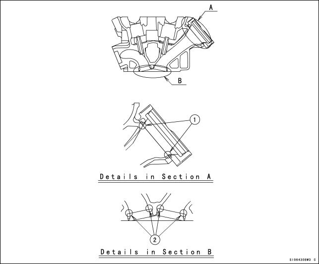
Cylinder Head
Grind off the stepped portions of the ports and smooth the inside of ports to make intake/exhaust gas flow more smooth.
Grind off the stepped portion only at the mating surface between the carburetor holder and the intake port. Do not port it. To extend the intake port, air flow speed will be reduced and the engine performance at the high speed range may be down.
Mark the carburetor holders so that they can be installed in their original positions. Grind off and smooth the stepped portions at the mating surface between valve seat and
the port.
Smooth the inside of the intake port and exhaust port. Use the hand grinder.
Use #200 oil stone for eliminating any stepped portions.
Use #200 oil stone for smoothing and #300 oil stone for finishing.
NOTE
These procedures make air resistance less and intake/exhaust gas flow more smooth. However, much more effect can not be expected by excessive grinding and smoothing. It may be done to the extent of getting rid of uneven surfaces.
1.Stepped Portions of carburetor holder and cylinder head.
2.Stepped Portions of valve seat and cylinder head.
11

The combustion chambers are modified by cutting work but the edges shown must be hand finished for smooth corners (Round them to about R1).
Chamfer the machining edge of the cylinder head where the valve seat is installed, also smooth the dome of the combustion chamber with the valves installed. Excessive smoothing may reduce the cylinder compression.
XXX. Edges
NOTE
When grinding the cylinder head bottom surface or using thinner gaskets, adjust the valve timing to keep that the valve to piston clearance is not less than the minimum value (IN: 0.8 mm, EX: 1.4 mm).
Camshaft Chain Tensioner
Replace the cam chain tensioner with the kit to gain the durability.
Apply the engine oil to the tensioner rod, O-ring and tensioner body, insert them into the tensioner body.
Check to see that the tensioner rod turns freely in the body, if not, polish the tensioner rod or fine the female threads in the body with a tap (Diameter × Pitch = 6 mm × 1.0 mm).
Install the tensioner on the cylinder block with the tensioner rod is fully pushed back. Turn the tensioner rod in with a screwdriver until it becomes hard to turn.
Turn the crankshaft clockwise forcing lightly to the tensioner rod with twisting force to take up any gap and tighten the locknut.
Tighten the rock nut after adjustment.
NOTE
Never forward the tensioner rod forcibly, this will increase mechanical loss of the tensioner and may damage to the chain guide.
The cam chain tensioner must be adjusted at every race.
12
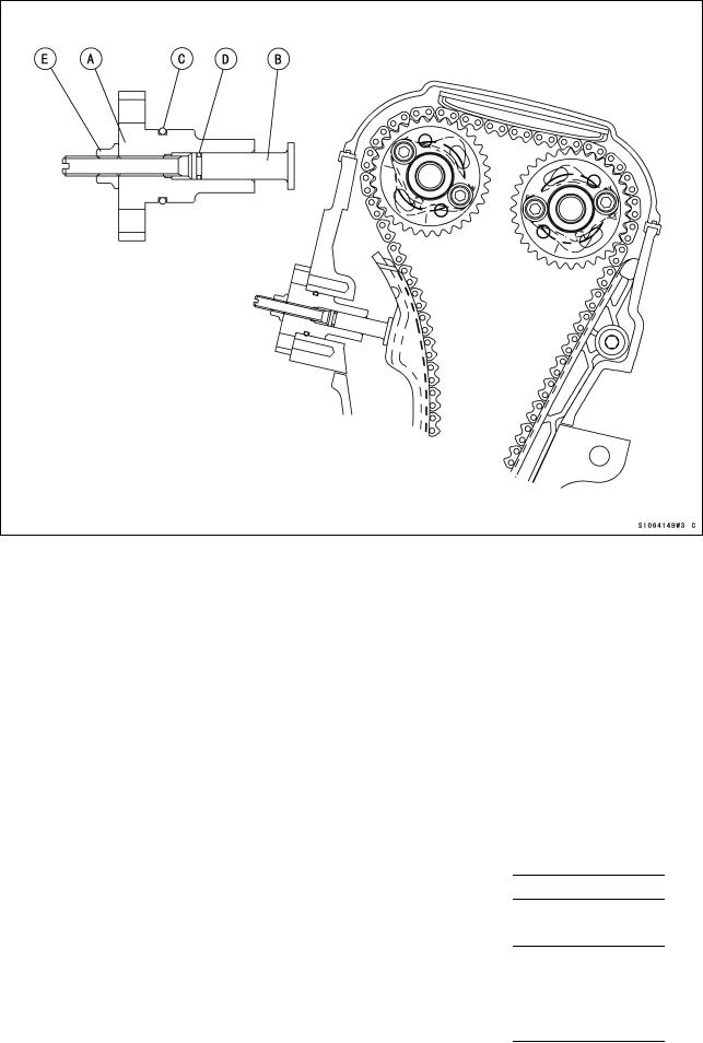
A.Tensioner
B.Tensioner Rod
C.O-ring
D.O-ring
E.Lock nut
Camshafts, Sprockets
Camshafts, Sprockets:
Adjust the valve clearance within the specified value, but more performance is expected when adjusted from middle value to upper limit between adjustable range.
|
Original |
Timing |
Cam Lift |
Valve Clearance |
|||||
|
Intake |
288° |
8.30 mm |
0.13 0.19 mm |
|||||
|
Exhaust |
266° |
7.50 mm |
0.24 0.31 mm |
|||||
|
Kit |
Timing |
Cam Lift |
Valve Clearance |
|||||
|
Intake |
308° |
8.30 mm |
0.13 0.19 mm |
|||||
|
49118-0110 |
(conformed to FIM regulation) |
|||||||
|
Exhaust |
274° |
7.30 mm |
0.24 0.31 mm |
|||||
|
49118-0111 |
(not conformed to FIM regulation) |
|||||||
|
Exhaust |
274° |
7.50 mm |
0.24 0.31 mm |
|||||
|
49118-0120 |
(conformed to FIM regulation) |
|||||||
|
13 |
If you don’t adjust the valve timing for racing, install the camshaft sprocket to the kit camshaft using the round bolt holes and adjust the cam chain timing according to the Ninja ZX-6R Service Manual. If you adjust the valve timing, install the sprocket to the camshaft between the adjustable range of the long bolt holes.
Tighten the camshaft sprocket bolts to 15 N·m (1.5 kgf·m, 11.0 ft·lb) of torque.
Valve Timing (when the round bolt holes are used)
|
Timing (cam lift center) |
Intake |
Exhaust |
|
Original |
105° |
110° |
|
Race use |
105° |
110° |
When grinding the cylinder head bottom surface, grinding the cylinder top surface or using thinner gaskets, be sure the valve to piston clearance especially.
When using the sprocket long bolt holes and adjusting the valve timing to be different from the standard timing, check the valve to piston clearance of all cylinders after adjusting the valve clearance correctly.
Valve to Piston Clearance (Min.)
|
Intake |
0.8 mm |
|
Exhaust |
1.4 mm |
If the valve to piston clearance is less than the minimum value, do not start the engine because the valves will touch the piston and the engine may be damaged.
Measure the valve to piston clearance at about 12° ATDC (Intake) and 11° BTDC (Exhaust) of crankshaft timing. At this point, the valve to piston clearance will be minimum.
Valve Springs
The original machine’s valve springs should be used
.
Cylinder Compression
To adjust the cylinder compression, adjust the thickness of the cylinder head gasket and the cylinder base gasket or smooth the cylinder top surface to make the piston squish 0.65 ~ 0.8 mm. Keep the piston squish more than 0.65 mm.
Position the piston at Top Dead Center, and put a small piece of modeling clay on the shoulder of the piston. Install the cylinder head gasket and cylinder head, and tighten the head bolts to the specified torque.
Remove the cylinder head and measure the thickness of the clay. The thickness of the collapsed clay is the size of the squish.
Squish Measurement
|
[1] |
Front and Rear |
0.65 ~ 0.80 mm |
|
[2] |
Left and Right |
0.67 ~ 0.85 mm |
The most preferable squish measurement is [1] 0.65 mm/[2] 0.67 mm. Select proper cylinder head gasket and cylinder base gasket.
Note that by grinding the cylinder head surface only left and right squishes become narrower, while by grinding the cylinder top surface or decreasing the gasket-thickness all the squishes become narrower.
14
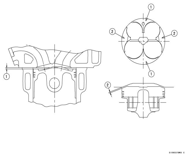
Cylinder Head Gasket
|
Part No. |
Thickness |
Note |
|
|
11004-0071 |
0.45 mm |
KIT |
|
|
11004-0070 |
0.50 mm |
KIT |
|
|
11004-0069 |
0.55 mm |
KIT |
|
|
11004-0068 |
0.60 mm |
KIT |
|
|
11004-0057 |
0.65 mm |
Original |
|
|
11004-0067 |
0.70 mm |
KIT |
|
1.Squish, Front/Rear
2.Squish, Left/Right
15
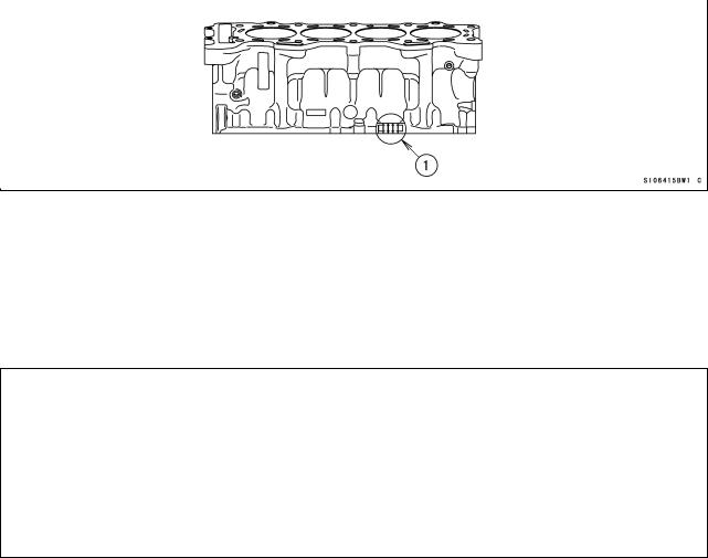
Crankshaft Main Journal and Connecting Rod Big End Bushings
To adjust clearance of crankshaft main journal you can select proper bush in accordance with the marks.
The kit bushings are improved in anti-seizuring characteristics as well as in wear-resistance as compared with the standard bushings.
1) Crankshaft Main Journal
Crankshaft Main Journal Diameter
1. Crankshaft Main Journal Diameter Marks
|
SIZE |
||
|
“1” mark |
: over 30.992 mm |
within 31.000 mm |
|
None |
: over 30.984 mm |
within 30.992 mm |
Crankcase Main Journal inside Diameter
1. Main Journal Diameter Marks
|
SIZE |
||
|
“{” mark |
: over 34.000 mm |
within 34.008 mm |
|
None |
: 34.008 mm and over |
within 34.016 mm |
16

Main Journal Bush
A. Size Color
|
Size Color |
Thickness mm |
Journal Number |
Part Number |
Part Number |
|||||||||||
|
(STD) |
(KIT) |
||||||||||||||
|
blue |
1.499-1.503 |
1-4 |
92139-0189 |
92139-0200 |
|||||||||||
|
5 |
92139-0171 |
92139-0197 |
|||||||||||||
|
black |
1.495-1.499 |
1-4 |
92139-0190 |
92139-0201 |
|||||||||||
|
5 |
92139-0172 |
92139-0198 |
|||||||||||||
|
brown |
1.491-1.495 |
1-4 |
92139-0191 |
92139-0202 |
|||||||||||
|
5 |
92139-0173 |
92139-0199 |
|||||||||||||
|
Selection Table |
|||||||||||||||
|
Size |
Journal |
Part |
Part |
||||||||||||
|
Crankcase inner Diameter |
Crankshaft Diameter |
Number |
Number |
||||||||||||
|
Color |
Number |
||||||||||||||
|
(STD) |
(KIT) |
||||||||||||||
|
○ |
1 |
brown |
1-4 |
92139-0191 |
92139-0202 |
||||||||||
|
(34.000 mm ~ 34.008 mm) |
(30.992 mm ~ 31.000 mm) |
5 |
92139-0173 |
92139-0199 |
|||||||||||
|
○ |
NONE |
black |
1-4 |
92139-0190 |
92139-0201 |
||||||||||
|
(34.000 mm ~ 34.008 mm) |
(30.984 mm ~ 30.992 mm) |
5 |
92139-0172 |
92139-0198 |
|||||||||||
|
NONE |
1 |
black |
1-4 |
92139-0190 |
92139-0201 |
||||||||||
|
(34.008 mm ~ 34.016 mm) |
(30.992 mm ~ 31.000 mm) |
5 |
92139-0172 |
92139-0198 |
|||||||||||
|
NONE |
NONE |
blue |
1-4 |
92139-0189 |
92139-0200 |
||||||||||
|
(34.008 mm ~ 34.016 mm) |
(30.984 mm ~ 30.992 mm) |
5 |
92139-0171 |
92139-0197 |
|||||||||||
17
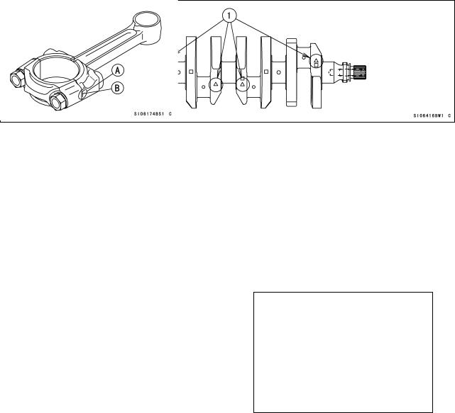
2) Crankpin
Crankpin Diameter
1. Crankpin Diameter Marks
|
“{” mark |
: |
over 29.992 mm |
within 30.000 mm |
|
None |
: |
29.984 mm and over |
within 29.992 mm |
Connecting Rod Big End Inside Diameter
Connecting Rod Big End Inside Diameter Marks
|
“{” mark |
: |
over 33.008 mm |
within 33.016 mm |
|
None |
: |
33.000 mm and over |
within 33.008 mm |
A.Inside Diameter Mark ({ or None)
B.Weight Mark, Alphabet (G.H etc)
Connecting Rod Big End Bushings
|
Size Color |
Thickness mm |
Part Number |
Part Number |
|
|
(STD) |
(KIT) |
|||
|
blue |
1.485-1.490 |
92139-0165 |
92139-0194 |
|
|
black |
1.480-1.485 |
92139-0166 |
92139-0195 |
|
|
brown |
1.475-1.480 |
92139-0167 |
92139-0196 |
18
![]()
Selection Table
|
Connecting Rod Big End |
Crankpin Diameter Mark |
Size |
Part Number |
Part Number |
|
|
Inside Diameter |
Color |
(STD) |
(KIT) |
||
|
None |
○ |
brown |
92139-0167 |
92139-0196 |
|
|
(33.000 mm ~ 33.008 mm) |
(29.992 mm ~ 30.000 mm) |
||||
|
None |
None |
black |
92139-0166 |
92139-0195 |
|
|
(33.000 mm ~ 33.008 mm) |
(29.984 mm ~ 29.992 mm) |
||||
|
○ |
○ |
black |
92139-0166 |
92139-0195 |
|
|
(33.008 mm ~ 33.016 mm) |
(29.992 mm ~ 30.000 mm) |
||||
|
○ |
None |
blue |
92139-0165 |
92139-0194 |
|
|
(33.008 mm ~ 33.016 mm) |
(29.984 mm ~ 29.992 mm) |
||||
Connecting Rod Bolts
Use the original connecting bolts and nuts.
The original connecting rod bolt has recesses at both ends to measure its length and determine the bolt stretch.
Install the original bolts into the connecting rod.
Before every tightening, use a point micrometer to measure the length of the bolts and record the values to find the bolt stretch.
Apply a small amount of molybdenum disulfide grease to the threads of bolts. Tighten the big end nuts at the torque of 11.8 ±2 N·m (1.2 ±0.2 kgf·m): reference Check the length of the bolts and find the bolt stretch.
Bolt Length after tightening – Bolt Length before tightening = Stretch
Bolt Stretch
Usable Range: 0.33 ~ 0.38 mm (0.013 ~ 0.015 in.)
Turn the big end nuts more until the bolt stretch reaches the usable range.
NOTE
Replace the original bolts with new ones if they have already been tightened up to usable range 2 times.
19
 Loading…
You can only view or download manuals with
Sign Up and get 5 for free
Upload your files to the site. You get 1 for each file you add
Get 1 for every time someone downloads your manual
Buy as many as you need