Материал из BikesWiki — энциклопедия японских мотоциклов
Перейти к: навигация, поиск

Kawasaki Z750
Ниже представлены прямые ссылки на скачку сервисной документации.
Для Kawasaki Z750
- Руководство пользователя (Owners Manual) на Kawasaki Z750R (на русском)
- Сервисный мануал (Service Manual) на Kawasaki Z750 (2003-2006)
- Сервисный мануал (Service Manual) на Kawasaki Z750 (2007-2010)
- Сервисный мануал (Service Manual) на Kawasaki Z750S (2005)
- Мануал по обслуживанию Kawasaki Z750R
Обзор модели
- Kawasaki Z750
Источник — «https://bikeswiki.ru/index.php?title=Kawasaki_Z750:_мануалы&oldid=9719»
Категория:
- Сервисная документация
#1
![]()
motogad
- Пол:Мужчина
- Город:Москва ВАО
- Мото:Kawasaki Ninja ZX6R
Отправлено 18 Август 2008 — 18:34
Все мануалы которые у нас есть ниже по теме
Сообщение отредактировал max232: 31 Январь 2014 — 13:53
- bktspro, Michaelgrorm, SCpraics и 2 другим это нравится
- Наверх
#2
![]()
max232
max232
- Пол:Мужчина
- Страна:Россия
- Город:Елец, Липецкая область
- Мото:zx-10r `08
Отправлено 09 Январь 2014 — 21:19
Просьба к обладателям мануалов которых нет в списке,
мы будем признательны если вы с нами поделитесь.
Руководство по ремонту демпфера Ohlins
Каталог з/ч Kawasaki
Руководство по эксплуатации Kawasaki Ninja H2 (ZX1000NF) 2014-
Руководство по эксплуатации Kawasaki Ninja H2 SX (ZX1000NF) 2017- (РУС) НОВОЕ! Спасибо Mikhail72
Руководство по ремонту KNinja H2 SX 2018- НОВОЕ! Спасибо belenkiy
Руководство по ремонту Kawasaki ZZR1400, ZZR1400 ABS, Ninja ZX-14 2012-2013 (РУС) НОВОЕ! Спасибо Назарий
Руководство пользователя Kawasaki ZZR1400, ZZR1400 ABS, Ninja ZX-14 2012- (РУС) НОВОЕ! Спасибо Ewil Dwarf
Руководство по ремонту Kawasaki ZZR1400, ZZR1400 ABS, Ninja ZX-14 2010-2011
Руководство по ремонту Kawasaki ZZR1400, ZZR1400 ABS, Ninja ZX-14 2008-2009
Руководство по ремонту Kawasaki ZZR1400, ZZR1400 ABS, Ninja ZX-14 2006-2007
Руководство по ремонту Ninja ZX-12R 2002-2005
Руководство по ремонту Ninja ZX-12R 2000-2001
Руководство по ремонту Kawasaki Ninja ZX-10R, Ninja ZX-10R ABS 2016-2017 НОВОЕ!
Руководство по ремонту Kawasaki Ninja ZX-10R, Ninja ZX-10R ABS 2013-2015
Руководство по ремонту Kawasaki Ninja ZX-10R, Ninja ZX-10R ABS 2011-2012
Руководство по эксплуатации (РУС) Kawasaki Ninja ZX-10R 2011-2012
Руководство по эксплуатации (EN) Kawasaki Ninja ZX-10R 2008-2010
Руководство по ремонту Kawasaki Ninja ZX-10R 2008-2010
Руководство по ремонту Kawasaki Ninja ZX-10R 2006-2007
Руководство по ремонту Kawasaki Ninja ZX-10R 2004-2005
Руководство по ремонту Kawasaki Ninja ZX-10 1988-1990
Руководство по ремонту Kawasaki ZX-9R 1998 — 1999
Руководство по ремонту Kawasaki ZX-9R 1998 — 1999 RUS
Руководство по ремонту Kawasaki ZX-9R 1994-1997
Руководство по ремонту Kawasaki ZX-9R (Ger) 2002-2003
Руководство по ремонту Kawasaki ZX750 (ZXR-750) 1989-1996, ZX750 (Ninja ZX-7)1989-1995
Руководство по ремонту Kawasaki Ninja ZX-7R, ZX-7RR 1996-2003
Руководство по ремонту Kawasaki Ninja ZX-6R, Ninja ZX-6R ABS 2013
Руководство по ремонту (РУС пер.Viktor72) Kawasaki Ninja ZX-6R, Ninja ZX-6R ABS 2013
Руководство по ремонту Kawasaki Ninja ZX-6R 2009-2011
Руководство по ремонту Kawasaki ZX-6R 2007-2008
Руководство по ремонту Kawasaki Ninja ZX-6R 2005-2006
Руководство по ремонту Kawasaki Ninja ZX–6R, ZX-6RR 2003-2004
Руководство по ремонту Kawasaki Ninja ZX-6R 2001-2002
Руководство по ремонту Kawasaki Ninja ZX-6R 2001-2002 (РУС) НОВОЕ! Спасибо Vjaceslav
Руководство по ремонту Kawasaki Ninja ZX–6R, 98-99
Руководство по ремонту Kawasaki Ninja ZX-6R 95-97
Руководство по ремонту Kawasaki ZXR400 (zx-4), ZX400-H2 1989-1990
Руководство по ремонту Kawasaki ZXR400 (zx-4), ZX400 L1-L8 1991-1998
Руководство по ремонту Kawasaki ZXR400(zx-4), ZX400 G1,G1A,G1B 1988
Руководство по ремонту Kawasaki Ninja 250 2008-2012
Руководство пользователя Kawasaki Ninja 250 (РУС) 2008-2012
Руководство по ремонту Kawasaki Ninja 300, Ninja 300 ABS 2013-
Руководство по эксплуатации (РУС) Kawasaki Ninja 300, Ninja 300 ABS 2013-
Дорожные мотоциклы Kawasaki. Общее руководство по эксплуатации (РУС) 2012-
Руководство по ремонту Kawasaki ER-6n, ER-6n ABS 2012-
Руководство по эксплуатации (РУС) Kawasaki ER-6n, ER-6n ABS 2012-
Руководство по ремонту Kawasaki ER-6n, ER-6n ABS 2009-2011
Руководство по ремонту Kawasaki ER-6n, ER-6n ABS 2006-2008
Руководство по ремонту Kawasaki Ninja 650, Ninja 650 ABS, ER-6f, ER-6f ABS 2012-
Руководство по эксплуатации (РУС) Kawasaki Ninja 650, Ninja 650 ABS, ER-6f, ER-6f ABS 2012-
Руководство по ремонту Kawasaki Ninja 650, Ninja 650 ABS, ER-6f, ER-6f ABS 2009-2011
Руководство по ремонту Kawasaki NINJA 650R, ER-6f, ER-6f ABS 2006-2008
Руководство по ремонту Kawasaki ER500 C1-C5
2001 ER500-C1 37Kw
2001 ER500-D1 25kw
2002 ER500-C2 37Kw
2003 ER500-C3 37Kw
2004 ER500-C4 катализатор -1Kw
2005 ER500-C5 модифицирован выхлоп, авто выключение/включение света
Руководство по ремонту Kawasaki Z1000, Z1000 ABS 2017- НОВОЕ! Спасибо Назарий
Руководство по ремонту Kawasaki Z1000SX Ninja 1000 2017- НОВОЕ! Спасибо Ghost1195
Руководство по ремонту Kawasaki Z1000SX, Z1000SX ABS, Ninja 1000, Ninja 1000 ABS 2014-2016 НОВОЕ! Спасибо alexus1313
Руководство по ремонту Kawasaki Z1000SX, Z1000SX ABS, Ninja 1000, Ninja 1000 ABS 2011-2013 НОВОЕ! Спасибо Glareone
Руководство по ремонту Kawasaki Z1000, Z1000 ABS 2014-2016
Руководство по ремонту Kawasaki Z1000, Z1000 ABS 2010-2013
Руководство по эксплуатации (РУС) Kawasaki Z1000SX, Z1000SX ABS 2010-2013
Руководство по ремонту Kawasaki Z1000, Z1000 ABS 2007-2009
Руководство по ремонту Kawasaki Z1000 2003-2006
Руководство по ремонту Kawasaki Z900, Z900 ABS, ZR900 2017- НОВОЕ! Спасибо ev6en!
Руководство по ремонту Kawasaki Z800 2013-
Инструкция по эксплуатации Kawasaki Z800 (РУС) 2013-
Инструкция по эксплуатации Kawasaki Z750R (РУС) 2011
Руководство по ремонту Kawasaki Z750S 2005-2006
Руководство по ремонту Kawasaki Z750 2003-2006
Руководство по ремонту Kawasaki Z750, Z750 ABS 2007-2010
Руководство по ремонту Kawasaki Z750R, Z750R ABS 2011- 2012 РОЗЫСК!
Инструкция по эксплуатации Kawasaki Z400 ABS (РУС) 2019- НОВОЕ! Спасибо Бродячий Кот!
Kawasaki 1400GTR, CONCOURS 14 ABS, CONCOURS 14 2010-2014 РОЗЫСК
Kawasaki 1400GTR, CONCOURS 14 ABS, CONCOURS 14 2008-2009
Руководство по эксплуатации (РУС) Kawasaki 1400GTR 2010
Руководство по ремонту Kawasaki VERSYS 650 VERSYS 650 ABS 2015-2016
Руководство по ремонту Kawasaki VERSYS 650 VERSYS 650 ABS 2010-2014
Руководство по ремонту Kawasaki VERSYS 650 2007-2009
Руководство по ремонту Kawasaki VERSYS 1000 2012-2014
Руководство по эксплуатации (РУС) Kawasaki VERSYS 1000 2012-2014
Руководство по эксплуатации (РУС) Kawasaki VERSYS 1000 SE 2019 — НОВОЕ!
Руководство по эксплуатации (РУС) Kawasaki VULCAN S VULCAN S ABS 2015- НОВОЕ! Спасибо offlineb!
Руководство по эксплуатации (РУС) Kawasaki W800 2012-
Руководство по эксплуатации (РУС) Kawasaki KLX250
Руководство по эксплуатации (ENG) Kawasaki KLX150L 2014- НОВОЕ!Спасибо roy0864!
Руководство по эксплуатации (РУС) Kawasaki 1000GTR ZG1000-A1 1986
Все что у нас есть выложено здесь, и мы больше ничего от Вас не прячем. Затрудните себя хотя бы поиском в списке мануала для своей модели мотоцикла.
По этим ссылкам расположены 2 архива по гигабайту с мануалами которых нет в вышеуказанном списке.
http://yadi.sk/d/yrnnmcxJJ9wxG
http://yadi.sk/d/nxb6nuh_J9x52
Эта ссылка на теже мануалы с возможностью не скачивать архивы целиком https://yadi.sk/d/OzesQZ8RUrXPE
- mrkvch, EnergyControl, Walazar и еще 1 это нравится
- Наверх
#3
![]()
Smart
Smart
- Пол:Мужчина
- Страна:Россия
- Город:Митино
- Мото:9-ka 1999г—>9-ka 2001г
Отправлено 17 Январь 2014 — 11:26
По ссылке https://yadi.sk/d/I61_p9A6mdk6m находятся мануалы на следующие модели которые не вошли в список выложенный выше.
Kawasaki ZZR1100 & ZX11 1993-2001
Kawasaki NINJA 250 86-07
Kawasaki GPZ400-550 & Z400F-FII & Z500F-550F 83-85 Service Manual
Kawasaki GPZ-500,600,ZX-500-A1,ZX-600-A1 Service Manual
Kawasaki GPZ-500S 86-94 Service Manual
Kawasaki GPZ-600R/GPX-600R/Ninja 600R/RX/GPX-750R/Ninja 750R
Kawasaki GPZ-750 Turbo 1984 Service Manual
Kawasaki GPZ900R 1984-1990 Workshop Manual
Kawasaki GPZ-1000RX,GPZ-900R Service Manual
Kawasaki GPZ-1100E Service Manual
Kawasaki GTR-1400 2014 Service Manual
Kawasaki KDX200 89-94 Service Manual
Kawasaki KH250-400 72-76
Kawasaki KLV1000-A1 2004 Service Manual
Kawasaki KLX650
Kawasaki KR250
Kawasaki KX250F 2004 Service Manual
Kawasaki KX450F 2006 Service Manual
Kawasaki KZ400 1974 Service Manual
Kawasaki KZ440 Service Manual
Kawasaki VN1500 87-99 Service Manual
Kawasaki VN1600-A1&A2 2003 Service Manual
Kawasaki VN2000-A1 2003 Service Manual
Kawasaki VN750 Manual and Parts
Kawasaki ZZR250 90-96 Service Manual
Kawasaki A Series Rotary Valve Twins 250,350,500 69-71 Workshop Manual
Kawasaki EN450,EN500,EN454,LTD500 Vulcan 85-04 Service Manual
Kawasaki ER-5 2004 Service Manual
Kawasaki ER-5 1997 Service Manual(DE)
Kawasaki VN800 Vulcan 96-04 Service Manual
Kawasaki VN900 Vulcan Classic 2006 Service Manual
Kawasaki W650 ’99 Service Manual (German)
Kawasaki ZR1100A,Zephir-1100 Service Manual
Kawasaki ZRX1200R,ZRX1200S 2001-2007 Service Manual
Kawasaki ZR550,ZR750 Zephyr 1990 Service Manual
Kawasaki ZR-7S,ZR-750H1 Service Manual
Kawasaki ZXR400R Kit 1989 Service Manual
Kawasaki ZXR400L Service Manual
Kawasaki ZXR750R,ZXR750J,ZXR750K Service Manual
Kawasaki ZXR750 Racing Kit 1992 Service Manual
Kawasaki ZX-10 Ninja 1988-1990 Service Manual
Kawasaki ZZR1200 ’03 Service Manual (German)
Kawasaki Z1 1972 Service Manual
Kawasaki KLE500 Service Manual
Kawasaki ZRX1200 Service Manual(German)
Kawasaki KLX110 Service Manual
Kawasaki ZXR 250 Service Manual 1997
- sem01 и Walazar это нравится
- Наверх
#4
![]()
albert8121984
albert8121984
-

- Members
-
- 35 сообщений
Прохожий


- Пол:Мужчина
- Страна:Россия
- Город:Москва СВАО(Алтуфьево), (КБР г.Прохладный)
- Мото:Kawasaki Z1000SX, (Versys 650B-08г), (ZX-6R 636 05г.) (ZZR 400 — 2)
Отправлено 16 Октябрь 2015 — 14:29
Пользуюсь сайтом ManualsLib – Search For Manuals Online.
Если что-то не понятно с помощью googla можно перевести страничку.
- Cher Tannov это нравится
- Наверх
#5
![]()
Cher Tannov
Cher Tannov
-
Вконтакте:
- Пол:Мужчина
- Страна:Россия
- Город:Москва, Чер Танново
- Мото:ER-6F ’12
Отправлено 06 Апрель 2016 — 10:32
Каталог Hiflo по масляным и воздушным фильтрам: https://yadi.sk/i/8FAFZ19PqmkhH
Немало каталогов и мануалов на тайском сайте Кавасаки.
http://www.kawasaki….c&page=download
ONLINE КАТАЛОГИ
Каталоги производителей, представленных в наших магазинах. Ссылки открываются в новом окне.
HIFLOFILTRO — Воздушные и маслянные фильтры
MOTUL — Моторные масла и мотохимия
JTSPROKETS — Звёзды и цепи привода
LUCAS TRW — Тормозные колодки
FERODO — Тормозные колодки
NGK — Свечи зажигания
ARIETE — Сальники и пыльники вилки
ALL BALLS RACING — Подшипники рулевой колонки
Сообщение отредактировал Cher Tannov: 06 Май 2016 — 11:35
- Coreydus и gtaemblem.club это нравится
- Наверх
#6
![]()
max232
max232
- Пол:Мужчина
- Страна:Россия
- Город:Елец, Липецкая область
- Мото:zx-10r `08
Отправлено 19 Сентябрь 2019 — 15:43
Ребята, думаю навести в этом разделе порядок.
Если просто так скидывать ссылки, без указания точной модели для разных рынков,от какого года до какого года, сервисный мануал/руководство по эксплуатации, на каком языке.
Этот раздел очень быстро превратиться в помойку в котором невозможно ничего найти.
Зачастую люди кидают ссылки на то что у нас уже есть.
Очень много мото для разных рынков называются по разному.
Я вроде недалекий человек от мото, но и мне не просто разобраться какие модели одинаковые а какие нет.
Пожалуйста, если у вас есть чем поделиться указывайте как минимум следующую информацию:
1. точная модель мотоцикла
2. модельный год. (от какого года и ДО какого года)
3. Сервисный мануал или руководство по эксплуатации
4. На каком языке издание
5. Ссылка
БЕЗ УКАЗАНИЯ ЭТОЙ ИНФОРМАЦИИ Я БУДУ УДАЛЯТЬ ПОСТЫ
- Наверх
#7
![]()
ведьмак 24
ведьмак 24
-
- Читатели
- 1 сообщений

- Пол:Мужчина
- Страна:россия
- Город:иркутск
- Мото:кавасаки илиминатор VN250
Отправлено 22 Октябрь 2020 — 09:40
а не подскажеш где найти мануал на кавасаки илименатор вн 250,нигде найти не могу
- Наверх
#8
![]()
max232
max232
- Пол:Мужчина
- Страна:Россия
- Город:Елец, Липецкая область
- Мото:zx-10r `08
Отправлено 13 Апрель 2021 — 12:14
а не подскажеш где найти мануал на кавасаки илименатор вн 250,нигде найти не могу
https://www.ebay.com.au/p/2185422503
- Наверх
#9
![]()
Назарий
Назарий
-
- Читатели
- 6 сообщений

- Пол:Мужчина
- Страна:Россия
- Город:Москва
- Мото:Z1000
Отправлено 18 Август 2021 — 16:39
- Наверх
#10
![]()
max232
max232
- Пол:Мужчина
- Страна:Россия
- Город:Елец, Липецкая область
- Мото:zx-10r `08
Отправлено 19 Август 2021 — 00:27
- Наверх
#11
![]()
Lavarock
Lavarock
-
- Читатели
- 1 сообщений

- Пол:Мужчина
- Страна:Россия
- Город:Сочи
- Мото:z650
Отправлено 14 Декабрь 2021 — 21:53
Помогите найти мануал на Z650 2017 год
- Наверх
#12
![]()
advokat56
advokat56
-
- Читатели
- 1 сообщений

- Пол:Мужчина
- Страна:РФ
- Город:Оренбург
- Мото:Ninja 1000SX
Отправлено 25 Январь 2022 — 18:44
Доброе время суток! Поменял свой мот на Ninja 1000SX 2020 г. долго искал мануал на русском. Нашел делюсь. https://e-kawasaki.r…ba66894759a.pdf
- Наверх
#13
![]()
belenkiy
belenkiy
-
- Читатели
- 3 сообщений

- Пол:Мужчина
- Страна:Россия
- Город:Москва
- Мото:fz6r
Отправлено 15 Май 2022 — 18:50
Руководство по ремонту — Kawasaki h2 2018
https://1drv.ms/b/s!…-l2jLg?e=kLBago
К сожалени к SX не смог найти
- Наверх
#14
![]()
max232
max232
- Пол:Мужчина
- Страна:Россия
- Город:Елец, Липецкая область
- Мото:zx-10r `08
Отправлено 15 Май 2022 — 22:10
По вашей ссылке именно SX
Я добавил к списку. спасибо!
- Наверх
#15
![]()
Denisik
Denisik
-
- Читатели
- 1 сообщений

- Пол:Мужчина
- Страна:Россия
- Город:Вологда
- Мото:Z250
Отправлено 16 Сентябрь 2022 — 10:20
Руководство по эксплуатации Kawasaki Z250
https://disk.yandex…./zXaOezF2k7TSSQ
- Наверх
#16
![]()
L0ckhead
L0ckhead
-
- Members
-
- 20 сообщений
Прохожий

- Пол:Мужчина
- Страна:Россия
- Город:Краснознаменск
- Мото:Kawasaki Ninja 1000 sx
Отправлено 26 Март 2023 — 20:52
Мб кому пригодится мануал на ninja 1000 sx 2020+ Файл можно получить по ссылке:
Ninja 1000 sx.pdf
https://disk.yandex…./ddmFwjH-2Lc4Yg
- Наверх
#17
![]()
L0ckhead
L0ckhead
-
- Members
-
- 20 сообщений
Прохожий
- Пол:Мужчина
- Страна:Россия
- Город:Краснознаменск
- Мото:Kawasaki Ninja 1000 sx
Отправлено 26 Март 2023 — 20:53
Дубль
- Наверх
#18
![]()
AnDrRew
AnDrRew
-
- Читатели
- 4 сообщений

- Пол:Мужчина
- Страна:Russia
- Город:Moscow
- Мото:Ninja 1000
Отправлено 08 Апрель 2023 — 14:39
На manualslib больше нет наших мануалов((
Пока искал сервис мануал для своего мотоцикла нашёл:
Руководство пользователя z1000sx ninja1000 2017-19 на русском языке
https://docviewer.ya…m89MCJ9&lang=ru
- Наверх
#19
![]()
AnDrRew
AnDrRew
-
- Читатели
- 4 сообщений
- Пол:Мужчина
- Страна:Russia
- Город:Moscow
- Мото:Ninja 1000
Отправлено 08 Апрель 2023 — 14:40
На manualslib больше нет наших мануалов((
Пока искал сервис мануал для своего мотоцикла нашёл:
Руководство пользователя z1000sx ninja1000 2017-19 на русском языке
https://mot63.ru/upl…6e444596981.pdf
- Наверх
![]()
Z750
Z750 ABS
Motorcycle
Service Manual


Quick Reference Guide
This quick reference guide will assist you in locating a desired topic or procedure.
•Bend the pages back to match the black tab of the desired chapter number with the black tab on the edge at each table of contents page.
•Refer to the sectional table of contents for the exact pages to locate the specific topic required.
|
General Information |
1 |
j |
|
Periodic Maintenance |
2 |
j |
|
Fuel System (DFI) |
3 |
j |
|
Cooling System |
4 |
j |
|
Engine Top End |
5 |
j |
|
Clutch |
6 |
j |
|
Engine Lubrication System |
7 |
j |
|
Engine Removal/Installation |
8 |
j |
|
Crankshaft/Transmission |
9 |
j |
|
Wheels/Tires |
10 |
j |
|
Final Drive |
11 |
j |
|
Brakes |
12 |
j |
|
Suspension |
13 |
j |
|
Steering |
14 |
j |
|
Frame |
15 |
j |
|
Electrical System |
16 |
j |
|
Appendix |
17 |
j |


Z750
Z750 ABS
Motorcycle
Service Manual
All rights reserved. No parts of this publication may be reproduced, stored in a retrieval system, or transmitted in any form or by any means, electronic mechanical photocopying, recording or otherwise, without the prior written permission of Quality Assurance Division/Consumer Products & Machinery Company/Kawasaki Heavy Industries, Ltd., Japan.
No liability can be accepted for any inaccuracies or omissions in this publication, although every possible care has been taken to make it as complete and accurate as possible.
The right is reserved to make changes at any time without prior notice and without incurring an obligation to make such changes to products manufactured previously. See your Motorcycle dealer for the latest information on product improvements incorporated after this publication.
All information contained in this publication is based on the latest product information available at the time of publication. Illustrations and photographs in this publication are intended for reference use only and may not depict actual model component parts.
|
© 2007 Kawasaki Heavy Industries, Ltd. |
First Edition (1) : Feb. 28, 2007 (K) |

LIST OF ABBREVIATIONS
|
A |
ampere(s) |
lb |
pound(s) |
|
ABDC |
after bottom dead center |
m |
meter(s) |
|
AC |
alternating current |
min |
minute(s) |
|
ATDC |
after top dead center |
N |
newton(s) |
|
BBDC |
before bottom dead center |
Pa |
pascal(s) |
|
BDC |
bottom dead center |
PS |
horsepower |
|
BTDC |
before top dead center |
psi |
pound(s) per square inch |
|
°C |
degree(s) Celsius |
r |
revolution |
|
DC |
direct current |
rpm |
revolution(s) per minute |
|
F |
farad(s) |
TDC |
top dead center |
|
°F |
degree(s) Fahrenheit |
TIR |
total indicator reading |
|
ft |
foot, feet |
V |
volt(s) |
|
g |
gram(s) |
W |
watt(s) |
|
h |
hour(s) |
Ω |
ohm(s) |
|
L |
liter(s) |
COUNTRY AND AREA CODES
|
AT |
Austria |
GB |
United Kingdom |
|
AU |
Australia |
MY |
Malaysia |
|
CH |
Switzerland |
WVTA |
Whole Vehicle Type Approval |
|
DE |
Germany |

Foreword
This manual is designed primarily for use by trained mechanics in a properly equipped shop. However, it contains enough detail and basic information to make it useful to the owner who desires to perform his own basic maintenance and repair work. A basic knowledge of mechanics, the proper use of tools, and workshop procedures must be understood in order to carry out maintenance and repair satisfactorily. Whenever the owner has insufficient experience or doubts his ability to do the work, all adjustments, maintenance, and repair should be carried out only by qualified mechanics.
In order to perform the work efficiently and to avoid costly mistakes, read the text, thoroughly familiarize yourself with the procedures before starting work, and then do the work carefully in a clean area. Whenever special tools or equipment are specified, do not use makeshift tools or equipment. Precision measurements can only be made if the proper instruments are used, and the use of substitute tools may adversely affect safe operation.
For the duration of the warranty period, we recommend that all repairs and scheduled maintenance be performed in accordance with this service manual. Any owner maintenance or repair procedure not performed in accordance with this manual may void the warranty.
To get the longest life out of your vehicle.
•Follow the Periodic Maintenance Chart in the Service Manual.
•Be alert for problems and non-scheduled maintenance.
•Use proper tools and genuine Kawasaki Motorcycle parts. Special tools, gauges, and testers that are necessary when servicing Kawasaki motorcycles are introduced by the Service Manual. Genuine parts provided as spare parts are listed in the Parts Catalog.
•Follow the procedures in this manual carefully. Don’t take shortcuts.
•Remember to keep complete records of maintenance and repair with dates and any new parts installed.
How to Use This Manual
In this manual, the product is divided into its major systems and these systems make up the manual’s chapters. The Quick Reference
Guide shows you all of the product’s system and assists in locating their chapters. Each chapter in turn has its own comprehensive Table of Contents.
For example, if you want ignition coil information, use the Quick Reference Guide to locate the Electrical System chapter. Then, use the Table of Contents on the first page of the chapter to find the Ignition Coil section.
Whenever you see these WARNING and CAUTION symbols, heed their instructions! Always follow safe operating and maintenance practices.

 WARNING
This warning symbol identifies special instructions or procedures which, if not correctly followed, could result in personal injury, or loss of life.
CAUTION
This caution symbol identifies special instructions or procedures which, if not strictly observed, could result in damage to or destruction of equipment.
This manual contains four more symbols (in addition to WARNING and CAUTION) which will help you distinguish different types of information.
NOTE
○This note symbol indicates points of particular interest for more efficient and convenient operation.
•Indicatesdone. a procedural step or work to be ○Indicates a procedural sub-step or how to do the work of the procedural step it follows. It
also precedes the text of a NOTE.
 Indicates a conditional step or what action to take based on the results of the test or inspection in the procedural step or sub-step it follows.
In most chapters an exploded view illustration of the system components follows the Table of Contents. In these illustrations you will find the instructions indicating which parts require specified tightening torque, oil, grease or a locking agent during assembly.

GENERAL INFORMATION 1-1
|
General Information |
|
|
Table of Contents |
|
|
1 |
|
|
Before Servicing ……………………………………………………………………………………………………… |
1-2 |
|
Model Identification………………………………………………………………………………………………….. |
1-7 |
|
General Specifications……………………………………………………………………………………………… |
1-9 |
|
Unit Conversion Table ……………………………………………………………………………………………… |
1-12 |
1-2 GENERAL INFORMATION
Before Servicing
Before starting to perform an inspection service or carry out a disassembly and reassembly operation on a motorcycle, read the precautions given below. To facilitate actual operations, notes, illustrations, photographs, cautions, and detailed descriptions have been included in each chapter wherever necessary. This section explains the items that require particular attention during the removal and reinstallation or disassembly and reassembly of general parts.
Especially note the following.
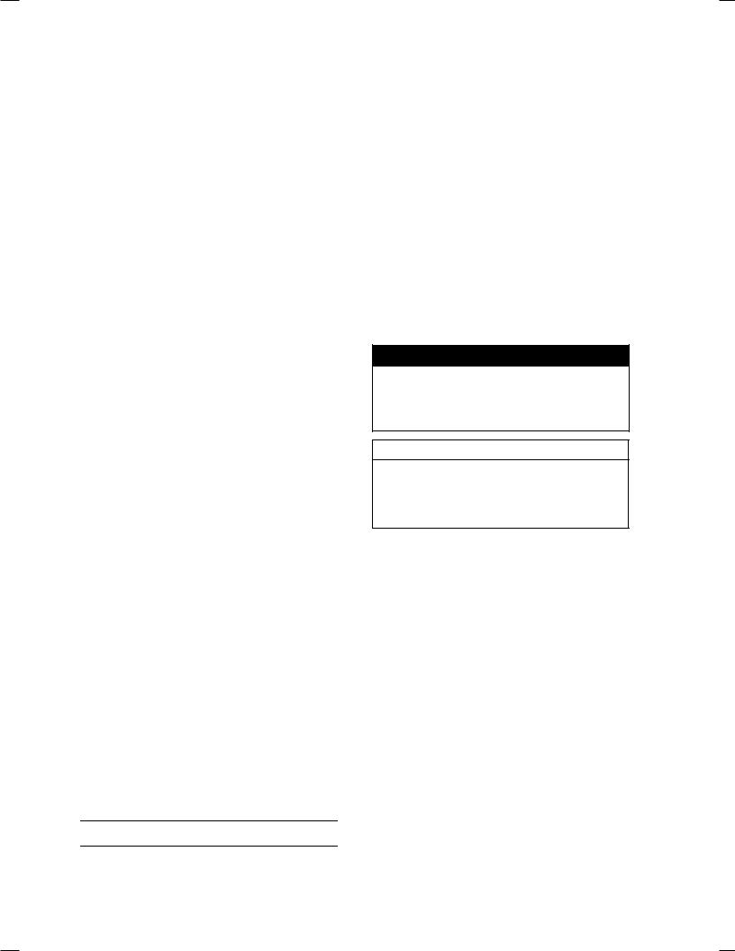
Battery Ground
Before completing any service on the motorcycle, disconnect the battery cables from the battery to prevent the engine from accidentally turning over. Disconnect the ground cable (–) first and then the positive (+). When completed with the service, first connect the positive (+) cable to the positive (+) terminal of the battery then the negative (–) cable to the negative terminal.
Edges of Parts
Lift large or heavy parts wearing gloves to prevent injury from possible sharp edges on the parts.
Solvent
Use a high-flush point solvent when cleaning parts. High -flush point solvent should be used according to directions of the solvent manufacturer.
Cleaning Vehicle before Disassembly
Clean the vehicle thoroughly before disassembly. Dirt or other foreign materials entering into sealed areas during vehicle disassembly can cause excessive wear and decrease performance of the vehicle.
![]()
GENERAL INFORMATION 1-3
Before Servicing
Arrangement and Cleaning of Removed Parts
Disassembled parts are easy to confuse. Arrange the parts according to the order the parts were disassembled and clean the parts in order prior to assembly.
Storage of Removed Parts
After all the parts including subassembly parts have been cleaned, store the parts in a clean area. Put a clean cloth or plastic sheet over the parts to protect from any foreign materials that may collect before re-assembly.
Inspection
Reuse of worn or damaged parts may lead to serious accident. Visually inspect removed parts for corrosion, discoloration, or other damage. Refer to the appropriate sections of this manual for service limits on individual parts. Replace the parts if any damage has been found or if the part is beyond its service limit.
Replacement Parts
Replacement parts must be KAWASAKI genuine or recommended by KAWASAKI. Gaskets, O-rings, oil seals, grease seals, circlips or cotter pins must be replaced with new ones whenever disassembled.
Assembly Order
In most cases assembly order is the reverse of disassembly, however, if assembly order is provided in this Service Manual, follow the procedures given.
1-4 GENERAL INFORMATION
Before Servicing
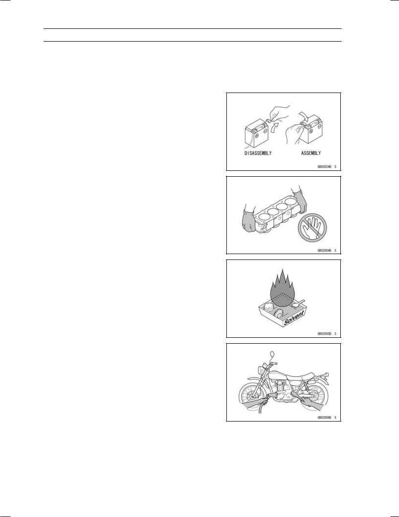
Tightening Sequence
Generally, when installing a part with several bolts, nuts, or screws, start them all in their holes and tighten them to a snug fit. Then tighten them according to the specified sequence to prevent case warpage or deformation which can lead to malfunction. Conversely when loosening the bolts, nuts, or screws, first loosen all of them by about a quarter turn and then remove them. If the specified tightening sequence is not indicated, tighten the fasteners alternating diagonally.
Tightening Torque
Incorrect torque applied to a bolt, nut, or screw may lead to serious damage. Tighten fasteners to the specified torque using a good quality torque wrench.
Force
Use common sense during disassembly and assembly, excessive force can cause expensive or hard to repair damage. When necessary, remove screws that have a non -permanent locking agent applied using an impact driver. Use a plastic-faced mallet whenever tapping is necessary.
Gasket, O-ring
Hardening, shrinkage, or damage of both gaskets and O-rings after disassembly can reduce sealing performance. Remove old gaskets and clean the sealing surfaces thoroughly so that no gasket material or other material remains. Install the new gaskets and replace the used O-rings when re-assembling.
Liquid Gasket, Non-permanent Locking Agent
For applications that require Liquid Gasket or a Non-permanent Locking Agent, clean the surfaces so that no oil residue remains before applying liquid gasket or non-permanent locking agent. Do not apply them excessively. Excessive application can clog oil passages and cause serious damage.
GENERAL INFORMATION 1-5
Before Servicing
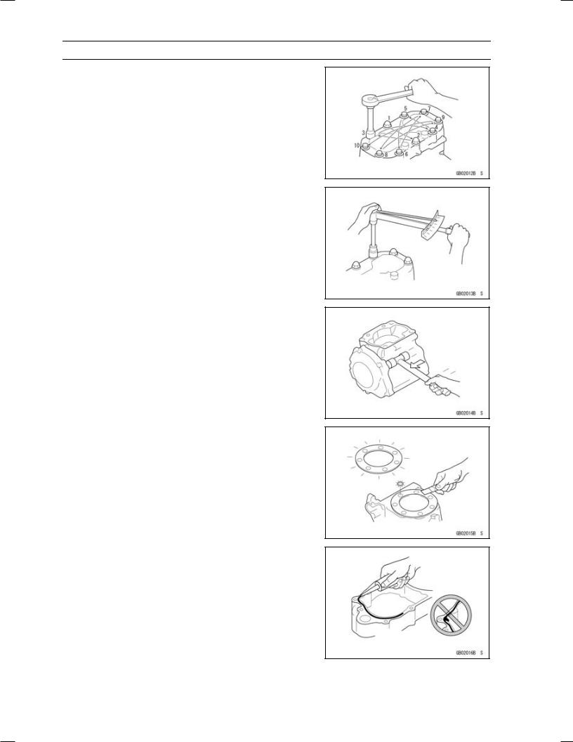
Press
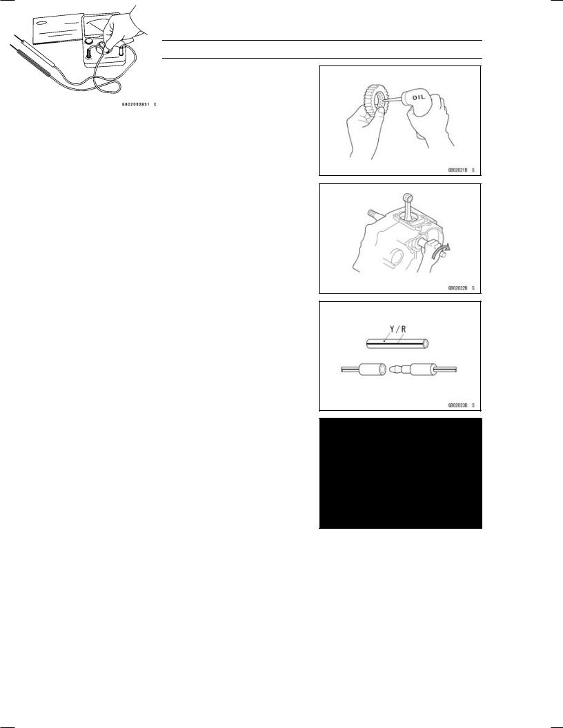
For items such as bearings or oil seals that must be pressed into place, apply small amount of oil to the contact area. Be sure to maintain proper alignment and use smooth movements when installing.
Ball Bearing and Needle Bearing
Do not remove pressed ball or needle unless removal is absolutely necessary. Replace with new ones whenever removed. Press bearings with the manufacturer and size marks facing out. Press the bearing into place by putting pressure on the correct bearing race as shown.
Pressing the incorrect race can cause pressure between the inner and outer race and result in bearing damage.
Oil Seal, Grease Seal
Do not remove pressed oil or grease seals unless removal is necessary. Replace with new ones whenever removed. Press new oil seals with manufacture and size marks facing out. Make sure the seal is aligned properly when installing.
Apply specified grease to the lip of seal before installing the seal.
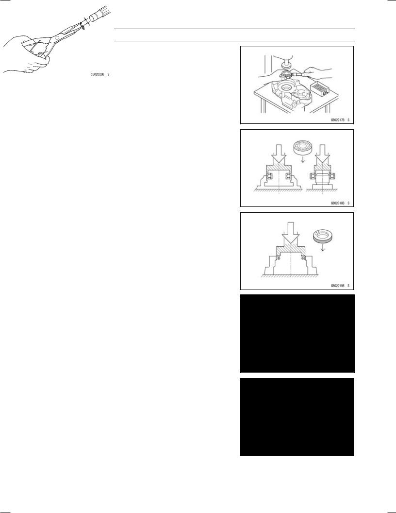
Circlips, Cotter Pins
Replace the circlips or cotter pins that were removed with new ones. Take care not to open the clip excessively when installing to prevent deformation.
1-6 GENERAL INFORMATION
Before Servicing
Lubrication
It is important to lubricate rotating or sliding parts during assembly to minimize wear during initial operation. Lubrication points are called out throughout this manual, apply the specific oil or grease as specified.
Direction of Engine Rotation
When rotating the crankshaft by hand, the free play amount of rotating direction will affect the adjustment. Rotate the crankshaft to positive direction (clockwise viewed from output side).
Electrical Wires
A two-color wire is identified first by the primary color and then the stripe color. Unless instructed otherwise, electrical wires must be connected to those of the same color.
Instrument
Use a meter that has enough accuracy for an accurate measurement. Read the manufacture’s instructions thoroughly before using the meter. Incorrect values may lead to improper adjustments.
GENERAL INFORMATION 1-7
Model Identification
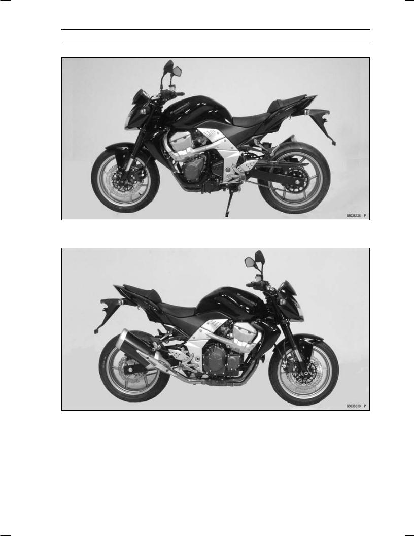
ZR750L7F (Europe) Left Side View
ZR750L7F (Europe) Right Side View
1-8 GENERAL INFORMATION
Model Identification
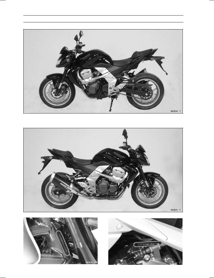
ZR750M7F Left Side View
ZR750M7F Right Side View
|
Frame Number |
Engine Number |
|

|
GENERAL INFORMATION 1-9 |
|
|
General Specifications |
|
|
Items |
ZR750L7F, ZR750M7F |
|
Dimensions |
|
|
Overall Length |
2 085 mm (82.09 in.) |
|
Overall Width |
805 mm (31.69 in.) |
|
Overall Height |
1 100 mm (43.31 in.) |
|
Wheelbase |
1 440 mm (56.69 in.) |
|
Road Clearance |
155 mm (6.10 in.) |
|
Seat Height |
815 mm (32.09 in.) |
|
Dry Mass: |
|
|
ZR750L7F |
203 kg (447.6 lb) |
|
ZR750M7F |
207 kg (456.4 lb) |
|
Curb Mass: |
|
|
Front: |
|
|
ZR750L7F |
113 kg (249.2 lb) |
|
ZR750M7F |
115 kg (253.6 lb) |
|
Rear: |
|
|
ZR750L7F |
113 kg (249.2 lb) |
|
ZR750M7F |
115 kg (253.6 lb) |
|
Fuel Tank Capacity |
18.5 L (4.9 US gal.) |
|
Performance |
|
|
Minimum Turning Radius |
3.0 m (9.8 ft) |
|
Engine |
|
|
Type |
4-stroke, DOHC, 4-cylinder |
|
Cooling System |
Liquid-cooled |
|
Bore and Stroke |
68.4 × 50.9 mm (2.69 × 2.00 in.) |
|
Displacement |
748 cm³ (45.64 cu in.) |
|
Compression Ratio |
11.3 : 1 |
|
Maximum Horsepower |
77.7 kW (106 PS) @10 500 r/min (rpm) |
|
(MY) 73.2 kW (100 PS) @9 000 r/min (rpm) |
|
|
Maximum Torque |
78.0 N·m (8.0 kgf·m, 57.5 ft·lb) @8 300 r/min (rpm) |
|
Carburetion System |
FI (Fuel Injection) KEIHIN TTK32 × 4 |
|
Starting System |
Electric starter |
|
Ignition System |
Battery and coil (transistorized) |
|
Timing Advance |
Electronically advanced (digital igniter) |
|
Ignition Timing |
From 10° BTDC @1 100 r/min (rpm) to 37.0° BTDC |
|
@5 000 r/min (rpm) |
|
|
Spark Plug |
NGK CR9EK |
|
Cylinder Numbering Method |
Left to right, 1-2-3-4 |
|
Firing Order |
1-2-4-3 |
|
Valve Timing: |
|
|
Inlet: |
|
|
Open |
38° BTDC |
|
Close |
66° ABDC |
|
Duration |
284° |

1-10 GENERAL INFORMATION
General Specifications
|
Items |
ZR750L7F, ZR750M7F |
|
|
Exhaust: |
||
|
Open |
51° BBDC |
|
|
Close |
25° ATDC |
|
|
Duration |
256° |
|
|
Lubrication System |
Forced lubrication (wet sump) |
|
|
Engine Oil: |
||
|
Type |
API SE, SF or SG |
|
|
API SH, SJ or SL with JASO MA |
||
|
Viscosity |
SAE 10W-40 |
|
|
Capacity |
3.8 L (4.0 US qt) |
|
|
Drive Train |
||
|
Primary Reduction System: |
||
|
Type |
Gear |
|
|
Reduction Ratio |
1.714 |
(84/49) |
|
Clutch Type |
Wet multi disc |
|
|
Transmission: |
||
|
Type |
6-speed, constant mesh, return shift |
|
|
Gear Ratios: |
||
|
1st |
2.571 |
(36/14) |
|
2nd |
1.941 |
(33/17) |
|
3rd |
1.556 |
(28/18) |
|
4th |
1.333 |
(28/21) |
|
5th |
1.200 |
(24/20) |
|
6th |
1.095 |
(23/21) |
|
Final Drive System: |
||
|
Type |
Chain drive |
|
|
Reduction Ratio |
2.867 |
(43/15) |
|
Overall Drive Ratio |
5.382 |
@Top gear |
|
Frame |
||
|
Type |
Tubular, diamond |
|
|
Caster (Rake Angle) |
24.5° |
|
|
Trail |
103 mm (4.06 in.) |
|
|
Front Tire: |
||
|
Type |
Tubeless |
|
|
Size |
120/70 ZR17 M/C (58W) |
|
|
Rim Size |
17 × 3.50 |
|
|
Rear Tire: |
||
|
Type |
Tubeless |
|
|
Size |
180/55 ZR17 M/C (73W) |
|
|
Rim Size |
17 × 5.50 |
|
|
Front Suspension: |
||
|
Type |
Telescopic fork |
|
|
Wheel Travel |
120 mm (4.72 in.) |
|

|
GENERAL INFORMATION 1-11 |
|
|
General Specifications |
|
|
Items |
ZR750L7F, ZR750M7F |
|
Rear Suspension: |
|
|
Type |
Swingarm (uni-trak) |
|
Wheel Travel |
125 mm (4.92 in.) |
|
Brake Type: |
|
|
Front |
Dual discs |
|
Rear |
Single disc |
|
Electrical Equipment |
|
|
Battery |
12 V 8 Ah |
|
Headlight: |
|
|
Type |
Semi-sealed beam |
|
Bulb |
12 V 55 W × 2/55 W (Hi/Lo) |
|
Tail/Brake Light |
12 V 0.5/4.1 W (LED) |
|
Alternator: |
|
|
Type |
Three-phase AC |
|
Rated Output |
24 A/14 V @5 000 r/min (rpm) |
Specifications are subject to change without notice, and may not apply to every country.

1-12 GENERAL INFORMATION
Unit Conversion Table
|
Prefixes for Units: |
Units of Length: |
|
Prefix |
Symbol |
Power |
||
|
mega |
M |
× 1 000 |
000 |
|
|
kilo |
k |
× |
1 000 |
|
|
centi |
c |
× |
0.01 |
|
|
milli |
m |
× |
0.001 |
|
|
micro |
µ |
× 0.000001 |
Units of Mass:
|
kg |
× |
2.205 |
= |
lb |
|
g |
× |
0.03527 |
= |
oz |
Units of Volume:
|
L |
× |
0.2642 |
= |
gal (US) |
|
L |
× |
0.2200 |
= |
gal (imp) |
|
L |
× |
1.057 |
= |
qt (US) |
|
L |
× |
0.8799 |
= |
qt (imp) |
|
L |
× |
2.113 |
= |
pint (US) |
|
L |
× |
1.816 |
= |
pint (imp) |
|
mL |
× |
0.03381 |
= |
oz (US) |
|
mL |
× |
0.02816 |
= |
oz (imp) |
|
mL |
× |
0.06102 |
= |
cu in |
Units of Force:
|
N |
× |
0.1020 |
= |
kg |
|
N |
× |
0.2248 |
= |
lb |
|
kg |
× |
9.807 |
= |
N |
|
kg |
× |
2.205 |
= |
lb |
|
km |
× |
0.6214 |
= |
mile |
|
m |
× |
3.281 |
= |
ft |
|
mm |
× |
0.03937 |
= |
in |
Units of Torque:
|
N·m |
× |
0.1020 |
= |
kgf·m |
|
N·m |
× |
0.7376 |
= |
ft·lb |
|
N·m |
× |
8.851 |
= |
in·lb |
|
kgf·m |
× |
9.807 |
= |
N·m |
|
kgf·m |
× |
7.233 |
= |
ft·lb |
|
kgf·m |
× |
86.80 |
= |
in·lb |
Units of Pressure:
|
kPa |
× |
0.01020 |
= |
kgf/cm² |
|
kPa |
× |
0.1450 |
= |
psi |
|
kPa |
× |
0.7501 |
= |
cmHg |
|
kgf/cm² |
× |
98.07 |
= |
kPa |
|
kgf/cm² |
× |
14.22 |
= |
psi |
|
cmHg |
× |
1.333 |
= |
kPa |
Units of Speed:
km/h × 0.6214 = mph
Units of Power:
|
kW |
× |
1.360 |
= |
PS |
|
kW |
× |
1.341 |
= |
HP |
|
PS |
× |
0.7355 |
= |
kW |
|
PS |
× |
0.9863 |
= |
HP |
Units of Temperature:
![]()
PERIODIC MAINTENANCE 2-1
Periodic Maintenance
Table of Contents
|
Periodic Maintenance Chart ……………………………………………………………………………………… |
2-3 |
||
|
Torque and Locking Agent………………………………………………………………………………………… |
2-6 |
2 |
|
|
Specifications |
2-12 |
||
|
Special Tools ………………………………………………………………………………………………………….. |
2-14 |
||
|
Periodic Maintenance Procedures……………………………………………………………………………… |
2-15 |
||
|
Fuel System (DFI)…………………………………………………………………………………………………. |
2-15 |
||
|
Air Cleaner Element Cleaning………………………………………………………………………………. |
2-15 |
||
|
Throttle Control System Inspection……………………………………………………………………….. |
2-15 |
||
|
Engine Vacuum Synchronization Inspection…………………………………………………………… |
2-16 |
||
|
Idle Speed Inspection …………………………………………………………………………………………. |
2-19 |
||
|
Idle Speed Adjustment………………………………………………………………………………………… |
2-20 |
||
|
Fuel Hose Inspection (fuel leak, damage, installation condition) ……………………………….. |
2-20 |
||
|
Cooling System…………………………………………………………………………………………………….. |
2-22 |
||
|
Coolant Level Inspection……………………………………………………………………………………… |
2-22 |
||
|
Radiator Hose and Pipe Inspection (coolant leak, damage, installation condition) ………. |
2-22 |
||
|
Engine Top End ……………………………………………………………………………………………………. |
2-23 |
||
|
Valve Clearance Inspection …………………………………………………………………………………. |
2-23 |
||
|
Valve Clearance Adjustment………………………………………………………………………………… |
2-24 |
||
|
Exhaust Butterfly Valve Cable Inspection ………………………………………………………………. |
2-27 |
||
|
Exhaust Butterfly Valve Cable Adjustment……………………………………………………………… |
2-28 |
||
|
Air Suction System ……………………………………………………………………………………………….. |
2-31 |
||
|
Air Suction System Damage Inspection…………………………………………………………………. |
2-31 |
||
|
Clutch………………………………………………………………………………………………………………….. |
2-31 |
||
|
Clutch Operation Inspection…………………………………………………………………………………. |
2-31 |
||
|
Wheels/Tires………………………………………………………………………………………………………… |
2-32 |
||
|
Air Pressure Inspection……………………………………………………………………………………….. |
2-32 |
||
|
Wheel/Tire Damage Inspection…………………………………………………………………………….. |
2-33 |
||
|
Tire Tread Wear Inspection………………………………………………………………………………….. |
2-33 |
||
|
Wheel Bearing Damage Inspection ………………………………………………………………………. |
2-34 |
||
|
Drive Train …………………………………………………………………………………………………………… |
2-34 |
||
|
Drive Chain Lubrication Condition Inspection …………………………………………………………. |
2-34 |
||
|
Drive Chain Slack Inspection ……………………………………………………………………………….. |
2-35 |
||
|
Drive Chain Slack Adjustment ……………………………………………………………………………… |
2-35 |
||
|
Wheel Alignment Inspection ………………………………………………………………………………… |
2-36 |
||
|
Drive Chain Wear Inspection ……………………………………………………………………………….. |
2-37 |
||
|
Chain Guide Wear Inspection ………………………………………………………………………………. |
2-37 |
||
|
Brake System ………………………………………………………………………………………………………. |
2-38 |
||
|
Brake Fluid Leak (Brake Hose and Pipe) Inspection ……………………………………………….. |
2-38 |
||
|
Brake Hose and Pipe Damage and Installation Condition Inspection…………………………. |
2-39 |
||
|
Brake Operation Inspection …………………………………………………………………………………. |
2-39 |
||
|
Brake Fluid Level Inspection………………………………………………………………………………… |
2-39 |
||
|
Brake Pad Wear Inspection …………………………………………………………………………………. |
2-40 |
||
|
Brake Light Switch Operation Inspection ……………………………………………………………….. |
2-41 |
||
|
Suspensions ………………………………………………………………………………………………………… |
2-41 |
||
|
Front Forks/Rear Shock Absorber Operation Inspection ………………………………………….. |
2-41 |
||
|
Front Fork Oil Leak Inspection……………………………………………………………………………… |
2-42 |
||
|
Rear Shock Absorber Oil Leak Inspection ……………………………………………………………… |
2-42 |
||
|
Rocker Arm Operation Inspection…………………………………………………………………………. |
2-42 |
||
|
Tie-Rod Operation Inspection ………………………………………………………………………………. |
2-42 |
||
|
Steering System …………………………………………………………………………………………………… |
2-43 |

2-2 PERIODIC MAINTENANCE
|
Steering Play Inspection ……………………………………………………………………………………… |
2-43 |
|
Steering Play Adjustment…………………………………………………………………………………….. |
2-43 |
|
Steering Stem Bearing Lubrication ……………………………………………………………………….. |
2-44 |
|
Electrical System ………………………………………………………………………………………………….. |
2-45 |
|
Spark Plug Condition Inspection…………………………………………………………………………… |
2-45 |
|
Lights and Switches Operation Inspection……………………………………………………………… |
2-46 |
|
Headlight Aiming Inspection ………………………………………………………………………………… |
2-48 |
|
Sidestand Switch Operation Inspection …………………………………………………………………. |
2-49 |
|
Engine Stop Switch Operation Inspection………………………………………………………………. |
2-50 |
|
Others…………………………………………………………………………………………………………………. |
2-50 |
|
Chassis Parts Lubrication ……………………………………………………………………………………. |
2-50 |
|
Bolts, Nuts and Fasteners Tightness Inspection……………………………………………………… |
2-52 |
|
Replacement Parts ……………………………………………………………………………………………….. |
2-53 |
|
Air Cleaner Element Replacement………………………………………………………………………… |
2-53 |
|
Fuel Hose Replacement ……………………………………………………………………………………… |
2-54 |
|
Coolant Change …………………………………………………………………………………………………. |
2-56 |
|
Radiator Hose and O-ring Replacement………………………………………………………………… |
2-58 |
|
Engine Oil Change……………………………………………………………………………………………… |
2-58 |
|
Oil Filter Replacement ………………………………………………………………………………………… |
2-59 |
|
Brake Hose and Pipe Replacement………………………………………………………………………. |
2-60 |
|
Brake Fluid Change ……………………………………………………………………………………………. |
2-62 |
|
Master Cylinder Rubber Parts Replacement ………………………………………………………….. |
2-63 |
|
Caliper Rubber Parts Replacement ………………………………………………………………………. |
2-64 |
|
Spark Plug Replacement …………………………………………………………………………………….. |
2-67 |

PERIODIC MAINTENANCE 2-3
Periodic Maintenance Chart
The scheduled maintenance must be done in accordance with this chart to keep the motorcycle in good running condition.The initial maintenance is vitally important and must not be neglected.
Periodic Inspection
|
FREQUENCY |
Whichever |
* ODOMETER READING |
|||||||||||||
|
comes |
× 1 000 km |
See |
|||||||||||||
|
first |
(× 1 000 mile) |
||||||||||||||
|
Page |
|||||||||||||||
|
1 |
6 |
12 |
18 |
24 |
30 |
36 |
|||||||||
|
INSPECTION |
Every |
(0.6) |
(4) |
(7.5) |
(12) |
(15) |
(20) |
(24) |
|||||||
|
Fuel System |
|||||||||||||||
|
Air cleaner element — clean |
• |
• |
2-15 |
||||||||||||
|
Throttle control system (play, smooth return, |
year |
• |
• |
• |
• |
2-15 |
|||||||||
|
no drag) — inspect |
|||||||||||||||
|
Engine vacuum synchronization — inspect |
• |
• |
• |
2-16 |
|||||||||||
|
Idle speed — inspect |
• |
• |
• |
• |
2-19 |
||||||||||
|
Fuel leak (fuel hose and pipe) — inspect |
year |
• |
• |
• |
• |
2-20 |
|||||||||
|
Fuel hose and pipe damage — inspect |
year |
• |
• |
• |
• |
2-20 |
|||||||||
|
Fuel hose and pipe installation condition — |
year |
• |
• |
• |
• |
2-20 |
|||||||||
|
inspect |
|||||||||||||||
|
Cooling System |
|||||||||||||||
|
Coolant level — inspect |
• |
• |
• |
• |
2-22 |
||||||||||
|
Coolant leak (radiator hose and pipe) — |
year |
• |
• |
• |
• |
2-22 |
|||||||||
|
inspect |
|||||||||||||||
|
Radiator hose damage — inspect |
year |
• |
• |
• |
• |
2-22 |
|||||||||
|
Radiator hose installation condition — inspect |
year |
• |
• |
• |
• |
2-22 |
|||||||||
|
Engine Top End |
|||||||||||||||
|
AU Model |
• |
2-23 |
|||||||||||||
|
Valve clearance — inspect |
|||||||||||||||
|
Other than AU |
Every 42 000 km (26 000 mile) |
2-23 |
|||||||||||||
|
Model |
|||||||||||||||
|
Exhaust butterfly valve cable — inspect |
• |
• |
• |
• |
• |
• |
• |
2-27 |
|||||||
|
Air Suction System |
|||||||||||||||
|
Air suction system damage — inspect |
• |
• |
• |
2-31 |
|||||||||||
|
Clutch |
|||||||||||||||
|
Clutch operation (play, disengagement, |
• |
• |
• |
• |
2-31 |
||||||||||
|
engagement) — inspect |
|||||||||||||||
|
Wheels and Tires |
|||||||||||||||
|
Tire air pressure — inspect |
year |
• |
• |
• |
2-32 |
||||||||||
|
Wheel/tire damage — inspect |
• |
• |
• |
2-33 |
|||||||||||
|
Tire tread wear, abnormal wear — inspect |
• |
• |
• |
2-33 |
|||||||||||
|
Wheel bearing damage — inspect |
year |
• |
• |
• |
2-34 |
||||||||||
|
Drive Train |
|||||||||||||||
|
Drive chain lubrication condition — inspect # |
Every 600 km (400 mile) |
2-34 |
|||||||||||||
|
Drive chain slack — inspect # |
Every 1 000 km (600 mile) |
2-35 |
|||||||||||||
|
Drive chain wear — inspect # |
• |
• |
• |
2-37 |
|||||||||||
|
Drive chain guide wear — inspect |
• |
• |
• |
2-37 |

2-4 PERIODIC MAINTENANCE
Periodic Maintenance Chart
|
FREQUENCY |
Whichever |
* ODOMETER READING |
|||||||||||
|
comes |
× 1 000 km |
See |
|||||||||||
|
first |
(× 1 000 mile) |
||||||||||||
|
Page |
|||||||||||||
|
1 |
6 |
12 |
18 |
24 |
30 |
36 |
|||||||
|
INSPECTION |
Every |
(0.6) |
(4) |
(7.5) |
(12) |
(15) |
(20) |
(24) |
|||||
|
Brake System |
|||||||||||||
|
Brake fluid leak (brake hose and pipe) — |
year |
• |
• |
• |
• |
• |
• |
• |
2-38 |
||||
|
inspect |
|||||||||||||
|
Brake hose and pipe damage — inspect |
year |
• |
• |
• |
• |
• |
• |
• |
2-39 |
||||
|
Brake hose and pipe installation condition — |
year |
• |
• |
• |
• |
• |
• |
• |
2-39 |
||||
|
inspect |
|||||||||||||
|
Brake operation (effectiveness, play, no |
year |
• |
• |
• |
• |
• |
• |
• |
2-39 |
||||
|
drag) — inspect |
|||||||||||||
|
Brake fluid level — inspect |
6 |
• |
• |
• |
• |
• |
• |
• |
2-39 |
||||
|
months |
|||||||||||||
|
Brake pad wear — inspect # |
• |
• |
• |
• |
• |
• |
2-40 |
||||||
|
Brake light switch operation — inspect |
• |
• |
• |
• |
• |
• |
• |
2-41 |
|||||
|
Suspensions |
|||||||||||||
|
Front forks/rear shock absorber operation |
• |
• |
• |
2-41 |
|||||||||
|
(damping and smooth stroke) — inspect |
|||||||||||||
|
Front forks/rear shock absorber oil leak — |
year |
• |
• |
• |
2-42 |
||||||||
|
inspect |
|||||||||||||
|
Rocker arm operation — inspect |
• |
• |
• |
2-42 |
|||||||||
|
Tie-rods operation — inspect |
• |
• |
• |
2-42 |
|||||||||
|
Steering System |
|||||||||||||
|
Steering play — inspect |
year |
• |
• |
• |
• |
2-43 |
|||||||
|
Steering stem bearings — lubricate |
2 years |
• |
2-44 |
||||||||||
|
Electrical System |
|||||||||||||
|
Spark plug condition — inspect |
• |
• |
• |
2-45 |
|||||||||
|
Lights and switches operation — inspect |
year |
• |
• |
• |
2-46 |
||||||||
|
Headlight aiming — inspect |
year |
• |
• |
• |
2-48 |
||||||||
|
Sidestand switch operation — inspect |
year |
• |
• |
• |
2-49 |
||||||||
|
Engine stop switch operation — inspect |
year |
• |
• |
• |
2-50 |
||||||||
|
Others |
|||||||||||||
|
Chassis parts — lubricate |
year |
• |
• |
• |
2-50 |
||||||||
|
Bolts and nuts tightness — inspect |
• |
• |
• |
• |
2-52 |
#: Service more frequently when operating in severe conditions; dusty, wet, muddy, high speed or frequent starting/stopping.
*: For higher odometer readings, repeat at the frequency interval established here.

PERIODIC MAINTENANCE 2-5
Periodic Maintenance Chart
Periodic Replacement Parts
|
FREQUENCY |
Whichever |
* ODOMETER READING |
|||||||||
|
comes |
× 1 000 km |
See |
|||||||||
|
first |
(× 1 000 mile) |
||||||||||
|
Page |
|||||||||||
|
1 |
12 |
24 |
36 |
48 |
|||||||
|
CHANGE/REPLACE ITEM |
Every |
(0.6) |
(7.5) |
(15) |
(24) |
(30) |
|||||
|
Air cleaner element # |
• |
2-53 |
|||||||||
|
Fuel hose |
4 years |
• |
2-54 |
||||||||
|
Coolant |
3 years |
• |
2-56 |
||||||||
|
Radiator hose and O-ring |
3 years |
• |
2-58 |
||||||||
|
Engine oil # |
year |
• |
• |
• |
• |
• |
2-58 |
||||
|
Oil filter |
year |
• |
• |
• |
• |
• |
2-59 |
||||
|
Brake hose and pipe |
4 years |
• |
2-60 |
||||||||
|
Brake fluid |
2 years |
• |
• |
2-62 |
|||||||
|
Rubber parts of master cylinder and caliper |
4 years |
• |
2-63, |
||||||||
|
2-64 |
|||||||||||
|
Spark plug |
• |
• |
• |
• |
2-67 |
#: Service more frequently when operating in severe conditions; dusty, wet, muddy, high speed or frequent starting/stopping.
*: For higher odometer readings, repeat at the frequency interval established here.

2-6 PERIODIC MAINTENANCE
Torque and Locking Agent
The following tables list the tightening torque for the major fasteners requiring use of a non-permanent locking agent or silicone sealant etc.
Letters used in the “Remarks” column mean:
AL: Tighten the two clamp bolts alternately two times to ensure even tightening torque. EO: Apply engine oil.
G: Apply grease.
HG: Apply high-temperature grease.
L: Apply a non-permanent locking agent.
MO: Apply molybdenum disulfide grease oil solution.
(mixture of the engine oil and molybdenum disulfide grease in a weight ratio 10 : 1)
R:Replacement Parts
S:Follow the specified tightening sequence. Si: Apply silicone grease (ex. PBC grease).
SS: Apply silicone sealant.
|
Fastener |
Torque |
Remarks |
|||
|
N·m |
kgf·m |
ft·lb |
|||
|
Fuel System (DFI) |
|||||
|
Air Cleaner Duct Screws |
3.8 |
0.39 |
34 in·lb |
||
|
Air Cleaner Housing Mounting Bolts |
9.8 |
1.0 |
87 in·lb |
||
|
Air Cleaner Housing Tapping Screws |
1.2 |
0.12 |
11 in·lb |
||
|
Air Duct Clamp Bolts |
2.0 |
0.20 |
18 in·lb |
||
|
Bypass Screws |
0.2 |
0.02 |
1.8 in·lb |
||
|
Camshaft Position Sensor Bolt |
12 |
1.2 |
106 in·lb |
||
|
Crankshaft Sensor Bolts |
5.9 |
0.60 |
52 in·lb |
||
|
Delivery Pipe Assy Mounting Screws |
3.4 |
0.35 |
30 in·lb |
||
|
Exhaust Butterfly Valve Actuator Bracket Bolt |
6.9 |
0.70 |
61 in·lb |
||
|
Exhaust Butterfly Valve Actuator Mounting Bolts |
6.9 |
0.70 |
61 in·lb |
||
|
Exhaust Butterfly Valve Actuator Pulley Bolt |
5.0 |
0.51 |
44 in·lb |
||
|
Fuel Pump Bolts |
9.8 |
1.0 |
87 in·lb |
L, S |
|
|
Idle Adjusting Cable Clamp Screw |
3.4 |
0.35 |
30 in·lb |
||
|
Oxygen Sensor (Equipped Models) |
44.1 |
4.50 |
32.5 |
||
|
Speed Sensor Bolt |
12 |
1.2 |
106 in·lb |
||
|
Throttle Body Assy Holder Bolts |
13 |
1.3 |
115 in·lb |
||
|
Throttle Body Assy Holder Clamp Bolts |
2.0 |
0.20 |
18 in·lb |
||
|
Throttle Cable Plate Bolt |
5.9 |
0.60 |
52 in·lb |
||
|
Throttle Link Holder Screws |
2.0 |
0.20 |
18 in·lb |
||
|
Vehicle-down Sensor Bolts |
6.0 |
0.61 |
53 in·lb |
||
|
Water Temperature Sensor |
25 |
2.5 |
18 |
||
|
Cooling System |
|||||
|
Coolant Drain Bolt (Cylinder) |
9.8 |
1.0 |
87 in·lb |
||
|
Coolant Drain Bolt (Water Pump) |
11 |
1.1 |
97 in·lb |
||
|
Radiator Bracket Mounting Bolt |
6.9 |
0.70 |
61 in·lb |
||
|
Radiator Lower Bolt |
6.9 |
0.70 |
61 in·lb |
||
|
Radiator Upper Bolts |
6.9 |
0.70 |
61 in·lb |
||
|
Radiator (Water) Hose Clamp Screws |
3.0 |
0.31 |
27 in·lb |
||
|
Reserve Tank Bolts |
9.8 |
1.0 |
87 in·lb |

PERIODIC MAINTENANCE 2-7
Torque and Locking Agent
|
Fastener |
Torque |
Remarks |
|||
|
N·m |
kgf·m |
ft·lb |
|||
|
Thermostat Bracket Bolt |
6.9 |
0.70 |
61 in·lb |
||
|
Thermostat Housing Ground Bolt |
6.9 |
0.70 |
61 in·lb |
||
|
Thermostat Housing Screws |
5.9 |
0.60 |
52 in·lb |
||
|
Water Pipe Bolts |
11 |
1.1 |
97 in·lb |
L |
|
|
Water Pump Cover Bolts |
11 |
1.1 |
97 in·lb |
||
|
Water Pump Impeller Bolt |
9.8 |
1.0 |
87 in·lb |
||
|
Water Temperature Sensor |
25 |
2.5 |
18 |
||
|
Engine Top End |
|||||
|
Air Suction Valve Cover Bolts |
9.8 |
1.0 |
87 in·lb |
||
|
Camshaft Cap Bolts (L = 45 mm) |
12 |
1.2 |
106 in·lb |
S |
|
|
Camshaft Cap Bolts (L = 40 mm) |
12 |
1.2 |
106 in·lb |
S |
|
|
Camshaft Chain Tensioner Cap Bolt |
20 |
2.0 |
15 |
||
|
Camshaft Chain Tensioner Mounting Bolts |
11 |
1.1 |
97 in·lb |
||
|
Coolant Drain Bolt (Cylinder) |
9.8 |
1.0 |
87 in·lb |
||
|
Cylinder Head Bolts (M10 New Bolts) |
54 |
5.5 |
40 |
S |
|
|
Cylinder Head Bolts (M10 Used Bolts) |
49 |
5.0 |
36 |
S |
|
|
Cylinder Head Bolts (M6) |
12 |
1.2 |
106 in·lb |
S |
|
|
Cylinder Head Cover Bolts |
9.8 |
1.0 |
87 in·lb |
S |
|
|
Cylinder Head Jacket Plugs |
22 |
2.2 |
16 |
L |
|
|
Exhaust Butterfly Valve Actuator Bracket Bolt |
6.9 |
0.70 |
61 in·lb |
||
|
Exhaust Butterfly Valve Actuator Mounting Bolts |
6.9 |
0.70 |
61 in·lb |
||
|
Exhaust Butterfly Valve Actuator Pulley Bolt |
5.0 |
0.51 |
44 in·lb |
||
|
Exhaust Butterfly Valve Cable Adjuster Locknuts |
6.9 |
0.70 |
61 in·lb |
||
|
Exhaust Butterfly Valve Cable Locknuts |
6.9 |
0.70 |
61 in·lb |
||
|
Exhaust Butterfly Valve Cover Bolts |
6.9 |
0.70 |
61 in·lb |
||
|
Exhaust Pipe Manifold Holder Nuts |
17 |
1.7 |
13 |
S |
|
|
Front Camshaft Chain Guide Bolt (Lower) |
12 |
1.2 |
106 in·lb |
||
|
Front Camshaft Chain Guide Bolt (Upper) |
25 |
2.5 |
18 |
||
|
Muffler Body Clamp Bolt |
15 |
1.5 |
11 |
S |
|
|
Muffler Body Mounting Bolt |
4.9 |
0.50 |
43 in·lb |
S |
|
|
Muffler Body Mounting Nut |
34 |
3.5 |
25 |
S |
|
|
Muffler Body Side Cover Bolts |
6.9 |
0.70 |
61 in·lb |
||
|
Rear Camshaft Chain Guide Bolt |
25 |
2.5 |
18 |
||
|
Spark Plugs |
13 |
1.3 |
115 in·lb |
||
|
Throttle Body Assy Holder Bolts |
13 |
1.3 |
115 in·lb |
||
|
Throttle Body Assy Holder Clamp Bolts |
2.0 |
0.20 |
18 in·lb |
||
|
Clutch |
|||||
|
Clutch Cover Mounting Bolts |
11 |
1.1 |
97 in·lb |
||
|
Clutch Hub Nut |
135 |
13.8 |
99.6 |
R |
|
|
Clutch Lever Clamp Bolts |
7.8 |
0.80 |
69 in·lb |
S |
|
|
Clutch Spring Bolts |
8.8 |
0.90 |
78 in·lb |
||
|
Oil Filler Plug |
2.0 |
0.20 |
18 in·lb |
||

2-8 PERIODIC MAINTENANCE
Torque and Locking Agent
|
Fastener |
Torque |
Remarks |
|||
|
N·m |
kgf·m |
ft·lb |
|||
|
Engine Lubrication System |
|||||
|
Coolant Drain Bolt (Water Pump) |
11 |
1.1 |
97 in·lb |
||
|
Engine Oil Drain Bolt |
29 |
3.0 |
21 |
||
|
Oil Filter |
17 |
1.7 |
13 |
G, R |
|
|
Oil Filter Holder |
78 |
8.0 |
58 |
EO |
|
|
Oil Filler Plug |
2.0 |
0.20 |
18 in·lb |
||
|
Oil Jet Nozzle Bolts |
6.9 |
0.70 |
61 in·lb |
L |
|
|
Oil Pan Bolts |
11 |
1.1 |
97 in·lb |
||
|
Oil Pan Side Dummy Bolts |
6.9 |
0.70 |
61 in·lb |
||
|
Oil Passage Plugs |
20 |
2.0 |
15 |
L |
|
|
Oil Pipe Holder Bolts |
13 |
1.3 |
115 in·lb |
L |
|
|
Oil Pressure Relief Valve |
15 |
1.5 |
11 |
L |
|
|
Oil Pressure Switch |
15 |
1.5 |
11 |
SS |
|
|
Oil Pressure Switch Terminal Bolt |
2.0 |
0.20 |
18 in·lb |
HG |
|
|
Water Pump Cover Bolts |
11 |
1.1 |
97 in·lb |
||
|
Water Pump Impeller Bolt |
9.8 |
1.0 |
87 in·lb |
||
|
Engine Removal/Installation |
|||||
|
Adjusting Collar Lock Bolt |
34 |
3.5 |
25 |
S |
|
|
Adjusting Collar Locknut |
49 |
5.0 |
36 |
S |
|
|
Engine Ground Cable Terminal Bolt |
9.8 |
1.0 |
87 in·lb |
||
|
Front Engine Mounting Bolts |
44 |
4.5 |
32 |
S |
|
|
Lower Engine Mounting Nut |
44 |
4.5 |
32 |
S |
|
|
Middle Engine Mounting Nut |
44 |
4.5 |
32 |
S |
|
|
Rear Engine Bracket Bolts |
25 |
2.5 |
18 |
S |
|
|
Subframe Bolts |
25 |
2.5 |
18 |
S |
|
|
Upper Engine Bracket Bolts |
44 |
4.5 |
32 |
S |
|
|
Crankshaft/Transmission |
|||||
|
Breather Plate Bolts (M6) |
9.8 |
1.0 |
87 in·lb |
L |
|
|
Breather Plate Bolts (M5) |
5.9 |
0.60 |
52 in·lb |
L |
|
|
Connecting Rod Big End Nuts |
see the text |
← |
← |
MO |
|
|
Crankcase Bolts (M9) |
42 |
4.3 |
31 |
MO, S |
|
|
Crankcase Bolts (M8) |
27 |
2.8 |
20 |
S |
|
|
Crankcase Bolts (M7) |
20 |
2.0 |
15 |
S |
|
|
Crankcase Bolts (M6) |
12 |
1.2 |
106 in·lb |
S |
|
|
Front Footpeg Bracket Bolts |
25 |
2.5 |
18 |
||
|
Gear Positioning Lever Bolt |
12 |
1.2 |
106 in·lb |
||
|
Neutral Switch |
15 |
1.5 |
11 |
||
|
Oil Jet Nozzle Bolts |
6.9 |
0.70 |
61 in·lb |
L |
|
|
Oil Passage Plugs |
20 |
2.0 |
15 |
L |
|
|
Oil Pipe Holder Bolts |
13 |
1.3 |
115 in·lb |
L |
|
|
Shift Drum Bearing Holder Bolt |
13 |
1.3 |
115 in·lb |
L |
|
|
Shift Drum Bearing Holder Screw |
5.9 |
0.60 |
52 in·lb |
L |
|
|
Shift Drum Cam Holder Bolt |
12 |
1.2 |
106 in·lb |
L |

PERIODIC MAINTENANCE 2-9
Torque and Locking Agent
|
Fastener |
Torque |
Remarks |
|||
|
N·m |
kgf·m |
ft·lb |
|||
|
Shift Lever Bolt |
6.9 |
0.70 |
61 in·lb |
||
|
Shift Pedal Mounting Bolt |
34 |
3.5 |
25 |
L |
|
|
Shift Shaft Return Spring Pin |
29 |
3.0 |
21 |
L |
|
|
Starter Motor Clutch Bolts |
12 |
1.2 |
106 in·lb |
L |
|
|
Tie-Rod Locknuts |
6.9 |
0.70 |
61 in·lb |
||
|
Wheels/Tires |
|||||
|
Front Axle |
108 |
11.0 |
79.7 |
||
|
Front Axle Clamp Bolt |
20 |
2.0 |
15 |
||
|
Rear Axle Nut |
108 |
11.0 |
79.7 |
||
|
Final Drive |
|||||
|
Engine Sprocket Cover Bolts |
9.8 |
1.0 |
87 in·lb |
||
|
Engine Sprocket Cover Plate Bolts |
9.8 |
1.0 |
87 in·lb |
||
|
Engine Sprocket Nut |
125 |
12.7 |
92.2 |
MO |
|
|
Rear Axle Nut |
108 |
11.0 |
79.7 |
||
|
Rear Sprocket Nuts |
59 |
6.0 |
44 |
||
|
Brakes |
|||||
|
Bleed Valves |
7.8 |
0.80 |
69 in·lb |
||
|
Brake Hose Banjo Bolts |
25 |
2.5 |
18 |
||
|
Brake Lever Pivot Bolt |
1.0 |
0.10 |
9 in·lb |
Si |
|
|
Brake Lever Pivot Bolt Locknut |
5.9 |
0.60 |
52 in·lb |
||
|
Brake Pedal Bolt |
34 |
3.5 |
25 |
L |
|
|
Brake Pipe Joint Nuts (ABS Equipped Models) |
18 |
1.8 |
13 |
||
|
Front Brake Disc Mounting Bolts |
27 |
2.8 |
20 |
L |
|
|
Front Brake Light Switch Screw |
1.2 |
0.12 |
11 in·lb |
||
|
Front Brake Pad Pin Plugs |
2.5 |
0.25 |
25 in·lb |
||
|
Front Brake Pad Pins |
17.2 |
1.8 |
13 |
||
|
Front Brake Reservoir Cap Stopper Screw |
1.2 |
0.12 |
11 in·lb |
||
|
Front Caliper Holder Pin Bolt |
22 |
2.2 |
16 |
L, Si |
|
|
Front Caliper Mounting Bolts |
25 |
2.5 |
18 |
||
|
Front Master Cylinder Clamp Bolts |
8.8 |
0.90 |
78 in·lb |
S |
|
|
Rear Brake Disc Mounting Bolts |
27 |
2.8 |
20 |
L |
|
|
Rear Brake Pad Pin |
17.2 |
1.8 |
13 |
||
|
Rear Brake Pad Pin Plug |
2.5 |
0.25 |
25 in·lb |
||
|
Rear Caliper Mounting Bolt |
22 |
2.2 |
16 |
||
|
Rear Caliper Pin Bolt |
27 |
2.8 |
20 |
Si |
|
|
Rear Master Cylinder Mounting Bolts |
25 |
2.5 |
18 |
||
|
Rear Master Cylinder Push Rod Locknut |
17.2 |
1.8 |
13 |
||
|
Suspension |
|||||
|
Front Axle Clamp Bolt |
20 |
2.0 |
15 |
||
|
Front Fork Bottom Allen Bolts |
40 |
4.1 |
30 |
L |
|
|
Front Fork Top Plugs |
23 |
2.3 |
17 |
||
|
Lower Front Fork Clamp Bolts |
21 |
2.1 |
15 |
AL |
|
|
Piston Rod Nuts |
15 |
1.5 |
11 |

2-10 PERIODIC MAINTENANCE
Torque and Locking Agent
|
Fastener |
Torque |
Remarks |
|||
|
N·m |
kgf·m |
ft·lb |
|||
|
Rear Shock Absorber Nut (Lower) |
34 |
3.5 |
25 |
||
|
Rear Shock Absorber Nut (Upper) |
34 |
3.5 |
25 |
||
|
Swingarm Pivot Shaft |
9.8 |
1.0 |
87 in·lb |
||
|
Swingarm Pivot Shaft Locknut |
98 |
10.0 |
72.3 |
||
|
Swingarm Pivot Shaft Nut |
108 |
11.0 |
79.7 |
||
|
Tie-Rod Nuts |
59 |
6.0 |
44 |
||
|
Uni-Trak Rocker Arm Nut |
34 |
3.5 |
25 |
||
|
Upper Front Fork Clamp Bolts |
20 |
2.0 |
15 |
||
|
Steering |
|||||
|
Handlebar Holder Bolts |
25 |
2.5 |
18 |
S |
|
|
Handlebar Lower Clamp Nuts |
34 |
3.5 |
25 |
||
|
Lower Front Fork Clamp Bolts |
21 |
2.1 |
15 |
AL |
|
|
Steering Stem Head Bolt |
108 |
11.0 |
79.7 |
||
|
Steering Stem Nut |
27 |
2.8 |
20 |
||
|
Switch Housing Screws |
3.5 |
0.36 |
31 in·lb |
||
|
Upper Front Fork Clamp Bolts |
20 |
2.0 |
15 |
||
|
Frame |
|||||
|
Front Fender Bolts |
3.9 |
0.40 |
35 in·lb |
||
|
Front Footpeg Bracket Bolts |
25 |
2.5 |
18 |
||
|
Rear Footpeg Bracket Bolts |
25 |
2.5 |
18 |
||
|
Sidestand Bolt |
44 |
4.5 |
32 |
||
|
Sidestand Switch Bolt |
8.8 |
0.90 |
78 in·lb |
L |
|
|
Electrical System |
|||||
|
Alternator Cover Bolts |
11 |
1.1 |
97 in·lb |
||
|
Alternator Lead Holding Plate Bolt |
12 |
1.2 |
106 in·lb |
L |
|
|
Alternator Rotor Bolt |
155 |
15.8 |
114 |
S |
|
|
Camshaft Position Sensor Bolt |
12 |
1.2 |
106 in·lb |
||
|
Crankshaft Sensor Bolts |
5.9 |
0.60 |
52 in·lb |
||
|
Crankshaft Sensor Cover Bolts |
11 |
1.1 |
97 in·lb |
||
|
Engine Ground Cable Terminal Bolt |
9.8 |
1.0 |
87 in·lb |
||
|
Front Brake Light Switch Screw |
1.2 |
0.12 |
11 in·lb |
||
|
Fuel Level Sensor Bolts |
6.9 |
0.70 |
61 in·lb |
L |
|
|
License Plate Light Cover Mounting Screws |
0.9 |
0.09 |
8 in·lb |
||
|
License Plate Light Mounting Screws |
1.2 |
0.12 |
11 in·lb |
||
|
Meter Mounting Screws |
1.2 |
0.12 |
11 in·lb |
||
|
Neutral Switch |
15 |
1.5 |
11 |
||
|
Oil Pressure Switch |
15 |
1.5 |
11 |
SS |
|
|
Oil Pressure Switch Terminal Bolt |
2.0 |
0.20 |
18 in·lb |
HG |
|
|
Oxygen Sensor (Equipped Models) |
44.1 |
4.50 |
32.5 |
||
|
Regulator/Rectifier Bolts |
6.9 |
0.70 |
61 in·lb |
||
|
Regulator/Rectifier Bracket Bolts |
6.9 |
0.70 |
61 in·lb |
L |
|
|
Sidestand Switch Bolt |
8.8 |
0.90 |
78 in·lb |
L |
|
|
Spark Plugs |
13 |
1.3 |
115 in·lb |
![]()
PERIODIC MAINTENANCE 2-11
Torque and Locking Agent
|
Fastener |
Torque |
Remarks |
|||
|
N·m |
kgf·m |
ft·lb |
|||
|
Speed Sensor Bolt |
12 |
1.2 |
106 in·lb |
||
|
Starter Motor Mounting Bolts |
11 |
1.1 |
97 in·lb |
||
|
Starter Relay Cable Terminal Bolts |
3.9 |
0.40 |
35 in·lb |
||
|
Stator Coil Bolts |
12 |
1.2 |
106 in·lb |
L |
|
|
Switch Housing Screws |
3.5 |
0.36 |
31 in·lb |
||
|
Tail/Brake Light Mounting Screws |
1.2 |
0.12 |
11 in·lb |
||
|
Timing Rotor Bolt |
39 |
4.0 |
29 |
||
|
Vehicle-down Sensor Bolts |
6.0 |
0.61 |
53 in·lb |
||
|
Water Temperature Sensor |
25 |
2.5 |
18 |
The table below, relating tightening torque to thread diameter, lists the basic torque for the bolts and nuts. Use this table for only the bolts and nuts which do not require a specific torque value. All of the values are for use with dry solvent-cleaned threads.
Basic Torque for General Fasteners
|
Threads Diameter |
Torque |
||||||||
|
(mm) |
N·m |
kgf·m |
ft·lb |
||||||
|
5 |
3.4 |
4.9 |
0.35 |
0.50 |
30 |
43 in·lb |
|||
|
6 |
5.9 |
7.8 |
0.60 |
0.80 |
52 |
69 in·lb |
|||
|
8 |
14 |
19 |
1.4 |
1.9 |
10.0 |
13.5 |
|||
|
10 |
25 |
34 |
2.6 |
3.5 |
19.0 |
25 |
|||
|
12 |
44 |
61 |
4.5 |
6.2 |
33 |
45 |
|||
|
14 |
73 |
98 |
7.4 |
10.0 |
54 |
72 |
|||
|
16 |
115 |
155 |
11.5 |
16.0 |
83 |
115 |
|||
|
18 |
165 |
225 |
17.0 |
23.0 |
125 |
165 |
|||
|
20 |
225 |
325 |
23.0 |
33.0 |
165 |
240 |

2-12 PERIODIC MAINTENANCE
Specifications
|
Item |
Standard |
Service Limit |
||
|
Fuel System (DFI) |
||||
|
Throttle Grip Free Play |
2 3 mm (0.08 0.12 in.) |
– – – |
||
|
Idle Speed |
1 100 ±50 r/min (rpm) |
– – – |
||
|
Bypass Screws (Turn Out) |
2 1/2 (for reference) |
– – – |
||
|
Throttle Body Vacuum |
35.3 ±1.3 kPa (265 ±10 mmHg) at idle |
– – – |
||
|
speed |
||||
|
Air Cleaner Element |
Paper filter |
– – – |
||
|
Cooling System |
||||
|
Coolant: |
||||
|
Type (Recommended) |
Permanent type of antifreeze |
– – – |
||
|
Color |
Green |
– – – |
||
|
Mixed Ratio |
Soft water 50%, Coolant 50% |
– – – |
||
|
Freezing Point |
–35°C (–31°F) |
– – – |
||
|
Total Amount |
2.9 L (3.1 US qt) |
– – – |
||
|
Engine Top End |
||||
|
Valve Clearance: |
||||
|
Exhaust |
0.22 |
0.31 mm (0.0087 |
0.0122 in.) |
– – – |
|
Inlet |
0.15 |
0.24 mm (0.0059 |
0.0094 in.) |
– – – |
|
Clutch |
||||
|
Clutch Lever Free Play |
2 3 mm (0.08 0.12 in.) |
– – – |
||
|
Engine Lubrication System |
||||
|
Engine Oil: |
||||
|
Type |
API SE, SF or SG |
– – – |
||
|
API SH, SJ or SL with JASO MA |
||||
|
Viscosity |
SAE 10W-40 |
– – – |
||
|
Capacity |
3.1 L (3.3 US qt) (when filter is not |
– – – |
||
|
removed) |
||||
|
3.3 L (3.5 US qt) (when filter is removed) |
– – – |
|||
|
3.8 L (4.0 US qt) (when engine is |
– – – |
|||
|
completely dry) |
||||
|
Level |
Between upper and lower level lines |
– – – |
||
|
(Wait 2 3 minutes after idling or running) |
||||
|
Wheels/Tires |
||||
|
Tread Depth: |
||||
|
Front |
4.0 mm (0.16 in.) |
1 mm (0.04 in.), |
||
|
(AT, CH, DE) |
||||
|
1.6 mm (0.06 in.) |
||||
|
Rear |
5.0 mm (0.20 in.) |
Up to 130 km/h (80 mph): |
||
|
2 mm (0.08 in.), |
||||
|
Over 130 km/h (80 mph): |
||||
|
3 mm (0.12 in.) |
||||
|
Air Pressure (when Cold): |
||||
|
Front |
Up to 180 kg (397 lb) load: |
– – – |
||
|
250 kPa (2.5 kgf/cm², 36 psi) |
||||
|
Rear |
Up to 180 kg (397 lb) load: |
– – – |
||
|
290 kPa (2.9 kgf/cm², 42 psi) |

PERIODIC MAINTENANCE 2-13
Specifications
|
Item |
Standard |
Service Limit |
|
Final Drive |
||
|
Drive Chain Slack |
30 40 mm (1.2 1.6 in.) |
– – – |
|
Drive Chain Wear (20-link |
317.5 318.2 mm (12.50 12.53 in.) |
323 mm (12.7 in.) |
|
Length) |
||
|
Standard Chain: |
||
|
Make |
ENUMA |
– – – |
|
Type |
EK520MVXL1 |
– – – |
|
Link |
112 Links |
– – – |
|
Brakes |
||
|
Brake Fluid: |
||
|
Grade |
DOT4 |
– – – |
|
Brake Pad Lining |
||
|
Thickness: |
||
|
Front |
4.0 mm (0.16 in.) |
1 mm (0.04 in.) |
|
Rear |
5.0 mm (0.20 in.) |
1 mm (0.04 in.) |
|
Brake Light Timing: |
||
|
Front |
Pulled ON |
– – – |
|
Rear |
ON after about 10 mm (0.39 in.) of pedal |
– – – |
|
travel |
||
|
Electrical System |
||
|
Spark Plug: |
||
|
Type |
NGK CR9EK |
– – – |
|
Gap |
0.7 0.8 mm (0.028 0.031 in.) |
– – – |

2-14 PERIODIC MAINTENANCE
Special Tools
|
Inside Circlip Pliers: |
Vacuum Gauge: |
|
|
57001-143 |
57001-1369 |
|
Steering Stem Nut Wrench: 57001-1100
Throttle Sensor Setting Adapter: 57001-1538
|
Jack: |
Extension Tube: |
|
|
57001-1238 |
57001-1578 |
|
Oil Filter Wrench: 57001-1249
Jack Attachment: 57001-1608

PERIODIC MAINTENANCE 2-15
Periodic Maintenance Procedures
Fuel System (DFI)
Air Cleaner Element Cleaning
NOTE
○In dusty areas, the element should be cleaned more frequently than the recommended interval.
○After riding through rain or on muddily roads, the element should be cleaned immediately.

 WARNING
If dirt or dust is allowed to pass through into the throttle assy, the throttle may become stuck, possibly causing accident.
CAUTION
If dirt gets through into the engine, excessive engine wear and possibly engine damage will occur.
•Remove the element (see Air Cleaner Element Replacement).
•Clean the element by tapping it lightly to loosen dust.
•Blow away the remaining dust by applying compressed air [A] from the outside to the inside (from the clean side to the dirty side).
•Visually inspect the element for no tears or no breaks and inspect the sponge gaskets [B] also.
 If the element or gasket has any tears or breaks, replace the element.
Throttle Control System Inspection
•Check that the throttle grip [A] moves smoothly from full open to close, and the throttle closes quickly and com-
pletely by the return spring in all steering positions.
 If the throttle grip does not return properly, check the throttle cable routing, grip free play, and cable damage. Then lubricate the throttle cable.
•Check the throttle grip free play [B].
Throttle Grip Free Play
Standard: 2 3 mm (0.08 0.12 in.)
 If the free play is incorrect, adjust the throttle cable as follows.
•Loosen the locknut [A].
•Turn the adjuster [B] until the proper amount of free play can be obtained.
•Tighten the locknut against the adjuster securely.
 If the throttle grip free play can not be adjusted with the adjuster, use the adjusters in the middle of the throttle cables.
•Loosen the locknut, and screw the adjuster at the upper end of the accelerator cable all the way in.
•Tighten the locknut against the adjuster securely.

2-16 PERIODIC MAINTENANCE
Periodic Maintenance Procedures
•Loosen the locknuts [A], and turn the lower adjusters [B] until the proper amount of throttle grip free play is obtained.
•Tighten the locknuts against the adjusters securely.
 If the throttle grip free play can not be adjusted with the lower adjusters, use the adjuster at the upper end of the cable again.
Engine Vacuum Synchronization Inspection
NOTE
○These procedures are explained on the assumption that the inlet and exhaust systems of the engine are in good condition.
•Situate the motorcycle so that it is vertical.
•Remove the fuel tank (see Fuel Tank Removal in the Fuel System (DFI) chapter).
•Pull off the rubber caps [A] from the fittings of each throttle body.
Upside View [B]
•Pull off the air switching valve hose [A] from the air cleaner housing.
•Plug the air switching valve hose end and air cleaner housing fitting.
•Connect a vacuum gauge (special tool) and hoses [A] to the fittings on the throttle body.
Special Tool — Vacuum Gauge: 57001-1369
•Connect a highly accurate tachometer [B] to one of the stick coil primary leads.

PERIODIC MAINTENANCE 2-17
Periodic Maintenance Procedures
•Remove the fuel outlet hose (see Fuel Hose Replacement).
•Connect the following parts temporary. Fuel Pump Lead Connector [A]
Fuel Level Sensor Lead Connector [B] Extension Tube [C]
Special Tool — Extension Tube: 57001-1578
•Start the engine and warm it up thoroughly.
•Check[A]. the idle speed, using a highly accurate tachometer
Idle Speed
Standard: 1 100 ±50 r/min (rpm)
 If the idle speed is out of the specified range, adjust it with the adjusting screw (see Idle Speed Adjustment).
CAUTION
Do not measure the idle speed by the tachometer of the meter unit.
•While idling the engine, inspect the throttle body vacuum, using the vacuum gauge [B].
Throttle Body Vacuum
Standard: 35.3 ±1.3 kPa (265 ±10 mmHg) at idle speed
 If any vacuum is not within specifications, first synchronize the balance of the left (#1, #2 throttle valves) and right (#3, #4 throttle valves) assemblies.
Example:
#1: 260 mmHg #2: 290 mmHg #3: 250 mmHg #4: 270 mmHg
•With the engine at the correct idle speed, equalize higher vacuum of #1 or #2 (for example 290 mmHg) to higher vacuum of #3 or #4 (for example 270 mmHg) by turning the center adjusting screw [A].
Upside View [B]
NOTE
○After adjustment, the final vacuum measurement between the highest throttle valves may not be 290 mmHg (for example). The goal is to have the highest two vacuums between the left (#1 and #2) and right (#3 and #4) banks be the same.
•Open and close the throttle after each measurement, and adjust the idle speed as necessary.
•Once the throttle valves have been synchronized, inspect output voltage of the main throttle sensor to ensure proper operation (procedure is explained at the end of this section).

2-18 PERIODIC MAINTENANCE
Periodic Maintenance Procedures
 If any one vacuum measurement is out of the specified range after left (#1, #2) and right (#2, #3) synchronization, adjust the bypass screws [A].
Upside View [B]
•Adjust the lower vacuum between #1 and #2 to the higher vacuum of #1 and #2.
•Adjust the lower vacuum between #3 and #4 to the higher vacuum of #3 and #4.
•Open and close the throttle valves after each measurement, and adjust the idle speed as necessary.
•Check the vacuums as before.
 If all vacuums are within the specification range, finish the engine vacuum synchronization.
 If any vacuum can not be adjusted within the specification, remove the bypass screws #1 #4 and clean them.
•Turn in the bypass screw [A] with counting the number of turns until it seals fully but not tightly. Record the number of turns.
Torque — Bypass Screws: 0.2 N·m (0.02 kgf·m, 1.8 in·lb)
CAUTION
Do not over tighten them. They could be damaged, requiring replacement.
•Remove:Bypass Screw
Spring [B]
Washer [C]
O-ring [D]
•Check the bypass screw and its hole for carbon deposits.  If any carbons accumulate, wipe the carbons off from the bypass screw and the hole, using a cotton pad penetrated with a high-flash point solvent.
•Replace the O-ring with a new one.
•Check the tapered portion [E] of the bypass screw for wear or damage.
If the bypass screw is worn or damaged, replace it.
•Turn in the bypass screw until it seats fully but not tightly.
Torque — Bypass Screws: 0.2 N·m (0.02 kgf·m, 1.8 in·lb)

PERIODIC MAINTENANCE 2-19
Periodic Maintenance Procedures
•Back out the same number of turns counted when first turned in. This is to set the screw to its original position.
NOTE
○A throttle body has different “turns out” of the bypass screw for each individual unit. On setting the bypass screw, use the “turns out” determined during disassembly.
•Repeat the same procedure for other bypass screws.
•Repeat the synchronization.
 If the vacuums are correct, check the output voltage of the main throttle sensor (see Main Throttle Sensor Output Voltage Inspection in the Fuel System (DFI) chapter).
Special Tool — Throttle Sensor Setting Adapter: 57001 -1538
Main Throttle Sensor Output Voltage
Connections to Adapter:
Digital Meter (+) → R (sensor Y/W) lead
Digital Meter (–) → W (sensor BR/BK) lead
Standard: DC 0.985 1.015 V at idle throttle opening
 If the output voltage is out of the standard, check the input voltage of the main throttle sensor (see Main Throttle Sensor Input Voltage Inspection in the Fuel System (DFI) chapter).
•Remove the vacuum gauge hoses and install the rubber caps on the original position.
Idle Speed Inspection
•Start the engine and warm it up thoroughly.
•With[A]. the engine idling, turn the handlebar to both sides
 If handlebar movement changes the idle speed, the throttle cables may be improperly adjusted or incorrectly routed or damaged. Be sure to correct any of these conditions before riding (see Throttle Control System Inspection and Cable, Wire, and Hose Routing section in the Appendix chapter).

 WARNING
Operation with improperly adjusted, incorrectly routed or damaged cables could result in an unsafe riding condition.
•Check the idle speed.
Idle Speed
Standard: 1 100 ±50 r/min (rpm)
 If the idle speed is out of the specified range, adjust it.

2-20 PERIODIC MAINTENANCE
Periodic Maintenance Procedures
Idle Speed Adjustment
•Start the engine and warm it up thoroughly.
•Turn the adjusting screw [A] until the idle speed is correct. ○Open and close the throttle a few times to make sure that the idle speed is within the specified range. Readjust if
necessary.
Fuel Hose Inspection (fuel leak, damage, installation condition)
○If the motorcycle is not properly handled, the high pressure inside the fuel line can cause fuel to leak [A] or the hose to burst. Remove the fuel tank (see Fuel Tank Removal in the Fuel System (DFI) chapter) and check the fuel hoses.
 Replace the hose if any fraying, cracks [B] or bulges [C] are noticed.
•Check that the hoses are routed according to Cable, Wire, and Hose Routing section in the Appendix chapter.
 Replace the hose if it has been sharply bent or kinked. Hose Joints [A]
Fuel Outlet Hose [B]
Fuel Inlet Hose [C] Front [D]
![]()
PERIODIC MAINTENANCE 2-21
Periodic Maintenance Procedures
•Check that the outlet hose joints are securely connected. ○Push and pull [A] the hose joint [B] back and forth more than two times, and make sure it is locked and does not
come off.
Fuel Pump Side [C] Throttle Body Assy Side [D]

 WARNING
Make sure the hose joint is installed correctly on the delivery pipe or the fuel could leak.
 If it comes off, reinstall the hose joint.
•Check that the inlet hose [A] is onto the pipe fully and the clamps [B] are installed beyond the raised rib [C].
1 2 mm (0.039 0.079 in.) [D]

2-22 PERIODIC MAINTENANCE
Periodic Maintenance Procedures
Cooling System
Coolant Level Inspection
NOTE
○Check the level when the engine is cold (room or ambient temperature).
•Remove the front seat (see Front Seat Removal in the Frame chapter).
•Check the coolant level in the reserve tank [A] with the motorcycle held perpendicular (Do not use the side-
stand.).
 If the coolant level is lower than the “L” level line [B], unscrew the reserve tank cap and add coolant to the “F” level line [C].
“L”: low “F”: full
CAUTION
For refilling, add the specified mixture of coolant and soft water. Adding water alone dilutes the coolant and degrades its anticorrosion properties. The diluted coolant can attack the aluminum engine parts. In an emergency, soft water alone can be added. But the diluted coolant must be returned to the correct mixture ratio within a few days.
If coolant must be added often or the reservoir tank has run completely dry, there is probably leakage in the cooling system. Check the system for leaks.
Coolant ruins painted surfaces. Immediately wash away any coolant that spills on the frame, engine, wheels or other painted parts.
Radiator Hose and Pipe Inspection (coolant leak, damage, installation condition)
○The high pressure inside the radiator hose can cause coolant to leak [A] or the hose to burst if the line is not properly maintained.
•Visually inspect the hoses for signs of deterioration. Squeeze the hoses. A hose should not be hard and
brittle, nor should it be soft or swollen.
 Replace the hose if any fraying, cracks [B] or bulges [C] are noticed.
•Check that the hoses are securely connected and clamps are tightened correctly.
Torque — Radiator (Water) Hose Clamp Screws: 3.0 N·m (0.31 kgf·m, 27 in·lb)

PERIODIC MAINTENANCE 2-23
Periodic Maintenance Procedures
Engine Top End
Valve Clearance Inspection
NOTE
○Valve clearance must be checked and adjusted when the engine is cold (room temperature).
•Remove:Crankshaft Sensor Cover (see Crankshaft Sensor Removal in the Electrical System chapter)
Cylinder Head Cover (see Cylinder Head Cover Removal in the Engine Top End chapter)
•Position the crankshaft at 1,4 piston TDC. TDC Mark [A] for #1, 4 Pistons
Timing Mark [B] (Crankcase Halves Mating Surface)
•Using the thickness gauge [A], measure the valve clearance between the cam and the valve lifter.
Valve Clearance
Standard:
|
Exhaust |
0.22 |
0.31 mm (0.0087 |
0.0122 in.) |
|
Inlet |
0.15 |
0.24 mm (0.0059 |
0.0094 in.) |
NOTE
○Thickness gauge is horizontally inserted on the valve lifter.
Appropriateness [A] Inadequacy [B] Thickness Gauge [C] Horizontally Inserts [D] Cam [E]
Valve Lifter [F]
Hits the Valve Lifter Ahead [G]

2-24 PERIODIC MAINTENANCE
Periodic Maintenance Procedures
○When positioning #1 piston TDC at the end of the compression stroke:
Inlet Valve Clearance of #2 and #4 Cylinders Exhaust Valve Clearance of #3 and #4 Cylinders Measuring Valve [A]
○When positioning #4 piston TDC at the end of the compression stroke:
Inlet Valve Clearance of #1 and #3 Cylinders Exhaust Valve Clearance of #1 and #2 Cylinders Measuring Valve [A]
 If the valve clearance is not within the specified range, first record the clearance, and then adjust it.
Valve Clearance Adjustment
•To change the valve clearance, remove the camshaft chain tensioner, camshafts and valve lifters. Replace the shim with one of a different thickness.
NOTE
○Mark and record the locations of the valve lifters and shims so that they can be reinstalled in their original positions.
○Bisides the standard shims in the valve clearance adjustment charts, the following additional shims maybe used.
Adjustment Shims
|
Part Number |
Thickness |
|
92180-0276 |
3.225 mm |
|
92180-0277 |
3.275 mm |
|
92180-0278 |
3.325 mm |
•Clean the shim to remove any dust or oil.
•Measure the thickness of the removed shim [A].

PERIODIC MAINTENANCE 2-25
Periodic Maintenance Procedures
VALVE CLEARANCE ADJUSTMENT CHART INLET VALVE
1.Measure the clearance (when engine is cold).
2.Check present shim size.
3.Match clearance in vertical column with present shim size in horizontal column.
4.Install the shim specified where the lines intersect. This shim will give the proper clearance.
Example: Present shim is 2.95 mm
Measured clearance is 0.45 mm
Replace 2.95 mm shim with 3.20 mm shim. 5. Remeasure the valve clearance and readjust if necessary.

2-26 PERIODIC MAINTENANCE
Periodic Maintenance Procedures
VALVE CLEARANCE ADJUSTMENT CHART EXHAUST VALVE
1.Measure the clearance (when engine is cold).
2.Check present shim size.
3.Match clearance in vertical column with present shim size in horizontal column.
4.Install the shim specified where the lines intersect. This shim will give the proper clearance.
Example: Present shim is 2.95 mm.
Measured clearance is 0.47 mm.
Replace 2.95 mm shim with 3.15 mm shim. 5. Remeasure the valve clearance and readjust if necessary.

PERIODIC MAINTENANCE 2-27
Periodic Maintenance Procedures
CAUTION
Be sure to remeasure the clearance after selecting a shim according to the table. If the clearance is out of the specified range, use the additional shim.
○If there is no valve clearance, use a shim that is a few sizes smaller, and remeasure the valve clearance.
•When installing the shim, face the marked side toward the valve lifter. At this time, apply engine oil to the shim or the valve lifter to keep the shim in place during camshaft installation.
CAUTION
Do not put shim stock under the shim. This may cause the shim to pop out at high rpm, causing extensive engine damage.
Do not grind the shim. This may cause it to fracture, causing extensive engine damage.
•Applylifter. engine oil to the valve lifter surface and install the
•Install the camshaft (see Camshaft Installation in the Engine Top End chapter).
•Recheck the valve clearance and readjust if necessary.
•Install the removed parts (see appropriate chapters).
Exhaust Butterfly Valve Cable Inspection
•Remove the left side cover (see Side Cover Removal in the Frame chapter).
•Confirm whether pulley [A] is an angle shown in the figure. 41.7° ±7° [B]
○This position is original position of the pulley.
NOTE
○Correct the position electrically after confirming the use is discontinued and there no damage when differing from the angle of shown in the figure.
CAUTION
Do not correct the pulley position with the tool, forcibly. The actuator damage will occur.
 If the pulley angle is wrong, adjust the angle as follows. ○Turn the ignition switch ON.
○Confirm the pulley turns clockwise and then counterclockwise, and clockwise again.
○The pulley returns to the original position. ○Turn the ignition switch OFF.
 If the operation of the pulley is different, adjust the exhaust butterfly valve cables (see Exhaust Butterfly Valve Cable Adjustment).
 If the pulley does not return to the original position, adjust the pulley (see Exhaust Butterfly Valve Actuator Installation in the Fuel System (DFI) chapter).

2-28 PERIODIC MAINTENANCE
Periodic Maintenance Procedures
•Check that there is no play in the inner cables [A] by pulling them lightly.
 If there is play in the inner cables, adjust them (see Exhaust Butterfly Valve Cable Adjustment).
Exhaust Butterfly Valve Cable Adjustment
•Slide the dust covers [A].
•Loosen the locknuts [B].

PERIODIC MAINTENANCE 2-29
Periodic Maintenance Procedures
•Stretch the open cable (white) [A] first by using the adjuster [B].
○Turn the adjuster counterclockwise until it becomes hard to turn.
Locknut of White [C]
CAUTION
To keep the correct exhaust butterfly valve position, adjust the open cable first.
Do not overstretch. If the adjustment of the exhaust butterfly valve cables are incorrect, the exhaust butterfly valve actuator does not operate correctly.
•Then, stretch the close cable (black) [D] by using the adjuster [E].
○Turn the adjuster counterclockwise until it becomes hard to turn.
Locknut of Black [F]

2-30 PERIODIC MAINTENANCE
Periodic Maintenance Procedures
•Turn the ignition switch ON and wait until the pulley [A] turns fully clockwise [B].
•Turn off the ignition switch when the pulley become fully clockwise position [C] as shown in the figure.
○The target position is a position in which the upper end [D] of the open cable and the screw [E] of the actuator become almost straight.
•The pulley stops at fully clockwise position.
NOTE
○The exhaust butterfly valve is full closed position when the pulley turned fully clockwise. Therefore, the play [F] appears in the open cable when pulley is fully clockwise position. The open and close cables can be evenly stretching by adjusting this play.
 Loading…
Руководство на английском языке по техническому обслуживанию и ремонту мотоциклов Kawasaki серии Z.
- Издательство: Kawasaki Heavy Industries, Ltd.
- Год издания: 1972
- Страниц: 160
- Формат: PDF
- Размер: 26,8 Mb
Руководство (дополнение) на английском языке по техническому обслуживанию и ремонту мотоциклов Kawasaki GPZ400/GPZ550/Z400F/Z400F-II/Z500F/Z550F.
- Издательство: Kawasaki Heavy Industries, Ltd.
- Год издания: 1984
- Страниц: 126
- Формат: PDF
- Размер: 9,9 Mb
Руководство на английском языке по техническому обслуживанию и ремонту мотоциклов Kawasaki KZ650 и Z650 с 1976 года выпуска.
- Издательство: Haynes Publishing
- Год издания: 1978
- Страниц: 132
- Формат: PDF
- Размер: 27,0 Mb

Руководство на английском языке по техническому обслуживанию и ремонту мотоциклов Kawasaki Z750.
- Издательство: Kawasaki Heavy Industries, Ltd.
- Год издания: 2007
- Страниц: 681
- Формат: PDF
- Размер: 13,0 Mb

Руководство на английском языке по техническому обслуживанию и ремонту мотоциклов Kawasaki Z750S.
- Издательство: Kawasaki Heavy Industries, Ltd.
- Год издания: 2004
- Страниц: 571
- Формат: PDF
- Размер: 11,3 Mb

Руководство на английском языке по техническому обслуживанию и ремонту мотоциклов Kawasaki Z1000.
- Издательство: Kawasaki Heavy Industries, Ltd.
- Год издания: 2003
- Страниц: 515
- Формат: PDF
- Размер: 10,7 Mb

Руководство по эксплуатации и техническому обслуживанию мотоциклов Kawasaki Z750R.
- Издательство: Kawasaki Heavy Industries, Ltd.
- Год издания: 2011
- Страниц: 173
- Формат: PDF
- Размер: 5,2 Mb

Руководство по эксплуатации и техническому обслуживанию мотоциклов Kawasaki Z800.
- Издательство: Kawasaki Heavy Industries, Ltd.
- Год издания: —
- Страниц: 158
- Формат: PDF
- Размер: 4,7 Mb
Руководство по эксплуатации и техническому обслуживанию мотоциклов Kawasaki Z1000SX.
- Издательство: Kawasaki Heavy Industries, Ltd.
- Год издания: 2011
- Страниц: 172
- Формат: PDF
- Размер: 4,7 Mb

-
Kawasaki Z750 — page 1
…
-
Kawasaki Z750 — page 2
…
-
Kawasaki Z750 — page 3
This quick refer ence guide will assi st you in locating a desired topic or pr o- cedure. •Bend the pages back to match the black tab of the desired chapter num- ber with the black t ab on the edge at each table of conten ts page. •Refer to the sectional table of contents for the exact pages to locate the spe- cific topic req uired. Quick Refer …
-
Kawasaki Z750 — page 4
…
-
Kawasaki Z750 — page 5
Z750 All rights r eserved. No parts of this publ ication may be reproduced, stor ed in a retrieval system, or transmitted i n any form or by any means, electronic mechanical photocopyi ng, recording or other wise, without the prior wri tten permissio n of Quality A ssurance Department/Consumer Products & Machinery Company/Kawasaki Heavy Industr …
-
Kawasaki Z750 — page 6
LIST OF ABBREVIA TIONS A ampere(s) lb pound(s) ABDC after bottom dea d center m meter(s) AC alternati ng current min minute( s) AT D C after top dead center N newton(s) BBDC before bottom dead center Pa pascal(s) BDC bottom dead center PS horsepower BTDC before top dead center psi pound(s) per square inch °C degree(s) Celsius r revolu tion DC dire …
-
Kawasaki Z750 — page 7
Foreword This manual is designed primarily for use by trained mechanics in a properly equipped shop. However , it contai ns enough detail and basic i n- formation t o make it useful to the owner who de- sires to perfor m his own basic maintenance and repair work. A basic knowledge of mechanics, the proper use of tools, and workshop proce- dures mus …
-
Kawasaki Z750 — page 8
NOTE ○ This note symbo l indicat es points o f par — ticul ar interest f or more effici ent and con- venien t opera tion. • Indicates a procedural step or work t o be done. ○ Indicates a proc edural sub-step or how t o do the work of the procedural step i t follows. It also precedes the tex t of a NOTE. Indicates a c onditional step or what a …
-
Kawasaki Z750 — page 9
GENERAL INFORMA TION 1-1 1 General Information T able o f Content s Befor e Servic ing …… …… ……. …… …… …… …… ……. …… …… …… …… ……. …… …… …… ……. ………. . 1-2 Model Identif ication… …… ……. …….. …….. …….. ……. …….. …….. …….. ……. …….. …. …
-
Kawasaki Z750 — page 10
1-2 GENERAL INFORMA TION Before Servic ing Before start ing to perform an inspection servi ce or carry out a disassembly and reassembly opera- tion on a motorcycl e, read the precauti ons given below . T o facilitate actual operat ions, notes, illust ra- tions, photograph s, cautions, and detailed descr iptions have been i ncluded in each chapt er …
-
Kawasaki Z750 — page 11
GENERAL INFORMA TION 1-3 Before Servicing Arrang emen t and Clea ning of Re moved Pa rts Disassembled parts ar e easy to confuse. Arrange the parts accor ding to the order the parts were disass embled and clean the par ts in order prior to assembly . Stor age of Removed Pa rts After all the parts including subassembly part s have been cleaned, stor …
-
Kawasaki Z750 — page 12
1-4 GENERAL INFORMA TION Before Servic ing Tight ening S equen ce Bolts, nuts, or screws must be tight ened according to the specified sequence to pr event case warpage or deformati on which can lead to malf unction. If the specified t ightening sequence is not indicated, tighten the fasteners alt ernating diagonally . Tighte ning T orque Incorrect …
-
Kawasaki Z750 — page 13
GENERAL INFORMA TION 1-5 Before Servicing Pres s For items such as bearings or oil seal s that must be pressed into place, apply small amount of oil to the con- tact area. Be sure to maintain proper al ignment and use smooth movements when install ing. Ball Bea ring and N eedl e Bearin g Do not remove pressed ball o r needle unless removal is absol …
-
Kawasaki Z750 — page 14
1-6 GENERAL INFORMA TION Before Servic ing Directio n of Engine Rot ation When rotating the crank shaft by hand, the free play amount of rotati ng direction will af fect the adjustment. Ro- tate the crankshaft to positive direct ion (clockwise vi ewed from output side). Electri cal Wi res A two-color wire is identif ied first by the primary col or …
-
Kawasaki Z750 — page 15
GENERAL INFORMA TION 1-7 Model Identificatio n ZR750–J1 Lef t Side View : ZR750–J1 Right Side V iew: …
-
Kawasaki Z750 — page 16
1-8 GENERAL INFORMA TION General Sp ecifications Items ZR750–J1 Dimensions: Overall length 2 080 mm (81.9 in.) Overall width 780 mm (30.7 in.) Overall height 1 055 mm (41.5 in.) Wheelbase 1 425 mm (56.1 in.) Road clearance 165 m m (6.5 in.) Seat height 815 mm (32.1 in.) Dry m ass 195 kg (430.0 lb) Cu rb mass : Fron t 1 1 1 kg (244.8 lb) Rear 107 …
-
Kawasaki Z750 — page 17
GENERAL INFORMA TION 1-9 General Specificati ons Items ZR750–J1 Viscosi ty SAE 10W-40 Capacity 3.8 L (4.0 US qt) Driv e T r ain: Primary reducti on system: Ty p e Gear Reduction rati o 1.714 (84/49) Clutch type W et multi disc T ransmission: Ty p e 6-speed, constant mesh, return shi ft Gear ratios: 1st 2.571 (36/14) 2nd 1.941 (33/17) 3rd 1.555 (2 …
-
Kawasaki Z750 — page 18
1-10 GENERAL INFORMA TION T echnical Infor mation – Air Inlet System Subthrottle Contr ol System The ZR750–J1 employs large bore thrott le bodies to increase power output. However , sudden changes in thrott le opening can cause hesitati on and jerky throttl e response with a single butt erfly valve in a large bore. Therefore two thrott le valve …
-
Kawasaki Z750 — page 19
GENERAL INFOR MA TION 1-1 1 T ec hnical Information – Air In let System Operation The subthrottle cont rol system consists of the subthr ottle valve, subthrottle valve actuator wi th a stepping motor built in it, ECU, and subthrottle sensor . The subthrottl e valve is built in the each t hrottle body . The subthrottle control s ystem operates on …
-
Kawasaki Z750 — page 20
1-12 GENERAL INFORMA TION T echnical In formation – New Igniti on Interlock Side stand Out lin e The New Ignit ion Inter lock Sidestand Syst em applied to ZR750–J1 models that cannot func tion if gears are engaged and/or the sidestand is not lifted upward even though clutch lever pulled in, which diff ers from the tradi tional one. Refer to the …
-
Kawasaki Z750 — page 21
GENERAL INFORMA TION 1-13 T ec hnical Information – T ail/Brake Lights Emplo ying LED Outline This model employs a tail/brake light contai ning 21 Light Emitting Diodes (LED). The LED emits luminous beams over a longer life span t han those emitted f rom a traditional electric heated bulb (more than 5 times longer), uses lower voltage, expends lo …
-
Kawasaki Z750 — page 22
1-14 GENERAL INFORMA TION T echnical In formation – T ail/Brake Light s Employing LED The emitting color dif fers according to the materials of semi-conductors. Materials of Semi-Conductor and Emitting Color Materi als of Semi-C onductor Emitt ing Color GaAsP , GaAlAs Red GaP Gree n GaN Blue Ga: Ga llium As: Arsenic P: Phosphorus N: Nitrogen Al: …
-
Kawasaki Z750 — page 23
GENERAL INFORMA TION 1-15 T ec hnical Information – KA W ASAKI LOW E XHAUST EMISSION S YSTEM Since the emission regulati ons become more severe, Kawasaki has adopted a type of simplified KA WASAKI LOW EXHAUST EMISSION SYS TEM (KLEEN), which have no catalyst protect ion sys- tem, according t o each regulation of dif ferent countries. The muffl er …
-
Kawasaki Z750 — page 24
1-16 GENERAL INFORMA TION Unit Conver sion T able Prefixes for Units: Prefix Symbol Power mega M × 1 000 000 kilo k × 1 000 centi c ×0 . 0 1 milli m × 0.001 micro µ × 0.000001 Units of Mass: k g ×2 . 2 0 5 =l b g × 0.03527 = oz Units of V olume: L × 0.2642 = gal (US) L × 0.2200 = gal (imp) L × 1.057 = qt (US) L × 0.8799 = qt (i mp) L × …
-
Kawasaki Z750 — page 25
PERIODIC MAINTENANCE 2-1 2 Periodic Maintenance T able o f Content s Periodic M aint enance Chart …. ………. 2-2 T orque and Lock ing Agent …………… .. 2-5 Spec ifica tions …. …… …… ……. …… …… . 2-10 Spec ial T ools . …… …… …… ……. …… ….. 2- 12 Periodic Maintenance Procedur es….. 2-13 Fue l Sy …
-
Kawasaki Z750 — page 26
2-2 PERIODIC MAINTENANCE Periodic Main tenance Chart The scheduled mai ntenance must be done i n accordance with thi s chart to keep the motorcycle i n good running condit ion. The initial maint enance is vitally important and must not be neglected. Periodic I nspection: FREQUENCY Whichever comes first * ODOMETER READING km × 1000 (mile × 1000) 1 …
-
Kawasaki Z750 — page 27
PERIODIC MAINTENANCE 2-3 Periodic Mainten ance Chart FREQUENCY Whichever comes first * ODOME TER READING km × 1000 (mile × 1 000) 1 6 12 18 24 30 36 See INSPECTION Every (0.6) (4) (7.5) (12) (15) (20) (24) Page Engine stop switch operati on year • • • — Fuel system (DFI): Air cleaner ele ment — clean # • 2–18 Throttle control syst em …
-
Kawasaki Z750 — page 28
2-4 PERIODIC MAINTENANCE Periodic Main tenance Chart Periodic Repla cement Parts: FREQUENCY Whichever com es first * ODOMETER READING km × 1000 (mile × 1000) 1 12 24 36 48 See CHANGE/REPLACE ITEM Eve ry (0.6) (7.5) (15) (24) (30) Page Brake hoses 4 years • 2–36 Brake fluid ( front and rear) 2 years • • 2–32 Rubber parts of master cylind …
-
Kawasaki Z750 — page 29
PERIODIC MAINTENANCE 2-5 T orq ue and Locking Ag ent The following tabl es list the tight ening torque for the major fas teners requiring use of a non -permanent locking agent or liquid gasket. Letters used in the “Remarks” column mean: AL: T ighten the two clamp bolts alte rnately two times to ensure even ti ghtening torque. G: Apply grease to …
-
Kawasaki Z750 — page 30
2-6 PERIODIC MAINTENANCE T orque and Lo cking Agent T orque Fastener N·m kgf·m ft·lb Remarks W ater pump drain bolt 11 1.1 95 in·lb Water pipe bo lts 11 1.1 95 in·lb Thermostat housing gr ound bolt 7.0 0.70 61 in·lb Thermostat bracket bolt 7.0 0.70 61 in·lb Radiator upper bolts 7.0 0.70 61 in·lb Radiator lower bolts 7.0 0.70 61 in·lb Radia …
-
Kawasaki Z750 — page 31
PERIODIC MAINTENANCE 2-7 T orq ue and Locking Ag ent T orque Fastener N·m kgf·m ft·lb Remarks Engine Lubricat ion: Oil fil ler plug 1.5 0.15 13 in·lb Engine oil dr ain bolt 20 2.0 14 Oil filter 31 3. 2 23 EO, R Holder mounting bolt 76 7.8 56 EO Oil pan bolts 11 1.1 95 in·l b Oil pipe holder bolts 13 1. 3 11 3 i n · l b L Oil pressure reli ef …
-
Kawasaki Z750 — page 32
2-8 PERIODIC MAINTENANCE T orque and Lo cking Agent T orque Fastener N·m kgf·m ft·lb Remarks T i e-rod lock nuts 6.9 0.70 61 in·lb Neutral switch 15 1.5 11 Wheels/T ires: Front axle clamp bolt 34 3.5 25 Front axle 108 11 80 Rear axle nut 108 11 80 Final Drive: Engine sprocket nut 125 13 92 MO Engine sprocket cover bolts 9.8 1.0 87 in·lb Speed …
-
Kawasaki Z750 — page 33
PERIODIC MAINTENANCE 2-9 T orq ue and Locking Ag ent T orque Fastener N·m kgf·m ft·lb Remarks Handlebar lower clamp nuts 34 3.5 25 Switch housing scr ews 3.5 0.36 31 in·l b Front fork c lamp bolts (Upper) 20 2.0 14 Front fork c lamp bolts (Lower) 20 2.0 14 AL Frame: Footpeg bracket bol ts 34 3.5 25 L Side stand bolt 44 4.5 33 Side stand switc h …
-
Kawasaki Z750 — page 34
2-10 PERIODIC MAINTENANCE Specification s Item Standard S ervi ce Lim it Fuel System: Throttle grip f ree play 2 ∼ 3 mm (0.08 ∼ 0.12 in .) ––– Idle speed 1 100 ±50 r/min (rpm) ––– Bypass screws (turn out) 2 ±1/4 (for reference) ––– Engine vacuum 29.7 ±1.333 kPa (225 ±10 mmHg) ––– Air cleaner element Paper filter –? …
-
Kawasaki Z750 — page 35
PERIODIC MAINTENANCE 2-1 1 Specifications Item Standard Servi ce Limit Air pressure: (when cold) Front Up to 180 kg (397 lb) load: 250 kPa (2.5 kgf/cm², 36 psi) ––– Rear Up to 180 kg (397 lb) load: 290 kPa (2.9 kgf/cm², 42 psi) ––– Final Drive: Drive chain slack 25 ∼ 35 mm (1.0 ∼ 1.4 in.) ––– Drive chain 20-li nk length 317. …
-
Kawasaki Z750 — page 36
2-12 PERIODIC MAINTENANCE Special T oo ls Steer ing Stem Nu t Wrench: 57001–1100 Jack: 57001–1 238 Oil Filter Wrench: 57001–1 249 Pilo t Scre w Adj uster , C: 57001–12 92 Hand T est er: 57001–13 94 Spark Pl ug Wr ench (Owner’s T ool): 921 10–1 146 …
-
Kawasaki Z750 — page 37
PERIODIC MAINTENANCE 2-13 Periodic Maint enance Proced ures Fuel System (DFI) Fuel Hose and Connect ion Inspection ○ The fuel hoses are desi gned to be used thr oughout the motorcycle’ s l ife wit hout any maintenance, however , if the motorcycle is not properly handled, the high pr essure in- side the fuel line can cause fuel t o leak [A] or t …
-
Kawasaki Z750 — page 38
2-14 PERIODIC MAINTENANCE Periodic Ma intenance Proc edures Throttle Control System Inspection Throttle Grip Play Inspecti on • Check the throttle gri p free play [A]. If the free pl ay is incorrect, adjust the throttle cable. Throttle Grip Free P lay Standard: 2 ∼ 3m m( 0 . 0 8 ∼ 0.12 in.) • Check that the thrott le grip moves smoothly fro …
-
Kawasaki Z750 — page 39
PERIODIC MAINTENANCE 2-15 Periodic Maint enance Proced ures Idle Sp eed Ins pection • Start the engine and warm i t up thoroughly . • With the engi ne idling, turn the handlebar to both sides. If handlebar movement changes the idle speed, the throttl e cables may be improperly adjusted or incorrectl y routed or damaged. Be sure to correct any o …
-
Kawasaki Z750 — page 40
2-16 PERIODIC MAINTENANCE Periodic Ma intenance Proc edures • Install t he fuel tank (see Fuel System (DFI) chapter). • Start the e ngine and warm it up thoroughly . • Check the idle speed. T achometer [A] If the idle speed is out of the specif ied range, adjust it. CAUTION Do not measure the idle speed by the tachometer of the meter unit. Wh …
-
Kawasaki Z750 — page 41
PERIODIC MAINTENANCE 2-17 Periodic Maint enance Proced ures If any one vacuum measurement is out of the standard measurement after synchronization, adjust the bypass screws [A]. Front [B] Specia l T ool — Pilot Screw Adju ster , C: 5 7001–1292 • Adjust the lowest vac uum between #1 and #2 to the hi gh- est of #1 and #2. • Adjust the lowest va …
-
Kawasaki Z750 — page 42
2-18 PERIODIC MAINTENANCE Periodic Ma intenance Proc edures • Back out the same number of turns counted when first turned in. This is to set the screw to its original pos ition. NOTE ○ A throttle body has diff erent “turns out” of the bypass screw for each i ndividual unit. When setting the bypass screw , use the “turns out” determined …
-
Kawasaki Z750 — page 43
PERIODIC MAINTENANCE 2-19 Periodic Maint enance Proced ures • Remove the fuel tank (see Fuel System (DFI) chapt er). • Remove the fuel tank bracket bol ts and bracket [A]. • Remove: Air Cleaner Duct Holder Screws [A] • Remove the air clean er duct holder [B] backwar d. • Clean the element by tapping it lightly t o loosen dust. • Blow aw …
-
Kawasaki Z750 — page 44
2-20 PERIODIC MAINTENANCE Periodic Ma intenance Proc edures Cooling System Radiator H ose and Conn ection Insp ection ○ The high pressure insi de the radiator hose can caus e coolant to l eak [A] or the hose to burst if the line is not properly mai ntained. Visually inspec t the hoses for signs of deterio ration. Squeeze the hoses. A hose should …
-
Kawasaki Z750 — page 45
PERIODIC MAINTENANCE 2-21 Periodic Maint enance Proced ures • When filli ng the coolant, choose a suita ble mixture ratio by referring to t he coolant manufacturer’s direct ions. CAUTION Soft or distilled water must be used with the an- tifreeze in t he cooling system. If hard water is used in the system, it causes scale accumulation in the wat …
-
Kawasaki Z750 — page 46
2-22 PERIODIC MAINTENANCE Periodic Ma intenance Proc edures Engine T op End Air Su ction V alve Ins pectio n • Remove the air suction v alve (see Engine T o p End chap- ter). • V isually inspect the reeds for cracks, folds, warps, heat damage or other damage. If there is any doubt as to th e condition of the reeds [A], replace t he air suction …
-
Kawasaki Z750 — page 47
PERIODIC MAINTENANCE 2-23 Periodic Maint enance Proced ures ○ When positioning #4 piston TDC at the end of the compression stroke: Inlet valve clearance of #2 and #4 cylind ers Exhaust valve clearance of #3 and #4 cylinders Measuring V alve [A] ○ When positioning #1 piston TDC at the end of the compression stroke: Inlet valve clearance of #1 an …
-
Kawasaki Z750 — page 48
2-24 PERIODIC MAINTENANCE Periodic Ma intenance Proc edures • Slide the dust cover [A] at the clutch cable lower end out of place. • Loosen both adjust ing nuts [B] at the cl utch cover as far as they will go. • Pull the clutch outer cabl e [C] tight and tighten the adjust- ing nuts against the cover [D]. • Slip the rubber dus t cover back …
-
Kawasaki Z750 — page 49
PERIODIC MAINTENANCE 2-25 Periodic Maint enance Proced ures NOTE ○ Although 10W-40 engine oil is the recommended oil for most condi tions, the oil viscosi ty may need t o be changed to accommodate atmospheric conditions in your riding area. Oil Fi lter Chan ge • Drain the engine oi l (see Engine O il Change) . • Remove the oil fi lter [A] wit …
-
Kawasaki Z750 — page 50
2-26 PERIODIC MAINTENANCE Periodic Ma intenance Proc edures Tr e a d D e p t h Front: Stand ard: 3.4 mm (0.1 3 in.) Service Limit: 1 mm (0.04 in.) 1.6 mm (0.06 in.) (A T , CH, DE ) Rear: Stand ard: 5.8 mm (0.2 3 in.) Service Limit: 2 mm (0.08 in.) (U p to 130 km/h (80 mph )) 3 mm ( 0.12 in.) (Over 130 km /h (80 mph)) W A RNING T o ensure safe handl …
-
Kawasaki Z750 — page 51
PERIODIC MAINTENANCE 2-27 Periodic Maint enance Proced ures Final Drive Drive Chain Slack Inspection NOTE ○ Check the slack with the mot orcycle setting on i ts side stand. ○ Clean the chain i f it is dirty , and lubricate it if it appears dry . • Check the wheel alignment (see Wheel Ali gnment Inspec- tion). • Rotate the rear wheel to find …
-
Kawasaki Z750 — page 52
2-28 PERIODIC MAINTENANCE Periodic Ma intenance Proc edures • Bend the cott er pin [A] over t he nut. W A RNING If the rear axle nut is not securely tightened or the cotter pin i s not installed, an unsafe riding condi- tion may result. Drive Chai n W ear Inspect ion • Remove: Chain Cover Screws [A] Chain Cover [B] Mud Guard [C] (see Frame chap …
-
Kawasaki Z750 — page 53
PERIODIC MAINTENANCE 2-29 Periodic Maint enance Proced ures Driv e Chain Lu bricati on • If a special lubricant is not available, a heavy oil such as SAE 90 is preferr ed to a lighter oi l because it will stay on the chain l onger and provide bet ter lubricat ion. • If the chain appear s especiall y dirty , clean it bef ore lubri- cation. CAUTI …
-
Kawasaki Z750 — page 54
2-30 PERIODIC MAINTENANCE Periodic Ma intenance Proc edures If it does not, adjust and inspect the brake light switch. • While holding the switch body , turn the adjusting nut [A] to adjust t he switch. CAUTION T o avoid damaging the electri cal connections in- side the swit ch, be sure that the swi tch body does not turn during adjustment. • R …
-
Kawasaki Z750 — page 55
PERIODIC MAINTENANCE 2-31 Periodic Maint enance Proced ures Mas ter Cyl inder In spect ion (Visua l Insp ection ) • Remove the master cyli nders (see Brakes chapter ). • Disassemble the front and r ear master cylinders. • Check that there are no sc ratches, rust or pitting on the inner wall [A] of each m aster cylinder and on t he outside of …
-
Kawasaki Z750 — page 56
2-32 PERIODIC MAINTENANCE Periodic Ma intenance Proc edures Brake Fluid Le vel Inspection • Check that th e brake fluid l evel in the fr ont brake reservo ir [A] is ab ove the lower level l ine [B]. NOTE ○ Hold the reservoir hor izontal by turning the handl ebar when checking brake flui d level. If the fluid l evel is lower than the lower level …
-
Kawasaki Z750 — page 57
PERIODIC MAINTENANCE 2-33 Periodic Maint enance Proced ures • Level the brake fluid reser voir . • Remove the reservoir cap and diaphragm. • Remove the rubber cap from the bleed val ve [A] on the caliper . • Attach a cl ear plasti c hose [B] to t he bleed valve, and run the other end of the hose int o a container . • Fill the reservoi r w …
-
Kawasaki Z750 — page 58
2-34 PERIODIC MAINTENANCE Periodic Ma intenance Proc edures B r a k eL i n eB l e e d i n g The brake flui d has a very low compression coeffici ent so that almost all the movement of the brake lever or pedal is transmitted di rectly to the cal iper for braking action. Air , however , is easily c ompressed. When air enters t he brake lines, brake l …
-
Kawasaki Z750 — page 59
PERIODIC MAINTENANCE 2-35 Periodic Maint enance Proced ures • Bleed the brake line and the caliper: ○ Repeat this operati on until no more air can be seen com- ing out i nto the plast ic hose. 1. P ump the brake leve r until it becomes hard, and apply the brake and hold i t [A]. 2. Q uickly open and close [ B] the bleed valve while hold- ing th …
-
Kawasaki Z750 — page 60
2-36 PERIODIC MAINTENANCE Periodic Ma intenance Proc edures W A RNING When working with the disc brake, observe the pre- cautions listed below . 1. Never reuse old brake fluid. 2. Do not use fluid from a container that has been left unsealed or that has been open f or a long time. 3. Do not mix two types a nd brands of fluid for use in the brake. T …
-
Kawasaki Z750 — page 61
PERIODIC MAINTENANCE 2-37 Periodic Maint enance Proced ures Suspension Front Fork Oi l Leak Check • Visual ly inspect t he front forks [ A] for oil l eakage, scoring or scratches on the inner surface of the inner tubes. Replace or repair any defective parts, if neces sary . Rear Shoc k Absorber Oil L eak C heck • Visual ly inspect the shock abs …
-
Kawasaki Z750 — page 62
2-38 PERIODIC MAINTENANCE Periodic Ma intenance Proc edures • Bend the claw washer tabs [A]. • Remove the steering st em locknut [B] and claw washer [C]. • Adjust the steeri ng. Special T ool — Steering Stem N ut Wrench: 5 7001–1 1 00 [B] If the steering i s too tight, loosen the stem nut [A] a fraction of a turn. If the steering is too loo …
-
Kawasaki Z750 — page 63
PERIODIC MAINTENANCE 2-39 Periodic Maint enance Proced ures Electrical System Spark Pl ug Inspe ction • Remove: Fuel T ank (see Fu el System (DFI ) chapter) • Unscrew the thermostat br acket bolt [A]. • Disconnect: W ater T emperature Sen sor Connector [B] Left Switch Housi ng Connector [C] ○ If removing t he spark plug #2 o r #3. • Disco …
-
Kawasaki Z750 — page 64
2-40 PERIODIC MAINTENANCE Periodic Ma intenance Proc edures • Clean the spark plug, preferably in a sandbl asting device, and then clean of f any abrasive particles. The plug may also be cleaned using a high-fl ash point solvent and a wire brush or ot her suitable t ool. If the spark plug center electrode [A] and/or side electr ode [B] are correc …
-
Kawasaki Z750 — page 65
PERIODIC MAINTENANCE 2-41 Periodic Maint enance Proced ures General Lubricatio n Lubri cation • Before lubric ating each part, clean off a ny rusty spots with rust remover and wipe off any greas e, oil, dirt, or grime. • Lubricate the po ints listed below wit h indicated l ubricant. NOTE ○ Whenever the vehicle has been operated under wet or r …
-
Kawasaki Z750 — page 66
2-42 PERIODIC MAINTENANCE Periodic Ma intenance Proc edures Nut, Bolt, and Fastener Tightness Tight ness I nspec tion • Check the tightness of the bolts and nuts l isted here. Also, check to see that each cotter pin is in place and in good conditi on. NOTE ○ For the engine fa steners, check the tightness of them when the engine is cold (at room …
-
Kawasaki Z750 — page 67
FUEL SYSTEM (DFI) 3 -1 3 Fuel System (DFI) T able o f Content s Exploded V iew …. …… …… ….. …….. …… …….. ……. . … …… …….. …… ……. …… …….. …… …….. ….. . ….. 3-4 DFI Pa rts Loc atio n . …… ……. …… …… …… …… ……. …… …… …… …… ……. …… …….. …
-
Kawasaki Z750 — page 68
3-2 FUEL SYSTEM (DFI) Senso r R esista nce I nspe ction . …… …… …… ……. …… …… …… …… ……. …… …… …….. …… ……. 3-5 0 Atmospheric Pressure Sensor (Ser vice Code 15) ….. ………… ………. ……… ………… ………. …….. 3-51 Remo val …… …… …… …… ……. …… …… …
-
Kawasaki Z750 — page 69
FUEL SYSTEM (DFI) 3 -3 3 Fuel Pu mp R elay R emov al … …… …… …… ……. …… …… …….. ……. …… …… …… …… ……. …… … 3- 80 Fuel Pu mp R elay I nspe ction … …… …… …… ……. …… …… …… ……. …… …… …… …… ……. …… … 3- 80 Fuel Inje ctors . …… …… .. …
-
Kawasaki Z750 — page 70
3-4 FUEL SYSTEM (DFI) Exploded View …
-
Kawasaki Z750 — page 71
FUEL SYSTEM (DFI) 3 -5 Exploded View T orque No. Fastener N·m kgf·m ft ·lb Remarks 1 Throttle cable plat e bolt 6.0 0.60 52 in·lb 2 Throttle body assy holder clamp bolts 2.0 0.20 17 in·l b 3 Choke link holder screws 2.1 0.21 18 in·lb 4 Delivery pipe s crews 3.4 0.35 30 in·lb 5 Fuel pump bolts 9.8 1.0 87 in·lb L,S 6 Fuel level sensor bol ts …
-
Kawasaki Z750 — page 72
3-6 FUEL SYSTEM (DFI) Exploded View …
-
Kawasaki Z750 — page 73
FUEL SYSTEM (DFI) 3 -7 Exploded View T orque No. Fastener N·m kgf·m ft ·lb Remarks 1 Inlet air pressur e sensor bolt 12 1.2 104 in·l b 2 W ater t emperature sensor 25 2.5 18 3 V ehicle down sensor bolts 2.0 0.20 17 in·lb 4 Camshaft position sensor bolt 12 1.2 104 in·l b 5 Camshaft position sensor rotor bolt 12 1.2 104 in·lb L 6 Air cleaner d …
-
Kawasaki Z750 — page 74
3-8 FUEL SYSTEM (DFI) DFI Parts L ocation DFI: DFI Parts (this chapt er) 1. W ater tem peratur e Sen- sor (DFI) 2. Inlet Air Pressure Sensor (DFI) 3. Injectors (DFI) 4. Fuel Pump (DFI) 5. Inlet Air T emperature Sensor (DFI) 6. Sealed Battery 7. Junction Box 8. ECU Fuse 15 A 9. ECU (DFI) 10. Stick Coils 1 1. Throttle Body Assy 12. Self-diagnosi s T …
-
Kawasaki Z750 — page 75
FUEL SYSTEM (DFI) 3-9 DFI Parts Location [1], [2], [ 10], [13], [22] a nd [24] are not included. …
-
Kawasaki Z750 — page 76
3-10 FUEL SYSTEM (DFI) DFI Wirin g Diagram …
-
Kawasaki Z750 — page 77
FUEL SYSTEM (DFI) 3-1 1 DFI Wiring Diagram T erminal Names 1. Power Supply to Sensors 2. Main Throttle Sensor Signal 3. Subthrottl e Sensor Signal 4. Atmospheric Pressure Sensor Signal 5. W ater T emperature Senso r Signal (+) 6. Unused 7. Igniti on Switch Signal 8. Unused 9. Camshaft Position Sensor Signal (+) 10. Unused 1 1. Crankshaft Sensor Sig …
-
Kawasaki Z750 — page 78
3-12 FUEL SYSTEM (DFI) Specification s Item Standard Digital Fuel Inject ion System Idle Speed 1 100 ±50 r/min (rpm) Throttle Assy: Ty p e Four barrel type Bore 34 mm (1.34 in.) ECU (Electronic Control Unit): Make Denso Ty p e Digital memory type, wit h built in IC ignit er , sealed with resin Usable engine speed 100 ∼ 12 240 r/min (rpm) Fuel Pr …
-
Kawasaki Z750 — page 79
FUEL SYSTEM (DFI) 3-13 Specifications Item Standard Detection time Within 0.5 ∼ 1.0 sec. Output voltage with the sensor tilt ed 60 ∼ 70° or m ore: 3.7 ∼ 4.4 V with sensor arrow mark pointed up: 0.4 ∼ 1.4 V Subthrottl e Sensor: Non-adjustabl e and non-removal Input voltage 4.75 ∼ 5.25 V DC between BL and BR/BK leads Output voltage at i dl …
-
Kawasaki Z750 — page 80
3-14 FUEL SYSTEM (DFI) Special T oo ls Oil Pressure Gauge: 57001–1 25 Fork Oil Level Gauge: 57001–1 290 Hand T est er: 57001–1 394 Thrott le Sens or Setting A dapter: 57001–1 400 Fuel Pressure Gauge Adapter : 57001–1 417 Needle Adapter Set: 57001–14 57 Throttle Sensor Setting Adapter: 57001–15 38 Sensor Harness Ada pter: 57001–15 61 …
-
Kawasaki Z750 — page 81
FUEL SYSTEM (DFI) 3-15 DFI Servicing P recautions DFI Servici ng Precaut ions There are a number of important prec autions that should be followed servi cing the DFI syst em. ○ This DFI system is designed to be used with a 12 V sealed battery as its power source. Do not use any other battery except for a 12 V sealed batt ery as a power source. ? …
-
Kawasaki Z750 — page 82
3-16 FUEL SYSTEM (DFI) DFI Servicing Precaution s ○ Whenever the DFI electri cal connections are t o be discon- nected, fir st turn off the ignit ion SW (switch), and discon- nect the battery (–) t erminal. Do no t pull the lead, onl y the connector . Conversely , make sure that all the DFI elec- trical connect ions are firmly reconnected befor …
-
Kawasaki Z750 — page 83
FUEL SYSTEM (DFI) 3-17 T ro ubleshooting the DF I System Outline Outline When an abnormality in t he system occurs, t he FI i ndica- tor LED (Light Emitti ng Diode) light goes on to aler t the rider on the meter panel. In addition, the condition of the problem is stored in the m emory of the ECU (electronic control uni t). With the engine stopped a …
-
Kawasaki Z750 — page 84
3-18 FUEL SYSTEM (DFI) T roubleshooting the DFI Syste m ○ The DFI part connectors [A] have seal s [B], includin g the ECU. • Join the conn ector and insert the needle adapt ers (special tool) [C] ins ide the seals [B] from behind the connector until the adapte r reaches the terminal. Special T ool — Needle Ad apter Set: 57 001–1457 CAUTION In …
-
Kawasaki Z750 — page 85
FUEL SYSTEM (DFI) 3-19 T ro ubleshooting the DF I System • Pull each connector [A] apar t and inspect it for corrosi on, dirt, and damage. If the connecto r is corroded or dirty , clean it carefully . If it is damaged, replace it. Connect the connectors sec urely . • Check the wiring for continuit y . ○ Use the wiri ng diagram to find the e n …
-
Kawasaki Z750 — page 86
3-20 FUEL SYSTEM (DFI) T roubleshooting the DFI Syste m ○ There are two ways to inspect the DFI system. One is voltage Check Method and the other is Resist ance Check Method. (V oltage Check Method) ○ This method is conducted by measuring the input volt age [B] to a sensor [A] fir st, and then the output voltage [C] from the sensor . ○ Someti …
-
Kawasaki Z750 — page 87
FUEL SYSTEM (DFI) 3-21 T ro ubleshooting the DF I System DFI Diagnosis Flow Chart Inquiries to Rider Inquir ies to Rider ○ Each rider reac ts to problems in di fferent ways, so it is import ant to confirm what ki nd of symptoms the rider has encountered. ○ T ry to find out exactly what problem occurred under exactly what condi tions by asking t …
-
Kawasaki Z750 — page 88
3-22 FUEL SYSTEM (DFI) T roubleshooting the DFI Syste m Sample Diagnosis She et Rider name: Registration No. (license plate No.): Y ear of initial regi stration: Model: Engine No.: Frame No.: Date problem occurred: Mileage: Environment when problem occurred. Weather □ fine, □ cl oudy , □ rain , □ snow , □ always, □ other: T emperature ? …
-
Kawasaki Z750 — page 89
FUEL SYSTEM (DFI) 3-23 T ro ubleshooting the DF I System Poor running □ choke lever pulled out fully (push it in fully) at low speed □ very l ow choke speed (adjust choke cable) □ very low idle speed, □ very high id le speed, □ rough idle speed □ battery vol tage is low (charge t he battery) □ spark plug loose ( tighten it ) □ spark …
-
Kawasaki Z750 — page 90
3-24 FUEL SYSTEM (DFI) DFI System T roublesh ooting Guide DFI System T roubleshooting Guide NOTE ○ This is not an exhaustive list , giving every possible cause for each problem list ed. It is meant simply as a rough guide to ass ist the troubleshoot ing for s ome of the more common diff iculties. ○ The ECU may be involved i n the DFI electr ica …
-
Kawasaki Z750 — page 91
FUEL SYSTEM (DFI) 3-25 DFI System T rouble shooting Guide Symptoms or possible Causes Actions (chapter) Starting techniqu e faulty When flooded, don’t crank engine wi th thrott le fully opened. No spark or spark weak : Ignition and engine stop swi tches not ON T urn both switches ON . Clutch lever not pulled in and gear not in neutral whether sid …
-
Kawasaki Z750 — page 92
3-26 FUEL SYSTEM (DFI) DFI System T roublesh ooting Guide Symptoms or possible Causes Actions (chapter) Cylinder , piston worn Inspect and replace (see chapter 5). Piston ring bad (worn, weak, broken or sticking) Inspect and replace (see chapt er 5). Piston ri ng/groove clearance excessive Inspect and replace ( see chapter 5). Cylinder head gasket …
-
Kawasaki Z750 — page 93
FUEL SYSTEM (DFI) 3-27 DFI System T rouble shooting Guide Symptoms or Possible Causes Actions (chapter) Inlet ai r temperature sens or trouble Inspect (s ee chapter 3). W ater temperature sensor trou ble Inspect (see chapter 3). Atmospheric pressure sensor troubl e Ins pect (see chapter 3). Fuel pressure too l ow or too high Inspect (see chapter 3) …
-
Kawasaki Z750 — page 94
3-28 FUEL SYSTEM (DFI) DFI System T roublesh ooting Guide Symptoms or Possible Causes Actions (chapter) Main throttle sens or trouble Inspect (see chapter 3). Subthrottle sensor t rouble Inspect (see chapter 3). Subthrottle valve act uator trouble Inspect (see chapt er 3). W ater temperature sensor trouble Inspect (see chapter 3). Atmospheric press …
-
Kawasaki Z750 — page 95
FUEL SYSTEM (DFI) 3-29 DFI System T rouble shooting Guide Symptoms or Possible Causes Actions (chapter) Spark plug dir ty , broken or gap mal adjusted Clean spark plugs and adjust plug gap (see chapter 2). T oo low fuel pressure Inspect (see chapter 3) . Fuel pump trouble Inspect (see chapter 3) . Main throttle sensor tr ouble Inspect (see chapter …
-
Kawasaki Z750 — page 96
3-30 FUEL SYSTEM (DFI) DFI System T roublesh ooting Guide Poor Runni ng or No P ower at High Speed: Symptoms or Possible Causes Actions (chapter) Firing incorrect : Spark plug dirty , broken or maladjusted Clean spark plug and adjust plug gap (see chapter 2). Spark plug cap trouble Inspect stick coil (see chapter 16). Spark plug cap shorted or not …
-
Kawasaki Z750 — page 97
FUEL SYSTEM (DFI) 3-31 DFI System T rouble shooting Guide Symptoms or Possible Causes Actions (chapter) Fuel poor quality or incorrect (Use the gasol ine recommended in the Owner ’s Manual) Change fuel (see chapter 3). Spark plug incorrect Replace it with the corr ect plug ( see chapter 16). Stick coil trouble Inspect (see chapter 1 6). IC ignite …
-
Kawasaki Z750 — page 98
3-32 FUEL SYSTEM (DFI) DFI System T roublesh ooting Guide Symptoms or Possible Causes Actions (chapter) T oo low fuel pressure Inspect fuel line and fuel pump (see chapter 3). W ater temperature sens or trouble Inspect and replace (see chapter 3). Inlet air temperatur e sensor trouble Inspect and repl ace (see chapter 3). …
-
Kawasaki Z750 — page 99
FUEL SYSTEM (DFI) 3-33 Self-Diagn osis Self-diagn osis Outline Self-dia gnosis O utline The self-diagnos is system has three modes and can be switched to anot her mode by gr ounding the self -diagnosis term inal. User Mode: The ECU notifies t he rider of troubles in DFI system and ignition syst em by lighting the FI indicator when DFI system and ig …
-
Kawasaki Z750 — page 100
3-34 FUEL SYSTEM (DFI) Self-Diagnosi s • T o enter the self-diagnosis dealer mode 2, open [B] and ground [A] the lead more than five times [F] within 2 sec- onds [C] after t he lead is first gro unded, and then keep it grounded conti nuously [D] for more than 2 seconds. ○ Count the blinks of the LED light to read the servi ce code. Keep the aux …
-
Kawasaki Z750 — page 101
FUEL SYSTEM (DFI) 3-35 Self-Diagn osis …
-
Kawasaki Z750 — page 102
3-36 FUEL SYSTEM (DFI) Self-Diagnosi s How to Re ad Service Codes How to Read Service Codes ○ Service codes are shown by a series of long and shor t blinks of the FI indi cator LED light as shown below . ○ Read 10th digit and unit digit as the FI indi cator LED light blinks. ○ When there are a number of problems, all the service codes can be …
-
Kawasaki Z750 — page 103
FUEL SYSTEM (DFI) 3-37 Self-Diagn osis Service Code T abl e Servi ce Cod e T ab le Ser vic e Code FI Indicator LED Light Problems 11 Main throttle sensor malfu nction, wiring open or short 12 Inlet ai r pressure sensor malfunct ion, wiring open or short 13 Inlet air temperature sensor malfunction, wi ring open or short 14 W ater temperature sensor …
-
Kawasaki Z750 — page 104
3-38 FUEL SYSTEM (DFI) Self-Diagnosi s Backup s Backups ○ The ECU takes the following measur es to prevent engine damage wh en the DFI or the ignit ion syste m parts have troubles. Service Codes Parts Output Signal Usable Range or Criteria Backups by ECU 11 Mai n Throttle Sensor Main Throttle Sensor Output V oltage 0.2 ∼ 4.8 V If the mai n thro …
-
Kawasaki Z750 — page 105
FUEL SYSTEM (DFI) 3-39 Self-Diagn osis Service Codes Par ts Output Signal Usable Range or Criteria Backups by ECU 32 Subthrottle sensor Subthrottl e Sensor Output V oltage 0.15 ∼ 4.85 V If the s ubthrottle sensor system fa ils (the signal is out of the usable range, wiri ng short or open), the actuator locks sub throt tle valve at ful l open posi …
-
Kawasaki Z750 — page 106
3-40 FUEL SYSTEM (DFI) Main Thro ttle Sensor (Service Code 1 1) Main Th rottle Senso r Rem oval/Adjustme nt CAUTION Do not remove or adjust the main throttle sensor [A] since it has been adjusted and set wi th precision at the factory . Never drop the sensor , especially on a hard surface. Such a shock to the sensor can damage it. Main Throttl e Se …
-
Kawasaki Z750 — page 107
FUEL SYSTEM (DFI) 3-41 Main Throttle Sensor (Serv ice Code 1 1) Output V oltage Inspectio n • Measure the output voltage at the main throt tle sensor in the same way as input voltage inspection, Note the follo wing. • Disconnect t he main throttl e sensor (g ray) [A] and c on- nect the harness adapter [B] between these connectors. Specia l T oo …
-
Kawasaki Z750 — page 108
3-42 FUEL SYSTEM (DFI) Main Thro ttle Sensor (Service Code 1 1) Resistance Inspe ction • T urn the ignition switch OFF . • Disconnect the mai n throttle s ensor connector . • Connect a digital meter [A] to the main throttle sensor connector [B]. • Measure the main t hrottle s ensor resistance. Main Throttle Sensor Resistance Connections: BL …
-
Kawasaki Z750 — page 109
FUEL SYSTEM (DFI) 3-43 Inlet Air Pressure Se nsor (Service Code 12) CAUTION Never drop the sensor , especially on a hard surface. Such a shock to the part can damage it. Removal • Remove: Fuel T ank (see Fuel System chapter) W ater T emperature Sensor Connector [A] Inlet Air Pr essure Sensor Bolt [ B] • Raise the inlet a ir pressure sensor [C] …
-
Kawasaki Z750 — page 110
3-44 FUEL SYSTEM (DFI) Inlet A ir Pressure Senso r (Service Co de 12) Output V oltage Inspe ction NOTE ○ The output vol tage changes according to t he local at- mospheric pressure. • Measure the output voltage at the ECU in the same way as input voltage ins pection. Note the followin g. Inlet Air Pressur e Sensor Output V o ltage Connections to …
-
Kawasaki Z750 — page 111
FUEL SYSTEM (DFI) 3-45 Inlet Air Pressure Se nsor (Service Code 12) then Pv = Pl – Pg For example, suppose t he following dat a is obtai ned: Pg = 8 cmHg (vacuum gauge reading) Pl = 70 cmHg (barometer reading) Vv = 3.2 V (digital volt meter reading) then P v= 7 0–8=6 2c m H g( a b s ) Plot this Pv (62 cmHg) at a point [1] on t he chart and draw …
-
Kawasaki Z750 — page 112
3-46 FUEL SYSTEM (DFI) Inlet A ir Pressure Senso r (Service Co de 12) Pv = 55 ∼ 86 cmHg Vv: Inlet Air Pressure Sensor Output V olt- age (V) (Digital Meter Reading) ID: Idling Pv: Throttle V acuum Pressure (absolute) TO: Throttle Full Open Ps: Standard Atmospheric Pressure (abso- lute) ST : Standard of Sensor Output V oltage (v) UR: U sable Range …
-
Kawasaki Z750 — page 113
FUEL SYSTEM (DFI) 3-47 Inlet Air T emperature Sensor (Service Code 13) Removal/Installation CAUTION Never drop the sensor , especially on a hard surface. Such a shock to the sensor can dam age it. • Remove the fuel tank (see Fuel T ank Removal). • Disconnect the connect or [A] from the inl et air tempera- ture sensor . • Pull out the inl et a …
-
Kawasaki Z750 — page 114
3-48 FUEL SYSTEM (DFI) Inlet Air T em perature Sen sor (Service Co de 13) Sensor Resistance Inspection • Remove the inlet air temperat ure sensor (see this sec- tion). • Suspend the senso r [A] in a con t ainer of machine oil so that the h eat-sensitive por tion is submerged. • Suspend a thermometer [B] with the heat-sensi tive por- tion [C] …
-
Kawasaki Z750 — page 115
FUEL SYSTEM (DFI) 3-49 W ater T e mperature Sensor ( Service Code 1 4) Removal/Installation CAUTION Never drop the sensor , especially on a hard surface. Such a shock to the sensor can dam age it. • Remove the fuel tank (see Fuel T ank Removal). • Drain the coolant (see Cooling Syst em chapter). • Disconnect the sens or connector , and unscre …
-
Kawasaki Z750 — page 116
3-50 FUEL SYSTEM (DFI) W ater T emp erature Sensor (Service Code 14) A. ECU D. W ater T em perature Sensor V . Coolant T emperature Gauge in T achometer Sensor Resistance Inspection • Remove the water temperature senso r (see this section). • Refer to the Electri cal System chapter for water t emper- ature sensor i nspection. …
-
Kawasaki Z750 — page 117
FUEL SYSTEM (DFI) 3-51 Atmospheric Pre ssure Sensor (Ser vice Code 15) CAUTION Never drop the sensor , especially on a hard surface. Such a shock to the sensor can dam age it. NOTE ○ The atmospheric pr essure sensor is t he same part as the inlet air pressur e sensor except that the inlet air pressure sensor has the vacuum hose and differ ent wir …
-
Kawasaki Z750 — page 118
3-52 FUEL SYSTEM (DFI) Atmosp heric Pressure Sensor ( Service Code 15) Output V oltage Inspe ction • Measure the output voltage at the ECU in the same way as input voltage ins pection. Note the followin g. Digital Met er [A] ECU Connector [B] Atmospheric Press ure Sensor Output V oltage Connections to ECU Meter ( +) → G/W lead ( terminal 4 ) Me …
-
Kawasaki Z750 — page 119
FUEL SYSTEM (DFI) 3-53 Atmospheric Pre ssure Sensor (Ser vice Code 15) V a: Atmospheric Pressure Sensor O utput V oltage (v) ST : Standard of Sensor Output V oltage (v) H: Altitude (m or feet) UR: Usabl e Range of Sensor Output V oltage (v) A. ECU E. Atmospheric Pressure Sensor …
-
Kawasaki Z750 — page 120
3-54 FUEL SYSTEM (DFI) Crankshaft Se nsor (Service Co de 21) Start the engine and swi tch the diagnosis mode to Dealer 1 mode to know a ll the problem t hat the DFI system h as at the time of self-dia gnosis. If the engine cannot be started, the self-dia gnosis system does not detec t dynamic condi- tion of the crankshaft sensor . In this case, tur …
-
Kawasaki Z750 — page 121
FUEL SYSTEM (DFI) 3-55 Camshaft Position Senso r (Service Code 23) Start the engin e and switch the diagnosis mode to Dealer 1 mode to know all the problem that the DFI system has at the time of self-di agnosis. If the engine cannot be start ed, the self-diagnosi s system does not detect dynamic condi- tion of the c am shaft posi tion sensor . In t …
-
Kawasaki Z750 — page 122
3-56 FUEL SYSTEM (DFI) Speed Senso r (Service Code 24, 25) Sp eed Senso r Rem oval/I nstalla tion • See the Switches and Sensors section in the Electrical System chapter . Sp eed Sen sor Insp ecti on • See the Switches and Sensors section in the Electrical System chapter . Input V oltage Inspection NOTE ○ Be sure the bat tery is fully charged …
-
Kawasaki Z750 — page 123
FUEL SYSTEM (DFI) 3-57 Speed Sen sor (Service Co de 24, 25 ) • Disconnect the speed sensor connect or [A] and connect the harness adapt er [B] between t he harness connect or and speed sensor connector . Engine Sprocket Cover [C] • Connect a digital meter to the harness adapter l eads. Specia l T ool — Throttle Sen sor Setting Ad apter: 57001? …
-
Kawasaki Z750 — page 124
3-58 FUEL SYSTEM (DFI) V ehicl e-down Senso r (Service Code 31) Removal CAUTION Never drop the down-sensor , especially on a hard surface. Such a shock to the sensor can damage it. • Remove: Connection and V ehicle-down Sensor [A] Bolts [B] Installation • The UP mark [A] of the sens or should face upward. T orqu e — V ehi cle-down Senso r Bol t …
-
Kawasaki Z750 — page 125
FUEL SYSTEM (DFI) 3-59 V ehicle-d own Sensor (S ervice Code 31) • T urn the ignition swi tch OFF . • Remove the sensor . • Connect a digital volt meter [A] to the connector with nee- dle adapter set [ B]. Specia l T ool — Needle Adapt er Set : 57001–1 457 V ehicle-down Sensor Output V oltage Connections to Sensor Meter ( +) → Y/ G lead [ …
-
Kawasaki Z750 — page 126
3-60 FUEL SYSTEM (DFI) V ehicl e-down Senso r (Service Code 31) A. ECU S. ECU Main Relay T . Ignition Switch a. ECU Fuse 15 A b. V ehicle-down Sensor d. Starter Relay f. Sealed Battery j. Joint Connector B k. Main Fuse 30 A …
-
Kawasaki Z750 — page 127
FUEL SYSTEM (DFI) 3-61 Subthrottle Sensor (Service Code 32) Subthr ottle Sensor Removal /Adjust ment CAUTION Do not remove or adjust the subthrot tle sensor [A] since it has been adjusted and set wit h precision at the factory . Never drop the sensor , especially on a hard surface. Such a shock to the sensor can dam age it. Subthrottle Sensor Conne …
-
Kawasaki Z750 — page 128
3-62 FUEL SYSTEM (DFI) Subthrottle Se nsor (Service Cod e 32) Output V oltage Inspe ction • Remove the throttle body assy (see Thrott le Body Assy Removal). • Measure the output volt age at the subthrottl e sensor in the same way as input voltage ins pection. Note the fo l- lowing. • Disconnect the subthrott le sensor (black) [A] and (black) …
-
Kawasaki Z750 — page 129
FUEL SYSTEM (DFI) 3-63 Subthrottle Sensor (Service Code 32) Resistance Inspection • T urn the ignition swi tch OFF . • Disconnect the subthrottle sensor connector . • Connect a digital meter [A] to the subthrott le sensor con- nector [B]. • Measure the subthrot tle sensor resist ance. Throttle Sensor Resistance Connections: BL le ad [C] ← …
-
Kawasaki Z750 — page 130
3-64 FUEL SYSTEM (DFI) Stick Coils (#1, #2, #3 , #4: Service Cod e 51, 52, 53, 54) Stick Coil #1: Igniti on Coil (Service Code 51) Stick Coil #2: Igniti on Coil (Service Code 52) Stick Coil #3: Igniti on Coil (Service Code 53) Stick Coil #4: Igniti on Coil (Service Code 54) Removal/Installation CAUTION Never drop the stick coils, especially on a ha …
-
Kawasaki Z750 — page 131
FUEL SYSTEM (DFI) 3-65 Stick Coils (#1, #2, #3, # 4: Serv ice Code 51, 52, 53, 54) A. ECU M. Sti ck Coils N. Engine Stop Switch T . Ignitio n Switch X. Ignition Fus e 10 A Y . Junction Box d. Starter Relay e. Joint Connector C f. Sealed Battery k. Main Fuse 30 A …
-
Kawasaki Z750 — page 132
3-66 FUEL SYSTEM (DFI) Subthrottle V alve Actuator (Serv ice Code 62) Subthrottle V alve Actuator Removal CAUTION Do not remove the subthrottle valve actuator [ A] since it has been adjusted and set wit h precision at the factory . Never drop the actuator , especially on a hard sur- face. Such a shock to the actuat or can damage it. Audibl e Inspec …
-
Kawasaki Z750 — page 133
FUEL SYSTEM (DFI) 3-67 Subthrottle V alve A ctuator (Service Code 62 ) Input V oltage In spection NOTE ○ Be sure the batt ery is f ully charged. • T urn the ignition swi tch OFF . • Remove the throt tle body ass y (see Thrott le Body Assy Removal). • Connect the peak voltage adapter [A] and a digital meter [B] to the connector [C], using th …
-
Kawasaki Z750 — page 134
3-68 FUEL SYSTEM (DFI) FI Indicator LED L ight Inspection Flow Chart …
-
Kawasaki Z750 — page 135
FUEL SYSTEM (DFI) 3-69 FI Indicator LED Light LED Lig ht Inspe ction • Remove the meter uni t (see Elec trical System chapt er). • Using two auxili ary leads, supply battery power to t he FI indicator LED li ght [A]. 12 V Battery [B] FI Indicator LED Light Check Connector: Meter Connector [C] (disconnected) Connection: B R / W L e a dT e r m i …
-
Kawasaki Z750 — page 136
3-70 FUEL SYSTEM (DFI) ECU CAUTION Never drop the ECU, especial ly on a hard surface. Such a shock to the ECU can damage it. ECU Removal • Remove: Seats (see Frame c hapter) Junction Box [A] • T ake the ECU [A] out along w ith the harness. • Disconnect the ECU lead connector s [B]. ECU Installation • Connect the ECU connectors, noting the l …
-
Kawasaki Z750 — page 137
FUEL SYSTEM (DFI) 3-71 ECU • With the ECU connectors [A] co nnected, check the fol- lowing ground lead for continuit y with the ignition switch OFF , using a tester and needl e adapter set. ECU Grounding Inspection 26, 50, o r 51 ( BK/Y) Te r m i n a l ←→ Batt ery (–) T ermin al: 0 Ω Engine Ground ←→ Ba tter y (–) T er minal : 0 Ω …
-
Kawasaki Z750 — page 138
3-72 FUEL SYSTEM (DFI) ECU ECU Power Source Circuit A. ECU S. ECU Main Relay T . Ignition Switch a. ECU Fuse 15 A d. Starter Relay e. Joint Connector C f. Sealed Battery j. Joint Connector B k. Main Fuse 30 A …
-
Kawasaki Z750 — page 139
FUEL SYSTEM (DFI) 3-73 DFI Power Source ECU Fu se R emova l • Refer to the Electrical System chapter for the ECU fuse removal. ECU Fuse Installation If a fuse fails during operation, inspect the DFI system to determine the cause, and then r eplace it with a new fuse of proper amperage. • Refer to the Electrical System chapter for the ECU fuse i …
-
Kawasaki Z750 — page 140
3-74 FUEL SYSTEM (DFI) Fuel Line Fuel Pressure Inspe ction NOTE ○ This inspec tion can det ermine which t rouble the DFI system has, mechanical or elec t rical trou ble. ○ It is prefera ble to measure the fuel pressure while run- ning the motorcycl e just when trouble occurred in order to kno w sym ptom w ell. ○ Be sure the bat tery is fully …
-
Kawasaki Z750 — page 141
FUEL SYSTEM (DFI) 3-75 Fuel Line • Start the engine, and let it idl e. • Measure the fuel pressure with the engi ne idling. Fuel Pressure ( idling) S t a n d a r d : 3 1 0k P a( 3 . 2k g f / c m ² ,4 6p s i ) NOTE ○ The gauge needle will fluctuat e. Read the pressure at the average of the maximum and minimum indications. If the fuel pr essur …
-
Kawasaki Z750 — page 142
3-76 FUEL SYSTEM (DFI) Fuel Line • Open the fuel tank cap [A] to lower the pressur e in the tank. • Be sure to place a piece of cloth ar ound the fuel pump outlet hose. • Remove the fuel pump outlet hose [A] from the fuel pump [B] and t he delivery pipe [C] (see Fuel Pump Removal). Front [D] W A RNING Be prepared for fuel spill age; any spill …
-
Kawasaki Z750 — page 143
FUEL SYSTEM (DFI) 3-77 Fuel Pump Fuel Pump Removal CAUTION Never drop the fuel pump, especially on a har d sur- face. S uch a shock to the pump can damage it. W ARN ING Gasoline is ext remely flammable and can be explo- sive under certai n conditions. Make sure the area is well-ventil ated and free from any source of flame or sparks; this includes …
-
Kawasaki Z750 — page 144
3-78 FUEL SYSTEM (DFI) Fuel Pump • Replace the fuel pump gasket [A] with a new one. • Check that the fuel pump (–) te rminal [A] and band [B] ar e in place. Front [C] • Apply a non-permanent loc king agent to the threads of the fuel pump bolts. • T ighten the fuel pump bolts to a snug fit, following the tightening se quence shown. • Fol …
-
Kawasaki Z750 — page 145
FUEL SYSTEM (DFI) 3-79 Fuel Pump • Connect the hand tester (25 V DC) t o the fuel pump con- nector [A] with needle adapt er set. Specia l T ools — Hand T ester: 5 7001–1394 Needle Adap ter Set: 5 7001–1457 ○ Measure the operat ing voltag e with the en gine stopped, and with t he connector joi ned. • T urn the i gniti on swi tch ON. ○ Th …
-
Kawasaki Z750 — page 146
3-80 FUEL SYSTEM (DFI) Fuel Pump Fuel Pump Relay Removal CAUTION Never drop the relay , especiall y on a hard surface. Such a shock to the relay can damage it. • Remove the seat cov er (see Frame chapte r). • Remove the fuel pump relay [A] from the tongue of the storage c ompartment. • Disconnect the connect or . Fuel Pump Relay Inspe ction ? …
-
Kawasaki Z750 — page 147
FUEL SYSTEM (DFI) 3-81 Fuel Injectors Removal/Installation • Refer to t he Throttle Body Ass y Disassembly/Assembly . Audibl e Inspecti o n • Start the engine. • Apply the tip o f a screwdriver [A] to t he injector [C]. Put the grip end onto your ear , and listen whether the injector is clicking or not. ○ A sound scope [B] can also be used. …
-
Kawasaki Z750 — page 148
3-82 FUEL SYSTEM (DFI) Fuel In jectors Output V oltage Inspe ction • T urn the ignition switch OFF . • Remove the ECU (see ECU sec tion). • Connect a digital voltmeter [A] to the ECU connector [B] with the needle adapt er set [C]. Special T ool — Needle Ad apter Se t: 57 001-1457 Injector Output V oltage Connections to Injector #1 Meter ( +) …
-
Kawasaki Z750 — page 149
FUEL SYSTEM (DFI) 3-83 Fuel Injectors Injector Signal T est • Prepare two test light sets with male ter minals as shown. Rating of Bulb [A]: 12 V × 3 ∼ 3.4 W T erminal Width [B]: 1.8 mm (0.071 in.) T erminal Thickness [C]: 0.8 mm (0 .031 in.) CAUTION Do not use larger terminals than specified above. A larger terminal could damage the injector …
-
Kawasaki Z750 — page 150
3-84 FUEL SYSTEM (DFI) Fuel In jectors Injector Resistance Inspection • Remove the fuel tank (see Fuel T ank Removal). • Disconnect the connect or from the injector [A] (see Throt- tle Body Assy Disassembly/ Assembly). • Measure the i njector resi stance with t he hand tester [B]. Special T ool — Hand T es ter: 57 001–1394 Injector Resi sta …
-
Kawasaki Z750 — page 151
FUEL SYSTEM (DFI) 3-85 Fuel Injectors • Check the injector fuel li ne for leakage as follows: ○ Connect a commercially avail able vacuum/pressure pump [A] to the nipple of the delivery pipe [B] with a high-pressur e fuel hose [C] (both ends connected with the clamps [D]) as shown. T orque — F uel Hose Clamp Screws: 1.5 N·m (0.15 kgf·m, 13 in? …
-
Kawasaki Z750 — page 152
3-86 FUEL SYSTEM (DFI) Fuel In jectors A. ECU K. Fuel Injectors N. Engine Stop Switch T . Ignition Switch X. Ignition Fuse 10 A Y . Junction Box Z. Fuel Pump Relay ( for fuel pump an injectors) d. Starter Relay e. Joint Connector C f. Sealed Battery j. Joint Connector B k. Main Fuse 30 A …
-
Kawasaki Z750 — page 153
FUEL SYSTEM (DFI) 3-87 Throttle Grip a nd Cables Throttl e Grip Play Inspe ction/Adj ustment • Refer to the Throttle Control Syst em Inspection in the Pe- riodic Maintenance chapte r . Chok e Lever O perat ion ○ Do not use the chok e lever except when the engine has a starting dif ficulty like in col d weather (10°C, 50°F o r below) or at hig …
-
Kawasaki Z750 — page 154
3-88 FUEL SYSTEM (DFI) Throttle Bod y Assy Idle S peed In spect ion • Refer to the Idle Speed Inspecti on in the Per iodic Main- tenance chapter . Engine V acuum Synchroni zation Inspe ction/ Adjustment • Refer to the Engine V acuum S ynchroni zation Inspection in the Per iodic Maintenance chapt er . High Altit ude Performance Ad justment • A …
-
Kawasaki Z750 — page 155
FUEL SYSTEM (DFI) 3-89 Throttle Body Assy • Loosen: Throttle Assy Holder Clamp Bolts [A] Air Cleaner Duct Clamp Bol ts [B] • Remove: Right and Left Side Covers (see Frame chapter) Coolant Reserve T ank (see Cooling Syst em in the Peri- odic Maintenance chapter) Crankcase Breather Hose Right and Left Air Cleaner Housing Mounting Bolts [A] • Mo …
-
Kawasaki Z750 — page 156
3-90 FUEL SYSTEM (DFI) Throttle Bod y Assy • Remove the bolt [A] and the t hrottle cable p late [B] from the throt tle body front s ide. • Remove the throttle cable lower ends from the throttl e pulley . • Remove: Choke Cable Upper End (From choke lever) Choke Cable Lower End [A] • After r emoving the throttl e body assy , stuff piec es of …
-
Kawasaki Z750 — page 157
FUEL SYSTEM (DFI) 3-91 Throttle Body Assy • Apply a thin coating of grease to the throttl e cable upper ends. • Install the u pper ends of the throttl e cables in the grip. • Fit the projecti on [A] of the right switc h housing into the hole [B] of the handlebar . • T urn the throttle gri p and make sure that the throt tle valves move smoot …
-
Kawasaki Z750 — page 158
3-92 FUEL SYSTEM (DFI) Throttle Bod y Assy CAUTION Never drop the injector , especially on a hard sur- face. Such a shock to the injector can damage it. • Pull out the i njectors along with the delivery pipe [ A]. If necessar y , remove the injector s from the deliver y pipe. Replace the O-r igs of the indicat ors. If necessary , cut straps and t …
-
Kawasaki Z750 — page 159
FUEL SYSTEM (DFI) 3-93 Air Cleaner Elem ent Rem oval/ Insta llation • Refer to t he Air Cleaner Element Cleani ng in the Periodi c Maintenance chapter . Air Cle aner Oil Dr aining A drain hose is connected to the bottom of the air cleaner to drain water or oil accumulated in the cleaner part. • Visual ly check the drain hose [A] if the water or …
-
Kawasaki Z750 — page 160
3-94 FUEL SYSTEM (DFI) Fuel T ank Fuel T ank Removal W A RNING Gasoline is extremely flammable and can be explo- sive under cert ain conditions. Make sure the ar ea is well-ventilat ed and free from any source of flame or sparks; this incl udes any appli ance with a pilot light. Do not smoke. T urn the ignition switch OFF . Be prepared for fuel spi …
-
Kawasaki Z750 — page 161
FUEL SYSTEM (DFI) 3-95 Fuel T ank • Be sure to place a piece of cl oth [A] around t he fuel hose pump outlet joint [B]. • While pinchi ng the hose joint locks [C] with fi ngers, pull the joint out along the delivery pipe. W ARN ING Be prepared for fuel spillage; any spill ed fuel must be com plet ely wip ed up im media tely . When the fuel hose …
-
Kawasaki Z750 — page 162
3-96 FUEL SYSTEM (DFI) Fuel T ank • Insert the pump outlet hos e joint [A] strai ght onto the de- livery pipe [B] until the hose joint clicks [C]. Front [D] • Push and pull [A] the hose j oint [B] back and fort h more than two times and make sure i t is locked and doesn’t come of f. When the hose joint is correctly instal led, it should sli d …
-
Kawasaki Z750 — page 163
COOLING SYSTEM 4 -1 4 Cooling System T able o f Content s Exploded V iew …. …… …… ….. …….. …… …….. ……. . … …… …….. …… ……. …… …….. …… …….. ….. . ….. 4-2 Coola nt Flow Ch art …… ……. …… …… …… …… ……. …… …… …… …… ……. …… …… …… … …
-
Kawasaki Z750 — page 164
4-2 COOLING SYSTEM Exploded View …
-
Kawasaki Z750 — page 165
COOLING SYSTEM 4 -3 Exploded View T orque No. Fastener N·m kgf·m ft ·lb Remarks 1 Radiator hose c lamp screws 2.0 0.20 17 in·l b 2 Radiator fan bolts 8.3 0.85 74 in·lb 3 W ater pum p impeller bolt 9.8 1.0 87 in·l b 4 W ater pump cover bolts 11 1.1 95 in·l b 5 W ater pump drain bolt 11 1.1 95 in·lb 6 W ater pipe bolts 11 1.1 95 in·lb 7 Ther …
-
Kawasaki Z750 — page 166
4-4 COOLING SYSTEM Coolant Flo w Chart …
-
Kawasaki Z750 — page 167
COOLING SYSTEM 4 -5 Coolant Flow Ch art 1. Drain Bolt 2. W ater Pump 3. Cylinder Jacket 4. Cylinder Head Jacket 5. Thermostat Housing 6. Radiator Cap 7. Radiator 8. Oil Filter 9. Reserve T ank 10. Reserve T ank Hose 1 1. Reserve T ank Overflow Hose 12. Radiator Fan 13. W ater T em perat ure Sensor 14. Radiator Fan Switch 15. Hot Coolant 16. Cold Co …
-
Kawasaki Z750 — page 168
4-6 COOLING SYSTEM Specification s Item Standard Coolant provided when shipping: T ype (recommended) Permanent type of antifreeze (soft water and ethyl ene glycol plus corrosion and rust inhibitor chemicals for alumi num engines and radiator s) Color Green Mixed ratio Sof t water 50%, coolant 50% Freezing point –35°C (–31°F) T otal amount 2.9 …
-
Kawasaki Z750 — page 169
COOLING SYSTEM 4 -7 Special T ools and Se alant Bearing Dr iver: 57001–382 Bear ing Drive r Set: 57001–1129 Kawasa ki Bond (Sili cone Seala nt): 56019–1 20 …
-
Kawasaki Z750 — page 170
4-8 COOLING SYSTEM Coolant Coolant Deter ioratio n Inspection • Remove the left side cover (see Frame chapter ). • V isually inspect the coolant [A] in the reserve tank. If whit ish cotton-l ike wafts are obser ved, aluminum parts in the cooli ng system are cor roded. If the coolant is brown, iron or steel parts are rus ting. In either cas e, f …
-
Kawasaki Z750 — page 171
COOLING SYSTEM 4-9 Coolant Pressure T esting • Remove the fuel tank (see Fuel System (DFI) chapt er). • Remove the radiat or cap, and install a cooling system pressure te ster [A] on the filler neck [B]. NOTE ○ Wet the cap sealing sur faces with water or coolant to prevent pressure leaks. • Build up pressur e in the system carefull y until …
-
Kawasaki Z750 — page 172
4-10 COOLING SYSTEM W ater Pum p Wat er Pump Removal • Refer to the Oil Pump Removal in the Engine Lubrication System chapter . Wate r Pum p Insta llation • Refer to the Oil Pum p Install ation in t he Engine Lubrica- tion System chapt er . Wate r Pum p Inspec tion • Check the drainage outl et passage [A] at the bot tom of the water pump body …
-
Kawasaki Z750 — page 173
COOLING SYSTEM 4-1 1 Wa t e r P u m p • T ake the oil seal [A] out of the housing [B] with a hook [C]. Water Pump Housin g Assembl y CAUTION Do not reuse the mechanical seal and oil seal. • Apply high temperat ure grease to t he oil seal lips [A] . • Press the new oi l seal into t he housing with a beari ng driver [B] unti l it stops at the b …
-
Kawasaki Z750 — page 174
4-12 COOLING SYSTEM Radi ator Radiat or and Radiator Fan Removal W A RNING The radiator f an is connected directly to t he bat- tery . The radiator fan may start even if the ignition switch is off. NEVER TOUCH THE RADIA TOR F AN UNTIL THE RADIA TOR F AN CONNECTOR IS DIS- CONNECTED. TOUCHING THE F AN BEFORE THE CONNECTOR IS DISCONNECTED COULD CAUSE …
-
Kawasaki Z750 — page 175
COOLING SYSTEM 4-13 Radiator Radia tor an d Radi ator Fan Insta llation • Installa tion is th e reverse of removal . • Install the radiat or bracket collar s [A] as shown. Rubber Damper [B] 30 ∼ 40° [C] Radiator [D] Bracket [E] • T ighten: T orq ue — Radiator L ower Bolts [F]: 7.0 N·m (0.70 kgf·m, 61 in·lb) Radiator Upper Bolts [G]: 7.0 …
-
Kawasaki Z750 — page 176
4-14 COOLING SYSTEM Radi ator • Install the cap [A] on a coolin g system pressure t ester [B]. NOTE ○ Wet the cap seali ng surfaces with water or coolant to prevent pressure leak s. • W atching the pressure gauge, pump t he pressure tes ter to build up the pr essure until the relief valve opens: the gauge needle f licks downward. Stop pumping …
-
Kawasaki Z750 — page 177
COOLING SYSTEM 4-15 Thermostat Thermostat Removal • Drain the cool ant (see Cooling Syst em in the Periodi c Maintenance chapter) . • Remove: Fuel T ank (see Fuel System (DFI ) chapter) Thermostat Bracket Bolt [A] Ground Lead [B] W ater T emperature Sensor Connector [C] Three W ater Hoses [D] • Remove the thermostat housing [E]. • Remove th …
-
Kawasaki Z750 — page 178
4-16 COOLING SYSTEM Thermo stat • T o check valve opening t emperature, suspend the ther- mostat [A] in a container of water and raise the tempera- ture of the water . ○ The thermostat must be co mpletely submerged and must not touch the cont ainer sides or bottom. Suspend an ac- curate ther mometer [B] in the water so that the heat sen- sitive …
-
Kawasaki Z750 — page 179
COOLING SYSTEM 4-17 Hoses and Pipes Hose Installation • Install the hoses and pipes, being careful to follow bend- ing direction. Avoid sharp bending, kinking, flattening or twisting. • Run the hoses in accordance with the Cable, Wire, and Hose Routing section in the Appendix chapter . • Install the clamp [A] as near as possible to the hose e …
-
Kawasaki Z750 — page 180
4-18 COOLING SYSTEM Radiator Fan Switch, Water T empe rature Sensor CAUTION The fan switch or the water temperatur e sensor should never be al lowed to fall on a hard surface. Such a shock to their parts can damage them. Radiator Fan Swi tch Removal • Drain the c oolant (see Cooling Sy stem in the Periodic Maintenance c hapter). • Remove: Radia …
-
Kawasaki Z750 — page 181
ENGINE TOP END 5-1 5 Engine T op End T able o f Content s Exploded V iew …. …… …… ….. …….. …… 5-2 Spec ifica tions …. …… …… ……. …… …… . 5- 6 Spec ial T ools a nd Seala nt …… …… ….. 5- 8 Clean A ir System . …… …… ……. …… ….. 5- 10 Air Suction V alve Removal ….. …… 5-10 Air Su …
-
Kawasaki Z750 — page 182
5-2 ENGINE T OP END Exploded View …
-
Kawasaki Z750 — page 183
ENGINE TOP END 5-3 Exploded View T orque No. Fastener N·m kgf·m ft ·lb Remarks 1 Air suction val ve cover bolts 9.8 1. 0 87 in·lb 2 Cylinder head cover bo lts 9.8 1.0 87 in·lb S 3 Camshaft cap bolts 12 1.2 104 in·lb S 4 Camshaft chain guide bolt s 12 1.2 104 in· lb S 5 Cylinder head bolts (M10 new bolts) 54 5.5 40 MO, S (W asher) 5 Cylinder …
-
Kawasaki Z750 — page 184
5-4 ENGINE T OP END Exploded View …
-
Kawasaki Z750 — page 185
ENGINE TOP END 5-5 Exploded View T orque No. Fastener N·m kgf· m ft·l b Remarks 1 Coolant drain plug (cylinder) 9.8 1.0 87 in·l b 2 Exhaust pipe manifol d holder nuts 17 1.7 12 3 Muffler body cl amp bolt 17 1.7 12 4 Muffler bod y mounting bolt 30 3.0 22 5 Crankshaft sensor cover bolt s 11 1.1 95 in·lb 6. «1T» marked side faces up. 7. …
-
Kawasaki Z750 — page 186
5-6 ENGINE T OP END Specification s Item Standard Service Limit Clean Air System: V acuum switch valve c lo sing Open → Close ––– pressure 41 ∼ 49 kPa (310 ∼ 370 mmHg, 6.0 ∼ 7.1 psi) Camshafts: Cam height: Exhaust 36.146 ∼ 36.254 mm (1.4231 ∼ 1.4273 i n.) 36.05 mm (1.419 in.) Inlet 36.746 ∼ 36. 854 mm (1.4467 ∼ 1.4509 in.) 36. …
-
Kawasaki Z750 — page 187
ENGI NE TOP END 5 -7 Specifications Item Standard Servi ce Limit V alve spring free l ength: Exhaust 40.7 mm (1.602 in.) 38. 9 mm (1.531 in.) Inlet 40.7 mm (1.602 in.) 38.9 mm (1.531 in.) Cylinder , Pistons: Cylinder inside diameter: 68.400 ∼ 68.412 mm (2.6929 ∼ 2.6934 in.) 68.50 mm (2.6969 in.) Piston diameter 68.345 ∼ 68.360 mm (2.6907 ∼ …
-
Kawasaki Z750 — page 188
5-8 ENGINE T OP END Special T ool s and Sealant Compress ion Gauge: 57001–2 21 V alve S pring Comp ressor Ass embly: 57001–2 41 Piston Pin Pull er Assembly: 57001–9 10 V alve S eat Cutter , 45° — 24: 57001–11 13 V alve Seat Cutter , 45° — 27.5: 57001–11 14 V alve Seat C utte r , 32° — 25: 57001–11 18 V alve Seat C utte r , 32° — 28: …
-
Kawasaki Z750 — page 189
ENGINE TOP END 5-9 Special T ools and Se alant V alve Guide Reamer , 4: 57001–127 4 V alve Seat Cutter Holder , 4: 57001–127 5 Fork Oil Level Gauge: 57001–129 0 Compression Gau ge Adapter , M10 × 1.0: 57001–131 7 V alve Seat Cutt er , 60° — 25: 57001–1 328 V alve Seat Cutt er , 60° — 27: 57001–1 409 Spark Plug Wre nch (Owner ’ s T …
-
Kawasaki Z750 — page 190
5-10 ENGINE T OP END Clean Ai r System Air Sucti on V alve Removal • Remove: Fuel T ank (see Fuel System (DFI) chapter) Connector [A] (from Clamp [B]) Air Suction V alve Cover Bol ts [C] and Clamp Air Suction V alve Cover [D] Air Suction V alve Air Sucti on V alve Install ation • Install t he air suct ion valv e [A] so that its w ider side [B] …
-
Kawasaki Z750 — page 191
ENGINE T OP END 5-1 1 Clean Air System V acuum Switch V alve T est • Remove: V acuum Switch V alve (see V acuum Switch V alve Re- mova l) • Connect a vacuum gauge [ A] and syri nge [B] or fork oil level gauge to the vacuum hoses as shown. Specia l T ool — Fork Oil Le vel Gauge: 57001–1 290 Air F lo w [C] • Gradually raise the vacuum (lower …
-
Kawasaki Z750 — page 192
5-12 ENGINE T OP END Cylinder H ead Cover Cylinder Head Cover Remova l • Remove: Fuel T ank (see Fuel System (DFI) chapter) V acuum Switch V alve and Hoses Stick Coil s (see Electrical System chapter) Air Sucti on V alve Covers [ A] • Remove the cylinder head cover bolts [A] and tak e off t he cove r . Cylinder He ad Cover Instal lation • Rep …
-
Kawasaki Z750 — page 193
ENGINE TOP END 5-13 Cylinder Hea d Cover • T ighten the cover bolts fol lowing the spec ified tighteni ng sequence. T orque — Cylinder Head Cover Bolts [B]: 9.8 N·m (1.0 kgf·m, 87 in·lb) • Install the r emoved parts (s ee appropriate chapters ). …
-
Kawasaki Z750 — page 194
5-14 ENGINE T OP END Camshaft Cha in T e nsioner Camshaft Chain T ensioner Removal CAUTION This is a non-return type camshaft chain tensioner . The push rod does not return to its original posi tion once it moves out to take up camshaft chain slack. Observe all the rules listed below: When removing the tensi oner , do not take out the mounting bolt …
-
Kawasaki Z750 — page 195
ENGINE TOP END 5-15 Camshaft, Camshaft C hain Camshaft Removal • Remove: Cylinder Head Cover (see Cylinder Head Cover Re- mova l) Pickup Coil Cover • Position the crankshaft at #1, 4 piston TDC. TDC m ark [A] for #1, 4 Pistons T i ming Mark (crankc ase halves mating surface) [B] • Remove: Camshaft Chain T ensioner (see Camshaft Chain T en- si …
-
Kawasaki Z750 — page 196
5-16 ENGINE T OP END Camshaft, Camsha ft Chain • Position the crankshaf t at #1, 4 piston TDC. • Pull the tensio n side (exhaust side ) [A] of the chain taut to inst all the chain. • Engage the camshaft chain wit h the camshaft sprockets so that t he timing marks on the sprockets are positio ned as shown. ○ The timing marks of #1, 4T m ust …
-
Kawasaki Z750 — page 197
ENGINE TOP END 5-17 Camshaft, Camshaft C hain If any clearance exceed s t he servi ce limit, measure the diameter of each camshaft journal with a micrometer . Camshaft Journal Diameter Standard : 23.950 ∼ 23.972 mm (0.942 9 ∼ 0.9438 in.) Service Limit: 23 .92 mm (0.942 in.) If the camshaf t journal diameter i s less than the s ervice limit, rep …
-
Kawasaki Z750 — page 198
5-18 ENGINE T OP END Cylinder Hea d Cylinder Compr ession Measuremen t NOTE ○ Use the battery which is fully char ged. • W arm up the engine thoroughly . • Stop the engine. • Remove: Seats (see Frame c hapter) Fuel T ank (see Fuel System (DFI) chapter) Stic k Coils Spark Plugs Owner ’s T ool — Spark Plu g Wrench, 16 mm: 921 10 –1 146 ? …
-
Kawasaki Z750 — page 199
ENGINE TOP END 5-19 Cylinder Head Cylinde r Head Removal • Drain the coolant (see Cooling Syst em chapter). • Remove: Exhaust Pipes (see Exhaust Pi pe Removal) Coolant Drain Bolt [ A] (cylinder) • Remove: Cylinder Head Cover (see Cylinder Head Cover Re- mova l) Camshaft Position Sensor (see Elect rical System chap- ter) Camshafts (see Camshaf …
-
Kawasaki Z750 — page 200
5-20 ENGINE T OP END Cylinder Hea d • Instal l: Front Camshaft Chain Guide [A] O-ring [B] Collar [C] • T ighten: T orque — Front Camshaft Chain Guide Bolt (Upper) [D]: 25 N·m (2.5 kgf·m, 18 ft·lb) Front Camshaft Chain Guide Bolt (Lower ) [E]: 12 N·m (1.2 kgf·m, 104 in·lb) • Install the removed parts (see appropri ate chapters) . Cylinde …
-
Kawasaki Z750 — page 201
ENGINE TOP END 5-21 V al ves V a lve Cleara nce Ins pection • Refer to the E ngine T op End in the P eriodic Maintenance chapter . V alve Removal • Remove the cylinder head (see Cylinder Head Removal). • Remove the valve lifter and shim. ○ Mark and recor d the valv e lifter and shim locations so t hey can be install ed in their original pos …
-
Kawasaki Z750 — page 202
5-22 ENGINE T OP END Va l v e s V alve Guide Installati on • Apply oil to the val ve guide outer surface befor e installa- tion. • Heat the area around the valve gui de hole to about 120 ∼ 150°C (248 ∼ 302°F) . • Drive the valve guide in fr om the top of the head using the valve gu ide arbor . The flange stops the guide f rom going in t …
-
Kawasaki Z750 — page 203
ENGINE TOP END 5-23 V al ves V alve Seat Inspe ction • Remove the valve (see V alve Removal). • Check the valve seating surface [A] between the valv e [B] and valve seat [C]. ○ Measure the outsi de diameter [D] of the seat ing pattern on the valve seat. If the outsi de diameter is too large or to o small, repair the seat (see Seat Repair) . V …
-
Kawasaki Z750 — page 204
5-24 ENGINE T OP END Va l v e s Seat Cutter Operation Care: 1. This valve seat cutter is devel oped to grind the valve for repair . Therefore the cutter must not be used for other purposes than seat repair . 2. Do not drop or shock the valv e seat cutter , or the dia- mond particl es may fall of f. 3. Do not fail to appl y engine oil to the val ve …
-
Kawasaki Z750 — page 205
ENGINE TOP END 5-25 V al ves • Measure the outside diamet er of the seating surface wi th a vernier caliper . If the outsi de diameter of the seat ing surface is too s mall, repeat the 45° gr ind until the di ameter is wit hin the spec- ified range. Widened Width [A] of engagement by machining wi th 45° cutter Ground V olume [B] by 32° cutter …
-
Kawasaki Z750 — page 206
5-26 ENGINE T OP END Va l v e s If the seat width is t oo wide, make the 60° [A] grind de- scribed bel ow . If t he seat width i s withi n the speci fied range, lap the valve to the seat as described below . • Grind the seat at a 60° angle until the seat width is within the specif ied range. ○ T o make the 60° grind, fit 60° cutter int o th …
-
Kawasaki Z750 — page 207
ENGINE TOP END 5-27 V al ves …
-
Kawasaki Z750 — page 208
5-28 ENGINE T OP END Cylinder , Piston s Cylinder Removal • Remove: Cylinder Head (see Cylinder Head Removal) Wa t e r H o s e [ A ] • Remove the cylinder [B]. Cylinder Inst allati on NOTE ○ If a new cylinder is used, use new piston ring. • Install t he dowel pins [A] and new cylinder gasket [B]. • Apply engine oil to the cyli nder bore. …
-
Kawasaki Z750 — page 209
ENGINE TOP END 5-29 Cylinder , Pis tons • Remove the piston pin s. Specia l T ool — Piston Pin P uller Assembl y: 57001–910 [ A] • Rem ove the pis tons. • Carefully spread the ri ng opening with your thumbs and then push up on the opposite side of t he ring [A] to remove it. • Remove the 3- piece oil r ing with your thumbs in the same man …
-
Kawasaki Z750 — page 210
5-30 ENGINE T OP END Cylinder , Piston s NOTE ○ If a new pi ston is used, use new piston ri ng. • Install the piston with i ts marking hollow facing for ward. • Fit a new piston pin snap r ing into the side of the pist on so that the ring opening [A] does not coincide with the s lit [B] of the pist on pin hole. ○ Apply molybdenum disulfi de …
-
Kawasaki Z750 — page 211
ENGINE TOP END 5-31 Cylinder , Pis tons Piston Rin g, Piston Ring Groo ve Wear • Check for uneven groove wear by ins pecting the ring seat — ing. The rings should fit perfectly parall el to groove surfaces . If not, replace th e piston and all the piston rings. • With the piston ri ngs in their grooves, make several mea- surements with a thickn …
-
Kawasaki Z750 — page 212
5-32 ENGINE T OP END Cylinder , Piston s Piston Ring E nd Gap • Place the pi ston ring [A] i nside the cyli nder , using the pis- ton to locate the ri ng squarely in place. Set it close to the bottom of the cyl inder , where cylinder wear is low . • Measure the gap [B] between the ends of the ring with a thickness ga uge. Piston Ring End Gap To …
-
Kawasaki Z750 — page 213
ENGINE TOP END 5-33 Throttle Body Holder Throt tle Bo dy Holde r Insta llation • Be sure to instal l the O-rings [A]. • Install the clamps [B] as shown and so that its hole fit on the projecti on [C] of the holder . • T ighten: T orque — T hrottle Body H older B olts [D]: 13 N·m (1.3 kgf·m, 1 13 in·lb) Throttle Bo dy Assy Hold er Clamp Bo …
-
Kawasaki Z750 — page 214
5-34 ENGINE T OP END Muffler W A RNING T o avoid a serious burn, do not remove the muffl er when the engine is still hot. Wait until t he muffler cool down. Muffler Body Removal • Remove: Muffler Body Clamp Bolt [A] Muffler Body Mounti ng Bolt [B] • Pull the muff ler body backward. Exhaust Pipe Removal • Remove: Radiator Lower Bolt (see Cooli …
-
Kawasaki Z750 — page 215
ENGINE TOP END 5-35 Muffler ○ Install the muf fler body clamp bolt as shown. Upper Side [H] Ou tside [I] • Thoroughly warm up t he engine, wait until the engine cools down, and retighten all the bolts and nuts. …
-
Kawasaki Z750 — page 216
…
-
Kawasaki Z750 — page 217
CLUTCH 6-1 6 Clutch T able o f Content s Exploded V iew …. …… …… ….. …….. …… …….. ……. . … …… …….. …… ……. …… …….. …… …….. ….. . ….. 6-2 Spec ifica tions …. …… …… ……. …… …… …… …… ……. …… …….. …… ……. …… …… …… …… ……. . …
-
Kawasaki Z750 — page 218
6-2 CLUTCH Exploded View …
-
Kawasaki Z750 — page 219
CLUTCH 6-3 Exploded View T orque No. Fastener N·m kgf·m ft·l b Remarks 1 Clutch lever clamp bolts 7.8 0.80 69 in·l b S 2 Clutch cover mounting bolts 11 1.1 95 in·lb 3 Oil fille r plug 1.5 0.15 13 in·lb 4 Clutch spri ng bolts 8.8 0.90 78 i n·lb 5 Clutch hub nut 135 14 100 R CL: Apply cable lubricant. EO: Apply engine oil. G: Apply grease. M: …
-
Kawasaki Z750 — page 220
6-4 CLUTCH Specification s Item Standard Service Limit Clutch Lever Free Play 2 ∼ 3 m m (0.08 ∼ 0.12 in .) ––– Clutch: Clutch plate assembly 37.7 ∼ 38.3 mm (1.48 ∼ 1.51 in.) ––– Fricti on plate thickness 2. 72 ∼ 2.88 mm (0.107 ∼ 0.1 13 in.) 2.4 mm (0.094 in.) Friction and steel plate warp 0.2 mm (0.008 in.) or l ess 0.3 mm ( …
-
Kawasaki Z750 — page 221
CLUTCH 6-5 Special T ool a nd Sealant Clutch Holder: 57001–124 3 Kawasa ki Bond (Sili cone Seala nt): 56019–1 20 …
-
Kawasaki Z750 — page 222
6-6 CLUTCH Clutch L ever and Cable Clutch Lever Free Play Inspection • Refer to the Clutch in the Periodic Maint enance chapter . Clutch Lever Free Play Adjustment • Refer to the Clutch in the Periodic Maint enance chapter . Cable Removal • Slide the dust cover [A] at the clutch cable lower end out of place. • Loosen the nut s [B], and slid …
-
Kawasaki Z750 — page 223
CLUTCH 6-7 Clutch Lever and Cable Clutch Lever Adjustment The adjuster has 5 positions so tha t the clutch lever posi- tion can be adjusted to suit the operator ’ s hand. • Push the lever forward and turn t he adjuster [ A] to align the number with the arrow mark [B] on the lever holder . ○ The distance from the grip to the l ever is minimum …
-
Kawasaki Z750 — page 224
6-8 CLUTCH Clutch Cover Clutch Cover Removal • Remove: Engine Oil (drain, see Engine Lubric ation S ystem in t he Periodic Maintenance chapter ) Clutch Cable Lower End [A] Clutch Cover Mounting Bol ts [B] • T urn the release lever [A] toward the rear as shown, and r e m o v et h ec l u t c hc o v e r[ B ] . About 90° [C] Clutch Cover Installat …
-
Kawasaki Z750 — page 225
CLUTCH 6-9 Clutch Cover • Fit the spri ng [A] as shown. Viewed from Rear [B] Release Shaft [C] Clutch Cover [D] Clutch Cover Disassembly • Remove: Oil Seal [A] Needle Bearings • Remove: Cir cli p [A] Oil Level Gauge [B] Clutch Cover Assembly • Replace the needl e bearings and oil seal with new ones. NOTE ○ Install the needle bearings so t …
-
Kawasaki Z750 — page 226
6-10 CLUTCH Clutch Clutch Removal • Remove: Engine Oil (drain, see Engine Lubric ation S ystem in t he Periodic Maintenance chapter ) Clutch Cover (see Clut ch Cover Removal) Clutch Spring Bolts [A] Clutch Springs Clutch Spring Plat e [B] (wit h thrust bearing and pusher [C], spring and washer) • Remove: Frictio n Plates, Steel Plates Spring, S …
-
Kawasaki Z750 — page 227
CLUTCH 6-1 1 Clutch ○ Install the spacer [A] so that the tapered side [B] f aces inw ard. ○ Install the washer [A] so that the OUTSIDE mark faces outward. ○ Replace the clutch hub nut with a new one. ○ Holding the clutch hub, ti ghten the clutch hub nut. Specia l T ool — Clutch H older: 570 01–1243 T orque — Clutc h Hub Nut: 135 N·m (14 …
-
Kawasaki Z750 — page 228
6-12 CLUTCH Clutch • Apply molybdenum disul fide grease to the pusher ends [A] and install the bearing [B], pusher [ C], spring [D] and washer [E] in the clutch spr ing plate [F]. ○ Apply engine oil to the needle bearing. • Install the clut ch spring plate, springs and spring holders, and tighten t he clutch spri ng bolts. T orque — Clutch Sp …
-
Kawasaki Z750 — page 229
CLUTCH 6-13 Clutch Clutch Pla te, Wear , Damage In spection • Visual ly inspect the friction and steel plates for si gns of seizure, overheatin g (discoloration), or uneven wear . • Measure the thickness of each friction plate [ A] at several points. If any plates show signs of damage, or if they have worn past the service li mit, replace them …
-
Kawasaki Z750 — page 230
…
-
Kawasaki Z750 — page 231
ENGINE LUBRICA TION SYSTEM 7-1 7 Engine Lubrication System T able o f Content s Exploded V iew …. …… …… ….. …….. …… …….. ……. . … …… …….. …… ……. …… …….. …… …….. ….. . ….. 7-2 Engin e Oil Flo w Char t…. ……. …… …… …… …… ……. …… …… …….. ……. …… …
-
Kawasaki Z750 — page 232
7-2 ENGINE LUBRICA TION SYSTEM Exploded View …
-
Kawasaki Z750 — page 233
ENGINE LUBRICA TION SYSTEM 7-3 Exploded View T orque No. Fastener N·m kgf·m ft·l b Remarks 1 Oil filler plug 1.5 0.15 13 in·l b 2 Engine oil drain bol t 20 2.0 14 3 Oil f ilt er 31 3.2 23 EO, R 4 Holder mounting bolt 76 7.8 56 EO 5 Oil pan bolts 11 1.1 95 in·lb 6 Oil pipe holder bolts 13 1.3 11 3 i n · l b L 7 Oil p ressu re relie f valve 15 …
-
Kawasaki Z750 — page 234
7-4 ENGINE LUBRICA TION SYSTEM Engine Oil Flow C hart …
-
Kawasaki Z750 — page 235
ENGINE LUBRICA TION SYSTEM 7-5 Engine Oil Flow Chart 1. Camshaft Oil Passage 2. Oil Passage Hole in Alter nator Rotor Bolt 3. Starter Clutch Oil Passage Hole 4. Main Oil Passage 5. Crankshaft Oil Passage 6. Oil Filter 7. Oil Pressure Switch 8. Oil Pipe 9. Oil Pump 10. T o Drive S haft 11 . O i l P i p e 12. T o Output Shaft 13. Drive Shaft Oil Pass …
-
Kawasaki Z750 — page 236
7-6 ENGINE LUBRICA TION SYSTEM Specification s Item Standard Engine Oil: Ty p e API SE, SF or SG API SH or SJ wi th JASO MA V iscosity SAE 10W-40 Capacity: 3.1 L (3.3 US gt) (when filter is not removed) 3.3 L (3.5 US gt) (when fi lter is removed) 3.8 L (4.0 US gt) (when engine is completely dry) Level Between upper and lower level lines Oil Pressur …
-
Kawasaki Z750 — page 237
ENGINE LUBRICA TION SYSTEM 7-7 Special T ools and Se alant Oil Pressure Gauge , 10 kgf/cm²: 57001–164 Oil Press ure Gauge Adapter , PT3/8 : 57001–123 3 Oil Filter Wrench: 57001–1 249 Kawasa ki Bond (Sili cone Seala nt): 56019–1 20 …
-
Kawasaki Z750 — page 238
7-8 ENGINE LUBRICA TION SYSTEM Engine Oil and Oil F ilter W A RNING Motorcycle operati on with insufficient, deteri- orated, or contaminated engine oil will cause accelerated wear and may result in engine or trans- mission seiz ure, accident, and injury . Oil Le vel Inspec tion • Check that the engine oi l level is between the upper [A] and lower …
-
Kawasaki Z750 — page 239
ENGINE LUBRICA TION SYSTEM 7-9 Oil Pan Oil Pan Removal • Remove: Engine Oil (drain, see Engine Lubri cation System in the Periodic Maintenance chapt er) Exhaust Pipe Assy and Muf fler Body (see Engine T op End chapter) Oil Pan Bo lt s [A] Oil P an [B ] Oil Pan Installation • Clean the oil screen [A] . • Install the oi l screen so that the cra …
-
Kawasaki Z750 — page 240
7-10 ENGINE LUBRICA TION SYSTEM Oil Pressure Relief V alve Oil Pressure Relief V alve Removal • See Oil Pan Removal. Oil Pr essure Relie f V alve Install ation • See Oil Pan Ins tallat ion. Oil Pre ssure Reli ef V alve Inspect ion • Check to see if the val ve [A] slides smoothly when push- ing it in with a wooden or other sof t rod, and see i …
-
Kawasaki Z750 — page 241
ENGINE LUBRICA TION SYSTEM 7-1 1 Oil Pump Oil Pump Removal • Drain: Coolant (see Cooli ng System in the Periodic Mainte- nance chapter) Engine Oil (see Engine Lubr ication System i n the Peri- odic Maintenance chapter) • Remove: Water Pip e Bolts [ A] Water Pipes [B ] • Remove: W ater Pump Cover Bolts [A] Cla mp [B ] W ater Pump Cover [C] • …
-
Kawasaki Z750 — page 242
7-12 ENGINE LUBRICA TION SYSTEM Oil Pu mp • Instal l: Pins [A] W ater P ump Body [B] • Instal l: Impeller [A], W asher and Bolt [B] • T ighten: T orque — Water Pump Impeller Bolt: 9 .8 N·m (1.0 kgf·m, 87 in·lb) • Instal l: Pins [C] W ater Pump C over and Bolts T orqu e — Water Pump Cover Bolts: 1 1 N·m (1.1 kgf·m, 95 in·lb) • Instal …
-
Kawasaki Z750 — page 243
ENGI NE LUBRICA TIO N SYST EM 7-13 Oil Pressure Me asurement Oil Pressu re Measurement • Remove the oil passage pl ug, and attach the adapter [A] and gauge [B] to the plug hole. Special T ools — Oil Pressure Gauge, 10 kgf/cm²: 57001–164 Oil Pre ssure Gaug e Adapter , PT 3/8: 57001–1 233 • Start the engine and warm up th e engine. • Run t …
-
Kawasaki Z750 — page 244
7-14 ENGINE LUBRICA TION SYSTEM Oil Press ure Switch Oil Pressure Switch Removal • Remove: Engine Oil (drain, see Engine Lubric ation S ystem in t he Periodic Maintenance chapter ) Switch Cover [A] Switch T erminal [B] O i lP r e s s u r eS w i t c h[ C ] Oil Pressure Switch Installation • Apply silicone sealant to the t hreads of the oil press …
-
Kawasaki Z750 — page 245
ENGINE REMOV AL/INST ALLA TI ON 8-1 8 Engine Removal/Installation T able o f Content s Exploded V iew …. …… …… ….. …….. …… …….. ……. . … …… …….. …… ……. …… …….. …… …….. ….. . ….. 8-2 Spec ial T ool … …… …… …… ……. …… …… …… …… ……. …… …… ….. …
-
Kawasaki Z750 — page 246
8-2 ENGINE REMOV AL /INST ALLA TION Exploded View …
-
Kawasaki Z750 — page 247
ENGINE REMOV AL/INST ALLA TION 8-3 Exploded View T orque No. Fastener N·m kgf·m ft·l b Remarks 1 Adjusting coll ar locknut 49 5.0 36 S 2 Upper engine mounting bolts 44 4.5 33 S 3 Rear engine bracket bolts 25 2.5 18 S 4 Front engine bracket bolts 44 4.5 33 S 5 Middle engine mounting n ut 44 4.5 33 S 6 Lower engine mounting nut 44 4.5 33 S 7 Engin …
-
Kawasaki Z750 — page 248
8-4 ENGINE REMOV AL /INST ALLA TION Special T o ol Engine Mount Nut Wrench: 57001–1 450 …
-
Kawasaki Z750 — page 249
ENGINE REMOV AL/INST ALLA TION 8-5 Engine Removal/ Installation Engine Remo val • Support the rear part of the swi ngarm with a stand. • Squeeze the brake lever slowly and hold it with a band [A]. W ARN ING Be sure to hold the front brake when removing the engine, or the motorcycle may fall over . I t could cause an accident and injury . CAUTIO …
-
Kawasaki Z750 — page 250
8-6 ENGINE REMOV AL /INST ALLA TION Engine Remov al/Installation • Remove: Camshaft Positi on Sensor Connector [A] Injector Harness Connector [B] • Remove the vacuum switch valve hose f rom the air cleaner housing. • Remove: Breather Hose End [A] Engine Ground Cabl e T erminal Bolt [B] • Support the engine wi th a suitable st and [A]. ○ P …
-
Kawasaki Z750 — page 251
ENGINE REMOV AL/INST ALLA TION 8-7 Engine Removal/ Installation • Remove the middle a nd lower engine m ounting nut s [A] and bolts. • Remove: Rear Engine Bracket B olts [B] Rear Engine Bracket [C] • Using the nut w rench [ A], loosen the locknut [B]. Specia l T ool — Engine M ount Nut Wrenc h: 57 001–1450 • Using the Hexagon Wr ench, tur …
-
Kawasaki Z750 — page 252
8-8 ENGINE REMOV AL /INST ALLA TION Engine Remov al/Installation • Install the engine mounting bolts and nuts, following the specified i nstallin g sequence. ○ First, hang the drive chain over the output shaft just before moving the engine i nto its final position in the frame. ○ Second, insert the lower engine mountin g bolt [A]. ○ Third, …
-
Kawasaki Z750 — page 253
ENGINE REMOV AL/INST ALLA TION 8-9 Engine Removal/ Installation ○ T enth, temporari ly install : Front Engine Bracket [C] Right Upper Engine Mounting Bolt [A] Front Engine Bracket Bolts [ B] ○ Eleventh, ti ghten the right upper engine mounting bolt. ○ Lastly , tighten th e front engine brac ket bolts. T orque — Right Upper Engine Mounting Bol …
-
Kawasaki Z750 — page 254
…
-
Kawasaki Z750 — page 255
CRANKSHAFT/TRA NSMISSION 9-1 9 Crankshaft/T ransmission T able o f Content s Exploded V iew …. …… …… ….. …….. …… 9-2 Spec ifica tions …. …… …… ……. …… …… . 9- 6 Spec ial T ools a nd Seala nt …… …… ….. 9- 9 Crank case S plit ting.. …… ……. …… ……. 9- 10 Cra nkcase Sp littin g ……. . …
-
Kawasaki Z750 — page 256
9-2 CRANKSHAFT/TRANSMISSION Exploded View …
-
Kawasaki Z750 — page 257
CRANKSHAFT/TRA NSMISSION 9-3 Exploded View T orque No. Fastener N· m kgf·m ft·lb Re ma rks 1 Breather plate bolts 9.8 1.0 87 in·lb L 2 Crankcase bolts (M9, L = 81 mm) 42 4.3 31 MO, S 3 Crankcase bolts (M9, L = 95 mm) 42 4.3 31 MO, S 4 Crankcase bolts (M8) 27 2.8 20 S 5 Crankcase bolts (M7) 20 2.0 14 S 6 Crankcase bolts (M6) 12 1.2 104 in·lb S …
-
Kawasaki Z750 — page 258
9-4 CRANKSHAFT/TRANSMISSION Exploded View …
-
Kawasaki Z750 — page 259
CRANKSHAFT/TRA NSMISSION 9-5 Exploded View T orque No. Fastener N·m kgf·m ft·l b Remarks 1 Shift pedal mounting bolt 34 3.5 25 L 2 Gear positioning lever bolt 12 1.2 104 i n·lb 3 Shift shaft r eturn spring pin 29 3.0 22 L 4 Shift drum cam hol der bolt 12 1.2 104 in·lb L 5 Footpeg bracket bolts 34 3.5 25 L 6 Shift lever bol t 6.9 0.70 61 in·lb …
-
Kawasaki Z750 — page 260
9-6 CRANKSHAFT/TRANSMISSION Specification s Item Standard Service L imit Crankshaft, Connecting Rods: Connecting rod bend ––– TIR 0.2/100 mm (0.008/3.94 i n.) Connecting rod twist ––– TIR 0.2/100 mm (0.008/3.94 i n.) Connecting rod bi g end side clearanc e 0.13 ∼ 0.38 mm 0.58 mm (0.0051 ∼ 0.0150 in. ) (0.023 in. ) Connecting rod bi …
-
Kawasaki Z750 — page 261
CRANKSHAFT/TRAN SMISSION 9-7 Specifications Item Standard Service Limit Crankshaft side clearance 0.05 ∼ 0.20 m m 0.40 mm (0.0020 ∼ 0.0079 i n.) (0.0157 in.) Crankshaft runout TIR 0.02 mm (0.0008 in.) or less TIR 0.05 mm (0.0020 in.) Crankshaft main bearing inser t/journal clearanc e 0.020 ∼ 0.044 mm 0.07 mm (0.0008 ∼ 0.0017 i n.) (0.0028 i …
-
Kawasaki Z750 — page 262
9-8 CRANKSHAFT/TRANSMISSION Specification s Item Standard Service L imit Shift fork guide pin diameter 6.9 ∼ 7.0 mm 6.8 mm (0.272 ∼ 0.276 i n.) (0.268 i n.) Sh ift drum g roov e width 7.05 ∼ 7.20 mm 7.3 mm (0.278 ∼ 0.283 i n.) (0.287 i n.) …
-
Kawasaki Z750 — page 263
CRANKSHAFT/TRA NSMISSION 9-9 Special T ools and Se alant Bearing Puller: 57001–135 Bearing Puller Adapter: 57001–317 Kawasa ki Bond (Sili cone Seala nt): 56019–1 20 Kawasa ki Bond (Sili cone Seala nt): 92104–1 066 …
-
Kawasaki Z750 — page 264
9-10 CRANKSHAFT/T RANSMISSION Crankcase Spl itting Crankcase Splitting • Remove the engine (see Engine Remov al/Installat ion chapter). • Set the engine on a clean surf ace and hold the engine steady while parts are being removed. • Remove: Crankshaft Sensor (see Electric al System chapter) Clutch (see Clutch chapter) External Shif t Mechanis …
-
Kawasaki Z750 — page 265
CRANKSHAFT/T RANSMISSION 9-1 1 Crankcase Splittin g • Apply liq uid gasket t o the breather p l ate mati ng surface [A] 1 to 1. 5 mm (0.04 to 0.06 i n.) thick, and then inst all the breather plate. Sealant — Three Bond: 1207B • Apply a non-permanent locking agent to the threa ds and tighten t he bolts [ A]. T orque — Breather Plate Bolts: 9.8 N …
-
Kawasaki Z750 — page 266
9-12 CRANKSHAFT/T RANSMISSION Crankcase Spl itting • Apply liquid gasket [A] to the mating surface of the lower crankcase half . Sealant — Kawas aki Bond (Silicone S ealant): 92104–1066 CAUTION Do not apply liquid gasket around the crankshaft main bearing inserts, and oil passage holes. • Fit the lower crankcase to the upper cra nkcase. • A …
-
Kawasaki Z750 — page 267
CRANKSHAFT/TRANSMISSION 9-13 Crankshaft an d Connecting R ods Crankshaft Removal • Split the crankcase (see Crankcase Splitt ing). • Remove the crankshaft [A]. Crankshaft Inst allation CAUTION If the crankshaft, bearin g inserts, or crankcase halves are replaced wit h new ones, select the bear- ing inserts and check clearance with a plastigage …
-
Kawasaki Z750 — page 268
9-14 CRANKSHAFT/T RANSMISSION Crankshaft and Conne cting Rods • Apply molybdenum disul fide grease [A] t o the outer sur- face of the upper insert and the inner surf ace of the con- necting r od big end. • Apply molybdenum di sulfide oil [ B] to the inner sur faces of upper and lower bearing inserts . ○ The molybdenum disulfide o il is a mixt …
-
Kawasaki Z750 — page 269
CRANKSHAFT/TRANSMISSION 9-15 Crankshaft an d Connecting R ods (1) Bolt Length Measurement Method • Be sure to clean the bol ts, nuts, and connecting rods thoroughly with a high-fl ash point solvent, because the new connecting rods, bolts, and nuts are treated with an anti-rust sol ution. W ARN ING Clean the bolts, nuts, and connecti ng rods in a …
-
Kawasaki Z750 — page 270
9-16 CRANKSHAFT/T RANSMISSION Crankshaft and Conne cting Rods (2) Rotation Angl e Method If you don’t have a point micrometer , you may tighten the nuts using the “Rot ation Angle Method”. • Be sure to clean the bol ts and nuts thoroughly with a high -flash point solvent , because the new bolts and nut s are treated wit h an anti-rust solut …
-
Kawasaki Z750 — page 271
CRANKSHAFT/TRANSMISSION 9-17 Crankshaft an d Connecting R ods Connecti ng Rod Bend • Remove the connecting rod big end bearing inser ts, and reinstall the connecting rod big end cap. • Select an arbor [A] of the same diameter as the connect — ing rod big end, and ins ert the arbor through the connect- ing rod big end. • Select an arbo r of th …
-
Kawasaki Z750 — page 272
9-18 CRANKSHAFT/T RANSMISSION Crankshaft and Conne cting Rods Connectin g Rod Big End Bea ring Insert /Crankpin Wear • Measure the bearin g insert/crankpin [ B] clearance wit h plasti gage [A]. • T ighten the big end nuts to the specified torque (see Con- necting R od Installati on). NOTE ○ Do not move the connecting rod and crankshaft during …
-
Kawasaki Z750 — page 273
CRANKSHAFT/TRANSMISSION 9-19 Crankshaft an d Connecting R ods • Measure the connecting rod big end inside diameter , and mark each connecti ng rod big end in accordance with the inside diameter . • T ighten the connecting rod big end nuts to the specified torque (see Connecti ng Rod Installation). NOTE ○ The mark already on the big end s houl …
-
Kawasaki Z750 — page 274
9-20 CRANKSHAFT/T RANSMISSION Crankshaft and Conne cting Rods Crankshaft Run out • Measure the crankshaft runout. If the measurement exceeds the serv ice limit, replace the crankshaft . Crankshaft Runout Standard : TI R 0.02 mm (0 .0008 in.) or less Service Limit: TIR 0.05 mm (0.0020 in. ) Cran kshaf t Main B earing Insert/ Journal We ar • Usin …
-
Kawasaki Z750 — page 275
CRANKSHAFT/TRANSMISSION 9-21 Crankshaft an d Connecting R ods • Measure the main bearing inside diameter , and mark the upper crankcase half in accordance wit h the inside di am- eter . Crankcase Main Bearing Inside Diameter Marks : » » or no mark. • T ighten the crankcase bolts to t he specified t orque (see Crankcase Assembly). NOTE …
-
Kawasaki Z750 — page 276
9-22 CRANKSHAFT/T RANSMISSION Starter Motor Clutch Starter Motor Clutch Removal/Installation • Refer to the Alternator Rotor Removal and Install ation in the Electri cal System chapter . Star ter Mo tor C lutch In spect ion • Remove: Alternator Cover (see Electrical System chapter) Starter Idle Gear • T urn the starter motor clutch gear [A] b …
-
Kawasaki Z750 — page 277
CRANKSHAFT/TRANSMISSION 9-23 T ran smission Shift Pedal Removal • Mark [A] the position of the shif t lever [B] on the shift shaft so that it can be inst alled later in the same posi tion. • Remove: Shift Lever Bolt [C] Shift Lever • Remove: Footpeg Bracket Bolts [A] Footpeg Bracket [B] • Remove the bolt [A], foot peg [B] and shift pedal [C …
-
Kawasaki Z750 — page 278
9-24 CRANKSHAFT/T RANSMISSION T ransmissio n • Install the footpeg bracket [A]. • T ighten: T orque — Footpeg Bracket Bolts [B]: 34 N·m (3.5 kgf·m, 25 ft·lb) • Install the shift lever [A], aligning the mark (previ ously marked). • T ighten: T orque — Shift Lever Bolt: 6.9 N·m (0.70 k gf·m, 61 in·lb) • Install t he shift pedal [B] as …
-
Kawasaki Z750 — page 279
CRANKSHAFT/TRANSMISSION 9-25 T ran smission • Remove: Gear Positioning Lever Bolt [ A] Gear Positioning Lever [B], Coll ar and Spring Exte rnal Sh ift Mech anism I nstalla tion • Install the gear positioning lever [A] as shown. Spr in g [B] Co llar [C] Bol t [D] • T ighten: T orque — Gear Positioning Lever Bolt: 12 N·m (1.2 kgf·m, 104 in·l …
-
Kawasaki Z750 — page 280
9-26 CRANKSHAFT/T RANSMISSION T ransmissio n T ransmissi on Shaft Removal • Split the c rankcase (see Crankc ase Splitting). • Remove the drive shaft [A] and output shaft [B]. T ransmissi on Shaft Install ation • Check to see that the set pins [A] and set rings [B] are in place. • Install the drive shaft and out put shaft i nto the upper cr …
-
Kawasaki Z750 — page 281
CRANKSHAFT/TRANSMISSION 9-27 T ran smission • Remove the ball bearing [A] from each shafts . Specia l T ools — Bearin g P uller: 57001 –135 [B] Bearing Pull er Adapte r: 57001–317 [C] • Discard the bearing. T ransmission Shaft Assembly • Apply engine oil to the bushings, ball bearings and shaf ts. • Install the gear bushings [A] on the …
-
Kawasaki Z750 — page 282
9-28 CRANKSHAFT/T RANSMISSION T ransmissio n NOTE ○ When the toothed washers [28] [29] are assembled onto the output shaft , note the foll owing. ○ When the tangs [A] of the t oothed washer [29] shall be assembled, they shoul d be install ed into the not ch [B] of the to othed washer [28] (see Page 9–29). • Fit the st eel balls i nto the 5t …
-
Kawasaki Z750 — page 283
CRANKSHAFT/TRANSMISSION 9-29 T ran smission 1. 1st Gear 2. 2nd Gear 3. 3rd Gear 4. 4th Gear 5. 5th Gear 6. 6th (T op) Gear 7. T oothed W asher , 31 mm (1.22 in.) 8. Thrust Washer , 30 mm (1.18 in.) 9. Circlip 10. Circlip 1 1. Bushing 12. Bushing 13. Needle Bearing 14. Needle Bearing 15. Bearing Outer Race 16. Steel Ball 17. Nut 18. Bushing 19. Bush …
-
Kawasaki Z750 — page 284
9-30 CRANKSHAFT/T RANSMISSION T ransmissio n Shift Drum and Fork Removal • Remove: Lower Crankcase Half (see Crankcase Spli tting) T ransmission Shafts External Shif t Mechanism (see Extern al Shift Mecha- nism Removal) Bolt [A] and Screw [B] Shift Drum Bearing Holder [C] • Pull out the shi ft rods [D] , and take off the shift forks. • Pull o …
-
Kawasaki Z750 — page 285
CRANKSHAFT/TRANSMISSION 9-31 T ran smission Shif t Fork Bendi ng • Visual ly inspect the shift forks, and replace any for k that is bent. A bent fork could cause dif ficulty in shifting, or al low the transmission to jump out of gear when under power . 90° [A] Shif t Fork/Gear Groo ve Wear • Measure the thickness of the shift fork ear s [A], a …
-
Kawasaki Z750 — page 286
…
-
Kawasaki Z750 — page 287
WHEELS/TIRES 10-1 10 Wheels/T ires T able o f Content s Exploded V iew …. …… …… ….. …….. …… …….. ……. . … …… …….. …… ……. …… …….. …… …….. ….. . ….. 10-2 Spec ifica tions …. …… …… ……. …… …… …… …… ……. …… …….. …… ……. …… …… …… . …
-
Kawasaki Z750 — page 288
10-2 W HEEL S/TI RES Exploded View …
-
Kawasaki Z750 — page 289
WHEELS/TIRES 10-3 Exploded View T orque No. Fastener N·m kgf·m ft ·lb Remarks 1 Front axle clamp bolt 34 3.5 25 2 Front axle 108 11 80 3 Rear axle nut 108 11 80 G: Apply grease. R: Replacement Parts WL: Apply soap and water solution or rubber lubr icant. …
-
Kawasaki Z750 — page 290
10-4 W HEEL S/TI RES Specification s Item Standard Se rvice Lim it Wheels (Rims): Rim runout: Axial ––– TI R 0.5 mm (0.020 in.) Radial ––– TI R 0.8 mm (0.031 in.) Axle runout/ TIR 0.05 mm (0.0020 in.) or less TI R 0.2 mm 100 mm (3.94 in.) (0.008 in.) Wheel balance 10 g (0.35 oz. ) or less ––– Balance weights 10 g (0.35 oz.), 20 g …
-
Kawasaki Z750 — page 291
WHEELS/TIRES 10-5 Special T ools Bear ing Drive r Set: 57001–1129 Jack: 57001–123 8 Bearin g Remover Head, 20 × 22: 57001–1 293 Bearin g Remover S haft, 13: 57001–1 377 …
-
Kawasaki Z750 — page 292
10-6 W HEEL S/TI RES Wheels (Rim s) Front Wheel Removal • Remove: Brake Caliper Mounting Bol ts [A] • Loosen the fr ont axle clamp bolt [A]. • Remove the front axle [B]. • Raise the front wheel off the ground. Special T ool — Jack: 5 7001–1238 • Pull out the axle to the right and drop the front wheel out of the forks. CAUTION Do not lay …
-
Kawasaki Z750 — page 293
WHEELS/TIRES 1 0-7 Wheels (Rims) • T ighten the front axle. T orque — F ront Axle: 108 N·m (1 1 kgf·m, 8 0 ft·lb) • Before tightening the cl amp bolt on the right front fork leg, pump the front fork up a nd down 4 or 5 times to all ow the right fr ont fork leg to seat on the fr ont axle. NOTE ○ Put a block i n front of the front wheel to s …
-
Kawasaki Z750 — page 294
10-8 W HEEL S/TI RES Wheels (Rim s) • Remove: Caliper Mounting Bolts [A] Caliper [B] • Remove the drive chain [A] f rom the rear sprocket toward the lef t. • Move the rear wheel back and remove the wheel from the rear caliper . • Remove the rear wheel. CAUTION Do not lay the wheel on the ground wit h the disc facing down. This can damage or …
-
Kawasaki Z750 — page 295
WHEELS/TIRES 1 0-9 Wheels (Rims) • Bend the cotter pin [A] over the n ut. W ARN ING If the rear axle nut is not securely tightened or the cotter pin is not inst alled, an unsafe riding condi- tion may result. • Adjust the drive chain sla ck after installation (see Final Drive chapter). • Check the rear brake ef fectiveness. W ARN ING Do not a …
-
Kawasaki Z750 — page 296
10-10 WHEELS/TIRES Wheels (Rim s) Axle Inspe ction • Remove the front and rear axl es. • V isually inspect the f ront and rear axle for damages. If the axle is damaged or bent, repl ace it. • Place the axle in V blocks that are 100 mm (3.94 in. ) [A] apart, and set a dial gauge [B] on the axle at a point halfway between the blocks. T urn [C] …
-
Kawasaki Z750 — page 297
WHEELS/TIRES 10-1 1 Wheels (Rims) CAUTION When removing the balance weight, do not touch the brake disc. The disc could be damaged. Do not tap the screwdrivers. The rim could be dam- aged. Balan ce Weight Inst allation • Check if the weight port ion has any play on the cli p. If it does, discard it. W ARN ING If the balance weight has any play on …
-
Kawasaki Z750 — page 298
10-12 WHEELS/TIRES Tire s Air P ressur e Insp ection • Refer to the Air Pressur e Inspection in the Periodic Main- tenance chapter . Tire Inspecti on • Refer to the T ire Wear I nspection in t he Periodic Mai nte- nance chapter . Tire Removal • Remove: Wheel (see Front Wheel Removal, Rear Wheel Re- moval) Disc(s) V alve Core (let out the air) …
-
Kawasaki Z750 — page 299
WHEELS/TIRES 10-13 Tir e s • Install a ne w valve in the rim. ○ Remove the valve cap, lubricate the stem seal with a soap and water soluti on or rubber lubricant, and pull [B] the valve stem [A] through the ri m from the inside out until it snaps into plac e. CAUTION Do not use engine oil or petrol eum distillates to l u- bricate the stem becau …
-
Kawasaki Z750 — page 300
10-14 WHEELS/TIRES Tire s • Check to see that the r im lines [A] on both sides of the ti re sidewalls are parallel with the rim flanges. If the rim fla nges and tire sidewall ri m lines are not parallel, remove the valve core. • Lubricate t he rim flanges and tire beads. • Install the valve core and inflate t he tire agai n. • After t he ti …
-
Kawasaki Z750 — page 301
WHEELS/TIRES 10-15 Hub Bearing Hub Bearing Removal • Remove the wheel, and take out the f oll owing. Co llars Coupling (out of rear hub) Grease Seals Cir cli p • Use the bearing remover to re move the hub bearings [A]. CAUTION Do not lay the wheel on the ground with the disc facing down. This can damage or warp the disc. Please blocks under t h …
-
Kawasaki Z750 — page 302
…
-
Kawasaki Z750 — page 303
FINAL DRIVE 1 1-1 11 Final Drive T able o f Content s Exploded V iew …. …… …… ….. …….. …… …….. ……. . … …… …….. …… ……. …… …….. …… …….. ….. . ….. 1 1-2 Spec ifica tions …. …… …… ……. …… …… …… …… ……. …… …….. …… ……. …… …… …… .. …
-
Kawasaki Z750 — page 304
1 1-2 F INAL DRIVE Exploded View …
-
Kawasaki Z750 — page 305
FINAL DRIVE 1 1-3 Exploded View T orque No. Fastener N·m kgf·m ft ·lb Remarks 1 Engine sprocket cover bolts 9.8 1.0 87 in·lb 2 Engine sprocket nut 125 13 92 MO 3 Rear sprocket nuts 59 6.0 43 4 Speed sensor cover bolts 6.9 0.70 61 in·lb L 5 Speed sensor bolt 6.9 0.70 61 in·lb L 6 Rear axle nut 108 11 80 G: Apply grease. HO: Apply heavy oil. L: …
-
Kawasaki Z750 — page 306
1 1-4 F INAL DRIVE Specification s Item Standard Se rvice L imit Drive Chain: Chain slack 25 ∼ 35 mm (1.0 ∼ 1.4 i n.) ––– 20-link l ength 317.5 ∼ 318.2 mm (12.50 ∼ 12.53 in.) 323 mm (12.7 in.) Standard chain Make ENUMA ––– Ty p e EK520MVXL ––– Link 1 12 lin ks ––– Sprockets: Rear sprocket warp 0.4 mm (0.016 in.) or l …
-
Kawasaki Z750 — page 307
FINAL DRIVE 1 1-5 Special T ools Bear ing Drive r Set: 57001–1129 Jack: 57001–1 238 …
-
Kawasaki Z750 — page 308
1 1-6 F INAL DRIVE Driv e Chain Driv e Chain Slac k Inspec tion • Refer to the Drive Chain Slack Inspect ion in the Periodic Maintenance chap ter . Drive Chain Sl ack Adjustment • Refer to the Drive Chai n Slack Adjustment in the Peri odic Maintenance chap ter . Drive Chai n W ear Inspect ion • Refer to the Drive Chain Wear I nspection in the …
-
Kawasaki Z750 — page 309
FINAL DRIVE 1 1-7 Drive Chain Drive Chai n Replacemen t • Remove: Chain Cover (see Drive Chain Removal) Engine Sprocket Cover (see Engine Sprocket Removal) EK JOINT TOOL #50 Body [A] Handlebar [B] C u t t i n g&R i v e t i n gP i n[ C ] For Cutting [D] For R ivet in g [E] Plate Holder (A) [F] Plate Holder (B) [G] Gauge [H] • Grind [A] pin h …
-
Kawasaki Z750 — page 310
1 1-8 F INAL DRIVE Driv e Chain • Replace the link pin, link pl ate and grease seals. • Apply grease to the link pins [A] and grease seals [B] [C]. • Engage the drive chain on the engine and rear sprockets. • Insert the li nk pins in the drive chain ends. • Install the grease seal s [C]. • Install the link plate so that the mark [D] fac …
-
Kawasaki Z750 — page 311
FINAL DRIVE 1 1-9 Drive Chain • T urn pin holder until riveti ng pin touches link pin. • T urn wrench clock wise until tip of rivet ing pin hits of link pin. • Rivet it. • Some work for the other link pin. • After staki ng, check the stake d area of the link pin for cracks. • Measure the outside diameter [A] of the link pin and link pla …
-
Kawasaki Z750 — page 312
1 1-10 FINAL DRIVE Sprocket, Co upling Engine Spro cket Removal • Remove: Speed Sensor Connector [A] Engine Sprocket Cover Bolts [B] Engine Sprocket Cover [C] with Speed Sensor • Flatten out the bended washer [A]. • Remove the engine sprocket nut [B] and washer . NOTE ○ When loosening the engine s procket nut, hold t he rear brake on. • U …
-
Kawasaki Z750 — page 313
FINAL DRIVE 1 1-1 1 Sprocket, Coupling Rear Sprocket Rem oval • Remove the rear wheel (see Wheels/T ires chapter). CAUTION Do not lay the wheel on the ground with the disc facing down. This can damage or warp the disc. Place blocks under the wheel so that the disc does not touch the ground. • Remove the rear sprock et nuts [A]. • Remove the r …
-
Kawasaki Z750 — page 314
1 1-12 FINAL DRIVE Sprocket, Co upling • Replace the grease seal with a new one. • Press in the gr ease seal so that the seal surface is f lush with the end of the hol e. ○ Apply high temperature grease to the grease seal l ips. Special T ool — Bearing Dr iver Set : 5700 1–1 129 Coupli ng Installation • Grease the fol lowing and instal l …
-
Kawasaki Z750 — page 315
FINAL DRIVE 1 1-13 Sprocket, Coupling Sprocket Wear Insp ection • Visual ly inspect the engine an d rear sprocket teeth for wear and damage. If the teeth are worn as ill ustrated, replace the spro cket, and inspect the drive chain wear (see Drive Chain W ear Inspection) . Worn T ooth (Engine Sprocket) [A] Worn T ooth (Rear Sprocket) [B] Direction …
-
Kawasaki Z750 — page 316
…
-
Kawasaki Z750 — page 317
BRAKES 12-1 12 Brakes T able o f Content s Exploded V iew …. …… …… ……. …… …… 12-2 Spec ifica tions …. …… …… ……. …… …… . 1 2-6 Special T ool …….. …… …… ….. …….. . … .. 12-7 Brake Lever , Brake Pedal ………….. …. 12-8 Brake Lever Position Adjustment . 12-8 Brake Pedal Position Ins …
-
Kawasaki Z750 — page 318
12-2 BRAKES Exploded View …
-
Kawasaki Z750 — page 319
BRAKES 12-3 Exploded View T orque No. Fastener N·m kgf·m ft·lb Remarks 1 Front caliper mounting bolts 34 3.5 25 2 Brake hose banjo bolts 25 2.5 18 3 Bleed valve 7.8 0.80 69 in·l b 4 Brake lever pivot bolt 1.0 0.10 9i n · l b Si 5 Brake lever pivot bolt locknut 5.9 0.60 52 in·l b 6 Front brake di sc mounting bolts 27 2. 8 20 L 7 Front brake li …
-
Kawasaki Z750 — page 320
12-4 BRAKES Exploded View …
-
Kawasaki Z750 — page 321
BRAKES 12-5 Exploded View T orque No. Fastener N·m kgf·m ft·lb Remarks 1 Rear master cylinder push rod locknut 18 1.8 13 2 Rear caliper mounting bolts 25 2.5 18 3 Brake hose banjo bolts 25 2.5 18 4 Bleed valve 7.8 0.80 69 in·l b 5 Rear master cylinder mounting bolts 25 2.5 18 6 Rear brake disc mounting bolts 27 2.8 20 L B: Apply brake fluid. G: …
-
Kawasaki Z750 — page 322
12-6 BRAKES Specification s Item Standard Se rvice Lim it Brake Lever , Brake Pedal: Brake lever position 5-way adjustable (to suit rider) ––– Brake lever free play Non-adjust able ––– Pedal free play Non-adjustable ––– Pedal position About 47 mm (1.85 in.) below footpeg top ––– Brake Fluid: Grade DOT4 ––– Brake Pads: …
-
Kawasaki Z750 — page 323
BRAKES 12-7 Special T ool Jack: 57001–123 8 …
-
Kawasaki Z750 — page 324
12-8 BRAKES Brake Lever , B rake Pedal Brake Lever P osition Adjustmen t The brake lever adjuster has 5 posit ions so that the brake lever positi on can be adjusted to suit the operator ’s hand. • Push the l ever forward and turn the adjust er [A] to al ign the number wit h the arrow mark [B] on the lever holder . ○ The distance from the grip …
-
Kawasaki Z750 — page 325
BRAKES 12-9 Calipers Front Cal iper Removal • Loosen the banjo bolt [A] at the brak e hose lower end, and tighten it loos ely . • Unscrew the caliper mounting bolts [B], and detach the caliper [C] from the disc. • Unscrew the banjo bol t and remove the brake hoses [ D] from the cal iper (see Br ake Hose Removal/Inst allation). CAUTION Immedia …
-
Kawasaki Z750 — page 326
12-10 BRAKES Calipers Front Caliper Disassembly • Remove: Front Caliper (see Caliper Removal) Brake Pads and Springs ( see Brake Pad Removal) • Using compressed ai r , remove the pistons. ○ Cover the piston area with a clean, thick c loth [A]. ○ Blow compressed air [B] into the hole f or the banjo bolt to remove the pi ston. W A RNING T o a …
-
Kawasaki Z750 — page 327
BRAKES 12-1 1 Calipers • Replace the fluid seal s [A] with new ones. ○ Apply brake fluid to the flui d seals, and install them into the cylinders by hand. • Replace the dust seals [B] with new ones if they are dam- aged. ○ Apply brake fl uid to the dust s eals, and install them i nto the cylinders by hand. • Apply brake fluid to the outsi …
-
Kawasaki Z750 — page 328
12-12 BRAKES Calipers Rear Caliper Assembly • Clean the caliper parts except for the pads. CAUTION For cleaning t he parts, use only disc brake fluid, isopropyl alcohol, or ethyl al cohol. • Install the bleed valve and rubber cap. T orqu e — Ble ed V al ve: 7.8 N·m (0.80 kgf· m, 69 in·lb) • Replace the fluid seal [A] with a new one. ○ Ap …
-
Kawasaki Z750 — page 329
BRAKES 12-13 Calipers Caliper Piston and Cylinder Damage • Visual ly inspect the pi ston [E] and cylinder surfaces. Replace the cal iper if the cylinder and pist on are badly scores or rusty . Fluid Seal [A] Dust Seal [B] Rubber Boot [C] Front Caliper [J] Rear Caliper [K] Calipe r Holder S haft W ear The caliper body must slide smoot hly on the c …
-
Kawasaki Z750 — page 330
12-14 BRAKES Brake Pad s Front Brake Pad Remova l • Remove the caliper from the disc. • Draw out the holder shaft pi n [A], and take off t he holder shaft [B]. • Remove the pad [C] on the piston side. • Push the holder [D ] towards the piston, and remove the pad of the other side [E] from the holder shaft [F]. Fron t Brake Pad I nstalla tio …
-
Kawasaki Z750 — page 331
BRAKES 12-15 Master Cylinder Front Master Cyli nder Removal • Disconnect the front brake light s witch connectors [A] . • Remove the banjo bolt [B] t o disconnect the brake hose from the master cy linder [C] (see Br ake Hose Removal/In- stallati on). • Unscrew the clamp bolts [A], and take of f the master cylin- der as an assembly with the re …
-
Kawasaki Z750 — page 332
12-16 BRAKES Master Cylind er Rear Master Cylin der Removal • Unscrew the brake hose banjo bolt [A] on the master c ylin- der (see Brake Hose Removal /Installati on). • Pull off the reservoir hose lower end [B], and drain the brake fl uid into a cont ainer . • Loosen the master cylinder mounti ng bolts [C] lightly . • Remove the cotter pin …
-
Kawasaki Z750 — page 333
BRAKES 12-17 Master Cylinder Rear Master Cylin der Disassem bly NOTE ○ Do not remove t he push rod c levis for mast er cylinder disassembly since removal requires brake position ad- justment. • Remove the rear master cylinder (see Rear Master Cylin- der Removal). • Slide the dust cover on the push rod out of place, and remove the circlip. • …
-
Kawasaki Z750 — page 334
12-18 BRAKES Brake Disc Brake Disc Remova l • Remove the wheel (see Wheels/T ires chapter). • Unscrew the mounting bol ts, and take off t he disc. Brake Disc Insta llati on • Install the brake disc on the wheel so that the marked side [A] faces out. • Apply a non-permanent loc king agent to the threads of the fr ont and rear brak e disc mou …
-
Kawasaki Z750 — page 335
BRAKES 12-19 Brake Fluid Brake F luid Leve l Inspectio n • Refer to the Brakes i n the Periodic Maint enance chapter . Brake Fluid Ch ange • Refer to the Brakes i n the Periodic Maint enance chapter . Brake L ine Ble eding • Refer to the Brakes i n the Periodic Maint enance chapter . …
-
Kawasaki Z750 — page 336
12-20 BRAKES Brake Hose Brake Hose Removal /Install ation CAUTION Brake fluid quickly ruins pai nted or plastic sur- faces; any spilled flui d should be completely wiped up immediately with wet cloth. • When removing t he brake hose, take care not to s pill the brake flui d on the painted or plasti c parts. • When removing the brak e hose, temp …
-
Kawasaki Z750 — page 337
SUSPENSION 13-1 13 Suspension T able o f Content s Exploded V iew …. …… …… ….. …….. …… …….. ……. . … …… …….. …… ……. …… …….. …… …….. ….. . ….. 13-2 Spec ifica tions …. …… …… ……. …… …… …… …… ……. …… …….. …… ……. …… …… …… …… …
-
Kawasaki Z750 — page 338
13-2 SUSPENSION Exploded View …
-
Kawasaki Z750 — page 339
SUSPENSION 13-3 Exploded View T orque No. Fastener N·m kgf· m ft·l b Remarks 1 Front fork clamp bolt s (Upper) 20 2.0 14 2 Front fork clamp bolt s (Lower) 20 2. 0 14 AL 3 Front fork top plugs 25 2.5 18 4 Front fork bottom Allen bo lts 30 3.1 22 L 5 Front axle clamp bol t 34 3.5 25 6. Right fork leg 7. Left fork leg AL: T ighten the two clamp bol …
-
Kawasaki Z750 — page 340
13-4 SUSPENSION Exploded View …
-
Kawasaki Z750 — page 341
SUSPENSION 13-5 Exploded View To r q u e No. Fastener N·m kgf· m ft·l b Remarks 1 Rear shock absorber nuts (upper and lower) 34 3.5 25 2 Swingarm pivot shaft nut 108 11 80 3 Swingarm pivot shaft locknut 98 10 72 4 Rocker arm nut 34 3.5 25 5 T ie-rod bolts 59 6.0 43 …
-
Kawasaki Z750 — page 342
13-6 SUSPENSION Specification s Item S tandard Front Fork (per one unit): Fork inner tube outside diamet er 41 mm (1.61 in.) Air Pressure Atmospheri c pressure (Non-adjustabl e) Fork spring sett ing Non-adjustable Damper setting Non-adjustabl e Fork oil viscosit y KA Y ABA KHL34-G10 Fork oil capacity 452 ±4 mL (15.28 ±0.135 US oz.) (completely dr …
-
Kawasaki Z750 — page 343
SUSPENSION 13-7 Special T ools Fork Cylinder Holder Handle: 57001–183 Fork Cylinder Holder Adapter: 57001–105 7 O i lS e a l&B e a r i n gR e m o v e r : 57001–105 8 Bear ing Drive r Set: 57001–1129 Jack: 57001–123 8 Fork Oil Seal Dr iver: 57001–1 288 Fork Oil Level Gauge: 57001–1 290 Hook Wrench: 57001–1 539 Swingarm pivot Nut …
-
Kawasaki Z750 — page 344
13-8 SUSPENSION Front Fork Front Fork Remova l • Remove: Front Wheel (see T ires/Wheels chapter) Front Fender (see Frame chapt er) Fairing (see Fr ame chapter) Loosen the hand lebar bolt, upper fork clamp bol t and fork top plug bef ore-hand if the for k leg is to be d isassembled. NOTE ○ Loosen the t op plug aft er loosenin g the upper fork cl …
-
Kawasaki Z750 — page 345
SUSPENSION 13-9 Front Fork • Hold the outer t ube vertically i n a vise and compress the fork comple tely . • W ait until the oil level stabil izes. • Use the fork oil lev el gauge [A] to measure the distance between the top of the inner tube to the oil level . Specia l T ool — Fork Oil Le vel Gauge: 57001–1 290 ○ Set the oil l evel gauge …
-
Kawasaki Z750 — page 346
13-10 SUSPENSION Front Fork • Remove the cylinder unit [A], washer , and the spring [B] from the inner tube. • Remove the following f rom the top of the outer t ube: Dust Seal [A] Reta ining Ring [ B] • Separate the in ner tube [A] from the outer tube [B] . NOTE ○ From the compressed stat e, firmly pull down the outer tube a few ti mes towa …
-
Kawasaki Z750 — page 347
SUSPENSION 13-1 1 Front Fork Front For k Assembly • Check the top plug O-ring and replace it with a new one. • Replace the foll owing parts with new ones: Re taining R ing [A] Dust Seal [B] Oil Seal [C] Inner Guide Bushing [D] Outer Guide Bushing [E] Fork Bottom Allen Bolt Gasket [F] • Install the gui de bushing on the en d of the inner tube. …
-
Kawasaki Z750 — page 348
13-12 SUSPENSION Front Fork Inner T ube/Ou ter T ube Inspection • V isually inspect the i nner tube [A] and repair any nicks or rust by usin g an oil stone. If the damage is not repairable, replace the inner tube. Since damage to the inner tube damages the oil seal slip, replace t he oil seal whenever the inner tube i s repaire d or replaced. CAU …
-
Kawasaki Z750 — page 349
SUSPENSION 13-13 Rear Shock Absorber Rebo und Dam ping For ce Adjustm ent • T urn the damper adjuster [A] to ad just the rebo und damp- ing. ○ Align the numbered mar k [B] of the adjuster . ○ The standard adjuster setting for average-build ri der of 68 kg (150 I b) with no pas senger and no access ories is position «2». If the dampe …
-
Kawasaki Z750 — page 350
13-14 SUSPENSION Rear Shoc k Absorber • Remove: Lower Shock Absorber Nut [A] Lower Shock Absorber Bolt [B] • Remove: Upper Shock Absorber Nut [A] Upper Shock Absorber Bolt [B] • Remove the shock absor ber [A] from upside. Rear Shock Absorbe r Installati on • T ighten: T orque — Rear Shock Absorbe r Nuts: 34 N·m (3.5 kgf·m, 25 ft·lb) Rear …
-
Kawasaki Z750 — page 351
SUSPENSION 13-15 Swingarm Swingarm Removal • Raise the rear wheel off the ground with jack. Specia l T ool — Jack: 57001 –1238 • Remove: Chain Cover (see Final Drive chapter) Mud Guard (see Frame chapter) Brake Hose Clamp [A] Rear Wheel (see W heels/ T ires chapter) Lower Shock Absorber Nut and Bolt [A] Upper T ie-rod Nut and Bolt [B] • Rem …
-
Kawasaki Z750 — page 352
13-16 SUSPENSION Swingarm Swingar m Installat ion ○ Place the collar [A] on the stopper [B] inside the frame [C]. • Insert the p ivot shaft int o the frame fr om the right side. • T ighten the pivot shaft so t hat the clearance [ D] between the colla r and the f rame c ome to ze ro mm. • T ighten: T orque — S wingarm Pivot Shaft Nut : 1 08 …
-
Kawasaki Z750 — page 353
SUSPENSION 13-17 Swingarm Swingar m Bearin g Install ation • Install the needl e bearings so t hat the manufacturer’s marks face in. • Install the ball beari ng so that the manufacturer’s marks faces out. Specia l T ool — Bearing Dr iver S et: 57001 –1 129 [ A] Swingar m Bearing, Sl eeve Inspection CAUTION Do not remove the bearings for i …
-
Kawasaki Z750 — page 354
13-18 SUSPENSION Tie-rod, Rock er Arm Tie-ro d Remov al • Remove the side stand ( see Frame chapter). • Using the jack, rai se the rear wheel off t he ground. Special T ool — Jack: 5 7001–1238 • Squeeze the brak e lever slowly and hold it with a band [A]. • Remove: Lower Rear Shock Absorber Bolt and Nut [A] Upper and Lower T ie-rod Nuts a …
-
Kawasaki Z750 — page 355
SUSPENSION 13-19 Tie-rod, Rocker Ar m Rock er Arm/T ie-rod Be aring, S leeve In spect ion • Visual ly inspect the rocker arm/tie-rod s leeves and needle bearings. • The rollers in a needle bearing normally wear very li ttle, and wear is diffi cult to measure. Instead of measuring, inspect the beari ng for abrasion, color change, or other damage …
-
Kawasaki Z750 — page 356
…
-
Kawasaki Z750 — page 357
STEERING 14-1 14 Steering T able o f Content s Exploded V iew …. …… …… ….. …….. …… …….. ……. . … …… …….. …… ……. …… …….. …… …….. ….. . ….. 14-2 Spec ial T ools … …… …… ……. …… …… …… …… ……. …… …… …… …… ……. …… …… …… …… …
-
Kawasaki Z750 — page 358
14-2 STEERING Exploded View …
-
Kawasaki Z750 — page 359
STEERING 14-3 Exploded View T orque No. Fastener N·m kgf· m ft·l b Remarks 1 Steering stem nut 27 2.8 20 2 Steering stem head bolt 108 11 80 3 Front fork clamp bolts (Upper) 20 2.0 14 4 Front fork clamp bolts (Lower) 20 2.0 14 AL 5 Handlebar clamp bolts 25 2.5 18 S 6 Handlebar lower clamp nuts 34 3.5 25 7 Switch housing screws 3.5 0.36 31 in·lb …
-
Kawasaki Z750 — page 360
14-4 STEERING Special T oo ls Steer ing Stem Nu t Wrench: 57001–1100 Bearing D river Set: 57001–1129 Jack: 57001–1 238 Stee ring St em Bear ing Dri ver: 57001–13 44 Stee ring Ste m Bearin g Driver Ad apter : 57001–13 45 …
-
Kawasaki Z750 — page 361
STEERING 14-5 Steering Steeri n g Inspecti on • Refer to the Steeri ng in the Periodi c Maintenance chapter . Steer ing Adjus tment • Refer to the Steeri ng in the Periodi c Maintenance chapter . …
-
Kawasaki Z750 — page 362
14-6 STEERING Steerin g Stem Stem , Stem B earing Re moval • Remove: Inner Cover (see Frame chapter ) Fairing and Bracket (see Fr ame chapter) Front Wheel (see Wheels/T i res chapter) Handlebar (see Handlebar Removal) Steering Stem Head Bolt Plug Steering Stem Head Bolt [A] and W asher Front Fork Clamp B olts (Lower) (Loosen) Steering Stem H ead …
-
Kawasaki Z750 — page 363
STEERING 14-7 Steering Stem Stem, Stem Beari ng Installa tion • Replace the bear ing outer rac es with new ones . • Apply grease to the outer races, and drive t hem into the head pipe at the same t ime. Specia l T ool — Bearing Dr iver S et: 57001 –1 129 [ A] • Replace the bearing inner r aces and oil seal with new ones. • Apply grease t …
-
Kawasaki Z750 — page 364
14-8 STEERING Steerin g Stem • Install t he claw washer [A] so that its bent side [B] faces upward, and engage the bent claws with the grooves of stem locknut [C]. • Hand tighten the stem locknut until it t ouches the claw washer . • T ighten the stem locknut clockwise until the claws are aligned with t he grooves (rangi ng from 2nd to 4th) o …
-
Kawasaki Z750 — page 365
STEERING 14-9 Handlebar Handleb ar Removal • Remove: Handlebar Holder Plugs Clutch Lever Assembly [A] Left Handlebar Swit ch Housing [B] Front Brake Master Cyli nder [C] Right Handlebar Switch Housing [D] Handlebar Holder Bolts [E] • Remove the handlebar holder [F] and then pull out the handlebar . • Remove the cotter pins [A]. • Remove the …
-
Kawasaki Z750 — page 366
…
-
Kawasaki Z750 — page 367
FRAME 15-1 15 Frame T able o f Content s Exploded V iew …. …… …… ….. …….. …… …….. ……. . … …… …….. …… ……. …… …….. …… …….. ….. . ….. 15-2 Seats .. ……. …… …… …… ……. …… …… …… …… ……. …… …… …… …… ……. …… …… …… …… .. …
-
Kawasaki Z750 — page 368
15-2 FRAME Exploded View …
-
Kawasaki Z750 — page 369
FRAME 15-3 Exploded View T orque No. Fastener N·m kgf·m ft ·lb Remarks 1 Footpeg bracket bolt s 34 3.5 25 L 2 Side stand bracket bolts 49 5.0 36 3 Side stand bolt 44 4.5 33 4 Side stand switch bolt 8.8 0.90 78 in·l b G: Apply grease. L: Apply a non-permanent locking agent. …
-
Kawasaki Z750 — page 370
15-4 FRAME Exploded View …
-
Kawasaki Z750 — page 371
FRAME 15-5 Exploded View T orque No. Fastener N·m kgf·m ft·lb Remarks 1 Front fender brac ket bolts 8. 8 0. 90 78 in·lb L 2 Front fender bolt s 3.9 0.40 35 in·lb …
-
Kawasaki Z750 — page 372
15-6 FRAME Exploded View …
-
Kawasaki Z750 — page 373
FRAME 15-7 Seats Rear Seat Removal • Insert the i gnition switch k ey into the seat lock [A], t urning the key clockwis e, pulling up on the rear of the seat [B], and pulling the seat backward. Rear S eat Inst allation • Slip the rear seat hooks [A] into the hollow-cubic bracket [B] on the fr ame. • Insert t he seat latch [ C] i nto the latch …
-
Kawasaki Z750 — page 374
15-8 FRAME Side Covers Side Cover Remova l • Remove the bolt [A]. • Pull the side cover [B] evenly outward to clear the s top- pers. Side Cover Installa tion • Insert the t abs [A] into the holes [B]. • Install the bolt. …
-
Kawasaki Z750 — page 375
FRAME 15-9 Fairings Inner Cover Re moval • Remove: Inner Cover Screws [A] and W ashers Inner Cover [B] Inner Cover In stallat ion • Fit the proj ection [A] on the inner cover [B] into the hole [C] in the fairing. • Install the washer s and inner cover screws. Fairin g Remo val • Remove: Fairing Mounti ng Bolts [A] (both side) Headlight Conn …
-
Kawasaki Z750 — page 376
15-10 FRAME Seat Covers Seat C over R emova l • Remove: Seats Screws [A] • Push the centr al pin, and then r emove the quic k rivets [A]. • Pull the front porti ons [A] of the seat cover outside [B], and then remove the seat cover backward. Seat Cover Inst allation • Install ation is reverse of removal. • Put the project ions [A] into t h …
-
Kawasaki Z750 — page 377
FRAME 15-1 1 Mud Guard Mud Guard Removal • Remove: Chain Cover (see Final Drive chapter) Bol t [A] Cla mp [B ] • Lift up the mud guard [A], and then pull it out backward. Mud Guard Install ation • Put the projecti ons [A] into th e grommets [B]. …
-
Kawasaki Z750 — page 378
15-12 FRAME Fenders Fron t Fen der Re moval • Remove: Front Wheel (see Wheels/T i res chapter) Brake Hose Clamps Front Reflecto r Bolts [A] Bolts [B] (both side) • Remove the front fender [C]. Front Fender I nstallati on • Apply a non-permanent loc king agent to the threads of the bra cket b olts . • T ighten: T orque — Front Fe nder Bracke …
-
Kawasaki Z750 — page 379
FRAME 15-13 Fenders • Remove: Quic k Rive ts [A] Rear Fender Rear [B] Rear Fender Rear Insta llation • Put the projection [A] into the hole [B]. • Put the projections [A] i nto the holes [B]. • Installa tion is rever se of removal. …
-
Kawasaki Z750 — page 380
15-14 FRAME Frame Cover Fram e Cov er Rem oval • Remove: Bolts [A] Frame Cover [B] (both side) …
-
Kawasaki Z750 — page 381
FRAME 15-15 Battery Case Battery Case Removal • Remove: Seats Seat Cover Rear Fender Assy Sid e Cov ers Bat ter y Reserver T ank Screws • Pull out the battery case [A] backward. Battery Case Installation • Put the battery case attachments [A] at the proj ections [B] on the frame. …
-
Kawasaki Z750 — page 382
15-16 FRAME Side S tand Side Stand Remo val • Raise the rear wheel of f the ground with the stand. • Remove: Side Stand Switch Bolt [A ] Side Stand Switch [B] Spring [C] Side Stand Nut [D] Side Stand Bolt [E] Side Stand [F] Side Stand Insta llati on • Apply grease to the sliding area [B] of the side stand [ A]. • T ighten the bolt and lock …
-
Kawasaki Z750 — page 383
FRAME 15-17 Rear View Mirrors Rear V iew Mirror s Removal • Loosen the lower hexagonal area [ A] for tightening to r e- move the rear view mirror f rom the holder . CAUTION Do not force to tighten and/or loosen the upper hexagonal area (Adapter) [B] wit h a pair of span- ners. Disassembly of this ar ea is Not A vailable. Non-permanent locking age …
-
Kawasaki Z750 — page 384
15-18 FRAME Frame Frame Inspecti on • V isually i nspect the f rame for c racks, dents, bending, or warp. ○ If there is any damage to the frame, replace i t. W A RNING A repaired f rame may fail in use, possibly causi ng an accident. If the frame is bent, dented, cracked, or warped, replace it. …
-
Kawasaki Z750 — page 385
ELECTRICAL SYSTEM 16-1 16 Electrical System T able o f Content s Part s Locati on.. …… …… ……. …… …… …… …….. ……. …… …… …… …… ……. …… …… …… …… ……….. . 16-3 Exploded V iew …. …… …… ….. …….. …… …….. ……. . … …… …….. …… ……. …… …… …
-
Kawasaki Z750 — page 386
16-2 ELECTRICAL SYSTEM Spark P lug In stalla tion .. ……. …… …… …… …… ……… …… …… …… ……. …… …… …… …… ……. …. 16 -4 4 Spark P lug In spect ion ….. ……. …… …… …… …… ……. …… …… …… ……. …… …… …… …… ……. …. 16 -44 Spark P lug G ap Insp …
-
Kawasaki Z750 — page 387
ELECTRICAL SYSTEM 16-3 Parts Location 1. Starter Lockout Switch 2. Camshaft Position Sen- sor 3. Radiator Fan Switch 4. Starter Motor 5. Alternator 6. Speed Sensor 7. Neutral S witch 8. Side Stand Switch 9. W ater T emperature Sen- sor 10. Battery 1 1. Junction Box 12. Fr ont Brake Light Switch 13. Stick Coils 14. Crankshaft Sensor 15. Rear Brake L …
-
Kawasaki Z750 — page 388
16-4 ELECTRICAL SYSTEM Exploded View …
-
Kawasaki Z750 — page 389
ELECTRICAL SYSTEM 16-5 Exploded View T orque No. Fastener N·m kgf·m ft·lb Remarks 1 Meter mounting screws 1.2 0.12 10 in·l b 2 T ail/bra ke light mounting screws 1.2 0.12 10 in·lb 3 License plate l ight mounting screws 1. 2 0.12 10 in· lb 4 Front brake light swi tch screw 1.0 0. 10 9i n · l b 5 Starter locknut s witch screws – – – L 6 …
-
Kawasaki Z750 — page 390
16-6 ELECTRICAL SYSTEM Exploded View …
-
Kawasaki Z750 — page 391
ELECTRICAL SYSTEM 16-7 Exploded View T orque No. Fastener N·m kgf·m ft·lb Remarks 1 W ater temperature senso r 25 2.5 18 SS 2 Spark plugs 13 1.3 11 3 i n · l b 3 Alternator lead holding plate bolt 11 1.1 95 in·lb L 4 Starter motor mounting bolts 11 1.1 95 in·lb 5 Stator coil bolts 11 1.1 95 in·lb 6 Alternator rot or bolt 11 0 11 81 7 Starter …
-
Kawasaki Z750 — page 392
16-8 ELECTRICAL SYSTEM Exploded View …
-
Kawasaki Z750 — page 393
ELECTRICAL SYSTEM 16-9 Exploded View T orque No. Fastener N·m kgf·m ft·lb Remarks 1 Regulator/r ectifier bolt s 6.9 0. 70 61 in·lb 2 Fuel level sensor bolts 6.9 0.70 61 in· lb 3 Side stand switch bolt 8.8 0. 90 78 in·lb L 4 Neutral switc h 15 1.5 11 5 Speed sensor bolt 6.9 0.70 61 in·lb L 6 Speed sensor cover bolts 6.9 0.70 61 in·l b L 7 Re …
-
Kawasaki Z750 — page 394
16-10 ELECTRICAL SYSTEM Specification s Item Standard Battery: Ty p e Sealed Battery Capacity 12 V 8 Ah Vo l t a g e 12.6 V or more Charging System: Ty p e Three-phase AC Alternat or output volt age 42 V or more Stator coil resist ance 0.3 ∼ 0. 4 Ω Charging voltage 14.7 ±0.5 V (regulator/r ectifier output vol tage) Ignition System: Crankshaft …
-
Kawasaki Z750 — page 395
ELECTRICAL SYSTEM 16-1 1 Special T ools and Se alant Rotor Pu ller , M16/M 18/M20/M2 2 × 1.5 : 57001–121 6 Flywheel & Pulle y Holder : 57001–134 3 Hand T e ster : 57001–139 4 Flywheel Puller , M38 × 1.5 : 57001–140 5 Lead Wire-P eak V oltage Adapter : 57001–144 9 Needle Adapter : 57001–1 457 Harness Adapter : 57001–1 542 Rotor H …
-
Kawasaki Z750 — page 396
16-12 ELECTRICAL SYSTEM Wiring Diagram (C anada) …
-
Kawasaki Z750 — page 397
ELECTRICAL SYSTEM 16-13 Wiring Diagram (Can ada) …
-
Kawasaki Z750 — page 398
16-14 ELECTRICAL SYSTEM Wiring Diagram (Au stralia) …
-
Kawasaki Z750 — page 399
ELECTRICAL SYSTEM 16-15 Wiring Diagram (Austr alia) …
-
Kawasaki Z750 — page 400
16-16 ELECTRICAL SYSTEM Wiring Diagram (Other t han Canada, Austr alia and Malaysia) …
-
Kawasaki Z750 — page 401
ELECTRICAL SYSTEM 16-17 Wiring Diagram (O ther than Canada, Au stralia and Malaysia) …
-
Kawasaki Z750 — page 402
16-18 ELECTRICAL SYSTEM Wiring Diagram (Ma laysia) …
-
Kawasaki Z750 — page 403
ELECTRICAL SYSTEM 16-19 Wiring Diagram (Mala ysia) …
-
Kawasaki Z750 — page 404
16-20 ELECTRICAL SYSTEM Precautions There are a number of important precautions that ar e musts when s ervicing elect rical systems. Learn and ob- serve all the rules below . ○ Do not reverse the batter y lead connections. This will burn out the di odes on the electrical parts. ○ Always check battery condition before condemning other parts of a …
-
Kawasaki Z750 — page 405
ELECTRICAL SYSTEM 16-21 Precautions Male Connectors [ B] …
-
Kawasaki Z750 — page 406
16-22 ELECTRICAL SYSTEM Electrical Wiring Wiring Inspection • V isually inspect the wir ing for signs of burning, fraying, etc. If any wiring is poor , replace the damaged wiring. • Pull each connector [A] apart and inspect it for corrosion, dirt, and damage. If the connector i s corroded or dirty , clean it carefully . If it is damaged, replac …
-
Kawasaki Z750 — page 407
ELECTRICAL SYSTEM 16-23 Battery Battery Removal CAUTION Do not disconnect the battery cables or any other electrical connect ions when the ignition switch is ON, as this could damage t he ECU (Electronic Con- trol Unit). Never reverse the connections of the battery , this could damage the ECU. • Remove: Seats (see Frame Chapter) • Disconnect th …
-
Kawasaki Z750 — page 408
16-24 ELECTRICAL SYSTEM Battery CAUTION Do not remove the aluminum seal sheet [A] sealing the fille r ports [B] until just before use. • Check to see that ther e is no peeling, tears or hole s in the seal sheet on the top of the battery . • Place the bat tery on a level surface. • Remove the seal sheet. NOTE ○ A battery whose seal sheet has …
-
Kawasaki Z750 — page 409
ELECTRICAL SYSTEM 16-25 Battery • Fit the seal cap [A] tightly into the f il ler ports until t he seal caps are at the same level as t he top of the battery . NOTE ○ Do not hammer . Press down evenly w it h both hands. CAUTION Once you installed the seal caps aft er filling t he bat- tery , never remove it, nor add any water or el ec- trolyte. …
-
Kawasaki Z750 — page 410
16-26 ELECTRICAL SYSTEM Battery Precauti ons 1) No need of topping–up No topping–up is necessary i n this battery unti l it ends its life under normal use. F orc ibly prying off the se at cap to add w ater is very da ngerous. Neve r do that. 2) Refreshing charge If an engine wil l not start, a horn sounds weak, or lamps are dim, it indicates th …
-
Kawasaki Z750 — page 411
ELECTRICAL SYSTEM 16-27 Battery Interchang e The sealed batter y can fully displ ay its perfo rmance only when combined with the pr oper vehicle elect ric system. Therefore, replace a sealed batte ry only on a motorcycl e which was originall y equipped with a sealed battery . Be careful, if a sealed batt ery is installed on a motorcycl e which had …
-
Kawasaki Z750 — page 412
16-28 ELECTRICAL SYSTEM Battery T erminal V oltage: 1 1.5 ∼ less than 12.6 V Standard Charge 0.9 A × 5 ∼ 10 h Quick Charge 4.0 A × 1.0 h Battery T erminal V oltage (V) [A] Charge T ime (h) [B] CAUTION If possible, do not quick charge. If the quick charge is done due to unavoidable circumstances, do stan- dard charge later on. T erminal V o lt …
-
Kawasaki Z750 — page 413
ELECTRICAL SYSTEM 16-29 Charging System Alter nator Cover R emoval • Remove: Left Frame Cover (see Frame chapter) Clamp (open) [A] Alternator Lead Connector [B] • Place a suitable container under the alternator cover [A], and remove the cover bolts [B] . • Pull the alternator cover outside. Alter nator Cover Inst allation • Apply silicone s …
-
Kawasaki Z750 — page 414
16-30 ELECTRICAL SYSTEM Chargin g System Stator Co il Installation • Apply a non-permanent loc king agent to the threads of the stator coil bolt s and tighten them. T orque — S tator Coil Bolts: 1 1 N·m (1.1 kgf·m, 95 in·lb) • Secure the al ternator lead with a hol ding plate, and tighten t he bolt. ○ Apply a non-permanent locking agent to …
-
Kawasaki Z750 — page 415
ELECTRICAL SYSTEM 16-31 Charging System • Install the starter gear [A]. • Again, clean the crankshaft taper ed portion [B] and dr y there. • Fit the woodruf f key [C] securel y in the slot i n the crank- shaft before instal ling the alternat or rotor . • Install the alternator rot or [A] while turn ing [B] the sta rter clutch gear [C]. • …
-
Kawasaki Z750 — page 416
16-32 ELECTRICAL SYSTEM Chargin g System • Apply a thin c oat of molybdenum disulfide grease to the shaft [A], and inst all it and starter i dle gear [B]. • Install t he alternator cover (see Alternator Cover Inst alla- tion). Alternator Inspe ction There are three ty pes of alternator fail ures: short, open (wire burned out), or loss in rot or …
-
Kawasaki Z750 — page 417
ELECTRICAL SYSTEM 16-33 Charging System If ther e is more resi stance than shown in the table, or no hand tester readi ng (infinity ) for any two leads, the stator has an open lead and must be replaced. Much less than this resi stance means the stato r is shorted, and must be replaced. • Using the highes t resistance ran ge of the hand tes ter , …
-
Kawasaki Z750 — page 418
16-34 ELECTRICAL SYSTEM Chargin g System • Do the 1st s tep regulator ci rcuit test: ○ Connect the test li ght and the 12 V batt ery to the regula- tor/re ctifier as shown. ○ Check BK1, BK2, and BK3 terminal respectively . If the test l ight turns on, the regulato r/rectifi er is defective. Replace it. If the test light does not turn on, cont …
-
Kawasaki Z750 — page 419
ELECTRICAL SYSTEM 16-35 Charging System Char ging V oltage I nspec tion • Check the battery conditi on (see Battery secti on). • W arm up the engine to obtain act ual alternator operati ng conditions. • Remove the seats (see Frame chapter). • Check that the igniti on switch is turned of f, and connect the hand tester [A] to the battery term …
-
Kawasaki Z750 — page 420
16-36 ELECTRICAL SYSTEM Chargin g System Charging System Circuit 1. Ignition Switch 2. T o Starter Circuit Relay 3. Alternator 4. Regulator/Recti fier 5. Joint Connector C 6. Battery 12 V 8 Ah 7. Main Fuse 30 A 8. Load …
-
Kawasaki Z750 — page 421
ELECTRICAL SYSTEM 16-37 Ignition System W ARN ING The ignition system produces extremely high volt- age. D o not touch the spark plugs or stick coils while the engi ne is running, or you could r eceive a severe electr ical shock. CAUTION Do not disconnect the battery cables or any other electrical connect ions when the ignition switch is on, or w h …
-
Kawasaki Z750 — page 422
16-38 ELECTRICAL SYSTEM Ignition System Crankshaft Sensor Inst allation • Route the crankshaft sens or lead correctly (s ee Cable, Wire, and Hose Routing in Appendix chapt er). • T ighten: T orque — Cranksh aft Senso r Bolt s: 5.9 N·m (0 .60 kg f·m, 52 in·lb) • Apply silicone seal ant [A] to the crankshaft s ensor lead grommet and crankcas …
-
Kawasaki Z750 — page 423
ELECTRICAL SYSTEM 16-39 Ignition System Crankshaft Sensor In spection • Remove: Right Frame Cover (see Frame chapter) Crankshaft Sensor Lead Connector [A] • Set the hand tester to the × 100 Ω range and connect (+) lead to the yel low/black lead and ( –) lead to the black l ead in the connector . Specia l T ool — Hand T e ster: 5 7001– 13 …
-
Kawasaki Z750 — page 424
16-40 ELECTRICAL SYSTEM Ignition System Timin g Roto r Remov al • Remove the crankshaf t sensor cover (s ee Crankshaft Sensor Removal) • Remove th e timing rot or [A]. ○ Holding the timing rotor w ith the fl ywheel & pulley holder [B] and remove the bolt [C]. Special T ool — Flywheel & Pu lley Holde r : 57001–134 3 Timing Rotor I ns …
-
Kawasaki Z750 — page 425
ELECTRICAL SYSTEM 16-41 Ignition System Camshaft Positi on Sensor Inspect ion • Remove: Fuel T ank (see Fuel System (DFI ) chapter) Camshaft Position Sensor Lead Connector [A] (disc on- nect) • Set the hand tester t o the × 10 Ω range and connec t it to the yellow and bl ack leads in the connect or . Specia l T ool — Hand T ester : 5 7001– …
-
Kawasaki Z750 — page 426
16-42 ELECTRICAL SYSTEM Ignition System Stic k Coil (I gniti on Coil t ogeth er with S park Pl ug Cap ) Removal • Remove the fuel tank (see Fuel System (DFI) chapter ). • Remove the thermostat brack et bolt [A]. • Disconnect: W ater T emperature Sensor C onnector [B] Left Switch Hous ing Connector [C] ○ If removing the stic k coil #2 or #3. …
-
Kawasaki Z750 — page 427
ELECTRICAL SYSTEM 16-43 Ignition System Stick Coi l (Ignition Coi l together with Spar k Plug Cap) Inspection • Remove the stick c oils (see this chapter ). • Measure the primary winding resistance [A] as follows. ○ Connect the hand tester between t he coil terminals . ○ Set the tester t o the × 1 Ω range, and read the tester . • Measu …
-
Kawasaki Z750 — page 428
16-44 ELECTRICAL SYSTEM Ignition System W A RNING T o avoid extremely high voltage shocks, do not touch the spark plugs or tester connecti ons. • T urn the ignition switch and the engine stop switch ON. • Pushing the st arter button, tur n the engine 4 ∼ 5 seconds with the t ransmission in neut ral to measure t he primary peak vo ltage. • R …
-
Kawasaki Z750 — page 429
ELECTRICAL SYSTEM 16-45 Ignition System Interl ock Operati on Inspecti on • Remove: Seats (see Frame chapter) Junction Box (see this chapter ) ○ Do not disconnect the connect ors. 1st Check • Measure the terminal voltage of t he G/BK lead in the junc- tion box connector [A] in accordance w ith the following procedure. ○ Insert the nee dle a …
-
Kawasaki Z750 — page 430
16-46 ELECTRICAL SYSTEM Ignition System IC Igniter Inspection ○ The IC Igniter i s built in th e ECU [A]. • Refer to the Interl ock Operation Inspecti on, Igniti on System T roubleshooting chapter and Fuel System (DFI) chapter for ECU Inspection. …
-
Kawasaki Z750 — page 431
ELECTRICAL SYSTEM 16-47 Ignition System …
-
Kawasaki Z750 — page 432
16-48 ELECTRICAL SYSTEM Ignition System Ignition System Circuit 1. Ignition Switch 2. Engine Stop Switch 3. Starter Button 4. Spark Plugs 5. Stick Coils 6. Side Stand Switch 7. Crankshaft Sensor 8. Camshaft P osit ion Sen- sor 9. Throttle Sensor 10. Neutral Switch 1 1. Junction Box 12. Ignition Fuse 10 A 13. Starter Lockout Switch 14. Diode 15. ECU …
-
Kawasaki Z750 — page 433
ELECTRICAL SYSTEM 16-49 Electric Starte r System Star ter Motor Removal CAUTION Do not tap the starter motor shaft or body . T apping the shaft or body could damage the motor . • Slide back the rubber cap [A]. • Remove the starter motor terminal nut [B]. • Remove the mounting bolt s [A]. • Pull out the starter mo tor [B]. Starter Mo tor Ins …
-
Kawasaki Z750 — page 434
16-50 ELECTRICAL SYSTEM Electric Starter Syste m ○ The brush plate [A] and brushes come of f with the right -hand end cover [B]. • Remove the terminal locknut [A] and terminal bolt [B], and then remove t he brush with the brush plate [C] from the right- hand end cover . Star ter Mo tor As semb ly • Install the brush p late and brushes [A], an …
-
Kawasaki Z750 — page 435
ELECTRICAL SYSTEM 16-51 Electric Starte r System • Align the line [A] marked on the yoke wit h the through bolt hole [B]. Brush I nspection • Measure the length [A] of each brush. If any is worn down t o the service l imit, replace the ca rbon brush holder assembl y [B] and the terminal bol t assembly [C]. Starter Motor Brush Length Stand ard: …
-
Kawasaki Z750 — page 436
16-52 ELECTRICAL SYSTEM Electric Starter Syste m NOTE ○ Even if the f oregoing checks show the armatur e to be good, it may be defective in some manner not readily detectable wi th the hand tester . If all other starter motor and starter motor circuit components check good, but the starter motor st ill does not turn over or onl y turns over weakl …
-
Kawasaki Z750 — page 437
ELECTRICAL SYSTEM 16-53 Electric Starte r System • Connect the hand tester [A] and 12 V battery [B] to the starter relay [C] as shown. Specia l T ool — Hand T ester : 5 7001–1394 If the rel ay does not work as specified, the rel ay is defec- tive. Replace the relay . T es ting Relay T ester R ang e: × 1 Ω range Criteria : When b attery is co …
-
Kawasaki Z750 — page 438
16-54 ELECTRICAL SYSTEM Lighting System This models adopt the day light system and have a head- light relay in t he junction box. In these m odels, the head- light does not go on when the igni tion switch and the engine stop switch ar e first turned on. The headlight comes on after the starter button is released and stays on until the ignition swit …
-
Kawasaki Z750 — page 439
ELECTRICAL SYSTEM 16-55 Lighting System • Fit the projecti on [A] of the bulb in the hollow [B ] of the headlight. • Install the hook [C]. • Fit the dust cover [A] with the arrow mark upward onto the bulb [B] firmly as shown. Good [C] Bad [ D] Arr ow Ma rk [E ] • After installat ion, adjust the headlight aim (see this chap- ter). Headlight …
-
Kawasaki Z750 — page 440
16-56 ELECTRICAL SYSTEM Lighting System City Ligh t Bulb Repl acement ( Europea n Model) • Remove the fairi ng (see Frame chapter). • Pull out the socket [A] together with the bulb. • Pull the bulb [A] out of the socket. CAUTION Do not turn the bulb. Pull the bulb out to prevent damage to the bulb. Do not use bulb rated for greater watt age t …
-
Kawasaki Z750 — page 441
ELECTRICAL SYSTEM 16-57 Lighting System Headlight/T ail Light Circuit (CA, AS) Headlight/T ail Light Circuit ( Other than CA, AS) AS: Australia CA: Canada 1. Ignitio n Switch 2. Meter Ground 3. Alternator 4. Headlight Diodes 5. T aillight Fuse 10 A 6. Headlight Fuse 10 A 7. Junction Box 8. High Beam Indicator Light (LED) 9. Joint Connector D 10. Ci …
-
Kawasaki Z750 — page 442
16-58 ELECTRICAL SYSTEM Lighting System T urn Signal Light Circuit CA: Canada model MY : M alaysia model 1. Joint Connector D 2. Meter Unit 3. Right T urn Signal Indica- tor Light (LED) 4. Left Turn Signal Indicator Light (LED) 5. Front Right T urn Signal Light 6. Front Left T urn Signal Light 7. Joint Connector A 8. Frame Ground 9. Hazard Button 1 …
-
Kawasaki Z750 — page 443
ELECTRICAL SYSTEM 16-59 Lighting System • Push and turn the bulb [A] counterclockwis e and remove it. • Insert the new bulb [A] by aligning its upper and lower pins [B] with th e upper and lower grooves [C] in t he socket, and turn the bulb cl ockwise. ○ T urn the bulb about 15°. For the Canadian Model: • Unscrew the screw [A]. • Unscrew …
-
Kawasaki Z750 — page 444
16-60 ELECTRICAL SYSTEM Lighting System • Insert the new bulb [A] by aligning its upper and lower pins [B] with the upper and lower grooves [C] in the s ocket, and turn th e bulb c lockwis e. T urn Signa l Relay Inspect ion • Remove: Seats (see Frame c hapter) Upper Seat Cover (see Frame chapter) T urn S ignal Relay [A] • Connect one 12 V bat …
-
Kawasaki Z750 — page 445
ELECTRICAL SYSTEM 16-61 Lighting System • Unsc rew the bo lts [A]. • Unscrew the mounting scr ews [A]. • Remove the tail /brake light (LED) [B]. ○ Pull out the mount port ion [C]. T ail/Brake Light (LED) Installation • T ighten the tail/brake light mountin g screws. T orque — T a il/Brake Light Mounting Screws: 1.2 N·m (0.1 2 kgf·m, 10 …
-
Kawasaki Z750 — page 446
16-62 ELECTRICAL SYSTEM Radiator F an System Fan System Circuit Inspection • Disconnect the le ad connector [A] from the radiat or fan switc h. • Using an auxiliary wi re [A], connect the radiat or fan switch leads. If the fan rotates, i nspect the fan switch. If the fan does not rot ate, inspect the following. Leads and Connectors Main Fuse an …
-
Kawasaki Z750 — page 447
ELECTRICAL SYSTEM 16-63 Radiator Fan System Radiator Fan Circuit 1. Radiator Fan 2. Radiator Fan Switch 3. Joint Connector A 4. Joint Connector D 5. Meter Ground 6. Frame Ground 7. Joint Connector B 8. Junction Box 9 . F a nF u s e1 5A 10. Main Fuse 30 A 1 1. Battery 12 V 8 Ah …
-
Kawasaki Z750 — page 448
16-64 ELECTRICAL SYSTEM Meter , Gaug e, Indicator U nit Meter Unit Removal • Remove: Fairing (see Fr ame chapter) • Slide the dust cov er [A] and remove the wiring connec tor [B]. • Remove the meter unit by taking of f the mounting screws [C] with the washers. CAUTION Place the meter or gauge so that the face is up. If a meter or gauge is l e …
-
Kawasaki Z750 — page 449
ELECTRICAL SYSTEM 16-65 Meter , Gauge, Indicator Uni t Elect ronic C ombi nation M eter U nit Insp ecti on • Remove the meter unit [A]. [1] Igni tion [10 ] Ba ttery (+ ) [2] Fuel Reser ve Switch [1 1] Oil Pres sure W arning [3] U nused Ind icator Light (LE D) [4] Fuel Lev el Sensor Ground (–) [5] N eutral In dicator Li ght [12] Speed Sensor S u …
-
Kawasaki Z750 — page 450
16-66 ELECTRICAL SYSTEM Meter , Gaug e, Indicator U nit MODE AND RESET BUTTON Operati on Check: • Connect the 12 V battery and terminals in the same man- ner as specified in the «Liqu id Crystal Display (LCD) Seg- ments Check». • Check that the display change t o the ODO, TRIP , and CLOCK displays each t ime the MODE button [A] is pre …
-
Kawasaki Z750 — page 451
ELECTRICAL SYSTEM 16-67 Meter , Gauge, Indicator Uni t • In the HOUR setting mode, press the RESET button to eff ect the MINUTE setting mode. ○ The minute dis play flashes on the display . • Press the MODE button to set the minute. • In the MINUTE setti ng mode, press the RESET button to return to t he HOUR/MINUTE setting mode. • Press th …
-
Kawasaki Z750 — page 452
16-68 ELECTRICAL SYSTEM Meter , Gaug e, Indicator U nit • If the oscill ator is not available, the speedometer can be checked as f ollows. ○ Install the meter unit. ○ Raise the rear wheel of f the ground, using the jack. ○ T urn on the ignition s witch. ○ Rotate the rear wheel by hand. ○ Check that the speedometer shows the speed. If th …
-
Kawasaki Z750 — page 453
ELECTRICAL SYSTEM 16-69 Meter , Gauge, Indicator Uni t W ater T em perature Meter Check: • Connect the 12 V battery and t erminals in t he same man- ner as specified in the «Liquid Crystal Displ ay (LCD) Seg- ments Check». • Connect the variable rheostat [A] to the termi nal [8] as shown. • Check that the number of segments matches …
-
Kawasaki Z750 — page 454
16-70 ELECTRICAL SYSTEM Meter , Gaug e, Indicator U nit Fuel Level Gauge Inspection: • Connect the 12 V battery and terminals in the same man- ner as speci fied in the “Liqui d Crystal Displ ay (LCD) Seg- ments Check”. • Connect a variable r heostat [A] to termi nal [4] and [9] as shown. • Check that the number of segment [B] matches the …
-
Kawasaki Z750 — page 455
ELECTRICAL SYSTEM 16-71 Meter , Gauge, Indicator Uni t • If the oscil lator is not avai lable, the tachometer can be checked as follows. ○ Connect the 12 V battery and t erminals in t he same man- ner as specified in the «Liquid Crystal Displ ay (LCD) Seg- ments Check». ○ Using an auxiliar y wire, quick open and connect the ter- min …
-
Kawasaki Z750 — page 456
16-72 ELECTRICAL SYSTEM Meter , Gaug e, Indicator U nit Right and Left T urn Signal Indicator Light (LED): For Right T urn Signal Indicator Light (LED) Battery Positi ve (+) T erminal to T erminal [13] For Left T urn Signal Indi cator Light (LED) Battery Positi ve (+) T erminal to T erminal [14] High Beam Indicator Light: Battery Positi ve (+) T er …
-
Kawasaki Z750 — page 457
ELECTRICAL SYSTEM 16-73 Meter , Gauge, Indicator Uni t Meter Circuit 1. Right T urn Signal Indica- tor Light (LED) 2. High Beam Indicator Light (LED) 3. Neutral Indicator Light (LE D) 4. Oil Pressure W arning In- dicator Li ght (LED) 5. FI Indi cator Light (LED) 6. Odometer/T rip Meter/ Clock/Fuel Indicator 7. W ater T emperature Gauge 8. Fuel Leve …
-
Kawasaki Z750 — page 458
16-74 ELECTRICAL SYSTEM Switches a nd Sensors Brake Light T iming Inspect ion • Refer to the Brake s in the Periodic Maintenan ce chapter . Bra ke Light Timi ng Adjus tment • Refer to the Brake s in the Periodic Maintenan ce chapter . Switch Inspection • Using a hand tes ter , check to see that only the con- nections shown i n the table have …
-
Kawasaki Z750 — page 459
ELECTRICAL SYSTEM 16-75 Switches and Se nsors • Rem ove th e fan switc h [A]. • Suspend the switch [A] in a container of coolant so that the temperature–sensi ng projection and threaded porti on are submerged. • Suspend an accurate t hermometer [B] in the coo lant so that the sensit ive portions are locat ed in almost the same depth. NOTE ? …
-
Kawasaki Z750 — page 460
16-76 ELECTRICAL SYSTEM Switches a nd Sensors • Suspend the sensor [A] in a contai ner of coolant so that the temperatur e-sensing proj ection [E] and threade d por- tion [E] are submerged. • Suspend an accurate thermometer [B] in the coolant. NOTE ○ The sensor and t hermometer must not touc h t he con- tainer side or bottom. • Place the co …
-
Kawasaki Z750 — page 461
ELECTRICAL SYSTEM 16-77 Switches and Se nsors • Remove: Bol ts [A ] Speed Sensor Cover • Remove: Bol t [A] • T ake out t he speed sensor [B]. • Connect the speed sens or connector [A] with t he battery [B], 10 k Ω re sistor [C] and hand tester [D] as shown. • Set the tester t o the DC 25 V range. Specia l T ool — Hand T ester : 5 7001? …
-
Kawasaki Z750 — page 462
16-78 ELECTRICAL SYSTEM Switches a nd Sensors Fuel Level Senso r Inspection • Remove: Fuel T ank (see Fuel System (DFI) chapter) • Open the clamps [A]. • Remove: Bolts [B] Fuel Level Sensor [C] • Check that t he float moves up and down smoothly without binding. It should go down under its own weight. If the float does not move smoothly , re …
-
Kawasaki Z750 — page 463
ELECTRICAL SYSTEM 16-79 Switches and Se nsors • Connect the test light [ A] (12 V 3.4 W bulb a socket with leads) and t he 12 V battery [B] to the fuel l evel sensor connector [C]. Connections: Battery (+) → 1 2 V 3.4 W Bulb (one side) 12 V 3.4 W Bulb (other side) → Blue Lead T ermin al Battery (–) → BK/Y Lead T ermi nal If the test light …
-
Kawasaki Z750 — page 464
16-80 ELECTRICAL SYSTEM Junction Box The junction box [A] has fuses [B], relays, and diodes. The relays and diodes can not be removed. Junction Box Fuse Circuit Inspection • Remove the seats (see Frame chapter). • Remove the junction box [A]. • Pull of f the connectors [A] from the j unction box [B]. • Make sure all connector terminals are …
-
Kawasaki Z750 — page 465
ELECTRICAL SYSTEM 16-81 Junction Box Starter C ircuit/Headl ight Rela y Inspe ction • Remove the junct ion box (s ee Junction Box Fuse Circuit Inspection) . • Check conductivi ty of the foll owing numbered terminal s by connecting t he hand tester and one 12 V battery to the junction box as shown. ○ Refer to the Junction Box Int ernal Circuit …
-
Kawasaki Z750 — page 466
16-82 ELECTRICAL SYSTEM Junction Box Diode Circuit Inspection • Remove the junction box. • Check conductiv ity of the fol lowing pairs o f terminals. Diode Circui t Inspection Te s t e r Connectio n 13-8, 13-9, 12 -1 1, 12 -14, 15-14, 16 -14 The resist ance should be low i n one direction and more than ten times as much in the other di rection. …
-
Kawasaki Z750 — page 467
ELECTRICAL SYSTEM 16-83 Fuse 30 A Mai n Fuse R emova l • Remove: Right Side Cover ( see Frame chapter ) 30 A Main Fuse Connector [A] • Pull out t he main fuse [B] from the starter relay wit h needle nose pliers. Junction Box Fus e Removal • Remove the seats (see Frame chapter). • Unlock the hook t o lift up the l id [A]. • Pull the f uses …
-
Kawasaki Z750 — page 468
16-84 ELECTRICAL SYSTEM Fuse Fuse Inspection • Remove the fus e (see Fuse Removal) . • Inspect the fuse element. If it is blown out, replace the fuse. Before replacing a blown fuse, always check the amperage in the af fected circui t. If the amperage is equal to or greater than the fuse rati ng, check the wiring and related components for a sho …
-
Kawasaki Z750 — page 469
APPENDIX 17-1 17 Appendix T able o f Content s Cable , Wire, a nd Hos e Rout ing …. …… …… …… ……. …… …… …… ……. …… …… …… …… ……. …… … 17 -2 T roubleshooting Guide …… ………. ………… ……….. ………… ………. ……….. ………… ………… ……… .. 17-18 …
-
Kawasaki Z750 — page 470
17-2 APPENDIX Cable, Wire, and Hose Routing …
-
Kawasaki Z750 — page 471
APPENDIX 17-3 Cable, Wire, a nd Hose Routing 1. Fixes by the left side cl amp of the tank. 2. Run the tank drain hose unde r the bracket for the side cover . 3. Air cleaner drain hose 4. Cooling reserve tank hose (Run the hose inside the under ring.) 5. Fuel tank drain hose 6. Fixes by the swingarm clamp 7. Fuel level sensor 8. Fixes by the right s …
-
Kawasaki Z750 — page 472
17-4 APPENDIX Cable, Wire, and Hose Routing …
-
Kawasaki Z750 — page 473
APPENDIX 17-5 Cable, Wire, a nd Hose Routing 1. Clutch cable 2. Meter ground 3. Clamp (Ignition switch connector) 4. Ignition swit ch connector 5. Inlet air pressure sensor 6. T o ignition coil 7. Fan motor connector (Connect the con- nector on t he inlet air pr essure sensor .) 8. Clamp 9. T o fuel pump 10. T o fuel level gauge and fuel reserve sw …
-
Kawasaki Z750 — page 474
17-6 APPENDIX Cable, Wire, and Hose Routing …
-
Kawasaki Z750 — page 475
APPENDIX 17-7 Cable, Wire, a nd Hose Routing 1. Run the main harness through lower and right side of the thermostat. 2. Frame ground (with thermostat brac ket) 3. Ignition switch connect or 4. Meter ground 5. Engine harness 6. W ater t emperatur e sensor 7. Inlet air pressure sensor 8. Clamp 9. T o pickup coil and oil pressure swi tch 10. T o fuel …
-
Kawasaki Z750 — page 476
17-8 APPENDIX Cable, Wire, and Hose Routing …
-
Kawasaki Z750 — page 477
APPENDIX 17-9 Cable, Wire, a nd Hose Routing 1. T ail light 2. Clamp 3. Atmospheric pressure sensor 4. T o ECU fuse 5. Junction Box 6. T o self-diagnosis indicator terminal 7. Pickup coil and oil pressure switch 8. Fuel pump 9. Fuel level gauge and fuel reser ve switch 10. T o inlet air temperature sensor 1 1. Fan m otor connector 12. Inlet air pre …
-
Kawasaki Z750 — page 478
17-10 APPENDIX Cable, Wire, and Hose Routing …
-
Kawasaki Z750 — page 479
APPENDIX 17-1 1 Cable, Wire, a nd Hose Routing 1. Clamp the position of branch harness and front r ight turn signal light lead. 2. Run the meter harness into the hole of cover . 3. Meter 4. Set the cover to cover all of the connector . 5. Clamp the right and left switch housing lead and front left turn sign al light lead. 6. T o left switch housing …
-
Kawasaki Z750 — page 480
17-12 APPENDIX Cable, Wire, and Hose Routing …
-
Kawasaki Z750 — page 481
APPENDIX 17-13 Cable, Wire, a nd Hose Routing 1. Clamp 2. Brake hose 3. Run the brake hose thr ough the inside of the reservoir hose. 4. T ight the bolt to the specified torque wi th the stopper (for t urning preventi on) applied. 5. Seat lock 6. Seat lock cable …
-
Kawasaki Z750 — page 482
17-14 APPENDIX Cable, Wire, and Hose Routing …
-
Kawasaki Z750 — page 483
APPENDIX 17-15 Cable, Wire, a nd Hose Routing 1. Cam sensor lead (Run the lead between the convex area of cap c enter and bolt head to secure the coupler .) 2. Fan switch horn lead 3. Cap 4. Clutch cable (Run the cable through forward the water hose.) 5. Air suction valve 6. W ater hose (Thermostat – Radiator) 7. W ater hose (Head – Ther mostat …
-
Kawasaki Z750 — page 484
17-16 APPENDIX Cable, Wire, and Hose Routing …
-
Kawasaki Z750 — page 485
APPENDIX 17-17 Cable, Wire, a nd Hose Routing 1. Bend the bracket as shown to secure the lead. 2. Bend the b racket. 3. Install the lead upward. 4. Pickup coil and oil pressure swi tch (Run the cable t hrough inner si de from the start er lead.) 5. Install the exterior of the lead wit h staking area facing downward. 6. Battery negative cable (Run t …
-
Kawasaki Z750 — page 486
17-18 APPENDIX T roubleshooting Guide NOTE ○ Refer to the Fuel System chapter for most of DFI trouble shooting guide. ○ This is not an exhaust ive list, giving every possible cause for each problem list ed. It is meant simply as a rough guide to assist the troubleshoot ing for some of the more common difficult ies. Engine Doesn ’t Start, Star …
-
Kawasaki Z750 — page 487
APPENDIX 17-19 T rou bleshooting Guide Air cleaner duct loose Compression low: Spark plug loose Cylinder head not suf ficiently ti ghtened down No valve clearance Cylinder , piston worn Piston ring bad ( worn, weak, broken, or sticking) Piston ring/ groove clearance exces sive Cylinder head warped Cylinder head gasket damaged V alve spring br oken …
-
Kawasaki Z750 — page 488
17-20 APPENDIX T roubleshooting Guide Engine load fault y: Clutch slipping Engine oil level too high Engine oil vis cosity too high Drive trai n trouble Brake dragging Lubrication i nadequate: Engine oil level too low Engine oil poor quality or incorrect Gauge incorrect: W ater temperature gauge broken W ater temperature sensor br oken Coolant inco …
-
Kawasaki Z750 — page 489
APPENDIX 17-21 T rou bleshooting Guide Engine mount loose Crankshaft beari ng worn Primary gear worn or chipped Camshaft chain tensioner trouble Camshaft chain, sprocket , guide worn Air suction valve damaged V acuum switch valve damaged Alternator rot or loose Catalytic convert er melt down due to muf fler overheating (KLEEN) Abnormal Drive T rain …
-
Kawasaki Z750 — page 490
17-22 APPENDIX T roubleshooting Guide Rear shock adjustment too soft Front fork , rear shock absorber sp ring weak Rear shock absorbe r oil leaking Brake Doesn’t Hold: Air in the brake line Pad or disc worn Brake fluid leakage Disc warped Contaminated pa d Brake fluid deter iorated Primary or secondary cup damaged in master cylinder Master cylind …
-
Kawasaki Z750 — page 491
MODEL APPLICA TION Y ear Model Beginning Frame No. 2004 ZR750–J1 JKAZRDJ1 □ 4A000001 ZR750J–000001 JKAZR750JJA000001 □ :This digit in the frame number changes from one machine to another . Part No.99924-1 323-01 Printed in Japan …
Complete PDF version of the Service Manual for the Kawasaki Z750. A MUST for every Z750 owner.
Download: Immediately after payment!
OEM Original factory workshop manual.
Models covered by this manual: 2007 to 2012
Number of pages: 681 pages
Table of contents:
This PDF repair manual can be downloaded right after the payment process in complete, on the device of your choice.
We do not offer printed manuals, for the following reasons:
- it is more eco-friendly to use a digital version
- your manual never gets dirty or greasy
- you can always choose to print the specific page(s) you need to work on your bike
- you receive your manual immediately after payment
- it is searchable
From 2004 until 2012, Kawasaki produced the Z750, a 750 cc (46 cu in) inline-four engine standard motorcycle. It’s a scaled-down version of the Kawasaki Z1000.
The Kawasaki Z750 was introduced in 2004 as an economy model, after the release of its larger brother, the Z1000, in 2003. It has a 750 cc sleeved down version of the Z1000 engine, a less expensive front suspension, and a standard exhaust. Like the Z1000, which is a modern take on the Kawasaki Z900/Z1, the Z750 is a modern take on the Kawasaki Z750RS Z2. Kawasaki released a redesigned version of both the Z750 and the Z1000 in 2007, with several cosmetic and technical upgrades. Kawasaki introduced the Z750R in 2011, alongside the normal Z750, with enhanced suspension and braking components and somewhat altered design.
Kawasaki released a revised version of the Z750 with a bikini fairing in 2007. The engine has reduced vibration and has been modified to provide better low-end torque. An upside down fork serves as the front suspension. The front and rear disk brakes are petal-shaped.
Kawasaki introduced the Z750R with the normal Z750 in 2011. This model is similar to the Z750 from 2007 to 2012, however it has an updated front suspension, a rear suspension piggyback nitrogen tank, radial front brake calipers with metal-braided brake lines, an aluminum swingarm, and black electronics. For a more sporty appearance, the headlamp cluster, front mudguard, and front and rear indicators have all been changed.
Kawasaki debuts the Z800, which succeeds the Z750, in 2012. The Z800, which has a larger bore size and new body style, was released to compete with the Yamaha FZ8.
Source: Wikipedia
Kawasaki Z750 Service Repair Manuals on Motor Era

Motor Era offers service repair manuals for your Kawasaki Z750 — DOWNLOAD your manual now! Kawasaki Z750 service repair manuals
Complete list of Kawasaki Z750 motorcycle service repair manuals:
Kawasaki Z750 Z750S 2005-2007 Workshop Service Repair Manual
Kawasaki Z750 2005-2007 Workshop Service Repair Manual
KAWASAKI Z750 2004 SERVICE MANUAL
2007-2010 Kawasaki Z750 Workshop Service Repair Manual
2007-2012 Kawasaki Z750 ZR750 Service Repair Manual INSTANT DOWNLOAD
Kawasaki Z750 Z750S 2005 2006 Factory Service Repair Manual
Kawasaki Z750 Z750S 2005-2007 Workshop Repair Service Manual
Kawasaki Z750 ZR750 2004-2006 Service Repair Workshop Manual
Kawasaki Z750 ZR750 2007-2012 Service Repair Workshop Manual
Kawasaki KZ750-E1 Z750-E1 1980 Service Repair Manual
Kawasaki KZ750-H2 Z750-H2 1981 Service Repair Manual
Kawasaki KZ750-H3 Z750-H3 1982 Service Repair Manual
Kawasaki KZ750-L3 Z750-L3 1983 Service Repair Manual
Kawasaki KZ750-L4 Z750-L4 1984 Service Repair Manual
Kawasaki KZ750-R1 Z750-R1 1982 Service Repair Manual
Kawasaki Z750-L1 1981 Workshop Service Repair Manual
Kawasaki Z750-L2 1982 Workshop Service Repair Manual
Kawasaki Z750 2007-2010 Factory Service Repair Manual PDF
kawasaki Z750 2004-2006 Workshop Repair Service Manual PDF
Kawasaki Z750 Z750S 2005 2006 Workshop Repair Service Manual
Kawasaki Z750 2007-2010 Workshop Repair Service Manual PDF
Kawasaki KZ750-E1 Z750-E1 1980 Workshop Service Manual PDF
Kawasaki KZ750-H2 Z750-H2 1981 Workshop Service Manual PDF
Kawasaki KZ750-H3 Z750-H3 1982 Workshop Service Manual PDF
Kawasaki KZ750-L3 Z750-L3 1983 Workshop Service Manual PDF
Kawasaki KZ750-L4 Z750-L4 1984 Workshop Service Manual PDF
Kawasaki KZ750-R1 Z750-R1 1982 Workshop Service Manual PDF
Kawasaki Z750-L1 1981 Workshop Repair Service Manual PDF
Kawasaki KZ750-E1 Z750-E1 1980 Factory Service Repair Manual
Kawasaki KZ750-H2 Z750-H2 1981 Factory Service Repair Manual
Kawasaki KZ750-H3 Z750-H3 1982 Factory Service Repair Manual
Kawasaki KZ750-L3 Z750-L3 1983 Factory Service Repair Manual
Kawasaki KZ750-L4 Z750-L4 1984 Factory Service Repair Manual
Kawasaki KZ750-R1 Z750-R1 1982 Factory Service Repair Manual
Kawasaki Z750-L1 1981 Factory Service Repair Manual PDF
Kawasaki Z750-L2 1982 Factory Service Repair Manual PDF
Kawasaki KZ750-E1 Z750-E1 1980 Service Repair Manual
Kawasaki KZ750-H2 Z750-H2 1981 Service Repair Manual
Kawasaki KZ750-H3 Z750-H3 1982 Service Repair Manual
Kawasaki KZ750-L3 Z750-L3 1983 Service Repair Manual
Kawasaki KZ750-L4 Z750-L4 1984 Service Repair Manual
Kawasaki KZ750-R1 Z750-R1 1982 Service Repair Manual
Kawasaki Z750-L1 1981 Service Repair Workshop Manual
Kawasaki Z750-L2 1982 Service Repair Workshop Manual
Kawasaki Z750 2003-2008 All Service Manual Repair
Kawasaki Z750 2007-2010 All Service Manual Repair
Kawasaki Z750 Z750S 2005-2007 All Service Manual Repair
kawasaki Z750 2004-2006 Service Repair Manual PDF
Kawasaki Z750 Z750S 2005 2006 Service Repair Manual PDF
Kawasaki Z750 2007-2010 Service Repair Manual PDF
Kawasaki Z750 2005-2007 All Service Repair Manual
Kawasaki Z750 2005-2007 Factory Service Repair Manual
Kawasaki Z750 2004-2006 Factory Service Repair Manual PDF
Kawasaki Z750-L2 1982 Workshop Repair Service Manual PDF
Kawasaki Z750 2003 Full Service Repair Manual
Kawasaki Z750 2004 Full Service Repair Manual
Kawasaki Z750 2005 Full Service Repair Manual
Kawasaki Z750 2006 Full Service Repair Manual
Kawasaki Z750 2007 Full Service Repair Manual
Kawasaki Z750 2008 Full Service Repair Manual
Kawasaki Z750 2009 Full Service Repair Manual
Kawasaki Z750 2010 Full Service Repair Manual
Kawasaki Z750 Z750S 2005-2007 WSM Service Manual Repair
Kawasaki Z750 Z750S 2005-2007 Full Service Repair Manual
Kawasaki Z750 Z750S 2005-2007 Workshop Service Manual Repair
Kawasaki Z750 2003-2008 WSM Service Manual Repair
Kawasaki Z750 2007-2010 WSM Service Manual Repair
Kawasaki Z750 ZR750 2007-2012 Workshop Repair Service Manual
Kawasaki Z750 2005-2007 Workshop Service Manual Repair
Kawasaki Z750 2005-2007 Full Service Repair Manual
Kawasaki KZ750-E1 Z750-E1 1980 Service Repair Manual PDF
Kawasaki KZ750-H2 Z750-H2 1981 Service Repair Manual PDF
Kawasaki KZ750-H3 Z750-H3 1982 Service Repair Manual PDF
Kawasaki KZ750-L3 Z750-L3 1983 Service Repair Manual PDF
Kawasaki KZ750-L4 Z750-L4 1984 Service Repair Manual PDF
Kawasaki KZ750-R1 Z750-R1 1982 Service Repair Manual PDF
Kawasaki Z750-L1 1981 Service Repair Manual PDF
Kawasaki Z750-L2 1982 Service Repair Manual PDF
Kawasaki Z750 Z750S 2005-2007 Factory Service Repair Manual
Kawasaki Z750 2004 2005 2006 Workshop Repair Service Manual
Kawasaki Z750 2007 2008 2009 2010 Workshop Service Manual
Kawasaki Z750 1980-1988 Workshop Service Manual
Kawasaki Z750 ABS 2007-2010 Workshop Service Manual
Kawasaki Z750 2004 2005 2006 Workshop Service Manual
Kawasaki Z750 2007 2008 2009 2010 Workshop Service Manual
Kawasaki Z750 Z750S 2004 2005 2006 Workshop Service Manual
Kawasaki Z750 2003 Repair Service Manual
Kawasaki Z750 2004 Repair Service Manual
Kawasaki Z750 2005 Repair Service Manual
Kawasaki Z750 2006 Repair Service Manual
Kawasaki Z750 2007 Repair Service Manual
Kawasaki Z750 2009 Repair Service Manual
Kawasaki Z750 2010 Repair Service Manual
Kawasaki KZ750-E1 Z750-E1 1980 Workshop Service Manual
Kawasaki KZ750-H2 Z750-H2 1981 Workshop Service Manual
Kawasaki KZ750-H3 Z750-H3 1982 Workshop Service Manual
Kawasaki Z750 2003-2008 Repair PDF Service Manual
Kawasaki Z750 2007-2010 Repair PDF Service Manual
Kawasaki Z750 1980-1988 Workshop Service Manual for Repair
Kawasaki Z750 ABS 2007-2010 Workshop Service Manual
Kawasaki Z750 Z750S 2005-2007 Repair Service Manual
Kawasaki Kz750-l3 Z750-l3 1983 Service Repair Manual
Kawasaki Z750 2005-2007 Repair Service Manual
2003-2006 Kawasaki Z750 Workshop Service Repair Manual
2003-2006 Kawasaki Z750 SERVICE MANUAL
2003-2006 Kawasaki Z750 Workshop Service Repair Manual
Kawasaki Z750 2003-2008 Repair Service Manual
2007 Kawasaki Z750 & Z750 Abs Workshop Repair Service Manual
Kawasaki Z750 2003-2008 Online Service Repair Manual
Kawasaki Z750 2003-2008 Service Repair Manual
Kawasaki Z750 2003-2008 Service Repair Manual
Kawasaki Z750 2007-2008 Service Repair Manual
2003 Kawasaki Z750 Workshop Service Repair Manual
Kawasaki Z750 2003-2008 Service Repair Manual Download
2007 Kawasaki Z750, Z750 ABS (ZR750L7/F, ZR750M7/F) Motorcycle Workshop Repair Service Manual
2007 Kawasaki Z750 & Z750 ABS Motorcycle Workshop Repair Service Manual BEST DOWNLOAD
2007 Kawasaki Z750 & Z750 ABS Motorcycle Workshop Repair Service Manual BEST DOWNLOAD in SPANISH
Kawasaki Z750 2003 Factory Service Repair Manual
Kawasaki Z750 2004 Factory Service Repair Manual
Kawasaki Z750 2005 Factory Service Repair Manual
2007 Kawasaki Z750 & Z750 ABS Service Repair Manual INSTANT DOWNLOAD
2007 — 2009 KAWASAKI Z750 ABS Repair Service Manual Motorcycle PDF Download
Kawasaki Z750, Z750 ABS Complete Workshop Service Repair Manual 2007 2008 2009 2010 2011 2012
Kawasaki Z750 Z750-ABS 2007-2012 Service & Repair Manual Download PDF
Kawasaki Z750 Z750 ABS Motorcycle Complete Workshop Service Repair Manual 2007 2008 2009
2004 — 2006 KAWASAKI Z750 Repair Service Manual Motorcycle PDF Download
2007 — 2008 Kawasaki Z750 ABS Service Repair Manual
2004 Kawasaki Z750 ZR750 Service Repair Workshop Manual Download
2004-2006 Kawasaki Z750 Service Repair Manual DOWNLOAD ( 04 05 06 )
2004 Kawasaki ZR750-J Z750 Service Repair Manual INSTANT DOWNLOAD
2004 Kawasaki Z750 (ZR750-J1) Motorcycle Workshop Repair Service Manual
2004 Kawasaki Z750 (ZR750-J1) Service Repair Manual INSTANT DOWNLOAD
Kawasaki Z750 2003 Digital Service Repair Manual
Kawasaki Z750 2004 Digital Service Repair Manual
Kawasaki Z750 2005 Digital Service Repair Manual
Kawasaki Z750 2006 Digital Service Repair Manual
Kawasaki Z750 2007 Digital Service Repair Manual
Kawasaki Z750 2008 Digital Service Repair Manual
KAWASAKI Z750, Z750 ABS MOTORCYCLE SERVICE REPAIR MANUAL 2007 2008 DOWNLOAD!!!
KAWASAKI Z750, Z750 ABS MOTORCYCLE SERVICE & REPAIR MANUAL (2007 2008) — DOWNLOAD!
Kawasaki Z750, Z750 ABS (ZR750L7, ZR750M7) Motorcycle Workshop Service Repair Manual 2007 (ES) (730 Pages, Searchable, Printable, Bookmarked, iPad-ready PDF)
2007 Kawasaki Z750 Z750ABS ZR750 Service Repair Manual DOWNLOAD
2003 Kawasaki Z750 Workshop Repair manual DOWNLOAD
2007-2008 Kawasaki Z750 ABS Workshop Repair manual DOWNLOAD
2004 Kawasaki Z750 Motorcycle Workshop Repair Service Manual BEST DOWNLOAD
2007 Kawasaki Z750, Z750 ABS (ZR750L7F, ZR750M7F) Motorcycle Workshop Repair Service Manual
2004 Kawasaki ZR750-J Z750 Service Repair Manual DOWNLOAD 04
Kawasaki Z750 service manual
2007 Kawasaki Z750 Service Repair Manual DOWNLOAD
2004 Kawasaki Z750 Service Repair Manual INSTANT DOWNLOAD
2007-2008 Kawasaki Z750 Workshop Service Repair Manual DOWNLOAD
Kawasaki 2007-2008 Z750 Z750ABS Service Manual
2004-2006 Kawasaki Z750 Workshop Repair manual DOWNLOAD
Kawasaki Z750 Service Repair Manual 2007-2008
Kawasaki Z750 Service Manual 2007-2008
Kawasaki Z750 ZR 750cc 2004 PDF Service & Repair Manual Download
Kawasaki Z750 ZR 750cc 2004 PDF Factory Service & Work Shop Manual Download
Kawasaki Z750 ABS Motorcycle Complete Workshop Service Repair Manual 2007 2008 2009 2010
Kawasaki Z750 ABS Motorcycle 2007-2010 Service & Repair Manual Download PDF
2004 Kawasaki Z750 Service Repair Manual Instant Download
Kawasaki Z750 ZR750 ABS Motorcycle Complete Workshop Service Repair Manual 2007 2008 2009
Kawasaki KZ750 ZX750 Z750 Motorcycle Complete Workshop Service Repair Manual 1980 1981 1982 1983 1984 1985 1986 1987 1988
Kawasaki KZ700 KZ750 Z750 ZX750 Motorcycle 1980-1988 Service Repair Workshop Manual Download Pdf
Kawasaki KZ700 KZ750 Z750 ZX750 Complete Workshop Service Repair Manual 1980 1981 1982 1983 1984 1985 1986 1987 1988
Kawasaki KZ750-L3 Z750-L3 KZ750 Four Motorcycle Complete Workshop Service Repair Manual 1983 1984 1985
Kawasaki KZ750 L3 Z750 L3 Motorcycle 1983 Service Repair Workshop Manual Download Pdf
Kawasaki Z750 2004 Service Manual
Kawasaki Motorcycle Z750 2004-2006 Service Repair manual
KAWASAKI Z750 REPAIR MANUAL 2003-2007 DOWNLOAD
kawasaki Z750 (ZR750-J1) Motorcycle Service & Repair Manual 2003-2006 (Searchable, Printable PDF)
2003 Kawasaki Z750 Service Repair Manual Download
2004 Kawasaki Z750 Service Repair Manual Download
2005 Kawasaki Z750 Service Repair Manual Download
2006 Kawasaki Z750 Service Repair Manual Download
2007 Kawasaki Z750 Service Repair Manual Download
2007 — 2008 Kawasaki Z750 Factory Service Manual Download
2004 Kawasaki Z750 ZR750-J1 Service Repair Manual Z-750
Kawasaki Z750 ’03 ’04 ’05’06 ’07 Service Manual Repair Guide Download
2003-2004 Kawasaki Z750 ZR750 Service Repair Manual Download 2003 2004
KAWASAKI Z750 MOTORCYCLE SERVICE REPAIR MANUAL 2003 2004 DOWNLOAD!!!
KAWASAKI Z750 MOTORCYCLE SERVICE & REPAIR MANUAL (2003 2004) — DOWNLOAD!
Kawasaki Z750 2003 Factory Service Repair Manual Download
Kawasaki Z750 2004 Factory Service Repair Manual Download
Kawasaki Z750 2005 Factory Service Manual Download
Kawasaki Z750 2006 Factory Service Repair Manual Download
Kawasaki Z750 2007 Factory Service Repair Manual Download
2004 Kawasaki Z750 Service Repair Manual Download
2007 Kawasaki Z750 ABS Service Repair Manual Download
kawasaki Motorcycle 2003 Z750 Service Manual
2003 Kawasaki Z750 Factory Service Repair Manual
2003-2005 Kawasaki Z750 Factory Service Repair Manual 2004
2007-2008 Kawasaki Z750 Abs Workshop Repair Manual Download
KAWASAKI Z750 2004-2010 BIKE REPAIR SERVICE MANUAL
2003 Kawasaki Z750 Repair Service Manual
2007-2008 Kawasaki Z750 Service Manual
2003-2006 Kawasaki Z750 Motorcycle Workshop Service Manual
2007-2008 Kawasaki Z750 Workshop Service Repair Manual DOWNLOAD
2003 Kawasaki Z750 Workshop Service Repair Manual DOWNLOAD
Kawasaki Z750 2003 2004 2005 2006 2007 Workshop Service Repair Manual Pdf Download
Kawasaki Z750 2003 Service Repair Manual Download
Kawasaki Z750 2003-2004 Service Repair Manual
Kawasaki Z750 2005 Service Repair Manual
Kawasaki Z750 2007 ABS Service Repair Manual Pdf Download
Z750, ZR750, 2004-06 KAWASAKI SERVICE REPAIR MANUAL
Z750, ZR750, 2004 KAWASAKI SERVICE REPAIR MANUAL
KAWASAKI Z750 BIKE 2004-2010 WORKSHOP REPAIR SERVICE MANUAL
KAWASAKI Z750 BIKE 2004-2010 WORKSHOP REPAIR SERVICE MANUAL
1980-1988 Kawasaki KZ750 Four Service Repair Workshop Manual Download
Kawasaki Z750 ZR750-J1 Service Manual
2005 Kawasaki Z750 Z 750 Service Manual
Kawasaki Z750 Service & Repair Workshop Manual
2003 Kawasaki Z750 Service Manual Download
KAWASAKI KZ750 ZX750 Z750 DIGITAL WORKSHOP REPAIR MANUAL 1980-1988
KAWASAKI Z750 2004-2010 WORKSHOP REPAIR SERVICE MANUAL
Kawasaki Z 750 ZR 750 2004-2006 Motorcycle Service Repair Workshop Manual
Kawasaki Z750 Service Manual
Kawasaki Z 750 2007-2008 Complete Repair PDF Manual
Z750S, ZR750, 2005-06 KAWASAKI SERVICE REPAIR MANUAL
Z750S, ZR750, 2005 KAWASAKI SERVICE REPAIR MANUAL
2003 — 2005 Kawasaki Z750 Motorcycle Service & Repair Manual
Kawasaki Z750 2004-2005-2006 Service repair manual
2003 Kawasaki Z750 Service & Repair Manual Download
2003-2004 Kawasaki Z750 ZR750 ZR750-J1 Service Repair Workshop Manual Download
KAWASAKI Z750 Z750 ABS MOTORCYCLE SERVICE REPAIR MANUAL 2007-2009
KAWASAKI Z750 Z750 ABS MOTORCYCLE FULL SERVICE & REPAIR MANUAL 2007-2009
Kawasaki Z750 2004-2005-2006 Service repair manual
Kawasaki Z750 ABS Service Repair Manual 2007 — 2009
KAWASAKI Z750 ZR750 MOTORCYCLE SERVICE REPAIR MANUAL 2007-ONWARDS
KAWASAKI Z750 ZR750 MOTORCYCLE SERVICE REPAIR MANUAL 2004-2006
KAWASAKI KZ750 ZX750 Z750 SERVICE REPAIR MANUAL 1980-1988
Kawasaki Z750 Models: 2007-2008 PDF Repair PDF Manual
KAWASAKI Z750 Z750 ABS MOTORCYCLE SERVICE REPAIR MANUAL 2007-2009
Kawasaki Z750 2003-2008 Factory Service Repair Manual Download Pdf
Kawasaki Z750 2003-2008 Factory Service Repair Manual Download PDF
Kawasaki 2003 Z750 Motorcycle Service Repair Manual
KAWASAKI Z750 ZR750 MOTORCYCLE FULL SERVICE & REPAIR MANUAL 2007-ONWARDS
KAWASAKI Z750 ZR750 MOTORCYCLE FULL SERVICE & REPAIR MANUAL 2004-2006
KAWASAKI KZ750 ZX750 Z750 FULL SERVICE & REPAIR MANUAL 1980-1988
Kawasaki Z750 2004 Service Repair Manual PDF
Kawasaki Z750 2007-2012 Service Repair Manual PDF
Kawasaki Z750 2005-2006 Service Repair Manual PDF
Kawasaki Z750 2007-2008 Workshop Service repair manual
Kawasaki Z750 S 2004-2006 Workshop Service repair manual
KAWASAKI Z750 ZR750 SERVICE REPAIR MANUAL DOWNLOAD 2007 ONWARD
KAWASAKI Z750 ZR750 MOTORCYCLE SERVICE REPAIR MANUAL DOWNLOAD 2004-2006
KAWASAKI Z750 ABS MOTORCYCLE SERVICE REPAIR MANUAL DOWNLOAD 2007-2009
KAWASAKI KZ750 ZX750 Z750 SERVICE REPAIR PDF MANUAL DOWNLOAD 1980-1988
Kawasaki Z750 2003 Repair Manual Download
KAWASAKI Z750 ZR750 MOTORCYCLE SERVICE REPAIR MANUAL 2004-2006
KAWASAKI Z750 ZR750 MOTORCYCLE SERVICE REPAIR MANUAL 2007 ONWARD
KAWASAKI KZ750 ZX750 Z750 SERVICE REPAIR MANUAL 1980-1988
2003 Kawasaki Z750 Service Manual
DOWNLOAD SERVICE MANUAL 2010 2012 Z750R ZR750 ABS
Смотреть руководство для Kawasaki Z750 (2007) ниже. Все руководства на ManualsCat.com могут просматриваться абсолютно бесплатно. Нажав кнопку «Выбор языка» вы можете изменить язык руководства, которое хотите просмотреть.

MANUALSCAT | RU
Вопросы и ответы
У вас есть вопрос о Kawasaki Z750 (2007), но вы не можете найти ответ в пользовательском руководстве? Возможно, пользователи ManualsCat.com смогут помочь вам и ответят на ваш вопрос. Заполните форму ниже — и ваш вопрос будет отображаться под руководством для Kawasaki Z750 (2007). Пожалуйста, убедитесь, что вы опишите свои трудности с Kawasaki Z750 (2007) как можно более детально. Чем более детальным является ваш вопрос, тем более высоки шансы, что другой пользователь быстро ответит на него. Вам будет автоматически отправлено электронное письмо, чтобы проинформировать вас, когда кто-то из пользователей ответит на ваш вопрос.
Задать вопрос о Kawasaki Z750 (2007)
- Бренд:
- Kawasaki
- Продукт:
- без категории
- Модель/название:
- Z750 (2007)
- Тип файла:
- Доступные языки:
- испанский