- Manuals
- Brands
- KTM Manuals
- Motorcycle
- 390 Duke EU 2013
- Repair manual
-
Contents
-
Table of Contents
-
Bookmarks
Quick Links
REPAIR MANUAL
2013
390 Duke EU
390 Duke AUS
390 Duke MAL
390 Duke 2014 COL
Art. no. 3206167en
Related Manuals for KTM 390 Duke EU 2013
Summary of Contents for KTM 390 Duke EU 2013
-
Page 1
REPAIR MANUAL 2013 390 Duke EU 390 Duke AUS 390 Duke MAL 390 Duke 2014 COL Art. no. 3206167en… -
Page 3
KTM accepts no liability for delivery options, deviations from illustrations and descriptions, as well as misprints and other errors. -
Page 4: Table Of Contents
TABLE OF CONTENTS 11 FUEL TANK, SEAT, TRIM ……….. 38 TABLE OF CONTENTS MEANS OF REPRESENTATION ……..5 11.1 Opening the filler cap……..38 Symbols used ……….. 5 11.2 Closing the filler cap ……..38 Formats used………… 5 11.3 Removing the seat ………. 38 SAFETY ADVICE…………
-
Page 5
TABLE OF CONTENTS 14.11 Adding rear brake fluid ……..73 16.4.6 Changing the balancer shaft bearing … 111 14.12 Changing the rear brake fluid ……73 16.4.7 Work on the cylinder head ……112 15 LIGHTING SYSTEM, INSTRUMENTS ……75 16.4.8 Checking the cylinder head…… -
Page 6
TABLE OF CONTENTS 17 SHIFT MECHANISM……….147 17.1 Adjusting the shift lever……… 147 18 WATER PUMP, COOLING SYSTEM ……148 18.1 Draining the coolant ……..148 18.2 Filling/bleeding the cooling system ….148 18.3 Checking the antifreeze and coolant level ..149 18.4 Checking the coolant level …… -
Page 7: Means Of Representation
MEANS OF REPRESENTATION Symbols used The meaning of specific symbols is described below. Indicates an expected reaction (e.g. of a work step or a function). Indicates an unexpected reaction (e.g. of a work step or a function). Indicates a page reference (more information is provided on the specified page). Indicates information with more details or tips.
-
Page 8: Safety Advice
Read this Repair Manual carefully and thoroughly before beginning work. It contains useful information and tips that will help you repair and maintain your vehicle. This manual assumes that the necessary special KTM tools and KTM workplace and workshop equipment are available. Safety advice A number of safety instructions need to be followed to operate the vehicle safely.
-
Page 9: Important Information
Guarantee, warranty The work prescribed in the service schedule must be carried out by an authorized KTM workshop only and confirmed in the customer’s Service & Warranty Booklet and in the KTM dealer.net; otherwise, all warranty claims will be void. No warranty claims can be consid- ered for damage resulting from manipulations and/or alterations to the vehicle.
-
Page 10: Serial Numbers
SERIAL NUMBERS Chassis number/type label The chassis number is stamped on the right of the steering head. The type label is on the right of the frame behind the steering head. 101877-10 Key number can be found on the KEYCODECARD. The key number Info You need the key number to order a spare key.
-
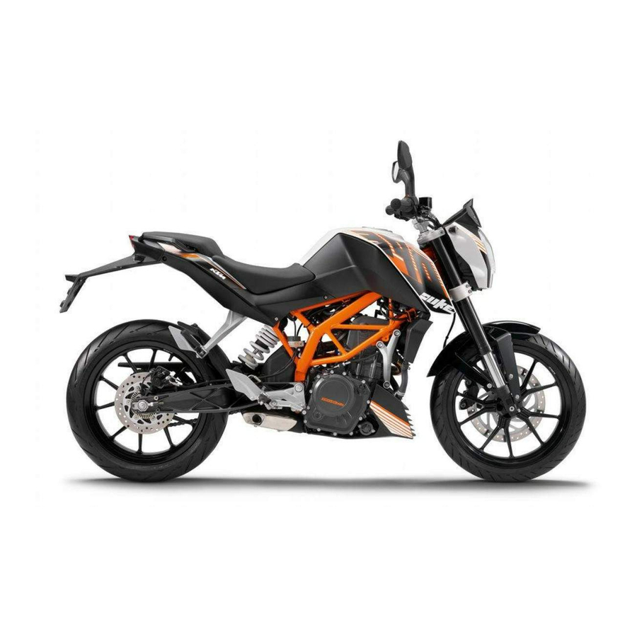
Page 11: Motorcycle
MOTORCYCLE Raising the motorcycle with the rear wheel stand Note Danger of damage The parked vehicle may roll away or fall over. – Always place the vehicle on a firm and even surface. – Mount the support of the wheel stand. –…
-
Page 12: Taking The Motorcycle Off Of The Front Wheel Stand
MOTORCYCLE – Move the handlebar to the straight-ahead position. Attach the lifting gear to the steering stem. Adapter (61029955620) ( p. 191) Front wheel stand (61029055500) ( p. 191) Info Always raise the rear of the motorcycle first. – Raise the front of the motorcycle. 101888-01 Taking the motorcycle off of the front wheel stand Note…
-
Page 13: Removing The Motorcycle From The Work Stand
MOTORCYCLE – Mount special tool on the right side of the vehicle. Work stand (62529055000) ( p. 192) 308228-10 – Remove screw 308229-10 – Mount special tool on the left side of the vehicle. Work stand (62529055000) ( p. 192) 308230-10 –…
-
Page 14: Starting
MOTORCYCLE – Mount and tighten screws Guideline Screw, engine bearer on frame 30 Nm (22.1 lbf ft) 308232-10 Starting Danger Danger of poisoning Exhaust gases are toxic and inhaling them may result in unconsciousness and/or death. – When running the engine, always make sure there is sufficient ventilation, and do not start or run the engine in an enclosed space without an effective exhaust extraction system.
-
Page 15: Starting The Motorcycle To Make Checks
MOTORCYCLE Switching off ABS KTM recommends riding with ABS at all times. However, situations may arise in which ABS is not advantageous. Condition Vehicle stationary, engine running. – button for 3 – 5 seconds. Press the The ABS warning lamp starts flashing; ABS is deactivated.
-
Page 16: Fork, Triple Clamp
FORK, TRIPLE CLAMP Cleaning the dust boots of the fork legs – Push dust boot of both fork legs downwards. Info The dust boots should remove dust and coarse dirt particles from the fork tubes. Over time, dirt can penetrate behind the dust boots. If this dirt is not removed, the oil seals behind can start to leak.
-
Page 17: Installing The Fork Legs
FORK, TRIPLE CLAMP – Loosen screws . Remove the fork legs from the bottom. 308238-10 Installing the fork legs Warning Danger of accidents Modifications to the suspension settings can seriously alter the vehicle’s ride behavior. – Following modifications, ride slowly at first to get the feel of the new ride behavior. Main work –…
-
Page 18: Disassembling The Fork Legs
FORK, TRIPLE CLAMP – Position the brake calipers and check that the brake linings are seated correctly. – Mount screws but do not tighten yet. – Operate the hand brake lever repeatedly until the brake linings are in contact with the brake disc and there is a pressure point.
-
Page 19
FORK, TRIPLE CLAMP – Loosen the screw cap Info The screw cap cannot be removed yet. 201506-10 – Empty the fork oil. 201507-10 – Release the fork leg and clamp it with the fork stub. Info Use soft jaws. 201508-10 –… -
Page 20: Checking The Fork Legs
FORK, TRIPLE CLAMP – Clamp the outer tube in the area of the lower triple clamp. Clamping stand (T612S) ( p. 197) – Remove dust boot 201512-10 – Remove lock ring Info The lock ring has a beveled end where a screwdriver can be applied. 201513-10 –…
-
Page 21: Assembling The Fork Legs
FORK, TRIPLE CLAMP – Measure the outside diameter of the inner tube in several places. External diameter of inner tube 42.975… 43.005 mm (1.69193… 1.69311 in) » If the measured value is less than the specified value: – Change the fork leg. 200684-10 –…
-
Page 22
FORK, TRIPLE CLAMP – Slide on lock ring – Grease and slide on seal ring Lubricant (T511) ( p. 187) Info Mount with the sealing lip facing down and the open side facing up. – Slide on support ring – Sand the edges of sliding bushing with 600-grit sandpaper, then clean and grease. -
Page 23: Removing The Lower Triple Clamp
FORK, TRIPLE CLAMP – Mount screw cap onto the piston rod. Info must be turned all the way down. – Hold the screw cap and tighten the nut. Guideline Nut, piston rod on screw cap M12x1 30 Nm (22.1 lbf ft) 202097-10 –…
-
Page 24
FORK, TRIPLE CLAMP – Detach connectors 308244-10 – Detach connectors 308245-10 – Remove the connector holder. – Disconnect connector 308246-10 – Remove the combination instrument. 308247-10 – Remove screws – Remove the headlight mask. 308248-10 – Remove screw 308249-10… -
Page 25: Installing The Lower Triple Clamp
FORK, TRIPLE CLAMP – Remove the upper triple clamp with the handlebar and set aside. Info Protect the vehicle and its attachments from damage by covering them. 308251-10 – Expose the cable. 308252-10 – Remove nut Castle nut wrench; ½» drive (90129050100) ( p.
-
Page 26
FORK, TRIPLE CLAMP Guideline Nut, steering head M30x1 Step 1 50 Nm (36.9 lbf ft) 2nd stage (loosen, counter- clockwise) 2 turns Step 3 5 Nm (3.7 lbf ft) Castle nut wrench; ½» drive (90129050100) ( p. 195) Alternative 2 The steering head bearing is used again. -
Page 27
FORK, TRIPLE CLAMP – Position the combination instrument. – Plug in connector – Mount the connector holder 308246-11 – Plug in connectors 308245-11 – Plug in connectors 308244-11 – Fold the headlight mask up. – Mount and tighten screws Guideline Screw, headlight mask 11 Nm (8.1 lbf ft) 308243-11… -
Page 28: Checking The Steering Head Bearing Play
FORK, TRIPLE CLAMP Finishing work – Check that the wiring harness, throttle cables, and brake line have the necessary freedom of movement and are correctly routed. – Check the steering head bearing play. ( p. 26) – Remove the motorcycle from the work stand. ( p.
-
Page 29
FORK, TRIPLE CLAMP – Using a plastic hammer, tap lightly on the upper triple clamp to avoid strains. – Tighten screw Guideline Screw, top steering head M16x1.5 52 Nm (38.4 lbf ft) – Tighten screws Guideline Screw, top triple clamp 11 Nm (8.1 lbf ft) 308256-10 Finishing work… -
Page 30: Handlebar, Controls
HANDLEBAR, CONTROLS Checking the play in the throttle cable – Check the throttle grip for smooth operation. – Move the handlebar to the straight-ahead position. Move the throttle grip back- wards and forwards to ascertain the play in the throttle cable. Throttle cable play 3……
-
Page 31: Adjusting The Clutch Cable Play
HANDLEBAR, CONTROLS Adjusting the clutch cable play – Move the handlebar to the straight-ahead position. – Push back sleeve – Loosen lock nut – Adjust the play in the clutch level by turning adjusting screw Guideline Clutch lever play 1… 3 mm (0.04… 0.12 in) –…
-
Page 32: Shock Absorber, Swingarm
SHOCK ABSORBER, SWINGARM Adjusting the spring preload of the shock absorber Warning Danger of accidents Modifications to the suspension settings can seriously alter the vehicle’s ride behavior. – Following modifications, ride slowly at first to get the feel of the new ride behavior. Info The spring preload defines the initial situation of the spring process on the shock absorber.
-
Page 33: Removing The Spring
SHOCK ABSORBER, SWINGARM – Lift the link fork. – Mount and tighten screw Guideline Screw, top shock absorber M10x1.25 50 Nm (36.9 lbf ft) – Tighten fitting Guideline Fitting, bottom shock absorber M10x1.25 45 Nm 308258-11 (33.2 lbf ft) Finishing work –…
-
Page 34
SHOCK ABSORBER, SWINGARM Alternative 1 – Tension the spring to the prescribed position by turning the adjusting ring. Guideline Spring preload Standard 3 clicks Full payload 10 clicks Hook wrench (T106S) ( p. 196) Alternative 2 201698-10 Warning Danger of accidents Modifications to the suspension settings can seri- ously alter the vehicle’s ride behavior. -
Page 35: Exhaust
EXHAUST Removing the exhaust manifold Warning Danger of burns The exhaust system gets very hot when the vehicle is driven. – Allow the exhaust system to cool down. Do not touch hot components. – Remove nuts with the washers. – Swing the radiator forward slightly. 308293-10 –…
-
Page 36: Installing The Exhaust Manifold
EXHAUST Installing the exhaust manifold – Position the exhaust manifold. 308297-10 – Mount nuts but do not tighten them yet. Guideline Nut, exhaust flange 22 Nm (16.2 lbf ft) 308296-11 – Position and tighten exhaust clamp Guideline Exhaust clamp 10 Nm (7.4 lbf ft) –…
-
Page 37: Removing The Main Silencer
EXHAUST Removing the main silencer Preparatory work – Remove the exhaust manifold. ( p. 33) Main work – Remove screw with washers. 308299-10 – Remove screw with the sleeve. – Hang the brake fluid reservoir to the side. Info Ensure that brake fluid does not escape. 308300-10 –…
-
Page 38: Installing The Main Silencer
EXHAUST Installing the main silencer Main work – Position the main silencer. 308303-10 – Mount and tighten screw Guideline Screw, main silencer 23 Nm (17 lbf ft) Info Make sure the sleeves are seated correctly. 308302-11 – Mount and tighten screw with the washers.
-
Page 39: Air Filter
AIR FILTER 10.1 Removing the air filter Note Engine failure Unfiltered intake air has a negative effect on the service life of the engine. – Never ride the vehicle without an air filter since dust and dirt can get into the engine and result in increased wear. Preparatory work –…
-
Page 40: Fuel Tank, Seat, Trim
FUEL TANK, SEAT, TRIM 11.1 Opening the filler cap Danger Fire hazard Fuel is highly flammable. – Never refuel the vehicle near open flames or burning cigarettes, and always switch off the engine first. Be careful that no fuel is spilt, especially on hot vehicle components. Clean up spilt fuel immediately. –…
-
Page 41: Mounting The Seat
FUEL TANK, SEAT, TRIM 11.4 Mounting the seat Main work – Attach seat recesses at screws and lower at the rear. – Mount and tighten screws Guideline Screw, seat 11 Nm (8.1 lbf ft) 101892-10 Finishing work – Mount the passenger seat. ( p.
-
Page 42
FUEL TANK, SEAT, TRIM Warning Danger of poisoning Fuel is poisonous and a health hazard. – Fuel must not come into contact with the skin, eyes, or clothing. Do not breathe in the fuel vapors. If contact occurs with the eyes, rinse with water immediately and contact a physician. Immediately clean contaminated areas on the skin with soap and water. -
Page 43
FUEL TANK, SEAT, TRIM – Remove filler cap 308276-10 – Remove screws with the washers. 308277-10 – Remove screws – Remove screws 308278-10 – Remove cap from the compensating tank. 308279-10 – Remove screws 308280-10 – Lift the fuel tank cover. –… -
Page 44: Installing The Fuel Tank Cover
FUEL TANK, SEAT, TRIM – Push back hose clamp – Pull off the vent hose. – Remove the fuel tank cover. 308282-10 – Close the fuel tank with a suitable plug. 308283-10 11.8 Installing the fuel tank cover Danger Fire hazard Fuel is highly flammable. –…
-
Page 45
FUEL TANK, SEAT, TRIM – Position the fuel tank cover. – Attach the side cover on both sides. 308281-10 – Mount and tighten screws Guideline Remaining screws, chassis 5 Nm (3.7 lbf ft) 308280-11 – Mount plug of the compensating tank. 308279-11 –… -
Page 46: Removing The Fuel Tank
FUEL TANK, SEAT, TRIM – Mount and tighten screws with the washer. Guideline Screw, fuel tank 11 Nm (8.1 lbf ft) 308285-10 – Mount and tighten screws Guideline Screw, fuel tank trim 5 Nm (3.7 lbf ft) – Mount and tighten screws Guideline Screw, front seat fixing 5 Nm (3.7 lbf ft)
-
Page 47: Installing The Fuel Tank
FUEL TANK, SEAT, TRIM – Remove screws 308287-10 – Take off the holder 308288-10 – Detach connector 308289-10 – Detach the fuel line with a suitable tool 308290-10 – Push back hose clamp – Pull off the fuel line and remove the fuel tank. 308291-10 11.10 Installing the fuel tank…
-
Page 48
FUEL TANK, SEAT, TRIM Warning Danger of poisoning Fuel is poisonous and a health hazard. – Fuel must not come into contact with the skin, eyes, or clothing. Do not breathe in the fuel vapors. If contact occurs with the eyes, rinse with water immediately and contact a physician. Immediately clean contaminated areas on the skin with soap and water. -
Page 49: Removing The Front Spoiler
FUEL TANK, SEAT, TRIM – Position the EFI control unit. – Mount and tighten screws Guideline Screw, EFI control unit 4 Nm (3 lbf ft) 308286-11 Finishing work – Install the fuel tank cover. ( p. 42) – Mount the seat. ( p.
-
Page 50: Dismounting The Front Fender
FUEL TANK, SEAT, TRIM 11.13 Dismounting the front fender – Remove screws . Remove the front fender. 308234-10 11.14 Installing the front fender – Position the front fender. Mount and tighten screws Guideline Screw, front fender 11 Nm (8.1 lbf ft) 308234-10 11.15 Checking the fuel pressure…
-
Page 51: Changing The Fuel Filter
FUEL TANK, SEAT, TRIM – Mount special tool 0 0 3 Pressure testing tool (61029094000) ( p. 191) – with the nozzle code 0,45. Mount special tool Testing hose (61029093000) ( p. 191) – Position the hose end in a fuel can. 0 0 2 Guideline Minimum size of fuel can…
-
Page 52
FUEL TANK, SEAT, TRIM Warning Environmental hazard Improper handling of fuel is a danger to the environment. – Do not allow fuel to get into the ground water, the ground, or the sewage system. Preparatory work – Remove the passenger seat. ( p. -
Page 53: Replacing The Fuel Pump
FUEL TANK, SEAT, TRIM 11.17 Replacing the fuel pump Danger Fire hazard Fuel is highly flammable. – Never refuel the vehicle near open flames or burning cigarettes, and always switch off the engine first. Be careful that no fuel is spilt, especially on hot vehicle components. Clean up spilt fuel immediately. –…
-
Page 54: Wheels
Danger of accidents Uncontrollable handling characteristic due to non-approved and/or non-recommended tires/wheels. – Only tires/wheels approved by KTM and with the corresponding speed index should be used. Info The type, condition and air pressure of the tires all have a major impact on the riding behavior of the motorcycle.
-
Page 55: Checking The Brake Discs
WHEELS » If a tire is more than 5 years old: – Change the tires. 12.3 Checking the brake discs Warning Danger of accidents Reduced braking efficiency due to worn brake disc(s). – Change the worn brake disc(s) without delay. – Check the thickness of the front and rear brake discs at several places on the disk to see if it conforms to measurement Info…
-
Page 56: Removing The Brake Disc Of The Front Brake
WHEELS Main work – Check the wheel bearing for damage and wear. » If the wheel bearing is damaged or worn: – Change the wheel bearing. – Clean and grease the shaft seal rings and mating surfaces of the spacers. Long-life grease ( p.
-
Page 57: Rear Wheel
WHEELS Finishing work – Install the front wheel. ( p. 53) – Take the motorcycle off of the rear wheel stand. ( p. 9) 12.5 Rear wheel 12.5.1 Removing the rear wheel Preparatory work – Raise the motorcycle with the rear wheel stand. ( p.
-
Page 58: Removing The Brake Disc Of The Rear Brake
WHEELS – Pull the rear wheel back and mount wheel spindle with the washer and chain adjuster Info Mount the left and right chain adjusters in the same position. – Mount nut and washer. – Push the rear wheel forward so that the chain adjusters are on the screws, and tighten nut Guideline In order for the rear wheel to be correctly aligned, the markings on the left and…
-
Page 59: Checking The Chain Tension
WHEELS – Position the ABS sensor wheel. – Mount and tighten screws Guideline Screw, ABS sensor wheel 12 Nm Loctite ® 243™ (8.9 lbf ft) 307350-11 Finishing work – Install the rear wheel. ( p. 55) – Take the motorcycle off of the rear wheel stand. ( p.
-
Page 60: Checking The Chain, Rear Sprocket, And Engine Sprocket
WHEELS Main work – Loosen nut – Loosen nuts – Adjust the chain tension by turning adjusting screws on the left and right. Guideline Chain tension 5… 7 mm (0.2… 0.28 in) Turn adjusting screws on the left and right so that the markings on the left and right chain adjuster are in the same position in relation to reference marks…
-
Page 61: Cleaning The Chain
WHEELS – Remove screws and release screw . Push the chain guard aside. B01416-10 – Check the chain sliding guard for wear. » If drill hole becomes visible on the chain sliding guard in area – Change the chain sliding guard. –…
-
Page 62: Checking The Rear Hub Rubber Dampers
WHEELS Warning Environmental hazard Hazardous substances cause environmental damage. – Oil, grease, filters, fuel, cleaners, brake fluid, etc., should be disposed of as stipulated in applicable regulations. Info The service life of the chain depends largely on its maintenance. – Clean the chain regularly. –…
-
Page 63: Wiring Harness, Battery
WIRING HARNESS, BATTERY 13.1 Removing the battery Warning Risk of injury Battery acid and battery gases cause serious chemical burns. – Keep batteries out of the reach of children. – Wear suitable protective clothing and goggles. – Avoid contact with battery acid and battery gases. –…
-
Page 64: Disconnecting The Negative Cable Of The Battery
– Do not discard batteries with the household waste. Dispose of faulty batteries in an environmentally compatible manner. Give the battery to your authorized KTM dealer or dispose of it at a collection point for used batteries. Info Even when there is no load on the battery, it still loses power steadily.
-
Page 65: Checking The Charging Voltage
WIRING HARNESS, BATTERY Preparatory work – Switch off all power consumers and switch off the engine. – Remove the passenger seat. ( p. 39) – Remove the seat. ( p. 38) – Disconnect the negative cable of the battery to avoid damage to the motorcycle’s electronics.
-
Page 66: Changing The Fuses Of Individual Power Consumers
WIRING HARNESS, BATTERY 13.7 Changing the fuses of individual power consumers Info The fuse box with the main fuse and the fuses of the individual power consumers is located under the passenger seat. Preparatory work – Switch off all power consumers and switch off the engine. –…
-
Page 67: Brake System
Brake linings available from accessory suppliers are often not tested and approved for use on KTM vehicles. The construc- tion and friction factor of the brake linings and therefore the brake power can differ considerably from the original KTM brake linings. If brake linings are used that differ from the originals, there is no guarantee that they comply with the origi- nal license.
-
Page 68
BRAKE SYSTEM – Move the brake fluid reservoir mounted on the handlebar to a horizontal position. – Remove screws – Remove cover with membrane 307304-10 – Remove locking clip 307305-10 – Remove pin – Take off springs 307306-10 – Remove brake linings –… -
Page 69: Checking The Brake Fluid Level Of The Front Brake
BRAKE SYSTEM – Position springs The arrow on the spring points in the direction of travel. – Mount pin Info Make sure the springs are seated correctly. – Activate the hand brake lever until there is a firm pressure point. 307306-10 –…
-
Page 70: Changing The Front Brake Fluid
BRAKE SYSTEM Warning Environmental hazard Hazardous substances cause environmental damage. – Oil, grease, filters, fuel, cleaners, brake fluid, etc., should be disposed of as stipulated in applicable regulations. Info Avoid contact between brake fluid and painted parts. Brake fluid attacks paint! Use only clean brake fluid from a sealed container.
-
Page 71: Checking The Rear Brake Linings
BRAKE SYSTEM – Open shut-off valve Info Follow the operating instructions of the bleeding device. – Ensure that the filling pressure is set on pressure gauge . Correct the filling pres- sure on pressure regulator if necessary. Guideline Filling pressure 2……
-
Page 72: Changing The Rear Brake Linings
Brake linings available from accessory suppliers are often not tested and approved for use on KTM vehicles. The construc- tion and friction factor of the brake linings and therefore the brake power can differ considerably from the original KTM brake linings. If brake linings are used that differ from the originals, there is no guarantee that they comply with the origi- nal license.
-
Page 73: Checking The Free Travel Of Foot Brake Lever
BRAKE SYSTEM – Position brake linings – Mount pin 308265-10 – Mount locking clips 308263-11 – Operate the foot brake lever repeatedly until the brake linings are in contact with the brake disc and there is a pressure point. – Add brake fluid to the MAX marking.
-
Page 74: Adjusting The Free Travel Of The Foot Brake Lever
BRAKE SYSTEM 14.9 Adjusting the free travel of the foot brake lever Warning Danger of accidents Brake system failure. – If there is no free travel on the foot brake lever, pressure builds up on the rear brake circuit. The rear brake can fail due to overheating.
-
Page 75: Adding Rear Brake Fluid
BRAKE SYSTEM 14.11 Adding rear brake fluid Warning Danger of accidents Failure of the brake system. – If the brake fluid level falls below the MIN mark, this indicates a leakage in the brake system or worn-out brake linings. Check the brake system and do not continue riding. Warning Skin irritation Brake fluid can cause skin irritation on contact.
-
Page 76
BRAKE SYSTEM – Cover painted parts. – Remove screw cap with membrane. – Draw the old brake fluid out of the brake fluid reservoir using a syringe and fill with fresh brake fluid. Bleed syringe (50329050000) ( p. 189) Brake fluid DOT 4 / DOT 5.1 ( p. -
Page 77: Lighting System, Instruments
LIGHTING SYSTEM, INSTRUMENTS 15.1 Setting kilometers or miles Info Make the country-specific setting. Condition The ignition is on. The motorcycle is stationary. – Press the MODE button briefly and repeatedly until ODO appears on the display. – Press the MODE button for 5 — 10 seconds. The display changes from km/h to mph or from mph to km/h.
-
Page 78: Setting The Time
LIGHTING SYSTEM, INSTRUMENTS – Do not activate the two buttons for approx. 15 seconds. The display RPM 2 goes out and the set speed is stored. 15.4 Setting the time Condition The ignition is on. The motorcycle is stationary. – Press the MODE button briefly and repeatedly until ODO appears on the display.
-
Page 79: Adjusting The Headlight Range
LIGHTING SYSTEM, INSTRUMENTS 15.7 Adjusting the headlight range Main work – Remove expanding rivets 101907-10 – Remove screws – Lift the headlight mask slightly and swing forward. 101908-10 – Adjust the beam distance of the headlight by turning screw Guideline For a motorcycle with rider, and with luggage and a passenger if applicable, the light/dark boundary must be exactly on the lower mark (applied in: Checking headlight adjustment).
-
Page 80: Changing The Parking Light Bulb
LIGHTING SYSTEM, INSTRUMENTS 15.8 Changing the parking light bulb Note Damage to reflector Reduced brightness. – Grease on the lamp will evaporate due to the heat and be deposited on the reflector. Clean the lamp and keep it free of grease before mounting.
-
Page 81: Changing The Headlight Bulb
LIGHTING SYSTEM, INSTRUMENTS – Position cover – Mount and tighten screws B00762-10 – Fold the headlight mask up. – Mount and tighten screws Guideline Screw, headlight mask 11 Nm (8.1 lbf ft) 308243-10 – Mount expanding rivets on both sides. –…
-
Page 82
LIGHTING SYSTEM, INSTRUMENTS – Take off protection cap – Disconnect plug-in connector B00760-10 – Detach retaining clamp – Remove headlight bulb – Position the new headlight bulb in the headlight housing. Headlight (H4/socket P43t) ( p. 160) Info Insert the headlight bulb so that the catches latch into the recesses. –… -
Page 83: Engine
ENGINE 16.1 Removing the engine Preparatory work – Raise the motorcycle with the rear wheel stand. ( p. 9) – Remove the front spoiler. ( p. 47) – Remove the passenger seat. ( p. 39) – Remove the seat. ( p.
-
Page 84
ENGINE – Detach spark plug connector 308309-10 – Remove screws – Remove screw – Take off the engine sprocket cover. 308310-10 – Remove screws and take off the lock washer. 308311-10 – Remove nut with washer. – Take off chain adjuster –… -
Page 85
ENGINE – Push back the rubber cap. – Remove nut with washer. 308315-10 – Expose the cable and unplug connectors 308316-10 – Expose the cable and unplug connector 308317-10 – Release hose clip – Push the throttle valve body upward out of the intake flange. 308318-10 –… -
Page 86
ENGINE – Push back hose clamp – Pull off the radiator hose. 308321-10 – Remove screws – Pull off the radiator pipe and hang it to one side. 308322-10 – Remove screws – Take off the retaining bracket. 308323-10 – Position the floor jack under the engine and fix it using the special tool. -
Page 87: Installing The Engine
ENGINE – Lower the engine. Info You should have an assistant for this step. Make sure that the engine is sufficiently secured against falling over. Protect the frame and attachments from damage. 308326-10 16.2 Installing the engine Preparatory work – Lift the motor onto the special tool and secure it.
-
Page 88
ENGINE – Position the retaining bracket. – Mount and tighten screws Guideline Remaining screws, chassis 10 Nm (7.4 lbf ft) 308323-11 – Mount the radiator pipe with the O-ring. – Mount and tighten screws Guideline Remaining screws, chassis 10 Nm (7.4 lbf ft) 308322-11 –… -
Page 89
ENGINE – Position the throttle valve body in the intake flange. – Tighten hose clip 308318-11 – Plug in connector – Position the cable and secure with cable binders. 308317-11 – Plug in connectors – Position the cable and secure with cable binders. 308316-11 –… -
Page 90
ENGINE – Pull the rear wheel toward the rear. – Mount chain adjuster – Mount and tighten nut with the washer. Guideline For the rear wheel to be aligned correctly, the markings on the left and right of the chain adjuster must be in the same position as the reference marks. Nut, rear wheel spindle M14x1.5 90 Nm… -
Page 91
Fit the front spoiler. ( p. 47) – Take a short test ride. – Read out the fault memory using the KTM diagnostics tool. – Check the engine for leak tightness. – Check the engine oil level. ( p. 152) –… -
Page 92: Disassembling The Engine
ENGINE 16.3 Disassembling the engine 16.3.1 Preparations – Mount special tools on the engine assembly stand. Engine fixing arm (90129002060) ( p. 194) Engine fixing arm (90129002050) ( p. 193) Engine assembly stand (61229001000) ( p. 192) – Mount the engine on special tool. Info Have an assistant help you or use a crane.
-
Page 93: Removing The Valve Cover
ENGINE 16.3.4 Removing the valve cover – Remove screws with the gasket. – Take off the valve cover with the valve cover seal. 307961-10 – Take off gasket 307962-10 – Remove the spark plug shaft insert 307963-10 16.3.5 Removing the spark plug –…
-
Page 94: Setting The Engine To Ignition Top Dead Center
ENGINE – Take off the clutch cover. Info Pull the clutch lever forward slightly. 307973-10 – Remove dowels – Take off clutch cover gasket 307974-10 16.3.7 Setting the engine to ignition top dead center – Remove screw plug 307967-10 – Remove screw plug 307968-10 –…
-
Page 95: Removing The Timing Chain Tensioner
ENGINE – Remove screw 307975-10 – Mount special tool Engine blocking screw (61229015000) ( p. 192) 307976-10 16.3.8 Removing the timing chain tensioner – Remove screw with the O-ring. 307978-10 – Turn the timing chain tensioner screw clockwise. The timing chain tensioner is locked. –…
-
Page 96: Removing The Cylinder Head
ENGINE – Remove intake camshaft 307982-10 – Remove exhaust camshaft 307983-10 16.3.10 Removing the cylinder head – Remove screws 307985-10 – Release screws in a crisscross pattern and remove them with the washers. – Take off the cylinder head. 307986-10 –…
-
Page 97: Removing The Piston
ENGINE 16.3.11 Removing the piston – Push the cylinder upward. Info Push the cylinder upward only far enough to allow removal of the piston pin. – Remove piston pin retainer – Remove the piston pin. – Take off the cylinder with the piston. –…
-
Page 98: Removing The Water Pump Wheel
ENGINE 16.3.14 Removing the water pump wheel – Remove screws – Remove the water pump cover with the gasket. 308000-10 – Remove locating pins 308001-10 – Remove nut with washer. – Take off the water pump impeller 308002-10 16.3.15 Removing the alternator cover –…
-
Page 99: Removing The Rotor
ENGINE 16.3.16 Removing the rotor – Remove screw with the washer. 308005-10 – Mount special tool in the crankshaft. Pressure screw for crankshaft (90129020000) ( p. 194) – Mount special tool on the rotor. Info Left-handed thread! – Hold it tight using the special tool and pull off the rotor by turning the screw in. 308066-10 Puller for rotor (90229009000) ( p.
-
Page 100: Removing The Balancer Shaft Drive Wheel
ENGINE 16.3.18 Removing the balancer shaft drive wheel – Remove screw with the washer. 308010-10 – Remove balancer shaft gear with a wedge. 308011-10 – Remove nut with washers. Castle nut wrench; ½» drive (90129022000) ( p. 194) – Take off drive wheel of the balancer shaft. –…
-
Page 101: Removing The Suction Pump
ENGINE – Remove contact pin and the contact spring. 308016-10 16.3.20 Removing the suction pump – Remove screws – Take off the oil pump housing of the suction pump. 308017-10 – Remove dowels 308018-10 – Remove external rotor and internal rotor 308019-10 –…
-
Page 102: Removing The Spacer
ENGINE 16.3.21 Removing the spacer – Remove the spacer of the countershaft. 308022-10 16.3.22 Removing the clutch cage – Loosen screws in a crisscross pattern and remove together with the washers and the clutch springs. – Take off pressure cap 308023-10 –…
-
Page 103: Removing The Primary Gear
ENGINE – Take off inner clutch hub and washer Info The washer usually sticks to the inner clutch hub. – Take off clutch basket 308027-10 – Remove collar sleeve 308028-10 16.3.23 Removing the primary gear – Remove nut with washer. 308030-10 –…
-
Page 104: Removing The Force Pump
ENGINE – Remove woodruff key 308034-10 16.3.24 Removing the force pump – Remove lock ring – Take off washer – Remove the oil pump gear 308035-10 – Remove pin – Take off the washer. 308036-10 – Remove screws – Take off the pressure pump housing. 308037-10 –…
-
Page 105: Removing The Shift Shaft
ENGINE – Remove pin – Remove the oil pump shaft 308040-10 16.3.25 Removing the shift shaft – Push sliding plate away from the shift drum locating . Remove shift shaft with the washer. 308044-10 16.3.26 Removing the shift drum locating –…
-
Page 106: Removing The Left Engine Case
ENGINE – Pull oil filter out of the oil filter housing. Circlip pliers reverse (51012011000) ( p. 189) 308048-10 16.3.29 Removing the left engine case – Remove special tool Engine blocking screw (61229015000) ( p. 192) 308055-10 – Remove screw 308056-10 308057-10 –…
-
Page 107: Removing The Shift Rails
ENGINE – Mount special tool Pressure screw for crankshaft (90129020000) ( p. 194) 308067-10 – Mount special tool with suitable screws. Case separating tool (90129048100) ( p. 195) Info Use the drill hole marked with 902. – Pull off the section of the engine case by screwing in the screw. Info 308068-10 Do not wedge the engine case section.
-
Page 108: Removing The Shift Forks
ENGINE 16.3.32 Removing the shift forks – Remove shift forks 308061-10 16.3.33 Removing the transmission shafts – Pull both transmission shafts out of the bearing seats together. 308063-10 16.3.34 Removing the balancer shaft – Remove screw – Take off the lock washer. –…
-
Page 109: Work On Individual Parts
ENGINE 16.4 Work on individual parts 16.4.1 Work on the left section of the engine case – Remove all dowels. – Remove lock ring – Remove shaft seal ring of the shift shaft and of the countershaft. – Remove oil nozzle –…
-
Page 110: Work On The Right Section Of The Engine Case
ENGINE 16.4.2 Work on the right section of the engine case – Remove all dowels. – Remove screws . Remove the bearing retainers. – Remove oil nozzle – Remove nozzle – Remove any sealing mass remnants and clean the engine case section thoroughly. –…
-
Page 111: Checking The Radial Play Of The Lower Conrod Bearing
ENGINE – Remove shaft seal ring 308076-10 – Remove shaft seal ring – Press the new shaft seal ring in all the way with the open side facing inward. Mounting sleeve (90129043000) ( p. 195) 308077-10 – Press shaft seal ring all the way in with the open side facing inward.
-
Page 112: Changing The Conrod Bearing
ENGINE – Clamp the connecting rod with soft jaws. – Position the crankshaft. – Position the bearing shells. Insert the Plastigauge clearance gauge offset by 90° to the bearing face. Plastigauge measuring strips (60029012000) ( p. 190) – Position the conrod bearing cover. Mount and tighten the screws. Guideline Screw, conrod bearing M8x1…
-
Page 113: Changing The Balancer Shaft Bearing
ENGINE – Measure the crank pin diameter. Guideline Crankshaft – diameter, crank pin Crankshaft classification A 31.970… 31.977 mm (1.25866… 1.25893 in) Crankshaft classification B 31.978… 31.985 mm (1.25897… 1.25925 in) Info The crankshaft classification is indicated by marking – Check the radial play of the lower conrod bearing.
-
Page 114: Work On The Cylinder Head
ENGINE – Press on the balancer shaft bearing with a suitable tool. – Remove the special tools. Disassembly tool, balancer shaft bearing (90129056000) ( p. 196) 308072-10 16.4.7 Work on the cylinder head – Fold cam lever – Take the shims out of the valve spring retainers and lay them to one side accord- ing to their normal built-in position.
-
Page 115: Checking The Cylinder Head
ENGINE 16.4.8 Checking the cylinder head – Check valve guides with the special tool. Limit plug gauge (77029026000) ( p. 193) » If the special tool is easy to insert into the valve guide: – Change the valve guides and valves. –…
-
Page 116: Checking/Measuring The Cylinder
ENGINE – Position camshaft bearing bridge – Mount the screws and tighten in a crisscross pattern from the inside to the outside. Guideline Screw, camshaft bearing bridge 11 Nm (8.1 lbf ft) Info Make sure the dowel pins are seated correctly. Do not twist the camshaft.
-
Page 117: Checking/Measuring The Piston
ENGINE » If the cylinder wear is within the tolerance range: – Change the piston ring. – Mount the piston ring with the marking facing toward the piston head. 16.4.12 Checking/measuring the piston – Check the piston bearing surface for damage. »…
-
Page 118: Checking The Oil Pressure Regulator Valve
ENGINE – With special tool , check the play between the internal rotor and external rotor and between the external rotor and the oil pump housing. Feeler gauge (59029041100) ( p. 190) Oil pump Play between external rotor and 0.10… 0.20 mm (0.0039… internal rotor 0.0079 in) Oil pump…
-
Page 119: Checking The Clutch
ENGINE 16.4.16 Checking the clutch 308085-01 – Check collar sleeve for damage and wear. » If there is damage or wear: – Change the collar sleeve. – Check the length of clutch springs ≥ 37 mm (≥ 1.46 in) Clutch spring — length »…
-
Page 120: Checking The Shift Mechanism
ENGINE » If the intermediate discs are not level or are pitted: – Replace all intermediate discs. 16.4.17 Checking the shift mechanism 308086-01 – Check the shift forks (see ) for damage and wear (visual check). » If there is damage or wear: –…
-
Page 121: Preassembling The Shift Shaft
ENGINE – Preassemble the shift shaft. ( p. 119) – Check the play between the sliding plate and the shift quadrant. Shift shaft – play in sliding plate/shift 0.15… 0.45 mm (0.0059… quadrant 0.0177 in) » If the measured value does not equal the specified value: –…
-
Page 122: Dismantling The Countershaft
ENGINE 16.4.20 Dismantling the countershaft 308094-01 – Fix the countershaft in the vise with the geared end facing downward. Guideline Use soft jaws – Remove stop disk and the 1st-gear idler gear – Remove collar bushing – Remove the 6th-gear sliding gear –…
-
Page 123: Assembling The Main Shaft
ENGINE 308098-01 – Check collar bushings for damage and wear. » If there is damage or wear: – Change the collar bushings. – Check the pivot points of main shaft and countershaft for damage and wear. » If there is damage or wear: –…
-
Page 124: Assembling The Countershaft
ENGINE Preparatory work – Oil all parts carefully before assembling. – Check the transmission. ( p. 120) 308097-01 Main work – Fix the main shaft in the vise with the geared end facing downward. Guideline Use soft jaws – Mount sixth-gear idler gear –…
-
Page 125
ENGINE 308095-01 Main work – Fix the countershaft in the vise with the geared end facing downward. Guideline Use soft jaws – Mount collar bushing – Mount second-gear idler gear – Mount the fifth-gear sliding gear with the shift groove facing upward. –… -
Page 126: Checking The Timing Assembly
ENGINE 16.4.24 Checking the timing assembly 308087-01 – Check timing chain for damage and wear. » If there is damage or wear: – Change the timing chain. – Let the timing chain hang down freely. Check that the timing chain links move easily. »…
-
Page 127: Checking The Electric Starter Drive
ENGINE – Remove screws – Remove the stator. – Position the new stator. – Mount and tighten screws Guideline Screw, stator 8 Nm Loctite ® 243™ (5.9 lbf ft) 308093-01 – Position the cable guide in the alternator cover. – Position the cable retainer.
-
Page 128: Checking The Freewheel
ENGINE – Replace the starter motor. 16.4.27 Checking the freewheel – Insert freewheel gear into the freewheel hub by turning the freewheel gear clock- wise; do not wedge! – Check the locking action of the freewheel gear. » If the freewheel gear does not turn clockwise or if it does not lock counterclock- wise: –…
-
Page 129: Installing The Transmission Shafts
ENGINE 16.5.3 Installing the transmission shafts – Oil the bearing. – Slide both transmission shafts into the bearing seats together. 308063-10 16.5.4 Installing the shift forks – Oil all parts carefully before assembling. – Shift fork has a smaller inside diameter; mount it in the shift groove of the main shaft.
-
Page 130: Installing The Left Engine Case
ENGINE 16.5.7 Installing the left engine case – Clean the sealing areas. – Mount dowels 308058-11 – Mount the new O-rings on oil spray tube – Mount the oil spray tube. Catch engages in recess – Apply sealing compound to the left section of the engine case. Loctite ®…
-
Page 131: Installing The Oil Filter
ENGINE – Mount and tighten screw Guideline Screw, engine case M6x35 12 Nm (8.9 lbf ft) 309201-10 – Position crankshaft to TDC and block with special tool Engine blocking screw (61229015000) ( p. 192) 309202-10 16.5.8 Installing the oil filter –…
-
Page 132: Installing The Shift Drum Locating
ENGINE 16.5.10 Installing the shift drum locating – Mount spacer ring on the shift drum locating unit. – Press locking lever away from the shift drum locating and position the shift drum locating Pins engage in hole – Release the locking lever. –…
-
Page 133: Installing The Primary Gear
ENGINE – Position the oil pump shaft with the internal rotor in the pressure pump housing. – Position external rotor in the pressure pump housing. Markings are visible after assembly. 308043-10 – Check that the oil holes are clear and fill with a small amount of oil. –…
-
Page 134: Installing The Clutch Cage
ENGINE – Mount timing chain sprocket 308032-10 – Mount washer 308031-11 – Mount and tighten nut with the washer. Guideline Nut, primary gear/timing M16x1.5 120 Nm Loctite ® 243™ chain sprocket (88.5 lbf ft) 308030-11 16.5.14 Installing the clutch cage –…
-
Page 135: Installing The Spacer
ENGINE – Mount nut with the washer. Hold the inner clutch hub with the special tool and tighten the nut. Guideline Nut, inner clutch hub M16LHx1.5 120 Nm Loctite ® 243™ (88.5 lbf ft) Clutch holder (51129003000) ( p. 189) 308026-10 –…
-
Page 136: Installing The Suction Pump
ENGINE 16.5.16 Installing the suction pump – Position pin 308020-11 – Mount internal rotor and external rotor Marking of the external rotor is not visible after assembly. 308021-10 – Mount dowels 308018-11 – Oil the oil pump. – Position the oil pump housing. –…
-
Page 137: Installing The Gear Position Sensor
ENGINE 16.5.17 Installing the gear position sensor – Mount the contact spring and contact pin The rounded sides of the contact pins face the sensor. 308016-11 – Install the gear position sensor. – Mount and tighten screws Guideline Screw, gear sensor 6 Nm Loctite ®…
-
Page 138: Installing The Starter Drive
ENGINE – Mount and tighten nut Guideline Nut, drive wheel for balancer shaft 60 Nm (44.3 lbf ft) Castle nut wrench; ½» drive (90129022000) ( p. 194) 308012-10 – Position balancer shaft gear Markings align. – Mount wedge 308052-10 – Mount and tighten screw Guideline Screw, balancer shaft gear…
-
Page 139: Installing The Rotor
ENGINE 16.5.20 Installing the rotor – Mount the spring washer. – Mount the rotor. Info Turn the freewheel gear counterclockwise to simplify assembly. – Mount and tighten screw Guideline Rotor screw 75 Nm Loctite ® 243™ 308005-10 (55.3 lbf ft) 16.5.21 Installing the alternator cover –…
-
Page 140: Installing The Timing Chain
ENGINE – Mount the water pump cover with the seal ring. – Mount screws and tighten them in a crisscross pattern. Guideline Screw, water pump cover 12 Nm (8.9 lbf ft) 308000-11 16.5.23 Installing the timing chain – Feed in the timing chain tensioning rail from above. –…
-
Page 141
ENGINE – Position the piston with the special tool on the cylinder. – Carefully slide the piston into the cylinder from the top. Info The piston rings should not become caught; otherwise, they may be dam- aged. 307993-10 – Ensure that piston marking faces the outfeed side. -
Page 142: Installing The Cylinder Head
ENGINE – Cover the engine case opening with a cloth. – Position piston ring lock 6-o’clock position. – Insert the special tool and firmly press it toward the piston. Insert for piston pin retainer (77329030100) ( p. 193) – Turn the special tool clockwise, thereby pressing the piston pin retainer into the groove.
-
Page 143: Installing The Camshafts
ENGINE – Mount and tighten screws Guideline Cylinder head screw 12 Nm (8.9 lbf ft) 307985-11 16.5.27 Installing the camshafts – Oil the camshafts and pivot points. – Ensure that the crankshaft is blocked in the TDC position. – Pull up the timing chain and insert exhaust camshaft –…
-
Page 144: Checking The Valve Clearance
ENGINE – Holding it with the correct orientation, mount the timing chain tensioner with the gasket. – Mount and tighten screws Guideline Screw, timing chain tensioner 12 Nm (8.9 lbf ft) 307980-10 – Unlock the timing chain tensioner screw counterclockwise. –…
-
Page 145: Adjusting The Valve Clearance
ENGINE – Mount and tighten screw plug Guideline Screw plug, alternator cover M24x1.5 10 Nm (7.4 lbf ft) 307967-11 – Remove special tool Engine blocking screw (61229015000) ( p. 192) 307976-11 – Mount and tighten screws Guideline Screw plug 12 Nm (8.9 lbf ft) 307975-11 16.5.30 Adjusting the valve clearance Preparatory work…
-
Page 146: Installing The Spark Plug
ENGINE – Position the clutch cover. Info Pivot the clutch lever. 307973-10 – Mount and tighten screws Guideline Screw, clutch cover 12 Nm (8.9 lbf ft) 307972-11 16.5.32 Installing the spark plug – Mount and tighten the spark plug using special tool Guideline Spark plug 15 Nm…
-
Page 147: Installing The Chain Securing Guide
ENGINE – Degrease the sealing areas and thinly coat with sealant in areas Loctite ® 5910 – Position the gasket in the valve cover. 307964-10 – Position the valve cover with the gasket. – Mount and tighten screws with the gaskets. Guideline Screw, valve cover 12 Nm (8.9 lbf ft)
-
Page 148: Removing The Engine From The Engine Assembly Stand
ENGINE – Mount oil screen with the O-ring. 307958-10 – Mount and tighten oil drain plug with the O-ring. Guideline Oil drain plug M24x1.5 15 Nm (11.1 lbf ft) 307957-11 16.5.36 Removing the engine from the engine assembly stand – Remove the fitting from special tools Engine fixing arm (90129002060) ( p.
-
Page 149: Shift Mechanism
SHIFT MECHANISM 17.1 Adjusting the shift lever Info The adjustment range of the shift lever is limited. – Loosen nuts – Adjust the shift lever by turning shift rod Guideline Shift rod adjustment range 110… 122 mm (4.33… 4.8 in) Info Make the same adjustments on both sides.
-
Page 150: Water Pump, Cooling System
WATER PUMP, COOLING SYSTEM 18.1 Draining the coolant Warning Danger of scalding During motorcycle operation, the coolant gets very hot and is under pressure. – Do not remove the radiator cap, radiator hoses or other cooling system components when the engine is hot. Allow the engine and cooling system to cool down.
-
Page 151: Checking The Antifreeze And Coolant Level
WATER PUMP, COOLING SYSTEM – Rest the vehicle on the side stand. Danger Danger of poisoning Exhaust gases are toxic and inhaling them may result in unconsciousness and/or death. – When running the engine, always make sure there is sufficient ventila- tion, and do not start or run the engine in an enclosed space without an effective exhaust extraction system.
-
Page 152: Checking The Coolant Level
WATER PUMP, COOLING SYSTEM – Remove radiator cap – Check the coolant antifreeze. −25… −45 °C (−13… −49 °F) » If the coolant antifreeze does not meet specifications: – Correct the coolant antifreeze. – Check the coolant level in the radiator. The radiator must be completely filled.
-
Page 153
WATER PUMP, COOLING SYSTEM » If you had to add more coolant than the specified amount: > 0.20 l (> 0.21 qt.) – Fill/bleed the cooling system. ( p. 148) – Mount the radiator cap. -
Page 154: Lubrication System
LUBRICATION SYSTEM 19.1 Oil circuit Suction pump Force pump Oil filter Oil pressure regulator valve Oil jet for piston cooling Oil spray tube Oil jet for cam follower lubrication 308470-10 19.2 Checking the engine oil level Condition The engine is at operating temperature. Preparatory work –…
-
Page 155
LUBRICATION SYSTEM – Remove oil filter Circlip pliers reverse (51012011000) ( p. 189) 308271-10 – Position the special tool with the O-ring. Mount and tighten the screws. Guideline Screw, oil filter cover 8 Nm (5.9 lbf ft) Oil pressure adapter (75029094000) ( p. -
Page 156: Changing The Engine Oil And Oil Filter, Cleaning The Oil Screen
LUBRICATION SYSTEM 19.4 Changing the engine oil and oil filter, cleaning the oil screen Warning Danger of scalding Engine oil and gear oil get very hot when the motorcycle is ridden. – Wear appropriate protective clothing and safety gloves. In case of burns, rinse immediately with lukewarm water. Warning Environmental hazard Hazardous substances cause environmental damage.
-
Page 157: Adding Engine Oil
LUBRICATION SYSTEM – Remove the oil filler plug with the O-ring from the clutch cover and fill up with engine oil. Engine oil 1.6 l (1.7 qt.) Engine oil (SAE 15W/50) ( p. 186) – Install and tighten the oil filler plug with the O-ring. Danger Danger of poisoning Exhaust gases are toxic and inhaling them may result in unconsciousness and/or death.
-
Page 158: Ignition System
IGNITION SYSTEM 20.1 Alternator — checking the stator winding Stator winding, measurement I — check the resistance – Measure the resistance between the specified points. Stator, connector HB pin 1 – Stator, connector HB pin 2 Alternator ≤ 1 Ω Resistance of stator winding at: 20 °C (68 °F) »…
-
Page 159: Technical Data
TECHNICAL DATA 21.1 Engine Design 1-cylinder 4-stroke engine, water-cooled Displacement 375 cm³ (22.88 cu in) Stroke 60 mm (2.36 in) Bore 89 mm (3.5 in) Compression ratio 12.8:1 Control DOHC, 4 valves controlled via cam lever, chain drive Valve diameter, intake 36 mm (1.42 in) Valve diameter, exhaust 29 mm (1.14 in)
-
Page 160: Engine Tightening Torques
TECHNICAL DATA Wear limit 0.080 mm (0.00315 in) Crankshaft – diameter, crank pin Crankshaft classification A 31.970… 31.977 mm (1.25866… 1.25893 in) Crankshaft classification B 31.978… 31.985 mm (1.25897… 1.25925 in) Clutch facing discs – thickness of total package ≥ 21.30 mm (≥ 0.8386 in) ≥…
-
Page 161: Capacities
TECHNICAL DATA – Oil pressure sensor 14 Nm (10.3 lbf ft) ® Rotor screw 75 Nm (55.3 lbf ft) Loctite 243™ ® Screw, camshaft drive sprocket 32 Nm (23.6 lbf ft) Loctite 243™ Screw, cylinder head 1st stage Thread is oiled, head flat is greased 30 Nm (22.1 lbf ft) 2nd stage…
-
Page 162: Electrical System
Front tires Rear tires 110/70 R 17 M/C 54S TL 150/60 R 17 M/C 66S TL MRF revz FC MRF revz C Additional information is available in the Service section under: http://www.ktm.com 21.8 Fork Fork part number 90101000044 Fork WP Suspension Fork length 736 mm (28.98 in)
-
Page 163: Chassis Tightening Torques
TECHNICAL DATA 21.10 Chassis tightening torques – Exhaust clamp 10 Nm (7.4 lbf ft) – Screw, chain guard EJOT PT ® 4 Nm (3 lbf ft) – Screw, headlight EJOT PT ® 4 Nm (3 lbf ft) – Remaining screws, chassis 4 Nm (3 lbf ft) –…
-
Page 164
TECHNICAL DATA – Screw, bottom triple clamp 15 Nm (11.1 lbf ft) – Screw, engine bearer on frame 30 Nm (22.1 lbf ft) ® Screw, foot brake lever 15 Nm (11.1 lbf ft) Loctite 243™ – Screw, fork stub 15 Nm (11.1 lbf ft) ®… -
Page 165: Cleaning/Protective Treatment
CLEANING/PROTECTIVE TREATMENT 22.1 Cleaning the motorcycle Note Material damage Damage and destruction of components by high-pressure cleaning equipment. – When cleaning the vehicle with a pressure cleaner, do not point the water jet directly onto electrical components, connectors, cables, bearings, etc. Maintain a minimum distance of 60 cm between the nozzle of the pressure cleaner and the component. Excessive pressure can cause malfunctions or destroy these parts.
-
Page 166: Checks And Maintenance Steps For Winter Operation
CLEANING/PROTECTIVE TREATMENT 22.2 Checks and maintenance steps for winter operation Info If the motorcycle is used in the winter, salt can be expected on the roads. Precautions need to be taken against road salt corro- sion. If the vehicle was operated in road salt, clean it with cold water after riding. Warm water would enhance the corrosive effects of salt.
-
Page 167: Storage
– Store the vehicle in a dry location that is not subject to large fluctuations in tem- perature. Info KTM recommends jacking up the motorcycle. – Raise the motorcycle with the rear wheel stand. ( p. 9) –…
-
Page 168: Service Schedule
Final check: Check the vehicle for roadworthiness and take a test ride. ○ ● Read out the fault memory using the KTM diagnostics tool after a test ride. ○ ● Make the service entry in KTM DEALER.NET and in the service booklet.
-
Page 170: Wiring Diagram
WIRING DIAGRAM 25.1 Page 1 of 9 bl-ye ye-rd wh-bl ye-bu ye-bu wh-gn wh-gn ye-rd ye-rd wh-or ye-rd bu-gr rd-gr wh-or gn-rd wh-br wh-gn wh-or gn-rd gn-rd bl-ye gn-rd gn-rd bu-gr wh-or bu-gr bu-gr wh-or wh-or 308201-01…
-
Page 171
WIRING DIAGRAM Components: EFI control unit Alarm system (optional) Vehicle control unit Fuse Fuse Battery Start auxiliary relay 1 Start auxiliary relay 2 Start auxiliary relay 3 Starter relay Starter motor Emergency OFF switch, electric starter button… -
Page 172: Page 2 Of
WIRING DIAGRAM 25.2 Page 2 of 9 wh-rd wh-bl wh-rd bu-gn bu-gn wh-rd wh-br wh-br wh-br wh-bu wh-bu wh-rd bu-or bl-ye bu-or wh-bl wh-br gn-pk gn-pk ye-gr bl-ye ye-gr wh-bl wh-bl bu-br bu-br bu-br ye-rd bu-br ye-rd bl-ye 308202-01…
-
Page 173
WIRING DIAGRAM Components: EFI control unit Alarm system (optional) Fuse Fuse Fuse Fuse Power relay Fuel pump relay Radiator fan relay Fuel pump Radiator fan Ignition/steering lock X293 Connector for accessory ground ACC 2 (not assigned) X294 Connector for accessory plug terminal 15 ACC 2 (not assigned) -
Page 174: Page 3 Of
WIRING DIAGRAM 25.3 Page 3 of 9 wh-bl wh-bl wh-bl HC/3 HB/3 bl-ye ye-bu ye-bu bu-gn bu-gn bl-ye bl-ye 308203-01…
-
Page 175
WIRING DIAGRAM Components: EFI control unit Alarm system (optional) Alarm system switch (optional) Fuse Alternator Combination instrument Voltage regulator X295 Diagnostics connector… -
Page 176: Page 4 Of
WIRING DIAGRAM 25.4 Page 4 of 9 wh-bl wh-bl wh-br wh-br wh-br bu-rd bu-rd ye-bu ye-bu wh-br bl-gn bl-gn bl-gn ye-gn ye-gn bl-rd bl-rd bl-ye bl-ye bu-rd bu-rd br-gn br-gn bl-ye bl-ye bu-rd bu-rd wh-rd wh-rd bl-ye bl-ye gn-rd gn-rd gn-rd 308204-01…
-
Page 177
WIRING DIAGRAM Components: EFI control unit Throttle position sensor circuit A Rollover sensor Side stand switch Fuel tank sensor Temperature and manifold absolute pressure sensor Lambda sensor (cylinder 1) Injection valve (cylinder 1) Combination instrument… -
Page 178: Page 5 Of
WIRING DIAGRAM 25.5 Page 5 of 9 wh-or wh-or ye-gn ye-gn gn-rd gn-rd wh-gr wh-gr bl-bu bl-bu wh-rd wh-rd bl-ye bl-ye wh-ye bu-pk bu-pk ye-gn wh-ye wh-ye wh-gn wh-ye wh-bu wh-bu wh-gn bl-ye ye-gn ye-gn 308205-01…
-
Page 179
WIRING DIAGRAM Components: EFI control unit Vehicle control unit Coolant temperature sensor (cylinder 1) Gear position sensor Ignition pulse generator Clutch switch Idle speed actuator Combination instrument Ignition coil (cylinder 1) -
Page 180: Page 6 Of
WIRING DIAGRAM 25.6 Page 6 of 9 bl-ye wh-br ye-rd bl-rd bl-rd bl-rd bl-rd bl-rd ye-rd ye-rd bl-ye ye-rd bl-ye bl-rd bl-ye bl-ye bl-ye bl-ye wh-br FG/1 FG/1 bl-ye bl-ye bl-ye 308206-01…
-
Page 181
WIRING DIAGRAM Components: Vehicle control unit Brake light switch, front Brake light switch, rear Low beam, high beam License plate lamp Combination instrument Horn Parking light Brake/tail light Emergency OFF switch, electric starter button Light switch, horn button, high beam flasher button, turn signal switch… -
Page 182: Page 7 Of
WIRING DIAGRAM 25.7 Page 7 of 9 bl-ye bl-ye bl-ye bl-ye bl-ye bl-ye bl-ye bl-ye bu-pk bu-pk pk-br pk-br 308207-01…
-
Page 183
WIRING DIAGRAM Components: Alarm system (optional) Vehicle control unit Oil pressure sensor Combination instrument Turn signal, front left Turn signal, front right Turn signal, rear left Turn signal, rear right Light switch, horn button, high beam flasher button, turn signal switch… -
Page 184: Page 8 Of
WIRING DIAGRAM 25.8 Page 8 of 9 bl-ye bl-ye bl-ye bl-ye bl-ye bl-ye wh-gr wh-gr bl-ye bl-ye bl-ye bl-pu wh-ye bl-ye br-rd bu-or bl-ye bl-ye bl-ye bu-or br-rd bl-ye wh-ye bl-pu bl-ye bl-ye bl-ye bl-ye bl-ye bl-ye 308208-01…
-
Page 185
WIRING DIAGRAM Components: EFI control unit Alarm system (optional) Vehicle control unit Combination instrument… -
Page 186: Page 9 Of
WIRING DIAGRAM 25.9 Page 9 of 9 gn-gr rd-gr ye-gr ye-gr rd-gr ye-gr ye-gr wh-bl wh-br wh-bu wh-bu wh-br wh-bl bl-ye bl-ye bl-ye bl-ye wh-rd wh-bu wh-bu gn-gr gn-gr wh-bl wh-bl bu-pk bu-pk wh-rd wh-rd bl-bu bl-bu wh-rd wh-rd 308209-01…
-
Page 187
WIRING DIAGRAM Components: EFI control unit ABS control unit Vehicle control unit Wheel speed sensor, front Wheel speed sensor, rear Fuse Fuse ABS fuse ABS fuse Combination instrument Cable colors: Black Brown Blue Green Gray Light blue Orange Pink Violet White Yellow… -
Page 188: Substances
Brake fluid DOT 4 / DOT 5.1 According to – Guideline – Use only brake fluid that complies with the specified standard (see specifications on the container) and that possesses the corre- sponding properties. KTM recommends Castrol and Motorex ® products. Supplier Castrol –…
-
Page 189: Auxiliary Substances
AUXILIARY SUBSTANCES Chain cleaner Guideline – KTM recommends Motorex ® products. Supplier Motorex ® – Chain Clean Chain lube for road use Guideline – KTM recommends Motorex ® products. Supplier Motorex ® – Chainlube Road Cleaning and preserving materials for metal, rubber and plastic Guideline –…
-
Page 190
AUXILIARY SUBSTANCES Lubricant (T152) Guideline – KTM recommends Bel‑Ray ® products. Supplier Bel‑Ray ® – Molylube ® Anti‑Seize Motorcycle cleaner Guideline – KTM recommends Motorex ® products. Supplier Motorex ® – Moto Clean 900 Paint cleaner and polish for high-gloss and matte finishes, bare metal and plastic surfaces Guideline –… -
Page 191: Special Tools
SPECIAL TOOLS Bleeder cover Art. no.: 00029013000 201490-10 Bleeding device Art. no.: 00029013100 201491-10 Bleed syringe Art. no.: 50329050000 400058-01 Circlip pliers reverse Art. no.: 51012011000 400059-01 Clutch holder Art. no.: 51129003000 400289-01…
-
Page 192
SPECIAL TOOLS Valve spring compressor Art. no.: 59029019000 400101-01 Feeler gauge Art. no.: 59029041100 400110-01 Plastigauge measuring strips Art. no.: 60029012000 400122-01 Piston ring mounting tool Art. no.: 60029015000 400123-01 Adapter Art. no.: 61029055130 C00194-01… -
Page 193
SPECIAL TOOLS Rear wheel stand Art. no.: 61029055400 500077-01 Front wheel stand Art. no.: 61029055500 B00756-01 Testing hose Art. no.: 61029093000 201314-01 Pressure testing tool Art. no.: 61029094000 400149-01 Adapter Art. no.: 61029955620 B00757-01… -
Page 194
SPECIAL TOOLS Engine assembly stand Art. no.: 61229001000 200306-01 Engine blocking screw Art. no.: 61229015000 200312-01 Work stand Art. no.: 62529055000 400151-01 Floor jack attachment Art. no.: 75029055000 400184-01 Oil pressure adapter Art. no.: 75029094000 400169-01… -
Page 195
SPECIAL TOOLS Limit plug gauge Art. no.: 77029026000 400104-01 Insert for valve spring lever Art. no.: 77029041100 303272-10 Spark plug wrench Art. no.: 77229172000 304549-10 Insert for piston pin retainer Art. no.: 77329030100 400160-01 Engine fixing arm Art. no.: 90129002050 304419-10… -
Page 196
SPECIAL TOOLS Engine fixing arm Art. no.: 90129002060 304418-10 Mounting sleeve Art. no.: 90129005000 201612-01 Pressure screw for crankshaft Art. no.: 90129020000 304527-10 Castle nut wrench; ½» drive Art. no.: 90129021000 304430-10 Castle nut wrench; ½» drive Art. no.: 90129022000 304469-10… -
Page 197
SPECIAL TOOLS Mounting sleeve Art. no.: 90129043000 304541-10 Case separating tool Art. no.: 90129048100 308111-01 Castle nut wrench; ½» drive Art. no.: 90129050000 305037-10 Castle nut wrench; ½» drive Art. no.: 90129050100 305037-10 Key for steering head bearing Art. no.: 90129051000 304951-10… -
Page 198
SPECIAL TOOLS Disassembly tool, balancer shaft bearing Art. no.: 90129056000 304565-10 Puller for rotor Art. no.: 90229009000 308102-01 Hook wrench Art. no.: T106S 301085-01 Spring compressor Art. no.: T14050S 201648-10… -
Page 199
SPECIAL TOOLS Mounting tool Art. no.: T528S 200634-10 Clamping stand Art. no.: T612S 200638-10… -
Page 200: Standards
STANDARDS JASO T903 MA Different technical development directions required a new specification for 4-stroke motorcycles – the JASO T903 MA Standard. Ear- lier, engine oils from the automobile industry were used for 4-stroke motorcycles because there was no separate motorcycle specifi- cation.
-
Page 201: Index
INDEX Brake discs INDEX checking ……. . . 53 Accessories ……..7 Brake fluid front brake, adding .
-
Page 202
INDEX preparations ……90 Engine oil primary gear, removing ….. . 101 adding . -
Page 203
INDEX Shift lever adjusting ……. . 147 Key number ……..8 Shift speed RPM 1 Kilometers or miles adjusting . -
Page 204
*3206167en* 3206167en 07/2013 KTM-Sportmotorcycle AG 5230 Mattighofen/Austria Photo: Mitterbauer/KTM http://www.ktm.com…
Информация, представленная на Сайте, носит информационный характер и ни при каких условиях не является публичной
офертой, определяемой положениями статьи 437 Гражданского кодекса Российской Федерации. Все содержащиеся на
Сайте сведения носят исключительно информационный характер и не являются исчерпывающими. Все условия
приобретения мототехники, цены, спецпредложения и комлектации мототехники указаны с целью ознакомления.
Комплектации и цены действительны на момент публикации и могут быть изменены без предварительного оповещения.
Представленная на Сайте мототехника может быть укомплектована дополнительным оборудованием, не входящим в
стандартную версию, но доступным за дополнительную плату. Сведения о продукции, касающиеся объёмов поставки,
внешнего вида, характеристик, габаритов и веса, эксплуатационных затрат и т.д. не являются обязательными,
рассматриваются как приблизительные и указаны с условием того, что могут возникнуть ошибки при печати, настройке
и/или наборе текста. Такая информация может быть изменена без предварительного уведомления. Чтобы получить
полную информацию о продукции, услугах, дополнительном оборудовании и спецпредложениях, интересных для Вас,
обращайтесь к менеджерам Дилерского центра
- Manuals
- Brands
- KTM Manuals
- Motorcycle
- 390 Duke EU
- Owner’s manual
-
Contents
-
Table of Contents
-
Troubleshooting
-
Bookmarks
Quick Links
OWNER’S MANUAL
2021
390 DUKE
Art. no. 3214321en
Related Manuals for KTM 390 DUKE EU
Summary of Contents for KTM 390 DUKE EU
-
Page 1
OWNER’S MANUAL 2021 390 DUKE Art. no. 3214321en… -
Page 3
KTM accepts no liability for delivery options, deviations from fig- ures and descriptions, misprints, and other errors. The models portrayed partly contain special equipment that does not belong to the regular scope of supply. -
Page 4: Table Of Contents
Quick Selector 2 display ….28 View of vehicle, front left (example) … 11 7.17 Menu……….28 View of vehicle, rear right 7.17.1 KTM MY RIDE (optional) ….28 (example)……..12 7.17.2 Trips/Data ……..29 SERIAL NUMBERS ……..13 7.17.3 Motorcycle ……..
-
Page 5
TABLE OF CONTENTS 7.17.27 Extra Functions ……39 13 BRAKE SYSTEM ……… 66 PREPARING FOR USE……… 41 13.1 Anti-lock braking system (ABS) ..66 13.2 Adjusting the basic position of the Advice on preparing for first use ..41 hand brake lever ……67 Running in the engine …… -
Page 6
TABLE OF CONTENTS 18 SERVICE WORK ON THE ENGINE ….99 18.1 Checking the engine oil level….. 99 18.2 Changing the engine oil and oil filter, cleaning the oil screens ..99 18.3 Adding engine oil ……101 19 CLEANING, CARE ……..102 19.1 Cleaning the motorcycle …. -
Page 7: Means Of Representation 1
Indicates work that requires expert knowledge and technical understanding. In the interest of your own safety, have these jobs performed by an authorized KTM workshop! Your motorcycle will be cared for there to the highest degree by specially trained experts using the special tools required.
-
Page 8: Safety Advice
2 SAFETY ADVICE Use definition KTM sport motorcycles are designed and constructed to meet the normal demands of regular road operation but not for use on race courses or offroad. Info The motorcycle is authorized for public road traffic in the homologous version only.
-
Page 9: Tampering Warning
An appropriate driver’s license is needed to ride the vehicle on public roads. Have malfunctions that impair safety promptly eliminated by an authorized KTM workshop. Adhere to the information and warning labels on the vehicle.
-
Page 10: Protective Clothing
– Always wear protective clothing that is in good condition and meets the legal regulations. In the interest of your own safety, KTM recommends that you only operate the vehicle while wearing protective clothing. Work rules Unless specified otherwise, the ignition must be turned off during all work (models with ignition lock, models with remote key) or the engine must be at a standstill (models without ignition lock or remote key).
-
Page 11
The Owner’s Manual can be downloaded several times using the QR code or the link on the delivery certificate. The Owner’s Manual is also available for download from your authorized KTM dealer and on the KTM website. A printed copy can also be ordered from your authorized KTM dealer. -
Page 12: Important Notes
Manufacturer warranty, implied warranty The work prescribed in the service schedule must only be carried out in an authorized KTM workshop and con- firmed in the KTM Dealer.net, as otherwise all warranty claims will be void. Damage or secondary damage caused by tampering with and/or conversions on the vehicle are not covered by the manufacturer warranty.
-
Page 13: View Of Vehicle 4
VIEW OF VEHICLE 4 View of vehicle, front left (example) S04740-10 Combination instrument Clutch lever ( p. 15) Front rider’s seat Passenger seat Grab handles ( p. 20) Seat lock ( p. 19) Side stand ( p. 21) Shift lever ( p.
-
Page 14: View Of Vehicle, Rear Right (Example)
4 VIEW OF VEHICLE View of vehicle, rear right (example) S04741-10 Tool set ( p. 20) Light switch ( p. 16) Menu buttons ( p. 16) Turn signal switch ( p. 16) Horn button ( p. 16) Ignition and steering lock ( p.
-
Page 15: Serial Numbers 5
SERIAL NUMBERS 5 Vehicle identification number The vehicle identification number is stamped on the right side of the steering head. 402408-10 Type label (EU/JP/AR/BR/CN/CO/MY/PH/TH, 390 DUKE B.D. 3 EU) The type label is on the right of the frame behind the steering head.
-
Page 16: Key Number
5 SERIAL NUMBERS Key number can be found on the KEYCODECARD. The key number Info The key number is needed to order a replacement key. Keep the KEYCODECARD in a safe place. If at least one ignition key is still available, a spare key can be produced.
-
Page 17: Controls 6
CONTROLS 6 Clutch lever The clutch lever is fitted on the left side of the handlebar. F00783-10 Hand brake lever The hand brake lever is fitted on the right side of the handle- bar. The front brake is engaged using the hand brake lever. F00784-10 Throttle grip The throttle grip…
-
Page 18: Light Switch
6 CONTROLS 6.4.2 Light switch Light switch is fitted on the left side of the handlebar. Possible states Low beam on – Light switch in position . In this position, the low beam and the tail light are switched High beam on – Push the light switch to position In this position, the high beam and the tail light are switched on.
-
Page 19: Switches On The Right Side Of The Handlebar
CONTROLS 6 Switches on the right side of the handlebar 6.5.1 Emergency OFF switch The emergency OFF switch is fitted on the right side of the handlebar. Possible states Emergency OFF switch off – In this position, the igni- tion circuit is interrupted, a running engine stops, and a non-running engine cannot be started.
-
Page 20: Unlocking The Steering
6 CONTROLS – Park the vehicle. – Turn the handlebar all the way to the left. – Insert the ignition key into the ignition and steering lock, press in, and turn to the left. Remove the ignition key. Steering is no longer possible. 400732-01 Unlocking the steering –…
-
Page 21: Closing The Fuel Tank Filler Cap
CONTROLS 6 – Lift cover of the fuel tank filler cap and insert the ignition key into the lock. Note Danger of damage The ignition key may break if overloaded. Damaged ignition keys must be replaced. – Push down on the fuel tank filler cap to take pressure off the ignition key.
-
Page 22: Tool Set
6 CONTROLS 6.12 Tool set The tool set is located under the passenger seat. F00729-10 6.13 Grab handles The grab handles are used for moving the motorcycle around. If you carry a passenger, the passenger can hold onto the grab handles during the trip.
-
Page 23: Foot Brake Lever
CONTROLS 6 The gear positions can be seen in the photograph. The neutral or idle position is between the first and second gears. 401950-11 6.16 Foot brake lever Foot brake lever is located in front of the right footrest. The foot brake lever is used to activate the rear brake. 402177-10 6.17 Side stand…
-
Page 24: Combination Instrument
7 COMBINATION INSTRUMENT Combination instrument The combination instrument is attached in front of the handlebar. The combination instrument is divided into two function areas. indicator lamps ( p. 23) Display M01577-10 Activation and test Activation The combination instrument is activated when the ignition is switched on.
-
Page 25: Warnings
(taking care not to endanger yourself or other road users in the process) and contact an authorized KTM workshop. The oil pressure warning lamp always lights up as long as the engine is not running. If the engine is run- ning and the oil pressure warning lamp lights up, stop immediately (taking care not to endanger yourself or other road users in the process) and switch off the engine.
-
Page 26: Display
Malfunction indicator light lights up yellow – The OBD has detected a malfunction in the vehi- cle electronics. Come safely to a halt, and contact an authorized KTM workshop. The ABS warning lamp lights up yellow – Status or error messages relating to ABS. The ABS warning lamp flashes if the ABS mode Super Moto is enabled.
-
Page 27: Speed
COMBINATION INSTRUMENT 7 ODO display ( p. 26) ABS mode Coolant temperature indicator ( p. 26) Fuel level display ( p. 27) Bluetooth ® (optional) Time ( p. 27) Only shown where the menu overview is closed. Favourites display ( p.
-
Page 28: Speed
7 COMBINATION INSTRUMENT Speed is shown in kilometers per hour km/h or in miles per Speed hour mph. M01581-11 7.10 ODO display The total distance covered ODO is shown in area of the display. Info This value is retained, even if the 12-V battery is discon- nected from the vehicle or the fuse blows.
-
Page 29: Fuel Level Display
COMBINATION INSTRUMENT 7 7.12 Fuel level display The fuel tank contents are shown in area of the display. The fuel level indicator consists of bars. The more bars are lit, the more fuel is in the fuel tank. Info If the fuel level is getting low, the last segment flashes red and the following warning also appears LOW FUEL.
-
Page 30: Quick Selector 1 Display
Press the SET button when the menu is closed. – Press the UP or DOWN button until KTM MY RIDE is marked. Press the SET button to open the menu. A suitable cellphone or headset can be paired with the combina- tion instrument via Bluetooth ®…
-
Page 31: Trips/Data
– Press the SET button when the menu is closed. – Press the UP or DOWN button until KTM MY RIDE is marked. Press the SET button to open the menu. – Press the UP or DOWN button until Pairing is marked. Press the SET button to open the menu.
-
Page 32: Phone (Optional)
– Press the SET button when the menu is closed. – Press the UP or DOWN button until KTM MY RIDE is marked. Press the SET button to open the menu. F01959-01 – Press the UP or DOWN button until Pairing is marked. Press the SET button to open the menu.
-
Page 33: Headset (Optional)
– Press the SET button when the menu is closed. – Press the UP or DOWN button until KTM MY RIDE is marked. Press the SET button to open the menu. F01960-01 – Press the UP or DOWN button until Pairing is marked. Press the SET button to open the menu.
-
Page 34: Audio (Optional)
– Press the SET button when the menu is closed. – Press the UP or DOWN button until KTM MY RIDE is marked. Press the SET button to open the menu. S05091-01 Warning Danger of accidents Headphone volume which is too high distracts attention from traffic activity.
-
Page 35: Telephony (Optional)
COMBINATION INSTRUMENT 7 7.17.9 Telephony (optional) Condition • Function KTM MY RIDE activated (optional). • Function Bluetooth ® activated. • The Bluetooth ® function should also be activated in the device to be paired. • Headset linked with appropriate cellphone.
-
Page 36: Trip 2
7 COMBINATION INSTRUMENT Press and All the entries in the Trip 1 menu are reset. hold the SET button for 3-5 seconds. 7.17.12 Trip 2 – Press the SET button when the menu is closed. – Press the UP or DOWN button until Trips/Data is highlighted. Press the SET button to open the menu.
-
Page 37: Favourites
COMBINATION INSTRUMENT 7 Info If the ABS mode Road is enabled, ABS controls both wheels. If the ABS mode Super Moto is enabled, ABS only con- trols the front wheel. The rear wheel is not controlled by ABS and may lock during braking maneuvers. The ABS warning lamp flashes slowly to remind you that the Super Moto ABS mode is enabled.
-
Page 38: Bluetooth (Optional)
V01171-01 off. Info The Bluetooth ® function can only be used in conjunction with KTM MY RIDE (optional). When the Bluetooth ® function is switched on and the device is connected, the Bluetooth ® symbol appears in the display of the combination instrument.
-
Page 39: Shift Light
COMBINATION INSTRUMENT 7 7.17.20 Shift Light Condition • The motorcycle is stationary. • ODO > 1,000 km (621 mi). – Press the SET button when the menu is closed. – Press the UP or DOWN button until Settings is highlighted. Press the SET button to open the menu.
-
Page 40: Distance
7 COMBINATION INSTRUMENT Setting the date – Press UP or DOWN button until the date is marked. – Press the SET button. The day flashes and is underlined. – Press UP or DOWN button until the current day is set. –…
-
Page 41: Consumption
COMBINATION INSTRUMENT 7 7.17.24 Consumption Condition • The motorcycle is stationary. – Press the SET button when the menu is closed. – Press the UP or DOWN button until Settings is highlighted. Press the SET button to open the menu. –…
-
Page 42
7 COMBINATION INSTRUMENT Info The current KTM PowerParts and the available software for your vehicle can be found on the KTM website. -
Page 43: Preparing For Use 8
Info When using the vehicle, remember that others may feel disturbed by excessive noise. – Ensure that the pre-sales inspection work has been carried out by an authorized KTM workshop. The delivery certificate is transferred upon vehicle handover. – Read the entire Owner’s Manual before riding for the first time.
-
Page 44: Running In The Engine
8 PREPARING FOR USE Running in the engine – During the running-in phase, do not exceed the specified engine speed. Guideline Maximum engine speed During the first: 1,000 km (620 mi) 7,500 rpm Info During the running-in phase, the shift warning light is set to a specified value and cannot be changed. –…
-
Page 45
PREPARING FOR USE 8 Guideline Maximum permissible overall weight 355 kg (783 lb.) Maximum permissible front axle load 127 kg (280 lb.) Maximum permissible rear axle load 228 kg (503 lb.) -
Page 46: Riding Instructions
9 RIDING INSTRUCTIONS Checks and maintenance measures when preparing for use Info Before every trip, check the condition of the vehicle and ensure that it is roadworthy. The vehicle must be in perfect technical condition when it is being operated. –…
-
Page 47: Starting Off
RIDING INSTRUCTIONS 9 – Unlock the steering. ( p. 18) – Sit on the vehicle, take the weight off of the side stand, and move it all the way up with your foot. – Turn the emergency OFF switch to the position –…
-
Page 48
9 RIDING INSTRUCTIONS Warning Danger of accidents If you change down at high engine speed, the rear wheel blocks and the engine races. – Do not change into a low gear at high engine speed. Warning Danger of accidents An incorrect ignition key position causes malfunctions. –… -
Page 49
Info If unusual noises occur while riding, stop immediately (taking care not to endanger yourself or other road users in the process), switch off the engine and contact an authorized KTM workshop. – Shift into a higher gear when conditions allow (incline, road situation, etc.). -
Page 50: Applying The Brakes
Danger of accidents A spongy pressure point on the front or rear brake reduces braking efficiency. – Check the brake system and do not continue riding until the problem is eliminated. (Your authorized KTM workshop will be glad to help.) Warning Danger of accidents The brake system fails in the event of overheating.
-
Page 51: Stopping, Parking
RIDING INSTRUCTIONS 9 Stopping, parking Warning Risk of injury People who act without authorization endanger themselves and others. – Do not leave the vehicle unattended if the engine is running. – Protect the vehicle against access by unauthorized persons. – Lock the steering and remove the ignition key if you leave the vehicle unattended. Warning Danger of burns Some vehicle components become very hot when the vehicle is operated.
-
Page 52: Refueling
In some countries and regions, the available fuel quality and cleanliness may not be sufficient. This will result in problems with the fuel system. – Refuel only with clean fuel that meets the specified standards. (Your authorized KTM workshop will be glad to help.) Note Environmental hazard Improper handling of fuel is a danger to the environment.
-
Page 53
RIDING INSTRUCTIONS 9 – Switch off the engine. – Open fuel tank filler cap. ( p. 18) – Fill the fuel tank with fuel up to the lower edge of the fuel filler. Total fuel tank 13.5 l Super unleaded capacity, approx. -
Page 54: Service Schedule
Different service intervals may apply in your country, depending on the local operating conditions. Individual service intervals and scopes may change in the course of technical developments. The most up-to-date service schedule can always be found on KTM Dealer.net. Your authorized KTM dealer will be happy to advise you.
-
Page 55: Recommended Work
15,000 km (9,300 mi) every 7,500 km (4,650 mi) after 1,000 km (620 mi) ○ ● ● ● ● Make a service entry in KTM Dealer.net. ○ One-time interval ● Periodic interval 10.3 Recommended work every 48 months every 12 months…
-
Page 56: Tuning The Chassis
11 TUNING THE CHASSIS 11.1 Adjusting the spring preload of the shock absorber Warning Danger of accidents Modifications to the suspension setting may seriously alter the handling characteris- tic. – Ride slowly to start with after making adjustments to get the feel of the new handling characteristic. Info The spring preload defines the initial status of the spring operation on the shock absorber.
-
Page 57
TUNING THE CHASSIS 11 Info After the nuts have been tightened, the bearings of the shift rod must be central and aligned identically to each other in order to ensure freedom of movement in the bearing shells. – Check the shift lever to ensure it is functioning properly and can move freely. -
Page 58: Service Work On The Chassis
12 SERVICE WORK ON THE CHASSIS 12.1 Raising the motorcycle with rear lifting gear Note Danger of damage The parked vehicle can roll away or fall over. – Park the vehicle on a firm and level surface. – Mount the supports of the lifting gear. –…
-
Page 59: Taking The Motorcycle Off The Front Lifting Gear
SERVICE WORK ON THE CHASSIS 12 – Move the handlebar to the straight-ahead position. Position the lifting gear. Mounting pin (69329965030) Front wheel work stand, large (69329965100) Info Always raise the motorcycle at the rear first. – Lift the motorcycle at the front. 402345-01 12.4 Taking the motorcycle off the front lifting gear…
-
Page 60: Removing The Passenger Seat
12 SERVICE WORK ON THE CHASSIS Main work – Push dust boots of both fork legs downward. Info The dust boots remove dust and coarse dirt particles from the inside fork tubes. Over time, dirt can accumu- late behind the dust boots. If this dirt is not removed, the oil seals behind can start to leak.
-
Page 61: Removing The Front Rider’s Seat
SERVICE WORK ON THE CHASSIS 12 Warning Danger of accidents The seat can come loose from the anchoring if it is not mounted correctly. – After assembly, check whether the seat is correctly locked and cannot be pulled up. – Finally, check that the passenger seat is correctly mounted. 12.8 Removing the front rider’s seat Preparatory work…
-
Page 62: Cleaning The Chain
12 SERVICE WORK ON THE CHASSIS 12.11 Cleaning the chain Warning Danger of accidents Lubricants on the tires reduces the road grip. – Remove lubricants from the tires using a suitable cleaning agent. Warning Danger of accidents Oil or grease on the brake discs reduces the braking effect. –…
-
Page 63: Adjusting The Chain Tension
SERVICE WORK ON THE CHASSIS 12 Main work – Shift the transmission into neutral. – In the area after the chain sliding guard, press the chain upward toward the link fork and measure chain tension Info Top chain section must be taut. Chain wear is not always even, so you should repeat this measurement at different chain positions.
-
Page 64: Checking The Chain, Rear Sprocket, And Engine Sprocket
12 SERVICE WORK ON THE CHASSIS – Make sure that chain adjusters are fitted correctly on adjusting screws – Tighten nut Guideline Nut, rear wheel spin- M14x1.5 98 Nm (72.3 lbf ft) Finishing work – Remove the rear of the motorcycle from the lifting gear. p.
-
Page 65: Adjusting The Basic Position Of The Clutch Lever
SERVICE WORK ON THE CHASSIS 12 – Check the chain sliding guard for wear. » If screw becomes visible in area of the chain slid- ing guard when viewed from above: – Change the chain sliding guard. – Check that the chain sliding guard is firmly seated. »…
-
Page 66: Removing The Front Spoiler
12 SERVICE WORK ON THE CHASSIS 12.16 Removing the front spoiler – Remove screws and remove the front spoiler. S04745-10 – Remove screws – Remove lower part of front spoiler. S04746-10…
-
Page 67: Fitting Front Spoiler
SERVICE WORK ON THE CHASSIS 12 12.17 Fitting front spoiler – Position the lower part of front spoiler. Mount and tighten screws Guideline Screw, front spoiler M6x14 9 Nm (6.6 lbf ft) lower part S04746-11 – Position the front spoiler, mount and tighten screws Guideline Screw, front spoiler M6x12…
-
Page 68: Brake System
Do not make any changes to the suspension travel. – Only use spare parts on the brake system which have been approved and recommended by KTM. – Only use tires/wheels approved by KTM with the corre- sponding speed index. – Maintain the specified tire pressure. –…
-
Page 69: Adjusting The Basic Position Of The Hand Brake Lever
Warning Danger of accidents Worn-out brake discs reduce the braking effect. – Make sure that worn-out brake discs are replaced immediately. (Your authorized KTM workshop will be glad to help.) – Check the front and rear brake disc thickness at multiple…
-
Page 70: Adding The Front Brake Fluid
– Make sure that brake fluid for the front and rear brake is changed in accordance with the service schedule. (Your authorized KTM workshop will be glad to help.) – Move the brake reservoir mounted on the handlebar into a hori- zontal position.
-
Page 71: Checking The Front Brake Linings
Checking the front brake linings Warning Danger of accidents Worn-out brake linings reduce the braking effect. – Ensure that worn-out brake linings are replaced immediately. (Your authorized KTM workshop will be glad to help.) Warning Danger of accidents Damaged brake discs reduce the braking effect.
-
Page 72: Checking The Free Travel Of Foot Brake Lever
13 BRAKE SYSTEM 13.7 Checking the free travel of foot brake lever Warning Danger of accidents The brake system fails in the event of overheating. If there is no free travel on the foot brake lever, pressure builds up in the brake system on the rear brake.
-
Page 73: Checking The Rear Brake Fluid Level
Danger of accidents Old brake fluid reduces the braking effect. – Make sure that brake fluid for the front and rear brake is changed in accordance with the service schedule. (Your authorized KTM workshop will be glad to help.) – Stand the vehicle upright.
-
Page 74: Adding Rear Brake Fluid
Danger of accidents Old brake fluid reduces the braking effect. – Make sure that brake fluid for the front and rear brake is changed in accordance with the service schedule. (Your authorized KTM workshop will be glad to help.) Note Environmental hazard Hazardous substances cause environmental damage.
-
Page 75: Checking The Rear Brake Linings
Checking the rear brake linings Warning Danger of accidents Worn-out brake linings reduce the braking effect. – Ensure that worn-out brake linings are replaced immediately. (Your authorized KTM workshop will be glad to help.) Warning Danger of accidents Damaged brake discs reduce the braking effect.
-
Page 76: Wheels, Tires
14 WHEELS, TIRES 14.1 Removing the front wheel Preparatory work – Raise the motorcycle with the rear lifting gear. ( p. 56) – Lift the motorcycle with the front lifting gear. ( p. 56) Main work – Remove screws with washers and push the fender slightly to the side.
-
Page 77: Removing The Rear Wheel
WHEELS, TIRES 14 – Clean the thread of the wheel spindle and screw – Clean and grease the wheel spindle. Long-life grease ( p. 120) – Position the front wheel and insert the wheel spindle. The brake linings are correctly positioned. –…
-
Page 78: Installing The Rear Wheel
14 WHEELS, TIRES – Remove screw and pull wheel speed sensor out of the hole. – Remove nut and washer. – Take off chain adjuster – Holding the rear wheel, withdraw wheel spindle with the washer and chain adjuster – Push the rear wheel forward as far as possible and take the chain off the rear sprocket.
-
Page 79
WHEELS, TIRES 14 – Mount the damping rubber and rear sprocket carrier on the rear wheel. – Insert the spacers. – Position the rear wheel. The brake linings are correctly positioned. – Push the rear wheel forward as far as possible and lay the chain on the rear sprocket. -
Page 80: Checking The Rear Hub Damping Rubber Pieces
Check the chain tension. ( p. 60) 14.6 Checking the tire condition Warning Danger of accidents If a tire bursts while riding, the vehicle becomes uncontrollable. – Ensure that damaged or worn tires are replaced immediately. (Your authorized KTM workshop will be glad to help.)
-
Page 81
Danger of accidents Non-approved or non-recommended tires and wheels impact the handling character- istic. – Only use tires/wheels approved by KTM with the corresponding speed index. Info The type, condition, and pressure of the tires all have a major impact on the handling characteristic of the motorcycle. -
Page 82: Checking Tire Pressure
14 WHEELS, TIRES 14.7 Checking tire pressure Info Low tire pressure leads to abnormal wear and overheating of the tire. Correct tire pressure ensures optimal riding comfort and maximum tire service life. – Remove the protection cap. – Check the tire pressure when the tires are cold. Tire pressure when solo front 2.0 bar (29 psi)
-
Page 83: Electrical System 15
Make sure that the daytime running light is deacti- vated with the diagnostics tool when the menu item is not available, but the low beam is required. (Your authorized KTM workshop will be glad to help.) – Note the legal regulations regarding the daytime run- ning light.
-
Page 84: Installing The 12-V Battery
15 ELECTRICAL SYSTEM Main work – Disconnect negative cable from the 12-V battery. V01273-10 – Pull back positive terminal cover – Disconnect positive cable from the 12-V battery. – Detach rubber strap – Pull the 12-V battery upwards and out of the battery compart- ment.
-
Page 85: Charging The 12-V Battery
ELECTRICAL SYSTEM 15 15.4 Charging the 12-V battery Warning Risk of injury Battery acid and battery gases cause serious chemical burns. – Keep 12 V batteries out of the reach of children. – Wear suitable protective clothing and safety glasses. – Avoid contact with battery acid and battery gases.
-
Page 86: Changing The Main Fuse (Eu/Jp)
15 ELECTRICAL SYSTEM Main work – Connect a battery charger to the 12-V battery. Switch on the battery charger. Battery charger (58429074000) In addition, this battery charger can be used to test the open- circuit voltage, the starting ability of the 12-V battery, and the alternator.
-
Page 87: Changing The Abs Fuses
ELECTRICAL SYSTEM 15 Main work – Remove protection cap S04754-10 – Remove faulty main fuse Info A faulty fuse has a burned-out fuse wire A spare fuse is located in the fuse box. – Insert a new main fuse. Fuse (75011088030) ( p.
-
Page 88
15 ELECTRICAL SYSTEM To change the fuse of the ABS hydraulic unit: – Take off the protection cap and remove fuse Info A faulty fuse has a burned-out fuse wire Warning Fire hazard Incorrect fuses overload the electrical S04756-10 system. – Only use fuses with the required ampere value. -
Page 89: Changing The Fuses Of Individual Electrical Power Consumers
ELECTRICAL SYSTEM 15 15.7 Changing the fuses of individual electrical power consumers Info The fuse box with the main fuse and the fuses of the individual electrical power consumers is located under the passenger seat. Preparatory work – Remove the passenger seat. ( p.
-
Page 90
15 ELECTRICAL SYSTEM Guideline Fuse 1 — not assigned Fuse 2 — 10 A — combination instrument Fuse 3 — 10 A — power relay Fuse 4 — 15 A — ignition coil, fuel pump, start auxiliary relay, horn Fuse 5 — 15 A — radiator fan Fuse 6 — 15 A — brake light, turn signal, high beam, low beam, position light, tail light, license plate lamp Fuse 7 — 10 A — engine control unit, ABS control unit… -
Page 91: Checking The Headlight Setting
ELECTRICAL SYSTEM 15 15.8 Checking the headlight setting – Park the vehicle on a horizontal surface in front of a light- colored wall and make a mark at the height of the center of the low beam headlight. – Make another mark at a distance under the first marking.
-
Page 92: Diagnostics Connector
15 ELECTRICAL SYSTEM 15.10 Diagnostics connector Diagnostics connector is located under the passenger seat. H01906-10 15.11 Front ACC1 and ACC2 Installation location – Power supplies ACC1 and ACC2 front are located on the left of the vehicle, behind the cover under the fuel tank. E01189-10 15.12 ACC2 rear…
-
Page 93: Cooling System 16
COOLING SYSTEM 16 16.1 Cooling system Water pump in the engine ensures forced circulation of the coolant. The pressure resulting from the warming of the cooling system is regulated by a valve in radiator cap . Heat expansion causes excess coolant to flow into compensating tank .
-
Page 94: Checking The Coolant Level
16 COOLING SYSTEM Condition The engine is cold. – Stand the motorcycle upright on a horizontal surface. – Remove cap of the compensating tank. – Check the antifreeze in the coolant. −25 … −45 °C (−13 … −49 °F) » If the antifreeze in the coolant does not match the speci- fied value: –…
-
Page 95: Draining The Coolant
COOLING SYSTEM 16 Warning Danger of poisoning Coolant is toxic and a health hazard. – Keep coolant out of the reach of children. – Do not allow coolant to come into contact with the skin, the eyes and clothing. – Consult a doctor immediately if coolant is swallowed. –…
-
Page 96: Filling/Bleeding The Cooling System
16 COOLING SYSTEM Warning Danger of poisoning Coolant is toxic and a health hazard. – Keep coolant out of the reach of children. – Do not allow coolant to come into contact with the skin, the eyes and clothing. – Consult a doctor immediately if coolant is swallowed. –…
-
Page 97: Changing The Coolant
COOLING SYSTEM 16 – Loosen bleeder screw Guideline 3 turns – Tilt the vehicle slightly to the right. – Pour in the coolant until it emerges without bubbles at the bleeder screw, and then mount and tighten the bleeder screw immediately.
-
Page 98
16 COOLING SYSTEM Warning Danger of poisoning Coolant is toxic and a health hazard. – Keep coolant out of the reach of children. – Do not allow coolant to come into contact with the skin, the eyes and clothing. – Consult a doctor immediately if coolant is swallowed. –… -
Page 99
COOLING SYSTEM 16 Danger Danger of poisoning Exhaust gases are toxic and inhal- ing them may result in unconsciousness and death. – Always make sure there is sufficient ventilation when running the engine. – Use effective exhaust extraction when starting or running the engine in an enclosed space. -
Page 100: Tuning The Engine
17 TUNING THE ENGINE 17.1 Checking the clutch lever play Note Clutch damage If there is no free travel by the clutch lever, the clutch will begin to slip. – Check the free travel of the clutch lever each time before using the motorcycle. –…
-
Page 101: Service Work On The Engine 18
SERVICE WORK ON THE ENGINE 18 18.1 Checking the engine oil level Condition The engine is at operating temperature. Preparatory work – Stand the motorcycle upright on a horizontal surface. Main work – Check the engine oil level. Info After switching off the engine, wait one minute before checking the level.
-
Page 102
18 SERVICE WORK ON THE ENGINE Main work – Place an appropriate container under the engine. – Remove oil drain plug with the O-ring. – Remove oil screen with the O-ring. – Remove screw plug with oil screen – Allow the engine oil to drain completely. –… -
Page 103: Adding Engine Oil
Engine oil (SAE 15W/50) ( p. 118) Info In order to achieve optimal engine oil performance, it is not advisable to mix different engine oils. KTM recommends changing the engine oil. 401955-10 – Mount and tighten the filler plug together with the O-ring. Danger Danger of poisoning Exhaust gases are toxic and inhal-…
-
Page 104: Cleaning, Care
19 CLEANING, CARE 19.1 Cleaning the motorcycle Note Material damage Components become damaged or destroyed if a pressure cleaner is used incorrectly. The high pressure forces water into the electrical components, connectors, throttle cables, and bearings, etc. Pressure which is too high causes malfunctions and destroys components. –…
-
Page 105: Checks And Maintenance Steps For Winter Operation
CLEANING, CARE 19 – Push back the sleeves of the handlebar controls to allow any water that has penetrated to evaporate. – After the motorcycle has cooled down, lubricate all moving parts and pivot points. – Clean the chain. ( p.
-
Page 106: Storage
– Store vehicle in a dry location that is not subject to large fluc- tuations in temperature. Info KTM recommends jacking up the motorcycle. – Raise the motorcycle with the rear lifting gear. ( p. 56) – Lift the motorcycle with the front lifting gear. ( p.
-
Page 107: Preparing For Use After Storage
STORAGE 20 20.2 Preparing for use after storage – Take the motorcycle off the front lifting gear. ( p. 57) – Remove the rear of the motorcycle from the lifting gear. p. 56) – Install the 12-V battery. p. 82) –…
-
Page 108: Troubleshooting
Carry out start procedure. ( p. 44) – Malfunction in the electronic Read out the fault memory using the fuel injection KTM diagnostics tool. – Engine has too little power Air filter is very dirty Change the air filter. –…
-
Page 109
TROUBLESHOOTING 21 Faults Possible cause Action – 12 V battery discharged Ignition was not switched off Charge the 12-V battery. p. 83) when vehicle was parked – The 12-V battery is not being Check the charging voltage. charged by the alternator –… -
Page 110: Technical Data
22 TECHNICAL DATA 22.1 Engine Design 1-cylinder 4-stroke engine, water-cooled Displacement 373 cm³ (22.76 cu in) Stroke 60 mm (2.36 in) Bore 89 mm (3.5 in) Compression ratio 12.4:1 Control DOHC, four valves controlled via cam lever, chain drive Intake valve diameter 36 mm (1.42 in) Exhaust valve diameter 29 mm (1.14 in)
-
Page 111: Engine Tightening Torques
TECHNICAL DATA 22 22.2 Engine tightening torques Oil nozzle 6 Nm (4.4 lbf ft) Loctite ® 243™ Screw, crankshaft speed sensor 6 Nm (4.4 lbf ft) Loctite ® 243™ Screw, gear sensor 6 Nm (4.4 lbf ft) Loctite ® 243™ Screw, retaining bracket 6 Nm (4.4 lbf ft) Loctite…
-
Page 112
22 TECHNICAL DATA Screw, shift drum locating 12 Nm (8.9 lbf ft) Loctite ® 243™ Screw, starter motor 12 Nm (8.9 lbf ft) Screw, timing chain tensioner 12 Nm (8.9 lbf ft) Screw, timing chain tensioning rail 12 Nm (8.9 lbf ft) Loctite ®… -
Page 113: Capacities
TECHNICAL DATA 22 22.3 Capacities 22.3.1 Engine oil Engine oil 1.7 l (1.8 qt.) Engine oil (SAE 15W/50) p. 118) 22.3.2 Coolant Coolant 1.2 l (1.3 qt.) Coolant ( p. 118) 22.3.3 Fuel Please observe the labels on EU fuel pumps. A00420-10 Total fuel tank capacity, approx.
-
Page 114: Electrical System
Metzeler Sportec M5 Interact 110/70 R 17 M/C 54H TL 150/60 R 17 M/C 66H TL Continental ContiMotion Continental ContiMotion The tires specified represent one of the possible series production tires. Additional information is available in the Service section under: KTM.COM…
-
Page 115: Fork
TECHNICAL DATA 22 22.7 Fork Fork article number 93301000144 WP Suspension Fork Fork length 744 mm (29.29 in) Fork oil 450 ml (15.21 fl. oz.) Fork oil (SAE 4) (48601166S1) p. 119) 22.8 Shock absorber Shock absorber article number 93304010000 Shock absorber WP Suspension Spring preload…
-
Page 116
22 TECHNICAL DATA Screw, damper block 8 Nm (5.9 lbf ft) Screw, engine sprocket cover 8 Nm (5.9 lbf ft) Screw, foot brake cylinder 9 Nm (6.6 lbf ft) Loctite ® 243™ Screw, front fender 7 Nm (5.2 lbf ft) Screw, front seat fixing 6 Nm (4.4 lbf ft) Screw, front spoiler… -
Page 117
TECHNICAL DATA 22 Screw, front wheel spindle 25 Nm (18.4 lbf ft) Screw, fuel tank 20 Nm (14.8 lbf ft) Screw, grab handle 22 Nm (16.2 lbf ft) Screw, handlebar clamp 20 Nm (14.8 lbf ft) Loctite ® 243™ Screw, horn 12 Nm (8.9 lbf ft) Screw, main silencer 23 Nm (17 lbf ft) -
Page 118
22 TECHNICAL DATA Nut, steering head M30x1 1st stage 45 Nm (33.2 lbf ft) 2nd stage (loosen, counterclock- wise) 2 turns 3rd stage 5 Nm (3.7 lbf ft) -
Page 119: Declarations Of Conformity 23
COBO SpA hereby declares that the BT‑ROUTER wireless system conforms with the relevant guidelines. The full text of the Declaration of Conformity is available at the following Internet address. Certification website: http://www.ktm.com/btrouter JNS Instruments Ltd. hereby declares that the 210M1100 wireless system conforms with the relevant guidelines.
-
Page 120: Substances
24 SUBSTANCES Brake fluid DOT 4 / DOT 5.1 Standard/classification – Guideline – Use only brake fluid that complies with the specified standard (see specifications on the container) and that exhibits the corresponding properties. Recommended supplier Castrol – REACT PERFORMANCE DOT 4 MOTOREX ®…
-
Page 121
SUBSTANCES 24 Fork oil (SAE 4) (48601166S1) Standard/classification – SAE ( p. 121) (SAE 4) Guideline – Use only oils that comply with the specified standards (see specifications on the container) and that exhibit the corresponding properties. Gasohol 95 E20 (RON 95) Standard/classification –… -
Page 122: Auxiliary Substances
25 AUXILIARY SUBSTANCES Chain cleaner Recommended supplier MOTOREX ® – Chain Clean Fuel additive Recommended supplier MOTOREX ® – Fuel Stabilizer Long-life grease Recommended supplier MOTOREX ® – Bike Grease 2000 Motorcycle cleaner Recommended supplier MOTOREX ® – Moto Clean Perfect finish and high gloss polish for paints Recommended supplier MOTOREX…
-
Page 123: Standards 26
STANDARDS 26 JASO T903 MA2 Different technical development directions required a separate specification for motorcycles – the JASO T903 MA2 standard. Earlier, engine oils from the automobile industry were used for motorcycles because there was no separate motor- cycle specification. Whereas long service intervals are demanded for automobile engines, the focus for motorcycle engines is on high performance at high engine speeds.
-
Page 124: Index Of Special Terms
Light, which enhances the visibility of the vehicle dur- ing the day but is not focused, and in contrast to low beam does not illuminate the road surface KTM MY RIDE System for wireless communication with appropriate cellphones and headsets for telephony and audio…
-
Page 125: List Of Abbreviations 28
LIST OF ABBREVIATIONS 28 Art. no. Article number circa compare e.g. for example etc. et cetera i.a. inter alia number poss. possibly…
-
Page 126: List Of Symbols
Malfunction indicator light lights up yellow – The OBD has detected a malfunction in the vehi- cle electronics. Come safely to a halt, and contact an authorized KTM workshop. The ABS warning lamp lights up yellow – Status or error messages relating to ABS. The ABS warning lamp flashes if the ABS mode Super Moto is enabled.
-
Page 127: Index
Applying the brakes ….. . 48 KTM MY RIDE ….. . . 28 Auxiliary substances .
-
Page 128
INDEX Cooling system ……91 filling/bleeding ….. . 94 Hand brake lever . -
Page 129
INDEX checks and maintenance measures when Throttle grip ……15 preparing for use ….44 Time Protective clothing . -
Page 130
*3214321en* 3214321en 09/2021 KTM Sportmotorcycle GmbH 5230 Mattighofen/Austria Photo: Mitterbauer/KISKA/KTM KTM.COM…
owner’s Manuals
PowerWear & PowerParts Manuals
Here is your personal document
If you prefer a printed document to thumb through, or you would like to search for an older document, these are available in the Print on Demand portal.
In the portal, you can find owner’s and repair manuals for a wide variety of models.
You can choose between PDF downloads and printed copies.
To the Print on Demand portal