
- Manuals
- Brands
- KTM Manuals
- Motorcycle
- 690 DUKE R EU
- Owner’s manual
-
Contents
-
Table of Contents
-
Troubleshooting
-
Bookmarks
Quick Links
OWNER’S MANUAL
2008
690 DUKE
ART. NO. 3211248en
Related Manuals for KTM 690 Duke
Summary of Contents for KTM 690 Duke
-
Page 1
OWNER’S MANUAL 2008 690 DUKE ART. NO. 3211248en… -
Page 3
KTM accepts no liability for delivery options, devi- ations from illustrations and descriptions, as well as printing and other errors. -
Page 4
Reproduction, even in part, is permitted only with the express written permission of the copyright owner. ISO 9001(12 100 6061) Within the meaning of the international quality management standard ISO 9001, KTM uses quality assurance processes that lead to the maximum possible quality of the products. -
Page 5: Table Of Contents
CONTENTS Setting the clock ………….. 28 MEANS OF REPRESENTATION ……….6 Combination instrument — ODO display ……. 29 IMPORTANT NOTES …………… 7 Combination instrument — setting/resetting TRIP 1 display..29 VIEW OF VEHICLE…………..12 Combination instrument — setting/resetting TRIP 2 display..30 View of vehicle, front left side……….
-
Page 6
Checking free play of foot brake lever ……… 75 Important maintenance work to be carried out by an Checking rear brake fluid level……….. 75 authorized KTM workshop. (as additional order)….55 Topping up brake fluid of front brake ……76 MAINTENANCE WORK ON CHASSIS AND ENGINE…. -
Page 7
CONTENTS Checking the low beam headlight adjustment….110 STORAGE …………….145 Checking the high beam headlight adjustment ….111 Storage…………….145 Adjusting the light range of the low beam headlight … 112 Putting into operation after storage ……..146 Adjusting the light range of the high beam headlight ..114 TECHNICAL DATA — ENGINE ………. -
Page 8: Means Of Representation
All work marked with this symbol requires specialist knowledge and technical understanding. In the interest of your own safety, have these jobs done in an authorized KTM workshop! There, your motorcycle will be serviced optimally by specially trained experts using the specialist tools required.
-
Page 9: Important Notes
IMPORTANT NOTES Use definition KTM sport motorcycles are designed and constructed to meet the normal demands of regular road operation but not for use on race courses or offroad. Info The motorcycle is authorized for public road traffic in the homologous version only.
-
Page 10
IMPORTANT NOTES Spare parts, accessories For your own safety, use only spare parts and accessories approved by KTM, and have these mounted only in an authorized KTM workshop. KTM accepts no liability for other products and any resulting damage or loss. -
Page 11
IMPORTANT NOTES Warning notes In your own interest, read the specified warning notes. Info Various warning labels are attached to your vehicle. Do not remove any warning labels. If they are missing, you or others may not recognize dangers and may therefore be injured. Grades of risks Danger Danger that leads immediately and certainly to severe and permanent injury or death. -
Page 12
IMPORTANT NOTES The owner’s manual is an important component of the motorcycle and should be handed over to the new owner if the vehicle is sold. -
Page 14: View Of Vehicle
VIEW OF VEHICLE View of vehicle, front left side 700132-01…
-
Page 15
VIEW OF VEHICLE Combination instrument Rear mirror Clutch lever Seat Handrail Front brake caliper Left fuel tap Shift lever Engine number Side stand… -
Page 16: View Of Vehicle, Rear Right Side
VIEW OF VEHICLE View of vehicle, rear right side 700133-01…
-
Page 17
VIEW OF VEHICLE Seat lock Light switch, headlight flasher switch, indicator switch, horn Filler cap Emergency OFF switch, electric starter button Hand brake lever Chassis number, type label Rear brake caliper Passenger footrests Map Select Switch Foot brake pedal Engine oil level viewer Right fuel tap… -
Page 18: Location Of Serial Numbers
LOCATION OF SERIAL NUMBERS Chassis number/type label The chassis number is stamped on the steering head on the right. The type label is located under the chassis number. 500006-01 Key number The key number can be found on the KEYCODECARD. Info You need the key number to order a spare key.
-
Page 19: Engine Number
LOCATION OF SERIAL NUMBERS Engine number The engine number is stamped on the left side of the engine under the engine sprocket. 700125-01 Fork part number The fork part number is stamped on the inner side of the fork stub. 700126-01…
-
Page 20: Shock Absorber Part Number
LOCATION OF SERIAL NUMBERS Shock absorber part number The shock absorber part number is stamped on the top of the shock absorber above the adjusting ring toward the rear. 700128-01…
-
Page 21: Operating Elements
OPERATING ELEMENTS Clutch lever The clutch lever is fitted on the left side of the handlebar. The clutch is hydraulically operated and self-adjusting. 100114-10 Hand brake lever The hand brake lever is located on the right side of the handlebar and operates the front wheel brake.
-
Page 22: Light Switch
OPERATING ELEMENTS Light switch The light switch is fitted on the left side of the handlebar. Possible states Low beam on Light switch is turned downwards. In this position, the low beam and tail light are switched on. High beam on Light switch is turned upwards.
-
Page 23: Flasher Switch
OPERATING ELEMENTS Flasher switch The flasher switch is fitted on the left side of the handlebar. Possible states Flasher light off Flasher light, left, on Flasher switch pressed to the right. The flasher switch returns automatically to the central position after use. Flasher light, right, on Flasher switch pressed to the right.
-
Page 24: Ignition/Steering Lock
OPERATING ELEMENTS Ignition/steering lock The ignition/steering lock is located in front of the upper triple clamp. Possible states Ignition off In this position, the ignition circuit is interrupted, a running engine stops, and a non-running engine will not start. The ignition key can be removed.
-
Page 25: Electric Starter Button
OPERATING ELEMENTS Electric starter button The electric starter button is fitted on the right side of the handlebar. Possible states • Electric starter button in basic position • Electric starter button pressed In this position, the electric starter is actuated. 500022-11 Combination instrument The combination instrument is attached in fromt of the handlebar.
-
Page 26: Combination Instrument — Function Buttons
OPERATING ELEMENTS Combination instrument — function buttons Press the MODE button to change the display mode. Possible display modes are total distance covered (ODO), tripmaster 1 (TRIP 1) and tripmas- ter 2 (TRIP 2). Press the SET button to reset tripmaster 1 (TRIP 1) and tripmaster 2 (TRIP 2) to 0.0. Button has no function.
-
Page 27: Combination Instrument — Control Lamps
OPERATING ELEMENTS Combination instrument — control lamps The indicator lamps provide additional information on the operating state of the motorcycle. Possible states Flashing indicator flashes green in flash rhythm Flasher light is switched Idling speed indicator lamp lights up green Transmission is in neutral.
-
Page 28: Combination Instrument — Display
OPERATING ELEMENTS Combination instrument — Display When you switch on the ignition, all display segments light up for a second as a function test. 700118-01 LEnGTth Following the display function test, the wheel circumference LEnGth is shown for one sec- ond.
-
Page 29: Combination Instrument — Speed Display
OPERATING ELEMENTS Combination instrument — speed display The speed is displayed in kilometers per hour km/h or miles per hour Mph. 700114-01 Setting kilometers or miles Info If you change the unit, the ODO value is retained and converted accordingly. Making the setting according to the country.
-
Page 30: Combination Instrument — Time
OPERATING ELEMENTS Turn the ignition key to the position . Press the MODE button several times until the ODO display mode is active. Keep the MODE button pressed until the display mode changes from Km/h to Mph or from Mph to Km/h. Specification Activation duration of MODE button 10 s…
-
Page 31: Combination Instrument — Odo Display
OPERATING ELEMENTS Turn the ignition key to the position . Press the MODE button several times until the ODO display mode is active. Keep the MODE button and the SET button pressed simultaneously. The time begins to flash. Press the MODE button to adjust the hour. Press the SET button to adjust the minute.
-
Page 32: Combination Instrument — Setting/Resetting Trip 2 Display
OPERATING ELEMENTS Turn the ignition key to the position . Press the MODE button several times until the TRIP 1 display mode is active. Keep the SET button pressed. The TRIP 1 display is at 0.0. 700121-01 Combination instrument — setting/resetting TRIP 2 display Info The tripmaster TRIP 2 operates constantly and counts up to 999.9.
-
Page 33: Combination Instrument — Trip F Display
OPERATING ELEMENTS Combination instrument — TRIP F display When the fuel level reaches the reserve mark, the display automatically changes to TRIP F and begins to count from 0.0, regardless of which display mode was previously active. Info Parallel to the TRIP F display, the fuel warning light begins to light up. 700123-01 Combination instrument — coolant temperature indicator The temperature indicator in the display consists of 12 bars.
-
Page 34: Opening Filler Cap
OPERATING ELEMENTS Opening filler cap Lift the cover of the filler cap and insert the ignition key. Turn the ignition key 90° counterclockwise and remove the filler cap. Info The filler cap has a tank air vent system. 500023-10 Closing filler cap Put the filler cap back on and turn the ignition key 90°…
-
Page 35: Fuel Taps
OPERATING ELEMENTS Fuel taps The fuel taps are located on the left/right under the fuel tank. Possible states • Fuel supply closed The knurled screws are turned clockwise as far as possible. The level cannot be compensated and no fuel can flow out of the fuel tank. •…
-
Page 36: Seat Lock
OPERATING ELEMENTS Seat lock The seat lock is located to the right of the seat. You can lock it with the ignition key. 700131-01 OWNER’S MANUAL You can find the owner’s manual in its protective case on the underside of the seat. 500031-10…
-
Page 37: Tool Set
OPERATING ELEMENTS Tool set The tool set is located in the storage compartment under the seat. 700134-01 Passenger footrests The passenger footrests can be folded in and out. Possible states • Passenger footrests folded up For operation without a passenger. •…
-
Page 38: Shift Lever
OPERATING ELEMENTS Shift lever The shift lever is mounted on the left side of the engine. 700137-01 The gear positions can be seen in the photograph. The neutral or idle position is between the first and second gears. 700138-01…
-
Page 39: Foot Brake Pedal
OPERATING ELEMENTS Foot brake pedal The footbrake pedal is located in front of the right footrest. The footbrake pedal operates the rear brake. 700136-01 Side stand The side stand is coupled with the safety electric starter system — see the riding instruc- tions.
-
Page 40: Tips On Putting Into Operation
The front and rear wheels must be fitted with tires with similar tread patterns to prevent loss of control over the vehicle. Warning Danger of accidents Uncontrollable handling behavior caused by non-approved tires/wheels. Use only tires/wheels approved by KTM with the corresponding speed index. Warning Danger of accidents Reduced road grip with new tires.
-
Page 41: Running In The Engine
When using your vehicle, remember that others may feel disturbed by excessive noise. Make sure that the pre-delivery inspection work has been carried out by an authorized KTM workshop. You receive a delivery certificate and the service record at vehicle handover.
-
Page 42: Loading The Vehicle
TIPS ON PUTTING INTO OPERATION Avoid fully opening the throttle! Loading the vehicle Warning Danger of accidents Unstable riding behavior. Do not exceed the maximum permitted weight and axle loads. The overall weight consists of: motorcycle operational and with a full tank, driver and passenger with protective clothing and helmet, baggage.
-
Page 43
TIPS ON PUTTING INTO OPERATION Warning Danger of accidents Unstable handling characteristics due to slipped baggage. Check the way your baggage is fixed regularly. Warning Danger of burns A hot exhaust system can burn baggage. Fasten your baggage in such a way that it cannot be burned or singed by the hot exhaust system. If you carry any baggage, make sure it is fixed firmly as close as possible to the center of the vehicle and ensure even weight distribu- tion between the front and rear wheels. -
Page 44: Riding Instructions
RIDING INSTRUCTIONS Checks before putting into operation Info Make sure that the motorcycle is in a perfect technical condition before use. In the interests of riding safety, make a habit of making a general check before you ride. Check the engine oil level. ( P.
-
Page 45: Starting
RIDING INSTRUCTIONS Starting Danger Danger of poisoning Exhaust gases are poisonous and can result in unconsciousness and/or death. When running the engine, always make sure there is sufficient ventilation, and do not start or run the engine in a closed space. Caution Danger of accidents If the vehicle is operated with a discharged battery or without a battery, electronic components and safety equipment may be damaged.
-
Page 46
RIDING INSTRUCTIONS Turn the emergency OFF switch to the position Turn the ignition key to the position . After switching on the ignition, you can hear the fuel pump working for about 2 seconds. At the same time, the combination instrument runs a function test. Shift gear to neutral. -
Page 47: Starting Up
RIDING INSTRUCTIONS Starting up Pull the clutch lever, engage 1st gear, release the clutch lever slowly and simultaneously open the throttle carefully. Shifting, riding Warning Danger of accidents An abrupt load alterations can cause the vehicle to get out of control. Avoid abrupt load alterations and sudden braking actions, and adapt your speed to the road conditions.
-
Page 48
RIDING INSTRUCTIONS Warning Danger of accidents Reduced road grip with cold tires. On every journey, take the first miles carefully at moderate speed until the tires reach operating temperature and optimal road grip is ensured. Warning Danger of accidents Reduced road grip with new tires. New tires have a smooth roll surface and therefore cannot provide full road grip. -
Page 49
Info If you hear unusual noises while riding, stop immediately, switch off the engine and contact an authorized KTM workshop. When conditions allow (incline, road situation, etc.), you can shift into a higher gear. Release the throttle while simultaneously pulling the clutch lever, shift into the next gear, release the clutch and open the throttle. -
Page 50: Braking
Clean or dry dirty or wet brakes by riding and braking gently. Warning Danger of accidents Reduced braking caused by spongy pressure point of front or rear brake. Have the brake system checked in an authorized KTM workshop, and do not ride any further. Warning Danger of accidents Brake system failure.
-
Page 51: Stopping, Parking
RIDING INSTRUCTIONS Warning Danger of accidents Longer stopping distance due to higher overall weight. Take the longer stopping distance into account when carrying a passenger and baggage. Warning Danger of accidents Delayed brake action on salted roads. Salt can be deposited on the brake discs. To achieve the normal braking effect, the brake discs must first be cleaned by brak- ing.
-
Page 52
RIDING INSTRUCTIONS Always place the vehicle on a firm and even surface. Note Fire hazard Some components (engine, radiator and exhaust system) get very hot when the engine is running. Do not place the vehicle where there are flammable or explosive substances. Note Material damage Damage and destruction of components by excessive load. -
Page 53: Refueling
RIDING INSTRUCTIONS Refueling Danger Fire hazard Fuel can easily catch fire. Never fill up the vehicle near open flames or burning cigarettes, and always switch off the engine first. Be careful that no fuel is spilt, especially on hot vehicle components. Clean up spilt fuel immediately. Fuel in the fuel tank expands when warm and can escape if the tank is overfilled.
-
Page 54
RIDING INSTRUCTIONS Switch off engine. Open the filler cap. ( P. 32) Fill the fuel tank with fuel up to measurement Specification Measurement of 50 mm (1.97 in) Fuel tank content 13.5 l Super unleaded (ROZ 95 / RON 95 / (3.57 US gal) PON 91) ( P. -
Page 55: Greasing And Service Table
GREASING AND SERVICE TABLE Important maintenance work to be carried out by an authorized KTM workshop. K10N K50A K100A Engine Change engine oil and oil filter, clean oil screens. P. 127) • • • • • • • Check and adjust valve clearance.
-
Page 56
GREASING AND SERVICE TABLE K10N K50A K100A Attachments Check the functioning of the electrical equipment. • • • • • Check screws and nuts for tightness. • • • • • Brakes Check the front brake linings. ( P. 74) •… -
Page 57: Important Maintenance Work To Be Carried Out By An Authorized Ktm Workshop. (As Additional Order)
K50A: every 5,000 km (3,107 mi) K100A: every 10,000 km (6,214 mi) J1A: annually J2A: every 2 years Important maintenance work to be carried out by an authorized KTM workshop. (as additional order) K100A • • Carry out a complete fork service.
-
Page 58: Maintenance Work On Chassis And Engine
MAINTENANCE WORK ON CHASSIS AND ENGINE Jacking up front of motorcycle Note Danger of damage Danger of damage by the vehicle running away or falling over. Always place the vehicle on a firm and even surface. Jack up the rear of the motorcycle. ( P.
-
Page 59: Jacking Up Rear Of Motorcycle
MAINTENANCE WORK ON CHASSIS AND ENGINE Jacking up rear of motorcycle Note Danger of damage Danger of damage by the vehicle running away or falling over. Always place the vehicle on a firm and even surface. Insert the work stand adapter in the work stand and screw it into the link forks. Work stand adapter (61029055110) Work stand rear (61029055100) Stand the motorcycle upright, align the work stand to the rear, and jack up the motorcy-…
-
Page 60: Fork/Shock Absorber
MAINTENANCE WORK ON CHASSIS AND ENGINE Fork/shock absorber The fork and the shock absorber offer many options of adapting the chassis to your riding style and the payload. Info To help you adapt the vehicle, we have summarized our findings in Table .
-
Page 61: Adjusting Rebound Damping Of Fork
MAINTENANCE WORK ON CHASSIS AND ENGINE Turn back counterclockwise the number of clicks corresponding to the fork type. Specification Compression damping Comfort 20 clicks Standard 15 clicks Sport 10 clicks full payload 10 clicks Info Turn clockwise to increase damping, turn counterclockwise to reduce suspension damping.
-
Page 62: Compression Damping Of Shock Absorber
MAINTENANCE WORK ON CHASSIS AND ENGINE Turn back counterclockwise the number of clicks corresponding to the fork type. Specification Rebound damping Comfort 20 clicks Standard 15 clicks Sport 10 clicks full payload 10 clicks Info Turn clockwise to increase damping, turn counterclockwise to reduce suspension damping.
-
Page 63: Adjusting High-Speed Compression Damping Of The Shock Absorber
MAINTENANCE WORK ON CHASSIS AND ENGINE Turn the adjusting screw clockwise with a screwdriver until it stops. Info Do not loosen nut Turn back counterclockwise the number of clicks corresponding to the shock absorber type. Specification Compression damping, low-speed 700144-01 Comfort 20 clicks Standard…
-
Page 64: Adjusting Rebound Damping Of The Shock Absorber
MAINTENANCE WORK ON CHASSIS AND ENGINE Turn the adjusting screw clockwise with an open-ended spanner until it stops. Info Do not loosen nut Turn back counterclockwise the number of turns corresponding to the shock absorber type. Specification Compression damping, high-speed 700147-01 Comfort 2 turns…
-
Page 65: Bleeding Fork Legs
MAINTENANCE WORK ON CHASSIS AND ENGINE Turn the adjusting screw clockwise until it stops. Turn back counterclockwise the number of clicks corresponding to the shock absorber type. Specification Rebound damping Comfort 20 clicks Standard 15 clicks Sport 10 clicks 700148-01 full payload 10 clicks Info…
-
Page 66: Checking Chain Dirt
MAINTENANCE WORK ON CHASSIS AND ENGINE Checking chain dirt Check the chain for coarse dirt accumulation. » If the chain is very dirty: Clean the chain. ( P. 64) Cleaning the chain Warning Danger of accidents Oil or grease on the tires reduces their grip. Remove oil and grease with a suitable cleaning material.
-
Page 67: Checking The Chain Tension
MAINTENANCE WORK ON CHASSIS AND ENGINE After drying, apply chain spray. Onroad chain spray ( P. 165) Checking the chain tension Warning Danger of accidents Danger caused by incorrect chain tension. If the chain tension is too high, the components of the secondary power train (chain, engine sprocket, rear sprocket, bearings in transmission and rear wheel) are under additional load.
-
Page 68: Adjusting Chain Tension
MAINTENANCE WORK ON CHASSIS AND ENGINE Lean the motorcycle on the side stand. Shift gear to neutral. Push the chain upwards near the vertical rib of the swingarm and measure the chain tension Info The upper chain section must be taut. Chain wear is not always even, so you should repeat this measurement at differ- ent chain positions.
-
Page 69
MAINTENANCE WORK ON CHASSIS AND ENGINE Lean the motorcycle on the side stand. Shift gear to neutral. Loosen nut Loosen nuts Adjust the chain tension by turning the adjusting screws left and right. Specification Chain tension 5 mm (0.2 in) Turn the adjusting screws left and right so that the markings on the left and right chain adjusters… -
Page 70: Checking Rear Sprocket / Engine Sprocket For Wear
The engine sprocket, rear sprocket and chain should always be replaced together. For safety reasons, the chain has no chain joint. Always have the chain replaced in an authorized KTM workshop, where the necessary chain rivet tool is available. 100132-10…
-
Page 71: Checking Chain Wear
When the chain is replaced, the rear sprocket and engine sprocket should also be changed. New chains wear out faster on old, worn sprockets. For safety reasons, the chain has no chain joint. Always have the chain 700152-01 changed in an authorized KTM workshop, where the necessary tool is available.
-
Page 72: Checking Brake Discs
Warning Danger of accidents Reduced braking due to worn brake discs. Worn brake discs should be replaced immediately in an authorized KTM workshop. Check the thickness of the front and rear brake discs at several places on the disc to…
-
Page 73: Adjusting Basic Position Of Handbrake Lever
Have the brake system checked in an authorized KTM workshop, and do not ride any further. Warning Danger of accidents Reduced braking due to old brake fluid. Have the front and rear brake fluid replaced according to the service plan in an authorized KTM workshop.
-
Page 74: Topping Up Brake Fluid Of Front Brake
If brake fluid gets into your eyes, rinse thoroughly with water and contact a doctor immediately. Warning Danger of accidents Reduced braking due to old brake fluid. Have the front and rear brake fluid replaced according to the service plan in an authorized KTM workshop.
-
Page 75: Brake Linings
Clean up overflowed or spilt brake fluid immediately with water. 100181-10 Brake linings The brake linings fitted by KTM were tested over long periods and ensure optimal braking properties. The type names of brake pads are entered in the homologation documents.
-
Page 76: Checking The Front Brake Linings
Brake linings available from accessory suppliers are often not tested and approved for use on KTM vehicles. The construction and friction factor of the brake linings and therefore the brake power can differ considerably from the original KTM brake linings. If brake linings are used that differ from the originals, there is no guarantee that they comply with the original license.
-
Page 77: Checking Free Play Of Foot Brake Lever
Have the brake system checked in an authorized KTM workshop, and do not ride any further. Warning Danger of accidents Reduced braking due to old brake fluid. Have the front and rear brake fluid replaced according to the service plan in an authorized KTM workshop.
-
Page 78: Topping Up Brake Fluid Of Front Brake
If brake fluid gets into your eyes, rinse thoroughly with water and contact a doctor immediately. Warning Danger of accidents Reduced braking due to old brake fluid. Have the front and rear brake fluid replaced according to the service plan in an authorized KTM workshop.
-
Page 79
Dispose of oil, grease, filters, fuel, cleaning substances, brake fluid, batteries, etc. according to regulations. Info ® KTM recommends DOT 5.1 brake fluid from Motorex . This has a higher wet boiling point than DOT 4 brake fluid and provides greater safety for high demands. -
Page 80: Checking Rear Brake Linings
Checking rear brake linings Warning Danger of accidents Reduced braking due to worn brake linings. Worn brake linings should be replaced immediately in an authorized KTM workshop. Note Danger of accidents Reduced braking due to damaged brake discs. If the brake linings are not changed in time, the steel brake lining carriers grind on the brake disc. The braking effect is greatly reduced and the brake discs are destroyed.
-
Page 81
MAINTENANCE WORK ON CHASSIS AND ENGINE Remove screw and spacing sleeve Press back the brake linings with a light lateral tilting of the brake caliper on the brake disc. Pull the brake caliper carefully back from the brake disc and hang it to one side. Info Do not pull the handbrake lever when the brake caliper is removed. -
Page 82: Fitting Front Wheel
MAINTENANCE WORK ON CHASSIS AND ENGINE Fitting front wheel Warning Danger of accidents Reduced braking due to oil or grease on the brake discs. Always keep the brake discs free of oil and grease, and clean them with brake cleaner when necessary. Check parts for damage and wear.
-
Page 83: Removing Rear Wheel
MAINTENANCE WORK ON CHASSIS AND ENGINE Operate the hand brake lever several times until the brake pads are lying correctly on the brake disc. Take the front from the work stand. ( P. 56) Pull the front wheel brake and push down hard on the fork several times to align the fork legs.
-
Page 84: Fitting Rear Wheel
MAINTENANCE WORK ON CHASSIS AND ENGINE Pull the rear wheel and brake caliper support together to the rear until you can swing the brake caliper support to the side. Warning Danger of accidents Reduced braking due to damaged brake discs. Always lay the wheel down in such a way that the brake disc is not damaged.
-
Page 85
MAINTENANCE WORK ON CHASSIS AND ENGINE Check parts for damage and wear. Replace damaged or worn parts. Remove the bushing . Clean and grease the roll surfaces of the bushing and the shaft seal ring Long-life grease ( P. 165) Clean and grease the thread of the wheel spindle and nut Long-life grease ( P. -
Page 86: Checking The Rear Hub Rubber Dampers
MAINTENANCE WORK ON CHASSIS AND ENGINE Checking the rear hub rubber dampers Info The engine power is transmitted from the rear sprocket to the rear wheel via 6 rubber dampers. They eventually wear out during operation. If the rubber dampers are not changed in time, the rear sprocket carrier and the rear hub will be damaged. Remove the rear wheel.
-
Page 87: Tire Condition Checking
The front and rear wheels must be fitted with tires with similar tread patterns to prevent loss of control over the vehicle. Warning Danger of accidents Uncontrollable handling behavior caused by non-approved tires/wheels. Use only tires/wheels approved by KTM with the corresponding speed index. Warning Danger of accidents Reduced road grip with new tires.
-
Page 88: Checking Tire Air Pressure
MAINTENANCE WORK ON CHASSIS AND ENGINE Examine the tires for cuts, foreign bodies and other damage. Check the depth of the tread. » Info Note local national regulations concerning the minimum tread depth. Minimum tread depth: 2 mm ( 0.08 in) If the minimum tread depth is insufficient: Change the tires.
-
Page 89: Removing The Seat
MAINTENANCE WORK ON CHASSIS AND ENGINE Removing the seat Insert the ignition key in the seat lock and turn it 45° counterclockwise. Lift up the seat at the rear, pull it back and remove from above. 700131-01 Mounting the seat Suspend the seat on the screw , press the rear downwards and at the same time push it forwards.
-
Page 90: Reinstalling The Fuel Tank
MAINTENANCE WORK ON CHASSIS AND ENGINE Reinstalling the fuel tank Remove the seat. ( P. 87) Remove screw Info The fuel lines do not need to be disconnected. 700159-01 Lay a cloth over the subframe and straighten the steering. Carefully raise the fuel tank and move it backwards. Place the fuel tank on the vehicle so that the left spoiler is still lying on the compensat- ing tank (see illustration).
-
Page 91: Positioning The Fuel Tank
MAINTENANCE WORK ON CHASSIS AND ENGINE Positioning the fuel tank Remove the cloth from between the compensating tank and the spoiler. 700160-11 Carefully move the fuel tank forwards and lower it. Mount and tighten screw with bearing sleeve and rubber bushing .
-
Page 92: Removing The Battery
MAINTENANCE WORK ON CHASSIS AND ENGINE Removing the battery Warning Risk of injury Battery acid and battery gases cause serious cauterization. Keep batteries out of the reach of children. Wear suitable protective clothing and goggles. Avoid contact with battery acid and battery gases. Keep the battery away from sparks or open fire.
-
Page 93
MAINTENANCE WORK ON CHASSIS AND ENGINE Fold up positive terminal cover Disconnect the positive (plus) cable of the battery. Detach rubber band 700163-10 Disconnect plug-in connector Remove cover 700164-10 Pull battery up and out of the battery rack. Take the battery out of the frame toward the right. -
Page 94: Installing The Battery
MAINTENANCE WORK ON CHASSIS AND ENGINE Installing the battery Push battery from the right into the frame. Position the battery in the battery rack. Info The battery terminals must be at the front. 700165-11 Position cover Connect plug-in connector 700164-11…
-
Page 95
MAINTENANCE WORK ON CHASSIS AND ENGINE Secure the cover with rubber band Connect positive cable . Position positive terminal cover 700163-11 Secure the cover with rubber band Attach the minus cable Position the fuel tank. ( P. 89) Mount the seat. ( P. -
Page 96: Recharging The Battery
MAINTENANCE WORK ON CHASSIS AND ENGINE Recharging the battery Warning Risk of injury Battery acid and battery gases cause serious cauterization. Keep batteries out of the reach of children. Wear suitable protective clothing and goggles. Avoid contact with battery acid and battery gases. Keep the battery away from sparks or open fire.
-
Page 97
MAINTENANCE WORK ON CHASSIS AND ENGINE Switch off all power-consuming components and switch off the engine. Reinstall the fuel tank. ( P. 88) Disconnect the minus (negative) cable of the battery to avoid damage to the motorcy- cle’s electronics. Connect the battery charger to the battery. Switch on the battery charger. Battery charger (58429074000) You can also use the battery charger to test rest potential and start potential of the bat- tery, and to test the generator. -
Page 98: Changing The Main Fuse
MAINTENANCE WORK ON CHASSIS AND ENGINE Changing the main fuse Warning Fire hazard The electrical system can be overloaded by the use of incorrect fuses. Use only fuses with the prescribed amperage. Never by-pass or repair fuses. Info The main fuse protects all power-consuming components of the vehicle. It is located in the housing of the electric starter relay next to the battery.
-
Page 99: Changing Fuses Of Individual Power Consumers
Fit a new main fuse. Fuse (58011109130) ( P. 153) 700167-01 Info If the new fuse burns out, contact an authorized KTM workshop. Replace protection cover Position the fuel tank. ( P. 89) Mount the seat. ( P. 87) Set the clock.
-
Page 100
MAINTENANCE WORK ON CHASSIS AND ENGINE Open the fuse box cover 700168-01 Remove defective fuse. Specification Fuse 1 — 10A — ignition, combination instrument, alarm system (optional) Fuse 2 — 10A — clock, ignition (EFI control unit) Fuse 3 — 10A — throttle valve control unit Fuse 4 — 10A — fuel pump Fuse 5 — 10A — radiator fan Fuse 6 — 10A — horn, brake light, flasher light, alarm system (optional) -
Page 101: Adjusting The Engine Characteristics
Fuse (75011088015) ( P. 153) Info If the new fuse burns out, contact an authorized KTM workshop. Replace the spare fuse in the fuse box so that it will be available if needed. Close the fuse box cover. Mount the seat. ( P.
-
Page 102
MAINTENANCE WORK ON CHASSIS AND ENGINE Map Select Pull the switch with holder downward off of the retaining bracket. 700196-10 Map Select Position the switch on the outside of the frame. Map Select Pull the switch out of the holder. 700197-01 Turn the adjusting wheel until the desired number is adjacent to marking Info… -
Page 103: Removing Headlight Mask With Headlight
MAINTENANCE WORK ON CHASSIS AND ENGINE Map Select Set the switch to Performance. Set the adjusting wheel to position 2. Performance Higher performance Map Select Set the switch to Standard. Set the adjusting wheel to position 3, 4, 5, 6, 7, 8 or 9. Standard Map Select Position the switch in the holder.
-
Page 104
MAINTENANCE WORK ON CHASSIS AND ENGINE Swing the headlight mask forward. 700170-01 Disconnect plug-in connector. 700171-01 Remove the screw fitting on both sides. Place the headlight mask to one side. 700172-10… -
Page 105: Refitting The Headlight Mask With The Headlight
MAINTENANCE WORK ON CHASSIS AND ENGINE Refitting the headlight mask with the headlight Position the headlight mask. Mount and tighten screws on both sides. Specification Screw, headlight mask 5 Nm (3.7 lbf ft) 700172-11 Connect the plug-in connector. 700171-01…
-
Page 106: Changing The Low Beam Bulb
MAINTENANCE WORK ON CHASSIS AND ENGINE Swing the headlight mask upward. 700170-01 Position the headlight mask. Mount and tighten screws Specification Screw, headlight mask 5 Nm (3.7 lbf ft) Check lighting function. 700169-11 Changing the low beam bulb Note Damage to reflector Keep the glass of the bulb free of grease. After fitting the bulb in the holder, clean the glass with a clean cloth.
-
Page 107
MAINTENANCE WORK ON CHASSIS AND ENGINE Remove screws 700169-10 Swing the headlight mask forward. 700170-01 Turn headlight lamp counterclockwise and remove it. Check parts for damage and wear. Replace damaged or worn parts. Position the new headlight bulb in the headlight housing. Low beam/high beam (HB3/P20d) ( P. -
Page 108: Changing The High Beam Bulb
MAINTENANCE WORK ON CHASSIS AND ENGINE Swing the headlight mask upward. 700170-01 Position the headlight mask. Mount and tighten screws Specification Screw, headlight mask 5 Nm (3.7 lbf ft) Check lighting function. 700169-12 Changing the high beam bulb Note Damage to reflector Keep the glass of the bulb free of grease. After fitting the bulb in the holder, clean the glass with a clean cloth.
-
Page 109
MAINTENANCE WORK ON CHASSIS AND ENGINE Remove screws 700169-10 Swing the headlight mask forward. 700170-01 Turn headlight lamp counterclockwise and remove it. Check parts for damage and wear. Replace damaged or worn parts. Position the new headlight bulb in the headlight housing. Low beam/high beam (HB3/P20d) ( P. -
Page 110: Changing The Parking Light Bulb
MAINTENANCE WORK ON CHASSIS AND ENGINE Swing the headlight mask upward. 700170-01 Position the headlight mask. Mount and tighten screws Specification Screw, headlight mask 5 Nm (3.7 lbf ft) Check lighting function. 700169-12 Changing the parking light bulb Note Damage to reflector Keep the glass of the bulb free of grease. After fitting the bulb in the holder, clean the glass with a clean cloth.
-
Page 111: Changing The Flasher Bulb
MAINTENANCE WORK ON CHASSIS AND ENGINE Remove the headlight mask with the headlight. ( P. 101) Set down the headlight mask in front of you as shown in the illustration and carefully tilt the high beam headlight in the direction of the low beam headlight. Turn the bulb holder about 30°…
-
Page 112: Checking The Low Beam Headlight Adjustment
MAINTENANCE WORK ON CHASSIS AND ENGINE Remove the screw on the rear of the flasher housing. Carefully swing the diffuser forwards and remove it. Press the flasher bulb carefully into the holder, turn it about 30° counterclockwise and remove it from the holder. Info Do not touch the reflector with your fingers and try to avoid contact will oil or grease.
-
Page 113: Checking The High Beam Headlight Adjustment
MAINTENANCE WORK ON CHASSIS AND ENGINE Check the low beam headlight adjustment. The boundary between light and dark must be exactly on the lower mark for a motor- cycle with driver. » If the boundary between light and dark does not meet specifications: Adjust the light range of the low beam headlight.
-
Page 114: Adjusting The Light Range Of The Low Beam Headlight
MAINTENANCE WORK ON CHASSIS AND ENGINE Adjusting the light range of the low beam headlight On a light-colored wall behind a horizontal area, make a mark as high as the center of the low beam headlight. Make another mark at a distance of under the first mark.
-
Page 115
MAINTENANCE WORK ON CHASSIS AND ENGINE Adjust the light range of the headlight by turning screw Specification The boundary between light and dark must be exactly on the lower mark for a motor- cycle with driver. Info Turn clockwise to increase the light range, turn counterclockwise to reduce the light range. -
Page 116: Adjusting The Light Range Of The High Beam Headlight
MAINTENANCE WORK ON CHASSIS AND ENGINE Adjusting the light range of the high beam headlight On a light-colored wall behind a horizontal area, make a mark as high as the center of the high beam headlight. Make another mark at a distance of under the first mark.
-
Page 117
MAINTENANCE WORK ON CHASSIS AND ENGINE Adjust the beam distance of the headlight by turning screw Specification The boundary between light and dark must be exactly on the lower mark for a motor- cycle with driver. Info Turn clockwise to increase the light range, turn counterclockwise to reduce the light range. -
Page 118: Cooling System
MAINTENANCE WORK ON CHASSIS AND ENGINE Cooling system The water pump in the engine forces the coolant to flow. The pressure resulting from the warming of the cooling system is regulated by a valve in the radiator cap . Heat expansion causes excess coolant to flow into the compensating tank .
-
Page 119
MAINTENANCE WORK ON CHASSIS AND ENGINE Warning Danger of poisoning Coolants are poisonous and a health hazard. Avoid contact between coolants and skin, eyes and clothing. If fuel gets into your eyes, rinse immediately with water and con- tact a doctor. Wash affected skin areas immediately with soap and water. If coolant is swallowed, contact a doctor immediately. Change clothes that have come into contact with coolants. -
Page 120
MAINTENANCE WORK ON CHASSIS AND ENGINE Screw off the radiator cap Check antifreeze of coolant. 25… 45 °C ( 13… 49 °F) » If the antifreeze of the cooling liquid does not meet specifications: Correct antifreeze of coolant. Check the coolant level in the radiator. The radiator must be completely full. -
Page 121: Checking The Coolant Level
MAINTENANCE WORK ON CHASSIS AND ENGINE Checking the coolant level Warning Danger of scalding The coolant gets very hot when the motorcycle is driven and is under high pressure. Do not open the radiator, radiator hoses or other cooling system components when the engine is hot. Allow the engine and cool- ing system to cool down.
-
Page 122: Draining Coolant
MAINTENANCE WORK ON CHASSIS AND ENGINE Screw off the radiator cap and check the coolant level in the radiator. The radiator must be completely full. » If the level of the cooling liquid does not meet specifications: Correct the coolant level and find out the cause of the loss. Alternative 1 Coolant ( P.
-
Page 123: Filling/Bleeding The Cooling System
MAINTENANCE WORK ON CHASSIS AND ENGINE Warning Danger of poisoning Coolants are poisonous and a health hazard. Avoid contact between coolants and skin, eyes and clothing. If fuel gets into your eyes, rinse immediately with water and con- tact a doctor. Wash affected skin areas immediately with soap and water. If coolant is swallowed, contact a doctor immediately. Change clothes that have come into contact with coolants.
-
Page 124
MAINTENANCE WORK ON CHASSIS AND ENGINE Remove the radiator cap and the bleeder screw Tilt the vehicle slightly to the right. 700182-10 Pour coolant in until it overflows free of bubbles, and then replace the bleeder screw immediately. Alternative 1 Coolant ( P. -
Page 125: Adjusting Basic Position Of Clutch Lever
MAINTENANCE WORK ON CHASSIS AND ENGINE Switch off the engine and allow it to cool down. After the engine has cooled down, check the coolant level in the radiator again and add more coolant if necessary. Remove the cap of the compensating tank and top up the coolant level up to the MAX marking.
-
Page 126: Checking/Correcting Fluid Level Of Hydraulic Clutch
MAINTENANCE WORK ON CHASSIS AND ENGINE Checking/correcting fluid level of hydraulic clutch Info The fluid level rises with increasing wear of the clutch lining disc. Do not use brake fluid. Move the clutch fluid reservoir mounted on the handlebar to a horizontal position. Check the fluid level.
-
Page 127: Adjusting Play In Gas Bowden Cable
MAINTENANCE WORK ON CHASSIS AND ENGINE Danger Danger of poisoning Exhaust gases are poisonous and can result in unconsciousness and/or death. When running the engine, always make sure there is sufficient ventilation, and do not start or run the engine in a closed space. Start the engine and let it run idle.
-
Page 128: Adjusting The Handlebar Angle
MAINTENANCE WORK ON CHASSIS AND ENGINE Adjusting the handlebar angle Loosen screw Move the handlebar to the desired position and slightly tichten the screws. Move the handlebar carefully in both directions as far as it will go. » If the handlebar instruments touch the fuel tank: Correct the handlebar angle.
-
Page 129: Changing Engine Oil And Oil Filter, Cleaning Oil Screens
MAINTENANCE WORK ON CHASSIS AND ENGINE Condition The engine is at operating temperature. Check the engine oil level. Info After switching off the engine, wait for one minute and then check. The engine oil must be between the lower and upper edge of the oil level viewer. »…
-
Page 130
MAINTENANCE WORK ON CHASSIS AND ENGINE Info Drain the engine oil only when the engine is warm. Stand the motorcycle on its side stand on a horizontal surface. Place a suitable container under the engine. Remove the oil drain plug with the magnet and seal ring. -
Page 131: Removing The Oil Filter
MAINTENANCE WORK ON CHASSIS AND ENGINE Removing the oil filter Warning Danger of scalding Engine oil and gear oil get very hot when the motocycle is driven. Wear suitable protective clothing and gloves. If you scald yourself, hold the affected area under cold water immediately. Warning Environmental hazard Problem materials cause environmental damage.
-
Page 132
MAINTENANCE WORK ON CHASSIS AND ENGINE Remove screws . Remove oil filter cover with O-ring. Pull the oil filter insert out of the oil filter casing. Circlip pliers reverse (51012011000) Completely drain the engine oil. Thoroughly clean parts and sealing area. 700189-01… -
Page 133: Mounting Oil Filter
MAINTENANCE WORK ON CHASSIS AND ENGINE Mounting oil filter Check parts for damage and wear. Replace damaged or worn parts. Insert oil filter Oil the O-rings of the oil filter cover. Refit the oil filter cover Mount and tighten screws. Specification Screw, oil filter cover 6 Nm (4.4 lbf ft)
-
Page 134
MAINTENANCE WORK ON CHASSIS AND ENGINE Warning Environmental hazard Problem materials cause environmental damage. Dispose of oil, grease, filters, fuel, cleaning substances, brake fluid, batteries, etc. according to regulations. Place a suitable container under the engine. Remove the plug with the oil screen and O-rings. -
Page 135: Filling Up With Engine Oil
MAINTENANCE WORK ON CHASSIS AND ENGINE Position oil screen with O-rings. Refit plug with O-ring and tighten it. Specification Plug, oil screen M20x1,5 15 Nm (11.1 lbf ft) 700193-01 Position oil screen with O-rings. Refit plug with O-ring and tighten it. Specification Plug, oil screen M20x1,5…
-
Page 136: Topping Up Engine Oil
MAINTENANCE WORK ON CHASSIS AND ENGINE Remove filler plug with O-ring from the clutch cover and add engine oil. Engine oil 1.70 l (1.8 qt.) Engine oil (SAE 10W/60) ( P. 163) Refit plug with O-ring and tighten it. Danger Danger of poisoning Exhaust gases are poisonous and can result in unconsciousness and/or death.
-
Page 137
MAINTENANCE WORK ON CHASSIS AND ENGINE Danger Danger of poisoning Exhaust gases are poisonous and can result in unconsciousness and/or death. When running the engine, always make sure there is sufficient ventilation, and do not start or run the engine in a closed space. Start the engine and check that it is oil-tight. -
Page 138: Troubleshooting
Socket connector of cable harness oxidized Clean socket connector and treat it with contact spray. Defect in fuel injection system Read the error memory with the KTM diagnostics tool and correct the fault. Engine has too little power. Air filter very dirty…
-
Page 139
Engine has too little power. Fuel filter very dirty Have the fuel filter changed. Defect in fuel injection system Read the error memory with the KTM diagnostics tool and correct the fault. Engine overheats. Too little coolant in cooling system Check the cooling system for leakage. -
Page 140
TROUBLESHOOTING Faults Possible cause Measure High oil consumption Engine oil level too high Check the engine oil level. ( P. 126) Engine oil too thin (low viscosity) Change engine oil and oil filter, clean oil screens. P. 127) Headlight and parking light not functioning Fuse 7 blown Change the fuses of individual power consumers. -
Page 141: Flashing Code
FLASHING CODE Fault Description Possible cause Measure FI warning lamp (MIL) flashes Malfunction in ignition pulse Check the ignition pulse briefly 2x generator circuit generator. FI warning lamp (MIL) flashes Input signal from throttle valve Check the throttle valve sen- briefly 6x sensor too low/high sor.
-
Page 142
FLASHING CODE Fault Description Possible cause Measure FI warning lamp (MIL) flashes 2x Malfunction in voltage supply Check the throttle valve con- long, 7x short circuit of throttle valve control trol unit voltage supply. unit FI warning lamp (MIL) flashes 3x Malfunction in injection valve Check the injection long, 3x short… -
Page 143
FLASHING CODE Fault Description Possible cause Measure FI warning lamp (MIL) flashes 9x Malfunction in CAN bus com- Check CAN bus communica- long, 1x short munication tion. FI warning lamp (MIL) flashes 9x Malfunction in voltage supply Check the throttle valve con- long, 2x short circuit of throttle valve control trol unit. -
Page 144: Cleaning
CLEANING Cleaning motorcycle Note Material damage Damage and destruction of components by high-pressure cleaning equipment. Never clean the vehicle with high-pressure cleaning equipment or a strong water-jet. The excessive pressure can penetrate electrical components, connects, Bowden cables, and bearings, etc., and can damage or destroy these parts. Warning Environmental hazard Problem materials cause environmental damage.
-
Page 145
CLEANING Warning Danger of accidents Reduced braking due to wet or dirty brakes. Clean or dry dirty or wet brakes by riding and braking gently. After cleaning, ride the vehicle a short distance until the engine warms up, and then apply the brakes. Info The heat produced causes water at inaccessible positions in the engine and the brakes to evaporate. -
Page 146: Conserve For Winter Operation
CONSERVE FOR WINTER OPERATION. Conservation for winter operation Info If you use the motorcycle in winter, you must expect salt on the roads. You should therefore take precautions against aggressive road salt. If you have ridden the vehicle on salted roads, clean it with cold water. Warm water would reinforce the effect of the salt. Clean the motorcycle.
-
Page 147: Storage
0… 35 °C (32… 95 °F) The storage place should be dry and not subject to large temperature differences. Info KTM recommends jacking up the motorcycle. Jack up the rear of the motorcycle. ( P. 57) Jack up the front of the motorcycle. (…
-
Page 148: Putting Into Operation After Storage
STORAGE Cover the motorcycle with a porous sheet or blanket. Info Do not use non-porous materials since they prevent humidity from escaping, thus causing corrosion. Avoid running the engine for a short time only. Since the engine cannot warm up properly, the water vapor produced during combustion condenses and causes valves and exhaust system to rust.
-
Page 149: Technical Data — Engine
TECHNICAL DATA — ENGINE Design 1-cyliner 4-stroke engine, water-cooled Displacement 654 cm³ (39.91 cu in) Stroke 80 mm (3.15 in) Bore 102 mm (4.02 in) Compression ratio 11,8:1 Control OHC, 4 valves controlled via rocker arm, chain drive Valve diameter, intake 40 mm (1.57 in) Valve diameter, exhaust 34 mm (1.34 in)
-
Page 150: Capacity — Engine Oil
TECHNICAL DATA — ENGINE 6th gear 23:20 Mixture preparation Electronic fuel injection Ignition Contactless controlled fully electronic ignition with digital ignition adjustment, type Keihin Generator 12 V, 224 W Spark plug NGK LKAR 8AI — 9 spark plug electrode gap 0.9 mm (0.035 in) Cooling Water cooling, permanent circulation of coolant by water pump…
-
Page 151: Technical Data — Engine Tightening Torques
TECHNICAL DATA — ENGINE TIGHTENING TORQUES ® Plug, oil bore self-tapping 9 Nm (6.6 lbf ft) Loctite 243™ ® Screw, membrane fixation 2.5 Nm (1.84 lbf ft) Loctite 243™ ® Oil jet, conrod lubrication 2 Nm (1.5 lbf ft) Loctite 243™…
-
Page 152
TECHNICAL DATA — ENGINE TIGHTENING TORQUES Screw, engine housing 10 Nm (7.4 lbf ft) ® Screw, shift drum locating 10 Nm (7.4 lbf ft) Loctite 243™ ® Screw, shift lever 10 Nm (7.4 lbf ft) Loctite ® Screw, timing chain tensioning rail 10 Nm (7.4 lbf ft) Loctite 243™… -
Page 153
TECHNICAL DATA — ENGINE TIGHTENING TORQUES Screw, cylinder head Tightening sequence: Engine oil (any) Tighten diagonally, beginning with the rear screw on the chain shaft. Step 1 15 Nm (11.1 lbf ft) Step 2 30 Nm (22.1 lbf ft) Step 3 45 Nm (33.2 lbf ft) Step 4 60 Nm (44.3 lbf ft) -
Page 154: Technical Data — Chassis
TECHNICAL DATA — CHASSIS Frame Lattice frame made of chrome molybdenum steel tubing, powder- coated Fork WP Suspension Up Side Down 4860 ROMA Shock absorber WP Suspension 4618 with Pro Lever deflector Suspension travel front 140 mm (5.51 in) Rear 140 mm (5.51 in) Brake system front…
-
Page 155: Lighting Equipment
TECHNICAL DATA — CHASSIS Steering head angle 63.5° Wheelbase 1,472±15 mm (57.95±0.59 in) Seat height unloaded 865 mm (34.06 in) Ground clearance unloaded 155 mm (6.1 in) Weight without fuel 148.5 kg (327.4 lb.) Maximum permissible front axle load 150 kg (331 lb.) Maximum permissible rear axle load 200 kg (441 lb.) Maximum permissible overall weight…
-
Page 156: Capacity — Fuel
160/60 R 17 69 H TL Dunlop Sportmax GPR Alpha 10 Dunlop Sportmax GPR Alpha 10 For further information, see: http://www.ktm.com Capacity — fuel Fuel tank content 13.5 l (3.57 US gal) Super unleaded (ROZ 95 / RON 95 / PON 91) ( P.
-
Page 157: Technical Data — Fork
TECHNICAL DATA — FORK Fork part number 14.18.7D.09 Fork WP Suspension Up Side Down 4860 ROMA Compression damping Comfort 20 clicks Standard 15 clicks Sport 10 clicks full payload 10 clicks Rebound damping Comfort 20 clicks Standard 15 clicks Sport 10 clicks full payload 10 clicks…
-
Page 158: Technical Data — Shock Absorber
TECHNICAL DATA — SHOCK ABSORBER Shock absorber part number 15.18.7D.09 Shock absorber WP Suspension 4618 with Pro Lever deflector Compression damping, high-speed Comfort 2 turns Standard 1.5 turns Sport 1 turn full payload 1 turn Compression damping, low-speed Comfort 20 clicks Standard 15 clicks Sport…
-
Page 159
TECHNICAL DATA — SHOCK ABSORBER Weight of rider: 85… 95 kg (187… 209 lb.) 75 N/mm (428 lb/in) Spring length 185 mm (7.28 in) Gas pressure 10 bar (145 psi) Static sag 25 mm (0.98 in) Riding sag 60… 65 mm (2.36… 2.56 in) Fitted length 376 mm (14.8 in) -
Page 160: Technical Data — Chassis Tightening Torques
TECHNICAL DATA — CHASSIS TIGHTENING TORQUES Screw, combination instrument 1 Nm (0.7 lbf ft) Screw, combination instrument holder 1 Nm (0.7 lbf ft) ® Screw, side stand switch 2 Nm (1.5 lbf ft) Loctite 243™ Remaining screws, chassis 4 Nm (3 lbf ft) Screw, pressure regulator 4 Nm (3 lbf ft) ®…
-
Page 161
TECHNICAL DATA — CHASSIS TIGHTENING TORQUES Screw, fuel tap Tightening sequence: tighten in parallel 6 Nm (4.4 lbf ft) ® Screw, magnetic holder on side stand 10 Nm (7.4 lbf ft) Loctite 243™ Screw, voltage regulator/rectifier 8 Nm (5.9 lbf ft) Screw, SLS valve 6 Nm (4.4 lbf ft) Screw, headlight mask… -
Page 162
TECHNICAL DATA — CHASSIS TIGHTENING TORQUES Screw, manifold on main silencer 25 Nm (18.4 lbf ft) Copper paste Screw, handlebar clamp 20 Nm (14.8 lbf ft) ® Screw, upper subframe 35 Nm (25.8 lbf ft) Loctite 243™ ® Screw, side stand bracket 25 Nm (18.4 lbf ft) Loctite 243™… -
Page 163
TECHNICAL DATA — CHASSIS TIGHTENING TORQUES Nut, rear wheel spindle M25x1.5 90 Nm (66.4 lbf ft) -
Page 164: Substances
Brake fluid DOT 5.1 according to Specification Use only brake fluid that complies with the specified standards (see specifications on the container) and that possesses the corre- ® sponding properties. KTM recommends Motorex products. Supplier ® Motorex Brake Fluid DOT 5.1…
-
Page 165
Hydraulic fluid (15) according to ISO VG (15) Specification Use only hydraulic fluid that complies with the specified standards (see specifications on the container) and that possesses the corre- ® sponding properties. KTM recommends Motorex products. Supplier ® Motorex Hydraulic Fluid 75… -
Page 166
SUBSTANCES Specification Use only oils that comply with the specified standards (see specifications on the container) and that possesses the corresponding prop- ® erties. KTM recommends Motorex products. Supplier ® Motorex Racing Fork Oil… -
Page 167: Auxiliary Substances
AUXILIARY SUBSTANCES Chain cleaner Specification ® KTM recommends Motorex products. Supplier ® Motorex ® Motorex Chain Clean 611 Onroad chain spray Specification ® KTM recommends Motorex products. Supplier ® Motorex ® Motorex Chain Lube 622 Strong Long-life grease Specification ®…
-
Page 168
AUXILIARY SUBSTANCES Cleaning and polishing materials for metal, rubber and plastic Specification ® KTM recommends Motorex products. Supplier ® Motorex ® Motorex Protect & Shine 645 High-luster polish for paint Specification ® KTM recommends Motorex products. Supplier ® Motorex ®… -
Page 169: Standards
STANDARDS JASO T903 MA Different technical development directions required a new specification for 4-stroke motorcycles the JASO T903 MA Standard. Ear- lier, engine oils from the automobile industry were used for 4-stroke motorcycles because there was no separate motorcycle specification. Whereas long service intervals are demanded for automobile engines, high performance at high engine speeds are in the foreground for motorcycle engines.
-
Page 170: Index
INDEX cleaning ……..64 Chain tension Antifreeze adjusting .
-
Page 171
INDEX Coolant level opening ……..32 checking . -
Page 172
INDEX Loading the vehicle ……. 40 Low beam bulb Hand brake lever ……. changing . -
Page 173
INDEX Parking light bulb Shifting ……..45 changing . -
Page 174
INDEX Transport ……..8 Troubleshooting . -
Page 175
*3211248en* 3211248en 12/2007 Photo Mitterbauer KTM-Sportmotorcycle AG 5230 Mattighofen/Austria http://www.ktm.com…
owner’s Manuals
PowerWear & PowerParts Manuals
Here is your personal document
If you prefer a printed document to thumb through, or you would like to search for an older document, these are available in the Print on Demand portal.
In the portal, you can find owner’s and repair manuals for a wide variety of models.
You can choose between PDF downloads and printed copies.
To the Print on Demand portal
Посмотреть инструкция для KTM 690 Duke (2010) бесплатно. Руководство относится к категории мотоциклы, 2 человек(а) дали ему среднюю оценку 8.9. Руководство доступно на следующих языках: английский. У вас есть вопрос о KTM 690 Duke (2010) или вам нужна помощь? Задайте свой вопрос здесь
- HOME
- MEANS OF REPRESENTATION
- IMPORTANT NOTES
- LOCATION OF SERIAL NUMBERS
- MOTORCYCLE
- 01/FORK, TRIPLE CLAMP
- 02/HANDLEBAR, INSTRUMENTS
- 04/SHOCK ABSORBER, SWINGARM
- 05/EXHAUST
- 06/AIR FILTER
- 07/FUEL TANK, SEAT, TRIM
- 09/FRONT WHEEL
- 10/REAR WHEEL
- 11/WIRING HARNESS, BATTERY
- 13/BRAKE SYSTEM
- 14/LIGHT SYSTEM, INSTRUMENTS
- 30/ENGINE
- 30/DISASSEMBLING THE ENGINE
- 30/ENGINE — WORK ON INDIVIDUAL PARTS
- 30/ASSEMBLING THE ENGINE
- 32/CLUTCH
- 35/WATER PUMP, COOLING SYSTEM
- 38/LUBRICATION SYSTEM
- 39/IGNITION SYSTEM
- 41/THROTTLE VALVE BODY
- TECHNICAL DATA — ENGINE
- TECHNICAL DATA — TOLERANCE, WEAR LIMITS OF ENGINE
- TECHNICAL DATA — ENGINE TIGHTENING TORQUES
- TECHNICAL DATA — CHASSIS
- TECHNICAL DATA — FORK
- TECHNICAL DATA — SHOCK ABSORBER
- TECHNICAL DATA — CHASSIS TIGHTENING TORQUES
- CLEANING/PROTECTIVE TREATMENT
- STORAGE
- SERVICE PLAN
- WIRING DIAGRAM
- SUBSTANCES
- AUXILIARY SUBSTANCES
- SPECIAL TOOLS
- STANDARDS
- INDEX
Главная
| KTM | |
| 690 Duke (2010) | |
| мотоцикл | |
| английский | |
| Руководство пользователя (PDF) |
Не можете найти ответ на свой вопрос в руководстве? Вы можете найти ответ на свой вопрос ниже, в разделе часто задаваемых вопросов о KTM 690 Duke (2010).
Как перевести мили в километры?
В чем разница между топливом E10 и E5?
Какова рекомендуемая частота замены масляного фильтра в двигателе KTM?
Как часто следует менять масло в двигателе KTM?
Как удалить ржавчину с устройства KTM мотоцикл?
Инструкция KTM 690 Duke (2010) доступно в русский?
Не нашли свой вопрос? Задайте свой вопрос здесь
Информация, представленная на Сайте, носит информационный характер и ни при каких условиях не является публичной
офертой, определяемой положениями статьи 437 Гражданского кодекса Российской Федерации. Все содержащиеся на
Сайте сведения носят исключительно информационный характер и не являются исчерпывающими. Все условия
приобретения мототехники, цены, спецпредложения и комлектации мототехники указаны с целью ознакомления.
Комплектации и цены действительны на момент публикации и могут быть изменены без предварительного оповещения.
Представленная на Сайте мототехника может быть укомплектована дополнительным оборудованием, не входящим в
стандартную версию, но доступным за дополнительную плату. Сведения о продукции, касающиеся объёмов поставки,
внешнего вида, характеристик, габаритов и веса, эксплуатационных затрат и т.д. не являются обязательными,
рассматриваются как приблизительные и указаны с условием того, что могут возникнуть ошибки при печати, настройке
и/или наборе текста. Такая информация может быть изменена без предварительного уведомления. Чтобы получить
полную информацию о продукции, услугах, дополнительном оборудовании и спецпредложениях, интересных для Вас,
обращайтесь к менеджерам Дилерского центра
![]()
REPAIR MANUAL 2010
690 Duke EU
690 Duke AUS/UK
690 Duke JP
690 Duke USA
690 Duke R EU
690 Duke R AUS/UK
690 Duke R JP
Article no. 3206084en

Read this repair manual carefully and thoroughly before beginning work.
Only use ORIGINAL KTM SPARE PARTS.
The vehicle will only be able to meet the demands placed on it if the specified service work is performed regularly and properly.
This repair manual was written to correspond to the latest state of this series. We reserve the right to make changes in the interest of technical advancement without at the same time updating this manual.
We shall not provide a description of general workshop methods. Likewise, safety rules that apply in a workshop are not specified here. It is assumed that the repair work will be performed by a fully trained mechanic.
All specifications are non-binding. KTM Sportmotorcycle AG specifically reserves the right to modify or delete technical specifications, prices, colors, forms, materials, services, designs, equipment, etc., without prior notice and without specifying reasons, to adapt these to local conditions, as well as to stop production of a particular model without prior notice. KTM accepts no liability for delivery options, deviations from illustrations and descriptions, as well as misprints and other errors. The models portrayed partly contain special equipment that does not belong to the regular scope of delivery.
© 2010 KTM-Sportmotorcycle AG, Mattighofen Austria All rights reserved
Reproduction, even in part, as well as copying of all kinds, is permitted only with the express written permission of the copyright owner.
ISO 9001(12 100 6061)
According to the international quality management standard ISO 9001, KTM uses quality assurance processes that lead to the maximum possible quality of the products.
Issued by: TÜV Management Service
KTM-Sportmotorcycle AG
5230 Mattighofen, Austria
|
MEANS OF REPRESENTATION …………………………………….. |
5 |
|
IMPORTANT NOTES…………………………………………………… |
6 |
|
LOCATION OF SERIAL NUMBERS …………………………………. |
7 |
|
Chassis number/type label (Duke R, 690 Duke EU, |
|
|
690 Duke AUS/UK, 690 Duke JP) ……………………………… |
7 |
|
Chassis number/type label (690 Duke USA) ………………….. |
7 |
|
Key number ………………………………………………………….. |
7 |
|
Engine number………………………………………………………. |
7 |
|
Fork part number……………………………………………………. |
8 |
|
Shock absorber part number……………………………………… |
8 |
|
MOTORCYCLE…………………………………………………………… |
9 |
|
Raising the motorcycle with the rear wheel stand……………. |
9 |
|
Taking the motorcycle off of the rear wheel stand …………… |
9 |
|
Raising the motorcycle with the front wheel stand ………….. |
9 |
|
Taking the motorcycle off of the front wheel stand ………….. |
9 |
|
Raising the motorcycle with the work stand…………………. |
10 |
|
Removing the motorcycle from the work stand……………… |
10 |
|
Starting ……………………………………………………………… |
11 |
|
Starting the motorcycle to make checks……………………… |
11 |
|
01/FORK, TRIPLE CLAMP………………………………………….. |
12 |
|
Adjusting the compression damping of the fork ……………. |
12 |
|
Adjusting the rebound damping of the fork………………….. |
12 |
|
Bleeding the fork legs ……………………………………………. |
13 |
|
Removing fork legs ……………………………………………….. |
13 |
|
Installing the fork legs …………………………………………… |
14 |
|
Servicing the fork …………………………………………………. |
16 |
|
Disassembling the fork legs …………………………………….. |
16 |
|
Checking the fork legs……………………………………………. |
19 |
|
Assembling the fork legs (Duke)……………………………….. |
21 |
|
Assembling the fork legs (Duke R)…………………………….. |
25 |
|
Checking the steering head bearing play …………………….. |
29 |
|
Adjusting the steering head bearing play…………………….. |
29 |
|
02/HANDLEBAR, INSTRUMENTS………………………………… |
30 |
|
Checking the play in the throttle cable……………………….. |
30 |
|
Adjusting the play in the throttle cable ………………………. |
30 |
|
04/SHOCK ABSORBER, SWINGARM…………………………….. |
31 |
|
Adjusting the high-speed compression damping of the |
|
|
shock absorber …………………………………………………….. |
31 |
|
Adjusting the low-speed compression damping of the |
|
|
shock absorber …………………………………………………….. |
31 |
|
Adjusting the rebound damping of the shock absorber……. |
32 |
|
Removing the shock absorber ………………………………….. |
32 |
|
Installing the shock absorber …………………………………… |
33 |
|
Servicing the shock absorber …………………………………… |
34 |
|
Removing the spring ……………………………………………… |
35 |
|
Disassembling the damper ……………………………………… |
35 |
|
Disassembling the piston rod …………………………………… |
37 |
|
Checking the damper …………………………………………….. |
38 |
|
Removing the heim joint ………………………………………… |
39 |
|
Installing the heim joint …………………………………………. |
39 |
|
Assembling the piston rod ………………………………………. |
40 |
|
Assembling the damper………………………………………….. |
41 |
|
Bleeding and filling the damper ……………………………….. |
43 |
|
Filling the damper with nitrogen ………………………………. |
46 |
|
Installing the spring………………………………………………. |
46 |
|
05/EXHAUST ………………………………………………………….. |
48 |
|
Removing the exhaust system ………………………………….. |
48 |
|
Installing the exhaust system…………………………………… |
48 |
|
06/AIR FILTER………………………………………………………… |
50 |
|
Removing the air filter …………………………………………… |
50 |
|
Installing the air filter ……………………………………………. |
50 |
|
07/FUEL TANK, SEAT, TRIM………………………………………. |
51 |
|
Opening filler cap…………………………………………………. |
51 |
|
Closing filler cap ………………………………………………….. |
51 |
|
Removing the seat ………………………………………………… |
51 |
|
Mounting the seat ………………………………………………… |
51 |
|
Removing the fuel tank ………………………………………….. |
51 |
|
Installing the fuel tank…………………………………………… |
52 |
|
Reinstalling the fuel tank ……………………………………….. |
53 |
|
Positioning the fuel tank ………………………………………… |
54 |
|
Removing the front spoiler………………………………………. |
54 |
|
Fitting front spoiler……………………………………………….. |
55 |
|
Checking the fuel pressure ……………………………………… |
55 |
|
Changing the fuel filter ………………………………………….. |
56 |
|
09/FRONT WHEEL …………………………………………………… |
58 |
|
Removing the front wheel……………………………………….. |
58 |
|
Installing the front wheel………………………………………… |
58 |
|
Checking the tire pressure ………………………………………. |
59 |
|
Checking the tire condition……………………………………… |
59 |
|
Checking the brake discs………………………………………… |
60 |
|
10/REAR WHEEL …………………………………………………….. |
61 |
|
Removing rear wheel……………………………………………… |
61 |
|
Installing the rear wheel…………………………………………. |
61 |
|
Checking the chain tension …………………………………….. |
62 |
|
Adjusting the chain tension …………………………………….. |
62 |
|
Checking the chain, rear sprocket and engine sprocket…… |
63 |
|
Cleaning the chain………………………………………………… |
64 |
|
Checking the rear hub rubber dampers ………………………. |
64 |
|
11/WIRING HARNESS, BATTERY ………………………………… |
66 |
|
Removing the battery …………………………………………….. |
66 |
|
Installing the battery……………………………………………… |
67 |
|
Disconnecting negative (minus) cable of battery …………… |
67 |
|
Reconnecting negative (minus) cable of battery……………. |
68 |
|
Recharging the battery …………………………………………… |
68 |
|
Checking the charging voltage …………………………………. |
69 |
|
Changing the main fuse …………………………………………. |
69 |
|
Changing the fuses of individual power consumers………… |
70 |
|
Adjusting the engine characteristic……………………………. |
71 |
|
13/BRAKE SYSTEM………………………………………………….. |
72 |
|
Checking the front brake linings……………………………….. |
72 |
|
Changing the front brake linings ………………………………. |
72 |
|
Adjusting the basic position of the hand brake lever………. |
74 |
|
Checking the front brake fluid level …………………………… |
74 |
|
Adding front brake fluid …………………………………………. |
75 |
|
Changing the front brake fluid …………………………………. |
75 |
|
Checking the rear brake linings ………………………………… |
76 |
|
Changing the rear brake linings………………………………… |
77 |
|
Checking the free travel of foot brake lever………………….. |
78 |
|
Adjusting the basic position of the foot brake lever ……….. |
79 |
|
Checking rear brake fluid level…………………………………. |
79 |
|
Adding rear brake fluid ………………………………………….. |
80 |
|
Changing the rear brake fluid…………………………………… |
80 |
|
14/LIGHT SYSTEM, INSTRUMENTS …………………………….. |
82 |
|
Setting kilometers or miles ……………………………………… |
82 |
|
Setting the clock ………………………………………………….. |
82 |
|
Combination instrument — setting/resetting TRIP 1………… |
82 |
|
Combination instrument — setting/resetting TRIP 2………… |
82 |
|
Combination instrument — setting the wheel |
|
|
circumference ……………………………………………………… |
83 |
|
Checking the low beam headlight adjustment………………. |
83 |
|
Adjusting the light range of the low beam headlight ………. |
84 |
|
Checking the high beam headlight adjustment …………….. |
85 |
|
Adjusting the light range of the high beam headlight …….. |
85 |
|
Removing headlight mask with headlight ……………………. |
86 |
|
Installing the headlight mask with the headlight…………… |
86 |
|
Changing the parking light bulb ……………………………….. |
87 |
|
Changing the low beam bulb……………………………………. |
88 |
|
Changing the turn signal bulb ………………………………….. |
89 |
|
30/ENGINE…………………………………………………………….. |
90 |
|
Removing the engine …………………………………………….. |
90 |
|
Installing the engine ……………………………………………… |
93 |
|
30/DISASSEMBLING THE ENGINE………………………………. |
98 |
|
Clamping engine into engine work stand …………………….. |
98 |
|
Draining the engine oil…………………………………………… |
98 |
|
Removing starter motor ………………………………………….. |
98 |
|
Removing valve cover…………………………………………….. |
98 |
|
Removing the alternator cover………………………………….. |
99 |
|
Removing spacer ………………………………………………….. |
99 |
|
Removing gear position sensor …………………………………. |
99 |
|
Removing oil filter ………………………………………………… |
99 |
|
Removing thermostat …………………………………………… |
100 |
|
Setting engine to ignition top dead center…………………. |
100 |
|
Removing water pump wheel …………………………………. |
100 |
|
Removing clutch cover …………………………………………. |
101 |
|
Removing spacer and spring ………………………………….. |
101 |
|
Removing spark plug …………………………………………… |
101 |
|
Removing timing chain tensioner ……………………………. |
102 |
|
Removing camshafts……………………………………………. |
102 |
|
Removing cylinder head ……………………………………….. |
102 |
|
Removing piston (Duke) ……………………………………….. |
102 |
|
Removing piston (Duke R) …………………………………….. |
103 |
|
Removing rotor…………………………………………………… |
103 |
|
Removing timing chain rails ………………………………….. |
104 |
|
Removing timing chain and timing chain sprocket ………. |
104 |
|
Removing crankshaft position sensor ……………………….. |
105 |
|
Removing clutch cage………………………………………….. |
105 |
|
Removing primary gear…………………………………………. |
106 |
|
Removing starter drive …………………………………………. |
106 |
|
Removing shift shaft……………………………………………. |
107 |
|
Removing shift drum locating ………………………………… |
107 |
|
Removing locking lever ………………………………………… |
107 |
|
Removing oil pumps ……………………………………………. |
107 |
|
Removing left engine case (Duke) …………………………… |
108 |
|
Removing left engine case (Duke R) ………………………… |
108 |
|
Removing crankshaft and balancer shaft (Duke) …………. |
109 |
|
Removing crankshaft and balancer shaft (Duke R) ………. |
109 |
|
Removing transmission shafts………………………………… |
109 |
|
30/ENGINE — WORK ON INDIVIDUAL PARTS………………… |
111 |
|
Work on the right section of the engine case ……………… |
111 |
|
Work on the left section of the engine case ……………….. |
112 |
|
Work on the clutch cover………………………………………. |
114 |
|
Removing crankshaft bearing inner ring (Duke)…………… |
114 |
|
Removing crankshaft bearing inner ring (Duke R) ……….. |
114 |
|
Removing balancer shaft drive wheel (Duke) ……………… |
115 |
|
Removing balancer shaft drive wheel (Duke R) …………… |
115 |
|
Changing the conrod bearing (Duke)………………………… |
115 |
|
Changing the conrod bearing (Duke R)……………………… |
117 |
|
Checking crankshaft run-out at bearing pin ……………….. |
118 |
|
Installing balancer shaft drive wheel (Duke) ………………. |
118 |
|
Installing balancer shaft drive wheel (Duke R) ……………. |
119 |
|
Installing crankshaft bearing inner ring (Duke) …………… |
120 |
|
Installing crankshaft bearing inner ring (Duke R) ………… |
120 |
|
Measuring axial clearance of crankshaft and balancer |
|
|
shaft ……………………………………………………………….. |
120 |
|
Cylinder — Nikasil® coating …………………………………….. |
121 |
|
Checking/measuring the cylinder…………………………….. |
121 |
|
Checking/measuring the piston (Duke)……………………… |
122 |
|
Checking/measuring the piston (Duke R)…………………… |
123 |
|
Checking piston ring end gap…………………………………. |
123 |
|
Checking piston/cylinder mounting clearance …………….. |
124 |
|
Checking oil pumps for wear………………………………….. |
124 |
|
Replacing autodecompressor …………………………………. |
124 |
|
Preparing timing chain tensioner for installation …………. |
125 |
|
Checking timing assembly …………………………………….. |
126 |
|
Removing rocker arm …………………………………………… |
126 |
|
Changing camshaft bearing …………………………………… |
126 |
|
Removing valves…………………………………………………. |
127 |
|
Checking valves………………………………………………….. |
128 |
|
Checking valve springs …………………………………………. |
128 |
|
Checking valve spring retainer ……………………………….. |
128 |
|
Checking cylinder head ………………………………………… |
128 |
|
Installing valves …………………………………………………. |
129 |
|
Installing rocker arm……………………………………………. |
130 |
|
Dismantling antihopping clutch ……………………………… |
130 |
|
Checking the clutch…………………………………………….. |
131 |
|
Preassembling antihopping clutch…………………………… |
132 |
|
Checking shift mechanism ……………………………………. |
133 |
|
Preassembling shift shaft ……………………………………… |
133 |
|
Disassembling the main shaft ………………………………… |
134 |
|
Dismantling countershaft ……………………………………… |
134 |
|
Checking the transmission…………………………………….. |
135 |
|
Assembling the main shaft ……………………………………. |
136 |
|
Assembling countershaft ………………………………………. |
137 |
|
Checking electric starter drive………………………………… |
138 |
|
Removing freewheel…………………………………………….. |
138 |
|
Checking freewheel……………………………………………… |
139 |
|
Installing freewheel …………………………………………….. |
139 |
|
30/ASSEMBLING THE ENGINE …………………………………. |
141 |
|
Installing transmission shafts ………………………………… |
141 |
|
Installing crankshaft and balancer shaft (Duke) ………….. |
142 |
|
Installing crankshaft and balancer shaft (Duke R)……….. |
142 |
|
Installing left engine case (Duke) ……………………………. |
143 |
|
Installing left engine case (Duke R)…………………………. |
143 |
|
Installing oil pumps …………………………………………….. |
144 |
|
Installing locking lever …………………………………………. |
144 |
|
Installing shift drum locating …………………………………. |
145 |
|
Installing shift shaft…………………………………………….. |
145 |
|
Installing starter drive ………………………………………….. |
145 |
|
Installing primary gear …………………………………………. |
146 |
|
Installing clutch cage (Duke) …………………………………. |
146 |
|
clutch cage, installing (Duke R) ……………………………… |
147 |
|
Installing crankshaft position sensor………………………… |
148 |
|
Installing timing chain and timing chain sprocket……….. |
149 |
|
Installing timing chain rails …………………………………… |
149 |
|
Installing rotor……………………………………………………. |
149 |
|
Adjusting crankshaft position sensor distance…………….. |
150 |
|
Setting engine to top dead center……………………………. |
150 |
|
Installing piston (Duke)………………………………………… |
150 |
|
Installing piston (Duke R)……………………………………… |
152 |
|
Installing cylinder head………………………………………… |
153 |
|
Installing camshafts ……………………………………………. |
154 |
|
Installing timing chain tensioner …………………………….. |
154 |
|
Checking valve clearance ……………………………………… |
155 |
|
Adjusting valve clearance ……………………………………… |
155 |
|
Installing spark plug ……………………………………………. |
156 |
|
Installing spacer and spring…………………………………… |
156 |
|
Installing clutch cover………………………………………….. |
156 |
|
Mounting water pump cover…………………………………… |
157 |
|
Installing thermostat……………………………………………. |
157 |
|
Installing the oil filter ………………………………………….. |
157 |
|
Installing gear position sensor………………………………… |
158 |
|
Installing the spacer ……………………………………………. |
158 |
|
Installing oil screens……………………………………………. |
159 |
|
Installing alternator cover ……………………………………… |
159 |
|
Installing starter motor (Duke) ……………………………….. |
160 |
|
starter motor, installing (Duke R) ……………………………. |
160 |
|
Installing valve cover …………………………………………… |
160 |
|
Taking engine off universal mounting rack ………………… |
160 |
|
32/CLUTCH ………………………………………………………….. |
161 |
|
Checking/rectifying the fluid level of the hydraulic |
|
|
clutch ……………………………………………………………… |
161 |
|
35/WATER PUMP, COOLING SYSTEM ………………………… |
162 |
|
Draining the coolant ……………………………………………. |
162 |
|
Filling/bleeding the cooling system………………………….. |
162 |
|
Checking the antifreeze and coolant level …………………. |
163 |
|
Checking the coolant level…………………………………….. |
164 |
|
38/LUBRICATION SYSTEM ………………………………………. |
166 |
|
Oil circuit …………………………………………………………. |
166 |
|
Checking the engine oil level …………………………………. |
166 |
|
Checking the engine oil pressure…………………………….. |
167 |
|
Changing the engine oil and filter, cleaning the oil |
|
|
screens…………………………………………………………….. |
168 |
|
Draining the engine oil…………………………………………. |
168 |
|
Removing the oil filter………………………………………….. |
169 |
|
Installing the oil filter ………………………………………….. |
170 |
|
Cleaning the oil screens ……………………………………….. |
170 |
|
Refilling with engine oil ……………………………………….. |
171 |
|
Adding engine oil ……………………………………………….. |
171 |
|
39/IGNITION SYSTEM …………………………………………….. |
173 |
|
Alternator — checking the stator winding……………………. |
173 |
|
Checking the spark plug connector………………………….. |
173 |
|
Ignition coil — checking the secondary winding……………. |
174 |
|
41/THROTTLE VALVE BODY……………………………………… |
175 |
|
Checking the basic setting of the motor drive …………….. |
175 |
|
Adjusting the basic setting of the motor drive…………….. |
176 |
|
Removing EPT control unit holder …………………………… |
180 |
|
Installing EPT control unit holder……………………………. |
180 |
|
Removing rollover sensor………………………………………. |
181 |
|
Installing rollover sensor……………………………………….. |
181 |
|
Flashing the EFI control unit and/or the EPT control |
|
|
unit…………………………………………………………………. |
181 |
|
Requesting the enabling code………………………………… |
182 |
|
Coding the EFI control unit and/or EPT control unit …….. |
183 |
|
TECHNICAL DATA — ENGINE…………………………………….. |
185 |
|
Capacity — engine oil ……………………………………………. |
185 |
|
Capacity — coolant……………………………………………….. |
186 |
|
TECHNICAL DATA — TOLERANCE, WEAR LIMITS OF |
|
|
ENGINE ………………………………………………………………. |
187 |
|
TECHNICAL DATA — ENGINE TIGHTENING TORQUES…….. |
189 |
|
TECHNICAL DATA — CHASSIS …………………………………… |
191 |
|
Lighting equipment …………………………………………….. |
191 |
|
Capacity — fuel……………………………………………………. |
192 |
|
TECHNICAL DATA — FORK………………………………………… |
193 |
|
Duke ……………………………………………………………….. |
193 |
|
Duke R…………………………………………………………….. |
193 |
|
TECHNICAL DATA — SHOCK ABSORBER ……………………… |
194 |
|
Duke ……………………………………………………………….. |
194 |
|
Duke R…………………………………………………………….. |
194 |
|
TECHNICAL DATA — CHASSIS TIGHTENING TORQUES …… |
196 |
|
CLEANING/PROTECTIVE TREATMENT ………………………… |
198 |
|
Cleaning the motorcycle ……………………………………….. |
198 |
|
Protective treatment for winter operation ………………….. |
199 |
|
STORAGE …………………………………………………………….. |
200 |
|
Storage…………………………………………………………….. |
200 |
|
Putting into operation after storage …………………………. |
200 |
|
SERVICE PLAN ……………………………………………………… |
201 |
|
Service schedule ………………………………………………… |
201 |
|
WIRING DIAGRAM …………………………………………………. |
202 |
|
Page 1 of 10 (Duke) ……………………………………………. |
202 |
|
Page 2 of 10 (Duke) ……………………………………………. |
204 |
|
Page 3 of 10 (Duke) ……………………………………………. |
206 |
|
Page 4 of 10 (Duke) ……………………………………………. |
208 |
|
Page 5 of 10 (Duke) ……………………………………………. |
210 |
|
Page 6 of 10 (Duke) ……………………………………………. |
212 |
|
Page 7 of 10 (Duke) ……………………………………………. |
214 |
|
Page 8 of 10 (Duke) ……………………………………………. |
216 |
|
Page 9 of 10 (Duke) ……………………………………………. |
218 |
|
Page 10 of 10 (Duke) ………………………………………….. |
220 |
|
Page 1 of 10 (Duke R) …………………………………………. |
222 |
|
Page 2 of 10 (Duke R) …………………………………………. |
224 |
|
Page 3 of 10 (Duke R) …………………………………………. |
226 |
|
Page 4 of 10 (Duke R) …………………………………………. |
228 |
|
Page 5 of 10 (Duke R) …………………………………………. |
230 |
|
Page 6 of 10 (Duke R) …………………………………………. |
232 |
|
Page 7 of 10 (Duke R) …………………………………………. |
234 |
|
Page 8 of 10 (Duke R) …………………………………………. |
236 |
|
Page 9 of 10 (Duke R) …………………………………………. |
238 |
|
Page 10 of 10 (Duke R) ……………………………………….. |
240 |
|
SUBSTANCES……………………………………………………….. |
242 |
|
AUXILIARY SUBSTANCES………………………………………… |
244 |
|
SPECIAL TOOLS…………………………………………………….. |
246 |
|
STANDARDS…………………………………………………………. |
259 |
|
INDEX …………………………………………………………………. |
260 |
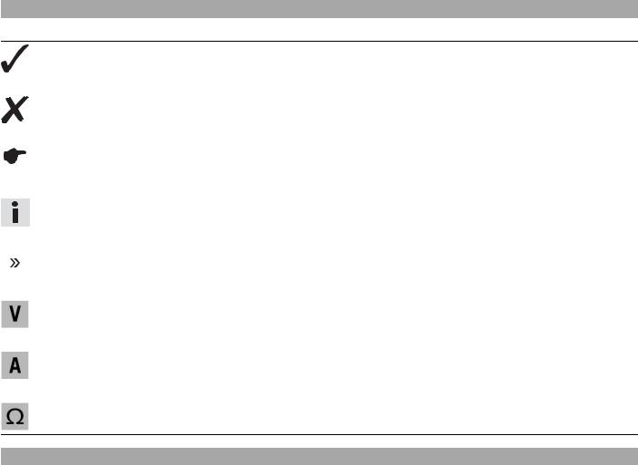
MEANS OF REPRESENTATION |
5 |
Symbols used
The symbols used are explained in the following.
Indicates an expected reaction (e.g. of a work step or a function).
Indicates an unexpected reaction (e.g. of a work step or a function).
Identifies a page reference (more information is provided on the specified page).
Indicates information with more details or tips.
Indicates the result of a testing step.
Identifies a voltage measurement.
Identifies a current measurement.
Identifies a resistance measurement.
Formats used
The typographical and other formats used are explained below.
|
Specific name |
Indicates a proprietary name. |
|
Name® |
Identifies a protected name. |
|
Brand™ |
Identifies a trademark. |
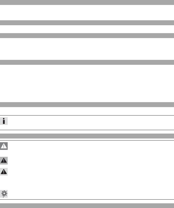
Warranty
The work prescribed in the service plan must only be carried out in an authorized KTM workshop and confirmed in the service record; otherwise all warranty claims will be disregarded. No warranty claim can be met for damage resulting from manipulation and/or other changes to the vehicle.
Fuel, oils, etc.
You should use the fuels, oils and greases according to specifications as listed in the repair manual.
Spare parts, accessories
Only use spare parts and accessories approved and/or recommended by KTM. KTM accepts no liability for other products and any resulting damage.
You will find the current KTM PowerParts for your vehicle on the KTM website.
International KTM Website: http://www.ktm.com
Work rules
Special tools are necessary for certain tasks. The tools are not contained in the vehicle but can be ordered under the number in parentheses. Example: valve spring mounter (59029019000)
During assembly, non-reusable parts (e.g. self-locking screws and nuts, seals and seal rings, O-rings, pins, lock washers) must be replaced by new parts.
If a thread lock (e.g. Loctite®) is used for screw connections, be sure to comply with the manufacturer’s specific instructions on its usage.
Parts that you want to reuse following repairs and servicing should be cleaned and checked for damage and wear. Change damaged or worn parts.
Following repairs or servicing, the vehicle must be checked for roadworthiness.
Notes/warnings
Pay close attention to the notes/warnings.
Info
Various information and warning labels are affixed to the vehicle. Do not remove information/warning labels. If they are missing, you or others may not recognize potential hazards and may therefore be injured.
Grades of risks
Danger
Identifies a danger that will immediately and invariably lead to fatal or serious permanent injury if the appropriate measures are not taken.
Warning
Identifies a danger that is likely to lead to fatal or serious injury if the appropriate measures are not taken.
Caution
Identifies a danger that may lead to minor injuries if the appropriate measures are not taken.
Note
Identifies a danger that will lead to considerable machine and material damage if the appropriate measures are not taken.
Warning
Identifies a danger that will lead to environmental damage if the appropriate measures are not taken.
Repair manual
–Read this repair manual carefully and thoroughly before beginning work. It contains useful information and tips that will help you repair and service your motorcycle.
–This manual assumes that the necessary special KTM tools and workplace and workshop equipment are available.
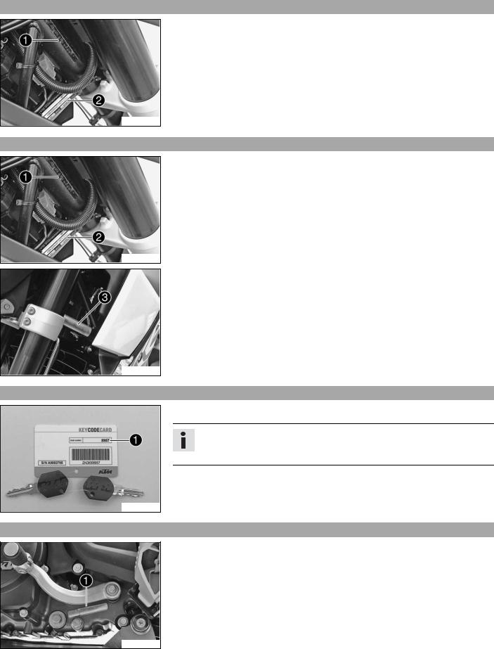
LOCATION OF SERIAL NUMBERS |
7 |
Chassis3.1 number/type label (Duke R, 690 Duke EU, 690 Duke AUS/UK, 690 Duke JP)
The chassis number is stamped on the right of the steering head.
The type label is on the right of the frame behind the steering head.
500006-01
Chassis3.2 number/type label (690 Duke USA)
The chassis number is stamped on the right of the steering head.
The USA type label is on the right of the frame behind the steering head.
500006-01
The Canada type label is on the right of the frame behind the steering head.
700218-01
Key3.3 number
The key number can be found on the KEYCODECARD.
Info
You need the key number to order a spare key. Keep the KEYCODECARD in a safe place.
100179-10
Engine3.4 number
The engine number is stamped on the left side of the engine under the engine sprocket.
700125-01

|
LOCATION OF SERIAL NUMBERS |
8 |
Fork3.5 part number
The fork part number is stamped on the inner side of the fork stub.
700126-01
Shock3.6 absorber part number
The shock absorber part number is stamped on the top of the shock absorber above the adjusting ring toward the rear.
700128-01
![]()
Raising4.1 the motorcycle with the rear wheel stand
Note
Danger of damage The parked vehicle may roll away or fall over.
–Always place the vehicle on a firm and even surface.
–Insert the adapter into the rear wheel stand and screw into the swingarm on both sides.
Adapter (61029055110) ( p. 248)
Rear wheel stand (61029055100) ( p. 248)
–Position the motorcycle upright, align the stand and raise the motorcycle.
700142-01
Taking4.2 the motorcycle off of the rear wheel stand
Note
Danger of damage The parked vehicle may roll away or fall over.
–Always place the vehicle on a firm and even surface.
–Secure the motorcycle against falling over.
–Remove the rear wheel stand and lean the vehicle on the side stand.
Raising4.3 the motorcycle with the front wheel stand
Note
Danger of damage The parked vehicle may roll away or fall over.
–Always place the vehicle on a firm and even surface.
–Raise the motorcycle with the rear wheel stand. ( p. 9)
p. 9)
–Move the handlebar to the straight-ahead position. Align the front wheel stand with the fork legs using the adapters.
Front wheel stand (61029055300) ( p. 249)
Info
Always raise the rear of the motorcycle first.
–Raise the front of the motorcycle.
700141-01
Taking4.4 the motorcycle off of the front wheel stand
Note
Danger of damage The parked vehicle may roll away or fall over.
–Always place the vehicle on a firm and even surface.
–Secure the motorcycle against falling over.
–Remove the front wheel stand.
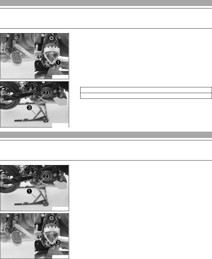
Raising4.5 the motorcycle with the work stand
Note
Danger of damage The parked vehicle may roll away or fall over.
–Always place the vehicle on a firm and even surface.
–Remove the nuts on both sides.
–Take off the footrest rubber and holder.
300602-10
–Mount the special tool and .
Work stand (62529055000) ( p. 249)
Work stand adapter (75029036000) ( p. 251)
–Position the motorcycle upright, align the special tool and raise the motorcycle.
300603-10
Removing4.6 the motorcycle from the work stand
Note
Danger of damage The parked vehicle may roll away or fall over.
–Always place the vehicle on a firm and even surface.
–Secure the motorcycle against falling over.
–Remove the special tool and .
300603-11
–Position the footrest rubbers with holders on both sides.
–Install nuts on both sides. Guideline
|
Remaining nuts, chassis |
M6 |
15 Nm |
|
(11.1 lbf ft) |
||
300602-11
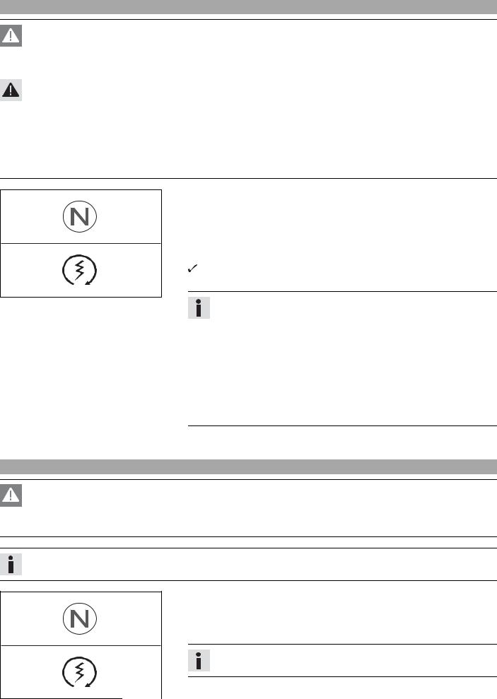
Starting4.7
Danger
Danger of poisoning Exhaust gases are poisonous and inhaling them may result in unconsciousness and/or death.
–When running the engine, always make sure there is sufficient ventilation, and do not start or run the engine in an enclosed space without an effective exhaust extraction system.
Caution
Danger of accidents If the vehicle is operated with a discharged battery or without a battery, electronic components and safety equipment may be damaged.
–Never operate the vehicle with a discharged battery or without a battery.
Note
Engine failure High engine speeds in cold engines have a negative effect on the service life of the engine.
–Always warm up the engine at low engine speeds.
–Turn the emergency OFF switch to the position  .
.
–Switch on the ignition by turning the ignition key to the position  .
.
 After you switch on the ignition, you can hear the fuel pump working for about 2 seconds. At the same time, the function test of the combination instrument is run.
–Shift gear to neutral.
The green idling speed indicator lamp N lights up.
– Press the electric starter button  .
.
B00103-10
Info
Do not press the electric starter button until the function test of the combination instrument is finished.
When starting, DO NOT open the throttle. If you open the throttle during the starting procedure, fuel is not injected by the engine management system and the engine cannot start.
Press the starter for a maximum of 5 seconds. Wait for at least 5 seconds before trying again.
This motorcycle is equipped with a safety start system. You can only start the engine if the gearbox is in neutral or if the clutch is pulled when a gear is engaged. If the side stand is folded out and you shift into gear and release the clutch, the engine stops.
–Take the weight off the side stand and swing it back up with your foot as far as it will go.
Starting4.8 the motorcycle to make checks
Danger
Danger of poisoning Exhaust gases are poisonous and inhaling them may result in unconsciousness and/or death.
–When running the engine, always make sure there is sufficient ventilation, and do not start or run the engine in an enclosed space without an effective exhaust extraction system.
Info
Press the starter for a maximum of 5 seconds. Wait for a least 5 seconds before trying again.
–Turn the emergency OFF switch to the position  .
.
–Shift gear to neutral.
–Switch on the ignition.
–Press the electric starter button  .
.
Info
Do not open the throttle.
B00103-10
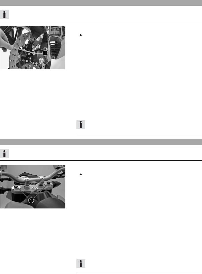
Adjusting5.1 the compression damping of the fork
Info
The hydraulic compression damping determines the fork suspension behavior.
|
– Turn adjusting screws clockwise until they stop. |
|||||||
|
Info |
|||||||
|
The adjusting screws are located at the bottom end of the fork legs. |
|||||||
|
Make the same adjustment on both fork legs. |
|||||||
|
– Turn back counterclockwise by the number of clicks corresponding to the fork type. |
|||||||
|
Guideline |
|||||||
|
Compression damping (Duke) |
|||||||
|
700146-01 |
Comfort |
20 clicks |
|||||
|
Standard |
15 clicks |
||||||
|
Sport |
10 clicks |
||||||
|
Full payload |
10 clicks |
||||||
|
Compression damping (Duke R) |
|||||||
|
Comfort |
20 clicks |
||||||
|
Standard |
15 clicks |
||||||
|
Sport |
10 clicks |
||||||
|
Full payload |
10 clicks |
||||||
Info
Turn clockwise to increase damping, turn counterclockwise to reduce suspension damping.
Adjusting5.2 the rebound damping of the fork
Info
The hydraulic rebound damping determines the fork rebound behavior.
|
– Turn adjusting screws clockwise until they stop. |
|||||||
|
Info |
|||||||
|
The adjusting screws are located at the top end of the fork legs. |
|||||||
|
Make the same adjustment on both fork legs. |
|||||||
|
– Turn back counterclockwise by the number of clicks corresponding to the fork type. |
|||||||
|
Guideline |
|||||||
|
Rebound damping (Duke) |
|||||||
|
700145-01 |
Comfort |
20 clicks |
|||||
|
Standard |
15 clicks |
||||||
|
Sport |
10 clicks |
||||||
|
Full payload |
10 clicks |
||||||
|
Rebound damping (Duke R) |
|||||||
|
Comfort |
25 clicks |
||||||
|
Standard |
20 clicks |
||||||
|
Sport |
15 clicks |
||||||
|
Full payload |
15 clicks |
||||||
Info
Turn clockwise to increase damping; turn counterclockwise to reduce damping.
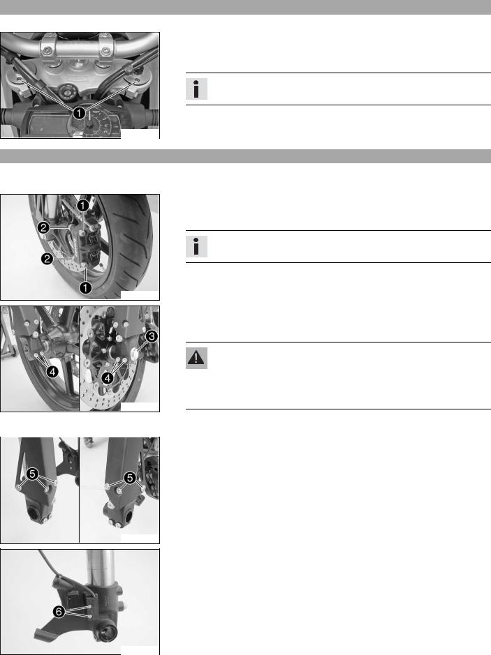
Bleeding5.3 the fork legs
–Lean the motorcycle on the side stand.
–Remove bleeder screws briefly.
 Any excess pressure escapes from the interior of the fork.
–Mount and tighten bleeder screws.
Info
Carry out this action on both fork legs.
100849-10
Removing5.4 fork legs
–Raise the motorcycle with the work stand. ( p. 10)
–Tie the rear of the vehicle down.
–Remove screws and spacers .
–Press back the brake linings with a light lateral tilting of the brake caliper on the brake disc. Carefully pull the brake caliper backwards from the brake disc.
Info
Do not pull the hand brake lever while the brake caliper is removed.
200707-10
–Loosen screws and .
–Unscrew screw about 6 turns and press your hand on the screw to push the wheel spindle out of the axle clamp. Remove screw .
Warning
Danger of accidents Reduced braking efficiency caused by damaged brake discs.
–Always lay the wheel down in such a way that the brake disc is not damaged.
200708-10
–Holding the front wheel, withdraw the wheel spindle. Take the front wheel out of the fork.
–Remove screws with the washers. Remove the splash protector.
200709-10
–Remove the screws of the wheel speed sensor . Hang the wheel speed sensor to one side.
–Loosen the cable binders.
200710-10
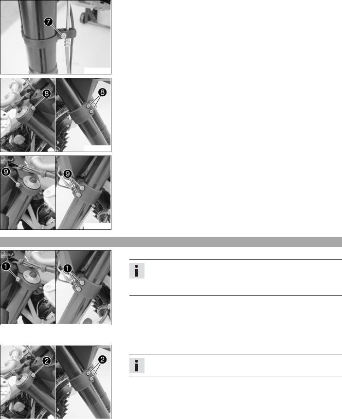
–Remove screw . Take the brake line and wiring harness out of the clamp.
200711-10
–Loosen the screws of the triple clamp. Remove the fork leg downwards.
200712-10
–Loosen the screws of the triple clamp. Remove the fork leg downwards.
200713-10
Installing5.5 the fork legs
–Push the fork leg into the triple clamps.
Info
The bleeder screws must face forwards.
The topmost milled groove in the fork leg must be flush with the top edge of the upper triple clamp.
|
– Tighten screws of the triple clamps. |
|||||||
|
Guideline |
|||||||
|
Screw, top triple clamp |
M8 |
12 |
Nm (8.9 lbf ft) |
||||
|
200713-11 |
|||||||
|
Screw, bottom triple clamp |
M8 |
15 |
Nm |
||||
|
(11.1 lbf ft) |
|||||||
|
– Push the fork leg into the triple clamps. |
|||||||
Info
The upper fork projection must be the same on both sides.
|
– Tighten screws of the triple clamps. |
||||||
|
Guideline |
||||||
|
Screw, top triple clamp |
M8 |
12 |
Nm (8.9 lbf ft) |
|||
|
Screw, bottom triple clamp |
M8 |
15 |
Nm |
|||
|
200712-11 |
(11.1 lbf ft) |
|||||
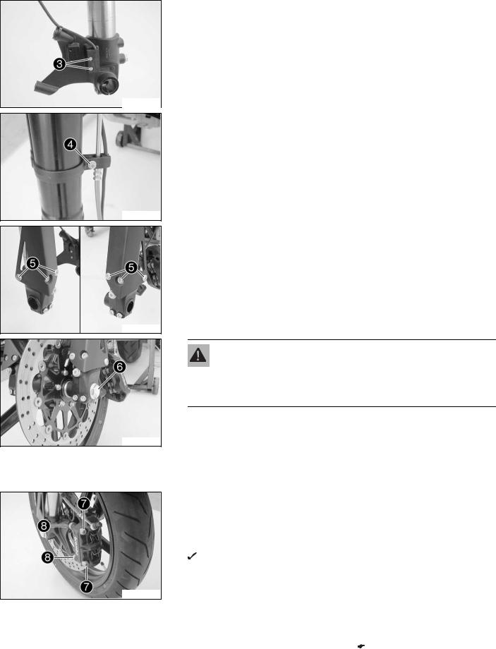
–Position the wheel speed sensor. Mount and tighten screws . Guideline
|
Screw, wheel speed sensor |
M4 |
2 Nm |
Loctite® 243™ |
|
(1.5 lbf ft) |
|||
200710-11
–Position the brake line, wiring harness and clamp.
–Mount and tighten screw . Guideline
|
Screw, plastic clamp of brake line on |
M5 |
2 Nm (1.5 lbf ft) |
|
fork leg |
||
200711-11
–Position the splash protector. Mount and tighten screws with the washers. Guideline
|
Remaining screws, chassis |
M6 |
10 Nm (7.4 lbf ft) |
200709-10
Warning
Danger of accidents Reduced braking efficiency due to oil or grease on the brake discs.
– Always keep the brake discs free of oil and grease, and clean them with brake cleaner when necessary.
– Clean screw and the wheel spindle.
– Lift the front wheel into the fork, position it, and insert the wheel spindle.
– Mount and tighten screw . Guideline
|
Screw, front wheel spindle |
M24x1.5 |
40 Nm |
|
(29.5 lbf ft) |
||
– Position the brake calipers and check that the brake linings are seated correctly.
– Mount screws with spacers but do not tighten.
– Operate the hand brake lever repeatedly until the brake linings are in contact with the brake disc and there is a pressure point. Fix the hand brake lever in the activated position.
The brake caliper straightens.
– Tighten screws . Guideline
|
Screw, front brake caliper |
M10x1.25 |
45 Nm |
Loctite® 243™ |
||
|
(33.2 lbf ft) |
|||||
|
– Remove the fixation of the hand brake lever. |
|||||
|
– |
Unload the rear of the vehicle. |
||||
|
– |
Remove the motorcycle from the work stand. ( |
p. 10) |

–Pull the front brake and compress the fork powerfully a few times.  The fork legs straighten.
–Tighten screws . Guideline
|
Screw, fork stub |
M8 |
15 Nm |
|
(11.1 lbf ft) |
||
200717-10
Servicing5.6 the fork
Info
These operations are the same on both fork legs.
Condition
The fork legs have been removed.
–Disassemble the fork legs. ( p. 16)
–Check the fork legs. ( p. 19)
– Assemble the fork legs. ( p. 21)
201244-01
Disassembling5.7 the fork legs
Info
These operations are the same on both fork legs.
Condition
The fork legs have been removed.
–Establish and note the current state of the rebound damping and compression damping .
–Completely open the adjusters of the rebound and compression damping.
200660-01
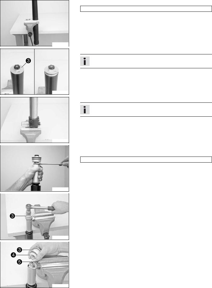
200643-10
200644-12
200661-01
200729-10
200730-10
200731-10
–Clamp the fork leg in the area of the lower triple clamp. Clamping stand (T1403S) ( p. 257)
–Loosen the screw cover .
Info
The screw cover cannot be removed yet.
–Release the fork leg and clamp it with the fork stub.
Info
Use soft jaws.
–Push the outer tube downward.
–Pull the tube downwards. Mount the special tool on the hexagon.
Open-end wrench (T14032) ( p. 257)
– Clamp the special tool in the vise. Loosen the screw cover .
–Remove screw cover with preload spacers .
–Remove adjusting tube .

–Pull the tube downwards. Remove the special tool.
–Remove the tube, washer and spring.
200732-10
–Drain the fork oil.
Info
Pull out and push in the piston rod a few times to empty the cartridge.
200650-01
–Clamp the fork leg with the fork stub.
–Remove screws of the axle clamp.
200662-01
–Loosen screw of the cartridge and remove it with the sealing ring.
Info
Place a container underneath to catch any oil that may run out.
200667-10
–Remove the cartridge.
200653-01
–Remove valve of the rebound damping with the spring from the cartridge.
200654-12
![]()
200655-12
200656-12
200668-10
200658-12
200659-12
Checking5.8 the fork legs
–Remove dust boot .
–Remove lock ring .
Info
The lock ring has a beveled end where a screwdriver can be applied.
–Heat up the outer tube in area of the lower sliding bushing. Guideline
50 °C (122 °F)
–Pull the fork outer tube with a jerk from the inner tube.
Info
The lower sliding bushing must be pulled from its bearing seat.
–Remove the upper sliding bushing .
Info
Without using a tool, carefully pull the stack apart by hand.
–Take off the lower sliding bushing .
–Take off support ring .
–Take off seal ring .
–Take off lock ring .
–Take off dust boot .
Condition
The fork legs have been disassembled.

200686-10
200684-10
200685-10
200632-10
200665-10
201249-10
–Check the inner tube and the axle clamp for damage. » If damage is found:
– Replace the inner tube.
–Measure the external diameter of the inner tube in several places.
|
External diameter of inner tube |
47.975… 48.005 mm (1.88878… |
|
1.88996 in) |
|
» If the measured value is less than the specified value:
– Replace the inner tube.
–Measure the run-out of the inner tube.
|
Run-out of inner tube |
≤ 0.20 mm (≤ 0.0079 in) |
»If the measured value is greater than the specified value:
–Replace the inner tube.
–Check the outer tube for damage.
»If damage is found:
–Replace the outer tube.
–Check the surface of the sliding bushings.
»If the bronze-colored layer under sliding layer is visible:
–Replace the sliding bushings.
–Check the spring length. Guideline
|
Spring length with preload spacer(s) |
352 mm (13.86 in) |
»If the measured value is greater than the specified value:
–Reduce the strength of the pretensioning bushes.
»If the measured value is less than the specified value:
–Increase the strength of the preload spacers.
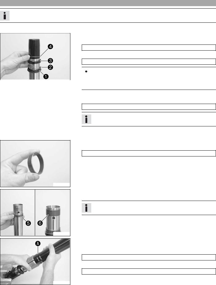
Assembling5.9 the fork legs (Duke)
Info
These operations are the same on both fork legs.
–Check the fork legs. ( p. 19)
–Clamp the inner tube with the axle clamp.
–Mount the special tool.
Protecting sleeve (T1401) ( p. 256)
–Grease and push on dust boot . Lubricant (T511) ( p. 244)
|
Info |
|||||||
|
Always replace the dust boot, seal ring, lock ring, and support ring. |
|||||||
|
200669-10 |
|||||||
|
Install the dust boot with the sealing lip and spring expander facing down- |
|||||||
|
ward. |
–Push on lock ring .
–Grease and push on seal ring .
Lubricant (T511) ( p. 244)
Info
Sealing ring downward, open side upward.
–Push on support ring .
–Remove the special tool.
–Sand the edges of the sliding bushes with 600-grain sandpaper, then clean and grease them.
Fork oil (SAE 5) ( p. 243)
200670-10
–Push on the lower sliding bushing .
–Mount the upper sliding bushing .
Info
Without using a tool, carefully pull the stack apart by hand.
200671-10
–Push on the outer tube.
–Heat up the outer tube in area of the lower sliding bushings. Guideline
50 °C (122 °F)
–Hold the lower sliding bushing with the longer side of the special tool. Assembly tool (T1402S) ( p. 257)
–Press on the outer tube as far as it will go.
200672-10

–Position the support ring.
–Hold the seal ring with the shorter side of the special tool.
Assembly tool (T1402S) ( p. 257)
–Press on the outer tube as far as it will go.
200673-10
–Mount lock ring .
Info
The lock ring must engage audibly.
200656-11
–Install dust boot .
200655-11
–Grease the O-ring of valve of the rebound damping. Lubricant (T158) ( p. 244)
– Mount valve of the rebound damping with the spring on adjusting tube .
–Mount valve of the rebound damping from below in cartridge .
 The adjusting tube protrudes 5 mm from the cartridge and can be pressed in against the resistance of the spring.
|
The adjusting tube protrudes more than 7 mm from the cartridge and cannot |
|
|
200674-10 |
be pressed in against the resistance of the spring. |
–Screw on fluid barrier as far as it will go.
Info
The fluid barrier must be tightened as much as possible. Do not use tools.
–Install the special tool on the cartridge. Gripping tool (T14026S1) ( p. 256)
Info
The special tool must be used to prevent the adjusting tube being lifted and thus to prevent oil from reaching the piston rod.
200675-10

200683-10
200682-10
200677-10
201245-10
201246-10
201247-10
– Push the cartridge with the spring seat and preload spacer into the inner tube.
– Mount screw of the cartridge with the seal ring and tighten it. Guideline
|
Cartridge screw |
M12x1 |
25 Nm |
||
|
(18.4 lbf ft) |
||||
|
– Grease and mount screws of the axle clamp but do not tighten. |
||||
|
Lubricant (T152) ( |
p. 245) |
|||
–Clamp the fork vertically.
–Fill it with fork oil.
|
Fork oil per fork |
775 ml |
Fork oil (SAE 5) ( p. 243) |
|
leg |
(26.2 fl. oz.) |
|
Info
Pull out and push in the piston rod completely a few times to remove air from the cartridge.
–Remove pin of the special tool. Gripping tool (T14026S1) ( p. 256)
–Pull out the piston rod. Mount the spring and tube. Mount the spring again. Guideline
Spring rate
|
Medium (standard) |
6.5 N/mm (37.1 lb/in) |
–Pull the tube downwards. Mount the special tool on the hexagon. Open-end wrench (T14032) ( p. 257)
–Remove the special tool.
Gripping tool (T14026S1) ( p. 256)
–Clamp the special tool in the vise.
–Grease the thread of the piston rod.
Lubricant (T159) ( p. 245)
–Grease the upper edge of the piston rod. Lubricant (T158) ( p. 244)
–Screw the screw cover with the preload spacers on to the piston rod.
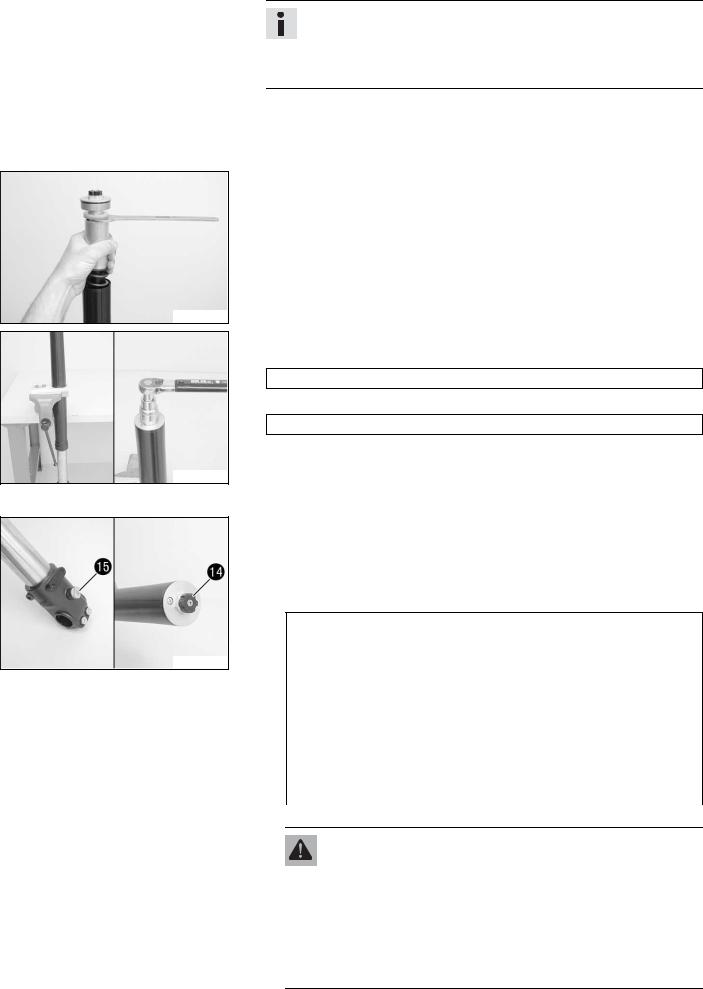
201248-10
200681-10
200660-11
Info
The screw cover must be screwed to the stop before the piston rod starts to turn. If the thread of the piston rod is stiff, it must be held to prevent it from turning. If the screw cover is not screwed to the stop, the rebound adjustment will not work correctly.
|
– |
Tighten the screw cover. |
||
|
Guideline |
|||
|
Screw cover on piston rod |
M12x1 |
25 Nm |
|
|
(18.4 lbf ft) |
|||
|
– |
|||
|
Release the special tool. Pull the tube downward and take off the special tool. |
–Push the outer tube upward.
–Clamp the fork in the area of the lower triple clamp.
Clamping stand (T1403S) ( p. 257)
–Grease the O-ring of the screw cover. Lubricant (T511) ( p. 244)
–Screw on and tighten the screw cover. Guideline
|
Screw cover on outer tube |
M51x1.5 |
50 Nm |
|
(36.9 lbf ft) |
||
Alternative 1
–Turn the adjusting screw of rebound damping and the adjusting screw of compression damping clockwise as far as possible.
–Turn back counterclockwise by the number of clicks corresponding to the fork leg type.
Guideline
Rebound damping
|
Comfort |
20 clicks |
|
Standard |
15 clicks |
|
Sport |
10 clicks |
|
Full payload |
10 clicks |
|
Compression damping |
|
|
Comfort |
20 clicks |
|
Standard |
15 clicks |
|
Sport |
10 clicks |
|
Full payload |
10 clicks |
Alternative 2
Warning
Danger of accidents Modifications to the suspension settings can seriously alter the vehicle’s ride behavior.
–Extreme modifications to the adjustment of the spring elements can cause a serious deterioration in the handling characteristics and overload some components.
–Only make adjustments within the recommended range.
–After making adjustments, ride slowly at first to get the feel of the new ride behavior.
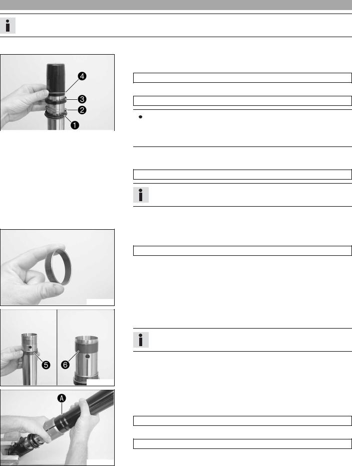
–Turn the adjusting screws to the position they were in before dismantling.
Assembling5.10 the fork legs (Duke R)
Info
These operations are the same on both fork legs.
–Check the fork legs. ( p. 19)
–Clamp the inner tube with the axle clamp.
–Mount the special tool.
Protecting sleeve (T1401) ( p. 256)
–Grease and push on dust boot . Lubricant (T511) ( p. 244)
|
Info |
|||||||
|
Always replace the dust boot, seal ring, lock ring, and support ring. |
|||||||
|
200669-10 |
|||||||
|
Install the dust boot with the sealing lip and spring expander facing down- |
|||||||
|
ward. |
–Push on lock ring .
–Grease and push on seal ring .
Lubricant (T511) ( p. 244)
Info
Sealing ring downward, open side upward.
–Push on support ring .
–Remove the special tool.
–Sand the edges of the sliding bushes with 600-grain sandpaper, then clean and grease them.
Fork oil (SAE 5) ( p. 243)
200670-10
–Push on the lower sliding bushing .
–Mount the upper sliding bushing .
Info
Without using a tool, carefully pull the stack apart by hand.
200671-10
–Push on the outer tube.
–Heat up the outer tube in area of the lower sliding bushings. Guideline
50 °C (122 °F)
–Hold the lower sliding bushing with the longer side of the special tool. Assembly tool (T1402S) ( p. 257)
–Press on the outer tube as far as it will go.
200672-10
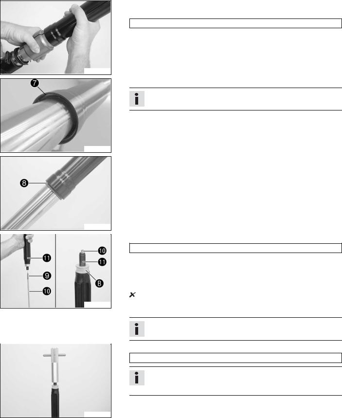
–Position the support ring.
–Hold the seal ring with the shorter side of the special tool.
Assembly tool (T1402S) ( p. 257)
–Press on the outer tube as far as it will go.
200673-10
–Mount lock ring .
Info
The lock ring must engage audibly.
200656-11
–Install dust boot .
200655-11
–Grease the O-ring of valve of the rebound damping. Lubricant (T158) ( p. 244)
– Mount valve of the rebound damping with the spring on adjusting tube .
–Mount valve of the rebound damping from below in cartridge .
 The adjusting tube protrudes 5 mm from the cartridge and can be pressed in against the resistance of the spring.
|
The adjusting tube protrudes more than 7 mm from the cartridge and cannot |
|
|
200674-10 |
be pressed in against the resistance of the spring. |
–Screw on fluid barrier as far as it will go.
Info
The fluid barrier must be tightened as much as possible. Do not use tools.
–Install the special tool on the cartridge. Gripping tool (T14026S1) ( p. 256)
Info
The special tool must be used to prevent the adjusting tube being lifted and thus to prevent oil from reaching the piston rod.
200675-10
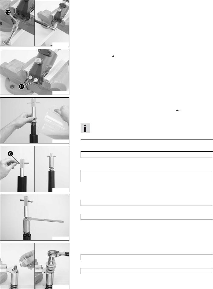
200683-10
200682-10
200677-10
201245-10
201246-10
201247-10
– Push the cartridge with the spring seat and preload spacer into the inner tube.
– Mount screw of the cartridge with the seal ring and tighten it. Guideline
|
Cartridge screw |
M12x1 |
25 Nm |
||
|
(18.4 lbf ft) |
||||
|
– Grease and mount screws of the axle clamp but do not tighten. |
||||
|
Lubricant (T152) ( |
p. 245) |
|||
–Clamp the fork vertically.
–Fill it with fork oil.
|
Fork oil per fork |
760 ml |
Fork oil (SAE 5) ( p. 243) |
|
leg |
(25.7 fl. oz.) |
|
Info
Pull out and push in the piston rod completely a few times to remove air from the cartridge.
–Remove pin of the special tool. Gripping tool (T14026S1) ( p. 256)
–Pull out the piston rod. Mount the spring and tube. Mount the spring again. Guideline
Spring rate
|
Medium (standard) |
7.5 N/mm (42.8 lb/in) |
–Pull the tube downwards. Mount the special tool on the hexagon. Open-end wrench (T14032) ( p. 257)
–Remove the special tool.
Gripping tool (T14026S1) ( p. 256)
–Clamp the special tool in the vise.
–Grease the thread of the piston rod.
Lubricant (T159) ( p. 245)
–Grease the upper edge of the piston rod. Lubricant (T158) ( p. 244)
–Screw the screw cover with the preload spacers on to the piston rod.

201248-10
200681-10
200660-11
Info
The screw cover must be screwed to the stop before the piston rod starts to turn. If the thread of the piston rod is stiff, it must be held to prevent it from turning. If the screw cover is not screwed to the stop, the rebound adjustment will not work correctly.
|
– |
Tighten the screw cover. |
||
|
Guideline |
|||
|
Screw cover on piston rod |
M12x1 |
25 Nm |
|
|
(18.4 lbf ft) |
|||
|
– |
|||
|
Release the special tool. Pull the tube downward and take off the special tool. |
–Push the outer tube upward.
–Clamp the fork in the area of the lower triple clamp.
Clamping stand (T1403S) ( p. 257)
–Grease the O-ring of the screw cover. Lubricant (T511) ( p. 244)
–Screw on and tighten the screw cover. Guideline
|
Screw cover on outer tube |
M51x1.5 |
50 Nm |
|
(36.9 lbf ft) |
||
Alternative 1
–Turn the adjusting screw of rebound damping and the adjusting screw of compression damping clockwise as far as possible.
–Turn back counterclockwise by the number of clicks corresponding to the fork leg type.
Guideline
Rebound damping
|
Comfort |
25 clicks |
|
Standard |
20 clicks |
|
Sport |
15 clicks |
|
Full payload |
15 clicks |
|
Compression damping |
|
|
Comfort |
20 clicks |
|
Standard |
15 clicks |
|
Sport |
10 clicks |
|
Full payload |
10 clicks |
Alternative 2
Warning
Danger of accidents Modifications to the suspension settings can seriously alter the vehicle’s ride behavior.
–Extreme modifications to the adjustment of the spring elements can cause a serious deterioration in the handling characteristics and overload some components.
–Only make adjustments within the recommended range.
–After making adjustments, ride slowly at first to get the feel of the new ride behavior.
![]()
–Turn the adjusting screws to the position they were in before dismantling.
Checking5.11 the steering head bearing play
Warning
Danger of accidents Unstable vehicle handling from incorrect steering head bearing play.
–Adjust the steering head bearing play without delay.
Info
If the bike is ridden with play in the steering head bearing, the bearing and the bearing seats in the frame can become damaged with time.
–Raise the motorcycle with the work stand. ( p. 10)
–Move the handlebar to the straight-ahead position. Move the fork legs to and fro in the direction of travel.
No play should be noticeable in the steering head bearing.
|
» If there is noticeable play present: |
|||||
|
– Adjust the steering head bearing play. ( |
p. 29) |
||||
|
– Move the handlebar to and fro over the entire steering range. |
|||||
|
The handlebar must be able to move easily over the entire steering range. No |
|||||
|
resting locations should be noticeable. |
|||||
|
400738-11 |
|||||
|
» If click positions are noticeable: |
|||||
|
– Adjust the steering head bearing play. ( |
p. 29) |
||||
|
– Check the steering head bearing and change if necessary. |
|||||
|
– Remove the motorcycle from the work stand. ( |
p. 10) |
Adjusting5.12 the steering head bearing play
–Raise the motorcycle with the work stand. ( p. 10)
–Loosen screws . Remove screw .
–Loosen and retighten screw . Guideline
|
Screw, steering head |
M20x1.5 |
12 Nm (8.9 lbf ft) |
–Using a plastic hammer, tap lightly on the upper triple clamp to avoid strains.
–Tighten screws . Guideline
|
Screw, top triple clamp |
M8 |
12 |
Nm (8.9 lbf ft) |
||||
|
302000-10 |
|||||||
|
– Mount and tighten screw . |
|||||||
|
Guideline |
|||||||
|
Screw, steering stem |
M8 |
20 |
Nm |
||||
|
(14.8 lbf ft) |
|||||||
|
– Check the steering head bearing play. ( |
p. 29) |

02/HANDLEBAR, INSTRUMENTS |
30 |
|||
|
Checking6.1 |
the play in the throttle cable |
–Move the handlebar to the straight-ahead position. Move the throttle grip backwards and forwards to ascertain the play in the throttle cable.
|
Throttle cable play |
3… 5 mm (0.12… 0.2 in) |
»If the throttle cable play does not meet specifications:
– Adjust the play in the throttle cable. ( p. 30)
Danger
Danger of poisoning Exhaust gases are poisonous and inhaling them may result in unconsciousness and/or death.
–When running the engine, always make sure there is sufficient ventilation, and do not start or run the engine in an enclosed space without an effective exhaust extraction system.
–Start the engine and let it run idle. Move the handlebar to and fro over the entire steering range.
The idle speed must not change.
»If the idle speed changes:
– Adjust the play in the throttle cable. ( p. 30)
Adjusting6.2 the play in the throttle cable
–Move the handlebar to the straight-ahead position.
–Use the KTM diagnostics tool to set the motor drive to the basic position.
–Loosen counter nut .
–Set the play in the throttle cable by turning the adjusting screw . Guideline
|
Throttle cable play |
3… 5 mm (0.12… 0.2 in) |
–Tighten counter nut .
100195-10

04/SHOCK ABSORBER, SWINGARM |
31 |
Adjusting7.1 the high-speed compression damping of the shock absorber
Danger
Danger of accidents Disassembly of pressurized parts can lead to injury.
–The shock absorber is filled with high density nitrogen. Adhere to the description provided.
Info
The high-speed setting can be seen during the fast compression of the shock absorber.
|
– Turn adjusting screw all the way clockwise using a socket wrench. |
|||||||
|
Info |
|||||||
|
Do not loosen nut ! |
|||||||
|
– Turn back counterclockwise by the number of turns corresponding to the shock |
|||||||
|
absorber type. |
|||||||
|
Guideline |
|||||||
|
Compression damping, high-speed (Duke) |
|||||||
|
100843-10 |
Comfort |
2.0 turns |
|||||
|
Standard |
1.5 turns |
||||||
|
Sport |
1.0 turn |
||||||
|
Full payload |
1.0 turn |
||||||
|
Compression damping, high-speed (Duke R) |
|||||||
|
Comfort |
2.0 turns |
||||||
|
Standard |
1.5 turns |
||||||
|
Sport |
1.0 turn |
||||||
|
Full payload |
1.0 turn |
||||||
Info
Turn clockwise to increase damping; turn counterclockwise to reduce damping.
Adjusting7.2 the low-speed compression damping of the shock absorber
Danger
Danger of accidents Disassembly of pressurized parts can lead to injury.
–The shock absorber is filled with high density nitrogen. Adhere to the description provided.
Info
The low-speed setting can be seen during the slow to normal compression of the shock absorber.
–Turn the adjusting screw clockwise with a screwdriver up to the last perceptible click.
Info
Do not loosen nut !
–Turn back counterclockwise by the number of clicks corresponding to the shock absorber type.
700144-01

|
04/SHOCK ABSORBER, SWINGARM |
32 |
|||
|
Guideline |
||||
|
Compression damping, low-speed (Duke) |
||||
|
Comfort |
20 clicks |
|||
|
Standard |
15 clicks |
|||
|
Sport |
10 clicks |
|||
|
Full payload |
10 clicks |
|||
|
Compression damping, low-speed (Duke R) |
||||
|
Comfort |
20 clicks |
|||
|
Standard |
15 clicks |
|||
|
Sport |
10 clicks |
|||
|
Full payload |
10 clicks |
|||
Info
Turn clockwise to increase damping; turn counterclockwise to reduce damping.
Adjusting7.3 the rebound damping of the shock absorber
Danger
Danger of accidents Disassembly of pressurized parts can lead to injury.
–The shock absorber is filled with high density nitrogen. Adhere to the description provided.
–Turn adjusting screw clockwise up to the last perceptible click.
–Turn back counterclockwise by the number of clicks corresponding to the shock absorber type.
Guideline
|
Rebound damping (Duke) |
||||
|
Comfort |
20 clicks |
|||
|
Standard |
15 clicks |
|||
|
Sport |
10 clicks |
|||
|
700148-01 |
||||
|
Full payload |
10 clicks |
|||
|
Rebound damping (Duke R) |
||||
|
Comfort |
20 clicks |
|||
|
Standard |
15 clicks |
|||
|
Sport |
10 clicks |
|||
|
Full payload |
10 clicks |
|||
Info
Turn clockwise to increase damping; turn counterclockwise to reduce damping.
Removing7.4 the shock absorber
–Raise the motorcycle with the work stand. ( p. 10)
–Loosen screw .
300604-10

|
04/SHOCK ABSORBER, SWINGARM |
33 |
300605-10
300606-10
300604-10
300607-10
–Remove the nut with the screw.
–Loosen screw .
–Remove the nut with the screw.
–Lift the link fork.
–Swing the connecting lever downwards.
–Remove screw .
–Take off deflector .
–Remove screw .
– Lift the link fork and take out the shock absorber downwards.
Installing7.5 the shock absorber
– Lift the link fork and insert the shock absorber upwards.
300607-11
–Mount screw but do not tighten it yet. Guideline
|
Screw, top shock absorber |
M10 |
45 Nm |
Loctite® 243™ |
|
(33.2 lbf ft) |
|||
300604-11

|
04/SHOCK ABSORBER, SWINGARM |
34 |
300606-11
300605-11
300604-11
|
– Lift the link fork. |
||||||
|
– |
Position deflector . |
|||||
|
– Mount screw but do not tighten it yet. |
||||||
|
Guideline |
||||||
|
Screw, bottom shock |
M10 |
45 Nm |
Loctite® 243™ |
|||
|
absorber |
(33.2 lbf ft) |
|||||
|
– Mount and tighten screw with nut . |
||||||
|
Guideline |
||||||
|
Nut, linkage lever on swingarm |
M14x1.5 |
100 Nm |
||||
|
(73.8 lbf ft) |
||||||
|
– Position the connecting lever. |
||||||
|
– Mount and tighten screw with nut . |
||||||
|
Guideline |
||||||
|
Nut, frame to linkage lever |
M14x1.5 |
100 Nm |
||||
|
(73.8 lbf ft) |
||||||
|
– |
||||||
|
Tighten screw . |
||||||
|
Guideline |
||||||
|
Screw, bottom shock |
M10 |
45 Nm |
Loctite® 243™ |
|||
|
absorber |
(33.2 lbf ft) |
|||||
|
– |
||||||
|
Tighten screw . |
||||||
|
Guideline |
||||||
|
Screw, top shock absorber |
M10 |
45 Nm |
Loctite® 243™ |
|||
|
(33.2 lbf ft) |
||||||
|
– |
||||||
|
Remove the motorcycle from the work stand. ( p. 10) |
Servicing7.6 the shock absorber
Danger
Danger of accidents Disassembly of pressurized parts can lead to injury.
–The shock absorber is filled with high density nitrogen. Adhere to the description provided.
Condition
The shock absorber has been removed.

|
04/SHOCK ABSORBER, SWINGARM |
35 |
–Remove the spring. ( p. 35)
–Disassemble the damper. ( p. 35)
– Disassemble the piston rod. ( p. 37)
– Check the damper. ( p. 38)
– Remove the heim joint. ( p. 39)
– Install the heim joint. ( p. 39)
– Assemble the piston rod. ( p. 40)
– Assemble the damper. ( p. 41)
– Install the spring. ( p. 46)
201269-01
Removing7.7 the spring
Condition
The shock absorber has been removed.
–Clamp the shock absorber in the vise using soft jaws for protection.
–Measure and note spring length in preloaded state.
–Loosen retaining ring and the adjusting ring with the special tool.
Hook wrench (T106S) ( p. 255)
Hook wrench (T157S) ( p. 257)
–Turn the retaining ring and adjusting ring until the spring is fully relieved of tension.
201250-10
–Remove spring retainer .
–Take off spring with the retaining ring and adjusting ring .
201251-10
Disassembling7.8 the damper
–Remove the spring. ( p. 35)
–Establish and note the current state of the rebound damping and compression damping.
–Completely open the adjusters of the rebound and compression damping.
–Remove rubber cap of the reservoir.
–Open screw slowly.
 The pressurized nitrogen escapes.
201258-10

|
04/SHOCK ABSORBER, SWINGARM |
36 |
–Remove locking cap .
201256-10
–Press in seal ring retainer . Remove lock ring .
Info
Do not scratch the inner surface.
201255-10
–Remove screw . Drain the oil.
201254-10
–Remove the piston rod. Drain the remaining oil.
201253-10
– Remove compression damping adjuster . Remove the spring, sleeve and piston.
201252-10

|
04/SHOCK ABSORBER, SWINGARM |
37 |
Disassembling7.9 the piston rod
–Disassemble the damper. ( p. 35)
–Clamp the piston rod with the heim joint in a vise.
–Remove nut .
300540-10
–Remove supporting plate and rebound shim stack together with piston .
Info
Thread the rebound shim set on a screwdriver and set the parts down together.
300541-10
–Remove compression shim stack with supporting plate .
Info
Thread the compression shim stack on a screwdriver and set the parts down together.
200572-11
– Remove seal ring retainer .
300542-10
–Remove locking cap and rubber buffer .
300543-10

|
04/SHOCK ABSORBER, SWINGARM |
38 |
Checking7.10 the damper
201268-10
300554-10
300460-01
Condition
The damper has been disassembled.
–Measure the inside diameter at both ends and in the center of the damper cartridge.
Damper cartridge
|
Minimum diameter |
46.10 mm (1.815 in) |
»If the measured value is greater than the specified value:
–Change the damper cartridge.
–Check the damper cartridge for damage and wear.
»If there is damage or wear:
–Change the damper cartridge.
–Measure the diameter of the piston rod.
Piston rod
|
Diameter |
≥ 17.95 mm (≥ 0.7067 in) |
» If the specification is not reached:
– Change the piston rod.
–Measure the run-out of the piston rod.
Piston rod
|
Run-out |
≤ 0.03 mm (≤ 0.0012 in) |
»If the measured value is greater than the specified value:
–Change the piston rod.
–Check the piston rod for damage and wear.
»If there is damage or wear:
–Change the piston rod.
–Check the heim joint for damage and wear.
»If there is damage or wear:
–Change the heim joint.
![]()
|
04/SHOCK ABSORBER, SWINGARM |
39 |
Removing7.11 the heim joint
Condition
The shock absorber has been removed.
–Clamp the shock absorber in the vise using soft jaws for protection.
–Remove collar bushing of the heim joint.
Pin (T120) ( p. 255)
–Turn over the shock absorber and remove collar bushing of the heim joint. Pin (T120) ( p. 255)
200577-10
–Remove seal rings on both sides.
200578-10
–Remove lock rings on both sides.
200579-10
–Place special tool underneath and press out the heim joint with special tool . Pressing tool (T1207S) ( p. 256)
200580-10
Installing7.12 the heim joint
–Place special tool underneath and press in the heim joint as far as the center using special tool .
Pressing tool (T1206) ( p. 255)
Pressing tool (T129) ( p. 256)
200581-10

|
04/SHOCK ABSORBER, SWINGARM |
40 |
–Mount lock rings on both sides.
200579-11
–Mount seal rings on both sides and grease them. Lubricant (T158) ( p. 244)
200578-11
– Press in both collar sleeves of the heim joint.
200582-10
Assembling7.13 the piston rod
300543-11
300548-10
200572-11
–Check the damper. ( p. 38)
–Clamp the piston rod with the heim joint in a vise.
–Mount rubber buffer and locking cap .
–Position special tool on the piston rod. Mounting sleeve (T1515) ( p. 257)
–Grease the seal ring and push seal ring retainer on to the piston rod. Lubricant (T625) ( p. 245)
–Remove the special tool.
–Mount supporting plate with the rounded side facing downward.
–Mount the compression shim stack with the smaller shims facing downward.

|
04/SHOCK ABSORBER, SWINGARM |
41 |
201270-10
300541-11
300540-11
Assembling7.14 the damper
201259-10
– Sand both sides of the piston on a surface plate using 1200-grit sandpaper.
|
– |
Clean the piston. |
|
|
– |
Assemble the piston. |
|
|
Guideline |
||
|
View |
Piston from above |
|
|
View |
Piston from below |
|
– Mount the rebound shim stack with the smaller shims facing upward.
– Install supporting plate .
–Mount and tighten nut . Guideline
|
Piston rod nut |
M12x1 |
40 Nm |
|
(29.5 lbf ft) |
||
–Assemble the piston rod. ( p. 40)
–Push the spring and sleeve onto the compression damping adjuster. Attach the piston.
–Mount and tighten the compression damping adjuster . Guideline
|
Compression damping adjustment |
M31x1 |
50 Nm |
|
(36.9 lbf ft) |
||

|
04/SHOCK ABSORBER, SWINGARM |
42 |
201254-11
201260-10
201253-11
201255-10
201257-10
201261-10
–Mount and tighten screw . Guideline
|
Filling port screw |
M10x1 |
14 Nm |
|
(10.3 lbf ft) |
||
–Fill the damper cartridge about half full.
Shock absorber oil (SAE 2,5) (50180342S1) ( p. 243)
–Grease O-ring of the seal ring retainer. Lubricant (T158) ( p. 244)
–Mount the piston rod carefully.
–Mount seal ring retainer and push it under the ring groove.
–Mount lock ring .
Info
Do not scratch the inner surface.
–Pull out the piston rod so that the seal ring retainer rests against the lock ring.
–Mount locking cap of the damper cartridge.
–Bleed and fill the damper. ( p. 43)
–Fill the damper with nitrogen. ( p. 46)
Alternative 1
–Turn adjusting screw clockwise with a screwdriver up to the last perceptible click.
–Turn back counterclockwise by the number of clicks corresponding to the shock absorber type.
Guideline
Compression damping, low-speed
|
Comfort |
20 clicks |
|
Standard |
15 clicks |
|
Sport |
10 clicks |
|
Full payload |
10 clicks |

|
04/SHOCK ABSORBER, SWINGARM |
43 |
– Turn adjusting screw all the way clockwise using a socket wrench.
– Turn back counterclockwise by the number of turns corresponding to the shock absorber type.
Guideline
Compression damping, high-speed
|
Comfort |
2.0 turns |
|
Standard |
1.5 turns |
|
Sport |
1.0 turn |
|
Full payload |
1.0 turn |
– Turn adjusting screw clockwise up to the last perceptible click.
– Turn back counterclockwise by the number of clicks corresponding to the shock absorber type.
Guideline
|
Rebound damping |
|
|
Comfort |
20 clicks |
|
Standard |
15 clicks |
|
Sport |
10 clicks |
|
Full payload |
10 clicks |
Alternative 2
Warning
Danger of accidents Modifications to the suspension settings can seriously alter the vehicle’s ride behavior.
–Extreme modifications to the adjustment of the spring elements can cause a serious deterioration in the handling characteristics and overload some components.
–Only make adjustments within the recommended range.
–After making adjustments, ride slowly at first to get the feel of the new ride behavior.
–Turn adjusting screws , and to the position determined during disassembly.
–Install the spring. ( p. 46)
Bleeding7.15 and filling the damper
Info
Before working with the vacuum pump, be sure to read the operating instructions carefully.
Completely open the adjusters of the rebound and compression damping.
|
– Remove the screw of the filling port. |
||||||
|
– Install adapter on the damper. |
||||||
|
Info |
||||||
|
Tighten hand-tight only without using tools. |
||||||
|
– Connect adapter to connector of the vacuum pump. |
||||||
|
Vacuum pump (T1240S) ( p. 256) |
||||||
|
– Clamp the damper with soft jaws or hold it as shown in the photo. |
||||||
|
201262-10 |
||||||
Info
Clamp the damper only lightly.
The filling port must be at the highest point.
The piston rod slides in and out during filling — do not hold it tight with your hand!

|
04/SHOCK ABSORBER, SWINGARM |
44 |
–Place the control lever as shown in the photo.
 The External tank control lever is on Closed, Damper on Vacuum, and Oil reservoir on Vacuum.
–Operate the On/Off switch .
 The vacuum pump process starts.
 Pressure gauge falls to the specified value.
<0 bar
|
200271-10 |
Vacuum gauge falls to the specified value. |
4mbar
–Measure distance between the floating piston and reservoir hole with the special tool.
Depth micrometer (T107S) ( p. 255)
The floating piston is positioned all the way at the bottom.
201263-10
–When the vacuum pressure gauge reaches the specified value, turn the Oil reservoir control lever to Equalize pressure.
Guideline
4 mbar
The pressure gauge rises to the specified value.
0 bar
200267-10
–When the pressure gauge reaches the specified value, turn the Damper control lever to Pressure.
Guideline
0 bar
Oil is pumped into the damper.
The pressure gauge rises to the specified value.
3 bar
200268-10
–When the pressure gauge reaches the specified value, turn the Damper control lever to Vacuum.
Guideline
3 bar
The pressure gauge falls to the specified value.
0 bar
200269-10
–When the pressure gauge reaches the specified value, turn the Oil reservoir control lever to Vacuum.
Guideline
0 bar
The vacuum gauge falls to the specified value.
4 mbar
200270-10

|
04/SHOCK ABSORBER, SWINGARM |
45 |
200267-10
200268-10
200269-10
201264-10
201265-10
–When the vacuum pressure gauge reaches the specified value, turn the Oil reservoir control lever to Equalize Pressure.
Guideline
4 mbar
The pressure gauge falls to the specified value.
0bar
–When the pressure gauge reaches the specified value, turn the Damper control lever to Pressure.
Guideline
0 bar
Oil is pumped into the damper.
The pressure gauge rises to the specified value.
3bar
–When the pressure gauge reaches the specified value, turn the Damper control lever to Vacuum.
Guideline
3 bar
The pressure gauge falls to the specified value.
0bar
–When the pressure gauge reaches the specified value, operate the On/Off switch. Guideline
0 bar
 The vacuum pump is switched off.
–Slide O-ring to the end of the special tool by the specified value (distance minus specified value).
Guideline
10 mm
Depth micrometer (T107S) ( p. 255)
–Slide the floating piston into the reservoir to the shortened position using the special tool.
Info
The floating piston must be positioned at exactly this point when the rod is fully extended; otherwise, damage will occur during compression of the shock absorber.
–Remove the special tool.
–Remove adapter from connection of the vacuum pump.
Info
Hold the damper so that the filling port is at the highest point.
–Remove the adapter.
–Mount and tighten screw . Guideline
|
Filling port screw |
M10x1 |
14 Nm |
|
(10.3 lbf ft) |
||

|
04/SHOCK ABSORBER, SWINGARM |
46 |
Filling7.16 the damper with nitrogen
–Screw in screw by approx. 2 rotations but do not tighten.
Info
The piston rod is fully extended.
201266-10
–Clamp special tool in the vise.
Nitrogen filling tool (T170S1) ( p. 258)
–Connect the special tool to the pressure regulator of the filling cylinder. Filling gas — nitrogen
–Adjust pressure regulator. Guideline
|
Gas pressure |
10 bar (145 psi) |
201267-10
–Position the damper in the special tool.
 The hexagonal part of the tap handle engages in the hexagon socket of the filling port screw.
–Open filler tap .
–Fill the damper for at least 15 seconds. Guideline
|
Gas pressure |
10 bar (145 psi) |
Info
Watch the pressure regulator dial.
Make sure that the damper is filled to the specified pressure.
–Close the filling port screw using tap handle .
–Close spigot and take the damper out of the special tool.
–Tighten the filling port screw. Guideline
|
Screw, reservoir filling port |
M5 |
3 Nm (2.2 lbf ft) |
–Mount the rubber cap of the reservoir.
Installing7.17 the spring
201251-11
–Clamp the damper in the vise using soft jaws.
–Install retaining ring and turn it down as far as possible.  The collar points to the adjusting ring.
–Mount adjusting ring and turn it down as far as possible.  The collar points to the spring.
–Measure the overall spring length without a load.
–Mount spring . Guideline Spring rate
|
Medium (standard) |
70 N/mm (400 lb/in) |
|
Hard |
75 N/mm (428 lb/in) |
–Mount spring retainer .
 The open end is opposite the spring end.

|
04/SHOCK ABSORBER, SWINGARM |
47 |
Alternative 1
–Tension the spring to the prescribed amount by turning the adjusting ring. Guideline
|
Spring preload |
|||||
|
Comfort |
12 mm (0.47 in) |
||||
|
Standard |
12 mm (0.47 in) |
||||
|
Sport |
12 mm (0.47 in) |
||||
|
Full payload |
15 mm (0.59 in) |
||||
|
201250-11 |
|||||
|
Hook wrench (T106S) ( |
p. 255) |
||||
|
Hook wrench (T157S) ( |
p. 257) |
||||
Alternative 2
Warning
Danger of accidents Modifications to the suspension settings can seriously alter the vehicle’s ride behavior.
–Extreme modifications to the adjustment of the spring elements can cause a serious deterioration in the handling characteristics and overload some components.
–Only make adjustments within the recommended range.
–After making adjustments, ride slowly at first to get the feel of the new ride behavior.
–Tension the spring to the amount measured during dismantling by turning the adjusting ring.
Hook wrench (T106S) ( p. 255)
Hook wrench (T157S) ( p. 257)
–Lock the retaining ring with the adjusting ring.

Removing8.1 the exhaust system
Condition
Fuel tank is reset or removed.
–Remove the front spoiler. ( p. 54)
–Unplug connector of the lambda sensor. Open the cable binder.
300283-10
–Remove nuts of the exhaust manifold.
Info
Do not misplace the spacers.
300284-10
–Remove screw .
300285-10
–Remove screws .
–Take off the exhaust system.
300286-10
Installing8.2 the exhaust system
Condition
Fuel tank is reset or removed.
–Position the spacer.
–Position the exhaust system with the gasket.
–Mount nuts but do not tighten them yet.
300284-11
 Loading…