- Manuals
- Brands
- Mercedes-Benz Manuals
- Trucks
- Atego
Manuals and User Guides for Mercedes-Benz Atego. We have 1 Mercedes-Benz Atego manual available for free PDF download: Manual
-
Contents
-
Table of Contents
-
Bookmarks
Quick Links
Related Manuals for Mercedes-Benz Atego
Summary of Contents for Mercedes-Benz Atego
-
Page 1
Towing — Recovery Atego… -
Page 3
Service Towing – Recovery Atego Guidelines for Breakdown Services 2009 Edition Daimler AG · Teile-Technik und Technische Information (GSP/TID) · D-70546 Stuttgart… -
Page 4
Information and copyright If you have any questions or problems in connection with the towing or recovery of Atego vehicles, please contact: Daimler AG Technical Field Service Tel. +49 711/17 – 59 762 Technical details of the data and illustrations provided in these guidelines are subject to change without notice. -
Page 5: Table Of Contents
Contents General Safety and liability information Conventions Vehicle identification Description and roadside assistance Quick guide Instrument panel Overview Standard onboard computer Plus onboard computer Display messages STOP lamp Symbol and text messages System abbreviations Indicator lamps Warning buzzer Oil level in engine Oil level in automatic transmission Fuel system Overview of fuel system…
-
Page 6
Contents Transmission Manual gearshift system Automatic transmission ® Telligent automatic gearshift system ® Teach-in process (vehicles with Telligent automatic gearshift system) Teach-in errors Emergency shift (live PTO) Brake system General Frequent-stop brake Hill holder Overview of compressed air reservoirs Filling the compressed air system from an external source Releasing the spring-loaded parking brake ®… -
Page 7
Contents Recovery Recovery General Maximum permissible pulling forces Safety components Special tools Special tools Guidelines for Breakdown Services (Subject to technical modifications) -
Page 8: Safety And Liability Information
Mercedes-Benz recommends a Mercedes-Benz service center for this work. It is absolutely essential that all safety-relevant work and all work on safety-relevant systems is performed by a qualified specialist workshop.
-
Page 9: Vehicle Identification
Vehicle identification Vehicle model designation 12 24 Permissible gross vehicle weight in tonnes 24 Engine output in hp (x 10) Location of vehicle model plate/vehicle identification number Model plate (example) Vehicle identification number on right longitudinal frame member Vehicle identification number (example) Guidelines for Breakdown Services (Subject to technical modifications)
-
Page 10
Vehicle identification Data on the vehicle model plate • Vehicle model • Headlamp basic setting • Smoke index • Rear axle ratio • Vehicle identification number (VIN) • Permissible gross vehicle weight • Permissible axle loads (example) Key to vehicle identification number Vehicle identification number (VIN) 970.213 1 K 896063… -
Page 11: Quick Guide
Quick guide Instrument panel Overview………………….Page 11 Reservoir pressure gauge for brake circuit 1 or 2……….Page 12 Gear indicator ………………..Page 13 ® Fuel/AdBlue level gauge …………….Page 14 Standard onboard computer…………….Page 16 Plus onboard computer………………Page 20 Display messages ………………..
-
Page 12
Quick guide Transmission Overview of transmissions…………….Page 68 Manual gearshift system……………… Page 69 Automatic transmission ………………. Page 71 ® Telligent automatic gearshift system…………. Page 73 ® Teach-in process for Telligent automatic gearshift system……Page 75 Teach-in errors………………..Page 77 Emergency shift of power take-off (live PTO) ……….. Page 78 Brake system General …………………. -
Page 13: Instrument Panel
Instrument panel Overview Standard Plus onboard onboard computer computer The Standard and Plus onboard computers can be distinguished by the symbols on the control pad. Vehicles with Plus onboard computer have an additional display in the tachometer (outside/coolant temperature display 3) and a display in the speedometer (total mileage 4). ®…
-
Page 14: Reservoir Pressure Gauge For Brake Circuit 1 Or 2
Mercedes-Benz recommends a Mercedes-Benz service center for this work. It is absolutely essential that all safety-relevant work and all work on safety-relevant systems is performed by a qualified specialist workshop.
-
Page 15: Gear Indicator
Instrument panel Gear indicator Telligent ® automatic gearshift system Ì Standard onboard computer Í Plus onboard computer Engaged: 4th gear Recommended or preselected: 3rd gear The display shows the engaged gear 1 and the recommended or preselected gear 2. 1st to 6th gear Transmission neutral Reverse gear Guidelines for Breakdown Services (Subject to technical modifications)
-
Page 16: Fuel/Adblue ® Level Gauge
Instrument panel ® Fuel/AdBlue level gauge ® AdBlue level gauge Fuel level gauge Turn vehicle key in steering lock to drive position. ® Check level on fuel/AdBlue level gauge and top up if necessary. Switch off the engine and the auxiliary heater be- fore filling the reservoir.
-
Page 17
Instrument panel ® AdBlue supply exhausted ® If the AdBlue supply is exhausted or there is a Segments All segments are off malfunction, the engine power may be signifi- Display Standard onboard computer: cantly reduced the first time the vehicle comes to a standstill. -
Page 18: Standard Onboard Computer
Instrument panel Standard onboard computer Design and operation The Standard onboard computer is activated as soon as you turn the vehicle key in the steering lock to the drive position. The Standard onboard computer allows you to call up information about your vehicle and to make and change various settings.
-
Page 19
Instrument panel Default display Outside/coolant temperature display Main odometer Trip odometer Time The TRIP button can be used to change between the trip mileage display and the trip data in the instrument panel. If the Standard onboard computer detects malfunctions in the system, the messages appear in sequence on the display and the segments of the status indicator lights up yellow or red, see page 27. -
Page 20
Instrument panel Menus in detail The number and sequence of the menus depend on the vehicle model and the vehicle equipment. The values given are examples. Risk of accident Operating the onboard computer while driving can distract your attention away from what is happening on the road. -
Page 21
Instrument panel Menu structure Description Total axle load: Axle load: … other axle The front axle (VA/FA) or loads: rear axle (HA/RA) GES 23.5t VA 7.5t indicated flashes in the SUM 23.5t FA 7.5t Axle load HA 1 display. RA 1 The axle load display is not Axle load HA 2… -
Page 22: Plus Onboard Computer
Instrument panel Plus onboard computer Design and operation The Plus onboard computer is activated as soon as you turn the vehicle key in the steering lock to the drive position. The Plus onboard computer allows you to call up information about your vehicle and to make and change various settings.
-
Page 23
Instrument panel If the Plus onboard computer detects malfunctions in the system, the display messages appear in sequence and the segments of the status indicator lights up yellow or red, see page 27. Confirming display messages, see page 27. Display fields The display fields are actuated according to the installed equipment or the activated functions. -
Page 24
Instrument panel Menus in detail The number and sequence of the menus depend on the vehicle model and the vehicle equipment. The values given are examples. Risk of accident Operating the onboard computer while driving can distract your attention away from what is happening on the road. -
Page 25
Instrument panel Home menu The home menu follows a circular pattern and contains the following displays, depending on the vehicle equipment: • Default display with speed • Date display • Info display • Trip computer • Radio • Navigation ‚ ƒ… -
Page 26
Instrument panel Default display Speed display Time Trip mileage Main menus and submenus The various main menus each comprise a number of functions pertaining to the same subject. In the Check Info main menu, the submenus Reservoir pressure Oil level Axle load indicator etc. -
Page 27
Instrument panel menu Check Info „ º ‚ ƒ „ ‚ Call up home menu ( ), Check Info main menu ( ), and submenu ( ƒ). Description » „ AdBlue tank AdBlue The tank content is tank 28 l displayed as a bar graph. -
Page 28
Instrument panel menu Service Info „ º ‚ ƒ „ Call up main menu ( ) and Service Info main menu ( Description RESET condensation? submenu only appears in conjunction with a relevant RESET condensation? display message, see page 27. In some cases the condensation message can be reset by pressing the Reset button. -
Page 29: Display Messages
Instrument panel Display messages Display messages are operating information, fault messages or warnings that appear automatically in the display. The segments of the status indicator light up yellow or red depending on the priority rating. In addition to the display message, an indicator lamp in the instrument panel may light up. Display messages can be canceled and called up at a later time.
-
Page 30
Mercedes-Benz recommends a Mercedes-Benz service center for this work. It is absolutely essential that all safety-relevant work and all work on safety-relevant systems is performed by a qualified specialist workshop. -
Page 31: Stop Lamp
Mercedes-Benz recommends a Mercedes-Benz service center for this work. It is absolutely essential that all safety-relevant work and all work on safety-relevant systems is performed by a qualified specialist workshop.
-
Page 32: Symbol And Text Messages
Instrument panel Symbol and text messages Display message with yellow status indicator Standard Plus onboard Possible cause/consequence Possible remedy onboard computer: computer: Ã ~Ã Switch on antilock brake system Risk of accident (ABS). Malfunction in brake system of Malfunction If the fault is still displayed: vehicle (indicator lamp in trailer lights up) and/or of trailer/…
-
Page 33
The condensation level in the Have the following work carried out compressed air reservoirs is too without delay at a qualified specialist Condensation high. workshop, e.g. a Mercedes-Benz in compressed service center. air reservoir Even at temperatures around freezing (0 °C), condensation in Drain condensation from com- pressed air reservoir. -
Page 34
Instrument panel Display message with yellow status indicator Standard Plus onboard Possible cause/consequence Possible remedy onboard computer: computer: ¥ ¥. Stop the vehicle as soon as possible Risk of accident taking into account the traffic situa- The reservoir pressure in the tion. -
Page 35
The engine output is reduced. If the engine is still running in limp- home mode: Have the fault rectified at a qualified specialist workshop, e.g. a Mercedes-Benz service cen- ter. The automatic transmission has Continue driving with special care. shifting problems. -
Page 36
Instrument panel Display message with yellow status indicator Standard Plus onboard Possible cause/consequence Possible remedy onboard computer: computer: ÕÃ The cargo fluid level set on the Have the cargo monitor checked at a qualified workshop. cargo monitor in the trailer/ Cargo fluid semitrailer has been exceeded (example) -
Page 37
Instrument panel Display message with yellow status indicator Standard Plus onboard Possible cause/consequence Possible remedy onboard computer: computer: • When the lights are switched Check and replace the appropriate fuses. Bulb/fuse Check the appropriate bulb and re- Bulb or fuse for standing defective place if necessary. -
Page 38: Display Messages With Red Status Indicator
Instrument panel Display message with red status indicator Standard Plus onboard Possible cause/consequence Possible remedy onboard computer: computer: N Ã ~Ã Risk of accident Drive with special care. Avoid heavy braking, except in emergency situa- The antilock brake system Malfunction tions, so that the wheels of the trail- (ABS) in the trailer/semitrailer in trailer…
-
Page 39
Instrument panel Display message with red status indicator Standard Plus onboard Possible cause/consequence Possible remedy onboard computer: computer: ® ® «. The AdBlue supply is Fill AdBlue tank. 0% 0 l exhausted. The indicator lamp ® When the AdBlue supply is topped up, Power reduced ±… -
Page 40
The air filter is clogged. Have the air filter replaced at a qual- ified specialist workshop at the first The engine output may be Air filter opportunity, e.g. at a Mercedes-Benz reduced. clogged service center. Service due i The display message consists of 2 parts. -
Page 41
Instrument panel Display message with red status indicator Standard Plus onboard Possible cause/consequence Possible remedy onboard computer: computer: ¬ ¬. The engine oil level is too high. Have at least 2 liters of engine oil drained or extracted at a qualified This can cause the engine oil Drain the workshop. -
Page 42
Instrument panel Display message with red status indicator Standard Plus onboard Possible cause/consequence Possible remedy onboard computer: computer: The coolant level has dropped 2 Stop the vehicle as soon as possible taking into account the traffic situa- liters below the normal fill level. Top up tion. -
Page 43
Instrument panel Display message with red status indicator Standard Plus onboard Possible cause/consequence Possible remedy onboard computer: computer: £ £. Have the brake system checked at a Risk of accident qualified workshop. Malfunction in brake system of The braking vehicle (indicator lamp behavior may lights up). -
Page 44: System Abbreviations
Instrument panel System abbreviations Abbrevia- System Abbrevia- System tion tion Antilock brake system Comfort locking system ® Automatic transmission Telligent engine control ® ® Telligent brake system Telligent level control Electronic trailer brake Parameterizable special module Radio remote control Retarder control Cold-start aid Supplemental restraint system Drive control…
-
Page 45: Indicator Lamps
Instrument panel Indicator lamps Indicator lamp Function & Turn signal indicator, tractor vehicle, left Turn signal indicator, tractor vehicle, right High beam Permanent brake Parking brake STOP lamp (see page 29) Ÿ Cab lock (see page 91) Acceleration skid control (ASR) Apply brake —…
-
Page 46
Always have service work performed at a qualified specialist workshop possessing the required expertise and tools in order to perform the necessary work. Mercedes-Benz recommends a Mercedes-Benz service center for this work. In particular, it is absolutely essential that all safety-relevant work and all work on safety-relevant systems is performed by a qualified specialist workshop. -
Page 47
Always have service work performed at a qualified specialist workshop possessing the required expertise and tools in order to perform the necessary work. Mercedes-Benz recommends a Mercedes-Benz service center for this work. In particular, it is absolutely essential that all safety-relevant work and all work on safety-relevant systems is performed by a qualified specialist workshop. -
Page 48: Warning Buzzer
Warning buzzer Warning buzzer The warning buzzer sounds in addition to the operating information in the display. Warning buzzer function (test circuit) Turn vehicle key in steering lock to drive position. The warning buzzer sounds for about 2 seconds. Overview of warning buzzer in addition to display message or indicator lamp ª…
-
Page 49
Warning buzzer ª Warning buzzer sounds when Display Action Display failure. Tow the vehicle away. Important operating information, warnings or service indicators in the display can no longer be shown. With lights switched on and the vehicle Switch off lights. key removed. -
Page 50: Oil Level In Engine
Oil level in engine Calling up the engine oil level in the display (Standard onboard computer) To check the engine oil level the vehicle must be parked on level ground and the engine must be at operating temperature and must have been switched off for at least one minute. If the engine oil level is called up earlier, the display will not show the correct quantity.
-
Page 51: Topping Up The Engine Oil
Oil level in engine Topping up engine oil The filler neck for the engine oil is at the front of the vehicle behind the maintenance flap. If the oil level in the engine is too low or too high, the status indicator lights up yellow and the display shows and the necessary top-up quantity, or…
-
Page 52: Oil Level In Automatic Transmission
Oil level in automatic transmission Oil level in automatic transmission To check the oil level in the automatic transmission the vehicle must be parked on level ground and the transmission must be at operating temperature. If the indicator lamp lights up or flashes while driving, the temperature of the transmission oil or coolant is too high.
-
Page 53
Oil level in automatic transmission Fault code display during transmission oil level measurement Code Cause Remedy oL 50 Engine speed too low. Make sure engine is at idle speed. oL 59 Engine speed too high. Make sure engine is at idle speed. oL 65 Transmission is not in neutral N. -
Page 54
Oil level in automatic transmission Checking the transmission oil level using the oil dipstick Oil dipstick Oil filler neck Warm zone Cold zone Checking the transmission oil level Park the vehicle on a flat, horizontal surface. Apply parking brake. Shift transmission to neutral N. Start engine and run at idle speed for about 1 minute. -
Page 55: Fuel System
Fuel system Fuel system overview (example) ® AdBlue tank Fuel filter Fuel tank with fuel pump unit High pressure pumps Hand pump (example) Fuel pump Location of hand pump, (see page 56). Injection nozzles Engine control unit Guidelines for Breakdown Services (Subject to technical modifications)
-
Page 56: Fuel System/Adblue
Fuel system Fuel tank Main fuel tank The main fuel tank is usually located on the right- hand side of the vehicle frame. The main fuel tank can be recognized by the fuel pump unit. Additional fuel tank Additional fuel tanks may be mounted on the left or right side of the vehicle frame and are identifiable by a cap with vent line or by a fuel pump unit with no electrical connection.
-
Page 57
Fuel system Combination tank Filler neck Diesel fuel Hydraulic fluid The combination tank consists of two separate chambers for diesel fuel and hydraulic fluid. It is possible for the hydraulic tank to be installed separately. AdBlue ® tank ® The AdBlue tank is located on the right-hand side of the vehicle frame and is identifiable by its blue cap. -
Page 58: Hand Pump (Location)
Fuel system Hand pump (location) A hand pump is integrated into the top section of the fuel prefilter housing. The fuel prefilter may be installed in various locations depending on the vehicle version. Hand pump Shutoff valve Sightglass Drain screw Fuel prefilter with hand pump on cab rear panel Fuel prefilter with hand pump on frame Guidelines for Breakdown Services (Subject to technical modifications)
-
Page 59: Checking The Fuel System
Fuel system Checking the fuel system Check that the sightglass 1 of the fuel prefilter is full of diesel fuel. If the sightglass 1 is not full of diesel: Bleed/de- water the fuel system, see page 58. When driving uphill/downhill with an almost empty fuel tank, the system may be unable to draw fuel from the tank.
-
Page 60
Fuel system Bleeding Press hand pump 3 of fuel prefilter repeatedly until the filter housing is completely filled with fuel. Start engine and run for about 1 minute. The fuel system bleeds itself automatically. Environmental warning Dispose of the water/fuel mixture properly without contaminating the environment. Vehicles with fuel prefilter and heated water separator Dewatering Before bleeding, check whether water has settled in the sightglass 1. -
Page 61: Electrical System
Electrical system Overview of electrical system EMERGENCY OFF switch on carrier frame EMERGENCY OFF switch on dashboard (see page 60) (see page 60) Batteries (see page 62) Guidelines for Breakdown Services (Subject to technical modifications)
-
Page 62: Emergency Off Switch
Electrical system EMERGENCY OFF switch Vehicles used to transport hazardous goods are equipped with two EMERGENCY OFF switches. The switches are used to interrupt the power supply in an emergency. This prevents short circuits with sparks which may ignite a fire or an explosion. Risk of accident Press the EMERGENCY OFF switch only in the event of danger and only when the vehicle is stationary;…
-
Page 63: Jump Starting
Electrical system Jump starting When the vehicle batteries are flat, another vehicle can be used to jump start the engine. Risk of explosion While jump starting, deflagration may occur due to gases escaping from the batteries. Avoid producing sparks. Do not use open flames near batteries, and do not smoke. When handling batteries, always comply with the safety information and precautions, see page 62 Before jump starting, the condition of the batteries must be checked.
-
Page 64: Batteries
Dispose of batteries in an environmentally acceptable way. Hand in batteries to a specialist workshop, e.g. a Mercedes-Benz service center, or a recycling station for used batteries. Full batteries must be transported and stored upright. Secure batteries to prevent them from tipping over while transporting.
-
Page 65
Electrical system Disconnecting and connecting batteries The batteries are on the left-hand side on the frame behind the cab. Risk of injury There is a risk of short circuit if the positive terminal of the connected battery comes into contact with vehicle parts. -
Page 66: Fuses
Electrical system Fuses Risk of fire Do not use fuses with a higher amperage than that specified. This could result in damage to the electrical system and even cable fires. Only use fuses of the specified amperage and never bridge or repair any fuses. Only replace fuses when the cause of the fault has been rectified.
-
Page 67
Electrical system Location of fuses in main fuse carrier Spare fuses Fuses F1 – F41 Relays Fuse assignment of Atego base module Consumer Consumer Fog lamps, including trailer 10 A Headlamp cleaning system 10 A Instrument/switch illumination, 10 A Alternator, transmission, heavy vehicle… -
Page 68
Electrical system Consumer Consumer Left taillight, standing light, side 10 A Trailer socket ABS, condensation 10 A marker lamp, trailer socket, Toll sensor Collect terminal 58 Right taillight, standing light, side 10 A Not assigned marker lamp, trailer socket Transmission control 10 A Windshield washer system 10 A… -
Page 69
Electrical system Fuse assignment of Atego additional fuse carrier Fuse module A1 Consumer Consumer Auxiliary heater clock, Toll Collect, 10 A Central locking/comfort locking 10 A ® FleetBoard terminal 30 system, radio remote control Auxiliary heater 20 A Compressed air drier… -
Page 70: Transmission
Transmission Overview of transmissions The Atego is available with three different versions of transmission shift. Manual gearshift system, see page 69 Automatic transmission, see page 71 ® Telligent automatic gearshift system, see page 73 Guidelines for Breakdown Services (Subject to technical modifications)
-
Page 71: Manual Gearshift System
Mercedes-Benz recommends a Mercedes-Benz service center for this work. It is absolutely essential that all safety-relevant work and all work on safety-relevant systems is performed by a qualified specialist workshop.
-
Page 72
Have the malfunction repaired immediately at a qualified specialist workshop possessing the required expertise and tools in order to perform the necessary work. Mercedes-Benz recommends a Mercedes-Benz service center for this work. -
Page 73: Automatic Transmission
Transmission Automatic transmission Risk of accident Do not shift down to braking on slippery roads. The drive wheels could lose grip and the vehicle could start to skid. The automatic transmission is equipped with a button shift. The individual gears are shifted automatically according to: •…
-
Page 74
Transmission Starting off Apply the service brake; do not depress the accelerator pedal. Press button D 6 or R 8. Vehicles with backup warning system: The backup warning system sounds in reverse gear. Only release the brakes when ready to move off, otherwise there is a risk of the vehicle starting off prema- turely (creeping forward). -
Page 75: Telligent ® Automatic Gearshift System
Mercedes-Benz recommends a Mercedes-Benz service center for this work. It is absolutely essential that all safety-relevant work and all work on safety-relevant systems is performed by a qualified specialist workshop.
-
Page 76
Transmission Operating modes Automatic mode Press mode selector switch 5. Vehicles with Standard onboard computer: The display shows constantly. Vehicles with Plus onboard computer: The display shows Auto constantly. Manual mode Press mode selector switch 5. Vehicles with Standard onboard computer: The display shows constantly. -
Page 77: Teach-In Process (Vehicles With Telligent ® Automatic Gearshift System)
Transmission Teach-in process The teach-in process cannot be performed in vehicles with automatic transmission. ® In vehicles with Telligent automatic gearshift system, the minor or major teach-in process is necessary in order to program vehicle-specific data in the electronic system of the transmission control (GS), e.g. if the clutch has been replaced or a fault has occurred.
-
Page 78
If the fault displays do not disappear after the teach-in process, have the fault rectified at a qualified specialist workshop possessing the required expertise and tools in order to perform the necessary work. Mercedes-Benz recommends a Mercedes-Benz service center for this work. Guidelines for Breakdown Services (Subject to technical modifications) -
Page 79: Teach-In Errors
Mercedes-Benz recommends a Mercedes-Benz service center for this work. GS 19 Vehicle rolling. Apply parking brake. GS 20 The display shows U <<<…
-
Page 80: Emergency Shift (Live Pto)
Brake system General In the basic version the service brake is a pneumatically controlled brake with antilock brake system (ABS). As ® ® well as the basic version, the service brake is also available as the Telligent brake system. The Telligent brake system features an electronic control system to control and monitor the brake system and incorporating the following systems:…
-
Page 81: Frequent-Stop Brake
Brake system Frequent-stop brake The frequent-stop brake requires less compressed air than the parking brake. When the frequent-stop brake switch is operated, a certain brake pressure is applied to all brake cylinders. The parking brake system is unaffected. Risk of accident The parking brake must be applied in order to switch off the engine.
-
Page 82: Hill Holder
Brake system Hill holder ® The hill holder is part of the Telligent brake system and assists with moving off on gradients. When the hill holder is switched on, it remains in the ready state in forward and reverse gear even after an intermediate stop or when the engine is switched off.
-
Page 83: Overview Of Compressed Air Reservoirs
Brake system Overview of compressed air reservoirs Compressed air reservoir, circuit 1 Separate compressed air reservoir Compressed air reservoir, circuit 2 Compressed air drier Compressed air reservoir, circuit 4 Four-circuit protection valve Compressed air reservoir, circuit 3 Filling the compressed air system from an external source The entire compressed-air system can only be filled from an external source via the tire inflation connection 1 or via the coupling head/filler connection (see page 90).
-
Page 84: Releasing The Spring-Loaded Parking Brake
Brake system The tire inflation connection 1 is located on the compressed air drier. If the compressed air system is filled via the tire inflation connection 1, the compressed air is neither cleaned nor dried. The pressure safeguard of the pressure regulator is bypassed.
-
Page 85: Releasing Mechanically
Brake system Releasing the spring-loaded parking brake mechanically In an emergency, if there is insufficient reservoir pressure in the brake system, the spring-loaded parking brake can be released mechanically to allow the vehicle to be towed away. Risk of accident Before releasing the spring-loaded parking brake, secure the vehicle with wheel chocks to prevent it from rolling.
-
Page 86
Brake system Cotter pin Stop plug Release bolt Bracket (for release bolt) Washer Releasing the spring-loaded parking brake mechanically Remove cotter pin 1 and unscrew nut 2. Remove washer 6. Pull release bolt 4 out of bracket 5. Remove stop plug 3. Insert release bolt 4 into hole of spring-loaded cylinder and turn 90°… -
Page 87
Brake system Restoring spring-loaded parking brake to driving position Clean and grease release screws before screwing in. Fill brake system up to cutoff pressure. Move lever of parking brake valve to release position. Unscrew nut 2 with washer 6 from release bolt 4. Unscrewing the nut 2 retightens the spring in the spring-loaded cylinder. -
Page 88: Telligent® Level Control
Telligent® level control Diagram of Telligent level control ® ® Telligent level control operating unit (beside Air spring bellows with test valve (2-bellows driver seat) system) Compressed air reservoir Valve block for front or rear axle Air spring bellows (4-bellows system) Filler and test connections for air suspension system Because of the pneumatic pilot control, a reservoir pressure is always necessary to actuate the air…
-
Page 89: General
Telligent® level control General The chassis frame can be raised/lowered. Vehicles with air-sprung rear axle: The chassis frame can only be raised or lowered at the rear axle. Vehicles with full air suspension: The chassis frame can be raised or lowered at the front and rear axles. When the vehicle key in the ignition lock is in the drive position, the height of the chassis frame readjusts automatically.
-
Page 90: Raising/Lowering The Chassis Frame
Telligent® level control Raising/lowering the chassis frame Risk of accident When driving with a raised driving level, there is a risk of damage if you fail to observe the headroom of underpasses. Do not exceed the maximum permissible vehicle height when driving with a raised driving level. In the Federal Republic of Germany the permissible vehicle height is limited to 4 m.
-
Page 91
Telligent® level control Normal level When continuing to drive after changing the chassis frame height, you must return the chassis frame to the normal level (driving position). Press normal level button 7. The operation indicator lamps go out. The chassis frame rises or drops to the stored height automatically. When the normal level (driving position) is reached, the display in the display and the status indicator go out. -
Page 92: Filling The Air Suspension System From An External Source
Telligent® level control Filling the air suspension system from an external source If it is not possible to fill the air suspension system via the tire inflation connection 1 or the coupling head 2 (see page 81), the system can be filled directly via the test connection 5.
-
Page 93: Tilting The Cab
Tilting the cab Tilting the cab Before tilting the cab Apply parking brake. Shift transmission to neutral. Switch off engine. Switch off auxiliary heater. If you have to start the engine after tilting the cab: Turn the vehicle key in the steering lock to the drive po- sition.
-
Page 94
Tilting the cab Tilting the cab forward Unlock the cab lock using the operating lever 1 on the right behind the passenger seat. Unlock safety catch 2 using operating lever. Unlocking can be facilitated by pulling the cab downwards by the grab handles. Tilt cab forward by the grab handles. -
Page 95: Mechanical/Hydraulic
If the tilting hydraulics are defective or leaking, contact a qualified specialist workshop possessing the required expertise and tools for the necessary work. Mercedes-Benz recommends a Mercedes-Benz service center for this work. It is absolutely essential that all safety-relevant work and all work on safety-relevant systems is performed by a qualified specialist workshop.
-
Page 96
Tilting the cab Tilting back to driving position Risk of accident Before driving off, make sure that the valve lever is at «Lower to driving position». Otherwise there is a danger that the cab lock could open by itself while driving and the cab could tip forward if the vehicle brakes hard. -
Page 97: Engine
Engine Starting and stopping the engine with the cab tilted Risk of injury When the cab is tilted and the engine is running, make sure that you do not touch hot or moving engine parts (e.g. exhaust manifold, poly-V belt, fan). You may be injured. If working on public roads, pay attention to the traffic situation and secure the area around the vehicle accordingly.
-
Page 98
Engine Vehicles with one pushbutton on the engine The pushbutton is on the left-hand side of the engine. Starting the engine Hold down the start/stop pushbutton 1 until the engine starts. If a gear is engaged, the start/stop pushbutton 1 is inoperative. -
Page 99: Tow-Starting
Tow-starting General Risk of accident • If the reservoir pressure in the compressed air system is too low or nonexistent (STOP lamp lights up below 6.8 bar), there will not be adequate braking effect. The clutch booster and gearshift system may be inoperative depending on the pressure level.
-
Page 100: Tow-Starting Vehicles With Manual Gearshift System
Tow-starting Swing cover of coupling jaw down. Disengage coupling pin 1, swing forward about 90° and pull out upwards. Insert tow bar into coupling jaw. Engage coupling pin 1 in the catch with an audi- ble click. Tow-starting vehicles with manual transmission Fully depress clutch pedal.
-
Page 101: Vehicles With Telligent ® Automatic Gearshift System
Tow-starting ® Vehicles with Telligent automatic gearshift system Shift to 2nd gear. The engaged gear must be shown in the display. Tow-start vehicle. At about 20 km/h slowly depress accelerator pedal. The electronic system engages the clutch automatically. Immediately after the engine starts: Shift transmission to neutral.
-
Page 102: Quick Guide
Quick guide General Hazard information ………………Page 101 General rules for towing ……………… Page 102 Propeller shaft removal………………Page 102 Electrical circuits Deactivating acceleration skid control (ASR) ……….. Page 103 Switching transfer case to road position …………Page 103 Air brake system Maintenance flap/cover ………………
-
Page 103: Towing
Towing General Hazard information Risk of accident If the vehicle must be transported on a low loader (e.g. after an accident), the maximum permissible vehicle height may be exceeded. Drive with particular care and attention. Observe the maximum headroom of bridges and underpasses.
-
Page 104: General Rules For Towing
Towing General rules for towing • The propeller shafts must be removed to avoid damage to the transmission and transfer case, see page 102. • The safety features for ASR must be switched off, see page 103. • The transfer case must be switched to road position, see page 103. •…
-
Page 105: Electrical Circuits
Towing Electrical circuits Deactivating acceleration skid control (ASR) Deactivating acceleration skid control (ASR): Turn vehicle key in steering lock to drive position. Press top of ASR shutoff switch. The indicator lamp in the instrument panel flashes. The ASR system is reactivated automatically when the engine is switched off and restarted.
-
Page 106: Air Brake System
Towing Air brake system If the engine of the vehicle to be towed is inoperative, a compressed air connection must be made from the towing vehicle to the towed vehicle in order to guarantee a constant reservoir pressure in the compressed air system.
-
Page 107: Connecting An External Compressed Air Source
Towing Connecting an external source Open maintenance flap. Unscrew cover, see page 104. Different service brake valves may be installed depending on the vehicle version. On vehicles raised at the front for towing: Un- screw connection 21 1 on service brake valve. On vehicles raised at the rear for towing: Un- screw connection 22 2 on service brake valve.
-
Page 108
Towing Connect compressed air supply line of towing ve- hicle (red coupling head) to tire inflation connection 3 or to front coupling head. A reservoir pressure of 10 bar is required. When filling directly at four-circuit protection valve: Test connection 22 for rear axle brake circuit, test connection 21 for front axle brake circuit. -
Page 109: Stopped Engine, Transmission And/Or Axle Damage
Towing Notes on stopped engine, transmission and/or axle damage Stopped engine Comply with section entitled «Towing with a tow bar», see page 111. Remove propeller shaft to drive axles complete. If it is not possible to remove the propeller shaft, remove the appropriate drive shafts, see page 109. All-wheel drive vehicles: Switch transfer case to road position.
-
Page 110: Drive Shafts
Towing Drive shafts Ascertaining the damage location on a blocked drive train Secure the vehicle to prevent it from rolling. Start engine. Fill compressed air system up to cutoff pressure. Release parking brake. The indicator lamp and the STOP lamp in the instrument panel must not light up. Disengage the clutch, select a gear and gradually release the clutch pedal.
-
Page 111: Removing The Rear Axle Drive Shafts
Towing Removing the rear axle drive shafts Engaging differential lock with bolt (HL4): Remove cable connector 1 from shift cylinder housing 2. Unscrew switch using socket wrench (size 24 mm). Carefully screw bolt 3 all the way into shift cyl- inder housing 2.
-
Page 112
Towing Removing drive shafts on rear axles HL 2 and HL 4: Turn the vehicle key in the steering lock all the way back or remove. Engage differential lock (interwheel differential lock) with bolt. Unscrew bolts 1 on wheel hubs. Place oil pan under wheel hub. -
Page 113: Preparations For Towing
Towing Preparations for towing Towing with a tow bar Do not tow the vehicle without a compressed air supply. Always use a tow bar for towing. If possible, tow the vehicle empty; unload the vehicle if necessary in order to avoid consequential damage.
-
Page 114: Overview Of Towing Options
Towing Vehicles involved in an accident: Before raising the vehicle, check the connections between the frame sections and between the frame and the axle. On air-sprung vehicles: Set air suspension (on the raised axle) to «Lower». If the air spring bellows on a rolling axle are defective, ensure adequate clearance and tow at a maximum of 10 km/h.
-
Page 115: Raising By The Wheels
Towing Raising by the wheels (taking the Actros as an example) Secure vehicle using wheel chocks to prevent it from rolling. Set the lift fork 2 to the track width of the vehi- cle. Raise the vehicle with the aid of inflatable jacks if necessary.
-
Page 116: Raising By The Front Axle
Towing Raising by the front axle Lift the front axle with lifting forks 1. Ensure that the steering linkage, springs, stabilizer bars, hos- es and cables are not damaged. Secure the front axle to the lifting device with chains 2. Air-sprung vehicles Do not raise the vehicle by the front crossmember.
-
Page 117: Raising By The Leaf Springs (Construction Site Vehicles Only)
Towing Raising by the leaf springs (construction site vehicles only) In certain vehicles a crossmember may be installed under the spring mounting. The spring support 1 cannot be used on these vehicles. Only unladen vehicles should be raised by the leaf springs.
-
Page 118: Raising At The Rear
Towing Raising at the rear On vehicles with driven front axle: Remove pro- peller shaft between transfer case and front axle complete; mark the propeller shaft before remov- ing. Remove the vehicle key from the steering lock and engage the steering wheel lock. Secure the steering wheel with two additional straps 1 in the tangential direction to prevent it from turning.
-
Page 119: Raising The Vehicle At The Rear Crossmember
Towing Tie the axle up to the frame with chains. Place a wooden block between the frame and the chain. Attach lifting device. Secure the vehicle to the lifting device with straps. Observe the tire pressure and changes in the tire temperature. The front axle load increases when multi-axle vehicles are raised at the last axle.
-
Page 120
Recovery General The force application points referred to in these guidelines do not have an infinite load capacity. They should only be regarded as suitable points for the application of external forces and are intended for experienced recovery experts. Application of these instructions is left to the discretion of the recovery experts. The steering may be damaged if the vehicle is towed with recovery tools which are fastened to the wheels/ hubs on steering axles. -
Page 121
Recovery Maximum permissible pulling forces Recovery at the front coupling jaw • Atego up to 12t with 17.5“ tires Permissible pulling force: 6t • Atego over 12t with 19.5“ tires Permissible pulling force: 8t Recovering by the axle (sunken vehicles) Attach towing straps to axle housing. -
Page 122
Recovery Safety components When recovering a vehicle, pay attention to the following safety components: Frame • Longitudinal members and crossmembers. • Cab mounting including catch. Steering system • Steering shaft, steering wheel with steering lock, steering gear, steering gear pitman arms, pitman arms, steering cylinders, drag links, track levers, tie rods and joints. -
Page 123
Special tools Mercedes-Benz special tools The following special tools/aids can be acquired from any Mercedes-Benz service center. Special tools and bolts are not included in the vehicle tool kit. Bolt M 18 x 1.5 x 60 mm (for locking the rear axle differentials, see page 109). -
Page 124
Special tools Compressed air hose Connection Hose Adapter Coupling head Lifting fork Front axle lifting fork Spacer plate Guidelines for Breakdown Services (Subject to technical modifications) -
Page 125
Special tools Shop-made special tools Square wooden block for rear crossmember Wheel hub cover HL4 Item Designation Dimension Diameter 190 mm Hole circle radius 78 mm Hole diameter 17 mm Wheel hub cover HL2 Item Designation Dimension Diameter 194 mm Hole circle radius, outside 82 mm Hole circle radius, inside… -
Page 126
Special tools The following special tools/aids are recommended by Mercedes-Benz Inflatable jack Lift height up to 200 mm, lift force up to 9000 kg Guidelines for Breakdown Services (Subject to technical modifications) -
Page 127
Index Abbreviation Electrical system ABS 42 Mechanical/hydraulic EMERGENCY OFF switch AGN 42 cab tilt system 93 Emergency release connection BS 42 Starting and stopping the engine Emergency shift, live PTO EAB 42 with the cab tilted 95 Engine diagnosis indicator lamp EDW 42 Tilting 91 FLA 42… -
Page 128
Index Gear indicator Maintenance flap Quick charger ® Telligent automatic gearshift Manual gearshift system Quick guide system 13 6-speed transmission 70 Description and roadside Ground cable 9-speed transmission 70 assistance 9 Towing 100 Guide pulleys Manual transmission Guidelines Maximum filling pressure Trade association 6 Menu overview of Plus onboard Rear axle damage… -
Page 129
Index Teach-in errors Valve block ® Telligent Vehicle automatic gearshift Identification number 8 system Model designation 7 Automatic mode 74 Raising at the frame 114 General 73 Raising at the rear Manual mode 74 crossmember 117 Shift control unit 73 Raising by the leaf springs 115 ®… -
Page 131
Daimler AG, GSP/OI, HPC R 822, D-70546 Stuttgart Technical status 10/2008…

Daimler AG · Technical Information and Workshop Equipment (GSP/OR) · D-70546 Stuttgart
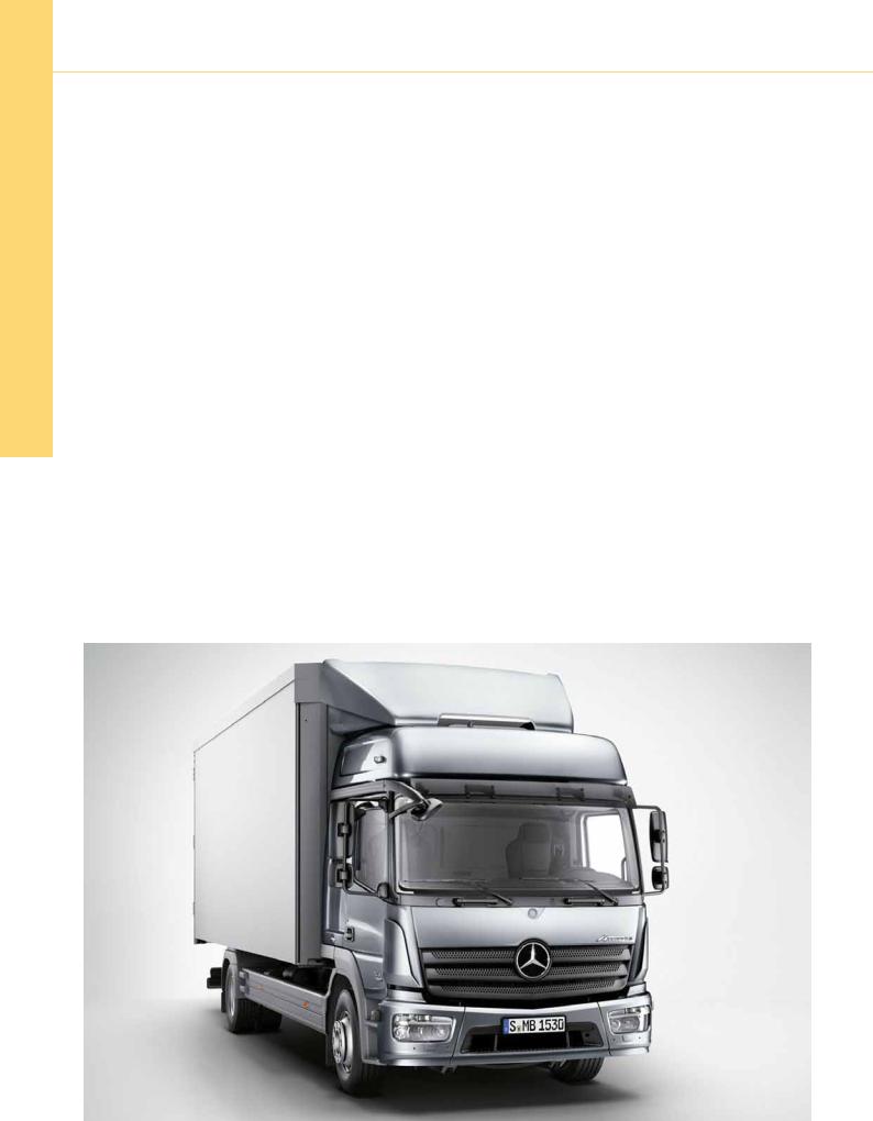
Introduction of the New Truck Generation The New Atego (Model 967)
Introduction into Service Manual
– This printout will not be recorded by the update service. Status: 02 / 2013 –

|
Preface |
3 |
|
Overview |
4 |
|
New features/modifications |
4 |
|
Overall vehicle |
6 |
|
Distribution haulage |
6 |
|
Construction vehicle |
7 |
|
Equipment |
8 |
|
Drive |
10 |
|
Engines |
10 |
|
Engine power take-off |
15 |
|
Exhaust system |
16 |
|
Fuel system |
17 |
|
Transmission |
18 |
|
Clutch |
18 |
|
Manual and automated transmission |
21 |
|
Transmission modes |
24 |
|
Automatic transmission |
25 |
|
Power take-off |
26 |
|
Transfer case |
29 |
|
Chassis |
31 |
|
Frame |
31 |
|
Axles |
34 |
|
Suspension |
36 |
|
Brakes |
37 |
|
Permanent magnet retarder |
39 |
|
Wheels and tires |
40 |
|
Body |
41 |
|
Cab |
41 |
|
Networking |
49 |
|
Overall network |
49 |
|
Introduction of the New Truck Generation | The New Atego (Model 967) |
1 |
– This printout will not be recorded by the update service. Status: 02 / 2013 –

|
Lights |
58 |
|
Exterior lights |
58 |
|
Special tools |
59 |
|
Transmission |
59 |
|
Transfer case |
62 |
|
Axles |
63 |
|
Annex |
64 |
|
Abbreviations |
64 |
|
Index |
66 |
|
Information and copyright |
67 |
|
2 |
Introduction of the New Truck Generation | The New Atego (Model 967) |
– This printout will not be recorded by the update service. Status: 02 / 2013 –

Preface
Dear Reader,
This Introduction into Service Manual presents the new Atego (model 967).
This brochure is intended for the use of technical personnel familiar with the service and maintenance of Mercedes-Benz trucks. It is assumed here that the reader is already familiar with the Mercedes-Benz model series currently on the market.
In terms of the contents, the emphasis in this Introduction into Service Manual is on presenting new and modified components and systems.
All of the data in this brochure correspond to the technical status as of the copy deadline in February 2013 and may therefore differ from the current production configuration.
We will publish modifications and new features in the relevant WIS documents only. Individual details in this brochure may therefore differ from more up-to-date versions published in WIS.
Daimler AG
Wörth plant (GSP/TTH)
February 2013
BBNote
All of the displays and messages of the multifunction display are shown in German because the corresponding versions in other languages were not available at the copy deadline.
BBNote
Information about the vehicles and about operating the vehicle functions can also be found in the interactive owner‘s manual on the Internet.
This Introduction into Service manual is also available in digital form as a PDF in SDmedia.
|
Introduction of the New Truck Generation | The New Atego (Model 967) |
3 |
– This printout will not be recorded by the update service. Status: 02 / 2013 –
Overview
New features/modifications
General
With the introduction of the new Atego (model 967) in May 2013, the new generation of trucks in the area of light commercial vehicles of up to 18 t in the segments of distribution haulage, code V1D (Atego distribution haulage, new) and construction vehicles, code V1G (Atego construction vehicle, new) is complete.
The new light model series benefits from the modular system of the Actros/Antos (model 963) and the Arocs (model 964). It has the following advantages:
•Uniform electronic architecture
•Same cab configuration for all model series
•Uniform drive configuration
•Uniform range of special equipment (SA)
The model designation logic for the new Atego is also the same as for the model series 963/964. The wheelbase is not part of the model designation any more, but represented in a code.
Wheelbases can be selected in 300-mm increments, as was the case until now. For more than 12 t, the wheelbases are shorter by 60 mm due to larger tires; the front axle is shifted toward the rear by 60 mm.
The range of models of the new Atego comprises 42 different model designations, e.g.
•Dumper vehicle
•Platform vehicle
•Semitrailer tractor
•Fire-fighting vehicle
•Municipal vehicle
W00.01-1032-00
The new Atego (model 967)
|
4 |
Introduction of the New Truck Generation | The New Atego (Model 967) |
– This printout will not be recorded by the update service. Status: 02 / 2013 –

New features/modifications
Innovations
•New engines OM 934 (4-cylinder) and OM 936 (6-cylin- der) as standard with Euro VI in seven output stages from 115 to 220 kW
•Nine different transmissions that are optimized for the intended application
•Shift-by-wire with power-assisted gear shifting
•Automated gearshift, Mercedes PowerShift 3 with the transmission functions crawling mode and EcoRoll, and transmission modes that can be individually selected
•Permanent magnet retarder
•New model designation (967.603) for fire-fighting vehicles 9.8 t, steel suspension, in two wheelbases
W46.10-1040-00
• Separate model designation for municipal vehicles (use of Multifunction steering wheel sweeper body)
•Short/extended/long cab and crew cabin, available in two roof variants ClassicSpace and BigSpace
•New 4-point cab suspension (mechanical/hydraulic)
•Electronic air-processing unit as on Actros/Antos/Arocs
•Driver seat and front passenger seat with armrests (SA), with flat-weave fabric (standard) and in velour (SA)
•Electronic Stability Program (ESP®) as standard (not available for all-wheel drive vehicles)
•Modified rear axle guide
•New steering for better vehicle dynamics
•Multifunction steering wheel
•Instrument cluster in two variants with FleetBoard® Eco Support
•Broader range of light alloy rims from Daewoo and Alcoa
W26.10-1169-00
• Headlamps in new design with halogen or LED daytime Shift-by-wire switching unit running lamps, stone impact protection, folding (SA for
construction vehicles)
•New transfer case (VG 1000)
•Permanent or shift-on-the-fly four wheel drive
•Wide selection of engine power take-offs at front, for example, for the operation of Frigo alternator
W35.10-1063-00
Rear axle guide
Overview
|
Introduction of the New Truck Generation | The New Atego (Model 967) |
5 |
– This printout will not be recorded by the update service. Status: 02 / 2013 –

Overall vehicle
Distribution haulage/ Construction vehicle
Overview of model designations
|
Model |
Vehicle type |
Wheel configuration |
Permissible gross |
Suspension |
|
designation |
vehicle weight |
|||
|
(max. GVW) |
||||
|
967.000 |
Platform vehicle |
4 x 2 |
6, 5 t |
Steel |
|
967.001 |
Platform vehicle |
4 x 2 |
7,49 t |
Steel |
|
967.002 |
Platform vehicle |
4 x 2 |
7,99 t |
Steel |
|
967.003 |
Platform vehicle |
4 x 2 |
9,5 t |
Steel |
|
967.004 |
Platform vehicle |
4 x 2 |
10,5 t |
Steel |
|
967.005 |
Platform vehicle |
4 x 2 |
11,99 t |
Steel |
|
967.006 |
Platform vehicle |
4 x 2 |
13,5 t |
Steel |
|
967.007 |
Platform vehicle |
4 x 2 |
15,0 t |
Steel |
|
967.008 |
Platform vehicle |
4 x 2 |
11,99 t |
Steel |
|
967.020 |
Platform vehicle |
4 x 2 |
6,5 t |
Air |
|
967.021 |
Platform vehicle |
4 x 2 |
7,49 t |
Air |
|
967.023 |
Platform vehicle |
4 x 2 |
9,5 t |
Air |
|
967.024 |
Platform vehicle |
4 x 2 |
10,5 t |
Air |
|
967.025 |
Platform vehicle |
4 x 2 |
11,99 t |
Air |
|
967.026 |
Platform vehicle |
4 x 2 |
13,5 t |
Air |
|
967.027 |
Platform vehicle |
4 x 2 |
15,0 t |
Air |
|
967.028 |
Platform vehicle |
4 x 2 |
11,99 t |
Air |
|
967.034 |
Platform vehicle |
4 x 4 |
10,5 t |
Steel |
|
967.036 |
Platform vehicle |
4 x 4 |
13,5 t |
Steel |
|
967.037 |
Platform vehicle |
4 x 4 |
15,0 t |
Steel |
|
967.201 |
Dumper vehicle |
4 x 2 |
7,49 t |
Steel |
|
967.202 |
Dumper vehicle |
4 x 2 |
7,99 t |
Steel |
|
967.203 |
Dumper vehicle |
4 x 2 |
9,5 t |
Steel |
|
967.204 |
Dumper vehicle |
4 x 2 |
10,5 t |
Steel |
|
967.205 |
Dumper vehicle |
4 x 2 |
11,99 t |
Steel |
|
967.206 |
Dumper vehicle |
4 x 2 |
13,5 t |
Steel |
|
967.207 |
Dumper vehicle |
4 x 2 |
15,0 t |
Steel |
|
967.234 |
Dumper vehicle |
4 x 4 |
10,5 t |
Steel |
|
967.236 |
Dumper vehicle |
4 x 4 |
13,5 t |
Steel |
|
967.237 |
Kipper |
4 x 4 |
15,0 t |
Stahl |
|
6 |
Introduction of the New Truck Generation | The New Atego (Model 967) |
– This printout will not be recorded by the update service. Status: 02 / 2013 –

Distribution haulage/ Construction vehicle
Overview of model designations
|
Model |
Vehicle type |
Wheel configuration |
Permissible gross |
Suspension |
|
designation |
vehicle weight |
|||
|
(max. GVW) |
||||
|
967.426 |
Semitrailer tractor |
4 x 2 |
13,5 t |
Air |
|
967.504 |
Municipal vehicle |
4 x 2 |
10,5 t |
Steel |
|
967.526 |
Municipal vehicle |
4 x 2 |
13,5 t |
Air |
|
967.603 |
Fire-fighting vehicle |
4 x 2 |
9,8 t |
Steel |
|
967.605 |
Fire-fighting vehicle |
4 x 2 |
11,99 t |
Steel |
|
967.606 |
Fire-fighting vehicle |
4 x 2 |
13,5 t |
Steel |
|
967.607 |
Fire-fighting vehicle |
4 x 2 |
15,0 t |
Steel |
|
967.633 |
Fire-fighting vehicle |
4 x 4 |
9,5 t |
Steel |
|
967.635 |
Fire-fighting vehicle |
4 x 4 |
11,99 t |
Steel |
|
967.636 |
Fire-fighting vehicle |
4 x 4 |
13,5 t |
Steel |
|
967.637 |
Fire-fighting vehicle |
4 x 4 |
15,0 t |
Steel |
Overall vehicle
W00.10-1223-00
Atego distribution haulage, new (V1D)
|
Introduction of the New Truck Generation | The New Atego (Model 967) |
7 |
– This printout will not be recorded by the update service. Status: 02 / 2013 –

Overall vehicle
Equipment
Equipment packages
In addition to the basic equipment and the various standard equipment packages installed according to the vehicle model/intended use, a number of additional safety and comfort features are also available. These are bundled in packages that are coded at the factory, such as:
•Cold Climate Pack Basic (Z0U)
•Cold Climate Pack Classic (Z0V)
•Cargo liftgate package (P0L)
•LED light package in the front, with turn signal glasses, white (L1Y)
W68.20-1032-00
Stowage box/tray above windshield, 2 compartments (D7M)
W68.20-1031-00
Stowage box/tray, high, on engine tunnel (D7Q)
|
W00.01-1036-00 |
|
|
Engine version Euro VI (M5Z) |
|
|
8 |
Introduction of the New Truck Generation | The New Atego (Model 967) |
– This printout will not be recorded by the update service. Status: 02 / 2013 –
Equipment
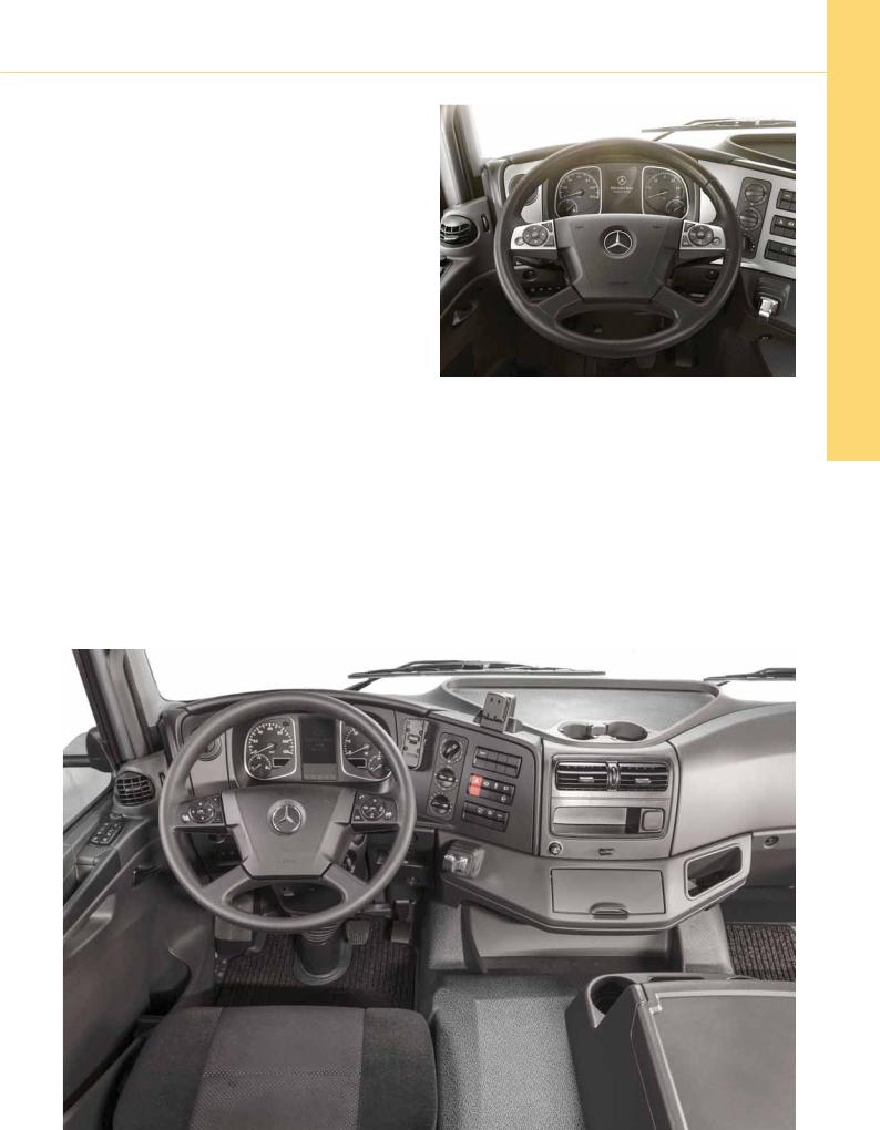
Cockpit
The cockpit is available in three variants depending on the requirements based on the application:
•Classic cockpit (D4B), standard
•Standard cockpit (D4A), special equipment, standard for center seat, with seat belt (D1Z)
•Comfort cockpit (D4C), special equipment
W46.10-1041-00
Multifunction steering wheel for comfort cockpit (D4C)
W68.10-1107-00
Classic cockpit (D4B)
|
Introduction of the New Truck Generation | The New Atego (Model 967) |
9 |
Overall vehicle
– This printout will not be recorded by the update service. Status: 02 / 2013 –
![]()
Drive
Engines
In terms of design, the 4-cylinder engine OM 934 builds on the 6-cylinder engine OM 936.
Features of engine OM 934:
•Common rail injection system
•One-stage charging (115 kW and 130 kW engine)
•Two-stage charging (155 kW and 170 kW engine)
•Newly developed engine braking system (decompression brake) with higher braking power
•Sturdy construction for high output
•Compliance with Euro VI emissions standard with Selective Catalytic Reduction (SCR), cooled and regulated exhaust gas recirculation (EGR) and diesel particulate filters
•Electrically controlled viscous coupling
The engines are available in the following output categories:
•OM 934, R4, 5,1 l, 115 kW (156 PS), 650 Nm (M1H)
•OM 934, R4, 5,1 l, 130 kW (177 PS), 750 Nm (M1I)
•OM 934, R4, 5,1 l, 155 kW (211 PS), 850 Nm (M1J)
•OM 934, R4, 5,1 l, 170 kW (231 PS), 900 Nm (M1K)
•OM 936, R6, 7,7 l, 175 kW (238 PS), 1000 Nm (M2A)
•OM 936, R6, 7,7 l, 200 kW (272 PS), 1100 Nm (M2C)
•OM 936, R6, 7,7 l, 220 kW (299 PS), 1200 Nm (M2D)
BBNote
The Introduction into Service Manual for the engine OM 936 is available in digital form in SDmedia.
W01.10-1171-00
Engine OM 934
|
10 |
Introduction of the New Truck Generation | The New Atego (Model 967) |
– This printout will not be recorded by the update service. Status: 02 / 2013 –

W01.10-1172-00
|
Overview of engine OM 934 |
|||
|
1 |
Rail |
10 |
Turbocharger |
|
2 |
Diesel fuel metering unit (for regeneration of diesel particulate filter) |
11 |
Coolant manifold |
|
3 |
Fuel filter module |
12 |
Low-pressure stage turbocharger |
|
4 |
Compressor |
13 |
High-pressure stage turbocharger |
|
5 |
Refrigerant compressor |
G2 |
Alternator |
|
6 |
Power steering pump |
M1 |
Starter |
|
7 |
Fuel system high pressure pump |
Y636 |
boost pressure regulator |
|
8 |
Exhaust gas recirculation cooler |
A |
OM 934.911 with one-stage charging |
|
9 |
Oil/coolant module |
B |
OM 934.913 with two-stage charging |
|
Introduction of the New Truck Generation | The New Atego (Model 967) |
11 |
– This printout will not be recorded by the update service. Status: 02 / 2013 –

Drive
Engines
Technical data
|
Unit |
OM 934 |
OM 936 |
|||
|
Displacement |
cm3 |
5132 |
7698 |
||
|
Cylinder number/arrangement |
4/inline |
6/inline |
|||
|
Valve timing |
DOHC |
DOHC |
|||
|
Number of valves per cylinder inlet/outlet |
2/2 |
2/2 |
|||
|
Idle speed |
1/min |
600 |
600 |
||
|
Output |
kW |
115 |
(M1H) |
175 |
(M2A) |
|
130 |
(M1I) |
200 (M2C) |
|||
|
155 |
(M1J) |
220 |
(M2D) |
||
|
170 |
(M1K) |
||||
|
Torque |
Nm |
650 |
(M1H) |
1000 (M2A) |
|
|
750 |
(M1I) |
1100 (M2C) |
|||
|
850 |
(M1J) |
1200 (M2D) |
|||
|
900 |
(M1K) |
||||
|
Compression ratio ε |
17,0 |
17,0 |
|||
|
Stroke |
mm |
135 |
135 |
||
|
Cylinder bore |
mm |
110 |
110 |
||
|
Total piston height |
mm |
110 |
110 |
||
|
Connecting rod length |
mm |
215 |
215 |
||
|
Cylinder spacing |
mm |
128 |
128 |
||
|
Rail pressure (max.) |
bar |
2400 |
2400 |
||
|
Braking power |
|||||
|
Engine brake, standard system (M5U) |
kW |
120 |
233 |
||
|
Engine brake, high-performance system (M5V) |
kW |
160 |
302 |
||
|
Weight (DIN-GZ) |
kg |
5101 |
6511 |
1 at maximum output
BBNote
It is mandatory that the engine brake for high-perfor- mance system (M5V) is installed on vehicles carrying dangerous goods (ADR code E5T, E5U, E5V, E5W, E5X, E9E) with OM 934.
|
12 |
Introduction of the New Truck Generation | The New Atego (Model 967) |
– This printout will not be recorded by the update service. Status: 02 / 2013 –

Engines
Performance graphs
Drive
|
W01.00-1119-00 |
W01.00-1120-00 |
||||
|
a |
OM 934, |
115 kW/650 Nm (M1H) |
c |
OM 934, |
155 kW/850 Nm (M1J) |
|
b |
OM 934, |
130 kW/750 Nm (M1I) |
d |
OM 934, |
170 kW/900 Nm (M1K) |
M Torque [Nm] P Output [kW]
n Engine speed [rpm]
|
Introduction of the New Truck Generation | The New Atego (Model 967) |
13 |
– This printout will not be recorded by the update service. Status: 02 / 2013 –

Drive
Engines
Performance graphs
|
W01.00-1121-00 |
W01.00-1122-00 |
|
|
a |
OM 936, 175 kW/1000 Nm (M2A) |
c OM 936, 220 kW/1200 Nm (M2D) |
|
b |
OM 936, 200 kW/1100 Nm (M2C) |
M Torque [Nm] P Output [kW]
n Engine speed [rpm]
|
14 |
Introduction of the New Truck Generation | The New Atego (Model 967) |
– This printout will not be recorded by the update service. Status: 02 / 2013 –
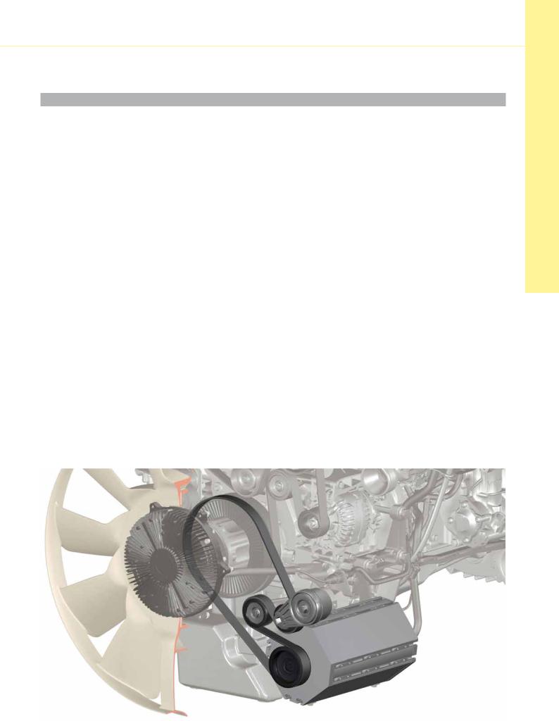
Engine power take-off
Front engine power take-off
|
Code |
Name |
|
N7C |
Front engine power take-off, oil pan changed |
|
N7E |
Front engine power take-off, with tandem pump |
|
N7F |
Front engine power take-off, Frigo alternator preinstallation AW 15 |
|
N7G |
Front engine power take-off, Frigo alternator preinstallation AW 22.5 |
|
N7H |
Front engine power take-off, Frigo alternator preinstallation AW 30 |
|
N7V |
Front engine power take-off, tandem pump preinstallation |
|
N7W |
Front engine power take-off, TK 315 preinstallation |
|
Rear engine power take-off |
|
|
Code |
Name |
|
N7K |
Rear engine power take-off, c, hydraulic pump SAE A |
|
N7M |
Rear engine power take-off, c, hydraulic pump ISO 7653D |
|
N7N |
Rear engine power take-off, c, hydraulic pump SAE B, 200 Nm |
|
N7P |
Rear engine power take-off, b, flange, 600 Nm |
Drive
W23.10-0001-00
Engine power take-off, Frigo alternator AW 22,5
|
Introduction of the New Truck Generation | The New Atego (Model 967) |
15 |
– This printout will not be recorded by the update service. Status: 02 / 2013 –
Drive
Exhaust system
Overview of exhaust systems
|
Code |
Name |
|
K7A |
Exhaust system, end pipe upwards |
|
K7H |
Exhaust system, fire brigade |
|
K7I |
Exhaust system, on the frame at right, end pipe inward |
|
K7K |
Exhaust system, positioned horizontally behind cab |
|
K7L |
Exhaust system, end pipe toward center of traveled way |
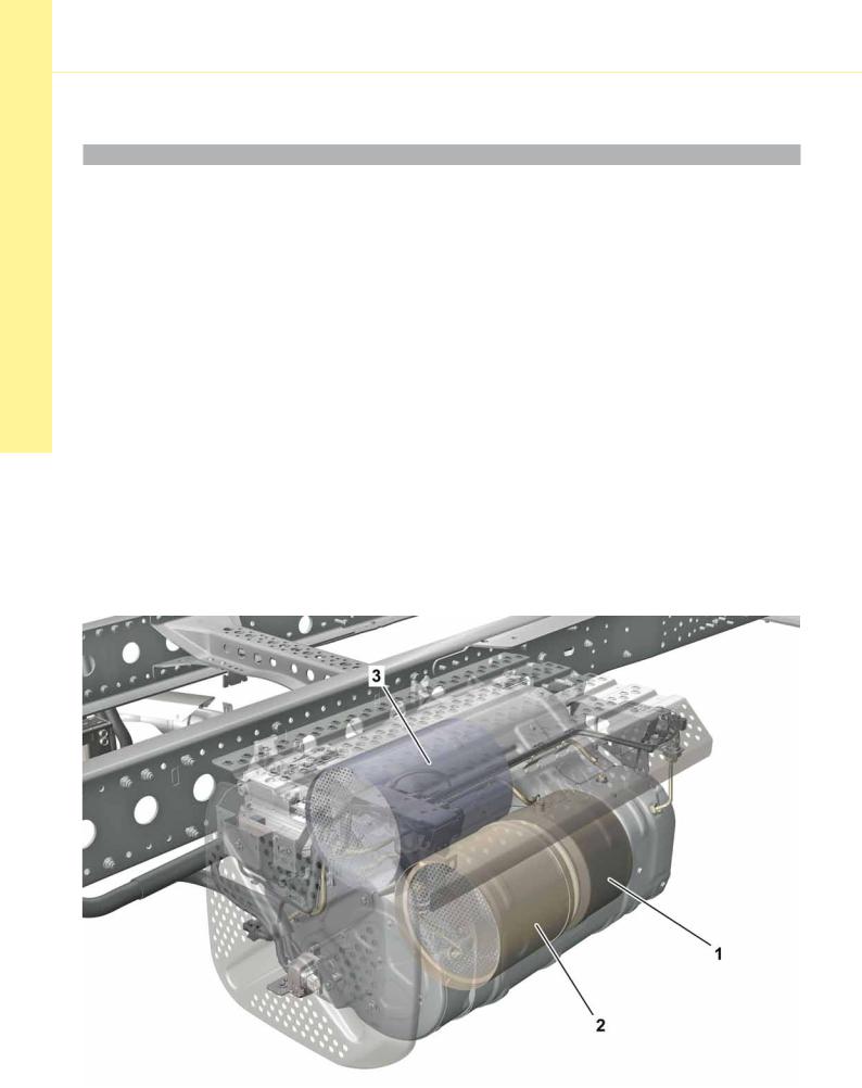
Exhaust aftertreatment
In order to achieve the applicable exhaust limits, an exhaust aftertreatment unit is installed in addition to the EGR inside the engine. It consists of a diesel oxidation catalytic converter, a diesel particulate filter (DPF) and an SCR catalytic converter (Selective Catalytic Reduction). All the components are in the exhaust aftertreatment unit (EATU).
Diesel particulate filter regeneration
Normally, the active regeneration runs automatically approx. every 8000 km. The exact point of time is determined by the exhaust aftertreatment control module (ACM). Furthermore, manual activation of regeneration by the driver is possible as soon as the message that regeneration is required is shown on the multifunction display.
W49.20-1101-00
Exhaust aftertreatment unit, engine OM 934
1 Diesel oxidation catalytic converter 3 SCR catalytic converter
2 Diesel Particulate Filter
|
16 |
Introduction of the New Truck Generation | The New Atego (Model 967) |
– This printout will not be recorded by the update service. Status: 02 / 2013 –

Fuel system
Fuel tank
The fuel tanks are made of LMDPE (Linear Medium Density Polyethylene). The capacity of the standard tank has been increased to 120 liters. A fuel tank (K0I) with a capacity of 80 liters has been newly introduced in order to maximize the payload of the vehicle.
Overview
AdBlue® tank
The AdBlue® tank has a capacity of 25 liters; however, a 35-liter tank can be ordered as special equipment.
On municipal vehicles, an AdBlue® tank with a capacity of 8 liters (K3R) is installed in the equipment bridge behind the cab. On fire-fighting vehicles, the AdBlue® tank is located behind the EATU on the right side of the frame.
|
Code |
Designation |
Allocation |
|
K0I |
Plastic tank 80 l, left |
Special equipment for platform vehicle |
|
K0E |
Plastic tank 120 l, left |
Standard on platform vehicle, dumper vehicle, |
|
semitrailer tractor |
||
|
K0G |
Plastic tank 180 l, left |
Special equipment for platform vehicle and dumper |
|
vehicle |
||
|
K0P |
Additional plastic tank 100 l, left |
Special equipment for platform vehicle with K0G |
|
K0Q |
Additional plastic tanks 2 x 100 l, left |
Special equipment for platform vehicle with K0G |
|
K0F |
Plastic tank 130 l, fire-fighting vehicle |
Special equipment for fire-fighting vehicle |
|
K0H |
Plastic tank 125 l, at frame end |
Standard on municipal vehicle |
|
K5V |
Shunt tank 20 l, tank system from body |
Special equipment for all, standard on fire-fighting |
|
manufacturer |
vehicle |
|
Drive
W47.10-1056-00
Plastic tank 180 l, left (K0G)
|
Introduction of the New Truck Generation | The New Atego (Model 967) |
17 |
– This printout will not be recorded by the update service. Status: 02 / 2013 –

Transmission
Clutch
|
Clutch plate |
|
|
In order to allow greater mileages with the same contact |
BBNote |
|
force of the clutch, clutch plates with thicker linings and |
The adjustment mechanism cannot be manually reset. |
|
pressure plates with integrated automatic self adjustment are |
In case of repair, the clutch pressure plate must al- |
|
installed. |
ways be replaced along with the clutch plate. |
|
The self adjustment mechanism of the clutch pressure plate |
|
|
compensates for the wear travel of the clutch linings and |
|
|
keeps the contact force constant during 90% of the clutch |
|
|
service life. |
|
|
The self adjustment mechanism continuously registers the |
|
|
decrease in clutch lining thickness and compensates for the |
|
|
gap by turning an adjusting ring. |
|
|
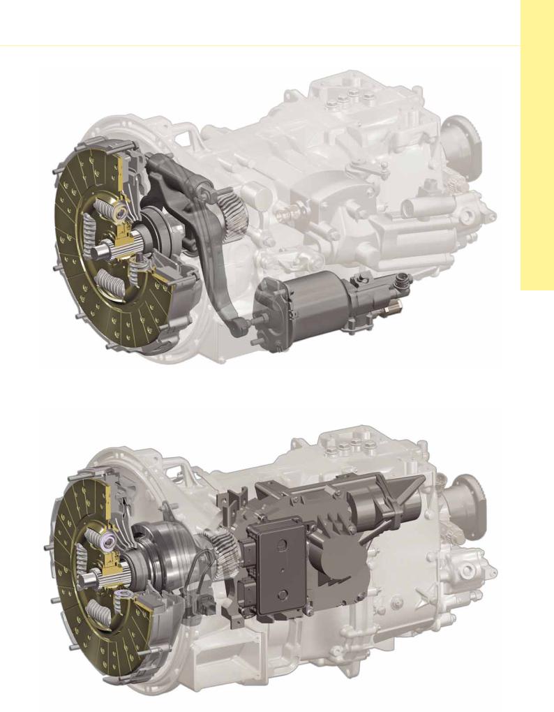
Clutch operating system |
|
|
With manual transmission, the clutch is operated by pressing |
|
|
it using a clutch release fork and clutch booster. |
|
|
In case of automated gearshift Mercedes PowerShift 3 (G5G), |
|
|
the clutch is pressed using the central clutch operator, as is |
|
|
the case in heavy vehicles. |
|
|
The central clutch release bearing is located on the trans- |
|
|
mission input shaft of the manual transmission and is rigidly |
|
|
bolted to the front of the transmission housing. |
|
|
Actuation of the pneumatic central clutch release bearing is |
|
|
carried out by the transmission control unit (TCM) and via the |
|
|
solenoid valves integrated in the transmission positioner. |
|
18 |
Introduction of the New Truck Generation | The New Atego (Model 967) |
– This printout will not be recorded by the update service. Status: 02 / 2013 –
W25.10-1088-00
Clutch for manual gearshift (G5H)
|
Clutch for Mercedes PowerShift 3 (G5G) |
W25.10-1089-00 |
|
Introduction of the New Truck Generation | The New Atego (Model 967) |
19 |
– This printout will not be recorded by the update service. Status: 02 / 2013 –
![]()
Transmission
Clutch
Assignment clutch — transmission — engine
|
Clutch |
Flange |
Transmission |
Engine |
P/M |
Remarks |
|
|
115 kW / 650 Nm |
||||||
|
Ø 362 mm |
SAE 3 |
OM 934 |
130 kW / 750 Nm |
|||
|
G 70-6 |
||||||
|
155 kW / 850 Nm |
||||||
|
G 71-6 |
||||||
|
175 kW / 1.000 Nm |
||||||
|
G 90-6 |
||||||
|
Ø 395 mm |
SAE 2 |
OM 936 |
200 kW / 1.100 Nm |
Only on fire-fighting |
||
|
220 kW / 1.200 Nm |
vehicles |
|||||
|
175 kW / 1.000 Nm |
||||||
|
G 140-8 |
||||||
|
Ø 395 mm |
SAE 2 |
OM 936 |
200 kW / 1.100 Nm |
|||
|
G 141-9 |
||||||
|
220 kW / 1.200 Nm |
||||||
|
130 kW / 750 Nm |
Oil cooler: oil/air |
|||||
|
Torque |
Allison |
OM 934 |
155 kW / 850 Nm |
|||
|
170 kW / 900 Nm |
||||||
|
converter |
SAE 2 |
3000P |
||||
|
TC 418 |
3000PR |
|||||
|
175 kW / 1.000 Nm |
||||||
|
iW= 1,98 |
3500P |
|||||
|
OM 936 |
200 kW / 1.100 Nm |
Oil cooler: oil/water |
||||
|
Except for 967.526: oil/air |
||||||
|
220 kW / 1.200 Nm |
||||||
|
130 kW / 750 Nm |
||||||
|
Ø 395 mm |
SAE 2 |
9S-1115 TD |
OM 934 |
155 kW / 850 Nm |
||
|
ZF-ECOMID |
||||||
|
170 kW / 900 Nm |
||||||
|
OM 936 |
175 kW / 1.000 Nm |
P = Output [kW]
M =Torque [Nm]
|
20 |
Introduction of the New Truck Generation | The New Atego (Model 967) |
– This printout will not be recorded by the update service. Status: 02 / 2013 –

- Форум
- Общие темы
- Эксплуатация и обслуживание
- Техническая литература по Атего

Тема: Техническая литература по Атего
-
05.09.2016, 17:23
#31
Re: Техническая литература по Атего
Сервис и запчасти Мерседес Атего
8(495)643-1024
8(800)707-1024
М.О. Осташковское шоссе вл.15Не ленитесь,
то что сбрасывают на почту
находится вот тут (ниже ссылка синем цветом),
качаем и работаем:
http://rutracker.org/forum/viewtopic.php?t=3888646http://www.atego-club.ru/forum
Сервис и запчасти Мерседес Атего
8(495)643-1024
8(800)707-1024
М.О. Осташковское шоссе вл.15
-
18.09.2016, 20:22
#32
Санчело
Guest
Re: Техническая литература по Атего
Сообщение от Максим F1
Рутрекер заблокирован((( Скиньте литературку Petrovav12007@yandex.ru заранее благодарен.Атего 815 2002 г.в.
-
18.09.2016, 21:49
#33
Re: Техническая литература по Атего
Заблокирован только для лентяев! На просторах полно инструкций по обходу блокировок….
-
01.12.2016, 12:06
#34
iam
Guest
Re: Техническая литература по Атего
В pdf. файле покачественнее будут электросхемы. Спасибо и на этом!
-
28.05.2017, 20:40
#35
Dr. Alex
Guest
Re: Техническая литература по Атего
Ребята скиньте книгу вот такую
на просторах инета не нашел(
вот почта abpo-trans@yandex.ru
Или может у кого есть руководство по эксплуатации на русском языке на Атего 1 со старой панелью и новой (это та книжка что идет с завода)
прост очень интересно возможности бортового компьютера изучитьПоследний раз редактировалось Dr. Alex; 28.05.2017 в 20:44.
-
28.05.2017, 21:33
#36
Re: Техническая литература по Атего
Нет литературы по старой панели с синими будильниками
-
17.10.2017, 21:00
#37
Nike
Guest
Re: Техническая литература по Атего
Доброго времени суток Всем! Видимо я ещё один лентяй который не может скачать книгу. Пожалуйста помогите мне, интересует книга по atego 1223 2006г.в. ( gav9801@yandex.ru ) за ранен спасибо Доброго пути Всем.
-
05.05.2018, 12:27
#38
Вячеслав75
Guest
Re: Техническая литература по Атего
Помогите пожалуйста с технической литературой по Атего815 2004г, если есть возможность на почту salov75@bk.ru Буду очень благодарен за помощь!
-
05.05.2018, 12:48
#39
Re: Техническая литература по Атего
Я видимо один из старых дурней.пошел купил в бумажном виде.сидю читаю
-
05.05.2018, 15:20
#40
Член клуба
- Вес репутации
- 10
Re: Техническая литература по Атего
Сервис и запчасти Мерседес Атего
8(495)643-1024
8(800)707-1024
М.О. Осташковское шоссе вл.15Почему один? Я тоже сторонник бумажных носителей, что на Атего1 покупал, что и для Атего2. Лучше иметь под рукой, гаджеты вещь ненадежная


Информация о теме
Пользователи, просматривающие эту тему
Эту тему просматривают: 1 (пользователей: 0 , гостей: 1)
Ваши права

- Вы не можете создавать новые темы
- Вы не можете отвечать в темах
- Вы не можете прикреплять вложения
- Вы не можете редактировать свои сообщения
- BB коды Вкл.
- Смайлы Вкл.
- [IMG] код Вкл.
- [VIDEO] код Вкл.
- HTML код Выкл.
Правила форума
13.10.2012
1 187 просмотров
В данном руководстве по Руководство по ремонту и эксплуатации автомобиля MERCEDES-BENZ ATEGO, которые выпускались с (1998-2004 гг.) описаны автомобили с грузоподъемностью от 8 до 18 тонн, с 6-ти цилиндровыми двигателями ОМ 906 LA с двумя уровнями мощности: 231 и 279 л.с. и 4-х цилиндровыми двигателями серии ОМ 904 LA представленные тремя уровнями мощности: 122, 152 и 170 л.с.
В руководстве подробно описаны технические характеристики, устройство и ремонт грузовых автомобилей MERCEDES-BENZ ATEGO первого поколения (производимые с 1998 года) и второго поколения (производимые с 2004 года). Также есть электро схемы.
| Год выхода книги: | 2007 |
| Автор книги: | |
| Книжное издательство: | «Мерседес» |
| Размер файла: | 32,19 Мб |
| Формат файла | PDF | DjVu |
| Язык книги | Русский |
| Пользовательское соглашение: | правообладателям |
| Скачать книгу: | с Letitbit.net
c Vip-file.com c ShareFlare.net |
Дорогие друзья!
Если представленный материал принес Вам пользу — поделитесь ссылкой в своих социальных сетях.
Будем Вам бесконечно благодарны.