Mitsubishi Outlander III: Руководства по эксплуатации
Материал из MMC Manuals
Перейти к навигации
Перейти к поиску
Руководства по эксплуатации Mitsubishi Outlander III. Брошюры, каталоги, спецификации, карты технического обслуживания.
↑ Mitsubishi Outlander III
![]()
| Язык/Language: | Русский • English |
|---|
Брошюры, каталоги, спецификации
Руководства по эксплуатации
- Руководство по эксплуатации Mitsubishi Outlander MY 2013 (Россия), рус., pdf, 102 МБ
- Руководство по эксплуатации Mitsubishi Outlander MY 2015 (Россия), рус., pdf, 17,9 МБ
- Руководство по эксплуатации Mitsubishi Outlander MY 2016 (Россия), рус., pdf, 18,6 МБ
- Руководство по эксплуатации Mitsubishi Outlander MY 2017 (Россия), рус., pdf, 24,7 МБ
- Руководство по эксплуатации Mitsubishi Outlander MY 2019 (Россия), рус., pdf, 28,6 МБ
- Руководство по эксплуатации Mitsubishi Outlander MY 2020 (Россия), рус., pdf, 30,3 МБ
- Руководство по эксплуатации Mitsubishi Outlander MY 2021 (Россия), рус., pdf, 30,7 МБ
- Руководство по эксплуатации Mitsubishi Outlander MY 2014 (North America), eng., pdf, 49,0 МБ
- Руководство по эксплуатации Mitsubishi Outlander MY 2015 (North America), eng., pdf, 59,5 МБ
- Руководство по эксплуатации Mitsubishi Outlander MY 2016 (North America), eng., pdf, 60,7 МБ
- Руководство по эксплуатации Mitsubishi Outlander MY 2017 (North America), eng., pdf, 14,9 МБ
- Руководство по эксплуатации Mitsubishi Outlander MY 2018 (North America), eng., pdf, 13,7 МБ
- Руководство по эксплуатации Mitsubishi Outlander MY 2019 (North America), eng., pdf, 58,0 МБ
- Руководство по эксплуатации Mitsubishi Outlander MY 2020 (North America), eng., pdf, 60,0 МБ
- Руководство по эксплуатации Mitsubishi Outlander MY 2016 (Europe), eng., pdf, 23,1 МБ
- Руководство по эксплуатации Mitsubishi Outlander MY 2017 (Europe), eng., pdf, 24,2 МБ
- Руководство по эксплуатации Mitsubishi Outlander MY 2018 (Europe), eng., pdf, 25,9 МБ
- Руководство по эксплуатации Mitsubishi Outlander MY 2019 (Europe), eng., pdf, 72,2 МБ
- Руководство по эксплуатации Mitsubishi Outlander MY 2020 (Europe), eng., pdf, 69,3 МБ
- Краткое руководство Mitsubishi Outlander MY 2014 (North America), eng., pdf, 2,88 МБ
- Краткое руководство Mitsubishi Outlander MY 2015 (North America), eng., pdf, 1,98 МБ
- Краткое руководство Mitsubishi Outlander MY 2016 (North America), eng., pdf, 2,96 МБ
- Краткое руководство Mitsubishi Outlander MY 2017 (North America), eng., pdf, 1,35 МБ
- Краткое руководство Mitsubishi Outlander MY 2018 (North America), eng., pdf, 1,21 МБ
Руководства по эксплуатации аудио-системы
- См. раздел Аудиооборудование: Руководства по эксплуатации
Карты технического обслуживания
- Периодическое техническое обслуживание (карта ТО), pdf, 301 кБ
- Периодическое техническое обслуживание при тяжелых условиях эксплуатации, pdf, 392 кБ
Разное
- Активация противотуманных фар без специального оборудования
Сборник руководств на английском языке по кузовному ремонту автомобиля Mitsubishi Outlander 2004-2006 годов выпуска.
- Автор: —
- Издательство: Mitsubishi Motors Corp.
- Год издания: 2003-2005
- Страниц: —
- Формат: PDF
- Размер: 23,7 Mb
Руководство на английском языке по техническому обслуживание и ремонту автомобиля Mitsubishi Outlander 2011 года выпуска.
- Автор: —
- Издательство: Mitsubishi Motors Corp.
- Год издания: 2010
- Страниц: 7200
- Формат: PDF
- Размер: 191,0 Mb
Сборник мультимедийных руководств на английском языке по техническому обслуживанию и ремонту автомобиля Mitsubishi Outlander 2007-2012 годов выпуска.
- Автор: —
- Издательство: Mitsubishi Motors Corp.
- Год издания: —
- Страниц: —
- Формат: ISO
- Размер: 2,2 Gb
Сборник мультимедийных руководств на английском языке по техническому обслуживанию и ремонту автомобиля Mitsubishi Outlander 2013-2016 годов выпуска.
- Автор: —
- Издательство: Mitsubishi Motors Corp.
- Год издания: —
- Страниц: —
- Формат: ISO
- Размер: 1,9 Gb
Руководство на английском языке по техническому обслуживанию и ремонту + схемы электрооборудования автомобиля Mitsubishi Outlander первого поколения.
- Автор: —
- Издательство: Mitsubishi Motors Corp.
- Год издания: 2003
- Страниц: —
- Формат: PDF
- Размер: 147,9 Mb
Сборник руководств на английском языке по техническому обслуживание и ремонту автомобиля Mitsubishi Outlander 2007 года выпуска.
- Автор: —
- Издательство: Mitsubishi Motors Corp.
- Год издания: 2006
- Страниц: —
- Формат: PDF
- Размер: 167,3 Mb
Сборник руководство на английском языке по техническому обслуживание и ремонту автомобиля Mitsubishi Outlander 2013 года выпуска.
- Автор: —
- Издательство: Mitsubishi Motors Corp.
- Год издания: 2011
- Страниц: —
- Формат: PDF
- Размер: 133,0 Mb
Сборник руководство на английском и немецком языках по техническому обслуживанию и ремонту автомобиля Mitsubishi Outlander первого поколения.
- Автор: —
- Издательство: Mitsubishi Motors Corp.
- Год издания: 2006
- Страниц: —
- Формат: PDF
- Размер: 428,8 Mb

Руководство по техническому обслуживанию и ремонту автомобиля Mitsubishi Outlander третьего поколения
- Автор: —
- Издательство: Mitsubishi Motors Corp.
- Год издания: —
- Страниц: —
- Формат: PDF
- Размер: 107,4 Mb
Руководство по эксплуатации, техническому обслуживанию и ремонту + каталог расходных запчастей автомобиля Mitsubishi Outlander 2002-2007 годов выпуска с бензиновыми двигателями объемом 2,0/2,4 л.
- Автор: —
- Издательство: Легион-Автодата
- Год издания: —
- Страниц: 526
- Формат: —
- Размер: —
Руководство по эксплуатации, техническому обслуживанию и ремонту + каталог расходных запчастей автомобиля Mitsubishi Outlander III с 2012 года выпуска с бензиновыми двигателями объемом 2,0/2,4/3.0 л.
- Автор: —
- Издательство: Легион-Автодата
- Год издания: —
- Страниц: 590
- Формат: —
- Размер: —
Руководство по эксплуатации, техническому обслуживанию и ремонту + каталог расходных запчастей автомобиля Mitsubishi Outlander 2006-2012 годов выпуска с бензиновыми двигателями объемом 2,0/2,4/3.0 л.
- Автор: —
- Издательство: Легион-Автодата
- Год издания: —
- Страниц: 738
- Формат: —
- Размер: —
Руководство по эксплуатации и ремонту автомобилей Mitsubishi Airtrek и Mitsubishi Outlander XL с 2005 года выпуска с бензиновыми и дизельными двигателями.
- Автор: —
- Издательство: Монолит
- Год издания: —
- Страниц: 458
- Формат: —
- Размер: —
Руководство по эксплуатации и ремонту автомобиля Mitsubishi Outlander с 2009 года выпуска с бензиновыми двигателями объемом 2,0/2,4/3,0 л.
- Автор: —
- Издательство: Монолит
- Год издания: —
- Страниц: 360
- Формат: —
- Размер: —

Руководство по эксплуатации и ремонту автомобиля Mitsubishi Outlander с 2013 года выпуска с бензиновыми и дизельными двигателями.
- Автор: —
- Издательство: Монолит
- Год издания: —
- Страниц: 456
- Формат: —
- Размер: —

Руководство по эксплуатации и техническому обслуживанию автомобиля Mitsubishi Outlander XL с 2006 года выпуска.
- Автор: —
- Издательство: MoToR
- Год издания: —
- Страниц: 510
- Формат: —
- Размер: —
Сборник руководств по эксплуатации и техническому обслуживанию автомобиля Mitsubishi Outlander третьего поколения.
- Автор: —
- Издательство: Mitsubishi Motors Corp.
- Год издания: 2013
- Страниц: —
- Формат: PDF
- Размер: 161,4 Mb

Руководство по эксплуатации и техническому обслуживанию автомобиля Mitsubishi Outlander XL 2007 года выпуска.
- Автор: —
- Издательство: Mitsubishi Motors Corp.
- Год издания: —
- Страниц: 522
- Формат: PDF
- Размер: 27,7 Mb
Руководство по эксплуатации и техническому обслуживанию автомобиля Mitsubishi Outlander XL после рестайлинга.
- Автор: —
- Издательство: Mitsubishi Motors Corp.
- Год издания: 2010
- Страниц: —
- Формат: PDF
- Размер: 85,1 Mb
Руководство по эксплуатации и техническому обслуживанию автомобиля Mitsubishi Outlander первого поколения.
- Автор: —
- Издательство: Mitsubishi Motors
- Год издания: 2005
- Страниц: 350
- Формат: PDF
- Размер: 15,0 Mb

Мультимедийное руководство по эксплуатации, техническому обслуживанию и ремонту автомобиля Mitsubishi Outlander с 2003 года выпуска с двигателями объемом 2,0/2,4 л.
- Автор: —
- Издательство: Новая версия
- Год издания: —
- Страниц: —
- Формат: —
- Размер: 255,4 Mb


Данная инструкция на русском языке предназначена для автомобиля
Mitsubishi Outlander III (2021), описывает принцип работы и основные моменты эксплуатации устройства.
Производитель настойчиво рекомендует перед включением автомобиля
внимательно изучить настоящую инструкцию.
Инструкция для автомобиля
представлена в формате PDF. Все современные браузеры уже поддерживают данный формат и сложностей с открытием файла возникнуть не должно.
Но если открыть инструкцию все же не удается, то необходимо установить на компьютер программу для чтения PDF файлов, например, Acrobat Reader. Если у вас возникли сложности с открытием инструкции на смартфоне под управлением Android, нужно установить, например, Adobe Acrobat Reader.
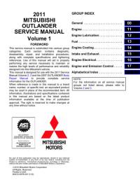
Оглавление
Краткий обзор
Общие сведения
Запирание и отпирание дверей
Сиденья и ремни безопасности
Органы управления и контрольноизмерительные приборы
Начало движения и вождение автомобиля
Создание комфортных условий в салоне
Действия в сложных ситуациях
Уход за автомобилем
Техническое обслуживание автомобиля
Технические характеристики
Алфавитный указатель
1
2
3
4
5
6
7
8
9
10
11
12
Комментарии (0)
Комментарии про другие Автомобили
Другие Автомобили Mitsubishi
- Manuals
- Brands
- Mitsubishi MOTORS Manuals
- Automobile
- Outlander 2007
- Owner’s manual
-
Contents
-
Table of Contents
-
Bookmarks
Related Manuals for Mitsubishi MOTORS Outlander 2007
Summary of Contents for Mitsubishi MOTORS Outlander 2007
-
Page 1
OWNER’S MANUAL English… -
Page 2
Foreword Throughout this owner’s manual, the words WARNING and CAUTION appear. E09300101597 E09200102098 Thank you for selecting a MITSUBISHI MOTORS product as These serve as reminders to be especially careful. Failure to fol- 2WD models 63 litres your new vehicle. -
Page 3
Table of contents Overview General information Locking and unlocking Seat and seat belts Instruments and controls Starting and driving For pleasant driving For emergencies Vehicle care Maintenance Specifications… -
Page 4
Overview Instruments and Controls E00100102818 LHD (Left-hand drive) Headlamp levelling switch* P. 3-65 Sonar switch* P. 4-78 Combination headlamps and dipper switch P. 3-60 Turn-signal lever P. 3-68 Front fog lamp switch* P. 3-69 Instruments P. 3-2 Active stability control (ASC) OFF switch* P. -
Page 5
Overview RHD (Right-hand drive) Headlamp levelling switch P. 3-65 Sonar switch* P. 4-78 Windscreen wiper and washer switch P. 3-71 Rear window wiper and washer switch P. 3-77 Instruments P. 3-2 Active stability control (ASC) OFF switch* P. 4-65 Shift paddles* P. -
Page 6
Overview LHD (Left-hand drive) Centre ventilators P. 5-2 Digital clock* P. 5-76 Supplemental restraint system Audio system* P. 5-16, 5-40 (SRS)-airbag (for front passen- HDD navigation & Mitsubishi Multi-Communication System* ger’s seat) P. 2-55, 2-62 Hazard warning flasher switch P. 3-69 Upper glove box P. -
Page 7
Overview RHD (Right-hand drive) Digital clock* P. 5-76 Centre ventilators Audio system* P. 5-16, 5-40 P. 5-2 Supplemental restraint system HDD navigation & Mitsubishi Multi-Communication System* (SRS)-airbag (for front passen- ger’s seat) P. 2-55, 2-62 Hazard warning flasher switch P. 3-69 Upper glove box P. -
Page 8
Overview Interior E00100202082 Outside rear-view mirror switch P. 4-10 Adjustable seat belt anchor P. 2-38 Lock switch Seat belts P. 2-34 P. 1-56 Room lamp (rear) P. 5-121 Central door lock switch P. 1-43 Assist grip P. 5-139 Electric window control switch P. 1-56 Coat hook P. -
Page 9
Overview LHD (Left-hand drive) Head restraints P. 2-23 Sunglasses holder P. 5-132 SRS curtain airbag* P. 2-55, 2-67 Sunroof switch* P. 1-61 Map lamp & room Cargo area cover P. 5-137 lamp (front) P. 5-121 Quarter trim box P. 5-132 Bottle holder P. -
Page 10
Overview RHD (Right-hand drive) Outside rear-view mirror switch P. 4-10 Central door lock Adjustable seat belt anchor P. 2-38 switch P. 1-43 Seat belts P. 2-34 Lock switch P. 1-56 Room lamp (rear) P. 5-121 Assist grip P. 5-139 Electric window control switch P. 1-56 Coat hook P. -
Page 11
Overview RHD (Right-hand drive) Head restraints P. 2-23 Sunglasses holder P. 5-132 SRS curtain airbag* P. 2-55, 2-67 Sunroof switch* P. 1-61 Map lamp & room lamp (front) P. 5-121 Cargo area cover P. 5-137 Bottle holder P. 5-135 Luggage floor box (with 5 seat Armrest P. -
Page 12
Overview Luggage area E00100400699 Accessory socket P. 5-119 Luggage hook P. 5-140 Luggage hook P. 5-140 Jack P. 6-14 Tools P. 6-14 Luggage hook P. 5-140 Luggage hook P. 5-140… -
Page 13
Overview Exterior E00100502274 Windscreen wipers P. 3-71 Sunroof* P. 1-61 Electric window control P. 1-56 Bonnet P. 8-3 Fuel tank filler P. 3 Outside rear-view mirror P. 4-10 Headlamps P. 3-60, 8-41, 8-43 Position lamps P. 3-60, 8-41, 8-46 Turn-signal lamps/Hazard warning lamps Turn-signal lamps P. -
Page 14
Overview Split tailgate P. 1-49 Keyless entry system P. 1-6 Antenna P. 5-75 Keyless operation system* P. 1-10 Locking and unlocking the doors P. 1-41 Rear spoiler Rear window wiper P. 3-77 Rear view camera P. 4-82 Rear fog lamp Size of tyres and wheels P. -
Page 15: Table Of Contents
General information Fuel selection ……Filling the fuel tank ……Installation of accessories .
-
Page 16: Fuel Selection
General information Fuel selection ● Repeatedly driving short distances at very low speeds can cause deposits in the fuel system and engine, which can E00200101375 lead to poor starting ability or acceleration. If these prob- Petrol-powered vehicles lems occur, add a detergent additive to the petrol when Unleaded petrol, octane number (EN228) refuelling.
-
Page 17: Filling The Fuel Tank
If you move away and do something else (for example, cleaning your wind- screen) partway through the refuelling process, you could pick up a fresh charge of static electricity. ● If the tank cap must be replaced, use only a MITSUBISHI MOTORS original part.
-
Page 18
General information 3. Remove the fuel cap. Open the fuel tank filler neck by slowly turning the cap anticlockwise. Except for 2200 models 1- Remove 2- Close… -
Page 19
General information CAUTION For 2200 models ● The fuel cap does not turn more than 90 degrees. Turning it further by force could damage the fuel cap. ● Since the fuel system may be under pressure, remove the fuel cap slowly. This relieves any pres- sure or vacuum that might have built up in the fuel tank. -
Page 20: Installation Of Accessories
We recommend you to consult your MITSUBISHI MOTORS ferent manufactures available in the market, it is not possible, Authorised Service Point. not only for MITSUBISHI MOTORS, but also a MITSUBISHI ● The installation of accessories, optional components, etc., MOTORS Authorised Service Point, to check whether the…
-
Page 21: Modification/Alterations To The Electrical Or Fuel Systems
General information Modification/alterations to the electrical or Genuine Parts fuel systems E00200500499 MITSUBISHI MOTORS has gone to great lengths to bring you E00200400368 a superbly crafted automobile offering the highest quality and MITSUBISHI MOTORS CORPORATION has always manu- dependability. factured safe, high quality vehicles. In order to maintain this…
-
Page 22: Safety And Disposal Information For Used Engine Oil
General information Safety and disposal information for used engine oil E00200600155 WARNING ● Prolonged and repeated contact may cause serious skin disorders, including dermatitis and cancer. ● Avoid contact with the skin as far as possible and wash thoroughly after any contact. ●…
-
Page 23
Locking and unlocking Keys ……..1- Electronic immobiliser (Anti-theft starting system). -
Page 24: Keys
Locking and unlocking Keys Type 2 E00300101217 Type 1, Type 2, Type 3 The keys fit all locks. Type 1 1- Keyless entry key (with electronic immobiliser) 2- Key number tag 1- Electronic immobiliser key 2- Key number tag…
-
Page 25
Locking and unlocking Type 4 Type 3 The emergency key fits all locks. Type 4 1- Keyless entry key (with electronic immobiliser) 2- Key number tag 1- Keyless operation key (with electronic immobiliser and lock remote control but- tons) 2- Emergency key 3- Key number tag… -
Page 26: Electronic Immobiliser (Anti-Theft Starting System)
Locking and unlocking Electronic immobiliser NOTE ● The key number is stamped on the tag as indicated in the (Anti-theft starting system) illustration. E00300201146 Make a record of the key number and store the key and [For vehicles equipped with keyless operation key] key number tag in separate places so that you can order a For information on operations for vehicles equipped with key- key in case the original keys are lost.
-
Page 27
(including keys of other vehicles) (Type C) In these cases remove the object or additional key from the vehicle key. Then try to restart the engine. If the engine does not start, contact a MITSUBISHI MOTORS Authorised Service Point. -
Page 28: Keyless Entry System
To obtain a key, take your vehicle and any remaining all doors as well as the tailgate will lock or unlock respectively. key to a MITSUBISHI MOTORS Authorised Service These switches can also operate the door mirrors and electric Point.
-
Page 29
Locking and unlocking To lock To unlock Press the LOCK switch (1) and all doors and the tailgate will Press the UNLOCK switch (2) and all doors and the tailgate be locked. The turn-signal lamps will blink once when the will be unlocked. -
Page 30
Locking and unlocking ● It is possible to modify functions as follows: Operation of the Dead Lock System For further information, please contact your MITSUBI- On a vehicle equipped with a Dead Lock System, it is possible SHI MOTORS Authorised Service Point. On vehicles to set the Dead Lock System using the remote controller. -
Page 31
To fold out ● In case of loss or damage of your key with remote control Press the Release button (4). switches please contact your MITSUBISHI MOTORS Authorised Service Point for a replacement. NOTE ● The function of the remote control switches can be modi- ●… -
Page 32: Keyless Operation System (Kos)
Locking and unlocking Keyless operation system (KOS) E00305600106 On vehicles with keyless operation system or KOS you can lock and unlock the doors as well as the tailgate and start the engine simply by carrying the KOS key or electronic key with you.
-
Page 33
• You can limit operations to the locking and unlocking of ing on usage conditions. When the battery wears out, doors and the tailgate. have it replaced at your MITSUBISHI MOTORS • You can limit operations to starting the engine. Authorised Service Point. -
Page 34
Locking and unlocking Operating range of the KOS system Operating range for locking and unlocking of doors and tailgate (keyless operation system) E00306200095 E00305700093 The operating range extends about 70 cm from the driver’s When carrying the KOS key you need to enter the operating door handle, front passenger’s door handle, and tailgate handle. -
Page 35
Locking and unlocking Operating range for starting the engine NOTE ● Locking and unlocking are only possible when the door or E00306300012 The operating range is the interior of the vehicle. tailgate is operated while the KOS key is being detected. ●… -
Page 36
Locking and unlocking Operation with keyless operation function Driver’s door and front passenger’s door switches E00305800094 Locking the doors and tailgate When you are carrying the KOS key and press the “LOCK” switch (A) on the driver’s door, front passenger’s door, or tail- gate within the system’s operating range, the doors and the tail- gate will lock. -
Page 37
The time allowed for checking whether the vehicle is locked can be adjusted. For further information, please contact your MITSUBISHI MOTORS Authorised Service Point. On vehicles with the Mitsubishi Multi-Communi- cation System (MMCS), this function can be customised via the display. -
Page 38
● The time allowed for checking whether the vehicle is electromagnetic waves, or an electronic device. locked can be adjusted. For further information, please contact your MITSUBISHI MOTORS Authorised Service Point. On vehicles with the Mitsubishi Multi-Communi- cation System (MMCS), this function can be customised via the display. -
Page 39
If this happens, the vehi- ● This function can be modified as stated below. For further cle is automatically locked again after about 30 seconds. information, please contact your MITSUBISHI MOTORS On vehicles with the Mitsubishi Multi-Communication Authorised Service Point. -
Page 40
To obtain a key, take your vehicle and any remaining key • Link the outside rear-view mirror retraction to door to a MITSUBISHI MOTORS Authorised Service Point. locking. All the keys have to be re-registered in the immobiliser • Disable all operations. -
Page 41
Locking and unlocking Ignition switch The engine is stopped, but the audio system and other electric E00306500102 In order to prevent theft, the engine will not start unless a pre- devices can be operated. registered keyless operation key is used. (Engine immobiliser function) The engine is running and all of the vehicle’s electrical devices Provided you are carrying the KOS key, you can start the… -
Page 42
Locking and unlocking When turning from “LOCK” (PUSH OFF) to “ACC” When turning from “ACC” to “LOCK” E00306600015 E00306700032 Push the ignition switch and then turn it slowly. [Vehicles with M/T] Put the gearshift lever into the “N” (Neutral) position, and slowly turn the ignition switch to the “LOCK”… -
Page 43
Locking and unlocking Warning activation CAUTION E00305900109 In order to prevent vehicle theft or an accidental operation of ● Do not turn the ignition switch to “LOCK” position the keyless operation system, a buzzer and messages on the while driving. The steering wheel will lock, causing multi-information display are used to alert the driver. -
Page 44
Locking and unlocking If any of the following warnings are activated, please contact a KOS key location monitoring system MITSUBISHI MOTORS Authorised Service Point. E00308000042 If you open any of the doors and take the KOS key out of the vehicle while the ignition switch is in an other position than There is a fault in the keyless operation system. -
Page 45
3 seconds. Under these cir- opening a door. For further information, please contact cumstances locking of doors and tailgate will be impossible. your MITSUBISHI MOTORS Authorised Service Point. ● Even though the KOS key is within the engine start oper-… -
Page 46
Locking and unlocking Door ajar prevention system Ignition switch reminder system E00308200031 E00308300032 If you try to lock the doors and tailgate by pressing one of the If you close all doors and the tailgate with the ignition switch “LOCK” switches while one of the doors or the tailgate is not in any position other than “LOCK”… -
Page 47
Locking and unlocking Steering wheel lock Starting E00306800017 E00306900089 To lock Tips for starting ● Do not operate the starter motor continuously for longer Turn the steering wheel until it is locked. than 10 seconds to avoid discharging the battery. If the To unlock engine does not start, turn the ignition switch back to the Turn the ignition switch to the “ACC”… -
Page 48
Locking and unlocking Starting the engine (petrol-powered vehicles) 5. On vehicles with M/T, place the gearshift lever in the “N” (Neutral) position. E00307000117 This vehicle is equipped with an electronically controlled fuel On vehicles with A/T or CVT, make sure the selector injection system. -
Page 49
Locking and unlocking At extreme low ambient temperatures Starting the engine (diesel-powered vehicles) If the engine will not start, depress the accelerator pedal about E00307000120 1. Fasten the seat belt. halfway while cranking the engine. Once the engine starts, 2. Make sure the parking brake is applied. release the accelerator pedal. -
Page 50
This is not an abnormal condition. The noise will disap- pear after the engine has run for a short time. If the ticking noise continues after the engine is warmed up, please contact your MITSUBISHI MOTORS Author- ised Service Point. 1-28… -
Page 51
Locking and unlocking Locking and unlocking the door NOTE ● Only use the emergency key for emergencies. If the KOS Turning the emergency key to the vehicle front locks the door, and turning it to rear unlocks the door. Also refer to “Locking key battery wears out, replace it as quickly as possible so and unlocking: Doors”… -
Page 52
To obtain a key, take your vehicle and any remaining key to a MITSUBISHI MOTORS Authorised Service Point. All the keys have to be re-registered in the immobiliser computer unit. The immobiliser can register up to 4 differ- ent keys. -
Page 53
Locking and unlocking When turning from “LOCK” to “ACC” NOTE ● The KOS key is combined with an electronic immobiliser. 1. Take the emergency key out of the KOS key. Refer to “Emergency keys” on page1-28. To start the engine, the ID code which the transponder 2. -
Page 54
Locking and unlocking 3. Insert the emergency key into the ignition switch, and turn When turning from “ACC” to “LOCK” it while pushing. 1. [Vehicles with M/T] While pushing the ignition switch, turn it to the “LOCK” position and pull out the key. [Vehicles with A/T or CVT] First, set the selector lever to the “P”… -
Page 55
Locking and unlocking Steering wheel lock CAUTION E00307500095 ● Do not leave the emergency key in the “ON” posi- To lock tion for a long time when the engine is not running Turn the emergency key to the “LOCK” position. as this will cause discharge of the battery. -
Page 56
Locking and unlocking Starting Starting the engine (petrol-powered vehicles) This vehicle is equipped with an electronically controlled fuel E00307600100 injection system. When starting the engine, do not depress the Tips for starting accelerator pedal. ● Do not operate the starter motor continuously for longer than 10 seconds to avoid discharging the battery. -
Page 57
Locking and unlocking 3. Insert the emergency key of the KOS key. 5. Make sure the parking brake is applied. 6. Depress and hold the brake pedal. 7. On vehicles with M/T, depress the clutch pedal all the way and place the gearshift lever in the “N” (Neutral) position. On vehicles with A/T or CVT, make sure the selector lever is in the “P”… -
Page 58
Locking and unlocking At extreme low ambient temperatures Starting the engine (diesel-powered vehicles) If the engine will not start, depress the accelerator pedal about 1. Fasten the seat belt. halfway while cranking the engine. Once the engine starts, 2. Remove the cover of the ignition switch. release the accelerator pedal. -
Page 59
Locking and unlocking 4. Set the emergency key onto the KOS key. 7. Depress the clutch pedal all the way and place the gear- shift lever in the “N” (Neutral) position. 5. Make sure the parking brake is applied. 6. Depress and hold the brake pedal. 8. -
Page 60
) switch If the ticking noise continues after the engine is warmed 2- UNLOCK ( ) switch up, please contact your MITSUBISHI MOTORS Author- 3- Indicator lamp ised Service Point. 1-38… -
Page 61
MITSUBISHI MOTORS Authorised Service Point. On To unlock vehicles with the Mitsubishi Multi-Communication Sys- Press the UNLOCK switch (2). All the doors and the tailgate tem (MMCS), this function can be customised via the dis- will be unlocked. -
Page 62
• The indicator lamp (3) is dim or does not come on. ● In case of loss or damage of your key with remote control To fold out switches please contact your MITSUBISHI MOTORS You can fold out the outside rear-view mirrors within 30 sec- Authorised Service Point for a replacement. -
Page 63: Doors
Locking and unlocking Doors To lock or unlock with the key E00300401496 CAUTION ● Make sure the doors are closed: driving with doors not completely closed is dangerous. ● Never leave children in the vehicle unattended. ● Be careful not to lock the doors while the key is inside the vehicle.
-
Page 64
Locking and unlocking To lock or unlock from inside the vehicle To lock without using the key Front passenger’s door, Rear door 1- Lock 2- Unlock Set the inside lock knob (1) to the locked position and close the Pull the inside door handle to open the door. door (2). -
Page 65: Central Door Locking System
Locking and unlocking Ignition switch reminder system Central door locking system E00310100040 E00300801025 When the engine was started using the keyless operation NOTE function ● Each door can be locked or unlocked independently using If the driver’s door is opened with the ignition switch in a posi- the inside lock knob.
-
Page 66
Locking and unlocking Central locking function with key in driver’s Central locking function with door lock switch on door driver’s door Pushing the central door lock switch on the driver’s door will Vehicles without keyless entry system or keyless operation lock or unlock all doors and the tailgate. -
Page 67: Dead Lock System
Locking and unlocking Dead Lock System* RHD (Right-hand drive) E00305100068 The Dead Lock System helps prevent theft. When the remote control switch on the key (keyless entry system) has been used to lock all of the doors and the tailgate, the Dead Lock System makes it impossible to unlock the doors using the inside lock knobs.
-
Page 68
Locking and unlocking Vehicles with keyless entry system Vehicles with keyless operation system (KOS) NOTE Vehicles with keyless operation system (KOS) ● Pressing the LOCK switch (A) once after the Dead Lock System has been set, causes the turn-signal lamps to flash three times, which confirms that the Dead Lock System has been set. -
Page 69
● It is possible to adjust the time span until automatic relocking after the UNLOCK switch (B) has been pressed. For details, please contact a MITSUBISHI MOTORS Authorised Service Point. On vehicles with the Mitsubishi Multi-Communication System (MMCS), this function can be customised via the display. -
Page 70: Child-Protection» Rear Doors
NOTE ● If you need advice on how to set the Dead Lock System, please contact a MITSUBISHI MOTORS Authorised Service Point. 1- Lock 2- Unlock Child protection helps prevent the rear doors from being opened accidentally from the inside.
-
Page 71: Split Tailgate
Locking and unlocking Split tailgate To lock or unlock from outside the vehicle E00301400760 Vehicle with key cylinder WARNING ● It is dangerous to drive with upper, lower or both tailgates open since carbon monoxide (CO) gas can enter the cabin. Carbon monoxide is a colourless and odourless gas.
-
Page 72
Locking and unlocking To lock or unlock from inside the vehicle RHD (Right-hand drive) The tailgate can be locked or unlocked by pushing the central door lock switch (driver’s door). LHD (Left-hand drive) 1- Lock 2- Unlock NOTE ● Repeated switching between locking and unlocking could trigger the central locking system’s built-in protection cir- cuit and temporarily prevent the system from operating. -
Page 73
Locking and unlocking To open 2. Move the lever (A) in the direction of the arrow and slowly fold down the lower gate. 1. After unlocking the tailgate, pull the handle and lift the upper gate. CAUTION ● If a trailer hitch is mounted, do not open the lower gate! Otherwise, the trailer hitch could scratch and dam- age the lower gate. -
Page 74
Locking and unlocking To close NOTE ● Do not jump on the lower gate or subject it to a strong 1. Raise the lower gate until it locks properly in position impact. This could damage the lower gate. with a click. ●… -
Page 75
Locking and unlocking 2. Pull the upper gate grip (B) downward as illustrated. Gen- CAUTION tly slam the upper tailgate from the outside so that it is completely closed. Always make sure that the upper gate ● Before closing the upper gate, always make sure that is securely closed. -
Page 76: Tailgate Emergency Release Lever
Locking and unlocking ● Gas struts (D) and wires (E) are installed to support the Tailgate emergency release lever tailgate. E00303400168 To prevent damage or faulty operation: The tailgate emergency release lever allows opening of the tail- • Do not hold the gas struts when closing the tailgate. gate in case of a discharged battery.
-
Page 77
Locking and unlocking To open 2. Move the lever (B) up to open the tailgate. 1. Open the lid (A) on the inside of the tailgate. 3. Push out the upper gate to open it. 4. Slowly lower the lower gate. CAUTION ●… -
Page 78: Electric Window Control
Locking and unlocking Electric window control Electric window control switch E00302300997 E00302200446 Each door window opens or closes while the corresponding The electric windows can only be operated with the ignition switch is operated. switch in the “ON” position. Driver’s switch (LHD) WARNING ●…
-
Page 79
Locking and unlocking Driver’s / Passenger’s switches Driver’s switch (RHD) The driver’s switches can be used to operate all door windows. A window can be opened or closed by operating the corre- sponding switch. Press the switch down to open the door window, and pull it up to close the window. -
Page 80
Locking and unlocking Lock switch NOTE ● Repeated operation of the RHT when the engine is turned E00303100673 When this switch is pressed in, the passenger’s switches cannot off will run down the battery. Operate the window control be used to open or close the door windows. switches only while the engine is running. -
Page 81
If the driver’s door switches when the lock switch is depressed. is opened during this period, the door window can be opened or Please consult your MITSUBISHI MOTORS Authorised closed for another 30 seconds. Service Point. On vehicles with the Mitsubishi Multi- However, once the driver’s door is closed, the windows cannot… -
Page 82
Locking and unlocking Safety mechanism ● If the safety mechanism is activated three or more times in a row, the safety mechanism will be cancelled and the E00302500292 If a hand or head is trapped in the closing window, it will lower door window will not close correctly. -
Page 83: Sunroof
Locking and unlocking Sunroof* To close, press the switch (3) To stop the moving sunroof, press the switch (1) or (2). E00302800237 Sunroof To tilt up, press the switch (2) The sunroof can only be operated when the ignition switch is in The rear sunroof will rise to ventilate the car interior.
-
Page 84
Locking and unlocking Sunshade NOTE ● The safety mechanism can be triggered if driving condi- Slide the sunshade manually to open and close it. tions or other circumstances cause the door windows to be subjected to a physical shock similar to that caused by a trapped hand or head. -
Page 85
Locking and unlocking ● Depending on the ski carrier or roof carrier models, the WARNING sunroof may touch the carrier when it is tilted up. Be care- ● Do not stick your head, hands or anything else out of ful when tilting up the sunroof if such a ski carrier or a roof carrier is installed on the vehicle. -
Page 87
Seat and seat belts Seats ……..2- Arrangement of seats . -
Page 88: Seats
Seat and seat belts Seats E00400101061 1-Front seat 2- Second seat ● To adjust forward or backward → P. 2-6 ● To adjust forward or backward (vehicles with second seat ● To recline the seatback → P. 2-7 slide function) → P. 2-11 ●…
-
Page 89: Arrangement Of Seats
Seat and seat belts Arrangement of seats E00400200342 The seats can be arranged as desired to the patterns shown below. 5 persons 7 persons Normal usage 7 persons → P. 2-13 Flat seat → P. 2-31 Folding the seatbacks for- Making a luggage ward room…
-
Page 90
Seat and seat belts 5 persons 7 persons To collapse the second seat → P. 2-25… -
Page 91: Seat Adjustment
Seat and seat belts Seat adjustment CAUTION E00400300271 ● Make sure the seat is adjusted by an adult or with Adjust the driver’s seat so that you are comfortable and that adult supervision for correct and safe operation. you can reach the pedals, steering wheel, switches etc. while ●…
-
Page 92: Front Seat
Seat and seat belts Front seat Power type Adjust the seat by operating the switch as indicated by the E00400400142 arrows. To adjust forward or backward E00400500462 Manual type Pull the seat adjusting lever and adjust the seat forward or backward to the desired position, and release the adjusting lever.
-
Page 93
Seat and seat belts To recline the seatback Power type Adjust the seatback angle by operating the switch as indicated E00400600580 by the arrows. Manual type In order to recline the seatback, lean forward slightly, pull the seatback lock lever up, and then lean backward to the desired position and release the lever. -
Page 94
Seat and seat belts To adjust seat height (driver’s seat only) Power type To adjust the seat height, operate the switch as indicated by E00400700549 arrows. Manual type To adjust the seat height, operate the lever repeatedly to adjust. NOTE ●… -
Page 95
Seat and seat belts Armrest E00400900206 The lid of the floor console box can be moved forward and backward, and used as an armrest. 2- To move the rear of the seat up and down 3- To move the whole seat up and down… -
Page 96
Seat and seat belts Seat heaters CAUTION E00401100380 The seat heaters can only be operated with the ignition switch ● Switch off the seat heaters when not in use. in the “ON” position. The indicator lamp (A) will illuminate ● Operate in the high position for quick heating. Once while the heater is on. -
Page 97: Second Seat
Seat and seat belts Second seat WARNING E00402000256 ● To make sure that the seat is securely locked in place When the second seat is used raise the head restraints to a after adjustment, try to move it forward and back- height at which they lock in position.
-
Page 98
Seat and seat belts Armrest WARNING E00402400247 To use the armrest, fold it down. ● To reduce the risk of serious or life-threatening inju- To return it to the original position, push it backward until it is ries in case of accident or sudden stops, make sure flush with the seat. -
Page 99: Third Seat (7 Persons)
Seat and seat belts Accessing the underfloor-stowable third seat Third seat (7 persons) (7 persons) E00402700211 To fold out the underfloor-stowable third seat E00412600011 The passenger gets on or off the third seat after collapsing the The third seat is stowed under the floor. Use the seat when second seat.
-
Page 100
Seat and seat belts To fold out WARNING 1. Open the tailgate. Refer to “Split tailgate” on page 1-49 ● For safety reasons, whenever a passenger sits in the 2. Pull up the cover from the rear. third seat, ensure that all head restraints of the sec- Fasten the pulled up cover to the seatback with the band ond seats are raised. -
Page 101
Seat and seat belts 3. Pull the belt (B) located in the centre of the seatback and 4. Pull the belt (C- black) to release the lock. raise the seatback. 2-15… -
Page 102
Seat and seat belts 5. Tilt the whole of the third seat to the rear. 6. Raise the head restraints. NOTE ● If the third seat is locked to the floor after tilting it to the rear, pull the belt (C-black) again to release the lock. 2-16… -
Page 103
Seat and seat belts 7. Lift up the whole of the third seat from the floor and push NOTE it forward to lock it in place. ● Push the third seat once more to the front to make sure it is securely locked in place. -
Page 104
Seat and seat belts 8. Return the cover to its position. WARNING Lightly push the seat and seatback to make sure they are ● When lifting the third seat, keep your hands away firmly fixed in place. from the areas indicated by the red labels (D). Oth- erwise, you could trap your fingers in the seat hinge and be injured. -
Page 105
Seat and seat belts To retract 3. Slide the knob (C) while folding the head restraint to the rear, then fold it down the seat front. Fold them one side at 1. Open the tailgate. Refer to “Split tailgate” on page 1-49 a time. -
Page 106
Seat and seat belts 4. Pull the belt (D — grey) and stow the whole of the third seat CAUTION under the floor. ● Do not put your hands on the end trim (E) when stowing the third sea. Doing so you could trap and injure your hand. -
Page 107
Seat and seat belts 5. Tilt the whole of the seat to the front. NOTE ● Push down on the rear of the third seat until it is securely locked to the floor. ● If the third seat is difficult to lock, return it to its original position. -
Page 108
Seat and seat belts 6. Fold the seatback while pulling the belt (F) located in the NOTE ● Before folding the seatback, make sure that the front of centre of the seatback. the third seat is securely locked to the floor. ●… -
Page 109: Head Restraints
Seat and seat belts Head restraints E00403300937 WARNING ● Driving without the head restraints in place can cause you and your passengers serious injury or death in an accident. To reduce the risk of injury in an accident, always make sure the head restraints are installed and properly positioned when the seat is occupied.
-
Page 110
Seat and seat belts To remove CAUTION To remove the head restraints, lift them with the height adjust- ● Confirm that the height adjusting knob (A) is cor- ing knob (A) pushed in. rectly adjusted as shown in the illustration, and also lift the head restraints to ensure they do not come out of the seatback. -
Page 111: Making A Luggage Room
Seat and seat belts Making a luggage room CAUTION E00403400156 ● The head restraints for the front and rear seats dif- WARNING fer in size. When installing head restraints, make sure the head restraints are fitted in their respective ● When making a luggage area, never arrange the seats.
-
Page 112
Seat and seat belts To collapse Luggage area switch operation (if so equipped) While the tailgate or a rear door is open, pull the switch 1. Lower the head restraints of the second seat to the lowest (B) for about 1 second or more. position. -
Page 113
Seat and seat belts Second seat lock release belt operation 3. On vehicles with second seat slide function, the seatbacks first fold forward, and then the entire seat unit rises up while moving forward. 2-27… -
Page 114
Seat and seat belts On vehicles without second seat slide function, the seat- CAUTION backs fold forward. Lift the entire seat unit until you hear a click. ● The exhaust pipe is still hot for a while after stop- ping the engine, so be sure not to touch it. ●… -
Page 115
Seat and seat belts To replace CAUTION 1. Pull the lock release belt (A) on the rear of the seat cush- ● When returning the second seat on vehicles with a ion while supporting the seat with the other hand and third seat, be careful not to trap the feet of any third lower it. -
Page 116
Seat and seat belts 2. Push down the seats until they click to firmly lock them in NOTE ● On vehicles with a third seat, the rear of the seat cushion place. of the second seat is equipped with a foot lamp (B). When the lock release belt is pulled, the lamp illuminates for about 10 seconds to light the foot area of the third seat occupants. -
Page 117: Making A Flat Seat
Seat and seat belts Making a flat seat 3. Pull the lock release belt on the rear of the seatback to fold up the seatback. E00404300471 You can transform the rear seats into a large flat laying area by removing the head restraints and fully reclining the seatbacks of the seats.
-
Page 118
Seat and seat belts 1. Remove the head restraints from the front seats, raise the 2. Move the second seat fully to the rear (vehicles with sec- armrest and remove the cargo area cover (if so equipped). ond seat slide function). (Refer to “Head restraints”… -
Page 119
Seat and seat belts 3. Slide the front seats fully forward, then recline their seat- 4. Recline the seatbacks of the second seat backwards. backs backwards to form a flat surface. (Refer to “To recline the seatback” on page 2-7) (Refer to “To adjust forward or backward”… -
Page 120: Seat Belts
Seat and seat belts Seat belts 5. Flattening the seat is now complete. To return the seats to their normal position, reverse the above procedure. E00404800636 In order to protect you and your passengers in the event of an accident, it is extremely important that seat belts are worn cor- rectly while the vehicle is in motion.
-
Page 121
Seat and seat belts WARNING WARNING ● Always place the shoulder belt over your shoulder ● Never hold a child in your arms or on your lap when and across your chest. Never put it behind you or riding in this vehicle, even if you are wearing your under your arm. -
Page 122
Seat and seat belts 3-point-type seat belt WARNING (with emergency locking mechanism) ● Never wear the lap portion of the belt across your E00404900897 abdomen. The risk of injury in an accident is This type of belt requires no length adjustment. Once fastened, increased due to sharp pressure on the abdomen the belt adjusts itself to the movement of the wearer. -
Page 123
Seat and seat belts Driver’s seat belt warning lamp and display the seat belt whenever the vehicle is stopped and started off again. The warning will operate in the same way if the seat belt E00409800426 A warning tone and warning lamp are used to remind the driver is unbuckled while driving the vehicle. -
Page 124
Seat and seat belts Front passenger seat belt warning lamp Adjustable seat belt anchor (front seats) E00411600027 E00405000329 The front passenger seat belt warning lamp is located in the The seat belt anchor height can be adjusted. instrument panel. Raise or lower the seat belt anchor (A) while pressing the lock knob (B). -
Page 125
Seat and seat belts Second and third seat belt storage Seat belt plate storage After passing the belt through the rear notch (C), insert the E00405300205 Store the second seat belts (excluding the centre seat belt) and plate into the front notch (D). third seat belts as shown in the illustration. -
Page 126: Pregnant Women Restraint
Seat and seat belts To store the second seat belt buckles Pregnant women restraint E00412100016 E00405600077 When the second seat belts are not in use, insert the buckles WARNING into the seat cushion slits. ● Seat belts work for everyone, including pregnant women.
-
Page 127: Seat Belt Pre-Tensioner System And Force Limiter System
● If you need to scrap the vehicle, please consult a MITSUBISHI MOTORS Authorised Service Point. It is important to do so because unexpected activa- tion of the pre-tensioner seat belts could cause inju- ries.
-
Page 128: Child Restraint
Seat and seat belts SRS warning Child restraint E00405900243 E00406401196 The same warning lamp/display is shared by the SRS airbags When transporting children in your vehicle, some type of child and the pre-tensioner seat belts. restraint system should always be used according to the size of Refer to “SRS warning lamp/display”…
-
Page 129
Seat and seat belts Caution for installing a child restraint on vehicles Use rearward facing child restraints only in the rear seat or turn off the front passenger’s airbag ON-OFF switch. (Refer to “To with front passenger airbag turn an airbag off” on page 2-61) The label shown here is affixed to vehicles with a front passen- ger airbag. -
Page 130
Seat and seat belts Infants and small children WARNING E00406600609 When transporting infants and small children in your vehicle, ● A FORWARD-FACING CHILD RESTRAINT follow the instructions provided below. should be used in the rear seat whenever possible; if used in the front seat, adjust the seat to the most rearward position. -
Page 131
Seat and seat belts Depending on the seating position in the vehicle and the NOTE ● Before purchasing a child restraint system, try installing it child restraint system that you have, the child restraint can be attached using one of the following two locations: in the rear seat to make sure it fits properly. -
Page 132
Seat and seat belts Older children E00406700105 Children who have outgrown the child restraint system should be seated in the rear seat and wear combination lap shoulder belt. The lap portion of the belt should be snug and positioned low on the abdomen so that it is below the top of the hip-bone. -
Page 133
Seat and seat belts Suitability for various ISOFIX positions E00411400113 Vehicle ISOFIX positions Mass Group Size class Fixture Front Passenger Second Outboard carrying cot ISO/L1 ISO/L2 -Up to 10 kg ISO/R1 -Up to 13 kg ISO/R1 IL, IL* ISO/R2 ISO/R3 -9 to 18 kg ISO/R2 ISO/R3… -
Page 134
IL (Genuine part information) Genuine part No. ECE no. MZ313589 E1-04301146 MZ313045 E1-04301133 NOTE ● MITSUBISHI MOTORS Europe B.V. reserves the right to make changes without any prior announcement. For detailed information, please consult your MITSUBISHI MOTORS Authorised Service Point. 2-48… -
Page 135
● U — Suitable for “universal” category restraints approved for use in this mass group. ● UF — Suitable for forward-facing “universal” category restraints approved for use in this mass group. ● L- Suitable for particular child restraints (MITSUBISHI MOTORS genuine parts.) ● B — Built-in restraint approved for this mass group. -
Page 136
E1-04301148 NOTE ● There are no applicable MITSUBISHI MOTORS Genuine Parts for the Mass Group “0 — Up to 10 kg (0 — 9 months)”. MITSUBISHI MOTORS Europe B.V. reserves the right to make changes without any prior announcement. For detailed information, please consult your MITSUBISHI MOTORS Authorised Service Point. -
Page 137
Seat and seat belts Installing a child restraint system on the lower Tether anchorage locations anchorage (ISOFIX child restraint mountings) There are 3 child restraint anchorage points located on the back of the seatbacks of the 2nd seat. These are for fastening the and tether anchorage child restraint tether straps to the 3 seating positions of the sec- E00406900471… -
Page 138
Seat and seat belts Child restraint system with ISOFIX mountings To install The child restraint system is only designed for seats that incor- 1. Remove any foreign material in or around the connectors porate lower anchorages. Retain the child restraint system and ensure the vehicle seat belt is in its normal storage using the lower anchorages. -
Page 139
Seat and seat belts Installing a child restraint system to a 3-point 3. Remove the head restraint from the seat on which you wish to install a child restraint. type seat belt (with emergency locking 4. Latch the tether strap hook (F) of the child restraint sys- mechanism) tem to the tether anchor (G) and tighten the strap so that it E00408700196… -
Page 140: Seat Belt Inspection
● Do not attempt to repair or replace any part of the seat belt assemblies; we recommend you have this work done by a MITSUBISHI MOTORS Author- ised Service Point. Incorrect repair or replacement could reduce the effectiveness of the belts and could result in serious injury in the event of a collision.
-
Page 141: Supplemental Restraint System (Srs)-Airbag
Seat and seat belts Supplemental restraint system (SRS)-airbag How the supplemental restraint system works E00407300948 E00407201410 The SRS includes the following components: This information about SRS airbags includes important infor- mation concerning the driver’s and front passenger’s airbags, the side airbags and the curtain airbags. The SRS are designed to supplement the primary protection of the driver and front passenger seat belt systems by providing those occupants with protection against head and chest injuries…
-
Page 142
Seat and seat belts The deployment of the airbags produces a sudden, loud noise and releases some smoke and powder, but these conditions are not injurious and do not indicate a fire in the vehicle. People with respiratory problems may feel some temporary irritation from chemicals used to produce the deployment;… -
Page 143
Seat and seat belts WARNING WARNING ● IT IS VERY IMPORTANT TO BE PROPERLY ● Do not sit on the edge of the seat or lean your head SEATED. or chest close to the steering wheel or instrument A driver or front passenger seated too close to the panel. -
Page 144
Seat and seat belts Use rearward facing child restraints only in the rear seat or turn WARNING off the front passenger’s airbag ON-OFF switch. (Refer to “To ● Infants and small children should never be unre- turn an airbag off” on page 2-61) strained, allowed to stand up against the instrument panel or held in your arms or on your lap. -
Page 145
Seat and seat belts Caution for installing the child restraint on WARNING vehicle with front passenger airbag ● A FORWARD FACING CHILD RESTRAINT E00408800038 should be used in the rear seat whenever possible; if The label shown here is attached on vehicles with front passen- it must be used in the front passenger seat, adjust ger airbag. -
Page 146
Seat and seat belts Front passenger’s airbag ON-OFF switch Front passenger’s airbag off indicator lamp E00410100083 E00410200130 The front passenger’s airbag ON-OFF switch can be used to The front passenger’s airbag off indicator is located on the disable the front passenger’s airbag. If you have a rearward instrument panel. -
Page 147
Seat and seat belts To turn the front passenger airbag off WARNING E00412300034 ● Do not fit any accessory that makes the indicator WARNING impossible to see, and do not cover the indicator with a sticker. You would not be able to verify the ●… -
Page 148
Seat and seat belts Driver’s and passenger’s front airbag system To turn the front passenger airbag off, follow these steps: 1. Insert the key into the airbag ON-OFF switch, and turn it E00407400486 The driver’s airbag is located under the padded cover in the to the “OFF”… -
Page 149
Seat and seat belts Deployment of front airbags The front airbags will deploy if the severity of the impact exceeds the designed threshold level, comparable to a collision E00407501149 at approximately 25 km/h when impacting straight into a solid The front airbags ARE DESIGNED TO DEPLOY wall that does not move or deform. -
Page 150
Seat and seat belts The front airbags MAY NOT DEPLOY when… The front airbags ARE NOT DESIGNED TO DEPLOY when… With certain types of frontal collisions, the vehicle’s body structure is designed to absorb the shock to help protect the The front airbags are not designed to deploy in conditions occupants from harm. -
Page 151
Seat and seat belts The front airbags MAY DEPLOY when… WARNING The front airbags may deploy if the bottom of the vehicle suf- ● Do not attach anything to the steering wheel’s pad- fers a moderate-to-severe impact (undercarriage damage). ded cover, such as badges or accessories. They might Examples of some typical conditions are shown in the illustra- strike and injure occupants when the airbag inflates. -
Page 152
● The airbag system is designed to work only once. Once the airbags have deployed, they will not work again. They must be replaced immediately. We rec- ommend you have the entire airbag system inspected by a MITSUBISHI MOTORS Authorised Service Point. 2-66… -
Page 153
Seat and seat belts Curtain airbag system* The label shown here is attached to the seatbacks equipped with a side airbag. E00409100113 The curtain airbags are contained in the front pillars and roof side rail. The curtain airbag is designed to inflate only on the side of the vehicle that is impacted, even with no passenger in the front seat or second seat. -
Page 154
Seat and seat belts Deployment of side airbags and curtain airbags The side airbags and curtain airbags MAY NOT DEPLOY when… E00407700593 With certain types of side collisions, the vehicle’s body struc- The side airbags and curtain airbags ARE DESIGNED ture is designed to absorb the shock to help protect the occu- TO DEPLOY when… -
Page 155
Seat and seat belts The side airbags and curtain airbags ARE NOT DESIGNED TO DEPLOY when… The side airbags and curtain airbags are not designed to deploy in conditions where they cannot usually provide protection to the occupant. Typical conditions are shown in the illustration. 4- Oblique side impacts 5- Vehicle rolls onto its side or roof Because the side airbags and curtain airbags do not protect the… -
Page 156
Seat and seat belts Because the side airbags and curtain airbags do not protect the occupant in all types of collisions, be sure to always properly wear your seat belts. WARNING ● The side airbags and curtain airbags are designed to supplement the driver and passenger seat belts in certain side impacts. -
Page 157
Failure to follow all of these instructions could lead to serious or fatal injury to a child. ● We recommend work around and on the side airbag system to be done by a MITSUBISHI MOTORS Authorised Service Point. 2-71… -
Page 158
Therefore, have them inspected by an go out. authorised MITSUBISHI MOTORS dealer as soon After deployment of an SRS airbag or operation of the pre-ten- as possible. sioner system, the warning lamp will illuminate and stay on. -
Page 159
● If your vehicle has to be scrapped do this in line with local near the components of the SRS to be performed by legislation and contact a MITSUBISHI MOTORS a MITSUBISHI MOTORS Authorized Service Authorised Service Point to safely dismantle the airbag Point. -
Page 161
Instruments and controls Instruments…….3- Multi-information display ….3- Indicator lamp, warning lamp, and information screen display list . -
Page 162: Instruments
Instruments and controls Instruments Tachometer E00500300445 E00500100573 The tachometer indicates the engine speed (r/min). The tachometer can help you obtain more economical driving and also warns you of excessive engine speeds (Red zone). 1- Speedometer (km or mph + km/h) 2- Multi-information display →…
-
Page 163
Instruments and controls Daytime dipper button (meter illumination control) E00519800055 Each time you press this button, there is a confirmation sound and the brightness of the instruments changes. NOTE ● If you press and hold the button for longer than about 1 second, the brightness automatically scrolls through its different levels, and stops scrolling when you release the button. -
Page 164: Multi-Information Display
Instruments and controls Multi-information display E00519900186 The multi-information display gives following information: warnings, odometer/tripmeter, service reminder, engine coolant tem- perature, fuel level, outside temperature, selector lever position, 4WD operation status, average and momentary fuel consumption, driving range, average speed and meter illumination. It is also possible to change the language and units used on the multi-information display etc.
-
Page 165
Instruments and controls NOTE ● The fuel units, temperature units, display language, and Information screen (when the ignition switch is “OFF”) other settings can be changed. P. 3-6 Refer to “Changing the function settings (when the igni- tion switch is “ON”)” on page 3-28. ●… -
Page 166
Instruments and controls “!” mark display screen (when the ignition switch is “OFF”) E00520100016 If you press the multi-information meter switch and return from the warning display screen to the previous screen, the “!” mark is displayed. Refer to “To return to the screen displayed before the warning display”… -
Page 167
Instruments and controls 1- Odometer/Tripmeter 2- Odometer/Tripmeter 3- Service reminder 4- Redisplay of a warning display screen Odometer / Tripmeter E00521200434 Each time you lightly press the multi-information meter switch, the display screen switches. → Odometer / Tripmeter → Odometer / Tripmeter Service reminder →… -
Page 168
Instruments and controls ● When disconnecting the battery terminal, the memories of Interrupt display screen (when the ignition switch is “OFF”) tripmeter display and display are erased, and their displays return to 0.0 km (0.0 miles). E00520500010 When there is information to be announced, such as lamp Service reminder reminders, the buzzer sounds and the multi-information display E00521300451… -
Page 169
Instruments and controls To return to the screen displayed before the warning NOTE display ● Warning display screens with a “ ” or “ ” mark dis- Even if the cause of the warning display is not eliminated, you played in the upper right of the screen can be switched. If can return to the screen that was displayed before the warning you want to switch the display, press the multi-informa- display. -
Page 170
Instruments and controls Door ajar warning display screen Information screen (when the ignition switch is “OFF”) (when the ignition switch is turned from “OFF” to “ON”) E00520600011 If any of the doors or the tailgate is not completely closed, this E00520700184 displays the open door or tailgate. -
Page 171
Instruments and controls System check screen Service reminder When the ignition switch is turned to the “ON” position, the When the time for periodic inspection arrives, “PERIODIC system check screen is displayed for about 4 seconds. If there INSPECTION” is displayed for a few seconds after the igni- is no fault, the information screen (for ignition “ON”) is dis- tion switch “ON”… -
Page 172
Instruments and controls Drive mode display screen* Active Stability Control (ASC) OFF display screen* E00520800198 This displays the 4WD system status. E00521000012 If you select “4WD LOCK” mode with the drive This is displayed when the active stability con- mode selector, “4WD LOCK” is displayed; if trol (ASC) is turned off with the ASC OFF you select “4WD AUTO”… -
Page 173
Instruments and controls Information screen (when the ignition switch is “ON”) E00521100198 Each time you lightly press the multi-information meter switch, the display screen switches in the following order. When there is no warning display When there is a warning display 3-13… -
Page 174
Instruments and controls Service reminder 1- Odometer / Tripmeter E00521300448 This displays the distance and number of months 2- Odometer / Tripmeter until the next periodic inspection. 3- Service reminder Refer to “Service reminder” on page 3-24. 4- Engine coolant temperature display 5- Driving range display Engine coolant temperature display 6- Average speed display, average fuel consumption display,… -
Page 175
Instruments and controls Driving range display ● The display setting can be changed to the preferred units (km or miles). E00521500017 This displays the approximate driving range Refer to “Changing the function settings (how many more kilometres or miles you can (when the ignition switch is “ON”)”… -
Page 176
Instruments and controls Average speed display Auto reset mode ● When the average speed is being displayed, E00521600210 This displays the average speed from the last if you hold down the multi-information reset to the present time. meter switch, the average speed displayed There are the following 2 mode settings. -
Page 177
Instruments and controls Average fuel consumption display ● If the ignition switch is at “ACC” or “LOCK” for about 4 hours or longer, the E00521700208 This displays the average fuel consumption from average fuel consumption display is auto- the last reset to the present time. matically reset. -
Page 178
Instruments and controls Momentary fuel consumption display Function setting screen E00521800010 E00521900011 While driving, this displays the momentary fuel The “Display language”, “Temperature unit”, consumption, using a bar graph. “Fuel consumption unit”, and “Average fuel con- sumption and speed reset method” settings can NOTE be modified as desired. -
Page 179
Instruments and controls Interrupt display screen (when the ignition switch is “ON”) E00522000080 Warning display When there is information to be announced, such as a system fault, a sound is emitted and the information screen is switched to the warning display screen. Refer to the warning list and take the necessary measures. -
Page 180
Instruments and controls Selector lever position display screen* Redisplay of a warning display screen When the “!” mark is displayed, if you lightly press the multi- E00532500118 Shows the position of the selector lever. information meter switch a few times, the warning display Refer to “Selector lever operation”… -
Page 181
Instruments and controls Outside temperature display screen E00522100140 This displays the temperature outside the vehi- cle. NOTE ● The display setting can be changed to the preferred units (°C or °F). Refer to “Changing the function settings (when the ignition switch is “ON”)” on page 3-28. -
Page 182
Instruments and controls Fuel remaining display screen NOTE ● It may take several seconds to stabilise the display after E00522200011 This displays the amount of fuel remaining. refilling the tank. ● If fuel is added with the ignition switch in the “ON” posi- tion, the fuel gauge may incorrectly indicate the fuel level. -
Page 183
Instruments and controls Fuel remaining warning display E00522400071 When the fuel is reduced to about 10 litres, the information screen switches to the interrupt display of the fuel remaining warning display, and the “ ” mark (B) on the fuel remaining display flashes slowly (about once per second). -
Page 184
Displays the approximate time until the next periodic inspec- ● The distance is shown in units of 100 km (100 miles). The tion recommended by MITSUBISHI MOTORS. When the time is shown in units of months. inspection time has arrived “—” is displayed. -
Page 185
Instruments and controls 3. After your vehicle has been inspected by a MITSUBISHI 1. When you lightly press the multi-information meter MOTORS Authorised Service Point, the display will switch a few times, the information screen switches to the show the time until the next periodic inspection. service reminder display screen. -
Page 186
● When “—” is displayed, after a certain distance and a cer- tain period of time, the display is reset and the time until the next periodic inspection is displayed. ● If you accidentally reset the display, we recommend you to consult a MITSUBISHI MOTORS Authorised Service Point. 3-26… -
Page 187
Instruments and controls Door ajar warning display screen CAUTION (when the ignition switch is “ON”) ● Before moving your vehicle, check that the warning E00522600073 lamp is OFF. If any of the doors or the tailgate is not completely closed, this displays the open door or tailgate. -
Page 188
Instruments and controls Changing the function settings (when the ignition switch is “ON”) E00522700016 The multi-information display average fuel consumption and speed reset mode, fuel consumption unit, temperature unit, dis- play language, language cooperative control, buzzer sound, and the time until the “REST REMINDER” display appears can be modified as desired. -
Page 189
Instruments and controls NOTE CAUTION ● To return the menu screen to the function setting screen, ● For safety, stop the vehicle before operating. press and hold the multi-information meter switch for While driving, even if you operate the multi-infor- about 2 seconds or more. -
Page 190
Instruments and controls Changing the reset mode for average fuel consumption and average speed E00522900180 The mode conditions for the average fuel consumption and average speed display can be switched between “Auto reset” and “Manual reset”. 1. Press and hold the multi-information meter switch for about 2 seconds or more to switch from the setting mode screen to the menu screen. -
Page 191
Instruments and controls Manual reset mode Changing the fuel consumption display unit • When the average fuel consumption and average speed E00523000159 The display unit for fuel consumption can be switched. The are being displayed, if you hold down the multi-infor- distance, speed, and amount units are also switched to match mation meter switch, the average fuel consumption and the selected fuel consumption unit. -
Page 192
Instruments and controls 3. Press and hold the multi-information meter switch for NOTE about 2 seconds or more to display “AVG UNIT” (fuel ● The display units for the driving range, the average fuel consumption display unit setting). consumption, the average speed and the momentary fuel 4. -
Page 193
Instruments and controls Changing the temperature unit 3. Press and hold the multi-information meter switch for about 2 seconds or more to switch in sequence from °C → E00523100147 The display unit for temperature can be switched. °F → °C. 1. -
Page 194
Instruments and controls 2. Lightly press the multi-information meter switch to select 4. Lightly press the multi-information meter switch to switch in sequence from JAPANESE → ENGLISH → GER- “LANGUAGE” (language setting). MAN → FRENCH → SPANISH → ITALIAN → “—” (do not display warning message) →… -
Page 195
Instruments and controls 5. If you hold down the multi-information meter switch for 2. Lightly press the multi-information meter switch to select about 2 seconds or more, the setting is changed to the “ ” (language cooperative control). (Located on MENU selected language. -
Page 196
Instruments and controls 3. Press and hold the multi-information meter switch to Operation sound setting switch in sequence from A (language cooperation ena- E00523400010 You can turn off the operation sounds of the multi-information bled) → M (language cooperation disabled) → A (lan- meter switch. -
Page 197
Instruments and controls NOTE ● The memory of the operation sound setting is erased if the battery is disconnected, and it returns automatically to ON (operation sound on). ● The operation sound setting only deactivates the operation sound of the multi-information meter switch. The warning display and other sounds cannot be deactivated. -
Page 198
Instruments and controls Changing the time until “REST REMINDER” is 3. Press and hold the multi-information meter switch for about 2 seconds or more to display “ALARM” (rest time displayed setting). E00523500011 The time until the display appears can be changed. 1. -
Page 199
Instruments and controls 5. Press and hold the multi-information meter switch for Returning to the factory settings about 2 seconds or more, the setting is changed to the E00523600012 All of the function settings can be returned to their factory set- selected time. -
Page 200
Instruments and controls 3. When you press and hold the multi-information meter switch for about 5 seconds or more, the buzzer sounds and all of the function settings are returned to the factory set- tings. NOTE ● The factory settings are as follows. •… -
Page 201: Indicator Lamp, Warning Lamp, And Information Screen Display List
Instruments and controls Indicator lamp, warning lamp, and information screen display list E00523700013 Indicator and warning lamps E00523800131 11- Cruise control indicator lamp* → P. 4-70 1- Turn-signal indicator lamps/Hazard warning indicator lamps → P. 3-53 12- Supplemental restraint system (SRS) warning lamp →…
-
Page 202
• Abnormal voltage or a static electricity discharge is generated by the operation of installed electrical equipment (including after-market parts). If the warning display appears many times, we recommend you to consult a MITSUBISHI MOTORS Authorised Service Point. 3-42… -
Page 203
Instruments and controls Warning display list (when the ignition switch is “OFF”) E00524000130 Screen Cause Solution (Reference) ● You have forgotten to turn off the Refer to “Lamp auto-cutout function (head- lamps. lamps, fog lamp, etc.) ” on page 3-60. ●… -
Page 204
Instruments and controls Screen Cause Solution (Reference) ● There is a fault in the keyless operation Refer to “Keyless operation system” on system. page 1-10. 3-44… -
Page 205
Instruments and controls Warning display list (when the ignition switch is “ON”) E00524100131 Screen Cause Solution (Reference) ● There is a fault in the keyless operation Refer to “Keyless operation system” on system. page 1-10. 3-45… -
Page 206
Instruments and controls Screen Cause Solution (Reference) ● The brake fluid level in the reservoir ● Stop the vehicle in a safe place and has fallen to a low level. inspect it. ● There is a fault in the brake system. ●… -
Page 207
Instruments and controls Screen Cause Solution (Reference) ● The automatic transmission (A/T or Refer to “Automatic transmission INVECS- CVT) fluid temperature is too high. II Sports Mode 6A/T (Intelligent & Innova- tive Vehicle Electronic Control System II)” on page 4-27. Refer to “Automatic transmission INVECS- III Sports Mode 6CVT (Intelligent &… -
Page 208
Solution (Reference) ● There is a fault in the charging system. ● Immediately stop the vehicle in a safe place. We recommend you to consult a MITSUBISHI MOTORS Authorised Service point. Refer to “Charge warning display” on page 3-58. ● There is a fault in the SRS airbag or the ●… -
Page 209
Instruments and controls Screen Cause Solution (Reference) ● There is a fault in the A/T or CVT. ● We recommend you have it checked. Refer to “Automatic transmission INVECS-II Sports Mode 6A/T (Intelli- gent & Innovative Vehicle Electronic Control System II)” on page 4-27. Refer to “Automatic transmission INVECS-III Sports Mode 6CVT (Intel- ligent &… -
Page 210
Cause Solution (Reference) ● More than the specified amount of par- ● We recommend you to consult a ticulate matter (PM) has accumulated MITSUBISHI MOTORS Authorised inside the diesel particulate filter Service point. (DPF). Refer to “Diesel particulate filter (DPF)” on page 4-23. -
Page 211
Instruments and controls Other interrupt displays (when the ignition switch is “ON”) E00524200057 The operation status of each system is displayed on the information screen. For further details, please refer to the appropriate page about the system. Screen System operation status Reference ●… -
Page 212
Instruments and controls Alerts the driver in time for periodic inspections. Screen Solution We recommend you have it checked. Refer to “Service reminder” for further details on page 3-24. The setting for rest intervals can be changed. Screen Solution Stop the vehicle in a safe place, turn off the engine, and take a rest. Use this display as rough guide for taking rests during a long drive. -
Page 213: Indicator Lamps
Instruments and controls Indicator lamps Rear fog lamp indicator lamp E00502000185 E00501600100 This lamp illuminates while the rear fog lamp is Turn-signal indicator lamps/Hazard warning indicator lamps E00501700172 These indicator lamps blink on and off when a Position lamp indicator lamp turn-signal lamp is operating.
-
Page 214: Warning Lamps
Instruments and controls Warning lamps CAUTION E00502400147 ● If the brake warning lamp comes on at Brake warning lamp the same time as the ABS warning lamp, the brake force distribution E00502501073 This lamp will illuminate for a few seconds function is not working so hard brak- when the ignition switch is turned to the “ON”…
-
Page 215
Instruments and controls Check engine warning lamp CAUTION E00502600703 ● If the lamp illuminates while the This lamp is a part of an onboard diagnostic sys- engine is running, avoid driving at tem which monitors the emissions, engine and high speeds and we recommend you to automatic transmission control systems. -
Page 216: Information Screen Display
Instruments and controls Charge warning lamp Information screen display E00502700456 E00502400150 This lamp illuminates when the ignition switch Fuel filter warning display is turned “ON”, and goes off after the engine has started. E00503500028 If the water accumulated in the fuel filter exceeds the limit A warning is also displayed on the multi-infor- when the ignition switch is turned to “ON”, the message mation display.
-
Page 217
● If “REMOVE WATER IN SEPARATOR” does not go out ● If a vehicle is driven without releasing the parking or appears frequently after removing the water, we recom- mend you to consult a MITSUBISHI MOTORS Author- brake, the brake will be overheated, resulting in ised Service Points. -
Page 218
Instruments and controls Charge warning display CAUTION E00502700502 If there is a fault with the charging system, the “SERVICE ● If this warning stays illuminated and does not go out REQUIRED” warning is displayed on the information screen while driving, there is a danger of ineffective brak- in the multi-information display. -
Page 219
Instruments and controls Oil pressure warning display Engine oil level warning display E00524300090 E00502900113 If the engine oil pressure drops while the engine is running, the If the engine oil level falls the specified limit with the ignition “CHECK” warning is displayed on the information screen of switch turned to “ON”, the “CHECK ENGINE OIL LEVEL”… -
Page 220: Combination Headlamps And Dipper Switch
Instruments and controls Combination headlamps and dipper switch Rotate the switch to turn on the lamps. E00506001236 Headlamps NOTE ● Do not leave the lights on for a long time while the engine is stopped. Otherwise, the battery will discharge. ●…
-
Page 221
Type 1 ● The sensitivity of the automatic light control can be adjusted. For further information, please contact your MITSUBISHI MOTORS Authorised Service Point. On vehicles with the Mitsubishi Multi-Communication System (MMCS), this function can be customised via the display. -
Page 222
Instruments and controls ● If the lamps do not turn on or off with the switch in the Lamp automatic cut-out function “AUTO” position, operate the switch manually. We rec- (headlamps, fog lamp, etc.) ommend you have your vehicle checked. ●… -
Page 223
The buzzer stops when the driver’s door is closed. (A For further information, we recommend you to consult a warning will also appear on the multi-information dis- MITSUBISHI MOTORS Authorised Service Point. play.) On vehicles with the Mitsubishi Multi-Communication The buzzer can be stopped in the following manner: System (MMCS), this function can be customised via the •… -
Page 224
Instruments and controls Lamp reminder buzzer Dipper (High/Low beam change) E00506100344 E00506200329 [When the engine was started using the key] When the lamp switch is in the “ ” position, the beam If the lights are on when the driver’s door is opened while the changes from high to low (or low to high) each time the lever is ignition key is in the “LOCK”… -
Page 225: Headlamp Levelling
Instruments and controls Headlamp flasher Headlamp levelling E00506300199 E00517400031 The high beams flash when the lever is pulled slightly (2), and Headlamp levelling switch will go off when it is released. (except for vehicles with discharge headlamps) When the high beam is on, the high beam indicator lamp in the instrument cluster will illuminate.
-
Page 226
Instruments and controls 5 seat configuration 7 seat configuration Vehicle Vehicle condition condition Switch Switch “0” “0” “2” “3” “4” position position “0” “0” “2” “3” “3” “4” ● :1 person ● :1 person :Full luggage loading :Full luggage loading Switch position 0 — Driver only/Driver + 1 front passenger Switch position 0 — Driver only/Driver + 1 front passenger Switch position 2 — 5 passengers (including driver) -
Page 227
Instruments and controls Automatic headlamp levelling CAUTION (vehicles with discharge headlamps) ● If this warning is displayed, the system may be mal- E00517600118 functioning and we recommend you to have your This system automatically adjusts the direction of the head- vehicle inspected. -
Page 228: Turn-Signal Lever
● It is possible to change the following functions: For fur- ther information, we recommend you to consult a MITSUBISHI MOTORS Authorised Service Point. On vehicles with the Mitsubishi Multi-Communication System (MMCS), this function can be customised via the display.
-
Page 229: Hazard Warning Flasher Switch
Instruments and controls Hazard warning flasher switch Fog lamp switch E00506600408 E00506700034 Use the hazard warning flasher switch when the vehicle has to Front fog lamp switch* be parked on the road for any emergency. E00508300294 The hazard warning flashers can always be operated, regard- The front fog lamps can be operated while the headlamps or less of the position of the ignition switch.
-
Page 230
Instruments and controls ● In the case of vehicles with a Daytime Running Lamp, the front fog lamps can be operated even if the lamp switch is set to the “OFF” position. Rear fog lamp switch E00508400107 The rear fog lamp can be operated when the headlamps or front fog lamps (if so equipped) turn on. -
Page 231: Wiper And Washer Switch
Instruments and controls Wiper and washer switch Windscreen wipers E00516900055 E00507101218 Except for vehicles with rain sensor CAUTION The windscreen wipers can be operated with the ignition switch in the “ON” or “ACC” position. ● If the washer is used in cold weather, washer fluid If the blades are frozen to the windscreen or rear window, do sprayed against the glass may freeze, resulting in not operate the wipers until the ice has melted and the blades…
-
Page 232
● The speed-sensitive-operation function of the windscreen wipers can be deactivated. For further information, we recommend you to consult a MITSUBISHI MOTORS Authorised Service Point. On vehicles with the Mitsubishi Multi-Communication System (MMCS), this function can be customised via the display. -
Page 233
Instruments and controls Vehicles with rain sensor Rain sensor E00517000024 E00517100025 The windscreen wipers can be operated with the ignition Only functional when the ignition switch is “ON” position. switch in the “ON” or “ACC” position. If the lever is put in the “AUTO” position, the rain sensor (A) If the blades are frozen to the windscreen or rear window, do will detect the extent of rain (or snow, other moisture, dust, not operate the wipers until the ice has melted and the blades… -
Page 234
To make the wipers start operating again, place the lever in the “LO” or “HI” position after the objects stuck to the windscreen have been removed. ● Contact an authorised MITSUBISHI MOTORS dealer for replacing the windscreen or reinforcing the glass around the sensor. -
Page 235
With the lever in the “AUTO” (rain sensor) position, it is possi- ther information, we recommend you to consult a ble to adjust the sensitivity of the rain sensor by turning the MITSUBISHI MOTORS Authorised Service Point. knob (B). On vehicles with the Mitsubishi Multi-Communication System (MMCS), this function can be customised via the display. -
Page 236
Instruments and controls Mist removal function E00517300027 If you pull the lever in direction of the arrow and release it, the wipers will operate once. Use this function when you are driving in mist or drizzle. The wipers will operate once if the lever is in the “AUTO” position and the knob (C) is turned in the “+”… -
Page 237
Instruments and controls Windscreen washer Rear window wiper and washer E00507200371 E00507300776 The washer fluid will be sprayed onto the windscreen by pull- The rear window wiper and washer switch can be operated ing the lever toward you. The wipers operate automatically with the ignition switch in the “ON”… -
Page 238
Instruments and controls Headlamp washer switch* NOTE ● To ensure a clear rear view, the wiper performs several E00507800188 continuous operations when the reverse gear is engaged The headlamp washer can be operated with the ignition switch while the switch is in the “INT” position. in the “ON”… -
Page 239: Wiper Deicer Switch
Instruments and controls Precautions to observe when using wipers and Wiper deicer switch washers E00507700057 The rear window demister switch can be operated when the E00510000025 ● If the moving wipers become blocked by ice or other engine is running. deposits on the glass, the motor may burn out even if the When the front wipers have frozen to the windscreen at the wiper switch is turned to OFF.
-
Page 240: Rear Window Demister Switch
Instruments and controls Rear window demister switch ● When cleaning the inside of the rear window, use a soft cloth and wipe lightly along the heater wires, being care- E00507900697 ful not to damage the wires. The rear window demister switch can be operated when the ●…
-
Page 241: Horn Switch
Instruments and controls Horn switch E00508000318 Press the steering wheel on or around the “ ” mark. 3-81…
-
Page 243
Starting and driving Economical driving ……4- Inspection and maintenance following Driving, alcohol and drugs….4- rough road operation . -
Page 244: Economical Driving
Starting and driving Economical driving Idling The vehicle consumes fuel even during idling. Avoid extended E00600100789 For economical driving, there are some technical requirements idling whenever possible. that have to be met. The prerequisite for low fuel consumption Speed is a properly adjusted engine. In order to achieve longer life of At higher the vehicle speed, more fuel is consumed.
-
Page 245: Driving, Alcohol And Drugs
Starting and driving Driving, alcohol and drugs Safe driving techniques E00600200070 E00600300446 Drunk driving is one of the most frequent causes of accidents. Driving safety and protection against injury cannot be fully Your driving ability can be seriously impaired even with blood ensured.
-
Page 246
Starting and driving Floor mats Carrying children in the vehicle ● Never leave your vehicle unattended with the key and WARNING children inside the vehicle. Children may play with the driving controls and this could lead to an accident. ● Keep floor mats clear of the pedals by correctly lay- ●… -
Page 247: Running-In Recommendations
Starting and driving Running-in recommendations Vehicles with A/T E00600401196 During the running-in period for the first 1,000 km, it is advis- Shift point Speed limit able to drive your new vehicle using the following precautions 1st gear 15 km/h as a guideline to aid long life as well as future economy and performance.
-
Page 248: Parking Brake
Starting and driving Parking brake To release E00600500653 To park the vehicle, first bring in to a complete stop, fully engage the parking brake. To apply 1- Pull the lever up slightly. 2- Push the button at the end of hand grip. 3- Push the lever downward.
-
Page 249
Starting and driving CAUTION CAUTION ● Before driving, be sure that the parking brake is ● When you intend to apply the parking brake, firmly fully released and brake warning lamp is off. press the brake pedal to bring the vehicle to a com- If you drive without the parking brake fully plete stop before pulling the parking brake lever. -
Page 250: Parking
Starting and driving Parking NOTE ● If your vehicle is equipped with A/T or CVT, be sure to E00600600856 apply the parking brake before moving the selector lever To park the vehicle, fully engage the parking brake, and then to the “P” (PARK) position. If you move the selector lever move the gearshift lever to 1st or “R”…
-
Page 251: Steering Wheel Height Adjustment
Starting and driving Steering wheel height adjustment Inside rear-view mirror E00600700352 E00600800366 1. Release the tilt lock lever while holding the steering wheel Adjust the rear-view mirror only after making any seat adjust- ments so you have a clear view to the rear of the vehicle. 2.
-
Page 252: Outside Rear-View Mirrors
Starting and driving To reduce the glare Outside rear-view mirrors The lever (A) at the bottom of the mirror can be used to adjust E00600900338 the mirror to reduce the glare from the headlamps of vehicles To adjust the mirror position behind you during night driving.
-
Page 253
Starting and driving 1. Place the lever (A) to the same side as the mirror whose 2. Press the switch (B) to the left, right, up or down to adjust adjustment is desired. the mirror position. 1- Up Except for vehicles equipped with the mirror 2- Down retractor switch 3- Right… -
Page 254
Starting and driving Retracting and extending the outside mirrors [For vehicles equipped with the mirror retractor switch] E00601100438 Retracting and extending the mirrors using the mirror The outside mirror can be folded in towards the side window to retractor switch prevent damage when parking in narrow areas. -
Page 255
Starting and driving NOTE CAUTION ● Be careful not to get your hands trapped while a mirror is ● It is possible to retract and extend the mirrors by moving. ● If the vehicle is equipped with the keyless entry system or hand. -
Page 256
Use the mirror switch to extend the mirrors. ● Functions can be modified as stated below. Please consult a MITSUBISHI MOTORS Authorised Service Point. On vehicles equipped with Mitsubishi Multi-Communica- tion System (MMCS), screen operations can be used to make the adjustment. -
Page 257: Ignition Switch
Starting and driving Ignition switch LOCK The engine is stopped and the steering wheel locked. The key E00601401148 can only be inserted and removed in this position. [For vehicles equipped with the keyless operation system] For information on operations for vehicles equipped with the keyless operation system, refer to “Keyless operation system: The engine is stopped, but the audio system and other electric Ignition switch”…
-
Page 258
The factory setting is “No Auto Cut”. If you wish to modify the setting to “Auto Cut”, please consult a MITSUBISHI MOTORS Authorised Service Point. NOTE ● The time until the power cuts out can be set either “Auto Cut after 30 minutes”… -
Page 259
Starting and driving For vehicles with an A/T or CVT, when removing the key, first CAUTION set the selector lever to the “P” (PARK) position, and then turn the key to the “LOCK” position and remove it. ● Do not remove the ignition key from the ignition switch while driving. -
Page 260: Steering Wheel Lock
Starting and driving Steering wheel lock CAUTION E00601500429 ● Remove the key when leaving the vehicle. [For vehicles equipped with the keyless operation system] In some countries, it is prohibited to leave the key on For information on operations for vehicles equipped with the the vehicle when parked.
-
Page 261: Starting The Engine
Starting and driving Starting the engine CAUTION E00601600723 ● Release the ignition key as soon as the engine starts [For vehicles equipped with the keyless operation system] to avoid damaging the starter motor. For information on operations for vehicles equipped with the ●…
-
Page 262
Starting and driving Starting the engine (petrol-powered vehicles) 6. After turning the ignition key to the “ON” position, make certain that all warning lamps are functioning properly E00601701415 before starting the engine. Normal conditions 7. Turn the ignition key to the “START” position without The starting procedure is as follows: depressing the accelerator pedal, and release it when the 1. -
Page 263
Starting and driving Starting the engine (diesel-powered vehicles) Flooded engine If the engine was flooded during starting, first operate the E00601800103 1. Insert the ignition key and fasten the seat belt. starter for 5 to 6 seconds while fully depressing the accelerator 2. -
Page 264
Starting and driving Fuel injection amount learning process 6. Turn the ignition key to the “ON” position. The diesel preheat indicator lamp will first illuminate, and (diesel-powered vehicles) then after a short time go out, indicating that preheating is E00616000086 completed. -
Page 265: Diesel Particulate Filter (Dpf)
Starting and driving Diesel particulate filter (DPF) DPF warning lamp There could be a system malfunction if “CHECK” is displayed E00619800085 The diesel particulate filter (DPF) is a device that captures on the information screen in the multi-information display. most of the particulate matter (PM) in the exhaust emissions of the diesel engine.
-
Page 266
DPF system. Have the system inspected by a MITSUBI- in the DPF system. Have the system inspected immediately by SHI MOTORS Authorized Service Point as soon as possible. a MITSUBISHI MOTORS Authorized Service Point. CAUTION ● Continuing to drive with “… -
Page 267: Manual Transmission
Starting and driving Manual transmission NOTE ● If it is hard to shift into 1st, depress the clutch pedal again; E00602000317 the shift will then be easier to make. The shift pattern is shown on the gearshift lever knob. Be sure to always fully depress the clutch pedal before attempting to Moving the gearshift lever to the “R”…
-
Page 268
Starting and driving Vehicles equipped with 6M/T CAUTION Pull up the pull-ring (A), then move the gearshift lever to the ● If the pull-ring will not return from the pulled-up “R” (Reverse) position with the pull-ring still pulled. position, we recommend you to have the vehicle inspected. -
Page 269: Automatic Transmission Invecs-Ii Sports Mode 6A/T (Intelligent & Innovative Vehicle Electronic Control System Ii)
Starting and driving Possible driving speed Automatic transmission INVECS-II Sports Mode 6A/T (Intelligent & Innovative E00610800750 Avoid shifting down at high speed, as this may cause excessive Vehicle Electronic Control System II) engine speed (the tachometer needle into the red zone) and damage the engine.
-
Page 270
Starting and driving Selector lever operation NOTE ● During running-in period or immediately after reconnec- E00603300636 The transmission has 6 forward gears and 1 reverse gear. tion of the battery cable, there may be a case where gear The individual gears are selected automatically, depending on shifts are not made smoothly. -
Page 271
Starting and driving While depressing the brake pedal, move the selector lever through the gate. Move the selector lever through the gate. 4-29… -
Page 272
Starting and driving Selector lever position display WARNING E00603500667 When the ignition switch is turned to the “ON” position, the ● Always depress the brake pedal when shifting the position of the selector lever is indicated in the multi-informa- selector lever into a gear from the “P” (PARK) or tion display. -
Page 273
Starting and driving Selector lever positions (Main gate) WARNING E00603800439 ● Always keep your right foot on the brake pedal “P” PARK when shifting into or out of “N” (NEUTRAL), to This position locks the transmission to prevent the vehicle minimize the risk of loss of control. -
Page 274
Starting and driving Sports mode SHIFT E00603900788 Whether the vehicle is stationary or in motion, sports mode is selected by gently pushing the selector lever from the “D” (DRIVE) position into the manual gate (A). To return to “D” SHIFT range operation, gently push the selector lever back into the DOWN main gate (B). -
Page 275
Starting and driving NOTE CAUTION ● In sports mode, only the 6 forward gears can be selected. ● Upward shifts do not take place automatically in To reverse or park the vehicle, move the selector lever to sports mode. The driver must execute upward shifts the “R”… -
Page 276
Starting and driving When a malfunction occurs in the A/T Sports mode display E00612300270 E00615100110 In sports mode, the currently selected position is displayed on When the warning display appears the multi-information display. There could be a system malfunction if the warning display and “SLOW DOWN”, or the warning display and “SERV-… -
Page 277
Starting and driving Operation of the A/T CAUTION E00604200355 ● If malfunction occurs in the A/T while driving, the CAUTION warning display and “SLOW DOWN” or the warning display and “SERVICE REQUIRED” will ● Before selecting a gear with the engine running and appear on the information screen in the multi-infor- the vehicle stationary, fully depress the brake pedal mation display. -
Page 278
Starting and driving Passing acceleration Waiting E00604500185 E00604600258 To gain extra acceleration in “D” (DRIVE) position push the For short waiting periods, such as at traffic signals the vehicle accelerator to the floor. The A/T will automatically downshift. can be left in gear and held stationary with the service brake. For longer waiting periods with the engine running, place the NOTE selector lever in the gNh (NEUTRAL) position and apply the… -
Page 279: Automatic Transmission Invecs-Iii Sports Mode 6Cvt (Intelligent & Innovative Vehicle Electronic Control System Iii)
Starting and driving Automatic transmission INVECS-III Sports When the A/T makes no speed change E00604800654 Mode 6CVT (Intelligent & Innovative If the transmission does not change speeds while driving, or Vehicle Electronic Control System III)* your vehicle does not pick up enough speed when starting on an uphill slope, it may be that there is something unusual hap- E00602100031 pening in the transmission, causing a safety device to activate.
-
Page 280
Starting and driving Selector lever operation E00602200117 The CVT selects an optimum gear ratio automatically, depend- ing on the speed of the vehicle and the position of the accelera- tor pedal. The selector lever (A) has 2 gates; the main gate (B) and the manual gate (C). -
Page 281
Starting and driving WARNING ● Always depress the brake pedal when shifting the selector lever into the other position from the “P” (PARK) or “N” (NEUTRAL) position. Never put your foot on the accelerator pedal while shifting the selector lever from the “P” (PARK) or “N”… -
Page 282
Starting and driving Selector lever position display Selector lever positions (Main gate) E00602300147 E00602400089 When the ignition switch is turned to the “ON” position, the “P” PARK position of the selector lever is indicated in the multi-informa- This position locks the transmission to prevent the vehicle tion display. -
Page 283
Starting and driving “N” NEUTRAL “D” DRIVE At this position the transmission is disengaged. It is the same as This position is for normal driving. The transmission automati- the neutral position on a manual transmission, and should only cally selects a suitable gear ratio for your speed and accelera- be used when the vehicle is stationary for an extended length of tion. -
Page 284
Starting and driving Sports mode E00602500064 Whether the vehicle is stationary or in motion, sports mode is selected by gently pushing the selector lever from the “D” SHIFT SHIFT (DRIVE) position into the manual gate (A). To return to “D” DOWN SHIFT DOWN… -
Page 285
Starting and driving NOTE CAUTION ● In sports mode, only the 6 forward gear ratios can be ● Upward shifts do not take place automatically in selected. To reverse or park the vehicle, move the selector sports mode. The driver must execute upward shifts lever to the “R”… -
Page 286
Starting and driving When a malfunction occurs in the CVT Sports mode display E00612200022 E00602300163 In sports mode, the currently selected position is displayed on When the warning display appears the multi-information display. There could be a system malfunction if the warning display and “SLOW DOWN”, or the warning display and “SERV-… -
Page 287
Starting and driving Operation of the CVT CAUTION E00602600094 ● If malfunction occurs in the CVT while driving, the CAUTION warning display and “SLOW DOWN” or the warning display and “SERVICE REQUIRED” will ● Before selecting a position with the engine running appear on the information screen in the multi-infor- and the vehicle stationary, fully depress the brake mation display. -
Page 288
Starting and driving Passing acceleration Waiting E00602700037 E00602800067 To gain extra acceleration in “D” (DRIVE) position push the For short waiting periods, such as at traffic signals the vehicle accelerator to the floor. The CVT will automatically downshift. can be left in seleter lever position and held stationary with the service brake. -
Page 289: Electronically Controlled 4Wd System
Starting and driving Electronically controlled 4WD system When the CVT makes no speed change E00603100139 E00604900176 If the transmission does not change speeds while driving, or The electronically controlled 4WD system is a 4-wheel drive your vehicle does not pick up enough speed when starting on system that allows one of three drive modes to be selected with an uphill slope, it may be that there is something unusual hap- a dial, in accordance with the driving conditions.
-
Page 290
Starting and driving Drive mode-selector Drive mode Display The drive mode can be switched by turning the dial while the ignition switch is in the “ON” position. 4WD AUTO 4WD LOCK CAUTION ● Do not operate the drive mode-selector with the front wheels spinning on a snowy road or in similar conditions. -
Page 291
Starting and driving Drive mode indicator CAUTION Normally the indicator illuminates when the ignition switch is ● If the selected drive mode indicator is blinking, the turned to the “ON” position, and then the drive mode is dis- vehicle switches automatically to front-wheel drive played a few seconds after the engine is started. -
Page 292
Starting and driving CAUTION CAUTION ● If the “4WD” and “LOCK” indicators blink alter- ● Always use tyres of the same size, type, and brand nately and “SERVICE REQUIRED” appears on the that have no wear differences. Using tyres that differ information screen in the multi-information display, in size, type, brand, or wear amount may activate a problem has occurred with the electronically con-… -
Page 293: 4-Wheel Drive Operation
Starting and driving 4-wheel drive operation WARNING E00606600643 ● Do not over-rely on the 4-wheel drive vehicles. Even Your vehicle has been designed primarily for use on pavement. 4-wheel drive vehicles have limits to the system and But its unique 4-wheel drive system allows you to occasionally ability to maintain control and traction.
-
Page 294
The phenomenon is typical ● MITSUBISHI MOTORS is not responsible to the opera- of 4-wheel drive vehicles. If this occurs, either straighten out tor for any damage or injury caused or liability incurred the steering wheel, or change to “2WD”… -
Page 295
Starting and driving On snowy or icy roads Driving on sandy or muddy roads Set the drive mode-selector to “4WD AUTO” or “4WD Set the drive mode-selector to “4WD LOCK” and then gradu- LOCK” in accordance with the road conditions, and then grad- ally depress the accelerator pedal for a smooth start. -
Page 296
Starting and driving Driving through water NOTE ● Avoid sudden braking, sudden acceleration and sharp E00618900034 If the electrical circuits become wet, further operation of the turning; such operations could result in the vehicle vehicle will be impossible; therefore, avoid driving through becoming stuck. -
Page 297: Inspection And Maintenance Following Rough Road Operation
Starting and driving Inspection and maintenance following Cautions on the handling of 4-wheel drive rough road operation vehicles E00606700338 E00606800397 After operating the vehicle in rough road conditions, be sure to Tyres and wheels perform the following inspection and maintenance procedures: Since the driving torque can be applied to the 4 wheels, the ●…
-
Page 298
Starting and driving Towing CAUTION ● Even in “2WD” drive mode, the vehicle cannot be towed with the front or the rear wheels on the ground. Jacking up a 4-wheel drive vehicle WARNING ● Do not crank the engine while jacking up the vehi- cle. -
Page 299: Braking
Starting and driving Braking Warning display The brake warning lamp illuminates to indicate a fault in the E00607001029 All the parts of the brake system are critical to safety. We rec- braking system. A warning is also displayed on the multi-infor- ommend you to have the vehicle checked at regular intervals mation display.
-
Page 300: Anti-Lock Brake System (Abs)
Starting and driving When driving downhill Anti-lock brake system (ABS) It is important to take advantage of the engine braking by shift- E00607100834 Environmental conditions can have an effect on braking. Dur- ing to a lower shift position while driving on steep downhill ing sudden braking when there is snow, ice, oil, water etc.
-
Page 301
Starting and driving ● When the ABS is activated, you may feel the brake pedal CAUTION pulsation and the vibrations of the vehicle body and steer- ing wheel. You may also hear a characteristic noise. At ● Even the ABS cannot prevent the natural laws of this time, you may feel as if the pedal attempts to resist physics from acting on the vehicle. -
Page 302
Starting and driving If the waning lamp / display illuminate while driving E00607300878 If only the ABS warning lamp/display illuminate Avoid hard braking and high-speed driving. Stop the vehicle in a safe place. Restart the engine and check to see whether the lamp goes out after a few minutes driving;… -
Page 303
Starting and driving If the ABS warning lamp / display and brake warning NOTE ● The ABS warning lamp and brake warning lamp illumi- lamp / display illuminate at the same time nate at the same time and the warning displays appear The ABS and brake force distribution function may not work, alternately on the information screen in the multi-informa- so hard braking could make the vehicle unstable. -
Page 304
Starting and driving After driving on icy roads Rear E00618800020 After driving on snowy roads, remove any snow and ice which may have become adhered to the wheel areas. When doing this, be careful not to damage the wheel speed sensors (A) and cables located at each wheel on vehicles equipped with an ABS. -
Page 305: Power Steering System
Starting and driving Power steering system Active stability control (ASC) E00607400156 E00616700155 When the engine is stopped, the power steering system will not The active stability control (ASC) takes overall control of the function and it will require greater manual effort to operate the anti-lock brake system, traction control function and stability steering wheel.
-
Page 306
Starting and driving Traction control function NOTE ● An operation noise may be emitted from the engine com- E00619000087 On slippery surfaces, the traction control function prevents the partment in the following situations. The sound is associ- drive wheels from spinning excessive, thus helping the vehicle ated with checking the operations of the ASC. -
Page 307
Starting and driving “ASC OFF” switch NOTE ● When moving out of mud, sand or fresh snow, pressing E00619200106 the accelerator pedal may not allow the engine speed to The ASC is automatically activated when the ignition switch is increase. In such situations, temporarily turning off the turned to the “ON”… -
Page 308
Starting and driving ASC operation display, ASC OFF display CAUTION E00619300093 ● When display blinks, ASC is operating, which ASC operation display means that the road is slippery or that your vehicle’s When the ASC is operating, the information screen in the wheels are beginning to slip. -
Page 309
Starting and driving ASC warning display CAUTION E00619400108 If an abnormal condition occurs in the system while driving, ● The system may be malfunctioning. Park your vehicle in a safe place and stop the engine. display will blink or the warning display, “SERVICE Restart the engine and check whether the warn-… -
Page 310: Cruise Control
Starting and driving Cruise control CAUTION E00609100623 ● If the 2WD vehicle is towed with the ignition switch Cruise control is an automatic speed control system that keeps in the “ON” position and only the front wheels or a set speed. It can be activated at about 40 km/h (25 mph) or only the rear wheels raised off the ground, the ASC more.
-
Page 311
Starting and driving Cruise control switches NOTE ● When operating the cruise control switches, press the cruise control switches correctly. The set speed driving may be deactivated automatically if two or more switches of the cruise control are pressed at the same time. A- “ON OFF”… -
Page 312
Starting and driving To activate NOTE ● If the cruise control is on when the ignition switch is E00609300582 1. With the ignition switch in the “ON” position, press the turned to “LOCK” or “ACC” position, cruise control will “ON OFF” switch (A) to turn on the cruise control. The be on automatically the next time you start the engine. -
Page 313
Starting and driving To increase the set speed 2. Accelerate or decelerate to your desired speed, then press and release the “COAST SET” switch (B) when the E00609400479 There are 2 ways to increase the set speed. “CRUISE” indicator lamp is illuminated. The vehicle will then maintain the desired speed. -
Page 314
Starting and driving To decrease the set speed Accelerator pedal While driving at the set speed, use the accelerator pedal to E00609500409 There are 2 ways to decrease the set speed. reach your desired speed and then press the “COAST SET” switch (B) and release the switch momentarily to set a new “COAST SET”… -
Page 315
Starting and driving To temporarily increase or decrease the speed Brake pedal While driving at the set speed, use the brake pedal, which dis- E00609600136 engages the cruise control, then press the “COAST SET” To temporarily increase the speed switch (B) and release the switch momentarily to set a new Depress the accelerator pedal as you would normally. -
Page 316
Starting and driving To deactivate To temporarily decrease the speed Depress the brake pedal to decrease the speed. To return to the E00609700658 The set speed driving can be deactivated as follows: previously set speed, press the “ACC RES” switch (C). ●… -
Page 317
Press the “ON OFF” switch to turn off the cruise control and have your vehicle inspected by a MITSUBISHI MOTORS Authorised Service Point. Under either of the following conditions, however, using the switch does not allow you to resume the previously set speed. -
Page 318: Reversing Sensor System
Starting and driving Reversing sensor system* Obstacle detection areas E00615600102 E00615500068 The detection areas of the corner and back sensors are limited This system operates when you are backing the vehicle. It uses to those shown in the illustration. Moreover, the sensors are corner and back sensors to detect an obstacle and sounds a unable to detect low or thin objects or objects near the rear buzzer to inform you of the approximate distance to the obsta-…
-
Page 319
Have the vehicle inspected at a MITSUBISHI MOTORS Authorised Service Point. ● The sensors do not detect objects located in the area directly below or near the bumper. If the height of an… -
Page 320
Starting and driving For information on how to change the detection areas, please NOTE refer to “Changing the detection areas” on page4-81. ● The buzzer may sound lower than the normal warning sound when the reversing sensor system is receiving ultra- CAUTION sonic noise from other sources, but this is not a malfunc- tion. -
Page 321
Starting and driving The reversing sensor system operation indicator lamp (A) will NOTE ● Only when the gearshift lever is in the “R” (Reverse) posi- turn off when the system has stopped operating. It will flash in case there is a malfunction in the system. For tion (with M/T) or the selector lever is in the “R”… -
Page 322
Starting and driving The warning buzzer sounds when the system detects an obsta- Warning for obstacles cle during operation. If there is an obstacle behind the vehicle, a warning buzzer sounds to indicate the distance between the vehicle and the NOTE obstacle. -
Page 323
Starting and driving Reversing sensor system operation indicator Back sensor (vehicles with a towbar) lamp Vehicle to obstacle distance Warning sound cycle E00615900088 In case there is a malfunction in the reversing sensor system, Approx. 150 to 100 cm Intermittent the reversing sensor system operation indicator lamp will blink and the warning buzzer will sound for approximately 5 sec- Approx. -
Page 324: Rear-View Camera
Starting and driving Rear-view camera Location of rear-view camera The rear-view camera (A) is integrated into the part near the E00618400042 The rear-view camera is a system that shows the view behind tailgate handle. the vehicle on a screen in the centre panel. CAUTION ●…
-
Page 325
Starting and driving How to use the rear-view camera Range of view of rear-view camera When you place the gearshift lever in the “R” (Reverse) posi- tion (with M/T) or the selector lever in the “R” (REVERSE) position (with A/T or CVT) with the ignition switch in the “ON”… -
Page 326
Starting and driving Example of rear-view camera screen indication A: Upper part of the rear bumper The lines (E and F) in the view from the rear-view camera have B: Approx. 20 cm the meanings shown below. Please use them as guides. C: Approx. -
Page 327
Starting and driving ● It is not possible to fully see obstacles when the lens is NOTE ● It is possible to set the display language of the screen to dirty. If the lens becomes contaminated by water droplets, snow, mud, or oil, wipe off the contamination, taking care English, Spanish, French, German, Italian, Swedish, not to scratch the lens. -
Page 328: Cargo Loads
● Load heavy cargo or luggage in the front of the vehi- MITSUBISHI MOTORS Authorised Service Point. cle. If the load in the back of the vehicle is too heavy, steering may become unstable. 4-86…
-
Page 329
Starting and driving Roof carrier mounting brackets* Attaching the roof carrier Slide each cover (B) toward the front of the vehicle to remove When installing the roof carrier, use the brackets (A). The brackets (A) are located under each cover (B). 4-87… -
Page 330
Starting and driving Roof carrier precaution Refitting the covers 1. With each cover, put the tabs (C) on the cover in the holes CAUTION (D) in the roof. 2. Slide the cover (B) toward the rear of the vehicle to install ●… -
Page 331: Trailer Towing
● Remove the roof carrier before using an automatic car towing device mounted that meets all relevant regulations in wash. your area, consult a MITSUBISHI MOTORS Authorised Serv- ● Be sure that adequate clearance is maintained for raising ice Point.
-
Page 332
Starting and driving Towing bar mounting specifications See the following table for fixing points (A) for the towing bar. 4-90… -
Page 333
Starting and driving Operating hints 553 mm ● To prevent the clutch from slipping (Vehicle with a M/T 171 mm only), do not rev the engine more than is required when starting off. 353 mm ● Be sure that the driving speed does not exceed the 100 540 mm km/h for trailer operation. -
Page 335
For pleasant driving Ventilators …….5- Cup holder ……. 5-133 Automatic air conditioning . -
Page 336: Ventilators
For pleasant driving Ventilators Air flow and direction adjustments E00700200534 E00700100357 Centre ventilators Move the knob (A) to adjust the air flow direction. To close the ventilator, move the knob (A) toward the inside completely. 1- Centre ventilators 2- Side ventilators 1- Close 2- Open…
-
Page 337
For pleasant driving Side ventilators Mode selection dial Move the knob (A) to adjust the air flow direction. E00726500014 To change the amount of air flowing from the ventilators, turn To close the ventilator, move the knob (A) toward the outside the mode selection dial. -
Page 338
For pleasant driving Changing the mode selection Face position Air flows only to the upper section of the passenger compart- E00700300942 To change the position and amount of air flowing from the air ment. vents, turn the mode selection dial. (Refer to “Mode selection dial”… -
Page 339
For pleasant driving Foot/face position Foot position Air flows to the upper section of the passenger compartment Air flows mainly to the leg area. and to the leg area. NOTE ● With the mode selection dial between the “ ” and “ ”… -
Page 340
For pleasant driving Foot/demister position Demister position Air flows to the leg area, the windscreen and the door win- Air flows mainly to the windscreen and the door windows. dows. NOTE ● With the mode selection dial between the “ ”… -
Page 341: Automatic Air Conditioning
For pleasant driving Automatic air conditioning NOTE ● There is an interior air temperature sensor (A) in the E00702400211 shown position. The air conditioning can only be used while the engine is run- Never place anything on top of the sensor, since doing so ning.
-
Page 342
For pleasant driving Blower speed selection dial Temperature control dial E00702800172 E00703000227 Select the blower speed by turning the blower speed selection Turn the temperature control dial clockwise or anticlockwise. dial clockwise or anticlockwise. Turn the dial clockwise to increase the air flow and anticlock- wise to decrease the air flow. -
Page 343
For further information, we recommend you to consult a MITSUBISHI MOTORS Authorised Service Point. Refer to “Customising the air conditioning switch (Changing function settings)” on page 5-12. -
Page 344
For pleasant driving Customising the air selection CAUTION (Changing function settings) ● Normally, use the outside position to keep the wind- E00725800010 Functions can be changed as desired, as stated below. screen and side windows clear and quickly remove fog or frost from the windscreen. ●… -
Page 345
For pleasant driving Air conditioning switch NOTE ● If a fault is detected in the air conditioning system, the air E00703500903 Push the switch to turn the air conditioning on. At the same conditioning operation indicator lamp (A) blinks. Press time the indicator lamp (A) will come on. -
Page 346
For pleasant driving Operating the system in automatic mode Customising the air conditioning switch (Changing function settings) E00704100586 E00725900011 Functions can be changed as desired, as stated below. ● Enable automatic air conditioning control: If the mode selection dial or blower speed selection dial is turned to the “AUTO”… -
Page 347
For pleasant driving Operating the system in manual air mode The outlet port (except “ ”), recirculation/outside air selec- tion and blower speed, as well as ON/OFF of air conditioning E00704200167 Blower speed and ventilator mode may be controlled manually will be controlled automatically. -
Page 348
For pleasant driving For ordinary demisting For quick demisting Perform the following settings to prevent the misting of the windscreen and door windows, and heat the leg area. 1. Set the mode selection dial to the “ ” position. 2. Set your blower to the maximum speed. 1. -
Page 349: Important Operation Tips For The Air Conditioning System
For pleasant driving Important operation tips for the air Air conditioning system refrigerant and lubricant recommendations conditioning system If the air conditioning seems less effective than usual, the cause E00708300762 might be a refrigerant leak. We recommend you have the sys- ●…
-
Page 350: Air Purifier
For pleasant driving Air purifier LW/MW/FM digital tuning radio with CD player E00708400415 An air filter has been incorporated into this air conditioning so E00708501093 that pollen and dust are cleaned from the air. The audio system can only be used when the ignition switch is Replace the air filter periodically as its ability to clean the air in the “ON”…
-
Page 351
For pleasant driving Volume and tone control panel To adjust the tone E00708600693 E00708800738 Press the SOUND switch (4) to select: TYPE → FIELD → BASS → MID → TREBLE → FADER → BALANCE → audio control mode OFF. QUICK ACCESS MODE To access the sound customisation features directly, push and hold the SOUND switch (4), then turn the switch clockwise or anticlockwise to access your desired sound customisation set-… -
Page 352
For pleasant driving TYPE (Acoustic characteristics selection) FIELD (Sound field selection) 1. Turn the SOUND switch (4) to select the desired music 1. Turn the SOUND switch (4) to select the desired music type. type. 2. Press the SOUND switch (4) to set the audio system to the 2. -
Page 353
For pleasant driving BALANCE (Left /Right balance control) Turn the SOUND switch (4) to balance the volume of the front and rear speakers. NOTE ● When set to 0, a beep sounds. ● When TYPE or FIELD is changed, the sound will cut out briefly, but this does not indicate a malfunction. -
Page 354
For pleasant driving Radio control panel and display E00708900771 1- PWR (On-Off) switch 2- AM/FM (FM/MW/LW selection) button 3- Memory select buttons 4- TUNE switch 5- SEEK (Up-seek) button 6- SEEK (Down-seek) button 7- FM (FM1/FM2/FM3) indicator 8- ST (Stereo) indicator 5-20… -
Page 355
For pleasant driving To listen to the radio E00709000522 1. Press the PWR switch (1) or the AM/FM button (2) to turn ON the radio. Press the PWR switch again to turn OFF the radio. 2. Press the AM/FM button (2) to select the desired band. 3. -
Page 356
For pleasant driving Automatic setting Via this method, all manually set stations in the band currently selected for reception are replaced with stations in the same band that are automatically selected in order of signal strength. The radio automatically selects 6 stations in the FM band (FM3 stations only) and 6 stations each in the MW and LW band. -
Page 357
For pleasant driving Radio data system (RDS) E00709200276 1- PWR (On-Off) switch 8- SEEK (Down-seek) button 2- AM/FM (FM/MW/LW selection) button 9- CT (Clock time) indicator 3- Memory select buttons 10- RDS (Radio data system) indicator 4- TP (Traffic programme) button 11- TP (Traffic programme identification) indicator 5- PTY (Programme type) button 12- PTY (Programme type) indicator… -
Page 358
For pleasant driving RDS uses PI (programme identification) signals and AF (alter- REG (Regional) function native frequency) lists transmitted in addition to the normal E00721100060 REG function limits to receive the stations broadcasting FM broadcasting programmes. It picks up the FM stations that regional programmes. -
Page 359
For pleasant driving PTY (Programme type) To search for a broadcast of the desired programme type: 1. Press the PTY button (5). E00721300206 RDS broadcasts are classified according to programme type 2. Turn the TUNE switch (6) or press a memory select but- (PTY) as follows. -
Page 360
For pleasant driving To change the language of PTY display NOTE ● If you press the SEEK button (7 or 8), the radio will try to E00721500123 You can select your favourite language among English, French, find another broadcast of the same programme type that is German, Swedish, Spanish and Italian. -
Page 361
For pleasant driving Traffic information E00721600182 The radio will automatically tune into traffic information broadcasts while receiving FM broadcasts or playing compact discs. To select this function, follow the instructions below. 1. Press the TP button (4). The display will show “TP” (11). If RDS data can be read, the display will show “RDS”… -
Page 362
For pleasant driving TP (Traffic information Programme) search function E00721800083 The traffic information programme standby function is turned on (with the TP indicator (11) shown on the display) and after about 45 seconds since the RDS indicator (10) turns off due to weak signal or the tuning station is changed over from a TP station to a station which does not broadcast traffic informa- tion, the sound will beep 5 times and seeks out a TP station in… -
Page 363
For pleasant driving Emergency broadcasts Function setup mode E00721700112 E00722500117 It is possible to change the following functions: ● AF ● CT ● REG ● TP-S ● PI-S* ● Language of PTY display ● SCV If an emergency broadcast is caught while receiving a FM broadcast or playing back a compact disc with the ignition switch in “ACC”… -
Page 364
For pleasant driving 1. Enter the function setup mode by pressing the TUNE switch (6) for 2 seconds or longer. 2. Press the TUNE switch (6) repeatedly to select the mode you wish to change. The order is: AF → CT → REG → TP-S → PI-S* → Lan- guage of PTY display →… -
Page 365
For pleasant driving 3. Select the desired setting for each mode by turning them ON or OFF as shown below. The setting will be shown on the display. NOTE ● After selecting a mode, you can leave the function setup mode by taking either of the following steps: •… -
Page 366
For pleasant driving CD control panel and display E00709500774 1- AM/FM button 13- FOLDER switch 2- CD (CD mode changeover) button (Track up) button 3- PWR (On-Off) switch (Track down) button 4- PAGE (Title scroll) button 16- CD indicator 5- DISP (Display) button 17- FOLDER indicator 6- RPT (Repeat) button 18- TRACK (Track number) indicator… -
Page 367
For pleasant driving To listen to a CD To listen to a music CD E00709601147 1. Insert the disc with the label facing up. When a disc is inserted, the CD indicator (16) will come on and the CD player will begin playing even if the radio is being used. -
Page 368
For pleasant driving To listen to an MP3 CD NOTE ● While listening to a disc featuring both CD-DA (CD-Dig- This CD player allows you to play MP3 (MPEG Audio Layer- ital Audio) and MP3 files, you can switch between read- 3) files recorded on CD-ROMs, CD-Rs (recordable CDs), and ing of CD-DA files, MP3 files, and external input by CD-RWs (rewritable CDs) in ISO9660 Level 1/Level 2, Joliet,… -
Page 369
For pleasant driving Folder selection order/MP3 file playback order (Example) CAUTION ● Attempting to play a file which is not in the MP3 Root folder (root directory) format, but which has an “.mp3” file extension nev- ertheless may produce noise from the speakers and damage the speakers. -
Page 370
For pleasant driving To fast-forward/reverse the disc To select a desired folder (MP3 CDs only) You can select your desired folder by turning the FOLDER Fast-forward switch (13). The disc is fast-forwarded when the button (9) is held down. Playback will begin once the button is released. Fast-reverse The disc is fast-reversed when the button (8) is held down. -
Page 371
For pleasant driving To select a desired track To repeat tracks You can cue tracks on a disc by using the button (15 To repeat a track or 14). Press the RPT button (6) to repeat the same track. If the RPT button is pressed, the RPT indicator (20) will come Track up The disc will skip as many songs as the number of times the To exit this mode, press the button again. -
Page 372
For pleasant driving To change track playback order To find the start of each track on a disc for playback Press the SCAN button (10). “SCAN” will appear on the dis- Random playback for a disc (music CDs only) play (22) and the CD player will play back the first 10 seconds If the RDM button (7) is pressed, the RDM indicator (21) will of each track on the disc. -
Page 373
For pleasant driving CD text and MP3 title display MP3 titles The CD player can display folder and track titles for discs with E00725000328 This CD player can display CD text and MP3 titles including encoded folder and track information. Press the DISP button ID3 tag information. -
Page 374
For pleasant driving LW/MW/FM digital tuning radio with CD ID3 tag information The CD player can display ID3 tag information for files that changer have been recorded with ID3 tag information. E00708501107 1. Press the DISP button (5) for 2 seconds or longer to The audio system can only be used when the ignition switch is switch to the ID3 tag information. -
Page 375
For pleasant driving Volume and tone control panel To adjust the volume E00708600707 E00708700261 VOL (Volume control) Turn the VOL knob (2) clockwise to increase the volume; anti- clockwise to decrease the volume. To adjust the tone E00708800741 Press the SOUND switch (4) to select: SUB PUNCH → TYPE →… -
Page 376
For pleasant driving TYPE (Acoustic characteristics selection) FIELD (Sound field selection) 1. Turn the SOUND switch (4) to select the desired music 1. Turn the SOUND switch (4) to select the desired music type. type. 2. Press the SOUND switch (4) to set the audio system to the 2. -
Page 377
For pleasant driving BALANCE (Left /Right balance control) Turn the SOUND switch (4) to balance the volume of the front and rear speakers. NOTE ● When set to 0, a beep sounds. ● When SUB PUNCH, TYPE or FIELD is changed, the sound will cut out briefly, but this does not indicate a mal- function. -
Page 378
For pleasant driving Radio control panel and display E00708900784 1- PWR (On-Off) switch 2- AM/FM (FM/MW/LW selection) button 3- Memory select buttons 4- TUNE switch 5- SEEK (Up-seek) button 6- SEEK (Down-seek) button 7- FM (FM1/FM2/FM3) indicator 8- ST (Stereo) indicator 5-44… -
Page 379
For pleasant driving To listen to the radio E00709000548 1. Press the PWR switch (1) or the AM/FM button (2) to turn ON the radio. Press the PWR switch again to turn OFF the radio. 2. Press the AM/FM button (2) to select the desired band. 3. -
Page 380
For pleasant driving Automatic setting Via this method, all manually set stations in the band currently selected for reception are replaced with stations in the same band that are automatically selected in order of signal strength. The radio automatically selects 6 stations in the FM band (FM3 stations only) and 6 stations each in the MW and LW band. -
Page 381
For pleasant driving Radio data system (RDS) E00709200289 1- PWR (On-Off) switch 8- SEEK (Down-seek) button 2- AM/FM (FM/MW/LW selection) button 9- CT (Clock time) indicator 3- Memory select buttons 10- RDS (Radio data system) indicator 4- TP (Traffic programme) button 11- TP (Traffic programme identification) indicator 5- PTY (Programme type) button 12- PTY (Programme type) indicator… -
Page 382
For pleasant driving RDS uses PI (programme identification) signals and AF (alter- REG (Regional) function native frequency) lists transmitted in addition to the normal E00721100073 REG function limits to receive the stations broadcasting FM broadcasting programmes. It picks up the FM stations that regional programmes. -
Page 383
For pleasant driving PTY (Programme type) To search for a broadcast of the desired programme type: 1. Press the PTY button (5). E00721300219 RDS broadcasts are classified according to programme type 2. Turn the TUNE switch (6) or press a memory select but- (PTY) as follows. -
Page 384
For pleasant driving To change the language of PTY display NOTE ● If you press the SEEK button (7 or 8), the radio will try to E00721500136 You can select your favourite language among English, French, find another broadcast of the same programme type that is German, Swedish, Spanish and Italian. -
Page 385
For pleasant driving Traffic information E00721600124 The radio will automatically tune in to traffic information broadcasts while receiving FM broadcasts or playing compact discs. To select this function, follow the instructions below. 1. Press the TP button (4). The display will show “TP” (11). If the RDS data can be read, the display will show “RDS”… -
Page 386
For pleasant driving TP (Traffic information Programme) search function E00721800096 The traffic information programme standby function is turned on (with the TP indicator (11) shown on the display) and after about 45 seconds since the RDS indicator (10) turns off due to weak signal or the tuning station is changed over from a TP station to a station which does not broadcast traffic informa- tion, the sound will beep 5 times and seeks out a TP station in… -
Page 387
For pleasant driving Emergency broadcasts Function setup mode E00721700125 E00722500120 It is possible to change the following functions: ● AF ● CT ● REG ● TP-S ● PI-S* ● Language of PTY display ● SCV If an emergency broadcast is caught while receiving a FM broadcast or playing back a compact disc with the ignition switch in “ACC”… -
Page 388
For pleasant driving 1. Enter the function setup mode by pressing the TUNE switch (6) for 2 seconds or longer. 2. Press the TUNE switch (6) repeatedly to select the mode you wish to change. The order is: AF → CT → REG → TP-S → PI-S* → Lan- guage of PTY display →… -
Page 389
For pleasant driving 3. Select the desired setting for each mode by turning them ON or OFF as shown below. The setting will be shown on the display. NOTE ● After selecting a mode, you can leave the function setup mode by taking either of the following steps: •… -
Page 390
For pleasant driving CD control panel and display E00709500787 16- CD insertion slot 1- AM/FM button 17- FOLDER switch 2- CD (CD mode changeover) button (Track up) button 3- PWR (On-Off) switch (Track down) button 4- LOAD indicator 20- CD indicator 5- LOAD button 21- FOLDER indicator 6- PAGE (Title scroll) button… -
Page 391
For pleasant driving To listen to a CD To load discs E00709601150 The CD can be loaded or ejected by pressing the LOAD button (5) or the eject button (15) even while the audio system is switched off. 1. Press the PWR switch (3) to turn the audio system ON and OFF. -
Page 392
For pleasant driving To load all discs To eject discs 1. Press the LOAD button (5) for 2 seconds or longer (until you hear a beep). 2. The autochanger will select the lowest-numbered empty slot and switch to loading standby mode. 3. -
Page 393
For pleasant driving To eject all discs To listen to a music CD 1. Press the eject button (15) for 2 seconds or longer (until you hear a beep). 2. The currently selected disc will be ejected. When you remove the ejected disc, the next disc will automatically be ejected. -
Page 394
For pleasant driving To listen to an MP3 CD NOTE ● While listening to a disc featuring both CD-DA (CD-Dig- This autochanger allows you to play MP3 (MPEG Audio ital Audio) and MP3 files, you can switch between read- Layer-3) files recorded on CD-ROMs, CD-Rs (recordable ing of CD-DA files, MP3 files, and external input by CDs), and CD-RWs (rewritable CDs) in ISO9660 Level pressing the CD button for 2 seconds or longer (until you… -
Page 395
For pleasant driving To fast-forward/reverse the disc Folder selection order/MP3 file playback order (Example) Fast-forward The disc is fast-forwarded when the button (11) is held Root folder (root directory) down. Playback will begin once the button is released. Fast-reverse The disc is fast-reversed when the button (10) is held down. -
Page 396
For pleasant driving To select a desired folder (MP3 CDs only) To select a desired track You can select your desired folder by turning the FOLDER You can cue tracks on a disc by using the button (19 switch (17). or 18). -
Page 397
For pleasant driving To repeat tracks To change track playback order To repeat a track Random playback for a disc (music CDs only) Press the RPT button (8) to repeat the same track. If the RDM button (9) is pressed, the RDM indicator (26) will If the RPT button is pressed, the RPT indicator (25) will come come on and the tracks for playback will be selected at random. -
Page 398
For pleasant driving Random playback for all folders on a disc (MP3 CDs only) CD text and MP3 title display Press the RDM button (9) for 2 seconds or longer (until you E00725000331 This autochanger can display CD text and MP3 titles, including hear a beep). -
Page 399
For pleasant driving MP3 titles ID3 tag information The autochanger can display folder and track titles for discs The autochanger can display ID3 tag information for files that with recorded folder and track information. Press the DISP but- have been recorded with ID3 tag information. ton (7) repeatedly to make selections in the following 1. -
Page 400: To Use The External Audio Input Function (Vehicles With A Rear-Seat Display)
For pleasant driving To use the external audio input function To activate the external audio input mode (vehicles with a rear-seat display)* E00732200133 Auxiliary Video connector (RCA) 1. Use a commercially available audio cable to connect the audio equipment to the internal audio input connector (A or B).
-
Page 401
For pleasant driving To listen to a disc in the rear-seat display CAUTION (vehicle with rear-seat display) ● Do not operate the connected audio equipment while E00755100025 driving. It is possible to listen to the audio from the rear-seat display This could distract you and cause an accident. -
Page 402: Steering Wheel Audio Remote Control Switches
For pleasant driving Steering wheel audio remote control Turning on the power Press the power switch (3) to turn on the power. When you turn switches the power on, the mode that was selected when the power was E00710000056 last turned off appears. To turn off the power, press and hold The remote control switch is located on the left side of the down the power switch (3) for about 2 seconds until you hear a steering wheel.
-
Page 403
For pleasant driving To listen to a CD Press the mode selector button (3) and select CD mode. To fast-forward/reverse the disc To fast-forward/reverse the disc, press the fast-forward button (4) or the fast-reverse button (5). Fast-forward You can fast-forward the disc by holding down the fast-for- ward button (4). -
Page 404: Error Codes
For pleasant driving Error codes E00710100800 If an error code (1) appears on the display, take action in accordance with the table below. Error display Problem Item Remedy NO DISC No disc inserted There are no discs in the CD player. Insert disc.
-
Page 405
For pleasant driving Error display Problem Item Remedy Communication error between external Communication or Please consult your MITSUBISHI MOTORS ERROR device and audio equipment. power supply error Authorised Service Point. Power supply of external device faulty. 5-71… -
Page 406: Handling Of Compact Discs
For pleasant driving Handling of compact discs E00723000151 ● Use only the type of compact discs that have the mark shown in the illustration below. (Playback of CD-R or CD-RW discs may cause problems.) ● The use of special shaped, damaged compact discs (like cracked discs) or low-quality compact discs (like warped discs or burrs on the discs) such as those shown will dam- age the CD player.
-
Page 407
For pleasant driving ● Under the following circumstances, moisture can form on ● To clean a disc, use a soft, clean, dry cloth. Wipe directly discs and inside the audio system, preventing normal from the centre hole toward the outer edge. Do not wipe in operation. -
Page 408
For pleasant driving ● Do not put additional labels (A) or stickers (B) on com- Notes on CD-Rs/RWs pact discs. Also, do not use any compact disc on which a E00725100055 ● You may have trouble playing back some CD-R/RW discs label or sticker has started to peel off or any compact disc recorded on CD recorders (CD-R/RW drives), either due that has stickiness or other contamination left by a peeled-… -
Page 409: Antenna
For pleasant driving Antenna To remove Turn the pole (A) anticlockwise. E00710500237 Roof antenna Before listening to the radio, raise the antenna until you feel a click. To install Screw the pole (A) clockwise into the base (B) until it is securely retained.
-
Page 410: Digital Clock
For pleasant driving Digital clock* Select the automatic mode or the manual mode by performing the following operations: E00711800178 1. Press the PWR switch (A) to turn ON the audio system. 2. Enter the function setup mode by pressing the TUNE switch (B) for 2 seconds or longer.
-
Page 411
For pleasant driving 3. Press the TUNE switch (B) repeatedly to select the CT NOTE (Clock Time) mode. ● Although “PHONE” appears on the display, the PHONE The order is: AF → CT → REG →TP-S → Language of function is inoperative. PTY display →… -
Page 412
For pleasant driving Automatic mode 4. Turn the TUNE switch (B) left and right and select either ON or OFF. The automatic mode can set the local time automatically by using the signal from local RDS stations. In this mode, CT (A) is shown on the display. -
Page 413
For pleasant driving Manual mode 3. Once the time is set, press the “DISP” button, and the time display will stop flashing. The manual mode is also available in case the “Automatic After the time adjustment has been made, the flashing mode”… -
Page 414: Hands-Free Bluetooth® Cellular Phone Interface System With Voice Recognition
For pleasant driving ® Hands-free Bluetooth cellular phone WARNING interface system with voice recognition ® ● Although the Hands-free Bluetooth cellular phone E00726000077 interface system with voice recognition allows you to ® The Hands-free Bluetooth cellular phone interface system make hands-free calls, if you choose to use the cell with voice recognition uses a wireless communication technol- phone while driving, you must not allow that usage ®…
-
Page 415
For pleasant driving Steering control switch Volume up button Press this button to increase the volume. E00727200018 Volume down button Press this button to decrease the volume. SPEECH button ● Press this button to change to voice recognition mode. While the system is in voice recognition mode, “Listen- ing”… -
Page 416
For pleasant driving Voice recognition function HANG-UP button ● Press this button when an incoming call is received to E00727300048 ® refuse the call. The Hands-free Bluetooth cellular phone interface system ● Press this button during a call to end the current call. features a voice recognition function. -
Page 417
For pleasant driving Selecting the Language The system recognises your spoken command and changes the language There are two ways to change the language. From the main menu, say ‘English’ (Spanish, French, German NOTE ® or Italian) and the Hands-free Bluetooth cellular phone inter- ●… -
Page 418
For pleasant driving Speaker enrolment function Speaker enrolment It takes about 10 to 15 minutes to complete the speaker enrol- E00727400094 ® ment process. The Hands-free Bluetooth cellular phone interface system To ensure optimum results, run through the process while in with voice recognition offers a speaker enrolment function to the driver’s seat, in an environment that is as quiet as possible create a voice model for one person per language. -
Page 419
For pleasant driving 6. When all enrolment commands have been read out, the NOTE ● If you do not start the speaker enrolment process within 3 voice guide will say “Speaker Enrolment is complete”. The system will then end the speaker enrolment process minutes after pressing the SPEECH button, the speaker and return to the main menu. -
Page 420
For pleasant driving Help function Enabling and disabling the voice model and retraining You can turn a voice model registered with the speaker enrol- E00727700013 ® ment function on and off according to your needs. The Hands-free Bluetooth cellular phone interface system You can also retrain the system. -
Page 421
For pleasant driving Confirmation function setting Security function E00728000013 E00728100014 ® It is possible to use a password as a security function by setting The Hands-free Bluetooth cellular phone interface system ® with voice recognition is equipped with a confirmation func- a password of your choice for the Hands-free Bluetooth cellu- tion. -
Page 422
For pleasant driving Entering the password Disabling the password E00728300016 E00728400017 If a password has been set and the security function is enabled, Use the following procedure to turn off the security function by the voice guide will say “Hands-free System is locked. State disabling the password. -
Page 423
For pleasant driving Pairing a cellular phone ® Use the following procedure to pair a Bluetooth compatible ® E00728500063 cell phone to the vehicle’s Bluetooth cellular phone interface. ® To use the Hands-free Bluetooth cellular phone interface sys- 1. Stop your vehicle in a safe area, put the gearshift lever in ®… -
Page 424
For pleasant driving 6. After the voice guide says “Please say a 4-digit pairing ® 8. When the system finds a Bluetooth compatible cell code,” say a 4 digit number. The 4 digit number will be phone, the voice guide will say “Please say the name of registered as the pairing code for the phone. -
Page 425
For pleasant driving 10. After the voice guide says “<phone tag> set to priority 4. After the voice guide says “Please say,” it will read out <priority>,” the system will start the pairing process. Wait each priority number and phone name pair in order, start- a moment for the pairing process to complete. -
Page 426
For pleasant driving Calling out a list of the registered cellular phones Deleting a phone E00728700052 E00728800037 You can use the following procedure to hear a list of the cellu- ® Use the following procedure to delete a paired Bluetooth cell lar phones that are currently registered. -
Page 427
For pleasant driving 7. When the phone deletion process is completed, the voice NOTE guide will say “Deleted.” The system will then beep and ● For English, the system will recognise both “zero” and the voice recognition mode will be deactivated. “oh (Letter “o”) for the number “0.”… -
Page 428
For pleasant driving 4. If multiple telephone numbers are registered for the per- Redialling son, the voice guide will ask “Would you like to call E00729200012 You can redial the last number called, based on the history of <voice tag> at {home}, {work}, {mobile} or {pager}?” dialed calls in the paired cellular phone. -
Page 429
For pleasant driving Switching between hands-free mode and private Emergency calls mode E00729300039 You can make quick calls to “112” in the event of an emer- E00730900019 gency. The simple process to call “112” is described below. ® The Hands-free Bluetooth cellular phone interface system 1. -
Page 430
For pleasant driving Phonebook function New entry E00729800021 E00729700017 You can add a new entry to the phone book by saying “New ® The Hands-free Bluetooth cellular phone interface system entry” while in the Phone Book Main menu. You can register with voice recognition has its own phonebook separate from up to 32 entries. -
Page 431
For pleasant driving 3. Say the telephone number to register it. Edit E00729900019 NOTE You can edit information in the phonebook by saying “Edit” on ● In the case of English, the system will recognise both the Phonebook Main menu. “zero”… -
Page 432
For pleasant driving 3. After the voice guide says “Number Please,” say the tele- Having the system tell you a list of the phonebook phone number to register it. entries If a telephone number has been registered for the selected E00730000023 You can hear a list of the names registered in the phonebook by location, the voice guide will say “The current number is… -
Page 433
For pleasant driving Deleting a registered number 4. When the deletion of the telephone number is completed, the voice guide will say “<voice tag> <location> deleted” E00730100011 You can delete a telephone number in the phonebook by saying and then the system will return to the main menu. “Delete”… -
Page 434
For pleasant driving Voice Command Tree E00730400027 5-100… -
Page 435
For pleasant driving Voice Command Tree — Phonebook E00730500028 5-101… -
Page 436
For pleasant driving Voice Command Tree — Setup E00730600029 5-102… -
Page 437
For pleasant driving Commands and Alternatives Alternative Command Language Primary Command E00730700059 Commands Alternative English Call Command Language Primary Command Commands French Appeler English Setup CALL Spanish Llamar French Configurer Italian Chiama SETUP Spanish Configuración German Anrufen Italian Configura English Redial German Einrichtung… -
Page 438
For pleasant driving Alternative Alternative Command Language Primary Command Command Language Primary Command Commands Commands English Pairing Options English Delete A Phone Options De Supprimer Un French French Jumelage Téléphone Opciones De Eliminar Un PHONE Spanish DELETE Spanish Emparejamiento Teléfono OPTIONS A PHONE Opzioni Di… -
Page 439
For pleasant driving Alternative Alternative Command Language Primary Command Command Language Primary Command Commands Commands English Select Phone English Add Location Sélectionner Un Ajouter {Un} French French Téléphone Emplacement SELECT Seleccionar Telé- Agregar {Una} PHONE Spanish LOCA- Spanish fono Ubicación TION Italian Seleziona telefono… -
Page 440
For pleasant driving Alternative Alternative Command Language Primary Command Command Language Primary Command Commands Commands English New Entry English Call This Number Nouvelle Inscrip- French Appeler Ce Numéro — French tion Llamar A Este CALL Spanish ENTRY Spanish Nueva Entrada Número THIS Italian… -
Page 441
For pleasant driving Alternative Alternative Command Language Primary Command Command Language Primary Command Commands Commands English Erase All English Work French Effacer Tout French Travail, au Travail ERASE Spanish Borrar Todo Trabajo, en Su Tra- Spanish WORK bajo Italian Cancella Tutte Italian Lavoro, al Lavoro German… -
Page 442
For pleasant driving Alternative Alternative Command Language Primary Command Command Language Primary Command Commands Commands English Help English Mute French Aide French Sourdine HELP Spanish Ayuda Spanish Silencio MUTE Italian Aiuto Italian Disattiva Audio German Hilfe Stummschaltung German English Continue English Mute Off French… -
Page 443
For pleasant driving Alternative Alternative Command Language Primary Command Command Language Primary Command Commands Commands English English Three French French Trois Spanish Three Spanish Tres Italian Italian German Nein German Drei English Zero English Four French Zéro French Quatre Zero Spanish Cero Four… -
Page 444
For pleasant driving Alternative Alternative Command Language Primary Command Command Language Primary Command Commands Commands English Seven English Hash ( # ) French Sept French Dièse (#) Seven Spanish Siete Pound Spanish Almohadilla ( # ) Italian Sette Italian Cancelletto (#) German Sieben German… -
Page 445
For pleasant driving Alternative Alternative Command Language Primary Command Command Language Primary Command Commands Commands English Italian English Phone book Edit French Italien French Répertoire Modifier — Spoken Language Spanish Italiano PHONE Spanish Agenda — Editar (Italian) BOOK Italian Italiano Modifica Nella Italian EDIT… -
Page 446
For pleasant driving Alternative Alternative Command Language Primary Command Command Language Primary Command Commands Commands Phone book Erase Setup Confirmation English English Prompts Répertoire Effacer Configurer Les French Tout French Invites De PHONE Confirmation Agenda — Borrar BOOK Spanish Todo Configurar ERASE SETUP… -
Page 447
For pleasant driving Alternative Alternative Command Language Primary Command Command Language Primary Command Commands Commands Setup Pairing English Setup Language English Options Configurer La French SETUP Configurer Les Langue LAN- French Options De Spanish Configurar Idioma GUAGE Jumelage Italian Configura Lingua SETUP Configurar PHONE… -
Page 448
For pleasant driving Alternative Alternative Command Language Primary Command Command Language Primary Command Commands Commands English Password English Join Calls French French Intégrer L’appel PASS- Spanish Contraseña JOIN Spanish Unir Llamadas WORD CALLS Italian Codice Di Accesso Italian Unisci Chiamate German Passwort Konferenzgespräch… -
Page 449
For pleasant driving Enrolment Commands E00732400050 # = “Hash” # = “Diése” # = “Cancelletto” # = “Raute” # = “Almohadilla” * = “Star” * = “Étoile” * = “Asterisco” * = “Stern” * = “Asterisco” Phrase # English French Italian German Spanish… -
Page 450
For pleasant driving Phrase # English French Italian German Spanish 19 Call * 350 Appeler * 350 Chiama * 350 Anrufen * 350 Llamar * 350 Call 1 Appeler 1 Chiama 1 Anrufen 1 Llamar 1 (234) 567 — 8901 (234) 567 — 8901 (234) 567 — 8901 (234) 567 — 8901… -
Page 451
For pleasant driving Phrase # English French Italian German Spanish Répertoire: Cancella tutte dalla Alle Telefon- 37 Phone book: Erase All Agenda — borrar todo Effacer tout rubrica bucheinträge löschen 38 Redial Recomposer Ricomponi Wahlwiederholung Volver a marcar Ripetere l’addestra- 39 Retrain Refaire I’entraînement Erneut trainieren… -
Page 452: Sun Visors
For pleasant driving Sun visors Card holder Cards can be slipped into the front (A) of the vanity mirror lid. E00711200765 1- To eliminate front glare 2- To eliminate side glare 5-118…
-
Page 453: Vanity Mirror
For pleasant driving Vanity mirror Accessory socket E00711300548 E00711600730 The vanity mirrors are located on the back of the sun visor. CAUTION ● Ensure you use a “plug-in” type accessory that oper- ates at 12 V and at 120 W or less. When using more than one socket at the same time, make sure that the electrical accessories are 12 V accessories and that their total power consumption…
-
Page 454
For pleasant driving The accessory socket are operational with the ignition switch Floor console box in either the “ON” or “ACC” position. Floor console Luggage area 5-120… -
Page 455: Interior Lamps
For pleasant driving Interior lamps NOTE ● If you leave the lamps on without running the engine, you E00712000526 will run down the battery. Before you leave the vehicle, ensure that all lamps are switched off. Room lamps E00712100875 Front 1- (DOOR) The lamp illuminates when a door or the tailgate is opened.
-
Page 456
15 seconds. ● The time until the lamp goes out can be customised. For details, please contact a MITSUBISHI MOTORS Author- ised Service Point. For vehicles equipped with the HDD 1- (ON) -
Page 457
● The time until the lamp goes out can be customised. For details, please contact a MITSUBISHI MOTORS Author- ised Service Point. For vehicles equipped with the HDD… -
Page 458
● The interior lamp auto-cut function can be deactivated. details support, consult your nearest MITSUBISHI MOTORS Authorised Service Point. For vehicles equipped with the HDD navigation Mitsubi- shi Multi-Communication System (MMCS), adjustments can be made using screen operations. For details, refer to 1- (ON) the separate owner’s manual. -
Page 459: Storage Spaces
For pleasant driving Storage spaces E00713100973 CAUTION ● Never leave lighters, cans of carbonated drink and glasses in the cabin when parking the vehicle in direct sunlight. The cabin will become extremely hot, lighters or other flammable items may ignite and unopened drink cans (including beer cans) may rupture.
-
Page 460
For pleasant driving Upper glove box To use the warming and cooling function* The upper glove box can be used to keep its contents (e.g. E00726100065 Press the button (A) and lift the lid to open. drink bottles) warm or cool with hot or cold air from the air To close, pull down the lid. -
Page 461
For pleasant driving 2. Turn the air conditioning temperature control dial (A) to CAUTION the desired temperature. 3. Turn the air conditioning blower speed selection dial (B) ● When the vehicle is subjected to strong direct sun- to the desired air flow. light, the temperature inside the vehicle becomes very high. -
Page 462
For pleasant driving Lower glove box Pen holder There is a pen holder inside the lower glove box. E00726200066 If the vehicle is equipped with key cylinders, the lower glove box can be locked and unlocked using the key. NOTE ●… -
Page 463
For pleasant driving Floor console box Card holder There is a card holder inside the lower glove box. E00723300330 Upper and lower boxes are located inside the floor console box. The floor console box can also be used as an arm rest. NOTE ●… -
Page 464
For pleasant driving Upper box Lower box To open the upper box, lift the right release lever (A) and raise To open the lower box, lift the left release lever (B) and raise the lid. the lid. 5-130… -
Page 465
For pleasant driving Upper instrument panel box Personal box E00726300012 E00718000313 Press the centre front of the lid until it clicks, and then open. Pull the lid to open. To close, push until the lid clicks into place. 5-131… -
Page 466
For pleasant driving Sunglasses holder* Quarter trim box* E00718600159 E00730800018 Push the lid to open. The box for storing articles is located inside the luggage com- To close, push until it locks. partment. 1- To close CAUTION 2- To open ●… -
Page 467: Cup Holder
For pleasant driving Luggage floor box* Cup holder E00718700293 E00714500381 The box for storing articles is located inside the luggage com- CAUTION partment. To use the box, raise the luggage floor board. ● Do not drink beverages while driving. This is dis- tracting and could cause an accident.
-
Page 468
For pleasant driving For the front seat For the second seat The cup holder is located in front of the floor console box. E00716900305 1. Allow the armrest to drop down. 5-134… -
Page 469: Bottle Holder
For pleasant driving Bottle holder 2. Open the lid (A) while holding the side face of the lid with your hand. E00718200083 CAUTION ● Do not drink beverages while driving. This is dis- tracting and could cause an accident. ● Drinks could be spilled by the vibration and jolts while driving.
-
Page 470
For pleasant driving For the front seat For the second seat There are bottle holders located on both sides. There are bottle holders located on both sides. 5-136… -
Page 471: Cargo Area Cover
For pleasant driving Cargo area cover To change There are 2 installation holes (B) for the cargo area cover. E00715500333 To use 1. Draw out the spring-loaded cover and insert it in the mounting grooves (A). 2. Remove the cover from the mounting grooves. The cover will automatically wind up.
-
Page 472
For pleasant driving To remove 1. Move one of the sliders (C) toward the inside of the vehi- cle, and fit the tab (D) into the installation hole that is to 1. Wind up the cargo area cover. be used. Move the opposite slider in the same fashion. 2. -
Page 473: Coat Hook
For pleasant driving Assist grips Coat hook E00732800038 E00725600119 The assist grips (located above the doors on the headliner) are There is a coat hook on the rear seat assist grip of the driver’s not designed to support full body weight. They are intended for side.
-
Page 474: Luggage Hooks
For pleasant driving Luggage hooks E00715700292 There are 4 hooks located on the floor and side walls of the luggage area. Use the hooks on the floor for securing the luggage. CAUTION ● Do not pile up the luggage beyond the seatback height.
-
Page 475
For emergencies If the vehicle breaks down ….6- Emergency starting ……6- Engine overheating . -
Page 476: If The Vehicle Breaks Down
For emergencies If the vehicle breaks down Emergency starting E00800100563 E00800501304 If the vehicle breaks down on the road, move it to the shoulder If the engine cannot be started because the battery is weak or and use the hazard warning flashers. dead, the battery from another vehicle can be used with jumper Refer to “Hazard warning flasher switch”…
-
Page 477
For emergencies 1. Position the vehicles close enough so the jumper cables 4. Ensure the battery electrolyte is at the proper level. can reach, but make sure the vehicles do not touch. Refer to “Battery” on page 8-14. CAUTION WARNING ●… -
Page 478
For emergencies 5. On diesel-powered vehicles, remove the engine cover. [2200 models] [2000 models] Lift up the front of the engine cover to release the 4 grom- Lift up the front of the engine cover to release the 3 grom- mets (A) and remove the cover. -
Page 479
For emergencies Diesel-powered vehicles Petrol-powered vehicles 2000 models 2400 models 2200 models 3000 models… -
Page 480
For emergencies 7. Connect one end of the other jumper cable to the negative 8. Start the engine of the vehicle with the booster battery, let (-) terminal of the booster battery, and the other end to the the engine idle a few minutes and then start the engine of engine block of the vehicle with the discharged battery at the vehicle with the discharged battery. -
Page 481: Engine Overheating
For emergencies Engine overheating NOTE ● If the vehicle is driven off without fully charging the bat- E00800601392 tery, the engine might not run smoothly and the anti-lock When the engine is overheating, the multi-information display brake warning lamp might illuminate. will interrupt the information screen and switch to the engine Refer to “Anti-lock brake system (ABS)”…
-
Page 482
For emergencies 3. Confirm that the cooling fan is turning. If the fan is not WARNING turning, stop the engine immediately and have it checked. ● Do not open the bonnet while steam is coming from Petrol-powered vehicles the engine compartment. Doing so could cause steam or hot water to spurt out, resulting in burns. -
Page 483
For emergencies 5. Check the coolant level in the reserve tank (A). A — Radiator fan B — Radiator cap Petrol-powered vehicles C — Reserve tank cap * : Front of the vehicle WARNING FULL ● Be careful not to get your hands or clothes caught in the cooling fan. -
Page 484: Bleeding The Fuel System (2200 Models)
For emergencies Bleeding the fuel system (2200 models) WARNING E00800700208 ● If there is none, ensure the engine has cooled down If the vehicle has run out of fuel while driving, the fuel system before removing the radiator cap (B) (petrol-pow- requires bleeding to remove air as described below ered vehicles) or reserve tank cap (C) (diesel-pow- 1.
-
Page 485: Draining Water From The Fuel Filter (2200 Models)
For emergencies Draining water from the fuel filter 3. Shift the duct (C) to the front of the vehicle. (2200 models) E00800800225 If the fuel filter indicator symbol in the instrument panel illu- minates during driving, a large amount of water has accumu- lated in the fuel filter.
-
Page 486
For emergencies 4. Take out the duct (C) after removing the air cleaner filter 5. Locate the fuel filter (E). (D). 6-12… -
Page 487
For emergencies 6. Loosen the plug (G) at the fuel filter (E) with a hexagonal 8. Install the air cleaner filter and put the cover back on in its wrench (5 mm). original position. Loosening the plug forces the water out through the drain NOTE pipe (F). -
Page 488: Tools And Jack
For emergencies Tools and jack 11. Check to be sure that the fuel filter indicator display lights when the ignition switch is turned to “ON”, and that it E00800900633 goes off as soon as the engine has started. If in doubt, we Storage recommend you to consult a specialist for necessary infor- The tools and jack are stowed on the right side of the luggage…
-
Page 489
For emergencies Tools Jack To remove 1. Turn the knob (A) anticlockwise and remove the lid (B). 1- Tool case 2- Wheel nut wrench 3- Jack bar 4- Towing hook 6-15… -
Page 490
For emergencies 2. Remove the fastening band (C) and remove the tools. 3. Retract the jack and remove it from its installation fitting (D). To retract 6-16… -
Page 491: How To Change A Tyre
For emergencies How to change a tyre To store 1. Retract the jack, then return it to its original position. E00801201630 2. Extend the jack and firmly secure it. Before changing a tyre, first stop your vehicle in a safe, flat location.
-
Page 492
For emergencies 5. To prevent the vehicle from rolling when it is raised on the 6. Get the jack bar and wheel nut wrench ready. jack, place chocks or blocks (A) in front and behind the Refer to “Tools and jack” on page 6-14. tyre diagonally opposite the tyre (B) you are changing. -
Page 493
For emergencies Spare wheel information Compact spare wheel* The compact spare wheel is stored beneath the floor of the lug- E00803600136 Check the air pressure of the spare tyre frequently and ensure it gage area. It is designed to save space in the luggage area and is ready for emergency use at any time. -
Page 494
For emergencies CAUTION CAUTION ● Do not use a tyre chain on your compact spare ● Installation of the compact spare wheel slightly low- wheel. Due to the smaller tyre size, a tyre chain will ers the overall vehicle height since the tyre is smaller not fit properly. -
Page 495
For emergencies To remove the spare wheel 2. Loosen the tyre hanger installation bolt by turning it anti- clockwise with the wheel nut wrench. E00803500047 On vehicles with a compact spare wheel 1. Open the tailgate and remove the tyre hanger installation bolt covers (A) with the jack bar. -
Page 496
For emergencies 4. Lift up the tyre hanger (B) at the section indicated by the NOTE arrow in the diagram, remove it from the hook (C), lower ● Put the spare wheel under the vehicle body near the jack. it, and then take the tyre off the tyre hanger. This makes it safer if the jack slips out of position. -
Page 497
For emergencies On vehicles with a standard spare wheel 2. Insert the wheel nut wrench in the hole and lower the standard spare wheel by turning anticlockwise. 1. Open the tailgate and remove the cover (A) with the jack bar. Refer to “Tailgate: To open”… -
Page 498
For emergencies 4. Remove the chain from the spare tyre hanger. 5. Separate the standard spare wheel from the spare tyre hanger. 6-24… -
Page 499
For emergencies To change a tyre 2. Place the jack under one of the jacking points (A) shown in the illustration. Use the jacking point closest to the tyre E00803200145 1. If a wheel cover is installed, first remove the cover. (Refer you wish to change. -
Page 500
For emergencies 3. Rotate the jack by hand until the flange portion (B) fits in 4. Insert the jack bar (D) into the wheel nut wrench (E). the groove (C) at the top of the jack. Then set the end of the bar to the shaft’s jack end, as shown in the illustration. -
Page 501
For emergencies 6. Wipe off any mud, etc. on the hub surface (F), hub bolts WARNING (G) or in the installation holes (G) in the wheel, and then ● No one should be in your vehicle when the jack is in mount the spare tyre. -
Page 502
For emergencies 7. Turn the wheel nuts clockwise by hand to initially tighten WARNING them. ● Be sure align the tyres correctly mounting them on [On vehicles with steel wheels] the vehicle. The valves should be on the outer side of •… -
Page 503
For emergencies [On vehicles with aluminium wheels] • Steel wheel and compact spare wheel • Normal wheel For compact spare wheels, initially tighten the wheel For normal tyres, initially tighten the wheel nuts until nuts until the tapered area (A) of the nuts lightly touches the wheel nut flange area (C) touches the wheel enough the wheel hole seat area (B) enough to keep the tyre to keep the tyre from wobbling. -
Page 504
For emergencies 8. Lower the vehicle slowly by rotating the wheel nut 9. Then tighten the nuts in the order shown in the illustration wrench anticlockwise until the tyre touches the ground. until each nut has been tightened to the torque listed here. Tightening torque 88 ˜… -
Page 505
For emergencies 10. If the vehicle has a wheel cover, install it. CAUTION Refer to “Wheel covers” on page 6-35. ● After changing the tyre and driving the vehicle 11. Retract and remove the jack, and then store the jack, flat about 1000 km (600 miles), retighten the wheel nuts tyre and chock. -
Page 506
● Storing the tyre with the wheel surface facing down may damage the wheel or tyre hanger. If you find any damage on a spare tyre, do not use the tyre and contact a MITSUBISHI MOTORS Authorised Serv- ice Point. CAUTION ●… -
Page 507
For emergencies 3. Open the lower gate. On vehicles with a standard spare wheel Refer to “Tailgate: To open” on page 1-49. 1. Put the tyre on the spare tyre hanger with the wheel sur- 4. Tighten the tyre hanger installation bolt securely by turn- face facing downwards. -
Page 508
For emergencies 2. Install the chain on the spare tyre hanger. 4. Turn the wheel nut wrench until the tyre is secure and the chain is tight. Do not over tighten. 3. Open the lower gate. Refer to “Tailgate: To open” on page 1-49. CAUTION ●… -
Page 509
For emergencies Wheel covers* 5. Install the cover (A). E00801300315 To remove Wrap the tip of the jack bar with a cloth, insert it deeply into the notch provided in the wheel cover, and pry the cover away from the wheel. Using the same procedure at the other wheel cover notches, work the wheel cover away from the wheel to remove it completely. -
Page 510
(B). If in doubt, do not install the wheel cover and consult your MITSUBISHI MOTORS Authorised Servise Point. NOTE ● There is a symbol (E) on the back of the wheel cover indi- cating the cut out area. -
Page 511: Towing
5. Gently push around the top (H) of the wheel cover. If you need to tow your vehicle, we recommend that you con- tact a MITSUBISHI MOTORS Authorised Service Point or tow truck company. In the following cases, transport the vehicle using a tow truck.
-
Page 512
For emergencies Towing the vehicle with a tow truck CAUTION ● This vehicle must not be towed by a tow truck using sling-lift equipment (Type A) as illustrated. Using a sling lift will damage the bumper and front end. ● Do not tow 4WD vehicles with the front or rear wheels on the ground (Type B or Type C) as illus- trated. -
Page 513
For emergencies Towing with rear wheels off the ground (Type B) If your vehicle is to be towed by another vehicle Place the gearshift lever in the “N” (Neutral) position. 1. The front towing hook (A) is located as shown in the illus- Turn the ignition switch to the “ACC”… -
Page 514
For emergencies ● Using a wire rope or metal chain can result in damage to 2. Keep the engine running. the vehicle body. It is best to use a non-metallic rope. If If the engine is not running, turn the ignition switch to the you use a wire rope or metal chain, wrap it with cloth at “ACC”… -
Page 515
For emergencies If your vehicle tows another vehicle WARNING 1. Take out the towing hook, wheel nut wrench and jack bar. ● Avoid sudden braking, acceleration and steering Refer to “Tools and jack” on page 6-14. wheel movements; since such actions could cause 2. -
Page 516
For emergencies 3. Use the wheel nut wrench (D) to securely attach the tow- NOTE ing hook. ● Do not tow a vehicle heavier than your own vehicle. 4. Always attach the towing rope to the towing hook. Other- wise, the instructions are the same as for “When being towed by another vehicle”. -
Page 517: Operation Under Adverse Driving Conditions
For emergencies Operation under adverse driving conditions On a snow-covered or frozen road ● The use of snow tyres or tyre chains is recommended for E00801701420 driving on snow and ice. On a flooded road Refer to the “Snow tyres” and “Tyre chains” sections. ●…
-
Page 519
Vehicle care Vehicle care precautions ….7- Cleaning the interior of your vehicle …7- Cleaning the exterior of your vehicle. -
Page 520
Vehicle care Vehicle care precautions Cleaning the interior of your vehicle E00900100362 E00900200116 In order to maintain the value of your vehicle, it is necessary to After cleaning the interior of your vehicle with water, cleaner perform regular maintenance using the proper procedures. or similar, wipe and dry in a shady, well-ventilated area. -
Page 521
Vehicle care Upholstery ● Dirty genuine leather seat may mildew. Be very careful about oil stains and remove them quickly. E00900500076 1. To maintain the value of your new vehicle, handle the ● The genuine leather surface may harden and shrink if it is upholstery carefully and keep the interior clean. -
Page 522
Vehicle care Cleaning the exterior of your vehicle CAUTION E00900700108 ● If your vehicle has a an automatic wiper system with If the following is left on your vehicle, it may cause corrosion, rain sensor, place the wiper switch lever in the “” discolouration and stains, wash the vehicle as soon as possible. -
Page 523
Vehicle care Waxing CAUTION E00901000469 ● When using an automatic car wash, pay attention to Waxing the vehicle will help prevent the adherence of dust and the following points and refer to the operation man- road chemicals to the paintwork. Apply a wax solution after ual or consult the car wash operator. -
Page 524
Vehicle care Polishing Cleaning plastic parts E00901100066 E00901300358 The vehicle should only be polished if the paintwork has Use a sponge or chamois leather. become stained or lost its lustre. Do not polish parts with a mat If a car wax adheres on a grey or black rough surface of the coating and the plastic bumpers. -
Page 525
Vehicle care Aluminium wheels* Window glass E00901500347 E00901600117 1. Remove dirt using a sponge while sprinkling water on the The window glass can normally be cleaned using only a vehicle. sponge and water. 2. Use neutral detergent on any dirt that cannot be removed Glass cleaner can be used to remove oil, grease, insect car- easily with water. -
Page 526
Vehicle care Engine compartment E00902100308 Clean the engine compartment at the beginning and end of winter. Pay particular attention to flanges, crevices and periph- eral parts where dust containing road chemicals and other cor- rosive materials might collect. If salt and other chemicals are used on the roads in your area, clean the engine compartment at least every three months. -
Page 527
Maintenance Service precautions ……8- Catalytic converter ……8- Bonnet . -
Page 528: Service Precautions
Always use automotive jack We recommend you to have the periodic inspection and main- stands. tenance performed by a MITSUBISHI MOTORS Authorised ● Improper handling of components and materials Service Point or another specialist. used in the vehicle can endanger your personal In the event a malfunction or a problem is discovered, we rec- safety.
-
Page 529: Catalytic Converter
Maintenance Catalytic converter Bonnet E01000200765 E01000301226 The exhaust gas scavenging devices used with the catalytic To open converter are extremely efficient for the reduction of noxious 1. Pull the release lever towards you to unlock the bonnet. gases. The catalytic converter is installed in the exhaust sys- tem.
-
Page 530
Maintenance 2. Raise the bonnet while pressing the safety catch. RHD (Right-hand drive) NOTE ● Only open the bonnet when the wipers are in the parked position. In any other position, the wipers could damage the paint or bonnet. -
Page 531
Maintenance To close 3. Support the bonnet by inserting the support bar in its slot. 1. Unlatch the support bar and clip it in its holder. 2. Slowly lower the bonnet to a position 30 cm above the closed position, then let it drop. 3. -
Page 532: Engine Oil
Maintenance Engine oil 3000 models E01000401256 MIN. MAX. To check and refill engine oil Petrol-powered vehicles 2400 models MIN. MAX. Diesel-powered vehicles 2000 models Max. Min.
-
Page 533
Maintenance 7. If the oil level is below the specified limit, remove the cap 2200 models located on the cylinder head cover and add enough oil to raise the level to within the specified range. Do not over- fill to avoid engine damage. Ensure you use the specified engine oil and do not mix various types of oil. -
Page 534
Maintenance Recommended engine oil viscosity NOTE ● The use of additives is not recommended since they may Petrol-powered vehicles reduce the effectiveness of additives already included in the engine oil. Doing so may cause mechanical assembly failure. Diesel-powered vehicles Use engine oil in accordance with the following classifi- cation: •… -
Page 535: Engine Coolant
Maintenance Engine coolant Diesel-powered vehicles E01000500986 To check the coolant level A transparent coolant reserve tank (A) is located in the engine FULL compartment. The coolant level in this tank should be kept between the “LOW” and “FULL” marks when measured while the engine is cold.
-
Page 536
Maintenance To add coolant (Petrol-powered vehicles) Because of the necessity of this anti-corrosion agent, the cool- ant must not be replaced with plain water even in summer. The The cooling system is a closed system and normally the loss of required concentration of anti-freeze differs depending on the coolant should be very slight. -
Page 537
Maintenance During cold weather To add coolant (diesel-powered vehicles) If the temperatures in your area drop below freezing, there is The cooling system is a closed system and normally the loss of the danger that the coolant in the engine or radiator could coolant should be very slight. -
Page 538: Washer Fluid
Maintenance Washer fluid Brake fluid/Clutch fluid* E01000700539 E01000800543 Open the washer fluid reservoir cap and check the level of Brake fluid and clutch fluid share a reservoir tank. washer fluid with the dipstick. To check the fluid level If the level is low, replenish the container with washer fluid. EMPTY FULL The fluid level must be between the “MAX”…
-
Page 539: Power Steering Fluid
Maintenance Power steering fluid If the fluid level falls markedly in a short length of time, it may indicate a leak in the brake system. E01001100439 If this occurs, we recommend you have the vehicle checked. Fluid type Use brake fluid conforming to DOT3 or DOT4 from a sealed container.
-
Page 540: Battery
Maintenance Battery Checking the battery electrolyte level E01001201381 The condition of the battery is very important for quick starting of the engine and proper functioning of the vehicle’s electrical system. Regular inspection and care are especially important in cold weather. NOTE ●…
-
Page 541
Maintenance During cold weather Type A The capacity of the battery is reduced at low temperatures. This is an inevitable result of its chemical and physical properties. This is why a very cold battery, particularly one that is not fully charged will only deliver a fraction of the starter current which is normally available. -
Page 542
Maintenance WARNING CAUTION ● Keep sparks, cigarettes, and flames away from the ● Keep it out of the reach of children. ● Never disconnect the battery when the ignition battery as it could explode. ● The battery electrolyte is extremely caustic. Do not switch is in the “ON”… -
Page 543
Maintenance ● When the vehicle is left unused for a long period of time, remove the battery and store it in a place where the battery fluid will not freeze. The battery should be stored in a fully charged condition only. 8-17… -
Page 544: Tyres
Maintenance Tyres E01001300255 WARNING ● Driving with tyres that are worn, damaged or improperly inflated can lead to loss of control, tyre blow-out etc. and cause a collision involving serious or fatal injuries. Tyre inflation pressures E01001401468 Up to 5 passengers Up to Max.
-
Page 545
Maintenance Wheel condition When replacement of any of the tyres is necessary, replace all of them. E01001800465 CAUTION ● Always use tyres of the same size, same type, and same brand, and which have no wear differences. Using tyres of defferent size, type, brands or degree of wear, will increase the differential oil tempera- ture, resulting in possible damage to the driving sys- tem. -
Page 546
Maintenance Tyre rotation Spare tyre used E01001900974 Tyre wear varies with vehicle conditions, road surface condi- tions and individual driver’s driving habits. To equalize the wear and help extend tyre life, it is recommended that you Front rotate the tyres immediately after discovery of abnormal wear, or whenever the wear difference between the front and rear tyres is recognisable. -
Page 547
Maintenance CAUTION CAUTION ● A compact spare tyre can be fitted temporarily in ● If the tyres have arrows (A) indicating the correct place of a tyre that has been removed during the direction of rotation, swap the front and rear wheels tyre rotation. -
Page 548
Contact a MITSUBISHI MOTORS Authorised Service Point A snow tyre that is worn down more than 50% is no longer before putting on tyre chains. The maximum chain height is as appropriate to use. -
Page 549
Maintenance NOTE CAUTION ● Laws and regulations concerning the use of tyre chains ● Choose a clear, straight stretch of road where you vary. Always follow local laws and regulations. can pull off and still be seen while you are fitting the The law in most countries prohibits the use of tyre chains chains. -
Page 550: Parking Brake Break-In
(B). Pull the wiper blade further to remove it. This procedure is described in the vehicle service manual and can be carried out by a MITSUBISHI MOTORS Authorised Service Point. NOTE ● Do not let the wiper arm drop onto the windscreen. This could damage the glass.
-
Page 551
Maintenance 3. Attach the retainers (C) to a new wiper blade. 5. Push the wiper blade until the hook (B) engages securely Refer to the illustration to ensure that the retainers are cor- with the stopper (A). rectly aligned as you attach them. 4. -
Page 552
Maintenance Rear window wiper blades 4. Firmly insert the retainer (C) into the groove (D) in the wiper blade. 1. Lift the wiper arm off the window glass. Refer to the illustration to ensure that the retainers are cor- 2. Pull the wiper blade downward to disengage it from the rectly aligned as you insert them into the groove. -
Page 553: General Maintenance
Maintenance General maintenance Meter, gauge and indicator/warning lamps operation E01002700344 Start the engine and check the operation of all instruments, Fuel, engine coolant, oil and exhaust gas leakage gauges and indicator and warning lamps. Look under the body of your vehicle to check for fuel, engine If there is anything wrong, we recommend you to have your coolant, oil and exhaust gas leaks.
-
Page 554: For Cold And Snowy Weather
Maintenance For cold and snowy weather Fusible links E01002800361 E01002900476 The fusible links will melt to prevent a fire if a large current Ventilation slots attempts to flow through certain electrical systems. The ventilation slots in front of the windscreen should be In case of a melted fusible link, we recommend you to have brushed clear after a heavy snowfall to avoid impairing opera- your vehicle inspected.
-
Page 555: Fuses
Maintenance Fuses 1. Open the personal box and pull to remove it. E01003001745 Fuse block location Each individual circuit is equipped with a fuse to prevent dam- age to the electrical system caused by short-circuiting or over- loading. There are fuse blocks in the passenger compartment and in the engine compartment.
-
Page 556
Maintenance 2. To put back the personal box, line up the personal box Passenger compartment (RHD vehicles) hook (C) with the clamp (D) on the instrument panel and The fuse block in the passenger compartment is located behind push the box back in. the lower glove box at the position shown in the illustration. -
Page 557
Maintenance Main fuse block 2. Move the rod (A) on the left side of the lower glove box to 1. Open the lower glove box. the left side of the box. 8-31… -
Page 558
Maintenance 3. While pressing the side of the lower glove box, unhook 4. Remove the lower glove box fastener, and then remove the left and right hooks (B) and lower the lower glove the lower glove box. box. 8-32… -
Page 559
Maintenance Sub fuse block Engine compartment 1. Remove the cover from the bottom of the glove box. In the engine compartment, the fuse block is located as shown in the illustration. 1- Push the knob. 2- Remove the cover. 8-33… -
Page 560
Maintenance Fuse load capacity Passenger compartment fuse location (LHD) E01007700091 The fuse capacity and the names of electrical systems protected by the fuses are indicated on the inside of the personal box (LHD vehicles), the inside of the lower glove box (RHD vehi- cles) and the inside of the fuse block cover (inside of the engine compartment). -
Page 561
Maintenance Symbol Electrical system Capacities Passenger compartment fuse location (RHD) Heater 30 A* Stop lamps Main fuse block 15 A (Brake lamps) Rear fog lamp 10 A Windscreen wipers 30 A Option 10 A Door locks 20 A Radio 15 A Control unit relay 7.5 A Interior lamps… -
Page 562
Maintenance Engine compartment fuse location table Symbol Electrical system Capacities Reversing lamps Engine compartment fuse location 7.5 A (Backup lamps) Accessory socket 15 A Electric window control 30 A* Rear window demister 30 A* Heated door mirror 7.5 A AC power supply 15 A Power seats 25 (20) A… -
Page 563
Maintenance Symbol Electrical system Capacities Symbol Electrical system Capacities Headlamp low Front fog lamps 15 A Halogen 10 A beam (right) Engine 7.5 A ENG/POWER 10 A Automatic transmission 20 A Ignition coil 10 A Horn 10 A ENG/POWER 20 A Alternator 7.5 A Fuel pump… -
Page 564
Maintenance ● Depending on the vehicle model or specifications, some Identification of fuse fuses may not be installed on your vehicle. ● The table above shows the main equipment corresponding 7.5 A Brown to each fuse. 10 A The fuse box does not contain spare fuses of 7.5 A, 25 A and 15 A Blue 30 A. -
Page 565
Maintenance 2. Remove the fuse puller (A) from the inside of the fuse box 3. Referring to the fuse load capacity table, check the fuse in the engine compartment. pertaining to the problem. B — Fuse is OK C — Blown fuse NOTE ●… -
Page 566: Replacement Of Lamp Bulbs
Maintenance Replacement of lamp bulbs 4. Use the fuse puller to insert a new fuse of the same capac- ity. Make sure you insert the fuse into the same location in E01003100488 the fuse block. Before replacing a bulb, ensure the lamp is off. Do not touch the glass part of the new bulb with your bare fingers;…
-
Page 567
Maintenance Bulb capacity E01003200157 When replacing a bulb, use a new bulb with the same wattage and colour. Outside E01003301546 7- High mounted stop lamp 8- Rear turn-signal lamps: 21 W (WY21W) 9- Rear fog lamp (driver’s side): 21 W (W21W) 10- Tail lamps / Stop lamps 11- Reversing lamps: 21 W (W21W) 12- License plate lamps: 5 W (W5W) -
Page 568
● For the side turn-signal lamp, it is not possible to repair or replace just the bulb. Contact a MITSUBISHI MOTORS Authorised Service Point when there is a need for repair or replacement. 1- Luggage room lamp: 8 W 2- Room lamp (rear): 8 W 3- Map &… -
Page 569
Maintenance Headlamps 2. Turn the bulb (B) anticlockwise and remove it. E01003500945 Replacement of low beam (halogen lamp type) 1. When replacing the bulb on the left side of the vehicle in the case of 2000 models, 2200 models and 3000 models, remove the bolt (A) holding down the relay box and move the relay box toward the rear of the vehicle. -
Page 570
Maintenance 4. To install a bulb, perform the removal steps in reverse. Replacement of low beam lamp (high intensity discharge lamp type) CAUTION WARNING ● Handle halogen lamp bulbs with care. The gas inside a halogen lamp bulb is highly pressurised, so drop- ●… -
Page 571
Maintenance 2. While holding down the tab (B), pull out the socket (C). CAUTION ● Handle halogen lamp bulbs with care. The gas inside a halogen lamp bulb is highly pressurised, so drop- ping, knocking, or scratching a halogen lamp bulb can cause it to shatter. -
Page 572
Maintenance Position lamps 2. To ensure that you have enough space to work, pull out the socket (B) while pushing down on the tab (C) of the E01003700468 1. When replacing the bulb on the right side of the vehicle, headlamp (high beam) (D). -
Page 573
Maintenance 3. Turn the position lamp socket (E) anticlockwise and 4. Remove the bulb from the socket. remove it. 5. To install a bulb, perform the removal steps in reverse. NOTE ● Securely install the headlamp (high beam) socket after replacing the bulb. -
Page 574
Maintenance Front turn-signal lamps 2. Remove the bulb from the socket. E01003800401 1. Turn the socket (A) anticlockwise and remove it. 3. To install a bulb, perform the removal steps in reverse. 8-48… -
Page 575
For the side turn-signal lamp, it is not possible to repair or body, then remove the front bumper under cover. replace just the bulb. Contact a MITSUBISHI MOTORS Authorised Service Point when there is a need for repair or replacement. Front fog lamps* E01004000761 1. -
Page 576
Maintenance 3. Remove the cover below the fog lamp that you intend to 4. When replacing the bulb on the left side of the vehicle, replace. take off the duct (if so equipped) by removing the 2 bolts Insert a minus screwdriver into the clip groove on the (D). -
Page 577
Maintenance 5. While holding down the tab (F), pull out the socket (G). CAUTION ● On vehicles equipped with an oil cooler (E), make sure you do not put pressure on the oil cooler when replacing the fog lamp bulb. Otherwise you might injure yourself or damage the oil cooler. -
Page 578
Maintenance Rear fog lamp (driver’s side) 7. To install a bulb, perform the removal steps in reverse. E01004100254 CAUTION 1. Open the lower gate and pull back the cover between the passenger compartment and the lower gate. ● Handle halogen lamp bulbs with care. The gas inside 2. -
Page 579
Maintenance 3. Remove the lamp mounting screws (B) and remove the 4. Remove the socket and bulb assembly (C) together by lamp unit. turning it anticlockwise, and then remove the bulb by pulling it out. 8-53… -
Page 580
Maintenance Rear combination lamps 5. To install a bulb, perform the removal steps in reverse. E01004200620 NOTE 1. Remove the screws (A) and then remove the lamp unit. ● For mounting the lamp unit align the pins (G) on the unit with the holes in the body. -
Page 581
B — Stop lamps/tail lamps (LED) — Cannot be replaced. C — Rear turn-signal lamps NOTE ● An LED, not a bulb, is used in the stop lamp/tail lamp. Contact a MITSUBISHI MOTORS Authorised Service Point when there is a need for repair or replacement. 8-55… -
Page 582
Maintenance Reversing lamps 4. To install a bulb, perform the removal steps in reverse. E01004400101 NOTE 1. Open the tailgate. ● For mounting the lamp unit align the holes in the unit with 2. Use a minus screwdriver with its blade covered in a cloth the pins (G) on the vehicle body. -
Page 583
E01004500261 NOTE ● An LED, not a bulb, is used in the high mounted stop lamp. Contact a MITSUBISHI MOTORS Authorised Service Point when there is a need for repair or replacement. License plate lamps E01004600464 1. Press the lamp unit (A) to the left side of the vehicle and remove it. -
Page 584
Maintenance 2. Use a minus screwdriver with its blade covered in a cloth 3. Remove the bulb from the socket. or another suitable tool to press the hook (B) aside and remove the lens. 8-58… -
Page 585
Maintenance Map & room lamps (front) 4. To install a bulb, perform the removal steps in reverse. E01005000045 NOTE ● When installing the lamp unit, first insert the end of tab 1. Use a minus screwdriver with its blade covered in a cloth (C) and then tab (D). -
Page 586
Maintenance 2. While holding down the tab (A), pull out the bulb. 3. To install a bulb, perform the removal steps in reverse. NOTE ● When installing the lens, align the hooks (B) with the holes in the vehicle body. 8-60… -
Page 587
Maintenance Room lamp (rear) / luggage room lamp 2. While holding down the tab (A), pull out the bulb. E01005300208 1. Use a minus screwdriver with its blade covered in a cloth or another suitable tool and insert it into the cut out area of the lens and wedge it off. -
Page 588
Maintenance Foot lamps* 3. To install a bulb, perform the removal steps in reverse. E01008600055 NOTE 1. Use a minus screwdriver with its blade covered in a cloth ● When installing the lens, align the hooks (B) with the or another suitable tool and insert it into the cut out area of holes in the vehicle body. -
Page 589
Maintenance Glove box lamp 2. Remove the bulb. E01006100203 1. Turn the socket (A) anticlockwise and remove it. 3. To install a bulb, perform the removal steps in reverse. 8-63… -
Page 590
E01008700072 NOTE ● An LED, not a bulb, is used in the centre console footwell lamp. Contact a MITSUBISHI MOTORS Authorised Service Point when there is a need for repair or replace- ment. 3. To install a bulb, perform the removal steps in reverse. -
Page 591
Specifications Vehicle labeling ……9- Vehicle dimensions ……9- Vehicle performance . -
Page 592: Vehicle Labeling
Specifications Vehicle labeling 2-Vehicle information code plate The vehicle information code plate is riveted in the location E01100101687 shown in the illustration. The plate shows the model code, engine model, transmission model and body colour code, etc. Please use this number when ordering replacement parts. 1-Vehicle identification number The vehicle identification number is stamped on the bulkhead as shown in the illustration.
-
Page 593
Specifications Vehicle identification number plate Engine number (RHD vehicles only) The engine number is stamped on the engine cylinder block as shown in the illustration. This is stamped on the number plate riveted to the front left corner of the instrument panel pad. It is visible from the outside 2000 models of the vehicle through the windscreen. -
Page 594
Specifications 2400 models 3000 models *: Front of the vehicle… -
Page 595: Vehicle Dimensions
Specifications Vehicle dimensions E01100201343 Front track 1,540 mm Overall width 1,800 mm Front overhang 965 mm Wheel base 2,670 mm Rear overhang 1,005 mm Overall length 4,640 mm 2000 models 205 mm, 178 mm* Ground clearance 2200 models 176 mm* (unladen) 2400 models, 215 mm…
-
Page 596
Specifications With roof rails 1,680 mm Overall height (unladen) With roof rails 1,720 mm Rear track 1,540 mm Body 5.65 m Minimum turning radius Wheel 5.3 m… -
Page 597: Vehicle Performance
Specifications Vehicle performance E01100301142 2000 models 187 km/h (116 mph) 2200 models 200 km/h (124 mph) Maximum speed 2400 models 190 km/h (118 mph) 3000 models 200 km/h (124 mph)
-
Page 598: Vehicle Weight
Specifications Vehicle weight E01100402371 2000 models 2200 models 5 persons 7 persons Item 5 persons 7 persons Without Without With DPF With DPF Without optional parts 1,660 kg 1,655 kg 1,700 kg 1,695 kg 1,695 kg 1,735 kg Kerb weight With full optional parts 1,742 kg 1,737 kg…
-
Page 599
Specifications 2400 models Item 3000 models 5 persons 7 persons 5 persons 7 persons Without optional parts 1,490 kg 1,555 kg 1,595 kg 1,585 kg 1,625 kg 1,645 kg Kerb weight With full optional parts 1,572 kg 1,637 kg 1,662 kg 1,667 kg 1,692 kg 1,722 kg… -
Page 600: Engine Specifications
Specifications Engine specifications E01100601350 Item 2000 models 2200 models 2400 models 3000 models Engine model 4B12 6B31 No. of cylinders 4 in line 4 in line 4 in line 6-V (60°) Total displacement 1,968 cc 2,179 cc 2,360 cc 2,998 cc Bore 81.0 mm 85.0 mm…
-
Page 601: Electrical System
Specifications Electrical system E01100801235 Item 2000 models, 2200 models 2400 models 3000 models Voltage 12 V Type (JIS) 95D31L (622CCA/159RC) 75D23L (520CCA/118RC) 80D26L (582CCA/133RC) Battery Capacity (5HR) 64Ah 52Ah 55Ah Alternator capacity 140A 120A FR5EI ILKR7B8 Spark plug type DENSO K16PSR-B8 SXU22HDR8 9-11…
-
Page 602: Tyres And Wheels
Specifications Tyres and wheels E01100901382 Item 2000 models, 2200 models, 2400 models 3000 models Tyre 215/70R16 100H 225/55R18 98V 215/70R16 100H P225/55R18 97H* 16×6 1/2 JJ (Steel) 18×7 JJ (Aluminium) 18×7 JJ (Aluminium)* Size 16×6 1/2 JJ (Aluminium) 16×6 1/2 JJ (Aluminium) 18×7 J (Aluminium) 18×7 J (Aluminium)* Wheel…
-
Page 603: Fuel Consumption
Specifications Fuel consumption E01101100342 Extra urban Combined Urban conditions conditions Item Fuel consumption Fuel consumption Fuel consumption (g/km) (L/100 km) (L/100 km) (L/100 km) With DPF 2000 models Without DPF 2200 models 12.4 2400 models 12.6 12.6 3000 models 10.6 15.1 NOTE ●…
-
Page 604: Notes Regarding Diesel Fuel
Specifications Notes regarding diesel fuel E01101400055 Due to the separation of paraffin, the fluidity of the fuel decreases considerably as the temperature falls. Because of this fact there are two kinds of fuel: “summer” and “winter”. This must be considered in winter use. When travelling abroad, find out in advance about the fuels served in local service stations.
-
Page 605: Refill Capacities
Specifications Refill capacities E01101301790 2000 models LHD (Left-hand drive) RHD (Right-hand drive) 2200 models LHD (Left-hand drive) RHD (Right-hand drive) 9-15…
-
Page 606
Specifications 2400 models LHD (Left-hand drive) RHD (Right-hand drive) 3000 models LHD (Left-hand drive) RHD (Right-hand drive) 9-16… -
Page 607
Specifications Item Quantity Lubricants Oil pan 3.7 litres 2000 models Oil filter 0.3 litres Oil pan 5.0 litres 2200 models Oil filter 0.3 litres Engine oil Refer to page 8-6 Oil pan 4.3 litres 2400 models Oil filter 0.3 litres Oil pan 4.0 litres 3000… -
Page 608
Specifications Item Quantity Lubricants Automatic transmission 8.2 litres DIA QUEEN ATF-J2 (3000 models) CVT fluid (2400 models) 7.8 litres DIA QUEEN CVTF-J1 5 M/T 2.5 litres 2000 Manual 2.0 litres DIA QUEEN NEW MULTI GEAR OIL API classification models transmission oil GL-3 SAE 75W-80 6 M/T 2200… -
Page 609
Alphabetical index Fluid 8-12, 9-17 Parking brake 4-6 Bulb capacity 8-41 Accessory socket 5-119, 8-36 Accessory (Installation) 6 Active stability control (ASC) 4-63 Additional equipment 8-28 Capacities 9-17 Air conditioning Card holder 5-118, 5-129 Automatic air conditioning 5-7 Cargo loads 4-86 Important operation tips for the air conditioning 5-15 Catalytic converter 8-3 Air purifier 5-16… -
Page 610
Alphabetical index Exterior and interior lamp operation 8-27 Demister (rear window) 3-80 Dimensions 9-5 Fluid Dipper (High/Low beam change) 3-64 Automatic transmission fluid 9-17 Doors Brake fluid 8-12, 9-17 Central door locking system 1-43 Clutch fluid 8-12 Child-protection 1-48 Engine coolant 9-17 Locking and unlocking 1-41 Power steering fluid 8-13, 9-17 Driving, alcohol and drugs 4-3… -
Page 611
Alphabetical index Fuses 8-29 Interior lamps 5-121, 8-35 General maintenance 8-27 Jack 6-15 General vehicle data 9-5 Storage 6-14 Genuine parts 7 Jump starting (Emergency starting) 6-2 Hazard warning flasher switch 3-69 Keyless entry system 1-6 Hazard warning indicator lamps 3-53 Keys 1-2 Head restraints 2-23 Headlamp levelling switch 3-65… -
Page 612
Alphabetical index MIVEC engine 4-21 Modification/alterations to the electrical or fuel systems 7 Rear combination lamps Bulb capacity 8-41 Notes regarding diesel fuel 9-14 Replacement 8-54 Rear differential oil 9-17 Rear fog lamp Bulb capacity 8-41 Replacement 8-52 Engine oil 8-6 Switch 3-70 Rear differential oil 9-17 Rear room lamp 5-121… -
Page 613
Alphabetical index Seat Bulb capacity 8-41 Adjustment 2-5 Replacement 8-54 Front seat 2-6 Sun visors 5-118 Head restraints 2-23 Supplemental restraint system 2-55 Making a flat seat 2-31 Servicing 2-73 Seat belt 2-34 Adjustable seat belt anchor 2-38 Child restraint 2-42 Tail lamps Inspection 2-54 Bulb capacity 8-41… -
Page 614
Alphabetical index Tread wear indicators 8-19 Wiper Tyre chains 8-22 Rear window 3-77 Wiper blades 8-24 Used engine oils safety instructions and disposal information 8 Vanity mirror 5-119 Vehicle care precautions 7-2 Vehicle dimensions 9-5 Vehicle identification number plate 9-3 Vehicle information code plate 9-2 Vehicle labeling 9-2 Vehicle performance 9-7…
Комментарии
20
Войдите или зарегистрируйтесь, чтобы писать комментарии, задавать вопросы и участвовать в обсуждении.

Я езжу на Mitsubishi Outlander (3G)

а по аутлендеру с V 6 нет ни у кого ссылок на мануал ?


Спасибо за книжку, любопытно…


Отличная книга!
Спасибо!
Я когда на первый свой авто нашел такую книгу, радости не знал, от схем электрики, до переборки движка информации куча)
это не заменимая вещь, для тех кто любит перебирать авто)))


Я езжу на Mitsubishi Outlander (3G)
Спасибо, оно почитать всегда пригодится!

о… чётко, а я искал … спасибо ! жаль с языками не дружу …
скачай там Русская версия
Все комментарии
We have 76 Mitsubishi
Outlander manuals
covering a total of 20 years of production.
In the table below you can see 0
Outlander Workshop Manuals,0
Outlander Owners Manuals and 1 Miscellaneous
Mitsubishi Outlander downloads.
Our most popular manual is the
2003-2006 Mitsubishi Outlander Electrical Wiring Diagram PDF
.
This (like all of our manuals) is available to download for free in PDF format.
How to download a Mitsubishi Outlander
Repair Manual (for any year)
These Outlander manuals have been provided by our users,
so we can’t guarantee completeness. We’ve checked the years that the manuals cover
and we have Mitsubishi Outlander repair manuals
for the following years; 1998, 2000, 2003, 2003, 2003, 2003, 2003, 2003, 2006, 2007, 2010, 2011, 2012, 2013, 2014, 2015, 2016, 2017 and 2018.
Go through the 76 different PDF’s that are displayed below,
for example this one. You’ll then be shown the first 10 pages of this specific
document, you can then scroll down and click ‘show full PDF’. Then you can click
download you’ve got a totally free car manual, forever!
What topics does the Mitsubishi Outlander
Service/Repair Manual cover?
In total, that’s over 12239 pages of content dedicated to your
Mitsubishi Outlander. Here’s a non exhaustive list
of what’s covered;
- Mitsubishi Outlander service manual for roadside repairs
- Mitsubishi Outlander owners manual covering weekly checks
- Mitsubishi Outlander workshop manual covering Lubricants, fluids and tyre pressures
- Mitsubishi Outlander service PDF’s covering routine maintenance and servicing
- Detailed Mitsubishi Outlander Engine and Associated Service Systems (for Repairs and Overhaul) (PDF)
- Mitsubishi Outlander Transmission data Service Manual PDF
- Mitsubishi Outlander Brakes and suspension PDF
- Mitsubishi Outlander Wiring Diagrams
Looking for a Free Mitsubishi Outlander Haynes /
Mitsubishi Outlander Chilton Manuals?
We get a lot of people coming to the site looking to get themselves a free
Mitsubishi Outlander Haynes
manual. There are two things you need to know; firstly it’s illegal, and secondly —
there are much better ways of servicing and understanding your
Mitsubishi Outlander engine than
the Haynes manual. That’s essentially what we’re here for — to give you an
alternative to the Haynes and Chilton, online and totally for free.
- 681
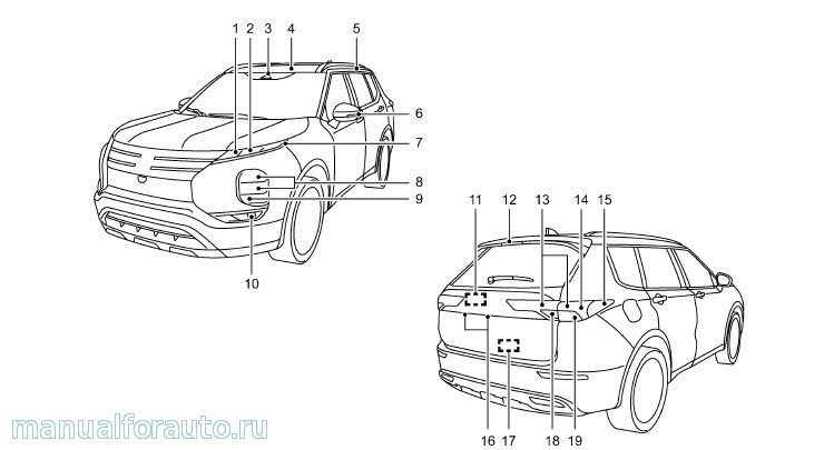
Руководство по эксплуатации на Митсубиси Аутлендер 4 поколение с 2021 года
Заправочные объемы Митсубиси Аутлендер 4
Моторное масло 4.8л synthetic 0W-20 GF-5 SN
Охлаждающая жидкость 9.4л SURPER LONG LIFE COOLANT PREMIUM
Автоматическая трансмиссия (CVT) 7.9л MITSUBISHI MOTORS GENUINE CVTF-J4
Дифференциал 0.5л NISSAN HYPOID FLUID·S1 GL-5 75W-80
Руководство Mitsubishi Outlander
Добавлять комментарии могут только зарегистрированные пользователи.
[
Регистрация
|
Вход
]

- Manuals
- Brands
- Mitsubishi Manuals
- Automobile
- 2013 Outlander
- Service manual
-
Contents
-
Table of Contents
-
Bookmarks
Related Manuals for Mitsubishi 2013 Outlander
Summary of Contents for Mitsubishi 2013 Outlander
-
Page 1: Table Of Contents
00-1 GROUP 00 GENERAL CONTENTS HOW TO USE THIS MANUAL..00-2 SPACIOUS CABIN ….00-6 ACTIVE SAFETY….. 00-7 TARGETS OF DEVELOPMENT .
-
Page 2: How To Use This Manual
INVECS:Indicates the intelligent and innovative vehi- <4N14> diesel engine. cles electronic control system. 2400:Indicates models equipped with the 2,360 mL MIVEC:Indicates the Mitsubishi innovative valve tim- <4B12> petrol engine. ing electronic control system. 2WD:Indicates the 2-wheel drive vehicles. MPI:Indicates the multipoint injection.
-
Page 3: Technical Features
GENERAL 00-3 TECHNICAL FEATURES • Long and flat cargo space (with luggage box) + Mode type Explanation 335 mm in comparison with current model. 4WD ECO 2WD at normal situation for fuel economy and turns to 4WD due to ENHANCEMENT OF ACTUAL FUEL road condition automatically.
-
Page 4
GENERAL 00-4 TECHNICAL FEATURES MAIN FEATURES ACB05806 ACC00047 • Lighter body due to rich tensioned surfaces 1. FRONT DESIGN • Wide and stable image due to the combina- which helps to attain rigidity. (The form itself create rigidity.) tion of horizontal graphic and trapezoid grille. •… -
Page 5: Interior
GENERAL 00-5 TECHNICAL FEATURES INTERIOR M2000018002103 MAIN FEATURES ACC00822AC • Good haptic quality with soft upper pad on 1. INSTRUMENT PANEL • Simple and clear image with few parting lines. front doors. • Wide haptic due to horizontal large decoration •…
-
Page 6: Spacious Cabin
GENERAL 00-6 TECHNICAL FEATURES SPACIOUS CABIN M2000000400456 COMFORT ACC00826 Item Dimension mm Overall length 4,655 Front overhang Wheelbase 2,670 Rear overhang 1,030 Overall height (unladen) 1,680 Ground clearance (unladen) Overall width 1,800 Front track 1,540 Rear track 1,540 Front leg space Rear leg space Third leg space Head room…
-
Page 7: Active Safety
GENERAL 00-7 TECHNICAL FEATURES AERODYNAMICS Rear under cover Front under cover <4N1> ACC00050 • NEW OUTLANDER achieved a drag coefficient • ABS (Anti-skid Braking System) with EBD (Elec- of C =0.33, 7-percent reduction as compared to tronic Brake-force Distribution) (Refer to GROUP 35B − Anti-skid Braking System the current model, the cutting-edge computer P.35B-2.) simulation technology and with the numerous…
-
Page 8: Passive Safety
• Features 6.1 inch QVGA (Quarter Video Start System (OSS) P.42B-18] Graphics Array) full-colour display and touch screen. • Supports USB/iPod control functions • Rear view camera image with reference lines NEWLY DEVELOPED NAVIGATION − MITSUBISHI MULTI COMMUNICATION SYSTEM (MMCS)
-
Page 9: Environmental Protection
• Dual display function such as navigation and ENVIRONMENTAL PROTECTION AV (Audio Visual)/Vehicle information, etc. • Supports USB/i-Pod control functions and SD M2000027000945 Mitsubishi Motors Corporation has given careful con- audio files sideration to protection of natural resources and the environment. Environmentally friendly features are A/C SYSTEM shown below.
-
Page 10
GENERAL 00-10 VEHICLE IDENTIFICATION <2200> Model code Seating Engine model Transmission model Fuel supply capacity system GF6W XJHXR6 5-persons 4N14 (2,268 mL) F6MBA (Front wheel Electrical fuel DOHC Direct drive 2WD, 6M/T) injection XJHXL6 injection-diesel with (Direct XJXXL6 7-persons intercooled turbocharger injection-Diesel engine, Auto Stop &… -
Page 11
GENERAL 00-11 VEHICLE IDENTIFICATION No. Item Content Engine type 2.0L MPI (4B11) MIVEC 2.4L MPI (4B12) MIVEC 2.2L Diesel (4N14) 2.0L MPI (4J11) Smart MIVEC Vehicle type Station wagon Body style 4-door with tailgate Transmission type 6M/T 6A/T 5M/T Trim level (Price class) Vehicles for Europe: H-line <5-seating>… -
Page 12
GENERAL 00-12 MAJOR SPECIFICATIONS MAJOR SPECIFICATIONS M2000030003278 VEHICLES FOR EUROPE ACB04339AB <2000> Item GF7W XNSXL6 XTXXL6 Vehicle Front track 1 1,540 1,540 dimension mm Overall width 2 1,800 1,800 Front overhang 3 955 Wheelbase 4 2,670 2,670 Rear overhang 5 1,030 1,030 Overall length 6 4,655… -
Page 13
GENERAL 00-13 MAJOR SPECIFICATIONS Item GF7W XNSXL6 XTXXL6 Turning radius Body 5.73 5.73 Wheel Item GF7W XTHXL6 XTHXZL6 Vehicle Front track 1 1,540 1,540 dimension mm Overall width 2 1,800 1,800 Front overhang 3 955 Wheelbase 4 2,670 2,670 Rear overhang 5 1,030 1,030 Overall length… -
Page 14: Major Specifications
GENERAL 00-14 MAJOR SPECIFICATIONS Item GF7W XTXXZL6 Vehicle Front track 1 1,540 dimension mm Overall width 2 1,800 Front overhang 3 955 Wheelbase 4 2,670 Rear overhang 5 1,030 Overall length 6 4,655 Ground clearance (unladen) 7 215 Overall height (unladen) 8 1,680 Rear track 9 1,540…
-
Page 15
GENERAL 00-15 MAJOR SPECIFICATIONS <2200> Item GF6W XJHXL6/XJHXR6 XJXXL6 Vehicle Front track 1 1,540 1,540 dimension mm Overall width 2 1,800 1,800 Front overhang 3 955 Wheelbase 4 2,670 2,670 Rear overhang 5 1,030 1,030 Overall length 6 4,655 4,655 Ground clearance (unladen) 7 215 Overall height (unladen) -
Page 16
GENERAL 00-16 MAJOR SPECIFICATIONS Item GF6W XLHFZL6 XLXFZL6/XLXFZR6 Vehicle Front track 1 1,540 1,540 dimension mm Overall width 2 1,800 1,800 Front overhang 3 955 Wheelbase 4 2,670 2,670 Rear overhang 5 1,030 1,030 Overall length 6 4,655 4,655 Ground clearance (unladen) 7 215 Overall height (unladen) 8 1,680… -
Page 17
GENERAL 00-17 MAJOR SPECIFICATIONS Item GF6W XJXXZL6/XJXXZR6 XJSXZL6/XJSXZR6 Vehicle Front track 1 1,540 1,540 dimension mm Overall width 2 1,800 1,800 Front overhang 3 955 Wheelbase 4 2,670 2,670 Rear overhang 5 1,030 1,030 Overall length 6 4,655 4,655 Ground clearance (unladen) 7 215 Overall height (unladen) 8 1,680… -
Page 18
GENERAL 00-18 MAJOR SPECIFICATIONS Item GF6W XJSXZL6/XJSXZR6 Vehicle Front track 1 1,540 dimension mm Overall width 2 1,800 Front overhang 3 955 Wheelbase 4 2,670 Rear overhang 5 1,030 Overall length 6 4,655 Ground clearance (unladen) 7 215 Overall height (unladen) 8 1,680 Rear track 9 1,540… -
Page 19
GENERAL 00-19 MAJOR SPECIFICATIONS VEHICLES FOR RUSSIA ACB04339AB <2000> Item GF2W XTSHL6Z XTSHZL6Z Vehicle Front track 1 1,540 1,540 dimension mm Overall width 2 1,800 1,800 Front overhang 3 955 Wheelbase 4 2,670 2,670 Rear overhang 5 1,030 1,030 Overall length 6 4,655 4,655 Ground clearance (unladen) -
Page 20
GENERAL 00-20 MAJOR SPECIFICATIONS <2400> Item GF3W XTHHZL6Z Vehicle Front track 1 1,540 dimension mm Overall width 2 1,800 Front overhang 3 955 Wheelbase 4 2,670 Rear overhang 5 1,030 Overall length 6 4,655 Ground clearance (unladen) 7 215 Overall height (unladen) 8 1,680 Rear track 9 1,540… -
Page 21
11-1 GROUP 11 ENGINE MECHANICAL CONTENTS GENERAL INFORMATION ..11-2 BASE ENGINE ….11-3… -
Page 22
• Valve train with direct-acting valve tappets and 4B12 (2,360 cc). • Silent timing chain These engines have adopted the following features: • MIVEC (Mitsubishi Innovative Valve timing Elec- • Unit type balancer<4B12> tronic Control system) for the intake valves MAIN SPECIFICATIONS… -
Page 23
ENGINE MECHANICAL 11-3 BASE ENGINE BASE ENGINE M2112001002194 CYLINDER HEAD RELATION Cylinder head cover PCV valve Front camshaft bearing cap Valve guide Camshaft bearing cap Cylinder head Camshaft Camshaft position bearing sensor Valve seat Cylinder head gasket Oil feeder control valve Oil hole Oil feeder control valve filter… -
Page 24
ENGINE MECHANICAL 11-4 BASE ENGINE CYLINDER BLOCK Crankshaft bearing cap Cylinder block Crankshaft oil seal Ladder frame AKB00850 A cylinder block made of an aluminium alloy has Item 4B11 4B12 been adopted for weight reduction. Overall height 230.1 240.1 Five bearings are provided for the crankshaft jour- nals and the No. -
Page 25
ENGINE MECHANICAL 11-5 BASE ENGINE PISTON RELATION Piston ring No.1 Piston ring No.2 Piston ring No.1 Piston Piston pin Maker mark Piston ring No.2 Connecting <4B11> Oil ring <4B12> Oil ring Rail Spacer Connecting rod bearing AKB00851AB • The connecting rod is made of highly rigid, forged 1. -
Page 26
ENGINE MECHANICAL 11-6 BASE ENGINE CRANKSHAFT RELATION Adapter plate Thrust bearing Upper crankshaft groove bearing Drive plate Crankshaft Crankshaft sensing ring Crankshaft sprocket Crankshaft pulley Lower crankshaft bearing Balance weight Crankshaft sensing ring Crankshaft sprocket Crankshaft Oil hole Balance weight Balance weight AKB00852 1. -
Page 27
ENGINE MECHANICAL 11-7 BASE ENGINE TIMING CHAIN RELATION Inlet V.V.T. sprocket Exhaust camshaft sprocket Timing chain Tensioner lever assembly Timing chain mark Timing mark link plate (blue) Timing chain mark link plate (blue) Chain guide Timing chain V.V.T. sprocket tensioner Camshaft sprocket timing mark timing mark… -
Page 28
ENGINE MECHANICAL 11-8 BASE ENGINE VALVE RELATION Valve tappet Inlet camshaft Valve spring Exhaust camshaft Valve stem seal Inlet valve Exhaust valve AK502499 The valve mechanism is based on a 4-valve DOHC 3. VALVE • The valves have heat-resistance. The entire (Double Over Head Camshaft) design having the camshaft on the upper valve. -
Page 29
ENGINE MECHANICAL 11-9 BASE ENGINE MIVEC (MITSUBISHI INNOVATIVE VALVE TIMING ELECTRONIC CONTROL SYSTEM) RELATION V.V.T. camshaft sprocket (Inlet ) Oil feeder control valve Cylinder head Oil feeder control valve filter Cylinder block Section A-A AKB00854AB MIVEC (Mitsubishi Innovative Valve timing Electronic… -
Page 30
ENGINE MECHANICAL 11-10 BASE ENGINE CAMSHAFT Cam position sensing cam Inlet camshaft Advance oil channel Retard oil channel Dowel pin Sealing cap Hollow section Exhaust camshaft AK502506 The lightweight camshaft is achieved by the hollow A cam position sensing ring is press-fitted onto the design. -
Page 31
ENGINE MECHANICAL 11-11 BASE ENGINE BALANCER RELATION<4B12> Crank shaft sprocket Balancer shaft module assembly Counter balancer shaft Balancer chain guide Balancer Timing mark tensioner link plate lever Crankshaft sprocket timing mark Balancer timing chain Crank shaft Balancer tensioner sprocket lever Balancer shaft module Balancer Balancer timing… -
Page 32
NOTES… -
Page 33
12-1 GROUP 12 ENGINE LUBRICATION CONTENTS GENERAL INFORMATION ..12-2 OIL PASSAGE ….12-3… -
Page 34
ENGINE LUBRICATION 12-2 GENERAL INFORMATION GENERAL INFORMATION M2120000100465 The lubrication system is the full-flow, filter pumping After the oil is pumped to the individual crankshaft system. journals, it passes through a passage in the crank- The engine oil that accumulates in the oil pan is shaft and is fed to the pins. -
Page 35
ENGINE LUBRICATION 12-3 OIL PASSAGE The oil pump case, which is installed to the bottom of Item Specification the ladder flame, is driven by the oil pump chain Displacement L/min(6,000 r/min.) through the oil pump sprocket installed to the front of the oil pump case. OIL PASSAGE M2120000200741 Oil screen… -
Page 36
NOTES… -
Page 37
13-1 GROUP 13 FUEL CONTENTS MULTIPOINT FUEL INJECTION (MPI)….FUEL SUPPLY …….. -
Page 38
NOTES… -
Page 39
13A-32 PURGE CONTROL ….13A-41 MIVEC (Mitsubishi Innovative Valve CONTROLLER AREA NETWORK Timing Electronic Control (CAN) …… -
Page 40: General Information
MULTIPOINT FUEL INJECTION (MPI) 13A-2 GENERAL INFORMATION GENERAL INFORMATION M2132000102640 The following points of the 4B1 engine introduced to the previous OUTLANDER have been changed: Improvement / Additions Remark The variable valve timing control (V.V.T.) system has Due to this, the exhaust oil control valve and the been discontinued at the engine exhaust side.
-
Page 41
No.2 ignition coil [3] Ignition timing and control for Throttle position sensor (sub) current carrying time No.3 ignition coil Accelerator pedal position MIVEC (Mitsubishi Innovative sensor (main) Valve timing Electronic No.4 ignition coil Control system) Accelerator pedal position sensor (sub) -
Page 42
MULTIPOINT FUEL INJECTION (MPI) 13A-4 GENERAL INFORMATION Control System Diagram Air flow sensor Power supply Injector Engine- Ignition coil Intake air temperature Ignition switch-IG Inlet oil feeder Engine control relay sensor Ignition switch-ST control valve Fuel pump relay Barometric Throttle position sensor Accelerator pedal Throttle valve control Starter relay… -
Page 43: Control Unit
MULTIPOINT FUEL INJECTION (MPI) 13A-5 CONTROL UNIT CONTROL UNIT M2132021500960 ENGINE-ECU Engine-ECU Microprocessor Input Input Output Output sensor interface interface actuator AK602218AD Engine-ECU is installed in the engine room. Input /Output interface. Engine-ECU uses Engine-ECU judges (calculates) the optimum control flash-memory ROM that allows re-writing of data so to deal with the constant minute changes in driving that change and correction of control data is possible…
-
Page 44
MULTIPOINT FUEL INJECTION (MPI) 13A-6 CONTROL UNIT Terminal Terminal Terminal name Terminal Terminal Terminal name code code TPS5 Power supply voltage TPSE Throttle position sensor earth applied to throttle position sensor Inlet camshaft position ETV+ Throttle valve control servo (+) sensor ETV−… -
Page 45: Sensor
MULTIPOINT FUEL INJECTION (MPI) 13A-7 SENSOR Terminal Terminal Terminal name Terminal Terminal Terminal name code code CANL CAN interface (low) Ignition switch-IG GNDE Engine-ECU earth FP/R Fuel pump relay AFS5 Air flow sensor reference AC/R A/C compressor relay voltage Flash EP-ROM data BACK Backup power source rewriting power source…
-
Page 46: Intake Air Temperature Sensor
MULTIPOINT FUEL INJECTION (MPI) 13A-8 SENSOR INTAKE AIR TEMPERATURE SENSOR Intake air temperature sensor is built in to the air flow sensor. Intake air temperature sensor detects intake air temperature through thermistor’s resistance change and outputs the voltage according to intake air temperature to engine-ECU.
-
Page 47: Engine Coolant Temperature Sensor
MULTIPOINT FUEL INJECTION (MPI) 13A-9 SENSOR Output voltage (V) Manifold absolute Engine-ECU pressure sensor Power source Output signal Earth Pressure (kPa) AK602206AF ENGINE COOLANT TEMPERATURE The engine coolant temperature sensor is installed in the thermostat housing. Engine coolant temperature SENSOR sensor uses thermistor’s resistance change to detect coolant temperature and output the voltage accord- ing to coolant temperature to engine-ECU.
-
Page 48: Throttle Position Sensor
MULTIPOINT FUEL INJECTION (MPI) 13A-10 SENSOR THROTTLE POSITION SENSOR STRUCTURE AND SYSTEM Throttle position sensor is composed of a permanent Throttle body magnet fixed on the throttle shaft, Hall IC that outputs voltage according to magnetic flux density and a sta- tor that efficiently introduces magnetic flux from the permanent magnet to Hall IC.
-
Page 49
MULTIPOINT FUEL INJECTION (MPI) 13A-11 SENSOR When abnormality is detected Restrict or shut off the operating Throttle valve control servo Main Throttle position Fuel cut sensor Engine-ECU Injector Accelerator pedal position sensor Main AKB00593 ACCELERATOR PEDAL POSITION Engine-ECU compares output voltage of the throttle SENSOR position sensor (main) and throttle position sensor (sub) to check for abnormality in the throttle position… -
Page 50
MULTIPOINT FUEL INJECTION (MPI) 13A-12 SENSOR Accelerator pedal position sensor is integrated with Magnetic flux density at Hall IC is proportional to the accelerator pedal, and detects accelerator opening output voltage. angle. Engine-ECU uses the output voltage of this The accelerator pedal position sensor has 2 output systems −… -
Page 51
MULTIPOINT FUEL INJECTION (MPI) 13A-13 SENSOR When abnormality is detected Restrict or shut off the operating Throttle valve control servo Main Throttle position Fuel cut sensor Engine-ECU Injector Accelerator pedal position sensor Main AKB00595 OXYGEN SENSOR Engine-ECU compares output voltage of the acceler- Front Rear ator pedal position sensor (main) and accelerator… -
Page 52
MULTIPOINT FUEL INJECTION (MPI) 13A-14 SENSOR From engine control relay Oxygen sensor Heater Engine-ECU Zirconia element 0.5V AK602576AB CRANK ANGLE SENSOR Crankshaft sensing ring Crankshaft sensing ring (36 teeth including 3 missing teeth) Magnet flux Vane Crank angle sensor Magnetic resistance element Crankshaft sensing ring AK602737AE A crank angle sensor is installed on the exhaust side… -
Page 53
MULTIPOINT FUEL INJECTION (MPI) 13A-15 SENSOR the flux from the magnet does not pass the magnetic resistance element and the resistance decreases. The crank angle sensor converts this change in resistance of the magnetic resistance element to a 5 V pulse signal and outputs it to engine-ECU. Engine-ECU Crank angle sensor Magnetic resistance element… -
Page 54
MULTIPOINT FUEL INJECTION (MPI) 13A-16 SENSOR not pass the magnetic resistance element and the resistance decreases. The inlet camshaft position sensor converts this change in resistance of the magnetic resistance element to a 5 V pulse signal and outputs it to engine-ECU. Engine-ECU Camshaft position sensor Magnetic resistance element… -
Page 55
MULTIPOINT FUEL INJECTION (MPI) 13A-17 SENSOR BAROMETRIC PRESSURE SENSOR OIL PRESSURE SWITCH Barometric pressure sensor (built in engine-ECU) pressure Contact switch AK602575AB AK602587AB A barometric pressure sensor is built into The oil pressure switch is installed on the inlet side of engine-ECU. -
Page 56
MULTIPOINT FUEL INJECTION (MPI) 13A-18 SENSOR Battery Engine-ECU Field coil Voltage regulator Alternator AK604998AB ALTERNATOR L TERMINAL tion diode. After the electric generation begins, the current is supplied to the field coil from this circuit. In After turning on the ignition switch, the current is addition, the generated voltage is output from the input by the engine-ECU to the alternator L terminal. -
Page 57
MULTIPOINT FUEL INJECTION (MPI) 13A-19 SENSOR Battery Engine-ECU communication Charge Field coil warning lamp Combination meter Voltage regulator Alternator AK604999 AB… -
Page 58: Actuator
MULTIPOINT FUEL INJECTION (MPI) 13A-20 ACTUATOR ACTUATOR M2132002001129 INJECTOR An injector is an injection nozzle with the electromag- netic valve that injects fuel based on the injection sig- Fuel nal sent by engine-ECU. 1 injector is installed in the inlet manifold of each cylinder and fixed to the deliv- ery pipe.
-
Page 59
MULTIPOINT FUEL INJECTION (MPI) 13A-21 ACTUATOR From battery Engine control relay No. 1 No. 2 No. 3 No. 4 Injectors Engine-ECU AKB00844 Voltage from the battery gets applied from the injec- A throttle valve control servo is installed in throttle tor relay to the injector and up to the engine-ECU. -
Page 60
MULTIPOINT FUEL INJECTION (MPI) 13A-22 ACTUATOR From battery Engine control relay Throttle valve control servo engine-ECU Throttle valve control servo relay Engine-ECU Power source AK602231 IGNITION COIL The inlet oil feeder control valve is installed on the inlet side of the cylinder head. Receiving the duty Refer to GROUP 16 −… -
Page 61
MULTIPOINT FUEL INJECTION (MPI) 13A-23 ACTUATOR From engine control relay Engine-ECU Inlet oil feeder control valve AK700721 ALTERNATOR G TERMINAL adjusted to about 14.4 V. When alternator output voltage is about 14.4 V, alternator outputs current to Engine-ECU uses ON/OFF of alternator G terminal produce electricity. -
Page 62: Fuel Injection Control
MULTIPOINT FUEL INJECTION (MPI) 13A-24 FUEL INJECTION CONTROL Battery Engine-ECU Field coil Voltage regulator Alternator AK605000 FUEL INJECTION CONTROL M2132003001876 Fuel injection volume is regulated to obtain the opti- intake air volume. Engine-ECU adds prescribed mum air-fuel ratio in accordance with the constant compensations to this basic drive time according to minute changes in engine driving conditions.
-
Page 63
MULTIPOINT FUEL INJECTION (MPI) 13A-25 FUEL INJECTION CONTROL System Configuration Diagram Air flow sensor Intake air temperature sensor Manifold absolute pressure sensor Barometric pressure sensor Engine coolant temperature sensor Injector Throttle position sensor Engine- Accelerator pedal position sensor Detonation sensor Inlet camshaft position sensor Crank angle sensor Ignition switch-ST… -
Page 64
MULTIPOINT FUEL INJECTION (MPI) 13A-26 FUEL INJECTION CONTROL Fuel Injection During Cranking and Normal Operation <No. 2 TDC> <No.1 TDC> <No. 3 TDC> <No. 4 TDC> <No. 2 TDC> Crank angle sensor signal Inlet camshaft position sensor signal : Fuel injection Cylinder stroke Combustion Exhaust… -
Page 65
MULTIPOINT FUEL INJECTION (MPI) 13A-27 FUEL INJECTION CONTROL signal (engine rotation signal). This basic drive time is compensated according to signals from various 2. Fuel injection volume (injector drive sensors and optimum injector drive time (fuel injec- time) control tion volume) is calculated according to driving condi- Under normal operating conditions, the figure shows tions. -
Page 66
MULTIPOINT FUEL INJECTION (MPI) 13A-28 FUEL INJECTION CONTROL Fuel Injection Volume Control Block Diagram (Normal Operation) Air fuel ratio compensation (Predetermined Air flow sensor compensation) Basic fuel injection time determination Crank angle sensor Oxygen sensor feedback compensation Oxygen sensor Engine coolant Engine coolant temperature temperature sensor… -
Page 67
MULTIPOINT FUEL INJECTION (MPI) 13A-29 FUEL INJECTION CONTROL Intake air volume of each cycle of 1 cylinder is calcu- [Injector drive time compensation] lated by engine-ECU based on the airflow sensor After calculating the injector basic drive time, the signal and crank angle sensor signal. Also, during engine-ECU makes the following compensations to engine start, the map value prescribed by the coolant control the optimum fuel injection volume according… -
Page 68: Ignition Timing And Control For Current Carrying Time
MULTIPOINT FUEL INJECTION (MPI) 13A-30 IGNITION TIMING AND CONTROL FOR CURRENT CARRYING TIME IGNITION TIMING AND CONTROL FOR CURRENT CARRYING TIME M2132027100573 Ignition timing is pre-set according to engine driving conditions. Compensations are made according to pre-set values depending on conditions such as engine coolant temperature, battery voltage etc.
-
Page 69
MULTIPOINT FUEL INJECTION (MPI) 13A-31 IGNITION TIMING AND CONTROL FOR CURRENT CARRYING TIME <No. 2 TDC> <No.1 TDC> <No. 3 TDC> <No. 4 TDC> <No. 2 TDC> Crank angle sensor signal Inlet camshaft position sensor signal Cylinder stroke Ignition Combustion Exhaust Intake No. -
Page 70: Throttle Valve Opening Angle Control And Idle Speed Control
MULTIPOINT FUEL INJECTION (MPI) 13A-32 THROTTLE VALVE OPENING ANGLE CONTROL AND IDLE SPEED CONTROL Compensations Content Battery voltage compensation Compensation is made depending on battery voltage. The lower the battery voltage the greater the current carrying time and when battery voltage is high current carrying time is shortened.
-
Page 71
MULTIPOINT FUEL INJECTION (MPI) 13A-33 THROTTLE VALVE OPENING ANGLE CONTROL AND IDLE SPEED CONTROL While idling While driving Engine-ECU controls the throttle valve to achieve the Compensations are made to the target opening target opening angle that are set based on the angle set according to the accelerator pedal opening engine coolant temperature. -
Page 72: Mivec (Mitsubishi Innovative Valve Timing Electronic Control System)
MULTIPOINT FUEL INJECTION (MPI) 13A-34 MIVEC (Mitsubishi Innovative Valve Timing Electronic Control System) MIVEC (Mitsubishi Innovative Valve Timing Electronic Control System) M2132023500911 The MIVEC system effects a continuously variable control on the inlet valve timing. The valve operating angle is not change. MIVEC enables valve timing control that is optimal for the operating conditions of the engine.
-
Page 73
MULTIPOINT FUEL INJECTION (MPI) 13A-35 MIVEC (Mitsubishi Innovative Valve Timing Electronic Control System) <No.2TDC> <No.1TDC> <No.3TDC> <No.4TDC> <No.2TDC> Crank angle sensor signal Inlet camshaft position sensor signal : Phase angle AKB00756AB The engine-ECU calculates the detected phase angle by using the signal from the inlet camshaft position sensor and the crank angle sensor. -
Page 74: Engine Control Relay Control
MULTIPOINT FUEL INJECTION (MPI) 13A-36 ENGINE CONTROL RELAY CONTROL ENGINE CONTROL RELAY CONTROL M2132006000720 Battery LOCK Ignition switch Engine control relay ETACS-ECU To each sensor and actuator Power Battery Engine-ECU backup source Engine control relay control Ignition switch-IG AK604134AD • Throttle valve initializing control When the ignition switch-IG «ON»…
-
Page 75: Fuel Pump Relay Control
MULTIPOINT FUEL INJECTION (MPI) 13A-37 FUEL PUMP RELAY CONTROL FUEL PUMP RELAY CONTROL M2132006500769 Battery LOCK Ignition switch Engine control relay To engine-ECU ETACS-ECU Fuel pump relay Fuel pump Ignition switch-ST and gauge unit Engine-ECU Fuel pump Crank angle sensor relay control AK700635 When current flows through the fuel pump relay, the…
-
Page 76: Starter Relay Control
MULTIPOINT FUEL INJECTION (MPI) 13A-38 STARTER RELAY CONTROL STARTER RELAY CONTROL M2132025500672 Battery Ignition switch-ST Inhibitor switch ETACS -ECU Starter relay Engine-ECU Starter Starter relay control AK800140 When the ignition switch-ST signal is input, engine-ECU turns ON the power transistor for control of the starter relay.
-
Page 77: Oxygen Sensor Heater Control
MULTIPOINT FUEL INJECTION (MPI) 13A-39 OXYGEN SENSOR HEATER CONTROL OXYGEN SENSOR HEATER CONTROL M2132007000734 Engine-ECU Oxygen sensor heater Engine coolant Engine control temperature sensor relay Battery AK602241AE When exhaust gas temperature is low, the oxygen the fuel during deceleration. Based on driving condi- sensor response is dull.
-
Page 78: A/C Compressor Relay Control
MULTIPOINT FUEL INJECTION (MPI) 13A-40 A/C COMPRESSOR RELAY CONTROL A/C COMPRESSOR RELAY CONTROL M2132034500722 Battery A/C compressor relay refrigerant A/C switch (CAN) temperature switch Crank angle sensor A/C compressor assembly Accelerator pedal position sensor A/C compressor A/C compressor Vehicle speed signal (CAN) clutch relay control Inhibitor switch (CAN)
-
Page 79: Alternator Control
MULTIPOINT FUEL INJECTION (MPI) 13A-41 ALTERNATOR CONTROL ALTERNATOR CONTROL M2132025000785 Alternator G terminal Engine coolant temperature sensor Alternator FR terminal Crank angle sensor Engine-ECU A/C switch (CAN) Ignition switch-ST Alternator AK602242 AL During engine idle operation, engine-ECU controls increase in alternator output current and output cur- duty of conduction between alternator G terminal and rent is increased only gradually.
-
Page 80
NOTES… -
Page 81: Fuel Supply
13B-1 GROUP 13B FUEL SUPPLY CONTENTS GENERAL INFORMATION ..13B-2 FUEL TANK ….13B-3…
-
Page 82
FUEL SUPPLY 13B-2 GENERAL INFORMATION GENERAL INFORMATION M2134000101676 • Fuel high-pressure hose The fuel system consists of the following compo- • Fuel line pipe nents: • Fuel injector • Fuel tank assembly • Fuel delivery pipe • Fuel pump and gauge assembly •… -
Page 83: Second Seat
FUEL SUPPLY 13B-3 FUEL TANK <4WD> Fuel gauge unit Fuel tank assembly Fuel vapour canister Fuel delivery pipe Fuel injector Fuel pump and Fuel line pipe gauge assembly Fuel high-pressure hose ACB05408AB • A return less fuel system eliminates returned fuel This fuel system is designed with consideration for global environment protection to ensure safety at a from the engine.
-
Page 84
FUEL SUPPLY 13B-4 FUEL TANK CONSTRUCTION DIAGRAM <2WD> Fuel pump and gauge assembly Fuel tank ACC00445AB Fuel tank safety valve Fuel tank safety valve ACC00461AB… -
Page 85
FUEL SUPPLY 13B-5 FUEL TANK <4WD> Fuel gauge unit Fuel pump and gauge assembly Fuel tank ACC00446AB Fuel tank safety valve Fuel tank safety valve Fuel tank suction hose Fuel in tank filter ACC00462AB… -
Page 86
NOTES… -
Page 87: Engine Cooling
14-1 GROUP 14 ENGINE COOLING CONTENTS GENERAL INFORMATION ..14-2 WATER PUMP ….14-3 WATER PASSAGE ….14-3…
-
Page 88
ENGINE COOLING 14-2 GENERAL INFORMATION GENERAL INFORMATION M2140000101567 • A down-flow radiator has been adopted in order For the cooling method, a forced water-cooling circu- lation system is adopted and it has the following to reduce the number of parts and improve serv- characteristics: iceability. -
Page 89: Water Pump
ENGINE COOLING 14-3 WATER PASSAGE WATER PASSAGE M2140004000718 <Hot> <Cold> Thermostat Thermostat Water pump Water pump Heater Heater Throttle body Throttle body oil cooler oil cooler Radiator Radiator ACB04926 WATER PUMP M2140003000492 The water pump is the centrifugal, impeller type that is installed in front of the cylinder block.
-
Page 90
NOTES… -
Page 91
15-1 GROUP 15 INTAKE AND EXHAUST CONTENTS AIR INTAKE SYSTEM … . 15-2 EXHAUST SYSTEM ….15-3 AIR DUCT AND AIR CLEANER . -
Page 92: Air Intake System
INTAKE AND EXHAUST 15-2 AIR INTAKE SYSTEM AIR INTAKE SYSTEM AIR DUCT AND AIR CLEANER M2150004001381 CONSTRUCTION DIAGRAM Resonator Air cleaner assembly Air duct ACB05021AB In order to save weight, an air cleaner element with- out plastics is used and the panel thicknesses of the cover and the housing are optimised.
-
Page 93: Exhaust System
INTAKE AND EXHAUST 15-3 EXHAUST SYSTEM EXHAUST SYSTEM EXHAUST MANIFOLD M2150006001105 The exhaust manifold incorporates a catalytic con- verter. In order to reduce vibration, a spherical joint is used at the front pipe connection. EXHAUST PIPE AND MUFFLER M2150003001775 CONSTRUCTION DIAGRAM Hanger bracket Tail pipe Hanger bracket…
-
Page 94
NOTES… -
Page 95
16-1 GROUP 16 ENGINE ELECTRICAL CONTENTS STARTER MOTOR ….16-2 IGNITION COIL ….16-2 ALTERNATOR . -
Page 96: Starter Motor
ENGINE ELECTRICAL 16-2 STARTER MOTOR STARTER MOTOR M2161002000728 The starter motor is a reduction drive type with plan- etary gear. ALTERNATOR M2162001000687 The alternator is the battery detection type. IGNITION COIL M2163001000561 The ignition coil is the plug-top type. This plug-top type ignition coil has the following fea- tures: Coil •…
-
Page 97
17-1 GROUP 17 ENGINE AND EMISSION CONTROL CONTENTS ENGINE CONTROL ….17-2 GENERAL INFORMATION … . . 17-8 CONSTRUCTION AND OPERATION . -
Page 98: Engine Control
ENGINE AND EMISSION CONTROL 17-2 ENGINE CONTROL ENGINE CONTROL GENERAL INFORMATION This system detects the amount of the accelerator pedal movement by using an accelerator pedal posi- M2170001001522 For the accelerator system, an electronic throttle tion sensor in the accelerator pedal assembly for valve control system has been adopted, eliminating electronically controls the throttle valve.
-
Page 99
ENGINE AND EMISSION CONTROL 17-3 CRUISE CONTROL SYSTEM CONSTRUCTION DIAGRAM Fuel injection system <Diesel engine> Accelerator pedal <Standard meter> (Built-in accelerator Cruise control indicator lamp pedal position sensor) Hydraulic unit Assembly Speed limiter display screen (Built-in ABS-ECU ACC00039 <Vehicles without ASC> or ASC-ECU <High contrast meter>… -
Page 100
ENGINE AND EMISSION CONTROL 17-4 CRUISE CONTROL SYSTEM COMPONENTS AND FUNCTIONS Component Function ABS-ECU <Vehicles without ASC> or Outputs the cruise control cancel signal to the engine-ECU. ASC-ECU <Vehicles with ASC> Accelerator pedal position sensor Informs the engine-ECU of the accelerator pedal depression. Cruise control indicator lamp <standard When the cruise control ON/OFF switch is pressed, a lamp will meter>… -
Page 101: Construction And Operation
ENGINE AND EMISSION CONTROL 17-5 CRUISE CONTROL SYSTEM Component Function • Based on the input signal from each sensors and switches, Engine-ECU the throttle opening angle indication signal is sent. • Based on the input signal from each sensors and switches, the CVT control signal is sent to the CVT-ECU.
-
Page 102: Block Diagram
ENGINE AND EMISSION CONTROL 17-6 CRUISE CONTROL SYSTEM • The speed limiter controls the engine output and The combination meter will turn on the cruise control the transmission gear ratio to regulate the vehicle indicator lamp <Standard meter>, the cruise control speed.
-
Page 103
ENGINE AND EMISSION CONTROL 17-7 CRUISE CONTROL SYSTEM DECELERATION FUNCTION 3. In addition when the RES + switch is pressed for less than approximately 0.5 second, the vehicle 1. When the SET − switch is pressed and held for speed is increased by approximately 1.6 km/h approximately 0.5 second or longer during the from the constant speed driving speed. -
Page 104: Adaptive Cruise Control System (Acc)
ENGINE AND EMISSION CONTROL 17-8 ADAPTIVE CRUISE CONTROL SYSTEM (ACC) • An abnormality occurs in the stop lamp signal. • An abnormality occurs in the vehicle speed sig- When one of the following conditions is met, unless nal. • Throttle position sensor abnormality. the vehicle is stopped to turn the ignition switch to •…
-
Page 105
ENGINE AND EMISSION CONTROL 17-9 ADAPTIVE CRUISE CONTROL SYSTEM (ACC) If vehicle travelling in front accelerates faster than your vehicle’s set speed, your vehicle will accelerate Acceleration control until it reaches your set speed gradually, and then be Vehicle travelling ahead driven at a constant speed. -
Page 106
ENGINE AND EMISSION CONTROL 17-10 ADAPTIVE CRUISE CONTROL SYSTEM (ACC) CONSTRUCTION DIAGRAM Accelerator pedal (Built-in accelerator Hydraulic unit Assembly pedal position sensor) Steering wheel sensor (Built-in ASC-ECU) Throttle body assembly (Built-in throttle position sensor and throttle valve control servo) Cruise control display screen Multi information Stop lamp switch display… -
Page 107
ENGINE AND EMISSION CONTROL 17-11 ADAPTIVE CRUISE CONTROL SYSTEM (ACC) COMPONENTS AND FUNCTIONS Component Function • ACC status is changed based on the ACC/ cruise control ACC/FCM-ECU system/ adjustable speed limitation control mode and on the signal of switch state sent from engine-ECU. •… -
Page 108: Construction And Operation
ENGINE AND EMISSION CONTROL 17-12 ADAPTIVE CRUISE CONTROL SYSTEM (ACC) Component Function • Signals of state of steering switches (including failure Engine-ECU judgement result) are sent. • Acceleration/deceleration are controlled according to ACC target torque received from ASC-ECU when ACC mode is ON and ACC status is active.
-
Page 109
ENGINE AND EMISSION CONTROL 17-13 ADAPTIVE CRUISE CONTROL SYSTEM (ACC) BLOCK DIAGRAM Brake switch Cruise control switches (ACC/ cruise control/ speed limiter) Cruise control switches Stop lamp switch ASC-ECU (ACC distance switch) ACC status or target engine torque Switch signal Switch signal or target primary speed (CAN) -
Page 110: Emission Control
ENGINE AND EMISSION CONTROL 17-14 EMISSION CONTROL<MPI> EMISSION CONTROL<MPI> GENERAL INFORMATION M2171000101756 The emission control is basically the same as the 4B1 engine mounted on the ASX. SYSTEM CONFIGURATION DIAGRAM Purge control Canister solenoid valve Air cleaner From Positive fuel pump crankcase ventilation valve…
-
Page 111: Crankcase Ventilation System
ENGINE AND EMISSION CONTROL 17-15 EMISSION CONTROL<MPI> System Objective / Function Composition parts • Engine-ECU Emission reduction Air-fuel ratio Decrease of CO, HC and • Air flow sensor systems feedback control • Injector Controls air-fuel ratio of • Oxygen sensor air-fuel mixture to become •…
-
Page 112: Evaporative Emission Control System
ENGINE AND EMISSION CONTROL 17-16 EMISSION CONTROL<MPI> cover, and it mixes with the blow-by gas in the crank- POSITIVE CRANKCASE VENTILATION case. The blow-by gas in the crankcase is induced to (PCV) VALVE the inlet manifold through the rocker cover and PCV valve.
-
Page 113: Emission Reduction Systems
ENGINE AND EMISSION CONTROL 17-17 EMISSION CONTROL<MPI> A purge control solenoid valve is installed in the inlet passes through the coil, air can pass between nipple manifold. The purge control solenoid valve controls A and B and fuel vapour gas is sucked in. the intake volume of fuel vapour gas from the canis- Engine-ECU changes the ON duty ratio according to ter.
-
Page 114
NOTES… -
Page 115
23-1 GROUP 23 CONTINUOUSLY VARIABLE TRANSMISSION (CVT) CONTENTS CVT……23-2 TRANSMISSION CONTROL ..23-3 GENERAL INFORMATION. -
Page 116: Cvt
Fail-safe function Present − (detected by the ABS sensor) Number of speedometer gears (drive/driven) Oil pump Model Vane-type pump Drive type Driven by the engine, sprocket, and chain CVT fluid Brand name MITSUBISHI MOTORS GENUINE CVTF-J4 Capacity (L) Approximately 7.1…
-
Page 117: Transmission Control
CONTINUOUSLY VARIABLE TRANSMISSION (CVT) 23-3 TRANSMISSION CONTROL NEW ACCELERATION CONTROL : New Accelerator pedal operation : Conventional Time New: To reduce a feel of untimely shifting, the downshift amount at the initial acceleration is adjusted. In addition, the upshift amount CVT gear ratio is restricted at the later acceleration with the aim of providing the acceleration feeling like a multi-stage transmission.
-
Page 118
CONTINUOUSLY VARIABLE TRANSMISSION (CVT) 23-4 TRANSMISSION CONTROL Transmission control cable Selector lever assembly ACC00027AB… -
Page 119: Propeller Shaft
25-1 GROUP 25 PROPELLER SHAFT CONTENTS GENERAL INFORMATION ..25-2…
-
Page 120: General Information
PROPELLER SHAFT 25-2 GENERAL INFORMATION GENERAL INFORMATION M2250000100829 • Inside the rear propeller shaft, the dynamic The 2-piece, 3-joint type propeller shaft with a centre bearing is adopted. damper is integrated to reduce a booming noise It has the following features: cased by the resonance at the high engine •…
-
Page 121
26-1 GROUP 26 FRONT AXLE CONTENTS GENERAL INFORMATION ..26-2… -
Page 122: General Information
FRONT AXLE 26-2 GENERAL INFORMATION GENERAL INFORMATION M2260000101533 • Dynamic damper is mounted on driveshaft (RH) For the front axle, the multi-line angular contact ball bearing with an integral oil seal is adopted as a to reduce differential booming noise. <2000> •…
-
Page 123
FRONT AXLE 26-3 GENERAL INFORMATION CONSTRUCTION DIAGRAM Strut assembly AC602514 ACB04894 Knuckle <LH> Driveshaft (LH) Driveshaft (RH) <RH — 4WD> Dynamic damper Front hub <RH — 2WD> Wheel bearing Driveshaft (RH) Magnetic Oil seal encoder AC504925 ACC00499… -
Page 124
NOTES… -
Page 125: Rear Axle
27-1 GROUP 27 REAR AXLE CONTENTS REAR AXLE <2WD> … . . 27-2 ELECTRONICALLY CONTROLLED 4WD……27-6 REAR AXLE <4WD>…
-
Page 126: Rear Axle <2Wd
REAR AXLE 27-2 REAR AXLE <2WD> REAR AXLE <2WD> M2270002000325 • The number of parts has been reduced by inte- The rear axle has the following features: • The wheel bearing is a unit ball bearing (dou- grating the magnetic encoder for ABS wheel ble-row angular contact ball bearing) which incor- speed detection into the wheel bearing.
-
Page 127: Rear Axle <4Wd
REAR AXLE 27-3 REAR AXLE <4WD> REAR AXLE <4WD> M2270003000447 • Lead-free grease for the constant velocity joint For the rear axle, the unit ball bearing (double-row angular contact ball bearing) in which the hub and has been adopted. • Hexavalent chromium has been eliminated from ball bearing are incorporated has been adopted for the wheel bearing, and the EUJ−ETJ type constant the dust cover material.
-
Page 128: Differential
Straight bevel gear × 2 Pinion gear Number of teeth Drive gear Drive pinion Side gear Pinion gear Gear oil MITSUBISHI MOTORS GENUINE Approx. 0.4 L super hypoid gear oil API classification GL-5, SAE 80W ACB05767 Electronic control coupling Equal altitude Differential…
-
Page 129
REAR AXLE 27-5 DIFFERENTIAL DIFFERENTIAL MOUNT Rear suspension crossmember Upper stopper Rear differential mount insulator Lower Upper stopper stopper Rear differential mount Weight front bracket (LH) Rear differential mount front bracket (RH) Electronic control coupling Lower stopper Differential carrier Weight ACC02383 The front side of the differential carrier is installed to the rear suspension crossmember via rear differen-… -
Page 130: Electronically Controlled 4Wd
REAR AXLE 27-6 ELECTRONICALLY CONTROLLED 4WD ELECTRONICALLY CONTROLLED 4WD • Under severe driving condition, the system is pro- GENERAL INFORMATION tected by minimizing the limitation force of the dif- M2270000101136 • Electronically controlled 4WD has been adopted ferential. • During high-speed driving, the fuel efficiency is to ensure the on-road performance, achieve lighter and smaller body, and realize better fuel improved by reducing the limitation force of the…
-
Page 131
REAR AXLE 27-7 ELECTRONICALLY CONTROLLED 4WD CONSTRUCTION DIAGRAM Steering wheel sensor Combination meter ABS/ASC-ECU ECO switch 4WD switch ETACS-ECU Electronic control coupling Engine-ECU 4WD-ECU CVT-ECU or A/T-ECU Diagnosis connector < Standard meter> < High contrast meter> Drive mode indicator Drive mode display ACB05569 AC System component and function Parts name… -
Page 132
REAR AXLE 27-8 ELECTRONICALLY CONTROLLED 4WD Parts name Functional description Steering wheel sensor Sends the following signals required by 4WD-ECU via CAN communication. • Steering angle signal 4WD switch Sends the drive mode switch signal (4WD) to 4WD-ECU. ECO switch Sends the ECO ON/OFF signal to 4WD-ECU. -
Page 133
REAR AXLE 27-9 ELECTRONICALLY CONTROLLED 4WD System configuration ETACS-ECU Combination meter Engine-ECU ABS/ASC-ECU CAN-C CAN-C-Mid CVT-ECU Steering wheel CAN-C sensor A/T-ECU Diagnosis connector 4WD-ECU Engine Electronic control coupling Transmission 4WD switch NOTE:The dashed line indicates CAN communication lines (CAN-C, CAN-C-Mid). ACC00455 AC… -
Page 134
REAR AXLE 27-10 ELECTRONICALLY CONTROLLED 4WD Control schematic diagram 4WD switch (4WD ECO 4WD AUTO 4WD-ECU 4WD LOCK) Coupling torque Engine-ECU CAN-C CAN-C-Mid · Engine r/min Combination meter · Engine torque · Drive mode indicator ETACS-ECU or display ABS/ASC-ECU · Fail information ·… -
Page 135: 4Wd-Ecu
REAR AXLE 27-11 ELECTRONICALLY CONTROLLED 4WD Electronically controlled 4WD electric circuit diagram Fusible link Ignition switch(IG1) Fusible link ETACS-ECU ETACS-ECU 15 A (Fuse) (Fuse) relay Electronic control coupling solenoid 10 A 7.5 A 4WD-ECU 4WD switch ABS/ASC CVT-ECU or Engine-ECU -ECU A/T-ECU ETACS-ECU…
-
Page 136
REAR AXLE 27-12 ELECTRONICALLY CONTROLLED 4WD • Communication with drive mode switch: The • Compares the command current value from signal from the drive mode switch changes CPU with the monitored current and checks if the drive mode. they agree. •… -
Page 137: 4Wd Switch
REAR AXLE 27-13 ELECTRONICALLY CONTROLLED 4WD 4WD SWITCH If the ECO switch is turned on during 4WD AUTO mode, the drive mode will switch into 4WD ECO to M2270001300022 The 4WD switch has been installed on the floor con- reduce fuel consumption. When the ECO switch is sole.
-
Page 138
REAR AXLE 27-14 ELECTRONICALLY CONTROLLED 4WD OPERATION Coupling stops (2WD: Magnetic coil de-energized.) Main clutch Pilot clutch Magnet coil Front housing Propeller shaft Drive pinion Shaft (Rear differential) AC505106AE The drive force from the transfer is transmitted to the front housing connected to the propeller shaft. The drive force is also transferred to the pilot clutch and the outer side of the main clutch assembled to the front housing. -
Page 139
REAR AXLE 27-15 ELECTRONICALLY CONTROLLED 4WD Coupling operates (4WD: Magnetic coil energized.) Main cam Main clutch Armature Magnetic field Pilot clutch Front housing Magnet coil Rear housing Propeller shaft Pilot cam Ball Drive pinion Shaft (Rear differential) AC505106AD Pilot cam Main cam Ball AC507947AD… -
Page 140
NOTES… -
Page 141
31-1 GROUP 31 WHEEL AND TYRE CONTENTS GENERAL INFORMATION ..31-2… -
Page 142
WHEEL AND TYRE 31-2 GENERAL INFORMATION GENERAL INFORMATION M2310000102022 The wheels and tyres of the following specifications have been established. SPECIFICATIONS Road wheel and tyre <2000> Item Standard Option <4WD> Wheel Type Steel type Aluminium type Aluminium type 16 × 6.5JJ 16 ×… -
Page 143
32-1 GROUP 32 POWER PLANT MOUNT CONTENTS GENERAL INFORMATION ..32-2… -
Page 144
POWER PLANT MOUNT 32-2 GENERAL INFORMATION GENERAL INFORMATION M2320000101503 • Roll-rod stopper has two rubber-to-metal bush- New pendulum engine mounting system reduces noise and vibration, which has the following features. ings including large voided bushing and reduces • The power train mass is supported in line with the vibration and noise doubly. -
Page 145
33-1 GROUP 33 FRONT SUSPENSION CONTENTS GENERAL INFORMATION ..33-2… -
Page 146
FRONT SUSPENSION 33-2 GENERAL INFORMATION GENERAL INFORMATION M2330000101979 • The newly adopted polyurethane bump stopper The well-proven MacPherson strut type suspension has been adopted. Various components such as the absorbs high load without transmitting sharp strut assembly and the coil spring have been modi- vibrations to the bodyshell. -
Page 147: Specifications
FRONT SUSPENSION 33-3 GENERAL INFORMATION CONSTRUCTION DIAGRAM Coil spring and strut assembly Strut insulator assembly (Cup for stopper fixation) Strut bearing Upper spring pad Bump stopper Coil spring Lower spring pad Coil spring Strut Stabilizer link Strut assembly Coil spring Stabilizer bar Strut assembly Lower arm assembly…
-
Page 148
FRONT SUSPENSION 33-4 GENERAL INFORMATION Item Specification Toe-in At the centre of tyre tread mm Toe-in angle (per wheel) 0°02’… -
Page 149: Rear Suspension
34-1 GROUP 34 REAR SUSPENSION CONTENTS GENERAL INFORMATION ..34-2…
-
Page 150
REAR SUSPENSION 34-2 GENERAL INFORMATION GENERAL INFORMATION M2340000101657 • New designed blade suspension has a slight pas- New blade multi-link rear suspension is an evolution of the current rear suspension to enhance stability sive toe-steer effect and provides safer handling. •… -
Page 151
REAR SUSPENSION 34-3 GENERAL INFORMATION CONSTRUCTION DIAGRAM <2WD> Shock absorber assembly Upper arm Coil spring Shock absorber assembly Upper arm Stabilizer bar Coil spring Trailing arm Rear suspension crossmember Control link Trailing arm ACB05753 <4WD> Shock absorber assembly Upper arm Coil spring Shock absorber assembly Upper arm… -
Page 152
NOTES… -
Page 153: Service Brake
35-1 GROUP 35 SERVICE BRAKE CONTENTS BASIC BRAKE SYSTEM ……ANTI-SKID BRAKING SYSTEM (ABS) ….ACTIVE STABILITY CONTROL SYSTEM (ASC).
-
Page 154
NOTES… -
Page 155
35A-1 GROUP 35A BASIC BRAKE SYSTEM CONTENTS GENERAL INFORMATION ..35A-2 MASTER CYLINDER ….35A-3 BRAKE BOOSTER ….35A-3 CONSTRUCTION DESCRIPTION . -
Page 156: General Information
BASIC BRAKE SYSTEM 35A-2 GENERAL INFORMATION GENERAL INFORMATION M2350000101755 • The installation of 16-inch ventilated disc brake Brake systems with higher reliability and durability have achieved distinguished braking performance. on the front axle and 16-inch solid disc brake on the rear axle achieves the secure braking force FEATURES and direct braking feeling.
-
Page 157: Master Cylinder
BASIC BRAKE SYSTEM 35A-3 CONSTRUCTION DESCRIPTION Item Specification Front disc brake Type Floating caliper, 1-piston, ventilated disc Brake disc effective dia. × thickness 241.6 × 26 Cylinder I.D. mm 57.1 Brake pad thickness mm 10.0 Clearance adjustment Automatic adjustment Rear disc brake Type Floating caliper with parking brake mechanism integrated, 1-piston, solid disc…
-
Page 158: Rear Brake
BASIC BRAKE SYSTEM 35A-4 CONSTRUCTION DESCRIPTION REAR BRAKE M2350004000917 <Brake pads> Inner pad Rear brake assembly Outer pad Brake disc Wear indicator <Normal> <At wear limit> Brake disc Brake disc Wear Wear indicator indicator ACC00071 • The outer disc type brake disc which can be tight- •…
-
Page 159
35B-1 GROUP 35B ANTI-SKID BRAKING SYSTEM (ABS) CONTENTS GENERAL INFORMATION ..35B-2 SENSOR ……35B-7 ACTUATORS . -
Page 160: General Information
ANTI-SKID BRAKING SYSTEM (ABS) 35B-2 GENERAL INFORMATION GENERAL INFORMATION M2351000101554 • For wiring harness saving and secure data com- The 4ABS ensures directional stability and control during hard braking. munication, CAN bus has been adopted as a This ABS uses a 4-sensor system that controls all tool of communication with another ECU.
-
Page 161
ANTI-SKID BRAKING SYSTEM (ABS) 35B-3 GENERAL INFORMATION CONSTRUCTION DIAGRAM <Standard meter> <High contrast meter> 4, 5, 11 <4WD> ACB06010 MAIN COMPONENTS AND FUNCTIONS Name of part Number Outline of function Sensor Wheel speed sensor Outputs the frequency signal in proportion to the rotation speed of each wheel to ABS-ECU. -
Page 162
ANTI-SKID BRAKING SYSTEM (ABS) 35B-4 GENERAL INFORMATION Name of part Number Outline of function Actuator Hydraulic unit Drives the solenoid valve using the signal from ABS-ECU, and controls the brake fluid pressure for each wheel. ABS warning lamp Informs the driver of the system status by illuminating, flashing, or turning off the warning lamp according to the signal from ABS-ECU. -
Page 163
ANTI-SKID BRAKING SYSTEM (ABS) 35B-5 GENERAL INFORMATION SCHEMATIC DIAGRAM FR solenoid valve (OUT) Wheel speed sensor (FL) FR solenoid valve (IN) Wheel speed sensor (RL) FL solenoid valve (OUT) Wheel speed sensor (RR) FL solenoid valve (IN) RR solenoid valve (OUT) Wheel speed sensor (FR) RR solenoid valve (IN) ABS-ECU… -
Page 164
ANTI-SKID BRAKING SYSTEM (ABS) 35B-6 GENERAL INFORMATION ABS ELECTRICAL DIAGRAM Ignition Fusible Fusible switch (IG1) or link No.4 link No.2 OSS-ECU (IG1) CAN drive CAN drive circuit circuit Field Effect Interface Interface Transistor circuit circuit Stop lamp switch 4WD- Diagnosis connector Engine- Hydraulic unit… -
Page 165: Sensor
ANTI-SKID BRAKING SYSTEM (ABS) 35B-7 CONSTRUCTION DESCRIPTION CONSTRUCTION DESCRIPTION SENSOR M2351001001000 WHEEL SPEED SENSOR FRONT REAR <2WD> REAR <4WD> Front wheel speed sensor Rear wheel Rear wheel speed sensor speed sensor Encoder for wheel Encoder for wheel Encoder for wheel speed detection speed detection speed detection…
-
Page 166: Abs-Ecu
ANTI-SKID BRAKING SYSTEM (ABS) 35B-8 CONSTRUCTION DESCRIPTION NOTE: • : The ABS warning lamp and the brake warning lamp stay on until the ignition switch is turned to the LOCK (OFF) position. • When the brake fluid level in the brake fluid reservoir tank is lower than the specified value, or when the parking brake lever is pulled, the brake warning lamp turns ON.
-
Page 167
ANTI-SKID BRAKING SYSTEM (ABS) 35B-9 CONSTRUCTION DESCRIPTION ABS fluid pressure control ABS control cycle Increase Hold Decrease Wheel speed Estimated vehicle speed Actual vehicle speed Brake pressure AC506830AB 1. The ABS-ECU calculates the speed and deceler- 3. When the vehicle deceleration and wheel speed ation of each wheel based on the signals from the begin recovery, and the vehicle speed reaches four wheel speed sensors and the G sensor… -
Page 168
ANTI-SKID BRAKING SYSTEM (ABS) 35B-10 CONSTRUCTION DESCRIPTION EBD fluid pressure control EBD control is activated in a range with lower slip tain level or more, EBD increases, holds, and ratio where ABS is disabled. EBD calculates vehicle decreases the pressure at the rear wheel control deceleration and slip amount of the four wheels solenoid valve in the hydraulic unit, and then adjusts based on the wheel speed sensor signal. -
Page 169
ANTI-SKID BRAKING SYSTEM (ABS) 35B-11 CONSTRUCTION DESCRIPTION (3) Checks if wheel speed which is abnormally Checks that the ABS-ECU output signal and the higher or lower than the vehicle speed is input. operating conditions of the pump motor and solenoid valve agree with each other. 4. -
Page 170
NOTES… -
Page 171
35C-1 GROUP 35C ACTIVE STABILITY CONTROL SYSTEM (ASC) CONTENTS ACTIVE STABILITY CONTROL SYSTEM DESCRIPTION OF CONSTRUCTION AND OPERATION ……35C-16 (ASC) . -
Page 172: Active Stability Control System (Asc)
ACTIVE STABILITY CONTROL SYSTEM (ASC) 35C-2 ACTIVE STABILITY CONTROL SYSTEM (ASC) ACTIVE STABILITY CONTROL SYSTEM (ASC) GENERAL INFORMATION M2355000100694 Active Stability Control System (ASC) has been • The emergency stop signal system (ESS) installed. which makes the hazard warning lamps flash •…
-
Page 173: Construction Diagram
ACTIVE STABILITY CONTROL SYSTEM (ASC) 35C-3 ACTIVE STABILITY CONTROL SYSTEM (ASC) CONSTRUCTION DIAGRAM <Standard meter> <High contrast meter> 13, 15 13, 15 4, 7, 8, 20 <4WD> 19 <4WD> ACC01951…
-
Page 174
ACTIVE STABILITY CONTROL SYSTEM (ASC) 35C-4 ACTIVE STABILITY CONTROL SYSTEM (ASC) MAIN COMPONENTS AND FUNCTIONS Name of part Number Functional description Sensor Wheel speed sensor Outputs the frequency signal in proportion to the rotation speed of each wheel to ASC-ECU. Magnetic encoder for The wheel speed sensor is a pulse generator. -
Page 175
ACTIVE STABILITY CONTROL SYSTEM (ASC) 35C-5 ACTIVE STABILITY CONTROL SYSTEM (ASC) Name of part Number Functional description Engine-ECU Controls the engine output based on the signal from ASC-ECU. CVT-ECU CVT-ECU performs integrated control with ASC-ECU. Output the gear position to ASC-ECU. Outputs the drive status to ASC-ECU. -
Page 176
ACTIVE STABILITY CONTROL SYSTEM (ASC) 35C-6 ACTIVE STABILITY CONTROL SYSTEM (ASC) SCHEMATIC DIAGRAM Combination meter and multi information display · ABS warning lamp and display · Brake warning lamp and display · ASC operation lamp Wheel speed sensor (FL) · ASC OFF lamp Parking brake ·… -
Page 177
ACTIVE STABILITY CONTROL SYSTEM (ASC) 35C-7 ACTIVE STABILITY CONTROL SYSTEM (ASC) ASC ELECTRICAL DIAGRAM Ignition switch (IG1) or OSS-ECU (IG1) Fusible link No.2 ETACS- CAN drive CAN drive No.14 relay circuit circuit No.11 Interface Interface Field Effect Transistor No.15 circuit circuit Steering wheel… -
Page 178: Sensor
ACTIVE STABILITY CONTROL SYSTEM (ASC) 35C-8 ACTIVE STABILITY CONTROL SYSTEM (ASC) CONSTRUCTION DIAGRAM The steering wheel sensor is attached to the column switch, and detects the rotational angle of the steer- ing wheel. SENSOR M2355001100471 WHEEL SPEED SENSOR ASC OFF SWITCH Refer to GROUP 35B −…
-
Page 179: Asc-Ecu
ACTIVE STABILITY CONTROL SYSTEM (ASC) 35C-9 ACTIVE STABILITY CONTROL SYSTEM (ASC) ASC OPERATION LAMP, ASC WARNING ASC warning display and lamp • Turns ON when the system malfunction occurs. DISPLAY AND LAMP, ASC OFF lamp The ASC system illuminates or flashes the ASC ASC OFF lamp •…
-
Page 180
ACTIVE STABILITY CONTROL SYSTEM (ASC) 35C-10 ACTIVE STABILITY CONTROL SYSTEM (ASC) STABILITY CONTROL DESCRIPTION ASC-ECU detects vehicle movement based on infor- mation from various sensors and calculates a model of ideal vehicle movement. ASC-ECU compares the actual vehicle movement with the ideal vehicle model, and manages the brake of the specific wheel so that the actual vehicle movement gets close to the ideal vehicle mode. -
Page 181
ACTIVE STABILITY CONTROL SYSTEM (ASC) 35C-11 ACTIVE STABILITY CONTROL SYSTEM (ASC) For example, on a slippery surface, if the vehicle moment (a restorative moment) is created to restrain tends to be under-steered contrary to the driver’s the oversteering by increasing the front-outside intention, a yaw moment (a rotational moment) is wheel braking force. -
Page 182
ACTIVE STABILITY CONTROL SYSTEM (ASC) 35C-12 ACTIVE STABILITY CONTROL SYSTEM (ASC) When the driving wheels slip on the slippery road surface, TCL applies the brake automatically, sends the signal requesting engine speed reduction to the engine-ECU, and prevents the loss of the driving force resulting from the slippage of the driving wheel. -
Page 183
ACTIVE STABILITY CONTROL SYSTEM (ASC) 35C-13 ACTIVE STABILITY CONTROL SYSTEM (ASC) HSA function state transition diagram (Overview) HSA function control not activated — Steep uphill — The vehicle has been stopped by depressing the brake during uphill driving — The accelerator pedal is not depressed When the conditions above are met HSA function control activated… -
Page 184
ACTIVE STABILITY CONTROL SYSTEM (ASC) 35C-14 ACTIVE STABILITY CONTROL SYSTEM (ASC) START MODE FORCIBLE TERMINATION MODE ASC-ECU releases the brake wheel cylinder pres- ASC-ECU immediately releases the brake wheel cyl- sure maintained by the cut valve, depending on the inder pressure maintained by the cut valve and termi- engine torque generated by depressing the accelera- nates HSA function control. -
Page 185
ACTIVE STABILITY CONTROL SYSTEM (ASC) 35C-15 ACTIVE STABILITY CONTROL SYSTEM (ASC) ESS FUNCTION ESS SYSTEM CONFIGURATION ASC-ECU Wheel speed sensor Vehicle speed G and yaw rate sensor Vehicle deceleration (longitudinal G) The judgment of a brake operation operation judging ABS operation The lighting state of hazard warning lamp by operation of hazard warning lamp switch CAN-C line… -
Page 186: Description Of Construction And Operation
ACTIVE STABILITY CONTROL SYSTEM (ASC) 35C-16 ACTIVE STABILITY CONTROL SYSTEM (ASC) FAIL-SAFE AND DIAGNOSTIC FUNCTIONS ASC-ECU constantly monitors the input and output All the above items can be diagnosed using signals. If an error is detected in the system, M.U.T.-III. ASC-ECU sends a fail signal and the corresponding CALIBRATION indicator lamp is illuminated or blinks.
-
Page 187
ACTIVE STABILITY CONTROL SYSTEM (ASC) 35C-17 ACTIVE STABILITY CONTROL SYSTEM (ASC) When brake fluid pressure decreases during ABS operation Master cylinder Hydraulic unit Outlet valve Inlet valve Cut valve Suction valve Outlet valve Wheel cylinder Inlet valve (Front) Suction Pressure sensor damper Damping Pump… -
Page 188
ACTIVE STABILITY CONTROL SYSTEM (ASC) 35C-18 ACTIVE STABILITY CONTROL SYSTEM (ASC) When brake fluid pressure is held by ABS Master cylinder Hydraulic unit Outlet valve Inlet valve Cut valve Suction valve Outlet valve Wheel cylinder Inlet valve (Front) Suction Pressure sensor damper Damping Pump… -
Page 189
ACTIVE STABILITY CONTROL SYSTEM (ASC) 35C-19 ACTIVE STABILITY CONTROL SYSTEM (ASC) When brake fluid pressure is increased by normal braking or ABS Master cylinder Hydraulic unit Outlet valve Inlet valve Cut valve Suction valve Brake fluid flow Outlet valve Wheel cylinder Inlet valve (Front) -
Page 190
ACTIVE STABILITY CONTROL SYSTEM (ASC) 35C-20 ACTIVE STABILITY CONTROL SYSTEM (ASC) When brake fluid pressure is increased by stability control (or increased by TCL) Master cylinder Hydraulic unit Outlet valve Inlet valve Cut valve Suction valve Outlet valve Wheel cylinder Inlet valve (Front) Suction… -
Page 191
ACTIVE STABILITY CONTROL SYSTEM (ASC) 35C-21 ACTIVE STABILITY CONTROL SYSTEM (ASC) When brake fluid pressure is held by stability control, TCL or HSA (Hill Start Assist) function Master cylinder Hydraulic unit Outlet valve Inlet valve Suction valve Cut valve Outlet valve Wheel cylinder Inlet valve… -
Page 192
ACTIVE STABILITY CONTROL SYSTEM (ASC) 35C-22 ACTIVE STABILITY CONTROL SYSTEM (ASC) When brake fluid pressure is decreased by stability control (or decreased by TCL) Master cylinder Hydraulic unit Outlet valve Inlet valve Cut valve Suction valve Outlet valve Wheel cylinder Inlet valve (Front) Suction… -
Page 193
ACTIVE STABILITY CONTROL SYSTEM (ASC) 35C-23 ACTIVE STABILITY CONTROL SYSTEM (ASC) other via the CAN bus line. When the accelerator pedal is depressed too far, the signal requesting the engine speed reduction is sent to the engine-ECU. The ASC-ECU performs joint control with CVT-ECU and secures the TCL controllability. -
Page 194: Forward Collision Mitigation (Fcm)
ACTIVE STABILITY CONTROL SYSTEM (ASC) 35C-24 FORWARD COLLISION MITIGATION (FCM) FORWARD COLLISION MITIGATION (FCM) GENERAL INFORMATION d. There are road humps, pothole or any M2357000200136 metal obstacles. CAUTION e. Your vehicle becomes too close to the Do not overestimate the FCM. It is never vehicle-travelling-ahead during overtak- almighty.
-
Page 195
ACTIVE STABILITY CONTROL SYSTEM (ASC) 35C-25 FORWARD COLLISION MITIGATION (FCM) CONSTRUCTION DIAGRAM 5, 15 2, 14 ACC00407 ACC00406 MAIN COMPONENTS AND FUNCTIONS Name of part Number Functional description • Switches on and off the FCM. Switch/se FCM ON/OFF switch • Switches the warning timing of the FCM between «FAR» nsor and «NEAR». -
Page 196
ACTIVE STABILITY CONTROL SYSTEM (ASC) 35C-26 FORWARD COLLISION MITIGATION (FCM) Name of part Number Functional description Actuator Hydraulic unit Drives the solenoid valve using the signal from ASC-ECU, and controls the brake fluid pressure for each wheel. FCM warning display Is displayed to request the driver to depress the brake pedal when a head-on collision is imminent. -
Page 197: System Operation
ACTIVE STABILITY CONTROL SYSTEM (ASC) 35C-27 FORWARD COLLISION MITIGATION (FCM) Name of part Number Functional description • Contains the stop lamp activation circuit when the FCM ETACS-ECU automatic braking is in progress. • Sends a signal, which indicates FCM ON/OFF switch status and stop lamp switch status via hardwires, to the CAN bus lines.
-
Page 198
ACTIVE STABILITY CONTROL SYSTEM (ASC) 35C-28 FORWARD COLLISION MITIGATION (FCM) Function General Forward collision mitigation brake for low Activates the automatic emergency braking to reduce the speed driving vehicle speed when the system determines that a forward collision is imminent when the vehicle is being driven at 30 km/h or less. -
Page 199
ACTIVE STABILITY CONTROL SYSTEM (ASC) 35C-29 FORWARD COLLISION MITIGATION (FCM) FCM ON/OFF SWITCH How to switch on and off the FCM The FCM is toggled between on and off when the FCM ON/OFF switch is pressed for 1.5 seconds or more. -
Page 200
NOTES… -
Page 201: Parking Brakes
36-1 GROUP 36 PARKING BRAKES CONTENTS GENERAL INFORMATION ..36-2…
-
Page 202
PARKING BRAKES 36-2 GENERAL INFORMATION GENERAL INFORMATION M2360000101165 A parking brake lever is used to operate the mechan- ical rear-wheel acting type parking brake. CONSTRUCTION DIAGRAM <2WD> Parking brake lever Parking brake rear cable ACB04927… -
Page 203
37-1 GROUP 37 ELECTRIC POWER STEERING (EPS) CONTENTS GENERAL INFORMATION ..37-2 ELECTRIC POWER STEERING..37-5 GENERAL INFORMATION … . . 37-5 STEERING WHEEL . -
Page 204: General Information
ELECTRIC POWER STEERING (EPS) 37-2 GENERAL INFORMATION GENERAL INFORMATION M2370000102158 • 3-spoke type steering wheel integrated with an An electrical power steering system has been adopted. SRS air bag has been adopted. • Shock absorbing mechanism has been adopted FEATURES with the steering column shaft assembly.
-
Page 205: Steering Wheel
ELECTRIC POWER STEERING (EPS) 37-3 STEERING WHEEL STEERING WHEEL M2370001001474 <Urethane steering wheel> <Leather steering wheel> Section A — A Driver’s air bag module Bezel cover Bezel cover Inflator Steering wheel remote control Cruise control switch switch Driver’s air bag module Driver’s air bag module ACB05486 •…
-
Page 206: Steering Shaft And Column
ELECTRIC POWER STEERING (EPS) 37-4 STEERING SHAFT AND COLUMN STEERING SHAFT AND COLUMN M2370002001046 Motor Torque sensor Steering column shaft Intermediate shaft Tilt lever Contracting mechanism View A One-way capsule ACB05495AB The steering shaft and column, which informs the IMPACT-ABSORBING MECHANISM EPS-ECU of steering effort on the steering wheel, PRIMARY COLLISION consist of a torque sensor and motors, etc.
-
Page 207: Electric Power Steering
ELECTRIC POWER STEERING (EPS) 37-5 ELECTRIC POWER STEERING When a vehicle crash occurs and the intermediate SECONDARY COLLISION shaft is loaded from the gearbox side, the intermedi- Before collision ate shaft (A) is forced into the intermediate shaft (B) Resin pin to absorb an impact load.
-
Page 208
ELECTRIC POWER STEERING (EPS) 37-6 ELECTRIC POWER STEERING GENERAL DESCRIPTION ON SYSTEM Motor EPS-ECU Torque sensor ACB05501AB To improve operational reliability, the dual-circuit sys- informs a driver of the system malfunction by illumi- tem has been adopted for the torque sensor. If any nating the warning lamp on the combination meter. -
Page 209: Motor
ELECTRIC POWER STEERING (EPS) 37-7 ELECTRIC POWER STEERING SYSTEM CONFIGURATION EPS-ECU Power supply Output current value Ignition switch Engine speed Engine-ECU Vehicle speed Earth EPS warning lamp Odometer (distance information) Combination ETACS-ECU EPS-ECU Diagnosis code allowed meter to be stored Additional Torque AWC-ECU Torque sensor signal (main)
-
Page 210: Torque Sensor
ELECTRIC POWER STEERING (EPS) 37-8 ELECTRIC POWER STEERING TORQUE SENSOR M2370001600020 Torque sensor Torque sensor characteristic chart Output voltage (V) Main Torque sensor Input shaft Neutral Torsion bar Lower shaft ACB05508AB The torque sensor is mounted on the column shaft, ELECTRIC POWER STEERING-ECU and detects the steering force.
-
Page 211: Operation
ELECTRIC POWER STEERING (EPS) 37-9 ELECTRIC POWER STEERING Output signal name Received by Engine-ECU Combination meter Diagnosis connector (via the ETACS-ECU) • − − Motor current signal − • − EPS warning lamp illumination request signal − − • Diagnosis code signal −…
-
Page 212
ELECTRIC POWER STEERING (EPS) 37-10 ELECTRIC POWER STEERING STEERING WHEEL OPERATION Torque sensor signal (main) Motor current Torque sensor Motor EPS-ECU Torque sensor signal (sub) ACB05506 1. When the steering wheel is operated, the torque 3. The motor outputs the rotational torque (assist sensor integrated into the column shaft detects torque) in proportion to the current intensity and the steering torque and outputs the torque sensor… -
Page 213
42-1 GROUP 42 BODY CONTENTS BODY……….KEYLESS OPERATION SYSTEM (KOS). -
Page 214
NOTES… -
Page 215
42A-1 GROUP 42A BODY CONTENTS GENERAL INFORMATION ..42A-2 KEYLESS ENTRY SYSTEM <Vehicles without keyless operation system> ..42A-12 POWER WINDOW ….42A-16 MAIN BODY . -
Page 216: General Information
BODY 42A-2 GENERAL INFORMATION GENERAL INFORMATION M2420000102064 FEATURES IMPROVEMENTS IN OPERATION PERFORMANCE LIGHT WEIGHT, HIGH RIGIDITY, • The central door locking system which can ANTI-CORROSIVE lock/unlock all the doors and tailgate has been • High-tensile steel plates and anti-corrosion steel adopted.
-
Page 217: Main Body
BODY 42A-3 MAIN BODY MAIN BODY BODY PANELLING M2420002001554 NOTE: : Anti-corrosion steel panels : High-tensile steel panels (*: Indicates 590MPa-high-tensile steel panels.) (**: Indicates 980MPa-ultra-high-tensile steel panels.) ABC00060…
-
Page 218: Body Shell
BODY 42A-4 MAIN BODY • RISE (Reinforced Impact Safety Evolution) has • Some high-tensile steel panels in 590 MPa-class been adopted for the main body in order to and 980 MPa-class have been adopted to improve all-round impact safety at high level. improve the rigidity and weight reduction of the •…
-
Page 219
BODY 42A-5 MAIN BODY View A View B Crush box Front floor sidemember View C Section D — D Cowl top panel upper Cowl top stay centre Front floor sidemember Cowl top panel lower Cowl top panel inner ABC00115AB The front and rear structures to absorb high energy, 2. -
Page 220
BODY 42A-6 MAIN BODY STEEL PLATE WITH UNEVEN THICK- NESS Front door inner panel Thickness is thicker on the forward part of the vehicle from this line. ABB00850AB The uneven thickness steel panels* (in uneven thick- NOTE: *: A steel sheet of varying thickness that is ness integrated structure) have been adopted for the welded into one steel sheet. -
Page 221: Quietness
BODY 42A-7 MAIN BODY QUIETNESS M2420004000911 ABB00855AB BODY COLOUR CHARTS 1. The sound dampening foam material has been adopted to the upper and lower sections of the M2420005002891 Two types of colour variation have been introduced; front pillar, roof side rail section, centre pillar the colour suggesting the great nature or the colour lower section, wheel house arch, and rear end providing the sporty and tough impression.
-
Page 222: Hood
BODY 42A-8 HOOD Colour Colour Colour Colour name Coating film Composition of film code number structure WHITE CMW10013 White Pearl Pearl WHITE CMW10037 White Solid Solid BLACK AC11342 Black Mica Interferenced Pearl NOTE: • The coating film structure indicates top coating only (2S: 2 coat solid, 2M: 2 coat metallic, 2P: 2 coat pearl, 3P: 3 coat pearl).
-
Page 223: Door And Tailgate
BODY 42A-9 DOOR AND TAILGATE DOOR AND TAILGATE DOOR AND TAILGATE LOCK M2420001100317 CENTRAL DOOR LOCKING <Front door> <Rear door> Outside handle Outside handle Inside lock cable Key cylinder (Driver’s side only) Inside lock cable Inside lock knob Inside lock knob Door check Door latch Door check…
-
Page 224
BODY 42A-10 DOOR AND TAILGATE • The selector «P» position-linked door unlocking SELECTOR «P» POSITION-LINKED DOOR function has been introduced. UNLOCKING FUNCTION • The ignition switch «LOCK (OFF)» position-linked • When the selector lever is shifted to the «P» (park- door unlocking function has been introduced. -
Page 225
BODY 42A-11 DOOR AND TAILGATE DIRECT COMBINATION KEY CYLINDER The electric tailgate lock release handle which requires a small operating force and has no tempera- MECHANISM ture dependency has been adopted to improve the • Direct combination opening operation. The switch will be turned on by key cylinder mechanism pressing the arrow mark on tailgate lock release han- dle. -
Page 226: Keyless Entry System
BODY 42A-12 DOOR AND TAILGATE TAILGATE OPENER CONTROL When the tailgate lock release handle is operated to open the tailgate (the tailgate lock release handle FUNCTION switch turns ON) while the vehicle is parked and the tailgate is unlocked, ETACS-ECU turns the unlock Vehicle speed relay output ON for 0.3 seconds, thus the tailgate 0km/h…
-
Page 227
BODY 42A-13 DOOR AND TAILGATE • By using the lock/unlock switches, the driver can The transmitter is integrated into the master key. • When either switch is pressed, the transmitter lock/unlock all the doors (including tailgate), fold/unfold the door mirrors. emits a radio signal representing a specific ID •… -
Page 228
BODY 42A-14 DOOR AND TAILGATE Function Transmitter operation System operation Multi mode Press the lock switch once to lock all doors The door mirrors are retracted. function (including the tailgate), and within 30 seconds press the lock switch twice consecutively. Press the unlock switch once to unlock all The door mirrors return to the original doors (including the tailgate), and within… -
Page 229
BODY 42A-15 DOOR AND TAILGATE KEYLESS ENTRY HAZARD LAMP When LOCK signal from the keyless entry transmit- ter is input to the ETACS-ECU, all doors (including ANSWERBACK FUNCTION tailgate) are locked and the hazard warning lamp flashes once. When UNLOCK signal is input, all LOCK Keyless entry doors (including tailgate) are unlocked and the haz-… -
Page 230: Power Window
BODY 42A-16 DOOR AND TAILGATE POWER WINDOW M2420022000735 <Rear door> <Front door> Door window glass Door window glass Power window motor Power window motor Power window regulator assembly Power window regulator assembly ACB05643 Power window main switch (Driver’s side) Power window lock switch Power window switch ACB04936…
-
Page 231: Electric Tailgate
BODY 42A-17 DOOR AND TAILGATE • Even after the ignition is switched off, the POWER WINDOW TIMER FUNCTION • The power window can be opened or closed after ETACS-ECU keeps the power window relay acti- vated for approximately 30 seconds, enabling the ignition switch is turned OFF by the timer raising or lowering of the power windows by using function.
-
Page 232
BODY 42A-18 DOOR AND TAILGATE • The electric tailgate can be automatically opened • The safety mechanism has been adopted. • A safety mechanism prevents the electric tailgate and closed using the electric tailgate switch. • The electric tailgate can be closed fully by using from lowering. -
Page 233
BODY 42A-19 DOOR AND TAILGATE DESCRIPTION OF CONSTRUCTION AND OPERATION Electric tailgate control unit system circuit Electric tailgate motor Electro- Pulse magnetic sensor clutch Tailgate motor assembly Tailgate latch assembly Electric tailgate main switch Latch Electric tailgate motor switch Neutral switch A/C-ECU Full latch switch OSS-ECU… -
Page 234
BODY 42A-20 DOOR AND TAILGATE ELECTRIC TAILGATE CONTROL UNIT Open No.3 gear No.2 gear No.1 gear Electric tailgate motor assembly Electric tailgate control unit Close ACB05624AB The electric tailgate motor consists of an electric motor assembly (incorporating an electromagnetic clutch and gears), gears and arms. It is integrated in the electric tailgate control unit. -
Page 235: Tailgate Latch
BODY 42A-21 DOOR AND TAILGATE TAILGATE LATCH Neutral switch OFF area Lever Latch motor (Engaged side) Neutral switch ON area (Disengaged side) AC402604 Lever Half latch switch Door-ajar switch AC610260 Full latch switch AC402603 AC610751 The tailgate latch includes the latch motor and NOTE: *: Overrun indicates that the striker is pulled switches.
-
Page 236
BODY 42A-22 DOOR AND TAILGATE TAILGATE SENSOR When the electric tailgate main switch in the instru- ment panel is OFF, the electric tailgate cannot be opened or closed automatically. This prevents the electric tailgate from an unintentional operation caused by the accidental pressing of electric tailgate switch or electric tailgate close switch of the keyless operation key. -
Page 237
BODY 42A-23 DOOR AND TAILGATE • When the vehicle is stationary with the selector CONDITIONS FOR AUTOMATIC lever at «P» (parking) position. OPERATION BY USING THE KEYLESS • When the electric tailgate is opened or closed OPERATION KEY, ELECTRIC TAILGATE fully. -
Page 238
BODY 42A-24 DOOR AND TAILGATE If the electric tailgate switch is operated If the electric tailgate switch is operated when when the tailgate is being opened the tailgate is being closed automatically, the automatically, the tailgate will be closed. tailgate will be opened. Electric tailgate Open Fully open… -
Page 239
BODY 42A-25 DOOR AND TAILGATE Opening and closing of electric tailgate using electric tailgate switch Electric tailgate Door- Door- Fully closed Open Fully open Open Fully closed position ajar ajar Electric tailgate switch Half latch switch Full latch switch Door-ajar switch Neutral switch Warning buzzer Hazard warning… -
Page 240
BODY 42A-26 DOOR AND TAILGATE If the electric tailgate switch is operated If the electric tailgate switch is operated when when the tailgate is being opened the tailgate is being closed automatically, the automatically, the tailgate will be closed. tailgate will be opened. Electric tailgate position Open Fully open… -
Page 241
BODY 42A-27 DOOR AND TAILGATE Opening the electric tailgate fully by using its tailgate lock release handle Door- Fully closed Open Fully open Electric tailgate position ajar Tailgate lock release handle Half latch switch Full latch switch Door-ajar switch Neutral switch Warning buzzer *¹… -
Page 242
BODY 42A-28 DOOR AND TAILGATE If the electric tailgate switch is operated If the electric tailgate switch is operated when when the tailgate is being opened the tailgate is being closed automatically, the automatically, the tailgate will be closed. tailgate will be opened. Electric tailgate position Open Fully open… -
Page 243
BODY 42A-29 DOOR AND TAILGATE Closing the electric tailgate fully by using its close switch Door- Fully open Open Fully closed Electric tailgate position ajar Electric tailgate close switch Half latch switch Full latch switch Door-ajar switch Neutral switch Warning buzzer Hazard warning lamps Electro-magnetic clutch Open… -
Page 244
BODY 42A-30 DOOR AND TAILGATE If the electric tailgate switch is operated If the electric tailgate switch is operated when when the tailgate is being opened the tailgate is being closed automatically, the automatically, the tailgate will be closed. tailgate will be opened. Electric tailgate position Open Fully open… -
Page 245
BODY 42A-31 DOOR AND TAILGATE SAFETY MECHANISM If the tailgate bumps against something If something is jammed when the tailgate is when it is being opened automatically, being closed automatically, it will be opened. it will be closed. Fully closed or Electric tailgate position Open Fully open… -
Page 246: Weatherstrip
BODY 42A-32 DOOR AND TAILGATE EASY CLOSER SYSTEM If the electric tailgate is closed to its ajar position, the system will close the tailgate automatically to its full position. This ensures safety by closing the tailgate fully, and improves comfort by eliminating unpleasant noise during slamming.
-
Page 247: Window Glass
BODY 42A-33 WINDOW GLASS WINDOW GLASS M2420015001640 VISIBLE RAY TRANSMISSIVITY RATE FOR WINDOW GLASS ACB05026 Number Name Type Thickness Colour Visible ray (mm) transmissivity rate (%) Windshield Laminated glass 4.76 Green Front door window glass Tempered glass Green…
-
Page 248: Sunroof
BODY 42A-34 SUNROOF Number Name Type Thickness Colour Visible ray (mm) transmissivity rate (%) Rear door window glass Tempered glass Green Dark grey (privacy glass) Quarter window glass Green Dark grey (privacy glass) Tailgate window glass Green Dark grey (privacy glass) Sunroof lid glass Dark grey…
-
Page 249
BODY 42A-35 SUNROOF Close/down switch Tilt-up switch AC505240 Open switch Sunroof switch AC505239 AC506511AB • During the safety mechanism activation, when The electric sliding glass sunroof with tilt-up mecha- nism has been adopted as an option. This sunroof the sunroof close switch is operated, the sunroof has the following characteristics: lid glass stops. -
Page 250
BODY 42A-36 SUNROOF SUNROOF-ECU ETACS-ECU Ignition switch Driver Motor circuit Tilt-up switch Sunroof-ECU Open switch Sensor Close/Tilt-down switch Sunroof switch EEPROM Sunroof motor assembly ZC604430 AC609032 ZC604430 AC700720 The sunroof-ECU incorporates a microcomputer and controls motor operations with the sunroof switch signals, depending on various conditions. -
Page 251: Loose Panels
BODY 42A-37 LOOSE PANELS LOOSE PANELS M2420000200418 Front end side panel Front bumper reinforcement A Front bumper reinforcement B ACC00273AB The front end side panel under the engine compart- ment absorbs impact energy during frontal collision more effectively than the predecessor. In addition, an impact-absorbing bumper minimises the risk of injury to pedestrians, in particular to legs and head.
-
Page 252: Customisation Function
BODY 42A-38 CUSTOMISATION FUNCTION CUSTOMISATION FUNCTION M2420002500891 By operating the M.U.T.-III ETACS system, the fol- lowing functions can be customised. The pro- grammed information is held even when the battery is disconnected. Adjustment Adjustment item Adjusting content Adjusting content item (M.U.T.-III (M.U.T.-III display) display) Hazard answer…
-
Page 253
BODY 42A-39 CUSTOMISATION FUNCTION Adjustment Adjustment item Adjusting content Adjusting content item (M.U.T.-III (M.U.T.-III display) display) Timer lock timer Timer lock period 30 sec. 30 seconds (initial condition) adjustment 60 sec. 60 seconds 120 sec. 120 seconds 180 sec. 180 seconds Multi mode Multi-mode keyless Disable… -
Page 254
NOTES… -
Page 255
42B-1 GROUP 42B KEYLESS OPERATION SYSTEM (KOS) CONTENTS GENERAL INFORMATION ..42B-2 OSS (ONE-TOUCH START SYSTEM) ..42B-18 WARNINGS/ALARMS <Standard meter> . . 42B-23 SYSTEM OPERATION… . 42B-8 WARNINGS/ALARMS <High contrast meter>… -
Page 256: General Information
KEYLESS OPERATION SYSTEM (KOS) 42B-2 GENERAL INFORMATION GENERAL INFORMATION M2421000100630 • The keyless operation key incorporates an emer- The keyless operation system (KOS) enables the driver to lock or unlock all the doors (including the gency key to lock/unlock the front doors in case tailgate) by just operating the lock/unlock switch on the battery in the keyless operation key is dis- the front door outside handles or operating the tail-…
-
Page 257
KEYLESS OPERATION SYSTEM (KOS) 42B-3 GENERAL INFORMATION CONSTRUCTION DIAGRAM Engine switch ACB05528 Lock/Unlock switch Combination meter KOS-ECU (Passenger’s side) Brake pedal OSS-ECU (Stop lamp switch) Key slot Exterior transmitter antenna assembly Engine-ECU (Passenger’s side) Interior transmitter antenna assembly (Rear) Tailgate lock release handle ETACS-ECU Electric… -
Page 258
KEYLESS OPERATION SYSTEM (KOS) 42B-4 GENERAL INFORMATION Combination meter <Standard meter> <High contrast meter> Keyless operation Immobilizer/electric Multi information display system indicator steering lock warning lamp KEYLESS OPERATION SYSTEM SERVICE REQUIRED ACB05440 ACB05441 ACC00331 Keyless operation key Indicator lamp Lock switch Unlock switch Emergency key Electric tailgate switch… -
Page 259
KEYLESS OPERATION SYSTEM (KOS) 42B-5 GENERAL INFORMATION Parts name Functional description • The keyless operation key receives signals sent from each Keyless operation key (incorporates emergency key) interior/exterior transmitter antenna, certifies the key ID code, calculates the encrypted code, and sends the reply data signal to KOS-ECU. -
Page 260
KEYLESS OPERATION SYSTEM (KOS) 42B-6 GENERAL INFORMATION Parts name Functional description OSS-ECU Controls OSS by using the following inputs/outputs and communications. • Input from the engine switch • Input from stop lamp switch • Input from P range detection switch •… -
Page 261
KEYLESS OPERATION SYSTEM (KOS) 42B-7 GENERAL INFORMATION System configuration Keyless operation key (Lock/Unlock/Electric tailgate <Vehicles with Frequency electric tailgate>) signal Exterior transmitter Frequency Interior transmitter antenna signal antenna assembly (Driver’s side/ Frequency (Front/Rear) Passenger’s side/ signal Tailgate) Outer buzzer Door lock actuator Tailgate lock actuator Receiver Door mirrors… -
Page 262: System Operation
KEYLESS OPERATION SYSTEM (KOS) 42B-8 SYSTEM OPERATION SYSTEM OPERATION DOOR ENTRY FUNCTION M2421009100411 DESCRIPTION OF CONSTRUCTION AND OPERATION <Vehicles outside area> Front door outside handle (passenger’s side) Tailgate lock release handle Front door outside handle (driver’s side) ACB05583 Keyless operation key AC608093 ACB05951 Front door outside handle (driver’s side, passenger’s side)
-
Page 263
KEYLESS OPERATION SYSTEM (KOS) 42B-9 SYSTEM OPERATION When a driver carrying a keyless operation key the received factor, and sends the result to presses the lock/unlock switch on the front door out KOS-ECU together with the response data. side handle (driver’s side, front passenger’s side) or KOS-ECU determines that the communication is the lock switch of tailgate lock release handle, the established only when the code calculation results of… -
Page 264
KEYLESS OPERATION SYSTEM (KOS) 42B-10 SYSTEM OPERATION CONTROL OF LOCKING OPERATION Lock/unlock switch of Jamming is not transmitted at If there is no keyless operation key response, door outside handle (driver’s the time of tailgate operation. retry that keyless operation key locates outside. side, passenger’s side) or lock switch of tailgate lock release handle… -
Page 265
KEYLESS OPERATION SYSTEM (KOS) 42B-11 SYSTEM OPERATION LOCKING OPERATION INHIBITION 6. After the specified time (varies with the number of keyless operation keys registered in KOS-ECU) CONDITIONS has elapsed, a confirmation is made if the lock In the following cases, the door locking operation is conditions are met. -
Page 266
KEYLESS OPERATION SYSTEM (KOS) 42B-12 SYSTEM OPERATION CONTROL OF UNLOCKING OPERATION Lock/unlock switch of Jamming is not transmitted at If there is no keyless operation key door outside handle (driver’s the time of tailgate operation. response, retry is performed once. side, passenger’s side) or open switch of tailgate lock release handle… -
Page 267
KEYLESS OPERATION SYSTEM (KOS) 42B-13 SYSTEM OPERATION • When the registered keyless operation key UNLOCKING OPERATION INHIBITION receives the exterior data only, KOS-ECU trans- CONDITIONS mits the unlock request (request to unlock the In the following cases, the unlocking operation is pro- applicable position) to ETACS-ECU. -
Page 268: Keyless Entry Function
KEYLESS OPERATION SYSTEM (KOS) 42B-14 SYSTEM OPERATION KEYLESS ENTRY FUNCTION M2421000400512 KOS-ECU (incorporating receiver and antenna) ACB05509 Radio frequency signal Keyless operation key Lock switch Electric tailgate switch ETACS-ECU <Vehicles with electric tailgate> Electric signal Unlock switch Door lock actuators (lock/unlock) Tailgate latch assembly AC608093 Door mirror assembly (unfolding/folding)
-
Page 269
KEYLESS OPERATION SYSTEM (KOS) 42B-15 SYSTEM OPERATION • The two switches <vehicles without electric tail- DESCRIPTION OF CONSTRUCTION AND gate> and three switches <vehicles with electric OPERATION tailgate> have been adopted for keyless opera- KEYLESS OPERATION KEY tion key, and the specific encrypted code is trans- mitted as radio wave signal. -
Page 270
KEYLESS OPERATION SYSTEM (KOS) 42B-16 SYSTEM OPERATION Function Keyless operation key operation System operation Standard function Press the lock switch once. All doors (including the tailgate) are (lock/unlock/electri locked. c tailgate <vehicles NOTE: If the retracting function of the with electric electric folding mirrors is added using a tailgate>) customisation function, it can be retracted… -
Page 271
KEYLESS OPERATION SYSTEM (KOS) 42B-17 SYSTEM OPERATION KEYLESS ENTRY HAZARD LAMP Transmitter lock or unlock button ANSWERBACK FUNCTION LOCK Keyless entry transmitter switch UNLOCK Lock relay output Data code Unlock relay output AC508281AB Illuminate Hazard Four data codes are transmitted when a switch is warning lamp Extinguish operated once. -
Page 272: Oss (One-Touch Start System)
KEYLESS OPERATION SYSTEM (KOS) 42B-18 SYSTEM OPERATION When the LOCK signal from the keyless operation OPERATION INHIBITION CONDITIONS key is input to ETACS-ECU, all doors (including tail- The operation of the system is inhibited when: gate) are locked, and the room lamp is turned off in •…
-
Page 273
KEYLESS OPERATION SYSTEM (KOS) 42B-19 SYSTEM OPERATION ONE-TOUCH START SYSTEM CONFIGURATION Key slot KOS-ECU CAN-C-Mid Interior/Exterior Receiver antenna transmitter antenna assembly Frequency Frequency Permission signal signal signal for actuator activation CAN-C-Mid Combination meter Keyless operation key Electric steering lock Back-up Power supply power supply for electric… -
Page 274
KEYLESS OPERATION SYSTEM (KOS) 42B-20 SYSTEM OPERATION Interior transmitter antenna assembly (Front) Interior transmitter antenna assembly (Rear) Antenna receiving area ACB05584 AB NOTE: Centre panel box Key slot Keyless operation key ACB05527 If the keyless operation key battery is discharged, the one-touch start system (power supply changeover, engine start/stop) becomes available when the key- less operation key is inserted into the key slot… -
Page 275
KEYLESS OPERATION SYSTEM (KOS) 42B-21 SYSTEM OPERATION Flow of power supply changeover control <1> Under the power OFF status, operate the engine switch without depressing the brake pedal. <2> By the operation of engine switch, OSS-ECU sends KOS-ECU the certification request via CAN, and at the same time, supplies the electric steering lock unit power to the electric steering lock. -
Page 276
KEYLESS OPERATION SYSTEM (KOS) 42B-22 SYSTEM OPERATION Flow of electric steering lock unlocking control <2> By the operation of engine switch, OSS-ECU sends KOS-ECU the certification request via CAN, and at the same time, supplies the electric steering lock unit power to the electric steering lock. •… -
Page 277: Warnings/Alarms
KEYLESS OPERATION SYSTEM (KOS) 42B-23 SYSTEM OPERATION Engine start control (Operation description.) <2> <3> OSS-ECU ETACS-ECU Engine-ECU <3> <2> <4> <1> <1> Engine switch Brake pedal AC905173 Flow of engine start control <1> With the power supply set to OFF, operate the engine switch while depressing the brake pedal. •…
-
Page 278
KEYLESS OPERATION SYSTEM (KOS) 42B-24 SYSTEM OPERATION Item Indicator State Warning operation Warning cancellation condition (when any of the condition met) • The warning • Power supply mode Keyless The keyless operation operation key key is carried out of indicator flashes OFF is detected. -
Page 279
KEYLESS OPERATION SYSTEM (KOS) 42B-25 SYSTEM OPERATION Item Indicator State Warning operation Warning cancellation condition (when any of the condition met) System error Engine switch is The warning 5 minutes have passed pressed when an indicator illuminates after the alarm is output, error has been for 5 minutes. -
Page 280
KEYLESS OPERATION SYSTEM (KOS) 42B-26 SYSTEM OPERATION <Sound pattern 1> <Sound pattern 2> : 1.01 seconds : 0.55 second : 0.17 ± 0.01 second : 0.08 ± 0.01 second : 0.11 ± 0.01 second : 2.96 seconds : 5.69 seconds AC501053AE OSS WARNING AND WARNING INDICATOR LIST When the OSS fails or operates improperly, the… -
Page 281: Warnings/Alarms
KEYLESS OPERATION SYSTEM (KOS) 42B-27 SYSTEM OPERATION Item Indicator Factor Warning operation • The warning indicator Electrical steering Displayed when a malfunction lock malfunction occurs to the steering lock illuminates. • Buzzer sounds. system. AC809615 − Steering lock not The door is open with the Buzzer sounds.
-
Page 282
KEYLESS OPERATION SYSTEM (KOS) 42B-28 SYSTEM OPERATION Item Display content State Warning Warning cancellation operation condition (when any of the condition met) • Warning • Lock/unlock switch Door lock KEY STILL The lock/unlock does not IN VEHICLE switch of the front indicator of the front door operate… -
Page 283
KEYLESS OPERATION SYSTEM (KOS) 42B-29 SYSTEM OPERATION Item Display content State Warning Warning cancellation operation condition (when any of the condition met) • The warning • Key is removed REMOVE With the driver’s reminder KEY FROM door kept open, indicator from the key slot. -
Page 284
KEYLESS OPERATION SYSTEM (KOS) 42B-30 SYSTEM OPERATION Item Display contents Factor • Displayed when the Immobilizer error IMMOBILIZER SYSTEM SERVICE REQUIRED certification communication fails with KOS, electrical steering lock, or engine-ECU. AC904253 • Displayed when the power supply mode is turned ON while the keyless operation key is judged to be brought outside the vehicle with the… -
Page 285: Customisation Function
KEYLESS OPERATION SYSTEM (KOS) 42B-31 CUSTOMISATION FUNCTION Item Display contents Factor Engine starting PRESS BRAKE PEDAL Displayed when the shift lever method TO START ENGINE is in other than «P» range or «N» range at the engine start, or when the engine switch is pressed without the brake AC904258 pedal depressed.
-
Page 286
KEYLESS OPERATION SYSTEM (KOS) 42B-32 CUSTOMISATION FUNCTION Adjustment Adjustment item Adjusting content Adjusting content item (M.U.T.-III (M.U.T.-III display) display) Door unlock Adjustment of All Doors Unlock Without function: The first operation of mode power door locks keyless entry system or unlock operation with selective by KOS unlocks all doors (initial condition). -
Page 287
51-1 GROUP 51 EXTERIOR CONTENTS GENERAL INFORMATION ..51-2 WINDSHIELD WIPER AND WASHER ..51-7 REAR WIPER AND WASHER ..51-14 BUMPER . -
Page 288: General Information
EXTERIOR 51-2 GENERAL INFORMATION GENERAL INFORMATION M2510000103171 FEATURES 11 Roof rails <Optional> BETTER PRODUCT PACKAGE BETTER APPEARANCE 12. Front bumper to reduce the severity of an injury 1. Newly designed front bumper and radiator grille in an accident with pedestrians. (Refer to P.42A-37) 2.
-
Page 289: Bumper
EXTERIOR 51-3 BUMPER BUMPER M2510001300566 FRONT BUMPER CONSTRUCTION DIAGRAM Front bumper reinforcement Front bumper face Front bumper side bracket Splash shield front Bulge ACC00353AB • Impact-absorbing structure • front side air dam The front bumper reinforcement has been installed The front side air dams have been adopted in front of behind the front bumper assembly and the left and right tyres to suppress the airflow energy-absorbing material has been adopted to…
-
Page 290: Rear Bumper
EXTERIOR 51-4 BUMPER REAR BUMPER CONSTRUCTION DIAGRAM Rear bumper face support bracket Rear bumper face ACB05705AB • Resin-made rear bumper face support brackets have been adopted to improve the alignment with the body.
-
Page 291: Aero Parts
EXTERIOR 51-5 AERO PARTS AERO PARTS M2510003001348 CONSTRUCTION DIAGRAM Roof drip moulding Door mirror Front side air dam Overfender shape Overfender shape ACC00450AB • Roof drip moulding: Groove in the roof moulding Aerodynamic performance has been improved by the optimised shape of the following parts. is eliminated in order to reduce wind noise and •…
-
Page 292: Garnishes
EXTERIOR 51-6 GARNISHES GARNISHES M2510008300675 CONSTRUCTION DIAGRAM Tailgate garnish ACB05464AB The following tailgate garnish have been installed on the body to improve the appearance and marketabil- ity.
-
Page 293: Wiper And Washer
EXTERIOR 51-7 WIPER AND WASHER WIPER AND WASHER WINDSHIELD WIPER AND WASHER M2510007001469 CONSTRUCTION DIAGRAM Lighting control sensor (rain sensor) <Optional> Windshield wiper blade Windshield washer hose Windshield wiper Windshield washer nozzle Windshield Wiper link wiper motor assembly Windshield washer tank <Vehicles with Headlamp washer>…
-
Page 294
EXTERIOR 51-8 WIPER AND WASHER • The windshield washer is a 2-nozzle and 6-jet • The delayed finishing wipe function* has been type. adopted to the windshield wiper. When the wiper • The windshield washer nozzle with the integral operation is stopped after spraying the washer check valve has been adopted to prevent the fluid, the wiper operates once to wipe out the washer fluid from running down, and to improve… -
Page 295
EXTERIOR 51-9 WIPER AND WASHER When the windshield wiper mist switch on the col- umn switch is turned ON while the ignition switch is in ACC or ON position, the column switch turns the windshield wiper relay ON. At the same time, the wiper speed switching relay turns ON (HI). -
Page 296
EXTERIOR 51-10 WIPER AND WASHER Windshield wiper linked with washer function <Initial condition: with function> Windshield washer switch Windshield washer relay Windshield wiper auto stop signal Windshield wiper relay Windshield wiper switch in Windshield wiper intermittent operation position switch in off position AC802704 AE t: Less than 0.35 seconds T: Windshield wiper operation time… -
Page 297
EXTERIOR 51-11 WIPER AND WASHER NOTE: • Using the customise function, the washer linked windshield wiper function can be invalidated (Refer to P.51-20). • Using the customise function, when the washer linked windshield wiper function is invalidated, only the washer operates. It is useful to melt ice from the frozen windshield. -
Page 298
EXTERIOR 51-12 WIPER AND WASHER NOTE: 1. Turn on the windshield washer switch for less • If the windshield washer switch is turned ON for than 0.35 second. less than 0.35 second when the windshield 2. The windshield washer operates for 0.5 seconds. washer is injecting washer fluid for 0.5 seconds 3. -
Page 299
EXTERIOR 51-13 WIPER AND WASHER Rain sensitive AUTO wiper function <Optional> Dry windshield Windshield Lighting control sensor Optical element High intensity Infrared rays Emitter diode Receiver diode Wet windshield Raindrop Windshield Optical element Reduced intensity Windshield Infrared rays Emitter diode Receiver diode ACB05683AB •… -
Page 300: Rear Wiper And Washer
EXTERIOR 51-14 WIPER AND WASHER REAR WIPER AND WASHER M2510008000759 CONSTRUCTION DIAGRAM Rear washer nozzle Rear washer hose Rear wiper blade Rear wiper arm Rear wiper motor ACC00126 AC • Resin wiper arm has been adopted to achieve • Reverse gear-linked rear wiper function (auto- weight reduction and integration of the arm and matic rear window wiper operation with reverse blade.
-
Page 301
EXTERIOR 51-15 WIPER AND WASHER DESCRIPTION OF CONSTRUCTION AND OPERATION Rear wiper control <Initial condition: Front or rear wiper switch ON> Rear wiper switch Inhibitor switch «R» position Rear wiper relay AC207474 t: 1.0 second T2: 7.4 seconds T4: 0.6 second T1: 3.0 seconds T3: 8.0 seconds When the rear wiper switch on the column switch is… -
Page 302: Headlamp Washer
EXTERIOR 51-16 HEADLAMP WASHER <OPTIONAL> HEADLAMP WASHER <OPTIONAL> M2510000500448 CONSTRUCTION DIAGRAM Windshield washer tank Headlamp washer cover Headlamp washer cover Headlamp washer motor Headlamp washer hose Section A – A <Headlamp washer operated> Section A – A Headlamp Headlamp washer nozzle Headlamp washer actuator assembly…
-
Page 303: Wiper Deicer
EXTERIOR 51-17 WIPER DEICER <OPTIONAL> WIPER DEICER <OPTIONAL> M2510008200184 CONSTRUCTION DIAGRAM Windshield glass Heated print ACB05706AB For the prevention measures for the wiper freeze-up at the stop position, the wiper deicer has been installed. The wiper is deiced by the heater element integrated in the windshield to perform its operation.
-
Page 304
EXTERIOR 51-18 OUTSIDE MIRROR • One of the optional functions, such as the vehicle NOTE: *: Using the customise function, the vehicle speed-dependent automatic unfolding function*, speed-dependent automatic unfolding function, igni- ignition switch-linked function* or keyless tion switch-linked function or the keyless entry-linked entry-linked function*, can be selected. -
Page 305
EXTERIOR 51-19 OUTSIDE MIRROR When the vehicle speed reaches 30 km/h with the ignition switch ON and the mirrors folded, ETACS turns the door mirror unfold relay (ON) for 16 sec- onds to unfold the door mirrors. However, the door mirrors do not return to their unfolded positions auto- matically if the ignition switch is turned from OFF to ON, and then the folding/unfolding switch on the… -
Page 306: Customisation Function
EXTERIOR 51-20 CUSTOMISATION FUNCTION NOTE: • : For vehicles with KOS, the door mirrors are folded linked with lock operation of KOS, and unfolded linked with unlock operation. • Using the customise, the functions 1, 2, and 3 can be selected or disabled (Refer to P.51-20). •…
-
Page 307
EXTERIOR 51-21 CUSTOMISATION FUNCTION Adjustment Adjustment item Adjusting content Adjusting content item (M.U.T.-III (M.U.T.-III display) display) Intelligent/Comf With/without Disable No function (Initial condition) ort washer Comfort washer Enable With function function Intermittent time Adjustment of rear 0 sec No wiper interval of rear wiper wiper interval 4 sec… -
Page 308
NOTES… -
Page 309
52-1 GROUP 52 INTERIOR AND SUPPLEMENTAL RESTRAINT SYSTEM (SRS) CONTENTS INTERIOR ……… . SUPPLEMENTAL RESTRAINT SYSTEM (SRS) . -
Page 310
NOTES… -
Page 311
52A-1 GROUP 52A INTERIOR CONTENTS GENERAL INFORMATION ..52A-2 SEAT BELT….. 52A-7 INSTRUMENT PANEL AND FLOOR TRIMS . -
Page 312: General Information
INTERIOR 52A-2 GENERAL INFORMATION GENERAL INFORMATION M2520000101767 Functionality, interior comfort, and safety have been 5. Rear console tray emphasized, giving interior design for elegance and 6. Rear floor console box relaxation space. Various measures have been taken 7. Rear side box (lower quarter trim RH) actively to protect the environment and recycle 8.
-
Page 313: Instrument Panel And Floor Console
INTERIOR 52A-3 INSTRUMENT PANEL AND FLOOR CONSOLE INSTRUMENT PANEL AND FLOOR CONSOLE M2520001001473 Key box Glove box assembly Instrument centre panel Decoration panel Key box Armrest Console cup holder Front floor console Rear floor console Console cup holder Accessory USB adapter socket ACC00967 •…
-
Page 314: Seat
INTERIOR 52A-4 SEAT • A lamp has been added to the large-sized glove • Soft pads attached around the upper part, thus box with card holder have been installed for the improving the sense of touch. • Ergonomic layout where controls are arranged at improved convenience.
-
Page 315
INTERIOR 52A-5 SEAT • Glared fabric has been newly developed based resulting in the improved riding comfort. By the height adjustment amount up to 45 mm, the more on fine and high-quality fabric has been adopted, optimised driving position can be adjusted. The thus offering tailor-made smoothness. -
Page 316: Second Seat
INTERIOR 52A-6 SEAT SECOND SEAT M2520005000364 Reclining adjustment Double-action folding structure Cup holder <Double-action folding structure> : ISO-FIX child seat fixing bar positions : Tether anchorage positions ACC00464AB • Headrestraints have been installed to the second The second seats offer the following features. •…
-
Page 317: Seat Belt
INTERIOR 52A-7 SEAT BELT SEAT BELT M2520010001299 Seat belt warning lamp Seat belt warning lamp (passenger’s side) Seat belt retractor ELR 3-point seat belt incorporated in seat ELR 3-point seat belt (RH/LH) ELR 3-point seat belt (RH/LH) Seat belt retractor with a pre-tensioner and force limiter (driver’s side)
-
Page 318: Trims
INTERIOR 52A-8 TRIMS • A seat belt warning lamp has been included on <Second seat belt> • 3-point seat belt with ELR has been installed. the combination meter to encourage the driver to • The seat belt tongue can be inserted into the fasten the seat belt when the belt is not con- nected.
-
Page 319: Interior Trim
INTERIOR 52A-9 TRIMS DOOR TRIM M2520012300828 <Rear door trim> <Front door trim> Armrest Armrest Door pocket Door pocket Bottle holder ACB05049 • Soft pads are attached to the front door trim The door trims offer the following features. • Break-proof resin material has been used for trim upper panels.
-
Page 320: Luggage Room
INTERIOR 52A-10 LUGGAGE ROOM LUGGAGE ROOM M2520013000422 Tonneau cover Rear side box Luggage floor board Luggage floor board Luggage floor box ACC00099AB • The rear side box has been equipped to improve • The luggage floor board is divided into two pieces usability.
-
Page 321: Headlining
INTERIOR 52A-11 HEADLINING HEADLINING M2520014000674 Headlining ACB05042AB • Chemical substances such as formaldehyde and Interior design with safe material has been adopted, achieving more safe and comfortable interior. organic solvent generated from the interior parts • Headlining which absorbs and dissolves chemi- have been minimised by the refined material and cal substances has been adopted.
-
Page 322
NOTES… -
Page 323
52B-1 GROUP 52B SUPPLEMENTAL RESTRAINT SYSTEM (SRS) CONTENTS GENERAL INFORMATION ..52B-2 SIDE-AIRBAG MODULE ….52B-10 CURTAIN AIR BAG MODULE… 52B-11 SYSTEM OPERATION. -
Page 324: General Information
SUPPLEMENTAL RESTRAINT SYSTEM (SRS) 52B-2 GENERAL INFORMATION GENERAL INFORMATION M2521000102031 • To provide a better safety upon impact, the • The curtain air bag is activated simultaneously driver’s and front passenger’s air bags have been with the side-airbag upon a side collision to pro- installed to all vehicles as standard.
-
Page 325
SUPPLEMENTAL RESTRAINT SYSTEM (SRS) 52B-3 GENERAL INFORMATION CONSTRUCTION DIAGRAM <Standard meter> <High contrast meter> ACB05440 ACB05441 SRS warning lamp SRS warning lamp Passenger’s (front) air bag module Driver’s air bag module Clock spring Passenger’s air bag ON indicator lamp Passenger’s air bag OFF indicator lamp Passenger’s air bag cut off switch ACB05561… -
Page 326
SUPPLEMENTAL RESTRAINT SYSTEM (SRS) 52B-4 GENERAL INFORMATION CAUTION LABELS The labels indicating the precautions for handling and maintenance of SRS air bags and seat belt with pre-tensioner are attached to the locations shown in the figure. If the label is damaged or is dirty, replace with the new label. -
Page 327
SUPPLEMENTAL RESTRAINT SYSTEM (SRS) 52B-5 GENERAL INFORMATION SRS SYSTEM CIRCUIT DIAGRAM Ignition switch (IG1) Fusible link SRS-ECU relay ETACS-ECU Front impact sensor (LH) 7.5A Driver’s air bag module Front impact sensor (RH) Passenger’s (front) air bag module Side impact sensor (LH) Side-airbag module (LH) Side impact sensor (RH) Side-airbag module (RH) -
Page 328
SUPPLEMENTAL RESTRAINT SYSTEM (SRS) 52B-6 GENERAL INFORMATION Number in system Circuit name Universal harness circuit diagram Wire size and colour Driver’s knee air bag (squib) (-) Driver’s knee air bag (squib) (+) Driver’s air bag squib (-) Driver’s air bag squib (+) Passenger’s (front) air bag squib (+) Passenger’s (front) air bag squib (-) Passenger’s air bag OFF indicator lamp… -
Page 329: System Operation
SUPPLEMENTAL RESTRAINT SYSTEM (SRS) 52B-7 SYSTEM OPERATION SYSTEM OPERATION DUAL STAGE AIR BAGS AND SEAT BELT PRE-TENSIONER M2521000700781 Front impact Front impact Air bags sensor (LH) sensor (RH) Frontal collision against another vehicle Shock SRS-ECU above a certain Ignition signal G-sensor (Front air bag) level Frontal collision against a…
-
Page 330: Side And Curtain Air Bags
SUPPLEMENTAL RESTRAINT SYSTEM (SRS) 52B-8 SYSTEM CONSTRUCTION SIDE AND CURTAIN AIR BAGS M2521000800573 Side-airbag modules Side impact Side impact sensor (RH) sensor (LH) Side impact against another Shock above a vehicle certain level Ignition signal Ignition judgment G-sensor (Side-airbag, curtain air bag) AC802080 SRS-ECU Curtain air bag modules…
-
Page 331: Passenger’s (Front) Air Bag Module
SUPPLEMENTAL RESTRAINT SYSTEM (SRS) 52B-9 SYSTEM CONSTRUCTION The airbag module is equipped with an inflator that The air bag is made of nylon and is inflated by the does not contain sodium azide. gas from the inflator. Then, as the air bag contacts the passenger, the gas is discharged through two openings of backside of air bag, thus deflating the air bag to reduce the impact on the passenger.
-
Page 332: Side-Airbag Module
SUPPLEMENTAL RESTRAINT SYSTEM (SRS) 52B-10 SYSTEM CONSTRUCTION The knee air bag module consists of a cover, an air For the inflator, the gas which is harmless to the bag, an inflator, and the fixing gear relating to those human body has been used. parts, and is installed under the steering column.
-
Page 333: Curtain Air Bag Module
SUPPLEMENTAL RESTRAINT SYSTEM (SRS) 52B-11 SYSTEM CONSTRUCTION CURTAIN AIR BAG MODULE M2521000500431 Curtain air bag module Inflator ACB05422 ACC00251 • The front impact sensor transmits the coded The curtain air bag module consists of an air bag, an inflator, and the fixing gear relating to those parts, acceleration data to SRS-ECU.
-
Page 334: Seat Belt With Pre-Tensioner
SUPPLEMENTAL RESTRAINT SYSTEM (SRS) 52B-12 SYSTEM CONSTRUCTION • The front impact sensor transmits the coded • SRS-ECU performs the diagnostics of the side acceleration data to SRS-ECU. Based on the impact sensor internal components. If a malfunc- data, SRS-ECU determines the deployment of tion occurs, it sets the diagnosis code.
-
Page 335: Passenger’s Air Bag Cut Off Switch
SUPPLEMENTAL RESTRAINT SYSTEM (SRS) 52B-13 SYSTEM CONSTRUCTION PASSENGER’S AIR BAG CUT OFF SWITCH M2521001700278 Instrument panel Passenger’s air bag cut OFF switch Front view ACB05631 ACB05632 ACC00118 Passenger’s air bag cut off switch is located in the 3. Insert the key into the ignition switch, and turn instrument panel passenger’s side.
-
Page 336: Srs-Ecu
SUPPLEMENTAL RESTRAINT SYSTEM (SRS) 52B-14 SYSTEM CONSTRUCTION When passenger’s air bag cut off switch is turned DIAGNOSIS FUNCTION ON, the indicator goes off to show that the passen- To improve the system reliability, SRS-ECU performs ger’s (front) air bag is operational. the diagnostics of each part.
-
Page 337: Srs Air Bag Special Connector
SUPPLEMENTAL RESTRAINT SYSTEM (SRS) 52B-15 SYSTEM CONSTRUCTION SRS AIR BAG SPECIAL CONNECTOR M2521009001027 Curtain air bag module (RH) Side-airbag module (RH) Seat belt pre-tensioner (RH) Passenger’s (front) air bag module Clock spring SRS-ECU Driver’s air bag module Seat belt pre-tensioner (LH) Lap pre-tensioner Side-airbag module (LH) Curtain air bag module (LH)
-
Page 338
SUPPLEMENTAL RESTRAINT SYSTEM (SRS) 52B-16 SYSTEM CONSTRUCTION • Connector between the clock spring and • Intermediate connector between curtain air bag body-side wiring harness module and SRS-ECU • Each air bag module connector… -
Page 339
54-1 GROUP 54 CHASSIS ELECTRICAL CONTENTS CHASSIS ELECTRICAL ……. LOCAL INTERCONNECT NETWORK (LIN) ….CONTROLLER AREA NETWORK (CAN) . -
Page 340
NOTES… -
Page 341
GENERAL INFORMATION… . . 54A-4 MITSUBISHI MULTI COMMUNICATION SYSTEM (MMCS) …. -
Page 342
54A-2 SECURITY ALARM ….54A-59 LANE DEPARTURE WARNING SYSTEM (LDW) ….54A-64 GENERAL INFORMATION. -
Page 343: Diagnosis System
CHASSIS ELECTRICAL 54A-3 DIAGNOSIS SYSTEM DIAGNOSIS SYSTEM GENERAL INFORMATION M2544100200740 For improved serviceability, a diagnosis connecter for inspection of M.U.T.-III is built into the instrument panel, near the position of the driver’s left foot. System name Diagnosis Output of Actuator Erasure of Freeze Special…
-
Page 344: Battery
CHASSIS ELECTRICAL 54A-4 BATTERY DIAGNOSIS CONNECTOR Diagnosis connector Terminal Connecting contents − 2, 3 Earth Earth CAN communication line (CAN_H) 7, 8 − Diagnosis connector 9 to 13 ACB05016AB CAN communication line (CAN_L) Diagnosis connector − Terminal Connecting contents Battery power supply Diagnosis control BATTERY GENERAL INFORMATION…
-
Page 345: Lighting
CHASSIS ELECTRICAL 54A-5 LIGHTING LIGHTING EXTERIOR LAMPS M2544300301131 Construction diagram <Halogen type headlamp assembly> Low-beam Front turn-signal lamp Side turn-signal lamp (Door mirror type) Side turn-signal lamp (Fender panel type) Position lamp High-beam <Discharge type headlamp assembly> Front turn-signal lamp Low-beam Front fog lamp (vehicles without daytime running lamp), Front fog lamp (vehicles with daytime running lamp),…
-
Page 346
CHASSIS ELECTRICAL 54A-6 LIGHTING • For the low-beam of the headlamp, the headlamp • The rear combination lamp are integrated with manual levelling system <Vehicles with halogen the stop/tail lamp and rear turn-signal lamp. • The LED-type high-mounted stop lamp have type headlamp>… -
Page 347: Third Seat
CHASSIS ELECTRICAL 54A-7 LIGHTING Headlamp manual levelling system The beam direction of the headlamps changes according to the number of passengers and the amount of load. The headlamp manual levelling func- tion is a system that allows the driver to change the direction of headlamp beam so that the drivers of oncoming cars are not dazzled by the headlamps.
-
Page 348
CHASSIS ELECTRICAL 54A-8 LIGHTING Operation AC302836 Fuse Headlamp Headlamp levelling levelling unit (LH) unit (RH) Headlamp levelling Variable resistor Variable resistor switch Motor Voltage Motor Voltage drive comparison drive comparison circuit circuit circuit circuit AC314086AB 1. The headlamp levelling switch increases the 2. -
Page 349
CHASSIS ELECTRICAL 54A-9 LIGHTING Vehicle condition Control content When parking When the engine is stopped with the headlamp (low-beam) ON or when the vehicle is stopped with the headlamp (low-beam) ON and the accelerator pedal is released, the ETACS-ECU controls the beam direction according to the height sensor values of the change in load resulting from getting on/off of passengers or loading/unloading of loads. -
Page 350
CHASSIS ELECTRICAL 54A-10 LIGHTING Parts name Functional description Height sensor (rear) Detects the elongation/contraction of the rear suspension and transmits the signal to the ETACS-ECU. Headlamp assembly (integrating Drives the headlamp reflector by receiving signals from the headlamp automatic levelling motor) ETACS-ECU. -
Page 351: Interior Lamp
CHASSIS ELECTRICAL 54A-11 LIGHTING INTERIOR LAMP M2544300400823 CONSTRUCTION DIAGRAM Front room lamp (map and room lamp) Rear room lamp Luggage compartment lamp Downlight ACB05572 ACB05571 Glove box lamp Ignition key cylinder illumination lamp Vanity mirror lamp ACB05573 ACC00330 • A front room lamp, installed to the front part of the •…
-
Page 352: Function And Control By Etacs-Ecu
CHASSIS ELECTRICAL 54A-12 LIGHTING Specifications Item Specification Front room lamp (map and room lamp) W × quantity 8 × 2 Downlight LED type rear room lamp W Luggage compartment lamp W Glove box lamp W Ignition key cylinder illumination lamp W <Vehicles without KOS> Vanity mirror lamp W FUNCTION AND CONTROL BY ETACS-ECU.
-
Page 353
CHASSIS ELECTRICAL 54A-13 LIGHTING HEADLAMP HEADLAMP AUTOMATIC-SHUTDOWN FUNCTION (INITIAL CONDITION: WITH FUNCTION) Ignition switch (IG) (Open) ON Driver’s door switch (Closed) OFF Headlamp Tail lamp Lighting switch Tail lamp output Headlamp output 3 minutes 1 second AC606266 • Auto lamp function automatically turns ON/OFF Even when the lighting switch (tail lamp switch or headlamp switch) is ON, the headlamp (including the the headlamp and tail lamp according to the sig-… -
Page 354
CHASSIS ELECTRICAL 54A-14 LIGHTING AUTO LAMP FUNCTION (INITIAL CONDITION: ILLUMINATES IN STANDARD AMBIENT BRIGHTNESS) <Vehicles with photo sensor> Ignition switch (IG1) AUTO Lighting switch 2.46 V Photo sensor 1.66 V voltage 0.9 V Headlamp and tail lamp T1: 15 m driving or 3 seconds T2: 15 m driving or 1 seconds AC606267 When the lighting switch is turned to the AUTO posi-… -
Page 355
CHASSIS ELECTRICAL 54A-15 LIGHTING WIPER-LINKED AUTO LAMP FUNCTION (INITIAL CONDITION: WITHOUT FUNCTION) <Vehicles with photo sensor> Windshield wiper switch AUTO Lighting switch Illuminated Headlight Extinguished AC101630 AB t: 3 seconds T: 1 second When the lighting switch is in AUTO position, the NOTE: Using a customisation function, this function headlamp will illuminate 3 seconds after the wind- can be enabled or disabled. -
Page 356
CHASSIS ELECTRICAL 54A-16 LIGHTING NOTE: Using the customisation function, the illumi- With the ignition switch in the ON position, when the nation time can be adjusted to 15 seconds, 30 sec- turn signal switch is turned ON momentarily (0.4 sec- onds, 60 seconds, or 180 seconds. -
Page 357: Fog Lamp
CHASSIS ELECTRICAL 54A-17 LIGHTING FOG LAMP FRONT FOG LAMP FUNCTION Headlamp Lighting switch Tail lamp Fog lamp switch Neutral Headlamp automatic shutdown (Switched off) ON output (Illuminated) OFF Illuminated Front fog lamps Extinguished AC804207AB When the fog lamp switch is turned to ON with the If the tail lamp is turned off by the headlamp auto- tail lamp or the headlamp lit (the tail lamp switch or matic-shutdown function, the front fog lamps turn off…
-
Page 358
CHASSIS ELECTRICAL 54A-18 LIGHTING INTERIOR LAMP INTERIOR LAMP DIMMER CONTROL FUNCTION (INITIAL CONDITION: 15 SECONDS) Ignition switch Key removed Door switch (Any one open) ON (All closed) OFF (Lock) ON Driver’s door lock actuator switch (lock switch) (Unlock) OFF LOCK Keyless entry lock or unlock signal UNLOCK… -
Page 359
CHASSIS ELECTRICAL 54A-19 LIGHTING INTERIOR LAMP AUTOMATIC-SHUTOFF FUNCTION (INITIAL CONDITION: 30 MINUTES) Ignition switch (Any one open) ON Door switch (All closed) OFF (Illuminated) ON Interior lamp (Extinguished) OFF T: 30 minutes AC302243AB t: Within 30 minutes • After the auto-turn OFF, the interior lamp returns When the interior lamp such as the room lamp [all interior lamps connecting to the room lamp fuse (the to the illumination state when the doors are… -
Page 360: Customisation Function
CHASSIS ELECTRICAL 54A-20 LIGHTING CUSTOMISATION FUNCTION M2544300700891 By operating the M.U.T.-III ETACS system, the fol- lowing functions can be customised. The pro- grammed information is held even when the battery is disconnected. Adjustment Adjustment item Adjusting content Adjusting content item (M.U.T.-III (M.U.T.-III display) display) Turn power…
-
Page 361
CHASSIS ELECTRICAL 54A-21 LIGHTING Adjustment Adjustment item Adjusting content Adjusting content item (M.U.T.-III (M.U.T.-III display) display) Room lamp Adjustment of 0 sec 0 second (no delay shutdown time) delay timer with interior lamp delay 7.5 sec 7.5 seconds door shutdown time 15 sec 15 seconds (initial condition) 30 sec… -
Page 362: Combination Meter
CHASSIS ELECTRICAL 54A-22 COMBINATION METER COMBINATION METER • An ECO drive assist indicator makes the driver GENERAL INFORMATION aware of economical driving to reduce fuel con- M2545500201078 There are two types of the combination meter; stand- sumption. ard meter and high contrast meter. A speedometer is •…
-
Page 363
CHASSIS ELECTRICAL 54A-23 COMBINATION METER <High contrast meter> Speedometer (km) Tachometer Meter information switch ACB05980 Rheostat illumination switch Multi-information display Tachometer <diesel powered vehicles> Speedometer (mile and km) ACC01604 Standard meter 20. Coolant temperature warning lamp 1. Position lamp indicator lamp 21. -
Page 364: Multi-Information Display
CHASSIS ELECTRICAL 54A-24 COMBINATION METER MULTI-INFORMATION DISPLAY 9. Supplemental restraint system warning lamp 10. Check engine warning lamp <STANDARD METER> 11. Anti-skid braking system warning lamp M2545500500537 In the multi-information display, the followings are 12. Active stability control system OFF indicator lamp displayed;…
-
Page 365
CHASSIS ELECTRICAL 54A-25 COMBINATION METER DRIVING RANGE DISPLAY A long press of the meter information switch will change unit displayed while the average fuel con- sumption is displayed. Possible cruising AS&G STATUS <VEHICLES WITH AS&G distance SYSTEM> AS&G status ACB06037AB Calculates current driving range possible on the remaining fuel and displays it on the multi-informa- tion display. -
Page 366: Multi Information Display
CHASSIS ELECTRICAL 54A-26 COMBINATION METER SERVICE REMINDER ing condition is met, the indicator does not display immediately. It illuminates next time when the ignition Service reminder indicator switch is turned ON. The impending inspection inter- val can be displayed by changing the LCD section by the meter information switch.
-
Page 367
CHASSIS ELECTRICAL 54A-27 COMBINATION METER When the ignition switch is LOCK (OFF), ACC position When the ignition switch is ON position km/h OVER LIMIT km/h ACC01940 WHEN THE IGNITION SWITCH IS IN THE LOCK (OFF) POSITION (DISPLAYED WHEN A DOOR IS OPEN OR THE MULTI INFORMATION METER SWITCH IS OPERATED.) Item Content… -
Page 368
CHASSIS ELECTRICAL 54A-28 COMBINATION METER Item Content ACC main/cruise Displays a ACC/cruise control system/speed limiter status. control/speed limiter status display screen Display screen for ACC set Displays the vehicle speed which the driver sets. speed/speed limiter set speed Display screen for Displays when the ACC system detects a vehicle travelling ahead. -
Page 369
CHASSIS ELECTRICAL 54A-29 COMBINATION METER METER ILLUMINATION CONTROL NOTE: The brightness can be set separately for the daytime and nighttime. The configured information is The brightness of the combination meter can be stored in the RAM. In the initial setting of brightness, adjusted in eight stages (LEVEL 1 to LEVEL by the daytime is set at LEVEL 8 and the nighttime is pushing the rheostat illumination switch when the…
 -
Page 370: Buzzer
CHASSIS ELECTRICAL 54A-30 COMBINATION METER BUZZER M2545500600404 Using its own signal or signal sent via CAN commu- nication, the combination meter sounds the inte- grated buzzer. Item Relating ECU Front seat belt reminder function Combination meter FCM collision warning buzzer/FCM approaching warning buzzer ACC/FCM-ECU ACC approaching warning buzzer ACC/FCM-ECU…
-
Page 371
CHASSIS ELECTRICAL 54A-31 COMBINATION METER AS&G BUZZER 3. <Except vehicles for Russia> If the vehicle speed exceeds 8 km/h, the driver’s seat belt warning The buzzer will sound if any of the following condi- lamp illuminates and blinks for 90 seconds. The tions is satisfied during the Auto Stop &… -
Page 372: Reversing Sensor (Corner Sensor And Back Sensor)
CHASSIS ELECTRICAL 54A-32 REVERSING SENSOR (CORNER SENSOR AND BACK SENSOR) KEYLESS OPERATION KEY REMINDER ETACS-ECU FUNCTION CUSTOMIZATION BUZZER (VEHICLES WITH KOS) BUZZER With the ignition switch in the LOCK (OFF) position, When entering into the customize mode of when the driver’s door is opened with the keyless ETACS-ECU functions or when the customisation is operation key left in the vehicle, the buzzer sounds.
-
Page 373
CHASSIS ELECTRICAL 54A-33 REVERSING SENSOR (CORNER SENSOR AND BACK SENSOR) CAUTION When the illuminated licence plate is installed, the sensors may not operate because of noise from the plate.Refer to FAIL-SAFE FUNCTION (1) Approx. 100 cm (MAX 150cm) Back sensor detection range Corner sensor detection range Approx. -
Page 374: Chassis Electrical
CHASSIS ELECTRICAL 54A-34 REVERSING SENSOR (CORNER SENSOR AND BACK SENSOR) BACK SENSOR Distance Buzzer duration between The standard mode The towing bar mode back sensor and obstacles Less than Buzzer: OFF Buzzer: ON approximat ely 40 cm Buzzer: OFF Continuity AC808131 Approximat Buzzer: ON…
-
Page 375: Accessory Socket
CHASSIS ELECTRICAL 54A-35 ACCESSORY SOCKET Distance Buzzer duration between corner sensor and obstacles Approximat Buzzer: ON ely 40 to 50 Buzzer: OFF 0.2s 0.2s 0.2s 0.2s 0.2s AC808132 FAIL-SAFE FUNCTION 3. When an abnormality occurs in the system, the reversing sensor indicator keeps flashing with 1.
-
Page 376: Column Switch
Vehicles with Rockford Fosgate premium audio as well as the display audio. sound system. • For Mitsubishi Multi Communication System • A roof antenna has been mounted for receiving (MMCS), the multivision display with CD drive radio broadcast. and SD memory card drive is established.
-
Page 377
CHASSIS ELECTRICAL 54A-37 AUDIO AND NAVIGATION SYSTEM CONSTRUCTION DIAGRAM GPS antenna Microphone unit Radio and CD player or multivision display (MMCS) Roof antenna CAN box Hands free ECU USB adapter ACB05387 ACB05387AB… -
Page 378: Radio And Cd Player
CHASSIS ELECTRICAL 54A-38 AUDIO AND NAVIGATION SYSTEM DC/DC converter DAB tuner Steering wheel remote control switch Audio amplifier Tweeter ETACS-ECU Front door speaker Rear door speaker Rear view camera Subwoofer ACC00993 RADIO AND CD PLAYER M2544900400632 • 2 line bright white letters on VFD (Vacuum Fluo- For the audio unit, the following two types have been established: the 1CD audio as well as the display rescent Display), umber illumination.
-
Page 379
CHASSIS ELECTRICAL 54A-39 AUDIO AND NAVIGATION SYSTEM Item 1CD audio Display audio − CD player, compatible with Equipped MP3/WMA/AAC format (CD-R/CD-RW supported) Audio integrated 4 channel power General 140 W General 140 W amplifier Supports iPod®/portable music Equipped Equipped player/USB memory device (MP3/WMA/AAC compatible) connection NOTE:… -
Page 380: Mitsubishi Multi Communication System (Mmcs)
Adopt high-definition screen M2544800100571 • Change WQVGA (480 x 234 dot) display into For Mitsubishi Multi Communication System WVGA (800 x 480 dot) in the same size. So, sup- (MMCS), the multivision display (7 inch WVGA dis- ply sharper image.
-
Page 381
CHASSIS ELECTRICAL 54A-41 AUDIO AND NAVIGATION SYSTEM • Group each menu easy to understand (Left side: Improve Usability AV, Right side: Navigation, Under: Setting). Add map of new countries • Create expensive-looking high gross black and • Add new countries as below. plating on the panel. -
Page 382: Rear View Camera
CHASSIS ELECTRICAL 54A-42 AUDIO AND NAVIGATION SYSTEM ETACS FUNCTION CUSTOMISATION REAR VIEW CAMERA M2544700100198 FUNCTION A rear view camera has been established to the tail- The ETACS functions can be customised by select- gate. The rear view camera displays the rear view ing of the multivision display.
-
Page 383: Steering Wheel Remote Control Switch
CHASSIS ELECTRICAL 54A-43 AUDIO AND NAVIGATION SYSTEM OPERATION When the selector lever is moved to the R (reverse) position with the ignition switch «ON», the image of the rear view camera is displayed on the display audio screen or multivision display screen. Screen display Displays rear view camera.
-
Page 384: Usb Adapter
CHASSIS ELECTRICAL 54A-44 AUDIO AND NAVIGATION SYSTEM USB ADAPTER An USB adapter is equipped in the rear console. A iPod®/portable music player can be connected M2547100100021 through the USB connection to play its stored audio file on the radio and CD player or the multivision dis- play, or charge its battery.
-
Page 385: Antenna
And the sound system is tuned thoroughly by professional Mitsubishi and Rockford engineers, the Rockford Fosgate® premium sound system accomplished higher sound quality than the current model having high reputation at world wide markets.
-
Page 386: Audio Amplifier
CHASSIS ELECTRICAL 54A-46 AUDIO AND NAVIGATION SYSTEM CONSTRUCTION DIAGRAM Audio amplifier Tweeter Front door speaker Rear door speaker Subwoofer ACC00014 FUNCTION Wide stereo technology: PremiDIA-WIDE Various attractive new sound adjusting functions are Emphasize stereo image more expanded, beyond added, to select sound setting precisely, according to cabin space.
-
Page 387
CHASSIS ELECTRICAL 54A-47 AUDIO AND NAVIGATION SYSTEM By using AUREUS® 32 bit digital signal processor SPEAKER and BURR-BROWN® 24 bit D/A converter, system M2545000100437 9 speakers [tweeter, front door, rear door (2-way), has higher accretion of digital sound processing, and subwoofer] are provided. -
Page 388: Speaker
CHASSIS ELECTRICAL 54A-48 AUDIO AND NAVIGATION SYSTEM DOOR AS A SPEAKER BOX Resin cover Resin plug Front door speaker Resin cover Resin plug Resin plug Sheet metal cover Rear door speaker Urethane integrated Front door resin sheet water proof film Sheet metal cover Urethane integrated…
-
Page 389
CHASSIS ELECTRICAL 54A-49 AUDIO AND NAVIGATION SYSTEM General operation of DC/DC converter IGNITION SWITCH:OFF Battery <Multivision display> DC/DC converter Battery (+B) output Boost section Radio and CD player Battery Multivision display Battery (+B) input Hands free-ECU Ignition switch Relay 2 Relay 1 (OFF) Control section… -
Page 390: Immobilizer System
CHASSIS ELECTRICAL 54A-50 IMMOBILIZER SYSTEM <Vehicles without keyless operation system> IGNITION SWITCH: ON position <at auto start by Auto Stop & Go (AS&G) System> <Multivision display> Battery DC/DC converter Battery (+B) output Boost section Radio and CD player Battery Multivision display Hands free-ECU Battery (+B) input Ignition switch…
-
Page 391
CHASSIS ELECTRICAL 54A-51 IMMOBILIZER SYSTEM <Vehicles without keyless operation system> CONSTRUCTION DIAGRAM Receiver Immobilizer Ignition key antenna ETACS-ECU Engine-ECU antenna Starter relay CAN-C Ignition Transponder Injection Steering lock ACB05551 MAIN COMPONENTS Component name Outline of function Receiver antenna Receives the operation signals from the lock/unlock switches on the ignition key (transmitter and transponder), sends them to ETACS-ECU Sends signal to the transponder in the ignition key and receives the reply data from the transponder via the steering lock (immobilizer antenna), sends the… -
Page 392
CHASSIS ELECTRICAL 54A-52 IMMOBILIZER SYSTEM <Vehicles without keyless operation system> System configuration Ignition key Lock switch Unlock switch Transmitter Transponder Room lamp, Door mirror assembly Ignition key cylinder illumination lamp Radio Radio frequency frequency signal signal (Transmitter) Door lock actuator (Transponder) Tailgate latch Steering lock… -
Page 393: Etacs
CHASSIS ELECTRICAL 54A-53 ETACS ETACS GENERAL INFORMATION NOTE: : ETACS (Electronic Time and Alarm Control System) M2545400200744 ETACS -ECU has three main functions (gateway function, coding function, body electrical equipment control function). GATEWAY FUNCTION LIN-TAS ETACS-ECU CAN-C-Mid CAN-C ACC01043AB As a central ECU for the on-vehicle communication CODING FUNCTION network system established in the vehicle, the gate- By writing the coding data such as vehicle model,…
-
Page 394: Customisation Function
CHASSIS ELECTRICAL 54A-54 ETACS CUSTOMISATION FUNCTION M2545400400953 By operating the M.U.T.-III ETACS system, the fol- lowing functions can be customised. The pro- grammed information is held even when the battery is disconnected. Adjustment Adjustment item Adjusting content Adjusting content item (M.U.T.-III (M.U.T.-III display) display) Turn power…
-
Page 395
CHASSIS ELECTRICAL 54A-55 ETACS Adjustment Adjustment item Adjusting content Adjusting content item (M.U.T.-III (M.U.T.-III display) display) Front/rear wiper Disabling or Only Washer No function washer enabling Washer & Wiper With function: Without delayed finishing washer-linked wiper wipe function <Initial condition (vehicles for function RUSSIA)>… -
Page 396
CHASSIS ELECTRICAL 54A-56 ETACS Adjustment Adjustment item Adjusting content Adjusting content item (M.U.T.-III (M.U.T.-III display) display) Room lamp Adjustment of 0 sec. 0 second (no delay shutdown time) delay timer with interior lamp delay 7.5 sec. 7.5 seconds door shutdown time 15 sec. -
Page 397
CHASSIS ELECTRICAL 54A-57 ETACS Adjustment Adjustment item Adjusting content Adjusting content item (M.U.T.-III (M.U.T.-III display) display) Timer lock timer Timer lock period 30 sec. 30 seconds (initial condition) adjustment 60 sec. 60 seconds 120 sec. 120 seconds 180 sec. 180 seconds Alarm Enables/disables Disable… -
Page 398
CHASSIS ELECTRICAL 54A-58 ETACS Adjustment Adjustment item Adjusting content Adjusting content item (M.U.T.-III (M.U.T.-III display) display) Remote ENG Remote engine Disable No function (Initial condition) starter answer starter answer back Enable With function back function adjustment ACC power Time to ACC power Disable No function auto cut… -
Page 399: Security Alarm
CHASSIS ELECTRICAL 54A-59 SECURITY ALARM Adjustment Adjustment item Adjusting content Adjusting content item (M.U.T.-III (M.U.T.-III display) display) A/C Sensible Adjusting mean Decreases the control temperature two temp. value for degrees than the temperature displayed customize temperature setting on the LCD. Decreases the control temperature one degree than the temperature displayed on the LCD.
-
Page 400
CHASSIS ELECTRICAL 54A-60 SECURITY ALARM CONSTRUCTION DIAGRAM Hazard indicators assembly Rear turn-signal lamp Security alarm indicator Security alarm horn Hood latch switch Side turn-signal lamp ETACS-ECU Front turn-signal lamp Horns ACC01584 <Vehicles with security alarm sensor> NOTE: The sensor sensitivity can be adjusted by the M.U.T.-III. -
Page 401
CHASSIS ELECTRICAL 54A-61 SECURITY ALARM CONSTRUCTION DIAGRAM Hazard indicators assembly Security alarm sensor Rear turn-signal lamp Security alarm indicator Security alarm siren Hood latch switch Side turn-signal lamp ETACS-ECU Front turn-signal lamp ACC01583 SYSTEM BLOCK DIAGRAM keyless entry function or the keyless operation system ignition switch, Door switch, Tailgate latch switch, Hood switch Security alarm sensor… -
Page 402: Etacs-Ecu Functions And Controls
CHASSIS ELECTRICAL 54A-62 SECURITY ALARM ETACS-ECU FUNCTIONS AND CONTROLS <Vehicles without security alarm sensor> M2545700300407 SECURITY ALARM FUNCTION (Default: interior protection 10 seconds) System disarmed · Door(s) is unlocked by the keyless entry function or the keyless operation system. Door(s) is locked by the keyless entry function ·…
-
Page 403: Etacs-Ecu Functions And Controls
CHASSIS ELECTRICAL 54A-63 SECURITY ALARM ETACS-ECU FUNCTIONS AND CONTROLS <Vehicles with security alarm sensor> M2545700300399 SECURITY ALARM FUNCTION System disarmed · Door(s) is unlocked by the keyless entry function or the keyless operation system. Door(s) is locked by the keyless entry function ·…
-
Page 404: Lane Departure Warning System (Ldw)
CHASSIS ELECTRICAL 54A-64 LANE DEPARTURE WARNING SYSTEM (LDW) Adjustment item Adjustment item Adjusting content Adjusting content (M.U.T.-III display) (M.U.T.-III display) Alarm Enables/disables security Disable Without function alarm Enable With function (initial condition) Duration of pre-alarm Adjustment of pre-alarm 10 sec. 10 seconds (initial (interior alarm) continue condition)
-
Page 405
CHASSIS ELECTRICAL 54A-65 LANE DEPARTURE WARNING SYSTEM (LDW) Construction diagram LDW-ECU LDW switch ACC00901 ASC-ECU Column switch Steering wheel sensor Combination meter Side turn-signal lamp ETACS-ECU Engine-ECU Stop lamp switch ACC00954 Main components and functions Component name Functional Description LDW-ECU (integrating Controls the LDW by using the following inputs/outputs and communications. -
Page 406
CHASSIS ELECTRICAL 54A-66 LANE DEPARTURE WARNING SYSTEM (LDW) Component name Functional Description Engine-ECU Sends vehicle speed signal to the LDW-ECU via CAN communication. ASC-ECU Detects the yaw rate and longitudinal and lateral acceleration of the vehicle, and sends the corresponding signal to the LDW-ECU via CAN communication. Steering wheel sensor Detects steering angle of the steering wheel, and sends the corresponding signal to the LDW-ECU via CAN communication. -
Page 407
CHASSIS ELECTRICAL 54A-67 LANE DEPARTURE WARNING SYSTEM (LDW) NOTE: The indicator and warning depend on these 2. Warning monitor status (standby) stages. If predetermined warning conditions are sat- 3. Warning (WARNING L-LANE or WARNING isfied, the buzzer will sound. R-LANE) 1. -
Page 408
CHASSIS ELECTRICAL 54A-68 LANE DEPARTURE WARNING SYSTEM (LDW) 3. Warning (WARNING L-LANE or WARN- ING R-LANE) ACC01083AB If your vehicle intrudes a warning range, the LDW will provide visual and audible warnings. The warning will be activated for 10 seconds in maximum. Even if the vehicle exits from the range soon, the warning will con- tinue for at least three seconds. -
Page 409
54B-1 GROUP 54B LOCAL INTERCONNECT NETWORK (LIN) CONTENTS GENERAL INFORMATION ..54B-2 SYSTEM OPERATION … . 54B-3 STRUCTURE ….54B-2… -
Page 410
LOCAL INTERCONNECT NETWORK (LIN) 54B-2 GENERAL INFORMATION GENERAL INFORMATION M2545600100019 LIN refers to «Local Interconnect Network,» which is a NOTE: : The regulations that have been decided in detail, from software matters such as the necessary serial multiplex communication protocol adminis- transmission rate for communication, the system, trated by LIN consortium. -
Page 411: System Operation
LOCAL INTERCONNECT NETWORK (LIN) 54B-3 SYSTEM OPERATION SYSTEM OPERATION M2545600300132 LIN bus line Slave ECU Master ECU Slave task C Master task Slave task A Slave task B Slave ECU Slave task D State of message on LIN bus line Byte field 1 byte Logical value:…
-
Page 412
LOCAL INTERCONNECT NETWORK (LIN) 54B-4 SYSTEM OPERATION VOLTAGE VARIATION OF LIN BUS LINE Battery voltage Voltage variation of LIN bus line: Earth level Recessive Dominant Recessive State: Logical value: AC309813 • When no communication is established, the LIN When each ECU sends or receives signals, LIN bus line voltage varies as follows: bus line remains recessive (battery voltage). -
Page 413
LOCAL INTERCONNECT NETWORK (LIN) 54B-5 SYSTEM OPERATION Frame Region name Description Response Data region A region to store the control data used by ECU that is called by the header Checksum region A region for checking errors in data content The sending-end ECU calculates data region value according to the specified computing equation, and the result is stored in this filed. -
Page 414
NOTES… -
Page 415
54C-1 GROUP 54C CONTROLLER AREA NETWORK (CAN) CONTENTS GENERAL INFORMATION ..54C-2 SELF-DIAGNOSIS ….54C-6 STRUCTURE ….54C-3 CAN BUS DIAGNOSTICS . -
Page 416
CONTROLLER AREA NETWORK (CAN) 54C-2 GENERAL INFORMATION GENERAL INFORMATION M2542000100386 • Each ECU connected via the CAN communicates CAN, an abbreviation for Controller Area Network, is an ISO-certified international standard for a serial independently, therefore if the ECU enters dam- aged mode, communications can be continued in multiplex communication protocol . -
Page 417
CONTROLLER AREA NETWORK (CAN) 54C-3 STRUCTURE STRUCTURE M2542000201405 Terminal resistor Terminal resistor ETACS-ECU CAN_L CAN_H CAN_L CAN_H Steering 4WD-ECU OSS-ECU wheel sensor ABS-ECU A/C-ECU SRS-ECU ASC-ECU KOS-ECU CVT-ECU EPS-ECU Radio and CD player Diagnosis or CAN box connector unit Main bus line Electric tailgate… -
Page 418
CONTROLLER AREA NETWORK (CAN) 54C-4 SYSTEM OPERATION • With CAN bus, the terminal resistors are incorpo- • ABS-ECU <vehicles without ASC> or rated in ECU. Resistors with approximately 120 ASC-ECU <vehicles with ASC> • CVT-ECU Ω is used for the dominant ECU. •… -
Page 419
CONTROLLER AREA NETWORK (CAN) 54C-5 SYSTEM OPERATION • When data frames conflict with one another MEDIATION (when plural ECUs transmit signals simultane- Because each ECU transmits data independently on ously), data is prioritised for transmission by the CAN bus, there are cases of data collision when mediation, therefore, plural data frames are not multiple data frames that ECUs attempt to transmit sent simultaneously. -
Page 420
CONTROLLER AREA NETWORK (CAN) 54C-6 SELF-DIAGNOSIS DATA FRAMES Data Frames ID region Control Data region CRC region region region AC404606 The data frame, which is sent from each ECU (or ACK (Acknowledge) region • Region where to conform the reception of sent sensor) to the CAN bus line, consists of the fields bellow. -
Page 421
CONTROLLER AREA NETWORK (CAN) 54C-7 CAN BUS DIAGNOSTICS CAN BUS DIAGNOSTICS M2542000500339 As ECUs are connected via CAN bus (including M.U.T.-III), always diagnose CAN bus to confirm its normality when inspecting. When the CAN bus diag- nosis is carried out, the M.U.T.-III will monitor the mutual communication status of the ECUs and then display a current status of the CAN bus on its screen. -
Page 422
NOTES… -
Page 423
55-1 GROUP 55 HEATER, AIR CONDITIONER AND VENTILATION CONTENTS GENERAL INFORMATION ..55-2 CUSTOMIZATION FUNCTION ..55-13 HEATER AND AIR CONDITIONER A/C COMPRESSOR ….55-14 SYSTEM . -
Page 424: General Information
HEATER, AIR CONDITIONER AND VENTILATION 55-2 GENERAL INFORMATION GENERAL INFORMATION M2551000101826 • The idle-up speed is controlled in two steps to The new heater unit integrates blower, and evapora- tor, it increases the air flow but reduces air flow secure the air cooling performance during sum- resistance and air flow noise.
-
Page 425
HEATER, AIR CONDITIONER AND VENTILATION 55-3 GENERAL INFORMATION CONSTRUCTION DIAGRAM A/C pressure sensor Ambient temperature sensor ACB03811 ACB03813 Interior temperature sensor ACB05399 AB… -
Page 426
HEATER, AIR CONDITIONER AND VENTILATION 55-4 GENERAL INFORMATION A/C compressor suction hose High-pressure side valve Low-pressure side valve Heater unit A/C compressor discharge hose Condenser A/C compressor assembly A/C condenser outlet pipe ACB05002… -
Page 427
HEATER, AIR CONDITIONER AND VENTILATION 55-5 GENERAL INFORMATION Heater controller assembly (A/C-ECU) ACB05540… -
Page 428
HEATER, AIR CONDITIONER AND VENTILATION 55-6 GENERAL INFORMATION COMMUNICATION ETACS-ECU ·A/C compressor Ambient temperature sensor · ·Cooling fan Engine water temperature sensor · ·Idle-Up A/C out put · ·Rear defogger relay Rear defogger · Status of ignition key · CAN-C-Mid CAN-C +B (12V) (ETACS) -
Page 429: Heater And Air Conditioner System
HEATER, AIR CONDITIONER AND VENTILATION 55-7 HEATER AND AIR CONDITIONER SYSTEM HEATER AND AIR CONDITIONER SYSTEM M2551001000896 Front defroster Side defroster Side defroster Side outlet Centre outlet Recirculation Fresh Side outlet Heater core Clean air filter Heater outlet for 2nd seat Heater outlet Evaporator for front seat…
-
Page 430
HEATER, AIR CONDITIONER AND VENTILATION 55-8 HEATER AND AIR CONDITIONER SYSTEM <SINGLE-ZONE AUTO A/C> Heater unit Evaporator Mode selection damper Air intake duct Air mixing damper Outside / inside air selection damper Heater core Clean air filter Blower case ACB05542 <DUAL- ZONE AUTO A/C>… -
Page 431
HEATER, AIR CONDITIONER AND VENTILATION 55-9 HEATER AND AIR CONDITIONER SYSTEM • The evaporator and heater core has been longi- Crushable space tudinally installed in the vehicle length, and a crushable space has been ensured so that it Crushable space absorbs the impact in case of a collision and reduces the risk of passenger injuries. -
Page 432: Heater Control
HEATER, AIR CONDITIONER AND VENTILATION 55-10 HEATER CONTROL HEATER CONTROL M2551000900904 WITHOUT DUAL A/C Air outlet Temperature set switch A/C switch changeover switch Fan mode Outside/inside air changeover switch OFF switch changeover switch AUTO switch Rear defogger switch Defogger switch ACB05984 LCD panel <WITHOUT DUAL A/C>…
-
Page 433: Air Conditioner Control System
HEATER, AIR CONDITIONER AND VENTILATION 55-11 AIR CONDITIONER CONTROL SYSTEM DUAL A/C Fan mode Air outlet Temperature set switch (LH) changeover switch A/C switch changeover switch Outside/inside air Temperature set switch (RH) OFF switch changeover switch AUTO switch Rear defogger switch Defogger switch ACB05404 LCD panel <DUAL A/C>…
-
Page 434
HEATER, AIR CONDITIONER AND VENTILATION 55-12 AIR CONDITIONER CONTROL SYSTEM CONTROL IDLE-UP CONTROL A/C-ECU and the engine-ECU communicate with FORCED DEF CONTROL each other through the CAN communication. The When air outlet position is switched to DEF, A/C is idle-up speed of the engine is controlled in two steps automatically turned ON, and outside/inside air depending on the A/C load to secure the air cooling selection damper is set to the fresh air position to… -
Page 435: Operation
HEATER, AIR CONDITIONER AND VENTILATION 55-13 CUSTOMIZATION FUNCTION CUSTOMIZATION FUNCTION M2551003000018 By operating the M.U.T.-III ETACS system, the fol- lowing functions can be customised. The pro- grammed information is held even when the battery is disconnected. Adjustment Adjustment item Adjusting content Adjusting content item (M.U.T.-III (M.U.T.-III display)
-
Page 436: A/C Compressor
HEATER, AIR CONDITIONER AND VENTILATION 55-14 A/C COMPRESSOR Adjustment Adjustment item Adjusting content Adjusting content item (M.U.T.-III (M.U.T.-III display) display) Auto Rear When ambient Disable No function (Initial condition) Defogger(Engin temperature is 3 Enable With function e Start) degree or less, the rear defogger will be turned on automatically.
-
Page 437: Condenser
HEATER, AIR CONDITIONER AND VENTILATION 55-15 CONDENSER 3D-PROFILE COMPRESSOR Refrigerant temperature switch Discharge valve (internal relief valve) AC708240 • The 3D profile improves durability and efficiency, • The refrigerant temperature switch can measure and shortens the total length. temperature without any openings on the case. •…
-
Page 438: Duct
HEATER, AIR CONDITIONER AND VENTILATION 55-16 DUCT DUCT M2551001300842 To windshield (Defroster) To front door window (Side defroster) Side ventilator Centre ventilator To front door window (Side defroster) Side ventilator To driver seat footwell To passenger seat footwell To rear seat footwell To rear seat footwell ACB05540 ACB05540…
-
Page 439: Ventilation System
HEATER, AIR CONDITIONER AND VENTILATION 55-17 VENTILATION SYSTEM VENTILATION SYSTEM M2551002001096 Rear ventilation duct ACB05000 Fresh air is sucked from the front deck and exhausted through the air outlet behind the rear bumper. Optimising areas of the outside air induction hole and the air outlet enhances ventilated air amount, reducing noise.
-
Page 440
NOTES…
 by the daytime is set at LEVEL 8 and the nighttime is pushing the rheostat illumination switch when the…