Материал из BikesWiki — энциклопедия японских мотоциклов
Перейти к: навигация, поиск

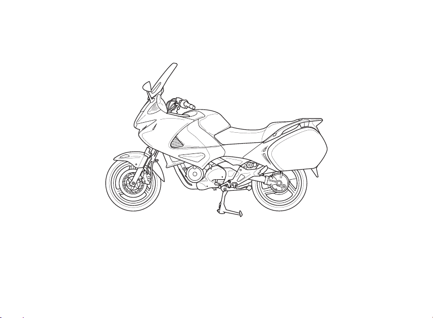
Honda NT700V Deauville
Ниже представлены прямые ссылки на скачку сервисной документации.
Для Honda NT700V Deauville
- Руководство пользователя (Owners Manual) на Honda NT700V Deauville
- Сервисный мануал (Service Manual) на Honda NT700V Deauville
Обзор модели
- Honda NT700V Deauville
Источник — «https://bikeswiki.ru/index.php?title=Honda_NT700V_Deauville:_мануалы&oldid=12005»
Категория:
- Сервисная документация
-
Contents
-
Table of Contents
-
Bookmarks
Quick Links
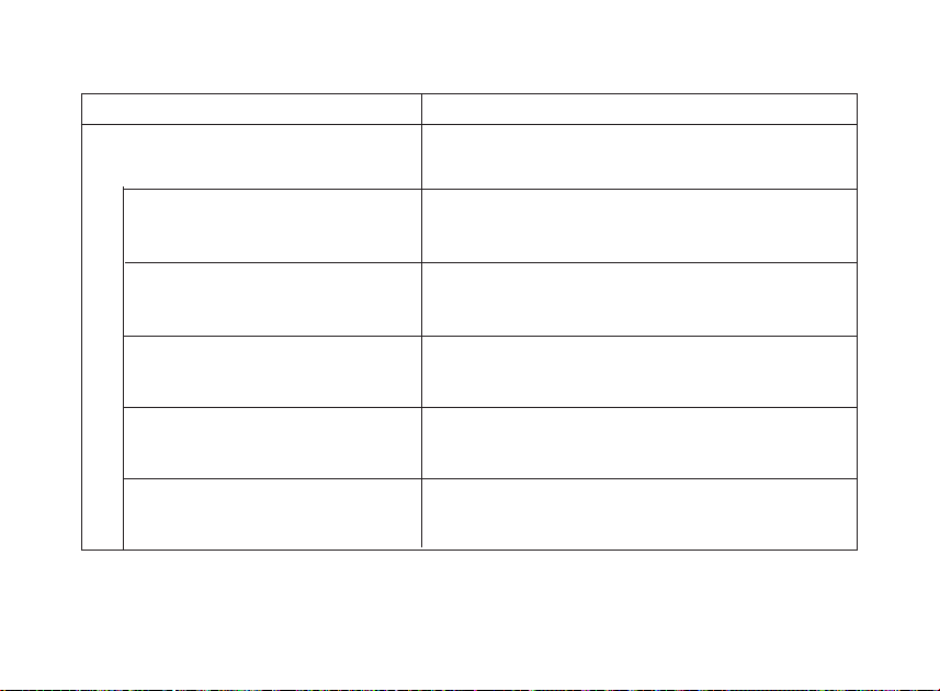
Contents
These pages give an overview of the
contents of your owner’s manual. The first
page of each section lists the topics
covered in that section.
Motorcycle Safety
…………………………
Important safety information you
should know, plus a look at the safety-
related labels on your motorcycle.
Instruments & Controls
The location and function of indicators
and controls on your motorcycle and
operating instructions for various
controls and features.
Contents
.
1
………………..
.
9
Before Riding
……………………………….
The importance of wearing a helmet
and other protective gear, how to make
sure you and your motorcycle are ready
to ride, and important information about
loading.
Basic Operation & Riding
How to start and stop the engine, shift
gears, and brake. Also, riding
precautions and important information
about riding with a passenger or cargo.
.
35
…………….
.
53
Chapters
Summary of Contents for Honda 2010 NT700V
This manual is also suitable for:
2010 nt700vaDeauville nt700v 2010Deauville nt700va 2010
Paper Book Part No.
6 2 l W E V V O O
HOW TO USE THlS MANUAL
This service manual describes the service procedures for the NT700VI
VA.
Follow the Maintenance Schedule (Section
4)
recommendations to
ensure that the vehicle is in peak operating condition.
Performing the first scheduled maintenance is very important. It
compensates for the initial wear that occurs during the break-in period.
Sections 1 and 4 apply to the whole motorcycle. Section 3 illustrates
procedures for remwaVinstallation of components that may be required
to perform service described in the following sections.
Section 5 through 23 describe parts of the motorcycle, grouped
according to location.
Find the section you want
m
this page, then turn to the table of contents
on the first page of the section.
Most sections start with an assembly or system illustration, service
information and troubleshooting for the section. The subsequent pages
If you are not familiar with this motorcycle, read Technical Feature in
Section 2.
If you don’t know the source of the trouble, go to section 25
Your safety, and the safety of others, is very important. To help you
make informed decisions we have provided safety messages and
other information throughout this manual. Of course, it is not
~ractical or possible to warn you about all the hazards associated
with servicing this vehicle.
You must use your own good judgement.
You will find important safety information in a variety of forms
including:
Safety Labels -on the vehicle
*
Safety Messages
—
preceded by a safety alert symbol
f:
and
one of three signal words, DANGER, WARNING, or CAUTION.
These signal words mean:
m
You WILL be KILLED or SERIOUSLY
HURT if you don’t follow instructions.
m
You CAN be HURT if you don’t follow
instructions.
Instructions
—
how to service this vehicle correctly and safely.
m
symbol. The purpose of this message is to help prevent
damage to your vehicle, other property, or the environment.
ALL INFORMATION, ILLUSTRATIONS, DIREC-
TIONS AND SPECIFICATIONS INCLUDED IN
THlS PUBLICATION ARE BASED ON THE LAT-
EST PRODUCT INFORMATION AVAILABLE AT
THE TlME OF APPROVAL FOR PRINTING.
Honda Motor Co., Ltd. RESERVES THE RIGHT
TO MAKE CHANGES AT ANY TlME WITHOUT
NOTICE AND WITHOUT INCURRING ANY OBLI-
GATION WHATSOEVER. NO PART OF THlS
PUBLICATION MAY BE REPRODUCED WITH-
WRllTEN
FOR
PERSONS
WHO
HAVE
ACQUIRED BASIC KNOWLEDGE OF MAINTE-
NANCE ON Honda MOTORCYCLES, MOTOR
SCOOTERS OR ATVS.
Honda Motor Co., Ltd.
C t PUUl ICAJlON OFFICE
ONTENTS
TROUBLESHOOTING
INDEX
Date of Issue: November, 2005
O
Honda Motor Co., Ltd.
Honda NT700V: List of Available Documents
Note for Owners:
Guidesimo.com webproject is not a service center of Honda trademark and does not carries out works for diagnosis and repair of faulty Honda NT700V equipment. For quality services, please contact an official service center of Honda company. On our website you can read and download documentation for your Honda NT700V device for free and familiarize yourself with the technical specifications of device.
More Motorcycle Devices:
-
Buell 2002 S3T
2002 BUELL S3T SERVICE MANUAL Part Number 99489-02Y Section 1: MaintenanceSection 2: ChassisSection 3: EngineSection 4: Fuel SystemSection 5: StarterSection 6: Drive/TransmissionSection 7: ElectricalAppendix …
2002 S3T Motorcycle, 450
-
Polaris SLINGSHOT
Polaris Slingshot Alarm Systemwww.electricalconnection.comInstallation Instructionsp/n 04151, 05/19/17, version 1Part Listing1 alarm module w/harness2 remote 1 shock sensor w/harness.1 led dash indicator1 valet switch1 main power t harness2 cockpit/ground led light w/harness1 siren w/harness1 stainless hood pin switch w/harness8 8” wire ties2 alcohol wipesTools / Supplies Requireddril …
SLINGSHOT Car Alarm, 4
-
Yamaha CS-5
__tt_rt_t_______y__vAym__nAtHhA_gsl_l_1 gr _ t___OWNER’SmANUAL_ , _ExT__N _L __ m !x E_ _ _ YAm AHA__ __ _c ov;aTL__ _LEE D __ _c ov NoT _ _ GL LEE _ _: F 0 _c ov NoTL__LGLEE D ____ __ TR!GG__LEvEL Nom,0 TuNE» _xTNo_sEO iN_T_LLEvEL _owE_GE_e__Ta_ m32_’__ ‘a _co5w;__E;__E, __ ___ __ __ __ ____ ____ ,’ LFO ,_ ___,FE ___ __0 ___, C_U’_O FKE’ _KE_SO NCE __&apos …
CS-5 Synthesizer, 19
-
HUSABERG FS 400 e
INDEX1123456789111012SAFETY AND PRECAUTIONS Page 4-GENERAL INFORMATION Page 6-MAINTENANCE SCHEDULE Page 9-CONTROLS Page 12-WIRING DIAGRAMS Page 33-INTRODUCTION Page 2-STARTING PROCEDURE Page 15ENGINE Page 16-A LUBRICATION SYSTEMB IGNITIONC AIR FILTERD VALVE ADJUSTMENTWHEELS & BRAKES Page 23-A WHEELSB CHAINC BRAKESSUSPENSION Page 29-A SUSPENSIONB STEERING HEADC SWINGARMFUEL & COOLING Page 2 …
FS 400 e Motorcycle, 34
Recommended Documentation:
Посмотреть инструкция для Honda Deauville NT700V (2008) бесплатно. Руководство относится к категории мотоциклы, 1 человек(а) дали ему среднюю оценку 7.6. Руководство доступно на следующих языках: английский. У вас есть вопрос о Honda Deauville NT700V (2008) или вам нужна помощь? Задайте свой вопрос здесь
Главная
| Honda | |
| Deauville NT700V (2008) | |
| мотоцикл | |
| английский | |
| Руководство пользователя (PDF) |
Не можете найти ответ на свой вопрос в руководстве? Вы можете найти ответ на свой вопрос ниже, в разделе часто задаваемых вопросов о Honda Deauville NT700V (2008).
Как перевести мили в километры?
В чем разница между топливом E10 и E5?
Какова рекомендуемая частота замены масляного фильтра в двигателе Honda?
Как часто следует менять масло в двигателе Honda?
Как удалить ржавчину с устройства Honda мотоцикл?
Инструкция Honda Deauville NT700V (2008) доступно в русский?
Не нашли свой вопрос? Задайте свой вопрос здесь
Table of Contents for Honda NT700V:
-
Check the coolant level of the reserve tank with the engine running at normal operating temperature. The level should be between the «UPPER» and «LOWER» level lines with the motorcycle is in an upright position. If the level is low, remove the reserve tank cap, and fill the tank to the «UPPER» level line with a 1:l mix- ture of distilled water and antifreeze (coolant prepa- ration: page 7-6). RFCOMMERII2ED ANTIFREEZE: High quality ethylene glycol antifreeze containing co
-
GENERAL INFORMATION FRONT MASTER CYLINDER
-
GENERAL INFORMATION EXHAUST EMISSION CONTROL SYSTEM The exhaust emission control system includes of a pulse secondary air supply system and PGM-FI system. No adjustment should be made about the exhaust emission control systems. The exhaust emission control system is separate from the crank case emission control system. SECONDARY AIR SUPPLY SYSTEM The secondary air supply system introduces filtered air into the exhaust gases in the exhaust port. Fresh ai
-
GENERAL INFORMATION PAIR CONTROL FUEL HOSE SOLENOID VALVE 2P (BLACK) CONNECTOR VACUUM HOSES
-
GENERAL INFORMATION FRONT IGNITION COIL 2P (NATURAL) CONNECTOR RIGHT HANDLEBAR SWITCH 9P (RED) CONNECTOR IAT SENSOR 2P RIGHT HANDLEBAR SWITCH (NATURAL) CONNECTOR 2P (RED) CONNECTOR IMMOBILIZER RECEIVER 4P CONNECTOR MAIN WIRE HARNESS LEFT HANDLEBAR IGNITION SWITCH 4P SWITCH 4P (NATURAL) LEFT HANDLEBAR SWITCH (NATURAL) CONNECTOR CONNECTOR 6P (BLACK) CONNECTOR
-
GENERAL INFORMATION MODEL IDENTIFICATION SERIAL NUMBERS The Vehicle Identification Number (V.1.N) is stamped on the right side of the steering head. The engine crankcase. serial number stamped the right side of the
-
GENERAL INFORMATION LUBRICATION SYSTEM SPECIFICATIONS Unit: mm (ir FUEL SYSTEM (PGM-FI) SPECIFICATIONS ITEM Throttle body identification number Idle speed Throttle grip free play IAT sensor resistance (at 20 «Cl68 «F) SPECIFICATIONS GQ66A 1,200 f 100 min.’ (rpm) 2 — 6 mm (1112 — 114 in) 1-4kR ECT sensor resistance (at 20 «Cl68 «F) 00LING SYSTEM SPECIFICATIONS 2.32 — 2.59 k
-
GENERAL INFORMATION REAR WHEEL SPEED SENSOR 2P (ORANGE) CONNECTOR FRONT BRAKE- SUB PIPE REAR BRAKE LIGHT SWITCH 2P (BLACK) CONNECTOR l 02 SENSOR WIRE o2 SENSOR 4~ (BLACK) CONNECTOR
-
GENERAL WORMATION THROTTLE CABLES CLUTCH CABLE h FRONTSPARK PLUG WIRE
-
GENERAL INFORMATION CYLINDER HEADIVALVE ITEM Cylinder head cover bolt Cylinder head bolt Cylinder head nut Cam sprocket bolt Cam chain tensioner bolt Camshaft holder bolt Reed valve cover bolt Cylinder head sealing bolt Q’TY 8 4 8 4 4 12 4 2 THREAD DIA. (mm) 6 8 TORQUE N.m (kgfam, Ibfaft) 10 (1.0,7) 23 (2.3, 17) REMARKS Apply engine oil to the threads and,flange surface Apply engine oil to the threads and flange surface Apply a lock
Questions, Opinions and Exploitation Impressions:
You can ask a question, express your opinion or share our experience of Honda NT700V device using right now.

© Honda Italia Industriale S.p.A. 2010
NT700V/VA
Honda
OWNERʼS MANUAL
MANUAL DO PROPRIETÁRIO
MANUAL DEL PROPIETARIO

IMPORTANT INFORMATION
• OPERATOR AND PASSENGER
This motorcycle is designed to carry the operator and one passenger. Never exceed the
maximum weight capacity as shown on the accessories and loading label.
• ON-ROAD USE
This motorcycle is designed to be used only on the road.
• READ THIS OWNERʼS MANUAL CAREFULLY
Pay special attention to the safety messages that appear throughout the manual. These
messages are fully explained in the ʻʻA Few Words About Safetyʼʼ section which appears
before the Contents page.
This manual should be considered a permanent part of the motorcycle and should remain with
the motorcycle when resold.
Honda NT700V/VA
OWNERʼS MANUAL
All information in this publication is based on the latest production information available
at the time of approval for printing. Honda Italia Industriale S.p.A. reserves the right to
make changes at any time without notice and without incurring any obligation. No part of
this publication may be reproduced without written permission.

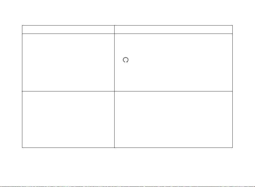
The motorcycle presents you a challenge to master the machine, a challenge to adventure. You
ride through the wind, linked to the road by a vehicle that responds to your commands as no
other does. Unlike an automobile, there is no metal cage around you. Like an airplane, a preride inspection and regular maintenance are essential to your safety. Your reward is freedom.
To meet the challenges safely, and to enjoy the adventure fully, you should become thoroughly
familiar with this owner’s manual BEFORE YOU RIDE THE MOTORCYCLE.
As you read this manual, you will find information that is preceded by a symbol.
This information is intended to help you avoid damage to your motorcycle, other property, or the
environment.
When service is required, remember that your Honda dealer knows your motorcycle best. If you
have the required mechanical “know-how” and tools, your dealer can supply you with an official
Honda Service Manual to help you perform many maintenance and repair tasks.
Pleasant riding, and thank you for choosing a Honda!
NOTICE
WELCOME
• Following codes in this manual indicate each country.
• The illustrations here in are based on the NT700VA ED type.
• The specifications may vary with each locale.
4E UK
4F France
5ED European direct sales
NT700V/VA

Your safety, and the safety of others, is very important, and operating this motorcycle safely is
an important responsibility.
To help you make informed decisions about safety, we have provided operating procedures and
other information on labels and in this manual. This information alerts you to potential hazards
that could hurt you or others.
Of course, it is not practical or possible to warn you about all hazards associated with operating
or maintaining a motorcycle. You must use your own good judgment.
You will find important safety information in a variety of forms, including:
• Safety Labels — on the motorcycle.
• Safety Messages — preceded by a safety alert symbol
n and one of three signal words:
DANGER, WARNING or CAUTION.
These signal words mean:
A FEW WORDS ABOUT SAFETY

You WILL be KILLED or SERIOUSLY HURT if you donʼt follow
instructions.
You CAN be KILLED or SERIOUSLY HURT if you don’t follow
instructions.
You CAN be HURT if you don’t follow instructions.
• Safety Headings — such as Important Safety Reminders or Important Safety Precautions.
• Safety Section — such as Motorcycle Safety.
• Instructions — how to use this motorcycle correctly and safely.
This entire manual is filled with important safety information — please read it carefully.
n
DANGER
n
WARNING
n
CAUTION

OPERATION
Page
1
MOTORCYCLE SAFETY
1
Important safety information
2
Protective apparel
4
Load Limits and Guidelines
8
Image labels
13
PARTS LOCATION
16
Instruments and Indicators
32
MAJOR COMPONENTS
(
Information you need to operate this motorcycle
)
32 Suspension
34 Brakes
37 Clutch
39 Coolant
41 Fuel
44 Engine oil
45 Final drive oil
46
Tubeless Tyres
52
ESSENTIAL INDIVIDUAL COMPONENTS
52
Ignition Switch
53 Keys
55
Immobilizer System (HISS
)
58
Right Handlebar Controls
60
Left Handlebar Controls
Page
61
FEATURES
(
Not required for operation
)
61
Steering lock
62 Seat
63
Helmet Holder
64
Windscreen height adjustment
65 Document bag
66
Storage compartment for U-shaped
anti-theft lock
67
Side cover
68 Middle fairing lid
69 Rear fender
71 Fairing pockets
73 Saddlebags
74
Headlight aim vertical adjustment
75
OPERATION
75
Pre-ride Inspection
77
Starting the Engine
80
Running-in
81
Riding
83
Braking
87
Parking
88
Anti-theft Tips

MAINTENANCE
Page
89
MAINTENANCE
89
The importance of Maintenance
90
Maintenance Safety
91
Safety precautions
92
Maintenance Schedule
95
Tool kit
96
Serial Numbers
97
Colour Label
98 Air cleaner
100 Engine oil
105 Spark plugs
107 Final drive oil
108 Throttle Operation
109 Coolant
110 Front and Rear Suspension Inspection
111
Side Stand
112
Wheel Removal
119
Brake Pad Wear
121 Battery
123 Fuse replacement
126
Brakelight switch adjustment
127
Bulb replacement
Page
132
CLEANING
137
STORAGE GUIDE
137
Storage
139
Removal from Storage
140 TAKING CARE OF THE UNEXPECTED
141
SPECIFICATIONS
145
CATALYTIC CONVERTER


1
IMPORTANT SAFETY INFORMATION
Your motorcycle can provide many years of
service and pleasure — if you take
responsibility for your own safety and
understand the challenges that you can meet
on the road.
There is much that you can do to protect
yourself when you ride. Youʼll find many
helpful recommendations throughout this
manual. Following are a few that we consider
to be most important.
Always Wear a Helmet
Itʼs a proven fact: helmets significantly
reduce the number and severity of head
injuries. So always wear an approved
motorcycle helmet and make sure your
passenger does the same. We also
recommend that you wear eye protection,
sturdy boots, gloves, and other protective
gear (page 2).
Make Yourself Easy to See
Some drivers do not see motorcycles because
they are not looking for them. To make
yourself more visible, wear bright reflective
clothing, position yourself so other drivers can
see you, signal before turning or changing
lanes, and use your horn when it will help
others notice you.
Ride Within Your Limits
Pushing the limits is another major cause of
motorcycle accidents. Never ride beyond
your personal abilities or faster than
conditions warrant. Remember that alcohol,
drugs, fatigue and inattention can
significantly reduce your ability to make good
judgements and ride safely.
MOTORCYCLE SAFETY

Donʼt Drink and Ride
Alcohol and riding donʼt mix. Even one drink
can reduce your ability to respond to
changing conditions, and your reaction time
gets worse with every additional drink. So
donʼt drink and ride, and donʼt let your friends
drink and ride either.
Keep Your Bike in Safe Condition
For safe riding, itʼs important to inspect your
motorcycle before every ride and perform all
recommended maintenance. Never exceed
load limits, and only use accessories that
have been approved by Honda for this
motorcycle. See page 4 for more details.
PROTECTIVE APPAREL
For your safety, we strongly recommend that
you always wear an approved motorcycle
helmet, eye protection, boots, gloves, long
pants, and a long-sleeved shirt or jacket
whenever you ride. Although complete
protection is not possible, wearing proper
gear can reduce the chance of injury when
you ride.
Following are suggestions to help you
choose proper gear.
2
n
WARNING
Not wearing a helmet increases the chance
of serious injury or death in a crash.
Be sure you and your passenger always
wear a helmet, eye protection and other
protective apparel when you ride.

Helmets and Eye Protection
Your helmet is your most important piece of
riding gear because it offers the best
protection against head injuries. A helmet
should fit your head comfortably and
securely. A bright-coloured helmet can make
you more noticeable in traffic, as can
reflective strips.
An open-face helmet offers some protection,
but a full-face helmet offers more. Always
wear a face shield or goggles to protect your
eyes and help your vision.
Additional Riding Gear
In addition to a helmet and eye protection,
we also recommend:
• Sturdy boots with non-slip soles to help
protect your feet and ankles.
• Leather gloves to keep your hands warm
and help prevent blisters, cuts, burns and
bruises.
• A motorcycle riding suit or jacket for
comfort as well as protection. Brightcoloured and reflective clothing can help
make you more noticeable in traffic. Be
sure to avoid loose clothes that could get
caught on any part of your motorcycle.
3

LOAD LIMITS AND GUIDELINES
Your motorcycle has been designed to carry
you and one passenger. When you carry a
passenger, you may feel some difference
during acceleration and braking. But so long
as you keep your motorcycle wellmaintained, with good tyres and brakes, you
can safely carry loads within the given limits
and guidelines.
However, exceeding the weight limit or
carrying an unbalanced load can seriously
affect your motorcycleʼs handling, braking
and stability. Non-Honda accessories,
improper modifications, and poor
maintenance can also reduce your safety
margin.
The following pages give more specific
information on loading, accessories and
modifications.
Loading
How much weight you put on your
motorcycle, and how you load it, are
important to your safety. Anytime you ride
with a passenger or cargo you should be
aware of the following information.
n
WARNING
Overloading or improper loading can cause
a crash and you can be seriously hurt or
killed.
Follow all load limits and other loading
guidelines in this manual.
4

5
Load Limits
Following are the load limits for your
motorcycle:
Maximum weight capacity:
197 kg (434 lb)
Includes the weight of the rider, passenger,
all cargo and all accessories
Maximum cargo weight:
27 kg (60 lb)
Putting too much weight in individual storage
compartments can also affect stability and
handling. So be sure to stay within the limits
given below:
Maximum weight:
in each saddlebag 5.0 kg (11.0 lb)
in each fairing pocket 1.0 kg (2.2 lb)
The weight of added accessories will reduce
the maximum cargo weight you can carry.
Loading Guidelines
Your motorcycle is primarily intended for
transporting you and a passenger. You may
wish to secure a jacket or other small items
to the seat when you are not riding with a
passenger.
If you wish to carry more cargo, check with
your Honda dealer for advice, and be sure to
read the information regarding accessories on
page 6.
Improperly loading your motorcycle can affect
its stability and handling. Even if your
motorcycle is properly loaded, you should
ride at reduced speeds and never exceed
130 km/h (80 mph) when carrying cargo.

Follow these guidelines whenever you carry
a passenger or cargo:
• Check that both tyres are properly inflated
(page 46).
• If you change your normal load, you may
need to adjust your rear suspension (page
32).
• To prevent loose items from creating a
hazard, make sure that all cargo is
securely tied down before you ride away.
• Place cargo weight as close to the center
of the motorcycle as possible.
• Balance cargo weight evenly on both
sides.
• To avoid possible heat damage to the
headlight lens, do not cover the headlight
lens with baggage or clothing.
Accessories and Modifications
Modifying your motorcycle or using nonHonda accessories can make your
motorcycle unsafe. Before you consider
making any modifications or adding an
accessory, be sure to read the following
information.
6
n
WARNING
Improper accessories or modifications can
cause a crash in which you can be seriously
hurt or killed.
Follow all instructions in this ownerʼs manual
regarding accessories and modifications.

7
Accessories
We strongly recommend that you use only
Honda Genuine Accessories that have been
specifically designed and tested for your
motorcycle. Because Honda cannot test all
other accessories, you must be personally
responsible for proper selection, installation and
use of non-Honda accessories. Check with
your dealer for assistance and always follow
these guidelines:
• Make sure the accessory does not obscure
any lights, reduce ground clearance and
banking angle, limit suspension travel or
steering travel, alter your riding position or
interfere with operating any controls.
• Be sure electrical equipment does not
exceed the motorcycleʼs electrical system
capacity (page 144). A blown fuse can
cause a loss of lights or engine power.
• Do not pull a trailer or sidecar with your
motorcycle. This motorcycle was not
designed for these attachments, and their
use can seriously impair your motorcycleʼs
handling.
Modifications
We strongly advise you not to remove any
original equipment or modify your motorcycle
in any way that would change its design or
operation. Such changes could seriously
impair your motorcycleʼs handling, stability
and braking, making it unsafe to ride.
Removing or modifying your lights, mufflers,
emission control system or other equipment
can also make your motorcycle illegal.
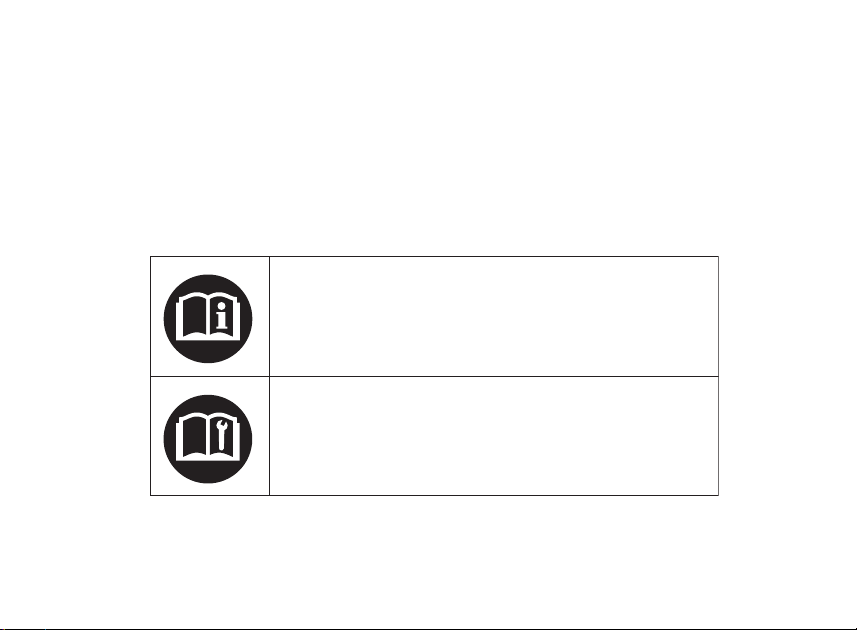
IMAGE LABELS
The following pages describe the label
meanings. Some labels warn you of potential
hazards that could cause serious injury.
Others provide important safety information.
Read this information carefully and donʼt
remove the labels.
If a label comes off or becomes hard to read,
contact your Honda dealer for a replacement.
There is a specific symbol on each label. The
meanings of each symbol and
label are as follows.
8
Read instructions contained in Ownerʼs Manual carefully.
Read instructions contained in Shop Manual carefully.
In the interest of safety, take the motorcycle to be serviced
only by a Honda dealer.
9
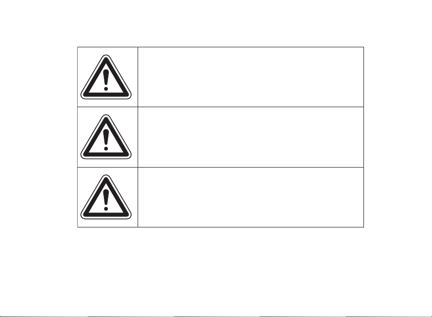
DANGER (with RED background)
You WILL be KILLED or SERIOUSLY HURT if you
donʼt follow instructions.
WARNING (with ORANGE background)
You CAN be KILLED or SERIOUSLY HURT if you
donʼt follow instructions.
CAUTION (with YELLOW background)
You CAN be HURT if you donʼt follow instructions.
10
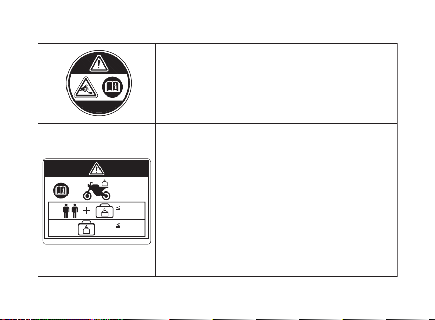
ACCESSORIES AND LOADING WARNING LABEL
WARNING
ACCESSORIES AND LOADING
• The safety stability and handling of this motorcycle may be
affected by the addition of accessories and luggage.
• Read carefully the instructions contained in userʼs manual
and installation guide before installing any accessory.
• The total weight of accessories and luggage added to
riderʼs and passengerʼs weight should not exceed 197 kg
(434 lb), which is the maximum weight capacity.
• The luggage weight must not exceed 27 kg (60 lb) under
any circumstances.
• The fitting of large fork-mounted or large handlebar
mounted fairing is not recommended.
RADIATOR CAP SEAL
DANGER
NEVER OPEN WHEN HOT.
Hot coolant will scald you.
Relief pressure valve begins to open at 1.1 kgf/cm
2
.
(434 lb)
197 kg
(60 lb)
27 kg
11
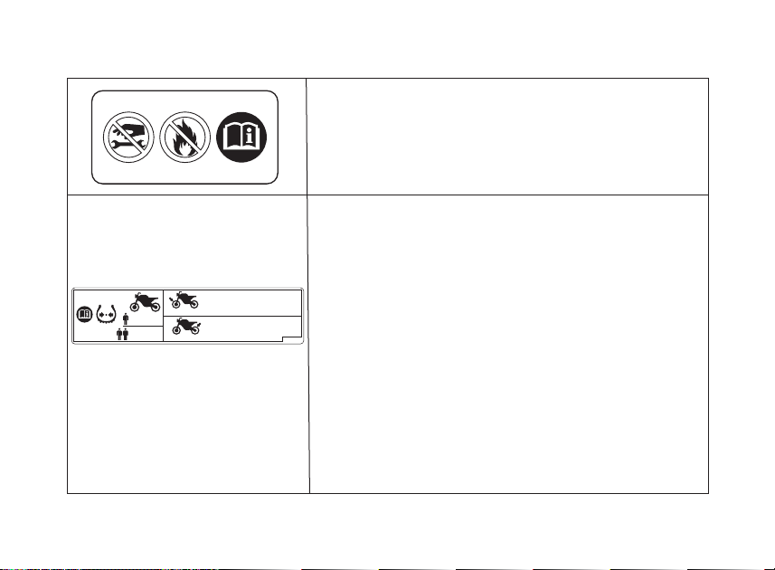
TYRE INFORMATION LABEL
Cold tyre pressure:
[Driver only]
Front 250 kPa (2.50 kgf/cm
2
, 36 psi)
Rear 290 kPa (2.90 kgf/cm
2
, 42 psi)
[Driver and passenger]
Front 250 kPa (2.50 kgf/cm
2
, 36 psi)
Rear 290 kPa (2.90 kgf/cm
2
, 42 psi)
Tyre size:
Front 120/70ZR17M/C (58W)
Rear 150/70ZR17M/C (69W)
Tyre brand:
BRIDGESTONE
Front BT020F RADIAL J
Rear BT020R RADIAL U
REAR CUSHION LABEL
GAS FILLED
Do not open.
Do not heat.
BRIDGESTONE BT020F RADIAL J
120/70ZR17M/C(58W)
250 290
kPa
250 290
BRIDGESTONE BT020R RADIAL U
150/70ZR17M/C(69W)
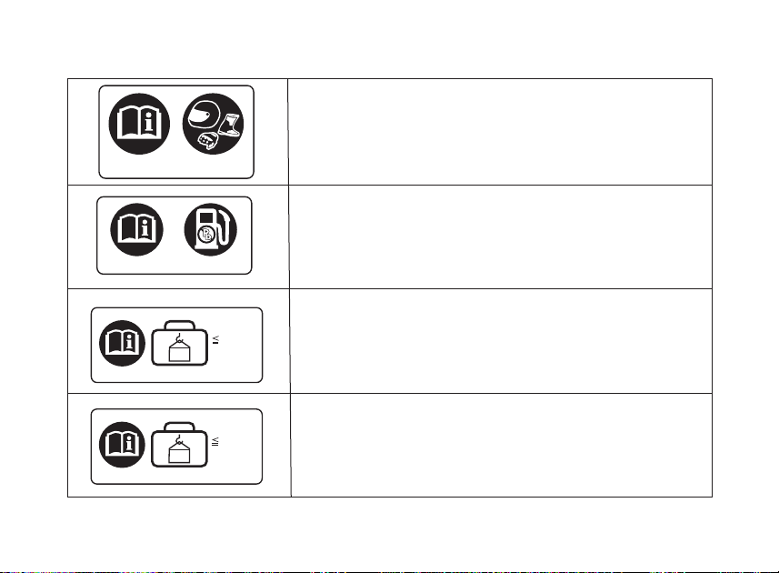
SAFETY REMINDER LABEL
For your protection, always wear your helmet and
protective apparel while riding.
FUEL LABEL
UNLEADED FUEL ONLY
CARGO LIMIT LABEL
Do not exceed 5.0 kg (11.0 lb)
CARGO LIMIT LABEL
Do not exceed 1.0 kg (2.2 lb)
13
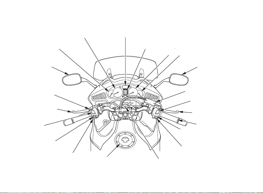
Multi-function display
Tachometer
Indicators
Speedometer
Fuel gauge
Turn signal switch
Rearview
mirror
Clutch lever
Passing light
control switch
Headlight
dimmer switch
Coolant temperature
gauge
Rearview mirror
Engine stop switch
Front brake lever
Hazard switch
Start button
Ignition switch
Fuel fill cap
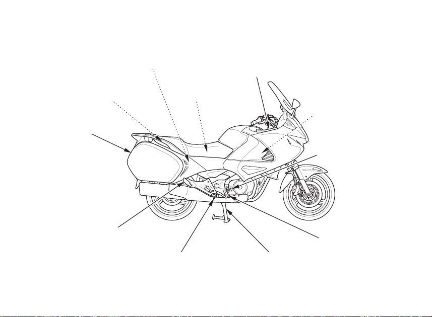
PARTS LOCATION
Horn button
Throttle grip
Front brake fluid
reservoir
14
Right fairing pocket
Battery
Fuse boxes
Center stand
Footpeg
Passenger footpeg
Rear brake
fluid reservoir
Tool kit
Saddlebag
Coolant reserve tank
Oil filler cap/dipstick
Rear brake pedal
15
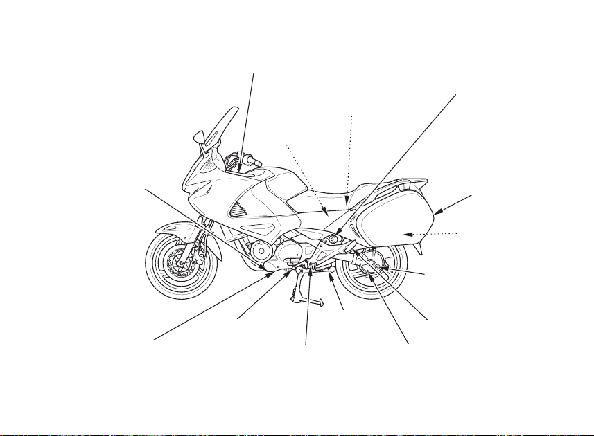
Passenger footpeg
Footpeg
Side
stand
Engine oil filter
Shift lever
Final drive oil filler cap
Helmet holder
Left fairing pocket
Main fuse
Saddlebag
Rear suspension spring
preload adjuster knob
Document bag
Engine oil
drain plug
Final drive oil drain plug
16
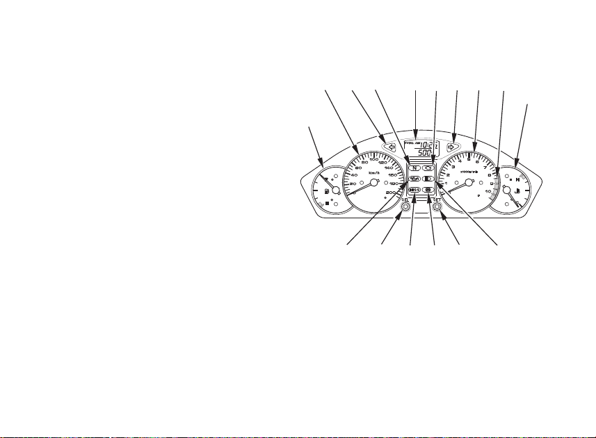
INSTRUMENTS AND INDICATORS
The indicators are contained in the
instrument panel. Their functions are
described in the tables on the following
pages.
(1) Fuel gauge
(2) Speedometer
(3) Left turn signal indicator
(4) Neutral indicator
(5) Multi-function display
(6) PGM-FI malfunction indicator lamp
(MIL)
(7) Right turn signal indicator
(8) Tachometer
(9) Tachometer red zone
(10) Coolant temperature gauge
(11) High beam indicator
(12) SET button
(13) Anti-lock brake system (ABS)
indicator (NT700VA)
(14) Immobilizer system (HISS) indicator
(15) SEL button
(16) Low oil pressure indicator
(1)
(14) (13)
)7()8(
(9))2()3()4()5()6(
(10)
)21()11()61()51(
17
(Ref. Nr.) Description Function
(1) Fuel gauge Shows approximate fuel supply available (page 25).
The fuel gauge needle will swing to the maximum
scale on the dial once when the ignition switch is
turned ON
(2) Speedometer Shows riding speed.
This shows your speed in kilometers per hour
(km/h) and/or miles per hour (mph) depending on
the type.
The speedometer needle will swing to the
maximum scale on the dial once when the ignition
switch is turned ON.
(3) Left turn signal indicator (green) Flashes when the left turn signal operates.
Should light for a few seconds and then go off
when the ignition switch is turned ON.
(4) Neutral indicator (green)
Lights when the transmission is in neutral. Should
also light for a few seconds and then go off when
the ignition switch is turned ON.
18
(Ref. Nr.) Description Function
(5) Multi-function display The display includes the following functions;
This display shows the initial display (page 24).
Odometer Shows accumulated mileage (page 27).
Tripmeter A and B
Current fuel consumption meter
Shows current fuel consumption meter (page 28).
Average fuel consumption meter
Shows average fuel consumption meter after reset
(page 28).
Shows hour and minute (page 30).
Digital clock
Shows mileage per trip (page 27).
19
(Ref. Nr.) Description Function
(6) PGM-FI malfunction indicator lamp
(MIL) (amber)
Lights when there is any abnormality in the PGM-FI
(Programmed Fuel Injection) system. Should also
light for a few seconds and then go off when the
ignition switch is turned ON and engine stop switch is
at run.
If it comes on at any other time, reduce speed and
take the motorcycle to your Honda dealer as soon as
possible.
(7) Right turn signal indicator
(green)
Flashes when the right turn signal operates. Should
light for a few seconds and then go off when the
ignition switch is turned ON.
20
(Ref. Nr.) Description Function
(8) Tachometer Shows engine revolutions per minute.
The tachometer needle will swing to the maximum
scale on the dial once when the ignition switch is
turned ON.
(9)Tachometer red zone Never allow the tachometer needle to enter the red
zone, even after the engine has been broken in.
Running the engine beyond recommended maximum
engine speed (the beginning of the tachometer red
zone) can damage the engine.
NOTICE
(10) Coolant temperature gauge Shows coolant temperature (page 26).
The coolant temperature gauge needle will swing to
the maximum scale on the dial once when the ignition
switch is turned ON.
(11) High beam indicator (blue) Lights when the headlight is on high beam. Should also
light for a few seconds and then go off when the ignition
switch is turned ON.
21
(Ref. Nr.) Description Function
(12) SET button This button is used to adjust the time (page 30), and
units for distance (page 29). E type only.
(13) Anti-lock Brake System (ABS)
indicator (amber) (NT700VA)
This light normally comes on when the ignition is turned
ON, and goes off after you ride the motorcycle at
speed above 10 km/h (6 mph). If there is a problem
with the Anti-lock Brake System, this light flashes and
remains on (page 86).
(14) Immobilizer system (HISS) indicator
(red)
This indicator lights for a few seconds when the
ignition switch is turned ON and the engine stop switch
is at (RUN). It will then go off if the properly-coded
key has been inserted. If an improperly-coded key
has been inserted, the indicator will remain on and
the engine will not start (page 55).
22
(Ref. Nr.) Description Function
(15) SEL button Except E type:
This button is used to reset the tripmeter or to adjust
the time or to select the tripmeter or odometer or
current fuel consumption meter or avarage fuel
consumption meter or to reset the average fuel
consumption or to change the mileage units for the
fuel consumption meter (pages 27-31).
For E type:
This button is used to reset the tripmeter or to adjust
the time or to select the tripmeter or odometer or
current fuel consumption meter or average fuel
consumption meter or to reset the average fuel
consumption (pages 27-31).
23
(Ref. Nr.) Description Function
(16) Low oil pressure indicator (red) Lights when the engine oil pressure is below normal
operating range. Should light when ignition switch is
ON and engine is not running. Should go out when
the engine starts, except for occasional flickering at
or near idling speed when engine is warm.
Running the engine with insufficient oil pressure may
cause serious engine damage.
NOTICE
24
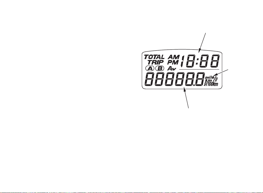
Initial Display
When the ignition switch is turned ON, the
display will temporarily show all the modes
and digital segments so you can make sure
the liquid crystal display is functioning properly.
The unit ʻʻmile/
lʼʼ (1) will be displayed only for
E type.
Digital clock (2) and tripmeter (3) will reset if
the battery is disconnected.
(1) ʻʻmile/lʼʼ
(2) Digital clock
(3) Tripmeter
(2)
(1)
(3)
25
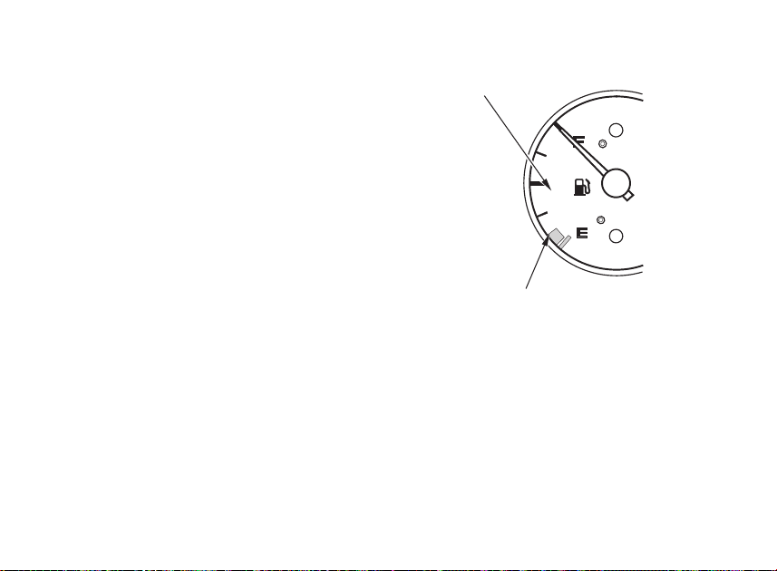
Fuel Gauge
The fuel gauge (1) shows the approximate
fuel supply available in a graduated display.
When the gauge needle enters the red band
(2), fuel will be low and you should refill the
tank as soon as possible. The amount of fuel
left in the tank with the vehicle set upright
when the needle enters the red band is
approximately:
3.7
l (0.98 US gal, 0.81 Imp gal)
(1) Fuel gauge
(2) Red band
(1)
(2)
26
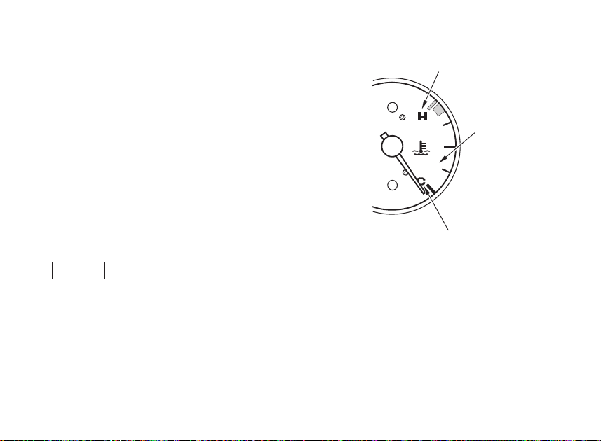
Coolant Temperature Gauge
The coolant temperature gauge (1) shows
coolant temperature.
When the needle begins to move above the
C (Cold) mark (2), the engine is warm
enough for the motorcycle to be ridden.
The normal operating temperature range is
within the section between the H and C
marks. If the needle reaches the H (Hot)
mark (3), stop the engine and check the
reserve tank coolant level. Read pages 39-40
and do not ride the motorcycle until the
problem has been corrected.
Exceeding maximum running temperature
may cause serious engine damage.
(1) Coolant temperature gauge
(2) C (Cold) mark
(3) H (Hot) mark
(3)
(1)
(2)
27
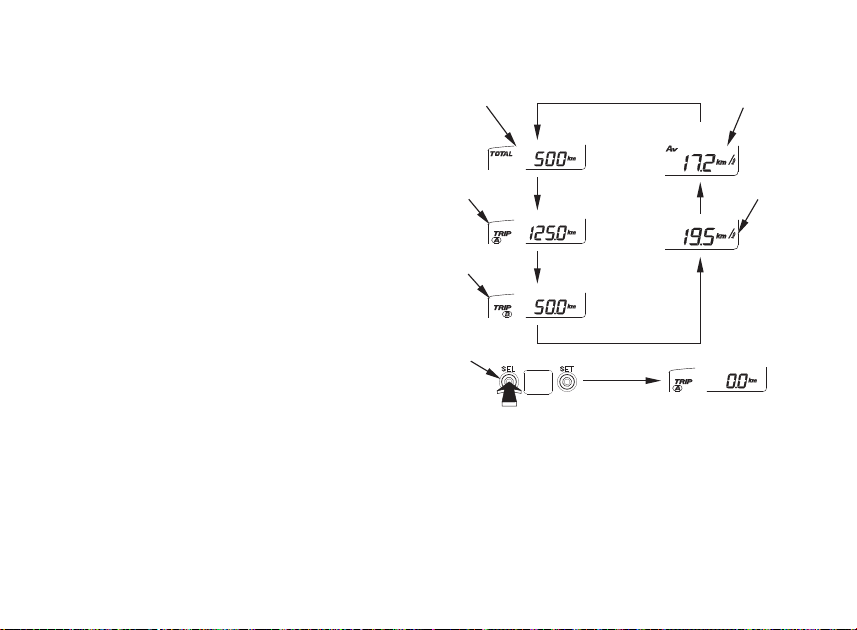
Odometer / Tripmeter /
Current Fuel Consumption Meter/
Average Fuel Consumption Meter
Push the SEL button (1) repeatedly to
change the display mode.
Odometer
Shows accumulated mileage.
Tripmeter
Shows mileage per trip.
There are two tripmeters, tripmeter A (3) and
tripmeter B (4). Switch between the A and B
displays by pressing the SEL button
repeatedly.
To reset the tripmeter, push and hold the
SEL button for more than 2 seconds with the
display in the tripmeter A or tripmeter B
mode.
(1) SEL button
(2) Odometer
(3) Tripmeter A
(4) Tripmeter B
(5) Current fuel consumption
(6) Average fuel consumption
(3)
(4)
(1)
(6)(2)
(5)
28
Current Fuel Consumption Meter
Indicates the momentary fuel consumption of
each 3 seconds during engine operation. When
motorcycle stopped, ʻʻ—.-ʼʼ is displayed.
The indicated fuel consumption may differ
from the actual fuel consumption.
The E type uses mile/
l, except E type uses
km/
l or l/100 km.
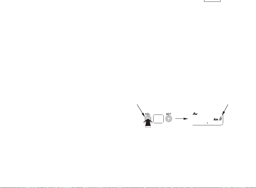
Average Fuel Consumption Meter
The average fuel consumption after reset
until that moment is indicated every 15
seconds.
The indicated fuel consumption may differ
from the actual fuel consumption.
The E type uses mile/
l, except E type uses
km/
l or l/100 km.
To reset the average fuel consumption (6),
push and hold the SEL button (1) for more
than 2 seconds with the display in the
average fuel consumption.
Average fuel consumption will reset if the
battery is disconnected.
(1) SEL button
(6) Average fuel consumption
(6)(1)
29
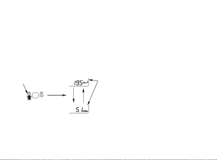
Fuel Consumption Unit Change
(Except E Type)
The current/average fuel consumption meter
displays either ʻʻkm/
lʼʼ or ʻʻl/100 kmʼʼ.
Push and hold the SEL button (1) for more than
2 seconds to select with the display in the
current fuel consumption (5).
Mileage and Fuel Consumption Unit
Change
(E type only)
The odometer/tripmeter can display ʻʻmileʼʼ or
ʻʻkmʼʼ.
The fuel consumption meter can display
ʻʻmile/
lʼʼ or ʻʻkm/lʼʼ.
1. Turn the ignition switch ON.
2. Press and hold the SET button for more
than 4 seconds.
3. Press the SEL button to select ʻʻmileʼʼ/
ʻʻmile/
l” or ʻʻkmʼʼ/ʻʻkm/lʼʼ.
4. To end the selection, press the SET
button.
The display will stop blinking automatically if
the button is not pressed for about 30
seconds.
As you turn off the ignition switch during the
presetting procedures, the preset data just
before turning off the ignition switch will be
registered.
(1) SEL button
(5) Current fuel consumption
(1)
(5)
30
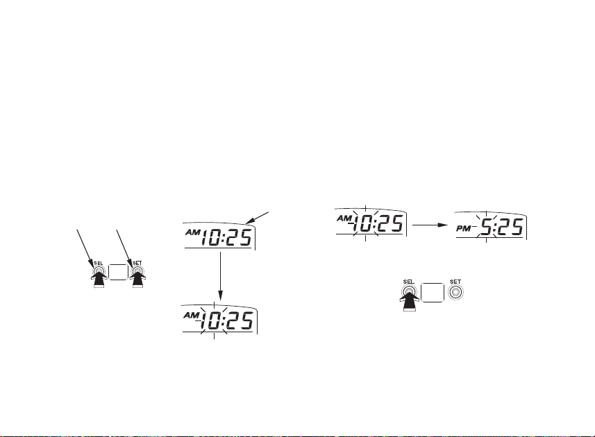
Digital Clock
The digital clock will show hours and minutes
up to 12:59 with ʻʻAMʼʼ and ʻʻPMʼʼ.
To adjust the time, proceed as follows:
1. Turn the ignition switch ON.
2. Push and hold both the SEL button (2)
and SET button (3) for more than 2
seconds. The clock will be set in the
adjust mode with the hour display
flashing.
3. To set the hour, push the SEL button until
the desired hour and AM/PM are
displayed.
• The time is advanced by one hour,
each time the button is pushed.
• The time advances fast when the
button is pushed and held.
(1) Digital clock
(2) SEL button
(3) SET button
(1)
(2) (3)
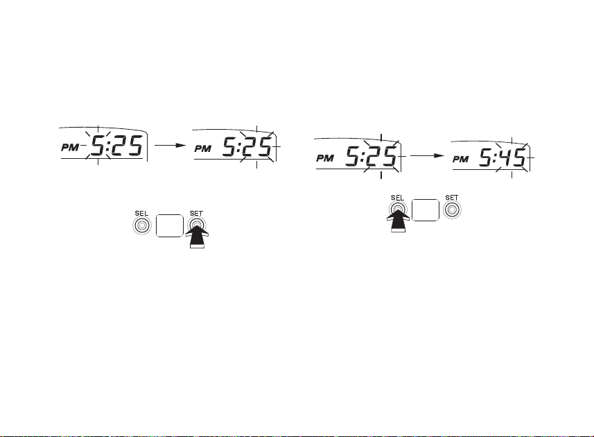
31
4. Push the SET button. The minute display
will start flashing.
5. To set the minute, push the SEL button
until the desired minute. The minute
display will return to ʻʻ00ʼʼ when ʻʻ60ʼʼ is
reached without affecting the hour display.
• The time advances by one minute, each
time the button is pushed.
• The time advances fast when the button is
pushed and held.
6. To end the adjustment, push the SET
button or turn the ignition switch OFF. The
display will stop flashing automatically and
the adjustment will be cancelled if the
button is not pushed for about 30
seconds.
The clock will be reset AM 1:00 if the battery
is disconnected.

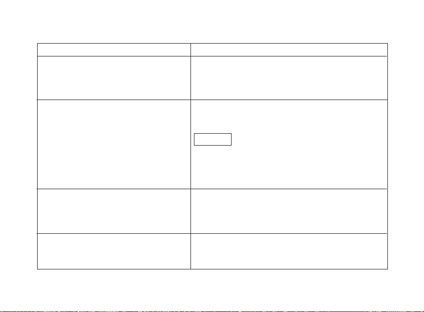
32
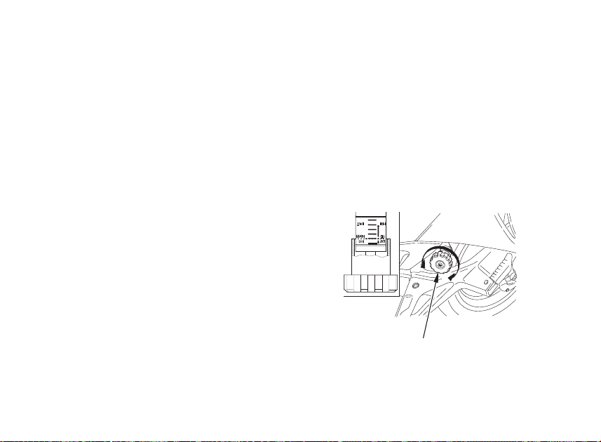
SUSPENSION
Rear Suspension
The rear suspension can provide the desired
ride under various rider/passenger weight
and riding conditions through adjustments of
the spring preload with the adjuster.
Spring preload:
This model has the spring preload adjuster
on the left side.
The spring preload adjuster has 40 positions
for different load or riding conditions.
To adjust the spring preload, turn the
adjuster knob (1).
To reduce (LOW):
Turn the adjuster counterclockwise toward
LOW for a light load and smooth road
condition.
To increase (HIGH):
Turn the adjuster clockwise toward HIGH for
a firmer ride and rough road condition.
MAJOR COMPONENTS (Information you need to operate this motorcycle)
33
To adjust the adjuster to the standard
position, proceed as follows:
1. Turn the spring preload adjuster knob (1)
counterclockwise until it will no longer turn
(lightly seats). This is the full LOW
position.
2. The adjuster is set in the standard position
when the spring preload adjuster knob is
turned clockwise 11 clicks.
The rear shock absorber assembly includes
a damper unit that contains high pressure
nitrogen gas. Do not attempt to disassemble
or service the damper; it cannot be rebuilt
and must be replaced when worn out.
Disposal should only be done by your Honda
dealer. The instructions found in this ownerʼs
manual are limited to adjustment of the shock
assembly only.
(1) Spring preload adjuster knob
(1)
34
BRAKES
Both the front and rear brakes are the
hydraulic disc types.
As the brake pads wear, the brake fluid level
drops.
There are no adjustments to perform, but
fluid level and pad wear must be inspected
periodically. The system must be inspected
frequently to ensure there are no fluid leaks.
If the control lever or pedal free travel
becomes excessive and the brake pads are
not worn beyond the recommended limit
(page 119), there is probably air in the brake
system and it must be bled. See your Honda
dealer for this service.
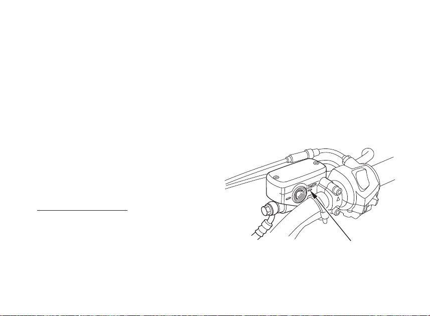
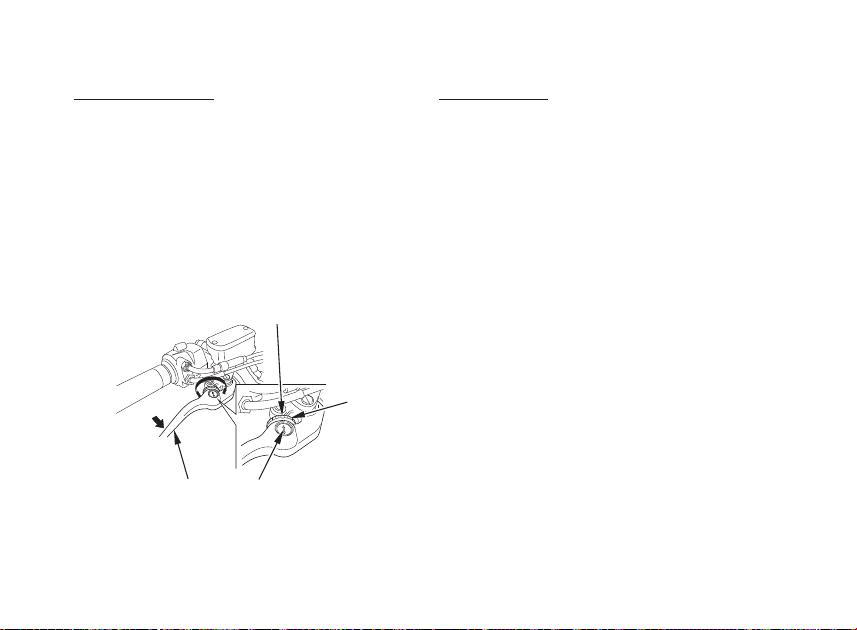
Front Brake Fluid Level:
With the motorcycle in an upright position,
check the fluid level. It should be above the
LOWER level mark (1). If the level is at or
below the LOWER level mark, check the
brake pads for wear (page 119).
Worn pads should be replaced. If the pads
are not worn, have your brake system
inspected for leaks.
The recommended brake fluid is Honda DOT
4 brake fluid from a sealed container, or an
equivalent.
(1) LOWER level mark
35
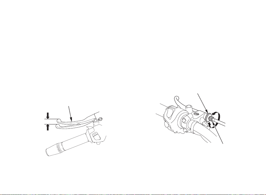
Front Brake Lever:
The distance between the tip of the brake
lever (1) and the grip can be adjusted by
turning the adjuster (2) while pushing the
lever forward.
Align the arrow (3) on the brake lever with
the index mark (4) on the adjuster.
Apply the brake several times and check for
free wheel rotation after the brake lever is
released.
Other Checks:
Make sure there are no fluid leaks. Check for
deterioration or cracks in the hoses and
fittings.
(1) Brake lever (3) Arrow
(2) Adjuster (4) Index mark
(4)
(2)
(1)
(3)
36
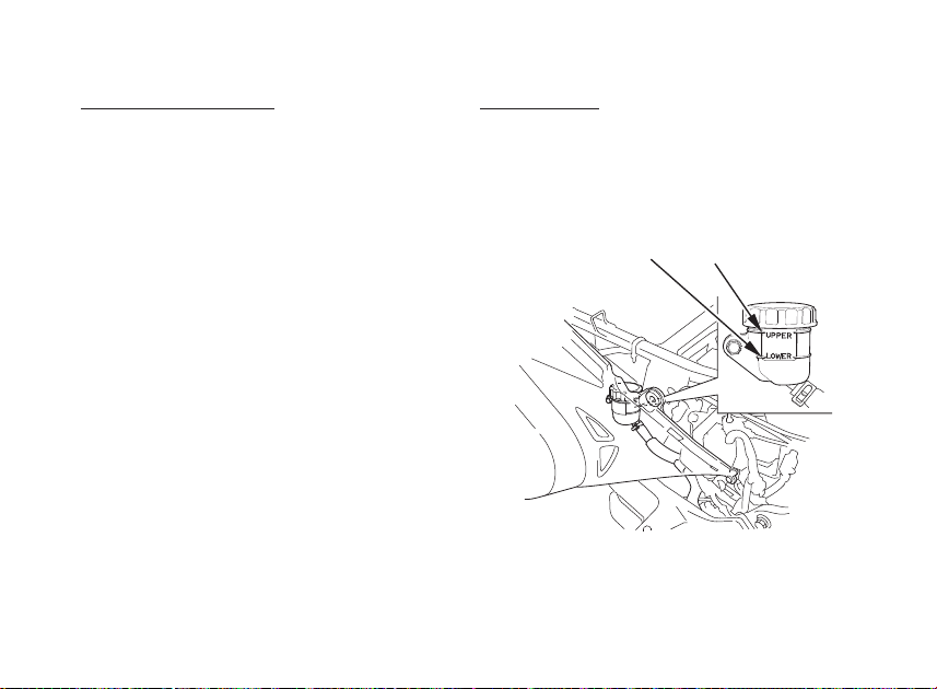
Rear Brake Fluid Level:
The reserve tank is located below the seat.
Remove the seat (page 62).
With the motorcycle in an upright position,
check the fluid level. It should be between
the UPPER (1) and LOWER (2) level marks.
If the level is at or below the LOWER level
mark, check the rear brake pads for wear
(page 120).
Worn pads should be replaced. If the pads
are not worn, have your brake system
inspected for leaks.
The recommended brake fluid is Honda DOT
4 brake fluid from a sealed container, or an
equivalent.
Other Checks:
Make sure there are no fluid leaks. Check for
deterioration or cracks in the hoses and
fittings.
(1) UPPER level mark
(2) LOWER level mark
(1)(2)
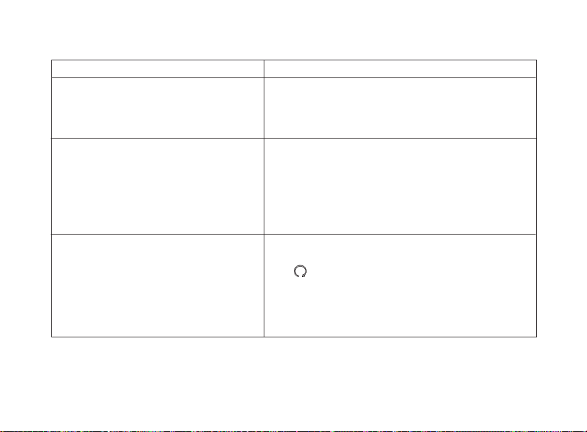
37
CLUTCH
Clutch adjustment may be required if the
motorcycle stalls when shifting into gear or
tends to creep; or if the clutch slips, causing
acceleration to lag behind engine speed.
Minor adjustments can be made with the
clutch cable adjuster (3) at the clutch lever (1).
Normal clutch lever freeplay is:
10 — 20 mm (0.4 — 0.8 in).
1. Loosen the lock nut (2) and turn the clutch
cable adjuster. Tighten the lock nut and
check the adjustment.
2. If the adjuster is threaded out near its limit
or if the correct freeplay cannot be
obtained, loosen the lock nut and turn in
the clutch cable adjuster completely.
Tighten the lock nut.
(1) Clutch lever
(2) Lock nut
(3) Clutch cable adjuster
(A) Increase freeplay
(B) Decrease freeplay
(1)
(2)
(B)
)
(3)
 Loading…