- Manuals
- Brands
- Rotax Manuals
- Engine
- 582 UL series
- Operator’s manual
-
Contents
-
Table of Contents
-
Bookmarks
Quick Links
AIRCRAFT ENGINES
OperatOrs Manual
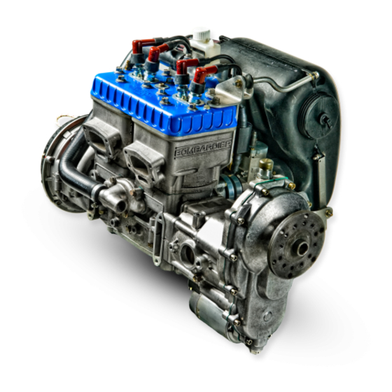
FOr rOtax® EnginE tYPE 582 UL SERIES
rOtaX® 582 ul dCdI Mod. 99
with OPtiOnS
rOtaX® 582 ul dCdI Mod. 17
with OPtiOnS
ref. no.: OM-582 UL | part no.: 899122
picture: rOtax® 582 UL DCDi Mod. 99 with options
Related Manuals for Rotax 582 UL series
Summary of Contents for Rotax 582 UL series
-
Page 1
FOr rOtax® EnginE tYPE 582 UL SERIES rOtaX® 582 ul dCdI Mod. 99 with OPtiOnS rOtaX® 582 ul dCdI Mod. 17 with OPtiOnS ref. no.: OM-582 UL | part no.: 899122 picture: rOtax® 582 UL DCDi Mod. 99 with options… -
Page 2
These technical data and the information embodied therein are the property of BRP-Rotax GmbH & CO KG, Austria, acc, BGBI 1984 no. 448, and shall not, without prior written permission of BRP-Rotax GmbH & Co KG, be disclosed in whole or in part to third parties. -
Page 3: Table Of Contents
4 – Abnormal operation Chapter 5 – Performance and Fuel consumption Chapter 7 – System Description Chapter 8 – Checks Chapter 9 – Supplement Chapter 10 – Proper disposal BRP-Rotax Page Content-1 Effectivity: 582 UL Edition 3 / Rev. 0 January 01/2018…
-
Page 4
NOTES Page Notes-2 BRP-Rotax Effectivity: 582 UL January 01/2018 Edition 3 / Rev. 0… -
Page 5
INTRO) Introduction Topics in this chapter Foreword BRP-Rotax GmbH & Co KG (hereinafter “BRP-Rotax”) provides “Instructions of Continued Airworthiness”, which are based on the design, the tests and certification of the engine and its components. These instructions apply only to engines and components supplied by BRP-Rotax. -
Page 6
NOTES Page Notes-2 BRP-Rotax Effectivity: 582 UL January 01/2018 Edition 3 / Rev. 0… -
Page 7
Jan. 01 2018 Jan. 01 2018 Jan. 01 2018 Jan. 01 2018 Jan. 01 2018 Jan. 01 2018 Jan. 01 2018 Jan. 01 2018 Jan. 01 2018 Effectivity: 582 UL BRP-Rotax Page LEP-1 Edition 3 / Rev. 0 January 01/2018… -
Page 8
Chapter Page Date Chapter Page Date rear Jan. 01 2018 page Page LEP-2 BRP-Rotax Effectivity: 582 UL January 01/2018 Edition 3 / Rev. 0… -
Page 9: Toa) Table Of Amendments
INTRO Jan. 01 2018 DOA* Jan. 01 2018 DOA* Jan. 01 2018 DOA* 1 up to Jan. 01 2018 DOA* BRP-Rotax Page TOA-1 Effectivity: 582 UL Edition 3 / Rev. 0 January 01/2018…
-
Page 10
Summary of the relevant amendments in this context, but without any claim to completeness. page current no. chapter date of comments change 1 up to 10 Jan. 01 2018 new layout and change of company name BRP-Rotax Effectivity: 582 UL Page TOA-2 January 01/2018 Edition 3 / Rev. 0… -
Page 11: General Note
………………15 1.9 Technical data ………………16 1.9.1 Dimensions ………………16 1.9.2 Weights ……………….. 16 1.9.3 Fuel consumption …………….16 1.9.4 Direction of rotation …………….17 Effectivity: 582 UL BRP-Rotax Page 1-1 Edition 3 / Rev. 0 January 01/2018…
-
Page 12: General
For additional information on engines, maintenance or parts, you can also contact your nearest ROTAX® authorized aircraft engines distributor or their independent Service Center. Engine serial When making inquiries or ordering parts, always indicate the number engine serial number.
-
Page 13: Abbreviations And Terms
General Aviation Manufacturers Association g/kWh Gram per kilowatt hour High Altitude Compensation Horsepower Inch in³ Cubic inch in³/h Cubic inch per hour INTRO Introduction International Standard Atmosphere Effectivity: 582 UL BRP-Rotax Page 1-3 Edition 3 / Rev. 0 January 01/2018…
-
Page 14
Newtonmeter Pounds per square inch Power Take Off Rev. Revision Research Octane Number ROTAX® Is a trademark of BRP-Rotax GmbH & Co KG Revolutions per minute Society of Automotive Engineers Service Bulletin Service Instruction Service Letter Type certificate Table Of Amendment… -
Page 15: Safety
The information and descriptions of components and systems contained in this Manual are correct at the time of publication. BRP-Rotax maintains a policy of continuous improvement of its products without imposing upon itself any obligation to retrofit products previously manufactured.
-
Page 16
ENVIRONMENTAL NOTE Environmental notes give you tips on environmental protection. A revision bar outside the page margin indicates a change to text or graphic. Page 1-6 BRP-Rotax Effectivity: 582 UL January 01/2018 Edition 3 / Rev. 0… -
Page 17: Safety Information
Never fly the aircraft equipped with this engine at locations, air speeds, altitudes or in other situations which do not allow a success- ful no-power landing after sudden engine stoppage. Effectivity: 582 UL BRP-Rotax Page 1-7 Edition 3 / Rev. 0 January 01/2018…
-
Page 18
• Due to the varying designs, equipment and types of aircraft, BRP-Rotax grants no warranty on the suitability of its engines use on any particular aircraft. Further, BRP-Rotax grants no warranty on this Engine’s suitability with any other part, com- ponents or system which may be selected by the aircraft manufacturer, assembler or user for aircraft application. -
Page 19
• Select and use proper aircraft instrumentation. This instru- Instrumentation mentation is not included in the ROTAX® engine package. Only approved instrumentation may be installed. Engine log book • Keep an engine log book and respect engine and aircraft maintenance schedules. Keep the engine in top operating condition at all times. -
Page 20
• To eliminate the risk of injury or damage, ensure any loose equipment or tools are properly secured before starting the engine. • Allow the engine to cool at idle for several minutes before turning off the engine. Page 1-10 BRP-Rotax Effectivity: 582 UL January 01/2018 Edition 3 / Rev. 0… -
Page 21
Reference Any reference to a document refers to the latest edition issued by BRP-Rotax if not stated otherwise. Illustrations The illustrations in this Manual are merely sketches and show typical arrangements. -
Page 22
This number (e.g. AE 2St_001) is of no significance for the content. 1.6) Description of design Figure 1 Page 1-12 BRP-Rotax Effectivity: 582 UL January 01/2018 Edition 3 / Rev. 0… -
Page 23: 582 Ul Dcdi Mod. 99 / Mod. 17
• Radiator (one-piece or two-piece radiator set). NOTE 582 UL DCDI mod. 99 and 582 UL DCDI mod. 17 are only avail- able as 48 kW version. Effectivity: 582 UL BRP-Rotax Page 1-13 Edition 3 / Rev. 0 January 01/2018…
-
Page 24: Type Description
1.7) Type description The type description consists of the following: e.g. mod. ROTAX 99 / DCDI mod. type ignition model certification Designation Designation Description Type Two stroke engine, 2 cylinder in line with ro- tary valve inlet. Certifica- Non-certified aircraft engines…
-
Page 25: Engine Components, Engine Views, Cylinder Designation
1.8) Engine components, engine views, cylinder designation 582 UL DCDI Figure 2 Engine serial number Propeller gearbox Electric starter Magneto side Power take off side Effectivity: 582 UL BRP-Rotax Page 1-15 Edition 3 / Rev. 0 January 01/2018…
-
Page 26: Technical Data
582 UL DCDI / mod. 99 / mod. 17 at take-off performance 26.5 l/h (7 US gal/h) at 75 % continuous performance 20.5 l/h (5.4 US gal/h) specific fuel consumption 425 g/kWh (0.7 lb/hph) Page 1-16 BRP-Rotax Effectivity: 582 UL January 01/2018 Edition 3 / Rev. 0…
-
Page 27: Direction Of Rotation
1.9.4) Direction of rotation Direction of Direction of rotation on propeller shaft: clockwise, viewed from rotation the front. Figure 3: Normal direction of propeller rotation Effectivity: 582 UL BRP-Rotax Page 1-17 Edition 3 / Rev. 0 January 01/2018…
-
Page 28
NOTES Page Notes-18 BRP-Rotax Effectivity: 582 UL January 01/2018 Edition 3 / Rev. 0… -
Page 29: Operating Instructions
2.3 Operating media – Fuel…………….4 2.4 Operating media — Lubricants …………..6 Introduction This chapter of the Operators Manual contains the operating limits that must be observed to ensure the ROTAX® aircraft engine and standard systems operate safely. 2.1) Operating limits Speed Take-off speed 6800 rpm (max.
-
Page 30
-25 °C (-13 °F) Coolant temperature Max. 80 °C (175 °F) Min. 65 °C (150 °F) Fuel pressure Max. 0.4 bar (5.8 psi) Min. 0.2 bar (2.9 psi) Page 2-2 BRP-Rotax Effectivity: 582 UL January 01/2018 Edition 3 / Rev. 0… -
Page 31
At verification of the coolant level replenish coolant at radiator cap (radiator or expansion tank). The coolant level in the over- flow bottle should be between min. and max. mark. Effectivity: 582 UL BRP-Rotax Page 2-3 Edition 3 / Rev. 0 January 01/2018… -
Page 32
Risk of vapor formation when using winter fuel for summer operation. ATTENTION If the engine is not equipped with injection lubrication, a 2 % Super two stroke oil must be added to the fuel. Page 2-4 BRP-Rotax Effectivity: 582 UL January 01/2018 Edition 3 / Rev. 0… -
Page 33
Non-compliance can result in serious injuries or death! At refueling use only metal containers and ground the aircraft in ac- cordance with the grounding specifications to avoid electrostatic charging. Effectivity: 582 UL BRP-Rotax Page 2-5 Edition 3 / Rev. 0 January 01/2018… -
Page 34
Gear oil API-GL5 or GL6, SAE 140 EP, or 85 W — 140 EP. lubrication Rotary valve drive Super two stroke oil (same as used for engine lubrication). lubrication Page 2-6 BRP-Rotax Effectivity: 582 UL January 01/2018 Edition 3 / Rev. 0… -
Page 35: Standard Operation
The control elements mentioned in this chapter are only symbolic and should support the understanding of the procedures. The execution of control elements is in the responsibility of the aircraft manufacturer. Effectivity: 582 UL BRP-Rotax Page 3-1 Edition 3 / Rev. 0 January 01/2018…
-
Page 36: Daily Checks
• Verify oil tank content (oil injection engines) • Inspect for coolant leaks • Inspect engine and gearbox for oil leaks Ignition system • Verify spark plug connectors for security Page 3-2 BRP-Rotax Effectivity: 582 UL January 01/2018 Edition 3 / Rev. 0…
-
Page 37: Engine Start
If the engine fails to start or operates only on one cylinder, check whether the ignition wiring is correctly connected to the spark plug connectors, check spark plugs and check the igni- tion is in ON position. Effectivity: 582 UL BRP-Rotax Page 3-3 Edition 3 / Rev. 0 January 01/2018…
-
Page 38
ATTENTION Ensure ignition switch is in correct position and wired correctly. Page 3-4 BRP-Rotax Effectivity: 582 UL January 01/2018 Edition 3 / Rev. 0… -
Page 39: After Engine Start
Operate the engine at 3000 to 3500 rpm. Alternately ignition system 1 and 2 must be switched off. Speed drop with only one ignition circuit must not ex- ceed 300 rpm. Effectivity: 582 UL BRP-Rotax Page 3-5 Edition 3 / Rev. 0 January 01/2018…
-
Page 40: Operation In Flight
A well designed and well maintained air intake system (e.g. RO- TAX® intake silencer with K & N oil impregnated air filter) will help to prevent water ingestion. Page 3-6 BRP-Rotax Effectivity: 582 UL January 01/2018 Edition 3 / Rev. 0…
-
Page 41
Be aware that modifications will require a different carburetor setting. Enquire at your dealer for more information, and consult author- ized ROTAX® aircraft engines distributor or their independent Service Center. Winter Winter can create additional problems such as carburetor icing, frozen fuel lines, higher air densities etc., which may affect car-… -
Page 42
NOTES Page Notes-8 BRP-Rotax Effectivity: 582 UL January 01/2018 Edition 3 / Rev. 0… -
Page 43: Abnormal Operation
Further checks — see Maintenance Manual. The following description of procedures depends on the respective type of installation in the aircraft and shall therefore only be seen functionally. Effectivity: 582 UL BRP-Rotax Page 4-1 Edition 3 / Rev. 0 January 01/2018…
-
Page 44
Any exceeding of the max. admissible exhaust gas temperature haust gas temper- must be entered by the pilot into the logbook, stating duration ature max. and extent of excess-temperature condition. Page 4-2 BRP-Rotax Effectivity: 582 UL January 01/2018 Edition 3 / Rev. 0… -
Page 45
4.4.1) Too low fuel pressure m WARNING Non-compliance can result in serious injuries or death! Repair as necessary all discrepancies and shortcoming before flight. Effectivity: 582 UL BRP-Rotax Page 4-3 Edition 3 / Rev. 0 January 01/2018… -
Page 46
Start by checking the supply (tank), fittings (loose?), filter (plugged?), float chamber (fouled?). Spark Try new spark plugs. Problems of a more complex nature are best left to a ROTAX® engine technician: See your ROTAX® Authorized Distributor or their independent Service Centers. Knocking under load… -
Page 47
Those values need to determined and provided by the aircraft manufacturer. Effectivity: 582 UL BRP-Rotax Page 5-1 Edition 3 / Rev. 0 January 01/2018… -
Page 48
5.1) Performance data 582 UL DCDI mod.99 / mod. 17 Figure 1 Page 5-2 BRP-Rotax Effectivity: 582 UL January 01/2018 Edition 3 / Rev. 0… -
Page 49: System Description
The design shown in this chapter does not represent a specified execution but should support the understanding of the system. Effectivity: 582 UL BRP-Rotax Page 7-1 Edition 3 / Rev. 0 January 01/2018…
-
Page 50
Radiator screw cap, with ex- Hose from cylinder head to cess pressure valve and re- radiator turn valve Temperature gauge for 10 Overflow hose cooling water Page 7-2 BRP-Rotax Effectivity: 582 UL January 01/2018 Edition 3 / Rev. 0… -
Page 51
For fuel refer to section 2.3. 7.3) Lubrication system Lubrication Generally the engines are designed to run on a gasoline-oil mixture of 50:1 unless equipped with optional ROTAX® oil in- jection system. For preparation of fuel-oil mixture refer to sec- tion 2.3. Oil injection… -
Page 52
Gearbox lubrication operates with its own oil filled into gearbox lubrication housing. ATTENTION Never operate engine with a dry gearbox. NOTE For lubricants refer to section 2.4. Page 7-4 BRP-Rotax Effectivity: 582 UL January 01/2018 Edition 3 / Rev. 0… -
Page 53
The secondary winding supplies the high voltage for the ignition spark. NOTE The grey cable is provided for a rev-counter signal. Figure 3 Effectivity: 582 UL BRP-Rotax Page 7-5 Edition 3 / Rev. 0 January 01/2018… -
Page 54
3.00 : 1 Crankshaft : propeller shaft 3.47: 1 4.00 : 1 NOTE This type of gearbox designated as EL is also available with an incorporated lighting generator. Page 7-6 BRP-Rotax Effectivity: 582 UL January 01/2018 Edition 3 / Rev. 0… -
Page 55: Checks
ATTENTION Carry out all directives of Service Bulletins (SB), according to their priority. Observe applicable Service Instructions (SI) and Service Letter (SL). Effectivity: 582 UL BRP-Rotax Page 8-1 Edition 3 / Rev. 0 January 01/2018…
-
Page 56
• Remove air filters and inject approx. 6 cm³ of preservation oil or equivalent oil into the air intake of each carburetor • Stop engine and secure against inadvertent engine start Page 8-2 BRP-Rotax Effectivity: 582 UL January 01/2018 Edition 3 / Rev. 0… -
Page 57
• Spray all external steel parts with engine oil or appropriate preservation oil Effectivity: 582 UL BRP-Rotax Page 8-3 Edition 3 / Rev. 0 January 01/2018… -
Page 58
NOTES Page Notes-4 BRP-Rotax Effectivity: 582 UL January 01/2018 Edition 3 / Rev. 0… -
Page 59: Supplement
9) Supplement Authorized Overview of ROTAX® Authorized Distributor or their Distributor independent Service Center. Refer to the official ROTAX® AIRCRAFT ENGINES Website www.FLYROTAX.com. Effectivity: 582 UL BRP-Rotax Page 9-1 Edition 3 / Rev. 0 January 01/2018…
-
Page 60
NOTES Page Notes-2 BRP-Rotax Effectivity: 582 UL January 01/2018 Edition 3 / Rev. 0… -
Page 61: Proper Disposal
ENVIRONMENTAL NOTE Work with the utmost care to ensure that no water pollutants can penetrate into the soil, water or the sewerage system. Effectivity: 582 UL BRP-Rotax Page 10-1 Edition 3 / Rev. 0 January 01/2018…
-
Page 62
Please return old/used parts (not periodic maintenance parts) Old/used parts from ROTAX® aircraft engines F.O.B to ROTAX® Authorized Distributors or their independent Service Centers. Chemical agents Please observe the safety and disposal instructions of the (cleaner, LOCTITE manufacturer. etc.) Page 10-2… -
Page 63
4 weeks up to 1 year……..2 Engine start ……. 2–3 Engine views …….15 Re-Start during flight ……2 Exceeding cylinder head temperature ………2 Exceeding engine speed ….2 Effectivity: 582 UL BRP-Rotax Page Index-1 Edition 3 / Rev. 0 January 01/2018… -
Page 64
Technical documentation ….11 Temperature ……..2 Safety notice ……5, 7 Trouble shooting ……4 Special operating conditions …6 Type description ……14 Table of amendments …..1 Weights……..16 Technical data ……16 Page Index-2 BRP-Rotax Effectivity: 582 UL January 01/2018 Edition 3 / Rev. 0… -
Page 68
AIRCRAFT ENGINES __________________________________________________________ Engine serial no. __________________________________________________________ Type of aircraft __________________________________________________________ Aircraft registration no. ROTAX® authorized distributor WWW.FLYROTAX.COM ® and TM are trademarks of BRP-Rotax GmbH & Co KG. © 2018 BRP-Rotax GmbH & Co KG. All rights reserved…

MAINTENANCE
MANUAL
FOR ROTAX® 582 UL DCDI MOD. 99 AND MOD. 17
ROTAX® ENGINE TYPE 582 UL SERIES
HEAVY MAINTENANCE | REF. NO.: MMH-2STROKE | PART NO.: 899059
WARNING
Before starting any maintenance work, please read the
Maintenance Manual completely as it contains important
safety relevant information. Failure to do so may result
in personal injuries including death. Consult the orginal
equipment manufacturers handbook for additional instructions!
ROTAX® is a trade mark of BRP-Rotax GmbH & Co KG. In the
following document the short form of BRP-Rotax GmbH &
Co KG = BRP-Rotax is used.
Other product names in this documentation are used purely
for ease of identification and may be trademarks of the respective company or owner.
These technical data and the information embodied therein
are the property of BRP-Rotax GmbH & CO KG, Austria, acc,
BGBI 1984 no. 448, and shall not, without prior written permission of BRP-Rotax GmbH & Co KG, be disclosed in whole
or in part to third parties. This legend shall be included on
any reproduction of these data, in whole or in part. The Manual must remain with the engine/aircraft in case of sale.
Copyright 2020 © - all rights reserved.
Translation into other languages might be performed in the
course of language localization but does not lie within
ROTAX® scope of responsibility.
In any case the original text in English language and the metric units are authoritative.
BRP-Rotax
MAINTENANCE MANUAL HEAVY
Table of Content
Chapter
INTRO – GENERAL NOTE
Chapter
LEP – LIST OF EFFECTIVE PAGES
Chapter
TOA – TABLE OF AMENDMENTS
Chapter
00–00–00 – GENERAL NOTE
Chapter
24–00–00 – Electrical Power
Chapter
72–10–00 – Propeller gearbox
Chapter
72-20-00 – Crankcase, Crank shaft, water pump, rotary valve drive
Chapter
72–30–00 – Cylinder Head
Chapter
72–30–10 – Displacement parts
Chapter
73-00-00 – Fuel system and distribution
Chapter
79–00–00 – Lubrication system
Chapter
80–10–00 – Electric starter
Chapter
80-20-00 – Rewind starter
Effectivity: 582 UL
Rev. 1
Content
Page 1
October 01 2020
BRP-Rotax
MAINTENANCE MANUAL HEAVY
INTENTIONALLY LEFT
BLANK
Page 2
October 01 2020
Effectivity: 582 UL
Rev. 0
BRP-Rotax
MAINTENANCE MANUAL HEAVY
Chapter: INTRO
GENERAL NOTE
Foreword
Before carrying out maintenance work on the engine, read this Maintenance Manual
carefully.
If any passages of the Manual are not clearly understood or in case of any questions,
please contact your nearest ROTAX® Authorized Aircraft Engines Distributors or their
independent Service Centers.
BRP-Rotax wishes you much pleasure and satisfaction flying your aircraft powered by this
ROTAX®-aircraft engine.
The structure of the Manual follows whenever it is possible the structure of the ATA (Air
Transport Association) standards. The aim is the compatibility with the aircraft
manufacturers documentation, which means they must then adapt the documentation to
their standard.
Effectivity: 582 UL
Rev. 1
INTRO
Page 1
October 01 2020
BRP-Rotax
MAINTENANCE MANUAL HEAVY
INTENTIONALLY LEFT
BLANK
Page 2
October 01 2020
Effectivity: 582 UL
Rev. 0
BRP-Rotax
MAINTENANCE MANUAL HEAVY
Chapter: LEP
LIST OF EFFECTIVE PAGES
Each new revision to the Maintenance Manual Heavy will have a new List of Effective Pages.
Page
Chapter
Date
Title page
INTRO
LEP
TOA
00-00-00
Page
Chapter
Date
19
October 01 2020
1
October 01 2020
20
October 01 2020
2
October 01 2020
21
October 01 2020
1
October 01 2020
22
October 01 2020
2
October 01 2020
23
October 01 2020
3
October 01 2020
24
October 01 2020
4
October 01 2020
25
October 01 2020
5
October 01 2020
26
October 01 2020
6
October 01 2020
27
October 01 2020
1
October 01 2020
28
October 01 2020
2
October 01 2020
29
October 01 2020
1
October 01 2020
30
October 01 2020
2
October 01 2020
31
October 01 2020
3
October 01 2020
32
October 01 2020
4
October 01 2020
33
October 01 2020
5
October 01 2020
34
October 01 2020
6
October 01 2020
1
October 01 2020
7
October 01 2020
2
October 01 2020
8
October 01 2020
3
October 01 2020
9
October 01 2020
4
October 01 2020
10
October 01 2020
5
October 01 2020
11
October 01 2020
6
October 01 2020
12
October 01 2020
7
October 01 2020
13
October 01 2020
8
October 01 2020
14
October 01 2020
9
October 01 2020
15
October 01 2020
10
October 01 2020
16
October 01 2020
11
October 01 2020
17
October 01 2020
12
October 01 2020
18
October 01 2020
13
October 01 2020
Effectivity: 582 UL
Rev. 1
24–00–00
LEP
Page 1
October 01 2020
BRP-Rotax
MAINTENANCE MANUAL HEAVY
Page
Chapter
72-10-00
LEP
Page 2
October 01 2020
Date
Page
Chapter
Date
14
October 01 2020
21
October 01 2020
15
October 01 2020
22
October 01 2020
16
October 01 2020
23
October 01 2020
17
October 01 2020
24
October 01 2020
18
October 01 2020
25
October 01 2020
19
October 01 2020
26
October 01 2020
20
October 01 2020
27
October 01 2020
21
October 01 2020
28
October 01 2020
22
October 01 2020
29
October 01 2020
23
October 01 2020
30
October 01 2020
24
October 01 2020
31
October 01 2020
25
October 01 2020
32
October 01 2020
26
October 01 2020
33
October 01 2020
1
October 01 2020
34
October 01 2020
2
October 01 2020
35
October 01 2020
3
October 01 2020
36
October 01 2020
4
October 01 2020
37
October 01 2020
5
October 01 2020
38
October 01 2020
6
October 01 2020
39
October 01 2020
7
October 01 2020
40
October 01 2020
8
October 01 2020
41
October 01 2020
9
October 01 2020
42
October 01 2020
10
October 01 2020
43
October 01 2020
11
October 01 2020
44
October 01 2020
12
October 01 2020
45
October 01 2020
13
October 01 2020
46
October 01 2020
14
October 01 2020
47
October 01 2020
15
October 01 2020
48
October 01 2020
16
October 01 2020
49
October 01 2020
17
October 01 2020
50
October 01 2020
18
October 01 2020
51
October 01 2020
19
October 01 2020
52
October 01 2020
20
October 01 2020
53
October 01 2020
Effectivity: 582 UL
Rev. 1
BRP-Rotax
MAINTENANCE MANUAL HEAVY
Page
Chapter
72-20-00
Date
Page
Chapter
Date
54
October 01 2020
15
October 01 2020
55
October 01 2020
16
October 01 2020
56
October 01 2020
17
October 01 2020
57
October 01 2020
18
October 01 2020
58
October 01 2020
19
October 01 2020
59
October 01 2020
20
October 01 2020
60
October 01 2020
21
October 01 2020
61
October 01 2020
22
October 01 2020
62
October 01 2020
23
October 01 2020
63
October 01 2020
24
October 01 2020
64
October 01 2020
25
October 01 2020
65
October 01 2020
26
October 01 2020
66
October 01 2020
27
October 01 2020
67
October 01 2020
28
October 01 2020
68
October 01 2020
29
October 01 2020
69
October 01 2020
30
October 01 2020
70
October 01 2020
31
October 01 2020
71
October 01 2020
32
October 01 2020
72
October 01 2020
33
October 01 2020
1
October 01 2020
34
October 01 2020
2
October 01 2020
1
October 01 2020
3
October 01 2020
2
October 01 2020
4
October 01 2020
3
October 01 2020
5
October 01 2020
4
October 01 2020
6
October 01 2020
5
October 01 2020
7
October 01 2020
6
October 01 2020
8
October 01 2020
7
October 01 2020
9
October 01 2020
8
October 01 2020
10
October 01 2020
9
October 01 2020
11
October 01 2020
10
October 01 2020
12
October 01 2020
1
October 01 2020
13
October 01 2020
2
October 01 2020
14
October 01 2020
3
October 01 2020
Effectivity: 582 UL
Rev. 1
72-30-00
72-30-10
LEP
Page 3
October 01 2020
BRP-Rotax
MAINTENANCE MANUAL HEAVY
Page
Chapter
73-00-00
LEP
Page 4
October 01 2020
Date
Page
Chapter
Date
4
October 01 2020
17
October 01 2020
5
October 01 2020
18
October 01 2020
6
October 01 2020
19
October 01 2020
7
October 01 2020
20
October 01 2020
8
October 01 2020
21
October 01 2020
9
October 01 2020
22
October 01 2020
10
October 01 2020
23
October 01 2020
11
October 01 2020
24
October 01 2020
12
October 01 2020
25
October 01 2020
13
October 01 2020
26
October 01 2020
14
October 01 2020
27
October 01 2020
15
October 01 2020
28
October 01 2020
16
October 01 2020
29
October 01 2020
17
October 01 2020
30
October 01 2020
18
October 01 2020
1
October 01 2020
19
October 01 2020
2
October 01 2020
20
October 01 2020
3
October 01 2020
1
October 01 2020
4
October 01 2020
2
October 01 2020
5
October 01 2020
3
October 01 2020
6
October 01 2020
4
October 01 2020
7
October 01 2020
5
October 01 2020
8
October 01 2020
6
October 01 2020
9
October 01 2020
7
October 01 2020
10
October 01 2020
8
October 01 2020
11
October 01 2020
9
October 01 2020
12
October 01 2020
10
October 01 2020
13
October 01 2020
11
October 01 2020
14
October 01 2020
12
October 01 2020
15
October 01 2020
13
October 01 2020
16
October 01 2020
14
October 01 2020
17
October 01 2020
15
October 01 2020
18
October 01 2020
16
October 01 2020
19
October 01 2020
79-00-00
Effectivity: 582 UL
Rev. 1
BRP-Rotax
MAINTENANCE MANUAL HEAVY
Page
Chapter
80-10-00
80-20-00
Date
Page
Chapter
Date
20
October 01 2020
7
October 01 2020
1
October 01 2020
8
October 01 2020
2
October 01 2020
9
October 01 2020
3
October 01 2020
10
October 01 2020
4
October 01 2020
11
October 01 2020
5
October 01 2020
12
October 01 2020
6
October 01 2020
13
October 01 2020
7
October 01 2020
14
October 01 2020
8
October 01 2020
Index
9
October 01 2020
Rear page
10
October 01 2020
11
October 01 2020
12
October 01 2020
13
October 01 2020
14
October 01 2020
15
October 01 2020
16
October 01 2020
17
October 01 2020
18
October 01 2020
19
October 01 2020
20
October 01 2020
21
October 01 2020
22
October 01 2020
23
October 01 2020
24
October 01 2020
25
October 01 2020
26
October 01 2020
1
October 01 2020
2
October 01 2020
3
October 01 2020
4
October 01 2020
5
October 01 2020
6
October 01 2020
Effectivity: 582 UL
Rev. 1
LEP
Page 5
October 01 2020
BRP-Rotax
MAINTENANCE MANUAL HEAVY
INTENTIONALLY LEFT
BLANK
Page 6
October 01 2020
Effectivity: 582 UL
Rev. 0
BRP-Rotax
MAINTENANCE MANUAL HEAVY
Chapter: TOA
TABLE OF AMENDMENTS
Edition 0/Rev. 0
January 01 2019
Rev. 1
October 01 2020
Rev.
no.
chapter
page
date of change
0
INTRO
all
Jan. 01 2019
0
LEP
all
Jan. 01 2019
0
TOA
all
Jan. 01 2019
0
00-00-00
all
Jan. 01 2019
0
24-00-00
all
Jan. 01 2019
0
72-10-00
all
Jan. 01 2019
0
72-20-00
all
Jan. 01 2019
0
72-30-00
all
Jan. 01 2019
0
72-30-10
all
Jan. 01 2019
0
73-00-00
all
Jan. 01 2019
0
79-00-00
all
Jan. 01 2019
0
80-10-00
all
Jan. 01 2019
0
80-20-00
all
Jan. 01 2019
Rev.
no.
chapter
page
date of change
1
INTRO
all
Oct. 01 2020
1
LEP
all
Oct. 01 2020
1
TOA
all
Oct. 01 2020
1
00-00-00
up to
80-20-00
inclusive
all
Oct. 01 2020
Effectivity: 582 UL
Rev. 1
Obsolete with Revision 1, which is a complete re-revision
remark for
approval
date of
approval
from
authorities
date of
inclusion
signature
remark for
approval
date of
approval
from
authorities
date of
inclusion
signature
TOA
Page 1
October 01 2020
BRP-Rotax
MAINTENANCE MANUAL HEAVY
Summary of amendments
Summary of the relevant amendments in this context, but without requirement on completeness.
current
no.
chapter
page
date of change
comment
1
24–00–00
17, 18
Oct. 01 2020
Wear limits
1
79–00–00
13 - 15
Oct. 01 2020
Rotary valve installation: change of text
TOA
Page 2
October 01 2020
Effectivity: 582 UL
Rev. 1
BRP-Rotax
MAINTENANCE MANUAL HEAVY
Chapter: 00–00–00
GENERAL NOTE
TOPICS IN THIS CHAPTER
General....................................................................................................................................................2
Type description......................................................................................................................................4
Abbreviations and terms .........................................................................................................................5
Wiring color codes .................................................................................................................................8
Conversion table ...................................................................................................................................9
Safety notice .........................................................................................................................................10
Safety information ............................................................................................................................... 11
Instruction...........................................................................................................................................12
Maintenance Concept..........................................................................................................................13
Technical documentation......................................................................................................................14
Use for intended purpose .....................................................................................................................16
Inspection of parts and report of findings..............................................................................................17
Classification of parts for maintenance/repair.......................................................................................19
Maintenance ..........................................................................................................................................22
Fastener information............................................................................................................................23
LOCTITE Application procedure ...........................................................................................................24
Consumable materials...........................................................................................................................29
Tools .....................................................................................................................................................33
Effectivity: 582 UL
Rev. 1
00–00–00
Page 1
October 01 2020
BRP-Rotax
MAINTENANCE MANUAL HEAVY
GENERAL
Purpose
The purpose of this Manual is to acquaint (iRMT) trained maintenance service staff with
some necessary technical requirements for maintaining the engine into the aircraft in compliance with the relevant installation and safety instructions provided by the engine
manufacturer.
Documentation
For more detailed information regarding, installation, maintenance, safety- or flight operation, consult the documentation provided by the aircraft manufacturer and/or dealer.
For additional information on engines, maintenance or parts, you can also contact your
nearest ROTAX® Authorized Aircraft Engines Distributors or their independent Service
Centers.
ROTAX® Distributors
For ROTAX® Authorized Distributors for Aircraft Engines see latest Operators Manual or
on the Internet at the official Website www.FLYROTAX.com.
Engine serial number
When making inquiries or ordering parts, always indicate the engine serial number, as the
manufacturer might make modifications to the engine in the course of product improvement. The engine serial number is on the top of the crankcase, magneto side.
00–00–00
Page 2
October 01 2020
Effectivity: 582 UL
Rev. 1
BRP-Rotax
MAINTENANCE MANUAL HEAVY
Figure 1.1: Serial number
Effectivity: 582 UL
Rev. 1
00–00–00
Page 3
October 01 2020
BRP-Rotax
MAINTENANCE MANUAL HEAVY
TYPE DESCRIPTION
The type description consists of the following:
e.g.
ROTAX
582
UL
DCDI
mod. 99
/ mod.
17
type
certification
ignition
model
Designation
Designation
00–00–00
Page 4
October 01 2020
Description
Type
582
Two stroke engine, 2 cylinder in line with rotary valve
inlet.
Certification
UL
Approved to ASTM F2339.
Ignition
DCDI
Dual Capacitor Discharge Ignition
Model
mod. 99 /
mod. 17
Model year
Effectivity: 582 UL
Rev. 1
BRP-Rotax
MAINTENANCE MANUAL HEAVY
ABBREVIATIONS AND TERMS
Abbreviations
Description
*
Reference to another section
@
center of gravity
The drop symbol indicates use of sealing agents, adhesives or lubricants (only in the
Illustrated Parts Catalog).
°C
Degrees Celsius (Centigrade)
°F
Degrees Fahrenheit
rpm
Revolutions per minute
A
Ampere
AC
alternating current
Ah
Ampere hour
A/C
Aircraft
AR
as required
assy.
assembly
ASB
Alert Service Bulletin
ACG
Austro Control GmbH
API
American Petrol Institute
ASTM
American Society for Testing and Materials
ATA
Air Transport Association
AWG
American Wire Gauge
CW
clockwise
CCW
counter-clockwise
CGSB
Canadian General Standards Board
DCDI
Dual Capacitor Discharge Ignition
DOA
Design Organisation Approval
DOT
Department of Transport
EASA
European Aviation Safety Agency
EN
European Norm
FAA
Federal Aviation Administration
FAR
Federal Aviation Regulations
hr.
hours
Effectivity: 582 UL
Rev. 1
00–00–00
Page 5
October 01 2020
BRP-Rotax
MAINTENANCE MANUAL HEAVY
IFR
Instrument Flight Rules
IM
Installation Manual
INTRO
Introduction
IPC
Illustrated Parts Catalog
ips
inch per second
iRMT
independent ROTAX Maintenance Technican
ISA
International Standard Atmosphere
kg
Kilograms
LEP
List of Effective Pages
MMH
Maintenance Manual Heavy
MML
Maintenance Manual Line
MON
Motor Octane Number
MAG
Magneto Side
N
Newton
n.a.
not available
NDT
Non Destructive Testing
Nm
Newton metre
NVFR
Night Visual Flight Rules
OHM
Overhaul Manual
OHV
Over Head Valve
OM
Operators Manual
part no.
Part number
POA
Production Organisation Approval
PTO
Power Take Off
Rev.
Revision
ROTAX®
is a trademark of BRP-Rotax GmbH & Co KG
RON
Research Octane Number
S/N
Serial Number
SAE
Society of Automotive Engineers
SB
Service Bulletin
SI
Service Instruction
SL
Service Letter
SMD
Surface Mounted Devices
00–00–00
Page 6
October 01 2020
Effectivity: 582 UL
Rev. 1
BRP-Rotax
MAINTENANCE MANUAL HEAVY
s.v.
still valid (only Illustrated Parts Catalog)
TBO
Time Between Overhaul
TC
Type certificate
TOA
Table Of Amendment
TOC
Table of content
TSN
Time Since New
TSNP
Time Since New Part
TSO
Time Since Overhaul
V
Volt
VFR
Visual Flight Rules
XXXX
shows the serial component number
Effectivity: 582 UL
Rev. 1
00–00–00
Page 7
October 01 2020
BRP-Rotax
MAINTENANCE MANUAL HEAVY
WIRING COLOR CODES
Figure 1.2
00–00–00
Page 8
October 01 2020
Effectivity: 582 UL
Rev. 1
BRP-Rotax
MAINTENANCE MANUAL HEAVY
CONVERSION TABLE
Units of length:
Units of power:
1 mm = 0.03937 in
1 in = 25.4 mm
1 ft = 12 in
= 0.3048 m
Units of area:
1 kW = 1.341 hp
1 hp = 0.7457 kW
1 kW = 1.3596 PS
1 PS = 0.7355 kW
Units of temperature:
1 cm² = 0.155 sq. in (in²)
1 sq. in (in²) = 6.4516 cm²
Units of volume:
1 cm³ = 0.06102 cu in (in³)
1 cu in (in³) = 16.3871 cm³
1 dm³ = 1 l
1 dm³ = 0.21997 gal (UK)
1 gal (UK) = 4.5461 dm³
1 dm³ = 0.26417 gal (US)
1 gal (US) = 3.7854 dm³
Units of mass:
K = °C – 273,15
°C = (°F – 32) / 1,8
°F = (°C x 1.8) +32
Units of velocity:
1 m/s = 3.6 km/h
1 ft/min = 0.3048 m/min
= 0.00508 m/sec
1 m/s = 196.85 ft/min
1 kt = 1.852 km/h
1 km/h = 0.53996 kn
spec. fuel consumption:
1 kg = 2.2046 lbs.
1 lb. = 0.45359 kg
Density:
1 g/kWh = 0.001644 lb/hph
1 lb/hph = 608.277 g/kWh
Units of torque:
1 g/cm³ = 0.016018 lb/ft³
1 lb/ft³ = 62.43 g/cm³
Units of force:
Cable cross-section: Conversion table-Wire
Gauge: AWG-mm²
1 N = 0.224809 lbf
1 lbf = 4.4482 N
Units of pressure:
1 Pa = 1 N/m²
1 bar = 100 000 Pa / 1000 hPa / 100 kPa
1 bar = 14.503 lbf/in² (psi)
1 in Hg = 33.8638 hPa
Effectivity: 582 UL
Rev. 1
1 Nm = 0.737 ft lb
= 8.848 in lb
1 ft lb = 1.356 Nm
1 in lb = 0.113 Nm
AWG —> mm²
4 —> 21
6 —> 13
8 —> 8.4
10 —> 5.3
12 —> 3.3
14 —> 2.1
16 —> 1.3
18 —>0.8
20—> 0.52
00–00–00
Page 9
October 01 2020
BRP-Rotax
MAINTENANCE MANUAL HEAVY
SAFETY NOTICE
Although reading such information does not eliminate any hazards, it promotes understanding and application of the information and will promote correct use of the engine. Always apply common workshop safety rules.
The information and descriptions of components and systems contained in this Manual
are correct at the time of publication. BRP-Rotax maintains a policy of continuous improvement of its products without imposing upon itself any obligation to retrofit products
previously manufactured.
Revisions
BRP-Rotax reserves the right to remove, replace or discontinue any design, specification,
feature or other at any time, and without incurring obligation.
Measurement
Specifications are given in the SI metric system with the imperial- and US customary
measurement system equivalents in parenthesis.
Symbols used
This Manual uses the following symbols to emphasize particular information. This information is important and must be observed.
m WARNING
Identifies an instruction which, if not followed, may cause serious injury or even
fatal injury.
m CAUTION
Identifies an instruction which, if not followed, may cause minor or moderate
injury.
ATTENTION
Identifies an instruction which, if not followed, may severely damage the engine
or could void any warranty.
NOTE
Indicates supplementary information which may be needed to fully complete or
understand an instruction.
ENVIRONMENTAL NOTE
Environmental notes give you tips on environmental protection.
A revision bar outside the page margin indicates a change to text or graphic.
00–00–00
Page 10
October 01 2020
Effectivity: 582 UL
Rev. 1
BRP-Rotax
MAINTENANCE MANUAL HEAVY
SAFETY INFORMATION
Use for intended purpose
m WARNING
Non-compliance can result in serious injuries or death!
The user has to assume all risks possibly arising from utilizing auxiliary equipment.
m WARNING
Non-compliance can result in serious injuries or death!
Never fly the aircraft equipped with this engine at locations, air speeds, altitudes or in
other situations which do not allow a successful no-power landing after sudden engine
stoppage.
• This engine is not suitable for aerobatics (inverted flight, etc.). Flight attitudes outside
the permissible limits are not allowed.
• It should be clearly understood that the choice, selection and use of this particular engine on any aircraft is at the sole discretion and responsibility of the aircraft manufacturer, assembler or owner/user.
• Due to the varying designs, equipment and types of aircraft, BRP-Rotax grants no warranty on the suitability of its engines use on any particular aircraft. Further, BRP-Rotax
grants no warranty on this engines suitability with any other part, component or system
which may be selected by the aircraft manufacturer, assembler or user for aircraft
application.
m WARNING
Non-compliance can result in serious injuries or death!
For each use of DAY VFR, NIGHT VFR or IFR in an aircraft the applicable legal requirements and other existing regulations must be adhered to.
• In addition to observing the instructions in our Manual, general safety and accident precautions, legal regulations and regulations of any aeronautical authority must be
observed.
• Where differences exist between this Manual and regulations provided by any authority,
the more stringent regulation shall be applied.
• Unauthorized modifications of engine or aircraft will automatically exclude any liability of
the engine manufacturer for sequential damage.
Effectivity: 582 UL
Rev. 1
00–00–00
Page 11
October 01 2020
BRP-Rotax
MAINTENANCE MANUAL HEAVY
INSTRUCTION
Engines require instructions regarding their installation, application, use, operation, maintenance and repair.
Technical documentation and regulations are useful and necessary complementary elements for trainings, but can by no means substitute for theoretical and practical
instructions.
These instructions should cover explanation of the technical context, advice for operation,
maintenance, installation, use and operational safety of the engine.
Safety notice
In this technical Manual passages concerning safety are especially marked. Pass on
safety warnings to other users!
Accessories
This engine must only be operated with accessories supplied, recommended and released by BRP-Rotax. Modifications are only allowed after consent of the engine
manufacturer.
Spare parts
See Illustrated Parts Catalog for the engine type 582 mod. 99 / mod. 17,
latest issue.
ATTENTION
Only use GENUINE ROTAX® spare parts. Spare parts must meet the requirements defined by the engine manufacturer. This can only be guaranteed when using GENUINE ROTAX® spare parts and/or accessories. Spare parts are available
at ROTAX® Authorized Distributors and their independent Service Centers. Any
warranty by BRP-Rotax will become void if spare parts and/ or accessories other
than GENUINE ROTAX® spare parts and/or accessories are used (see latest Warranty Conditions).
See relevant Service Letter on www.FLYROTAX.com
Standard tools / Special tools
ATTENTION
Only use tools and appliances which are suitable for the relevant task according
to the latest Manuals.
State of delivery
m WARNING
Engine and gearbox are delivered in “dry“ conditions (without fuel, oil and
coolant).
Before putting the engine into operation it must be filled with oil and cooling liquid. Use
only oil and coolant as specified.
00–00–00
Page 12
October 01 2020
Effectivity: 582 UL
Rev. 1
BRP-Rotax
MAINTENANCE MANUAL HEAVY
MAINTENANCE CONCEPT
General note
The maintenance functions detailed in this Manual are divided into two categories:
• Maintenance I (Line Maintenance)
• Maintenance II (Heavy Maintenance)
Repairs beyond the levels detailed in this Manual are not recommended as maintenance
functions and must be conducted by an authorized service facility.
Maintenance I (Line Maintenance)
Chapter 00,05 and 12
The scope of line maintenance consists of removal, installation and adjustment of engine
components (including part wear). All procedures in this Manual are to be considered line
maintenance.
NOTE
Where applicable, you will be referred to the Heavy Maintenance Manual for work
above and beyond line maintenance.
Maintenance II (Heavy Maintenance)
Separate Manual.
Maintenance Manual II details removal, installation and repair of components or parts normally considered beyond the scope of the "Line Maintenance".
NOTE
This Manual can only be used in combination with Maintenance Manual I (Line
Maintenance), as it builds upon it.
Effectivity: 582 UL
Rev. 1
00–00–00
Page 13
October 01 2020
BRP-Rotax
MAINTENANCE MANUAL HEAVY
TECHNICAL DOCUMENTATION
These documents form the instructions ensuring continued airworthiness of ROTAX® aircraft engines.
The information contained herein is based on data and experience that are considered applicable for authorized mechanics (iRMT, see Maintenance Manual Line) under normal
conditions for engine removal and installation. Concerning design of engine installations
in depth knowledge of aircraft design is required.
Due to the fast technical progress and fulfillment of particular specifications of the customers it may occur that existing laws, safety prescriptions, constructional and operational
regulations may not be sufficient or cannot be transferred completely to the object bought,
in particular for special constructions.
Documentation
• Installation Manual
• Operators Manual
• Maintenance Manual (Line and Heavy Maintenance)
• Illustrated Parts Catalog
• Alert Service Bulletin
• Service Bulletin / Service PAC
• Service Instruction
• Service Instruction-Parts and Accessories
• Service Letter
Status
The status of the Manuals can be determined by checking the table of amendments. The
first column of this table indicates the revision status, which should be compared with the
revision provided on the ROTAX®-Website: www.FLYROTAX.com
Amendments and current versions can be downloaded free of charge.
Replacement pages
Furthermore the Manual is constructed in such a way that single pages can be replaced
instead of the complete document. The list of affected pages is given in the chapter LEP.
The particular edition and revision number is given on the footer of each page.
Reference
This Manual for maintenance is only part of the technical documentation and will be supplemented by the respective Operators Manual, Installation Manual and Illustrated Parts
Catalog.
ATTENTION
Pay attention to references to other documentation, found in various parts of this
Manual.
If not stated otherwise, any reference to a document refers to the latest edition issued by
BRP-Rotax.
00–00–00
Page 14
October 01 2020
Effectivity: 582 UL
Rev. 1
BRP-Rotax
MAINTENANCE MANUAL HEAVY
This symbol informs you of additional references (data sheets, Manuals,
etc.) associated with the given subject.
Illustrations
The illustrations in this Manual are merely sketches and show typical arrangements. They
may not represent full detail or the exact shape of the parts but should outline the same or
similar function. Therefore deriving dimensions or other details from illustrations is not
permitted.
TYPICAL indicates a general view which may not represent exact details.
NOTE
The Illustrations in this Manual are stored in a graphic data base system and are
provided with a consecutive irrelevant number.
This number (e.g. AE 2ST_001) is of no significance for the content.
Some measurements are given in the drawings, these are manufacturing dimensions and
are subject to corresponding tolerances.
Effectivity: 582 UL
Rev. 1
00–00–00
Page 15
October 01 2020
BRP-Rotax
MAINTENANCE MANUAL HEAVY
USE FOR INTENDED PURPOSE
m WARNING
Explosion hazard.
Flying components can cause serious injuries.
Never run an engine without propeller.
Use
The engine ROTAX® 582 UL DCDI mod. 99 / mod. 17 is intended for use in uncertified aircraft. In case of doubt the regulations of the national authorities or the respective sportive
federations have to be observed.
Never run the engine without propeller, this inevitably causes engine damage and hazard
of explosion.
Uncertified engines
The engine ROTAX® 582 UL DCDI mod. 99 / mod. 17 is uncertified. These engines have
not received any safety or durability testing, and conform to no aircraft standards. These
engines are meant for use in experimental, uncertified aircraft and vehicles only, in which
an engine failure will not compromise safety.
Engine stoppage
In using the engine the operator assumes all risk of use and acknowledges that he/she
knows this engine is subject to sudden stoppage.
Maintenance and repair conditions
Use for intended purpose also includes observation of the operational, maintenance and
repair conditions prescribed by the manufacturer. This is a crucial factor concerning the
reliability of the engine and can increase the durability of the engine.
00–00–00
Page 16
October 01 2020
Effectivity: 582 UL
Rev. 1
BRP-Rotax
MAINTENANCE MANUAL HEAVY
INSPECTION OF PARTS AND REPORT OF FINDINGS
General note
Measure all parts listed in the dimension sheets. These are attached directly after each
section.
All measurements must be entered in the corresponding dimension sheets as shown.
Filling in the dimension sheets
Following the description how to fill in the dimension sheets.
ATTENTION
If the engine is overhauled/repaired before the end of the TBO, the 50 % specified values for wear limits do not apply and must be calculated separately in accordance with
section ”Classification of parts for maintenance/repair”.
Figure 1.3: EXAMPLE ONLY
ATTENTION
Where measurement values are taken in hundredth of a millimeter or more precisely,
the temperature of the part must be 20 to 25 °C (68 to 77 °F).
• Look up the desired control point code (1) in the illustration in the specified section
Effectivity: 582 UL
Rev. 1
00–00–00
Page 17
October 01 2020
BRP-Rotax
MAINTENANCE MANUAL HEAVY
• The maximum limits for wear are divided into the columns maximum wear 100 % (2)
and 50 % wear (3)
• The first line (4) gives the maximum permissible value in [mm], the second line (5) in
[inches]
• The respective actual value must be entered in the corresponding box (6) in [mm] or
[inches]
• The actual value for any part which has been replaced must be entered in the corresponding field (7) in [mm] or [inches]
List of abbreviations
The following table shows the abbreviations used for the control points.
Abbreviation
00–00–00
Page 18
October 01 2020
Description
AL
alternator
CA
camshaft
CC
crankcase
CH
cylinder head
CR
conrod
CS
crankshaft
CY
cylinder
EL
electric
ES
electric starter
EX
exhaust
GB
gearbox
GO
governor
OP
oil pump
PI
piston pin
ST
stator
VT
valve train
WP
water pump
Effectivity: 582 UL
Rev. 1
BRP-Rotax
MAINTENANCE MANUAL HEAVY
CLASSIFICATION OF PARTS FOR MAINTENANCE/REPAIR
General note
As for an overhaul, parts for maintenance/repair must be classified. They are classified either as “parts usable“ (“On-Condition“) or as “parts to be replaced“ (“100 % Parts“).
Criteria
The classification is made on the basis of following criteria:
• Hours of operation (decisive are the total operating hours of the part/engine or hours
since the last overhaul)
• Determined (measured) actual dimension of the respective parts
Max. permissible wear
Proceed as follows:
• Determine the hours of operation for the part in question (logbook etc.)
• Determine wear as a percentage of the wear tolerance (see the dimension sheets attached directly after each section for the wear limit (100 %) of the part in question)
• The classification is carried out as per following table:
max. permissible wear
for repair [%]
TSN [h]
Time Since New
to
from
Effectivity: 582 UL
Rev. 1
TBO 300 h
0
25
2
26
50
4
51
75
9
76
100
12
101
150
18
151
200
24
201
250
30
251
300
36
00–00–00
Page 19
October 01 2020
BRP-Rotax
MAINTENANCE MANUAL HEAVY
Determination of actual wear [%]
• Determine actual dimension F of the part in question
• For new dimension (max.) B and wear limit C see the corresponding dimension sheets
attached after each section
• Determine the actual wear [%] with following formula
10068
Figure 1.4: Formula
A
New dimension (min)
B
New dimension (max)
C
Wear limit
D
New dimension tolerance
E
Wear tolerance
F
Actual dimension
ATTENTION
New dimension (max.) B is always the dimension which is closest to wear limit C.
00–00–00
Page 20
October 01 2020
Effectivity: 582 UL
Rev. 1
BRP-Rotax
MAINTENANCE MANUAL HEAVY
Classification of “On-Condition“ parts at maintenance/repair:
Actual wear [%] is greater than or equal to the
max. permissible wear [%] calculated from the
table
Parts must be replaced
Actual wear [%] is smaller than the max. permissible wear [%] calculated from the table
Parts can be used again
NOTE
A negative result means that the actual dimension F is within the new dimension
tolerance D and the part can be used again.
Example
The hours of operation are indicated with 300 h. The determined percentage of maximum
permissible wear is therefore 36 %.
New dimension (max.)
B
28.03 mm (1.1035 in.)
Wear limit
C
28.10 mm (1.1062 in.)
Actual dimension
F
28.07 mm (1.1051 in.)
Actual wear
Effectivity: 582 UL
Rev. 1
57.1%
00–00–00
Page 21
October 01 2020
BRP-Rotax
MAINTENANCE MANUAL HEAVY
MAINTENANCE
General note
Beyond the maintenance and special checks (see therefore Line Maintenance Manual),
as well as the system descriptions hitherto, the following sections describe the maintenance procedures for affected engine type. The description is subdivided into subsections
and descriptions of the function of the various systems.
Some overlapping maintenance instructions are treated as generally valid information at
the beginning of this section.
Troubleshooting
In the Operators Manual possible problems as well as feasible remedies are listed. At the
same time, brief reference is made to the necessary remedial action.
See the respective section in the Operators Manual for the engine Type .
Tightening torques
Tighten fasteners to the torque specified in the exploded view(s) and/or in the written
procedure.
m WARNING
Non-compliance can result in serious injuries or death!
Exactly observe the tightening torques for screws and nuts. Overtightening or a connection which is too loose could cause serious engine damage.
In order to avoid a poor assembly, tighten screws, bolts, or nuts in accordance with the following procedure:
• Manually screw all screws, bolts and/or nuts
• Apply half the recommended torque value
• Tighten fastener to the recommended torque value
ATTENTION
Be sure to use the recommended tightening torque for the specified fastener.
NOTE
When possible, always apply torque on the nut.
NOTE
Always torque screws, bolts and/or nuts using a crisscross pattern when multiple
fasteners are used to secure a part. Some parts must be torqued according to a
specific sequence and torque pattern as detailed in the installation procedure.
00–00–00
Page 22
October 01 2020
Effectivity: 582 UL
Rev. 1
BRP-Rotax
MAINTENANCE MANUAL HEAVY
ATTENTION
If not specified otherwise, the threads are not lubricated when fastened.
FASTENER INFORMATION
Self locking fasteners procedure
The following describes common procedures used when working with self-locking fasteners (Hardware supplies with pre-applied adhesive).
Use a metal brush on the fastener threads or a tap to clean the hole properly, then use a
solvent. Allow the solvent time to act, then wipe off or blow out with shop air. Solvent utilization is to ensure proper adhesion of the product used for locking the fastener.
Figure 1.5: Fastener Information
Effectivity: 582 UL
Rev. 1
00–00–00
Page 23
October 01 2020
BRP-Rotax
MAINTENANCE MANUAL HEAVY
LOCTITE APPLICATION PROCEDURE
The following describes common procedures used when working with LOCTITE products.
NOTE
Always use proper strength LOCTITE product as recommend in this Manual.
Observe the instructions of the manufacturer!
Thread locker application
Thread locker application for uncovered holes (Bolts and nuts).
1
2
B00002
Figure 1.6: Application for uncovered holes (Bolts and nuts)
1
Step
Do not apply
Procedure
Clean threads (bolt and nut) with solvent.
2
Apply LOCTITE 7063 on threads and allow to dry.
4
5
6
Page 24
October 01 2020
2
1
3
00–00–00
Apply here
Choose proper strength LOCTITE thread locker.
Fit bolt in the hole.
Apply a few drops of thread locker at proposed tightened nut engagement
area.
Position nut and tighten as required.
Effectivity: 582 UL
Rev. 1
BRP-Rotax
MAINTENANCE MANUAL HEAVY
Thread locker
for blind holes
Thread locker application for blind holes.
Figure 1.7: Application for blind holes
1
Step
2
On threads and at the bottom of hole
Procedure
1
Clean threads (bolt and nut) with solvent.
2
Apply LOCTITE 7063 on threads and allow to dry.
3
4
5
6
Effectivity: 582 UL
Rev. 1
On fastener threads
Choose proper strength LOCTITE thread locker.
Apply several drops along the threaded hole and at the bottom of the hole.
Apply several drops on bolt threads.
Tighten as required.
00–00–00
Page 25
October 01 2020
BRP-Rotax
MAINTENANCE MANUAL HEAVY
Thread locker for
stud installation
Thread locker application for stud installation in blind holes.
Figure 1.8: Application for stud installation in blind holes
1
On stud threads
3
On retaining nut threads
Step
2
On threads and in the hole
Procedure
1
Clean threads (stud and hole) with solvent.
2
Apply LOCTITE 7063 on threads and allow to dry.
3
Put 2 or 3 drops of proper strength LOCTITE thread locker on female
threads and in hole.
NOTE
To avoid a hydro lock situation, do not apply too much LOCTITE.
Step
4
5
6
00–00–00
Page 26
October 01 2020
Procedure
Apply several drops of proper strength LOCTITE on stud threads.
Install stud.
Install cover, part, etc.
7
Apply a few drops of proper strength LOCTITE on uncovered stud threads.
8
Install and tighten retaining nut(s) as required.
Effectivity: 582 UL
Rev. 1
BRP-Rotax
MAINTENANCE MANUAL HEAVY
Thread locker for
pre-assembled parts
Thread locker application for pre-assembled parts.
1
2
B00003
Figure 1.9: Application for pre-assembled parts
1
Step
Apply here
2
Do not apply
Procedure
1
Clean bolts and nuts with solvent.
2
Assemble components.
3
Tighten nuts.
4
Apply a few drops of proper strength LOCTITE on bolt/nut contact surfaces.
5
Avoid touching metal with tip of flask.
NOTE
For preventive maintenance on existing equipment, retighten nuts and apply proper strength LOCTITE on bolt/nut contact surfaces.
Effectivity: 582 UL
Rev. 1
00–00–00
Page 27
October 01 2020
BRP-Rotax
MAINTENANCE MANUAL HEAVY
Thread locker for an
adjustment screw
Thread locker application for an adjustment screw.
B00004
Figure 1.10: Application for an adjustment screw
1
Step
Apply here
2
Plunger
Procedure
1
Adjust screw to proper setting.
2
Apply a few drops of proper strength LOCTITE thread locker on screw/body
contact surfaces.
3
Avoid touching metal with tip of flask.
NOTE
If it is difficult to readjust, heat screw with a soldering iron (232 °C) (450 °F).
00–00–00
Page 28
October 01 2020
Effectivity: 582 UL
Rev. 1
BRP-Rotax
MAINTENANCE MANUAL HEAVY
CONSUMABLE MATERIALS
ATTENTION
Use only the specified or technically equivalent materials for all maintenance
work.
ATTENTION
When handling chemicals, comply with all the customary regulations and specifications of the producer, including the expiry date and instructions of use.
Consider the curing time of the sealing surface compound as stated by the
manufacturers instructions.
The materials listed have undergone longterm testing and are suitable for all operating
conditions indicated by the manufacturer.
No.
Part no.
Description, application
Qty.
n.a.
MOLYKOTE PG 54
High-performance grease for plastic/plastic, plastic/metal and rubber/metal combinations involving slow to medium fast movements
and light to medium loads.
AR
B
897651
LOCTITE 243
Blue medium duty screw locking agent, oil tolerant
10 ml
C
899788
LOCTITE 648
Green high temperature screw locking agent + retaining compound
5 ml
E
297434
LOCTITE ANTI SEIZE 8151
Long-term lubricant for shaft seals
50 ml
F
n.a.
LOCTITE 7063
For degreasing and cleaning surfaces
AR
H
897870
FILTER OIL
For optimum filter efficiency and moisture protection
14.8 ml
I
897330
LITHIUM-BASE GREASE
Electrical isolating
250 g
O
n.a.
Engine oil
For easier assembly of components or for first lubrication before first
engine start
AR
Q
297386
Silastic 732 RTV
One-component silicone adhesive/sealant
100 g
AA
Effectivity: 582 UL
Rev. 1
00–00–00
Page 29
October 01 2020
BRP-Rotax
MAINTENANCE MANUAL HEAVY
No.
Part no.
Description, application
Qty.
V
898570
Screw securing paint
20 ml
Z
899789
LOCTITE 603
Oil tolerant retaining compound, heavy-duty
10 ml
Figure 1.11: Lubricant tools
00–00–00
Page 30
October 01 2020
Effectivity: 582 UL
Rev. 1
BRP-Rotax
MAINTENANCE MANUAL HEAVY
Additional materials
ATTENTION
All metal and synthetic parts should be cleaned with suitable cleaning agents.
Before using new and unknown cleaning agents, check their compatibility with
the materials they are being used on.
No.
Effectivity: 582 UL
Rev. 1
Part no.
Description, application
Qty.
1
n.a.
Cleaning agent/solvent/parts cleaner
Soak combustion chamber, piston and cylinder head
with cleaning agent and remove combustion residues
with a bronze brush. CASTROL “Clenvex 2000“ has
proved very effective. It is a solvent - cold cleaner, free
of halogen, on the basis of selected fuel fractions and
is biodegradable. Never use caustic or corrosive cleaning agents.
AR
2
n.a.
Multipurpose grease
Generally usable, neutrally colored multipurpose
grease, water resistant and highly adherent. Usable for
temperatures from -35 °C to +120 °C (-31 °F to 248 °F)
and can be subjected to high mechanical loads.
AR
3
n.a.
Preservation oil
This special oil has excellent penetrating capabilities
and reaches even tiny gaps, its highly effective additives protect against corrosion of metal surfaces.
AR
4
n.a.
Flexible web for surface finishing 3M Scotch-Brite
Multi Flex - very fine or ultra fine (or equivalent)
Is sold by the meter and used for manual removal of
smaller rust spots or oxidation, especially for optimum
ground connections. It is particularly suitable for removing LOCTITE from surfaces or threads to make them
metallic clean. Before re-applying LOCTITE, clean surfaces with nitrothinner or degreasing agent (CASTROL
ZA 30 or OMV - SOFT SOL). When using solvents, observe the safety regulations for persons and the
environment.
AR
5
n.a.
MS4 / DC4 corning #4 (or equivalent)
Electrical insulation compound for protection of electrical connections.
AR
00–00–00
Page 31
October 01 2020
BRP-Rotax
MAINTENANCE MANUAL HEAVY
No.
Part no.
Description, application
Qty.
6
n.a.
Valve lapping paste
This paste, produced by various manufacturers, is a
fine granulate lapping paste for manual lapping of valve
seats and valves. The paste is usually available in 3 different granulate sizes. Use as per manufacturers
instructions.
7
n.a.
AR
Compressed air blasting using a solid blasting
agent
This method is suitable for local and gradual very fine
treatment of steel parts with rust film (propeller shaft).
The Compressed air blasting contains no harmful substances, is approved by the competent authorities and
guarantees optimum cleaning. The granulates used
are of sizes 40 to 60 μ . The achievable surface roughness is between 0.5 and 1 μ, which corresponds to ultra
fine machining of surfaces.
AR
ATTENTION
Exhaust valves and intake valves may NOT undergo a compressed air blasting
treatment with solid blasting, strong abrasive material. Due to this surface treatment one does gain a microscopic surface pitting which does allow as a consequence the adhesion of fuel residues. These deposits are then involved in a
chemical reaction (especially of the sulfur and lead content of AVGAS) with the
valve material. This effect may cause hot-gas corrosion on the affected parts.
00–00–00
Page 32
October 01 2020
Effectivity: 582 UL
Rev. 1
BRP-Rotax
MAINTENANCE MANUAL HEAVY
TOOLS
Auxiliary tools
• Compression tester or 2 pressure gauges with calibrated orifice, adapter for dial gauge
in spark plug thread
• Valve spring mounting pliers
• Step punch for valve guide
• Adjustable reamer 6.5 to 7.5 mm (0.256 to 0.295 in.)
• Valve seat machining device, valve lapping paste
• Gearbox support plate
• Stud extraction tool
• Scraper, very fine emery cloth, grinding tool, cover sheet, adhesive tape
• Cleaning agent, approved cleaners, funnel, graphite marker
• Magnetic holder
• Screw extractor set
• Box wrench set with torque wrench 5 Nm to 50 Nm (44 in.lb to 37 ft.lb)
• Magnetic particle tester DEUTROFLUX, series UHW, or equivalent
Disassembly device
• Manual hydraulic press
Measuring tools
• Caliper rule, dial gauge indicator, micrometer, inner micrometer, inner fine measuring
device, feeler gauge, spring scale up to 50 kp (500 N) (112.5 lbf)
Multimeter
• FLUKE Series 70, Series 80 or equivalent
• Electronic, 3 1/2 digit indication
• Current range 10 A
• Direct voltage range 200 V minimum
• Resistance range 200 Ω to 2 MΩ
• Acoustic continuity tester
Effectivity: 582 UL
Rev. 1
00–00–00
Page 33
October 01 2020
BRP-Rotax
MAINTENANCE MANUAL HEAVY
INTENTIONALLY LEFT
BLANK
Page 34
October 01 2020
Effectivity: 582 UL
Rev. 0
BRP-Rotax
MAINTENANCE MANUAL HEAVY
Chapter: 24–00–00
ELECTRICAL POWER
TOPICS IN THIS CHAPTER
Special tools............................................................................................................................................2
Service products .....................................................................................................................................3
System description .................................................................................................................................6
Safety instructions .................................................................................................................................7
Maintenance .........................................................................................................................................7
General information ...............................................................................................................................7
Before the internal generator is removed .................................................................................................7
Removal ..................................................................................................................................................8
Ignition coils - removal ...........................................................................................................................8
Support plate - removal........................................................................................................................10
Magneto flywheel — Removal ..............................................................................................................10
Stator – Removal.................................................................................................................................12
Pickup coils - removal ..........................................................................................................................14
Inspection .............................................................................................................................................15
Pickup coil - inspection.........................................................................................................................15
Stator – Inspection...............................................................................................................................15
Ignition coil - inspection........................................................................................................................16
Magneto flywheel – Inspection..............................................................................................................16
Wear limits..........................................................................................................................................17
Assembly ..............................................................................................................................................19
Electronic module/Support plate - assembly and installation ...................................................................19
Installation.............................................................................................................................................21
Spark plug – installation .......................................................................................................................21
Stator — Installation ............................................................................................................................21
Trigger coil – installation.......................................................................................................................22
Magneto flywheel – Installation .............................................................................................................23
Setting of ignition timing .......................................................................................................................24
Finishing work .....................................................................................................................................26
Effectivity: 582 UL
Rev. 1
24–00–00
Page 1
October 01 2020
BRP-Rotax
MAINTENANCE MANUAL HEAVY
SPECIAL TOOLS
Description
Part number
Puller assembly
876065
Protector mushroom
876557
Puller plate
876081
Locking pin
876640
Gauge adapter (mod. 99 - 14 mm / 0.55 in.)
876940
Gauge adapter (mod. 17 - 12 mm / 0.47 in.)
876942
Gauge pin
876945
Dial gauge
876950
Figure 2.1
24–00–00
Page 2
October 01 2020
Effectivity: 582 UL
Rev. 1
BRP-Rotax
MAINTENANCE MANUAL HEAVY
SERVICE PRODUCTS
Description
Part number
LOCTITE 243
897651
LITHIUM-BASED GREASE,
897330
LOCTITE 648
899788
Effectivity: 582 UL
Rev. 1
24–00–00
Page 3
October 01 2020
BRP-Rotax
MAINTENANCE MANUAL HEAVY
Figure 2.2: Components
24–00–00
Page 4
October 01 2020
Effectivity: 582 UL
Rev. 1
BRP-Rotax
MAINTENANCE MANUAL HEAVY
Figure 2.3: Components
Effectivity: 582 UL
Rev. 1
24–00–00
Page 5
October 01 2020
BRP-Rotax
MAINTENANCE MANUAL HEAVY
SYSTEM DESCRIPTION
General
The ROTAX® 582 UL Mod. 99 and 17 are equipped
with a breakerless 12 V 170 W DUCATI capacitor
discharge dual ignition. The unit consists of a flywheel magneto generator, 2 double ignition coils with
integrated electronic control circuit and 2 external
pick-ups.
The 12-pole flywheel generator is an outer rotor type
with 12 permanent magnets. The stator is equipped
with 12 coils, 8 of them used for feeding auxiliary
equipment and 4 to supply current for the 2 ignition
circuits
Ignition coil
The ignition coil generates an AC voltage which is
supplied to the ignition module via an insulated
connector.
Two pairs of charging coils fitted on the stator plate
and independent from each other feed one ignition
circuit each. The energy supplied is stored in the capacitor. At the moment of ignition, the external pickups trigger the discharge of the capacitors via the primary winding in the ignition coil. The secondary
winding supplies the high voltage for the ignition
spark. The ignition voltage is approx. 25 kV at 6000
rpm. and a load of 50 pF.
Each of the two ignition switches needs its own
grounding switch. Both grounding cables connected
to one switch only would render both circuits
grounded and ineffective.
Figure 2.4
24–00–00
Page 6
October 01 2020
Effectivity: 582 UL
Rev. 1
BRP-Rotax
MAINTENANCE MANUAL HEAVY
SAFETY INSTRUCTIONS
m WARNING
Danger of damage to engine! There is a risk of
short circuits and cable fires during work on
the electric system.
All installation work on the electric system should
be carried out with the engine switched off and the
battery (negative terminal) disconnected.
Engine cleaning.
See Maintenance Manual Line for the respective engine type.
Carry out an engine test run.
See Maintenance Manual Line for the respective engine type.
m WARNING
Danger of severe burns and scalds! Always allow the engine to cool down to ambient temperature before starting any work.
ATTENTION
Interruption could destroy the electronic box.
With the engine running, the trigger cable (red)
must not be disconnected from the electronic box.
MAINTENANCE
As well as the maintenance and special
checks, see current Maintenance Manual
Line for the respective engine type.
GENERAL INFORMATION
Before the component is removed, the work described below must be carried out to identify any further faults in the component and rectify them as part
of repair work.
BEFORE THE INTERNAL GENERATOR
IS REMOVED
ATTENTION
If these checks are omitted, it may be necessary to dismantle the product again to rectify
any faults after repair work.
General visual inspection.
See Maintenance Manual Line for the respective engine type.
Effectivity: 582 UL
Rev. 1
24–00–00
Page 7
October 01 2020
BRP-Rotax
MAINTENANCE MANUAL HEAVY
REMOVAL
Preparation
• Disconnect negative terminal of battery
• Ignition and main switches must be “OFF”
ATTENTION
Prevent the ingress of foreign bodies into all
disconnected lines and connections.
Use appropriate protective coverings.
ATTENTION
Cracking and other obvious damage to the
ignition cable is not permitted!
If in doubt, always replace the cable and connectors in question.
IGNITION COILS - REMOVAL
1
Tie wrap
2
Rubber spacer
Figure 2.5
NOTE
Ignition coils can be removed individually or attached together with the support plate.
Preparation
• Remove intake silencer and carburetor, see Chapter 73-00-00
• Remove stator connections (electrical + mechanical), see Stator - removal in this chapter (Step 2-5)
• Carefully cut tie wrap (1) and remove rubber
spacer (2)
ATTENTION
Mark cables and connectors before removing
the connector receptacle.
Step
Procedure
1
Disconnect charging coils (1) and pickup
coils (2) from stator. See Section – Stator
removal.
2
Disconnect ignition shut-off wires YE/BK
(3) from the 4-pin connector housing (4).
3
Pull spark plug connectors (5) from the
spark plugs.
NOTE
Cut tie wraps on ignition plugs.
4
24–00–00
Page 8
October 01 2020
Hold ignition cable (6) and rotate the connector counter-clockwise to unscrew and
remove it.
Effectivity: 582 UL
Rev. 1
BRP-Rotax
MAINTENANCE MANUAL HEAVY
Figure 2.6
1
Charging coil
2
Pickup coil
3
Ignition shut-off
4
4-pin connector
housing
5
Spark plug connector
6
Ignition cable
Figure 2.7
Procedure
7
Grommet
8
5
Pull ignition cables through grommets (7).
9
Washer
10 Hex. screw M6x25
6
Unscrew lock nut (8) with washer (9) and
remove ignition coil.
11 Rubber grommet
Step
NOTE
Support hex. screw M6x25 (10) with
washer.
7
Step
8
Lock nut
Procedure
Hold ignition coil securely (12) and rotate
the cables counter-clockwise to unscrew
and remove it.
Pull rubber grommet (11) from ignition cable in direction to coil.
Effectivity: 582 UL
Rev. 1
24–00–00
Page 9
October 01 2020
BRP-Rotax
MAINTENANCE MANUAL HEAVY
Figure 2.8
12 Ignition coil
Figure 2.9
1
Allen screw M6x16
2
Hex. screw M8x25
SUPPORT PLATE - REMOVAL
Preparation
MAGNETO FLYWHEEL — REMOVAL
• Remove tie wrap from oil tank of rotary valve
Preparation
• Remove carburetors. See Chapter 73-00-00 Fuel
System
• Remove the starter assembly (rewind or electric)
in order to access the magneto flywheel and stator
coil. See Chapter 80-10-00 Electric Starter removal and Chapter Chapter 80-20-00 Rewind Starter
removal
• Disconnect electrical connection of ignition coils,
see Ignition coil - removal in this chapter
Step
Procedure
1
Carefully cut any plastic ties holding ignition cables or wires in place.
2
Remove 2 hex. screws M8x25 (2) along
with lock washers and washers.
3
Remove 2 Allen screws M6x16 (1) along
with lock washers and washers.
24–00–00
Page 10
October 01 2020
ATTENTION
Use hex. screws M8x20 only!
Longer screws destroy the stator coil assy.
Step
1
Procedure
Attach puller plate part no. 876081 (1) to
magneto flywheel using 3 hex. screws
M8x20 (2).
Effectivity: 582 UL
Rev. 1
BRP-Rotax
MAINTENANCE MANUAL HEAVY
Step
Procedure
2
Remove hex. nut M22x1.5. Take off hex.
nut along with lock washer A22 (3).
3
Slightly grease mushroom-shaped protection piece part no. 876557 and place
on crankshaft end.
Figure 2.10
1
Puller plate
3
Hex. nut M22x1.5
with lock washer
2
Hex. screw M8x20
Figure 2.11
Effectivity: 582 UL
Rev. 1
24–00–00
Page 11
October 01 2020
BRP-Rotax
MAINTENANCE MANUAL HEAVY
Step
4
Procedure
Thread puller part no. 876065 fully into
puller plate and pull off magneto flywheel
by turning puller screw clockwise.
On a tight fit, a blow to the puller with a
hammer might be effective.
NOTE
ATTENTION
Put aside flywheel in a way to prevent any metallic matter collecting on magnets.
STATOR – REMOVAL
Step
Help to break the magneto flywheel’s
LOCTITE bond by heating up evenly
and carefully using a hot –air gun ,
being careful not to apply too much
heat and damage stator assy.
1
Procedure
Mark stator plate assy. (1) to crankcase
(2) so there won’t be any need for adjustment at re-assembly.
Figure 2.13
1
Stator plate assy.
2
Crankcase
Figure 2.12
Step
Step
Procedure
5
Remove the flywheel assembly together
with puller and puller plate in place.
6
Detach puller and puller plate.
7
Remove woodruff key from crankshaft
end.
24–00–00
Page 12
October 01 2020
Procedure
2
Remove Allen screw, lock washer, wire
(BN) and clamp (3).
3
Remove spiral hose (4).
4
The rev. counter wire (GY) (5) is connected to 4 pin connector housing. Remove the wire from the connector
housing with a small screwdriver by moving the plastic retainer to the side.
Effectivity: 582 UL
Rev. 1
BRP-Rotax
MAINTENANCE MANUAL HEAVY
Step
5
Procedure
Step
Disconnect the 2-pin charging coil connectors (WH and GN wires) (6).
7
Remove both torx screws M5x16 (8) attaching stator plate to crankcase.
NOTE
8
Remove cable grommet (9) and pull out
stator plate and stator coil assy.
Only needed if ignition coils will be
dismantled too.
6
Procedure
NOTE
Disconnect 2-pin lighting coil connector
(YE and YE/BK wires) (7) .
Be careful when passing cables and
connectors through the opening in
crankcase.
Figure 2.14
3
Clamp
4
Spiral hose
5
Rev. counter wire on
4-pin connector
6
2-pin charging coil
connectors
7
2-pin lighting coil
connector
Figure 2.15
8
Torx screws M5x16
Step
9
Effectivity: 582 UL
Rev. 1
9
Cable grommet
Procedure
Loosen 3 Allen screws M5x30 (11) and
remove stator plate (10).
24–00–00
Page 13
October 01 2020
BRP-Rotax
MAINTENANCE MANUAL HEAVY
Step
2
Procedure
Disconnect RD/WH pickup coil wires (2)
and remove pickup coils from crankcase.
Figure 2.16
10 Stator plate
11 Allen screw M5x30
PICKUP COILS - REMOVAL
These instructions show the magneto flywheel and
stator and plate assembly already removed.
Figure 2.18
2
Step
1
Procedure
RD/WH pickup coil
wire
Loosen 2 Taptite (self-tapping) screws
M5x16 (1) with washers.
NOTE
Removal of the stator plate will allow
proper access for wiring.
Figure 2.17
1
M5x16 Taptite screw
24–00–00
Page 14
October 01 2020
Effectivity: 582 UL
Rev. 1
BRP-Rotax
MAINTENANCE MANUAL HEAVY
INSPECTION
Step
PICKUP COIL - INSPECTION
1
Carry out a visual inspection of the stator
assembly and wiring, checking for damage and wear.
2
Check resistance of lighting coil (SC01),
charging coils (SC02) and rev counter
pickup (SC03). See Chapter Wear Limits.
NOTE
Formation of a rust film on the metal cores of
the trigger coils is harmless.
Step
1
Procedure
Procedure
Visually inspect the pickup coil. Check
coils and wiring for damage and wear.
NOTE
If the metal core of the coil shows
signs of contact or wear, replace with
a new part.
Figure 2.20
1
Lighting coil (SC01)
3
Rev counter(SC03)
2
Charging coil (YE and
YE/BK) (SC02)
Figure 2.19
1
RD/WH wire
2
Ground
STATOR – INSPECTION
ATTENTION
Danger of consequent damage to engine!
The stator may not be post-machined! If the stator
or its wiring is damaged or worn, always replace
with a new part.
Effectivity: 582 UL
Rev. 1
24–00–00
Page 15
October 01 2020
BRP-Rotax
MAINTENANCE MANUAL HEAVY
IGNITION COIL - INSPECTION
The ignition coil is integrated within the CDI module
and can only be replaced, not repaired.
Step
Procedure
1
Check screws and washers for damage,
corrosion and deformation, replace lock
nuts with new.
2
Check ignition coils for damage, corrosion and deformation.
3
Check the resistance of the secondary
high voltage coil (IC01) between the 2
ignition-cable threaded prongs (1). See
section Wear Limits (IC01).
Figure 2.22
1
Magneto ring
3
Woodruff key groove
2
Taper
ATTENTION
Signs of wear on the magnets are not
permissible!
Damaged parts on the flywheel are not
permissible.
Step
3
Figure 2.21
1
Threaded prong
Procedure
Check for signs of wear or damage at the
permanent magnets.
NOTE
Formation of a rust film on the magnets is harmless.
MAGNETO FLYWHEEL – INSPECTION
Step
1
Procedure
Clean flywheel and inspect magneto ring
(1) for cracks.
NOTE
Even with a small crack in the magneto ring, the flywheel must be
exchanged.
2
Visual check of taper (2) and woodruff
key groove (3).
24–00–00
Page 16
October 01 2020
Figure 2.23
Effectivity: 582 UL
Rev. 1
BRP-Rotax
MAINTENANCE MANUAL HEAVY
WEAR LIMITS
Figure 2.24
Description
Top Dead Center
Code
TDC
Tolerance Value
min
max
1.76 mm (0.069 in.)
2.16 mm (0.085 in.)
5.1 kΩ
6.3 kΩ
Readings
Ignition coil
Secondary high voltage
coil HV1-HV2
IC01
Secondary high voltage
coil HV1-ground
open
electronic box
transducer
Stator
Effectivity: 582 UL
Rev. 1
24–00–00
Page 17
October 01 2020
BRP-Rotax
MAINTENANCE MANUAL HEAVY
Description
Code
Charging coil
(green – white)
SC01
Lighting coil
(yellow – yellow/black)
SC02
Rev counter
(grey – white (ground)
Tolerance Value
min
max
280 Ω
330 Ω
Readings
primary coil
0.3 Ω
0.35 Ω
SC03
30 Ω
35 Ω
35 Ω
42 Ω
old taped
new molded
Pickup coil (red/white – engine ground)
PC01
140 Ω
50 Ω
180 Ω
70 Ω
new
old
Pickup coil – Air gap
PC02
0.4 mm (0.016 in)
0.5 mm (0.020 in)
Pickup coil - Timing
PC03
charging circuit
Pickup coil
18° B.T.D.C
Spark plug and spark plug connector
See Maintenance Manual Line for the engine type 582 mod. 99 / mod.
17 Chapter 12–20–00 section Spark plugs.
24–00–00
Page 18
October 01 2020
Effectivity: 582 UL
Rev. 1
BRP-Rotax
MAINTENANCE MANUAL HEAVY
ASSEMBLY
ELECTRONIC MODULE/SUPPORT
PLATE - ASSEMBLY AND INSTALLATION
CABLE ACTUATED ASSEMBLY
Step
1
Procedure
Attach new ignition cable to electronic
modules.
NOTE
Apply lithium based grease to end of
ignition wire and screw wire onto ignition module threaded prong (1) approx. 22 mm (0.87 in) depth.
2
Pull over rubber grommets (2).
3
Route ignition cables through grommets
(3) and attach ignition coils to plate with
M6 lock nuts along with washers 6.4 (4)
and hex. screws M6x25 (5) with washers
6.4 and LOCTITE 648. Tightening torque
3 Nm (27 in. lb)
Figure 2.25
Effectivity: 582 UL
Rev. 1
1
Threaded prongs
2
Rubber grommet
3
Grommet
4
M6 lock nut with washer 6.4
5
Hex. screw M6x25
with washer 6.4
24–00–00
Page 19
October 01 2020
BRP-Rotax
MAINTENANCE MANUAL HEAVY
Step
4
Procedure
Step
Attach plate to cylinder head with 2 Allen
screw M6x16 (6) along with lock-washer
A6 and washer 6.4.
Tightening torque 10 Nm (89 in.lb).
NOTE
First tighten screws M6x16 (6) only
hand-tight, after the hex. screws
M8x25 (7) are tightened, tighten with
torque.
5
Attach plate to rotary valve cover handtight with 2 hex. screws M8x25 (7) along
with lock washer A8 and washer 8.4.
6
Tighten rotary valve cover with 2 hex.
screws M8x20 (8) and 2 hex screws
M8x25 (7) cross-wise. Tightening torque
20 Nm (15 ft.lb)
Procedure
7
Connect charging coils (9) and pickup
coils (10) to stator.
8
Insert ignition shut-off wires (YE/BK) (11)
into 4-pin connector housing (12).
9
Install clamp (13), (BN) wire (14) and Allen screw M5x16 with lock washer. Tightening torque 6 Nm (53 in. lb).
10
Install spiral hose (15).
Figure 2.27
9
Charging coils
10 Pickup coils
4-pin connector
housing
11 Ignition shut-off wires
12
13 Clamp
14 Brown wire
15 Spiral hose
NOTE
Figure 2.26
6
Allen screw M6x16
8
Hex. screw M8x20
24–00–00
Page 20
October 01 2020
Fix remaining cables with cable ties.
7
Hex. screw M8x25
Effectivity: 582 UL
Rev. 1
BRP-Rotax
MAINTENANCE MANUAL HEAVY
INSTALLATION
SPARK PLUG – INSTALLATION
See Maintenance Manual Line of the engine type 582 mod. 99 / mod. 17 Chapter
12-20-00 section Spark plug install.
STATOR — INSTALLATION
Step
Procedure
1
Feed the stator wires (1) through the stator plate (2) and align stator with the
thread holes (3) of the stator plate.
2
Secure the stator with 3 Allen screws
M5x30 (4) and lock washers (5) with
LOCTITE 243.
Tightening torque 10 Nm (89 in. lb).
Figure 2.29
6
Stator wires
8
Lug
Step
4
Figure 2.28
1
Stator wires
2
Stator plate
3
Thread holes
4
Allen screws M5x30
5
Lock washers A5
Step
3
Procedure
7
Alignment marks
Procedure
Place the stator assembly into position on
crankcase so that marking (7) on stator
plate (9) aligns.
Secure stator plate with 2 Torx screws
M5x16 (10) with LOCTITE 243.
Tightening torque 6 Nm (53 in.lb).
NOTE
Now install the trigger coil, see Trigger coil installation.
Feed stator wires through crankcase (6).
NOTE
Route the stator wires and pickup
wires so that they are behind and held
in place by the outer lugs (8) of the
stator plate.
Effectivity: 582 UL
Rev. 1
24–00–00
Page 21
October 01 2020
BRP-Rotax
MAINTENANCE MANUAL HEAVY
Figure 2.30
9
Stator plate
Step
10 Torx screws M5x16
Procedure
5
Place rubber grommet (11) into
crankcase.
6
Connect the 2-pin charging coil connectors (12), lubricate with lithium based
grease.
11 Rubber grommet
12
13 Rev. counter wire
14 Clamp
7
Connect (GY) rev. counter wire (13) to 4pin connector housing.
15 Brown wire
16 Spiral hose
8
Install clamp (14) and (BN) wire (15) with
Allen screw M5x16 and lock washer.
Tightening torque 6 Nm (53 in. lb).
9
Mount spiral hose (16). (YE) and (BK)
lighting coil wires(YE/BK) are provided
with 2-pin connector housing (17)
Figure 2.31
17
Charging coils
connectors
2-pin connector
housing
TRIGGER COIL – INSTALLATION
Step
1
Procedure
Place magneto side pickup coil in position
(1) and attach using 2 Taptite screws
M5x16 with washers.
NOTE
Set ignition timing before final torque
of Taptite screws.
24–00–00
Page 22
October 01 2020
2
Carefully route RD/WH wire behind stator
plate bosses and feel wire through grommet (2).
3
Connect RD/WH wire to ignition module.
4
Repeat for P.T.O. side pickup coil (3).
Effectivity: 582 UL
Rev. 1
BRP-Rotax
MAINTENANCE MANUAL HEAVY
Figure 2.32
1
Pickup coil (MAG)
3
P.T.O. side
2
Grommet
MAGNETO FLYWHEEL – INSTALLATION
Step
1
Procedure
Polish the tapers of the crankshaft (1)
and the magneto flywheel (2) using very
fine abrasive pad then degrease.
2
Lock the crankshaft with locking pin part
no. 876640.
3
Place woodruff key (3) securely in the
crankshaft key slot.
4
Apply a thin layer of LOCTITE 243 to the
taper surface of the flywheel and place
flywheel into position on the crankshaft
aligning woodruff key with flywheel
groove (4).
Figure 2.33
1
Crankshaft taper
2
Magneto flywheel
3
Woodruff key
4
Flywheel groove
Step
5
Remove locking pin part no. 876640.
Effectivity: 582 UL
Rev. 1
Procedure
6
Attach puller plate part no. 876081 (5) to
magneto flywheel using 3 hex. screws
M8x20 (6).
7
Place lock washer A22 over crankshaft
threads and attach hex. nut M22 (7) with
LOCTITE 243. Tightening torque 105 Nm
(77 ft.lb).
24–00–00
Page 23
October 01 2020
BRP-Rotax
MAINTENANCE MANUAL HEAVY
Step
Procedure
1
Remove spark plug on each cylinder.
2
Rotate the engine in the normal direction
of rotation until the “Magneto End” cylinder’s piston is close to Top Dead Center
(TDC).
NOTE
The magneto flywheel nut can be
used to rotate the crankshaft. Normal
rotation direction is shown by an arrow on magneto flywheel.
Figure 2.34
5
Puller plate
7
Hex. nut M22
Step
8
6
Hex. screws M8x20
Procedure
Remove puller plate part no. 876081.
SETTING OF IGNITION TIMING
General
Timing of the rotary valve requires that pistons, cylinders and head is installed. See Chapters 72-30-10
“Displacement Parts” and 72-30-00 “Cylinder Head”.
Rotary valve timing is set by aligning valve with intake opening for MAG end cylinder, while at TDC.
Figure 2.35
Step
3
Insert dial gauge and gauge pin part no.
876945 with 14 mm spark plug adapter
part no. 876940 (mod. 99) or 12 mm
adapter part no. 876942 (mod. 17) into
spark plug hole of the magneto end
cylinder.
4
Slowly turn the crank in the direction of
normal rotation until the dial gauge indicates that the piston is at its top most
point of travel (TDC) and “zero” the
gauge.
5
Slowly rotate the crankshaft in REVERSE
direction until the dial gauge indicates
1.96 mm +/- 0.2 mm (0.077 in +/- 0.008
in). The magneto end piston is now resting at 18° B.T.D.C.
ATTENTION
Piston may be damaged!
To avoid piston damage, ensure that the dial
gauge has sufficient travel to allow the piston full
stroke.
NOTE
Error of measurement caused by the slightly inclined spark plug hole is minimal and can therefore be ignored.
24–00–00
Page 24
October 01 2020
Procedure
Effectivity: 582 UL
Rev. 1
BRP-Rotax
MAINTENANCE MANUAL HEAVY
Figure 2.36
Figure 2.37
Procedure
1
Taptite screws
2
Mark lines
6
Slacken the 2 Taptite screws (1) attaching
the 9 O’clock position pick-up coil.
3
Magneto flywheel
4
Gap
7
Move the pick-up until its alignment mark
lines (2) up with the mark on the magneto
flywheel (3).
Step
8
Adjust gap (4) to 0.45 - 0.55 mm (0,018 0,022 in.). Hand tighten the Taptite
screws (1) in place.
9
Tighten trigger coil mounting screws to 6
Nm (53 in.lb).
10
Re-check timing mark alignment and trigger coil gap. Adjust if necessary.
Step
Procedure
11
Move the dial gauge and adapter to the
PTO cylinder.
12
Repeat the ignition timing and trigger gap
for the 3 O’clock position pick-up coil
which corresponds to the PTO cylinder.
Figure 2.38
Effectivity: 582 UL
Rev. 1
24–00–00
Page 25
October 01 2020
BRP-Rotax
MAINTENANCE MANUAL HEAVY
FINISHING WORK
• Check ignition pickup coil gap
• Re-install the rewind starter or electric starter
(magneto end) if optionally equipped. See Chapter
80-10–00 or 80-20-00, section Installation
• Install carburetor and intake silencer, see Chapter
73-00-00
• Remove the crankshaft locking pin. See Maintenance Manual Line for 582 mod. 99 / mod. 17
• Re-connect negative terminal of battery
• Setting of the ignition timing. See Chapter 72-2000 section Rotary valve assembly, installation and
timing.
Carry out an engine test run.
See Maintenance Manual Line for the engine type 582 mod. 99 / mod. 17.
24–00–00
Page 26
October 01 2020
Effectivity: 582 UL
Rev. 1
BRP-Rotax
MAINTENANCE MANUAL HEAVY
Chapter: 72–10–00
PROPELLER GEARBOX
TOPICS IN THIS CHAPTER
Special tools............................................................................................................................................3
Service products .....................................................................................................................................5
System description .................................................................................................................................9
Gearbox version “B” ..............................................................................................................................9
Gearbox version “C” ..............................................................................................................................9
Gearbox version “E” ..............................................................................................................................9
Safety instructions .................................................................................................................................9
Removal ................................................................................................................................................10
Propeller gearbox “B” — Removal ........................................................................................................10
Propeller gearbox “C” — Removal ........................................................................................................12
Propeller gearbox “E” — Removal ........................................................................................................15
Propeller gearbox “B” — Disassembly ..................................................................................................20
Removal of the propeller shaft (B).........................................................................................................20
Removal of the ball bearings and oil seal (B) .........................................................................................21
Propeller gearbox “C” — Disassembly ..................................................................................................22
Removal of the propeller shaft (C).........................................................................................................23
Removal of the ball bearings and oil seal (C) .........................................................................................23
Propeller gearbox “E” — Disassembly ..................................................................................................25
Removal of the propeller shaft (E).........................................................................................................26
Removal of the ball bearings and oil seal (E) .........................................................................................26
Inspection .............................................................................................................................................28
Propeller Gearbox “B” SINGLE PARTS CHECK.....................................................................................28
Gear cover /gear housing assy. Check (“B” Box) ....................................................................................28
Propeller shaft check (“B” Box) .............................................................................................................29
Dog hub check (“B” Box) ......................................................................................................................30
Gear set check (“B” Box)......................................................................................................................30
Disk spring check (“B” Box) ..................................................................................................................31
Inspection .............................................................................................................................................32
Propeller Gearbox “C” Single parts check..............................................................................................32
Gear cover /gear housing assy. Check (“C” Box) ....................................................................................32
Propeller shaft check (“C” Box) .............................................................................................................33
Rubber coupling check (C) ...................................................................................................................34
Gear set check (“C” Box)......................................................................................................................34
Inspection .............................................................................................................................................36
Propeller Gearbox “E” Single parts check ..............................................................................................36
Gear cover /gear housing assy. Check (“E” Box) ....................................................................................36
Propeller shaft check (“E” Box) .............................................................................................................37
Rubber coupling check (E) ...................................................................................................................38
Gear set check (“E” Box)......................................................................................................................38
Idle gear and idle shaft - check .............................................................................................................39
Freewheel gear - check........................................................................................................................39
Wear limits..........................................................................................................................................40
Effectivity: 582 UL
Rev. 1
72–10–00
Page 1
October 01 2020
BRP-Rotax
MAINTENANCE MANUAL HEAVY
Pitting, general information ...................................................................................................................47
Slight pitting ........................................................................................................................................47
Destructive pitting................................................................................................................................48
Flake pitting (large-area flank fractures) ................................................................................................49
Propeller gearbox “B” - Assembly.........................................................................................................50
Installation of propeller shaft (B) ...........................................................................................................51
Disk spring assembly and pre-load setting.............................................................................................51
Propeller gearbox “C” — Assembly.......................................................................................................54
Installation of propeller shaft (C) ...........................................................................................................55
Propeller gearbox “E” — Assembly.......................................................................................................58
Installation of propeller shaft (E) ...........................................................................................................59
Sprag clutch - assembly (E)..................................................................................................................61
Installation.............................................................................................................................................62
Propeller gearbox “B” – Installation .......................................................................................................62
Propeller gearbox “C” – Installation .......................................................................................................64
Propeller gearbox “E” — Installation......................................................................................................67
Propeller strike - shock load inspection (for all gearbox types) .............................................................72
72–10–00
Page 2
October 01 2020
Effectivity: 582 UL
Rev. 1
BRP-Rotax
MAINTENANCE MANUAL HEAVY
SPECIAL TOOLS
Description
Part number
Mounting yoke
876880
Locking pin
876640
Puller assy.
276808
Insertion punch
876668
Gasket set “B”
995781
Protection mushroom
876552
Figure 3.1
Effectivity: 582 UL
Rev. 1
72–10–00
Page 3
October 01 2020
BRP-Rotax
MAINTENANCE MANUAL HEAVY
Description
Part number
Insertion punch
877430
Insertion jig
877432
Insertion jig
277982
Socket 41x12.5
877445
Cone sleeve expander
877810
Protector mushroom
877415
Puller assembly
877425
Protector mushroom
876552
Clamp
851160
Gasket set “C”
995775
Gasket set “E”
995776
Locking pin
876640
Puller assy.
877379
Figure 3.2
72–10–00
Page 4
October 01 2020
Effectivity: 582 UL
Rev. 1
BRP-Rotax
MAINTENANCE MANUAL HEAVY
SERVICE PRODUCTS
Description
Part number
LOCTITE 243
897651
LOCTITE 603
899789
LOCTITE 648
899788
LOCTITE ANTI-SEIZE
297434
LOCTITE 7063
n.a.
SILASTIC 732 RTV
297386
LITHIUM BASED GREASE
897330
Gear Oil (85W140)
n.a.
Effectivity: 582 UL
Rev. 1
72–10–00
Page 5
October 01 2020
BRP-Rotax
MAINTENANCE MANUAL HEAVY
Figure 3.3: Gearbox B
72–10–00
Page 6
October 01 2020
Effectivity: 582 UL
Rev. 1
BRP-Rotax
MAINTENANCE MANUAL HEAVY
Figure 3.4: Gearbox C
Effectivity: 582 UL
Rev. 1
72–10–00
Page 7
October 01 2020
BRP-Rotax
MAINTENANCE MANUAL HEAVY
Figure 3.5: Gearbox E
72–10–00
Page 8
October 01 2020
Effectivity: 582 UL
Rev. 1
BRP-Rotax
MAINTENANCE MANUAL HEAVY
SYSTEM DESCRIPTION
GEARBOX VERSION “E”
GEARBOX VERSION “B”
The propeller shaft is driven by the crankshaft by
means of a linear helical gear unit.
The propeller shaft is driven by the crankshaft by
means of a linear helical gear unit.
The propeller gearbox has a damping means to
counteract torsional vibrations. This consists of torsional shock absorption by means of contoured dogs
with axial spring loading by disc springs.
ATTENTION
For “B” version gearbox, the moment of inertia
of the propeller must not exceed 3.000 kg cm2.
GEARBOX VERSION “C”
The propeller shaft is driven by the crankshaft by
means of a linear helical gear unit.
The propeller gearbox has a damping means to
counteract torsional vibrations. This consists of torsional shock absorption by means of a rubber coupling and a flywheel.
The propeller gearbox has a damping means to
counteract torsional vibrations. This consists of torsional shock absorption by means of a rubber coupling and a flywheel.
Gearbox version “E” is fitted with an electric starter
which is attached to the drive gear by a sprag clutch.
ATTENTION
For gearbox version “E”, the moment of inertia
of the propeller must not exceed 6.000 kg cm 2.
SAFETY INSTRUCTIONS
m WARNING
Danger of severe burns and scalds!
Always allow the engine to cool down to ambient
temperature before starting any work.
ATTENTION
m WARNING
For “C” version gearbox, the moment of inertia
of the propeller must not exceed 6.000 kg cm2.
During work on the engine there is a risk of
life-threatening injuries from the propeller and
rotating parts in the engine!
Ensure that the ignition is switched off!
Disconnect the battery
Prevent the engine from being unintentionally
switched on!
Effectivity: 582 UL
Rev. 1
72–10–00
Page 9
October 01 2020
BRP-Rotax
MAINTENANCE MANUAL HEAVY
REMOVAL
For removal of the propeller gearbox, see
current Maintenance Manual Line for the
respective engine type.
Preparation
Before the propeller gearbox is removed, the work
described below must be carried out to identify any
further malfunctions in the propeller gearbox and rectify them as part of repair work.
ATTENTION
If these checks are omitted, it may be necessary to dismantle the propeller gearbox again
to rectify any faults after it has been repaired.
PROPELLER GEARBOX “B” —
REMOVAL
ENVIRONMENTAL NOTE
1
Magnetic plug with
gasket ring
2
Hex. screw M8x110
3
Hex. screw M8x125
4
Hex. screw M8x65
Figure 3.6
Step
3
Remove gear cover assembly (5) and set
aside. If required, tap gently using a soft
mallet to remove gear cover.
4
Remove 2 hex. collar screws (6) M8x65
inside and remove gear housing (7) and
O-ring.
Ensure proper collection and disposal of gear
oil.
Step
1
2
Procedure
Remove magnetic plug (1) with gasket
ring and drain gear oil into suitable tray
(0.5 l capacity).
Remove 2 hex screws (2) M8x110, 2 hex.
screws (3) M8x125 and 2 hex. screws (4)
M8x65 along with lock washers.
72–10–00
Page 10
October 01 2020
Procedure
NOTE
To reduce fretting, the gear housing is glued in
place using LOCTITE 648.
Effectivity: 582 UL
Rev. 1
BRP-Rotax
MAINTENANCE MANUAL HEAVY
ATTENTION
Use GENUINE ROTAX® locking pin part no.
876640 only, to prevent any damage to crankcase and crankshaft.
Step
6
Procedure
Remove hex. screw (10) 1/2-20 UNFX2
along with lock washer (11) and washer
(12).
Figure 3.7
5
Gear cover assy.
7
Gear housing
Step
5
6
Hex. collar screws
Procedure
Lock crankshaft by inserting locking pin
part no. 876640 (8) into fuel pump pulse
hose nipple (9) and turning crankshaft until pin engages in crank blade recess.
Figure 3.9
10
Hex. screw
12
Washer
Step
11
Lock washer
Procedure
7
Thread puller assy. (13) part no. 276808
into the drive gear (14).
8
Pull off drive gear by turning the puller
screw clockwise.
NOTE
If the drive gear is difficult to pull off, do not
strike puller screw which can damage the bearing. Heat gear while protecting seal.
Figure 3.8
8
Locking pin
Effectivity: 582 UL
Rev. 1
9
Hose nipple
72–10–00
Page 11
October 01 2020
BRP-Rotax
MAINTENANCE MANUAL HEAVY
Figure 3.10
13
Puller assy.
14
Drive gear
PROPELLER GEARBOX “C” —
REMOVAL
ENVIRONMENTAL NOTE
Ensure proper collection and disposal of gear
oil.
Step
1
2
Procedure
Remove magnetic plug (1) with gasket
ring and drain gear oil into suitable tray
(0.5 l capacity).
Remove 11 Allen screws (2) M6x30 attaching gear cover to the gearbox
housing.
72–10–00
Page 12
October 01 2020
1
Magnetic plug with
gasket ring
2
Allen screws M6x30
Figure 3.11
Step
3
Procedure
Remove gear cover (3) by tapping cover
on the lugs (4), using a soft mallet. Gear
cover is kept in position by 2 dowel pins
(5).
ATTENTION
Damage to bearings can occur.
Never hammer on propeller shaft to remove gearbox cover.
Effectivity: 582 UL
Rev. 1
BRP-Rotax
MAINTENANCE MANUAL HEAVY
ATTENTION
Use GENUINE ROTAX® locking pin part no.
876640 only, to prevent any damage to crankcase or crankshaft.
Step
3
Gear cover
5
Dowel pins
4
Procedure
5
Remove Allen screw (8) M8x35 with lock
washer and with gear set (9).
6
Remove shim 26.5/34/0.2 (10).
Lugs
Figure 3.12
Step
4
Procedure
Lock crankshaft by inserting locking pin
part no. 876640 (6) into fuel pump pulse
hose nipple (7) and turning crankshaft until pin engages in crank blade recess.
8
10
Allen screws M8x35
9
Gear set
Shim 26.5/34/0.2
Figure 3.14
Step
7
Procedure
Remove the 8 hex. collar screws (11)
M8x90, 4 of them inside the gearbox
housing and pull off gearbox housing
(12).
Figure 3.13
6
Locking pin
Effectivity: 582 UL
Rev. 1
7
Hose nipple
72–10–00
Page 13
October 01 2020
BRP-Rotax
MAINTENANCE MANUAL HEAVY
11
Hex. collar screws
M8x90
12
Gearbox housing
Figure 3.15
ATTENTION
13
Hose clamp
14
Rubber coupling
15
Allen screws
M10x45
16
Coupling flange
17
Nut M8
Figure 3.16
Placed on the back side of the pinion gear are
the shims for proper axial distance of pinion
shaft.
Step
8
9
Procedure
Fit hose clamp (13) and tighten around
rubber coupling (14). Remove 3 Allen
screws (15) M10x45.
Remove coupling flange (16) together
with the rubber coupling (14) and nut M8
(17).
72–10–00
Page 14
October 01 2020
ATTENTION
To prevent any damage to rubber coupling,
hold washer with flats in position using 17 mm
wrench.
Step
10
Procedure
Remove hex. screw (18) 1/2-20 UNFX1
3/16 along with washer 13/34/5 (19).
Effectivity: 582 UL
Rev. 1
BRP-Rotax
MAINTENANCE MANUAL HEAVY
18
Hex. collar screw 1/
2–20 UNFX1 3/16
19
Washer 13/34/5
Figure 3.17
Step
Procedure
11
Slightly grease mushroom shaped protection piece part no. 876552 (20) and place
it onto crankshaft.
12
Fit flywheel puller part no. 877425 (21)
using 3 Allen screws (22) M10x45 and
pull off flywheel by turning hex. screw
clockwise.
13
Put aside flywheel and protection
mushroom.
NOTE
The flywheel is glued in place with LOCTITE
603. If the flywheel is difficult to pull off, a smart
blow with a hammer to the puller screw may
help. If necessary, heat the flywheel with a hot
air gun.
20
Protection piece
22
Allen screws
M10x45
Flywheel puller
Figure 3.18
PROPELLER GEARBOX “E” —
REMOVAL
ENVIRONMENTAL NOTE
Ensure proper collection and disposal of gear
oil.
Step
Effectivity: 582 UL
Rev. 1
21
Procedure
1
Remove magnetic plug (1) (Wrench size:
17) and drain gear oil into suitable tray
(0.5 l capacity).
2
Remove 11 Allen screws (2) M6x30 attaching gear cover to the gearbox
housing.
3
Remove gear cover (3) by tapping cover
on the lugs (4), using a soft mallet. Gear
cover is kept in position by 2 dowel pins
(5).
72–10–00
Page 15
October 01 2020
BRP-Rotax
MAINTENANCE MANUAL HEAVY
Step
4
1
Magnetic plug
2
Allen screw M6x30
3
Gear cover
4
Lug
5
Dowel pin
Figure 3.19
Procedure
Lock crankshaft by inserting locking pin
(6) part no. 876640 into fuel pump pulse
hose nipple (7) and turning crankshaft until pin engages in crank blade recess.
Figure 3.20
6
Locking pin
7
Hose nipple
ATTENTION
Use GENUINE ROTAX® locking pin part no.
876640 only, to prevent any damage to crankcase or crankshaft.
Step
72–10–00
Page 16
October 01 2020
Procedure
5
Remove the idle gear along with idle gear
(14) shaft and two thrust washers.
6
Remove Allen screw (8) M8 x 35 and
withdraw pinion shaft (9), thrust washer
(10), needle bearing (11), freewheel gear
(12) and sprag clutch assy. (13).
Effectivity: 582 UL
Rev. 1
BRP-Rotax
MAINTENANCE MANUAL HEAVY
15
Hex. collar screws
M8x90
Figure 3.21
Figure 3.22
8
Allen screw M8x35
9
Pinion shaft
10 Thrust washer
11 Needle bearing
12 Freewheel gear
13 Sprag clutch assy.
Step
8
Fit hose clamp (16) part no. 851160 and
tighten around rubber coupling (17). Remove 3 Allen screws (18) M10x45.
9
Remove coupling flange (19) together
with the rubber coupling and nut M8 (20).
14 Idle gear
Step
7
Procedure
Remove the 8 hex. collar screws (15)
M8x90 (11 mm / 0.43 in.), 6 of them inside
the gearbox housing and pull off gearbox
housing.
Effectivity: 582 UL
Rev. 1
Procedure
NOTE
To reduce fretting, the gearbox housing is glued
in place using LOCTITE 648.
72–10–00
Page 17
October 01 2020
BRP-Rotax
MAINTENANCE MANUAL HEAVY
Step
Procedure
11
Slightly grease mushroom shaped protection piece (23) part no. 876552 and place
it onto crankshaft.
12
Fit flywheel puller (24) part no. 877425
using 3 Allen screws (25) M10x45 and
pull off flywheel by turning hex. screw
clockwise.
13
Put aside flywheel and protection piece.
NOTE
Figure 3.23
16 Hose clamp
17 Rubber coupling
18 Allen screw M10x45
19 Coupling flange
The flywheel is glued in place with LOCTITE
603. If the flywheel is difficult to pull off, a smart
blow with a hammer to the puller screw may
help. If necessary, heat the flywheel with a hot
air gun.
20 Nut M8
ATTENTION
To prevent any damage to rubber coupling,
hold washer with flats in position using 17 mm
wrench.
Step
10
Procedure
Remove hex. screw (21) 1/2-20 UNFX1
3/16 (Wrench size: A/F: 19) along with
washer (22).
Figure 3.24
21 Hex. screw
72–10–00
Page 18
October 01 2020
22 Washer
Effectivity: 582 UL
Rev. 1
BRP-Rotax
MAINTENANCE MANUAL HEAVY
Figure 3.25
23 Protection mushroom
25
24 Flywheel puller assy.
Hex. collar screw
M8x90
Effectivity: 582 UL
Rev. 1
72–10–00
Page 19
October 01 2020
BRP-Rotax
MAINTENANCE MANUAL HEAVY
PROPELLER GEARBOX “B” —
DISASSEMBLY
After disassembly, clean and examine single components for damage and wear.
Step
Procedure
1
Place reduction gear assembly with prop
flange on suitable support (1) under hydraulic press. Apply a load of 16 kN (3600
lbs) on the dog gear (2) via the mounting
yoke (3) part no. 876880.
2
Remove ring halves (4) and slowly release pressure and remove mounting
yoke.
Figure 3.27
5
Angular ring
6
Thrust washers
7
Dog gear
8
Dog hub
9
Disk springs
10 Distance ring
11 Shim(s)
REMOVAL OF THE PROPELLER SHAFT
(B)
Step
1
Procedure
Place protection mushroom (1) part no.
876552 onto propeller shaft. Place gear
cover on a suitable support (2) and press
out propeller shaft.
Figure 3.26
1
Support
2
Dog gear
3
Mounting yoke
4
Ring halves
ATTENTION
Take care not to damage gear cover with yoke,
and that the load applied is not in excess of 16
kN (3600 lbs), otherwise dog gear might crack.
Step
3
Procedure
Withdraw angular ring (5), 2 thrust washers (6), dog gear (7), dog hub (8), 12 disk
springs (9), distance ring (10) and shims
(11) from the propeller shaft.
72–10–00
Page 20
October 01 2020
Effectivity: 582 UL
Rev. 1
BRP-Rotax
MAINTENANCE MANUAL HEAVY
Figure 3.29
Figure 3.28
1
Protection mushroom
2
Suitable support
ATTENTION
1
Spring
2
Ball bearing
3
Distance ring
4
Oil seal
Step
4
If the propeller shaft is removed, the oil seal
and the ball bearing must be replaced.
REMOVAL OF THE BALL BEARINGS
AND OIL SEAL (B)
Procedure
Heat up gear cover to 100 to 120° C (212
to 248° F). With the bearing facing down,
gently tap the gearbox housing on a
clean, solid surface until the ball bearing
(5) drops out.
m WARNING
Danger of severe burns and scalds!
Wear heat resistant gloves!
Step
Procedure
1
Remove snap ring (1).
2
Heat up gear cover to 100 to 120° C (212
to 248° F). With the bearing facing down,
gently tap the gearbox housing on a
clean, solid surface until the ball bearing
(2)and distance ring (3) drops out.
3
Press out oil seal (4).
Effectivity: 582 UL
Rev. 1
Figure 3.30
5
Bearing
72–10–00
Page 21
October 01 2020
BRP-Rotax
MAINTENANCE MANUAL HEAVY
PROPELLER GEARBOX “C” —
DISASSEMBLY
Step
3
Place lightly greased protection piece
part no. 877415 on propeller shaft and
thread the puller tool (4) part no. 877379
securely onto layshaft gear (5).
4
Pull off layshaft gear by turning the puller
tool bolt (19 mm) clockwise.
m WARNING
Danger of severe burns and scalds!
Wear heat resistant gloves!
Procedure
ATTENTION
Never clamp propeller shaft or propeller flange
directly in a vice.
Step
Procedure
1
Fix gear cover assy. with propeller flange
down, bolted to suitable fixture (1), to lock
the propeller shaft against rotation.
2
Remove hex. nut (2) M30x1.5 (Socket
41x12.5 part no. 877445, turn clockwise)
with washer 30 (3).
NOTE
M30 nut and layshaft gear is glued in place with
LOCTITE 648. Use a heat gun for removal..
Figure 3.32
4
Puller
Step
5
Layshaft gear
Procedure
5
Place puller tool (6) part no. 877810 over
cone sleeve (7) and align with split.
6
Tighten tool (19 mm) to pry open the cone
sleeve and put off propeller shaft.
Figure 3.31
1
Fixture
3
Washer
72–10–00
Page 22
October 01 2020
2
Hex. nut M30x1.5 (left
hand)
Effectivity: 582 UL
Rev. 1
BRP-Rotax
MAINTENANCE MANUAL HEAVY
Figure 3.34
1
Protection mushroom
Puller
7
Cone sleeve
When pressing out prop shaft, properly brace
the gear cover to avoid damage.
NOTE
ATTENTION
Split cone sleeve is glued in place with LOCTITE 648. Use a heat gun for removal.
REMOVAL OF THE PROPELLER SHAFT
(C)
Step
1
Suitable support
ATTENTION
Figure 3.33
6
2
Procedure
Place protection mushroom (1) part no.
877415 onto propeller shaft. Place gear
cover on a suitable support (2) and press
out propeller shaft.
Effectivity: 582 UL
Rev. 1
If the propeller shaft is removed, the oil seal
and the ball bearing must be replaced.
REMOVAL OF THE BALL BEARINGS
AND OIL SEAL (C)
Step
Procedure
1
Remove 6 Allen screws (1) M6x16 along
with lock washers and bearing retaining
plate (2).
2
Heat up gear cover to 100 to 120° C (212
to 248° F). Press out ball bearing inwards, along with distance ring (3) and oil
seal (4).
3
Remove the alignment dowel pins (5) if
they are in place in the gear cover.
4
Heat up gear cover to 100 to 120° C (212
to 248° F). With the bearing facing down,
gently tap the gearbox housing on a
clean, solid surface until the ball bearing
(6) drops out.
72–10–00
Page 23
October 01 2020
BRP-Rotax
MAINTENANCE MANUAL HEAVY
Figure 3.35
Figure 3.36
1
Allen screws M6x16
2
Retaining plate
7
Retaining ring
8
3
Distance ring
4
Oil seal
9
Oil seal
10 Ball bearing
5
Dowel pin
6
Ball bearing
11 Oil seal
Step
Roller bearing
Procedure
5
Remove retaining ring (7) from rear gearbox housing and heat housing to 100 to
120 °C (212 to 248 °F).
6
Press out roller bearing (8) inwards along
with oil seal (9).
7
Press out ball bearing (10) inwards along
with oil seal (11).
72–10–00
Page 24
October 01 2020
Effectivity: 582 UL
Rev. 1
BRP-Rotax
MAINTENANCE MANUAL HEAVY
PROPELLER GEARBOX “E” —
DISASSEMBLY
Step
3
Place lightly greased protection piece
part no. 877415 on propeller shaft and
thread puller (5) part no. 877379 securely
onto layshaft gear (6).
4
Pull off layshaft gear by turning the puller
tool bolt (19 mm) clockwise.
m WARNING
Danger of severe burns and scalds!
Wear heat resistant gloves!
Procedure
ATTENTION
Never clamp propeller shaft or propeller flange
directly in a vice.
Step
Procedure
1
Fix gear cover assembly with propeller
flange down, bolted to suitable fixture (1),
to lock the propeller shaft against
rotation.
2
Remove hex. nut (2) M30x1.5 (Socket
41x12.5 part no. 877445, turn clockwise)
with washer (3).
Figure 3.38
4
Puller
Step
Figure 3.37
1
Fixture
3
Washer
2
5
Layshaft gear
Procedure
5
Place puller tool (6) part no. 887810 over
cone sleeve (7) and align with split.
6
Tighten tool (19 mm) to pry open the cone
sleeve and pull off propeller shaft.
Hex. nut M30x1.5 (left
hand)
NOTE
M30 nut and layshaft gear is glued in place with
LOCTITE 648. Use a heat gun for removal.
Effectivity: 582 UL
Rev. 1
72–10–00
Page 25
October 01 2020
BRP-Rotax
MAINTENANCE MANUAL HEAVY
Figure 3.40
1
Protection mushroom
Figure 3.39
6
Puller
2
Suitable support
ATTENTION
7
Cone sleeve
When pressing out of propeller shaft, properly
brace the gear cover to avoid damage.
NOTE
Split cone sleeve is glued in place with LOCTITE 648. Use heat gun for removal.
REMOVAL OF THE PROPELLER SHAFT
(E)
Step
1
Procedure
Place protection mushroom (1) part no.
877415 onto propeller shaft. Place gear
cover on a suitable support (2) and press
out propeller shaft.
72–10–00
Page 26
October 01 2020
ATTENTION
If the propeller shaft is removed, the oil seal
and the ball bearing must be replaced.
REMOVAL OF THE BALL BEARINGS
AND OIL SEAL (E)
Step
Procedure
1
Remove 6 Allen screws (1) M6x16 along
with lock washers and bearing retaining
plate (2).
2
Heat up gear cover to 100 to 120° C (212
to 248° F). Press out ball bearing inwards, along with distance ring (3) and oil
seal (4).
Effectivity: 582 UL
Rev. 1
BRP-Rotax
MAINTENANCE MANUAL HEAVY
Step
Procedure
3
Remove the alignment dowel pins (5) if
they are in place in the gear cover.
4
Heat up gear cover to 100 to 120° C (212
to 248° F). With the bearing facing down,
gently tap the gearbox housing on a
clean, solid surface until the ball bearing
(6) drops out.
Figure 3.42
7
Retaining rings
8
Roller bearing
9
Oil seal
10 Ball bearing
11 Oil seal
Figure 3.41
1
Allen screws M6x16
2
Retaining plate
3
Distance ring
4
Oil seal
5
Dowel pin
6
Ball bearing
Step
Procedure
5
Remove retaining rings (7) from rear
gearbox housing and heat housing to 100
to 120 °C (212 to 248 °F).
6
Press out roller bearing (8) inwards along
with oil seal (9).
7
Press out ball bearing (10) inwards along
with oil seal (11).
Effectivity: 582 UL
Rev. 1
72–10–00
Page 27
October 01 2020
BRP-Rotax
MAINTENANCE MANUAL HEAVY
INSPECTION
PROPELLER GEARBOX “B”
SINGLE PARTS CHECK
Preparation
• Clean all parts carefully
GEAR COVER /GEAR HOUSING ASSY.
CHECK (“B” BOX)
ATTENTION
When using dye penetrant, observe the product manufacturer’s directions and safety
information.
Figure 3.43
1
Step
1
Screw mating surface
Inspect the gear housing and gear cover
for cracks using a dye penetration
method.
Step
Sealing contact surface
Only carry out in the case of propeller
strike! See latest Maintenance Manual Line.
Procedure
4
Measure the gear cover propeller shaft
ball bearing seat (3).
See Chapter 72-10-00 section Wear Limits “B” gearbox (GB01)
5
Measure the rear gear housing bearing
seat (4). See Chapter 72-10-00 section
Wear Limits “B” gearbox (GB02).
NOTE
2
2
Procedure
Inspect gear housing and gear cover for
damage.
• Depressions and scratches outside flat
and sealing surfaces up to a maximum
of 0.5 mm (0.02 in.) in depth and 2 mm
(0.08 in.) in diameter are permissible
• Traces of corrosion and pitting outside
sealing surfaces up to a maximum of
0.3 mm (0.012 in.) in depth and 2 mm
(0.08 in.) in diameter are permissible
3
Inspect mating surfaces for Allen screws.
• Indentations up to a maximum of 0.2
mm (0.008 in.) are permissible
• Bumps up to a maximum of 0.2 mm
(0.008 in.) are permissible
72–10–00
Page 28
October 01 2020
Effectivity: 582 UL
Rev. 1
BRP-Rotax
MAINTENANCE MANUAL HEAVY
PROPELLER SHAFT CHECK (“B” BOX)
Step
1
Procedure
Inspect propeller shaft for cracks by using
a magnetic particle method.
NOTE
Only carry out in the case of propeller
strike! See latest Maintenance Manual Line.
2
Roll the propeller shaft and check the
roundness (1). Check flatness on propeller flange (2). See Chapter 72-10-00 section “Wear Limits B gearbox” (GB03/04).
3
Measure propeller shaft at bearing seat
(3+4) and dog gear set (5). See Chapter
72-10-00 section “Wear Limits B gearbox”
(GB05/06/07).
Figure 3.44
3
Bearing seat (prop
shaft)
4
Bearing seat (gear
housing)
Figure 3.45
1
Roundness check
2
Flatness check
3
Bearing seat
4
Bearing seat (shaft
end)
5
Dog gear set
Step
4
Effectivity: 582 UL
Rev. 1
Procedure
Check the grooves for retaining ring
halves (6), oil seal running surface (7)
and shaft splines (8).
72–10–00
Page 29
October 01 2020
BRP-Rotax
MAINTENANCE MANUAL HEAVY
ATTENTION
To apply protective paint, carefully cover the
propeller hub mating surface, fastening bores
and propeller shaft.
DOG HUB CHECK (“B” BOX)
Step
1
Ring groove
8
Shaft splines
Visually check the dog hub for damage
and wear.
NOTE
Figure 3.46
6
Procedure
7
Slight to moderate traces of wear and
pitting on the dogs (1) are
permissible.
Running surface (oil
seal)
2
ATTENTION
Visually inspect the splines (2) for damage and wear. Dog hub has to slide
smoothly on the propeller shaft. At noticeable wear of splines exchange hub.
The entire propeller shaft including fastener
bores must be free from corrosion. There must
be no fretting corrosion at the bearing seats.
Treatment of corrosion damage and surface damage on the propeller flange.
The flange of the propeller shaft is susceptible to
flash rust. After the propeller shaft has been covered
with an adhesive plastic tape or plastic tube, the propeller flange can be treated with a blasting medium.
To prevent corrosion damage, the rear of the propeller flange should be coated with a layer of anti-corrosion paint.
In the event of more severe corrosion damage which
has affected the material, the propeller shaft must be
replaced.
Figure 3.47
1
Dogs
2
Splines
GEAR SET CHECK (“B” BOX)
The gear set is checked to identify any damage to
the gear-tooth system.
72–10–00
Page 30
October 01 2020
Effectivity: 582 UL
Rev. 1
BRP-Rotax
MAINTENANCE MANUAL HEAVY
Step
Procedure
1
Measure dog gear sleeve (2). See Chapter 72-10-00 section “Wear limits B gearbox” (GB08).
2
Visually check the dogs for damage and
wear.
NOTE
Slight to moderate traces of wear and
pitting on the dogs (1) are
permissible.
3
4
Visually inspect all tooth flanks (3) for any
damage or pitting. See Chapter 72-10-00
section Gear set check.
Figure 3.49: Disk springs
Check the cone (4) for any damage or
pitting.
Figure 3.48
1
Dogs
2
Dog gear sleeve
3
Tooth flanks
4
Cone
DISK SPRING CHECK (“B” BOX)
Step
1
Procedure
If wear of the disk springs is visible in the
contact area, replace the disk springs.
All 12 disk springs should be replaced
together.
Effectivity: 582 UL
Rev. 1
72–10–00
Page 31
October 01 2020
BRP-Rotax
MAINTENANCE MANUAL HEAVY
INSPECTION
PROPELLER GEARBOX “C” SINGLE
PARTS CHECK
Preparation
• Clean all parts carefully
GEAR COVER /GEAR HOUSING ASSY.
CHECK (“C” BOX)
ATTENTION
When using dye penetrant, observe the product manufacturer’s directions and safety
information.
Figure 3.50
1
Step
1
Screw mating surface
Step
Inspect the gear housing and gear cover
for cracks using a dye penetration
method.
Sealing contact surface
Procedure
4
Measure the gear cover propeller shaft
ball bearing seat (3). See Chapter 72-1000 section Wear Limits “C” gearbox
(GB01)
Only carry out in the case of propeller
strike! See latest Maintenance Manual Line.
5
Measure the gear cover pinion gear bearing seat (4). See Chapter 72-10-00 section Wear Limits “C” gearbox (GB02).
Inspect gear housing and gear cover for
damage.
6
Measure the rear gear housing bearing
seat (5). See Chapter 72-10-00 section
Wear Limits “C” gearbox (GB03).
7
Measure the rear gear housing pinion
gear bearing seat (6). See Chapter 72–
10–00 section Wear Limits “C” gearbox
(GB04).
NOTE
2
2
Procedure
• Depressions and scratches outside flat
and sealing surfaces up to a maximum
of 0.5 mm (0.02 in.) in depth and 2 mm
(0.08 in.) in diameter are permissible
• Traces of corrosion and pitting outside
sealing surfaces up to a maximum of
0.3 mm (0.012 in.) in depth and 2 mm
(0.08 in.) in diameter are permissible
3
Inspect mating surfaces for Allen screws.
• Indentations up to a maximum of 0.2
mm (0.008 in.) are permissible
• Bumps up to a maximum of 0.2 mm
(0.008 in.) are permissible
72–10–00
Page 32
October 01 2020
Effectivity: 582 UL
Rev. 1
BRP-Rotax
MAINTENANCE MANUAL HEAVY
Figure 3.52
1
Roundness check
2
Flatness check
3
Bearing seat
4
Running surface (oil
seal)
Figure 3.51
ATTENTION
3
Prop bearing seat
4
Pinion bearing seat
5
Prop bearing seat
6
Pinion bearing seat
PROPELLER SHAFT CHECK (“C” BOX)
Step
1
Procedure
Inspect propeller shaft for cracks by using
a magnetic particle method.
NOTE
Only carry out in the case of propeller
strike! See latest Maintenance Manual Line.
2
Roll the propeller shaft and check the
roundness (1). Check flatness on propeller flange (2). See Chapter 72-10-00 section “Wear Limits C gearbox” (GB05/06).
3
Measure propeller shaft at bearing seat
(3). See Chapter 72-10-00 section “Wear
Limits C gearbox” (GB07/08).
4
Check oil seal running surface (4).
Effectivity: 582 UL
Rev. 1
The entire propeller shaft including fastener
bores must be free from corrosion. There must
be no fretting corrosion at the bearing seats.
Treatment of corrosion damage and surface damage on the propeller flange.
The flange of the propeller shaft is susceptible to
flash rust. After the propeller shaft has been covered
with an adhesive plastic tape or plastic tube, the propeller flange can be treated with a blasting medium.
To prevent corrosion damage, the rear of the propeller flange should be coated with a layer of anti-corrosion paint.
In the event of more severe corrosion damage which
has affected the material, the propeller shaft must be
replaced.
72–10–00
Page 33
October 01 2020
BRP-Rotax
MAINTENANCE MANUAL HEAVY
ATTENTION
To apply protective paint, carefully cover the
propeller hub mating surface, fastening bores
and propeller shaft.
RUBBER COUPLING CHECK (C)
Step
Procedure
1
Examine rubber coupling for physical
damage and cracks.
2
Ensure the use of a rubber coupling
marked with “75”. This number specifies
the Shore hardness. If hardness of the
rubber used does not comply, exchange
rubber coupling.
Figure 3.54
1
Flange
2
Pinion shaft
GEAR SET CHECK (“C” BOX)
The gear set is checked to identify any damage to
the gear-tooth system.
Step
Figure 3.53
Procedure
1
Visually inspect all tooth flanks (1) for any
damage or pitting. See Chapter 72-10-00,
section Gear set check.
2
Measure pinion shaft at bearing seat (2).
See Chapter 72-10-00 section “Wear Limits C gearbox” (GB09/GB10)
3
Check the cone (3) for any damage or
pitting.
4
Visually check the coupling splines (4) for
wear and pitting.
Rubber coupling
inspection
Step
3
Procedure
Coupling flange (1) must be easy to move
on pinion shaft (2). At distinct wear of
spline teeth, renew coupling flange and
pinion shaft.
72–10–00
Page 34
October 01 2020
Effectivity: 582 UL
Rev. 1
BRP-Rotax
MAINTENANCE MANUAL HEAVY
Figure 3.55
1
Tooth flanks
2
Bearing seats
3
Cone
4
Coupling splines
Effectivity: 582 UL
Rev. 1
72–10–00
Page 35
October 01 2020
BRP-Rotax
MAINTENANCE MANUAL HEAVY
INSPECTION
PROPELLER GEARBOX “E” SINGLE
PARTS CHECK
Preparation
• Clean all parts carefully
GEAR COVER /GEAR HOUSING ASSY.
CHECK (“E” BOX)
ATTENTION
When using dye penetrant, observe the product manufacturer’s directions and safety
information.
Step
1
Procedure
Inspect the gear housing and gear cover
for cracks using a dye penetration
method.
NOTE
Only carry out in the case of propeller
strike! See latest Maintenance Manual Line.
2
Figure 3.56
1
Screw mating surface
Step
Sealing contact surface
Procedure
4
Measure the gear cover propeller shaft
ball bearing seat (3). See Chapter 72-1000 section Wear Limits “E” gearbox
(GB01)
5
Measure the gear cover pinion gear bearing seat (4). See Chapter 72-10-00 section Wear Limits “E” gearbox (GB02).
6
Measure the rear gear housing bearing
seat (5). See Chapter 72-10-00 section
Wear Limits “E” gearbox (GB03).
7
Measure the rear gear housing pinion
gear bearing seat (6). See Chapter 72–
10–00 section Wear Limits “E” gearbox
(GB04).
Inspect gear housing and gear cover for
damage.
• Depressions and scratches outside flat
and sealing surfaces up to a maximum
of 0.5 mm (0.02 in.) in depth and 2 mm
(0.08 in.) in diameter are permissible
2
• Traces of corrosion and pitting outside
sealing surfaces up to a maximum of
0.3 mm (0.012 in.) in depth and 2 mm
(0.08 in.) in diameter are permissible
3
Inspect mating surfaces for Allen screws.
• Indentations up to a maximum of 0.2
mm (0.008 in.) are permissible
• Bumps up to a maximum of 0.2 mm
(0.008 in.) are permissible
72–10–00
Page 36
October 01 2020
Effectivity: 582 UL
Rev. 1
BRP-Rotax
MAINTENANCE MANUAL HEAVY
Figure 3.58
1
Roundness check
2
Flatness check
3
Bearing seats
4
Running surface (oil
seal)
Figure 3.57
ATTENTION
3
Prop bearing seat
4
Pinion bearing seat
5
Prop bearing seat
6
Pinion bearing seat
PROPELLER SHAFT CHECK (“E” BOX)
Step
1
Procedure
Inspect propeller shaft for cracks by using
a magnetic particle method.
NOTE
Only carry out in the case of propeller
strike! See latest Maintenance Manual Line.
2
Roll the propeller shaft and check the
roundness (1). Check flatness on propeller flange (2). See Chapter 72-10-00 section “Wear Limits E gearbox” (GB05/06).
3
Measure propeller shaft at bearing seats
(3). See Chapter 72-10-00 section Wear
Limits E gearbox (GB07/08).
4
Check oil seal running surface (4).
Effectivity: 582 UL
Rev. 1
The entire propeller shaft including fastener
bores must be free from corrosion. There must
be no fretting corrosion at the bearing seats.
Treatment of corrosion damage and surface damage on the propeller flange.
The flange of the propeller shaft is susceptible to
flash rust. After the propeller shaft has been covered
with an adhesive plastic tape or plastic tube, the propeller flange can be treated with a blasting medium.
To prevent corrosion damage, the rear of the propeller flange should be coated with a layer of anti-corrosion paint.
In the event of more severe corrosion damage which
has affected the material, the propeller shaft must be
replaced.
72–10–00
Page 37
October 01 2020
BRP-Rotax
MAINTENANCE MANUAL HEAVY
ATTENTION
To apply protective paint, carefully cover the
propeller hub mating surface, fastening bores
and propeller shaft.
RUBBER COUPLING CHECK (E)
Step
Procedure
1
Examine rubber coupling for physical
damage and cracks.
2
Ensure the use of a rubber coupling
marked with “75”. This number specifies
the Shore hardness. If hardness of the
rubber used does not comply, exchange
rubber coupling.
Figure 3.60
1
Flange
2
Pinion shaft
GEAR SET CHECK (“E” BOX)
The gear set is checked to identify any damage to
the gear-tooth system.
Step
Figure 3.59
Procedure
1
Visually inspect all tooth flanks (1) for any
damage or pitting. See Chapter 72-10-00,
section Gear set check.
2
Visually check the coupling splines (2+3)
for wear and pitting.
3
Measure pinion shaft at bearing seat (4).
See Chapter 72-10-00 section “Wear Limits C gearbox” (GB09/GB10/GB11).
4
Check the cone (5) for any damage or
pitting.
Rubber coupling
inspection
Step
3
Procedure
Coupling flange (1) must be easy to move
on pinion shaft (2). At distinct wear of
spline teeth, renew coupling flange and
pinion shaft.
72–10–00
Page 38
October 01 2020
Effectivity: 582 UL
Rev. 1
BRP-Rotax
MAINTENANCE MANUAL HEAVY
Figure 3.62
Figure 3.61
1
Tooth flanks
2
Coupling splines
3
Coupling splines
4
Bearing seats
5
Cone
1
Tooth flanks
3
Idle shaft
Step
Visually inspect all tooth flanks (1) for any
damage or pitting. See Chapter 72-10-00,
section Gear set check.
2
Measure the idle gear bore (2) and idle
shaft (3). See Chapter 72-10- 00 section
Wear Limits “E” gearbox (GB12/GB13)
Procedure
1
Visually inspect all tooth flanks (1) for any
damage or pitting. See Chapter 72-10-00,
section Gear set check.
2
Measure the freewheel gear bore (2) and
idle shaft (3). See Chapter 72-10- 00 section Wear Limits “E” gearbox (GB14)
Procedure
1
Idle gear bore
FREEWHEEL GEAR - CHECK
IDLE GEAR AND IDLE SHAFT - CHECK
Step
2
Figure 3.63
1
Effectivity: 582 UL
Rev. 1
Tooth flanks
2
Freewheel gear bore
72–10–00
Page 39
October 01 2020
BRP-Rotax
MAINTENANCE MANUAL HEAVY
WEAR LIMITS
Figure 3.64
72–10–00
Page 40
October 01 2020
Effectivity: 582 UL
Rev. 1
BRP-Rotax
MAINTENANCE MANUAL HEAVY
Description
Code
Reading new
Wear limit
Readings
min
max
71.94 mm
2.832 in.
71.958 mm
2.833 in.
71.96 mm
2.833 in.
actual
51.955 mm
2.045 in.
51.965 mm
2.046 in.
51.97 mm
2.046 in.
actual
0.000 mm
0.000 in.
0.05 mm
0.002 in.
actual
0.000 mm
0.000 in.
0.05 mm
0.002 in.
actual
100 %
Propeller gearbox “B”
1. Gearbox cover
Bearing seat, 72
mm
GB01
Bearing seat, 52
mm
GB02
renewed
renewed
2. Propeller shaft
Out of round
Out of true
GB03
GB04
Shaft diameter
20 mm (bearing)
GB05
Shaft diameter
25 mm (bearing)
GB06
Shaft diameter
20.2 mm (dog
gear)
GB07
renewed
renewed
19.993 mm
0.7871 in.
19.998 mm
0.7873 in.
20.00 mm
0.7874 in.
actual
24.993 mm
0.9840 in.
25.009 mm
0.9878 in.
25.01 mm
0.9882 in.
actual
20.187 mm
0.7947 in.
20.200 mm
0.7952 in.
20.205 mm
0.7953 in.
actual
20.205 mm
0.7953 in.
20.215 mm
0.7959 in.
20.27 mm
0.798 in.
actual
0.00 %
0.00 %
5.00 %
actual
renewed
renewed
renewed
3. Gear set
Dog gear sleeve
Drive gear pitting
GB08
GB09
renewed
renewed
Dog gear pitting
GB10
0.00 %
0.00 %
5.00 %
actual
renewed
Gear set backlash
Effectivity: 582 UL
Rev. 1
GB11
0.3 mm
0.012 in.
0.5 mm
0.02 in.
0.9 mm
0.036 in.
actual
renewed
72–10–00
Page 41
October 01 2020
BRP-Rotax
MAINTENANCE MANUAL HEAVY
Figure 3.65
72–10–00
Page 42
October 01 2020
Effectivity: 582 UL
Rev. 1
BRP-Rotax
MAINTENANCE MANUAL HEAVY
Description
Code
Reading new
Wear limit
Readings
min
max
71.955 mm
2.832 in.
71.965 mm
2.833 in.
71.97 mm
2.833 in.
actual
51.955 mm
2.045 in.
51.965 mm
2.046 in.
51.97 mm
2.046 in.
actual
46.967 mm
1.849 in.
46.978 mm
1.850 in.
46.98 mm
1.850 in.
actual
61.955 mm
2.439 in.
61.965 mm
2.440 in.
61.97 mm
2.440 in.
actual
0.000 mm
0.000 in.
0.05 mm
0.002 in.
actual
0.000 mm
0.000 in.
0.05 mm
0.002 in.
actual
100 %
Propeller gearbox “C”
1. Gearbox cover
Bearing seat, 72
mm
front prop shaft
GB01
Bearing seat, 52
mm
front pinion
GB02
Bearing seat, 47
mm
rear prop shaft
GB03
Bearing seat, 62
mm
rear pinion
GB04
renewed
renewed
renewed
renewed
2. Propeller shaft
Out of round
Out of true
GB05
GB06
Shaft diameter
30 mm
GB08
Shaft diameter
26.5 mm
GB07
renewed
renewed
30.008 mm
1.181 in.
30.021 mm
1.182 in.
30.022 mm
1.182 in.
actual
26.480 mm
1.042 in.
26.493 mm
1.043 in.
26.45 mm
1.041 in.
actual
24.980 mm
0.9834 in.
24.993 mm
0.9839 in.
24.975 mm
0.9832 in.
actual
24.987 mm
0.9837 in.
24.996 mm
0.9840 in.
24.982 mm
0.9835 in.
actual
0.00 %
0.00 %
5.00 %
actual
renewed
renewed
3. Pinion shaft
Shaft diameter
Shaft diameter
GB09
GB10
renewed
renewed
4. Gear set
Drive gear pitting
GB11
renewed
Dog gear pitting
GB12
0.00 %
0.00 %
5.00 %
actual
renewed
Effectivity: 582 UL
Rev. 1
72–10–00
Page 43
October 01 2020
BRP-Rotax
MAINTENANCE MANUAL HEAVY
Gear set backlash
GB13
0.3 mm
0.012 in.
0.5 mm
0.02 in.
0.9 mm
0.036 in.
actual
renewed
Figure 3.66
72–10–00
Page 44
October 01 2020
Effectivity: 582 UL
Rev. 1
BRP-Rotax
MAINTENANCE MANUAL HEAVY
Description
Code
Reading new
Wear limit
Readings
min
max
71.955 mm
2.832 in.
71.965 mm
2.833 in.
71.97 mm
2.833 in.
actual
51.955 mm
2.045 in.
51.965 mm
2.046 in.
51.97 mm
2.046 in.
actual
46.967 mm
1.849 in.
46.978 mm
1.850 in.
46.98 mm
1.850 in.
actual
61.955 mm
2.439 in.
61.965 mm
2.440 in.
61.97 mm
2.440 in.
actual
0.000 mm
0.000 in.
0.05 mm
0.002 in.
actual
0.000 mm
0.000 in.
0.05 mm
0.002 in.
actual
100 %
Propeller gearbox “E”
1. Gearbox cover
Bearing seat
front prop shaft
GB01
Bearing seat
front pinion
GB02
Bearing seat
rear prop shaft
GB03
Bearing seat
rear pinion
GB04
renewed
renewed
renewed
renewed
2. Propeller shaft
Out of round
Out of true
GB05
GB06
Shaft diameter
30 mm
GB08
Shaft diameter
26.5 mm
GB07
renewed
renewed
30.008 mm
1.181 in.
30.021 mm
1.182 in.
30.022 mm
1.182 in.
actual
26.480 mm
1.042 in.
26.493 mm
1.043 in.
26.45 mm
1.041 in.
actual
24.980 mm
0.9834 in.
24.993 mm
0.9840 in.
24.975 mm
0.9832 in.
actual
24.987 mm
0.9837 in.
24.996 mm
0.9840 in.
24.983 mm
0.9835 in.
actual
27.980 mm
1.1015 in.
27.993 mm
1.1020 in.
27.975 mm
1.1013 in.
actual
11.973 mm
0.4713 in.
11.984 mm
0.4718 in.
11.990 mm
0.4720 in.
actual
12.000 mm
0.4724 in.
12.018 mm
0.4731 in.
12.025 mm
0.4734 in.
actual
renewed
renewed
3. Pinion shaft
Shaft diameter
Shaft diameter
Shaft diameter
GB09
GB10
GB011
renewed
renewed
renewed
4. Idle gear, idle shaft
Idle shaft diameter
Idle gear bore
Effectivity: 582 UL
Rev. 1
GB13
GB12
renewed
renewed
72–10–00
Page 45
October 01 2020
BRP-Rotax
MAINTENANCE MANUAL HEAVY
5. Freewheel gear
Freewheel gear
bore
GB14
34.025 mm
1.3395 in.
34.041 mm
1.3400 in.
34.049 mm
1.3405 in.
actual
0.00 %
0.00 %
5.00 %
actual
renewed
6. Gearset
Drive gear pitting
GB15
renewed
Dog gear pitting
GB16
0.00 %
0.00 %
5.00 %
actual
renewed
Gear set backlash
72–10–00
Page 46
October 01 2020
GB17
0.3 mm
0.012 in.
0.5 mm
0.02 in.
0.9 mm
0.036 in.
actual
renewed
Effectivity: 582 UL
Rev. 1
BRP-Rotax
MAINTENANCE MANUAL HEAVY
PITTING, GENERAL INFORMATION
NOTE
prevent pits which have already formed from
developing.
Conclusion:
These pits are not important for safe operation. The
gear set can still be used.
When pitting occurs it is necessary to distinguish between tolerable initial pitting and
flake pitting. To make the assessment easier
for you, see the following assessment tips.
NOTE
Pitting is the breaking off of more or less small, flat
material particles from the active tooth flank. Whereas tooth breakage results in failure of the gearbox,
this is not the case for pitting damage. There are in
this case different stages of damage.
The illustrations are sometimes not very informative due to fine pitting or the printing process.
If in doubt, consult technical literature or contact
the ROTAX® Authorized Distributor or their independent Service Centers.
Rate of development
The rate of development depends on the lubricant
and amount of stress. The pitting surface can become so large that the remaining undamaged flank
can no longer transfer the load. During further operation the gear-tooth system is then completely
destroyed.
NOTE
Fine pitting or pitted areas hardly affect the running behavior of the gear-tooth system at all.
The rule is however pitting damage which increases
over time.
A distinction can be made according to the size, type
and number of pitting, as follows.
• Slight pitting (initial pitting)
• Destructive pitting
• Flake pitting (large-area flank fractures)
SLIGHT PITTING
Features:
Individual small pits (up to approx. 0.5% of the flank
area) or pore-like areas of pitting, generally only
present in the dedendum area of the flank. This pit
formation can cease during the operating phase of
the gearbox.
Causes:
Locally high stresses in gears which have not yet run
in can result in isolated pits. The adjustable runningin wear which results in these areas being relieved of
stress, as a result of which the formation of pits can
cease. Similarly, changed operating conditions can
Effectivity: 582 UL
Rev. 1
72–10–00
Page 47
October 01 2020
BRP-Rotax
MAINTENANCE MANUAL HEAVY
DESTRUCTIVE PITTING
Features:
Extensive flank fractures, generally occurring as
zones of pitting. The bottom of the fracture generally
has a mussel-shaped structure. The total pitting area
can be so great that the running smoothness is noticeably affected and/or the remaining flank area
which still bears the load is rapidly destroyed by wear
etc.
Figure 3.67: Magnification: approx. 2x
Causes:
Pitting is attributable to the fatigue of the material
due to combined stresses from compression and
sliding. They are triggered when the material
strength is exceeded locally. Essential influences on
pit strength are: oil viscosity and oil temperature.
Conclusion:
Pitting of up to 5% of the flank area is permissible if
the individual flank fractures do not exceed a size
(greatest longitudinal extent) of 0.5 mm. Otherwise
the gear set must be replaced.
ATTENTION
The whole gear set must always be replaced.
Dog hubs or drive gears must not be replaced
individually.
Figure 3.68: Magnification: approx. 1.5x
Figure 3.70: Magnification approx. 5x.
Pitted area in the dedendum flank region of a spur gear.
Figure 3.69: Magnification: approx. 1.5x
72–10–00
Page 48
October 01 2020
Effectivity: 582 UL
Rev. 1
BRP-Rotax
MAINTENANCE MANUAL HEAVY
Causes:
This pattern of damage generally occurs at low operating oil viscosities and/or high oil temperatures.
Apart from these, the same causes apply as for
pitting.
Figure 3.71: Magnification approx. 1.5x.
Pit formation in the dedendum region of a spur gear
tooth system
FLAKE PITTING (LARGE-AREA FLANK
FRACTURES)
See the following figures.
Figure 3.72: Magnification approx. 2x.
Triangular flake pitting
Features:
A large-area, triangular flank fracture emanating from
a micropitting zone or a fine line of pits in the tooth
dedendum. The fracture area has a relatively constant depth. Further cracks can run obliquely over
the flank from the fracture. The damage sometimes
extends into the addendum region, which results in
breakage of the tooth tip.
ATTENTION
If flake pitting is found, the gear set must be
replaced.
Max. permissible pitting or flake pitting. See Destructive pitting.
ATTENTION
Figure 3.73: Magnification approx. 2x.
Triangular flake pitting
The whole gear set must always be replaced.
Gears must not be replaced individually.
Effectivity: 582 UL
Rev. 1
72–10–00
Page 49
October 01 2020
BRP-Rotax
MAINTENANCE MANUAL HEAVY
PROPELLER GEARBOX “B” ASSEMBLY
Step
Procedure
3
Add distance ring (3) with chamfering towards the propeller flange and fit ball
bearing 25-62-17 (4) in the still warm cover. If needed, push bearing to positive
stop with a suitable punch.
4
Install retaining ring 62x2 (5) with circlip
pliers.
m WARNING
Danger of severe burns and scalds!
Wear heat resistant gloves!
ATTENTION
Apply force on outer race only, never on inner
race.
NOTE
NOTE
Place the retaining ring in the groove with the
sharp edge pointing towards bearing.
Use new oil seal and bearing only.
Step
Procedure
1
Heat the gearbox cover with hot air (or in
an oven) to approx. 100 to 120 °C (212 to
248 °F).
2
Lubricate the sealing lips of new oil seal
30x47x7/7.5 (1) with engine oil and press
into the gearbox housing (from inside) using insertion jig part no. 876668 (2).
Figure 3.75
3
Distance ring
5
Retaining ring
Step
Figure 3.74
1
Oil seal
72–10–00
Page 50
October 01 2020
2
Insertion jig
4
Ball bearing
Procedure
5
Heat the rear gearbox housing with
hot air (or in an oven) to approx. 100 to
120 °C (212 to 248 °F).
6
With the still warm rear gearbox housing,
push in the ball bearing 20-52-15 (6). If
needed, push bearing to positive stop by
suitable punch.
Effectivity: 582 UL
Rev. 1
BRP-Rotax
MAINTENANCE MANUAL HEAVY
Figure 3.76
Figure 3.77
6
Ball bearing
1
INSTALLATION OF PROPELLER SHAFT
(B)
Support propeller
shaft
Step
Step
1
2
3
1
Procedure
Lubricate the propeller shaft with LOCTITE ANTI SEIZE at the bearing seat and
place into the gearbox cover.
Place the propeller shaft with gearbox
cover onto a suitable flat support (1).
Using a hand operated hydraulic press
and a suitable hollow tube (2), press the
bearing inner race until the propeller shaft
is seated and stops against the distance
ring.
Effectivity: 582 UL
Rev. 1
Hollow tube
DISK SPRING ASSEMBLY AND PRELOAD SETTING
ATTENTION
Press on the inner race of the bearing only.
2
Procedure
With the propeller shaft fitted in gear cover, place distance ring (1) with tapered
side and identification groove inwards towards springs.
NOTE
Don’t fit any shims at this stage.
2
Add 12 ungreased springs (2) in alternating pairs towards each other followed by
dog hub (3).
3
Place the dog gear over dog hub taking
care to align the dogs, followed by 2
thrust washers 0.8 mm (0.031 in.) (5).
72–10–00
Page 51
October 01 2020
BRP-Rotax
MAINTENANCE MANUAL HEAVY
Figure 3.78
1
Distance ring
2
Springs
3
Dog hub
4
Dog gear
5
Thrust washers
Step
4
5
6
7
Procedure
Place gearbox with propeller shaft on
suitable support under hand press.
Place the mounting yoke, part no. 876880
on the dog gear. See section: Gearset removal “B” box.
Apply a load of 16 kN (3600 lbs) on the
dog gear via the mounting yoke. With this
load, disk springs will be completely
compressed.
Figure 3.79
1
Angular ring
A
Measure for shim
thickness
Step
8
With springs in compressed state (2),
measure the distance from top side of angular ring to lower edge of groove (A).
2
Compressed springs
Procedure
Relieve pressure, remove all items from
prop shaft and compensate distance A by
placing appropriate shims under distance
ring.
NOTE
Shims are available as spare parts in
the sizes 0.1 / 0.2 / 0.3 / 0.5 and 1.0
mm (0.004 / 0.008 / 0.012 / 0.02 and
0.04 in.).
9
72–10–00
Page 52
October 01 2020
Grease the shims, distance ring and disk
springs with lithium grease and place
over the propeller shaft. See Illustrated
Parts Catalog, Chapter 72-10-00 for
blow-up diagram.
Effectivity: 582 UL
Rev. 1
BRP-Rotax
MAINTENANCE MANUAL HEAVY
Step
Procedure
Step
Procedure
10
Apply LOCTITE ANTI-SEIZE to the dog
hub’s dogs and inner splines and place
over the propeller shaft with dogs facing
upward.
16
Apply a load of 16 kN (3600 lbs) on the
dog gear via the mounting yoke. With this
load, disk springs will be completely
compressed.
11
Apply LOCTITE ANTI-SEIZE to the dog
gear’s dogs and inner sleeve and place
over the propeller shaft, taking care to
align the dogs.
17
Mount ring halves into the groove
12
Grease the 2 thrust washers 0.8 mm
(0.031 in.) and place them over the propeller shaft.
13
Apply LOCTITE ANTI-SEIZE to both
faces of the angular ring and place it flat
face down over the propeller shaft.
NOTE
Slightly relieve pressure of the handpress.
Figure 3.80: Assembly with shims
Step
14
15
Procedure
Place gearbox with propeller shaft on
suitable support under hand-press.
Figure 3.81
Place the mounting yoke part no. 876880
on the dog gear. See section: Gear set removal “B” box.
Effectivity: 582 UL
Rev. 1
72–10–00
Page 53
October 01 2020
BRP-Rotax
MAINTENANCE MANUAL HEAVY
PROPELLER GEARBOX “C” —
ASSEMBLY
Step
3
Add distance ring (3) with chamfering towards the propeller flange and fit ball
bearing 30-72-19 (4) in the still warm cover. If need be, push bearing to positive
stop by suitable punch.
4
With the gear cover still warm, fit ball
bearing 25-52-15 (5). If need be, push
bearing to positive stop by suitable
punch.
m WARNING
Danger of severe burns and scalds!
Wear heat resistant gloves!
ATTENTION
Apply force on outer race only, never on inner
race.
5
NOTE
Procedure
Fit retaining plate (6) and attach with 6 Allen screws M6 x 16 (7) and lock washers.
Tightening torque 10 Nm (90 in.lb).
Use new oil seal and bearing only.
Step
Procedure
1
Heat the rear gearbox cover with hot air
(or in an oven) to approx. 100 to 120 °C
(212 to 248 °F).
2
Lubricate the sealing lips of new oil seal
35x47x7 (1) with engine oil and press into
the gearbox housing (from inside) using
insertion jig part no. 877430 (2).
Figure 3.83
3
Distance ring
4
Bearing 30-72-19
5
Bearing 25-52-15
6
Retaining plate
7
Allen screw M6x16
Figure 3.82
1
Oil seal
72–10–00
Page 54
October 01 2020
2
Insertion jig
Effectivity: 582 UL
Rev. 1
BRP-Rotax
MAINTENANCE MANUAL HEAVY
Step
Procedure
6
Heat the gearbox cover with hot air (or in
an oven) to approx. 100 to
120 °C (212 to 248 °F).
7
Lubricate the sealing lips of new oil seal
32x47x7 (8) with engine oil and press into
the gearbox housing (from inside) using
insertion jig part no. 877432 (9).
8
Lubricate the sealing lips of new oil seal
25x38x7 (10) with engine oil and press into the gearbox housing (from inside) using insertion jig part no. 277982 (11).
Figure 3.85
12 Ball bearing
13 Roller bearing
14 Retaining ring
INSTALLATION OF PROPELLER SHAFT
(C)
ATTENTION
Press on the inner race of the bearing only.
Step
Figure 3.84
8
Oil seal 32x47x7
10 Oil seal 25x38x7
Step
9
Carefully feed in prop shaft and push it into position. If necessary, support inner
race of ball bearing and press-in prop
shaft. Never knock it into position.
2
Fix gear cover assembly with prop flange
down, bolted to suitable fixture, to lock
the prop shaft against rotation.
11 Insertion jig 277982
9
With the rear gearbox housing still warm,
push in both ball bearing 26-62-17 (12)
and roller bearing 26.5-47-14 (13). If need
be, push bearing to positive stop by suitable punch.
10
Install retaining ring 47x1.75 (14) with circlip pliers.
Effectivity: 582 UL
Rev. 1
1
Insertion jig 877432
Procedure
Procedure
72–10–00
Page 55
October 01 2020
BRP-Rotax
MAINTENANCE MANUAL HEAVY
Figure 3.86
ATTENTION
Handle LOCTITE 648 adhesive carefully and
economically. At any contact of adhesive with
propeller shaft ball bearing, immediately clean
thoroughly with solvent. If adhesive has cured
hard already, exchange bearing.
Step
3
4
Figure 3.87
Procedure
2
2 screws with lock
washers
2
Retaining plate in sliding cover
Remove 2 screws with lock washers (1)
from retaining plate in the sliding cover
(2).
3
Expansion tool part
no. 877810
4
Tapered piece
Insert the tapered piece (4) into the expansion tool part no. 877810 (3).
Step
5
Degrease propeller shaft taper sleeve,
cone of layshaft gear (5) and split cone
sleeve (6). Moisten both inner and outer
surfaces of the split cone sleeve with
LOCTITE 648.
6
Slide split cone sleeve (4) over propeller
shaft with large taper end towards propeller flange.
NOTE
Large taper end to the outside with 5
mm (0.20 in.) projecting length.
72–10–00
Page 56
October 01 2020
Procedure
Effectivity: 582 UL
Rev. 1
BRP-Rotax
MAINTENANCE MANUAL HEAVY
Step
Procedure
7
Refit the two screws with lock washers
(1) at retaining plate in the gearbox cover
(2). Tightening torque 10 Nm (89 in.lb)
8
Slide layshaft gear (5) over propeller shaft
with large taper opening facing towards
propeller flange.
NOTE
Lubricate layshaft gear (inner side)
and split cone sleeve with LOCTITE
648.
Figure 3.89
6
Friction washer
7
Nut M30x1.5
Figure 3.88
4
Split cone sleeve
Step
9
5
Layshaft gear
Procedure
Place friction washer (6) with crowning
upwards over prop flange. Apply LOCTITE 648 on nut M30x1.5 (7), place over
propeller shaft and tighten to 250 Nm
(184 ft.lb).
NOTE
M30 nut is left hand thread.
Effectivity: 582 UL
Rev. 1
72–10–00
Page 57
October 01 2020
BRP-Rotax
MAINTENANCE MANUAL HEAVY
PROPELLER GEARBOX “E” —
ASSEMBLY
Step
3
Add distance ring (3) with chamfering towards the propeller flange and fit ball
bearing 30-72-19 (4) in the still warm cover. If need be, push bearing to positive
stop by suitable punch.
4
With the gear cover still warm, fit roller
bearing NJ205 (5). If need be, push bearing to positive stop by suitable punch.
5
Fit retaining plate (6) and attach with 6 Allen screws M6 x 16 (7) and lock washers.
Tightening torque 10 Nm (89 in.lb).
m WARNING
Danger of severe burns and scalds!
Wear heat resistant gloves!
ATTENTION
Apply force on outer race only, never on inner
race.
NOTE
NOTE
Use new oil seal and bearing only.
Step
Procedure
With proper pre-heating, bearing can
be pushed in easily.
Procedure
1
Heat the gearbox cover with hot air (or in
an oven) to approx. 100 to 120 °C (212 to
248 °F).
2
Lubricate the sealing lips of new oil seal
35x47x7 (1) with engine oil and press into
the gearbox housing (from inside) using
insertion jig part no. 877430 (2).
Figure 3.91
3
Distance ring
4
Ball bearing
5
Roller bearing
6
Retaining plate
7
Allen screw M6x16
Figure 3.90
1
Seal
72–10–00
Page 58
October 01 2020
2
Insertion jig
Effectivity: 582 UL
Rev. 1
BRP-Rotax
MAINTENANCE MANUAL HEAVY
Step
Procedure
6
Heat the rear gearbox housing with hot
air (or in an oven) to approx. 100 to 120 °
C (212 to 248 °F).
7
Lubricate the sealing lips of new oil seal
32x47x7 (8) with engine oil and press into
the gearbox housing (from inside) using
insertion jig part no. 877432 (9).
8
Lubricate the sealing lips of new oil seal
25x38x7 (10) with engine oil and press into the gearbox housing (from inside) using insertion jig part no. 277982 (11).
Figure 3.93
12 Ball bearing
13 Roller bearing
14 Retaining ring
15 Retaining ring
INSTALLATION OF PROPELLER SHAFT
(E)
ATTENTION
Press on the inner race of the bearing only.
Step
Figure 3.92
8
Oil seal 32x47x7
10 Oil seal 25x38x7
Step
9
Carefully feed in prop shaft and push it into position. If necessary, support inner
race of ball bearing and press-in prop
shaft. Never knock it into position
2
Fix gear cover assembly with prop flange
down, bolted to suitable fixture, to lock
the prop shaft against rotation.
11 Insertion jig 277982
9
With the rear gearbox housing still warm,
push in both ball bearing 25-62-17 (12)
and roller bearing 26.5-47-14 (13). If need
be, push bearings to positive stop by suitable punch.
10
Install retaining rings 47x1.75 (14) and
62x2 (15) with circlip pliers.
Effectivity: 582 UL
Rev. 1
1
Insertion jig 877432
Procedure
Procedure
72–10–00
Page 59
October 01 2020
BRP-Rotax
MAINTENANCE MANUAL HEAVY
Figure 3.94: Propeller flange secured
ATTENTION
Handle LOCTITE 648 adhesive carefully and
economically. At any contact of adhesive with
propeller shaft ball bearing, immediately clean
thoroughly with solvent. If adhesive has cured
hard already, exchange bearing.
Step
Procedure
3
Remove 2 screws with lock washers (1)
from retaining plate in the sliding cover
(2).
4
Insert the tapered piece (4) into the expansion tool part no. 877810 (3).
Figure 3.95
1
2 screws with lock
washers
2
Retaining plate in sliding cover
3
Expansion tool part
no. 877810
4
Tapered piece
Step
5
Degrease propeller shaft taper sleeve,
cone of layshaft gear (5) and split cone
sleeve (6). Moisten inner surface of the
split cone sleeve with LOCTITE 648.
6
Slide split cone sleeve (4) over propeller
shaft with large taper end towards propeller flange.
7
Refit the two screws with lock washers
(1) at retaining plate in the gearbox cover
(2). Tightening torque 10 Nm (89 in.lb)
8
Slide layshaft gear (5) over propeller shaft
with large taper opening facing towards
propeller flange.
NOTE
Large taper end to the outside with 5
mm (0.20 in.) projecting length.
Procedure
NOTE
Lubricate cone with LOCTITE 648.
72–10–00
Page 60
October 01 2020
Effectivity: 582 UL
Rev. 1
BRP-Rotax
MAINTENANCE MANUAL HEAVY
SPRAG CLUTCH - ASSEMBLY (E)
NOTE
Do not disassemble the sprag clutch.
If wear or damage is apparent, or if starter engagement issues occur, replace the sprag clutch
with new.
Step
1
Procedure
Grease the sprag clutch (1) with Lithium
based grease and insert into the sprag
clutch housing (2).
NOTE
The sprag clutch must be inserted
with the arrow (3) facing upwards.
Figure 3.96
4
Split cone sleeve
Step
9
5
2
Layshaft gear
Insert the snap ring (4), ensuring that it
seats completely into its groove.
Procedure
Place friction washer (6) with crowning
upwards over prop flange. Apply LOCTITE 648 on nut M30x1.5 (7), place over
propeller shaft and tighten to 250 Nm
(184 ft.lb).
NOTE
M30 nut is left hand thread.
Figure 3.98
1
Sprag clutch
2
Clutch housing
3
Directional arrow
4
Snap ring
Figure 3.97
6
Friction washer
Effectivity: 582 UL
Rev. 1
7
Nut M30x1.5
72–10–00
Page 61
October 01 2020
BRP-Rotax
MAINTENANCE MANUAL HEAVY
INSTALLATION
GENERAL NOTES FOR ALL REDUCTION GEARBOX TYPES
The engine can be installed in two basic options:
• Upright, with spark plugs up (standard version) = S
• Inverted, with spark plugs down = H
Additionally, there are two possible positions how to
fit the reduction gear:
• With propeller shaft towards cylinder = Z
• With propeller shaft towards engine base = S
See Installation Manual for further details on engine
and gearbox position configurations.
Figure 3.99
1
1/2” screw
3
Lock washer
2
Washer
Fitting of gearbox to engine
NOTE
The max. permitted out-of-balance on a propeller is 1 g m. If gear set was changed in course of
a repair, oil change will be necessary after the
first 10 hours of operation. Any change of the
gear ratio has to be marked on the gear cover.
Step
1
Apply LOCTITE 648 on crankcase mating
face. Insert O-ring 75 x 2.5 (1) into groove
and fit gear housing to crankcase.
2
Lubricate support face of collar hex
screws M8x65 (2) to minimize friction. Attach gear housing with the two hex. collar
screws located inside and tighten to 24
Nm (18 ft.lb.)
3
Fit both dowel sleeves (3) on gear housing and place new gasket (4) in position.
NOTE
Gearbox will be delivered always “dry”, i.e. without oil, even on a gearbox fitted to engine prior
to delivery.
PROPELLER GEARBOX “B” –
INSTALLATION
Procedure
Fitting of drive gear to engine
Step
Procedure
1
Thoroughly degrease taper of crankshaft
end and drive gear as well as 1/2" screw
and tapped hole in crankshaft.
2
Lock crankshaft with locking pin part no.
876640 and attach drive gear by 1/2"
screw (1) along with washer (2) and lock
washer (3), applying LOCTITE 243 on
thread only, but not on taper. Tighten
screw to 80 Nm (59 ft.lb.). Withdraw
crankshaft locking pin.
72–10–00
Page 62
October 01 2020
Effectivity: 582 UL
Rev. 1
BRP-Rotax
MAINTENANCE MANUAL HEAVY
Figure 3.100
Figure 3.101
1
O-ring 75x2.5
2
Hex. screw M8x65
3
Dowel pin
4
Gasket
Step
Cover assy.
6
Hex. screw M8x110
(x2)
7
Hex. screw M8x125
(x2)
8
Hex. screw M8x65 (x2)
9
Lock washers (x6)
Procedure
4
Fit gear cover assembly (5) to gear housing with dog gear engaging in drive gear.
5
Attach cover with hex. screws M8x110
(6), M8x125 (7) and M8x65 (8) with lock
washers (9) and tighten it crosswise.
Tightening torque 24 Nm (18 ft.lb).
6
5
NOTE
Wire secure oil level plugs, oil drain plug and
vent screw.
Check for backlash of gears. See Chapter
72-10-00 section Wear Limits “B” gearbox
(GB10).
Effectivity: 582 UL
Rev. 1
72–10–00
Page 63
October 01 2020
BRP-Rotax
MAINTENANCE MANUAL HEAVY
Step
Procedure
7
Fit oil drain plug (10) with new sealing
ring. Tightening torque 24 Nm (18 ft.lb).
8
Fit top oil level plug (11) with new sealing
ring, tightening torque 10 Nm (89 in.lb).
Fill gearbox with oil up to the lower level
plug.
NOTE
See SI-2ST-008 “Selection of suitable
operating fluids for ROTAX 2-stroke
UL engines”
NOTE
Oil quantity: “SS” and “HS” prop shaft
towards base: c. 300 cm3 (0,63 liq.
pt.) “SZ” and “HZ” prop shaft towards
cyl.: c. 330 cm3 (0,70 liq.pt.).
9
Fit lower oil level plug (12) and vent screw
(13) along with new sealing rings. Tightening torque 10 Nm (89 in.lb)
NOTE
Vent screw must always be at the
upper position of the gearbox.
Figure 3.102
10 Oil drain plug
11 Top level plug
12 Lower level plug
13 Vent screw
PROPELLER GEARBOX “C” –
INSTALLATION
Fitting flywheel and rubber coupling to engine
For this part see Propeller gearbox (E) - installation.
Adjusting pinion gear clearance
First, axial clearance is shimmed to “zero”. The necessary clearance of 0.4 mm (0.016 in.) is given by fitting the gasket between housing and cover.
72–10–00
Page 64
October 01 2020
Effectivity: 582 UL
Rev. 1
BRP-Rotax
MAINTENANCE MANUAL HEAVY
Step
1
2
3
Procedure
To determine shims needed, take dimension by depth gauge from jointing plane
of housing and cover to bearing.
Fitting gearbox
Step
Add dimensions A and B and compare
with dimension C of pinion shaft. Compensate the difference by shims to zero,
placed between pinion shaft and gear
housing.
Procedure
1
Lubricate support face of 4 hex. collar
screws M8x90 (1). Fit gearbox to engine
(with prop shaft either down or up) using
the 4 outside collar screws but tighten only finger tight.
2
Apply LOCTITE ANTI-SEIZE to splines
and bearing seat of pinion shaft (2) and fit
along with the number of shims (3) determined , through ball bearing into coupling
flange.
Dim. A: from jointing plane of cover to ball
bearing, P.T.O. side.
Dim. B: from jointing plane of housing to
ball bearing, engine side
Dim. C: length of pinion shaft between
bearings
Dim. A + Dim. B - Dim. C = thickness of
shimming
NOTE
To ease engagement of splines, turn
slightly.
3
Fit Allen screw M8x35 (4) and lock washer (5) into pinion shaft. Tightening torque
24 Nm (18 ft.lb)
4
Lubricate support face of 4 hex. collar
screws M8x90 to minimize friction. Fit the
4 inside located collar screws.
Figure 3.103
Determining thickness of shimming
Effectivity: 582 UL
Rev. 1
Figure 3.104
1
Hex. collar screw
M8x90
2
Pinion shaft
3
Shims
4
Allen screw M8x35
5
Lock washer
72–10–00
Page 65
October 01 2020
BRP-Rotax
MAINTENANCE MANUAL HEAVY
Step
5
Procedure
Tighten now all hex. collar screws in the
shown sequence. Tightening torque 24
Nm (18 ft.lb).
Figure 3.106
6
Gasket
8
Allen screw M6x30
7 Dowel pins
Figure 3.105
Tightening sequence
NOTE
Apply LOCTITE Anti Seize on points shown in
the following figure.
Step
Procedure
6
Place dry gasket (6) on gear housing and
carefully fit gear cover, paying attention to
proper engagement of dowel pins (7) and
not to damage oil seal. Attach gear cover
with 11 Allen screws M6 x 30 (8) along
with lock washers tightened crosswise.
Tightening torque 10 Nm (89 in.lb).
7
Remove crankshaft locking pin.
8
Check for backlash of gears. See chapter
72-10-00 section Wear Limits “C” gearbox
(GB13).
72–10–00
Page 66
October 01 2020
Effectivity: 582 UL
Rev. 1
BRP-Rotax
MAINTENANCE MANUAL HEAVY
Step
Procedure
9
Fit oil drain magnetic plug (9) along with
sealing ring at bottom of gear housing
and tighten it. Tightening torque 24 Nm
(18 ft.lb)
10
Fit top oil level plug (10) with new sealing
ring, tightening torque 10 Nm (89 in.lb).
Fill gearbox with oil up to the lower level
plug.
NOTE
See SI-2ST-008 “Selection of suitable
operating fluids for ROTAX 2-stroke
UL engines”
NOTE
Oil quantity: “SS” and “HS” prop shaft
towards base: c. 300 cm3 (0,63 liq.
pt.) “SZ” and “HZ” prop shaft towards
cyl.: c. 330 cm3 (0,70 liq.pt.).
11
Fit lower oil level plug (11) and vent screw
(12) along with new sealing rings. Tightening torque 10 Nm (89 in.lb)
Figure 3.107
9
Magnetic plug
11 Lower oil level plug
10 Top oil level plug
12 Vent screw
NOTE
Vent screw must always be at the
upper position of the gearbox.
PROPELLER GEARBOX “E” —
INSTALLATION
Fitting flywheel and rubber coupling to engine
Step
Effectivity: 582 UL
Rev. 1
Procedure
1
Thoroughly degrease taper of crankshaft
end and cone of flywheel as well as 1/2"
screw and tapped hole in crankshaft using LOCTITE 7063. Lock crankshaft with
locking pin part no. 876640.
2
Apply LOCTITE 603 to the flywheel taper
(1) and fit flywheel on P.T.O. end of
crankshaft.
72–10–00
Page 67
October 01 2020
BRP-Rotax
MAINTENANCE MANUAL HEAVY
Step
3
Procedure
Apply LOCTITE 243 on hex. screw 1/2"20 UNF (2) and fit flywheel (3) along with
washer (4) on crankshaft taper.
Tightening torque 80 Nm (59 ft.lb).
4
Procedure
Step
Compress rubber coupling (5) using
clamp (6) to align the holes with hole pattern in coupling flange (7).
Lubricate 3 Allen screws M10x45 (8) with
LOCTITE 243 and attach coupling to
flange with flat sided washers (9).
Tightening torque 40 Nm (30 ft.lb).
5
If a new coupling flange (7) has to be
mounted, insert M8 nut (10) with LOCTITE 648 at first.
6
Lubricate 3 Allen screws M10x45 (8) with
LOCTITE 243 and attach coupling flange
assy. (11) to flywheel with flat sided washer (9). Tightening torque 40 Nm (30 ft.lb).
7
Remove the clamp (6).
NOTE
To prevent deformation of the rubber
coupling during tightening the screws,
hold flat sided washer (9) in position
by open end spanner 17 A/F.
Figure 3.109
6
Clamp
9
Flat sided
washer
8
11
Allen screws
M10x45
Coupling flange
assy.
Fitting gearbox
Step
Figure 3.108
1
Flywheel taper
2
Hex. screw 1/2”
3
Flywheel
4
Washer
5
Coupling
6
Clamp
7
Coupling flange
8
Allen screw
M10x45
9
Flat sided washer
72–10–00
Page 68
October 01 2020
10
Nut M8
Procedure
1
Lubricate support face of hex collar
screws M8x90 (1). Fit gearbox to engine
(with prop shaft either down or up) using
the 8 collar screws but tighten only finger
tight.
2
Apply LOCTITE ANTI-SEIZE to splines
and bearing seat of pinion shaft (2) and fit
through thrust washer (3), needle bearing
(4), freewheel gear (5) and sprag clutch
assembly (6).
Effectivity: 582 UL
Rev. 1
BRP-Rotax
MAINTENANCE MANUAL HEAVY
Step
3
Procedure
Fit the pinion gear and clutch assy.
through ball bearing into coupling flange.
NOTE
To ease engagement of splines, turn
slightly.
4
Tighten Allen screw M8x80 (7) and lock
washer (8) into pinion shaft.
Tightening torque 24 Nm (18 ft.lb).
Figure 3.111
Tightening sequence
NOTE
Apply LOCTITE Anti Seize on points shown in
the following figure.
Figure 3.110
ATTENTION
1
Hex. collar screw
M8x90
2
Pinion shaft
3
Thrust washer
4
Needle bearing
5
Freewheel gear
6
Clutch assy.
7
Allen screw M8x80
8
Lock washer
Step
5
If the inner ring of the roller bearing is missing,
check if all rolls are inside the bearing. The inner
ring must now be mounted.
Step
6
Fit idle gear (9) and gear shaft (10) with
thrust washers (11). Ensure correct sequence of fitting.
7
Place dry gasket (12) into position and fit
gear cover (13) carefully, paying attention
to proper engagement of dowel pins (14)
and not to damage oil seal.
8
Attach gear cover with 14 Allen screws
M6x30 (15) along with lock washers (16)
tightened crosswise to 10 Nm (89 in.lb).
Procedure
Tighten now all hex. collar screws in the
shown sequence. Tightening torque 24
Nm (18 ft.lb).
Effectivity: 582 UL
Rev. 1
Procedure
72–10–00
Page 69
October 01 2020
BRP-Rotax
MAINTENANCE MANUAL HEAVY
Step
Procedure
Step
9
Remove crankshaft locking pin.
10
Check for backlash of gears. See Chapter
72-10-00 section Wear Limits “E” gearbox
(GB17).
Procedure
11
Fit oil drain magnetic plug (17) along with
sealing ring at bottom of gear housing
and tighten it. Tightening torque 24 Nm
(18 ft.lb).
12
Fit top oil level plug (18) with new sealing
ring, tightening torque 10 Nm (89 in.lb).
Fill gearbox with oil up to the lower level
plug.
NOTE
See SI-2ST-008 “Selection of suitable
operating fluids for ROTAX 2-stroke
UL engines”.
NOTE
Oil quantity: “SS” and “HS” prop shaft
towards base: c. 300 cm3 (0,63 liq.
pt.) “SZ” and “HZ” prop shaft towards
cyl.: c. 330 cm3 (0,70 liq.pt.).
13
Figure 3.112
9
Idle gear
10 Gear shaft
11 Thrust washer
12 Gasket
13 Gear cover
14 Dowel pin
15 Allen screw M6x30
16 Lock washer
72–10–00
Page 70
October 01 2020
Fit lower oil level plug (19) and vent screw
(20) along with new sealing rings. Tightening torque 10 Nm (89 in.lb)
NOTE
Vent screw must always be at the
upper position of the gearbox.
Effectivity: 582 UL
Rev. 1
BRP-Rotax
MAINTENANCE MANUAL HEAVY
Figure 3.113
17 Magnetic plug
18 Top oil level plug
19 Lower oil level plug
20 Vent screw
Effectivity: 582 UL
Rev. 1
72–10–00
Page 71
October 01 2020
BRP-Rotax
MAINTENANCE MANUAL HEAVY
PROPELLER STRIKE - SHOCK
LOAD INSPECTION (FOR ALL
GEARBOX TYPES)
• Remove gearbox if installed
• Disassembling of complete gearbox, visual inspection of all lose parts
• Perform MT Inspection (Magnetic crack inspection)of gear set, propeller shaft, gear-box fly-wheel
and coupling flange ( type “C” and “E” gearbox)
• Perform PT inspection (Fluorescent penetrant
crack inspection) of gearbox housing
• Dismantle MAG side flywheel. Perform visual inspection of wood-ruff key slot in crankshaft and
flywheel
• Check out of round crankshaft - PTO and MAG
side
• Perform PT inspection (Fluorescent penetrant
crack inspection) of crankcase attaching point to
engine frame
• Assembling of engine and gearbox, perform test
run
72–10–00
Page 72
October 01 2020
Effectivity: 582 UL
Rev. 1
BRP-Rotax
MAINTENANCE MANUAL HEAVY
Chapter: 72-20-00
CRANKCASE, CRANK SHAFT, WATER PUMP, ROTARY VALVE DRIVE
TOPICS IN THIS CHAPTER
Special tools............................................................................................................................................2
Service products .....................................................................................................................................4
System description .................................................................................................................................7
Safety instructions .................................................................................................................................7
Maintenance .........................................................................................................................................7
Removal and disassembly.......................................................................................................................8
Water pump - disassembly .....................................................................................................................8
Rotary valve shaft - removal and disassembly .........................................................................................8
Crankcase - disassembly .....................................................................................................................10
Crankshaft — disassembly PTO end.....................................................................................................12
Crankshaft — disassembly MAG end ....................................................................................................13
Inspection .............................................................................................................................................15
Crankcase bore measurement .............................................................................................................15
Crankcase - inspection ........................................................................................................................16
Rotary valve cover - inspection .............................................................................................................18
Rotary valve shaft - inspection ..............................................................................................................19
Water pump - inspection ......................................................................................................................20
Wear limits..........................................................................................................................................21
Installation and assembly......................................................................................................................25
Crankshaft - installation PTO end .........................................................................................................25
Crankshaft - installation MAG end.........................................................................................................26
Crankcase - assembly .........................................................................................................................27
Rotary valve assembly, installation and timing .......................................................................................30
Water pump - assembly .......................................................................................................................32
Finishing work .....................................................................................................................................34
Effectivity: 582 UL
Rev. 1
72-20-00
Page 1
October 01 2020
BRP-Rotax
MAINTENANCE MANUAL HEAVY
SPECIAL TOOLS
Description
Part number
Puller assy.
877636
Insertion jig
876602
Insertion jig
876500
Insertion jig
877825
Distance ring 72/105/28
876569
Protection mushroom
876552
Protection mushroom
876557
Ring
977490
Ring half
977475
Ring half
276025
Insertion jig
876512
Extrusion jig
876612
Guide sleeve
876980
Crankshaft fixation bolt
876640
Mounting plate with detent
876746
Puller assy.
877860
72-20-00
Page 2
October 01 2020
Effectivity: 582 UL
Rev. 1
BRP-Rotax
MAINTENANCE MANUAL HEAVY
Figure 4.1
Effectivity: 582 UL
Rev. 1
72-20-00
Page 3
October 01 2020
BRP-Rotax
MAINTENANCE MANUAL HEAVY
SERVICE PRODUCTS
Description
Part number
LOCTITE 243
897651
LOCTITE 648
899788
LOCTITE 5910
899791
LITHIUM-BASED GREASE
897330
LOCTITE ANTI SEIZE
297434
ENGINE OIL
n.a.
72-20-00
Page 4
October 01 2020
Effectivity: 582 UL
Rev. 1
BRP-Rotax
MAINTENANCE MANUAL HEAVY
Figure 4.2: Components
Effectivity: 582 UL
Rev. 1
72-20-00
Page 5
October 01 2020
BRP-Rotax
MAINTENANCE MANUAL HEAVY
Figure 4.3: Components
72-20-00
Page 6
October 01 2020
Effectivity: 582 UL
Rev. 1
BRP-Rotax
MAINTENANCE MANUAL HEAVY
SYSTEM DESCRIPTION
SAFETY INSTRUCTIONS
m WARNING
Danger of severe burns and scalds! Always allow the engine to cool down to ambient temperature before starting any work.
MAINTENANCE
As well as the maintenance and special
checks, see current Maintenance Manual
Line for the respective engine type.
Effectivity: 582 UL
Rev. 1
72-20-00
Page 7
October 01 2020
BRP-Rotax
MAINTENANCE MANUAL HEAVY
REMOVAL AND DISASSEMBLY
Step
Procedure
Preparation
2
• Remove carburetors. See Chapter 73-00-00 Fuel
system section Carburetor removal.
Lock the crankshaft using the locking pin
part no. 876640.
3
Remove lock nut (4) and washer (5), followed by impeller (6) along with the friction washer (7) and thrust washer (8)
placed behind impeller.
• Remove ignition coils and supporting plate. See
Chapter 24-00-00 section Ignition coils removal.
• If optionally equipped, remove oil tank. See Chapter 79-00-00 section Oil tank (engine) removal
• Remove cylinder head, cylinders and pistons. See
Chapter Chapter 72-30-00 Cylinder Head and
Chapter Chapter 72-30-10 Displacement Parts.
• Remove rotary valve cover and rotary valve oil
tank. See Chapter 79-00–00 section Oil tank (rotary valve) installation.
WATER PUMP - DISASSEMBLY
Step
1
Procedure
Remove 4 hex. screws M6x25 (1) and
take off water pump housing (2) along
with gasket (3).
4
Lock nut M6
5
Washer 6.4
6
Impeller
7
Friction washer
8
Thrust washer
Figure 4.5
ROTARY VALVE SHAFT - REMOVAL AND
DISASSEMBLY
Preparation
Prior to disassembly check backlash of rotary valve
drive. Nominal backlash is 0,3 mm (.012 in.) but not
exceeding 0,9 mm (.035 in.). See section Rotary
valve shaft – Inspection.
REMOVAL
Figure 4.4
Step
1
Hex. screw M6x25
3
Gasket
72-20-00
Page 8
October 01 2020
2
Water pump housing
1
Procedure
Extract the retaining ring (1) on the rotary
valve side using circlip pliers.
Effectivity: 582 UL
Rev. 1
BRP-Rotax
MAINTENANCE MANUAL HEAVY
1
Retaining ring
Figure 4.7
Figure 4.6
2
Step
2
3
Procedure
Heat crankcase up to 60 - 70 °C (140 160 °F) around rotary valve and tap out
rotary valve shaft assy.
Fit extrusion jig part no. 876612 (2) to rotary valve shaft on water pump side.
Extrusion jig part no.
876612
DISASSEMBLY
Step
1
Depress spring holding cup (1) and remove circlip (2), then carefully release
spring.
2
Remove the compression spring (3), rotary valve gear (4), O-ring (5) and spacer
(6).
3
Remove retaining ring (7) and shim (8).
NOTE
Thread the tool carefully and fully until
it stops against the rotary valve shaft.
NOTE
Procedure
Use hard plastic hammer only.
Effectivity: 582 UL
Rev. 1
72-20-00
Page 9
October 01 2020
BRP-Rotax
MAINTENANCE MANUAL HEAVY
Figure 4.9
Figure 4.8
1
Spring holding cup
2
Circlip 12
3
Compression spring
25.1 mm
4
Rotary valve gear
5
O-ring 14-3
6
Spacer
7
Retaining ring 17x1
8
Shim 17.2/32.5/1.5
Extrusion jig part no.
876612
9
11
Oil seal 20x40x7
CRANKCASE - DISASSEMBLY
Step
Step
4
10 Ball bearing 6203
Procedure
Procedure
1
Using extrusion jig part no. 876612 (9),
press off the ball bearing (10) and remove
and discard the oil seal (11).
Place 4 M8x65 cylinder mounting screws
(1) loosely into the crank case and turn
the engine over, resting on the screws.
2
Loosen all fasteners, starting from outside towards inside.
Figure 4.10
1
72-20-00
Page 10
October 01 2020
Mounting screws
Effectivity: 582 UL
Rev. 1
BRP-Rotax
MAINTENANCE MANUAL HEAVY
Step
3
Procedure
Split crankcase in its 2 halves by carefully
twisting with 2 large screwdrivers between the reinforcement ribs at joint face
(2).
ATTENTION
Do not set the crankcase half down on the
sealing surfaces.
NOTE
Do not damage crankcase sealing
surface.
Figure 4.12
ATTENTION
Renew rotary seal, oil seal and bearing.
Step
6
Figure 4.11
2
Procedure
Break out the rotary seal (3) and pull out
the remaining part with puller assy
877860 (4).
Reinforcement ribs at
joint face
Step
Procedure
4
Remove bottom crankcase half carefully
allowing the crankshaft to rest in the
upper case-half.
5
Hold crankshaft at both ends with an other person tapping loose the remaining
crankcase half, but without hitting the
sealing surfaces.
Effectivity: 582 UL
Rev. 1
72-20-00
Page 11
October 01 2020
BRP-Rotax
MAINTENANCE MANUAL HEAVY
Figure 4.14
5
Retaining ring
6
Punch part no. 877512
Figure 4.13
3
Rotary seal
Step
4
Puller assy. 877860
Procedure
CRANKSHAFT — DISASSEMBLY PTO
END
Step
Procedure
7
Remove the retaining ring (5) at rotary
valve shaft bearing.
1
Remove outside oil seal from crankshaft
and O-rings from bearings.
8
Heat up top half of crankcase in the vicinity of rotary valve shaft bearing to 60 - 70
°C (140 - 160 °F) and push out bearing
and oil seal from outside using punch part
no. 877512 (6).
2
Support crankshaft on magneto side and
place 2 puller-ring halves part no. 977475
(1) on the lower bearing and center with
ring part no. 977490 (2).
3
Place mushroom shaped protection piece
part no. 876552 (3) to protect crankshaft.
4
Fit puller assy. part no. 877636 (4) using
4 hex. head screws M8x70.
72-20-00
Page 12
October 01 2020
Effectivity: 582 UL
Rev. 1
BRP-Rotax
MAINTENANCE MANUAL HEAVY
Figure 4.16
5
Figure 4.15
1
Ring half part no.
977475
3
Protection mushroom
part no. 876552
Step
5
6
2
Ring part no. 977490
4
Puller assy. part no.
877636
Labyrinth sleeve
Procedure
1
Remove outside oil seal from crankshaft.
2
Support crankshaft on P.T:O side and
place the 2 puller ring halves part no.
276025 (1) under the lower bearing and
center with ring part no. 977490 (2).
3
Place mushroom shaped protection piece
part no. 876557(3) to protect crankshaft.
4
Fit distance ring part no. 876569 (5) and
puller assy. part no. 877636 (4) to pullerring halves using 4 hex. head screws
M8x70.
Procedure
Remove distance ring (6).
Effectivity: 582 UL
Rev. 1
Distance ring 35.5/4
CRANKSHAFT — DISASSEMBLY MAG
END
Step
Pull off both bearings together along with
labyrinth sleeve (5) by turning puller tool
hex. head screw clockwise.
6
72-20-00
Page 13
October 01 2020
BRP-Rotax
MAINTENANCE MANUAL HEAVY
Figure 4.18
6
Stop shim 30.4/51/1
7
Spacer ring 30.5/
42/2
Figure 4.17
1
Ring halves part no.
276025
2
Ring part no. 977490
3
Protection mushroom
part no. 876557
4
Puller assy. part no.
877636
5
Distance ring part no.
876569
Step
Procedure
5
Pull off both bearings together along with
stop shim (6) by turning puller tool hex.
head screw clockwise.
6
Remove spacer ring (7).
72-20-00
Page 14
October 01 2020
Effectivity: 582 UL
Rev. 1
BRP-Rotax
MAINTENANCE MANUAL HEAVY
INSPECTION
Preparation
Step
2
• Clean crankcase. See Chapter 00-00-00 – Section
Cleaning of components
Procedure
Take readings in cylinder axis on all 3
bearing locations. See section Wear Limits (CC01, CC02 and CC03).
• Check all tapped holes
• Inspect mating face of rotary valve for wear and
score marks
• Visual check for cracks and traces for wear on bearing seats. Look for marks indicating that any of
the bearing outer races had been rotating during
engine operation
CRANKCASE BORE MEASUREMENT
NOTE
All crankcase fasteners to be tightened, otherwise readings will be false.
Step
1
Procedure
For taking dimensions of the bearing
seats, join clean, dry crankcase halves,
align with ball bearings and tighten
screws as specified:
(M8 to 24 Nm, M6 to 10 Nm)
Figure 4.20
NOTE
The clearance of rotary valve between cover
and crankcase is decisive for starting behavior.
The bigger the clearance, the higher the starting
speed needed to compensate for losses.
Step
3
Procedure
Place the rotary valve cover on crank
case and measure clearance. See section Wear Limits (RV05).
NOTE
To determine the actual clearance at different
spots, place putty evenly over face of crankcase
and fit rotary valve and cover.
After removal of cover and valve, the thickness of the
compressed putty represents the actual clearance.
Wear occurs mainly in the vicinity of intake openings
Step
Figure 4.19: Torque sequence
Effectivity: 582 UL
Rev. 1
4
Procedure
In both intake ducts a cast deviation vane
will prevent scavenging of oil out of con
rod bearing. Never cut off this vane.
72-20-00
Page 15
October 01 2020
BRP-Rotax
MAINTENANCE MANUAL HEAVY
Step
1
Procedure
With crankshaft supported on the outer
bearing seats (1), check concentricity at
the inner bearings (2). See section Wear
Limits (CS01/CS03/CS05/CS06).
NOTE
Readings are taken with bearings
fitted.
2
Check concentricity at the P,T.O. end (3)
and the magneto end (4) of the crankshaft. See section Wear Limits (CS02)
and (CS04).
3
Check con rod axial clearance (5) by feeler gauge. See section Wear Limits
(CS09).
4
Check con rod small end (6). See section
Wear Limits (CS07).
Figure 4.21
CRANKCASE - INSPECTION
Preparation
• Clean all removed bearings in non-flammable
cleaning agent. See Chapter 00-00-00.
• Check every bearing for smooth running - it is advisable to replace a bearing even with only slight
traces of wear or pitting
NOTE
It is recommended or advisable to replace all removable ball bearings in the course of an engine repair.
NOTE
If the oil consumption of the rotary valve drive is
above 1 cc/hour, the possible reason could be
leaking inner oil seals, allowing oil to reach the
crank space, and it is burnt during combustion
process. In case of faulty inner oil seals or bearings, renew crankshaft.
72-20-00
Page 16
October 01 2020
Figure 4.22
1
Outer bearing seats
2
Inner bearings
3
Concentricity P.T.O.
end
4
Concentricity MAG end
5
Con rod axial
clearance
6
Con rod small end
Effectivity: 582 UL
Rev. 1
BRP-Rotax
MAINTENANCE MANUAL HEAVY
Step
5
Procedure
ATTENTION
Check con rod radial clearance (6), utilizing dial gauge and suitable fixture. See
section Wear Limits (CS08)
NOTE
Prior to check, clean con rod bearings
in gasoline and blow out.
6
If con rod axial or radial clearance exceeds
wear limit or shows signs of damage, pitting or
corrosion as viewed through lubrication slot,
crankshaft must be replaced with new.
Step
Visually examine big end con rod bearing
through lubrication slot (7) for wear (pitting, discoloration etc.) and corrosion.
Procedure
7
Check taper (8) on both ends of crankshaft. Check external (9) and internal (10)
threads.
Check groove for Woodruff key (11) on
magneto-side. Inspect oil seal contact
surfaces (12).
8
Check rotary valve gear (13) for wear and
damage.
In case of damaged gear, renew
crankshaft.
Figure 4.23
6
Con rod radial
clearance
7
Lubrication slot
Figure 4.24
8
Effectivity: 582 UL
Rev. 1
Taper
9
External threads
10 Internal threads
11 Key groove
12 Seal surface
13 Rotary valve gear
72-20-00
Page 17
October 01 2020
BRP-Rotax
MAINTENANCE MANUAL HEAVY
ROTARY VALVE COVER - INSPECTION
Step
1
Procedure
Place the rotary valve cover on crankcase
and measure clearance.
See section Wear Limits (RV05).
NOTE
Wear occurs mainly in the vicinity of
intake openings.
Figure 4.25
NOTE
The clearance of rotary valve between cover
and crankcase is important for starting behavior.
The bigger the clearance, the higher the starting
speed needed to compensate for losses.
NOTE
To determine the actual clearance at different
spots, place putty evenly over face of crankcase
and fit rotary valve and cover. After removal of
cover and valve, the thickness of the compressed putty represents the actual clearance.
72-20-00
Page 18
October 01 2020
Effectivity: 582 UL
Rev. 1
BRP-Rotax
MAINTENANCE MANUAL HEAVY
ROTARY VALVE SHAFT - INSPECTION
Step
1
Step
Procedure
4
Check shaft for deflection (1). See section
Wear Limits (RV01/02).
2
Visual inspection of contact face for oil
seals (2). At traces of wear above 0.05
mm (0.0019 in.) renew rotary valve shaft.
3
Check shaft splines (3) for bronze gear.
This gear needs easy axial movement for
trouble free operation.
Procedure
Inspect helical teeth of rotary valve gear
(4).
NOTE
A reason for damage of gear could be
a broken compression spring.
5
Visually inspect the spring for wear or discoloration. Measure free length of compression spring (5). Renew as required.
See Wear Limits (RV03).
6
The O-ring (6) behind rotary valve gear
serves as damping element and should
be renewed at an engine repair.
Figure 4.26
1
Deflection RV01/02
3
Splines
Effectivity: 582 UL
Rev. 1
2
Seal contact face
Figure 4.27
4
Rotary valve gear 14
t.
6
O-ring 14-3
5
Compression spring
72-20-00
Page 19
October 01 2020
BRP-Rotax
MAINTENANCE MANUAL HEAVY
WATER PUMP - INSPECTION
Step
1
Procedure
Pay attention to free passage of venting
bore (1) at water pump side. Check
thread of tapped holes M6 (2) for attaching water pump housing. If need be, repair by using Heli-Coil inserts.
NOTE
On the bottom crankcase half, the
vent screw M6 (3) for the rotary valve
drive is located.
Figure 4.28
1
Venting bore
3
Vent screw M6
72-20-00
Page 20
October 01 2020
2
M6 threads
Effectivity: 582 UL
Rev. 1
BRP-Rotax
MAINTENANCE MANUAL HEAVY
WEAR LIMITS
Figure 4.29: Wear limits
Effectivity: 582 UL
Rev. 1
72-20-00
Page 21
October 01 2020
BRP-Rotax
MAINTENANCE MANUAL HEAVY
Figure 4.30: Wear limits
72-20-00
Page 22
October 01 2020
Effectivity: 582 UL
Rev. 1
BRP-Rotax
MAINTENANCE MANUAL HEAVY
Description
Code
Reading new
Wear limit
min
max
Readings
100 %
Crankcase
Bearing seat
ball bearing
CC02/
03
71.940 mm
2.832 in.
71.958 mm
2.833 in.
71.960 mm
2.833 in.
actual
Bearing seat
ball bearing
CC01/
02
61.940 mm
2.438 in.
61.958 mm
2.439 in.
61.960 mm
2.439 in.
actual
Ball bearing
6206 MAG end
61.989 mm
2.440 in.
62.000 mm
2.441 in.
61.987 mm
2.440 in.
actual
Ball bearing
6207 P.T.O. end
71.989 mm
2.834 in.
72.000 mm
2.835 in.
71.987 mm
2.834 in.
actual
Interference of
press fit
0.029 mm
0.0011 in.
0.060 mm
0.002 in.
0.027 mm
0.001 in.
actual
0.3 mm
0.012 in.
0.45 mm
0.018 in.
0.177 mm
0.007 in.
actual
21.997 mm
0.8662 in.
22.005 mm
0.8663 in.
22.010 mm
0.8665 in.
actual
0.020 mm
0.0008 in.
0.033 mm
0.0013 in.
0.050 mm
0.0020 in.
actual
0.400 mm
0.0157 in.
0.727 mm
0.0286 in.
1.00 mm
0.0393 in.
actual
0.00 mm
0.000 in.
0.05 mm
0.0019 in.
0.06 mm
0.0024 in.
actual
0.00 mm
0.000 in.
0.03 mm
0.0012 in.
0.06 mm
0.0024 in.
actual
17.997 mm
0.708 in.
18.000 mm
0.709 in.
17.970 mm
0.707 in.
actual
0.003 mm
0.0001 in.
0.012 mm
0.0005 in.
0.030 mm
0.0010 in.
actual
35.003 mm
1.378 in.
35.013 mm
1.379 in.
35.000 mm
1.378 in.
actual
34.988 mm
1.377 in.
35.000 mm
1.378 in.
35.000 mm
1.378 in.
actual
Clearance (cover/
case)
RV05
renewed
renewed
renewed
renewed
renewed
renewed
Crankshaft
Con rod
small end
CS07
Radial clearance
CS08
Axial clearance
CS09
Concentricity
P.T.O. end
CS02
Concentricity
MAG end
CS04
Piston pin
CS10
Radial clearance,
Piston pin
Crankshaft,
P.T.O side
CS01
Ball bearing
P.T.O side
CS05
Effectivity: 582 UL
Rev. 1
renewed
renewed
renewed
renewed
renewed
renewed
renewed
renewed
72-20-00
Page 23
October 01 2020
BRP-Rotax
MAINTENANCE MANUAL HEAVY
renewed
Bearing
clearance
Crankshaft
Magneto side
CS03
Ball bearing
Magneto side
CS06
Bearing
clearance
0.015 mm
0.0006 in.
0.033 mm
0.0013 in.
0.05 mm
0.002 in.
actual
30.003 mm
1.1810 in.
30.013 mm
1.1820 in.
30.000 mm
0.1810 in.
actual
29.990 mm
1.1807 in.
30.000 mm
0.1810 in.
30.000 mm
0.1810 in.
actual
0.023 mm
0.001 in.
0.041 mm
0.0016 in.
0.060 mm
0.002 in.
actual
0.3 mm
0.0118 in.
0.5 mm
0.0196 in.
0.9 mm
0.0354 in.
actual
renewed
renewed
renewed
renewed
Rotary valve drive
Backlash
72-20-00
Page 24
October 01 2020
RV04
renewed
Effectivity: 582 UL
Rev. 1
BRP-Rotax
MAINTENANCE MANUAL HEAVY
INSTALLATION AND ASSEMBLY
Generally, always pay attention to absolute cleanliness. Small amount of foreign matter in the oil circuit
could cause severe damage or reduce the lifespan of
the engine essentially.
Lubricate all bearings and moving parts in the course
of assembly.
All O-rings, oil seals and gaskets have to be renewed
at re-assembly.
The axial position of crankshaft is predetermined by
the two ball bearings at crankshaft center with one
each locating ring engaging in groove of crankcase.
Fitting and completing of crankshaft assembly generally in reverse sequence to disassembly. Clean and
degrease all bearing seats. For correct arrangement
of ball bearings, distance rings and oil seals, consult
illustrations in the respective spare parts list.
The ball bearings are furnished with an O-ring on the
circumference, to avoid possible rotation of the outer
race in the crankcase. To prevent squeezing of the
O-rings when joining the crankcase halves, clearances are provided on jointing face of crankcase.
CRANKSHAFT - INSTALLATION PTO
END
Step
Procedure
1
Warm up ball bearings to 70 - 80 °C (160
- 175 °F).
2
To prevent fretting corrosion, apply LOCTITE Anti-Seize on crankshaft bearing
seats.
3
Support crankshaft on magneto side and
place distance ring (1) with rounded side
towards crank blade, followed by preheated 6207 ball bearing (2) with O-ring
groove outwards, on crankshaft.
4
Fit labyrinth sleeve (3) with O-ring groove
outwards followed by pre-heated 6207
ball bearing (4) with O-ring groove
inwards.
Effectivity: 582 UL
Rev. 1
Figure 4.31
1
Distance ring 35.5/47/
2
2
Ball bearing 6207
3
Labyrinth sleeve
4
Ball bearing 6207
NOTE
Properly pre-heated bearings can be fitted
easily onto journals of crankshaft.
Step
5
Procedure
The labyrinth sleeve must not be clamped
by the two bearings. Ensure axial clearance of 0.5 mm (0.019 in.) by suitable
shimming (5).
Remove shims from both sides of labyrinth after bearings have cooled down.
72-20-00
Page 25
October 01 2020
BRP-Rotax
MAINTENANCE MANUAL HEAVY
CRANKSHAFT - INSTALLATION MAG
END
Step
1
Warm up ball bearings to 70 - 80 °C (160
- 175 °F).
2
To prevent fretting corrosion, apply LOCTITE Anti-Seize on crankshaft bearing
seats.
3
Support crankshaft on PTO side and
place distance ring (1) with rounded side
towards crank blade, followed by preheated 6206 ball bearing (2) with O-ring
groove outwards, on crankshaft.
4
Fit stop shim (3) and add pre-heated
6206 ball bearing (4) with O-ring groove
inwards.
Figure 4.32
5
0.5 mm shim
Step
6
Procedure
Procedure
Fit O-rings (6) on ball bearings and labyrinth seal and slide greased oil seal (8) on
crankshaft end.
Figure 4.34
Figure 4.33
6
O-ring 64-2
8
Oil seal 35x72x7/8.5
72-20-00
Page 26
October 01 2020
7
O-ring 63-2.5
1
Spacer ring 30.5/42/2
2
Ball bearing 6206
3
Stop shim 30.4/51/1
4
Ball bearing 6206
Step
5
Procedure
Allow bearings to cool and fit O-rings (5)
on ball bearings and slide greased oil seal
(6) on crankshaft end.
Effectivity: 582 UL
Rev. 1
BRP-Rotax
MAINTENANCE MANUAL HEAVY
Figure 4.35
Figure 4.36
5
O-ring 49.2-1.8
6
Oil seal 30x62x7/7.5
CRANKCASE - ASSEMBLY
Step
Procedure
1
Pre-heat crankcase to 70 - 80 °C (160 175 °F).
2
Press bearing (1) for rotary valve shaft on
water pump side into position, using
punch part no. 876500 (2) and secure
bearing with retaining ring 32 x 1.2 (3).
1
Ball bearing 6201
3
Retaining ring 32 x
1.2
Step
Effectivity: 582 UL
Rev. 1
Punch part no. 876500
Procedure
3
To facilitate assembly, support upper half
of crankcase on cylinders (1).
4
Place crankshaft with con rods down into
crankcase, ensuring the 2 inner ball bearing locating rings (2) are seated within the
grooves of the crankcase.
5
Push oil seals at crankshaft center (3)
outwards onto ball bearings. Ensure that
the retaining bead comes to rest in the
assigned groove in the crankcase.
NOTE
Closed side of ball bearing to point towards inside.
2
72-20-00
Page 27
October 01 2020
BRP-Rotax
MAINTENANCE MANUAL HEAVY
Step
8
Procedure
Degrease the sealing surface of lower
crankcase half and apply a thin coat of
LOCTITE 5910 sealing compound.
Keep a 1 - 2 mm (0.04 – 0.08 in.) wide
strip free of sealing compound along
bearings (6) to prevent sealant from entering in bearing.
Ensure that narrow bridge area (7) adjacent to drain hole is coated with sealant.
Figure 4.37
1
Cylinder
3
Oil seal
Step
2
Locating ring
Procedure
6
Push outer oil seals (4) also against ball
bearing. The retaining bead of the oil seal
on P.T.O. side has to fit into the provided
groove in crankcase.
7
Rotate the oil seal so that the oil gallery
(5) is not obstructed by the seal’s spacer
feet.
Figure 4.39
6
Bearings
Step
7
Narrow bridge area
Procedure
9
Carefully place the lower crankcase half
over the crankshaft and upper case-half.
10
Place 16 case bolts into their respective
positions using new lock washers.
See IPC chapter 72-20-00 Crankcase.
11
Prior to tightening of crankcase screws,
align the two halves on the face at P.T.O
side (8), utilizing a straightedge or by running a finger across joint at P.T.O end and
also across rotary valve face (9). If need
be, align by mallet.
Figure 4.38
4
Oil seal 35x72x7/8.5
72-20-00
Page 28
October 01 2020
5
Oil gallery
Effectivity: 582 UL
Rev. 1
BRP-Rotax
MAINTENANCE MANUAL HEAVY
Figure 4.41: Crank case torque sequence
Figure 4.40
8
P.T.O face
Step
12
Step
9
Rotary valve face
13
Procedure
Tighten screws crosswise, beginning at
center as per the following diagram, to
prevent any locking up of stresses in the
crankcase assembly.
Tightening torque for M6 screws 10 Nm
(89 in.lb).
Tightening torque for M8 screws 24 Nm
(18 ft.lb).
Effectivity: 582 UL
Rev. 1
Procedure
Lift crankcase assembly, turn upright and
relieve stress in the bearings by a blow
with a plastic hammer.
Crankshaft must turn freely now. Check
with a few rotations cranking on con rods.
NOTE
If crankshaft won’t turn freely, disassemble crankcase again, find reason
and rectify.
14
To ensure that sealing face won’t get
damaged by the con rods, feed an O-ring
through small end of both con rods and
attach ring on 2 hex. head screws.
15
Attach crankcase assembly to mounting
plate part no. 876746 using 2 M10 hex.
nuts. Place mounting plate on trestle part
no. 876740.
16
Lubricate all crankshaft bearings sufficiently with 2-stroke oil. Apply oil to oil
ducts (10) in crankcase as well.
72-20-00
Page 29
October 01 2020
BRP-Rotax
MAINTENANCE MANUAL HEAVY
Step
Procedure
3
Slide (with step inside downwards) on
spacer (5), new O-ring (6) and rotary
valve gear (7), followed by spring (8) and
spring holding cup (9).
4
Depress spring via spring cup and insert
circlip (10). Mount on second position
(11).
Figure 4.42
10
Oil duct
ROTARY VALVE ASSEMBLY,
INSTALLATION AND TIMING
ASSEMBLY
Step
Procedure
1
Grease oil seal (1) and fit with open side
towards inside on rotary valve shaft. Add
ball bearing (2) and shim (3).
2
Attach retaining ring (4) with circlip pliers.
Figure 4.44
5
Spacer
6
O-ring 14-3
7
Rotary valve gear
14 T
8
Compression spring
25.1 mm (0.99 in.)
9
Spring holding
cup
11
10
Circlip 12
Second position
INSTALLATION
Step
1
Figure 4.43
1
Oil seal 20x40x7
2
Ball bearing 6203
3
Shim 15.1/22.5/0.5
4
Retaining ring 17x1
Procedure
Tap pre-lubricated oil seal (1), with open
side inwards, into crankcase utilizing insertion jig. part no. 876512 (2).
NOTE
Coolant rotary seal will be installed
after rotary valve shaft.
72-20-00
Page 30
October 01 2020
Effectivity: 582 UL
Rev. 1
BRP-Rotax
MAINTENANCE MANUAL HEAVY
Step
4
Procedure
Tap shaft using insertion jig. part no.
876602 (4) into locally pre-heated crankcase to positive stop. This insertion jig. is
used also to push oil seal into correct
position.
NOTE
Take care of easy engagement of the
rotary valve gear with mating gear on
crankshaft.
Figure 4.45
1
Oil seal 10x30x8
Step
2
Insertion jig part no.
876512
Procedure
2
Pre-heat crankcase rotary valve area to
70 - 80 °C (160 - 175 °F).
3
Fit guide sleeve part no. 876980 (3) on
rotary valve shaft and place through the
crank case into the water pump ball
bearing.
Figure 4.47
4
Insertion jig. part no.
876602
Step
5
Procedure
Fit snap-ring 40 x 1.75 (5) on rotary valve
side.
NOTE
Snap ring must be fully engaged in
groove.
Figure 4.46
3
Guide sleeve part no.
876980
Effectivity: 582 UL
Rev. 1
72-20-00
Page 31
October 01 2020
BRP-Rotax
MAINTENANCE MANUAL HEAVY
Figure 4.49: Backlash check (RV04)
Figure 4.48
WATER PUMP - ASSEMBLY
Step
5
Retaining ring
40x1.75
Step
6
1
Procedure
Page 32
October 01 2020
Place new rotary seal (1) over rotary
valve shaft so that the shoulder (2) seats
against the crank case.
NOTE
Rotate crankshaft and check backlash on
rotary valve drive. See section Wear Limits (RV04).
72-20-00
Procedure
The shoulder has pre-applied blue
LOCTITE 243.
2
Attach insertion jig part no. 877825 (3) to
crankcase at water pump using 4 M6x25
hex. screws.
3
Rotate the insertion jig screw (4) clockwise until the rotary seal stops against
the crankcase.
Effectivity: 582 UL
Rev. 1
BRP-Rotax
MAINTENANCE MANUAL HEAVY
Figure 4.50
Figure 4.51
1
Rotary seal
2
Seal shoulder
3
Insertion jig part no.
877825
4
Insertion jig screw
Step
4
Procedure
Place thrust washer (5) and friction washer (6) over rotary valve shaft with washer
serrations outward.
5
Place impeller (7) and washer (8) onto
shaft.
6
Lock crankshaft with assigned pin, thus
also locking rotary valve shaft.
7
Apply a small amount of LOCTITE 648 to
threads and tighten new M6 lock nut (9)
to 6 Nm (53 in.lb).
8
Withdraw crankshaft locking pin and
check crankshaft for easy rotation.
Effectivity: 582 UL
Rev. 1
5
Thrust washer 8.1/15/
0.5
6
Friction washer
7
Impeller
8
Washer 6.4
9
Lock nut M6
Step
Procedure
9
Attach water pump housing (10) with new
gasket (11). Apply a small amount of
LOCTITE 243 to threads of 4 hex. screws
M6x25 (12) and tighten to 8 Nm (70 in.lb).
10
Vent hole (13) can be oriented up or down
and plugged with hex screw (14) or hose
nipple (15) and tighten to 8 Nm (70 in.lb).
See Illustrated Parts Catalog for engine
type 582 mod. 99 / mod. 17 Chapter 7220-00 Crankcase.
72-20-00
Page 33
October 01 2020
BRP-Rotax
MAINTENANCE MANUAL HEAVY
Figure 4.52
10
Water pump
housing
11
Gasket
12
Hex. screw
M6x25
13
Vent hole
14
Hex. screw M6x8
15
Hose nipple M6
FINISHING WORK
• Setting of ignition timing see Chapter Chapter 2400-00 must be completed after pistons, cylinders
and heads are installed. See Chapters 72-30-00
“Displacement Parts” and 72-30-00 “Cylinder
Head”
• Rotary valve installation. and timing, see Chapter
Chapter 79-00-00
72-20-00
Page 34
October 01 2020
Effectivity: 582 UL
Rev. 1
BRP-Rotax
MAINTENANCE MANUAL HEAVY
Chapter: 72–30–00
CYLINDER HEAD
TOPICS IN THIS CHAPTER
Service products .....................................................................................................................................2
System description .................................................................................................................................4
Safety instructions .................................................................................................................................4
Maintenance .........................................................................................................................................4
Removal ..................................................................................................................................................5
Cylinder head – removal ........................................................................................................................5
Bent socket - removal ............................................................................................................................6
Inspection ...............................................................................................................................................7
Cylinder head — inspection....................................................................................................................7
Thermostat — inspection .......................................................................................................................7
Installation...............................................................................................................................................8
Cylinder head — installation ...................................................................................................................8
Thermostat - installation.........................................................................................................................9
Finishing work .....................................................................................................................................10
Effectivity: 582 UL
Rev. 1
72–30–00
Page 1
October 01 2020
BRP-Rotax
MAINTENANCE MANUAL HEAVY
SERVICE PRODUCTS
Description
Part number
LOCTITE 243
897651
LITHIUM-BASED GREASE
897330
72–30–00
Page 2
October 01 2020
Effectivity: 582 UL
Rev. 1
BRP-Rotax
MAINTENANCE MANUAL HEAVY
Figure 5.1: Components
Effectivity: 582 UL
Rev. 1
72–30–00
Page 3
October 01 2020
BRP-Rotax
MAINTENANCE MANUAL HEAVY
SYSTEM DESCRIPTION
The 582 UL engine has 1 common liquid-cooled cylinder head for both cylinders.
SAFETY INSTRUCTIONS
m WARNING
Danger of severe burns and scalds! Always allow the engine to cool down to ambient temperature before starting any work.
MAINTENANCE
As well as the maintenance and special
checks, see current Maintenance Manual
Line for the respective engine type.
72–30–00
Page 4
October 01 2020
Effectivity: 582 UL
Rev. 1
BRP-Rotax
MAINTENANCE MANUAL HEAVY
REMOVAL
CYLINDER HEAD – REMOVAL
Step
Preparation
• Remove intake silencer (1) (if optionally equipped)
and carburetors (2). See Chapter 73-00-00 “Fuel
system”
• Remove ignition coils (3), supporting plate (4) and
disconnect the spark plug connectors (5) to remove the spark plugs. See Chapter 24-00-00
“Electrical power”
Procedure
1
Drain coolant, see the relevant Maintenance Manual Line for the respective engine type 582 mod. 99 / mod. 17.
2
Remove coolant hoses from outlet elbow
(1) and thermostat elbow (2).
NOTE
If necessary, remove the coolant elbow and hose nipple. See bent socket
removal in this chapter.
• Remove oil tank. See Chapter 79-00-00 section
“Oil tank - removal”
• If optionally equipped, remove 2-piece radiator.
See Chapter 75-00-00 “Cooling System”.
Figure 5.3
1
Outlet elbow
Step
Figure 5.2
3
1
Intake silencer
2
Carburetors
3
Ignition coils
4
Supporting plate
5
Spark plug
connectors
6
Oil tank
2
Thermostat elbow
Procedure
Loosen 12 hex. collar screws M8x65 (3)
from cylinder head crosswise, beginning
with the outer screws
Lift off cylinder head. Take off O-rings (4)
at compression chamber and rubber rings
(5) for water jacket.
NOTE
The optional mounted brackets for
the intake silencer, oil tank and coolers are disassembled at the same
time.
Effectivity: 582 UL
Rev. 1
72–30–00
Page 5
October 01 2020
BRP-Rotax
MAINTENANCE MANUAL HEAVY
Figure 5.4
3
Hex. collar screw
M8x65
5
Rubber ring
4
O-ring
Figure 5.5
1
Lock washers
2
Bent socket
BENT SOCKET - REMOVAL
3
Rubber gasket
4
Thermostat
Bent socket thermostat
5
Plug screw
6
Lock washers
7
Bent outlet socket
8
Gasket
9
Sealing ring
10 Hose nipple M6
Step
1
2
Procedure
Remove 2 Allen Screw M6x20 with lock
washers (1) and remove the bent socket
(2).
11 Hex. screw M6x8
Remove the rubber gasket ( 3) and thermostat (4)
Bent outlet socket
Step
1
Procedure
Remove 2 Allen Screw M6x20 with lock
washers (6) and remove the bent outlet
socket (7) with gasket (8).
72–30–00
Page 6
October 01 2020
Effectivity: 582 UL
Rev. 1
BRP-Rotax
MAINTENANCE MANUAL HEAVY
INSPECTION
CYLINDER HEAD — INSPECTION
Step
Procedure
1
Visual check of sealing face (1) for cracks
and distortion. Inspect thread and sealing
face of spark plug holes (2).
2
True sealing face of cylinder head using
straight edge (3).
Figure 5.7
4
Sealing faces
THERMOSTAT — INSPECTION
Step
1
Figure 5.6
1
Sealing face
3
Straight edge
2
Spark plug holes
Procedure
To make an operational test, drop thermostat into a glass filled with water, heat it
up and watch at which temperature it
starts opening (standard opening temperature 55 – 60 °C (130 – 140 °F).
ATTENTION
For safety’s sake, do not repair tapped holes
for spark plugs, exchange the cylinder head instead. HELICOIL cannot be used.
Step
3
Procedure
Visual check of sealing faces (4).
NOTE
Cylinder head collar screws are designed to seal against the cylinder
head. Damage here will result in a
coolant leak.
Figure 5.8
Thermostat operational test
Effectivity: 582 UL
Rev. 1
72–30–00
Page 7
October 01 2020
BRP-Rotax
MAINTENANCE MANUAL HEAVY
INSTALLATION
CYLINDER HEAD — INSTALLATION
If a single or both cylinders have been removed, they
must be aligned and torqued together, see Chapter
72-30-10 “Displacement parts”.
Step
Procedure
1
Insert a rubber ring 152.5x2.5x5 (1) and
an O-ring 78-2 (2) on to each cylinder.
2
Place the cylinder head in position, taking
care not to move or pinch the rubber
rings.
3
Lubricate support face of 12 collar hex.
screws M8x65 (3) with LITHIUM-BASED
GREASE to minimize friction and use to
attach cylinder head.
NOTE
If equipped with optional oil tank, intake silencer and 2-piece radiator, the
brackets must be in position with all
collar hex. screws finger tight at this
point. See Chapter 75-00-00 section
cooling System, Chapter 79-00–00 lubrication System and Chapter 73-0000 Fuel System.
72–30–00
Page 8
October 01 2020
Figure 5.9
1
Rubber ring
3
Hex- screw M8.
Step
4
2
O-ring 78–2
Procedure
Tighten the head screws in the depicted
sequence. Tightening torque: 22 Nm (16
ft.lb)
Effectivity: 582 UL
Rev. 1
BRP-Rotax
MAINTENANCE MANUAL HEAVY
Figure 5.10: Torque sequence
NOTE
Pay attention to additional sealing considerations required for optional brackets.
Step
5
6
Procedure
With new gasket (4) attach bent outlet
socket using 2 Allen screws M6x20 (5)
and lock-washers.
2 positions are available on the cylinder
head for attachment of coolant system
vent:
• Fit hose nipple (6) with gasket (7).
Tightening torque 8 Nm (70 in. lb)
• Fit hex. screw M6x8 (8) with gasket in
un-used position. Tightening torque 8
Nm (70 in. lb)
7
A single position is provided for Coolant
Temperature Sensor:
If un-used, fit plug screw 1/8-27 NPT (9)
with LOCTITE 243. Tightening torque 6
Nm (53 in. lb)
NOTE
Use protective plugs until spark plugs are
installed.
Effectivity: 582 UL
Rev. 1
Figure 5.11
4
Gasket
5
Allen screws M6x20
6
Hose nipple
7
Gasket
8
Hex. screw M8
9
Plug screws
THERMOSTAT - INSTALLATION
Step
1
2
3
Procedure
Ensure the rubber gasket (1) is placed
onto the thermostat (2) evenly with no distortion or pinching.
Place thermostat into cylinder head with
spring facing inward and attach bent outlet socket (3) with 2 Allen screws M6x20
(4) and lock washers.
Tightening torque 10 Nm (89 in.lb).
Fit plug screw 1/8-27 NPT (5) with LOCTITE 243. Tightening torque 6 Nm (53 in.
lb)
72–30–00
Page 9
October 01 2020
BRP-Rotax
MAINTENANCE MANUAL HEAVY
Figure 5.12
Figure 5.13
1
Gasket
2 Thermostat
3
Bent socket
4 Allen screw M6x20
5
Plug screw
1
Intake silencer
2
Carburetors
3
Ignition coils
4
Supporting plate
5
Spark plugs
6
Oil tank
FINISHING WORK
NOTE
Re-torque collar hex. screws of cylinder head
after 10 hours of operation.
• If optionally equipped, remove 2-piece radiator.
See Chapter 75-00-00 “Cooling System”.
• Install oil tank. See Chapter 79-00-00 section “Oil
tank - installation”
• Install ignition coils (3), supporting plate (4) and
spark plugs with spark plug connectors (5). See
Chapter 24-00-00 “Electrical power”
• If optionally equipped, install intake silencer (1)
and carburetors (2). See Chapter 73-00-00 “Fuel
system”
72–30–00
Page 10
October 01 2020
Effectivity: 582 UL
Rev. 1
BRP-Rotax
MAINTENANCE MANUAL HEAVY
Chapter: 72–30–10
DISPLACEMENT PARTS
TOPICS IN THIS CHAPTER
Special tools............................................................................................................................................2
Service products .....................................................................................................................................3
System description .................................................................................................................................4
Safety instructions .................................................................................................................................4
Maintenance .........................................................................................................................................4
Removal ..................................................................................................................................................5
Cylinder - removal .................................................................................................................................5
Piston and Piston Pin - removal ..............................................................................................................5
Piston rings - removal ............................................................................................................................8
Inspection ...............................................................................................................................................9
Piston - inspection .................................................................................................................................9
Piston rings - inspection .......................................................................................................................10
Piston pin - inspection..........................................................................................................................10
Piston pin bearing - inspection .............................................................................................................. 11
Cylinder - inspection ............................................................................................................................ 11
Wear limits..........................................................................................................................................13
Installation.............................................................................................................................................16
Piston rings - assembly ........................................................................................................................16
Piston - installation ..............................................................................................................................16
Cylinder - installation ...........................................................................................................................19
Finishing work .....................................................................................................................................20
Effectivity: 582 UL
Rev. 1
72–30–10
Page 1
October 01 2020
BRP-Rotax
MAINTENANCE MANUAL HEAVY
SPECIAL TOOLS
Description
Part number
Circlip installation tool
877805
Piston pin extractor
877091
Aligning tool
876572
Aligning tool
876904
Mono-hook circlip remover
976380
Figure 6.1: Components
72–30–10
Page 2
October 01 2020
Effectivity: 582 UL
Rev. 1
BRP-Rotax
MAINTENANCE MANUAL HEAVY
SERVICE PRODUCTS
Description
Part number
LOCTITE 243
897651
LITHIUM-BASED GREASE
897330
ENGINE OIL
n.a
Figure 6.2: Components
Effectivity: 582 UL
Rev. 1
72–30–10
Page 3
October 01 2020
BRP-Rotax
MAINTENANCE MANUAL HEAVY
SYSTEM DESCRIPTION
Preparation
• Remove carburetors. See Chapter 73-00-00 “Fuel
System”.
• Remove ignition coil supporting plate. See Chapter
24-00-00 “Electrical power”.
• If optionally equipped, remove oil tank. See Chapter 79-00-00 “Lubrication system”.
• If optionally equipped, remove 2-piece radiator.
See Chapter 75-00-00 “Cooling System”.
• Remove cylinder head. See Chapter 72-30-00
“Cylinder Head”.
SAFETY INSTRUCTIONS
m WARNING
Danger of severe burns and scalds! Always allow the engine to cool down to ambient temperature before starting any work.
MAINTENANCE
As well as the maintenance and special
checks, see current Maintenance Manual
Line for the respective engine type.
72–30–10
Page 4
October 01 2020
Effectivity: 582 UL
Rev. 1
BRP-Rotax
MAINTENANCE MANUAL HEAVY
REMOVAL
Step
NOTE
2
Lift off cylinder whilst supporting piston by
hand (2) to make sure that a tilting piston
won’t damage crankcase sealing face.
If need be, loosen cylinder by a plastic
hammer.
3
Take off cylinder base gasket (3). Cover
crankcase completely (4) to avoid any foreign matter from dropping into crankcase.
Cover openings in crankcase to protect against
entry of foreign objects.
Clean all parts carefully.
See relevant Maintenance Manual Line
Chapter 05-00-00 section Procedure.
Procedure
CYLINDER - REMOVAL
NOTE
Prior to disassembly place coordination marks
on cylinder and piston to ensure their matched
running in case of re-use.
Step
1
Procedure
Remove 4 hex. collar screws M8x68.5 (1)
per cylinder.
Figure 6.4
2
Support piston
4
Cover crankcase
3
Base gasket
PISTON AND PISTON PIN - REMOVAL
ATTENTION
Cover crankcase completely to avoid any foreign matter from dropping into crankcase.
Figure 6.3
Step
1
Hex. collar screws
Effectivity: 582 UL
Rev. 1
1
Procedure
Remove piston pin circlip (1) with mono
hook circlips remover part no. 976380 (2)
and discard it.
72–30–10
Page 5
October 01 2020
BRP-Rotax
MAINTENANCE MANUAL HEAVY
Figure 6.5
1
Figure 6.6
Circlip
2
Circlip remover
3
Extractor tool
5
Extracting nut
4
Expansion sleeve
ATTENTION
Step
Circlips are damaged during removal and must
always be replaced with new.
3
By turning the spindle clockwise, pull out
piston pin until its end (6) aligns with the
engine-specific mark on extractor sleeve.
When pulling out the piston pin, the expansion sleeve will be pulled in instead ,
thus keeping bearing needles as well as
thrust washers in position in con rod.
Procedure
4
Insert the piston pin extractor tool part no.
877091 (3) into piston pin and fit expansion sleeve (4) and extracting nut (5) onto
extractor spindle.
Do not yet pull the piston pin completely
from the piston.
Remove extracting nut and withdraw extraction tool. Finally, take off piston.
5
Once piston has been removed from the
con rod, leaving the needle bearing behind, the piston pin can be fully removed.
ATTENTION
Mark installation direction of pistons, in direction of exhaust.
Step
2
Procedure
72–30–10
Page 6
October 01 2020
Effectivity: 582 UL
Rev. 1
BRP-Rotax
MAINTENANCE MANUAL HEAVY
Step
6
Procedure
The bearing needles, thrust washers and
expansion sleeve located in the small end
of the con rod can be pushed out into a
plastic tube (7) (as supplied with new
bearing) and stored this way for further
use.
NOTE
Store needle bearing without fail coordinated with piston.
Figure 6.7
6
Piston pin stop mark
Figure 6.8
7
Plastic tube
ATTENTION
Ensure that wrist pin needle bearings and piston rings remain paired with the piston and
cylinder.
Effectivity: 582 UL
Rev. 1
72–30–10
Page 7
October 01 2020
BRP-Rotax
MAINTENANCE MANUAL HEAVY
PISTON RINGS - REMOVAL
Step
1
Procedure
Carefully spread the upper, semi trapeze
piston ring (1) by hand or by using
spreader type pliers and pull it off the
piston.
NOTE
Use caution not to damage piston
during ring removal.
With heavy carbon buildup, soak the
piston and rings in solvent to help with
removal.
2
Repeat the removal procedure for the
lower rectangular ring (2).
NOTE
Each piston rings end gap is held in
position with a steel pin (3), do not
damage during ring removal or
cleaning.
Figure 6.9
1
Semi-trapeze ring
3
Alignment pin
72–30–10
Page 8
October 01 2020
2
Rectangular ring
Effectivity: 582 UL
Rev. 1
BRP-Rotax
MAINTENANCE MANUAL HEAVY
INSPECTION
PISTON - INSPECTION
Step
1
Procedure
Remove carbon residues from piston
rings grooves and from the piston crown.
NOTE
Use only plastic scrapers or plastic
media to clean pistons.
2
Check pistons for cracks, seizure or scuffing marks. Visually inspect ring securing
pins and groove for piston pin circlip.
Figure 6.11: For example
4 corner seizure
Step
7
Procedure
Take readings of piston pin bore and determine the permissible installation clearance. See section Wear Limits (PI02).
NOTE
Bore readings are taken vertically.
Figure 6.10: Carbon residues
Step
Procedure
3
Inspect pistons for signs of seizure (fourcorner, cold and other seizure).
4
Inspect for vertical scoring.
5
Inspect for transfer of material.
6
Inspect for excessive heat or
discoloration.
Figure 6.12: PI02
Step
Effectivity: 582 UL
Rev. 1
Procedure
8
Measure the piston skirt diameter at 20
mm (0.8 in.) from end of piston skirt. See
section Wear Limits (PI01).
9
Determine the piston-to-wall clearance by
deducting biggest piston diameter from
smallest cylinder bore diameter.
72–30–10
Page 9
October 01 2020
BRP-Rotax
MAINTENANCE MANUAL HEAVY
Figure 6.13: PI01
Step
Procedure
Figure 6.15: PI06/PI07
10
With cleaned rings installed in piston,
measure piston ring flank clearance. See
section Wear Limits (PI04/PI05).
PISTON PIN - INSPECTION
Step
1
Procedure
Check the piston pin for traces of wear in
the region of the conrod bearing and in
the region of the piston bearing and
measure its diameter. See section Wear
Limits (PI03).
Figure 6.14: PI04/PI05
PISTON RINGS - INSPECTION
Step
1
Procedure
To measure the end gap (5) of a piston
ring, position ring in cylinder using piston
as pusher and check gap by feeler gauge.
See section Wear Limits (PI06/PI07).
72–30–10
Page 10
October 01 2020
Effectivity: 582 UL
Rev. 1
BRP-Rotax
MAINTENANCE MANUAL HEAVY
Figure 6.16: PI03
PISTON PIN BEARING - INSPECTION
Step
1
Procedure
Figure 6.17: Needles
Inspect needles (1) for wear and pitting.
CYLINDER - INSPECTION
NOTE
With one needle visibly damaged, renew the whole lot (all 31 needles).
Step
1
Procedure
Visual check of cylinder bore for
scratches and seizing marks.
NOTE
NOTE
If piston pin must be replaced, also replace the piston pin bearing.
Cylinders must be acid etched if any
aluminum has been transferred from
piston to cylinder.
NOTE
Cylinders may be re-honed to remove
damage due to seizure but pay attention to maintain correct diameter. If
out of tolerance, re-bore and hone to
next oversize.
NOTE
Honing can be done only after acid
etching.
Effectivity: 582 UL
Rev. 1
72–30–10
Page 11
October 01 2020
BRP-Rotax
MAINTENANCE MANUAL HEAVY
Step
2
Procedure
Measure cylinder diameter at depicted
points. See section Wear Limits (CY01).
NOTE
Diameter readings are taken in crankshaft axis and 90° across.
Figure 6.18: Cylinder check
Figure 6.19: CY01/CY02/CY03
72–30–10
Page 12
October 01 2020
Effectivity: 582 UL
Rev. 1
BRP-Rotax
MAINTENANCE MANUAL HEAVY
WEAR LIMITS
Figure 6.20
Effectivity: 582 UL
Rev. 1
72–30–10
Page 13
October 01 2020
BRP-Rotax
MAINTENANCE MANUAL HEAVY
NOTE
Cylinders are machined to 2 tolerance groups, marked on the spigot either red or green.
The difference in bore diameter is 0.01 mm. Suitable pistons are available in the same color code
Description
Code
Reading new
Wear limit
Readings
min
max
76.01 mm
2.9925 in.
76.02 mm
2.9929 in.
76.10 mm
2.9960 in.
actual
76.02 mm
2.9929 in.
76.03 mm
2.9933 in.
76.10 mm
2.9960 in.
actual
76.26 mm
3.0023 in.
76.27 mm
3.0027 in.
76.35 mm
3.0060 in.
actual
76.27 mm
3.0027 in.
76.28 mm
3.0031 in.
76.35 mm
3.0060 in.
actual
76.51 mm
3.0122 in.
76.52 mm
3.0126 in.
76.60 mm
3.0160 in.
actual
76.52 mm
3.0126 in.
76.53 mm
3.0130 in.
76.60 mm
3.0160 in.
actual
0.00 mm
0.0000 in.
0.02 mm
0.0008 in.
0.05 mm
0.0020 in.
actual
0.00 mm
0.0000 in.
0.03 mm
0.0012 in.
0.08 mm
0.0032 in.
actual
75.94 mm
2.989 in.
75.95 mm
2.990 in.
75.87 mm
2.987 in.
actual
75.95 mm
2.9901 in.
75.96 mm
2.9905 in..
75.87 mm
2.987 in.
actual
0.06 mm
0.002 in.
0.08 mm
0.003 in.
0.15 mm
0.006 in.
actual
18.001 mm
0.709 in.
18.005 mm
0.709 in.
18.04 mm
0.710 in.
actual
17.997 mm
0.7085 in.
18.000 mm
0.7087 in.
17.97 mm
0.700 in.
actual
100 %
1. Cylinder
Cylinder diameter
standard red
CY01
Cylinder diameter
standard green
CY01
Cylinder diameter
1st oversize red
CY01
Cylinder diameter
1st oversize green
CY01
Cylinder diameter
2nd oversize red
CY01
Cylinder diameter
2nd oversize
green
CY01
Out of round
Conicity
renewed
renewed
renewed
renewed
renewed
renewed
renewed
renewed
2. Piston pin/ring
Piston skirt diameter, red
PI01
Piston skirt diameter, green
PI01
Clearance of piston to cylinder wall
Piston pin bore
Piston pin
72–30–10
Page 14
October 01 2020
PI02
PI03
renewed
renewed
renewed
renewed
renewed
Effectivity: 582 UL
Rev. 1
BRP-Rotax
MAINTENANCE MANUAL HEAVY
Clearance of pin in
piston
0.001 mm
0.0000 in.
0.008 mm
0.0003 in.
0.03 mm
0.001 in.
actual
renewed
Piston ring, height
of groove
PI04/
PI05
2.04 mm
0.080 in.
2.06 mm
0.081 in.
2.15 mm
0.085 in.
actual
Piston ring, height
of ring
PI04/
PI05
1.978 mm
0.770 in.
1.990 mm
0.780 in.
1.900 mm
0.750 in.
actual
Piston ring, flank
clearance
PI04/
PI05
0.05 mm
0.002 in.
0.082 mm
0.003 in.
0.20 mm
0.008 in.
actual
Piston ring, end
gap
PI06/
PI07
0.30 mm
0.012 in.
0.45 mm
0.017 in.
1.00 mm
0.040 in.
actual
Effectivity: 582 UL
Rev. 1
renewed
renewed
renewed
renewed
72–30–10
Page 15
October 01 2020
BRP-Rotax
MAINTENANCE MANUAL HEAVY
INSTALLATION
PISTON - INSTALLATION
Step
NOTE
1
Cover openings in crankcase to protect against
entry of foreign objects.
PISTON RINGS - ASSEMBLY
Step
1
Procedure
Push cage-less piston pin bearing, with
expansion sleeve placed inside (1), from
the plastic sleeve (2) into the respectively
marked con rod end and grease needles
and the two thrust washers with lithium
grease.
NOTE
Fit the piston rings beginning with the lower rectangular ring (1).
To facilitate pushing the bearing into
position, use dial gauge adapter part
no. 876940 (3) or a pin with ø 21 mm
(0.826 in.).
NOTE
With its directional mark (2) facing upwards, carefully spread the piston ring
by hand or by using spreader type
pliers.
2
Procedure
Align the ring’s end gap (3) with the piston
ring groove’s steel pin (4).
NOTE
Piston ring end gaps must be properly
aligned with pins to avoid engine
damage.
Figure 6.22
1
Expansion sleeve
3
21 mm pin
Step
1
2
Directional mark
3
End gap
4
Steel pin
72–30–10
Page 16
October 01 2020
Plastic sleeve
Procedure
2
Place collar (4) of insertion tool part no.
877805 onto base (5) and fit a new piston
circlip (6) into the collar, aligning the circlip hook with gap in collar.
3
Push the tool (7) into the collar until it
stops on base.
Figure 6.21
Rectangular ring
2
Effectivity: 582 UL
Rev. 1
BRP-Rotax
MAINTENANCE MANUAL HEAVY
Figure 6.23
Figure 6.24
4
Collar
5
Base
6
Circlip
7
Tool
8
Piston pin
ATTENTION
Circlips which are used or have already been
installed have insufficient tangential tension,
can twist and consequently abrade the groove
in the piston.
Always use new mono hook circlips.
Step
4
5
Non-secured piston pin may lead to severe engine damage.
Ensure that all circlips are engaging properly in
groove and fitted in correct position.
Step
Install one circlip in piston with the preloaded tool (7). Hit the end of the insertion
tool by hand, with a quick, solid blow to insert the circlip
7
Place the piston with piston pin inserted
over the corresponding con rod with needle bearing inserted.
Pre-heat piston up to 100-120 °C (212° to
248 °F).
NOTE
Oil piston pin (8) and push into piston
bore that has had circlip removed until
level with face of con rod boss (9).
Ensure the arrow and “AUS” (or
marked position) on the piston dome
are pointing towards the exhaust side
of the engine.
NOTE
Effectivity: 582 UL
Rev. 1
Procedure
6
Procedure
Piston pin should slide easily into piston bore. Carefully dress any damage
caused by circlip removal with fine
lapping fleece.
Facing with con rod
boss
ATTENTION
m WARNING
Danger of severe burns and scalds!
Wear heat resistant gloves!
9
8
Align the piston pin bore with the con rod
bore and carefully push the piston pin
through the con rod, pushing out the expansion sleeve.
72–30–10
Page 17
October 01 2020
BRP-Rotax
MAINTENANCE MANUAL HEAVY
Step
Procedure
9
Insert spindle of piston pin extractor part
no. 877091 (10) into piston pin and screw
on the extracting nut (11). Pull piston pin
carefully into piston till stop on circlip, by
turning the extractor spindle.
10
Turn spindle backwards several turns, remove extracting nut and withdraw
extractor.
Figure 6.26
12 Insertion tool
Figure 6.25
10 Piston pin extractor
Step
11 Nut
Procedure
11
Place insertion tool part no. 877805 (12)
with new circlip into wrist pin, aligning circlip hook with slot in piston.
12
Brace the piston and con rod.
13
Hit the end of the insertion tool by hand,
with a quick, solid blow to insert the
circlip.
NOTE
It is important to brace the piston and
con rod and absorb the impact of the
mallet to prevent damage.
14
Ensure that all circlips are engaging properly in grooves and circlip hooks are fitted
in correct position.
72–30–10
Page 18
October 01 2020
Effectivity: 582 UL
Rev. 1
BRP-Rotax
MAINTENANCE MANUAL HEAVY
CYLINDER - INSTALLATION
Step
Procedure
1
Place cylinder base gasket on crankcase.
2
Apply engine oil to cylinder wall.
3
Ensure piston ring end gaps are correctly
engaged on securing pins and place piston at T.D.C.
Figure 6.28: Cylinder installation
Step
6
Procedure
To enable the subsequent assembly of
cylinder head, the two cylinders must be
aligned.
NOTE
Aligning tools provide correct distance
between cylinders and ensure plane
face of exhaust flanges.
Figure 6.27
ATTENTION
Cylinder must move easily onto piston, without too
much turning. Otherwise one of the ring ends
could engage on the edge of a port, causing ring
breakage.
Step
Procedure
4
Compress rings with fingers and carefully
push cylinder over piston, while slightly
pushing and turning cylinder.
5
Put cylinder to rest on crankcase. If necessary, set second piston to T.D.C. and
repeat procedure.
7
Attach cylinder alignment tool 876572 (1)
using 4 hex screws M8x60. Hand tighten
only!
8
Attach exhaust manifold alignment tool
part no. 876904 (2) using 4 hex screws
M8x25. Hand tighten only!
ATTENTION
Do not clamp the sealing.
Effectivity: 582 UL
Rev. 1
72–30–10
Page 19
October 01 2020
BRP-Rotax
MAINTENANCE MANUAL HEAVY
FINISHING WORK
• Continue with Cylinder head - assembly, see
Chapter 72-30-00
If cylinders were machined or new piston
rings were installed, perform engine test
run. See latest Operators Manual for the
engine type 582 mod. 99 / mod. 17.
Figure 6.29
1
Alignment tool
876572
Step
9
2
Alignment tool 876904
Procedure
Lubricate bearing area of 8 hex. collar
screws M8x68.5 with LITHIUM-BASED
GREASE and tighten crosswise. Apply
LOCTITE 243 to screws depicted as position 1. Tightening torque 24 Nm (18 ft. lb).
Figure 6.30
1
With LOCTITE 243
72–30–10
Page 20
October 01 2020
2
Without LOCTITE 243
Effectivity: 582 UL
Rev. 1
BRP-Rotax
MAINTENANCE MANUAL HEAVY
Chapter: 73-00-00
FUEL SYSTEM AND DISTRIBUTION
TOPICS IN THIS CHAPTER
Service products .....................................................................................................................................2
System description .................................................................................................................................4
Safety instruction...................................................................................................................................4
Maintenance .........................................................................................................................................4
Removal ..................................................................................................................................................5
Intake silencer - removal ........................................................................................................................5
Intake silencer - disassembly..................................................................................................................6
Carburetor - removal..............................................................................................................................7
Carburetor - disassembly .......................................................................................................................9
Fuel pump - disassembly ..................................................................................................................... 11
Inspection .............................................................................................................................................12
Carburetor - inspection ........................................................................................................................12
Fuel pump - inspection.........................................................................................................................14
Float level check .................................................................................................................................15
Intake silencer - inspection ...................................................................................................................15
Assembly ..............................................................................................................................................16
Carburetor - assembly .........................................................................................................................16
Carburetor choke - assembly................................................................................................................19
Fuel pump - assembly..........................................................................................................................20
Carburetor test ....................................................................................................................................21
Installation.............................................................................................................................................22
Carburetor - installation........................................................................................................................22
Throttle cable - installation....................................................................................................................22
Carburetor choke (cable actuated) - assembly .......................................................................................24
Carburetor synchronization ..................................................................................................................25
Fuel pump - connections ......................................................................................................................25
Intake silencer - assembly ....................................................................................................................26
Intake silencer - installation ..................................................................................................................29
Effectivity: 582 UL
Rev. 1
73-00-00
Page 1
October 01 2020
BRP-Rotax
MAINTENANCE MANUAL HEAVY
SERVICE PRODUCTS
Description
Part number
LOCTITE 243
897651
Figure 7.1: Components
73-00-00
Page 2
October 01 2020
Effectivity: 582 UL
Rev. 1
BRP-Rotax
MAINTENANCE MANUAL HEAVY
Figure 7.2: Components
Effectivity: 582 UL
Rev. 1
73-00-00
Page 3
October 01 2020
BRP-Rotax
MAINTENANCE MANUAL HEAVY
SYSTEM DESCRIPTION
General
Generally, the engines are designed to run on a gasoline-oil mixture of 50:1. This mixture supplies proper
engine lubrication.
If the engine has been assembled for oil injection lubrication, the carburetors are supplied with pure
gasoline.
The integrated oil pump will deliver the exact amount
of oil required for engine lubrication.
Make sure that adequate amount of oil is in the oil
tank before putting engine into service.
Carburetor
For more details see latest Operators and Installation
Manual.
m WARNING
Non-compliance can result in serious injuries
or death!
When handling with fuel, do not smoke or allow
open flames. Gasoline and gasoline vapor are
highly flammable and explosive under certain
conditions.
MAINTENANCE
As well as the maintenance and special
checks, see current Maintenance Manual
Line for the respective engine type.
Fuel pump
For more details see latest Operators and Installation
Manual.
SAFETY INSTRUCTION
m WARNING
Danger of severe burns and scalds!
Always allow the engine to cool down to ambient
temperature before starting any work.
ATTENTION
The design of the fuel system is the responsibility of the aircraft manufacturer.The fuel system must be designed to ensure that the
engine is supplied with sufficient fuel at the
correct pressure in every operational situation.
Operating limits must be adhered to!
m WARNING
Risk of fire and explosion!
Make sure that fuel will not splash onto hot engine
components or equipment.
73-00-00
Page 4
October 01 2020
Effectivity: 582 UL
Rev. 1
BRP-Rotax
MAINTENANCE MANUAL HEAVY
REMOVAL
INTAKE SILENCER - REMOVAL
Step
1
1
Procedure
Loosen the 2 rubber socket clamps (1)
carburetor side
Clamp
Figure 7.3
Step
Procedure
2
Remove the lock nut M6 with washer from
the rubber buffer (2).
3
Remove 4 hex. screws with washers (3).
Figure 7.4
Effectivity: 582 UL
Rev. 1
2
Rubber buffer
4
Bracket
3
Hex. screws with
washer
73-00-00
Page 5
October 01 2020
BRP-Rotax
MAINTENANCE MANUAL HEAVY
Step
4
Procedure
Pull the silencer assembly from the
engine.
NOTE
Cover the open sockets to prevent
foreign object entry and set aside.
5
Remove bracket (4) only if necessary.
See Chapter 72-30-00 Cylinder head.
INTAKE SILENCER - DISASSEMBLY
Step
Procedure
1
Loosen the hex. screw M6x20 (3) and remove the distance bar (6) including the
lock washer (4) and 2 washers (5).
2
Unscrew the rubber buffer (1) from the
distance bar (6) and pull off the protection
hose (2).
Figure 7.6
7
Lock nuts M6
9
Rubber buffer
Step
4
8
Intake silencer
bracket
Procedure
Loosen 3 hex. screws M6x20 (10) with
washers 6.4 (11) and lock nuts M6 (12),
at least remove the frame (13).
Figure 7.5
1
Rubber buffer
2
Protection hose
3
Hex. screw M6x20
4
Lock washer
5
Washer
6
Distance bar
Step
3
Procedure
Loosen lock nuts M6 (7), remove washers, rubber buffer (9) and intake silencer
bracket (8).
73-00-00
Page 6
October 01 2020
Effectivity: 582 UL
Rev. 1
BRP-Rotax
MAINTENANCE MANUAL HEAVY
Figure 7.8
14
Figure 7.7
10
Hex. screws M6x20
11 Washer 6.4
12
Lock nuts M6
13 Frame
Step
5
ATTENTION
Non-observance may lead to engine damage!
Cover all openings of the intake silencer.
15 Silencer socket
CARBURETOR - REMOVAL
For the subsequent works see Maintenance Manual Line for engine type 582
mod. 99 / mod.17.
Procedure
Remove clamp 50-70 (14) and silencer
socket (15) from the intake silencer.
Clamp 50–70
General
Before the carburetors are removed, the work described below must be carried out to identify any further faults in the fuel system and rectify them as part
of repair work.
• General visual inspection.
• Engine cleaning.
• Carry out an engine test run.
NOTE
If these checks are omitted, it may be necessary
to dismantle the carburetors again to rectify any
faults after repair work.
NOTE
If both carburetors should be removed, start with
the right one at first.
Effectivity: 582 UL
Rev. 1
73-00-00
Page 7
October 01 2020
BRP-Rotax
MAINTENANCE MANUAL HEAVY
Procedure
Step
1
Place throttle at idle position.
Loosen 2 hex. screws M5x12 (1), remove
cover plate (2) along with connected piston (3) and piston spring (4).
Figure 7.10
Spring cup
6
Figure 7.9
Step
Keyhole slot
7
Procedure
Step
1
Hex. screws M5x12
2
Cover plate with
pin
5
Loosen choke housing (5) and remove
choke assembly from carburetor.
3
Piston
4
Piston spring
6
5
Choke housing
Compress spring (8) and slide sleeve (9)
up.
Push choke cable end through keyhole
slot in choke piston (10).
Procedure
2
Compress spring and slide spring cup (6)
out from slide.
3
Push slackened throttle cable through
piston, then slide the cable end out
through keyhole slot (7).
4
Release spring tension and remove piston along with needle, spring cup, spring
and cover plate.
Figure 7.11
73-00-00
Page 8
October 01 2020
8
Compression
spring
10
Chock piston
with gasket
9
Sleeve
Effectivity: 582 UL
Rev. 1
BRP-Rotax
MAINTENANCE MANUAL HEAVY
Step
Procedure
7
Remove fuel line (11) and primer line (12)
if optionally equipped.
8
Loosen the rubber socket clamp (13) carburetor side and pull carburetor from rubber socket.
Figure 7.13
14 Clamp
15 Socket
CARBURETOR - DISASSEMBLY
Step
Figure 7.12
11 Fuel line
1
12 Primer line
It may be necessary to pry the clip using a flat blade screwdriver.
Procedure
9
Loosen the rubber socket clamp (14) engine side and remove socket.
10
Inspect socket (15) for cracks and replace
as necessary or after 5 years of service.
Slide float bowl spring clip (1) to the side
and remove float bowl along with floats.
NOTE
13 Clamp
Step
Procedure
Figure 7.14
1
Effectivity: 582 UL
Rev. 1
Spring clip
73-00-00
Page 9
October 01 2020
BRP-Rotax
MAINTENANCE MANUAL HEAVY
Step
Procedure
2
Remove sieve sleeve (2).
3
Tap out float bracket pin (3) using small
punch.
NOTE
Pin is serrated on one side (4). Tap
out pin from smooth end.
4
Remove float bracket (5) and float needle
valve along with clip (6).
Figure 7.16
8
Mixing tube
10 Needle jet
Step
9
Main jet
11 Idle jet
Procedure
8
Remove idle screw (12) and spring (13).
9
Remove air screw (14) and discard O-ring
(15).
Figure 7.15
2
Sieve sleeve
3
Bracket pin
4
Serrations
5
Float bracket
6
Clip
Step
Procedure
5
Hold the mixing tube (8) in place with
10 mm wrench and remove main jet (9).
6
Remove mixing tube (8) and needle jet
(10).
7
Remove idle jet (11).
73-00-00
Page 10
October 01 2020
Figure 7.17
12 Idle screw
13 Spring
14 Air screw
15 O-Ring
Effectivity: 582 UL
Rev. 1
BRP-Rotax
MAINTENANCE MANUAL HEAVY
FUEL PUMP - DISASSEMBLY
Step
Procedure
1
Loosen the 6 M4x28 screws (1) and separate the fuel pump
2
Set aside diaphragms (2) and gaskets
(3).
Figure 7.18
1
Screws M4x28
3
Gaskets
2
Diaphragms
NOTE
Replace all diaphragms and gaskets, especially
if the fuel pump has been in service for longer
than 5 years.
Effectivity: 582 UL
Rev. 1
73-00-00
Page 11
October 01 2020
BRP-Rotax
MAINTENANCE MANUAL HEAVY
INSPECTION
Step
CARBURETOR - INSPECTION
2
Preparation
Wash carburetor parts with clean solvent. High volatility solvents may be required to dissolve deposits
left behind by fuel
Procedure
Inspect carburetor piston (4) for wear.
NOTE
Chafing on the piston or the carburetor piston bore may cause rough
running.
ENVIRONMENTAL NOTE
3
All the operating fluids and cleaning agents
can damage the environment if not disposed
of properly.
Dispose of operating fluids in an eco-friendly
manner!
Inspect jet needle (5), retaining clip (6)
and needle jet (7) for wear. Replace as
necessary.
m WARNING
Risk of eye injury!
Wear safety goggles.
Step
1
Procedure
Blow out passages with compressed air.
Check all fuel ducts (1) and air ducts (2)
for free passage.
Figure 7.20
4
Piston
5
Jet needle
6
Retaining clip
7
Needle jet
Step
Procedure
4
Inspect floats for deterioration or cracking
of the float material.
See ASB-2ST-003 Exchange of floats.
5
Inspect float pin (8) and guide tubes (9)
for wear. Replace floats if necessary.
NOTE
Figure 7.19
1
Fuel duct
2
Do not flip floats to place wear on opposite side of pin 8, if pin 8 is worn replace float with new.
Air duct
6
73-00-00
Page 12
October 01 2020
Inspect float bowl (10) for corrosion .
Check guide pins (11) for wear and solid
attachment to bowl.
Effectivity: 582 UL
Rev. 1
BRP-Rotax
MAINTENANCE MANUAL HEAVY
Figure 7.21
8
Float pin
10 Float bowl
Step
7
Figure 7.22
9
Guide tube
11 Guide pin
Procedure
12 Clip groove
13 Float bracket
14 Bracket pin
15 Sieve sleeve
Step
Procedure
Check float needle valve for wear, especially at grooves for clip (12).
11
Inspect main jet (16) for free passage and
record the jet size.
NOTE
12
Inspect idle jet (17) for free passage.
Float needle and clip must be replaced together.
13
Inspect the air screw (18) for wear and
damage.
8
Inspect float bracket for wear at contact
faces (13). Replace if worn or damaged.
14
Inspect the choke cable piston (19).
9
Inspect float bracket pin (14) for wear or
flaking of coating.
10
Inspect sieve sleeve (15) for damage, distortion and mesh condition. Replace if
worn or damaged.
Figure 7.23
Effectivity: 582 UL
Rev. 1
16 Main jet
17 Idle jet
18 Air screw
19 Cable piston
73-00-00
Page 13
October 01 2020
BRP-Rotax
MAINTENANCE MANUAL HEAVY
FUEL PUMP - INSPECTION
Step
1
Procedure
Inspect the inlet (1) and outlet (2) oneway valves for wear and damage.
NOTE
BRP-Rotax does not supply fuel
pump valve components, however
they are available “after-market”.
Figure 7.24
1
Inlet valve
73-00-00
Page 14
October 01 2020
2
Outlet valve
Effectivity: 582 UL
Rev. 1
BRP-Rotax
MAINTENANCE MANUAL HEAVY
FLOAT LEVEL CHECK
For float level check, see latest Maintenance Manual Line of engine type 582
mod. 99 / mod. 17.
INTAKE SILENCER - INSPECTION
Step
Procedure
1
Check intake silencer (1) for damage and
dirt. Cover all openings of the intake
silencer.
2
Check silencer socket (2) for cracks and
damage.
Figure 7.26
3
Frame
4
Intake silencer bracket
5
Distance bar
6
Rubber buffers
Figure 7.25
1
Intake silencer
Step
2
Silencer socket
Procedure
3
Check frame (3), brackets (4) and distance bar (5) for damage and wear.
4
Check rubber buffers (6) for cracks and
damage.
Effectivity: 582 UL
Rev. 1
73-00-00
Page 15
October 01 2020
BRP-Rotax
MAINTENANCE MANUAL HEAVY
ASSEMBLY
Step
CARBURETOR - ASSEMBLY
4
Preparation
During assembly process, all components and assembly area must remain clean.
Step
Place the float needle with clip (1) on ear
of float bracket (2) so valve hangs by its
clip.
2
Fit the float bracket so that float needle
sits within the seat (3).
3
Insert the float bracket pin (4) and tap the
splinted end into place.
Set the float bracket parallel to float
chamber by bending the bracket lobe (5)
accordingly.
NOTE
With the bracket parallel, the dimension shown should be approximately
10.5 mm (0.413 in.).
Procedure
1
Procedure
NOTE
Pin is serrated on one side. Tap in pin
with smooth end.
Figure 7.28
5
Bracket lobe
Step
Figure 7.27
1
Float needle
2
Clip
3
Needle seat
4
Bracket pin
73-00-00
Page 16
October 01 2020
Procedure
5
Place Needle jet (6) into place with small
shoulder facing inwards.
6
Thread the mixing tube (7) into carburetor
body.
7
Attach the main jet (8) to the mixing tube.
Effectivity: 582 UL
Rev. 1
BRP-Rotax
MAINTENANCE MANUAL HEAVY
Step
8
Procedure
Step
Place the sieve sleeve (9) over the mixing
tube.
10
Attach the float bowl clip (11) with the
bump facing engine side.
NOTE
11
Place new gasket (12) in position within
the carburetor body groove.
12
Place the floats (13) onto the float bowl
guide pins (14).
13
Turn the carburetor body upright, bring
the float bowl into place from below and
secure with spring clip.
In particularly severe operating conditions this ensures that the fuel is not
spun away from the main jet. The
strainer does not act as a filter!
NOTE
Do not crush sieve screen on mixing
tube. Sieve screen must be free
floating.
9
Procedure
Place the idle jet (10) into carburetor body
and tighten using flat blade screwdriver.
NOTE
The sieve sleeve (15) must stay in position to avoid being damaged during
float bowl attachment. The sleeve can
be pinched slightly oval before
installation.
Figure 7.29
Figure 7.30
6
Needle jet
7
Mixing tube
8
Main jet
9
Sieve sleeve
10 Idle jet
11 Spring clip
12 Gasket
13 Floats
14 Guide pins
15 Sieve sleeve
Effectivity: 582 UL
Rev. 1
73-00-00
Page 17
October 01 2020
BRP-Rotax
MAINTENANCE MANUAL HEAVY
Step
Procedure
14
Place tensioner spring (16) over the idle
adjustment screw (17) and thread into
carburetor body.
15
Place idle air regulating screw (18) with
new O-ring (19) into carburetor body.
16
Turn air screw clockwise until it stops but
do not tighten. Now turn the screw counter clockwise 1.5 rotations.
NOTE
The rubber O-ring will hold the adjustment screw in place.
Figure 7.32
20 Clip
21 Jet needle
22 O-Ring
23 Carburetor piston
24 Clip orientation
25 Needle position
NOTE
Ensure that the jet needle seats within the needle jet.
For attachment of throttle cable, see section
Carburetor Installation.
Step
Figure 7.31
19
16 Tensioner spring
17 Idle screw
18 Air screw
19 O-ring
Step
Procedure
Set piston into carburetor body, aligning
the piston slot (26) with key (27).
Procedure
17
Press clip (20) over jet needle (21) in the
same clip position as recorded.
18
Place O-ring (22) on needle jet and place
assembled needle jet into carburetor piston (23).
The needle clip must be oriented as depicted (24).
For default jet needle clip position as well
as adjustments for altitude etc., see Maintenance Manual Line for engine type 582
mod. 99 / mod. 17.
73-00-00
Page 18
October 01 2020
Effectivity: 582 UL
Rev. 1
BRP-Rotax
MAINTENANCE MANUAL HEAVY
Step
22
Procedure
With a new O-ring (31), set cover plate
(32) onto carburetor, compressing spring
and aligning cover pin with hole (33).
Attach cap with 2 hex. screws M5x12
(34).
Figure 7.33
26 Piston slot
Step
27 Key
Procedure
20
Place spring cup (28) into piston aligning
the 3 slots with piston tabs (29).
21
Set spring (30) into spring cup.
Figure 7.35
31 O–ring
32 Cover plate
33 Hole
34 Hex. screw M5x12
CARBURETOR CHOKE - ASSEMBLY
NOTE
For attachment of choke cable, see section Carburetor Installation.
Step
Figure 7.34
28 Spring cup
30 Spring
Effectivity: 582 UL
Rev. 1
Procedure
1
Put the sleeve (2) with the choke piston
with gasket (1) and the compression
spring (3) into the carburetor body (4).
2
Thread adjustment screw with nut (5) into
choke housing (6).
3
Place rubber grommet (7) over choke cable sheath.
4
Thread choke assembly into carburetor
body (4) and tighten it.
29 Piston tabs
73-00-00
Page 19
October 01 2020
BRP-Rotax
MAINTENANCE MANUAL HEAVY
Step
Procedure
3
Place the fuel pump cover (9) in position
with the alignment tab aligned with the
center housing tab.
4
Carefully feed 6 combined screw M4x28
(10), thread into fuel pump base and tighten evenly in a cross pattern using a
screwdriver.
Figure 7.36
1
Choke piston with
gasket
2
Sleeve
3
Compression spring
4
Carburetor body
5
Adjustment screw
with nut
6
Choke housing
7
Rubber grommet
FUEL PUMP - ASSEMBLY
For identification of correct gasket order,
see Illustrated Parts Catalog of engine
type 582 mod. 99 / mod. 17.
Step
1
2
Procedure
Beginning with the fuel pump base (1),
stack a thick, single chamber gasket (2)
followed by a diaphragm (3) and a thin,
single chamber gasket (4).
Next stack the center pump housing (5)
with split chambers facing up, followed by
a thin, double chamber gasket (6), a diaphragm (7) and a thick, double chamber
gasket (8).
Figure 7.37
1
Fuel pump base
2
Gasket
3
Diaphragm
4
Gasket
5
Center pump housing
6
Gasket
7
Diaphragm
8
Gasket
9
Cover
10 M4x28
Step
5
Procedure
If the center pump housing, split chamber
gaskets and pump cover are properly assembled, all 4 tabs will be aligned (11).
NOTE
Ensure that the shape of the gasket
aligns with the center housing.
73-00-00
Page 20
October 01 2020
Effectivity: 582 UL
Rev. 1
BRP-Rotax
MAINTENANCE MANUAL HEAVY
Figure 7.38
11 Alignment tabs
Figure 7.39
1
Pressure source
2
Fuel inlet
CARBURETOR TEST
Float needle valve leakage check
This check is carried out to ensure that the float valve
seat is not leaking.
If the pressure is not maintained, pay particular attention during disassembly to the float valve with the Viton tip and the seat in the carburetor housing
Step
Procedure
1
Turn the carburetor upside down, allowing gravity and the floats to hold the float
needle closed.
2
Connect pressure source (1) to the carburetor fuel supply line (2) and apply approx. 0.4 bar (5.8 psi.) of pressure.
3
The pressure must be maintained for
about 5 seconds.
NOTE
If pressure drops, this indicates leakage which may cause fuel overflow
and in consequent engine damage
due to hydraulic lock. Replacement of
the float valve seat is not permissible.
Effectivity: 582 UL
Rev. 1
73-00-00
Page 21
October 01 2020
BRP-Rotax
MAINTENANCE MANUAL HEAVY
INSTALLATION
THROTTLE CABLE - INSTALLATION
Step
Procedure
ATTENTION
1
All parts must always be clean and in good
condition.
Clean and inspect disassembled parts and assemble them in accordance with the instructions. Inspect surfaces, bores and threads for damage.
Loosen 2 hex. screws M5x12 (1) and remove cover plate (2), adjustment screw
+nut (3) spring (4) and piston (5) along
with spring cup (6) and jet needle with clip
+ O-ring (7).
CARBURETOR - INSTALLATION
The following instructions show installation of new or
repaired carburetors in original configuration.
Step
1
Procedure
Attach carburetor to rubber socket engine
side (1).
NOTE
Ensure that the rubber socket and
carburetor spigot are clean and free
of grease or oil before attaching.
Figure 7.41
1
Hex. screws M5x12
2
Cover plate
3
Adjustment screw
+nut
4
Piston spring 1.25/14
5
Piston
6
Spring cup
7
Needle+clip+O-ring
Step
2
Ensure jet needle (8) with clip and new Oring is correctly oriented within the carburetor piston.
3
Slide rubber grommet (9) over throttle cable sheath.
4
Place throttle cable end through adjustment screw and cover plate (10), spring
(11) and spring cup (12).
Figure 7.40
1
Socket
73-00-00
Page 22
October 01 2020
Procedure
Effectivity: 582 UL
Rev. 1
BRP-Rotax
MAINTENANCE MANUAL HEAVY
Step
6
8
Jet needle
10
Cover plate and adjustment screw
12
Spring cup
9
11
Procedure
With cable end secure in the smaller key
slot (14), align spring cup slots with piston
tabs (15) and slowly release spring
tension.
Rubber grommet
Piston spring
1.25/14
Figure 7.42
Step
5
Figure 7.44
Procedure
Compress the spring, place cable end
through key slot (13) in the piston.
14 Key slot
Step
15 Piston tabs
Procedure
7
Slide the piston assembly into the carburetor body, aligning the piston groove (16)
with pin (17).
8
Secure cover plate with 2 M5x12 screws.
Figure 7.43
12 Spring cup
Effectivity: 582 UL
Rev. 1
13 Key slot
73-00-00
Page 23
October 01 2020
BRP-Rotax
MAINTENANCE MANUAL HEAVY
Figure 7.45
16 Groove
Step
9
17 Pin
Procedure
Connect fuel line (18) and secure with appropriate clamp.
NOTE
If air vent line (19) is damaged, replace it.
NOTE
Check to see that air vent line (19) is free of any
blockage, holes must not be blocked or
covered.
Figure 7.46
18 Fuel line
19 Vent line
CARBURETOR CHOKE (CABLE
ACTUATED) - ASSEMBLY
ATTENTION
Do not induce twist into the choke cable during
choke housing tightening.
73-00-00
Page 24
October 01 2020
Effectivity: 582 UL
Rev. 1
BRP-Rotax
MAINTENANCE MANUAL HEAVY
Step
CARBURETOR SYNCHRONIZATION
Procedure
1
Thread adjustment screw with nut (2) into
choke housing (3).
2
Place rubber grommet (1) over choke cable sheath.
3
Feed choke cable crimped end through
ferrule and choke housing, followed by
compression spring (4) and sleeve (5).
4
Compress the spring with sleeve and
feed choke cable end into the choke piston key slot (6).
5
Thread choke assy. into carburetor body
(7) and tighten using 13 mm wrench.
6
Check for free movement of choke cable
and that choke returns to fully closed
position.
For carburetor synchronization see latest
Maintenance Manual Line of engine type
582 mod. 99 / mod. 17.
FUEL PUMP - CONNECTIONS
The fuel pump must be isolated from vibration and installed with drainage bores at
the bottom, see Installation Manual of engine type 582 mod. 99 / mod. 17.
Step
Procedure
1
Connect the lower chamber (1) to the
crank case impulse nipple (2).
2
Connect the fuel inlet line (3) and fuel outlets (4) to carburetors.
NOTE
Arrows indicating flow directions are
cast into the cover.
Figure 7.47
1
Rubber grommet
2
Adjustment screw with
nut
3
Choke housing
4
Compression spring
5
Sleeve
6
Choke piston with
gasket
7
Carburetor body
Effectivity: 582 UL
Rev. 1
73-00-00
Page 25
October 01 2020
BRP-Rotax
MAINTENANCE MANUAL HEAVY
INTAKE SILENCER - ASSEMBLY
NOTE
Check intake silencer for contamination before
assembly.
NOTE
Always use new lock nuts.
Step
1
Procedure
Install silencer socket (2) onto intake silencer (1).
Figure 7.48
1
Lower chamber
2
Impulse nipple
3
Fuel inlet line
4
Fuel outlet
Figure 7.49
1
Step
2
73-00-00
Page 26
October 01 2020
Intake silencer
2
Silencer socket
Procedure
Secure frame (3) to the intake silencer using 3 hex. screws M6x20 (4) with 2 washers (5) and new lock nuts M6 (6).
Tightening torque 10 Nm (89 in.lb)
Effectivity: 582 UL
Rev. 1
BRP-Rotax
MAINTENANCE MANUAL HEAVY
Figure 7.50
Figure 7.51
3
Frame
4
Hex. screw M6x20
5
Washers 6.4
6
Lock nuts M6
Step
3
4
7
Rubber buffer
9
Intake silencer
bracket
8
Washer 6.4
Procedure
Secure the rubber buffers (7) to the frame
with new lock nut M6 and washer 6.4 (8).
Tightening torque 10 Nm (89 in.lb.)
Hand-tighten intake silencer bracket (9)
with new lock nut M6 and washer 6.4 (8)
to rubber buffer (7).
Effectivity: 582 UL
Rev. 1
Step
Procedure
5
Push the protection hose (11) onto the
distance bar (10) and screw on the rubber
buffer (12).
6
Fasten distance bar (10) to intake silencer using a hex. screw M6x20 (13),
lock washer A6 (14) and 2 washers 6,4
(15).
73-00-00
Page 27
October 01 2020
BRP-Rotax
MAINTENANCE MANUAL HEAVY
Step
Procedure
9
Tighten 1 hex. screw M6x20 (17) to 10
Nm (89 in. lb) and 3 hex screws M8x16
(18) with washers to 24 Nm (18 ft. lb).
10
Install a new lock nut M6 with washer 6.4
(19). Tightening torque 10 Nm (89 in.lb)
11
Tighten lock nuts M6 (20) and hex. screw
M6x20 (21). Tightening torque 10 Nm (89
in. lb)
Figure 7.52
10
Distance bar
11 Protection hose
12
Rubber buffer
13 Hex. screw M6x20
14
Lock washer A6
15 Washers 6.4
Step
Procedure
7
Install the 2 rubber socket clamps (16)
onto intake silencer.
8
Pull the silencer assy. on the engine and
tighten the 2 rubber socket clamps (16).
NOTE
Uncover the sockets, if necessary.
Figure 7.53
16
Socket clamp 50-70
73-00-00
Page 28
October 01 2020
Effectivity: 582 UL
Rev. 1
BRP-Rotax
MAINTENANCE MANUAL HEAVY
INTAKE SILENCER - INSTALLATION
NOTE
Installation only if not been disassembled.
Step
Procedure
1
Install bracket (1) if necessary. See Chapter 72-30-00 Cylinder head.
2
Pull the silencer assembly on the engine.
NOTE
Uncover the sockets, if necessary.
3
Install 1 hex. screw M6x20 (2) (Tightening
torque 10 Nm / 89 in.lb) and 3 hex screws
M8x16 (3) (Tightening torque 24 Nm/ 18
ft.lb) with washers.
4
Install a new lock nut M6 with washer and
rubber buffer (4).
Figure 7.54
17
Hex. screw M6x20
18 Hex screws M8x16
19
Washer 6.4
20 Lock nuts M6
21
Hex. screw M6x20
Effectivity: 582 UL
Rev. 1
73-00-00
Page 29
October 01 2020
BRP-Rotax
MAINTENANCE MANUAL HEAVY
Figure 7.56
5
Clamp
Figure 7.55
1
Bracket
2
Hex. screw M6x20
3
Hex. screw M8x16
4
Rubber buffer
Step
5
Procedure
Install the 2 rubber socket clamps (5) on
carburetor side.
73-00-00
Page 30
October 01 2020
Effectivity: 582 UL
Rev. 1
BRP-Rotax
MAINTENANCE MANUAL HEAVY
Chapter: 79–00–00
LUBRICATION SYSTEM
TOPICS IN THIS CHAPTER
Special tools............................................................................................................................................2
Service products .....................................................................................................................................3
System description .................................................................................................................................6
Safety instructions .................................................................................................................................6
Maintenance .........................................................................................................................................6
Removal and disassembly.......................................................................................................................7
Oil tank (engine) - removal .....................................................................................................................7
Oil tank (rotary valve) - removal ..............................................................................................................8
Oil pump - removal ................................................................................................................................8
Rotary valve cover - removal ..................................................................................................................9
Rotary valve - removal .........................................................................................................................10
Inspection ............................................................................................................................................. 11
Oil tank (engine) - inspection ................................................................................................................ 11
Oil tank (rotary valve) - inspection ......................................................................................................... 11
Oil pump - inspection ...........................................................................................................................12
Installation and assembly......................................................................................................................13
Oil pump - installation ..........................................................................................................................13
Rotary valve - setting and installation ....................................................................................................13
Rotary valve cover - installation ............................................................................................................15
Oil pump - adjustment..........................................................................................................................16
Oil tank (rotary valve) - installation ........................................................................................................17
Oil tank (engine) - installation ...............................................................................................................19
Finishing work .....................................................................................................................................20
Effectivity: 582 UL
Rev. 1
79–00–00
Page 1
October 01 2020
BRP-Rotax
MAINTENANCE MANUAL HEAVY
SPECIAL TOOLS
Description
Part number
Wrench
277905
Figure 8.1
79–00–00
Page 2
October 01 2020
Effectivity: 582 UL
Rev. 1
BRP-Rotax
MAINTENANCE MANUAL HEAVY
SERVICE PRODUCTS
Description
Part number
SILASTIC 732 RTV
297386
LOCTITE 243
897651
LITHIUM-BASE GREASE
897330
Effectivity: 582 UL
Rev. 1
79–00–00
Page 3
October 01 2020
BRP-Rotax
MAINTENANCE MANUAL HEAVY
79–00–00
Page 4
October 01 2020
Effectivity: 582 UL
Rev. 1
BRP-Rotax
MAINTENANCE MANUAL HEAVY
Figure 8.2: Components
Effectivity: 582 UL
Rev. 1
79–00–00
Page 5
October 01 2020
BRP-Rotax
MAINTENANCE MANUAL HEAVY
SYSTEM DESCRIPTION
Engine lubrication
m WARNING
In case of fresh oil injection lubrication the carburetors are supplied with pure gasoline (no oil/gasoline mixture).
This engine is equipped with an oil pump, gear driven
from the rotary valve shaft. It supplies the exact
quantity of Super 2-stroke oil to each cylinder via one
each atomizer jet in rotary valve cover. The pump
used is a plunger pump with proportioning system.
The amount of oil is determined by engine speed and
pump lever position. This lever is actuated by a Bowden cable connected with the throttle cable. The oil
pump is gravity fed from an oil tank.
Rotary valve lubrication
An oil hose leads from the oil tank (rotary valve) to
the bottom side of the crankcase, and a return line
from top of the gear leads back to the tank for
venting.
ATTENTION
Before every operation check the oil level (approx. mid height of the rotary valve oil tank).
Check oil tubes for security and condition of
connections.In case of notable oil consumption (more than 1 cc/hour) look for the leak and
check the oil seals inside the crankshaft, as
necessary.
SAFETY INSTRUCTIONS
m WARNING
Danger of severe burns and scalds! Always allow the engine to cool down to ambient temperature before starting any work.
MAINTENANCE
As well as the maintenance and special
checks, see current Maintenance Manual
Line for the respective engine type.
79–00–00
Page 6
October 01 2020
Effectivity: 582 UL
Rev. 1
BRP-Rotax
MAINTENANCE MANUAL HEAVY
REMOVAL AND DISASSEMBLY
Preparation
• Remove carburetors. See Chapter 73-00-00 Fuel
System section Carburetor removal
• Remove ignition coils and supporting plate. See
Chapter 24-00-00 Electrical power, section Ignition
coils removal.
OIL TANK (ENGINE) - REMOVAL
ENVIRONMENTAL NOTE
Ensure that no oil gets into the waste water
system or the ground – risk of contaminating
drinking water!
NOTE
If the engine is to be operated without the oil tank
brackets installed, the 3 M8x65 collar screws must
be re-installed and torqued.
See Chapter 72-30-00 section Cylinder head
removal.
Step
Procedure
1
Loosen clamp and remove oil supply line
(1) from oil pump and drain oil into suitable container.
2
Loosen 3 collar hex. screws M8x65 (2)
and remove oil tank and bracket
assembly.
Figure 8.3
1
Effectivity: 582 UL
Rev. 1
Clamp (supply line)
2
Collar hex. screw
M8x65
79–00–00
Page 7
October 01 2020
BRP-Rotax
MAINTENANCE MANUAL HEAVY
OIL TANK (ROTARY VALVE) - REMOVAL
Step
ENVIRONMENTAL NOTE
Ensure that no oil gets into the waste water
system or the ground – risk of contaminating
drinking water!
Step
Procedure
3
Carefully cut tie wrap (4) and remove rubber spacer (5).
4
Remove oil tank with oil lines.
Procedure
1
Loosen Allen screw M5x15 with lock
washer (1) and remove clamp 18/M5.
2
Loosen clamp (2+3) and remove oil supply lines from the elbows. Drain oil into
suitable container.
Figure 8.5
4
Tie wrap
5
Rubber spacer
OIL PUMP - REMOVAL
Step
Procedure
1
Disconnect oil outlet fittings by removing
2 banjo bolts M6x12 (1) with one washer
on each side..
2
Loosen 7 hex. screws M6x20 with lock
washers (2) and remove the pump
mounting flange (3).
Figure 8.4
1
Allen screw M5x15
with lock washer
3
Clamp (upper elbow)
79–00–00
Page 8
October 01 2020
2
Clamp (lower elbow)
Effectivity: 582 UL
Rev. 1
BRP-Rotax
MAINTENANCE MANUAL HEAVY
Step
4
Procedure
Loosen 2 Allen screws M5x16 (8) and remove oil pump along with lock washers
(9).
Figure 8.6
1
Banjo bolt M6x12
3
Pump mounting
flange
Step
3
2
Hex. screw M6x20 with
lock washers
Figure 8.8
8
Procedure
Remove lock nut M5 (4) and pump gear
(5) along with one washer (6) each side.
During this operation hold unit with
wrench part no. 277905 (7) as shown.
Allen screws M5x16
9
M5 lock washers
ROTARY VALVE COVER - REMOVAL
Preparation
• Lock the crankshaft using the locking pin to align
position of P.T.O side piston at T.D.C. See also
Chapter 72-20-00 for locking the crankshaft.
Step
1
Procedure
Loosen 4 hex. screws M8 (1+2) and remove rotary valve cover.
NOTE
Upper hex. screws M8x25 (2) attach
also ignition support plate.
2
Figure 8.7
NOTE
4
Lock nut M5
5
Pump gear
6
Washer
7
Wrench part no.
277905
Effectivity: 582 UL
Rev. 1
Before removing the rotary valve cover,
hold the rotary valve (3) in position
against the crankcase with a suitable tool.
Do not allow the rotary valve to come
off the shaft splines.
79–00–00
Page 9
October 01 2020
BRP-Rotax
MAINTENANCE MANUAL HEAVY
Figure 8.10
Figure 8.9
1
Hex. screws M8 (lower position)
3
Rotary valve
2
Hex. screws M8 (upper
position)
1
Pencil
NOTE
Ensuring that the valve stays in position verifies
if rotary valve timing was correct.
ATTENTION
Personal injury or engine damage may occur.
Do not rotate the crankshaft while holding rotary
valve in position.
ROTARY VALVE - REMOVAL
Step
Procedure
1
Mark the position of rotary valve as depicted with a pencil (1).
2
Remove rotary valve.
79–00–00
Page 10
October 01 2020
Effectivity: 582 UL
Rev. 1
BRP-Rotax
MAINTENANCE MANUAL HEAVY
INSPECTION
For inspection of rotary valve cover see Chapter 7220-00.
OIL TANK (ENGINE) - INSPECTION
Step
Procedure
1
Visually inspect the tank for cracks or
wear, especially at attachment points (1)
and outlet elbow (2). Renew as required.
2
Inspect level indicator (3).
NOTE
When the internal float is near the bottom of its travel, the two contacts are
joined, providing continuity for a low
oil level warning lamp.
3
4
Inspect rubber buffers (4) and rubber
washers (5) for deterioration. Replace as
necessary.
Inspect oil filter (6) for any cracks or visible debris or moisture within.
See Maintenance Manual Line for engine
type 582 mod. 99 / mod. 17, Chapter 0550-00 section Maintenance Checks for
scheduled filter replacement.
Step
5
Procedure
Inspect the oil tank cap (7) for wear and
damage and for proper fit. Vent hole must
be clear.
Effectivity: 582 UL
Rev. 1
Figure 8.11
1
Attachment points
2
Outlet elbow
3
Level indicator
4
Rubber buffer
5
Rubber washer
6
Oil filter
7
Oil tank cap
OIL TANK (ROTARY VALVE) INSPECTION
Step
Procedure
1
Visually inspect the tank for cracks or
wear, especially at clamp location (1) and
inlet and outlet connections (2). Renew
as required.
2
Inspect the oil tank cap with gasket for
wear and damage and for proper fit. Vent
hole (3) must be clear. Renew as
required.
79–00–00
Page 11
October 01 2020
BRP-Rotax
MAINTENANCE MANUAL HEAVY
Figure 8.12
1
Clamp location
3
Vent hole
Figure 8.13
2
Inlet and outlet
connections
1
Oil pump
2
Drive gear
3
Oil lines
4
Check valves
5
Oil bore
OIL PUMP - INSPECTION
Step
Procedure
1
Inspect oil pump (1), drive gear (2), oil
lines (3) and pump mounting flange for
wear or damage, renew as required.
2
Both check valves (4) must block the flow
in direction to oil pump and provide free
passage to rotary valve cover.
3
Check oil bore (5) in rotary valve cover for
free passage.
ATTENTION
If for some reason fresh oil lubrication is not
utilized, then it is absolutely necessary to connect oil supply line to pump and warrant adequate oil quantity, otherwise oil pump would
seize.A better alternative is to remove the oil
pump and replace with cover plate part no.
810827 and gasket part no. 931566.
NOTE
Oil pump flow test can be completed on a running engine.
NOTE
If the oil pump is not working perfectly, the complete pump assembly must be exchanged. Further dis-assembly or repair of pump is not
allowed.
79–00–00
Page 12
October 01 2020
Effectivity: 582 UL
Rev. 1
BRP-Rotax
MAINTENANCE MANUAL HEAVY
INSTALLATION AND ASSEMBLY
OIL PUMP - INSTALLATION
Step
1
Procedure
Place a new O-ring (1) on oil pump, apply
LOCTITE 243 to 2 Allen screws M5x16
(2) and attach pump with lock-washers
(3) to mounting flange.
Tightening torque 6 Nm (53 in. lb)
Figure 8.15
4
Thrust washer
5
Oil pump gear
6
Lock nut M5
7
Wrench part no.
277905
ROTARY VALVE - SETTING AND
INSTALLATION
Figure 8.14
1
O-ring
3
Lock washer
Step
2
Allen screw M5x16
Procedure
2
Place thrust washer (4), followed by oil
pump gear (5) onto oil pump shaft.
3
Apply LOCTITE 243 to new lock nut M5
(6) and thrust washer (4), hold gear in
place with wrench part no. 277905 (7)
and tighten it.
Tightening torque 8Nm (70 in. lb)
Prior to final installation of rotary valve, determine
valve timing. It is easier if timing marks were made
at disassembly (see Chapter 79-00-00 section rotary
valve -removal). Even with marks existing, timing
has to be checked.
Rotary valve timing has to be set to the TDC of magneto side cylinder and piston. See also for reference
Chapter 24-00-00 section of ignition timing step 1 up
to 4.
Relevant timing for 582 MY99 and 582 MY17:
Effectivity: 582 UL
Rev. 1
rotary valve opens
B.T.D.C. 130°
rotary valve closes
A.T.D.C. 50°
cut–away portion
132°
79–00–00
Page 13
October 01 2020
BRP-Rotax
MAINTENANCE MANUAL HEAVY
m CAUTION
Personal injury or engine damage may occur
Do not rotate the crankshaft while holding rotary
valve in position.
Step
2
Figure 8.16
1
1
Fit dial gauge into magneto side spark
plug thread and turn crankshaft against
direction of operation to T.D.C. of magneto side piston. See also for reference
Chapter 24-00-00 section of ignition timing step 1 up to 4.
NOTE
rotary valve cut–away
portion
Step
Procedure
By turning against direction of operation, the
backslash of rotary valve drive will be
eliminated.
Procedure
Utilizing an degree disc mark (2) β 50° on
face of crankcase from closing edge (3)
of magneto side inlet port (4).
Step
3
Procedure
Check flatness and cut-away portion of
rotary valve. Place rotary valve on gear
of rotary shaft, trying to align the closing
edge (5). of rotary valve as exactly as
possible with marking on crankcase (2).
Max. allowance +/- 4°.
NOTE
The toothing (6) of the rotary valve is
asymmetrical respective to closing
edge. Therefore, at assembly, try by
turning over best possible
installation.
4
Apply oil on both sides of the rotary valve
for reasons of adequate lubrication at beginning of engine run.
Figure 8.17
2
degree disc mark
4
inlet port
79–00–00
Page 14
October 01 2020
3
closing edge
Effectivity: 582 UL
Rev. 1
BRP-Rotax
MAINTENANCE MANUAL HEAVY
Figure 8.19
Figure 8.18
5
Closing edge
6
Toothing
ROTARY VALVE COVER - INSTALLATION
1
O-ring
3
Upper position
Step
2
Lower position
Procedure
Procedure
3
Place new rubber ring (4) into rotary valve
cover slot.
1
Place new O-ring (1) on the inside of the
rotary valve cover.
4
Ensure alignment dowel (5) is in place in
rotary valve cover.
2
Attach the rotary valve cover hand-tight to
the crankcase using 2 hex. screws
M8x20 with new lock washers in the lower
position (2).
5
Lubricate oil pump gear with lithium
based grease.
6
Attach pump mounting flange to rotary
valve cover using 7 hex. screws M6x20
(6) with lock-washers. Tighten evenly in a
cross-wise pattern.
Tightening torque 10 Nm (89 in. lb)
7
Connect oil outlet fittings by 2 banjo bolts
M6x12 (7) and washers (on both sides).
Tighten to 6 Nm (53 in.lb).
Step
NOTE
Upper 2 hex. screws (3) are longer as
they also attach ignition plate. See
Chapter 24-00-00 Electrical power.
Effectivity: 582 UL
Rev. 1
79–00–00
Page 15
October 01 2020
BRP-Rotax
MAINTENANCE MANUAL HEAVY
OIL PUMP - ADJUSTMENT
Attach Bowden cable to pump lever simultaneously
with the carburetors.
See Installation Manual for engine type
582 mod. 99 / mod. 17, Chapter 79-00-00
Lubrication System and Chapter 73-00-00
Fuel system.
Step
Procedure
1
Connect the Oil pump inlet (1) to the oil
tank and fill with super 2 stroke oil.
See Service Bulletin SB-2ST-008 for selection of suitable operating fluids.
2
Open the oil pump vent plug (2) until all
air has been vented from the oil supply
line, then tighten plug.
Tightening torque 4 Nm (35 in.lb)
Figure 8.20
4
Rubber ring
5
Dowel
6
Hex. screws M6x20
7
Banjo bolt with washer
Figure 8.21
1
Oil pump inlet
Step
79–00–00
Page 16
October 01 2020
2
Vent plug
Procedure
3
Set throttle lever to idle position.
4
Alignment marks on the oil pump body (3)
and the pump arm (4) must align.
5
Make coarse adjustments at throttle cable
splitter or at throttle lever. See Installation
Manual Chapter 73-00-00 Fuel and
Control
Effectivity: 582 UL
Rev. 1
BRP-Rotax
MAINTENANCE MANUAL HEAVY
Step
Procedure
6
Make fine adjustments at ferrule (5).
7
Lock ferrule in place with nut (6).
Figure 8.22
3
Mark on oil pump
body
4
Mark on oil pump arm
5
Ferrule
6
Nut
NOTE
Figure 8.23
It is recommended to fill the first tank of fuel with
a gasoline oil mixture at a mixing ratio of 100: 1.
This is for safety until the complete system is
properly filled with oil.
1
Hose (lower rotary
shaft oil elbow)
Step
OIL TANK (ROTARY VALVE) INSTALLATION
Step
1
Procedure
2
2
Hose (outlet fitting)
Procedure
Attach a new 155 mm (6.10 in.) length oil
hose part no. 956140 to upper rotary
shaft vent elbow (3) and to the oil tank
vent fitting (4) and secure with clamps.
Attach a new 360 mm (14.17 in.) length
oil hose part no. 956140 to lower rotary
shaft oil elbow (1) and to the oil tank outlet fitting (2) and secure with clamps
Effectivity: 582 UL
Rev. 1
79–00–00
Page 17
October 01 2020
BRP-Rotax
MAINTENANCE MANUAL HEAVY
Step
Procedure
5
Place rubber spacer (5) between oil tank
and support plate and secure oil tank with
tie wrap (6).
6
Fill the oil tank to the maximum level mark
with super 2 stroke oil, see Service Bulletin SB-2ST-008 for selection of suitable
operating fluids.
NOTE
Allow time for the rotary valve oil to fill
the crankcase cavity. Several oil tank
refills may be necessary.
NOTE
Minimum 315 ml total oil to fill cavity
and tank. Vent cavity if inverted engine, see latest Installation Manual.
Figure 8.24
3
Vent elbow
Step
3
4
4
Vent fitting
Procedure
Mount hose clamp and secure with hex.
screw M5x16 and circlip. Tightening torque 6 Nm (53in.lb)
Re-install ignition coils and supporting
plate. See Chapter 24-00-00 Electrical
power.
79–00–00
Page 18
October 01 2020
Figure 8.25
5
Rubber spacer
6
Tie wrap
Effectivity: 582 UL
Rev. 1
BRP-Rotax
MAINTENANCE MANUAL HEAVY
OIL TANK (ENGINE) - INSTALLATION
7
Rubber buffer
Use the installation instructions in Chapter 72-30–00
section Cylinder head installation with the addition of
the following steps for oil tank bracket installation.
9
Lock nuts M6
Step
1
Step
Washer 6.4
Procedure
Procedure
3
Attach oil tank to upper bracket (1) with
washer (4) and new lock nuts (5).
Tighten lock nuts to 4 Nm (35 in.lb).
At the 3 cylinder-head screw positions required for oil tank bracket attachment,
place a film of Silastic 732 RTV.
4
Place a shim (10) followed by a rubber
washer (11) then oil tank brackets (12),
followed by another rubber washer and a
cup washer (13).
5
Lubricate the support face and upper
shaft of 3 collar hex screws M8x65 (14)
with Silastic 732 RTV.
6
Place a spacer (15) and hex. screw into
each of the 3 positions and hand-tighten
the screws.
7
Torque the screws M8x65 to 22 Nm (16 ft.
lb).
NOTE
Tightening screw (2) and O-ring (3)
are inside of the tank.
2
8
Attach lower bracket (6) to oil tank with
rubber buffers (7), washers (8) and new
lock nuts (9). Tightening torque 10 Nm
(89 in. lb)
NOTE
If adding the oil tank brackets at the
time of cylinder head installation, torque all screws in pattern shown in
Chapter 72-30–00 section Cylinder
head installation.
Figure 8.26
1
Upper bracket
2
Tightening screw
3
O-ring
4
Washer 6.2/20/2
5
Lock nut M6
6
Lower bracket
Effectivity: 582 UL
Rev. 1
79–00–00
Page 19
October 01 2020
BRP-Rotax
MAINTENANCE MANUAL HEAVY
Figure 8.27
10 Shim 8.2
11 Rubber washer 18/26/3
12 Bracket
13 Cup washer
14 Hex. screw M8x65
15 Spacer 8.4/12/7.5
FINISHING WORK
• Re-install carburetors. See Chapter 73-00-00 section Carburetor installation.
• Cover all openings.
m WARNING
Non-compliance can result in serious injuries
or death!
All work performed must be checked by an iRMT
with current Heavy Maintenance endorsement.
79–00–00
Page 20
October 01 2020
Effectivity: 582 UL
Rev. 1
BRP-Rotax
MAINTENANCE MANUAL HEAVY
Chapter: 80–10–00
ELECTRIC STARTER
TOPICS IN THIS CHAPTER
Special tools............................................................................................................................................2
Service products .....................................................................................................................................3
System description .................................................................................................................................7
Safety instruction...................................................................................................................................7
Maintenance .........................................................................................................................................7
Removal ..................................................................................................................................................8
Electric starter (MAG END) – removal .....................................................................................................8
Electric starter (MAG END) – disassembly...............................................................................................9
Electric starter (Gearbox E) – removal...................................................................................................10
Electric starter (Gearbox E) – disassembly ............................................................................................10
Inspection .............................................................................................................................................13
Hydro damper – inspection...................................................................................................................13
Starter gear – inspection ......................................................................................................................13
Electric starter (MAG END) — Single Parts — inspection........................................................................14
Electric starter (Gearbox E) - Single Parts - inspection............................................................................15
Wear limits..........................................................................................................................................18
Installation.............................................................................................................................................19
Electric starter (MAG END) – assembly.................................................................................................19
Electric starter (MAG END) – installation ...............................................................................................23
Electric starter (Gearbox E) – assembly ................................................................................................24
Electric starter (Gearbox E) – installation...............................................................................................26
Finishing work .....................................................................................................................................26
Effectivity: 582 UL
Rev. 1
80–10–00
Page 1
October 01 2020
BRP-Rotax
MAINTENANCE MANUAL HEAVY
SPECIAL TOOLS
Description
Part number
Locking pin
876640
Figure 9.1
80–10–00
Page 2
October 01 2020
Effectivity: 582 UL
Rev. 1
BRP-Rotax
MAINTENANCE MANUAL HEAVY
SERVICE PRODUCTS
Description
Part number
LOCTITE 243
897651
LOCTITE 648
899788
SILASTIC 732 RTV
297386
MOLYKOTE PG 54
n.a.
Figure 9.2
Effectivity: 582 UL
Rev. 1
80–10–00
Page 3
October 01 2020
BRP-Rotax
MAINTENANCE MANUAL HEAVY
Figure 9.3
80–10–00
Page 4
October 01 2020
Effectivity: 582 UL
Rev. 1
BRP-Rotax
MAINTENANCE MANUAL HEAVY
Figure 9.4: Electric starter, gearbox E
Effectivity: 582 UL
Rev. 1
80–10–00
Page 5
October 01 2020
BRP-Rotax
MAINTENANCE MANUAL HEAVY
Figure 9.5: Electric starter – single parts, gearbox E
80–10–00
Page 6
October 01 2020
Effectivity: 582 UL
Rev. 1
BRP-Rotax
MAINTENANCE MANUAL HEAVY
SYSTEM DESCRIPTION
The electric starter is a DC motor with permanent
magnets and carbon brushes.
The pinion gear of the electric starter engages the
crankshaft starter gear via a Bendix® style centrifugal mechanism.
Optionally available is a magneto side electric starter
assy.
SAFETY INSTRUCTION
m WARNING
Danger of severe burns and scalds!
Always allow the engine to cool down to ambient
temperature before starting any work.
ATTENTION
Danger of damage to engine! There is a risk of
short circuits and cable fires during work on
the electric starter!
• All installation work on the rewind starter must be
carried out with the engine switched OFF and the
battery (negative pole) disconnected!
MAINTENANCE
As well as the maintenance and special
checks, see current Maintenance Manual
Line for the respective engine type.
Effectivity: 582 UL
Rev. 1
80–10–00
Page 7
October 01 2020
BRP-Rotax
MAINTENANCE MANUAL HEAVY
REMOVAL
Step
Preparation
2
Procedure
• Switch the ignition key OFF.
Loosen 3 hex. screws M8x40 (3) and remove starter gear (4), starter adapter (5)
and hydro damper placed behind.
• Disconnect the battery (negative pole).
NOTE
ELECTRIC STARTER (MAG END) –
REMOVAL
Starter gear adapter is attached to
starter gear and hydro damper with
LOCTITE 648. Use caution not to
damage while removing.
Preparation
• Before removing electric starter, record its
orientation
• Lock the crankshaft
Step
1
Procedure
Loosen 4 hex. screws M6x40 (1) and remove starter assy. (2) complete with
starter.
Figure 9.7
3
Hex. screw M8x40
5
Starter adapter
4
Starter gear
Figure 9.6
1
Hex. screws M6x40
80–10–00
Page 8
October 01 2020
2
Starter assy.
Effectivity: 582 UL
Rev. 1
BRP-Rotax
MAINTENANCE MANUAL HEAVY
ELECTRIC STARTER (MAG END) –
DISASSEMBLY
Step
1
Step
3
Loosen 2 M5 studs (5) and remove along
with washers and O-rings followed by
starter end frame (6).
4
Remove the yoke assy. (7) from the drive
housing (8) and rotor assy. (9). Set aside
shims (10).
Procedure
Remove M8 lock nuts (1) from the starter
studs (2) along with washer and O-rings
(3).
NOTE
NOTE
Studs are not attached rigidly to the
starter nor the starter cover. This allows the O-rings to absorb vibration
and protect against stress and
cracking.
2
Procedure
The yoke assy. contains strong magnets, use caution to avoid damage
and injury when removing from the rotor assy.
5
Loosen TAPTITE screw M5x8 (4) and remove grounding cable.
Push down on stop collar (11) to compress spring (12) and remove circlip (13)
from rotor assembly shaft.
Figure 9.8
1
Lock nut M8
2
Stud
3
O-rings
4
TAPTITE screw M5x8
Figure 9.9
5
M5 stud
6
End frame
7
Yoke assy.
8
Drive housing
9
Rotor assy.
10 Shim
11 Stop collar
12 Spring
13 Circlip
Effectivity: 582 UL
Rev. 1
80–10–00
Page 9
October 01 2020
BRP-Rotax
MAINTENANCE MANUAL HEAVY
NOTE
Put aside yoke in a way to prevent any metallic
matter collecting on magnets.
Step
Procedure
6
Remove the over-running clutch drive
(14) and the rotor assy. (15).
7
Remove the O-ring (16) from the drive
housing (17) as well as the thrust washer
(18) from the rotor assy.
Figure 9.11
19 Neg. brush assy.
20 O-ring 62–1.5
21 Combined nut
22 Sheath
23 O-ring 6x1.7
24 Pos. brush stud
25 Isolating bushing
ELECTRIC STARTER (GEARBOX E) –
REMOVAL
NOTE
Figure 9.10
14 Clutch drive
15 Rotor assy.
16 O-ring
17 Drive housing
18 Thrust washer
Step
8
Procedure
Remove negative brush assy. (19) along
with the O-ring (20).
9
Unscrew combined nut (21) and remove
connector sheath (22) and O-ring (23).
10
Remove positive brush stud (24) and isolating bushing (25).
80–10–00
Page 10
October 01 2020
For removal of the electric starter (gearbox E),
see Chapter 72-10-00, section Propeller gearbox E - removal.
ELECTRIC STARTER (GEARBOX E) –
DISASSEMBLY
Step
1
Procedure
Loosen and remove the hex. screws
M5x100 (1) with O-rings (2) from the
starter.
Effectivity: 582 UL
Rev. 1
BRP-Rotax
MAINTENANCE MANUAL HEAVY
Step
Procedure
4
Remove brush holder assy. (8) and Oring (9) from end frame.
5
Loosen the combined nut M6 (10) with
sheath (11) and O-ring (12) and remove
the carbon brush with screw (13) with isolating bushing (14).
Figure 9.12
1
Hex. screws M5x100
Step
2
O-rings
Procedure
2
Remove front (3) and end frame (4) from
the starter housing (5).
3
Pull or press out rotor assy. (6) from yoke
assy. (5) and remove the washer (7).
Figure 9.14
8
Brush holder assy.
9
O-ring 62–1.5
10 Combined nut M6
11 Connector sheath
12 O-ring 6x1.7
13
Carbon brush with
screw
14 Isolating bushing
Step
6
Procedure
Remove the O-rings (15+16) from the
front frame. Press out the oil seal (17), if
damaged.
Figure 9.13
3
Front frame
4
End frame
5
Yoke assy.
6
Rotor assy.
7
Washer
Effectivity: 582 UL
Rev. 1
80–10–00
Page 11
October 01 2020
BRP-Rotax
MAINTENANCE MANUAL HEAVY
Figure 9.15
15 O-ring 24.4-3.1
16 O-ring 62-1.5
17 Oil seal
80–10–00
Page 12
October 01 2020
Effectivity: 582 UL
Rev. 1
BRP-Rotax
MAINTENANCE MANUAL HEAVY
INSPECTION
Preparation
Clean all parts carefully.
See Maintenance Manual Line for the engine type 582 mod. 99 / mod. 17.
STARTER GEAR – INSPECTION
Step
1
Procedure
Clean starter gear and inspect both sides
for cracks starting at root circle. At presence of cracks, exchange starter gear
without fail.
HYDRO DAMPER – INSPECTION
General
The hydro damper reduces crankshaft vibrations.
The inside of the damper consists of a steel ring
floating in oil. The freely moving damper ring inside
the case transforms vibration energy into heat.
The damper case is sealed by 2 O-rings and cannot
be taken apart. In case of leakage, the damper assembly has to be renewed.
Step
1
Procedure
Carry out a visual inspection of the hydro
damper for any cracks, deformation or
leaks.
Figure 9.17
Figure 9.16
Effectivity: 582 UL
Rev. 1
80–10–00
Page 13
October 01 2020
BRP-Rotax
MAINTENANCE MANUAL HEAVY
ELECTRIC STARTER (MAG END) —
SINGLE PARTS — INSPECTION
Step
1
Step
4
Inspect teeth and check free-wheeling of
overrun clutch (6). Ensure clutch moves
freely on rotor shaft coarse threads.
5
Inspect starter rotor shaft at coarse
thread (7) and bearing stud (8) for wear
and damage.
Procedure
Clean commutator, check for run out,
carry out visual inspection, if necessary
fine machine and undercut commutator
ribs (1). The insulation should be 0.5 mm
(0.02 in.) lower than the ribs (2).
Procedure
NOTE
If the rotor shows clear signs of overheating, replace it.
2
Check armature with continuity tester or
12 Volt test lamp between commutator (4)
and iron core (3) for connection to
ground. If continuity to ground exists, replace rotor.
3
Check rotor coils (5) for interruption at 2
or 4 Volts and an interposed ammeter
(measuring range 60 A).
If there are great differences between the
individual ribs, the rotor must be
replaced.
Figure 9.19
6
Overrun clutch
8
Bearing stud
Step
7 Coarse thread
Procedure
6
Carbon brushes (9) must move freely in
their guides. Measure brush length. See
wear limits (ES09).
Replace the brushes if the starter has
been overheated.
7
Carry out visual inspection of the yoke inner magnets (10) for cracks.
NOTE
If cracks or loose magnets are found,
yoke must be replaced with new.
Figure 9.18
1
Ribs
2
Ribs
3
Ground - iron core
4
Commutator
5
Rotor coils
80–10–00
Page 14
October 01 2020
Effectivity: 582 UL
Rev. 1
BRP-Rotax
MAINTENANCE MANUAL HEAVY
Figure 9.20
9
Carbon brushes
Step
8
Figure 9.21
10 Magnets
11 Bushings
12 Oil seal
Procedure
Inspect bushings (11) and oil seal (12) for
wear and damage.
NOTE
If bushings or oil seal are worn, they
must be replaced along with their respective end frame or drive housing.
ELECTRIC STARTER (GEARBOX E) SINGLE PARTS - INSPECTION
Step
1
Procedure
Clean commutator, check for run out,
carry out visual inspection, if necessary
fine machine and undercut commutator
ribs (1). The insulation should be 0.5 mm
(0.02 in.) lower than the ribs (2).
NOTE
If the rotor shows clear signs of overheating, replace it.
Effectivity: 582 UL
Rev. 1
2
Check armature with continuity tester or
12 Volt test lamp between commutator (4)
and iron core (3) for connection to
ground. If continuity to ground exists, replace rotor.
3
Check rotor coils (5) for interruption at 2
or 4 Volts and an interposed ammeter
(measuring range 60 A).
If there are great differences between the
individual ribs, the rotor must be
replaced.
80–10–00
Page 15
October 01 2020
BRP-Rotax
MAINTENANCE MANUAL HEAVY
Step
Procedure
6
Carbon brushes (10) must move freely in
their guides. Measure brush length. See
wear limits (ES09).
Replace the brushes if the starter has
been overheated.
7
Carry out visual inspection of the yoke inner magnets (11) for cracks.
NOTE
If cracks or loose magnets are found,
yoke must be replaced with new.
Figure 9.22
1
Undercut commutator
ribs
2
Ribs
3
Ground - iron core
4
Commutator
5
Rotor coils
Step
Procedure
4
Inspect teeth (6), oil seal running surface
(7) and bearing point (8).
5
Check bearing (9) for free movement.
Figure 9.24
10 Carbon brushes
Step
11 Magnets
Procedure
8
Check bearing (12) in end cap for
damage
9
Check bearing and oil seal seat (13) in
the front housing for damage
Figure 9.23
6
Teeth
7 Oil seal running surface
8
Bearing point
9 Bearing
80–10–00
Page 16
October 01 2020
Effectivity: 582 UL
Rev. 1
BRP-Rotax
MAINTENANCE MANUAL HEAVY
Figure 9.25
12 Bearing
Effectivity: 582 UL
Rev. 1
13
Bearing and oil seal
seat
80–10–00
Page 17
October 01 2020
BRP-Rotax
MAINTENANCE MANUAL HEAVY
WEAR LIMITS
Figure 9.26
Description
Brush length
80–10–00
Page 18
October 01 2020
Code
ES09
Reading new
Wear limit
min
max
12.0 mm
0.4724 in.
12.5 mm
0.4921 in.
Readings
100 %
8.5 mm
0.3346 in.
actual
renewed
Effectivity: 582 UL
Rev. 1
BRP-Rotax
MAINTENANCE MANUAL HEAVY
INSTALLATION
ELECTRIC STARTER (MAG END) –
ASSEMBLY
Step
1
Procedure
Place the connector stud of a new positive brush assembly (1) through the Isolating bushing (2) and then through the
end cap (3).
NOTE
The rectangular shaped base of the
positive brush must sit securely within
the isolating bushing so that the carbon brush lays to the right side of the
end housing.
2
3
Place a new O-ring (4) over the stud followed by the connector sheath (5) and
M6 combined nut (6). Tighten nut to 10
Nm (89 in.lb).
Place a new O-ring (7) over the end cap
and place the bushing (2) into the end
cap bore.
Figure 9.27
1
Positive brush
2
Isolating bushing
3
End cap
4
O-ring
5
Sheath
6
Nut
7
O-ring
Step
4
Place the negative brush assy. (8) into
the end cap with the carbon brush (9) facing inwards at the 8 o’clock position so
that the positive carbon brush fits easily
into the empty brush holder and spring.
5
Align the gap in the brush assy. with the
tab in the end cap (10).
NOTE
Press bearing until end stop on a new
end cap.
Effectivity: 582 UL
Rev. 1
Procedure
80–10–00
Page 19
October 01 2020
BRP-Rotax
MAINTENANCE MANUAL HEAVY
Figure 9.28
8
Neg. brush assy.
9
Carbon brush
10 Tab in end cap
Figure 9.29
Step
Procedure
11 Shim(s)
6
Place the shim(s) (11) over the commutator end of the rotor shaft. Lubricate the
bearing stud with MOLYKOTE PG 54.
7
Gently place the rotor shaft (12) into the
assembled end cap (13).
13 Tab in the end cap
Step
Place the end cap and rotor (14) on a
sturdy surface.
9
Slide the yoke assy. (15) over the rotor so
that the alignment tab on the yoke fits
within the slot of the brush assy.
Carefully compress both carbon
brushes and springs to allow the commutator to fit between. Ensure the rotor shaft sits within the bushing and
end cap
NOTE
Yoke contains strong magnets. To
avoid injury and damage, hold the rotor in place in a safe manner, as the
yoke will pull down towards the rotor
as well as pulling the rotor upwards.
NOTE
80–10–00
Page 20
October 01 2020
Procedure
8
NOTE
Take care not to damage the carbon
brushes while inserting the rotor and
commutator.
12 Rotor shaft
10
Place the thrust washer (16) over the rotor shaft.
11
If necessary, replace the yoke assy. vent
rubber (17).
Effectivity: 582 UL
Rev. 1
BRP-Rotax
MAINTENANCE MANUAL HEAVY
Figure 9.31
Figure 9.30
14 End cap and rotor
15 Yoke assy.
18 Lock washer
19 Washer
16 Thrust washer
17 Vent rubber
20 O-ring
21 M5 stud
22 O-ring
23 Drive housing
24 Overrun clutch
25 Spring
Step
12
Procedure
Place lock washers (18), washers (19)
and O-rings (20) over M5 studs (21) and
slide the studs through the end cap.
NOTE
Ensure that the alignment of yoke,
brush assy. and end cap is correct.
13
Place O-ring (22) on the drive housing
(23), lubricate oil seal and bearing point
with MOLYKOTE PG 54. Place housing
over the rotor shaft, aligning the inner
threads with the two M5 studs (21).
Tighten the studs to 6 Nm (55 in.lb).
26 Stop collar
Step
Procedure
15
Push down on stop collar so that groove
in rotor shaft is exposed and place circlip
(27) in position within groove.
16
The circlip will be bent during assembly
and must now be compressed again with
suitable pliers, so that the stepped sleeve
can slip over the ring.
NOTE
Press bearing until end stop on a new
end cap.
14
Place overrun clutch drive assy. (24) over
rotor shaft, followed by spring (25) and
stop collar (26).
Effectivity: 582 UL
Rev. 1
80–10–00
Page 21
October 01 2020
BRP-Rotax
MAINTENANCE MANUAL HEAVY
ATTENTION
Damage to cover or studs, starter must not be
attached rigidly on the gearbox cover.
A gap of 1 mm (0.04 in.) has to be kept without fail,
otherwise engine vibration would be transferred
on to the rather long projecting starter.Adjustment
of this gap is made by tightening or loosening
nuts.
Figure 9.32
27 Circlip
Step
Procedure
17
Lightly grease O-ring 60x4 (28) with lithium grease and place in position within
the starter housing.
18
Thread M8 studs (31) through starter
assy. attachment and place M8 lock nuts
(29) with washers (30) over it.
NOTE
The left M8 stud must be placed
through grounding cable lug (32).
19
Over each M8 stud place an O-ring 8x5
(33) followed by 5 O-rings 6x3 (34) and
place the starter with studs and O-rings
into place in the starter housing.
20
From the inside of the starter housing,
place over each M8 stud an O-ring 8x4
(35) and a O-ring 16x4 (36) followed by
washer (37) and M8 lock nut (38).
21
Tighten the nuts until a gap of 1 mm (0.04
in.) is left between the gearbox cover (39)
and the electric starter (40).
22
Attach grounding cable (32) to gearbox
cover (39) with TAPTITE screw M5x8
(41). Tighten to 6 Nm (55 in.lb).
80–10–00
Page 22
October 01 2020
Figure 9.33
Effectivity: 582 UL
Rev. 1
BRP-Rotax
MAINTENANCE MANUAL HEAVY
28 O-ring 60x4
29 Lock nut M8
30 Washer A8
31 Stud M8
32 Grounding cable lug
33 O-ring 8x5
34 O-rings 6x3
35 O-ring 8x4
36 O-ring 16x4
37 Washer A8
38 Lock nut M8
39 Gearbox cover
40 Electric starter
41 TAPTITE screw M5x8
ELECTRIC STARTER (MAG END) –
INSTALLATION
Preparation
• Clean all components and remove any residual
LOCTITE.
• Lock the crankshaft.
Step
Procedure
1
Apply a thin film of LOCTITE 648 on the
flat face of the magneto flywheel (1) and
the contact faces of the starter gear
adapter (3).
2
Position the hydro damper (2), adapter
(3) and starter gear (4) aligning holes with
magneto flywheel.
3
Apply LOCTITE 243 to the threads of 3
hex. screws M8x40 (5) along with lock
washers (6) and washers (7).
Place screws through starter gear, adapter and hydro damper into magneto flywheel. Tighten to 24 Nm (18 ft.lb).
Figure 9.34
1
Magneto flywheel
2
Hydro damper
3
Adapter
4
Starter gear
5
Hex. screw M8x40
6
Lock washer
7
Washer
ATTENTION
ATTENTION
Use only M8x40 mm screws. Longer screws would
damage stator assy. coils.
Electric starter (magneto end) is allowed to be installed with starter facing up or down only.
Step
4
Effectivity: 582 UL
Rev. 1
Procedure
Place the electric starter assy. (8) to its
original position and attach to the crankcase using 4 hex. screws M6x40 with lock
washers (9).
Tightening torque 10 Nm (89 in. lb)
80–10–00
Page 23
October 01 2020
BRP-Rotax
MAINTENANCE MANUAL HEAVY
Figure 9.35
Figure 9.36
8
Electric starter assy.
9
Hex. screws M6x40
with washers
ELECTRIC STARTER (GEARBOX E) –
ASSEMBLY
Step
1
Procedure
Place the connector stud of a new positive brush assy. (1) through the isolating
bushing (2) and then through the end cap
(3).
1
Positive brush assy.
2
Isolating bushing
3
End cap
4
O-ring 6x1.7
5
Connector sheath
6
Combined nut M6
7
O-ring 62–1.5
Step
4
Place the negative brush assy. (8) into
the end cap with the carbon brush (9) facing inwards so that the positive carbon
brush fits easily into the empty brush
holder and spring.
5
Align the gap in the brush assy. with the
tab (10) in the end cap.
NOTE
The rectangular shaped base of the
positive brush must sit securely within
the isolating bushing so that the carbon brush lays to the right side of the
end housing.
2
Place a new O-ring (4) over the stud followed by the connector sheath (5) and
combined nut M6 (6). Tighten nut to 10
Nm (89 in.lb).
3
Place a new O-ring (7) over the end cap.
Procedure
NOTE
Press bearing until end stop on a new
end cap.
80–10–00
Page 24
October 01 2020
Effectivity: 582 UL
Rev. 1
BRP-Rotax
MAINTENANCE MANUAL HEAVY
Step
7
Procedure
Fit the washer (14) on the rotor (16) and
slide it into the end cap (15). Lubricate
bearing of the end cap with Molykote PG
54.
Figure 9.37
8
Negative brush assy.
9
Carbon brush
10 Tab in the end cap
Step
6
Procedure
Grease the oil seal (11) with Molycote PG
54 with the open side outwards. Mount Orings (12 + 13).
Figure 9.39
14 Washer
15 End cap
16 Rotor
Step
Procedure
8
Slide stator yoke assy. (17) over the rotor
(16).
9
Carefully slide front cap (18) onto rotor
(16).
NOTE
Take care not to damage the oil seal.
Figure 9.38
11 Oil seal
10
12 O-ring 24.4-3.1
Slide the front cap (18) and the stator
yoke assy (17) further on to end cap (15).
Mount and align with marking (19).
13 O-ring 62–1.5
Effectivity: 582 UL
Rev. 1
80–10–00
Page 25
October 01 2020
BRP-Rotax
MAINTENANCE MANUAL HEAVY
Figure 9.41
19 Marking
21 Hex. screws M5x100
Figure 9.40
15 End cap
16 Rotor
17 Stator yoke assy.
18 Front cap
19 Marking
Step
11
20 O-rings
Procedure
Place O-rings (20) on to hex. screws
M5x100 (21) and tighten starter.
Tightening torque 6 Nm (55 in.lb)
ELECTRIC STARTER (GEARBOX E) –
INSTALLATION
NOTE
For installation of the electric starter (gearbox
E), see Chapter 72-10-00, section Propeller
gearbox E - installation.
FINISHING WORK
NOTE
• Remove the crankshaft locking pin
Observe the marking (19).
• Re-connect the negative terminal of the onboard
battery
Carry out an engine test run.
See Maintenance Manual Line for engine
type 582 mod. 99 / mod. 17.
80–10–00
Page 26
October 01 2020
Effectivity: 582 UL
Rev. 1
BRP-Rotax
MAINTENANCE MANUAL HEAVY
Chapter: 80-20-00
REWIND STARTER
TOPICS IN THIS CHAPTER
Special tools............................................................................................................................................2
Service products .....................................................................................................................................3
System description .................................................................................................................................4
Safety instruction...................................................................................................................................4
Maintenance .........................................................................................................................................4
Removal ..................................................................................................................................................5
Rewind starter – removal .......................................................................................................................5
Rewind starter - rope replacement ..........................................................................................................6
Rewind starter – disassembly .................................................................................................................7
Inspection ...............................................................................................................................................9
Rewind starter - inspection .....................................................................................................................9
Rewind starter single parts - inspection ...................................................................................................9
Installation.............................................................................................................................................10
Rewind starter — assembly..................................................................................................................10
Rewind starter – installation .................................................................................................................13
Finishing work .....................................................................................................................................14
Effectivity: 582 UL
Rev. 1
80-20-00
Page 1
October 01 2020
BRP-Rotax
MAINTENANCE MANUAL HEAVY
SPECIAL TOOLS
Description
Part number
Locking pin
876640
Figure 10.1
80-20-00
Page 2
October 01 2020
Effectivity: 582 UL
Rev. 1
BRP-Rotax
MAINTENANCE MANUAL HEAVY
SERVICE PRODUCTS
Description
Part number
LOCTITE 243
897651
LOCTITE 648
899788
MOLYKOTE PG 54
n.a.
Figure 10.2
Effectivity: 582 UL
Rev. 1
80-20-00
Page 3
October 01 2020
BRP-Rotax
MAINTENANCE MANUAL HEAVY
SYSTEM DESCRIPTION
The ROTAX engine type 582 mod. 99 / mod. 17 is
equipped with an integrated rewind starter.
SAFETY INSTRUCTION
m WARNING
Danger of severe burns and scalds!
Always allow the engine to cool down to ambient
temperature before starting any work.
ATTENTION
Danger of damage to engine! There is a risk of
short circuits and cable fires during work on
the electric starter!
• All installation work on the rewind starter must be
carried out with the engine switched OFF and the
battery (negative pole) disconnected!
MAINTENANCE
As well as the maintenance and special
checks, see current Maintenance Manual
Line for the respective engine type.
80-20-00
Page 4
October 01 2020
Effectivity: 582 UL
Rev. 1
BRP-Rotax
MAINTENANCE MANUAL HEAVY
REMOVAL
Preparation
• Switch the ignition key OFF.
• Disconnect the battery (negative pole).
REWIND STARTER – REMOVAL
Step
1
Procedure
Loosen 4 TAPTITE screws M6x20 (1)
and remove rewind starter cover (2).
Figure 10.4
3
Connecting flange
Step
4
Allen screws M6x16
Procedure
3
Lock the crankshaft with locking pin part
no. 876640.
4
Loosen 3 hex. screws M8 (7) and remove
starting pulley (5) and hydro damper
assy. (6).
NOTE
Figure 10.3
1
TAPTITE screws
M6x20
Step
2
2
Rewind starter cover
Hydro damper is attached to magneto
flywheel with LOCTITE 648, use caution not to damage while removing.
Procedure
Loosen Allen screws M6 (4) and remove
connecting flange (3).
Effectivity: 582 UL
Rev. 1
80-20-00
Page 5
October 01 2020
BRP-Rotax
MAINTENANCE MANUAL HEAVY
REWIND STARTER - ROPE
REPLACEMENT
Step
1
Procedure
Completely pull out rope. Hold rewind
starter in a vise. Slide rope and untie the
knot (1). Pull out the rope completely.
Figure 10.5
5
Starting pulley
7
Hex. screws M8x20
6
Hydro damper assy.
Figure 10.6
1
Knot to be untied
NOTE
When rope is completely pulled out, spring preload is 4-1/2 turns.
Step
2
80-20-00
Page 6
October 01 2020
Procedure
To install rope, insert rope into sheave orifice and lock it by making a knot, leaving
behind a free portion of about 25 mm
(0.98 in.) in length.
Effectivity: 582 UL
Rev. 1
BRP-Rotax
MAINTENANCE MANUAL HEAVY
REWIND STARTER – DISASSEMBLY
Step
Procedure
1
Pull out rope about 50 cm (20 in.) and attach with hose pliers or similar near the
starter housing.
2
Using a small screwdriver, extract rope
knot (1) from starter handle (2). Cut rope
close to knot.
3
Remove the hose pliers. Let sheave get
free to release spring preload.
Figure 10.7
Free portion of about 25 mm (0.98 in.)
Step
3
Procedure
Fuse rope end with a lit match and insert
it into sheave.
Figure 10.9
1
2
Knot
Step
Starter handle
Procedure
4
Cut push nut (3) and discard.
5
Remove lock lever with O-ring (4), collar
sleeve (5), pawl lock (6) and pawl (7).
Figure 10.8
Free portion inserted into
sheave
Effectivity: 582 UL
Rev. 1
80-20-00
Page 7
October 01 2020
BRP-Rotax
MAINTENANCE MANUAL HEAVY
Figure 10.10
3
Push nut
4
O-ring
5
Collar sleeve
6
Pawl lock
7
Pawl
Step
Procedure
6
Remove sheave from starter housing.
Hold spring with a screwdriver.
7
First take out the knot and then the rope.
Figure 10.11
80-20-00
Page 8
October 01 2020
Effectivity: 582 UL
Rev. 1
BRP-Rotax
MAINTENANCE MANUAL HEAVY
INSPECTION
Preparation
Clean all parts carefully.
See Maintenance Manual Line for the engine type 582 mod. 99 / mod. 17.
REWIND STARTER - INSPECTION
ATTENTION
Rewind starter component life will be shortened and/or rewind starter will not operate
properly under very cold temperatures.
It is of the utmost importance that the rewind starter spring be lubricated periodically using specific
lubricant.
• Due to dust accumulation, rewind starter must be
periodically cleaned, inspected and lubricated
Figure 10.12
1
Bearing pin
3
Spring engagement
Step
• Check if rope is fraying, replace if so
• When pulling starter grip, mechanism must engage within 30 cm (1 ft) of rope pulled. If not, disassemble rewind starter, clean and check for
damaged plastic parts. Replace as required, lubricate, reassemble and recheck
2
Rope guide
Procedure
3
Inspect pawl (4) for cracks and wear at
guide pin (5), engaging nose (6) and supporting edge (7).
4
Inspect pawl lock (8) at guide pin (9) and
gliding face (10).
• When releasing starter grip, it must return to its
stopper and stay against it. If not, check for proper
spring preload or damage. Readjust or replace as
required
• When pulling starter grip 10 times in a row, it must
return freely. If not, check for damaged parts or
lack of lubrication. Replace parts or lubricate
accordingly.
REWIND STARTER SINGLE PARTS INSPECTION
Step
1
2
Procedure
Inspect the bearing pin (1) for wear and
cracks and inspect the rope guide (2) in
starter housing.
Inspect the rope sheave for cracks and
wear, especially at spring engagement
(3).
Effectivity: 582 UL
Rev. 1
Figure 10.13
4
Pawl
5
Guide pin
6
Engaging nose
7
Support edge
8
Pawl lock
9
Guide pin
10 Gliding face
80-20-00
Page 9
October 01 2020
BRP-Rotax
MAINTENANCE MANUAL HEAVY
INSTALLATION
REWIND STARTER — ASSEMBLY
Step
1
Procedure
Lubricate spring contact area and spring
guide inside housing with MOLYKOTE
PG 54.
Figure 10.15
ATTENTION
Figure 10.14
Step
2
Procedure
At assembly, position spring outer end into spring guide notch then wind the spring
counterclockwise into guide.
NOTE
It is of the utmost importance to lubricate the rewind starter spring periodically using MOLYKOTE
PG 54. The use of standard multipurpose grease
could result in rewind starter malfunction under
very cold temperatures and components life will
be shortened.
Step
3
Procedure
Lubricate spring assy. (1) and 1 cm (1/2
in) wide on bottom of housing (2) with
MOLYKOTE PG 54.
Always handle with care! Since the
spring is tightly wound inside the
guide it may fly out when rewind is
handled.
80-20-00
Page 10
October 01 2020
Effectivity: 582 UL
Rev. 1
BRP-Rotax
MAINTENANCE MANUAL HEAVY
Step
5
Procedure
SPRING TENSION ADJUSTMENT:
Wind rope on sheave and place rope
sheave into starter housing making sure
that the sheave hub notch engages in the
rewind spring hook.
Rotate the sheave counterclockwise until
rope end is accessible through rope exit
hole. This will give 1/2 turn of preload.
Pull the rope out of the starter housing
and temporarily make a knot to hold it.
Figure 10.16
1
Spring assy.
Step
4
2
Bottom of housing
Procedure
Lubricate housing post with MOLYKOTE
PG 54. Install sheave.
Figure 10.18
Step
6
Procedure
Lubricate pawl with MOLYKOTE PG 54
then install over rope sheave.
Figure 10.17
Effectivity: 582 UL
Rev. 1
80-20-00
Page 11
October 01 2020
BRP-Rotax
MAINTENANCE MANUAL HEAVY
Figure 10.21
Figure 10.19
Step
7
3
Collar sleeve
5
Lock lever
4
O-ring
Procedure
Lubricate pawl lock with MOLYKOTE PG
54. Install over pawl.
Step
9
Procedure
Secure lock lever with a new push nut.
Figure 10.22
Figure 10.20
Step
8
Procedure
Install collar sleeve (3) with its collar first.
Lubricate a new O-ring (4) and lock lever
(5) with MOLYKOTE PG 54. Install over
pawl lock with O-ring downwards.
80-20-00
Page 12
October 01 2020
Effectivity: 582 UL
Rev. 1
BRP-Rotax
MAINTENANCE MANUAL HEAVY
Step
Procedure
ATTENTION
10
Pull out rope about 50 cm (20 in.) and attach with hose pliers or similar near the
starter housing.
11
Before installing starter handle on the
rope, it is necessary to fuse the rope end
with a lit match. Pass rope through starter
handle and tie a knot on the rope end.
12
Remove the hose pliers.
Use only M8x20 mm screws. Longer screws would
damage stator assy. coils.
Figure 10.23
6
7
Knot
Starter handle
REWIND STARTER – INSTALLATION
Step
1
2
3
Figure 10.24
Procedure
Lock the crankshaft with locking pin part
no. 876640.
Apply LOCTITE 648 on contact area of
magneto flywheel with hydro damper
assy. / starting pulley.
Install starting pulley (3) and hydro damper assy. (1) onto magneto flywheel (2) using 3 hex. screws M8 (4). Tightening
torque 24 Nm (18 ft.lb)
Effectivity: 582 UL
Rev. 1
1
Hydro damper assy.
2
Magneto flywheel
3
Starting pulley
4
Hex. screws M8x20
Step
4
Procedure
Install connecting flange (5) with Allen
screws M6 (6). Tightening torque 10 Nm
(89 in.lb)
80-20-00
Page 13
October 01 2020
BRP-Rotax
MAINTENANCE MANUAL HEAVY
Carry out an engine test run.
See Maintenance Manual Line for engine
type 582 mod. 99 / mod. 17.
Figure 10.25
5
Connecting flange
Step
5
6
Allen screws M6x16
Procedure
Install starter cover (7) using 4 TAPTITE
screws (8) with LOCTITE 243. Tightening
torque 8 Nm (70 in.lb)
Figure 10.26
7
Rewind starter cover
8
TAPTITE screws
M6x20
FINISHING WORK
• Remove the crankshaft locking pin
• Re-connect the negative terminal of the onboard
battery
80-20-00
Page 14
October 01 2020
Effectivity: 582 UL
Rev. 1
BRP-Rotax
MAINTENANCE MANUAL HEAVY
Index
A
Abbreviations........................................................5
Auxiliary tools .....................................................33
B
Bent socket removal ..............................................6
C
Carburetor assembly ...........................................16
Carburetor choke assembly ........................... 19, 24
Carburetor disassembly.........................................9
Carburetor inspection ..........................................12
Carburetor installation .........................................22
Carburetor removal ...............................................7
Carburetor synchronization ..................................25
Carburetor test....................................................21
Classification of parts for maintenance/repair ........19
Consumable materials.........................................29
Conversion table ...................................................9
Crankcase assembly ...........................................27
Crankcase bore measurement .............................15
Crankcase disassembly.......................................10
Crankcase inspection ..........................................16
Crankshaft - installation PTO end .........................25
Crankshaft disassembly MAG end........................13
Crankshaft disassembly PTO end.........................12
Crankshaft installation MAG end ..........................26
Cylinder head , installation .....................................8
Cylinder head , removal .........................................5
Cylinder head, inspection.......................................7
Cylinder inspection.............................................. 11
Cylinder installation .............................................19
Cylinder, removal ..................................................5
D
Destructive pitting ...............................................48
Disk spring assembly and pre-load setting ............51
Disk spring check (“B” Box) ..................................31
Dog hub check (“B” Box)......................................30
Electric starter (Gearbox E) – disassembly ............10
Electric starter (Gearbox E) – installation ..............26
Electric starter (Gearbox E) – removal ..................10
Electric starter (gearbox E) — Single Parts —
inspection .........................................................15
Electric starter (MAG END) – assembly.................19
Electric starter (MAG END) – disassembly ..............9
Electric starter (MAG END) – installation ...............23
Electric starter (MAG END) – removal.....................8
Electric starter (MAG END) — Single Parts —
inspection .........................................................14
Electrical Power ....................................................1
Electronic module/Support plate- assembly and
installation ........................................................19
F
Fastener information ...........................................23
finishing work................................................ 34, 20
Flake pitting (large-area flank fractures) ................49
Float level check .................................................15
Freewheel gear - check .......................................39
Fuel pump assembly ...........................................20
Fuel pump disassembly ....................................... 11
Fuel pump inspection ..........................................14
Fuel pump installation..........................................25
G
Gear cover /gear housing assy.Check (“B” Box).....28
Gear cover /gear housing assy.Check (“C” Box) ....32
Gear cover /gear housing assy.Check (“E” Box).....36
Gear set check (“B” Box)......................................30
Gear set check (“C” Box) .....................................34
Gear set check (“E” Box)......................................38
Gearbox version “B” ..............................................9
Gearbox version “C” ..............................................9
Gearbox version “E” ..............................................9
General ................................................................2
General information...............................................7
H
Hydro damper – inspection ..................................13
E
Electric starter (Gearbox E) – assembly ................24
Effectivity: 582 UL
Rev. 1
Index
Page 15
October 01 2020
BRP-Rotax
MAINTENANCE MANUAL HEAVY
I
Idle gear and idle shaft - check .............................39
Ignition coil - inspection .......................................16
Ignition coils removal .............................................8
Inspection of parts...............................................17
Installation of propeller shaft ..................... 51, 55, 59
Instruction ..........................................................12
Intake silencer - assembly....................................26
Intake silencer - installation ..................................29
Intake silencer disassembly ...................................6
Intake silencer inspection.....................................15
Intake silencer removal..........................................5
Internal generator – removel ..................................7
L
List of effective pages ............................................1
LOCTITE Application procedure...........................24
M
Magneto flywheel – Installation.............................23
Magneto flywheel, Inspection ...............................16
Maintenance.......................................................22
Maintenance Concept..........................................13
Piston ring, removal...............................................8
Piston rings, inspection........................................10
Piston, inspection..................................................9
Pitting, general information ..................................47
Propeller gearbox............................................ 2, 10
Propeller gearbox “B” — Disassembly ..................20
Propeller gearbox “B” — Removal ........................10
Propeller gearbox “B” assembly ...........................50
Propeller gearbox “B” installation..........................62
Propeller Gearbox “B” SINGLE PARTS CHECK ....28
Propeller gearbox “C” — Disassembly ..................22
Propeller gearbox “C” — Removal ........................12
Propeller gearbox “C” assembly ...........................54
Propeller gearbox “C” installation..........................64
Propeller Gearbox “C” Single parts check..............32
Propeller gearbox “E” — Disassembly ..................25
Propeller gearbox “E” — Removal ........................15
Propeller gearbox “E” assembly ...........................58
Propeller gearbox “E” installation..........................67
Propeller Gearbox “E” Single parts check..............36
Propeller shaft check (“B” Box) .............................29
Propeller shaft check (“C” Box).............................33
Propeller shaft check (“E” Box) .............................37
Propeller strike - shock load inspection (for all
gearbox types) ..................................................72
R
O
Oil pump adjustment ...........................................16
Oil pump inspection.............................................12
Oil pump installation ............................................13
Oil pump removal ..................................................8
Oil tank (engine) - removal .....................................7
Oil tank (engine) installation .................................19
Oil tank (rotary valve) - installation ........................17
Oil tank (rotary valve) - removal..............................8
Oil tank of engine inspection ................................ 11
Oil tank of rotary valve inspection ......................... 11
P
Pickup coil inspection ..........................................15
Pickup coils removal............................................14
Piston and piston pin, removal................................5
Piston and rings assembly ...................................16
Piston installation ................................................16
Piston pin bearing, inspection............................... 11
Piston pin, inspection...........................................10
Effectivity: 582 UL
Rev. 1
Removal........................................................... 8, 5
Removal of the ball bearings and oil seal ... 21, 23, 26
Removal of the propeller shaft................... 20, 23, 26
Removal, Magneto flywheel .................................10
Removal, Stator ..................................................12
Rewind starter - inspection.....................................9
Rewind starter - rope replacement ..........................6
Rewind starter – disassembly.................................7
Rewind starter – installation .................................13
Rewind starter – removal .......................................5
Rewind starter — assembly .................................10
Rewind starter single parts - inspection ...................9
Rotary valve assembly, installation and timing .......30
Rotary valve cover inspection...............................18
Rotary valve cover installation ..............................15
Rotary valve cover removal....................................9
Rotary valve removal...........................................10
Rotary valve setting and installation......................13
Rotary valve shaft inspection................................19
Rotary valve shaft removal and disassembly ...........8
Rubber coupling check (C)...................................34
Index
Page 16
October 01 2020
BRP-Rotax
MAINTENANCE MANUAL HEAVY
Rubber coupling check (E) ...................................38
S
Safety ................................................................10
Safety information ............................................... 11
Setting of ignition timing.......................................24
Slight pitting........................................................47
Spark plug – installation.......................................21
Sprag clutch - assembly (E) .................................61
Starter gear – inspection......................................13
Stator — Installation ............................................21
Stator, Inspection ................................................15
Support plate removal .........................................10
T
Table of amendments ............................................1
Technical documentation .....................................14
Terms...................................................................5
Thermostat — inspection .......................................7
Thermostat installation ..........................................9
Throttle cable installation .....................................22
Trigger coil – installation ......................................22
Type description....................................................4
U
Use for intended purpose.....................................16
W
Water pump - assembly .......................................32
Water pump disassembly.......................................8
Water pump inspection ........................................20
Wiring color codes.................................................8
Effectivity: 582 UL
Rev. 1
Index
Page 17
October 01 2020
Engine serial no.
Type of aircraft
Aircraft registration no.
Rotax® authorized distributor
FLYROTAX.COM
® and TM are trademarks of BRP-Rotax GmbH & Co KG.
©
2020 BRP-Rotax GmbH & Co KG. All rights reserved.
Before starting the engine, read the Operators Manual, as it contains
important safety relevant information. Failure to do so may result in per-
sonal injuries including death. Consult the original eq uipment
manufactur-ers handbook for additional instructions!
These technical data and the information embodied therein are the property of
BRP-Rotax GmbH & CO KG, Austria, acc, BGBI 1984 no. 448, and shall not,
without prior written permission of BRP-Rotax GmbH & Co KG, be disclosed in
whole or in part to third parties. This legend shall be included on any reproduction
of these data, in whole or in part. The Manual must remain with the engine/aircraft
in case of sale.
ROTAX
is a trade mark of BRP-Rotax GmbH & Co KG. In the following
®
document the short form of BRP-Rotax GmbH & Co KG = BRP-Rotax is used.
Other product names in this documentation are used purely for ease of
identification and may be trademarks of the respective company or owner.
Copyright 2018 © — all rights reserved.
Translation into other languages might be performed in the course of language
localization but does not lie within ROTAX ® scope of responsibility.
In any case the original text in English language and the metric units are
authoritative.
WARNING

ИНСТРУКЦИЯ ПО ЭКСПЛУАТАЦИИ
АЭРОЛОДКИ (АЭРОГЛИССЕРА)
«ANACONDA SU-600 ER» (ROTAX-582 с электростартером)
Рекомендации по эксплуатации
1. При эксплуатации установки необходимо использовать топливо бензин АИ-92
2. Масло для смазки двигателя специальное, предназначенное для смазки двухтактных двигателей водяного (жидкостного) охлаждения, предварительно смешивается с топливом в пропорции 3% масла на объем топлива как в период обкатки, так и при последующей эксплуатации (3 л. масла на 100 л топлива).
3. Для охлаждения двигателя в системе охлаждения используется антифриз TCL-50 зеленый в объеме 4 литра. Замена через каждые 100 моточасов.
4. Обкатка двигателя производится в первые 8 часов работы двигателя или 100-150 литров топлива. В период обкатки рекомендуется эксплуатировать лодку в щадящем режиме, т.е. не давать максимальных оборотов двигателю более чем на 3-5 мин., не загружать лодку свыше 350 кг. с учетом веса топлива, не добавлять и не сбрасывать резко обороты двигателя.
5. Через 15-20 отработанных моточасов произвести замену масла в редукторе (рекомендуемое SAE 75W140 ) . Последующие замены масла в редукторе производить каждые 50 моточасов.
Перед каждой поездкой:
1. Осмотрите установку на наличие посторонних предметов и мусора, во избежание засасывания их под воздушный винт после запуска.
2. Убедитесь в отсутствии подтеков топлива.
3. Проверьте топливный бак. Достаточно ли прочно он пристегнут ремнями. Какое количество топлива в баке и лежит ли на дне бака приемная трубка топлива, закручена ли топливная крышка.
4. Проконтролируйте, чтобы топливные шланги не прижимались к металлическим деталям двигателя.
5. Проверьте, одеты ли свечные колпачки на свечи зажигания до конца и одеты ли вообще.
6. Осмотрите подушки крепления двигателя.
7. Осмотрите пружины глушителя.
8. Проверьте рулевую систему на плавность хода и отсутствие люфтов, а именно: рулевую колонку и рулевой трос а так же кили управления, поперечину килей управления и соединение рулевого троса с килями управления.
9. Проверьте систему управления газом на плавность хода и отсутствие люфтов, а именно: ручку газа, трос газа с делителем.
10. Проверьте систему электропитания: проводку, приборы, разъемы.
11. Проверьте затяжку основных резьбовых соединений.
12. Осмотрите воздушный винт на наличие трещин, глубоких сколов и других следов повреждений.
13. Проверьте крепление ограждения воздушного винта.
14. Проверьте крепление воздушного винта к фланцу редуктора.
ЗАПУСК ДВИГАТЕЛЯ
Заправьте топливо в топливный бак.
Откройте воздушный клапан в крышке топливного бака.
Включите выключатель массы аккумулятора.
Поверните ключ включения зажигания в положение «зажигание».
Поднимите тумблер выключения зажигания вверх.
Закачайте топливо в топливную систему электрическим насосом, подняв тумблер «бензонасос» вверх до заполнения, что обычно занимает 5-10 секунд.
Выключите тумблер «бензонасос» вниз.
Прокачайте топливо «праймером», расположенным в нижнем левом углу панели управления, тремя-пятью интенсивными нажатиями.
Установите рукоятку управления газом примерно в положение ¼ от максимального.
Запустите двигатель кратковременным поворотом ключа зажигания в крайне правое положение.
Остановка двигателя осуществляется переведением тумблера «зажигание» вниз.
ВНИМАНИЕ!!!
Двигатель глушится ДВУМЯ тумблерами зажигания ОДНОВРЕМЕННО!
«Горячий» запуск двигателя осуществляется без предварительной закачки топлива.
В ручном режиме топливо закачивается топливной грушей и запуск осуществляется ручным стартером.
ВОЗМОЖНЫЕ НЕИСПРАВНОСТИ И ИХ УСТРАНЕНИЕ
1. Двигатель не запускается, вспышки топлива отсутствуют:
— Избыточное количество топлива в камере сгорания двигателя:
Вывернуть свечи зажигания. Провернуть двигатель. Продуть свечи. Завернуть свечи зажигания. Повторить запуск.
— Недостаточное количество топлива в камере сгорания двигателя:
Подкачать топливо электрическим насосом и «праймером». Повторить запуск.
— Отсутствует искра на свечах зажигания:
а) Неисправны свечи зажигания — замените свечи зажигания.
б) Неисправна электропроводка, катушка зажигания, тумблера выключения зажигания.
Проверьте узлы. При невозможности устранить неполадку, замените катушку зажигания. Проверить катушку можно, отсоединив четырехконтактный разъем на двигателе (слева по ходу движения) и провернув двигатель ручным стартером, замкнув свечи зажигания на «массу». Если искра появится, то катушка исправна, неисправность в электропроводке.
В) Неисправен датчик аварийного отключения двигателя при перегреве.
Проверните датчик аварийного отключения двигателя при перегреве, подняв тумблер выключения защиты отключения двигателя при перегреве вверх в положение «выключено» и проверьте искру на свечах зажигания. Если искра на свечах зажигания появилась, замените датчик аварийного отключения двигателя при перегреве, предварительно слив охлаждающую жидкость из системы охлаждения двигателя.
ВНИМАНИЕ!!!
После окончания работ не забудьте заполнить систему охлаждения двигателя охлаждающей жидкостью!
ВНИМАНИЕ!!!
При сливе охлаждающей жидкости соблюдайте меры предосторожности. Не допускайте попадания охлаждающей жидкости на лодку, в воду и почву!
2. Двигатель запускается, при добавлении газа начинает захлебываться, терять обороты, глохнуть
— Нехватка топлива:
Не глуша двигатель, качните топливо тремя-пятью интенсивными качками «праймером».
— Засорился фильтр тонкой очистки топлива:
Замените фильтр тонкой очистки топлива.
— Засорились воздушные фильтры карбюраторов:
Снимите воздушные фильтры, промойте их в чистом бензине. Установите на место. При необходимости замените.
ВНИМАНИЕ!!!
Эксплуатация двигателя без воздушных фильтров недопустима!
— Засорились фильтрующие элементы в топливном баке:
Вытащите и промойте фильтрующие элементы, промойте топливный бак.
— Подсос воздуха по топливным шлангам:
Проверьте топливные шланги на подтеки топлива и наличие трещин, затяжку хомутов в местах их соединений. Протяните хомуты. При необходимости замените топливные шланги.
— Подсос воздуха в патрубках крепления карбюраторов к двигателю:
Проверьте затяжку хомутов патрубков. Проверьте патрубки на наличие трещин и разрывов. При необходимости замените патрубки.
— Неисправен топливный насос:
Снимите топливный насос. Аккуратно разберите. Проверьте состояние прокладок, диафрагмы и клапанов. При невозможности ремонта замените топливный насос в сборе.
— Засорились карбюраторы двигателя:
Слить топливо с карбюраторов, открутив спускные винты на нижних крышках.
ВНИМАНИЕ!!!
При сливе топлива соблюдайте меры предосторожности. Не допускайте попадания топлива на лодку, в воду и почву. При необходимости снимите и разберите карбюраторы. Продуйте топливные жиклеры сжатым воздухом. При сборке-разборке постарайтесь не сбивать регулировки карбюраторов.
3. Двигатель не запускается, редкие вспышки топлива присутствуют
— Повышенное нагарообразование на свечах зажигания:
Почистите свечи. Выставьте зазор в свечах зажигания.
— Неисправны свечи зажигания:
Замените свечи зажигания.
— Неисправна система питания двигателя:
Проверьте согласно пункту 2 настоящих рекомендаций по возможным неполадкам и их устранениям.
— Недостаточная компрессия в цилиндрах двигателя (менее 6.5-7 кгс/см2).
а) Повреждено кольцо-прокладка головки цилиндра. Замените кольцо-прокладку головки цилиндра.
б) Разрушились детали цилиндро-поршневой группы (поршень, поршневые кольца, задиры на цилиндре). Замените поврежденные детали.
4. Двигатель греется
— Недостаточное количество охлаждающей жидкости в системе охлаждения двигателя:
Внимательно осмотрите систему охлаждения на наличие следов утечки охлаждающей жидкости по хомутам крепления шлангов, сами шланги и места их подсоединения (штуцера и патрубки), прокладки крышек расширительных бачков, датчики (температурный и датчик аварийного отключения двигателя при перегреве), радиатор. Устраните причину утечки. Заполните систему охлаждения до нужного уровня.
— Неисправен термостат (если он установлен):
Замените термостат или снимите вообще, предварительно слив охлаждающую жидкость из системы охлаждения двигателя.
ВНИМАНИЕ!!!
После окончания работ не забудьте заполнить систему охлаждения двигателя охлаждающей жидкостью!
ВНИМАНИЕ!!!
При сливе охлаждающей жидкости соблюдайте меры предосторожности. Не допускайте попадания охлаждающей жидкости на лодку, в воду и почву.
— Некачественная топливная смесь:
А) Недостаточное количество масла в топливе.
ВНИМАНИЕ!!!
Тщательно следите за приготовлением топливной смеси – 3% масла на объем бензина!
Б) Некачественный бензин.
Слейте топливо из топливного бака. Залейте качественную топливную смесь.
ВНИМАНИЕ!!!
При сливе топлива соблюдайте меры предосторожности. Не допускайте попадания топлива на лодку, в воду и почву!
5. Двигатель не развивает или перекручивает максимальные обороты
— Неправильно установлен угол установки лопастей воздушного винта:
Ослабьте гайки крепления воздушного винта к фланцу редуктора. Ослабьте ступичные винты. При помощи угломерной линейки выставьте лопасти воздушного винта (для данной установки с двигателем ROTAX-582 угол 17*). Затяните гайки крепления и ступичные винты.
ВНИМАНИЕ!!!
Все работы с воздушным винтом во избежании травм производить при отключенной «массе» двигателя!
ВНИМАНИЕ!!!
Перед установкой шага воздушного винта проверти угломерную линейку на «ноль» на ровном столе. Выставляйте угол точно с учетом выявленной погрешности (в случае наличия таковой).
6. При запуске стартер проворачивает двигатель слабо, недостаточно для номального запуска, либо вообще не проворачивает:
— Разряжена аккумуляторная батарея:
Снимите аккумуляторную батарею. Зарядите ее. Установите на место. Запустите двигатель. Проверьте по вольтметру на панели приборов, идет ли зарядка аккумуляторной батареи (на оборотах выше средних не менее 13.5-14V). Если зарядка не идет — проверьте при помощи тестера электропроводку, предохранители.
— Окислились клеммы аккумуляторной батареи:
Зачистите клеммы и выводы аккумуляторной батареи. После установки на место тщательно затяните клеммы.
7. Двигатель стабильно работает на всех оборотах, на определенных оборотах появляется вибрация, которая с увеличением оборотов усиливается.
— Не точно выставлен угол установки лопастей воздушного винта относительно друг друга:
Ослабьте гайки крепления воздушного винта к фланцу редуктора. Ослабьте ступичные винты. При помощи угломерной линейки выставьте лопасти воздушного винта. Затяните гайки крепления и ступичные винты.
— Воздушный винт имеет значительные повреждения, вносящие дисбаланс:
Осмотрите винт. Замените лопасти воздушного винта.
ВНИМАНИЕ!!!
Все работы с воздушным винтом во избежание травм производить при отключенной «массе» двигателя!
ВНИМАНИЕ!!!
Лопасти воздушного винта меняются только комплектом 3 шт.!
8. При работе двигателя появляются внешние посторонние звуки:
— Ослабли резьбовые соединения установки:
Проверьте и протяните все резьбовые соединения.
— Ослабли текстильные застежки (липы) крепления периметра ограждения воздушного винта:
Проверьте и затяните все текстильные застежки.
— Разрушилась одна или несколько подушек крепления глушителя:
Замените разрушенные подушки крепления глушителя.
— Лопнули пружины крепления фланцев глушителя:
Замените пружины глушителя.
ВНИМАНИЕ!!!
При замене пружин глушителя обязательно проденьте и зафиксируйте контровочный тросик!
— Разрушились внутренние элементы глушителя:
Снимите глушитель. Разрежьте его и проварите разрушившиеся элементы. При невозможности ремонта замените глушитель.
9. Заедает ручка газа
— Недостаточное количество смазки в самой ручке газа:
Разберите ручку газа. Удалите старую смазку. Тщательно промажьте консистентной смазкой. Соберите ручку газа.
— Клинит трос газа в результате недостаточной смазки, попадания внутрь влаги или сильного перегиба:
Снимите и разберите ручку газа. Отсоедините трос газа. Визуально осмотреть на перегиб. Промойте, просушите и смажьте жидким незамерзающим маслом. Соберите узел и установите на место.
ВНИМАНИЕ!!!
Перед началом эксплуатации установки внимательно ознакомьтесь с руководством по эксплуатации двигателя ROTAX-582!!!

DiKey
Я люблю строить самолеты!
-
#1.721
Положил в файловый архив англоязычное руководство по ремонту двигателей Rotax «Repair manual 462 -532- 582».
На этой ветке были ссылки этого документа на сторонние ресурсы и не на очень удачный вариант скана.
http://www.reaa.ru/cgi-bin/yabbB/YaBB.pl?num=1450676844
-

23,3 КБ
Просмотры: 68
-
#1.722
Добрый день,подскажите чем можно заменить клей локтайт и другие рекомендованные герметики,на какие нибудь аналогичные при ремонте? А то по прайсу цена на них невеселая какая то. Поделитесь у кого есть опыт.
С уважением, Николай.
-
#1.723
https://www.google.ru/search?sclient=tablet-gws&newwindow=1&site=&source=hp&q=%D0%B0%D0%BD%D0%B0%D0%BB%D0%BE%D0%B3%D0%B8+%D0%BB%D0%BE%D0%BA%D1%82%D0%B0%D0%B9%D1%82&oq=%D0%B0%D0%BD%D0%B0%D0%BB%D0%BE%D0%B3%D0%B8+%D0%BB%D0%BE%D0%BA%D1%82%D0%B0%D0%B9%D1%82&gs_l=tablet-gws.12..0l2.6574.15378.0.18798.16.13.0.3.3.0.642.2920.2-6j1j1j1.9.0….0…1c.1.64.tablet-gws..5.11.2304.0.cO7QTAMwvn8
-
#1.724
Спасибо!
Что то таким макаром не сообразил погуглить
Еще вопрос-при снятии редуктора Е прокладку надо всегда менять или не обязательно?
влад
Я люблю строить и летать!
-
#1.725
В этом мануале диаметр нижней шейки шатуна на коленвалу
указан один — 24 мм, т.е. одинаков для 532 и 582 -го
а измерил у своего вала- оказалось 26 мм. Снегоходные фирмы продают на 24 про 26 мм не знают.
Кто подскажет где можно заказать шатуны с нижним подшипником и пальцем на 26 мм для 582-го?
Vova-n
Я люблю строить самолеты!
-
#1.726
Кто подскажет где можно заказать шатуны с нижним подшипником и пальцем на 26 мм для 582-го?
Позвоните в авиагамму, они Вас отговорят, а вообще фины делают ремонт снегоходных валов.
-
#1.727
Тот же вопрос по шатунам (видимо усиленным)
Понятно, что Авиагамма отговорят. Но стоимость вала у них 1250 евро- не шутка для пенсионера. Хотелось бы отремонтировать спецы есть = нужны запчасти
-
#1.728
Тот же вопрос по шатунам (видимо усиленным)
Понятно, что Авиагамма отговорят. Но стоимость вала у них 1250 евро- не шутка для пенсионера. Хотелось бы отремонтировать спецы есть = нужны запчасти
Мне называли сумму в 1450 евреев. За такие деньги можно не 8кг железа с подшипниками купить, а авто, вполне себе еще на ходу.

Aвиастиль
вы не ошибетесь, если поступите правильно
-
#1.729
Подскажите, кто знает, будет ли полезна эта штуковина http://www.aviasport.com/Pagina_1035.aspx
DiKey
Я люблю строить самолеты!
-
#1.730
Мне кажется, простите за слог, что это из раздела «чо за хрень?»
Vova-n
Я люблю строить самолеты!
-
#1.731
Мне кажется, простите за слог, что это из раздела «чо за хрень?»
Сдается мне, что это дополнительный гидродемпфер.
Aвиастиль
вы не ошибетесь, если поступите правильно
-
#1.732
Пишут, что борется с дисбалансом винта как-то с помощью ртути. Физику этого процесса не могу представить.
Vova-n
Я люблю строить самолеты!

5vvv5
Пустяки, дело-то житейское.
-
#1.734
Для разведки ВДВ как то делались ножи для метания, где лезвие частично было заполнено ртутью для стабильного полета лезвием вперед, не давая ему вращаться. Получается, что ртуть только усугубит дисбаланс и увеличит вибрацию. Я так понимаю или я что то не понимаю :-[
-
#1.735
Подскажите, кто знает, будет ли полезна эта штуковина
http://www.aviasport.com/Pagina_1035.aspx
Некоторые модели моторов Ротакс имеют на коленчатом валу ( поверх ротора магнето ) гидравлический ( гидомеханический ) демпфер крутильных колебаний. Он правда не ртутный. В кольцевом канале находится тяжелое стальное кольцо и масло. Однако о своему действию — демпфер схож с ртутным. Размещение подобного девайза на ступице винта — ИМХО — может быть полезно. ( Если конечно он работает, а не имитирует работу ). Работает ли ртутный демпфер из рекламного обьявления — нельзя сказать не испытав его в реальных условиях. Увы — последнее время часто под видом полезных вещей продают нерабочие подделки…. Сам принцип устройства — правильный. А качество изделия — дело темное.
Кто не в курсе — в поиске по картинкам в Гугле — поставьте поисковый запрос :
Rotax 582 — The hydro damper assembly
Или полюбопытствуйте на страничке — где много фотографий сделанных при ремонте 582 мотора :
http://www.aerofixaviation.co.uk/rotax-582-strip-service-rebuild.shtml


Aвиастиль
вы не ошибетесь, если поступите правильно
-
#1.736
У меня такой стоит и принцип работы мне понятен.
А как решают проблему с дисбалансом в стиральной машине?
Aвиастиль
вы не ошибетесь, если поступите правильно
-
#1.737
Бельё, которое в процессе стирки намокает и становится тяжёлым, создаёт сильный дисбаланс при вращении барабана, особенно на стадии отжима. Для компенсации этого дисбаланса, на бак стиральной машины устанавливают противовесы. Их изготавливают из прочного бетона или чугуна. Количество, форма, вес противовесов и их расположение на баке подбирается инженерами проектировщиками стиральных машин.
Видать выполняет функцию просто груза.
-
#1.738
Этот механизм борется с пульсацией крутящего момента, а не с дисбалансом винта или коленвала.
DiKey
Я люблю строить самолеты!
-
#1.739
пульсацией крутящего момента
Если бы написано было так, то и вопросов, может быть было-бы меньше.
Ан испанским по белому:
«До недавнего времени единственным способом сокращения вибраций
до приемлемого минимального уровня было балансирование пропеллера с частй прверкой
и корректировкой этого параметра, а также установка двигателя на резинометаллические втулки. Но эти меры не всегда гарантирует низкий уровень вибраций, так как сам двигатель из-за своей собственной работы является их источником и, кроме того, винт почти никогда идеально не сбалансирован.»
Т.е. цепляешь свежесоструганный винт вкупе с «мастер балансом» и все?
Там где он нужен — он есть, а где не предусмотрен — стоит ли платить 75-100 евро?

Pisman
Постепенно твердеющий тряпколетчик
-
#1.740
А как решают проблему с дисбалансом в стиральной машине?
в основном- как было отмечено- колоссальным утяжелением основания.
+довольно навороченная система крепления барабана включающая например гидравлические амортизаторы- не хухры-мухры.
так же -режим запуска способствующий равномерному распределению белья:
Автоматическая балансировка — это система, осуществляющая контроль над оборотами барабана на стадии отжима. Если наблюдается дисбаланс, мотор останавливается, после чего начинается т.н. реверсивное вращение, т.е. барабан вращается попеременно то в одну, то в другую стороны, что оптимизирует распределение находящегося в нем белья. В случае неудачной попытки достичь баланса двигатель снова включается, но уже на меньших скоростях. За счет работы этой системы достигается устойчивость машины, ее узлы служат дольше.