- Руководства по ремонту
- Руководство по ремонту Субару Легаси 1990-1998 г.в.
Руководство по ремонту Subaru Legacy / Субару Легаси 1990-
Общая информация об автомобиле.
Полтора десятка лет назад автомобили Subaru имели репутацию неприхотливых фермерских «лошадок». Желая изменить сложившийся имидж и сделать из Subaru культовую марку, руководство японской компании в конце 80х годов приняло решение начать программу участия в чемпионате мира по ралли, вести которую было доверено британской фирме Prodrive.
Начало было положено в 1990 году, когда Subaru вышла на сцену с моделью Legacy. Её не слишком успешная карьера в чемпионате мира продолжалась три года, однако стараниями Колина Макрея она завершилась на победной ноте — в 1993 году молодой шотландец выиграл за рулем Legacy ралли Новая Зеландия, после которого наступила эра Subaru Impreza, дебют которой состоялся в Финляндии.
Последним же значительным успехом Legacy перед отправкой на пенсию стал завоеванный Ричардом Бёрнсом титул чемпиона Великобритании.
↓ Комментарии ↓
1. Идентификационные номера
1.0 Идентификационные номера
1.2 Органы управления и контрольные приборы
1.3 Переключатели освещения, поворотов, омывателя и очистителя стекла
1.3. Переключатель освещения, поворотов и яркости освещения
1.4 Каталитический нейтрализатор
1.5 Система вентиляции и кондиционирования воздуха
1.6 Система климат-контроля
1.7 Система круиз-контроля
1.8 Механическая коробка передач
1.9 Автоматическая коробка передач
1.10. Передние сиденья
1.11 Расположение и мощность лампочек
1.12. Предохранители и электрические цепи
1.13 Основы безопасной эксплуатации автомобиля
1.14 Колеса и шины
1.15 Углы установки колес
2. Техническое обслуживание
2.0 Техническое обслуживание
2.2 Технические характеристики
2.3 Периодичность обслуживания
2.4 Проверка уровня моторного масла
2.5 Уровень охлаждающей жидкости
2.6 Уровень тормозной жидкости и жидкости привода сцепления
2.7 Жидкость для омывателя ветрового стекла
2.8 Проверка аккумулятора
2.9 Шины и проверка давления в шинах
2.10 Проверка уровня масла в автоматической коробке передач
2.11 Проверка уровня жидкости в усилителе рулевого управления
2.12 Замена масла и масляного фильтра
2.13 Проверка и обслуживание аккумулятора
2.14 Зарядка аккумулятора
2.15 Проверка системы охлаждения
2.16 Проверка шлангов, трубок и их замена
2.17 Проверка и замена щеток стеклоочистителей
2.18 Перестановка шин
2.19 Проверка подвески и рулевого управления
2.20 Проверка выхлопной системы
2.21 Проверка уровня масла в коробке передач и главной передаче
2.22 Проверка уровня масла в дифференциале (главной передаче)
2.23 Проверка тормозной системы
2.24 Проверка вакуумного усилителя тормозов
2.25 Проверка ручного тормоза
2.26 Проверка топливной системы
2.27 Замена топливного фильтра
2.28 Проверка и замена приводного ремня
2.29 Проверка свободного хода педали тормоза
2.30 Проверка свободного хода педали сцепления
2.31 Проверка и замена свечей зажигания
2.32 Проверка высоковольтных проводов
2.33 Проверка и регулировка оборотов холостого хода
2.34 Замена воздушного фильтра
2.35 Проверка и замена клапана вентиляции картера (PCV)
2.36 Проверка системы улавливания паров топлива
2.37 Проверка системы повторного сжигания отработанных газов (EGR)
2.38 Обслуживание системы охлаждения
2.39 Замена тормозной жидкости
2.40 Замена масла в автоматической коробке передач
2.41 Замена масла в механической коробке передач
2.42 Проверка и регулировка зазоров клапанов
2.43. Основные неисправности
3. Двигатели
3.0 Двигатели
3.2 Операции по ремонту двигателя, установленного в автомобиле
3.3 Верхняя мертвая точка первого цилиндра
3.4 Крышка головки блока цилиндров
3.5 Впускной коллектор
3.6. Зубчатый ремень и шкивы
3.7 Замена переднего уплотнительного кольца коленчатого вала
3.8 Замена уплотнительных колец распределительных валов
3.9 Распределительные валы и толкатели
3.10 Головки блока цилиндров
3.11 Масляный поддон
3.12 Масляный насос
3.13 Маховик/ пластина привода
3.14 Замена заднего уплотнительного кольца коленчатого вала
3.15 Подвеска силового агрегата
3.16. Капитальный ремонт двигателя
4. Отопление, вентиляция
4.0 Отопление, вентиляция
4.1. Технические характеристики
4.2. Система отопления
4.3. Система кондиционирования воздуха
4.4 Система климат-контроля
5. Топливная система
5.0 Топливная система
5.2 Технические характеристики
5.3 Снятие давления в топливной системе
5.4 Проверка топливного насоса
5.5 Топливный насос
5.6 Сепаратор топлива (только модели 4WD)
5.7 Датчик уровня топлива
5.8 Топливный бак
5.9 Кожух воздушного фильтра
5.10 Трос акселератора
5.11 Электронная система впрыска топлива
5.12 Топливная система
5.13 Система подачи воздуха
5.14 Система электронного управления
5.15 Проверка системы впрыска топлива
5.16. Проверка и замена элементов системы впрыска топлива
5.17 Турбонагнетатель
5.18 Проверка исполнительного механизма заслонки турбонагнетателя
5.19 Общая проверка турбонагнетателя
5.20 Снятие и установка турбонагнетателя
6. Выхлопная система
6.0 Выхлопная система
6.2. Уменьшение токсичности выхлопных газов и управление работой двигателя
7. Системы запуска, зажигания
7.0 Системы запуска, зажигания
7.2 Технические характеристики
7.3 Проверка аккумулятора
7.4 Зарядка аккумулятора
7.5 Аккумулятор
7.6. Система зажигания
7.7. Система зарядки
7.8. Система запуска двигателя
8. Коробки передач
8.0 Коробки передач
8.1. Технические характеристики
8.2. Автоматическая коробка передач
9. Сцепление, валы
9.0 Сцепление, валы
9.2. Сцепление
9.3. Карданный вал
9.4. Приводные валы
10. Тормозная система
10.0 Тормозная система
10.2 Технические характеристики
10.3 Замена тормозных колодок на дисковых тормозах
10.4 Суппорт дисковых тормозов
10.5 Тормозной диск
10.6 Замена тормозных колодок барабанных тормозов
10.7 Рабочий тормозной цилиндр
10.8 Главный тормозной цилиндр
10.9 Тормозные трубопроводы и шланги
10.10 Замена регулятора давления
10.11 Прокачка гидравлической тормозной системы
10.12 Регулировка ручного тормоза
10.13 Замена троса ручного тормоза
10.14 Замена тормозных колодок ручного тормоза на задних дисковых тормозах
10.15 Дополнительная тормозная система
10.16 Вакуумный усилитель тормозов
10.17 Выключатель стоп-сигнала
10.18 Антиблокировочная система тормозов (ABS)
11. Подвеска
11.0 Подвеска
11.2 Технические характеристики
11.3. Передняя стойка
11.4. Стойка задней подвески
11.5 Воздушная самовыравнивающаяся подвеска
12. Рулевое управление
12.0 Рулевое управление
12.2 Технические характеристики
12.3 Рулевое колесо
12.4 Наконечники рулевой тяги
12.5 Замена защитных чехлов рулевой передачи
12.6 Рулевая передача
12.7 Насос усилителя рулевого управления
12.8 Удаление воздуха из системы рулевого управления с усилителем
13. Кузов
13.0 Кузов
13.2 Уход за кузовом
13.3 Уход за обивкой и ковриками
13.4 Ремонт незначительных повреждений кузова
13.5 Ремонт сильных повреждений кузова
13.6 Капот
13.7 Замена замка капота
13.8 Замена троса замка капота
13.9 Решетка радиатора
13.10 Передний бампер
13.11 Задний бампер
13.12 Переднее крыло
13.13 Обивка двери
13.14 Замок, цилиндр замка и ручки открытия двери
13.15 Стекло двери
13.16 Стеклоподъемник
13.17 Наружное зеркало
13.18 Двери
13.19 Крышка багажника
13.20 Замок багажника
13.21 Трос открытия замка багажника
13.22 Замена стоек поддержки задней двери
13.23 Задняя дверь
13.24 Замок задней двери, наружная ручка и цилиндр замка
13.25 Кожухи рулевой колонки
13.26 Центральная консоль
13.27 Элементы панели приборов
13.28 Панель приборов
13.29 Решетка воздухозаборника
13.30 Передние сиденья
14. Электрооборудование
14.0 Электрооборудование
14.1. Электрические цепи
14.2. Электросхемы
Руководство на английском языке по техническому обслуживанию и ремонту автомобиля Subaru Legacy 2012 модельного года.
- Автор: —
- Издательство: Fuji Heavy Industries Ltd.
- Год издания: —
- Страниц: —
- Формат: PDF
- Размер: 138,2 Mb
Сборник руководств на английском языке по техническому обслуживанию и ремонту автомобиля Subaru Legacy второго поколения 1995-1999 годов выпуска.
- Автор: —
- Издательство: Fuji Heavy Industries Ltd.
- Год издания: —
- Страниц: —
- Формат: PDF
- Размер: 373,6 Mb
Сборник руководств на английском языке по техническому обслуживанию и ремонту автомобиля Subaru Legacy третьего поколения 2000-2003 годов выпуска.
- Автор: —
- Издательство: Fuji Heavy Industries Ltd.
- Год издания: —
- Страниц: —
- Формат: PDF
- Размер: 420,2 Mb
Сборник руководств на английском языке по техническому обслуживанию и ремонту автомобиля Subaru Legacy четвертого поколения 2003-2009 годов выпуска.
- Автор: —
- Издательство: Fuji Heavy Industries Ltd.
- Год издания: —
- Страниц: —
- Формат: PDF
- Размер: 219,0 Mb
Сборник руководств на английском языке по техническому обслуживанию и ремонту автомобиля Subaru Legacy 1989-1994 годов выпуска.
- Автор: —
- Издательство: Fuji Heavy Industries Ltd.
- Год издания: —
- Страниц: —
- Формат: PDF, HTML
- Размер: 70,5 Mb

Мультимедийное руководство по эксплуатации и ремонту автомобиля Subaru Legacy 1990-1998 годов выпуска.
- Автор: —
- Издательство: —
- Год издания: —
- Страниц: —
- Формат: —
- Размер: 211,4 Mb
Руководство по техническому обслуживанию и ремонту автомобиля Subaru Legacy 2008 года выпуска.
- Автор: —
- Издательство: Fuji Heavy Industries Ltd.
- Год издания: —
- Страниц: 5228
- Формат: PDF
- Размер: 80,1 Mb

Руководство по техническому обслуживанию и ремонту автомобиля Subaru Legacy 1990-1998 годов выпуска с бензиновыми двигателями объемом 1,8/2,0/2,2/2,5 л.
- Автор: —
- Издательство: Техно-ВООК
- Год издания: 1999
- Страниц: 272
- Формат: PDF
- Размер: 864,0 Mb

Руководство по эксплуатации, техническому обслуживанию и ремонту автомобилей Subaru Legacy/Legacy Outback 1989-1998 годов выпуска с бензиновыми двигателями.
- Автор: —
- Издательство: Легион-Автодата
- Год издания: —
- Страниц: 384
- Формат: —
- Размер: —

Руководство по эксплуатации, техническому обслуживанию и ремонту + каталог расходных запчастей автомобилей Subaru Legacy/Outback/Wagon/B4/Lancaster 1998-2003 годов выпуска с двигателями объемом 2,0/2,5/3,0 л.
- Автор: —
- Издательство: Легион-Автодата
- Год издания: —
- Страниц: 680
- Формат: —
- Размер: —

Руководство по эксплуатации, техническому обслуживанию и ремонту + каталог расходных запчастей автомобилей Subaru Legacy/Outback/Wagon/B4 2003-2009 годов выпуска с двигателями объемом 2,0/2,5/3,0 л.
- Автор: —
- Издательство: Легион-Автодата
- Год издания: —
- Страниц: 504
- Формат: —
- Размер: —

Руководство по эксплуатации и ремонту автомобилей Subaru Baja/Forester/Legacy/Outback с 2000 года выпуска с бензиновыми двигателями объемом 2,5 л.
- Автор: —
- Издательство: Монолит
- Год издания: —
- Страниц: 468
- Формат: —
- Размер: —

Руководство по эксплуатации и ремонту автомобилей Subaru Legacy и Subaru Outback с 2009 года выпуска с бензиновыми двигателями объемом 2,0/2,5/3,6 литра.
- Автор: —
- Издательство: Монолит
- Год издания: —
- Страниц: 728
- Формат: —
- Размер: —
Сборник руководств по эксплуатации и техническому обслуживанию автомобилей Subaru Legacy и Subaru Outback 2005-2007 годов выпуска.
- Автор: —
- Издательство: Fuji Heavy Industries Ltd.
- Год издания: 2004/2006
- Страниц: 600/528
- Формат: PDF
- Размер: 19,3 Mb
Руководство по эксплуатации и техническому обслуживанию автомобиля Subaru Legacy с 2003 года выпуска.
- Автор: —
- Издательство: MoToR
- Год издания: —
- Страниц: 600
- Формат: —
- Размер: —

Руководство по эксплуатации и ремонту автомобилей Subaru Forester с 1997 и Subaru Legacy/Outback 1999-2003 годов выпуска.
- Автор: —
- Издательство: —
- Год издания: —
- Страниц: —
- Формат: HTML
- Размер: 127,1 Mb

Мультимедийное руководство по эксплуатации и ремонту автомобилей Subaru Legacy и Subaru Outback 1999-2003 годов выпуска.
- Автор: —
- Издательство: —
- Год издания: —
- Страниц: —
- Формат: ISO
- Размер: 643,1 Mb
Всем привет, долго искал книгу по ремонту и эксплуатации авто.
Просто выложу её здесь вдруг кому пригодится.
Subaru Legacy 1990-98г.в: Ремонт и эксплуатация
Ремонт и эксплуатация SUBARU Legacy 1990-98г.в
Язык интерфейса: русский
Формат: (.iso)
Описание: Руководство «Устройство Обслуживание Ремонт» составленное для автомобиля SUBARU представляет собой мультимедийный вариант популярного печатного издания
В ссылке архив без пароля, в нем файл открывается через любой эмулятор Windows.
Вирусов нет 100%
Если будет еще какая-то полезная инфа обязательно выложу.
Скачать
Пользуйтесь на здоровье
Manufacturer: SUBARU, Model Year: 1995,
Model line: LEGACY,
Model: SUBARU LEGACY 1995
Pages: 2248, PDF Size: 48.81 MB
Trending: ECU, Safety switch, charging, warning light, Cv axle, Fuel pump
Page 1 of 2248
Page 2 of 2248
Page 3 of 2248
Page 4 of 2248
Page 5 of 2248
Page 6 of 2248
Page 7 of 2248
Page 8 of 2248
Page 9 of 2248
Page 10 of 2248
- Load next 10 pages
Trending: charging, Cv axle, warning light, Safety switch, Fuel pump, ECU
View, print and download for free: SUBARU LEGACY 1995 Service Repair Manual, 2248 Pages, PDF Size: 48.81 MB. Search in SUBARU LEGACY 1995 Service Repair Manual online. CarManualsOnline.info is the largest online database of car user manuals. SUBARU LEGACY 1995 Service Repair Manual PDF Download.
All product names, logos, and brands are property of their respective owners.
Privacy Policy | About Us & Contact

|
2-1 |
SERVICE PROCEDURE |
|
1. Front Catalytic Converter |
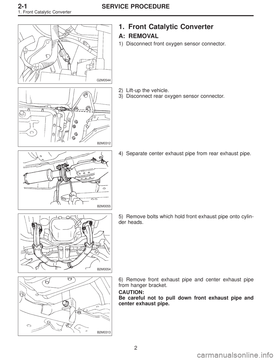
1. Front Catalytic Converter
A: REMOVAL
1) Disconnect front oxygen sensor connector.
G2M0544
2)Lift-up the vehicle.
3)Disconnect rear oxygen sensor connector.
B2M0312
4) Separate center exhaust pipe from rear exhaust pipe.
B2M0055
5) Remove bolts which hold front exhaust pipe onto cylinder heads.
B2M0054
6) Remove front exhaust pipe and center exhaust pipe from hanger bracket.
CAUTION:
Be careful not to pull down front exhaust pipe and center exhaust pipe.
B2M0313
2

|
SERVICE PROCEDURE |
2-1 |
|
1. Front Catalytic Converter |
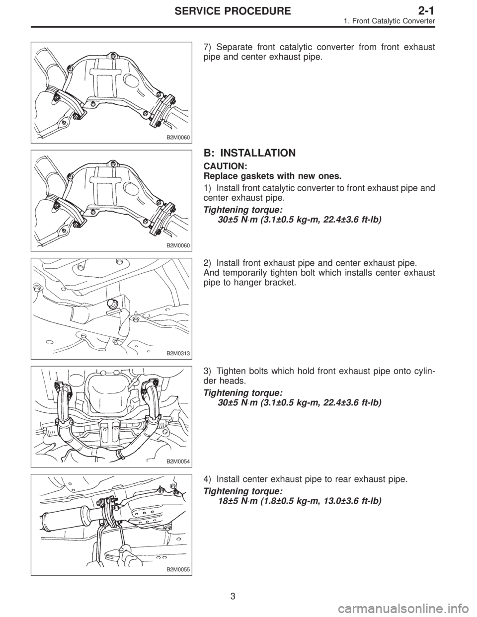
7) Separate front catalytic converter from front exhaust pipe and center exhaust pipe.
B2M0060
B: INSTALLATION
CAUTION:
Replace gaskets with new ones.
1) Install front catalytic converter to front exhaust pipe and center exhaust pipe.
Tightening torque:
30±5 N m (3.1±0.5 kg-m, 22.4±3.6 ft-lb)
B2M0060
2) Install front exhaust pipe and center exhaust pipe. And temporarily tighten bolt which installs center exhaust pipe to hanger bracket.
B2M0313
3) Tighten bolts which hold front exhaust pipe onto cylinder heads.
Tightening torque:
30±5 N m (3.1±0.5 kg-m, 22.4±3.6 ft-lb)
B2M0054
4) Install center exhaust pipe to rear exhaust pipe.
Tightening torque:
18±5 N m (1.8±0.5 kg-m, 13.0±3.6 ft-lb)
B2M0055
3

1.Front Catalytic Converter — 2. Rear Catalytic Converter
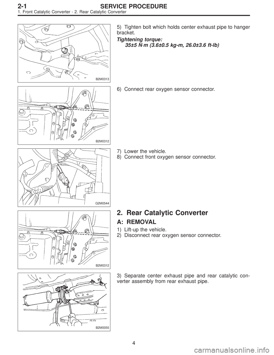
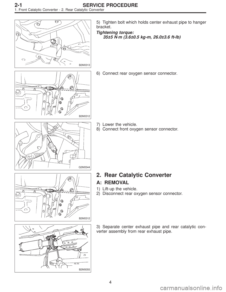
5)Tighten bolt which holds center exhaust pipe to hanger bracket.
Tightening torque:
35±5 N m (3.6±0.5 kg-m, 26.0±3.6 ft-lb)
B2M0313
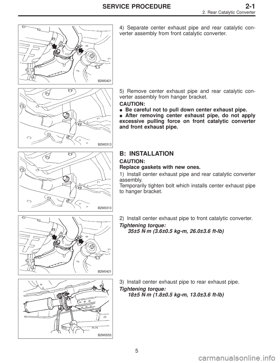
6) Connect rear oxygen sensor connector.
B2M0312
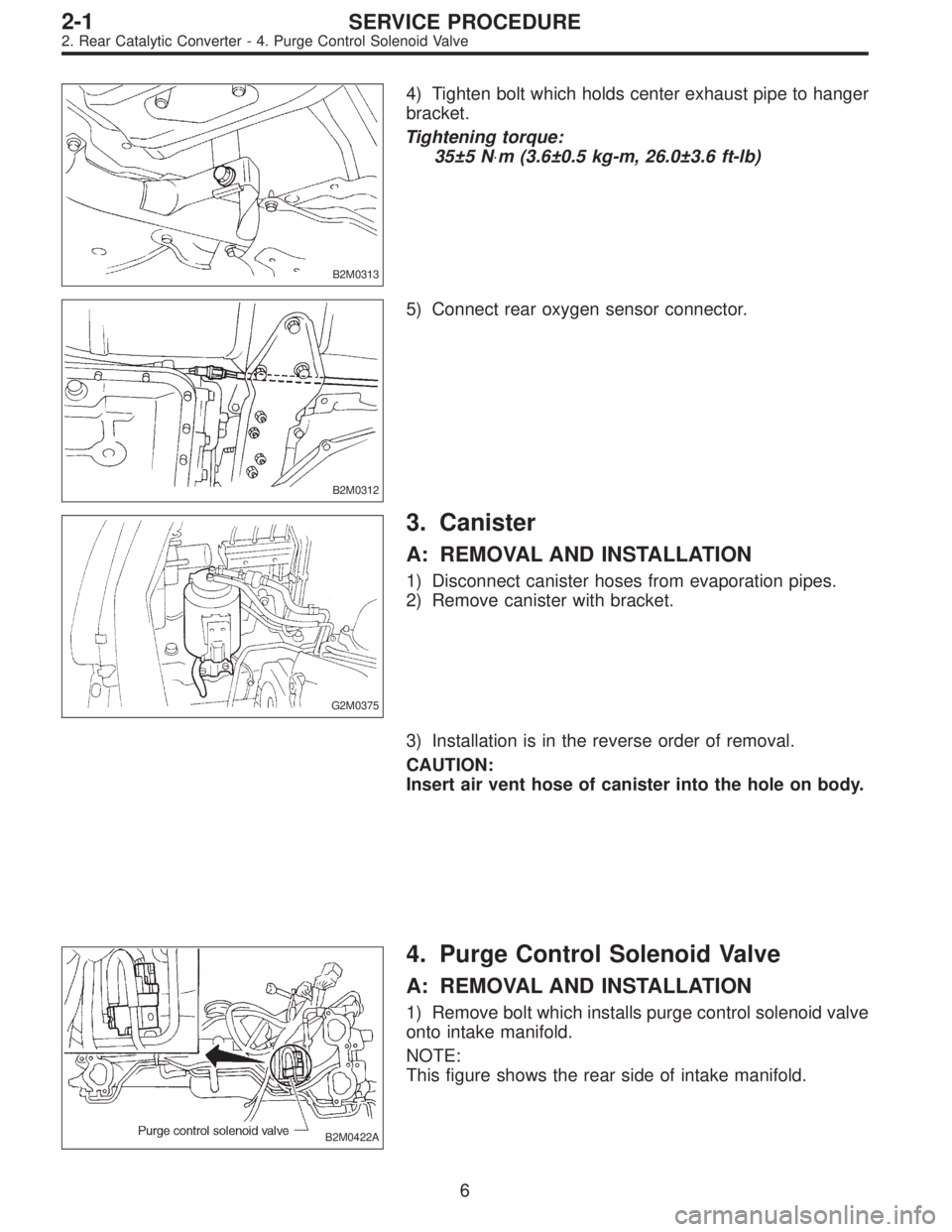
7)Lower the vehicle.

G2M0544
2. Rear Catalytic Converter
A: REMOVAL
1)Lift-up the vehicle.
2)Disconnect rear oxygen sensor connector.
B2M0312
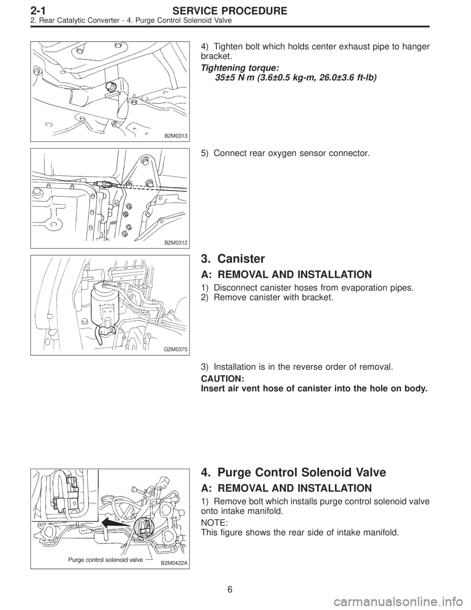
3) Separate center exhaust pipe and rear catalytic converter assembly from rear exhaust pipe.
B2M0055
4

1.Front Catalytic Converter — 2. Rear Catalytic Converter
5)Tighten bolt which holds center exhaust pipe to hanger bracket.
Tightening torque:
35±5 N m (3.6±0.5 kg-m, 26.0±3.6 ft-lb)
B2M0313
6) Connect rear oxygen sensor connector.
B2M0312
7)Lower the vehicle.

G2M0544
2. Rear Catalytic Converter
A: REMOVAL
1)Lift-up the vehicle.
2)Disconnect rear oxygen sensor connector.
B2M0312
3) Separate center exhaust pipe and rear catalytic converter assembly from rear exhaust pipe.
B2M0055
4

|
SERVICE PROCEDURE |
2-1 |
|
2. Rear Catalytic Converter |
4) Separate center exhaust pipe and rear catalytic converter assembly from front catalytic converter.
B2M0421
5) Remove center exhaust pipe and rear catalytic converter assembly from hanger bracket.
CAUTION:
!Be careful not to pull down center exhaust pipe.
!After removing center exhaust pipe, do not apply excessive pulling force on front catalytic converter and front exhaust pipe.
B2M0313
B: INSTALLATION
CAUTION:
Replace gaskets with new ones.
1) Install center exhaust pipe and rear catalytic converter assembly.
Temporarily tighten bolt which installs center exhaust pipe to hanger bracket.
B2M0313
2) Install center exhaust pipe to front catalytic converter.
Tightening torque:
35±5 N m (3.6±0.5 kg-m, 26.0±3.6 ft-lb)
B2M0421
3) Install center exhaust pipe to rear exhaust pipe.
Tightening torque:
18±5 N m (1.8±0.5 kg-m, 13.0±3.6 ft-lb)
B2M0055
5

2.Rear Catalytic Converter — 4. Purge Control Solenoid Valve
4)Tighten bolt which holds center exhaust pipe to hanger bracket.
Tightening torque:
35±5 N m (3.6±0.5 kg-m, 26.0±3.6 ft-lb)
B2M0313
5) Connect rear oxygen sensor connector.
B2M0312
3. Canister
A: REMOVAL AND INSTALLATION
1)Disconnect canister hoses from evaporation pipes.
2)Remove canister with bracket.
G2M0375
3) Installation is in the reverse order of removal.
CAUTION:
Insert air vent hose of canister into the hole on body.
4. Purge Control Solenoid Valve
A: REMOVAL AND INSTALLATION
1) Remove bolt which installs purge control solenoid valve onto intake manifold.
NOTE:
This figure shows the rear side of intake manifold.
B2M0422A
6

4.Purge Control Solenoid Valve — 6. Back-Pressure Transducer (BPT)
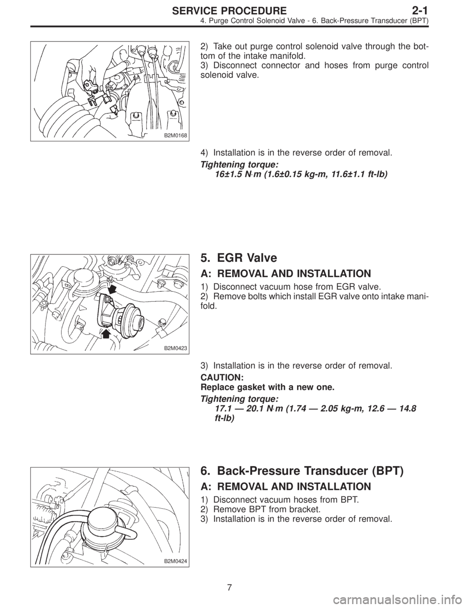
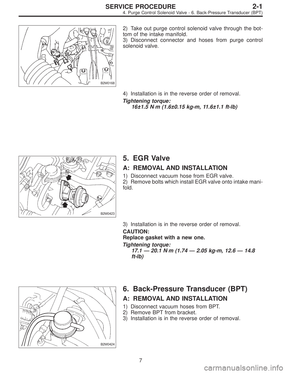
2)Take out purge control solenoid valve through the bottom of the intake manifold.
3)Disconnect connector and hoses from purge control solenoid valve.
B2M0168
4) Installation is in the reverse order of removal.
Tightening torque:
16±1.5 N m (1.6±0.15 kg-m, 11.6±1.1 ft-lb)
5. EGR Valve
A: REMOVAL AND INSTALLATION
1)Disconnect vacuum hose from EGR valve.
2)Remove bolts which install EGR valve onto intake manifold.
B2M0423
3) Installation is in the reverse order of removal.
CAUTION:
Replace gasket with a new one.
Tightening torque:
17.1 — 20.1 N m (1.74 — 2.05 kg-m, 12.6 — 14.8 ft-lb)
6. Back-Pressure Transducer (BPT)
A: REMOVAL AND INSTALLATION
1)Disconnect vacuum hoses from BPT.
2)Remove BPT from bracket.
3)Installation is in the reverse order of removal.
B2M0424
7

|
2-1 |
SERVICE PROCEDURE |
|
7. EGR Solenoid Valve |
7. EGR Solenoid Valve
A: REMOVAL AND INSTALLATION
1)Remove bolt which installs EGR solenoid valve onto intake manifold.
2)Disconnect hoses and connector from EGR solenoid valve.
NOTE:
This figure shows the rear side of intake manifold.
B2M0425A
3) Installation is in the reverse order of removal.
Tightening torque:
19±5 N m (1.9±0.5 kg-m, 13.7±3.6 ft-lb)
8

2-2
1. Foreword — 2. Ignition Timing
1. Foreword
This chapter describes major inspection and service procedures for the engine mounted on the body. For procedures not found in this chapter, refer to the service procedure section in the applicable chapter.
2. Ignition Timing
A: MEASUREMENT
1) Warm-up the engine.
2)To check the ignition timing, connect a timing light to #1 cylinder spark plug cord, and illuminate the timing mark with the timing light.
3)Start the engine at idle speed and check the ignition timing.
If the timing is not correct, check the ignition control system. <Ref. to 2-7 On-Board Diagnostics II System.>
Ignition timing [BTDC/rpm]: 14°±8°/700 (MT)
G2M0094 20°±8°/700 (AT)
2

2-2
3. Engine Idle Speed
3. Engine Idle Speed
A: MEASUREMENT
1)Before checking idle speed, check the following:
(1)Ensure that air cleaner element is free from clogging, ignition timing is correct, spark plugs are in good condition, and that hoses are connected properly.
(2)Ensure that malfunction indicator light (CHECK ENGINE light) does not illuminate.
2)Warm-up the engine.
3)Connect Subaru Select Monitor or the OBD-II general scan tool to data link connector.
CAUTION:
When connecting Subaru Select Monitor, turn ignition switch to OFF.
4) Start the engine and measure engine speed.
NOTE:
Engine speed is indicated on Subaru Select Monitor by
selecting “MODE F04”.
G2M0096
NOTE:
!When using the OBD-II general scan tool, carefully read its operation manual.
!When Subaru Select Monitor is not used, attach the pickup sensor on tachometer (Secondary pickup type) to #1 cylinder spark plug cord.
!This ignition system provides simultaneous ignition for #1 and #2 plugs. It must be noted that some tachometers may register twice that of actual engine speed.
G2M0097
3

2-2
3. Engine Idle Speed
5) Check idle speed when unloaded. (With headlights, heater fan, rear defroster, radiator fan, air conditioning, etc. OFF)
Idle speed (No load and gears in neutral (MT) or N or P (AT) position):
700±100 rpm
6) Check idle speed when loaded. (Turn air conditioning switch to “ON” and operate compressor for at least one minute before measurement.)
Idle speed [A/C “ON”, no load and gears in neutral (MT) or N or P (AT) position]:
850±50 rpm
CAUTION:
Never rotate idle adjusting screw. If idle speed is out of specifications, refer to General On-board Diagnosis Table under “2-7 On-Board Diagnostics II System”.
4

2-2
4. Engine Compression
4. Engine Compression
A: MEASUREMENT
1)After warming-up the engine, turn ignition switch to OFF.
2)Make sure that the battery is fully charged.
3)Remove all the spark plugs.
4)Disconnect connectors from fuel injectors.
5)Fully open throttle valve.
6)Check the starter motor for satisfactory performance and operation.
7)Hold the compression gauge tight against the spark plug hole.
CAUTION:
When using a screw-in type compression gauge, the screw (put into cylinder head spark plug hole) should be less than 18 mm (0.71 in) long.

G2M0098
9) Perform at least two measurements per cylinder, and make sure that the values are correct.
Compression (200 — 300 rpm and fully open throttle): Standard
1,079 — 1,275 kPa
(11.0 — 13.0 kg/cm2, 156 — 185 psi) Limit
883 kPa (9.0 kg/cm2, 128 psi) Difference between cylinders
196 kPa (2.0 kg/cm2, 28 psi)
5

2-2
5. Intake Manifold Vacuum
5. Intake Manifold Vacuum
A: MEASUREMENT
1)Warm-up the engine.
2)Disconnect the brake vacuum hose and install the vacuum gauge to the hose fitting on the manifold.
3)Keep the engine at the idle speed and read the vacuum gauge indication.
By observing the gauge needle movement, the internal condition of the engine can be diagnosed as described below.
Vacuum pressure (at idling, A/C “OFF”): Less than −60.0 kPa
(−450 mmHg, −17.72 inHg)
G2M0099
Diagnosis of engine condition by measurement of manifold vacuum
|
Vacuum gauge indication |
Possible engine condition |
|
|
1. |
Needle is steady but lower than normal position. This |
Leakage around intake manifold gasket or disconnection or |
|
tendency becomes more evident as engine temperature |
damaged vacuum hose |
|
|
rises. |
||
|
2. |
When engine speed is reduced slowly from higher speed, |
Back pressure too high, or exhaust system clogged |
|
needle stops temporarily when it is lowering or becomes |
||
|
steady above normal position. |
||
|
3. |
Needle intermittently drops to position lower than normal |
Leakage around cylinder |
|
position. |
||
|
4. |
Needle drops suddenly and intermittently from normal |
Sticky valves |
|
position. |
||
|
5. |
When engine speed is gradually increased, needle begins |
Weak or broken valve springs |
|
to vibrate rapidly at certain speed, and then vibration |
||
|
increases as engine speed increases. |
||
|
6. |
Needle vibrates above and below normal position in narrow |
Defective ignition system or throttle chamber idle adjustment |
|
range. |
6

2-2
6. Engine Oil Pressure
6. Engine Oil Pressure
A: MEASUREMENT
1)Remove generator from bracket.
(1)Disconnect connector and terminal from generator.
G2M0088
(2)Remove V-belt cover.
(3)Loosen lock bolt and slider bolt, and remove V-belt for generator.
G2M0089
(4)Remove generator lock bolt.
(5)Remove bolt which install generator on bracket.
G2M0090
2)Disconnect connector from oil pressure switch.
3)Remove oil pressure switch from engine cylinder block.
G2M0091
7

2-2
6. Engine Oil Pressure
4)Connect oil pressure gauge hose to cylinder block.
5)Start the engine, and measure oil pressure.
Oil pressure:
98 kPa (1.0 kg/cm2,14 psi) or more at 800 rpm 294 kPa (3.0 kg/cm2, 43 psi) or more at 5,000 rpm
CAUTION:
! If oil pressure is out of specification, check oil pump, oil filter and lubrication line.
<Ref. to 2-4 [K100].>
G2M0093 ! If oil pressure warning light is turned ON and oil pressure is in specification, replace oil pressure switch.
<Ref. to 2-4 [W3A0].>
NOTE:
The specified data is based on an engine oil temperature of 80°C (176°F).
6) After measuring oil pressure, install oil pressure switch.
Tightening torque:
25±3 N m (2.5±0.3 kg-m, 18.1±2.2 ft-lb)
7) Install generator and V-belt in the reverse order of removal, and adjust the V-belt deflection.
8
|
2-3 |
SPECIFICATIONS AND SERVICE DATA |
|
1. Engine |
1. Engine
A: SPECIFICATIONS
|
Model |
2200 cc |
||||
|
Type |
Horizontally |
opposed, liquid cooled, 4-cylinder, 4-stroke |
|||
|
gasoline engine |
|||||
|
Valve arrangement |
Belt driven, single over-head camshaft, 4-valve/cylinder |
||||
|
Bore x Stroke |
mm (in) |
96.9 x 75.0 (3.815 x 2.953) |
|||
|
Displacement |
cm3 (cu in) |
2,212 (135.0) |
|||
|
Compression ratio |
9.5 |
||||
|
Compression pressure |
kPa (kg/cm2, psi) |
1,079 — 1,275 |
|||
|
(at 200 — 300 rpm) |
(11.0 — 13.0, 156 — 185) |
||||
|
Engine |
Number of piston rings |
Pressure ring: 2, Oil ring: 1 |
|||
|
Intake valve timing |
Opening |
1° BTDC |
|||
|
Closing |
55° ABDC |
||||
|
Exhaust valve timing |
Opening |
48° BBDC |
|||
|
Closing |
12° ATDC |
||||
|
Idling speed |
700±100 (No load) |
||||
|
[At neutral position on MT, or |
|||||
|
850±50 (A/C switch ON) |
|||||
|
“P” or “N” position on AT] |
rpm |
||||
|
Firing order |
1 , 3 , 2 , 4 |
||||
|
Ignition timing |
BTDC/rpm |
14°±8°/700 (MT), 20°±8°/700 (AT) |
2
|
SPECIFICATIONS AND SERVICE DATA |
2-3 |
||||||||
|
1. Engine |
|||||||||
|
B: SERVICE DATA |
|||||||||
|
Belt |
Protrusion of adjuster rod |
15.4 — 16.4 mm |
(0.606 — 0.646 in) |
||||||
|
tension |
|||||||||
|
adjuster |
|||||||||
|
Spacer O.D. |
16 mm |
(0.63 in) |
|||||||
|
Tensioner bush I.D. |
16.16 mm |
(0.6362 in) |
|||||||
|
Belt ten- |
Clearance between spacer and bush |
STD |
0.117 — 0.180 mm |
(0.0046 — 0.0071 in) |
|||||
|
sioner |
Limit |
0.230 mm |
(0.0091 in) |
||||||
|
Side clearance of spacer |
STD |
0.37 — 0.54 mm |
(0.0146 — 0.0213 in) |
||||||
|
Limit |
0.8 mm |
(0.031 in) |
|||||||
|
Valve |
Clearance between shaft and arm |
STD |
0.020 — 0.054 mm |
(0.0008 — 0.0021 in) |
|||||
|
rocker arm |
Limit |
0.10 mm |
(0.0039 in) |
||||||
|
Bend limit |
0.025 mm |
(0.0010 in) |
|||||||
|
Thrust clearance |
STD |
0.030 — 0.260 mm |
(0.0012 — 0.0102 in) |
||||||
|
Limit |
0.35 mm |
(0.0138 in) |
|||||||
|
Intake |
STD |
31.994 — 32.094 mm |
(1.2596 — 1.2635 in) |
||||||
|
Cam lobe height |
Limit |
31.844 mm |
(1.2537 in) |
||||||
|
Exhaust |
STD |
32.624 — 32.724 mm |
(1.2844 — 1.2883 in) |
||||||
|
Camshaft |
Limit |
32.474 mm |
(1.2785 in) |
||||||
|
Camshaft journal O.D. |
RH |
Front |
LH |
Rear |
31.935 — 31.950 mm |
(1.2573 — 1.2579 in) |
|||
|
Center |
Center |
37.435 — 37.450 mm |
(1.4738 — 1.4744 in) |
||||||
|
Rear |
Front |
37.935 — 37.950 mm |
(1.4935 — 1.4941 in) |
||||||
|
Camshaft journal hole |
Front |
Rear |
32.005 — 32.025 mm |
(1.2600 — 1.2608 in) |
|||||
|
RH |
Center |
LH |
Center |
37.505 — 37.525 mm |
(1.4766 — 1.4774 in) |
||||
|
I.D. |
|||||||||
|
Rear |
Front |
38.005 — 38.025 mm |
(1.4963 — 1.4970 in) |
||||||
|
Oil clearance |
STD |
0.055 — 0.090 mm |
(0.0022 — 0.0035 in) |
||||||
|
Limit |
0.10 mm |
(0.0039 in) |
|||||||
|
Cylinder |
Surface warpage limit |
0.05 mm |
(0.0020 in) |
||||||
|
Surface grinding limit |
0.1 mm |
(0.004 in) |
|||||||
|
head |
|||||||||
|
Standard height |
98.3 mm |
(3.870 in) |
|||||||
|
Refacing angle |
90° |
||||||||
|
Intake |
STD |
0.7 mm |
(0.028 in) |
||||||
|
Valve set |
Contacting width |
Limit |
1.4 mm |
(0.055 in) |
|||||
|
Exhaust |
STD |
1.4 mm |
(0.055 in) |
||||||
|
Limit |
1.8 mm |
(0.071 in) |
|||||||
|
Valve |
Inner diameter |
6.000 — 6.012 mm |
(0.2362 — 0.2367 in) |
||||||
|
guide |
Protrusion above head |
17.5 — 18.0 mm |
(0.689 — 0.709 in) |
||||||
|
Intake |
STD |
1.0 mm |
(0.039 in) |
||||||
|
Head edge thickness |
Limit |
0.8 mm |
(0.031 in) |
||||||
|
Exhaust |
STD |
1.2 mm |
(0.047 in) |
||||||
|
Limit |
0.8 mm |
(0.031 in) |
|||||||
|
Stem diameter |
Intake |
5.950 — 5.965 mm |
(0.2343 — 0.2348 in) |
||||||
|
Valve |
Exhaust |
5.945 — 5.960 mm |
(0.2341 — 0.2346 in) |
||||||
|
STD |
Intake |
0.035 — 0.062 mm |
(0.0014 — 0.0024 in) |
||||||
|
Stem oil clearance |
Exhaust |
0.040 — 0.067 mm |
(0.0016 — 0.0026 in) |
||||||
|
Limit |
— |
0.15 mm |
(0.0059 in) |
||||||
|
Overall length |
Intake |
101.0 mm |
(3.976 in) |
||||||
|
Exhaust |
101.2 mm |
(3.984 in) |
|||||||
|
STD: Standard I.D.: Inner Diameter |
O.D.: Outer Diameter |
3
|
2-3 |
SPECIFICATIONS AND SERVICE DATA |
|||||
|
1. Engine |
||||||
|
Free length |
44.05 mm |
(1.7342 in) |
||||
|
Valve spring |
Squareness |
2.5°, 1.9 mm |
(0.075 in) |
|||
|
174.6 — 200.1 N |
||||||
|
Tension/spring height |
(17.8 — 20.4 kg, 39.2 — 45.0 lb)/36.0 mm (1.417 in) |
|||||
|
405.0 — 458.0 N |
||||||
|
(41.3 — 46.7 kg, 91.1 — 103.0 lb)/28.2 mm (1.110 in) |
||||||
|
Surface warpage limit (mating with cylinder head) |
0.05 mm |
(0.0020 in) |
||||
|
Surface grinding limit |
0.1 mm |
(0.004 in) |
||||
|
Cylinder bore |
STD |
A |
96.905 — 96.915 mm |
(3.8151 — 3.8155 in) |
||
|
B |
96.895 — 96.905 mm |
(3.8148 — 3.8151 in) |
||||
|
Cylinder |
Taper |
STD |
0.015 mm |
(0.0006 in) |
||
|
Limit |
0.050 mm |
(0.0020 in) |
||||
|
block |
||||||
|
Out-of-roundness |
STD |
0.010 mm |
(0.0004 in) |
|||
|
Limit |
0.050 mm |
(0.0020 in) |
||||
|
Piston clearance |
STD |
0.010 — 0.030 mm |
(0.0004 — 0.0012 in) |
|||
|
Limit |
0.050 mm |
(0.0020 in) |
||||
|
Enlarging (boring) limit |
0.5 mm |
(0.020 in) |
||||
|
STD |
A |
96.885 — 96.895 mm |
(3.8144 — 3.8148 in) |
|||
|
B |
96.875 — 96.885 mm |
(3.8140 — 3.8144 in) |
||||
|
Piston |
Outer diameter |
0.25 mm (0.0098 in) |
97.115 — 97.145 mm |
(3.8234 — 3.8246 in) |
||
|
OS |
||||||
|
0.50 mm (0.0197 in) |
97.365 — 97.395 mm |
(3.8333 — 3.8344 in) |
||||
|
OS |
||||||
|
Standard clearance between piston |
STD |
0.004 — 0.010 mm |
(0.0002 — 0.0004 in) |
|||
|
Piston pin |
pin and hole in piston |
Limit |
0.020 mm |
(0.0008 in) |
||
|
Degree of fit |
Piston pin must be fitted into position with thumb at 20°C |
|||||
|
(68°F). |
||||||
|
Top ring |
STD |
0.20 — 0.35 mm |
(0.0079 — 0.0138 in) |
|||
|
Limit |
1.0 mm |
(0.039 in) |
||||
|
Piston ring gap |
Second |
STD |
0.20 — 0.50 mm |
(0.0079 — 0.0197 in) |
||
|
ring |
Limit |
1.0 mm |
(0.039 in) |
|||
|
Piston ring |
Oil ring |
STD |
0.20 — 0.70 mm |
(0.0079 — 0.0276 in) |
||
|
Limit |
1.5 mm |
(0.059 in) |
||||
|
Top ring |
STD |
0.040 — 0.080mm |
(0.0016 — 0.0031 in) |
|||
|
Clearance between piston |
Limit |
0.15 mm |
(0.0059 in) |
|||
|
ring and piston ring groove |
Second |
STD |
0.030 — 0.070 mm |
(0.0012 — 0.0028 in) |
||
|
ring |
Limit |
0.15 mm |
(0.0059 in) |
|||
|
Bend twist per 100 mm (3.94 in) in |
Limit |
0.10 mm |
(0.0039 in) |
|||
|
Connecting |
length |
|||||
|
rod |
Side clearance |
STD |
0.070 — 0.330 mm |
(0.0028 — 0.0130 in) |
||
|
Limit |
0.4 mm |
(0.016 in) |
||||
|
Oil clearance |
STD |
0.015 — 0.045 mm |
(0.0006 — 0.0018 in) |
|||
|
Limit |
0.05 mm |
(0.0020 in) |
||||
|
STD |
1.492 — 1.501 mm |
(0.0587 — 0.0591 in) |
||||
|
0.03 mm |
1.510 — 1.513 mm |
(0.0594 — 0.0596 in) |
||||
|
Connecting |
(0.0012 in) |
|||||
|
US |
||||||
|
rod bearing |
||||||
|
Thickness at center portion |
0.05 mm |
1.520 — 1.523 mm |
(0.0598 — 0.0600 in) |
|||
|
(0.0020 in) |
||||||
|
US |
||||||
|
0.25 mm |
1.620 — 1.623 mm |
(0.0638 — 0.0639 in) |
||||
|
(0.0098 in) |
||||||
|
US |
||||||
|
Connecting |
Clearance between piston pin and |
STD |
0 — 0.022 mm |
(0 — 0.0009 in) |
||
|
rod bushing |
bushing |
Limit |
0.030 mm |
(0.0012 in) |
||
|
STD: Standard |
OS: Oversize US: Undersize |
4
|
SPECIFICATIONS AND SERVICE DATA |
2-3 |
||||
|
1. Engine |
|||||
|
Bend limit |
0.035 mm |
(0.0014 in) |
|||
|
Crank pin and crank journal |
Out-of-roundness |
0.030 mm (0.0012 in) or less |
|||
|
Grinding limit |
0.25 mm |
(0.0098 in) |
|||
|
STD |
51.984 — 52.000 mm |
(2.0466 — 2.0472 in) |
|||
|
0.03 mm |
51.954 — 51.970 mm |
(2.0454 — 2.0461 in) |
|||
|
(0.0012 in) |
|||||
|
US |
|||||
|
Crank pin outer diameter |
0.05 mm |
51.934 — 51.950 mm |
(2.0446 — 2.0453 in) |
||
|
(0.0020 in) |
|||||
|
US |
|||||
|
0.25 mm |
51.734 — 51.750 mm |
(2.0368 — 2.0374 in) |
|||
|
(0.0098 in) |
|||||
|
US |
|||||
|
STD |
59.992 — 60.008 mm |
(2.3619 — 2.3625 in) |
|||
|
0.03 mm |
59.962 — 59.978 mm |
(2.3607 — 2.3613 in) |
|||
|
(0.0012 in) |
|||||
|
US |
|||||
|
#1, #5 |
0.05 mm |
59.934 — 59.950 mm |
(2.3596 — 2.3602 in) |
||
|
(0.0020 in) |
|||||
|
Crankshaft |
US |
||||
|
0.25 mm |
59.742 — 59.758 mm |
(2.3520 — 2.3527 in) |
|||
|
(0.0098 in) |
|||||
|
Crank journal outer diameter |
US |
||||
|
STD |
59.992 — 60.008 mm |
(2.3619 — 2.3625 in) |
|||
|
0.03 mm |
59.954 — 59.970 mm |
(2.3604 — 2.3610 in) |
|||
|
(0.0012 in) |
|||||
|
US |
|||||
|
#2, #3, #4 |
0.05 mm |
59.934 — 59.950 mm |
(2.3596 — 2.3602 in) |
||
|
(0.0020 in) |
|||||
|
US |
|||||
|
0.25 mm |
59.734 — 59.750 mm |
(2.3517 — 2.3524 in) |
|||
|
(0.0098 in) |
|||||
|
US |
|||||
|
Thrust clearance |
STD |
0.030 — 0.115 mm |
(0.0012 — 0.0045 in) |
||
|
Limit |
0.25 mm |
(0.0098 in) |
|||
|
#1, #5 |
STD |
0.003 — 0.030 mm |
(0.0001 — 0.0012 in) |
||
|
Oil clearance |
#2, #3, #4 |
STD |
0.010 — 0.033 mm |
(0.0004 — 0.0013 in) |
|
|
#1, #3, #5 |
Limit |
0.040 mm |
(0.0016 in) |
||
|
#2, #4 |
Limit |
0.035 mm |
(0.0014 in) |
||
|
STD |
1.998 — 2.011 mm |
(0.0787 — 0.0792 in) |
|||
|
0.03 mm |
2.017 — 2.020 mm |
(0.0794 — 0.0795 in) |
|||
|
(0.0012 in) |
|||||
|
US |
|||||
|
#1, #5 |
0.05 mm |
2.027 — 2.030 mm |
(0.0798 — 0.0799 in) |
||
|
(0.0020 in) |
|||||
|
US |
|||||
|
0.25 mm |
2.127 — 2.130 mm |
(0.0837 — 0.0839 in) |
|||
|
Crankshaft |
(0.0098 in) |
||||
|
Crankshaft bearing thickness |
US |
||||
|
bearing |
|||||
|
STD |
2.000 — 2.013 mm |
(0.0787 — 0.0793 in) |
|||
|
0.03 mm |
2.019 — 2.022 mm |
(0.0795 — 0.0796 in) |
|||
|
(0.0012 in) |
|||||
|
US |
|||||
|
#2, #3, #4 |
0.05 mm |
2.029 — 2.032 mm |
(0.0799 — 0.0800 in) |
||
|
(0.0020 in) |
|||||
|
US |
|||||
|
0.25 mm |
2.129 — 2.132 mm |
(0.0838 — 0.0839 in) |
|||
|
(0.0098 in) |
|||||
|
US |
|||||
|
STD: Standard US: Undersize |
5

|
2-3 |
COMPONENT PARTS |
|
1. Timing Belt |
1. Timing Belt
B2M0102A
!1 Crankshaft sprocket !2 Belt cover No. 2 (RH) !3 Belt cover No. 2 (LH)
!4 Camshaft sprocket (RH) !5 Belt idler
!6 Tensioner bracket !7 Belt idler
!8 Belt tensioner
!9 Tensioner adjuster !10 Belt idler No. 2
!11 Camshaft sprocket (LH) !12 Timing belt
!13 Belt cover (RH) !14 Front belt cover !15 Belt cover (LH)
!16 Crankshaft pulley
Tightening torque: N m (kg-m, ft-lb)
T1: 5±1 (0.5±0.1, 3.6±0.7) T2: 25±2 (2.5±0.2, 18.1±1.4) T3: 39±4 (4.0±0.4, 28.9±2.9)
T4: 78±5 (8.0±0.5, 57.9±3.6)
T5: 108+10−5 (11+1.0−0.5 , 79.6+7.2−3.6 )
6

|
COMPONENT PARTS |
2-3 |
|
2. Cylinder Head and Camshaft |
2. Cylinder Head and Camshaft
B2M0103A
!1 Rocker cover (RH) !2 Rocker cover gasket
!3 Camshaft support (RH) !4 O-ring
!5 Camshaft (RH) !6 Intake valve guide
!7 Exhaust valve guide !8 Oil seal
!9 Cylinder head (RH) !10 Cylinder head gasket !11 Cylinder head (LH) !12 Plug
!13 Camshaft (LH) !14 O-ring
!15 Camshaft support (LH)
!16 Oil seal
!17 Oil filler cap !18 Gasket
!19 Oil filler pipe !20 O-ring
!21 Rocker cover gasket !22 Rocker cover (LH)
Tightening torque: N m (kg-m, ft-lb)
T1: Refer to [W6E1].
T2: 5±1 (0.5±0.1, 3.6±0.7) T3: 10 (1.0, 7)
T4: 16 (1.6, 12)
7

|
2-3 |
COMPONENT PARTS |
|
3. Cylinder Head and Valve Assembly |
3. Cylinder Head and Valve Assembly
B2M0380A
!1 Exhaust valve !2 Intake valve
!3 Intake valve oil seal !4 Valve spring
!5 Retainer
!6 Retainer key
!7 Exhaust valve oil seal !8 Rocker shaft support !9 Rocker shaft support !10 Rocker shaft support
!11 Rocker shaft
!12 Hydraulic lash adjuster !13 Intake valve rocker arm !14 Exhaust valve rocker arm !15 Spring
Tightening torque: N m (kg-m, ft-lb)
T1: 5±1 (0.5±0.1, 3.6±0.7)
T2: 12±1 (1.2±0.1, 8.7±0.7)
8

|
COMPONENT PARTS |
2-3 |
|
4. Cylinder Block |
4. Cylinder Block
B2M0381A
!1 Oil pressure switch !2 Cylinder block (RH) !3 Service hole plug !4 Gasket
!5 Oil separator cover !6 Water pipe
!7 Oil pump
!8 Front oil seal !9 Rear oil seal !10 O-ring
!11 Service hole cover !12 Cylinder block (LH) !13 Water pump
!14 Baffle plate
!15 Oil strainer stay !16 Oil strainer
!17 Gasket !18 Oil pan
!19 Oil drain plug !20 Gasket
!21 Oil filler pipe
Tightening torque: N m (kg-m, ft-lb)
T1: 5 (0.5, 3.6) T2: 6.4 (0.65, 4.7) T3: 10 (1.0, 7)
T4: 25±2 (2.5±0.2, 18.1±1.4)
T5: 47±3 (4.8±0.3, 34.7±2.2)
T6: 69±7 (7.0±0.7, 50.6±5.1)
T7: First 12±2 (1.2±0.2, 8.7±1.4) Second 12±2 (1.2±0.2, 8.7±1.4)
9

|
2-3 |
COMPONENT PARTS |
|
5. Crankshaft and Piston |
5. Crankshaft and Piston
G2M0105
!1 Drive plate (AT)
!2 Reinforcement (AT) !3 Flywheel (MT)
!4 Bell bearing (MT) !5 Top ring
!6 Second ring !7 Oil ring
!8 Piston
!9 Piston pin !10 Circlip
!11 Connecting rod bolt !12 Connecting rod
!13 Connecting rod bearing !14 Connecting rod cap
!15 Crankshaft !16 Woodruff key
!17 Crankshaft bearing #1, #5 !18 Crankshaft bearing #2, #4 !19 Crankshaft bearing #3
Tightening torque: N m (kg-m, ft-lb)
T1: 44±2 (4.5±0.2, 32.5±1.4) T2: 72±3 (7.3±0.3, 52.8±2.2)
10

1.General Precautions — 2. Hydraulic Lash Adjuster
1.General Precautions
1) Before disassembling engine, place it on ST3.
|
ST1 |
498457000 |
ENGINE STAND ADAPTER RH |
|
ST2 |
498457100 |
ENGINE STAND ADAPTER LH |
|
ST3 |
499817000 |
ENGINE STAND |
G2M0106
2)All parts should be thoroughly cleaned, paying special attention to the engine oil passages, pistons and bearings.
3)Rotating parts and sliding parts such as piston, bearing and gear should be coated with oil prior to assembly.
4)Be careful not to let oil, grease or coolant contact the timing belt, clutch disc and flywheel.
5)All removed parts, if to be reused, should be reinstalled in the original positions and directions.
6)Gaskets and lock washers must be replaced with new ones. Liquid gasket should be used where specified to prevent leakage.
7)Bolts, nuts and washers should be replaced with new ones as required.

2. Hydraulic Lash Adjuster
A: INSPECTION
1)Disconnect blow-by hose from rocker cover.
2)Remove spark plug cap.
3)Remove left and right rocker covers.
CAUTION:
Before removing left rocker cover, disconnect battery cables and generator cable.
B2M0413A
11

1.General Precautions — 2. Hydraulic Lash Adjuster
1.General Precautions
1) Before disassembling engine, place it on ST3.
|
ST1 |
498457000 |
ENGINE STAND ADAPTER RH |
|
ST2 |
498457100 |
ENGINE STAND ADAPTER LH |
|
ST3 |
499817000 |
ENGINE STAND |
G2M0106
2)All parts should be thoroughly cleaned, paying special attention to the engine oil passages, pistons and bearings.
3)Rotating parts and sliding parts such as piston, bearing and gear should be coated with oil prior to assembly.
4)Be careful not to let oil, grease or coolant contact the timing belt, clutch disc and flywheel.
5)All removed parts, if to be reused, should be reinstalled in the original positions and directions.
6)Gaskets and lock washers must be replaced with new ones. Liquid gasket should be used where specified to prevent leakage.
7)Bolts, nuts and washers should be replaced with new ones as required.

2. Hydraulic Lash Adjuster
A: INSPECTION
1)Disconnect blow-by hose from rocker cover.
2)Remove spark plug cap.
3)Remove left and right rocker covers.
CAUTION:
Before removing left rocker cover, disconnect battery cables and generator cable.
B2M0413A
11

|
2-3 |
SERVICE PROCEDURE |
|
2. Hydraulic Lash Adjuster |
4) Manually push valve rocker (at lash adjuster location) to check that there is no air in it.
NOTE:
When air is in lash adjuster, valve rocker moves when pushed with fingers.
G2M0198
5) If air is in lash adjuster, remove valve rocker assembly from engine and bleed air completely.
G2M0199
|
B: AIR BLEEDING |
||
|
1) |
Remove valve rocker assembly. |
|
|
(1) Remove bolts !1 through !4 in numerical |
||
|
sequence. |
||
|
CAUTION: |
||
|
Leave two or three threads of bolt !1 engaged to retain |
||
|
valve rocker assembly. |
||
|
(2) Equally loosen bolts !5 through !8 all the way, |
||
|
B2M0382A |
being careful that knock pin is not gouged. |
2) Manually remove lash adjusters where air is trapped.
CAUTION:
If lash adjuster is difficult to remove manually, use pliers. Be careful not to scratch lash adjuster.
12

|
SERVICE PROCEDURE |
2-3 |
|
2. Hydraulic Lash Adjuster |
3) Bleed air from hydraulic lash adjuster as described below:
(1)While dipping hydraulic lash adjuster in engine oil, as shown in Figure, push check ball in using a 2 mm (0.08 in) diameter round bar.
(2)With check ball pushed in, manually move plunger up and down at one second intervals until air bubbles disappear.
(3)After air bubbles disappear, remove round bar and
quickly push plunger in to ensure it is locked. If plunger does not lock properly, replace hydraulic lash adjuster.
CAUTION:
Leave hydraulic lash adjuster (after air is bled) in engine oil until it is ready for installation.
4)Using ST;
(1)Insert lash adjuster into ST, and fill ST with engine oil. Using a 2 mm (0.08 in) diameter rod, push check ball in.
ST 499597000 OIL SEAL GUIDE
(2)With check ball pushed in, push plunger at an interval of one second.
(3)Move plunger up and down until air bubbles are no longer emitted from lash adjuster.
NOTE:
Hold hydraulic lash adjusters vertically during air bleeding.
5) Remove the rod. Push plunger to ensure that air is completely bled out.
CAUTION:
If plunger does not properly lock (when pushed), replace lash adjuster with a new one.
13

|
2-3 |
SERVICE PROCEDURE |
|
2. Hydraulic Lash Adjuster |
6) Fill rocker arm’s oil reservoir with engine oil and install lash adjuster.
CAUTION:
«Do not rotate lash adjuster during installation.
«Be careful not to scratch the oil seal.
CAUTION:
When removing valve rocker assembly, keep the assembly soaked in engine oil, or position it with air bleeding orifice on rocker arm facing upward as shown. This prevents oil leakage from and air entering into the hydraulic lash adjuster. Failure to do so may cause air to enter the hydraulic lash adjuster, causing loss in performance.
B2M0414
7)Temporarily and equally tighten bolts !1 through !4 . Do not allow knock pin to catch valve rocker assembly.

9)Tighten bolts !1 through !4 to specified torque.
Tightening torque:
12±1 N m (1.2±0.1 kg-m, 8.7±0.7 ft-lb)
B2M0382B
10) Install rocker covers.
Tightening torque:
5±1 N m (0.5±0.1 kg-m, 3.6±0.7 ft-lb)
11) Connect harness connectors, hoses, etc. to their positions.
14

|
SERVICE PROCEDURE |
2-3 |
|
3. Timing Belt |
3. Timing Belt
A: REMOVAL
1. CRANKSHAFT PULLEY AND BELT COVER
G2M0107
1)Remove V-belt and A/C belt tensioner.
2)Remove pulley bolt. To lock crankshaft use ST.
ST 499977000 CRANKSHAFT PULLEY WRENCH
3)Remove crankshaft pulley.
4)Remove left side belt cover.
5)Remove right side belt cover.
6)Remove front belt cover.
G2M0108
15

|
2-3 |
SERVICE PROCEDURE |
|
3. Timing Belt |
|
|
2. TIMING BELT |
B2M0415A
1) If alignment mark !2 and/or arrow mark (which indicates rotation direction) on timing belt fade away, put new marks before removing timing belt as follows:
G2M0616
(1) Turn crankshaft, and align alignment marks !2 on crankshaft sprocket, and left and right camshaft
sprockets with notches !1 of belt cover and cylinder block.
ST 499987500 CRANKSHAFT SOCKET
B2M0064A
16

|
SERVICE PROCEDURE |
2-3 |
|
3. Timing Belt |
(2) Using white paint, put alignment and/or arrow marks on timing belts in relation to the sprockets.
Z1: 44 tooth length Z2: 40.5 tooth length
G2M0111
2) Loosen tensioner adjuster mounting bolts.
B2M0065
3)Remove belt idler.
4)Remove belt idler No. 2.
5)Remove timing belt.
6)Remove tensioner adjuster.
17

|
2-3 |
SERVICE PROCEDURE |
|
3. Timing Belt |
|
|
3. BELT TENSIONER AND IDLER |
G2M0112
1)Remove belt idler.
2)Remove belt tensioner and spacer.
3)Remove belt tensioner adjuster.
18

|
SERVICE PROCEDURE |
2-3 |
|
3. Timing Belt |
|
|
4. SPROCKET |
B2M0416A
1)Remove left side camshaft sprocket.
2)Remove right side camshaft sprocket. To lock camshaft use ST.
ST 499207100 CAMSHAFT SPROCKET WRENCH
G2M0114
3)Remove crankshaft sprocket.
4)Remove left side belt cover No. 2.
5)Remove right side belt cover No. 2.
CAUTION:
Do not damage or lose the seal rubber when removing belt covers.
6) Remove tensioner bracket.
19

|
2-3 |
SERVICE PROCEDURE |
|
3. Timing Belt |
B: INSPECTION
1. TIMING BELT
1)Check timing belt teeth for breaks, cracks, and wear. If any fault is found, replace belt.
2)Check the condition of back side of belt; if any crack is found, replace belt.
CAUTION:
» Be careful not to let oil, grease or coolant contact the belt. Remove quickly and thoroughly if this happens.
» Do not bend the belt sharply.
Bending radius: h
60 mm (2.36 in) or more
G2M0115
2. BELT TENSION ADJUSTER
1) Visually check oil seals for leaks, and rod ends for abnormal wear or scratches. If necessary, replace belt tension adjuster.
CAUTION:
Slight traces of oil at rod’s oil seal does not indicate a problem.
2) While holding tensioner with both hands, push the rod section against floor or wall ensuring the rod section will react as follows:
(1)When applying a force of 147 N (15 kg, 33 lb), the rod section should not sink.
(2)When applying a force of 147 to 490 N (15 to 50 kg, 33 to 110 lb), the rod section should maintain a projectionally acting force and should not sink within 8.5 seconds.
20

|
SERVICE PROCEDURE |
2-3 |
|
3. Timing Belt |
3) Measure the extension of rod beyond the body. If it is not within specifications, replace with a new one.
Rod extension: H
15.4 — 16.4 mm (0.606 — 0.646 in)
B2M0108A
3. BELT TENSIONER
1)Check mating surfaces of timing belt and contact point of tension adjuster rod for abnormal wear or scratches. Replace belt tensioner if faulty.
2)Check spacer and tensioner bushing for wear.
3)Check tensioner for smooth rotation. Replace if noise or excessive play is noted.
4)Check tensioner for grease leakage.
4. BELT IDLER
1)Check idler for smooth rotation. Replace if noise or excessive play is noted.
2)Check outer contacting surfaces of idler pulley for abnormal wear and scratches.
3)Check idler for grease leakage.
5. SPROCKET
1)Check sprocket teeth for abnormal wear and scratches.
2)Make sure there is no free play between sprocket and key.
3)Check crankshaft sprocket notch for sensor for damage and contamination of foreign matter.
21

|
2-3 |
SERVICE PROCEDURE |
|
3. Timing Belt |
C: INSTALLATION
1. SPROCKET
B2M0416B
Tightening torque: N m (kg-m, ft-lb)
T1: 5±1 (0.5±0.1, 3.6±0.7)
T2: 25±2 (2.5±0.2, 18.1±1.4)
T3: 78±5 (8.0±0.5, 57.9±3.6)
1)Install right side belt cover No. 2.
2)Install tensioner bracket.
3)Install left side belt cover No. 2.
4)Install crankshaft sprocket.
5)Install right side camshaft sprocket and left side camshaft sprocket. To lock camshaft use ST.
ST 499207100 CAMSHAFT SPROCKET WRENCH
CAUTION:
Do not confuse left and right side camshaft sprockets G2M0114 during installation. The left side camshaft sprocket is identified by a projection used to monitor cam angle
sensor.
22

|
SERVICE PROCEDURE |
2-3 |
|
3. Timing Belt |
|
|
2. BELT TENSIONER AND IDLER |
B2M0070A
Tightening torque: N m (kg-m, ft-lb)
T: 39±4 (4.0±0.4, 28.9±2.9)
1) Installation of belt tension adjuster
Insert stopper pin 1.5 mm (0.059 in) diameter into place while pushing tension adjuster rod into body using a press.
CAUTION:
«Do not allow press pressure to exceed 9,807 N (1,000 kg, 2,205 lb).
«Do not release press pressure until stopper pin is completely inserted.
«Push tension adjuster rod vertically.
«Press-in the push rod gradually taking three minutes or more.
B2M0109A
23

|
2-3 |
SERVICE PROCEDURE |
|
3. Timing Belt |
2)Install belt tensioner and spacer.
3)Install belt idler.
4) Temporarily tighten bolts while belt tension adjuster is pushed all the way to the right.
B2M0110
3. TIMING BELT
B2M0071A
Tightening torque: N m (kg-m, ft-lb)
T1: 25±2 (2.5±0.2, 18.1±1.4)
T2: 39±4 (4.0±0.4, 28.9±2.9)
24

|
SERVICE PROCEDURE |
2-3 |
|
3. Timing Belt |
1) Installation of timing belt
(1) Using ST, turn left and right camshaft sprockets so that their alignment marks come to top positions.
ST 499207100 CAMSHAFT SPROCKET WRENCH
G2M0122
(2) While aligning alignment mark on timing belt with marks on sprockets, position timing belt properly.
CAUTION:
Ensure belt’s rotating direction is correct.
B2M0417A
2)Install belt idler No. 2.
3)Install belt idler.
4) Loosen belt tension adjuster attaching bolts and move adjuster all the way to the left. Tighten the bolts.
B2M0111
5) After ensuring that the marks on timing belt and camshaft sprockets are aligned, remove stopper pin from belt tension adjuster.
CAUTION:
After properly installing timing belt, remove rocker cover and ensure that the valve lash adjuster contains no air.
G2M0125
25

|
2-3 |
SERVICE PROCEDURE |
|
3. Timing Belt |
4. CRANKSHAFT PULLEY AND BELT COVER
G2M0126
Tightening torque: N m (kg-m, ft-lb)
T1: 5±1 (0.5±0.1, 3.6±0.7)
T2: 108−+105 (11+1−0..05 , 79.6+7−3..26 )
1)Install front belt cover.
2)Install right side belt cover.
3)Install left side belt cover.
4)Install crankshaft pulley.
|
5) |
Install pulley bolt. |
|
To lock crankshaft, use ST. |
|
|
ST |
499977000 CRANKSHAFT PULLEY WRENCH |
|
6) |
Install V-belt. |
G2M0108
26

|
SERVICE PROCEDURE |
2-3 |
|
4. Valve Rocker Assembly |
4. Valve Rocker Assembly
A: REMOVAL
B2M0418A
1)Disconnect PCV hose and remove rocker cover.
2)Removal of valve rocker assembly
(1) Remove bolts !1 through !4 in numerical sequence.
CAUTION:
Leave two or three threads of bolt !1 engaged to retain valve rocker assembly.
(2) Equally loosen bolts !5 through !8 all the way, being careful that knock pin is not gouged.
B2M0382A
(3) Remove valve rocker assembly.
CAUTION:
Locate valve rocker assembly with air vent (on rocker arm) facing upward or dip it in engine oil after removal.
B2M0414
27

|
2-3 |
SERVICE PROCEDURE |
|
4. Valve Rocker Assembly |
B: DISASSEMBLY
B2M0383A
1)Remove bolts which secure rocker shaft.
2)Extract rocker shaft. Remove valve rocker arms, springs and shaft supports from rocker shaft.
CAUTION:
«Arrange all removed parts in order so that they can be installed in their original positions.
«Locate rocker arms with air vents facing upward.
3) Remove valve lash adjuster from valve rocker.
CAUTION:
«Do not remove valve lash adjuster unless it requires air bleeding or replacement.
«If valve lash adjuster is hard to remove by hand, use pliers. Be careful not to scratch valve lash adjuster.
«Dip lash adjuster in engine oil after removal.
28

|
SERVICE PROCEDURE |
2-3 |
|
4. Valve Rocker Assembly |
C: INSPECTION
1. HYDRAULIC LASH ADJUSTER
1) Bleed air from hydraulic lash adjuster as described below:
(1)While dipping hydraulic lash adjuster in engine oil, as shown in Figure, push check ball in using a 2 mm (0.08 in) diameter round bar.
(2)With check ball pushed in, manually move plunger
|
G2M0131 |
up and down at one second intervals until air bubbles |
|
|
disappear. |
||
|
(3) After air bubbles disappear, remove round bar and |
||
|
quickly push plunger in to ensure it is locked. If plunger |
||
|
does not lock properly, replace hydraulic lash adjuster. |
CAUTION:
Leave hydraulic lash adjuster (after air is bled) in engine oil until it is ready for installation.
2) Replace hydraulic lash adjuster with a new one if valve contact surface is scratched.
29

|
2-3 |
SERVICE PROCEDURE |
|
4. Valve Rocker Assembly |
2. VALVE ROCKER ARM
1) Measure inside diameter of valve rocker arm and outside diameter of valve rocker shaft, and determine the difference between the two (= oil clearance).
Clearance between arm and shaft: Standard
0.020 — 0.054 mm (0.0008 — 0.0021 in) Limit
0.10 mm (0.0039 in)
If oil clearance exceeds specifications, replace valve rocker arm or shaft.
NOTE:
Replace valve rocker arm or shaft, whichever shows greater amount of wear.
Rocker arm inside diameter:
22.020 — 22.041 mm (0.8669 — 0.8678 in)
Rocker shaft diameter:
21.987 — 22.000 mm (0.8656 — 0.8661 in)
2) Measure inside diameter of rocker shaft support and outside diameter of valve rocker shaft, and determine the difference between the two (= oil clearance).
Clearance between support and shaft: Standard
0.005 — 0.039 mm (0.0002 — 0.0015 in) Limit
0.05 mm (0.0020 in)
If oil clearance exceeds specifications, replace rocker shaft support or shaft.
NOTE:
Replace rocker shaft support or shaft, whichever shows greater amount of wear.
Rocker shaft support inside diameter: 22.005 — 22.026 mm (0.8663 — 0.8672 in)
Rocker shaft diameter:
21.987 — 22.000 mm (0.8656 — 0.8661 in)
3)If cam or valve contact surface of valve rocker arm is worn or dented excessively, replace valve rocker arm.
4)Check that valve rocker arm roller rotates smoothly. If not, replace valve rocker arm.
3. VALVE ROCKER SHAFT
Visually check oil relief valve of shaft end for any of the following abnormalities.
«Breaks in check ball body
«Foreign particles caught in valve spring
«Oil leakage at check ball
CAUTION:
Repair or replace valve rocker shaft as necessary.
30


