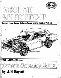
Руководство на английском языке по эксплуатации, техническому обслуживанию и ремонту Datsun 510 серии и Datsun PL521 Pick-Up 1968-1973 годов выпуска.
- Автор: J.H. Haynes
- Издательство: Haynes Publishing
- Год издания: 1974
- Страниц: 250
- Формат: PDF
- Размер: 11,0 Mb
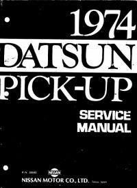
Подборка руководств на английском языке по техническому обслуживанию и ремонту Datsun Pick-Up 620 серии.
- Автор: —
- Издательство: Nissan Motor Co., Ltd
- Год издания: 1974/1977
- Страниц: 438/537
- Формат: PDF
- Размер: 69,6 Mb

Подборка руководств на английском языке по техническому обслуживанию и ремонту Datsun Pick-Up 720 серии.
- Автор: —
- Издательство: Nissan Motor Co., Ltd
- Год издания: 1981
- Страниц: 564
- Формат: PDF
- Размер: 45,1 Mb

Подборка руководств на английском языке по техническому обслуживанию и ремонту Datsun Pick-Up 520 серии.
- Автор: —
- Издательство: Nissan Motor Co., Ltd
- Год издания: —
- Страниц: —
- Формат: PDF
- Размер: 27,7 Mb
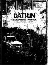
Руководство на английском языке по эксплуатации, техническому обслуживанию и ремонту Datsun 510 серии и Datsun Pick-Up 1968-1972 годов выпуска.
- Автор: —
- Издательство: Clymer Publications
- Год издания: —
- Страниц: 252
- Формат: PDF
- Размер: 8,5 Mb
|
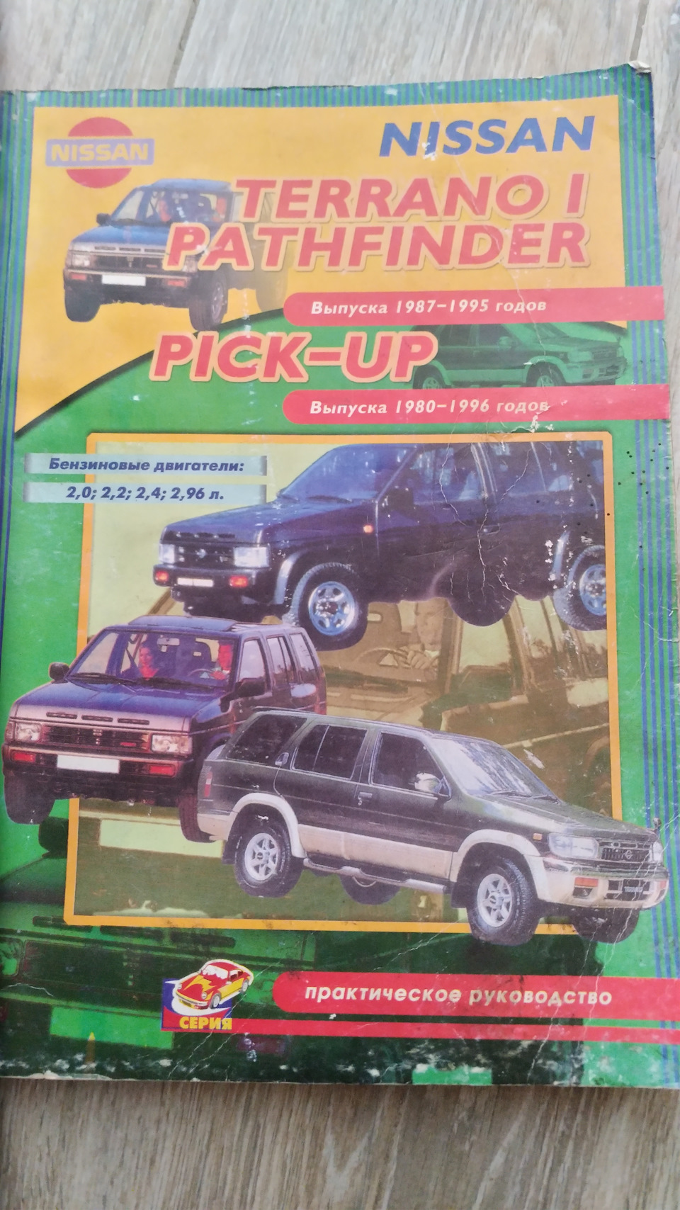
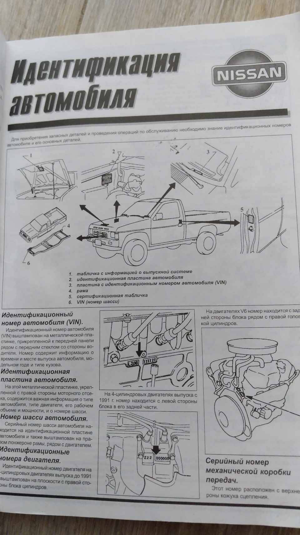
Инструкция NISSAN Pickup (1985-94гг) на русском языке в формате pdf для устройства: внедорожник. |
Описание к файлу:Тип устройства: внедорожник Фирма производитель: NISSAN Модель: NISSAN Pickup (1985-94гг) Инструкция на русском языке Формат файла: pdf, размер: 15.98 MB Обслуживание, устройство, ремонт
|
Для ознакомления с инструкцией необходимо нажать на ссылку «ЗАГРУЗИТЬ», чтобы скачать pdf файл. Если есть кнопка «ПРОСМОТР», то можно просто посмотреть документ онлайн.
Для удобства, Вы можете сохранить данную страницу с файлом руководства по эксплуатации в свой список «избранное» прямо на сайте (доступно для зарегистрированных пользователей).
Смотрите инструкцию для похожих моделей:

Вы можете задать вопрос посетителям сайта по модели NISSAN Pickup (1985-94гг). Если Вы являетесь её пользователем, то пожалуйста оставьте, по возможности развёрнутый отзыв:
В общем, задумался я о приобретении полезной книжки для ремонта. Но цены на новые смутили, полез на авито. Там тоже люди не стесняются в ценах за б/у. И тут попалось объявление, что дяденька отдает такое руководство бесплатно. Правда живет он в Нижегородской обл. Списались, оказался пожилой дальнобойщик. Он посетовал, что рейсов нет в мою сторону, поэтому, в итоге, он просто сходил на почту и отправил мне книжку. Расходы он оплатил сам — все на полном доверии.
Полный размер
Книга 97 года, но состояние неплохое.
Через несколько дней я ее получил. Отправил ему 300 за отправку и 300 сверху. Книга обошлась мне в 600р., но засада была в том, что книга для авто с бензиновыми движками)). На авитовском фото этого было не разобрать и я не уделил этому внимания.
Полный размер
Издательство ПОНЧик)
Но зато по ходовке и прочему мне подходит.
Полный размер
Перевод нормальный, иллюстрации четкие.
В общем, если кому че отсканировать (в пределах 2-3х страниц) обращайтесь…
Цена вопроса: 600 ₽
Техническая документация по ремонту автомобилей Nissan Datsun ( все годы выпуска) Бесплатно, без регистрации и СМС


Руководство по ремонту, эксплуатации и техническому обслуживанию Nissan Datsun
— полные технические характеристик
-особенности эксплуатации
— устранение неисправностей Nissan Datsun
— цветные электросхемы Nissan Datsun
СКАЧАТЬ / СКАЧАТЬ С ЗЕРКАЛА 
Руководство по эксплуатации Nissan Datsun
— полные технические характеристики Nissan Datsun
— особенности эксплуатации
— устранение неисправностей
— цветные электросхемы
СКАЧАТЬ / СКАЧАТЬ С ЗЕРКАЛА 
Руководство по ремонту Nissan Datsun в фотографиях
— полные технические характеристики
— особенности эксплуатации Nissan Datsun
— устранение неисправностей
в фотографиях своими руками
— более 1980 фотографий процесса ремонта
СКАЧАТЬ / СКАЧАТЬ С ЗЕРКАЛА 
Каталог деталей и сборочных единиц Nissan Datsun
— таблица взаимозаменяемости деталей автомобилей
— предназначен для работников СТО и владельцев автомобилей Nissan Datsun
— каталог деталей Nissan Datsun
СКАЧАТЬ / СКАЧАТЬ С ЗЕРКАЛА 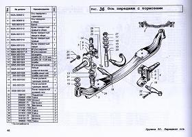
Подробная электросхема Nissan Datsun
— полное описание электрооборудования Nissan Datsun , подробная интерактивная электрическая схема Nissan Datsun
— подробно описан алгоритм поиска неисправностей электрооборудования (стартер, генератор, система зажигания, впрыск, инжектор)
— подробная схема электрооборудования ( электро схема ) Nissan Datsun
— распиновка разъемов электрических, распиновка электро проводки Nissan Datsun
СКАЧАТЬ / СКАЧАТЬ С ЗЕРКАЛА 
Руководство по ремонту двигателя Nissan Datsun
— полные технические характеристики двигателя Nissan Datsun
— особенности конструкции и ремонта двигателя Nissan Datsun
— подробное описание процессов разборки, дефектовки и сборки двигателя с фотографиями, ГРМ
СКАЧАТЬ / СКАЧАТЬ С ЗЕРКАЛА 
Руководство по ремонту коробок передач Nissan Datsun
— полные технические характеристики КПП
— особенности конструкции и ремонта КПП Nissan Datsun
— устранение неисправностей КПП трансмиссия, валы, шестерни, ШРУС
— подробное описание процессов разборки, дефектовки и сборки КПП с фотографиями
СКАЧАТЬ / СКАЧАТЬ С ЗЕРКАЛА 
а вот здесь можно заработать на новую машину, и тогда старую не придется ремонтировать!!!
Nissan Datsun
Мой сайт. Ниссан датсун пикап устройство и ремонт
Все для ремонта Nissan Datsun
скачать бесплатно
|
Руководство по ремонту Nissan Datsun Руководство ремонту, эксплуатации и техническому обслуживанию Nissan Datsun Ремонт в фотографиях Nissan Datsun |
|
||
|
Скачать bonar |
Скачать turbobit |
Скачать bitoman |
|

|
Электросхема Nissan Datsun Схема электрооборудования Nissan Datsun Подробная электросхема Nissan Datsun |
|
||
|
Скачать bonar |
Скачать turbobit |
Скачать bitoman |
|

|
Каталог деталей Nissan Datsun Каталог деталей и сборочных единиц Nissan Datsun Каталог деталей Nissan Datsun |
|
||
|
Скачать bonar |
Скачать turbobit |
Скачать полная версия bitoman |
|

Недостатки / достоинства Nissan Datsun / преимущества / плюсы / минусы / особенности / неисправности генератор, стартер, свечи, Nissan Datsun зажигание, электропроводка, КПП, дифференциал, трансмиссия, ступицы, ШРУС, капот, двери, Nissan Datsun кузов, приборная панель, контрольные приборы, шины, диски, колеса, сиденье, тормоза, колодки, диски, шланги, прокладки, пыльники, манжеты, литература, мануалы, книги, схемы, пособие, стойки, пружины амортизаторы, руль, наконечник, рейка, лонжерон, балка, подрамник Nissan Datsun
Техническая документация Nissan Datsun
avtoo.ucoz.ru
Nissan-datsun пикап 1988 год ремонт. Советы, отзывы, фото

Содержание статьи:
Владивосток. 1988 год, 2400 куб. см., Дизель, Коробка, Полный привод. В салоне тепло. До этого владел пикапами Датсун 94 г.в с и Хайлюксом 98 г.в. с дизелем 2,8. В них зимой Отзывы владельцев Nissan Datsun о своих машинах.
Руководства по эксплуатации, обслуживанию и ремонту Datsun Pick — Up. Автор: Издательство: Nissan Motor Co., Ltd Год издания: Страниц: Формат: PDF Размер: 69,6 Mb.
![]() ФАКТ! Nissan – третий в японском рейтинге автопроизводителей (после Toyota и Honda) и 8-й в мировом рейтинге. Самым популярным автомобилем считается Nissan Qashqai. Название «Кашкай» взято от названия племени, живущего в Иране.
ФАКТ! Nissan – третий в японском рейтинге автопроизводителей (после Toyota и Honda) и 8-й в мировом рейтинге. Самым популярным автомобилем считается Nissan Qashqai. Название «Кашкай» взято от названия племени, живущего в Иране.
Паспортные данные.


Мучаю их постоянно, ни одного толком не замучил. Агрегаты не доставляют хлопот. В каталоге нет его квалификации. Содержание Габаритные размеры Технические характеристики Коробка передач и тормозная система Последняя модель двадцатого века Фото.


Nissan Datsun в кузове Пикап, I выпускаемый с 1988 по Список модификаций Nissan Datsun в кузове Пикап, I VERcity.
Japanese Used Cars Portal. Search by Car Make. Search for Make, Model, Chassis, Year, Fuel, Transmission etc. JUMVEA Japan Used Motor Vehicle Exporters Association is approved by the Ministry of International Trade and Industry MITI , presently the Ministry of Economy, Trade and Industry METI in Japan. JUMVEA certified member compnay is a legally registered company in Japan and have a license to buy, sell the second-hand vehicles and an exporter of the used motor vehicles.
For More information, please Click Here. What is JUMVEA SAFE TRADE Membership? Bank information will be provided by supplier in proforma invoice. Disclaimers All Right Reserved. Search by Car Type.

Search by Car Fuel. Search by Car Model. Search by Car Sub Type. Search by Car Steering. Search by Car Price. Search by Car Mileage. Search by Car MFG Year. Price Low to High. Price High to Low. Year New to Old. Year Old to New. Make A to Z. Make Z to A. Model A to Z. Model Z to A. Select All Clear All. Save as my search. PHOTO YEAR MAKE MODEL JCT REF. ID KM Steering DEALER FOB PRICE.

1996 Datsun/Nissan pickup 2.7L turbodiesel
rfautoinfo.ru
MAХИНА — Nissan DATSUN
Электронные книги Nissan DATSUN для автомобилистов бесплатно

Руководство по ремонту, эксплуатации и техническому обслуживанию Nissan DATSUN СКАЧАТЬ 194 Мб(Руководство по ремонту Nissan DATSUN полная версия)
Руководство по ремонту Nissan DATSUN в фотографиях СКАЧАТЬ 116 Mб(Ремонт Nissan DATSUN в фотографиях)
Секреты ремонта Nissan DATSUN СКАЧАТЬ 51 Мб(подробное описание особенностей ремонта Nissan DATSUN )
Подробная схема электрооборудования Nissan DATSUN СКАЧАТЬ 72 Мб ( электросхема Nissan DATSUN )
Каталог деталей Nissan DATSUN СКАЧАТЬ 101 Мб( Nissan DATSUN Каталог деталей и сборочных единиц )
Руководство по ремонту двигателя Nissan DATSUN СКАЧАТЬ 73 Мб(ремонт двигателя Nissan DATSUN своими руками в фотографиях)
Руководство по ремонту трансмиссии Nissan DATSUN СКАЧАТЬ 104 Мб(ремонт КПП и дифференциала Nissan DATSUN своими руками в фотографиях)
Коды неисправностей Nissan DATSUN СКАЧАТЬ 15 Мб( Nissan DATSUN коды ошибок инжектора, распиновка, самодиагностика )
Мультимедийное Руководство по тюнингу Nissan DATSUN СКАЧАТЬ 115 Мб(тюнинг Nissan DATSUN своими руками с фотографиями)
ТЕГИ: Руководства по ремонту Nissan DATSUNбесплатно, без регистрации и СМС Nissan DATSUN Бесплатно, без регистрации и СМС Nissan DATSUN
Nissan DATSUN
maxina.ucoz.net
loveavto — Nissan Datsun
Техническая документация по ремонту автомобилей Nissan Datsun ( все годы выпуска) Бесплатно, без регистрации и СМС


Руководство по ремонту, эксплуатации и техническому обслуживанию Nissan Datsun
— полные технические характеристик
-особенности эксплуатации
— устранение неисправностей Nissan Datsun
— цветные электросхемы Nissan DatsunСКАЧАТЬ / СКАЧАТЬ С ЗЕРКАЛА 
Руководство по эксплуатации Nissan Datsun- полные технические характеристики Nissan Datsun- особенности эксплуатации
— устранение неисправностей
— цветные электросхемыСКАЧАТЬ / СКАЧАТЬ С ЗЕРКАЛА 
Руководство по ремонту Nissan Datsun в фотографиях- полные технические характеристики
— особенности эксплуатации Nissan Datsun- устранение неисправностей в фотографиях своими руками- более 1980 фотографий процесса ремонтаСКАЧАТЬ / СКАЧАТЬ С ЗЕРКАЛА 
Каталог деталей и сборочных единиц Nissan Datsun- таблица взаимозаменяемости деталей автомобилей
— предназначен для работников СТО и владельцев автомобилей Nissan Datsun- каталог деталей Nissan DatsunСКАЧАТЬ / СКАЧАТЬ С ЗЕРКАЛА 
Подробная электросхема Nissan Datsun- полное описание электрооборудования Nissan Datsun , подробная интерактивная электрическая схема Nissan Datsun- подробно описан алгоритм поиска неисправностей электрооборудования (стартер, генератор, система зажигания, впрыск, инжектор)- подробная схема электрооборудования ( электро схема ) Nissan Datsun- распиновка разъемов электрических, распиновка электро проводки Nissan DatsunСКАЧАТЬ / СКАЧАТЬ С ЗЕРКАЛА 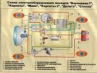
Руководство по ремонту двигателя Nissan Datsun- полные технические характеристики двигателя Nissan Datsun- особенности конструкции и ремонта двигателя Nissan Datsun- подробное описание процессов разборки, дефектовки и сборки двигателя с фотографиями, ГРМСКАЧАТЬ / СКАЧАТЬ С ЗЕРКАЛА 
Руководство по ремонту коробок передач Nissan Datsun- полные технические характеристики КПП- особенности конструкции и ремонта КПП Nissan Datsun- устранение неисправностей КПП трансмиссия, валы, шестерни, ШРУС- подробное описание процессов разборки, дефектовки и сборки КПП с фотографиямиСКАЧАТЬ / СКАЧАТЬ С ЗЕРКАЛА 
а вот здесь можно заработать на новую машину, и тогда старую не придется ремонтировать!!!
Nissan Datsun
loveavto.ucoz.net
Смотрите также
Закрыть
Запись на тест-драйв
-
Aet tO
DATSUN TRUCK
MODEL 320
SfRVICE MANUAL
NISSAN
yNI55AN MOTOR CO LTD
OTEMACHI BLDG OTEMACHI CHIYODA KU
TOKYO JAPAN
CAlLI ADDRISS I NISMO TOKTO
HONU I 211 5281
c
fi 11t
lJ
l
E
t
Book Sale
-
MODEL 1IO U
NEW MODEL 1IO U
I
i
-
INTRODUCTION
ThIS manual has been comphes for purpose
of asslstmg DATSUN dIstnbutors and dealers
for effectIve serVIce and mamtenance of the
Model P L 320 U Each assembly of the major
components IS descnbed 10 detaIl In addItIOn
comprehenSIve mstructlOns are gIven for com
pIete dlsmanthng assembImg and mspectlOn of
these assembltes
It IS emphasIsed that only genuine DATSUN
Spare Parts should be used as replacements
l
cfi4
-
CONTENTS
SPEClFICA TION
ENGINE
1 6
1
1
3
1015
203435
38
3943444954
General SpecIftcatlOnsCOOLING SYSTEM
Lubncatlon
ServIce OperatIOns wIth EngIne In PosItionRocker Mechamsm
Removmg RefittIngOperatIOn WIth the Engme Removed
FUEL SYSTEM
The GasolIne TankFuel StrainerFuel PumpAdjustment and Inspection
of EngIneCarburetorBRAKER POINT AND IGNITION TIMING ADJUSTMENT
DlstnbutorAdjustIng the Igmtlon TImIngCheckIng the Spark
PlugsCLUTCH
Clutch
Descnptlon of Clutch Control
TRANSMISSION
TransmIssIOn
DIsassemblIng the CaseAssembhng the TransmISSIOnSelector Inner
Operatmg Lever Cross ShaftPROPELLER SHAFT UNIVERSAL JOINT
Propeller Shaft Umversal jomts
STEERING
FRONT AXLE
Front Axle
Settmg of TenSIon Rex
Page
59
596165
qit0 t
1
66
67
68
76
77818791
93
U1IJJ
l
rt
i1
94
97
106t
106 l114
-
uc
Page
REAR AXLE 117
Rear Axle 118AssemblIng Adjustment 122
BRAKE 138
IGNIfI0N SYSFEM 147
ELECTRICAL SYSTEM 150
Starter Motor 164
Battery 171
t
v
-
SPECIFICA TIONS
For Model 320 U
VEHICLE DIMENSIONS
Length overall approxWIdth overall approx
HeIght overall approxWheelbaseTread Front
Rear
Mm road clearance
CARGO SPACE DIMENSIONS
Intenor lengthlntenor wIdthlntenor height
WEIGHTS
Dry vehIcle weIght emptySeating capacItyMax cargo weIght
Model 320 UModel 320 UN
Model 320 UP
PERFORMANCE
Max speedGrade ablhty Sm 6Mm turnmg radIUs
ENGINE
NameKmd
Cyhnder No and arrdngementCyclevalve arrangementBore x
StrokeTotal piston dIsplacementCompressIOn ratioMax powerMax
torqueFInng order
4 185 mm 164 8 m1 515 mm 59 6 m1 50S mm 59 3 m2 470 mm 97 2 InI
170 mm 46 1 In1 187 mm 46 7 m177 mm 7 0 In
I 850 mm 72 8 m1 427 mm 56 2 In
406 mm 16 0 In r
945 kg 2 080 lbs 12
225 kg 500 lbs500 kg 1 000 lbs910 kg 2 000 lbs
J
120 KPH 75 MPH
t385 2 m 17 ft
Model E 1
Gasohne engme4 cvls m lme
4 cycleValve m head
73x7l mm 2 875 m x 2 796 m1 189 cc 72 5 cu m
8 2
60 HP at 5 000 r P m SAE
9 3 kg m 673ft lb at 3 600 r p m1 3 4 2
ir f
-
rValve tlmmgInlet opemngInlet closmgExhaust opemngExhaust
closmgValve clearance Both m1et and exhaust Hot
IGNITION SYSTEM
19mtlon tlmmgSpark plugsSpark plug gap
FUEL SYSTEM
CarburetorThrottle valve dlaVentlro dlaMam Jet dla
t Slow Jet dla
PQwer Jet dlaSlo economlzerSlow aIr FIrstSlow atr Second
Float levelFuel tanJlcapaclty
Llj RICA TION SYSTEM
OIl pan capacity
COOLING SYSTEMt
r
Coolmg water capacIty
BATTERY
TypeVoltage
Capacity
Termmal grounded
JGENERATOR
CapacityVoltage current regulator
2
14 deg B T C50 deg A B C52 deg B B C
12 deg A T C0 35 mm 0 014 m
10 deg B T C 600 rpmNGK Model B 6E 14 mm
0 7 0 8 mm
Pnmary28 mm
21 8 mm
9848
4Q145
100220
Secondary30mm25 14 7 mm
11540
19mm35 htres 9 3 U S gal
3 1 htres 0 86 U S gal
5 4 htres 1 4 U S gal
CF3 12K 14M2 M39 1212 volts2 SMS
40 amp hr 20 hr50 amp hr 20 hr
posltlve sIde
0 2 KWCarbon ptie type
-
STARTER MOTOR
Voltage and power 12 volts 14 hp
CLUTCH
TypeOperating systemMaster cyhnder mSlde dlaOperatmg cy1mder
mSlde dzaDry smgle plate typeHydrauhc
15 85 mm 5 8 m19 05mm 3 410
TRANSMISSION
Type Four forward speeds and one reverseSynchromesh on 2nd 3rd
and top gearsFor 320U320 UN For 320UP
3 94 4 942 40 3 01149 1731 00 1 005 16 6 46
2 0 lures 0 53 U S gal
Gear ratIOs
1st speed2nd speed3rcl speed4th speedReverse
all capacIty
REAR AXLE
TypeGear ratIo
all capacIty
Semi floatIng4 875 39T 8T for 320 U 320 UN 5 143 36T 7T for 320
UPfor other 320 senes as potIonalO 85 htres 0 22 U S gal
STEERING SYSTEM
Gear mechamsm
Gear ratIO
Warm and roller
17 3 I
FRONT AXLE
Toe mCamberCaster
Kmg pm mchnatIon
2 3 mm1 deg 30 mm4 deg 15 min6 deg
c
BRAKE SYSTEM
Type Foot brake FrontRear
Hydrauhc umservo typeHydrauhc duoservo type
Mechanical rear wheels brakedHand brake
3
-
Brake drum dla front and rearMaster cylmder boreWheel cyhnder
boreFront wheelsRear wheels
254 rom 10 1019 05 mm 0 77 10
19 05 mm 0 77 lD19 05 mm 0 77 lD
SUSPENSWN SYSTEM
Front suspensIOnFront spnngsDimensIOn Ola x LengthRear
spnngs111lckness numberWishbone type Independent suspensionTorsIOn bar spnng
20 5 x 604 5 mmParallel semlelltptic leaf spnng
7 mm x 2f 320 U
6 mm x 1or
6mm 412 mm 1
6mm
215 mm 212 mm 1for 320 UN
for 320 UP With
helper rubber
Shock absorbers FrontRear
smgle actionsmgle action
TIRES
Model Front Rear
320 U 5 60 14 6PL T 24 lb 5 60 14 6PL T 30 lb
320 UN 5 50 14 6PL T 22 lb 5 50 i4 6PL T 36 lb320 UP 6 00 14 6PL
T 22 lb 6 00 14 8PL T 60 lbI
4
-
FOT
RUNCH SEDAN U320 Double Seat 2 DOOR ST WAGON V320N320 Single
SeatVEHICLE DIMENSIONS
U320 V320 N320
Length overall 4 285 mm 4 155 mm 4 155 mmapprox 168 7 m 163 6 m
163 6 mWIdth overall 1 497 mm 1 497 mm 1 497 mm
approx 58 9 10 58 9 m 58 9 m
HeIght overall 1 520 mm 1 515 mm 1 530 mmapprox 59 8 m 59 6 m 60
3 mWheel base 2 470 mm 2 470 mm 2 470 mm97 2 10 97 2 m 97 2 m
CARGO SPACE DIMENSIONS
Intenor length 880 mm 2 1 555 mm 1 560 mm34 6 m 61 2 m 61 6 m
FIntenor wIdth 1 245 mm 5940 mm 1 254 mm49 m 1 180 10 49 4 m
tIntenor heIght 420 mm 905mm 430 mm
16 5 m 35 6 m 16 9 m
WEIGHTS
VehIcle weIght 1 000 kg 1 020 kg 955 kg2 200 lbs 2 255 lbs 2 100
lbsSeatmg and loadmgcapacIty 5 400 kg 2 SOO kg 2 500 kg
880 lbs 1 100 Ibs 1 100 1bs5 300 kg
660 lbs
TRANSMISSION
Gear tram HIgh gear 4 forward1 reverse
Gear ratIO Low 3 94 2nd 2 40 3rd 1 49 Low 3 94 2nd 2 40
hIgh 100 reverse 5 16 3rd 1 49 4th 1 000Reverse 5 16
5
-
FINAL GEAR
Gear ratIO 5 143 36T 7T 4 875 39T 8T
SUSPENSION
Front Wishbone type IndependentsuspensIOn wIth torsIOn bar
Rear thickness andnumber of spnngleaves 6 mm 4
12 mm I6 mm I12 mm 1
Supplemental Sp 108 mm 80 mm
Shock absorbers Front Single actingRear Single acting
Optional
Single actionSingle action
TIRE SIZE AND PRESSURE
Front
Rear5 50 l4 6PL T 22 lb5 50 14 6PL T 46 lb
5 50 14 6PL5 50 14 6PL
1 PERFORMANCE
iT Max speedGrade abilityMin turning
radIus
110 KPH 70 MPH0 30
120 KPH 74 6 MPH0 30
5 2 m 17 ft 5 2 m 17 ft
NOTE Other speclftcatlOns are same as Model 320 U
6
-
ENGINE
I
c
1
l
I
I
-
ENGINE
The engme IS of monobloc construction and IS fitted with
overheadvalvesoperated by rockers and push rods from the camshaft 011 seals
are fItted to thevalves Three steel backed beanngs support the
camshaft whIch IS cham dnvenThe OIl pump and dlstnbutor are dnven from the camshatt each
componenthavmg Its own dnve shaftThe pIstons are each htted with two
compressIOn rmgs and a slotted011
control nng Beanngs of the thm shell preformed type are fitted
to the connect109 rod bIg ends and to the malO beanngs A counter
blanced crankshaft IS fittedThe end thrust on this component IS
taken by specIal washers at the center malObeanng The centnfugal water pump and coolmg fan are dnven by the
dynamobeltGENERAL SPECIFICATIONS
No of Cyhnder 4
Bore 73 025 mm 2 875 m
Stroke 71 mm 2 796 m
Volume 1 189 cc
Max brake horse power 60 HP at 5000 r p m
Torque 9 3 kg m at 3600 r p m
Flnngorder 1 3 4 2
Valve arrangement Overhead valve push rod type
CompressIOn pressure 163 lbs per sq m 11 5 kg cmat 350 r p m
CompressIOn ratio 8 2 1
1
-
1Engine Rightside
Engine Leftside
2
-
COOLING SYSTEM
An effIcIent coohng system IS of major Importance to ensure the
satisfactoryrunmng of the engIne and It IS therefore necessary to
pay patlcular attention toIts maIntanceDescriptionThe coohng system IS maIntaIned by water pump
CIrculation combIned wIthan effIcient fan cooled radIator and thermostat
The system IS pressunsed and the rehef valve Incorporated 10 the
radIatorfIller cap controls the pressure at approxImately O 4 kg
per sq cm Do notremove the ftller cap If the temperature of the
coolant IS above IXJhng poInt orIf the engIne IS runmng ToppIng up should only be requIred
occasIOnally to replace water lost through the overflow pIpe Top up
when the engIne IS cold andIf pOSSIble use clean soft waterlij
l
Fig 1 Rmliator
FIll to wIthIn 1 2 of the bottom of the fIller plug well
OverfIlhng when theengIne IS cold may cause water to flow through the overflow pIpe
The capacItyof the system IS approxImately 5 2 htres3
-
In order to ensure maxImum effIcIency It IS essential to keep
the engineoperating temperatures within certain hmlts To assist
this a bellows typethermostat IS fttted being located In the water
outlet at the front of the cyhnderhead The deVIce consIsts of
metalhc bellows fIlled WIth a volatile hqUledwhIch controls a
mushroom valve When the engine IS cold thIS valve IS closedand on
starting the engine the flow of water to the radiator IS temporanly
restnctedDue to thiS the temperature of the water In the cyhnder head and
cyhnderJackets wIll qUIckly nse thus ensunng rapid warnllng up The
heat so generatedwill gradually expand the bellows so opening the
valve and ultlmatelly permittinga full flow of water to the
radIatorThe thermostat Itself IS detachabletherefore should the occasIOn
anse Itcan be removed from ItS housmg and thehose reconnected to
aVOId laYing up thecar Should the thermostat be tightthere are two
tapped holes on the topwhIch may be utlhzed to ease It fromcasting When the system has been com
pletely emptied It IS essential to allowaIr to escape through
the thermostatvalve and then fmally top up The thermostat opening
IS set by the manufacturerand cannot be altered It open at a
temperature of 71 5 74 5 C Dunng decarbomslng It IS pohcy to test
thiS openlng by Immersing the thermostat In waterraIsed to the
reqUIsite temperature Thet lQ valve should open under these conditIOnsAr but If It fads
to open a new umt should befitted Fig 2Therm ostat
Overheating
r lt ffr i itl
J
J II
t
4Y 2Jr
0
J tc
J
nlustTahng the Removelof the Thermostat fromits Housing
Overheating may be caused by a slack fan belt excessIve carbon
depoSItIn the cyhnders runmng WIth the Igmtlon too far retarded
Incorrect carburetoradjustment falhre of the water to CIrculate or
loss of waterFan Belt Adjustment
The fan IS dnven from the crankshaft by a V belt thIS also
dnvlng thedynamoA New belt can be fitted by ftrst loosemng the clamp bolts FIg 3
whIchhold the dynamo m posltJon llld moving the dynamo towards the
engine Shdethe belt over the fan and onto the fan pulley4
-
Adjustment IS then made by bnngmg thedynamo away from the engme
The belt shouldbe sufftclently tight to prevent shp yet thebelt
should have 15 to 20 rnm 5 8 3 4 slackbetween the generator and crankshaft pulleywhen the mIdspan IS
pushed ftrmlyAs the dnve IS taken on the V of the
pulleys It IS not necessary to have the fan belttight to do so
may cause excessIve wear tothe dynamo and water pump beanngs
Afterthe correct tensIOn has been obtamed securelylock the dynamo m
pOSItiOn agamFIg 3 Fan Belt AdjustmentI Generator hmge bolt2 AdJustmg lmk
boltFrost Precautions 0
Freezmg may occur ftrst at the bottom of the radIator or m the
lower hoseconnectionsIce m the hose wIll stop water cIrculation and may
cause bOllmg A muffcan be used to advantage but care must be taken not to run wIth
the muff fullyclosed or bOlhng wIll result When frost IS expected
or when the car IS to beused m a very low temperature make sure
that the strength of the solution ISm fact up to the strength
adVIsed by the manufacturers The strength of thesolution must be
mamtamed by toppmg up WIth anti freeze solution as
necessaryExcessIve toppmg up with water reduces the degree of
protection affordedSolution must be made up m accordance WIth
mstructlons supphed WIth thecontamerRelations of freezmg temperatures of alchol water and
glycenne mIxturesratIO
co
5
10
15
lDIS
31
35
III
45
1
co
5
10
i5
ID
15
JOJ5
41
45
1
1
10 lOYJ 4Q 50 601lI a1 10 20 30 40 50 60 70 80
Glycenne Water mIxture roAlcohol Water ro
5
-
Top up when the system IS coldIf the coolmg system has to be
dramed run the mIxture mto a clear contamerand use agam
Protection by Draining
On cars where antI freeze IS not used the followmg precautions
must betaken dunng frosty weather to obvIate any damage due to
freezmg of the coohngsystemWhen heavy frost IS Immment the coohng system must be completely
dramedIt IS not suffIcient merely to cover the radiator and engme
wIth rugs and musksThere are two dram cocks one on the left hand
SIde of the cyhnder block and theother at the base of the radiator
block Both taps must be opened to dram the system and the car must
be on level ground while drammgThe dram taps should be tested at frequent mtervals by lOsertlng
a pIece ofwIre to ensure that they are cleare Tlus should be done
immedIately the tapsare opened so that any obstruction freed by the
wIre may be flushed out by thewater The drammg should be carned out
when the engme IS hotWhen completely dramed the engme should be run for a tImed mmute
to ensurethat all water has been cleaned from the systemA SUItable notice should be then affIxed to the radIator
mdIcatlng that thewater has been dramedI Flushing the Radiator
To ensure effICIent CIrculatIon of the coolant and to reduce the
fonnatIon ofscale and sedIment m the radIator the system should be
pencxhcally flushed Withclear runnmg water preferably before puttmg
m antI freeze m the wlOter andagam when takmg It out m the spnng
The water should be allowed to run throughuntIl It comes out clear
from the dralO taps At mtervals a stIff pIece ofWireshould be
mserted mto the taps durmg drammg to ensure that they are not
becommgclogged with sedImentTlus rnethod of radiator flushmg may serve well but m cases
where the furrlOg up is excessIve the operator Will find it more effiCIent
practIce to removethe radIator completely and flush m the reverse
way to the flow turn the radIatorupSIde down and let the water flow
m through the bottom hose connectIon and out ofthe top
connectIonWATER PUMP
After drammg the water from the radIator remove the pump unIt
from thecylInder block by takmg off the fan belt and releasmg the
setbolts WIth spnnpwashers and hmge bolts to dynamo4
6
-
WATER PUMP
Removing the Pump Shaft Assembly
DIsconnect the fan blades pulley and coverThe shaft and ball
beanngs IS combmed with one umtPut the pulley hub on the benchFIrst
press or knock the shaftend WIth a dnft hard bar and drawout the pulley hub on the U
typebenchTake out the set pm from thesht whIch locked the shaft
assemblyto the pump body See Fig 1Next turn the body upsIde downand press out the shaft
assemblyfrom the vane SIde on the U typebenchji
7
-
The shaft and ball beanng assembly can be drewout from the
bodyThus take out the vane floatmg seal and seal whIch remamed the
pump bodyReassem bly
The reassembhng of the pump IS a reversal of the disassembly
procedurebut a care should be taken to ensure that the shaft
assembly IS fItted correctlyfor a slIt a hole of set nng wIth a
groove of shaft so as to msert and set the saIdnng correctly
Pulley
Pulley hub
Set bol t
Shaft WJ thbearIngs
21035 OOO
Set rlDg plD
SPrIng washer
Body
Washer
Cover
Fig 1 Sectional View of the Water Pump
8
-
Adjusting the Clearance the Vane End and BodyFIrst press down
the shaft fIttmg wIth a groove lme to msert the set pmInsertmg
thIckness gauge fhlckness O 4 0 5 mm between the vane end onthe U block bench Take out the thickness gauge and fmd out good
condmonScrew up wIth the cover and cork washersere
Shaft bear1llgsassembly
Set p1ll 0Yf VaneFloatl llg seal
Insert herethlckness
gauge0 40 5 mm
9
-
LUBRICATION
Circulation
Pressure lubncatlon IS used throughout the umt and IS provIded
by gear 011pump The 011 pump IS bolted mto the left hand sIde of
the crankcase and IS dnven from the camshaft gear by a short
vertical shaftOllIS drawn mto the pump vIa the filter and IS dehvered through
mternal 011way The rehef valve dIrectly IS situated m the 011
filter bodyFrom the rehef valve the 011 passes Into the mam 011 way If
caused the elementfml to pass rhe 011 The flow then passes vIa
connectmg 011 ways to the mam bIgend and cam shaft beanngs through
dnllmgs m the crankshaft The connectmg rodends are dnlhng m the
cyhnder block and the rear rocker shaft bracket to lubncate the
rockers and then drams back Into the engme sump vIa the push rod
apertures all from the center camshaft beanng enters a gallery on
the left handsIde of the engme and lubncates the tappets through
mdlvldual dnlhngs As thecamshaft rotates two grooves m the front
Journal regIster WIth a small hole mthe camshaft thrust plate thus
allowmga small amount of 011 to pass mto thetlmmg case tWIce dunng case revolution of the camshaft to
provIdelubncatlOn for the tlmmg cham andgears From the tlmmg case
the011 returns VIa a dram hole back tothe engme sump The ftlter therefore forms part of the mam oJ
gallery and as such IS fIlled withoJ under pressure
The full of 011 enters the element through holes m the casmgand
passes through the element mtothe annular space round the
centerboltThIs space IS sealed top and
bottom so that the 011 can only escape through the hole mto the
hollow center bolt and from thIS pomtback Into the mlet passage
throughthe elementFlg 1 Checkmg the Oil FlUt
10
-
Draining the Sump Oil Pan
The sump IS a metal pressmg with the dram plugOne new and
reconditiOned engmes the sump must be dramed and refilled withnew 011 after the first 1000 km and subsequently atmtervals of
5000 kmDram the 011 when the engme IS hot smce warm Oil flows freely
and takeswith It any sludge or sediment whIch may have
accumulattedNever use petrol or paraffm for flushmg purposes Such cleamng
medlUmsare never completely dIspersed from the engme lubncatiOn
system and wIll remam to contammate any fresh Oll ThIs may cause
premature beanng faIlureOil Pressure
The normal operatmg OIl pressure IS 60 lb per sq m
The warmng lIght whIch IS emboclted 10 the mstrument panel hght
If the Oilpressure drops below 8 lbs sq m under these cIrcumstances
do not attemptto run the engme or serIOus damage may resultRefillig
When refllltng the sump do not pour the OIl m too qUIckly as It
may overflowfrom the fIller orifIce and mIslead the operator as to
the quantity of lubricant 10the engmeBefore testing the level of the Oil ensure that the
vehIcle IS as near levelas pOSSIble Always WIpe the dIp stick clean wIth a non fluffy
cloth before talangthe readmg It should be remembered that time
must be allowed for new 011 toreach to sump before readmg the
dIpstickCheck for Low Oil Pressure
Check the level of OIl m the engme sump by means of the dip
stIck and topup If nece sal v If the warnmg Itgiit IS still on
after reftllmg the sump switchoff and ascertam that the gauge
stramer m the ump IS clean and not chokedwith sludge ale that no aIr leakage eXIsts at the strainer uniOn
on the suctionSide of the Oil pump bemg defectIve remove the umt
and rectify the fault11
-
Removing the Filter
A new hlter element should be fitted every 6 000 km
The fIlter forms part of the mam 011 gallery of the engme To
remove thehlter It IS only necessary to unscrew the center bolt
when the bowl can be removedfrom the cylinder block complete wIth
the element For full flow type E1 engmeIt IS neceE sary to cover
wIth some of rugs to prevent from flow 011 on the generatorwhen
remove the body Take care not to lose the rubber seahng nng Remove
theelement and note the assembly of the componentsWash out the bowl WIth pettol so that It IS clean It IS
Important to thoroughlydry the bowl to obVIate any contammatIon of
the lubncatmg 011rr
J
Flg 3 Components of Oil Rlter
Replacing the Filter4
Put the element WIth seat of It on the bracket Cover with the
filter body afterputtmg the element retamer spnng andthe gasket 10 posltlon
Insert the centershaft mto posltlon and screw up Itwith ughtmg torque 2 2 5 kg m
and secure mtoposttJon by means of the center bolt
12
-
Removing the Oil Pan0
The sump capacIty IS 3 1 htres Dram the 011 and replace the dram
plugRemove the set screw bolts whIch are mserted from the undersIde
of the secunng flange and the lower bolts from the bottom edge of the
bell housmg Lowerthe OIl pan from the engme takmg care not to
damage the Jomt washers m theprocessmoviDg the StrainerJ
i
l t
WIth the sump lowered It IS possIble to remove the OIl stramer
through whIch011 IS drawn mto the 011 pump To remove the stramer
unto the umon connectingthe 011 pIck up to the pump and unscrew the
secunng boltsThe stramer may be dIsmantled for cleamng purpose by removing
the dehvery pipe flange boltsNotice that there are the dowel pinS to the cover whICh must be
posItIOnedcorrectly when reftttmgRemoving the Oil Pump
Remove the 011 pan and pIck up strainer Three of the ftve bolts
secunng theOIl pump bottom cover are long enough to secure the pump
to the crankcaseFIg 4 Illustrates the pump In explosed form Unscrew
the long bolts and removethe pump with ItS dnve shaftDismantling the Oil PumpRemove the setscrews and spnng washers
whIch secure the cover to the b6dyand take off the cover On tlltmg the body upSide down the Inner
rotor with ItSdnve shaft and the outer rotor wIth shde outRefitting the Sump
Clean out the sump by washing It In paraffin the care to remove
any tracesof the paraffm before reflttmg the OIl pan to the engme
Pay patlcular attentIOnto the 011 pan and crank case JOint faces
and remove any traces of old Jomtlngmatenal Examme the JOint washer
and renew It If necessary The old JOintwasher can be used again If
It IS sound but It IS adVIsable to ftt a new oneSmear the faces of the JOint WIth grease and ftt the JOint
washer Lift the OIl panInto positIOn and Insert the setscrews Into
the flange tlghtlng them up evenlyReassembling the Oil Pump
The outer rotor FIg 4 has a chamfered edge It IS of great
Importance thattills chamfer be towards the base of the body ftlure to assemble
In thIS way Willresult In the cover IS tightened down Insert the
slotted end of the dnve shaft Intothe body and brmg the rotors Into
mesh13
-
Oil strainer ass y
Oil pump dnve spmdle 01l pump plalnwasher
Lock washer
Oil pump bolt
Oil pump gearshaft
ass y
I
eJV Dowel pinl Oil pump
Dcover
f
f i
Fig 4 Oil Pump
14
a
-
SERVICE OPERATIONSENGINE IN
WITHPOSITION
Removing Starting Nut and PulleyRemove the radIator Slacken the
dynamo attachment bolts and remove thefan beltBend back the tab on the startmg dog nut lockmg washer
Unscrew the startmg dog nut by usmg Heavy duty Shock type spannerA few sharp
blows m an ant1 clockwlse d1reCtIOn WIll slacken the nutPull off
the crankshaft pulleyRemoving the Timing Cover
The tImmg cover IS secured by set screw bolts each havmg
ashakeproofwasher and a special plam washer Note that the specIal
washer IS of elongatedshape and IS f1tted next to the tImmg cover
flangeThe spnng washers are Imme
dIately below the bolt headsTake out the set screw bolts
remove the cover and Its Jomt twasher Care should be taken notto
damage the washer when breakmgthe Jomt If damage does occur fita
new washer cleanmg of the facesof the JOint surfaces beforehandFag 1 Heavy Duty Shock TypeSpanner
Removing the Timing GearJI
The tImmg cham IS endless and It 1S necessary to remove both the
crankshaft and camshaft gears together Before domg thIS notIce the
tImmg markson both gears and theIr relatIonshIp to each otherDraw off both the gears a httle at a t1me hrst removmg the
crankshaft gearretaining nutAs the gears are w1thdrawn care must be taken not to lose the
packmgwashers from behind the crankshaft gear Between the camshaft
gear teeth IS arubber nng Wh1Ch acts as a tenslOner and ensures
SIlent operatIon of the chamdnve Examme the felt washer and renew
It If 011 has been lost be seepageRefitting the Timing Gear
ReplaCing the components of the tlmmg gear 1S largely a reversal
of the dISmantlmg process but spec1al attentlon should be pa1d to
the follOWing pomts15
-
FIt the crankshaft and camshaft gears mto theIr respective
shafts Ensurethe tlmmg marks are opposIte and mimeTurn the engme crankshaft until the keyway IS at T D C and the
camshaftWIth Its keyway m approximately the one 0 clock
posJtJonPlace the gears mto pOSitIOn ensunng that the keys are present m
keywayson the shafts Ensure that the tJmmg marks on the gears are
opposite to eachother and mime Dnve the gears homeThe same number of packmg washers taken from behmd the
crankshaft gearmust be replaced unless a new crank or camshaft has
been fitted In thIs case thealIgnment of the gear faces and
measuremg the alIgnment wIth a feeler gauge Toadjust the alIgnment
It Will be necessary to vary the number of packmg washersFIt the 011 thrower behmd the crankshaft gear so that Its
concave face It towards the front of the car and check that the
felt washer IS In posJtJonValve Rocker Cover Removal
Remove the aIr cleaner Unscrew the cap nuts secunng the engme
IIftmgbrackets Remove the rocker cover and the cork Jomt washerRemoving the Rocker Assembly
Dram the coolmg system If anti freeze IS m use use a clean
contamerfor the flUId If It IS to be used agamIt IS necessary to dram the system and slacken the cylmder head
nutsbecause four of the rocker shaft ftxmg nuts also secure the
cylmder headIf the cylmder head nuts are not slackened dlstonatlOn may
result and allowwater to find ItS way from the coolmg system mto
the cylmders and pumpNotice that under the nght hand rear rocker stud nut IS a
speCIal lockmgplate Completely unscrew the rocker shaft blacket
nuts and remove the rockerassembly Complete with brackets and
rockersDismantling the AssemblyTo dIsmantle the rocker shaft assembly
ftrst remove the grub screw andlockmg plate from the rear rocker bracketRemove the split pms
flat washers and spnng washers from each end of theshaft SlIde the rockers brackets and spnngs from the shaft
Unscrew the plugfrom the end of the shaft and clean out the OIl
wayThe two end rockers may be dIsmantled without the whole rocker
assemblybemg drawn out ThIS may be achlved by turmng the engme by
hand untIl No Ipush rod reacher Its lowest pOSItIOnUnlock the tappet adJustmg screw and screw It back as far as It
WIll goWithdraw the split pm flat and spnng washers and slide the
rocker off theshaftSometimes the valve spnng WIll have to be slIghtly
compressed by levennga screwdnvel under No 2 rocker thus allOWing the end rocker to
slIde off theshaft eaSily Repeat the procedure for No 8 rocker16
-
Frg 2 Rear Locking Plate 1 Plate 2 Locatmg Stud
Reassembling the Rocker
On reassembly tIghten the pedestal bracket secunng nuts a httle
at a timeworkmg dIagonally from nut to nut left nut of No 1
pedestal bracket nght nutof No 2 left of No 3 and so on returmng
from the left nut of No 4 bracket andrepeating the process until they are all tight If the rocker
assembly has beencompletely stnpped down and rebushed the OIl holes
wIll have to be rednlledand the bushes reamed down to sIze before
assembly on the shaftThe rockers and spnng must be replaced m theIr ongmal pOSJtJon
on theends of the shaft Remember to replace the rocker shaft
locating screw andlock plateReplace the spnng and flat washers wIth the spht pms on the ends
of theshaft Replace the rocker cover and gasket The vent pIpe
should be at thefront of the engme Secure the cover by means of the
two cap nuts ensunngthat the rubber bushed and engme hftlng plates
are m positIOn If the rockercover gasket or the rubber bushes are
found to be faulty they must be renewedotherwIse OIl leaks will
resultPush Rod Removal
If the valve rocker assembly has already been removed all that
remamsIS for the push rods to be hfted out They may on the other
hand be taken outWIthout detaclung the rocker assemblyRemove the aIr cleaner and rocker cover
Slacken all the tappet adJustmg screws to their full extent then
usmg ascrewdnver with the rocker shaft as a fulcrum depress the
valve sprmg17
-
sltde the rocker sIde ways and Itft out the push rodAll but the
end push rods can be withdrawn In thIs way These wIll have to
bewithdrawn after the removal of the two end rockers from the
shaft When replacingpush rods ensure that the ball ends regIster In
the tappet cups From here onwards reassembly IS a straIght forward
reversal of the dIsmantling processAdjusting Valve Rocker Cltarances
Remove the aIr cleaner and rocker coverThere should be a
clearance of O 014 In 0 3S mm fbetween the face of therocker and the base of the valve stem Whtlst checking the
clearances It IS lmportant to maintain pressure wIth a screw dnver
on the tappet adjusting screw todIsperse the fIlm of 011 from the
push rod cup Fallure to follow thIs procedureWIll result In a wrong
reading being takenTurn the engine over by hand Starting handle untll the push rod
stops fallingthe valve IS fully closedFig 3 Adjusting the Rocker Clearance
18
-
To adjust FIg 3 msert a screwdnver m the adJustmg screw slot and
slakenthe lock nut Then msert 014 m feeler gauge between the face
of the rocker andthe valve stem RaIse or lower the adJustmg screw until the
correct clearanceIS obtamedTIghten the lock nut and recheck the clearanceIt IS Important to
note that whIle the clearance IS bemg set the tappet of thevalve bemg adjusted must be on the back of the cam opposite to
ItS peakI
19
-
ROCKER MECHANISM
Rocker shaft
LengthOuter dIameter
Rocker arm bush
TypeOuter dIameter before
mountmgInner dIameter Reamer
flntshed dImensIOn after
mountIngThIckness before reamer
fmlshmgClearance
Rocker arm
Bore
Lever ratIo
355 63 mm 14 1 32 m15 850 15 875 mm 0 624 0 625 m
WhIte metal wIth steel hnmg
19075 19 101 mm 0 751 0 752 m
15 888 15 901 mm 0 625 1 2 0 626m
1 644 1 727 mm 0 065 1 2 0 068 m0 013 0 051 mm 0 0001 2 0 002
m19012 19 037 mm 0 7481 2
0 749 1 2 In25 003 to 35 719 mm
63 64 to 1 13 32 m
CYLINDER HEAD
Removing the Cylinder HeadDram the coohng system by openmg the
radIator and cylmder block dramtapsOne IS sItuated mlet tube at the backSIde of the radIator
and other at therear nght hand SIde of the engme If antI freeze mIxture IS m use
It should bedramed mto a SUItable contamer and retamed for future
useDIsconnect the negatIve cable from the battery be extractmg the
termmalscrew and removmg the lug from the battery term mal postSlacken both the retammg chps on the hose connectIng the
radIator to thethermostat housmg and remove the hoseExtract the termostat housmg securmg nuts and remove the housmg
andthermostatRemove the alrcleaner carburetor rocker cover and the mlet and
exhaustmamfo1dsDetach the Iugh tensIOn cables and remove the sparklOg plugs
also dISconnect the water temperature gauge connectIon from the
thermostat housmgTake off the rocker assembly not forgettmg to slacken the
external cyhnderhead nuts at the same tImeWithdraw the push rods keepmg them m the order of removal
I
i
20
-
The cylinder head can now be lifted off the cylinder block To
facIlitatebreadmg the cylmder head omt tap each sIde of the head
wIth a hammer usmga pIece of wood mterposed to take the blow Do not
use excessIve force Whenlifting the head a dIrect pull should be
gIven so that the head IS pulled evenly upthe studs Remove the
cylinder head gasketRemove the cylmder head WIth the valves still m posJtJon remove
thecarbon from the combustion chambers and the valve faces Leavmg
the valvesm positIOn for thIs operation ensures that damage cannot
be caused to the seatsby the wIre brush whIch should be used for
the removal of carbonIf the exhaust valve heads are coated with a very hard deposit
thIs may beremoved by usmg a chIsel shaped pIece of hardwoodRemove the valves and usmg the wIre brush clean out the carbon
from themlet and exhaust portsBlowout all traces of carbon dust with
compressed aIr or type pump andfmally clean the ports with gasolme and dry them out The carbon
should nowbe removed from the pIston crowns Rotate the engme until
the pIston to beworked on IS at T D C Protect the other cylinder bore from the
entry ofcarbon particles by pushmg a non fluffy rag mto themUsmg a chIsel shaped pIece of hardwood Carefully remove the
carbon fromthe pIston crowns A nng of carbon should be left round
the penphery of eachpIston and the deposIt round the top of the
cylinder bore should not be touchedAn mdlcatlon as to when
decarbomsatlOn IS requIred IS generally gIven by an allround loss
of power Cars used mamly on short runs WIll reqUIre thIS
attentIOnmore often than those used for longrunsDecarbonising
Removal and Replacementof a Valve
WhIlst the cylmder head ISremoved the valves can be taken
out To do thIS compress thevalve sprmg WIth the specIal
valvespnng compressor as shown mFIg 4
Removal
Remove the two cap retammgcollets Release the valve sprmgthe
valve spnng cap valve 011 sealInlet valve only and ItS retamerWIthdraw the valve from the
gUIdeKeep the valves m theIr relative posJtJons when removed from
the engme to ensure replacementm theIr ongmal valve guIdes
r 1
1
p t4T l
l
y
irlAf 1h
C
t
i
1 h
tJ
n
oyt t 5 r jL I r i4ldl
Fig 4 Valve pring Compressor
21
-
ReplacementNote that the dIameter of the exhaust valve heads are
smaller than the mletvalve To replace the valves msert each valve mto Its gUIde and
replace thesprmg OIl seal and retamer FIt 011 seal chamfered sIde
down wards The 011seals are more easIly fItted If they have been
soaked m engme 011 for a shortpenod before use The 011 seal IS used
for the mtake valve onlyReplace the valve spnng and compress the valve spnngRefIt the
cap retamers and secure them by means of the valve cottersRemove the compressor
Free length mmLength m use and loaded
mm kgTurnmng Nos of COIlEffectlve turn of COliDIa of COli
wireDIameter of COlIInner Sp50mm
Outer Sp52mm
36 9 13 1 t O 78 56 55 6 tO 2 mm24mm
38 9 29 t1 56 54 58 510 2 mm33 7 mm
VALVE SPRING
f
i x0
I
r1
i
r
A
O132j4 0 IOO
10N EH
00 I1320 o Jcj1 t f r
Fig 5 Valve Spring Valve Ass y
22
-
Valve GrindingBefore replacement of the cyhnder head the valves
and theIr seats should beexammed for SIgnS of pitting or burnt patches and dIstortionIf
these condItIOns are present the valve seats must be recut before
attempt109 to gnnd m the valves whtlst dIstorted valve heads should be
trued or the valverenewed Only the mmlmum amount of metal should be
removed 10 the turmngprocessWhen gnndmg a valve onto Its seahng the valve face should be
smeared hghtly WIth gnndmg paste and then lapped 10 WIth a suction
type gnndmg tool Thevalve must be ground to ItS seat WIth a semI
rotary motlron A ltght COIl spnngmterposed between the valve head
and the port WIll assIst consIderably when ltftmgthe valve m order
to rotate the face to a dIfferent posJtJon ThIs should be donefrequently to spread the gnndmg compound evenlyIt IS necessary
to contmue the gnndmg process until an even matt surface ISproduced on the seatmg and the valve faceOn completion the valve
seats and ports should be throughly cleaned WIthgasoltne soaked rag and dned and the subjected to a compressed
aIr blast Thevalves should be washed 10 gasoltne and all traces of
gnndmg compound removedVALVESJ
Valve head dIameter
Intake valveExhaust valve
Valve seat WIdth
Valve stem outer dIameter
both mtake and ex
Overall lengthIntake valveEx valve
34 7911 34 935 mm 1 370 1 375 m30 023 30 150 mm 1 182 1 187
m1 6310 015 mm
8 6805 8 6932 mm 0 341 3 4
0 342 1 4 m
109 54 mm 4 5 16 m108 74 mm 4 9 32 m
VAL VE GUIDE
f r
Length Intake valveExhaust valve
Outer dIameter both mtakeand exhaust
Inner dIameter both mtakeand exhaust
Inner dIameter at guIdemlet to msert both mtakeand exhaust
Clearance of valve stemand guIde both mtake andexhaust
47 63 mm 1 7 8 1057 94 mm 2 9 32 m
14 313 14 440 mm 0 5635 0 5685 m
8 733 8 860 mm 0 3438 0 3443m
14 3 mm 0 5634 m
0 0394 0 0648 mm 0 0015 0 0025m
I
23
-
Refitting the Cylinder Head
Ensure that the cyhnder head and cylInder block Jomt faces are
cleanThe cylInder head gasket IS marked Top so that It wIll be
placed headm correctly Place the gasket mto posltJon and lower the cyhnder
head mto placeFit the cylInder head securing nuts fmger tIghtInsert the push rods replacmg them m the posltJons from whIch
they weretakenScrew back all the tappet adJustmg screws Replace the rocker
assemblyand screw down the securing nuts finger tIght Evenly
tIghten the eleven cyhnderhead nuts a lIttle at a tIme m the order
gIven m FIg 6 fmally pullmg them downwith a torque wrench set to 45
Ibs 1ft5 7
oooo
o
D 10
8 4 2 6
Fig 6 The Order of Tighting the Cylinder Heag Nuts
1
Reset the valve clearances and fmally check them when the engme
IS nothot or cold The cyhnder head nuts may pull down shghtly more
after the engmehas attamea Its normal workmg temperature 10 whIch
case the valve clearancest will have to be checked agam and reset If necessaryRefit the
mlet and exhaust mamfoldsFIt the craburetor and reconnect the
control hnkage Reftt the IgmtIon advancesuctIon pIpe to the connectIon on the carburetter but do not at
thIs stage refit theair cleaner or It WIll have to be removed later
to check the valve clearances Replace the rocker cover takmg care to ftt the cork gasket
correctlyPlace the thermostat and Its housmg m posltJon and secure
wIth the three nutsReconnect the water temperature gauge wIre and fIt the radIator
hose to the thermostat housmg Connect the cables to the battery
Ensure that the radiator andcyhnder block dram tapes are closed and
reftll the radIatorClean and adjust the sparkmg plugs and reftt them chppmg on the
hlghtenslOnleads The flnng order of the engme IS 1 3 4 2 Replace
the chp wluch secures parr of the electrical whlnng harness to the
SIde of the headThe IgnltJon can now be switched on and the engme started When
the normaloperatmg temperature has been reached sWItch off and remove the
rocker coverso that the valve clearances may be rechecked Replace
the rocker cover and fitthe atr cleaner when the fmal check has
been madeWhilst the engifie IS runmng check that the water hose
connectIOns and fuelline umons do not leak TIghten them If
necessary24
-
Removing and Refitting Valve Guides
Remove the cyhnder headRemove the appropnate valve and
spnngRest the ylmder head with Its
machmed face downwards on a cleansurface and dnve the gUIde
downwardmto the combustion space wIth a dnftThIS should take the form of a hardened steel punch See Fig
8When fIttmg new valve guides theseshould be dnven m from the top
of thecyhnder head
0
Fig 8 Hardened Steel Punch
Renewing a Valve Spring in Position
Fig 7 Renewmg a Valve Glade
In an emergency a new valve spnng can be fitted wIthout removmg
the cyhnderhead When domg thIS the apphcable pIston must be brought
to ItS T D C posltJonto ehmmate any posslblhty of the valve falhng
mto the cylmderRemove the spark plug from the cyhnder concerned Hold the valve
onto Itsseahng WIth the aId of a sUItable tool such as a bent
screwdnver WhICh WIll passthrough the sparkmg plug onftce and
locate on the valve head By usmg the rockershaft as a fulcrum pomt
the spnng can be compressed WIth two screwdnvers or afork ended
barWlthClraw the valve cotters and renew the valve spnng
25
-
rr
O ilt
l
Jt
J
r
tI 1
co
t
1
Nut
CotterPln
f
Washer
Washer
fldJust
screwnut
l
LocatIng
spnng
V
I
ker
iplate
outs
del
IliC1
a
ve
roc
S
II
5
crew
h
f
h
I
71
v
Jalve
rocker
IlJJ
shalt
i
Rockershaft
racket
t
9b
t
Sprm8retalner
TappetadjustIng
screw
Il
Rubberring
Pushrod
Outer
spnng
lnnerspnns
1
j
1Jl
Valverocker
ll
1
t
01
r
rI
ChaIntenSIon
Boltt
LOC
wasberlol
l
TImIngchan
CAMSHAFTVALVE
GEAR
-
rJ
11 1
A [email protected]
I
e
tJ 3
@ Q
[email protected]
eflelt o
00Or
e
Frg 9 Cylinder Head
I Engine slln2 011 fIll
g brdcket
1 Valver cap
4 was eercover
over JOint
n Thermostat6 JOint washer7 Cylmder head
ff
27
JA
rr
evh
I
rq
w
fcr
l
-
Jrit
Removing and Replacing the Tappets
Remove the carrWetor and therocker cover then tak off
themamfoldsDIsconnect the hIgh tensIOnleads from the sprkmg plugsremove the
rocker assembly andwIthdraw the push rods keepmgthem m theIr
respective pOSItIOnsso that they wIll be replaced ontothe same
tappetsRemove the tappet covers andhft out the tappets also keepmgthem
m same locations FIg 10New tappet should be fitted byselective assembly so that they
fallmto the gUJds under theIr ownwdlght when luorlcatedAssembly IS a reversal of theabove procedure but car should
betaken to see that tappet cover JOIntSare 011 tight and that the
rockersare adjusted to gIve the correctvalve clearance Fig 10
Removing a Tappet7
Piston and Connecting Rod Removal
Dram the coohng water from the engme and radIator Dram and
removethe sump from the engme then dIsconnect and remove the od
strainer Takeout the set screws and rock washers from the bIg ends
and WIthdraw the capsIt WIll be noted that the caps are off set
When used parts are replaced afterdlsmantlmg It IS essential they
are fItted mto theIr ongmal posltJons To ensure Qorrect refIttmg
mark the caps and connectmg rods on the SIdes to Identify them
together The pIston and connecting rods must be WIth drawn upwards
through the cyhnder boresRelease the connecting rod from the crankshaft and slowly push
the pIstonand rod upwards through the cyhnder boreNOTE
It may be necessary to remove the nng of carbon or hp from the
topof the cyhnder bore WIth a hand scraper to aVOId risk of pIston
nngbreakageRemove the assembly from the top of the cyhnder blockCheck the
crankpms for ovahty WIth a paIr of mIcro meter caltpersand examme the beanng surface for scoring eIther defect WIll
necesSItate the removal of the crankshaft for regnndmg28
-
CONNECTING ROD
pl
DIstance between center of
large end and small end
Large end beanng
Type
Overall lengthThICkness
Outer dIameterWidth of large endEnd play of large end
Fmlshmg dimensIOn of mnerdIameter of small end bush
Standard
1441 0 03 mm
Coppensh metal with steel llnmg upperSIde
WhIte metal with steel lmmg lowerSIde
25 273 25 527 mm 0 995 0 005 mI 8288 1 8352 mm 0 072 0 0725 m51
346 mm 2 015 m26 8 mm 1055 mo 203 0 305 mm 0 008 0 012 m
17 450 17 462 mm 0 6870 0 6875 m
CRANKSHAFT
Clearance of beanng penphery to cyhnder block hole
Matenal
Clearance of beanng mnerdtameter and crank Journal
DIameter of mam Journal
End play of crankshaftCrank pm dIameter
Standard
DIfference of crank pmdIameter
End play when flywheel wasmstalled
0 013 0 050 mm
Forged steell
o 0127 0 0508 mm 0 0005 0 0020 m i
50 183 50 825 mm 2 0005 2 001 m
o 051 0 076 mm 0 002 0 003 m
47 640 47 652 mm 1 875 1 876 m
Less than 0 012 mm 0 00048 m
Less than O 05 mm 0 002 m
The shell beanng are removable by hand The beanngs are reqUIre
nobeddmg m It IS bemg only necessary to ensure that the hOlsmgs
are scrupulously clean and dry and to place the beanngs mto
posltJon with the tangs locatedm theIr correspondmg slots Always
renew beanngs If they are scored or damaged m any way or followmg the regnndmg of the crankshaft beanng
surfacesIn the latter case underSIze beanngs Will be requIred and
the bnds of sIzes avaIlable are 0 010 0 020 0 030 and 0 040 etc29
-
ri II
h
J
q
l
l
ol
ilIdA5r
I Ir
t
I
Jc t
i t
J
7 8Jr1t
y
I
ConnectingrodasSY
tit
Dowelo
t
f
Crankshaftkey
lowerilo
PlSTONCRANK
SHAFT
-
ILI J
Fig 11 Crank Shaft
1f
PI STON
Replacing Pistons and Connecting Rods
Insert each pIston and connecting rod assembly Into the cyhnder
from whIch Itwas taken It IS essential that the splIt In the skIrt
of the pIston IS pObltJOned towards the camshaftCompress the piston rings WIth inserting pIston uSing tool FIg
12 and gentlytap the crown of the pIston With the wooden end ofa hammer handle until the pIstonIS clear of the pIston nng
clampI
Fig 12 PIston Adapter
if
l
t 1itJf J
l31
-
Now push the piston down the cylmder block until the big end of
the connectmgrod Just protrudes through the bottom of the cylmder
bore then posItIOn upper halfbeanng shellsNOTE Each upper lower beanng has two OIl holes there by
ensunngsuffIcient and It IS of the greatest Importance that the
correspondmg 011 hole m thebeanng shell regIsters with the 011 way
to provide an unobstructed passagePull the connecting rod onto the crankpm takmg care not to
injure the beanngsurface Insert the shell mto the connecting rod
cap posltlon the cap and the lockmg washers Insert the setscrews
and tighten with a torque wrench to 21 7 24 6lbs ftFmally knock back the lock washersCheck the connectmg rod bIg
end for side clearance 1 1000 m and see thatthe shell beanngs are not bmdmg on the crankpm when rotatmg the
crankshaftIf It IS dIffIcult to turn undo the bIg end and examme
the shell and seat for dIrtor gritBefore reassembhng always apply a httle clean Oil to the pIston
surfaces andmto the cyhnder bore Never ftle the connectmg rod caps
or theIr matmg surfacesas thiS creates ovallty m the beanngRemoving a Piston
Remove the clampmg bolt from the small end of the connectmg rod
and push outthe gudgeon pm The gudgeon pm IS a push ftt m pIston at
70 F 21 1 CWhen reassembhng ensure the gadgeon pm IS posItIoned m the
connectmg rodso that ItS groove IS mime with the clamp screw hole
Check that the spnng washerfttted under the head of the pitch bolt
IS not damagedCf
PISTON PIN
DIameter
10 1000 m
17 447 17 452mm0 6869 0 6871 m
17 574 17 579 mm0 6919 0 6921 m
17 701 17 706 mm0 6969 0 6971 m
17 828 17 833 mm0 7019 0 7021 In
64 20 64 45 mm2 568 2 578 m
Degree to be able to push It byfmger at 200C
o 003 0 010 mrn0 0001 0 0004 m
Over SIze 5 1000 m
2tt 15 1000 m
Length
Clearance of pm and pm hole
Clearance of pm and connectmgrod bush hole
32
-
PISTON AND BORES
There should be a clearance of O 0010 0 0016 m 0 025 0 040
mmPISTON RINGS
The pIston nng gap should be O 008 0 013 10 0 203 0 330 mm when
checked10 the cyhnder bore The clearance of tne compressJOn rlOgs
10 theIr groovesshould amount to 0 0015 0 0035 m 0 038 0 089 mm and
the 011 control nngo 0016 0 003610 0 041 0 092 mmHecause the pIston nngs do nor travel to the end of the cyhnder
bores a hpIS eventually formed due to wearThIs may be checked wIth a dIal gauge and must be removed If
thIs IS notdone there wIll be a tendency to nOIsy operation or a
fractured nng caused bythe top pIston nng stnklOg the hpPIston and nngs are avatlable 10 0 OlD 10 0 254 mm 0 020 10 0
508 mm0 030 10 0 762 mm and 0 04010 1 016 mm overslzes The pIston
nngsshould always be htted from the crown of the pIston and never
pushed upwardsover the skIrt Before httmg the nngs remove any
carbon deposit from thegrooves 10 the pIston When httIng note that
the second compressIOn IS taperedtype and 011 control nng IS slat
type processed by chromIUm platIng33
-
Jt REMOVING REFITTING
Experience has shown that It IS much easIer to remove the engine
and transmISSIOn as a smgle umt than to detach the engme by
ItselfTo remove the engme and transmISSIOn upwards proceed as
followsCompletely dram the coolmg system and the transmIsSIOn
dIsconnect andremove the battery and ItS supportmg trayRemove the upper and
lower radIator hoses by undonng the retammg clIpSDIsconnect the
capacitor lead at the dlstnbutor also the hIgh tenSIOn andswitch wIres at the COIlTake off the dynamo lead and dIsconnect
the starter motor cable at the motorend
Remove the 011 gauge and water temperature gauge leads from
theIr termmalson the engmeEngine Transmtsswn Assembly bemg ltfled from ChasSlS
The throttle and choke controls must be dIsconnected from the
carburetorDIsconnect the fuel pIpe from the fuel pumpNext remove the exhaust pipe from the mamfoldFrom below the
vehIcle remove the gear change selector rod from the leveron the transmISSIOn casmgDIsconnect the earth strap from the
starter motor Remove the hand brakecontrol rod supporting from transmISSIOnDIsconnect the speed
meter cable from the transmISSIOn Uncouple the propeller shaft pmIOn franges at rear axle and draw the shaft out
of the transmIssIonTo allow the engme and transmISSIOn to be drawn
forward the radIator mustbe removed by undomg the four secunng bolts
34
-
OPERA TION WITH THE ENGINE REMOVED
The followmg operations are best performed wIth the engme
removed fromthe carAlthough Itmay be found possIble to carry out cerram attentlons
wIth theengme m posItIOn It IS more convement to do the work on the
benchWithdrawing Camshaft
The camshaft IS pOSJtJoned by a locatmg plate held by three
screws andshakeproof washers Note the posJtJon of the small
lubncatlng 011 hole m thelocating plate when replacmg should be to the nght of the
engmeEnd play of O 003 0 007 m 0 076 0 178 mm IS controlled by the
thIcknessof the locating plate and can be checked WIth a dIal mdlcator
set agamst the camshaft gearBefore wlthdrawmg the camshaft the dlstnbutor and ItS dnvmg
spmdle pushrods and tappet WIll have to be removed Remove the 011
pump and ItS dnveshaft and take off the tlmmg cover and gears The engme front
mountmg plateIS now accessIble and may be removed by wlthdrawmg the
setscrew and lockmgplates The dynamo swmgmg Itnk must be
removedTake out the setscrews secunng the camshaft locatmg plate when
the camshaft can be WIthdrawn from the cyltnder blockCAMSHAFT BEARINGS
Wlute metal beanngs with steel lmmg are used for the camshaft
They canbe taken out renewed when necessary It bemg usual to do
thIS when the cyltnderblock IS bemg recondJtJonedThe beanngs can be removed by dnftmg them out of theIr
hosmgsWhen fitting new beanngs care must be taken to lme up the 011
holes WIth thecorrespondmg holes m the cylmder blockTap the new beanngs mto
pOSItIOn and ream them to gIve a runmng clearanceof O 001 0 002 m 0 025 0 051 mm
Refitting the Camshaft
Tlus IS a reversal of the lOtroductlons for removal Care should
be takenhowever to ahgn and engage the dnve pm m the rear end of the
camshaft WIththe slot m the 011 pump dnve shaft
35
-
Main Bearing Caps
Remove the flywheel and clutchTake off the tJmmg cham the sump
and stramer and the engme rear mountmg plate Unlock and remove the bolts secunng the mam beanng caps
to thecyhnder block also the two bolts secunng the front cap to the
engme front bearerplateNote that a thrust washer IS fitted on each sIde of the centre
mam beanng totake the crankshaft end thrust These thrust washers
each consIst of two semIcIrcular valves one half havmg a lug whIch
IS located m a recess m the detachable half of the beanng the other
bemg plamWhen flttmg new beanngs no scrapmg IS reqUIred as they are
machmed togIVe the correct runmng clearance of 0 0005 0 002 m 0
0127 0 0508 nnEnsure that the locating tangs are properly engaged m theIr
recessesHandle the new beanngs carefully so as not to damage the
fme surface ftmshRemove all traces of dIrt and 011 from the housmgs
and throughly dry themWIth a non fluffy rag Make sure that the Oil ways are clear When
flttmg thebearmg caps ensure that they are replaced the nght way
round Each cap IS punchmarked and the marks should face the
camshaft SIde of the engmefJ
I
Engine Rear Slde
36
-
CautionNever file the beanng caps to take up excessIve playas
thIs wIll causeovalttyAlways cover the beanng surfaces wIth engine OIl when
they are replacedThe main beanng caps are held In posJt1on by set
screws and lock washersPull the set screws up tight WIth a torque wrench set to a
loading of 75 80Ibs ft10 36 11 05 kgmWhen refItting the mam beanng caps tIghten the center one ftrst
after eachcap IS tighten rotate the crankshaft to ascertam that It
revalues freelyIf It IS tight remove the last cap tightened and examme the
beanng and ItSseating for foreIgn matterCheck the crankshaft end play by means of a dIal gauge ThIS
should be 0 002m 0 051 mmIf a beanng has run It IS essential to clean out all OIl ways m
the crankshaft and block Wash out the engme sump and the
stramerThe OIl pump sho lld be dIsmantled and cleaned Ensure that no
particles ofbeanng metal are left wlthm the engme lubncatlon
systemFIg 15 Remarmlg a Mcnn Bearing Cap Extractor
37
-
FUEL SYSTEM
38
1627508100
16119 08100
-
The fuel tank has a capacIty of 31 0 Ittres and IS sItuated at
the rear of theluggage compartmentThe fuel pump operated off the camshaft draws
fuel from the tank and forcesIt mto the carburetor float chamber A large and effIcIent air
cleaner fIlters theaIr supply to the carburetorTHE GASOLINE TANK
Drainin the Tank and Fuel Gauge
The fuel tank IS dramed by tummg the wrench operated dram
cockFuel Tank Gauge Unit
Fig 1 Fuel Tank Securing
SItuated on the top face of the tank IS the gauge unIt To remove
wIthrawthe set screws whIch secure the Unit to the tank not
forgettmg to dIsconnect theelectncallead beforehand Care must be
taken not to stram or bend the floatlever as thIS may serously effect subsequent gauge readmgs
Remember thISalso appltes when eftttmg the UnitExamme the Jomt washer to ensure that It IS m pOSItion and
undamageThIs IS essential as the JOInt between the tank and gauge
Unit must be fuel tight39
-
o2
11
o1
i coOg
sl
S
0
-
Troubles and Repairs of Gasoline Tank
A When Fuel Leaks from Gasoline Tank
When a crack dIstortion or damage IS found In the tank repaIr or
replace ItTo make repaIrs put marks with chalk at the leakIng
pOInts and even afterthe fuel In the tank has been draIned out blow with compressed
aIr through thetank to force out stagnant gasolIne vapor completely
RepaIrs should be done onlywhen the tank IS completely dryLeakage IS ordInanly mended by soldenng When weldIng IS
necessary theabove precaution must be stnctly observed OtherWIse
there WIll be danger ofexploslOnB When Gasoline Fails to Reach Gasoline Strainer
If the fuel fatls to reach the gasohne strainer when there IS
some fuel left Inthe gasoline tank and the operation of fuel pump
IS known to be satisfactory checkthe follOWIng pOintsWhen It IS dlfftcult to confIrm the dehvery of fuel at the
strainer loosen theconnector at the fuel Intake of the
carburetor1 Check to see If gasohne pIpe ISclogged with dust and dIrt ThIS
canbe eastly checked by dIsconnectingthe connector of the pIpe and
blowIng WIth compressed aIr toward thedIrection of the tank Then
from thetank end blow the pipe again andclean the pIpeIn many cases the tip of gasohneIntake pIpe of tank umt IS
cloggedwith dust and waterTherefore together with cleaningof the pIpe the Intenor of the
tankshould be cleaned by removmg thedrain plug at the bottom of the
tankCheck to see If the gasohne pIpeof the tank umt IS so bent as to
fallto reach the fuel surfaceThe standard posJtJon of the bottom
end of pIpe IS about 3 4 m apart from
the bottom m order to prevent ItS
suckIng up sedIments on the tank bottom
If not normal remove tank umtand adjust the bend of the pIpe
Check too seelf the vent hole of the
ftller cap IS clogged WIth dust and dIrtnot supplymg aIr to the
tankAccordIng to the degree of vacuumwlthm the tank fuel cannot be
drawnup even by the operatlOn of fuel pump
j
Fig 2 Wtring of Fuel Gauge1 Umt Gauge 4 19mtlon Switch2 Fuse 5
Ammeter3 Fuel Gauge 6 Battery41
-
So be sure to clean the aIr vent of the capIf you should lose
the cap and substitute a wooden plug for It a measurewhIch is sometimes wirnessed the condItIOn mSIde of the tank
becomes the sameas though It were sealed up Always use only the
standard capOperation and Repairs of Fuel GaugeAs shown m FIg 2 the fuel
gauge consIsts of the dash Unit and tank UnitThe dash Unit whIch is
mstalled on the mstrument panel has two cotls thatcross each other at nght angles whose magnetic forces control
the movementof a keeper iron pIece with a hand mdlcatorOn the tank Unit a contact arm shdes over a resIstance m
response to thefloat levelAs shown m FIg 2 If the IgnJtJon switch IS turned on when the
tank IS emptyelectnc current WIll flow from the battery through the
ammeter mto COIl A andthen through the contact arm to the
groundCotl A IS then magnetized attracts the Iron pIece and the
mdlcator pomtsto EAs the float IS raIsed and the contact arrn moves tank unit
mcreases resIstance m the CIrcuit and thus the current wluch
traveled through COIl A then flowsthIs time both contact arm and
COIl B and fmally to the groundAs both A and B cils are so wound as to have theIr magnetic
poles m the samedIreCtiOn the iron pIece wtll rotate to the
directIOn where the magnetic power ofthe two COIls can be balanced
WIth the mdlcator deflectmg m the dlrecnon of FThat IS this IS a gauge of electnc resIstance control type E
sIgnifIesEmpty level and F Full levelTroubles with Fuel Gauge and their Remedies
When somethmg IS wrong with the readmgs of the fuel gauge fIrst
diSconnect the wlnng at the Unit and turnm on the IgnitIOn SWItch
ground and unground the termmal end of the saId wlnng to the body
of the carIf the mdIcator of the dash Unit swmgs acnvely between E and F
the wIrmgbetween the dash Unit and the saId termmal end IS m good
condltJon WIth the defect eXlstmg either m tank Unit Itself or m
poor ground of thIS UnitIn the test mentIOned m the preceedmg secnon If the mdlcator
does not swmgbut Itmoves moves to E when the dash UDlt end of the
wlnng from the tank UnitIS grounded the wlnng between the dash Unit
and tank Unit IS def ctJveTherefore rewlnng or repalrmg is reqUIredIf when mdlcator flals
to swmg but sparkmg is observed when the wlnngconnectmg the battery with the termmal on the dash Unit IS
dIsconnected at thedash Unit end and grounded It proves the wlrmg
IS satisfactory and the troubleIS m the dash Unit ItselfIf sparkmg does not occur the wlrmg whIch IS thus mdlcated to be
out oforder should be repaIred or replacedIncorrect readmgs of the mdlcator probably means that the heIght
of the floatof the tank Unit is m errorIn thIS case adJust the heIght of the float by bendmg the
rodTroubles with the Unit are dIffIcult to repaIr so it should be
replaced by a newUnit
42
-
In checlang the tank Untt be sure to Insert a fuel gauge In the
CIrcuitbetween the battery and the unitFUEL STRAINER
Instruction for Disassembly
To remove the bowl from the body loosen the strainer nut and
remove thewIre to a SIde Take off the bolt nut and washer from the wIre
and remove bowlgasket and screenThe strainer body IS made of aluminum alloy
Take good care not to breakthreads of each connectIOn
Pay attention not to tighten the strainer nut so excessIvely
that the gasket andbowl are brokenWhen mstalhng the stramer assembly the strainer bracket should
be cleanedsuffICIently Dust and dIrt on the bracket surface prevent plug
from keeping aIrtight1Il I
1511tl
a
IN071l2lO
lUOl 5GOOO
1N03SOODO
Fuel stromer Assembly
43
-
FUELCOMPONENTS
PUMPOF FUEL PUMP
Hand pnmerlever rod
i Cap boltcap screw washer
Fuel pump capFuel pump cap gasket
Angle connector
Rocker arm
slde spacer
Rockerarm pln
Lower body gasket sheet
Rocker arm slde spacel
rRocker [email protected] ass yRocker arm plnRocker arm slde spacer
44
-
FUEL PUMP
TypeMethod dnven
DIaphragm spnngFree legnthLength m use and tenslOn
Rocker arm spnng
Free lengthValve spnng
Free length
ThIckness of valve
Performance
Max quantIty dIscharged
Max pressure dIschargedMax degree of suctlOn
vacuum
Hand pnmer quanty
dIscharged
DIaphragm purnp
Dnven by camshaft
36 5 O 1 mm
18 mm 1 6 O 1 kg
30mm
95mm
1 6mm
1300 cu cm per mmute at 1000 r p m
of cam 500 mm m suction heIght110 130 mm m mercury column
More than 400 mm m mercury column
80 cu cm at 20 strokes
The fuel pump whIch IS of the dIaphragm type IS mechanIcally
dnven bytheeccentnc part of the camshaft of the engmeIt draws gasohne from
the tank and dehvers It under pressure to the carburetor
Even when the engme IS not runnmg fuel can be dehveredunder
pressure bymovmg the hand pnmer up and down
By the rotation of camshaft rocker arm IS pushed and pullrod of
dIaphragmIS pulled downAt the same time dIaphragm goes down agamst
dIaphragm spnng and then ISpushed up agam by ItS spnngBy the movements of the dIaphragm and
functIonmg of the valves atthe mlet
and outlet of the pump chamber gasohne IS drawn up from the tank
to the carburetorIf the float chamber of the carburetor contams enough gasolme
and the needlevalve IS closed gasohne IS not allowed mto the
carburetorThus gasolme IS stored m the pump chamber and due to ItS
pressurethedIaphragm IS kept down and cannot returnUnder thIs condltlOn the
rocker arm works m vam as the rodremams low
The rocker arm spnng serves to prevent nOIse keepmgthe rocker
armpushed agamst the eccentnc of the camshaft
45
-
Disassembling Inspection
Checkmg wIth fuel pump mstalled on engmeSwitch off and stop the
engme Disconnect the fuel pIpe at the mlet umon ofthe carburetor and then turn the engme with the crank handle
Now the gasohne should be ejected vlgorounsly from the tip of
the pIpe onceevery two rotations of the crankshaftTo test the functIOn of the pump alone operation of the hand
pnmer andcheckmg the fuel ejection IS enough
Removal from engmeFuel pump can be easIly removed by
disconnecting the mlet and outlet umonsand loosenmg the 2 attachment nuts
Inspection pnor to dlsassembhngPnor to dlsassembhng of the
removed pump measure the distance betweenthe rocker arm and flange of the lower body by means of a scale
and see If therocker arm rocker lmk and pms are wornMethod of dlsassembhngfirst wipe dIrt off the outer surface of
the pump and put marks on both theupper and lower bodies to make their reassemblmg easyIt IS
eaSIly separated mto two when the fIve screws around the upper
bodyare loosened
Take great carenot to damage the diaphragm dunng thiS
disassemblyChecking Repaires of Parts
Wash the dIsassembled parts well m gasohne then mspect
themIReplace the dIaphragm If any damage ImpregnatIOn by
gasohneReplace a valve assembly If any wear or faulty operation IS
detectedEven If repaIrs are unavoIdably reqUIred the hmlt for
repaIrs of warp orwear of the valve IS 0 001 In
When the surface of the valve seat or valve IS found Irregular
remove thevalve seat of the outlet and dress the surface with a fme
oIlstoneIn case of Irregulanty of the seat surface of the mlet valve
which cannotbe taken off from the body recondItion ItwIth a cutter
and gnndmg toolWhen the surface of the valve IS faulty place some very fme
gnndmg cornpound on the surface of a flat pIece of glass plate and gnnd
Ithghtly wIth the tipof a finger The standard thIckness of tbe
valve IS 1 6 mmThe hole of the jomt parts of diaphragm shaft and lmk may be
worn to someextent ThIS IS not senous but when senous eccentnc wear
crack or breakage IS found the part must be replacedAs a remedIal measure such
wear can be compensated for at the time ofdlsmanthng and reassembhng of the body by msertmg a packmg made
of thIckpaper between the lower body and diaphragm to raise the relative
pOSition ofdIaphragm shaft WIth respect to the lower bodyThe rocker arm
should be replace when ItS contact face WIth the cam andthat WIth the hnk and ItS pm hole are senously worn1
46
-
When ItS re employment by recondmomng IS unavoIdable add matenal
tothe rocker arm and lmk by weldmg and flmsh them wIth a file but
thIs cannotlast long and IS no more than a temporary measureRenew the arm pm when It IS found worn excessivelyThe dIaphragm
spnng arm spnng seldom become faulty but when weakenedreplace them always with standard onesIf the dIaphragm spnng IS
too stron It results 10 overflow of the float chamber of the carburetorThe tensIOn of the spnng must not be
strengthened or weakened arbltranlyby handCheck to see If there IS any warp on the Jomt surfaces of
the cap and bodyand after dlsassembltng IS over renew the gasket to keep Its alr
tlghtenessReassembling Installing
Employ standard spnngs for the vanous uses as stated
beforeInstall valves preCIsely for close contact wIth theIr
respective seatsIn screwmg 10 of upper and lower bodIes and
dIaphragm fit them togetheraccordmg to the marks WhClh were put before the dlsassemblmg and
altgn onescrewmg hole to Its mate and then screw 10 at the
positIOnwhere the dIaphragmIS fully pulled down with the rocker arm
pushed towards the SIde of the body byand pressureDo not screw 10 tight one by one smce It causes warpmg Instead
clamp allthe screws ruund loosely and umformlyThen tighten them dIagonally and lastly re tlghten all of them
10 order to makesureAs a general rule gaskets should be replaced by new
onesInstallation on the engme IS done 10 the reverse order tothat for dIsassemblyBe sure to set the rocker arm so that It IS
contacting the eccentnc of camshaftproperly not the rear SIde or to one SIde Replace the gasket
between the cyltnderblock and pump with a new standard oneChecking Function
When repaIrs of the pump IS over or before It IS mstalledon the
engmemake a check to see
When a vacuum gauge IS connected to the pump mlet portand the
pump ISmounted on a tester the rocker arm IS activated by the eccentnc
of the camshaftrevolvmg at 1000 rpm Then the gauge pressure should nse to
hIgher than 400mm of mercury column and even If operation IS
dlscontmuedthIS condItion
should remain for more than 3 secondsWhen a gauge or tester IS
not avatlable test10 the followmg wayClost the mlet port and outlet port wIth
ftnger tips Then after operatingthe rocker arm several times suddenly release the ftngers The
pump IS 10 goodcondltlons If 3 to 5 seconds thence there can be
heard strong mletand outlet
nOIse respectivelyThe pump IS mechamcally fIt for use when by
connectmg a hose to the mletport It IS able to draw up gasoltne from a heIght of more than O
5 m Aftermstallmg the pump test Its functlons dunng operatlon
47
-
A Connect the gasohne pIpe on the mlet post sIde only Leave that
on theoutlet port sIde as It IS and turn the engIne 6 to 7
rotatIOns by means of the crankhandle and make sure that there IS
sure outflow of gasohne from the outlet port8 Connect the gasohne pIpe to the outlet port sIde and tighten
all the plpmgomts Then turn the engme agam several times to see If
there IS any leakageof aIr or gasohne from each connection
48
-
ADJUSTMENT AND INSPECTION OF ENGINE
The engme must always be operated m the best possIble condItIon
and forthIS purpose pencxhc mspectlon and adjustment must be
mamtamed m a certamorder whIle m use as well as after overhaulOrder of Inspection and Adjustment of Engine1 Check the coolmg
water water level and extent of ftlthmess2 Inspect the battery all
connections level of electrolyte speclftc gravItyof electrolyte and
voltage3 Inspect the 011 amount fIlthmess clasSIfICation and
vIscosIty4 Cleaning of spark plugs and adjustment of theIr gaps5
Measurement of compressslOn pressure of cyhnders The standard
compressIOn pressure of the engme IS approx 163 lbs per sq m at 350
r p mMeasurement of pressure IS made m the followmg manner see FIg
1 Firstwarm up the engme temperature of coolmg water 70 80 C Then
remove allspark plugs and pull out the throTtle knob all the way
that IS m the carburetortne throttle valve and choke valveare fully
opened press a compresSIOn gauge agamst each spark plughole and
runmng the startermotor with a fully charged batteryread the
maxImum pressure obtamed wIthm 5 8 rotations of xhemotor ThIS
measurement mustbe made as qUIckly as pOSSIbleIt the compressIOn pressureof anyone cyhnder differs by 10lb jsq
In or more from that ofanother the cause must be mvestlgated6 Check and adjust the dlstn
butorIf the breaker contact pomts
have defective contact surfacesdress them and adjust the gapto O
45 0 55 mmAlso turn the cam of the dlstnbutor clockwIse and check tosee If
the governor can carry out advancmg functIOn7 Adjust IgnItIOn tlmmg
correctlyBy utJhzmg a power tlmmg hght the function of the governor can
be checkedtogether WIth the IgnitIOn tlmmg tilummatlon of carnk
pulley Will enable to mspect the condItIons of runnmg and advancmg
of the tlmmg B T D C 208 Inspection of fuel pump and gasohne
stramer9 Adjust the slow settmg of carburetorFig Compression Gauge1
49
-
10 Checkmg operatIOn of generatorCheck the generating conditIOn
and functlonmg of the cut out relay by meansof mdlCatlOnS of the ammeter11 Adjustment of slack m fan
belt12 Adjustment of valve tappet clearance13 Road test
WhIle dnvmg m 3rd speed at about 25 km hr suddenly step on
theaccelerator If only a sltght knockmg results the IgnItion tlmmg
IS correctSlow speed adjustment IS made so that the speed IS about
15 km hr whendnvmg m 3rd speedDiagnosing of Engine by means of VacuumGauge and Combustion
TesterIn dlagnosmg the engme the condmon of eachcyltnder can be
assumed by measunng ItS compressIOnFor employment of a vacuum gauge connectIt to the engme mtake
manIfold and refer to FIg2The use of a master motor tester as shownm FIg 2 IS
convenIentWhen a combustion tester IS used mstall a
speCIal mtake pIck up m the exhaust tube andafter the engme has
been started analyze bymeans of a speclal gauge the combustIOn
gaswhIch flows through the connectmg hose mto thetester and Judge
the combustion condmon accordmg to the mIxture ratio of fuel and
aIrWhen measurement IS to be made m ramyor coldweather use an
auxlltary condenser between thepIck up and the meter otherWIse the
excessIvemOIsture m the exhaust gas WIll damage the functlonmg of
the meter If permitted to enter ItFg 2 Motor Master TesterAva lable for 4 6 and 8
CylmderEngrneWhen a SUN tester IS to be used make adjustments accordmg to the
followmgtableCondmons Without load SUItable WeIght RatIO of MIxture
Low Speed RunnIng 70 t 2600 r p m
HIgh Speed Runnmg 5852 000 r p m 2
50
-
Engine Trouble Shooting
FIg 3 IS mtended to be of assIstance m the systematic analysIs
and IsolatIOn of symptoms of engme troubles so that the defective
pomts may be accuratelytraced and economIcally repaIred1
Normal condItIOn
Settles between 18 20 In
2
Normal condItiOn
When IndIcator fluctuates
between a range of 0 251D
as engme IS raced rings
and valves are In good
condltlODs
3
Even If Indicator settles
If read mg IS low rmgs or
011 arc ID faulty condition
4
When above 3 condItIon
eXists Indicator Will sWing
to 0 In 1f engIne IS raced
5
When Indicator sometimes
drops by 4 In or so valve
sticking eXists
51
6
When mdlcator drops by
several Inches at certalOtime alves are burnt
7
When Indicator drops Jy
about 2 m valves leak
Faulty sllatmg of valves
8
When IndIcator OSCIllates
actIvely between 14 and18 In valve stem gutde ISworD out
9
When wIth a shght speedIng up mdlcator movesbetween 10 22 m
andwIth Increase of speed therange becomes largervalve sprIngs are weak
10
When mdlcator remamsstIll between 8 15 m It15 because either
valvetimIng IS retarded or valveclearances are notcorrect
J
-
Io
iiw
11
When indIcator settles bet
ween 14 7 In IgnItion
tIming s retarded
12
When IndIcator moves
slowly between 14 16 mIt s because eIther electrode gaps of
plugs are toonarrow or breaker pOIntIS defectIve13
When md cator polOts to5 m or below there IS
leakage at mtake manlfoldor gasket of carburetor
Faulty clampmg of gasket
14
When indIcator oscIllates
regularlybet een 5 19 Inthere IS leakage at cy lInder head
gasket Faultyclamping of gasket15
When indIcator first rises
hIgh drops down to zeroand then returns to 16 In
muffler IS clogged
16
When IndIcator moves
slowly between 13 17 In
carburetor IS poorly ad
Justed
FIg 3 IAagnosmg Engme by means of a Vacuum Gauge
No gasolme In carburetor
Batter dlschaq ed or connections poor
Tlmmg poorl adjustedIrbemg sucked In
lPlugspark Plug sparking weak
il Sparking at termlnalS Tr
gdlorrect
Immg mcorrect
U
PI dShort m CirCUIt
ugs 0t3 not spark
LIgmtlOD COil or condenser defective
No sparkIng at ter contact pOint dirtymmals Breaker POtnt
contact poordefectIveBreak r arm m ulatlOn defective
Rotor shorted
asohne to tunk
Stramer defective
PIpe cloggedFloat vah e stiCkmgNo aIr can enter tanh
Fuel pump not operatmg
52
-
tl
80
S
d
0d
0
c
cbO
lo
Plugsspark
Plugs donot spark
10 ga olIne or ga olm supply stopped
Carburetor EEngmeseIzed
free of Lubrication msuffiClenttrouble
Compres AII bemg sucked InSlon good Jet or pipe clogged
Carburetor Float sunkdefective Float m hIgh positIOn will not
descendCarburetor attachment not secure
EPlstonf1ng or vahe sticky
Piston or connectmg rod broken
alve seatmg poorBreaker arm sprmg defectIve
No spark
reontaetpomt poor
mg from Rotor shortedcOli hne
Breaker Igmtlon coil or condenser defectivearm good Dlstnbutor
wetCap insulatIOn defective
Cord shorted or connectIOn poor
CVlnng shorted or cut
Sparkmg form coil hne Plugs dirt orbroken
ompreSSlOn poor
A Trouble Shootmg Chart
Compression weak
Valve clearance Incorrect
Valve spring weakValve deformed
Muffler cloggedContinuous
lack of power Valve tlmmg Incorrect
lgOltlOn retarded too much
Carburetor adjustment poorGasolIne supphed InsuffiCIentlyarbon
deposits exceSSiveGasolme of poor grade
Intermittent carburetor defective
lack of power Valves slickIngPre Ignition
gives off abnormal nOIse I verheatlngBearIng wornPlugs dirty
Sparkmg Breaker pOint defectIveIrregular Intermittent
shortmgMlsfirmg Mixture too rtch
Insuffielent gasolIne supply to carburetorSparkmg normal Water
In gasolineNozzle clogged
Power weak
Engine operatIOndefective darmg
runningEngme
B Trouble Shoohng Chart
53
-
CARBURETOR
SPECIFICATlONS
20 30C Type Pnmary Secondary
Bore dIameter 28mm 30mm
Ventun dIameter 21 8 mm 25 14 7 mm
Mam Jet 98 115
Mam aIr breed 60 60
Slow Jet 48 48
Slow AIr FIrst 100 160
Slow AIr Second 220
Slow EconomIzer 145
Power Jet 40
Power valve Begms to open when the pnmary throttlevalve IS at 48
openmgFloat level 19 mm below the upper surface of thefloat chamber
bodyt
The carburetor has the functIOn of atomIzmg the fuel mlxmg It m
sUItableratio to aIr mId supplymg the mIxture to the engmeIt IS therefore an Important parr whIch can mfluence the
performance of theengmThe Model 2D 3OC carburetor IS a hIghly effIcIent carburetor of
two barreltwo step and down draft type havmg the followmg specIal
featuresj
ll Construction and Operation
@
54
-
Secondary SIde Pnmary SIde Seconcary SIde
I Ikxlv a embly2 VenturI
rloat chamberI Throttle shaft5 MaID Jet6 MaID Jet carrier
7 Float chamber clver8 Float9 Ma ID aJ r bleed
Ill AIr bent pipeII Choke valve
12 Choke control 11l1k
11 Conneclng rod11 Choke wIre blacket
15 Throttle Wlre blacker
16 Lower body
17 AUX 1l Y throttle valve
18 Throttle valve19 Bv pass hule20 Iow Jet21 VentUri22 Auxlharv
valve hdft21 MaID Jet24 MaID aIr bleed25 Pump IDJecler20 Out let valve27 Inlet check valve28 Power
valve29 Pump pl ton10 AIr vent hole
11 Pump pl ton return pnng12 Connecl ng rod
55
-
Main Carburetting SystemThe fuel flowing out of the passage at
the bottom of the float chamber passesthrough the pnmary main Jet and then mIxed WIth the aIr commlng
from the mainaIr bleed to be minute drops and inJect Into the
ventun through the main nozzleWhen the throttle valve IS WIdely open and the engine reqUIres
dense mIxturegas the acceletlng pump opens ItS power valve from
where the fuel also flowsInto the main systemThe power valve beginS to operate when the throttle valve opens
48 fromfull closed posJtJonSlow Speed SystemPassing through the main Jet the fuel passage
separate from main line andflows through the slow Jet slow aIr bleed fIrst slow economIzer
slow aIrbleed second and Inject from the by pass holes and Idle
holesAccelerating SystemMechamcal accelerating pump synchromzed WIth
the throttle valve IS adaptedWhen throttle valve IS open the pIston rod IS pushed up with the
hnkage wluchpushed up the pIston through the dumper spring When the
pIston IS commlngdown the Inlet check valve closes the out let
check valve opens and the fuel withinthe pump IS blown out from the pump Jet by the compressed dumper
spnng andhIts against the SIde wall of the small ventun to be
minute drops compensatingtranclent sparseness of the fuel A Jetting
amount of the fuel can be vaned WIththe two holes provIded on the
pump arm that IS the inserting posmons of theconnectIng rodr Starting Systemhe choke valve IS provIded with the spnng and
Installed eccentncally on thenormal carburetting deVIce and synchromzed with the throttle
valve When thechoke IS fully closed the throttle valve opens about
14 from a full close ThIsIS the best condItIOn to start operation
The synchromzatlon of the choke valveand the throttle valve can be
exactly maintained often the engine has started fIrIngS6
-
12 Choke conrrol lmkI3 Connectmg rod14 Choke wIre blacket15
Throttle WIre blacket33 Sta rung con rod34 AUXIliary lever35 Stanmg
throttle lever36 Sprmg37 Throttle adJustmg screw38 Con rod39 Throtrle wIre clamp40 Throtrle lever
41 Scale42 Idle adjust screw
0 0
000 6
POWER CARBURETTING FUNCTION
Main Carburetting SystemSame as the normal carburettIng function
the fuel flowmg out of the passageat the bottom of the float chamber passes through the secondary
mam Jet and become mmute drops mlxmg with the aIr commg from the
mam aIr bleed and ISblown mto the ventun through the mam nozzleFig 12 Carburetor
1 Float level2 Float
Model NJkkt 2D 30C
3 Needle valve4 Needle valve carner
When the throttle valve of the normal carburetor IS WIdely
opened and theengme produces hIgh power the throttle valve of the
power carburetor begmsto open by the sunchromzed ItnkageHowever at the top of the power carburetor throttle valve IS an
auxlltaryvalve whIch IS not open at a slow speed with a heavy load
due to the load of the57
-
counter weIght connected to the valve shaft even when the
throttle valve IS openWhen the engine change to sull hIgher
revoluuons the auxlhary valve openagainst the loat of the counter
weIght and the power carburetor stans operauonfor high power When
the normal carburetor throttle valve IS In a full open thepower
craburetor throttle valve IS also to be In a full openFloat Chamber
The float chamber IS provIded cover of whIch IS made of glass of
faCilitatefor inspecting inSide condItIon through the marked line
of cover of It Adjustmentof the float level can be done from
outSide by adding or subtracting the needle valvecarner gasket
after removing the float needle valve Installed at the Inlet
connectorAs venulatlon within the float chamber IS of a aIr vent method
and pressurewltlun the ventun and the float chamber IS always
constant no matter how sucuonalreglstance of the aIr cleaner vanes fuel consumption can be
always economIcallymaintained@
Float Chamber
Adjusting Fuel Level
3 Pump armFloat valve sheet gasket
45 Float yalve sheet6 UnIOn bolt
7 BanjO Union48 Needle vdlve49 Spnng retdmerSO Needle valve
spnng51 Choke wIre clampFloat level IS shown on the float chamber cover With the hne 19
mm belowthe body top to whIch fuel IS to be adjusted Adjusting the
float level IS done byadding or subtracting the gasket of float
valve seat needle valve carnerAddJt10n or subtraction of 2 numbers gasket make the float level
up ordown about I mm58
-
BRAKER POINT AND IGNITIONTIMING ADJUSTMENT
DISTRIBUTOR
Type
19mtlon timing standard
Apparatus of automatic advance
Advance starting vacuum pressure
Advance angle by vacuumpressure of 340 mm HgNumber of revolution
at thestart of advance angleMax advance angle at crankshaft
Rotating dIrection of cam
Flnng orderPOint gap
Dowel angleContact arm spnng pressure
Condenser capacity
HItachI 0406 01
10 before top dead centerat 600 r p m
Governor type
100 120 mm Hg
120 18 Crankshaft6 9 DIstnbutor
450 r p m
11 15 at 2400 r p m
CounterclockwIse
1 3 4 2
0 45 0 55 mm 0 018 0 022 In
50 55
O 5 O 65 kgO 20 O 24 mfd
InsIde the dlstnbutor IS a braker pOint as shown In FIg ThIS
braker makesand brakes contact several thousand times In one minute
Each time thIS brakerbrakes contact a spark IS generated In one of
the spark plugs Therefore themaintenance of thIS braker must not be
treated Itghtly Also because the timedunng whIch the IgnItlon COIl
current flows vanes with the gap between thesebraker pOints see
that thIS gap IS maintained at the standard value WhICh IS 0 45mm 0
018 to 0 022 InThe braker pOints must be kept free of grease and 011 If the
pOints shouldbecome burnt or blackened they are cleaned With a fine
honing stone or croucuscloth after WhICh they should be wIped clean
WIth a pIece of cloth whIch has beendampened WIth gasoltneIf the pOints are badly burnt they must be replaced Braker
points mustalways be replaced as setsAdjusting the Braker Points
To adJust the braker pOints turn the engine crankshaft with the
crank handleuntil the braker IS fully open Then loosen the braker
pOint ftxlng screw Nextby turning the adjusting screw move the
plate until a feeler gauge of O 45 to 0 5559
-
DISTRIBUTOR
60
1tr
-
mm 0 018 to 0 022 ms thIckness shdes easily between the braker
pomtsThen tighten the Flxmg screw securelyfmally check the gap once more then remstall the rotor The
Intenor andextenor of the cap IS wIped clean with a soft dry piece
of cloth extra attentionbemg paId to the areas between the termmals
Clean the center electrode on themSlde of the cap alsoWhether or not the
![]()
Datsun Pick-Up Model 521 Service Manual
Datsun Pick-Up Model 521 Service Manual
Datsun Pick-Up Model 521 Service Manual.
Adobe Acrobat Document
2.2 MB
![]()
Datsun Truck Model 320 Service Manual
Datsun Truck Model 320 Service Manual
Datsun Truck Model 320 Service Manual.pd
Adobe Acrobat Document
1.9 MB
Some Datsun Truck Service Manuals PDF shown above.
Look above — DATSUN 320 & 521 Trucks Service Manuals PDF.
Datsun (originally named Kaishin Sha Motor Works) was founded in 1911 in Tokyo by the Japanese engineer Masujiro Hashimoto, and in 1914 the first car was
launched under the brand name DAT (abbreviation from the names of investors), it received the name DAT Go.
Until 1931, the company changed its name several times until it came to the modern. From that moment on, Datsun brand cars receive a new emblem and are produced only under that
brand name.
Until 1981, when the leadership of Nissan Motor Co., which had acquired Datsun at that time, decided to
introduce a single Nissan brand for all of its automotive products. The process lasted five years, until 1986.
In March 2012, President Carlos Ghosn announced plans for Nissan Motor Co., Ltd. as part of a strategic development plan, revive the Datsun brand, and already in
July 2013 he introduced a new model — Datsun Go.
Datsun cars are designed for the fastest growing markets in India, Indonesia, Russia and South Africa.