Руководства пользователя
Версия E5940
10.92 MB
P8P67 User’s Manual (English)
Версия C5940
12.19 MB
P8P67 user’s manual (Simplified Chinese)
Версия T5940
11.89 MB
P8P67 user’s manual (Traditional Chinese)
Версия T5940
11.89 MB
P8P67 Manual (Traditional Chinese)
Версия J5940
6.11 MB
P8P67 User’s Manual (Japanese)
Версия G6307
5.81 MB
P8P67 User Manual (German)
Версия —
6.11 MB
P8P67 and P8H67 Series Bios update Insert page. (Japanese)
Версия F6520
174.32 KB
P8P67 and P8H67 Series Bios update Insert page. (French)
Версия —
103.91 KB
P8P67 and P8H67 Series Bios update Insert page. (Germany)
Версия —
124 KB
P8P67 and P8H67 Series Bios update Insert page. (Chinese Traditional)
Версия —
115.06 KB
P8P67 and P8H67 Series Bios update Insert page. (Chinese Simplified)
Версия —
82.77 KB
P8P67 and P8H67 Series Bios update Insert page. (English)
Версия F6307
5.99 MB
P8P67 User Manual (French)
Версия E6307
10.88 MB
P8P67 User’s Manual (English)
Версия —
6.09 MB
BT Turbo Remote User Guide
Версия E6174
4.84 MB
P8P67 Series DIGI+ VRM/BT GO! Feature Manual (English)
- Manuals
- Brands
- Asus Manuals
- Motherboard
- P8P67 LX
- User manual
-
Contents
-
Table of Contents
-
Bookmarks
Quick Links
Related Manuals for Asus P8P67
Summary of Contents for Asus P8P67
-
Page 1
P8P67… -
Page 2
Product warranty or service will not be extended if: (1) the product is repaired, modified or altered, unless such repair, modification of alteration is authorized in writing by ASUS; or (2) the serial number of the product is defaced or missing. -
Page 3: Table Of Contents
Contents Notices ……………………vi Safety information ………………… vii About this guide ………………….. viii P8P67 specifications summary …………….. x Chapter 1: Product introduction Welcome! ………………..1-1 Package contents………………1-1 Special features………………1-2 1.3.1 Product highlights……………. 1-2 1.3.2 Dual Intelligent Processors 2 with DIGI+ VRM ……1-3 1.3.3…
-
Page 4
Onboard Devices Configuration ……….3-20 3.5.7 APM ………………3-22 Monitor menu ………………. 3-24 Boot menu ………………..3-27 Tools menu ………………..3-29 3.8.1 ASUS EZ Flash Utility …………… 3-29 3.8.2 ASUS O.C. Profile …………..3-29 Exit menu ………………..3-31 3.10 Updating BIOS ………………3-32 3.10.1 ASUS Update utility………….. -
Page 5
Contents 4.3.5 EPU ………………. 4-11 4.3.6 FAN Xpert……………… 4-12 4.3.7 Probe II………………4-13 4.3.8 Sensor Recorder …………… 4-14 4.3.9 Monitor ………………4-15 4.3.10 System Information …………..4-16 4.3.11 Audio configurations…………..4-17 RAID configurations …………….4-18 4.4.1 RAID definitions ……………. 4-18 4.4.2 Installing Serial ATA hard disks ………. -
Page 6: Notices
Complying with the REACH (Registration, Evaluation, Authorisation, and Restriction of Chemicals) regulatory framework, we published the chemical substances in our products at ASUS REACH website at http://csr.asus.com/english/REACH.htm. DO NOT throw the motherboard in municipal waste. This product has been designed to enable proper reuse of parts and recycling.
-
Page 7: Safety Information
Safety information Electrical safety • To prevent electrical shock hazard, disconnect the power cable from the electrical outlet before relocating the system. • When adding or removing devices to or from the system, ensure that the power cables for the devices are unplugged before the signal cables are connected. If possible, disconnect all power cables from the existing system before you add a device.
-
Page 8: About This Guide
Where to find more information Refer to the following sources for additional information and for product and software updates. ASUS websites The ASUS website provides updated information on ASUS hardware and software products. Refer to the ASUS contact information. Optional documentation Your product package may include optional documentation, such as warranty flyers, that may have been added by your dealer.
-
Page 9: Conventions Used In This Guide
Conventions used in this guide To ensure that you perform certain tasks properly, take note of the following symbols used throughout this manual. DANGER/WARNING: Information to prevent injury to yourself when trying to complete a task. CAUTION: Information to prevent damage to the components when trying to complete a task.
-
Page 10: P8P67 Specifications Summary
Extreme Memory Profile (XMP) ® * The max. 32GB memory capacity can be supported with DIMMs of 8GB (or above). ASUS will update QVL once the DIMMs are available on the market. ** Due to CPU behavior, DDR3 2400/2200/2000/1800 MHz memory module will run at DDR3 2133/2133/1866/1600 MHz frequency as default.
-
Page 11
ASUS Exclusive Features: — MemOK! — AI Suite II — Anti Surge — AI Charger — ASUS EFI BIOS EZ Mode featuring friendly graphics user interface ASUS Quiet Thermal Solution: — ASUS Fanless Design: Stylish Heat-sink solution — ASUS Fan Xpert… -
Page 12
BIOS features 32 Mb Flash ROM, EFI AMI BIOS, PnP, DMI 2.0, WfM 2.0, SM BIOS 2.5, ACPI 2.0a, Multi-language BIOS, ASUS EZ Flash 2, ASUS CrashFree BIOS 3 Manageability WfM 2.0, DMI 2.0, WOL by PME, WOR by PME, PXE… -
Page 13: Chapter 1: Product Introduction
® The motherboard delivers a host of new features and latest technologies, making it another standout in the long line of ASUS quality motherboards! Before you start installing the motherboard, and hardware devices on it, check the items in your package with the list below.
-
Page 14: Special Features
2133/2133/1866/1600 frequency as default. Complete USB 3.0 solution ASUS facilitates strategic USB 3.0 accessibility for both the front and rear panel—4 USB 3.0 ports in total. Experience the latest plug & play connectivity at speeds up to 10 times faster than USB 2.0.
-
Page 15: Dual Intelligent Processors 2 With Digi+ Vrm
Unleash your performance with ASUS’ simple onboard switch or AI Suite II utility. The TPU chip offers precise voltage control and advanced monitoring through Auto Tuning and TurboV functions.
-
Page 16: Asus Quiet Thermal Solution
ASUS Fan Xpert ASUS Fan Xpert intelligently allows you to adjust both the CPU and chassis fan speeds according to different ambient temperatures caused by different climate conditions in different geographic regions and your PC’s loading. The built-in variety of useful profiles offer flexible controls of fan speed to achieve a quiet and cool environment.
-
Page 17: Chapter 2: Hardware Information
Before you install or remove any component, ensure that the ATX power supply is switched off or the power cord is detached from the power supply. Failure to do so may cause severe damage to the motherboard, peripherals, or components. ASUS P8P67…
-
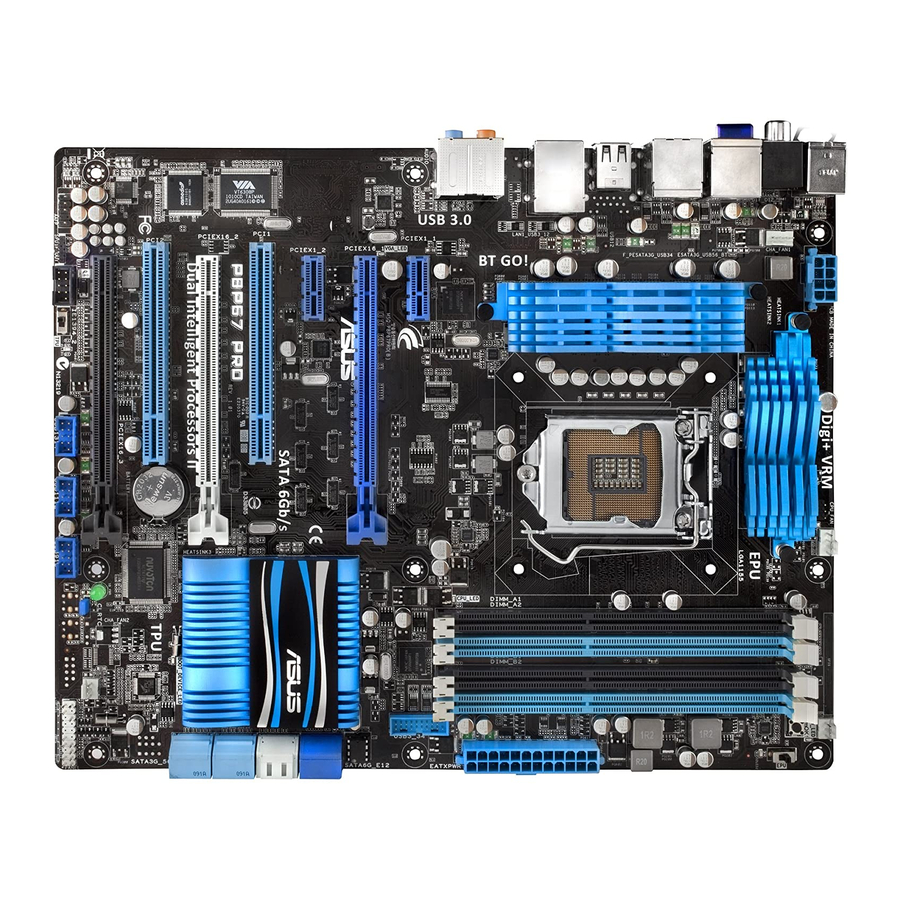
Page 18: Motherboard Overview
Motherboard overview 2.2.1 Motherboard layout Refer to 2.2.8 Internal Connectors and 2.3.10 Rear panel connection for more information about internal connectors and rear panel connectors. Chapter 2: Hardware information…
-
Page 19: Layout Contents
Standby power LED 2-17 USB 2.0 connectors (10-1 pin USB910, USB1112, USB1314) 2-23 TPU switch 2-15 IEEE 1394a port connector (10-1 pin IE1394_2) 2-24 Front panel audio connector (10-1 pin AAFP) 2-26 Digital audio connector (4-1 pin SPDIF_OUT) 2-24 ASUS P8P67…
-
Page 20: Central Processing Unit (Cpu)
Contact your retailer immediately if the PnP cap is missing, or if you see any damage to the PnP cap/socket contacts/motherboard components. ASUS will shoulder the cost of repair only if the damage is shipment/ transit-related.
-
Page 21: System Memory
The motherboard comes with four Double Data Rate 3 (DDR3) Dual Inline Memory Modules (DIMM) slots. A DDR3 module is notched differently from a DDR or DDR2 module. DO NOT install a DDR or DDR2 memory module to the DDR3 slot. Recommended memory configurations ASUS P8P67…
-
Page 22: Memory Configurations
• The max. 32GB memory capacity can be supported with DIMMs of 8GB (or above). ASUS will update QVL once the DIMMs are available on the market. • According to Intel CPU spec, DIMM voltage below 1.65V is recommended to protect the CPU.
-
Page 23
P8P67 Motherboard Qualified Vendors Lists (QVL) DDR3-2133 MHz capability DIMM socket support Chip Chip (Optional) Vendors Part No. Size Timing Voltage Brand 1 DIMM 2 DIMM 4 DIMM G.SKILL F3-17066CL9D-4GBTDS(XMP) 4GB (2 x 2GB) 1.65 • • • G.SKILL F3-17066CL8D-4GBPS(XMP) -
Page 24
P8P67 Motherboard Qualified Vendors Lists (QVL) DDR3-1600MHz capability DIMM socket support Chip Vendor Part No. Size Chip NO. Timing Voltage (Optional) Brand 1 DIMM 2 DIMM 4 DIMM G.SKILL F3-14400CL6D-4GBFLS(XMP) 4GB(2 x 2GB) DS — 6-8-6-24 1.65 • • G.SKILL… -
Page 25
P8P67 Motherboard Qualified Vendors Lists (QVL) DDR3-1333MHz capability DIMM socket support Vendor Part No. Size Chip Brand Chip NO. Timing Voltage (Optional) 1 DIMM 2 DIMM 4 DIMM A-DATA SU3U1333B1G9-B Hynix H5TQ1G83TFR • • • A-DATA SU3U1333B2G9-B Hynix H5TQ1G83TFR •… -
Page 26
P8P67 Motherboard Qualified Vendors Lists (QVL) DDR3-1333MHz capability (continued) DIMM socket support Vendor Part No. Size Chip Brand Chip NO. Timing Voltage (Optional) 1 DIMM 2 DIMM 4 DIMM SAMSUNG M378B2873DZ1-CH9 SAMSUNG K4B1G0846D • • • SAMSUNG M378B2873EH1-CH9 SAMSUNG K4B1G0846E •… -
Page 27
ASUS exclusively provides hyper DIMM support function. • Hyper DIMM support is subject to the physical characteristics of individual CPUs. Load the X.M.P. or D.O.C.P. settings in the BIOS for the hyper DIMM support. • Visit the ASUS website for the latest QVL. ASUS P8P67 2-11… -
Page 28: Expansion Slots
2.2.4 Expansion slots Ensure to unplug the power cord before adding or removing expansion cards. Failure to do so may cause you physical injury and damage motherboard components. Slot No. Slot Description PCIe 2.0 x1_1 slot PCIe 2.0 x16_1 slot [blue] (single at x16 mode) PCIe 2.0 x1_2 slot PCI slot 1 PCIe 2.0 x16_2 slot [black] (at max.
-
Page 29
– – shared – – – Marvell ATA Controller – – – shared – – – – 1394 Controller – shared – – – – – – HD Audio – – – – – – shared – ASUS P8P67 2-13… -
Page 30: Onboard Switches
BIOS default settings. A messgae will appear during POST reminding you that the BIOS has been restored to its default settings. • We recommend that you download and update to the latest BIOS version from the ASUS website at www.asus.com after using the MemOK! function. 2-14 Chapter 2: Hardware information…
-
Page 31
• You may use the TurboV Auto Tuning, overclock in the BIOS setup program, and enable the TPU function at the same time. However, the system will use the last setting you have made. ASUS P8P67 2-15… -
Page 32
EPU switch Turning this switch to Enable will automatically detect the current PC loadings and intelligently moderate the power consumption. For ensuring the system performance, turn the switch setting to Enable when the system is powered off. • The EPU LED (O2LED2) near the EPU switch lights when the switch setting is turned to Enable. -
Page 33: Onboard Leds
ON, in sleep mode, or in soft-off mode. This is a reminder that you should shut down the system and unplug the power cable before removing or plugging in any motherboard component. The illustration below shows the location of the onboard LED. ASUS P8P67 2-17…
-
Page 34
TPU LED The TPU LED lights when the TPU switch is turned to Enable. EPU LED The EPU LED lights when the EPU switch is turned to Enable. 2-18 Chapter 2: Hardware information… -
Page 35: Jumper
• Due to the chipset behavior, AC power off is required to enable C.P.R. function. You must turn off and on the power supply or unplug and plug the power cord before rebooting the system. ASUS P8P67 2-19…
-
Page 36: Internal Connectors
2.2.8 Internal connectors Intel P67 Serial ATA 6.0 Gb/s connectors (7-pin SATA6G_1/2 [gray]) ® These connectors connect to Serial ATA 6.0 Gb/s hard disk drives via Serial ATA 6.0 Gb/s signal cables. If you installed Serial ATA hard disk drives, you can create a RAID 0, 1, 5, and 10 configuration with the Intel Rapid Storage Technology through the onboard Intel ®…
-
Page 37
You must install Windows XP Service Pack 2 or later versions before using Serial ® ATA hard disk drives. The Serial ATA RAID feature is available only if you are using Windows ® XP SP2 or later versions. ASUS P8P67 2-21… -
Page 38
Marvell Serial ATA 6.0 Gb/s connectors (7-pin SATA6G_E1/E2 [navy blue]) ® These connectors connect to Serial ATA 6.0 Gb/s hard disk drives via Serial ATA 6.0 Gb/s signal cables. • The SATA6G_E1/E2 (navy blue) connectors are for data drives only. ATAPI device is not supported. -
Page 39
Never connect a 1394 cable to the USB connectors. Doing so will damage the motherboard! You can connect the front panel USB cable to the ASUS Q-Connector (USB, blue) first, and then install the Q-Connector (USB) to the USB connector onboard if your chassis supports front panel USB ports. -
Page 40
IEEE 1394a port connector (10-1 pin IE1394_2) This connector is for an IEEE 1394a port. Connect the IEEE 1394a module cable to this connector, then install the module to a slot opening at the back of the system chassis. Never connect a USB cable to the IEEE 1394a connector. Doing so will damage the motherboard! The IEEE 1394a module is purchased separately. -
Page 41
• The CPU_FAN connector supports the CPU fan of maximum 1A (12 W) fan power. • Only the CPU_FAN, CHA_FAN 1 and CHA_FAN 2 connectors support the ASUS FAN Xpert feature. • If you install two VGA cards, we recommend that you plug the rear chassis fan cable to the motherboard connector labeled CHA_FAN1 or CHA_FAN2 for better thermal environment. -
Page 42: Front Panel Audio Connector
Front panel audio connector (10-1 pin AAFP) This connector is for a chassis-mounted front panel audio I/O module that supports either HD Audio or legacy AC`97 audio standard. Connect one end of the front panel audio I/O module cable to this connector. •…
-
Page 43
1000W power or above to ensure the system stability. • If you are uncertain about the minimum power supply requirement for your system, refer to the Recommended Power Supply Wattage Calculator at http://support.asus. com/PowerSupplyCalculator/PSCalculator.aspx?SLanguage=en-us for details. PSU Suggested List AcBel PC7030… -
Page 44
Serial port connector (10-1 pin COM1) This connector is for a serial (COM) port. Connect the serial port module cable to this connector, then install the module to a slot opening at the back of the system chassis. The COM module is purchased separately. 2-28 Chapter 2: Hardware information… -
Page 45: System Panel Connector
Pressing the power switch for more than four seconds while the system is ON turns the system OFF. • Reset button (2-pin RESET) This 2-pin connector is for the chassis-mounted reset button for system reboot without turning off the system power. ASUS P8P67 2-29…
-
Page 46: Building Your Computer System
Building your computer system 2.3.1 Additional tools and components to build a PC system 1 bag of screws Philips (cross) screwdriver PC chassis Power supply unit Intel LGA 1155 CPU Intel LGA 1155 compatible CPU Fan DDR3 DIMM SATA hard disk drive SATA optical disc drive (optional) Graphics card (optional) The tools and components in the table above are not included in the motherboard package.
-
Page 47: Cpu Installation
2.3.2 CPU installation The LGA1156 CPU is incompatible with the LGA1155 socket. DO NOT install a LGA1156 CPU on the LGA1155 socket. ASUS P8P67 2-31…
-
Page 48
2-32 Chapter 2: Hardware information… -
Page 49: Cpu Heatsink And Fan Assembly Installation
2.3.3 CPU heatsink and fan assembly installation Apply the Thermal Interface Material to the CPU heatsink and CPU before you install the heatsink and fan if necessary. To install the CPU heatsink and fan assembly ASUS P8P67 2-33…
-
Page 50
To uninstall the CPU heatsink and fan assembly 2-34 Chapter 2: Hardware information… -
Page 51: Dimm Installation
2.3.4 DIMM installation To remove a DIMM ASUS P8P67 2-35…
-
Page 52: Motherboard Installation
2.3.5 Motherboard installation The diagrams in this section are for reference only. The motherboard layout may vary with models, but the installation steps remain the same. 2-36 Chapter 2: Hardware information…
-
Page 53
DO NOT overtighten the screws! Doing so can damage the motherboard. ASUS P8P67 2-37… -
Page 54: Atx Power Connection
2.3.6 ATX Power connection 2-38 Chapter 2: Hardware information…
-
Page 55: Sata Device Connection
2.3.7 SATA device connection ASUS P8P67 2-39…
-
Page 56: Front I/O Connector
2.3.8 Front I/O Connector To install ASUS Q-Connector To install USB 2.0 Connector To install front panel audio connector AAFP USB 2.0 2-40 Chapter 2: Hardware information…
-
Page 57: Expension Card Installation
2.3.9 Expension Card installation To install PCIe x16 cards To install PCIe x1 cards To install PCI cards ASUS P8P67 2-41…
-
Page 58: Rear Panel Connection
2.3.10 Rear panel connection Rear panel connectors 1. PS/2 mouse port (green) 7. USB 2.0 ports 5 and 6 2. Optical S/PDIF Out port 8. USB 2.0 ports 3 and 4 3. Bluetooth module* 9. USB 2.0 ports 1 and 2 4.
-
Page 59: Audio I/O Connections
Mic In Mic In Mic In Mic In Orange – – Center/Subwoofer Center/Subwoofer Black – Rear Speaker Out Rear Speaker Out Rear Speaker Out Gray – – – Side Speaker Out 2.3.11 Audio I/O connections Audio I/O ports ASUS P8P67 2-43…
-
Page 60
Connect to Headphone and Mic Connect to Stereo Speakers Connect to 2.1 channel Speakers Connect to 4.1 channel Speakers 2-44 2-44 Chapter 2: Hardware information Chapter 2: Hardware information… -
Page 61
Connect to 5.1 channel Speakers Connect to 7.1 channel Speakers When the DTS Surround Sensation UltraPC function is enabled, ensure to connect the rear speaker to the gray port. ASUS P8P67 ASUS P8P67 2-45 2-45… -
Page 62: Starting Up For The First Time
Starting up for the first time After making all the connections, replace the system case cover. Be sure that all switches are off. Connect the power cord to the power connector at the back of the system chassis. Connect the power cord to a power outlet that is equipped with a surge protector. Turn on the devices in the following order: Monitor External SCSI devices (starting with the last device on the chain)
-
Page 63: Chapter 3: Bios Setup
USB mouse. The BIOS setup program can be used under two modes: EZ Mode and Advanced Mode. You can change modes from the Exit menu or from the Exit/Advanced Mode button in the EZ Mode/Advanced Mode screen. ASUS P8P67…
-
Page 64: Ez Mode
Selects the boot device priority Power Saving mode Displays the system properties of the Normal mode ASUS Optimal mode selected mode on the right hand side Selects the boot device priority • The boot device options vary depending on the devices you installed to the system.
-
Page 65: Advanced Mode
The Advanced Mode provides advanced options for experienced end-users to configure the BIOS settings. The figure below shows an example of the Advanced Mode. Refer to the following sections for the detailed configurations. To access the EZ Mode, click Exit, then select ASUS EZ Mode. Back button Menu items…
-
Page 66: Menu Items
Menu items The highlighted item on the menu bar displays the specific items for that menu. For example, selecting Main shows the Main menu items. The other items (Ai Tweaker, Advanced, Monitor, Boot, Tool, and Exit) on the menu bar have their respective menu items.
-
Page 67: Main Menu
RAM to clear the BIOS password. See section 2.2.7 Jumper for information on how to erase the RTC RAM. The Administrator or User Password items on top of the screen show the default • Not Installed. After you set a password, these items show Installed. ASUS P8P67…
-
Page 68: Administrator Password
Administrator Password If you have set an administrator password, we recommend that you enter the administrator password for accessing the system. Otherwise, you might be able to see or change only selected fields in the BIOS setup program. To set an administrator password: Select the Administrator Password item and press <Enter>.
-
Page 69: Ai Tweaker Menu
Offset Mode Sign CPU Offset Voltage Auto DRAM Voltage 1.500V Auto VCCSA Voltage 0.925V Auto VCCIO Voltage 1.050V Auto CPU PLL Voltage 1.800V Auto PCH Voltage 0.975V Auto CPU Spread Spectrum Auto Version 2.00.1201. Copyright (C) 2010 American Megatrends, Inc. ASUS P8P67…
-
Page 70
Ai Overclock Tuner [Auto] Allows you to select the CPU overclocking options to achieve the desired CPU internal frequency. Select any of these preset overclocking configuration options: [Auto] Loads the optimal settings for the system. [Manual] Allows you to individually set overclocking parameters. [X.M.P.] If you install memory modules supporting the eXtreme Memory Profile (X.M.P.) Technology, choose this item to set the profiles supported by your… -
Page 71: Dram Timing Control
Turbo ratio in BIOS. Maximum Turbo Ratio setting in OS [Auto] This item appears only when you set the Turbo Ratio item to [Maximum Turbo Ratio setting in OS]. Use the <+> and <-> keys to adjust the value. ASUS P8P67…
-
Page 72
1-/2-/3-/4-Core Ratio Limi [Auto] This item appears only when you set the Turbo Ratio item to [Maximum Turbo Ratio setting in BIOS]. Use the <+> and <-> keys to adjust the value Long Duration Power Limit [Auto] Use the <+> and <-> keys to adjust the value. Long Duration Maintained [Auto] Use the <+>… -
Page 73
Reduce phase number under light system loading to increase VRM efficiency. [Standard] Phase control based on CPU command. [Optimized] ASUS optimized phase tuning profile [Extreme] Full phase mode [Manual Adjustment] Phase number adjusted by current (A) step Manual Adjustment [Medium] This item appears only when you set the Phase Control item to [Manual Adjustment]. -
Page 74
CPU Manual Voltage [Auto] This item appears only when you set the CPU Voltage item to [Manual Mode] and allows you to set a fixed CPU voltage. The values range from 0.800V to 1.990V with a llows you to set a fixed CPU voltage. The values range from 0.800V to 1.990V with a 0.005V interval. -
Page 75
CPU PLL Voltage 1.88750V 1.97500V 2.06875V 2.20000V 0.80000V– 1.11000V– 1.16000V– 1.21000V– PCH Voltage 1.10000V 1.15000V 1.20000V 1.70000V CPU Spread Spectrum [Auto] [Auto] Automatic configuration. [Disabled] Enhances the BCLK overclocking ability. [Enabled] Sets to [Enabled] for EMI control. ASUS P8P67 3-13… -
Page 76: Advanced Menu
Advanced menu The Advanced menu items allow you to change the settings for the CPU and other system devices. Be cautious when changing the settings of the Advanced menu items. Incorrect field values can cause the system to malfunction. EFI BIOS Utility — Advanced Mode Exit Main Ai Tweaker…
-
Page 77: Cpu Configuration
<-> keys to adjust the ratio. The valid value ranges vary according to your CPU model. Intel Adaptive Thermal Monitor [Enabled] [Enabled] Enables the overheated CPU to throttle its clock speed to cool down. [Disabled] Disables the CPU thermal monitor function. ASUS P8P67 3-15…
-
Page 78
Hyper-threading [Enabled] The Intel Hyper-Threading Technology allows a hyper-threading processor to appear as two logical processors to the operating system, allowing the operating system to schedule two threads or processes simultaneously. [Enabled] Two threads per activated core are enabled. [Disabled] Only one thread per activated core is enabled. -
Page 79: System Agent Configuration
Tool Back Advanced PCH Configuration > PCH Configuration Enabled/Disabled the High Precision Event Timer. High Precision Timer Enabled High Precision Timer [Enabled] Allows you to enable or disable the High Precision Event Timer. Configuration options: [Enabled] [Disabled] ASUS P8P67 3-17…
-
Page 80: Sata Configuration
3.5.4 SATA Configuration While entering Setup, the BIOS automatically detects the presence of SATA devices. The SATA Port items show Not Present if no SATA device is installed to the corresponding SATA port. EFI BIOS Utility — Advanced Mode Exit Ai Tweaker Main Advanced…
-
Page 81: Usb Configuration
Legacy USB3.0 Support [Enabled] [Enabled] Enables the support for USB 3.0 devices on legacy operating systems (OS). [Disabled] Disables the function. EHCI Hand-off [Disabled] [Enabled] Enables the support for operating systems without an EHCI hand-off feature. [Disabled] Disables the function. ASUS P8P67 3-19…
-
Page 82: Onboard Devices Configuration
3.5.6 Onboard Devices Configuration EFI BIOS Utility — Advanced Mode Exit Main Ai Tweaker Advanced Monitor Boot Tool Back Advanced Onboard Devices Configuration > Enabled/Disabled Azalia HD Audio HD Audio Controller Enabled Front Panel Type SPDIF Out Type SPDIF Renesas Electronics USB 3.0 Enabled VIA 1394 Enabled…
-
Page 83
Allows you to enable or disable the serial port (COM). Configuration options: [Enabled] [Disabled] Change Settings [IO=3F8h; IRQ=4] Allows you to select the Serial Port base address. Configuration options: [IO=3F8h; IRQ=4] [IO=2F8h; IRQ=3] [IO=3E8h; IRQ=4] [IO=2E8h; IRQ=3] ASUS P8P67 3-21… -
Page 84: Apm
3.5.7 EFI BIOS Utility — Advanced Mode Exit Ai Tweaker Main Advanced Monitor Boot Tool Back Advanced APM > Restore AC Power Loss Power Off Specify what state to go to when power is re-applied after a power Power On By PS/2 Keyboard Disabled failure (G3 state).
-
Page 85
Enables Ring to generate a wake event. Power On By RTC [Disabled] [Disabled] Disables RTC to generate a wake event. When set to [Enabled], the items RTC Alarm Date (Days) and Hour/ [Enabled] Minute/Second will become user-configurable with set values. ASUS P8P67 3-23… -
Page 86: Monitor Menu
Monitor menu The Monitor menu displays the system temperature/power status, and allows you to change the fan settings. EFI BIOS Utility — Advanced Mode Exit Main Ai Tweaker Advanced Monitor Boot Tool CPU Temperature +45ºC / +113ºF +45ºC / +113ºF MB Temperature +34ºC / +93ºF CPU Fan Speed…
-
Page 87
This item appears only when you enable the Chassis Q-Fan Control feature and allows you to disable or set the chassis fan warning speed. Configuration options: [Ignore] [200 RPM] [300 RPM] [400 RPM] [500 RPM] [600 RPM] ASUS P8P67 3-25… -
Page 88
Chassis Fan Profile [Standard] This item appears only when you enable the Chassis Q-Fan Control feature and allows you to set the appropriate performance level of the chassis fan. [Standard] Sets to [Standard] to make the chassis fan automatically adjust depending on the chassis temperature. -
Page 89: Boot Menu
Enables the full screen logo display feature. [Disabled] Disables the full screen logo display feature. Set this item to [Enabled] to use the ASUS MyLogo 2™ feature. Option ROM Messages [Force BIOS] [Force BIOS] The third-party ROM messages will be forced to display during the boot sequence.
-
Page 90: Boot Option Priorities
• To select the boot device during system startup, press <F8> when ASUS Logo appears. • To access Windows OS in Safe Mode, do any of the following: — Press <F5>…
-
Page 91: Tools Menu
> ASUS O.C. Profile 3.8.1 ASUS EZ Flash Utility Allows you to run ASUS EZ Flash Utility. When you press <Enter>, a confirmation message appears. Use the left/right arrow key to select between [Yes] or [No], then press <Enter> to confirm your choice.
-
Page 92
Save to Profile Allows you to save the current BIOS settings to the BIOS Flash, and create a profile. Key in a profile number from one to eight, press <Enter>, and then select Yes. Load from Profile Allows you to load the previous BIOS settings saved in the BIOS Flash. Key in the profile Key in the profile number that saved your CMOS settings, press <Enter>, and then select Yes. -
Page 93: Exit Menu
Load Optimized Defaults Save Changes & Reset Discard Changes & Exit ASUS EZ Mode Launch EFI Shell from filesystem device Load Optimized Defaults This option allows you to load the default values for each of the parameters on the Setup menus.
-
Page 94: Updating Bios
BIOS in the future. Copy the original motherboard BIOS using the ASUS Update or BIOS Updater utilities. 3.10.1 ASUS Update utility The ASUS Update is a utility that allows you to manage, save, and update the motherboard BIOS in Windows environment. The ASUS Update utility allows you to: ®…
-
Page 95
To update the BIOS through the Internet: From the ASUS Update screen, select Update BIOS from Internet, and then click Next. Select the ASUS FTP site nearest you to avoid network traffic. If you want to enable the BIOS downgradable function and auto… -
Page 96
The screenshots in this section are for reference only. The actual BIOS information vary by models. • Refer to the software manual in the support DVD or visit the ASUS website at www.asus.com for detailed software configuration. 3-34 Chapter 3: BIOS setup… -
Page 97: Asus Ez Flash Utility
3.10.2 ASUS EZ Flash Utility The ASUS EZ Flash Utlity feature allows you to update the BIOS without having to use a bootable floppy disk or an OS-based utility. Before you start using this utility, download the latest BIOS from the ASUS website at www.asus.com.
-
Page 98: Asus Crashfree Bios 3 Utility
The BIOS file in the motherboard support DVD may be older than the BIOS file published on the ASUS official website. If you want to use the newer BIOS file, download the file at support.asus.com and save it to a USB flash drive.
-
Page 99: Asus Bios Updater
3.10.4 ASUS BIOS Updater The ASUS BIOS Updater allows you to update BIOS in DOS environment. This utility also allows you to copy the current BIOS file that you can use as a backup when the BIOS fails or gets corrupted during the updating process.
-
Page 100
The BIOS Updater backup screen appears indicating the BIOS backup process. When BIOS backup is done, press any key to return to the DOS prompt. ASUSTek BIOS Updater for DOS V1.18 [2010/04/29] Current ROM Update ROM BOARD: P8P67 BOARD: Unknown VER: 0204 VER:… -
Page 101
Select the Load Optimized Defaults item under the Exit BIOS menu. See Chapter 3 of your motherboard user manual for details. • Ensure to connect all SATA hard disk drives after updating the BIOS file if you have disconnected them. ASUS P8P67 3-39… -
Page 102
3-40 Chapter 3: BIOS setup… -
Page 103: Chapter 4: Software Support
The contents of the support DVD are subject to change at any time without notice. Visit the ASUS website at www.asus.com for updates. 4.2.1 Running the support DVD Place the support DVD into the optical drive.
-
Page 104: Obtaining The Software Manuals
The software manual files are in Portable Document Format (PDF). Install the Adobe ® Acrobat Reader from the Utilities menu before opening the files. ® Click the Manual tab. Click ASUS Motherboard Utility Guide from the manual list on the left. The Manual folder of the support DVD appears. Double-click the folder of your selected software.
-
Page 105: Software Information
4.3.1 AI Suite II AI Suite II is an all-in-one interface that integrates several ASUS utilities and allows users to launch and operate these utilities simultaneously. Installing AI Suite II To install AI Suite II on your computer Place the support DVD to the optical drive.
-
Page 106: Digi+ Vrm
4.3.2 DIGI+ VRM ASUS DIGI+ VRM allows you to adjust VRM voltage and frequency modulation to enhance reliability and stability. It also provides the highest power efficiency, generating less heat to longer component lifespan and minimize power loss. After installing AI Suite II from the motherboard support DVD, launch DIGI+ VRM by clicking Tool >…
-
Page 107: Bt Go
Music Player: allows you to play the selected music files in the BT device through the computer’s speakers. BT Turbo Remote: provides a user-friendly interface that allows you to use your smartphone as the remote controller via the bluetooth connection for the BT Turbo Key, Pocket Media, and Reset/Off functions. ASUS P8P67…
-
Page 108: Turbov Evo
4.3.4 TurboV EVO ASUS TurboV EVO introduces TurboV that allows you to manually adjust the CPU frequency and related voltages as well as Auto Tuning function that offers automatic and easy overlocking and system level up. After installing AI Suite II from the motherboard support After installing AI Suite II from the motherboard support DVD, launch TurboV EVO by clicking Tool >…
-
Page 109
Click Yes to make the change take effect. GPU Boost Adjustment bars Target values Current values Undoes all changes without applying Applies all changes Click to restore immediately all start-up settings GPU Boost is available on selected models. ASUS P8P67… -
Page 110
CPU Ratio Allows you to manually adjust the CPU ratio. The first time you use CPU Ratio, go to AI Tweaker > CPU Power Management in BIOS and set the Turbo Ratio item to [Maximum Turbo Ratio setting in OS], or activate CPU Ratio by clicking the ON button on the CPU Ratio function screen. -
Page 111: Auto Tuning
Auto Tuning ASUS TurboV EVO includes two auto tuning modes, providing the most flexible auto-tuning options. • The overclocking result varies with the CPU model and the system configuration. • To prevent overheating from damaging the motherboard, a better thermal environment is strongly recommended.
-
Page 112
TurboV automatically overclocks the CPU and memory and restarts the system. After re-entering Windows, a message appears indicating the current overclocking result. To keep the result, click Stop. If you did not click Stop in the previous step, TurboV automatically starts further system overclocking and stability test. -
Page 113: Epu
Select From EPU Installation to show the CO2 that has been reduced since you *• installed EPU. Select From the Last Reset to show the total CO2 that has been reduced since you *• click the Clear button ASUS P8P67 4-11…
-
Page 114: Fan Xpert
4.3.6 FAN Xpert Fan Xpert intelligently allows you to adjust both the CPU and chassis fan speeds according to different ambient temperatures caused by different climate conditions in different geographic regions and your PC’s system loading. The built-in variety of useful profiles offer flexible controls of fan speed to achieve a quiet and cool environment.
-
Page 115: Probe Ii
The Preference tab allows you to customize the time interval of sensor alerts, or change the temperature unit. Saves your configuration Loads the default Loads your saved Applies your threshold values configuration changes for each sensor ASUS P8P67 4-13…
-
Page 116: Sensor Recorder
4.3.8 Sensor Recorder Sensor Recorder allows you to monitor the changes in the system voltage, temperature, and fan speed, as well as recording the changes. Launching Sensor Recorder After installing AI Suite II from the motherboard support DVD, click Tool > Sensor Recorder on the AI Suite II main menu bar to launch PC Probe II.
-
Page 117: Monitor
CPU frequency and CPU usage. Click Monitor > CPU Frequency on the AI Suite II main menu bar to open the CPU Frequency panel. CPU Frequency panel Resident in the right pane (system information area) Sensor panel ASUS P8P67 4-15…
-
Page 118: System Information
4.3.10 System Information The System Information section displays the information about the motherboard, CPU, and memory slots. Click the MB tab to see the details on • the motherboard manufacturer, product name, version, and BIOS. Click the CPU tab to see the details on •…
-
Page 119: Audio Configurations
Realtek HD Audio Manager for Windows XP Exit button Configuration options Minimize button Control settings window Information button Refer to the software manual in the support DVD or visit the ASUS website at www.asus.com for detailed software configuration. ASUS P8P67 4-17…
-
Page 120: Raid Configurations
RAID configurations The motherboard supports the following SATA RAID solution: Intel Rapid Storage Technology with RAID 0, RAID 1, RAID 10 and RAID 5 support. ® • You must install Windows XP Service Pack 2 or later versions before using Serial ®…
-
Page 121: Installing Serial Ata Hard Disks
RAID Volumes: None defined. Physical Devices: Port Device Model Serial # Size Type/Status(Vol ID) ST3160812AS 9LS0HJA4 149.0GB Non-RAID Disk ST3160812AS 9LS0F4HL 149.0GB Non-RAID Disk ST3160812AS 3LS0JYL8 149.0GB Non-RAID Disk ST3160812AS 9LS0BJ5H 149.0GB Non-RAID Disk [↑↓]-Select [ESC]-Exit [ENTER]-Select Menu ASUS P8P67 4-19…
-
Page 122: Creating A Raid Set
The navigation keys at the bottom of the screen allow you to move through the menus and select the menu options. The RAID BIOS setup screens shown in this section are for reference only and may not exactly match the items on your screen. The utility supports maximum four hard disk drives for RAID configuration.
-
Page 123
WARNING: ALL DATA ON SELECTED DISKS WILL BE LOST. Are you sure you want to create this volume? (Y/N): Press <Y> to create the RAID volume and return to the main menu, or <N> to go back to the CREATE VOLUME menu. ASUS P8P67 4-21… -
Page 124
Deleting a RAID set Take caution when deleting a RAID set. You will lose all data on the hard disk drives when you delete a RAID set. To delete a RAID set: From the utility main menu, select 2. Delete RAID Volume and press <Enter>. The following screen appears: Intel(R) Rapid Storage Technology — Option ROM — v10.0.0.1032 Copyright(C) 2003-10 Intel Corporation. -
Page 125: Creating A Raid Driver Disk
Go to the Make Disk menu, and then click Intel AHCI/RAID Driver Disk to create a RAID driver disk. Select USB floppy disk drive as the destination disk. Follow the succeeding screen instructions to complete the process. Write-protect the floppy disk to avoid a computer virus infection. ASUS P8P67 4-23…
-
Page 126: Installing The Raid Driver During Windows ® Os Installation
4.5.3 Installing the RAID driver during Windows OS installation ® To install the RAID driver in Windows ® During the OS installation, the system prompts you to press the F6 key to install third- party SCSI or RAID driver. Press <F6>, and then insert the floppy disk with RAID driver into the USB floppy disk drive. When prompted to select the SCSI adapter to install, select the RAID driver for the corresponding OS version.
-
Page 127: Using A Usb Floppy Disk Drive
Click Details tab. The Vendor ID (VID) and Product ID (PID) are displayed. Browse the contents of the RAID driver disk to locate the file txtsetup.oem. Double-click the file. A window appears, allowing you to select the program for opening the oem file. ASUS P8P67 4-25…
-
Page 128
Use Notepad to open the file. Find the [HardwareIds.scsi.iaAHCI_DesktopWorkstationServer] and [HardwareIds.scsi.iaStor_DesktopWorkstationServer] sections in the txtsetup.oem file. Type the following line to the bottom of the two sections: id = “USBVID_xxxx&PID_xxxx”, “usbstor” [HardwareIds.scsi.iaAHCI_DesktopWorkstationServer] id= “PCIVEN_8086&DEV_1C02&CC_0106”,”iaStor” id= “USBVID_03EE&PID_6901”, “usbstor” [HardwareIds.scsi.iaStor_DesktopWorkstationServer] id= “PCIVEN_8086&DEV_2822&CC_0104”,”iaStor” id= “USBVID_03EE&PID_6901”, “usbstor”… -
Page 129: Chapter 5: Ati ® Crossfirex™ Technology Support
For Windows XP, go to Control Panel > Add/Remove Programs. For Windows Vista, go to Control Panel > Programs and Features. Select your current graphics card driver/s. For Windows XP, select Add/Remove. For Windows Vista, select Uninstall. Turn off your computer. ASUS P8P67…
-
Page 130: Installing Crossfirex™ Graphics Cards
Installing CrossFireX™ graphics cards The following pictures are for reference only. The graphics cards and the motherboard layout may vary with models, but the installation steps remain the same. Prepare two CrossFireX-ready graphics cards. Insert the two graphics card into the PCIEX16 slots.
-
Page 131: Software Information
ATI icon in the Windows notification area and select Cayalist Control Center. The Catalyst Control Center Setup Assistant appears when the system detects the existance of multi-graphics cards. Click Go to continue to the Catalyst Control Center Advanced View window. ASUS P8P67…
-
Page 132
Enabling Dual CrossFireX settings In the Catalyst Control Center window, click Graphics Settings > CrossFireX > Configure. From the Graphics Adapter list, select the graphics card to act as the display GPU. Select Enable CrossFireX. Click Apply, and then click OK to exit the window. -
Page 133: Asus Contact Information
+1-812-282-3777 +1-510-608-4555 Web site usa.asus.com Technical Support Telephone +1-812-282-2787 Support fax +1-812-284-0883 Online support support.asus.com ASUS COMPUTER GmbH (Germany and Austria) Address Harkort Str. 21-23, D-40880 Ratingen, Germany +49-2102-959911 Web site www.asus.de Online contact www.asus.de/sales Technical Support Telephone +49-1805-010923* Support Fax…
-
Contents
-
Table of Contents
-
Bookmarks
Quick Links
Related Manuals for Asus P8P67 LE
Summary of Contents for Asus P8P67 LE
-
Page 1
P8P67 LE… -
Page 2
Product warranty or service will not be extended if: (1) the product is repaired, modified or altered, unless such repair, modification of alteration is authorized in writing by ASUS; or (2) the serial number of the product is defaced or missing. -
Page 3: Table Of Contents
Contents Notices ………………….vi Safety information ………………vii About this guide ………………vii P8P67 LE specifications summary …………ix Chapter 1: Product introduction Welcome! ………………1-1 Package contents …………….. 1-1 Special features …………….1-1 1.3.1 Product highlights …………1-1 1.3.2 Innovative ASUS features ……….
-
Page 4
Managing and updating your BIOS ……….2-1 2.1.1 ASUS Update utility …………2-1 2.1.2 ASUS EZ Flash 2 …………2-2 2.1.3 ASUS CrashFree BIOS 3 utility ……..2-3 2.1.4 ASUS BIOS Updater …………2-4 BIOS setup program …………..2-7 Main menu ……………… 2-11 2.3.1 System Language …………2-11… -
Page 5
Setup Mode …………..2-27 2.7.5 Boot Option Priorities ………… 2-28 2.7.6 Boot Override …………..2-28 Tools menu …………….. 2-29 2.8.1 ASUS EZ Flash Utility ……….. 2-29 2.8.2 ASUS SPD Information ……….2-29 2.8.3 ASUS O.C. Profile …………2-29 Exit menu ………………2-30… -
Page 6: Notices
Complying with the REACH (Registration, Evaluation, Authorisation, and Restriction of Chemicals) regulatory framework, we published the chemical substances in our products at ASUS REACH website at http://csr.asus.com/english/REACH.htm. DO NOT throw the motherboard in municipal waste. This product has been designed to enable proper reuse of parts and recycling.
-
Page 7: Safety Information
Safety information Electrical safety • To prevent electric shock hazard, disconnect the power cable from the electric outlet before relocating the system. • When adding or removing devices to or from the system, ensure that the power cables for the devices are unplugged before the signal cables are connected. If possible, disconnect all power cables from the existing system before you add a device.
-
Page 8: Conventions Used In This Guide
Refer to the following sources for additional information and for product and software updates. ASUS websites The ASUS website provides updated information on ASUS hardware and software products. Refer to the ASUS contact information. Optional documentation Your product package may include optional documentation, such as warranty flyers, that may have been added by your dealer.
-
Page 9: P8P67 Le Specifications Summary
Extreme Memory Profile (XMP) ® The maximum 32GB memory capacity can be supported with 8GB or above DIMMs. ASUS will update the memory QVL once the DIMMs are available in the market. ** Hyper DIMM support is subject to the physical characteristics of individual CPUs.
-
Page 10
ASUS Anti-Surge Protection Low EMI ASUS Hybrid Switches — MemOK! — TPU ASUS Quiet Thermal Solutions — ASUS Fanless Design: Stylish Heatsink Solution & MOS Heatsink — ASUS Fan Xpert ASUS EZ DIY — EFI BIOS — ASUS AI Suite II… -
Page 11
SFS (Stepless Frequency Selection): — BCLK/PEG frequency tuning from 80MHz up to 300MHz at 1MHz increment Overclocking protection: — ASUS C.P.R. (CPU Parameter Recall) Other features 100% All High-quality Conductive Polymer Capacitors Rear panel ports 1 x PS/2 Mouse port (green) -
Page 12
P8P67 LE specifications summary Support DVD Drivers ASUS utilities ASUS Update Anti-virus software (OEM version) Form factor ATX form factor: 12 in x 8.8 in (30.5 cm x 22.4 cm) * Specifications are subject to change without notice. -
Page 13: Chapter 1: Product Introduction
® The motherboard delivers a host of new features and latest technologies, making it another standout in the long line of ASUS quality motherboards! Before you start installing the motherboard, and hardware devices on it, check the items in your package with the list below.
-
Page 14
• The maximum 32GB memory capacity can be supported with 8GB or above DIMMs. ASUS will update the memory QVL once the DIMMs are available in the market. • Hyper DIMM support is subject to the physical characteristics of individual CPUs. -
Page 15: Innovative Asus Features
Innovative ASUS features ASUS EFI BIOS (EZ Mode) ASUS brand new EFI BIOS offers a user-friendly interface that goes beyond traditional keyboard BIOS input to enable more flexible and convenient mouse controls. You can easily navigate the new EFI BIOS with the same smoothness as their operating system.
-
Page 16: Asus Turbov
Get your system up and running in no time. ASUS TurboV Feel the adrenaline rush of real-time OC-now a reality with the ASUS TurboV. This easy OC tool allows you to overclock without exiting or rebooting the OS; and its user-friendly interface makes overclock with just a few clicks away.
-
Page 17: Asus Mylogo2
BIOS file using the bundled support DVD or USB flash disk that contains the latest BIOS file. ASUS EZ Flash 2 ASUS EZ Flash 2 is a utility that allows you to update the BIOS without using an OS-based utility. C.P.R. (CPU Parameter Recall) The BIOS C.P.R.
-
Page 18: Before You Proceed
• Before you install or remove any component, ensure that the ATX power supply is switched off or the power cord is detached from the power supply. Failure to do so may cause severe damage to the motherboard, peripherals, or components. ASUS P8P67 LE…
-
Page 19: Motherboard Overview
Place six screws into the holes indicated by circles to secure the motherboard to the chassis. Do not overtighten the screws! Doing so can damage the motherboard. Place this side towards the rear of the chassis P8P67 LE Chapter 1: Product introduction…
-
Page 20: Motherboard Layout
Lithium Cell AUDIO CMOS Power AAFP PCIEX1_1 P8P67 LE Marvell SATA6G 8111E PCIEX16_1 asmedia PCIEX1_2 ASM1085 Super Intel ® PCI1 PCIEX16_2 PCI2 VT6308P 32Mb BIOS PCI3 CHA_FAN2 SPDIF_OUT IE1394_1 USB78 USB910 USB1112 USB1314 PANEL CLRTC SB_PWR COM1 ASUS P8P67 LE…
-
Page 21: Layout Contents
1.5.4 Layout contents Connectors/Jumpers/Slots/LED Page Connectors/Jumpers/Slots/LED Page Front panel audio connector (10-1 pin AAFP) 1-28 Marvell Serial ATA 6.0Gb/s connector (7-pin 1-34 ® SATA6G_E1 [navy blue]) ATX power connectors (24-pin EATXPWR, 1-30 Intel P67 Serial ATA 6.0Gb/s connectors 1-32 ® 8-pin EATX12V) (7-pin SATA6G_1/2 [gray]) CPU, chassis, and power fan connectors…
-
Page 22: Central Processing Unit (Cpu)
Contact your retailer immediately if the PnP cap is missing, or if you see any damage to the PnP cap/socket contacts/motherboard components. ASUS will shoulder the cost of repair only if the damage is shipment/transit-related. • Keep the cap after installing the motherboard. ASUS will process Return Merchandise Authorization (RMA) requests only if the motherboard comes with the cap on the LGA1155 socket.
-
Page 23
Lift the load lever in the direction of the arrow until the load plate is completely lifted. Load plate Remove the PnP cap from the CPU socket by lifting the tab only. PnP cap Position the CPU over the socket, ensuring that the gold triangle is on the bottom-left corner of the socket, and CPU notches… -
Page 24
Close the load plate (A), and then push down the load lever (B), ensuring that the front edge of the load plate slides under the retention knob (C). Insert the load lever under the retention tab. 1-12 ASUS P8P67 LE… -
Page 25: Installing The Cpu Heatsink And Fan
1.6.2 Installing the CPU heatsink and fan The Intel LGA1155 processor requires a specially designed heatsink and fan assembly to ® ensure optimum thermal condition and performance. • When you buy a boxed Intel processor, the package includes the CPU fan and ®…
-
Page 26: Uninstalling The Cpu Heatsink And Fan
Connect the CPU fan cable to the connector on the motherboard labeled CPU_FAN. CPU_FAN P8P67 LE P8P67 LE CPU fan connector Do not forget to connect the CPU fan connector! Hardware monitoring errors can occur if you fail to plug this connector.
-
Page 27: System Memory
The figure illustrates the location of the DDR3 DIMM sockets: Channel Sockets Channel A DIMM_A1 and DIMM_A2 P8P67 LE Channel B DIMM_B1 and DIMM_B2 P8P67 LE 240-pin DDR3 DIMM sockets Chapter 1: Product introduction 1-15…
-
Page 28: Memory Configurations
• The maximum 32GB memory capacity can be supported with 8GB or above DIMMs. ASUS will update the memory QVL once the DIMMs are available in the market. • The default memory operation frequency is dependent on its Serial Presence Detect (SPD), which is the standard way of accessing information from a memory module.
-
Page 29
P8P67 LE Motherboard Qualified Vendors Lists (QVL) DDR3-2200(O.C.) MHz capability DIMM socket support (Optional) SS/DS Chip Vendors Part No. Size Brand Chip NO. Timing Voltage G.SKILL F3-17600CL8D-4GBPS(XMP) 4GB(2 x 2GB) DS 8-8-8-24 1.65V • KINGMAX FLKE85F-B8KJAA-FEIS(XMP) 2GB • • Kingmax… -
Page 30
• Mushkin 998659(XMP) 6GB(3 x 2GB) DS — 9-9-9-24 • • • Mushkin 998659(XMP) 6GB(3 x 2GB) DS — 9-9-9-24 1.5~1.6V • • • PATRIOT PGS34G1600LLKA 4GB(2 x 2GB) DS — 7-7-7-20 1.7V • • • 1-18 ASUS P8P67 LE… -
Page 31
DDR3-1333 MHz capability DIMM socket Chip support (Optional) Vendors Part No. Size Chip NO. Timing Voltage Brand AD30908C8D-151C A-Data AD31333001GOU A-Data • • • E0906 A-Data AD31333G001GOU 3GB(3 x 1GB) SS 8-8-8-24 1.65-1.85V • • AD30908C8D-151C A-Data AD31333002GOU A-Data • •… -
Page 32
• • • TAKEMS TMS2GB364D081-107EY 7-7-7-20 1.5V • • TAKEMS TMS2GB364D081-138EY 8-8-8-24 1.5V • • • TAKEMS TMS2GB364D082-138EW 8-8-8-24 1.5V • • UMAX E41302GP0-73BDB UMAX U2S24D30TP-13 • • • WINTEC 3WVS31333-2G-CNR AMPO AM3420803-13H • • • 1-20 ASUS P8P67 LE… -
Page 33
• C*: Supports two pairs of modules inserted into both the blue slots and the black slots as two pairs of dual-channel memory configuration. Visit the ASUS website at www.asus.com for the latest QVL. Chapter 1: Product introduction 1-21… -
Page 34: Installing A Dimm
DIMM. Support the DIMM lightly with your fingers when pressing the retaining clips. The DIMM might get damaged when it flips out with extra force. DIMM notch Remove the DIMM from the socket. 1-22 ASUS P8P67 LE…
-
Page 35: Expansion Slots
Expansion slots In the future, you may need to install expansion cards. The following sub-sections describe the slots and the expansion cards that they support. Unplug the power cord before adding or removing expansion cards. Failure to do so may cause you physical injury and damage motherboard components.
-
Page 36
• The PCIe x1 slots share the bandwidth with the PCIe x16_2 slot. Thus, all PCIe x1 slots will be disabled when you install two CrossFireX™ graphics cards on both the PCIe x16 slots to set up a CrossFireX™ configuration. 1-24 ASUS P8P67 LE… -
Page 37: Jumpers
Normal Clear RTC (Default) P8P67 LE Clear RTC RAM To erase the RTC RAM: 1. Turn OFF the computer and unplug the power cord. 2. Move the jumper cap from pins 1-2 (default) to pins 2-3. Keep the cap on pins 2-3 for about 5-10 seconds, then move the cap back to pins 1-2.
-
Page 38: Connectors
8-channel configurations, the function of this port becomes Front Speaker Out. Microphone port (pink). This port connects to a microphone. Side Speaker Out port (gray). This port connects to the side speakers in the 8-channel audio configuration. 1-26 ASUS P8P67 LE…
-
Page 39
Refer to the audio configuration table below for the function of the audio ports in the 2, 4, 6, or 8-channel configuration. Audio 2, 4, 6, or 8-channel configuration Headset Port 4-channel 6-channel 8-channel 2-channel Light Blue Line In Line In Line In Line In Lime… -
Page 40: Internal Connectors
Legacy AC’97 pin definition compliant definition P8P67 LE Front panel audio connector • We recommend that you connect a high-definition front panel audio module to this connector to avail of the motherboard’s high-definition audio capability. • If you want to connect a high-definition front panel audio module to this connector, set the Front Panel Type item in the BIOS setup to [HD].
-
Page 41
P8P67 LE PIN1 NOTE:Orient the red markings on the IDE ribbon cable to PIN 1. P8P67 LE IDE connector If any device jumper is set as “Cable-Select,” ensure that all other device jumpers have the same setting. Chapter 1: Product introduction… -
Page 42
• If you are uncertain about the minimum power supply requirement for your system, refer to the Recommended Power Supply Wattage Calculator at http://support.asus. com/PowerSupplyCalculator/PSCalculator.aspx?SLanguage=en-us for details. Serial port connector (10-1 pin COM1) This connector is for a serial (COM) port. -
Page 43
• The CPU_FAN connector supports a CPU fan of maximum 2A (24 W) fan power. • Only the CPU_FAN, CHA_FAN1 and CHA_FAN2 connectors support the ASUS Fan Xpert feature. • If you install two VGA cards, we recommend that you plug the rear chassis fan cable to the motherboard connector labeled CHA_FAN1 or CAH_FAN 2 for better thermal environment. -
Page 44
RSATA_TXN1 RSATA_RXP2 RSATA_TXP1 RSATA_RXN2 P8P67 LE Intel SATA 6.0 Gb/s connectors ® • These connectors are set to [AHCI Mode] by default. If you intend to create a Serial ATA RAID set using these connectors, set the SATA Mode item in the BIOS to [RAID Mode]. -
Page 45
RSATA_TXN4 RSATA_RXP2 RSATA_TXP4 RSATA_RXN2 P8P67 LE Intel SATA 3.0 Gb/s connectors ® • These connectors are set to [AHCI Mode] by default. If you intend to create a Serial ATA RAID set using these connectors, set the SATA Mode item in the BIOS to [RAID Mode]. -
Page 46
SATA6G_E1 RSATA_TXP1 RSATA_TXN1 P8P67 LE RSATA_RXP1 RSATA_RXN1 P8P67 LE Marvell SATA 6.0 Gb/s connector ® • The SATA6G_E1 (navy blue) connector is for data drives only. ATAPI device is not supported. • You must install Windows XP Service Pack 3 or later versions before using Serial ATA ®… -
Page 47
IDE_LED PWRSW RESET * Requires an ATX power supply P8P67 LE System panel connector • System power LED (2-pin PLED) This 2-pin connector is for the system power LED. Connect the chassis power LED cable to this connector. The system power LED lights up when you turn on the system power, and blinks when the system is in sleep mode. -
Page 48: Onboard Switches
P8P67 LE PIN 1 PIN 1 PIN 1 PIN 1 P8P67 LE USB2.0 connectors Never connect a 1394 cable to the USB connectors. Doing so will damage the motherboard! The USB module cable is purchased separately. 1.11 Onboard switches Onboard switches allow you to fine-tune performance when working on a bare or open-case system.
-
Page 49
If the installed DIMMs still fail to boot after the whole tuning process, the DRAM_LED lights continuously. Replace the DIMMs with ones recommended in the Memory QVL (Qualified Vendors Lists) in this user manual or on the ASUS website at www.asus.com. -
Page 50: Onboard Leds
P8P67 LE Standby Power Powered Off P8P67 LE Onboard LED DRAM LED DRAM LED checks the DRAM in sequence during motherboard booting process. If an error is found , the LED next to the error device will continue lighting until the problem is solved.
-
Page 51: Software Support
The contents of the Support DVD are subject to change at any time without notice. Visit the ASUS website at www.asus.com for updates. To run the Support DVD Place the Support DVD to the optical drive.
-
Page 52
1-40 ASUS P8P67 LE… -
Page 53: Chapter 2: Bios Information
BIOS in the future. Copy the original motherboard BIOS using the ASUS Update utility. 2.1.1 ASUS Update utility The ASUS Update is a utility that allows you to manage, save, and update the motherboard BIOS in Windows environment. ®…
-
Page 54: Asus Ez Flash 2
Follow the onscreen instructions to complete the updating process. 2.1.2 ASUS EZ Flash 2 The ASUS EZ Flash 2 feature allows you to update the BIOS without using an OS-based utility. Before you start using this utility, download the latest BIOS file from the ASUS website at www.asus.com.
-
Page 55: Asus Crashfree Bios 3 Utility
2.1.3 ASUS CrashFree BIOS 3 utility The ASUS CrashFree BIOS 3 is an auto recovery tool that allows you to restore the BIOS file when it fails or gets corrupted during the updating process. You can restore a corrupted BIOS file using the motherboard support DVD or a USB flash drive that contains the updated BIOS file.
-
Page 56: Asus Bios Updater
2.1.4 ASUS BIOS Updater The ASUS BIOS Updater allows you to update BIOS in DOS environment. This utility also allows you to copy the current BIOS file that you can use as a backup when the BIOS fails or gets corrupted during the updating process.
-
Page 57
The BIOS Updater backup screen appears indicating the BIOS backup process. When BIOS backup is done, press any key to return to the DOS prompt. ASUSTek BIOS Updater for DOS V1.18 Current ROM Update ROM BOARD: P8P67 LE BOARD: Unknown VER: 0711 VER:… -
Page 58: Updating The Bios File
Select the Load Optimized Defaults item under the Exit menu. Refer to section 2.9 Exit menu for details. • Ensure to connect all SATA hard disk drives after updating the BIOS file if you have disconnected them. ASUS P8P67 LE…
-
Page 59: Bios Setup Program
• The BIOS setup screens shown in this section are for reference purposes only, and may not exactly match what you see on your screen. • Visit the ASUS website at www.asus.com to download the latest BIOS file for this motherboard.
-
Page 60: Bios Menu Screen
Selects the boot device priority • The boot device options vary depending on the devices you installed to the system. • The Boot Menu(F8) button is available only when the boot device is installed to the system. ASUS P8P67 LE…
-
Page 61: Advanced Mode
The Advanced Mode provides advanced options for experienced end-users to configure the BIOS settings. The figure below shows an example of the Advanced Mode. Refer to the following sections for the detailed configurations. To access the EZ Mode, click Exit, then select ASUS EZ Mode. Back button Menu items…
-
Page 62: Menu Items
You cannot select an item that is not user-configurable. A configurable field is highlighted when selected. To change the value of a field, select it and press <Enter> to display a list of options. 2-10 ASUS P8P67 LE…
-
Page 63: Main Menu
Main menu The Main menu screen appears when you enter the Advanced Mode of the BIOS Setup program. The Main menu provides you an overview of the basic system information, and allows you to set the system date, time, language, and security settings. EFI BIOS Utility — Advanced Mode Exit Main…
-
Page 64: Administrator Password
To clear the user password, follow the same steps as in changing a user password, but press <Enter> when prompted to create/confirm the password. After you clear the password, the User Password item on top of the screen shows Not Installed. 2-12 ASUS P8P67 LE…
-
Page 65: Ai Tweaker Menu
Ai Tweaker menu The Ai Tweaker menu items allow you to configure overclocking-related items. Be cautious when changing the settings of the Ai Tweaker menu items. Incorrect field values can cause the system to malfunction. The configuration options for this section vary depending on the CPU and DIMM model you installed on the motherboard.
-
Page 66: Ai Overclock Tuner
Selecting a very high memory frequency may cause the system to become unstable! If this happens, revert to the default setting. 2.4.4 EPU Power Saving Mode [Disabled] Allows you to enable or disable the EPU power saving function. Configuration options: [Disabled] [Enabled] 2-14 ASUS P8P67 LE…
-
Page 67: Oc Tuner
EPU Setting [AUTO] This item appears only when you set the EPU Power Saving MODE item to [Enabled] and allows you to select the EPU power saving mode. Configuration options: [AUTO] [Light Power Saving Mode] [Medium Power Saving Mode] [Max Power Saving Mode] 2.4.5 OC Tuner OC Tuner automatically overclocks the frequency and voltage of CPU and DRAM for…
-
Page 68: Offset Mode Sign
• The values of the CPU Offset Voltage, DRAM Voltage, VCCIO Voltage, and PCH Voltage items are labeled in different color, indicating the risk levels of high voltage settings. • The system may need better cooling system to work stably under high voltage settings. 2-16 ASUS P8P67 LE…
-
Page 69: Load-Line Calibration
2.4.12 Load-Line Calibration [Auto] Load-line is defined by Intel VRM specification and affects CPU voltage. The CPU working voltage will decrease proportionally to CPU loading. Higher load-line calibration would get higher voltage and better overclocking performance, but increase the CPU and VRM thermal. This item allows you to set this function for better system performance.
-
Page 70: Advanced Menu
Enables the overheated CPU to throttle its clock speed to cool down. [Disabled] Disables the CPU thermal monitor function. Active Processor Cores [All] Allows you to choose the number of CPU cores to activate in each processor package. Configuration options: [All] [1] [2] [3] 2-18 ASUS P8P67 LE…
-
Page 71: System Agent Configuration
Limit CPUID Maximum [Disabled] [Enabled] Allows legacy operating systems to boot even without support for CPUs with extended CPUID functions. [Disabled] Disables this function. Execute Disable Bit [Enabled] [Enabled] Enables the No-Execution Page Protection Technology. [Disabled] Forces the XD feature flag to always return to zero (0). Intel Virtualization Technology [Disabled] [Enabled] Allows a hardware platform to run multiple operating systems separately…
-
Page 72: Pch Configuration
The USB devices can be used only for the BIOS setup program. [Auto] Allows the system to detect the presence of USB devices at startup. If detected, the USB controller legacy mode is enabled. If no USB device is detected, the legacy USB support is disabled. 2-20 ASUS P8P67 LE…
-
Page 73: Onboard Devices Configuration
Legacy USB3.0 Support [Enabled] [Enabled] Enables the support for USB 3.0 devices on legacy operating systems (OS). [Disabled] Disables the function. EHCI Hand-off [Disabled] [Enabled] Enables the support for operating systems without an EHCI hand-off feature. [Disabled] Disables the function. 2.5.6 Onboard Devices Configuration HD Audio Controller [Enabled]…
-
Page 74: Serial Port Configuration
Allows you to enable or disable the serial port (COM). Configuration options: [Enabled] [Disabled] Change Settings [IO=3F8h; IRQ=4] Allows you to select the Serial Port base address. Configuration options: [IO=3F8h; IRQ=4] [IO=2F8h; IRQ=3] [IO=3E8h; IRQ=4] [IO=2E8h; IRQ=3] 2-22 ASUS P8P67 LE…
-
Page 75: Apm
2.5.7 Restore AC Power Loss [Power Off] [Power On] The system goes into on state after an AC power loss. [Power Off] The system goes into off state after an AC power loss. [Last State] The system goes into either off or on state, whatever the system state was before the AC power loss.
-
Page 76: Monitor Menu
The onboard hardware monitor automatically detects and displays the CPU, chassis, and power fan speeds in rotations per minute (RPM). If the fan is not connected to the motherboard, the field shows N/A. Select Ignore if you do not wish to display the detected speed. 2-24 ASUS P8P67 LE…
-
Page 77
2.6.3 CPU Q-Fan Control [Enabled] [Disabled] Disables the CPU Q-Fan control feature. [Enabled] Enables the CPU Q-Fan control feature. CPU Fan Speed Low Limit [600 RPM] This item appears only when you enable the CPU Q-Fan Control feature and allows you to disable or set the CPU fan warning speed. -
Page 78: Cpu Voltage, 3.3V Voltage, 5V Voltage, 12V Voltage
The onboard hardware monitor automatically detects the voltage output through the onboard voltage regulators. Select Ignore if you do not want to detect this item. 2.6.6 Anti Surge Support [Enabled] This item allows you to enable or disable the Anti Surge function. Configuration options: [Disabled] [Enabled] 2-26 ASUS P8P67 LE…
-
Page 79: Boot Menu
[Enabled] Enables the full screen logo display feature. [Disabled] Disables the full screen logo display feature. Set this item to [Enabled] to use the ASUS MyLogo 2™ feature. 2.7.3 Option ROM Messages [Force BIOS] [Force BIOS] The third-party ROM messages will be forced to display during the boot sequence.
-
Page 80: Boot Option Priorities
• To select the boot device during system startup, press <F8> when ASUS Logo appears. • To access Windows OS in Safe Mode, do any of the following: — Press <F5>…
-
Page 81: Tools Menu
> ASUS O.C. Profile 2.8.1 ASUS EZ Flash Utility Allows you to run ASUS EZ Flash 2. Press [Enter] to launch the ASUS EZ Flash 2 screen. For more details, see section 2.1.2 ASUS EZ Flash 2. 2.8.2 ASUS SPD Information…
-
Page 82: Exit Menu
This option allows you to enter the EZ Mode screen. Launch EFI Shell from filesystem device This option allows you to attempt to launch the EFI Shell application (shellx64.efi) from one of the available devices that have a filesystem. 2-30 ASUS P8P67 LE…
-
Page 83: Asus Contact Information
+1-510-739-3777 +1-510-608-4555 Web site usa.asus.com Technical Support Telephone +1-812-282-2787 Support fax +1-812-284-0883 Online support support.asus.com ASUS COMPUTER GmbH (Germany and Austria) Address Harkort Str. 21-23, D-40880 Ratingen, Germany +49-2102-959911 Web site www.asus.de Online contact www.asus.de/sales Technical Support Telephone (Component) +49-1805-010923*…
-
Драйверы
40
-
Инструкции по эксплуатации
1

ASUS P8P67 инструкция по эксплуатации
(136 страниц)
- Языки:Японский
-
Тип:
PDF -
Размер:
6.33 MB -
Описание:
P8P67 User’s Manual (Japanese)
P8P67 User’s Manual (Japanese)
Просмотр
На NoDevice можно скачать инструкцию по эксплуатации для ASUS P8P67. Руководство пользователя необходимо для ознакомления с правилами установки и эксплуатации ASUS P8P67. Инструкции по использованию помогут правильно настроить ASUS P8P67, исправить ошибки и выявить неполадки.
(скачивание инструкции бесплатно)
Формат файла: PDF
Доступность: Бесплатно как и все руководства на сайте. Без регистрации и SMS.
Дополнительно: Чтение инструкции онлайн

Quick Start Guide
Revised Edition
December 2010
Copyright © 2010 ASUSTeK Computer Inc.
All Rights Reserved
U6297
P8P67 LE
Motherboard
Français
Deutsh
Italiano
Español
Русский
Português
Polski
Česky
Magyar
Български
Română
Srpski
Türkçe
Қазақ
+U627_P8P67 LE QSG_Euro.indd 1
12/17/10 :07:1 PM
Страница:
(1 из 14)
навигация

1

2

3

4

5

6

7

8

9

10

11

12

13

14
Оглавление инструкции
- Страница 1 из 15
U6297 P8P67 LE Motherboard Quick Start Guide Français Deutsh Italiano Español Русский Português Polski Česky Magyar Български Română Srpski Türkçe Қазақ Revised Edition December 2010 Copyright © 2010 ASUSTeK Computer Inc. All Rights Reserved +U627_P8P67 LE QSG_Euro.indd 1 12/17/10 :07:1 PM - Страница 2 из 15
Bienvenue ! / Willkommen! / Benvenuti! / ¡Bienvenido! / Приветствие! / Bem-vindo! / Witamy! / Vítejte! / Üdvözöljük! / Добре дошли!/ Bun venit! / Dobrodošli! / Hoş Geldiniz! / Қо келдіңіз! Ce guide contient les informations essentielles à la configuration de votre système. Suivez les étapes - Страница 3 из 15
Това кратко ръководство предоставя най-необходимата информация за конфигуриране на Вашата нова система. Следвайте стъпките, отбелязани на изображението с дънната платка по-долу, за да конфигурирате своята нова система. Вижте ръководството на дънната платка за повече информация относно инсталирането - Страница 4 из 15
Step 2 Step 7 TPU O2LED1 KBMS CPU_FAN PWR_FAN EATX12V USB56 LGA1155 F_ESATA6G _USB34 AAFP PRI_EIDE Step 7 Lithium Cell CMOS Power SATA6G_1 CHA_FAN1 AUDIO DRAM_LED EATXPWR LAN1_USB12 Step 3 MemOK! PCIEX1_1 P8P67 LE SATA6G_2 SATA6G_E1 SPDIF_O2 DDR3 DIMM_B2 (64bit, 240-pin module) Step 1 DDR3 DIMM_B1 - Страница 5 из 15
Step 1 Installer le CPU Installieren der CPU Installare la CPU Instalar la CPU Установка процессора Instale a CPU Instalacja procesora Instalace procesoru Helyezze be a CPU-t Инсталирайте процесора Instalaţi CPU-ul Instalirajte CPU CPU’yu takın CPU орнатыңыз 1 2 3 A B 4 5 6 C A B ASUS P8P67 LE - Страница 6 из 15
Step 2 Installer le ventilateur de CPU Installieren des CPU-Lüfters Installare la ventola della CPU Instalar el ventilador de la CPU Установка вентилятора Instale a ventoinha de CPU Instalacja wentylatora procesora Instalace ventilátoru procesoru Szerelje be a CPU ventillátort Инсталирайте - Страница 7 из 15
Step 3 Installer les modules mémoire Installieren der Speichermodule Installare i moduli di memoria Instalar los módulos de memoria Установка модулей памяти Instale módulos de memória Instalacja modułów pamięci Instalace paměťových modulů Helyezze be a memória modulokat Инсталирайте модулите памет - Страница 8 из 15
Step 4 Installer des périphériques SATA Installieren der SATA-Geräte Installare i dispositivi SATA Instalar dispositivos SATA Установка SATA устройств Instale dispositivos SATA Instalacja urządzeń SATA Instalace zařízení SATA Szerelje be a SATA eszközöket Инсталирайте SATA устройства Instalaţi - Страница 9 из 15
Step 5 Installer une carte d’extension Installieren der Erweiterungskarte(n) Installare le schede di espansione Instalar tarjetas de expansión Установка карт расширения Instale placas de expansão Instalacja kart(y) rozszerzenia Instalace přídavné karty (karet) Helyezze be a bővítőkártyá(ka)t - Страница 10 из 15
Step 6 Installer les connecteurs système Installieren des Systemtafelanschlusses Installare i connettori del pannello del sistema Instalar conectores del panel del sistema Установка соединений системной панели Instale os conectores do painel do sistema Instalacja złączy panela systemu Instalace - Страница 11 из 15
Step 7 Installer les connecteurs d’alimentation ATX Installieren des ATX-Stromanschlusses Installare i connettori di alimentazione ATX Instalar conectores de alimentación ATX Установка ATX разъема Instale os conectores de alimentação ATX Instalacja złączy zasilacza ATX Instalace konektorů napájení - Страница 12 из 15
Step 8 Allumer le système et installer le système d’exploitation et les pilotes Einschalten des Systems und installieren des Betriebssystems und der Treiber Accendere il sistema e installare il sistema operativo e i driver Proporcionar alimentación al sistema e instalar el sistema operativo y los - Страница 13 из 15
ASUS P8P67 LE +U627_P8P67 LE QSG_Euro.indd 1 13 12/17/10 :07:20 PM - Страница 14 из 15
www.asus.com 15G0623941K2 +U627_P8P67 LE QSG_Euro.indd 1 12/17/10 :07:20 PM - Страница 15 из 15
Скачать файл PDF «ASUS P8P67 Руководство по эксплуатации» (11.33 Mb)
Популярность:
12492 просмотры
Подсчет страниц:
134 страницы
Тип файла:
Размер файла:
11.33 Mb
![]()

E6306
Third Edition (V3)
January 2011
Copyright © 2011 ASUSTeK COMPUTER INC. All Rights Reserved.
No part of this manual, including the products and software described in it, may be reproduced, transmitted, transcribed, stored in a retrieval system, or translated into any language in any form or by any means, except documentation kept by the purchaser for backup purposes, without the express written permission of ASUSTeK COMPUTER INC. (“ASUS”).
Product warranty or service will not be extended if: (1) the product is repaired, modified or altered, unless such repair, modification of alteration is authorized in writing byASUS; or (2) the serial number of the product is defaced or missing.
ASUS PROVIDES THIS MANUAL “AS IS” WITHOUT WARRANTY OF ANY KIND, EITHER EXPRESS OR IMPLIED, INCLUDING BUT NOT LIMITED TO THE IMPLIED WARRANTIES OR CONDITIONS OF MERCHANTABILITY OR FITNESS FOR A PARTICULAR PURPOSE. IN NO EVENT SHALL ASUS, ITS DIRECTORS, OFFICERS, EMPLOYEES OR AGENTS BE LIABLE FOR ANY INDIRECT, SPECIAL, INCIDENTAL, OR CONSEQUENTIAL DAMAGES (INCLUDING DAMAGES FOR LOSS OF PROFITS, LOSS OF BUSINESS, LOSS OF USE OR DATA, INTERRUPTION OF BUSINESS AND THE LIKE), EVEN IF ASUS HAS BEEN ADVISED OF THE POSSIBILITY OF SUCH DAMAGES ARISING FROM ANY DEFECT OR ERROR IN THIS MANUAL OR PRODUCT.
SPECIFICATIONS AND INFORMATION CONTAINED IN THIS MANUAL ARE FURNISHED FOR INFORMATIONAL USE ONLY, AND ARE SUBJECT TO CHANGE AT ANY TIME WITHOUT NOTICE, AND SHOULD NOT BE CONSTRUED AS A COMMITMENT BY ASUS. ASUS ASSUMES NO RESPONSIBILITY OR LIABILITY FOR ANY ERRORS OR INACCURACIES THAT MAY APPEAR IN THIS MANUAL, INCLUDING THE PRODUCTS AND SOFTWARE DESCRIBED IN IT.
Products and corporate names appearing in this manual may or may not be registered trademarks or copyrights of their respective companies, and are used only for identification or explanation and to the owners’ benefit, without intent to infringe.
Offer to Provide Source Code of Certain Software
This product may contain copyrighted software that is licensed under the General Public License (“GPL”) and under the Lesser General Public License Version (“LGPL”). The GPL and LGPL licensed code in this product is distributed without any warranty. Copies of these licenses are included in this product.
You may obtain the complete corresponding source code (as defined in the GPL) for the GPL Software, and/or the complete corresponding source code of the LGPL Software (with the complete machinereadable “work that uses the Library”) for a period of three years after our last shipment of the product including the GPL Software and/or LGPL Software, which will be no earlier than December 1, 2011, either
(1) for free by downloading it from http://support.asus.com/download; or
(2) for the cost of reproduction and shipment, which is dependent on the preferred carrier and the location where you want to have it shipped to, by sending a request to:
ASUSTeK Computer Inc.
Legal Compliance Dept.
15 Li Te Rd.,
Beitou, Taipei 112
Taiwan
In your request please provide the name, model number and version, as stated in the About Box of the product for which you wish to obtain the corresponding source code and your contact details so that we can coordinate the terms and cost of shipment with you.
The source code will be distributed WITHOUT ANY WARRANTY and licensed under the same license as the corresponding binary/object code.
This offer is valid to anyone in receipt of this information.
ASUSTeK is eager to duly provide complete source code as required under various Free Open Source Software licenses. If however you encounter any problems in obtaining the full corresponding source code we would be much obliged if you give us a notification to the email address gpl@asus.com, stating the product and describing the problem (please do NOT send large attachments such as source code archives etc to this email address).
ii

Contents
|
Notices ………………………………………………………………………………………………………… |
vi |
|
Safety information……………………………………………………………………………………….. |
vii |
|
About this guide………………………………………………………………………………………….. |
viii |
|
P8P67 Deluxe specifications summary…………………………………………………………… |
x |
|
Chapter 1: |
Product introduction |
||
|
1.1 |
Welcome! |
……………………………………………………………………………………….. |
1-1 |
|
1.2 |
Package contents…………………………………………………………………………… |
1-1 |
|
|
1.3 |
Special features……………………………………………………………………………… |
1-2 |
|
|
1.3.1 ……………………………………………………………… |
Product highlights |
1-2 |
|
|
1.3.2 ………………………. |
Dual Intelligent Processors 2 with DIGI+ VRM |
1-3 |
|
|
1.3.3 …………………………………………………… |
ASUS Exclusive Features |
1-3 |
|
|
1.3.4 .……………………………………………. |
ASUS Quiet Thermal Solution |
1-4 |
|
|
1.3.5 .………………………………………………………………….. |
ASUS EZ DIY |
1-4 |
|
|
1.3.6 ………………………………………………………… |
Other special features |
1-5 |
|
Chapter 2: |
Hardware information |
||
|
2.1 |
Before you proceed………………………………………………………………………… |
2-1 |
|
|
2.2 |
Motherboard overview……………………………………………………………………. |
2-2 |
|
|
2.2.1 |
Motherboard layout……………………………………………………………. |
2-2 |
|
|
2.2.2 |
Central Processing Unit (CPU)……………………………………………. |
2-4 |
|
|
2.2.3 |
System memory………………………………………………………………… |
2-5 |
|
|
2.2.4 |
Expansion slots……………………………………………………………….. |
2-13 |
|
|
2.2.5 |
Onboard switches……………………………………………………………. |
2-15 |
|
|
2.2.6 |
Onboard LEDs………………………………………………………………… |
2-19 |
|
|
2.2.7 |
Internal connectors………………………………………………………….. |
2-25 |
|
|
2.3 |
Building your computer system…………………………………………………….. |
2-34 |
|
|
2.3.1 |
Additional tools and components to build a PC system…………. |
2-34 |
|
|
2.3.2 |
CPU installation………………………………………………………………. |
2-35 |
|
|
2.3.3 |
CPU heatsink and fan assembly installation………………………… |
2-37 |
|
|
2.3.4 |
DIMM installation…………………………………………………………….. |
2-39 |
|
|
2.3.5 |
Motherboard installation.………………………………………………….. |
2-40 |
|
|
2.3.6 |
ATX Power connection.……………………………………………………. |
2-42 |
|
|
2.3.7 |
SATA device connection.………………………………………………….. |
2-43 |
|
|
2.3.8 |
Front I/O Connector…………………………………………………………. |
2-44 |
|
|
2.3.9 |
Expension Card installation………………………………………………. |
2-45 |
|
|
2.3.10 |
Rear panel connection……………………………………………………… |
2-46 |
|
|
2.3.11 |
Audio I/O connections………………………………………………………. |
2-48 |
|
|
2.4 |
Starting up for the first time………………………………………………………….. |
2-50 |
|
|
2.5 |
Turning off the computer………………………………………………………………. |
2-50 |
iii

Contents
|
Chapter 3: |
BIOS setup |
||
|
3.1 |
Knowing BIOS………………………………………………………………………………… |
3-1 |
|
|
3.2 |
BIOS setup program……………………………………………………………………….. |
3-1 |
|
|
3.2.1 |
EZ Mode………………………………………………………………………….. |
3-2 |
|
|
3.2.2 |
Advanced Mode………………………………………………………………… |
3-3 |
|
|
3.3 |
Main menu……………………………………………………………………………………… |
3-5 |
|
|
3.4 |
Ai Tweaker menu……………………………………………………………………………. |
3-7 |
|
|
3.5 |
Advanced menu……………………………………………………………………………. |
3-13 |
|
|
3.5.1 |
CPU Configuration…………………………………………………………… |
3-14 |
|
|
3.5.2 |
SystemAgent Configuration……………………………………………… |
3-16 |
|
|
3.5.3 |
PCH Configuration…………………………………………………………… |
3-16 |
|
|
3.5.4 |
SATAConfiguration………………………………………………………….. |
3-16 |
|
|
3.5.5 |
USB Configuration…………………………………………………………… |
3-18 |
|
|
3.5.6 |
Onboard Devices Configuration…………………………………………. |
3-19 |
|
|
3.5.7 |
APM………………………………………………………………………………. |
3-22 |
|
|
3.6 |
Monitor menu……………………………………………………………………………….. |
3-23 |
|
|
3.7 |
Boot menu……………………………………………………………………………………. |
3-26 |
|
|
3.8 |
Tools menu…………………………………………………………………………………… |
3-27 |
|
|
3.8.1 |
ASUS EZ Flash 2…………………………………………………………….. |
3-27 |
|
|
3.8.2 |
ASUS O.C. Profile.………………………………………………………….. |
3-28 |
|
|
3.8.3 |
ASUS Drive Xpert……………………………………………………………. |
3-29 |
|
|
3.9 |
Exit menu……………………………………………………………………………………… |
3-30 |
|
|
3.10 |
Updating BIOS……………………………………………………………………………… |
3-31 |
|
|
3.10.1 |
ASUS Update utility…………………………………………………………. |
3-31 |
|
|
3.10.2 |
ASUS EZ Flash 2 utility.…………………………………………………… |
3-34 |
|
|
3.10.3 |
ASUS CrashFree BIOS 3 utility…………………………………………. |
3-35 |
|
|
3.10.4 |
ASUS BIOS Updater………………………………………………………… |
3-36 |
|
Chapter 4: |
Software support |
||
|
4.1 |
Installing an operating system………………………………………………………… |
4-1 |
|
|
4.2 |
Support DVD information………………………………………………………………… |
4-1 |
|
|
4.2.1 |
Running the support DVD…………………………………………………… |
4-1 |
|
|
4.2.2 |
Obtaining the software manuals………………………………………….. |
4-2 |
|
|
4.3 |
Software information………………………………………………………………………. |
4-3 |
|
|
4.3.1 |
AI Suite II…………………………………………………………………………. |
4-3 |
|
|
4.3.2 |
DIGI+ VRM.……………………………………………………………………… |
4-4 |
|
|
4.3.3 |
BT GO!…………………………………………………………………………….. |
4-5 |
|
|
4.3.4 |
TurboV EVO…………………………………………………………………….. |
4-6 |
iv

Contents
|
4.3.5 |
EPU.……………………………………………………………………………… |
4-10 |
|
|
4.3.6 |
FAN Xpert………………………………………………………………………. |
4-11 |
|
|
4.3.7 |
Probe II………………………………………………………………………….. |
4-12 |
|
|
4.3.8 |
Audio configurations………………………………………………………… |
4-13 |
|
|
4.4 |
RAID configurations……………………………………………………………………… |
4-14 |
|
|
4.4.1 |
RAID definitions………………………………………………………………. |
4-14 |
|
|
4.4.2 |
Installing Serial ATA hard disks………………………………………….. |
4-15 |
|
|
4.4.3 |
Setting the RAID item in BIOS…………………………………………… |
4-15 |
|
|
4.4.4 |
Intel® Rapid Storage Technology Option ROM utility…………….. |
4-15 |
|
|
4.4.5 |
Marvell RAID utility.…………………………………………………………. |
4-19 |
|
|
4.5 |
Creating a RAID driver disk…………………………………………………………… |
4-23 |
|
|
4.5.1 |
Creating a RAID driver disk without entering the OS…………….. |
4-23 |
|
|
4.5.2 |
Creating a RAID driver disk in Windows®.…………………………… |
4-23 |
|
|
4.5.3 |
Installing the RAID driver during Windows® OS installation……. |
4-24 |
|
|
4.5.4 |
Using a USB floppy disk drive.………………………………………….. |
4-25 |
|
Chapter 5: |
Multiple GPU technology support |
||
|
5.1 |
ATI® CrossFireX™ technology…………………………………………………………. |
5-1 |
|
|
5.1.1 |
Requirements.………………………………………………………………….. |
5-1 |
|
|
5.1.2 |
Before you begin……………………………………………………………….. |
5-1 |
|
|
5.1.3 |
Installing two CrossFireX™ graphics cards…………………………… |
5-2 |
|
|
5.1.4 |
Installing the device drivers.……………………………………………….. |
5-3 |
|
|
5.1.5 |
Enabling the ATI® CrossFireX™ technology………………………….. |
5-3 |
|
|
5.2 |
NVIDIA® SLI™ technology……………………………………………………………….. |
5-4 |
|
|
5.2.1 |
Requirements.………………………………………………………………….. |
5-4 |
|
|
5.2.2 |
Installing two SLI-ready graphics cards………………………………… |
5-4 |
|
|
5.2.3 |
Installing the device drivers.……………………………………………….. |
5-5 |
|
|
5.2.4 |
Enabling the NVIDIA® SLI™ technology……………………………….. |
5-5 |
Notices
Federal Communications Commission Statement
This device complies with Part 15 of the FCC Rules. Operation is subject to the following two conditions:
•This device may not cause harmful interference, and
•This device must accept any interference received including interference that may cause undesired operation.
This equipment has been tested and found to comply with the limits for a Class B digital device, pursuant to Part 15 of the FCC Rules. These limits are designed to provide reasonable protection against harmful interference in a residential installation. This equipment generates, uses and can radiate radio frequency energy and, if not installed and used in accordance with manufacturer’s instructions, may cause harmful interference to radio communications. However, there is no guarantee that interference will not occur in a particular installation. If this equipment does cause harmful interference to radio or
television reception, which can be determined by turning the equipment off and on, the user is encouraged to try to correct the interference by one or more of the following measures:
•Reorient or relocate the receiving antenna.
•Increase the separation between the equipment and receiver.
•Connect the equipment to an outlet on a circuit different from that to which the receiver is connected.
•Consult the dealer or an experienced radio/TV technician for help.
The use of shielded cables for connection of the monitor to the graphics card is required to assure compliance with FCC regulations. Changes or modifications to this unit not expressly approved by the party responsible for compliance could void the user’s authority to operate this equipment.
Canadian Department of Communications Statement
This digital apparatus does not exceed the Class B limits for radio noise emissions from digital apparatus set out in the Radio Interference Regulations of the Canadian Department of Communications.
This class B digital apparatus complies with Canadian ICES-003.
REACH
Complying with the REACH (Registration, Evaluation, Authorisation, and Restriction of Chemicals) regulatory framework, we published the chemical substances in our products at ASUS REACH website at http://csr.asus.com/english/REACH.htm.
DO NOT throw the motherboard in municipal waste. This product has been designed to enable proper reuse of parts and recycling. This symbol of the crossed out wheeled bin indicates that the product (electrical and electronic equipment) should not be placed in municipal waste. Check local regulations for disposal of electronic products.
DO NOT throw the mercury-containing button cell battery in municipal waste. This symbol of the crossed out wheeled bin indicates that the battery should not be placed in municipal waste.
vi

Safety information
Electrical safety
•To prevent electrical shock hazard, disconnect the power cable from the electrical outlet before relocating the system.
•When adding or removing devices to or from the system, ensure that the power cables for the devices are unplugged before the signal cables are connected. If possible, disconnect all power cables from the existing system before you add a device.
•Before connecting or removing signal cables from the motherboard, ensure that all power cables are unplugged.
•Seek professional assistance before using an adapter or extension cord. These devices could interrupt the grounding circuit.
•Ensure that your power supply is set to the correct voltage in your area. If you are not sure about the voltage of the electrical outlet you are using, contact your local power company.
•If the power supply is broken, do not try to fix it by yourself. Contact a qualified service technician or your retailer.
Operation safety
•Before installing the motherboard and adding devices on it, carefully read all the manuals that came with the package.
•Before using the product, ensure all cables are correctly connected and the power cables are not damaged. If you detect any damage, contact your dealer immediately.
•To avoid short circuits, keep paper clips, screws, and staples away from connectors, slots, sockets and circuitry.
•Avoid dust, humidity, and temperature extremes. Do not place the product in any area where it may become wet.
•Place the product on a stable surface.
•If you encounter technical problems with the product, contact a qualified service technician or your retailer.
vii

About this guide
Thisuserguidecontainstheinformationyouneedwheninstallingandconfiguringthemotherboard.
How this guide is organized
This guide contains the following parts:
•Chapter 1: Product introduction
This chapter describes the features of the motherboard and the new technology it supports.
•Chapter 2: Hardware information
This chapter lists the hardware setup procedures that you have to perform when installing system components. It includes description of the switches, jumpers, and connectors on the motherboard.
•Chapter 3: BIOS setup
This chapter tells how to change system settings through the BIOS Setup menus. Detailed descriptions of the BIOS parameters are also provided.
•Chapter 4: Software support
This chapter describes the contents of the support DVD that comes with the motherboard package and the software.
•Chapter 5: Multiple GPU technology support
This chapter describes how to install and configure multipleATI® CrossFireX™ and NVIDIA® SLI™ graphics cards.
Where to find more information
Refer to the following sources for additional information and for product and software updates.
1.ASUS websites
The ASUS website provides updated information on ASUS hardware and software products. Refer to the ASUS contact information.
2.Optional documentation
Your product package may include optional documentation, such as warranty flyers, that may have been added by your dealer. These documents are not part of the standard package.
viii

Conventions used in this guide
To ensure that you perform certain tasks properly, take note of the following symbols used throughout this manual.
DANGER/WARNING: Information to prevent injury to yourself when trying to complete a task.
CAUTION: Information to prevent damage to the components when trying to complete a task.
IMPORTANT: Instructions that you MUST follow to complete a task.
NOTE: Tips and additional information to help you complete a task.
Typography
|
Bold text |
Indicates a menu or an item to select. |
|
Italics |
Used to emphasize a word or a phrase. |
|
<Key> |
Keys enclosed in the less-than and greater-than sign means |
|
that you must press the enclosed key. |
|
|
Example: <Enter> means that you must press the Enter or |
|
|
Return key. |
|
|
<Key1> + <Key2> + <Key3> |
If you must press two or more keys simultaneously, the key |
|
names are linked with a plus sign (+). |
|
|
Example: <Ctrl> + <Alt> + <Del> |
ix

P8P67 Deluxe specifications summary
CPU
Chipset
Memory
Expansion slots
Multi-GPU support
Storage
LAN
Bluetooth
LGA1155 socket for Intel® 2nd Generation Core™ i7 / Core™ i5 / Core™ i3 Processors
Supports 32nm CPU
Supports Intel® Turbo Boost Technology 2.0
* The Intel® Turbo Boost Technology 2.0 support depends on the CPU types.
** Refer to www.asus.com for Intel CPU support list
Intel® P67 Express Chipset
4 x DIMM, max. 32GB*, DDR3 2200(O.C.)** / 2133(O.C.) /
1866(O.C.)/1600/1333/1066MHz,non-ECC,un-buffered memory
Dual channel memory architecture
Supports Intel® Extreme Memory Profile (XMP)
* According to Intel® specification, the max. 32GB memory capacity can be supported with DIMMs of 8GB (or above). ASUS will update QVL once the DIMMs are available on the market.
** Due to CPU behavior, DDR3 2200/2000/1800 MHz memory module will run at DDR3 2133/1866/1600 MHz frequency as default.
*** Hyper DIMM support is subject to the physical characteristics of individual CPUs. Some hyper DIMMs only support one DIMM per channel. Please refer to Memory QVL for details.
**** Refer to www.asus.com or this user manual for the Memory
QVL (Qualified Vendors Lists)
2 x PCI Express 2.0 x16 slots (single at x16 or dual at x8/x8 mode)
1 x PCI Express 2.0 x16 slot [black] (at x4 mode, compatible with PCIe x1 and x4 devices)
2 x PCI Express 2.0 x1 slots
2 x PCI slots
Supports NVIDIA® Quad-GPU SLI™ Technology Supports ATI® Quad-GPU CrossFireX™ Technology
Intel® P67 Express Chipset
— 2 x SATA 6.0 Gb/s ports (gray) — 4 x SATA 3.0 Gb/s ports (blue)
— Intel® Rapid Storage Technology supports RAID 0, 1, 5, and 10
Marvell® PCIe 9128 SATA 6.0 Gb/s controller with HyperDuo function*
— 2 x SATA 6.0 Gb/s ports (navy blue)
JMicron® JMB362 SATA controller*
— 2 x eSATA 3.0 Gb/s ports (1 x Power eSATA)
*These SATA ports are for data hard drives only. ATAPI devices are not supported.
Dual Gigabit LAN controllers—802.3az Energy Efficient Ethernet
(EEE) appliance
Intel® 82579 Gigabit LAN controller—Dual interconnect between the Integrated LAN controller and Physical Layer (PHY)
Realtek® 8111E Gigabit LAN controller
Bluetooth v2.1 + EDR
ASUS BT GO! Utility
(continued on the next page)
![]()
P8P67 Deluxe specifications summary
Audio
IEEE 1394
USB
ASUS unique features
ASUS Q-Design
Realtek® ALC889 8-channel High DefinitionAudio CODEC — Absolute Pitch 192khz/24bit True BD Lossless Sound
— BD Audio Layer Content Protection
— DTS Surround Sensation UltraPC
— Supports Jack-Detection, Multi-Streaming and
Front Panel Jack-Retasking
— Coaxial / Optical S/PDIF Out ports at back I/O
VIA® 6315N controller supports 2 x IEEE 1394a ports (one at midboard, one at back panel)
2 x NEC® USB 3.0 controllers
— 2 x USB 3.0 ports at midboard for front panel support — 2 x USB 3.0 ports at back panel (blue)
Intel® P67 Express Chipset
— 12 x USB 2.0 ports
(4 ports at midboard; 8 ports at back panel)
ASUS Dual Intelligent Processors 2 with DIGI+ VRM:
ASUS DIGI+ VRM
— Industry leading Digital 16+2 Phase Power Design — ASUS DIGI+ VRM Utility
ASUS EPU
— EPU, EPU switch
ASUS TPU
— Auto Tuning, TurboV, TPU switch
ASUS BT GO! (Bluetooth):
— Folder Sync, BT Transfer, Shot & Send, BT to Net, Music Player, Personal Manager
ASUS BT Turbo Remote:
— Exclusive Smartphone Interface supporting iPhone, Android, Windows Mobile, and Symbian systems
|
ASUS Exclusive Features: |
|
|
— |
MemOK! |
|
— |
AI Suite II |
|
— |
AI Charger |
|
— |
Anti Surge |
— ASUS EFI BIOS EZ Mode featuring friendly graphics user interface
ASUS Quiet Thermal Solution:
— ASUS Fanless Design: Heat-pipe solution
— ASUS Fan Xpert
ASUS EZ DIY:
— ASUS Q-Shield
— ASUS Q-Connector
— ASUS O.C. Tuner
— ASUS CrashFree BIOS 3
— ASUS EZ Flash 2
ASUS Q-Code
ASUS Q-LED (CPU, DRAM, VGA, Boot Device LED)
ASUS Q-Slot
ASUS Q-DIMM
(continued on the next page)
xi

P8P67 Deluxe specifications summary
ASUS exclusive overclocking features
Back panel I/O ports
Internal I/O connectors
BIOS features
Manageability
Support DVD contents
Form factor
Precision Tweaker 2:
— vCore: Adjustable CPU voltage at 0.005V increment — vCCIO: Adjustable I/O voltage at 0.00625V increment — vCCSA: 144-step system agent voltage control
— vDRAM Bus: 160-step Memory voltage control — vPCH: 90-step Chipset voltage control
— vCPU PLL: 160-step CPU & PCH PLL voltage control
SFS (Stepless Frequency Selection):
— BCLK/PEG frequency tuning from 80MHz up to 300MHz at 0.1MHz increment
Overclocking Protection:
— ASUS C.P.R.(CPU Parameter Recall)
1 x PS/2 keyboard/mouse combo port
1 x Coaxial S/PDIF Out port
1 x Optical S/PDIF Out port
1 x Bluetooth module
2 x eSATA ports (1 x Power eSATA)
1 x IEEE 1394a port
2 x LAN (RJ-45) ports (1 x Intel® LAN) 2 x USB 3.0/2.0 ports (blue)
8 x USB 2.0/1.1 ports
1 x Clear CMOS switch
8-channel Audio I/O ports
1 x USB 3.0/2.0 connector supports additional 2 USB ports (19-pin) 2 x USB 2.0/1.1 connectors support additional 4 USB ports
4 x SATA6.0 Gb/s connectors (2 x gray; 2 x navy blue)
4 x SATA 3.0 Gb/s connectors (blue)
1 x CPU Fan connector (4-pin)
2 x Chassis Fan connectors (1 x 4-pin, 1 x 3-pin) 2 x Power Fan connectors (2 x 3-pin)
1 x IEEE1394a connector Front panel audio connector 1 x S/PDIF Out header 24-pin EATX Power connector
8-pin EATX 12V Power connector System Panel (Q-Connector)
1 x MemOK! button
1 x EPU switch
1 x TPU switch
1 x Power-on switch
1 x Reset switch
32 Mb Flash ROM, EFI AMI BIOS, PnP, DMI 2.0, WfM 2.0, SM BIOS 2.5, ACPI 2.0a, Multi-language BIOS,
ASUS EZ Flash 2, ASUS CrashFree BIOS 3
WfM 2.0, DMI 2.0, WOL by PME, WOR by PME, PXE
Drivers
ASUS Utilities
ASUS Update
Anti-virus software (OEM version)
ATX form factor: 12 in. x 9.6 in. (30.5 cm x 24.4 cm)
*Specifications are subject to change without notice.
xii
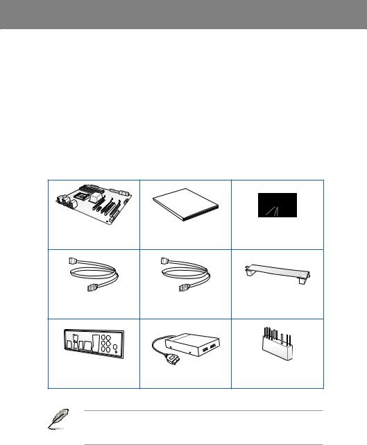
Chapter 1
|
Chapter 1: |
Product introduction |
1.1Welcome!
Thank you for buying an ASUS® P8P67 Deluxe motherboard!
The motherboard delivers a host of new features and latest technologies, making it another standout in the long line of ASUS quality motherboards!
Before you start installing the motherboard, and hardware devices on it, check the items in your package with the list below.
1.2Package contents
Check your motherboard package for the following items.
Chapter 1
Manual
User
|
ASUS P8P67 Deluxe |
User guide |
Support DVD |
|
|
motherboard |
|||
|
4 x Serial ATA 6.0 Gb/s cables 2 x Serial ATA 3.0 Gb/s cables |
1 x ASUS SLI™ bridge |
|
|
connector |
||
|
1 x ASUS Q-Shield |
1 x ASUS front panel |
1 x 2-in-1 ASUS Q-Connector kit |
|
|
USB 3.0 box |
|||
• If any of the above items is damaged or missing, contact your retailer.
• The illustrated items above are for reference only.Actual product specifications may vary with different models.

1 Chapter
1.3Special features
1.3.1Product highlights
LGA1155 socket for Intel® Second Generation Core™ i7 / Core™ i5 / Core™ i3 Processors
This motherboard supports the Intel® second generation Core™ i7 / Core™ i5 / Core™ i3 processors in LGA1155 package with memory and PCI Express controllers integrated to support 2-channel (4 DIMMs) DDR3 memory and 16 PCI Express 2.0 lanes. This provides great graphics performance. Intel® second generation Core™ i7 / Core™ i5 / Core™ i3 processors are among the most powerful and energy efficient CPUs in the world.
Intel® P67 Express Chipset
The Intel® P67 Express Chipset is the latest single-chipset design to support the new 1155 socket Intel® Core™ i7 / Core™ i5 / Core™ i3 second generation processors. It uses serial point-to-point links, which allows increased bandwidth and stability, and provides an improved performance. It also provides two SATA 6.0 Gb/s and four SATA 3.0 Gb/s ports for faster data retrieval at double the bandwidth of current bus systems.
Quad-GPU SLI™ and Quad-GPU CrossFireX™ Support
The motherboard’s powerful Intel® P67 platform optimizes PCIe allocation in multiple-GPU configurations of either SLI™ or CrossFireX™. This allows you to enjoy a never before-experienced brand new gaming style.
Dual-Channel DDR3 2200(O.C.) / 2133(O.C.) / 1866(O.C.) / 1600 / 1333 / 1066 Support
The motherboard supports DDR3 memory that features data transfer rates of 2200(O.C.) /
2133(O.C.) / 1866(O.C.) / 1600 / 1333 / 1066 MHz to meet the higher bandwidth requirements of the latest 3D graphics, multimedia, and Internet applications. The dualchannel DDR3 architecture enlarges the bandwidth of your system memory to boost system performance.
*Due to CPU behavior, DDR3 2200/2000/1800 MHz memory module will run at DDR3 2133/1866/1600 MHz frequency as default.
Complete USB 3.0 Integration
ASUS facilitates strategic USB 3.0 accessibility for both the front and rear panel – 4 USB 3.0 ports in total. Experience the latest plug & play connectivity at speeds up to 10 times faster than USB 2.0. The P8P67 Deluxe affords greater convenience to high speed connectivity.
Extra SATA 6.0 Gb/s Support
The Intel® P67 Express Chipset natively supports the next-generation Serial ATA (SATA) interface, delivering up to 6.0 Gb/s data transfer. ASUS provides extra SATA 6.0 Gb/s ports with enhanced scalability, faster data retrieval, and double the bandwidth of current bus systems.
ASUS Front Panel USB 3.0 Box
ASUS feature-proofs your PC with full USB 3.0 implementation for better computing through super-fast data transfers. The provided standard-sized USB 3.0 front panel box is compatible with most PC cases, letting you enjoy the faster throughput of USB 3.0 without relegating cables and devices to the hard-to-reach rear I/O or having to purchase a new case.
|
1-2 |
Chapter 1: Product Introduction |

1.3.2Dual Intelligent Processors 2 with DIGI+ VRM
The world’s first Dual Intelligent Processors fromASUS pioneered the use of two onboard chips—EPU (Energy Processing Unit) and TPU (TurboV Processing Unit). New generation Dual Intelligent Processors 2 with DIGI+ VRM digital power design launch control into a new era, empowering users with superior flexibility and perfect precision to ensure optimized performance, extreme system stability and greater power efficiency.
DIGI+ VRM
The new ASUS DIGI+ VRM design upgrades motherboard power delivery to a digital standard. The 16+2 digital architecture delivers twice the precision power, intelligently adjusting PWM voltage and frequency modulation with minimal power loss through BIOS tuning and exclusive user interface to increase over-clocking range while performance reaches its full potential. It also adjusts frequencies dynamically, cutting radiation interference by half to enhance system stability through enabling VRM spread spectrum. The DIGI+ VRM digital power design empowers users with superior flexibility and perfect precision to ensure optimized performance, extreme system stability, and greater power efficiency.
2X Precise Power Control
ASUS DIGI+ VRM delivers twice the precision power, intelligently adjusting PWM voltage and frequency modulation to minimize power loss while performance reaches its full potential.
2X Less Radiation
ASUS DIGI+ VRM adjusts frequencies dynamically, cutting radiation by half to enhance system stability through enabling spread spectrum.
TPU
Unleash your performance with ASUS’ simple onboard switch or AI Suite II utility. The TPU chip offers precise voltage control and advanced monitoring through Auto Tuning and TurboV functions.Auto tuning offers a user friendly way to automatically optimize the system for fast, yet stable clock speeds, while TurboV enables unlimited freedom to adjust CPU frequencies and ratios for optimized performance in diverse situations.
EPU
Tap into the world’s first real-time PC power saving chip through a simple onboard switch or AI Suite II utility. Get total system-wide energy optimization by automatically detecting current
PC loadings and intelligently moderating power consumption. This also reduces fan noise and extends component longevity.
1.3.3ASUS Exclusive Features
BT GO! (Bluetooth)
Onboard Bluetooth wireless design enables smart connectivity to Bluetooth devices with no additional adapter.ASUS BT GO! comes with 7 special functions that offer significant breakthrough in Bluetooth evolution, including Folder Sync, BT Transfer, BT Turbo Remote, BT-to-Net, Music Player, Shot and Send, and Personal Manager. All are accessible through the exclusive, user-friendly ASUS interface.
Chapter 1

1 Chapter
MemOK!
MemOK! quickly ensures memory boot compatibility. This remarkable memory rescue tool requires a mere push of a button to patch memory issues. MemOK! determines failsafe settings and dramatically improves your system boot success.
AI Suite II
With its user-friendly interface, ASUS AI Suite II consolidates all the exclusive ASUS features into one simple to use software package. It allows you to supervise overclocking, energy management, fan speed control, voltage and sensor readings, and even interact with mobile devices via Bluetooth. This all-in-one software offers diverse and ease to use functions, with no need to switch back and forth between different utilities.
1.3.4ASUS Quiet Thermal Solution
ASUS Fanless Design—Heat-pipe solution
The ASUS heat-pipe features 0-dB thermal solution that offers you a noiseless PC environment. Its beautiful shape upgrades the visual enjoyment and the heat-pipe design lowers the temperature of the chipset and power phase area through high efficient heatexchange. Combined with usability and aesthetics, the ASUS heat-pipe gives you an extremely silent and cooling experience with its elegant appearance.
DO NOT uninstall the heat-pipe by yourself. Doing so may bend the tubing and affect the heat dissipation performance.
ASUS Fan Xpert
ASUS Fan Xpert intelligently allows you to adjust both the CPU and chassis fan speeds according to different ambient temperatures caused by different climate conditions in different geographic regions and your PC’s loading. The built-in variety of useful profiles offer flexible controls of fan speed to achieve a quiet and cool environment.
1.3.5ASUS EZ DIY
ASUS EFI BIOS (EZ Mode)
The new ASUS EFI BIOS is an Extensible Firmware Interface that complies with uEFI architecture, offering a user-friendly interface that goes beyond traditional keyboard-only
BIOS controls to enable more flexible and convenient mouse input. Users can easily navigate the new EFI BIOS with the same smoothness as their operating system. The exclusive EZ Mode displays frequently-accessed setup info, while the Advance Mode is for experienced performance enthusiasts that demand far more intricate system settings.
Supports Hard Drives over 2.2TB
AUS EFI BIOS natively supports hard drives larger than 2.2TB in 64-bit, with full storage space utilization, helping deliver far more exciting computing than traditional BIOS versions!
ASUS Q-Design
ASUS Q-Design enhances your DIY experience. All of Q-LED, Q-Slot, Q-Code and Q-DIMM design speed up and simplify the DIY process!
|
1-4 |
Chapter 1: Product Introduction |

ASUS Q-Shield
The specially designedASUS Q-Shield does without the usual «fingers» — making it convenient and easy to install. With better electric conductivity, it ideally protects your motherboard against static electricity and shields it against Electronic Magnetic Interference (EMI).
ASUS Q-Connector
ASUS Q-Connector allows you to easily connect or disconnect the chassis front panel cables to the motherboard. This unique module eliminates the trouble of connecting the system panel cables one at a time and avoiding wrong cable connections.
ASUS EZ-Flash 2
ASUS EZ Flash 2 is a user-friendly utility that allows you to update the BIOS without using a bootable floppy disk or an OS-based utility.
1.3.6Other special features
Power eSATA on the Go
The Power eSATA solution combines the eSATA connector and power source together, allowing you to use external SATA devices without the need of additional power source*. Easily backup photos, videos and other entertainment contents on external devices.
*Power eSATA requires a specially designed signal cable to provide 5V power for the external SATA device. The cable is purchased separately.
DTS Surround Sensation UltraPC
DTS Surround Sensation UltraPC delivers exceptional 5.1 surround experience through the most common PC audio setups—your existing stereo speakers or headphones. In addition to virtual surround, “Bass enhancement” provides stronger low frequency bass sound, and
“Voice clarification” provides clear human dialogue even with loud background sound. With these technologies, you may experience a better home-theater audio with ease.
ErP Ready
The motherboard is European Union’s Energy-related Products (ErP) ready, and ErP requires products to meet certain energy efficiency requirement in regards to energy consumptions. This is in line withASUS vision of creating environment-friendly and energy-efficient products through product design and innovation to reduce carbon footprint of the product and thus mitigate environmental impacts.
Chapter 1

1 Chapter
|
1-6 |
Chapter 1: Product Introduction |

Chapter 2
|
Chapter 2: |
Hardware information |
2.1Before you proceed
Take note of the following precautions before you install motherboard components or change any motherboard settings.
• Unplug the power cord from the wall socket before touching any component.
• Before handling components, use a grounded wrist strap or touch a safely grounded object or a metal object, such as the power supply case, to avoid damaging them due to static electricity.
•Hold components by the edges to avoid touching the ICs on them.
•Whenever you uninstall any component, place it on a grounded antistatic pad or in the bag that came with the component.
•Before you install or remove any component, ensure that the ATX power supply is switched off or the power cord is detached from the power supply. Failure to do so may cause severe damage to the motherboard, peripherals, or components.

2.2Motherboard overview
2.2.1Motherboard layout
2 Chapter
Refer to 2.2.7 Internal connectors and 2.3.10 Rear panel connection for more information about rear panel connectors and internal connectors.
|
2-2 |
Chapter 2: Hardware information |
![]()
Layout contents
|
Connectors/Jumpers/Slots |
Page |
|
|
1. |
ATX power connectors (24-pin EATXPWR, 8-pin EATX12V) |
2-31 |
|
2. |
LGA1155 CPU socket |
2-4 |
|
3. |
CPU, chassis, and power fan connectors (4-pin CPU_FAN, |
2-30 |
|
4-pin CHA_FAN1, 3-pin CHA_FAN2, 3-pin PWR_FAN1–2) |
||
|
4. |
DDR3 DIMM slots |
2-5 |
|
5. |
TPU switch |
2-17 |
|
6. |
MemOK! switch |
2-17 |
|
7. |
USB 3.0 connector (20-1 pin USB3_34) |
2-28 |
|
8. |
Marvell® Serial ATA 6.0 Gb/s connectors |
2-27 |
|
(7-pin SATA6G_E1/E2 [navy blue]) |
||
|
9. |
Intel® P67 Serial ATA 6.0 Gb/s connectors |
2-25 |
|
(7-pin SATA6G_1/2 [gray]) |
||
|
10. |
Intel® P67 Serial ATA 3.0 Gb/s connectors |
2-26 |
|
(7-pin SATA3G_3–6 [blue]) |
||
|
11. |
System panel connector (20-8 pin PANEL) |
2-33 |
|
12. |
Q-Code LED (LED1, LED2) |
2-21 |
|
13. |
USB 2.0 connectors (10-1 pin USB1112, USB1314) |
2-28 |
|
14. |
Reset switch |
2-15 |
|
15. |
Power-on switch |
2-15 |
|
16. |
EPU switch |
2-18 |
|
17. |
IEEE 1394a port connector (10-1 pin IE1394_2) |
2-29 |
|
18. |
Front panel audio connector (10-1 pin AAFP) |
2-31 |
|
19. |
Digital audio connector (4-1 pin SPDIF_OUT) |
2-29 |
Chapter 2
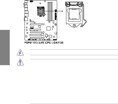
2 Chapter
2.2.2Central Processing Unit (CPU)
The motherboard comes with a surface mount LGA1155 socket designed for the Intel® 2nd Generation Core™ i7 / Core™ i5 / Core™ i3 Processors.
Ensure that all power cables are unplugged before installing the CPU.
•The LGA1156 CPU is incompatible with the LGA1155 socket. DO NOT install a LGA1156 CPU on the LGA1155 socket.
•Upon purchase of the motherboard, ensure that the PnP cap is on the socket and the socket contacts are not bent. Contact your retailer immediately if the PnP cap is missing, or if you see any damage to the PnP cap/socket contacts/motherboard components. ASUS will shoulder the cost of repair only if the damage is shipment/ transit-related.
•Keep the cap after installing the motherboard. ASUS will process Return Merchandise
Authorization (RMA) requests only if the motherboard comes with the cap on the
LGA1155 socket.
•The product warranty does not cover damage to the socket contacts resulting from incorrect CPU installation/removal, or misplacement/loss/incorrect removal of the PnP cap.
|
2-4 |
Chapter 2: Hardware information |
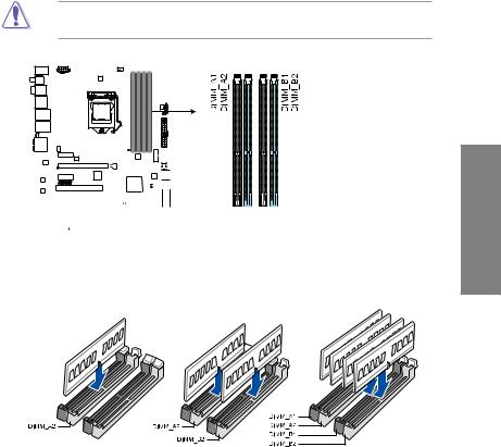
Memory configurations
You may install 1GB, 2GB and 4GB unbuffered and non ECC DDR3 DIMMs into the DIMM sockets.
2 Chapter
•You may install varying memory sizes in ChannelAand Channel B. The system maps the total size of the lower-sized channel for the dual-channel configuration.Any excess memory from the higher-sized channel is then mapped for single-channel operation.
•Due to CPU behavior, DDR3 2200/2000/1800 MHz memory module will run at DDR3 2133/1866/1600 MHz frequency as default.
•According to Intel® spec, the max. 32GB memory capacity can be supported with DIMMs of 8GB (or above). ASUS will update QVL once the DIMMs are available on the market.
•According to Intel CPU spec, DIMM voltage below 1.65V is recommended to protect the CPU.
•Always install DIMMs with the same CAS latency. For optimum compatibility, we recommend that you obtain memory modules from the same vendor.
•Due to the memory address limitation on 32-bit Windows OS, when you install 4GB or more memory on the motherboard, the actual usable memory for the OS can be about 3GB or less. For effective use of memory, we recommend that you do any of the following:
—Use a maximum of 3GB system memory if you are using a 32-bit Windows OS.
—Install a 64-bit Windows OS when you want to install 4GB or more on the motherboard.
For more details, refer to the Microsoft® support site at http://support.microsoft.com/kb/929605/en-us.
•This motherboard does not support DIMMs made up of 512Mb (64MB) chips or less (Memory chip capacity counts in Megabit, 8 Megabit/Mb = 1 Megabyte/MB).
•The default memory operation frequency is dependent on its Serial Presence Detect (SPD), which is the standard way of accessing information from a memory module. Under the default state, some memory modules for overclocking may operate at a lower frequency than the vendor-marked value. To operate at the vendor-marked
or at a higher frequency, refer to section 3.4 Ai Tweaker menu for manual memory frequency adjustment.
•For system stability, use a more efficient memory cooling system to support a full memory load (4 DIMMs) or overclocking condition.
P8P67 Deluxe Motherboard Qualified Vendors Lists (QVL)
DDR3 2200(O.C.) MHz capability
|
Vendors |
Part No. |
Size |
SS/ |
Chip |
Chip |
Timing |
Voltage |
DIMM socket support (Optional) |
||
|
DS |
Brand |
NO. |
1 DIMM |
2 DIMM |
4 DIMM |
|||||
|
G.SKILL |
F3-17600CL7D-4GBFLS(XMP) |
4GB (2 x 2GB) |
DS |
— |
— |
7-10-10-28 |
1.65 |
• |
• |
• |
|
G.SKILL |
F3-17600CL8D-4GBPS(XMP) |
4GB (2 x 2GB) |
DS |
— |
— |
8-8-8-24 |
1.65 |
• |
• |
|
|
G.SKILL |
F3-17600CL9D-4GBTDS(XMP) |
4GB (2 x 2GB) |
DS |
— |
— |
9-9-9-24 |
1.65 |
• |
• |
|
|
KINGMAX |
FLKE85F-B8KHA(XMP) |
4GB (2 x 2GB) |
DS |
— |
— |
— |
1.5~1.7 |
• |
• |
|
|
KINGMAX |
FLKE85F-B8KJAA-FEIS(XMP) |
4GB (2 x 2GB) |
DS |
Kingmax |
N/A |
— |
— |
• |
• |
*The memory modules in 2200MHz and above are supported by this motherboard; however, the actual frequency support varies depending on the O.C. margin of the installed CPU.
|
2-6 |
Chapter 2: Hardware information |

P8P67 Deluxe Motherboard Qualified Vendors Lists (QVL)
DDR3 2133(O.C.) MHz capability
|
Vendor |
Part No. |
Size |
SS/ |
Chip |
Chip NO. |
Timing |
Voltage |
DIMM socket support |
||
|
(Optional) |
||||||||||
|
DS |
Brand |
|||||||||
|
1 DIMM |
2 DIMM |
4 DIMM |
||||||||
|
G.SKILL |
F3-17600CL9D-4GBTDS(XMP) |
4GB(2 x 2GB) |
DS |
— |
— |
9-9-9-24 |
1.65 |
• |
• |
*The above QVL is for the DDR3 2200 MHz memory module. Due to CPU behavior, DDR3 2200 MHz memory module will run at DDR3 2133 MHz frequency.
|
Vendor |
Part No. |
Size |
SS/ |
Chip |
Chip NO. |
Timing |
Voltage |
DIMM socket support |
|||
|
(Optional) |
|||||||||||
|
DS |
Brand |
||||||||||
|
1 DIMM |
2 DIMM |
4 DIMM |
|||||||||
|
G.SKILL |
F3-17066CL9D-4GBTDS(XMP) |
4GB ( 2x 2GB ) |
DS |
— |
— |
— |
1.65 |
• |
• |
• |
|
|
G.SKILL |
F3-17066CL8D-4GBPS(XMP) |
4GB(2 x 2GB) |
DS |
— |
— |
8-8-8-24 |
1.65 |
• |
• |
||
|
G.SKILL |
F3-17066CL9D-4GBTD(XMP) |
4GB(2 x 2GB) |
DS |
— |
— |
9-9-9-24 |
1.65 |
• |
• |
||
|
G.SKILL |
F3-17066CL9T-6GB-T |
6GB(3 x 2GB) |
DS |
— |
— |
9-9-9-24 |
1.65 |
• |
• |
||
|
GEIL |
GE34GB2133C9DC(XMP) |
4GB(2 x 2GB) |
DS |
— |
— |
9-9-9-28 |
1.65 |
• |
• |
||
|
GEIL |
GU34GB2133C9DC(XMP) |
4GB(2 x 2GB) |
DS |
— |
— |
9-9-9-28 |
1.65 |
• |
• |
||
|
KINGSTON |
KHX2133C9D3T1K2/4GX(XMP) |
4GB(2 x 2GB) |
DS |
— |
— |
9 |
1.65 |
• |
• |
• |
|
|
Patriot |
PVV34G2133C9K(XMP) |
4GB ( 2x 2GB ) |
DS |
— |
— |
9-11-9-27 |
1.66 |
• |
• |
• |
P8P67 Deluxe Motherboard Qualified Vendors Lists (QVL)
DDR3 1866(O.C.) MHz capability
|
Vendor |
Part No. |
Size |
SS/ |
Chip |
Chip NO. |
Timing |
Voltage |
DIMM socket support |
|||
|
(Optional) |
|||||||||||
|
DS |
Brand |
||||||||||
|
1 DIMM |
2 DIMM |
4 DIMM |
|||||||||
|
Apacer |
78.AAGD5.9KD(XMP) |
6GB(3 x 2GB) |
DS |
— |
— |
9-9-9-27 |
— |
• |
• |
• |
|
|
CORSAIR |
CMT6GX3M3A2000C8(XMP) |
6GB ( 3x 2GB ) |
DS |
— |
— |
8-9-8-24 |
1.65 |
• |
• |
• |
|
|
Crucial |
BL12864BE2009.8SFB3(EPP) |
1GB |
SS |
— |
— |
9-9-9-28 |
2 |
• |
• |
||
|
G.SKILL |
F3-16000CL6Q-8GBPIS(XMP) |
8GB ( 4x 2GB ) |
SS |
— |
— |
6-9-6-24 |
1.65 |
• |
• |
||
|
G.SKILL |
F3-16000CL9D-4GBRH(XMP) |
4GB(2 x 2GB) |
DS |
— |
— |
9-9-9-24 |
1.65 |
• |
• |
• |
|
|
G.SKILL |
F3-16000CL9D-4GBTD(XMP) |
4GB(2 x 2GB) |
DS |
— |
— |
9-9-9-24 |
1.65 |
• |
• |
• |
|
|
G.SKILL |
F3-16000CL7T-6GBPS(XMP) |
6GB(3 x 2GB) |
DS |
— |
— |
7-8-7-20 |
1.65 |
• |
• |
||
|
G.SKILL |
F3-16000CL9T-6GBPS(XMP) |
6GB(3 x 2GB) |
DS |
— |
— |
9-9-9-24 |
1.65 |
• |
• |
||
|
G.SKILL |
F3-16000CL9T-6GBTD(XMP) |
6GB(3 x 2GB) |
DS |
— |
— |
9-9-9-24 |
1.6 |
• |
• |
• |
|
|
G.SKILL |
F3-16000CL7Q-8GBFLS(XMP) |
8GB(4 x 2GB) |
DS |
— |
— |
7-9-7-24 |
1.65 |
• |
• |
||
|
GEIL |
GU34GB2000C9DC(XMP) |
4GB(2 x 2GB) |
DS |
— |
— |
9-9-9-28 |
2 |
• |
• |
||
|
GEIL |
GE38GB2000C9QC(XMP) |
8GB(4 x 2GB) |
DS |
— |
— |
9-9-9-28 |
1.65 |
• |
• |
||
|
KINGSTON |
KHX2000C9D3T1K2/4GX(XMP) |
4GB ( 2x 2GB ) |
DS |
— |
— |
— |
1.65 |
• |
• |
• |
|
|
Transcend |
N/A(XMP) |
6GB ( 3x 2GB ) |
DS |
— |
— |
— |
— |
• |
• |
||
|
Gingle |
9CAASS37AZZ01D1 |
2GB |
DS |
— |
— |
9-9-9-24 |
— |
• |
• |
• |
|
|
Patriot |
PVT36G2000LLK(XMP) |
6GB(3 x 2GB) |
DS |
— |
— |
8-8-8-24 |
1.65 |
• |
• |
||
|
Slicon Power |
SP002GBLYU200S02(XMP) |
2GB |
DS |
— |
— |
— |
— |
• |
• |
||
|
Team |
TXD32048M2000C9(XMP) |
2GB |
DS |
Team |
T3D1288RT-20 |
9-9-9-24 |
1.5 |
• |
• |
||
|
Team |
TXD32048M2000C9-L(XMP) |
2GB |
DS |
Team |
T3D1288LT-20 |
9-9-9-24 |
1.5 |
• |
• |
||
|
Team |
TXD32048M2000C9-L(XMP) |
2GB |
DS |
Team |
T3D1288RT-20 |
9-9-9-24 |
1.6 |
• |
• |
• |
*The above QVL is for the DDR3 2000 MHz memory module. Due to CPU behavior, DDR3 2000 MHz memory module will run at DDR3 1866 MHz frequency.
|
Vendor |
Part No. |
Size |
SS/ |
Chip Brand |
Chip NO. |
Timing |
Voltage |
DIMM socket support |
|||
|
(Optional) |
|||||||||||
|
DS |
|||||||||||
|
1 DIMM |
2 DIMM |
4 DIMM |
|||||||||
|
CORSAIR |
CMT6GX3M3A1866C9(XMP) |
6GB ( 3x 2GB ) |
DS |
— |
— |
9-9-9-24 |
1.65 |
• |
• |
• |
|
|
CORSAIR |
TR3X6G1866C9DVer4.1(XMP) |
6GB(3 x 2GB) |
DS |
— |
— |
9-9-9-24 |
1.65 |
• |
• |
||
|
G.SKILL |
F3-15000CL9D-4GBRH (XMP) |
4GB(2 x 2GB) |
DS |
— |
— |
9-9-9-24 |
1.65 |
• |
• |
• |
|
|
G.SKILL |
F3-15000CL9D-4GBTD(XMP) |
4GB(2 x 2GB) |
DS |
— |
— |
9-9-9-24 |
1.65 |
• |
• |
• |
|
|
OCZ |
OCZ3P1866LV4GK |
4GB(2 x 2GB) |
DS |
— |
— |
9-9-9 |
1.65 |
• |
• |
||
|
OCZ |
OCZ3P1866C9LV6GK |
6GB(3 x 2GB) |
DS |
— |
— |
9-9-9 |
1.65 |
• |
• |
• |
|
|
OCZ |
OCZ3RPR1866C9LV6GK |
6GB(3 x 2GB) |
DS |
— |
— |
9-9-9 |
1.65 |
• |
• |
Chapter 2

2 Chapter
P8P67 Deluxe Motherboard Qualified Vendors Lists (QVL)
DDR3 1600 MHz capability
|
Vendor |
Part No. |
Size |
SS/ |
Chip Brand |
Chip NO. |
Timing |
Voltage |
DIMM socket support |
||||
|
(Optional) |
||||||||||||
|
DS |
||||||||||||
|
1 DIMM |
2 DIMM |
4 DIMM |
||||||||||
|
G.SKILL |
F3-14400CL6D-4GBFLS(XMP) |
4GB(2 x 2GB) |
DS |
— |
— |
6-8-6-24 |
1.65 |
• |
• |
|||
|
G.SKILL |
F3-14400CL9D-4GBRL(XMP) |
4GB(2 x 2GB) |
DS |
— |
— |
9-9-9-24 |
1.6 |
• |
• |
• |
||
|
KINGSTON |
KHX1800C9D3T1K3/6GX(XMP) |
6GB(3 x 2GB) |
DS |
— |
— |
— |
1.65 |
• |
• |
*The above QVL is for the DDR3 1800 MHz memory module. Due to CPU behavior, DDR3 1800 MHz memory module will run at DDR3 1600 MHz frequency.
|
Vendor |
Part No. |
Size |
SS/ |
Chip |
Chip NO. |
Timing |
Voltage |
DIMM socket support |
|||
|
(Optional) |
|||||||||||
|
DS |
Brand |
||||||||||
|
1 DIMM |
2 DIMM |
4 DIMM |
|||||||||
|
A-DATA |
AX3U1600GC4G9-2G |
8GB ( 2x 4GB ) |
DS |
— |
— |
9-9-9-24 |
1.55~1.75 |
• |
• |
• |
|
|
CORSAIR |
TR3X3G1600C8DVer2.1(XMP) |
3GB(3 x 1GB) |
SS |
— |
— |
8-8-8-24 |
1.65 |
• |
• |
• |
|
|
CORSAIR |
CMG4GX3M2A1600C6 |
4GB ( 2x 2GB ) |
DS |
— |
— |
6-6-6-18 |
1.65 |
• |
• |
• |
|
|
CORSAIR |
CMD4GX3M2B1600C8 |
4GB( 2x 2GB ) |
DS |
— |
— |
8-8-8-24 |
1.65 |
• |
• |
• |
|
|
CORSAIR |
CMG4GX3M2A1600C6 |
4GB( 2x 2GB ) |
DS |
— |
— |
6-6-6-18 |
1.65 |
• |
• |
||
|
CORSAIR |
CMX4GX3M2A1600C8(XMP) |
4GB( 2x 2GB ) |
DS |
— |
— |
8-8-8-24 |
1.65 |
• |
• |
• |
|
|
CORSAIR |
CMD4GX3M2A1600C8(XMP) |
4GB(2 x 2GB) |
DS |
— |
— |
8-8-8-24 |
1.65 |
• |
• |
• |
|
|
CORSAIR |
CMG4GX3M2A1600C7(XMP) |
4GB(2 x 2GB) |
DS |
— |
— |
7-7-7-20 |
1.65 |
• |
• |
||
|
CORSAIR |
CMX4GX3M2A1600C9(XMP) |
4GB(2 x 2GB) |
DS |
— |
— |
9-9-9-24 |
1.65 |
• |
• |
• |
|
|
CORSAIR |
TR3X6G1600C8D |
6GB(3 x 2GB) |
DS |
— |
— |
8-8-8-24 |
1.65 |
• |
• |
||
|
CORSAIR |
CMX8GX3M4A1600C9(XMP) |
8GB(4 x 2GB) |
DS |
— |
— |
9-9-9-24 |
1.65 |
• |
• |
||
|
Crucial |
BL12864BN1608.8FF(XMP) |
2GB( 2x 1GB ) |
SS |
— |
— |
8-8-8-24 |
1.65 |
• |
• |
• |
|
|
Crucial |
BL25664BN1608.16FF(XMP) |
2GB |
DS |
— |
— |
8-8-8-24 |
1.65 |
• |
• |
• |
|
|
G.SKILL |
F3-12800CL9D-4GBNG |
4GB( 2x 2GB ) |
SS |
— |
— |
— |
1.6 |
• |
• |
• |
|
|
G.SKILL |
F3-12800CL9D-4GBRL |
4GB(2 x 2GB) |
SS |
— |
— |
— |
1.6 |
• |
• |
• |
|
|
G.SKILL |
F3-12800CL7D-4GBRH(XMP) |
4GB(2 x 2GB) |
DS |
— |
— |
7-7-7-24 |
1.65 |
• |
• |
• |
|
|
G.SKILL |
F3-12800CL8D-4GBRM(XMP) |
4GB(2 x 2GB) |
DS |
— |
— |
8-8-8-24 |
1.6 |
• |
• |
• |
|
|
G.SKILL |
F3-12800CL9D-4GBECO(XMP) |
4GB(2 x 2GB) |
DS |
— |
— |
9-9-9-24 |
1.35 |
• |
• |
• |
|
|
G.SKILL |
F3-12800CL8T-6GBPI(XMP) |
6GB(3 x 2GB) |
DS |
— |
— |
8-8-8-21 |
1.6~1.65 |
• |
• |
||
|
G.SKILL |
F3-12800CL9T-6GBNQ |
6GB(3 x 2GB) |
DS |
— |
— |
9-9-9-24 |
1.5-1.6 |
• |
• |
• |
|
|
GEIL |
GV34GB1600C8DC(XMP) |
4GB(2 x 2GB) |
DS |
— |
— |
8-8-8-28 |
1.6 |
• |
• |
||
|
KINGMAX |
FLGD45F-B8MF7(XMP) |
1GB |
SS |
— |
— |
— |
• |
• |
• |
||
|
KINGSTON |
KHX1600C8D3K2/4GX(XMP) |
4GB ( 2x 2GB ) |
DS |
— |
— |
8 |
1.65 |
• |
• |
• |
|
|
OCZ |
OCZ3P1600EB1G |
1GB |
SS |
— |
— |
7-6-6-24 |
— |
• |
• |
||
|
OCZ |
OCZ3G1600LV3GK |
3GB(3 x 1GB) |
SS |
— |
— |
8-8-8 |
1.65 |
• |
• |
• |
|
|
OCZ |
OCZ3P1600LV3GK |
3GB(3 x 1GB) |
SS |
— |
— |
7-7-7 |
1.65 |
• |
• |
• |
|
|
OCZ |
OCZ3BE1600C8LV4GK |
4GB( 2x 2GB ) |
DS |
— |
— |
8-8-8 |
1.65 |
• |
• |
||
|
OCZ |
OCZ3BE1600C8LV4GK |
4GB( 2x 2GB ) |
DS |
— |
— |
8-8-8 |
1.65 |
• |
• |
• |
|
|
OCZ |
OCZ3P1600LV4GK |
4GB(2 x 2GB) |
DS |
— |
— |
7-7-7 |
1.65 |
• |
• |
||
|
OCZ |
OCZ3X1600LV4GK(XMP) |
4GB(2 x 2GB) |
DS |
— |
— |
8-8-8 |
1.65 |
• |
• |
• |
|
|
OCZ |
OCZ3FXE1600C7LV6GK |
6GB ( 3x 2GB ) |
DS |
— |
— |
7-7-7 |
1.65 |
• |
• |
||
|
OCZ |
OCZ3FXE1600C7LV6GK |
6GB(3 x 2GB) |
DS |
— |
— |
7-7-7 |
1.65 |
• |
• |
||
|
OCZ |
OCZ3G1600LV6GK |
6GB(3 x 2GB) |
DS |
— |
— |
8-8-8 |
1.65 |
• |
• |
||
|
OCZ |
OCZ3X1600LV6GK(XMP) |
6GB(3 x 2GB) |
DS |
— |
— |
8-8-8 |
1.65 |
• |
• |
• |
|
|
OCZ |
OCZ3X1600LV6GK(XMP) |
6GB(3 x 2GB) |
DS |
— |
— |
8-8-8 |
1.65 |
• |
• |
• |
|
|
Super Talent |
WP160UX4G9(XMP) |
4GB(2 x 2GB) |
DS |
— |
— |
9 |
— |
• |
• |
• |
|
|
Super Talent |
WB160UX6G8(XMP) |
6GB(3 x 2GB) |
DS |
— |
— |
— |
— |
• |
• |
• |
|
2-8 |
Chapter 2: Hardware information |

P8P67 Deluxe Motherboard Qualified Vendors Lists (QVL)
DDR3 1600 MHz capability (continued)
|
Vendor |
Part No. |
Size |
SS/ |
Chip |
Chip NO. |
Timing |
Voltage |
DIMM socket support |
|||
|
(Optional) |
|||||||||||
|
DS |
Brand |
||||||||||
|
1 DIMM |
2 DIMM |
4 DIMM |
|||||||||
|
Super Talent |
WB160UX6G8(XMP) |
6GB(3 x 2GB) |
DS |
— |
— |
8 |
— |
• |
• |
• |
|
|
EK Memory |
EKM324L28BP8-I16(XMP) |
4GB( 2x 2GB ) |
DS |
— |
— |
9 |
— |
• |
• |
• |
|
|
EK Memory |
EKM324L28BP8-I16(XMP) |
4GB(2 x 2GB) |
DS |
— |
— |
9 |
— |
• |
• |
• |
|
|
GoodRam |
GR1600D364L9/2G |
2GB |
DS |
GoodRam |
GF1008KC-JN |
— |
— |
• |
• |
• |
|
|
KINGTIGER |
KTG2G1600PG3(XMP) |
2GB |
DS |
— |
— |
— |
— |
• |
• |
• |
|
|
Mushkin |
996805(XMP) |
4GB ( 2x 2GB ) |
DS |
— |
— |
6-8-6-24 |
1.65 |
• |
• |
||
|
Mushkin |
996657 |
4GB(2 x 2GB) |
DS |
— |
— |
7-7-7-20 |
— |
• |
• |
• |
|
|
Mushkin |
998805(XMP) |
6GB ( 3x 2GB ) |
DS |
— |
— |
6-8-6-24 |
1.65 |
• |
• |
||
|
Patriot |
PVT33G1600ELK |
3GB(3 x 1GB) |
SS |
— |
— |
9-9-9-24 |
1.65 |
• |
• |
||
|
Patriot |
PGS34G1600LLKA2 |
4GB ( 2x 2GB ) |
DS |
— |
— |
8-8-8-24 |
1.7 |
• |
• |
• |
|
|
Patriot |
PGS34G1600LLKA |
4GB( 2x 2GB ) |
DS |
— |
— |
7-7-7-20 |
1.7 |
• |
• |
• |
|
|
PATRIOT |
PGS34G1600LLKA |
4GB(2 x 2GB) |
DS |
— |
— |
7-7-7-20 |
1.7 |
• |
• |
• |
|
|
Patriot |
PVS34G1600ELK |
4GB(2 x 2GB) |
DS |
— |
— |
9-9-9-24 |
1.8 |
• |
• |
||
|
Patriot |
PVS34G1600LLK(XMP) |
4GB(2 x 2GB) |
DS |
— |
— |
7-7-7-20 |
1.9 |
• |
• |
||
|
Patriot |
PVS34G1600LLKN |
4GB(2 x 2GB) |
DS |
— |
— |
7-7-7-20 |
2.0 |
• |
• |
||
|
Patriot |
PVT36G1600ELK |
6GB(3 x 2GB) |
DS |
— |
— |
9-9-9-24 |
1.65 |
• |
• |
• |
|
|
Patriot |
PVT36G1600ELK |
6GB(3 x 2GB) |
DS |
— |
— |
9-9-9-24 |
1.65 |
• |
• |
• |
|
|
Patriot |
PVT36G1600LLK(XMP) |
6GB(3 x 2GB) |
DS |
— |
— |
8-8-8-24 |
1.65 |
• |
• |
P8P67 Deluxe Motherboard Qualified Vendors Lists (QVL)
DDR3 1333 MHz capability
|
Vendor |
Part No. |
Size |
SS/ |
Chip Brand |
Chip NO. |
Timing |
Voltage |
DIMM socket support |
||
|
(Optional) |
||||||||||
|
DS |
||||||||||
|
1 DIMM |
2 DIMM |
4 DIMM |
||||||||
|
A-DATA |
SU3U1333B1G9-B |
1GB |
SS |
Hynix |
H5TQ1G83TFR |
— |
— |
• |
• |
• |
|
A-DATA |
SU3U1333B2G9-B |
2GB |
DS |
Hynix |
H5TQ1G83TFR |
— |
— |
• |
• |
• |
|
A-DATA |
SU3U1333C4G9-B |
4GB |
DS |
Hynix |
H5TQ2G83AFR |
— |
— |
• |
• |
• |
|
Apacer |
78.01GC6.9L0 |
1GB |
SS |
Apacer |
AM5D5808DEJSBG |
9 |
— |
• |
• |
• |
|
CORSAIR |
TR3X3G1333C9 (Ver2.1) |
3GB(3 x 1GB) |
SS |
— |
— |
9-9-9-24 |
1.5 |
• |
• |
• |
|
CORSAIR |
CM3X1024-1333C9DHX |
1GB |
DS |
— |
— |
— |
1.1 |
• |
• |
|
|
CORSAIR |
CMX8GX3M4A1333C9 |
8GB(4 x 2GB) |
DS |
— |
— |
9-9-9-24 |
1.5 |
• |
• |
• |
|
Crucial |
CT12864BA1339.8FF |
1GB |
SS |
MICRON |
D9KPT |
9 |
— |
• |
• |
• |
|
Crucial |
CT12864BA1339.8SFD |
1GB |
SS |
MICRON |
MT8JF12864AY-1G4D1 |
— |
— |
• |
• |
• |
|
Crucial |
CT12872BA1339.9FF |
1GB |
SS |
MICRON |
D9KPT(ECC) |
9 |
— |
• |
• |
• |
|
Crucial |
BL25664BN1337.16FF(XMP) |
2GB |
DS |
— |
— |
7-7-7-24 |
1.65 |
• |
• |
• |
|
Crucial |
CT25664BA1339.16FF |
2GB |
DS |
MICRON |
D9KPT |
9 |
— |
• |
• |
• |
|
Crucial |
CT25664BA1339.16SFD |
2GB |
DS |
MICRON |
D9JNM |
— |
— |
• |
• |
• |
|
Crucial |
CT25672BA1339.18FF |
2GB |
DS |
MICRON |
D9KPT(ECC) |
9 |
— |
• |
• |
• |
|
ELPIDA |
EBJ10UE8BDF0-DJ-F |
1GB |
SS |
ELPIDA |
J1108BDSE-DJ-F |
— |
— |
• |
• |
• |
|
ELPIDA |
EBJ10UE8EDF0-DJ-F |
1GB |
SS |
ELPIDA |
J1108EDSE-DJ-F |
— |
— |
• |
• |
• |
|
ELPIDA |
EBJ21UE8BAW0-DJ-E |
2GB |
DS |
ELPIDA |
J1108BABG-DJ-E |
9 |
— |
• |
• |
• |
Chapter 2

2 Chapter
P8P67 Deluxe Motherboard Qualified Vendors Lists (QVL)
DDR3 1333 MHz capability (continued)
|
Vendor |
Part No. |
Size |
SS/ |
Chip Brand |
Chip NO. |
Timing |
Voltage |
DIMM socket support |
|||
|
(Optional) |
|||||||||||
|
DS |
|||||||||||
|
1 DIMM |
2 DIMM |
4 DIMM |
|||||||||
|
ELPIDA |
EBJ21UE8BDF0-DJ-F |
2GB |
DS |
ELPIDA |
J1108BDSE-DJ-F |
— |
— |
• |
• |
• |
|
|
G.SKILL |
F3-10600CL8D-2GBHK |
2GB(2 x 1GB) |
SS |
— |
— |
— |
1.65 |
• |
• |
• |
|
|
G.SKILL |
F3-10666CL7D-4GBPI(XMP) |
4GB(2 x 2GB) |
DS |
— |
— |
7-7-7-21 |
1.5 |
• |
• |
• |
|
|
G.SKILL |
F3-10666CL7D-4GBRH(XMP) |
4GB(2 x 2GB) |
DS |
— |
— |
7-7-7-21 |
1.5 |
• |
• |
• |
|
|
G.SKILL |
F3-10666CL8D- |
4GB(2 x 2GB) |
DS |
— |
— |
8-8-8-24 |
1.35 |
• |
• |
• |
|
|
4GBECO(XMP) |
|||||||||||
|
G.SKILL |
F3-10666CL8D-4GBHK(XMP) |
4GB(2 x 2GB) |
DS |
— |
— |
8-8-8-21 |
1.5-1.6 |
• |
• |
• |
|
|
G.SKILL |
F3-10666CL8D- |
4GB(2 x 2GB) |
DS |
— |
— |
8-8-8-21 |
1.5-1.6 |
• |
• |
• |
|
|
4GBRM(XMP) |
|||||||||||
|
G.SKILL |
F3-10666CL9T-6GBNQ |
6GB(3 x 2GB) |
DS |
— |
— |
9-9-9-24 |
1.5 |
• |
• |
• |
|
|
G.SKILL |
F3-10666CL9D-8GBRL |
8GB ( 2x 4GB ) |
DS |
— |
— |
9-9-9-24 |
1.5 |
• |
• |
• |
|
|
GEIL |
GG34GB1333C9DC |
4GB ( 2x 2GB ) |
DS |
GEIL |
GL1L128M88BA115FW |
9-9-9-24 |
1.3 |
• |
• |
• |
|
|
GEIL |
GB34GB1333C7DC |
4GB(2 x 2GB) |
DS |
GEIL |
GL1L128M88BA15FW |
7-7-7-24 |
1.5 |
• |
• |
• |
|
|
GEIL |
GG34GB1333C9DC |
4GB(2 x 2GB) |
DS |
GEIL |
GL1L128M88BA12N |
9-9-9-24 |
1.3 |
• |
• |
• |
|
|
GEIL |
GV34GB1333C7DC |
4GB(2 x 2GB) |
DS |
— |
— |
7-7-7-24 |
1.5 |
• |
• |
||
|
Hynix |
HMT112U6BFR8C-H9 |
1GB |
SS |
Hynix |
H5TQ1G83BFR |
9 |
— |
• |
• |
• |
|
|
Hynix |
HMT112U6TFR8A-H9 |
1GB |
SS |
Hynix |
H5TC1G83TFR |
— |
— |
• |
• |
• |
|
|
Hynix |
HMT125U6BFR8C-H9 |
2GB |
DS |
Hynix |
H5TQ1G83BFRH9C |
9 |
— |
• |
• |
• |
|
|
Hynix |
HMT125U6TFR8A-H9 |
2GB |
DS |
Hynix |
H5TC1G83TFR |
— |
— |
• |
• |
• |
|
|
KINGMAX |
FLFE85F-B8KL9 |
2GB |
DS |
KINGMAX |
KFB8FNLXL-BNF-15A |
— |
— |
• |
• |
• |
|
|
Kingston |
KVR1333D3N9/1G |
1GB |
SS |
Elpida |
J1108BDSE-DJ-F |
9 |
1.5 |
• |
• |
• |
|
|
Kingston |
KVR1333D3N9/2G |
2GB |
DS |
Kingston |
D1288JPNDPLD9U |
9 |
1.5 |
• |
• |
• |
|
|
Kingston |
KHX1333C9D3UK2/ |
4GB ( 2x 2GB ) |
DS |
— |
— |
9 |
1.25 |
• |
• |
• |
|
|
4GX(XMP) |
|||||||||||
|
MICRON |
MT8JTF12864AZ-1G4F1 |
1GB |
SS |
MICRON |
9FF22 D9KPT |
9 |
— |
• |
• |
• |
|
|
MICRON |
MT8JTF12864AZ-1G4F1 |
1GB |
SS |
MICRON |
D9KPT |
9 |
— |
• |
• |
• |
|
|
MICRON |
MT9JSF12872AZ-1G4F1 |
1GB |
SS |
MICRON |
D9KPT(ECC) |
9 |
— |
• |
• |
• |
|
|
MICRON |
MT16JF25664AZ-1G4F1 |
2GB |
DS |
MICRON |
D9KPT |
9 |
— |
• |
• |
• |
|
|
MICRON |
MT16JTF25664AZ-1G4F1 |
2GB |
DS |
MICRON |
9FF22 D9KPT |
9 |
— |
• |
• |
• |
|
|
MICRON |
MT18JSF25672AZ-1G4F1 |
2GB |
DS |
MICRON |
D9KPT(ECC) |
9 |
— |
• |
• |
• |
|
|
OCZ |
OCZ3RPX1333EB2GK |
1GB |
SS |
— |
— |
— |
— |
• |
• |
||
|
OCZ |
OCZ3G1333LV3GK |
3GB(3 x 1GB) |
SS |
— |
— |
9-9-9 |
1.65 |
• |
• |
||
|
OCZ |
OCZ3P1333LV3GK |
3GB(3 x 1GB) |
SS |
— |
— |
7-7-7 |
1.65 |
• |
• |
• |
|
|
OCZ |
OCZ3P13332GK |
1GB |
DS |
— |
— |
7-7-7-20 |
— |
• |
• |
||
|
OCZ |
OCZ3G1333ULV4GK |
4GB ( 2x 2GB ) |
DS |
— |
— |
8-8-8 |
1.35 |
• |
• |
||
|
OCZ |
OCZ3P1333LV4GK |
4GB ( 2x 2GB ) |
DS |
— |
— |
— |
1.65 |
• |
• |
• |
|
|
OCZ |
OCZ3G1333ULV4GK |
4GB(2 x 2GB) |
DS |
— |
— |
8-8-8 |
1.65 |
• |
• |
||
|
OCZ |
OCZ3P13334GK |
4GB(2 x 2GB) |
DS |
— |
— |
7 |
1.8 |
• |
• |
||
|
OCZ |
OCZ3P1333LV4GK |
4GB(2 x 2GB) |
DS |
— |
— |
7-7-7 |
1.65 |
• |
• |
• |
|
|
OCZ |
OCZ3RPX1333EB4GK |
4GB(2 x 2GB) |
DS |
— |
— |
— |
1.85 |
• |
• |
||
|
OCZ |
OCZ3G1333LV6GK |
6GB(3 x 2GB) |
DS |
— |
— |
9-9-9 |
1.65 |
• |
• |
• |
|
|
OCZ |
OCZ3P1333LV6GK |
6GB(3 x 2GB) |
DS |
— |
— |
7-7-7 |
1.65 |
• |
• |
• |
|
|
OCZ |
OCZX1333LV6GK(XMP) |
6GB(3 x 2GB) |
DS |
NA |
— |
8-8-8 |
1.6 |
• |
• |
• |
|
|
PSC |
AL8F8G73D-DG1 |
2GB |
DS |
PSC |
A3P1GF3DGF |
— |
— |
• |
• |
• |
|
|
SAMSUNG |
M378B2873DZ1-CH9 |
1GB |
SS |
SAMSUNG |
K4B1G0846D |
9 |
— |
• |
• |
• |
|
|
SAMSUNG |
M378B2873EH1-CH9 |
1GB |
SS |
SAMSUNG |
K4B1G0846E |
— |
— |
• |
• |
• |
|
|
SAMSUNG |
M378B2873FHS-CH9 |
1GB |
SS |
SAMSUNG |
K4B1G0846F |
— |
— |
• |
• |
• |
|
|
SAMSUNG |
M391B2873DZ1-CH9 |
1GB |
SS |
SAMSUNG |
K4B1G0846D(ECC) |
9 |
— |
• |
• |
• |
|
|
SAMSUNG |
M378B5673DZ1-CH9 |
2GB |
DS |
SAMSUNG |
K4B1G0846D |
9 |
— |
• |
• |
• |
|
|
SAMSUNG |
M378B5673FH0-CH9 |
2GB |
DS |
SAMSUNG |
K4B1G0846F |
— |
— |
• |
• |
• |
|
|
SAMSUNG |
M391B5673DZ1-CH9 |
2GB |
DS |
SAMSUNG |
K4B1G0846D(ECC) |
9 |
— |
• |
• |
• |
|
|
SAMSUNG |
M378B5273BH1-CH9 |
4GB |
DS |
SAMSUNG |
K4B2G0846B-HCH9 |
9 |
— |
• |
• |
• |
|
|
SAMSUNG |
M378B5273CH0-CH9 |
4GB |
DS |
SAMSUNG |
K4B2G0846C |
K4B2G0846C |
— |
• |
• |
• |
|
|
Transcend |
N/A |
2GB |
DS |
Elpida |
J1108BDBG-DJ-F |
— |
— |
• |
• |
• |
|
2-10 |
Chapter 2: Hardware information |

P8P67 Deluxe Motherboard Qualified Vendors Lists (QVL)
DDR3 1333 MHz capability (continued)
|
Vendor |
Part No. |
Size |
SS/ |
Chip Brand |
Chip NO. |
Timing |
Voltage |
DIMM socket support |
|||
|
(Optional) |
|||||||||||
|
DS |
|||||||||||
|
1 DIMM |
2 DIMM |
4 DIMM |
|||||||||
|
ASUS |
N/A |
1GB |
DS |
— |
— |
— |
— |
• |
• |
||
|
ATP |
AQ28M64A8BJH9S |
1GB |
SS |
SAMSUNG |
K4B1G0846E |
— |
— |
• |
• |
• |
|
|
ATP |
AQ28M72D8BJH9S |
1GB |
SS |
SAMSUNG |
K4B1G0846D(ECC) |
— |
— |
• |
• |
• |
|
|
ATP |
AQ56M64B8BJH9S |
2GB |
DS |
SAMSUNG |
K4B1G0846D |
— |
— |
• |
• |
• |
|
|
ATP |
AQ56M72E8BJH9S |
2GB |
DS |
SAMSUNG |
K4B1G0846D(ECC) |
— |
— |
• |
• |
• |
|
|
ATP |
AQ12M72E8BKH9S |
4GB |
DS |
SAMSUNG |
K4B2G0846B- |
— |
— |
• |
• |
• |
|
|
HCH9(ECC) |
|||||||||||
|
BUFFALO |
FSX1333D3G-1G |
1GB |
SS |
— |
— |
— |
— |
• |
• |
||
|
BUFFALO |
FSH1333D3G-T3G(XMP) |
3GB(3 x 1GB) |
SS |
— |
— |
7-7-7-20 |
— |
• |
• |
• |
|
|
BUFFALO |
FSX1333D3G-2G |
2GB |
DS |
— |
— |
— |
— |
• |
• |
• |
|
|
EK Memory |
EKM324L28BP8-I13 |
4GB(2 x 2GB) |
DS |
— |
— |
9 |
— |
• |
• |
• |
|
|
Elixir |
M2F2G64CB88B7N-CG |
2GB |
SS |
Elixir |
N2CB2G808N-CG |
— |
— |
• |
• |
• |
|
|
Elixir |
M2Y2G64CB8HA9N-CG |
2GB |
DS |
— |
— |
— |
— |
• |
• |
• |
|
|
Elixir |
M2Y2G64CB8HC9N-CG |
2GB |
DS |
— |
— |
— |
— |
• |
• |
• |
|
|
Elixir |
M2F4G64CB8HB5N-CG |
4GB |
DS |
Elixir |
N2CB2G808N-CG |
— |
— |
• |
• |
• |
|
|
GoodRam |
GR1333D364L9/2G |
2GB |
DS |
Qimonda |
IDSH1G-03A1F1C-13H |
— |
— |
• |
• |
• |
|
|
KINGTIGER |
F10DA2T1680 |
2GB |
DS |
KINGTIGER |
KTG1333PS1208NST-C9 |
— |
— |
• |
• |
• |
|
|
KINGTIGER |
KTG2G1333PG3 |
2GB |
DS |
— |
— |
— |
— |
• |
• |
• |
|
|
Patriot |
PDC32G1333LLK |
1GB |
SS |
PATRIOT |
— |
7 |
1.7 |
• |
• |
||
|
Patriot |
PVT33G1333ELK |
3GB(3 x 1GB) |
SS |
— |
— |
9-9-9-24 |
1.65 |
• |
• |
• |
|
|
Patriot |
PGS34G1333LLKA |
4GB(2 x 2GB) |
DS |
— |
— |
7-7-7-20 |
1.7 |
• |
• |
• |
|
|
Patriot |
PVS34G1333ELK |
4GB(2 x 2GB) |
DS |
— |
— |
9-9-9-24 |
1.5 |
• |
• |
||
|
Patriot |
PVS34G1333LLK |
4GB(2 x 2GB) |
DS |
— |
— |
7-7-7-20 |
1.7 |
• |
• |
||
|
Patriot |
PVT36G1333ELK |
6GB(3 x 2GB) |
DS |
— |
— |
9-9-9-24 |
1.65 |
• |
• |
• |
|
|
Silicon |
SP001GBLTU1333S01 |
1GB |
SS |
NANYA |
NT5CB128M8AN-CG |
— |
— |
• |
• |
• |
|
|
Power |
|||||||||||
|
Silicon |
SP001GBLTU133S02 |
1GB |
SS |
S-POWER |
I0YT3E0 |
9 |
— |
• |
• |
||
|
Power |
|||||||||||
|
Silicon |
SP002GBLTU133S02 |
2GB |
DS |
S-POWER |
I0YT3E0 |
9 |
— |
• |
• |
||
|
Power |
|||||||||||
|
Slicon |
SP001GBLTE133S01 |
1GB |
SS |
NANYA |
NT5CB128M8AN-CG |
— |
— |
• |
• |
• |
|
|
Power |
|||||||||||
|
Slicon |
SP002GBLTE133S01 |
2GB |
DS |
NANYA |
NT5CB128M8AN-CG |
— |
— |
• |
• |
• |
|
|
Power |
|||||||||||
Chapter 2
2 Chapter
P8P67 Deluxe Motherboard Qualified Vendors Lists (QVL)
DDR3 1066 MHz capability
|
Vendor |
Part No. |
Size |
SS/ |
Chip |
Chip NO. |
Timing |
Voltage |
DIMM socket support |
|||
|
(Optional) |
|||||||||||
|
DS |
Brand |
||||||||||
|
1 DIMM |
2 DIMM |
4 DIMM |
|||||||||
|
Crucial |
CT12864BA1067.8FF |
1GB |
SS |
MICRON |
D9KPT |
7 |
— |
• |
• |
• |
|
|
Crucial |
CT12864BA1067.8SFD |
1GB |
SS |
MICRON |
D9JNL |
7 |
— |
• |
• |
• |
|
|
Crucial |
CT12872BA1067.9FF |
1GB |
SS |
MICRON |
D9KPT(ECC) |
7 |
— |
• |
• |
• |
|
|
Crucial |
CT25664BA1067.16FF |
2GB |
DS |
MICRON |
D9KPT |
7 |
— |
• |
• |
• |
|
|
Crucial |
CT25664BA1067.16SFD |
2GB |
DS |
MICRON |
D9JNL |
7 |
— |
• |
• |
• |
|
|
Crucial |
CT25672BA1067.18FF |
2GB |
DS |
MICRON |
D9KPT(ECC) |
7 |
— |
• |
• |
• |
|
|
ELPIDA |
EBJ10UE8BAW0-AE-E |
1GB |
SS |
ELPIDA |
J1108BABG-DJ-E |
7 |
— |
• |
• |
• |
|
|
ELPIDA |
EBJ10UE8EDF0-AE-F |
1GB |
SS |
ELPIDA |
J1108EDSE-DJ-F |
— |
— |
• |
• |
• |
|
|
ELPIDA |
EBJ11UD8BAFA-AG-E |
1GB |
DS |
ELPIDA |
J5308BASE-AC-E |
8 |
— |
• |
• |
||
|
ELPIDA |
EBJ21UE8BAW0-AE-E |
2GB |
DS |
ELPIDA |
J1108BABG-DJ-E |
7 |
— |
• |
• |
• |
|
|
ELPIDA |
EBJ21UE8EDF0-AE-F |
2GB |
DS |
ELPIDA |
J1108EDSE-DJ-F |
— |
— |
• |
• |
• |
|
|
GEIL |
GG34GB1066C8DC |
4GB ( 2x 2GB ) |
DS |
GEIL |
GL1L128M88BA115FW |
8-8-8-20 |
1.3 |
• |
• |
• |
|
|
Hynix |
HMT112U6AFP8C-G7N0 |
1GB |
SS |
HYNIX |
H5TQ1G83AFPG7C |
7 |
— |
• |
• |
• |
|
|
Hynix |
HYMT112U64ZNF8-G7 |
1GB |
SS |
HYNIX |
HY5TQ1G831ZNFP-G7 |
7 |
— |
• |
• |
||
|
Hynix |
HMT125U6AFP8C-G7N0 |
2GB |
DS |
HYNIX |
H5TQ1G83AFPG7C |
7 |
— |
• |
• |
• |
|
|
Hynix |
HYMT125U64ZNF8-G7 |
2GB |
DS |
HYNIX |
HY5TQ1G831ZNFP-G7 |
7 |
— |
• |
• |
• |
|
|
Kingston |
KVR1066D3N7/1G |
1GB |
SS |
Kingston |
D1288JPNDPLD9U |
7 |
1.5 |
• |
• |
• |
|
|
Kingston |
KVR1066D3N7/2G |
2GB |
DS |
Elpida |
J1108BDSE-DJ-F |
7 |
1.5 |
• |
• |
• |
|
|
MICRON |
MT8JTF12864AZ-1G1F1 |
1GB |
SS |
MICRON |
8ZF22 D9KPV |
7 |
— |
• |
• |
• |
|
|
MICRON |
MT8JTF12864AZ-1G1F1 |
1GB |
SS |
MICRON |
D9KPT |
7 |
— |
• |
• |
• |
|
|
MICRON |
MT9JSF12872AZ-1G1F1 |
1GB |
SS |
MICRON |
D9KPT(ECC) |
7 |
— |
• |
• |
• |
|
|
MICRON |
MT16JTF25664AZ-1G1F1 |
2GB |
DS |
MICRON |
8ZF22 D9KPV |
7 |
— |
• |
• |
• |
|
|
MICRON |
MT16JTF25664AZ-1G1F1 |
2GB |
DS |
MICRON |
D9KPT |
7 |
— |
• |
• |
• |
|
|
MICRON |
MT18JSF25672AZ-1G1F1 |
2GB |
DS |
MICRON |
D9KPT(ECC) |
7 |
— |
• |
• |
• |
|
|
SAMSUNG |
M378B5273BH1-CF8 |
4GB |
DS |
SAMSUNG |
K4B2G0846B-HCF8 |
8 |
1.5 |
• |
• |
• |
|
|
Elixir |
M2Y2G64CB8HA9N-BE |
2GB |
DS |
— |
— |
— |
— |
• |
• |
• |
|
|
Elixir |
M2Y2G64CB8HC5N-BE |
2GB |
DS |
Elixir |
N2CB1G80CN-BE |
— |
— |
• |
• |
• |
|
|
Elixir |
M2Y2G64CB8HC9N-BE |
2GB |
DS |
— |
— |
— |
— |
• |
• |
• |
|
|
WINTEC |
3DU3191A-10 |
1GB |
DS |
Qimonda |
IDSH51-03A1F1C-10F |
7 |
— |
• |
• |
Side(s): SS — Single-sided DS — Double-sided
DIMM support:
•1 DIMM: Supports one (1) module inserted into any slot as Single-channel memory configuration. We suggest that you install the module into A2 slot.
•2 DIMMs: Supports two (2) modules inserted into either the blue slots or the black slots as one pair of Dual-channel memory configuration. We suggest that you install the modules into slots A2 and B2 for better compatibility.
•4 DIMMs: Supports four (4) modules inserted into both the blue and black slots as two pairs of Dual-channel memory configuration.
•ASUS exclusively provides hyper DIMM support function.
•Hyper DIMM support is subject to the physical characteristics of individual CPUs. Load the X.M.P. or D.O.C.P. settings in the BIOS for the hyper DIMM support.
•Visit the ASUS website for the latest QVL.
|
2-12 |
Chapter 2: Hardware information |
![]()
2.2.4Expansion slots
Ensure to unplug the power cord before adding or removing expansion cards. Failure to do so may cause you physical injury and damage motherboard components.
1
2
3


 ®
®
4
P8P67 DELUXE
5
6
7
RESET
Slot No. Slot Description
1PCIe 2.0 x1_1 slot
2PCIe 2.0 x16_1 slot (single at x16 or dual at x8/x8 mode)
3PCIe 2.0 x1_2 slot
4PCI slot 1
5PCIe 2.0 x16_2 slot (at x8 mode)
6PCI slot 2
7PCIe 2.0 x16_3 slot [black] (at x4 mode, compatible with PCIe x1 and x4 devices)
|
VGA configuration |
PCI Express operating mode |
||
|
PCIe 2.0 x16_1 |
PCIe 2.0 x16_2 |
||
|
Single VGA/PCIe card |
x16 |
N/A |
|
|
(Recommend for single VGA) |
|||
|
Dual VGA/PCIe card |
x8 |
x8 |
Chapter 2

2 Chapter
•In single VGA card mode, use the PCIe 2.0 x16_1 slot (navy blue) for a PCI Express x16 graphics card to get better performance.
•In CrossFireX™ or SLI™ mode, use the PCIe 2.0 x16_1 and PCIe 2.0 x16_2 slots for PCI Express x16 graphics cards to get better performance.
•We recommend that you provide sufficient power when running CrossFireX™ or SLI™ mode. Refer to page 2-31 for details.
•Connect a chassis fan to the motherboard connector labeled CHA_FAN1/2 when using multiple graphics cards for better thermal environment. See page 2-30 for details.
IRQ assignments for this motherboard
|
Intel PCH SATA |
A |
B |
C |
D |
E |
F |
G |
H |
|
|
– |
– |
shared |
– |
– |
– |
– |
– |
||
|
Controller #0 |
|||||||||
|
Intel PCH SATA |
– |
– |
– |
shared |
– |
– |
– |
– |
|
|
Controller #1 |
|||||||||
|
SMBUS Controller |
– |
shared |
– |
– |
– |
– |
– |
||
|
Thermal Controller |
– |
shared |
– |
– |
– |
– |
– |
||
|
EHCI #0 |
– |
– |
– |
– |
– |
– |
– |
shared |
|
|
EHCI #1 |
– |
– |
– |
– |
– |
– |
– |
shared |
|
|
PCIE x16_1 |
shared |
– |
– |
– |
– |
– |
– |
– |
|
|
PCIE x16_2 |
shared |
– |
– |
– |
– |
– |
– |
||
|
PCIE x4 |
shared |
– |
– |
– |
– |
– |
– |
– |
|
|
Renesas Electronics |
shared |
– |
– |
– |
– |
– |
– |
– |
|
|
USB 3.0 #1 |
|||||||||
|
Renesas Electronics |
– |
– |
shared |
– |
– |
– |
– |
– |
|
|
USB 3.0 #2 |
|||||||||
|
Intel 82579 LAN |
– |
shared |
– |
– |
– |
– |
– |
– |
|
|
PLX PCIE Bridge |
– |
– |
shared |
– |
– |
– |
– |
||
|
LAN_2 |
– |
– |
shared |
– |
– |
– |
– |
||
|
VIA 6315N |
shared |
– |
– |
– |
– |
– |
– |
– |
|
|
RealTek 8111E |
– |
– |
– |
shared |
– |
– |
– |
– |
|
|
JMicron 362 IDE |
shared |
– |
– |
– |
– |
– |
– |
– |
|
|
Controller |
|||||||||
|
Marvell 9128 Hardware |
– |
shared |
– |
– |
– |
– |
– |
– |
|
|
RAID Controller |
|||||||||
|
PCIE x1_1 |
– |
– |
shared |
– |
– |
– |
– |
– |
|
|
PCIE x1_2 |
shared |
– |
– |
– |
– |
– |
– |
– |
|
|
PCI slot 1 |
– |
– |
shared |
– |
– |
– |
– |
||
|
PCI slot 2 |
shared |
– |
– |
– |
– |
– |
– |
– |
|
2-14 |
Chapter 2: Hardware information |

2.2.5Onboard switches
Onboard switches allow you to fine-tune performance when working on a bare or opencase system. This is ideal for overclockers and gamers who continually change settings to enhance system performance.
1.Power-on switch
The motherboard comes with a power-on switch that allows you to power up or wake up the system. The switch also lights up when the system is plugged to a power source indicating that you should shut down the system and unplug the power cable before removing or plugging in any motherboard component. The illustration below shows the location of the onboard power-on switch.
Chapter 2
2.Reset switch
Press the reset switch to reboot the system.

3.MemOK! switch
Installing DIMMs that are incompatible with the motherboard may cause system boot failure, and the DRAM_LED near the MemOK! switch lights continuously. Press and hold the MemOK! switch until the DRAM_LED starts blinking to begin automatic memory compatibility tuning for successful boot.
|
2 Chapter |
|||||||||||||||||||||||||||||||||||||
|
• |
Refer to section 2.2.6 Onboard LEDs for the exact location of the DRAM_LED. |
||||||||||||||||||||||||||||||||||||
|
• |
The DRAM_LED also lights when the DIMM is not properly installed. Turn off the |
||||||||||||||||||||||||||||||||||||
|
system and reinstall the DIMM before using the MemOK! function. |
|||||||||||||||||||||||||||||||||||||
|
• |
The MemOK! switch does not function under Windows™ OS environment. |
||||||||||||||||||||||||||||||||||||
|
• |
During the tuning process, the system loads and tests failsafe memory settings. It |
||||||||||||||||||||||||||||||||||||
|
takes about 30 seconds for the system to test one set of failsafe settings. If the test |
|||||||||||||||||||||||||||||||||||||
|
fails, the system reboots and test the next set of failsafe settings. The blinking speed |
|||||||||||||||||||||||||||||||||||||
|
of the DRAM_LED increases, indicating different test processes. |
|||||||||||||||||||||||||||||||||||||
|
• |
Due to memory tuning requirement, the system automatically reboots when each |
||||||||||||||||||||||||||||||||||||
|
timing set is tested. If the installed DIMMs still fail to boot after the whole tuning |
|||||||||||||||||||||||||||||||||||||
|
process, the DRAM_LED lights continuously. Replace the DIMMs with ones |
|||||||||||||||||||||||||||||||||||||
|
recommended in the Memory QVL (Qualified Vendors Lists) in this user manual or on |
|||||||||||||||||||||||||||||||||||||
|
the ASUS website at www.asus.com. |
|||||||||||||||||||||||||||||||||||||
|
• |
If you turn off the computer and replace DIMMs during the tuning process, the system |
||||||||||||||||||||||||||||||||||||
|
continues memory tuning after turning on the computer. To stop memory tuning, turn |
|||||||||||||||||||||||||||||||||||||
|
off the computer and unplug the power cord for about 5–10 seconds. |
|||||||||||||||||||||||||||||||||||||
|
• |
If your system fail to boot due to BIOS overclocking, press the MemOK! switch to boot |
||||||||||||||||||||||||||||||||||||
|
and load BIOS default settings. A messgae will appear during POST reminding you |
|||||||||||||||||||||||||||||||||||||
|
that the BIOS has been restored to its default settings. |
|||||||||||||||||||||||||||||||||||||
|
• |
We recommend that you download and update to the latest BIOS version from the |
||||||||||||||||||||||||||||||||||||
|
ASUS website at www.asus.com after using the MemOK! function. |
|||||||||||||||||||||||||||||||||||||
|
2-16 |
Chapter 2: Hardware information |

4.TPU switch
Turning this switch to Enable will automatically optimize the system for fast, yet stable clock speeds.
For ensuring the system performance, turn the switch setting to Enable when the system is powered off.
Chapter 2
•The TPU LED (O2LED1) near the TPU switch lights when the switch setting is turned to Enable. Refer to section 2.2.6 Onboard LEDs for the exact location of the TPU LED.
•If you change the switch setting to Enable under the OS environment, the TPU function will be activated after the next system bootup.
•You may use the TurboV and Auto Tuning feature in the TurboV EVO application, adjust the BIOS setup program, or enable the TPU switch at the same time. However, the system will use the last setting you have made.

5.EPU switch
Turning this switch to Enable will automatically detect the current PC loadings and intelligently moderate the power consumption.
For ensuring the system performance, turn the switch setting to Enable when the system is powered off.
2 Chapter
•The EPU LED (O2LED2) near the EPU switch lights when the switch setting is turned to Enable. Refer to section 2.2.6 Onboard LEDs for the exact location of the EPU LED.
•If you change the switch setting to Enable under the OS environment, the EPU function will be activated after the next system bootup.
•You may change the EPU settings in the software application or BIOS setup program, and enable the EPU function at the same time. However, the system will use the last setting you have made.
|
2-18 |
Chapter 2: Hardware information |

2.2.6Onboard LEDs
1.POST State LEDs
The POST State LEDs of CPU, DRAM, VGA card, and HDD indicate key components status during POST (Power-on Self Test). If an error is found , the LED next to the error device will continue lighting until the problem is solved. This user-friendly design provides an intuitional way to locate the root problem within a second.
Chapter 2
2.ID LEDs
The ID LEDs provide an elegant embellishment to the motherboard design.

2 Chapter
3.TPU LED
The TPU LED lights when the TPU switch is turned to Enable.
4.EPU LED
The EPU LED lights when the EPU switch is turned to Enable.
|
2-20 |
Chapter 2: Hardware information |

5.Q-Code LEDs
The Q-Code LED design provides you the 2-digit display, allowing you to know the system status. Refer to the Q-Code table below for details.
|
Q-Code table |
|||||||||||||||||||||||||||||||||||
|
Code |
Description |
||||||||||||||||||||||||||||||||||
|
00 |
Not used |
||||||||||||||||||||||||||||||||||
|
01 |
Power on. Reset type detection (soft/hard). |
||||||||||||||||||||||||||||||||||
|
02 |
AP initialization before microcode loading |
||||||||||||||||||||||||||||||||||
|
03 |
SystemAgent initialization before microcode loading |
||||||||||||||||||||||||||||||||||
|
04 |
PCH initialization before microcode loading |
||||||||||||||||||||||||||||||||||
|
05 |
OEM initialization before microcode loading |
||||||||||||||||||||||||||||||||||
|
06 |
Microcode loading |
||||||||||||||||||||||||||||||||||
|
07 |
AP initialization after microcode loading |
||||||||||||||||||||||||||||||||||
|
08 |
SystemAgent initialization after microcode loading |
||||||||||||||||||||||||||||||||||
|
09 |
PCH initialization after microcode loading |
||||||||||||||||||||||||||||||||||
|
0A |
OEM initialization after microcode loading |
||||||||||||||||||||||||||||||||||
|
0B |
Cache initialization |
||||||||||||||||||||||||||||||||||
|
0C – 0D |
Reserved for future AMI SEC error codes |
||||||||||||||||||||||||||||||||||
|
0E |
Microcode not found |
||||||||||||||||||||||||||||||||||
|
0F |
Microcode not loaded |
||||||||||||||||||||||||||||||||||
|
10 |
PEI Core is started |
||||||||||||||||||||||||||||||||||
|
11 – 14 |
Pre-memory CPU initialization is started |
||||||||||||||||||||||||||||||||||
|
15 |
– 18 |
Pre-memory SystemAgent initialization is started |
|||||||||||||||||||||||||||||||||
|
19 |
– 1C |
Pre-memory PCH initialization is started |
|||||||||||||||||||||||||||||||||
|
1D – 2A |
OEM pre-memory initialization codes |
||||||||||||||||||||||||||||||||||
|
2B – 2F |
Memory initialization |
||||||||||||||||||||||||||||||||||
|
30 |
Reserved for ASL (see ASL Status Codes section below) |
Chapter 2

2 Chapter
Q-Code table (continued)
|
Code |
Description |
||
|
31 |
Memory Installed |
||
|
32 |
– 36 |
CPU post-memory initialization |
|
|
37 |
– 3A |
Post-Memory SystemAgent initialization is started |
|
|
3B – 3E |
Post-Memory PCH initialization is started |
||
|
3F – 4E |
OEM post memory initialization codes |
||
|
4F |
DXE IPL is started |
||
|
50 |
– 53 |
Memory initialization error. Invalid memory type or incompatible memory |
|
|
speed |
|||
|
54 |
|||
|
Unspecified memory initialization error |
|||
|
55 |
Memory not installed |
||
|
56 |
Invalid CPU type or Speed |
||
|
57 |
CPU mismatch |
||
|
58 |
CPU self test failed or possible CPU cache error |
||
|
59 |
CPU micro-code is not found or micro-code update is failed |
||
|
5A |
Internal CPU error |
||
|
5B |
Reset PPI is not available |
||
|
5C – 5F |
Reserved for future AMI error codes |
||
|
E0 |
S3 Resume is stared (S3 Resume PPI is called by the DXE IPL) |
||
|
E1 |
S3 Boot Script execution |
||
|
E2 |
Video repost |
||
|
E3 |
OS S3 wake vector call |
||
|
E4 – E7 |
Reserved for future AMI progress codes |
||
|
E8 |
S3 Resume Failed |
||
|
E9 |
S3 Resume PPI not Found |
||
|
EA |
S3 Resume Boot Script Error |
||
|
EB |
S3 OS Wake Error |
||
|
EC – EF |
Reserved for future AMI error codes |
||
|
F0 |
Recovery condition triggered by firmware (Auto recovery) |
||
|
F1 |
Recovery condition triggered by user (Forced recovery) |
||
|
F2 |
Recovery process started |
||
|
F3 |
Recovery firmware image is found |
||
|
F4 |
Recovery firmware image is loaded |
||
|
F5 – F7 |
Reserved for future AMI progress codes |
||
|
F8 |
Recovery PPI is not available |
||
|
F9 |
Recovery capsule is not found |
||
|
FA |
Invalid recovery capsule |
||
|
FB – FF |
Reserved for future AMI error codes |
||
|
60 |
DXE Core is started |
||
|
61 |
NVRAM initialization |
||
|
62 |
Installation of the PCH Runtime Services |
|
2-22 |
Chapter 2: Hardware information |
![]()
Q-Code table (continued)
|
Code |
Description |
|
63 – 67 |
CPU DXE initialization is started |
68PCI host bridge initialization
69SystemAgent DXE initialization is started
|
6A |
|
|
SystemAgent DXE SMM initialization is started |
|
|
6B – 6F |
SystemAgent DXE initialization (SystemAgent module specific) |
70PCH DXE initialization is started
71PCH DXE SMM initialization is started
72PCH devices initialization
73– 77 PCH DXE Initialization (PCH module specific)
78ACPI module initialization
79CSM initialization
|
7A – 7F |
|
|
Reserved for future AMI DXE codes |
|
|
80 – 8F |
OEM DXE initialization codes |
90Boot Device Selection (BDS) phase is started
91Driver connecting is started
92PCI Bus initialization is started
93PCI Bus Hot Plug Controller Initialization
94PCI Bus Enumeration
95PCI Bus Request Resources
96PCI Bus Assign Resources
97Console Output devices connect
98Console input devices connect
99Super IO Initialization
|
9A |
|
|
USB initialization is started |
|
|
9B |
USB Reset |
|
9C |
USB Detect |
|
9D |
USB Enable |
|
9E – 9F |
Reserved for future AMI codes |
|
A0 |
IDE initialization is started |
|
A1 |
IDE Reset |
|
A2 |
IDE Detect |
|
A3 |
IDE Enable |
|
A4 |
SCSI initialization is started |
|
A5 |
SCSI Reset |
|
A6 |
SCSI Detect |
|
A7 |
SCSI Enable |
|
A8 |
Setup Verifying Password |
|
A9 |
Start of Setup |
|
AA |
Reserved for ASL (see ASL Status Codes section below) |
|
AB |
Setup Input Wait |
Chapter 2

2 Chapter
Q-Code table (continued)
|
Code |
Description |
||
|
AC |
Reserved for ASL (see ASL Status Codes section below) |
||
|
AD |
Ready To Boot event |
||
|
AE |
Legacy Boot event |
||
|
AF |
Exit Boot Services event |
||
|
B0 |
Runtime Set Virtual Address MAP Begin |
||
|
B1 |
Runtime Set Virtual Address MAP End |
||
|
B2 |
Legacy Option ROM Initialization |
||
|
B3 |
System Reset |
||
|
B4 |
USB hot plug |
||
|
B5 |
PCI bus hot plug |
||
|
B6 |
Clean-up of NVRAM |
||
|
B7 |
Configuration Reset (reset of NVRAM settings) |
||
|
B8– BF |
Reserved for future AMI codes |
||
|
C0– CF |
OEM BDS initialization codes |
||
|
D0 |
CPU initialization error |
||
|
D1 |
SystemAgent initialization error |
||
|
D2 |
PCH initialization error |
||
|
D3 |
Some of the Architectural Protocols are not available |
||
|
D4 |
PCI resource allocation error. Out of Resources |
||
|
D5 |
No Space for Legacy Option ROM |
||
|
D6 |
No Console Output Devices are found |
||
|
D7 |
No Console Input Devices are found |
||
|
D8 |
Invalid password |
||
|
D9 |
Error loading Boot Option (LoadImage returned error) |
||
|
DA |
Boot Option is failed (StartImage returned error) |
||
|
DB |
Flash update is failed |
||
|
DC |
Reset protocol is not available |
||
|
ACPI/ASL Checkpoints |
|||
|
Code |
Description |
||
|
0x01 |
System is entering S1 sleep state |
||
|
0x02 |
System is entering S2 sleep state |
||
|
0x03 |
System is entering S3 sleep state |
||
|
0x04 |
System is entering S4 sleep state |
||
|
0x05 |
System is entering S5 sleep state |
||
|
0x10 |
System is waking up from the S1 sleep state |
||
|
0x20 |
System is waking up from the S2 sleep state |
||
|
0x30 |
System is waking up from the S3 sleep state |
||
|
0x40 |
System is waking up from the S4 sleep state |
||
|
0xAC |
System has transitioned into ACPI mode. Interrupt controller is in PIC mode. |
||
|
0xAA |
System has transitioned into ACPI mode. Interrupt controller is in APIC mode. |
|
2-24 |
Chapter 2: Hardware information |

2.2.7Internal connectors
1.Intel® P67 Serial ATA 6.0 Gb/s connectors (7-pin SATA6G_1/2 [gray])
These connectors connect to Serial ATA 6.0 Gb/s hard disk drives via Serial ATA 6.0 Gb/s signal cables.
If you installed Serial ATA hard disk drives, you can create a RAID 0, 1, 5, and 10 configuration with the Intel® Rapid Storage Technology through the onboard Intel® P67 chipset.
Chapter 2
•These connectors are set to [AHCI Mode] by default. If you intend to create a Serial ATA RAID set using these connectors, set the SATA Mode item in the BIOS to [RAID Mode]. Refer to section 3.5.4 SATA Configuration for details.
•Before creating a RAID set, refer to section 4.4 RAID configurations or the manual bundled in the motherboard support DVD.
•When using NCQ, set the SATA Mode in the BIOS to [AHCI Mode]. Refer to section
3.5.4 SATA Configuration for details.
•You must install Windows® XP Service Pack 3 or later versions before using Serial ATA hard disk drives. The Serial ATA RAID feature is available only if you are using Windows® XP SP3 or later versions.
 Loading…