
The N47TU engine replaces the N47 engine.
Since the N47TU motor can have
transverse arrangement, big changes were required.
This brochure contains only modifications / changes,
undertaken on the longitudinal motor N47TU with respect to
engine N47 for BMW cars.
This edition contains the following sections:
-Specifications
-Mechanical part of the engine
-Belt drive
-Oil supply system
-System of intake and exhaust system
-System for preparing the working mixture
-Nozzles СRI2.2, CRI2.5
-Electrical equipment of the engine
1999-06 Bmw X5 Engine – Technical Data – (4.4L) Download
1999-06 Bmw X5 Engine Mechanical – Repair Instructions – (3.0i) M54 Download
1999-06 Bmw X5 Engine Mechanical – (4.6L) Download
1999-06 Bmw X5 Ignition System – Repair Instructions – (3.0i) M54 Download
1999-06 Bmw X5 Engine Electrical System – Tightening Torque – (3.0i) Download
1999-06 Bmw X5 Engine & Transmission Mounts – Repair Instructions – (3.0i) M54 Download
Bmw M62TU Engine / ME7.2 Technical Information Download
Download Bmw M54 Engine Technical
Information
BMW 330i E46
BMW 530i E39
BMW 530i E60
BMW 730i E65
BMW X3 E83
BMW X5 E53
BMW Z4 E85
BMW Z3
Technical documentation containing information on the BMW N13 engine.
This brochure contains the following sections with detailed descriptions:
Mechanical part of the engine
-Crankcase
-Crank mechanism
-Camshaft drive
-Valve actuator (Valvetronic)
Oil supply system
-Oil pump and pressure adjustment
-Oil cooling and filtration
-Control of oil level and pressure
-Oil nozzles
Cooling system
-Thermal control system
-Thermostat and working principles
Exhaust gas intake and exhaust system
-Film hot-film air mass meter
-Turbocharger
-Exhaust manifold and catalyst
Working mixture preparation system
Fuel supply
Engine electrical equipment and wiring diagrams
BMW 5 F10 2009-17 N52 ENGINE Download
BMW 5 F10 2009-17 ENGINE N55 Download
BMW 5 F10 2009-17 N63 ENGINE Download
BMW 5 F10 2009-17 ENGINE OVERHAUL PROCEDURES Download
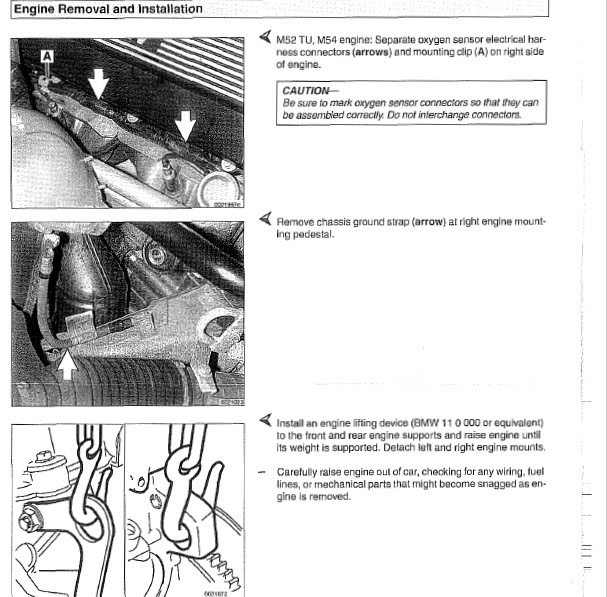
BMW E60/E61 2004-10 – Engine-General Download
BMW E60/E61 2004-10 – Engine Removal and Installation Download
BMW E60/E61 2004-10 – Cylinder Head Removal and Installation Download
BMW E60/E61 2004-10 – Camshaft Timing Chain Download
BMW E60/E61 2004-10 – Lubrication System Download
BMW E60/E61 2004-10 – Ignition System Download
BMW E60/E61 2004-10 – Battery, Starter, Alternator Download
BMW E60/E61 2004-10 – Fuel Injection MS45.1 (M54 Engine) Download
BMW E60/E61 2004-10 – Fuel Injection MSV70, MSV80 (N52 Engine) Download
BMW E60/E61 2004-10 – Fuel Injection MSD80, MSD81 (N54 Engine) Download
BMW E60/E61 2004-10 – Fuel Injection ME 9.2, ME 9.2.2 (V8 Engine) Download
BMW E60/E61 2004-10 – Fuel Tank and Fuel Pump Download
BMW E60/E61 2004-10 – Radiator and Cooling System Download
BMW E60/E61 2004-10 – Exhaust System Download
BMW 2 Series F45 Engine Download
Engine – E39 1997-2001 Download
Engine Removal and Installation – BMW E32 88-94 Download
Engine General – BMW E32 88-94 Download
N62 Engine – E65/E66 05-07 Download
BMW 7 Series E-65 Download
BMW F01/F02 Training Docs – N63 Engine Download
BMW F01/F02 Training Docs – N63TU Engine Download
BMW X1 (E84) – Engine Download
BMW X2 (F39) 2017 – Engine Download
BMW X2 (F39) 2017 – Engine electrical system Download
BMW X3 E83 07-10 Engine Download
BMW X3 E83 07-10 Engine Performance Download
ENGINE – BMW X3 F25 2010-2014 Download
BMW X7 (G07) FSM – Engine Download
BMW X7 (G07) FSM – Engine electrical system Download
Руководство по ремонту и ТО двигателей BMW.
Руководство по техническому обслуживанию и ремонту двигателей BMW N40, N42, N43, N45, N46, N51, N52, N53 и N54.
- Автор: —
- Издательство: Легион-Автодата
- Год издания: —
- Страниц: 308
- Формат: —
- Размер: —
Руководство по ремонту и ТО двигателей BMW.
Руководство по техническому обслуживанию и ремонту двигателей BMW M50, M52, M54, M56, S50, S52 и S54.
- Автор: —
- Издательство: Легион-Автодата
- Год издания: —
- Страниц: 314
- Формат: —
- Размер: —

Вся следующая информация взята из DIS и должна расцениваться вами как официальная.
Все эталонные параметры работы выведены из среднего множества проведённых мной компьютерных диагностик М51. Мои допуски параметров работы гораздо строже, нежели официальные допуски и должны расцениваться как рекомендованные, а не обязательные. Помни, каждая конкретная ситуация и экземпляр двигателя является индивидуальным!
Вся следующая информация написана профессионалом для профессионалов. Тут не найти ответов, например, на «почему у меня плавают обороты?». Для этого существуют форумы с диванными экспертами и советчиками уровня «я сделал так и у меня всё норм».
Список и расшифровка ошибок
Данные реального времени и эталонные параметры
47 Частота вращения коленвала:
МКПП:
— заданное значение: 750 об/мин (± 50)
— фактическое значение: 750 об/мин (± 50)
АКПП:
— заданное значение: 800 об/мин (± 50)
— фактическое значение: 800 об/мин (± 50)
21 Потенциометр регулятора подачи топлива: 2600 мВ (± 50 мВ)
— фактическое значение.
59 Коррекция частоты вращения коленвала на холостом ходу: **** об/мин
— заданное значение.
58 Количество впрыскиваемого топлива: 5.5 мг/ход поршня (± 0.5 мг)
— заданное значение.
37 Потенциометр датчика положения педали: 0% | 353 — 451 мВ
— фактическое значение.
25 Датчик положения педали-выключатель холостого хода: ****
— фактическое значение.
53 Датчик температуры охлаждающей жидкости двигателя: 88 — 92 °С | 1295 — 1135 мВ
— фактическое значение.
52 Датчик температуры всасываемого воздуха: **** °С | **** мВ (в зависимости от температуры окружающего воздуха)
— фактическое значение.
35 Датчик температуры топлива: 20 — 60 °С | **** мВ
— фактическое значение.
20 Панель управления системой поддержания заданной скорости: 3400 — 3600 мВ
— фактическое значение.
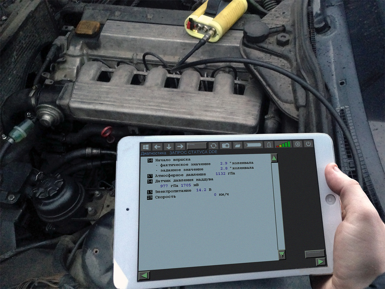
56 Начало впрыска:
— фактическое значение: 2.8 ° коленвала (± 1°)
— заданное значение: 2.8 ° коленвала (± 1°)
57 Атмосферное давление: 1007 гПа (в зависимости от атмосферного давления в данный момент)
— фактическое значение.
54 Датчик давления наддува: 1007 гПа | 1764 мВ (на ХХ = атмосферному, при 3000 об/мин = атмосферное + 150 — 300 гПа).
— фактическое значениех.
15 Электропитание: 14.2 В (± 0.5 В)
— фактическое значение.
29 Скорость: **** км/ч
— фактическое значение.
3 Электрический прерыватель подачи топлива: ****
— заданное значение.
4 Сигнальная лампа системы DDE: ****
— заданное значение.
11 Лампа предпускового разогрева: ****
— заданное значение.
8 Активизация реле свечи накаливания: ****
— заданное значение.
45 Система охранной сигнализации: ****
— фактическое значение.
26 Выключатель стоп-сигналов: ****
— фактическое значение.
31 Выключатель проверки стоп-сигналов: ****
— фактическое значение.
28 Выключатель сцепления или выключатель P/N: ****
— фактическое значение.
44 Выключатель кондиционера: ****
— фактическое значение.
24 Запрос компрессора кондиционера от ЭБУ системы IHK
— фактическое значение.
9 Активизация компрессора кондиционера сигналом от ЭБУ системы DDE
— заданное значение
Активизация деталей/исполнительные элементы
6 Реле времени накаливания свечей
— активизируется в течении 40 секунд с 1-секундным тактом. Проверить на слух.
8 Переключающий клапан системы рециркуляции ОГ
— активизируется в течении 40 секунд с 1-секундным тактом. Проверить сигнал путём измерений.
9 Муфта компрессора кондиционера
— активизируется в течении 40 секунд с 1-секундным тактом. Проверить реакцию.
10 Электромагнитный клапан муфты опережения впрыска
— активизируется в течении 40 секунд с 1-секундным тактом. Проверить реакцию.
11 Лампа предпускового разогрева
— активизируется в течении 40 секунд с 1-секундным тактом. Проверить реакцию. У блоков управления с датой изготовления < 167 активизация выполняется только на 2 секунды.
Специальные функции
1 Проверка аварийного режима. В ходе данной проверки проверяется аварийное отключение ТНВД.
Частота вращения коленвала: **** об/мин
— Запустить двигатель! Сразу после этого начать проверку аварийного режима клавишей.
— Идёт проверка! Ждите!
— Проверка аварийного режима выполнена!
ДА:
Внешняя аварийная цепь в порядке.
НЕТ:
Повышение частоты вращения коленвала возможно только приблизительно до 1500 об/мин?
Да:
Цепь аварийного отключения в порядке (незначительные потери от утечки не прекращают работу двигателя).
Нет:
Возможные причины неисправности, если результаты проверки аварийного режима неудовлетворительные:
— электрический прерыватель подачи топлива неисправен;
— негерметичность клапана в прерывателе подачи топлива, возможно, из-за его засорения;
— ЭБУ системы DDE неисправен.
Примечание:
Для обеспечения надёжной остановки двигателя ЭБУ системы DDE в зависимости от обстоятельств активизирует электрический прерыватель подачи топлива (ELAB) постоянно. В данном случае отмена этой активизации возможна только через зажигание ВЫКЛ/ВКЛ.
2 Функции внесения исправлений
3 Замена ЭБУ системы DDE
Необходимо точно установить, что имеющаяся неисправность действительно является следствием неисправного ЭБУ системы DDE 2! Замена деталей, не являющихся причиной рекламации, приводит к ненужных расходам по гарантийному ремонту и может вызвать недовольство клиента.
Поэтому прежде всего:
— устранить все записанные неисправности (проверить также в ЭБУ систем EGS и ASC);
— удалить информацию в ЗУ неисправностей, проверить отсутствие повторной записи неисправности в ЗУ (например, пробная поездка).
Только если поиск неисправности не привёл к ее устранению, и сообщение об этой неисправности повторно записываются в ЗУ, выполнить следующие указания.
Примечание:
Сначала прочесть до конца, затем использовать MoDiC!
Последовательность действий:
— распечатать код проверки;
— выполнить процедуру по замене ЭБУ в «Программировании» (только MoDiC!);
— заменить ЭБУ системы DDE 2 согласно Руководству по ремонту;
— устранить остальные неисправности в режиме «Диагностика»;
— после стирания информации в ЗУ неисправностей проверить, устранена ли теперь неисправность или нарушение функционирования, например, пробная поездка или пробный пуск двигателя.
Примечание по корректировочным функциям в новом ЭБУ системы DDE 2:
— если номера версий одинаковые — все значения коррекции и поля характеристик переносятся;
— если новый номер версии — коррекция AGR, поля характеристик SB автоматически кодируются соответствующими новыми значениями, остальные значения коррекции перенимаются.
Указание:
По этой причине следует проверить правильность перенесённых корректировочных значений и характеристик (в особенности выхлоп чёрного дыма или подобное), например, посредством пробной поездки или обкатки двигателя.
4 Замена распределительного ТНВД
Необходимо убедиться в том, что причиной имеющейся неисправности действительно является дефект распределительного ТНВД! Замена деталей, не являющихся причиной рекламации, приводит к ненужных расходам по гарантийному ремонту и может вызвать недовольство клиента.
Поэтому прежде всего:
— устранить все записанные неисправности (проверить также в ЭБУ систем EGS и ASC);
— удалить информацию в ЗУ неисправностей, проверить отсутствие повторной записи неисправности в ЗУ (например, пробная поездка).
Только если поиск неисправности не привёл к ее устранению, и сообщение об этой неисправности повторно записываются в ЗУ, выполнить следующие указания.
Примечание:
Сначала прочесть до конца, затем использовать MoDiC!
Последовательность действий:
— распечатать код проверки;
— выключить зажигание, заменить распределительный ТНВД согласно Руководству по ремонту;
— затем включить зажигание;
— выбрать «Диагностику»;
— все корректировочные значения и характеристики сохраняются, т. е. проверить правильность (в особенности выхлоп чёрного дыма или подобное), например, посредством пробной поездки или пробного пуска двигателя;
— устранить остальные неисправности;
— после стирания информации в ЗУ неисправностей проверить, устранена ли теперь неисправность или нарушение функционирования, например, пробной поездкой или пробным запуском двигателя.
Распределение контактных штырей в разъёме ЭБУ и их описание
Пометки:
А — выход
E — вход
M — масса
7 — резервный
22 — резервный
23 — резервный
30 — резервный
32 — резервный
34 — резервный
38 — резервный
46 — резервный
48 — резервный
55 — резервный
Сокращения
AG — автоматическая коробка передач
AGR — система рециркуляции ОГ
B- — масса
B+ — плюс
ELAB — электронный прерыватель подачи топлива
EP — топливный насос высокого давления (ТНВД)
FGR — система поддержания заданной скорости
HG — механическая коробка передач
KD — режим максимального ускорения
LL — холостой ход
mg/H — миллиграммов на ход поршня
ME — количество впрыскиваемого топлива
MV — электромагнитный клапан
SB — начало впрыска
SG — блок управления
PWG — датчик положения педали
RxD — возбуждающий диагностический провод
TxD — личия передачи диагностических данных
UBatt — напряжение питания
VL — полная нагрузка
Примечания
Отсоединять разъём от блока управления можно только при выключенном зажигании.
Выполнять проверку провода только при отсоединённых разъёмах.
Доброго времени суток BMWводы)
В данной записи, хочу предложить Вам — Руководства по ремонту/обслуживанию/эксплуатации/дооснащению BMW разных кузовов е-серии.
Прошу обратить внимание, что, руководства будут на русском, немецком либо английском языке, читайте внимательно описание к руководству. Руководства могут быть как в отсканированном варианте формата (.pdf/.djvu), в виде изображений (.jpeg), так и в виде приложения с файлом запуска (.exe).Так же хочу отметить, что руководства по ремонту и обслуживанию, встречаются в основном в более старых кузовах, таких как е36/е34/е38/е39/е46, кузова же свежее (е60/е65/е90/е83) это в основном руководства по эксплуатации, но, все таки не меньшим объемом страниц, поэтому могут быть полезны. Так же в список руководств данной записи, попадут и мотоциклы BMW, но в одном сборнике, разбитых на модели.
Данные руководства, были собраны на просторах всемирной паутины, ссылки на скачивание, так же будут присутствовать в записи.
Итак начнем, так сказать по возрастанию, от более старых кузовов, ну а в конце списка будут руководства по мотоциклам и по дооснащению по имеющимся кузовам (е46, е39, е90, е60 и тд) вместе.
BMW e12/e28
1) Руководство по ремонту и обслуживанию BMW e12/e28 c 1972 по 1987 года выпуска.
Руководство на немецком языке. В виде изображений (.jpg) в количестве 288-и страниц.
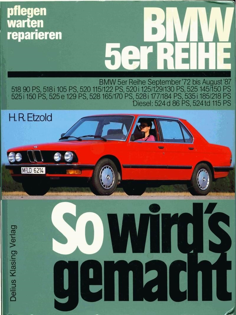
Заглавная
Ссылка на скачивание (34.7 Мб). Требуется распаковать архив (.rar), в архиве 288 изображений (.jpg) руководства.
BMW e21
2) Руководство по ремонту, обслуживанию, эксплуатации BMW e21.
Руководство на английском языке, в отсканированном варианте (.pdf), файлы разбиты по главам общим объемом более 1000 страниц.
Ссылка на скачивание (245 Мб). Требуется распаковать архив (.rar), пользоваться.
BMW 7 Серия е23/е32
3) Руководство по ремонту. Инструкция по эксплуатации. BMW 7 — E23 (1977-1986 гг. выпуска) и E32 (1986-1994 гг. выпуска)
Руководство на русском языке (213 страниц).
Заглавная страница
Ссылка на скачивание (48 Мб). Руководство в отсканированном варианте формат .pdf, запаковано в архиве (.rar)
BMW 5 серия е28/е34
4) Устройство. Обслуживание. Ремонт BMW 5-ой серии кузовов е28 и е34 с 1981 по 1993 года выпуска.
Руководство на русском языке, в виде мультимедийного приложения.
Заглавная приложения
Ссылка на скачивание (54.8 Мб). Распаковать архив (.rar), для запуска приложения запустить файл Run.exe.
5) Руководство по ремонту, эксплуатации и техническому обслуживанию BMW e34 1987-1995 годов выпуска.
Руководство на русском языке, в отсканированном варианте .djvu (358 страниц).
Заглавная
Ссылка на скачивание (11.4 Мб). Требуется распаковать архив, открыть файл .djvu.
BMW 3 Серия e30
6) Ремонт и эксплуатация автомобиля BMW e30 1983-1994 годов выпуска.
Руководство на русском языке, в виде приложения (.exe).
Заглавная приложения е30
Ссылка на скачивание (90.4 Мб). Требуется распаковать архив (.rar), для запуска приложения открыть файл Run.exe
BMW 8 Серия e31
7) Руководство по ремонту и обслуживанию BMW 8 Series e31.
Руководство на английском языке, в отсканированном варианте (.pdf), разбитых по главам, общим количеством более 500 страниц.
Ссылка на скачивание (240 Мб). Требуется распаковать архив, открывать файлы требуемой главы.
BMW е36
 Руководство по ремонту и обслуживанию BMW e36.
Подробное руководство на английском языке, в отсканированном варианте .pdf (759 страниц).
Заглавная
Ссылка на скачивание (63.2 Мб). Требуется распаковать архив (.rar) и открыть файл .pdf.
BMW e38
9) Устройство. Обслуживание. Ремонт BMW 7-ой серии кузова е38 с 1994 по 2002 года выпуска.
Руководство на русском языке, в виде мультимедийного приложения (.exe).
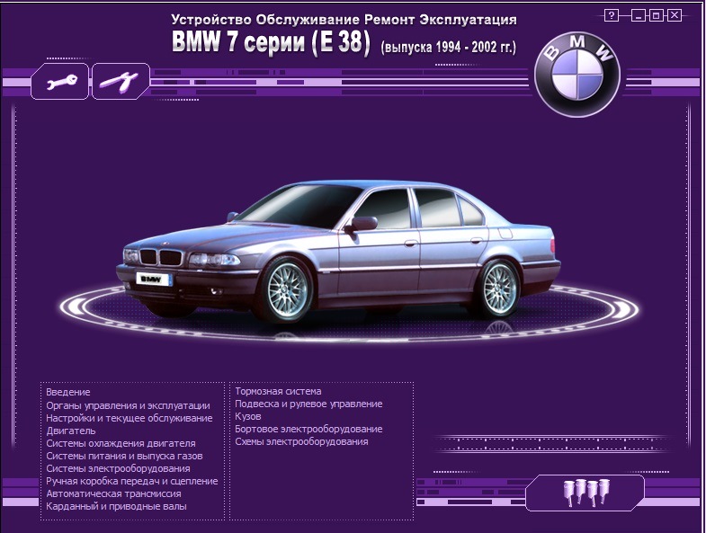
Заглавная приложения е38
Ссылка на скачивание (297 Мб). Требуется распаковать архив (.rar), для запуска приложения открыть файл Run.exe.
BMW e39
10) Руководство по ремонту и обслуживанию BMW 5 в кузове е39 от компании Алфамер
Руководство на русском языке. 237 страниц.
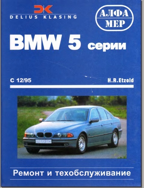
Заглавная
Книга в отсканированном варианте в формате .djvu, лежит в архиве. Распаковать и пользоваться.Ссылка скачивание (12 МВ).
11) Руководство органов управления и эксплуатации BMW e39.
Руководство на русском языке.
Книга в отсканированном варианте, в формате .pdf, разбита на 6 частей. Распаковать архив и пользоваться.
Ссылка на скачивание (21.6 МВ).
12) Руководство по обслуживанию и ремонту е39.
Руководство на английском языке. 1002 страницы.
Руководство скриншот
Руководство в отсканированном варианте, в формате .pdf.
Ссылка на скачивание (44.8 МВ)
13) Устройство, ремонт и обслуживание BMW е39.
Инструкция на русском языке — приложение.
Скриншот приложения е39
Инструкция идет как мультимедийное руководство (приложение .exe), находится в архиве (.rar). Распаковать и запустить файл Run.exe
Ссылка на скачивание (72.3 МВ)
BMW e46
14) Руководство по ремонту и обслуживанию BMW в кузове е46 от компании Алфамер
Руководство на русском языке, 320 страниц.
Заглавная
Руководство в отсканирванном виде, в формате .pdf.
Ссылка на скачивание (110 МВ).
15) Руководство по ремонту и обслуживанию BMW e46.
Руководство на английском языке, в отсканированном варианте (.pdf), подробное описание количеством 1258 страниц.
Заглавная руководства
Ссылка на скачивание (33.8 Мб). Формат (.pdf)
16) Устройство, ремонт и обслуживание BMW е46.
Инструкция на русском языке — приложение.
Скриншот приложения е46
Инструкция идет как мультимедийное руководство (приложение .exe), находится в архиве. Распаковать и запустить файл Run.exe
Ссылка на скачивание (84.1 МВ)
BMW e60
17) Руководство по эксплуатации BMW e60.
Руководство на русском языке, в отсканированном варианте .pdf, разбито на несколько частей, запаковано в архив.
Заглавная
Ссылка на скачивание (109 Мб). Распаковать архив, открывать файлы .pdf.
BMW e65
18) Руководство по эксплуатации BMW e65.
Руководство на русском языке, в отсканированном варианте .pdf, разбито на несколько частей, запаковано в архив.
заглавная
Ссылка на скачивание (44.3 Мб). Распаковать архив, открывать файлы .pdf.
BMW X5 e53/e70
19) Руководство по эксплуатации BMW X5 e53/e70.
Руководство на русском языке, в отсканированном варианте .pdf, разбито на несколько частей, запаковано в архив.

Заглавная
Ссылка на скачивание (76.5 Мб). Распаковать архив, открывать файлы .pdf.
BMW X3 e83
20) Руководство по эксплуатации BMW X3 e83.
Руководство на русском языке, в отсканированном варианте .pdf, разбито на несколько частей, запаковано в архив.

Заглавная
Ссылка на скачивание (36 Мб). Распаковать архив, открывать файлы .pdf.
BMW 3 e90
21) Руководство по эксплуатации BMW 3 e90.
Руководство на русском языке, в отсканированном варианте .pdf, разбито на несколько частей, запаковано в архив.
Заглавная
Ссылка на скачивание (218 Мб). Распаковать архив, открывать файлы .pdf.
Дооснащение BMW
22) Различные инструкции по дооснащению BMW кузовов е46/е39/е90/е60/е53/е70/Mini
Инструкции на английском языке, с номерами необходимых деталей, с электросхемами, с подробным описанием и фото.
Список:
— Инструкция по дооснащению bluetooth E46.pdf
— Инструкция по дооснащению Bluetooth E90.pdf
— Инструкция по дооснащению bluetooth E53.pdf
— Инструкция по дооснащению Night Vision Е60, Е61.pdf
— Инструкция по дооснащению TV E38.pdf
— Инструкция по дооснащению TV E46.pdf
— Инструкция по дооснащению TV E85.pdf
— Инструкция по дооснащению TV Е60, Е61.pdf
— Инструкция по дооснащению TV Е7x.pdf
— Инструкция по дооснащению TV Е83.pdf
— Инструкция по дооснащению USB-Audio Interface Е8х, Е9х.pdf
— Инструкция по дооснащению адаптивным освещением Е6x.pdf
— Инструкция по дооснащению навигационной системой Е83.pdf
— Инструкция по установке Bluetooth E90.pdf
— Инструкция по установке Nav 16-9 E53.pdf
— Инструкция по установке ACM.pdf
— Инструкция по установке Alpine Hi-Fi System Е8х, Е9х.pdf
— Инструкция по установке Areal Amplifer E39, E39-2.pdf
— Инструкция по установке Audio, iPod E46.pdf
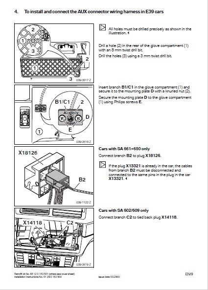
— Инструкция по установке AUX E46, E39, E53.pdf
— Инструкция по установке Bluetooth 5-Series Е39.pdf
— Инструкция по установке bluetooth E81, E82, E87.pdf
— Инструкция по установке Bluetooth Е6x.pdf
— Инструкция по установке Bluetooth Е7x.pdf
— Инструкция по установке Bluetooth Е81, Е82, Е87 после 03.07.pdf
— Инструкция по установке BMWTraffic Pro 3-Series E46х.pdf
— Инструкция по установке BMWTraffic PRO Z3 E36x.pdf
— Инструкция по установке CD Changer E85.pdf
— Инструкция по установке CD-чейнджера Е60, Е61.pdf
— Инструкция по установке CD-чейнджера Е63, Е64.pdf
— Инструкция по установке CD-чейнджера Е70, Е71.pdf
— Инструкция по установке DVD Navigation System E46(2,4).pdf
— Инструкция по установке DVD Navigation System E46(3).pdf
— Инструкция по установке DVD-table Е70, Е71.pdf
— Инструкция по установке DVD-чейнджера c TV Е7x.pdf
— Инструкция по установке DVD-чейнджера без TV Е7x.pdf
— Инструкция по установке High OBC E39, E53.pdf
— Инструкция по установке iPod Interface (without CD changer) MINI R56.pdf
— Инструкция по установке iPod Interface 3-Series E90.pdf
— Инструкция по установке iPod Interface E 83, E53, E85, E39.pdf
— Инструкция по установке iPod Interface mini R50, R53.pdf
— Инструкция по установке iPod Interface MINI R56.pdf
— Инструкция по установке iPod Interface R50, R52, R53.pdf
— Инструкция по установке iPod-адаптера Е60, Е61.pdf
— Инструкция по установке iPod-адаптера Е70, Е71.pdf
— Инструкция по установке iPod-адаптера Е82, Е87.pdf
— Инструкция по установке iPod-адаптера Е9x.pdf
— Инструкция по установке LVDS converter.pdf
— Инструкция по установке Nav 4_3 BEFORE 10.2000 Е53.pdf
— Инструкция по установке Nav 4_3 Е53.pdf
— Инструкция по установке PDC E46.pdf
— Инструкция по установке PDC Е53.pdf
— Инструкция по установке PDC Е60, Е61.pdf
— Инструкция по установке PDC Е63, Е64.pdf
— Инструкция по установке PDC Е70, Е71.pdf
— Инструкция по установке PDC Е8x.pdf
— Инструкция по установке PDC Е90, Е91.pdf
— Инструкция по установке PDC Е92, Е93.pdf
— Инструкция по установке round vision Е6x.pdf
— Инструкция по установке round vision Е7x.pdf
— Инструкция по установке round vision Е9x.pdf
— Инструкция по установке SIRIUS на Е83 with Navi.pdf
— Инструкция по установке TMC Module E39.pdf
— Инструкция по установке Traffic Pro Е85.pdf
— Инструкция по установке USB интерфейса для ACM.pdf
— Инструкция по установке USB-audio Е70, Е71.pdf
— Инструкция по установке USB-iPod Interface (with SA 6NB Wave radio) MINI R56.pdf
— Инструкция по установке Webasto E36.pdf
— Инструкция по установке Webasto Е63, Е64.pdf
— Инструкция по установке xenon E53.pdf
— Инструкция по установке бортового компьютера E36.pdf
— Инструкция по установке бортового компьютера MINI R50.pdf
— Инструкция по установке бортового компьютера и навигации E39.pdf
— Инструкция по установке бортового компьютера и навигации Е38.pdf
— Инструкция по установке доп. света MINI Cooper.pdf
— Инструкция по установке камеры заднего вида E38.pdf
— Инструкция по установке камеры заднего вида mini R50, R53.pdf
— Инструкция по установке камеры заднего вида Е39(2).pdf
— Инструкция по установке камеры заднего вида Е46(2,4).pdf
— Инструкция по установке камеры заднего вида Е53.pdf
— Инструкция по установке камеры заднего вида Е6x.pdf
— Инструкция по установке камеры заднего вида Е7x.pdf
— Инструкция по установке камеры заднего вида Е9x.pdf
— Инструкция по установке кнопки start mini R50, R53.pdf
— Инструкция по установке навигации Е85.pdf
— Инструкция по установке навигации ОЕМ Е83.pdf
— Инструкция по установке передней камеры Е53.pdf
— Инструкция по установке передней камеры Е7x.pdf
— Инструкция по установке подогрева переднего сиденья Е87, E90, Е91, Е92.pdf
— Инструкция по установке подсветки дверных проёмов E90.pdf
— Инструкция по установке портативной навигации E9x.pdf
— Инструкция по установке портативной навигации MINI R56.pdf
— Инструкция по установке портативной навигации Е9х.pdf
— Инструкция по установке прицепного устройства X5.pdf
— Инструкция по установке сигнализации BMW 1 Series Coupe E82.pdf
— Инструкция по установке сигнализации MINI R50, R53.pdf
— Инструкция по установке сигнализации Е60, Е61.pdf
— Инструкция по установке сигнализации Е70, Е71.pdf
— Инструкция по установке ССС Е60, Е61.pdf
— Инструкция по установке ССС Е63, Е64.pdf
— Инструкция по установке ССС Е90, Е91.pdf
— LCI conversion E60, E61.pdf
Дооснащения руководство
Инструкции в отсканированном варианте, в форматах .pdf. Лежат в архиве. Распаковать и пользоваться.
Ссылка на скачивание (88.2 МВ)
В качестве бонуса, руководства по мотоциклам BMW.
Мотоциклы BMW
23) Руководство по ремонту и обслуживанию Мотоциклов BMW моделей 1200GS, C1, C1-200, F650GS, K1100LT, R850, K1200LS, R100R, R1100S, R1150RT и другие.
Руководства на английском языке в отсканированном варианте (.pdf), файлы собраны в архиве, разбиты по моделям.
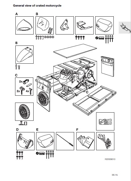
Скриншот одного из руководств
Ссылка на скачивание (486 Мб). Распаковать архив (.rar), открывать файлы (.pdf) по моделям мотоциклов BMW.
Так же рекомендую пользоваться интернет руководством по ремонту, жидкостям, рабочим характеристикам BMW — TIS.
Если еще что полезного по руководствам найду, обновлю тему. Надеюсь кому-нибудь пригодится и будет полезно.
Всем спасибо за внимание! До скорых встреч!
6-цилиндровые двигатели М20 (320i, 325е), М21 (324d/td) В рамках регламента технического обслуживания зубчатый ремень
РК типа «NV125/LWX-500» Технология замены сальника выходного фланца РК типа «NV125/LWX-500» на задний привод
Снятие шарнира равных угловых скоростей (ШРУСа) карданного вала необходимо проводить в следующем порядке. Подготовить
Автомобиль с АКПП Снятие раздаточной коробки в сочетании с АКПП, необходимо проводить в следующем
Снятие карданного привода задних колес (рис. 10.25) необходимо проводить в следующем порядке. Выставить автомобиль
Замену стержня (1, см. рис. 8.16) опоры рычага ПП необходимо проводить в следующем порядке.
РК «NV125» Замену сальника полуоси РК «NV125» необходимо проводить в следующем порядке. Приготовить приспособления
Внимание! Рукоятку рычага переключения передач при снятии не вращать, иначе фиксатор угловых перемещений будет
Замену резинометаллического шарнира крепления РКПП необходимо проводить в следующем порядке. Приготовить приспособления «22.1.011», «22.1.012»,
Конструктивное исполнение механизма переключения передач (ПП) показано на рисунке 8.16. РКПП S5D 280Z Замену
-
Contents
-
Table of Contents
-
Bookmarks
Quick Links
New Generation N62 Engine
Course Contents/Background Material
Information status:
April 2001
BMW
Service Training
Related Manuals for BMW N62 Series
Summary of Contents for BMW N62 Series
-
Page 1
New Generation N62 Engine Course Contents/Background Material Information status: April 2001 Service Training… -
Page 2: Table Of Contents
— Coolant compressor — Starter motor — Power steering pump Cylinder heads — Engine cover — Cylinder head covers — Valve gear — Valvetronic — Bi-VANOS (variable camshaft adjustment) — Vacuum pump — Chain drive © BMW AG, Service Training…
-
Page 3
— Variable intake manifold — Idle speed control Valvetronic — General information — Function — Valvetronic control unit — DME control unit — DME main relay — Valvetronic additional relay — Valvetronic motors — Valvetronic sensors © BMW AG, Service Training… -
Page 4
CHAP 6 E65 fuel systems — General information — Filling the tank — Tank ventilation — Fuel supply system Fuel tank leak diagnostic module — General information — Function — Diagnostic procedure CHAP 7 Glossary © BMW AG, Service Training… -
Page 5: N62 Engine
Throttle valve use is conditional for engine load control. The N62 is the best engine in its class. At this time there is no other engine on the market which uses comparable technology. © BMW AG, Service Training…
-
Page 6: Technical Data
Digital motor electronics ME9.2 + ME9.2 + Valvetronic Valvetronic control unit control unit Complies with exhaust emission regulations EU-3 EU-3 EU-4 EU-4 Engine length (mm) Fuel consumption saving compared with the M62 Vmax (km/h) E65 electronic cut-out © BMW AG, Service Training…
-
Page 7: Full Load Graphs
New Generation N62 Engine Chapter 1 P.3 Course Contents/Background Material — Full load graphs N62B36 Speed KT-8235 Fig. 1: Full load graphs comparison. Broken lines = M62B35 © BMW AG, Service Training…
-
Page 8
New Generation N62 Engine Chapter 1 P.4 Course Contents/Background Material N62B44 Speed KT-8236 Fig. 2: Full load graphs comparison. Broken lines = M62B44 © BMW AG, Service Training… -
Page 9: Views Of The N62 Engine
Fig. 3: N62 engine front view Index Description Valvetronic motors Tank ventilation valve (AKF valve) VANOS solenoid valve Alternator Pulley for the water pump Thermostat housing Throttle unit Vacuum pump Intake pipe to air cleaner © BMW AG, Service Training…
-
Page 10
New Generation N62 Engine Chapter 1 P.6 Course Contents/Background Material KT-7682 Fig. 4: N62 engine side view Index Description Starter motor with heat protection © BMW AG, Service Training… -
Page 11
Camshaft position sensor, cylinder bank 5-8 Valvetronic eccentric shaft position sensor, cylinder bank 5-8 Valvetronic eccentric shaft position sensor, cylinder bank 1-4 Camshaft position sensor, cylinder bank 1-4 Secondary air valves Servomotor for variable intake manifold © BMW AG, Service Training… -
Page 12: N62 Supplement To Existing Documents
See the M62 and DME M5.2 for details of how the characteristic mapping thermostats function — Engine management See N42 engine management — VANOS See the N42 engine — Valvetronic system See the N42 Valvetronic system © BMW AG, Service Training…
-
Page 13: N62 Engine Mechanics
— 150 mm water depth at 30 km/h — 300 mm water depth at 14 km/h — 450 mm water depth at 7 km/h The air cleaner element is designed to be changed at 100,000 km intervals. © BMW AG, Service Training…
-
Page 14
The air intake system consists of the following components: — Intake air ducts upstream of the air cleaner — Air cleaner — Intake pipe with HFM (hot-film air-mass flow sensor) — Throttle unit — Variable intake manifold — Intake port © BMW AG, Service Training… -
Page 15
If the Valvetronic system should fail, the throttle valve imple- ments the engine’s emergency running function (conventional load control). Throttle valve structure — Throttle-valve housing with throttle valve — Throttle valve actuator — Two throttle valve potentiometers (feedback signal is contra- rotating) © BMW AG, Service Training… -
Page 16: Intake Manifold
Good cylinder filling is the basic prerequisite for the fulfilment of the requirements. The complete air intake system, and to a certain extent the intake manifold, contribute to optimum cylinder filling. © BMW AG, Service Training…
-
Page 17
With the N62, a variable intake manifold is used for the first time. It ensures that the intake path is always the optimum length for the engine speed, thus ensuring the best possible volumetric efficiency. © BMW AG, Service Training… -
Page 18
The air is compressed and the pressure and the air flow increase. KT-8409 Fig. 7: Intake air flows in front of the closed intake valve Index Description Closed intake valve Air manifold © BMW AG, Service Training… -
Page 19
KT-8408 Fig. 8: Movement of the intake air with the intake valve open Index Description Pressure waves Air manifold Suction waves © BMW AG, Service Training… -
Page 20
Since the suction waves and pressure waves expand at sonic speed, the suction path length must be adapted depending on the engine speed to ensure that the tip of the pressure wave reaches the intake valve before it is closed. © BMW AG, Service Training… -
Page 21
Injection valve holes Fuel rail thread The intake manifold is located in the V of the engine, and is mounted on the cylinder head intake ducts. The variable intake manifold housing is made from a magnesium alloy. © BMW AG, Service Training… -
Page 22
(5) in the opposite direction from the driven shaft. The intake air flows via the manifold volume through the funnel (2) and on to the cylinders. The intake path length is set as the rotor turns. © BMW AG, Service Training… -
Page 23
New Generation N62 Engine Chapter 3 P.11 Course Contents/Background Material Setting the intake manifold KT-8114 Fig. 11: Intake manifold set to short intake path KT-8115 Fig. 12: Intake manifold set to longer intake path © BMW AG, Service Training… -
Page 24
(cylinder bank 1-4). The second shaft with funnels for cylinder bank 5-8 is synchronously adjusted by the spur gears. The drive motor is controlled by the DME and is intended for providing feedback about the funnel position via a potentio- meter. © BMW AG, Service Training… -
Page 25: Crankcase Venting System
Engine running is affected if the blow-by gases are returned to the combustion process, particularly in near-idling speed ranges. This influence is taken into account by lambda regulation. The blow-by gases must be intentionally passed into the intake tract to avoid negative side-effects © BMW AG, Service Training…
-
Page 26
The throttle valve is controlled such that there is always a vacuum pressure of 50 mbar in the intake manifold. The pressure control valve regulates the crankcase pressure to a low 0-30 mbar. © BMW AG, Service Training… -
Page 27: Exhaust System
The exhaust system was completely redesigned for the N62B36 and N62B44 engines, and is identical in each engine. It has been optimized in terms of cylinder filling and scavenging, the acoustic system and rapid catalytic converter light-off. © BMW AG, Service Training…
-
Page 28: Exhaust Manifold With Catalytic Converter
The exhaust gas flap is closed using vacuum pressure, and is opened by ventilating the diaphragm box. This control procedure is carried out using a solenoid valve which is electrically actuated from the DME. © BMW AG, Service Training…
-
Page 29: Secondary Air System
(HC) and carbon monoxide (CO) contained in the exhaust vapours. The energy generated during this process heats up the catalytic converter faster during the warm-up phase, and increases its conversion rate. © BMW AG, Service Training…
-
Page 30
— Coolant temperature (from -10 ºC to approximately 60 ºC) — Air flow — Engine speed Secondary air valves (SLV) KT-8090 Fig. 16: Secondary air valve Index Description Cylinder head lead Secondary air valve Secondary air pump connection © BMW AG, Service Training… -
Page 31
The secondary air is led through a pipe to the secondary air ducts. The SLV is closed as soon as the secondary air pump is switched off, preventing exhaust vapours from flowing back to the secondary air pump. © BMW AG, Service Training… -
Page 32: Ancillary Components And Belt Drive
— Belt drive KT-6968 Fig. 17: Belt drive Index Description Index Description Air conditioning Alternator compressor 4-V-belt Deflection pulley Crankshaft Power steering pump pulley Coolant pump 6-V-belt Tensioning unit main drive Tensioning unit A/C drive © BMW AG, Service Training…
-
Page 33
To disassemble the V-belt, the tensioning pulley is pushed back using a Torx tool (1) and fixed in this position using a peg (2). KT-7732 Fig. 18: Tensioning pulley Index Description Recess for Torx tool Special tool © BMW AG, Service Training… -
Page 34: Alternator
The function and design of the alternator are the same as that in the M62, with only minor modifications. The BSD interface (bit-serial data interface) for the DME control unit is new. KT-7321 Fig. 19: Alternator Index Description Watertight housing Rotor Stator Seal © BMW AG, Service Training…
-
Page 35
— Controlling the alternator’s response to load pressure (Load Response) — Diagnosing the data line between the alternator and the engine management system — Saving alternator fault codes — Activating the charge indicator lamp in the instrument cluster © BMW AG, Service Training… -
Page 36
— Electrical faults such as exciter diode defects or over/under- voltage caused by regulation defects — Connection defects between the DME and the alternator Coil breaks and short-circuits cannot be recognized. Basic alternator function is also guaranteed even if the BSD interface fails. © BMW AG, Service Training… -
Page 37
15.5 V, depending on the battery temperature. If, therefore, the after-sales service measure a battery charge voltage of up to 15.5 V, the regulator is not faulty. A high charge voltage indicates a low battery temperature. © BMW AG, Service Training… -
Page 38: Coolant Compressor
There is an internal compressor coolant circuit to maintain lubrication. The air conditioning electronics regulate the compressor output via an external control valve. The compressor is driven via the 4-V-belt. KT-7703 Fig. 21: Coolant compressor Index Description Control valve © BMW AG, Service Training…
-
Page 39: Starter Motor
The power steering pump is a tandem radial piston pump, and is driven by the 6-V-belt. A vane pump is fitted on cars without the Dynamic-Drive-System. Further information about the power steering pump can be found in the Chassis/steering section. © BMW AG, Service Training…
-
Page 40: Cylinder Heads
Course Contents/Background Material Cylinder heads General information The two N62 cylinder heads are a new development from BMW. They are fitted with the Valvetronic valve timing system. The secondary air ducts for subsequent exhaust vapour treatment are integrated in the cylinder heads.
-
Page 41: Engine Cover
The engine is additionally fitted with a sound absorption cover (2) which also covers the two Valvetronic motors. This cover is fixed to the intake manifold housing using four screws. © BMW AG, Service Training…
-
Page 42: Cylinder Head Covers
Opening for Valvetronic sensor connector Camshaft sensor The cylinder head covers are made from plastic. The sleeves for threading the ignition coil rods are inserted into the cylinder head through the cylinder head cover (nos. 1-4). © BMW AG, Service Training…
-
Page 43
Fig. 25: Plastic sleeves for threading the ignition coil rods through the cylinder head cover to the spark plugs. Index Description Moulded-on gaskets Note The plastic sleeves have moulded-on gaskets. The sleeves must be completely replaced if any hardening or damage is visible on the gaskets. © BMW AG, Service Training… -
Page 44: Valve Gear
Upper timing chain guide Oil pressure switch with oil jet Hole for VANOS intake Chain tensioner mount solenoid valve Hole for VANOS outlet Upper timing chain guide solenoid valve with oil jet Chain tensioner mount © BMW AG, Service Training…
-
Page 45
New Generation N62 Engine Chapter 3 P.33 Course Contents/Background Material KT-7712 Fig. 27: Cylinder head, cylinder bank 1-4, seen from below Cylinder head gaskets KT-7694 Fig. 28: Cylinder head gaskets © BMW AG, Service Training… -
Page 46
The cylinder head bolts for the N62 engine are always M10x160 necked-down bolts. These bolts should always be replaced when repairs are carried out. The lower part of the timing chain housing is bolted to the cylinder head using two M8x45 bolts. © BMW AG, Service Training… -
Page 47
Thrust bearing area with oil ducts for the VANOS units The camshafts are made from chilled cast iron and are hollowed to reduce their weight. The camshafts are fitted with balancing weights for equalising imbalances in the valve gear. © BMW AG, Service Training… -
Page 48: Valvetronic
9.85 mm, according to speed and load. This means that it controls the fuel-air mixture volume according to engine require- ments. This type of mixture volume control makes the load control throttle valve unnecessary. © BMW AG, Service Training…
-
Page 49
On the whole, the additional variability of the Valvetronic system, made possible by the adjustable valve lift, results in better adaptation and optimisation of cylinder filling and scavenging throughout the engine’s entire operating range, in terms of output, torque, consumption and exhaust emissions. © BMW AG, Service Training… -
Page 50
— Improved engine idling — Improved engine torque — Improved engine torque curve — Fewer pollutant emissions These benefits result in a clear improvement in handling charac- teristics and fuel consumption reduction (14%) for the driver. © BMW AG, Service Training… -
Page 51
In addition, the following components belong to the Valvetronic system: — A Valvetronic motor for each cylinder head — A Valvetronic control unit — A Valvetronic sensor for each cylinder head © BMW AG, Service Training… -
Page 52
Bridge support Spark plug threads Valve gear oil supply 10+11 Camshaft sensor wheels Upper timing chain guide Oil pressure switch The inlet camshaft thrust bearing is mounted on the cylinder head independently of the bridge support. © BMW AG, Service Training… -
Page 53
The bridge support and the lower eccentric shaft and inlet camshaft bearings therefore work together in the cylinder head once fitted, to the tightest limits. If the bridge support or the lower bearings are damaged, the entire cylinder head must also be replaced. © BMW AG, Service Training… -
Page 54
Course Contents/Background Material Valvetronic motor The two Valvetronic motors are located towards the inside in the engine’s V. KT-8261 Fig. 32: Valvetronic motor Index Description Cylinder head cover, cylinder bank 1-4 Valvetronic motor for eccentric shaft adjustment © BMW AG, Service Training… -
Page 55
A hole must be drilled in the rear plastic motor cover in order to get to the motor shaft (worm shaft) using the Allen key. The motor can then no longer be used. © BMW AG, Service Training… -
Page 56: Bi-Vanos (Variable Camshaft Adjustment)
The VANOS function is the same as that of the N42 engine. VANOS units KT-7692 Fig. 33: VANOS units Index Description VANOS unit outlet side VANOS threaded connection Spring plate VANOS unit inlet side Toothed chain gear teeth © BMW AG, Service Training…
-
Page 57
The VANOS unit for the cylinders 1-4 outlet shaft has a mounting for the vacuum pump drive. A spring plate has been fitted between the VANOS unit and the vacuum pump drive to reduce wear. © BMW AG, Service Training… -
Page 58
Fig. 34: Camshaft with VANOS oil supply holes Index Description Rear oil duct with four holes Front oil duct with four holes Front oil duct outlets Hook sealing washer KT-7761 Fig. 35: Cross section of a camshaft © BMW AG, Service Training… -
Page 59
(3+4). The oils moves through the camshaft to the VANOS units. VANOS solenoid valves The design of the VANOS solenoid valves is the same as those in the N42 engine. The gasket is used only for the N62 engine. © BMW AG, Service Training… -
Page 60
The sensor wheels are made from a sintered material. The following diagram shows the VANOS unit camshaft adjustment possibilities. Crankshaft KT-7635 Fig. 36: N62 valve timing diagram Index Description Index Description Outlet open Intake open Outlet closed Intake closed © BMW AG, Service Training… -
Page 61: Vacuum Pump
The vacuum pump is driven by the cylinders 1-4 outlet shaft. The power comes from the VANOS unit. The design of the vacuum pump is described in the documen- tation for the N42 engine. © BMW AG, Service Training…
-
Page 62: Chain Drive
Chapter 3 P.50 Course Contents/Background Material — Chain drive KT-7959 Fig. 37: Chain drive The camshafts are driven by a toothed chain, one for each cylinder bank. The oil pump is driven by a separate roller chain. © BMW AG, Service Training…
-
Page 63
Timing case lower section Tensioning rail, cylinder bank 1-4 Solenoid valve, VANOS outlet Solenoid valve, VANOS intake Upper timing chain cover Chain tensioner, cylinder bank 1-4 VANOS outlet Upper timing chain guide with integrated oil jet VANOS intake © BMW AG, Service Training… -
Page 64
The relevant toothed chain gear wheels are located on the crankshaft and on the VANOS unit. Use of the new toothed chains optimizes the drive chain rolling process to the sprocket, thus reducing noise. © BMW AG, Service Training… -
Page 65
Please observe the instal- lation instructions and the relevant labels (V8 Front/V12 Front) when fitting the sprocket. On the V-12 engine, the sprocket is fitted the other way round, with the oil pump gear wheel to the rear. © BMW AG, Service Training… -
Page 66
The guide ball moves in an arched groove at the tensioning rail. The chain tensioner seal must be replaced each time the chain tensioner is disassembled. The chain tensioners are the same for both the left and the right cylinder heads. © BMW AG, Service Training… -
Page 67
(cylinder bank 1-4) is hollowed. There is a ball valve in the bearing pin. The valve closes at an oil pressure of 1.5 bar and allows engine oil to flow to the tensioning rail via a hole (1). © BMW AG, Service Training… -
Page 68
An oil jet has been fitted to lubricate the right-hand drive chain (cylinder bank 5-8). There is a valve in the oil jet which opens at a pressure of 1.5 bar and supplies the drive chain with engine oil. © BMW AG, Service Training… -
Page 69
There is a small hole in the guide rail through which the cylinder head area of the drive chain is supplied with engine oil. There is a rubber-coated steel gasket between the guide rail and the cylinder head. © BMW AG, Service Training… -
Page 70: Cooling System
New Generation N62 Engine Chapter 3 P.58 Course Contents/Background Material Cooling system — Coolant circuit KT-7960 Fig. 44: N62 coolant circuit © BMW AG, Service Training…
-
Page 71
Thermostat for transmission oil heat exchanger Alternator housing Radiator Radiator, low temperature area Temperature sensor Water pump Radiator return flow Radiator ventilation line Expansion tank Thermostat Cylinder head, cylinder bank 1-4 Vehicle heating Radiator, high temperature area © BMW AG, Service Training… -
Page 72
The complex coolant area and the targeted small ventilation bores mean that a certain time should be allowed after the cooling system has been filled for the air to evacuate (see Workshop Manual). © BMW AG, Service Training… -
Page 73
The still cold coolant flows from the thermostat directly into the water pump and back to the engine (short circuit). When the engine reaches operating temperature (85 ºC-110 ºC), the thermostat closes the small coolant circuit and opens the large coolant circuit, including the radiator. © BMW AG, Service Training… -
Page 74
From the rear of the engine block, the coolant flows through the side apertures to the cylinder walls, and from there it flows to the cylinder heads. KT-7695 Fig. 47: Cast aluminium cover at the rear of the engine block © BMW AG, Service Training… -
Page 75: Water Pump
Heat exchanger transmission oil return flow Leakage chamber (evaporation space) Alternator in-flow Water pump Expansion tank connection The water pump is combined with the thermostat housing and is screwed to the timing case lower section. © BMW AG, Service Training…
-
Page 76
(evaporation area). If the sliding ring seal is faulty, the leakage chamber fills completely with coolant. Sliding ring seal leakages can be detected by monitoring the fluid level in the leakage chamber (inspection hole) © BMW AG, Service Training… -
Page 77
The leakage restraint system has the advantage that the coolant escaping from the sliding ring seal (normal, functional leakage) evaporates without a trace and cannot be mistakenly identified as a water pump defect during visual inspections by the after- sales-service. © BMW AG, Service Training… -
Page 78
Chapter 3 P.66 Course Contents/Background Material KT-7731 Fig. 50: Timing chain lower section Index Description Coolant to engine Water pump housing in lower section of timing chain Threaded connection for tensioning pulley Crankshaft sealing ring © BMW AG, Service Training… -
Page 79: Map-Controlled Thermostat
This reduces fuel consumption by around 1-6%. The electrical connections, the design and the map-controlled thermostat throttle response have been optimized. The map-controlled thermostat function is the same as that for previous engines (M62). © BMW AG, Service Training…
-
Page 80: Cooling Module
— Cooling radiator — Air conditioning condenser — Transmission oil/water heat exchanger (ÖWT) with control unit — Hydraulic fluid radiator — Engine oil radiator — Main electric fan — Fan shroud for viscous coupling fan © BMW AG, Service Training…
-
Page 81: Cooling Radiator
It is also best to avoid overfilling the expansion tank after repairs have been carried out on the cooling system since the newly- designed cooling circuit ensures very good engine ventilation. © BMW AG, Service Training…
-
Page 82: Transmission Oil/Water Heat Exchanger (Öwt)
E38M62. The viscous coupling fan is the last cooling level and switches on at an air temperature of 92 ºC. © BMW AG, Service Training…
-
Page 83: Engine Block
Engine block — Oil sump KT-7686 Fig. 53: Oil sump Index Description Upper section of the oil sump Oil pump Oil condition sensor Lower section of the oil sump Oil filter element Oil drain plug © BMW AG, Service Training…
-
Page 84
The upper section of the oil sump has a crossed-shaped cut-out oil filter element recess. The upper section of the oil sump is sealed to the oil pump using a sealing ring. © BMW AG, Service Training… -
Page 85: Crankcase
The crankcase can be treated twice (sun honing procedure). Repair stage 1+2 pistons are available for this purpose. Due to the different cylinder bore diameters (84 mm/92 mm), the two engine variants (3.6 l/4.4 l) have different part numbers. © BMW AG, Service Training…
-
Page 86: Crankshaft
The crankshaft has five bearings. The fifth bearing is also the axial guide bearing. The crankshaft lift is — 81.2 mm for the B36 — 82.7 mm for the B44 The crankshaft can be reground in two repair stages. © BMW AG, Service Training…
-
Page 87
New Generation N62 Engine Chapter 3 P.75 Course Contents/Background Material KT-7676 Fig. 56: Crankshaft thrust bearing A locating bearing is fitted transmission side as a crankshaft thrust bearing. © BMW AG, Service Training… -
Page 88: Connecting Rod And Piston
The pistons are made from high-temperature aluminium alloy and are equipped with three piston rings. — First piston ring groove = square ring — Second piston ring groove = taperface ring — Third piston ring groove = three-part oil control ring © BMW AG, Service Training…
-
Page 89
The pistons are cooled by oil jets on the exhaust side of the piston crown. The pistons for the B36 and B44 engines are made by different manufacturers and have different diameters. If a cylinder is redressed, the pistons are available in two oversizes. © BMW AG, Service Training… -
Page 90: Flywheel
The engine suspension is provided by means of two hydraulic damping engine mounts. The engine mounts are located on the front axle carrier. The structure and function of the engine mounts are the same as those of the E38/M62. © BMW AG, Service Training…
-
Page 91: Lubrication System
— Tensioning rail for chain drive on cylinder bank 1-4 Cylinder head: — Chain tensioner — Guide rail on cylinder head — Hydraulic tappet (hydraulic valve adjustment elements) — VANOS supply — Camshaft bearing — Oil jet strips for the valve gear © BMW AG, Service Training…
-
Page 92: Oil Check Valve
This prevents the engine oil from flowing back out of the cylinder head and the VANOS units. As the check valves are accessible from the outside, there is no need to remove the cylinder head when changing the check valves. © BMW AG, Service Training…
-
Page 93: Oil Pressure Switch
The oil check valves are identical in design which means that they cannot be mixed up. — Oil pressure switch The oil pressure switch is located on the side in the cylinder head (cylinder bank 1-4). © BMW AG, Service Training…
-
Page 94: Oil Pump
The oil pump is a two-level gear oil pump with two parallel switched gear clusters. The oil pump function is the same as that of the N42 engine. © BMW AG, Service Training…
-
Page 95: Oil Filter
The filter element support dome contains a bursting pressure valve. If the filter element is blocked, this valve guides the unfil- tered engine oil around the filter element to the engine’s lubri- cation points. © BMW AG, Service Training…
-
Page 96: Pressure Control
A separate pressure relief valve in the oil pump automatically switches off at the maximum pressure of approximately 15 bar. This prevents damage in the oil pump, especially at low oil temperatures. © BMW AG, Service Training…
-
Page 97: Oil Cooling
This ensures that the minimum amount of oil is supplied even if the oil cooler is faulty. A modified generator support, without connections for the oil thermostat, is fitted to vehicles which do not have an oil cooler. © BMW AG, Service Training…
-
Page 98: Technical Data
1.5 — 2.0 bar Minimum oil pressure at 20 ºC 4.0 — 6.0 bar Maximum oil pressure at 20 ºC Oil delivery rate Description 60-65 l/min At maximum speed (6,500 rpm) and at 150 ºC © BMW AG, Service Training…
-
Page 99: N62 Engine Management System Me 9.2
The ME 9.2 control unit is the same for all N62 engine variants. The engine management data is programmed according to the version. The ME 9.2 control unit is combined with BMW’s own invention, the Valvetronic control unit. Both control units control the N62 engine.
-
Page 100: Me 9.2 Overview
New Generation N62 Engine Chapter 4 P.2 Course Contents/Background Material — ME 9.2 overview ME 9.2, section 1 KT-7075 Fig. 62: ME 9.2 block diagram, section 1 © BMW AG, Service Training…
-
Page 101
New Generation N62 Engine Chapter 4 P.3 Course Contents/Background Material ME 9.2, section 2 KT-7029 Fig. 63: ME 9.2 block diagram, section 2 © BMW AG, Service Training… -
Page 102
Secondary air valve Map-controlled thermostat heating Fuel tank vent valve OEZS Oil condition sensor VA 1-2 Vanos exhaust camshafts VE 1-2 Vanos inlet camshafts V SG Valvetronic control unit ZS 1-8 Ignition coil rods 1 to 8 © BMW AG, Service Training… -
Page 103
Oxygen sensor 1 upstream of catalytic converter 2-21 Oxygen sensor signal Oxygen sensor 2 upstream of catalytic converter 2-22 Oxygen sensor signal Oxygen sensor 2 upstream of catalytic converter 2-23 DME relay controls DME relay 2-24 Blank © BMW AG, Service Training… -
Page 104
Engine LoCAN high (engine local CAN) Valvetronic control unit 3-39 Blank 3-40 Variable intake manifold control 1 3-41 Variable intake manifold control 2 3-42 Throttle valve motor controls Throttle valve operation 3-43 Throttle valve motor controls Throttle valve operation © BMW AG, Service Training… -
Page 105
Oil pressure switch signal 4-26 Voltage supply, terminal 15 Fuse 4-27 Blank 4-28 Brake light switch signal (CAS) Brake light switch 4-29 Blank 4-30 Blank 4-31 Blank 4-32 Blank 4-33 Communication line (EWS) Electronic vehicle immobilizer (EWS) © BMW AG, Service Training… -
Page 106
Ground Ground terminal 5-06 Signal, terminal 1 Ignition coil, cylinder 8 5-07 Signal, terminal 1 Ignition coil, cylinder 2 5-08 Signal, terminal 1 Ignition coil, cylinder 6 5-09 Signal, terminal 1 Ignition coil, cylinder 5 © BMW AG, Service Training… -
Page 107: Components
— VANOS exhaust camshaft 1 (VA1) — VANOS inlet camshaft 1 (VE1) — VANOS exhaust camshaft 2 (VA2) — VANOS inlet camshaft 2 (VE2) — Valvetronic control unit (V SG) — Ignition coil rods 1-8 — Map-controlled thermostat © BMW AG, Service Training…
-
Page 108
— Power supply relay to ignition coils 1-8 (K5) Interfaces — Car CAN bus high (CAN F H) — Car CAN bus low (CAN F L) — Engine LoCAN high (engine local CAN) — Engine LoCAN low (engine local CAN) © BMW AG, Service Training… -
Page 109
Fig. 64: Engine wiring harness Index Description Plug connector to electronic equipment compartment Plug connector to injection valves Valvetronic sensor plug connector Camshaft angle sensor plug connector Plug connector to ignition coil rods Device control unit plug connector © BMW AG, Service Training… -
Page 110: Functional Description
The DME signals required for the refrigerant compressor control system are received in the air conditioning system control electronics via the PT CAN bus and the ZGM. The FGR (cruise control) is integrated in the DME. © BMW AG, Service Training…
-
Page 111: Oxygen Sensor Regulation
This monitoring means that if the exhaust gas concentration is too high, the MIL (malfunction indicator lamp) lights up and a fault code is stored. Details of how the planar broadband oxygen sensor works can be found in the description of the N42 engine. © BMW AG, Service Training…
-
Page 112: Oil Condition Sensor (Oezs)
Recording the engine oil level protects the engine from having an oil level which is too low and thereby from the resultant engine damage. Recording the condition of the oil, means that it is possible to determine exactly when an oil change is required. © BMW AG, Service Training…
-
Page 113
Two metal tubes (2+3) which act as capacitor electrodes are located inside the sensor. The engine oil (4) dielectric is located between the electrodes. The electrical material properties of the engine oil change in accordance with increased wear and additive deterioration. © BMW AG, Service Training… -
Page 114
The oil condition sensor is supplied with voltage via terminal 87 . Possible malfunctions/consequences The oil condition sensor electronics system has its own diagno- stics function. A fault in the OEZS results in a corresponding error message being transmitted to the DME. © BMW AG, Service Training… -
Page 115: Variable Intake Manifold
60 seconds after it is started up. However, at temperatures below -10 ºC, the engine is started with the throttle valve fully opened since this has a positive effect on the starting characteristics. © BMW AG, Service Training…
-
Page 116
If the idle speed control is faulty, the engine must be checked for leaks because leaking air has an immediate effect on idling. This also becomes noticeable when there is no oil dipstick, for example. © BMW AG, Service Training… -
Page 117: Valvetronic
V SG Valvetronic control unit Valvetronic sensor, cylinder bank 1-4 Valvetronic sensor, cylinder bank 5-8 The N42 Valvetronic control system was extended for the N62 engine by adding two Valvetronic motors and two Valvetronic sensors. © BMW AG, Service Training…
-
Page 118
Engine LoCAN low (engine local CAN) Cylinder banks 1+2 2-20 Sensor shield Cylinder bank 2 2-21 Sensor ground Cylinder bank 2 2-22 Reference sensor signal (chip select) Cylinder bank 2 2-23 Reference sensor signal (data) Cylinder bank 2 © BMW AG, Service Training… -
Page 119: Function
The Valvetronic control unit converts the DME command by operating the operating motor at 16 kHz until the actual value from the eccentric shaft position sensor corresponds with the target value. © BMW AG, Service Training…
-
Page 120
Valvetronic control unit. Only two messages can be transmitted using this wire: — Test function — Maximum valve lift A signal with a frequency of 100 Hz is placed on this wire to transmit these two messages. © BMW AG, Service Training… -
Page 121: Valvetronic Control Unit
Control unit faults or faults in the Valvetronic peripherals are detected by the Valvetronic control unit and are transmitted via the LoCAN to the DME control unit where they are stored for diagnostics. © BMW AG, Service Training…
-
Page 122: Dme Control Unit
However, if automatic adjustment does take place, this is recorded by the monitoring and the engine is moved back to the predetermined position. The adjustment time required to move the engine from minimum to maximum valve lift is 200 ms. © BMW AG, Service Training…
-
Page 123: Valvetronic Sensors
CS line to transmit the data from the internal register to the output register. The Valvetronic control unit then sends the command to the output register via the CLK line to transfer the data in serial. © BMW AG, Service Training…
-
Page 124
DAT line, giving the exact position of the eccentric shaft. The reference sensor works in exactly the same way but does not transfer the information to the Valvetronic control unit as often as the guide sensor. © BMW AG, Service Training… -
Page 125: N62 Fuel System
Greater fuel spray atomization leads to optimum fuel mixing and thereby reduces fuel consumption and exhaust emissions. The fuel distributor blocks have been improved for better fuel distribution. This measure guarantees optimum engine smoothness even at low speeds. © BMW AG, Service Training…
-
Page 126: Fuel Pressure Regulator
— The lower power input reduces the fuel pump’s heat radiation. This reduces the amount of fuel being heated in the fuel tank — Integration of the crash-cut-out in the EKP regulation — Longer EKP service life — Omission of the EKP relay © BMW AG, Service Training…
-
Page 127
The fuel quantity required is then set from the coded mapping in the SBSR, after correction according to the pump speed (PWM control current). KT-7872 Fig. 69: Fuel requirement signal course © BMW AG, Service Training… -
Page 128
If the fuel quantity requirement from the DME and EKP rotation speed signal in the SBSR fails, the fuel pump will continue to operate with the greatest delivery rate when terminal 15 is activated. This guarantees the fuel supply even if the control signals fail. © BMW AG, Service Training… -
Page 129: E65 Fuel Systems
New Generation N62 Engine Chapter 6 P.1 Course Contents/Background Material E65 fuel systems — General information KT-8112 Fig. 70: E65/US design fuel system © BMW AG, Service Training…
-
Page 130
Service vent valve (float valve) Anti-spitback flap Surge chamber Electric fuel pump Pressure relief valve Suction jet pumps Fuel tank Outlet protection valve Refuelling breather Fuel filter Pressure regulator Injection rail Float valve Expansion tank Filler vent valve © BMW AG, Service Training… -
Page 131: Filling The Tank
An anti-spitback flap (17) is fitted on the fuel tank filler hole. This flap prevents fuel from splashing back towards the pump nozzle during refuelling. © BMW AG, Service Training…
-
Page 132
The tank pressure must not exceed the pump nozzle cut-out pressure as a result of the extra air flowing into the tank, even at the maximum delivery rate. This could otherwise cause the pump nozzle to cut-out early. © BMW AG, Service Training… -
Page 133: Tank Ventilation
A simple ventilation connection piece (16) is located in the left tank chamber. Both service vent valves (16) ensure that no air cushions form in the lower positions of the tank. © BMW AG, Service Training…
-
Page 134
(8). The fuel evaporation control valve (6), which is controlled by the digital engine-management, controls the proportioning. © BMW AG, Service Training… -
Page 135
The tank pressure increases beyond the pump nozzle cut-out pressure and switches it off. During fuel withdrawal, the fuel tank system is ventilated in the reverse direction to prevent the formation of a vacuum. © BMW AG, Service Training… -
Page 136: Fuel Supply System
This pressure should prevent fuel vapour locks in the return flow and should also ensure operation of the two suction jet pumps (delivery rate required for both pumps = 25 litres per hour) at the same time. © BMW AG, Service Training…
-
Page 137
The surge chamber ensures that the fuel delivery pump is always supplied with sufficient fuel in all driving conditions. © BMW AG, Service Training… -
Page 138: Fuel Tank Leak Diagnostic Module
If a lower pressure is detected in the subsequent pressure build- up compared to the reference pump flow previously measured, this signals a leak in the fuel system. If the reference flow is exceeded, there is no leakage in the system. © BMW AG, Service Training…
-
Page 139: Diagnostic Procedure
KT-8113 Fig. 71: Current intake of the fuel tank leak diagnostic module pump Index Description Reference measurement Reference leak Ø 0.5 mm Leak No leakage © BMW AG, Service Training…
-
Page 140
Fig. 72: Diagnostic procedure: 1st Flushing the activated-carbon filter Index Description Throttle valve To the engine Fresh air Tank ventilation valve (TEV) Activated-carbon filter (AKF) Fuel tank Fuel tank leak diagnostic module (DMTL) Filter Pump Reference leak © BMW AG, Service Training… -
Page 141
Fig. 73: Diagnostic procedure: 2nd Reference measurement Index Description Throttle valve To the engine Fresh air Tank ventilation valve (TEV) Activated-carbon filter (AKF) Fuel tank Fuel tank leak diagnostic module (DMTL) Filter Pump Reference leak © BMW AG, Service Training… -
Page 142
Fig. 74: Diagnostic procedure: 3rd Tank measurement Index Description Throttle valve To the engine Fresh air Tank ventilation valve (TEV) Activated-carbon filter (AKF) Fuel tank Fuel tank leak diagnostic module (DMTL) Filter Pump Reference leak © BMW AG, Service Training… -
Page 143
The leakage diagnosis is only carried out every second time the main start conditions are fulfilled. The main start conditions are usually fulfilled twice daily, for example if the driver drives to work in the morning and drives home in the evening. © BMW AG, Service Training… -
Page 144
If refuelling does not take place immediately after the fuel filler cap has been opened, the system detects a large leak and the digital engine management system records an error. If refuelling is detected in the next driving cycle, the error is cleared. © BMW AG, Service Training… -
Page 145: Glossary
Oil condition sensor On-Board Diagnosis ÖWT Oil/water heat exchanger Pulse width modulation PT CAN Powertrain CAN SBSR Satellite, B-pillar right Secondary air pump Secondary air valve Fuel tank vent valve VANOS Variable camshaft adjustment Central gateway module © BMW AG, Service Training…