![]()
© 2017. Все объекты, размещенные на Веб-сайте, в том числе: текст, графические изображения, иллюстрации, видео, программы и иные объекты и их подборки («Контент»), являются объектами исключительных прав ООО «Моторверк Рус» и их использование без согласия правообладателя запрещено.
Информация, представленная на сайте, не является публичной офертой.

- Manuals
- Brands
- Deutz Manuals
- Engine
- TCD 2013 2V
- Workshop manual
-
Contents
-
Table of Contents
-
Bookmarks
Quick Links
Workshop Manual
competence level 3
TCD 2013 2V
0312 2904 en
Illustrations and data in this workshop manual are subject to technical change in
the course of improvements to the engines. Reprinting and reproductions of any
kind, even in part, require our written permission.
Related Manuals for Deutz TCD 2013 2V
Summary of Contents for Deutz TCD 2013 2V
-
Page 1
Workshop Manual competence level 3 TCD 2013 2V 0312 2904 en Illustrations and data in this workshop manual are subject to technical change in the course of improvements to the engines. Reprinting and reproductions of any kind, even in part, require our written permission. -
Page 2
Workshop Manual TCD 2013 2V 0312 2904 en This document is subject to changes which may become necessary in the course of further de- velopment of the engines. Reprinting and reproductions of any kind, even in part, require our written permission. -
Page 3
DEUTZ AG Service Information Systems Ottostraße 1 D-51149 Köln (Cologne) Phone: +49 (0) 221-822-0 Fax: +49 (0) 221-822-5850 Internet: www.deutz.com E-mail: info@deutz.com Printed in Germany All rights reserved 2nd edition, 06/2007 The engine company. Order no. 0312 2904 en… -
Page 4
TCD 2013 2V Table of contents Foreword General User notes General Specifications 3.2.1 Safety regulations and rules for the prevention of accidents 3.2.2 Disposal regulations Operating manual and workshop manual Job cards Explanation of symbols Technical data Testing and setting data… -
Page 5
Table of contents TCD 2013 2V © 11/2005 4182-001… -
Page 6
DEUTZ engines Foreword Foreword © 11/2005 4183-001… -
Page 7
Foreword DEUTZ engines © 11/2005 4183-001… -
Page 8
(use for the intended purpose). Any use above and beyond this is con- The engines made by DEUTZ are developed for sidered improper use. The manufacturer will not a wide range of applications. A wide range of var- be liable for damages resulting from this. -
Page 9
Foreword DEUTZ engines © 11/2005 4183-001… -
Page 10
DEUTZ engines General General © 11/2005 4184-001… -
Page 11
General DEUTZ engines © 11/2005 4184-001… -
Page 12
DEUTZ engines General DEUTZ engines are the product of years of re- search and development. The profound expertise gained through this, in combination with high de- mands on quality, attests to the fact that our engines possess all the qualities of long life, high reliability and low fuel consumption. -
Page 13
General DEUTZ engines © 11/2005 4184-001… -
Page 14
User notes User notes © 12/2005 4076-001… -
Page 15
User notes © 12/2005 4076-001… -
Page 16
User notes 3.1 General 3.2 Specifications The documentation of the workshop manual has 3.2.1 Accident prevention and safety regu- been created based on the engine available at the lations time of going to press. The legally prescribed rules for the prevention of ac- There may be deviations in the descriptions, illustra- cidents must be observed. -
Page 17
Rail System Working materials and tools must be cleaned be- fore work. Only use tools without damage to the The DEUTZ Common Rail system used in the chrome plating or tools which are not chrome- DEUTZ engines consists of high-precision compo- plated. -
Page 18
User notes When removing and installing components, no operating materials among other things. The re- materials which can leave behind particles or fi- newed parts / operating materials must be stored, bres (cardboard, wood, cloths) may be used. transported and disposed of according to regula- tions. -
Page 19
User notes 3.3 Operation manual and workshop 3.4 Job cards manual The job cards are divided in the workshop manual into «W» and «I» job cards. To structure the information to suit the user, the The «W» job card documents standard repairs on the service documentation is divided into operation engine and/or its components. -
Page 20
7. Chapter ference is given to the Test and Setting Va- 8. Graphic or photo lues table. For example: 9. DEUTZ internal creation number and technical ID no. P01 61 = valve clearance, inlet order number Tightening specification 10.Page number The necessary values are specified here. -
Page 21
User notes © 12/2005 4076-001… -
Page 22
TCD 2013 2V Technical data Technical data Testing and setting data 1/18 © 11/2005 4200-001… -
Page 23
Technical data Testing and setting data TCD 2013 2V 2/18 © 11/2005 4200-001… -
Page 24
ID no. Designation Information Series Value Unit General engine data approx. P00 04 Engine weight according to DIN 70020-A TCD 2013 without cooling system Four-stroke with char- P00 10 Working principle TCD 2013 ging P00 20 Combustion process TCD 2013 Direct injection 4761 P00 30… -
Page 25
ID no. Designation Information Series Value Unit Valve seat + 0,1 P01 45 Valve lag dimension, inlet TCD 2013 0,99 − 0,1 +0,15 P01 46 Valve lag dimension, outlet TCD 2013 −0,1 Valve spring Valve spring length untensioned, normal 64,7 P01 51 TCD 2013 Valve spring wire diameter… -
Page 26
ID no. Designation Information Series Value Unit Fit bearing pin +0,06 P02 11 Fit bearing pin, width TCD 2013 P02 12 Fit bearing pin, width one overdimension stage TCD 2013 P02 13 Limit for overmeasure step TCD 2013 38,46 Lifting journal P02 22 Lifting journal, diameter TCD 2013… -
Page 27
ID no. Designation Information Series Value Unit Piston bolt P02 61 Piston bolt, diameter TCD 2013 −0,006 Piston P02 70 Piston Identification of the installation position on the piston base P02 71 Piston, diameter, standard Measuring point 1 = height 12 mm TCD 2013 107.700 P02 72… -
Page 28
ID no. Designation Information Series Value Unit Crankcase Cylinder liners +0,02 P03 31 Cylinder bore, inside diameter Standard TCD 2013 Fit depth of collar rest and sealing surface for cy- + 0,03 P03 35 TCD 2013 8,92 linder liner P03 36 Cylinder liners, collar height TCD 2013 −0,02… -
Page 29
Technical data Testing and setting data TCD 2013 2V T01 63 Setting valve and control piston clearance 4-cylinder ignition sequence: 1 — 3 — 4 — 2 Valves Cylinder Set to overlap Valve overlap: Exhaust valve is not yet clo- sed, inlet valve begins to open. -
Page 30
Technical data TCD 2013 2V Tightening specifications Tightening specifications 9/18 © 11/2005 4200-001… -
Page 31
Technical data Tightening specifications TCD 2013 2V 10/18 © 11/2005 4200-001… -
Page 32
Post- Pre-clam- ID no. Designation Screw type Notes / Remarks Series clamping ping value value Screw + 10 A00 001 Clamping bracket on crankcase TCD 2013 − 10 A00 002 Clamping bracket on adapter for assembly block TCD 2013 90 Nm Screw Mounting feet/engine mounting on crankcase and + 10… -
Page 33
Post- Pre-clam- ID no. Designation Screw type Notes / Remarks Series clamping ping value value Observe installation specifica- tion. +60° A02 020 Big end bearing cap on con rod Use new screws every time TCD 2013 30 Nm +60° they are loosened. Screws oiled Observe tightening sequence. -
Page 34
A05 011 Impulse transmitter (crankshaft) front cover M6x12 TCD 2013 −1 Insert with locking agent DEUTZ DW72. Impulse transmitter installed by pressing in, not by knocking A05 012 Impulse transmitter (camshaft) on gearcase TCD 2013 −1 Insert with locking agent DEUTZ DW72. -
Page 35
Post- Pre-clam- ID no. Designation Screw type Notes / Remarks Series clamping ping value value A07 031 High-pressure pump on crankcase Screws oiled TCD 2013 10 Nm 50 Nm M8x75 A07 032 Control block on crankcase TCD 2013 30 Nm M8x85 A07 034 Fuel pipe on high-pressure pump… -
Page 36
Post- Pre-clam- ID no. Designation Screw type Notes / Remarks Series clamping ping value value Retainer (oil return) on crankcase 20 Nm A08 046 TCD 2013 Connection holder of oil return pipe 20 Nm M8x50 A08 051 Oil cooler housing on crankcase Observe tightening sequence. -
Page 37
Post- Pre-clam- ID no. Designation Screw type Notes / Remarks Series clamping ping value value M10x1x85 M10x1x80 M10x1x75 + 10 M10x1x70 Observe tightening specificati- +60° M10x1x55 +60° A12 001 Flywheel on crankcase Use new screws. TCD 2013 M10x1x50 Renew screws every time they M10x1x45 are loosened. -
Page 38
Post- Pre-clam- ID no. Designation Screw type Notes / Remarks Series clamping ping value value A13 017 V-belt clamping strap on console M8x25 TCD 2013 30 Nm A13 041 Cable rail on cylinder head cover M6x16 self-tapping TCD 2013 8.5 Nm Screw M6 maximum 4.5 Nm… -
Page 40
TCD 2013 2V Job card overview Job card overview Sorted alphabetically 1/20 © 11/2005 4300-001… -
Page 41
Job card overview Sorted alphabetically TCD 2013 2V 2/20 © 11/2005 4300-001… -
Page 42
Job card overview TCD 2013 2V Sorted alphabetically Activity Job card Maintenance group Checking the axial clearance of the crankshaft W 02-01-04 Drive system Checking the camshaft W 04-05-06 Engine control Checking the compression pressure W 00-02-06 General Checking the con rod… -
Page 43
Job card overview Sorted alphabetically TCD 2013 2V Activity Job card Maintenance group Removing and installing the fuel pressure sensor W 07-15-18 Fuel system Removing and installing the fuel supply pump (V- W 07-11-01 Fuel system belt drive) Removing and installing the gearcase cover… -
Page 44
TCD 2013 2V Job card overview Activity Job card Maintenance group Setting the valve clearance (with installed exhaust W 01-01-01 Cylinder head return module) Setting the valve clearance (without or with removal W 01-01-01 Cylinder head of exhaust return module) -
Page 45
Job card overview Sorted alphabetically TCD 2013 2V 6/20 © 11/2005 4300-001… -
Page 46
Job card overview TCD 2013 2V Sorted numerically Sorted numerically 7/20 © 11/2005 4300-001… -
Page 47
Job card overview Sorted numerically TCD 2013 2V 8/20 © 11/2005 4300-001… -
Page 48
TCD 2013 2V Job card overview Job card Activity Maintenance group W 00-02-06 Checking the compression pressure General Mounting engine on assembly block and demoun- W 00-05-01 General ting Setting the valve clearance (with installed exhaust W 01-01-01 Cylinder head… -
Page 49
Job card overview Sorted numerically TCD 2013 2V Job card Activity Maintenance group Removing and installing the impulse transmitter W 05-07-01 Speed governing (crankshaft) Removing and installing the impulse transmitter W 05-07-03 Speed governing (camshaft) W 06-01-05 Removing and installing the exhaust line… -
Page 50
Job card overview TCD 2013 2V Sorted numerically Job card Activity Maintenance group W 13-01-02 Removing and installing the cable harness Electrical system W 13-02-03 Removing and installing the generator (V-belt drive) Electrical system W 13-03-02 Removing and installing the starter… -
Page 51
Job card overview Sorted numerically TCD 2013 2V 12/20 © 11/2005 4300-001… -
Page 52
Job card overview TCD 2013 2V Job card references Job card references 13/20 © 11/2005 4300-001… -
Page 53
Job card overview Job card references TCD 2013 2V 14/20 © 11/2005 4300-001… -
Page 54
Job card overview TCD 2013 2V Job card references 00 General Job card Activity and additional job cards necessary for its execution Checking the compression pressure W 00-02-06 W 01-01-01 W 01-01-01 W 07-15-11 Mounting engine on assembly block and demounting… -
Page 55
Job card overview TCD 2013 2V 02 Drive system (continued) Job card Activity and additional job cards necessary for its execution Renewing the crankshaft sealing ring (flywheel side) W 02-02-02 W 12-06-01 Renewing the crankshaft sealing ring (opposite side to flywheel) -
Page 56
TCD 2013 2V Job card overview 04 Engine control Job card Activity and additional job cards necessary for its execution Removing and installing the gearcase cover W 04-04-09 W 02-02-02 W 03-09-04 W 05-07-03 W 08-04-07 W 12-06-01 W 13-03-02… -
Page 57
Job card overview TCD 2013 2V 07 Fuel system (continued) Job card Activity and additional job cards necessary for its execution Removing and installing the control block W 07-15-01 User notes Removing and installing the high-pressure pump (installation position A) -
Page 58
TCD 2013 2V Job card overview 09 Cooling system Job card Activity and additional job cards necessary for its execution Removing and installing the coolant pump (V-belt drive) W 09-07-08 W 09-08-04 Checking the coolant thermostat when uninstalled W 09-08-01… -
Page 59
Job card overview TCD 2013 2V 20/20 © 11/2005 4300-001… -
Page 60
DEUTZ engines Job cards Job cards © 11/2005 1621-002… -
Page 61
Job cards DEUTZ engines © 11/2005 1621-002… -
Page 62
General TCD 2013 2V W 00-02-06 Checking the compression pressure Commercial available tools: – W 01-01-01 – Compression pressure – W 07-15-11 tester……8005 –… -
Page 63
General W 00-02-06 TCD 2013 2V Connect adapter (1) to connector. © 44102-0 Connect compression pressure tester to connector. Turn over engine with starter. © 44103-0 The measured compression pressure depends on the starting speed during the measuring process and the altitude of the Kompression in bar engine installation site. -
Page 64
General TCD 2013 2V W 00-02-06 Remove the compression pressure tester. © 44103-0 Unscrew screw (1). Remove clamping shoe (2). Remove connector. Remove sealing ring. Install injector. W 07-15-11 © 44101-0 © 11/2005 3676-001… -
Page 65
General W 00-02-06 TCD 2013 2V © 11/2005 3676-001… -
Page 66
General TCD 2013 2V W 00-05-01 Mounting engine on assembly block and demounting Commercial available tools: Different customer scopes are not taken – Lifting gear into account in the repair sequence shown here, accessories which deviate from the – Suspension ropes –… -
Page 67
General W 00-05-01 TCD 2013 2V Unscrew screws (1). Remove mounting foot (2). © 42641-0 Unscrew screw (1). Loosen pipe clip (2). Unscrew hollow screw (3). Remove sealing rings. Loosen hose clip (4). Pull off oil return line (5). Remove bleed line. -
Page 68
General TCD 2013 2V W 00-05-01 Mount clamping bracket 6066/158-2 (1) on holder. Mount clamping bracket 6066/158-4 (3) on crank- case. Tighten nuts (2). A00 001 Tighten screws (4). A00 001 © 43946-0 Insert engine in engine block. Align all clamping brackets (1) on the adapter plates (2) of the assembly block. -
Page 69
General W 00-05-01 TCD 2013 2V Demounting engine from assembly block Hang engine on workshop crane. © 44105-0 Remove all clamping brackets (1) from the adapter plates (2). Lift engine. © 42740-0 Unscrew the nuts (2). Unscrew screws (4). Remove clamping bracket (1). -
Page 70
General TCD 2013 2V W 00-05-01 Unscrew nuts (4). Unscrew screw (2). Remove clamping bracket (1). Remove clamping bracket (3). © 43945-0 Mount the bleed line. Plug in oil return line (5). Tighten hollow screw (3). A12 091 Use new sealing rings. -
Page 71
General W 00-05-01 TCD 2013 2V Mount mounting foot (2). Tighten nuts (1). A00 003 Set down engine. Unhook engine. © 42640-0 © 11/2005 3677-001… -
Page 72
Cylinder head TCD 2013 2V W 01-01-01 Setting the valve clearance (with or without removal of exhaust return module) Commercial available tools: – W 06-09-01 – Rotation angle disc … . . 8190 –… -
Page 73
Cylinder head W 01-01-01 TCD 2013 2V Insert turn-over gear (1). The toothed gear of the turn-over gear must grip into the teeth of the camshaft wheel. Attention! Do not trap the cable (2). © 43952-0 Tighten screws (1). © 43953-0… -
Page 74
Cylinder head TCD 2013 2V W 01-01-01 Valve overlap means: The inlet valve starts opening,exhaust valve closes. © 44111-0 Arrangement of the inlet and exhaust val- ves. IN = inlet valve EX = exhaust valve Setting values. P01 63 Attention! -
Page 75
Cylinder head W 01-01-01 TCD 2013 2V Set the rotation angle disc with a screwdriver insert at the adjusting screw. Fix magnet of rotation angle disc on cylinder head. Set the rotation angle disc in the direction of the ar- row to „0“. -
Page 76
Cylinder head TCD 2013 2V W 01-01-01 Setting the exhaust valve clearance Loosen lock nut (1). Press in the adjusting screw (2) to the stop. The rocker arm must touch the thrust was- her of the spring cap (arrow). © 44117-0 Set the rotation angle disc on the adjusting screw with a screwdriver insert for slotted screws. -
Page 77
Cylinder head W 01-01-01 TCD 2013 2V Hold adjusting screw. Tighten locking nut (arrow) with open-end wrench. A01 003 Remove rotation angle disc. Set all other valves according to the valve setting schematic T01 63. © 44120-0 Setting the control piston clearance Install exhaust return module. -
Page 78
Cylinder head TCD 2013 2V W 01-01-01 Valve overlap means: The inlet valve starts opening,exhaust valve closes. © 43040-0 Arrangement of the exhaust valves. EX = exhaust valve © 44121-0 Loosen lock nut (1). Press in the adjusting screw (2) to the stop. -
Page 79
Cylinder head W 01-01-01 TCD 2013 2V Set the rotation angle disc on the adjusting screw with a screwdriver insert for hexagon socket head screw. Fix magnet of rotation angle disc on cylinder head. Set the rotation angle disc in the direction of the ar- row to „0“. -
Page 80
Cylinder head TCD 2013 2V W 01-01-01 Assembly Unscrew screws (1). Remove turn-over gear. © 43953-0 Clean sealing surfaces. Insert new O-ring (arrow). Lightly oil O-ring. © 43983-0 Press in the cap to the stop. Tighten screws (1). A03 092 Use M8 x 60 mm screws. -
Page 81
Cylinder head W 01-01-01 TCD 2013 2V Mount holder (1). Tighten screws (2). A03 092 Use M8 x 55 mm screws. © 43985-0 10/10 © 11/2005 4250-001… -
Page 82
Cylinder head TCD 2013 2V W 01-01-01 Setting the valve clearance (with exhaust return module installed) Commercial available tools: Allow the engine to cool down for at least – Rotation angle disc … . . 8190 30 minutes before setting the valve clea- –… -
Page 83
Cylinder head W 01-01-01 TCD 2013 2V Unscrew all screws. Remove cylinder head cover and gasket. © 44127-0 Unscrew screws (1). Remove the holder (2). © 43950-0 Unscrew screws (1). Remove cover (2). © 43951-0 2/12 © 11/2005 4273-001… -
Page 84
Cylinder head TCD 2013 2V W 01-01-01 Insert turn-over gear (1). The toothed gear of the turn-over gear must grip into the teeth of the camshaft wheel. Attention! Do not trap the cable (2). © 44952-0 Tighten screws (1). © 43953-0… -
Page 85
Cylinder head W 01-01-01 TCD 2013 2V Valve overlap means: Inlet valves begin to open and exhaust val- ves close. Observe valve clearance setting diagram. © 43040-0 Arrangement of the inlet and exhaust val- ves. IN = inlet valve EX = exhaust valve… -
Page 86
Cylinder head TCD 2013 2V W 01-01-01 Set the rotation angle disc on the adjusting screw with the crowfoot wrench. Fix magnet of rotation angle disc on cylinder head. Set the rotation angle disc in the direction of the ar- row to „0“. -
Page 87
Cylinder head W 01-01-01 TCD 2013 2V Setting the exhaust valve clearance Loosen lock nut (1). Press in the adjusting screw (2) to the stop. The rocker arm must touch the thrust was- her of the spring cap (arrow). © 43046-0 Set the rotation angle disc on the adjusting screw with a screwdriver insert for slotted screws. -
Page 88
Cylinder head TCD 2013 2V W 01-01-01 Hold adjusting screw. Tighten locking nut (arrow) with open-end wrench. A01 003 Remove rotation angle disc. Set all other valves according to the valve setting schematic T01 63. © 43049-0 Setting the control piston clearance The control piston clearance (X) must be set after setting the valve clearance. -
Page 89
Cylinder head W 01-01-01 TCD 2013 2V Valve overlap means: Inlet valves begin to open and exhaust val- ves close. Observe valve clearance setting diagram. © 43040-0 Arrangement of the exhaust valves. EX = exhaust valve © 44121-0 Loosen lock nut (1). -
Page 90
Cylinder head TCD 2013 2V W 01-01-01 Set the rotation angle disc on the adjusting screw with a screwdriver insert for hexagon socket head screw. Fix magnet of rotation angle disc on cylinder head. Set the rotation angle disc in the direction of the ar- row to „0“. -
Page 91
Cylinder head W 01-01-01 TCD 2013 2V Assembly Unscrew screws (1). Remove turn-over gear. © 43953-0 Clean the sealing surface on cover and gearcase. Insert new O-ring (arrow). Lightly oil O-ring. © 43983-0 Press in the cap to the stop. -
Page 92
Cylinder head TCD 2013 2V W 01-01-01 Mount holder (1). Tighten screws (arrows) alternately. A03 092 Use M8 x 55 mm screws. © 43985-0 Clean sealing surfaces. Insert new gasket (arrow). © 44128-0 Mount cylinder head cover. Tighten screws alternately. -
Page 93
Cylinder head W 01-01-01 TCD 2013 2V Mount cover (2). Tighten screws (1). A13 041 © 44126-0 Plug on bleeding hose. Position the spring band clip (1) with the spring band pliers. © 44129-0 12/12 © 11/2005 4273-001… -
Page 94
Cylinder head TCD 2013 2V W 01-02-02 Removing and installing the rocker arm and rocker arm bracket Commercial available tools – W 01-01-01 – W 06-09-01 Special tools: – Turn-over gear ….100320… -
Page 95
Cylinder head W 01-02-02 TCD 2013 2V Visually inspect the components. © 44133-0 Installing the rocker arm and rocker arm bracket Insert stop rods (1). Note the assignment of the stop rods. The stop rod must be seated with the ball head in the ladle of the tappet. -
Page 96
Cylinder head TCD 2013 2V W 01-02-02 Unscrew screws (1). Remove cover (2). © 43951-0 Insert turn-over gear (1). The toothed gear of the turn-over gear must grip into the teeth of the camshaft wheel. Attention! Do not trap the cable (2). -
Page 97
Cylinder head W 01-02-02 TCD 2013 2V Mount rocker arm bracket (1). The ball heads must be seated in the lad- les of the pushrods (arrows). © 44134-0 Align rocker arm bracket symmetrically with the valve axles. The bore (arrow) in the rocker arm bracket must be in line with the threaded bore in the cylinder head. -
Page 98
Cylinder head TCD 2013 2V W 01-02-02 Unscrew screws (1). Remove turn-over gear. © 43953-0 Clean sealing surfaces. Insert new O-ring (arrow). Lightly oil O-ring. © 43983-0 Press in cover (2) to the stop. Tighten screws (1). A03 092 Use M8 x 60 mm screws. -
Page 99
Cylinder head W 01-02-02 TCD 2013 2V Mount holder (1). Tighten screws (1). A03 092 Use M8 x 55 mm screws. © 43950-0 © 11/2005 3678-001… -
Page 100
Cylinder head TCD 2013 2V W 01-02-06 Disassembling, assembling and checking the rocker arm and rocker arm bracket Commercial available tools: – W 01-02-02 – Internal measuring device – Micrometer gauge Special tools: – Dial gauge….100400 Disassembling the rocker arm bracket Remove rocker arm and rocker arm bracket. -
Page 101
Cylinder head W 01-02-06 TCD 2013 2V Checking the rocker arm Measure rocker arm bore with internal precision measuring device. P01 72 P01 73 When the wear limit is reached the rocker arm must be renewed. © 39032-1 Loosen lock nut (1). -
Page 102
Cylinder head TCD 2013 2V W 01-02-06 Screw in setting screw (1). Loosen lock nuts (2). © 43011-0 Checking the rocker arm pin Measure the diameter of the rocker arm pin with the micrometer gauge. P01 74 When the wear limit is reached the rocker arm bracket must be replaced. -
Page 103
Cylinder head W 01-02-06 TCD 2013 2V Press new lockwashers (1) into the rocker arm pin up to the stop. Install rocker arm and rocker arm bracket. W 01-02-02 © 44141-0 © 11/2005 3679-001… -
Page 104
Cylinder head TCD 2013 2V W 01-04-04 Removing and installing cylinder head Commercial available tools: – W 01-02-02 – Torx tool set ….8189 –… -
Page 105
Cylinder head W 01-04-04 TCD 2013 2V Unlock cable plug (1) and remove. Unlock cable plug (2) and remove. © 44144-0 Hold connection piece (3). Unscrew hollow screw (1). Remove sealing rings. Remove fuel return line (2). © 44145-0 Unscrew all screws (arrows). -
Page 106
Cylinder head TCD 2013 2V W 01-04-04 Hang cylinder head on suitable cross beam (1) and workshop crane. Align chains parallel to the cross beam. Lift the cylinder head carefully from the crankcase. © 44147-0 Remove the cylinder head gasket. -
Page 107
Cylinder head W 01-04-04 TCD 2013 2V Turn the crankshaft until the respective piston is just in front of the top dead centre (arrow). Keep the cylinder liner pressed down to the stop. © 44150-0 Insert dial gauge into measuring beam. -
Page 108
Cylinder head TCD 2013 2V W 01-04-04 Measuring points see diagram. Measuring points (1) and (2). © 34151-2 Move the measuring beam. Apply stylus to the specified measuring points under pre-tension. Measuring points see diagram. Do not position the stylus on the piston marking. -
Page 109
Cylinder head W 01-04-04 TCD 2013 2V Make sure the clamping bushings (arrows) are in place. © 44155-0 Fit a new cylinder head gasket. The sealing surfaces for the cylinder head gasket must be clean and free of oil. Label OBEN / TOP facing the cylinder head. -
Page 110
Cylinder head TCD 2013 2V W 01-04-04 Tighten all cylinder head screws according to the tightening sequence. A01 001 © 42526-1 Install rocker arm brackets and stop rods. W 01-02-02 © 44158-0 Mount fuel return pipe (1). Tighten hollow screw (arrow) with new sealing rings. -
Page 111
Cylinder head W 01-04-04 TCD 2013 2V Plug cable plug (1) onto temperature transmitter. Plug cable plug (2) into the solenoid valve (exhaust gas return line). Ensure that the connection is perfect. © 44160-0 Install injector. W 07-15-11 Do not tighten the screws of the clamping shoe until after assembling the rail. -
Page 112
Cylinder head TCD 2013 2V W 01-05-01 Removing and installing the valves Commercial available tools: – W 01-04-04 – Slide gauge – Assembly lever ….9017 Special tools: –… -
Page 113
Cylinder head W 01-05-01 TCD 2013 2V Remove thrust washer (1). © 44165-0 Install assembly lever (1). Press down valve spring with assembly lever. Remove both tapper collets (2). Remove valve spring plates, valve springs and valves. Remove assembly lever. -
Page 114
Cylinder head TCD 2013 2V W 01-05-01 Clean cylinder head. Check cylinder head. Visually inspect the components. © 44168-0 Installing the valves Measure valve spring length with slide gauge. P01 51 When the wear limit is reached, the valve spring must be renewed. -
Page 115
Cylinder head W 01-05-01 TCD 2013 2V Oil the valve stem lightly. Insert the valve in the valve guide by turning with a slight pressure. Do not damage or press out the valve stem seal when inserting the valve. © 44170-0 Insert valve spring (1). -
Page 116
Cylinder head TCD 2013 2V W 01-05-01 Remove assembly lever. Insert thrust washer (1). Ensure that the installation location is free from faults. © 44165-0 Insert snap ring (arrow). Ensure that the installation location is free from faults. © 44173-0 Remove cylinder head from support bracket (1). -
Page 117
Cylinder head W 01-05-01 TCD 2013 2V © 11/2005 3680-001… -
Page 118
Cylinder head TCD 2013 2V W 01-05-04 Checking the valves Commercial available tools: – W 01-05-01 – Micrometer gauge – Slide gauge Clean all valves. When the wear limit is reached, the valve must be renewed. Valve stem diameter Dismantle valves. -
Page 119
Cylinder head W 01-05-04 TCD 2013 2V Valve head diameter Measure diameter. P01 37 P01 38 Install valves. W 01-05-01 © 42184-1 © 11/2005 3999-001… -
Page 120
Cylinder head TCD 2013 2V W 01-06-03 Checking the valve guide Commercial available tools: – W 01-05-01 – Magnetic measuring stand Special tools: New valves are used for testing. – Dial gauge….100400 When the wear limit is reached, the valve guide must be renewed. -
Page 121
Cylinder head W 01-06-03 TCD 2013 2V Measuring valve stem clearance Move valve in the direction of the arrow. P01 33 P01 34 The valve stem ends must be flush with the valve guide. The whole tilt distance must be taken into account. -
Page 122
Cylinder head TCD 2013 2V W 01-07-08 Checking the valve lag Commercial available tools: – W 01-04-04 – Depth-measuring appliance Attention! Special tools: – Support bracket … . . 120900 When the wear limit is reached, the valve –… -
Page 123
Cylinder head W 01-07-08 TCD 2013 2V Measure the valve lag with the depth measuring ap- pliance from the valve head to the cylinder head seal- ing surface. P01 45 P01 46 © 42598-0 Remove cylinder head from support bracket (1). -
Page 124
Drive system TCD 2013 2V W 02-01-04 Checking the axial clearance of the crankshaft Commercial available tools: – W 03-08-01 8190 – Magnetic measuring stand – W 04-04-09 – Micrometer gauge – W 02-04-01 – Internal measuring device – Socket wrench insert … 8035 Special tools: –… -
Page 125
Drive system W 02-01-04 TCD 2013 2V Unscrew screws (1). Use socket wrench insert. Remove bearing cap (2). Remove lower bearing shell. Remove both thrust ring halves (arrows). © 44181-0 Remove both thrust ring halves (arrows). © 44182-0 Measure strength of thrust ring halves. -
Page 126
Drive system TCD 2013 2V W 02-01-04 Dismantle crankshaft. W 02-04-01 Set micrometer gauge to 38 mm. Push the internal measuring device between the test surfaces of the micrometer gauge and set to «0». © 35825-2 Measure locating bearing width Note measured value, dimension (a). -
Page 127
Drive system W 02-01-04 TCD 2013 2V Determine axial clearance. P02 34 Calculation example Desired: Axial clearance Given: Measured: (a) = 38.6 mm (b) = 38.4 mm Calculation: Dimension (a) — Dimension (b) Result: = 0.2 mm Install crankshaft. W 02-04-01 Make sure the clamping bushings (1) are in place. -
Page 128
Drive system TCD 2013 2V W 02-01-04 Fix both thrust ring halves with a little grease to the bearing cap. Use lower thrust ring halves with guide lug (arrow). Install thrust ring halves according to mea- sured axial clearance. Bearing cap with identification “2“. -
Page 129
Drive system W 02-01-04 TCD 2013 2V Check the axial clearance of the crankshaft again. P02 34 Remove magnetic measuring stand. Remove dial gauge. Mount front cover. W 03-08-01 Mount gearcase cover. W 04-04-09 © 44187-0 © 11/2005 3695-001… -
Page 130
Drive system TCD 2013 2V W 02-01-07 Checking the crankshaft Commercial available tools: – W 02-04-01 – Magnetic measuring stand – Micrometer gauge – Internal measuring device – Prisms – Hardness tester Special tools: – Dial gauge….100400 Checking the bearing pin hardness Dismantle crankshaft. -
Page 131
Drive system W 02-01-07 TCD 2013 2V Raise stylus (1) and press release (2). Stylus (1) falls down, briefly strikes the sur- face and jumps up to the measured value. © 44445-0 Read off displayed value (arrow) from hardness test-… -
Page 132
Drive system TCD 2013 2V W 02-01-07 Checking the diameter of the main bearing pins Measure main bearing pins with micrometer gauge. P02 03 P02 04 P02 05 P02 06 Measuring points see diagram. © 42603-0 Checking the diameter of the lifting jour-… -
Page 133
Drive system W 02-01-07 TCD 2013 2V Measuring the fit bearing width Set micrometer gauge to 38 mm. – Balance the internal measuring device between the test surfaces of the micrometer gauge and set the meter to the reversal point of the pointer to «0». -
Page 134
Drive system TCD 2013 2V W 02-02-02 Renewing the crankshaft sealing ring (flywheel side) Commercial available tools: – W 12-06-01 – Pricker….. . . 8198 –… -
Page 135
Drive system W 02-02-02 TCD 2013 2V Pull out the crankshaft sealing ring with assembly le- ver. © 44190-0 Visually inspect all running surfaces. © 44191-0 Install crankshaft sealing ring Mount guide sleeve (1). Tighten screws . The bores in the guide sleeve must match the threaded holes in the crankshaft flange. -
Page 136
Drive system TCD 2013 2V W 02-02-02 Oil the sealing lip of the crankshaft sealing ring light- Push the crankshaft sealing ring carefully onto the guide sleeve. Use new crankshaft sealing ring. The sealing lip faces the crankcase. © 44193-0 Mount shims (1). -
Page 137
Drive system W 02-02-02 TCD 2013 2V Plug in the bearing (1). Screw on nut (2). © 44196-0 Tighten nut to the stop of the assembly sleeve (1). The crankshaft sealing ring is now at the pre-selected installation depth. Remove assembly tool. -
Page 138
Drive system TCD 2013 2V W 02-02-04 Renewing the crankshaft sealing ring (opposite side to flywheel) Commercial available tools: – W 12-02-02 – Pricker….. . . 8198 –… -
Page 139
Drive system W 02-02-04 TCD 2013 2V Pull out the crankshaft sealing ring with assembly le- ver. © 44200-0 Visually inspect all running surfaces. © 44201-0 Installing the crankshaft sealing ring Remove clamping bushing (1). © 44202-0 © 11/2005 3696-001… -
Page 140
Drive system TCD 2013 2V W 02-02-04 Mount guide sleeve (1). Make sure the clamping bushing (2) is in line with the bore (3). © 44203-0 Tighten screws (1). © 44204-0 Oil the sealing lip of the crankshaft sealing ring light- Push the crankshaft sealing ring carefully onto the guide sleeve. -
Page 141
Drive system W 02-02-04 TCD 2013 2V Mount shims (1). Pay attention to installation depth of crankshaft seal- ing ring and select shim accordingly. – First assembly = 2 shims – 1. Repair installation depth = 1 shim – Maximum installation depth = without washers ©… -
Page 142
Drive system TCD 2013 2V W 02-02-04 Tighten nut to the stop of the assembly sleeve (1). The crankshaft sealing ring is now at the pre-selected installation depth. Remove assembly tool. © 44209-0 Insert clamping bushing (1). Mount V-belt, V-belt pulley. -
Page 143
Drive system W 02-02-04 TCD 2013 2V © 11/2005 3696-001… -
Page 144
Drive system TCD 2013 2V W 02-03-01 Checking the con rod Commercial available tools: – Micrometer gauge – Internal measuring device – Con rod test device Special tools: – Dial gauge….100400… -
Page 145
Drive system W 02-03-01 TCD 2013 2V Insert internal measuring device. Balance the internal measuring device at the given measuring points and read off the measured value at the reversal point of the pointer. P02 43 Measuring points see diagram. -
Page 146
Drive system TCD 2013 2V W 02-03-01 Mount big end bearing cap. Attention! Note the assignment of the big end bearing cap. The identification numbers (1) on the con rod and the big end bearing cap must be identical and opposite to each other when assembled. -
Page 147
Drive system W 02-03-01 TCD 2013 2V Diagram for measuring the con rod bearing bore at the points «a» and «b» in the levels «1» and «2». © 37239-1 Insert internal measuring device. Balance the internal measuring device at the given measuring points and read off the measured value at the reversal point of the pointer. -
Page 148
Drive system TCD 2013 2V W 02-03-01 Insert bearing shell in the con rod. Note the assignment of the bearing shells. The anti-rotation lock (1) must lock in groove (2). © 44215-0 Insert bearing shell in the respective big end bearing cap. -
Page 149
Drive system W 02-03-01 TCD 2013 2V Tighten screws. A02 020 © 44218-0 Prepare internal measuring device: – Mount probe bolt for the appropriate measuring range in the internal measuring device. – Mount dial gauge with approx. 1 mm pre-tension in the internal measuring device. -
Page 150
Drive system TCD 2013 2V W 02-03-01 Insert internal measuring device. Balance the internal measuring device at the given measuring points and read off the measured value at the reversal point of the pointer. P02 52 When the wear limit is reached the con rod must be replaced. -
Page 151
Drive system W 02-03-01 TCD 2013 2V Check the angle of the con rod. Permissible deviation (A) to (B) = maximum 0.05 mm at a dis- tance of (X) = 100 mm. © 35881-2 © 11/2005 4010-001… -
Page 152
Drive system TCD 2013 2V W 02-04-01 Removing and installing the crankshaft Commercial available tools: – W 02-01-04 – Socket wrench insert … 8035 – W 03-08-01 – W 04-04-09 Special tools: –… -
Page 153
Drive system W 02-04-01 TCD 2013 2V Removing the big end bearing cap Insert turn-over gear (1). Tighten screws (2). © 44222-0 Place lifting journal of the respective cylinder at bot- tom dead centre (BDC). Attention! Do not jam the con rods when turning the crankshaft. -
Page 154
Drive system TCD 2013 2V W 02-04-01 Make a mark (1) on the camshaft gear wheel for as- sistance. Your mark must be on a line between the marking (2) and the middle (3) of the camshaft. © 44225-0 Turn the crankshaft evenly until the marking (1) on the crankshaft flange is in line with your mark (2) on the camshaft gear wheel. -
Page 155
Drive system W 02-04-01 TCD 2013 2V Remove bearing cap (1). Remove bearing shell. Remove both thrust ring halves (arrows). Remove all main bearing covers (2). Remove bearing shells. Lay out components in the order in which they should be installed. -
Page 156
Drive system TCD 2013 2V W 02-04-01 Installing the crankshaft Insert upper main bearing shells. Note the assignment of the bearing shells. The anti-rotation lock (1) must lock in groove (2). © 44232-0 Insert lower main bearing shells in the respective main bearing cover. -
Page 157
Drive system W 02-04-01 TCD 2013 2V Insert bearing shell in the con rod. Note the assignment of the bearing shells. The anti-rotation lock (1) must lock in groove (2). © 44235-0 Insert bearing shell in the respective big end bearing cap. -
Page 158
Drive system TCD 2013 2V W 02-04-01 Position camshaft. The bore (1) must be facing the cylinder head. Lightly oil bearing surfaces. © 44237-0 Insert the crankshaft carefully in the crankcase. Attention! Do not jam the con rods when inserting the crankshaft! Set the crankshaft in line with the camshaft. -
Page 159
Drive system W 02-04-01 TCD 2013 2V Install upper thrust ring halves according to meas- ured axial clearance. Thrust ring halves, without guide lugs, bet- ween the crankshaft and the crankcase (arrows). Oil grooves (1) of the thrust ring halves… -
Page 160
Drive system TCD 2013 2V W 02-04-01 Tighten all screws (1) of the main and fit bearing cov- ers. A02 010 Attention! Screws can be used a maximum 3 times with written documentation. Use socket wrench insert. © 44241-0 Installing the big end bearing cap Pull con rods carefully on to the lifting journal. -
Page 161
Drive system W 02-04-01 TCD 2013 2V Mount big end bearing cap. Attention! Note the assignment of the big end bearing cap. The identification numbers (1) on the con rod and the big end bearing cap must be identical and opposite to each other when assembled. -
Page 162
Drive system TCD 2013 2V W 02-04-01 Insert oil dipstick (1). © 44221-0 Check axial clearance with the crankshaft installed. W 02-01-04 © 44187-0 Install gearcase (flywheel side). W 04-04-09 Mount front cover (opposite side to flywheel). W 03-08-01 © 44220-0 11/12 ©… -
Page 163
Drive system W 02-04-01 TCD 2013 2V 12/12 © 11/2005 4345-001… -
Page 164
Drive system TCD 2013 2V W 02-09-03 Removing and installing the piston and con rod Commercial available tools: – W 01-04-04 – Rotation angle disc … . . 8190 –… -
Page 165
Drive system W 02-09-03 TCD 2013 2V Press out the piston with con rod. P01 63 Lay out components in the order in which they should be installed. Note order of cylinders. © 44249-0 Remove con rod bearing shells (1). -
Page 166
Drive system TCD 2013 2V W 02-09-03 Completing con rod and piston Insert new locking ring. Ensure that the installation location is free from faults. © 44252-0 Insert con rod. The flywheel/crankshaft symbol (1) on the piston base must face to the right and the identification number (2) on the con rod must face upwards. -
Page 167
Drive system W 02-09-03 TCD 2013 2V Installing the piston and con rod Make sure the clamping bushings (1) are in place. © 44211-0 Insert bearing shell in the con rod. Note the assignment of the bearing shells. The anti-rotation lock (1) must lock in groove (2). -
Page 168
Drive system TCD 2013 2V W 02-09-03 Arrange the piston ring joints with an offset of about 120° to each other. Check piston rings and piston ring grooves. W 02-10-03 © 42380-1 Lightly oil cylinder running surface, piston, piston rings and lifting bearing journal lightly. -
Page 169
Drive system W 02-09-03 TCD 2013 2V Press the con rod carefully against the lifting journal. Attention! Do not jam the con rod with the crankshaft. © 44257-0 Installing the big end bearing cap Mount big end bearing cap. Attention! Note the assignment of the big end bearing cap. -
Page 170
Drive system TCD 2013 2V W 02-09-03 Insert oil dipstick. Unscrew screws (1). Remove the liner holder (2). © 44260-0 Install oil suction pipe. W 08-04-06 Install cylinder head. W 01-04-04 © 44261-0 © 11/2005 4012-001… -
Page 171
Drive system W 02-09-03 TCD 2013 2V © 11/2005 4012-001… -
Page 172
Drive system TCD 2013 2V W 02-09-07 Checking the piston Commercial available tools: – W 02-09-03 – Micrometer gauge – Internal measuring device When the piston wear limit is reached, the Special tools: piston must be renewed. – Dial gauge….100400 Checking the piston bolt bore Disassemble piston from con rod. -
Page 173
Drive system W 02-09-07 TCD 2013 2V Diagram for measuring the piston bolt bore at the points «a» and «b» in the levels «1» and «2». © 37239-1 Insert internal measuring device in the piston bolt bore. Balance the internal measuring device at the given measuring points and read off the measured value at the reversal point of the pointer. -
Page 174
Drive system TCD 2013 2V W 02-09-07 Measure piston diameter with micrometer gauge. P02 71 P02 72 P02 73 Measuring points, see diagram. Complete con rod with piston. W 02-09-03 © 43427-0 © 11/2005 3705-001… -
Page 175
Drive system W 02-09-07 TCD 2013 2V © 11/2005 3705-001… -
Page 176
Drive system TCD 2013 2V W 02-10-03 Checking the piston rings and piston ring grooves Commercial available tools: – W 02-09-03 – Feeler gauges Special tools: – Universal piston ring pliers ..130300 – Trapezoidal groove wear gauge . -
Page 177
Drive system W 02-10-03 TCD 2013 2V Measure piston ring groove for first piston ring with trapezoidal groove wear gauge. © 33866-2 If there is a gap «S» between the trapezoi- dal groove wear gauge and piston, the piston can be used again. -
Page 178
Drive system TCD 2013 2V W 02-10-03 Checking the piston ring joint clearance Unscrew screws (1). Remove the liner holder (2). © 44260-0 Insert the piston ring (1) in the cylinder. Align the piston ring in the cylinder by pushing the piston. -
Page 179
Drive system W 02-10-03 TCD 2013 2V Install piston rings. Order and position of the piston rings as seen from the piston base. — Double-sided keystone ring (1) — Taper-faced ring (2) — Bevelland-edge oil control ring with coiled spring expander (3) “Top“… -
Page 180
Drive system TCD 2013 2V W 02-10-03 Complete con rod with piston. W 02-09-03 © 44270-0 Mount liner holder (2). Tighten screws (1). © 44260-0 © 11/2005 4013-001… -
Page 181
Drive system W 02-10-03 TCD 2013 2V © 11/2005 4013-001… -
Page 182
Drive system TCD 2013 2V W 02-15-01 Removing and installing the piston cooling nozzles Commercial available tools – W 02-04-01 Removing the piston cooling nozzles Dismantle crankshaft. W 02-04-01 Screw self-tapping screw (1) carefully into the piston cooling nozzle. © 44271-0 Pull out piston cooling nozzle (1) with pliers. -
Page 183
Drive system W 02-15-01 TCD 2013 2V Installing the piston cooling nozzles Clean the bores for the piston cooling nozzles in the crankcase. Knock in new piston cooling nozzle (1) with pin to the stop. Install crankshaft. W 02-04-01 © 44273-0 ©… -
Page 184
Crankcase TCD 2013 2V W 03-01-11 Removing and installing the crankcase bleeding Commercial available tools: – Spring band pliers ….9090 Removing the crankcase bleeding Loosen spring band clip (1) with spring band pliers. -
Page 185
Crankcase W 03-01-11 TCD 2013 2V Visually inspect the components. © 44132-0 Install crankcase bleeding Clean sealing surface on crankcase bleeding. Clean cylinder head cover. Insert new seal (1). © 44106-0 Mount crankcase bleeding (1). Tighten screws. A03 060 © 44107-0 ©… -
Page 186
Crankcase TCD 2013 2V W 03-01-11 Plug on bleeding hose. Position the spring band clip (1) with the spring band pliers. © 44129-0 © 11/2005 3682-001… -
Page 187
Crankcase W 03-01-11 TCD 2013 2V © 11/2005 3682-001… -
Page 188
Crankcase TCD 2013 2V W 03-03-01 Testing the cylinder liner Commercial available tools: – W 01-04-04 – Micrometer gauge – W 02-09-03 – Internal measuring device – W 03-03-02 – Depth-measuring The crankshaft bearing covers must be appliance mounted properly for measuring the cylin- Special tools: ders. -
Page 189
Crankcase W 03-03-01 TCD 2013 2V Diagram for measuring the cylinder run- ning surface at the points «a» and «b» in the levels «1» — «3». © 39100-1 Insert internal measuring device in cylinder. Balance the internal measuring device at the given measuring points and read off the measured value at the reversal point of the pointer. -
Page 190
Crankcase TCD 2013 2V W 03-03-01 Measure collar rest with depth measuring appliance. P03 35 Measure collar rest at several points. © 44077-0 Visually inspect sealing surfaces (arrows). © 44078-0 Measure collar height in area (X) with micrometer gauge. P03 36 Measure collar height at several points. -
Page 191
Crankcase W 03-03-01 TCD 2013 2V Install cylinder liner. W 03-03-02 Install piston and con rod. W 02-09-03 Install cylinder head. W 01-04-04 © 44080-0 © 11/2005 4014-001… -
Page 192
Crankcase TCD 2013 2V W 03-03-02 Removing and installing the cylinder liner Commercial available tools – W 02-09-03 8190 – W 03-03-01 Special tools: – W 03-03-08 – Extraction tool, universal..150170 – Tension plate….150171 Collect leaking operating substances in –… -
Page 193
Crankcase W 03-03-02 TCD 2013 2V Fold the plate (1) to the side and insert the disassem- bly device in the cylinder liner. Attention! Do not damage the running surfaces and the sealing surfaces. © 44442-0 Mount the counter holder (1) on the crankcase. -
Page 194
Crankcase TCD 2013 2V W 03-03-02 Turn the nut (1) clockwise. Remove the disassembly device. © 44064-0 Pull the cylinder liner up and out. © 44065-0 Remove O-rings. Visually inspect the components. Check the collar rest for the cylinder liner. -
Page 195
Crankcase W 03-03-02 TCD 2013 2V Install cylinder liner Clean cylinder liner. Insert new O-rings. © 43568-0 Coat the crankcase and the cylinder liner in area (X) with engine oil. © 44441-0 Insert the cylinder liner in the crankcase. Make sure that the liner surface and the crankcase are absolutely clean before installing the cylinder liner. -
Page 196
Crankcase TCD 2013 2V W 03-03-02 Select the pressing disc (1) according to the diame- ter of the cylinder liner and screw to the assembly le- ver. © 43610-0 Fasten screw (2). Hook assembly lever (1) to screw. Mount disc (3) on cylinder liner. -
Page 197
Crankcase W 03-03-02 TCD 2013 2V Remove assembly lever. Check the overhang of the cylinder liner. W 03-03-08 © 44070-0 Mount liner holder (2). Tighten screws (1). Install piston and con rod. W 02-09-03 © 44260-0 © 11/2005 4015-001… -
Page 198
Crankcase TCD 2013 2V W 03-03-08 Checking the overhang of the cylinder liner Commercial available tools – W 01-04-04 8190 Special tools: – Dial gauge….100400 –… -
Page 199
Crankcase W 03-03-08 TCD 2013 2V Move the measuring beam on the shims so that the stylus is on the sealing surface of the cylinder liner (arrow). P03 39 Make measurements at at least 3 other points on the cylinder liner. -
Page 200
Crankcase TCD 2013 2V W 03-08-01 Removing and installing the front cover (opposite side to flywheel) Commercial available tools: – W 02-02-04 – Feeler gauges – W 08-04-06 – W 12-02-02 – Locking agent DEUTZ DW 72 Remove the front cover Remove V-belt pulley. -
Page 201
Crankcase W 03-08-01 TCD 2013 2V Unscrew screws (1). Remove front cover. © 44542-0 Visually inspect the components. © 44543-0 Install front cover Knock out crankshaft sealing ring (1). Attention! Do not damage sealing surface when knocking out. Clean sealing surfaces. -
Page 202
Crankcase TCD 2013 2V W 03-08-01 Fix the new gasket to the crankcase with a little grease. Note installation position. Make sure the clamping bushing (1) is in place. © 44545-0 Oil oil pump with engine oil. © 44546-0 Position the inner rotor on the crankshaft. -
Page 203
Crankcase W 03-08-01 TCD 2013 2V Mount front cover. Fasten screws. Do not tighten screws. Align front cover flush with the oil tray sealing sur- face. © 44548-0 Tighten screws according to the tightening se- quence. A03 020 © 44550-0 Cut off overhanging gasket (arrows) flush with the sealing surface of the oil tray. -
Page 204
Crankcase TCD 2013 2V W 03-08-01 Turn engine 180°. Lay cable between front cover and coolant pump (ar- row). © 44552-0 Mount clamping strap. Tighten screws (1). A13 017 Install crankshaft sealing ring (opposite side to fly- wheel). W 02-02-04 Assemble V-belt pulley. -
Page 205
Crankcase W 03-08-01 TCD 2013 2V Set gap dimension for impulse transmitter (crankshaft) Push feeler gauge blade between tooth lock washer and impulse transmitter. Press the impulse transmitter lightly against the feel- er gauge blade. P05 91 © 44092-0 Press the impulse transmitter lightly against the feel- er gauge blade. -
Page 206
Crankcase TCD 2013 2V W 03-09-04 Removing and installing the connection housing Commercial available tools: – Socket wrench insert … 8113 – Socket wrench insert … 8114 Removing the connection housing Unscrew screws (arrows). -
Page 207
Crankcase W 03-09-04 TCD 2013 2V Installing the connection housing Clean contact surfaces. © 44082-0 Make sure the clamping bushing (arrow) is in place. © 44083-0 Mount connection housing. Centre connection housing over the clamping bush- ings. Fasten screws. Note different screw lengths:… -
Page 208
Crankcase TCD 2013 2V W 03-09-04 Tighten the screws according to the tightening se- quence. See graphic for tightening sequence. Use socket wrench insert. Fasten screw (1) hand tight. Pre-tighten screws (2), (3) (4) and (5) alternately. Tighten screw (1) and (6). -
Page 209
Crankcase W 03-09-04 TCD 2013 2V © 11/2005 4186-001… -
Page 210
Engine control TCD 2013 2V W 04-04-09 Removing and installing the gearcase cover Commercial available tools – W 02-02-02 – W 03-09-04 – W 05-07-03 – W 08-04-07 – Packing compound – W 12-06-01 DEUTZ DW 67 – W 13-03-02 –… -
Page 211
Engine control W 04-04-09 TCD 2013 2V Remove cable tie (arrows). Expose cable harness. © 44449-0 Unlock central plug (1) (arrow) and pull off from hold- Remove connection housing. W 03-09-04 Remove flywheel. W 12-06-01 Remove lube oil tray. W 08-04-07 ©… -
Page 212
Engine control TCD 2013 2V W 04-04-09 Unscrew screws (1). Remove cover (2). © 44452-0 Unscrew screws (1). Remove cover (2). © 44453-0 Unscrew screws (1). © 44454-0 3/12 © 11/2005 4187-001… -
Page 213
Engine control W 04-04-09 TCD 2013 2V Unscrew screws (1). Remove gearcase cover. © 44455-0 Visually inspect the component. © 44456-0 Installing the gearcase cover Knock out crankshaft sealing ring (1). Attention! Do not damage sealing surface when knocking out. -
Page 214
© 44456-0 Apply packing compound (arrow). Attention! The assembly must be completed within 1 hour at most. Use packing compound DEUTZ DW 67. Sealing bead thickness approx. 1.4 mm. © 44458-0 Align gearcase cover. Mount gearcase cover. Do not move the gearcase cover after mounting. -
Page 215
Clean sealing surfaces. The sealing surfaces must be dry and free from grease and dirt. Fill the ring groove (arrows) with packing compound. Use packing compound DEUTZ DW 48. Sealing bead thickness approx. 1.5 mm. © 44462-0 6/12 © 11/2005… -
Page 216
Engine control TCD 2013 2V W 04-04-09 Mount cap (1). Tighten screws (2). Note the installation position of the cap (1). Use M8 x 50 mm screws. Mount holder (arrow). Do not tighten screws. © 44463-0 Clean sealing surfaces. Mount the new O-ring. -
Page 217
Engine control W 04-04-09 TCD 2013 2V Mount holder (1). Tighten screws (2). Use M8 x 55 mm screws. Do not tighten screws. © 44465-0 Tighten the screws according to the tightening se- quence. Note different tightening values. Tighten screws (1) to (12). -
Page 218
Engine control TCD 2013 2V W 04-04-09 Tighten screws (1) alternately. A04 022 © 44592-0 Tighten screws (1) alternately. A04 022 © 44593-0 Install new crankshaft sealing ring (flywheel side). W 02-02-02 Install flywheel. Install connection housing. W 03-09-04 Install starter. -
Page 219
Engine control W 04-04-09 TCD 2013 2V Push the central plug onto the holder until it snaps in. © 44468-0 Lay cable harness and fix with cable ties (arrows). © 44449-0 Plug in the cable plug (1). Plug in the cable plug (2). -
Page 220
Engine control TCD 2013 2V W 04-04-09 Install impulse transmitter (camshaft). W 05-07-03 Install lube oil tray. W 08-04-07 © 44469-0 11/12 © 11/2005 4187-001… -
Page 221
Engine control W 04-04-09 TCD 2013 2V 12/12 © 11/2005 4187-001… -
Page 222
Engine control TCD 2013 2V W 04-05-05 Removing and installing the camshaft Commercial available tools: – W 01-02-02 – Lifting gear – W 02-04-01 – W 07-15-04 – W 07-15-05 Removing the camshaft Remove high-pressure pump and roller tappet (in- stallation position A). -
Page 223
Engine control W 04-05-05 TCD 2013 2V Remove clamping bracket (1) from the adapter plates (2). © 44472-0 Push away the assembly block on the flywheel side. © 44473-0 Press in all tappets. Pull out the camshaft (1) carefully in the direction of the arrow. -
Page 224
Engine control TCD 2013 2V W 04-05-05 Removing tappets. Remove all tappets (arrow). Lay out components in the order in which they should be installed. Note order of cylinders. Visually inspect the components. © 42711-0 Installing tappets Oil all tappets (arrow) lightly. -
Page 225
Engine control W 04-05-05 TCD 2013 2V Push on and align the flywheel side assembly block. Remove the clamping bracket (1) from the adapter plates (2). A00 002 © 44472-0 Unhook the crankcase from the workshop crane. Unscrew screws (1). -
Page 226
Engine control TCD 2013 2V W 04-05-06 Checking the camshaft Commercial available tools: – W 04-05-05 – Micrometer gauge Checking the camshaft Remove camshaft. W 04-05-05 Visually inspect cams and bearing pins for wear. © 42713-0 Diagram for measuring the journals at the points 1 and 2 in the levels a and b. -
Page 227
Engine control W 04-05-06 TCD 2013 2V Checking the diameter of the journal Measure journal with micrometer gauge. P04 31 See schematic diagram for measuring points. When the limit value is reached the cams- haft must be replaced. © 42714-0 Check camshaft gear wheel for visible signs of wear. -
Page 228
Speed governing TCD 2013 2V W 05-07-01 Removing and installing the impulse transmitter (crankshaft) Commercial available tools: – Feeler gauges – Locking agent DEUTZ DW 72 Removing the impulse transmitter Disconnect cable plug (1). Remove cable tie (2). Lay cable bare. -
Page 229
Speed governing W 05-07-01 TCD 2013 2V Unscrew screw (1). Remove impulse transmitter from holder. © 44089-0 Visually inspect the components. © 44090-0 Installing the impulse transmitter Press impulse transmitter into holder. Attention! Do not knock in impulse transmitter! Clean thread of the screw and bore. -
Page 230
Speed governing TCD 2013 2V W 05-07-01 Tighten screw (1). A05 011 © 44089-0 Mount holder with impulse transmitter. Clean the threads of the screws and holes. Pay attention to different screw lengths. Screw M8 x 45 mm (1) Screw M8 x 40 mm (2) Insert screws with safety agent DEUTZ DW 72. -
Page 231
Speed governing W 05-07-01 TCD 2013 2V Press the impulse transmitter lightly against the feel- er gauge blade. Tighten screws (arrows) alternately. A05 013 © 44093-0 Check gap dimension with feeler gauge blade. P05 91 The feeler gauge blade must fit between the tooth lock washer and impulse trans- mitter (crankshaft) with low resistance. -
Page 232
Speed governing TCD 2013 2V W 05-07-01 Plug cable plugs (1) together. Ensure that the connection is perfect. Lay cable. Fix cable with cable tie (2). © 44087-0 © 11/2005 3684-001… -
Page 233
Speed governing W 05-07-01 TCD 2013 2V © 11/2005 3684-001… -
Page 234
Speed governing TCD 2013 2V W 05-07-03 Removing and installing the impulse transmitter (camshaft) Commercial available tools – Locking agent DEUTZ DW 72 Removing the impulse transmitter Remove cable tie (1). Pull out cable plug (2). © 44059-0 Unscrew screw (1). -
Page 235
Speed governing W 05-07-03 TCD 2013 2V Visually inspect the components. © 44058-0 Installing the impulse transmitter Clean sealing surfaces on impulse transmitter and gearcase cover. Insert new O-ring (arrow). Lightly oil O-ring. © 42739-0 Insert impulse transmitter (2). Tighten screw (1). -
Page 236
Speed governing TCD 2013 2V W 05-07-03 Plug cable plugs (1) together. Ensure that the connection is perfect. Lay cable. Fix cable with cable tie (2). © 44061-0 © 11/2005 3685-001… -
Page 237
Speed governing W 05-07-03 TCD 2013 2V © 11/2005 3685-001… -
Page 238
Exhaust system / Charging TCD 2013 2V W 06-01-05 Removing and installing the exhaust line Commercial available tools – W 06-06-04 Removing exhaust line Remove turbocharger. W 06-06-04 © 44295-0 Unscrew all nuts (arrow). Remove exhaust manifold (1). Remove seals. -
Page 239
Exhaust system / Charging W 06-01-05 TCD 2013 2V Remove studs. Visually inspect the component. © 44297-0 Installing exhaust line Mount new studs. Clean sealing surfaces. Mount new seals. © 44580-0 Mount exhaust manifold. © 44578-0 © 11/2005 3698-001… -
Page 240
Exhaust system / Charging TCD 2013 2V W 06-01-05 Mount washers (1). Mount spacer sleeves (2). Screw on new nuts. © 44299-0 Tighten nuts alternately. A06 001 Tightening sequence: From the centre out- wards. © 44298-0 Install turbocharger. W 06-06-04 ©… -
Page 241
Exhaust system / Charging W 06-01-05 TCD 2013 2V © 11/2005 3698-001… -
Page 242
Exhaust system / Charging TCD 2013 2V W 06-06-04 Removing and installing the turbocharger Commercial available tools Collect leaking operating substances in suitable vessels and dispose of according to regulations. – Fitting compound DEUTZ S1 – Fitting compound DEUTZ AP1908 Removing turbocharger Unscrew screw (1). -
Page 243
Exhaust system / Charging W 06-06-04 TCD 2013 2V Pull out oil return pipe (1). Remove pipe socket (2). © 44279-0 Unscrew hollow screws (1). Remove lubricating oil pipe (2). Remove sealing rings. © 44280-0 Unscrew nuts (arrows). Remove turbocharger (1). -
Page 244
Installing the turbocharger Clean sealing surfaces. Mount new gasket. Mount turbocharger (1). Tighten all nuts. A06 020 Coat studs with fitting compound DEUTZ © 44283-0 Mount lubrication oil line (1). Tighten hollow screws (2). A08 040 Use new sealing rings. -
Page 245
Exhaust system / Charging W 06-06-04 TCD 2013 2V Unscrew screw (1). Pull pipe socket (2) out of oil return line (3). © 44285-0 Insert new O-rings (arrows). Coat the O-rings with fitting compound. Use fitting compound AP 1908. © 44286-0 Plug pipe socket (2) into oil return line (3). -
Page 246
Exhaust system / Charging TCD 2013 2V W 06-06-04 Clean sealing surfaces. Push oil return line (1) into crankcase (arrow). © 44287-0 Insert new seal. Align pipe socket. Tighten screws (1). A08 044 Attention! Install tension-free! © 44278-0 Mount retainer. -
Page 247
Exhaust system / Charging W 06-06-04 TCD 2013 2V Tighten screw (1). A08 046 © 44288-0 © 11/2005 3686-001… -
Page 248
Exhaust system / Charging TCD 2013 2V W 06-07-03 Remove and install the charge air line Commercial available tools: – W 13-08-01 – Spring band pliers ….9090 Remove charge air line Loosen spring band clip (1) with spring band pliers. -
Page 249
Exhaust system / Charging W 06-07-03 TCD 2013 2V Unscrew all screws (arrow). Remove cylinder head cover and gasket. Remove pressure/temperature sensor. W 13-08-01 © 44127-0 Unscrew screws (1). Remove charge air manifold (2). Remove gasket. © 44289-0 Unscrew all screws (arrow). -
Page 250
Exhaust system / Charging TCD 2013 2V W 06-07-03 Visually inspect the components. © 44291-0 Install charge air line Clean sealing surfaces. Mount new gaskets (1). Ensure that the installation location is free from faults. © 44292-0 Mount charge air line. -
Page 251
Exhaust system / Charging W 06-07-03 TCD 2013 2V Clean sealing surfaces. Mount new gasket. Mount charge air manifold. Fasten screws. Note different screw lengths: Screws M8 x 30 mm (1) Screws M8 x 90 mm (2) Tighten screws. A06 046 Install pressure/temperature sensor. -
Page 252
Exhaust system / Charging TCD 2013 2V W 06-07-03 Mount cover (2). Tighten screws (1). A13 041 © 44126-0 Plug on bleeding hose. Position the spring band clip (1) with the spring band pliers. © 44129-0 © 11/2005 4188-001… -
Page 253
Exhaust system / Charging W 06-07-03 TCD 2013 2V © 11/2005 4188-001… -
Page 254
Exhaust system / Charging TCD 2013 2V W 06-09-01 Removing and installing the exhaust return module Commercial available tools: – W 01-01-01 – Spring band pliers ….9090 Remove exhaust return module Loosen spring band clip (1) with spring band pliers. -
Page 255
Exhaust system / Charging W 06-09-01 TCD 2013 2V Unscrew all screws (arrow). Remove cylinder head cover and gasket. © 44127-0 Unscrew screws (1). Loosen screws evenly to avoid jamming the exhaust return module. Pull the exhaust return module (2) off the plug ele- ment in the direction of the arrow. -
Page 256
Exhaust system / Charging TCD 2013 2V W 06-09-01 Visually inspect the components. © 44099-0 Installing the exhaust return module Set valve clearance (without or with removal of ex- haust return module). W 01-01-01 Pull out plug element (1). © 42927-0 Insert new O-rings (arrows). -
Page 257
Exhaust system / Charging W 06-09-01 TCD 2013 2V Mount exhaust return module for cylinders 1 — 3. Fasten screws. Note the labelling (1) for assigning the exhaust return modules. Note different screw lengths: Screws M8 x 55 mm (2) Screws M8 x 120 mm (3) ©… -
Page 258
Exhaust system / Charging TCD 2013 2V W 06-09-01 Tighten the screws in tightening sequence (1), 2 and (3). A01 011 Set control piston clearance. W 01-01-01 © 44275-0 Clean sealing surfaces. Insert new gasket (arrow). © 44128-0 Mount cylinder head cover. -
Page 259
Exhaust system / Charging W 06-09-01 TCD 2013 2V Mount cover (2). Tighten screws (1). A13 041 © 44126-0 Plug on bleeding hose. Position the spring band clip (1) with the spring band pliers. © 44129-0 © 11/2005 4189-001… -
Page 260
Exhaust system / Charging TCD 2013 2V W 06-09-02 Removing and installing the solenoid valve (exhaust return line) Commercial available tools – W 03-01-11 Collect leaking operating substances in suitable vessels and dispose of according to regulations. Removing the solenoid valve (exhaust re- turn line) Remove crankcase bleeding. -
Page 261
Exhaust system / Charging W 06-09-02 TCD 2013 2V Visually inspect the components. © 44419-0 Installing the solenoid valve (exhaust re- turn line) Clean sealing surfaces. Mount new O-ring (1). Insert new O-ring (2). Observe the order of installation of the O- ring (2) and the support ring (3). -
Page 262
Exhaust system / Charging TCD 2013 2V W 06-09-02 Plug in the cable plug (1). Ensure that the connection is perfect. Install crankcase bleeding. W 03-01-11 © 44417-0 © 11/2005 3687-001… -
Page 263
Exhaust system / Charging W 06-09-02 TCD 2013 2V © 11/2005 3687-001… -
Page 264
Fuel system TCD 2013 2V W 07-10-08 Removing and installing the fuel filter console Commercial available tools – User notes – Operation manual Special tools: – Special wrench ….170 050 Danger! –… -
Page 265
Fuel system W 07-10-08 TCD 2013 2V Unscrew screw (1). Loosen pipe clip. Unscrew hollow screw (2). Remove sealing rings. Collect draining fuel and dispose of accor- ding to regulations. © 43961-0 Loosen the locking ring (1). Pull out cable plug. -
Page 266
Fuel system TCD 2013 2V W 07-10-08 Unscrew screws (1). Remove fuel filter console (2). © 43963-0 Visually inspect the components. © 43965-0 Installing the fuel filter console Install the fuel filter console. Pay attention to different screw lengths. Screws M8 x 40 mm (1) Screw M8 x 55 mm (2) Tighten screws (1) and (2). -
Page 267
Fuel system W 07-10-08 TCD 2013 2V Mount the fuel pipe with new sealing rings. Tighten hollow screw (arrow). A12 092 © 43968-0 Mount fuel pipe. Tighten hollow screw (arrow) with new sealing rings. Check hose pipes and renew if necessary. -
Page 268
Fuel system TCD 2013 2V W 07-10-08 Clean sealing surfaces. © 44577-0 Lightly oil sealing ring on new fuel filter cartridge. Screw on fuel filter cartridge by hand. The seal must fit evenly. © 44576-0 Tighten the fuel filter cartridge (1) three quarters of a turn. -
Page 269
Fuel system W 07-10-08 TCD 2013 2V © 11/2005 3691-001… -
Page 270
Fuel system TCD 2013 2V W 07-11-01 Removing and installing the fuel supply pump (V-belt drive) Commercial available tools: – User notes – Hose clip pliers ….8011 –… -
Page 271
Fuel system W 07-11-01 TCD 2013 2V Loosen screws (1). © 44038-0 Loosen V-belt by unscrewing the clamping screw (1). © 44039-0 Remove V-belt (1). © 44040-0 2/10 © 11/2005 3975-001… -
Page 272
Fuel system TCD 2013 2V W 07-11-01 Unscrew screws (1). Remove V-belt pulley (2). © 44041-0 Loosen screws (1). Swing the fuel supply pump (2) to the side (arrow). © 44042-0 Remove V-belt (1). © 44043-0 3/10 © 11/2005 3975-001… -
Page 273
Fuel system W 07-11-01 TCD 2013 2V Loosen hose clip (1). Pull off fuel pipe (2). Check hose pipes and renew if necessary. © 44044-0 Unscrew screws (1). Remove clamping strap (2) and fuel supply pump. © 44045-0 Unscrew screws (1). -
Page 274
Fuel system TCD 2013 2V W 07-11-01 Visually inspect the components. © 44047-0 Installing the fuel supply pump Mount fuel supply pump (2) and tighten screws (1). A07 024 Note installation position of the clamping strap. © 44046-0 Mount clamping strap (2) with fuel supply pump. -
Page 275
Fuel system W 07-11-01 TCD 2013 2V Attach fuel pipe. Fix the hose clip (1) with the hose clip pliers. © 44048-0 Mount V-belt (1) for coolant pump. © 44043-0 Press clamping strap (1) with a suitable tool in the di- rection of the arrow and tighten the screw (2). -
Page 276
Fuel system TCD 2013 2V W 07-11-01 Check V-belt tension with V-belt tension measuring device Lower indicator arm (1) into V-belt tension measuring device. © 39582-1 Mount V-belt tension measuring device on V-belt. The V-belt must be between the guides (arrow). -
Page 277
Fuel system W 07-11-01 TCD 2013 2V Tighten screw (arrows). A12 041 © 44052-0 Mount V-belt pulley (2). Tighten screws (1). © 44041-0 Mount V-belt (1) for generator. © 44040-0 8/10 © 11/2005 3975-001… -
Page 278
Fuel system TCD 2013 2V W 07-11-01 Tighten V-belt (1) by turning the clamping screw (2). © 44053-0 Lower indicator arm (1) into V-belt tension measuring device. © 39582-1 Mount V-belt tension measuring device on V-belt. The V-belt must be between the guides (arrow). -
Page 279
Fuel system W 07-11-01 TCD 2013 2V Press the V-belt measuring device against the V-belt with the button (1) until you hear it click. Read the measured value at the point of intersection of the indicator arm and the scale (arrow). -
Page 280
Fuel system TCD 2013 2V W 07-15-01 Removing and installing the control block Commercial available tools – User notes – Operation manual Special tools: – Plugs/caps ….170160… -
Page 281
Fuel system W 07-15-01 TCD 2013 2V Unscrew hollow screws (1). Remove sealing rings. Unscrew screw (2). Loosen pipe clip. Remove fuel pipe. Collect draining fuel and dispose of accor- ding to regulations. © 43998-0 Unscrew hollow screw (1). Remove fuel pipe (2), pipe connection and sealing rings. -
Page 282
Fuel system TCD 2013 2V W 07-15-01 Unscrew screws (1). Remove control block (2). © 44001-0 Visually inspect the component. © 44002-0 Installing the control block Insert control block. Pre-assemble screws loosely. Pay attention to different screw lengths. — Screw M8 x 75 mm (2) — Screw M8 x 85 mm (1) Do not tighten screws. -
Page 283
Fuel system W 07-15-01 TCD 2013 2V Install fuel pipe. Insert hollow screws (1) and (2) with new sealing rings tension-free. Use new sealing rings. Pay attention to different screws: — Hollow screw M14 (1) — Hollow screws M12 (2) ©… -
Page 284
Fuel system TCD 2013 2V W 07-15-01 Tighten hollow screws (1). A07 045 Tighten screw (2). A12 095 Check the fuel pipes for perfect installation position. © 44007-0 Tighten screws (1). A07 032 Attention! Do not bend high pressure and fuel pipe. -
Page 285
Fuel system W 07-15-01 TCD 2013 2V Plug in the cable plug (1). Ensure that the connection is perfect. Bleed the fuel system via the manual fuel pump on the fuel pre-filter according to the operation manual. © 43986-0 © 11/2005… -
Page 286
Fuel system TCD 2013 2V W 07-15-04 Removing and installing the high-pressure pump (Installation position A) Commercial available tools – User notes – W 07-15-01 Special tools: – Turn-over gear ….100320 Danger! –… -
Page 287
Fuel system W 07-15-04 TCD 2013 2V Unscrew screws (1). Remove cover (2). © 43951-0 Insert turn-over gear (1). The toothed gear of the turn-over gear must grip into the teeth of the camshaft wheel. Attention! Do not trap the cable (2). -
Page 288
Fuel system TCD 2013 2V W 07-15-04 Danger! Wait 30 seconds after switching off the engine before working on the fuel system. Remove control block. W 07-15-01 © 43954-0 Unscrew hollow screws (1). Remove fuel pipe (2) and sealing rings. -
Page 289
Fuel system W 07-15-04 TCD 2013 2V Loosen screws (1) evenly Loosen screws evenly to avoid jamming the high-pressure pump. If necessary, turn the crankshaft with turn- over gear in the direction of rotation of the engine until the high-pressure pump is felt to release. -
Page 290
Fuel system TCD 2013 2V W 07-15-04 Installing the high-pressure pump Turn the crankshaft with the turn-over gear until the cam for the high-pressure pump is on the cam base circle (arrow). © 42816-0 Oil the roller tappet slightly and insert carefully with the assembly pliers. -
Page 291
Fuel system W 07-15-04 TCD 2013 2V Push the O-ring (1) with assembly sleeve (2) up to the groove (3). Coat the O-ring, mounting bore and chamfers in the crankcase with fitting compound. © 43330-0 Insert the high-pressure pump carefully in the crank- case. -
Page 292
Fuel system TCD 2013 2V W 07-15-04 Install control block. W 07-15-01 Tighten screws (arrows) of the high-pressure pump. A07 031 © 43979-0 Attention! The high-pressure line must always be renewed after disassembly. Install new high-pressure line. Screw on union nuts (1). -
Page 293
Fuel system W 07-15-04 TCD 2013 2V Mount fuel return pipe (1). Tighten hollow screw (arrow) with new sealing rings. A07 045 Bleed the fuel system via the manual fuel pump on the fuel pre-filter according to the operation manual. -
Page 294
Fuel system TCD 2013 2V W 07-15-04 Press in the cap to the stop. Tighten all screws (arrows). A03 092 Use M8 x 60 mm screws. © 43984-0 Mount holder (1). Tighten all screws (arrows). A03 092 Use M8 x 55 mm screws. -
Page 295
Fuel system W 07-15-04 TCD 2013 2V 10/10 © 11/2005 3692-001… -
Page 296
Fuel system TCD 2013 2V W 07-15-05 Removing and installing the high-pressure pump (Installation position B) Commercial available tools – User notes Special tools: – Turn-over gear ….100330 Danger! –… -
Page 297
Fuel system W 07-15-05 TCD 2013 2V Unscrew screws (1). Remove cover (2). © 43951-0 Insert turn-over gear (1). The toothed gear of the turn-over gear must grip into the teeth of the camshaft wheel. Attention! Do not trap the cable (2). -
Page 298
Fuel system TCD 2013 2V W 07-15-05 Danger! Wait 30 seconds after switching off the engine before working on the fuel system. Unlock cable plug (1) and remove. © 43986-0 Unscrew hollow screws (1). Remove fuel pipe (2) and sealing rings. -
Page 299
Fuel system W 07-15-05 TCD 2013 2V Unscrew screws (1). Remove high-pressure pump (2). Loosen screws evenly to avoid jamming the high-pressure pump. If necessary, turn the crankshaft with turn- over gear in the direction of rotation of the engine until the high-pressure pump is felt to release. -
Page 300
Fuel system TCD 2013 2V W 07-15-05 Installing the high-pressure pump Turn the crankshaft with the turn-over gear until the cam for the high-pressure pump is on the cam base circle (arrow). © 42816-0 Oil the roller tappet slightly and insert carefully with the assembly pliers. -
Page 301
Fuel system W 07-15-05 TCD 2013 2V Push the O-ring (1) with assembly sleeve (2) up to the groove (3). Coat the O-ring, mounting bore and chamfers in the crankcase with fitting compound. © 43330-0 Insert the high-pressure pump carefully in the crank- case. -
Page 302
Fuel system TCD 2013 2V W 07-15-05 Mount the fuel pipe between the high-pressure pumps and the control block. Fasten hollow screws with new O-rings without ten- sion. Use new sealing rings. Pay attention to different screws: — Hollow screw M14 (1) — Hollow screws M12 (2) ©… -
Page 303
Fuel system W 07-15-05 TCD 2013 2V Attention! The high-pressure line must always be renewed after disassembly. Mount new high-pressure line on high-pressure pump and rail. Screw on union nuts (1). © 43995-0 Tighten union nuts (arrows) with a special wrench. -
Page 304
Fuel system TCD 2013 2V W 07-15-05 Unscrew screws (1). Remove turn-over gear. © 43953-0 Clean the sealing surface on cover and gearcase. Pull new O-ring (arrow) onto cap. Lightly oil O-ring. © 43983-0 Press in the cap to the stop. -
Page 305
Fuel system W 07-15-05 TCD 2013 2V Mount holder (1). Tighten screws (arrows). A03 092 Use M8 x 55 mm screws. © 43985-0 10/10 © 11/2005 3976-001… -
Page 306
Fuel system TCD 2013 2V W 07-15-08 Removing and installing the rail Commercial available tools – User notes Special tools: – Special wrench ….110500 Danger! – Plugs/caps ….170160 Wait 30 seconds after switching off the –… -
Page 307
Fuel system W 07-15-08 TCD 2013 2V Unscrew hollow screw (1). Remove fuel return pipe (2) and sealing rings from rail. Collect draining fuel and dispose of accor- ding to regulations. © 44010-0 Collect draining fuel and dispose of accor- ding to regulations. -
Page 308
Fuel system TCD 2013 2V W 07-15-08 Unlock cable plug (1) and remove. © 44013-0 Unscrew screws (1). Remove the rail (2). © 44014-0 Visually inspect the component. © 44015-0 © 11/2005 3977-001… -
Page 309
Fuel system W 07-15-08 TCD 2013 2V Mounting rail Pre-assemble the rail (2) loosely with screws (1). Do not tighten screws. © 44014-0 Attention! The injection lines must always be rene- wed after disassembly. Mount new injection lines (arrow) on rail and injec- tors and screw on union nuts. -
Page 310
Fuel system TCD 2013 2V W 07-15-08 Tighten screws (1). A07 038 © 44018-0 Tighten all union nuts (1) on the rail and on the injec- tors with a special wrench. A07 003 Attention! Install injection pipes without tension! Check the injection pipes for perfect installation posi- tion. -
Page 311
Fuel system W 07-15-08 TCD 2013 2V Mount fuel return pipe (1). Tighten hollow screw (arrow) with new sealing rings. A07 045 Bleed the fuel system via the manual fuel pump on the fuel pre-filter according to the operation manual. -
Page 312
Fuel system TCD 2013 2V W 07-15-11 Removing and installing the injector Commercial available tools: – User notes – Assembly pliers….8024 – Torx tool set ….8189… -
Page 313
Fuel system W 07-15-11 TCD 2013 2V Unscrew union nuts (1). Use special wrench. Support the pipe connection of the injector. Remove injection line. Collect draining fuel and dispose of accor- ding to regulations. © 44012-0 Unscrew screws (1). Remove the cover (2). -
Page 314
Fuel system TCD 2013 2V W 07-15-11 Unscrew screw (1). Remove clamping shoe (2). When removing the injectors on cylinders 1 to 5, the clamping shoe can only be removed together with the injector. © 44024-0 Attention! Remove residue paint and particles of dirt from the injector before removing it. -
Page 315
Fuel system W 07-15-11 TCD 2013 2V Attention! Do not brush off the nozzle tip of the injec- tor. Do not damage the nozzle tip of the injec- tor when removing the sealing ring (1). Grip a tight sealing ring (1) with the assembly pliers (2) and pull off, turning slightly. -
Page 316
Fuel system TCD 2013 2V W 07-15-11 Mount adapter (1) and slide hammer (2) on extrac- tion device. Remove tight sealing ring. © 44030-0 Remove the round sealing ring (1) carefully from the injector with the disassembly tool. Attention! Do not damage the injector. -
Page 317
Fuel system W 07-15-11 TCD 2013 2V Push the O-ring (1) with assembly sleeve (2) up to the groove (3). © 43029-0 Lightly oil O-ring (1). Mount new sealing ring (2) on injector. © 42987-1 Attention! Before installing the injector, combustion residue must be cleaned carefully from the bore on the cylinder head. -
Page 318
Fuel system TCD 2013 2V W 07-15-11 Mount clamping shoe. Tighten screw. A07 001 Do not tighten the screw until after assem- bling the injection line. © 44031-0 Attention! The injection lines must always be rene- wed after disassembly. Mount new injection line (1) on rail and injector. -
Page 319
Fuel system W 07-15-11 TCD 2013 2V Tighten union nuts (1) of the injection line. A07 003 Use special wrench. Attention! Install injection line without tension. © 44034-0 Mount cable on injector. Tighten nuts (1). A13 051 © 44035-0 Mount cover (1). -
Page 320
Fuel system TCD 2013 2V W 07-15-14 Removing and installing the pressure limiting valve Commercial available tools – User notes Special tools: – Disassembly tool… . . 110901 Danger! – Plugs/caps ….170160 Wait 30 seconds after switching off the –… -
Page 321
Fuel system W 07-15-14 TCD 2013 2V Visually check the thread and the sealing edge of the pressure limiting valve. © 43253-1 Remove the O-ring with the disassembly tool. © 43335-0 Installing the pressure limiting valve Attention! No foreign bodies may get into the rail. -
Page 322
Fuel system TCD 2013 2V W 07-15-14 Screw in and tighten pressure limiting valve (1). A07 039 Bleed the fuel system via the manual fuel pump on the fuel pre-filter according to the operating instructions. © 43976-0 © 11/2005 3979-001… -
Page 323
Fuel system W 07-15-14 TCD 2013 2V © 11/2005 3979-001… -
Page 324
Fuel system TCD 2013 2V W 07-15-16 Removing and installing the rail pressure sensor Commercial available tools – User notes Special tools: – Long socket wrench insert ..110700 Danger! – Plugs/caps ….170160 Wait 30 seconds after switching off the –… -
Page 325
Fuel system W 07-15-16 TCD 2013 2V Attention! Do not touch the pin contacts of the rail pressure sensor with your hands to avoid electrostatic discharging. Ensure absolute cleanliness of the connec- tor. Visually check the thread and the sealing edge (arrows)of the rail pressure sensor. -
Page 326
Fuel system TCD 2013 2V W 07-15-18 Removing and installing the fuel pressure sensor Commercial available tools – User notes Special tools: – Long socket wrench insert ..110 700 Danger! – Plugs/caps ….170 160 Wait 30 seconds after switching off the engine before working on the fuel system. -
Page 327
Fuel system W 07-15-18 TCD 2013 2V Unscrew fuel pressure sensor (1) with the socket wrench. Collect draining fuel and dispose of accor- ding to regulations. © 43973-0 Visually inspect the component. © 43974-0 Installing the fuel pressure sensor Tighten fuel pressure sensor (1) with new sealing ring. -
Page 328
Fuel system TCD 2013 2V W 07-15-18 Press the cable plug onto the fuel pressure sensor. Turn in the locking ring (1) until it snaps in. Make sure that the contacts match up. Bleed the fuel system via the manual fuel pump on the fuel pre-filter according to the operation manual. -
Page 329
Fuel system W 07-15-18 TCD 2013 2V © 11/2005 3981-001… -
Page 330
Lube oil system TCD 2013 2V W 08-04-06 Removing and installing the oil suction pipe Commercial available tools – W 08-04-07 Removing the oil suction pipe Remove lubrication oil pan. W 08-04-07 Unscrew screws (1). Remove oil suction pipe (2). -
Page 331
Lube oil system W 08-04-06 TCD 2013 2V Installing the oil suction pipe Clean sealing surfaces. Mount new gasket. Mount oil suction pipe. Fasten screws. Ensure that the installation location is free from faults. Pay attention to different screw lengths. -
Page 332
Lube oil system TCD 2013 2V W 08-04-07 Removing and installing the lubricating oil pan Commercial available tools Collect leaking operating substances in suitable vessels and dispose of according to regulations. The engine oil should be filled according to – Packing compound the operating manual. -
Page 333
Lube oil system W 08-04-07 TCD 2013 2V Mount lube oil tray with gasket. Clean sealing surfaces. The sealing surfaces must be dry and free from grease and dirt. Apply packing compound to the joints (arrows). Fit a new gasket to the crankcase. -
Page 334
Lube oil system TCD 2013 2V W 08-04-07 Tighten screws in the tightening sequence alternate- A03 030 Representation: Tightening sequence 6- cylinder 18 22 26 30 © 43414-0 Representation: Tightening sequence 4- cylinder © 43413-0 Fill engine oil according to operating instructions. -
Page 335
Lube oil system W 08-04-07 TCD 2013 2V © 11/2005 4190-001… -
Page 336
Lube oil system TCD 2013 2V W 08-08-02 Removing and installing the oil cooler Commercial available tools – W 08-08-03 – Fitting compound Collect leaking operating substances in DEUTZ AP1908 suitable vessels and dispose of according to regulations. Observe the appropriate operating instruc- tions for emptying and filling the engine. -
Page 337
Lube oil system W 08-08-02 TCD 2013 2V Remove the sealing ring (arrows) of both collar screws. Remove collar screws. © 44487-0 Remove sealing ring (1). Clean collar screw (2). © 44488-0 Visually inspect the components. © 44489-0 © 11/2005… -
Page 338
Lube oil system TCD 2013 2V W 08-08-02 Installing the oil cooler Clean sealing surfaces. Cover thread with adhesive film. Push on new sealing ring (1). © 44490-0 Cover thread with adhesive film. Push on new sealing ring (1). The sealing ring must fit in the groove (arrow). -
Page 339
Lube oil system W 08-08-02 TCD 2013 2V Insert both collar screws (1). © 44492-0 Insert oil cooler (2). Tighten collar screws (1). A08 052 © 44486-0 Coat new sealing rings with fitting compound . Tighten screw plug (1). A08 058 Install oil cooler housing. -
Page 340
Lube oil system TCD 2013 2V W 08-08-03 Removing and installing the oil cooler housing Commercial available tools – W 07-10-08 Collect leaking operating substances in suitable vessels and dispose of according to regulations. Removing the oil cooler housing Remove fuel filter console. -
Page 341
Lube oil system W 08-08-03 TCD 2013 2V Visually inspect the components. © 44496-0 Installing the oil cooler housing Clean sealing surfaces. Mount new gasket. Mount oil cooler housing. Tighten screws alternately. Pay attention to different screw lengths. Screws M8 x 50 mm (1) Screws M8 x 80 mm (2) ©… -
Page 342
Lube oil system TCD 2013 2V W 08-08-03 Insert oil dipstick (1). Plug in the cable plug (2). Ensure that the connection is perfect. Install oil filter cartridge. Install fuel filter console. W 07-10-08 © 44494-0 © 11/2005 3701-001… -
Page 343
Lube oil system W 08-08-03 TCD 2013 2V © 11/2005 3701-001… -
Page 344
Lube oil system TCD 2013 2V W 08-11-08 Removing and installing the oil pressure switch Commercial available tools – User notes Special tools: – Long socket wrench insert ..110700 Pay attention to utmost cleanliness when –… -
Page 345
Lube oil system W 08-11-08 TCD 2013 2V Visually inspect the components. © 44512-0 Installing the oil pressure switch Tighten oil pressure switch (1) with new sealing ring. A08 091 © 44511-0 Plug in the cable plug (1). Ensure that the connection is perfect. -
Page 346
– Slide hammer ….150800 Collect leaking operating substances in suitable vessels and dispose of according – Locking agent to regulations. DEUTZ DW 72 Removing the pressure holding valve Remove oil suction pipe. W 08-04-06 Pull out oil dipstick. -
Page 347
Lube oil system W 08-11-10 TCD 2012 2V Turn slide hammer into thread. Pull out pressure holding valve. Remove chips thoroughly. © 44572-0 Install pressure holding valve. Apply locking agent to the collar of the new pressure holding valve. © 44573-0 Insert new pressure holding valve in the crankcase. -
Page 348
Lube oil system TCD 2012 2V W 08-11-10 Knock in pressure holding valve to the stop with a suitable tool. Install oil suction pipe. W 08-04-06 Insert oil dipstick. © 44575-0 © 05/2005 4192-001… -
Page 349
Lube oil system W 08-11-10 TCD 2012 2V © 05/2005 4192-001… -
Page 350
Cooling system TCD 2013 2V W 09-07-08 Removing and installing the coolant pump (V-belt drive) Commercial available tools: – W 09-08-04 – V-belt tension measuring device ….. . . 8115 Attention! –… -
Page 351
Cooling system W 09-07-08 TCD 2013 2V Loosen screws (1). © 44038-0 Loosen V-belt by unscrewing the clamping screw (1). © 44039-0 Remove V-belt (1). © 44040-0 2/12 © 11/2005 4275-001… -
Page 352
Cooling system TCD 2013 2V W 09-07-08 Unscrew screws (1). Remove V-belt pulley (2). © 44041-0 Loosen screws (1). Swing the fuel supply pump (2) to the side (arrow). © 44042-0 Mount V-belt (1) for coolant pump. © 44043-0 3/12 ©… -
Page 353
Cooling system W 09-07-08 TCD 2013 2V Unscrew screws (1). Remove V-belt pulley (2). © 44514-0 Unscrew screws (1). Remove clamping strap (2) and fuel supply pump. Unhook the fuel supply pump at the side. Remove the coolant thermostat housing. -
Page 354
Cooling system TCD 2013 2V W 09-07-08 Visually inspect the components. © 44517-0 Installing coolant pump Clean sealing surfaces. Mount new gasket. Insert screw (1) with packing compound. Fasten screw (1). © 44586-0 Tighten screws (arrows). © 44246-0 5/12 © 11/2005… -
Page 355
Cooling system W 09-07-08 TCD 2013 2V Tighten screws according to the tightening se- quence. A09 010 Tightening sequence: Tighten screw (1), then screw (2), then the other screws in any order. Install the coolant thermostat housing. W 09-08-04 © 44518-0 Mount clamping strap (2) with fuel supply pump. -
Page 356
Cooling system TCD 2013 2V W 09-07-08 Mount V-belt (1) for coolant pump. © 44043-0 Press clamping strap (1) in direction of arrow with a suitable tool. Tighten screw (2). A12 041 © 44049-0 Check V-belt tension with V-belt tension… -
Page 357
Cooling system W 09-07-08 TCD 2013 2V Mount V-belt tension measuring device on V-belt. The V-belt must be between the guides (arrow). © 44050-0 Press the V-belt measuring device against the V-belt with the button (1) until you hear it click. -
Page 358
Cooling system TCD 2013 2V W 09-07-08 Mount V-belt pulley (2). Tighten screws (1). © 44041-0 Mount V-belt (1) for generator. © 44040-0 Tighten V-belt (1) by turning the clamping screw (2). © 44053-0 9/12 © 11/2005 4275-001… -
Page 359
Cooling system W 09-07-08 TCD 2013 2V Lower indicator arm (1) into V-belt tension measuring device. © 44591-0 Mount V-belt tension measuring device on V-belt. The V-belt must be between the guides (arrow). © 44054-0 Press the V-belt measuring device against the V-belt with the button (1) until you hear it click. -
Page 360
Cooling system TCD 2013 2V W 09-07-08 Tighten screw (1). A13 012 Tighten screw (2). A13 017 Tighten screw (3). A13 015 © 44056-0 Tighten screws (1). A09 015 © 44519-0 11/12 © 11/2005 4275-001… -
Page 361
Cooling system W 09-07-08 TCD 2013 2V 12/12 © 11/2005 4275-001… -
Page 362
Cooling system TCD 2013 2V W 09-08-01 Checking the thermostat when uninstalled Commercial available tools: – W 09-08-02 – Thermometer Danger! Risk of injury! Hot water and hot thermostat. Checking thermostat Remove coolant thermostat (1). W 09-08-02 © 44424-0 Measure beginning of stroke, dimension (a). -
Page 363
Cooling system W 09-08-01 TCD 2013 2V Heat up the thermostat in the water bath. Determine beginning of opening. In order to determine the exact beginning of opening, the temperature should be measured as close as possible to the ther- mostat. -
Page 364
Cooling system TCD 2013 2V W 09-08-02 Removing and installing the thermostat Commercial available tools Collect leaking operating substances in suitable vessels and dispose of according to regulations. The appropriate documentation of the – Fitting compound vehicle/equipment manufacturer should be… -
Page 365
Cooling system W 09-08-02 TCD 2013 2V Installing the thermostat Clean sealing surfaces. Insert new sealing ring (1). Coat the sealing ring with fitting compound. © 44439-0 Insert coolant thermostat. Arrow (1) points up. © 44424-0 Mount outlet nozzle. Tighten screws (arrows). -
Page 366
Cooling system TCD 2013 2V W 09-08-04 Removing and installing the thermostat housing Commercial available tools Collect leaking operating substances in 8190 suitable vessels and dispose of according to regulations. – Fitting compound The relevant documentation from the DEUTZ AP1908… -
Page 367
Cooling system W 09-08-04 TCD 2013 2V Visually inspect the components. © 44522-0 Installing the coolant thermostat housing Insert new O-rings (arrows). Coat the O-rings with fitting compound. © 44523-0 Insert plug element (1). © 44521-0 © 11/2005 4195-001… -
Page 368
Cooling system TCD 2013 2V W 09-08-04 Clean sealing surfaces. Insert new sealing ring (arrow). Coat the sealing ring with fitting compound. © 44524-0 Push the coolant thermostat housing onto the adapt- er first. Mount the coolant thermostat housing. Tighten screws (arrows). -
Page 369
Cooling system W 09-08-04 TCD 2013 2V © 11/2005 4195-001… -
Page 370
Cooling system TCD 2013 2V W 09-12-01 Removing and installing temperature transmitter Commercial available tools Collect leaking operating substances in suitable vessels and dispose of according to regulations. The relevant documentation from the vehicle manufacturer must be observed when emptying and filling the cooling system. -
Page 371
Cooling system W 09-12-01 TCD 2013 2V Visually inspect the component. © 44084-0 Installing temperature transmitter Screw the coolant temperature sensor (arrow) tight. A09 031 Make sure the sealing ring is in place. © 44428-0 Plug in the cable plug (1). -
Page 372
Other components TCD 2013 2V W 12-01-04 Removing and installing torsional vibration damper (V-belt drive) Commercial available tools Removing the torsional vibration damper Unscrew all screws (1). Remove the torsional vibration damper. Visually inspect the components. © 44436-0 Installing the torsional vibration damper Mount the torsional vibration damper. -
Page 373
Other components W 12-01-04 TCD 2013 2V © 11/2005 4196-001… -
Page 374
Other components TCD 2013 2V W 12-02-02 Removing and installing the V-belt, V-belt pulley Commercial available tools: Attention! – Feeler gauges Only test / tighten / renew V-belts when the – V-belt tension measuring engine is not running. device ….. . . 8115 The V-belt tension of new V-belts must be –… -
Page 375
Other components W 12-02-02 TCD 2013 2V Loosen V-belt by unscrewing the clamping screw (1). © 44039-0 Remove V-belt (1). © 44040-0 Unscrew screws (1). Remove V-belt pulley (2). © 44041-0 2/14 © 11/2005 4197-001… -
Page 376
Other components TCD 2013 2V W 12-02-02 Loosen all screws (arrow). Do not unscrew screws. © 44526-0 Loosen screws (1). Swing the fuel supply pump (2) to the side (arrow). © 44042-0 Remove V-belt (1). © 44043-0 3/14 © 11/2005… -
Page 377
Other components W 12-02-02 TCD 2013 2V Unscrew all screws (arrow). Remove the torsional vibration damper. © 44527-0 Unscrew screws (arrows). Remove adapter (1). Remove V-belt pulley (2). Block flywheel with suitable tool. © 44528-0 Unscrew screws (1). Remove tooth lock washer (2). -
Page 378
Other components TCD 2013 2V W 12-02-02 Visually inspect the components. © 44530-0 Installing the V-belt, V-belt pulley Make sure the clamping bushing (arrow) is in place. Clean the threads of the screws and holes. © 44531-0 Fix the tooth lock washer with the largest hole (1) to the V-belt pulley with clamping bushing (2). -
Page 379
Other components W 12-02-02 TCD 2013 2V Tighten screws (arrows). A05 14 Insert screw with locking agent. © 44533-0 Make sure the clamping bushings (arrows) are in place. © 44534-0 Mount V-belt pulley. The clamping bushing (1) must grip in the hole (2). -
Page 380
Other components TCD 2013 2V W 12-02-02 Mount adapter. Fasten screws. The centring bolt (1) must face the V-belt pulley. © 44536-0 Tighten new screws (1). A12 030 Attention! Renew screws every time they are loo- sened. Block flywheel with suitable tool. -
Page 381
Other components W 12-02-02 TCD 2013 2V Mount V-belt (1) for coolant pump. © 44043-0 Press clamping strap (1) in direction of arrow with a suitable tool. Tighten screw (2). A12 041 © 44049-0 Check V-belt tension with V-belt tension… -
Page 382
Other components TCD 2013 2V W 12-02-02 Mount V-belt tension measuring device on V-belt. The V-belt must be between the guides (arrow). © 44050-0 Press the V-belt measuring device against the V-belt with the button (1) until you hear it click. -
Page 383
Other components W 12-02-02 TCD 2013 2V Mount V-belt pulley (2). Tighten screws (1). © 44041-0 Mount V-belt (1) for generator. © 44040-0 Tighten V-belt (1) by turning the clamping screw (2). © 44053-0 10/14 © 11/2005 4197-001… -
Page 384
Other components TCD 2013 2V W 12-02-02 Lower indicator arm (1) into V-belt tension measuring device. © 44591-0 Mount V-belt tension measuring device on V-belt. The V-belt must be between the guides (arrow). © 44054-0 Press the V-belt measuring device against the V-belt with the button (1) until you hear it click. -
Page 385
Other components W 12-02-02 TCD 2013 2V Tighten screw (1). A13 012 Tighten screw (2). A13 017 Tighten screw (3). A13 015 © 44056-0 Tighten screws (arrows). A09 015 © 44057-0 Set gap dimension for impulse transmitter (crankshaft). Check gap dimension with feeler gauge blade. -
Page 386
Other components TCD 2013 2V W 12-02-02 Set gap dimension for impulse transmitter (crankshaft) Unscrew screws (1). Clean the threads of the screws and holes. © 44539-0 Mount holder with impulse transmitter. Fasten screws. Pay attention to different screw lengths. -
Page 387
Other components W 12-02-02 TCD 2013 2V Press the impulse transmitter lightly against the feel- er gauge blade and tighten screws (arrows). A05 013 Check gap dimension with feeler gauge blade again. © 44093-0 14/14 © 11/2005 4197-001… -
Page 388
Other components TCD 2013 2V W 12-06-01 Removing and installing the flywheel Commercial available tools: – Rotation angle disc … . . 8190 – Guide pin (self-construc- ted) Removing the flywheel Unscrew all screws (arrow). -
Page 389
Other components W 12-06-01 TCD 2013 2V Installing the flywheel Insert clamping bushing (1). © 44555-0 Insert self-made guide pin (arrow). For example a pin bolt. Mount flywheel. The bores in the flywheel must match the threaded bores in the crankshaft flange. -
Page 390
Other components TCD 2013 2V W 12-06-01 Tighten screws. A12 001 Block flywheel with suitable tool. © 42826-0 Drive plugs into the threaded bores (arrows) to the stop. © 31115-1 © 11/2005 3694-001… -
Page 391
Other components W 12-06-01 TCD 2013 2V © 11/2005 3694-001… -
Page 392
Electrical system TCD 2013 2V W 13-01-02 Removing and installing the cable harness Commercial available tools Removing the cable harness Remove cable tie (1). Unlock cable plug (2) and disconnect. impulse transmitter (camshaft) © 44059-0 Unlock cable plug (1) and remove. -
Page 393
Electrical system W 13-01-02 TCD 2013 2V Remove cable tie (arrows). Expose cable harness. © 44449-0 Unscrew screw (1). Remove the cover (2). © 44433-0 Unlock cable plug (1) and remove. Pressure/temperature sensor © 44435-0 2/12 © 11/2005 3983-001… -
Page 394
Electrical system TCD 2013 2V W 13-01-02 Unlock central plug (1) (arrow) and pull off from hold- © 44450-0 Unlock cable plug (1) and remove. Control block © 44557-0 Loosen the locking ring (1). Pull off cable plug (2). Fuel pressure sensor Unlock cable plug (3) and remove. -
Page 395
Electrical system W 13-01-02 TCD 2013 2V Unlock cable plug (1) and disconnect. Impulse transmitter (crankshaft) © 44559-0 Remove cable tie (arrows). Expose cable harness. © 44560-0 Unlock cable plug (1) and remove. Rail pressure sensor © 44561-0 4/12 © 11/2005… -
Page 396
Electrical system TCD 2013 2V W 13-01-02 Unscrew screws (1). Remove the cover (2). © 44562-0 Unscrew nuts (1). Remove cable from injector. Remove cables from all injectors. Remove cable harness. © 44563-0 Remove cable tie (arrows). Remove the cover (1). -
Page 397
Electrical system W 13-01-02 TCD 2013 2V Installing the cable harness Position cable harness on the cover plate and fix with cable ties (arrows). © 44565-0 Position the cable harness on the engine according- Lay the cable plugs to the individual components. -
Page 398
Electrical system TCD 2013 2V W 13-01-02 Mount cover (2). Tighten screws (1). A13 041 © 44562-0 Plug in the cable plug (1). Rail pressure sensor Ensure that the connection is perfect. © 44561-0 Plug cable plugs (1) together. Impulse transmitter (crankshaft) Ensure that the connection is perfect. -
Page 399
Electrical system W 13-01-02 TCD 2013 2V Press the cable plug onto the fuel pressure sensor. Turn in the locking ring (1) until it snaps in. Make sure that the contacts match up. © 43970-1 Plug in the cable plug (1). -
Page 400
Electrical system TCD 2013 2V W 13-01-02 Plug in the cable plug (1). Control block Ensure that the connection is perfect. © 44557-0 Push the central plug onto the holder until it snaps in. © 44468-0 Plug in the cable plug (1). -
Page 401
Electrical system W 13-01-02 TCD 2013 2V Mount cover (2). Tighten screw (1). A13 046 © 44433-0 Lay cable harness and fix with cable ties (arrows). © 44449-0 Plug in the cable plug (1). Coolant temperature sensor Ensure that the connection is perfect. -
Page 402
Electrical system TCD 2013 2V W 13-01-02 Plug in the cable plug (1). impulse transmitter (camshaft) Ensure that the connection is perfect. Lay cable harness and fix with cable tie (1). © 44059-0 11/12 © 11/2005 3983-001… -
Page 403
Electrical system W 13-01-02 TCD 2013 2V 12/12 © 11/2005 3983-001… -
Page 404
Electrical system TCD 2013 2V W 13-02-03 Removing and installing the generator (V-belt drive) Commercial available tools: Attention! – V-belt tension measuring Only test / tighten / renew V-belts when the device ….. . . 8115 engine is not running. -
Page 405
Electrical system W 13-02-03 TCD 2013 2V Loosen V-belt by unscrewing the clamping screw (1). © 44039-0 Remove V-belt (1). © 44040-0 Unscrew screws (1). Remove generator (2). Visually inspect the components. © 44431-0 © 11/2005 3984-001… -
Page 406
Electrical system TCD 2013 2V W 13-02-03 Installing the generator Mount generator (2). Tighten screws (1). Do not tighten screws. © 44431-0 Mount V-belt (1) for generator. © 44040-0 Tighten V-belt (1) by turning the clamping screw (2). © 44053-0 ©… -
Page 407
Electrical system W 13-02-03 TCD 2013 2V Check V-belt tension with V-belt tension measuring device Lower indicator arm (1) into V-belt tension measuring device. © 39582-1 Mount V-belt tension measuring device on V-belt. The V-belt must be between the guides (arrow). -
Page 408
Electrical system TCD 2013 2V W 13-02-03 Tighten screw (1). A13 012 Tighten screw (2). A13 017 Tighten screw (3). A13 015 © 44056-0 Remove cable from generator. Note assignment! — (1) = terminal W — (2) = terminal D+ — (3) = terminal B+ Connect the battery’s negative terminal. -
Page 409
Electrical system W 13-02-03 TCD 2013 2V © 11/2005 3984-001… -
Page 410
Electrical system TCD 2013 2V W 13-03-02 Removing and installing the starter Commercial available tools Removing the starter Disconnect the battery’s negative terminal. Disconnect cables. © 44432-0 Unscrew screws (arrows). Remove starter. Visually inspect the components. © 44554-0 © 11/2005… -
Page 411
Electrical system W 13-03-02 TCD 2013 2V Installing the starter Insert starter. Tighten screws (arrows). A13 001 © 42898-0 Connect cables. Connect the battery’s negative terminal. © 44432-0 © 11/2005 3693-001… -
Page 412
Electrical system TCD 2013 2V W 13-08-01 Removing and installing the pressure/temperature sensor (charge air) Commercial available tools – Fitting compound DEUTZ AP1908 Remove pressure/temperature sensor Unscrew screw (1). Remove the cover (2). © 44433-0 Unlock cable plug (1) and remove. -
Page 413
Electrical system W 13-08-01 TCD 2013 2V Installing the pressure/temperature sensor Mount new O-ring (1). Lightly coat O-ring with fitting compound. © 43271-0 Insert pressure/temperature sensor. Plug in the cable plug (1) and snap in lock. Ensure that the connection is perfect. -
Page 414
TCD 2013 2V Standard tools Standard tools 1/10 © 11/2005 4198-001… -
Page 415
Standard tools TCD 2013 2V Orders The tools can be ordered directly, stating the order number, from: WILBAER Wilhelm Bäcker GmbH & Co.KG Postfach 14 05 80 42826 Remscheid Germany Tel.: +49 (0) 2191 9339-0 Fax: +49 (0) 2191 9339-200 E-mail: info@wilbaer.de… -
Page 416
TCD 2013 2V Standard tools 8002 Pressure pump Checking cooling system for leak-tightness © 35409-2 8005 Compression pressure tester for diesel engines 10 — 40 bar Checking compression pressure © 35410-3 8011 Hose clip pliers Loosen and fasten hose clips e. -
Page 417
Standard tools TCD 2013 2V 8024 Assembly pliers Removing valve shaft seals © 37509-2 8035 Socket wrench insert reinforced, size 22 removing and installing main bearing © 37504-2 8113 Socket wrench insert Torx — E 14 © 43022-0 4/10 © 11/2005… -
Page 418
TCD 2013 2V Standard tools 8114 Socket wrench insert Torx — E 20 © 35415-1 8115 V-belt tension measuring device 150 to 600 N Check V-belt tension © 35416-3 8189 Torx tool set Contents of case: — Double-ended ring spanner E6/E8… -
Page 419
Standard tools TCD 2013 2V 8190 Rotation angle disc with magnet Setting valve clearance © 43528-0 8191 Screwdriver insert for slotted screw Valve clearance setting © 43060-0 8192 Bowl wrench Fuel pre-filter (type: Racor) © 43193-1 6/10 © 11/2005 4198-001… -
Page 420
TCD 2013 2V Standard tools 8193 Screwdriver insert with pressed in hexagonal pin (5 mm), 1/2 inch, long version (in conjunction with rotation angle disc 8190) © 43183-0 8194 Screwdriver insert with hexagon socket (size 4 mm), 1/2 inch, long version (in conjunction with rotation angle disc 8190) ©… -
Page 421
Standard tools TCD 2013 2V 8196 Open end wrench adapter Size 13, for torque wrench Tighten lock nut of the valve clearance setting screw. © 43019-0 8198 Pricker Removing rotary shaft lip seal © 43206-0 8199 Crowfoot wrench Size 15… -
Page 422
TCD 2013 2V Standard tools 9017 Assembly lever e. g. removing and installing valves © 37511-2 9090 Spring band pliers 320 mm Tighten spring clamp © 35420-3 9/10 © 11/2005 4198-001… -
Page 423
Standard tools TCD 2013 2V 10/10 © 11/2005 4198-001… -
Page 424
TCD 2013 2V Special tools Special tools 1/14 © 11/2005 4199-001… -
Page 425
Special tools TCD 2013 2V Orders The tools can be ordered directly, stating the order number, from: WILBAER Wilhelm Bäcker GmbH & Co.KG Postfach 14 05 80 42826 Remscheid Germany Tel.: +49 (0) 2191 9339-0 Fax: +49 (0) 2191 9339-200 E-mail: info@wilbaer.de… -
Page 426
TCD 2013 2V Special tools 100 190 Connector (in conjunction with compression pressure tester 8005) © 42524-1 100 320 Turning gear flywheel side © 35422-1 100 330 Turning gear V-belt pulley Turning crankshaft on torsional vibration damper © 35423-1 3/14 ©… -
Page 427
Special tools TCD 2013 2V 100 400 Dial gauge with fixing wheel Measuring range 0 — 10 mm / 0.01 mm © 35424-1 100 410 Digital gauge Measuring range 0 — 30 mm / 0.01 mm © 43205-0 100 750… -
Page 428
TCD 2013 2V Special tools 103 050 Socket wrench insert Size 15 for valve clearance setting with removed exhaust return module (in connection with 8190) © 43023-0 103 220 Special pliers for removing the roller tappet © 43010-0 110 500… -
Page 429
Special tools TCD 2013 2V 110 640 Lever tool Removing the injector © 43941-0 110 700 Socket wrench insert long Installing and removing pressure sensors (rail pressure, oil pressure, fuel pressure) © 43198-2 110 900 Assembly case Case for O-rings, complete with:… -
Page 430
TCD 2013 2V Special tools 120 430 Assembly tool Removing and installing the glow plugs © 43020-0 120 680 Puller (in conjunction with slide hammer 150800) Removing jammed injector sealing ring © 35437-1 120 900 Support bracket pivoting Clamping cylinder head ©… -
Page 431
Special tools TCD 2013 2V 120 910 Base plate (in conjunction with support bracket 120900 if support bracket is not screwed tightly) © 35439-3 121 330 Assembly lever Removing and installing the valves © 43185-0 121 420 Assembly sleeves Set of assembly sleeves for valve shaft seal ©… -
Page 432
TCD 2013 2V Special tools 130 300 Universal piston ring pliers Removing and installing the piston rings © 43021-0 130 420 Trapezoidal groove wear gauge Piston diameter 108 mm © 36461-2 130 640 Piston ring compressor Piston diameter 108 mm ©… -
Page 433
Special tools TCD 2013 2V 142 810 Assembly tool Installing crankshaft sealing ring (flywheel side) © 35446-1 142 820 Assembly tool Installing crankshaft sealing ring (opposite side to flywheel) © 35445-1 150 170 Puller, universal comprising traverse, support and threaded rod… -
Page 434
TCD 2013 2V Special tools 150 171 Plate (in conjunction with disassembly device 150170) for liner diameter: 108 mm Removing cylinder liner © 43204-0 150 180 Liner holder (Set comprises 7 holders) Turning crankshaft with cylinder head removed © 43181-0… -
Page 435
Special tools TCD 2013 2V 150 191 Washer (in conjunction with assembly lever 150190) for liner diameter: 108 mm Installing cylinder liner © 43203-2 150 800 Slide hammer (in conjunction with disassembly device 120680) Disassembling injector sealing ring © 35449-2… -
Page 436
TCD 2013 2V Special tools 170 160 Stoppers/caps 1 set of differently-sized stoppers and caps Sealing openings on the fuel system © 43663-0 6066 Assembly block Engine clamping, double-sided © 35451-2 6066/158 Clamping bracket consisting of: 1 holder 6066/158-1 rear right,… -
Page 437
Special tools TCD 2013 2V 6068 Engine lifting device Load capacity (2t), 3-point suspension, spindle clamp, traverse, chains and hooks © 43184-0 6692 Slotted nut wrench Cable plug © 43199-0 14/14 © 11/2005 4199-001… -
Page 438
Workshop Manual TCD 2013 2V Workshop Manual TCD 2013 2V Hinweis für Druckerei Farbe: weiß Papier: Ikonofix 250 g/Qm… -
Page 440
Regarding copyright questions and licensing agreements please contact : VS-DI, Mr. Sonntag Tel.: + 49 (0) 221 822-3053 EMail: sonntag.j@deutz.com Deutz AG Service Information Systems Ottostraße 1 D — 51149 Cologne Tel.: + 49 (0) 221-8 22-0 Fax: + 49 (0) 221-8 22-58 50 http://www.deutz.com…
Deutz Engines 912, BF4M2012, F4M2011, BF4M2011, 1011F operators, service and maintenance manuals, error codes list, DTC, spare parts manuals & catalogues, wiring diagrams, schematics free download PDF
![]()
Deutz logo
Deutz engine manuals free download are available for free download.
| Title | File Size | Download Links |
| Deutz 2008-2009 Parts Manual [PDF] | 3.1Mb | Download |
| Deutz 2008-2009 Service Manual [PDF] | 4.4Mb | Download |
| Deutz 226B Operation Manual [PDF] | 8.5Mb | Download |
| Deutz 413 Parts Manual [PDF] | 4.5Mb | Download |
| Deutz Accessories Catalogue [PDF] | 5.2Mb | Download |
| Deutz BF4M1013C Spare Parts Catalogue [PDF] | 3Mb | Download |
| Deutz BFM 1015 Series – BF6M 1015 C, BF8M 1015, BF8M 1015 C, BF8M 1015 CP, BF6M 1015 CP Workshop Manual [PDF] | 12.3Mb | Download |
| Deutz D 2008-2009 Workshop Manual [PDF] | 4.6Mb | Download |
| Deutz D 909 / 910, B / FL 1011 / F / 2011, B / FL 912 / 913 / 914 / C, B / FL 413 F / 513 / C / CP, B / FM 1011 F 2011 Installation Manual [PDF] | 7.8Mb | Download |
| Deutz Engine D2008 2009 Workshop Manual PDF [PDF] | 3.8Mb | Download |
| Deutz Engine Fire Protection – Operation Manual [PDF] | 21.2Mb | Download |
| Deutz Engine S-BV6-8-9M628 Operation Manual [PDF] | 10Mb | Download |
| Deutz FL 411 Service Manual [PDF] | 8.7Mb | Download |
| Deutz FL 413 Service Manual [PDF] | 8.7Mb | Download |
| Deutz Serie 7 Agrotron Service Manual [PDF] | 4.1Mb | Download |
| Gt-50dz Tow Tractor With Deutz Engine [PDF] | 36.1Mb | Download |
Deutz 912
| Title | File Size | Download Links |
| Deutz 912 Parts Manual [PDF] | 4.3Mb | Download |
| Deutz 912 Technical Specifications [PDF] | 384.6kb | Download |
| Deutz 912-913 Repair Manual [PDF] | 5.8Mb | Download |
| Deutz 912-913 Service Manual [PDF] | 2.6Mb | Download |
| Deutz 912-913 Workshop Manual [PDF] | 34.5Mb | Download |
| Deutz F 3 L912 / W, F 4 L912 / W, F 5 L912 / W, B / F6 L912 / W Spare Parts Catalog [PDF] | 15.7Mb | Download |
Deutz 914
| Title | File Size | Download Links |
| Deutz 914 Parts Manual [PDF] | 4.3Mb | Download |
| Deutz 914 Service Manual [PDF] | 2.7Mb | Download |
| Deutz Engine 914 Operation Manual [PDF] | 3.2Mb | Download |
Deutz 1008
| Title | File Size | Download Links |
| Deutz – Workshop Manual BFM 1008F part 1 [PDF] | 2.5Mb | Download |
| Deutz – Workshop Manual BFM 1008F part 2 [PDF] | 2.2Mb | Download |
| Deutz Engines B / FM 1008 / F Workshop Manual [PDF] | 2.7Mb | Download |
Deutz 1011
| Title | File Size | Download Links |
| Deutz 0312 1936 2011 Workshop Manual [PDF] | 20.6Mb | Download |
| Deutz 1011 Parts Manual [PDF] | 1.9Mb | Download |
| Deutz 1011F Workshop Manual [PDF] | 4.7Mb | Download |
| Deutz BF4m1011F Engine Service Parts Manual [PDF] | 4.2Mb | Download |
| Deutz Engine 1011F Werkstatthandbuch [PDF] | 10.3Mb | Download |
| Deutz Engine 1011F Workshop Manual [PDF] | 10.6Mb | Download |
| Deutz Engine B-F L 1011F B-FM 1011F Operation Manual – Engine Description [PDF] | 1.1Mb | Download |
| Deutz Engine B-F L 1011F B-FM 1011F Operation Manual – Engine Operation [PDF] | 157.3kb | Download |
| Deutz Engine B-F L 1011F B-FM 1011F Operation Manual – Engine Preservation [PDF] | 14.2kb | Download |
| Deutz Engine B-F L 1011F B-FM 1011F Operation Manual – Faults, Causes and Remedies [PDF] | 25.1kb | Download |
| Deutz Engine B-F L 1011F B-FM 1011F Operation Manual – General [PDF] | 24.2kb | Download |
| Deutz Engine B-F L 1011F B-FM 1011F Operation Manual – Notes [PDF] | 144.3kb | Download |
| Deutz Engine B-F L 1011F B-FM 1011F Operation Manual – Operating Media [PDF] | 411.2kb | Download |
| Deutz Engine B-F L 1011F B-FM 1011F Operation Manual – Routine Maintenance [PDF] | 299.2kb | Download |
| Deutz Engine B-F L 1011F B-FM 1011F Operation Manual – Service and Maintenance [PDF] | 429.8kb | Download |
| Deutz Engine B-F L 1011F B-FM 1011F Operation Manual – Technical Specifications [PDF] | 53.8kb | Download |
| Deutz Engine B-FL 1011F Operation Manual [PDF] | 2.9Mb | Download |
| Deutz F3M 1011F, BF3M, F4M, BF4M Service Manual [PDF] | 1.3Mb | Download |
Deutz 1012 1013
| Title | File Size | Download Links |
| Deutz 1012 1013 Operation and Maintenance Manual [PDF] | 3.8Mb | Download |
| Deutz 1012-1013 Service Manual [PDF] | 3.6Mb | Download |
| Deutz Engine 1012-1013 Workshop Manual [PDF] | 4.7Mb | Download |
Deutz 1015
| Title | File Size | Download Links |
| Deutz 1015 Maintenance Manual rus [PDF] | 2.8Mb | Download |
| Deutz BFM 1015 Workshop Manual [PDF] | 3.9Mb | Download |
Deutz 2011
| Title | File Size | Download Links |
| Deutz 0312 1936 2011 Workshop Manual- competence level 3 [PDF] | 20.6Mb | Download |
| Deutz 0312 4004 2011 Workshop Manual- competence level 2 [PDF] | 7.5Mb | Download |
| Deutz 2011 – Operation Manual [PDF] | 2.7Mb | Download |
| Deutz D 2011 w, TD 2011 w, TCD 2011 w Workshop Manual- competence level 2 [PDF] | 9.9Mb | Download |
| Deutz D 2011, TD 2011 Workshop Manual- competence level 2 [PDF] | 15.8Mb | Download |
| Deutz Engine B-FL-FM 2011 Operation Manual [PDF] | 7.1Mb | Download |
| Deutz F2M 2011, F3M 2011, F4M 2011, BF3M 2011, BF4M 2011, BF3L 2011, BF4L 2011 F2L 2011, F3L 2011, F4L 2011 Operation Manual [PDF] | 5.2Mb | Download |
| Deutz F4M 2011 Technical Specifications [PDF] | 278.7kb | Download |
| Deutz F4M2011 Service Manual pdf [PDF] | 5.2Mb | Download |
Deutz 2012
| Title | File Size | Download Links |
| Deutz 2012 Service Manual [PDF] | 9.5Mb | Download |
| Deutz BF4M 2012 Operation Manual [PDF] | 4.6Mb | Download |
| Deutz BF4M2012 Workshop Manual [PDF] | 14.3Mb | Download |
| Deutz Engine 2012 Operation Manual [PDF] | 3.7Mb | Download |
| Deutz Engine BF6M 1013 Operation Manual [PDF] | 3.3Mb | Download |
| Deutz Engine BFM-2012 Workshop Manual [PDF] | 8.7Mb | Download |
Deutz TCD 2012
| Title | File Size | Download Links |
| Deutz TCD 2012-2013 Service Manual [PDF] | 3.9Mb | Download |
| Deutz TCD2012 Instruction Manual [PDF] | 5.1Mb | Download |
Deutz TCD 2013
| Title | File Size | Download Links |
| Deutz Engine TCD 2013 2V Workshop Manual [PDF] | 26.9Mb | Download |
| Deutz Engine TCD 2013 L04-06 4V Instruction Manual – Care and maintenance work [PDF] | 1017.5kb | Download |
| Engine corrosion protection [PDF] | 119kb | Download |
| Engine Description [PDF] | 2.1Mb | Download |
| Faults, causes, and remedies [PDF] | 79.7kb | Download |
| General [PDF] | 13.1kb | Download |
| Maintenance [PDF] | 493.5kb | Download |
| Operating substances [PDF] | 44.7kb | Download |
| Operation Manual [PDF] | 15.6kb | Download |
| Operation [PDF] | 151.7kb | Download |
| Service [PDF] | 22.5kb | Download |
| Technical data [PDF] | 72.2kb | Download |
| Deutz TCD 2013 4V – Industry Workshop Manual [PDF] | 535.7kb | Download |
Deutz Engine TCD 2015 Service Manual
| Title | File Size | Download Links |
| General [PDF] | 18.1kb | Download |
| Job card overview [PDF] | 20.3Mb | Download |
| Special tools [PDF] | 299.3kb | Download |
| Standard tools [PDF] | 93.2kb | Download |
| Technical data [PDF] | 185.4kb | Download |
| User notes [PDF] | 51.8kb | Download |
| Deutz TCD 2015 Service Manual [PDF] | 3.2Mb | Download |
Deutz Engines
Modern technologies and materials, top quality, dependability, durability, and longevity are all features of Deutz diesel engines manufactured in Germany. German brand engines have high specific power and torque at the lightest possible weight for power plants with such specs. As a result, Deutz engines, which use the company’s unique innovations, can function well even in the most adverse circumstances and at a high maximum load for extended periods without diminishing motor resources or increasing overhaul time, therefore saving operational expenses.
After years of research at the company’s scientific and design bureaus, Deutz engineers developed motors that balance low operating costs and little impact on the environment. Because of their low fuel consumption, power plants from the German company Deutz are among the most cost effective in the world per kilowatt-hour produced, and they conform to the strictest standards for environmental protection. This means you may save money on gasoline and put Deutz generator installations close to where people live and work.
The Deutz 413 Series consists of V-shaped (V-Twin) diesel engines with 6, 8, 10, or 12 cylinders, a horizontal selection shaft, and valves in the upper location (OHV) for use in industrial and domestic applications. Focused on usage in sub-zero temperatures (down to -30 degrees Celsius), the 137 hp. (100 kW) to 322 hp. (236 kW) range of power and forced air conditioning;
Four-stroke, overhead-valve (OHV), horizontal power-shaft (HPS), and forced-air-cooled (FAC.) Deutz 912 Series diesel engines are designed for typical circumstances and may produce anywhere from 47 horsepower (34 kilowatts) to 111 horsepower (70 kW) (82 kW). The W models have a two-stage fuel combustion mechanism;
The Deutz 913 Series consists of 4-stroke, 3, 4, and 6-cylinder diesel engines with OHV, a horizontal power shaft, and forced air cooling, designed for use in typical circumstances and ranging in output from 59 horsepower (44 kilowatts) to 191 horsepower (141 kilowatts);
The Deutz 914 Series consists of four-stroke, three-, four-, five-, and six-cylinder diesel engines designed for professional and household appliances, featuring overhead valves, a horizontal power shaft, and forced air cooling, and optimized for normal conditions of operation between 59 horsepower (44 kilowatts) and 189 horsepower (141 kilowatts);
The Deutz 912/914 Genset Series includes 19 hp (14 kW) to 97.9 hp (4-stroke, 2, 3, 4, 6, 6-cylinder, OHV, horizontal air-cooled shaft, air-cooled) diesel engines for electro generators designed for usage in normal and harsh climatic situations (73 kW) manufactured with a mechanical or electronic (optional) fuel supply regulator;
The Deutz 1008 Series is a line of four-stroke, 2, 3, and 4-cylinder diesel engines designed for use in construction machinery, featuring overhead valves (OHV), a horizontal power shaft, liquid cooling, and an emphasis on operating in harsh environments, with outputs ranging from 17.7 horsepower (13 kilowatts) to 42 horsepower (31 kilowatts).
The Deutz 1011 Series is a line of 30-liter, 4-stroke, 2-, 3-, and 4-cylinder diesel engines used in construction machinery. These engines have overhead valves (OHV), a horizontal power shaft, and liquid cooling and are optimized for usage in harsh climates. (22 kW) up to (89.5 hp) (61 kW). Gas emission regulations that are in line with those of the European Union’s STEP II and the United States CFR 40, part 89, Tier II;
The Deutz 1013 Series consists of 4-stroke, 4- and 6-cylinder diesel engines with OHV, the horizontal power shaft, liquid cooling, and an output range of 154 hp (115 kW) to 313 hp (233 kW) for use in industrial and construction equipment in both mild and severe climates.
The Deutz 1015 Series consists of 6- and 8-cylinder V-shaped diesel engines with OHV, a horizontal power shaft, liquid cooling, and an output range of 407 hp (300 kW) to 598 hp (440 kW) that are designed for usage in typical climates.
The Deutz 1013/1015 Genset Series consists of four-stroke, six- and eight-cylinder diesel engines for electric generators, with overhead valves (OHV), a horizontal power shaft, liquid cooling, and an output ranging from 103 horsepower (77 kilowatts) to 571 horsepower (362 kilowatts) (426 kW) produced using both a mechanical regulator and electronic control (as an extra);
With power ranging from 31 horsepower (23 kilowatts) to 88 horsepower (65 kilowatts), the Deutz 2011 Series consists of 2, 3, 4, and 4-cylinder diesel engines for mobile medium-power mobile equipment with OHV, horizontal power shaft, air or liquid cooling, and an emphasis on operation in normal climatic conditions; the L models feature a heat exchanger.
The Deutz TCD 2011 Series is a line of air-cooled, OHV, horizontally-mounted, 2- and 3-cylinder diesel engines for medium-power mobile equipment ranging in output from 31 to 100 horsepower (23 to 74 kilowatts) (74.9 kW). Meet the gas emission requirements of European Union (EU) STEP III and United States (US) Tier 3;

Deutz f4m2011
The Deutz 2012 Series is a line of four- and six-cylinder diesel engines designed for medium-power mobile equipment. They feature overhead valves (OHV), a horizontal power shaft, and liquid cooling and are optimized for use in typical climates. Their output ranges from 101.8 horsepower (74.9 kilowatts) to 210 horsepower (155 kilowatts).
The Deutz TCD 2012 Series is a four-stroke and six-cylinder diesel engine line designed for medium-power mobile equipment. They feature overhead valves (OHV), a horizontal power shaft, and liquid cooling and are optimized for use in temperate climates.
The Deutz 2011/2012 Genset Series consists of four-stroke 2, 3, and 4-cylinder diesel engines for electric generators with overhead valves, horizontal power shafts, liquid or air cooling, and a primary focus on operation in both normal and difficult climatic conditions, with outputs ranging from 15.5 horsepower (11.4 kilowatts) to 101 horsepower (75 kilowatts);
The Deutz TCD2013 Series is a line of four- and six-cylinder diesel engines designed for use in mobile medium-power equipment. These engines feature overhead valves (OHV), a horizontal power shaft, liquid cooling, and are optimized for use in temperate climates. Their output ranges from 173 horsepower (129 kilowatts) to 325.9 horsepower (243 kW). Meet the requirements for gas emissions set out by the European Union’s STEP III A and the United States’ Tier 3;
The Deutz TCD2013 Genset Series consists of four- and six-cylinder diesel engines with an output ranging from 121 horsepower (90 kilowatts) to 314 horsepower (234 kilowatts) with an emphasis on normal climate operating.
The Deutz TCD 2015 Series consists of 6 and 8-cylinder, OHV, the horizontal power shaft, liquid-cooled, industrial diesel engines designed for usage in typical climates and capable of producing between 489 horsepower (360 kilowatts) and 670 horsepower (500 kilowatts);
The Deutz TCD 2.9-16 liter Series consists of 4, 6, and 8-cylinder diesel engines for mobile equipment; their engine volumes range from 2.9 to 16 liters; they feature overhead valves (OHV), a horizontal power shaft, water cooling, and are optimized for use in extreme climates; their outputs range from 50 horsepower (36.9 kW) to 697 horsepower (600 lb-ft) (520 kW).
- Manuals
- Brands
- Deutz Manuals
- Engine
ManualsLib has more than 75 Deutz Engine manuals
Click on an alphabet below to see the full list of models starting with that letter:
0
1
9
B
D
F
S
T
W
Popular manuals
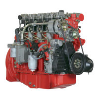
267 pages
TD 2011 w Workshop Manual
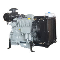
87 pages
BF4M 2012 Operation Manual
490 pages
BFM 1012 Workshop Manual
82 pages
BL 1011F Operation Manual
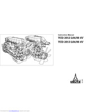
96 pages
TCD 2012 L04/06 4V Instruction Manual
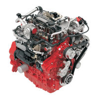
84 pages
TD 3.6 L4 Operation Manual
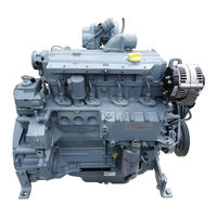
120 pages
1012 Operation Manual
144 pages
TD 3.6 L4 Operation Manual
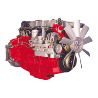
441 pages
TCD 2013 2V Workshop Manual
102 pages
TCD 2012 L04/06 V2 Operation Manual
290 pages
D 909 / 910 Installation Manual
169 pages
TCD 2012 Series Installation Manual
85 pages
914 Operation Manual
711 pages
TCD 2015 Workshop Manual
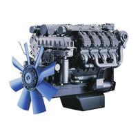
402 pages
BFM 1015 Workshop Manual
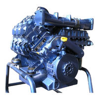
428 pages
BFM 1015 Series Workshop Manual
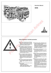
42 pages
1015 Operation Manual
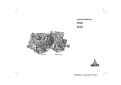
104 pages
1012 Operation Manual
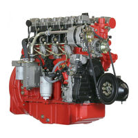
77 pages
D 2011 L02 o Operation Manual
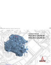
80 pages
TCD 2013 L04 4V Operation Manual
Models
Document Type
0
0297 9929en

Operation Manual
1
1012
Operation Manual • Operation Manual • Workshop Manual
1013
Operation Manual • Operation Manual • Workshop Manual
1015
Operation Manual
9
914
Operation Manual
9929en
Operation Manual
B
B/FL 1011 / F / 2011
Installation Manual
B/FL 413 F / 513 /C / CP
Installation Manual
B/FL 912/913/914/C
Installation Manual
B/FM 1011 F / 2011
Installation Manual
BF3L 2011
Operation Manual
BF3M 2011
Operation Manual
BF4L 2011
F2L 2011
Operation Manual
BF4L 2011
Operation Manual
BF4M 2011
Operation Manual
BF4M 2012
Operation Manual
BF6M 1015 C
Workshop Manual
BF6M 1015 CP
Workshop Manual
BF6M 2012 C
Operation Manual
BF8M 1015
Workshop Manual
BFM 1015
Workshop Manual
BFM 1015 C
Workshop Manual
BFM 1015 Series
Workshop Manual
BFM 2011
Operation Manual
D
D 2008
Workshop Manual
D 2009
Workshop Manual
D 2011 L02 i
Operation Manual
D 2011 L02 o
Operation Manual
D 2011 L03 i
Operation Manual
D 2011 L03 o
Operation Manual
D 2011 L04 i
Operation Manual
D 2011 L04 o
Operation Manual
D 2011 L04 w
Operation Manual
D 2011 w
Workshop Manual
D 909 / 910
Installation Manual
D302
Repair Manual
F
F2M 2011
Operation Manual
F3L 2011
Operation Manual
F3M 2011
Operation Manual
F4L 2011
Operation Manual
F4M 2011
Operation Manual
FL 1011F
Operation Manual
FL 2011
Operation Manual
FM 2011
Operation Manual
S
S/BV6/8/9M628
Operation Manual
T
TBD 616 OEM
Operating Instructions Manual
TBD 616 V-12
Operating Instructions Manual
TBD 616 V-16
Operating Instructions Manual
TBD 616 V-8
Operating Instructions Manual
TBG 620
Operation Manual • Workshop Manual
TBG 620K
Workshop Manual
TCD 2011 L04 w
Operation Manual
TCD 2011 w
Workshop Manual
TCD 2012 L04/06 4V
Instruction Manual
TCD 2012 L04/06 V2
Operation Manual
TCD 2012 Series
Installation Manual
TCD 2013 2V
Workshop Manual • Workshop Manual
TCD 2013 L04 4V
Operation Manual
TCD 2013 L04/06 4V
Instruction Manual
TCD 2013 L04/06 V2
Operation Manual
TCD 2013 L06 4V: TCD 2013 L06 4V
Operation Manual
TCD 2013 Series
Installation Manual
TCD 2015
Workshop Manual • Operation Manual
TCD 3.6 L4
Operation Manual • Operation Manual • Operation Manual
TCD 4.1 L4
Operating Manual
TCD 6.1 L6
Operating Manual
TD 2011 L04 i
Operation Manual
TD 2011 L04 o
Operation Manual
TD 2011 L04 w
Operation Manual
TD 2012 Series
Installation Manual
TD 2013 Series
Installation Manual
TD 3.6 L4
Operation Manual • Operation Manual • Operation Manual
TTCD 6.1 L6
Operating Manual
W
WP4C Series
Operation And Maintenance Manual
WP6C Series
Operation And Maintenance Manual