
20,7 Мб
Руководство по эксплуатации и обслуживанию мини-экскаватора
Формат: pdf
-
Год:
2012
-
Страниц:
141
-
Язык:
русский
-
Размер:
20,7 Мб
-
Категории:
Hidromek
10,9 Мб
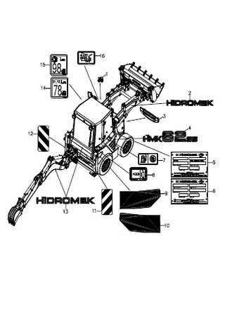
Каталог запчастей мини-экскаватора Hidromek HMK 62SS
Формат: pdf
-
Год:
2005
-
Страниц:
247
-
Язык:
турецкий, английский
-
Размер:
10,9 Мб
-
Категории:
Hidromek

15,9 Мб
Экскаваторы-погрузчики Hidromek HMK 102B и HMK 102S
Формат: pdf
-
Год:
2012
-
Страниц:
196
-
Язык:
русский
-
Размер:
15,9 Мб
-
Категории:
Hidromek
HMK 102 ENERGY WORKSHOP MANUAL
GENERAL 00- 01 REVISION HISTORY 00 — 02 FOREWORD 00 — 03 SAFETY 00 — 04 STANDARTS
00
00
HMK 102 ENERGY WORKSHOP MANUAL
01 0
REVISION HISTORY When new or revised information is published to update this manual the action to be taken with the pages is indicated in the table. Pages not marked are not currently revised, but are included for page numbering continuity.
Mark
Indication
Action required
+
Page to be newly added Page to be replaced Page to be delated
Add
— /+
x
Mark
Page
Revision number
Mark
Page
Revision number
Mark
Page
Revision number
Replace Discard
HMK ENERGY WORKSHOP MANUAL
SPECIFICATIONS 01- 01 GENERAL — Location of components — General dimensions — Specifications and performance data 01 — 02 LUBRICATION CHART
01
01
HMK 102 ENERGY WORKSHOP MANUAL
01 SPECIFICATIONS
1 GENERAL
LOCATION OF COMPONENTS
1 2 3 4 5 6
BUCKET LOADER LOADER ARM ENGINE HYDRAULIC TANK FUEL TANK CAB
7 8 9 10 11
STABILIZERS KINGPOST CARRIAGE BOOM ARM BACKHOE BUCKET BACKHOE
GENERAL VIEW OF HMK 102 ENERGY
01
HMK 102 ENERGY WORKSHOP MANUAL
01 SPECIFICATIONS 2
GENERAL
GENERAL DIMENSIONS
G1: 1780 mm G2 : 2210 mm
GENERAL DIMENSIONS OF HMK 120 B ENERGY
01
HMK 102 ENERGY WORKSHOP MANUAL
01 SPECIFICATIONS GENERAL
G1 : 1905 mm G2 : 2340 mm
GENERAL DIMENSIONS OF HMK 120 S ENERGY
3
01
HMK 102 ENERGY WORKSHOP MANUAL
01 SPECIFICATIONS 4
GENERAL MODEL :
HMK 102B
HMK 102S
A. OVERALL TRANSPORT LENGTH
6090 mm
6125 mm
B. TREAD WİDTH, FRONT
1920 mm
1905 mm
C. TREAD WİDTH, REAR
1780 mm
1905 mm
D. OVERALL TRANSPORT WIDTH
2440 mm
2440 mm
E. BACKHOE MAX. DIGGING DEPTH (STD. ARM)
4400 mm
4350 mm
F. BACKHOE MAX. DIGGING DEPTH (TELESCOP. ARM)
5640 mm
5590 mm
G. TRANSPORT HEIGHT (MAX.)
3530 mm
3595 mm
400 mm
400 mm
I. BUCKET WIDTH (STD)
2440 mm
2440 mm
J. DUMP HEIGHT (LOADER)
2610 mm
2760 mm
K. DUMP HEIGHT (BACKHOE STD.)
3700 mm
3750 mm
L.. DUMP HEIGHT (BACKHOE TELESCOP.)
4650 mm
4700 mm
M. BUCKET LOADER MAX HEIGTH
4100 mm
4165 mm
195 mm
140 mm
H. GROUND CLEARANCE, BUCKET, DRIVE POSITION
N. BUCKET LOADER LEVELLING (MINUS)
HMK 102 ENERGY WORKSHOP MANUAL
01 01
SPECIFICATIONS HMK 102 B HMK 102 S
SPECIFICATIONS AND PERFORMANCE Unit
Specifications
Loader Bucket Capacity (CECE) heaped Backhoe bucket options 350 mm 400 mm 500 mm 600 mm 700 mm 800 mm Operating Weights (STD) 102B / 102S 1. speed Travel 2. speed 3. speed Speed 4. speed Bucket breakout force B / S Arm breakout force B & S Backhoe bucket breakout force B & S Maker Model
m3
1,1
m3 m3 m3 m3 m3 m3
0,08 0,09 0,11 0,14 0,18 0,22
kg
8.400 / 8.700
km/h km/h km/h km/h kgf kgf kgf —
5,0 9,0 21,0 40,0 7.190 / 7.155 6.100 / 6.260 4.395 PERKINS 1104C-44T
—
4 cycle, 4 cylinders, in line, direct injection, water cooled diesel engine
Attachment
Item
Engine
Type Rated output Maximum torque Bore x Stroke Total displacement Compression Ratio Injection pump Low Idle speed (No load) High Idle speed (No Load) Firing Order Lubricating oil pressure Suction Valve clearance Exhaust Starter Voltage Alternator Output Turbocharger Engine oil pan capacity Weight (dry)
HP (Kw) / rpm Nm (lb.ft) / rpm mm cm3 (in3) rpm
100 (74,5) / 2200 415 (306,08) /1350 105 x 127 4400 (268) 18,2 : 1 DELPHI 950 ±50
rpm
2150 ±50
kgf/ cm2 (kpa)
1–3–4-2 3,0 (300) 0,20 (0,008) 0,45 (0,018) 12 12 115 Installed 11 305
mm (inch) V V A l kg
5
01
HMK 102 ENERGY WORKSHOP MANUAL
01 SPECIFICATIONS 6
Electric system
Cooling System
Item Type Radiator Horn Battery Light Light Circuit protection
Hydraulic System
Main Pump Brake pump
HMK 102 B HMK 102 S Specifications Aluminium Air cooled
Unit —
Coolant capacity
l
Type Type Capacity Voltage Headlight (L/H) Working lamp Type Number of fuses Maker Flow Rate Type Type Flow rate Maker Pressure
V/Ah V 2 each 1 each each
25
cc/rev cc/rev bar
Main Control Valve
Function
—
Electric Horn Lead-acid 12V / 165 Ah 12 halogen ( 55W / 60W ) halogen ( 55W ) FUSE + HEMA 37/29 Tandem gear pump Gear pump 4 HUSCO 230 Unloader valve function depends upon digging & load conditions Anti-schock & anticavitation valves HSC Hydraulic Speed Control provides more engine power & less fuel consumption while driving
HMK 102 ENERGY WORKSHOP MANUAL
01 01
SPECIFICATIONS HMK 102 B HMK 102 S Unit
Specifications
—
Anti-wear, anti oxidation, anti foam mineral oil for the high pressurized hydraulic system
Grade Kinematic Viscosity @ 40 º C Viscosity index Fuel Capacity Type Capacity Hydraulic Pressure Oil Suction filter Return filter Maker Model type Torque converter stall ratio
cSt liter Liter kg/cm2 —
ISO VG 46 47,5 158 120,0 Closed Type 120,0 0 — 0.5 90 10 ITL PS764
—
2,52 : 1
Lubricating
L
12,0
Weight
kg
258
Dimension
Transmission
Type
Tİres
Travel System
Tank
Hydraulic Oil
Item
HMK 102 B
FRONT 12.5-80/18 12PR REAR 16,9/14x 28 12PR
HMK 102 S
ALL 4
Tire Pressure front
Pump Accumulator
Service Brake Service Brake
Brake System
Brake System
Tire Pressure rear Type
Psi / bar Psi / bar
16,9/14 x 28 12PR 58 /4 38 / 2,6
—
Gear Pump
cc/rev
4,0
Type
—
With diaphragm
Capacity
l
0,75
bar
16
bar
210
—
Disc
Flow rate
Gas pressure
Service brake pressure Axle Brake Type
7
01
HMK 102 ENERGY WORKSHOP MANUAL
02 SPECIFICATIONS LUBRICATION CHART UNIT : liter *Initial filling
LUBRICATION CHART Store
Oil
equipm.
type
Refill m Ambient temperature capacity HMK102 -30 -20 -10 0 10 20 B-S
0
C
30
40
SAE 30
Engine oil API Engine oil CF4/SG, pan CH-4, or CI-4
SAE 10W
11
SAE 10W 30 SAE 15W 40 * SAE 40
Transm. PS764
CAT TO4, ZF TE-ME 3C, Allison C4
12
SAE 10 W
Transm. Carraro
ATF Dexron IID & III
13
ATF
102 B 7,6
Front axle, differantial
102 B Rear axle hubs & differantial
102 S
23 Gear oil
Front axle, differantial & 2 hubs
102 S
SAE 90 API GL4, GL5
14 2 x 1,9 16 2 x 1,9
Rear axle, differantial & 2 hubs
ISO VG 32
Hydraulic oil tank
Hydraulic oil
120
ISO VG 46 ISO VG 68 ASTM D975 No.1
Fuel tank
Diesel fuel
120
Fittings of grease nipple
Grease
As required
Cooling system
Antifreeze & soft water mix 1:1
25
ASTM D975 No.2, EN590
NLGI 2, AW, EP (Li. soap or MoS2)
ASTM D4985, (antifreeze/water ratio depends on temperature)
50
1
HMK 102 ENERGY WORKSHOP MANUAL
00 02
GENERAL FOREWORD
FOREWORD Basically, this workshop manual contains the technical information necessary for operations and repairs in a service workshop. For easy understanding and using, this manual is divided into sections for each main system of HİDROMEK 102 energy series backhoe loader. In addition to this, the divided sections also include internal sections for better explanation of the topics.
!
SAFETY
Improper operation and maintenance of this machine could result in serious injury or death. Operation and maintenance manual must be read carefully and understood BEFORE OPERATING THE MACHINE. Always keep the Operation & Maintenance Manual and Spare Parts Catalogue in the machine. Precautions must be taken concerning flammable liquids, hazardous fluids, oils, lubricants and cleaning solvents.
!
To prevent injury to workers, the symbol is used to mark safety precautions in this manual. The precautions accompanying this symbol should always be followed carefully. The specifications contained in this manual are subject to change at any time and without any advance notice. Contact your HİDROMEK distributor for the latest information.
How to read this manual Chapter and section This manual is issued as a guide to carrying out repair and maintenance. To easily understand this manual it is divided as follows: Example:
10 – 01
Section number (01 : Structure and function) Chapter number (10 : Engine)
1
00
HMK 102 ENERGY WORKSHOP MANUAL
02 2
GENERAL FOREWORD
PAGE Page numbering is started from each section. Therefore, revised pages can be easily inserted. Also, additional pages and revision number can be indicated. Example: Chapter number (10 : Engine)
10
Section number (01 : Structure and function)
01 3
3 rd revision
For the revision status in this manual, refer to REVISION HISTORY.
SYMBOLS SYMBOL
ITEM
Safety
Caution
Tightening torque
REMARKS Special safety precautions are necessary when performing the work. Special technical precautions or other precautions for preserving standards are necessary when performing the work Pay attention to the tightening torque during assembly.
Tool
Use proper tools in assembling and disassembling.
Adhesive
Places to be applied with adhesive.
Places where oil or lubricant must be added.
HMK 102 ENERGY WORKSHOP MANUAL
00 02 3
GENERAL FOREWORD
HAZARD SYMBOL EXAMPLES Following symbols are used to convey a better understanding. HAZARDING ALERT SYMBOLS Caution – Warning – dangerous ISO 3864 – B.3.1
Caution – Warning – dangerous AINSI Z535.4 UL 1492
Caution, flammable ISO 3864 – B.3.2 Caution, explosion ISO 3864 – B.3.3
Caution, risk of electric shock ISO 3864 – B.3.6
Caution, risk of electric shock UL 1492
Caution, hot surface IEC 417 — 5041
Caution, rotational object
00
HMK 102 ENERGY WORKSHOP MANUAL
02 4
GENERAL FOREWORD
Caution , entanglement Design: ISO 7001-019
Oxidation Being reviewed in ISO 3864
Corrosive ISO 3864 (EC code by EC)
Corrosive ANSI Z535.3 (Being reviewed in ISO TC/96)
Caution, toxic risk ISO 3864 (EC code by EC)
Pungent, toxic Being reviewed in ISO 3864 (EC code by EC)
Caution, risk of electric shock ANSI Z535.3 (Being reviewed in ISO TC/96)
Hot surface ANSI Z535.3
HMK 102 ENERGY WORKSHOP MANUAL
00 02
GENERAL
5 FOREWORD
Caution , hot surface IEC 417-5041
Entanglement AINSI Z535.3 (Being reviewed in ISO TC/96)
Pinch AINSI Z535.3 (Being reviewed in ISO TC/96)
Cut-sever AINSI Z535.3 (Being reviewed in ISO TC/96)
PROHIBITION SIGNS
Use of matches, lighters and smoking prohibited ISO 3864 B.1.2
Do not touch JIS B 0139 Revised plan
Don’t use in a damp place IEC 417-5582Pr
00
HMK 102 ENERGY WORKSHOP MANUAL
03 GENERAL SAFETY
For safety observe the following rules.
GENERAL PRECAUTIONS SAFETY PRECAUTIONS Trained and experienced personnel should carry out the repair and maintenance works. Before carrying out any operation or maintenance, carefully read the OPERATING & MAINTENANCE MANUAL. Read all the precautions given on the decals, which are fixed on the machine. SAFETY DEVICE Make sure that all guards and covers are mounted in their proper positions. Repair or replace if damaged. Pay attention to the method of using any safety locking device or safety belt. SAFETY CLOTHES AND HELMET Wear the specified work clothes in the correct manner.
Use the specified protective gear (helmet, safety glasses, safety shoes, mask, gloves). Wear goggles, gloves and helmet for guarding against injury from flying objects. Always have a trained and experienced welder carry out any welding work. When carrying out welding work, always wear welding gloves, apron, glasses, cap and other suitable clothes.
1
00
102 ENERGY WORKSHOP MANUAL
03 2
GENERAL SAFETY
PREPARATION FOR EMERGENCIES Know where fire extinguishers are located and how to use them. Keep a first aid kit and an eye wash kit near the work area. Obtain emergency phone numbers for doctors, ambulance service, hospital and fire department
HANDLE FLUIDS SAFELY AND AVOID FIRE
Handle fuel with care. It is highly flammable Do not smoke when refueling and beware of open fire or sparks from refueling area. Engine must be stopped when refueling and Refuel in open and well ventilated area. Store flammable fluids away from fire hazards. It is dangerous to puncture or throw the pressurized containers in fire.
DISPOSE OF FLUIDS PROPERLY Improperly disposing of fluids is harmful for environment and ecology. Before draining any fluids, find out the proper way to dispose of waste from your local environmental agency. Collect draining fuel, oil or other fluids in Suitable containers. Do not use food or beverage containers, that may mislead someone to drink from them. Clean the oil spillage at once. Do not pour oil into the ground, sewer system, stream of the river, pond or lake. Observe the environmental protection regulations when disposing of oil fuel, coolant, brake fluid, filters, batteries and other harmful waste.
00
HMK 102 ENERGY WORKSHOP MANUAL
03 GENERAL
3 SAFETY
AVOID HARMFUL ASBESTOS DUST Avoid breathing dust containing asbestos fibers. Inhaled asbestos fibers may cause lung cancer.
Illuminate working area adequately with safety lamp. Always use a safety lamp when working inside or under the machine. The bulb of the safety lamp must be covered with a hard wire cage. The bulb may break accidentally and the hot filament can ignite the spilled fuel or oil.
CAUTION FOR USING HAND TOOLS AND STEPS Never jump on or off the machine. When you get on or off the machine, be sure to contact at three points with the machine. The steps and handrails must be used, and with face towards the machine. Do not hold any control lever or hand lever to escalate. Always keep the machine clean. Remove all mud or oil from the steps. Remember that, dirtiness is the first reason of any accident or trouble.
00
102 ENERGY WORKSHOP MANUAL
03 4
GENERAL SAFETY
PREPARATIONS FOR WORK WARN OTHERS WHEN SERVICING Unexpected machine movement can cause serious injury. Before performing any work on the machine, attach a “DO NOT OPERATE” tag on the steering wheel. When carrying out any operation with two or more workers, always agree on the operating procedure before starting. Whether a “DO NOT OPERATE” tag is attached or not, sound travel alarm before the machine starts to move. USE TOOLS PROPERLY
Keep all tools in good condition and learn how to use them. For keeping the tools and dismantled parts, have an appropriate and clean area in the workshop. Always keep the work area clean and be sure that the floor is out of dirt and oil. Park the machine on a level and firm ground before adding oil or starting any repair.
Lower the machine attachments on the ground before starting any repair work. If it is not possible, apply safety lock or blockage material to prevent the attachment from falling down. Turn the engine “OFF”, keep the start key with you and lock the levers to “LOCK” position before leaving operator cab. Otherwise the machine may suddenly operate and cause serious injury or death.
00
HMK 102 ENERGY WORKSHOP MANUAL
03 GENERAL SAFETY COOLING SYSTEM SAFETY Hot coolant can burn you. When the radiator is hot, turn the radiator cap slowly with a piece of cloth to release the pressure. Do not remove the radiator cap when the engine is overheated.
AVOID PRESSURIZED FLUIDS High pressurized fluids can penetrate under the skin and cause serious injury. Avoid the hazards of pressurized fluids by releasing pressure, before disconnecting the pressurized lines, like hydraulic, fuel or etc. Use a piece of a cardboard when searching for leaks. Protect your hands, eyes and body from the high pressurized fluids.
Be careful not to break, twist or damage the high pressurized pipes and hoses can cause electrical ignition and fire.
HANDLING OF HEAVY OBJECTS Use a hoist or crane when lifting heavy components. Wire ropes, chains and hooks must be in good working conditions and free of damages. The capacity of the lifting equipment and lifting points must be very well known. Before assembling or disassembling work, support the machine with wooden blocks, jacks or stands.
Before starting work, lower the bucket on the ground.
Its forbidden to work under the equipment without any support or lock.
5
00
102 ENERGY WORKSHOP MANUAL
03 6
GENERAL SAFETY
ELECTRICAL SYSTEM
Before welding on the machine or repairing the electrical system, ALWAYS turn the master switch OFF. Disconnect the negative ( — ) terminal of the battery. Be careful not to break or damage wiring, when dismounting or removing components. Damaged wires can cause short-circuit spark and fire. Wear safety glasses when working with the batteries. The sulfuric acid of the electrolyte is poisonous and harmful. If it is splashed, immediately flush with plenty of water. If splashed into eye, wash your eyes with plenty of water and get medical first aid. To inhale the electrolyte vapor is harmful for your lungs. Because of explosion risk, keep away sparks, open flame from top of the battery.
Wear a safety mask not to inhale the vapor.
If the terminals are short-circuited with a metal object, the battery may explode. Do not put any metal object or wire on the battery. It is important to tighten the battery terminals properly. Otherwise, because of insufficient contact, there will be a contact resistance and heat will be generates on the terminals. The lead terminal abrasion will occur. Be careful with the polarity when connecting the battery terminals. Do not wash the sensors, connectors and instruments in the cab with water or steam. Dampness in the electrical system can cause abnormal operation and failure.
00
HMK 102 ENERGY WORKSHOP MANUAL
03 GENERAL SAFETY CAUTIONS DURING REPAIRS When dismounting any cover or cap under spring tension or system pressure, be careful with removing the bolts. Two bolts on opposite sides must be removed after the spring tension or pressure is released. High pressure grease in the recoil spring adjusting system can eject and cause injury. Do not loosen the grease valve more then 1 turn, before the grease pressure is released in the system.
When assembling and disassembling parts, always use specified tightening torques. Installing protective guards, cage, etc. is very important. The rotation part’s guards must be installed and tighten correctly. Be careful not to let your clothes or hair loose to be caught by rotating parts. Never touch or try to hold rotating parts such as fan blades or fan belts.
Never insert your finger or hand to align two holes.
Be careful not to pinch your fingers in a hole, between parts or tools.
7
00
HMK 102 ENERGY WORKSHOP MANUAL
04 GENERAL
1 STANDARTS
MEASUREMENT CONVERSIONS LENGTH Unit
cm
m
km
in
cm m km in ft yd mile
1
0,01
0,00001
0,3937
0,032808 0,0109361
0,0000062
100
1
0,001
39,37
3,28083
1,093613
0,0006214
100000
1000
1
39370,078 3280,839
1093,613
0,6213712
2,54
0,0254
0,0000254
1
0,083333
0,027778
0,0000158
30,48
0,3048
0,0003048
12
1
0,333333
0,0001894
91,44
0,9144
0,000914
36
3
1
0,000568
1,609344
63360
5280
1760
1
160934,4 1609,344 1 mm = 0,1 cm 1μ = 0,001 mm
ft
yd
mile
AREA Unit
cm²
m²
km²
a
ft²
yd²
in²
cm²
1
0,0001
—
0,000001
0,0010764
0,0001196
0,155
m²
10000
1
0,000001
0,01
10,76391
1,19599
1550
km²
—
1000000
1
10000
10763910,4
1195990
—
a
1000000
100
0,0001
1
1076,39
119,5990
—
ft²
929,03
0,092903
—
0,000929
1
0,111111
144
yd²
8361,27
0,8361274
—
0,0083613
9
1
1296
in²
6,4516
0,0006452
—
0,0000065
0,0069444
0,0007716
1
1 ha = 100 a, 1 mile² = 259 ha = 2,59 km²
00
HMK 102 ENERGY WORKSHOP MANUAL
04 2
GENERAL STANDARTS
VOLUME Unit
cm³ = cc
m³
l
in³
ft³
yd³
cm³ = ml
1
0,000001
0,001
0,0610237
0,0000353
0,0000013
m³ l in³ ft³
1000000
1
1000
61,024
35,315
1,30795
1000
0,001
1
61,024
0,035315
0,001308
16,387
0,0000164
0,0163871
1
0,0005787
0,0000214
28316,84
0,0283168
28,31684
1728
1
0,037037
46656
27
1
yd³
764554,8 0,7645549 764,5548 1 gal (US) = 3785,41 cm³ = 231 in³ = 0,83267 gal (US)
WEIGHT Unit
g
kg
t
oz
lb
g
1
0, 001
0,000001
0,035274
0,0022
kg
1000
1
0,001
35273,96
2204,62
t
1000000
1000
1
35273
2204,59
oz
28,34952
0,0283495
0,0000283
1
0,0625
lb
453,59237
0,4535924
0,0004536
16
1
1 ton (metric) =1,1023 ton (US) = 0,9842 ton (UK)
PRESSURE Unit
kgf/cm²
bar
Pa = N/m²
kPa
Lbf/in²
Lbf/ft²
kgf/cm²
1
0,980665
98066,5
98,0665
14,22334
2048,161
1
100000
100
14,50377
2088,543
0,00001
1
0,001
0,000145
0,0208854
0,01
1000
1
0,1450377
20,88543
0,0689476
6894,7572
6,894757
1
144
0,0004788
47,8802589
0,0478803
0,0069444
1
bar 1,019716 Pa = N/m² 0,0000102 kPa 0,0101972 Lbf/in² 0,070307 Lbf/ft²
0,0004882
1 kgf/cm² = 735,55923 torr (mm Hg)= 0,967841 atm
00
HMK 102 ENERGY WORKSHOP MANUAL
04 GENERAL STANDARTS
APPROXIMATE CONVERSIONS TORQUE
Conversion factor
newton meter (N.m) newton meter (N.m) newton meter (N.m)
x 10,2 x 0,74 x 0,102
= kgf.cm = lbf.ft = kgf.m
x 0,8664 x 1,36 x 7,22
= lb.in = N.m = lbf.ft
PRESSURE (Pa =N/m²) kilopascal (kPa) kilopascal (kPa) kilopascal (kPa) bar kgf/cm² newton/mm² megapascal (MPa)
x 4,0 x 0,295 x 0,145 x 14,5 x 14,22 x 145,04 x 145
= in (water column) = in (Hg column) = psi = psi = psi = psi = psi
x 0,249 x 3,386 x 6,894 x 0,069 x 0,070 x 0,069 x 0,00689
= kPa = kPa = kPa = bar = kgf/cm² = bar = MPa
POWER (W = J/s) kilowatt (kW) kilowatt (kW) kilo watt (kW) watt (W)
x 1,359 x 1,34 x 0,948 x 0,737
= PS (cv) = HP = Btu / s = ft.lb/s
x 0,736 x 0,746 x 1,055 x 1,355
= kW = kW = kW =W
ENERGY (J =N.m) kilojoule (kJ) Joule (J)
x 0,9478 x 0,239
= Btu = calorie
x 1,055 x 4,185
= kJ =J
VELOCITY AND ACCELERATION meter per sec² (m/s²) meter per second (m/s) kilometer per hour (km/h)
x 3,28 x 3,28 x 0,62
= ft/s² = ft/s = mph
x 0,3048 x 0,3048 x 1,609
= m/s² = m/s = km/h
x 3,785
= l/min
TEMPERATURE ºC = (ºF — 32) ÷ 1,8 FLOW RATE l / min (dm³/min)
Conversion factor
ºF=(ºC x 1,8)+32
x 0,264
= US gal/min
3
00
HMK 102 ENERGY WORKSHOP MANUAL
04 4
GENERAL STANDARTS
STANDARD TIGHTENING TORQUE The following charts give the standard tightening torques of bolts and nuts. Exceptions are given in chapter of “Disassembly and Assembly “ METER TABLE Classification
4T, 5T
10T
Bolt type
Bolt size
Torque kgf.m
(lbf.ft)
Torque kgf.m (lbf.ft)
M4
0,2 ± 0,02
(1,4±0,1)
0,4 ± 0,04
(2,9±0,3)
M5
0,3 ± 0,03
(2,2±0,2)
0,8 ± 0,08
(5,8±0,6)
M6
0,5 ± 0,05
(3,6±0,4)
1,4 ± 0,14
(10,1±1,0)
M8
1,2 ± 0,12
(8,7±0,9)
3,3 ± 0,30
(23,8±2,2)
M10
2,3 ± 0,23
(16,6±1,7)
6,5 ± 0,70
(47,0±5,0)
M12
4,0 ± 0,40
(29,0±3,0)
11,3 ± 1,10
(82,0±8,0)
<M14>
6,4 ± 0,60
(46,0±4,0)
17,9 ± 1,80
(129±13)
M16
9,5 ± 0,90
(69,0±6,0)
26,7 ± 2,70
(193±19)
<M18>
13,5 ± 1,40
(97,0±10,0)
38,0± 3,80
(274±27)
M20
18,6 ± 1,90
(134±14,0)
52,2 ± 5,20
(377±38)
<M22>
24,7 ± 2,50
(178±18,0)
69,4 ± 6,90
(500±50)
M24
32,1 ± 3,20
(232±23,0)
90,2 ± 9,00
(650±65)
M30
62,6 ± 6,30
(452±45,0)
176,1 ± 17,6
(1270±127)
M36
108,2 ± 10,80
(781±78,0) 304,3 ± 30,4
(2200±220)
M42
171,8 ± 17,20 (1240±124) 483,2 ± 48,3
(3500±350)
M45
211,3 ± 21,10 (1525±152) 594,3 ± 50,4
(4300±430)
00
HMK 102 ENERGY WORKSHOP MANUAL
04 GENERAL STANDARTS INCH TABLE Classification
4T, 5T
10T
Bolt type
Bolt size
Torque kgf.m
(lbf.ft)
Torque kgf.m (lbf.ft)
¼”
0,6 ± 0,06
(4,3±0,4)
1,7 ± 0,20
(12,2±1,2)
5/16”
1,2 ± 0,12
(8,7±0,8)
3,0 ± 0,30
(21,7±2,2)
5,6 ± 0,50
(40±4,0)
3/8”
2,0 ± 0,20
(14,4±1,4)
7/16”
3,2 ± 0,32
(23,0±2,0)
8,9 ± 0,90
(64±6)
½”
4,7 ± 0,47
(34,0±3,0)
13,4 ± 1,30
(97±10)
9/16”
6,8 ± 0,68
(50,0±5,0)
19,0 ± 1,90
(137±14)
5/8”
9,3 ± 0,93
(67,0±7,0)
26,1 ± 2,60
(190±19)
¾”
16,0 ± 1,60
(115±15)
45,1 ± 4,50
(325±33)
7/8”
25,5 ± 2,55
(185±19)
71,6± 7,20
(520±52)
1”
38,0 ± 3,80
(275±27,0)
106,9 ± 10,7
(770±77)
1 1/8”
54,1 ± 5,40
(390±39,0)
152,2 ± 15,2
(1100±110)
1 ¼”
74,2 ± 7,42
(535±54,0)
208,9 ± 20,9
(1510±151)
1 ¾”
98,8 ± 9,88
(710±71,0)
277,8 ± 27,8
(2000±200)
1 ½”
128,2 ± 12,80
(925±93,0) 360,7 ± 36,1
(2600±260)
NOTE : 1N.m ~ 0,1 kgf.m
5
HMK 102 ENERGY WORKSHOP MANUAL
ENGINE
10- 01 Specifications 10 — 02 Workshop
10
HMK 102 ENERGY WORKSHOP MANUAL
10 01
ENGINE SPECIFICATIONS
INTRODUCTION
The PERKINS 1100 series engine is 4 cylinders and RG model turbocharged. Identification of the engine is: 1104C-44T.
The engine conforms with EEC stage 2 emmissions legislation for construction machine application.
Performance data Power output (kW) Power output (bhp) Peak torque (Nm) Peak torque (lbf.ft)
Gross intermittent ISO/TR 14396 74,5 99,5 372 274
Speed rev/min 2400 2400 1400 1400
1
10
HMK 102 ENERGY WORKSHOP MANUAL
01 ENGINE 2
SPECIFICATIONS PERFORMANCE CURVE
Note: Lower speed ratings cannot be read off this curve
GENERAL DATA Dimensions
HMK 102 ENERGY WORKSHOP MANUAL
10 01
ENGINE SPECIFICATIONS
GENERAL DATA Bore and stroke
105 mm x 127 mm
Number of cylinders
In-line 4 cylinders
Cubic capacity
4,4 litres (269 cu.in)
Cycle
4 stroke
Aspiration
Turbocharged
Combustion system
Direct injection
Compression ratio
19,3 : 1
Engine rotation
Anticlockwise (viewed on flywheel)
Governing
All speed mechanical
Cooling system
Pressurized water
Length
663 mm
Width
597 mm
Height
810 mm
Dry weight
305 kg
3
10
HMK 102 ENERGY WORKSHOP MANUAL
01 ENGINE 4
SPECIFICATIONS GENERAL VIEW
1 Rocker cover
4 Fuel injection pump
7 Water pump
2 Oil pan breather
5 Oil filter
8 Fan pulley
3 Fuel filter
6 Crank shaft pulley
9 Thermostat
HMK 102 ENERGY WORKSHOP MANUAL
10 01
ENGINE SPECIFICATIONS GENERAL VIEW (cont’d)
10 Oil filling cap
13 Turbocharger
16 Crank shaft dumper
11 Exhaust manifold
14 Starter
17 Air intake
12 Charge alternator
15 Dumper housing
5
10
HMK 102 ENERGY WORKSHOP MANUAL
01 ENGINE 6
SPECIFICATIONS GENERAL VIEW (cont’d)
18 Charge alternator
20 Turbo oil feed
22 Turbocharger
19 Fan pulley
21 Turbo oil drain
23 Exhaust manifold
HMK 102 ENERGY WORKSHOP MANUAL
10 01
ENGINE SPECIFICATIONS GENERAL VIEW (cont’d)
24 Fuel feed pump
27 Starter
30 Oil pan
25 Oil filling cap
28 Oil level dipstick
31 Crank shaft pulley
26 Fuel filter
29 Oil filter
32 Water pump 33 Thermostat housing
7
10
HMK 102 ENERGY WORKSHOP MANUAL
01 ENGINE 8
SPECIFICATIONS
INTAKE & EXHAUST VALVES
A : Intake valve
ENGINE IDENTIFICATION ETHICHET
B: Exhaust valve
HMK 102 ENERGY
10
WORKSHOP MANUAL
02 ENGINE WORKSHOP GENERAL INFORMATION INTRODUCTION This Workshop Manual has been written to provide assistance in the service and overhaul of Perkins 1100 series 4 cylinder engines. It should be used in conjunction with normal workshop practice and information contained in current service bulletins. Mention of certain accepted practices therefore, has been purposely omitted in order to avoid repetition. For overhaul procedures the assumption is made that the engine is removed from the application. The engine conforms with USA (EPA/CARB) stage 2 and EEC stage 2 emissions legislation for agriculture, construction and industrial applications. When reference is made to the “left” or “right” side of the engine, this is as seen from the flywheel end of the engine. “SAFETY PRECAUTIONS” are given for your protection and must be used all times. Danger is inbdicated in the text by two methods: Warning ! This indicates that there is a possible danger to the person. Caution : This indicates that there is a possible danger to the engine. Note : Is used where the information is important, but there is no a danger. In this Workshop Manual, the Perkins 1100 series RG model turbocharged 4 cylinders engine workshop procedures are explained. The correct identification of the engine is by the full engine number. The engine number is stamped on a label which is fastened to the left side of the cylinder block. If you need parts, service or information for your engine, you must give the complete engine number to the HİDROMEK ‘s After Sales Dealers and Service.
The engine serial number plate contains the following information: (1) TPL number (2) Type (3) Serial number (4) List number
1
10
HMK 102 ENERGY
WORKSHOP MANUAL
02 ENGINE WORKSHOP
2 SAFETY PRECAUTIONS
These safety precautions are important. You must refer also to the local regulations in the country of use. Some items only refer to specific applications. Only use these engines in the type of application for which they have been designed. Do not change the specification of the engine. Do not smoke when you fill the fuel tank. Clean away fuel which has been spilt. Material which has been contaminated by fuel must be moved to a safe place. Do not refill the fuel tank while the engine runs (unless it is absolutely necessary). Do not clean, add lubricating oil, or adjust the engine while it runs (unless you have had the correct training; even then extreme care must be used to prevent injury). Do not make adjustments that you do not understand. Ensure that the engine does not run in a location where it can cause a concentration of toxic emmisisons. Other persons must be kept at a safe distance while the engine or auxiliary equipment is in operation. Do not permit loose clothing or long hair near moving parts. Keep away from moving parts during engine operation. Warning! Some moving parts cannot be seen clearly while the engine runs. Do not operate the engine if a safety guard has been removed. Do not remove the filler cap, or any component of the cooling system while the engine is hot and while the coolant is under pressure because dangerous hot coolant can be discharged. Do not allow sparks or fire near the batteries (especially when the batteries are on charge) because the gases from the electrolyte are highly flammable. The battery fluid is dangerous to the skin and especially to the eyes. Disconnect the battery terminals before a repair is made to the electrical system. Only one person must control the engine. Ensure that the engine is operated only from the control panel or from the operator’s position. If your skin comes into contact with high pressure fuel, obtain medical assistance immediately. Diesel fuel and lubricating oil (especially used lubricating oil) can damage the skin of certain persons. Protect your hands with gloves or a special solution to protect the skin. The combustible material of some components of the engine (for example certain seals) can become extremely dangerous if it is burned. Never allow this burnt material to come into contact with the skin or with the eyes. Do not wear clothing which is contaminated by lubricating oil. Do not put material which is contaminated with oil into the pockets of clothings. Discard used lubricating oil in a safe place to prevent contamination.
HMK 102 ENERGY
10
WORKSHOP MANUAL
02 ENGINE WORKSHOP SAFETY PRECAUTIONS (cont’d)
Ensure that the control lever of the transmission drive is in the “out-of-drive” position before the engine is started. Use extreme care if emergency repairs must be made in adverse conditions. Always use a safety cage to protect the operator when a component is to be pressure tested in a container of water. Fit safety wires to secure the plugs which seal the hose connections of a component which is to be pressure tested. Do not allow compressed air to contact your skin. If compressed air enters your skin, obtain medical help immediately. Turbochargers operate at high speed and at high temperatures. Keep fingers, tools and items away from the inlet and outlet ports of the turbocharger and prevent contact with hot surfaces. Do not clean an engine while it runs. If cold cleaning fluids are applied to a hot engine, certain components on the engine may be damaged. Fit only genuine Perkins parts from your HİDROMEK dealer.
ENGINE LIFT EQUIPMENT The maximum weight of the engine without coolant, lubricant, or a gear box fitted will vary for different applications. It is recommended that lift equipment of minimum capacity is used: 600 kg (1320 lbs) Note: Use lift equipment or obtain assistance to lift heavy engine components. Before the engine is lifted: Always use lift equipment of the approved type and correct capacity to lift the engine. It is recommended that lift equipment of the type shown in the figure is used, to provide a vertical lift directly above the engine lift brackets (1). Never use a single lift bracket to raise an engine. Check the engine lift brackets for damage and that they are secure before the engine is lifted. The torque for the setscrews for the engine lift brackets is 44 Nm (33 lbf.ft) 4,5 kgf m. To prevent damage to the rocker cover, ensure that there is clearance between the hooks and the rocker cover.
3
10
HMK 102 ENERGY
WORKSHOP MANUAL
02 ENGINE WORKSHOP
4 VITON SEALS
Some seals used in engines, and in components fitted to engines, are made of Viton. Viton is used by many manufacturers and is a safe material under normal conditions of operation. If Viton is burned, a product of this burnt material is an acid which is extremely dangerous. Never allow this burnt material to come into contact with the skin or with the eyes. If it is necessary to come into contact with components which have been burnt, ensure that the precautions which follow are used: Ensure that the components have cooled. Use neoprene gloves and discard the gloves safely after use. Wash the area with the calcium hydroxide solution and then with clean water. Disposal of components and gloves which are contaminated must be in accordance with local regulations. If there is contamination of the skin or eyes, wash the affected area with a contunious supply of clean water or with calcium hydroxide solution for 15 — 60 minutes. Obtain immediate medical attention.
SAFETY CAUTIONS WHEN AN ENGINE IS CLEANED Care should be taken, when an engine is cleaned with a high pressure cleaning system. Cautions: Do not wash an engine while it runs or while it is hot. If cold cleaning fluids are applied to a hot engine, certain components on the engine could be damaged. Leave the engine to cool for at least one hour and disconnect the battery connections before cleaning. Do not wash any part of the fuel injection pump, cold starty device, electrical shut off solenoid or electrical connectors. Ensure that the alternator, starter motor and any other electrical components are shilded and not directly cleaned by the high pressure cleaning system. If these cautions are ignored, the engine or certain components could be damaged, fail to operate and also make the manufacturer’s warranty invalid.
HMK 102 ENERGY
10
WORKSHOP MANUAL
02 ENGINE WORKSHOP BASIC ENGINE DATA Number of cylinders ………………………. 4 Cylinder arrangement …………………….. In line Cycle ………………………………………..
Four stroke
Direction of rotation ……………………….
Clockwise from the front
Induction system …………………………..
Turbocharged
Combustion system ……………………….
Direct injection
Nominal bore ………………………………
105 mm (4.133 in)
Stroke ………………………………………. 127 mm (5.00 in) Compression ratio …………………………
19,3 : 1
Cubic capacity ……………………………..
4,4 liters (268 in3 )
Firing order …………………………………
1-3-4-2
Valve tip clearances (cold) Inlet …………………………………………. 0,20 mm (0.008 in) Exhaust …………………………………….. 0,45 mm (0.018 in) Lubricating oil pressure*………………… 300 kPa (43 lbf/in2 ) 3.0 kgf/cm2 * Minimum value at maximum engine speed and normal engine temperature.
5
10
HMK 102 ENERGY
WORKSHOP MANUAL
02 ENGINE WORKSHOP
6
DATA AND DIMENSIONS Note: This information is given as a guide for personnel engaged on engine overhauls. The dimensions which are shown are those which are mainly used in the factory. The information applies to all engines, unless an engine type code is shown. CYLINDER HEAD Angle of valve seat: Intake ………………………………………. Exhaust ……………………………………. Leak test pressure ……………………….. Head thickness ……………………………
300 (1200 included angle) 300 (1200 included angle) 200 kPa (29 lbf/in2 ) 2,04 kgf/cm2 117,95/118,05 mm (4.643/4.647 in)
Rz and Rmax to be measured to DIN EN ISO 4287 Surface finish of head face for cylinder head joint ………. Rz < 15µm Rmax < 20 µm Permissible wave depth: Wt < 4 µm with a wave distance Wd < 2,0 mm Wt < 6 µm with a wave distance Wd < 4,0 mm Wt < 8 µm with a wave distance Wd < 6,0 mm Wt < 10 µm with a wave distance Wd < 8,0 mm Diameter of parent bore for valve guide: Intake ………………………………………. Exhaust ……………………………………. Min permissible thickness after head face has been machined ……………………….
Max permissible distortion of cylinder head face: 1
0,03 mm (0.0012 in)
2
0,05 mm (0.0019 in)
3
0,05 mm (0.0019 in)
4
0,03 mm (0.0012 in)
13,000/13,027 mm (0.5118/0.5129 in) 13,000/13,027 mm (0.5118/0.5129 in) 117,20 mm (4.614 in)
HMK 102 ENERGY
10
WORKSHOP MANUAL
02 ENGINE WORKSHOP INTAKE AND EXHAUST VALVES: Intake valves: Diameter of valve stem ………………………….
8,953/8,975 mm (0.3525/0.3533 in)
Clearance in valve guide ………………………
0,025/0,069 mm (0.001/0.0027 in)
Max permissible clearance in valve guide: Production limit ………………………………….
0,069 mm (0.0027 in)
Service limit ……………………………………… 0,13 mm (0.005 in) Diameter of valve head …………………………
46,20/46,45 mm (1.819/1.829 in)
Angle of valve face ……………………………..
300
Full length ……………………………………….
128,92/129,37 mm (5.076/5.093 in) Stem seal with integral seating washer
Seal arrangement ……………………………… Depth of valve head below the face of cylinder head: Production limits …………………………………
1,58/1,84 mm (0.062/0.072 in)
Service limit ……………………………………… 2,09 mm (0.082 in) Exhaust valves: Diameter of valve stem ………………………….
8,938/8,960 mm (0.3519/0.0528 in)
Clearance in valve guide ………………………
0,040/0,84 mm (0.0016/0.033 in)
Max permissible clearance in valve guide: Production limit ………………………………….
0,084 mm (0.003 in)
Service limit ……………………………………… 0,15 mm (0.006 in) Diameter of valve head …………………………
41,51/41,75 mm (1.634/1.644 in)
Angle of valve face ……………………………..
300
Full length ……………………………………….
128,92/129,37 mm (5.076/5.093 in) Stem seal with integral seating washer
Seal arrangement ……………………………… Depth of valve head below the face of cylinder head: Production limits …………………………………
1,53/1,81 mm (0.060/0.071 in)
Service limit ……………………………………… 2,06 mm (0.081 in)
7
10
HMK 102 ENERGY
WORKSHOP MANUAL
02 ENGINE WORKSHOP
8 Dimensions of recesses for valve seat inserts: Intake 1
10,910/11,040 mm (0.4295/0.4346 in)
2
47,820/47,845 mm (1.8827/1.8837 in)
3
Radius 0,38 mm (0.015 in) maximum
Exhaust 1
10,910/11,040 mm (0.4295/0.4346 in)
2
42,420/42,445 mm (1.670/1.6711 in)
3
Radius 0,38 mm (0.015 in) maximum
Valve seat insert tool: Intake 1 1,5 mm (0.06 in) 2 20 mm (0.800 in) 3 6,8/7,1 mm (0.267/0.279 in) 100 mm (3.940 in) 4 5 6 7 8 9 10 Exhaust 1 2 3 4 5 6 7 8 9 10
38,10/38,30 mm (1.500/1.507 in) 46,25/46,50 mm (1.820/1.830 in) Radius 1,4 mm (0.055 in) maximum Radius 1,5 mm (0.06 in) 1,5 mm (0.06 in) 8,77/8,80 mm (0.345/0.346 in) 1,5 mm (0.06 in) 20 mm (0.800 in) 7,2/7,5 mm (0.283/0.295 in) 100 mm (3.940 in) 34,38/34,58 mm (1.353/1.361 in) 41,75/42,00 mm (1.643/1.653 in) Radius 1,4 mm (0.055 in) maximum Radius 1,5 mm (0.06 in) 1,5 mm (0.06 in) 8,77/8,80 mm (0.345/0.346 in)
HMK 102 ENERGY
10
WORKSHOP MANUAL
02 ENGINE WORKSHOP VALVE GUIDES AND VALVE SPRINGS : Valve guides Inside diameter of partially finished guide ….
8,25/8,35 mm (0.3248/0.3287 in)
Inside diameter of finshed guide …………….
9,000/9,022 mm (0.3543/0.3552 in)
Outside diameter: Intake ….…………………………………………
13,034/13,047 mm (0.5131/0.5137 in)
Exhaust ………………………………………….
13,034/13,047 mm (0.5131/0.5137 in)
Interference fit of valve guide in cylinder head.
0,007/0,047 mm (0.0003/0.0019 in)
Full length ……………………………………….
51,00/51,50 mm (2.008/2.028 in)
Protrusion from bottom of recess for valve spring……………………………………………..
12,35/12,65 mm (0.486/0.498 in)
Valve springs Fitted length: Models RG ……………………………………… Load fitted length:
34,5 mm (1.358 in)
Models RG ………………………………………
229 N (51 lbf) 23,0 kgf
Number of active coils ………………………….
3,8
Number of damper coils ………………………..
0
Direction of coils ………………………………… Right hand TAPPETS, ROCKER SHAFT, ROCKER LEVERS Tappets: Diameter of tappet stem ……………………….. 18,987/19,012 mm (0.7480/0.7485 in) Diameter of tappet bore in cylinder block …….
19,050/19,082 mm (0.7500/0.7513 in)
Clearance of tappet in cylinder block …………
0,038/0,095 mm (0.0015/0.0037 in)
Rocker shaft: Outside diameter ………………………………..
24,962/24,987 mm (0.9828/0.9837 in)
Rocker levers and bushes: Diameter of parent bore for rocker lever …….. 25,013/25,051 mm (0.9848/0.9863 in) Clearance between rocker lever bore and 0,026/0,890 mm (0.0010/0.0035 in) rocker shaft ……………………………………… Maximum permissible clearance between 0,17 mm (0.007 in) rocker lever bore and rocker shaft …………….
9
10
HMK 102 ENERGY
WORKSHOP MANUAL
02 ENGINE WORKSHOP
10 PISTONS AND PISTON COOLING JETS Pistons Type ………………………………………… Diameter of bore for gudgeon pin ……….. Height of piston above top face of cylinder block ………………………………………… Width of groove for top ring: Engine type RG ……………………………..
“Fastram” combustion bowl, re-entrant angle 800 39,703/39,709 mm (1.5631/1.5633 in) 0,21/0,35 mm (0.008/0.0137 in)
Tapered
Width of groove second ring……………….. 2,54/2,56 mm (0.0999/0.1007 in) Width of groove third ring ………………….. 3,52/3,54 mm (0.1385/0.1393 in) Piston cooling jets Valve opening pressure ……………………
150/250 kPa (22/36 lbf/in2) 1,5/2,5 kgf/cm2
Piston rings Top compression ring: Engine type RG …………………………….. Second compression ring ………………….
Barrel face, molybdenum insert, keystone Taper face, cast iron, internal bottom chamfer
Width of top ring: Engine type RG ……………………………..
Tapered
Width of second ring ………………………..
2,47/2,49 mm (0.097/0.098 in)
Width of third ring ……………………………
3,47/3,49 mm (0,1366/0,1374 in)
Clearance of top ring in groove: Engine type RG ……………………………..
Wedge
Clearance of second ring in groove ………
0,05/0,09 mm (0.002/0.003 in)
Clearance of third ring in groove ….………
0,03/0,07 mm (0.0011/0.0027 in)
Gap of top ring ………………………………
0,30/0,55 mm (0.0118/0.0216 in)
Gap of second ring …………………………. 0,70/0,95 mm (0.0275/0.0374 in) Gap of third ring …………………………….. 0,30/0,55 mm (0.0118/0.0216 in)
HMK 102 ENERGY
10
WORKSHOP MANUAL
02 ENGINE WORKSHOP
CONNECTING RODS AND BIG END BEARINGS Connecting rods: Type ………………………………………
“H” shape section, wedge shape small end
Location of cap to connecting rod …….
Fracture split
Diameter of parent bore for big end …..
67,21/67,22 mm (2.6460/2.6465 in)
Diameter of parent bore for small end ..
43,01/43,03 mm (1.693/1.694 in)
Length grade: Length between centres (parent bores).
219,05/219,10 mm (8.624/8.626 in)
Big end bearings: Turbocharged engines bearing cap …..
4x steel back, tin/aluminium bearing material
Turbocharged engines bearing rod …..
4x steel back, leaded bronze bearing material
Width ……………………………………..
31,55/31,88 mm (1.240/1.255 in)
Thickness at center of bearings ……….
1,835/1,842 mm (0.0723/0.0725 in)
Bearing clearance ………………………
0,030/0,081 mm (0.0012/0.0032 in) — 0,25 mm (- 0.010 in); — 0,50 mm (- 0.020 in) — 0,75 mm (- 0.030 in)
Available undersize bearings ………….
GUDGEON PINS AND SMALL END BUSHES Gudgeon pins: Type ……………………………………………
Fully floating
Outside diameter ……………………………..
39,694/39,700 mm (1.5628/1.5630 in)
Clearance fit in piston boss …………………. 0,003/0,015 mm (0.0001/0.0006 in) Small end bushes: Type ……………………………………………
Steel back, lead bronze
Outside diameter ……………………………..
43,66/43,84 mm (1.7190/1.7259 in)
Inside diameter ……………………………….
39,723/39,738 mm (1.5638/1.5645 in)
Surface finish grade …………………………. Cleararnce between bush in small end and gudgeon pin …………………………………..
Ra 0,8 µm 0,023/0,044 mm (0.0009/0.0017 in)
11
10
HMK 102 ENERGY
WORKSHOP MANUAL
02 ENGINE WORKSHOP
12 CRANKSHAFT Diameter of main journals ……………….. Maximum wear and ovality on journals and crank pins …………………………….. Width of center journal ……………………
76,159/76,180 mm (2.9984/2.9992 in) 0,04 mm (0.0016 in) 44,15/44,22 mm (1.738/1.741 in)
Width of all other journals ………………… 39,24/39,34 mm (1.545/1.549 in) Diameter of crank pins …………………… 63,47/63,49 mm (2.499/2.500 in) Width of crank pins ……………………….. 40,35/40,42 mm (1.589/1.591 in) Diameter of flange ………………………… 135,27/135,32 mm (5.3257/5.3277 in) Depth of recess for spigot bearing ……… Crankshaft end-float ………………………
46,96/46,99 mm (1.8488/1.8499 in) 0,05/0,38 mm (0.002/0.015 in)
Maximum permissible end-float …………. 0,51 mm (0.020 in) Fillet radii of journals and crank pins …… Undersize journals and crank pins ………
3,68/3,96 mm (0.145/0.156 in) — 0,25 mm (- 0.010 in); — 0,51 mm (- 0.020 in); — 0,76 mm (- 0.030 in)
Crankshaft heat treatment: Induction hardened ……………………….. Part no: 3131D74, 4114A006 Nitrocarburized ……………………………. Part no: 3131D072, 4112A005
CRANKSHAFT OVERHAUL Notes: Nitrocarburized crankshafts must be hardened again, each time they are machined. These crankshafts must be nitrocarburized or, if this process is not available, they can be nitrided for 20 hours. If neither process is available a new crankshaft, or a “new for old” crankshaft must be fitted. Check the crankshaft for cracks before and after it is ground. Demagnetize the crankshaft after it has been checked for cracks. After the crankshaft has been machined remove any sharp corners from the lubricating oil holes. Surface finish and fillet radii must be maintained and require Ra 0,4 µm.
HMK 102 ENERGY
10
WORKSHOP MANUAL
02 ENGINE WORKSHOP The finished sizes for crankshaft journals which have been ground undersize are given in the table below: Item 0,25 mm ( 0.10 in) 0,51 mm (0.20 in) 0,76 mm (0.030 in) 75,909/75,930 mm (2.9884/2.9892 in) 63,220/63,240 mm (2.488/2.4896 in)
75,649/75,670 mm (2.9784/2.9792 in) 62,960/62,982 mm (2.4788/2.4796 in)
75,399/75,420 mm )2.9684/2.9692 in) 62,708/62,728 mm (2.4688/2.4696 in)
3
39,47 mm (1.554 in) max
—
—
4
37,44 mm (1.474 in) max
—
—
5
44,68 mm (1.759 in) max
—
—
6
40,55 mm (1.596 in) max
—
—
7
Do not machine
—
—
8
Do not machine 3,68/3,69 mm (0.1448/0.1452 in)
—
—
—
—
1 2
9
Surface finish for journals, crank pins and fillet radii must be 0,4 microns (16 micro inches). Surface finish for the seal area of the crankshaft palm must be 0,4/1,1 microns (16/43 micro inches).
13
10
HMK 102 ENERGY
WORKSHOP MANUAL
02 ENGINE WORKSHOP
14
With the crankshaft on mountings at the front and rear journals, the maximum run-out (total indicator reading) at the journals must not be more than shown below: Journal
Maximum run-out
1
mounting
2
0,08 mm (0.0031 in)
3
0,15 mm (0.0059 in)
4
0,08 mm (0.0031 in)
5
mounting
Run-out must not be opposite. The difference in run-out between one journal and the next must not be more than 0,10 mm (0.004 in). Run-out on the crankshaft pulley diameter, rear oil seal diameter and the rear flange diameter must not be more than 0,05 mm (0.002 in) total indicator reading. MAIN BEARINGS Type …………………………………
Steel back with, tin/aluminium bearing material
Bearing width: All bearings ………………………….
31,62/31,88 mm (1.244/1.255 in)
Bearing thickness at center ………..
2,083/2,089 mm (0.0820/0.0823 in)
Bearing clearance: All bearings ………………………….
0,057/0,117 mm (0.0022/0.0046 in)
Available undersize bearings ………
— 0,25 mm (- 0.010 in); -0,50 mm (- 0.020 in); -0,75 mm (-0.030 in)
CRANKSHAFT THRUST WASHERS Type …………………………………
Steel back bearing material
Position …………………………….
Each side of center main bearing
Thickness: Standard ……………………………
2,26/2,31 mm (0.089/0.091 in)
Oversize ……………………………
2,45/2,50 mm (0.096/0.098 in)
HMK 102 ENERGY
10
WORKSHOP MANUAL
02 ENGINE WORKSHOP Balancer unit: Number of teeth on gear of drive shaft ……….
17
Backlash from gear of drive shaft to idler gear
0,097/0,17 mm (0.0038/0.0066 in)
Diameter of bore for idler gear …………………
37,197/37,212 mm (1.5431/1.5437 in)
Diameter of hub of idler gear …………………..
37,152/37,162 mm (1.4626/1.4630 in)
End-float of idler gear …………………………..
0,12/0,27 mm (0.0047/0.0106 in)
Number of teeth on idler gear …………………
44
Lubricating oil pump on the balancer: Type ……………………………………………. Differential rotor, gear driven Number of lobes: Inner rotor ……………………………………… 4 Outer rotor …………………………………….. 5 Clearance of outer rotor to body ……………. 0,13/0,23 mm (0.005/0.009 in) Clearance of inner rotor to outer rotor ……… 0,05/0,20 mm (0.0020/0.0079 in) End clearance: Inner rotor ……………………………………… 0,032/0,125 mm (0.0013/0.0049 in) Outer rotor …………………………………….. 0,032/0,125 mm (0.0013/0.0049 in) TIMING CASE AND DRIVE ASSEMBLY Camshaft: Diameter of number 1 journal ……………….. 50,711/50,737 mm (1.9965/1.9975 in) Diameter of number 2 journal ……………….. 50,457/50,483 mm (1.9865/1.9875 in) Diameter of number 3 journal ……………….. 49,949/49,975 mm (1.9665/1.9675 in) Cam lift: Intake for model RG ………………………….. Exhaust for model RG ……………………….. Maximum permissible ovality and wear on journals ………………………………………… End-float : Production limits ……………………………… Service limits …………………………………..
7,031/7,130 mm (0.2768/0.2807 in) 7,963/8,063 mm (0.3135/0.3174 in)
Width of spigot for thrust washer ……………
5,64/5,89 mm (0.222/0.232 in)
0,05 mm (0.021 in) 0,10/0,55 mm (0.004/0.022 in) 0,60 mm (0.023 in)
15
10
HMK 102 ENERGY
WORKSHOP MANUAL
02 ENGINE WORKSHOP
16 Camshaft thrust washer: Type ………………………………………… Depth of recess in cylinder block for thrust washer ……………………………………….. Thickness of thrust washer ………………… Relationship of thrust washer to front face of cylinder block …………………………….
3600 5,54/5,64 mm (0.218/0.222 in) 5,486/5,537 mm (0.216/0.218 in) -0,154/-0,003 mm (-0.0006/-0.0001 in)
Camshaft gear: Number of teeth …………………………….. 68 Diameter of bore ……………………………. 34,92/34,95 mm (1.3750/1.3760 in) Outside diameter of the camshaft hub ……
34,90/34,92 mm (1.3741/1.3747 in)
Fuel pump gear: Number of teeth …………………………….. 68 Bore ………………………………………….. 36,00/36,06 mm (1.1809/1.1819 in) Crankshaft gear: Number of teeth …………………………….. Diameter of bore ……………………………. Diameter of hub for gear on crankshaft ….. Transition fit of gear on crankshaft ………..
34 47,625/47,650 mm (1.8750/1.8760 in) 47,625/47,645 mm (1.8750/1.8758 in) -0,20/+0,20 mm (-0.0008/+0.0008 in)
Idler gear and hub: Number of teeth ……………………………
73
Diameter of bore of gear …………………..
57,14/57,18 mm (2.2495/2.2512 in)
“ — with roller bearings ………………… Width of gear and split bush assy. (fitted) ..
72,35/72,36 mm (2.8482/2.8489 in) 30,14/30,16 mm (1.186/1.187 in)
Inside diameter of flanged bushes (fitted) ..
50,78/50,80 mm (1.999/2.000 in)
Outside diameter of hub …………………… “ — with needle roller bearings …………
50,70/50,74 mm (1.9990/1.9999 in) 49,975/49,988 mm (0.0016/0.0039 in)
End float of gear: Production limits ……………………………. “ — with needle roller bearings ………… Service limit .…………………………………
0,10/0,20 mm (0.004/0.008 in) 0,10/0,75 mm (0.0039/0.0295 in) 0,38 mm (0.015 in)
HMK 102 ENERGY
10
WORKSHOP MANUAL
02 ENGINE WORKSHOP
Timing gear backlash values Oil pump gear (without oil pump idler) …… 0,046/0,106 mm (0.0018/0.0041 in) Oil pump idler gear (with crankshaft gear).. 0,095/0,160 mm (0.0037/0.0063 in) Crankshaft gear (with idler gear) …………. 0,064/0,124 mm (0.0025/0.0049 in) Camshaft gear (with idler gear) …………… 0,052/0,107 mm (0.0020/0.0042 in) PTO gear (with idler gear) …………………. 0,112/0,172 mm (0.0044/0.0068 in) Fuel injection pump gear (with idler gear) .
0,054/0,109 mm (0.0021/0.0043 in)
Coolant pump gear (with fuel injection pump gear) ………………………………….
0,073/0,133 mm (0.0028/0.0052 in)
CYLINDER BLOCK ASSEMBLY Cylinder block Height between top and bottom faces……. Diameter of cylinder bore …………………. Diameter of first oversize cylinder bore ….. Diameter of second oversize cylinder bore Maximum permissible cylinder bore wear..
441,073/441,374 mm (17.3657/173769 in) 105,000/105,025 mm (4.1338/4.1348 in) 105,500/105,525 mm (4.1535/4.1545 in) 106,00/106,025 mm (4.1732/4.1742 in) 0,15 mm (0.0059 in)
Diameter of parent bore for main bearing .. 80,416/80,442 mm (3.1660/3.1670 in) Camshaft bore diameter Number 1 (for bush) ………………………..
55,563/55,593 mm (2.188/2.189 in)
Number 2 ……………………………………
50,546/50,597 mm (1.990/1.992 in)
Number 3 ……………………………………
50,038/50,089 mm (1.969/1.972 in)
17
10
HMK 102 ENERGY
WORKSHOP MANUAL
02 ENGINE WORKSHOP
18 TURBOCHARGER
The make and type and part number of turbocharger fitted is marked on the turbocharger identification plate, that is fitted to the turbocharger body. As a general guide, the make and type of turbocharger fitted is ………Garret GT25 Waste-gate test pressure for rod movement of 1,00 mm (0.039 in)
Waste — gate pressure Turbocharger Part number
(kPa) (± 5)
(lbf/in2) (± 0,72)
(kgf/cm2) (± 0,05)
2674A200
100
14.5
1,01
2674A201
110
15.9
1,12
2674A202
128
18.5
1,30
2674A209
100
14.5
1,01
2674A211
128
18.5
1,30
2674A215
128
18.5
1,30
2674A223
136
19.7
1,38
2674A224
136
19.7
1,30
2674A225
136
19.7
1,38
2674A226
100
14.5
1,01
2674A227
128
18.5
1,30
HMK 102 ENERGY
10
WORKSHOP MANUAL
02 ENGINE WORKSHOP LUBRICATION SYSTEM Canister type oil filter Type ………………………………………… Pressure to open by-pass valve in filter … Lubricating oil pump Type ………………………………………… Number of lobes: Inner rotor ………………………………….. Outer rotor …………………………………. Clearance of outer rotor to body …………
Full flow, screw-on type canister 80/120 kPa (16/24 lbf/in2)
Diferantial rotor, gear driven 5 6 0,152/,0330 mm (0.0059/0.0129 in)
End clearance. Inner rotor ………………………………….. 0,038/0,089 mm (0.0014/0.0035 in) Outer rotor …………………………………. 0,025/0,076 mm (0.0010/0.0029 in) Idler gear for lubricating oil pump End float …………………………………… Inside diameter of bush (fitted) ………….. Outside diameter of idler shaft …………… Clearance of bush of idler gear on shaft .. Oil pressure relief valve (oil pump)
0,050/0,275 mm (0.0019/0.0108 in) 16,012/16,038 mm (0.6303/0.6314 in) 15,966/15,984 mm (0.6285/0.6292 in) 0,028/0,072 mm (0.0011/0.0028 in)
Diameter of bore for plunger ……………. Outside diameter of plunger ……………..
19,250/19,300 mm (0.7578/0.7598 in) 19,186/19,211 mm (0.7553/0.7563 in)
Clearance of plunger in bore ……………. Length of spring (fitted) ….……………….. Load on spring (fitted) ……………………. Oil pressure relief valve (balancer)
0,039/0,114 mm (0.0015/0.0044 in) 59,8 mm (2.3543 in) 121 N (27.1 lbf) 12,0 kgf
Diameter of bore for plunger …………….
14,52/14,54 mm (0.5716/0.5724 in)
Outside diameter of plunger …………….. Clearance of plunger in bore ……………. Length of spring (fitted) ….……………….. Load on spring (fitted) …………………….
14,46/14,48 mm (0.5692/0.5700 in) 0,04/0,08 mm (0.0015/0.0031 in) 45 mm (1.77 in) 77/84 N (17.3/18.9 lbf) 7,8/8,5 kgf
19
10
HMK 102 ENERGY
WORKSHOP MANUAL
02 ENGINE WORKSHOP
20 COOLING SYSTEM Coolant pump Type ……………………………………….
Centrifugal gear diven
Outside diameter of shaft ………………..
21,425/21,438 mm (0.8435/0.8440 in)
Diameter of bore of drive gear ………….. 21,375/21,400 mm (0.8415/0.8425 in) Interference fit of drive gear on shaft …..
0,025/0,063 mm (0.0009/0.0024 in)
Diameter of bore of impeller …………….
11,943/11,971 mm (0.4701/0.4712 in)
Outside diameter of shaft for impeller ….
11,997/12,008 mm (0.4723/0.4727 in)
Interference fit of impeller on shaft ……..
0,026/0,065 mm (0.0010/0.0025 in)
Diameter of bore for bearing ……………. 39,989/40,014 mm (1.5743/1.5753 in) Diameter of bearing ……………………… Interference fit of bearing in pump body (transition fit) ……………………………… Dimension of impeller boss to front face of pump body (fitted) …………………….. Dimension of gear from rear flat face of pump body (fitted) ………………………..
39,989/40,000 mm (1.5743/1.5747 in) +0,025/-0,011 mm (0.0009/-0.0005 in) 7,030/7,330 mm (0.276/0.288 in) 31,60/32,10 mm (1.244/1.263 in)
Fan drive housing Bore of housing for bearing ……………..
61,986/62,005 mm (2.4403/2.4411 in)
Outside diameter of bearing …………….
61,987/62,000 mm (2.4404/2.4409 in)
Interference fit of bearing in housing …… 0,014/-0,018 mm (0.0006/-0.0007 in) Outside diameter of shaft ………………..
25,002/25,011 mm (0.9843/0.9846 in)
Maximum permissible end-float of shaft .
0,200 mm (0.0079 in)
Thermostat Type:
Single wax element, by-pass blanking
Part number
Nominal temperature stamped on thermostat by-pass valve
“start to open” temperature
“fully open” temperature
Minimum valve lift, fully open
2485C034
82 0C
79/84 0C
93 0C
10 mm
HMK 102 ENERGY
10
WORKSHOP MANUAL
02 ENGINE WORKSHOP FUEL SYSTEM Delphi fuel injection pump Type …………………………………………. DP210, with a locking screw Direction of rotation from drive end ………
Clockwise from drive end
Fuel lift pump Type …………………………………………. Electrically operated Method of drive ……………………………..
Electric motor 12V
Green fuel filter Type …………………………………………. Replaceable paper element
ATOMISER SERVICE SETTINGS Colour
Set
and
reset
pressure
code
Holder
Nozzle
atm
lbf/in2
MP
Yellow
2645A611
290 +8/-0
4262 +117.6/-0
29,4 +0,8/-0
Blue
2645A321 2645A321
2645A612
290 +8/-0
4262 +117.6/-0
29,4 +0,8/-0
Red
2645A322
2645A613
290 +8/-0
4262 +117.6/-0
29,4 +0,8/-0
Black
2645A322
2645A614
290 +8/-0
4262 +117.6/-0
29,4 +0,8/-0
white
2645A322
2645A612
290 +8/-0
4262 +117.6/-0
29,4 +0,8/-0
FLYWHEEL AND HOUSING Limits for flywheel housing run-out and alignment (total indicator reading) Diameter of housing flange bore
Maximum limit (total indicator reading)
mm
in
mm
in
410
16.14
0,25
0.010
21
10
HMK 102 ENERGY
WORKSHOP MANUAL
02 ENGINE WORKSHOP
22 ELECTRICAL EQUIPMENT
Alternators Note: The information which follows is general and may varies with specific applications. Make and type …………………………….. Denso Rating: Denso A 115i 12V …………………………
12V/65A, 12V/85A
Rotation …………………………………….
Clockwise from the drive end
Starter motors Note: The information which follows is general and may varies with specific applications. Make and type …………………………….. Denso Voltage: Denso P95RL ………………………………
12V 3,0 kW
Number of teeth on pinion ………………..
10
Max starter cable resistance at 200 0C 12 V …………………………………………
0.0017 Ω
Starter aids Note: The information which follows is general and may varies with specific applications. Type ………………………………………… Glow plugs Voltage ……………………………………..
12 V
THREAD SEALANT When setscrews or studs are fitted into holes which are tapped through the cylinder block, a suitable sealant must be used to prevent leakage. Micro encapsulated anaerobic sealant (M.E.A.S.) fasteners have been introduced instead of jointing compounds or other sealants when the fasteners are fitted in through holes into oil or coolant passages. The identification of these fasteners, as supplied, is by a red, blue, or other colour sealant around the fastener threads. With M.E.A.S. sealed studs, the sealed end must be fitted into the cylinder head/ cylinder block etc. Ensure that the threaded holes have a 1,59 mm (0.0625 in) 45 0 chamfer, to ensure that when the new fasteners are fitted the M.E.A.S. sealant is not removed. If the fasteners have to be removed and fitted again, the threads must be cleaned and a suitable sealant used. Note: New setscrews have sealant applied by the manufacturer to the first 13,0 mm (0.50 in) of the threads. If the setscrews are to be used again, clean the old sealant from the male and female threads and apply new sealant to the setscrews.
HMK 102 ENERGY
10
WORKSHOP MANUAL
02 ENGINE WORKSHOP STANDARD TORQUE VALUES Most of the torque values on the engine are standard. Special torque values are listed in the separate special torque tables. The standard torque values listed in the tables below can be used when a special torque is not necessary. The torque values below apply to components lubricated with a little clean engine oil before they are fitted. Standard torques for setscrews and nuts Thread size M6 x 1,00 M8 x 1,25 M10 x 1,50 M12 x 1,75 M14 x 2,00 M16 x 2,00
Nm 9 22 44 78 124 190
Torque lbf ft 7 16 32 58 92 140
kgf m 0,9 2,2 4,5 8,0 13,0 19,3
Torque lbf ft 4 8 13 18
kgf m 4 1,1 1,8 2,5
Standard torques for studs (metal end) Thread size M6 x 1,00 M8 x 1,25 M10 x 1,50 M12 x 1,75
Nm 5 11 18 25
Standard torques for pipe unions, plugs, and adaptors Thread size inches 1/8 PTF ¼ PTF 3/8 & ½ PTF ¾ PTF
Nm 9,5 17 30 45
Torque lbf ft 7 12 22 33
kgf m 0,9 1,7 3,0 4,6
23
10
HMK 102 ENERGY
WORKSHOP MANUAL
02 ENGINE WORKSHOP
24 SPECIFIC TORQUE VALUES
The torque values below apply to components lubricated with a little clean engine oil before they are fitted. Special torques for setscrews and nuts
Thread Description
size
Torque Nm
lbf ft
kgf m
Cylinder head assembly Setscrew cylinder head Torx screw, rocker shaft
See operation page M8
35
26
3,5
3/8 UNF
27
20
2,7
Fastener, rocker cover
M6
9
7
0,9
Setscrew, heatshield to cover
M6
9
7
0,9
Setscrew, exhaust manifold to cylinder head
M10
33
24
3,3
Lock nut, rocker lever adjustment
Piston and connection rod assemblies Setscrew, fracture split connecting rod
See operation page
Crankshaft assembly Setscrews, main bearing
5/8 UNF
245
180
25
Setscrews, crankshaft pulley
7/16 UNF
115
85
12
Allen screws, bridge piece to cylinder block
M6
16
12
1,6
Torx screw, rear end oil seal housing
M8
22
16
2,2
Setscrews, balancer to cylinder block
M10
54
39
5,5
Setscrew, camshaft gear
M12
95
70
9,7
Setscrew, PTO blanking plate plastic
M10
22
16
2,2
Setscrew, plastic oil filler
M8
22
16
2,2
Timing case and drive assembly
HMK 102 ENERGY
10
WORKSHOP MANUAL
02 ENGINE WORKSHOP SPECIFIC TORQUE VALUES (cont’d) Thread Description
Torque
size
Nm
lbf ft
kgf m
M10
22
16
2,2
7/8 UNF
68
50
7,0
M12
46
34
4,6
M10 x1
19
14
1,9
¼ NSPM
40
29
4,0
Nuts, high pressure fuel pipes
M12
30
22
3,0
Setscrew, atomizer clamp
M8
35
26
3,5
Nut, fuel injection pump to gear
M14
88
65
9,0
Setscrew, timing case to fuel injection pump Locking screw on shaft of DP210 fuel injection pump Locking screw in run position of DP210 fuel injection pump
M8
25
18
2,5
M12
17
12
1,7
M12
12
9
1,2
G¾
34
25
3,4
Oil inspection valve
M10 x1
12
9
1,2
Oil inspection valve plug
M10 x1
12
9
1,2
Nut, dipstick tube
M16
18
13
1,8
Element, oil filter
3 ½ ACME
25
18
2,5
M10
44
32
4,5
Setscrews, fan drive pulley to hub
M8
12
9
1,2
Setscrews, fan
M8
12
9
1,2
Cylinder block Plug, compressor oil feed Plug, oil rail rear face Plug, front feed Plug, turbocharger feed Plug, coolant drain Fuel system
Lubrication system Plug, lubricating oil sump
Cooling system Setscrews, fan drive housing to cylinder head
25
10
HMK 102 ENERGY
WORKSHOP MANUAL
02 ENGINE 26
WORKSHOP SPECIFIC TORQUE VALUES (cont’d) Thread Description
Torque
size
Nm
lbf ft
kgf m
½ UNF
105
77
10,7
Head stamped 8,8 Head stamped 10,9 Head stamped 10,9
M10 M12 M10 M12
44 75 63 115
32 55 46 85
4,5 7,6 6,4 11,7
Setscrews, flywheel housing to cylinder block
M10
70
52
7,1
M10
47
35
4,8
M10 x1
22
16
2,2
M6
9
7
0,9
Sensor, engine oil pressure
M12 x1,5
10
7
1,0
Plug, engine oil pressure
M12 x1,5
12
9
1,2
Sensor, inlet manifold temperature
M18
20
15
2,0
Plug, inlet manifold temperature
M18
20
15
2,0
Sensor, inlet manifold pressure
M12
10
7
1,0
Plug, inlet manifold pressure
M12
10
7
1,0
Sensor, coolant temperature
M18
20
15
2,0
Plug, coolant temperature
M18
20
15
2,0
Glow plug to cylinder head
M10
18
13
1,8
Nut, bus-bar to glow plug
M4
2
1
0,2
Nut, alternator pulley
M16
80
59
8,1
Nut, starter motor
M10
44
32
4,5
Flywheel and housing Setscrews, flywheel to crankshaft Setscrews cast iron flywheel housing to cylinderblock
Aspiration system Nuts, turbocharger to manifold Banjo bolt, turbo feed Fastener, breather pipe to cylinder head Electrical equipment
HMK 102 ENERGY
10
WORKSHOP MANUAL
02 ENGINE WORKSHOP
COMPRESSION TEST DATA Tests have shown that many factors affected compression pressures. Battery and starter motor condition, ambient conditions and the type of gauge used can give a wide variation of results for a given engine. It is not possible to give accurate data for compression pressure, but tests have shown that the results should be within 2000/3500 kPa, (300/500 lbf/in 2), 21,0/35,0 kgf/cm2 for diesel engines. Compression tests should only be used to compare between the cylinders of an engine. If one or more cylinders vary by more then 350 kPa, (50 lbf/ in 2), 3,5 kgf/cm2 then those cylinders may be faulty. Compression tests should not be the only method used to show the condition of an engine, but they should be used together with other symptoms and tests.
How to do a compression test Caution: Before the compression test, ensure that the battery is in good condition and that it is fully charged. Also ensure that the starter motor is in good condition. 1. Ensure that the valve tip clearances are set correctly 2. Remove the atomizers
3. Fit a suitable gauge into the atomizer hole of the cylinder to be tested. Warning: ensure that the engine can not start. 4. Operate the starter motor and record the pressure indicated on the gauge for each cylinder.
27
10
HMK 102 ENERGY
WORKSHOP MANUAL
02 ENGINE WORKSHOP
28 CYLINDER HEAD ASSEMBLY General description
In a diesel engine there is little carbon deposit and for this reason th number of hours run is no indication of when to overhaul a cylinder head assembly. The factors which indicate when an overhaul is necessary are how easily the engine starts and its general performance. The cast iron cylinder head is fastened to the cylinder block by flanged head setscrews. The cylinder head gasket is a multi-layer contruction. The individual inlet and exhaust ports are designed to assist air swirl and improve air flow. The intake manifold is integral within the cylinder head, and the rocker cover also contains the engine breather pipe. The cylinder head assembly has two overhead valves fitted for each cylinder. Each overhead valve is held in place by a single coil spring, cap, and two collets. The face angle of the intake and the exhaust valves are both 300. The valves move in sintered steel valve guides which can also be renewed. The exhaust valve guides have a counterbore to prevent seizure of the valve stem caused by a build up of carbon under the head of the valve. Each valve stem is fitted with a synthetic rubber oil seal. The overhead valves are operated by a rocker shaft assembly fitted to the top of the cylinder head and under a composite rocker cover. The forged steel rocker levers are operated by cold drawn push rods with hardened heads. The rocker shaft is secured to the cylinder head by sintered steel brackets between each pair of valves. The rockers and valve gear are lubricated by an oil flow from the hollow rocker shaft that receives a reduced oil flow from the cam shaft oil feed. Tappet adjustment is achieved by adjustment screws and locknuts at the push rod end of each rocker lever.
HMK 102 ENERGY
10
WORKSHOP MANUAL
02 ENGINE WORKSHOP ATOMISER COVER
To remove and to fit To remove Unscrew the atomizer cover setscrews (1) and remove the atomizer cover (2). To fit Fit the atomizer cover (2) and tighten the setscrews (1) to 9 Nm, ( 7 lbf ft), 0,9 kgf m.
ROCKER COVER
To remove 1. Remove the atomizer cover 2. Remove the breather pipe 3. Unscrew the fasteners (number 1 to 10), remove the rocker cover and discard the joint.
29
10
HMK 102 ENERGY
WORKSHOP MANUAL
02 ENGINE WORKSHOP
30 ROCKER COVER To fit 1. If the rocker cover has an oil filler cap, check the condition of the Oring, renew as required. 2. Ensure that the rocker cover and the groove for the joint are clean and free from oil and grease. 3. Fit a new joint (1) to the rocker cover.
4. Check the condition of the fasteners, renew as required. 5. Clean the seal face of the cylinder head and fit the rocker cover.
6. Secure the rocker cover to the cylinder head with the fasteners and tighten in sequence (1 to 10) to 9 Nm, (7 lbf ft), 0,9 kgf m.
7. Fit the breather pipe.
HMK 102 ENERGY
10
WORKSHOP MANUAL
02 ENGINE WORKSHOP ROCKER ASSEMBLY To remove and to fit Special tool Rocker assembly tools
Part number 27610227
To remove 1. Remove the atomizer cover. 2. Remove the rocker cover. 3. Fit the rocker assembly tools (1) between each pair of rocker levers. 4. Release evenly and gradually the Torx screws of the rocker shaft; begin with the end Torx screws and move toward center. Remove the Torx screws and lift off the rocker assembly. To fit Note: Ensure that the machined square is facing upwards before the rocker assembly is fitted and that the longest Torx screw (2) is fitted in. 1. Check that the push rods fit correctly in the sockets of the tappets and ensure that the rocker assembly tools (1) are correctly fitted between each pair of rocker levers. Fit the rocker assembly. Check that the ends of the adjustment screws fit correctly in the sockets of the push rods. 2. Fit the Torx screws for the rocker shaft and tighten the torx screws 35 Nm, (26 lbf ft), 3,6 kgf m; begin with the inner Torx screws and work outwards. 3. Set valve tip clearance. 4. Fit the rocker cover. 5. Fit the atomizer cover.
31
10
HMK 102 ENERGY
WORKSHOP MANUAL
02 ENGINE WORKSHOP
32 ROCKER ASSEMBLY To dismantle and to assemble
To dismantle 1. Remove the circlips from both ends of the rocker shaft. Ensure that the ends of the rocker shaft are not damaged. 2. Dismantle the assembly and make a note of the position of each component to ensure that they can be assembled in the same position.
To assemble 1. Ensure that the oil holes in the rocker shaft and in the rocker levers are not restricted. 2. Lubricate the components with clean engine lubricating oil before assembly. Assemble the components in the correct order. Fit the circlips to the ends of the rocker shaft.
To inspect and to correct 1. Clean and inspect all components for wear and any other damage. 2. Check the clearance of the rocker levers on the rocker shaft. If the clearance is greater than 0,13 mm (0.005 in), renew the rocker lever and/or the rocker shaft.
HMK 102 ENERGY
10
WORKSHOP MANUAL
02 ENGINE WORKSHOP VALVE TIP CLEARANCES To check and to adjust The valve tip cleararnces are checked between the top of the valve stem and the rocker lever, with the engine cold. The correct clearance for intake valves is 0,20 mm (0.008 in) and for exhaust valves is 0,45 mm (0.018 in). The valve positions are shown in the below figure and table. The sequence of valves from number 1 cylinder is shown below. Note: Number 1 cylinder is the furthest cylinder from the flywheel end of engine.
Cylinder and valve number Valve I = Intake E = Exhaust
1
2
3
4
1
2
3
4
5
6
7
8
I
E
I
E
I
E
I
E
1. Rotate the crankshaft in the normal direction of rotation until the intake valve 7 of number 4 cylinder has just opened and the exhaust valve 8 of the same cylinder has not closed completely. Check clearances of thevalves 1 and 2 of number 1 cylinder and adjust them, if necessary. Note: The correct torque for the locknut on the adjusting screws is 27 Nm, (20 lbf ft), 2,8 kgf m.
33
10
HMK 102 ENERGY
WORKSHOP MANUAL
02 ENGINE 34
WORKSHOP Valve tip clearances (cont’d)
2. Rotate the crankshaft and set again the valves 3 and 4 of number 2 cylinder, as indicated above for number 4 cylinder. Then check/adjust the clearances of valves 5 and 6 of number 3 cylinder.
3. Set the valves 1 and 2 of number 1 cylinder. Then check/adjust the clearances of the valves 7 and 8 of number 4 cylinder. 4. Set the valves 5 and 6 of number 3 cylinder. Then check/adjust the clearances of valves 3 and 4 of number 2 cylinder. Note: After the valve tip clearances have been adjusted, lubricate the rocker assembly with clean engine oil. Apply particular attention to the rocker shaft bearing surfaces, valve tips, push rod sockets and the push rods so that the oil will drain to lubricate the cam followers.
HMK 102 ENERGY
10
WORKSHOP MANUAL
02 ENGINE WORKSHOP VALVE SPRINGS To change the valve springs (with cylinder head fitted) Special tools Valve spring compressor (1) Setscrew adaptor used with 21825666 (2)
Part No: 21825666 Part No: 27610235
Note: Steps above listed refer to a change of valve spring for a single cylinder. Warning ! Wear eye protection during this operation. 1. Remove the atomizer cover. 2. Remove the rocker cover. 3. Rotate the crankshaft in the normal direction of rotation until the intake valve of relevant cylinder has just opened and the exhaust valve has not fully closed. In this position the piston will be at approximately top dead center (TDC). 4. Remove the rocker assembly. 5. Fit the valve spring compressor (1) and the adaptor (2). Caution: Ensure that the valve spring is compressed squarely or damage can occur to the valve stem. Note: Do not over compress the valve springs so that coils are touching. 6. Compress the valve spring and remove the collets. Ensure that the valve spring is compressed squarely or damage to the valve stem can occur. Caution: Do not rotate the crankshaft while the valve spring is removed. 7. Release the valve spring compressor and remove the valve spring, cap and valve seal. Note: The valve stem seal must only be used once. 8. Ensure that the new valve stem seal is clean, not damaged and that the spring is present correctly located on the seal. 9. Lubricate the valve stem with clean engine oil. Fit the valve stem seal onto the valve guide and ensure that the seal and the seating washer are correctly located. 10. Put the new valve spring in position, ensure that the larger diameter is against the cylinder head.
35
10
HMK 102 ENERGY
WORKSHOP MANUAL
02 ENGINE 36
WORKSHOP Valve springs (cont’d) 11. Fit the valve spring cap. Caution:Ensure that the valve spring is compressed squarely or damage can occur to the valve stem. Note: Do not over compress the valve springs so that coils are touching. 12. Fit the valve spring compressor, compress the valve spring and fit the collets. Remove the valve spring compressor. 13. Fit the rocker assembly. 14. Check the valve tip clearances. 15. Fit the rocker cover. Note: If other or all the valve springs are to be changed, they can be changed two cylinders at a time. The sets of cylinders are 1 – 4 and 2 – 3.
If the rocker assembly has been removed, piston TDC can be found as follows:
1. Fit the valve spring compressor and compress the valve springs to open the valve. 2. Rotate the crankshaft, by hand, in the normal direction of rotation until the piston touches the valve. Note: Ensure that the collets are fully located before the pressure is released on the valve spring compressor. 3. Cotinue to rotate the crankshaft, and at the same time, release pressure on the valve spring compressor until the piston is at (TDC).
HMK 102 ENERGY
10
WORKSHOP MANUAL
02 ENGINE WORKSHOP CYLINDER HEAD ASSEMBLY To remove and to fit To remove 1. Drain cooling system. 2. Disconnect the battery terminals. 3. Remove the air filter/air cleaner hose at the intake manifold. 4. Remove the boost control pipe that is fitted between the intake manifold and the top of fuel injection pump. 5. Disconnect all connections to the turbocharger and remove the turbocharger. 6. Release the exhaust manifold fasteners in the reverse sequence to that shown in figure.
7. Remove the low-pressure fuel pipes which are fitted between the fuel injection pump and the fuel lift pump with integral fuel filter. 8. Remove the fuel lift pump with integral fuel filter. Caution: Where access to the fuel injection pump outlet unions is possible, ensure that a separate spanner is used to prevent movement of the fuel injection pump outlets when the connections of the high-pressure pipes are released. Fit suitable plugs to all open connections on the fuel injection pump. 9. Remove the atomizer cover. 10. Remove the high pressure fuel pipes. 11. Remove the atomizer leak-off hoses. 12. Remove the atomizers. Fit suitable plugs on to the nozzles and the open connections. 13. Remove the bus-bar and glow plugs. 14. Release the setscrews of the coolant by-pass pipe at the timing case. Remove the coolant by-pass pipe from the cylinder head.
37
10
HMK 102 ENERGY
WORKSHOP MANUAL
02 ENGINE 38
WORKSHOP Cylinder head assembly (cont’d) 15. Disconnect the coolant temperature sensor/sender unit. 16. Remove the rocker cover. 17. Remove the rocker assembly. 18. Remove the push rods. 19. Release the cylinder head setscrews evenly and gradually in the reverse sequence to that shown in the figure.
20. Check the setscrews for distortion with a straight edge held along the setscrew. If there is a visual reduction in the diameter of the thread that has not been in engagement with the cylinder block, tha setscrew must be discarded. Caution: Do not use a lever to separate the cylinder head fromn the cylinder block, as this may damage the face of either the cylinder head or the cylinder block. 21. Remove the cylinder head and put it on a surface that will not damage the bottom face of the cylinder head. 22. Remove the cylinder head gasket.
HMK 102 ENERGY
10
WORKSHOP MANUAL
02 ENGINE WORKSHOP Cylinder head assembly (cont’d) To fit Special tools Angle gauge (to tighten cylinder head screws)
Part No: 21825607
1. With a suitable cleaner, clean thoroughly the bottom face of the cylinder head and the top face of the cylinder block. Hard carbon and corrosion can be removed with a hard plastic or hard wood scraper. Ensure that the top face of the cylinder block and the bottom face of the cylinder head are free from scratches or other damage and there is no debris in the cylinder bores. Note: The engines have two location pins (2), one at each end of cylinder head, pressed into the cylinder block to hold the cylinder head and cylinder head gasket in the correct position when the cylinder head fitted. Cautions: To prevent damage to the cylinder head gasket, ensure that the location pins are pressed in the cylinder block before the cylinder head is fitted. The cylinder head gasket must be fitted without jointing compound. 2. Fit a new cylinder head gasket in the correct position. 3. To ensure the cylinder head is fitted into the correct position, fit two suitable M15 guide studs (1). Put the cylinder head in position. Ensure that the two location pins are fully engaged in the cylinder head. 4. Apply a small amount of lubricant to the threads and thrust faces of the cylinder head setscrews. Engage the seven short setscrews in positions 2, 5, 6, 7, 8, 9, 10, then remove the guide studs (1). Fit the three long setscrews in positions 1, 3, 4. 5. Tighten the setscrews to 50 Nm, (37 lbf ft), 5,1 kgf m in the sequence shown in the figure. 6. Tighten the setscrews to 100 Nm, (74 lb ft), 10,0 kgf m in the sequence shown in the figure.
39
10
HMK 102 ENERGY
WORKSHOP MANUAL
02 ENGINE 40
WORKSHOP Cylinder head assembly (cont’d) 7. Tighten the setscrews, in the correct sequence, a further part of a turn according to the length of the setscrews. Short setscrews (S) must be turned a further 225 0. Long setscrews (L) must be turned a further 270 0. A special tool can be used for this operation. Fit the tool between the socket and the handle. Position the stop (1) against a suitable protrusion on the cylinder head to prevent movement of the degree dial in a clockwise direction. Rotate the pointer to align with the relevant angle on the degree dial for the length of setscrew. Tighten the setscrew until the pointer on the tool is aligned with the zero position on the degree dial.
If no tool is available, make a suitable mark on the cylinder head in line with a corner of each setscrew . Make another mark, at the correct angle (counter-clockwise), on the edge of the flange of each fastener according to the length of the setscrew. Tighten each setscrew in the correct sequence until the marks on the flange are next to, and in line with , the marks on the cylinder head. 8. Put the push-rods in position. Ensure that the end of each push rod fits correctly in the tappet socket. 9. Fit the rocker assembly. 10. Set the valve tip clearances. 11. Fit the atomizers. 12. Fit the atomizers leak-off hoses. 13. Fit the glow plugs and bus-bar. 14. Fit the high-pressure fuel pipes; tighten the connection nuts to 22 Nm, (16 lbf ft), 2,2 kgf m. Caution: Where access to the fuel injection pump outlet unions is possible, ensure that a separate spanner is used to prevent movement of the fuel injection pump outlets when the connections of the high pressure pipes are tightened. 15. Fit the fuel lift pump with integral fuel filter and the bracket. Fit the low-pressure fuel pipes between the fuel injection pump and the fuel lift pump with integral fuel filter. 16. Fit the coolant by-pass pipe.
HMK 102 ENERGY
10
WORKSHOP MANUAL
02 ENGINE WORKSHOP Cylinder head assembly (cont’d) 17. Fit the two suitable temporary studs (1) then fit the exhaust manifold joint (2). Caution: Damage to the exhaust manifold can occur if not aligned and tightened correctly. 18. Fit the exhaust manifold and the fasteners, lightly tighten the fasteners 1 and 2.
19. Remove the two temporary studs, fit the remaining fasteners and lightly tighten. 20. Evenly and gradually tightem the exhaust manifold fasteners to 33 Nm, (24 lbf ft), 3,4 kgf m in the sequence shown in the figure. 21. Fit the turbocharger. 22. Connect the electrical connection to the cold start device. 23. Fit the boost control pipe between the intake manifold and the top of the fuel injection pump. 24. Fit the electrical connection to the coolant temperature sensor/sender unit. 25. Connect the coolant outlet and the hoses for the cab heater. Tighten the clips. 26. Fill the cooling system. 28. Connect the battery. 29. Bleed air from the fuel system. 30. Start the engine and run it at low speed. Check that oil flows from the holes in the rocker levers. If the oil flow is correct, fit the rocker cover. Note: It is not necessary to tighten the cylinder head setscrews again with the engine hot or after limited period in service.
41
10
HMK 102 ENERGY
WORKSHOP MANUAL
02 ENGINE WORKSHOP
42 VALVE AND VALVE SPRINGS To remove and to fit To remove Special tools Valve spring compressor
Part No: 21825666
Setscrew adaptor used with 21825666
Part No: 27610235
Warning ! Wear eye protection during this operation.
1. Remove the cylinder head. 2. Clean the bottom face of the cylinder head and check the depth of the heads of the valves below th face of the cylinder head. 3. Make a suitable mark on the heads of the valves to ensure that the valves can be fitted in their original positions, if they are to be used again. Caution: Ensure that the valve springs are compressed squarely or the valve stem can be damaged. Note : Do not over compress the valve springs so that coils are touching. 4. Use the valve spring compressor and the relevant adaptor to compress the valve spring (3) and remove the collets (1). 5. Release the valve spring compressor and remove the valve spring cap (2), valve spring and valve stem seal (4). 6. Repeat steps 4 and 5 for the other valves.
HMK 102 ENERGY
10
WORKSHOP MANUAL
02 ENGINE WORKSHOP Valve and valve springs (cont’d) To fit Special tools Valve spring compressor
Part No: 21825666
Setscrew adaptor used with 21825666
Part No: 27610235
Warning ! Wear eye protection during this operation. Cautions: Valves must not be lapped, as the special heat resistant layer on the face of the valve will be destroyed. If inlet valves are badly worn or damaged they must be replaced. Note: The intake valve has a larger diameter head than the exhaust valve. 1. Lubricate the valve stem (5) with clean engine oil and fit the valves in their respective guides. Note: The valve stem seal must only be used once. 2. Fit new valve stem seals (4) on the valve guides. 3. Put the valve springs in position, ensure that the larger diameter is against the cylinder head. Fit the valve spring cap (2). Caution: Ensure that the valve spring is compressed squarely or damage can occur to the valve stem. 4. Use the valve spring compressor and the relevant adaptor to compress the valve spring (3) and fit the collets (1).
43
10
HMK 102 ENERGY
WORKSHOP MANUAL
02 ENGINE 44
WORKSHOP Valve and valve springs (cont’d) To inspect and to correct Special tools Gauge, valve depth
Part No: 21825496
Dial gauge for use 21825496
Part No: 21825617
1. Ensure that the heads of the valves and the bottom face of the cylinder head are clean. 2. Put the valve depth gauge on the face of the cylinder head and zero the dial gauge. 3. Carefully put the valve depth gauge in position over the head of each valve and make a note of the measurement. The maximum depth, in service, is given in the relevant data and dimensions for the “Intake & exhaust valves”. 4. If a valve is below the depth limit, check the valve depth with a new valve in position. If the valve depth is still below the limit the valve seat insert must be renewed. 5. Check the valves for cracks. Check the stems of the valves for wear and for correct fit in their valve guides. Cautions: Valves must not be lapped, as the special heat resistant layer on the face of the valve will be destroyed. If inlet valves are badly worn or damaged they must be replaced. 6. Check that the seat faces of the valves are not badly burnt or damaged. Seat faces of valves which are damaged can be ground on a special machine. When new valves are fitted, the valve depyhs must be checked after the valve springs are fitted. 7. Check that the load on the valve springs is correct at their fitted length, refer to the relevant data and dimensions for the “Valve guides and valve springs”. Fit new valve springs at every complete engine overhaul.
HMK 102 ENERGY
10
WORKSHOP MANUAL
02 ENGINE WORKSHOP
45
VALVE GUIDES To inspect To check the valve guides for wear. The maximum permissible clearance (5) with a valve lift of 15,0 mm (0.6 in), between the valve stem and the bore of the guide is 0,22 mm (0.009 in) for intake valves, and 0,25 mm (0.010 in) for exhaust valves. If the clearance, with a new valve fitted, is more than the limit, than a new valve guide (4) must be fitted. It is recommended that the procedure given below is used to check the valve guide clearance: 1. Put a new valve in the valve guide. 2. Put a dial test indicator with a magnetic base (1) onto the face of the cylinder head. 3. With the valve lifted 15,0 mm ( 0.6 in) and the gauge (2) in contact with the edge of the level head (3), move the valve radially away from the gauge. With the valve held in this position, set the gauge to zero. 4. Move the valve radially across the axis of the cylinder head towards the gauge. Make a note of the reading on the gauge. If the reading is equal to or greater than the data given above, a new valve guide (4) must be fitted. To remove Special tools Remover / replacer for valve guides
Part No: 21825478
Adaptor used with 21825478
Part No: 21825479
1. Fit the adaptor (4) into the remover/ replacer tool (3). 2.With the adaptor fitted to the tool, put the spacer (5) in position on the tool. Pass the adaptor (4) through the valve guide (6) and put the spacer and tool in position on the valve seat. 3. Fit the attachment (7) to secure the adaptor to the valve guide. 4. Hold the top handle (1) and turn the bottom handle (2) clockwise to pull the valve guide out of the cylinder.
10
HMK 102 ENERGY
WORKSHOP MANUAL
02 ENGINE WORKSHOP
46 To fit Special tools Remover / replacer for valve guides
Part No: 21825478
Adaptor used with 21825478
Part No: 21825479
Adaptor used with 21825478 and 21825479
Part No: 27610234
Note: The partially finished valve guides are reamed and the valve seats are cut in one operation with a special tool. The valve seat and the guide are cut in one operation to ensure the concentricity of the valve seat to the valve guide. This will ensure a good seal between the guide and its seat. New valves and new valve seat inserts must be fitted each time a new valve guide is fitted. Valves must not be lapped. If all or most of the original valve guides need to be renewed it may be cost effective to overhaul or exchange the cylinder head. 1. Clean the parent bore in the cylinder head for the valve guide. 2. Lubricate the outer surface of the new valve guide (6) with clean engine lubricating oil. 3. Fit the adaptor (5) into the remover/ replacer tool (3). 4. With the adaptor fitted to the tool, put the spacer (4) in position on the tool. Pass the adaptor through the cylinder head and put the spacer and tool assembly in position on the valve seat. 5. Put the valve guide in position on the adaptor and fit the adaptor (7). Fit the attachement (8) to secure the valve guide to the adaptor. 6. Hold the top handle (1) and turn the bottom handle (2) clockwise to pull the valve guide until the distance piece contact the cylinder head. 7. When the valve guide is fitted correctly, the top of the valve guide will have a protrusion (9) of 12,35 / 12,65 mm (0.486/0.498 in) above the valve spring seat. 8. Ream the valve guide to the finished size.
HMK 102 ENERGY
10
WORKSHOP MANUAL
02 ENGINE WORKSHOP To inspect and to correct 1. 2. 3. 4. 5.
6. 7.
8. 9.
Remove the cylinder head assembly. Remove the thermostat housing. Inspect the cylinder head for signs of gas or coolant leakage. Remove the valve springs and valves. Clean the face of the cylinder head and the passages for coolant and for lubricating oil. The coolant jacket can be cleaned with a special solvent which must be used in accordance with the manufacturer’s instructions. Test the cylinder head for leaks at the pressure given in the relevant data and dimensions for the “Cylinder head”. When the cylinder head is throughly clean, check it for cracks. Inspect carefully the areas around the valve seats and around the holes for the atomizer nozzles. Caution: Remove only the minimum material and ensure that the thickness of the cylinder head will not be less than 117,20 mm (4.614 in) after the cylinder has been machined. The bottom face of the cylinder head can be machined if there is a distortion, or deep scratches. Use a straight edge and feeler gauges to check the cylinder head for distortion. Refer to relevant data and dimensions for the “Cylinder head”. Cautions: After the cylinder head has been machined the valve seats must be corrected to give the correct valve head depth. Work to the minimum limit to allow for later wear.
10. Check the valve seats for wear and for damage. 11. Before any work is done on the valve seats, new valve guides must be fitted. 12. Badly damaged valve seats can be corrected by use of the cutter tool or new inserts can be fitted. Special tools Cutter 300 for inlet & exhaust valve seats and valve guide reamer
Caution: Valves must not be lapped.
Part No: 27610030
47
10
HMK 102 ENERGY
WORKSHOP MANUAL
02 ENGINE 48
WORKSHOP To inspect and to correct (cont’d) Note: The partially finished valve guides are reamed and the valve seats are cut in one operation with a special tool. The valve seat and the guide are cut in one operation to ensure the concentricity of the valve seat to the valve guide. This will ensure a good seal between the guide and its seat. New valves and new valve seat inserts must be fitted each time a new valve guide is fitted. Valves must not be lapped. If all or most of the original valve guides need to be renewed it may be cost effective to overhaul or exchange the cylinder head. 1. Before any work is done on the valve seats, new valve guides must be fitted. Cautions: Ensure that the correct cutter is fitted, for 300 valve seats. Ensure that the valve seat cutter is not allowed to fall onto the seat as this can damage the blades. Note: The intake valve has a larger diameter head than the exhaust valve. 2. Select the relevant valve seat cutter, 300 (2) and the valve guide reamer (1). Set the blades of the cutters to the diameter of the valve seat to be cut. (see “Intake & exhaust valves”) Note: The blades of the reamer must not cut the valve guide when the seat is cut. 3. Fit the cutter onto the reamer and push the handle fully onto the reamer. Ensure that the flat part of the reamer shank is towards the allen screw. Tighten the allen screw to secure the reamer to the handle. 4. Fit the reamer / cutter assembly into the valve guide. Ensurethat the valve seat cutter is not allowed to fall onto the seat as this can damage the blades. Carefully turn the handle in a clockwise direction (3) and gradually move the reamer into the valve guide until the valve guide is reamed to the finished size. A lubricant is not necessary. 5. Contunue to turn the handle in a clockwise direction to cut the valve seat. Remove only the minimum material to ensure a good valve seat. Keep the seat as narrow as possible.
HMK 102 ENERGY
10
WORKSHOP MANUAL
02 ENGINE WORKSHOP To inspect and to correct (cont’d) 6. When the seat is cut, remove the reamer/cutter assembly. Remove any debris from the area of the valve guide, valve seat and port. 7. Fit the valve. 8. Check that the valve depth is within limits, refer to relevant data and dimensions for the “Intake and exhaust valves”. Note: If a valve seat has become too damaged or too worn to correct, a valve seat insert can be fitted. If all or most of the original valve seat inserts need to be renewe it may be cost effective to overhaul or exchange the cylinder head. To fit valve seat inserts 1. Remove the valve guide, and clean the bore into which the guide is to be fitted. 2. Fit new partially finished valve guide. 3. With the bore of the new partially finished valve used as a pilot, machine the recess in the cylinder head to the dimensions shown in “Dimensions of recesses for valve seat inserts”, or machine out the old insert. Remove all debris and clea the insert recess. 4. If the bottom face of the cylinder head has been machined, the insert will have to be surface ground on the back face to ensure that there is no protrusion of the insert above the bottom faceof the cylinder head. After the back of the insert has been ground, ensure that the outer edge of the back face has a 0,9 / 1,3 mm (0.035 / 0.051 in) chamfer at 300 to the vertical. 5. With the bore of the new, partially finished, valve guide used as a pilot, and with the rear face of the insert towards the cylinder head, press in the insert with the valve seat insert tool, see “Valve seat insert tool”. Caution: Do not use a hammer on the insert and do not use lubrication. Use a hydraulic press or a hand press in one continuous movement. Ensure that the bottom of the insert is in contact with the bottom of the recess. 6. Ream the valve guide and cut the valve seat at an included angle of 120 0 for 300 valve seats. Ensure that the depth of the valve head below the face of the cylinder head is within the production limits, refer to the relevant data and dimensions for the “Intake and exhaust valves”. Note: Work as near as possible to the minimum value to allow for future wear on the valve seat.
49
10
HMK 102 ENERGY
WORKSHOP MANUAL
02 ENGINE WORKSHOP
50 PISTON AND CONNECTING ROD ASSEMBLIES
General description The pistons that are used in the engine have a combustion chamber in the top of the piston. The combustion chamber is designed to give an efficient mix of fuel and air. The pistons and connecting rods are matched to the relevant cylinder. The pistons have two compression rings and an oil control ring. The groove for the top ring has a hard metal insert to reduce wear of the groove. The piston skirt has a layer of graphite to improve the wear characteristics. Axial location of the fully floating gudgeon pin is by circlips. The gudgeon pin is off-centre to reduce the noise level. Piston cooling jets are fitted in the cylinder block to spray lubricating oil onto the inner surface of the pistons. The correct piston height is important to ensure that the piston does not contact the cylinder head and to ensure the efficient combustion of fuel. The piston height is controlled by the length of the connecting rod. There are six length grades of connecting rods used to obtain the correct piston height. To obtain the different grades, the small-end bush is machined off-centre. The amount that the bush is off-centre gives the different length grades. In service, a partially finished small-end bush is available, which can be fitted to the original connecting rod and machined to obtain the correct length grade. Specialist equipment and personnel with the correct training are neede to machine the partially finished small-end bush. Connecting rod kits are also available with the small end bush fitted and machined to obtain the correct connecting rod grade. Notes: If the crankshaft of the cylinder block is to be renewed, it may be necessary to change the grade of the connecting rods. This will occur if the correct piston height above the cylinder block face cannot be maintained with the original connecting rod assemblies. Always use the engine identification number to order new parts. The connecting rod is a one-piece forging that is fractured hydraulically to split the big end cap from the connecting rod. This process produces rough but accurately matched surfaces (1).
HMK 102 ENERGY
10
WORKSHOP MANUAL
02 ENGINE WORKSHOP BIG END BEARING To remove 1. Drain the engine lubricating oil. 2. Remove the lubricating oil sump. 3. Remove the lubricating oil oilpump. 4. Unscrew the fasteners ((4) and remove the bearing cap(3). Caution: Do not stamp or punch the connecting rod assembly, as this cause a fracture. 5. Mark the bearing cap and the connecting rod with the cylinder number to ensure correct assembly. Caution: Ensure that the relevant shell bearing is kept with the correct cap or connecting rod. 6. Rotate the crankshaft until the relevant connecting rod as its lowest position. 7. Remove the shell bearing (5) from the cap (3). Keep the bearing with cap. 8. Carefully push the connecting rod up the cylinder bore just enough to allow access to the upper half of the shell bearing. Remove the shell bearing (6) from the connecting rod (1). Keep the bearing with the connecting rod. Caution: Do not allow the connecting rod to hit the piston cooling jet. To fit 1. Clean the bearing faces of the connecting rod and the crank pin. Cautions: 1. Ensure that the relevant shell bearing is kept with the correct cap or connecting rod. 2. Do not stamp or punch the connecting rod assembly, as this could cause a fracture. 2. Clean the complete bearing and lubricate the bearing surface and the crank pin with clean engine lubricating oil. 3. Fit the upper half of the shell bearing to the connecting rod; ensure that the bearing shell is fitted centrally (1).
51
10
HMK 102 ENERGY
WORKSHOP MANUAL
02 ENGINE WORKSHOP
52
4. Fit the connecting rod to the crank pin. Ensure that the forged marks (1) to the front of the engine. Note: The fasteners used with these connecting rods must only be used once. 5. Clean, lubricate and fit the lower half of the shell bearing into the cap; ensure that the bearing shell is fitted centrally. Fit the new connecting rod fasteners. Fit the cap to the connecting rod. Ensure thet the assembly has both of the forged marks on the same side (1). 6. Tighten the new fasteners to an initial torque of 18 Nm (13lbf ft), 1,9 kgf m. 7. Tigten the new fasteners to 70 Nm, (52 lbf ft), 7,1 kgf m. The fasteners must be tightened a further 1200. 8. Ensure that the crankshaft rotates freely. 9. Fit the lubricating oil pump. 10. Fit the lubricating oil sump and fill the sump to the correct level with lubricating oil.
To inspect Check the bearings and the crank pin for wear or other damage
HMK 102 ENERGY
10
WORKSHOP MANUAL
02 ENGINE WORKSHOP PISTON AND CONNECTING RODS To remove 1. Drain the lubricating oil and the cooling system. 2. Remove the cylinder head assembly. 3. Remove all carbon from the top of the boresof the cylinders. 4. Remove the lubricating oil sump. 5. Remove the lubricating oil pump. Cautions: Do not stamp or punch the connecting rod assembly, as this could cause a fracture. The pistons and connecting rods are matched to the relevant cylinder. Mark each connecting rod and piston with the cylinder number to ensure correct assembly. 6. Remove the big end caps and the big end bearings from the connecting rods. Caution: Do not allow the connecting rods to hit the piston cooling jets. If a cooling jet is hit, renew it if necessary. 7. Rotate the connecting rods 900 to prevent contact with the cooling jets. Push the pistons and the connecting rods out through the top of the cylinder liners. Keep the bearings and caps together to ensure that they can be fitted in their original positions. 8. Inspect the crank pins for damage.
To fit Special tools Piston replacer tool
Part No: 21825491
1. Ensure that the piston, the cylinder bore, the crank pin and the big end of the connecting rod are clean. Lubricate the piston and the cylinder bore with clean engine lubricating oil. 2. Rotate the crankshaft until the relevant crank pin is at its lowest position. Lubricate the crank pin with clean engine lubricating oil. 3. Fit the upper half of the shell bearings to the connecting rod. Ensure that the bearing shell is fitted correctly. Lubricate the bearing with clean engine lubricating oil.
53
10
HMK 102 ENERGY
WORKSHOP MANUAL
02 ENGINE WORKSHOP
54 To fit (cont’d)
4. Put the piston replacer tool in position at the top of the relevant cylinder. The tool has a tapered bore to compress the piston rings when the piston and connecting rod assembly is fitted. Ensure that the smaller end of the tapered bore is towards the face of the cylinder block. 5. Arrange the piston ring gaps 1200 apart. Pass the connecting rod through the piston replacer tool and allow the piston to enter the tool. The arrow mark on the top of the piston must be towards the front of the engine. Caution: Ensure that the connecting rod will not hit the piston cooling jet as the connecting rod assembly is fitted. 6. Push the piston and connecting rod assembly through the piston replacer tool and onto the crank pin. The piston and connecting rod assembly must be rotated to ensure that the connecting rod will not hit the piston cooling jet as the assembly is fitted. When the connecting rod has passed the piston cooling jet, rotate the connecting rod until the arrow mark on top of the piston is towards thefront of engine. 7. Clean the connecting rod cap and the lower half of the bearing. Fit the bearing to the cap; ensure that the bearing is fitted correctly. Lubricate the bearing with clean engine lubricating oil. Fit the cap and ensure that the assembly number is the same as that on the connecting rod and that the numbers are on the same side. Tighten the fasteners gradually and evenly. 8. Check the crankshaft will rotate freely. 9. Check the piston height above the top face of the cylinder block. 10. Fit the lubricating oil pump. 11. Fit the lubricating oil sump. 12. Fit the cylinder head assembly. 13. Fill the sump to the correct level with lubricating oil. 14. Fill the cooling system.
HMK 102 ENERGY
10
WORKSHOP MANUAL
02 ENGINE WORKSHOP To check the piston height above the cylinder block Special tools Piston height tool
Part No: 21825496
Dial gauge for use with 21825496
Part No: 21825617
Caution: If the correct piston height above the cylinder block is not obtained, damage to the engine can occur and the engine not be emissions compliant. Put the piston height tool on the face of the cylinder block and rotate the gauge dial to the zero position. Rotate the crankshaft until the piston crown is approximately at top dead center (TDC). Carefully put the tool over the top of the piston with the plunger of the aguge in contact with the piston above the axis of the gudgeon pin. Rotate the crankshaft to ensure that the piston is at the highest position and make a note of the gauge indication. The piston height above the top face of the cylinder block should be 0,21/0,35 mm (0.008/0.014 in)
Notes: The top of the piston should not be machined. If the original piston is used, ensure that it is assembled to the correct connecting rod and is used in the original cylinder. If any of the components listed below are renewed; refer to the relevant operation: The dconnecting rod. The small end bush.
55
10
HMK 102 ENERGY
WORKSHOP MANUAL
02 ENGINE WORKSHOP
56 PISTON RINGS To remove
Note: The pistons have two compression rings and an oil control ring. All the piston rings are above the gudgeon pin. To ensure that the correct type is obtained always use the engine identification number to order new parts. Caution: Only expand the ring gaps enough to ensure that the ends of the rings do not damage the piston when the ring is removed or put into position. 1. Fit the spring of the oil control ring in the bottom groove with the latch pin (1) inside both ends of the spring. Fit the oil control ring over the spring. Ensure that the ring gap is at 1800 to the latch pin. 2. Fit the cast iron ring with the taper face into the second groove. 3. The second ring has a green identification mark which must be on the left of the ring gap when the ring is fitted and the piston is upright, with the word “TOP” towards the top of the piston. 4. The first ring has red identification mark which must be on the left of the ring gap when the ring is fitted and the piston is upright. 5. Ensure that the ring gaps are 1200 apart.
HMK 102 ENERGY
10
WORKSHOP MANUAL
02 ENGINE WORKSHOP PISTON AND CONNECTING ROD ASSEMBLY To dismantle Caution: The pistons and connecting rods are matched to the relevant cylinder. Note the position of each connecting rod and piston for correct assembly. 1. Remove the piston rings. 2. Remove the circlips which retain the gudgeon pin. Caution: Do not scratch, etch or stamp the piston surface. 3. Put a temporary mark on the piston to indicate the cylinder number as shown on the connecting rod. Put the temporary mark on the piston on the same side as the mark on the big end to ensure that they are assembled correctly. 4. Push the gudgeon pin out by hand. If the gudgeon pin is tight, heat the piston to 40 / 50 0C (100/120 0F) for easy removal of the gudgeon pin. 5. Inspect the piston and connecting rod assembly.
To assemble 1. Clean the bore of the small end bush and lubricat it with clean engine lubricating oil. 2. Fit a new circlip in the circlip groove of one of the gudgeon pin bosses. Ensure that it fits correctly in the groove. 3. With the piston upside down, put the connection rod in position with the forged mark (1) on the same side as the recess in the gudgeon pin boss (2). If the original piston is used, ensure that it is assembled to the correct connecting rod and is used and is used in the original cylinder. 4. Lubricate the gudgeon pin bosses with clean engine lubricating oil and push in the gudgeon pin towards the circlip. If the gudgeon pin is a tight fit in the piston heat the piston to 40 / 50 0C (100/120 0F) before the gudgeon pin is fitted. 5. Fit a new circlip in the groove in the other gudgeon pin boss. Ensure that it fits correctly in the groove. 6. Fit the piston rings.
57
10
HMK 102 ENERGY
WORKSHOP MANUAL
02 ENGINE WORKSHOP
58 To check the length of a connecting rod
A partially finished small end bush, which can be fitted to the original connecting rod and machined to obtain the correct length grade is available. Specialist equipment and personnel with the correct training are needed to machine the partially finished small end bush. Connecting rod kits are also available with the small end bush fitted and machined to obtain the correct connecting rod grade. Cautions: It is important that the piston does not contact the cylinder head. Ensure that the piston height above the cylinder block is correct. Ensure that the connecting rods are fitted in the correct cylinder. Record the position of the connecting rod and its relevant cylinder when it is removed from the engine. To ensure that the piston height above the cylinder block is correct, the engine may have up to six length grades (F to L) of connectin rods fitted. Identification of the length grade is by a letter or color which is marked on the side of each connecting rod (1). The letter F is the longest grade of connecting rod and letter L is the shortest grade. The difference between grades is 0,046 mm (0.0018 in). The dimensions for each grade are listed below: Grade letter F G H J K L
Color code Red Orange White Green Purple Blue
Length (mm) 165,728 / 165,761 165,682 / 165,715 165,637 / 165,670 165,591 / 165,624 165,545 / 165,578 165,499 / 165,532
If the grade letter or coulor on the side of the connecting rod cannot be seen, the length can be checked by the measurement of the dimension (X). Before the length of the connecting rod is measured, ensure that the bores of the big end and the small end are square and parallel. The length is checked with the big end bearing removed and the original small end bush fitted.
HMK 102 ENERGY
10
WORKSHOP MANUAL
02 ENGINE WORKSHOP PISTON AND PISTON RINGS
To inspect 1. Check the piston for wear and other damage. 2. Check that the piston rings are free to move in their grooves and that the rings are not broken. 3. Remove the piston rings and clean the piston ring grooves and the piston rings. Note: The pistons have a tapered top groove and the piston ring is wedge shaped. The top piston ring clearance cannot be checked by this method. 4. Fit new piston rings in the grooves and check for wear of the grooves with feeler gauges. Compare the piston ring clearance in the groove to that given for new components in the relevant data and dimensions for the “Pistons and piston cooling jets” and renew the piston if necessary. 5. Clean all carbon deposits from the top of the cylinder bore. Fit each piston ring in the top part of the cylinder bore and measure the ring gap with gauges. The coil spring must be removed from the oil control ring when the gap of this piston ring is measured.
The piston ring ring gaps for new components are given in the relevant data and dimensions for the “Piston rings”.
59
10
HMK 102 ENERGY
WORKSHOP MANUAL
02 ENGINE WORKSHOP
60 CONNECTING ROD
To inspect 1. Check the small end bush for wear or for other damage and renew it, if necessary. Note: Connecting rod kits are available with a new small-end bush fitted and finished to the correct grade to identify the correct connecting rod grade. A partially finished small-end bush, which can be fitted to the original connecting rod and machined to obtain the correct length grade is also available. 2. Check the connecting rod for distortion. Refer the relevant data and dimensions for the “Connecting rods and big end bearings” to identify the correct mandrel size. Note: The large and small end bores must be square and parallel with each other within the limits of ± 0,25 mm (0.010 in) measured 127 mm (5.0 in) each side of the connecting rod axis on the test mandrel. With the small-end bush fitted, the limits are reduced to ± 0,06 mm (0.0025 in). 3. Check the fit of the gudgeon pin in the small-end bush and check the gudgeon pin for wear, refer to the relevant data and dimensions for the “Gudgeon pins and small-end bushes”.
PISTON COOLING JETS To remove and to fit To remove Release the setscrew (1) and remove the piston cooling jet assembly. Note: The crankshaft is removed to show clearly the piston cooling jet. To fit 1. Check that the spring loaded valve moves freely against spring pressure in the valve assembly and that the jet tube is not damaged. Renew piston cooling jets as necessary. 2. Fit the piston cooling jet; ensure that the valve is fitted correctly in the locating hole in the cylinder block. 3. Fit the setscrew (1) and tighten to 9 Nm, (17 lbf ft), 0,9 kgf m.
HMK 102 ENERGY
10
WORKSHOP MANUAL
02 ENGINE WORKSHOP To check the jet alignment Note: Ensure thjat the end of a 1,70 mm, (0.067 in), diameter rod, of 300 mm (11.8 in) in length, into the jet. If a suitable rod is not avaible, reduce the end of a thicker rod to 1,70 mm (0.067 in) diameter for a length of 16,00 mm (0.630 in). When the rod is inserted into the jet it must extend out of the top of the cylinder within the, are shown in the figure. Replace the piston cooling jet, as necessary.
CRANKSHAFT ASSEMBLY General description The crankshaft is forged from chromium molybdenum steel and has five main journals. There is a large flange at the rear of the crankshaft to which the flywheel is fitted. End-float and thrust movements are controlled by two split 3600 thrust washers on both sides of the center main bearing.
The main bearings have steel backs with an aluminium / tin bearing material, and main bearing caps are made of cast iron or spheroidal graphite iron. The timing ring is an interference fit onto the machined surface of the web. The timing ring is fitted behind the crankshaft palm and is located by a dowel. The rear end oil seal is made from a PTFE material and is an integral part of the pressed steel housing, which is fitted to the cylinder block. The crankshaft pulley (2) is held in position by a plain thrust block (3) and three setscrews (4). The nose (1) of the crankshaft and the pulley is serrated for location.
61
10
HMK 102 ENERGY
WORKSHOP MANUAL
02 ENGINE WORKSHOP
62 To remove
1. Remove the fan drive belts. 2. Remove the three setscrews (4) which hold the pulley and remove the setscrews, the thrust block (3) and the pulley (2).
3. Clean the components and check for damage. Renew damaged components as required. 4. Check the area of the seal contact on the pulley for wear. If there is excessive wear, a wear sleeve can be fitted.
To fit
1. Put the pulley (2) in position on the crankshaft nose (1). Lubricate lightly the threads of the setscrews (4) with clean engine lubricating oil. Fit the thrust block (3) and the setscrews to 115 Nm, (85 lbf ft), 11,8 kgf m. 2. Check each setscrew again to ensure that they are still to the correct torque. 3. Fit the drive belts.
HMK 102 ENERGY
10
WORKSHOP MANUAL
02 ENGINE WORKSHOP REAR END OIL SEAL ASSEMBLY To remove and to fit the rear end seal oil seal assembly Caution: The new rear end oil seal assembly includes a plastic protection sleeve (2) that is fitted to the inside of the seal. This sleeve is to protect the oil seal from damage when it is fitted to the crankshaft palm (1). The plastic sleeve must remain inside the seal until the assembly is fitted. When the assembly is fitted, the plastic sleeve will be pushed out of the oil seal and assembly. The plastic sleeve must be discarded after the assembly is fitted. The seal of the new rear end oil seal assembly is pre-waxed, there is no need to lubricate the palm or the seal before it is fitted.
Notes: The oil seal for the rear end oil seal assembly cannot be renewed, if the seal is faulty, the complete assembly must be renewed. If the crankshaft palm has a wear groove caused by the old oil seal assembly, a wear sleeve must be fitted to the crankshaft palm before the new assembly is fitted. An alignment tool is needed to fit therear end oil seal assembly. Therear end oil seal cannot be used again and must be replaced if removed. To remove 1. Remove the drive components from the rear end of the engine. 2. Remove the flywheel and the flywheel housing. 3. Remove the Torx screws from the rear end oil seal housing and remove the assembly.
63
10
HMK 102 ENERGY
WORKSHOP MANUAL
02 ENGINE WORKSHOP
64 To fit
Caution: To prevent contamination of the oil seal surface, keep the new seal assembly packed until required for use. Note: The rear end oil seal cannot be used again and must be replaced if removed. 1. Ensure that the crankshaft palm (1), the rear face of the cylinder block and the bridge piece are dry, free from dirt, and that there are no rough metal edges. Do not use a lubricant on either the crankshaft palm, or on the rear end oil seal, as the seal is pre-waxed.
2. Remove the new rear end oil seal assembly (3) from its pack. Ensure that the plastic sleeve (2)supplied with the rear end oil seal is square within the rear end oil seal. The plastic protection sleeve must be in place when the seal is fitted to the crankshaft palm, this will prevent the seal being damaged when fitted. 3. Place the rear end oil seal over the crankshaft palm and engage the plastic protection sleeve (1) onto the crankshaft palm. 4. With the plastic protection sleeve engaged on the crankshaft palm, push the rear end oil seal assembly evenly and smoothly onto the crankshaft palm until it is against the cylinder block. The plastic protection sleeve will be pushed out of the assembly.
HMK 102 ENERGY
10
WORKSHOP MANUAL
02 ENGINE WORKSHOP To fit (cont’d) 5. Discard the plastic sleeve. 6. Rotate the rear end oil seal (3) to align the holes in the rear end oil seal
assembly with the holes in the cylinder block rear face and the cylinder block bridge piece. 7. Losely fit the Torx screws (5). 8. Place the seal alignment tool (4) onto the crankshaft palm and over the rear end oil seal housing to align the rear end oil to crankshaft palm. Notes: Ensure that the two rubber locating pins are correctly located into the cylinder block. Ensure that there is no distortion of the rubber dust lip and that is in full contact with crankshaft palm. If there is distortion, discard the seal and replace with a new seal. 9. Tighten setscrews 1,2,3,4,5,6,7 and 10 in the sequence to 22 Nm, (16 lbf ft), 2,2 kgf m. 10. Remove the alignment tool and the remaining Torx screws 8 and 9 in sequence to 22 Nm, (16 lbf ft), 2,2 kgf m. 11. Fit the flywheel and flywheel housing. 12. Fit the drive components to rear end of the engine.
65
10
HMK 102 ENERGY
WORKSHOP MANUAL
02 ENGINE WORKSHOP
66 Alignment tool
The alignment tool must be manufactured locally to the following specifications:
1. Outer surface (1) to be knurled 2. Remove all sharp edges 3. To be made from material EN 32, harden 0,5 mm deep. Note: All dimensions are in millimeters.
To remove and to fit a wear sleeve Special requirements Powerpart liquid gasket
Part No: 21820518
To remove 1. Remove the rear end oil seal. 2. With a sharo tool mark a deep line along the length of the sleeve. 3. Insert a suitable thin blade between the crankshaft palm and the sleeve next to the marked line. The wear sleeve will separate along the marked line. 4. Remove the wear sleeve. Use a suitable cleaner to remove any sealant from the crankshaft palm.
HMK 102 ENERGY
10
WORKSHOP MANUAL
02 ENGINE WORKSHOP Wear sleeve To fit 1. Ensure that the crankshaft palm is dry and free from oil, dirt and sealant. 2. Remove any rough areas from the crankshaft palm surface. 3. Apply a small continuous bead of sealant (2), that does not harden, to the inner surface of the wear sleeve 5,0 mm (0.197 in) from the flange end of the sleeve (1). Caution: The wear sleeve must be fitted within five minutes of applying the sealant.
4. Ensure that the crankshaft is fully forward in the engine. 5. Place the wear sleeve onto the crankshaft palm (3), use the tool (1) tha is supplied with the new wear sleeve and suitable hammer, to force the wear sleeve (2) over the crankshaft palm leaving a gap (5) of 0,4 / 0,6 mm (0.016/0.024 in). 6. Remove the tool and measure the gap (5) between the wear sleeve flange and the cylinder block in two places 1800 apart. The correct gap is 0,4 / 0,6 mm (0.016/0.024 in). 7. After the wear sleeve has been fitted, check and remove any rough metal edges from the crankshaft palm and the wear sleeve. 8. Fit a new rear end oil seal.
67
10
HMK 102 ENERGY
WORKSHOP MANUAL
02 ENGINE WORKSHOP
68 To check crankshaft end-float The axial movement of the crankshaft is controlled by thrust washers fitted both sides of the center main bearing.
The end-float can be checked with a feeler gauge between a thrust washer and the crankshaft or wit a dial test indicator on one end of the crankshaft to check the movement.
If the end-float is more than the tolerance given in the relevant data and dimensions for the “Crankshaft”, thrust washerswhich are 0,019 mm (0.0075 in) oversize can be fitted. The oversize thrust washers can be fitted to one or to both sides of the main bearing. They are fitted instead of the standard size washer, to reduce the end-float to the factory tolerances.
HMK 102 ENERGY
10
WORKSHOP MANUAL
02 ENGINE WORKSHOP Thrust washers To remove 1. Drain the lubricating oil and remove the lubricating oil sump. 2. If necessary, remove the lubricating oil pump, or remove the balancer unit. 3. Release the setscrews of the center main bearing and remove the main bearing cap complete with the lower halves of the thrust washers.
4. Use a suitable tool (1) made of a soft material to push each of the upper halves of the thrust washers from their recesses. Where necessary, move the crankshaft to the front or to the rear to loosen a tight washer.
To fit
1. Lubricate the thrust washerswith clean engine lubricating oil. Caution: Factory built engines have an upper shell bearing that has an lubricating oil slot (1) that is fitted to the number one crankshaft journal. The remaining upper shell bearings have two lubricating oil holes (2). For service all upper shell bearings will be replaced with bearings that have the lubricating oil slot (1). 2. Slide each of the upper halves of the thrust washers into their recess in the cylinder block. Ensure that the sides of the thrust washers that have the grooves (1) are against the crankshaft.
3. Fit the lower half thrust washers to the main bearing cap with the location tags in their recesses.
69
10
HMK 102 ENERGY
WORKSHOP MANUAL
02 ENGINE 70
WORKSHOP To fit (cont’d)
4. Ensure that the location thimbles (2) are fitted correctly in the main bearing cap or in the cylinder block. 5. Ensure that the bearing is fitted correctly in the cap and that the bearing and the crankshaft journal are clean. Lubricate the bearing with clean engine lubricating oil.
6. Fit the cap with the location tags of both halves of the shell bearings to the same side (1), ensure that the plain bearing shell is fitted to the lower bearing cap. 7. Tighten the main bearingsetscrews to 245 Nm, (181 lbf ft), 25,0 kgf m. 8. Ensure that the crankshaft turns freely. If the thrust washers have been removed and fitted, check the crankshaft end-float. 9. If necessary, fit the lubricating oil pump or fit the balancer unit. 10. Fit the lubricating oil sump, and fill the sump to the correct level with lubricating oil of an approved grade.
HMK 102 ENERGY
10
WORKSHOP MANUAL
02 ENGINE WORKSHOP MAIN BEARINGS To remove (with the crankshaft in position) Caution: Ensure that the tops of the main bearing caps are stamped with their relevant position number. Keep the bearings with their relevant caps. Notes: If more than one set of main bearings are to removed than identify, and keep each pair as a set. If the rear main bearing cap is to be removed with thecrankshaft in position, The flywheel, the flywheel housing, the rear end oil seal assembly and the bridge piece will have to be removed. 1. Drain the lubricating oil and remove the sump. 2. Remove all necessary components to get access to the specific bearing cap. 3. Release the setscrews of the bearing cap and remove the bearing cap. Remove the lower half of the shell bearing from the cap. 4. With a suitable tool (1), push the upper half of the shell bearing from the side opposite to the location tag (2) to remove the bearing tag from its recess (3) in the bering housing.Carefully rotate the crankshaft to release the bearing from its housing.
To fit (with the crankshaft in position) 1. Clean the upper half of the shell bearing and lubricate the bearing surface with clean engine lubricating oil. Caution: Only the upper half of the bearing has lubrication holes and must be fitted to the cylinder block. 2. Fit the plain end of the upper half of the bearing between the crankshaft journal and the side of the bearing housing which has the recess for the location tag. Slide the bearing into its housing until the tag on the bearing is fitted correctly in its rscess in the housing. 3. Clean the lower half of the bearing and cap, lubricate the bearing surface with clean engine lubricating oil.
71
10
HMK 102 ENERGY
WORKSHOP MANUAL
02 ENGINE WORKSHOP
72 To fit (cont’d)
4. Fit the bearing into the cap with tag of the bearing fitted correctly in the recess in the cap. 5. Ensure that the location thimbles (2) are fitted correctly to the cap or to the cylinder block. Fit the bearing cap with the location tags of both bearings an the same side (1). 6. Inspect the setscrews for damage and for distortion and renew them if necessary. Lightly lubricate the setscrew threads with clean engine lubricating oil. Fit the setscrews and tighten the setscrews to 245 Nm, (181 lbf ft), 25,0 kgf m. 7. Ensure that the crankshaft turns freely. If the thrust washers have been removed and fitted, check the crankshaft end-float. 8. Fit all the components which were removed for access to the main bearing cap. 9. Fit the lubricating oil sump, and fill the sump to the correct level with lubricating oil of an approvedgrade.
HMK 102 ENERGY
10
WORKSHOP MANUAL
02 ENGINE WORKSHOP CRANKSHAFT To remove Note: If the crankshaft is to be renewed, it may be necessary to change the grade of the connecting rods. This will occur if the correct piston height above the block face cannot be maintained with the original piston and connecting rod assemblies. Warning: Use the lift equipment or obtain assistance to lift heavy engine components such as the flywheel, flywheel housing and the crankshaft. 1. Before the engine is removed from the machine, drain the lubricating oil and the coolant. 2. Remove the lubricating oil sump. 3. Remove the fan, the drive belts, the fan drive pulley and housing, and the coolant pump. 4. Remove the fuel fuel injection pump. 5. Remove the crankshaft pulley. 6. Remove the alternator and its mounting bracket. 7. Remove the exhauster. 8. Remove the timing case cover. 9. Remove the timing gears and the timing case. 10. Remove the flywheel and flywheel housing. 11. Remove the rear end oil seal housing. 12. Remove the lubricating oil pump, remove the balancer unit. 13. Remove the bridge piece. Warning: The engine should be upside down before the fasteners for the crankshaft are removed. If the engine cannot be turned upside down support thr crankshaft before the fasteners are removed. 14. Remove the caps of the connecting rods. Keep the bearings and caps together. Remove the bolts of the connecting rods and carefully push the pistons towards the top their bores. 15. Ensure that the tops of the main bearing caps are stamped with their relevant position number. Remove the main bearing caps, the lower half of the shell bearings and the upper and lower thrust washers. Keep the bearings with their relevant caps. 16. Lift out the crankshaft. Remove the upper half of the bearings and keep each bearing with its relevant lower half and cap. Caution: If a timing ring is fitted to the crankshaft ensure that is protected from damage and is correctly stored.
73
10
HMK 102 ENERGY
WORKSHOP MANUAL
02 ENGINE WORKSHOP
74 To fit Special requirements Powerpart silicone adhesive
Part No: 21826038
1. Ensure that all lubricating oil passages are clean and free from restriction. 2. Clean the main bearing housings and the upper half of the bearings. Fit the shell bearings with the location tags fitted correctly in their recesses. Lubricate the bearings with clean engine lubricating oil. 3. Ensure that the main journals of the crankshaft are clean. Put the crankshaft in position on the upper bearings. 4. Clean and lubricate the upper halves of the thrust washers and slide them into their recesses on both sides of the bearing housing. Ensure that the slotted sides of the thrust washers are towards the crankshaft. 5. Clean the bearing caps and the lower half of the bearings. Fit the bearings to the caps with the location tags fitted correctly in their recesses. Lubricate the bearings with clean engine lubricating oil. 6. Clean the lower halves of the thrust washers and lubricate them with clean engine lubricating oil. Fit the thrust washers on both sides of the bearing cap for the center main bearing. 7. Check that the location thimbles for the main bearing caps are fitted correctly in the caps or in the cylinder block. Fit the bearing caps in their correct positions with the location tags of the bearings on the same side. 8. Fit the setscrews to the main bearing caps and tighten them to 265 Nm, (196 lbf ft), 27,0 kgf m. 9. Clean the bridge piece and the location areas for the bridge piece in the cylinder block. Use a straight edge (2) to ensure that the bridge the bridge piece is in line with the rear face of the cylinder block. Tighten the bridge piece cap screws (1) to 16 Nm, (12lbf ft), 1,6 kgf m.
HMK 102 ENERGY
10
WORKSHOP MANUAL
02 ENGINE WORKSHOP To fit (cont’d)
Note: The maximum protrusion for the bridge piece (2) to the cylinder block (1) is 0 / -0,075 mm, (0-0.0029 in) (3).
10. When the bridge piece is in position, inject powerpart silicone adhesive into the groove (2) at each end of the bridge piece. Continue to inject adhesive until the groove is completely full and the adhesive leaves the lower groove (1) at the front and rear of the bridge piece. 11. Fit the connecting rod caps. 12. Fit the lubricating oil pump. 13. Fit the rear end oil seal housing. 14. Fit the flywheel housing and the flywheel. 15. Fit the timing case and the timing gears, timing case and drive assembly. 16. Fit the timing case cover. 17. Fit the exhauster. 18. Fit the alternator amd its mounting bracket. 19. Fit the crankshaft pulley. 20. Fit the fuel injection pump. 21. Fit the coolant pump, the fan drive pulley and housing, the drive belts, and the fan. 22. Fit the lubricating oil sump. 23. After the engine has been installed, fill the lubricating oil sump to the correct level with an approved oil. 24. Fill the cooling system.
To inspect Check the crankshaft for wear and other damage. The maximum permissible wear and ovality on the crankshaft journals and crank pins is 0,04 mm (0.0016 in). The main journals and the crank pins of standard size cranshafts can be machined to 0,25 mm (0.010 in), 0,50 mm (0.020 in), or 0,75 mm (0.030 in) undersize diameter. Special undersize bearings are available.
75
10
HMK 102 ENERGY
WORKSHOP MANUAL
02 ENGINE WORKSHOP
76 CRANKSHAFT TIMING RING To remove
Warning: Ensure that suitable protective clothing is worn. Cautions: Apply heat to timing ring only to reduce the risk of damage to the crankshaft. Carefully remove the timing ring, do not damage the crankshaft palm oil seal face. 1. Remove the crankshaft from the cylinder block. Note: If a “speedi sleeve” (wear sleeve) has been fitted to service the crankshaft palm seal diameter, the shoulder of ths sleeve must be removed to give clearance for the timing ring. 2. Support the crankshaft in a vertical position with the crankshaft palm at bottom 3. Apply heat to the timing ring (1) with a flame. The temperature of the timing ring must not exceed 270 0C (518 0F). When heat is applied to the timing ring, the ring will fall off the crankshaft web. 4. Discard the old timing ring after it has been allowed to cool safely. 5. Do not remove the timing ring locating dowel (2) from the crankshaft web unless the locating dowel is damaged.
To fit Warning: Ensure that suitable protective clothing is worn. Cautions: Apply heat to timing ring only to reduce the risk of damage to the crankshaft. Carefully remove the timing ring, do not damage the crankshaft palm oil seal face. 1. Ensure that the timing ring bore, and the crankshaft timing ring location shoulder, are both clean and free from any rough metal edges. 2. If the locating dowel (2) was removed press a new dowel into the hole in the crankshaft web. Ensure that the locating dowel is at the bottom of the hole. 3. Support the crankshaft in a vertical position with the crankshaft palm at the top. 4. Heat the timing ring (1) in an oven to a temperature 207 0/2500 C (4050/4820F). With the timing ring bore chamfer and relief groove towards the crankshaft web, and the dowel hole aligned with the dowel, immediately fit the timing ring. Ensure that the timing ring is fitted fully against the crankshaft web shoulder. 5. Allow the timing ring to cool safely. 6. Fit the crankshaft to the cylinder block.
HMK 102 ENERGY
10
WORKSHOP MANUAL
02 ENGINE WORKSHOP BALANCER UNIT To remove and to fit Special requirements Timing pin
Part No: 27610225
To remove 1. Drain the lubricating oil from the sump and remove the sump. 2. Set the piston of the number 1 cylinder to TDC. 3. Insert the timing pin (1) into the balancer, ensure that the timing pin is fully located in the drive shaft. Warning: The weight of the unit is approximately 25 kg (55 lb). 4. Provide a support for the balancer unit before release of the setscrews from the engine. 5. Release the setscrews and carefully remove the balancer unit.
To fit
1. Ensure that the contact faces of the cylinder block and of the balancer unit are clean and the thimble (1) and the dowel (2) are fitted correctly to the cylinder block or to the balancer unit. 2. Set the piston number 1 cylinder to TDC. 3. Fit two suitable M10 guide studs into position (1).
77
10
HMK 102 ENERGY
WORKSHOP MANUAL
02 ENGINE WORKSHOP
78 BALANCER UNIT To fit (cont’d) 4. Insert the timing pin (1) into balancer, ensure that the timing pin is fully located in the drive shaft and that the balancer weights are pointed away from the cylinder block.
5. Carefully fit the balancer unit onto the two M10 guide studs in the cylinder block, check that the balancer unit is fitted correctly on the thimble and the dowel. Ensure that the idler and crankshaft gears are in mesh. Fit two setscrews in the center positions of the balancer frame, then tighten the setscrews to 54 Nm, (40 lbf ft), 5,5 kgf m. 6. Remove the two M10 guide studs and fit the four remaining setscrews in their correct position.Tighten the setscrews to 54 Nm, (40 lbf ft), 5,5 kgf m. 7. Rotate the crankshaft through two turns to ensure that it is free to rotate. 8. Fit the lubricating oil sump, and fill the sump to correct level with lubricating oil of an approved grade.
HMK 102 ENERGY
10
WORKSHOP MANUAL
02 ENGINE WORKSHOP OIL PUMP To dismantle 1. Remove the balancer from the engine. 2. To prevent movement of the drive shaft, put a suitable flat distance piece in position between the balancer weights. 3. Release the setscrew and remove the idler gear assembly.
Note: Keep the components together as an assembly.
4. Release the nut of the lubricating oil pump gear and remove the nut. Using a suitable two legged puller (2), locate the puller arms on the back of the gear (1) and remove the lubricating oil pump gear from the shaft.
5. Release the four setscrews (1) from the lubricating oil pump cover plate and remove the cover.
6. Inspect the lubricating oil pump. 7. Dismantle the lubricating oil relief valve.
79
10
HMK 102 ENERGY
WORKSHOP MANUAL
02 ENGINE WORKSHOP
80 Oil pump To assemble Special requirements Powerpart Threadlock and nutlock
Part No: 21820117
1. Assemble the lubricating oil relief valve. 2. Fit the four setscrews (1) to the lubricating oil pump cover plate and tighteh to 26 Nm, (19 lbf ft), 2,6 kgf m.
3. Fit the lubricating oil pump gear and nut (1), gradually tighten to 95 Nm, (70 lbf ft), 9,7 kgf m. Note: Ensure that the flats on the thrust washer (2) are aligned.
4. If necessary, renew the idler gear. Lubricate the bush with clean engine lubricating oil. Fit the hub into the bush and fit the thrust washer onto the rear of hub. Ensure that the threads of the setscrew are clean and dry. Fit the setscrew through the assembly and apply a small amount of Threadlock and Locknut to the thread. Fit the assembly to the front of the balancer unit. Tighten the setscrew to 26 Nm, (19 lbf ft), 2,6 kgf m. 5. Check the end-float of the idler gear with a feeler gauge between the front race of the idler gear and the hub. Check the backlash between the idler gear and the drive shaft gear. Refer to the data and dimensions for “Balancer unit”. 6. Fit the suction tube and the joint and tighten the setscrews. 7. Remove the distance piece from the balancer weights. 8. Fit the balancer to engine.
HMK 102 ENERGY
10
WORKSHOP MANUAL
02 ENGINE WORKSHOP Oil pump To inspect Note: If any part is worn enough to have an effect on the performance of the oil pump, the complete oil pump must be renewed. 1. Remove the setscrews and remove the cover of the oil pump. 2. Remove the outer rotor and clean thoroughly all the parts. Check for cracks and any other damage.
3. Fit the outer rotor and check the outer rotor to body clearance, refer to the data and dimensions for the “Lubricating oil pump”.
4. Check the inner rotor to outer rotor clearance, refer to data and dimensions for the “Lubricating oil pump.
5. Check the rotor end-float with a straight edge and a feelr gauge. For all above clearances, refer to the data and dimensions for the “Lubricating oil pump”.
6. Lubricate the inner and outer rotor with clean engine lubricating oil. Clean the top face of the oil pump and the inner face of the cover. Fit the cover. Tighten the setscrews to 28 Nm, (21 lbf ft), 2,9 kgf m.
81
10
HMK 102 ENERGY
WORKSHOP MANUAL
02 ENGINE WORKSHOP
82 TIMING CASE AND DRIVE ASSEMBLY General description The timing case is made of either aluminium or cast iron. The cast iron timing case is used to mount two power take-off units.
The timing gears are made of steel. There are two different types of steel camshaft gear and upper idler gear. One is for heavy duty and one for light duty. A power take-off is available on either the left hand side or the right hand side or on both sides of the timing case. Some engines have an idler gear with a roller bearing. The drive from the crankshaft gear passes through an idler gear to the camshaft gear and to the gear of the fuel injection pump. The drive from the crankshaft gear also passes a lower idler gear to the gear of the lubricating oil pump. The coolant pump isdriven by the gear of the fuel injection pump. The camshaft and the fuel injection pump run at half the speed of the crankshaft. The timing case contains the front oil seal. To remove Notes: To assist with access to the timing case cover, the fan drive can be removed. The timing case cover can be removed with the crankshaft pulley fitted.
1. Remove the coolant pump.
2. Remove the setscrews and the cover (1) together with the joint.
3. Remove the joint from the cover and discard the joint.
HMK 102 ENERGY
10
WORKSHOP MANUAL
02 ENGINE WORKSHOP Timing case and drive assembly To fit 1. Clean the joint faces of the timing case and cover.
2. The new joint must be aligned by the three joint dowels (1). The joint dowels are a push fit into the cover (2).
3. Fit the two temporary studs (1) through the timing case and into the cylinder block.
4. Remove the timing pins. 5. Fit the cover to timing case and loosly fit the setscrews. 6. Loosely fit the coolant pump.
7. Tighten the cover setscrews (2) and coolant pump fasteners (1) together to 22 Nm, (16 lbf ft), 2,2 kgf m.
8. Fill the cooling system. 9. Fit the crankshaft pulley. 10. Fit the fan drives.
83
10
HMK 102 ENERGY
WORKSHOP MANUAL
02 ENGINE WORKSHOP
84 FUEL PUMP GEAR To remove Special tools Crankshaft timing pin Rocker assembly tools
Part No: 27610211 Part No: 27610227
Camshaft timing pin
Part No: 27610212
Cautions: These procedures must only be carried out by a person with the correct training. Fuel injection pump nut (1) is loosened before the fuel pump timing is set and the pump locked, the fuel injection pump timing will be lost and the fuel injection pump will have to be removed and sent to dealer to be reset.
The timing pins are a push fit. Do not use excessive force to fit the pins. The engine is pin timed at TDC, do not use the pins as a locking device when repairs are carried out on the engine.
Notes: The fuel pump gear can be removed with the crankshaft pulley fitted. It is recommended to help rotate the crankshaft, that the glow plugs are removed. 1. Rotate the crankshaft to TDC. 2. Remove the rocker assembly. Caution: The backlash must be removed from all the gears before the fuel injection pump is locked. Failure to do so will make the fuel pump timing incorrect. 3. Apply pressure counterclockwise by hand to the fuel pump gear (2), to remove back lash from the gears (1), than lock the fuel injection pump.
HMK 102 ENERGY
10
WORKSHOP MANUAL
02 ENGINE WORKSHOP To remove (cont’d) 4. To lock the pump shaft, ensure the backlash is removed. Loosen the locking screw (1) and move the washer (2). Tighten the locking screw (1) to 17 Nm, (12 lbf ft), 1,7 kgf m. The washer (2) can now rotate around the locking screw (1) with the pump shaft locked.
5. Release the nut (2) and fit a suitable two legged puller (3). Tighten the puller until the gear is released.
6. Remove the puller (3) and the nut (2). Remove the gear (1).
85
10
HMK 102 ENERGY
WORKSHOP MANUAL
02 ENGINE WORKSHOP
86 Fuel pump gear To fit Special tools Crankshaft timing pin
Part No: 27610211 Part No: 27610212
Camshaft timing pin
Cautions: These procedures must only be carried out by a person with the correct training. The drive shaft of the pump must not be turned without the locking screw released, as this will damage be the drive shaft. The engine is pin timed at TDC, do not use the pins as a locking device when repairs are carned out on the engine. 1. Clean and check the fuel pump gear and renew if damaged. Clean the fuel injection pump tapered shaft (1). 2. Check the engine is set to TDC. 3. Fit the gear (2) onto the tapered shaft (1). Check that the fuel pump gear is correctly in mesh with the idler gear. 4. Fit the washer and nut (1) and tighten by hand. Caution: The backlash must be removed before the fuel injection pump is released. Failure to do so will make the fuel pump timing incorrect.
5. Apply pressure counter clockwise by hand to the fuel pump gear to remove the backlash from all gears (shown in side figure 1). Tighten the nut (1) to 24 Nm, (18 lbf ft), 2,4 kgf m.
HMK 102 ENERGY
10
WORKSHOP MANUAL
02 ENGINE WORKSHOP Fuel pump gear To fit (cont’d) 6. Release the locked fuel pump shaft. To release the pump shat, ensure that the backlash is removed. Loosen the locking screw (1) and move the washer (2). Tighteh the locking screw (1) onto the washer to 12 Nm, (9 lbf ft), 1,2 kgf m.
7. Tighten the nut of the fuel pump gear to 88 Nm, (65 lbf ft), 9,0 kgf m. 8. Remove the two timing pins. 9. Check the fuel injection pump gear end-float (1) and the backlash (1).
10. Lightly lubricate each gear with clean engine lubricating oil. 11. Fit the timing case cover. 12. Fit the glow plugs. 13. Fit the rocker assembly. 14. Fit the rocker cover.
87
10
HMK 102 ENERGY
WORKSHOP MANUAL
02 ENGINE WORKSHOP
88 IDLER GEAR HUB To remove Notes: The idler gear hub is bushed. This gear is the heavy duty idler gear. To remove the heavy duty idler gear assembly, the plate (2) is removed and fitted as part of the gear assembly. When the idler gear is to be removed, it is good to practice to mark the plate (2) and the idler gear, to help align the parts when they are to be assembled.
1. 2. 3. 4.
Remove the fuel pump gear. Remove the rocker assembly. Remove the three setscrews (1) and the plate (2) from the idler gear. Remove the gear and the hub assembly (1) from the recess (1) in the cylinder block. The hub assembly must be moved forward and lifted over the front oil seal housing (2).
5. Slide the hub (2) out of gear (1).
HMK 102 ENERGY
10
WORKSHOP MANUAL
02 ENGINE WORKSHOP Idler gear To fit Special tools Crankshaft timing pin
Part No: 27610211
Camshaft timing pin
Part No: 27610212
Fuel pump timig pin
Part No: 27610032
Cautions: The hub assembly must be aligned correctly to the plate (2) and the cylinder block to allow the gear to be lubricated.
The marked teeth (2) on the idler gear must be assembled to the hub so that they face to front. The marked teeth (2) on the idler gear must not be used as timing marks.
The engine is pin timed at TDC, do not use the pins as a locking device when repairs are carried out on the engine.
Note: To fit the heavy duty idler gear assembly the plate (upper fig.shown 2) is fitted as part of the gear assembly. The plate will be marked with the word “TOP”, ensure this facing the front of the engine this is to allow the gear assembly to be fitted correctly.
89
10
HMK 102 ENERGY
WORKSHOP MANUAL
02 ENGINE WORKSHOP
90 Idler gear To fit (cont’d)
1. Clean and check the hub and gear for damage, renew if necessary. 2. Check the engine timing. 3. Lubricate the hub with clean lubricating engine oil and fit thegear to hub. Rotate the hub in the gear to align the oil way to the top.
4. Fit the hub assembly (1) over the front oil seal housing (2) and into mesh with crankshaft gear and camshaft gear.
5. Check that the hole (1) is towards the cylinder head.
6. Align the plate (2) to the three holes in the hub. Fit secrews (3). With the hub
assembly fitted, tighten evenly the three setscrews (3) to 44 Nm, (32 lbf ft), 4,5 kgf m. 7. Check the end float (1) and backlash, see “Timing case and drive assembly”. 8. Fit the fuel pump gear. 9. Fit the rocker assembly.
HMK 102 ENERGY
10
WORKSHOP MANUAL
02 ENGINE WORKSHOP Idler gear bushes To remove and fit Caution: If the bushed in the idler gear are to be renewed, the backlash between the camshaft gear and the idler gear, and between the idler gear and the fuel pump gear must be accurate. If the bushes are to be changed, remove them with a suitable puller. If a puller is not available, machine off the face of one of the bushes and press them out. Press in new bushes and machine the bores to get the correct clearance on the hub. The gear must have the correct backlash. Machine the faces to get the correct end clearance. When assembled, the idler gear backlash between the crank gear and idler gear must be checked in four positions. Rotate the crankshaft clockwise viewed from the front, and check the backlash between the two gears every 90 0, see “Timing case and drive assembly”.
91
10
HMK 102 ENERGY
WORKSHOP MANUAL
02 ENGINE WORKSHOP
92 CAMSHAFT GEAR To remove
Caution: The engine is pin timed at TDC, do not use the pinsas a locking device when repairs ae carried out on the engine. 1. Remove the idler gear. 2. Remove the camshaft timing pin. 3. Remove the setscrew (1), with its washer, and remove the gear from the camshaft. Ensure that the key in the camshaft is not lost.
To fit Note: The camshaft timing pin is a push fit into the timing case. The camshaft gear will rotate a small amount when the pin is fitted. This is to allow the assembly of the gears and removal of the backlash from the gears when needed, with the timing pin fitted. 1. Clean and check the camshaft gear and camshaft key for wear and damage, renew if necessary. 2. Ensure that the camshaft key is fitted correctly. 3. Fit the camshaft gear to the camshaft with the marked teeth towards the front and the keyway correctly aligned with the key. If necessary, lighly hit the gear with a soft face hammer to engage the key into the keyway. Fit the camshaft timing pin. If the camshaft needs to be rotated, remove the rocker assembly. 4. Fit the washer and setscrew to the gear and tighten the setscrew to 95 Nm, (70 lbf ft), 9,7 kgf m. 5. Fit the idler gear.
HMK 102 ENERGY
10
WORKSHOP MANUAL
02 ENGINE WORKSHOP FRONT OIL SEAL To remove Special tools Three legged puller
Part No: 27610230
To remove the oil seal from timing case fitted to the engine Warning! The oil seal housing must not be damaged when the oil seal is removed.
1. Remove the crankshaft pulley. 2. Thoroughly clean the area around the oil seal housing.
3. Fit the legs (2) of the puller under the oil seal and lock into position. 4. Fit a suitable distance piece (1) between the crankshaft and the puller.
5. Remove the oil seal from the housing. 6. Discard the oil seal.
Note: If the timing case is removed from the engine, the seal can be removed from the timing case. Use a suitable adaptor to press the seal out of the timing case. Ensure that the timing case is supported correctly, and that excessive pressure is not used to remove the seal, this can damage or distort the case.
To fit Special tools Crankshaft front oil seal replacer
Part No: 21825577
Fastener plate for use with 21825577 Pressure plate for use with 21825577
Part No: 21825580 Part No: 21825578
Adaptor for use with
Part No: 27610217
21825577
93
10
HMK 102 ENERGY
WORKSHOP MANUAL
02 ENGINE WORKSHOP
94 Front oil seal To fit (cont’d) To fit the oil seal from timing case fitted to the engine
Warning! The oil seal (6) is made of “VİTON”, see the safety precautions for “Viton seals”
Cautions: New timing case oil seals have a sleeve (5) fitted to protect the oil seal. Do not remove the sleeve until the crankshaft pulley is to be fitted. Discard the new oil seal if the sleeve (5) is not fitted. Damage may be done to the seal if the correct tool is not used. It is important that only genuine spare parts are used. The use of a seal that is not a genuine part, may damage the engine and will affect the warranty. Do not lubricate the oil seal or the oil seal housing. 1. Clean the oil seal housing and check for damage, renew if necessary. 2. Check the crankshaft pulley seal face for wear. 3. Assemble the oil seal tool. Fit the fastener plate (7) to the front of the crankshaft. 4. Assemble the nut (1) and the pressure plate (2) onto the threaded bar (3). 5. Align the seal (6) and the sleeve (5) to the front of the oil seal housing (8). 6. Fit the adaptor (4) onto the sleeve (5). 7. Put the pressure plate assembly onto the adaptor (4) and tighten the threaded bar (3) onto thefastener plate (7). Check the alignment of assembly and the oil seal to the oil seal housing. 8. Fit a rod through the hole in the end of the threaded bar to prevent movement of the bar when the nut is tightened. Tighten the nut (1) to push the seal into the housing. Tighten until contact is made with the bottom face of the oil seal housing. 9. Removethe replacer tool. 10. Turn and pull the sleeve (5) counter clockwise, to remove the sleeve from the oil seal. 11. Fit the crankshaft pulley immediately.
HMK 102 ENERGY
10
WORKSHOP MANUAL
02 ENGINE WORKSHOP Front oil seal To fit (cont’d) To fit the oil seal from timing case removed 1. 2. 3. 4. 5.
Clean the oil seal housing and check for damage, renew if necessary. Check the crankshaft pulley for damage, repair if is necessary. Check that the new oil seal has the sleeve protector fitted. Align the oil seal housing. Do not lubricate the oil seal or the housing. With a suitable tool, press the oil seal into the housing until contact is made with the bottom face of the housing. 6. Fit the timing case. 7. When the front timing case cover is fitted, turn and pull the sleeve protector counter clockwise, to remove the sleeve from the seal. 8. Fit the crankshaft pulley immediately.
To fit a wear sleeve To renew a worn or damaged crankshaft pulley, a wear sleeve (2) is fitted over the spigot (1).
1. Remove the crankshaft pulley. Note: Full instructions and a special tool to fit the wear sleeve are in each service kit. 2. Fit the wear sleeve, in accordance with the manufacturer’s instructions. It is not necessary to remove the flange (3) of the wear sleeve after it has been fitted. A new front oil seal (4) must be used when a wear sleeve is fitted. 3. Fit the crankshaft pulley.
95
10
HMK 102 ENERGY
WORKSHOP MANUAL
02 ENGINE WORKSHOP
96 TIMING CASE To remove Special tools Crankshaft timing pin
Part No: 27610211
Camshaft timing pin
Part No: 27610212
Fuel pump timig pin
Part No: 27610032
Note: It is not necessary to remove the alternator, if the belts and the link setscrew are removed. The alternator can be rotated away from the timing case. 1. 2. 3. 4. 5. 6. 7. 8.
Drain the lubricating oil and coolant. Remove the fan drive. Remove the crankshaft pulley. If required remove the alternator. Remove the lubricating oil sump. Remove the fuel injection pump. Remove the coolant by-pass. Remove the crankshaft timing pin and the camshaft timing pin. 9. Remove the camshaft gear. 10. Remove the timing case oil seal if a new oil seal is to be fitted. 11. Remove internal setscrews (1) and the outer setscrews (2) of the timing case.
12. Remove the timing case from the cylinder block. Remove the upper joint (1) from the timing case, and the lower joint from the cylinder block.
13. Discard all old joints.
HMK 102 ENERGY
10
WORKSHOP MANUAL
02 ENGINE WORKSHOP Timing case To fit Special tools Crankshaft timing pin
Part No: 27610211
Camshaft timing pin
Part No: 27610212
Fuel pump timig pin
Part No: 27610032
Alignment tool
Part No: 27910216
Powerpart retainer
Part No: 21820608
Note: If a new timing case is to be fitted, it may be necessary to fit blanking plugs. Apply powerpart retainer P/N: 21820608 to the blanking plug bore. This plug must be fitted into the timing case before the case is fitted to the engine. 1. Clean and check the timing case for damage, renew if necessary. 2. Check that the camshaft thrust washer is fitted correctly. Fit the lower timing case joint (1) onto the cylinder block. 3. Fit wo temporary studs (2) to the cylinder block.
4. Fit the upper timing case joint (1) to the timing case (2).
97
10
HMK 102 ENERGY
WORKSHOP MANUAL
02 ENGINE WORKSHOP
98 Timing case To fit (cont’d)
5. Fit the alignment tool (2) into the block and secure in place.
6. Fit the timing case (1) over the alignment tool (2) and onto the cylinder block. Fit the setscrews into the timing case and tighten by hand.
7. Align the timing case (5) to the cylinder block (4). Note: To seal the lubricating oil sump joint, ensure that the bottom of the timing case is correctly aligned with the bottom of the cylinder block before the setscrews are tightened. The alignment of the bottom face of the timing case (5) and the cylinder block (4) must not exceed ± 0,05 mm (0.002 in).
8. Tighten the setscrews to 22 Nm, (16 lbf ft), 2,2 kgf m And check the alignment (3) of the timing case face to the cylinder block face , adjust if necessary. 9. Fit the coolant by-pass. 10. Fit the lubricating oil sump. 11. Fit the camshaft gear. 12. Fit the idler gear. 13. Fit the fuel injection pump. 14. Fit the timing case cover. 15. Fit the coolant pump. Note: The coolant pump setscrews should be tightened together with the timing case cover setscrews. 16. Fit a new oil seal to the timing case. 17. Fit the crankshaft pulley. 18. Fit the alternator. 19. Fit the fan drive. 20. When the engine is fitted into the application, fill the lubricating oil sump to the correct level and with the correct grade of engine lubricating oil. Fill the cooling system to the correct level and with the recommended antifreeze.
HMK 102 ENERGY
10
WORKSHOP MANUAL
02 ENGINE WORKSHOP CRANKSHAFT GEAR To remove 1. Remove the timing case. 2. The crankshaft gear is a transition fit on the crankshaft. It may slide off easily or, if it is a tight fit and the gear is to be renewed. It may be necessary to remove the crankshaft, to remove the gear safely.
To fit Caution: Do not use a flame to heat gear, as this can cause local damage. 1. The gear (1) can fit easily, or it may be necessary to heat the gear before it will fit onto the crankshaft. If the gear is to be heated, heat the gear in an oven to not more than 200 0C (392 0 F). If an oven is not available, heat the gear in coolant which is at its boiling point. 2. Align the keyway in the gear to the key in the crankshaft. 3. Fit the gear (1) with the shoulder (2) facing outward. 4. Fit the timing case.
99
10
HMK 102 ENERGY
WORKSHOP MANUAL
02 ENGINE WORKSHOP
100 CAMSHAFT AND TAPPETS To remove 1. 2. 3. 4.
Remove the timing case. Remove the rocker cover. Remove the rocker assembly and the push rods. With the engine upside down, remove the camshaft thrust washer (1) and carefully remove the the cam shaft.
5. Remove the tappets. 6. Inspect the camshaft and the tappets for wear and other damage, also inspect the camshaft bush. Renew the components as necessary.
To fit 1. Ensure that all components are clean and are lubricated with clean engine lubricating oil. 2. With the engine upside down, fit the tappets into position. 3. Carefully fit the camshaft. 4. Fit the camshaft thrust washer (2). Ensure that it is fitted correctly onto the hollow dowel (1). 5. Turn the engine the right way up. 6. Fit the timing case. 7. Check that the camshaft end-float is within the limits. 8. Fit the push rods. 9. Fit the rocker assembly. 10. Adjust the valve tip clearance. 11. Fit the rocker cover.
HMK 102 ENERGY
10
WORKSHOP MANUAL
02 101
ENGINE WORKSHOP CYLINDER BLOCK ASSEMBLY General description The cylinder block is made of high duty cast iron with an integral crankcase. The sides of the cylinder block extend below the crankshaft center line to give added strength. The cylinder block provides full length support for the cylinder bores. All bores are honed with silicon carbide tools to a controlled finish to ensure long life and low oil consumption. A bush is fitted in the cylinder block for the front camshaft journal and the other camshaft journals run directly in the block. To dismantle Notes: If the cylinder block is to be renewed, it may be necessary to change the grade of the connecting rods. This will occur if the correct piston height above the block face cannot be maintained with the original piston and connecting rod assemblies. All of the components that need to be removed for access to the cylinder block are referred to in the procedure below. As a result some of the stages within operations may be repeated. 1. Ensure that all engine fluids are drained. 2. Remove the the wiring harness, and the speed and timing sensor. 3. Remove the VLPM. 4. Remove the lubricating oil cooler. 5. Remove the lubricating oil filter head. 6. Remove the cylinder head. 7. Remove the crankshaft. 8. Remove the piston and the connecting rod assemblies. 9. Remove the camshaft. 10. Remove the piston cooling jets.
To assemble Special requirement Powerpart threadlock & nutlock
Part No: 21820117
1. Clean througly the new cylinder block. Ensure that all the oil passages are clean and free from debris. 2. Remove the threaded plugs from the old cylinder block and clean the threads. Seal the threads with Powerpart threadlock & locknut, and fit the threaded plugs into the new cylinder block. 3. Fit the piston cooling jets.
10
HMK 102 ENERGY
WORKSHOP MANUAL
02 102
ENGINE WORKSHOP Cylinder block assembly To assemble (cont’d) 4. Fit the crankshaft. 5. fit the piston and connecting rod assemblies. 6. Fit the camshaft. 7. Fit the lubricating oil filter housing. 8. Fit the lubricating oil cooler. 9. Fit the ECM, the wiring harness, and the speed and timing sensor. 10. Fit the VLPM. 11. Install the engine into the machine. 12. Fill the cooling system. 13. Fill the lubricating oil sump to the correct level with an approved lubricating oil. 14. Bleed air from the fuel system.
To inspect 1. Clean the internal passages for the coolant and the oil.
2. Check the cylinder block for craks and for other damage.
3. Check the camshaft bush for wear. If the bush is to be renewed, use a suitable adaptor to press it out of the bore. Ensure that the lubricating oil hole in the new bush (1) will be towards the front of the engine when fitted. Press in the new bush with the oil hole on the same side and aligned with the oil hole in the block until the front end of the bush is aligned with the face of the recess.
HMK 102 ENERGY
10
WORKSHOP MANUAL
02 103
ENGINE WORKSHOP
CYLINDER BORE To inspect To ensure the best performance during the life of the engine it is important that worn or damaged cylinder bores are re-bored and re-honed. The condition of a cylinder bore is decided by: The amount and location of any polished areas Wear Damage to the bore wall Note: It will not be necessary to re-bore / re-hone if:
The honed finish can still be clearly seen. The engine performance and oil consumption are acceptable.
To check the condition of a cylinder bore 1. Inspect the bore surface for cracks and deep scratches. 2. Check the bore wall for areas where the honed finish has been polished away. Check especially the area around the top of the bore just below the carbon ring. In this area, thrust from the top piston ring is at its maximum.
Cautions:
Do not use “Flex-hone” to repair cylinder bores. New oversized piston and rings must be fitted when the cylinder bore is re-bored / re-honed. An engine can have high oil consumption with very little wear of the bores, if the surfaces of the bores are glazed. Specialist training and equipment are needed to machine the finish of a cylinder bore.
10
HMK 102 ENERGY
WORKSHOP MANUAL
02 104
ENGINE WORKSHOP ENGINE TIMING General description To ensure that 1100 series 4 cylinder engines have an accurate system of timing, the engines are pin timed. This system will set the engine so that number 1 piston is at top dead center (TDC) on the compression stroke. To reach the accurate fuel injection needed for engines to conform to emission legislation, the latest fuel injection pumps operate at a static timing of TDC. It is important that fuel injection timing is accurate to conform to emission legislation. Always use operation to obtain TDC on the compression stroke of number 1 cylinder. Cautions: The hub nut (1) must not be released until TDC on the compression stroke is set, the backlash is removed from the fuel injection pump gear and the fuel pump shaft is locked. If the nut (1) is loosened before TDC on the compression stroke is set and the fuel pump shaft is locked the fuel pump timing will be lost. The pump will have to be removed and sent to be reset.
To set number 1 piston to TDC on the compression stroke Special tools Crankshaft timing pin
Part No: 27610211
Camshaft timing pin
Part No: 27610212
Cautions: This procedure must only be carried out by a person with the correct training. The timing pins are a push fit. Do not use excessive force to fit the pins. Do not use the pins as a locking device when repairs are carried out on the engine. The timing pins must be removed before the timing case cover is fitted. Failure to do so will damage the engine.
HMK 102 ENERGY
10
WORKSHOP MANUAL
02
The marks on the timing gears are not to be use as timing marks. The marks indicate the front of the gear only.
ENGINE WORKSHOP To set number 1 piston to TDC on the compression stroke (cont’d) 1. Remove the rocker cover. 2. Remove the glow plugs. 3. Remove the timing case cover. Note: The crankshaft timing pin can be inserted with the crankshaft pulley still fitted. 4. To set the No 1 piston to TDC on the correct stroke, rotate the crankshaft in the normal direction of rotation until the intake valve (7) of number 4 cylinder has just opened and the exhaust valve (8) of the same cylinder has not closed completely.
5. Carefully rotate the crankshaft in the normal direction of rotation. Align the hole in the crankshaft with the hole in the cylinder block and the timing case (1). Insert the crankshaft timing pin through the timing case and the cylinder block. Push the pin fully into the hole in the crankshaft web. 6. Insert the camshaft timing pin, through the hole in the camshaft gear (2) and into the body of the timing case. With the two timing pins fitted the engine is set at TDC No 1 on the compression stroke. Note: The camshaft timing pin is a push fit into the timing case. The camshaft gear can rotate a small amount when the pin is fitted. This is to allow the assembly of the gears and removal of the backlash from the gears, with the timing pins fitted. 7. Remove the timing pin from each gear. 8. Fit the timing case cover. 9. Fit the glow plugs. 10. Fit the rocker cover. Caution: The fuel pump timing of the injection pump must not be checked or adjusted. If the fuel pump timing is lost, the pump must be removed and sent to the dealer to be reset.
105
10
HMK 102 ENERGY
WORKSHOP MANUAL
02 106
ENGINE WORKSHOP To check the valve timing Note: Do not fit the timing case cover, the glow plugs or the rocker cover at this stage. 1. Set the piston of No 1 cylinder to TDC on the compression stroke. 2. Mark the pulley at TDC, set a temporary pointer to the mark. 3. Set the valve tip cleararace of No 1 cylinder intake valve to 1,220 mm (0.048 in) and No 1 exhaust valve to 1,302 mm (0.051 in). 4. Rotate the crankshaft, clockwise from the front, until the push rod of No 1 cylinder intake valve is just loose and push rod for No 1 cylinder exhaust valve is equally loose. In this position, check if the mark on the crankshaft pulley or damper is within ± 2,50 of the temporary pointer. Use the formula below to find the measurement which is equal to 2,5 0 on the pulley or damper. CxP 360
C : circumference of pulley or damper P: 2,5 degrees
5. If the timing is more than 2,50 out of position , the timing gears are likely not to be in correct mesh. Notes: One tooth on the camshaft gear is equivalent to 18 mm (0.70 in) at the circumference of a pulley of 200 mm (7.87 in) diameter. One tooth on the camshaft gear is equivalent to 16 mm (0.62in) at the circumference of a pulley of 170 mm (6.69 in) diameter. 6. Rotate the crankshaft clockwise from the front, until the intake valve of the rear cylinder has just opened and the exhaust valve has just closed. Set the valve tip clearance of the intake valve No 1 cylinder to 2,20 mm (0.008 in). Set the valve tip clearance of the exhaust valve of No 1 cylinder to 0,45 mm (0.018 in). 7. Fit the timing case front cover. 8. Fit the glow plugs. 9. Fit the rocker cover. 10. Remove the temporary pointer from the timing case and the timing mark from the pulley.
HMK 102 ENERGY
10
WORKSHOP MANUAL
02 107
ENGINE WORKSHOP ASPIRATION SYSTEM General description Warning! Turbochargers operate at high speed and high temperatures. Keep fingers, tools and debris away from the inlet and outlet ports of the turbocharger and prevent contact with hot surfaces. The turbocharger is fitted between the exhaust and intake manifold and is driven by exhaust gas. The turbocharger passes air to the engine at more than atmospheric pressure. It is lubricated by oil from the main gallery. The oil enters through the bearing housing of theturbocharger and returns to the cylinder block. From there it is returned to the lubricating oil sump.
All turbochargers that are fitted with a waste-gate unit (1), which is controlled by boost pressure from the inlet manifold, will allow some of the exhaust gases to by-pass the turbine rotor at higher engine speeds. With this arrangement the turbocharger can be designed to be more effective at lower engine speeds.
10
HMK 102 ENERGY
WORKSHOP MANUAL
02 108
ENGINE WORKSHOP Aspiration system To remove and to fit an exhaust elbow To remove 1. Remove the two setscrews (3) from the exhaust elbow (1).
2. Pull the exhaust elbow (1) from the adaptor (4).
To fit 1. Ensure that all the component faces are clean and free of damage, renew if necessary. 2. Push the exhaust elbow (1) onto the adaptor (4). 3. Align the exhaust elbow (1) to the support bracket (5) and the exhaust pipe of the application.
4. Fit the setscrews (3) and tighten to 44 Nm, (33 lbf ft), 4,5 kgf m. Note: If the support bracket (5) is to be removed and fitted, remove the exhaust elbow, and remove the three setscrews that hold the support bracket. To fit the bracket, align the support bracket to the cylinder block. Fit the top setscrews (2) to align the bracket, then fit the two remaining setscrews. Tighten to 44 Nm, (33 lbf ft), 4,5 kgf m. 5. Connect the exhaust elbow to the application.
HMK 102 ENERGY
10
WORKSHOP MANUAL
02 109
ENGINE WORKSHOP TURBOCHARGER Warnings! The sealing washers used on the lubricating oil pipe (6) contain Viton. Read the safety precautions for Viton seals. Discard old lubricating oil in a safe place and in accordance with local regulations. Caution: Ensure that the turbocharger waste-gate and the actuator rod of the waste-gate are not used to lift or move the turbocharger. This could damage the waste-gate and effect the calibration. To remove 1. 2. 3. 4.
Througly clean the turbocharger. Remove the air cleaner hose at the compressor inlet. Put a suitable container under the oil drain pipe. Disconnect the exhaust pipe for the application and remove the exhaust elbow from the turbocharger. 5. Remove the three nuts (2) of the adaptor plate (3) and remove the adaptor plate. 6. Release the hose clip of the compressor outlet. Remove the setscrews of the crossover pipe. Remove the crossover pipe complete with the old gasket and hose. Discard the gasket. 7. Removethe banjo bolts (5) and the sealing washers. Remove the pipe and discard the old sealing washers. 8. Remove the setscrews (4) from the bottom flange of the oil drain pipe. 9. Remove the nuts (1) at the turbocharger to exhaust manifold flange. Remove the turbocharger and the gasket with the drain pipe. Remove the bottom joint of the drain pipe. 10. Remove the setscrews from the top of the oil drain pipe and remove the pipe joint from the turbocharger. Discard all old joints and gaskets. Cover the open ports in the manifold, the turbocharger and te pipes to ensure that dirt will not enter. 11. Check the air hoses and the oil drain pipe for damage, renew if necessary.
10
HMK 102 ENERGY
WORKSHOP MANUAL
02 110
ENGINE WORKSHOP Turbocharger To fit Warning! The sealing washers used on the lubricating oil pipe (5) contain Viton. Obey to the safety precautions. Cautions: The compressor inlet hose has a heat shild material that partly covers the hose. When a new hose fitted, the hose must be correctly aligned to the exhaust to protect the hose from theheat. When a new compressor inlet hose is to be fitted, use a water and 5% soap solution to fit the hose into position. Do not use oil or grease. The reflective heat shield of the inlet hose must be kept clean and free from dust, oil or paint. If the surface of the heat shield is not shiny, the part that is protected by the heat shield could be damaged.
1. Remove the covers from the pipes, manifold and turbocharger. 2. Check that the turbocharger inlet and outlet ports are clean and free from restriction and that the turbocharger shaft rotates freely. Also check that the open ports in the intake crossover pipe and the exhaust pipe are clean and free from restriction. 3. Fit loosely the drain pipe (2) and its new joint to turbocharger (1). Note: The turbocharger drain pipe has different size setscrews. The top flange has 6 mm setscrews and the bottom flange has 8 mm setscrews. 4. Fit a new gasket (4) to the exhaust manifold flange. If the original nuts are to be used, ensure that the threads of the studs are clean. Apply a suitable compound to the studs to prevent seizure. Note: The threads of new nuts are phosphated to prevent seizure. 5. Fit the turbocharger (1). Fit the nuts (5) and tighten them to 47 Nm, (34 lbf ft), 4,8 kgf m.
HMK 102 ENERGY
10
WORKSHOP MANUAL
02 111
ENGINE WORKSHOP Turbocharger To fit (cont’d) 6. Fit the bottom flange of the pipe (2) together with a new joint and tighten the flange setscrews to 22 Nm, (16 lbf ft), 2,2 kgf m. Tighten the top flange setscrews to 9 Nm, (7 lbf ft), 0,9 kgf m. 7. Lubricate the bearing housing of the turbocharger with clean engine lubricating oil. Fit loosely the pipe (3) and new sealing washers. Tighten both banjo bolts to 22 Nm, (16 lbf ft), 2,2 kgf m. Note: Ensure that the lubricating oil pipe (3) does not come in contact with other components.
8. Fit the adaptor plate (9) to the turbocharger and fit loosely the three nuts. 9. Fit the exhaust elbow to the adaptor. 10. With the elbow secure, tighten the nut (6) by hand, then (7) and (8). Tighten the nuts in the same sequence to 25 Nm, ( 18 lbf ft), 2,5 kgf m.
11. Connect the exhaust pipe for the application to the exhaust elbow. 12. Fit the crossover pipe and hose to the turbocharger. Tighten the setscrews to 22 Nm, (16 lbf ft), 2,2 kgf m.
13. Check that there is no restriction in the hose from the air filter to the turbocharger. Fit the hose and tighten the clip to 5 Nm, (4 lbf ft), 0,5 kgf m.
10
HMK 102 ENERGY
WORKSHOP MANUAL
02 112
ENGINE WORKSHOP Turbocharger To check the operation of the waste-gate If the waste-gate valve does not operate at the correct pressure, it can affect the engine performance. If the valve opens at a low pressure, this can cause black exhaust smoke and loss of power at lower engine speeds.
1. Disconnect the actuator hose (2) at the actuator. Connect to the actuator an air supply which can be adjusted accurately and is fitted with an accurate gauge. 2. Fasten a dial test indicator (1) to the turbocharger with its plunger in contact with the end of the actuator rod (3) to measure axial movement of the rod. Caution: Do not apply an air pressure of more than 205 kPa, (30 lbf/in2), 2,1 kgf/cm2 to the actuator. Higher pressures may damage the actuator. 3. Slowly apply air pressure. Check that the pressure necessary to move the rod 1,00 mm, (0.039 in), is within limits, refer to the data and dimensions for “Turbocharger”. Ensure that the pointer returns to zero when the pressure is released. Repeat the test several times to ensure that an accurate reading is obtained. It may be necessary to lightly hit the turbine housing with a soft hammer during the test operation. 4. Consult your nearest dealer if the operation of the waste-gate is not correct. 5. if the air pressure is correct, release the air pressure, remove the test equipment and connect the actuator.
HMK 102 ENERGY
10
WORKSHOP MANUAL
02 113
ENGINE WORKSHOP TURBOCHARGER FAULTS Caution: If the turbocharger or waste-gate is found to be damaged or faulty, a new turbocharger must be fitted. The chart below is given to assist in the correct diagnosis of turbocharger faults.
Problems
Possible causes code numbers
Black smoke
1,4,5,6,7,8,9,10,11,18,20,21,22,25,26,27,28,35, 36 1,4,5,6,7,8,9,10,11,18,20,21,22,25,26,27,28,35, 36
Blue smoke
1,2,4,6,8,9,17,19,20,21,22,30,31,32
High lubricating oil consumption
2,8,15,17,19,20,28,29,31,32
Too much lubricating oil at turbine end
2,7,8,17,19,20,22,28,30,31,32
Too much lubricating oil at compressor end
1,2,4,5,6,8,19,20,21,28,31,32
Not enough lubrication
8,12,14,15,16,23,24,29,32,33,37,38
Lubricating oil in the exhaust manifold
2,7,17,18,19,20,22,28,31,32
Inside of the intake manifold wet
1,2,3,4,5,6,8,10,11,17,18,19,20,21,28,32
Damaged compressor impeller
3,4,6,8,12,15,16,20,21,23,24,29,32,33,37,38
Damaged turbine rotor Rotating assembly does not turn freely
7,8,12,13,14,15,16,18,20,22,23,24,25,27,29,32, 33,37,38 3,6,7,8,12,13,14,15,16,18,20,21,22,23,24,29,32, 33,37
Worn bearings, bearing bores, journals
6,7,8,12,13,14,15,16,23,24,29,33,37,38
Noise from turbocharger
1,3,4,5,6,7,8,9,10,11,12,13,14,15,16,18,20,21,2 2,23,24,29,32,33,37,38
Sludge or carbon deposit in bearing housing
2,11,13,14,15,17,18,24,29,33,37,38
No enough power
List of possible causes 1 Element of the air filter dirty. 2 Restricted crankcase breather. 3 Element of the air filter not fitted, or not sealing correctly. Loose connection to turbocharger. 4 Internal distortion, or restriction in pipe from air filter to turbocharger. 5 Damaged/restricted crossover pipe, turbocharger to intake manifold. 6 Restriction between air filter and turbocharger. 7 Restriction in exhaust system. 8 Turbocharger loose or clamps/setscrews loose.
10
HMK 102 ENERGY
WORKSHOP MANUAL
02 114
9 Intake manifold crossover pipe has cracks, is loose, or has flange distortion. 10 Exhaust manifold has cracks, is loose, or has flange distortion.
ENGINE WORKSHOP List of possible causes (cont’d) 11 12 13 14 15 16 17 18 19 20 21 22 23 24 25 26 27 28 29 30 31 32 33
Restricted exhaust system. Delay of lubricating oil to turbocharger at engine start. Insufficient lubrication. Dirty lubricating oil. Incorrect lubricating oil. Restricted lubricating oil supply pipe. Restricted lubricating oil drain pipe. Turbine housing damaged or restricted. Leakage from turbocharger seals. Worn turbocharger bearings. Excessive dirt in compressor housing. Excessive carbon deposit behind turbine rotor. Engine speed raised too rapidly at initial start. Insufficient engine idle period. Faulty fuel injection pump. Worn or damaged atomizers. Valves burned. Worn piston rings. Lubricating oil leakage from supply pipe. Excessive preservation fluid (on initial engine start). Excessive engine idle period. Restriction in turbocharger bearing housing. Restriction in lubricating oil filter.
35 36 37 38
Waste-gate actuator faulty or damaged. Waste-gate valve not free. Engine stopped too soon from high load. Insufficient lubricating oil.
HMK 102 ENERGY
10
WORKSHOP MANUAL
02 115
ENGINE WORKSHOP LUBRICATION SYSTEM General description Pressure lubrication is supplied by a rotor type pump which is driven through an idler gear from the crankshaft gear. The pump has an inner rotor and outer rotor which are off-set to each other. There is an interference fit between the inner rotor and the drive shaft. When the pump rotates because the space between the lobes which are in mesh, increases to cause a suction to fill the space and a decrease to create a pressure increase. Lubricating oil from the sump passes through a strainer and pipe into the suction side of the pump. The pump delivers the oil to the cylinder block via oil cooler. The oil is transferred by the oil pump frame to the oil filter passage in the cylinder block. Then relief valve is integral with the pump and re-circulates the excess oil directly back to oil pump inlet. The lubricating oil passes through the oil filter and directly back to the mainpressure rail which drilled the full length of the left side of the cylinder block. From the pressure rail, lubricating oil passes to the main bearings of the crankshaft and through passages in the crankshaft to the big end bearings. The pistons and the cylinder bores by the oil jets which are attached the main pressure rail. Lubricating oil passes from the main bearings through passages in the cylinder block to the journals of the camshaft. The front camshaft bearings feeds oil through a drilling in the cylinder block and cylinder head to the rocker shaft. The oil passes through the center of the rocker shaft to the rocker levers. The rocker pads, valve stems, cam lobes and the tappetsare splash lubricated. The hub of the idler gear is lubricated by oil from the end pressure rail and the timing gears are splash lubricated. The lubricating oil for turbochargers is delivered by an external pipe from a tapping on the side of the cylinder block above the right hand side of filter face. The oil returns from the turbocharger down another extended drain pipe into the side of the cylinder block, or filter head, through an external pipe to the turbocharger. The oil passes through the turbocharger and returns through a pipe to the sump.
10
HMK 102 ENERGY
WORKSHOP MANUAL
02 116
ENGINE WORKSHOP
LUBRICATION SYSTEM 1: Suction pressure to the oil pump 2: Main engine oil press. 3: Reduced pressure
HMK 102 ENERGY
10
WORKSHOP MANUAL
02 117
ENGINE WORKSHOP Oil filter (canister type) To renew Warning! Discard the used canister, and lubricating oil in a safe place and in accordance with local regulations. Cautions: The canister contains a valve and a special tube to ensure that lubricating oil does not drain from the filter, when the lubricating oil is changed. Ensure that the genuine spare canister is used. Ensure that the application is on a level surface to ensure an accurate reading on dipstick. 1. Put a suitable container below the lubricatingoil filter. 2. Remove the filter canister with a strap wrench. Ensure that the adaptor is secure in the filter head. Discard the canister. 3. Clean the filter head. 4. Lubricate the top of the canister seal (1) with clean engine lubricating oil. 5. Fit the new canister and tighten by hand only. Do not use a strap wrench. 6. Remove the container and discard the old lubricating oil. 7. Start the engine and check for leakage from the filter. When the engine has cooled, check the engine oil level on the dipstick and add more oil into the sump, as necessary.
Filter head To remove 1. Put a tray under the filter head to contain split lubricating oil. 2. Remove the filter canister. 3. Remove the setscrews and remove the filter head (2) from the cylinder block. Discard the joint (1). 4. Clean the joint face (1) of the filter head and the cylinder block.
10
HMK 102 ENERGY
WORKSHOP MANUAL
02 118
ENGINE WORKSHOP Filter head To fit 1. Ensure that all joint surfaces are clean and free from damage. 2. Fit a new joint to the filter head, the joint is fitted dry. Note: The setscrews for securing the filter head have a sealant (MEAS) applied by the manufacturer to the first 13,0 mm (0.50 in) of the threads. If the setscrews are used again, the sealant must be removed from the male and female threads and Threadlock & locknut P/No:21820117 applied to the first 13,0 mm (0.050 in) of the setscrews threads. 3. Fit the filter head to the cylinder block. Gradually and even tighten the setscrews. 4. Fit the new filter canister. Sump To remove Warnings! Discard the used lubricating oil in a safe place and in accordance with local regulations. Before the sump is removed, ensure that the sump is fully supported before the setscrews removed. 1. Operate the engine until it is warm. 2. Stop the engine, remove the sump drain plug (1) and its O-ring , and drain the oil. Where necessary, remove the dipstick and the dipstick tube. 3. Provide a support for the sump and remove the setscrewsand, if relevant, the two nuts which fasten the sump to the timing case. Lower the sump and remove and discard the joint. 4. Wash the sump with an approved cleaning fluid, ensure all the cleaning fluid is removed. Clean the flange face of the sump and of the cylinder block.
HMK 102 ENERGY
10
WORKSHOP MANUAL
02 119
ENGINE WORKSHOP Sump To fit Special requirements Powerpart threadlock & nutlock
Part No: 21820117
Powerpart silicone rubber sealant
Part No: 1861108
Notes: If either the cylinder block bridge piece and/or the timing case, have just been fitted then fit the sump before any bridge piece/timing case sealant has been allowed to cure. If the sump only is to be fitted, then any old surface sealant from either the cylinder block bridge piece, and /or the timing case, should be removed and renewed. 1. Remove any old sealant from the cylinder block bridge piece, timing case, and cylinder block joint surfaces. 2. Ensure that the joint faces of the cylinder block and the sump are both free from dirt and damage. 3. Insert four alignment studs into holes (1). 4. Apply a bead of silicone rubber sealant to the joints between the cylinder block and the timing case (3), and the cylinder block and the bridge piece (2). Note: Handle the sump joint with care as rubber-sealing bead can be easily damaged.
10
HMK 102 ENERGY
WORKSHOP MANUAL
02 120
5. Place the joint onto the cylinder block over the alignment studs and ensure that all of the fixing holes align correctly.
ENGINE WORKSHOP Sump To fit (cont’d) 6. Place the sump onto the cylinder block over the alignment studs. Note: The setscrews for securing the sump have sealant (MEAS) applied by the manufacturer to the first 13,0 mm (0.050 in) of the threads. If the setscrews are used again, the sealant must be removed from the male and female threads and threadlock & nutlock applied to the first 13,0 mm (0.050 in) of the setscrew threads. 7. Loosely fit the setscrews into all of the available holes by hand. 8. Remove the alignment studs and fit the remainder of the setscrews. 9. Tighten the four setscrews (4) to 22 Nm, (16 lbf ft), 2,2 kgf m. 10. Tighten the remainig setscrews (4) to 22 Nm, (16 lbf ft), 2,2 kgf m.
11. Fit the drain plug (1), if necessary fit a new O-ring, and tihten to 34 Nm, (25 lbf ft), 3,5 kgf m.
12. Fill the sump to the mark (2) on the dipstick with new engine lubricating oil of an approved grade.
HMK 102 ENERGY
10
WORKSHOP MANUAL
02 121
ENGINE WORKSHOP Oil strainer and suction pump The oil strainer is an integral part of the suction pipe. No regular service is necessary. But wash the strainer when it is removed. To remove 1. If not already removed; remove the lubricating oil sump. 2. Remove the setscrews from the flange of the suction pipe. Remove the suction pipe and strainer. Remove the old joint. Clean the flange face of the oil pump and suction pipe. To fit 1. Fit the suction pipe to the oil pump together with a new joint. Tighten the setscrews (1).
2. Fit the lubricating oil sump.
To inspect and to correct 1. Wash the assembly in an approved cleaning fluid and dry it thoroughly. 2. Check the pipe, the strainer and the welded joints for craks and other damage. 3. If a component is damaged, renew as necessary.
10
HMK 102 ENERGY
WORKSHOP MANUAL
02 122
ENGINE WORKSHOP LUBRICATING OIL PUMP ASSEMBLY To remove Warning! Discard the used lubricating oil in a safe place and in accordance with local regulations. 1. If not already removed; remove the lubricating oil sump. 2. Remove the setscrews (1) and remove the oil pump assembly.
To fit 1. Fill the oil pump assembly with clean engine lubricating oil. Fit the oil pump assembly to the cylinder block., ensure that the dowel (1) and the thimble (2) are correctly located, then tighten the setscrews to 22 Nm, (16 lbf ft), 2,2 kgf m. 2. Check the idler gear for wear and other damage. If the gear is damaged, it must only be renewed as an assembly. The assembly consists of an idler gear, an idler shaft and a front plate. 3. Check that there is backlash between the oil pump
HMK 102 ENERGY
10
WORKSHOP MANUAL
02 idlergear and the crankshaft gear. 123
ENGINE WORKSHOP Lubricating oil pump assembly To inspect Note: For all the clearances, refer to the data and dimensions for the “Lubrication system” 1. Remove the setscrews and remove the cover of the oil pump. 2. Remove the outer rotor and clean all the parts. Check for craks and any other damage. 3. Fit the outer rotor, and check the outer rotor to body clearance.
4. Check the inner rotor to outer rotor to clearance.
5. Check the rotor end –float with a straight edge and a feeler gauge. 6. Lubricate the inner and outer rotor with clean engine lubricating oil. Clean the top face of the oil pump and the inner face of the cover. Fit the cover. Tighten the setscrews to 28 Nm, (21 lbf ft),2,9 kgf m.
10
HMK 102 ENERGY
WORKSHOP MANUAL
02 124
ENGINE WORKSHOP Relief valve To remove the relief valve of the balancer 1. Remove the plug that retains the relief valve (1). Remove the spring and valve.
To fit 1. Ensure the relief valve is clean. 2. Place the relief valve and spring into the balancer. 3. Tighten the plug for the relief valve (1) to 22 Nm, (16 lbf ft), 2,2 kgf m. To remove the relief valve of the lubricating oil pump Caution: Do not change the operation pressure of the relief valve by a method other than the installation of new components. 1. Remove the plug which fastens the relief valve (2), and remove the spring and valve.
To fit 1. Ensure the relief valve is clean. 2. Place the relief valve and spring into the lubricating oil pump. 3. Tighten the plug for the relief valve (2) to 22 Nm, (16 lbf ft), 2,2 kgf m.
HMK 102 ENERGY
10
WORKSHOP MANUAL
02 ENGINE WORKSHOP FUEL SYSTEM General description Cautions: There are no adjustments that can be carried out on the fuel pump. The fuel injection equipment must only be checked by personnel who have had the correct training. If a fuel injection pump is returned for repair, or under warranty, then all of the fuel ports must be closed with a plastic blanking cap to prevent the entry of water and dirt into the pump. If blanking caps are not fitted then the warranty will be affected.
The fuel injection pump comforms to emission legislation.
Cold start advance unit (KSB) The fuel pump has a cold start advance unit that holds the timing of the pump in an advanced position when the engine is cold. Caution: It is important that the electrical connections to the sender unit are connected correctly. Failure of the KSB to operate correctly could result in damage to the engine as the timing will be fully advanced for normal operation. The sender unit is on the rear of the timing case on the left side of the engine. With the engine cold, the sender unit energises to advance the pump timing for the cold start operation of the fuel injection pump. To ensure that the engine conforms to emissions legislation, it is important that the electrical connections of the engine cold start advance unit are fitted correctly before the engine is operated.
125
10
HMK 102 ENERGY
WORKSHOP MANUAL
02 ENGINE WORKSHOP
126 Fuel system
Wiring diagram for the cold start advance unit fitted to injection pump is shown below, on the illustration. For easy identification the cables are shown in circles on the illustration. The amperage of each of the cables listed in the cable identification table below. The identification numbers for the electrical components are shown in triangles. Refer to the component identification list to find a component.
Cable number 1 2 3
Cable identification Current (Amperes) 3 3 6
Component identification Component Description 1 Fuel injection pump 2 Engine stop solenoid 3 Sender unit 4 Start switch 5 Cold start advance unit
HMK 102 ENERGY
10
WORKSHOP MANUAL
02 ENGINE WORKSHOP Typical Fuel system
Fuel from the tank, passes to the electric lift pump / filter (4). Fuel leaves the lift pump (3) under pressure to the fuel injection pump (6). The fuel injection pump has a self-vent pipe to remove air from the fuel system back into the fuel tank through a connection on the connector block. The fuel in the injection pump also lubricates and cools the pump. The fuel injection pump increases the fuel pressure and injects high-pressure fuel at the correct time and sequence through pipes to the atomizers (1).
127
10
HMK 102 ENERGY
WORKSHOP MANUAL
02 ENGINE WORKSHOP
128 FUEL FILTER ASSEMBLY To renew
Warnings! The combustible material of some components of the engine can become extremely dangerous if it is burned. Never allow this burnt material to become into contact with the skin or with the eyes. Discard the used element and fuel oil in a safe place in accordance with local regulations. If the fuel level in the tank is higher than the fuel lift pump, the supply and return fuel line valves must be turned off before servicing or repairs are made. If the fuel line valves are not turned off, fuel will flow through the system. Ensure that the starter switch is in the OFF position before any service or repairs are made to the fuel system. If the lift pump has power, fuel will be released. Cautions: It is important that only genuine spare parts are used. The use of an element that is not a genuine part may damage the fuel injection pump. The pre-filter canister and main filter elements must be renewed at the same time. Do not allow dirt to enter the fuel system. Before a connection is disconnected, clean the area around the connection. After a component has been disconnected, fit a suitable cover to all open connections.
1. Place a suitable container below the fuel filter assembly to retain spilled fuel oil. 2. Througly clean the outside surfaces of the fuel filter assembly. Open the drain tap (1) at bottom of of the filter casing to drain the fuel from the filter.
3. Use a strap wrench to loosen the filter casing. Remove the casing and element from the fuel filter head.
HMK 102 ENERGY
10
WORKSHOP MANUAL
02 129
ENGINE WORKSHOP Fuel filter assembly To renew (cont’d) 4. To remove the filter element from the casing; press down on the filter element (1), against the spring pressure, and rotate the element to the left to release it from the filter casing (4). 5. Put the new filter element inside the casing and press the element down against the spring pressure. Rotate the element to the right to lock the element into the casing. 6. Fit a new seal (3) to the casing and lightly lubricate the seal face with clean fuel oil. 7. Check the thread (2) on the inside of the element is not damaged. 8. Fit the filter assembly to the fuel filter head and tighten by hand until the filter assembly contacts the filter head. Tighten the assembly a further 1/8 of a turn by hand. Do not use strap wrench. 9. Close the drain tap and remove the container.
10
HMK 102 ENERGY
WORKSHOP MANUAL
02 130
ENGINE WORKSHOP ATOMIZERS To identify a faulty atomizer Regular maintenance of the atomizers is not necessary. The atomizer should be renewed and not cleaned, and renewed only if an atomizer fault occurs. The major problems that may indicate that new atomizers are needed listed below: Engine will not start or is difficult to start Not enough power Engine misfires or runs erratically High fuel consumption Black exhaust smoke Engine knocksor vibration Excessive engine temperature Warnings! If your skin comes into contact with high-pressure fuel, obtain medical assistance immediately. Keep away from moving parts during engine operation. Some moving parts cannot be seen clearly while the engine runs.
To find the defective atomizer, release the atomizer cover setscrews (1) and remov the atomizer cover (2), run the engine at fast idle.
Release and tighten the union nuts (3) of the high-pressure fuel pipe at each atomizer, one at a time. Do not loosen the union nut more than half a turn. When the union nut of the defective atomizer is released, it has a little or no effect on the engine speed.
HMK 102 ENERGY
10
WORKSHOP MANUAL
02 131
ENGINE WORKSHOP Atomizers To remove Cautions: Atomizers must be removed and fitted by a person with the correct training. Do not allow dirt to enter the fuel system. Before a connection is disconnected, clean thoroughly the area around the connection. After a component has been disconnected, fit a suitable cover to all open connections.
1. Release the atomizer cover setscrews (1) and remove the atomizer cover (2).
2. Remove the fuel leak-off pipe from the connection (5).
3. Remove the union nuts of the high-pressure pipe from the atomizer (4) and from the fuel injection pump. Do not bend the pipe. If necessary, remove the pipe clamps. Fit a plastic cap to cover the fuel inlet connection. 4. Remove the setscrew (6) from the clamp (7) and remove the atomizer and its seat washer from the recess in the cylinder head. Caution: Remove and discard the seat washer (3). If the original seat washer remains in the recess for the atomizer, the nozzle protrusion will be incorrect when a new seat washer is added.
10
HMK 102 ENERGY
WORKSHOP MANUAL
02 132
ENGINE WORKSHOP Atomizers To fit 1. Put a new seat washer (3) into the seat recess in the cylinder head. 2. Ensure that the atomizer seal (1) is not damaged. Apply a small amount of clean engine oil to the seal. Caution: The atomizer must be fitted so that the two leak-off connections (5) point away from the cylinder head towards the intake manifold. 3. Place the atomizer (4) into the recess in the cylinder head. 4. Fit the clamp (7), tighten the setscrew (6) for the clamp to 27 Nm, ( 20 lbf ft), 2,8 kgf m. Caution: Do not tighten the union nuts ofth high-pressure pipes to more than the recommended torque value. If there is a leakage from the union nut, ensure that the pipe is correctly aligned with the atomizer inlet. Do not tighten the atomizer union nut more, as this can cause a restriction at the end of the pipe. This can affects the fuel delivery. 5. Remove the plastic cap and fit the high-pressure fuel pipe. Tighten the union nuts to 27 Nm, (20 lbf ft), 2,8 kgf m. 6. Fit the high pressure fuel pipe clamps. 7. Fit the fuel leak-off pipes to the connectors (5). 8. Operate the engine and check for leakage of fuel and that there is no air in the system. 9. Stop the engine. Refit the atomizer cover and tighten the setscrews.
HMK 102 ENERGY
10
WORKSHOP MANUAL
02 ENGINE
133 WORKSHOP
Fuel lift pump and filter assembly Caution: Do not allow dirt to enter the fuel system. Beforea connection is disconnected, clean thoroughly the area around the connection. After a component has been disconnected, fit a suitable cover to all open connections. To remove 1. Disconnect the fuel pipes from the electric fuel lift pump and filter assembly. 2. Drain the electric fuel lift pump and filter assembly. 3. Remove the setscrew (2) and the spacer from the support bracket (3) for the fuel pipes. 4. Remove the setscrews (1) and rubber washers. Remove the electric fuel lift pump and filter assembly.
To fit Note: Ensure that new rubber washers are fitted to the setscrews and the cylinder block before the electric fuel lift pump and filter assembly is fitted. 1. Fit the setscrews (1) and new rubber washers to the fuel lift pump and filter assembly. 2. Fit the spacer and setscrew (2) to the support bracket (3) for the fuel pipe. 3. Fit the fuel pipes to the fuel lift pump and filter assembly. 4. Eliminate any trapped air from the fuel system. 5. Operate the engine and check for leakage of fuel and that there is no air in the system.
10
HMK 102 ENERGY
WORKSHOP MANUAL
02 134
ENGINE WORKSHOP Fuel lift pump and filter assembly To test 1. Remove the two outlet fuel pipes from the electric fuel lift pump and filter assembly, make note of the location of the pipes to ensure that the pipes are fitted correctly. 2. Connect two suitable rubber hoses to the outlet pipes (feed to fuel injection pump and return to the fuel tank), and place into a three liters measuring cylinder. 3. Operate the engine until a consistent flow of fuel is running from the outlet pipe of the fuel injection pump. Note: The return pipe to the fuel tank will have a slower flow than the feed pipe from the fuel injection pump. 4. The combined flow of both pipes should be at a rate of two liters/per minute as a minimum. 5. If the flow is less than two liters/per minute, replace the electric fuel lift pump and filter assembly. 6. Connect the electric fuel lift pump outlet pipes in the correct position. 7. Operate the engine and check for leakage of fuel and that there is no air in the system.
To test pressure regulator 1. Remove the fuel lift pipe from the fuel injection pump, fit a suitable pipe with a pressure test point and connect a 0-80 kPa (0-12 lbf/in2 ), 0-0,8 kgf/cm2 pressure gauge. 2. Operate the engine at idle for two minutes to allow any trapped air to be removed. 3. The reading on the pressure gauge should be 27,5 kPa, (3,98 lbf/in 2), 0,28 kgf/cm2 at idle., and rated speed 28 kPa, (4.06 lbf/in 2), 0,28 kgf/cm2. 4. The combined flow of both pipes should be at a rate of 2 liters/per minute as a minimum. 5. Connect the fuel lift pipe to the fuel injectiom pump. Operate the engine at idle for two minutes. Note: If the fuel lift pump and filter assembly does not meet the above specifications check for the following; that all the electrical connections are fitted, there are no leaks in the pipes and connections, that the seal on the drain tap does not leak and that the O-ring for the canister to the lift pump does not leak.
HMK 102 ENERGY
10
WORKSHOP MANUAL
02 ENGINE
135 WORKSHOP
Air in the fuel system If air enters the fuel system, it must be removed before the engine can be started. Air can enter the system if: The fuel tank is drained during normal operation The low-pressure fuel pipes are disconnected A part of the low-pressure fuel system leaks during engine operation A fuel system componet such as a filter element, or a fuel pump, has been installed during a service The high-pressure fuel pipes have been disconnected.
To eliminate air from the fuel system Cautions: Do not operate the engine until the air is eliminated from the fuel injection pump. After the air is eliminated, operate the engine at low idle for two minutes. The fuel injection pump will eliminate air automatically when the start key is turned to the RUN position for three minutes. 1. Release the atomizer cover setscrews and remove the atomizer cover. 2. Turn the start key to the RUN position for three minutes then return the key to the OFF position. 3. Loosen the high-pressure pipes (1) at the atomizers.
4. Operate the starter motor until fuel free from air comes from the connections. 5. Tighten the connections to 30 Nm, (22 lbf ft), 3,0 kgf m. 6. Start the engine and check for leaks. 7. Fit the atomizer cover and tighten its setscrews.
10
HMK 102 ENERGY
WORKSHOP MANUAL
02 136
ENGINE WORKSHOP FUEL INJECTION PUMP General description Cautions: If the fuel injection pump is removed from the engine it will need to be returned to nearest dealer for the pump timing to be checked or reset. Do not unlock the shaft of the fuel injection pump until the fuel pump gear is fitted. A new fuel injection pump will be supplied with the pump shaft in the locked position. The drive shaft of the pump must not be turned without the spacer (2) in position under the locking screw (1).
The fuel injection pump has a drive gear fastened to the shaft of the pump. An O-ring (3) is fitted instead of a joint between the pump flange and the timing case.
HMK 102 ENERGY
10
WORKSHOP MANUAL
02 ENGINE
137 WORKSHOP
Fuel injection pump To remove 1. Disconnect the battery. 2. Set the engine to TDC No: 1 cylinder compression stroke. 3. Lock the pump shaft; to lock the fuel injection pump shaft loosen the locking screw (2) and rotate the washer (1). Tighten the locking screw (2) to 17 Nm, (12 lbf ft), 1,7 kgf m. Caution: Use a second spanner to prevent movement of the high-pressure outlet on the pump when the union nut for each high pressure pipe is released.
4. Remove the low-pressure and the high-pressure fuel pipes from the pump. Caution: Do not rotate the crankshaft when the pump is not on the engine. 5. Remove the fuel pump gear. 6. Remove the setscrew from the fuel pump support bracket (4). 7. Remove the setscrews and washers that secure the fuel pump and remove the pump.
8. Discard the fuel pump O-ring (3).
10
HMK 102 ENERGY
WORKSHOP MANUAL
02 138
ENGINE WORKSHOP Fuel injection pump To fit Cautions: The engine must be set to TDC No 1 cylinder, compression stroke before the pump is fitted. Do not unlock the shaft of the fuel ijection pump until the fuel pump gear is fitted. A new fuel injection pump will be supplied with the pump shaft in the locked position. The drive shaft of the pump must not be turned without the spacer (2) in position under the locking screw (1).
1. Fit a new O-ring (3) to the pump flange. Lightly lubricate the O-ring with clean engine lubricating oil.
2. Fit the pump into position in the timing case, fit the three washers and setscrews, then tighten the setscrews to 25 Nm, (18 lbf ft), 2,5 kgf m.
HMK 102 ENERGY
10
WORKSHOP MANUAL
02 ENGINE
139 WORKSHOP
Fuel injection pump To fit (cont’d) 3. Loosely fit the setscrew (4) of the support bracket. Ensure that force is not applied to the fuel pump. 4. Fit the fuel pump gear. Caution: The fuel pump gear must be fitted to the engine before the crankshaft is rotated. 5. Fit the timing case cover.
6. Tighten the setscrew (4) of the support bracket to 44 Nm, (32 lbf ft), 4,4 kgf m. Ensure that force is not applied to the fuel pump. Cautions: Do not tighten tighten the union nuts of the high-pressure pipes more than the recommended torque tension. If there is a leakage from the union nut, ensure that the pipe is correctly aligned with the pump outlet. Do not tighten the pump union nut more, as this can cause a restriction at the end of the pipe. This can affect the fuel delivery. Use a second spanner to prevent movement of the high-pressure outlet on the pump when the union nut for each high-pressure outlet on the pump when the union nut for each high-pressure pipe is tightened.
7. Fit the low-pressure and the high-pressure fuel pipes to the pump. Tighten the high-pressure pipe union nuts to 27,5 Nm, (21 lbf ft), 2,8 kgf m. 8. Connect the battery. 9. Eliminate air from the fuel system. 10. Operate the engine and check for leakage of fuel and that there is no air in the system.
10
HMK 102 ENERGY
WORKSHOP MANUAL
02 140
ENGINE WORKSHOP COOLING SYSTEM General description Coolant from the bottom of the radiator passes through the centrifugal coolant pump that is fitted onto the front of the timing case, to assist the flow of the coolant through the system. The coolant pump is gear driven by the fuel injection pump gear. An integral oil cooler, has an aluminium cover with a five or seven plate element. The oil cooler has no external pipes and is fitted to the left side of the cylinder block. From the pump, the coolant passes through a passage in the timing case to the coolant jacket in the top left side of the cylinder block. The coolant continues to the rear of the cylinder block where some of the coolant passes into the lubricating oil cooler. Some of the coolant passes around the element of the integral cooler and then to the rear of the cylinder block. The coolant then passes from the rear of the cylinder block and into the cylinder head. The coolant leaves the cylinder head at the front and passes into the thermostat housing. If the thermostat is closed, the coolant goes directly through a by-pass to the inlet side of the coolant pump. If the thermostat is open, the thermostat closes the by-pass and the coolant passes to the top of the radiator.
HMK 102 ENERGY
10
WORKSHOP MANUAL
02 141
ENGINE WORKSHOP THERMOSTAT To remove Special tools Thermostat tool
Part no: 27610226
Note: Engines are fitted with a single thermostat. Identification of the thermostat is by the nominal temperature which is stamped on the by-pass valve. 1. Drain the coolant in the cooling system to a level below the thermostat position and disconnect the top hose from the coolant outlet connection. 2. Release the two setscrews (1) and remove the thermostat housing from the cylinder head. 3. Remove the O-ring and discard.
4. Press down on the thermostat using the thermostat tool (3) and rotate the thermostat to release it from the housing (2).
5. Remove the thermostat from the housing.
10
HMK 102 ENERGY
WORKSHOP MANUAL
02 142
ENGINE WORKSHOP Thermostat To fit Special requirements Thermostat tool
Part no: 27610226
Powerpart red rubber grease
Part no: 21820221
1. Clean the thermostat housing. Ensure that the grooves for the spring retainers and the seat for O-ring are free of debris. 2. Ensure that the jiggle pins (1) in the thermostat are both free to move.
3. Lubricate a new O-ring (4) with powerpar red rubber grease before it is fitted. Fit O-ring. Place the thermostat (5) in position in the housing (7).
4. Use the thermostat tool (3) to push and rotate the thermostat to engage the spring retainers into the grooves in thehousing (6) and (8).
5. Fit the thermostat assembly to the cylinder head and tighten the setscrews.
HMK 102 ENERGY
10
WORKSHOP MANUAL
02 6. Connect the top hose and fill the cooling system. 143
ENGINE WORKSHOP Thermostat To test Note: Do not remove the thermostat from the housing to test. 1. Place the thermostat and the housing in a suitable container filled with coolant. 2. Heat the coolant gradually. Use a thermometer to check the temperature at which the valve starts to open and at which it is fully open. For the correct operating temperatures, refer to the data and dimensions for Thermostat”. Caution: If the thermostat does not operate correctly, it must be renewed. Do not try to adjust the settings.
COOLANT PUMP Note: Identification of the coolant pump is by the part number that is cast onto the coolant pump body. To remove 1. Drain the cooling system and disconnect the hose at the inlet connection of the coolant pump. 2. Remove the nine setscrews in which retain the coolant pump and remove the coolant pump. 3. Remove and discard the joint.
10
HMK 102 ENERGY
WORKSHOP MANUAL
02 144
ENGINE WORKSHOP COOLANT PUMP To fit Special requirement Powerpart threadlock & nutlock
Part no: 21820117
1. Ensure that all joint faces are clean. 2. Check the drive gear of the coolant pump for wear or other damage. If the gear is damaged, the pump must be renewed. 3. Fit two suitable guides (10), fit a new joint (11). 4. Fit the pump (12) onto the guides and into the timing case cover with its gear in mesh with the gear of the fuel injection pump.
5.
6. 7.
8.
Note: The setscrews that retain the coolant pump have a sealant (MEAS) applied by the manufacturer to the first 13,0 mm (0.50 in) of the threads. If the setscrews are used again, the sealant must be removed from the male and female threads and threadlock & nutlock applied to the first 13,0 mm (0.050 in) of the setscrew threads. Fit and lightly tighten the seven sescrews which retain the pump to the cover of the timing case. The pump is a tight fit in the cover, but can be pulled into position if the setscrews for the pump are gradually and evenly tightened. Remove the guides and fit the remaining setscrews. Tighten all the setscrews (1-9) on the coolant pump to 22 Nm, (16 lbf ft), 2,2 kgf m. Connect the hose to the inlet connection of the coolant pump and fill the cooling system.
HMK 102 ENERGY
10
WORKSHOP MANUAL
02 9. Operate the engine and check for leakage. 145
ENGINE WORKSHOP Coolant pump To dismantle 1. Remove the setscrews (1) the cover and the joint. Discard the joint.
2. To remove the impeller (3) from the pump shaft; drill twelwe 6,35 mm (0.25 in) holes between the existing holes at equal distance around the impeller. Drilling these holes will brak pieces off the impeller (3)to allow the 2 legged puller to be correctly fitted.
3. The impeller can be removed by using a suitable two legged puler attached to the back of the impeller (4). Tighten the center setscrew (2) of the puller until the impeller is removed. Discard the impeller. Caution: Do not damage the sealing face of the coolant seal housing during removal of the seal. 4. To remove the coolant seal (8), it will be necessary to break the seal and use an extractor to remove the center sleeve of the seal from the body of the shaft. This will loosen the grip of the seal on the shaft. To remove the body of the seal, drill three 3,175 mm (0.125 in) holes through the top of the coolant seal 1200 apart. Fit three 25,4 mm (1.00 in) self-tapping screws. Insert a suitable lever through the coolant inlet of the pump body and gradually and evenly apply the lever under head of each
10
HMK 102 ENERGY
WORKSHOP MANUAL
02 146
self-taping screw to remove the seal. Discard the seal. Caution: Do not damage the sealing face of the oil seal housing during removal of the seal.
ENGINE WORKSHOP Coolant pump To dismantle (cont’d) 5. Remove and discard the circlips (9) (10).
6. Put the impeller end of the pump body face down on a suitable press. Press the drive gear end of the shaft through the gear (13) and the pump body until the shaft (7)and ball bearing assembly (11) are released from the pump. Discard the bearing and the shaft. The gear will also be released through the side of the housing. 7. Inspect the gear for wear or other damage and renew it, if necessary. 8. Put the impeller end of the pump body face down on a press and use a suitable mandrel to engage the outer face of the oil seal (14). Press out the oil seal and discard it. 9. With the impeller end of the pump body face down on a press, use a suitable to engage the outer race of the needle roller bearing (12). Press out the bearing and discard it.
HMK 102 ENERGY
10
WORKSHOP MANUAL
02 147
ENGINE WORKSHOP Coolant pump To assemble Caution: It is important that all of the components in the kit for the coolant pump are used. 1. Clean thoroughly the inside of the pump body, the bearing bores and the counterbore for the coolant seal. These bores and their chamfers must be clean and free of corrosion. 2. Put the gear end of the pump body face down on a press. Use a suitable mandrel to engage the outer face of the oil seal and press in until the bottom face of the oil seal is level with the face of the gear housing. 3. With the gear end of the pump body face down a press, position the drive gear into the correct position. Use a suitable adaptor to press the drive shaft through the oil seal and into drive gear so that there is a 1,5 mm (0.060 in) gap between the drive gear and the top face of the drive gear pocket. 4. Use a suitable adaptor to press the bearing (11) onto the drive shaft, until it is against its shoulder. 5. Put the impeller end of the pump body face down on a press. Fit the new circlip (9), with the bevel edge away from the oil seal to retain the bearing assembly in the body of the pump. Fit the circlip (10) to the drive shaft to retain the bearing assembly to the drive shaft of the pump.
10
HMK 102 ENERGY
WORKSHOP MANUAL
02 148
ENGINE WORKSHOP Coolant pump To assemble (cont’d)
6. Turn the pump over and press the needle roller bearing (12) into the bearing housing until the end of the bearing is level with or 0,5 mm (0.020 in) below the top of the housing. Caution: Do not lubricate the coolant seal (8). The coolant seal must not be contaminated with oil or grease. If the coolant seal is held by the edge of the outside flange. A tool can be manufactured to press the new seal into position. The tool should be made of a suitable material to the dimensions shown as: A
54,00 mm (2.125 in)
B
6,00 mm (0.236 in)
C
10,00 mm (0.393 in)
D
48,00 mm (1.889 in)
E
44,00 mm (1.732 in)
F
18,00 mm (0.708 in)
G
54,00 mm (2.125 in)
7. Turn the pump over onto thegear end and with the widest end of the coolant seal towards the oil seal, push the seal onto the shaft util it is in contact with the coolant seal counterbore. Ensure that the seal is square with the bore and with a suitable adaptor press the seal into the counterbore, until the outer flange is in contact with the pump body. Continue to apply force for approximately ten seconds to ensure that the seal remains in position. 8. Press the impeller onto the shaft so that it is level with the top of the drive shaft. 9. Fit a new cover joint and fit the cover. Fit the setscrews and tighten to 22 Nm, 816 lbf ft), 2,2 kgf m.
HMK 102 ENERGY
10
WORKSHOP MANUAL
02 149
ENGINE WORKSHOP FAN To remove Remove the locknuts and remove the fan from the studs. The fan extension and the pulley can now be removed from the studs. To fit Clean thoroughly the rear of the fan where the fan fits onto the fan extension. Ensure that all paint is removed from this area. Fit the pulley onto the studs, and fit the fan extension. Clean the front face of the fan extension. Fit the fan and the locknuts, refer to the data and dimensions for “Special torques for setscrews and nuts”. FAN DRIVE To remove 1. Loosen the pivot fasteners of the alternator and the fasteners of the alternator adjustment link. Remove the drive belts. 2. Release the locknuts and remove the fan, fan extension and the pulley. 3. Check the end-float of the drive shaft. If it is more than 0,25 mm (0.010 in), the fan drive assembly must be renewed. 4. Release the setscrews and remove the fan drive.
To fit 1. Fit the fan drive and tighten the setscrews to 44 Nm. (33 lbf ft), 4,5 kgf m. 2. Fit the fan. 3. Fit the belts and adjust the tension.
10
HMK 102 ENERGY
WORKSHOP MANUAL
02 150
ENGINE WORKSHOP LUBRICATING OIL COOLER To remove 1. Drain the cooling system. 2. Place a suitable container under the oil cooler. Note: Do not remove setscrews (1), as these setscrews hold the oil cooler element to the cover. 3. Release the setscrews that retain the oil cooler to the cylinder block. 4. Remove the oil cooler and the joint.
To fit 1. 2. 3. 4. 5.
Renew the joint, ensure that all the joint faces are clean. Fit the oil cooler. Fit all the setscrews and tighten to the correct torque. Fill the cooling system. Check the oil level on the dipstick (2). Refill to the correct level with new lubricating oil of an approved grade. 6. Operate the engine and check for leakage of coolant or oil.
HMK 102 ENERGY
10
WORKSHOP MANUAL
02 151
ENGINE WORKSHOP Lubricating Oil cooler To dismantle 1. Remove the oil cooler from the cylinder block. 2. Remove the four setscrews (1) from the oil cooler and remove the cooler element. Warning! Do not allow compressed air to contact your skin. If compressed air enters your skin, obtain medical help immediately. 3. Clean the element and check for cracks. If a solution is used to clean the outside of the element, ensure that this does not enter the element.Check that there are no restrictions to the flow of lubricating oil through the element of the oil cooler. If the inside of the element needs to be cleaned, use a solvent which is suitable for copper. Dry the element with low pressure air and then flush it with clean engine lubricating oil.
To assemble
1. Renew the joints (2) on the flanges of the element. 2. Fit the element to the cover and tighten the setscrews (1) to the correct torque. 3. Fit the oil cooler.
10
HMK 102 ENERGY
WORKSHOP MANUAL
02 152
ENGINE WORKSHOP Coolant by-pass pipe Special requirements Powerpart red rubber grease
Part no: 21820221
To remove 1. Remove the two setscrews (1).
2. Carefully pull the coolant bypass pipe from the cylinder head. 3. Remove and discard the Orings.
To fit 1. Fit new O-rings (3) and (2) and lubricate with red rubber grease.
2. Carefully fit by-pass pipe into the cylinder head, ensure that the O-ring is correctly fitted. 3. Fit the two setscrews (1) and tighten to the correct torque.
HMK 102 ENERGY
10
WORKSHOP MANUAL
02 153
ENGINE WORKSHOP FLYWHEEL AND HOUSING General description The flywheel is fitted with a hardened starter ring. The starter rings have either 115 or 126 teeth. The flywheel housing is made of cast iron. Flywheel Warning! The flywheel is heavy. Use lift equipment or get help to assist with the lift operation before removal of the flywheel fasteners. To remove 1. Remove two opposite setscrews from the flywheel. Fit temporarily two guides to ensure that the flywheel can be removed and fitted safely. 2. Remove the reminder of the setscrews and washers and remove the flywheel. 3. Check the flywheel and ring gear for damage and renew.
To fit 1. Ensure that the location faces of the crankshaft and the flywheel are clean and free from damage. 2. Fit a hardened steel washer to each of ten setscrews. Fit the flywheel over the guide studs and secure in place with eight of the setscrews. Do not fully tighten the setscrews. Tighten the setscrews referring to “Specific torque values”. 3. Remove the temporary studs and fit the remaining two setscrews. Tighten the setscrews referring to “Specific torque values”. 4. Check the flywheel run-out with a dial test indicator. This must be less than 0,30 mm (0.012 in) total indicator reading.
10
HMK 102 ENERGY
WORKSHOP MANUAL
02 154
ENGINE WORKSHOP Flywheel To fit (cont’d) 5. Check the alignment of the flywheel face. The error in alignment must not be more than 0,03 mm (0.001 in) total indicator reading for every 25 mm (1.0 in) of the flywheel radius from the crankshaft axis to the indicator plunger. During this check, keep the crankshaft pressed toward the front of the engine to remove the effect of crankshaft end-float.
Ring gear To remove Warning: Wear eye protection and suitable protective clothing during this operation. Before the ring gear is removed, check the position of the chamfer on the teeth. To remove the ring gear use a hammer and chisel to break the ring. Ensure that the flywheel is not damaged during this operation.
To fit The ring gear is heated onto the flywheel. When a new gear is to be fitted, ensure that it is not heated to more than 250 0C (480 0F). ensure that the chamfer on the teeth of the gear is in the correct direction.
HMK 102 ENERGY
10
WORKSHOP MANUAL
02 155
ENGINE WORKSHOP Flywheel housing Warning! The flywheel housing is heavy, use a lift equipment or get help to assist with the lift operation before removal of the flywheel housing fasteners. To remove 1. Remove the starter, and the flywheel. 2. Release the housing setscrews and with a soft face hammer, hit carefully the housing to remove it from the dowels.
To fit 1. Ensure that the rear face of the cylinder block and the faces of the housing are clean and free from damage. Ensure that the location dowels are fitted correctly. 2. Fit the housing onto the dowels and lightly tighten the setscrews. 3. Check the housing concentricity with a dial test indicator. The run-out limit is given in the relevant data and dimensions for the “Flywheel and housing”. If any adjustment is necessary, it must be made on the housing and concentricity checked again. 4. Tighten the setscrews to the recomended torque value refer to “Specific torque values”.
5. Check the housing alignment. The maximum tolerance is given in the relevant data and dimensions for the “Flywheel and housing”. Any necessary adjustment must be made on the housing and not on the cylinder block.
6. Fit the flywheel and the starter motor.
10
HMK 102 ENERGY
WORKSHOP MANUAL
02 156
ENGINE WORKSHOP ELECTRICAL EQUIPMENT ALTERNATOR General description The alternator is driven from the crankshaft pulley by double belts. The diodes, resistors and brushes are fitted inside a cover to protect them against dirt and moisture. Fan is included within the alternator casing to cool and protect the alternator. This alternator has solid state regulator fitted within the rear cover. The regulators are sealed and repair is not possible. For any repairs to the alternator consult your dealer. Cautions: Do not disconnect the battery while the engine is in operation. This will cause a voltage surge in the alternator charge system which will immediately cause damage to the diodes or to the transistors. Do not disconnect an electrical wire before the engine is stopped and all electrical switches are in the “OFF” position. Do not cause a short circuit by the connection of electrical wires to the wrong terminals. The correct electrical wire must be connected to the correct terminal. A short circuit or wrong connection, which gives reverse polarity, will immediately cause permanent damage to the diodes and to the transistors. Do not connect a battery into the system until it has been checked for the correct polarity and voltage. Do not check for current flow with a spark contact as damage can be caused to the transistors. To check the belts 1. Check the belts for wear and damage and renew, if necessary in pairs. 2. Check the belt tension. Check / adjust the tension on both belts. To ensure maximum belt life, it is recommended that a belt tension gauge used. Fit the gauge (1) at the center of the longest free length and check the tension. If a Burroughs gauge is used, the correct tension is 535 N, (120 lbf ), 54 kgf. Adjust belts if necessary.
HMK 102 ENERGY
10
WORKSHOP MANUAL
02 157
ENGINE WORKSHOP Alternator To adjust drive belt tension 1. Loosen the pivot fastener (1) of the alternator and the fasteners of the adjustment link (2) and (3).
2. Change the position of the alternator to give the correct tension. Tighten the adjustment link fasteners, and then tighten the pivot link fasteners. First tighten the front and then the rear fastener in sequence. 3. Check the belt tension again to ensure that it is still correct.
To remove the drive belts Note: The drive belts are supplied as a set and must be renewed as a set. 1. Loosen the pivot fastener (1) of the alternator and the adjustment link fasteners (2) and (3). 2. Release all of the tension from the belts and remove the belts. 3. Fit the new belts and adjust the tension. The belt tension must be checked again after the first 20 hours of operation.
10
HMK 102 ENERGY
WORKSHOP MANUAL
02 158
ENGINE WORKSHOP Alternator To remove Warning! Ensure that the battery earth connection has been removed before any alternator connection is removed. 1. Disconnect the electrical connection. 2. Release all the belt tension and remove the belts. 3. Remove the adjustment link from the alternator and remove the pivot bolts. Make a note ot the position of the washers and distance pieces to ensure that they are fitted correctly. Remove the alternator. To fit 1. Put the alternator in position and assemble loosely the pivot fasteners and the adjustment link and its fasteners. Ensure that the washers and the distance pieces are fitted in their correct positions and that the alternator pulley is aligned to the crankshaft pulley within ± 2,4 mm (0.094 in) 2. Fit the drive belts and adjust the drive belt tension. 3. Connect the electrical connection. 4. If all of the work is complete, connect the battery earth connection.
To maintain 1. Ensure that the drive belts are not worn and that the belt tension is correct. 2. Keep the alternator clean. To clean the alternator, use a material which is damp with kerosene or a special fluid used for this purpose. Ensure that the fluid does not enter the cover of the alternator. 3. Ensure that air can pass easily over the casing to keep it cool.
Fault diagnosis for the alternator The alternator is designed in such a way that a flow of current shows that the system is in correct operation. If the system is in correct operation, no open circuit, voltage or current output checks need to be done on the installation unless:
The warning lamp does not show when the alternator is stationary and the switch is in the “ON” position, or it shows a light when the alternator is in operation.
HMK 102 ENERGY
10
WORKSHOP MANUAL
02 159
ENGINE WORKSHOP Alternator Fault diagnosis (cont’d)
No charge current is shown on the ammeter The battery is discharged The battery is hotter than normal, which is indication of loss of voltage control.
If one or more of the above sysmptoms occur, the procedure indicated below should be applied. Normal operation: 1. Ensure that the engine has stopped nd that the ignition switch is in the “OFF” position. 2. Check that the battery voltage is correct; either 12V to 12,8V. Check the condition of the battery if the voltage is not correct. 3. Turn the ignition switch to the “ON” position and checkthat the ignition warning lamp is illuminated. 4. Start the engine and operate it at a fast idle. Check that the ignition warning lamp is now extinguished. 5. Switch on an electrical load, such as the vehicle lights, and increase the engine to its maximum speed. 6. The battery voltage should now rise to 13,5 V. 7. Switch off the applied electrical load and the battery voltage should rise to 14 V. If the warning lamp is not illuminated when the ignition switch is in the “ON” position: 1. Check that the battery voltage is correct, with the ignition switch in the “OFF”
position. 1: Applied electrical load. 2: Battery. 3: Ignition switch 4: Ignition warning light
10
HMK 102 ENERGY
WORKSHOP MANUAL
02 160
5: Alternator terminal “D+” 6: Alternator terminal “W” 7. Alternator. 8: Alternator terminal B+”.
ENGINE WORKSHOP Alternator If the warning lamp is not illuminated when the ignition switch is in the “ON” position (cont’d):
2. Start and run the engine at a fast idle speed. Measure the voltages between the alternator terminal “B+” (8) and earth, and between alternator terminal “D+” (5) and earth. The voltages should be between 13 V to 15V. If the voltages are not within this range then the alternator is faulty. Renew the alternator. 3. Increase the engine to its maximum, switch on an electrical load (1) such as the vehicle lights, and measure the voltages between the alternator terminal “B+” (8) and earth, and the alternator terminal “D+” ((5) and earth. The voltages should be between 13V to 15V. If these values are correct then the fault is within the charging system circuit. Check that the cables and connections are all correct. If the voltages are still incorrect then the alternator is faulty. Renew the alternator. Starter motor The starter motor is operated by a solenoid and has roller clutch drive. The solenoid engages the starter drive in two operations to ensure that the motor gets its maximum torque only when the starter motor is engaged fully with the flywheel. The clutch prevents rotation of the armature at high speed if the starter is held in the engaged position. Warning: Always disconnect the battery terminals before the removal of any component of the electrical system.
HMK 102 ENERGY
10
WORKSHOP MANUAL
02 161
ENGINE WORKSHOP Starter motor To remove 1. Disconnect the starter motor cables. 2. Remove the fasteners and remove the starter motor. To fit 1. Check that the starter is free from faults, oil and grease. 2. Clean the flange face of the starter motor and the face of the flywheel housing. 3. Fit the starter motor and tighten the M10 setscrews to a torque of 44 Nm, (33 lbf ft), 4.5 kgf m. 4. Connect the starter motor cables. 5. Connect the battery. To maintain the brush gear and the commutator Repairs to the starter motor are not recommended. Your dealer’s aftersales department has specialist equipment and personnel with the correct training to repair your starter motor. To test on the engine Ensure that the battery is fully charged. Turn on the lights and operate the starter switch. If the starter does not operate but the lights keep their power, or there is no voltage drop across the battery, check the switch and all the connections and wires. Slow action of the starter can be caused by faulty connections.
10
HMK 102 ENERGY
WORKSHOP MANUAL
02 162
ENGINE WORKSHOP STARTING AID The starting aid consists of a set of glow plugs, one on each cylinder. The glow plugs are fitted in the cylinder head near the atomizers. The tip of the glow plugs reaches into the combustion chamber in the piston crown. The glow plugs are operated electrically, usually through the the start switch. When the glow plugs are energized, their tips become very hot and improve the combustion process during cold start conditions.
To remove 1. Disconnect the glow plugs power supply cable. 2. Remove the four nuts (1) that fasten the bus-bar, remove the bus-bar. 3. With a suitable socket, loosen then remove the glow plugs.
To fit 1. Ensure that the threads of the glow plugs and the cylinder head holes are clean. 2. Fit the glow plugs into the correct holes in the cylinder head, then gradually tighten to 18 Nm, (13 lbf ft), 1,8 kgf m. 3. Fit the bus-bar and the four nuts, tighten the nuts to 2 Nm, (1.5 lbf ft), 0,2 kgf m. 4. Connect the glow plugs power supply cable.
HMK 102 ENERGY
10
WORKSHOP MANUAL
02 163
ENGINE WORKSHOP Starting aid To check the glow plug’s power supply continuity 1. Disconnect the glow plug’s power supply cable and the bus-bar. 2. Apply one probe af a multimeter, that can check continuity, to the terminal of the glow plug and apply the other probe to a suitable earth. If the continuity is correct the multimeter will give an audible signal. If there is no audible signal, renew the glow plug. Repeat this check for all of the glow plugs. Note: If a multimeter is not available the following procedure can be used. 1. Connect a 12V test lamp between the positive ( +) terminal of the battery and earth to check that the lamp will light. 2. Connect the test lamp between the terminal of the glow plug, that is furthest away from the power supply and earth. 3. Operate the control switch than the test lamp should be illuminated if the power supply is correct. 4. Disconnect the cables at each glow plug. 5. Connect the test lamp to the positive terminal of the battery and to the terminal of a glow plug. The lamp will be illuminated if the continuity is correct. If thetest lamp is not illuminated, renew the glow plug. 6. When all of the glow plugs have been checked, connect the bus-bar to the glow plugs and reconnect the power supply cable. To check the operation of the glow plug 1. Disconnect the glow plug’s power supply cable and the bus-bar. 2. Connect a 50-0-50 ammeter between the power supply cable and the terminal of a glow plug. 3. Connect a voltameter between the glow plug terminal and the earth. 4. Engage the control switch and check the readings of the ammeter and the voltmeter: With a 12V supply, there is an immediate initial current of 30 amperes, that becomes approximately 21 amperes for each glow plug. This will reduce to approximately 14 amperes after 8 seconds, 10 amperes after 20 seconds and reach 9 amperes after 60 seconds. Note: If the ammeter reading is low, or there is no reading, renew the glow plug. If there is no voltmeter reading, check the switch and the power supply cable. When all of the glow plugs have been checked, remove the ammeter and the voltmeter and connect the power supply cable. Check that the glow plugs are correctly fitted.
10
HMK 102 ENERGY
WORKSHOP MANUAL
02 164
ENGINE WORKSHOP Pressure sensor Warning! The O-ring (2) fitted to the oil pressure sensor is made of “Viton”.
There is a pressure sensor fitted to the oil filter head (1) for the oil pressure.
To remove 1. Disconnect the electrical connector from the sensor. 2. With a suitable spanner, loosen, then remove the sensor from the oil filter head (1). 3. Discard O-ring (2). To fit 1. Ensure that the threads of the sensor are clean and free from damage. 2. Fit a new O-ring (2) to the sensor. Note: The O-ring for the oil pressure sensor’s color is brown, for temperature sensor is black. Caution: Do not use air operated tools to fit sensors as these may damage the sensor. 3. Fit and tighten the sensor to 10 Nm, (7 lbf ft), 1,0 kgf m. 4. Check that the connector seal is in place, that it is clean and not damaged. Renew the seal if it is damaged. 5. Carefully fit the electrical connector to the sensor. 6. Lightly pull the harness connector to ensure that it is locked to the sensor connector.
HMK 102 ENERGY
10
WORKSHOP MANUAL
02 ENGINE
165 WORKSHOP
Temperature sensor A temperature sensor is fitted to the cylinder head (1) for the coolant temperature.
To remove Caution: Before the coolant temperature sensor is removed from the cylinder head, ensure that the coolant is drained to a level that is below the sensor or cylinder head. 1. Disconnect the connector from the sensor. 2. With a suitable spanner, loosen then remove the sensor from the cylinder head. 3. Discard O-ring. To fit 1. Ensure that the threads of the sensor are clean and free from damage. 2. Fit a new O-ring (2) to the sensor. Note that the O-ring color is black. 3. Fit the sensor to the cylinder head and tighten to 20 Nm, (15 lbf ft), 2,1 kgf m. 4. Check that the connector seal is in place, that it is clean and not damaged. Renew the seal if it is damaged. 5. Carefully fit the electrical connector to the sensor. 6. Lightly pull the harness connector to ensure that it is locked to the sensor connector.
10
HMK 102 ENERGY
WORKSHOP MANUAL
02 166
ENGINE WORKSHOP List of special tools Part number
Description
21825478
Remover / replacer for valve guides (main tool)
21828479
Adaptor for use with 21825478
27610234
Inlet and outlet valve guide adaptor for use with 21825478
21825496
Gauge for piston height, valve depth and cylinder liner flange; for use with 21825617
21825580
Fastener plate for use with 21825577
21825577
Replacer tool for seal of timing case cover (main tool)
Illustration
HMK 102 ENERGY
10
WORKSHOP MANUAL
02 ENGINE
167 WORKSHOP
List of special tools (cont’d)
Part number
Description
21825578
Pressure plate for use with 21825577
27610217
Adaptor for front seal for use with 21825577
21825491
Replacer tool for pistons
21825617
Dial gauge for use with 21825496
21825666
Valve spring compressor
21825931
Stud adaptor for use with 21825666
Illustration
HMK 102 ENERGY SERVİS EL KİTABI
ELEKTRİK SİSTEMİ
20-01 Genel, özellikler
20
20
HMK 102 ENERGY WORKSHOP MANUAL
01 ELECTRICAL DATA TECHNICAL DATA GENERAL SYSTEM TYPE: BATTERY
12 VOLT, negative earth
: 1 unit 165 Ah heavy duty
— COLD CRANK amps for 1 minute to 1.4 volts per cell at -18 °C ( O °F) 550 — RESERVE CAPACITY ( minutes) for 25 amp load 220
ALTERNATOR 4WS
65 amp nominal output
FUSE IDENTIFICATION & LAYOUT TABLE
1
20
102 ENERGY WORKSHOP MANUAL
01 2 Spare
Spare
Spare
Spare
Spare
Spare
ELECTRICAL DATA FUSE IDENTIFICATION COLUMN A 1. Gearbox control ,transmission 2. Stop solenoid 3. Gauges, instrument cluster 4.Braking lights 5. Wiper rear 6. Working lights, rear, inner 7. Working lights, rear, outer 8. Steering system 9. Hydraulic breaker COLUMN B 1. Starter 2. Soft drive system (optional)
FUSE RATING 10 Amp 5 Amp 3 Amp 5 Amp 10 Amp 15 Amp 15 Amp 7,5 Amp 5 Amp 20 Amp 7,5 Amp
20
HMK 102 ENERGY WORKSHOP MANUAL
01 3. Clamp-shovel 4. Heater, fan 5. Wiper, front 6. Air-condition compressor 7. Return to dig & unloader 8.Signals 9. Head lights COLUMN C 1. Parking & tail lamps 2. Interior lighting 3. Hazard warning lights 4. Lighter 5. Beacon 6. Horn 7. Working lights , front 8. Long beam 9. Radio (optional)
7,5 Amp 10 Amp 15 Amp 20 Amp 5 Amp 7, 5 Amp 15 Amp 5 3 10 10 7,5 10 15 15 5
3
Amp Amp Amp Amp Amp Amp Amp Amp Amp
ELECTRICAL DATA BULBS Head lights-main/dipped Work lights ( rear & front) Side lights, front Cab interior lighting Brake lights Direction turn indicators Interior lighting Beacon Instruments-gauges RELAYS
RATING 60 W / 55 W 55 W HALOGEN 2W 5W 21 W 21 W 5W 55 W HALOGEN 1.2 W
20
102 ENERGY WORKSHOP MANUAL
01 4
The relays and fuses are located on the base underneath the cover in the front console. Note that the relays for steering and gears are not explained here. RELAY IDENTIFICATION The number of terminals of the relays are fully explained on the base illustration given.
The location of the relays on the relay base: A. Breaker valve relay (optional) B. Headlight, main — dipped relay C. Stabilizer warning D. Horn relay E. Intermittent wash / wiper F. Flasher(for hazard warning light)
ELECTRICAL DATA CIRCUIT DIAGRAM
HMK 102 ENERGY WORKSHOP MANUAL
20 01 5
20
102 ENERGY WORKSHOP MANUAL
01 6
ELECTRICAL DATA Electric Diagram Identification Item no A1 B1 C1 D1 E1 F1 G1 H1 J1 K1 L1 M1 N1 O1 P1 R1 S1 T1 U1 V1 X1 Y1 Z1 ZA ZB ZC ZD ZE ZF ZG ZH X1 X2 Y1 Y2 Y3
Description Intake heater Stop solenoid Lighter Clamping solenoid valve Steer mode solenoid valve Wiper assy, front Wash assy, front Timer relay Column switch Switch, fan Fan, air condition Column sw. gear& direction Horn switch, lever Switch, air-condition Compressor, air-condition Switch, air-condition press. Thermostat Gear selection Dump switch Stop light switch Front working lamps Buzzer for indicators Turn indicators Hazard lights Wiper assy, rear screen Wash assy, rear screen Main beam High beam Rear working lights, outer Rear working lights, inner Park lights Interior light switch Interior light Beacon switch Beacon 2WD / 4WD switch
Item no A2 B2 C2 D2 E2 F2 G2 H2 J2 K2 L2 M2 N2 O2 P2 R2 S2 T2 U2 V2 X2 Y2 Z2 Z2A Z2B Z2C Z2D Z2E Z2F Z2G Z2H Z2J Z2K
Description Battery Starter motor Starter relay Forward low& high Main shaft& lay shaft Reverse low& high Buzzer, reverse gear Transmission main board 4WD solenoid valve Horn relay Horn Horn switch Brake relay Brake press. warning switch Gauge, coolant temp. Switch, coolant temp. Gauge& sensor, fuel level Switch, park brake Sensor, coolant indicator Switch, transmission oil temp. Switch, engine oil pressure Switch, transmission oil press. Switch, air filter clogged Switch, indicator switch Gauge, engine R.P.M. Alternator Switch, hazardous light Flasher Column switch, turn indicator Switch, park &headlights Selector, main &high beam Relay, main &high beam Indicators, side panel
20
HMK 102 ENERGY WORKSHOP MANUAL
01 7
ELECTRICAL DATA POWERSHIFT TRANSMISSION MAINBOARD
20
102 ENERGY WORKSHOP MANUAL
01 8
ELECTRICAL DATA
Term No
Color
CONNECTIONS BETWEEN T/M CARD AND ITS SOCKETS Cross section Connector No Terminal (Pin) Connecting Point
FR 4WD+ 4WD R FR S4WD
darkblue blue-white purple-black green-white yellow blue-white-black
0,75 mm 0,75 mm 0,75 mm 1 mm 1 mm 1 mm
1 1 1 1 1 2
.+12V .+12V .+12V GVK S6 S5 S3 S4 M S1 S2
red red
1,5 mm 1 mm
1 1
yellow-blue orange white green red-white white-red pink brown
0,75 mm 1 mm 1 mm 1 mm 1 mm 1 mm 1 mm 1 mm
1 2 2 2 2 1 2 2
green yellow-black grey
0,75 mm 0,75 mm 0,75 mm
1 1 1
orange black black
1 mm 1,5 mm 1,5 mm
1 1 2
2V 3V 4V DP DP+ GROUND GROUND GROUND
9 7 8 6 5 6 no connection 1 12 no connection 13 7 8 2 1 11 4 3 no connection 2 3 4 no connection 10 14 5 no connection
From Brake Switch .+ 12 V to 2×4 Switch From 2×4 Switch From Direction Select Lever — Reverse From Direction Select Lever — Forward To 2×4 Solenoid
.+ 12 V to Back Up Alarm To Solenoid No. 6 To Solenoid No. 5 To Solenoid No. 3 To Solenoid No. 4 To Solenoid No. 1 To Solenoid No. 2 From Direction Select Lever — 2nd Gear From Direction Select Lever — 3rd Gear From Direction Select Lever — 4th Gear From Dump Switch
20
HMK 102 ENERGY WORKSHOP MANUAL
01 9
ELECTRICAL DATA
FORWARD/REVERSE GEAR SELECTION LEVER Term. No 1 2 3 4 5 6 7 8 9 10 11 12 13 14
ON THE LEVER Color Cross section N/A N/A N/A blue-yellow yellow green-red red black white-green green black white grey blue
0,75 mm 0,75 mm 0,75 mm 0,75 mm 0,75 mm 0,75 mm 0,75 mm 0,75 mm 0,75 mm 0,75 mm 0,75 mm 0,75 mm
ON THE HARNESS Color Cross section N/A N/A N/A white grey dark blue red pink green blue pink N/A purple red
0,75 mm 0,75 mm 0,75 mm 1,00 mm 0,75 mm 0,75 mm 0,75 mm 0,75 mm 0,75 mm 1 mm
Function
Forward Gears selected 3rd Gear selected Neutral Possition selected +’ to FR/RV selection +’ for Horn Reverse Gears selected 2nd Gear selected Horn 1st Gear selected 4th Gear selected +’ for Gear selections
SIGNAL LEVER Term. No 1 2 3 4 5 6 7 8 9 10 11 12 13 14
ON THE LEVER Color Cross section black-purple black-green red-white black N/A grey blue black-green black-white yellow white-black black-green white black-white-green
1,50 mm 1,00 mm 2 mm 1 mm 1 mm 1 mm 1 mm 1 mm 2 mm 1.5 mm 1 mm 1.5 mm 1 mm
ON THE HARNESS Color Cross section green-white grey white dark blue N/A blue grey green yellow dark blue dark blue N/A purple blue-white
Function
1,00 mm 0,75 mm 0,75 mm 0,75 mm
Wiper Motor 2nd speed Wiper intermittent +’ to Wiper Motor Flashing
0,75 mm 0,75 mm 0,75 mm 0,75 mm 2 mm 2 mm
Washing Motor/Front Wiper Motor 1st speed Turning Signal/RH Turning Signal/LH Short Lights Lights Common Pin Automatic Stop — Wiper Long Lights Turning Signal common Pin
0,75 mm 1 mm
20
102 ENERGY WORKSHOP MANUAL
01 10
ELECTRICAL DATA TRANSMISSION MAIN BOARD SCHEMATIC
20
HMK 102 ENERGY WORKSHOP MANUAL
01 11
ELECTRICAL DATA 4 WHEEL STEERING MAINBOARD AND ITS RELAYS This main board is only fitted to S machines just near to the transmission main board. This card energizes the coil of solenoids by means of relays on the steering system.
CHASSIS ( +12V ) (D) (C) (B) (A) ( A1 ) ( C1 ) ( D1 ) (3) (5) (1)
: Neutral : Positive connection point of main board feed line. : Positive end of coil in valve D (relay 1) : Positive end of coil in valve C (relay 2) : Positive end of coil in valve B (relay 3) : Positive end of coil in valve A (relay 4) : To warning light 2 WD mode : To warning light CRAB STEER mode : To warning light 4 WD mode : Outlet to terminal NO 3 STEER MODE selector : Outlet to terminal NO 5 STEER MODE selector : Outlet to terminal NO 1 STEER MODE selector
The relays and the solenoid valves according to the steer mode selected Steer mode 2WD CRAB STEER 4WD
Relays in contact 4-5 2-3 1-3
Valves in contact A B-C B-D
20
102 ENERGY WORKSHOP MANUAL
01 12
ELECTRICAL DATA STEERING MODE MAINBOARD ( continuously energized)
RL, RA, RB, RC, RD : 10 Amp 12V relay in the diagram, the mode is selected as 2WS. If 470N condensator is fitted, every mode can be selected directly. If not, there is no possibility of choosing any mode without selecting 2WS first and the lights for both modes are illuminated, meaning that incorrect mode is selected.
20
HMK 102 ENERGY WORKSHOP MANUAL
01 13
ELECTRICAL DATA THE TRANSMISSION GEARBOX SOLENOID VALVES The solenoid valves are located on the transmission gearbox seen as below.
Ts : Forward Low ratio Us : Forward High ratio Ws : Reverse Low ratio Vs : Reverse High ratio Ss : 2 / 4 WD clutch Ys : Main Clutch Zs : Lay-shft clutch Solenoid energizing combination is shown below table, on which gear is selected. Gear Forward Reverse Forward 4WD Reverse 4WD selection 1 Ts, Zs Ws, Zs Ts, Zs, Ss Ws, Zs, Ss 2
Us, Zs
Vs, Zs
Us, Zs, Ss
Vs, Zs, Ss
3
Ts, Ys
Ws, Ys
Ts, Ys, Ss
Ws, Ys, Ss
20
102 ENERGY WORKSHOP MANUAL
01 14
4
Us, Ys
Vs, Ys
Us, Ys, Ss
Vs, Ys, Ss
ELECTRICAL SPECIFICATIONS ELECTRICAL TROUBLE SHOOTING The aim of this section is to identify the basic electric failures and their causes. To inspect the electric circuit, please refer to the diagram of electrical system. PROBLEM 1 UNABLE TO CHOOSE STEERING MODES SOLUTION STEP 1. Check fuse B1 If it is failed, replace by the new one. If not, refer to step 2. STEP 2. CHECK IF PROXIMITY SWITCH IS ENERGISED OR NOT. If not, check wires and sockets. If energized, refer to step 3. STEP 3. CHECK WHETHER ADJUSTMENT GAP IS CORRECT OR NOT. If not, adjust it until signal comes. If correct, refer to step 4. STEP 4. CHECK WHETHER SIGNAL COMES FROM PROXIMITY TO SWITCH OR NOT. If not, check wires. If signal comes, refer to step 5. STEP 5. CHECK WHETHER ENDS OF THE PROXIMITY SWITCH ARE WELL OR NOT. If not, replace the switch. If it is well, refer to step 6. STEP 6. CHECK WHETHER INLET OF THE COIL IN STEERING MODE MAINBOARD ARE OKEY OR NOT. If not, check the main-board and if necessary replace it. If it is O.K., refer to step 7. STEP 7. CHECK WHETHER THE RELAY TERMINALS ON THE MAINBORD ARE OKEY OR NOT. If not, replace the relevant faulty relay. If O.K., refer to step 8. STEP 8. CHECK WHETHER THE OUTPUT TERMINAL OF THE SOLENOID VALVE IS OKEY OR NOT. If not, check the wiring harness and sockets. If O.K.., refer to step 9.
HMK 102 ENERGY WORKSHOP MANUAL
20 01 15
ELECTRICAL SPECIFICATIONS PROMLEM 1 SOLUTION (cont’d) STEP 9. CHECK WHETHER SOLENOID VALVE IS OKEY OR NOT. Check whether solenoid valve is faulty or not, and whether the plunger of the solenoid is O.K. or not. PROBLEM 2 : STARTER SWITCH DOES NOT WORK (NO START). SOLUTION STEP 1. CHECK WHETHER PARKING BRAKE IS APPLIED OR NOT. If it is, release it. If not, refer to step 2. STEP 2. CHECK WHETHER A GEAR IS SELECTED THROUGH THE COLUMN SWITCH OR NOT. If it is so, shift to neutral. If not, refer to step 3. STEP 3. CHECK WHETHER THE BATTERY TERMINALS ARE LOOSE AND OXIDISED OR NOT. If they are loose, tighten them. If they are oxidized, clean them with hot water or oxidation solvent. If not, refer to step 4. STEP 4. CHECK WHETHER CONTACTS OF THE STARTER SWITCH ARE OKEY OR NOT. If not, replace the contacts or starter switch. If O.K., refer to step 5. STEP 5. CHECK WHETHER STARTER SOLENOID IS ENERGIZED OR NOT. If not, check the wiring harness, sockets and terminals. If it is energized, refer to step 6. STEP 6. CHECK WHETHER STARTER SOLENOID IS OKEY OR NOT. If not, replace the starter solenoid. If O.K., refer to step 7. STEP 7. CHECK WHETHER FUSE A1 IS OKEY OR NOT. If not, replace it. (In the case that machine is not moving but starter is working properly.)
20
102 ENERGY WORKSHOP MANUAL
01 16
ELECTRICAL SPECIFICATIONS PROBLEM 5: MACHINE IS MOVING ALTHOUGH HAND BRAKE IS APPLIED (HAND BRAKE IS NOT WORKING). SOLUTION STEP 1. Check whether fuse B7 is O.K. or not. If it is not, replace it. If O.K., refer to step 2. STEP 2. CHECK WHETHER HAND BRAKE SWITCH IS WORKING PROPERLY OR NOT. If it is not, replace it. If O.K., refer to step 3. STEP 3. CHECK WHETHER THE WIRING HARNESS IS OKEY OR NOT. If not, check the wiring harness and sockets again; repair or replace faulty parts. PROBLEM 6: NO 4 WHEEL DRIVE. SOLUTION STEP 1. Check whether fuse A1 is O.K. or not. If it is not, replace it. If O.K., refer to step 2. STEP 2. CHECK WHETHER 4WD SELECTOR IS WORKING PROPERLY OR NOT. If it is not, replace it. If O.K., refer to step 3. STEP 3. CHECK WHETHER THE WIRING HARNESS IS OKEY OR NOT. If not, check the wiring harness and sockets again; repair or replace faulty parts. If O.K., refer to step 4. STEP 4. CHECK WHETHER THE 4WD SOLENOID IS ENERGIZED OR NOT. If it is not, check the wiring harness, sockets as well as terminals. If O.K., refer to step 5. STEP 5. CHECK WHETHER 4WD SOLENOID VALVE IS WORKING PROPERLY OR NOT. If not, replace its coil and the plunger if it is blocked; or replace it completely. If O.K., refer to step 6 . STEP 8. CHECK FOR MECHANICAL OR SIMILAR FAILURE IN THE GEARBOX. ( See transmission section, fault finding title )
HMK 102 ENERGY WORKSHOP MANUAL
20 01 17
ELECTRICAL SPECIFICATIONS PROBLEM 7: NO 4WD AND NO BRAKING LIGHT IS ILLUMINATED ( IN 4WD). SOLUTION STEP 1. CHECK WHETHER BRAKE SWITCH IS O.K. OR NOT. If it is not, replace it. If O.K., refer to step 2. STEP 2. CHECK WHETHER THE WIRING HARNESS IS OKEY OR NOT. If not, check the wiring harness and sockets again; repair or replace faulty parts. If O.K., refer to step 3. STEP 3. CHECK WHETHER BRAKING LIGHTS ARE OKEY OR NOT. Check whether they are energized and if necessary replace the relevant faulty bulb. PROBLEM 8: BRAKING PRESSURE WARNING LIGHT DOES NOT ILLUMINATE. SOLUTION STEP 1. CHECK WHETHER THE WIRING HARNESS IS OKEY OR NOT. If not, check the wiring harness and sockets again; repair or replace faulty parts. If O.K., refer to step 2. STEP 2. CHECK WHETHER THE BULB IS OKEY OR NOT. If it is not, replace it. If O.K., refer to step 3. STEP 3. CHECK WHETHER THE ACCUMULATOR LOW PRESSURE SWITCH IS ADJUSTED CORRECTLY OR NOT. If it is not, adjust it . If the problem can not be solved by adjusting, replace it. PROBLEM 9: BATTERY (CHARGE) WARNING LIGHT DOES NOT ILLUMINATE. SOLUTION STEP 1: CHECK THE FAN BELT WHETHER IT IS LOOSE OR NOT. If it is loose, try to tighten it. If it not, refer to step 2. STEP 2: CHECK WHETHER THE HARNESS FROM ALTERNATOR SIGNAL IS OKEY OR NOT. If not, check the wiring harness and sockets again; repair or replace faulty parts. If it is O.K., refer to step 3. STEP 3: CHECK WHETHER THE ALTERNATOR IS WORKING PROPERLY OR NOT. If the alternator is not working properly, repair it. If necessary, replace by a new one.
20
102 ENERGY WORKSHOP MANUAL
01 18
ELECTRICAL SPECIFICATIONS PROBLEM 10: THE HAZARD WARNING LIGHT DOES NOT ILLUMINATE. SOLUTION STEP 1. CHECK WHETHER FUSE C3 IS OKEY OR NOT. If it is not, replace it. If O.K., refer to step 2. STEP 2. CHECK WHETHER THE FLASHER IS WORKING PROPERLY OR NOT. If it is not, replace it. If O.K., refer to step 3. STEP 3. CHECK WHETHER THE WIRING HARNESS IS OKEY OR NOT. If not, check the wiring harness and sockets again; repair or replace faulty parts. If okey, refer to step 4. STEP4. CHECK WHETHER THE HAZARD WARNING LIGHT BUTTON IS WORKING PROPERLY OR NOT. If it is not, replace it. PROBLEM 11: NO TURN SIGNAL INDICATORS. SOLUTION STEP 1. CHECK WHETHER FUSE B2 IS OKEY OR NOT. If it is not, replace it. If O.K., refer to step 2. STEP 2. CHECK WHETHER THE COLUMN SWITCH IS WORKING PROPERLY OR NOT. If it is not, replace it. If O.K., refer to step 3. STEP 3. CHECK WHETHER THE WIRE HARNESS IS OKEY OR NOT. If not,check the wiring harness and sockets again; repair or replace faulty parts. If O.K., refer to step 4. STEP 4. CHECK WHETHER THE HAZARD WARNING LIGHT BUTTON IS WORKING PROPERLY OR NOT. If it is not, replace it. If O.K., refer to step 5. STEP 5.CHECK WHETHER THE BULBS ARE WORKING PROPERLY OR NOT. If they are not working properly, replace the faulty bulbs. PROBLEM 12: NO 2WD. SOLUTION STEP 1. CHECK WHETHER FUSE B3 IS OKEY OR NOT. If it is not, replace it. If O.K., refer to step 2. STEP 2. CHECK WHETHER THE WIRING HARNESS IS OKEY OR NOT. If not, check the wiring harness and sockets again; repair or replace faulty parts. If O.K., refer to step 3.
HMK 102 ENERGY WORKSHOP MANUAL
20 01
STEP 3. CHECK WHETHER 4WD BUTTON IS WORKING PROPERLY OR NOT. If it is not, replace it.
ELECTRICAL SPECIFICATIONS PROBLEM 13: WARNING LIGHT FOR AIR FILTER DOES NOT ILLUMINATE. SOLUTION STEP 1. CHECK WHETHER THE AIR FILTER IS WORKING PROPERLY OR NOT. If it is not, replace it. If O.K., refer to step 2. STEP 2. CHECK WHETHER THE WIRING HARNESS IS OKEY OR NOT. If not, check the wiring harness and sockets again; repair or replace the faulty parts. If O.K., refer to step 3. STEP 3. CHECK WHETHER VACUUM SENSOR SWITCH IS WORKING PROPERLY OR NOT. If it is not, replace it. PROBLEM 14: THERE IS FUEL IN THE TANK BUT NO LEVEL CAN BE SEEN ON THE GAUGE. SOLUTION STEP 1. CHECK WHETHER THE WIRING HARNESS IS OKEY OR NOT. If not, check the wiring harness and sockets again; repair or replace the faulty parts. If O.K., refer to step 2. STEP 2. CHECK WHETHER THE FLOAT IS WORKING PROPERLY OR NOT. If it is not, replace it. PROBLEM 15: NO INSTRUMENT PANEL LIGHT IS ILLUMINATED SOLUTION STEP 1. CHECK WHETHER FUSE A4 IS OKEY OR NOT. If it is not, replace it. If O.K., refer to step 2. STEP 2. CHECK WHETHER THE WIRING HARNESS IS OKEY OR NOT. If not, check the wiring harness and sockets again; repair or replace the faulty parts. If O.K., refer to step 3. STEP 3. CHECK WHETHER THE BULBS ARE WORKING PROPERLY OR NOT. If they are not working properly, replace the faulty bulbs. PROBLEM 16: WHEN TEST BUTTON IS APPLIED, ONE OF THE LIGHTS IN THE INSTRUMENT PANEL DOES NOT ILLUMINATE* *( for example: transmission oil pressure or engine oil pressure light) SOLUTION STEP 1. CHECK WHETHER THE WIRING HARNESS IS OKEY OR NOT. If not, check the wiring harness and sockets again; repair or replace the faulty parts. STEP 2. CHECK WHETHER THE BULBS ARE WORKING PROPERLY OR NOT. If they are not working properly, replace the faulty bulbs.
19
20
102 ENERGY WORKSHOP MANUAL
01 20
ELECTRICAL SPECIFICATIONS BATTERY
WARNING Batteries give off an explosive gas. Do not smoke when handling or working on the battery. Keep the battery away from sparks and flames. Battery electrolyte contains sulphuric acid. It may burn you if it touches your skin or eyes. Wear safety goggles. Handle the battery carefully to prevent spillage. Keep metallic items (watches, rings, zips etc.) away from the battery terminals. Such items could short the terminals and burn you. Set all switches in the cab to off before disconnecting and connecting the battery. When disconnecting the battery, take off the ground ( — ) lead first. When reconnecting, fit the positive ( +) lead first. Re-charge the battery away from the machine, in a well-ventilated area. Switch the charging circuit off before connecting or disconnecting the battery. When you install the battery on the machine, wait five minutes before connecting it up.
HMK 102 ENERGY WORKSHOP MANUAL
20 01 21
ELECTRICAL SPECIFICATIONS MAINTENANCE The following steps should be followed in order to provide optimum performance from the battery : 1 Make sure that the battery terminals are clean and tight. smear petroleum jelly on the battery terminals to prevent corrosion. 2 When applicable – never allow the electrolyte level to fall below the recommended level – 10 mm (0,4 in) above the plates. use only distilled water for topping up. 3 Keep the battery at least three quarters charged. Otherwise, the plates may become sulphated (hardened) – this condition makes recharging the battery very difficult. Extra precautions must be taken when bench charging the maintenance free batteries because they are more prone to be damaged by overcharging than the standard type of battery: Never boost-charge a maintenance free battery. Never charge a maintenance free battery at a voltage exceeding 15.8 volts. — Never continue to charge a maintenance free battery after it begins to generate gas bubbles. TESTING – SPECIFIC GRAVITY The specific gravity of the electrolyte gives an idea of the state of charge of the battery. Readings should be taken using a hydrometer, when the electrolyte temperature is 15 ºC (60 ºF). If the battery has recently been on charge, Wait approximately one hour (or slightly discharge the battery) to dissipate the surface charge before testing. Readings should be as tabulated and should not vary between cells by more than 0.04. A greater variation indicates an internal fault on that particular cell. If the electrolyte temperature is other than 15 ºC (60 ºF) a ‘correction factor’ must be applied to the reading obtained. Add 0,07 per 10 ºC (18 ºF) If the temperature is higher than 15 ºC (60 ºF) and subtract the same if the temperature is lower. SPECIFIC GRAVITY AT 15 ºC (60 ºF) FULLY CHARGED Ambient temperature 1,270 – 1,290 up to 27 ºC (80 ºF) above 1,240 – 1,260
SEMI CHARGED
FULLY DISCHARGED
1,190 – 1,210
1,110 – 1,130
1,170 – 1,190
1,090 – ,1110
20
102 ENERGY WORKSHOP MANUAL
01 22
27 ºC (80 ºF)
ELECTRICAL SPECIFICATIONS BATTERY TESTING This test is to determine the electrical condition of the battery and to give an indication of the remaining useful ‘life’. Before testing, ensure that the battery is at least 75 % charged (Specific gravity of 1.23 to 1.25 for ambient temperature up to 27 ºC ). Ensure that the battery is completely disconnected from the vehicle. Connect up the battery tester (part no. 993/85700) as follows: 1. 2. 3. 4. 5.
Set the check/load switch A to OFF. Set rocker switch B to the battery voltage (12 V). Connect the red flying lead to the battery positive (+) terminal and the black flying lead to the battery negative (-) terminal. Set the check/load switch a to check to read the battery no-load voltage, which should be at least 12.4 volts. Set the check/load switch a to load and hold down for 5 – 10 seconds until the meter reading stabilizes. The reading should be at least 9 volts. NOTE: Do not hold the switch in the load position for more than 10 seconds.
6.
If the foregoing tests are unsatisfactory, consult fault diagnosis on the following: FAULT DIAGNOSIS BATTERY TESTER READINGS REMEDY 1
Check : 0 – 12.6 volts Load : less than 6 volts
Renew battery.
2
Check: 6 – 12.4 volts Load: less than 9 volts and falls unsatisfactory
Recharge and re-test. If tests still yellow zone. Renew battery.
3
Check: less than 10 volts. load: less than 3 volts.
Indicates battery has been over-discharged and unlikely to recover. Renew the battery.
HMK 102 ENERGY WORKSHOP MANUAL
20 01
4
Check: more than 11 volts Load: 6 – 10 volts steady
Charge battery, which will probably recovers. 23
ELECTRICAL SPECIFICATIONS STARTER MOTOR
20
102 ENERGY WORKSHOP MANUAL
01 24
ELECTRICAL SPECIFICATIONS STARTER MOTOR REMOVAL AND REPLACEMENT Disconnect cables and remove battery. Remove cables from main starter terminal and solenoid terminal. using special tool 825/00410 (and adapter 825/99833 if required) unscrew three securing nuts and remove starter motor. Replace by reversing the removal sequence. DISMANTLING NOTE: Dismantle only to item 34 unless the field windings are to be renewed. Test the windings electrically before removing them from the motor yoke 15. Using a slotted steel tube, displace ring 23 to permit withdrawal of ring 22. Allow brake shoes 28 to remain in the end plate 11 unless requiring renewal. SERVICING AND RENEWAL Renew brushes 14 and 14A if their length is less than 8 mm (0.3 in.). Clean the commutator A. if individual copper bars are burned or eroded, the armature has broken windings and must be renewed. otherwise, polish with fine grade glass paper (not emery). Renew armature if commutator diameter is 38 mm (1.5in.) or less. Check the field windings for open circuits by connecting a multimeter set to measure resistance between the stud terminal B and each positive brush 14A in turn. A high or infinity reading indicates an open circuit. Similarly, connect the meter between brushes 14A and the motor yoke 15. any reading other than infinity indicates a short circuit between the coils and the yoke. renew the coils as necessary removing screws 36 with a pole shoe screwdriver C50 (obtainable from Lucas dealers). Check bronze bushes 32 and 34 for wear ASSEMBLY Align cross pin c with the notches in the brake shoes 28 before assembling brush carrier and back plate to motor yoke. Ensure that brushes 14A are correctly located in the insulated brush boxes. smear drive shaft splines and operating collar-bearing surface with grease before assembly. Assemble operating fork 19 with curved face forward the armature. set the movement of drive pinion 24 by connecting a 6v battery and switch as shown. operate switch and check dimension D. Adjust to 0.13-1.14 mm (0.005-0.045 in.) by slackening lock- nut 17 and rotating eccentric pin 18 as necessary. Re-tighten locknut.
HMK 102 ENERGY WORKSHOP MANUAL
20 01 25
ELECTRICAL SPECIFICATIONS ALTERNATOR
20
102 ENERGY WORKSHOP MANUAL
01 26
ELECTRICAL SPECIFICATIONS GENERAL DESCRIPTION The alternator is a three-phase generator having a rotating field winding and static power windings. When the starter switch is turned on, current from the battery flows by way of the ‘NO CHARGE’ warning light to the field winding. This creates a magnetic field, which supplements the residual magnetism in the rotor poles. As the engine is started, the fan belt drives the rotor and alternating current is generated in the power windings as they are cut by the rotating magnetic field. Output is controlled by a solid-state regulator, which varies the field current in accordance with electrical demand. Servicing is restricted to periodic inspection of slip ring brushes. Bearings are sealed for life. SERVICE PRECAUTIONS A.
Ensure that the battery negative terminal is connected to the earth cable.
B.
Never disconnect connections to the battery or alternator, or any part of the charging circuit whilst the engine is running. Disregarding this instruction will result in damage to the regulator or rectifying diodes.
C.
Main output cables are ‘live’ even when the engine is not running. take care not to earth connectors in the moulded plug if it is removed from the alternator.
D.
During arc welding on the machine, protect the alternator by removing the moulded plug (or if separate output cables fitted, remove the cables).
E.
If jump starting is necessary; connect the second battery in parallel without disconnecting the vehicle battery from the charging circuit. The booster battery may then be safely removed after a start has been obtained. Take care to connect batteries positive-to-positive, negative-to-negative.
HMK 102 ENERGY WORKSHOP MANUAL
20 01 27
ELECTRICAL SPECIFICATIONS ALTERNATOR REMOVAL & REPLACEMENT
20
102 ENERGY WORKSHOP MANUAL
01 28
ELECTRICAL SPECIFICATIONS Disconnect cables from rear of alternator, remove bolts A, B and C and withdraw unit from machine. Replace by reversing the removal sequence. Position the alternator until belt deflection is approximately 10 mm (3/8 in) before tightening bolts B and C. It may be necessary to slacken bolt d to allow full movement of alternator. Tighten bolt A last of all. DISMANTLING AND ASSEMBLY DISMANTLING Remove suppressor 2 (if fitted) by removing nut 1 and disconnecting lead E from terminal F. Unscrew bolts 3 and disconnect lead G from terminal H to remove the brush box and regulator assembly 4. If the brush length is less than 5 mm (0.2 in.), new length 17 mm (0.67 in), or if spring pressure is less than 1.3 N the brush box and regulator assembly must be renewed. Remove nuts and washers 5, bolts 6 and nuts 7. Remove slip ring end bracket 8. Carefully remove rectifier 10 and stator 11 as an assembly. Unsolder the interconnecting wires at X, Y and Z only if renewing either of these components. Remove nut and washer 12 using an 8 mm allen key in the shaft hexagon hole to prevent rotation. If necessary, use a press to remove rotor 19 from the drive end bracket 17. Check the rotor poles and the inner faces of the stator for signs of rubbing, which indicates worn bearings. The drive end bearing is part of bracket 17 and cannot be removed separately. if requiring renewal, needle roller bearing 20 should be pressed out in the direction of the arrow. ASSEMBLING Reverse the dismantling procedure, but note the following data: Ensure that spacers 14, 16 and 18 are correctly positioned as shown. Ensure that the slip rings J are clean and smooth, using extra fine glass paper to rectify slight imperfections. Ensure that insulation bushes 9 and washers 5 are positioned as shown. Take care not to damage the brushes when fitting the brush box and regulator assembly. TORQUE SETTINGS ITEM 3 5 6 7 12
Nm 2.7 4.1 3.4 5.4 60.0
kgf.m 0.28 0.41 0.35 0.55 6.10
lbf.ft 2.0 3.0 2.5 4.0 44.2
HMK 102 ENERGY WORKSHOP MANUAL
20 01 29
ELECTRICAL SPECIFICATIONS HARNESS WIRE SPECIFICATIONS
Code R Pk Br O Y G
Color RED PINK BROWN ORANGE YELLOW GREEN
Code B V Gr Bl W Db
ISO 6722 Class C Conductor std: DIN72551, P6, type B-FLR9Y. R. Ambient temperature: +125°C. -40°C.
Color BLUE VIOLET GREY BLACK WHITE DARK BLUE
20
102 ENERGY WORKSHOP MANUAL
01 30
ELECTRICAL SPECIFICATIONS SENSORS & SWITCHES
No: Description 1 2
T/M Oil Pressure Switch T/M Oil Temperature Switch
Part Number
Color
Type
Setting
515/23140
Brown
ON/OFF
515/23148
White
ON/OFF At 110 º C ¼” -19 BSP
At 40 Psi
Connection M12 x 1
HMK 102 ENERGY WORKSHOP MANUAL
20 01 31
ELECTRICAL SPECIFICATIONS Sensors & switches (cont’d)
1. Temperature Sensor (Temperature Gauge) 2. Temperature Switch (Warning Light)
20
102 ENERGY WORKSHOP MANUAL
01 32
ELECTRICAL SPECIFICATIONS Sensors & switches (cont’d)
No: Description E/N Temperature 1 Sensor E/N Temperature 2 Switch E/N Oil Pressure 3 Switch Air Filter Clogged 4 Sensor 5
Cold Start Switch
Part No
Color
515/26020
Yellow
515/22160
Grey
515/23003
Pink
515/22800
Orange
515/23003
5. Cold start advance
3. Engine oil pressure
Setting
Connection M18
On/Off Temperature 110° C On/Off Pressure at 40 Psi On/Off UnderPressure at 0,55 mbar On/Off Temperature 40 ° C
M18 M12 X 1,5
HMK 102 ENERGY WORKSHOP MANUAL
20 01 33
ELECTRICAL SPECIFICATIONS
4 WHEEL STEERING VALVE
SV2
SV1 – S1 SV1 – S2
SV3
20
102 ENERGY WORKSHOP MANUAL
01 34
ELECTRICAL SPECIFICATIONS TRANSMISSION SELECTION LEVER POSITIONS NEUTRAL POSITION
1ST GEAR FORWARD SELECTED
HMK 102 ENERGY WORKSHOP MANUAL
20 01
ELECTRICAL SPECIFICATIONS TRANSMISSION SELECTION LEVER POSITIONS (cont’d) 2ND GEAR FORWARD SELECTED
3RD GEAR FORWARD SELECTED
35
20
102 ENERGY WORKSHOP MANUAL
01 36
ELECTRICAL SPECIFICATIONS TRANSMISSION SELECTION LEVER POSITIONS (cont’d) 4TH GEAR FORWARD SELECTED
HMK 102 ENERGY WORKSHOP MANUAL
20 01 37
ELECTRICAL SPECIFICATIONS TRANSMISSION SELECTION LEVER POSITIONS (cont’d) 1ST GEAR REVERSE SELECTED
2ND GEAR REVERSE SELECTED
20
102 ENERGY WORKSHOP MANUAL
01 38
ELECTRICAL SPECIFICATIONS TRANSMISSION SELECTION LEVER POSITIONS (cont’d) 3RD GEAR REVERSE SELECTED
4TH GEAR REVERSE SELECTED
HMK 102 ENERGY WORKSHOP MANUAL
20 01
ELECTRICAL SPECIFICATIONS TRANSMISSION SELECTION LEVER POSITIONS (cont’d) 2WD (2TH GEAR FORWARD SELECTED)
PARK BRAKE OR TX DUMP APLLIED (1ST GEAR FORWARD SELECTED)
39
20
102 ENERGY WORKSHOP MANUAL
01 40
ELECTRICAL SPECIFICATIONS TRANSMISSION SELECTION LEVER POSITIONS (cont’d)
SERVICE BRAKE APPLIED 3RD GEAR FORWARD SELECTED
HMK 102 ENERGY WORKSHOP MANUAL
HYDRAULIC
30- 01 Hydraulic system general
30- 02 Hydraulic system service 30- 03 Brake system
30
30
HMK 102 ENERGY WORKSHOP MANUAL
01 HYDRAULIC GENERAL
GENERAL INFORMATION
OIL TYPE OIL CAPACITY (HYDRAULIC TANK) OIL CAPACITY (FULL SYSTEM) OIL CHANGE INTERVAL CHANGE INTERVAL OF RETURN FILTER PUMP CAPACITY (P1 + P2) STANDARD BOOM+BREAKER LINE TELESCOPIC ARM+BREAKER LINE MAX. SYSTEM PRESSURE
: ISO VG 46 HVI : 120 L : 160 L : EVERY 1.000 HOUR* : FIRST 50 HOUR / EVERY FOLLOWING 500* : 37 CC/REV + 29 CC/REV : 46 CC/REV + 23 CC/REV
: 230 BAR @ 1500 RPM / 40-50˚C
UNLOADER VALVE PRESSURE (SECOND PUMP) : 210 BAR @ 1500 RPM / 40-50˚C STEERING SYSTEM PRESSURE HMK102B : 125 BAR HMK102S : 140 BAR
NOTE: • THE FILTER AND OIL CHANGE INTERVALS SHOULD BE SHORTENED DOWN TO 2/3 OF THE STANDARD SERVICE LIFE WHEN HYDRAULIC BREAKER IS USED.
1
30
102 ENERGY WORKSHOP MANUAL
01 2
HYDRAULIC GENERAL General Hydraulic circuit’s block diagrams are shown below.
STANDART BOOM CIRCUIT
30
HMK 102 ENERGY WORKSHOP MANUAL
01 HYDRAULIC GENERAL STANDART BOOM & BREAKER CIRCUIT
STANDART BOOM & BREAKER CIRCUIT (ELECTRICAL VALVE)
3
30
102 ENERGY WORKSHOP MANUAL
01 4
HYDRAULIC GENERAL TELESCOPIC ARM
TELECOPIC ARM & BREAKER CIRCUIT
30
HMK 102 ENERGY WORKSHOP MANUAL
01 HYDRAULIC GENERAL TELESCOPIC ARM & BREAKER LINE , BUNCHER HDS
5
30
102 ENERGY WORKSHOP MANUAL
01 6
HYDRAULIC GENERAL HYDRAULIC SYSTEM OPERATION PRINCIPLE When the control valve lever is pressed down the spool moves downward too. The neutral cave is cut, respectively the oil flow to tank is obstructed. At the same moment pressure pump line is connected to the piston side of the cylinder while the rod chamber is connected to the tank. Because of the pressure difference created between piston and rod chambers of the piston, the latter starts to move in the shown direction.
When the control lever is pressed up and the spool moves upward too. So before mentioned operation is functioning reverse side.
30
HMK 102 ENERGY WORKSHOP MANUAL
01 HYDRAULIC GENERAL HYDRAULIC SYSTEM FUNCTIONS
7
30
102 ENERGY WORKSHOP MANUAL
01 8
HYDRAULIC GENERAL HYDRAULIC SYSTEM FUNCTIONS (cont’d)
30
HMK 102 ENERGY WORKSHOP MANUAL
01 HYDRAULIC GENERAL HYDRAULIC SYSTEM FUNCTIONS (cont’d)
9
30
102 ENERGY WORKSHOP MANUAL
01 10
HYDRAULIC GENERAL HYDRAULIC SYSTEM FUNCTIONS (cont’d)
30
HMK 102 ENERGY WORKSHOP MANUAL
01 HYDRAULIC GENERAL HYDRAULIC SYSTEM FUNCTIONS (cont’d)
11
30
102 ENERGY WORKSHOP MANUAL
01 12
HYDRAULIC GENERAL HYDRAULIC SYSTEM FUNCTIONS (cont’d)
30
HMK 102 ENERGY WORKSHOP MANUAL
01 HYDRAULIC GENERAL HYDRAULIC SYSTEM FUNCTIONS (cont’d)
13
30
102 ENERGY WORKSHOP MANUAL
01 14
HYDRAULIC GENERAL HYDRAULIC SYSTEM FUNCTIONS (cont’d)
30
HMK 102 ENERGY WORKSHOP MANUAL
01 HYDRAULIC GENERAL HYDRAULIC SYSTEM FUNCTIONS (cont’d)
15
30
102 ENERGY WORKSHOP MANUAL
01 16
HYDRAULIC GENERAL HYDRAULIC SYSTEM FUNCTIONS (cont’d)
30
HMK 102 ENERGY WORKSHOP MANUAL
01 HYDRAULIC GENERAL HYDRAULIC SYSTEM FUNCTIONS (cont’d)
17
30
102 ENERGY WORKSHOP MANUAL
01 18
HYDRAULIC GENERAL HYDRAULIC SYSTEM FUNCTIONS (cont’d)
30
HMK 102 ENERGY WORKSHOP MANUAL
01 HYDRAULIC GENERAL HYDRAULIC SYSTEM FUNCTIONS (cont’d)
19
30
102 ENERGY WORKSHOP MANUAL
01 20
HYDRAULIC GENERAL HYDRAULIC SYSTEM FUNCTIONS (cont’d)
30
HMK 102 ENERGY WORKSHOP MANUAL
01 HYDRAULIC GENERAL HYDRAULIC SYSTEM FUNCTIONS (cont’d)
21
30
102 ENERGY WORKSHOP MANUAL
01 22
HYDRAULIC GENERAL HYDRAULIC SYSTEM FUNCTIONS (cont’d)
30
HMK 102 ENERGY WORKSHOP MANUAL
01 HYDRAULIC GENERAL HYDRAULIC SYSTEM FUNCTIONS (cont’d)
23
30
102 ENERGY WORKSHOP MANUAL
01 24
HYDRAULIC GENERAL UNLOADER VALVE CROSS SECTION VIEW Selenoid coil for unloader valve
The gallery that two pumps combine P1 inlet
Main Relief Valve
Tank Line
P2 inlet
LOAD HOLDING CHECK VALVE Anti shock valves Load Holding Check valve Pressure line to the cylinder
Tank line from the cyl.
30
HMK 102 ENERGY WORKSHOP MANUAL
01 HYDRAULIC GENERAL STEERING SYSTEM 2WS
The steering function occurs by hydraulic flow from pump P 1. Depend upon steering wheel turning right or left, oil flows to the steering cylinder’s (8) piston or rod side via control valve (LS).
25
30
102 ENERGY WORKSHOP MANUAL
01 26
HYDRAULIC GENERAL STEERING SYSTEM 4WS
There is two steering cylinder, front and rear axle mounted. The steering function occurs by energizing solenoid valves combination. For example: 2WS MODE (NON ANY SOLENOID ENERGIZED) FRONT
F1 S2
F2 S1 SV 1
SV2
SV3 R2
R1
REAR
30
HMK 102 ENERGY WORKSHOP MANUAL
01 HYDRAULIC GENERAL CRAB MODE (SOLENOID SV1, SV2, SV3 & COIL S1 ENERGIZED) FRONT
F1
F2 S1
S2
SV1 SV2
SV3 R2
R1
REAR
TURN MODE (SOLENOID SV1, SV2, SV3 & COIL S2 ENERGIZED) FRONT
F1 S2
F2 S1 SV1
SV2
SV3 R2
R1
REAR
27
30
102 ENERGY WORKSHOP MANUAL
01 28
HYDRAULIC GENERAL CLAMPING SYSTEM Our machine has a specially designed backhoe attachment locking position for transport purposes. In this way, any load that may appear is distributed in the correct way. Otherwise, all the excessive forces that will appear during the riding will be beared by the metal frame. Also, it should be noted that the hydraulic system pressure is low while riding. This event affects negatively the clamping pressure, hence increases the possibility of impacts on the metal frame.
The correct operation of the clamping system could be checked by performing of so-called pressure loss test. It is simply required to put a “T”-connector on the clamping line and to install a 300 or 400 bar pressure gauge. With the system installed, when clamped, the pressure should be above 180 bar even when the oil called. Additionally, the mentioned above pressure should not drop more than 20 – 30 bar within 20 min interval.
DO NOT LUBRICATE the carrier rail flat surfaces (where the blockage pistons work on). As the side-shifter lock relies on the natural friction between the lock pistons and the carrier rails, any lubricant on the surfaces will affect the lock performance significantly. Thin layer of grease is allowed on the top surface of the rail only.
30
HMK 102 ENERGY WORKSHOP MANUAL
02 HYDRAULIC SERVICE TECHNICAL DATA THESE DATA ARE VALID FOR BOTH HMK 102B & HMK 102S MODELS. HYDRAULIC PUMP MODEL
Double pump
ROTATION (VIEWED FROM DRIVESHAFT END) MOUNTING
Anti-clockwise Coupled on the transmission
THEORETICAL DISPLACEMENT PUMP SECTION 1 (mounting flange end) PUMP SECTION 2
cc/rev 46 23
FLOW AT 2200 rev/min AND SYSTEM PRESSURE ( 95% DISPLACEMENT ) PUMP SECTION 1 (mounting flange end) 81,4 lt /min PUMP SECTION 2 64,0 lt/ min MAXIMUM SYSTEM PRESSURE 230 bar ( 3335 PSI )
AUXILARY RELIEF VALVE RELIEF VALVE OPERATING PRESSURES TELESCOPIC DIPPER RAM HEAD SIDE TELESCOPIC DIPPER RAM ROD SIDE JAW BUCKET RAM HEAD SIDE JAW BUCKET RAM ROD SIDE DIPPER RAM HEAD SIDE DIPPER RAM ROD SIDE SLEWING RAM HEAD SIDE SLEWING RAM ROD SIDE BOOM RAM HEAD SIDE BOOM RAM ROD SIDE SHOVEL CROWD RAM HEAD SIDE SHOVEL CROWD RAM ROD SIDE MAIN RELIEF VALVE HYDRAULIC FILTER ELEMENT RELIEF VALVE OPERATING PRESSURES BY-PASS PRESSURE
bar
PSI
210 210 248 248 248 248 158 158 248 310 158 248
3045 3045 3600 3600 3600 3600 2300 2300 3600 4500 2300 3600
230
3335
2
29
1
30
102 ENERGY WORKSHOP MANUAL
02 2
HYDRAULIC SERVICE TECHNICAL DATA LOADER VALVE
ITEM 4J 4K 4L 1H 2H 4A 4B
DESCRIPTION ARMS LIFT SERVICE SHOVEL SERVICE CLAM SHOVEL SERVICE PUMP SECTION 1- INLET PUMP SECTION 2- INLET PRESSURE TEST PORT CLAMSHOVEL RELIEF VALVE 4F UNLOADER RELIEF VALVE 4E UNLOADER SOLENOID 4M AUXILIARY RELIEF VALVE 4N AUXILIARY RELIEF VALVE 1H+2H CARRY-OVER PORT 1D TANK PORT P SERVICE PORTS Y DATA PLATE 4G,4H LOAD HOLD CHECK VALVES
RELIEF VALVE OPERATING PRESSURES MAIN RELIEF VALVE (1500 rpm) (M.R.V) UNLOADER VALVE CLAM SHOVEL RELIEF VALVE
bar PSI 227 3300 207 3000 217 3150
30
HMK 102 ENERGY WORKSHOP MANUAL
02 HYDRAULIC SERVICE TECHNICAL DATA BACKHOE VALVE
ITEM
DESCRIPTION
P1+P2 CARRY OVER from loader valve 5C
DIPPER
5J 5X
SERVICE PORT Dipper arm rod side SERVICE PORT Dipper arm head side A.R.V. Dipper arm rod side A.R.V. Dipper arm head side
5D
BUCKET CROWD
6 12
5 11 5L 5K 5E 5F 4
SERVICE PORT Bucket crowd ram head side SERVICE PORT Bucket crowd ram rod side A.R.V. slew head side A.R.V. slew rod side STABILIZER Left side STABILIZER Right side SERVICE PORT Stabilizer left side, rod side
ITEM DESCRIPTION SERVICE PORT Stabilizer left 10 side, head side SERVICE PORT Stabilizer right 3 side, rod side SERVICE PORT Stabilizer right 9 side, head side 5G
SLEW
5T 5S
A.R.V. Bucket crowd ram A.R.V. Bucket crowd ram SERVICE PORT Head side of right ram, rod side of left ram SERVICE PORT Rod side of right ram, head side of left ram
2 8 5H
BOOM
5V A.R.V. Boom head side 5U A.R.V. Boom rod side T1 ,T2 TANK PORTS 5R, 5Q, 5P, 5O, 5N, 5M ARE LOAD HOLD CHECK VALVES
3
30
102 ENERGY WORKSHOP MANUAL
02 4
HYDRAULIC SERVICE TECHNICAL DATA RELIEF VALVE OPERATING PRESSURES JAW BUCKET RAM HEAD SIDE JAW BUCKET RAM ROD SIDE DIPPER RAM HEAD SIDE DIPPER RAM ROD SIDE SLEWING RAM HEAD SIDE SLEWING RAM ROD SIDE BOOM RAM HEAD SIDE BOOM RAM ROD SIDE SHOVEL CROWD RAM HEAD SIDE SHOVEL CROWD RAM ROD SIDE
Bar 248 248 248 248 158 158 248 310 158 248
PSI 3600 3600 3600 3600 2300 2300 3600 4500 2300 3600
HYDRAULIC CONTAMINATION HYDRAULIC FLUID QUALITY Construction machinery uses different types of fluids in the hydraulic system for power transmission, equipment lubrication, and rust prevention. Seventy two percent ( 72 %) of the causes of problems in hydraulic equipment are related to the inadequate maintenance of the quality of the hydraulic fluid therefore, control of the quality of the hydraulic fluid minimizes hydraulic equipment problems and improves safety as well as reliability. EFFECTS OF CONTAMINATION Contamination greatly effects the performance and the life of the hydraulic equipment. for example , if there is a contaminant in a hydraulic pump, it develops internal wear to cause leakage and hence lower delivery output. The particles worn will cause further deterioration in the performance of the hydraulic system. Contaminants also enter principal sliding sections of the equipment causing temporary malfunction, scuffing, rubbing, sticking, chaffing and leakage and can lead to major problems seriously. THE CONTAMINANTS ARE CLASSIFIED AS FOLLOWS: 1. SOLID PARTICLES: Sand, fibres, metallic particles, welding scale, sealing materials and wear particles. 2.LIQUID: Usually water and inadequate oils and greases. 3.GASES: Air, sulphur dioxide etc. that cause corrosive compounds if dissolved in the fluid.
30
HMK 102 ENERGY WORKSHOP MANUAL
02 HYDRAULIC SERVICE
HYDRAULIC CONTAMINATION
FIGURE: SUDDEN FAILURE DRIVE SHAFT Big metal particles are squeezed in the tooth of the gear pump.
FIGURE:
BROKEN
PUMP
The pump drive shaft is broken by the effects of contaminants such as blocking A. R. V. and leading to occur of peak pressure.
FIGURE: SCRATCHED RAM You can see a scratched rod of a ram damaged by contaminants entering through the end cap of the ram. These scratches can cause greater problems by allowing more contaminant in.
FIGURE : RUST FORMATION You can see the results of the hydraulic contamination as rust formation on the samples given.
5
30
102 ENERGY WORKSHOP MANUAL
02 6
HYDRAULIC SERVICE
CONTAMINATION STANDARDS Contamination that damages the hydraulic system can be seen too small to be identified visually. The particle is in micron size.
1 MICRON (µ) =
0.001 mm
(0.0000394 in)
Listed below are a few typical comparisons: Red blood cells : 8µ Human hair : 72 µ Smallest particle that may be identified visually is 40 microns, normally.
FILTERS The filter assembly fitted to HMK 102 B and HMK 102 S are designed to filter all the contamination that is rated to the required level of cleanliness. It must be serviced according to the requirements given in the Operation & Maintenance manual. All data is given in this manual on specifications & periodical maintenance of the filters.
30
HMK 102 ENERGY WORKSHOP MANUAL
02 7
HYDRAULIC SERVICE
TROUBLE SHOOTING The aim of this section is to shoot the trouble when you face with a failure in a faulty unit such as valves, rams and pumps etc.. If you trace a failure in a faulty unit, refer to dismantling, inspecting and test instructions given in the following sections in this manual. It is very important to refer to hydraulic circuit diagrams and relevant sections to identify the failure. TO SHOOT THE TROUBLE: 1. 2. 3.
4. 5. 6. 7.
READ THE RELEVANT SAFETY INFORMATIONS. MAKE SIMPLE CHECKS AND BEGIN TO FIND THE CAUSE OF FAILURE FROM SIMPLE TO COMPLEX. MAKE SURE THAT THE HYDRAULIC FLUID IS AT CORRECT OPERATING TEMPERATURE AND MAKE SURE THAT THE TEMPERATURE IS NOT OVER 80°C MAXIMUM. CHECK THE CONDITION OF THE HYDRAULIC FLUID AND IF NECESSARY DRAIN & REPLACE IT. MAKE RELEVANT ELECTRICAL CHECKS BEFORE WORKING ON HYDRAULICS. REMOVE ALL CONTAMINATION AND IDENTIFY THE ORIGIN OF CONTAMINATION. REMOVE AND DISCARD ALL SEALS SUCH AS ‘O-RINGS’ AND REPLACE THEM BY NEW ONES BEFORE ASSEMBLING A HYDRAULIC COMPONENT.
FAULT 1 : LACK OF POWER IN ALL HYDRAULIC FUNCTIONS PROBABLE CAUSE ACTION INSUFFICIENT HYDRAULIC FLUID LEAKAGE IN HYDRAULIC SYSTEM
Check for leaks and top up fluid as required. Check the hoses for leakage.
ENGINE PERFORMANCE
Check the engine performance.
MAIN RELIEF VALVE (M.R.V) SETTING IS INCORRECT
Check and adjust as required.
LOW PUMP FLOW
Check pump flow, if required replace it.
TANK FILTER BY-PASS VALVE
Check the condition of hydraulic filter.
UNLOADER VALVE PRESSURE SETTING IS TOO HIGH
Check pressure setting of the un-loader valve.
30
102 ENERGY WORKSHOP MANUAL
02 8
HYDRAULIC SERVICE
FAULT 2: RAMS ARE OPERATING SLOWLY PROBABLE CAUSE
ACTION
LOW PRESSURE LINES ARE BLOCKED, DAMAGED OR LEAKING
Check pipe lines and replace the failed one.
LOW PUMP FLOW
Check pump flow
PRIORITY VALVE
Check priority valve if it is sticking, rectify as required.
(M.R.V) SETTING INCORRECT
Check and adjust as required
UNLOADER VALVE
Check whether un-loader valve sticking or not.
TANK FILTER BY-PASS VALVE
Check condition of hydraulic filter.
HYDRAULIC TANK BREATHER
Check pressure setting of the un-loader valve.
FAULT 3 :ONE HYDRAULIC SERVICE IS OPERATING SLOWLY OR NOT OPERATING PROBABLE CAUSE
ACTION
SERVICE PIPE LINES ARE BLOCKED OR DAMAGED
Check pipe lines hoses and replace the failed ones. Check ram.
RAM IS LEAKING
Identify leak origin and if required replace the seals. Check & adjust it.
A.R.V. SETTING IS INCORRECT VALVE BLOCK SECTION IS LEAKING
CHECK VALVE IF MALFUNCTIONING PISTON ROD IS BENT OR WORK IN ECCENTRICITY
Check for leaks and rectify as required. Make sure the associated load hold check valve is operating. Check the relevant control lever and linkages. Check whether spool is sticking or not. Test the check valve. Replace piston rod, check A.R.V, A.R.V. & M.R.V. pressure settings check the grease in pins.
30
HMK 102 ENERGY WORKSHOP MANUAL
02 HYDRAULIC SERVICE
FAULT 4 : A SPOOL IS STICKING IN LOADER VALVE OR BACKHOE VALVE. PROBABLE CAUSE
ACTION
OIL TEMPERATURE IS TOO HIGH and
Check for correct fluid. Refer Operation Maintenance manual. Check oil cooler and front grill for blockage.
THE HYDRAULIC FLUID IS CONTAMINATED
Check the hydraulic filter and strainer. If they are clogged badly, draiın and flush the hydraulic system effectively. Refill the hydraulic system.
SERVICE PIPE CONNECTIONS AND ADAPTERS
Check tightening torque for over- tightening.
THE VALVE HOUSING IS TWISTED BOLTS OR RETAINING ARE NOT WELL TIGHTENED
Loosen retaining bolts and tighten to correct torque value.
PRESSURE IS TOO HIGH
Check system pressure.
LINKAGE IS BENT OR BROKEN
Renew the failed one.
A SPOOL IS BENT OR SCRATCHED Dismantle and control the valve and replace the spool. A RETURN SPRING OR GLAND MISALIGNED
Remove the end cap, check spring is in correct position, dismantle the gland assy. and check whether there is a failed part or not.
9
30
102 ENERGY WORKSHOP MANUAL
02 10
HYDRAULIC SERVICE FAULT 5 : OIL SEALS IN THE CONTROL VALVE ARE LEAKING. PROBABLE CAUSE
ACTION
PAINT OR DIRT ON THE SEAL FACE
Remove the seal & clean, if necessary replace it.
THE BACK PRESSURE IN THE VALVE CIRCUIT IS EXCESSIVELY HIGH
Check circuit pressures and adjust.
SPOOL IS DAMAGED
Dismantle it for inspection. Renew if necessary.
THE SEAL IS NOT SECURED WELL.
Clean the seal and tighten the retaining bolts to the correct torque.
THE SEAL IS CUT OR DAMAGED
Fit a new seal.
FAULT 6 : RAM IS CREEPING. PROBABLE CAUSE
ACTION
RAM OR PIPE LINES MAY BE LEAKING.
Check & rectify as required.
CHECK VALVE MALFUNCTIONING.
Test check valve ,rectify .
VALVE SECTION SPOOLS ARE LEAKING.
Check for contamination.
A.R.V. IS LEAKING.
Check for contamination.
30
HMK 102 ENERGY WORKSHOP MANUAL
02 HYDRAULIC SERVICE FAULT 7: HYDRAULIC OIL BECOMES TOO HOT. PROBABLE CAUSE ACTION OIL COOLER OBSTRUCTED
Remove debris from cooler
RESTRICTION IN NEUTRAL CIRCUIT LINES
Check hoses
HYDRAULIC FILTER CLOGGED Change hydraulic filter AND BY-PASS VALVE NOT WORKING
FAULT 8 :THE ENGINE TENDS TO STALL WHEN HYDRAULICS ARE UNDER LOAD. PROBABLE CAUSE ACTION M.R.V. SETTING INCORRECT
Check and adjust .
POOR ENGINE PERFORMANCE
Check engine performance, see transmission workshop manual
UNLOADER VALVE PRESSURE SETTING IS TOO HIGH
Check pressure setting of the un-loader valve.
FAULT 9: STEERING FAILS TO RESPOND SELECTED MODE. PROBABLE CAUSE ACTION SELECTOR SWITCH FAULTY
Check selector switch
PROXIMITY SWITCHES ARE NOT OPERATING PROPERLY.
Check it’s setting, reset or replace
STEER MODE VALVE IS NOT OPERATING PROPERLY.
Check whether spools are sticking or not. Replace if required.
LEAKS IN THE RELEVANT HOSES OR COMPONENT CONNECTIONS
Check hoses and connections.
ELECTRICAL FAILURE
Check relevant electrical connectors, if problem still persists, check the wiring continuity on relevant circuits.
11
30
102 ENERGY WORKSHOP MANUAL
02 12
HYDRAULIC SERVICE HYDRAULIC CIRCUIT DIAGRAM HMK 102 B
30
HMK 102 ENERGY WORKSHOP MANUAL
02 HYDRAULIC SERVICE 1.
Hydraulic tank (0.3 bar inlet pressure) 1A. Suction strainer P1+P2. Pump section P1& P2 P1A. Pressure test port for P1 P2A. Pressure test port for P2 1H. Pressure line for P1 2H. Pressure line for P2 1H+2H. High pressure carry-over line 2. Priority valve 3H. Steering feed line LS. Steering load sensing line 1T. pressure test port for aux. val. 3. Auxiliary valve assy. 3A. M.R.V. (250 bar),auxiliary valve 3D. Auxiliary valve 3B,3C. Relief valve (180 bar for breaker) (210 bar for extradig dipper) 4. Loader valve block 4A. Pressure port for hydraulic system 4B. M.R.V.( 230 bar) 4C. Check valve 4D. Spool, un-loader valve 4E. H.S.C. solenoid valve 4F. Un-loader valve (210 bar) 4G,4H,4I Load hold check valves 4K. Control valve, shovel 4L. Control valve ,clam shovel 4M,4N A.R.V. shovel (4N:248 bar,4M:158 bar) 4O Parallel gallery 5. Backhoe valve block 5A. Clamping solenoid valve 5B. Make-up check valve
5C. Control valve, dipper 5D. Control valve, slew 5E,5F Control valve, stabilizers 5G Control valve, bucket crowd 5H Control valve, boom 5Ii,5J A.R.V. dipper (248 bar) 5K,5L A.R.V. slew (158 bar) 5S,5T A.R.V. bucket crowd (248 bar) 5U,5V A.R.V. boom (5U:310 bar,5V:248 bar) 6. Throttle valve, return line of loader lift 7, 8. Rams, loader lift 9,10. Rams, shovel 11,12. rams, clam shovel 13,14.Rams, hydraulic clamps 15. Ram, dipper 16. Ram, bucket crowd 17,18. Rams, stabilizers 19,20 Cushion valve, slew rams 21,22 Rams, slew 23. Throttle valve, return line of boom ram. 1D Return line, loader valve 2D Return line, backhoe valve 24. Ram, boom 4J. Control valve, loader lift 25. Oil cooler, hydraulic fluid. 26. Filter assembly, return line (bypass valve:2 bar) 26A Filter element, return line 27. Ram, telescopic dipper 28. Hydraulic breaker (optional) 29. Steering ram 30. Steering unit
13
30
102 ENERGY WORKSHOP MANUAL
02 14
HYDRAULIC SERVICE HYDRAULIC CIRCUIT DIAGRAM HMK 102 S
FRONT REAR
30
HMK 102 ENERGY WORKSHOP MANUAL
02 HYDRAULIC SERVICE 1.
Hydraulic tank (0.3 bar inlet pressure) 1A. Suction strainer P1+P2. Pump section P1&P2 P1A. Pressure test port for P1 P2A. Pressure test port for P2 1H. Pressure line for P1 2H. Pressure line for P2 2. Priority valve 3H. Steering feed line LS. Steering load sensing line 1T. Pressure test port for aux. val. 3. Auxiliary valve assy. 3A. M.R.V. (250 bar),auxiliary valve 3D. Auxiliary valve 3B,3C. Relief valve (180 bar for breaker) (210 bar for telescopic dipper) 4. Loader valve block 4A. Pressure port for hydraulic system 4B. M.R.V.( 230 bar) 4C. Check valve 4D. Spool, un-loader valve 4E. H.S.C. solenoid valve 4F. Un-loader valve (210 bar) 1H+2H. High pressure carry-over line 4J. Control valve, loader lift 4K. Control valve, shovel 4L. Control valve ,clam shovel 4M,4M A.R.V.,shovel (4N:248 bar,4M:158 bar) 4O parallel gallery 4G,4H,4I Load hold check valves 5. 5A. 5B.
Backhoe valve block Clamping solenoid valve Make-up check valve
5C. Control valve, dipper 5D. Control valve, slew 5E,5F Control valve, stabilizers 5G Control valve, bucket crowd 5H Control valve, boom 5I,5J A.R.V, dipper (248 bar) 5K,5L A.R.V., slew (158 bar) 5S,5T A.R.V., bucket crowd (248 bar) 5U,5V A.R.V, boom (5U:310 bar,5V:248 bar) 6. Throttle valve, return line of loader lift 7, 8. Rams, loader lift 9,10. Rrams, shovel 11,12. Rams, clam shovel 13,14. Rams, hydraulic clamps 15. Ram, dipper 16. Ram, bucket crowd 17,18. Rams, stabilizers 19,20 Cushion valve, slew rams 21,22 Rams, slew 23. Throttle valve, return line of boom ram. 1D Return line, loader valve 2D Return line, backhoe valve 24. Ram, boom 25. Oil cooler, hydraulic fluid. 26. Filter assembly, return line (bypass valve:2 bar) 26A Filter element, return line 27. Ram, telescopic dipper 28. Hydraulic breaker (optional) 29. Front steering cylinder 30. Rear steering cylinder 31. Steering solenoid valve 32. Steering solenoid valve 33. Steering unit
15
30
102 ENERGY WORKSHOP MANUAL
02 16
HYDRAULIC SERVICE DESCRIPTION OF NEUTRAL CIRCUIT
30
HMK 102 ENERGY WORKSHOP MANUAL
02 HYDRAULIC SERVICE NEUTRAL CIRCUIT RETURN
17
30
102 ENERGY WORKSHOP MANUAL
02 18
HYDRAULIC SERVICE
DESCRIPTION OF NEUTRAL CIRCUIT
When the hydraulic system of the machine is operated under neutral position, the hydraulic pump ( tandem, two sections, P1 & P2) receives the hydraulic fluid from the hydraulic tank and feeds this oil to the hydraulic circuit. The tandem pump is driven directly by a drive shaft. The oil fed by pump section P1, is delivered to priority valve 2. Then hydraulic oil passes to auxiliary valve 3 over priority valve. Since the auxiliary valve is in neutral position, the hydraulic oil enters loader valve block 4 through auxiliary valve. Pump section P2, feeds oil directly to loader valve. Thus, the oil fed by P1 & P2 comes together ( confluxes ) in the neutral gallery of the loader valve block and then passes to backhoe valve 5 block through high pressure carry-over line. Since the backhoe valve block is neutral position, the hydraulic fluid passes through the neutral gallery to collector over return line T4. The oil that is collected in the collector goes to oil cooler thorough pipe 4 and hose 3. then, after the cooled fluid is strained by return filter, it returns to hydraulic tank via pipe 6 and hose 8. (refer to page ’NEUTRAL CIRCUIT RETURN’)
30
HMK 102 ENERGY WORKSHOP MANUAL
02 HYDRAULIC SERVICE DESCRIPTION OF PUMP
The basic principle of the gear pump depends on the meshing of two spur gears, one of which is engine–driven while the other is an idler. Oil is picked up by the gear teeth on the suction side of the pump and carried out between the teeth and the pump body. As the gears come into mesh, the space carrying the oil is filled by a gear tooth on the mating gear, forcing the oil out of the space and through the pump inlet. PUMP FLOW TESTING Before removing the pump, it is necessary to determine the source of any problem by measuring the output flow at system pressure at both of the pump outlet ports. To check flow it is necessary to fit a flow meter into the output line of each pump section in turn. Make sure the flow meter is installed with its arrow pointing away from the pump and, if possible, located between pump and loader valve.
WARNING HYDRAULIC FLUID AT SYSTEM PRESSURE MAY INJURE YOU. BEFORE FITTING OR DISCONNECTING HYDRAULIC HOSES, STOP THE ENGINE AND RELEASE PRESSURE TRAPPED IN THE HOSES BY OPERATING CONTROL LEVERS A FEW TIMES. TAKE CARE NOT TO START THE ENGINE WHILE THE HOSE ENDS ARE OPEN WITHOUT ANY PLUG OR CAP.
19
30
102 ENERGY WORKSHOP MANUAL
02 20
HYDRAULIC SERVICE FITTING / REMOVING A FLOW METER AND LOAD VALVE Before removing / fitting a flow meter and load valve, switch off the machine and operate the loader / excavator control levers a few times to release the system pressure. FITTING 1 a. Open the test plug on the pump section P1 line. Fit the flow meter. b. Open the test plug on the pump section P2 line. Fit the flow meter. REMOVAL Removal is the reverse of fitting. CHECK FLOW 1. Check the setting of the main relief valve (M.R.V.) as described in LOADER VALVE, PRESSURE TESTING. Adjust if necessary. 2.
a. USING A LOAD VALVE: Fit a flow meter and a load valve to each pump each turn. Fit a 0-400 bar pressure gauge to the load valve pressure test connector. b. IF NO LOAD VALVE IS AVAILABLE: Fit a flow meter to each pump output plugs each turn.
3. START THE ENGINE AND ALLOW TO RAISE THE HYDRAULIC OIL TEMPERATURE UP TO THE OPERATING TEMPERATURE. SET THE ENGINE SPEED TO 2000 rpm. 4. a. USING A LOAD VALVE, Adjust the load valve so that pressure gauge reading is just below the M.R.V. setting. b. IF NO LOAD VALVE IS AVAILABLE, Raise or lower the loader arms until the ram’s stroke end. Continue to operate the raise/lower, control so that system pressure builds up. Observe the flow meter and note its reading at the moment of the M.R.V. operates.
30
HMK 102 ENERGY WORKSHOP MANUAL
02 HYDRAULIC SERVICE LOADER VALVE
21
30
102 ENERGY WORKSHOP MANUAL
02 22
HYDRAULIC SERVICE LOADER VALVE DESCRIPTION The loader valve is mounted on the chassis frame, right hand side (when viewed from rear). Standard equipment includes loader lift spool (4J), shovel spool (4K) and un-loader valve assembly (4D). Clam shovel spool (4L) is optional. Linkage rods connect the spool ends to the control levers. OPERATION In neutral circuit hydraulic oil from pump section P2 enters the loader valve via a steering priority valve. On entering the valve block, oil flows around the waist section of the un-loader valve 3L, past a check valve and joins flow from pump P1. Oil from pump section P1 enters the loader valve as shown. Combined oil from P1 and P2 passes the main relief valve (M.R.V.- not shown) and fills the parallel gallery (1H+2H). From the parallel gallery the oil flows around the waist central portions of spools 4J, 4K and 4L (all in neutral position) and flows on to feed the excavator valve via high pressure carry over line 1B. The exhaust gallery T is connected to the tank return line. COMPONENT KEY 4 LOADER VALVE BLOCK 4C LIFT RAM SPOOL 4K SHOVEL RAM SPOOL 4L CLAM SHOVEL SPOOL 4D UNLOADER VALVE SPOOL 4F UNLOADER PILOT VALVE
WARNING
MAKE THE MACHINE SAFE BEFORE WORKING UNDERNEATH IT. PARK THE MACHINE ON LEVEL GROUND, LOWER THE ARMS. APPLY THE PARKING BRAKE, PUT THE TRANSMISSION IN NEUTRAL AND STOP THE ENGINE. CHOCK BOTH SIDES OF ALL FOUR WHEELS. DISCONNECT THE BATTERY, TO PREVENT THE ENGINE BEING STARTED WHILE YOU ARE BENEATH THE MACHINE.
30
HMK 102 ENERGY WORKSHOP MANUAL
02 HYDRAULIC SERVICE LOADER VALVE REMOVAL & INSTALLATION REMOVAL 1. Operate the valve block levers back and forth to release residual pressure. 2. Remove clevis pins A to disconnect the control levers from the spools of valve block. 3. Disconnect all hydraulic hoses from the valve block and plug all orifices to prevent ingress of dirt. Label each hose before disconnecting, this will ensure correct position when refitting. 4. Loosen and remove nuts and bolts 2, 4 and spacing washers 3. INSTALLATION Installation is the reverse of removal sequence. After installation, check the main relief valve (M.R.V.) and auxiliary relief valve (A.R.V.) pressure settings. NOTE: All hydraulic adapters that are installed together with a sealing washer must also have sealant applied to the threads of the adapter.
23
30
102 ENERGY WORKSHOP MANUAL
02 24
HYDRAULIC SERVICE
LOADER VALVE CUTOFF VIEW
30
HMK 102 ENERGY WORKSHOP MANUAL
02 HYDRAULIC SERVICE ASSEMBLE 1. Lay out valve components on a clean, flat working surface. The inlet assembly will include an O-ring and the spool includes an O-ring, a load check poppet and a load check spring. Tools required for basic valve assembly include ¾ “ and 11/16” open or box end wrenches and a torque wrench with thin wall sockets.
2. Assemble tie rod nuts to one end of each tie rod with one or two threads showing. Insert tie rods through tie rod holes of inlet (larger tie rod at top). Lay inlet on end with tie rods up, place O-ring into position.
3. Place first spool section (O-ring side up) on inlet section, position O-ring and insert load check poppet (nose down) and spring (behind poppet) into load check cavity as shown. Repeat this procedure for each spool section ; the load check springs are compressed by the following sections during assembly.
25
30
102 ENERGY WORKSHOP MANUAL
02 26
HYDRAULIC SERVICE
4. Position end section on last spool section as shown and hand tighten tie rod nuts. The end section on picture is a “turn around” section without ports. Universal outlet/power beyond section and power beyond and closed center sections are also used as end sections. These end sections do not have O-ring grooves.
5. Position valve assembly with the mounting pads of the end sections on a flat surface. To obtain proper alignment of end sections relative to the spool sections apply downward pressure to the end sections; snug tie rod nuts to about 10 ft.lbs. Final torque the two 11/16” nuts to 48 ± 5 ft.lbs; final torque the ¾” nut to 74 ± 8 ft.lbs. Check for proper spool movement.
6. Install auxiliary valves and plugs and torque to proper specifications.
General assembly notes: A. Lever assemblies can be installed on section before or after complete valve assembly. B. The load check and spring may be omitted from assembly in certain circuit conditions.
30
HMK 102 ENERGY WORKSHOP MANUAL
02 HYDRAULIC SERVICE AUXILIARY RELIEF VALVE A.R.V.’s are positioned on the excavator valve block in order to relieve excessive pressure in the services. 1. VALVE AT REST Below figure shows the service in neutral with no forces acting on the equipment. The force of spring D acting through collar C keeps poppet B firmly held on its seat. Chamber J is connected to exhaust gallery via small drilled holes H, this means the pressure in the chamber will always be at the exhaust side. The A.R.V. pressure setting is adjustable by means of spring D and adjusting screw E. Turning the screw clockwise compresses the spring and therefore increases the pressure setting. Turning the screw anti-clockwise conversely, releases the spring which decreases the pressure setting. 2.
POPPET OPENS If the pressure in the service gallery A has reached the setting of the A.R.V., the pressure on the service side of the poppet is high enough to overcome the force of spring D so poppet B lifts off its seat. Oil in chamber J is displaced through small drilled holes H. Service pressure at A is now released to exhaust gallery K.
27
30
102 ENERGY WORKSHOP MANUAL
02 28
HYDRAULIC SERVICE OPERATION OF ANTI-CAVITATION When the service gallery is cavitating, the A.R.V. anti-cavitation operation allows oil from the exhaust gallery to supplement the cavitating service line. 1. OPERATION 1 When the A.R.V. is subjected to normal operating pressure in service gallery A, the force of spring F and pressure in the service gallery acting on the bottom face of anti-cavitation cone G keep the cone held firmly on its seat. 2. OPERATION 2 Whenever the service gallery is cavitating, the pressure in the exhaust gallery K is sufficient to overcome the force of spring F. The cone and the assembly move down allowing oil in the exhaust gallery and limit the effects of cavitation.
LOAD HOLD CHECK VALVES The following text describes how the load hold check valve works on the arms raise service. OPERATION 1 The weight of the loaded shovel produces a higher pressure in service line P than in parallel gallery 4O. This pressure differential causes load hold check valve 4G to close, thus preventing the load from dropping. OPERATION 2 As the neutral circuit has been blocked by the central area of the selected spool, the pressure in parallel gallery 4O increases until it is greater than that in service line P. At this point, load hold check valve 4G opens, allowing oil to flow from the parallel gallery into service line and operate the lift rams.
30
HMK 102 ENERGY WORKSHOP MANUAL
02 29
HYDRAULIC SERVICE AUXILIARY RELIEF VALVE & LOAD HOLD CHECK VALVE
30
102 ENERGY WORKSHOP MANUAL
02 30
HYDRAULIC SERVICE AUXILIARY RELIEF VALVE (A.R.V) & LOAD HOLD CHECK VALVE (L.H.C.V.) DISMANTLING & ASSEMBLY The numerical sequence shown on the illustration is intended as a guide to dismantling. For assembly, the sequence should be reversed. The following points must be avoided when dismantling and assembling the valve: CONTAMINATION DAMAGE TO SPOOL DAMAGE TO SEAL GROOVES All or any of the above points may result in possible problems with the valve. The Aux Relief Valves are identical in design but have different pressure settings. L.H.C.V., the load hold check valves are also identical. WHEN DISMANTLING When removing the O-rings and seals, use an appropriately rounded tool that will not cause any damage to the seal grooves. Discard all O-rings and back-up rings. DO NOT use worn or damaged items. Dismantle sub-assembly 14 from item 1 using a special tool (see service tools) the special spanner locates in cross holes B. Make sure that small drilling A is not blocked. Ensure good condition of sealing faces on poppet 18 and on the mating face of the valve block. Inspect the valve components for scratches, nicks or any other kind of damage, replace with new if required. WHEN ASSEMBLING Renew all O-rings and back-up rings. Coat the parts with hydraulic fluid before assembling. Make sure that all the parts move freely. Fit back-up ring 13 on the upper side of O-ring 12. Fit the face of sleeve 9 against shoulder of poppet 10. Torque tighten item 14 using the special tool (see service tools) until its shoulder seats firmly against item 1. Pressure test the relief valves using the procedure described. TORQUE SETTING ITEM 1 3 15
Nm 65 24 81
kgf m 6,6 2,5 8,3
30
HMK 102 ENERGY WORKSHOP MANUAL
02 HYDRAULIC SERVICE UNLOADER VALVE ASSEMBLY Un-loader spool operation avoids overloading the engine if a service is being worked particularly hard, for example when using the excavator to tear out. It does this by dumping the oil from pump section P2 to tank, allowing engine power to be applied fully to the main pump section P1. The un-loader is operated automatically when the system pressure reaches 210 bar. The un-loader is operated manually. This is referred to as HYDRAULIC SPEED CONTROL (HSC). The main applications for manual operation are: 1. 2. 3.
More traction force is made available to the loader end when entering a stock pile. More power from the engine is made available while traveling on the highway, providing improved fuel economy. Reduced backhoe speed when placing objects. (sensitivity)
31
30
102 ENERGY WORKSHOP MANUAL
02 32
HYDRAULIC SERVICE SYSTEM OPERATION Pressure in the inlet gallery C rises to the setting of pilot valve 4f via the bore of the spool 4D. At pressure below the setting of the un-loader valve, both pilot valve 4F and the spool 4D remain closed. If the pressure in the inlet gallery C rises to the setting of pilot valve 4F, this valve will open, allowing oil in spring cavity 3P to escape more quickly than it can be replaced by oil entering through the small drilling D. This creates a pressure differential between the spring cavity 3P and gallery C. Higher pressure in gallery C acts on the face of spool 4D causing the spool to be moved off its seat. Oil entering the valve block from pump P2 now flows directly to tank (T). High pressure in gallery C also holds check valve 4C firmly closed, preventing oil of pump P1 from being dumped too. When pressure in the inlet gallery C falls, for example if the excavator has stopped tearing out, pilot valve 4F will be at the same pressure as oil in gallery C, spring pressure will move spool 4D back onto its seat, closing pump P2 connection to tank.
HYDRAULIC SPEED CONTROL (HSC) Solenoid valve 4e is connected between the un-loader valve chamber 3P and the return to tank circuit. When the solenoid is de-energized spring force acting on the end of the spool keeps the connection from chamber 3P to tank closed. When the solenoid is energized by the switch in the cabin manually, the spool moves causing a connection from the un-loader spool chamber 3P to the hydraulic tank via valve block internal galleries and service hoses. Because the un-loader chamber is now connected to the tank and so at exhaust pressure, pressure in gallery C acts on the face of un-loader spool 4D causing the spool to be moved off its seat. Oil entering the valve block from pump section P2 now flows directly to tank. Therefore, hydraulic oil flow in the system can be decreased manually whenever required.
30
HMK 102 ENERGY WORKSHOP MANUAL
02 HYDRAULIC SERVICE UNLOADER VALVE ASSEMBLY
33
30
102 ENERGY WORKSHOP MANUAL
02 34
HYDRAULIC SERVICE DISMANTLING & ASSEMBLY The numerical sequence given on the illustration is intended as a guide to dismantling. For assembly, the sequence should be reversed. The following points must be avoided when dismantling and assembling the valve: CONTAMINATION DAMAGE TO SPOOL DAMAGE TO SEAL GROOVES All or any of the above points may result in problems with the valve possibly. The A.R.V.s are identical in design but have different pressure settings. the L.H.C.V.s are also identical. WHEN DISMANTLING Use an appropriately rounded tool when removing O-rings and seals that will not cause any damage to the seal grooves. Discard all O-rings and back up rings. Do not use worn or damaged items. Use a nylon rod to push out spool assembly item 23 , do not damage spool bore. Inspect the valve components for scratches, nicks or any other type of damage, replace with new if necessary. WHEN ASSEMBLING Renew all O-rings and back-up rings. Coat parts with hydraulic fluid before assembling. Make sure that all the parts move freely. Ensure that the small drilling through the centre of item 23 is clean. Shims 21 are intended to limit the maximum pressure setting the specified pressure setting is achieved by adjusting cap nut 15. If the specified pressure can not be achieved under test, it is permissible to add shims as required. There must be at least one hardened shim next to the spring item 22. Check pressure setting after refitting. Check the operation of the ‘Hydraulic Speed Control’. WARNING
DO NOT OVERTIGHTEN THE SOLENOID ASSEMBLY, OTHERWISE THE SOLENOID VALVE CAN BE DAMAGED OR THE OPERATION OF THE SOLENOID MAY BE EFFECTED, USE OF THE SPANNER FLATS AND TORQUE TIGHTEN TO FIGURE INDICATED IN THE TABLE BELOW. Torque settings ITEM Nm kgf.m 1 6,7 0,7 5 27 2,8 8 81 8,3 12 81 8,3 16 45 4,6 19 34 3,5
30
HMK 102 ENERGY WORKSHOP MANUAL
02 HYDRAULIC SERVICE STANDARD SPOOL
35
30
102 ENERGY WORKSHOP MANUAL
02 36
HYDRAULIC SERVICE DISMANTLING & ASSEMBLY The numerical sequence given on the illustration is intended as a guide to dismantling. For assembly, the sequence should be reversed. The following points must be avoided when dismantling and assembling the valve: CONTAMINATION DAMAGE TO SPOOL DAMAGE TO SEAL GROOVES All or any of the above points may result in problems with the valve possibly. WHEN DISMANTLING When removing O-ring’ and seals, use an appropriately rounded tool that will not cause any damage to the seal grooves, for instance item 3 which is a wiper seal and is a press fit in the counter bore. Care must be taken to ensure that the spool 8 is not damaged when removing it from the valve block. Hold the spool in clamp, unscrew bolt 9 and remove spring 12, spacer 10 and cups 11 and 13. Check for surface contamination on the under side of the seal plates 2 and 14. Clean if necessary. Check for the flatness of the seal plate. If found not to be bent-replace with a new one. WHEN ASSEMBLING Renew seal 3 and O-rings 4 and 15. Make sure that the O–rings and wiper seals are not trapped or damaged. When fitting bolt 9 , clean the threads through using a cleaning solvent, leave it for 10 minutes then apply a small quantity of lock & seal compound to the threads of the spool. Make sure that all the parts move freely, check that item 10 does not interfere with item 13. Re-connect lever mechanism to the lever end of the spool. run the engine and inspect the valve for external leaks. Torque settings Item 1 5 9
Nm 5,4 9,5 9,5
kgf.m 0,6 0,96 0,96
30
HMK 102 ENERGY WORKSHOP MANUAL
02 HYDRAULIC SERVICE FLOAT SPOOL
37
30
102 ENERGY WORKSHOP MANUAL
02 38
HYDRAULIC SERVICE DISMANTLING & ASSEMBLY The numerical sequence given on the illustration is intended as a guide to dismantling. For assembly, the sequence should be reversed. The following points must be avoided when dismantling and assembling the valve: CONTAMINATION DAMAGE TO SPOOL DAMAGE TO SEAL GROOVES All or any of the above points may result in problems with the valve possibly. WHEN DISMANTLING Use an appropriately rounded tool that will not cause any damage to the seal grooves when removing O-rings and seals. For instance item 3 which is a wiper seal and is a press fit in the counter bore. Care must be taken to ensure that the spool 15 is not damaged when removing it from the valve block. Remove collar 11 and collect detent balls 12 carefully. Using tool to hold the spool, remove circlip 18, plug 19, ball 20 and spring 21. Unscrew detent pin 22 and remove spring 24 and cups 23 and 25. Check for surface contamination on the under side of the seal plates 2 and 16. Clean if necessary. Check for the flatness of the seal plate. If found not to be bentreplace with the new one. WHEN ASSEMBLING Renew seal 3 and O-rings 4, 6 and 17. Make sure that the O–rings and wiper seals are not trapped or damaged. When fitting detent pin 22, clean the threads through using a cleaning solvent, leave it for 10 minutes then apply a small quantity of lock & seal compound to the threads of the spool. Make sure that all the parts move freely, apply grease balls 12, this will help to hold the balls in position while assembling. Re-connect lever mechanism to the lever end of the spool. Run the engine and inspect the valve for external leaks. Torque settings Item 1 5 8
Nm 9,5 9,5 9,5
kgf.m 0,96 0,96 0,96
30
HMK 102 ENERGY WORKSHOP MANUAL
02 HYDRAULIC SERVICE MAIN RELIEF VALVE 1. VALVE AT REST Main relief valve (M.R.V.) 4B is positioned in the loader valve block in order to relieve excessive pressure in the hydraulic system. When the hydraulic system is in neutral or under light load and there are no excessive forces acting on the equipment, hydraulic system pressure that enters chamber D through the small drilling e will not be sufficient to move the main plunger a off its seat B. The force of spring g is adjustable to suit the relevant service by means of adjuster at the top of the valve. As long as the pressure does not continue to rise, plunger a will remain on its seat. 2. PILOT VALVE OPENS as the system pressure increases sufficient to force the pilot valve f that moves against spring G, the pressurized oil in chamber D is allowed to escape into cavity K and to pass down the sides of sleeve J into the exhaust gallery H. 3. MAIN VALVE OPENS as system pressure reaches the setting of the valve, pressure in chamber D can not rise because the seat orifice of pilot valve f is larger than small drilling e and oil is can not fil the chamber as fast as it is being exhausted. Pressure acting on the lower faces of main plunger A is obviously greater than the combined force of both spring C and the pressure in chamber D. then, the plunger moves off its seat, allowing pressure to be vented into the exhaust gallery H. As the system pressure decreases, the pilot valve can close and pressure in chamber D helps spring C to push the main plunger a back to its seat.
39
30
102 ENERGY WORKSHOP MANUAL
02 40
HYDRAULIC SERVICE
LOAD HOLD CHECK VALVES the following text describes how the load hold check valve works in the arms raise service. OPERATION 1 The weight of the loaded shovel produces a higher pressure in service line P than in parallel gallery 4O. This pressure differential causes load hold check valve 4G to close, thus preventing the load from dropping. OPERATION 2 As the neutral circuit has been blocked by the central area of the selected spool, the pressure in parallel gallery 4O increases until it is greater than that in service line P. At this point, load hold check valve 4G opens, allowing oil to flow from the parallel gallery into service line and operate the lift rams.
30
HMK 102 ENERGY WORKSHOP MANUAL
02 HYDRAULIC SERVICE MAIN RELIEF VALVE
41
30
102 ENERGY WORKSHOP MANUAL
02 42
HYDRAULIC SERVICE
DISMANTLING & ASSEMBLY The numerical sequence given on the illustration is intended as a guide to dismantling. For assembly, the sequence should be reversed. The following points must be avoided when dismantling and assembling the valve: CONTAMINATION DAMAGE TO SPOOL DAMAGE TO SEAL GROOVES All or any of the above points may result in problems with the valve possibly. DISMANTLING Use an appropriately rounded tool when removing O-rings and seals that will not cause any damage to the seal grooves. Discard all ‘o-ring’s and back up rings. do not use worn or damaged items. Inspect the valve components for scratches, nicks or any other type of damage, replace with new if required. ASSEMBLING Renew all O-rings and back-up rings. Coat parts with hydraulic fluid before assembling. Make sure that all the parts move freely. Make sure that the O-rings and back-up rings are fitted in the correct order, items 10 and 11. Adjust pressure setting as required.
Torque settings Item
Nm
kgf.m
lbf.ft
3
5,4
0,6
4
30
HMK 102 ENERGY WORKSHOP MANUAL
02 HYDRAULIC SERVICE LOADER VALVE PRESSURE TESTING MAIN RELIEF VALVE Make sure that the hydraulic oil is at normal operating temperature, ie.50°C (122° F). Lower the backhoe bucket and loader shovel to rest on the ground; stop the engine; operate the control levers to release residual hydraulic pressure. 1.
Connect a 0-400 bar ( 0 — 6000 lbf / in2 ) pressure gauge to pressure test connector A on the loader valve, (see service tools )
2. With the engine running at 1500 revs./min., check M.R.V. pressure by raising or lowering the loader arms until the rams are fully open or closed and noting the maximum gauge reading. CAUTION: Do not select ‘FLOAT’. The maximum pressure should be as stated in technical data. NOTE: The rams must be ‘held’ open or closed when reading gauge. 3.
If the pressure is not correct, loosen locknut D and adjust screw C. Turn it clockwise to increase pressure and anti-clockwise to decrease the pressure. When the pressure is correct, tighten the locknut.
43
30
102 ENERGY WORKSHOP MANUAL
02 44
HYDRAULIC SERVICE
UNLOADER VALVE PRESSURE TESTING Make sure that the hydraulic oil is at normal operating temperature, ie. 50°C (122°F). Lower the backhoe bucket and loader shovel to rest on the ground; stop the engine; operate the control levers to release residual hydraulic pressure. Make sure that the hydraulic speed control facility is not switched on, otherwise the correct un-loader valve pressure cannot be obtained. 1. 2.
Connect a 0-400 bar ( 0 — 6000 lbf/in2 ) pressure gauge to pressure test connector P2A plug. With the engine running at 1500 revs./min., slowly operate arms raise or lower.
NOTE 1: The loader lift arms raise or lower service is specified because it has no auxiliary relief valve (A.R.V.). Selecting this service ensures that the pressure is released through the un-loader valve and not through an A.R.V. 3.
When the service reaches full travel, the gauge reading should rise slowly to unloading pressure then fall back to zero. The maximum reading should be as specified in technical data.
4.
If the pressure is not correct, slacken locknut E and adjust cap F. Turn it clockwise to increase pressure and anti-clockwise to decrease the pressure. When the pressure is correct, tighten the locknut.
If the correct pressure cannot be achieved, add or subtract shims as required, see un-loader valve assembly — dismantling and assembly.
30
HMK 102 ENERGY WORKSHOP MANUAL
02 HYDRAULIC SERVICE UNLOADER VALVE TESTING
45
30
102 ENERGY WORKSHOP MANUAL
02 46
HYDRAULIC SERVICE HYDRAULIC SPEED CONTROL (H.S.C.) TESTING The following procedure can be used to establish if the hydraulic speed control facility operates correctly. 1.
Connect a 0-400 bar (0 — 6000 lbf/in2) pressure gauge to pressure gauge to pressure test connector P2 A plug.
2.
With the engine running at maximum speed, slowly operate lift arms raise, raise the pressure to 210 bar approximately.
3.
Then, the pressure gauge reading should drop to zero, automatically.
4.
Repeat the above procedure once more. The pressure gauge reading should drop to zero again (or near zero).
5.
if there is no pressure drop at steps 3 and 4, then check the H.S.C. hydraulic and electrical circuits for any faults.
30
HMK 102 ENERGY WORKSHOP MANUAL
02 HYDRAULIC SERVICE REMOVAL & INSTALLATION WARNING MAKE THE MACHINE SAFE BEFORE WORKING UNDERNEATH IT. Park the machine on level ground, lower the arms. apply the parking brake, put the transmission in neutral and stop the engine. Chock both sides of all four wheels. Disconnect the battery, to prevent the engine being started while you are beneath the machine. Hydraulic fluid at system pressure can injure you. Before disconnecting or connecting hydraulic hoses, stop the engine and operate the controls to release pressure trapped in the hoses. Make sure that the engine cannot be started while the hoses are out without any plugs or caps. BACKHOE VALVE CAUTION : This component is heavy. Do not attempt to remove it unless its weight is held by a sling. Make sure that the sling is attached to a proper lifting equipment. REMOVAL 1. Operate the valve block levers back and forth to release residual pressure. 2. Remove the rear valance. 3. Remove clevis pins a to disconnect the control levers from the spools of valve block. 4. Disconnect all hydraulic hoses from the valve block and plug all orifices to prevent ingress of dirt. Label each hose before disconnecting, this will ensure correct positioning when refitting. 5. Loosen nuts 3 — do not remove the retaining nuts completely. 6. Wrap a suitable sling around the valve, make sure that the weight of the valve is supported by the sling. 7. Remove nuts 2 and lower the valve block to the ground. INSTALLATION Installation is the reverse of removal sequence. Hoses and pipes must be re-connected and phased in same position as removal. After installation, check the auxiliary relief valve (A.R.V.) pressure settings. NOTE: All hydraulic adapters that are installed together with a sealing washer must also have sealant applied to the threads of the adapter.
47
30
102 ENERGY WORKSHOP MANUAL
02 48
HYDRAULIC SERVICE BACKHOE VALVE
30
HMK 102 ENERGY WORKSHOP MANUAL
02 HYDRAULIC SERVICE BACKHOE VALVE DISMANTING AND ASSEMBLY The numerical sequence shown on the illustration is intended as a guide to dismantling. For assembly the sequence should be reversed. CHECK VALVES Each of the identical load hold check valves can be removed as shown. Make-up check valve 5B is smaller in size but otherwise identical. Ensure good condition of seating faces on poppets 4 and 8 and on the mating faces in the valve block. SPOOLS Spools 5C, 5D, 5E, 5F, 5G are identical but must not be interchanged as they are matched to their bores. Stabilizer spools 5E and 5F are identical to each other but different from the excavator spools. All spools have the same centering and sealing components (items 9 to 21). Follow the sequence 9 to 21 to dismantle a spool completely. To prevent spool rotation when turning screw 15, hold a rod through the eye end of the spool. If only renewing the seals, dismantle as far as cap 14. Then, remove items 15 to 22 as an assembly. Coat new seals with hydraulic fluid and take care to prevent them from being damaged by the sharp edges of the spool. Apply lock and seal compound to threads of screw 15. RELIEF VALVES Relief valves 4H to 4P appear identical but have various pressure settings (see technical data). ensure that they are correctly adjusted and fitted in their specified positions. relief valve dismantling and assembly procedures are detailed separately. NOTE: All hydraulic adapters that are installed together with a bonded sealing washer must also have sealant applied to the threads of the adapter. Torque settings Item 1 5 13 15 23
Nm 122 80 7 11 95
kgf.m 12,4 8,3 0.7 1,1 10,0
lbf.ft 90 60 5 8 70
49
30
102 ENERGY WORKSHOP MANUAL
02 50
HYDRAULIC SERVICE AUXILIARY RELIEF VALVE A.R.V.’s are positioned on the excavator valve block in order to relieve excessive pressure in the services. 1. VALVE AT REST Figure shows the service in neutral with no forces acting on the equipment. The force of spring D acting through collar C keeps poppet B firmly held on its seat. Chamber J is connected to exhaust gallery via small drilled holes H, this means the pressure in the chamber will always be at exhaust. The A.R.V. pressure setting is adjustable by means of spring D and adjusting screw E. Turning the screw clockwise compresses the spring and therefore increases the pressure setting. Conversely, turning the screw anti-clockwise, releases the spring which decreases the pressure setting. 2. POPPET OPENS If the pressure in the service gallery A has reached the setting of the A.R.V., the pressure on the service side of the poppet is high enough to overcome the force of spring D so poppet B lifts off its seat.
ANTI-CAVITATION OPERATION When the service gallery is cavitating, the A.R.V. anti-cavitation operation allows oil from the exhaust gallery to supplement the cavitating service line. OPERATION 1: When the A.R.V. is subjected to normal operating pressure in service gallery A, the force of spring f and pressure in the service gallery acting on the bottom face of anticavitation cone G keep the cone held firmly on its seat. OPERATION 2: When the service gallery is cavitating, the pressure in exhaust gallery k is sufficient to overcome the force of spring F. The cone and its assembly move down allowing oil in the exhaust gallery to enter the service gallery and limit the effects of cavitation. When the service gallery is no longer cavitating, compressed spring f will return to its relaxed position and thus bring the anti-cavitation cone back onto its seat.
30
HMK 102 ENERGY WORKSHOP MANUAL
02 HYDRAULIC SERVICE AUXILIARY RELIEF VALVES
51
30
102 ENERGY WORKSHOP MANUAL
02 52
HYDRAULIC SERVICE DISMANTING AND ASSEMBLY Eight A.R.V’s are fitted at positions 5X TO 5V. These are identical in design but have various pressure settings (see technical data). The numerical sequence shown on the illustration is intended as a guide to dismantling. For assembly the sequence should be reversed. DISMANTING Dismantle sub-assembly 14 from item 1 using a special tool . The special spanner locates in cross holes B. Dismantle sub-assembly 14 into its parts. Make sure that small drilling A is not blocked. discard old and worn ‘o-ring’s and back-up rings. ASSEMBLING Renew all O-rings and back-up rings. Coat O-rings and back-up rings with hydraulic fluid. Fit back-up ring 13 on the upper side of O-ring 12 as shown in the inset. Fit flat face of sleeve 9 against shoulder of poppet 10. Torque tighten item 14 using the special tool see service tools until its shoulder seats firmly against item 1. Pressure test the valve using the procedure described in backhoe valve pressure testing.
Torque settings Item 1 3
Nm 65 24
kgf.m 6.6 2.5
lb.ft 48 18
30
HMK 102 ENERGY WORKSHOP MANUAL
02 HYDRAULIC SERVICE HYDRO-CLAMP OPERATION (SIDESHIFT MACHINES) When the backhoe is being used for excavation, the kingpost assembly must be ‘clamped’ to the side-shift rear frame. The hydro-clamp control valve assembly (items G,D and C) is positioned in the inlet end of the excavator valve block and is connected directly to the parallel gallery B. The valve operates in conjunction with solenoid valve E housed in the side of the excavator valve block. 1. CLAMPS PRESSURIZED When the hydro-clamp control lever is pushed downwards the hydro-clamp valve is closed. The control lever of jaw bucket is hold steadily until M.R.V. relieves pressure fully. this situation builds maximum pressure in parallel gallery. In this case, hydroclamp check valve opens and let the maximum pressure enter to hydro-clamp piston when the lever of jaw bucket is released, the hydro-clamp check valve takes its position and let the oil blocked in pistons. In other words pistons are blocked in pressurized condition and clamps are pressurized. 2. CLAMPS RELEASED When hydro-clamp lever is pulled upwards the hydro-clamp valve housing is being turned clockwise and begin to spin until check valves stand to H. Then, the check valve takes off its position. In this case, the pressurized oil in hydro-clamp circuit is released to tank from the clearance that is formed by check valve. This means, the clamps are released. 3. CLAMPS LOCKED UP If no service is being operated, pressure in the parallel gallery falls to that of the neutral circuit and the force of spring G is sufficient to keep the poppet seated. Therefore, pressure is trapped in the line to the clamps, keeping the excavator end in a securely clamped condition.
53
30
102 ENERGY WORKSHOP MANUAL
02 54
HYDRAULIC SERVICE HYDRO-CLAMP OPERATION (SIDE SHIFT MACHINES)
5 : BACKHOE VALVE BLOCK 5A : HYDRO-CLAMP VALVE 5B : MAKE-UP CHECK VALVE
HYDRO-CLAMP ASSY.
30
HMK 102 ENERGY WORKSHOP MANUAL
02 HYDRAULIC SERVICE SIDE SHIFT VALVE – HOSE & PIPES (ISO PATTERN) 1 2 3 4 5 6 7 8 9 10 11 12
SERVICE PORT, BOOM RAM, HEAD SIDE SERVICE PORT,BUCKET CROWD RAM, HEAD SIDE SERVICE PORT, STABILIZER, LEFT SIDE, ROD SIDE SERVICE PORT, STABILIZER, RIGHT SIDE, ROD SIDE SERVICE PORT, SLEWING, HEAD SIDE OF RIGHT RAM, ROD SIDE OF LEFT RAM SERVICE PORT, DIPPER RAM, ROD SIDE SERVICE PORT, BOOM RAM, ROD SIDE SERVICE PORT, BUCKET CROWD RAM, ROD SIDE SERVICE PORT, STABILIZER,LEFT SIDE, HEAD SIDE SERVICE PORT, STABILIZER, RIGHT SIDE, HEAD SIDE SERVICE PORT , SLEWING, ROD SIDE OF RIGHT RAM, HEAD SIDE OF LEFT RAM SERVICE PORT, DIPPER RAM, HEAD SIDE
55
30
102 ENERGY WORKSHOP MANUAL
02 56
HYDRAULIC SERVICE HYDRAULIC TANK
2 3 3A 3B 7 8 9 13
TANK HYDRAULIC RETURN FILTER ASSEMBLY ELEMENT, RETURN FILTER CLOGGING & CONTAMINATION INDICATOR FILLER CAP TEMPERATURE& OIL LEVEL INDICATOR SUCTION STRAINER DRANING PLUG
30
HMK 102 ENERGY WORKSHOP MANUAL
02 HYDRAULIC SERVICE DESCRIPTION Hydraulic tank stores hydraulic fluid. There is a special valve in the filler cap 7 mounted on tank that forms a 0.3 bar inlet pressure in the tank to improve pump suction. The suction strainer in the tank 9 is 90 micron type. The return filter element fitted on the return line of the tank is 10 micron type. When the return line filter is clogged, we can only determine it by looking at its contamination indicator. The by-pass pressure rate of the return line filter is 2 bar. MAINTENANCE Hydraulic system oil change interval: 1000 operating hours Suction strainer flushing interval:1000 operating hours. Return line filter element change interval: first at 100 operating hours, Then at every 500 operating hours. NOTE: If suction strainer is found to be damaged, immediately replace it with a new one.
DIMENSIONS LOADER RAMS LOADER LIFT SHOVEL SHOVEL CLAM
Diameter Ø mm 90 80 80
EXCAVATOR RAMS SLEW BOOM DIPPER BUCKET CROWD EXTRADIG DIPPER
115 115 100 90 70
Stroke mm 725 735 255
203 985 820 725 1228
57
30
102 ENERGY WORKSHOP MANUAL
02 58
HYDRAULIC SERVICE PRIORITY VALVE
DISMANTLING & ASSEMBLY TOOLS 1. Open end spanner 2. Nylon pin 3. Hexagon socket spanner insert 8 mm 4. Torque wrench 5. Socket spanner 22 mm 6. Allen key 8mm
30
HMK 102 ENERGY WORKSHOP MANUAL
02 HYDRAULIC SERVICE
1. Screw out the pp plug using the 8mm allen key. Remove the seal ring.(alu.)
2. Loosen the is plug using the 22 mm open-end spanner
3. Pull out the plug with seal ring (alu.) and spring
59
30
102 ENERGY WORKSHOP MANUAL
02 60
HYDRAULIC SERVICE
4. Press out spool using the nylon pin.
5.
Dismantled OLS 80
30
HMK 102 ENERGY WORKSHOP MANUAL
02 HYDRAULIC SERVICE
REASSEMBLY
6. Guide the spool into bore. Use the nylon pin to centre the spool in the bore.
7. Put in the PP plug. Remember the seal ring.
8. Guide the spring and LS plug into the bore. Remember the seal ring.
61
30
102 ENERGY WORKSHOP MANUAL
02 62
HYDRAULIC SERVICE
9. Tighten the LS-plug with torque wrench using a 22 socket spanner insert.
10. Tighten the PP plug with a torque wrench using a 8 mm hexagon socket spanner insert.
Tightening torque: 5+-1 daNm (442 lbf in ± 88 lbf in)
11.
The OLS 80 is now reassembled.
30
HMK 102 ENERGY WORKSHOP MANUAL
02 HYDRAULIC SERVICE
EXPLODED VIEW OLS 80
1. INTERNAL PP-PLUG 2. O-RING 3. ORIFICE SCREW 5. SPOOL 6. HOUSING 7. SPRING(7 BAR)* 8. INTERNAL LS –PLUG 9. NAME PLATE 10. DRİVE SCREW
63
30
102 ENERGY WORKSHOP MANUAL
02 64
HYDRAULIC SERVICE VIEW WITH ADAPTERS
1. 2. 3. 4. 5. 6. 7. 8.
PRIORITY VALVE ASSEMBLY PRIORITY VALVE WASHER ADAPTER-S ADAPTER -S WASHER ADAPTER ADAPTER -S
30
HMK 102 ENERGY WORKSHOP MANUAL
02 HYDRAULIC SERVICE OPERATING INSTRUCTIONS FOR CAST IRON TYPE HYDRAULIC GEAR PUMP
1. BEFORE ASSEMBLY OF THE NEW PUMP YOU HAVE TO FOLLOW BELOW PROCEDURE a) Discharge hydraulic tank hydraulic oil, main hoses and its connections. As little and harmful metal particles which comes from old pump can have got into in your hydraulic components and it causes big problem for your system. Therefore you must clean it carefully. b) Disassemble to the valves which are out of order previously in your hydraulic system. And then check these valves. İf necessary repair it. c) Discharge all hydraulic oil which is used by hydraulic components from whole system, d) Renew connection and old hydraulic hoses in your system. Especially renew suction hydraulic hoses which lost quality. In order to succeed that touch it and check to the softness of the hose. e) Before assembly of the gear pump to the machine you must open to the pressure relief valve, valve groups. And check to the spring and spool holes. Renew conic elements spool and faulty or break spring. f) Adjust set pressure of the pump pressure relief valve to the zero position.
g) Throw out of the old filter which is used in pressure line, suction line and return line of the system. And then you must use new filter which is suggested by machine manufacturer .These new filters must have original filtering degree. h) Disassemble of the suction line strainer and clean it. During this cleaning operation if necessary disassemble of the connection hoses and then clean and dry to the tank entirely. i) Connect to the clean connection hoses and pipe connections. Close valve of the tank and fill up with proper hydraulic oil till maximum level of the indicator on the tank. j) Check drive shaft and coupling which is in the motor and gearbox. Broken or out of order shafts must be changed. Otherwise pump gears, parallel shaft spline and shaft bearings can be damaged easily.
65
30
102 ENERGY WORKSHOP MANUAL
02 66
HYDRAULIC SERVICE ASSEMBLY OF THE PUMP TO THE MACHINE a) Install pump shaft to the setting place. Mounting flange must be seat to the assembling place where on the drive shaft hole. And then mounting flange connection bolts and nuts must be tightened. These bolts and nuts must have 8.8 quality. Last tightening process must be done with torque-meter. Using torque-meter equalize axial load on every bolts. b) Fill up to the suction hoses with hydraulic oil and connect to the suction port flange with bolts. Hose flange or coupling O-ring must be installed properly. c) Check pressure line hoses, O- ring and these hoses must be tightened to the pressure line of the pump. Especially in multiple pumps connection of the pressure line hoses must be checked. As pressure line hoses can be tightened wrong pump. MOST IMPORTANT; Disassemble hoses must be checked because some piece of clothes can got into disassemble hoses .Therefore these hoses must be checked manually d) After completing to the hoses connections and checking to the valve. Tank valves must be opened and decreasing of the oil level must be observed and completed. e) Suction port flange bolts must be loosened slightly. Till hydraulic oil appears .As soon as hydraulic oil appears these bolts must be tightened again. These process must be made perfectly. As while operating of the system .Pump musn’t be sucked air for any reason 3-START UP TO THE HYDRAULIC GEAR PUMP a) Before starting up to the machine while all valves in neutral position. Revolve shaft one or more revolution finally start up to the motor which operates to the pump on neutral and unloading position b) During operating of the motor. You must listen to the hydraulic equipments and region where the pump is in .In addition to this new pump must start up between 10 and 15 minutes c) During this 10-15 minutes hydraulic oil level in the tank hydraulic hoses must be checked due to leakage of from hydraulic hoses
30
HMK 102 ENERGY WORKSHOP MANUAL
02 HYDRAULIC SERVICE ASSEMBLY OF THE PUMP TO THE MACHINE (cont’d) d) During above procedure if you didn’t any improper function. Pressure relief valve of the pump must be adjusted from hydraulic diagram During start up of the hydraulic equipments (motor,pump,lift etc ) you must not adjust pressure relief valve because; e) Pressure relief valve operates when hydraulic components comes to at the end of the stroke. f) After you adjust to the pressure relief valve .if your hydraulic circuit contains shock valve you must adjust shock valve .Shock valve set pressure always set to the over % 15 of the operating pressure of the system. g) Check oil level of the hydraulic equipments, h) Adjust to the level of hydraulic oil in the tank while maximum hydraulic oil out of the tank i) Check temperature indicator on the tank .Temperature must not pass to the 85 C. During initial start up of the pump you must check that pump frequently in first 5 hours manually, j) If you observe overheated in your system you must check radiator absolutely your radiator may have dirt .If your radiator contains fan ,Fan motor maybe breakdown, k) You don’t start up new pumps on overheated and over operating pressure Otherwise you faced with some problems like that fire, cutting shaft, bearing failure and body crack, 4 . In order to do not faced with any problem you must obey to the periodic care rules which are given to you by machine manufacturer. If you don’t have you must follow these procedure, a) You must check hydraulic oil leakage ,hydraulic oil level and dirty-ness condition of the system once every 50 hours , b) You must check hydraulic filters and oil level in the tank once every 250 hours, c) Renew hydraulic filters once 500 hours , d) Change hydraulic oil once 1500-2000 hours. During changing operation of the hydraulic oil from the tank. Check air ventilation of the tank and Check tightening of the connection bolts and nuts to the pump e) You must make maintenance of your hydraulic gear pump every 600 hours,
67
30
102 ENERGY WORKSHOP MANUAL
02 68
HYDRAULIC SERVICE PUMP VIEW
HMK 102 ENERGY WORKSHOP MANUAL
30 03
HYDRAULIC BRAKE SYSTEM GENERAL INFORMATIONS
OIL TYPE
: ISO VG 46 HVI
OIL CHANGE INTERVAL
: Every 1000 hours
BRAKE PUMP CAPACITY
: 4 cc / rev
MAX ALLOWED ON-BRAKE PRES.
: 90 bar
CUT-IN / CUT-OUT PRESSURE SINGLE BRAKE PEDAL DOUBLE BRAKE PEDAL
: 50/60 bar : 130/155 bar
“WARNING LIGHT ON” PRESSURE SINGLE BRAKE PEDAL DOUBLE BRAKE PEDAL
: 25 bar : 70 bar
BRAKE LIGHT ON (4×4 CUT-IN) PRESSURE : 3 – 5 bar ACUMULATOR CHARGING PRESSURE SINGLE BRAKE PEDAL DOUBLE BRAKE PEDAL
: 16 bar : 45 bar
1
30
102 ENERGY WORKSHOP MANUAL
03 2
HYDRAULIC BRAKE SYSTEM ACCUMULATOR & CHARGING VALVE
Single or double brake system main operation principal: Brake pump suction hydraulic oil is from the hydraulic oil tank. Accumulator charges and keeps hydraulic pressure for braking while the engine is stopped. In case of emergency, it is possible to brake.
30
HMK 102 ENERGY WORKSHOP MANUAL
03 HYDRAULIC BRAKE SYSTEM SINGLE PEDAL BRAKE NEUTRAL CIRCUIT
25 BARS
3-5 BARS
ACUMULATOR CHARGING
25 BARS
3-5 BARS
3
30
102 ENERGY WORKSHOP MANUAL
03 4
HYDRAULIC BRAKE SYSTEM SINGLE PEDAL BRAKE PRESSURE NEARLY 60 BARS
25 BARS
3-5 BARS
PRESSURE ABOVE 60 BARS
25 BARS
3-5 BARS
30
HMK 102 ENERGY WORKSHOP MANUAL
03 HYDRAULIC BRAKE SYSTEM SINGLE PEDAL BRAKE PRESSURE ABOVE 60 BARS
25 BARS
3-5 BARS
PRESSURE ABOVE 60 BARS
25 BARS
3-5 BARS
5
30
102 ENERGY WORKSHOP MANUAL
03 6
HYDRAULIC BRAKE SYSTEM BRAKE PEDAL VALVE
ACCUMULATOR CHARGING VALVE
N P
HMK 102 ENERGY WORKSHOP MANUAL
30 03
HYDRAULIC BRAKE SYSTEM DOUBLE BRAKE SYSTEM
Double brake system acts as to break separately to the left or right rear axle hub of the machine.
7
30
102 ENERGY WORKSHOP MANUAL
03 8
HYDRAULIC BRAKE SYSTEM DOUBLE BRAKE SYSTEM NETURAL CIRCUIT
70 BARS
3-5 BARS
PRESSURE NEARLY 90 BARS
70 BARS
3-5 BARS
30
HMK 102 ENERGY WORKSHOP MANUAL
03 HYDRAULIC BRAKE SYSTEM DOUBLE BRAKE SYSTEM PRESSURE ABOVE 155 BARS
70 BARS
3-5 BARS
PRESSURE ABOVE 90 BARS APPLIED ON RIGHT PEDAL
70 BARS
3-5 BARS
9
30
102 ENERGY WORKSHOP MANUAL
03 10
HYDRAULIC BRAKE SYSTEM BRAKE PISTON & DISCS
PARKING BRAKE
HMK 102 ENERGY WORKSHOP MANUAL
40 01
CHASSIS TRANSMISSION
ITL PS 760 UNIT IDENTIFICATION Powershift serial plate The powershift serial number is stamped on a plate which is mounted to the rear of the unit as shown. 1. When replacement parts are required, always ensure that the correct parts are obtained. e.g. in the case of gear replacements, always check the part number stamped on the gear and the number of teeth. 2. When ordering replacement parts, quote the details on the serial plate shown. 3. It is essential that all gaskets and seals removed while dismantling, should be renewed on reassembly. 4. On reassembly care should be taken that all parts are correctly replaced since any component omitted or incorrectly assembled can lead to a complete failure. 5. Lubricants should comply with the recommended list as provided in this manual. It is important to adhere to the oil changing procedure. 6. It is advisable to lightly lubricate with a recommended lubricant, parts such as gears, shafts, thrust washers and oil seals during reassembly.
1
40
HMK 102 ENERGY WORKSHOP MANUAL
01 2
CHASSIS TRANSMISSION Torque settings Use only where no torque setting is specified in the text. Values are for dry threads and may be within three per cent of the figures stated. For lubricated threads the values should be REDUCED by one third.
Note : All bolts used on Powershift gearboxes are high tensile and must not be replaced by bolts of lesser tensile.
HMK 102 ENERGY WORKSHOP MANUAL
40 01
CHASSIS TRANSMISSION Service tools
3
40
HMK 102 ENERGY WORKSHOP MANUAL
01 4
CHASSIS TRANSMISSION
HMK 102 ENERGY WORKSHOP MANUAL
40 01
CHASSIS TRANSMISSION
5
40
HMK 102 ENERGY WORKSHOP MANUAL
01 6
CHASSIS TRANSMISSION Powershift gearbox support plates for use with hydraulic jack. Plates should be locally manufactured from 5 mm thick mild steel plate
HMK 102 ENERGY WORKSHOP MANUAL
40 01
CHASSIS TRANSMISSION Powershift assembly Cradle Note: Support legs will also be required. These must be locally manufactured so that the gearbox can be supported as shown at A.
7
40
HMK 102 ENERGY WORKSHOP MANUAL
01 8
CHASSIS TRANSMISSION Powershift gearbox – hydraulic pump removal tools The tools detailed below enable the pump to be removed with the torque onverter housing in place. 1 : Reaction bar. Locally manufacture from mild steel bar. Drill the 2 holes through the bar as shown. 2 : Two of lengths of M10 x 1,5 threaded rod 250 mm (10 in) long. 3 : Two of M10 x 1,5 nuts. A set of M10 x 1,5 taps will also be required.
HMK 102 ENERGY WORKSHOP MANUAL
40 01
CHASSIS TRANSMISSION Torque converter alignement tool (For 12” and W300 torque converters)
9
40
HMK 102 ENERGY WORKSHOP MANUAL
01 10
CHASSIS TRANSMISSION
HMK 102 ENERGY WORKSHOP MANUAL
40 01
CHASSIS TRANSMISSION Sealing and Retaining Compounds Loctite 574 Loctite 275 Loctite 932 Loctite 242 Loctite 243 Loctite 648 Loctite 577 Loctite Activator Cleaner / Degreaser Loctite 509
A medium strength sealant suitable for all sizes of gasket flanges and for hydraulic fittings of 25-65 mm diameter. For all sizes of flange where the strength of the joint is important. For all retaining parts which are likely to be dismantled. A medium strength locking fluid foe sealing and retaining nuts, bolts and screws up to 50 mm diameter, and for hydraulic fittings up to 25 mm diameter. A medium strength fluid similar to Loctite 242 but with greater resistance to thread contamination. For retaining parts which are unlikely to be dismantled. A medium strength thread sealing compound. A clearing primer which speeds the curing rate of anaerobic products. For degreasing components prior to use of anaerobic adhesives and sealants. Flange sealant, medium strength
Note : The above list is the range of Sealants and Retaining Compounds available.
Lubricants & Capacities ITEM
CAPACITY
LUBRICANT
INTENATIONAL SPECIFICATION
Powershift 4 speed
15,5 lt dry 11,0 lt wet
TO4, Q8 EL4117 Q8 EL 4118
SAE 10W SAE 30
Note: The figure quoted is TOTAL system capacity and only intended as a guide. Use the MIN and MAX marks on the dipstick when filling the system. Use the dipstick on all occasions when filling. Note: EL4117 (SAE 10W)- This product is for use in Transmissions where the ambient temperature range is -32 0C to 40 0C EL4118 (SAE 30)- This product is for use in Transmissions where the ambient temperature range is -5 0C to 46 0C
11
40
HMK 102 ENERGY WORKSHOP MANUAL
01 12
CHASSIS TRANSMISSION
HMK 102 ENERGY WORKSHOP MANUAL
40 01
CHASSIS TRANSMISSION
13
40
HMK 102 ENERGY WORKSHOP MANUAL
01 14
CHASSIS TRANSMISSION
HMK 102 ENERGY WORKSHOP MANUAL
40 01
CHASSIS TRANSMISSION
15
40
HMK 102 ENERGY WORKSHOP MANUAL
01 16
CHASSIS TRANSMISSION
HMK 102 ENERGY WORKSHOP MANUAL
40 01
CHASSIS TRANSMISSION
17
40
HMK 102 ENERGY WORKSHOP MANUAL
01 18
CHASSIS TRANSMISSION
HMK 102 ENERGY WORKSHOP MANUAL
40 01
CHASSIS TRANSMISSION
19
40
HMK 102 ENERGY WORKSHOP MANUAL
01 20
CHASSIS TRANSMISSION Hydraulic and Electrical Operation
HMK 102 ENERGY WORKSHOP MANUAL
40 01
CHASSIS TRANSMISSION
21
40
HMK 102 ENERGY WORKSHOP MANUAL
01 22
CHASSIS TRANSMISSION
HMK 102 ENERGY WORKSHOP MANUAL
40 01
CHASSIS
23 TRANSMISSION
40
HMK 102 ENERGY WORKSHOP MANUAL
01 24
CHASSIS TRANSMISSION Drive paths 4 speed FORWARD
HMK 102 ENERGY WORKSHOP MANUAL
40 01
CHASSIS TRANSMISSION
Powershift Gearbox Drivepaths 4 speed REVERSE
25
40
HMK 102 ENERGY WORKSHOP MANUAL
01 26
CHASSIS TRANSMISSION Drivepaths 4 speed REVERSE
HMK 102 ENERGY WORKSHOP MANUAL
40 01
CHASSIS TRANSMISSION
27
40
HMK 102 ENERGY WORKSHOP MANUAL
01 28
CHASSIS TRANSMISSION
Clutch Operation FORWARD , REVERSE
HMK 102 ENERGY WORKSHOP MANUAL
40 01
CHASSIS TRANSMISSION
29
40
HMK 102 ENERGY WORKSHOP MANUAL
01 30
CHASSIS TRANSMISSION
HMK 102 ENERGY WORKSHOP MANUAL
40 01
CHASSIS TRANSMISSION Torque Converter
31
40
HMK 102 ENERGY WORKSHOP MANUAL
01 32
CHASSIS TRANSMISSION TROUBLE SHOOTING
HMK 102 ENERGY WORKSHOP MANUAL
40 01
CHASSIS TRANSMISSION
33
40
HMK 102 ENERGY WORKSHOP MANUAL
01 34
CHASSIS TRANSMISSION
HMK 102 ENERGY WORKSHOP MANUAL
40 01
CHASSIS TRANSMISSION
35
40
HMK 102 ENERGY WORKSHOP MANUAL
01 36
CHASSIS TRANSMISSION
HMK 102 ENERGY WORKSHOP MANUAL
40 01
CHASSIS TRANSMISSION
37
40
HMK 102 ENERGY WORKSHOP MANUAL
01 38
CHASSIS TRANSMISSION
HMK 102 ENERGY WORKSHOP MANUAL
40 02
CHASSIS TRANSMISSION
ITL PS 760 TEST PROCEDURES
1
40
102 ENERGY WORKSHOP MANUAL
02 2
CHASSIS TRANSMISSION
HMK 102 ENERGY WORKSHOP MANUAL
40 02
CHASSIS TRANSMISSION
3
40
102 ENERGY WORKSHOP MANUAL
02 4
CHASSIS TRANSMISSION
HMK 102 ENERGY WORKSHOP MANUAL
40 02
CHASSIS TRANSMISSION
5
40
102 ENERGY WORKSHOP MANUAL
02 6
CHASSIS TRANSMISSION
HMK 102 ENERGY WORKSHOP MANUAL
40 02
CHASSIS TRANSMISSION
7
40
102 ENERGY WORKSHOP MANUAL
02 8
CHASSIS TRANSMISSION
HMK 102 ENERGY WORKSHOP MANUAL
40 02
CHASSIS TRANSMISSION
9
40
102 ENERGY WORKSHOP MANUAL
02 10
CHASSIS TRANSMISSION
HMK 102 ENERGY WORKSHOP MANUAL
40 02
CHASSIS
11 TRANSMISSION
40
102 ENERGY WORKSHOP MANUAL
02 12
CHASSIS TRANSMISSION
HMK 102 ENERGY WORKSHOP MANUAL
40 02
CHASSIS TRANSMISSION
13
40
102 ENERGY WORKSHOP MANUAL
02 14
CHASSIS TRANSMISSION
HMK 102 ENERGY WORKSHOP MANUAL
40 02
CHASSIS
15 TRANSMISSION
40
102 ENERGY WORKSHOP MANUAL
02 16
CHASSIS TRANSMISSION
HMK 102 ENERGY WORKSHOP MANUAL
40 02
CHASSIS TRANSMISSION HAND BRAKE
17
40
102 ENERGY WORKSHOP MANUAL
02 18
CHASSIS TRANSMISSION
HMK 102 ENERGY WORKSHOP MANUAL
40 02
CHASSIS TRANSMISSION
19
40
102 ENERGY WORKSHOP MANUAL
02 20
CHASSIS TRANSMISSION COLUMN CONTROL LEVER PS760 gearbox speed selector is manually selectable foe each of the 4 gears.
HMK 102 ENERGY WORKSHOP MANUAL
40 02
CHASSIS TRANSMISSION
21
40
102 ENERGY WORKSHOP MANUAL
02 22
CHASSIS TRANSMISSION
HMK 102 ENERGY WORKSHOP MANUAL
40 02
CHASSIS TRANSMISSION
23
40
102 ENERGY WORKSHOP MANUAL
02 24
CHASSIS TRANSMISSION
HMK 102 ENERGY WORKSHOP MANUAL
40 02
CHASSIS TRANSMISSION
25
40
102 ENERGY WORKSHOP MANUAL
02 26
CHASSIS TRANSMISSION
HMK 102 ENERGY WORKSHOP MANUAL
40 02
CHASSIS TRANSMISSION
27
40
102 ENERGY WORKSHOP MANUAL
02 28
CHASSIS TRANSMISSION
THIS PAGE IS INTENTIONNALLY LEFT BLANK
HMK 102 ENERGY WORKSHOP MANUAL
40 02
CHASSIS TRANSMISSION REMOVAL AND REPLACEMENT
29
40
102 ENERGY WORKSHOP MANUAL
02 30
CHASSIS TRANSMISSION
HMK 102 ENERGY WORKSHOP MANUAL
40 02
CHASSIS TRANSMISSION
31
40
102 ENERGY WORKSHOP MANUAL
02 32
CHASSIS TRANSMISSION
HMK 102 ENERGY WORKSHOP MANUAL
40 02
CHASSIS TRANSMISSION
33
40
102 ENERGY WORKSHOP MANUAL
02 34
CHASSIS TRANSMISSION
HMK 102 ENERGY WORKSHOP MANUAL
40 02
CHASSIS TRANSMISSION
35
40
102 ENERGY WORKSHOP MANUAL
02 36
CHASSIS TRANSMISSION
HMK 102 ENERGY WORKSHOP MANUAL
40 02
CHASSIS TRANSMISSION
37
40
102 ENERGY WORKSHOP MANUAL
02 38
CHASSIS TRANSMISSION
HMK 102 ENERGY WORKSHOP MANUAL
40 02
CHASSIS TRANSMISSION
39
40
102 ENERGY WORKSHOP MANUAL
02 40
CHASSIS TRANSMISSION INSPECTION
HMK 102 ENERGY WORKSHOP MANUAL
40 02
CHASSIS TRANSMISSION
41
40
102 ENERGY WORKSHOP MANUAL
02 42
CHASSIS TRANSMISSION
HMK 102 ENERGY WORKSHOP MANUAL
40 02
CHASSIS TRANSMISSION
43
40
102 ENERGY WORKSHOP MANUAL
02 44
CHASSIS TRANSMISSION
HMK 102 ENERGY WORKSHOP MANUAL
40 02
CHASSIS TRANSMISSION
45
40
102 ENERGY WORKSHOP MANUAL
02 46
CHASSIS TRANSMISSION
HMK 102 ENERGY WORKSHOP MANUAL
40 02
CHASSIS TRANSMISSION
47
40
102 ENERGY WORKSHOP MANUAL
02 48
CHASSIS TRANSMISSION
HMK 102 ENERGY WORKSHOP MANUAL
40 02
CHASSIS TRANSMISSION
49
40
102 ENERGY WORKSHOP MANUAL
02 50
CHASSIS TRANSMISSION
HMK 102 ENERGY WORKSHOP MANUAL
40 02
CHASSIS TRANSMISSION
51
40
102 ENERGY WORKSHOP MANUAL
02 52
CHASSIS TRANSMISSION
HMK 102 ENERGY WORKSHOP MANUAL
40 02
CHASSIS TRANSMISSION
53
40
102 ENERGY WORKSHOP MANUAL
02 54
CHASSIS TRANSMISSION
HMK 102 ENERGY WORKSHOP MANUAL
40 02
CHASSIS TRANSMISSION
55
40
102 ENERGY WORKSHOP MANUAL
02 56
CHASSIS TRANSMISSION
HMK 102 ENERGY WORKSHOP MANUAL
40 02
CHASSIS TRANSMISSION
57
40
102 ENERGY WORKSHOP MANUAL
02 58
CHASSIS TRANSMISSION
HMK 102 ENERGY WORKSHOP MANUAL
40 02
CHASSIS TRANSMISSION
59
40
102 ENERGY WORKSHOP MANUAL
02 60
CHASSIS TRANSMISSION
HMK 102 ENERGY WORKSHOP MANUAL
40 02
CHASSIS TRANSMISSION
61
40
102 ENERGY WORKSHOP MANUAL
02 62
CHASSIS TRANSMISSION
HMK 102 ENERGY WORKSHOP MANUAL
40 02
CHASSIS TRANSMISSION
63
40
102 ENERGY WORKSHOP MANUAL
02 64
CHASSIS TRANSMISSION
HMK 102 ENERGY WORKSHOP MANUAL
40 02
CHASSIS TRANSMISSION
65
40
102 ENERGY WORKSHOP MANUAL
02 66
CHASSIS TRANSMISSION
HMK 102 ENERGY WORKSHOP MANUAL
40 02
CHASSIS TRANSMISSION
67
40
102 ENERGY WORKSHOP MANUAL
02 68
CHASSIS TRANSMISSION
HMK 102 ENERGY WORKSHOP MANUAL
40 02
CHASSIS TRANSMISSION
69
40
102 ENERGY WORKSHOP MANUAL
02 70
CHASSIS TRANSMISSION
HMK 102 ENERGY WORKSHOP MANUAL
40 02
CHASSIS TRANSMISSION
71
40
102 ENERGY WORKSHOP MANUAL
02 72
CHASSIS TRANSMISSION
HMK 102 ENERGY WORKSHOP MANUAL
40 02
CHASSIS TRANSMISSION
73
40
102 ENERGY WORKSHOP MANUAL
02 74
CHASSIS TRANSMISSION
41
HMK 102 ENERGY WORKSHOP MANUAL
01 CHASSIS AXLES
1
41
102 ENERGY WORKSHOP MANUAL
01 2
CHASSIS AXLES
41
HMK 102 ENERGY WORKSHOP MANUAL
01 CHASSIS AXLES
3
41
102 ENERGY WORKSHOP MANUAL
01 4
CHASSIS AXLES
41
HMK 102 ENERGY WORKSHOP MANUAL
01 CHASSIS AXLES
5
41
102 ENERGY WORKSHOP MANUAL
01 6
CHASSIS AXLES
41
HMK 102 ENERGY WORKSHOP MANUAL
01 CHASSIS AXLES
7
41
102 ENERGY WORKSHOP MANUAL
01 8
CHASSIS AXLES
41
HMK 102 ENERGY WORKSHOP MANUAL
01 CHASSIS AXLES
9
41
102 ENERGY WORKSHOP MANUAL
01 10
CHASSIS AXLES
TECHNICAL DATA STEERING (SD55 FRONT AXLE) RELIEF VALVE PRESSURE AT 1500 rpm SHOCK VALVE PRESSURE
STEERING CYLINDER SIZE BORE Diameter ROD Diameter
Ø 70 mm (2,75 in) Ø 30 mm (1,18 in)
TORQUE SETTINGS PISTON HEAD END CAP
405 Nm 678 Nm
41 kgf.m 69 kgf.m
300 lbf.ft 500 lbf.ft
NOTE: the above data refers to HİDROMEK steering cylinders. Please check the type of steering cylinder that is fitted on your machine before any operation to apply.
41
HMK 102 ENERGY WORKSHOP MANUAL
01 11
CHASSIS AXLES
41
102 ENERGY WORKSHOP MANUAL
01 12
CHASSIS AXLES
41
HMK 102 ENERGY WORKSHOP MANUAL
01 13
CHASSIS AXLES
41
102 ENERGY WORKSHOP MANUAL
01 14
CHASSIS AXLES Steering System Procedure
–
Bleeding
1
Whenever any hydraulic steering component is disconnected or removed the system must be bled in accordance with the below given procedure. NOTE: This procedure must be carried out in the correct order that is pre-determined with the engine running. You must not change the order of operations. 1. Start the engine. 2. Lower the stabilizers fully. 3. Lower the loader attachment and press the shovel to the ground to lift the machine up. 4. Turn the steering wheel to left fully. 5. Turn the steering wheel to right fully.
2 3
Please repeat to turn the steering wheel to left and right sequencely for 10 times.
5
The air blocked in the cylinder will be released to tank after this procedure is carried out.
4
41
HMK 102 ENERGY WORKSHOP MANUAL
01 CHASSIS AXLES SD55 / ST AXLE
TYPE
Spiral bevel input with epicyclic hub reduction
DESIGNATION
SD55 / ST AXLE
INTALLATION
CENTRE PIVOT
NO. OF STEER CYLINDER
1
WEIGTH (Dry, no steer cylinder & wheels)
330 kg
RATIOS OVERALL CROWNWHEEL & PINION NO. OF TEETH CROWNWHEEL PINION
33 11
HUB REDUCTION
5,4 : 1
INPUT TYPE
YOKE
16,2 : 1 3:1
TOE-IN
00
CASTOR ANGLE
00
CAMBER ANGLE
10
KINGPIN INCLINATION
00
(728 lbs) approximately
15
41
102 ENERGY WORKSHOP MANUAL
01 16
CHASSIS AXLES SD55 / ST AXLE – OFFSET DRIVE HEAD (STEER CYLINDER NOT SHOWN)
41
HMK 102 ENERGY WORKSHOP MANUAL
01 17
CHASSIS AXLES
41
102 ENERGY WORKSHOP MANUAL
01 18
CHASSIS AXLES REMOVAL & REPLACEMENT
BOTTOM VIEW
41
HMK 102 ENERGY WORKSHOP MANUAL
01 CHASSIS AXLES
Pay extra attention to re-install pivot pin retaining bolt F and Nylock nut E to their correct locations, respectively. Always install a new Nylock nut E. Do not fit the Nylock nut that was removed before.
19
41
102 ENERGY WORKSHOP MANUAL
01 20
CHASSIS AXLES
41
HMK 102 ENERGY WORKSHOP MANUAL
01 21
CHASSIS AXLES
41
102 ENERGY WORKSHOP MANUAL
01 22
CHASSIS AXLES DRIVE HEAD – ASSEMBLY (cont’d))
41
HMK 102 ENERGY WORKSHOP MANUAL
01 23
CHASSIS AXLES
41
102 ENERGY WORKSHOP MANUAL
01 24
CHASSIS AXLES
41
HMK 102 ENERGY WORKSHOP MANUAL
01 CHASSIS AXLES
25
41
102 ENERGY WORKSHOP MANUAL
01 26
CHASSIS AXLES AXLE HUB & DRIVESHAFT — DISMANTLING
41
HMK 102 ENERGY WORKSHOP MANUAL
01 CHASSIS AXLES
27
41
102 ENERGY WORKSHOP MANUAL
01 28
CHASSIS AXLES AXLE HUB & DRIVE SHAFT — ASSEMBLY
41
HMK 102 ENERGY WORKSHOP MANUAL
01 29
CHASSIS AXLES
41
102 ENERGY WORKSHOP MANUAL
01 30
CHASSIS AXLES
41
HMK 102 ENERGY WORKSHOP MANUAL
01 CHASSIS AXLES PD70 / PT AXLE CENRAL DRIVE HEAD (INBOARD BRAKES) TYPE
3 pieces, spiral bevel input with epicyclic hub reduction & inboard brakes.
DESIGNATION
PD 70 AXLE
INTALLATION
RIGID PAD MOUNT
NO. OF STEER CYLINDER
1 (DOUBLE ROD)
WEIGTH (Dry & without wheels)
386 kg
HALF (AXLE) SHAFT BRAKING / TYPE
5 FRICTION PLATE, 6 COUNTER PLATE (EACH HALF SHAFT)
HUB REDUCTION
5,4 : 1
INPUT TYPE
YOKE
OSCILLATION (PIN OR TRINNION MOUNT) RATIOS OVERALL NUMBER OF TEETH CROWNWHEL PINION
(852 lbs) approximately
± 50
15.78 : 1
38 13
31
41
102 ENERGY WORKSHOP MANUAL
01 32
CHASSIS AXLES CUT A WAY OF AXLE (CENTRAL DRIVE HEAD)
41
HMK 102 ENERGY WORKSHOP MANUAL
01 CHASSIS AXLES CUT A WAY OF AXLE CENTRAL CASING
33
41
102 ENERGY WORKSHOP MANUAL
01 34
CHASSIS AXLES CUT A WAY OF AXLE ARM
41
HMK 102 ENERGY WORKSHOP MANUAL
01 CHASSIS AXLES
REMOVAL & REPLACEMENT
35
41
102 ENERGY WORKSHOP MANUAL
01 36
CHASSIS AXLES
41
HMK 102 ENERGY WORKSHOP MANUAL
01 CHASSIS AXLES
37
41
102 ENERGY WORKSHOP MANUAL
01 38
CHASSIS AXLES
41
HMK 102 ENERGY WORKSHOP MANUAL
01 CHASSIS AXLES
39
41
102 ENERGY WORKSHOP MANUAL
01 40
CHASSIS AXLES
41
HMK 102 ENERGY WORKSHOP MANUAL
01 CHASSIS AXLES
41
41
102 ENERGY WORKSHOP MANUAL
01 42
CHASSIS AXLES
41
HMK 102 ENERGY WORKSHOP MANUAL
01 CHASSIS AXLES
43
41
102 ENERGY WORKSHOP MANUAL
01 44
CHASSIS AXLES
41
HMK 102 ENERGY WORKSHOP MANUAL
01 CHASSIS AXLES
45
41
102 ENERGY WORKSHOP MANUAL
01 46
CHASSIS AXLES
41
HMK 102 ENERGY WORKSHOP MANUAL
01 CHASSIS AXLES
47
41
102 ENERGY WORKSHOP MANUAL
01 48
CHASSIS AXLES
41
HMK 102 ENERGY WORKSHOP MANUAL
01 CHASSIS AXLES
49
41
102 ENERGY WORKSHOP MANUAL
01 50
CHASSIS AXLES
41
HMK 102 ENERGY WORKSHOP MANUAL
01 CHASSIS AXLES
51
41
102 ENERGY WORKSHOP MANUAL
01 52
CHASSIS AXLES
SD 80 AXLE
41
HMK 102 ENERGY WORKSHOP MANUAL
01 CHASSIS AXLES
53
41
102 ENERGY WORKSHOP MANUAL
01 54
CHASSIS AXLES
TECHNICAL DATA STEERING (SD55 FRONT AXLE) RELIEF VALVE PRESSURE AT 1500 rpm SHOCK VALVE PRESSURE
STEERING CYLINDER SIZE BORE Diameter ROD Diameter
Ø 90 mm (3,54 in) Ø 50 mm (1,96 in)
NOTE: the above data refers to HİDROMEK steering cylinders. Please check the type of steering cylinder that is fitted on your machine before any operation to apply.
41
HMK 102 ENERGY WORKSHOP MANUAL
01 CHASSIS AXLES
55
41
102 ENERGY WORKSHOP MANUAL
01 56
CHASSIS AXLES
LINK ARMS Removal & Replacement
41
HMK 102 ENERGY WORKSHOP MANUAL
01 CHASSIS AXLES
57
41
102 ENERGY WORKSHOP MANUAL
01 58
CHASSIS AXLES CYLINDER Dismantling & Assembly
41
HMK 102 ENERGY WORKSHOP MANUAL
01 CHASSIS AXLES
59
41
102 ENERGY WORKSHOP MANUAL
01 CHASSIS
60
AXLES Steering System – Bleeding Procedure Whenever any hydraulic steering component is disconnected or removed the system must be bled in accordance with the below given procedure. NOTE: This procedure must be carried out in the correct order that is predetermined with the engine running and the machine raised up by lowering loader attachment of which shovel should be pressed to the ground and pushing the stabilizers to the ground fully as well. The air blocked in the cylinders will be released to tank after this procedure is carried out.
1
1
Select 2 Wheel Steer
(a) Turn steering wheel to left, until front wheels are fully locked to left. (b) Turn steering wheel to right, until front wheels are fully locked to right.
a
b
41
HMK 102 ENERGY WORKSHOP MANUAL
01 CHASSIS AXLES 2
a
Select 4 Wheel Steer
(a) Turn steering wheel to left, until front wheels are fully locked to left. 3
2
a
Select 2 Wheel Steer
(a) Turn steering wheel to full right limit. (b) Turn steering wheel to full left limit. (c) Turn steering wheel to full right limit.
b
3
c
4
4
a
5
5
a
Select 4 Wheel Steer (a) Turn steering wheel to left, until front wheels are fully locked to left.
Select 2 Wheel Steer (a) Turn steering wheel to full right limit. (b) Turn steering wheel to full left limit. (c) Turn steering wheel to full right limit.
b
c
61
41
102 ENERGY WORKSHOP MANUAL
01 62
CHASSIS AXLES 6
a
Select 4 Wheel Steer
(a) Turn steering wheel to left, until front wheels are fully locked to left.
6 7
7 Select 2 Wheel Steer (a) Turn steering wheel to full right limit. (b) Turn steering wheel to full left limit. (c) Turn steering wheel to full right limit.
8 Select 4 Wheel Steer (a) Turn steering wheel to left, until front and rear wheels are fully locked.
a c
b
8
a
41
HMK 102 ENERGY WORKSHOP MANUAL
01 CHASSIS AXLES THE REMAINING AIR IN THE STEERING SYSTEM MAY CAUSE THE BLOCKAGE OF THE STEERING SYSTEM. Below given operations should be done in order to release the air blocked in the system:
1
(1) Select 2 Wheel Steer (Position 2 on the instrument panel in the operator cabin). When a thin piece of metal B like a feeler gauge etc. is placed in front of the proximity switch A of rear axle, rear steering is blocked. Turn steering wheel to left and right, until front wheels are fully locked. (2) Select 4 Wheel Steer (Position 1 on the instrument panel in the operator cabin). Place a thin piece of metal B like a feeler gauge etc. in front of the proximity switch A of front axle. Front steering will be blocked. Turn steering wheel to left and right, until rear wheels are locked fully.
2
Repeat this procedure until the steering system is free of air. After the steering system is bled; — Select 2 Wheel Steer (Position 2 on the instrument panel in the operator cabin). — Bring the wheels to straight ahead driving position by turning the steering wheel. Rear axle steering system should be blocked in straight forward drive position after this operation. The middle of proximity switch of rear axle steering should stay in line with the target disc exactly.
63
41
102 ENERGY WORKSHOP MANUAL
01 64
CHASSIS AXLES
41
HMK 102 ENERGY WORKSHOP MANUAL
01 CHASSIS AXLES SD80 AXLE CENTRAL DRIVEHEADS (INBOARD BRAKES) TYPE
3 pieces, spiral bevel input with epicyclic hub reduction & inboard brakes.
DESIGNATION
SD 80 AXLE
INTALLATION
RIGID PAD MOUNT
NO. OF STEER CYLINDER
1 (DOUBLE ROD)
WEIGTH (Dry & without wheels)
410 kg
HALF (AXLE) SHAFT BRAKING / TYPE
5 FRICTION PLATE, 6 COUNTER PLATE (EACH HALF SHAFT)
HUB REDUCTION
5,4 : 1
INPUT TYPE
YOKE
OSCILLATION
± 50
KINGPIN INCLINATION
00
TOE-IN
00
CASTOR ANGLE
00
CAMBER ANGLE
10
RATIOS OVERALL CROWNWHEEL & PINION NUMBER OF TEETH CROWNWHEL PINION
(904 lbs) approximately
15.78 : 1 2,923 : 1 38 13
65
41
102 ENERGY WORKSHOP MANUAL
01 66
CHASSIS AXLES CUTAWAY OF SD80 AXLE
41
HMK 102 ENERGY WORKSHOP MANUAL
01 CHASSIS AXLES OFFSET DRIVE HEAD Removal & Replacement
67
41
102 ENERGY WORKSHOP MANUAL
01 68
CHASSIS AXLES
41
HMK 102 ENERGY WORKSHOP MANUAL
01 CHASSIS AXLES
Pay extra attention to re-install pivot pin retaining bolt A and Nylock nut to their correct locations, respectively. Always install a new Nylock nut. Do not fit the Nylock nut that was removed before.
69
41
102 ENERGY WORKSHOP MANUAL
01 70
CHASSIS AXLES PROXIMITY SWITCH PROCEDURE
SETTING
When fitted, the proximity switch setting procedure is the same for both off-set (front) and central (rear) drive head axles. The illustration shows a central drive head axle. —
—
—
—
—
Park the machine on a level ground. Lift the machine sufficient enough the raise the wheels off the ground. Perform the Steering System Bleeding Procedure if any steering cylinder is dismantled for servicing before. Align the wheels in the straight ahead position. Check if straight ahead by measuring X and Y at the given illustration. The measurement X should be equal to the measurement Y. See Link Arms Removal and Replacement, Section:Replacement for correct wheel alignment on page E5-16. Remove the proximity switch cover C. Loosen the bracket fixing bolts E and slide the assembly just in line with the target disc A for lateral adjustment. With the starter switch on, loosen the proximity switch lock nut D. Make sure the light emitting diode (L.E.D.) is not illuminated (if it is so then screw the proximity switch out). Now, screw the proximity switch towards the target disc A until the light emitting diode (L.E.D.) on the proximity switch illuminates. Add a further 1 to 1,5 turns. Tighten the locknut.
NOTE: Take care not to overtighten the locknuts. Otherwise, the threads on the proximity switch may be damaged. 8
Refit the proximity switch cover C.
41
HMK 102 ENERGY WORKSHOP MANUAL
01 CHASSIS AXLES
71
41
102 ENERGY WORKSHOP MANUAL
01 72
CHASSIS AXLES
41
HMK 102 ENERGY WORKSHOP MANUAL
01 CHASSIS AXLES
73
41
102 ENERGY WORKSHOP MANUAL
01 74
CHASSIS AXLES
41
HMK 102 ENERGY WORKSHOP MANUAL
01 CHASSIS AXLES
75
41
102 ENERGY WORKSHOP MANUAL
01 76
CHASSIS AXLES
41
HMK 102 ENERGY WORKSHOP MANUAL
01 CHASSIS AXLES
77
41
102 ENERGY WORKSHOP MANUAL
01 78
CHASSIS AXLES
41
HMK 102 ENERGY WORKSHOP MANUAL
01 CHASSIS AXLES OFFSET DRIVE HEAD — DISMANTLING
79
41
102 ENERGY WORKSHOP MANUAL
01 80
CHASSIS AXLES
41
HMK 102 ENERGY WORKSHOP MANUAL
01 CHASSIS AXLES
81
41
102 ENERGY WORKSHOP MANUAL
01 82
CHASSIS AXLES DRIVE HEAD – ASSEMBLY (cont’d )
41
HMK 102 ENERGY WORKSHOP MANUAL
01 CHASSIS AXLES
83
41
102 ENERGY WORKSHOP MANUAL
01 84
CHASSIS AXLES
41
HMK 102 ENERGY WORKSHOP MANUAL
01 CHASSIS AXLES
85
41
102 ENERGY WORKSHOP MANUAL
01 86
CHASSIS AXLES
41
HMK 102 ENERGY WORKSHOP MANUAL
01 CHASSIS AXLES PROXIMITY SWITCH SETTING PROCEDURE The proximity switch setting procedure for the Central Drive Head axles (rear) is identical to the Off-set Drive Head (front). Please refer to PROXIMITY SWITCH SETTING PROCEDURE .
PROPSHAFTS REMOVAL and REPLACEMENT The removal and replacement propshafts of the Central Drive Head axles (rear) is identical to the Off-set Drive Head (front). Please, refer to PROPSHAFTS REMOVAL and REPLACEMENT
HUB and DRIVESHAFTDISMANTLING and ASSEMBLY Dismantling and assembly of the Central Drive Head axle (Rear) hub and driveshaft is the same as for the Off-set Drive Head axle (Front) hub and driveshaft.
87
41
102 ENERGY WORKSHOP MANUAL
01 88
CHASSIS AXLES The procedure for renewing the Central Drive Head axle (Rear) pinion oil seal is the same as for the Off-set Drive Head axle (Front) pinion oil seal. Please, refer to pages E5-33 and E5-34 for a complete description of the procedure.
41
HMK 102 ENERGY WORKSHOP MANUAL
01 CHASSIS AXLES
89
41
102 ENERGY WORKSHOP MANUAL
01 90
CHASSIS AXLES
41
HMK 102 ENERGY WORKSHOP MANUAL
01 CHASSIS AXLES
91
41
102 ENERGY WORKSHOP MANUAL
01 92
CHASSIS AXLES
41
HMK 102 ENERGY WORKSHOP MANUAL
01 CHASSIS AXLES
93
41
102 ENERGY WORKSHOP MANUAL
01 94
CHASSIS AXLES
41
HMK 102 ENERGY WORKSHOP MANUAL
01 CHASSIS AXLES
95
41
102 ENERGY WORKSHOP MANUAL
01 96
CHASSIS AXLES
HMK 102 ENERGY WORKSHOP MANUAL
41 01
CHASSIS TRANSMISSION
CARRARO GENERAL SPECIFICATIONS The transmission is a component that transmits the power from the engine to the wheels with an assigned transmission ratio.
PRODUCT IDENTIFICATION PLATE
1
41
HMK 102 ENERGY WORKSHOP MANUAL
01 2
CHASSIS TRANSMISSION TECHNICAL SPECIFICATIONS Code : CA643171 Model : TLB2 UP/CD-4WD DESCRIPTION
Values
Dry weight
248 kg
Speed n0
4
Forward
Transmission ratio
1st speed
5.533
2nd speed
3.360
3rd speed
1.532
4th speed
0.810
Reverse
Transmission ratio
1st speed
5.533
2nd speed
3.360
3rd speed
1.532
4th speed
0.810
Max engine power
81 kW at 2200 rpm
Max input speed to transmission
3000 rpm
Torque Converter type
W 300 SACHS
Converter stall torque ratio
3.01
Oil capacity (without converter & cooler)
13 liters
Oil specification
ATF Dexron II-D & Dexron III
Suction oil filter capacity
250 µm
Delivery oil filter capacity & type
10 µm – AGV BETA 2.2
Engine flange type
SAE 3
Front & rear output flange type
END YOKE 1410
PTO flange type
SAE C 127-2 BOLT
Rear PTO/ Front PTO ratio
1.044
HMK 102 ENERGY WORKSHOP MANUAL
41 01
CHASSIS TRANSMISSION DIMENSIONS Rear view
3
41
HMK 102 ENERGY WORKSHOP MANUAL
01 4
CHASSIS TRANSMISSION DIMENSIONS Left side view
HMK 102 ENERGY WORKSHOP MANUAL
41 01
CHASSIS TRANSMISSION MAIN POINTS NOMENCLATURE FRONT VIEW 1: Spin-on filter (10 µm)
2: Oil pump group (Acceptance criteria on bench test: 19 lt/min pump flow at 900 rpm measure before spin-on filter) 22: Pipe oil fill interface and dipstick fitting hole
RIGHT SIDE VIEW 5: Breather plug 6: Oil thermostat (115 ± 3 0C) 7: Oil inlet port from cooler 13: Magnetic oil drain plug (SW ½” ) 18: Boom lock oil return 19: Boom lock oil pressure port (14.0 ÷ 17.0 bar) (measure at 900÷2200 engine rpm with oil temperature 80 0C)
20: Brakes oil pressure port (14.0 ÷ 17.0 bar) (measure at 900÷2200 engine rpm with oil temperature 80 0C)
21: Oil out/inlet port to hydraulic differential lock (14.0 ÷ 17.0 bar) (measure at 900÷2200 engine rpm with oil temperature 80 0C)
5
41
HMK 102 ENERGY WORKSHOP MANUAL
01 6
CHASSIS TRANSMISSION MAIN POINTS NOMENCLATURE (cont’d)
REAR VIEW 25: ON / OFF solenoid valve
26: FWD / RVS proportional pressure reducing valves 27: Pressure sensor (setting value 9 ÷ 11bar)
LEFT SIDE VIEW 3: Torque converter SACHS W300 4: SAE 3 torque converter housing 9: Torque converter inlet pressure check port (3.0 ÷ 9.0 bar) (measure at 900÷2200 engine rpm with oil temperature 80 0C)
12: Suction filter (250 µm) 17: Brakes oil return
HMK 102 ENERGY WORKSHOP MANUAL
41 01
CHASSIS TRANSMISSION MAIN POINTS NOMENCLATURE (cont’d)
TOP VIEW 8: Oil outlet port to cooler 10: FWD clutch pressure check point (13.5 ÷ 16.5 bar) max pressure in NEUTRAL (0.3 bar) (measure at 900÷2200 engine rpm with oil temperature 80 0C)
11: RVS clutch pressure check point (13.5 ÷ 16.5 bar) max pressure in NEUTRAL (0.3 bar) (measure at 900÷2200 engine rpm with oil temperature 80 0C)
15: Holes eyebolt threads for lifting 16: Lubrication pressure check port (from cooler) oil outlet port to brake tank 23: Control valve supply pressure check port (14.0 ÷ 17.0 bar) 24: Gears pressure check port (13.5 ÷ 16.5 bar)
7
41
HMK 102 ENERGY WORKSHOP MANUAL
01 8
CHASSIS TRANSMISSION
FILLING AND CHECKS The oil quantity for the correct operation of the transmission is obtained by combining one volume check and level check. Correct determination of oil on the machine (first filling) Carry out the following instructions: Fill the transmission with a measured volume W of oil, about 19,5 liters. Apply the parking brake. Keep the shuttle shaft control in the NEUTRAL position. Start the engine by keeping the slow running of 800 ÷ 1000 rpm for about one minute. Stop the engine. Drain the oil from the transmission by unscrewing the oil drain plug. Let drip for some minutes. Measure the oil discharged quantity Z liters. Calculate the X quantity of oil to fill the first installation where X = W – Z liters. Screw again oil drain plug. Fill the transmission with the oil volume suggested of 13 liters. Start the engine by keeping the slow running of 800 ÷ 1000 rpm until an oil temperature higher than 25 0C is obtained. Check that the transmission oil level is 230 mm from the transmission inlet axis. If necessary, top up with oil to keep to the previous reference value.
HMK 102 ENERGY WORKSHOP MANUAL
41 01
CHASSIS TRANSMISSION Scheduled maintenance filling Carry out the following instructions:
Fill the transmission with a volume of oil of about 13 liters. Apply the parking brake. Keep the shuttle shaft control in NEUTRAL range. Start the engine by keeping the slow running of 800 ÷ 1000 rpm until an oil temperature higher than 25 0C is obtained. Check that the transmission oil level is 230 mm from the transmission inlet axis. If necessary, top up with oil to keep to the previous reference value.
1: Pipe oil fill interface and dipstick fitting hole 2: Oil drain port 3: Breather
9
41
HMK 102 ENERGY WORKSHOP MANUAL
01 10
CHASSIS TRANSMISSION SERVICE SCHEDULE Specified lubrication intervals are for standard-duty use. Severe operating conditions require shorter intervals.
Operation
Ordinary maintenance
First maintenance
Maintenance performing personnel
Seasonally or every 1000 hours of operation (1) Seasonally or every 500 hours of operation (1) Every 500 hours of operation (2)
Initial 100 hours of operation Initial 100 hours of operation Initial 50 hours of operation (3)
Seasonally or every 1000 hours of operation (1)
Initial 100 hours of operation
Only authorized personnel
Seasonally or every 1000 hours of operation (1)
Initial 100 hours of operation
Only authorized personnel
Electric and electronic Seasonally or every parts ( connections, 1000 hours of wirings, controls ) checks operation (1)
Initial 100 hours of operation
Only authorized personnel
Oil changing
Oil filter replacement Oil level check Couplings and tightening torques ( flanges, threaded parts ) checks Hydraulic parts (torque converter, oil pump, manifold, pipe connections) checks
Only trained personnel Only trained personnel Only trained personnel
(1)
Which both of conditions comes first 250 hours for severe operating conditions (3) At the season end if you have not reached the indicated operating hours (2)
LUBRICATION alternative approved oil Petrol Ofisi (TR) PO ATF 2
MOBIL Mobil fluid 424
Specifications Correspond to ATF-DEXRON IID and ATF-DEXRON III specifications
HMK 102 ENERGY WORKSHOP MANUAL
41 01
CHASSIS TRANSMISSION Sealing compounds and adhesives Apply contact surface or on bolts sealing compound / adhesives shown below
Apply on the contact surface Loctite 510 or equivalent Apply bolts thread / on pins
Loctite 270 or equivalent
11
41
HMK 102 ENERGY WORKSHOP MANUAL
01 12
CHASSIS TRANSMISSION TIGHTENING TORQUES
HMK 102 ENERGY WORKSHOP MANUAL
41 01
CHASSIS TRANSMISSION TIGHTENING TORQUES ( cont’d )
13
41
HMK 102 ENERGY WORKSHOP MANUAL
01 14
CHASSIS TRANSMISSION TIGHTENING TORQUES ( cont’d)
HMK 102 ENERGY WORKSHOP MANUAL
41 01
CHASSIS TRANSMISSION HYDRAULIC COMPONENTS
Hydraulic scheme
15
41
HMK 102 ENERGY WORKSHOP MANUAL
01 16
CHASSIS TRANSMISSION HYDRAULIC COMPONENTS Hydraulic components (in scheme) 1
Suction filter (250 µm )
2
Transmission oil pump ( 36 cc / rev.)
3
Oil filter relief valve
4
Spin-on delivery filter ( 10 µm )
5
Torque converter SACHS W300-204-2.64
6
Oil cooler
7
Torque converter pressure relief valve
8
Oil flow divider / pressure regulator valve
9
Air breather
10
FORWARD clutch pressure check port
11
REVERSE clutch pressure check valve
12
FORWARD clutch
13
REVERSE clutch
14
4WD engagement / disengagement
15
Ramp valve
16
Input shaft lubrication (axis A )
17
Brake oil port return to sump
18
Transport lock oil port return to sump
19
Oil outlet port to boom lock
20
Oil outlet port to brakes
21
Hydraulic differential lock engagement / disengagement
22
1st gear clutch
23
2nd gear clutch
24
3rd gear clutch
25
4th gear clutch
26
Primary shaft lubrication (axis B )
27
Output shafts lubrication (axis C / E )
28
Oil cooler back temperature thermostat port
29
Control valve unit
HMK 102 ENERGY WORKSHOP MANUAL
41 01
CHASSIS TRANSMISSION MAIN HYDRAULIC COMPONENTS
17
41
HMK 102 ENERGY WORKSHOP MANUAL
01 18
CHASSIS TRANSMISSION OIL PUMP TECHNICAL DATA Delivery pressure and flow 13.0 ÷ 14.5 bar 26 lt / min 14.0 ÷ 15.5 bar 60 lt / min
At Engine r.p.m. 900 rpm 2200 rpm
HMK 102 ENERGY WORKSHOP MANUAL
41 01
CHASSIS TRANSMISSION CONTROL VALVE UNIT
ON / OFF VALVE DATA Nominal voltage
: 12 V DC
Power consumption
: 19,8 W (20 0C)
IP rating
: IP 69
PROPORTIONAL VALVE DATA Coil resistance
: 7,25 Ω (20 0C)
Power consumption
: 19,8 W (20 0C)
IP rating
: IP 69
CONTROL VALVE SCHEME ( next figure) TS
Proportional pressure reducing valve
SV
2 / 3 directional valve
RMP
Ramp valve
PS
Supply pressure check port
PS1
Supply pressure check port
TP
Supply clutch pressure check port
P
Oil outlet port to boom lock
X
Oil outlet port to brakes
HDL
Hydraulic differential lock engagement / disengagement
19
41
HMK 102 ENERGY WORKSHOP MANUAL
01 20
CHASSIS TRANSMISSION Hydraulic control valve scheme
HMK 102 ENERGY WORKSHOP MANUAL
41 01
CHASSIS TRANSMISSION KINEMATIC SCHEME
21
41
HMK 102 ENERGY WORKSHOP MANUAL
01 22
CHASSIS TRANSMISSION
TROUBLE SHOOTING This list of possible failures and remedies provides no more than an indication of what the problem might be and how to fix it. It should be remembered that problems are not caused by just one part, but by the part’s interaction with other elements; accordingly, additional action over and above the steps described is frequently required. This list may not cover all possible problems and remedies. Specialist personnel must identify the problem and its cause and the n proceed with the necessary repairs. Warning ! All checks and tests must be performed with the oil at working temperature : 80 ± 2 0C CHECKS & TESTS Transmission oil check Always check the correct oil level and correct oil specifications. Pressure check Several transmission breakdowns can be identified by running pressure checks. Irregular measurements might indicate that there is a problem, which specialist personnel must identify. Stall test In order to create ideal conditions for troubleshooting, the converter stall procedure must be performed first. The purpose of this test is to determine whether the torque converter and hydraulic clutch units are operating correctly. This operation will also bring the oil up to its working temperature 80 ± 2 0C, allowing any problems in the engine, converter or transmission to be identified. Proceed as follows: Check the oil level. Activate the parking brake to block the wheels. Start the engine and keep it ticking over at idle speed (800 – 1000 rpm). Put the gear lever into 4th. Put the reverser in the FORWARD position. Rev the engine for short periods to a maximum of 1500 – 1700 rpm, to bring the oil up to working temperature. Important : The converter stall test must not exceed a maximum duration of 30 seconds each time. After this 30 seconds period, put the reverser in NEUTRAL for 15 seconds, then repeat the procedure. Warning ! Failure to keep to these test periods may result in the oil overheating and attendant damage to the clutches, filter, converter and seals. Gradually reduce the engine revs to minimum. Put the reverser in NEUTRAL.
HMK 102 ENERGY WORKSHOP MANUAL
41 01
CHASSIS TRANSMISSION GUIDE TO PROBLEMS Mechanical problems Check that all of the transmission’s internal and external mechanical parts are correctly fitted. Check the efficiency of the parking brake. Check that the cooling system is in good operating condition. Check the efficiency of the engine. Make sure that the engine’s idling speed is set correctly and that it complies with the maximum speed specifications under loadless conditions. Hydraulic problems Check the transmission oil level. Use the specified oils. Check that the hydraulic system is correctly filled. Check the efficiency of the hydraulic system. Check for oil leaks. Check the efficiency of the transmission’s hydraulic components (converter, oil pump, filter, connections, hoses)
Electrical problems Check the efficiency and correct installation of the machine battery. Check the efficiency and correct installation of all electrical components outside the transmission (wiring, cables, alternator, battery etc.) Check the efficiency and correct installation of all transmission electrical components (wiring, sensors, solenoid valves etc.)
23
41
HMK 102 ENERGY WORKSHOP MANUAL
01 24
CHASSIS TRANSMISSION TROUBLESHOOTING OF TRANSMISSION The next table lists problems, possible causes and recommended corrective action. Problem
Cause
Action Check / replace
Faulty supply to solenoid valves
Repair / replace
Damaged wiring connections between
Machine does not move
transmission and machine
Clean
Oxidized contacts in electrical wiring
Replace
Break in electric cable
Replace
Damaged solenoids
Replace
Damaged sensors
Check / replace fuses
Short circuits or false contacts
Top up
Incorrect oil level
Repair / top up
Check for leaks
Clean
Blocked intake filter
Replace
Damaged oil pump
Replace oil pump
Damaged oil pump relief valve
Replace
Blocked / damaged transmission filter
Replace
Damaged / jammed control valve
Replace
Damaged converter
Wait for oil to reach
Oil temperature below 0 0C
working temperature Replace
Damaged rotary seals
Repair
Blocked reverser lever
Replace / repair clutch
Worn clutch unit
Check / repair /
No drive transmission (broken gears,
replace
shafts, bearings etc.)
Irregular functioning of electronic gear management EGM / ECU
Replace EGM / ECU
HMK 102 ENERGY WORKSHOP MANUAL
41 01
CHASSIS TRANSMISSION TROUBLESHOOTING OF TRANSMISSION (cont’d) Problem
Cause
Action
Incorrect oil temperature
Wait for oil to reach working temperature
Transmission oil overheating
Restore acceptable temperature values
Incorrect operating pressure
Check hydraulic circuit and replace (oil pump,
Machine has reduced power transmission
filters, control valve) Damaged converter
Replace
Incorrect oil level
Top up
Worn clutch unit
Replace / repair
4WD clutch failure
Repair / replace 4WD shaft group
Overheating solenoids
Replace
Damaged transmission & machine
Repair / replace
wiring connections Damaged sensors
Replace
Damaged EGM / ECU logic
Replace EGM / ECU
Damaged hydraulic cooling system
Repair
Dirty heat exchanger
Clean
Parking brake inadvertently activated
Release
Excessive dirt on axle wheel hubs
Clean
Seizing (broken gears, shafts, bearings
Check / repair/
etc.)
Overheating
Braking force outside transmission :
replace Check / repair axle
irregular axle operation Clutch plate drag
Repair / replace
Damaged converter
Replace
Damaged oil thermostat
Replace
Incorrect oil level
Top up
Worn oil pump
Replace
25
41
HMK 102 ENERGY WORKSHOP MANUAL
01 26
CHASSIS TRANSMISSION TROUBLESHOOTING OF TRANSMISSION (cont’d)
Problem
Wheels rotate when machine is raised
Noise
Irregular actuation
Cause
Action
Clutch plate drag
Repair / replace
Low oil temperature ( high oil viscosity)
Wait for oil to reach working temperature
Incorrect oil specifications
Replace oil & filters
Damaged control valve
Replace
Faulty reverser locking
Repair / replace
Damaged converter
Replace
Seizing (broken gear, shafts, bearings )
Replace
Worn clutch plates
Replace
Worn synchronizer actuation unit
Replace
Worn 4WD clutch
Replace
Damaged control valve
Replace
Electrical system fault
Repair / replace
Worn clutch plates
Replace
Damaged converter
Replace
Low oil temperature (high oil viscosity)
Wait for oil to reach working temperature
Gear remains engaged
Overheating
See “ overheating”
Faulty EGM / ECU operation
Replace EGM / ECU
Damaged hydraulic system
Repair / replace
Damaged/ jammed shuttle-shaft lever
Repair / replace
Electrical system fault
Repair / replace
Damaged control valve
Replace
Damaged hydraulic system
Repair / replace
Damaged clutch unit
Repair / replace
Irregular EGM / ECU operation
Replace EGM / ECU
41
HMK 102 ENERGY WORKSHOP MANUAL
02 CHASSIS AXLES
AXLE SETTING STAMP
1
41
102 ENERGY WORKSHOP MANUAL
02 2
CHASSIS AXLES
41
HMK 102 ENERGY WORKSHOP MANUAL
02 CHASSIS AXLES
3
41
102 ENERGY WORKSHOP MANUAL
02 4
CHASSIS AXLES
41
HMK 102 ENERGY WORKSHOP MANUAL
02 CHASSIS AXLES
5
41
102 ENERGY WORKSHOP MANUAL
02 6
CHASSIS AXLES
41
HMK 102 ENERGY WORKSHOP MANUAL
02 CHASSIS AXLES
7
41
102 ENERGY WORKSHOP MANUAL
02 8
CHASSIS AXLES
41
HMK 102 ENERGY WORKSHOP MANUAL
02 CHASSIS AXLES
9
41
102 ENERGY WORKSHOP MANUAL
02 10
CHASSIS AXLES
41
HMK 102 ENERGY WORKSHOP MANUAL
02 CHASSIS AXLES
11
41
102 ENERGY WORKSHOP MANUAL
02 12
CHASSIS AXLES
41
HMK 102 ENERGY WORKSHOP MANUAL
02 CHASSIS AXLES
13
41
102 ENERGY WORKSHOP MANUAL
02 14
CHASSIS AXLES
41
HMK 102 ENERGY WORKSHOP MANUAL
02 CHASSIS AXLES
15
41
102 ENERGY WORKSHOP MANUAL
02 16
CHASSIS AXLES
41
HMK 102 ENERGY WORKSHOP MANUAL
02 CHASSIS AXLES
17
41
102 ENERGY WORKSHOP MANUAL
02 18
CHASSIS AXLES
41
HMK 102 ENERGY WORKSHOP MANUAL
02 CHASSIS AXLES
19
41
102 ENERGY WORKSHOP MANUAL
02 20
CHASSIS AXLES
41
HMK 102 ENERGY WORKSHOP MANUAL
02 CHASSIS AXLES
21
41
102 ENERGY WORKSHOP MANUAL
02 22
CHASSIS AXLES
41
HMK 102 ENERGY WORKSHOP MANUAL
02 CHASSIS AXLES
23
41
102 ENERGY WORKSHOP MANUAL
02 24
CHASSIS AXLES
41
HMK 102 ENERGY WORKSHOP MANUAL
02 CHASSIS AXLES
25
41
102 ENERGY WORKSHOP MANUAL
02 26
CHASSIS AXLES
41
HMK 102 ENERGY WORKSHOP MANUAL
02 CHASSIS AXLES
27
41
102 ENERGY WORKSHOP MANUAL
02 28
CHASSIS AXLES
41
HMK 102 ENERGY WORKSHOP MANUAL
02 CHASSIS AXLES
29
41
102 ENERGY WORKSHOP MANUAL
02 30
CHASSIS AXLES
41
HMK 102 ENERGY WORKSHOP MANUAL
02 CHASSIS AXLES
31
41
102 ENERGY WORKSHOP MANUAL
02 32
CHASSIS AXLES
41
HMK 102 ENERGY WORKSHOP MANUAL
02 CHASSIS AXLES
33
41
102 ENERGY WORKSHOP MANUAL
02 34
CHASSIS AXLES
41
HMK 102 ENERGY WORKSHOP MANUAL
02 CHASSIS AXLES
35
41
102 ENERGY WORKSHOP MANUAL
02 36
CHASSIS AXLES
HMK 102 ENERGY WORKSHOP MANUAL
41 02
CHASSIS TRANSMISSION
CARRARO PLUGS AND FİLTERS DISASSEMBLY & ASSEMBLY OPERATIONS
Some of the following pictures could not show exactly your transmission, but the indicated operations are correct anyway.
1
41
HMK 102 ENERGY WORKSHOP MANUAL
02 2
CHASSIS TRANSMISSION DISASSEMBLY
Remove the drain plug (1) and drain the oil from the transmission.
Remove the two cap screws (2) which fasten the cover for the oil screen.
Remove the cover (3).
Filter handling and wash according to the rules in force. In case of replacement, use only authorized disposal procedures. In case of doubt, refer to authorized bodies. Remove the oil screen (4) and the O-ring (5).
HMK 102 ENERGY WORKSHOP MANUAL
41 02
CHASSIS TRANSMISSION DISASSEMBLY (cont’d)
Unscrew the oil filter (6). Note: Filter handling and disposal according to the rules in force. Use only authorized disposal procedures. In case of doubt, refer to the authorized bodies.
If necessary, remove the connector (7) for the oil filter (6).
Unscrew and remove the oil filter protection valve (8).
Check the valve (8) condition. Clean with care the valve and replace the O-ring (9) and (10) if necessary.
3
41
HMK 102 ENERGY WORKSHOP MANUAL
02 4
CHASSIS TRANSMISSION DISASSEMBLY (cont’d)
Remove the breather (11) from the transmission housing only if this part is leaking or damaged.
To check the FORWARD clutch pressure, remove the plug (12).
To check the REVERSE clutch pressure, remove the plug (13).
To check the lubrication pressure, remove the plug (14).
HMK 102 ENERGY WORKSHOP MANUAL
41 02
CHASSIS TRANSMISSION DISASSEMBLY (cont’d)
Remove the speed sensor (15).
Remove the thermostat (16).
Remove the pressure switch (17).
5
41
HMK 102 ENERGY WORKSHOP MANUAL
02 6
CHASSIS TRANSMISSION ASSEMBLY
Assemble the pressure switch (17) to the prescribed torque.
Assemble the speed sensor (15) to the prescribed torque.
Assemble the thermostat (16) to the prescribed torque.
Assemble the plugs (12), (13) and (14) to prescribed torque after the pressure check.
Assemble by hand the breather (11) to the transmission housing and tighten it strongly.
HMK 102 ENERGY WORKSHOP MANUAL
41 02
CHASSIS TRANSMISSION ASSEMBLY (cont’d)
Clean with care the oil filter protection valve (8). Assemble the new O-ring (9) and (10).
Assemble the oil filter protection valve (8). Tighten the valve (8) to the prescribed torque.
Assemble the connector (7) for the oil filter (6) then tighten it to the prescribed torque.
Assemble new oil filter (6). Note: Put a thin coat of oil or grease on the filter gasket, turn clockwise until the gasket makes contact with the base, continue to turn the filter 2/3 turn.
7
41
HMK 102 ENERGY WORKSHOP MANUAL
02 8
CHASSIS TRANSMISSION ASSEMBLY (cont’d)
Assemble new O-ring (5) to the filter (4). Insert the filter (4) with O-ring (5) and assemble the cover (3).
Assemble the two cap screws (2) and tighten at prescribed torque to fasten the cover (3).
Assemble the drain plug (1) to the prescribed torque.
HMK 102 ENERGY WORKSHOP MANUAL
41 02
CHASSIS TRANSMISSION TORQUE CONVERTER AND OIL PUMP DISASSEMBLY & ASSEMBLY OPERATIONS
Some of the following pictures could not show exactly your transmission, but the indicated operations are correct anyway.
9
41
HMK 102 ENERGY WORKSHOP MANUAL
02 10
CHASSIS TRANSMISSION DISASSEMBLY
Drain oil transmission hydraulic circuit. Remove the torque converter (1) from the transmission housing.
Remove screws (2). Warning: Make reference mark on the pump and bell housing before unscrewing the bolts.
Extract the pump (3) by means of two levers.
Remove the oil pump (3). Note: Destructive operation for the O-ring (4).
HMK 102 ENERGY WORKSHOP MANUAL
41 02
CHASSIS TRANSMISSION DISASSEMBLY (cont’d)
Remove O-ring (4). Warning: Do not open/disassemble the pump or its operation may be compromised. Special tools from manufacturer are required for reassembly.
If replacement is necessary, remove the seal ring (5). Note: Destructive operation for the seal ring (5).
11
41
HMK 102 ENERGY WORKSHOP MANUAL
02 12
CHASSIS TRANSMISSION ASSEMBLY
Assemble new seal ring (5) on the oil pump (3).
Assemble new O-ring (4).
Warning: Before a new pump assembly, check that oil passage holes between pump and half-case or the visual marks coincide.
Grease the ring (5) to keep it centered / coaxial with respect to the shaft slot center line and make the introduction onto the pump easier.
HMK 102 ENERGY WORKSHOP MANUAL
41 02
CHASSIS TRANSMISSION ASSEMBLY (cont’d)
Apply a thin film of grease on the coupling seat with the transmission housing (6). Assemble the oil pump (3).
Assemble the screws (2) to prescribed torque. Warning: Check that reference marks made on the oil pump and on the bell housing coincide.
In order to avoid damage to the pump seal ring, it is recommended to fit the converter on the TLB transmission by hand (the two teeth of the pump driving converter can cut the seal ring lip). Match the transmission and the converter the engine flywheel with the screws of the converter driving disc of engine SAE3 bell housing. Fit the converter (1). Turn the torque converter until engaging the relative splined shafts.
13
41
HMK 102 ENERGY WORKSHOP MANUAL
02 14
CHASSIS TRANSMISSION HYDRAULIC CONTROL VALVE DISASSEMBLY & ASSEMBLY OPERATIONS
Some of the following pictures could not show exactly your transmission, but the indicated operations are correct anyway.
HMK 102 ENERGY WORKSHOP MANUAL
41 02
CHASSIS TRANSMISSION DISASSEMBLY
Drain oil from transmission hydraulic circuit, disconnect all electrical connections. Remove bolts (1).
Lift the control valve (2).
Remove gasket (3).
Place the control valve unit on a clean workbench. Remove fastening screws (4) from the valves (5) and (6).
15
41
HMK 102 ENERGY WORKSHOP MANUAL
02 16
CHASSIS TRANSMISSION DISASSEMBLY (cont’d)
Extract with care the valves (5) and (6) with a screwdriver.
Remove the valves (5) and (6).
Check the valves (5) and (6) condition.
Unscrew and remove the valve (7).
Check the valve (7) condition.
HMK 102 ENERGY WORKSHOP MANUAL
41 02
CHASSIS TRANSMISSION DISASSEMBLY (cont’d)
Unscrew and remove the oil filter protection valve (8).
Check the valve (8) condition. Clean with care the valve and replace the O-ring (9) and (10) if necessary.
ASSEMBLY
Clean with care the oil filter protection valve (8). Assemble the new O-ring (9) and (10).
Tighten the valve (8) to the prescribed torque.
17
41
HMK 102 ENERGY WORKSHOP MANUAL
02 18
CHASSIS TRANSMISSION ASSEMBLY (cont’d)
Assemble the on/off valves (6) and proportional valves (5) respecting the indicated position.
Assemble the valve fastening screws (4) to the prescribed torque.
HMK 102 ENERGY WORKSHOP MANUAL
41 02
CHASSIS TRANSMISSION ASSEMBLY (cont’d)
Assemble the new gasket (3).
Assemble the control valve unit (2) to the transmission (11).
Tighten the bolts (1) to the prescribed torque.
19
41
HMK 102 ENERGY WORKSHOP MANUAL
02 20
CHASSIS TRANSMISSION HYDRAULIC SYSTEM PIPES
Some of the following pictures could not show exactly your transmission, but the indicated operations are correct anyway.
HMK 102 ENERGY WORKSHOP MANUAL
41 02
CHASSIS TRANSMISSION DISASSEMBLY
Drain oil from the transmission hydraulic circuit. Unscrew the connections of pipe (1) (shaft lubrication) and remove the pipe (1).
Remove the pipe (2) ( 1st speed) unscrewing related connections.
Remove the pipes (3) (3rd speed)- (4) ( 2nd speed) and (5) (4th speed) unscrewing related connections Collect connection gaskets.
Remove the pipe (6) (4WD) unscrewing related connections.
21
41
HMK 102 ENERGY WORKSHOP MANUAL
02 22
CHASSIS TRANSMISSION ASSEMBLY
Assemble the pipe (6). Tighten the connections to the prescribed torque.
Assemble the connections of pipe (1). Tighten the connections to the prescribed torque.
Assemble the connections of the pipe (2). Tighten the connections to the prescribed torque.
Assemble the pipes (3), (4) and (5) then tighten related connections to the prescribed torque.
HMK 102 ENERGY WORKSHOP MANUAL
41 02
CHASSIS TRANSMISSION TRANSMISSION HOUSING
Some of the following pictures could not show exactly your transmission, but the indicated operations are correct anyway.
23
41
HMK 102 ENERGY WORKSHOP MANUAL
02 24
CHASSIS TRANSMISSION DISASSEMBLY
Drain oil from transmission. Unscrew flange (2) fastening bolt (1).
If necessary use a screwdriver and two screws to stop flange rotation.
Collect the washer (3).
Remove flange (2) and O-ring (4). Note: This is a destructive operation for the O-ring.
HMK 102 ENERGY WORKSHOP MANUAL
41 02
CHASSIS TRANSMISSION DISASSEMBLY (cont’d)
Remove seal ring (5). Note: This is a destructive operation for the O-ring.
Remove the fastening screws (6) from the flange (7).
Remove flange (7).
Extract transmission shaft PTO (8).
25
41
HMK 102 ENERGY WORKSHOP MANUAL
02 26
CHASSIS TRANSMISSION DISASSEMBLY (cont’d)
Remove the Teflon seal ring (9) by cutting it to replace.
Remove snap ring (10).
Extract bearing (11) with tool.
Unscrew flange (13) fastening bolt (12). Use a screwdriver and two screws to stop flange rotation.
HMK 102 ENERGY WORKSHOP MANUAL
41 02
CHASSIS TRANSMISSION DISASSEMBLY (cont’d)
Remove the bolt (12) and washer (14).
Remove flange (13) and O-ring (15). Note: This is a destructive operation for the O-ring.
Remove seal ring (16). Note: This is a destructive operation for the seal ring.
Remove the bearing snap ring (17).
27
41
HMK 102 ENERGY WORKSHOP MANUAL
02 28
CHASSIS TRANSMISSION DISASSEMBLY (cont’d)
Remove fastening bolts (18) from the rear (19) and front (20) half housings.
Insert a lever in the special slot to detach the cover. Note: The surfaces have been attached with a sealant.
Lift the front half housing (20) by means of two hooks.
Remove the three O-rings (21).
HMK 102 ENERGY WORKSHOP MANUAL
41 02
CHASSIS TRANSMISSION ASSEMBLY
Assemble three O-rings (21) to the rear half housing. Note: Accurately remove from mating surfaces any residual of sealant and clean them with a detergent.
Assemble all the transmission internal parts. Apply a thin film of prescribed sealant on the edge of rear half-housing.
Install the front half housing (20) on the rear half-housing. Make sure that the bearings on the shafts go straight into the bores in the front half housing. Push the front half housing all the way down on the rear half housing.
Assemble fastening bolts (18) to the rear (19) and front half (20) housings. Tighten the bolts to the prescribed torque.
29
41
HMK 102 ENERGY WORKSHOP MANUAL
02 30
CHASSIS TRANSMISSION ASSEMBLY (cont’d)
Assemble snap ring (17).
Assemble seal ring (5) on front shaft output.
Assemble flange (2) and new O-ring (4).
Assemble the washer (3) and bolt (1).
HMK 102 ENERGY WORKSHOP MANUAL
41 02
CHASSIS TRANSMISSION ASSEMBLY (cont’d)
Tighten the bolt (1) to the prescribed torque. Use a screwdriver and two screws to stop flange rotation.
Assemble seal ring (16) on rear shaft output.
Assemble flange (13) and new O-ring (15).
Assemble the washer (14) and bolt (12).
31
41
HMK 102 ENERGY WORKSHOP MANUAL
02 32
CHASSIS TRANSMISSION ASSEMBLY (cont’d)
Tighten the bolt (12) to the prescribed torque. Use a screwdriver and two screws to stop flange rotation.
Assemble bearing (11) on transmission shaft PTO (8).
Assemble snap ring (10).
Assemble Teflon seal ring (9) as mentioned in following section “Shafts assembly”.
HMK 102 ENERGY WORKSHOP MANUAL
41 02
CHASSIS TRANSMISSION ASSEMBLY (cont’d)
Insert transmission shaft PTO (8) to the end of stroke.
Apply a thin film of prescribed sealant to flange (7). Warning: The two holes for oil passage (A) should overlap during flange assembly.
Assemble screws (6) to the prescribed torque.
33
41
HMK 102 ENERGY WORKSHOP MANUAL
02 34
CHASSIS TRANSMISSION SHAFTS A — D
Some of the following pictures could not show exactly your transmission, but the indicated operations are correct anyway.
HMK 102 ENERGY WORKSHOP MANUAL
41 02
CHASSIS TRANSMISSION DISASSEMBLY
Grasp with pliers the input shaft assembly A. Remove with shaft assembly D and lift.
Remove the Teflon seal ring (1) to replace.
Remove the snap ring (2).
35
41
HMK 102 ENERGY WORKSHOP MANUAL
02 36
CHASSIS TRANSMISSION DISASSEMBLY (cont’d)
Install a bearing separator under the gear as shown (do not install the bearing separator between the gear and the bearing). Use a puller on the bearing separator and insert a shaft protector between the puller and the end of of the input shaft. By means of puller which operates between bearing separator and shaft protector pull only until the bearing is free. Pulling any farther can damage the parts.
Remove bearing (3).
Remove spacer (4).
HMK 102 ENERGY WORKSHOP MANUAL
41 02
CHASSIS TRANSMISSION DISASSEMBLY (cont’d)
Remove gear (6).
Remove needle cage (7).
Remove thrust washer (8).
Remove split pin (9).
37
41
HMK 102 ENERGY WORKSHOP MANUAL
02 38
CHASSIS TRANSMISSION DISASSEMBLY (cont’d)
Remove lock ring (10).
Use prybars to lift and to remove the thrust plate lock ring (11) evenly.
Remove the clutch plates (18) and the clutch drive plates (17).
Place a mark below the groove on the friction bell.
HMK 102 ENERGY WORKSHOP MANUAL
41 02
CHASSIS TRANSMISSION DISASSEMBLY (cont’d)
Place a mark on each thrust plate lock ring (11), clutch plate (18) and clutch drive plate (17). These marks will be used for reference during the reassembly procedure.
Lower the spring (15) lock washer (13).
Remove snap ring (14).
Loosen the handles of the threaded rods to release the tension from the spring. Remove the top piece of the special tool.
39
41
HMK 102 ENERGY WORKSHOP MANUAL
02 40
CHASSIS TRANSMISSION DISASSEMBLY (cont’d)
Remove lock spring cover (13) and spring (15).
Remove sleeve (5).
Remove clutch piston (19) by blowing in compressed air through the delivery hole.
Remove the Teflon seal ring and relevant inner O-ring (20) from outer seat of piston and Teflon seal ring and relevant inner Oring (21) from inner piston. To remove the rings it is necessary to cut them.
HMK 102 ENERGY WORKSHOP MANUAL
41 02
CHASSIS TRANSMISSION DISASSEMBLY (cont’d)
Turn the shaft. Remove Teflon seal rings (22) by cutting them.
Remove snap ring (23).
Remove bearing (24).
Remove bearing (24) and thrust washer (25).
41
41
HMK 102 ENERGY WORKSHOP MANUAL
02 42
CHASSIS TRANSMISSION DISASSEMBLY (cont’d)
Remove gear (26) and needle cage (12).
For disassembly of the other parts, repeat the necessary operations before done.
Check the sealing ring grooves (large and small) for wear and damage if necessary. Use new parts as required. Check on the output shaft for wear and damage. Check oil passages in the output shaft to be sure that the passages are open and free of foreign material. Use new parts as required. Check the ball bearings and the needle bearings for flat areas, pitting, and other damage. Use new parts as required.
HMK 102 ENERGY WORKSHOP MANUAL
41 02
CHASSIS TRANSMISSION DISASSEMBLY (cont’d)
If the clutch discs are to be used again, keep the clutch packs in the same previous assembly order separate and record which clutch pack goes with each clutch.
At each disassembly, verify with a caliper that the total thickness of the clutch kit is within the wear limit (see table next page). If not -, replace the clutch kit (18) with a new one. Verify that all the clutch plates do not appear burned or that the friction material is not damaged and that splines are well traced. Verify also that all the clutch drive plates (17) are perfectly plane and inspect for pitting or scoring. In the case that at least one of the above problems occurs, replace the complete clutch kit with a new one. If using a new clutch kit, soak the clutch plates in clean transmission oil for at least an hour before assembly. In any case lubricate the contact surfaces of clutches drive plates with clean transmission oil before assembly.
43
41
HMK 102 ENERGY WORKSHOP MANUAL
02 44
CHASSIS TRANSMISSION DISASSEMBLY (cont’d) Inspect the bore of the shaft in the input shaft housing for damage that will cause leakage when the clutch is assembled. Check the slots in the side of the input shaft housing for damage from the tangs on the steel discs. Use new parts as required during assembly. FORWARD -REVERSE GEAR CLUTCH Number of clutch plate (each side) Number of clutch steel plate (each side) Nominal clutch plate thickness
6 6 2,40 ± 0,05 mm
Nominal clutch kit thickness Maximum clutch plate wear (each side) Maximum clutch kit wear
* 29,00 ~ 29,20 mm 0,25 mm 1,5 mm
* Under load of 163 kg.
Remove bearing (16) of shaft D by means of an extractor.
Remove bearing (37) of shaft D by means of an extractor.
HMK 102 ENERGY WORKSHOP MANUAL
41 02
CHASSIS TRANSMISSION ASSEMBLY
Assemble new Teflon ring (20) and relevant inner O-rings (20), new Teflon ring (21) and relevant inner O-rings (21) respectively into the piston outer and inner seats. Apply a thin film of grease on the sealing rings just inserted.
Insert clutch piston (19) with special tool (a) as protection of seal rings (21).
Assemble sleeve (5).
Assemble spring (15) and washer (13).
45
41
HMK 102 ENERGY WORKSHOP MANUAL
02 46
CHASSIS TRANSMISSION ASSEMBLY (cont’d)
Lower the spring (15) lock washer (13) by using tool.
Insert snap ring (14). Note: Ensure that the snap ring (14) is well fitted.
Loosen the handles of threaded rods to release the tension from the spring. Remove the top piece of the special tool.
HMK 102 ENERGY WORKSHOP MANUAL
41 02
CHASSIS TRANSMISSION ASSEMBLY (cont’d)
Remove tool and assemble the split pin (9).
Insert thrust washer (8).
Insert needle cage (7).
To assemble the clutch pack, start with the gear (6) on the bench. Install the thrust plate (11) so that the reference mark on top of the plate made during disassembly is facing towards the gear.
47
41
HMK 102 ENERGY WORKSHOP MANUAL
02 48
CHASSIS TRANSMISSION ASSEMBLY (cont’d)
Assemble clutch plates (18) and clutch drive plates (17) on the gear (6). The assembled clutch pack must contain seven clutch drive plates and six clutch plates.
Locate the pack assembly by means of two screwdrivers.
Assemble lock ring (10).
HMK 102 ENERGY WORKSHOP MANUAL
41 02
CHASSIS TRANSMISSION ASSEMBLY (cont’d)
Assemble washer (4).
Heat the bearing (3) to 80 ~ 100 0C (176 ~ 212 0F ) Assemble bearing (3) using tool.
Install the snap ring (2). Note: For clarity of the Teflon sealing ring installation procedure the following photos do not show the clutch pack, gear, spacer, bearing, and snap ring installed on the input shaft.
Insert the Teflon seal ring (1) as follows.
49
41
HMK 102 ENERGY WORKSHOP MANUAL
02 50
CHASSIS TRANSMISSION ASSEMBLY (cont’d)
Install the spacer onto the input shaft with the chamfered end facing in.
Slide the expander/protector onto the input shaft and over the spacer. The expander/protector will stop in the correct position to install the seal ring in the groove.
Heat the Teflon seal ring to 60 ~ 80 0C (140 ~ 176 0F) for 5 minutes. Install the Teflon seal ring onto the expander/protector.
Install the pusher over the expander/protector and slide the seal ring until it reaches the groove in the shaft. Remove the pusher, expander/protector, and spacer from the shaft.
HMK 102 ENERGY WORKSHOP MANUAL
41 02
CHASSIS TRANSMISSION ASSEMBLY (cont’d)
Install the end of the seal compressor with the deep chamfer onto the shaft and over the seal ring. Use a back and forth twisting motion to allow the seal compressor to slip over the top of the sealing ring and seat the sealing ring into the groove. Be careful not to damage the sealing ring. After the sealing ring is seated in the groove, remove the seal compressor from the shaft.
Turn the seal compressor around and slide the end with the narrow chamfer over the shaft and over the seal ring. Leave the seal compressor in place for 15 minutes until the sealing ring has cooled and is properly sized and seated in the groove. After the seal ring has cooled, remove the seal compressor from the shaft.
Measure the clutch discs clearance for each clutch assembly. The thrust plate lock ring must be all the way up against the lock ring. Use a feeler gauge to measure the distance between the thrust plate lock ring and the first clutch drive plate. The distance must be 1,6 to 2,45 mm. If the distance is not within specification, the clutch is probably assembled wrong.
51
41
HMK 102 ENERGY WORKSHOP MANUAL
02 52
CHASSIS TRANSMISSION ASSEMBLY (cont’d)
Note: Overturn the shaft and execute the operations from the sequence before applied. Use clean transmission oil to lubricate the thrust washer (25). Install the thrust washer so that the notch in the inner edge fits over the pin. Make sure that the side with the oil grooves is down.
Heat the bearing (24) 80 ~ 100 0C (176 ~ 212 0F ) Use driver to drive the bearing (24) onto the input shaft until the bearing makes contact with the thrust washer.
Assemble snap ring (23).
Assemble the Teflon seal rings (22) as follows : Place the spacer into the expander/protector.
HMK 102 ENERGY WORKSHOP MANUAL
41 02
CHASSIS TRANSMISSION ASSEMBLY (cont’d)
Slide the expander/protector and the spacer onto the shaft. The expander/protector will stop in the correct position to install the seal ring in the groove.
Heat the Teflon seal ring to 60 ~ 80 0C (140 ~ 176 0F) for 5 minutes. Install the Teflon seal ring onto the expander/protector.
Install the pusher over the expander/protector and slide the seal until it reaches the groove in the shaft. Remove the pusher, expander/protector, and spacer from the shaft.
Install the end of the seal compressor with the deep chamfer onto the shaft and over the seal ring. Use a back and forth twisting motion to allow the seal compressor to slip over the top of the sealing ring and seat the sealing ring into the groove. Be careful not to damage the sealing ring. After the sealing ring is seated in the groove, remove the seal compressor from the shaft.
53
41
HMK 102 ENERGY WORKSHOP MANUAL
02 54
CHASSIS TRANSMISSION ASSEMBLY (cont’d)
Turn the seal compressor around and slide the end with the narrow chamfer over the shaft and over the seal ring. Leave the seal compressor in place for 15 minutes until the sealing ring has cooled and is properly sized and seated in the groove. After the seal ring has cooled, remove the seal compressor from the shaft. For the introduction of the other three (2 nd, 3rd, 4th ) Teflon rings, repeat the operations from sequence before applied.
1
Lubrication oil passage
5
Forward clutch pack
2 3 4
Forward clutch oil passage Reverse clutch oil passage Forward gear
6 7 8
Reverse clutch pack Reverse gear Input shaft
HMK 102 ENERGY WORKSHOP MANUAL
41 02
CHASSIS TRANSMISSION ASSEMBLY (cont’d) Apply compressed air of approximately 6 bar to the forward clutch passage. Listen to hear the forward piston moving to lock the forward clutch pack. Try to move the forward gear. The forward gear must not turn on the input shaft. Try to move the reverse gear. The reverse gear must turn freely on the input shaft. If the clutches do not work correctly, disassemble the clutches to find the problem. Apply compressed air of approximately 6 bar to the reverse clutch passage. Listen to hear the reverse piston moving to lock the reverse clutch pack. Try to move the reverse gear. The reverse gear must not turn on the input shaft. Try to move the forward gear. The forward gear must turn freely on the input shaft. If the clutches do not work correctly, disassemble the clutches to find the problem.
Assemble D shaft bearing (16).
Assemble D shaft bearing (37).
Lubricate with oil the shaft seat A.
Fit the shaft assembly D and shaft assembly A. the operation is correct only if the two shafts are fitted at the same time.
55
41
HMK 102 ENERGY WORKSHOP MANUAL
02 56
CHASSIS TRANSMISSION AXIS B
Some of the following pictures could not show exactly your transmission, but the indicated operations are correct anyway.
HMK 102 ENERGY WORKSHOP MANUAL
41 02
CHASSIS TRANSMISSION DISASSEMBLY
Lift the three shafts B-C-E, at the same time by using tool.
Remove seals (1) and (2). Note: This is a destructive operation for the Teflon seal rings.
By means of an extractor remove bearing (3) and gear (4).
Remove the bearing (3) and the gear (4).
57
41
HMK 102 ENERGY WORKSHOP MANUAL
02 58
CHASSIS TRANSMISSION DISASSEMBLY (cont’d)
Remove the lock ring (5).
Remove the washer (6).
Remove the spring pin (23).
Remove gear (8).
HMK 102 ENERGY WORKSHOP MANUAL
41 02
CHASSIS TRANSMISSION DISASSEMBLY (cont’d)
Remove roller retainers (7) and washer (13).
Remove spring pin (24) and spacer (14).
Slightly press thrust plate (10).
Remove lock ring (9).
59
41
HMK 102 ENERGY WORKSHOP MANUAL
02 60
CHASSIS TRANSMISSION DISASSEMBLY (cont’d)
Remove thrust plate (10) by means of two screwdrivers.
Remove disc (11) and counter-discs (12) pack.
Lower the spring (17) retaining washer (16) by using tool.
Remove snap ring (15).
HMK 102 ENERGY WORKSHOP MANUAL
41 02
CHASSIS TRANSMISSION DISASSEMBLY (cont’d)
Loosen the handles of the threaded rods to release the tension from the spring. Remove the top piece of the special tool.
Remove the washer (16) and spring (17).
Remove sleeve (18).
Remove clutch piston (19) by blowing in compressed air through the delivery hole.
61
41
HMK 102 ENERGY WORKSHOP MANUAL
02 62
CHASSIS TRANSMISSION DISASSEMBLY (cont’d)
Remove Teflon seal ring (20) and relevant inner O-ring from outer seat of piston and Teflon seal rings (21) and relevant inner Oring from inner of piston. To remove the rings it is necessary to cut them.
Remove the Teflon seal ring (26).
Remove bearing (25) by means of an extractor.
HMK 102 ENERGY WORKSHOP MANUAL
41 02
CHASSIS TRANSMISSION DISASSEMBLY (cont’d) Check the sealing ring grooves (large and small) for wear and damage if necessary. Use new parts as required. Check on the output shaft for wear and damage. Check oil passages in the output shaft to be sure that the passages are open and free of foreign material. Use new parts as required. Check the ball bearings and the needle bearings for flat areas, pitting, and other damage. Use new parts as required.
If clutch discs are to be used again, keep the clutch packs in the same previous assembly order separate and record which clutch pack goes with each clutch.
At each disassembly, verify with a caliper that the total thickness of the clutch kit is within the wear limit (see table on the next page). If not, replace the clutch kit (11) with a new one.
Verify that all the clutch plates do not appear burned or that the friction material is not damaged and that splines are well traced. Verify also that all the clutch drive plates (12) are perfectly plane and inspect for pitting or scoring. In the case that at least one of the above problems occurs, replace the complete clutch kit wit a new one.
63
41
HMK 102 ENERGY WORKSHOP MANUAL
02 64
CHASSIS TRANSMISSION DISASSEMBLY (cont’d)
If using a new clutch kit soak the clutch plates in clean transmission oil for at least an hour before assembly. In any case lubricate the contact surfaces of clutch drive plates with clean transmission oil before assembly. Inspect the bore of the shaft in the input shaft housing for damage from the tangs on the steel discs. Use new parts as required during assembly. 2nd GEAR CLUTCH Number of clutch plate Number of clutch steel plate Nominal clutch plate thickness Nominal clutch kit thickness Maximum clutch plate wear Maximum clutch kit wear
8 8 2,00 ± 0,05 mm
* 30,50 ~ 30,70 mm 0,20 mm 1,6 mm
* Under load of 163 kg.
HMK 102 ENERGY WORKSHOP MANUAL
41 02
CHASSIS TRANSMISSION ASSEMBLY
Assemble bearing (25) using tool.
Assemble new Teflon seal ring (26). For the introduction of the Teflon ring, repeat the operations from sequence before applied using spacer ring.
Assemble new Teflon ring (20) and relevant inner O-ring, new Teflon ring (21) and relevant inner O-rings respectively into the piston outer and inner seats.
Apply a thin film of grease on the seal rings just inserted.
65
41
HMK 102 ENERGY WORKSHOP MANUAL
02 66
CHASSIS TRANSMISSION ASSEMBLY (cont’d)
Insert clutch piston (19) with tool (a) as protection of seal rings (21).
Assemble the sleeve (18).
Assemble spring (17) and washer (16).
By using tool lower spring (16) lock washer (17).
HMK 102 ENERGY WORKSHOP MANUAL
41 02
CHASSIS TRANSMISSION ASSEMBLY (cont’d)
Insert snap ring (15). Note: Ensure that the snap ring (15) is well fitted.
Loosen the handles of the threaded rods to release the tension from the spring. Remove the top piece of the special tool.
Assemble clutch pack to shaft (22).
Assemble spacer (14) and spring pin (24).
67
41
HMK 102 ENERGY WORKSHOP MANUAL
02 68
CHASSIS TRANSMISSION ASSEMBLY (cont’d)
Insert washer (13) and roller bearing (7).
Assemble thrust plate (10) and press it against the clutch pack.
Assemble retaining ring (9).
Apply compressed air at low pressure in hole in order to push the thrust plate (10) against the retaining ring (9), then align the clutch plate (11) spline.
HMK 102 ENERGY WORKSHOP MANUAL
41 02
CHASSIS TRANSMISSION ASSEMBLY (cont’d)
Assemble gear (8) paying attention it completely fit in its seat.
Assemble spring pin (23).
Assemble the washer (6) and lock ring (5).
Measure the clutch discs clearance for each clutch assembly. The clutch plate lock ring must be all the way up against the lock ring. Use a feeler gauge to measure the distance between the clutch plate lock ring and the first clutch plate (11). The distance must be 2,20 to 3,05 mm. if the distance is not within specification. The clutch is probably assembled wrong.
69
41
HMK 102 ENERGY WORKSHOP MANUAL
02 70
CHASSIS TRANSMISSION ASSEMBLY (cont’d)
Assemble gear (4) taking care to orientate the shelf facing the clutch and bearing (3) by using tool.
1
Lubrication oil passage
4
2nd speed clutch pack
2 3
2nd speed clutch oil passage 2nd speed gear
5
Input shaft
HMK 102 ENERGY WORKSHOP MANUAL
41 02
CHASSIS TRANSMISSION ASSEMBLY (cont’d)
See illustration. Try to rotate the 2 nd speed gear. The 2 nd speed gear must turn freely on the input shaft. Apply compressed air of approximately 6 bar to the 2 nd speed gear clutch oil passage. Hear the 2 nd speed gear piston moving to lock the 2 nd speed gear clutch pack. Try to move the 2 nd speed gear. The 2 nd speed gear must not turn on the input shaft. If the clutch does not work correctly, disassemble the clutch to find the problem.
Insert Teflon seal (1) and (2). For the introduction of the rings, repeat the operations from sequence before applied by using special tools.
Lift the three shafts B-C-E at the same time and insert into the half-housing using tool.
71
41
HMK 102 ENERGY WORKSHOP MANUAL
02 72
CHASSIS TRANSMISSION AXIS C
Some of the following pictures could not show exactly your transmission, but the indicated operations are correct anyway.
HMK 102 ENERGY WORKSHOP MANUAL
41 02
CHASSIS TRANSMISSION DISASSEMBLY
Lift the three shafts B-C-E at the same time.
By means of an extractor remove bearing (58).
Remove bush (57).
Remove the gear (54) with its inner parts.
73
41
HMK 102 ENERGY WORKSHOP MANUAL
02 74
CHASSIS TRANSMISSION DISASSEMBLY (cont’d)
Overturn the group. Push down the thrust plate (39).
Remove the lock ring (38).
Remove the thrust plate (39) by means of two screwdrivers.
Remove clutch kit (40).
HMK 102 ENERGY WORKSHOP MANUAL
41 02
CHASSIS TRANSMISSION DISASSEMBLY (cont’d)
Push down the thrust washer (42) to allow lock ring removal (41) by using special tool.
Loosen the handles of threaded rods to release the tension from the spring. Remove the top piece of the special tool.
Remove the lock ring (41), the thrust washer (42) and spring (43).
Remove clutch piston (44) by blowing in compressed air through the delivery hole.
75
41
HMK 102 ENERGY WORKSHOP MANUAL
02 76
CHASSIS TRANSMISSION DISASSEMBLY (cont’d)
Remove the Teflon seal ring (45) and relevant timer O-ring from outer seat of piston (44).
Remove the Teflon seal ring (53) and relevant inner O-ring from seat of gear (54).
Remove gear (37) with an extractor. Remove bushing (47) and (56), roller bearing (46) and (55) and spacer (50).
Check the condition of removed parts (46), (47), (50), (55) and (56).
HMK 102 ENERGY WORKSHOP MANUAL
41 02
CHASSIS TRANSMISSION DISASSEMBLY (cont’d)
Remove the O-rings (48) and (53) from the bush (50). Note: Destructive operation for the seal rings.
Check the wear condition of the Teflon seal rings (49) and (51). If replacement is necessary, cut the Teflon seal rings (49) and (51) to remove them from the bush (50). Note: Destructive operation for the seal rings.
Remove gear (35).
Remove roller retainer (36).
77
41
HMK 102 ENERGY WORKSHOP MANUAL
02 78
CHASSIS TRANSMISSION DISASSEMBLY (cont’d)
Remove the thrust washer (31).
Push down the counter-disc (33) to set free the lock ring (34).
Remove the lock ring (34).
Remove the thrust plate (33) by means of two screwdrivers.
HMK 102 ENERGY WORKSHOP MANUAL
41 02
CHASSIS TRANSMISSION DISASSEMBLY (cont’d)
Remove the clutch kit (32).
Remove spring pin (22).
Lower the spring (28) lock washer (29) by using tool.
Remove snap ring (30).
79
41
HMK 102 ENERGY WORKSHOP MANUAL
02 80
CHASSIS TRANSMISSION DISASSEMBLY (cont’d)
Loosen the handless of the threaded rods to release the tension from the spring. Remove the top piece of the special tool.
Remove the lock ring (30), the thrust washer (29) and spring (28).
Extract clutch piston (26) from its seat by blowing in compressed air through the delivery hole.
Remove the bush (27) and clutch piston (26).
HMK 102 ENERGY WORKSHOP MANUAL
41 02
CHASSIS TRANSMISSION DISASSEMBLY (cont’d)
Remove the Teflon seal ring (25) and relevant inner O-ring from outer seat of piston and Teflon seal rings (24) and relevant inner O-ring from inner of piston. To remove the rings it is necessary to cut them.
Overturn the shaft (23). Cut and remove the seal rings (16), (17), (18) and (19).
By means of an extractor remove bearing (1).
Remove the thrust washer (2).
81
41
HMK 102 ENERGY WORKSHOP MANUAL
02 82
CHASSIS TRANSMISSION DISASSEMBLY (cont’d)
Remove gear (3).
Remove the roller retainer (7) and thrust washer (8).
Remove spring (21).
Push down the thrust plate (5) to set free the lock ring (4).
HMK 102 ENERGY WORKSHOP MANUAL
41 02
CHASSIS TRANSMISSION DISASSEMBLY (cont’d)
Remove the lock ring (4).
Remove the thrust plate (5) by means of two screwdrivers.
Remove the clutch kit (6).
Lower the spring (11) lock washer (10) by using tool.
83
41
HMK 102 ENERGY WORKSHOP MANUAL
02 84
CHASSIS TRANSMISSION DISASSEMBLY (cont’d)
Remove snap ring (9).
Loosen the handles of the threaded rods to release the tension from the spring. Remove the top piece of the special tool.
Remove the lock ring (9), the thrust washer (10) and spring (11).
Extract clutch piston (13) from its seat by blowing in compressed air through the delivery hole.
HMK 102 ENERGY WORKSHOP MANUAL
41 02
CHASSIS TRANSMISSION DISASSEMBLY (cont’d)
Remove the bush (12) and clutch piston (13).
Remove the Teflon seal ring (15) and relevant inner O-ring from outer seat of piston and Teflon seal rings (14) and relevant inner O-ring from inner of piston. To remove the rings it is necessary to cut them.
Check the sealing ring grooves (large and small) for wear and damage. If necessary use new parts as required. Check on the output shaft for wear and damage. Check oil passages in the output shaft to be sure that the passages are open and free of foreign material. Use new parts as required. Check the ball bearings and the needle bearings for flat areas, pitting, and other damage. Use new parts as required.
85
41
HMK 102 ENERGY WORKSHOP MANUAL
02 86
CHASSIS TRANSMISSION DISASSEMBLY (cont’d)
If the clutch discs are to be used again, keep the clutch packs in the same previous assembly order separate and record which clutch pack goes with each clutch.
At each disassembly, verify with a caliper that the total thickness of the clutch kit is within the wear limit. If not, replace the clutch kit B wit a new one.
Verify that the all clutch plates do not appear burned or that the friction material is not damaged and the splines are well traced.
Verify also that all the clutch drive plates (A) are perfectly plane and inspect for pitting or scoring. In the case that at least one of the above problems occurs, replace the complete clutch kit with a new one. If using a new clutch kit soak the clutch plates in clean transmission oil for at least an hour before assembly. In any case lubricate the contact surfaces of clutch drive plates with clean transmission oil before assembly.
HMK 102 ENERGY WORKSHOP MANUAL
41 02
CHASSIS TRANSMISSION DISASSEMBLY (cont’d) Inspect the bore of the shaft in the input shaft housing for damage that will cause leakage when the clutch is assembled. Check the slots in the side of the input shaft housing for damage from the tangs on the steel discs. Use new parts as required during assembly.
1d GEAR CLUTCH Number of clutch plate Number of clutch steel plate Nominal clutch plate thickness Nominal clutch kit thickness Maximum clutch plate wear (each side) Maximum clutch kit wear
6 6 2,20 ± 0,05 mm
* 27,50 ~ 27,70 mm 0,15 mm 0,90 mm
3nd GEAR CLUTCH Number of clutch plate Number of clutch steel plate Nominal clutch plate thickness Nominal clutch kit thickness Maximum clutch plate wear (each side) Maximum clutch kit wear
6 6 2,00 ± 0,05 mm
* 30,50 ~ 30,70 mm 0,20 mm 1,60 mm
4nd GEAR CLUTCH Number of clutch plate Number of clutch steel plate Nominal clutch plate thickness Nominal clutch kit thickness Maximum clutch plate wear (each side) Maximum clutch kit wear
6 6 2,00 ± 0,05 mm
* 15,90 ~ 16,10 mm 0,20 mm 0,80 mm
* Under load of 163 kg.
87
41
HMK 102 ENERGY WORKSHOP MANUAL
02 88
CHASSIS TRANSMISSION ASSEMBLY
Assemble new Teflon ring (53) and relevant inner O-ring on gear (54) using special tool. Assemble O-ring (52).
Calibrate the Teflon ring (53) using special tool.
Assemble new Teflon ring (45) with relative O-ring on clutch piston (44).
Apply a thin film of grease on the outer edge and in the inner part of clutch piston (44) and assemble in gear (54).
HMK 102 ENERGY WORKSHOP MANUAL
41 02
CHASSIS TRANSMISSION ASSEMBLY (cont’d)
Insert spring (43), thrust washer (42) and snap ring (41).
Lower the spring (43) lock washer (42) by using tool.
Insert snap ring (41). Note: Ensure that the snap ring (41) is well fitted.
Loosen the handles of the threaded rods to release the tension from the spring. Remove the top piece of the special tool.
89
41
HMK 102 ENERGY WORKSHOP MANUAL
02 90
CHASSIS TRANSMISSION ASSEMBLY (cont’d)
Insert clutch kit (40) and thrust plate (39) into the gear (54).
Assemble retaining ring (38) making sure it is correctly seated.
Measure the clutch discs clearance for each clutch assembly. The thrust plate lock ring must be all the way up against the lock ring. Use a feeler gauge to measure the distance between the thrust plate lock ring and the first clutch plate (40). The distance must be 1,725 to 2,375 mm. If the distance is not within the specification, the clutch is probably assembled wrong.
HMK 102 ENERGY WORKSHOP MANUAL
41 02
CHASSIS TRANSMISSION ASSEMBLY (cont’d)
Assemble new Teflon ring (25) and relevant inner O-ring, new Teflon ring (24) and relevant inner Orings respectively into the piston (26) outer and inner seats.
Apply a thin film of grease on the seal rings just inserted.
Insert clutch piston (26) with the special tool (a) as protection of seal rings (24).
Assemble sleeve (27).
91
41
HMK 102 ENERGY WORKSHOP MANUAL
02 92
CHASSIS TRANSMISSION ASSEMBLY (cont’d)
Assemble spring (28) and retainer washer (29).
Lower the spring (28) lock washer (29) by using tool.
Insert snap ring (30). Note: Ensure that the snap ring (30) is well fitted.
Loosen the handles of the threaded rods to release the tension from the spring. Remove the top piece of the special tool.
HMK 102 ENERGY WORKSHOP MANUAL
41 02
CHASSIS TRANSMISSION ASSEMBLY (cont’d)
Remove tool and assemble spring pin (22).
Insert the thrust washer (31) into the shaft (23). Apply a thin film of grease under washer (31) to avoid its failing when overturning the shaft.
Assemble the washer (31) on the pin (22).
Insert clutch kit (32) on main shaft (23).
93
41
HMK 102 ENERGY WORKSHOP MANUAL
02 94
CHASSIS TRANSMISSION ASSEMBLY (cont’d)
Insert the roller bearing (36) and thrust plate (33).
Assemble the lock ring (34).
Apply compressed air at low pressure in hole (a) in order to push the thrust plate (33) against retaining ring (34), then align the clutch plate (32) spline.
Measure the clutch discs clearance. The thrust plate lock ring must be all the way up against the lock ring. Use a feeler gauge to measure the distance between the thrust plate lock ring and the first clutch plate (32). The distance must be 1,50 to 1,95 mm. If the distance is not within specification, the clutch is probably assembled wrong.
HMK 102 ENERGY WORKSHOP MANUAL
41 02
CHASSIS TRANSMISSION ASSEMBLY (cont’d)
Insert the roller retainers (36) paying attention it completely fit in its seat.
Insert gear (37) on the shaft (23).
Assemble the gear assembly (54) on main shaft (23).
Assemble the bush (47) and needle bearing (46) with special tool.
95
41
HMK 102 ENERGY WORKSHOP MANUAL
02 96
CHASSIS TRANSMISSION ASSEMBLY (cont’d)
Assemble the new O-rings (48) and (52) to the bush (50).
Assemble the new seal rings (49) and (51) to the bush (50) with the special tools. Note: For correct assembly of seal rings follow operations before mentioned.
Assemble the bush (50) on main shaft (23) with special tool. Warning: The reference mark must be on the top surface.
HMK 102 ENERGY WORKSHOP MANUAL
41 02
CHASSIS TRANSMISSION ASSEMBLY (cont’d)
Assemble the bush (56) and needle bearing (55) with special tool.
Assemble the bush (57).
Assemble bearing (58) using tool.
Turn the shaft. Assemble new O-ring with relative Teflon ring (14) into the piston (13) outer seat. Assemble new O-ring with relative Teflon ring (15) into the piston (13) inner seat.
97
41
HMK 102 ENERGY WORKSHOP MANUAL
02 98
CHASSIS TRANSMISSION ASSEMBLY (cont’d)
Apply a thin film of grease on the seal rings just inserted.
Insert the clutch piston (13) with the special tool as protection of seal rings (15).
Assemble sleeve (12).
Assemble spring (11) and thrust washer (10).
HMK 102 ENERGY WORKSHOP MANUAL
41 02
CHASSIS TRANSMISSION ASSEMBLY (cont’d)
Lower the spring (11) lock washer (10) by using tool.
Insert snap ring (9). Note: Ensure that the snap ring (9) is well fitted.
Loosen the handles of the threaded rods to release the tension from the spring. Remove the top piece of the special tool.
Assemble spring pin (21).
99
41
HMK 102 ENERGY WORKSHOP MANUAL
02 100
CHASSIS TRANSMISSION ASSEMBLY (cont’d)
Insert clutch kit (6) on main shaft (23).
Assemble thrust plate (5).
Assemble retaining ring (4).
Apply compressed air at low pressure in hole in order to push the thrust plate (5) against the retaining ring (4), then align the clutch plate (6) spline.
HMK 102 ENERGY WORKSHOP MANUAL
41 02
CHASSIS TRANSMISSION ASSEMBLY (cont’d)
Measure the clutch discs clearance. The thrust plate lock ring must be all the way up against the lock ring. Use a feeler gauge to measure the distance between the thrust plate lock ring and the first clutch plate (32). The distance must be 2,20 to 3,05 mm. if the distance is not within specification, the clutch is probably assembled wrong.
Assemble the thrust washer (8) and roller bearing (7).
Assemble the gear (3).
Assemble the thrust washer (2).
101
41
HMK 102 ENERGY WORKSHOP MANUAL
02 102
CHASSIS TRANSMISSION ASSEMBLY (cont’d)
Assemble bearing (1) with the special tool.
Assemble Teflon seals (16), (17), (18) and (19) using special tools.
HMK 102 ENERGY WORKSHOP MANUAL
41 02
CHASSIS TRANSMISSION ASSEMBLY (cont’d)
1: 1st clutch oil passage 2: 3st clutch oil passage 3: 4st clutch oil passage 4: 3rd gear 5: 3rd gear clutch pack 6: 4th gear clutch pack 7: 4th gear 8: 1st gear 9: 1st gear clutch pack 10: Main shaft 11: Lubrication oil passage
See figure above. Verify that all the gears can freely rotate on the main shaft.
103
41
HMK 102 ENERGY WORKSHOP MANUAL
02 104
CHASSIS TRANSMISSION ASSEMBLY (cont’d) Apply compressed air of approximately 6 bar to the 1 st speed gear clutch passage. Hear the 1st speed gear piston moving to lock the 1st speed gear clutch pack. Try to move the 1st speed gear. The 1st speed gear must not turn on the input shaft. If the clutch does not work correctly, disassemble the clutch to find the problem. Apply compressed air of approximately 6 bar to the 3 rd speed gear clutch passage. Hear the 3rd speed gear piston moving to lock the 3rd speed gear clutch pack. Try to move the 3 rd speed gear. The 3 rd speed gear must not turn on the input shaft. If the clutch does not work correctly, disassemble the clutch to find the problem. Apply compressed air of approximately 6 bar to the 4th speed gear clutch passage. Hear the 4th speed gear piston moving to lock the 4th speed gear clutch pack. Try to move the 4th speed gear. The 4th speed gear must not turn on the input shaft. If the clutch does not work correctly, disassemble the clutch to find the problem.
Hook the three shafts B-C-E using the special tool. Lift the shafts B-C-E at the same time and insert the unit into the half housing using tool.
HMK 102 ENERGY WORKSHOP MANUAL
41 02
CHASSIS TRANSMISSION AXIS E
Some of the following pictures could not show exactly your transmission, but the indicated operations are correct anyway.
105
41
HMK 102 ENERGY WORKSHOP MANUAL
02 106
CHASSIS TRANSMISSION DISASSEMBLY
Lift the three shafts B-C-E at the same time.
Remove seals (22) and (23). Note: This is a destructive operation for the seal rings.
By means of an extractor, remove bearings (21) and (1). Remove spacer (20).
Remove gear (18).
HMK 102 ENERGY WORKSHOP MANUAL
41 02
CHASSIS TRANSMISSION DISASSEMBLY (cont’d)
Remove roller bearing (19).
Overturn the shaft (12). Press the spring washers (5) and remove retaining ring (2) by using tool. Danger: Springs can cause damages to persons if removed incorrectly.
Remove the shims (3) and washer (4).
Remove the spring washers (5) and spacer (6).
107
41
HMK 102 ENERGY WORKSHOP MANUAL
02 108
CHASSIS TRANSMISSION DISASSEMBLY (cont’d)
Remove the lock ring (17).
Remove the thrust plate (16) and clutch kit (15).
Remove brake counter disc (14).
Extract piston (8) using pins (10) as pusher.
HMK 102 ENERGY WORKSHOP MANUAL
41 02
CHASSIS TRANSMISSION DISASSEMBLY (cont’d)
Remove O-rings, inner (7) and outer (9). Note: This is a destructive operation for the O-rings.
Remove the O-rings (11) from pins (10). Note: This is a destructive operation for the Orings.
If the clutch discs are to be used again, keep the clutch packs in the same previous assembly order separate and record which clutch pack goes with each clutch.
At each disassembly, verify with a caliper that the total thickness of the clutch kit is within the wear limit. If not, replace the clutch kit B wit a new one.
109
41
HMK 102 ENERGY WORKSHOP MANUAL
02 110
CHASSIS TRANSMISSION DISASSEMBLY (cont’d) Verify that the all clutch plates do not appear burned or that the friction material is not damaged and the splines are well traced.
Verify also that all the clutch drive plates (A) are perfectly plane and inspect for pitting or scoring. In the case that at least one of the above problems occurs, replace the complete clutch kit with a new one. If using a new clutch kit soak the clutch plates in clean transmission oil for at least an hour before assembly. In any case lubricate the contact surfaces of clutch drive plates with clean transmission oil before assembly.
Inspect the bore of the shaft in the input shaft housing for damage that will cause leakage when the clutch is assembled. Check the slots in the side of the input shaft housing for damage from the tangs on the steel discs. Use new parts as required during assembly.
4WD GEAR CLUTCH Number of clutch plate Number of clutch steel plate Nominal clutch plate thickness Nominal clutch kit thickness Maximum clutch plate wear (each side) Maximum clutch kit wear
9 9 2,00 ± 0,05 mm
* 33,80 ~ 34,00 mm 0,15 mm 1,35 mm
* Under load of 163 kg
HMK 102 ENERGY WORKSHOP MANUAL
41 02
CHASSIS TRANSMISSION ASSEMBLY
Insert inner (7) and outer (9) O-rings on clutch piston (8).
Insert O-rings (11) on the relative pins (10).
Insert pins (10) on clutch piston (8).
Apply a thin film of grease on O-rings and position the pins on clutch piston (8) in correspondence with the holes on output shaft.
111
41
HMK 102 ENERGY WORKSHOP MANUAL
02 112
CHASSIS TRANSMISSION ASSEMBLY (cont’d)
Overturn the shaft (12) and fully insert the clutch piston (8).
Insert brake counter-disc (14) on shaft (12) with tapered edge facing down.
Mount the clutch kit (15) starting with a drive plate (A) followed by a clutch plate (B).
Mount thrust plate (16) on shaft (12).
HMK 102 ENERGY WORKSHOP MANUAL
41 02
CHASSIS TRANSMISSION ASSEMBLY (cont’d)
Assemble retaining ring (17).
Assemble gear (18).
Assemble roller bearing (19) and spacer (20).
Assemble bearing (21) using special tool.
113
41
HMK 102 ENERGY WORKSHOP MANUAL
02 114
CHASSIS TRANSMISSION ASSEMBLY (cont’d)
Turn shaft (12). Make sure that the disc/ counter-disc pack and the piston are correctly seated.
Preassemble spacer (6), washer (4) and lock ring (2).
Using a thickness gauge measure quote X between washer (4) and lock ring (2). Subtract from quote X fixed quote S1 ( S1 = 1,80 mm ). The result S is the thickness of shims (3) which has to be insert to between washer (4) and locking (2). S = X – S1 = X – 1,80 mm
HMK 102 ENERGY WORKSHOP MANUAL
41 02
CHASSIS TRANSMISSION ASSEMBLY (cont’d)
Select the shim (3) of thickness value ( S ) among the range available shims. Thickness of shims are: 0,1 mm, 0,3 mm, 0,5 mm. Note: Choose the shim (3) so that is guaranteed a stroke of 1,70 ~ 1,90 mm.
Disassemble the washer (4) and lock ring (2).
Insert spring washer (5). Warning: Check the spring washer (5) orientation.
Mount washer (4) and shims (3) with thickness S defined before.
115
41
HMK 102 ENERGY WORKSHOP MANUAL
02 116
CHASSIS TRANSMISSION ASSEMBLY (cont’d)
Lower spring washers (5) and assemble retaining ring (2) by using tool. Danger: Springs can cause damages to persons if the snap ring is not assembled correctly.
Assemble bearing (1) using tool.
Assemble Teflon seals (22) and (23) by using special tools.
HMK 102 ENERGY WORKSHOP MANUAL
41 02
CHASSIS TRANSMISSION ASSEMBLY (cont’d)
Use tool for piston operation check and correct adjustment check.
In order to verify the seal rings (7) and (9) feed the piston chamber with oil at 10 bar and check with a dial gauge located as shown in the photo.
Real stroke is included between 2,3 and 2,4 mm.
117
41
HMK 102 ENERGY WORKSHOP MANUAL
02 118
CHASSIS TRANSMISSION ASSEMBLY (cont’d)
1: 4WD oil passage 2: 4WD gear 3: 4WD lubricant oil passage 4: Shaft 5: Spring washers Apply compressed oil pressure of approximately 10 bar to the 4WD clutch passage. Listen to hear the piston moving to unlock the clutch pack. The spring washers compresses. Try to move the 4WD gear. The 4WD gear must turn freely on the shaft. If clutch does not work correctly, disassemble the clutch to find the problem.
Lift the three shafts B-C-E at the same time and insert the unit into the half housing by using tool.
HMK 102 ENERGY WORKSHOP MANUAL
41 02
CHASSIS TRANSMISSION TROUBLESHOOTING This list of possible failures and remedies provides no more than an indication of what the problem might be and how to fix it. It should be remembered that the problems are not caused by just one part, but by part’s interaction with other elements. Accordingly, additional action over and above the steps described is frequently required. This list may not cover all possible problems and remedies. Specialist personnel must identify the problem and its cause and then proceed with the necessary repairs. Warning: All checks and tests must be performed with the oil at working temperature 80 ± 2 0C. CHECKS AND TESTS Transmission oil check Always check the correct oil level and correct oil specification. Pressure test Several transmission breakdowns can be identified by running pressure checks. Irregular measurements might indicate that there is a problem, which specialist personnel must identify. Stall test In order to create ideal conditions for troubleshooting, the converter stall procedure must be performed first. The purpose of this test is to determine whether the torque converter and hydraulic clutch units are operating correctly. This operation will also bring the oil up to its working temperature of 80 ± 2 0C, allowing any problems in the engine, converter or transmission to be identified. Proceed as follows: Check the oil level. Apply the parking brake to block the wheels. Start the engine and keep it ticking over at idle speed (88-00-1000 rpm). Put the gear lever into 4th. Put the reverser in the FORWARD position. Rev the engine for short periods to a maximum of 1500-1700 rpm, to bring the oil up to working temperature. Important: The converter stall test must not exceed a maximum duration of 30 seconds each time. After this 30 sec period, put the reverser in NEUTRAL for 15 seconds than repeat the procedure. Warning: Failure to keep to these test periods may result in the oil overheating and attendant damage to the clutches, filter, converter and seals. Gradually reduce the engine revs to minimum. Put the reverser in NEUTRAL.
119
41
HMK 102 ENERGY WORKSHOP MANUAL
02 120
CHASSIS TRANSMISSION
GUIDE TO PROBLEMS
Mechanical problems Check that all of the transmission’s internal and external mechanical parts are correctly fitted. Check the efficiency of the parking brake. Check that the cooling system is in good operating condition. Check the efficiency of the engine. Make sure that the engine’s idling speed is set correctly and that it complies with the maximum speed specifications under no load conditions.
Hydraulic problems Check the transmission oil level. Use the specified oils. Check that the hydraulic system is correctly filled. Check the efficiency of the hydraulic system. Check for oil leaks. Check the efficiency of the transmission’s hydraulic components (converter, oil pump, filter, connections, hoses)
Electrical problems Check the efficiency and correct installation of the vehicle battery. Check the efficiency and correct installation of all electrical components, outside the transmission (wiring, cables, alternator, battery, et.). Check the efficiency and correct installation of all transmission electrical components (wiring, sensors, solenoid valves, EGM/ECU, etc.).
HMK 102 ENERGY WORKSHOP MANUAL
41 02
CHASSIS TRANSMISSION TROUBLESHOOTING OF TRANSMISSION The next table lists problems, possible causes and recommended corrective action.
Problem
MACHINE DOES NOT MOVE
Probable Cause
Remedy
Faulty supply to solenoid valves
Check/Replace
Damaged wiring connections between transmission and machine
Repair/Replace
Oxidized contacts in electrical wiring
Clean
Break in electric cable
Replace
Damaged solenoids
Replace
Damaged sensors
Replace
Short circuits or false contacts
Check/Replace fuses
Irregular functioning of electronic gear management (EGM/ECU)
Replace EGM/ECU
Incorrect oil level
Top up
Check for leaks
Repair/Top up
Blocked suction strainer
Clean
Damaged oil pump
Replace
Damaged oil pump relief valve
Replace oil pump
Blocked/damaged transmission oil filter
Replace
Damaged/jammed control valve
Replace
Damaged converter
Replace
Oil temperature below 0 0C
Wait for oil to reach working temperature
Damaged rotary seals
Replace
121
41
HMK 102 ENERGY WORKSHOP MANUAL
02 122
CHASSIS TRANSMISSION Problem
MACHINE HAS REDUCED POWER TRANSMISSION
Probable Cause Incorrect oil temperature
Remedy Wait for oil to reach working temperature
Transmission oil overheating
Restore acceptable temperature values
Incorrect operating pressure
Check hydraulic circuit and replace (oil pump, filter, control valve)
Damaged converter
Replace
Incorrect oil level
Top up
Worn clutch unit
Replace/Repair
4WD clutch failure
Repair/Replace 4WD shaft group
Overheating solenoids
Replace
Damaged transmission and machine wiring connections
Repair/Replace
Damaged EGM/ECU logic
Replace EGM/ECU
Damaged sensors
Replace
Damaged hydraulic cooling system
Repair
Dirty heat exchanger
Clean
Parking brake inadvertently applied
Release
Excessive dirt on axle wheel hubs
Clean
Seizing (broken gears, shafts, bearings, etc.)
Check/Repair/Replace
Braking force outside transmission: irregular axle operation
Check/Repair/Replace
Clutch plate drag
Repair/Replace
OVERHEATING
HMK 102 ENERGY WORKSHOP MANUAL
41 02
CHASSIS TRANSMISSION Problem OVERHEATING
WHEELS ROTATES WHEN MACHINE IS RAISED
NOISE
IRREGULAR ACTUATION
Probable Cause
Remedy
Damaged converter
Replace
Damaged oil thermostat
Replace
Incorrect oil level
Top up
Worn oil pump
Replace
Clutch plate drag
Repair/Replace
Low oil temperature (high oil viscosity)
Wait for oil to reach working temperature
Incorrect oil specifications
Change oil and filters
Damaged control valve
Replace
Faulty reverser locking
Repair/Replace
Damaged converter
Replace
Seizing (broken gears, shafts, bearings, etc.)
Check/Repair/Replace
Worn clutch plates
Replace
Worn synchronizer actuation unit
Replace
Worn 4WD clutch
replace
Damaged control valve
Replace
Electrical system fault
Repair/Replace
Worn clutch plates
Replace
Damaged converter
Replace
Low oil temperature
Wait for oil to reach working temperature
123
41
HMK 102 ENERGY WORKSHOP MANUAL
02 124
CHASSIS TRANSMISSION Problem IRREGULAR ACTUATION
GEAR REMAINS ENGAGED
NO 4WD POWER TRANSMISSION
GEAR SHIFT WON’T ENGAGE
Probable Cause
Remedy
Overheating
See “overheating”
Faulty EGM/ECU operation
Replace EGM/ECU
Damaged hydraulic system
Repair/Replace
Damaged/jammed shuttle shaft lever
Repair/Replace
Electrical system fault
Repair/Replace
Damaged control valve
Replace
Damaged hydraulic system
Repair/Replace
Damaged clutch unit
Repair/Replace
Irregular EGM/ECU operation
Replace EGM/ECU
Damaged 4WD clutch
Replace
Hydraulic system fault
Repair/Replace
Damaged control valve
Replace
Faulty brake sensor
Check/Replace
Electrical system fault
Repair/Replace
Faulty EGM/ECU operation
Replace EGM/ECU
Damaged clutch unit
Repair/Replace
Damaged hydraulic system
Repair/Replace
Damaged control valve
Replace
Damaged pressure sensor
Check/Replace
Electrical system fault
Repair/Replace
Irregular EGM/ECU operation
Replace EGM/ECU
HMK 102 ENERGY WORKSHOP MANUAL
41 02
CHASSIS TRANSMISSION
SPECIAL TOOLS
Description
CARRARO Part No:
Handle
CA119033
Driver
CA715004
Driver
CA7150046
Driver
CA715149
Calibrator
CA715356
Clutch assemble/disass.
CA715358
Figure
125
41
HMK 102 ENERGY WORKSHOP MANUAL
02 126
CHASSIS TRANSMISSION SPECIAL TOOLS (cont’d)
Description
CARRARO Part No:
Axe B,C,E rising tool
CA715750
Driver
CA715409
Check
CA715494
Protection + shims
CA715495
Pusher
CA715497
Protection
CA715499
Figure
HMK 102 ENERGY WORKSHOP MANUAL
41 02
CHASSIS TRANSMISSION SPECIAL TOOLS (cont’d) Description
CARRARO Part No:
Driver
CA715501
Driver
CA715623
Protection + shims
CA715743
Protection + shims
CA715744
Calibrator
CA715745
Pusher
CA715746
Calibrator
CA715747
Figure
127
41
HMK 102 ENERGY WORKSHOP MANUAL
02 128
CHASSIS TRANSMISSION SPECIAL TOOLS (cont’d) Description
CARRARO Part No:
Pusher
CA715748
Calibrator
CA716009
Protection
CA716010
Protection + shim
CA716018
Pusher
CA716019
Calibrator
CA716020
Extractor
CA716021
Figure
50
HMK 102 ENERGY WORKSHOP MANUAL
01 TIRE GENERAL
Proper tire care and safety is simple and easy. The Rubber Manufacturers Association (RMA) recommends getting in the habit of taking five minutes every month to check your tires, including the spare.
It’s important to have the proper air pressure in your tires, as under inflation may lead to tire failure. The right amount of air for your tires is specified by the vehicle manufacturer and is shown on the vehicle door edge, door post, glove box door or fuel door. It is also listed in the owner’s manual. 1. When you check the air pressure, make sure the tires are cool — meaning they are not hot from driving even a mile. (NOTE: If you have to drive a distance to get air, check and record the tire pressure first and add the appropriate air pressure when you get to the pump. It is normal for tires to heat up and the air pressure inside to go up as you drive. Never «bleed» or reduce air pressure when tires are hot.) 2. Remove the cap from the valve on one tire. 3. Firmly press a tire gauge onto the valve. 4. Add air to achieve recommended air pressure. 5. If you overfill the tire, release air by pushing on the metal stem in the center of the valve with a fingernail or the tip of a pen. Then recheck the pressure with your tire gauge. 6. Replace the valve cap. 7. Repeat with each tire, including the spare. (NOTE: Some spare tires require higher inflation pressure.) 8. Visually inspect the tires to make sure there are no nails or other objects embedded that could poke a hole in the tire and cause an air leak. 9. Check the sidewalls to make sure there are no gouges, cuts, bulges or other irregularities. NOTE: Air pressure in a tire goes up (in warm weather) or down (in cold weather) 1-2 pounds for every 10 degrees of temperature change.
1
50
102 ENERGY WORKSHOP MANUAL
01 2
TIRE GENERAL
Misalignment of wheels in the front or rear can cause uneven and rapid tread wear and should be corrected by a tire dealer. Front-wheel-drive vehicles, and those with independent rear suspension, require alignment of all four wheels. Have your alignment checked periodically as specified by the vehicles’ owners manual or whenever you have an indication of trouble such as «pulling» or vibration. Also have your tire balance checked periodically. An unbalanced tire and wheel assembly may result in irregular wear.
Sometimes irregular tire wear can be corrected by rotating your tires. Consult your vehicle’s owners manual, the tire manufacturer or your tire dealer for the appropriate rotation pattern for your vehicle. NOTE: If your tires show uneven wear, ask your tire dealer to check for and correct any misalignment, imbalance or other mechanical problem involved before rotation. Before rotating your tires, always refer to your car’s owner’s manual for rotation recommendations. If no rotation period is specified, tires should be rotated approximately every 6,000 miles
Tires must be replaced when the tread is worn down to 1/16 of an inch in order to prevent skidding and hydroplaning. An easy test: place a penny into a tread groove. If part of Lincoln’s head is covered by the tread, you’re driving with the proper amount of tread. If you can see all of his head, you should buy a new tire. Built-in tread wear indicators, or «wear bars,» which look like narrow strips of smooth rubber across the tread will appear on the tire when the tread is worn down to onesixteenth of an inch. When you see these «wear bars,» the tire is worn out and should be replaced. Visually check your tires for signs of uneven wear. You may have irregular tread wear if there are high and low areas or unusually smooth areas. Consult your tire dealer as soon as possible.
HMK 102 ENERGY WORKSHOP MANUAL
50 01
TIRE SPECIFICATIONS TIRE SIZE HMK 102 B front
12,5/80 x 18 12 ply rating TUBELESS
HMK 102 B rear
16,9/14 x 28 12 ply rating TUBELESS
HMK 102 S front & rear
16,9/14 x 28 12 ply rating TUBELESS
INFLATION PRESSURE Size
psi
bar
12,5/80 x 18
58
4
16,9/14 x 28
38
2,6
12,5/80 x 18
16,9/14 x 28 FRONT TIRES
16,9/14 X 28 REAR TIRE
3
HIdromek-102s-Backhoe-Loader-Parts-Catalog
Hidromek-62-ss-Backhoe-Loader-Parts-Catalog
Hidromek-HMK-62-S-Mini-Skid-Loader-Operator-Manual
History of Hidromek Tractors
Some HIDROMEK Tractor Service Manuals PDF are above the page.
The first factory Hidromek opened in Ankara in 1986.
And already in 1989, the production of its own excavator-loader NMK-80 started. It was the first Turkish-made excavator.
The company grew at a very fast pace, and in 1996 the company built its own factory, which established the production of massive steel welded parts.
The company’s headquarters also moved here.
Naturally, everything built on the outskirts of Ankara.
The growth of the enterprise led to the fact that there was not enough space to collect the equipment, and the company build another plant.
What was successfully done in 2001.
The assembly of excavator loaders moved to the new plant, which was built in the free economic zone of Izmir.
In Ankara in 2006, Hidromek built another plant. Now for the assembly of wheeled and tracked excavators Hidromek.
We draw your attention to how quickly the company was developing! But it engaged in mechanical engineering, and not in gas or oil trade.
The company produces the most complex construction machines of its own design.
If you compare Hidromek with many American and European companies, then it is on the market relatively recently.

![]()
HIdromek-102s-Backhoe-Loader-Parts-Catalog
HIdromek-102s-Backhoe-Loader-Parts-Catalog
HIdromek-102s-Backhoe-Loader-Parts-Catal
Adobe Acrobat Document
1.9 MB
![]()
Hidromek-HMK-62-S-Mini-Skid-Loader-Operator-Manual
Hidromek-HMK-62-S-Mini-Skid-Loader-Operator-Manual
Hidromek-HMK-62-S-Mini-Skid-Loader-Opera
Adobe Acrobat Document
2.0 MB
![]()
Hidromek-62-ss-Backhoe-Loader-Parts-Catalog
Hidromek-62-ss-Backhoe-Loader-Parts-Catalog
Hidromek-62-ss-Backhoe-Loader-Parts-Cata
Adobe Acrobat Document
1.9 MB

History
The Turkish company HIDROMEK was founded in 1978 in Ankara, where the headquarters of this company is still located. Initially, the company produced units that allow
re-equipping wheeled tractors into backhoe loaders. HIDROMEK began production of its own excavators in 1989, being the first manufacturer of such equipment in the country.
Today this company has more than 15 years of experience in accordance with the international requirements of ISO 9001. This fact alone proves that the quality of HIDROMEK equipment corresponds to
the highest level. The company is known for using high quality overseas components along with in-house engineering. Today, the share of HIDROMEK’s own components is almost half of all parts used
for the production of excavators.
Today, the equipment of this manufacturer not only occupies a leading position in the domestic market, but is also exported to more than fifty countries of the world. This includes most of the
CIS countries.
The highest quality of components is the result of strict control. Every part, whether manufactured at the HIDROMEK factory or purchased from suppliers, is tested accordingly, the results of
which are recorded the slightest deviations from the norm, subject to further correction. Typically, no more than 0.1 percent of all machines that come off the assembly line are subject to
rework.
HIDROMEK is the first and only Turkish manufacturer to be listed in the Top 50 World Construction Equipment Manufacturers, according to the KHL publishing house, now occupies 47th position and
intends to move up in the near future.
The company develops and manufactures products exclusively in-house. The high performance of our products is ensured through intensive quality control systems and best practices. To ensure the
quality, performance of the machines and the availability of spare parts, HIDROMEK uses components from global manufacturers.
HIDROMEK is recognized worldwide for its industrial development success. In 2008 and 2010. the company was awarded The Superior Design Award for the Maestro series backhoe loader and the Good
Design Award in the Turkish industrial design category for the GEN series excavator, thus HIDROMEK became the only company to win two awards at once in its category. In 2011, HIDROMEK was awarded
the 2011 Quality Industrial Engineering award, which is the most prestigious in this category in the United States. In 2012, the company received the IF Product Design Award in Germany. In 2016,
the IF Design award was again awarded for the new development of the HMK Vision Compactor in the Professional Concept category.
HIDROMEK has three subsidiaries in Spain, Russia and Bangkok, which offer its customers sales and after-sales services in the European, Russian and Asian markets.
.PNG)
HMS 102S SUPRA (2015)
HIDROMEK
.PNG)
HMK102S MEASTRO (2015)
HIDROMEK
.PNG)
HMK 490LC3 (2015)
HIDROMEK
.PNG)
HMK 370LC4 HD (2015)
HIDROMEK

HMK 300LC3 (2015)
HIDROMEK
.PNG)
HMK 300 LC-LR (2010)
HIDROMEK

HMK 220LCS (2015)
HIDROMEK

HMK 220 LC-2 LR (2010)
HIDROMEK
.PNG)
HMK 220 LC-2 (2005)
HIDROMEK
.PNG)
HMK 200 W-3 (2010)
HIDROMEK

HMK 102S MAESTRO SUPRA (2013)
HIDROMEK
.PNG)
HMK 102B MAESTRO SUPRA (2014)
HIDROMEK
.PNG)
HMK 102B MAESTRO A19001 (2013)
HIDROMEK
.PNG)
HMK 102B MAESTRO (2013)
HIDROMEK
.PNG)
HMK 102B MAESTO SERIES 155000 (2012)
HIDROMEK
.PNG)
HMK 102B MAESTO SERIES 115000 (2010)
HIDROMEK
.PNG)
HMK 102B ENERGY SERIES (2008)
HIDROMEK

HMK 102B ALPHA (2015)
HIDROMEK