Комментарии
10
Войдите или зарегистрируйтесь, чтобы писать комментарии, задавать вопросы и участвовать в обсуждении.


Прикольно, а что за файл?

Нашел как-то на просторах. Сюда не получается выгрузить, поэтому ссылка диск. Попробуйте может получится себе скачать.
Хорошо, а что за файл-то?
Файл расширение .pdf. Мануал на паф дорест. Не открывается чтоли?
Я и не качал, просто потом только тему увидел а из тела поста не ясно что за файл )
Sobol102
Нашел как-то на просторах. Сюда не получается выгрузить, поэтому ссылка диск. Попробуйте может получится себе скачать.
Мануал к патику чтоль?
Сборник руководств на английском языке по техническому обслуживанию и ремонту автомобилей Nissan Pathfinder и Nissan Truck серии D21 1989-1995 годов выпуска.
- Автор: —
- Издательство: Nissan Motor Co., Ltd.
- Год издания: 1988-1994
- Страниц: —
- Формат: PDF
- Размер: 225,9 Mb
Сборник руководств на английском языке по техническому обслуживанию и ремонту автомобиля Nissan Pathfinder серии R50 1996-2004 годов выпуска.
- Автор: —
- Издательство: Nissan Motor Co., Ltd.
- Год издания: 1995-2003
- Страниц: —
- Формат: PDF
- Размер: 382,6 Mb
Сборник руководств на английском языке по техническому обслуживанию и ремонту автомобиля Nissan Pathfinder серии R51 2005-2012 годов выпуска.
- Автор: —
- Издательство: Nissan Motor Co., Ltd.
- Год издания: 2004-2011
- Страниц: —
- Формат: PDF
- Размер: 618,1 Mb
Сборник руководств на английском языке по техническому обслуживанию и ремонту автомобиля Nissan Pathfinder серии R52 2013-2014 годов выпуска.
- Автор: —
- Издательство: Nissan Motor Co., Ltd.
- Год издания: 2012-2013
- Страниц: —
- Формат: PDF
- Размер: 285,7 Mb

Мультимедийное руководство на английском языке по техническому обслуживанию и ремонту автомобиля Nissan Pathfinder серии R51.
- Автор: —
- Издательство: Nissan
- Год издания: —
- Страниц: —
- Формат: —
- Размер: 205,9 Mb
Руководство по эксплуатации и техническому обслуживанию автомобиля Nissan Pathfinder 2011 года выпуска
- Автор: —
- Издательство: Nissan International
- Год издания: 2010
- Страниц: 300
- Формат: PDF
- Размер: 2,7 Mb

Руководство по техническому обслуживанию и ремонту автомобилей Nissan Pathfinder, Nissan Pick-Up и Nissan Terrano серии D21 1985-1994 годов выпуска с бензиновыми и дизельными двигателями.
- Автор: —
- Издательство: Автонавигатор
- Год издания: —
- Страниц: 280
- Формат: —
- Размер: —

Руководство по эксплуатации, техническому обслуживанию и ремонту автомобиля Nissan Pathfinder серии R51 с 2005 года выпуска с бензиновым двигателем объемом 4,0 л.
- Автор: —
- Издательство: Автонавигатор
- Год издания: —
- Страниц: 504
- Формат: —
- Размер: —

Мультимедийное руководство по эксплуатации и ремонту автомобилей Nissan Terrano/Pathfinder/Pick-Up 1985-1999 годов выпуска.
- Автор: —
- Издательство: Третий Рим
- Год издания: —
- Страниц: —
- Формат: —
- Размер: 72,1 Mb

Руководство по эксплуатации и техническому обслуживанию автомобиля Nissan Pathfinder с 2005 года выпуска.
- Автор: —
- Издательство: MoToR
- Год издания: —
- Страниц: 270
- Формат: —
- Размер: —

Руководство по техническому обслуживанию и ремонту автомобилей Nissan Terrano/Pick-Up/Pathfinder 1985-1994 годов выпуска с бензиновыми и дизельными двигателями.
- Автор: —
- Издательство: Машстрой
- Год издания: 2002
- Страниц: 281
- Формат: PDF
- Размер: 17,8 Mb

Руководство по эксплуатации, техническому обслуживанию и ремонту автомобиля Nissan Pathfinder серии R51 2005-2014 годов выпуска с дизельным двигателем объемом 2,5 л.
- Автор: —
- Издательство: Автонавигатор
- Год издания: —
- Страниц: 512
- Формат: —
- Размер: —

Руководство по эксплуатации, техническому обслуживанию и ремонту автомобиля Nissan Pathfinder серии R51 2010-2014 годов выпуска с дизельным двигателем объемом 3,0 л.
- Автор: —
- Издательство: Автонавигатор
- Год издания: —
- Страниц: 448
- Формат: —
- Размер: —

Руководство по эксплуатации, техническому обслуживанию и ремонту автомобилей Nissan Pathfinder и Nissan Terrano с 1995 года выпуска с бензиновым двигателем объемом 3,3 л.
- Автор: —
- Издательство: Автонавигатор
- Год издания: —
- Страниц: 328
- Формат: —
- Размер: —

Руководство по эксплуатации, техническому обслуживанию и ремонту автомобиля Nissan Pathfinder серии R52 с 2014 года выпуска с бензиновым двигателем объемом 3,5 л.
- Автор: —
- Издательство: Автонавигатор
- Год издания: —
- Страниц: 554
- Формат: —
- Размер: —

Nissan Pathfinder Manuals Index
-
-
Nissan Pathfinder 1994 Workshop Manual
- (1,490 Pages)
- (Free)
-
-
Nissan Pathfinder 1995 Workshop Manual
- (1,234 Pages)
- (Free)
-
-
Nissan Pathfinder 1996 Workshop Manual
- (1,373 Pages)
- (Free)
-
-
Nissan Pathfinder 1996 Workshop Manual 4WD V6 3.3L
- (19,941 Pages)
- (Free)
-
-
Nissan Pathfinder 1997 Workshop Manual
- (1,453 Pages)
- (Free)
-
-
Nissan Pathfinder 1998 Workshop Manual
- (1,449 Pages)
- (Free)
-
-
Nissan Pathfinder 1999 Workshop Manual
- (1,958 Pages)
- (Free)
-
-
Nissan Pathfinder 1999 Workshop Manual 3.3L
- (16,419 Pages)
- (Free)
-
-
Nissan Pathfinder 2000 Workshop Manual
- (2,135 Pages)
- (Free)
-
-
Nissan Pathfinder 2001 Workshop Manual
- (3,013 Pages)
- (Free)
-
-
Nissan Pathfinder 2002 Workshop Manual LE 4WD V6 3.5L
- (15,949 Pages)
- (Free)
-
-
Nissan Pathfinder 2002 Workshop Manual SE 4WD V6 3.5L
- (15,907 Pages)
- (Free)
-
-
Nissan Pathfinder 2003 Workshop Manual
- (2,935 Pages)
- (Free)
-
-
Nissan Pathfinder 2004 Workshop Manual
- (2,810 Pages)
- (Free)
-
-
Nissan Pathfinder 2006 Workshop Manual
- (3,252 Pages)
- (Free)
-
-
Nissan Pathfinder 2007 Workshop Manual
- (3,176 Pages)
- (Free)
-
-
Nissan Pathfinder 2008 Workshop Manual
- (5,169 Pages)
- (Free)
-
-
Nissan Pathfinder 2009 Workshop Manual
- (5,411 Pages)
- (Free)
-
-
Nissan Pathfinder Workshop Manual 2000 (1)
- (350 Pages)
- (Free)
-
-
Nissan Pathfinder Workshop Manual 2000 (10)
- (6 Pages)
- (Free)
-
-
Nissan Pathfinder Workshop Manual 2000 (11)
- (5 Pages)
- (Free)
-
-
Nissan Pathfinder Workshop Manual 2000 (12)
- (54 Pages)
- (Free)
-
-
Nissan Pathfinder Workshop Manual 2000 (13)
- (206 Pages)
- (Free)
-
-
Nissan Pathfinder Workshop Manual 2000 (14)
- (10 Pages)
- (Free)
-
-
Nissan Pathfinder Workshop Manual 2000 (15)
- (18 Pages)
- (Free)
-
-
Nissan Pathfinder Workshop Manual 2000 (16)
- (32 Pages)
- (Free)
-
-
Nissan Pathfinder Workshop Manual 2000 (17)
- (38 Pages)
- (Free)
-
-
Nissan Pathfinder Workshop Manual 2000 (18)
- (66 Pages)
- (Free)
-
-
Nissan Pathfinder Workshop Manual 2000 (19)
- (68 Pages)
- (Free)
-
-
Nissan Pathfinder Workshop Manual 2000 (2)
- (24 Pages)
- (Free)
-
-
Nissan Pathfinder Workshop Manual 2000 (20)
- (16 Pages)
- (Free)
-
-
Nissan Pathfinder Workshop Manual 2000 (21)
- (32 Pages)
- (Free)
-
-
Nissan Pathfinder Workshop Manual 2000 (22)
- (24 Pages)
- (Free)
-
-
Nissan Pathfinder Workshop Manual 2000 (23)
- (34 Pages)
- (Free)
-
-
Nissan Pathfinder Workshop Manual 2000 (3)
- (82 Pages)
- (Free)
-
-
Nissan Pathfinder Workshop Manual 2000 (4)
- (60 Pages)
- (Free)
-
-
Nissan Pathfinder Workshop Manual 2000 (5)
- (16 Pages)
- (Free)
-
-
Nissan Pathfinder Workshop Manual 2000 (6)
- (590 Pages)
- (Free)
-
-
Nissan Pathfinder Workshop Manual 2000 (7)
- (324 Pages)
- (Free)
-
-
Nissan Pathfinder Workshop Manual 2000 (8)
- (68 Pages)
- (Free)
-
-
Nissan Pathfinder Workshop Manual 2000 (9)
- (12 Pages)
- (Free)
-
-
Nissan Pathfinder Workshop Manual 2001 (1)
- (364 Pages)
- (Free)
-
-
Nissan Pathfinder Workshop Manual 2001 (10)
- (7 Pages)
- (Free)
-
-
Nissan Pathfinder Workshop Manual 2001 (11)
- (4 Pages)
- (Free)
-
-
Nissan Pathfinder Workshop Manual 2001 (12)
- (56 Pages)
- (Free)
-
-
Nissan Pathfinder Workshop Manual 2001 (13)
- (242 Pages)
- (Free)
-
-
Nissan Pathfinder Workshop Manual 2001 (14)
- (10 Pages)
- (Free)
-
-
Nissan Pathfinder Workshop Manual 2001 (15)
- (26 Pages)
- (Free)
-
-
Nissan Pathfinder Workshop Manual 2001 (16)
- (32 Pages)
- (Free)
-
-
Nissan Pathfinder Workshop Manual 2001 (17)
- (40 Pages)
- (Free)
-
-
Nissan Pathfinder Workshop Manual 2001 (18)
- (66 Pages)
- (Free)
-
-
Nissan Pathfinder Workshop Manual 2001 (19)
- (64 Pages)
- (Free)
-
-
Nissan Pathfinder Workshop Manual 2001 (2)
- (24 Pages)
- (Free)
-
-
Nissan Pathfinder Workshop Manual 2001 (20)
- (30 Pages)
- (Free)
-
-
Nissan Pathfinder Workshop Manual 2001 (21)
- (34 Pages)
- (Free)
-
-
Nissan Pathfinder Workshop Manual 2001 (22)
- (22 Pages)
- (Free)
-
-
Nissan Pathfinder Workshop Manual 2001 (23)
- (190 Pages)
- (Free)
-
-
Nissan Pathfinder Workshop Manual 2001 (3)
- (102 Pages)
- (Free)
-
-
Nissan Pathfinder Workshop Manual 2001 (4)
- (64 Pages)
- (Free)
-
-
Nissan Pathfinder Workshop Manual 2001 (5)
- (16 Pages)
- (Free)
-
-
Nissan Pathfinder Workshop Manual 2001 (6)
- (644 Pages)
- (Free)
-
-
Nissan Pathfinder Workshop Manual 2001 (7)
- (878 Pages)
- (Free)
-
-
Nissan Pathfinder Workshop Manual 2001 (8)
- (88 Pages)
- (Free)
-
-
Nissan Pathfinder Workshop Manual 2001 (9)
- (10 Pages)
- (Free)
-
-
Nissan Pathfinder Workshop Manual 2002 (1)
- (362 Pages)
- (Free)
-
-
Nissan Pathfinder Workshop Manual 2002 (10)
- (6 Pages)
- (Free)
-
-
Nissan Pathfinder Workshop Manual 2002 (11)
- (5 Pages)
- (Free)
-
-
Nissan Pathfinder Workshop Manual 2002 (12)
- (56 Pages)
- (Free)
-
-
Nissan Pathfinder Workshop Manual 2002 (13)
- (240 Pages)
- (Free)
-
-
Nissan Pathfinder Workshop Manual 2002 (14)
- (10 Pages)
- (Free)
-
-
Nissan Pathfinder Workshop Manual 2002 (15)
- (28 Pages)
- (Free)
-
-
Nissan Pathfinder Workshop Manual 2002 (16)
- (32 Pages)
- (Free)
-
-
Nissan Pathfinder Workshop Manual 2002 (17)
- (36 Pages)
- (Free)
-
-
Nissan Pathfinder Workshop Manual 2002 (18)
- (66 Pages)
- (Free)
-
-
Nissan Pathfinder Workshop Manual 2002 (19)
- (62 Pages)
- (Free)
-
-
Nissan Pathfinder Workshop Manual 2002 (2)
- (24 Pages)
- (Free)
-
-
Nissan Pathfinder Workshop Manual 2002 (20)
- (30 Pages)
- (Free)
-
-
Nissan Pathfinder Workshop Manual 2002 (21)
- (34 Pages)
- (Free)
-
-
Nissan Pathfinder Workshop Manual 2002 (22)
- (22 Pages)
- (Free)
-
-
Nissan Pathfinder Workshop Manual 2002 (23)
- (190 Pages)
- (Free)
-
-
Nissan Pathfinder Workshop Manual 2002 (3)
- (88 Pages)
- (Free)
-
-
Nissan Pathfinder Workshop Manual 2002 (4)
- (66 Pages)
- (Free)
-
-
Nissan Pathfinder Workshop Manual 2002 (5)
- (16 Pages)
- (Free)
-
-
Nissan Pathfinder Workshop Manual 2002 (6)
- (722 Pages)
- (Free)
-
-
Nissan Pathfinder Workshop Manual 2002 (7)
- (478 Pages)
- (Free)
-
-
Nissan Pathfinder Workshop Manual 2002 (8)
- (90 Pages)
- (Free)
-
-
Nissan Pathfinder Workshop Manual 2002 (9)
- (12 Pages)
- (Free)
-
-
Nissan Pathfinder Workshop Manual 2003 (1)
- (362 Pages)
- (Free)
-
-
Nissan Pathfinder Workshop Manual 2003 (10)
- (8 Pages)
- (Free)
-
-
Nissan Pathfinder Workshop Manual 2003 (11)
- (5 Pages)
- (Free)
-
-
Nissan Pathfinder Workshop Manual 2003 (12)
- (58 Pages)
- (Free)
-
-
Nissan Pathfinder Workshop Manual 2003 (13)
- (270 Pages)
- (Free)
-
-
Nissan Pathfinder Workshop Manual 2003 (14)
- (10 Pages)
- (Free)
-
-
Nissan Pathfinder Workshop Manual 2003 (15)
- (28 Pages)
- (Free)
-
-
Nissan Pathfinder Workshop Manual 2003 (16)
- (32 Pages)
- (Free)
-
-
Nissan Pathfinder Workshop Manual 2003 (17)
- (36 Pages)
- (Free)
-
-
Nissan Pathfinder Workshop Manual 2003 (18)
- (66 Pages)
- (Free)
-
-
Nissan Pathfinder Workshop Manual 2003 (19)
- (66 Pages)
- (Free)
-
-
Nissan Pathfinder Workshop Manual 2003 (2)
- (24 Pages)
- (Free)
-
-
Nissan Pathfinder Workshop Manual 2003 (20)
- (32 Pages)
- (Free)
-
-
Nissan Pathfinder Workshop Manual 2003 (21)
- (34 Pages)
- (Free)
-
-
Nissan Pathfinder Workshop Manual 2003 (22)
- (44 Pages)
- (Free)
-
-
Nissan Pathfinder Workshop Manual 2003 (23)
- (196 Pages)
- (Free)
-
-
Nissan Pathfinder Workshop Manual 2003 (3)
- (148 Pages)
- (Free)
-
-
Nissan Pathfinder Workshop Manual 2003 (4)
- (66 Pages)
- (Free)
-
-
Nissan Pathfinder Workshop Manual 2003 (5)
- (16 Pages)
- (Free)
-
-
Nissan Pathfinder Workshop Manual 2003 (6)
- (794 Pages)
- (Free)
-
-
Nissan Pathfinder Workshop Manual 2003 (7)
- (540 Pages)
- (Free)
-
-
Nissan Pathfinder Workshop Manual 2003 (8)
- (88 Pages)
- (Free)
-
-
Nissan Pathfinder Workshop Manual 2003 (9)
- (12 Pages)
- (Free)
-
-
Nissan Pathfinder Workshop Manual 2004 (1)
- (360 Pages)
- (Free)
-
-
Nissan Pathfinder Workshop Manual 2004 (10)
- (8 Pages)
- (Free)
-
-
Nissan Pathfinder Workshop Manual 2004 (11)
- (4 Pages)
- (Free)
-
-
Nissan Pathfinder Workshop Manual 2004 (12)
- (58 Pages)
- (Free)
-
-
Nissan Pathfinder Workshop Manual 2004 (13)
- (230 Pages)
- (Free)
-
-
Nissan Pathfinder Workshop Manual 2004 (14)
- (10 Pages)
- (Free)
-
-
Nissan Pathfinder Workshop Manual 2004 (15)
- (28 Pages)
- (Free)
-
-
Nissan Pathfinder Workshop Manual 2004 (16)
- (32 Pages)
- (Free)
-
-
Nissan Pathfinder Workshop Manual 2004 (17)
- (36 Pages)
- (Free)
-
-
Nissan Pathfinder Workshop Manual 2004 (18)
- (66 Pages)
- (Free)
-
-
Nissan Pathfinder Workshop Manual 2004 (19)
- (56 Pages)
- (Free)
-
-
Nissan Pathfinder Workshop Manual 2004 (2)
- (24 Pages)
- (Free)
-
-
Nissan Pathfinder Workshop Manual 2004 (20)
- (32 Pages)
- (Free)
-
-
Nissan Pathfinder Workshop Manual 2004 (21)
- (34 Pages)
- (Free)
-
-
Nissan Pathfinder Workshop Manual 2004 (22)
- (44 Pages)
- (Free)
-
-
Nissan Pathfinder Workshop Manual 2004 (23)
- (194 Pages)
- (Free)
-
-
Nissan Pathfinder Workshop Manual 2004 (3)
- (146 Pages)
- (Free)
-
-
Nissan Pathfinder Workshop Manual 2004 (4)
- (68 Pages)
- (Free)
-
-
Nissan Pathfinder Workshop Manual 2004 (5)
- (16 Pages)
- (Free)
-
-
Nissan Pathfinder Workshop Manual 2004 (6)
- (760 Pages)
- (Free)
-
-
Nissan Pathfinder Workshop Manual 2004 (7)
- (500 Pages)
- (Free)
-
-
Nissan Pathfinder Workshop Manual 2004 (8)
- (92 Pages)
- (Free)
-
-
Nissan Pathfinder Workshop Manual 2004 (9)
- (12 Pages)
- (Free)
-
-
Nissan Pathfinder Workshop Manual 2005 (1)
- (6 Pages)
- (Free)
-
-
Nissan Pathfinder Workshop Manual 2005 (10)
- (136 Pages)
- (Free)
-
-
Nissan Pathfinder Workshop Manual 2005 (11)
- (26 Pages)
- (Free)
-
-
Nissan Pathfinder Workshop Manual 2005 (12)
- (66 Pages)
- (Free)
-
-
Nissan Pathfinder Workshop Manual 2005 (13)
- (710 Pages)
- (Free)
-
-
Nissan Pathfinder Workshop Manual 2005 (14)
- (36 Pages)
- (Free)
-
-
Nissan Pathfinder Workshop Manual 2005 (15)
- (144 Pages)
- (Free)
-
-
Nissan Pathfinder Workshop Manual 2005 (16)
- (4 Pages)
- (Free)
-
-
Nissan Pathfinder Workshop Manual 2005 (17)
- (14 Pages)
- (Free)
-
-
Nissan Pathfinder Workshop Manual 2005 (18)
- (38 Pages)
- (Free)
-
-
Nissan Pathfinder Workshop Manual 2005 (19)
- (16 Pages)
- (Free)
-
-
Nissan Pathfinder Workshop Manual 2005 (2)
- (2 Pages)
- (Free)
-
-
Nissan Pathfinder Workshop Manual 2005 (20)
- (22 Pages)
- (Free)
-
-
Nissan Pathfinder Workshop Manual 2005 (21)
- (8 Pages)
- (Free)
-
-
Nissan Pathfinder Workshop Manual 2005 (22)
- (54 Pages)
- (Free)
-
-
Nissan Pathfinder Workshop Manual 2005 (23)
- (96 Pages)
- (Free)
-
-
Nissan Pathfinder Workshop Manual 2005 (24)
- (8 Pages)
- (Free)
-
-
Nissan Pathfinder Workshop Manual 2005 (25)
- (18 Pages)
- (Free)
-
-
Nissan Pathfinder Workshop Manual 2005 (26)
- (294 Pages)
- (Free)
-
-
Nissan Pathfinder Workshop Manual 2005 (27)
- (164 Pages)
- (Free)
-
-
Nissan Pathfinder Workshop Manual 2005 (28)
- (16 Pages)
- (Free)
-
-
Nissan Pathfinder Workshop Manual 2005 (29)
- (32 Pages)
- (Free)
-
-
Nissan Pathfinder Workshop Manual 2005 (3)
- (14 Pages)
- (Free)
-
-
Nissan Pathfinder Workshop Manual 2005 (30)
- (114 Pages)
- (Free)
-
-
Nissan Pathfinder Workshop Manual 2005 (31)
- (10 Pages)
- (Free)
-
-
Nissan Pathfinder Workshop Manual 2005 (32)
- (84 Pages)
- (Free)
-
-
Nissan Pathfinder Workshop Manual 2005 (33)
- (16 Pages)
- (Free)
-
-
Nissan Pathfinder Workshop Manual 2005 (34)
- (26 Pages)
- (Free)
-
-
Nissan Pathfinder Workshop Manual 2005 (35)
- (14 Pages)
- (Free)
-
-
Nissan Pathfinder Workshop Manual 2005 (36)
- (30 Pages)
- (Free)
-
-
Nissan Pathfinder Workshop Manual 2005 (37)
- (38 Pages)
- (Free)
-
-
Nissan Pathfinder Workshop Manual 2005 (38)
- (22 Pages)
- (Free)
-
-
Nissan Pathfinder Workshop Manual 2005 (39)
- (14 Pages)
- (Free)
-
-
Nissan Pathfinder Workshop Manual 2005 (4)
- (324 Pages)
- (Free)
-
-
Nissan Pathfinder Workshop Manual 2005 (40)
- (32 Pages)
- (Free)
-
-
Nissan Pathfinder Workshop Manual 2005 (41)
- (104 Pages)
- (Free)
-
-
Nissan Pathfinder Workshop Manual 2005 (42)
- (62 Pages)
- (Free)
-
-
Nissan Pathfinder Workshop Manual 2005 (43)
- (300 Pages)
- (Free)
-
-
Nissan Pathfinder Workshop Manual 2005 (44)
- (34 Pages)
- (Free)
-
-
Nissan Pathfinder Workshop Manual 2005 (45)
- (56 Pages)
- (Free)
-
-
Nissan Pathfinder Workshop Manual 2005 (5)
- (174 Pages)
- (Free)
-
-
Nissan Pathfinder Workshop Manual 2005 (6)
- (168 Pages)
- (Free)
-
-
Nissan Pathfinder Workshop Manual 2005 (7)
- (20 Pages)
- (Free)
-
-
Nissan Pathfinder Workshop Manual 2005 (8)
- (178 Pages)
- (Free)
-
-
Nissan Pathfinder Workshop Manual 2005 (9)
- (36 Pages)
- (Free)
-
-
Nissan Pathfinder Workshop Manual 2006 (1)
- (6 Pages)
- (Free)
-
-
Nissan Pathfinder Workshop Manual 2006 (10)
- (28 Pages)
- (Free)
-
-
Nissan Pathfinder Workshop Manual 2006 (11)
- (62 Pages)
- (Free)
-
-
Nissan Pathfinder Workshop Manual 2006 (12)
- (676 Pages)
- (Free)
-
-
Nissan Pathfinder Workshop Manual 2006 (13)
- (36 Pages)
- (Free)
-
-
Nissan Pathfinder Workshop Manual 2006 (14)
- (146 Pages)
- (Free)
-
-
Nissan Pathfinder Workshop Manual 2006 (15)
- (4 Pages)
- (Free)
-
-
Nissan Pathfinder Workshop Manual 2006 (16)
- (14 Pages)
- (Free)
-
-
Nissan Pathfinder Workshop Manual 2006 (17)
- (16 Pages)
- (Free)
-
-
Nissan Pathfinder Workshop Manual 2006 (18)
- (22 Pages)
- (Free)
-
-
Nissan Pathfinder Workshop Manual 2006 (19)
- (8 Pages)
- (Free)
-
-
Nissan Pathfinder Workshop Manual 2006 (2)
- (2 Pages)
- (Free)
-
-
Nissan Pathfinder Workshop Manual 2006 (20)
- (56 Pages)
- (Free)
-
-
Nissan Pathfinder Workshop Manual 2006 (21)
- (92 Pages)
- (Free)
-
-
Nissan Pathfinder Workshop Manual 2006 (22)
- (8 Pages)
- (Free)
-
-
Nissan Pathfinder Workshop Manual 2006 (23)
- (20 Pages)
- (Free)
-
-
Nissan Pathfinder Workshop Manual 2006 (24)
- (206 Pages)
- (Free)
-
-
Nissan Pathfinder Workshop Manual 2006 (25)
- (152 Pages)
- (Free)
-
-
Nissan Pathfinder Workshop Manual 2006 (26)
- (16 Pages)
- (Free)
-
-
Nissan Pathfinder Workshop Manual 2006 (27)
- (34 Pages)
- (Free)
-
-
Nissan Pathfinder Workshop Manual 2006 (28)
- (114 Pages)
- (Free)
-
-
Nissan Pathfinder Workshop Manual 2006 (29)
- (10 Pages)
- (Free)
-
-
Nissan Pathfinder Workshop Manual 2006 (3)
- (326 Pages)
- (Free)
-
-
Nissan Pathfinder Workshop Manual 2006 (30)
- (86 Pages)
- (Free)
-
-
Nissan Pathfinder Workshop Manual 2006 (31)
- (28 Pages)
- (Free)
-
-
Nissan Pathfinder Workshop Manual 2006 (32)
- (14 Pages)
- (Free)
-
-
Nissan Pathfinder Workshop Manual 2006 (33)
- (28 Pages)
- (Free)
-
-
Nissan Pathfinder Workshop Manual 2006 (34)
- (22 Pages)
- (Free)
-
-
Nissan Pathfinder Workshop Manual 2006 (35)
- (14 Pages)
- (Free)
-
-
Nissan Pathfinder Workshop Manual 2006 (36)
- (32 Pages)
- (Free)
-
-
Nissan Pathfinder Workshop Manual 2006 (37)
- (106 Pages)
- (Free)
-
-
Nissan Pathfinder Workshop Manual 2006 (38)
- (64 Pages)
- (Free)
-
-
Nissan Pathfinder Workshop Manual 2006 (39)
- (38 Pages)
- (Free)
-
-
Nissan Pathfinder Workshop Manual 2006 (4)
- (174 Pages)
- (Free)
-
-
Nissan Pathfinder Workshop Manual 2006 (40)
- (50 Pages)
- (Free)
-
-
Nissan Pathfinder Workshop Manual 2006 (5)
- (162 Pages)
- (Free)
-
-
Nissan Pathfinder Workshop Manual 2006 (6)
- (28 Pages)
- (Free)
-
-
Nissan Pathfinder Workshop Manual 2006 (7)
- (178 Pages)
- (Free)
-
-
Nissan Pathfinder Workshop Manual 2006 (8)
- (38 Pages)
- (Free)
-
-
Nissan Pathfinder Workshop Manual 2006 (9)
- (136 Pages)
- (Free)
-
-
Nissan Pathfinder Workshop Manual 2007 (1)
- (6 Pages)
- (Free)
-
-
Nissan Pathfinder Workshop Manual 2007 (10)
- (28 Pages)
- (Free)
-
-
Nissan Pathfinder Workshop Manual 2007 (11)
- (56 Pages)
- (Free)
-
-
Nissan Pathfinder Workshop Manual 2007 (12)
- (674 Pages)
- (Free)
-
-
Nissan Pathfinder Workshop Manual 2007 (13)
- (36 Pages)
- (Free)
-
-
Nissan Pathfinder Workshop Manual 2007 (14)
- (146 Pages)
- (Free)
-
-
Nissan Pathfinder Workshop Manual 2007 (15)
- (4 Pages)
- (Free)
-
-
Nissan Pathfinder Workshop Manual 2007 (16)
- (14 Pages)
- (Free)
-
-
Nissan Pathfinder Workshop Manual 2007 (17)
- (36 Pages)
- (Free)
-
-
Nissan Pathfinder Workshop Manual 2007 (18)
- (18 Pages)
- (Free)
-
-
Nissan Pathfinder Workshop Manual 2007 (19)
- (22 Pages)
- (Free)
-
-
Nissan Pathfinder Workshop Manual 2007 (2)
- (2 Pages)
- (Free)
-
-
Nissan Pathfinder Workshop Manual 2007 (20)
- (8 Pages)
- (Free)
-
-
Nissan Pathfinder Workshop Manual 2007 (21)
- (56 Pages)
- (Free)
-
-
Nissan Pathfinder Workshop Manual 2007 (22)
- (94 Pages)
- (Free)
-
-
Nissan Pathfinder Workshop Manual 2007 (23)
- (8 Pages)
- (Free)
-
-
Nissan Pathfinder Workshop Manual 2007 (24)
- (20 Pages)
- (Free)
-
-
Nissan Pathfinder Workshop Manual 2007 (25)
- (90 Pages)
- (Free)
-
-
Nissan Pathfinder Workshop Manual 2007 (26)
- (142 Pages)
- (Free)
-
-
Nissan Pathfinder Workshop Manual 2007 (27)
- (16 Pages)
- (Free)
-
-
Nissan Pathfinder Workshop Manual 2007 (28)
- (36 Pages)
- (Free)
-
-
Nissan Pathfinder Workshop Manual 2007 (29)
- (114 Pages)
- (Free)
-
-
Nissan Pathfinder Workshop Manual 2007 (3)
- (320 Pages)
- (Free)
-
-
Nissan Pathfinder Workshop Manual 2007 (30)
- (10 Pages)
- (Free)
-
-
Nissan Pathfinder Workshop Manual 2007 (31)
- (88 Pages)
- (Free)
-
-
Nissan Pathfinder Workshop Manual 2007 (32)
- (16 Pages)
- (Free)
-
-
Nissan Pathfinder Workshop Manual 2007 (33)
- (28 Pages)
- (Free)
-
-
Nissan Pathfinder Workshop Manual 2007 (34)
- (14 Pages)
- (Free)
-
-
Nissan Pathfinder Workshop Manual 2007 (35)
- (28 Pages)
- (Free)
-
-
Nissan Pathfinder Workshop Manual 2007 (36)
- (40 Pages)
- (Free)
-
-
Nissan Pathfinder Workshop Manual 2007 (37)
- (22 Pages)
- (Free)
-
-
Nissan Pathfinder Workshop Manual 2007 (38)
- (14 Pages)
- (Free)
-
-
Nissan Pathfinder Workshop Manual 2007 (39)
- (34 Pages)
- (Free)
-
-
Nissan Pathfinder Workshop Manual 2007 (4)
- (178 Pages)
- (Free)
-
-
Nissan Pathfinder Workshop Manual 2007 (40)
- (102 Pages)
- (Free)
-
-
Nissan Pathfinder Workshop Manual 2007 (41)
- (56 Pages)
- (Free)
-
-
Nissan Pathfinder Workshop Manual 2007 (42)
- (32 Pages)
- (Free)
-
-
Nissan Pathfinder Workshop Manual 2007 (43)
- (46 Pages)
- (Free)
-
-
Nissan Pathfinder Workshop Manual 2007 (5)
- (154 Pages)
- (Free)
-
-
Nissan Pathfinder Workshop Manual 2007 (6)
- (26 Pages)
- (Free)
-
-
Nissan Pathfinder Workshop Manual 2007 (7)
- (172 Pages)
- (Free)
-
-
Nissan Pathfinder Workshop Manual 2007 (8)
- (36 Pages)
- (Free)
-
-
Nissan Pathfinder Workshop Manual 2007 (9)
- (134 Pages)
- (Free)
-
-
Nissan Pathfinder Workshop Manual 2008 (1)
- (6 Pages)
- (Free)
-
-
Nissan Pathfinder Workshop Manual 2008 (10)
- (23 Pages)
- (Free)
-
-
Nissan Pathfinder Workshop Manual 2008 (11)
- (53 Pages)
- (Free)
-
-
Nissan Pathfinder Workshop Manual 2008 (12)
- (35 Pages)
- (Free)
-
-
Nissan Pathfinder Workshop Manual 2008 (13)
- (317 Pages)
- (Free)
-
-
Nissan Pathfinder Workshop Manual 2008 (14)
- (467 Pages)
- (Free)
-
-
Nissan Pathfinder Workshop Manual 2008 (15)
- (954 Pages)
- (Free)
-
-
Nissan Pathfinder Workshop Manual 2008 (16)
- (257 Pages)
- (Free)
-
-
Nissan Pathfinder Workshop Manual 2008 (17)
- (7 Pages)
- (Free)
-
-
Nissan Pathfinder Workshop Manual 2008 (18)
- (121 Pages)
- (Free)
-
-
Nissan Pathfinder Workshop Manual 2008 (19)
- (25 Pages)
- (Free)
-
-
Nissan Pathfinder Workshop Manual 2008 (2)
- (129 Pages)
- (Free)
-
-
Nissan Pathfinder Workshop Manual 2008 (20)
- (15 Pages)
- (Free)
-
-
Nissan Pathfinder Workshop Manual 2008 (21)
- (17 Pages)
- (Free)
-
-
Nissan Pathfinder Workshop Manual 2008 (22)
- (24 Pages)
- (Free)
-
-
Nissan Pathfinder Workshop Manual 2008 (23)
- (9 Pages)
- (Free)
-
-
Nissan Pathfinder Workshop Manual 2008 (24)
- (61 Pages)
- (Free)
-
-
Nissan Pathfinder Workshop Manual 2008 (25)
- (24 Pages)
- (Free)
-
-
Nissan Pathfinder Workshop Manual 2008 (26)
- (59 Pages)
- (Free)
-
-
Nissan Pathfinder Workshop Manual 2008 (27)
- (186 Pages)
- (Free)
-
-
Nissan Pathfinder Workshop Manual 2008 (28)
- (7 Pages)
- (Free)
-
-
Nissan Pathfinder Workshop Manual 2008 (29)
- (58 Pages)
- (Free)
-
-
Nissan Pathfinder Workshop Manual 2008 (3)
- (18 Pages)
- (Free)
-
-
Nissan Pathfinder Workshop Manual 2008 (30)
- (21 Pages)
- (Free)
-
-
Nissan Pathfinder Workshop Manual 2008 (31)
- (17 Pages)
- (Free)
-
-
Nissan Pathfinder Workshop Manual 2008 (32)
- (93 Pages)
- (Free)
-
-
Nissan Pathfinder Workshop Manual 2008 (33)
- (34 Pages)
- (Free)
-
-
Nissan Pathfinder Workshop Manual 2008 (34)
- (43 Pages)
- (Free)
-
-
Nissan Pathfinder Workshop Manual 2008 (35)
- (14 Pages)
- (Free)
-
-
Nissan Pathfinder Workshop Manual 2008 (36)
- (94 Pages)
- (Free)
-
-
Nissan Pathfinder Workshop Manual 2008 (37)
- (9 Pages)
- (Free)
-
-
Nissan Pathfinder Workshop Manual 2008 (38)
- (41 Pages)
- (Free)
-
-
Nissan Pathfinder Workshop Manual 2008 (39)
- (74 Pages)
- (Free)
-
-
Nissan Pathfinder Workshop Manual 2008 (4)
- (439 Pages)
- (Free)
-
-
Nissan Pathfinder Workshop Manual 2008 (40)
- (72 Pages)
- (Free)
-
-
Nissan Pathfinder Workshop Manual 2008 (41)
- (8 Pages)
- (Free)
-
-
Nissan Pathfinder Workshop Manual 2008 (42)
- (15 Pages)
- (Free)
-
-
Nissan Pathfinder Workshop Manual 2008 (43)
- (46 Pages)
- (Free)
-
-
Nissan Pathfinder Workshop Manual 2008 (44)
- (23 Pages)
- (Free)
-
-
Nissan Pathfinder Workshop Manual 2008 (45)
- (12 Pages)
- (Free)
-
-
Nissan Pathfinder Workshop Manual 2008 (46)
- (44 Pages)
- (Free)
-
-
Nissan Pathfinder Workshop Manual 2008 (47)
- (151 Pages)
- (Free)
-
-
Nissan Pathfinder Workshop Manual 2008 (48)
- (87 Pages)
- (Free)
-
-
Nissan Pathfinder Workshop Manual 2008 (49)
- (34 Pages)
- (Free)
-
-
Nissan Pathfinder Workshop Manual 2008 (5)
- (54 Pages)
- (Free)
-
-
Nissan Pathfinder Workshop Manual 2008 (50)
- (19 Pages)
- (Free)
-
-
Nissan Pathfinder Workshop Manual 2008 (51)
- (317 Pages)
- (Free)
-
-
Nissan Pathfinder Workshop Manual 2008 (52)
- (35 Pages)
- (Free)
-
-
Nissan Pathfinder Workshop Manual 2008 (53)
- (69 Pages)
- (Free)
-
-
Nissan Pathfinder Workshop Manual 2008 (54)
- (40 Pages)
- (Free)
-
-
Nissan Pathfinder Workshop Manual 2008 (55)
- (57 Pages)
- (Free)
-
-
Nissan Pathfinder Workshop Manual 2008 (6)
- (41 Pages)
- (Free)
-
-
Nissan Pathfinder Workshop Manual 2008 (7)
- (238 Pages)
- (Free)
-
-
Nissan Pathfinder Workshop Manual 2008 (8)
- (54 Pages)
- (Free)
-
-
Nissan Pathfinder Workshop Manual 2008 (9)
- (2 Pages)
- (Free)
-
-
Nissan Pathfinder Workshop Manual 2009 (1)
- (6 Pages)
- (Free)
-
-
Nissan Pathfinder Workshop Manual 2009 (10)
- (22 Pages)
- (Free)
-
-
Nissan Pathfinder Workshop Manual 2009 (11)
- (56 Pages)
- (Free)
-
-
Nissan Pathfinder Workshop Manual 2009 (12)
- (43 Pages)
- (Free)
-
-
Nissan Pathfinder Workshop Manual 2009 (13)
- (327 Pages)
- (Free)
-
-
Nissan Pathfinder Workshop Manual 2009 (14)
- (468 Pages)
- (Free)
-
-
Nissan Pathfinder Workshop Manual 2009 (15)
- (957 Pages)
- (Free)
-
-
Nissan Pathfinder Workshop Manual 2009 (16)
- (260 Pages)
- (Free)
-
-
Nissan Pathfinder Workshop Manual 2009 (17)
- (7 Pages)
- (Free)
-
-
Nissan Pathfinder Workshop Manual 2009 (18)
- (152 Pages)
- (Free)
-
-
Nissan Pathfinder Workshop Manual 2009 (19)
- (27 Pages)
- (Free)
-
-
Nissan Pathfinder Workshop Manual 2009 (2)
- (162 Pages)
- (Free)
-
-
Nissan Pathfinder Workshop Manual 2009 (20)
- (22 Pages)
- (Free)
-
-
Nissan Pathfinder Workshop Manual 2009 (21)
- (17 Pages)
- (Free)
-
-
Nissan Pathfinder Workshop Manual 2009 (22)
- (25 Pages)
- (Free)
-
-
Nissan Pathfinder Workshop Manual 2009 (23)
- (9 Pages)
- (Free)
-
-
Nissan Pathfinder Workshop Manual 2009 (24)
- (59 Pages)
- (Free)
-
-
Nissan Pathfinder Workshop Manual 2009 (25)
- (25 Pages)
- (Free)
-
-
Nissan Pathfinder Workshop Manual 2009 (26)
- (59 Pages)
- (Free)
-
-
Nissan Pathfinder Workshop Manual 2009 (27)
- (188 Pages)
- (Free)
-
-
Nissan Pathfinder Workshop Manual 2009 (28)
- (6 Pages)
- (Free)
-
-
Nissan Pathfinder Workshop Manual 2009 (29)
- (72 Pages)
- (Free)
-
-
Nissan Pathfinder Workshop Manual 2009 (3)
- (13 Pages)
- (Free)
-
-
Nissan Pathfinder Workshop Manual 2009 (30)
- (25 Pages)
- (Free)
-
-
Nissan Pathfinder Workshop Manual 2009 (31)
- (18 Pages)
- (Free)
-
-
Nissan Pathfinder Workshop Manual 2009 (32)
- (95 Pages)
- (Free)
-
-
Nissan Pathfinder Workshop Manual 2009 (33)
- (34 Pages)
- (Free)
-
-
Nissan Pathfinder Workshop Manual 2009 (34)
- (47 Pages)
- (Free)
-
-
Nissan Pathfinder Workshop Manual 2009 (35)
- (17 Pages)
- (Free)
-
-
Nissan Pathfinder Workshop Manual 2009 (36)
- (94 Pages)
- (Free)
-
-
Nissan Pathfinder Workshop Manual 2009 (37)
- (9 Pages)
- (Free)
-
-
Nissan Pathfinder Workshop Manual 2009 (38)
- (33 Pages)
- (Free)
-
-
Nissan Pathfinder Workshop Manual 2009 (39)
- (77 Pages)
- (Free)
-
-
Nissan Pathfinder Workshop Manual 2009 (4)
- (471 Pages)
- (Free)
-
-
Nissan Pathfinder Workshop Manual 2009 (40)
- (96 Pages)
- (Free)
-
-
Nissan Pathfinder Workshop Manual 2009 (41)
- (6 Pages)
- (Free)
-
-
Nissan Pathfinder Workshop Manual 2009 (42)
- (15 Pages)
- (Free)
-
-
Nissan Pathfinder Workshop Manual 2009 (43)
- (57 Pages)
- (Free)
-
-
Nissan Pathfinder Workshop Manual 2009 (44)
- (24 Pages)
- (Free)
-
-
Nissan Pathfinder Workshop Manual 2009 (45)
- (13 Pages)
- (Free)
-
-
Nissan Pathfinder Workshop Manual 2009 (46)
- (47 Pages)
- (Free)
-
-
Nissan Pathfinder Workshop Manual 2009 (47)
- (195 Pages)
- (Free)
-
-
Nissan Pathfinder Workshop Manual 2009 (48)
- (21 Pages)
- (Free)
-
-
Nissan Pathfinder Workshop Manual 2009 (49)
- (85 Pages)
- (Free)
-
-
Nissan Pathfinder Workshop Manual 2009 (5)
- (59 Pages)
- (Free)
-
-
Nissan Pathfinder Workshop Manual 2009 (50)
- (33 Pages)
- (Free)
-
-
Nissan Pathfinder Workshop Manual 2009 (51)
- (24 Pages)
- (Free)
-
-
Nissan Pathfinder Workshop Manual 2009 (52)
- (303 Pages)
- (Free)
-
-
Nissan Pathfinder Workshop Manual 2009 (53)
- (36 Pages)
- (Free)
-
-
Nissan Pathfinder Workshop Manual 2009 (54)
- (70 Pages)
- (Free)
-
-
Nissan Pathfinder Workshop Manual 2009 (55)
- (52 Pages)
- (Free)
-
-
Nissan Pathfinder Workshop Manual 2009 (56)
- (86 Pages)
- (Free)
-
-
Nissan Pathfinder Workshop Manual 2009 (6)
- (57 Pages)
- (Free)
-
-
Nissan Pathfinder Workshop Manual 2009 (7)
- (239 Pages)
- (Free)
-
-
Nissan Pathfinder Workshop Manual 2009 (8)
- (54 Pages)
- (Free)
-
-
Nissan Pathfinder Workshop Manual 2009 (9)
- (2 Pages)
- (Free)
Nissan Pathfinder Owners Manual
-
-
2009 Nissan Pathfinder Owners Manual
- (471 Pages)
- (Free)
-
-
2010 Nissan Pathfinder Owners Manual
- (463 Pages)
- (Free)
-
-
2011 Nissan Pathfinder Owners Manual
- (474 Pages)
- (Free)
-
-
2012 Nissan Pathfinder Owners Manual
- (480 Pages)
- (Free)
-
-
2013 Nissan Pathfinder Owners Manual
- (506 Pages)
- (Free)
-
-
2014 Nissan Pathfinder Hybrid Owners Manual
- (571 Pages)
- (Free)
-
-
2014 Nissan Pathfinder Owners Manual
- (492 Pages)
- (Free)
-
-
Nissan Pathfinder 2015 Owners Manual
- (506 Pages)
- (Free)
Nissan Pathfinder Misc Document
-
-
Nissan Pathfinder 2005 Misc Documents Brochure
- (21 Pages)
- (Free)
-
-
Nissan Pathfinder 2010 Misc Documents Brochure
- (3 Pages)
- (Free)
-
-
Nissan Pathfinder 2011 Misc Documents Brochure
- (3 Pages)
- (Free)
-
-
Nissan Pathfinder 2012 Misc Documents Brochure
- (3 Pages)
- (Free)
-
-
Nissan Pathfinder 2013 Misc Documents Brochure
- (18 Pages)
- (Free)
-
-
Nissan Pathfinder 2014 Misc Documents Brochure
- (19 Pages)
- (Free)
-
-
Nissan Pathfinder 2015 Misc Documents Brochure
- (19 Pages)
- (Free)
J AIR CONDITIONER
A
B
SECTION
AUTOMATIC AIR CONDITIONER
C
D
E
CONTENTS
PRECAUTIONS …………………………………………………. 5
Precautions for Supplemental Restraint System
(SRS) “AIR BAG” and “SEAT BELT PRE-TENSIONER” ………………………………………………………… 5
Precautions for Working with HFC-134a (R-134a)….. 5
Contaminated Refrigerant …………………………………. 5
General Refrigerant Precautions ………………………… 6
Precautions for Leak Detection Dye ……………………. 6
A/C Identification Label …………………………………….. 6
Precautions for Refrigerant Connection ………………. 6
FEATURES OF NEW TYPE REFRIGERANT
CONNECTION ……………………………………………… 7
O-RING AND REFRIGERANT CONNECTION….. 8
Precautions for Servicing Compressor ………………..11
Precautions for Service Equipment …………………….11
RECOVERY/RECYCLING EQUIPMENT ………….11
ELECTRONIC LEAK DETECTOR …………………..11
VACUUM PUMP …………………………………………. 12
MANIFOLD GAUGE SET ……………………………… 12
SERVICE HOSES ……………………………………….. 12
SERVICE COUPLERS …………………………………. 13
REFRIGERANT WEIGHT SCALE …………………. 13
CHARGING CYLINDER ……………………………….. 13
PREPARATION ………………………………………………… 14
Special Service Tools ……………………………………… 14
HFC-134a (R-134a) Service Tools and Equipment… 14
Commercial Service Tools ……………………………….. 17
REFRIGERATION SYSTEM ………………………………. 18
Components ………………………………………………….. 18
FRONT REFRIGERATION SYSTEM ……………… 18
REAR REFRIGERATION SYSTEM ……………….. 19
Refrigerant Cycle …………………………………………… 20
REFRIGERANT FLOW ………………………………… 20
FREEZE PROTECTION ………………………………. 20
Refrigerant System Protection …………………………. 21
REFRIGERANT PRESSURE SENSOR …………. 21
PRESSURE RELIEF VALVE …………………………. 21
Revision: September 2005
OIL ………………………………………………………………….. 22
Maintenance of Oil Quantity in Compressor ……….. 22
OIL …………………………………………………………….. 22
CHECKING AND ADJUSTING ………………………. 22
AIR CONDITIONER CONTROL …………………………. 25
Description …………………………………………………….. 25
Operation ………………………………………………………. 25
AIR MIX DOORS CONTROL ………………………… 25
BLOWER SPEED CONTROL ……………………….. 25
INTAKE DOOR CONTROL …………………………… 25
MODE DOOR CONTROL …………………………….. 25
DEFROSTER DOOR CONTROL …………………… 25
MAGNET CLUTCH CONTROL ……………………… 26
SELF-DIAGNOSTIC SYSTEM ………………………. 26
Description of Control System ………………………….. 27
Control Operation …………………………………………… 27
DISPLAY SCREEN ………………………………………. 28
AUTO SWITCH …………………………………………… 28
TEMPERATURE CONTROL DIAL (TEMPERATURE CONTROL) (DRIVER SIDE) ………………… 28
TEMPERATURE CONTROL DIAL (TEMPERATURE CONTROL) (PASSENGER SIDE) ………… 28
TEMPERATURE CONTROL DIAL (TEMPERATURE AND MODE CONTROL) (REAR) …………. 28
RECIRCULATION () SWITCH ……………………….. 28
DEFROSTER () SWITCH ……………………………… 28
REAR WINDOW DEFOGGER SWITCH …………. 28
OFF SWITCH ……………………………………………… 28
A/C SWITCH ………………………………………………. 28
MODE SWITCH (FRONT) …………………………….. 28
FRONT BLOWER CONTROL DIAL ……………….. 28
MODE SWITCH (REAR) ………………………………. 28
TEMPERATURE CONTROL DIAL (TEMPERATURE AND MODE CONTROL) ……………………… 29
REAR BLOWER CONTROL DIAL …………………. 29
Discharge Air Flow …………………………………………. 30
FRONT ………………………………………………………. 30
REAR ………………………………………………………… 30
System Description (Front) ………………………………. 31
SWITCHES AND THEIR CONTROL FUNCTION… 31
ATC-1
2006 Pathfinder
F
G
H
I
ATC
K
L
M
System Description (Rear) ………………………………. 32
SWITCHES AND THEIR CONTROL FUNCTION… 32
CAN Communication System Description ………….. 33
TROUBLE DIAGNOSIS …………………………………….. 34
CONSULT-II Function (BCM) ……………………………. 34
CONSULT-II BASIC OPERATION ………………….. 34
DATA MONITOR ………………………………………….. 35
How to Perform Trouble Diagnosis for Quick and
Accurate Repair ……………………………………………… 36
WORK FLOW ……………………………………………… 36
SYMPTOM TABLE ………………………………………. 36
Component Parts and Harness Connector Location… 37
ENGINE COMPARTMENT ……………………………. 37
FRONT PASSENGER COMPARTMENT ………… 38
REAR PASSENGER COMPARTMENT …………… 39
Schematic ……………………………………………………… 40
Wiring Diagram —A/C,A— ………………………………. 41
Front Air Control Terminals and Reference Value… 49
PIN CONNECTOR TERMINAL LAYOUT ………… 49
TERMINALS AND REFERENCE VALUE FOR
FRONT AIR CONTROL ………………………………… 49
A/C System Self-diagnosis Function …………………. 51
DESCRIPTION ……………………………………………. 51
Operational Check (Front) ……………………………….. 53
CHECKING MEMORY FUNCTION ………………… 53
CHECKING BLOWER ………………………………….. 53
CHECKING DISCHARGE AIR ………………………. 53
CHECKING RECIRCULATION ………………………. 53
CHECKING TEMPERATURE DECREASE ……… 54
CHECKING TEMPERATURE INCREASE ………. 54
CHECK A/C SWITCH …………………………………… 54
CHECKING AUTO MODE …………………………….. 54
Operational Check (Rear) ………………………………… 55
CHECKING BLOWER ………………………………….. 55
CHECKING TEMPERATURE DECREASE ……… 55
CHECKING TEMPERATURE INCREASE ………. 55
Power Supply and Ground Circuit for Front Air Control ………………………………………………………………… 56
INSPECTION FLOW ……………………………………. 56
COMPONENT DESCRIPTION ………………………. 57
DIAGNOSTIC PROCEDURE FOR A/C SYSTEM… 57
Mode Door Motor Circuit …………………………………. 59
INSPECTION FLOW ……………………………………. 59
SYSTEM DESCRIPTION ……………………………… 60
COMPONENT DESCRIPTION ………………………. 61
DIAGNOSTIC PROCEDURE FOR MODE
DOOR MOTOR …………………………………………… 61
Air Mix Door Motor Circuit ……………………………….. 63
INSPECTION FLOW ……………………………………. 63
SYSTEM DESCRIPTION ……………………………… 64
COMPONENT DESCRIPTION ………………………. 65
DIAGNOSTIC PROCEDURE FOR AIR MIX
DOOR MOTOR (DRIVER) …………………………….. 65
DIAGNOSTIC PROCEDURE FOR AIR MIX
DOOR MOTOR (PASSENGER) …………………….. 67
DIAGNOSTIC PROCEDURE FOR AIR MIX
DOOR MOTOR (REAR) ……………………………….. 69
Intake Door Motor Circuit …………………………………. 72
INSPECTION FLOW ……………………………………. 72
Revision: September 2005
SYSTEM DESCRIPTION ……………………………….73
COMPONENT DESCRIPTION ……………………….74
DIAGNOSTIC PROCEDURE FOR INTAKE
DOOR MOTOR …………………………………………….74
Front Blower Motor Circuit ………………………………..75
INSPECTION FLOW ……………………………………..75
SYSTEM DESCRIPTION ……………………………….76
COMPONENT DESCRIPTION ……………………….77
DIAGNOSTIC PROCEDURE FOR BLOWER
MOTOR ……………………………………………………….77
COMPONENT INSPECTION ………………………….81
Rear Blower Motor Circuit …………………………………82
INSPECTION FLOW ……………………………………..82
SYSTEM DESCRIPTION ……………………………….83
DIAGNOSTIC PROCEDURE FOR REAR
BLOWER MOTOR ………………………………………..83
COMPONENT INSPECTION ………………………….91
Rear Air Control Circuit …………………………………….93
INSPECTION FLOW ……………………………………..93
SYSTEM DESCRIPTION ……………………………….94
DIAGNOSTIC PROCEDURE FOR REAR AIR
CONTROL …………………………………………………..94
Magnet Clutch Circuit ……………………………………….96
INSPECTION FLOW ……………………………………..96
SYSTEM DESCRIPTION ……………………………….97
DIAGNOSTIC PROCEDURE FOR MAGNET
CLUTCH ……………………………………………………..97
Insufficient Cooling ………………………………………… 102
INSPECTION FLOW …………………………………… 102
PERFORMANCE TEST DIAGNOSES ………….. 103
PERFORMANCE CHART ……………………………. 105
TROUBLE DIAGNOSES FOR UNUSUAL PRESSURE ……………………………………………………….. 106
Insufficient Heating ……………………………………….. 109
INSPECTION FLOW …………………………………… 109
Heater Pump Circuit ………………………………………. 110
SYSTEM DESCRIPTION …………………………….. 110
DIAGNOSTIC PROCEDURE FOR HEATER
PUMP CIRCUIT …………………………………………. 111
COMPONENT INSPECTION ……………………….. 112
Noise …………………………………………………………… 113
INSPECTION FLOW …………………………………… 113
Self-diagnosis ………………………………………………. 115
INSPECTION FLOW …………………………………… 115
Memory Function ………………………………………….. 116
INSPECTION FLOW …………………………………… 116
Ambient Sensor 1 Circuit ……………………………….. 117
COMPONENT DESCRIPTION …………………….. 117
AMBIENT TEMPERATURE INPUT PROCESS . 117
DIAGNOSTIC PROCEDURE FOR AMBIENT
SENSOR 1 ………………………………………………… 117
COMPONENT INSPECTION ……………………….. 119
In-vehicle Sensor Circuit ………………………………… 120
COMPONENT DESCRIPTION …………………….. 120
DIAGNOSTIC PROCEDURE FOR IN-VEHICLE
SENSOR …………………………………………………… 120
COMPONENT INSPECTION ……………………….. 122
Optical Sensor Circuit ……………………………………. 123
COMPONENT DESCRIPTION …………………….. 123
ATC-2
2006 Pathfinder
OPTICAL INPUT PROCESS ………………………. 123
DIAGNOSTIC PROCEDURE FOR OPTICAL
SENSOR ………………………………………………….. 123
Intake Sensor Circuit …………………………………….. 125
COMPONENT DESCRIPTION ……………………. 125
DIAGNOSTIC PROCEDURE FOR INTAKE SENSOR ………………………………………………………… 125
COMPONENT INSPECTION ………………………. 126
CONTROL UNIT …………………………………………….. 127
Removal and Installation ……………………………….. 127
FRONT AIR CONTROL ……………………………… 127
REAR AIR CONTROL ………………………………… 127
AMBIENT SENSOR ………………………………………… 128
Removal and Installation ……………………………….. 128
REMOVAL ………………………………………………… 128
INSTALLATION …………………………………………. 128
IN-VEHICLE SENSOR …………………………………….. 129
Removal and Installation ……………………………….. 129
REMOVAL ………………………………………………… 129
INSTALLATION …………………………………………. 129
OPTICAL SENSOR ………………………………………… 130
Removal and Installation ……………………………….. 130
INTAKE SENSOR …………………………………………… 131
Removal and Installation ……………………………….. 131
REMOVAL ………………………………………………… 131
INSTALLATION …………………………………………. 131
BLOWER MOTOR ………………………………………….. 132
Components ………………………………………………… 132
Removal and Installation ……………………………….. 132
FRONT BLOWER MOTOR …………………………. 132
REAR BLOWER MOTOR …………………………… 133
IN-CABIN MICROFILTER ………………………………… 134
Removal and Installation ……………………………….. 134
FUNCTION ……………………………………………….. 134
REPLACEMENT TIMING ……………………………. 134
REPLACEMENT PROCEDURE ………………….. 134
HEATER & COOLING UNIT ASSEMBLY ………….. 136
Components ………………………………………………… 136
Removal and Installation ……………………………….. 137
FRONT HEATER AND COOLING UNIT ASSEMBLY ………………………………………………………….. 137
REAR HEATER AND COOLING UNIT ASSEMBLY ………………………………………………………….. 138
HEATER CORE ……………………………………………… 140
Components ………………………………………………… 140
Removal and Installation ……………………………….. 141
FRONT HEATER CORE …………………………….. 141
REAR HEATER CORE ………………………………. 141
HEATER PUMP ……………………………………………… 142
Removal and Installation ……………………………….. 142
REMOVAL ………………………………………………… 142
INSTALLATION …………………………………………. 142
INTAKE DOOR MOTOR ………………………………….. 143
Removal and Installation ……………………………….. 143
REMOVAL ………………………………………………… 143
INSTALLATION …………………………………………. 143
Revision: September 2005
MODE DOOR MOTOR …………………………………….. 144
Removal and Installation ……………………………….. 144
REMOVAL ………………………………………………… 144
INSTALLATION …………………………………………. 144
AIR MIX DOOR MOTOR ………………………………….. 145
Components ………………………………………………… 145
Removal and Installation ……………………………….. 145
FRONT AIR MIX DOOR MOTOR (DRIVER) ….. 145
FRONT AIR MIX DOOR MOTOR (PASSENGER). 145
REAR AIR MIX DOOR MOTOR …………………… 146
VARIABLE BLOWER CONTROL ……………………… 147
Removal and Installation ……………………………….. 147
REMOVAL ………………………………………………… 147
INSTALLATION …………………………………………. 147
REAR BLOWER MOTOR RESISTOR ……………….. 148
Removal and Installation ……………………………….. 148
REMOVAL ………………………………………………… 148
INSTALLATION …………………………………………. 148
DUCTS AND GRILLES ……………………………………. 149
Components ………………………………………………… 149
Removal and Installation ……………………………….. 151
DEFROSTER NOZZLE ………………………………. 151
RH AND LH SIDE DEMISTER DUCT …………… 151
RH AND LH VENTILATOR DUCT ………………… 152
CENTER VENTILATOR DUCT ……………………. 152
FLOOR CONNECTOR DUCT ……………………… 152
FRONT AND REAR FLOOR DUCTS ……………. 152
REAR OVERHEAD DUCTS ………………………… 152
SIDE REAR FLOOR DUCT …………………………. 153
GRILLES ………………………………………………….. 153
REFRIGERANT LINES ……………………………………. 154
HFC-134a (R-134a) Service Procedure …………… 154
SETTING OF SERVICE TOOLS AND EQUIPMENT ………………………………………………………. 154
Components ………………………………………………… 156
Removal and Installation for Compressor ………… 158
REMOVAL ………………………………………………… 158
INSTALLATION …………………………………………. 158
Removal and Installation for Compressor Clutch . 159
REMOVAL ………………………………………………… 159
INSPECTION ……………………………………………. 160
INSTALLATION …………………………………………. 160
BREAK-IN OPERATION ……………………………… 162
Removal and Installation for Front High-pressure
Flexible A/C Hose …………………………………………. 162
REMOVAL ………………………………………………… 162
INSTALLATION …………………………………………. 162
Removal and Installation for Front High-pressure
A/C Pipe ……………………………………………………… 162
REMOVAL ………………………………………………… 162
INSTALLATION …………………………………………. 162
Removal and Installation for Front Low-pressure
Flexible A/C Hose …………………………………………. 162
REMOVAL ………………………………………………… 162
INSTALLATION …………………………………………. 162
Removal and Installation for Front Low-pressure A/
C Pipe …………………………………………………………. 163
REMOVAL ………………………………………………… 163
INSTALLATION …………………………………………. 163
ATC-3
2006 Pathfinder
A
B
C
D
E
F
G
H
I
ATC
K
L
M
Removal and Installation for Rear High- and Lowpressure A/C Pipes ……………………………………….. 163
REMOVAL ………………………………………………… 163
INSTALLATION ………………………………………….. 163
Removal and Installation for Underfloor Rear Highand Low-pressure A/C and Heater Core Pipes …. 163
REMOVAL ………………………………………………… 163
INSTALLATION ………………………………………….. 165
Removal and Installation for Refrigerant Pressure
Sensor ………………………………………………………… 165
REMOVAL ………………………………………………… 165
INSTALLATION ………………………………………….. 165
Removal and Installation for Condenser …………… 165
REMOVAL ………………………………………………… 165
INSTALLATION ………………………………………….. 165
Removal and Installation for Front Evaporator ….. 166
REMOVAL ………………………………………………… 167
INSTALLATION ………………………………………….. 167
Removal and Installation for Rear Evaporator …… 168
REMOVAL ………………………………………………… 168
INSTALLATION ………………………………………….. 169
Revision: September 2005
Removal and Installation for Front Expansion Valve.169
REMOVAL …………………………………………………. 169
INSTALLATION ………………………………………….. 169
Removal and Installation for Rear Expansion Valve.169
REMOVAL …………………………………………………. 169
INSTALLATION ………………………………………….. 169
Checking for Refrigerant Leaks ………………………. 170
Checking System for Leaks Using the Fluorescent
Dye Leak Detector ………………………………………… 170
Dye Injection ………………………………………………… 170
Electronic Refrigerant Leak Detector ……………….. 171
PRECAUTIONS FOR HANDLING LEAK
DETECTOR ………………………………………………. 171
CHECKING PROCEDURE ………………………….. 172
SERVICE DATA AND SPECIFICATIONS (SDS) …. 174
Service Data and Specifications (SDS) ……………. 174
COMPRESSOR …………………………………………. 174
OIL …………………………………………………………… 174
REFRIGERANT …………………………………………. 174
ENGINE IDLING SPEED …………………………….. 174
BELT TENSION …………………………………………. 174
ATC-4
2006 Pathfinder
PRECAUTIONS
PRECAUTIONS
PFP:00001
Precautions for Supplemental Restraint System (SRS) “AIR BAG” and “SEAT
BELT PRE-TENSIONER”
A
EJS004O6
The Supplemental Restraint System such as “AIR BAG” and “SEAT BELT PRE-TENSIONER”, used along
with a front seat belt, helps to reduce the risk or severity of injury to the driver and front passenger for certain
types of collision. This system includes seat belt switch inputs and dual stage front air bag modules. The SRS
system uses the seat belt switches to determine the front air bag deployment, and may only deploy one front
air bag, depending on the severity of a collision and whether the front occupants are belted or unbelted.
Information necessary to service the system safely is included in the SRS and SB section of this Service Manual.
WARNING:
●
To avoid rendering the SRS inoperative, which could increase the risk of personal injury or death
in the event of a collision which would result in air bag inflation, all maintenance must be performed by an authorized NISSAN/INFINITI dealer.
●
Improper maintenance, including incorrect removal and installation of the SRS, can lead to personal injury caused by unintentional activation of the system. For removal of Spiral Cable and Air
Bag Module, see the SRS section.
●
Do not use electrical test equipment on any circuit related to the SRS unless instructed to in this
Service Manual. SRS wiring harnesses can be identified by yellow and/or orange harnesses or
harness connectors.
Precautions for Working with HFC-134a (R-134a)
B
C
D
E
F
G
EJS004O7
WARNING:
●
CFC-12 (R-12) refrigerant and HFC-134a (R-134a) refrigerant are not compatible. If the refrigerants H
are mixed compressor failure is likely to occur. Refer ATC-5, «Contaminated Refrigerant» . To
determine the purity of HFC-134a (R-134a) in the vehicle and recovery tank, use refrigerant recovery/recycling equipment and refrigerant identifier.
I
●
Use only specified oil for the HFC-134a (R-134a) A/C system and HFC-134a (R-134a) components.
If oil other than that specified is used, compressor failure is likely to occur.
●
The specified HFC-134a (R-134a) oil rapidly absorbs moisture from the atmosphere. The following ATC
handling precautions must be observed:
–
When removing refrigerant components from a vehicle, immediately cap (seal) the component to
minimize the entry of moisture from the atmosphere.
K
–
When installing refrigerant components to a vehicle, do not remove the caps (unseal) until just
before connecting the components. Connect all refrigerant loop components as quickly as possible to minimize the entry of moisture into system.
L
–
Only use the specified oil from a sealed container. Immediately reseal containers of oil. Without
proper sealing, oil will become moisture saturated and should not be used.
–
Avoid breathing A/C refrigerant and oil vapor or mist. Exposure may irritate eyes, nose and throat. M
Remove HFC-134a (R-134a) from the A/C system using certified service equipment meeting
requirements of SAE J2210 [HFC-134a (R-134a) recycling equipment], or SAE J2209 [HFC-134a (R134a) recovery equipment]. If accidental system discharge occurs, ventilate work area before
resuming service. Additional health and safety information may be obtained from refrigerant and
oil manufacturers.
–
Do not allow the refrigerant oil to come in contact with styrofoam parts. Damage may result.
Contaminated Refrigerant
EJS004O8
If a refrigerant other than pure HFC-134a (R-134a) is identified in a vehicle, your options are:
●
Explain to the customer that environmental regulations prohibit the release of contaminated refrigerant
into the atmosphere.
●
Explain that recovery of the contaminated refrigerant could damage your service equipment and refrigerant supply.
●
Suggest the customer return the vehicle to the location of previous service where the contamination may
have occurred.
●
If you choose to perform the repair, recover the refrigerant using only dedicated equipment and containers. Do not recover contaminated refrigerant into your existing service equipment. If your facility
Revision: September 2005
ATC-5
2006 Pathfinder
PRECAUTIONS
●
does not have dedicated recovery equipment, you may contact a local refrigerant product retailer for available service. This refrigerant must be disposed of in accordance with all federal and local regulations. In
addition, replacement of all refrigerant system components on the vehicle is recommended.
If the vehicle is within the warranty period, the air conditioner warranty is void. Please contact NISSAN
Customer Affairs for further assistance.
General Refrigerant Precautions
EJS004O9
WARNING:
●
Do not release refrigerant into the air. Use approved recovery/recycling equipment to capture the
refrigerant every time an air conditioning system is discharged.
●
Always wear eye and hand protection (goggles and gloves) when working with any refrigerant or
air conditioning system.
●
Do not store or heat refrigerant containers above 52°C (125°F).
●
Do not heat a refrigerant container with an open flame; if container warming is required, place the
bottom of the container in a warm pail of water.
●
Do not intentionally drop, puncture, or incinerate refrigerant containers.
●
Keep refrigerant away from open flames: poisonous gas will be produced if refrigerant burns.
●
Refrigerant will displace oxygen, therefore be certain to work in well ventilated areas to prevent
suffocation.
●
Do not pressure test or leak test HFC-134a (R-134a) service equipment and/or vehicle air conditioning systems with compressed air during repair. Some mixtures of air and HFC-134a (R-134a)
have been shown to be combustible at elevated pressures. These mixtures, if ignited, may cause
injury or property damage. Additional health and safety information may be obtained from refrigerant manufacturers.
Precautions for Leak Detection Dye
●
●
●
●
●
●
●
●
●
●
●
EJS004OA
The A/C system contains a fluorescent leak detection dye used for locating refrigerant leaks. An ultraviolet
(UV) lamp is required to illuminate the dye when inspecting for leaks.
Always wear fluorescence enhancing UV safety goggles to protect your eyes and enhance the visibility of
the fluorescent dye.
The fluorescent dye leak detector is not a replacement for an electronic refrigerant leak detector. The fluorescent dye leak detector should be used in conjunction with an electronic refrigerant leak detector (J41995).
For your safety and the customer’s satisfaction, read and follow all manufacturer’s operating instructions
and precautions prior to performing work.
A compressor shaft seal should not be repaired because of dye seepage. The compressor shaft seal
should only be repaired after confirming the leak with an electronic refrigerant leak detector (J-41995).
Always remove any remaining dye from the leak area after repairs are complete to avoid a misdiagnosis
during a future service.
Do not allow dye to come into contact with painted body panels or interior components. If dye is spilled,
clean immediately with the approved dye cleaner. Fluorescent dye left on a surface for an extended period
of time cannot be removed .
Do not spray the fluorescent dye cleaning agent on hot surfaces (engine exhaust manifold, etc.).
Do not use more than one refrigerant dye bottle (1/4 ounce / 7.4 cc) per A/C system.
Leak detection dyes for HFC-134a (R-134a) and CFC-12 (R-12) A/C systems are different. Do not use
HFC-134a (R-134a) leak detection dye in CFC-12 (R-12) A/C systems or CFC-12 (R-12) leak detection
dye in HFC-134a (R-134a) A/C systems or A/C system damage may result.
The fluorescent properties of the dye will remain for over three (3) years unless a compressor failure
occurs.
A/C Identification Label
EJS004OB
Vehicles with factory installed fluorescent dye have this identification label on the underside of hood.
Precautions for Refrigerant Connection
EJS004OC
A new type refrigerant connection has been introduced to all refrigerant lines except the following locations.
Revision: September 2005
ATC-6
2006 Pathfinder
PRECAUTIONS
●
●
●
Expansion valve to cooling unit
Evaporator pipes to evaporator (inside cooling unit)
Refrigerant pressure sensor
A
FEATURES OF NEW TYPE REFRIGERANT CONNECTION
●
●
The O-ring has been relocated. It has also been provided with a groove for proper installation. This
reduces the possibility of the O-ring being caught in, or damaged by, the mating part. The sealing direction
of the O-ring is now set vertically in relation to the contacting surface of the mating part to improve sealing
characteristics.
The reaction force of the O-ring will not occur in the direction that causes the joint to pull out, thereby facilitating piping connections.
B
C
D
E
F
G
H
I
SHA815E
ATC
K
L
M
Revision: September 2005
ATC-7
2006 Pathfinder
PRECAUTIONS
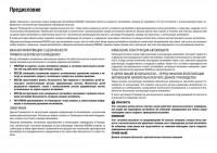
O-RING AND REFRIGERANT CONNECTION
Front A/C Compressor and Condenser
WJIA1399E
Revision: September 2005
ATC-8
2006 Pathfinder
PRECAUTIONS
1.
High-pressure service valve
2.
Clip
3.
Front high-pressure A/C pipe
4.
Refrigerant pressure sensor
5.
Condenser
6.
Compressor shaft seal
7.
Front high-pressure flexible A/C hose
8.
Front low-pressure flexible A/C hose
9.
Low-pressure service valve
10. Front low-pressure A/C pipe
11. Front expansion valve
12. Front A/C drain hose
A
B
Rear A/C
C
D
E
F
G
H
I
ATC
K
L
M
WJIA1400E
1.
Rear high- and low-pressure A/C pipes
4.
Rear expansion valve
2.
Rear heater core hoses
3.
Underfloor rear high- and low-pressure A/C and heater core pipes
CAUTION:
The new and former refrigerant connections use different O-ring configurations. Do not confuse Orings since they are not interchangeable. If a wrong O-ring is installed, refrigerant will leak at or
around the connection.
Revision: September 2005
ATC-9
2006 Pathfinder
PRECAUTIONS
O-Ring Part Numbers and Specifications
Connection type
O-ring
size
Part number*
D
New
8
92471 N8210
6.8 (0.268)
1.85 (0.0728)
Former
10
J2476 89956
9.25 (0.3642)
1.78 (0.0701)
92472 N8210
10.9 (0.429)
2.43 (0.0957)
92475 71L00
11.0 (0.433)
2.4 (0.094)
92473 N8210
13.6 (0.535)
2.43 (0.0957)
Former
92475 72L00
14.3 (0.563)
2.3 (0.091)
New
92474 N8210
16.5 (0.650)
2.43 (0.0957)
92477 N8200
17.12 (0.6740)
1.78 (0.0701)
92195 AH300
21.8 (0.858)
2.4 (0.094)
New
12
Former
New
SHA814E
16
19
Former
New
24
mm (in)
W
mm (in)
*: Always check with the Parts Department for the latest parts information.
WARNING:
Make sure all refrigerant is discharged into the recycling equipment and the pressure in the system is
less than atmospheric pressure. Then gradually loosen the discharge side hose fitting and remove it.
CAUTION:
When replacing or cleaning refrigerant cycle components, observe the following.
●
When the compressor is removed, store it in the same position as it is when mounted on the car.
Failure to do so will cause oil to enter the low pressure chamber.
●
When connecting tubes, always use a torque wrench and a back-up wrench.
●
After disconnecting tubes, immediately plug all openings to prevent entry of dirt and moisture.
●
When installing an air conditioner in the vehicle, connect the pipes as the final stage of the operation. Do not remove the seal caps of pipes and other components until just before required for
connection.
●
Allow components stored in cool areas to warm to working area temperature before removing seal
caps. This prevents condensation from forming inside A/C components.
●
Thoroughly remove moisture from the refrigeration system before charging the refrigerant.
●
Always replace used O-rings.
●
When connecting tube, apply oil to circle of the O-rings shown in illustration. Be careful not to
apply oil to threaded portion.
Oil name: NISSAN A/C System Oil Type S or equivalent.
●
O-ring must be closely attached to dented portion of tube.
●
When replacing the O-ring, be careful not to damage O-ring and tube.
●
Connect tube until you hear it click, then tighten the nut or bolt by hand until snug. Make sure that
the O-ring is installed to tube correctly.
●
After connecting line, conduct leak test and make sure that there is no leakage from connections.
When the refrigerant leaking point is found, disconnect that line and replace the O-ring. Then
tighten connections of seal seat to the specified torque.
Revision: September 2005
ATC-10
2006 Pathfinder
PRECAUTIONS
A
B
C
D
E
F
WJIA1994E
1.
Plug
2.
O-ring
A.
Torque wrench
B.
Apply oil
C.
Do not apply oil to thread
D.
No good
E.
Good
Precautions for Servicing Compressor
G
EJS004OD
H
Plug all openings to prevent moisture and foreign matter from entering.
●
When the compressor is removed, store it in the same position as it is when mounted on the car.
I
●
When replacing or repairing compressor, follow “Maintenance of Oil Quantity in Compressor”
exactly. Refer to ATC-22, «Maintenance of Oil Quantity in Compressor» .
●
Keep friction surfaces between clutch and pulley clean. If the surface is contaminated with oil,
wipe it off by using a clean waste cloth moistened with thinner.
ATC
●
After compressor service operation, turn the compressor shaft by hand more than 5 turns in both
directions. This will equally distribute oil inside the compressor. After the compressor is installed,
let the engine idle and operate the compressor for 1 hour.
K
●
After replacing the compressor magnet clutch, apply voltage to the new one and check for normal
operation. Refer to ATC-159, «Removal and Installation for Compressor Clutch» .
L
Precautions for Service Equipment
EJS004OE
●
RECOVERY/RECYCLING EQUIPMENT
Follow the manufacturer’s instructions for machine operation and machine maintenance. Never introduce any
refrigerant other than that specified into the machine.
ELECTRONIC LEAK DETECTOR
Follow the manufacturer’s instructions for tester operation and tester maintenance.
Revision: September 2005
ATC-11
2006 Pathfinder
M
PRECAUTIONS
VACUUM PUMP
The oil contained inside the vacuum pump is not compatible with the
specified oil for HFC-134a (R-134a) A/C systems. The vent side of
the vacuum pump is exposed to atmospheric pressure so the vacuum pump oil may migrate out of the pump into the service hose.
This is possible when the pump is switched off after evacuation (vacuuming) and hose is connected to it.
To prevent this migration, use a manual valve situated near the
hose-to-pump connection, as follows.
●
Usually vacuum pumps have a manual isolator valve as part of
the pump. Close this valve to isolate the service hose from the
pump.
●
For pumps without an isolator, use a hose equipped with a manual shut-off valve near the pump end. Close the valve to isolate
the hose from the pump.
●
If the hose has an automatic shut off valve, disconnect the hose
from the pump: as long as the hose is connected, the valve is
open and lubricating oil may migrate.
Some one-way valves open when vacuum is applied and close
under a no vacuum condition. Such valves may restrict the pump’s
ability to pull a deep vacuum and are not recommended.
RHA270D
MANIFOLD GAUGE SET
Be certain that the gauge face indicates HFC-134a (R-134a). Make
sure the gauge set has 1/2″-16 ACME threaded connections for service hoses. Confirm the set has been used only with refrigerant
HFC-134a (R-134a) along with specified oil.
SHA533D
SERVICE HOSES
Be certain that the service hoses display the markings described
(colored hose with black stripe). All hoses must include positive shutoff devices (either manual or automatic) near the end of the hoses
opposite the manifold gauge.
RHA272D
Revision: September 2005
ATC-12
2006 Pathfinder
PRECAUTIONS
SERVICE COUPLERS
A
Never attempt to connect HFC-134a (R-134a) service couplers to a
CFC-12 (R-12) A/C system. The HFC-134a (R-134a) couplers will
not properly connect to the CFC-12 (R-12) system. If an improper
connection is attempted, discharging and contamination may occur.
Shut-off valve rotation
B
A/C service valve
Clockwise
Open
Counterclockwise
Close
C
RHA273D
D
REFRIGERANT WEIGHT SCALE
Verify that no refrigerant other than HFC134a (R-134a) and specified
oils have been used with the scale. If the scale controls refrigerant
flow electronically, the hose fitting must be 1/2”-16 ACME.
E
F
G
RHA274D
H
CHARGING CYLINDER
Using a charging cylinder is not recommended. Refrigerant may be vented into air from cylinder’s top valve
when filling the cylinder with refrigerant. Also, the accuracy of the cylinder is generally less than that of an
electronic scale or of quality recycle/recharge equipment.
I
ATC
K
L
M
Revision: September 2005
ATC-13
2006 Pathfinder
PREPARATION
PREPARATION
Special Service Tools
PFP:00002
EJS004OG
The actual shapes of Kent-Moore tools may differ from those of special service tools illustrated here.
Tool number
(Kent-Moore No.)
Tool name
Description
—
(J-38873-A)
Pulley installer
Installing pulley
LHA171
KV99233130
(J-29884)
Pulley puller
Removing pulley
LHA172
HFC-134a (R-134a) Service Tools and Equipment
EJS004OH
Never mix HFC-134a (R-134a) refrigerant and/or its specified oil with CFC-12 (R-12) refrigerant and/or its oil.
Separate and non-interchangeable service equipment must be used for handling each type of refrigerant/oil.
Refrigerant container fittings, service hose fittings and service equipment fittings (equipment which handles
refrigerant and/or oil) are different between CFC-12 (R-12) and HFC-134a (R-134a). This is to avoid mixed
use of the refrigerants/oil.
Adapters that convert one size fitting to another must never be used refrigerant/oil contamination will occur
and compressor failure will result.
Tool number
(Kent-Moore No.)
Tool name
Description
HFC-134a (R-134a)
( — )
Refrigerant
Container color: Light blue
Container marking: HFC-134a (R134a)
Fitting size: Thread size
●
large container 1/2”-16 ACME
S-NT196
—
( — )
NISSAN A/C System Oil Type S
Type: Poly alkylene glycol oil (PAG),
type S
Application: HFC-134a (R-134a)
swash plate compressors (NISSAN
only)
Lubricity: 40 m (1.4 US fl oz, 1.4 Imp
fl oz)
S-NT197
KV991J0130
(ACR2005-NI)
ACR A/C Service Center
Refrigerant Recovery and Recycling
and Recharging
WJIA0293E
Revision: September 2005
ATC-14
2006 Pathfinder
PREPARATION
Tool number
(Kent-Moore No.)
Tool name
Description
—
(J-41995)
Electronic refrigerant leak detector
Power supply:
A
●
DC 12V (battery terminal)
B
C
D
AHA281A
—
(J-43926)
Refrigerant dye leak detection kit
Kit includes:
(J-42220)
UV lamp and UV safety goggles
(J-41459)
Refrigerant dye injector
(J-41447)
Fluorescent leak detection dye
(box of 24, 1/4 ounce bottles)
(J-43872)
Refrigerant dye cleaner
E
Power supply:
●
DC 12V (battery terminal)
F
G
H
ZHA200H
—
(J-42220)
Fluorescent dye leak detector
Power supply:
●
DC 12V (battery terminal)
For checking refrigerant leak when fluorescent dye is installed in A/C system.
Includes: UV lamp and UV safety goggles
I
ATC
SHA438F
—
(J-41447)
HFC-134a (R-134a) Fluorescent
leak detection dye
(Box of 24, 1/4 ounce bottles)
Application: For HFC-134a (R-134a)
PAG oil
Container: 1/4 ounce (7.4cc) bottle
(Includes self-adhesive dye identification labels for affixing to vehicle after
charging system with dye.)
For injecting 1/4 ounce of fluorescent
leak detection dye into A/C system.
SHA440F
—
(J-43872)
Refrigerant dye cleaner
For cleaning dye spills.
SHA441F
Revision: September 2005
ATC-15
L
M
SHA439F
—
(J-41459)
HFC-134a (R-134a) Refrigerant
dye injector
Use with J-41447, 1/4 ounce bottle
K
2006 Pathfinder
PREPARATION
Tool number
(Kent-Moore No.)
Tool name
Description
—
(J-39183-C)
Manifold gauge set (with hoses
and couplers)
Identification:
●
The gauge face indicates R-134a.
Fitting size-Thread size
●
1/2”-16 ACME
RJIA0196E
Service hoses:
●
Hose color:
High side hose
(J-39500-72B)
●
Low side hose
(J-39500-72R)
●
Utility hose
(J-39500-72Y)
S-NT201
High side coupler
(J-39500-20A)
●
Low side coupler
(J-39500-24A)
Low side hose: Blue with black stripe
●
High side hose: Red with black stripe
●
Utility hose: Yellow with black stripe
or green with black stripe
Hose fitting to gauge:
●
1/2”-16 ACME
Hose fitting to service hose:
Service couplers
●
●
●
M14 x 1.5 fitting is optional or permanently attached.
S-NT202
—
(J-39699)
Refrigerant weight scale
For measuring of refrigerant
Fitting size-Thread size
●
1/2”-16 ACME
S-NT200
—
(J-39649)
Vacuum pump
(Including the isolator valve)
Capacity:
●
Air displacement: 4 CFM
●
Micron rating: 20 microns
●
Oil capacity: 482 g (17 oz)
Fitting size-Thread size
●
1/2”-16 ACME
S-NT203
Revision: September 2005
ATC-16
2006 Pathfinder
PREPARATION
Commercial Service Tools
EJS004OI
A
Tool name
Description
(J-41810-NI)
Refrigerant identifier equipment (R134a)
For checking refrigerant purity and
system contamination
B
C
D
RJIA0197E
Power tool
Loosening bolts and nuts
E
F
PBIC0190E
(J-44614)
Clutch disc holding tool
G
Clutch disc holding tool
H
I
WHA230
ATC
K
L
M
Revision: September 2005
ATC-17
2006 Pathfinder
REFRIGERATION SYSTEM
REFRIGERATION SYSTEM
Components
PFP:KA990
EJS004OJ
FRONT REFRIGERATION SYSTEM
WJIA1260E
Revision: September 2005
ATC-18
2006 Pathfinder
REFRIGERATION SYSTEM
1.
Defroster nozzle
2.
LH side demister duct
3.
LH ventilator duct
4.
RH side demister duct
5.
RH ventilator duct
6.
Center ventilator duct
7.
Front heater and cooling unit assembly
8.
Floor connector duct grilles
9.
Floor connector duct
10. Front floor ducts
A
11. Rear floor ducts
B
REAR REFRIGERATION SYSTEM
C
D
E
F
G
H
I
ATC
K
L
M
LJIA0156E
1.
Side rear floor duct
4.
Rear upper overhead duct
Revision: September 2005
2.
Rear heater and cooling unit assembly
ATC-19
3.
Rear lower overhead duct
2006 Pathfinder
REFRIGERATION SYSTEM
Refrigerant Cycle
EJS004OK
WJIA1342E
REFRIGERANT FLOW
The refrigerant flows in the standard pattern, that is, through the compressor, the condenser with liquid tank,
through the front and rear evaporators, and back to the compressor. The refrigerant evaporation through the
evaporator coils are controlled by front and rear externally equalized expansion valves, located inside the front
and rear evaporator cases.
FREEZE PROTECTION
The compressor cycles on and off to maintain the evaporator temperature within a specified range. When the
evaporator coil temperature falls below a specified point, the intake sensor interrupts the compressor operation. When the evaporator coil temperature rises above the specification, the intake sensor allows compressor
operation.
Revision: September 2005
ATC-20
2006 Pathfinder
REFRIGERATION SYSTEM
Refrigerant System Protection
EJS004OL
A
REFRIGERANT PRESSURE SENSOR
The refrigerant system is protected against excessively high- or low-pressures by the refrigerant pressure sensor, located on the condenser. If the system pressure rises above or falls below the specifications, the refrigerant pressure sensor detects the pressure inside the refrigerant line and sends a voltage signal to the ECM.
The ECM de-energizes the A/C relay to disengage the magnetic compressor clutch when pressure on the high
pressure side detected by refrigerant pressure sensor is over about 2,746 kPa (28 kg/cm2 , 398 psi), or below
about 120 kPa (1.22 kg/cm2 , 17.4 psi).
B
C
PRESSURE RELIEF VALVE
The refrigerant system is also protected by a pressure relief valve, located in the rear head of the compressor.
When the pressure of refrigerant in the system increases to an abnormal level [more than 2,990 kPa (30.5 kg/
cm2 , 433.6 psi)], the release port on the pressure relief valve automatically opens and releases refrigerant
into the atmosphere.
D
E
F
G
H
I
ATC
K
L
M
Revision: September 2005
ATC-21
2006 Pathfinder
OIL
OIL
Maintenance of Oil Quantity in Compressor
PFP:KLG00
EJS004OM
The oil in the compressor circulates through the system with the refrigerant. Add oil to compressor when
replacing any component or after a large refrigerant leakage has occurred. It is important to maintain the specified amount.
If oil quantity is not maintained properly, the following malfunctions may result:
●
Lack of oil: May lead to a seized compressor
●
Excessive oil: Inadequate cooling (thermal exchange interference)
OIL
Oil name: NISSAN A/C System Oil Type S or equivalent
CHECKING AND ADJUSTING
CAUTION:
If excessive oil leakage is noted, do not perform the oil return operation.
Start the engine and set the following conditions:
Test Conditions
●
Engine speed: idling to 1,200 rpm
●
A/C switch: ON
●
Blower fan speed: HIGH
●
Temperature control: optional [set so intake air temperature is 25° to 30° C (77° to 86°F)]
●
Intake position: RECIRCULATION mode
●
Perform oil return operation for about ten minutes
Adjust the oil quantity according to the following table.
Oil Adjusting Procedure for Components Replacement Except Compressor
After replacing any of the following major components, add the correct amount of oil to the system.
Amount of Oil to be Added
Oil to be added to system
Part replaced
m
Amount of oil
(US fl oz, Imp fl oz)
Remarks
Front evaporator
75 (2.5, 2.6)
—
Rear evaporator
75 (2.5, 2.6)
—
Condenser
75 (2.5, 2.6)
—
Liquid tank
5 (0.2, 0.2)
Add if compressor is not replaced.
30 (1.0, 1.1)
Large leak
—
Small leak *1
In case of refrigerant leak
*1: If refrigerant leak is small, no addition of oil is needed.
Revision: September 2005
ATC-22
2006 Pathfinder
OIL
Oil Adjustment Procedure for Compressor Replacement
A
B
C
D
E
F
G
H
I
ATC
WJIA1716E
1.
2.
3.
4.
5.
6.
7.
8.
9.
1.
New compressor
2.
Old compressor
3.
Recovery/recycling equipment
4.
Measuring cup X
5.
Measuring cup Y
6.
New oil
A.
Drain oil from the new compressor
into clean container
B.
Record amount of oil recovered
C.
Add an additional 5 m (0.2 US fl oz,
0.2 Imp fl oz) of new oil when replacing liquid tank
D.
Install new oil equal to recorded
amounts in measuring cups X plus Y
K
Before connecting recovery/recycling equipment to vehicle, check recovery/recycling equipment gauges.
No refrigerant pressure should be displayed. If NG, recover refrigerant from equipment lines.
Connect recovery/recycling equipment to vehicle. Confirm refrigerant purity in supply tank using recovery/
recycling equipment and refrigerant identifier. If NG, refer to ATC-5, «Contaminated Refrigerant» .
Confirm refrigerant purity in vehicle A/C system using recovery/recycling equipment and refrigerant identifier. If NG, refer to ATC-5, «Contaminated Refrigerant» .
Discharge refrigerant into the refrigerant recovery/recycling equipment. Measure oil discharged into the
recovery/recycling equipment.
Drain the oil from the “old” (removed) compressor into a graduated container and recover the amount of
oil drained.
Drain the oil from the “new” compressor into a separate, clean container.
Measure an amount of new oil installed equal to amount drained from “old” compressor. Add this oil to
“new” compressor through the suction port opening.
Measure an amount of new oil equal to the amount recovered during discharging. Add this oil to “new”
compressor through the suction port opening.
If the liquid tank also needs to be replaced, add an additional 5 m (0.2 US fl oz, 0.2 Imp fl oz) of oil at this
time.
Revision: September 2005
ATC-23
2006 Pathfinder
L
M
OIL
Do not add this 5 m
Revision: September 2005
(0.2 US fl oz, 0.2 Imp fl oz) of oil if only replacing the compressor.
ATC-24
2006 Pathfinder
AIR CONDITIONER CONTROL
AIR CONDITIONER CONTROL
Description
PFP:27500
A
EJS004ON
The front air control provides automatic regulation of the vehicle’s interior temperature. The system is based
on the driver’s and passenger’s selected «set temperature», regardless of the outside temperature changes.
This is done by utilizing a microcomputer, also referred to as the front air control, which receives input signals
from the following six sensors:
●
Ambient sensor
●
In-vehicle sensor
●
Intake sensor
●
Optical sensor (providing one input for driver and one input for passenger side)
●
PBR (Position Balanced Resistor)
●
Vehicle speed sensor
The front air control uses these signals (including the set temperature) to automatically control:
●
Outlet air volume
●
Air temperature
●
Air distribution
The front air control also provides separate regulation of the vehicle’s interior temperature for the rear passenger area. The system is based on the temperature and rear blower settings selected from rear control
switches located on the front air control, or from the temperature and rear blower settings selected from rear
control switches on the rear air control, when the front air control switches are set to the rear position.
The front air control is used to select:
●
Outlet air volume
●
Air temperature/distribution
Operation
EJS004OO
B
C
D
E
F
G
H
I
AIR MIX DOORS CONTROL
The air mix doors are automatically controlled so that in-vehicle temperature is maintained at a predetermined
value by the temperature setting, ambient temperature, in-vehicle temperature and amount of sunload.
ATC
BLOWER SPEED CONTROL
Blower speed is automatically controlled by the temperature setting, ambient temperature, in-vehicle temperature, intake temperature, amount of sunload and air mix door position.
When AUTO switch is pressed, the blower motor starts to gradually increase air flow volume (if required).
When engine coolant temperature is low, the blower motor operation is delayed to prevent cool air from flowing.
K
L
INTAKE DOOR CONTROL
The intake door is automatically controlled by the temperature setting, ambient temperature, in-vehicle temperature, intake temperature, amount of sunload and the ON-OFF operation of the compressor.
MODE DOOR CONTROL
The mode door is automatically controlled by the temperature setting, ambient temperature, in-vehicle temperature, intake temperature and amount of sunload.
DEFROSTER DOOR CONTROL
The defroster door is controlled by: Turning the defroster dial to front defroster.
Revision: September 2005
ATC-25
2006 Pathfinder
M
AIR CONDITIONER CONTROL
MAGNET CLUTCH CONTROL
WJIA1163E
When A/C switch or DEF switch is pressed, front air control inputs compressor ON signal to BCM.
BCM sends compressor ON signal to ECM, via CAN communication line.
ECM judges whether compressor can be turned ON, based on each sensor status (refrigerant pressure sensor signal, throttle angle sensor, etc.). If it judges compressor can be turned ON, it sends compressor ON signal to IPDM E/R, via CAN communication line.
Upon receipt of compressor ON signal from ECM, IPDM E/R turns air conditioner relay ON to operate compressor.
SELF-DIAGNOSTIC SYSTEM
The self-diagnostic system is built into the front air control to quickly locate the cause of symptoms. Refer to
ATC-51, «A/C System Self-diagnosis Function» .
Revision: September 2005
ATC-26
2006 Pathfinder
AIR CONDITIONER CONTROL
Description of Control System
EJS004OP
The control system consists of input sensors, switches, the front air control (microcomputer) and outputs.
The relationship of these components is shown in the figure below:
A
B
C
D
E
F
G
H
I
ATC
WJIA1976E
Control Operation
K
EJS004OQ
Front air control
L
M
WJIA1878E
Revision: September 2005
ATC-27
2006 Pathfinder
AIR CONDITIONER CONTROL
DISPLAY SCREEN
Displays the operational status of the system.
AUTO SWITCH
●
●
The compressor, intake door, air mix doors, outlet doors and blower speed are automatically controlled so
that the in-vehicle temperature will reach, and be maintained at the set temperature selected by the operator.
When pressing AUTO switch, air inlet, air outlet, blower speed, and discharge air temperature are automatically controlled.
TEMPERATURE CONTROL DIAL (TEMPERATURE CONTROL) (DRIVER SIDE)
Increases or decreases the set temperature.
TEMPERATURE CONTROL DIAL (TEMPERATURE CONTROL) (PASSENGER SIDE)
Increases or decreases the set temperature.
TEMPERATURE CONTROL DIAL (TEMPERATURE AND MODE CONTROL) (REAR)
Increases or decreases the set temperature. The mode also changes from foot at full hot setting, to foot/vent
mid-range (warm) setting, and then to vent on full cold setting.
RECIRCULATION () SWITCH
●
●
●
When REC switch is ON, REC switch indicator turns ON, and air inlet is set to REC.
When REC switch is turned OFF, or when compressor is turned from ON to OFF, REC switch is automatically turned OFF. REC mode can be re-entered by pressing REC switch again.
REC switch is not operated when DEF switch is turned ON, or at the D/F position.
DEFROSTER () SWITCH
Positions the air outlet doors to the defrost position. Also positions the intake doors to the outside air position.
REAR WINDOW DEFOGGER SWITCH
When switch is ON, rear window is defogged.
OFF SWITCH
The compressor and blower are OFF, the intake doors are set to the outside air position, and the air outlet
doors are set to the foot (75% foot and 25% defrost) position.
A/C SWITCH
The compressor is ON or OFF.
(Pressing the A/C switch when the AUTO switch is ON will turn off the A/C switch and compressor.)
MODE SWITCH (FRONT)
Controls the air discharge outlets.
FRONT BLOWER CONTROL DIAL
Manually control the blower speed. Seven speeds are available for manual control (as shown on the display
screen on all models with Navi).
MODE SWITCH (REAR)
Controls the air/temperature at discharge outlets.
Revision: September 2005
ATC-28
2006 Pathfinder
AIR CONDITIONER CONTROL
Rear Air Control
A
B
C
D
E
WJIA1042E
F
TEMPERATURE CONTROL DIAL (TEMPERATURE AND MODE CONTROL)
The temperature increases or decreases the set temperature. The mode also changes from foot at full hot setting, to foot/vent at mid-range (warm) setting, and then to vent at full cold setting.
G
REAR BLOWER CONTROL DIAL
When the rear blower switch (front) is in the OFF position, the rear blower motor cannot operate.
When the rear blower switch (front) is in the REAR position, it allows the rear blower switch (rear) to control
the rear blower motor speed. In any other position (1-4), the rear blower switch (front) controls the rear blower
motor speed regardless of the rear blower switch (rear) position.
H
I
ATC
K
L
M
Revision: September 2005
ATC-29
2006 Pathfinder
AIR CONDITIONER CONTROL
Discharge Air Flow
EJS004OR
FRONT
LJIA0172E
Air outlet/distribution
Mode door position
Vent
Foot
Defroster
100%
0%
—
60%
40%
—
18%
64%
18%
14%
64%
33%
—
13%
83%
Airflow always present at driver and passenger side demisters
REAR
WJIA1076E
Air outlet/distribution
Mode door position
Roof Vent
Foot
Cool
80%
20%
Mid
80%
20%
Hot
80%
20%
Airflow distribution is always constant
Revision: September 2005
ATC-30
2006 Pathfinder
AIR CONDITIONER CONTROL
System Description (Front)
EJS004OS
A
SWITCHES AND THEIR CONTROL FUNCTION
B
C
D
E
F
G
H
I
WJIA1680E
ATC
K
L
M
WJIA1237E
Revision: September 2005
ATC-31
2006 Pathfinder
AIR CONDITIONER CONTROL
System Description (Rear)
EJS004OT
SWITCHES AND THEIR CONTROL FUNCTION
WJIA0623E
WJIA1685E
Revision: September 2005
ATC-32
2006 Pathfinder
AIR CONDITIONER CONTROL
CAN Communication System Description
EJS004OU
A
Refer to LAN-25, «CAN COMMUNICATION» .
B
C
D
E
F
G
H
I
ATC
K
L
M
Revision: September 2005
ATC-33
2006 Pathfinder
TROUBLE DIAGNOSIS
TROUBLE DIAGNOSIS
CONSULT-II Function (BCM)
PFP:00004
EJS004OV
CONSULT-II can display each diagnostic item using the diagnostic test modes shown following.
BCM diagnostic
test item
Diagnostic mode
WORK SUPPORT
DATA MONITOR
Inspection by part
ACTIVE TEST
SELF-DIAG RESULTS
CAN DIAG SUPPORT MNTR
ECU PART NUMBER
CONFIGURATION
Description
Supports inspections and adjustments. Commands are transmitted to the BCM
for setting the status suitable for required operation, input/output signals are
received from the BCM and received data is displayed.
Displays BCM input/output data in real time.
Operation of electrical loads can be checked by sending drive signal to them.
Displays BCM self-diagnosis results.
The result of transmit/receive diagnosis of CAN communication can be read.
BCM part number can be read.
Performs BCM configuration read/write functions.
CONSULT-II BASIC OPERATION
CAUTION:
If CONSULT-II is used with no connection of CONSULT-II CONVERTER, malfunctions might be
detected in self-diagnosis depending on control unit which carries out CAN communication.
1. With the ignition switch OFF, connect CONSULT-II and CONSULT-II CONVERTER to the data link connector, and turn the
ignition switch ON.
WJIA1078E
2.
Touch “START (NISSAN BASED VHCL)”.
BCIA0029E
3.
Touch “BCM” on “SELECT SYSTEM” screen.
If “BCM” is not indicated, go to GI-40, «CONSULT-II Data Link
Connector (DLC) Circuit» .
BCIA0030E
Revision: September 2005
ATC-34
2006 Pathfinder
TROUBLE DIAGNOSIS
DATA MONITOR
Operation Procedure
1.
A
Touch “AIR CONDITIONER” on “SELECT TEST ITEM” screen.
B
C
D
WJIA0468E
2.
E
Touch “DATA MONITOR” on “SELECT DIAG MODE” screen.
F
G
H
BCIA0031E
3.
Touch either “ALL SIGNALS” or “SELECTION FROM MENU” on
“DATA MONITOR” screen.
ALL SIGNALS
Monitors all the items.
SELECTION FROM
MENU
Selects and monitors the individual item selected.
4.
5.
6.
I
ATC
When “SELECTION FROM MENU” is selected, touch items to
be monitored. When “ALL SIGNALS” is selected, all the items
will be monitored.
Touch “START”.
Touch “RECORD” while monitoring, then the status of the monitored item can be recorded. To stop recording, touch “STOP”.
K
WJIA0469E
L
Display Item List
M
Monitor item name
“OPERATION OR UNIT”
Contents
IGN ON SW
“ON/OFF”
Displays “IGN Position (ON)/OFF, ACC Position (OFF)” status as judged from ignition switch signal.
COMP ON SIG
“ON/OFF”
Displays “COMP (ON)/COMP (OFF)” status as judged from air conditioner switch signal.
FAN ON SIG
“ON/OFF”
Displays “FAN (ON)/FAN (OFF)” status as judged from blower motor switch signal.
Revision: September 2005
ATC-35
2006 Pathfinder
TROUBLE DIAGNOSIS
How to Perform Trouble Diagnosis for Quick and Accurate Repair
EJS004OW
WORK FLOW
SHA900E
*1
ATC-53, «Operational Check (Front)»
or ATC-55, «Operational Check
(Rear)» .
SYMPTOM TABLE
Symptom
Reference Page
A/C system does not come on.
Go to Trouble Diagnosis Procedure for A/C System.
A/C system display is malfunctioning.
Go to Navigation System.
A/C system cannot be controlled.
Go to Self-diagnosis Function.
ATC-51
Go to Trouble Diagnosis Procedure for Mode Door Motor.
ATC-59
Go to Trouble Diagnosis Procedure for Air Mix Door Motor.
ATC-63
Go to Trouble Diagnosis Procedure for Intake Door Motor.
ATC-72
Front blower motor operation is malfunctioning.
Go to Trouble Diagnosis Procedure for Front Blower Motor.
ATC-75
Rear blower motor operation is malfunctioning.
Go to Trouble Diagnosis Procedure for Rear Blower Motor.
ATC-82
Rear discharge air temperature and/or air
outlet does not change.
Go to Trouble Diagnosis Procedure for Rear Air Control circuit.
ATC-93
Magnet clutch does not engage.
Go to Trouble Diagnosis Procedure for Magnet Clutch.
ATC-96
Insufficient cooling
Go to Trouble Diagnosis Procedure for Insufficient Cooling.
ATC-102
Insufficient heating
Go to Trouble Diagnosis Procedure for Insufficient Heating.
ATC-109
Noise
Go to Trouble Diagnosis Procedure for Noise.
ATC-113
Self-diagnosis cannot be performed.
Go to Trouble Diagnosis Procedure for Self-diagnosis.
ATC-115
Memory function does not operate.
Go to Trouble Diagnosis Procedure for Memory Function.
ATC-116
Air outlet does not change.
ATC-56
AV-78
Mode door motor is malfunctioning.
Discharge air temperature does not change.
Air mix door motor is malfunctioning.
Intake door does not change.
Intake door motor is malfunctioning.
Revision: September 2005
ATC-36
2006 Pathfinder
TROUBLE DIAGNOSIS
Component Parts and Harness Connector Location
EJS004OX
A
ENGINE COMPARTMENT
B
C
D
E
F
G
H
I
ATC
K
L
M
WJIA1982E
1.
Refrigerant pressure sensor E48
(View with battery removed)
⇐: Front
Revision: September 2005
2.
Ambient sensor 1 E1
ATC-37
3.
Compressor F3
2006 Pathfinder
TROUBLE DIAGNOSIS
FRONT PASSENGER COMPARTMENT
WJIA1977E
1.
Front air control M49, M50
2.
Rear blower switch (front) M52
3.
Rear blower motor relay M163
4.
In-vehicle sensor M32
5.
Intake sensor M146
6.
Intake door motor M58
7.
Variable blower control M122
8.
Air mix door motor (driver) M147
9.
Mode door motor M142
10. Air mix door motor (passenger)
M143
Revision: September 2005
11. Optical sensor M145
ATC-38
2006 Pathfinder
TROUBLE DIAGNOSIS
REAR PASSENGER COMPARTMENT
A
B
C
D
E
F
G
H
I
ATC
K
L
WJIA1238E
M
Revision: September 2005
ATC-39
2006 Pathfinder
TROUBLE DIAGNOSIS
Schematic
EJS004OY
WJWA0389E
Revision: September 2005
ATC-40
2006 Pathfinder
TROUBLE DIAGNOSIS
Wiring Diagram —A/C,A—
EJS004OZ
A
B
C
D
E
F
G
H
I
ATC
K
L
M
WJWA0390E
Revision: September 2005
ATC-41
2006 Pathfinder
TROUBLE DIAGNOSIS
WJWA0277E
Revision: September 2005
ATC-42
2006 Pathfinder
TROUBLE DIAGNOSIS
A
B
C
D
E
F
G
H
I
ATC
K
L
M
WJWA0391E
Revision: September 2005
ATC-43
2006 Pathfinder
TROUBLE DIAGNOSIS
WJWA0392E
Revision: September 2005
ATC-44
2006 Pathfinder
TROUBLE DIAGNOSIS
A
B
C
D
E
F
G
H
I
ATC
K
L
M
WJWA0393E
Revision: September 2005
ATC-45
2006 Pathfinder
TROUBLE DIAGNOSIS
WJWA0394E
Revision: September 2005
ATC-46
2006 Pathfinder
TROUBLE DIAGNOSIS
A
B
C
D
E
F
G
H
I
ATC
K
L
M
WJWA0194E
Revision: September 2005
ATC-47
2006 Pathfinder
TROUBLE DIAGNOSIS
WJWA0395E
Revision: September 2005
ATC-48
2006 Pathfinder
TROUBLE DIAGNOSIS
Front Air Control Terminals and Reference Value
EJS004P0
A
Measure voltage between each terminal and ground by following
Terminals and Reference Value for front air control.
B
C
D
WJIA1075E
PIN CONNECTOR TERMINAL LAYOUT
E
F
G
WJIA0402E
H
TERMINALS AND REFERENCE VALUE FOR FRONT AIR CONTROL
Terminal No.
Wire
color
1
BR
Mode door motor CW
ON
Clockwise rotation
Battery voltage
2
W
Air mix door motor (Driver) CW
ON
Clockwise rotation
Battery voltage
3
GR
Air mix door motor (Driver) CCW
ON
Counterclockwise rotation
Battery voltage
4
Y
Intake door motor CW
ON
Counterclockwise rotation
Battery voltage
5
O
Intake door motor CCW
ON
Clockwise rotation
Battery voltage
6
W/G
Power supply for IGN
ON
8
G
Illumination +
ON
Park lamps ON
9
BR
Illumination —
—
Park lamps ON
Item
Ignition
switch
Condition
—
Voltage (V)
(Approx.)
I
ATC
K
Battery voltage
Battery voltage
L
M
PIIA2344E
ON
A/C switch OFF
ON
A/C switch ON
5V
10
W
Compressor ON signal
11
Y
Rear defrost request
ON
—
Battery voltage
12
L
Intake sensor
ON
—
0 — 5V
13
V
Sensor ground
ON
—
0 — 5V
14
R
Mode door motor CCW
ON
Counterclockwise rotation
Battery voltage
15
P
Air mix door motor (Passenger) CW
ON
Clockwise rotation
Battery voltage
16
L
Air mix door motor (Passenger)
CCW
ON
Counter clockwise rotation
Battery voltage
17
GR
Air mix door motor (Rear) CW
ON
Clockwise rotation
Battery voltage
18
O
Air mix door motor (Rear) CCW
ON
Counterclockwise rotation
Battery voltage
Revision: September 2005
ATC-49
0V
2006 Pathfinder
TROUBLE DIAGNOSIS
Terminal No.
Wire
color
Ignition
switch
Condition
Voltage (V)
(Approx.)
19
R/Y
20
B
Power supply for BAT
—
—
Battery voltage
Ground
—
—
0V
21
V
Mode door motor feedback
ON
—
0 — 5V
22
SB
Air mix door motor (Driver) feedback
ON
—
0 — 5V
23
G
Power supply for mode door motor
PBR
ON
—
5V
24
L/G
Air mix door motor (Rear) PTC
ON
—
0 — 5V
25
R
Air mix door motor (Rear) feedback
ON
—
0 — 5V
26
P
Ground for mode door motor PBR
ON
—
0V
27
LG
In-vehicle sensor signal
ON
—
0 — 5V
28
W
Ambient sensor 1
ON
—
0 — 5V
29
G
Optical sensor (Driver)
ON
—
0 — 5V
30
Y
Rear select signal
ON
—
0V — Battery voltage
32
V
Variable blower control
ON
—
0 — 5V
33
BR
In-vehicle sensor motor (+)
ON
—
Battery voltage
34
O
In-vehicle sensor motor (-)
ON
—
0V
35
R
Fan ON signal
Item
ON
Blower switch OFF
5V
ON
Blower switch ON
0V
36
SB
Air mix door motor (Passenger)
feedback
ON
—
0 — 5V
37
GR
Optical sensor (Passenger)
ON
—
0 — 5V
38
BR
Front blower request
ON
39
O
Rear blower request
ON
Front blower motor OFF
Battery voltage
Front blower motor ON
0V
Front blower motor OFF
Battery voltage
Front blower motor ON
0V
41
L
CAN-H
ON
—
0 — 5V
42
P
CAN-L
ON
—
0 — 5V
44
GR
Heater pump request
ON
Revision: September 2005
Heater pump on
0V
Heater pump off
Battery voltage
ATC-50
2006 Pathfinder
TROUBLE DIAGNOSIS
A/C System Self-diagnosis Function
EJS004P1
A
DESCRIPTION
The self-diagnostic system diagnoses sensors, CAN system, battery voltage and stuck button on front air control. Refer to applicable sections (items) for details. Fault codes (if any are present) will be displayed in the
ambient temperature display area (with navi) and displayed in the driver temp display area (without navi).
Refer to ATC-52, «SELF-DIAGNOSIS CODE CHART» .
B
C
D
E
F
G
H
I
ATC
K
L
M
WJIA1879E
Revision: September 2005
ATC-51
2006 Pathfinder
TROUBLE DIAGNOSIS
SELF-DIAGNOSIS CODE CHART
Code No.
Reference page
02
EE changed by calibration
ATC-127, «FRONT AIR CONTROL»
03
Battery voltage out of range
SC-4, «BATTERY»
12
Air mix door motor (Passenger) circuit malfunction
ATC-67, «DIAGNOSTIC PROCEDURE FOR AIR MIX DOOR
MOTOR (PASSENGER)»
20
BCM not responding to A/C request
ATC-97, «DIAGNOSTIC PROCEDURE FOR MAGNET
CLUTCH»
21
BCM not responding to rear defroster request
GW-70, «REAR WINDOW DEFOGGER»
22
Air mix door motor (Driver) circuit failure
ATC-65, «DIAGNOSTIC PROCEDURE FOR AIR MIX DOOR
MOTOR (DRIVER)»
30
In-vehicle sensor circuit out of range (low)
31
In-vehicle sensor circuit out of range (high)
38
Air mix door motor (rear) circuit malfunction
40
Ambient sensor 1 circuit short
41
Ambient sensor 1 circuit open
44
In-vehicle sensor motor circuit open
46
In-vehicle sensor motor circuit short
50
Optical sensor (Driver) circuit open or short
52
Optical sensor (Passenger) circuit open or short
56
Intake sensor circuit short
57
Intake sensor circuit open
80
CAN bus fault
LAN-25, «CAN COMMUNICATION»
82
Intake door motor (driver) circuit malfunction
ATC-74, «DIAGNOSTIC PROCEDURE FOR INTAKE DOOR
MOTOR»
90
Stuck button
ATC-127, «FRONT AIR CONTROL»
92
Mode door motor circuit malfunction
ATC-59, «Mode Door Motor Circuit»
Revision: September 2005
ATC-120, «In-vehicle Sensor Circuit»
ATC-69, «DIAGNOSTIC PROCEDURE FOR AIR MIX DOOR
MOTOR (REAR)»
ATC-117, «Ambient Sensor 1 Circuit»
ATC-120, «In-vehicle Sensor Circuit»
ATC-123, «Optical Sensor Circuit»
ATC-125, «Intake Sensor Circuit»
ATC-52
2006 Pathfinder
TROUBLE DIAGNOSIS
Operational Check (Front)
EJS004P2
A
The purpose of the operational check is to confirm that the system operates properly.
Conditions
: Engine running and at normal operating temperature
CHECKING MEMORY FUNCTION
B
1.
2.
3.
4.
Set the temperature to 32°C (90°F).
Turn front blower control dial counterclockwise until system shuts OFF.
Turn ignition switch OFF.
Turn ignition switch ON.
C
5.
6.
Press the AUTO switch.
Confirm that the set temperature remains at previous temperature.
D
7. Turn front blower control dial counterclockwise until system shuts OFF.
If NG, go to trouble diagnosis procedure for ATC-116, «Memory Function» .
If OK, continue with next check.
E
CHECKING BLOWER
F
1.
Press the AUTO switch. Blower should operate on low speed. The blower symbol should have one blade
lit on display.
2. Turn the front blower control dial again, and continue checking blower speed and blower symbol until all
speeds are checked.
3. Leave blower on maximum speed.
If NG, go to trouble diagnosis procedure for ATC-77, «DIAGNOSTIC PROCEDURE FOR BLOWER MOTOR» .
If OK, continue with next check.
CHECKING DISCHARGE AIR
1.
2.
G
H
I
Press MODE switch four times and the DEF (
) switch.
Each position indicator should change shape on display.
ATC
3.
Confirm that discharge air comes out according to the air distribution table. Refer to ATC-30, «Discharge
Air Flow» .
Mode door position is checked in the next step.
If NG, go to trouble diagnosis procedure for ATC-59, «Mode Door Motor Circuit» .
If OK, continue the check.
NOTE:
Confirm that the compressor clutch is engaged (sound or visual inspection) and intake door position is at fresh
when the DEF or D/F is selected.
Discharge air flow
Air outlet/distribution
Vent
Foot
Defroster
100%
0%
—
60%
40%
—
18%
64%
18%
14%
64%
33%
—
13%
83%
Airflow always present at driver and passenger side demisters
CHECKING RECIRCULATION
Press recirculation (
) switch one time. Recirculation indicator should illuminate.
Press recirculation (
) switch one more time. Recirculation indicator should go off.
Listen for intake door position change (blower sound should change slightly).
Revision: September 2005
L
M
Mode door position
1.
2.
3.
K
ATC-53
2006 Pathfinder
TROUBLE DIAGNOSIS
If NG, go to trouble diagnosis procedure for ATC-72, «Intake Door Motor Circuit» .
If OK, continue next check.
NOTE:
Confirm that the compressor clutch is engaged (sound or visual inspection) and intake door position is at fresh
when the DEF or D/F is selected.
CHECKING TEMPERATURE DECREASE
1. Rotate temperature control dial (driver side) counterclockwise until 16°C (60°F) is displayed.
2. Check for cold air at appropriate discharge air outlets.
If NG, listen for sound of air mix door motor operation. If OK, go to trouble diagnosis procedure for ATC-102,
«Insufficient Cooling» . If air mix door motor appears to be malfunctioning, go to ATC-65, «DIAGNOSTIC PROCEDURE FOR AIR MIX DOOR MOTOR (DRIVER)» or ATC-67, «DIAGNOSTIC PROCEDURE FOR AIR MIX
DOOR MOTOR (PASSENGER)» .
If OK, continue the check.
CHECKING TEMPERATURE INCREASE
1. Rotate temperature control dial clockwise (driver side) until 32°C (90°F) is displayed.
2. Check for hot air at appropriate discharge air outlets.
If NG, listen for sound of air mix door motor operation. If OK, go to trouble diagnosis procedure for ATC-109,
«Insufficient Heating» . If air mix door motor appears to be malfunctioning, go to ATC-65, «DIAGNOSTIC PROCEDURE FOR AIR MIX DOOR MOTOR (DRIVER)» or ATC-67, «DIAGNOSTIC PROCEDURE FOR AIR MIX
DOOR MOTOR (PASSENGER)» .
If OK, continue with next check.
CHECK A/C SWITCH
1.
2.
Press A/C switch when AUTO switch is ON, or in manual mode.
A/C switch indicator will turn ON.
● Confirm that the compressor clutch engages (sound or visual inspection).
NOTE:
If current mode setting is DEF or D/F compressor clutch may already be engaged.
If NG, go to trouble diagnosis procedure for ATC-96, «Magnet Clutch Circuit» .
If OK, continue with next check.
CHECKING AUTO MODE
1.
2.
Press AUTO switch.
Display should indicate AUTO.
● If ambient temperature is warm, and selected temperature is cool, confirm that the compressor clutch
engages (sound or visual inspection). (Discharge air and blower speed will depend on ambient, in-vehicle, and set temperatures.)
If NG, go to trouble diagnosis procedure for ATC-56, «Power Supply and Ground Circuit for Front Air Control» ,
then if necessary, trouble diagnosis procedure for ATC-96, «Magnet Clutch Circuit» .
If all operational checks are OK (symptom cannot be duplicated), go to malfunction simulation tests in ATC-36,
«How to Perform Trouble Diagnosis for Quick and Accurate Repair» and perform tests as outlined to simulate
driving conditions environment. If symptom appears, refer to ATC-36, «How to Perform Trouble Diagnosis for
Quick and Accurate Repair» , ATC-36, «SYMPTOM TABLE» and perform applicable trouble diagnosis procedures.
Revision: September 2005
ATC-54
2006 Pathfinder
TROUBLE DIAGNOSIS
Operational Check (Rear)
EJS004P3
A
The purpose of the operational check is to confirm that the system operates properly.
Conditions
: Engine running and at normal operating temperature
B
CHECKING BLOWER
1.
Turn the rear blower control dial counterclockwise to switch position «1». Fan should operate on low
speed.
2. Turn the rear blower control dial clockwise to switch positions «2», «3», and «4» until all speeds are
checked.
3. Leave fan on maximum speed.
If NG, go to trouble diagnosis procedure for ATC-82, «Rear Blower Motor Circuit» .
If OK, continue the check.
CHECKING TEMPERATURE DECREASE
1. Rotate temperature and mode dial fully counterclockwise.
2. Check for cold air at appropriate discharge air outlets.
If NG, listen for sound of air mix door motor operation. If OK, go to trouble diagnosis procedure for ATC-102,
«Insufficient Cooling» . If air mix door motor appears to be malfunctioning, go to ATC-69, «DIAGNOSTIC PROCEDURE FOR AIR MIX DOOR MOTOR (REAR)» .
If OK, continue the check.
CHECKING TEMPERATURE INCREASE
1. Rotate temperature and mode dial clockwise.
2. Check for hot air at appropriate discharge air outlets.
If NG, listen for sound of air mix door motor operation. If OK, go to trouble diagnosis procedure for ATC-109,
«Insufficient Heating» . If air mix door motor appears to be malfunctioning, go to ATC-69, «DIAGNOSTIC PROCEDURE FOR AIR MIX DOOR MOTOR (REAR)» .
If OK, continue the check.
C
D
E
F
G
H
I
ATC
K
L
M
Revision: September 2005
ATC-55
2006 Pathfinder
TROUBLE DIAGNOSIS
Power Supply and Ground Circuit for Front Air Control
EJS004P4
SYMPTOM: A/C system does not come on.
INSPECTION FLOW
WJIA1439E
*1
ATC-56, «Power Supply and Ground
Circuit for Front Air Control»
Revision: September 2005
*2
ATC-53, «Operational Check (Front)»
or ATC-55, «Operational Check
(Rear)»
ATC-56
2006 Pathfinder
TROUBLE DIAGNOSIS
COMPONENT DESCRIPTION
Front Air Control
A
The front air control has a built-in microcomputer which processes
information sent from various sensors needed for air conditioner
operation. The air mix door motors, mode door motor, intake door
motor, blower motor and compressor are then controlled.
The front air control is unitized with control mechanisms. When the
various switches and temperature dials are operated, data is input to
the front air control.
Self-diagnostic functions are also built into the front air control to provide quick check of malfunctions in the auto air conditioner system.
B
C
D
WJIA1075E
Potentio Temperature Control (PTC)
E
There are two PTCs (passenger and driver) built into the front air
control. They can be set at an interval of 0.5°C (1.0°F) in the 16°C
(60°F) to 32°C (90°F) temperature range by rotating the temperature
dial. The set temperature is displayed.
F
G
H
WJIA1050E
DIAGNOSTIC PROCEDURE FOR A/C SYSTEM
I
SYMPTOM: A/C system does not come on.
ATC
K
L
WJIA1461E
M
Revision: September 2005
ATC-57
2006 Pathfinder
TROUBLE DIAGNOSIS
1. CHECK POWER SUPPLY CIRCUITS FOR FRONT AIR CONTROL
1.
2.
Disconnect front air control connector.
Check voltage between front air control harness connector M49
terminals 6 and 19, and ground.
Terminals
Ignition switch position
(+)
Front air
control
connector
Terminal No.
M49
6
M49
19
(-)
Ground
OFF
ACC
ON
Approx. 0V
Approx. 0V
Battery
voltage
Battery
voltage
Battery
voltage
Battery
voltage
WJIA1082E
OK or NG
OK
>> GO TO 2.
NG
>> Check 10A fuses [Nos. 8 and 19, located in the fuse block (J/B)]. Refer to PG-83 .
● If fuses are OK, check harness for open circuit. Repair or replace as necessary.
● If fuses are NG, replace fuse and check harness for short circuit. Repair or replace as necessary.
2. CHECK GROUND CIRCUIT FOR FRONT AIR CONTROL
1.
2.
Turn ignition switch OFF.
Check continuity between front air control harness connector
M49 terminal 20 and ground.
20 — Ground
: Continuity should exist.
OK or NG
OK
>> Replace front air control. Refer to ATC-127, «FRONT
AIR CONTROL» .
NG
>> Repair harness or connector.
WJIA1239E
Revision: September 2005
ATC-58
2006 Pathfinder
TROUBLE DIAGNOSIS
Mode Door Motor Circuit
EJS004P5
A
SYMPTOM:
●
Air outlet does not change.
●
Mode door motor does not operate normally.
B
INSPECTION FLOW
C
D
E
F
G
H
I
ATC
K
L
M
WJIA1686E
*1
ATC-30, «Discharge Air Flow»
*2
ATC-53, «Operational Check
(Front)»
*3
ATC-51, «A/C System Self-diagnosis
Function»
*4
ATC-52, «SELF-DIAGNOSIS CODE
CHART»
*5
ATC-61, «DIAGNOSTIC PROCEDURE FOR MODE DOOR
MOTOR»
*6
ATC-36, «SYMPTOM TABLE»
*7
ATC-127, «FRONT AIR CONTROL»
Revision: September 2005
ATC-59
2006 Pathfinder
TROUBLE DIAGNOSIS
SYSTEM DESCRIPTION
Component Parts
Mode door control system components are:
●
Front air control
●
Mode door motor
●
PBR (built into mode door motor)
●
In-vehicle sensor
●
Ambient sensor
●
Optical sensor
●
Intake sensor
System Operation
The mode door position (vent, B/L, foot, and defrost) is set by the front air control by means of the mode door
motor. When a mode door position is selected on the front air control, voltage is applied to one circuit of the
mode door motor while ground is applied to the other circuit, causing the mode door motor to rotate. The direction of rotation is determined by which circuit has voltage applied to it, and which one has ground applied to it.
The front air control monitors the mode door position by measuring the voltage signal on the PBR circuit.
In AUTO mode the mode door position is set by the front air control which determines the proper position
based on inputs from the in-vehicle sensor, ambient sensor, optical sensor, intake sensor, and the temperature
selected by the driver or passenger.
WJIA1240E
Mode Door Control Specification
WJIA0434E
Revision: September 2005
ATC-60
2006 Pathfinder
TROUBLE DIAGNOSIS
COMPONENT DESCRIPTION
Mode Door Motor
A
The mode door motor is attached to the heater & cooling unit assembly. It rotates so that air is discharged from the outlet as indicated by
the front air control. Motor rotation is conveyed to a link which activates the mode door.
B
C
D
WJIA1084E
DIAGNOSTIC PROCEDURE FOR MODE DOOR MOTOR
E
1. CHECK RESULT FROM FRONT AIR CONTROL SELF-DIAGNOSIS
Is self-diagnosis code 92 is present. Refer to ATC-51, «A/C System Self-diagnosis Function» .
YES or NO
YES >> GO TO 2.
NO
>> GO TO 3.
F
G
2. CHECK POWER SUPPLY AND GROUND CIRCUITS FOR MODE DOOR MOTOR
1.
2.
3.
H
Turn ignition switch OFF.
Disconnect front air control connector and mode door motor
connector.
Check continuity between front air control harness connector
M49 terminal 1 and mode door motor harness connector M142
terminal 1 and between front air control harness connector M49
terminal 14 and mode door motor harness connector M142 terminal 6.
1-1
14 — 6
: Continuity should exist.
: Continuity should exist.
I
ATC
WJIA1241E
OK or NG
OK
>> Replace mode door motor. Refer to ATC-144, «MODE DOOR MOTOR» .
NG
>> Repair or replace harness as necessary.
L
3. CHECK PBR REFERENCE SIGNAL VOLTAGE
1.
2.
3.
4.
M
Turn ignition switch OFF.
Disconnect the mode door motor connector.
Turn ignition switch ON.
Check voltage between mode door motor harness connector
M142 terminal 3 and ground.
3 — Ground
: Approx. 5V
OK or NG
OK
>> GO TO 5.
NG
>> GO TO 4.
Revision: September 2005
WJIA1242E
ATC-61
K
2006 Pathfinder
TROUBLE DIAGNOSIS
4. CHECK PBR REFERENCE VOLTAGE CIRCUIT BETWEEN MODE DOOR AND FRONT AIR CONTROL
1.
2.
3.
Turn ignition switch OFF.
Disconnect the front air control connector.
Check continuity between mode door motor harness connector
M142 terminal 3 and front air control harness connector M49 terminal 23.
3 — 23
: Continuity should exist.
OK or NG
OK
>> Replace front air control. Refer to ATC-127, «FRONT
AIR CONTROL» .
NG
>> Repair or replace harness as necessary.
WJIA1085E
5. CHECK PBR GROUND REFERENCE CIRCUIT
1.
2.
3.
Turn ignition switch OFF.
Disconnect the front air control connector.
Check continuity between mode door motor harness connector
M142 terminal 2 and front air control harness connector M49 terminal 26.
2 — 26
: Continuity should exist.
OK or NG
OK
>> GO TO 6.
NG
>> Repair or replace harness as necessary.
WJIA1087E
6. CHECK PBR FEEDBACK SIGNAL
1.
2.
3.
4.
Reconnect the front air control connector and mode door motor
connector.
Turn ignition switch ON.
Check voltage between front air control harness connector M49
terminal 21 and ground.
Press mode switch through all modes.
21 — Ground
: Approx. 0 — 5V
OK or NG
OK
>> Replace front air control. Refer to ATC-127, «FRONT
AIR CONTROL» .
NG
>> GO TO 7.
WJIA1088E
7. CHECK PBR FEEDBACK CIRCUIT
1.
2.
3.
Turn ignition switch OFF.
Disconnect the mode door motor connector and front air control
harness connector.
Check continuity between mode door motor harness connector
M142 terminal 4 and front air control harness connector M49 terminal 21.
4 — 21
: Continuity should exist.
OK or NG
OK
>> Replace mode door motor. Refer to ATC-144, «MODE
DOOR MOTOR» .
NG
>> Repair or replace harness as necessary.
Revision: September 2005
ATC-62
WJIA1089E
2006 Pathfinder
TROUBLE DIAGNOSIS
Air Mix Door Motor Circuit
EJS004P6
A
SYMPTOM:
●
Discharge air temperature does not change.
●
Air mix door motor does not operate.
B
INSPECTION FLOW
C
D
E
F
G
H
I
ATC
K
L
M
WJIA1462E
*1
ATC-53, «Operational Check (Front)» *2
or ATC-55, «Operational Check
(Rear)»
ATC-51, «A/C System Self-diagnosis Function»
*3
ATC-52, «SELF-DIAGNOSIS CODE
CHART»
*4
ATC-65, «DIAGNOSTIC PROCEDURE FOR AIR MIX DOOR
MOTOR (DRIVER)»
ATC-67, «DIAGNOSTIC PROCEDURE FOR AIR MIX DOOR
MOTOR (PASSENGER)»
*6
ATC-69, «DIAGNOSTIC PROCEDURE FOR AIR MIX DOOR
MOTOR (REAR)»
Revision: September 2005
*5
ATC-63
2006 Pathfinder
TROUBLE DIAGNOSIS
SYSTEM DESCRIPTION
Component Parts
Air mix door control system components are:
●
Front air control.
●
Air mix door motors (driver, passenger, and rear)
●
PBR (built into air mix door motors)
●
In-vehicle sensor
●
Ambient sensor
●
Optical sensor
●
Intake sensor
System Operation
The front air control receives data from the temperature selected by the driver side, passenger side, and rear.
The front air control then applies a voltage to one circuit of the appropriate air mix door motor, while ground is
applied to the other circuit, causing the appropriate air mix door motor to rotate. The direction of rotation is
determined by which circuit has voltage applied to it, and which one has ground applied to it. The front air control monitors the air mix door positions by measuring the voltage signal on the PBR circuits of each door.
In AUTO mode the air mix, intake, mode door, and defrost door positions are set by the front air control which
determines the proper position based on inputs from the in-vehicle sensor, ambient sensor, optical sensor,
intake sensor, and the temperature selected by the driver and front and rear passengers.
Subsequently, HOT/COLD or DEFROST/VENT or FRESH/RECIRCULATION operation is selected. The new
door position data is returned to the front air control.
WJIA1244E
Air Mix Door Control Specification
WJIA0435E
Revision: September 2005
ATC-64
2006 Pathfinder
TROUBLE DIAGNOSIS
COMPONENT DESCRIPTION
Air Mix Door Motors
A
The air mix door motor (passenger) (1) and the air mix door motor (driver) (2) are attached to the front heater
& cooling unit assembly. The air mix door motor (rear) is attached to the rear heater & cooling unit assembly.
These motors rotate so that the air mix door is opened or closed to a position set by the front (or rear) air control. Motor rotation is then conveyed through a shaft and the air mix door position is then fed back to the front
air control by the PBR built into the air mix door motors.
⇐: Front
B
C
D
E
WJIA1978E
F
G
H
I
WJIA1979E
ATC
K
L
M
WJIA1245E
DIAGNOSTIC PROCEDURE FOR AIR MIX DOOR MOTOR (DRIVER)
1. CHECK RESULT FROM FRONT AIR CONTROL SELF-DIAGNOSIS
Is self-diagnosis code 22 is present. Refer to ATC-51, «A/C System Self-diagnosis Function» .
YES or NO
YES >> GO TO 2.
NO
>> GO TO 3.
Revision: September 2005
ATC-65
2006 Pathfinder
TROUBLE DIAGNOSIS
2. CHECK POWER SUPPLY CIRCUITS FOR AIR MIX DOOR MOTOR (DRIVER)
1.
2.
3.
Turn ignition switch OFF.
Disconnect front air control connector and air mix door motor
(driver) connector.
Check continuity between front air control harness connector
M49 terminal 2 and 3 and air mix door motor (driver) harness
connector M147 terminal 5 and 6.
2-5
3-6
: Continuity should exist.
: Continuity should exist.
OK or NG
OK
>> Replace air mix door motor (driver). Refer to ATC-145,
«FRONT AIR MIX DOOR MOTOR (PASSENGER)» .
NG
>> Repair or replace harness as necessary.
WJIA1092E
3. CHECK PBR REFERENCE SIGNAL VOLTAGE
1.
2.
3.
4.
Turn ignition switch OFF.
Disconnect the air mix door motor (driver) connector.
Turn ignition switch ON.
Check voltage between air mix door motor (driver) harness connector M147 terminal 3 and ground.
3 — Ground
: Approx. 5V
OK or NG
OK
>> GO TO 5.
NG
>> GO TO 4.
WJIA1246E
4. CHECK PBR REFERENCE VOLTAGE CIRCUIT BETWEEN AIR MIX DOOR MOTOR (DRIVER) AND
FRONT AIR CONTROL
1.
2.
3.
Turn ignition switch OFF.
Disconnect the front air control connector.
Check continuity between air mix door motor (driver) harness
connector M147 terminal 3 and front air control harness connector M49 terminal 23.
3 — 23
: Continuity should exist.
OK or NG
OK
>> Replace front air control. Refer to ATC-127, «FRONT
AIR CONTROL» .
NG
>> Repair or replace harness as necessary.
WJIA1093E
5. CHECK PBR GROUND REFERENCE CIRCUIT
1.
2.
3.
Turn ignition switch OFF.
Disconnect the front air control connector.
Check continuity between air mix door motor (driver) harness
connector M147 terminal 1 and front air control harness connector M49 terminal 26.
1 — 26
: Continuity should exist.
OK or NG
OK
>> GO TO 6.
NG
>> Repair or replace harness as necessary.
Revision: September 2005
ATC-66
WJIA1247E
2006 Pathfinder
TROUBLE DIAGNOSIS
6. CHECK PBR FEEDBACK SIGNAL
1.
2.
3.
4.
A
Reconnect the front air control connector and air mix door motor
(driver) connector.
Turn ignition switch ON.
Check voltage between front air control harness connector M49
terminal 22 and ground.
Rotate driver temperature control dial through complete range.
22 — Ground
B
C
: Approx. 0V — 5V
OK or NG
OK
>> Replace front air control. Refer to ATC-127, «FRONT
AIR CONTROL» .
NG
>> GO TO 7.
D
WJIA1096E
E
7. CHECK PBR FEEDBACK CIRCUIT
1.
2.
3.
F
Turn ignition switch OFF.
Disconnect the air mix door motor (driver) connector and front
air control connector.
Check continuity between air mix door motor (driver) harness
connector M147 terminal 2 and front air control harness connector M49 terminal 22.
2 — 22
G
H
Continuity should exist.
OK or NG
OK
>> Replace air mix door motor (driver). Refer to ATC-145,
«FRONT AIR MIX DOOR MOTOR (PASSENGER)» .
NG
>> Repair or replace harness as necessary.
WJIA1248E
DIAGNOSTIC PROCEDURE FOR AIR MIX DOOR MOTOR (PASSENGER)
I
ATC
1. CHECK RESULT FROM FRONT AIR CONTROL SELF-DIAGNOSIS
Self-diagnosis code 12 is present. Refer to ATC-51, «A/C System Self-diagnosis Function» .
YES or NO
YES >> GO TO 2.
NO
>> GO TO 3.
K
L
2. CHECK POWER SUPPLY CIRCUIT FOR AIR MIX DOOR MOTOR (PASSENGER)
1.
2.
3.
M
Turn ignition switch OFF.
Disconnect front air control connector and air mix door motor
(passenger) connector.
Check continuity between front air control harness connector
M49 terminal 15 and 16 and air mix door motor (passenger) harness connector M143 terminal 6 and 5.
15 — 6
16 — 5
Continuity should exist.
Continuity should exist.
OK or NG
OK
>> Replace air mix door motor (passenger). Refer to ATC145, «FRONT AIR MIX DOOR MOTOR (DRIVER)» .
NG
>> Repair or replace harness as necessary.
Revision: September 2005
ATC-67
WJIA1097E
2006 Pathfinder
TROUBLE DIAGNOSIS
3. CHECK PBR REFERENCE SIGNAL VOLTAGE
1.
2.
3.
4.
Turn ignition switch OFF.
Disconnect the air mix door motor (passenger) connector.
Turn ignition switch ON.
Check voltage between air mix door motor (passenger) harness
connector M143 terminal 1 and ground.
Terminals
(+)
(-)
Condition
Air mix door motor
(passenger) connector
Terminal No.
M143
1
Voltage
(Approx.)
WJIA1682E
Ground
Air mix door
(passenger)
5V
OK or NG
OK
>> GO TO 5.
NG
>> GO TO 4.
4. CHECK PBR REFERENCE VOLTAGE CIRCUIT BETWEEN AIR MIX DOOR (PASSENGER) AND
FRONT AIR CONTROL
1.
2.
3.
Turn ignition switch OFF.
Disconnect the front air control connector.
Check continuity between air mix door motor (passenger) harness connector M143 (B) terminal 1 and front air control harness
connector M49 (A) terminal 23.
A
B
Connector
Terminal
Connector
Terminal
Continuity
Front air control:
M49
23
Air mix door motor
(passenger):
M143
1
Yes
WJIA1656E
OK or NG
OK
>> Replace front air control. Refer to ATC-127, «FRONT AIR CONTROL» .
NG
>> Repair or replace harness as necessary.
5. CHECK PBR GROUND REFERENCE CIRCUIT
1.
2.
3.
Turn ignition switch OFF.
Disconnect the front air control connector.
Check continuity between air mix door motor (passenger) harness connector M143 (B) terminal 3 and front air control harness
connector M49 (A) terminal 26.
A
B
Connector
Terminal
Connector
Terminal
Continuity
Front air control:
M49
26
Air mix door motor
(passenger):
M143
3
Yes
WJIA1650E
OK or NG
OK
>> GO TO 6.
NG
>> Repair or replace harness as necessary.
Revision: September 2005
ATC-68
2006 Pathfinder
TROUBLE DIAGNOSIS
6. CHECK PBR FEEDBACK SIGNAL
1.
2.
3.
4.
A
Reconnect the front air control connector and air mix door motor
(passenger) connector.
Turn ignition switch ON.
Check voltage between front air control harness connector M50
terminal 36 and ground.
Rotate passenger temperature control dial through complete
range.
36 — Ground
B
C
: Approx. 0 — 5V
D
OK or NG
OK
>> Replace front air control. Refer to ATC-127, «FRONT
AIR CONTROL» .
NG
>> GO TO 7.
WJIA1249E
E
7. CHECK PBR FEEDBACK CIRCUIT
1.
2.
3.
F
Turn ignition switch OFF.
Disconnect the air mix door motor (passenger) connector and
front air control connector.
Check continuity between air mix door motor (passenger) harness connector M143 terminal 2 and front air control harness
connector M50 terminal 36.
2 — 36
G
H
: Continuity should exist.
OK or NG
OK
>> Replace air mix door motor (passenger). Refer to ATC145, «FRONT AIR MIX DOOR MOTOR (DRIVER)» .
NG
>> Repair or replace harness as necessary.
I
WJIA1101E
ATC
DIAGNOSTIC PROCEDURE FOR AIR MIX DOOR MOTOR (REAR)
1. CHECK RESULT FROM FRONT AIR CONTROL SELF-DIAGNOSIS
K
Is self-diagnosis code 38 is present. Refer to ATC-51, «A/C System Self-diagnosis Function» .
YES or NO
YES >> GO TO 2.
NO
>> GO TO 3.
L
2. CHECK POWER SUPPLY CIRCUIT FOR AIR MIX DOOR MOTOR (REAR)
1.
2.
3.
M
Turn ignition switch OFF.
Disconnect front air control connector and air mix door motor
(rear) connector.
Check continuity between front air control harness connector
M49 terminal 17 and air mix door motor (rear) harness connector B155 terminal 6 and between front air control harness connector M49 terminal 18 and air mix door motor (rear) harness
connector B155 terminal 1.
17 — 6
18 — 1
Continuity should exist.
Continuity should exist.
WJIA1102E
OK or NG
OK
>> Replace air mix door motor (rear). Refer to ATC-146, «REAR AIR MIX DOOR MOTOR» .
NG
>> Repair or replace harness as necessary.
Revision: September 2005
ATC-69
2006 Pathfinder
TROUBLE DIAGNOSIS
3. CHECK PBR REFERENCE SIGNAL VOLTAGE
1.
2.
3.
4.
Turn ignition switch OFF.
Disconnect the air mix door motor (rear) connector.
Turn ignition switch ON.
Check voltage between air mix door motor (rear) harness connector B155 terminal 3 and ground.
3 — Ground
: Approx. 5V
OK or NG
OK
>> GO TO 5.
NG
>> GO TO 4.
LJIA0050E
4. CHECK PBR REFERENCE VOLTAGE CIRCUIT BETWEEN AIR MIX DOOR MOTOR (REAR) AND
FRONT AIR CONTROL
1.
2.
3.
Turn ignition switch OFF.
Disconnect the front air control connector.
Check continuity between air mix door motor (rear) harness connector B155 terminal 3 and front air control harness connector
M49 terminal 23.
3 — 23
Continuity should exist.
OK or NG
OK
>> Replace front air control. Refer to ATC-127, «FRONT
AIR CONTROL» .
NG
>> Repair or replace harness as necessary.
WJIA1103E
5. CHECK PBR GROUND REFERENCE CIRCUIT
1.
2.
3.
Turn ignition switch OFF.
Disconnect the front air control connector.
Check continuity between air mix door motor (rear) harness connector B155 terminal 2 and front air control harness connector
M49 terminal 26.
2 — 26
Continuity should exist.
OK or NG
OK
>> GO TO 6.
NG
>> Repair or replace harness as necessary.
WJIA1104E
6. CHECK PBR FEEDBACK SIGNAL
1.
2.
3.
4.
Reconnect the front air control connector and air mix door motor
(rear) connector.
Turn ignition switch ON.
Check voltage between front air control harness connector M49
terminal 25 and ground.
Rotate rear temperature and mode control dial through complete
range.
25 — Ground
: Approx. 0 — 5V
OK or NG
OK
>> Replace front air control. Refer to ATC-127, «FRONT
AIR CONTROL» .
NG
>> GO TO 7.
Revision: September 2005
ATC-70
WJIA1105E
2006 Pathfinder
TROUBLE DIAGNOSIS
7. CHECK PBR FEEDBACK CIRCUIT
1.
2.
3.
A
Turn ignition switch OFF.
Disconnect the air mix door motor (rear) connector and front air
control connector.
Check continuity between air mix door motor (rear) harness connector B155 terminal 4 and front air control harness connector
M49 terminal 25.
4 — 25
B
C
Continuity should exist.
OK or NG
OK
>> Replace air mix door motor (rear). Refer to ATC-146,
«REAR AIR MIX DOOR MOTOR» .
NG
>> Repair or replace harness as necessary.
D
WJIA1106E
E
F
G
H
I
ATC
K
L
M
Revision: September 2005
ATC-71
2006 Pathfinder
TROUBLE DIAGNOSIS
Intake Door Motor Circuit
EJS004P7
SYMPTOM:
●
Intake door does not change.
●
Intake door motor does not operate normally.
INSPECTION FLOW
WJIA1053E
*1
ATC-53, «Operational Check (Front)» *2
Revision: September 2005
ATC-51, «A/C System Self-diagnosis Function»
ATC-72
*3
ATC-52, «SELF-DIAGNOSIS CODE
CHART»
2006 Pathfinder
TROUBLE DIAGNOSIS
SYSTEM DESCRIPTION
Component Parts
A
Intake door control system components are:
●
Front air control
●
Intake door motor
●
In-vehicle sensor
●
Ambient sensor
●
Optical sensor
●
Intake sensor
B
C
D
System Operation
The intake door control determines the intake door position based on the position of the recirculation switch.
When the recirculation switch is depressed the intake door motor rotates closing off the fresh air inlet and
recirculating the cabin air. If the recirculation switch is depressed again, the intake door motor rotates in the
opposite direction, again allowing fresh air into the cabin.
In the AUTO mode, the front air control determines the intake door position based on the ambient temperature, the intake air temperature and the in-vehicle temperature. When the DEFROST, or OFF switches are
pushed or A/C switch is OFF, the front air control sets the intake door at the fresh position.
E
F
G
H
I
ATC
K
L
WJIA1352E
Intake Door Control Specification
M
WJIA0436E
Revision: September 2005
ATC-73
2006 Pathfinder
TROUBLE DIAGNOSIS
COMPONENT DESCRIPTION
Intake door motor
The intake door motor is attached to the intake unit. It rotates so that
air is drawn from inlets set by the front air control. Motor rotation is
conveyed to a lever which activates the intake door.
WJIA1107E
DIAGNOSTIC PROCEDURE FOR INTAKE DOOR MOTOR
1. CHECK RESULT FROM FRONT AIR CONTROL SELF-DIAGNOSIS
Is self-diagnosis code 72 is present. Refer to ATC-51, «A/C System Self-diagnosis Function» .
YES or NO
YES >> GO TO 2.
NO
>> Replace front air control. Refer to ATC-127, «FRONT AIR CONTROL» .
2. CHECK POWER SUPPLY CIRCUIT FOR INTAKE DOOR MOTOR
1.
2.
3.
Turn ignition switch OFF.
Disconnect front air control connector and intake door motor
connector.
Check continuity between front air control harness connector
M49 terminal 5 and intake door motor harness connector M58
terminal 6 and between front air control harness connector M49
terminal 4 and intake door motor harness connector M58 terminal 1.
5-6
4-1
Continuity should exist.
Continuity should exist.
OK or NG
OK
>> Replace intake door motor. Refer to ATC-143, «INTAKE DOOR MOTOR» .
NG
>> Repair or replace harness as necessary.
Revision: September 2005
ATC-74
WJIA1250E
2006 Pathfinder
TROUBLE DIAGNOSIS
Front Blower Motor Circuit
EJS004P8
A
SYMPTOM:
●
Blower motor operation is malfunctioning.
INSPECTION FLOW
B
C
D
E
F
G
H
I
ATC
K
L
M
WJIA1251E
*1
.ATC-53, «Operational Check
(Front)»
*2
ATC-51, «A/C System Self-diagnosis *3
Function»
ATC-52, «SELF-DIAGNOSIS CODE
CHART»
*4
ATC-77, «DIAGNOSTIC PROCEDURE FOR BLOWER MOTOR»
*5
EC-207, «DTC P0117, P0118 ECT
SENSOR»
ATC-36, «SYMPTOM TABLE»
Revision: September 2005
ATC-75
*6
2006 Pathfinder
TROUBLE DIAGNOSIS
SYSTEM DESCRIPTION
Component Parts
Blower speed control system components are:
●
Front air control
●
Front blower motor relay
●
Front blower motor
●
Variable blower control
●
In-vehicle sensor
●
Ambient sensor
●
Optical sensor
●
Intake sensor
System Operation
WJIA1788E
Automatic Mode
In the automatic mode, the blower motor speed is calculated by the front air control and variable blower control
based on input from the in-vehicle sensor, optical sensor, intake sensor and ambient sensor, and potentio temperature control (PTC).
When the air flow is increased, the blower motor speed is adjusted gradually. to prevent a sudden increase in
air flow.
In addition to manual air flow control and the usual automatic air flow control, starting air flow control, low
water temperature starting control and high passenger compartment temperature starting control are available.
Starting Blower Speed Control
Start up from cold soak condition (Automatic mode).
In a cold start up condition where the engine coolant temperature is below 50°C (122°F), the blower will not
operate at blower speed 1 for a short period of time (up to 210 seconds). The exact start delay time varies
depending on the ambient and engine coolant temperatures.
In the most extreme case (very low ambient temperature) the blower starting delay will be 210 seconds as
described above. After the coolant temperature reaches 50°C (122°F), or the 210 seconds has elapsed, the
blower speed will increase to the objective blower speed.
Start up from usual operating or hot soak condition (Automatic mode).
The blower will begin operation momentarily after the AUTO switch is pushed. The blower speed will gradually
rise to the objective speed over a time period of 3 seconds or less (actual time depends on the objective
blower speed).
Revision: September 2005
ATC-76
2006 Pathfinder
TROUBLE DIAGNOSIS
Blower Speed Compensation — Sunload
When the in-vehicle temperature and the set temperature are very close, the blower will be operating at low
speed. The speed will vary depending on the sunload. During conditions of low or no sunload, the blower
operates at low speed. During high sunload conditions, the front air control causes the blower speed to
increase.
A
B
Blower Speed Control Specification
C
D
E
WJIA0441E
F
COMPONENT DESCRIPTION
Variable Blower Control
The variable blower control is located on the cooling unit. The variable blower control receives a gate voltage from the front air control
to steplessly maintain the blower motor voltage in the 0 to 5 volt
range (approx.).
G
H
I
WJIA1111E
ATC
DIAGNOSTIC PROCEDURE FOR BLOWER MOTOR
SYMPTOM: Blower motor operation is malfunctioning under starting
blower speed control.
K
L
M
WJIA1657E
Revision: September 2005
ATC-77
2006 Pathfinder
TROUBLE DIAGNOSIS
1. CHECK FUSES
Check 15A fuses [No. 24 and 27, (located in the fuse and fusible link box)]. For fuse layout, refer to PG-84,
«FUSE AND FUSIBLE LINK BOX» .
Fuses are good.
OK or NG
OK
>> GO TO 2.
NG
>> GO TO 10.
2. CHECK FRONT BLOWER MOTOR POWER SUPPLY CIRCUIT
1.
2.
3.
4.
5.
Turn ignition switch OFF.
Disconnect front blower motor connector.
Turn ignition switch ON.
Turn the front blower control dial to select any mode except off.
Check voltage between front blower motor harness connector
M62 terminal 1 and ground.
1 — Ground
: Battery voltage
OK or NG
OK
>> GO TO 12.
NG
>> GO TO 3.
WJIA1980E
3. CHECK FRONT BLOWER MOTOR RELAY (SWITCH SIDE) POWER SUPPLY CIRCUIT
1.
2.
3.
Turn ignition switch OFF.
Disconnect front blower motor relay.
Check voltage between front blower motor relay harness connector E22 terminals 5 and 7 and ground.
A
Connector
Front blower motor
relay: E22
(+)
Condition
(-)
5
Ground
Front blower motor
relay: E22
7
Voltage
(Approx.)
Front
blower
motor relay
power
supply
Battery
voltage
Front
blower
motor relay
power
supply
Battery
Voltage
WJIA1658E
OK or NG
OK
>> GO TO 4.
NG
>> Repair harness or connector.
4. CHECK FRONT BLOWER MOTOR RELAY
Refer to ATC-81, «Front Blower Motor Relay» .
OK or NG
OK
>> GO TO 5.
NG
>> Replace front blower motor relay.
Revision: September 2005
ATC-78
2006 Pathfinder
TROUBLE DIAGNOSIS
5. CHECK FRONT BLOWER MOTOR RELAY (SWITCH SIDE) CIRCUIT FOR OPEN
1.
2.
3.
A
Turn ignition switch OFF.
Disconnect blower motor relay connector and front blower motor
connector.
Check continuity between front blower motor relay harness connector E22 (A) terminals 3 and 6
and front blower motor harness connector M62 (B) terminal 1.
A
B
C
B
Connector
Terminal
Connector
Terminal
Continuity
Front blower motor
relay: E22
3
Front blower
motor: M62
1
Yes
Front blower motor
relay: E22
6
Front blower
motor: M62
1
Yes
D
WJIA1659E
E
OK or NG
OK
>> GO TO 6.
NG
>> Repair harness or connector.
F
6. CHECK VARIABLE BLOWER CONTROL POWER SUPPLY CIRCUIT FOR OPEN
1.
2.
G
Disconnect variable blower control harness connector.
Check continuity between front blower motor relay harness connector E22 (A) terminals 3 and 6 and variable blower control
harness connector M122 (B) terminal 1.
A
H
B
I
Connector
Terminal
Connector
Terminal
Continuity
Front blower motor
relay: E22
3
Variable blower
control: M122
1
Yes
Front blower motor
relay: E22
6
Front blower
motor: M122
1
Yes
ATC
WJIA1660E
K
OK or NG
OK
>> GO TO 7.
NG
>> Repair harness or connector.
L
7. CHECK VARIABLE BLOWER CONTROL SIGNAL CIRCUIT
1.
2.
Disconnect front air control connector.
Check continuity between front air control harness connector
M50 terminal 32 and variable blower control harness connector
M122 terminal 2.
32 — 2
M
: Continuity should exist.
OK or NG
OK
>> GO TO 8.
NG
>> Repair harness or connector.
WJIA1263E
Revision: September 2005
ATC-79
2006 Pathfinder
TROUBLE DIAGNOSIS
8. CHECK FRONT BLOWER MOTOR RELAY (COIL SIDE) POWER SUPPLY
1.
2.
Turn ignition switch ON.
Check voltage between front blower motor relay connector E22
terminal 1 and ground.
1 — Ground
: Battery voltage
OK or NG
OK
>> GO TO 9.
NG
>> Repair harness or connector.
LJIA0080E
9. CHECK FRONT BLOWER MOTOR RELAY (COIL SIDE) GROUND CIRCUIT
1.
2.
Turn ignition switch OFF.
Check continuity between front blower motor relay connector
E22 terminal 2 and front air control harness connector M50 terminal 38.
2 — 38
: Continuity should exist.
OK or NG
OK
>> Replace front air control. Refer to ATC-127, «FRONT
AIR CONTROL» .
NG
>> Repair harness or connector.
WJIA1115E
10. REPLACE FUSES
1. Replace fuses.
2. Activate the front blower motor.
3. Do fuses blow?
YES or NO
YES >> GO TO 11.
NO
>> Inspection End.
11. CHECK FRONT BLOWER MOTOR POWER SUPPLY CIRCUIT FOR SHORT
1.
2.
3.
Turn ignition switch OFF.
Disconnect front blower motor connector and variable blower
control connector.
Check continuity between variable blower control harness connector M122 terminal 1 and ground.
1 — Ground
: Continuity should not exist.
OK or NG
OK
>> GO TO 12.
NG
>> Repair harness or connector.
Revision: September 2005
WJIA1264E
ATC-80
2006 Pathfinder
TROUBLE DIAGNOSIS
12. CHECK VARIABLE BLOWER CONTROL SIGNAL CIRCUIT
1.
2.
A
Disconnect front air control connector.
Check continuity between front air control harness connector
M50 terminal 32 and variable blower control harness connector
M122 terminal 2.
32 — 2
B
: Continuity should exist.
C
OK or NG
OK
>> Check blower motor. If OK, replace variable blower control. Refer to ATC-81, «Front Blower Motor» .
NG
>> Repair harness or connector.
D
WJIA1263E
COMPONENT INSPECTION
Front Blower Motor Relay
E
Check continuity between terminals by supplying 12 volts and
ground to coil side terminals of relay.
F
G
H
I
ATC
K
LJIA0068E
L
Front Blower Motor
Confirm smooth rotation of the blower motor.
●
Ensure that there are no foreign particles inside the blower unit.
●
Apply 12 volts to terminal 1 and ground to terminal 2 and verify
that the motor operates freely and quietly.
M
WJIA1265E
Revision: September 2005
ATC-81
2006 Pathfinder
TROUBLE DIAGNOSIS
Rear Blower Motor Circuit
EJS004P9
SYMPTOM:
●
Blower motor operation is malfunctioning.
INSPECTION FLOW
WJIA1266E
*1
ATC-55, «Operational Check (Rear)» *2
Revision: September 2005
ATC-91, «Rear Blower Switch
(Front)»
ATC-82
*3
ATC-36, «SYMPTOM TABLE»
2006 Pathfinder
TROUBLE DIAGNOSIS
SYSTEM DESCRIPTION
Component Parts
A
Rear blower speed control system components are:
●
Front air control
●
Rear blower switch (front)
●
Rear blower switch (rear)
●
Rear blower motor resistor
●
Rear blower motor
●
Rear blower motor relay
B
C
D
System Operation
E
F
G
H
I
WJIA1280E
ATC
Rear Blower Control
When the rear blower switch (front) is in the OFF position, the rear blower motor cannot operate.
When the rear blower switch (front) is in the REAR position, it allows the rear blower switch (rear) to control
the rear blower motor speed. In any other position (1-4), the rear blower switch (front) controls the rear blower
motor speed regardless of the rear blower switch (rear) position.
L
DIAGNOSTIC PROCEDURE FOR REAR BLOWER MOTOR
Rear Fan Switch (Rear) Circuit
SYMPTOM:
●
Rear blower motor does not rotate when rear blower switch (front) is set to REAR position and rear blower
switch (rear) is set at 1 — 4 speed.
1. CHECK REAR BLOWER MOTOR OPERATION
Rear blower motor rotates normally when rear blower switch (front) is set at 1 — 4 speed.
OK or NG
OK
>> GO TO 2.
NG
>> Refer to ATC-85, «Trouble Diagnosis Procedure For Rear Blower Motor (1 — 4 Speed)» .
2. CHECK REAR BLOWER SWITCH (FRONT)
Refer to ATC-91, «Rear Blower Switch (Front)» .
OK or NG
OK
>> GO TO 3.
NG
>> Replace rear blower switch (front). Refer to ATC-127, «FRONT AIR CONTROL» .
Revision: September 2005
ATC-83
K
2006 Pathfinder
M
TROUBLE DIAGNOSIS
3. CHECK REAR BLOWER SWITCH (REAR)
Refer to ATC-91, «Rear Air Control» .
OK or NG
OK
>> GO TO 4.
NG
>> Replace rear blower switch (rear). Refer to ATC-127, «REAR AIR CONTROL» .
4. CHECK CIRCUIT CONTINUITY
1.
2.
3.
Turn ignition switch OFF.
Disconnect rear blower switch (front) connector and rear air control connector.
Check continuity between rear blower switch (front) harness
connector M52 terminal 2 and rear air control harness connector
M208 terminal 10.
2 — 10
: Continuity should exist.
OK or NG
OK
>> Inspection End.
NG
>> Repair harness or connector.
Revision: September 2005
WJIA1281E
ATC-84
2006 Pathfinder
TROUBLE DIAGNOSIS
Trouble Diagnosis Procedure For Rear Blower Motor (1 — 4 Speed)
A
SYMPTOM:
●
Rear blower motor does not rotate when rear blower switch (front) is set at 1 — 4 speed.
Inspection Flow
B
C
D
E
F
G
H
I
ATC
K
L
M
WJIA1058E
*1
.ATC-55, «Operational Check
(Rear)» .
Revision: September 2005
*2
ATC-85, «Trouble Diagnosis Procedure For Rear Blower Motor (1 — 4
Speed)»
ATC-85
*3
ATC-36, «SYMPTOM TABLE»
2006 Pathfinder
TROUBLE DIAGNOSIS
1. DIAGNOSTIC PROCEDURE
Blower motor rotates normally at each speed.
OK or NG
OK
>> Inspection End.
NG
>> 1. Does not rotate at any speed, GO TO 2.
2. Does not rotate at 1 — 3 speed, GO TO 13.
3. Does not rotate at 4 speed, GO TO 18.
2. CHECK FUSES
Check 15A fuses (Nos. 28 and 31, located in the fuse and fusible link box). Refer to PG-84, «FUSE AND FUSIBLE LINK BOX» .
OK or NG
OK
>> GO TO 3.
NG
>> GO TO 8.
3. CHECK REAR BLOWER MOTOR POWER SUPPLY
1.
2.
3.
4.
5.
Turn ignition switch OFF.
Disconnect rear blower motor connector.
Select any rear blower speed except OFF.
Turn ignition switch ON.
Check voltage between rear blower motor harness connector
B201 terminal 1 and ground.
1 — Ground
: Battery voltage
OK or NG
OK
>> GO TO 11.
NG
>> GO TO 4.
WJIA1119E
4. CHECK REAR BLOWER MOTOR RELAY
Refer to ATC-91, «Rear Blower Motor Relay» .
OK or NG
OK
>> GO TO 5.
NG
>> Replace rear blower motor relay.
5. CHECK REAR BLOWER MOTOR POWER FROM RELAY TO REAR BLOWER MOTOR
1.
2.
3.
4.
5.
6.
Turn ignition switch OFF.
Reconnect rear blower motor connector.
Disconnect rear blower motor relay M163.
Turn ignition switch ON.
Set rear blower switch (front) to any position except OFF, REAR,
or 4 — speed.
Momentarily (no more than 4 seconds), connect a jumper wire
between rear blower motor relay connector M163 (harness side)
terminals 6 and 7.
WJIA1120E
Rear blower motor should rotate.
OK or NG
OK
>> GO TO 6.
NG
>> GO TO 10.
Revision: September 2005
ATC-86
2006 Pathfinder
TROUBLE DIAGNOSIS
6. CHECK REAR BLOWER MOTOR RELAY (COIL SIDE) POWER SUPPLY CIRCUIT
A
Check voltage between rear blower motor relay harness connector
M163 terminal 2 and ground.
2 — Ground
B
: Battery voltage
OK or NG
OK
>> GO TO 7.
NG
>> Repair harness or connector.
C
D
WJIA1289E
7. CHECK REAR BLOWER MOTOR RELAY (COIL SIDE) GROUND CIRCUIT
1.
2.
3.
E
Turn ignition switch OFF.
Disconnect the front air control M50.
Check continuity between rear blower motor relay harness connector M163 terminal 1 and front air control harness connector
M50 terminal 39.
1 — 39
F
G
: Continuity should exist.
OK or NG
OK
>> Replace front air control. Refer to ATC-127, «FRONT
AIR CONTROL» .
NG
>> Repair harness or connector.
H
WJIA1123E
I
8. REPLACE FUSE
Refer to PG-84, «FUSE AND FUSIBLE LINK BOX» .
Fuse should not open when rear blower motor is activated.
OK or NG
OK
>> Inspection End.
NG
>> GO TO 9.
ATC
K
9. CHECK REAR BLOWER MOTOR
L
Refer to ATC-92, «Rear Blower Motor» .
OK or NG
OK
>> Repair harness between the rear blower motor and the fuse.
NG
>> Replace rear blower motor. refer to ATC-133, «REAR BLOWER MOTOR»
M
10. CHECK REAR BLOWER MOTOR RELAY (SWITCH SIDE) POWER SUPPLY CIRCUIT
1.
2.
3.
Turn ignition switch OFF.
Disconnect rear blower motor relay M163.
Check voltage between rear blower motor relay harness connector E25 terminals 6 and 3, and ground.
3, 6 — Ground
: Battery voltage should
exist.
OK or NG
OK
>> GO TO 20.
NG
>> Repair harness or connector.
Revision: September 2005
WJIA1683E
ATC-87
2006 Pathfinder
TROUBLE DIAGNOSIS
11. CHECK REAR BLOWER MOTOR
Refer to ATC-92, «Rear Blower Motor» .
OK or NG
OK
>> GO TO 12.
NG
>> Replace rear blower motor. Refer to ATC-133, «REAR BLOWER MOTOR» .
12. CHECK REAR BLOWER SWITCH (FRONT)
Refer to ATC-91, «Rear Blower Switch (Front)» .
OK or NG
OK
>> GO TO 15.
NG
>> Replace rear blower switch (front). Refer to ATC-127, «FRONT AIR CONTROL» .
13. CHECK REAR BLOWER MOTOR RESISTOR
Refer to ATC-92, «Rear Blower Motor Resistor» .
OK or NG
OK
>> GO TO 14.
NG
>> Replace rear blower motor resistor. Refer to ATC-148, «REAR BLOWER MOTOR RESISTOR» .
14. CHECK REAR BLOWER SWITCH (FRONT) CIRCUIT
1.
2.
3.
4.
5.
Turn ignition switch OFF.
Disconnect rear blower switch (front) M52.
Reconnect rear blower motor resistor harness connector B133.
Turn ignition switch ON.
Check voltage between each rear blower switch (front) connector M52 terminals 3, 5, 7, and 8, and ground.
Terminal No.
(+)
(-)
Voltage
(Approx.)
WJIA1267E
3
5
7
Ground
Battery voltage
8
OK or NG
OK
>> GO TO 17.
NG
>> GO TO 16.
Revision: September 2005
ATC-88
2006 Pathfinder
TROUBLE DIAGNOSIS
15. CHECK REAR BLOWER MOTOR GROUND CIRCUIT TO REAR BLOWER MOTOR RESISTOR
1.
2.
3.
Turn ignition switch OFF.
Disconnect rear blower motor and rear blower motor resistor
connectors.
Check continuity between rear blower motor connector B201
terminal 2 and rear blower motor resistor harness connector
B133 terminal 3.
2-3
4.
A
B
C
: Continuity should exist.
Check continuity between rear blower motor connector B201
terminal 2 and ground.
D
WJIA1126E
2 — Ground
: Continuity should not exist.
E
OK or NG
OK
>> GO TO 16.
NG
>> Repair harness or connector.
F
16. CHECK REAR BLOWER SWITCH (FRONT) CIRCUIT
1.
2.
3.
Turn ignition switch OFF.
Disconnect rear blower switch (front) connector.
Check continuity between rear blower switch (front) connector
M52 (A) terminals 3, 7, and 8, and rear blower motor resistor
connector B133 (B) terminals 1, 4, and 2.
A
G
H
B
Connector
Terminal
Connector
Terminal
Continuity
Rear blower switch
(front): M52
3
Rear blower
motor resistor:
B133
1
Yes
Rear blower switch
(front): M52
7
Rear blower
motor resistor:
B133
4
Yes
Rear blower switch
(front): M52
8
Rear blower
motor resistor:
B133
2
I
WJIA1651E
K
Yes
L
OK or NG
OK
>> Repair harness between rear blower motor resistor and the rear blower motor.
NG
>> Repair harness or connector.
Revision: September 2005
ATC
ATC-89
M
2006 Pathfinder
TROUBLE DIAGNOSIS
17. CHECK REAR FAN SWITCH (FRONT) CIRCUIT
1.
2.
3.
Turn ignition switch OFF.
Disconnect rear air control connector.
Check continuity between rear blower switch (front) connector
M52 (A) terminals 3, 5, 7), and 8, and rear air control connector
R208 (B) terminals 9, 6, 8, and 7.
A
B
Connector
Terminal
Connector
Terminal
Continuity
Rear blower switch
(front): M52
3
Rear air control:
M208
9
Yes
Rear blower switch
(front): M52
5
Rear air control:
M208
6
Yes
Rear blower switch
(front): M52
7
Rear air control:
M208
8
Yes
Rear blower switch
(front): M52
8
Rear air control:
M208
7
Yes
WJIA1652E
OK or NG
OK
>> GO TO 18.
NG
>> Repair harness or connector.
18. CHECK REAR BLOWER SWITCH (FRONT)
Refer to ATC-91, «Rear Blower Switch (Front)» .
OK or NG
OK
>> GO TO 19.
NG
>> Replace rear blower switch (front). Refer to ATC-127, «FRONT AIR CONTROL» .
19. CHECK REAR BLOWER SWITCH (REAR) IN REAR AIR CONTROL
Refer to ATC-91, «Rear Air Control» .
OK or NG
OK
>> Repair harness between rear blower motor and rear blower switch (front) or rear air control.
NG
>> Replace rear air control. Refer to ATC-127, «REAR AIR CONTROL» .
20. CHECK CIRCUIT BETWEEN FRONT AIR CONTROL AND FUSE BLOCK (J/B) [REAR BLOWER
MOTOR RELAY (COIL SIDE) POWER]
1.
2.
Disconnect rear blower motor relay and fuse block (J/B) connectors M3.
Check continuity between rear blower motor relay harness connector M163 terminal 2 and fuse block (J/B) connector M3 terminal 5N.
Continuity should exist.
OK or NG
OK
>> Replace rear blower motor relay.
NG
>> Repair harness or connector.
WJIA1129E
Revision: September 2005
ATC-90
2006 Pathfinder
TROUBLE DIAGNOSIS
COMPONENT INSPECTION
Rear Blower Motor Relay
A
Check circuit continuity between terminals by supplying 12 volts and
ground to coil side terminals of relays.
B
C
D
E
F
G
LJIA0068E
H
Rear Air Control
Check continuity between terminals at each switch position.
I
ATC
K
WJIA1130E
L
Rear Blower Switch (Front)
Check continuity between terminals at each switch position.
M
WJIA1284E
Revision: September 2005
ATC-91
2006 Pathfinder
TROUBLE DIAGNOSIS
Rear Blower Motor
Check that there are no foreign particles inside the intake unit.
Apply 12 volts to terminal 1 and ground to terminal 2 and ensure that
the blower motor rotates freely and quietly.
WJIA1268E
Rear Blower Motor Resistor
Check continuity between terminals. There will be resistance, but
there should not be an open or short between any two terminals.
WJIA1269E
Revision: September 2005
ATC-92
2006 Pathfinder
TROUBLE DIAGNOSIS
Rear Air Control Circuit
EJS004PA
A
SYMPTOM:
●
Temperature cannot be adjusted from the rear air control.
INSPECTION FLOW
B
C
D
E
F
G
H
I
ATC
K
L
M
WJIA1270E
*1
ATC-55, «Operational Check (Rear)»
*2
ATC-51, «A/C System Self-diagnosis Function»
*4
ATC-94, «DIAGNOSTIC PROCEDURE FOR REAR AIR CONTROL»
*5
ATC-69, «DIAGNOSTIC PROCEDURE FOR AIR MIX DOOR
MOTOR (REAR)»
Revision: September 2005
ATC-93
*3
ATC-52, «SELF-DIAGNOSIS CODE
CHART»
2006 Pathfinder
TROUBLE DIAGNOSIS
SYSTEM DESCRIPTION
Component Parts
Rear air control system components are:
●
Front air control
●
Rear air control
●
Air mix door motor (rear)
●
Rear blower motor relay
●
Rear blower motor resistor
●
Rear blower motor
System Operation
WJIA1132E
Rear Air Control
When the rear fan switch (front) (integral to the front air control) is in the REAR position the rear blower motor
speeds and the rear temperature/mode are controlled by the rear fan switch (rear) and the rear temperature
switch (rear) (both integral to the rear air control).
DIAGNOSTIC PROCEDURE FOR REAR AIR CONTROL
SYMPTOM:
●
Blower motor operation is malfunctioning. Refer to ATC-82, «Rear Blower Motor Circuit» .
●
Temperature/mode operation is malfunctioning.
1. CHECK OPERATION FROM FRONT AIR CONTROL
Does rear temperature/mode operate normally from front air control?
YES or NO
YES >> GO TO 2.
NO
>> Refer to ATC-69, «DIAGNOSTIC PROCEDURE FOR AIR MIX DOOR MOTOR (REAR)» .
Revision: September 2005
ATC-94
2006 Pathfinder
TROUBLE DIAGNOSIS
2. CHECK CIRCUIT BETWEEN REAR AIR CONTROL AND FRONT AIR CONTROL FOR OPEN AND
SHORT
1.
2.
3.
Turn ignition switch OFF.
Disconnect front air control and rear air control connectors.
Check continuity between front air control harness connector
M49 terminal 24 and rear air control harness connector M209
terminal 5.
24 — 5
4.
B
C
Continuity should exist.
Check continuity between rear air control harness connector
M209 terminal 5 and ground.
5 — Ground
A
D
Continuity should not exist.
OK or NG
OK
>> GO TO 3.
NG
>> Repair harness or connector.
WJIA1133E
3. CHECK CIRCUIT BETWEEN REAR AIR CONTROL AND AIR MIX DOOR MOTOR (REAR) FOR OPEN
E
F
OR SHORT
1.
2.
2-2
4-3
3.
G
Disconnect air mix door motor (rear) connector.
Check continuity between rear air control harness connector
M209 terminal 2 and 4 and air mix door motor (rear) harness
connector B155 terminal 2 and 3.
H
Continuity should exist.
Continuity should exist.
I
Check continuity between rear air control harness connector
M209 terminals 2 and 4 and ground.
2, 4 — Ground
Continuity should not exist.
ATC
WJIA1271E
OK or NG
OK
>> Replace rear air control. Refer to ATC-127, «REAR AIR CONTROL» .
NG
>> Repair harness or connector.
K
L
M
Revision: September 2005
ATC-95
2006 Pathfinder
TROUBLE DIAGNOSIS
Magnet Clutch Circuit
EJS004PB
SYMPTOM: Magnet clutch does not engage.
INSPECTION FLOW
WJIA1285E
*1
.ATC-53, «Operational Check
(Front)»
*4
ATC-117, «Ambient Sensor 1 Circuit» *5
Revision: September 2005
*2
ATC-51, «A/C System Self-diagnosis
Function»
*3
ATC-52, «SELF-DIAGNOSIS CODE
CHART»
ATC-125, «Intake Sensor Circuit»
ATC-96
2006 Pathfinder
TROUBLE DIAGNOSIS
SYSTEM DESCRIPTION
The front air control controls compressor operation based on ambient and intake temperature and a signal
from ECM.
Low Temperature Protection Control
The front air control will turn the compressor ON or OFF as determined by a signal detected by the intake sensor and the ambient sensor.
When intake air temperature is higher than the preset value, the compressor turns ON. The compressor turns
OFF when intake air temperature is lower than the preset value. That preset value is dependent on the ambient temperature, refer to the following table.
Ambient temperature °C (°F)
Compressor ON
intake temperature °C (°F)
Compressor OFF
intake temperature °C (°F)
0 (32)
2.5 (37)
2.0 (36)
10 (50)
2.5 (37)
2.0 (36)
20 (68)
2.5 (37)
1.5 (35)
30 (86)
2.0 (36)
0.5 (33)
40 (104)
2.0 (36)
0.5 (33)
50 (122)
2.0 (36)
0.5 (33)
A
B
C
D
E
F
DIAGNOSTIC PROCEDURE FOR MAGNET CLUTCH
G
SYMPTOM: Magnet clutch does not engage when A/C switch is ON.
H
I
ATC
K
L
M
WJIA1272E
1. CHECK INTAKE AND AMBIENT SENSOR CIRCUITS
Check intake and ambient sensors. Refer to ATC-51, «A/C System Self-diagnosis Function» .
OK or NG
OK
>> GO TO 2.
NG
>> Malfunctioning intake sensor. Refer to ATC-125, «Intake Sensor Circuit» .
Revision: September 2005
ATC-97
2006 Pathfinder
TROUBLE DIAGNOSIS
2. PERFORM AUTO ACTIVE TEST
Refer to PG-24, «Auto Active Test» .
Does magnet clutch operate?
YES or NO
YES >> ●
WITH CONSULT-II
GO TO 5.
WITHOUT CONSULT-II
GO TO 6.
>> Check 10A fuse (No. 42, located in IPDM E/R), and GO TO 3.
●
NO
3. CHECK CIRCUIT CONTINUITY BETWEEN IPDM E/R AND COMPRESSOR
1.
2.
3.
Turn ignition switch OFF.
Disconnect IPDM E/R connector and compressor (magnet
clutch) connector.
Check continuity between IPDM E/R harness connector E119
terminal 11 and compressor harness connector F3 terminal 1.
11 – 1
: Continuity should exist.
OK or NG
OK
>> GO TO 4.
NG
>> Repair harness or connector.
WJIA0560E
4. CHECK MAGNET CLUTCH CIRCUIT
Check for operation sound when applying battery voltage direct current to terminal.
OK or NG
OK
>> Replace IPDM E/R. Refer to PG-32, «Removal and
Installation of IPDM E/R» .
NG
>> Replace magnet clutch. Refer to ATC-159, «Removal
and Installation for Compressor Clutch» .
SJIA0197E
5. CHECK BCM INPUT (COMPRESSOR ON) SIGNAL
Check compressor ON/OFF signal. Refer to ATC-34, «CONSULT-II
Function (BCM)» .
A/C SW ON
A/C SW OFF
: COMP ON SIG ON
: COMP ON SIG OFF
OK or NG
OK
>> GO TO 8.
NG
>> GO TO 6.
WJIA0469E
Revision: September 2005
ATC-98
2006 Pathfinder
TROUBLE DIAGNOSIS
6. CHECK CIRCUIT CONTINUITY BETWEEN BCM AND FRONT AIR CONTROL
1.
2.
3.
A
Turn ignition switch OFF.
Disconnect BCM connector and front air control connector.
Check continuity between BCM harness connector M18 terminal
27 and front air control harness connector M49 terminal 10.
27 — 10
B
Continuity should exist.
C
OK or NG
OK
>> GO TO 7.
NG
>> Repair harness or connector.
D
WJIA1136E
7. CHECK VOLTAGE FOR FRONT AIR CONTROL (COMPRESSOR ON SIGNAL)
1.
2.
3.
E
Reconnect BCM connector and front air control connector.
Turn ignition switch ON.
Check voltage between front air control harness connector M49
terminal 10 and ground.
F
G
Terminals
(+)
Front air
control connector
M49
Condition
Terminal No.
(-)
Voltage
(Approx.)
H
WJIA1137E
10
Ground
A/C switch: ON
0V
A/C switch: OFF
5V
I
OK or NG
OK
>> GO TO 8.
ATC
NG-1 >> If the voltage is approx. 5V when A/C switch is ON, replace front air control. Refer to ATC-127,
«FRONT AIR CONTROL» .
NG-2 >> If the voltage is approx. 0V when A/C switch is OFF, replace BCM. Refer to BCS-27, «Removal
K
and Installation» .
L
M
Revision: September 2005
ATC-99
2006 Pathfinder
TROUBLE DIAGNOSIS
8. CHECK REFRIGERANT PRESSURE SENSOR
1.
2.
1.
2.
WITH CONSULT-II
Start engine.
Check voltage of refrigerant pressure sensor. Refer to ATC-34, «CONSULT-II Function (BCM)» .
WITHOUT CONSULT-II
Start engine.
Check voltage between ECM harness connector F54 terminal
70 and ground.
Terminals
(+)
ECM connector
Terminal No.
(-)
F54
70
Ground
OK or NG
OK
>> ●
Condition
Voltage
(Approx.)
A/C switch: ON
0.36 — 3.88V
WITH CONSULT-II
GO TO 9.
LJIA0124E
WITHOUT CONSULT-II
GO TO 10.
>> Refer to EC-659, «REFRIGERANT PRESSURE SENSOR» .
●
NG
9. CHECK BCM INPUT (FAN ON) SIGNAL
Check FAN ON/OFF signal. Refer to ATC-34, «CONSULT-II Function
(BCM)» .
FRONT BLOWER CONTROL
DIAL ON
FRONT BLOWER CONTROL
DIAL OFF
: FAN ON SIG ON
: FAN ON SIG OFF
OK or NG
OK
>> GO TO 12.
NG
>> GO TO 10.
WJIA0469E
10. CHECK CIRCUIT CONTINUITY BETWEEN BCM AND FRONT AIR CONTROL
1.
2.
3.
Turn ignition switch OFF.
Disconnect BCM connector and front air control connector.
Check continuity between BCM harness connector M18 terminal
28 and front air control harness connector M50 terminal 35.
28 — 35
Continuity should exist.
OK or NG
OK
>> GO TO 11.
NG
>> Repair harness or connector.
WJIA1138E
Revision: September 2005
ATC-100
2006 Pathfinder
TROUBLE DIAGNOSIS
11. CHECK VOLTAGE FOR FRONT AIR CONTROL (FAN ON SIGNAL)
1.
2.
3.
A
Reconnect BCM connector and front air control connector.
Turn ignition switch ON.
Check voltage between front air control harness connector M50
terminal 35 and ground.
B
Terminals
C
(+)
Front air control connector
M50
Terminal No.
(-)
Condition
Voltage
(Approx.)
D
35
Ground
A/C switch: ON
Blower motor
operates
0V
A/C switch: OFF
5V
WJIA1139E
E
OK or NG
OK
>> GO TO 12.
NG-1 >> If the voltage is approx. 5V when blower motor is ON, replace front air control. Refer to ATC-127,
«FRONT AIR CONTROL» .
NG-2 >> If the voltage is approx. 0V when blower motor is OFF, replace BCM. Refer to BCS-27, «Removal
and Installation» .
12. CHECK CAN COMMUNICATION
F
G
H
Check CAN communication. Refer to LAN-25, «CAN COMMUNICATION» .
BCM – ECM
●
ECM – IPDM E/R
●
ECM – Front air control
OK or NG
OK
>> Inspection End.
NG
>> Repair or replace malfunctioning part(s).
●
I
ATC
K
L
M
Revision: September 2005
ATC-101
2006 Pathfinder
TROUBLE DIAGNOSIS
Insufficient Cooling
EJS004PC
SYMPTOM: Insufficient cooling
INSPECTION FLOW
WJIA1464E
*1
.ATC-53, «Operational Check
(Front)» .
*2
ATC-51, «A/C System Self-diagnosis Function»
*3
ATC-52, «SELF-DIAGNOSIS CODE
CHART»
*4
EC-493, «SYSTEM DESCRIPTION» *5
ATC-5, «Contaminated Refrigerant»
*6
.ATC-103, «PERFORMANCE TEST
DIAGNOSES»
*7
ATC-105, «Test Reading»
MA-13, «Checking Drive Belts»
Revision: September 2005
*8
ATC-102
2006 Pathfinder
TROUBLE DIAGNOSIS
PERFORMANCE TEST DIAGNOSES
A
B
C
D
E
F
G
H
I
ATC
K
L
M
RJIA1601E
*1
ATC-105, «PERFORMANCE
CHART»
*4
ATC-63, «Air Mix Door Motor Circuit»
Revision: September 2005
*2
ATC-105, «PERFORMANCE
CHART»
ATC-103
*3
ATC-106, «Trouble Diagnoses for
Unusual Pressure»
2006 Pathfinder
TROUBLE DIAGNOSIS
WJIA1371E
*1
ATC-159, «Removal and Installation
for Compressor Clutch»
Revision: September 2005
*2
ATC-75, «Front Blower Motor Circuit» *3
ATC-104
MA-13, «Checking Drive Belts»
2006 Pathfinder
TROUBLE DIAGNOSIS
PERFORMANCE CHART
Test Condition
A
Testing must be performed as follows:
Vehicle location
Indoors or in the shade (in a well-ventilated place)
Doors
Closed
Door window
Open
Hood
Open
TEMP.
Max. COLD
Mode switch
B
C
(Ventilation) set
Recirculation (REC) switch
D
(Recirculation) set
Max. speed set
Blower speed
Engine speed
E
Idle speed
Operate the air conditioning system for 10 minutes before taking measurements.
Test Reading
F
Recirculating-to-discharge Air Temperature Table
Inside air (Recirculating air) at blower assembly inlet
Relative humidity
%
Discharge air temperature at center ventilator
°C (°F)
Air temperature
°C (°F)
20 (68)
5.3 — 6.5 (42 — 44)
25 (77)
9.7 — 11.5 (49 — 53)
30 (86)
13.8 — 16.3 (57 — 61)
35 (95)
18.0 — 21.2 (64 — 70)
40 (104)
22.2 — 25.7 (72 — 78)
50 — 60
20 (68)
6.5 — 7.7 (44 — 46)
25 (77)
11.5 — 13.3 (53 — 56)
30 (86)
16.3 — 18.8 (61 — 66)
35 (95)
21.2 — 24.0 (70 — 75)
40 (104)
25.7 — 29.2 (78 — 85)
60 — 70
H
I
ATC
K
Ambient Air Temperature-to-operating Pressure Table
Ambient air
Relative humidity
%
50 — 70
Revision: September 2005
G
L
High-pressure (Discharge side)
Low-pressure (Suction side)
Air temperature
°C (°F)
kPa (kg/cm2 , psi)
kPa (kg/cm2 , psi)
20 (68)
680 — 840
(6.94 — 8.57, 98.6 — 121.8)
160 — 198
(1.63 — 2.02, 23.2 — 28.7)
25 (77)
800 — 985
(8.16 — 10.05, 116.0 — 142.8)
198 — 245
(2.02 — 2.50, 28.7 — 35.5)
30 (86)
940 — 1,150
(9.59 — 11.73, 136.3 — 166.8)
225 — 278
(2.30 — 2.84, 32.6 — 40.3)
35 (95)
1,160 — 1,410
(11.83 — 14.38, 168.2 — 204.5)
273 — 335
(2.78 — 3.42, 39.6 — 48.6)
40 (104)
1,325 — 1,620
(13.52 — 16.52, 192.1 — 234.9)
325 — 398
(3.32 — 4.06, 47.1 — 57.7)
M
ATC-105
2006 Pathfinder
TROUBLE DIAGNOSIS
TROUBLE DIAGNOSES FOR UNUSUAL PRESSURE
Whenever system′s high and/or low side pressure is unusual, diagnose using a manifold gauge. The marker
above the gauge scale in the following tables indicates the standard (usual) pressure range. Since the standard (usual) pressure, however, differs from vehicle to vehicle, refer to above table (Ambient air temperatureto-operating pressure table).
Both High- and Low-pressure Sides are Too High
Gauge indication
Refrigerant cycle
Pressure is reduced soon
after water is splashed on
condenser.
Air suction by cooling fan is
insufficient.
Probable cause
Excessive refrigerant charge
in refrigeration cycle
Insufficient condenser cooling
performance
↓
1. Condenser fins are clogged.
Corrective action
Reduce refrigerant until specified pressure is obtained.
●
Clean condenser.
●
Check and repair cooling fan
if necessary.
2. Improper fan rotation of
cooling fan
Both high- and low-pressure sides
are too high.
●
Low-pressure pipe is not
cold.
●
When compressor is
stopped high-pressure
value quickly drops by
approximately 196 kPa (2
kg/cm2 , 28 psi). It then
decreases gradually thereafter.
AC359A
Engine tends to overheat.
●
●
An area of the low-pressure pipe is colder than
areas near the evaporator
outlet.
Plates are sometimes covered with frost.
Poor heat exchange in condenser
(After compressor operation
stops, high-pressure
decreases too slowly.)
↓
Air in refrigeration cycle
Evacuate and recharge system.
Engine cooling systems malfunction.
Check and repair engine cooling system.
●
Excessive liquid refrigerant
on low-pressure side
●
Excessive refrigerant discharge flow
●
Expansion valve is open a
little compared with the
specification.
Replace expansion valve.
↓
Improper expansion valve
adjustment
High-pressure Side is Too High and Low-pressure Side is Too Low
Gauge indication
Refrigerant cycle
Probable cause
Corrective action
High-pressure side is too high and
low-pressure side is too low.
Upper side of condenser and
high-pressure side are hot,
however, liquid tank is not so
hot.
High-pressure tube or parts
located between compressor
and condenser are clogged or
crushed.
●
Check and repair or replace
malfunctioning parts.
●
Check oil for contamination.
AC360A
Revision: September 2005
ATC-106
2006 Pathfinder
TROUBLE DIAGNOSIS
High-pressure Side is Too Low and Low-pressure Side is Too High
Gauge indication
High-pressure side is too low and
low-pressure side is too high.
Refrigerant cycle
Probable cause
High- and low-pressure sides
become equal soon after compressor operation stops.
Compressor pressure operation is improper.
↓
Damaged inside compressor
packings.
No temperature difference
between high- and low-pressure sides.
Compressor pressure operation is improper.
↓
Damaged inside compressor
packings.
AC356A
Corrective action
Replace compressor.
A
B
C
Replace compressor.
D
Both High- and Low-pressure Sides are Too Low
Gauge indication
Refrigerant cycle
●
●
●
Both high- and low-pressure sides
are too low.
AC353A
There is a big temperature
difference between liquid
tank outlet and inlet. Outlet
temperature is extremely
low.
Probable cause
Liquid tank inside is slightly
clogged.
Corrective action
●
Replace liquid tank.
●
Check oil for contamination.
Liquid tank inlet and expansion valve are frosted.
Temperature of expansion
valve inlet is extremely low
as compared with areas
near liquid tank.
●
Expansion valve inlet may
be frosted.
●
Temperature difference
occurs somewhere in highpressure side.
Expansion valve and liquid
tank are warm or only cool
when touched.
There is a big temperature difference between expansion
valve inlet and outlet while the
valve itself is frosted.
Air flow volume is too low.
Revision: September 2005
F
G
High-pressure pipe located
between liquid tank and
expansion valve is clogged.
Low refrigerant charge.
↓
Leaking fittings or components.
●
Check and repair malfunctioning parts.
●
Check oil for contamination.
Check refrigerant system for
leaks. Refer to ATC-170,
«Checking for Refrigerant
Leaks» .
Expansion valve closes a little
compared with the specification.
↓
1. Improper expansion valve
adjustment.
2. Malfunctioning expansion
valve.
Low-pressure pipe is clogged
or crushed.
Evaporator is frozen.
ATC-107
H
I
ATC
K
L
●
Remove foreign particles by
using compressed air.
●
Check oil for contamination.
3. Outlet and inlet may be
clogged.
An area of the low-pressure
pipe is colder than areas near
the evaporator outlet.
E
●
Check and repair malfunctioning parts.
●
Check oil for contamination.
●
Check intake sensor circuit.
Refer to ATC-125, «Intake
Sensor Circuit» .
●
Replace compressor.
●
Repair evaporator fins.
●
Replace evaporator.
●
Refer to ATC-75, «Front
Blower Motor Circuit» .
2006 Pathfinder
M
TROUBLE DIAGNOSIS
Low-pressure Side Sometimes Becomes Negative
Gauge indication
Low-pressure side sometimes
becomes negative.
Refrigerant cycle
●
●
Air conditioning system
does not function and does
not cyclically cool the compartment air.
The system constantly functions for a certain period of
time after compressor is
stopped and restarted.
Probable cause
Refrigerant does not discharge cyclically.
↓
Moisture is frozen at expansion valve outlet and inlet.
↓
Water is mixed with refrigerant.
Corrective action
●
Drain water from refrigerant
or replace refrigerant.
●
Replace liquid tank.
AC354A
Low-pressure Side Becomes Negative
Gauge indication
Refrigerant cycle
Probable cause
Corrective action
Leave the system at rest until
no frost is present. Start it
again to check whether or not
the malfunction is caused by
water or foreign particles.
●
If water is the cause, initially
cooling is okay. Then the
water freezes causing a
blockage. Drain water from
refrigerant or replace refrigerant.
●
If due to foreign particles,
remove expansion valve
and remove the particles
with dry and compressed air
(not shop air).
●
If either of the above methods cannot correct the malfunction, replace expansion
valve.
●
Replace liquid tank.
●
Check oil for contamination.
Low-pressure side becomes negative.
Liquid tank or front/rear side of
expansion valve′s pipe is
frosted or dewed.
High-pressure side is closed
and refrigerant does not flow.
↓
Expansion valve or liquid tank
is frosted.
AC362A
Revision: September 2005
ATC-108
2006 Pathfinder
TROUBLE DIAGNOSIS
Insufficient Heating
EJS004PD
A
SYMPTOM: Insufficient heating
INSPECTION FLOW
B
C
D
E
F
G
H
I
ATC
K
L
M
WJIA1880E
*1
.ATC-53, «Operational Check
(Front)» or ATC-55, «Operational
Check (Rear)»
*2
ATC-63, «Air Mix Door Motor Circuit» *3
ATC-51, «A/C System Self-diagnosis Function»
*4
ATC-52, «SELF-DIAGNOSIS CODE
CHART»
*5
ATC-75, «Front Blower Motor Circuit» *6
EC-207, «DTC P0117, P0118 ECT
SENSOR»
*7
MA-13, «Changing Engine Coolant»
*8
CO-10, «CHECKING RESERVOIR
CAP»
ATC-110, «Heater Pump Circuit»
Revision: September 2005
ATC-109
*9
2006 Pathfinder
TROUBLE DIAGNOSIS
Heater Pump Circuit
EJS0052Q
SYSTEM DESCRIPTION
Component Parts
Heater pump control system components are:
●
Front air control
●
Heater pump relay
●
Heater pump
●
Intake sensor
System Operation
The heater pump improves heater performance specifically at idle conditions. It is designed to operate in
either of the following 2 situations:
1. Front blower motor set to maximum speed and temperature control dial (driver or passenger) set to full hot
32° C (90° F) or
2. Engine coolant temperature (signal via CAN communication) minus heater core outlet temperature (intake
sensor input to front air control) is greater than 20° C (68° F). If the difference is less than 16° C (61° F),
the heater pump will not operate unless the conditions in item No. 1 above are met.
WJIA1780E
Revision: September 2005
ATC-110
2006 Pathfinder
TROUBLE DIAGNOSIS
DIAGNOSTIC PROCEDURE FOR HEATER PUMP CIRCUIT
A
1. CHECK POWER SUPPLY TO HEATER PUMP
1.
2.
3.
4.
5.
Disconnect heater pump connector.
Turn ignition switch ON.
Set front blower motor to maximum speed.
Turn temperature control dial (passenger or driver) to full hot 32° C (90° F).
Check voltage between heater pump harness connector E141
terminal 1 and ground.
1 — Ground
B
C
: Battery voltage
D
OK or NG
OK
>> GO TO 2.
NG
>> GO TO 3.
E
F
WJIA1984E
2. CHECK HEATER PUMP GROUND
1.
2.
G
Turn ignition switch OFF.
Check continuity between heater pump harness connector E141
terminal 2 and ground.
2 — Ground
H
: Continuity should exist.
OK or NG
OK
>> Replace heater pump. Refer to ATC-142, «HEATER
PUMP» .
NG
>> Repair harness or connector.
I
ATC
WJIA1985E
K
3. CHECK HEATER PUMP RELAY
1. Turn ignition switch OFF.
2. Check heater pump relay. Refer to ATC-112, «Heater Pump Relay» .
OK or NG
OK
>> GO TO 4.
NG
>> Replace heater pump relay.
L
M
4. CHECK RELAY POWER SUPPLY
1.
2.
Turn ignition switch ON.
Check voltage between heater pump relay harness connector
E144 terminals 2, 5 and ground.
2 — Ground
5 — Ground
: Battery voltage
: Battery voltage
OK or NG
OK
>> GO TO 5.
NG
>> Repair harness or connector.
WJIA1986E
Revision: September 2005
ATC-111
2006 Pathfinder
TROUBLE DIAGNOSIS
5. CHECK HEATER PUMP MOTOR POWER CIRCUIT
1.
2.
Turn ignition switch OFF.
Check continuity between heater pump relay harness connector
(A) E144 terminal 3 and heater pump harness connector (B)
E141 terminal 1.
3-1
3.
: Continuity should exist.
Check continuity between heater pump relay harness connector
(A) E144 terminal 3 and ground.
3 — Ground
: Continuity should not exist.
OK or NG
OK
>> GO TO 6.
NG
>> Repair harness or connector.
WJIA1987E
6. CHECK CIRCUIT BETWEEN HEATER PUMP RELAY AND FRONT AIR CONTROL
1.
2.
Disconnect front air control connector.
Check continuity between front air control harness connector (A)
M50 terminal 44 and heater pump relay harness connector (B)
E144 terminal 1.
1 — 44
3.
: Continuity should exist.
Check continuity between heater pump relay harness connector
(B) E144 terminal 1 and ground.
1 — Ground
: Continuity should not exist.
OK or NG
OK
>> Replace front air control. Refer to ATC-127, «FRONT AIR CONTROL» .
NG
>> Repair harness or connector.
WJIA1988E
COMPONENT INSPECTION
Heater Pump Relay
Check continuity between terminals 3 and 5.
Conditions
Continuity
12V direct current supply between terminals 1 and 2
Yes
No current supply
No
If NG, replace relay.
LHA160
Revision: September 2005
ATC-112
2006 Pathfinder
TROUBLE DIAGNOSIS
Noise
EJS004PE
A
SYMPTOM: Noise
INSPECTION FLOW
B
C
D
E
F
G
H
I
ATC
K
L
M
WJIA1972E
Revision: September 2005
ATC-113
2006 Pathfinder
TROUBLE DIAGNOSIS
*1
ATC-159, «REMOVAL»
*4
ATC-53, «Operational Check (Front)» *5
or ATC-55, «Operational Check
(Rear)»
Revision: September 2005
*2
ATC-160, «INSTALLATION»
*3
ATC-22, «Maintenance of Oil Quantity in Compressor»
MA-13, «Checking Drive Belts»
ATC-114
2006 Pathfinder
TROUBLE DIAGNOSIS
Self-diagnosis
EJS004PF
A
SYMPTOM: Self-diagnosis cannot be performed.
INSPECTION FLOW
B
C
D
E
F
G
H
I
ATC
K
WJIA1063E
*1
ATC-56, «Power Supply and Ground
Circuit for Front Air Control»
*2
ATC-117, «Ambient Sensor 1 Circuit» *3
ATC-120, «In-vehicle Sensor Circuit»
*4
ATC-123, «Optical Sensor Circuit»
*5
ATC-125, «Intake Sensor Circuit»
ATC-63, «Air Mix Door Motor Circuit»
*7
ATC-53, «Operational Check (Front)» *8
*6
L
ATC-36, «SYMPTOM TABLE»
M
Revision: September 2005
ATC-115
2006 Pathfinder
TROUBLE DIAGNOSIS
Memory Function
EJS004PG
SYMPTOM: Memory function does not operate.
INSPECTION FLOW
WJIA1287E
*1
ATC-56, «Power Supply and Ground
Circuit for Front Air Control»
*4
ATC-52, «SELF-DIAGNOSIS CODE
CHART»
Revision: September 2005
*2
ATC-53, «Operational Check (Front)» *3
ATC-116
ATC-51, «A/C System Self-diagnosis
Function»
2006 Pathfinder
TROUBLE DIAGNOSIS
Ambient Sensor 1 Circuit
EJS004PH
A
COMPONENT DESCRIPTION
Ambient Sensor 1
Ambient sensor 1 (1) is attached to the radiator core support (left side). It detects ambient temperature and
converts it into a value which is then input into the front air control.
●
⇐: Front
NOTE:
Both of the ambient sensors are located behind the front grille, below
the hood latch. The upper ambient sensor 1 (1) provides input for the
automatic A/C system. The lower ambient sensor 2 (2) provides
input for the compass/temperature driver information system.
B
C
D
E
LJIA0192E
F
AMBIENT TEMPERATURE INPUT PROCESS
The front air control includes a processing circuit for ambient sensor 1 input. However, when the temperature
detected by ambient sensor 1 increases quickly, the processing circuit retards the front air control function. It
only allows the front air control to recognize an ambient temperature increase of 0.33°C (0.6°F) per 100 seconds.
This prevents constant adjustments due to momentary conditions, such as stopping after high speed driving.
Although the actual ambient temperature has not changed, the temperature detected by ambient sensor 1 will
increase. This is because the heat from the engine compartment can radiate to the front grille area, location of
ambient sensor 1.
G
H
I
DIAGNOSTIC PROCEDURE FOR AMBIENT SENSOR 1
SYMPTOM: Ambient sensor 1 circuit is open or shorted. [40 or 41 is
indicated on the navi screen (only if equipped) as a result of conducting the front air control self-diagnosis].
ATC
K
L
WJIA1141E
1. CHECK VOLTAGE BETWEEN AMBIENT SENSOR 1 AND GROUND
1.
2.
3.
Disconnect ambient sensor 1 connector.
Turn ignition switch ON.
Check voltage between ambient sensor 1 harness connector E1
terminal 1 and ground.
1 — Ground
: Approx. 5V
OK or NG
OK
>> GO TO 2.
NG
>> GO TO 4.
WJIA1273E
Revision: September 2005
ATC-117
2006 Pathfinder
M
TROUBLE DIAGNOSIS
2. CHECK CIRCUIT CONTINUITY BETWEEN AMBIENT SENSOR 1 AND FRONT AIR CONTROL
1.
2.
3.
Turn ignition switch OFF.
Disconnect front air control connector.
Check continuity between ambient sensor 1 harness connector
E1 terminal 2 and front air control harness connector M49 terminal 13.
2 — 13
: Continuity should exist.
OK or NG
OK
>> GO TO 3.
NG
>> Repair harness or connector.
WJIA1274E
3. CHECK AMBIENT SENSOR 1
Check ambient sensor 1. Refer to ATC-119, «Ambient Sensor 1» .
OK or NG
OK
>> 1. Replace front air control. Refer to ATC-127, «FRONT AIR CONTROL» .
2. Go to ATC-51, «A/C System Self-diagnosis Function» and perform self-diagnosis.
NG
>> 1. Replace ambient sensor 1. Refer to ATC-128, «AMBIENT SENSOR» .
2. Go to ATC-51, «A/C System Self-diagnosis Function» and perform self-diagnosis.
4. CHECK CIRCUIT CONTINUITY BETWEEN AMBIENT SENSOR 1 AND FRONT AIR CONTROL
1.
2.
3.
Turn ignition switch OFF.
Disconnect front air control connector.
Check continuity between ambient sensor 1 harness connector
E1 (B) terminal 1 and front air control harness connector M50
(A) terminal 28.
A
B
Connector
Terminal
Connector
Terminal
Continuity
Front air control:
M50
28
Ambient sensor 1:
E1
1
Yes
WJIA1653E
4.
Check continuity between ambient sensor 1 harness connector
E1 terminal 2 and ground.
B
Continuity
Connector
Terminal
Ambient Sensor 1:
E1
1
Ground
No
OK or NG
OK
>> 1. Replace front air control. Refer to ATC-127, «FRONT AIR CONTROL» .
2. Go to ATC-51, «A/C System Self-diagnosis Function» and perform self-diagnosis.
NG
>> Repair harness or connector.
Revision: September 2005
ATC-118
2006 Pathfinder
TROUBLE DIAGNOSIS
COMPONENT INSPECTION
Ambient Sensor 1
A
After disconnecting ambient sensor 1 (1) connector E1, measure
resistance between terminals 1 and 2 at sensor component side,
using the table below.
●
⇐: Front
NOTE:
Both of the ambient sensors are located behind the front grille, below
the hood latch. The upper ambient sensor 1 (1) provides input for the
automatic A/C system. The lower ambient sensor 2 (2) provides
input for the compass/temperature driver information system.
Temperature °C (°F)
Resistance kΩ
−15 (5)
12.73
−10 (14)
9.92
−5 (23)
7.80
0 (32)
6.19
5 (41)
4.95
10 (50)
3.99
15 (59)
3.24
20 (68)
2.65
25 (77)
2.19
30 (86)
1.81
35 (95)
1.51
40 (104)
1.27
45 (113)
1.07
B
C
D
E
F
G
WJIA1981E
H
I
If NG, replace ambient sensor 1.
ATC
K
L
M
Revision: September 2005
ATC-119
2006 Pathfinder
TROUBLE DIAGNOSIS
In-vehicle Sensor Circuit
EJS004PI
COMPONENT DESCRIPTION
In-vehicle Sensor
The in-vehicle sensor is located on cluster lid D. It converts variations in temperature of passenger compartment air (drawn in through
the integrated fan) into a resistance value. It is then input into the
front air control.
WJIA1145E
WJIA0606E
DIAGNOSTIC PROCEDURE FOR IN-VEHICLE SENSOR
SYMPTOM: In-vehicle sensor circuit is open or shorted. (44 or 46 is
indicated on front air control display as a result of conducting selfdiagnosis.)
WJIA1146E
1. CHECK IN-VEHICLE SENSOR CIRCUIT
Is self-diagnostic codes 44 or 46 present? Refer to ATC-51, «A/C System Self-diagnosis Function» .
YES or NO
YES >> GO TO 6.
NO
>> GO TO 2.
Revision: September 2005
ATC-120
2006 Pathfinder
TROUBLE DIAGNOSIS
2. CHECK VOLTAGE BETWEEN IN-VEHICLE SENSOR AND GROUND
1.
2.
3.
A
Disconnect in-vehicle sensor connector.
Turn ignition switch ON.
Check voltage between in-vehicle sensor harness connector
M32 terminal 4 and ground.
4 — Ground
B
: Approx. 5V.
C
OK or NG
OK
>> GO TO 3.
NG
>> GO TO 5.
D
LJIA0089E
3. CHECK CIRCUIT CONTINUITY BETWEEN IN-VEHICLE SENSOR AND FRONT AIR CONTROL
1.
2.
3.
Turn ignition switch OFF.
Disconnect front air control connector M49.
Check continuity between in-vehicle sensor harness connector
M32 terminal 1 and front air control harness connector M49 terminal 13.
1 — 13
E
F
G
: Continuity should exist.
OK or NG
OK
>> GO TO 4.
NG
>> Repair harness or connector.
H
WJIA1147E
4. CHECK IN-VEHICLE SENSOR
I
Check in-vehicle sensor. Refer to ATC-122, «In-vehicle Sensor» .
OK or NG
OK
>> 1. Replace front air control. Refer to ATC-127, «FRONT AIR CONTROL» .
2. Go to ATC-51, «A/C System Self-diagnosis Function» and perform self-diagnosis.
NG
>> 1. Replace in-vehicle sensor. Refer to ATC-129, «IN-VEHICLE SENSOR» .
2. Go to ATC-51, «A/C System Self-diagnosis Function» and perform self-diagnosis.
ATC
K
5. CHECK CIRCUIT CONTINUITY BETWEEN IN-VEHICLE SENSOR AND FRONT AIR CONTROL
L
1.
2.
3.
M
Turn ignition switch OFF.
Disconnect front air control connector.
Check continuity between in-vehicle sensor harness connector
M32 terminal 4 and front air control harness connector M50 terminal 27.
4 — 27
4.
: Continuity should exist.
Check continuity between in-vehicle sensor harness connector
M32 terminal 4 and ground.
4 — Ground
: Continuity should not exist.
WJIA1148E
OK or NG
OK
>> 1. Replace front air control. Refer to ATC-127, «FRONT AIR CONTROL» .
2. Go to ATC-51, «A/C System Self-diagnosis Function» and perform self-diagnosis.
NG
>> Repair harness or connector.
Revision: September 2005
ATC-121
2006 Pathfinder
TROUBLE DIAGNOSIS
6. CHECK CIRCUIT CONTINUITY BETWEEN IN-VEHICLE SENSOR MOTOR AND FRONT AIR CONTROL (SELF-DIAGNOSIS CODES 44 OR 46)
1.
2.
3.
Turn ignition switch OFF.
Disconnect front air control connector and in-vehicle sensor connector.
Check continuity between in-vehicle sensor harness connector
M32 terminal 2 and 3 and front air control harness connector
M50 terminal 34 and 33.
2 — 34
3 — 33
4.
: Continuity should exist.
: Continuity should exist.
Check continuity between in-vehicle sensor harness connector
M32 terminal 2 and 3 and ground.
2, 3 — Ground
WJIA1149E
: Continuity should not exist.
OK or NG
OK
>> 1. Replace front air control. Refer to ATC-127, «FRONT AIR CONTROL» .
2. Go to ATC-51, «A/C System Self-diagnosis Function» and perform self-diagnosis.
NG
>> Repair harness or connector.
COMPONENT INSPECTION
In-vehicle Sensor
After disconnecting in-vehicle sensor connector M32, measure resistance between terminals 1 and 4 at sensor component side, using
the table below.
Temperature °C (°F)
Resistance kΩ
−15 (5)
21.40
−10 (14)
16.15
−5 (23)
12.29
0 (32)
9.41
5 (41)
7.27
10 (50)
5.66
15 (59)
4.45
20 (68)
3.51
25 (77)
2.79
30 (86)
2.24
35 (95)
1.80
40 (104)
1.45
45 (113)
1.18
WJIA1150E
If NG, replace in-vehicle sensor.
Revision: September 2005
ATC-122
2006 Pathfinder
TROUBLE DIAGNOSIS
Optical Sensor Circuit
EJS004PJ
A
COMPONENT DESCRIPTION
The optical sensor is located in the center of the defroster grille. It
detects sunload entering through windshield by means of a photo
diode. The sensor converts the sunload into a current value which is
then input into the front air control.
B
C
D
WJIA1466E
OPTICAL INPUT PROCESS
The front air control includes a processing circuit which averages the variations in detected sunload over a
period of time. This prevents adjustments in the ATC system operation due to small or quick variations in
detected sunload.
For example, consider driving along a road bordered by an occasional group of large trees. The sunload
detected by the optical sensor will vary whenever the trees obstruct the sunlight. The processing circuit averages the detected sunload over a period of time, so that the (insignificant) effect of the trees momentarily
obstructing the sunlight does not cause any change in the ATC system operation. On the other hand, shortly
after entering a long tunnel, the system will recognize the change in sunload, and the system will react accordingly.
E
F
G
H
DIAGNOSTIC PROCEDURE FOR OPTICAL SENSOR
SYMPTOM: Optical sensor circuit is open or shorted. (44 or 46 is
indicated on front air control display as a result of conducting selfdiagnosis).
I
ATC
K
WJIA1152E
L
M
Revision: September 2005
ATC-123
2006 Pathfinder
TROUBLE DIAGNOSIS
1. CHECK CIRCUIT CONTINUITY BETWEEN OPTICAL SENSOR AND FRONT AIR CONTROL
1.
2.
3.
Turn ignition switch OFF.
Disconnect front air control connector and optical sensor connector.
Check continuity between optical sensor harness connector
M145 (B) terminal 1 and 2 and front air control harness connector M50 (A) terminal 37 and 29.
A
4.
B
Connector
Terminal
Connector
Terminal
Continuity
Front air control:
M50
29
Optical sensor:
M145
2
Yes
Front air control:
M50
37
Optical sensor:
M145
1
Yes
WJIA1654E
Check continuity between optical sensor harness connector M145 (B) terminal 1 and 2 and ground.
B
Continuity
Connector
Terminal
Optical sensor:
M145
1
Optical sensor:
M145
2
No
Ground
No
OK or NG
OK
>> GO TO 2.
NG
>> Repair harness or connector.
2. CHECK CIRCUIT CONTINUITY BETWEEN OPTICAL SENSOR AND BCM
1.
2.
3.
Turn ignition switch OFF.
Disconnect BCM connector and optical sensor connector.
Check continuity between optical sensor harness connector
M145 (B) terminal 3 and BCM harness connector M18 (A) terminal 18.
A
B
Connector
Terminal
Connector
Terminal
Continuity
BCM: M18
18
Optical sensor:
M145
3
Yes
WJIA1655E
4.
Check continuity between optical sensor harness connector
M145 (B) terminal 3 and ground.
B
Continuity
Connector
Terminal
Optical Sensor: M145
3
Ground
No
OK or NG
OK
>> Replace optical sensor. Refer to ATC-130, «OPTICAL SENSOR» .
NG
>> Repair harness or connector.
Revision: September 2005
ATC-124
2006 Pathfinder
TROUBLE DIAGNOSIS
Intake Sensor Circuit
EJS004PK
A
COMPONENT DESCRIPTION
Intake Sensor
The intake sensor is located on the heater & cooling unit assembly. It
converts temperature of air after it passes through the evaporator
into a resistance value which is then input to the front air control.
B
C
D
WJIA1155E
DIAGNOSTIC PROCEDURE FOR INTAKE SENSOR
SYMPTOM: Intake sensor circuit is open or shorted. (56 or 57 is indicated on front air control display as a result of conducting Self-diagnosis.)
E
F
G
H
WJIA1156E
1. CHECK VOLTAGE BETWEEN INTAKE SENSOR AND GROUND
1.
2.
3.
I
Disconnect intake sensor connector.
Turn ignition switch ON.
Check voltage between intake sensor harness connector M146
terminal 2 and ground.
2 — Ground
ATC
K
: Approx. 5V
OK or NG
OK
>> GO TO 2.
NG
>> GO TO 4.
L
WJIA1278E
M
2. CHECK CIRCUIT CONTINUITY BETWEEN INTAKE SENSOR AND FRONT AIR CONTROL
1.
2.
3.
Turn ignition switch OFF.
Disconnect front air control connector.
Check continuity between intake sensor harness connector
M146 terminal 1 and front air control harness connector M49 terminal 13.
1 — 13
: Continuity should exist.
OK or NG
OK
>> GO TO 3.
NG
>> Repair harness or connector.
Revision: September 2005
WJIA1157E
ATC-125
2006 Pathfinder
TROUBLE DIAGNOSIS
3. CHECK INTAKE SENSOR
Refer to ATC-126, «Intake Sensor» .
OK or NG
OK
>> 1. Replace front air control. Refer to ATC-127, «FRONT AIR CONTROL» .
2. Go to ATC-51, «A/C System Self-diagnosis Function» and perform self-diagnosis.
NG
>> 1. Replace intake sensor. Refer to ATC-131, «INTAKE SENSOR» .
2. Go to ATC-51, «A/C System Self-diagnosis Function» and perform self-diagnosis.
4. CHECK CIRCUIT CONTINUITY BETWEEN INTAKE SENSOR AND FRONT AIR CONTROL
1.
2.
3.
Turn ignition switch OFF.
Disconnect front air control connector.
Check continuity between intake sensor harness connector
M146 terminal 2 and front air control harness connector M49 terminal 12.
2 — 12
4.
: Continuity should exist.
Check continuity between intake sensor harness connector
M146 terminal 2 and ground.
2 — Ground
: Continuity should not exist.
WJIA1158E
OK or NG
OK
>> 1. Replace front air control. Refer to ATC-127, «FRONT AIR CONTROL» .
2. Go to ATC-51, «A/C System Self-diagnosis Function» and perform self-diagnosis.
NG
>> Repair harness or connector.
COMPONENT INSPECTION
Intake Sensor
After disconnecting intake sensor connector, measure resistance
between terminals 1 and 2 at sensor harness side, using the table
below.
Temperature °C (°F)
Resistance kΩ
−15 (5)
209.0
−10 (14)
160.0
−5 (23)
123.0
0 (32)
95.8
5 (41)
74.9
10 (50)
58.9
15 (59)
46.7
20 (68)
37.3
25 (77)
30.0
30 (86)
24.2
35 (95)
19.7
40 (104)
16.1
45 (113)
13.2
WJIA1159E
If NG, replace intake sensor.
Revision: September 2005
ATC-126
2006 Pathfinder
CONTROL UNIT
CONTROL UNIT
Removal and Installation
PFP:27500
A
EJS004PL
FRONT AIR CONTROL
Removal
1.
2.
3.
B
Remove cluster lid C. Refer to IP-11, «CLUSTER LID C -WITHOUT NAVIGATION SYSTEM» .
Remove the four screws securing the front air control to cluster
lid C.
Remove the front air control.
C
D
E
LBIA0416E
F
Installation
Installation is in the reverse order of removal.
REAR AIR CONTROL
Removal
1.
2.
G
Remove the rear finisher assembly from the back of the center console. Refer to IP-16, «CENTER CONSOLE» .
Remove the four screws and remove the rear air control.
H
I
ATC
K
LBIA0417E
Installation
L
Installation is in the reverse order of removal.
M
Revision: September 2005
ATC-127
2006 Pathfinder
AMBIENT SENSOR
AMBIENT SENSOR
Removal and Installation
PFP:27722
EJS004PM
REMOVAL
1.
2.
3.
Remove the front grille. Refer to EI-16, «FRONT GRILLE» .
Disconnect the ambient sensor 1 (1) electrical connector.
● ⇐: Front
NOTE:
Both of the ambient sensors are located behind the front grille,
below the hood latch. The upper ambient sensor 1 (1) provides
input for the automatic A/C system. The lower ambient sensor 2
(2) provides input for the compass/temperature driver information system.
Release the ambient sensor 1 (1) clip and then remove the
ambient sensor 1 (1).
LJIA0192E
INSTALLATION
Installation is in the reverse order of removal.
Revision: September 2005
ATC-128
2006 Pathfinder
IN-VEHICLE SENSOR
IN-VEHICLE SENSOR
Removal and Installation
PFP:27720
A
EJS004PN
REMOVAL
1.
2.
Remove the cluster lid D. Refer to IP-13, «CLUSTER LID D» .
Remove the two screws and remove the in-vehicle sensor.
B
C
D
E
WJIA1073E
INSTALLATION
F
Installation is in the reverse order of removal.
G
H
I
ATC
K
L
M
Revision: September 2005
ATC-129
2006 Pathfinder
OPTICAL SENSOR
OPTICAL SENSOR
Removal and Installation
PFP:28576
EJS004PO
The optical sensor is located in the top center of the instrument
panel. Refer to LT-55, «Removal and Installation» .
WJIA1072E
Revision: September 2005
ATC-130
2006 Pathfinder
INTAKE SENSOR
INTAKE SENSOR
Removal and Installation
PFP:27723
A
EJS004PP
REMOVAL
1.
2.
3.
4.
5.
6.
7.
8.
9.
Remove the front kick plate. Refer to EI-28, «KICK PLATES» .
Remove the lower dash side finisher. Refer to EI-28, «LOWER DASH SIDE FINISHER» .
Remove the front pillar lower finisher. Refer to EI-28, «FRONT PILLAR LOWER FINISHER» .
Remove the assist grip handle.
Remove the front pillar upper finisher. Refer to EI-28, «FRONT PILLAR UPPER FINISHER» .
Remove the lower glove box. Refer to IP-15, «LOWER INSTRUMENT PANEL RH AND LOWER GLOVE
BOX» .
Remove the upper glove box (cluster lid E). Refer to IP-10, «INSTRUMENT PANEL» .
Disconnect the intake sensor electrical connector.
NOTE:
The intake sensor is located on the top of the front heater and
cooling unit assembly next to the A/C evaporator cover.
Twist the intake sensor to remove the intake sensor from the
front heater and cooling unit assembly.
B
C
D
E
F
G
LJIA0133E
H
INSTALLATION
Installation is in the reverse order of removal.
I
ATC
K
L
M
Revision: September 2005
ATC-131
2006 Pathfinder
BLOWER MOTOR
BLOWER MOTOR
Components
PFP:27226
EJS004PQ
Front Blower Motor
LJIA0136E
1.
Front heater and cooling unit assembly
2.
Front blower motor
3.
Variable blower control
Rear Blower Motor
LJIA0055E
1.
Rear blower motor
2.
Rear blower motor case
Removal and Installation
3.
Rear blower motor resistor
EJS004PR
FRONT BLOWER MOTOR
Removal
1.
2.
3.
Remove the lower glove box assembly. Refer to IP-15, «LOWER INSTRUMENT PANEL RH AND LOWER
GLOVE BOX» .
Disconnect the front blower motor electrical connector.
Remove the three screws and remove the front blower motor.
Installation
Installation is in the reverse order of removal.
Revision: September 2005
ATC-132
2006 Pathfinder
BLOWER MOTOR
REAR BLOWER MOTOR
Removal
1.
2.
3.
A
Remove the rear heater and cooling unit assembly. Refer to ATC-138, «REAR HEATER AND COOLING
UNIT ASSEMBLY» .
Disconnect the rear blower motor electrical connector.
Remove the three screws and remove the rear blower motor.
Installation
B
C
Installation is in the reverse order of removal.
D
E
F
G
H
I
ATC
K
L
M
Revision: September 2005
ATC-133
2006 Pathfinder
IN-CABIN MICROFILTER
IN-CABIN MICROFILTER
Removal and Installation
PFP:27277
EJS004PS
FUNCTION
The air inside the passenger compartment is filtered by the in-cabin
microfilters when the heater or A/C controls are set on either the
recirculation or fresh mode. The two in-cabin microfilters are located
in the front heater and cooling unit assembly. The rear heater and
cooling unit assembly only draws in air from the passenger compartment to recirculate into the passenger compartment, so the rear
heater and cooling unit assembly is not equipped with in-cabin
microfilters.
LJIA0012E
REPLACEMENT TIMING
Replacement of the two in-cabin microfilters is recommended on a regular interval depending on the driving
conditions. Refer to MA-7, «PERIODIC MAINTENANCE» . It may also be necessary to replace the two in-cabin
microfilters as part of a component replacement if the in-cabin microfilters are damaged.
REPLACEMENT PROCEDURE
1.
Open the lower glove box and press in on the sides so that it will
open completely allowing it to hang by the cord.
WLIA0023E
2.
3.
Remove the screw and remove the in-cabin microfilter cover.
Remove the in-cabin microfilters from the front heater and cooling unit housing.
LJIA0134E
4.
Insert the first new in-cabin microfilter into the front heater and
cooling unit housing and slide it over to the right. Insert the second new in-cabin microfilter into the front heater and cooling unit
housing.
NOTE:
The in-cabin microfilters are marked with air flow arrows. The
end of the microfilter with the arrow should face the rear of the
vehicle. The arrows should point downward.
LJIA0148E
Revision: September 2005
ATC-134
2006 Pathfinder
IN-CABIN MICROFILTER
5.
Install the in-cabin microfilter cover.
A
B
C
LJIA0134E
D
6.
Close the lower glove box completely.
E
F
G
H
I
ATC
K
L
M
Revision: September 2005
ATC-135
2006 Pathfinder
HEATER & COOLING UNIT ASSEMBLY
HEATER & COOLING UNIT ASSEMBLY
Components
PFP:27110
EJS004PT
Front Heater and Cooling Unit Assembly
WJIA1402E
1.
Front high-pressure A/C pipe
2.
Front low-pressure A/C pipe
4.
Front heater core and evaporator
pipes grommet
5.
Front A/C drain hose grommet 6.
Front A/C drain hose
7.
Front heater core pipe mounts
8.
Front heater core pipes
Front heater and cooling unit assembly
Revision: September 2005
ATC-136
3.
9.
Front expansion valve
2006 Pathfinder
HEATER & COOLING UNIT ASSEMBLY
Rear Heater and Cooling Unit Assembly
A
B
C
D
E
F
G
H
I
ATC
K
L
WJIA1403E
1.
Rear high- and low-pressure A/C pipes
2.
4.
Underfloor rear high- and low-pressure A/C 5.
and heater core pipes
Rear heater core hoses
3.
Rear high- and low-pressure A/C pipes
cover
Rear expansion valve
6.
Rear heater and cooling unit assembly
Removal and Installation
EJS004PU
FRONT HEATER AND COOLING UNIT ASSEMBLY
Removal
1.
2.
Discharge the refrigerant from the A/C system. Refer to ATC-154, «Discharging Refrigerant» .
Drain the coolant from the engine cooling system. Refer to MA-13, «DRAINING ENGINE COOLANT» .
Revision: September 2005
ATC-137
2006 Pathfinder
M
HEATER & COOLING UNIT ASSEMBLY
3.
4.
5.
6.
7.
8.
9.
10.
11.
12.
13.
Remove the front heater core pipes RH nut.
Disconnect the front heater core hoses from the front heater
core.
Disconnect the high- and low-pressure A/C pipes from the front
expansion valve.
Move the two front seats to the rearmost position on the seat
track.
Remove the instrument panel and console panel. Refer to IP-10,
«Removal and Installation» .
Remove the two front floor ducts.
LJIA0165E
Remove the steering column. Refer to PS-10, «Removal and
Installation» .
Disconnect the instrument panel wire harness at the RH and LH in-line connector brackets, and the fuse
block (SMJ) electrical connectors. Refer to PG-43, «Harness Layout» .
Remove the covers then remove the three steering member bolts from each side to disconnect the steering member from the vehicle body.
Remove the front heater and cooling unit assembly with it attached to the steering member, from the vehicle.
CAUTION:
● Use care not to damage the seats and interior trim panels when removing the front heater and
cooling unit assembly with it attached to the steering member.
● Use suitable plugs on the heater core pipes to prevent coolant leakage.
Remove the front heater and cooling unit assembly from the steering member.
Installation
Installation is in the reverse order of removal.
CAUTION:
●
Replace the O-ring of the low-pressure A/C pipe and high-pressure A/C pipe with a new one, and
apply compressor oil to the O-ring for installation. Refer to ATC-156, «Components» .
●
After charging the refrigerant, check for leaks. Refer to ATC-170, «Checking for Refrigerant Leaks»
.
NOTE:
●
Fill the engine cooling system with the specified coolant mixture. Refer to MA-14, «REFILLING ENGINE
COOLANT» .
●
Recharge the A/C system. Refer to ATC-154, «Evacuating System and Charging Refrigerant» .
REAR HEATER AND COOLING UNIT ASSEMBLY
Removal
1.
2.
3.
4.
5.
6.
7.
8.
Discharge the refrigerant from the A/C system. Refer to ATC-154, «Discharging Refrigerant» .
Drain the coolant from the engine cooling system. Refer to MA-13, «DRAINING ENGINE COOLANT» .
Remove the luggage side lower finisher RH. Refer to EI-27, «Components» .
Disconnect the rear heater core hoses from the rear heater core.
Disconnect the rear A/C high- and low-pressure A/C pipes from the rear expansion valve.
Disconnect the following electrical connectors:
● Rear blower motor
● Rear blower motor resistor
● Rear air mix door motor
Disconnect the ducts from the rear heater and cooling unit assembly.
Remove the three bolts to remove the rear heater and cooling unit assembly.
Installation
Installation is in the reverse order of removal.
Revision: September 2005
ATC-138
2006 Pathfinder
HEATER & COOLING UNIT ASSEMBLY
CAUTION:
●
Replace the O-ring of the low-pressure A/C pipe and high-pressure A/C pipe with a new one, and
apply compressor oil to the O-ring for installation. Refer to ATC-156, «Components» .
●
After charging the refrigerant, check for leaks. Refer to ATC-170, «Checking for Refrigerant Leaks»
.
NOTE:
●
Fill the engine cooling system with the specified coolant mixture. Refer to MA-14, «REFILLING ENGINE
COOLANT» .
●
Recharge the A/C system. Refer to ATC-154, «Evacuating System and Charging Refrigerant» .
A
B
C
D
E
F
G
H
I
ATC
K
L
M
Revision: September 2005
ATC-139
2006 Pathfinder
HEATER CORE
HEATER CORE
Components
PFP:27140
EJS004PV
Front Heater and Cooling Unit Assembly
LJIA0167E
1.
Front heater core and evaporator pipe
bracket
4.
Front heater core cover
2.
Front heater core
3.
Front heater and cooling unit assembly
Rear Heater and Cooling Unit Assembly
LJIA0168E
1.
Rear heater and cooling unit assembly
4.
Rear heater core
Revision: September 2005
2.
Rear blower motor
ATC-140
3.
Rear heater core bracket
2006 Pathfinder
HEATER CORE
Removal and Installation
EJS004PW
A
FRONT HEATER CORE
Removal
1.
2.
3.
4.
Remove the front heater and cooling unit assembly. Refer to ATC-137, «FRONT HEATER AND COOLING
UNIT ASSEMBLY» .
Remove the three screws and remove the front heater core cover.
Remove the front heater core and evaporator pipe bracket.
Remove the front heater core.
NOTE:
If the in-cabin microfilters are contaminated from coolant leaking
from the front heater core, replace the in-cabin microfilters with
new ones before installing the new front heater core.
B
C
D
E
F
LJIA0134E
Installation
Installation is in the reverse order of removal.
G
REAR HEATER CORE
Removal
1.
2.
3.
4.
Partially drain the engine cooling system. Refer to MA-13, «DRAINING ENGINE COOLANT» .
Remove the rear heater and cooling unit assembly. Refer to ATC-138, «REAR HEATER AND COOLING
UNIT ASSEMBLY» .
Remove the rear heater core bracket.
Remove the heater core.
Installation
H
I
ATC
Installation is in the reverse order of removal.
K
L
M
Revision: September 2005
ATC-141
2006 Pathfinder
HEATER PUMP
HEATER PUMP
Removal and Installation
PFP:92264
EJS004PX
Heater Pump
LBIA0414E
1.
Cowl top
2.
Heater pump electrical connector
4.
Heater hose and clamp
5.
Heater hose and clamp
3.
Heater pump
REMOVAL
1.
2.
3.
4.
Partially drain the engine cooling system. Refer to MA-13, «DRAINING ENGINE COOLANT» .
Disconnect the heater pump electrical connector.
Disconnect the two heater hoses.
Remove the heater pump from the bracket securing the heater pump to the cowl top.
CAUTION:
Do not disassemble the heater pump, replace the heater pump as an assembly.
INSTALLATION
Installation is in the reverse order of removal.
CAUTION:
●
The heater pump rubber mount must be fully seated on the bracket.
●
Do not disassemble the heater pump, replace the heater pump as an assembly.
Revision: September 2005
ATC-142
2006 Pathfinder
INTAKE DOOR MOTOR
INTAKE DOOR MOTOR
Removal and Installation
PFP:27730
A
EJS004PY
Intake Door Motor — Front Heater and Cooling Unit Assembly
B
C
D
E
F
G
H
I
LBIA0415E
1.
Front heater and cooling unit assembly
2.
Intake door motor
3.
Air mix door motor (passenger)
4.
Variable blower control
5.
Air mix door motor (driver)
6.
Mode door motor
K
REMOVAL
1.
2.
3.
4.
Remove the front heater and cooling unit assembly. Refer to ATC-137, «FRONT HEATER AND COOLING
UNIT ASSEMBLY» .
Remove the steering member from the front heater and cooling unit assembly.
Disconnect the intake door motor electrical connector.
Remove the three screws and remove the intake door motor.
INSTALLATION
Installation is in the reverse order of removal.
Revision: September 2005
ATC
ATC-143
2006 Pathfinder
L
M
MODE DOOR MOTOR
MODE DOOR MOTOR
Removal and Installation
PFP:27731
EJS004PZ
Mode Door Motor — Front Heater and Cooling Unit Assembly
LBIA0415E
1.
Front heater and cooling unit assembly
2.
Intake door motor
3.
Air mix door motor (passenger)
4.
Variable blower control
5.
Air mix door motor (driver)
6.
Mode door motor
REMOVAL
1.
2.
3.
4.
Remove the instrument panel side finisher. Refer to EI-28, «LOWER DASH SIDE FINISHER» .
Remove the lower instrument cover. Refer to IP-15, «LOWER INSTRUMENT PANEL RH AND LOWER
GLOVE BOX» .
Disconnect the mode door motor electrical connector.
Remove the three screws and remove the mode door motor.
INSTALLATION
Installation is in the reverse order of removal.
Revision: September 2005
ATC-144
2006 Pathfinder
AIR MIX DOOR MOTOR
AIR MIX DOOR MOTOR
Components
PFP:27732
A
EJS004Q0
Air Mix Door Motors — Front Heater and Cooling Unit Assembly
B
C
D
E
F
G
H
I
LBIA0415E
1.
Front heater and cooling unit assembly
2.
Intake door motor
3.
Air mix door motor (passenger)
4.
Variable blower control
5.
Air mix door motor (driver)
6.
Mode door motor
K
Removal and Installation
EJS004Q1
FRONT AIR MIX DOOR MOTOR (DRIVER)
Removal
1.
2.
3.
4.
Remove the instrument panel side finisher. Refer to EI-27, «Components» .
Remove the lower instrument panel RH. Refer to IP-15, «LOWER INSTRUMENT PANEL RH AND
LOWER GLOVE BOX» .
Disconnect the air mix door motor electrical connector.
Remove the three screws and remove the air mix door motor.
Installation
Installation is in the reverse order of removal.
FRONT AIR MIX DOOR MOTOR (PASSENGER)
Removal
1.
2.
3.
4.
Remove the front heater and cooling unit assembly. Refer to ATC-137, «FRONT HEATER AND COOLING
UNIT ASSEMBLY» .
Remove the steering member from the front heater and cooling unit assembly.
Disconnect the air mix door motor electrical connector.
Remove the three screws and remove the air mix door motor.
Installation
Installation is in the reverse order of removal.
Revision: September 2005
ATC
ATC-145
2006 Pathfinder
L
M
AIR MIX DOOR MOTOR
REAR AIR MIX DOOR MOTOR
Removal
1.
2.
3.
Remove the luggage side lower finisher RH. Refer to EI-27, «Components» .
Disconnect the rear air mix door motor electrical connector.
Remove the three screws and remove the rear air mix door
motor.
WJIA1134E
Installation
Installation is in the reverse order of removal.
Revision: September 2005
ATC-146
2006 Pathfinder
VARIABLE BLOWER CONTROL
VARIABLE BLOWER CONTROL
Removal and Installation
PFP:27200
A
EJS004Q2
Variable Blower Control — Front Heater and Cooling Unit Assembly
B
C
D
E
F
G
H
I
LBIA0415E
1.
Front heater and cooling unit assembly
2.
Intake door motor
3.
Air mix door motor (passenger)
4.
Variable blower control
5.
Air mix door motor (driver)
6.
Mode door motor
K
REMOVAL
1.
2.
ATC
Disconnect the variable blower control electrical connector.
Remove the two screws and remove the variable blower control.
L
INSTALLATION
Installation is in the reverse order of removal.
M
Revision: September 2005
ATC-147
2006 Pathfinder
REAR BLOWER MOTOR RESISTOR
REAR BLOWER MOTOR RESISTOR
Removal and Installation
PFP:27150
EJS004Q3
Rear Blower Motor Resistor
LJIA0055E
1.
Rear blower motor
2.
Rear blower motor case
3.
Rear blower motor resistor
REMOVAL
1.
2.
3.
Remove the luggage side lower finisher RH. Refer to EI-27, «Components» .
Disconnect the rear blower motor resistor electrical connector.
Remove the two screws and remove the rear blower motor resistor.
INSTALLATION
Installation is in the reverse order of removal.
Revision: September 2005
ATC-148
2006 Pathfinder
DUCTS AND GRILLES
DUCTS AND GRILLES
Components
PFP:27860
A
EJS004Q4
Ducts — Front Heater and Cooling Unit Assembly
B
C
D
E
F
G
H
I
ATC
K
L
M
WJIA1260E
Revision: September 2005
ATC-149
2006 Pathfinder
DUCTS AND GRILLES
1.
Defroster nozzle
2.
4.
RH side demister duct
7.
Front heater and cooling unit assembly
10. Front floor ducts
LH side demister duct
3.
LH ventilator duct
5.
RH ventilator duct
6.
Center ventilator duct
8.
Floor connector duct grilles
9.
Floor connector duct
11. Rear floor ducts
Ducts — Rear Heater and Cooling Unit Assembly
LJIA0156E
1.
Side rear floor duct
4.
Rear upper overhead duct
Revision: September 2005
2.
Rear heater and cooling unit assembly
ATC-150
3.
Rear lower overhead duct
2006 Pathfinder
DUCTS AND GRILLES
Grilles
A
B
C
D
E
F
G
H
I
ATC
K
L
WJIA1404E
1.
Headliner
2.
Overhead grilles
3.
Instrument panel and pad assembly
4.
LH side ventilator grille
5.
LH ventilator grille
6.
RH ventilator grille
7.
RH side ventilator grille
8.
RH side demister grille
Removal and Installation
M
EJS004Q5
DEFROSTER NOZZLE
Removal
1.
2.
Remove the front heater and cooling unit assembly. Refer to ATC-137, «FRONT HEATER AND COOLING
UNIT ASSEMBLY» .
Remove the defroster nozzle.
Installation
Installation is in the reverse order of removal.
RH AND LH SIDE DEMISTER DUCT
Removal
1.
2.
Remove the front heater and cooling unit assembly. Refer to ATC-137, «FRONT HEATER AND COOLING
UNIT ASSEMBLY» .
Remove the center console. Refer to IP-18, «Center Console» .
Revision: September 2005
ATC-151
2006 Pathfinder
DUCTS AND GRILLES
3.
Remove the RH or LH side demister duct.
Installation
Installation is in the reverse order of removal.
RH AND LH VENTILATOR DUCT
Removal
1.
2.
3.
Remove the front heater and cooling unit assembly. Refer to ATC-137, «FRONT HEATER AND COOLING
UNIT ASSEMBLY» .
Remove the center console. Refer to IP-18, «Center Console» .
Remove the RH or LH ventilator duct.
Installation
Installation is in the reverse order of removal.
CENTER VENTILATOR DUCT
Removal
1.
2.
3.
4.
5.
6.
Remove the front heater and cooling unit assembly. Refer to ATC-137, «FRONT HEATER AND COOLING
UNIT ASSEMBLY» .
Remove the center console. Refer to IP-18, «Center Console» .
Remove the defroster nozzle.
Remove the RH and LH ventilator ducts.
Remove the RH and LH side demister ducts.
Remove the center ventilator duct.
Installation
Installation is in the reverse order of removal.
FLOOR CONNECTOR DUCT
Removal
1.
2.
3.
Remove the front heater and cooling unit assembly. Refer to ATC-137, «FRONT HEATER AND COOLING
UNIT ASSEMBLY» .
Remove the center console. Refer to IP-18, «Center Console» .
Remove the floor connector duct.
Installation
Installation is in the reverse order of removal.
FRONT AND REAR FLOOR DUCTS
Removal
1.
2.
3.
Remove the center console. Refer to IP-18, «Center Console» .
Remove the floor carpet. Refer to EI-29, «Removal and Installation» .
Remove the clips and remove the front and rear floor ducts.
Installation
Installation is in the reverse order of removal.
REAR OVERHEAD DUCTS
Removal
1.
2.
3.
Remove the luggage side lower finisher RH. Refer to EI-27, «Components» .
Remove the headliner. Refer to EI-30, «HEADLINING» .
NOTE:
The rear headliner duct (connected to the rear upper overhead duct) is part of the headliner and is
replaced as an assembly.
Remove the clips and remove the rear upper and lower overhead ducts.
Installation
Installation is in the reverse order of removal.
Revision: September 2005
ATC-152
2006 Pathfinder
DUCTS AND GRILLES
SIDE REAR FLOOR DUCT
Removal
1.
2.
3.
A
Remove the luggage side lower finisher RH. Refer to EI-27, «Components» .
Reposition the floor carpet out of the way.
Remove the clips and remove the side rear floor duct.
B
Installation
Installation is in the reverse order of removal.
C
GRILLES
Removal
1.
2.
Remove the necessary interior trim panel(s) to access the grille. Refer to IP-10, «Removal and Installation» .
NOTE:
The overhead grilles are part of the headliner. To replace the overhead grilles the headliner must be
replaced. Refer to EI-30, «HEADLINING» .
Remove the grille from the interior trim panel.
D
E
F
Installation
Installation is in the reverse order of removal.
G
H
I
ATC
K
L
M
Revision: September 2005
ATC-153
2006 Pathfinder
REFRIGERANT LINES
REFRIGERANT LINES
HFC-134a (R-134a) Service Procedure
PFP:92600
EJS004Q6
SETTING OF SERVICE TOOLS AND EQUIPMENT
Discharging Refrigerant
WJIA1160E
1.
Shut-off valve
2.
A/C service valve
3.
Recovery/recycling equipment
WARNING:
Avoid breathing A/C refrigerant and oil vapor or mist. Exposure may irritate eyes, nose and throat.
Remove HFC-134a (R-134a) refrigerant from the A/C system using certified service equipment meeting
requirements of SAE J2210 HFC-134a (R-134a) recycling equipment or SAE J2201 HFC-134a (R-134a)
recovery equipment. If an accidental system discharge occurs, ventilate the work area before resuming service. Additional health and safety information may be obtained from the refrigerant and oil manufacturers.
Evacuating System and Charging Refrigerant
WJIA1161E
1.
Shut-off valve
2.
A/C service valve
3.
Recovery/recycling equipment
4.
Refrigerant container (HFC-134a)
5.
Refrigerant weight scale (J-39699)
6.
Vacuum pump (J-39649)
7.
Manifold gauge set with hoses and
couplers (J-39183-C)
Revision: September 2005
ATC-154
2006 Pathfinder
REFRIGERANT LINES
A
B
C
D
E
F
G
H
I
ATC
K
L
M
WJIA1923E
*1
ATC-22, «CHECKING AND
ADJUSTING» .
*3
ATC-170, «Checking for Refrigerant
Leaks».
*2
ATC-170, «Checking for Refrigerant
Leaks».
*4
ATC-103, «PERFORMANCE TEST
DIAGNOSES».
Revision: September 2005
ATC-155
*5
ATC-5, «Contaminated Refrigerant».
2006 Pathfinder
REFRIGERANT LINES
Components
EJS004Q7
Front A/C Compressor and Condenser
WJIA1399E
Revision: September 2005
ATC-156
2006 Pathfinder
REFRIGERANT LINES
1.
High-pressure service valve
2.
Clip
3.
Front high-pressure A/C pipe
4.
Refrigerant pressure sensor
5.
Condenser
6.
Compressor shaft seal
7.
Front high-pressure flexible A/C hose
8.
Front low-pressure flexible A/C hose
9.
Low-pressure service valve
10. Front low-pressure A/C pipe
11. Front expansion valve
12. Front A/C drain hose
A
B
Rear A/C
C
D
E
F
G
H
I
ATC
K
L
M
WJIA1400E
1.
Rear high- and low-pressure A/C pipes
4.
Rear expansion valve
2.
Rear heater core hoses
3.
Underfloor rear high- and low-pressure A/C and heater core pipes
NOTE:
Refer to ATC-6, «Precautions for Refrigerant Connection» .
Revision: September 2005
ATC-157
2006 Pathfinder
REFRIGERANT LINES
Removal and Installation for Compressor
EJS004Q8
A/C Compressor Mounting
LJIA0176E
1.
Compressor
4.
Cylinder block
2.
Front timing chain case
3.
Rear timing chain case
REMOVAL
1.
2.
3.
4.
5.
6.
7.
8.
9.
Discharge the A/C refrigerant. Refer to ATC-154, «HFC-134a (R-134a) Service Procedure» .
Remove the front left wheel and tire assembly. Refer to WT-7, «Rotation» .
Remove the engine cover.
Remove the front left mud guard.
Remove the front left splash shield.
Remove the engine air cleaner and air ducts. Refer to EM-16, «AIR CLEANER AND AIR DUCT» .
Remove the drive belt. Refer to EM-14, «DRIVE BELTS» .
Disconnect the compressor harness connector.
Disconnect both the front high-pressure flexible A/C hose and front low-pressure flexible A/C hose from
the compressor.
CAUTION:
Cap or wrap the joint of the pipe with suitable material such as vinyl tape to avoid the entry of air.
10. Remove the A/C compressor bolts using power tools.
INSTALLATION
Installation is in the reverse order of removal.
CAUTION:
●
Replace the O-ring of the front low-pressure flexible A/C hose and front high-pressure flexible A/C
hose with a new one, apply compressor oil to the O-rings before installation.
●
After recharging the A/C system with refrigerant, check for leaks. Refer to ATC-170, «Checking for
Refrigerant Leaks» .
Revision: September 2005
ATC-158
2006 Pathfinder
REFRIGERANT LINES
Removal and Installation for Compressor Clutch
EJS004Q9
A
Magnet Clutch Assembly
B
C
D
E
F
WJIA1162E
1.
Magnet clutch assembly
2.
Magnet coil
3.
Pulley
4.
Clutch disc
5.
Snap ring
6.
Thermal protector (built in)
7.
Compressor
G
H
REMOVAL
1.
2.
Remove the compressor. Refer to ATC-158, «Removal and Installation for Compressor» .
Remove the center bolt while holding the clutch disc stationary
using Tool as shown.
Tool number
3.
I
ATC
: J-44614
Remove the clutch disc.
K
L
WHA228
4.
Remove the snap ring using external snap ring pliers or suitable
tool.
M
RHA072C
Revision: September 2005
ATC-159
2006 Pathfinder
REFRIGERANT LINES
5.
Remove the pulley using Tool with a small adapter. Position the
small adapter on the end of the drive shaft and the center of the
puller on the small adapter.
Tool number
: KV99233130 (J-29884)
CAUTION:
To prevent deformation of the pulley groove, the puller
claws should be hooked under the pulley groove and not
into the pulley groove.
WJIA1017E
6.
Remove the magnet coil harness clip using a screwdriver,
remove the three magnet coil fixing screws and remove the
magnet coil.
WHA212
INSPECTION
Clutch Disc
If the contact surface shows signs of damage due to excessive heat,
replace clutch disc and pulley.
WHA183
Pulley
Check the appearance of the pulley assembly. If contact surface of pulley shows signs of excessive grooving,
replace clutch disc and pulley. The contact surfaces of the pulley assembly should be cleaned with a suitable
solvent before reinstallation.
Coil
Check magnet coil for loose connections or any cracked insulation.
INSTALLATION
1.
Install the magnet coil.
CAUTION:
Be sure to align the magnet coil pin with the hole in the
compressor front head.
WHA213
Revision: September 2005
ATC-160
2006 Pathfinder
REFRIGERANT LINES
2.
3.
Install the magnet coil harness clip using a screwdriver.
Install the pulley assembly using Tool and a wrench, then install
the snap ring using snap ring pliers.
Tool number
:
—
A
(J-38873-A)
B
C
WJIA1016E
4.
Install the clutch disc on the compressor shaft, together with the
original shim(s). Press the clutch disc down by hand.
D
E
F
G
WHA184
5.
H
Install the clutch pulley bolt using Tool, to prevent the clutch disc
from turning and tighten the bolt to specification. Refer to ATC156, «Components» .
Tool number
I
: J-44614
CAUTION:
After tightening the clutch pulley bolt, check that the clutch
pulley rotates smoothly.
ATC
K
WHA229
6.
Check the pulley clearance all the way around the clutch disc as
shown.
Clutch disc-to-pulley clearance
7.
8.
L
: 0.3 — 0.6 mm
(0.012 — 0.024 in)
M
If the specified clearance is not obtained, replace the adjusting
spacer to readjust.
Install the compressor. Refer to ATC-158, «Removal and Installation for Compressor» .
WHA194
Revision: September 2005
ATC-161
2006 Pathfinder
REFRIGERANT LINES
BREAK-IN OPERATION
When replacing compressor clutch assembly, always conduct the break-in operation. This is done by engaging and disengaging the clutch about 30 times. Break-in operation raises the level of transmitted torque.
Removal and Installation for Front High-pressure Flexible A/C Hose
EJS004QA
REMOVAL
1.
2.
3.
4.
5.
Remove the front left wheel and tire assembly. Refer to WT-7, «Rotation» .
Remove the front left mud guard.
Remove the front left splash shield.
Discharge the refrigerant. Refer to ATC-154, «HFC-134a (R-134a) Service Procedure» .
Remove the front high-pressure flexible A/C hose. Refer to ATC-156, «Components» .
CAUTION:
Cap or wrap the joint of the pipe with suitable material such as vinyl tape to avoid the entry of air.
INSTALLATION
Installation is in the reverse order of removal.
Refer to ATC-156, «Components» .
CAUTION:
●
Replace the O-ring of the front high-pressure flexible A/C hose with a new one, then apply compressor oil to it for installation.
●
After charging refrigerant, check for leaks.
Removal and Installation for Front High-pressure A/C Pipe
EJS004QB
REMOVAL
1.
2.
3.
4.
5.
6.
Remove the front right wheel and tire assembly. Refer to WT-7, «Rotation» .
Remove the front right mud guard.
Remove the front right splash shield.
Discharge the refrigerant. Refer to ATC-154, «HFC-134a (R-134a) Service Procedure» .
Remove the front low pressure A/C pipe. Refer to ATC-163, «Removal and Installation for Front Low-pressure A/C Pipe» .
Remove the front high-pressure A/C pipe. Refer to ATC-156, «Components» .
CAUTION:
Cap or wrap the joint of the pipe with suitable material such as vinyl tape to avoid the entry of air.
INSTALLATION
Installation is in the reverse order of removal.
Refer to ATC-156, «Components» .
CAUTION:
●
Replace the O-ring of the front high-pressure A/C pipe with a new one, then apply compressor oil
to it for installation.
●
After charging refrigerant, check for leaks.
Removal and Installation for Front Low-pressure Flexible A/C Hose
EJS004QC
REMOVAL
1.
2.
3.
4.
5.
Remove the front right wheel and tire assembly. Refer to WT-7, «Rotation» .
Remove the front right mud guard.
Remove the front right splash shield.
Discharge the refrigerant. Refer to ATC-154, «HFC-134a (R-134a) Service Procedure» .
CAUTION:
Cap or wrap the joint of the pipe with suitable material such as vinyl tape to avoid the entry of air.
Remove the front low-pressure flexible A/C hose. Refer to ATC-156, «Components» .
INSTALLATION
Installation is in the reverse order of removal.
Refer to ATC-156, «Components» .
Revision: September 2005
ATC-162
2006 Pathfinder
REFRIGERANT LINES
CAUTION:
●
Replace the O-ring of the front low-pressure flexible A/C hose with a new one, then apply compressor oil to it for installation.
●
After charging refrigerant, check for leaks.
Removal and Installation for Front Low-pressure A/C Pipe
EJS004QD
A
B
REMOVAL
1.
2.
3.
4.
Discharge the refrigerant. Refer to ATC-154, «HFC-134a (R-134a) Service Procedure» .
Disconnect the heater pump connector.
Remove the heater pump from the bracket and reposition out of the way. Do not disconnect the heater
hoses from the heater pump.
Remove the front low-pressure A/C pipe. Refer to ATC-156, «Components» .
CAUTION:
Cap or wrap the joint of the pipe with suitable material such as vinyl tape to avoid the entry of air.
C
D
E
INSTALLATION
Installation is in the reverse order of removal.
Refer to ATC-156, «Components» .
CAUTION:
●
Replace the O-ring of the front low-pressure A/C pipe with a new one, then apply compressor oil to
it for installation.
●
After charging refrigerant, check for leaks.
Removal and Installation for Rear High- and Low-pressure A/C Pipes
F
G
EJS004QE
REMOVAL
H
1.
2.
3.
I
Discharge the refrigerant. Refer to ATC-154, «HFC-134a (R-134a) Service Procedure» .
Remove the luggage side lower finisher RH. Refer to EI-27, «Components» .
Remove the rear high- and low-pressure A/C pipes. Refer to ATC-156, «Components» .
CAUTION:
Cap or wrap the joint of the pipe with suitable material such as vinyl tape to avoid the entry of air.
ATC
INSTALLATION
Installation is in the reverse order of removal.
Refer to ATC-156, «Components» .
CAUTION:
●
Replace the O-ring of the rear high- and low-pressure A/C pipes with a new one, then apply compressor oil to it for installation.
●
After charging refrigerant, check for leaks.
Removal and Installation for Underfloor Rear High- and Low-pressure A/C and
Heater Core Pipes
EJS004QF
REMOVAL
1.
2.
3.
4.
5.
6.
7.
8.
9.
10.
Release the fuel pressure. Refer to EC-79, «FUEL PRESSURE RELEASE» .
Drain the engine coolant. Refer to MA-13, «Changing Engine Coolant» .
Disconnect the negative battery terminal.
Discharge the refrigerant. Refer to ATC-154, «HFC-134a (R-134a) Service Procedure» .
Remove the rear bumper. Refer to EI-15, «REAR BUMPER» .
Disconnect the fuel filler pipe and vent pipe from the lower fuel filler hose and fuel tank.
Remove the front fender protector. Refer to EI-21, «Removal and Installation of Front Fender Protector» .
Disconnect the chassis harness connector.
Remove the front and rear RH wheels and tires. Refer to WT-6, «WHEEL AND TIRE ASSEMBLY» .
Disconnect the fuel feed hose quick connectors. Disconnect the quick connectors as follows:
● Hold the sides of the connector, push in the tabs and pull out the tube.
● If the connector and the tube are stuck together, push and pull several times until they start to move.
Then disconnect them by pulling.
Revision: September 2005
ATC-163
2006 Pathfinder
K
L
M
REFRIGERANT LINES
CAUTION:
● The quick connector can be disconnected when the tabs
are completely depressed. Do not twist the quick connector more than necessary.
● Do not use any tools to disconnect the quick connector.
● Keep the resin tube away from heat. Be especially careful
when welding near the tube.
● Prevent any acid liquids such as battery electrolyte, from
getting on the resin tube.
● Do not bend or twist the resin tube during connection.
● Do not remove the remaining retainer on the hard tube (or
the equivalent) except when the resin tube or the retainer
is replaced.
● When the resin tube or hard tube, or the equivalent, is
replaced, also replace the retainer with a new one (semitransparent colored retainer).
PBIC1268E
●
To keep the quick connector clean and to avoid damage
and contamination from foreign materials, cover the
quick connector with plastic bags or suitable material as
shown.
PBIC0163E
11. Disconnect the frame mounted brake tubes from the brake system. Refer to BR-13, «BRAKE PIPING AND
HOSE» .
12. Remove the upper radiator mounting plates. Refer to CO-14, «RADIATOR» .
13. Disconnect the A/C lines ground strap.
14. Disconnect the exhaust system ground strap. Refer to EX-3, «EXHAUST SYSTEM» .
15. Disconnect each end of the underfloor rear high- and low-pressure A/C and heater core pipes. Refer to
ATC-156, «Components» .
CAUTION:
Cap or wrap the joint of the pipes with suitable material such as vinyl tape to avoid the entry of air.
16. Remove the front floor heat shield.
17. Remove the heater pipe heat shield.
18. Disconnect the steering column from the power steering gear. Refer to PS-15, «POWER STEERING
GEAR AND LINKAGE» .
19. Set four suitable jacks at the body mount points to support the vehicle body when it is separated from the
frame.
20. Remove the body mount bolts. Refer to BL-123, «BODY REPAIR» .
21. Use the vehicle hoist to lower the frame from the body [approximately 457 mm (18 in)] until there is sufficient clearance for the underfloor rear high- and low-pressure A/C and heater core pipes from the body.
22. Remove the underfloor rear high- and low-pressure A/C and heater core pipes.
Revision: September 2005
ATC-164
2006 Pathfinder
REFRIGERANT LINES
INSTALLATION
Installation is in the reverse order of removal.
CAUTION:
●
Replace the O-ring of the underfloor rear high- and low-pressure A/C and heater core pipes with a
new one, then apply compressor oil to it for installation.
●
After charging refrigerant, check for leaks.
●
Bleed the brake system. Refer to BR-12, «Bleeding Brake System» .
Removal and Installation for Refrigerant Pressure Sensor
A
B
C
EJS004QG
REMOVAL
1.
2.
Discharge the refrigerant. Refer to ATC-154, «HFC-134a (R-134a) Service Procedure» .
Disconnect the refrigerant pressure sensor harness connector
and remove the refrigerant pressure sensor from the condenser.
CAUTION:
Be careful not to damage the condenser fins.
D
E
F
G
LJIA0177E
INSTALLATION
H
Installation is in the reverse order of removal.
Refer to ATC-156, «Components» .
CAUTION:
I
●
Be careful not to damage the condenser fins.
●
Replace the O-ring of the refrigerant pressure sensor with a new one, then apply compressor oil to
it for installation.
ATC
●
After charging refrigerant, check for leaks.
Removal and Installation for Condenser
EJS004QH
REMOVAL
1.
2.
3.
4.
5.
6.
Discharge the refrigerant. Refer to ATC-154, «HFC-134a (R-134a) Service Procedure» .
Remove the radiator. Refer to CO-14, «RADIATOR» .
CAUTION:
Be careful not to damage the core surface of the condenser and the radiator.
Disconnect the front high-pressure flexible A/C hose and the front high-pressure A/C pipe from the condenser.
CAUTION:
Cap or wrap the joint of the pipes with suitable material such as vinyl tape to avoid the entry of air.
Disconnect the refrigerant pressure sensor harness connector.
Remove the refrigerant pressure sensor from the condenser.
Lift the condenser out of the mounting grommets and remove
the condenser.
LJIA0177E
INSTALLATION
Installation is in the reverse order of removal.
Refer to ATC-156, «Components» .
Revision: September 2005
ATC-165
2006 Pathfinder
K
L
M
REFRIGERANT LINES
CAUTION:
●
Replace the O-rings of the front high-pressure A/C pipe, refrigerant pressure sensor, and front
high-pressure flexible A/C hose with new ones, then apply compressor oil to them for installation.
●
After charging refrigerant, check for leaks.
●
Replace the mounting grommets as necessary.
Removal and Installation for Front Evaporator
EJS004QI
Front Heater and Cooling Unit Assembly
LJIA0178E
Revision: September 2005
ATC-166
2006 Pathfinder
REFRIGERANT LINES
1.
Center ventilator connector duct
2.
Front heater core cover
3.
Intake air case
4.
Front heater core and evaporator
pipes bracket
5.
Front heater core and evaporator
pipes grommet
6.
Front heater core
7.
Upper heater and cooling unit case
8.
Front expansion valve
9.
Front evaporator
10. Lower heater and cooling unit case
11. Variable blower control
A
B
12. Blower motor
REMOVAL
1.
2.
3.
Remove the front heater core. Refer to ATC-141, «FRONT HEATER CORE» .
Separate the heater and cooling unit case.
Remove the front evaporator.
C
INSTALLATION
D
Installation is in the reverse order of removal.
CAUTION:
Replace the O-rings on the front A/C low-pressure flexible A/C hose and the front high-pressure A/C
pipe with new ones. Apply compressor oil to the O-rings for installation.
E
F
G
H
I
ATC
K
L
M
Revision: September 2005
ATC-167
2006 Pathfinder
REFRIGERANT LINES
Removal and Installation for Rear Evaporator
EJS004QJ
Rear Heater and Cooling Unit Assembly
LJIA0135E
1.
Front cover
2.
Rear evaporator and heater core case
3.
Rear evaporator
4.
Side cover
5.
Rear heater core
6.
Rear blower motor
7.
Blower motor case
8.
Rear blower motor resistor
REMOVAL
1.
2.
3.
Remove the rear heater and cooling unit assembly from the vehicle. Refer to ATC-138, «REAR HEATER
AND COOLING UNIT ASSEMBLY» .
Remove the rear blower motor.
Remove the rear blower speed resistor.
Revision: September 2005
ATC-168
2006 Pathfinder
REFRIGERANT LINES
4.
5.
6.
Remove the rear air mix door motor.
Remove the rear duct and blend door assembly. Refer to ATC151, «DEFROSTER NOZZLE» .
Disassemble the rear heater and cooling unit assembly to
remove the rear evaporator.
A
B
C
WJIA1134E
D
INSTALLATION
Installation is in the reverse order of removal.
CAUTION:
●
Replace the O-rings on the rear high- and low-pressure A/C pipes with new ones. Apply compressor oil to the O-rings for installation.
●
After charging refrigerant, check for leaks.
Removal and Installation for Front Expansion Valve
E
F
EJS004QK
REMOVAL
1.
2.
3.
4.
Discharge the refrigerant. Refer to ATC-154, «HFC-134a (R-134a) Service Procedure» .
Remove the front heater and cooling unit assembly. Refer to ATC-137, «FRONT HEATER AND COOLING
UNIT ASSEMBLY» .
Remove the front heater core and evaporator pipes grommet.
Remove the front expansion valve.
INSTALLATION
Expansion valve bolts
A/C refrigerant pipe to expansion valve bolt
: Refer to ATC-156, «Components»
.
: Refer to ATC-156, «Components»
.
ATC
CAUTION:
●
Replace the O-rings on then front expansion valve and the A/C refrigerant pipes with new ones,
then apply compressor oil to them for installation.
●
After charging refrigerant, check for leaks.
Removal and Installation for Rear Expansion Valve
Discharge the refrigerant. Refer to ATC-154, «HFC-134a (R-134a) Service Procedure» .
Remove the luggage side lower finisher RH access door.
Disconnect the rear high- and low-pressure A/C pipes from the rear expansion valve.
CAUTION:
Cap or wrap the A/C refrigerant pipe ends with a suitable material such as vinyl tape to avoid the
entry of air and contaminants.
Remove the expansion valve.
INSTALLATION
Installation is in the reverse order of removal.
Expansion valve bolts
A/C refrigerant pipe to expansion valve bolt
Revision: September 2005
: Refer to ATC-156, «Components»
.
: Refer to ATC-156, «Components»
.
ATC-169
K
L
EJS004QL
REMOVAL
4.
H
I
Installation is in the reverse order of removal.
1.
2.
3.
G
2006 Pathfinder
M
REFRIGERANT LINES
CAUTION:
●
Replace the O-rings on the rear expansion valve and the rear high- and low-pressure A/C pipes
with new ones, then apply compressor oil to them for installation.
●
After charging refrigerant, check for leaks.
Checking for Refrigerant Leaks
EJS004QM
Perform a visual inspection of all refrigeration parts, fittings, hoses and components for signs of A/C oil leakage, damage, and corrosion. Any A/C oil leakage may indicate an area of refrigerant leakage. Allow extra
inspection time in these areas when using either an electronic refrigerant leak detector (J-41995) or fluorescent dye leak detector (J-42220).
If any dye is observed using a fluorescent dye leak detector (J-42220), confirm the leak using a electronic
refrigerant leak detector (J-41995). It is possible that the dye is from a prior leak that was repaired and not
properly cleaned.
When searching for leaks, do not stop when one leak is found but continue to check for additional leaks at all
system components and connections.
When searching for refrigerant leaks using an electronic refrigerant leak detector (J-41995), move the probe
along the suspected leak area at 25 — 50 mm (1 — 2 in) per second and no further than 6 mm (1/4 in) from the
component.
CAUTION:
Moving the electronic refrigerant leak detector probe slower and closer to the suspected leak area will
improve the chances of finding a leak.
Checking System for Leaks Using the Fluorescent Dye Leak Detector
1.
2.
3.
4.
EJS004QN
Check the A/C system for leaks using the fluorescent dye leak detector and safety goggles (J-42220) in a
low sunlight area (area without windows preferable). Illuminate all components, fittings and lines. The dye
will appear as a bright green/yellow area at the point of leakage. Fluorescent dye observed at the evaporator drain opening indicates an evaporator core assembly leak (tubes, core or expansion valve).
If the suspected area is difficult to see, use an adjustable mirror or wipe the area with a clean shop rag or
cloth, then inspect the shop rag or cloth with the fluorescent dye leak detector (J-42220) for dye residue.
After the leak is repaired, remove any residual dye using refrigerant dye cleaner (J-43872) to prevent
future misdiagnosis.
Perform a system performance check and then verify the leak repair using a electronic refrigerant leak
detector (J-41995).
NOTE:
● Other gases in the work area or substances on the A/C components, for example, anti-freeze, windshield washer fluid, solvents and oils, may falsely trigger the leak detector. Make sure the surfaces to
be checked are clean.
● Clean with a dry cloth or blow off with shop air.
● Do not allow the sensor tip of the electronic refrigerant leak detector (J-41995) to contact with any substance. This can also cause false readings and may damage the detector.
Dye Injection
EJS004QO
NOTE:
This procedure is only necessary when recharging the system or when the compressor has seized and must
be replaced.
1.
2.
3.
4.
5.
Check the A/C system static (at rest) pressure. Pressure must be at least 345 kPa (3.52 kg/cm2 , 50 psi).
Pour one bottle 7.4 cc (1/4 ounce) of the HFC-134a (R-134a) fluorescent leak detection dye (J-41447) into
the HFC-134a (R-134a) refrigerant dye injector (J-41459).
CAUTION:
If repairing the A/C system or replacing a component, pour the HFC-134a (R-134a) fluorescent leak
detection dye (J-41447) directly into the open system connection and proceed with the service
procedures.
Connect the refrigerant dye injector (J-41459) to the low-pressure service valve.
Start the engine and switch the A/C system ON.
When the A/C system is operating (compressor running), inject one bottle 7.4 cc (1/4 ounce) of HFC-134a
(R-134a) fluorescent leak detection dye (J-41447) through the low-pressure service valve using HFC134a (R-134a) refrigerant dye injector (J-41459). Refer to the manufacturer’s operating instructions.
Revision: September 2005
ATC-170
2006 Pathfinder
REFRIGERANT LINES
6.
7.
With the engine still running, disconnect the HFC-134a (R-134a) refrigerant dye injector (J-41459) from
the low-pressure service valve.
Operate the A/C system for a minimum of 20 minutes to mix the HFC-134a (R-134a) fluorescent leak
detection dye (J-41447) with the A/C system oil. Depending on the leak size, operating conditions and
location of the leak, it may take from minutes to days for the HFC-134a (R-134a) fluorescent leak detection dye to penetrate an A/C system leak and become visible.
Electronic Refrigerant Leak Detector
A
B
EJS004QP
PRECAUTIONS FOR HANDLING LEAK DETECTOR
C
NOTE:
When performing a refrigerant leak check, use a electronic refrigerant leak detector (J-41995) or equivalent.
Ensure that the electronic refrigerant leak detector (J-41995) is calibrated and set properly according to the
manufacturer’s operating instructions.
The electronic refrigerant leak detector (J-41995) is a delicate
device. To use the electronic refrigerant leak detector (J-41995)
properly, read the manufacturer’s operating instructions and perform
any specified maintenance.
D
E
F
G
AHA281A
H
1.
Position the probe approximately 5 mm (3/16 in) away from the
point to be checked as shown.
I
ATC
K
SHA707EA
2.
When checking for leaks, circle each fitting completely with the
probe as shown.
L
M
SHA706E
Revision: September 2005
ATC-171
2006 Pathfinder
REFRIGERANT LINES
3.
Move the probe along each component at a speed of approximately 25 — 50 mm (1 — 2 in)/second as shown.
SHA708EA
CHECKING PROCEDURE
NOTE:
To prevent inaccurate or false readings, make sure there is no refrigerant vapor, shop chemicals, or cigarette
smoke in the vicinity of the vehicle. Perform the leak test in a calm area (low air/wind movement) so that the
leaking refrigerant is not dispersed.
1. Turn the engine OFF.
2. Connect the manifold gauge set (J-39183-C) to the A/C service ports. Refer to ATC-154, «SETTING OF
SERVICE TOOLS AND EQUIPMENT» .
3.
4.
5.
6.
7.
8.
9.
Check if the A/C refrigerant pressure is at least 345 kPa (3.52 kg/cm2 , 50 psi) above a temperature of
16°C (61°F). If less than specification, recover/evacuate and recharge the system with the specified
amount of refrigerant. Refer to ATC-154, «HFC-134a (R-134a) Service Procedure» .
NOTE:
At temperatures below 16°C (61°F), leaks may not be detected since the system may not reach 345 kPa
(3.52 kg/cm2 , 50 psi) pressure.
Perform the leak test from the high-pressure side (front A/C compressor discharge “a” to evaporator inlet
“f” or rear piping connection “l”) to the low-pressure side (front A/C evaporator drain hose “g” to shaft seal
“k” and rear A/C evaporator drain hose “o” to piping connection “r”). Refer to ATC-156, «Components» .
Clean the component to be checked and carefully move the electronic refrigerant leak detector probe
completely around the following connections and components.
● Check the compressor shaft seal
● Check the high and low-pressure pipe and hose fittings, relief valve, and compressor shaft seal
● Check the liquid tank
● Check the refrigerant pressure sensor
● Check all around the service valves. Check that the service valve caps are screwed tightly on the service valves (to prevent leaks).
NOTE:
After removing manifold gauge set (J-39183-C) from the service valves, wipe any residue from the service valves to prevent any false readings by the electronic refrigerant leak detector (J-41995).
● Evaporator
With engine OFF, turn blower fan on “High” for at least 15 seconds to dissipate any refrigerant trace in
the heater and cooling unit assembly. Wait a minimum of 10 minutes accumulation time (refer to the
manufacturer’s recommended procedure for actual wait time) before inserting the electronic refrigerant
leak detector probe into the heater and cooling unit assembly drain hose.
NOTE:
Keep the probe inserted for at least 10 seconds. Use caution not to contaminate the probe tip with
water or dirt that may be in the drain hose.
If a leak is detected, verify at least once by blowing compressed air into the area of the suspected leak,
then repeat the leak check.
Do not stop when one leak is found. Continue to check for additional leaks at all system components and
connections.
If no leaks are found, perform steps 8 — 11.
Start the engine.
Set the heater A/C controls as follows:
Revision: September 2005
ATC-172
2006 Pathfinder
REFRIGERANT LINES
a.
b.
c.
d.
e.
NOTE:
For the automatic system, turn OFF the automatic controls and set the A/C controls manually.
A/C switch: ON
Air flow: VENT mode
Intake position: RECIRCULATION mode
Temperature: MAX cold
Blower fan speed: HIGH
A
B
C
10. Run the engine at 1,500 rpm for at least 2 minutes.
11. Turn the engine OFF and perform the leak check again following
steps 4 through 6 above.
Refrigerant leaks should be checked immediately after turning
the engine OFF. Begin with the leak detector at the compressor.
The pressure on the high pressure side will gradually drop after
the refrigerant circulation stops and pressure on the low pressure side will gradually rise, as shown in the graph. Some leaks
are more easily detected when the pressure is high.
D
E
F
SHA839E
G
12. Before connecting the recovery/recycling equipment to the vehicle, check the recovery/recycling equipment gauges. No refrigerant pressure should be displayed. If pressure is displayed, recover the refrigerant from the equipment lines and then check the refrigerant purity.
H
13. Confirm refrigerant purity in supply tank using recovery/recycling equipment and refrigerant identifier
equipment (J-41810-NI).
14. Confirm the refrigerant purity in the vehicle’s A/C system using recovery/recycling equipment and refrigerI
ant identifier equipment (J-41810-NI).
15. Discharge the A/C system using recovery/recycling equipment. Repair the leaking fitting or component as
necessary.
ATC
16. Evacuate and recharge the A/C system and perform the leak test to confirm that there are no refrigerant
leaks.
17. Conduct the Operational Check to ensure system works properly. Refer to ATC-53, «Operational Check K
(Front)» .
L
M
Revision: September 2005
ATC-173
2006 Pathfinder
SERVICE DATA AND SPECIFICATIONS (SDS)
SERVICE DATA AND SPECIFICATIONS (SDS)
Service Data and Specifications (SDS)
PFP:00030
EJS004QQ
COMPRESSOR
Make
ZEXEL VALEO CLIMATE CONTROL
Model
DKS-17D
Type
Swash plate
Displacement
175.5 cm3 (10.7 in3 ) / revolution
Cylinder bore × stroke
30.5 mm (1.20 in) x 24.0 mm (0.94 in)
Direction of rotation
Clockwise (viewed from drive end)
Drive belt
Poly V
OIL
Name
NISSAN A/C System Oil Type S or equivalent
Capacity
210 m
(7.1 US fl oz, 7.4 Imp fl oz)
REFRIGERANT
Type
HFC 134a (R-134a)
Capacity
0.85 ± 0.05 kg (1.87 ± 0.11 lb)
ENGINE IDLING SPEED
Refer to EC-75, «Idle Speed and Ignition Timing Check» .
BELT TENSION
Refer to MA-13, «DRIVE BELT TENSION» .
Revision: September 2005
ATC-174
2006 Pathfinder
F BRAKES
A
B
SECTION
BRAKE SYSTEM
C
D
E
CONTENTS
PRECAUTIONS …………………………………………………. 3
Precautions for Supplemental Restraint System
(SRS) “AIR BAG” and “SEAT BELT PRE-TENSIONER” ………………………………………………………… 3
Precautions for Brake System ……………………………. 3
PREPARATION ………………………………………………….. 4
Special Service Tool …………………………………………. 4
Commercial Service Tools …………………………………. 4
NOISE, VIBRATION, AND HARSHNESS (NVH)
TROUBLESHOOTING ………………………………………… 5
NVH Troubleshooting Chart ………………………………. 5
BRAKE PEDAL …………………………………………………. 6
Inspection and Adjustment ………………………………… 6
INSPECTION ……………………………………………….. 6
ADJUSTMENT ……………………………………………… 6
Removal and Installation …………………………………… 7
COMPONENTS ……………………………………………. 7
REMOVAL FOR ADJUSTABLE BRAKE PEDAL….. 8
REMOVAL FOR NON-ADJUSTABLE BRAKE
PEDAL ………………………………………………………… 9
INSPECTION AFTER REMOVAL ……………………. 9
INSTALLATION …………………………………………….. 9
BRAKE FLUID …………………………………………………..11
On-board Inspection …………………………………………11
LEVEL CHECK …………………………………………….11
Drain and Refill ………………………………………………..11
Bleeding Brake System …………………………………… 12
BRAKE PIPING AND HOSE ……………………………… 13
Hydraulic Circuit …………………………………………….. 13
Removal and Installation of Front Brake Piping and
Brake Hose …………………………………………………… 13
REMOVAL ………………………………………………….. 13
INSTALLATION …………………………………………… 14
Removal and Installation of Rear Brake Piping and
Brake Hose …………………………………………………… 14
REMOVAL ………………………………………………….. 14
INSTALLATION …………………………………………… 14
Inspection After Installation ……………………………… 15
BRAKE MASTER CYLINDER ……………………………. 16
On-board Inspection ……………………………………….. 16
Revision: September 2005
LEAK INSPECTION …………………………………….. 16
Removal and Installation …………………………………. 16
REMOVAL ………………………………………………….. 16
INSTALLATION …………………………………………… 17
Disassembly and Assembly ……………………………… 17
DISASSEMBLY …………………………………………… 17
ASSEMBLY ………………………………………………… 17
BRAKE BOOSTER …………………………………………… 18
On-Vehicle Service …………………………………………. 18
OPERATING CHECK …………………………………… 18
AIRTIGHT CHECK ………………………………………. 18
Removal and Installation …………………………………. 19
REMOVAL ………………………………………………….. 19
INSPECTION AFTER REMOVAL ………………….. 20
INSTALLATION …………………………………………… 20
VACUUM LINES ………………………………………………. 21
Removal and Installation …………………………………. 21
Inspection ……………………………………………………… 21
VISUAL INSPECTION ………………………………….. 21
CHECK VALVE INSPECTION ……………………….. 22
FRONT DISC BRAKE ……………………………………….. 23
On-vehicle Inspection ……………………………………… 23
PAD WEAR INSPECTION …………………………….. 23
Components ………………………………………………….. 24
Removal and Installation of Brake Pad ……………… 25
REMOVAL ………………………………………………….. 25
INSTALLATION …………………………………………… 25
Removal and Installation of Brake Caliper and Disc
Rotor …………………………………………………………….. 25
REMOVAL ………………………………………………….. 25
INSTALLATION …………………………………………… 25
Disassembly and Assembly of Brake Caliper ……… 26
DISASSEMBLY …………………………………………… 26
CALIPER INSPECTION ……………………………….. 27
ASSEMBLY ………………………………………………… 27
DISC ROTOR INSPECTION …………………………. 28
Brake Burnishing ……………………………………………. 29
REAR DISC BRAKE …………………………………………. 30
On-vehicle Inspection ……………………………………… 30
PAD WEAR INSPECTION …………………………….. 30
BR-1
2006 Pathfinder
BR
G
H
I
J
K
L
M
Components ………………………………………………….. 31
Removal and Installation of Brake Pad ………………. 32
REMOVAL ………………………………………………….. 32
INSTALLATION ……………………………………………. 32
Removal and Installation of Brake Caliper and Disc
Rotor …………………………………………………………….. 32
REMOVAL ………………………………………………….. 32
INSTALLATION ……………………………………………. 32
Disassembly and Assembly of Brake Caliper ……… 33
DISASSEMBLY …………………………………………… 33
CALIPER INSPECTION ……………………………….. 33
Revision: September 2005
ASSEMBLY ………………………………………………….34
DISC ROTOR INSPECTION ………………………….34
Brake Burnishing ……………………………………………..35
SERVICE DATA AND SPECIFICATIONS (SDS) ……36
General Specifications ……………………………………..36
Brake Pedal ……………………………………………………36
Brake Booster …………………………………………………36
Check Valve ……………………………………………………37
Front Disc Brake ……………………………………………..37
Rear Disc Brake ………………………………………………37
BR-2
2006 Pathfinder
PRECAUTIONS
PRECAUTIONS
PFP:00001
Precautions for Supplemental Restraint System (SRS) “AIR BAG” and “SEAT
BELT PRE-TENSIONER”
A
EFS00639
The Supplemental Restraint System such as “AIR BAG” and “SEAT BELT PRE-TENSIONER”, used along B
with a front seat belt, helps to reduce the risk or severity of injury to the driver and front passenger for certain
types of collision. This system includes seat belt switch inputs and dual stage front air bag modules. The SRS
system uses the seat belt switches to determine the front air bag deployment, and may only deploy one front C
air bag, depending on the severity of a collision and whether the front occupants are belted or unbelted.
Information necessary to service the system safely is included in the SRS and SB section of this Service Manual.
D
WARNING:
●
To avoid rendering the SRS inoperative, which could increase the risk of personal injury or death
in the event of a collision which would result in air bag inflation, all maintenance must be performed by an authorized NISSAN/INFINITI dealer.
E
●
Improper maintenance, including incorrect removal and installation of the SRS, can lead to personal injury caused by unintentional activation of the system. For removal of Spiral Cable and Air
Bag Module, see the SRS section.
BR
●
Do not use electrical test equipment on any circuit related to the SRS unless instructed to in this
Service Manual. SRS wiring harnesses can be identified by yellow and/or orange harnesses or
harness connectors.
G
Precautions for Brake System
EFS0063A
Recommended fluid is Genuine NISSAN Super Heavy Duty Brake Fluid or equivalent. Refer to MA-11,
«Fluids and Lubricants» .
●
Do not reuse drained brake fluid.
●
Be careful not to splash brake fluid on painted areas.
●
To clean or wash all parts of master cylinder, disc brake caliper and wheel cylinder, use clean brake fluid.
●
Do not use mineral oils such as gasoline or kerosene. They will ruin rubber parts of the hydraulic system.
●
Use flare nut wrench when removing and installing brake tube.
●
Always check tightening torque when installing brake lines.
●
Before working, turn ignition switch to OFF and disconnect connectors for ABS actuator and electric unit (control unit) or battery
terminals.
●
Burnish the brake contact surfaces after refinishing or replacing
drums or rotors, after replacing pads or linings, or if a soft pedal
occurs at very low mileage.
Refer to BR-29, «Brake Burnishing» .
WARNING:
SBR686C
●
Clean brake pads and shoes with a waste cloth, then wipe
with a dust collector.
●
Revision: September 2005
BR-3
2006 Pathfinder
H
I
J
K
L
M
PREPARATION
PREPARATION
Special Service Tool
PFP:00002
EFS0063B
The actual shapes of Kent-Moore tools may differ from those of special service tools illustrated here.
Tool number
Description
(Kent-Moore No.)
Tool name
—
(J-46532)
Brake and clutch pedal height measurement tool
Measuring brake pedal height
LFIA0227E
Commercial Service Tools
EFS0063C
Tool name
Description
1. Flare nut crowfoot
2. Torque wrench
Removing and installing each brake piping
a: 10 mm (0.39 in) / 12 mm (0.47 in)
S-NT360
Power tool
Removing nuts, bolts and screws
PBIC0190E
PBIC0191E
Revision: September 2005
BR-4
2006 Pathfinder
Symptom
Revision: September 2005
×
×
×
Shake
×
Shimmy, Shudder
×
×
BR-5
×
×
×
×
×
PROPELLER SHAFT
DIFFERENTIAL
DRIVESHAFT
SUSPENSION
TIRES AND ROAD WHEEL
STEERING
Rotor thickness variation
Rotor rust
Rotor deflection
Rotor deformation
Rotor runout
Rotor damage
Rotor imbalance
Shims damaged
Noise
Pads — uneven wear
Possible cause and
SUSPECTED PARTS
×
PS-5, «NVH Troubleshooting Chart»
NOISE, VIBRATION, AND HARSHNESS (NVH) TROUBLESHOOTING
NVH Troubleshooting Chart
WT-4, «NVH Troubleshooting Chart»
FSU-4, «NVH Troubleshooting Chart» (FSU), RSU-4, «NVH Troubleshooting Chart» (RSU)
FAX-4, «NVH Troubleshooting Chart» (FAX), RAX-4, «NVH Troubleshooting Chart» (RAX)
FFD-6, «NVH Troubleshooting Chart» (FFD), RFD-7, «NVH Troubleshooting Chart» (RFD)
PR-3, «NVH Troubleshooting Chart»
BR-29, BR-35
BR-29, BR-35
BR-28, BR-34
BR-28, BR-34
BR-28, BR-34
BR-28, BR-34
BR-28, BR-34
BR-24, BR-31
BR-23, BR-30
BR-23, BR-30
Reference page
Pads — damaged
NOISE, VIBRATION, AND HARSHNESS (NVH) TROUBLESHOOTING
PFP:00003
EFS0063D
A
Use the chart below to help you find the cause of the symptom. If necessary, repair or replace these parts.
B
C
D
×
×
×
×
×
×
×
×
×
×
×: Applicable
×
×
×
×
2006 Pathfinder
E
BR
G
H
I
J
K
L
M
BRAKE PEDAL
BRAKE PEDAL
Inspection and Adjustment
PFP:46501
EFS0063E
INSPECTION
1.
Inspect the brake pedal free height «H» from dash lower panel
using Tool.
Tool
2.
:
—
(J-46532)
Adjust the height referring to the following specifications.
CAUTION:
The adjustable pedal must be in the frontmost (closest to
the floor) position for pedal height measurement.
WFIA0160E
Unit: mm (in)
Free height «H»
: 182.1 — 192.1 (7.17 — 7.56)
Depressed pedal height («D» [under a force of 490 N (50 kg, 110
lb) with engine running]
: 105 — 115 (4.13 — 4.53)
Clearance between pedal stopper and threaded end of stop lamp
switch and ASCD cancel switch «C1 » or «C2 »
: 0.74 — 1.96 (0.029 — 0.077)
Pedal play «A»
: 3 — 11 (0.12 — 0.43)
ADJUSTMENT
1.
2.
Loosen the stop lamp switch and ASCD cancel switch by turning 45° counterclockwise.
Loosen lock nut on the input rod, then turn input rod to adjust the
pedal to specified height. When finished adjusting, tighten lock
nut.
CAUTION:
Make sure that the screw portion of the end of input rod is
located inside the clevis.
Lock nut
3.
4.
5.
: 18.6 N·m (1.9 kg-m, 14 ft-lb)
With the pedal pulled up and held by hand, press the stop lamp
switch and the ASCD cancel switch in until threaded ends contact pedal arm.
SBR229E
With the threaded ends of the stop lamp switch and ASCD cancel switch contacting the pedal arm, turn the switches 45° clockwise to lock in place.
CAUTION:
Make sure that the gap «C1 or C2 » between the rubber stops and switch ends are within specification.
Check the pedal play.
Revision: September 2005
BR-6
2006 Pathfinder
BRAKE PEDAL
6.
CAUTION:
Make sure that the stop lamp goes off when the pedal is released.
Start the engine and check the height of the brake pedal when depressing it.
Removal and Installation
A
EFS0063F
COMPONENTS
B
Adjustable Brake Pedal
C
D
E
BR
G
H
I
J
K
LFIA0231E
1.
Brake pedal assembly
2.
Snap pin
3.
Clip
4.
Stop lamp switch
5.
Pedal pad
6.
Clevis pin
7.
ASCD cancel switch
Revision: September 2005
L
M
BR-7
2006 Pathfinder
BRAKE PEDAL
Non-adjustable Brake Pedal
LFIA0232E
1.
Brake pedal assembly
2.
Snap pin
3.
Clip
4.
Stop lamp switch
5.
Pedal pad
6.
Clevis pin
7.
ASCD cancel switch
REMOVAL FOR ADJUSTABLE BRAKE PEDAL
WARNING:
Do not deform the brake tube.
CAUTION:
●
Before removal and installation the accelerator and brake pedals must be in the forward most
position (closest to the floor). This is to align the base position of the accelerator and brake pedals.
●
Do not disassemble the brake pedal adjusting mechanism.
●
Avoid damage from dropping the brake pedal assembly during handling.
●
Keep the brake pedal assembly away from water.
1. Remove the lower driver instrument panel. Refer to IP-10, «Removal and Installation» .
2. Remove the stop lamp switch and ASCD cancel switch from the pedal assembly.
Revision: September 2005
BR-8
2006 Pathfinder
BRAKE PEDAL
3.
Disconnect the adjustable brake pedal cable from the adjustable
pedal.
● Release the two lock tabs, then pull the adjustable brake
pedal cable to disconnect it from the adjustable brake pedal.
A
B
C
LFIA0233E
4.
5.
D
Remove snap pin and clevis pin from the clevis of the brake booster.
Remove mounting nuts and the pedal assembly.
E
● Temporarily install the nuts by hand to support the booster.
CAUTION:
● Before removal and installation the accelerator and brake pedals must be in the frontmost position (closest to the floor). This is to align the base position of the accelerator and brake pedals. BR
● Do not disassemble the brake pedal adjusting mechanism.
● Avoid damage from dropping the brake pedal assembly during handling.
G
● Keep the brake pedal assembly away from water.
REMOVAL FOR NON-ADJUSTABLE BRAKE PEDAL
WARNING:
Do not deform the brake tube.
CAUTION:
●
Do not disassemble the brake pedal assembly.
●
Avoid damage from dropping the brake pedal assembly during handling.
●
Keep the brake pedal assembly away from water.
1. Remove the lower driver instrument panel. Refer to IP-10, «Removal and Installation» .
2. Remove the stop lamp switch and ASCD cancel switch from the pedal assembly.
3. Remove snap pin and clevis pin from the clevis of the brake booster.
4. Remove mounting nuts and the pedal assembly.
● Temporarily install the nuts by hand to support the booster.
H
I
J
K
INSPECTION AFTER REMOVAL
L
Check brake pedal for following items.
●
Crack or deformation of clevis pin stopper
●
Clevis pin deformation
●
Crack of any welded portion
●
Brake pedal bend
M
SBR997
INSTALLATION
1.
Installation is in the reverse order of removal.
● Check the brake pedal for smooth operation. There should be no binding or sticking when applying or
releasing the brake pedal.
● On models equipped with adjustable brake pedal, check the adjustable feature for smooth operation.
There should be no binding or sticking when adjusting the brake pedal forward and backward.
Revision: September 2005
BR-9
2006 Pathfinder
BRAKE PEDAL
●
After installing the brake pedal assembly in the vehicle, be sure to adjust it. Refer to BR-6, «Inspection
and Adjustment» .
Revision: September 2005
BR-10
2006 Pathfinder
BRAKE FLUID
BRAKE FLUID
On-board Inspection
PFP:KN100
A
EFS0063G
LEVEL CHECK
●
●
●
●
Check that the brake fluid level in the reservoir tank is within
specification, between the MAX and MIN lines as shown.
Visually check around reservoir tank for fluid leaks.
If fluid level is excessively low, check brake system for leaks.
If brake warning lamp remains illuminated after the parking
brake pedal is released, check the brake system for any brake
fluid leaks.
B
C
D
LFIA0234E
Drain and Refill
E
EFS0063H
CAUTION:
BR
●
Refill with new brake fluid. Refer to MA-11, «Fluids and Lubricants» .
●
Do not reuse drained brake fluid.
●
Do not let brake fluid splash on the painted surfaces of the body. This might damage the paint, so
G
when splashing it, immediately wipe off the area and wash away with water.
●
Before servicing, disconnect battery negative cable.
1. Connect a vinyl tube to each bleed valve.
H
2. Depress brake pedal, loosen each bleed valve, and gradually
remove brake fluid.
I
J
K
SBR419C
3.
4.
Make sure there is no foreign material in reservoir tank, and refill
with new brake fluid.
Rest foot on brake pedal. Loosen bleed valve. Slowly depress
pedal until it stops. Tighten bleed valve. Release brake pedal.
Repeat this process a few times, then pause to add new brake
fluid to master cylinder. Continue until new brake fluid flows out.
Bleed air from brake system. Refer to BR-12, «Bleeding Brake
System» .
L
M
SBR995
Revision: September 2005
BR-11
2006 Pathfinder
BRAKE FLUID
Bleeding Brake System
EFS0063I
CAUTION:
While bleeding, monitor the master cylinder brake fluid level.
1. Turn ignition switch OFF and disconnect battery negative cable.
2. Connect a vinyl tube to the rear right bleed valve.
3. Fully depress brake pedal 4 to 5 times.
4. With brake pedal depressed, loosen bleed valve to let the air out, and then tighten it immediately.
5. Repeat steps 3 and 4 until no more air comes out.
6. Tighten bleed valve to the specified torque. Refer to BR-24, «Components» (front disc brake), BR-31,
«Components» (rear disc brake).
7. Perform steps 2 to 6 at each wheel, with master cylinder reservoir tank filled at least half way, bleed air
from the front left, rear left, and front right bleed valve, in that order.
Revision: September 2005
BR-12
2006 Pathfinder
BRAKE PIPING AND HOSE
BRAKE PIPING AND HOSE
Hydraulic Circuit
PFP:46210
A
EFS0063J
B
C
D
E
BR
G
WFIA0278E
1.
Actuator
4.
Connector
2.
Master cylinder
3.
Brake booster
H
CAUTION:
●
All hoses and piping (tubes) must be free from excessive bending, twisting and pulling.
●
Make sure there is no interference with other parts when turning steering both clockwise and
counterclockwise.
●
The brake piping is an important safety part. If a brake fluid leak is detected, always disassemble
the parts. Replace applicable part with a new one, if necessary.
●
Be careful not to splash brake fluid on painted areas; it way cause paint damage. If brake fluid is
splashed on painted areas, wash it away with water immediately.
●
Do not bend or twist brake hose sharply, or strongly pull it.
●
When removing components, cover connections so that no dirt, dust, or other foreign matter gets
in.
●
Refill with new brake fluid. Refer to MA-11, «Fluids and Lubricants» .
●
Do not reuse drained brake fluid.
Removal and Installation of Front Brake Piping and Brake Hose
EFS0063K
REMOVAL
1.
2.
3.
4.
Drain brake fluid. Refer to BR-11, «Drain and Refill» .
Using a flare nut wrench, remove brake tube from brake hose.
Remove lock plate and brake hose from bracket.
Remove union bolt and then remove brake hose from caliper assembly.
Revision: September 2005
BR-13
2006 Pathfinder
I
J
K
L
M
BRAKE PIPING AND HOSE
INSTALLATION
1.
Install brake hose by aligning with the protrusion on caliper
assembly, and tighten union bolt to the specified torque. Refer to
BR-13, «Hydraulic Circuit» .
NOTE:
Do not reuse copper washer.
LFIA0235E
2.
3.
4.
Insert brake hose end through bracket, then secure it to bracket
with lock plate.
Install brake tube to brake hose, then tighten flare nut to the
specified torque using a flare nut wrench.
Refill brake fluid and bleed air. Refer to BR-12, «Bleeding Brake
System» .
LFIA0236E
Removal and Installation of Rear Brake Piping and Brake Hose
EFS0063L
REMOVAL
1.
2.
3.
4.
Drain brake fluid. Refer to BR-11, «Drain and Refill» .
Using a flare nut wrench, remove brake tube from brake hose.
Remove lock plate and brake hose from bracket.
Remove union bolt, and then remove brake hose from caliper assembly.
INSTALLATION
1.
Install brake hose by aligning with the protrusion on caliper
assembly, and tighten union bolt to the specified torque. Refer to
BR-13, «Hydraulic Circuit» .
NOTE:
Do not reuse copper washer.
LFIA0237E
2.
3.
4.
Insert brake hose end through bracket, then secure it to bracket
with lock plate.
Install brake tube to brake hose, then tighten flare nut to the
specified torque using a flare nut wrench.
Refill brake fluid and bleed air. Refer to BR-12, «Bleeding Brake
System» .
LFIA0238E
Revision: September 2005
BR-14
2006 Pathfinder
BRAKE PIPING AND HOSE
Inspection After Installation
EFS0063M
CAUTION:
If a leak is detected at the connections, retighten it or, if necessary, replace the damaged part.
1. Check brake lines (tubes and hoses), and connections for fluid leaks, damage, twist, deformation, contact
with other parts, and loose connections. Replace any damaged parts.
2. While depressing brake pedal under a force of 785 N (80 kg-f, 177 lb-f) with engine running for approximately 5 seconds, check for fluid leaks from each part.
A
B
C
D
E
BR
G
H
I
J
K
L
M
Revision: September 2005
BR-15
2006 Pathfinder
BRAKE MASTER CYLINDER
BRAKE MASTER CYLINDER
On-board Inspection
PFP:46010
EFS0063N
LEAK INSPECTION
●
Check for leaks at master cylinder to brake booster attachment point, reservoir tank, and brake tube connections.
Removal and Installation
EFS0063O
Brake Master Cylinder
WFIA0411E
1.
Reservoir cap
2.
Strainer
3.
Fluid level sensor
4.
Reservoir tank
5.
Grommet
6.
Restriction washer
7.
Master cylinder sub-assembly
8.
Fluid pressure sensor
9.
O-ring
⇐
Front
10. Brake booster
CAUTION:
Be careful not to splash brake fluid on painted areas; it may cause paint damage. If brake fluid is
splashed on painted areas, wash it away with water immediately.
REMOVAL
1.
2.
Drain brake fluid. Refer to BR-11, «Drain and Refill» .
Disconnect harness connectors for fluid level sensor and pressure sensor.
Revision: September 2005
BR-16
2006 Pathfinder
BRAKE MASTER CYLINDER
3.
4.
Using a flare nut wrench, disconnect brake tube from master cylinder assembly.
Remove master cylinder assembly mounting nuts and master cylinder assembly.
A
INSTALLATION
●
●
●
Installation is in the reverse order of removal.
Refill brake fluid and bleed air. Refer to BR-12, «Bleeding Brake System» .
CAUTION:
● Refill using recommended brake fluid. Refer to MA-11, «RECOMMENDED FLUIDS AND LUBRICANTS» .
● Do not reuse drained brake fluid.
Adjust brake pedal. Refer to BR-6, «Inspection and Adjustment» .
Disassembly and Assembly
B
C
D
EFS0063P
DISASSEMBLY
E
CAUTION:
●
Master cylinder cannot be disassembled.
●
Remove reservoir tank only when absolutely necessary.
Pull reservoir tank off master cylinder sub-assembly, then remove grommets from master cylinder sub-assem- BR
bly body.
ASSEMBLY
CAUTION:
●
Never use mineral oils such as kerosene, gasoline during the cleaning and assembly process.
●
Do not drop parts. If a part is dropped, do not use it.
1. Apply brake fluid or rubber grease to new grommets, then insert into master cylinder sub-assembly. Refer
to GI-47, «RECOMMENDED CHEMICAL PRODUCTS AND SEALANTS» .
CAUTION:
Do not reuse grommet.
2. Install reservoir tank onto master cylinder assembly.
G
H
I
J
K
L
M
Revision: September 2005
BR-17
2006 Pathfinder
BRAKE BOOSTER
BRAKE BOOSTER
On-Vehicle Service
PFP:47200
EFS0063Q
OPERATING CHECK
With engine stopped, change the vacuum to the atmospheric pressure by depressing brake pedal several times. Then with brake
pedal fully depressed, start engine and when the vacuum pressure
reaches the standard, make sure the clearance between brake pedal
and floor panel decreases.
CAUTION:
Depressing pedal interval is approximately 5 seconds.
BRA0037D
AIRTIGHT CHECK
Run engine at idle for approximately 1 minute, and stop it after
applying vacuum to booster. Depress brake pedal normally to
change the vacuum to the atmospheric pressure. Make sure distance between brake pedal and floor panel gradually increases.
●
Depress brake pedal while engine is running and stop engine
with pedal depressed. The pedal stroke should not change after
holding pedal down for 30 seconds.
CAUTION:
Depressing pedal interval is approximately 5 seconds.
●
SBR365AA
Revision: September 2005
BR-18
2006 Pathfinder
BRAKE BOOSTER
Removal and Installation
EFS0063R
A
Brake Booster
B
C
D
E
BR
G
H
I
J
K
L
M
LFIA0241E
1.
Brake booster hose
2.
Brake booster vacuum check valve
3.
Brake booster
4.
Lock nut
5.
Gasket
6.
Spacer block
REMOVAL
CAUTION:
●
Be careful not to deform or bend brake piping while removing and installing brake booster.
●
Replace clevis pin if it is damaged.
●
Be careful not to damage brake booster stud bolt threads. If brake booster is tilted or inclined during installation, dash panel may damage the threads.
●
Attach the check valve in the correct direction.
1. Remove actuator and electric unit. Refer to BRC-62, «Removal and Installation» .
2. Remove brake piping from brake master cylinder.
Revision: September 2005
BR-19
2006 Pathfinder
BRAKE BOOSTER
3.
4.
5.
6.
7.
Remove brake master cylinder. Refer to BR-16, «Removal and Installation» .
Remove vacuum hose from brake booster. Refer to BR-21, «VACUUM LINES» .
Remove brake pedal attachment snap pin and clevis pin from inside the vehicle.
Remove nuts on brake booster and brake pedal assembly.
Remove brake booster assembly from dash panel.
INSPECTION AFTER REMOVAL
Output Rod Length Inspection
1.
2.
Using a suitable vacuum pump, apply a vacuum of -66.7 kPa (500 mmHg, -19.69 inHg) to brake booster.
Check output rod length.
Standard dimension when
vacuum – 66.7 kPa (– 500
mmHg, – 19.69 inHg)
: 15.6 − 15.9 mm
(0.614 − 0.626 in)
SBR208E
INSTALLATION
1.
Loosen lock nut to adjust input rod length so that the length «B»
satisfies the specified value.
Length «B»
: 150 mm (5.91 in)
2.
After adjusting «B», temporarily tighten lock nut and install
booster assembly to the vehicle.
● Install a gaskets and spacer block between booster assembly
and the dash panel.
3. Connect brake pedal with clevis of input rod.
4. Install brake booster nuts.
5. Install brake piping from brake master cylinder to actuator and
electric unit. Refer to BR-13, «Hydraulic Circuit» .
6. Connect vacuum hose to brake booster.
7. Install master cylinder to booster assembly. Refer to BR-19, «Removal and Installation» .
8. Adjust the height of brake pedal. Refer to BR-6, «Inspection and Adjustment» .
9. Tighten input rod lock nut.
10. Refill new brake fluid and bleed air. Refer to BR-12, «Bleeding Brake System» .
Revision: September 2005
BR-20
SGIA0060E
2006 Pathfinder
VACUUM LINES
VACUUM LINES
Removal and Installation
PFP:41920
A
EFS0063S
Brake Booster Vacuum Hose
B
C
D
E
BR
G
WFIA0332E
1.
1.
2.
3.
4.
Brake booster hose
2.
Brake booster hose clip
3.
Brake booster vacuum check valve
Disconnect brake booster hose from hose clip mounted on bracket.
Release clips and disconnect brake booster hose.
Remove check valve from brake booster.
Installation is in the reverse order of removal.
CAUTION:
● Insert vacuum hose for at least 24 mm (0.94 in).
● Do not use lubricating oil during assembly.
H
I
J
K
L
SBR225B
Inspection
EFS0063T
VISUAL INSPECTION
Check for improper assembly, damage and deterioration.
Revision: September 2005
BR-21
2006 Pathfinder
M
VACUUM LINES
CHECK VALVE INSPECTION
Airtightness Inspection
Use a suitable vacuum pump to check. Connect to brake booster
side of check valve.
Check
valve
specification
: Vacuum decrease should be within 1.3
kPa (10 mmHg, 0.39 inHg) for 15 seconds
under a vacuum of – 66.7 kPa (– 500 mmHg,
– 19.69 inHg)
LFIA0217E
Revision: September 2005
BR-22
2006 Pathfinder
FRONT DISC BRAKE
FRONT DISC BRAKE
On-vehicle Inspection
PFP:41000
A
EFS0063U
PAD WEAR INSPECTION
●
Inspect the thickness of pad through cylinder body inspection
hole. Use a scale for inspection if necessary.
Standard thickness
Repair limit thickness
B
: 11.88 mm (0.468 in)
: 1.0 mm (0.039 in)
C
D
BRA0010D
E
BR
G
H
I
J
K
L
M
Revision: September 2005
BR-23
2006 Pathfinder
FRONT DISC BRAKE
Components
EFS0063V
Front Disc Brake Caliper and Pads
WFIA0461E
1.
Sliding pin bolt
2.
Cylinder body
3.
4.
Piston
5.
Piston boot
6.
Piston seal
Sliding pin
7.
Sliding pin boot
8.
Torque member bolt
9.
Torque member
10. Upper pad retainer
11. Outer shim
13. Outer brake pad
14. Lower pad retainer
12. Inner brake pad
15. Shim cover
16. Bleed valve
17. Cap
18. Copper washers
19. Union bolt
20. Brake hose
⇐
Front
WARNING:
Clean dust on caliper and brake pad with a vacuum dust collector to minimize the hazard of airborne
particles or other materials.
Revision: September 2005
BR-24
2006 Pathfinder
FRONT DISC BRAKE
CAUTION:
●
While removing cylinder body never depress brake pedal because piston will pop out.
●
It is not necessary to remove bolts on torque member and brake hose except for disassembly or
replacement of cylinder body. In this case, hang cylinder body with a wire so as not to stretch
brake hose.
●
Do not damage piston boot.
●
Burnish brake contact surface after refinishing or replacing rotors, after replacing pads, or if a soft
pedal occurs at very low mileage. Refer to BR-29, «Brake Burnishing» .
Removal and Installation of Brake Pad
A
B
C
EFS0063W
REMOVAL
1.
2.
3.
4.
Remove wheel and tire using power tool.
Remove master cylinder reservoir cap.
Remove lower sliding pin bolt using power tool.
Suspend cylinder body with a wire and remove pads, shim, shim covers, and retainers from torque member.
INSTALLATION
1.
2.
3.
4.
5.
6.
7.
8.
4.
5.
H
I
J
K
L
M
Remove wheel and tire using power tool.
Drain brake fluid as necessary. Refer to BR-11, «Drain and Refill» .
NOTE:
Do not remove union bolt unless removing cylinder body from vehicle.
Remove union bolt as necessary and torque member bolts, then remove cylinder body from the vehicle.
NOTE:
● Position cylinder body aside using suitable wire, as necessary.
● When servicing brake caliper, remove sliding pin bolts and caliper from torque member.
Remove torque member.
Remove disc rotor.
INSTALLATION
CAUTION:
●
Refill with new brake fluid. Refer to MA-11, «Fluids and Lubricants» .
●
Do not reuse drained brake fluid.
Revision: September 2005
G
EFS0063X
REMOVAL
3.
E
BR
Apply Molykote AS880N grease between outer brake pad plate and shim, then attach shim and shim covers to brake pads. Refer to MA-11, «RECOMMENDED FLUIDS AND LUBRICANTS» .
Attach pad retainer to torque member, then install brake pad and
shim assemblies.
CAUTION:
When attaching pad retainer, attach it firmly so that it is
flush with torque member, as shown.
Push pistons into cylinder body.
NOTE:
Using a disc brake piston tool (commercial service tool), etc.,
makes it easier to push in piston.
CAUTION:
PFIA0273E
By pushing in piston, brake fluid returns to master cylinder
reservoir tank. Watch the level of the surface of reservoir tank.
Remove wire then swing cylinder body down over brake pad assemblies.
Install lower sliding pin bolt and tighten to specification. Refer to BR-24, «Components» .
Check brake for drag.
Inspect fluid level, then install master cylinder reservoir cap.
Install wheel and tire. Refer to WT-7, «Rotation» .
Removal and Installation of Brake Caliper and Disc Rotor
1.
2.
D
BR-25
2006 Pathfinder
FRONT DISC BRAKE
1.
2.
3.
4.
Install disc rotor.
Install torque member and tighten to specification. Refer to BR-24, «Components» .
Install sliding pin bolts, if removed.
Install cylinder body, then tighten sliding pin bolts to the specified
torque. Refer to BR-24, «Components» .
CAUTION:
When attaching cylinder body to the vehicle, wipe any oil
off knuckle spindle, washers and cylinder body attachment
surfaces.
LFIA0239E
5.
Install brake hose to cylinder body, if removed, then tighten
union bolt to the specified torque. Refer to BR-24, «Components» .
CAUTION:
● Do not reuse copper washers for union bolt.
● Attach brake hose to cylinder body together with union
bolt and washers.
LFIA0235E
6.
7.
Refill with new brake fluid as necessary and bleed air. Refer to BR-12, «Bleeding Brake System» .
Install wheel and tire. Refer to WT-7, «Rotation» .
Disassembly and Assembly of Brake Caliper
EFS0063Y
DISASSEMBLY
1.
Remove sliding pin bolt, and then remove the pad, shim, shim cover, and pad retainer from the torque
member.
2.
3.
Remove sliding pins and sliding pin boots from torque member.
Place a wooden block as shown, and blow air from union bolt
mounting hole to remove pistons and piston boots.
CAUTION:
Do not get your fingers caught in piston.
BRB0032D
Revision: September 2005
BR-26
2006 Pathfinder
FRONT DISC BRAKE
4.
Using a suitable tool, remove piston seal from cylinder body.
CAUTION:
● Be careful not to damage cylinder inner wall.
● Do not reuse piston seal.
A
B
C
SFIA0141E
D
CALIPER INSPECTION
Cylinder Body
CAUTION:
E
●
Use new brake fluid for cleaning. Do not use mineral oils such as gasoline or kerosene. Refer to
MA-11, «RECOMMENDED FLUIDS AND LUBRICANTS» .
●
Check inside surface of cylinder for score, rust, wear, damage or foreign materials. If any of the
BR
above conditions are observed, replace cylinder body.
●
Minor damage from rust or foreign materials may be eliminated by polishing surface with a fine
emery paper. Replace cylinder body if necessary.
G
Torque Member
Check for wear, cracks, and damage. If damage or deformation is present, replace the affected part.
Piston
H
Check piston for score, rust, wear, damage or presence of foreign materials. Replace if any of the above conditions are observed.
CAUTION:
Piston sliding surface is plated, do not polish with emery paper even if rust or foreign materials are
stuck to sliding surface.
I
J
Sliding Pins, and Sliding Pin Boots
Check sliding pin and sliding pin boot for wear, damage, and cracks. If damage or deformation is present,
replace the affected part.
CAUTION:
Trailing/upper sliding pin must be replaced at each service.
K
ASSEMBLY
L
CAUTION:
Do not use NISSAN Rubber Grease (KRE00 00010, KRE00 00010 01) when assembling.
1. Apply clean brake fluid to new piston seal and insert seal into
groove on cylinder body.
CAUTION:
Do not reuse piston seal.
M
SFIA2399E
Revision: September 2005
BR-27
2006 Pathfinder
FRONT DISC BRAKE
2.
Apply clean brake fluid to piston boot. Cover the piston end with
piston boot, and then install cylinder side lip on piston boot
securely into a groove on cylinder body.
CAUTION:
Do not reuse piston boot.
SFIA2432E
3.
Apply brake fluid to piston, then install piston into cylinder body
and insert piston boot side lip into groove of piston as shown.
CAUTION:
Press the piston evenly to prevent damage to cylinder wall.
WFIA0211E
4.
5.
6.
Insert into cylinder body by hand and insert piston boot piston-side lip into piston groove.
CAUTION:
Press piston evenly and vary the pressing point to prevent cylinder inner wall from being rubbed.
Install sliding pins and sliding pin boots to torque member.
CAUTION:
Trailing/upper sliding pin must be replaced at each service.
Install cylinder body. Tighten sliding pin bolt to the specified torque. Refer to BR-24, «Components» .
DISC ROTOR INSPECTION
Visual Inspection
Check surface of disc rotor for uneven wear, cracks, and serious damage. If any of them is detected, replace
applicable part.
Runout Inspection
1.
2.
Using wheel nuts, fix disc rotor to wheel hub in two or more positions.
Inspect runout using a dial gauge. [Measured at 10 mm (0.39 in)
inside the disc edge.]
Runout limit (on vehicle)
3.
4.
: 0.05 mm (0.0020 in)
NOTE:
Make sure that wheel bearing axial end play is within the specifications before measuring runout. Refer to FAX-5, «WHEEL
BEARING INSPECTION» .
If runout is outside the limit, find the minimum runout point by
shifting mounting positions of disc rotor and wheel hub by one
hole.
If runout still out of specification, turn rotor with on-car brake
lathe.
Revision: September 2005
BR-28
BRA0013D
2006 Pathfinder
FRONT DISC BRAKE
Thickness Inspection
A
Using a micrometer, check thickness of disc rotor. If thickness is
either at or below the wear limit, or exceeds maximum uneven wear,
replace disc rotor.
Standard thickness
Repair limit thickness
Maximum uneven wear
(Measured at 8 positions)
B
: 28.0 mm (1.102 in)
: 26.0 mm (1.024 in)
: 0.015 mm (0.0006 in)
C
SBR020B
Brake Burnishing
D
EFS006G8
Burnish brake contact surface according to the following procedure after refinishing or replacing rotors, after E
replacing pads, or if a soft pedal occurs at very low mileage.
CAUTION:
Only perform this procedure under safe road and traffic conditions. Use extreme caution.
BR
1. Drive the vehicle on a straight smooth road at 50 km/h (31 MPH).
2. Use medium brake pedal/foot effort to bring the vehicle to a complete stop from 50 km/h (31 MPH). Adjust
brake pedal/foot pressure such that vehicle stopping time equals 3 to 5 seconds.
G
3. To cool brake system, drive the vehicle at 50 km/h (31 MPH) for 1 minute without stopping.
4. Repeat steps 1 to 3, 10 times or more to complete the burnishing procedure.
H
I
J
K
L
M
Revision: September 2005
BR-29
2006 Pathfinder
REAR DISC BRAKE
REAR DISC BRAKE
On-vehicle Inspection
PFP:44000
EFS0063Z
PAD WEAR INSPECTION
●
Inspect the thickness of pad through cylinder body inspection
hole. Use a scale for inspection if necessary.
Standard thickness
Repair limit thickness
: 12.13 mm (0.478 in)
: 1.0 mm (0.039 in)
BRA0010D
Revision: September 2005
BR-30
2006 Pathfinder
REAR DISC BRAKE
Components
EFS00640
A
Rear Disc Brake Caliper and Pads
B
C
D
E
BR
G
H
I
J
K
L
M
WFIA0462E
1.
Union bolt
2.
Brake hose
3.
4.
Sliding pin bolt
5.
Cap
6.
Copper washers
Bleed valve
7.
Cylinder body
8.
Sliding pin
9.
Piston seal
10. Piston
11. Piston boot
13. Torque member bolt
14. Pad retainer
15. Outer shim
16. Outer brake pad
17. Inner brake pad
18. Inner shim
⇐
12. Torque member
Front
WARNING:
Clean dust on caliper and brake pad with a vacuum dust collector to minimize the hazard of airborne
particles or other materials.
Revision: September 2005
BR-31
2006 Pathfinder
REAR DISC BRAKE
CAUTION:
●
While removing cylinder body, never depress brake pedal because piston will pop out.
●
It is not necessary to remove bolts on torque member and brake hose except for disassembly or
replacement of cylinder body. In this case, hang cylinder body with a wire so as not to stretch
brake hose.
●
Do not damage piston boot.
●
Burnish brake contact surface after refinishing or replacing rotors, after replacing pads, or it a soft
pedal occurs at very low mileage. Refer to BR-35, «Brake Burnishing» .
Removal and Installation of Brake Pad
EFS00641
REMOVAL
1.
2.
3.
4.
Remove wheel and tire using power tool.
Remove master cylinder reservoir cap.
Remove lower sliding pin bolt using power tool.
Suspend cylinder body with a wire and remove pads, shims and retainers from torque member.
INSTALLATION
1.
2.
3.
4.
5.
6.
7.
8.
Apply Molykote AS880N grease between brake pad plate and shim, then attach shims to brake pads.
Refer to MA-11, «RECOMMENDED FLUIDS AND LUBRICANTS» .
Attach pad retainer to torque member, then install brake pad and
shim assemblies.
CAUTION:
When attaching pad retainer, attach it firmly so that it is
flush with torque member, as shown.
Push piston into cylinder body.
NOTE:
Using a disc brake piston tool (commercial service tool), etc.,
makes it easier to push in piston.
CAUTION:
PFIA0273E
By pushing in piston, brake fluid returns to master cylinder
reservoir tank. Watch the level of the surface of reservoir tank.
Remove wire then swing cylinder body down over brake pad assemblies.
Install lower sliding pin bolt and tighten to specification. Refer to BR-31, «Components» .
Check brake for drag.
Inspect fluid level, then install master cylinder reservoir cap.
Install wheel and tire. Refer to WT-7, «Rotation» .
Removal and Installation of Brake Caliper and Disc Rotor
EFS00642
REMOVAL
1.
2.
3.
4.
5.
Remove wheel and tire using power tool.
Drain brake fluid. Refer to BR-11, «Drain and Refill» .
Remove union bolt and mounting bolts, and remove cylinder
body.
Remove torque member.
Remove disc rotor.
LFIA0211E
INSTALLATION
CAUTION:
●
Refill with new brake fluid. Refer to MA-11, «Fluids and Lubricants» .
Revision: September 2005
BR-32
2006 Pathfinder
REAR DISC BRAKE
●
1.
2.
3.
4.
5.
6.
Do not reuse drained brake fluid.
Install disc rotor.
Install torque member and tighten to specification. Refer to BR-31, «Components» .
Install cylinder body to the vehicle, and tighten mounting bolts to specification.
CAUTION:
Before installing cylinder body to the vehicle, wipe off mounting surface of cylinder body.
Install brake hose to cylinder body and tighten union bolt to specification. Refer to BR-31, «Components» .
CAUTION:
● Do not reuse copper washer for union bolt.
● Securely attach brake hose to protrusion on cylinder body.
Refill new brake fluid and bleed air. Refer to BR-12, «Bleeding Brake System» .
Install tires to the vehicle.
Disassembly and Assembly of Brake Caliper
EFS00643
A
B
C
D
E
DISASSEMBLY
1.
2.
3.
Remove pads from cylinder body.
Remove sliding sleeve and boot from cylinder body.
Place a wooden block as shown, and blow air from union bolt
mounting hole to remove piston and piston boot.
CAUTION:
Do not get your fingers caught in piston.
BR
G
H
I
BRD0041D
4.
Using a suitable tool, remove piston seal from cylinder body.
CAUTION:
Be careful not to damage cylinder inner wall.
J
K
L
PFIA0269E
CALIPER INSPECTION
Cylinder Body
CAUTION:
●
Use new brake fluid to clean. Do not use mineral oils such as gasoline or kerosene.
●
Check inside surface of cylinder for score, rust wear, damage or foreign materials. If any of the
above conditions are observed, replace cylinder body.
●
Minor damage from rust or foreign materials may be eliminated by polishing surface with a fine
emery paper. Replace cylinder body if necessary.
Torque Member
Check for wear, cracks, and damage. If damage or deformation is present, replace the affected part.
Piston
CAUTION:
●
Piston sliding surface is plated, do not polish with emery paper even if rust or foreign materials
are stuck to sliding surface.
Revision: September 2005
BR-33
2006 Pathfinder
M
REAR DISC BRAKE
●
Check piston for score, rust, wear, damage or presence of foreign materials. Replace if any of the
above conditions are observed.
Sliding Pin Bolts and Sliding Pin Boots
Make sure there is no wear, damage, or cracks in sliding sleeve and sliding sleeve boots, and if there are,
replace them.
ASSEMBLY
CAUTION:
Do not use NISSAN Rubber Grease (KRE00 00010, KRE00 00010 01) when assembling.
1. Apply clean brake fluid to new piston seal and insert into groove
on cylinder body.
CAUTION:
Do not reuse piston seal.
WFIA0210E
2.
Apply brake fluid to piston and to piston boot, then install piston
boot into piston groove.
CAUTION:
Do not reuse piston boot.
WFIA0211E
3.
4.
Insert into cylinder body by hand and insert piston boot piston-side lip into piston groove.
CAUTION:
Press piston evenly and vary the pressing point to prevent cylinder inner wall from being rubbed.
Install sliding boots and sleeves to cylinder body.
DISC ROTOR INSPECTION
Visual Inspection
Check surface of disc rotor for uneven wear, cracks, and serious damage. If any non-standard condition is
detected, replace applicable part.
Runout Inspection
1.
2.
Using wheel nuts, install disc rotor to wheel hub in 2 or more positions.
Inspect runout using a dial gauge. [Measured at 10 mm (0.39 in)
inside disk edge.]
Runout limit (on vehicle)
3.
4.
: 0.07 mm (0.0028 in)
NOTE:
Make sure that wheel bearing axial end play is within the specification before measuring runout. Refer to RAX-5, «On-Vehicle
Inspection and Service» .
If runout is outside the limit, find the minimum runout point by
shifting mounting positions of disc rotor and wheel hub by one
hole.
If runout still out of specification, turn rotor with on-car brake
lathe.
Revision: September 2005
BR-34
BRA0013D
2006 Pathfinder
REAR DISC BRAKE
Thickness Inspection
A
Using a micrometer, check thickness of disc rotor. If thickness is
either at or below the wear limit, or exceeds maximum uneven wear,
replace disc rotor.
Standard thickness
Wear limit
Maximum uneven wear
(measured at 8 positions)
B
: 18.0 mm (0.709 in)
: 16.0 mm (0.630 in)
: 0.015 mm (0.0006 in)
C
SBR020B
Brake Burnishing
D
EFS006G9
Burnish brake contact surface according to the following procedure after refinishing or replacing rotors, after E
replacing pads, or if a soft pedal occurs at very low mileage.
CAUTION:
Only perform this procedure under safe road and traffic conditions. Use extreme caution.
BR
1. Drive the vehicle on a straight smooth road at 50 km/h (31 MPH).
2. Use medium brake pedal/foot effort to bring the vehicle to a complete stop from 50 km/h (31 MPH). Adjust
brake pedal/foot pressure such that vehicle stopping time equals 3 to 5 seconds.
G
3. To cool brake system, drive the vehicle at 50 km/h (31 MPH) for 1 minute without stopping.
4. Repeat steps 1 to 3, 10 times or more to complete the burnishing procedure.
H
I
J
K
L
M
Revision: September 2005
BR-35
2006 Pathfinder
SERVICE DATA AND SPECIFICATIONS (SDS)
SERVICE DATA AND SPECIFICATIONS (SDS)
General Specifications
PFP:00030
EFS00644
Unit: mm (in)
Front brake
Brake model
CLZ33VB
Rotor outer diameter × thickness
Rear brake
296 × 28 (11.654 × 1.102)
Pad Length × width × thickness
111.0 × 73.5 × 10.0 (4.73 × 2.894 × 0.394)
Cylinder bore diameter (each)
46.4 (1.83)
Brake model
CLZ14VB
Rotor outer diameter × thickness
308 × 18 (12.126 × 0.709)
Pad Length × width × thickness
83.0 × 33.0 × 11.0 (3.268 × 1.299 × 0.433)
Cylinder bore diameter
Control valve
Valve model
Brake booster
Booster model
38.1 (1.50)
Electric brake force distribution
C215T
Diaphragm diameter
215 (8.46)
Refer to MA-11, «RECOMMENDED FLUIDS AND LUBRICANTS» .
Recommended brake fluid
Brake Pedal
EFS00645
Unit: mm (in)
WFIA0160E
Free height «H»
182.1 — 192.1 (7.17 — 7.56)
Depressed pedal height («D» [under a force of 490 N (50 kg, 110 lb)
with engine running]
Clearance between pedal stopper and threaded end of stop lamp
switch and ASCD switch «C1 » or “C2 ”
Pedal play «A»
105 — 115 (4.13 — 4.53)
0.74 — 1.96 (0.029 — 0.077)
3 — 11 (0.12 — 0.43)
Brake Booster
EFS00646
Unit: mm (in)
15.6 − 15.9 (0.614 − 0.626)
Input rod installation standard dimension
Revision: September 2005
BR-36
2006 Pathfinder
SERVICE DATA AND SPECIFICATIONS (SDS)
Check Valve
EFS00647
A
Vacuum leakage
[at vacuum of -66.7 kPa(-500 mmHg, -19.69 inHg)]
Within 1.3 kPa (10 mmHg, 0.39 inHg) of vacuum for 15 seconds
Front Disc Brake
EFS00648
B
Unit: mm (in)
Brake model
Brake pad
Disc rotor
CLZ33VB
Standard thickness (new)
10.0 (0.394)
Repair limit thickness
2.0 (0.079)
Standard thickness (new)
28.0 (1.102)
Repair limit thickness
26.0 (1.024)
Maximum uneven wear (measured at 8 positions)
0.015 (0.0006)
Runout limit (with it attached to the vehicle)
0.05 (0.0020)
Rear Disc Brake
C
D
E
EFS00649
Unit: mm (in)
Brake model
Brake pad
Disc rotor
BR
CLZ14VB
Standard thickness (new)
11.0 mm (0.433 in)
Repair limit thickness
2.0 mm (0.079 in)
Standard thickness (new)
18.0 mm (0.709 in)
Repair limit thickness
16.0 mm (0.630 in)
Maximum uneven wear (measured at 8 positions)
0.015 mm (0.0006 in)
Runout limit (with it attached to the vehicle)
0.07 mm (0.0028 in)
G
H
I
J
K
L
M
Revision: September 2005
BR-37
2006 Pathfinder
SERVICE DATA AND SPECIFICATIONS (SDS)
Revision: September 2005
BR-38
2006 Pathfinder
E SUSPENSION
A
B
SECTION
ROAD WHEELS & TIRES
C
D
WT
CONTENTS
PRECAUTIONS …………………………………………………. 2
Precautions for Supplemental Restraint System
(SRS) “AIR BAG” and “SEAT BELT PRE-TENSIONER” ………………………………………………………… 2
PREPARATION ………………………………………………….. 3
Special Service Tool …………………………………………. 3
Commercial Service Tools …………………………………. 3
NOISE, VIBRATION, AND HARSHNESS (NVH)
TROUBLESHOOTING ………………………………………… 4
NVH Troubleshooting Chart ………………………………. 4
WHEEL …………………………………………………………….. 5
Inspection ……………………………………………………….. 5
WHEEL AND TIRE ASSEMBLY …………………………… 6
Balancing Wheels ……………………………………………. 6
WHEEL BALANCE REMOVAL ……………………….. 6
WHEEL BALANCE INSTALLATION AND
ADJUSTMENT ……………………………………………… 6
Rotation ………………………………………………………….. 7
LOW TIRE PRESSURE WARNING SYSTEM ………… 8
System Components ………………………………………… 8
System Description ………………………………………….. 8
TRANSMITTER …………………………………………….. 8
REMOTE KEYLESS ENTRY RECEIVER …………. 8
BCM (BODY CONTROL MODULE) …………………. 9
WARNING LAMP AND BUZZER …………………….. 9
DISPLAY UNIT (WITH NAVI) ………………………….. 9
CAN COMMUNICATION …………………………………… 10
System Description ………………………………………… 10
TROUBLE DIAGNOSES …………………………………….11
Wiring Diagram — T/WARN — ………………………….11
Terminal and Reference Value (BCM) ……………….. 13
ID Registration Procedure ……………………………….. 14
ID REGISTRATION WITH TRANSMITTER
ACTIVATION TOOL …………………………………….. 14
ID REGISTRATION WITHOUT TRANSMITTER
ACTIVATION TOOL …………………………………….. 16
Transmitter Wake Up Operation ……………………….. 18
WITH TRANSMITTER ACTIVATION TOOL …….. 18
CONSULT-II Function (BCM) …………………………… 19
Self-Diagnosis ……………………………………………….. 20
Revision: September 2005
DESCRIPTION ……………………………………………. 20
FUNCTION …………………………………………………. 20
…………………………………………………………………. 20
How to Perform Trouble Diagnosis for Quick and
Accurate Repair ……………………………………………… 22
INTRODUCTION …………………………………………. 22
WORK FLOW ……………………………………………… 22
Preliminary Check ………………………………………….. 23
Malfunction Code/Symptom Chart …………………….. 24
TROUBLE DIAGNOSIS FOR SELF-DIAGNOSTIC
ITEMS ……………………………………………………………… 26
Inspection 1: Transmitter or Control Unit (BCM) ….. 26
MALFUNCTION CODE NO. 21, 22, 23 OR 24 … 26
Inspection 2: Transmitter — 1 …………………………….. 26
MALFUNCTION CODE NO. 31, 32, 33, 34, 41,
42, 43, 44, 45, 46, 47 OR 48 …………………………. 26
Inspection 3: Transmitter — 2 …………………………….. 27
MALFUNCTION CODE NO. 35, 36, 37 OR 38 … 27
Inspection 4: Vehicle Speed Signal …………………… 28
MALFUNCTION CODE NO. 52 ……………………… 28
TROUBLE DIAGNOSIS FOR SYMPTOMS ………….. 29
Inspection 1: Warning Lamp Does Not Come On
When Ignition Switch Is Turned On …………………… 29
Inspection 2: Warning Lamp Stays On When Ignition
Switch Is Turned On ……………………………………….. 30
Inspection 3: Warning Lamp Flashes When Ignition
Switch Is Turned On ……………………………………….. 32
Inspection 4: Hazard Warning Lamp Flashes When
Ignition Switch Is Turned On ……………………………. 33
Inspection 5: “TIRE PRESSURE” Information In
Display Unit Does Not Exist ……………………………… 34
Inspection 6: ID Registration Cannot Be Completed… 35
REMOVAL AND INSTALLATION ……………………….. 36
Transmitter (Pressure Sensor) …………………………. 36
REMOVAL ………………………………………………….. 36
INSTALLATION …………………………………………… 36
SERVICE DATA AND SPECIFICATIONS (SDS) …… 38
Road Wheel …………………………………………………… 38
Tire ………………………………………………………………. 38
WT-1
2006 Pathfinder
F
G
H
I
J
K
L
M
PRECAUTIONS
PRECAUTIONS
PFP:00001
Precautions for Supplemental Restraint System (SRS) “AIR BAG” and “SEAT
BELT PRE-TENSIONER”
EES002BS
The Supplemental Restraint System such as “AIR BAG” and “SEAT BELT PRE-TENSIONER”, used along
with a front seat belt, helps to reduce the risk or severity of injury to the driver and front passenger for certain
types of collision. This system includes seat belt switch inputs and dual stage front air bag modules. The SRS
system uses the seat belt switches to determine the front air bag deployment, and may only deploy one front
air bag, depending on the severity of a collision and whether the front occupants are belted or unbelted.
Information necessary to service the system safely is included in the SRS and SB section of this Service Manual.
WARNING:
●
To avoid rendering the SRS inoperative, which could increase the risk of personal injury or death
in the event of a collision which would result in air bag inflation, all maintenance must be performed by an authorized NISSAN/INFINITI dealer.
●
Improper maintenance, including incorrect removal and installation of the SRS, can lead to personal injury caused by unintentional activation of the system. For removal of Spiral Cable and Air
Bag Module, see the SRS section.
●
Do not use electrical test equipment on any circuit related to the SRS unless instructed to in this
Service Manual. SRS wiring harnesses can be identified by yellow and/or orange harnesses or
harness connectors.
Revision: September 2005
WT-2
2006 Pathfinder
PREPARATION
PREPARATION
Special Service Tool
PFP:00002
A
EES0023S
The actual shapes of Kent-Moore tools may differ from those of special service tools illustrated here.
Tool number
(Kent-Moore No.)
Tool name
Description
B
—
(J-45295)
Transmitter activation tool
ID registration
C
D
LEIA0035E
WT
Commercial Service Tools
EES0023T
Tool name
Description
Power tool
Removing wheel nuts
F
G
H
PBIC0190E
I
J
K
L
M
Revision: September 2005
WT-3
2006 Pathfinder
—
Non-uniformity
×
×
×
×
×
×
Shake
×
×
×
×
×
Shimmy
×
×
×
×
×
Shudder
×
×
×
×
Poor quality ride or
handling
×
×
×
×
Noise
×
×
×
Shake
×
×
Shimmy, shudder
×
×
Poor quality ride or
handling
×
×
Revision: September 2005
×
WT-4
×
×
×
×
×
×
×
×
×
×
×
×
×
×
×
×
×
×
×
×
×
×
×
×
×
×
×
×
×
×
×
×
×
×
×
×
×
×
×
×
×
×
×
×
FFD-6, «NVH Troubleshooting Chart» (FFD)
RFD-7, «NVH Troubleshooting Chart» (RFD)
FAX-4, «NVH Troubleshooting Chart» (FAX)
FSU-4, «NVH Troubleshooting Chart» (FSU)
RAX-4, «NVH Troubleshooting Chart» (RAX)
RSU-4, «NVH Troubleshooting Chart» (RSU)
Refer to TIRES in this chart.
Refer to ROAD WHEEL in this chart.
BR-5, «NVH Troubleshooting Chart»
PS-5, «NVH Troubleshooting Chart»
FRONT AXLE AND FRONT SUSPENSION
REAR AXLE AND REAR SUSPENSION
TIRES
ROAD WHEEL
BRAKE
STEERING
×
FRONT AND REAR FINAL DRIVE
WT-38
—
Deformation or damage
Noise
Incorrect tire size
WT-7
Uneven tire wear
ROAD
WHEEL
WT-38
Symptom
Incorrect tire pressure
Vibration
WT-6
TIRES
Imbalance
Possible cause and SUSPECTED PARTS
WT-5
Reference page
Out-of-round
NOISE, VIBRATION, AND HARSHNESS (NVH) TROUBLESHOOTING
NOISE, VIBRATION, AND HARSHNESS (NVH) TROUBLESHOOTING
NVH Troubleshooting Chart
×
PFP:00003
EES0023U
Use chart below to help you find the cause of the symptom. If necessary, repair or replace these parts.
×
×
×
×
×
×
×
×
×
×
×
×
×: Applicable
2006 Pathfinder
WHEEL
WHEEL
Inspection
1.
2.
3.
a.
b.
4.
5.
6.
PFP:40300
A
EES0023V
Remove wheel and tire using power tool.
Check tires for wear and improper inflation.
Check wheels for deformation, cracks and other damage. If
deformed, remove wheel and check wheel runout.
Remove tire from wheel and mount wheel on a tire balance
machine.
Set dial indicator as shown in the illustration. Refer to WT-38,
«Road Wheel» .
Check front wheel bearings for looseness.
Check front suspension for looseness.
Install wheel and tire. Refer to WT-7, «Rotation» .
B
C
D
SFA975B
WT
F
G
H
I
J
K
L
M
Revision: September 2005
WT-5
2006 Pathfinder
WHEEL AND TIRE ASSEMBLY
WHEEL AND TIRE ASSEMBLY
Balancing Wheels
PFP:40300
EES0023W
WHEEL BALANCE REMOVAL
1.
2.
Remove wheel and tire using power tool.
Using releasing agent, remove double-faced adhesive tape from the wheel.
CAUTION:
● Be careful not to scratch the wheel during removal.
● After removing double-faced adhesive tape, wipe clean traces of releasing agent from the
wheel.
WHEEL BALANCE INSTALLATION AND ADJUSTMENT
●
1.
2.
If a tire balance machine has adhesion balance weight mode settings and drive-in weight mode setting,
select and adjust a drive-in weight mode suitable for wheels.
Set wheel on wheel balancer using the center hole as a guide. Start the tire balance machine.
When inner and outer imbalance values are shown on the wheel balancer indicator, multiply outer imbalance value by 1.6 to determine balance weight that should be used. Select the outer balance weight with
a value closest to the calculated value and install it to the designated outer position of, or at the designated angle in relation to the road wheel.
CAUTION:
● Do not install the inner balance weight before installing the outer balance weight.
● Before installing the balance weight, be sure to clean the mating surface of the wheel.
Indicated imbalance value × 5/3 = balance weight to be installed
Calculation example:
23 g (0.81 oz) × 5/3 = 38.33 g (1.35 oz) = 40 g (1.41 oz) balance
weight (closer to calculated balance weight value)
Note that balance weight value must be closer to the calculated
balance weight value.
Example:
37.4 g = 35 g (1.23 oz)
37.5 g = 40 g (1.41 oz)
SMA054D
a.
b.
Install balance weight in the position shown.
When installing balance weight to wheels, set it into the grooved
area on the inner wall of the wheel as shown so that the balance
weight center is aligned with the wheel balancer indication position (angle).
CAUTION:
● Always use Genuine NISSAN adhesion balance weights.
● Balance weights are not reusable; always replace with
new ones.
● Do not install more than three sheets of balance weights.
WDIA0060E
Revision: September 2005
WT-6
2006 Pathfinder
WHEEL AND TIRE ASSEMBLY
c.
3.
4.
5.
If calculated balance weight value exceeds 50 g (1.76 oz), install
two balance weight sheets in line with each other as shown.
CAUTION:
Do not install one balance weight sheet on top of another.
Start wheel balancer again.
Install drive-in balance weight on inner side of road wheel in the
wheel balancer indication position (angle).
CAUTION:
Do not install more than two balance weights.
Start wheel balancer. Make sure that inner and outer residual
imbalance values are 5 g (0.18 oz) each or below.
● If either residual imbalance value exceeds 5 g (0.18 oz), repeat installation procedures.
A
B
C
SMA056D
D
Wheel Balance (Maximum Allowable Imbalance)
Dynamic (at rim flange)
WT
5 g (0.18 oz) (one side)
Maximum allowable imbalance
Static
10 g (0.35 oz)
Rotation
EES0023X
NOTE:
Follow the maintenance schedule for tire rotation service intervals. Refer to MA-5, «GENERAL MAINTENANCE» .
1. Remove wheels and tires.
2. Rotate wheels and tires on each side from front to back as
shown. Do not include the spare wheel and tire when rotating
the wheels and tires.
Wheel nut
3.
4.
: 133 N·m (14 kg-m, 98 ft-lb)
F
G
H
I
CAUTION:
When installing wheels and tires, tighten them diagonally
by dividing the work two to three times in order to prevent
the wheels from developing any distortion.
Adjust the tire pressure to specification. Refer to WT-38, «Tire» .
After the wheel and tire rotation, retighten the wheel nuts after
the vehicle has been driven for 1,000 km (600 miles), and also
after any wheel and tire has been installed, such as after repairing a flat tire.
J
SMA829C
K
L
M
Revision: September 2005
WT-7
2006 Pathfinder
LOW TIRE PRESSURE WARNING SYSTEM
LOW TIRE PRESSURE WARNING SYSTEM
System Components
PFP:40300
EES0023Y
LEIA0126E
System Description
EES0023Z
TRANSMITTER
A sensor-transmitter integrated with a valve is installed on a wheel,
and transmits a detected air pressure signal in the form of a radio
wave.
WEIA0137E
REMOTE KEYLESS ENTRY RECEIVER
Receives the air pressure signal transmitted by the transmitter in
each wheel.
LEIA0069E
Revision: September 2005
WT-8
2006 Pathfinder
LOW TIRE PRESSURE WARNING SYSTEM
BCM (BODY CONTROL MODULE)
A
Reads the air pressure signal received by the remote keyless entry
receiver, and controls the warning lamp and the buzzer operations
as shown below. It also has a judgement function to detect a system
malfunction.
B
C
LEIA0068E
D
WARNING LAMP AND BUZZER
Indicates low tire pressure or system malfunction.
WT
Condition
Warning lamp
Buzzer
Less than 193 kPa (2.0 kg/cm2 , 28 psi)
[Flat tire]
ON
OFF
After key ON, flashes
once per second for 1
minute, then stays ON
OFF
ON for 1 second after
ignition ON
OFF
System malfunction
System normal
F
G
LEIA0055E
H
DISPLAY UNIT (WITH NAVI)
Displays the air pressure of each tire.
●
After the ignition switch is turned on, the pressure values are not
displayed until the data of each wheel is received.
I
J
K
LEIA0067E
L
M
Revision: September 2005
WT-9
2006 Pathfinder
CAN COMMUNICATION
CAN COMMUNICATION
System Description
PFP:23710
EES00240
Refer to LAN-25, «CAN COMMUNICATION» .
Revision: September 2005
WT-10
2006 Pathfinder
TROUBLE DIAGNOSES
TROUBLE DIAGNOSES
Wiring Diagram — T/WARN —
PFP:00004
A
EES00241
B
C
D
WT
F
G
H
I
J
K
L
M
WEWA0060E
Revision: September 2005
WT-11
2006 Pathfinder
TROUBLE DIAGNOSES
WEWA0021E
Revision: September 2005
WT-12
2006 Pathfinder
TROUBLE DIAGNOSES
Terminal and Reference Value (BCM)
EES00242
A
Refer to BCS-12, «Terminals and Reference Values for BCM» .
B
C
D
WT
F
G
H
I
J
K
L
M
Revision: September 2005
WT-13
2006 Pathfinder
TROUBLE DIAGNOSES
ID Registration Procedure
EES00243
ID REGISTRATION WITH TRANSMITTER ACTIVATION TOOL
NOTE:
This procedure must be done after replacement of a low tire pressure warning transmitter or BCM.
New replacement transmitters are provided «asleep» and must first be «woken up» using Transmitter
Activation Tool J-45295 before ID registration can be performed.
CAUTION:
If CONSULT-II is used with no connection of CONSULT-II CONVERTER, malfunction might be detected
during self-diagnosis depending on control unit which carries out CAN communication.
1. With the ignition switch OFF, connect CONSULT-II and CONSULT-II CONVERTER to the data link connector, then turn the ignition switch ON.
2. Select «START (NISSAN BASED VHCL)».
BCIA0029E
3.
Touch “BCM” on «SELECT SYSTEM» screen.
NOTE:
If «BCM» is not indicated, go to GI-40, «CONSULT-II Data Link
Connector (DLC) Circuit» .
BCIA0030E
4.
5.
Select “AIR PRESSURE MONITOR” on «SELECT TEST ITEM» screen.
Select “WORK SUPPORT” on «SELECT DIAG MODE» screen,
and select «ID REGIST».
BCIA0031E
Revision: September 2005
WT-14
2006 Pathfinder
TROUBLE DIAGNOSES
6.
With the transmitter activation tool (J-45295) pushed against the
front left transmitter position of the tire air valve, press the button
for 5 seconds.
Tool number
:
—
A
(J-45295)
B
C
SEIA0101E
7.
Register the IDs in order from FR LH, FR RH, RR RH and RR LH. When ID registration of each wheel has
been completed, a buzzer sounds and the warning lamp flashes.
Activation tire position
Buzzer
1
Front LH
Once
2
Front RH
2 times
3
Rear RH
3 times
4
Rear LH
4 times
D
Hazard warning lamp
CONSULT-II
WT
2 times flashing
“YET”
↓
“DONE”
F
8. After completing all ID registrations, press “END” to complete the procedure.
NOTE:
Be sure to register the IDs in order from FR LH, FR RH, RR RH, to RR LH, or the self-diagnostic results display will not function properly.
G
H
I
J
K
L
M
Revision: September 2005
WT-15
2006 Pathfinder
TROUBLE DIAGNOSES
ID REGISTRATION WITHOUT TRANSMITTER ACTIVATION TOOL
NOTE:
This procedure must be done after replacement of a low tire pressure warning transmitter or BCM.
New replacement transmitters are provided «asleep» and must first be «woken up» using Transmitter
Activation Tool J-45295 before ID registration can be performed.
1. With the ignition switch OFF, connect CONSULT-II and CONSULT-II CONVERTER to the data link connector, then turn the ignition switch ON.
2. Select «START (NISSAN BASED VHCL)».
BCIA0029E
3.
4.
Touch “BCM” on «SELECT SYSTEM» screen.
NOTE:
If «BCM» is not indicated, go to LAN-25, «CAN COMMUNICATION» .
Select “AIR PRESSURE MONITOR” on “SELECT TEST ITEM»
screen.
BCIA0030E
5.
Select “WORK SUPPORT” on “SELECT DIAG MODE» screen,
and select «ID REGIST».
BCIA0031E
6.
7.
Adjust the tire pressure to the values shown in the table below for ID registration, and drive the vehicle at
15 km/h (9.4 MPH) or more for a few minutes.
Tire position
Tire pressure kPa (kg/cm2 , psi)
Front – Left
250 (2.5, 36)
Front – Right
230 (2.3, 33)
Rear – Right
210 (2.1, 30)
Rear – Left
190 (1.9, 27)
After completing all ID registrations, press “END” to complete the procedure.
Revision: September 2005
WT-16
2006 Pathfinder
TROUBLE DIAGNOSES
Activation tire position
CONSULT-II
A
Front LH
“YET”
↓
“DONE”
Front RH
Rear RH
B
Rear LH
8.
Inflate all tires to proper pressure. Refer to WT-38, «SERVICE DATA AND SPECIFICATIONS (SDS)» .
C
D
WT
F
G
H
I
J
K
L
M
Revision: September 2005
WT-17
2006 Pathfinder
TROUBLE DIAGNOSES
Transmitter Wake Up Operation
EES00244
WITH TRANSMITTER ACTIVATION TOOL
NOTE:
This procedure must be done after replacement of a low tire pressure warning transmitter or BCM.
New replacement transmitters are provided «asleep» and must first be «woken up» using Transmitter
Activation Tool J-45295 before ID registration can be performed.
1. With the transmitter activation tool (J-45295) pushed against the
front left transmitter, press the button for 5 seconds.
Tool number
●
:
—
(J-45295)
With ignition switch ON, as the warning lamp flashes per the
following diagram, the respective transmitter then must be
woken up.
SEIA0101E
2.
When the BCM finishes assigning each tire ID, the BCM flashes the hazard warning lamps and trailer
flasher lamps (if equipped) and sends flashing indicator status by CAN according to the following time
chart. Please see trailer flasher specification details of trailer flashing lamps since the BCM controls trailer
flasher lamps as brake lamps. Refer to LT-106, «TRAILER TOW» .
3.
After completing wake up of all transmitters, make sure low tire pressure warning lamp goes out.
LEIA0059E
Revision: September 2005
WT-18
2006 Pathfinder
TROUBLE DIAGNOSES
CONSULT-II Function (BCM)
EES00245
CONSULT-II can display each diagnostic item using the diagnostic test modes shown following.
BCM
diagnostic test item
Diagnostic mode
Description
WORK SUPPORT
Supports inspections and adjustments. Commands are transmitted to the BCM for setting the status suitable for required operation, input/output signals are received from the BCM and received
data is displayed.
DATA MONITOR
ACTIVE TEST
Inspection by part
SELF-DIAG RESULTS
CAN DIAG SUPPORT MNTR
ECU PART NUMBER
CONFIGURATION
A
B
C
Displays BCM input/output data in real time.
Operation of electrical loads can be checked by sending drive signal to them.
D
Displays BCM self-diagnosis results.
The result of transmit/receive diagnosis of CAN communication
can be read.
WT
BCM part number can be read.
Performs BCM configuration read/write functions.
F
G
H
I
J
K
L
M
Revision: September 2005
WT-19
2006 Pathfinder
TROUBLE DIAGNOSES
Self-Diagnosis
EES00246
DESCRIPTION
During driving, the low tire pressure warning system receives the signal transmitted from the transmitter
installed in each wheel, and gives alarms when the tire pressure becomes low. The control unit (BCM) for this
system has pressure judgement and trouble diagnosis functions.
FUNCTION
When the low tire pressure warning system detects low inflation pressure or another unusual symptom, the
warning lamp in the combination meter comes on. To start the self-diagnostic results mode, ground the tire
pressure warning check terminal. The malfunction location is indicated by the warning lamp flashing and the
buzzer sounds.
CONSULT-II Application to Low Tire Pressure Warning System
ITEM
SELF-DIAGNOSTIC RESULTS
DATA MONITOR
Front — Left transmitter
×
×
Front — Right transmitter
×
×
Rear — Left transmitter
×
×
Rear — Right transmitter
×
×
Warning lamp
—
×
Vehicle speed
×
×
Buzzer (in combination meter)
—
×
CAN Communication
×
×
× : Applicable
– : Not applicable
Self-Diagnostic Results Mode
Diagnostic item
Diagnostic item is detected when ···
Reference page
2
Front-left tire pressure drops to 193 kPa (2.0 kg/cm , 28 psi) or less
FLAT — TIRE — FL
FLAT — TIRE — FR
FLAT — TIRE — RR
FLAT — TIRE — RL
Front-right tire pressure drops to 193 kPa (2.0 kg/cm2 , 28 psi) or
less
Rear-right tire pressure drops to 193 kPa (2.0 kg/cm2 , 28 psi) or
less
—
Rear-left tire pressure drops to 193 kPa (2.0 kg/cm2 , 28 psi) or less
[NO-DATA] — FL
[NO-DATA] — FR
[NO-DATA] — RR
[NO-DATA] — RL
Data from front-left transmitter cannot be received.
Data from front-right transmitter cannot be received.
Data from rear-right transmitter cannot be received.
Data from rear-left transmitter cannot be received.
WT-26, «Inspection 1: Transmitter or Control Unit (BCM)»
[CHECKSUM- ERR] — FL
[CHECKSUM- ERR] — FR
[CHECKSUM- ERR] — RR
[CHECKSUM- ERR] — RL
Checksum data from front-left transmitter is malfunctioning.
Checksum data from front-right transmitter is malfunctioning.
Checksum data from rear-right transmitter is malfunctioning.
Checksum data from rear-left transmitter is malfunctioning.
WT-26, «Inspection 2: Transmitter — 1»
[PRESSDATA- ERR] — FL
[PRESSDATA- ERR] — FR
[PRESSDATA- ERR] — RR
[PRESSDATA- ERR] — RL
Air pressure data from front-left transmitter is malfunctioning.
Air pressure data from front-right transmitter is malfunctioning.
Air pressure data from rear-right transmitter is malfunctioning.
Air pressure data from rear-left transmitter is malfunctioning.
WT-27, «Inspection 3: Transmitter — 2»
[CODE- ERR] — FL
[CODE- ERR] — FR
[CODE- ERR] — RR
[CODE- ERR] — RL
Function code data from front-left transmitter is malfunctioning.
Function code data from front-right transmitter is malfunctioning.
Function code data from rear-right transmitter is malfunctioning.
Function code data from rear-left transmitter is malfunctioning.
WT-26, «Inspection 2: Transmitter — 1»
[BATT — VOLT — LOW] — FL
[BATT — VOLT — LOW] — FR
[BATT — VOLT — LOW] — RR
[BATT — VOLT — LOW] — RL
Battery voltage of front-left transmitter drops.
Battery voltage of front-right transmitter drops.
Battery voltage of rear-right transmitter drops.
Battery voltage of rear-left transmitter drops.
WT-26, «Inspection 2: Transmitter — 1»
VHCL_SPEED_SIG_ERR
Vehicle speed signal is in error.
WT-28, «Inspection 4: Vehicle
Speed Signal»
Revision: September 2005
WT-20
2006 Pathfinder
TROUBLE DIAGNOSES
NOTE:
Before performing the self-diagnosis, be sure to register the ID or the actual malfunction location may be different from that displayed on
CONSULT-II.
A
Data Monitor Mode
MONITOR
VHCL SPEED
AIR PRESS FL
AIR PRESS FR
AIR PRESS RR
AIR PRESS RL
CONDITION
Drive vehicle.
●
Vehicle speed (km/h or MPH)
Drive vehicle for a few minutes.
or
●
B
SPECIFICATION
C
Tire pressure (kPa or psi)
Ignition switch ON and activation tool
is transmitting activation signals.
ID REGST FL1
ID REGST FR1
ID REGST RR1
ID REGST RL1
D
Registration ID: DONE
No registration ID: YET
Ignition switch ON
WARNING LAMP
Low tire pressure warning lamp on: ON
Low tire pressure warning lamp off: OFF
BUZZER
Buzzer in combination meter on: ON
Buzzer in combination meter off: OFF
WT
F
NOTE:
Before performing the self-diagnosis, be sure to register the ID, or the actual malfunction location may be different from that displayed on
CONSULT-II.
G
H
I
J
K
L
M
Revision: September 2005
WT-21
2006 Pathfinder
TROUBLE DIAGNOSES
How to Perform Trouble Diagnosis for Quick and Accurate Repair
EES00247
INTRODUCTION
●
●
●
Before troubleshooting, verify customer complaints.
If a vehicle malfunction is difficult to reproduce, harnesses, harness connectors or terminals may be malfunctioning. Hold and shake these parts to make sure they are securely connected.
When using a circuit tester to measure voltage or resistance of each circuit, be careful not to damage or
deform connector terminals.
WORK FLOW
SEIA0100E
Preliminary check :
Revision: September 2005
WT-23
Self-diagnosis :
WT-20
WT-22
Trouble diagnosis for symptoms :
WT-29
2006 Pathfinder
TROUBLE DIAGNOSES
Preliminary Check
EES00248
A
BASIC INSPECTION
1. CHECK ALL TIRE PRESSURES
B
Check all tire pressures. Refer to WT-38, «SERVICE DATA AND SPECIFICATIONS (SDS)» .
OK or NG
OK
>> GO TO 2.
NG
>> Adjust tire pressure to specified value.
C
2. CHECK LOW TIRE PRESSURE WARNING LAMP ACTIVATION
D
Check low tire pressure warning lamp activation.
Does warning lamp activate for 1 second when ignition switch is turned ON?
YES >> GO TO 3.
NO
>> Check fuse and combination meter.
WT
3. CHECK CONNECTOR
F
1. Disconnect BCM harness connector.
2. Check terminals for damage or loose connection.
3. Reconnect harness connector.
OK or NG
OK
>> GO TO 4.
NG
>> Repair or replace damaged parts.
G
H
4. CHECK TRANSMITTER ACTIVATION TOOL
I
Check transmitter activation tool battery.
OK or NG
OK
>> Carry out self-diagnosis.
NG
>> Replace transmitter activation tool battery.
J
K
L
M
Revision: September 2005
WT-23
2006 Pathfinder
TROUBLE DIAGNOSES
Malfunction Code/Symptom Chart
EES00249
Code/Symptom
15
16
17
18
Malfunction part
Reference
page
Front-left tire pressure drops to 193 kPa (2.0 kg/cm2 , 28 psi) or less
Front-right tire pressure drops to 193 kPa (2.0 kg/cm2 , 28 psi) or less
Rear-right tire pressure drops to 193 kPa (2.0 kg/cm2 , 28 psi) or less
—
Rear-left tire pressure drops to 193 kPa (2.0 kg/cm2 , 28 psi) or less
21
22
23
24
Transmitter no data (front — left)
Transmitter no data (front — right)
Transmitter no data (rear — right)
Transmitter no data (rear — left)
WT-26,
«Inspection 1:
Transmitter or
Control Unit
(BCM)»
31
32
33
34
Transmitter checksum error (front — left)
Transmitter checksum error (front — right)
Transmitter checksum error (rear — right)
Transmitter checksum error (rear — left)
WT-26,
«Inspection 2:
Transmitter 1»
35
36
37
38
Transmitter pressure data error (front — left)
Transmitter pressure data error (front — right)
Transmitter pressure data error (rear — right)
Transmitter pressure data error (rear — left)
WT-27,
«Inspection 3:
Transmitter 2»
41
42
43
44
Transmitter function code error (front — left)
Transmitter function code error (front — right)
Transmitter function code error (rear — right)
Transmitter function code error (rear — left)
WT-26,
«Inspection 2:
Transmitter 1»
45
46
47
48
Transmitter battery voltage low (front — left)
Transmitter battery voltage low (front — right)
Transmitter battery voltage low (rear — right)
Transmitter battery voltage low (rear — left)
WT-26,
«Inspection 2:
Transmitter 1»
Vehicle speed signal
WT-28,
«Inspection 4:
Vehicle Speed
Signal»
52
Low tire pressure warning lamp does
not come on when ignition switch is
turned on.
Low tire pressure warning lamp stays
on when ignition switch is turned on.
Low tire pressure warning lamp
flashes when ignition switch is turned
on.
Revision: September 2005
●
Fuse or combination meter
●
BCM connector or circuit
●
BCM
●
Combination meter
●
BCM connector or circuit
●
BCM
●
BCM harness connector or circuit
●
BCM
●
Transmitter’s mode off
●
ID registration not completed yet
WT-24
WT-29,
«Inspection 1:
Warning
Lamp Does
Not Come On
When Ignition
Switch Is
Turned On»
WT-30,
«Inspection 2:
Warning
Lamp Stays
On When
Ignition
Switch Is
Turned On»
WT-32,
«Inspection 3:
Warning
Lamp Flashes
When Ignition
Switch Is
Turned On»
2006 Pathfinder
TROUBLE DIAGNOSES
Code/Symptom
Hazard warning lamp flashes when
ignition switch is turned on.
“TIRE PRESSURE” information in display does not exist (with NAVI).
ID registration cannot be completed.
Malfunction part
●
BCM harness connector or circuit
●
BCM
●
Fuse
●
Display unit
●
BCM
Reference
page
WT-32,
«Inspection 3:
Warning
Lamp Flashes
When Ignition
Switch Is
Turned On»
WT-34,
«Inspection 5:
“TIRE PRESSURE” Information In
Display Unit
Does Not
Exist»
●
Transmitter
●
Remote keyless entry receiver harness connector or circuit
●
Remote keyless entry receiver
●
BCM harness connector or circuit
●
BCM
WT-35,
«Inspection 6:
ID Registration Cannot
Be Completed»
A
B
C
D
WT
F
G
H
I
J
K
L
M
Revision: September 2005
WT-25
2006 Pathfinder
TROUBLE DIAGNOSIS FOR SELF-DIAGNOSTIC ITEMS
TROUBLE DIAGNOSIS FOR SELF-DIAGNOSTIC ITEMS
Inspection 1: Transmitter or Control Unit (BCM)
PFP:00000
EES0024A
MALFUNCTION CODE NO. 21, 22, 23 OR 24
1. CHECK CONTROL UNIT
Drive for several minutes. Check all tire pressures with CONSULT-II “DATA MONITOR ITEM”.
Are all tire pressures displayed as 0 kPa?
YES >> GO TO 2.
NO
>> GO TO 3.
2. CHECK REMOTE KEYLESS ENTRY RECEIVER CONNECTOR
Check remote keyless entry receiver connector for damage or loose connections.
OK or NG
OK
>> Replace BCM, then GO TO 3. Refer to BCS-27, «Removal and Installation» .
NG
>> Repair or replace remote keyless entry receiver connector.
3. ID REGISTRATION
Carry out ID registration of all transmitters. Refer to WT-14, «ID Registration Procedure» .
Is there a tire that cannot register ID?
YES >> Replace transmitter of the tire, then GO TO 5. Refer to WT-36, «Transmitter (Pressure Sensor)» .
NO
>> GO TO 4.
4. VEHICLE DRIVING
1.
2.
Drive at a speed of 40 km/h (25 MPH) or more for several minutes without stopping.
Check all tire pressures with CONSULT-II “DATA MONITOR ITEM” within 15 minutes after vehicle speed
becomes 17 km/h (11 MPH).
Does “DATA MONITOR ITEM” display tire pressure as normal without any warning lamp?
YES >> Inspection End.
NO
>> GO TO 5.
5. ID REGISTRATION AND VEHICLE DRIVING
Carry out ID registration of all transmitters. Refer to WT-14, «ID Registration Procedure» .
Drive at a speed of 40 km/h (25 MPH) or more for 3 minutes, and then drive the vehicle at any speed for
10 minutes.
3. Check all tire pressures with CONSULT-II “DATA MONITOR ITEM” within 5 minutes.
Does “DATA MONITOR ITEM” display tire pressure as normal without any warning lamp?
YES >> Inspection End.
NO
>> GO TO the inspection applicable to DTC.
1.
2.
Inspection 2: Transmitter — 1
EES0024B
MALFUNCTION CODE NO. 31, 32, 33, 34, 41, 42, 43, 44, 45, 46, 47 OR 48
1. ID REGISTRATION (CORRECTION OF TRANSMITTER LOCATION)
1.
2.
Carry out ID registration of all transmitters. Refer to WT-14, «ID Registration Procedure» .
Drive at a speed of 40 km/h (25 MPH) or more for 3 minutes, and then drive the vehicle at any speed for
10 minutes.
>> GO TO 2.
Revision: September 2005
WT-26
2006 Pathfinder
TROUBLE DIAGNOSIS FOR SELF-DIAGNOSTIC ITEMS
2. REPLACE TRANSMITTER
A
1. Check low tire pressure warning lamp again for flashing, replace malfunctioning transmitter.
2. Carry out ID registration of all transmitters. Refer to WT-14, «ID Registration Procedure» .
Can ID registration of all transmitters be completed?
YES >> GO TO 3.
NO
>> GO TO Inspection 1. Refer to WT-26, «Inspection 1: Transmitter or Control Unit (BCM)» .
B
C
3. VEHICLE DRIVING
1.
Drive at a speed of 40 km/h (25 MPH) or more for 3 minutes, and then drive the vehicle at any speed for
D
10 minutes.
2. Check all tire pressures with CONSULT-II “DATA MONITOR ITEM” within 5 minutes.
Does “DATA MONITOR ITEM” display tire pressure as normal without any warning lamp?
WT
YES >> Inspection End.
NO
>> Replace malfunctioning transmitter, and perform Step 3 again. Refer to WT-36, «Transmitter
(Pressure Sensor)» .
F
Inspection 3: Transmitter — 2
EES0024C
MALFUNCTION CODE NO. 35, 36, 37 OR 38
1. CHECK ALL TIRE PRESSURES
G
Check all tire pressures. Refer to WT-38, «SERVICE DATA AND SPECIFICATIONS (SDS)» .
Are there any tires with pressure of 64 psi or more?
YES >> Adjust tire pressure to specified value.
NO
>> GO TO 2.
H
I
2. VEHICLE DRIVING
Carry out ID registration of all transmitters. Refer to WT-14, «ID Registration Procedure» .
Drive at a speed of 40 km/h (25 MPH) or more for several minutes without stopping.
Check all tire pressures with CONSULT-II “DATA MONITOR ITEM” within 15 minutes after vehicle speed
becomes 17 km/h (11 MPH).
Does “DATA MONITOR ITEM” display 64 psi or more?
YES >> Replace transmitter. Refer to WT-36, «Transmitter (Pressure Sensor)» . GO TO 3.
NO
>> GO TO 3.
1.
2.
3.
J
K
L
3. ID REGISTRATION AND VEHICLE DRIVING
Carry out ID registration of all transmitters. Refer to WT-14, «ID Registration Procedure» .
Drive at a speed of 40 km/h (25 MPH) or more for 3 minutes, and then drive the vehicle at any speed for
10 minutes.
3. Check all tire pressures with CONSULT-II “DATA MONITOR ITEM” within 5 minutes.
Does “DATA MONITOR ITEM” display tire pressure as normal without any warning lamp?
YES >> Inspection End.
NO
>> GO TO the inspection applicable to DTC.
1.
2.
Revision: September 2005
WT-27
2006 Pathfinder
M
TROUBLE DIAGNOSIS FOR SELF-DIAGNOSTIC ITEMS
Inspection 4: Vehicle Speed Signal
EES0024D
MALFUNCTION CODE NO. 52
1. SELF-DIAGNOSTIC RESULT CHECK
1.
2.
With the ignition switch OFF, connect CONSULT-II and CONSULT-II CONVERTER to the data link connector, then turn the ignition switch ON.
Select “START (NISSAN BASED VHCL)”.
BCIA0029E
3.
Select «BCM» on “SELECT SYSTEM” screen.
NOTE:
If the BCM is not indicated, refer to GI-40, «CONSULT-II Data
Link Connector (DLC) Circuit» .
BCIA0030E
4.
Select «BCM» on «SELECT TEST ITEM» screen, and select
«SELF-DIAG RESULTS».
BCIA0031E
5. Check display contents in self-diagnostic results.
Is «CAN COMM CIRCUIT» displayed in the self-diagnosis display items?
YES >> Malfunction in CAN communication system. GO TO LAN-25, «CAN COMMUNICATION» .
NO
>> GO TO 2.
2. CHECK BCM
Perform BCM diagnosis. Refer to BCS-18, «CONSULT-II OPERATION» .
Inspection results OK?
OK
>> Perform Vehicle Speed Sensor Inspection. Refer to EC-462, «Diagnostic Procedure» .
NG
>> Replace BCM. Refer to BCS-27, «Removal and Installation» .
Revision: September 2005
WT-28
2006 Pathfinder
TROUBLE DIAGNOSIS FOR SYMPTOMS
TROUBLE DIAGNOSIS FOR SYMPTOMS
PFP:00007
Inspection 1: Warning Lamp Does Not Come On When Ignition Switch Is Turned
On
A
EES0024E
DIAGNOSTIC PROCEDURE
B
1. SELF-DIAGNOSTIC RESULT CHECK
1.
2.
With the ignition switch OFF, connect CONSULT-II and CONSULT-II CONVERTER to the data link connector, then turn the ignition switch ON.
Select “START (NISSAN BASED VHCL)”.
C
D
WT
F
BCIA0029E
G
3.
Select «BCM» on “SELECT SYSTEM” screen.
NOTE:
If the BCM is not indicated, refer to GI-40, «CONSULT-II Data
Link Connector (DLC) Circuit» .
H
I
J
BCIA0030E
4.
K
Select «BCM» on «SELECT TEST ITEM» screen, and select
«SELF-DIAG RESULTS».
L
M
BCIA0031E
5. Check display contents in self-diagnostic results.
Is «CAN COMM CIRCUIT» displayed in the self-diagnosis display items?
YES >> Malfunction in CAN communication system. Go To LAN-25, «CAN COMMUNICATION» .
NO
>> GO TO 2.
2. CHECK COMBINATION METER
Check combination meter operation. Refer to DI-6, «Combination Meter»
Inspection results OK?
OK
>> GO TO 3.
NG
>> Replace combination meter. Refer to IP-14, «COMBINATION METER» .
Revision: September 2005
WT-29
2006 Pathfinder
TROUBLE DIAGNOSIS FOR SYMPTOMS
3. CHECK LOW TIRE PRESSURE WARNING LAMP
Disconnect BCM harness connector.
Does the low tire pressure warning lamp activate?
YES >> Replace BCM. Refer to BCS-27, «Removal and Installation» .
NO
>> Check combination meter and repair or replace.
Inspection 2: Warning Lamp Stays On When Ignition Switch Is Turned On
EES0024F
DIAGNOSTIC PROCEDURE
1. CHECK CONNECTOR
1. Turn ignition switch OFF.
2. Disconnect BCM harness connectors M18 and M20.
3. Check terminals for damage or loose connections.
Inspection results OK?
OK
>> GO TO 2.
NG
>> Repair or replace damaged parts.
2. CHECK POWER SUPPLY CIRCUIT (BAT)
Check voltage between BCM harness connector M20 terminal 70 and ground.
1.
Terminals
(+)
(–)
Connector
Terminal
M20
70
Ground
Voltage
(Approx.)
Battery
voltage
OK or NG
OK
>> GO TO 3.
NG
>> Check BCM power supply circuit for open or short.
LEIA0098E
3. CHECK POWER SUPPLY CIRCUIT (IGN)
1.
2.
Turn ignition switch ON.
Check voltage between BCM harness connector M18 terminal 38 and ground.
Terminals
(+)
(–)
Connector
Terminal
M18
38
Ground
Voltage
(Approx.)
Battery
voltage
OK or NG
OK
>> GO TO 4.
NG
>> Check BCM power supply circuit for open or short.
WEIA0038E
Revision: September 2005
WT-30
2006 Pathfinder
TROUBLE DIAGNOSIS FOR SYMPTOMS
4. CHECK GROUND CIRCUIT
1.
2.
A
Turn ignition switch OFF.
Check continuity between BCM harness connector M20 terminal 67 and ground.
B
Terminals
(+)
Continuity
(–)
Connector
Terminal
M20
67
Ground
C
Yes
OK or NG
OK
>> Replace BCM. Refer to BCS-27, «Removal and Installation» .
NG
>> Repair BCM ground circuit.
D
LIIA1040E
WT
F
G
H
I
J
K
L
M
Revision: September 2005
WT-31
2006 Pathfinder
TROUBLE DIAGNOSIS FOR SYMPTOMS
Inspection 3: Warning Lamp Flashes When Ignition Switch Is Turned On
EES0024G
NOTE:
If warning lamp flashes as shown, the system is normal.
Flash Mode A
●
This mode shows transmitter status is OFF-mode.
Carry out transmitter wake up operation. Refer to WT-18,
«Transmitter Wake Up Operation» .
SEIA0347E
DIAGNOSTIC PROCEDURE
1. CHECK CONNECTOR
1. Turn ignition switch OFF.
2. Disconnect BCM harness connectors M18 and M20.
3. Check terminals for damage or loose connections.
Inspection results OK?
OK
>> GO TO 2.
NG
>> Repair or replace damaged parts.
2. CHECK TIRE PRESSURE WARNING CHECK CONNECTOR CIRCUIT
Check continuity between BCM harness connector M18 terminal 15 and check connector M123 terminal 1.
1 — 15
Continuity should exist.
OK or NG
OK
>> Replace BCM. Refer to BCS-27, «Removal and Installation» .
NG
>> Repair or replace harness.
WEIA0052E
Revision: September 2005
WT-32
2006 Pathfinder
TROUBLE DIAGNOSIS FOR SYMPTOMS
Inspection 4: Hazard Warning Lamp Flashes When Ignition Switch Is Turned On
EES0024H
A
DIAGNOSTIC PROCEDURE
1. CHECK GROUND CIRCUIT
1.
2.
3.
B
Turn ignition switch OFF.
Disconnect BCM harness connector M20.
Check continuity between BCM harness connector M20 terminal 67 and ground.
Terminals
(+)
(–)
Connector
Terminal
M20
67
Ground
C
Continuity
D
Yes
WT
OK or NG
OK
>> Replace BCM. Refer to BCS-27, «Removal and Installation» .
NG
>> Repair BCM ground circuit.
F
LIIA1040E
G
H
I
J
K
L
M
Revision: September 2005
WT-33
2006 Pathfinder
TROUBLE DIAGNOSIS FOR SYMPTOMS
Inspection 5: “TIRE PRESSURE” Information In Display Unit Does Not Exist
EES0024I
DIAGNOSTIC PROCEDURE
1. SELF-DIAGNOSTIC RESULT CHECK
1.
2.
With the ignition switch OFF, connect CONSULT-II and CONSULT-II CONVERTER to the data link connector, then turn the ignition switch ON.
Select “START (NISSAN BASED VHCL)”.
BCIA0029E
3.
Select «BCM» on “SELECT SYSTEM” screen.
NOTE:
If the BCM is not indicated, refer to GI-40, «CONSULT-II Data
Link Connector (DLC) Circuit» .
BCIA0030E
4.
Select «BCM» on «SELECT TEST ITEM» screen, and select
«SELF-DIAG RESULTS».
BCIA0031E
5. Check display contents in self-diagnostic results.
Is «CAN COMM CIRCUIT» displayed in the self-diagnosis display items?
YES >> Malfunction in CAN communication system. Go To LAN-25, «CAN COMMUNICATION» .
NO
>> GO TO 2.
2. CHECK DISPLAY UNIT
Perform display unit self-diagnosis. Refer to AV-106, «Self-Diagnosis Mode (NAVI)» .
Inspection results OK?
OK
>> Replace BCM. Refer to BCS-27, «Removal and Installation» .
NG
>> Repair or replace malfunctioning parts.
Revision: September 2005
WT-34
2006 Pathfinder
TROUBLE DIAGNOSIS FOR SYMPTOMS
Inspection 6: ID Registration Cannot Be Completed
EES0024J
A
DIAGNOSTIC PROCEDURE
1. ID REGISTRATION (ALL)
B
Carry out ID registration of all transmitters. Refer to WT-14, «ID Registration Procedure» .
Can ID registration of all transmitters be completed?
YES >> Inspection End.
NO
>> GO TO WT-26, «Inspection 1: Transmitter or Control Unit (BCM)» .
C
D
WT
F
G
H
I
J
K
L
M
Revision: September 2005
WT-35
2006 Pathfinder
REMOVAL AND INSTALLATION
REMOVAL AND INSTALLATION
Transmitter (Pressure Sensor)
PFP:00000
EES0024K
REMOVAL
1.
2.
3.
Remove wheel and tire using power tool.
Deflate tire. Unscrew transmitter retaining nut and allow transmitter to fall into tire.
Gently bounce tire so that transmitter falls to bottom of tire.
Place wheel and tire assembly on tire changing machine and
break both tire beads. Ensure that the transmitter remains at the
bottom of the tire while breaking the bead.
SEIA0047E
4.
5.
6.
Turn tire so that valve hole is at bottom, and gently bounce the
tire to ensure transmitter is near valve hole. Carefully lift tire onto
turntable and position valve hole (and transmitter) 270 degrees
from mounting/dismounting head.
Lubricate tire well, and remove top side of tire. Reach inside the
tire and remove the transmitter.
Remove the second side of the tire as normal.
SEIA0048E
INSTALLATION
1.
Place first side of tire onto rim.
SEIA0049E
2.
3.
Apply suitable silicone lubricant to new transmitter seal then install seal on transmitter. Refer to MA-11,
«RECOMMENDED FLUIDS AND LUBRICANTS» .
NOTE:
Always replace the seal after every disassembly.
Mount transmitter on rim and tighten nut.
NOTE:
Make sure no burrs exist in the valve stem hole of the wheel.
Transmitter nut
tightening torque
: 5.5 N·m (0.56 kg-m, 49 in-lb)
WEIA0137E
Revision: September 2005
WT-36
2006 Pathfinder
REMOVAL AND INSTALLATION
4.
5.
6.
7.
8.
Place wheel on turntable of tire machine. Ensure that transmitter
A
is 270 degrees from mounting/dismounting head.
NOTE:
Do not touch transmitter with mounting head.
B
Lubricate tire well, and install second side of tire as normal.
Ensure that tire does not rotate relative to rim.
Inflate tire and balance the wheel and tire assembly. Refer to
C
WT-6, «WHEEL BALANCE INSTALLATION AND ADJUSTMENT» .
Install wheel and tire assembly in appropriate wheel position on
SEIA0048E
D
vehicle. Refer to WT-7, «Rotation» .
NOTE:
If replacing the transmitter, then transmitter wake up operation must be performed. Refer to WT-18,
WT
«Transmitter Wake Up Operation» .
Adjust neutral position of steering angle sensor. Refer to BRC-58, «Adjustment of Steering Angle Sensor
Neutral Position» .
F
G
H
I
J
K
L
M
Revision: September 2005
WT-37
2006 Pathfinder
SERVICE DATA AND SPECIFICATIONS (SDS)
SERVICE DATA AND SPECIFICATIONS (SDS)
Road Wheel
Wheel type
Maximum radial runout limit
Maximum residual imbalance
PFP:00030
EES0024L
Aluminum
Lateral mm (in)
0.3 (0.012) or less
Radial mm (in)
0.3 (0.012) or less
Dynamic
(at rim flange)
Less than 5 g (0.18 oz) (per side)
Static (at rim flange)
Less than 10 g (0.35 oz)
Tire
EES0024M
Unit: kPa
Conventional tire
Spare tire
—
240 (2.4, 35)
P245/75R16
240 (2.4, 35)
—
P265/70R16
240 (2.4, 35)
—
P265/75R16
240 (2.4, 35)
—
P265/65R17
240 (2.4, 35)
—
Revision: September 2005
, psi)
Air pressure
Tire size
Full size spare tire
(kg/cm2
WT-38
2006 Pathfinder
C TRANSMISSION/TRANSAXLE
A
B
SECTION
AUTOMATIC TRANSMISSION
AT
D
E
CONTENTS
INDEX FOR DTC ……………………………………………….. 5
Alphabetical Index ……………………………………………. 5
DTC No. Index ………………………………………………… 6
PRECAUTIONS …………………………………………………. 7
Precautions for Supplemental Restraint System
(SRS) “AIR BAG” and “SEAT BELT PRE-TENSIONER” ………………………………………………………… 7
Precautions for On Board Diagnostic (OBD) System
of A/T and Engine ……………………………………………. 7
Precautions …………………………………………………….. 8
Service Notice or Precautions ……………………………. 9
Wiring Diagrams and Trouble Diagnosis ……………… 9
PREPARATION ………………………………………………… 10
Special Service Tools ……………………………………… 10
Commercial Service Tools ……………………………….. 12
A/T FLUID ……………………………………………………….. 13
Checking the Automatic Transmission Fluid (ATF)… 13
Changing the Automatic Transmission Fluid (ATF)… 14
A/T Fluid Cooler Cleaning ……………………………….. 15
A/T CONTROL SYSTEM …………………………………… 19
Cross-Sectional View ……………………………………… 19
Shift Mechanism …………………………………………….. 21
TCM Function ………………………………………………… 32
CAN Communication ………………………………………. 33
Input/Output Signal of TCM ……………………………… 33
Line Pressure Control …………………………………….. 34
Shift Control ………………………………………………….. 35
Lock-up Control ……………………………………………… 36
Engine Brake Control ……………………………………… 37
Control Valve …………………………………………………. 38
ON BOARD DIAGNOSTIC (OBD) SYSTEM ………… 40
Introduction …………………………………………………… 40
OBD-II Function for A/T System ……………………….. 40
One or Two Trip Detection Logic of OBD-II ………… 40
OBD-II Diagnostic Trouble Code (DTC) …………….. 40
Malfunction Indicator Lamp (MIL) ……………………… 43
TROUBLE DIAGNOSIS …………………………………….. 44
DTC Inspection Priority Chart ………………………….. 44
Fail-Safe ……………………………………………………….. 44
How To Perform Trouble Diagnosis For Quick and
Revision: September 2005
Accurate Repair ……………………………………………… 46
A/T Electrical Parts Location ……………………………. 51
Schematic ……………………………………………………… 52
Inspections Before Trouble Diagnosis ……………….. 53
Check Before Engine is Started ………………………… 57
Check at Idle ………………………………………………….. 57
Cruise Test — Part 1 …………………………………………. 58
Cruise Test — Part 2 …………………………………………. 60
Cruise Test — Part 3 …………………………………………. 61
Vehicle Speed at Which Gear Shifting Occurs ……. 63
Vehicle Speed at Which Lock-up Occurs/Releases… 63
Symptom Chart ………………………………………………. 64
TCM Input/Output Signal Reference Values ……….. 86
CONSULT-II Function (A/T) ……………………………… 87
Diagnostic Procedure Without CONSULT-II ……… 101
DTC U1000 CAN COMMUNICATION LINE ………… 103
Description …………………………………………………… 103
On Board Diagnosis Logic ……………………………… 103
Possible Cause …………………………………………….. 103
DTC Confirmation Procedure …………………………. 103
Wiring Diagram — AT — CAN ………………………… 104
Diagnostic Procedure ……………………………………. 105
DTC P0615 START SIGNAL CIRCUIT ………………. 106
Description …………………………………………………… 106
CONSULT-II Reference Value ………………………… 106
On Board Diagnosis Logic ……………………………… 106
Possible Cause …………………………………………….. 106
DTC Confirmation Procedure …………………………. 106
Wiring Diagram — AT — STSIG …………………….. 107
Diagnostic Procedure ……………………………………. 108
DTC P0700 TCM …………………………………………….. 110
Description …………………………………………………… 110
On Board Diagnosis Logic ……………………………… 110
Possible Cause …………………………………………….. 110
DTC Confirmation Procedure …………………………. 110
Diagnostic Procedure ……………………………………. 110
DTC P0705 PARK/NEUTRAL POSITION SWITCH..111
Description …………………………………………………….111
CONSULT-II Reference Value ………………………….111
On Board Diagnosis Logic ……………………………….111
AT-1
2006 Pathfinder
F
G
H
I
J
K
L
M
Possible Cause ………………………………………………111
DTC Confirmation Procedure …………………………..111
Wiring Diagram — AT — PNP/SW ………………….. 112
Diagnostic Procedure ……………………………………. 113
DTC P0717 TURBINE REVOLUTION SENSOR …. 115
Description …………………………………………………… 115
CONSULT-II Reference Value ………………………… 115
On Board Diagnosis Logic ……………………………… 115
Possible Cause …………………………………………….. 115
DTC Confirmation Procedure …………………………. 115
Diagnostic Procedure ……………………………………. 116
DTC P0720 VEHICLE SPEED SENSOR A/T (REVOLUTION SENSOR) ……………………………………….. 117
Description …………………………………………………… 117
CONSULT-II Reference Value ………………………… 117
On Board Diagnosis Logic ……………………………… 117
Possible Cause …………………………………………….. 117
DTC Confirmation Procedure …………………………. 117
Wiring Diagram — AT — VSSA/T ……………………. 119
Diagnostic Procedure ……………………………………. 120
DTC P0725 ENGINE SPEED SIGNAL ………………. 122
Description …………………………………………………… 122
CONSULT-II Reference Value ………………………… 122
On Board Diagnosis Logic ……………………………… 122
Possible Cause …………………………………………….. 122
DTC Confirmation Procedure …………………………. 122
Diagnostic Procedure ……………………………………. 123
DTC P0740 TORQUE CONVERTER CLUTCH
SOLENOID VALVE …………………………………………. 124
Description …………………………………………………… 124
CONSULT-II Reference Value ………………………… 124
On Board Diagnosis Logic ……………………………… 124
Possible Cause …………………………………………….. 124
DTC Confirmation Procedure …………………………. 124
Diagnostic Procedure ……………………………………. 125
DTC P0744 A/T TCC S/V FUNCTION (LOCK-UP). 126
Description …………………………………………………… 126
CONSULT-II Reference Value ………………………… 126
On Board Diagnosis Logic ……………………………… 126
Possible Cause …………………………………………….. 126
DTC Confirmation Procedure …………………………. 126
Diagnostic Procedure ……………………………………. 127
DTC P0745 LINE PRESSURE SOLENOID VALVE. 128
Description …………………………………………………… 128
CONSULT-II Reference Value ………………………… 128
On Board Diagnosis Logic ……………………………… 128
Possible Cause …………………………………………….. 128
DTC Confirmation Procedure …………………………. 128
Diagnostic Procedure ……………………………………. 129
DTC P1705 THROTTLE POSITION SENSOR ……. 130
Description …………………………………………………… 130
CONSULT-II Reference Value ………………………… 130
On Board Diagnosis Logic ……………………………… 130
Possible Cause …………………………………………….. 130
DTC Confirmation Procedure …………………………. 130
Diagnostic Procedure ……………………………………. 131
DTC P1710 A/T FLUID TEMPERATURE SENSOR
CIRCUIT ………………………………………………………… 133
Description …………………………………………………… 133
Revision: September 2005
CONSULT-II Reference Value …………………………. 133
On Board Diagnosis Logic ……………………………… 133
Possible Cause …………………………………………….. 133
DTC Confirmation Procedure ………………………….. 133
Wiring Diagram — AT — FTS …………………………. 134
Diagnostic Procedure …………………………………….. 135
Component Inspection …………………………………… 137
DTC P1721 VEHICLE SPEED SENSOR MTR ……. 138
Description …………………………………………………… 138
CONSULT-II Reference Value …………………………. 138
On Board Diagnosis Logic ……………………………… 138
Possible Cause …………………………………………….. 138
DTC Confirmation Procedure ………………………….. 138
Diagnostic Procedure …………………………………….. 139
DTC P1730 A/T INTERLOCK …………………………… 140
Description …………………………………………………… 140
On Board Diagnosis Logic ……………………………… 140
Possible Cause …………………………………………….. 140
DTC Confirmation Procedure ………………………….. 140
Judgement of A/T Interlock …………………………….. 141
Diagnostic Procedure …………………………………….. 141
DTC P1731 A/T 1ST ENGINE BRAKING …………… 143
Description …………………………………………………… 143
CONSULT-II Reference Value …………………………. 143
On Board Diagnosis Logic ……………………………… 143
Possible Cause …………………………………………….. 143
DTC Confirmation Procedure ………………………….. 143
Diagnostic Procedure …………………………………….. 144
DTC P1752 INPUT CLUTCH SOLENOID VALVE . 145
Description …………………………………………………… 145
CONSULT-II Reference Value …………………………. 145
On Board Diagnosis Logic ……………………………… 145
Possible Cause …………………………………………….. 145
DTC Confirmation Procedure ………………………….. 145
Diagnostic Procedure …………………………………….. 146
DTC P1754 INPUT CLUTCH SOLENOID VALVE
FUNCTION …………………………………………………….. 147
Description …………………………………………………… 147
CONSULT-II Reference Value …………………………. 147
On Board Diagnosis Logic ……………………………… 147
Possible Cause …………………………………………….. 147
DTC Confirmation Procedure ………………………….. 147
Diagnostic Procedure …………………………………….. 148
DTC P1757 FRONT BRAKE SOLENOID VALVE … 149
Description …………………………………………………… 149
CONSULT-II Reference Value …………………………. 149
On Board Diagnosis Logic ……………………………… 149
Possible Cause …………………………………………….. 149
DTC Confirmation Procedure ………………………….. 149
Diagnostic Procedure …………………………………….. 150
DTC P1759 FRONT BRAKE SOLENOID VALVE
FUNCTION …………………………………………………….. 151
Description …………………………………………………… 151
CONSULT-II Reference Value …………………………. 151
On Board Diagnosis Logic ……………………………… 151
Possible Cause …………………………………………….. 151
DTC Confirmation Procedure ………………………….. 151
Diagnostic Procedure …………………………………….. 152
DTC P1762 DIRECT CLUTCH SOLENOID VALVE.153
AT-2
2006 Pathfinder
Description ………………………………………………….. 153
CONSULT-II Reference Value ………………………… 153
On Board Diagnosis Logic …………………………….. 153
Possible Cause ……………………………………………. 153
DTC Confirmation Procedure …………………………. 153
Diagnostic Procedure ……………………………………. 154
DTC P1764 DIRECT CLUTCH SOLENOID VALVE
FUNCTION …………………………………………………….. 155
Description ………………………………………………….. 155
CONSULT-II Reference Value ………………………… 155
On Board Diagnosis Logic …………………………….. 155
Possible Cause ……………………………………………. 155
DTC Confirmation Procedure …………………………. 155
Diagnostic Procedure ……………………………………. 156
DTC P1767 HIGH AND LOW REVERSE CLUTCH
SOLENOID VALVE …………………………………………. 157
Description ………………………………………………….. 157
CONSULT-II Reference Value ………………………… 157
On Board Diagnosis Logic …………………………….. 157
Possible Cause ……………………………………………. 157
DTC Confirmation Procedure …………………………. 157
Diagnostic Procedure ……………………………………. 158
DTC P1769 HIGH AND LOW REVERSE CLUTCH
SOLENOID VALVE FUNCTION ……………………….. 159
Description ………………………………………………….. 159
CONSULT-II Reference Value ………………………… 159
On Board Diagnosis Logic …………………………….. 159
Possible Cause ……………………………………………. 159
DTC Confirmation Procedure …………………………. 159
Diagnostic Procedure ……………………………………. 160
DTC P1772 LOW COAST BRAKE SOLENOID
VALVE …………………………………………………………… 161
Description ………………………………………………….. 161
CONSULT-II Reference Value ………………………… 161
On Board Diagnosis Logic …………………………….. 161
Possible Cause ……………………………………………. 161
DTC Confirmation Procedure …………………………. 161
Diagnostic Procedure ……………………………………. 162
DTC P1774 LOW COAST BRAKE SOLENOID
VALVE FUNCTION …………………………………………. 163
Description ………………………………………………….. 163
CONSULT-II Reference Value ………………………… 163
On Board Diagnosis Logic …………………………….. 163
Possible Cause ……………………………………………. 163
DTC Confirmation Procedure …………………………. 163
Diagnostic Procedure ……………………………………. 164
DTC P1841 ATF PRESSURE SWITCH 1 …………… 165
Description ………………………………………………….. 165
CONSULT-II Reference Value ………………………… 165
On Board Diagnosis Logic …………………………….. 165
Possible Cause ……………………………………………. 165
DTC Confirmation Procedure …………………………. 165
Diagnostic Procedure ……………………………………. 166
DTC P1843 ATF PRESSURE SWITCH 3 …………… 167
Description ………………………………………………….. 167
CONSULT-II Reference Value ………………………… 167
On Board Diagnosis Logic …………………………….. 167
Possible Cause ……………………………………………. 167
Revision: September 2005
DTC Confirmation Procedure …………………………. 167
Diagnostic Procedure ……………………………………. 168
DTC P1845 ATF PRESSURE SWITCH 5 …………… 169
Description …………………………………………………… 169
CONSULT-II Reference Value ………………………… 169
On Board Diagnosis Logic ……………………………… 169
Possible Cause …………………………………………….. 169
DTC Confirmation Procedure …………………………. 169
Diagnostic Procedure ……………………………………. 170
DTC P1846 ATF PRESSURE SWITCH 6 …………… 171
Description …………………………………………………… 171
CONSULT-II Reference Value ………………………… 171
On Board Diagnosis Logic ……………………………… 171
Possible Cause …………………………………………….. 171
DTC Confirmation Procedure …………………………. 171
Diagnostic Procedure ……………………………………. 172
MAIN POWER SUPPLY AND GROUND CIRCUIT. 173
Wiring Diagram — AT — MAIN ………………………. 173
Diagnostic Procedure ……………………………………. 174
CLOSED THROTTLE POSITION AND WIDE OPEN
THROTTLE POSITION CIRCUIT ………………………. 177
CONSULT-II Reference Value ………………………… 177
Diagnostic Procedure ……………………………………. 177
BRAKE SIGNAL CIRCUIT ……………………………….. 178
CONSULT-II Reference Value ………………………… 178
Diagnostic Procedure ……………………………………. 178
OVERDRIVE CONTROL SWITCH ……………………. 179
CONSULT-II Reference Value ………………………… 179
Diagnostic Procedure ……………………………………. 179
TROUBLE DIAGNOSIS FOR SYMPTOMS ………… 181
Wiring Diagram — AT — NONDTC …………………. 181
O/D OFF Indicator Lamp Does Not Come On …… 183
Engine Cannot Be Started In “P” or “N” Position . 184
In “P” Position, Vehicle Moves When Pushed …… 185
In “N” Position, Vehicle Moves ………………………… 186
Large Shock (“N” to “D” Position) ……………………. 187
Vehicle Does Not Creep Backward In “R” Position. 189
Vehicle Does Not Creep Forward In “D” Position . 192
Vehicle Cannot Be Started From D1 ………………… 194
A/T Does Not Shift: D1 → D2 ………………………….. 196
A/T Does Not Shift: D2 → D3 ………………………….. 198
A/T Does Not Shift: D3 → D4 ………………………….. 200
A/T Does Not Shift: D4 → D5 ………………………….. 202
A/T Does Not Perform Lock-up ………………………. 204
A/T Does Not Hold Lock-up Condition ……………… 206
Lock-up Is Not Released ……………………………….. 208
Engine Speed Does Not Return to Idle ……………. 209
A/T Does Not Shift: 5th gear → 4th gear ………….. 211
A/T Does Not Shift: 4th gear → 3rd gear ………….. 213
A/T Does Not Shift: 3rd gear → 2nd gear …………. 215
A/T Does Not Shift: 2nd gear → 1st gear …………. 217
Vehicle Does Not Decelerate By Engine Brake …. 219
SHIFT CONTROL SYSTEM ……………………………… 221
Control Device Removal and Installation ………….. 221
Adjustment of A/T Position …………………………….. 222
Checking of A/T Position ……………………………….. 222
A/T SHIFT LOCK SYSTEM ……………………………… 223
Description …………………………………………………… 223
Shift Lock System Electrical Parts Location ……… 223
AT-3
2006 Pathfinder
A
B
AT
D
E
F
G
H
I
J
K
L
M
Wiring Diagram — A/T — SHIFT …………………….. 224
Diagnostic Procedure ……………………………………. 225
KEY INTERLOCK CABLE ……………………………….. 228
Components ………………………………………………… 228
Removal and Installation ……………………………….. 229
ON-VEHICLE SERVICE …………………………………… 231
Oil Pan ………………………………………………………… 231
Control Valve With TCM and A/T Fluid Temperature
Sensor 2 ……………………………………………………… 233
Rear Oil Seal ……………………………………………….. 242
AIR BREATHER HOSE ……………………………………. 243
Removal and Installation ……………………………….. 243
A/T FLUID COOLER ……………………………………….. 245
Removal and Installation ……………………………….. 245
TRANSMISSION ASSEMBLY ………………………….. 246
Removal and Installation (2WD) ……………………… 246
Removal and Installation (4WD) ……………………… 249
OVERHAUL ……………………………………………………. 252
Components ………………………………………………… 252
Oil Channel ………………………………………………….. 260
Locations of Adjusting Shims, Needle Bearings,
Thrust Washers and Snap Rings …………………….. 262
DISASSEMBLY ………………………………………………. 264
Disassembly ………………………………………………… 264
Revision: September 2005
REPAIR FOR COMPONENT PARTS …………………. 281
Oil Pump ……………………………………………………… 281
Front Sun Gear, 3rd One-Way Clutch ………………. 284
Front Carrier, Input Clutch, Rear Internal Gear ….. 286
Mid Sun Gear, Rear Sun Gear, High and Low
Reverse Clutch Hub ………………………………………. 292
High and Low Reverse Clutch ………………………… 297
Direct Clutch ………………………………………………… 299
ASSEMBLY ……………………………………………………. 301
Assembly (1) ………………………………………………… 301
Adjustment …………………………………………………… 313
Assembly (2) ………………………………………………… 316
SERVICE DATA AND SPECIFICATIONS (SDS) …. 323
General Specifications …………………………………… 323
Vehicle Speed at Which Gear Shifting Occurs …… 323
Vehicle Speed at Which Lock-up Occurs/Releases.324
Stall Speed …………………………………………………… 324
Line Pressure ……………………………………………….. 324
A/T Fluid Temperature Sensor ………………………… 324
Turbine Revolution Sensor ……………………………… 325
Vehicle Speed Sensor A/T (Revolution Sensor) … 325
Reverse brake ………………………………………………. 325
Total End Play ………………………………………………. 325
AT-4
2006 Pathfinder
INDEX FOR DTC
INDEX FOR DTC
Alphabetical Index
PFP:00024
A
ECS00EEA
NOTE:
If DTC U1000 is displayed with other DTC, first perform the trouble diagnosis for DTC U1000. Refer to
AT-103, «DTC U1000 CAN COMMUNICATION LINE» .
B
DTC
Items
(CONSULT- II screen terms)
OBD- II
Except OBD- II
Reference page
CONSULT- II GST (*1)
CONSULT- II only “A/T”
A/T 1ST E/BRAKING
—
P1731
AT-143
ATF PRES SW 1/CIRC
—
P1841
AT-165
ATF PRES SW 3/CIRC
—
P1843
AT-167
ATF PRES SW 5/CIRC
—
P1845
AT-169
ATF PRES SW 6/CIRC
—
P1846
AT-171
A/T INTERLOCK
P1730
P1730
AT-140
A/T TCC S/V FNCTN
P0744
P0744
AT-126
ATF TEMP SEN/CIRC
P0710
P1710
AT-133
CAN COMM CIRCUIT
U1000
U1000
AT-103
D/C SOLENOID/CIRC
P1762
P1762
AT-153
P1764 (*2)
P1764
AT-155
—
P0725
AT-122
FR/B SOLENOID/CIRC
P1757
P1757
AT-149
FR/B SOLENOID FNCT
P1759
P1759
AT-151
HLR/C SOL/CIRC
P1767
P1767
AT-157
D/C SOLENOID FNCTN
ENGINE SPEED SIG
HLR/C SOL FNCTN
P1769 (*2)
P1769
AT-159
I/C SOLENOID/CIRC
P1752
P1752
AT-145
P1754 (*2)
P1754
AT-147
L/PRESS SOL/CIRC
P0745
P0745
AT-128
LC/B SOLENOID/CIRC
P1772
P1772
AT-161
LC/B SOLENOID FNCT
P1774
P1774
AT-163
PNP SW/CIRC
P0705
P0705
AT-111
I/C SOLENOID FNCTN
STARTER RELAY/CIRC
—
P0615
AT-106
TCC SOLENOID/CIRC
P0740
P0740
AT-124
TCM
P0700
P0700
AT-110
—
P1705
AT-130
TURBINE REV S/CIRC
P0717
P0717
AT-115
VEH SPD SE/CIR·MTR
—
P1721
AT-138
VEH SPD SEN/CIR AT
P0720
P0720
AT-117
TP SEN/CIRC A/T
*1: These numbers are prescribed by SAE J2012.
*2: These malfunctions cannot be displayed MIL if another malfunction is assigned to MIL.
Revision: September 2005
AT-5
2006 Pathfinder
AT
D
E
F
G
H
I
J
K
L
M
INDEX FOR DTC
DTC No. Index
ECS00EEB
NOTE:
If DTC U1000 is displayed with other DTC, first perform the trouble diagnosis for DTC U1000. Refer to
AT-103, «DTC U1000 CAN COMMUNICATION LINE» .
DTC
OBD- II
Except OBD- II
Items
(CONSULT- II screen terms)
CONSULT- II
GST (*1)
CONSULT- II
only “A/T”
—
P0615
STARTER RELAY/CIRC
AT-106
P0700
P0700
TCM
AT-110
P0705
P0705
PNP SW/CIRC
AT-111
P0710
P1710
ATF TEMP SEN/CIRC
AT-133
P0717
P0717
TURBINE REV S/CIRC
AT-115
P0720
P0720
VEH SPD SEN/CIR AT
AT-117
—
P0725
ENGINE SPEED SIG
AT-122
P0740
P0740
TCC SOLENOID/CIRC
AT-124
P0744
P0744
A/T TCC S/V FNCTN
AT-126
P0745
P0745
L/PRESS SOL/CIRC
AT-128
—
P1705
TP SEN/CIRC A/T
AT-130
—
P1721
VEH SPD SE/CIR·MTR
AT-138
P1730
P1730
A/T INTERLOCK
AT-140
Reference page
—
P1731
A/T 1ST E/BRAKING
AT-143
P1752
P1752
I/C SOLENOID/CIRC
AT-145
P1754 (*2)
P1754
I/C SOLENOID FNCTN
AT-147
P1757
P1757
FR/B SOLENOID/CIRC
AT-149
P1759 (*2)
P1759
FR/B SOLENOID FNCT
AT-151
P1762
P1762
D/C SOLENOID/CIRC
AT-153
P1764 (*2)
P1764
D/C SOLENOID FNCTN
AT-155
P1767
P1767
HLR/C SOL/CIRC
AT-157
P1769
P1769
HLR/C SOL FNCTN
AT-159
P1772
P1772
LC/B SOLENOID/CIRC
AT-161
P1774
P1774
LC/B SOLENOID FNCT
AT-163
—
P1841
ATF PRES SW 1/CIRC
AT-165
—
P1843
ATF PRES SW 3/CIRC
AT-167
—
P1845
ATF PRES SW 5/CIRC
AT-169
—
P1846
ATF PRES SW 6/CIRC
AT-171
U1000
U1000
CAN COMM CIRCUIT
AT-103
*1: These numbers are prescribed by SAE J2012.
*2: These malfunctions cannot be displayed MIL if another malfunction is assigned to MIL.
Revision: September 2005
AT-6
2006 Pathfinder
PRECAUTIONS
PRECAUTIONS
PFP:00001
Precautions for Supplemental Restraint System (SRS) “AIR BAG” and “SEAT
BELT PRE-TENSIONER”
A
ECS00EEC
The Supplemental Restraint System such as “AIR BAG” and “SEAT BELT PRE-TENSIONER”, used along B
with a front seat belt, helps to reduce the risk or severity of injury to the driver and front passenger for certain
types of collision. This system includes seat belt switch inputs and dual stage front air bag modules. The SRS
system uses the seat belt switches to determine the front air bag deployment, and may only deploy one front AT
air bag, depending on the severity of a collision and whether the front occupants are belted or unbelted.
Information necessary to service the system safely is included in the SRS and SB section of this Service Manual.
D
WARNING:
●
To avoid rendering the SRS inoperative, which could increase the risk of personal injury or death
in the event of a collision which would result in air bag inflation, all maintenance must be performed by an authorized NISSAN/INFINITI dealer.
E
●
Improper maintenance, including incorrect removal and installation of the SRS, can lead to personal injury caused by unintentional activation of the system. For removal of Spiral Cable and Air
Bag Module, see the SRS section.
F
●
Do not use electrical test equipment on any circuit related to the SRS unless instructed to in this
Service Manual. SRS wiring harnesses can be identified by yellow and/or orange harnesses or
harness connectors.
G
Precautions for On Board Diagnostic (OBD) System of A/T and Engine
ECS00EED
The ECM has an on board diagnostic system. It will light up the malfunction indicator lamp (MIL) to warn the
driver of a malfunction causing emission deterioration.
CAUTION:
●
Be sure to turn the ignition switch “OFF” and disconnect the negative battery cable before any
repair or inspection work. The open/short circuit of related switches, sensors, solenoid valves,
etc. Will cause the MIL to light up.
●
Be sure to connect and lock the connectors securely after work. A loose (unlocked) connector will
cause the MIL to light up due to an open circuit. (Be sure the connector is free from water, grease,
dirt, bent terminals, etc.)
●
Be sure to route and secure the harnesses properly after work. Interference of the harness with a
bracket, etc. May cause the MIL to light up due to a short circuit.
●
Be sure to connect rubber tubes properly after work. A misconnected or disconnected rubber tube
may cause the MIL to light up due to a malfunction of the EGR system or fuel injection system, etc.
●
Be sure to erase the unnecessary malfunction information (repairs completed) from the TCM and
ECM before returning the vehicle to the customer.
H
I
J
K
L
M
Revision: September 2005
AT-7
2006 Pathfinder
PRECAUTIONS
Precautions
●
ECS00EEE
Before connecting or disconnecting the A/T assembly harness connector, turn ignition switch “OFF” and disconnect
negative battery cable. Because battery voltage is applied
to TCM even if ignition switch is turned “OFF”.
SEF289H
●
After performing each TROUBLE DIAGNOSIS, perform
“DTC (Diagnostic Trouble Code) CONFIRMATION PROCEDURE”.
If the repair is completed the DTC should not be displayed
in the “DTC CONFIRMATION PROCEDURE”.
SEF217U
●
●
●
●
●
●
●
●
●
●
●
●
●
●
●
●
●
Always use the specified brand of ATF. Refer to MA-11, «RECOMMENDED FLUIDS AND LUBRICANTS»
.
Use paper rags not cloth rags during work.
After replacing the ATF, dispose of the waste oil using the methods prescribed by law, ordinance, etc.
Before proceeding with disassembly, thoroughly clean the outside of the transmission. It is important to
prevent the internal parts from becoming contaminated by dirt or other foreign matter.
Disassembly should be done in a clean work area.
Use lint-free cloth or towels for wiping parts clean. Common shop rags can leave fibers that could interfere
with the operation of the transmission.
Place disassembled parts in order for easier and proper assembly.
All parts should be carefully cleaned with a general purpose, non-flammable solvent before inspection or
reassembly.
Gaskets, seals and O-rings should be replaced any time the transmission is disassembled.
It is very important to perform functional tests whenever they are indicated.
The valve body contains precision parts and requires extreme care when parts are removed and serviced.
Place disassembled valve body parts in order for easier and proper assembly. Care will also prevent
springs and small parts from becoming scattered or lost.
Properly installed valves, sleeves, plugs, etc. will slide along bores in valve body under their own weight.
Before assembly, apply a coat of recommended ATF to all parts. Apply petroleum jelly to protect O-rings
and seals, or hold bearings and washers in place during assembly. Do not use grease.
Extreme care should be taken to avoid damage to O-rings, seals and gaskets when assembling.
Clean or replace ATF cooler if excessive foreign material is found in oil pan or clogging strainer. Refer to
AT-9, «ATF COOLER SERVICE» .
After overhaul, refill the transmission with new ATF.
When the A/T drain plug is removed, only some of the fluid is drained. Old A/T fluid will remain in torque
converter and ATF cooling system.
Always follow the procedures under “Changing A/T Fluid” in the AT section when changing A/T fluid. Refer
to AT-14, «Changing the Automatic Transmission Fluid (ATF)» , AT-13, «Checking the Automatic Transmission Fluid (ATF)» .
Revision: September 2005
AT-8
2006 Pathfinder
PRECAUTIONS
Service Notice or Precautions
ECS00EEF
A
ATF COOLER SERVICE
If A/T fluid contains frictional material (clutches, bands, etc.), or if an A/T is repaired, overhauled, or replaced,
inspect and clean the A/T fluid cooler mounted in the radiator or replace the radiator. Flush cooler lines using
cleaning solvent and compressed air after repair. For A/T fluid cooler cleaning procedure, refer to AT-15, «A/T
Fluid Cooler Cleaning» . For radiator replacement, refer to CO-14, «Removal and Installation» .
B
OBD-II SELF-DIAGNOSIS
A/T self-diagnosis is performed by the TCM in combination with the ECM. Refer to the table on AT-90, AT
«SELF-DIAGNOSTIC RESULT MODE» for the indicator used to display each self-diagnostic result.
●
The self-diagnostic results indicated by the MIL are automatically stored in both the ECM and TCM memD
ories.
Always perform the procedure on AT-41, «HOW TO ERASE DTC» to complete the repair and avoid
unnecessary blinking of the MIL.
For details of OBD-II, refer to EC-47, «ON BOARD DIAGNOSTIC (OBD) SYSTEM» .
E
●
Certain systems and components, especially those related to OBD, may use the new style slidelocking type harness connector. For description and how to disconnect, refer to PG-74, «HARNESS CONNECTOR» .
F
●
Wiring Diagrams and Trouble Diagnosis
ECS00EEG
When you read wiring diagrams, refer to the following:
●
GI-15, «How to Read Wiring Diagrams».
●
PG-4, «POWER SUPPLY ROUTING CIRCUIT» for power distribution circuit.
When you perform trouble diagnosis, refer to the following:
●
GI-10, «How to Follow Trouble Diagnoses».
●
GI-27, «How to Perform Efficient Diagnosis for an Electrical Incident».
G
H
I
J
K
L
M
Revision: September 2005
AT-9
2006 Pathfinder
PREPARATION
PREPARATION
Special Service Tools
PFP:00002
ECS00EEH
The actual shapes of Kent-Moore tools may differ from those of special service tools illustrated here.
Tool number
Description
(Kent-Moore No.)
Tool name
ST2505S001
(J-34301-C)
Oil pressure gauge set
1 ST25051001
( — )
Oil pressure gauge
2 ST25052000
( — )
Hose
3 ST25053000
( — )
Joint pipe
4 ST25054000
( — )
Adapter
5 ST25055000
( — )
Adapter
Measuring line pressure
LCIA0399E
KV31103600
(J-45674)
Joint pipe adapter
(With ST25054000)
Measuring line pressure
ZZA1227D
ST33400001
(J-26082)
Drift
●
Installing rear oil seal (2WD models)
●
Installing oil pump housing oil seal
a: 60 mm (2.36 in) dia.
b: 47 mm (1.85 in) dia.
NT086
KV31102400
(J-34285 and J-34285-87)
Clutch spring compressor
Installing reverse brake return spring retainer
a: 320 mm (12.60 in)
b: 174 mm (6.85 in)
NT423
Revision: September 2005
AT-10
2006 Pathfinder
PREPARATION
Tool number
(Kent-Moore No.)
Tool name
Description
ST25850000
(J-25721-A)
Sliding hammer
Remove oil pump assembly
a: 179 mm (7.05 in)
b: 70 mm (2.76 in)
c: 40 mm (1.57 in)
d: M12X1.75P
A
B
AT
NT422
—
(J-47002)
Transmission jack adapter kit
1.
—
(J-47002-1)
Center bracket
2.
—
(J-47002-3)
Adapter plate
3.
—
(J-47002-4)
Adapter block
Assist in removal of transmission and transfer
case as one assembly using only one transmission jack.
D
E
F
WCIA0499E
G
H
I
J
K
L
M
Revision: September 2005
AT-11
2006 Pathfinder
PREPARATION
Commercial Service Tools
ECS00EEI
Tool name
Description
Power tool
Loosening bolts and nuts
PBIC0190E
Drift
Installing manual shaft seals
a: 22 mm (0.87 in) dia.
NT083
Drift
Installing rear oil seal (4WD models)
a: 64 mm (2.52 in) dia.
SCIA5338E
Revision: September 2005
AT-12
2006 Pathfinder
A/T FLUID
A/T FLUID
Checking the Automatic Transmission Fluid (ATF)
1.
a.
b.
c.
d.
e.
f.
g.
Before driving, the ATF level can be checked at ATF temperatures of 30° to 50° C (86° to 122° F) using the “COLD” range on
the ATF level gauge as follows:
Park the vehicle on a level surface and set the parking brake.
Start the engine and move the selector lever through each gear
position. Shift the selector lever into the “P” position.
Check the ATF level with the engine idling.
Remove the ATF level gauge and wipe it clean with a lint-free
paper.
CAUTION:
When wiping the ATF from the ATF level gauge, always use
a lint-free paper, not a cloth.
Re-insert the ATF level gauge into the charging pipe until the
cap contacts the top of the charging pipe as shown.
CAUTION:
To check ATF level, insert the ATF level gauge until the cap
contacts the top of the charging pipe, with the gauge
reversed from the normal inserted position.
Remove the ATF level gauge and note the ATF level. If the ATF
level is at low side of range, add ATF to the transmission
through the charging pipe.
CAUTION:
Do not overfill the transmission with ATF.
Install the ATF level gauge and the ATF level gauge bolt.
ATF level gauge bolt
2.
3.
4.
5.
PFP:KLE40
A
ECS00FSK
B
AT
D
LLIA0071E
E
F
G
H
SCIA1684E
I
: Refer to AT-252, «Components» .
Warm up the engine and transmission.
Check for any ATF leaks.
Drive the vehicle to increase the ATF temperature to 80° C (176° F).
Allow the ATF temperature to fall to approximately 65°C (149°F). Use the CONSULT-II to monitor the ATF
temperature as follows:
J
K
L
M
SLIA0016E
Revision: September 2005
AT-13
2006 Pathfinder
A/T FLUID
a.
b.
c.
6.
NOTE:
The ATF level will be significantly affected by the ATF temperature as shown. Therefore monitor the ATF
temperature data using the CONSULT-II.
Connect CONSULT-II to data link connector.
Select “MAIN SIGNALS” in “DATA MONITOR” mode for “A/T” with CONSULT-II.
Read out the value of “ATF TEMP 1”.
Re-check the ATF level at ATF temperatures of approximately
65°C (149°F) using the “HOT” range on the ATF level gauge as
shown. The HOT range is between 50° — 80° C (122° — 176° F).
CAUTION:
● When wiping the ATF from the ATF level gauge, always
use lint-free paper, not a cloth.
LLIA0071E
To check the ATF level, insert the ATF level gauge until
the cap contacts the top of the charging pipe, with the
gauge reversed from the normal inserted position as
shown.
Check the ATF condition.
● If the ATF is very dark or has some burned smell, there may
be an internal problem with the transmission. Refer to AT-181,
«TROUBLE DIAGNOSIS FOR SYMPTOMS» . Flush the transmission cooling system after repairing the transmission.
● If the ATF contains frictional material (clutches, bands, etc.),
replace the radiator and flush the transmission cooler lines
using cleaning solvent and compressed air after repairing the
transmission.
Install the ATF level gauge in the charging pipe.
Tighten the ATF level gauge bolt to specification.
●
7.
8.
9.
ATF level gauge bolt
: Refer to AT-252, «Components» .
Changing the Automatic Transmission Fluid (ATF)
1.
2.
3.
4.
SCIA1684E
ECS00FSL
Drive the vehicle to warm up the ATF to approximately 80° C (176° F).
Stop the engine.
Remove the ATF level gauge.
Drain the ATF from the drain plug hole and then install the drain
plug with a new gasket. Refill the transmission with new ATF.
Always refill with the same volume as the drained ATF. Use the
ATF level gauge to check the ATF level as shown. Add ATF as
necessary.
Drain plug
: Refer to AT-252, «Components» .
LLIA0071E
●
To flush out the old ATF from the transmission oil coolers, pour new ATF into the charging pipe with the
engine idling and at the same time drain the old ATF from the auxiliary transmission oil cooler hose
return line.
Revision: September 2005
AT-14
2006 Pathfinder
A/T FLUID
●
When the color of the ATF coming out of the auxiliary transmission oil cooler hose return line is about
the same as the color of the new ATF, flushing out the old ATF is complete. The amount of new ATF
used for flushing should be 30% to 50% of the specified capacity.
: Refer to MA-11, «Fluids and Lubricants» .
ATF type and capacity
5.
6.
B
CAUTION:
● Use only Genuine NISSAN ATF and do not mix with other fluids.
● Using automatic transmission fluid other than Genuine NISSAN ATF will cause deterioration in
AT
driveability and automatic transmission durability, and may damage the automatic transmission, which is not covered by the warranty.
● When filling the transmission with ATF, do not spill the ATF on any heat generating parts such
D
as the exhaust manifold.
● Do not reuse the drain plug gasket.
Drive the vehicle to warm up the ATF to approximately 80° C (176° F).
E
Install the ATF level gauge and tighten the ATF level gauge bolt to specification.
ATF level gauge bolt
7.
A
: Refer to AT-252, «Components» .
F
Check the fluid level and condition. If the ATF is still dirty, repeat
steps 2 through 6.
G
H
I
LLIA0071E
8.
9.
Install the ATF level gauge in the charging pipe and install the ATF level gauge bolt.
Tighten the ATF level gauge bolt to specification.
ATF level gauge bolt
J
: Refer to AT-252, «Components» .
A/T Fluid Cooler Cleaning
ECS00EEL
Whenever an A/T is repaired, overhauled, or replaced, the A/T fluid cooler mounted in the radiator must be
inspected and cleaned.
Metal debris and friction material, if present, can become trapped in the A/T fluid cooler. This debris can contaminate the newly serviced A/T or, in severe cases, can block or restrict the flow of A/T fluid. In either case,
malfunction of the newly serviced A/T may result.
Debris, if present, may build up as A/T fluid enters the cooler inlet. It will be necessary to back flush the cooler
through the cooler outlet in order to flush out any built up debris.
A/T FLUID COOLER CLEANING PROCEDURE
1.
2.
Position a drain pan under the A/T inlet and outlet fluid cooler tube to cooler hose connection.
Put a different color matching mark on each cooler tube to cooler hose connection to aid in assembly.
CAUTION:
Use paint to make the matching mark. Do not damage the tubes or hose.
Revision: September 2005
AT-15
2006 Pathfinder
K
L
M
A/T FLUID
3.
4.
Disconnect the fluid cooler inlet and outlet rubber hoses from the
steel cooler tubes.
NOTE:
Replace the cooler hoses if rubber material from the hose
remains on the tube fitting.
Drain any A/T fluid from the cooler hose.
SCIA3830E
5.
6.
7.
8.
Insert the extension adapter hose of a can of Transmission
Cooler Cleaner (Nissan P/N 999MP-AM006) into the cooler outlet hose.
CAUTION:
● Wear safety glasses and rubber gloves when spraying
the Transmission Cooler Cleaner.
● Spray cooler cleaner only with adequate ventilation.
● Avoid contact with eyes and skin.
● Do not breath vapors or spray mist.
Hold the hose and can as high as possible and spray Transmission Cooler Cleaner in a continuous stream into the cooler outlet
hose until fluid flows out of the cooler inlet hose for 5 seconds.
Insert the tip of an air gun into the end of the cooler outlet hose.
Wrap a shop rag around the tip of the air gun and the cooler outlet hose.
SCIA3831E
SCIA3832E
9.
10.
11.
12.
13.
Blow compressed air regulated to 5 — 9 kg/cm2 (70 — 130 psi) through the cooler outlet hose for 10 seconds to force out any remaining fluid.
Repeat steps 5 through 9 three additional times.
Position an oil pan under the banjo bolts that connect the fluid cooler tubes to the A/T.
Remove the banjo bolts.
Flush each steel line from the cooler side back toward the A/T by spraying Transmission Cooler Cleaner
in a continuous stream for 5 seconds.
14. Blow compressed air regulated to 5 — 9 kg/cm2 (70 — 130 psi) through each steel line from the cooler side
back toward the A/T for 10 seconds to force out any remaining fluid.
15. Ensure all debris is removed from the steel cooler lines.
16. Ensure all debris is removed from the banjo bolts and fittings.
17. Perform AT-16, «A/T FLUID COOLER DIAGNOSIS PROCEDURE» .
A/T FLUID COOLER DIAGNOSIS PROCEDURE
NOTE:
Insufficient cleaning of the cooler inlet hose exterior may lead to inaccurate debris identification.
1. Position a drain pan under the A/T inlet and outlet fluid cooler tube to cooler hose connection.
2. Clean the exterior and tip of the cooler inlet hose.
3. Put a different color matching mark on each cooler tube to cooler hose connection to aid in assembly.
Revision: September 2005
AT-16
2006 Pathfinder
A/T FLUID
4.
CAUTION:
Use paint to make the matching mark. Do not damage the tubes or hose.
Disconnect the fluid cooler inlet and outlet rubber hoses from the
steel cooler tubes.
NOTE:
Replace the cooler hoses if rubber material from the hose
remains on the tube fitting.
A
B
AT
D
SCIA3830E
5.
6.
7.
Insert the extension adapter hose of a can of Transmission
Cooler Cleaner (Nissan P/N 999MP-AM006) into the cooler outlet hose.
CAUTION:
● Wear safety glasses and rubber gloves when spraying
the Transmission Cooler Cleaner.
● Spray cooler cleaner only with adequate ventilation.
● Avoid contact with eyes and skin.
● Do not breath vapors or spray mist.
Hold the hose and can as high as possible and spray Transmission Cooler Cleaner in a continuous stream into the cooler outlet
hose until fluid flows out of the cooler inlet hose for 5 seconds.
Tie a common white, basket-type coffee filter to the end of the
cooler inlet hose.
E
F
G
SCIA3831E
H
I
J
K
SCIA3833E
8.
9.
Insert the tip of an air gun into the end of the cooler outlet hose.
Wrap a shop rag around the air gun tip and end of cooler outlet
hose.
M
10. Blow compressed air regulated to 5 — 9 kg/cm2 (70 — 130 psi)
through the cooler outlet hose to force any remaining A/T fluid
into the coffee filter.
11. Remove the coffee filter from the end of the cooler inlet hose.
12. Perform A/T fluid cooler inspection. Refer to AT-18, «A/T FLUID
COOLER INSPECTION PROCEDURE» .
SCIA3834E
Revision: September 2005
AT-17
L
2006 Pathfinder
A/T FLUID
A/T FLUID COOLER INSPECTION PROCEDURE
1.
a.
Inspect the coffee filter for debris.
If small metal debris less than 1mm (0.040 in) in size or metal
powder is found in the coffee filter, this is normal. If normal
debris is found, the A/T fluid cooler/radiator can be re-used and
the procedure is ended.
SCIA2967E
b.
If one or more pieces of debris are found that are over 1mm
(0.040 in) in size and/or peeled clutch facing material is found in
the coffee filter, the fluid cooler is not serviceable. The A/T fluid
cooler/radiator must be replaced and the inspection procedure is
ended. Refer to CO-14, «RADIATOR» .
SCIA5659E
A/T FLUID COOLER FINAL INSPECTION
After performing all procedures, ensure that all remaining oil is cleaned from all components.
Revision: September 2005
AT-18
2006 Pathfinder
A/T CONTROL SYSTEM
A/T CONTROL SYSTEM
Cross-Sectional View
PFP:31036
A
ECS00EEM
2WD models
B
AT
D
E
F
G
H
I
SCIA5267E
1.
Front planetary gear
2.
Mid planetary gear
3.
Rear planetary gear
4.
Direct clutch
5.
High and low reverse clutch
6.
Reverse brake
7.
Drum support
Low coast brake
J
K
8.
Forward brake
9.
10. Input shaft
11.
Torque converter
12. Oil pump
13. Front brake
14. 3rd one-way clutch
15. Input clutch
16. 1st one-way clutch
17. Control valve with TCM
18. Forward one-way clutch
19. Rear extension
20. Output shaft
L
M
Revision: September 2005
AT-19
2006 Pathfinder
A/T CONTROL SYSTEM
4WD models
SCIA5268E
1.
Front planetary gear
4.
Direct clutch
5.
High and low reverse clutch
6.
Reverse brake
7.
Drum support
8.
Forward brake
9.
Low coast brake
10. Input shaft
11.
Torque converter
12. Oil pump
13. Front brake
14. 3rd one-way clutch
15. Input clutch
16. 1st one-way clutch
17. Control valve with TCM
18. Forward one-way clutch
19. Adapter case
20. Output shaft
Revision: September 2005
2.
Mid planetary gear
AT-20
3.
Rear planetary gear
2006 Pathfinder
A/T CONTROL SYSTEM
Shift Mechanism
ECS00EEN
The automatic transmission uses compact triple planetary gear systems to improve power-transmission efficiency, simplify construction and reduce weight.
It also employs an optimum shift control and super wide gear ratios. They improve starting performance and
acceleration during medium and high-speed operation.
A
B
CONSTRUCTION
AT
D
E
F
G
H
PCIA0002J
1.
Front brake
2.
Input clutch
3.
Direct clutch
4.
High and low reverse clutch
5.
Reverse brake
6.
Forward brake
7.
Low coast brake
8.
1st one-way clutch
9.
Forward one-way clutch
10. 3rd one-way clutch
11.
Front sun gear
12. Input shaft
13. Mid internal gear
14. Front internal gear
I
J
15. Rear carrier
16. Rear sun gear
17. Mid sun gear
18. Front carrier
19. Mid carrier
20. Rear internal gear
21. Output shaft
22. Parking gear
23. Parking pawl
K
FUNCTION OF CLUTCH AND BRAKE
Name of the Part
Abbreviation
Front brake (1)
FR/B
Input clutch (2)
I/C
Direct clutch (3)
High and low reverse clutch (4)
D/C
HLR/C
Fastens the front sun gear (11).
Connects the input shaft (12), the front internal gear (14) and the mid internal
gear (13).
Connects the rear carrier (15) and the rear sun gear (16).
Connects the mid sun gear (17) and the rear sun gear (16).
Reverse brake (5)
R/B
Forward brake (6)
Fwd/B
Fastens the mid sun gear (17).
LC/B
Fastens the mid sun gear (17).
Low coast brake (7)
L
Function
Fastens the rear carrier (15).
1st one-way clutch (8)
1st WOC
Allows the rear sun gear (16) to turn freely forward relative to the mid sun gear
(17) but fastens it for reverse rotation.
Forward one-way clutch (9)
Fwd OWC
Allows the mid sun gear (17) to turn freely in the forward direction but fastens it
for reverse rotation.
3rd one-way clutch (10)
3rd OWC
Allows the front sun gear (11) to turn freely in the forward direction but fastens
it for reverse rotation.
Revision: September 2005
AT-21
2006 Pathfinder
M
A/T CONTROL SYSTEM
CLUTCH AND BAND CHART
Shift position
I/C
HLR/C
D/C
R/B
FR/B
LC/B
Fwd/B
1st
OWC
Fwd
OWC
3rd
OWC
Remarks
P
PARK POSITION
R
REVERSE POSITION
N
NEUTRAL POSITION
1st
2nd
D*1
Automatic shift
1⇔2⇔3⇔4⇔5
3rd
4th
5th
1st
2nd
Automatic shift
1⇔2⇔3⇐4
3
3rd
4th
1st
2nd
Automatic shift
1⇔2⇐3⇐4
2
3rd
4th
1st
Locks (held stationary in 1st
gear)
1⇐2⇐3⇐4
2nd
1
3rd
4th
●
—Operates
●
—Operates during “progressive” acceleration.
●
—Operates and effects power transmission while coasting.
●
—Line pressure is applied but does not affect power transmission.
●
●
●
—Operates under conditions shown in HLR/C Operating Condition
—Operates under conditions shown in LC/B Operating Condition. Delay control is applied during D (4,3,2,1) ÞN shift.
*1: A/T will not shift to 5th when overdrive control switch is set in “OFF” position.
SCIA5642E
Revision: September 2005
AT-22
2006 Pathfinder
A/T CONTROL SYSTEM
POWER TRANSMISSION
“N” Position
A
Since both the forward brake and the reverse brake are released, torque from the input shaft drive is not transmitted to the output shaft.
B
“P” Position
●
●
The same as for the “N” position, both the forward brake and the reverse brake are released, so torque
from the input shaft drive is not transmitted to the output shaft.
AT
The parking pawl linked with the select lever meshes with the parking gear and fastens the output shaft
mechanically.
D
E
F
G
H
I
PCIA0003J
1.
Front brake
2.
Input clutch
3.
Direct clutch
4.
High and low reverse clutch
5.
Reverse brake
6.
Forward brake
7.
Low coast brake
8.
1st one-way clutch
9.
Forward one-way clutch
10. 3rd one-way clutch
11. Front sun gear
12. Input shaft
13. Mid internal gear
14. Front internal gear
15. Rear carrier
16. Rear sun gear
17. Mid sun gear
18. Front carrier
19. Mid carrier
20. Rear internal gear
21. Output shaft
22. Parking gear
23. Parking pawl
J
K
L
M
Revision: September 2005
AT-23
2006 Pathfinder
A/T CONTROL SYSTEM
“D”, “3” and “2” Positions 1st Gear
●
●
●
●
The forward brake and the forward one-way clutch regulate reverse rotation of the mid sun gear.
The 1st one-way clutch regulates reverse rotation of the rear sun gear.
The 3rd one-way clutch regulates reverse rotation of the front sun gear.
During deceleration, the mid sun gear turns forward, so the forward one-way clutch idles and the engine
brake is not activated.
SCIA1512E
1.
Front brake
2.
Input clutch
3.
Direct clutch
4.
7.
High and low reverse clutch
5.
Reverse brake
6.
Forward brake
Low coast brake
8.
1st one-way clutch
9.
Forward one-way clutch
10. 3rd one-way clutch
11. Front sun gear
12. Input shaft
13. Mid internal gear
14. Front internal gear
15. Rear carrier
16. Rear sun gear
17. Mid sun gear
18. Front carrier
19. Mid carrier
20. Rear internal gear
21. Output shaft
22. Parking gear
23. Parking pawl
Revision: September 2005
AT-24
2006 Pathfinder
A/T CONTROL SYSTEM
“1 ” Position 1st Gear
●
●
●
●
●
The front brake fastens the front sun gear.
The forward brake and the forward one-way clutch regulate reverse rotation of the mid sun gear.
High and low reverse clutch connects the rear sun gear and the mid sun gear.
The low coast brake fastens the mid sun gear.
During deceleration, the low coast brake regulates forward rotation of the mid sun gear and the engine
brake functions.
A
B
AT
D
E
F
G
H
I
J
K
SCIA1513E
1.
Front brake
2.
Input clutch
3.
Direct clutch
4.
High and low reverse clutch
5.
Reverse brake
6.
Forward brake
7.
Low coast brake
8.
1st one-way clutch
9.
Forward one-way clutch
10. 3rd one-way clutch
11. Front sun gear
12. Input shaft
13. Mid internal gear
14. Front internal gear
15. Rear carrier
16. Rear sun gear
17. Mid sun gear
18. Front carrier
19. Mid carrier
20. Rear internal gear
21. Output shaft
22. Parking gear
23. Parking pawl
Revision: September 2005
AT-25
L
M
2006 Pathfinder
A/T CONTROL SYSTEM
“D” and “3” Positions 2nd Gear
●
●
●
●
The forward brake and the forward one-way clutch regulate reverse rotation of the mid sun gear.
The 3rd one-way clutch regulates reverse rotation of the front sun gear.
The direct clutch is coupled and the rear carrier and rear sun gear are connected.
During deceleration, the mid sun gear turns forward, so the forward one-way clutch idles and engine
brake is not activated.
SCIA1514E
1.
Front brake
2.
Input clutch
3.
Direct clutch
4.
7.
High and low reverse clutch
5.
Reverse brake
6.
Forward brake
Low coast brake
8.
1st one-way clutch
9.
Forward one-way clutch
10. 3rd one-way clutch
11. Front sun gear
12. Input shaft
13. Mid internal gear
14. Front internal gear
15. Rear carrier
16. Rear sun gear
17. Mid sun gear
18. Front carrier
19. Mid carrier
20. Rear internal gear
21. Output shaft
22. Parking gear
23. Parking pawl
Revision: September 2005
AT-26
2006 Pathfinder
A/T CONTROL SYSTEM
“2” and “1” Positions 2nd Gear
●
●
●
●
●
The front brake fastens the front sun gear.
The forward brake and the forward one-way clutch regulate reverse rotation of the mid sun gear.
The direct clutch is coupled, and the rear carrier and rear sun gear are connected.
The low coast brake fastens the mid sun gear.
During deceleration, the low coast brake regulates forward rotation of the mid sun gear and the engine
brake functions.
A
B
AT
D
E
F
G
H
I
J
K
SCIA1515E
1.
Front brake
2.
Input clutch
3.
Direct clutch
4.
High and low reverse clutch
5.
Reverse brake
6.
Forward brake
7.
Low coast brake
8.
1st one-way clutch
9.
Forward one-way clutch
10. 3rd one-way clutch
11. Front sun gear
12. Input shaft
13. Mid internal gear
14. Front internal gear
15. Rear carrier
16. Rear sun gear
17. Mid sun gear
18. Front carrier
19. Mid carrier
20. Rear internal gear
21. Output shaft
22. Parking gear
23. Parking pawl
Revision: September 2005
AT-27
L
M
2006 Pathfinder
A/T CONTROL SYSTEM
“D” and “3” Positions 3rd Gear
●
●
●
The front brake fastens the front sun gear.
The direct clutch is coupled, and the rear carrier and rear sun gear are connected.
The high and low reverse clutch is coupled and the mid sun gear and rear sun gear are connected.
SCIA1516E
1.
Front brake
2.
Input clutch
3.
Direct clutch
4.
High and low reverse clutch
5.
Reverse brake
6.
Forward brake
7.
Low coast brake
8.
1st one-way clutch
9.
Forward one-way clutch
10. 3rd one-way clutch
11. Front sun gear
12. Input shaft
13. Mid internal gear
14. Front internal gear
15. Rear carrier
16. Rear sun gear
17. Mid sun gear
18. Front carrier
19. Mid carrier
20. Rear internal gear
21. Output shaft
22. Parking gear
23. Parking pawl
Revision: September 2005
AT-28
2006 Pathfinder
A/T CONTROL SYSTEM
“D” Position 4th Gear
●
●
●
●
The direct clutch is coupled, and the rear carrier and rear sun gear are connected.
The high and low reverse clutch is coupled and the mid sun gear and rear sun gear are connected.
The input clutch is coupled and the front internal gear and mid internal gear are connected.
The drive power is conveyed to the front internal gear, mid internal gear, and rear carrier and the three
planetary gears rotate forward as one unit.
A
B
AT
D
E
F
G
H
I
J
SCIA1517E
1.
Front brake
4.
High and low reverse clutch
7.
Low coast brake
10. 3rd one-way clutch
2.
Input clutch
3.
Direct clutch
5.
Reverse brake
6.
Forward brake
8.
1st one-way clutch
9.
Forward one-way clutch
11. Front sun gear
12. Input shaft
13. Mid internal gear
14. Front internal gear
15. Rear carrier
16. Rear sun gear
17. Mid sun gear
18. Front carrier
19. Mid carrier
20. Rear internal gear
21. Output shaft
22. Parking gear
23. Parking pawl
Revision: September 2005
AT-29
K
L
M
2006 Pathfinder
A/T CONTROL SYSTEM
“D” Position 5th Gear
●
●
●
The front brake fastens the front sun gear.
The input clutch is coupled and the front internal gear and mid internal gear are connected.
The high and low reverse clutch is coupled and the mid sun gear and rear sun gear are connected.
SCIA4984E
1.
Front brake
2.
Input clutch
3.
Direct clutch
4.
High and low reverse clutch
5.
Reverse brake
6.
Forward brake
7.
Low coast brake
8.
1st one-way clutch
9.
Forward one-way clutch
10. 3rd one-way clutch
11. Front sun gear
12. Input shaft
13. Mid internal gear
14. Front internal gear
15. Rear carrier
16. Rear sun gear
17. Mid sun gear
18. Front carrier
19. Mid carrier
20. Rear internal gear
21. Output shaft
22. Parking gear
23. Parking pawl
Revision: September 2005
AT-30
2006 Pathfinder
A/T CONTROL SYSTEM
“R” Position
●
●
●
The front brake fastens the front sun gear.
The high and low reverse clutch is coupled, and the mid sun gear and rear sun gear are connected.
The reverse brake fastens the rear carrier.
A
B
AT
D
E
F
G
H
I
J
SCIA1519E
1.
Front brake
2.
Input clutch
3.
Direct clutch
4.
High and low reverse clutch
5.
Reverse brake
6.
Forward brake
7.
Low coast brake
8.
1st one-way clutch
9.
Forward one-way clutch
10. 3rd one-way clutch
11. Front sun gear
12. Input shaft
13. Mid internal gear
14. Front internal gear
15. Rear carrier
16. Rear sun gear
17. Mid sun gear
18. Front carrier
19. Mid carrier
20. Rear internal gear
21. Output shaft
22. Parking gear
23. Parking pawl
Revision: September 2005
AT-31
K
L
M
2006 Pathfinder
A/T CONTROL SYSTEM
TCM Function
ECS00EEO
The function of the TCM is to:
●
Receive input signals sent from various switches and sensors.
●
Determine required line pressure, shifting point, lock-up operation, and engine brake operation.
●
Send required output signals to the respective solenoids.
CONTROL SYSTEM OUTLINE
The automatic transmission senses vehicle operating conditions through various sensors or signals. It always
controls the optimum shift position and reduces shifting and lock-up shocks.
SENSORS (or SIGNALS)
TCM
ACTUATORS
PNP switch
Accelerator pedal position sensor
Closed throttle position signal
Wide open throttle position signal
Engine speed signal
A/T fluid temperature sensor
Revolution sensor
Vehicle speed signal
Stop lamp switch signal
Turbine revolution sensor
1st position switch signal
Overdrive control switch signal
ATF pressure switch signal
Shift control
Line pressure control
Lock-up control
Engine brake control
Timing control
Fail-safe control
Self-diagnosis
CONSULT-II communication line
Duet-EA control
CAN system
Input clutch solenoid valve
Direct clutch solenoid valve
Front brake solenoid valve
High and low reverse clutch
solenoid valve
Low coast brake solenoid valve
Torque converter clutch solenoid
valve
Line pressure solenoid valve
O/D OFF indicator lamp
Starter relay
Back-up lamp relay
Þ
Þ
CONTROL SYSTEM DIAGRAM
SCIA6495E
Revision: September 2005
AT-32
2006 Pathfinder
A/T CONTROL SYSTEM
CAN Communication
ECS00EEP
A
SYSTEM DESCRIPTION
CAN (Controller Area Network) is a serial communication line for real time application. It is an on-vehicle multiplex communication line with high data communication speed and excellent error detection ability. Many electronic control units are equipped onto a vehicle, and each control unit shares information and links with other B
control units during operation (not independent). In CAN communication, control units are connected with 2
communication lines (CAN H line, CAN L line) allowing a high rate of information transmission with less wiring.
Each control unit transmits/receives data but selectively reads required data only. For details, refer to LAN-30,
AT
«CAN Communication Unit» .
Input/Output Signal of TCM
Line
pressure
control
Vehicle
speed
control
Shift
control
Lock-up
control
Engine
brake
control
Fail-safe
function
(*3)
Self-diagnostics
function
Accelerator pedal position signal (*4)
X
X
X
X
X
X
X
Vehicle speed sensor A/T
(revolution sensor)
X
X
X
X
X
X
Vehicle speed sensor MTR(*1) (*4)
X
X
X
X
Closed throttle position signal(*4)
X(*2)
X(*2)
Wide open throttle position signal(*4)
X(*2)
X(*2)
Turbine revolution sensor 1
X
X
X
X
X
Turbine revolution sensor 2
(for 4th speed only)
X
X
X
X
X
Control item
Input
ECS00EEQ
X
Engine speed signals(*4)
X
(*4)
A/T fluid temperature sensors 1, 2
Operation
ASCD
X
signal(*4)
Overdrive cancel
TCM power supply voltage signal
X
X
X
X
X
X(*2)
X
X
X
X
X
X
X
X
X
X
X
X
X
X
X
X
X
X
Direct clutch solenoid (ATF pressure switch 5)
X
X
X
X
Input clutch solenoid (ATF pressure
switch 3)
X
X
X
X
High and low reverse clutch solenoid (ATF pressure switch 6)
X
X
X
X
Front brake solenoid (ATF pressure
switch 1)
X
X
X
X
Low coast brake solenoid (ATF
pressure switch 2)
X
X
X
X
X
X
X
X
X
X
X
X
X
X
X
X
X
Starter relay
AT-33
H
I
J
X
*1: Spare for vehicle speed sensor·A/T (revolution sensor)
*2: Spare for accelerator pedal position signal
*3: If these input and output signals are different, the TCM triggers the fail-safe function.
*4: CAN communications
Revision: September 2005
G
K
X
TCC solenoid
F
X
X
Line pressure solenoid
X
E
X
X
X
signal(*4)
Output
X(*2)
X
PNP switch
Stop lamp switch signal
X
D
2006 Pathfinder
L
M
A/T CONTROL SYSTEM
Line Pressure Control
●
●
ECS00EER
When an input torque signal equivalent to the engine drive force is sent from the ECM to the TCM, the
TCM controls the line pressure solenoid.
This line pressure solenoid controls the pressure regulator valve as the signal pressure and adjusts the
pressure of the operating oil discharged from the oil pump to the line pressure most appropriate to the
driving state.
PCIA0007E
LINE PRESSURE CONTROL IS BASED ON THE TCM LINE PRESSURE CHARACTERISTIC
PATTERN
●
●
The TCM has stored in memory a number of patterns for the optimum line pressure characteristic for the
driving state.
In order to obtain the most appropriate line pressure characteristic to meet the current driving state, the
TCM controls the line pressure solenoid current value and thus controls the line pressure.
Normal Control
Each clutch is adjusted to the necessary pressure to match the
engine drive force.
PCIA0008E
Back-up Control (Engine Brake)
When the select operation is performed during driving and the transmission is shifted down, the line pressure is set according to the
vehicle speed.
PCIA0009E
Revision: September 2005
AT-34
2006 Pathfinder
A/T CONTROL SYSTEM
During Shift Change
A
The necessary and adequate line pressure for shift change is set.
For this reason, line pressure pattern setting corresponds to input
torque and gearshift selection. Also, line pressure characteristic is
set according to engine speed, during engine brake operation.
B
AT
D
E
F
G
PCIA0010E
At Low Fluid Temperature
H
When the A/T fluid temperature drops below the prescribed temperature, in order to speed up the action of each friction element, the line
pressure is set higher than the normal line pressure characteristic.
I
J
K
PCIA0011E
Shift Control
ECS00EES
The clutch pressure control solenoid is controlled by the signals from the switches and sensors. Thus, the
clutch pressure is adjusted to be appropriate to the engine load state and vehicle driving state. It becomes
possible to finely control the clutch hydraulic pressure with high precision and a smoother shift change characteristic is attained.
PCIA0012E
SHIFT CHANGE
The clutch is controlled with the optimum timing and oil pressure by the engine speed, engine torque information, etc.
Revision: September 2005
AT-35
2006 Pathfinder
L
M
A/T CONTROL SYSTEM
Shift Change System Diagram
PCIA0013E
*1: Full phase real-time feedback control monitors movement of gear ratio at gear change, and controls oil
pressure at real-time to achieve the best gear ratio.
Lock-up Control
ECS00EET
The torque converter clutch piston in the torque converter is engaged to eliminate torque converter slip to
increase power transmission efficiency.
The torque converter clutch control valve operation is controlled by the torque converter clutch solenoid valve,
which is controlled by a signal from TCM, and the torque converter clutch control valve engages or releases
the torque converter clutch piston.
Lock-up Operation Condition Table
Select lever
D position
3 position
2 position
Gear position
5
4
3
2
Lock-up
×
–
×
×
Slip lock-up
×
×
–
–
TORQUE CONVERTER CLUTCH CONTROL VALVE CONTROL
Lock-up Control System Diagram
PCIA0014E
Lock-up Released
●
In the lock-up released state, the torque converter clutch control valve is set into the unlocked state by the
torque converter clutch solenoid and the lock-up apply pressure is drained.
In this way, the torque converter clutch piston is not coupled.
Revision: September 2005
AT-36
2006 Pathfinder
A/T CONTROL SYSTEM
Lock-up Applied
●
In the lock-up applied state, the torque converter clutch control valve is set into the locked state by the
torque converter clutch solenoid and lock-up apply pressure is generated.
In this way, the torque converter clutch piston is pressed and coupled.
A
B
SMOOTH LOCK-UP CONTROL
When shifting from the lock-up released state to the lock-up applied state, the current output to the torque converter clutch solenoid is controlled with the TCM. In this way, when shifting to the lock-up applied state, the
AT
torque converter clutch is temporarily set to the half-clutched state to reduce the shock.
Half-clutched State
●
The current output from the TCM to the torque converter clutch solenoid is varied to gradually increase
the torque converter clutch solenoid pressure.
In this way, the lock-up apply pressure gradually rises and while the torque converter clutch piston is put
into half-clutched status, the torque converter clutch piston operating pressure is increased and the coupling is completed smoothly.
D
E
Slip Lock-up Control
●
In the slip region, the torque converter clutch solenoid current is controlled with the TCM to put it into the
half-clutched state. This absorbs the engine torque fluctuation and lock-up operates from low speed.
This raises the fuel efficiency for 4th and 5th gears at both low speed and when the accelerator has a low
degree of opening.
G
Engine Brake Control
●
F
ECS00EEU
The forward one-way clutch transmits the drive force from the engine to the rear wheels. But the reverse
drive from the rear wheels is not transmitted to the engine because the one-way clutch is idling.
Therefore, the low coast brake solenoid is operated to prevent the forward one-way clutch from idling and
the engine brake is operated in the same manner as conventionally.
H
I
J
K
L
M
SCIA1520E
●
The operation of the low coast brake solenoid switches the low coast brake switching valve and controls
the coupling and releasing of the low coast brake.
The low coast brake reducing valve controls the low coast brake coupling force.
Revision: September 2005
AT-37
2006 Pathfinder
A/T CONTROL SYSTEM
Control Valve
ECS00EEV
FUNCTION OF CONTROL VALVE
Name
Function
Torque converter regulator valve
In order to prevent the pressure supplied to the torque converter from being excessive,
the line pressure is adjusted to the optimum pressure (torque converter operating pressure).
Pressure regulator valve
Pressure regulator plug
Pressure regulator sleeve
Adjusts the oil discharged from the oil pump to the optimum pressure (line pressure) for
the driving state.
Front brake control valve
When the front brake is coupled, adjusts the line pressure to the optimum pressure
(front brake pressure) and supplies it to the front brake. (In 1st, 2nd, 3rd, and 5th gears,
adjusts the clutch pressure.)
Accumulator control valve
Adjusts the pressure (accumulator control pressure) acting on the accumulator piston
and low coast reducing valve to the pressure appropriate to the driving state.
Pilot valve A
Adjusts the line pressure and produces the constant pressure (pilot pressure) required
for line pressure control, shift change control, and lock-up control.
Pilot valve B
Adjusts the line pressure and produces the constant pressure (pilot pressure) required
for shift change control.
Low coast brake switching valve
During engine braking, supplies the line pressure to the low coast brake reducing valve.
Low coast brake reducing valve
When the low coast brake is coupled, adjusts the line pressure to the optimum pressure
(low coast brake pressure) and supplies it to the low coast brake.
N-R accumulator
Produces the stabilizing pressure for when N-R is selected.
Direct clutch piston switching valve
Operates in 4th gear and switches the direct clutch coupling capacity.
High and low reverse clutch control valve
When the high and low reverse clutch is coupled, adjusts the line pressure to the optimum pressure (high and low reverse clutch pressure) and supplies it to the high and low
reverse clutch. (In 1st, 3rd, 4th and 5th gears, adjusts the clutch pressure.)
Input clutch control valve
When the input clutch is coupled, adjusts the line pressure to the optimum pressure
(input clutch pressure) and supplies it to the input clutch. (In 4th and 5th gears, adjusts
the clutch pressure.)
Direct clutch control valve
When the direct clutch is coupled, adjusts the line pressure to the optimum pressure
(direct clutch pressure) and supplies it to the direct clutch. (In 2nd, 3rd, and 4th gears,
adjusts the clutch pressure.)
TCC control valve
TCC control plug
TCC control sleeve
Switches the lock-up to operating or released. Also, by performing the lock-up operation
transiently, lock-up smoothly.
Torque converter lubrication valve
Operates during lock-up to switch the torque converter, cooling, and lubrication system
oil path.
Cool bypass valve
Allows excess oil to bypass cooler circuit without being fed into it.
Line pressure relief valve
Discharges excess oil from line pressure circuit.
N-D accumulator
Produces the stabilizing pressure for when N-D is selected.
Manual valve
Sends line pressure to each circuit according to the select position. The circuits to which
the line pressure is not sent drain.
FUNCTION OF PRESSURE SWITCH
Name
Function
Pressure switch 1 (FR/B)
Detects any malfunction in the front brake hydraulic pressure. When it detects any malfunction, it puts the system into fail-safe mode.
Pressure switch 2 (LC/B)
Detects any malfunction in the low coast brake hydraulic pressure. When it detects any
malfunction, it puts the system into fail-safe mode.
Pressure switch 3 (I/C)
Detects any malfunction in the input clutch hydraulic pressure. When it detects any malfunction, it puts the system into fail-safe mode.
Revision: September 2005
AT-38
2006 Pathfinder
A/T CONTROL SYSTEM
Name
Function
Pressure switch 5 (D/C)
Detects any malfunction in the direct clutch hydraulic pressure. When it detects any malfunction, it puts the system into fail-safe mode.
Pressure switch 6 (HLR/C)
Detects any malfunction in the high and low reverse clutch hydraulic pressure. When it
detects any malfunction, it puts the system into fail-safe mode.
A
B
AT
D
E
F
G
H
I
J
K
L
M
Revision: September 2005
AT-39
2006 Pathfinder
ON BOARD DIAGNOSTIC (OBD) SYSTEM
ON BOARD DIAGNOSTIC (OBD) SYSTEM
Introduction
PFP:00028
ECS00EEW
The A/T system has two self-diagnostic systems.
The first is the emission-related on board diagnostic system (OBD-II) performed by the TCM in combination
with the ECM. The malfunction is indicated by the MIL (malfunction indicator lamp) and is stored as a DTC in
the ECM memory but not the TCM memory.
The second is the TCM original self-diagnosis indicated by the A/T CHECK indicator lamp. The malfunction is
stored in the TCM memory. The detected items are overlapped with OBD-II self-diagnostic items. For detail,
refer to AT-90, «SELF-DIAGNOSTIC RESULT MODE» .
OBD-II Function for A/T System
ECS00EEX
The ECM provides emission-related on board diagnostic (OBD-II) functions for the A/T system. One function
is to receive a signal from the TCM used with OBD-related parts of the A/T system. The signal is sent to the
ECM when a malfunction occurs in the corresponding OBD-related part. The other function is to indicate a
diagnostic result by means of the MIL (malfunction indicator lamp) on the instrument panel. Sensors, switches
and solenoid valves are used as sensing elements.
The MIL automatically illuminates in One or Two Trip Detection Logic when a malfunction is sensed in relation
to A/T system parts.
One or Two Trip Detection Logic of OBD-II
ECS00EEY
ONE TRIP DETECTION LOGIC
If a malfunction is sensed during the first test drive, the MIL will illuminate and the malfunction will be stored in
the ECM memory as a DTC. The TCM is not provided with such a memory function.
TWO TRIP DETECTION LOGIC
When a malfunction is sensed during the first test drive, it is stored in the ECM memory as a 1st trip DTC
(diagnostic trouble code) or 1st trip freeze frame data. At this point, the MIL will not illuminate. — 1st Trip
If the same malfunction as that experienced during the first test drive is sensed during the second test drive,
the MIL will illuminate. — 2nd Trip
The “Trip” in the “One or Two Trip Detection Logic” means a driving mode in which self-diagnosis is performed
during vehicle operation.
OBD-II Diagnostic Trouble Code (DTC)
ECS00EEZ
HOW TO READ DTC AND 1ST TRIP DTC
DTC and 1st trip DTC can be read by the following methods.
( with CONSULT-II or
GST) CONSULT-II or GST (Generic Scan Tool) Examples: P0705, P0720 etc.
These DTC are prescribed by SAE J2012.
(CONSULT-II also displays the malfunctioning component or system.)
●
1st trip DTC No. is the same as DTC No.
●
Output of the diagnostic trouble code indicates that the indicated circuit has a malfunction. However, in case of the Mode II and GST, they do not indicate whether the malfunction is still occurring
or occurred in the past and returned to normal.
CONSULT-II can identify them as shown below, therefore, CONSULT-II (if available) is recommended.
A sample of CONSULT-II display for DTC and 1st trip DTC is shown
on the next page. DTC or 1st trip DTC of a malfunction is displayed
in SELF-DIAGNOSTIC RESULTS mode for “ENGINE” with CONSULT-II. Time data indicates how many times the vehicle was driven
after the last detection of a DTC.
BCIA0030E
Revision: September 2005
AT-40
2006 Pathfinder
ON BOARD DIAGNOSTIC (OBD) SYSTEM
If the DTC is being detected currently, the time data will be “0”.
A
B
AT
SAT015K
D
If a 1st trip DTC is stored in the ECM, the time data will be “1t”.
E
F
G
SAT016K
Freeze Frame Data and 1st Trip Freeze Frame Data
H
The ECM has a memory function, which stores the driving condition such as fuel system status, calculated
load value, engine coolant temperature, short term fuel trim, long term fuel trim, engine speed and vehicle
speed at the moment the ECM detects a malfunction.
Data which are stored in the ECM memory, along with the 1st trip DTC, are called 1st trip freeze frame data,
and the data, stored together with the DTC data, are called freeze frame data and displayed on CONSULT-II
or GST. The 1st trip freeze frame data can only be displayed on the CONSULT-II screen, not on the GST. For
detail, refer to AT-40, «ON BOARD DIAGNOSTIC (OBD) SYSTEM» .
Only one set of freeze frame data (either 1st trip freeze frame data of freeze frame data) can be stored in the
ECM. 1st trip freeze frame data is stored in the ECM memory along with the 1st trip DTC. There is no priority
for 1st trip freeze frame data and it is updated each time a different 1st trip DTC is detected. However, once
freeze frame data (2nd trip detection/MIL on) is stored in the ECM memory, 1st trip freeze frame data is no
longer stored. Remember, only one set of freeze frame data can be stored in the ECM. The ECM has the following priorities to update the data.
Priority
Freeze frame data
2
3
Misfire — DTC: P0300 — P0306
Fuel Injection System Function — DTC: P0171, P0172, P0174, P0175
1st trip freeze frame data
Both 1st trip freeze frame data and freeze frame data (along with the DTC) are cleared when the ECM memory is erased.
HOW TO ERASE DTC
The diagnostic trouble code can be erased by CONSULT-II, GST or ECM DIAGNOSTIC TEST MODE as
described following.
●
If the battery cable is disconnected, the diagnostic trouble code will be lost within 24 hours.
●
When you erase the DTC, using CONSULT-II or GST is easier and quicker than switching the mode
selector on the ECM.
The following emission-related diagnostic information is cleared from the ECM memory when erasing DTC
related to OBD-II. For details, refer to EC-48, «EMISSION-RELATED DIAGNOSTIC INFORMATION ITEMS» .
●
Diagnostic trouble codes (DTC)
●
1st trip diagnostic trouble codes (1st trip DTC)
●
Freeze frame data
AT-41
K
M
Except the above items (Includes A/T related items)
Revision: September 2005
J
L
Items
1
I
2006 Pathfinder
ON BOARD DIAGNOSTIC (OBD) SYSTEM
●
●
●
1st trip freeze frame data
System readiness test (SRT) codes
Test values
HOW TO ERASE DTC (WITH CONSULT-II)
●
1.
2.
3.
4.
5.
6.
7.
If a DTC is displayed for both ECM and TCM, it is necessary to be erased for both ECM and TCM.
If the ignition switch stays “ON” after repair work, be sure to turn ignition switch “OFF” once. Wait at least
10 seconds and then turn it “ON” (engine stopped) again.
Turn CONSULT-II “ON” and touch “A/T”.
Touch “SELF-DIAG RESULTS”.
Touch “ERASE”. (The DTC in the TCM will be erased.) Then touch “BACK” twice.
Touch “ENGINE”.
Touch “SELF-DIAG RESULTS”.
Touch “ERASE”. (The DTC in the ECM will be erased.)
SCIA5671E
HOW TO ERASE DTC (WITH GST)
1.
2.
If the ignition switch stays “ON” after repair work, be sure to turn ignition switch “OFF” once. Wait at least
10 seconds and then turn it “ON” (engine stopped) again.
Select Mode 4 with the Generic Scan Tool (GST). For details refer to EC-125, «Generic Scan Tool (GST)
Function» .
Revision: September 2005
AT-42
2006 Pathfinder
ON BOARD DIAGNOSTIC (OBD) SYSTEM
HOW TO ERASE DTC (NO TOOLS)
1.
2.
A
Disconnect battery for 24 hours.
Reconnect battery.
Malfunction Indicator Lamp (MIL)
ECS00EF0
DESCRIPTION
The MIL is located on the instrument panel.
1. The MIL will light up when the ignition switch is turned “ON” without the engine running. This is a bulb check.
●
If the MIL does not light up, refer to DI-33, «WARNING LAMPS» .
2. When the engine is started, the MIL should go off.
If the MIL remains on, the on board diagnostic system has
detected an engine system malfunction.
B
AT
D
E
SEF217U
F
G
H
I
J
K
L
M
Revision: September 2005
AT-43
2006 Pathfinder
TROUBLE DIAGNOSIS
TROUBLE DIAGNOSIS
DTC Inspection Priority Chart
PFP:00004
ECS00EF1
If some DTCs are displayed at the same time, perform inspections one by one based on the following priority
chart.
NOTE:
If DTC U1000 is displayed with other DTCs, first perform the trouble diagnosis for DTC U1000. Refer to
AT-103 .
Priority
Detected items (DTC)
1
U1000 CAN communication line
2
Except above
Fail-Safe
ECS00EF2
The TCM has an electrical fail-safe mode. This mode makes it possible to operate even if there is an error in a
main electronic control input/output signal circuit. In fail-safe mode the transmission is fixed in 2nd, 4th or 5th
(depending on the breakdown position), so the customer should feel “slipping” or “poor acceleration”.
Even when the electronic circuits are normal, under special conditions (for example, when slamming on the
brake with the wheels spinning drastically and stopping the tire rotation), the transmission can go into fail-safe
mode. If this happens, switch “OFF” the ignition switch for 10 seconds, then switch it “ON” again to return to
the normal shift pattern. Therefore, the customer’s vehicle has returned to normal, so handle according to the
“diagnostics flow” (Refer to AT-47, «WORK FLOW» ).
FAIL-SAFE FUNCTION
If any malfunction occurs in a sensor or solenoid, this function controls the A/T to mark driving possible.
Vehicle Speed Sensor
●
Signals are input from two systems — from vehicle speed sensor A/T (revolution sensor) installed on the
transmission and from combination meter so normal driving is possible even if there is a malfunction in
one of the systems. And if vehicle speed sensor A/T (revolution sensor) has unusual cases, 5th gear is
prohibited.
Accelerator Pedal Position Sensor
●
If there is a malfunction in one of the systems, the accelerator opening angle is controlled by ECM according to a pre-determined accelerator angle to make driving possible. And if there are malfunctions in tow
systems, the engine speed is fixed by ECM to a pre-determined engine speed to make driving possible.
Throttle Position Sensor
●
If there is a malfunction in one of the systems, the accelerator opening angle is controlled by ECM according to a pre-determined accelerator angle to make driving possible. And if there are malfunctions in tow
systems, the accelerator opening angle is controlled by the idle signal sent from the ECM which is based
on input indicating either idle condition or off-idle condition (pre-determined accelerator opening) in order
to make driving possible.
PNP Switch
●
In the unlikely event that a malfunction signal enters the TCM, the position indicator is switched “OFF”, the
starter relay is switched “OFF” (starter starting is disabled), the back-up lamp relay switched “OFF” (backup lamp is OFF) and the position is fixed to the “D” range to make driving possible.
Starter Relay
●
The starter relay is switched “OFF”. (Starter starting is disabled.)
Revision: September 2005
AT-44
2006 Pathfinder
TROUBLE DIAGNOSIS
A/T Interlock
●
●
If there is an A/T interlock judgment malfunction, the transmission is fixed in 2nd gear to make driving pos- A
sible.
NOTE:
When the vehicle is driven fixed in 2nd gear, a turbine revolution sensor malfunction is displayed, B
but this is not a turbine revolution sensor malfunction.
When the coupling pattern below is detected, the fail-safe action corresponding to the pattern is performed.
AT
A/T INTERLOCK COUPLING PATTERN TABLE
●: NG X: OK
ATF pressure switch output
Gear position
A/T interlock coupling pattern
SW3
(I/C)
SW6
(HLR/
C)
SW5
(D/C)
SW1
(FR/B)
SW2
(LC/B)
3rd
–
X
X
–
●
4th
–
X
X
–
5th
X
X
–
X
Fail-safe
function
Clutch pressure output pattern after fail-safe function
I/C
HLR/C
D/C
FR/B
LC/B
L/U
Held in
2nd gear
OFF
OFF
ON
OFF
OFF
OFF
●
Held in
2nd gear
OFF
OFF
ON
OFF
OFF
OFF
●
Held in
2nd gear
OFF
OFF
ON
OFF
OFF
OFF
A/T 1st Engine Braking
●
When there is an A/T first gear engine brake judgment malfunction, the low coast brake solenoid is
switched “OFF” to avoid the engine brake operation.
Line Pressure Solenoid
●
The solenoid is switched “OFF” and the line pressure is set to the maximum hydraulic pressure to make
driving possible.
Torque Converter Clutch Solenoid
●
When a (electrical or functional) malfunction occurs, in order to make driving possible, the engine brake is
not applied in 1st and 2nd gear.
If a (electrical or functional) malfunction occurs with the solenoid either “ON” or “OFF”, the transmission is
held in 4th gear to make driving possible.
If a (electrical or functional) malfunction occurs with the solenoid “ON”, in order to make driving possible,
the A/T is held in 5th gear; if the solenoid is OFF, 4th gear.
If a (electrical or functional) malfunction occurs with the solenoid either “ON” or “OFF”, the transmission is
held in 4th gear to make driving possible.
Turbine Revolution Sensor 1 or 2
●
I
K
M
High and Low Reverse Clutch Solenoid
●
H
L
Front Brake Solenoid
●
G
If a (electrical or functional) malfunction occurs with the solenoid either “ON” or “OFF”, the transmission is
held in 4th gear to make driving possible.
Direct Clutch Solenoid
●
F
J
Input Clutch Solenoid
●
E
The solenoid is switched “OFF” to release the lock-up.
Low Coast Brake Solenoid
●
D
The control is the same as if there were no turbine revolution sensors, 5th gear is prohibited.
Revision: September 2005
AT-45
2006 Pathfinder
TROUBLE DIAGNOSIS
How To Perform Trouble Diagnosis For Quick and Accurate Repair
ECS00EF3
INTRODUCTION
The TCM receives a signal from the vehicle speed sensor, accelerator pedal position sensor (throttle position
sensor) or PNP switch and provides shift control or lock-up control via A/T solenoid valves.
The TCM also communicates with the ECM by means of a signal
sent from sensing elements used with the OBD-related parts of the
A/T system for malfunction-diagnostic purposes. The TCM is capable of diagnosing malfunctioning parts while the ECM can store malfunctions in its memory.
Input and output signals must always be correct and stable in the
operation of the A/T system. The A/T system must be in good operating condition and be free of valve seizure, solenoid valve malfunction, etc.
SAT631IB
It is much more difficult to diagnose a error that occurs intermittently
rather than continuously. Most intermittent errors are caused by poor
electric connections or improper wiring. In this case, careful checking of suspected circuits may help prevent the replacement of good
parts.
A visual check only may not find the cause of the errors. A road test
with CONSULT-II (or GST) or a circuit tester connected should be
performed. Follow the AT-47, «WORK FLOW» .
SAT632I
Before undertaking actual checks, take a few minutes to talk with a
customer who approaches with a driveability complaint. The customer can supply good information about such errors, especially
intermittent ones. Find out what symptoms are present and under
what conditions they occur. A “Diagnostic Worksheet” as shown on
the example (Refer to AT-48 ) should be used.
Start your diagnosis by looking for “conventional” errors first. This will
help troubleshoot driveability errors on an electronically controlled
engine vehicle.
Also check related Service bulletins.
SEF234G
Revision: September 2005
AT-46
2006 Pathfinder
TROUBLE DIAGNOSIS
WORK FLOW
A good understanding of the malfunction conditions can make troubleshooting faster and more accurate.
In general, each customer feels differently about a malfunction. It is important to fully understand the symptoms or conditions for a customer complaint.
Make good use of the two sheets provided, “Information From Customer” (Refer to AT-48 ) and “Diagnostic
Worksheet” (Refer to AT-48 ), to perform the best troubleshooting possible.
A
B
Work Flow Chart
AT
D
E
F
G
H
I
J
K
L
M
WCIA0251E
*1.
AT-48
*2.
AT-48
*3.
AT-44
*4.
AT-53
*5.
AT-53, AT-54
*6.
AT-56
*7.
AT-87
*8.
AT-40
*9.
AT-103
*10. AT-178
*11. AT-183
*12.
AT-219
*13. AT-64
*14. AT-41
*15.
AT-103
*16. EC-48
Revision: September 2005
AT-47
2006 Pathfinder
TROUBLE DIAGNOSIS
DIAGNOSTIC WORKSHEET
Information From Customer
KEY POINTS
●
WHAT….. Vehicle & A/T model
●
WHEN….. Date, Frequencies
●
WHERE….. Road conditions
●
HOW….. Operating conditions, Symptoms
Customer name
MR/MS
Model & Year
VIN
Trans. Model
Engine
Mileage
Malfunction Date
Manuf. Date
In Service Date
Frequency
❏ Continuous
Symptoms
❏ Vehicle does not move.
❏ No up-shift
❏ Intermittent (times a day)
(❏ 1st → 2nd
❏ No down-shift
❏ Particular position)
(❏ Any position
❏ 2nd → 3rd
❏ 3rd → 4th ❏ 4th → 5th)
(❏ 5th → 4th ❏ 4th → 3rd
❏ 3rd → 2nd
❏ 2nd → 1st)
❏ Lock-up malfunction
❏ Shift point too high or too low.
❏ Shift shock or slip
(❏ N → D
❏ Lock-up
❏ Any drive position)
❏ Noise or vibration
❏ No kick down
❏ No pattern select
❏ Others
(
Malfunction indicator lamp (MIL)
)
❏ Continuously lit
❏ Not lit
Diagnostic Worksheet Chart
1
2
❏ Read the item on cautions concerning fail-safe and understand the customer’s complaint.
AT-44
❏ ATF inspection
AT-53
❏ Leak (Repair leak location.)
❏ State
❏ Amount
❏ Stall test and line pressure test
AT-53, AT54
❏ Stall test
❏ Torque converter one-way clutch
❏ Front brake
❏ High and low reverse clutch
❏ Low coast brake
❏ Forward brake
❏ Reverse brake
❏ Forward one-way clutch
3
❏ 1st one-way clutch
❏ 3rd one-way clutch
❏ Engine
❏ Line pressure low
❏ Except for input clutch and direct
clutch, clutches and brakes OK
❏ Line pressure inspection — Suspected part:
Revision: September 2005
AT-48
2006 Pathfinder
TROUBLE DIAGNOSIS
❏ Perform all road tests and enter checks in required inspection items.
AT-56
Check before engine is started
AT-57
❏ AT-183, «O/D OFF Indicator Lamp Does Not Come On»
❏ Perform self-diagnostics Enter checks for detected items. AT-90
4
Idle inspection
4-2.
B
❏ AT-103, «DTC U1000 CAN COMMUNICATION LINE»
❏ AT-106, «DTC P0615 START SIGNAL CIRCUIT»
❏ AT-110, «DTC P0700 TCM»
❏ AT-111, «DTC P0705 PARK/NEUTRAL POSITION SWITCH»
❏ AT-115, «DTC P0717 TURBINE REVOLUTION SENSOR»
❏ AT-117, «DTC P0720 VEHICLE SPEED SENSOR A/T (REVOLUTION SENSOR)»
❏ AT-122, «DTC P0725 ENGINE SPEED SIGNAL»
❏ AT-124, «DTC P0740 TORQUE CONVERTER CLUTCH SOLENOID VALVE»
❏ AT-126, «DTC P0744 A/T TCC S/V FUNCTION (LOCK-UP)»
❏ AT-128, «DTC P0745 LINE PRESSURE SOLENOID VALVE»
❏ AT-130, «DTC P1705 THROTTLE POSITION SENSOR»
❏ AT-133, «DTC P1710 A/T FLUID TEMPERATURE SENSOR CIRCUIT»
❏ AT-138, «DTC P1721 VEHICLE SPEED SENSOR MTR»
❏ AT-140, «DTC P1730 A/T INTERLOCK»
❏ AT-143, «DTC P1731 A/T 1ST ENGINE BRAKING»
❏ AT-145, «DTC P1752 INPUT CLUTCH SOLENOID VALVE»
❏ AT-147, «DTC P1754 INPUT CLUTCH SOLENOID VALVE FUNCTION»
❏ AT-149, «DTC P1757 FRONT BRAKE SOLENOID VALVE»
❏ AT-151, «DTC P1759 FRONT BRAKE SOLENOID VALVE FUNCTION»
❏ AT-153, «DTC P1762 DIRECT CLUTCH SOLENOID VALVE»
❏ AT-155, «DTC P1764 DIRECT CLUTCH SOLENOID VALVE FUNCTION»
❏ AT-157, «DTC P1767 HIGH AND LOW REVERSE CLUTCH SOLENOID VALVE»
❏ AT-159, «DTC P1769 HIGH AND LOW REVERSE CLUTCH SOLENOID VALVE
FUNCTION»
❏ AT-161, «DTC P1772 LOW COAST BRAKE SOLENOID VALVE»
❏ AT-163, «DTC P1774 LOW COAST BRAKE SOLENOID VALVE FUNCTION»
❏ AT-165, «DTC P1841 ATF PRESSURE SWITCH 1»
❏ AT-167, «DTC P1843 ATF PRESSURE SWITCH 3»
❏ AT-169, «DTC P1845 ATF PRESSURE SWITCH 5»
❏ AT-171, «DTC P1846 ATF PRESSURE SWITCH 6»
4-1.
A
AT
D
E
F
G
H
I
J
AT-57
❏ AT-184, «Engine Cannot Be Started In “P” or “N” Position»
❏ AT-185, «In “P” Position, Vehicle Moves When Pushed»
❏ AT-186, «In “N” Position, Vehicle Moves»
❏ AT-187, «Large Shock (“N” to “D” Position)»
❏ AT-189, «Vehicle Does Not Creep Backward In “R” Position»
❏ AT-192, «Vehicle Does Not Creep Forward In “D” Position»
Driving tests
K
L
AT-58
Part 1
4-3.
M
❏ AT-194, «Vehicle Cannot Be Started From D1»
❏ AT-196, «A/T Does Not Shift: D1 → D2»
❏ AT-198, «A/T Does Not Shift: D2 → D3»
❏ AT-200, «A/T Does Not Shift: D3 → D4»
❏ AT-202, «A/T Does Not Shift: D4 → D5»
❏ AT-204, «A/T Does Not Perform Lock-up»
❏ AT-206, «A/T Does Not Hold Lock-up Condition»
❏ AT-208, «Lock-up Is Not Released»
❏ AT-209, «Engine Speed Does Not Return to Idle»
Revision: September 2005
AT-49
2006 Pathfinder
TROUBLE DIAGNOSIS
Part 2
AT-60
❏ AT-194, «Vehicle Cannot Be Started From D1»
❏ AT-196, «A/T Does Not Shift: D1 → D2»
❏ AT-198, «A/T Does Not Shift: D2 → D3»
❏ AT-200, «A/T Does Not Shift: D3 → D4»
Part 3
AT-61
❏ AT-211, «A/T Does Not Shift: 5th gear → 4th gear»
❏ AT-213, «A/T Does Not Shift: 4th gear → 3rd gear»
❏ AT-215, «A/T Does Not Shift: 3rd gear → 2nd gear»
❏ AT-217, «A/T Does Not Shift: 2nd gear → 1st gear»
❏ AT-219, «Vehicle Does Not Decelerate By Engine Brake»
❏ Perform self-diagnostics Enter checks for detected items. AT-90
❏ AT-103, «DTC U1000 CAN COMMUNICATION LINE»
❏ AT-106, «DTC P0615 START SIGNAL CIRCUIT»
❏ AT-110, «DTC P0700 TCM»
❏ AT-111, «DTC P0705 PARK/NEUTRAL POSITION SWITCH»
❏ AT-115, «DTC P0717 TURBINE REVOLUTION SENSOR»
❏ AT-117, «DTC P0720 VEHICLE SPEED SENSOR A/T (REVOLUTION SENSOR)»
❏ AT-122, «DTC P0725 ENGINE SPEED SIGNAL»
❏ AT-124, «DTC P0740 TORQUE CONVERTER CLUTCH SOLENOID VALVE»
❏ AT-126, «DTC P0744 A/T TCC S/V FUNCTION (LOCK-UP)»
❏ AT-128, «DTC P0745 LINE PRESSURE SOLENOID VALVE»
❏ AT-130, «DTC P1705 THROTTLE POSITION SENSOR»
❏ AT-133, «DTC P1710 A/T FLUID TEMPERATURE SENSOR CIRCUIT»
❏ AT-138, «DTC P1721 VEHICLE SPEED SENSOR MTR»
❏ AT-140, «DTC P1730 A/T INTERLOCK»
❏ AT-143, «DTC P1731 A/T 1ST ENGINE BRAKING»
❏ AT-145, «DTC P1752 INPUT CLUTCH SOLENOID VALVE»
❏ AT-147, «DTC P1754 INPUT CLUTCH SOLENOID VALVE FUNCTION»
❏ AT-149, «DTC P1757 FRONT BRAKE SOLENOID VALVE»
❏ AT-151, «DTC P1759 FRONT BRAKE SOLENOID VALVE FUNCTION»
❏ AT-153, «DTC P1762 DIRECT CLUTCH SOLENOID VALVE»
❏ AT-155, «DTC P1764 DIRECT CLUTCH SOLENOID VALVE FUNCTION»
❏ AT-157, «DTC P1767 HIGH AND LOW REVERSE CLUTCH SOLENOID VALVE»
❏ AT-159, «DTC P1769 HIGH AND LOW REVERSE CLUTCH SOLENOID VALVE
FUNCTION»
❏ AT-161, «DTC P1772 LOW COAST BRAKE SOLENOID VALVE»
❏ AT-163, «DTC P1774 LOW COAST BRAKE SOLENOID VALVE FUNCTION»
❏ AT-165, «DTC P1841 ATF PRESSURE SWITCH 1»
❏ AT-167, «DTC P1843 ATF PRESSURE SWITCH 3»
❏ AT-169, «DTC P1845 ATF PRESSURE SWITCH 5»
❏ AT-171, «DTC P1846 ATF PRESSURE SWITCH 6»
4
4-3
5
❏ Inspect each system for items found to be NG in the self-diagnostics and repair or replace the malfunction parts.
6
❏ Perform all road tests and enter the checks again for the required items.
AT-56
❏ For any remaining NG items, perform the “diagnostics procedure” and repair or replace the malfunction parts.
See the chart for diagnostics by symptoms. (This chart also contains other symptoms and inspection procedures.)
AT-64
7
8
❏ Erase the results of the self-diagnostics from the TCM.
AT-41
Revision: September 2005
AT-50
2006 Pathfinder
TROUBLE DIAGNOSIS
A/T Electrical Parts Location
ECS00EF4
A
B
AT
D
E
F
G
H
I
J
K
L
M
SCIA6251E
Revision: September 2005
AT-51
2006 Pathfinder
TROUBLE DIAGNOSIS
Schematic
ECS00EF5
BCWA0575E
Revision: September 2005
AT-52
2006 Pathfinder
TROUBLE DIAGNOSIS
Inspections Before Trouble Diagnosis
ECS00EF6
A
A/T FLUID CHECK
Fluid Leakage and Fluid Level Check
Inspect for fluid leakage and check the fluid level. Refer to MA-24, «Changing the Automatic Transmission
Fluid (ATF)» .
●
B
Fluid Condition Check
Inspect the fluid condition.
Fluid condition
AT
Conceivable Cause
Required Operation
Varnished (viscous
varnish state)
Clutch, brake
scorched
Replace the ATF and check the A/T
main unit and the vehicle for malfunctions (wire harnesses, cooler
pipes, etc.)
Milky white or
cloudy
Water in the fluid
Replace the ATF and check for
places where water is getting in.
Large amount of
metal powder mixed
in
Unusual wear of
sliding parts within
A/T
Replace the ATF and check for
improper operation of the A/T.
D
E
F
SAT638A
STALL TEST
Stall Test Procedure
1.
2.
G
Inspect the amount of engine oil. Replenish the engine oil if necessary.
Drive for about 10 minutes to warm up the vehicle so that the A/
T fluid temperature is 50 to 80°C (122 to 176°F). Inspect the
amount of ATF. Replenish if necessary.
H
I
J
SAT647B
K
3.
Securely engage the parking brake so that the tires do not turn.
L
M
SCIA1224E
4.
5.
6.
Engine start, apply foot brake, and place selector lever in “D”
position.
While holding down the foot brake, gradually press down the
accelerator pedal.
Quickly read off the stall speed, then quickly remove your foot
from the accelerator pedal.
CAUTION:
Do not hold down the accelerator pedal for more than 5 seconds during this test.
Stall speed:
Revision: September 2005
2,200 — 2,500 rpm
SAT514G
AT-53
2006 Pathfinder
TROUBLE DIAGNOSIS
7.
8.
9.
Move the selector lever to the “N” position.
Cool down the ATF.
CAUTION:
Run the engine at idle for at least one minute.
Repeat steps 5 through 8 with selector lever in “3”, “2”, “1” and “R” positions.
Judgement of Stall Test
Selector lever position
D, 3, 2, 1
H
Expected problem location
R
O
Stall rotation
●
Forward brake
●
Forward one-way clutch
●
1st one-way clutch
●
3rd one-way clutch
O
H
●
Reverse brake
L
L
●
Engine and torque converter one-way clutch
H
H
●
Line pressure low
O: Stall speed within standard value position
H: Stall speed higher than standard value
L: Stall speed lower than standard value
Stall test standard value position
Does not shift-up D position 1 → 2
Slipping in 2nd, 3rd, 4th gears
Direct clutch slippage
Does not shift-up D position 2 → 3
Slipping in 3rd, 4th, 5th gears
High and low reverse clutch slippage
Does not shift-up D position 3 → 4
Slipping in 4th, 5th gears
Input clutch slippage
Does not shift-up D position 4 → 5
Slipping in 5th gear
Front brake slippage
LINE PRESSURE TEST
Line Pressure Test Port
SCIA2187E
Line Pressure Test Procedure
1.
2.
Inspect the amount of engine oil and replenish if necessary.
Drive the car for about 10 minutes to warm it up so that the ATF reaches in range of 50 to 80°C (122 to
176°F), then inspect the amount of ATF and replenish if necessary.
NOTE:
The automatic fluid temperature rises in range of 50 to 80°C (122 to 176°F) during 10 minutes of
driving.
Revision: September 2005
AT-54
2006 Pathfinder
TROUBLE DIAGNOSIS
3.
After warming up remove the oil pressure detection plug and
install the oil pressure gauge [ST2505S001(J-34301-C)].
CAUTION:
When using the oil pressure gauge, be sure to use the Oring attached to the oil pressure detection plug.
A
B
AT
SCIA5309E
D
4.
Securely engage the parking brake so that the tires do not turn.
E
F
G
SCIA1224E
5.
6.
H
Start the engine, then measure the line pressure at both idle and
the stall speed.
CAUTION:
● Keep the brake pedal pressed all the way down during
measurement.
●
When measuring the line pressure at the stall speed,
refer to AT-53, «STALL TEST» .
After the measurements are complete, install the oil pressure
detection plug and tighten to the regulation torque below.
I
J
K
:7.3 N·m (0.74 kg-m, 65 in-lb)
SAT493G
CAUTION:
● Do not reuse the O-ring.
● Apply ATF to O-ring.
L
Line Pressure
M
Line pressure [kPa (kg/cm2 , psi)]
Engine speed
“R” position
“D” position
At idle speed
392 — 441 (4.0 — 4.5, 57 — 64)
373 — 422 (3.8 — 4.3, 54 — 61)
At stall speed
1,700 — 1,890 (17.3 — 19.3, 247 — 274)
1,310 — 1,500 (13.3 — 15.3, 190 — 218)
Revision: September 2005
AT-55
2006 Pathfinder
TROUBLE DIAGNOSIS
Judgement of Line Pressure Test
Judgement
Possible cause
Possible causes include malfunctions in the pressure supply system and low oil pump output.
For example
Low for all positions
(P, R, N, D)
Idle speed
Only low for a specific position
●
Oil pump wear
●
Pressure regulator valve or plug sticking or spring fatigue
●
Oil strainer Þ oil pump Þ pressure regulator valve passage oil leak
●
Engine idle speed too low
Possible causes include an oil pressure leak in a passage or device related to the position after
the pressure is distributed by the manual valve.
Possible causes include a sensor malfunction or malfunction in the line pressure adjustment function.
For example
High
●
Accelerator pedal position signal malfunction
●
ATF temperature sensor malfunction
●
Line pressure solenoid malfunction (sticking in “OFF” state, filter clog, cut line)
●
Pressure regulator valve or plug sticking
Possible causes include a sensor malfunction or malfunction in the pressure adjustment function.
For example
Oil pressure does
not rise higher than
the oil pressure for
idle.
Stall speed
The pressure rises,
but does not enter
the standard position.
Only low for a specific position
●
Accelerator pedal position signal malfunction
●
TCM breakdown
●
Line pressure solenoid malfunction (shorting, sticking in“ ON” state)
●
Pressure regulator valve or plug sticking
●
Pilot valve sticking or pilot filter clogged
Possible causes include malfunctions in the pressure supply system and malfunction in the pressure adjustment function.
For example
●
Accelerator pedal position signal malfunction
●
Line pressure solenoid malfunction (sticking, filter clog)
●
Pressure regulator valve or plug sticking
●
Pilot valve sticking or pilot filter clogged
Possible causes include an oil pressure leak in a passage or device related to the position after
the pressure is distributed by the manual valve.
ROAD TEST
Description
●
●
1.
2.
3.
●
●
The road test inspects overall performance of the A/T and analyzes possible malfunction causes.
The road test is carried out in the following three stages.
Check before engine is started. Refer to AT-57 .
Check at idle. Refer to AT-57 .
Cruise test
● Inspect all the items from Part 1 to Part 3. Refer to AT-58 , AT-60 , AT-61 .
Before beginning the road test, check the test procedure and inspection items.
Test all inspection items until the symptom is uncovered. Diagnose NG items when all road tests are complete.
Revision: September 2005
AT-56
2006 Pathfinder
TROUBLE DIAGNOSIS
Check Before Engine is Started
ECS00EF7
1. CHECK O/D OFF INDICATOR LAMP
A
1. Park vehicle on level surface.
B
2. Move selector lever to “P” position.
3. Turn ignition switch to “OFF” position and wait at least 10 seconds.
4. Turn ignition switch to “ON” position. (Do not start engine.)
AT
Does O/D OFF indicator lamp light up for about 2 seconds?
YES >> GO TO 2.
NO
>> 1. Turn ignition switch to “OFF” position.
D
2. Carry out the self-diagnostics and record all NG items on the diagnostics worksheet. Refer to
AT-90 .
3. Go to AT-57, «Check at Idle» .
E
Check at Idle
ECS00EF8
1. CHECK STARTING THE ENGINE
F
1. Park vehicle on level surface.
2. Move selector lever to “P” or “N” position.
3. Turn ignition switch to “OFF” position.
4. Turn ignition switch to “START” position.
Does the engine start?
YES >> GO TO 2.
NO
>> Stop the road test and go to AT-184, «Engine Cannot Be Started In “P” or “N” Position» .
2. CHECK STARTING THE ENGINE
H
I
1. Turn ignition switch to “ON” position.
2. Move selector lever in “D”, “3”, “2”, “1” or “R” position.
3. Turn ignition switch to “START” position.
Does the engine start in either position?
YES >> Stop the road test and go to AT-184, «Engine Cannot Be Started In “P” or “N” Position» .
NO
>> GO TO 3.
3. CHECK “P” POSITION FUNCTIONS
J
K
L
1. Move selector lever to “P” position.
2. Turn ignition switch to “OFF” position.
3. Release the parking brake.
4. Push the vehicle forward or backward.
5. Engage the parking brake.
When you push the vehicle with disengaging the parking brake, does it move?
YES >> Enter a check mark at “In “P” Position Vehicle Moves When Pushed” on the diagnostics worksheet, then continue the road test.
NO
>> GO TO 4.
Revision: September 2005
G
AT-57
2006 Pathfinder
M
TROUBLE DIAGNOSIS
4. CHECK “N” POSITION FUNCTIONS
1. Start the engine.
2. Move selector lever to “N” position.
3. Release the parking brake.
Does vehicle move forward or backward?
YES >> Enter a check mark at “In “N” Position Vehicle Moves” on the diagnostics worksheet, then continue the road test.
NO
>> GO TO 5.
5. CHECK SHIFT SHOCK
1. Engage the brake.
2. Move selector lever to “D” position.
When the transmission is shifted from “N” to “D”, is there an excessive shock?
YES >> Enter a check mark at “Large Shock (“N” to “D” Position)” on the diagnostics worksheet, then continue the road test.
NO
>> GO TO 6.
6. CHECK “R” POSITION FUNCTIONS
1. Engage the brake.
2. Move selector lever to “R” position.
3. Release the brake for 4 to 5 seconds.
Does the vehicle creep backward?
YES >> GO TO 7.
NO
>> Enter a check mark at “Vehicle Does Not Creep Backward In “R” Position” on the diagnostics
worksheet, then continue the road test.
7. CHECK “D” POSITION FUNCTIONS
Inspect whether the vehicle creep forward when the transmission is put into the “D” position.
Does the vehicle creep forward in the “D” positions?
YES >> Go to AT-58, «Cruise Test — Part 1» , AT-60, «Cruise Test — Part 2» and AT-61, «Cruise Test — Part 3»
.
NO
>> Enter a check mark at “Vehicle Does Not Creep Forward In “D” Positions” on the diagnostics
worksheet, then continue the road test.
Cruise Test — Part 1
ECS00EF9
1. CHECK STARTING OUT FROM D1
1.
2.
3.
4.
5.
6.
7.
Drive the vehicle for about 10 minutes to warm up the engine oil and ATF.
Appropriate temperature for the ATF: 50 — 80°C (122 — 176°F)
Park the vehicle on a level surface.
Move selector lever to “P” position.
Start the engine.
Set overdrive control switch to ON position.
Move selector lever to “D” position.
Press the accelerator pedal about half way down to accelerate the vehicle.
With CONSULT-II
Read off the gear positions.
Starts from D1?
YES >> GO TO 2.
NO
>> Enter a check mark at “Vehicle Cannot Be Started From D1” on the diagnostics worksheet, then
continue the road test.
Revision: September 2005
AT-58
2006 Pathfinder
TROUBLE DIAGNOSIS
2. CHECK SHIFT-UP D1 → D2
A
Press down the accelerator pedal about half way and inspect if the vehicle shifts up (D1 → D2) at the appropriate speed.
●
Refer to AT-63, «Vehicle Speed at Which Gear Shifting Occurs» .
B
With CONSULT-II
Read the gear position, throttle degree of opening, and vehicle speed.
AT
Does the A/T shift-up D1 → D2 at the correct speed?
YES >> GO TO 3.
NO
>> Enter a check mark at “A/T Does Not Shift: D1 → D2” on the diagnostics worksheet, then continue
D
the road test.
3. CHECK SHIFT-UP D2 → D3
Press down the accelerator pedal about half way and inspect if the vehicle shifts up (D2 → D3) at the appropriate speed.
●
Refer to AT-63, «Vehicle Speed at Which Gear Shifting Occurs» .
With CONSULT-II
Read the gear position, throttle degree of opening, and vehicle speed.
Does the A/T shift-up D2 → D3 at the correct speed?
YES >> GO TO 4.
NO
>> Enter a check mark at “A/T Does Not Shift: D2 → D3” on the diagnostics worksheet, then continue
the road test.
E
F
G
H
4. CHECK SHIFT-UP D3 → D4
Press down the accelerator pedal about half way and inspect if the vehicle shifts up (D3 → D4) at the appropriate speed.
●
Refer to AT-63, «Vehicle Speed at Which Gear Shifting Occurs» .
With CONSULT-II
Read the gear position, throttle degree of opening, and vehicle speed.
Does the A/T shift-up D3 → D4 at the correct speed?
YES >> GO TO 5.
NO
>> Enter a check mark at “A/T Does Not Shift: D3 → D4” on the diagnostics worksheet, then continue
the road test.
5. CHECK SHIFT-UP D4 → D5
Press down the accelerator pedal about half way and inspect if the vehicle shifts up (D4 → D5) at the appropriate speed.
●
Refer to AT-63, «Vehicle Speed at Which Gear Shifting Occurs» .
With CONSULT-II
Read the gear position, throttle degree of opening, and vehicle speed.
Does the A/T shift-up D4 → D5 at the correct speed?
YES >> GO TO 6.
NO
>> Enter a check mark at “A/T Does Not Shift: D4 → D5” on the diagnostics worksheet, then continue
the road test.
Revision: September 2005
AT-59
2006 Pathfinder
I
J
K
L
M
TROUBLE DIAGNOSIS
6. CHECK LOCK-UP
When releasing accelerator pedal from D5 (closed throttle position signal: OFF), check lock-up from D5 to L/U.
●
Refer to AT-63, «Vehicle Speed at Which Gear Shifting Occurs» .
With CONSULT-II
Select “TCC SOLENOID” with the “MAIN SIGNAL” mode for A/T.
Does it lock-up?
YES >> GO TO 7.
NO
>> Enter a check mark at “A/T Does Not Perform Lock-up” on the diagnostics worksheet, then continue the road test.
7. CHECK LOCK-UP HOLD
Check hold lock-up.
With CONSULT-II
Select “TCC SOLENOID” with the “MAIN SIGNAL” mode for A/T.
Does it maintain lock-up status?
YES >> GO TO 8.
NO
>> Enter a check mark at “A/T Does Not Hold Lock-up Condition” on the diagnostics worksheet, then
continue the road test.
8. CHECK LOCK-UP RELEASE
Check lock-up cancellation by depressing brake pedal lightly to decelerate.
With CONSULT-II
Select “TCC SOLENOID” with the “MAIN SIGNAL” mode for A/T.
Does lock-up cancel?
YES >> GO TO 9.
NO
>> Enter a check mark at “Lock-up Is Not Released” on the diagnostics worksheet, then continue the
road test.
9. CHECK SHIFT-DOWN D5 → D4
Decelerate by pressing lightly on the brake pedal.
With CONSULT-II
Read the gear position and engine speed.
When the A/T shift-down D5 → D4, does the engine speed drop smoothly back to idle?
YES >> 1. Stop the vehicle.
2. Go to Cruise test — Part 2 (Refer to AT-60 ).
NO
>> Enter a check mark at “Engine Speed Does Not Return to Idle” on the diagnostics worksheet, then
continue the road test. Go to Cruise test — Part 2 (Refer to AT-60 ).
Cruise Test — Part 2
ECS00EFA
1. CHECK STARTING FROM D1
1.
2.
Move selector lever to “D” position.
Accelerate at half throttle.
With CONSULT-II
Read the gear position.
Does it start from D1?
YES >> GO TO 2.
NO
>> Enter a check mark at “Vehicle Cannot Be Started From D1” on the diagnostics worksheet, then
continue the road test.
Revision: September 2005
AT-60
2006 Pathfinder
TROUBLE DIAGNOSIS
2. CHECK SHIFT-UP D1 → D2
A
Press the accelerator pedal down all the way and inspect whether or not the transmission shifts up (D1 → D2)
at the correct speed.
●
Refer to AT-63, «Vehicle Speed at Which Gear Shifting Occurs» .
B
With CONSULT-II
Read the gear position, throttle position and vehicle speed.
AT
Does the A/T shift-up D1 → D2 at the correct speed?
YES >> GO TO 3.
NO
>> Enter a check mark at “A/T Does Not Shift: D1 → D2” on the diagnostics worksheet, then continue
D
the road test.
3. CHECK SHIFT-UP D2 → D3
Press the accelerator pedal down all the way and inspect whether or not the transmission shifts up (D2 → D3)
at the correct speed.
●
Refer to AT-63, «Vehicle Speed at Which Gear Shifting Occurs» .
With CONSULT-II
Read the gear position, throttle position and vehicle speed.
Does the A/T shift-up D2 → D3 at the correct speed?
YES >> GO TO 4.
NO
>> Enter a check mark at “A/T Does Not Shift: D2 → D3” on the diagnostics worksheet, then continue
the road test.
E
F
G
H
4. CHECK SHIFT-UP D3 → D4 AND ENGINE BRAKE
When the transmission changes speed D3 → D4, return the accelerator pedal.
With CONSULT-II
Read the gear position.
Does the A/T shift-up D3 → D4 and apply the engine brake?
YES >> 1. Stop the vehicle.
2. See AT-61, «Cruise Test — Part 3» .
NO
>> Enter a check mark at “A/T Does Not Shift: D3 → D4” on the diagnostics worksheet, then continue
the road test.
Cruise Test — Part 3
ECS00EFB
I
J
K
L
1. CHECK SHIFT-DOWN
1.
2.
3.
4.
5.
Confirm overdrive control switch is ON position.
Confirm gear selector lever is in “D” position.
Accelerate vehicle using half-throttle to D5 .
Release accelerator pedal.
Set overdrive control switch to OFF position while driving in D5 .
M
With CONSULT-II
Read the gear position.
Does A/T shift from D5 to D4 (O/D OFF)?
YES >> GO TO 2.
NO
>> Enter a check mark at “A/T does not shift: 5th gear → 4th gear” on the diagnostics worksheet,
then continue the road test.
Revision: September 2005
AT-61
2006 Pathfinder
TROUBLE DIAGNOSIS
2. CHECK SHIFT-DOWN
During D4 driving, move gear selector from D → 3 → 2 → 1.
With CONSULT-II
Read the gear position.
Is downshifting correctly performed?
YES >> GO TO 3.
NO
>> Enter a check mark at “A/T does not shift” at the corresponding position (4th → 3rd, 3rd → 2nd,
2nd → 1st) on the diagnostics worksheet, then continue the road test.
3. CHECK ENGINE BRAKE
Does engine braking effectively reduce speed in 11 position?
YES >> 1. Stop the vehicle.
2. Carry out the self-diagnostics. Refer to AT-90, «SELF-DIAGNOSTIC RESULT MODE» .
NO
>> Enter a check mark at “Vehicle Does Not Decelerate By Engine Brake” on the diagnostics worksheet, then continue trouble diagnosis.
Revision: September 2005
AT-62
2006 Pathfinder
TROUBLE DIAGNOSIS
Vehicle Speed at Which Gear Shifting Occurs
ECS00EFC
A
2WD MODELS
Final
gear
ratio
Vehicle speed km/h (MPH)
Tire Size
Throttle
position
D1 →D2
D2 →D3
D3 →D4
D4 →D5
D5 →D4
D4 →D3
D3
→D2
D2 →D1
Full throttle
60 — 74
(37 — 47)
99 — 119
(61 — 75)
153 — 183
(95 — 115)
234 — 267
(145 — 167)
230 — 264
(143 — 165)
142 — 171
(88 — 107)
87 — 104
(54 — 65)
41 — 48
(25 — 30)
Half throttle
49 — 59
(30 — 37)
80 — 96
(50 — 60)
123 — 149
(76 — 94)
152 — 178
(95 — 112)
115 — 138
(71 — 87)
71 — 86
(44 — 54)
51 — 61
(31 — 39)
12 — 14
(7 — 9)
Full throttle
60 — 68
(37 — 43)
99 — 110
(61 — 69)
153 — 170
(95 — 107)
234 — 259
(146 — 162)
230 — 255
(143 — 160)
142 — 158
(88 — 99)
87 — 97
(54 — 61)
41 — 47
(25 — 30)
Half throttle
49 — 55
(30 — 35)
80 — 90
(50 — 57)
123 — 137
(76 — 85)
152 — 168
(95 — 105)
115 — 128
(71 — 80)
71 — 79
(44 — 50)
51 — 57
(31 — 36)
12 — 14
(7 — 9)
P265/75R16
3.133
P265/70R16
P245/75R16
P265/65R17
●
B
AT
D
E
At half throttle, the accelerator opening is 4/8 of the full opening.
4WD MODELS
Final
gear
ratio
Tire Size
P265/65R17
P265/70R16
P245/75R16
Throttle
position
D1 →D2
D2 →D3
D3 →D4
D4 →D5
D5 →D4
D4 →D3
D3
→D2
D2 →D1
Full throttle
58 — 65
(36 — 41)
94 — 104
(58 — 65)
144 — 160
(90 — 100)
221 — 245
(138 — 154)
218 — 241
(136 — 151)
135 — 150
(84 — 94)
82 — 92
(51 — 58)
40 — 45
(25 — 29)
Half throttle
46 — 52
(28 — 33)
76 — 84
(47 — 53)
117 — 130
(73 — 82)
143 — 159
(89 — 100)
109 — 121
(68 — 76)
67 — 75
(41 — 47)
48 — 54
(30 — 34)
12 — 14
(7 — 9)
Full throttle
60 — 68
(37 — 43)
99 — 110
(61 — 69)
153 — 170
(95 — 107)
234 — 259
(146 — 162)
230 — 255
(143 — 160)
142 — 158
(88 — 99)
87 — 97
(54 — 61)
41 — 47
(25 — 30)
Half throttle
49 — 55
(30 — 35)
80 — 90
(50 — 57)
123 — 137
(76 — 86)
152 — 168
(95 — 105)
115 — 128
(71 — 80)
71 — 79
(44 — 50)
51 — 57
(31 — 36)
12 — 14
(7 — 9)
3.357
P265/70R16
●
F
Vehicle speed km/h (MPH)
G
H
I
At half throttle, the accelerator opening is 4/8 of the full opening.
J
Vehicle Speed at Which Lock-up Occurs/Releases
ECS00EFD
2WD MODELS
Final
gear
ratio
Tire Size
P265/75R16
3.133
P265/70R16
P245/75R16
P265/65R17
Vehicle speed km/h (MPH)
Throttle position
K
Lock-up “ON”
Lock-up “OFF”
Closed throttle
78 — 93 (48 — 59)
68 — 82 (42 — 52)
Half throttle
188 — 218 (117 — 137)
147 — 175 (91 — 110)
Closed throttle
78 — 87 (48 — 55)
68 — 76 (42 — 48)
Half throttle
188 — 208 (117 — 130)
147 — 163 (91 — 102)
●
At closed throttle, the accelerator opening is less than 1/8 condition. (Closed throttle position signal: OFF)
●
At half throttle, the accelerator opening is 4/8 of the full opening.
4WD MODELS
Final
gear
ratio
3.357
Tire Size
P265/65R17
P265/70R16
P245/75R16
P245/75R16
Vehicle speed km/h (MPH)
Throttle position
Lock-up “ON”
Lock-up “OFF”
Closed throttle
73 — 81 (45 — 51)
64 — 72 (40 — 45)
Half throttle
179 — 198 (111 — 124)
140 — 155 (87 — 97)
Closed throttle
78 — 87 (48 — 55)
68 — 76 (42 — 48)
Half throttle
188 — 208 (117 — 130)
147 — 163 (91 — 102)
●
At closed throttle, the accelerator opening is less than 1/8 condition. (Closed throttle position signal: OFF)
●
At half throttle, the accelerator opening is 4/8 of the full opening.
Revision: September 2005
AT-63
2006 Pathfinder
L
M
TROUBLE DIAGNOSIS
Symptom Chart
ECS00EFE
The diagnostics item numbers show the sequence for inspection. Inspect in order from item 1.
Overhaul and inspect inside the A/T only if A/T fluid condition is NG. Refer to AT-53, «Fluid Condition
Check» .
●
●
No.
Items
Symptom
Large shock. (“N” →“
D” position)
Refer to AT-187,
«Large Shock (“N” to
“D” Position)» .
1
Condition
2
Shock is too large
when changing D1 →
D2 .
ON vehicle
OFF vehicle
3
Shock is too large
when changing D2 →
D3 .
ON vehicle
OFF vehicle
Revision: September 2005
1. Engine idle speed
EC-75
2. Engine speed signal
AT-122
3. Accelerator pedal position sensor
AT-130
4. Control cable adjustment
AT-222
5. ATF temperature sensor
AT-133
6. ATF pressure switch 1 and front brake solenoid valve
AT-165,
AT-149
7. CAN communication line
AT-103
8. Fluid level and state
AT-53
ON vehicle
OFF vehicle
Shift
Shock
Reference
page
Diagnostic Item
9. Line pressure test
AT-54
10. Control valve with TCM
AT-234
11. Forward brake (Parts behind drum support is impossible
to perform inspection by disassembly. Refer to AT-19 .)
AT-264
1. Accelerator pedal position sensor
AT-130
2. Control cable adjustment
AT-222
3. ATF pressure switch 5 and direct clutch solenoid valve
AT-169,
AT-153
4. CAN communication line
AT-103
5. Engine speed signal
AT-122
6. Turbine revolution sensor
AT-115
7. Vehicle speed sensor A/T and vehicle speed sensor MTR
AT-117,
AT-138
8. Fluid level and state
AT-53
9. Control valve with TCM
AT-233
10. Direct clutch
AT-299
1. Accelerator pedal position sensor
AT-130
2. Control cable adjustment
AT-222
3. ATF pressure switch 6, high and low reverse clutch solenoid valve
AT-171,
AT-157
4. CAN communication line
AT-103
5. Engine speed signal
AT-122
6. Turbine revolution sensor
AT-115
7. Vehicle speed sensor A/T and vehicle speed sensor MTR
AT-117,
AT-138
8. Fluid level and state
AT-53
9. Control valve with TCM
AT-233
10. High and low reverse clutch
AT-297
AT-64
2006 Pathfinder
TROUBLE DIAGNOSIS
No.
Items
Symptom
Shock is too large
when changing D3 →
D4 .
4
Condition
ON vehicle
OFF vehicle
5
Shift
Shock
Shock is too large
when changing D4 →
D5 .
ON vehicle
OFF vehicle
ON vehicle
6
Shock is too large for
downshift when accelerator pedal is
pressed.
OFF vehicle
Revision: September 2005
Reference
page
Diagnostic Item
1. Accelerator pedal position sensor
AT-130
2. Control cable adjustment
AT-222
3. ATF pressure switch 3 and input clutch solenoid valve
AT-167,
AT-145
4. CAN communication line
AT-103
5. Engine speed signal
AT-122
6. Turbine revolution sensor
AT-115
7. Vehicle speed sensor A/T and vehicle speed sensor MTR
AT-117,
AT-138
8. Fluid level and state
AT-53
9. Control valve with TCM
AT-233
10. Input clutch
AT-286
1. Accelerator pedal position sensor
AT-130
2. Control cable adjustment
AT-222
3. ATF pressure switch 1 and front brake solenoid valve
AT-165,
AT-149
4. CAN communication line
AT-103
5. Engine speed signal
AT-122
6. Turbine revolution sensor
AT-115
7. Vehicle speed sensor A/T and vehicle speed sensor MTR
AT-117,
AT-138
8. Fluid level and state
AT-53
9. Control valve with TCM
AT-233
10. Front brake (brake band)
AT-252
11. Input clutch
AT-286
1. Accelerator pedal position sensor
AT-130
2. Control cable adjustment
AT-222
3. CAN communication line
AT-103
4. Engine speed signal
AT-122
5. Turbine revolution sensor
AT-115
6. Vehicle speed sensor A/T and vehicle speed sensor MTR
AT-117,
AT-138
7. Fluid level and state
AT-53
8. Control valve with TCM
AT-233
9. Front brake (brake band)
AT-252
10. Input clutch
AT-286
11. High and low reverse clutch
AT-297
12. Direct clutch
AT-299
AT-65
2006 Pathfinder
A
B
AT
D
E
F
G
H
I
J
K
L
M
TROUBLE DIAGNOSIS
No.
Items
Symptom
Condition
ON vehicle
Shock is too large for
upshift when accelerator pedal is released.
7
OFF vehicle
Shift
Shock
8
Shock is too large for
lock-up.
ON vehicle
OFF vehicle
ON vehicle
9
Shock is too large
during engine brake.
OFF vehicle
Revision: September 2005
Reference
page
Diagnostic Item
1. Accelerator pedal position sensor
AT-130
2. Control cable adjustment
AT-222
3. Engine speed signal
AT-122
4. CAN communication line
AT-103
5. Turbine revolution sensor
AT-115
6. Vehicle speed sensor A/T and vehicle speed sensor MTR
AT-117,
AT-138
7. Fluid level and state
AT-53
8. Control valve with TCM
AT-233
9. Front brake (brake band)
AT-252
10. Input clutch
AT-286
11. High and low reverse clutch
AT-297
12. Direct clutch
AT-299
1. Accelerator pedal position sensor
AT-130
2. Control cable adjustment
AT-222
3. Engine speed signal
AT-122
4. CAN communication line
AT-103
5. Turbine revolution sensor
AT-115
6. Vehicle speed sensor A/T and vehicle speed sensor MTR
AT-117,
AT-138
7. Torque converter clutch solenoid valve
AT-124
8. Fluid level and state
AT-53
9. Control valve with TCM
AT-233
10. Torque converter
AT-264
1. Accelerator pedal position sensor
AT-130
2. Control cable adjustment
AT-222
3. CAN communication line
AT-103
4. Fluid level and state
AT-53
5. Control valve with TCM
AT-233
6. Front brake (brake band)
AT-252
7. Input clutch
AT-286
8. High and low reverse clutch
AT-297
9. Direct clutch
AT-299
AT-66
2006 Pathfinder
TROUBLE DIAGNOSIS
No.
Items
Symptom
Condition
Reference
page
Diagnostic Item
1. Fluid level and state
Gear does not change
from D1 → D2 .
Refer to AT-196, «A/T
Does Not Shift: D1 →
D2 » .
10
ON vehicle
OFF vehicle
Gear does not change
from D2 → D3 .
Refer to AT-198, «A/T
Does Not Shift: D2 →
D3 » .
11
ON vehicle
OFF vehicle
AT-53
2. Vehicle speed sensor A/T and vehicle speed sensor MTR
AT-117,
AT-138
3. ATF pressure switch 5 and direct clutch solenoid valve
AT-169,
AT-153
4. Line pressure test
AT-54
5. CAN communication line
AT-103
6. Control valve with TCM
AT-233
7. Direct clutch
AT-299
1. Fluid level and state
AT-53
2. Vehicle speed sensor A/T and vehicle speed sensor MTR
AT-117,
AT-138
3. ATF pressure switch 6, high and low reverse clutch solenoid valve
AT-171,
AT-157
4. Line pressure test
AT-54
5. CAN communication line
AT-103
6. Control valve with TCM
AT-233
7. High and low reverse clutch
AT-297
1. Fluid level and state
AT-53
2. Vehicle speed sensor A/T and vehicle speed sensor MTR
AT-117,
AT-138
3. ATF pressure switch 3 and input clutch solenoid valve
AT-167,
AT-145
4. ATF pressure switch 1 and front brake solenoid valve
AT-165,
AT-149
No Up
Shift
12
Gear does not change
from D3 → D4 .
Refer to AT-200, «A/T
Does Not Shift: D3 →
D4 » .
ON vehicle
OFF vehicle
13
Gear does not change
from D4 → D5 .
Refer to AT-202, «A/T
Does Not Shift: D4 →
D5 » .
ON vehicle
OFF vehicle
Revision: September 2005
5. Line pressure test
AT-54
6. CAN communication line
AT-103
7. Control valve with TCM
AT-233
8. Input clutch
AT-286
1. Fluid level and state
AT-53
2. Vehicle speed sensor A/T and vehicle speed sensor MTR
AT-117,
AT-138
3. ATF pressure switch 1 and front brake solenoid valve
AT-165,
AT-149
4. ATF pressure switch 5 and direct clutch solenoid valve
AT-169,
AT-153
5. Turbine revolution sensor
AT-115
6. Line pressure test
AT-54
7. CAN communication line
AT-103
8. Control valve with TCM
AT-233
9. Front brake (brake band)
AT-264
10. Input clutch
AT-286
AT-67
A
2006 Pathfinder
B
AT
D
E
F
G
H
I
J
K
L
M
TROUBLE DIAGNOSIS
No.
Items
Symptom
Condition
Reference
page
Diagnostic Item
1. Fluid level and state
In “D” range, does not
downshift to 4th gear.
Refer to AT-211, «A/T
Does Not Shift: 5th
gear → 4th gear» .
14
15
OFF vehicle
16
ON vehicle
OFF vehicle
17
In “D” or “1” range,
does not downshift to
1st gear.
Refer to AT-217, «A/T
Does Not Shift: 2nd
gear → 1st gear» .
ON vehicle
OFF vehicle
Revision: September 2005
3. ATF pressure switch 1 and front brake solenoid valve
AT-165,
AT-149
4. ATF pressure switch 5 and direct clutch solenoid valve
AT-169,
AT-153
5. CAN communication line
AT-103
6. Line pressure test
AT-54
7. Control valve with TCM
AT-233
8. Front brake (brake band)
AT-264
9. Input clutch
AT-286
1. Fluid level and state
AT-53
2. Vehicle speed sensor A/T and vehicle speed sensor MTR
AT-117,
AT-138
3. ATF pressure switch 3 and input clutch solenoid valve
AT-167,
AT-145
4. ATF pressure switch 1 and front brake solenoid valve
AT-165,
AT-149
5. CAN communication line
AT-103
6. Line pressure test
AT-54
7. Control valve with TCM
AT-233
8. Input clutch
AT-286
1. Fluid level and state
AT-53
ON vehicle
No Down
Shift
In “D” or “2” range,
does not downshift to
2nd gear.
Refer to AT-215, «A/T
Does Not Shift: 3rd
gear → 2nd gear» .
2. Vehicle speed sensor A/T and vehicle speed sensor MTR
ON vehicle
OFF vehicle
In “D” or “3”range,
does not downshift to
3rd gear.
Refer to AT-213, «A/T
Does Not Shift: 4th
gear → 3rd gear» .
AT-53
AT-117,
AT-138
2. Vehicle speed sensor A/T and vehicle speed sensor MTR
AT-117,
AT-138
3. ATF pressure switch 6, high and low reverse clutch solenoid valve
AT-171,
AT-157
4. CAN communication line
AT-103
5. Line pressure test
AT-54
6. Control valve with TCM
AT-233
7. High and low reverse clutch
AT-297
1. Fluid level and state
AT-53
2. Vehicle speed sensor A/T and vehicle speed sensor MTR
AT-117,
AT-138
3. ATF pressure switch 5 and direct clutch solenoid valve
AT-169,
AT-153
4. CAN communication line
AT-103
5. Line pressure test
AT-54
6. Control valve with TCM
AT-233
7. Direct clutch
AT-299
AT-68
2006 Pathfinder
TROUBLE DIAGNOSIS
No.
Items
Symptom
Condition
Reference
page
Diagnostic Item
1. Fluid level and state
ON vehicle
When “D” position,
remains in 1st gear.
18
OFF vehicle
Slips/Will
Not
engage
AT-53
2. Vehicle speed sensor A/T and vehicle speed sensor MTR
AT-117,
AT-138
3. Direct clutch solenoid valve
AT-153
4. Line pressure test
AT-54
5. CAN communication line
AT-103
6. Control valve with TCM
AT-233
7. 3rd one-way clutch
AT-284
8. 1st one-way clutch
AT-292
9. Gear system
AT-252
10. Reverse brake
AT-264
11. Forward one-way clutch (Parts behind drum support is
impossible to perform inspection by disassembly. Refer to
AT-19 .)
AT-264
12. Forward brake (Parts behind drum support is impossible
to perform inspection by disassembly. Refer to AT-19 .)
AT-264
1. Fluid level and state
AT-53
2. Vehicle speed sensor A/T and vehicle speed sensor MTR
ON vehicle
19
When “D” position,
remains in 2nd gear.
OFF vehicle
A
AT-117 ,
AT-138
3. Low coast brake solenoid valve
AT-161
4. Line pressure test
AT-54
5. CAN communication line
AT-103
6. Control valve with TCM
AT-233
7. 3rd one-way clutch
AT-284
8. Gear system
AT-252
9. Direct clutch
AT-299
10. Forward brake (Parts behind drum support is impossible
to perform inspection by disassembly. Refer to AT-19 .)
AT-264
B
AT
D
E
F
G
H
I
J
K
L
M
Revision: September 2005
AT-69
2006 Pathfinder
TROUBLE DIAGNOSIS
No.
Items
Symptom
Condition
Reference
page
Diagnostic Item
1. Fluid level and state
AT-53
2. Vehicle speed sensor A/T and vehicle speed sensor MTR
ON vehicle
When “D” position,
remains in 3rd gear.
20
OFF vehicle
Slips/Will
Not
engage
ON vehicle
21
When “D” position,
remains in 4th gear.
OFF vehicle
Revision: September 2005
AT-117,
AT-138
3. Line pressure test
AT-54
4. CAN communication line
AT-103
5. Control valve with TCM
AT-233
6. 3rd one-way clutch
AT-284
7. Gear system
AT-252
8. High and low reverse clutch
AT-297
9. Forward one-way clutch (Parts behind drum support is
impossible to perform inspection by disassembly. Refer to
AT-19 .)
AT-264
10. Forward brake (Parts behind drum support is impossible
to perform inspection by disassembly. Refer to AT-19 .)
AT-264
1. Fluid level and state
AT-53
2. Vehicle speed sensor A/T and vehicle speed sensor MTR
AT-117,
AT-138
3. ATF pressure switch 3 and input clutch solenoid valve
AT-167,
AT-145
4. ATF pressure switch 5 and direct clutch solenoid valve
AT-169,AT153
5. ATF pressure switch 6, high and low reverse clutch solenoid valve
AT-171,
AT-157
6. Low coast brake solenoid valve
AT-161
7. Front brake solenoid valve
AT-149
8. Line pressure test
AT-54
9. CAN communication line
AT-103
10. Control valve with TCM
AT-233
11. Input clutch
AT-286
12. Gear system
AT-252
13. High and low reverse clutch
AT-297
14. Direct clutch
AT-299
AT-70
2006 Pathfinder
TROUBLE DIAGNOSIS
No.
Items
Symptom
Condition
Reference
page
Diagnostic Item
1. Fluid level and state
ON vehicle
When “D” position,
remains in 5th gear.
22
OFF vehicle
ON vehicle
Slips/Will
Not
Engage
23
Vehicle cannot be
started from D1 .
Refer to AT-194,
«Vehicle Cannot Be
Started From D1» .
OFF vehicle
24
Does not lock-up.
Refer to AT-204, «A/T
Does Not Perform
Lock-up» .
ON vehicle
OFF vehicle
Revision: September 2005
AT-53
2. Vehicle speed sensor A/T and vehicle speed sensor MTR
AT-117,
AT-138
3. ATF pressure switch 1 and front brake solenoid valve
AT-165,
AT-149
4. Line pressure test
AT-54
5. CAN communication line
AT-103
6. Control valve with TCM
AT-233
7. Front brake (brake band)
AT-264
8. Input clutch
AT-286
9. Gear system
AT-252
10. High and low reverse clutch
AT-297
1. Fluid level and state
AT-53
2. Accelerator pedal position sensor
AT-130
3. Line pressure test
AT-54
4. CAN communication line
AT-103
5. Control valve with TCM
AT-233
6. Torque converter
AT-264
7. Oil pump assembly
AT-281
8. 3rd one-way clutch
AT-284
9. 1st one-way clutch
AT-292
10. Gear system
AT-252
11. Reverse brake
AT-264
B
AT
D
E
F
G
H
I
J
12. Forward one-way clutch (Parts behind drum support is
impossible to perform inspection by disassembly. Refer to
AT-19 .)
AT-264
13. Forward brake (Parts behind drum support is impossible
to perform inspection by disassembly. Refer to AT-19 .)
AT-264
1. Fluid level and state
AT-53
2. Line pressure test
AT-54
3. Engine speed signal
AT-122
4. Turbine revolution sensor
AT-115
5. Torque converter clutch solenoid valve
AT-124
6. CAN communication line
AT-103
7. Control valve with TCM
AT-233
8. Torque converter
AT-264
9. Oil pump assembly
AT-281
AT-71
A
2006 Pathfinder
K
L
M
TROUBLE DIAGNOSIS
No.
Items
Symptom
Does not hold lock-up
condition.
Refer to AT-206, «A/T
Does Not Hold Lockup Condition» .
25
Condition
ON vehicle
OFF vehicle
26
Slips/Will
Not
engage
Lock-up is not
released.
Refer to AT-208,
«Lock-up Is Not
Released» .
ON vehicle
OFF vehicle
ON vehicle
27
No shock at all or the
clutch slips when
vehicle changes
speed D1 → D2 .
OFF vehicle
Revision: September 2005
Reference
page
Diagnostic Item
1. Fluid level and state
AT-53
2. Line pressure test
AT-54
3. Engine speed signal
AT-122
4. Turbine revolution sensor
AT-115
5. Torque converter clutch solenoid valve
AT-124
6. CAN communication line
AT-103
7. Control valve with TCM
AT-233
8. Torque converter
AT-264
9. Oil pump assembly
AT-281
1. Fluid level and state
AT-53
2. Line pressure test
AT-54
3. Engine speed signal
AT-122
4. Turbine revolution sensor
AT-115
5. Torque converter clutch solenoid valve
AT-124
6. CAN communication line
AT-103
7. Control valve with TCM
AT-233
8. Torque converter
AT-264
9. Oil pump assembly
AT-281
1. Fluid level and state
AT-53
2. Vehicle speed sensor A/T and vehicle speed sensor MTR
AT-117,
AT-138
3. ATF pressure switch 5 and direct clutch solenoid valve
AT-169,
AT-153
4. CAN communication line
AT-103
5. Line pressure test
AT-54
6. Control valve with TCM
AT-233
7. Torque converter
AT-264
8. Oil pump assembly
AT-281
9. 3rd one-way clutch
AT-284
10. Gear system
AT-252
11. Direct clutch
AT-299
12. Forward brake (Parts behind drum support is impossible
to perform inspection by disassembly. Refer to AT-19 .)
AT-264
AT-72
2006 Pathfinder
TROUBLE DIAGNOSIS
No.
Items
Symptom
Condition
Reference
page
Diagnostic Item
1. Fluid level and state
ON vehicle
No shock at all or the
clutch slips when
vehicle changes
speed D2 → D3 .
28
OFF vehicle
Slips/Will
Not
engage
29
No shock at all or the
clutch slips when
vehicle changes
speed D3 → D4 .
OFF vehicle
Revision: September 2005
AT-53
2. Vehicle speed sensor A/T and vehicle speed sensor MTR
AT-117,
AT-138
3. ATF pressure switch 6, high and low reverse clutch solenoid valve
AT-171,
AT-157
4. CAN communication line
AT-103
5. Line pressure test
AT-54
6. Control valve with TCM
AT-233
7. Torque converter
AT-264
8. Oil pump assembly
AT-281
9. 3rd one-way clutch
AT-284
10. Gear system
AT-252
11. High and low reverse clutch
AT-297
12. Forward one- way clutch (Parts behind drum support is
impossible to perform inspection by disassembly. Refer to
AT-19 .)
AT-264
13. Forward brake (Parts behind drum support is impossible
to perform inspection by disassembly. Refer to AT-19 .)
AT-264
1. Fluid level and state
AT-53
AT-117,
AT-138
3. ATF pressure switch 3 and input clutch solenoid valve
AT-167,
AT-145
4. ATF pressure switch 1 and front brake solenoid valve
AT-165,
AT-149
5. CAN communication line
AT-103
6. Line pressure test
AT-54
7. Control valve with TCM
AT-233
8. Torque converter
AT-264
9. Oil pump assembly
AT-281
10. Input clutch
AT-286
11. Gear system
AT-252
12. High and low reverse clutch
AT-297
13. Direct clutch
AT-299
AT-73
B
AT
D
E
F
G
2. Vehicle speed sensor A/T and vehicle speed sensor MTR
ON vehicle
A
2006 Pathfinder
H
I
J
K
L
M
TROUBLE DIAGNOSIS
No.
Items
Symptom
Condition
Reference
page
Diagnostic Item
1. Fluid level and state
AT-53
2. Vehicle speed sensor A/T and vehicle speed sensor MTR
AT-117,
AT-138
3. ATF pressure switch 1 and front brake solenoid valve
AT-165,
AT-149
4. ATF pressure switch 5 and direct clutch solenoid valve
AT-169,
AT-153
5. CAN communication line
AT-103
6. Line pressure test
AT-54
7. Control valve with TCM
AT-233
8. Torque converter
AT-264
9. Oil pump assembly
AT-281
10. Front brake (brake band)
AT-264
11. Input clutch
AT-286
12. Gear system
AT-252
13. High and low reverse clutch
AT-297
1. Fluid level and state
AT-53
ON vehicle
No shock at all or the
clutch slips when
vehicle changes
speed D4 → D5 .
30
OFF vehicle
Slips/Will
Not
engage
2. Vehicle speed sensor A/T and vehicle speed sensor MTR
AT-117,
AT-138
3. ATF pressure switch 1 and front brake solenoid valve
AT-165,
AT-149
4. ATF pressure switch 5 and direct clutch solenoid valve
AT-169,
AT-153
5. CAN communication line
AT-103
6. Line pressure test
AT-54
7. Control valve with TCM
AT-233
8. Torque converter
AT-264
9. Oil pump assembly
AT-281
10. Input clutch
AT-286
11. Gear system
AT-252
12. High and low reverse clutch
AT-297
13. Direct clutch
AT-299
ON vehicle
31
When you press the
accelerator pedal and
shift speed D5 → D4
the engine idles or the
transmission slips.
OFF vehicle
Revision: September 2005
AT-74
2006 Pathfinder
TROUBLE DIAGNOSIS
No.
Items
Symptom
Condition
Reference
page
Diagnostic Item
1. Fluid level and state
AT-53
2. Vehicle speed sensor A/T and vehicle speed sensor MTR
AT-117,
AT-138
3. ATF pressure switch 3 and input clutch solenoid valve
AT-167,
AT-145
4. ATF pressure switch 1 and front brake solenoid valve
AT-165,
AT-149
5. CAN communication line
AT-103
6. Line pressure test
AT-54
7. Control valve with TCM
AT-233
8. Torque converter
AT-264
9. Oil pump assembly
AT-281
10. 3rd one-way clutch
AT-284
11. Gear system
AT-252
12. High and low reverse clutch
AT-297
13. Forward one- way clutch (Parts behind drum support is
impossible to perform inspection by disassembly. Refer to
AT-19 .)
AT-264
14. Forward brake (Parts behind drum support is impossible
to perform inspection by disassembly. Refer to AT-19 .)
AT-264
1. Fluid level and state
AT-53
ON vehicle
When you press the
accelerator pedal and
shift speed D4 → D3
the engine idles or the
transmission slips.
32
OFF vehicle
Slips/Will
Not
engage
2. Vehicle speed sensor A/T and vehicle speed sensor MTR
AT-117,
AT-138
3. ATF pressure switch 6, high and low reverse clutch solenoid valve
AT-171,
AT-157
4. ATF pressure switch 5 and direct clutch solenoid valve
AT-169,
AT-153
5. CAN communication line
AT-103
6. Line pressure test
AT-54
ON vehicle
33
When you press the
accelerator pedal and
shift speed D3 → D2
the engine idles or the
transmission slips.
OFF vehicle
Revision: September 2005
7. Control valve with TCM
AT-233
8. Torque converter
AT-264
9. Oil pump assembly
AT-281
10. 3rd one-way clutch
AT-284
11. Gear system
AT-252
12. Direct clutch
AT-299
13. Forward brake (Parts behind drum support is impossible
to perform inspection by disassembly. Refer to AT-19 .)
AT-264
AT-75
A
2006 Pathfinder
B
AT
D
E
F
G
H
I
J
K
L
M
TROUBLE DIAGNOSIS
No.
Items
Symptom
Condition
Reference
page
Diagnostic Item
1. Fluid level and state
ON vehicle
When you press the
accelerator pedal and
shift speed D2 → D1
the engine idles or the
transmission slips.
34
OFF vehicle
Slips/Will
Not
Engage
ON vehicle
35
With selector lever in
“D” position, acceleration is extremely poor.
OFF vehicle
Revision: September 2005
AT-53
2. Vehicle speed sensor A/T and vehicle speed sensor MTR
AT-117,
AT-138
3. ATF pressure switch 5 and direct clutch solenoid valve
AT-169,
AT-153
4. CAN communication line
AT-103
5. Line pressure test
AT-54
6. Control valve with TCM
AT-233
7. Torque converter
AT-264
8. Oil pump assembly
AT-281
9. 3rd one-way clutch
AT-284
10. 1st one-way clutch
AT-292
11. Gear system
AT-252
12. Reverse brake
AT-264
13. Forward one- way clutch (Parts behind drum support is
impossible to perform inspection by disassembly. Refer to
AT-19 .)
AT-264
14. Forward brake (Parts behind drum support is impossible
to perform inspection by disassembly. Refer to AT-19 .)
AT-264
1. Fluid level and state
AT-53
2. Line pressure test
AT-54
3. Accelerator pedal position sensor
AT-130
4. CAN communication line
AT-103
5. PNP switch
AT-111
6. Control cable adjustment
AT-222
7. Control valve with TCM
AT-233
8. Torque converter
AT-264
9. Oil pump assembly
AT-281
10. 1st one-way clutch
AT-292
11. Gear system
AT-252
12. Reverse brake
AT-264
13. Forward one- way clutch (Parts behind drum support is
impossible to perform inspection by disassembly. Refer to
AT-19 .)
AT-264
14. Forward brake (Parts behind drum support is impossible
to perform inspection by disassembly. Refer to AT-19 .)
AT-264
AT-76
2006 Pathfinder
TROUBLE DIAGNOSIS
No.
Items
Symptom
Condition
ON vehicle
With selector lever in
“R” position, acceleration is extremely poor.
36
OFF vehicle
ON vehicle
37
Slips/Will
Not
Engage
While starting off by
accelerating in 1st,
engine races or slippage occurs.
OFF vehicle
ON vehicle
38
While accelerating in
2nd, engine races or
slippage occurs.
OFF vehicle
Revision: September 2005
Reference
page
Diagnostic Item
1. Fluid level and state
AT-53
2. Line pressure test
AT-54
3. Accelerator pedal position sensor
AT-130
4. ATF pressure switch 6, high and low reverse clutch solenoid valve
AT-171,
AT-157
5. CAN communication line
AT-103
6. PNP switch
AT-111
7. Control cable adjustment
AT-222
8. Control valve with TCM
AT-233
9. Gear system
AT-252
10. Output shaft
AT-264
11. Reverse brake
AT-264
1. Fluid level and state
AT-53
2. Line pressure test
AT-54
3. Accelerator pedal position sensor
AT-130
4. CAN communication line
AT-103
5. Control valve with TCM
AT-233
6. Torque converter
AT-264
7. Oil pump assembly
AT-281
8. 3rd one-way clutch
AT-284
9. 1st one-way clutch
AT-292
10. Gear system
AT-252
11. Reverse brake
AT-264
12. Forward one- way clutch (Parts behind drum support is
impossible to perform inspection by disassembly. Refer to
AT-19 .)
AT-264
13. Forward brake (Parts behind drum support is impossible
to perform inspection by disassembly. Refer to AT-19 .)
AT-264
1. Fluid level and state
AT-53
2. Line pressure test
AT-54
3. Accelerator pedal position sensor
AT-130
B
AT
D
E
F
G
H
I
J
K
4. CAN communication line
AT-103
5. ATF pressure switch 5 and direct clutch solenoid valve
AT-169,
AT-153
6. Control valve with TCM
AT-233
7. Torque converter
AT-264
8. Oil pump assembly
AT-281
9. 3rd one-way clutch
AT-284
10. Gear system
AT-252
11. Direct clutch
AT-299
12. Forward brake (Parts behind drum support is impossible
to perform inspection by disassembly. Refer to AT-19 .)
AT-299
AT-77
A
2006 Pathfinder
L
M
TROUBLE DIAGNOSIS
No.
Items
Symptom
Condition
ON vehicle
While accelerating in
3rd, engine races or
slippage occurs.
39
OFF vehicle
Slips/Will
Not
Engage
ON vehicle
40
While accelerating in
4th, engine races or
slippage occurs.
OFF vehicle
Revision: September 2005
Reference
page
Diagnostic Item
1. Fluid level and state
AT-53
2. Line pressure test
AT-54
3. Accelerator pedal position sensor
AT-130
4. CAN communication line
AT-103
5. ATF pressure switch 6, high and low reverse clutch solenoid valve
AT-171,
AT-157
6. Control valve with TCM
AT-233
7. Torque converter
AT-264
8. Oil pump assembly
AT-281
9. 3rd one-way clutch
AT-284
10. Gear system
AT-252
11. High and low reverse clutch
AT-297
12. Forward one- way clutch (Parts behind drum support is
impossible to perform inspection by disassembly. Refer to
AT-19 .)
AT-264
13. Forward brake (Parts behind drum support is impossible
to perform inspection by disassembly. Refer to AT-19 .)
AT-264
1. Fluid level and state
AT-53
2. Line pressure test
AT-54
3. Accelerator pedal position sensor
AT-130
4. CAN communication line
AT-103
5. ATF pressure switch 3 and input clutch solenoid valve
AT-167,
AT-145
6. Control valve with TCM
AT-233
7. Torque converter
AT-264
8. Oil pump assembly
AT-281
9. Input clutch
AT-286
10. Gear system
AT-252
11. High and low reverse clutch
AT-297
12. Direct clutch
AT-299
AT-78
2006 Pathfinder
TROUBLE DIAGNOSIS
No.
Items
Symptom
Condition
ON vehicle
While accelerating in
5th, engine races or
slippage occurs.
41
OFF vehicle
ON vehicle
42
Slips at lock-up.
Slips/Will
Not
Engage
OFF vehicle
Reference
page
Diagnostic Item
1. Fluid level and state
AT-53
2. Line pressure test
AT-54
3. Accelerator pedal position sensor
AT-130
4. CAN communication line
AT-103
5. ATF pressure switch 1 and front brake solenoid valve
AT-165,
AT-149
6. Control valve with TCM
AT-233
7. Torque converter
AT-264
8. Oil pump assembly
AT-281
9. Front brake (brake band)
AT-264
10. Input clutch
AT-286
11. Gear system
AT-252
12. High and low reverse clutch
AT-297
1. Fluid level and state
AT-53
2. Line pressure test
AT-54
3. Engine speed signal
AT-122
4. Turbine revolution sensor
AT-115
5. Torque converter clutch solenoid valve
AT-124
6. CAN communication line
AT-103
7. Control valve with TCM
AT-233
8. Torque converter
AT-264
9. Oil pump assembly
AT-281
1. Fluid level and state
AT-53
2. Line pressure test
AT-54
3. Accelerator pedal position sensor
AT-130
4. ATF pressure switch 5 and direct clutch solenoid valve
AT-169,
AT-153
ON vehicle
43
No creep at all.
Refer to AT-189,
«Vehicle Does Not
Creep Backward In
“R” Position» , AT-192,
«Vehicle Does Not
Creep Forward In “D”
Position»
OFF vehicle
Revision: September 2005
5. PNP switch
AT-111
6. CAN communication line
AT-103
7. Control cable adjustment
AT-222
8. Control valve with TCM
AT-233
9. Torque converter
AT-264
10. Oil pump assembly
AT-281
11. 1st one-way clutch
AT-292
12. Gear system
AT-252
13. Reverse brake
AT-264
14. Direct clutch
AT-299
15. Forward one- way clutch (Parts behind drum support is
impossible to perform inspection by disassembly. Refer to
AT-19 .)
AT-264
16. Forward brake (Parts behind drum support is impossible
to perform inspection by disassembly. Refer to AT-19 .)
AT-264
AT-79
2006 Pathfinder
A
B
AT
D
E
F
G
H
I
J
K
L
M
TROUBLE DIAGNOSIS
No.
Items
Symptom
Condition
ON vehicle
Vehicle cannot run in
all positions.
44
OFF vehicle
ON vehicle
45
Slips/Will
Not
Engage
With selector lever in
“D” position, driving is
not possible.
OFF vehicle
ON vehicle
With selector lever in
“R” position, driving is
not possible.
46
OFF vehicle
47
Others
Shift point is high in
“D” position.
Revision: September 2005
ON vehicle
Reference
page
Diagnostic Item
1. Fluid level and state
AT-53
2. Line pressure test
AT-54
3. PNP switch
AT-111
4. Control cable adjustment
AT-222
5. Control valve with TCM
AT-233
6. Oil pump assembly
AT-281
7. Gear system
AT-252
8. Output shaft
AT-264
1. Fluid level and state
AT-53
2. Line pressure test
AT-54
3. PNP switch
AT-111
4. Control cable adjustment
AT-222
5. Control valve with TCM
AT-233
6. Torque converter
AT-264
7. Oil pump assembly
AT-281
8. 1st one-way clutch
AT-292
9. Gear system
AT-252
10. Reverse brake
AT-264
11. Forward one- way clutch (Parts behind drum support is
impossible to perform inspection by disassembly. Refer to
AT-19 .)
AT-264
12. Forward brake (Parts behind drum support is impossible
to perform inspection by disassembly. Refer to AT-19 .)
AT-264
1. Fluid level and state
AT-53
2. Line pressure test
AT-54
3. PNP switch
AT-111
4. Control cable adjustment
AT-222
5. Control valve with TCM
AT-233
6. Gear system
AT-252
7. Output shaft
AT-264
8. Reverse brake
AT-264
1. Vehicle speed sensor A/T and vehicle speed sensor MTR
AT-117,
AT-138
2. Accelerator pedal position sensor
AT-130
3. CAN communication line
AT-103
4. ATF temperature sensor
AT-133
5. Control valve with TCM
AT-233
AT-80
2006 Pathfinder
TROUBLE DIAGNOSIS
No.
Items
Symptom
Shift point is low in “D”
position.
48
Judder occurs during
lock-up.
49
ON vehicle
ON vehicle
Others
Strange noise in “R”
position.
OFF vehicle
ON vehicle
51
Strange noise in “N”
position.
OFF vehicle
ON vehicle
52
Strange noise in “D”
position.
OFF vehicle
Revision: September 2005
Reference
page
1. Vehicle speed sensor A/T and vehicle speed sensor MTR
AT-117,
AT-138
2. Accelerator pedal position sensor
AT-130
3. CAN communication line
AT-103
4. Control valve with TCM
AT-233
1. Fluid level and state
AT-53
2. Engine speed signal
AT-122
3. Turbine revolution sensor
AT-115
4. Vehicle speed sensor A/T and vehicle speed sensor MTR
AT-117,
AT-138
5. Accelerator pedal position sensor
AT-130
6. CAN communication line
AT-103
7. Torque converter clutch solenoid valve
AT-124
8. Control valve with TCM
AT-233
9. Torque converter
AT-264
1. Fluid level and state
AT-53
2. Engine speed signal
AT-122
3. CAN communication line
AT-103
4. Control valve with TCM
AT-233
5. Torque converter
AT-264
6. Oil pump assembly
AT-281
7. Gear system
AT-252
8. High and low reverse clutch
AT-297
9. Reverse brake
AT-264
1. Fluid level and state
AT-53
2. Engine speed signal
AT-122
3. CAN communication line
AT-103
ON vehicle
OFF vehicle
50
Diagnostic Item
Condition
4. Control valve with TCM
AT-233
5. Torque converter
AT-264
6. Oil pump assembly
AT-281
7. Gear system
AT-252
1. Fluid level and state
AT-53
2. Engine speed signal
AT-122
3. CAN communication line
AT-103
4. Control valve with TCM
AT-233
5. Torque converter
AT-264
6. Oil pump assembly
AT-281
7. Gear system
AT-252
8. Forward brake (Parts behind drum support is impossible
to perform inspection by disassembly. Refer to AT-19 .)
AT-264
AT-81
2006 Pathfinder
A
B
AT
D
E
F
G
H
I
J
K
L
M
TROUBLE DIAGNOSIS
No.
Items
Symptom
Vehicle dose not
decelerate by engine
brake.
Refer to AT-219,
«Vehicle Does Not
Decelerate By Engine
Brake» .
53
Condition
ON vehicle
OFF vehicle
ON vehicle
54
Others
Engine brake does
not operate in “2”
position.
OFF vehicle
ON vehicle
55
Engine brake does
not operate in “1”
position.
OFF vehicle
Revision: September 2005
Diagnostic Item
Reference
page
1. PNP switch
AT-111
2. Fluid level and state
AT-53
3. Control cable adjustment
AT-222
4. 1st position switch
AT-219
5. ATF pressure switch 5
AT-169
6. CAN communication line
AT-103
7. Control valve with TCM
AT-233
8. Input clutch
AT-286
9. High and low reverse clutch
AT-297
10. Direct clutch
AT-299
1. PNP switch
AT-111
2. Fluid level and state
AT-53
3. Control cable adjustment
AT-222
5. ATF pressure switch 6
AT-171
6. CAN communication line
AT-103
7. Control valve with TCM
AT-233
8. Front brake (brake band)
AT-264
9. Input clutch
AT-286
10. High and low reverse clutch
AT-297
1. PNP switch
AT-111
2. Fluid level and state
AT-53
3. Control cable adjustment
AT-222
4. 1st position switch
AT-219
5. ATF pressure switch 5
AT-169
6. CAN communication line
AT-103
7. Control valve with TCM
AT-233
8. Input clutch
AT-286
9. High and low reverse clutch
AT-297
10. Direct clutch
AT-299
AT-82
2006 Pathfinder
TROUBLE DIAGNOSIS
No.
Items
Symptom
Condition
ON vehicle
56
Maximum speed low.
OFF vehicle
Others
57
Extremely large
creep.
ON vehicle
OFF vehicle
58
59
With selector lever in
“P” position, vehicle
does not enter parking
condition or, with
selector lever in
another position, parking condition is not
cancelled.
Refer to AT-185, «In
“P” Position, Vehicle
Moves When Pushed»
.
Vehicle runs with
transmission in “P”
position.
ON vehicle
1. Fluid level and state
AT-53
2. Line pressure test
AT-54
3. Accelerator pedal position sensor
AT-130
4. CAN communication line
AT-103
5. Direct clutch solenoid valve
AT-153
6. Control valve with TCM
AT-233
7. Torque converter
AT-264
8. Oil pump assembly
AT-281
9. Input clutch
AT-286
10. Gear system
AT-252
11. High and low reverse clutch
AT-297
12. Direct clutch
AT-299
A
B
AT
D
E
F
13. Forward one- way clutch (Parts behind drum support is
impossible to perform inspection by disassembly. Refer to
AT-19 .)
AT-264
14 Forward brake (Parts behind drum support is impossible
to perform inspection by disassembly. Refer to AT-19 .)
AT-264
1. Engine idle speed
EC-75
2. CAN communication line
AT-103
3. ATF pressure switch 5
AT-169
4. Torque converter
AT-264
1. PNP switch
AT-111
2. Control cable adjustment
AT-222
G
H
I
J
OFF vehicle
3. Parking pawl components
AT-252
K
L
ON vehicle
OFF vehicle
Revision: September 2005
Reference
page
Diagnostic Item
1. PNP switch
AT-111
2. Fluid level and state
AT-53
3. Control cable adjustment
AT-222
4. Control valve with TCM
AT-233
5. Parking pawl components
AT-252
6. Gear system
AT-252
AT-83
2006 Pathfinder
M
TROUBLE DIAGNOSIS
No.
Items
Symptom
Condition
ON vehicle
Vehicle runs with
transmission in “N”
position.
Refer to AT-186, «In
“N” Position, Vehicle
Moves» .
60
Engine does not start
in “N” or “P” position.
Refer to AT-184,
«Engine Cannot Be
Started In “P” or “N”
Position» .
61
OFF vehicle
ON vehicle
Others
62
63
Engine starts in positions other than “N” or
“P”.
Engine stall.
ON vehicle
ON vehicle
OFF vehicle
64
Engine stalls when
select lever shifted “N”
→ “D”, “R”.
ON vehicle
OFF vehicle
Revision: September 2005
Reference
page
Diagnostic Item
1. PNP switch
AT-111
2. Fluid level and state
AT-53
3. Control cable adjustment
AT-222
4. Control valve with TCM
AT-233
5. Input clutch
AT-286
6. Gear system
AT-252
7. Direct clutch
AT-299
8. Reverse brake
AT-264
9. Forward one- way clutch (Parts behind drum support is
impossible to perform inspection by disassembly. Refer to
AT-19 .)
AT-264
10. Forward brake (Parts behind drum support is impossible
to perform inspection by disassembly. Refer to AT-19 .)
AT-264
1. Ignition switch and starter
PG-4, SC10
2. Control cable adjustment
AT-222
3. PNP switch
AT-111
1. Ignition switch and starter
PG-4, SC10
2. Control cable adjustment
AT-222
3. PNP switch
AT-111
1. Fluid level and state
AT-53
2. Engine speed signal
AT-122
3. Turbine revolution sensor
AT-115
4. Torque converter clutch solenoid valve
AT-124
5. CAN communication line
AT-103
6. Control valve with TCM
AT-233
7. Torque converter
AT-264
1. Fluid level and state
AT-53
2. Engine speed signal
AT-122
3. Turbine revolution sensor
AT-115
4. Torque converter clutch solenoid valve
AT-124
5. CAN communication line
AT-103
6. Control valve with TCM
AT-233
7. Torque converter
AT-264
AT-84
2006 Pathfinder
TROUBLE DIAGNOSIS
No.
Items
Symptom
Condition
Reference
page
Diagnostic Item
1. Fluid level and state
65
Others
Engine speed does
not return to idle.
Refer to AT-209,
«Engine Speed Does
Not Return to Idle» .
ON vehicle
OFF vehicle
A
AT-53
2. ATF pressure switch 5 and direct clutch solenoid valve
AT-169,
AT-153
3. ATF pressure switch 1 and front brake solenoid valve
AT-165,
AT-149
4. Accelerator pedal position sensor
AT-130
5. Vehicle speed sensor A/T and vehicle speed sensor MTR
AT-117,
AT-138
6. CAN communication line
AT-103
7. Control valve with TCM
AT-233
8. Front brake (brake band)
AT-264
9. Direct clutch
AT-299
B
AT
D
E
F
G
H
I
J
K
L
M
Revision: September 2005
AT-85
2006 Pathfinder
TROUBLE DIAGNOSIS
TCM Input/Output Signal Reference Values
ECS00EFF
A/T ASSEMBLY HARNESS CONNECTOR TERMINAL LAYOUT
SCIA1658E
TCM INSPECTION TABLE
Data are reference value and are measured between each terminal and ground.
Terminal
Wire
Item
Condition
No.
color
Data (Approx.)
1
R/B
Power supply
(Memory back-up)
Always
Battery voltage
2
R/B
Power supply
(Memory back-up)
Always
Battery voltage
3
L
CAN H
4
V
K-line (CONSULTII signal)
5
B
Ground
6
7
W/G
LG
–
–
The terminal is connected to the data link connector for CONSULT-II.
Always
–
0V
–
Battery voltage
–
0V
Selector lever in “R” position.
0V
Selector lever in other positions.
Battery voltage
Power supply
Back-up lamp
relay
8
P
CAN L
9
R
Starter relay
10
B
Ground
Revision: September 2005
–
–
Selector lever in “N”,“ P” positions.
Battery voltage
Selector lever in other positions.
0V
Always
AT-86
0V
2006 Pathfinder
TROUBLE DIAGNOSIS
CONSULT-II Function (A/T)
ECS00EFG
A
FUNCTION
Diagnostic test mode
Function
Reference page
Self-diagnostic results
Self-diagnostic results can be read and erased quickly.
AT-90
Data monitor
Input/Output data in the TCM can be read.
AT-93
CAN diagnostic support
monitor
The results of transmit/receive diagnosis of CAN communication can be read.
AT-98
Function test
Conducted by CONSULT-II instead of a technician to determine whether each system
is “OK” or “NG”.
DTC work support
Select the operating condition to confirm Diagnosis Trouble Codes.
ECU part number
TCM part number can be read.
B
AT
—
AT-98
CONSULT-II REFERENCE VALUE
NOTICE:
1. The CONSULT-II electrically displays shift timing and lock-up timing (that is, operation timing of each solenoid).
Check for time difference between actual shift timing and the CONSULT-II display. If the difference is
noticeable, mechanical parts (except solenoids, sensors, etc.) may be malfunctioning. Check mechanical
parts using applicable diagnostic procedures.
2. Shift schedule (which implies gear position) displayed on CONSULT-II and that indicated in Service Manual may differ slightly. This occurs because of the following reasons:
–
Actual shift schedule has more or less tolerance or allowance,
–
Shift schedule indicated in Service Manual refers to the point where shifts start, and
–
Gear position displayed on CONSULT-II indicates the point where shifts are completed.
3. Display of solenoid valves on CONSULT-II changes at the start of shifting, while gear position is displayed
upon completion of shifting (which is computed by TCM).
Item name
ATF TEMP SE 1
Condition
0°C (32° F) — 20°C (68°F) — 80°C (176°F)
ATF TEMP SE 2
TCC SOLENOID
3.3 — 2.7 — 0.9 V
When perform slip lock-up
0.2 — 0.4 A
When perform lock-up
0.4 — 0.6 A
R
Selector lever in “D” position.
D
Selector lever in “3” position.
3
Selector lever in “2” position.
2
Selector lever in “1” position.
1
Approximately matches the
speedometer reading.
ENGINE SPEED
Engine running
Closely matches the tachometer
reading.
LINE PRES SOL
During driving
TURBINE REV
During driving (lock-up ON)
Approximately matches the
engine speed.
VHCL/S SE·MTR
During driving
Approximately matches the
speedometer reading.
Revision: September 2005
G
H
I
J
0.2 — 0.6 A
Front brake engaged. Refer to AT-22
ON
Front brake disengaged. Refer to AT-22
OFF
Low coast brake engaged. Refer to AT-22
ON
Low coast brake disengaged. Refer to AT-22
OFF
AT-87
K
N/P
Selector lever in “R” position.
During driving
ATF PRES SW 2
F
Display value (Approx.)
VHCL/S SE·A/T
ATF PRES SW 1
E
3.3 — 2.5 — 0.7 V
Selector lever in “N”,“P” positions.
SLCT LVR POSI
D
—
2006 Pathfinder
L
M
TROUBLE DIAGNOSIS
Item name
ATF PRES SW 3
ATF PRES SW 5
ATF PRES SW 6
I/C SOLENOID
FR/B SOLENOID
D/C SOLENOID
HLR/C SOL
ON OFF SOL
STARTER RELAY
ACCELE POSI
CLSD THL POS
W/O THL POS
OD CONT SW
BRAKE SW
Revision: September 2005
Condition
Display value (Approx.)
Input clutch engaged. Refer to AT-22
ON
Input clutch disengaged. Refer to AT-22
OFF
Direct clutch engaged. Refer to AT-22
ON
Direct clutch disengaged. Refer to AT-22
OFF
High and low reverse clutch engaged. Refer to AT-22
ON
High and low reverse clutch disengaged. Refer to AT-22
OFF
Input clutch disengaged. Refer to AT-22
0.6 — 0.8 A
Input clutch engaged. Refer to AT-22
0 — 0.05 A
Front brake engaged. Refer to AT-22
0.6 — 0.8 A
Front brake disengaged. Refer to AT-22
0 — 0.05 A
Direct clutch disengaged. Refer to AT-22
0.6 — 0.8 A
Direct clutch engaged. Refer to AT-22
0 — 0.05 A
High and low reverse clutch disengaged. Refer to AT-22
0.6 — 0.8 A
High and low reverse clutch engaged. Refer to AT-22
0 — 0.05 A
Low coast brake engaged. Refer to AT-22
ON
Low coast brake disengaged. Refer to AT-22
OFF
Selector lever in “N”,“P” positions.
ON
Selector lever in other position.
OFF
Released accelerator pedal.
0.0/8
Fully depressed accelerator pedal.
8/8
Released accelerator pedal.
ON
Fully depressed accelerator pedal.
OFF
Fully depressed accelerator pedal.
ON
Released accelerator pedal.
OFF
Releasing overdrive control switch
OFF
Holding overdrive control switch
ON
Depressed brake pedal.
ON
Released brake pedal.
OFF
AT-88
2006 Pathfinder
TROUBLE DIAGNOSIS
CONSULT-II SETTING PROCEDURE
A
CAUTION:
If CONSULT-II is used with no connection of CONSULT-II CONVERTER, malfunctions might be
detected in self-diagnosis depending on control unit which carry out CAN communication.
B
●
For details, refer to the separate “CONSULT-II Operations Manual”.
1. Turn ignition switch “OFF”.
AT
2. Connect CONSULT-II and CONSULT-II CONVERTER to data
link connector, which is located in instrument lower panel on
driver side.
D
BBIA0369E
3.
4.
Turn ignition switch “ON”. (Do not start engine.)
Touch “START (NISSAN BASED VHCL)”.
E
F
G
H
BCIA0029E
5.
6.
Touch “A/T”.
If “A/T” is not indicated, go to GI-40, «CONSULT-II Data Link
Connector (DLC) Circuit» .
Perform each diagnostic test mode according to each service
procedure.
I
J
K
L
BCIA0030E
M
Revision: September 2005
AT-89
2006 Pathfinder
TROUBLE DIAGNOSIS
SELF-DIAGNOSTIC RESULT MODE
Operation Procedure
After performing AT-90, «SELF-DIAGNOSTIC RESULT MODE» , place check marks for results on the AT-48,
«DIAGNOSTIC WORKSHEET» . Reference pages are provided following the items.
1. Perform AT-89, «CONSULT-II SETTING PROCEDURE» .
2. Touch “SELF-DIAG RESULTS”.
Display shows malfunction experienced since the last erasing
operation.
BCIA0031E
Display Items List
X: Applicable, —: Not applicable
Items (CONSULT-II
screen terms)
CAN COMM CIRCUIT
Malfunction is detected when…
PNP SW/CIRC
ENGINE SPEED SIG
TCC SOLENOID/CIRC
“A/T” with
CONSULT-II
MIL indicator
lamp*1,
“ENGINE” with
CONSULT-II or
GST
Reference
page
When a malfunction is detected in CAN communications
U1000
U1000
AT-103
●
If this signal is ON other than in “P” or “N” position,
this is judged to be a malfunction.
(And if it is OFF in “P” or “N” position, this too is
judged to be a malfunction.)
P0615
—
AT-106
●
TCM is malfunctioning.
P0700
P0700
AT-110
●
PNP switch 1-4 signals input with impossible pattern
●
“P” position is detected from “N” position without any
other position being detected in between.
P0705
P0705
AT-111
●
TCM does not receive the proper voltage signal from
the sensor.
TCM detects an irregularity only at position of 4th
gear for turbine revolution sensor 2.
P0717
P0717
AT-115
●
●
Signal from vehicle speed sensor A/T (Revolution
sensor) not input due to cut line or the like
●
Unexpected signal input during running
P0720
P0720
AT-117
●
After ignition switch is turned ON, unexpected signal
input from vehicle speed sensor MTR before the
vehicle starts moving
●
TCM does not receive the CAN communication signal from the ECM.
P0725
—
AT-122
●
Normal voltage not applied to solenoid due to cut
line, short, or the like
P0740
P0740
AT-124
●
A/T cannot perform lock-up even if electrical circuit
is good.
TCM detects as irregular by comparing difference
value with slip rotation.
P0744
P0744*2
AT-126
●
TURBINE REV S/CIRC
VEH SPD SEN/CIR AT
(Revolution sensor)
OBD-II (DTC)
●
STARTER RELAY/
CIRC
TCM
TCM selfdiagnosis
A/T TCC S/V FNCTN
Revision: September 2005
AT-90
2006 Pathfinder
TROUBLE DIAGNOSIS
Items (CONSULT-II
screen terms)
Malfunction is detected when…
●
L/PRESS SOL/CIRC
“A/T” with
CONSULT-II
MIL indicator
lamp*1,
“ENGINE” with
CONSULT-II or
GST
Reference
page
P0745
P0745
AT-128
A
B
AT
TCM detects as irregular by comparing target value
with monitor value.
●
TCM does not receive the proper accelerator pedal
position signals (input by CAN communication) from
ECM.
P1705
—
AT-130
●
During running, the ATF temperature sensor signal
voltage is excessively high or low
P1710
P0710
AT-133
●
Signal (CAN communication) from vehicle speed
sensor MTR not input due to cut line or the like
P1721
—
AT-138
F
●
Unexpected signal input during running
●
Except during shift change, the gear position and
ATF pressure switch states are monitored and comparative judgement made.
P1730
P1730
AT-140
G
Each ATF pressure switch and solenoid current is
monitored and if a pattern is detected having engine
braking 1st gear other than in the “1” position, a malfunction is detected.
P1731
—
AT-143
H
P1752
P1752
AT-145
VEH SPD SE/CIR·MTR
A/T INTERLOCK
●
A/T 1ST E/BRAKING
●
I/C SOLENOID/CIRC
Normal voltage not applied to solenoid due to functional malfunction, cut line, short, or the like
●
TCM detects as irregular by comparing target value
with monitor value.
●
TCM detects that actual gear ratio is irregular, and
relation between gear position and condition of ATF
pressure switch 3 is irregular during depressing
accelerator pedal. (Other than during shift change)
●
TCM detects that relation between gear position and
condition of ATF pressure switch 3 is irregular during
releasing accelerator pedal. (Other than during shift
change)
●
Normal voltage not applied to solenoid due to functional malfunction, cut line, short, or the like
●
TCM detects as irregular by comparing target value
with monitor value.
●
TCM detects that actual gear ratio is irregular, and
relation between gear position and condition of ATF
pressure switch 1 is irregular during depressing
accelerator pedal. (Other than during shift change)
●
TCM detects that relation between gear position and
condition of ATF pressure switch 1 is irregular during
releasing accelerator pedal. (Other than during shift
change)
●
Normal voltage not applied to solenoid due to cut
line, short, or the like
●
TCM detects as irregular by comparing target value
with monitor value.
I/C SOLENOID FNCTN
FR/B SOLENOID/CIRC
FR/B SOLENOID
FNCT
OBD-II (DTC)
●
TP SEN/CIRC A/T
ATF TEMP SEN/CIRC
Normal voltage not applied to solenoid due to cut
line, short, or the like
TCM selfdiagnosis
D/C SOLENOID/CIRC
Revision: September 2005
AT-91
D
E
I
J
P1754
P1754*2
AT-147
K
L
P1757
P1757
AT-149
P1759
P1759*2
AT-151
P1762
P1762
AT-153
2006 Pathfinder
M
TROUBLE DIAGNOSIS
Items (CONSULT-II
screen terms)
D/C SOLENOID
FNCTN
Malfunction is detected when…
Reference
page
P1764
P1764*2
AT-155
P1767
P1767
AT-157
P1769
P1769*2
AT-159
P1772
P1772
AT-161
P1774
P1774*2
AT-163
●
TCM detects that relation between gear position and
condition of ATF pressure switch 5 is irregular during
releasing accelerator pedal. (Other than during shift
change)
●
Normal voltage not applied to solenoid due to functional malfunction, cut line, short, or the like
●
TCM detects as irregular by comparing target value
with monitor value.
●
TCM detects that actual gear ratio is irregular, and
relation between gear position and condition of ATF
pressure switch 6 is irregular during depressing
accelerator pedal. (Other than during shift change)
●
TCM detects that relation between gear position and
condition of ATF pressure switch 6 is irregular during
releasing accelerator pedal. (Other than during shift
change)
●
Normal voltage not applied to solenoid due to functional malfunction, cut line, short, or the like
●
TCM detects an improper voltage drop when it tries
to operate the solenoid valve.
●
Condition of ATF pressure switch 2 is different from
monitor value, and relation between gear position
and actual gear ratio is irregular.
●
TCM detects that actual gear ratio is normal, and
relation between gear position and condition of ATF
pressure switch 1 is irregular during depressing
accelerator pedal. (Other than during shift change)
P1841
—
AT-165
TCM detects that actual gear ratio is normal, and
relation between gear position and condition of ATF
pressure switch 3 is irregular during depressing
accelerator pedal. (Other than during shift change)
P1843
—
AT-167
TCM detects that actual gear ratio is normal, and
relation between gear position and condition of ATF
pressure switch 5 is irregular during depressing
accelerator pedal. (Other than during shift change)
P1845
—
AT-169
TCM detects that actual gear ratio is normal, and
relation between gear position and condition of ATF
pressure switch 6 is irregular during depressing
accelerator pedal. (Other than during shift change)
P1846
—
AT-171
X
X
—
ATF PRES SW 1/CIRC
●
ATF PRES SW 3/CIRC
●
ATF PRES SW 5/CIRC
●
ATF PRES SW 6/CIRC
NO DTC IS
DETECTED FURTHER TESTING MAY
BE REQUIRED
“A/T” with
CONSULT-II
MIL indicator
lamp*1,
“ENGINE” with
CONSULT-II or
GST
TCM detects that actual gear ratio is irregular, and
relation between gear position and condition of ATF
pressure switch 5 is irregular during depressing
accelerator pedal. (Other than during shift change)
HLR/C SOL FNCTN
LC/B SOLENOID FNCT
OBD-II (DTC)
●
HLR/C SOL/CIRC
LC/B SOLENOID/CIRC
TCM selfdiagnosis
●
No NG item has been detected.
*1: Refer to AT-43, «Malfunction Indicator Lamp (MIL)» .
*2:These malfunctions cannot be displayed MIL if another malfunction is assigned to MIL.
Revision: September 2005
AT-92
2006 Pathfinder
TROUBLE DIAGNOSIS
How to Erase Self-diagnostic Results
1.
2.
A
Perform AT-89, «CONSULT-II SETTING PROCEDURE» .
Touch “SELF-DIAG RESULTS”.
B
AT
D
BCIA0031E
3.
Touch ”ERASE”. (The self-diagnostic results will be erased.)
E
F
G
PCIA0061E
DATA MONITOR MODE
Operation Procedure
1.
2.
H
I
Perform AT-89, «CONSULT-II SETTING PROCEDURE» .
Touch “DATA MONITOR”.
NOTE:
When malfunction is detected, CONSULT-II performs
“REAL-TIME DIAGNOSIS”. Also, any malfunction detected
while in this mode will be displayed at real time.
J
K
L
BCIA0031E
Display Items List
M
X: Standard, —: Not applicable,
: Option
Monitor Item Selection
SELECTION
FROM
MENU
ECU
INPUT
SIGNALS
MAIN SIGNALS
VHCL/S SE·A/T (km/h)
X
X
VHCL/S SE·MTR (km/h)
X
—
ACCELE POSI (0.0/8)
X
—
Accelerator pedal position signal
X
Degree of opening for accelerator recognized by
the TCM
For fail-safe operation, the specific value used
for control is displayed.
Monitored item (Unit)
THROTTLE POSI (0.0/8)
Revision: September 2005
X
AT-93
Remarks
Revolution sensor
2006 Pathfinder
TROUBLE DIAGNOSIS
Monitor Item Selection
SELECTION
FROM
MENU
ECU
INPUT
SIGNALS
MAIN SIGNALS
CLSD THL POS (ON-OFF display)
X
—
W/O THL POS (ON-OFF display)
X
—
BRAKE SW (ON-OFF display)
X
—
Stop lamp switch
GEAR
—
X
Gear position recognized by the TCM updated
after gear-shifting
ENGINE SPEED (rpm)
X
X
TURBINE REV (rpm)
X
X
OUTPUT REV (rpm)
X
X
GEAR RATIO
—
X
TC SLIP SPEED (rpm)
—
X
F SUN GR REV (rpm)
—
—
F CARR GR REV (rpm)
—
—
ATF TEMP SE 1 (V)
X
—
ATF TEMP SE 2 (V)
X
—
ATF TEMP 1 (°C)
—
X
ATF TEMP 2 (°C)
—
X
BATTERY VOLT (V)
X
—
ATF PRES SW 1 (ON-OFF display)
X
X
(for FR/B solenoid)
ATF PRES SW 2 (ON-OFF display)
X
X
(for LC/B solenoid)
ATF PRES SW 3 (ON-OFF display)
X
X
(for I/C solenoid)
ATF PRES SW 5 (ON-OFF display)
X
X
(for D/C solenoid)
ATF PRES SW 6 (ON-OFF display)
X
X
(for HLR/C solenoid)
PNP SW 1 (ON-OFF display)
X
—
PNP SW 2 (ON-OFF display)
X
—
PNP SW 3 (ON-OFF display)
X
—
PNP SW 4 (ON-OFF display)
X
—
1 POSITION SW (ON-OFF display)
X
—
1st position switch
Selector lever position is recognized by the
TCM.
For fail-safe operation, the specific value used
for control is displayed.
Monitored item (Unit)
Remarks
Signal input with CAN communications
SLCT LVR POSI
—
X
OD CONT SW (ON-OFF display)
X
—
Revision: September 2005
AT-94
Difference between engine speed and torque
converter input shaft speed
2006 Pathfinder
TROUBLE DIAGNOSIS
Monitor Item Selection
ECU
INPUT
SIGNALS
MAIN SIGNALS
POWERSHIFT SW (ON-OFF display)
X
—
HOLD SW (ON-OFF display)
X
—
MANU MODE SW (ON-OFF display)
X
—
NON M-MODE SW (ON-OFF display)
X
—
UP SW LEVER (ON-OFF display)
X
—
DOWN SW LEVER (ON-OFF display)
X
—
SFT UP ST SW (ON-OFF display)
—
—
SFT DWN ST SW (ON-OFF display)
—
—
ASCD-OD CUT (ON-OFF display)
—
—
ASCD-CRUISE (ON-OFF display)
—
—
ABS SIGNAL (ON-OFF display)
—
—
ACC OD CUT (ON-OFF display)
—
—
ACC SIGNAL (ON-OFF display)
—
—
TCS GR/P KEEP (ON-OFF display)
—
—
TCS SIGNAL 2 (ON-OFF display)
—
—
TCS SIGNAL 1 (ON-OFF display)
—
—
TCC SOLENOID (A)
—
X
LINE PRES SOL (A)
—
X
I/C SOLENOID (A)
—
X
FR/B SOLENOID (A)
—
X
D/C SOLENOID (A)
—
X
HLR/C SOL (A)
—
X
ON OFF SOL (ON-OFF display)
—
—
TCC SOL MON (A)
—
—
L/P SOL MON (A)
—
—
I/C SOL MON (A)
—
—
FR/B SOL MON (A)
—
—
D/C SOL MON (A)
—
—
HLR/C SOL MON (A)
—
—
ONOFF SOL MON (ON-OFF display)
—
—
P POSI IND (ON-OFF display)
—
—
R POSI IND (ON-OFF display)
—
—
N POSI IND (ON-OFF display)
—
—
D POSI IND (ON-OFF display)
—
—
4TH POSI IND (ON-OFF display)
—
—
Monitored item (Unit)
A
SELECTION
FROM
MENU
Remarks
B
AT
D
Not mounted but displayed.
E
F
G
Not mounted but displayed.
H
I
J
Revision: September 2005
AT-95
K
L
LC/B solenoid
M
LC/B solenoid
2006 Pathfinder
TROUBLE DIAGNOSIS
Monitor Item Selection
SELECTION
FROM
MENU
ECU
INPUT
SIGNALS
MAIN SIGNALS
3RD POSI IND (ON-OFF display)
—
—
2ND POSI IND (ON-OFF display)
—
—
1ST POSI IND (ON-OFF display)
—
—
MANU MODE IND (ON-OFF display)
—
—
POWER M LAMP (ON-OFF display)
—
—
F-SAFE IND/L (ON-OFF display)
—
—
ATF WARN LAMP (ON-OFF display)
—
—
BACK-UP LAMP (ON-OFF display)
—
—
STARTER RELAY (ON-OFF display)
—
—
PNP SW3 MON (ON-OFF display)
—
—
C/V CLB ID1
—
—
C/V CLB ID2
—
—
C/V CLB ID3
—
—
UNIT CLB ID1
—
—
UNIT CLB ID2
—
—
UNIT CLB ID3
—
—
TRGT GR RATIO
—
—
TRGT PRES TCC (kPa)
—
—
TRGT PRES L/P (kPa)
—
—
TRGT PRES I/C (kPa)
—
—
TRGT PRE FR/B (kPa)
—
—
TRGT PRES D/C (kPa)
—
—
TRG PRE HLR/C (kPa)
—
—
SHIFT PATTERN
—
—
DRV CST JUDGE
—
—
START RLY MON
—
—
NEXT GR POSI
—
—
SHIFT MODE
—
—
MANU GR POSI
—
—
VEHICLE SPEED (km/h)
—
X
Vehicle speed recognized by the TCM.
Voltage (V)
—
—
Displays the value measured by the voltage
probe.
Monitored item (Unit)
Remarks
Not mounted but displayed.
Revision: September 2005
AT-96
2006 Pathfinder
TROUBLE DIAGNOSIS
Monitor Item Selection
ECU
INPUT
SIGNALS
MAIN SIGNALS
Frequency (Hz)
—
—
DUTY-HI (high) (%)
—
—
DUTY-LOW (low) (%)
—
—
PLS WIDTH-HI (ms)
—
—
PLS WIDTH-LOW (ms)
—
—
Monitored item (Unit)
SELECTION
FROM
MENU
A
Remarks
B
The value measured by the pulse probe is displayed.
AT
D
E
F
G
H
I
J
K
L
M
Revision: September 2005
AT-97
2006 Pathfinder
TROUBLE DIAGNOSIS
CAN DIAGNOSTIC SUPPORT MONITOR MODE
Operation Procedure
1.
2.
Perform AT-89, «CONSULT-II SETTING PROCEDURE» .
Touch “CAN DIAG SUPPORT MNTR”. Refer to LAN-16, «CAN
Diagnostic Support Monitor» .
SCIA5358E
DTC WORK SUPPORT MODE
Operation Procedure
1.
2.
Perform AT-89, «CONSULT-II SETTING PROCEDURE» .
Touch “DTC WORK SUPPORT”.
BCIA0031E
3.
Touch select item menu.
SCIA0512E
4.
Touch “START”.
SCIA5159E
Revision: September 2005
AT-98
2006 Pathfinder
TROUBLE DIAGNOSIS
5.
Perform driving test according to “DTC CONFIRMATION PROCEDURE” in “TROUBLE DIAGNOSIS FOR DTC”.
A
B
AT
SCIA5160E
D
●
When testing conditions are satisfied, CONSULT-II screen
changes from “OUT OF CONDITION” to “TESTING”.
E
F
G
SCIA5161E
6.
Stop vehicle.
H
I
J
SCIA5164E
●
If “NG” appears on the screen, malfunction may exist. Go
to “Diagnostic Procedure”.
K
L
M
SCIA5162E
Revision: September 2005
AT-99
2006 Pathfinder
TROUBLE DIAGNOSIS
7.
8.
9.
Perform test drive to check gear shift feeling in accordance with
instructions displayed.
Touch “YES” or “NO”.
CONSULT-II procedure is ended.
SCIA5163E
●
If “NG” appears on the screen, a malfunction may exist.
Go to “Diagnostic Procedure”.
SCIA5162E
Display Items List
DTC work support item
Description
Check item
I/C SOL FUNCTN CHECK*
—
—
FR/B SOL FUNCTN CHECK*
—
—
D/C SOL FUNCTN CHECK*
—
—
HLR/C SOL FUNCTN CHECK*
—
—
LC/B SOL FUNCTN CHECK*
—
—
Following items for “TCC solenoid function (lock-up) ” can be confirmed.
TCC SOL FUNCTN CHECK
●
●
Self-diagnosis status (whether the diagnosis is being conducted
or not)
●
TCC solenoid valve
●
Hydraulic control circuit
Self-diagnosis result (OK or NG)
*: Do not use, but displayed.
Revision: September 2005
AT-100
2006 Pathfinder
TROUBLE DIAGNOSIS
Diagnostic Procedure Without CONSULT-II
ECS00EFH
A
OBD-II SELF-DIAGNOSTIC PROCEDURE (WITH GST)
Refer to EC-125, «Generic Scan Tool (GST) Function» .
OBD-II SELF-DIAGNOSTIC PROCEDURE (NO TOOLS)
B
Refer to AT-43, «Malfunction Indicator Lamp (MIL)» .
TCM SELF-DIAGNOSTIC PROCEDURE (NO TOOLS)
Description
AT
In the unlikely event of a malfunction in the electrical system, when the ignition switch is switched “ON”, the O/
D OFF indicator lamp lights up for 2 seconds, then flashes for 8 seconds. If there is no malfunction, when the
ignition switch is turned “ON”, the indicator lamp lights up for 2 seconds. As a method for locating the suspect
circuit, when the self-diagnostics start signal is input, the memory for the malfunction location is output and the
O/D OFF indicator lamp flashes to display the corresponding DTC.
D
E
Diagnostic Procedure
1. CHECK O/D OFF INDICATOR LAMP
1. Start the engine with selector lever in “P” position. Warm engine to normal operating temperature.
2. Turn ignition switch ON and OFF at least twice, then leave it in the OFF position.
3. Wait 10 seconds.
4. Turn ignition switch ON. (Do not start engine.)
Does O/D OFF indicator lamp come on for about 2 seconds?
YES >> GO TO 2.
NO
>> GO TO AT-183, «O/D OFF Indicator Lamp Does Not Come On» .
2. JUDGEMENT PROCEDURE STEP 1
1.
2.
3.
4.
5.
6.
7.
8.
9.
10.
11.
12.
G
H
I
Turn ignition switch OFF.
Push shift lock release button.
Move selector lever from “P” to “D” position.
Release accelerator pedal. (Set the closed throttle position signal “ON”.)
Depress brake pedal. (Stop lamp switch signal “ON”.)
Turn ignition switch ON.
Wait 3 seconds.
Move the selector lever from “D” to “3” position.
Release brake pedal. (Stop lamp switch signal “OFF”.)
Move the selector lever from “3” to “2” position.
Depress brake pedal. (Stop lamp switch signal “ON”.)
Depress accelerator pedal fully and release it.
J
K
L
M
>> GO TO 3.
3. CHECK SELF-DIAGNOSIS CODE
Check O/D OFF indicator lamp.
Refer to AT-102, «Judgement Self-diagnosis Code» .
If the system does not go into self-diagnostics. Refer to AT-111, «DTC P0705 PARK/NEUTRAL POSITION
SWITCH» , AT-177, «CLOSED THROTTLE POSITION AND WIDE OPEN THROTTLE POSITION CIRCUIT» ,
AT-178, «BRAKE SIGNAL CIRCUIT» .
>> DIAGNOSIS END
Revision: September 2005
F
AT-101
2006 Pathfinder
TROUBLE DIAGNOSIS
Judgement Self-diagnosis Code
If there is a malfunction, the lamp lights up for the time corresponding to the suspect circuit.
SCIA4758E
Erase Self-diagnosis
●
●
In order to make it easier to find the cause of hard-to-duplicate malfunctions, malfunction information is
stored into the control unit as necessary during use by the user. This memory is not erased no matter how
many times the ignition switch is turned ON and OFF.
However, this information is erased by turning ignition switch OFF after executing self-diagnostics or by
erasing the memory using the CONSULT-II.
Revision: September 2005
AT-102
2006 Pathfinder
DTC U1000 CAN COMMUNICATION LINE
DTC U1000 CAN COMMUNICATION LINE
Description
PFP:23710
A
ECS00EFI
CAN (Controller Area Network) is a serial communication line for real time application. It is an on-vehicle multiplex communication line with high data communication speed and excellent malfunction detection ability. B
Many electronic control units are equipped onto a vehicle, and each control unit shares information and links
with other control units during operation (not independent). In CAN communication, control units are connected with 2 communication lines (CAN H line, CAN L line) allowing a high rate of information transmission
AT
with less wiring. Each control unit transmits/receives data but selectively reads required data only.
On Board Diagnosis Logic
●
●
ECS00EFJ
This is an OBD-II self-diagnostic item.
Diagnostic trouble code “U1000 CAN COMM CIRCUIT” with CONSULT-II or 17th judgement flicker without CONSULT-II is detected when TCM cannot communicate to other control units.
E
Possible Cause
ECS00EFK
Harness or connectors
(CAN communication line is open or shorted.)
F
DTC Confirmation Procedure
ECS00EFL
NOTE:
If “DTC Confirmation Procedure” has been previously performed, always turn ignition switch “OFF”
and wait at least 10 seconds before performing the next test.
After the repair, perform the following procedure to confirm the malfunction is eliminated.
G
H
WITH CONSULT-II
1.
2.
3.
4.
D
Turn ignition switch “ON”. (Do not start engine.)
Select “DATA MONITOR” mode for “ENGINE” with CONSULT-II.
Start engine and wait for at least 6 seconds.
If DTC is detected, go to AT-105, «Diagnostic Procedure» .
I
J
K
BCIA0030E
WITH GST
L
Follow the procedure “WITH CONSULT-II”.
M
Revision: September 2005
AT-103
2006 Pathfinder
DTC U1000 CAN COMMUNICATION LINE
Wiring Diagram — AT — CAN
ECS00EFM
BCWA0320E
Revision: September 2005
AT-104
2006 Pathfinder
DTC U1000 CAN COMMUNICATION LINE
TCM terminal and Data are reference value.
Terminal
Wire
Item
No.
color
Condition
Data (Approx.)
3
L
CAN H
–
–
8
P
CAN L
–
–
Diagnostic Procedure
A
B
ECS00EFN
1. CHECK CAN COMMUNICATION CIRCUIT
AT
With CONSULT-II
Turn ignition switch “ON” and start engine.
Select “SELF-DIAG RESULTS” mode for “A/T” with CONSULTII.
Is any malfunction of the “CAN COMM CIRCUIT” indicated?
YES >> Print out CONSULT-II screen, GO TO LAN section.
Refer to LAN-3, «Precautions When Using CONSULT-II»
.
NO
>> INSPECTION END
1.
2.
D
E
F
G
PCIA0061E
H
I
J
K
L
M
Revision: September 2005
AT-105
2006 Pathfinder
DTC P0615 START SIGNAL CIRCUIT
DTC P0615 START SIGNAL CIRCUIT
Description
PFP:25230
ECS00EFO
TCM prohibits cranking other than at “P” or “N” position.
●
CONSULT-II Reference Value
Item name
STARTER RELAY
ECS00EFP
Condition
Display value
Selector lever in “N”, “P” positions.
ON
Selector lever in other position.
OFF
On Board Diagnosis Logic
●
●
ECS00EFQ
This is not an OBD-II self-diagnostic item.
Diagnostic trouble code “P0615 STARTER RELAY/CIRC” with CONSULT-II or 14th judgement flicker
without CONSULT-II is detected when park/neutral (PNP) relay (starter relay) is switched “ON” other than
at “P” or “N” position. (Or when switched “OFF” at “P” or “N” position).
Possible Cause
●
●
ECS00EFR
Harness or connectors
[The park/neutral position (PNP) relay (starter relay) and TCM circuit is open or shorted.]
Park/neutral position (PNP) relay (starter relay)
DTC Confirmation Procedure
ECS00EFS
NOTE:
If “DTC Confirmation Procedure” has been previously performed, always turn ignition switch “OFF”
and wait at least 10 seconds before performing the next test.
After the repair, perform the following procedure to confirm the malfunction is eliminated.
WITH CONSULT-II
1.
2.
3.
4.
5.
Turn ignition switch “ON”. (Do not start engine.)
Select “DATA MONITOR” mode for “A/T” with CONSULT-II.
Start engine.
Drive vehicle for at least 2 consecutive seconds.
If DTC is detected, go to AT-108, «Diagnostic Procedure» .
BCIA0030E
Revision: September 2005
AT-106
2006 Pathfinder
DTC P0615 START SIGNAL CIRCUIT
Wiring Diagram — AT — STSIG
ECS00EFT
A
B
AT
D
E
F
G
H
I
J
K
L
M
BCWA0385E
Revision: September 2005
AT-107
2006 Pathfinder
DTC P0615 START SIGNAL CIRCUIT
TCM terminals and data are reference value. Measured between each terminal and ground.
Wire
Item
Condition
Terminal
color
9
R
Data (Approx.)
Selector lever in “N”, “ P” positions.
Battery voltage
Selector lever in other positions.
0V
Starter relay
Diagnostic Procedure
ECS00EFU
1. CHECK STARTER RELAY
1.
2.
With CONSULT-II
Turn ignition switch ON. (Do not start engine.)
Select “SELECTION FROM MENU” in “DATA MONITOR” mode
for “A/T” with CONSULT-II and check monitor “STARTER
RELAY” ON/OFF.
PCIA0056E
1.
2.
Without CONSULT-II
Turn ignition switch ON. (Do not start engine.)
Check voltage between the IPDM E/R connector and ground.
Item
Connector
Starter relay
E122
Terminal
48
Ground
Shift position
Voltage
(Approx.)
“N” and “P”
Battery voltage
“R” and “D”
0V
OK or NG
OK
>> GO TO 5.
NG
>> GO TO 2.
LCIA0320E
2.
CHECK HARNESS BETWEEN A/T ASSEMBLY HARNESS CONNECTOR AND IPDM E/R CONNEC-
TOR
1.
2.
3.
Turn ignition switch OFF.
Disconnect A/T assembly harness connector and IPDM E/R connector.
Check continuity between A/T assembly harness connector and
IPDM E/R connector.
Item
Connector
Terminal
F9
9
E122
48
A/T assembly harness
connector
IPDM E/R connector
Continuity
Yes
4. If OK, check harness for short to ground and short to power.
5. Reinstall any part removed.
OK or NG
OK
>> GO TO 3.
NG
>> Repair open circuit or short to ground or short to power in harness or connectors.
Revision: September 2005
AT-108
SCIA6254E
2006 Pathfinder
DTC P0615 START SIGNAL CIRCUIT
3. CHECK TERMINAL CORD ASSEMBLY
1.
2.
3.
A
Remove control valve with TCM. Refer to AT-233, «Control Valve With TCM and A/T Fluid Temperature
Sensor 2» .
Disconnect A/T assembly harness connector and TCM connector.
Check continuity between A/T assembly harness connector terminal and TCM connector terminal.
Item
Connector
Terminal
F9
9
A/T assembly harness
connector
TCM connector
AT
Continuity
Yes
F502
B
D
8
4. If OK, check harness for short to ground and short to power.
5. Reinstall any part removed.
OK or NG
OK
>> GO TO 4.
NG
>> Replace open circuit or short to ground and short to power in harness or connectors.
E
SCIA5440E
F
4. DETECT MALFUNCTIONING ITEM
Check the following.
●
Starter relay, Refer to SC-10, «STARTING SYSTEM» .
●
IPDM E/R, Refer to PG-18, «IPDM E/R (INTELLIGENT POWER DISTRIBUTION MODULE ENGINE
ROOM)» .
OK or NG
OK
>> Replace the control valve with TCM. Refer to AT-233, «Control Valve With TCM and A/T Fluid
Temperature Sensor 2» .
NG
>> Repair or replace damaged parts.
G
H
I
5. CHECK DTC
J
Perform AT-106, «DTC Confirmation Procedure» .
OK or NG
OK
>> INSPECTION END
NG
>> GO TO 2.
K
L
M
Revision: September 2005
AT-109
2006 Pathfinder
DTC P0700 TCM
DTC P0700 TCM
Description
PFP:31036
ECS00EFV
The TCM consists of a microcomputer and connectors for signal input and output and for power supply. The
TCM controls the A/T.
On Board Diagnosis Logic
●
●
ECS00EFW
This is an OBD-II self-diagnostic item.
Diagnostic trouble code “P0700 TCM” with CONSULT-II is detected when the TCM is malfunctioning.
Possible Cause
ECS00EFX
TCM.
DTC Confirmation Procedure
ECS00EFY
NOTE:
If “DTC Confirmation Procedure” has been previously performed, always turn ignition switch “OFF”
and wait at least 10 seconds before performing the next test.
After the repair, perform the following procedure to confirm the malfunction is eliminated.
WITH CONSULT-II
1.
2.
3.
4.
5.
Turn ignition switch “ON”. (Do not start engine.)
Select “DATA MONITOR” mode for “A/T” with CONSULT-II.
Start engine.
Run engine for at least 2 consecutive seconds at idle speed.
If DTC is detected, go to AT-110, «Diagnostic Procedure» .
BCIA0030E
WITH GST
Follow the procedure “WITH CONSULT-II”.
Diagnostic Procedure
ECS00EFZ
1. CHECK DTC
With CONSULT-II
Turn ignition switch “ON”. (Do not start engine.)
Select “SELF DIAG RESULTS” mode for “A/T” with CONSULTII.
3. Touch “ERASE”.
4. Turn ignition switch “OFF” and wait at least 10 seconds.
5. Perform AT-110, «DTC Confirmation Procedure» .
Is the “TCM” displayed again?
YES >> Replace the control valve with TCM. Refer to AT-233,
«Control Valve With TCM and A/T Fluid Temperature
Sensor 2» .
NO
>> INSPECTION END
1.
2.
Revision: September 2005
AT-110
BCIA0031E
2006 Pathfinder
DTC P0705 PARK/NEUTRAL POSITION SWITCH
DTC P0705 PARK/NEUTRAL POSITION SWITCH
Description
PFP:32006
A
ECS00EG0
The park/neutral position (PNP) switch includes a transmission position switch.
The transmission range switch detects the selector lever position and sends a signal to the TCM.
●
●
CONSULT-II Reference Value
Item name
ECS00EG1
Condition
●
–
–
R
Selector lever in “D” position.
D
Selector lever in “3” position.
3
Selector lever in “2” position.
2
Selector lever in “1” position.
1
●
D
E
ECS00EG2
This is an OBD-II self-diagnostic item.
Diagnostic trouble code “P0705 PNP SW/CIRC” with CONSULT-II or 9th judgement flicker without CONSULT-II is detected under the following conditions.
When TCM does not receive the correct voltage signal from the PNP switch 1, 2, 3, 4 based on the gear
position.
When no other position but “P” position is detected from “N” positions.
Possible Cause
●
N/P
Selector lever in “R” position.
On Board Diagnosis Logic
●
AT
Display value
Selector lever in “N”,“P” positions.
SLCTLVR POSI
B
F
G
H
ECS00EG3
Harness or connectors
[The park/neutral position (PNP) switch 1, 2, 3, 4 and TCM circuit is open or shorted.]
Park/neutral position (PNP) switch 1, 2, 3, 4
DTC Confirmation Procedure
I
ECS00EG4
CAUTION:
Always drive vehicle at a safe speed.
NOTE:
If “DTC Confirmation Procedure” has been previously performed, always turn ignition switch “OFF”
and wait at least 10 seconds before performing the next test.
After the repair, perform the following procedure to confirm the malfunction is eliminated.
J
K
L
WITH CONSULT-II
1.
2.
3.
4.
5.
Turn ignition switch “ON”. (Do not start engine.)
Select “DATA MONITOR” mode for “ENGINE” with CONSULT-II.
Start engine.
Drive vehicle and maintain the following conditions for at least 2
consecutive seconds.
THRTL POS SEN: More than 1.2V
If DTC is detected, go to AT-113, «Diagnostic Procedure» .
M
BCIA0030E
WITH GST
Follow the procedure “WITH CONSULT-II”.
Revision: September 2005
AT-111
2006 Pathfinder
DTC P0705 PARK/NEUTRAL POSITION SWITCH
Wiring Diagram — AT — PNP/SW
ECS00EG5
BCWA0576E
Revision: September 2005
AT-112
2006 Pathfinder
DTC P0705 PARK/NEUTRAL POSITION SWITCH
Diagnostic Procedure
ECS00EG6
1. CHECK PNP SW CIRCUIT
A
With CONSULT-II
Turn ignition switch ON. (Do not start engine.)
Select “SELECTION FROM MENU” in “DATA MONITOR” mode
for “A/T” with CONSULT-II.
3. Check if correct selector lever position (N/P, R, D, 3, 2 or 1) is
displayed as selector lever is moved into each position.
OK or NG
OK
>> GO TO 5.
NG
>> GO TO 2.
B
1.
2.
AT
D
E
PCIA0034E
2. CHECK TCM POWER SUPPLY AND GROUND CIRCUIT
F
Check TCM power supply and ground circuit. Refer to AT-173, «MAIN POWER SUPPLY AND GROUND CIRCUIT» .
OK or NG
OK
>> GO TO 3.
NG
>> Repair or replace damaged parts.
G
3. DETECT MALFUNCTIONING ITEM
H
Check the following.
●
A/T assembly harness connector pin terminals for damage or loose connection with harness connector.
OK or NG
OK
>> GO TO 4.
NG
>> Repair or replace damaged parts.
I
J
K
L
M
Revision: September 2005
AT-113
2006 Pathfinder
DTC P0705 PARK/NEUTRAL POSITION SWITCH
4. CHECK SUB-HARNESS
1.
2.
3.
Remove control valve with TCM. Refer to AT-233, «Control Valve With TCM and A/T Fluid Temperature
Sensor 2» .
Disconnect park/neutral position switch connector and TCM connector.
Check continuity between park/neutral position switch connector
terminals and TCM connector terminals.
Item
Connector
Terminal
Park/neutral position switch
connector
F505
1
TCM connector
F503
13
Park/neutral position switch
connector
F505
2
TCM connector
F503
11
Continuity
Yes
Yes
SCIA5457E
Park/neutral position switch
connector
F505
3
TCM connector
F503
12
Park/neutral position switch
connector
F505
5
TCM connector
F503
Yes
Yes
14
4. If OK, check harness for short to ground and short to power.
5. Reinstall any part removed.
OK or NG
OK
>> Replace the control valve with TCM. Refer to AT-233, «Control Valve With TCM and A/T Fluid
Temperature Sensor 2» .
NG
>> Replace open circuit or short to ground and short to power in harness or connectors.
5. CHECK DTC
Perform “DTC Confirmation Procedure”.
Refer to AT-111, «DTC Confirmation Procedure» .
OK or NG
OK
>> INSPECTION END
NG
>> GO TO 2.
●
Revision: September 2005
AT-114
2006 Pathfinder
DTC P0717 TURBINE REVOLUTION SENSOR
DTC P0717 TURBINE REVOLUTION SENSOR
Description
PFP:31935
A
ECS00EHQ
The turbine revolution sensor detects input shaft rpm (revolutions per minute). It is located on the input side of
the automatic transmission. Monitors revolution of sensor 1 and sensor 2 for non-standard conditions.
CONSULT-II Reference Value
Item name
TURBINE REV
ECS00EHR
Condition
During driving (lock-up ON)
Display value (rpm)
●
–
–
ECS00EHS
This is an OBD-II self-diagnostic item.
Diagnostic trouble code “P0717 TURBINE REV S/CIRC” with CONSULT-II or 11th judgement flicker without CONSULT-II is detected under the following conditions.
When TCM does not receive the proper voltage signal from the sensor.
When TCM detects an irregularity only at position of 4th gear for turbine revolution sensor 2.
●
Harness or connectors
(The sensor circuit is open or shorted.)
Turbine revolution sensor 1, 2
G
ECS00EHU
CAUTION:
Always drive vehicle at a safe speed.
NOTE:
If “DTC Confirmation Procedure” has been previously performed, always turn ignition switch “OFF”
and wait at least 10 seconds before performing the next test.
After the repair, perform the following procedure to confirm the malfunction is eliminated.
Turn ignition switch “ON”. (Do not start engine.)
Select “DATA MONITOR” mode for “A/T” with CONSULT-II.
Start engine and maintain the following conditions for at least 5
consecutive seconds.
VHCL SPEED SE: 40 km/h (25 MPH) or more
ENGINE SPEED: 1,500 rpm or more
ACCELE POS: 0.5/8 or more
Selector lever: “D” position
Gear position (Turbine revolution sensor 1): 4th or 5th position
Gear position (Turbine revolution sensor 2): All position
Driving location: Driving the vehicle uphill (increased
engine load) will help maintain the driving conditions required for this test.
If DTC is detected, go to AT-116, «Diagnostic Procedure» .
I
K
L
M
BCIA0030E
WITH GST
Follow the procedure “WITH CONSULT-II”.
Revision: September 2005
H
J
WITH CONSULT-II
4.
E
ECS00EHT
DTC Confirmation Procedure
1.
2.
3.
D
F
Possible Cause
●
AT
Approximately matches the engine speed.
On Board Diagnosis Logic
●
B
AT-115
2006 Pathfinder
DTC P0717 TURBINE REVOLUTION SENSOR
Diagnostic Procedure
ECS00EHV
1. CHECK INPUT SIGNAL
With CONSULT-II
Start engine.
Select “ECU INPUT SIGNALS” in “DATA MONITOR” mode for
“A/T” with CONSULT-II.
3. Vehicle start and read out the value of “TURBINE REV”.
OK or NG
OK
>> GO TO 4.
NG
>> GO TO 2.
1.
2.
PCIA0041E
2. CHECK TCM POWER SUPPLY AND GROUND CIRCUIT
Check TCM power supply and ground circuit. Refer to AT-173, «MAIN POWER SUPPLY AND GROUND CIRCUIT» .
OK or NG
OK
>> GO TO 3.
NG
>> Repair or replace damaged parts.
3. DETECT MALFUNCTIONING ITEM
Check the following.
The A/T assembly harness connector pin terminals for damage or loose connection with harness connector.
OK or NG
OK
>> Replace the control valve with TCM. Refer to AT-233, «Control Valve With TCM and A/T Fluid
Temperature Sensor 2» .
NG
>> Repair or replace damaged parts.
●
4. CHECK DTC
Perform “DTC Confirmation Procedure”.
●
Refer to AT-115, «DTC Confirmation Procedure» .
OK or NG
OK
>> INSPECTION END
NG
>> GO TO 2.
Revision: September 2005
AT-116
2006 Pathfinder
DTC P0720 VEHICLE SPEED SENSOR A/T (REVOLUTION SENSOR)
DTC P0720 VEHICLE SPEED SENSOR A/T (REVOLUTION SENSOR)
Description
PFP:32702
A
ECS00EG7
The revolution sensor detects the revolution of the idler gear parking pawl lock gear and emits a pulse signal.
The pulse signal is sent to the TCM which converts it into vehicle speed.
CONSULT-II Reference Value
Item name
VHCL/S SE·A/T
ECS00EG8
Condition
During driving
●
–
–
●
●
AT
ECS00EG9
This is an OBD-II self-diagnostic item.
Diagnostic trouble code “P0720 VEH SPD SEN/CIR AT” with CONSULT-II or 1st judgement flicker without
CONSULT-II is detected under the following conditions.
When TCM does not receive the proper voltage signal from the sensor.
After ignition switch is turned “ON”, irregular signal input from vehicle speed sensor MTR before the vehicle starts moving.
Possible Cause
●
Display value (km/h)
Approximately matches the speedometer reading.
On Board Diagnosis Logic
●
Harness or connectors
(The sensor circuit is open or shorted.)
Revolution sensor
Vehicle speed sensor MTR
ECS00EGB
I
J
K
Turn ignition switch “ON”. (Do not start engine.)
Select “DATA MONITOR” mode for “A/T” with CONSULT-II.
Drive vehicle and check for an increase of “VHCL/S SE·A/T”
value in response to “VHCL/S SE·MTR” value.
If the check result is NG, go to AT-120, «Diagnostic Procedure» .
If the check result is OK, go to following step.
Select “DATA MONITOR” mode for “ENGINE” with CONSULT-II.
Start engine and maintain the following conditions for at least 5
consecutive seconds.
VHCL SPEED SE: 30 km/h (19 MPH) or more
BCIA0030E
THRTL POS SEN: More than 1.0/8
Selector lever: “D” position
Driving location: Driving the vehicle uphill (increased engine load) will help maintain the driving
conditions required for this test.
If the check result is NG, go to AT-120, «Diagnostic Procedure» .
If the check result is OK, go to following step.
Maintain the following conditions for at least 5 consecutive seconds.
ENGINE SPEED: 3,500 rpm or more
THRTL POS SEN: More than 1.0/8
Selector lever: “D” position
Driving location: Driving the vehicle uphill (increased engine load) will help maintain the driving
conditions required for this test.
If the check result is NG, go to AT-120, «Diagnostic Procedure» .
Revision: September 2005
F
H
WITH CONSULT-II
6.
E
G
CAUTION:
●
Always drive vehicle at a safe speed.
●
Be careful not to rev engine into the red zone on the tachometer.
NOTE:
If “DTC Confirmation Procedure” has been previously performed, always turn ignition switch “OFF”
and wait at least 10 seconds before performing the next test.
After the repair, perform the following procedure to confirm the malfunction is eliminated.
4.
5.
D
ECS00EGA
DTC Confirmation Procedure
1.
2.
3.
B
AT-117
2006 Pathfinder
L
M
DTC P0720 VEHICLE SPEED SENSOR A/T (REVOLUTION SENSOR)
WITH GST
Follow the procedure “WITH CONSULT-II”.
Revision: September 2005
AT-118
2006 Pathfinder
DTC P0720 VEHICLE SPEED SENSOR A/T (REVOLUTION SENSOR)
Wiring Diagram — AT — VSSA/T
ECS00EGC
A
B
AT
D
E
F
G
H
I
J
K
L
M
BCWA0322E
Revision: September 2005
AT-119
2006 Pathfinder
DTC P0720 VEHICLE SPEED SENSOR A/T (REVOLUTION SENSOR)
Diagnostic Procedure
ECS00EGD
1. CHECK INPUT SIGNAL
With CONSULT-II
Turn ignition switch ON.
Select “ECU INPUT SIGNALS” in “DATA MONITOR” mode for
“A/T” with CONSULT-II.
3. Start the engine.
4. Read out the value of “VHCL/S SE·A/T” while driving.
Check the value changes according to driving speed.
OK or NG
OK
>> GO TO 6.
NG
>> GO TO 2.
1.
2.
SCIA2148E
2. CHECK TCM POWER SUPPLY AND GROUND CIRCUIT
Check TCM power supply and ground circuit. Refer to AT-173, «MAIN POWER SUPPLY AND GROUND CIRCUIT» .
OK or NG
OK
>> GO TO 3.
NG
>> Repair or replace damaged parts.
3. DETECT MALFUNCTIONING ITEM
Check the following.
The A/T assembly harness connector pin terminals for damage or loose connection with harness connector.
OK or NG
OK
>> GO TO 4.
NG
>> Repair or replace damaged parts.
●
4. CHECK SUB-HARNESS
1.
2.
3.
Remove control valve with TCM. Refer to AT-233, «Control Valve With TCM and A/T Fluid Temperature
Sensor 2» .
Disconnect park/neutral position switch connector and TCM connector.
Check continuity between park/neutral position switch connector
terminals and TCM connector terminals.
Item
Connector
Terminal
Park/neutral position switch
connector
F505
8
TCM connector
F503
20
Park/neutral position switch
connector
F505
9
TCM connector
F503
17
Park/neutral position switch
connector
F505
10
TCM connector
F503
16
Continuity
Yes
Yes
SCIA5458E
Yes
4. If OK, check harness for short to ground and short to power.
5. Reinstall any part removed.
OK or NG
OK
>> GO TO 5.
NG
>> Replace open circuit or short to ground and short to power in harness or connectors.
Revision: September 2005
AT-120
2006 Pathfinder
DTC P0720 VEHICLE SPEED SENSOR A/T (REVOLUTION SENSOR)
5. REPLACE THE REVOLUTION SENSOR AND CHECK DTC
A
1. Replace the revolution sensor. Refer to AT-264, «DISASSEMBLY» .
2. Perform “DTC Confirmation Procedure”. Refer to AT-117, «DTC Confirmation Procedure» .
B
OK or NG
OK
>> INSPECTION END
NG
>> Replace the control valve with TCM. Refer to AT-233, «Control Valve With TCM and A/T Fluid
AT
Temperature Sensor 2» .
6. CHECK DTC
D
Perform “DTC Confirmation Procedure”.
●
Refer to AT-117, «DTC Confirmation Procedure» .
OK or NG
OK
>> INSPECTION END
NG
>> GO TO 2.
E
F
G
H
I
J
K
L
M
Revision: September 2005
AT-121
2006 Pathfinder
DTC P0725 ENGINE SPEED SIGNAL
DTC P0725 ENGINE SPEED SIGNAL
Description
PFP:24825
ECS00EGE
The engine speed signal is sent from the ECM to the TCM.
CONSULT-II Reference Value
Item name
ENGINE SPEED
ECS00EGF
Condition
Engine running
Closely matches the tachometer reading.
On Board Diagnosis Logic
●
●
Display value (rpm)
ECS00EGG
This is not an OBD-II self-diagnostic item.
Diagnostic trouble code “P0725 ENGINE SPEED SIG” with CONSULT-II or 16th judgement flicker without
CONSULT-II is detected when TCM does not receive the ignition signal from ECM during engine cranking
or running.
Possible Cause
ECS00EGH
Harness or connectors
(The ECM to the TCM circuit is open or shorted.)
DTC Confirmation Procedure
ECS00EGI
CAUTION:
Always drive vehicle at a safe speed.
NOTE:
If “DTC Confirmation Procedure” has been previously performed, always turn ignition switch “OFF”
and wait at least 10 seconds before performing the next test.
After the repair, perform the following procedure to confirm the malfunction is eliminated.
WITH CONSULT-II
1.
2.
3.
Turn ignition switch “ON” and select “DATA MONITOR” mode for
“A/T” with CONSULT-II.
Start engine and maintain the following conditions for at least 10
consecutive seconds.
VHCL SPEED SE: 10 km/h (6 MPH) or more
ACCELE POSI: More than 1/8
Selector lever: “D” position
If DTC is detected, go to AT-123, «Diagnostic Procedure» .
BCIA0030E
Revision: September 2005
AT-122
2006 Pathfinder
DTC P0725 ENGINE SPEED SIGNAL
Diagnostic Procedure
ECS00EGJ
1. CHECK CAN COMMUNICATION LINE
A
Perform the self-diagnosis. Refer to AT-90, «SELF-DIAGNOSTIC RESULT MODE» .
Is a malfunction in the CAN communication indicated in the results?
YES >> Check CAN communication line. Refer to AT-103, «DTC U1000 CAN COMMUNICATION LINE» .
NO
>> GO TO 2.
B
AT
2. CHECK DTC WITH TCM
With CONSULT-II
1. Start engine.
2. Select “ECU INPUT SIGNALS” in “DATA MONITOR” mode for
“A/T” with CONSULT-II.
3. While monitoring engine speed, check for engine speed change
corresponding to wide-open throttle position signal.
OK or NG
OK
>> GO TO 3.
NG
>> Check the ignition signal circuit.
● Refer to EC-646, «IGNITION SIGNAL» .
D
E
F
G
PCIA0041E
3. CHECK DTC
H
Perform “DTC Confirmation Procedure”.
●
Refer to AT-122, «DTC Confirmation Procedure» .
OK or NG
OK
>> INSPECTION END
NG
>> GO TO 4.
I
J
4. CHECK TCM POWER SUPPLY AND GROUND CIRCUIT
Check TCM power supply and ground circuit. Refer to AT-173, «MAIN POWER SUPPLY AND GROUND CIRCUIT» .
OK or NG
OK
>> GO TO 5.
NG
>> Repair or replace damaged parts.
5. DETECT MALFUNCTIONING ITEM
L
M
Check the following.
●
The A/T assembly harness connector pin terminals for damage or loose connection with harness connector.
OK or NG
OK
>> Replace the control valve with TCM. Refer to AT-233, «Control Valve With TCM and A/T Fluid
Temperature Sensor 2» .
NG
>> Repair or replace damaged parts.
Revision: September 2005
K
AT-123
2006 Pathfinder
DTC P0740 TORQUE CONVERTER CLUTCH SOLENOID VALVE
DTC P0740 TORQUE CONVERTER CLUTCH SOLENOID VALVE
Description
PFP:31940
ECS00EGK
The torque converter clutch solenoid valve is activated, with the gear in D4 , D5 by the TCM in response
to signals sent from the vehicle speed sensor and accelerator pedal position sensor (throttle position sensor). Torque converter clutch piston operation will then be controlled.
Lock-up operation, however, is prohibited when A/T fluid temperature is too low.
When the accelerator pedal is depressed (less than 1/8) in lock-up condition, the engine speed should not
change abruptly. If there is a big jump in engine speed, there is no lock-up.
●
●
●
CONSULT-II Reference Value
Item name
TCC SOLENOID
ECS00EGL
Condition
0.2 — 0.4 A
When performing lock-up
0.4 — 0.6 A
On Board Diagnosis Logic
●
●
–
–
ECS00EGM
This is an OBD-II self-diagnostic item.
Diagnostic trouble code “P0740 TCC SOLENOID/CIRC” with CONSULT-II or 3rd judgement flicker without CONSULT-II is detected under the following conditions.
When TCM detects an improper voltage drop when it tries to operate the solenoid valve.
When TCM detects as irregular by comparing target value with monitor value.
Possible Cause
●
●
Display value (Approx.)
When performing slip lock-up
ECS00EGN
Torque converter clutch solenoid valve
Harness or connectors
(The solenoid circuit is open or shorted.)
DTC Confirmation Procedure
ECS00EGO
CAUTION:
Always drive vehicle at a safe speed.
NOTE:
If “DTC Confirmation Procedure” has been previously performed, always turn ignition switch “OFF”
and wait at least 10 seconds before performing the next test.
After the repair, perform the following procedure to confirm the malfunction is eliminated.
WITH CONSULT-II
1.
2.
3.
4.
Turn ignition switch “ON”. (Do not start engine.)
Select “DATA MONITOR” mode for “ENGINE” with CONSULT-II.
Start engine and maintain the following conditions for at least 5
consecutive seconds.
VHCL SPEED SE: 80 km/h (50 MPH) or more
ACCELE POS: 0.5/8 — 1.0/8
SELECTOR LEVER: “D” position
Driving location: Driving the vehicle uphill (increased
engine load) will help maintain the driving conditions
required for this test.
If DTC is detected go to AT-125, «Diagnostic Procedure» .
BCIA0030E
WITH GST
Follow the procedure “WITH CONSULT-II”.
Revision: September 2005
AT-124
2006 Pathfinder
DTC P0740 TORQUE CONVERTER CLUTCH SOLENOID VALVE
Diagnostic Procedure
ECS00EGP
1. CHECK INPUT SIGNAL
A
With CONSULT-II
Turn ignition switch ON.
Select “MAIN SIGNALS” in “DATA MONITOR” mode for “A/T”
with CONSULT-II.
3. Start engine.
4. Read out the value of “TCC SOLENOID” while driving.
OK or NG
OK
>> GO TO 4.
NG
>> GO TO 2.
B
1.
2.
AT
D
E
SCIA4793E
2. CHECK TCM POWER SUPPLY AND GROUND CIRCUIT
F
Check TCM power supply and ground circuit. Refer to AT-173, «MAIN POWER SUPPLY AND GROUND CIRCUIT» .
OK or NG
OK
>> GO TO 3.
NG
>> Repair or replace damaged parts.
G
3. DETECT MALFUNCTIONING ITEM
H
Check the following.
●
The A/T assembly harness connector pin terminals for damage or loose connection with harness connector.
OK or NG
OK
>> Replace the control valve with TCM. Refer to AT-233, «Control Valve With TCM and A/T Fluid
Temperature Sensor 2» .
NG
>> Repair or replace damaged parts.
J
K
4. CHECK DTC
Perform “DTC Confirmation Procedure”.
●
Refer to AT-124, «DTC Confirmation Procedure» .
OK or NG
OK
>> INSPECTION END
NG
>> GO TO 2.
Revision: September 2005
I
AT-125
L
M
2006 Pathfinder
DTC P0744 A/T TCC S/V FUNCTION (LOCK-UP)
DTC P0744 A/T TCC S/V FUNCTION (LOCK-UP)
Description
PFP:31940
ECS00EGQ
This malfunction is detected when the A/T does not shift into 5th gear position or the torque converter clutch
does not lock-up as instructed by the TCM. This is not only caused by electrical malfunction (circuits open or
shorted) but also by mechanical malfunction such as control valve sticking, improper solenoid valve operation,
etc.
CONSULT-II Reference Value
Item name
TCC SOLENOID
ECS00EGR
Condition
When performing slip lock-up
0.2 — 0.4 A
When performing lock-up
0.4 — 0.6 A
On Board Diagnosis Logic
●
●
–
–
ECS00EGS
This is an OBD-II self-diagnostic item.
Diagnostic trouble code “P0744 A/T TCC S/V FNCTN” with CONSULT-II is detected under the following
conditions.
When A/T cannot perform lock-up even if electrical circuit is good.
When TCM detects as irregular by comparing difference value with slip rotation.
Possible Cause
●
●
●
Display value (Approx.)
ECS00EGT
Harness or connectors
(The solenoid circuit is open or shorted.)
Torque converter clutch solenoid valve
Hydraulic control circuit
DTC Confirmation Procedure
ECS00EGU
CAUTION:
Always drive vehicle at a safe speed.
NOTE:
If “DTC Confirmation Procedure” has been previously performed, always turn ignition switch “OFF”
and wait at least 10 seconds before performing the next test.
After the repair, perform the following procedure to confirm the malfunction is eliminated.
WITH CONSULT-II
1.
2.
–
–
–
3.
Start engine and select “TCC S/V FNCTN CHECK” of “DTC
WORK SUPPORT” mode for “A/T” with CONSULT-II and touch
“START”.
Accelerate vehicle to more than 80 km/h (50 MPH) and maintain
the following condition continuously until “TESTING” has turned
to “COMPLETE”. (It will take approximately 30 seconds after
“TESTING” shows.)
ACCELE POSI: More than 1.0/8 (at all times during step 4)
TCC SOLENOID: 0.4 — 0.6 A
Selector lever: “D” position
[Reference speed: Constant speed of more than 80 km/h (50
BCIA0030E
MPH)]
Make sure “GEAR” shows “5”.
For shift schedule, refer to AT-63, «Vehicle Speed at Which Lock-up Occurs/Releases» .
If “TESTING” does not appear on CONSULT-II for a long time, select “SELF-DIAG RESULTS”. In
case a 1st trip DTC other than P0744 is shown, refer to applicable “TROUBLE DIAGNOSIS FOR
DTC”.
Make sure that “OK” is displayed. (If “NG” is displayed, refer to “DIAGNOSTIC PROCEDURE”.)
Refer to AT-127, «Diagnostic Procedure» .
Refer to shift schedule AT-63, «Vehicle Speed at Which Lock-up Occurs/Releases» .
Revision: September 2005
AT-126
2006 Pathfinder
DTC P0744 A/T TCC S/V FUNCTION (LOCK-UP)
WITH GST
A
Follow the procedure “WITH CONSULT-II”.
Diagnostic Procedure
ECS00EGV
1. CHECK INPUT SIGNAL
B
With CONSULT-II
1. Turn ignition switch ON.
2. Select “MAIN SIGNALS” in “DATA MONITOR” mode for “A/T”
with CONSULT-II.
3. Start the engine.
4. Read out the value of “TCC SOLENOID” while driving.
OK or NG
OK
>> GO TO 4.
NG
>> GO TO 2.
AT
D
E
SCIA4793E
F
2. CHECK TCM POWER SUPPLY AND GROUND CIRCUIT
Check TCM power supply and ground circuit. Refer to AT-173, «MAIN POWER SUPPLY AND GROUND CIRCUIT» .
OK or NG
OK
>> GO TO 3.
NG
>> Repair or replace damaged parts.
3. DETECT MALFUNCTIONING ITEM
H
I
Check the following.
●
The A/T assembly harness connector pin terminals for damage or loose connection with harness connector.
OK or NG
OK
>> Replace the control valve with TCM. Refer to AT-233, «Control Valve With TCM and A/T Fluid
Temperature Sensor 2» .
NG
>> Repair or replace damaged parts.
4. CHECK DTC
J
K
L
Perform “DTC Confirmation Procedure”.
●
Refer to AT-126, «DTC Confirmation Procedure» .
OK or NG
OK
>> INSPECTION END
NG
>> GO TO 2.
Revision: September 2005
G
AT-127
M
2006 Pathfinder
DTC P0745 LINE PRESSURE SOLENOID VALVE
DTC P0745 LINE PRESSURE SOLENOID VALVE
Description
PFP:31940
ECS00EGW
The line pressure solenoid valve regulates the oil pump discharge pressure to suit the driving condition in
response to a signal sent from the TCM.
CONSULT-II Reference Value
Item name
LINE PRES SOL
ECS00EGX
Condition
During driving
0.2 — 0.6 A
On Board Diagnosis Logic
●
●
–
–
ECS00EGY
This is an OBD-II self-diagnostic item.
Diagnostic trouble code “P0745 L/PRESS SOL/CIRC” with CONSULT-II or 4th judgement flicker without
CONSULT-II is detected under the following conditions.
When TCM detects an improper voltage drop when it tries to operate the solenoid valve.
When TCM detects as irregular by comparing target value with monitor value.
Possible Cause
●
●
Display value (Approx.)
ECS00EGZ
Harness or connectors
(The solenoid circuit is open or shorted.)
Line pressure solenoid valve
DTC Confirmation Procedure
ECS00EH0
NOTE:
If “DTC Confirmation Procedure” has been previously performed, always turn ignition switch “OFF”
and wait at least 10 seconds before performing the next test.
After the repair, perform the following procedure to confirm the malfunction is eliminated.
WITH CONSULT-II
1.
2.
3.
Turn ignition switch “ON” and select “DATA MONITOR” mode for
“ENGINE” with CONSULT-II.
Engine start and wait at least 5 second.
If DTC is detected, go to AT-129, «Diagnostic Procedure» .
BCIA0030E
WITH GST
Follow the procedure “WITH CONSULT-II”.
Revision: September 2005
AT-128
2006 Pathfinder
DTC P0745 LINE PRESSURE SOLENOID VALVE
Diagnostic Procedure
ECS00EH1
1. CHECK INPUT SIGNAL
A
With CONSULT-II
Turn ignition switch ON.
Select “MAIN SIGNALS” in “DATA MONITOR” mode for “A/T”
with CONSULT-II.
3. Start the engine.
4. Read out the value of “LINE PRES SOL” while driving.
OK or NG
OK
>> GO TO 4.
NG
>> GO TO 2.
B
1.
2.
AT
D
E
SCIA4793E
2. CHECK TCM POWER SUPPLY AND GROUND CIRCUIT
F
Check TCM power supply and ground circuit. Refer to AT-173, «MAIN POWER SUPPLY AND GROUND CIRCUIT» .
OK or NG
OK
>> GO TO 3.
NG
>> Repair or replace damaged parts.
G
3. DETECT MALFUNCTIONING ITEM
H
Check the following.
●
The A/T assembly harness connector pin terminals for damage or loose connection with harness connector.
OK or NG
OK
>> Replace the control valve with TCM. Refer to AT-233, «Control Valve With TCM and A/T Fluid
Temperature Sensor 2» .
NG
>> Repair or replace damaged parts.
J
K
4. CHECK DTC
Perform “DTC Confirmation Procedure”.
●
Refer to AT-128, «DTC Confirmation Procedure» .
OK or NG
OK
>> INSPECTION END
NG
>> GO TO 2.
Revision: September 2005
I
AT-129
L
M
2006 Pathfinder
DTC P1705 THROTTLE POSITION SENSOR
DTC P1705 THROTTLE POSITION SENSOR
Description
PFP:22620
ECS00EHC
Electric throttle control actuator consists of throttle control motor, accelerator pedal position sensor, throttle
position sensor, etc. The actuator sends a signal to the ECM, and ECM sends signals to TCM with CAN communication.
CONSULT-II Reference Value
Item name
ECS00EHD
Condition
Released accelerator pedal.
ACCELE POSI
Fully depressed accelerator pedal.
On Board Diagnosis Logic
●
●
Display value (Approx.)
0.0/8
8/8
ECS00EHE
This is not an OBD-II self-diagnostic item.
Diagnostic trouble code “P1705 TP SEN/CIRC A/T” with CONSULT-II or 15th judgement flicker without
CONSULT-II is detected when TCM does not receive the proper accelerator pedal position signals (input
by CAN communication) from ECM.
Possible Cause
ECS00EHF
Harness or connectors
(The sensor circuit is open or shorted.)
DTC Confirmation Procedure
ECS00EHG
NOTE:
If “DTC Confirmation Procedure” has been previously performed, always turn ignition switch “OFF”
and wait at least 10 seconds before performing the next test.
After the repair, perform the following procedure to confirm the malfunction is eliminated.
WITH CONSULT-II
1.
2.
3.
4.
Turn ignition switch “ON”. (Do not start engine.)
Select “DATA MONITOR” mode for “A/T” with CONSULT-II.
Start engine and let it idle for 1 second.
If DTC is detected, go to AT-131, «Diagnostic Procedure» .
BCIA0030E
Revision: September 2005
AT-130
2006 Pathfinder
DTC P1705 THROTTLE POSITION SENSOR
Diagnostic Procedure
ECS00EHH
1. CHECK CAN COMMUNICATION LINE
A
Perform the self-diagnosis. Refer to AT-90, «SELF-DIAGNOSTIC RESULT MODE» .
Is a malfunction in the CAN communication indicated in the results?
YES >> Check CAN communication line. Refer to AT-103, «DTC U1000 CAN COMMUNICATION LINE» .
NO
>> GO TO 2.
B
AT
2. CHECK DTC WITH TCM
With CONSULT-II
1. Turn ignition switch ON. (Do not start engine.)
2. Select “ECU INPUT SIGNALS” in “DATA MONITOR” mode for
“A/T” with CONSULT-II.
3. Depress accelerator pedal and read out the value of “ACCELE
POSI”.
4. Select “SELF-DIAG RESULTS” mode for “A/T” with CONSULTII. Refer to AT-90, «SELF-DIAGNOSTIC RESULT MODE» .
OK or NG
OK
>> GO TO 4.
NG
>> GO TO 3.
D
E
F
G
PCIA0070E
3. CHECK DTC WITH ECM
H
With CONSULT-II
1. Turn ignition switch ON. (Do not start engine.)
2. Select “SELF-DIAG RESULTS” mode for “ENGINE” with CONSULT-II. Refer to EC-113, «CONSULT-II Function (ENGINE)» .
OK or NG
OK
>> GO TO 4.
NG
>> Check the DTC detected item. Refer to EC-113, «CONSULT-II Function (ENGINE)» .
● If CAN communication line is detected, go to AT-103,
«DTC U1000 CAN COMMUNICATION LINE» .
I
J
K
SAT014K
L
4. CHECK DTC
Perform “DTC Confirmation Procedure”.
●
Refer to AT-130, «DTC Confirmation Procedure» .
OK or NG
OK
>> INSPECTION END
NG
>> GO TO 5.
M
5. CHECK TCM POWER SUPPLY AND GROUND CIRCUIT
Check TCM power supply and ground circuit. Refer to AT-173, «MAIN POWER SUPPLY AND GROUND CIRCUIT» .
OK or NG
OK
>> GO TO 6.
NG
>> Repair or replace damaged parts.
Revision: September 2005
AT-131
2006 Pathfinder
DTC P1705 THROTTLE POSITION SENSOR
6. DETECT MALFUNCTIONING ITEM
Check the following.
●
The A/T assembly harness connector pin terminals for damage or loose connection with harness connector.
OK or NG
OK
>> Replace the control valve with TCM. Refer to AT-233, «Control Valve With TCM and A/T Fluid
Temperature Sensor 2» .
NG
>> Repair or replace damaged parts.
Revision: September 2005
AT-132
2006 Pathfinder
DTC P1710 A/T FLUID TEMPERATURE SENSOR CIRCUIT
DTC P1710 A/T FLUID TEMPERATURE SENSOR CIRCUIT
Description
PFP:31940
A
ECS00EHI
The A/T fluid temperature sensor detects the A/T fluid temperature and sends a signal to the TCM.
B
CONSULT-II Reference Value
ECS00EHJ
Condition °C (°F)
Item name
ATF TEMP SE 1
ATF TEMP SE 2
●
●
3.3 — 2.5 — 0.7 V
ECS00EHK
This is an OBD-II self-diagnostic item.
Diagnostic trouble code “P1710 (A/T), P0710 (ENGINE) ATF TEMP SEN/CIRC” with CONSULT-II or 10th
judgement flicker without CONSULT-II is detected when TCM receives an excessively low or high voltage
from the sensor.
Possible Cause
●
AT
3.3 — 2.7 — 0.9 V
0 (32) — 20 (68) — 80 (176)
On Board Diagnosis Logic
●
Display value (Approx.)
ECS00EHL
Harness or connectors
(The sensor circuit is open or shorted.)
A/T fluid temperature sensors 1, 2
F
ECS00EHM
CAUTION:
Always drive vehicle at a safe speed.
NOTE:
If “DTC Confirmation Procedure” has been previously performed, always turn ignition switch “OFF”
and wait at least 10 seconds before performing the next test.
After the repair, perform the following procedure to confirm the malfunction is eliminated.
WITH CONSULT-II
4.
E
G
DTC Confirmation Procedure
1.
2.
3.
D
H
I
J
Turn ignition switch “ON”. (Do not start engine.)
Select “DATA MONITOR” mode for “ENGINE” with CONSULT-II.
Start engine and maintain the following conditions for at least 10
minutes (Total). (It is not necessary to maintain continuously.)
VHCL SPEED SE: 10 km/h (6 MPH) or more
THRTL POS SEN: More than 1.0/8
Selector lever: “D” position
If DTC is detected, go to AT-135, «Diagnostic Procedure» .
K
L
M
BCIA0030E
WITH GST
Follow the procedure “WITH CONSULT-II”.
Revision: September 2005
AT-133
2006 Pathfinder
DTC P1710 A/T FLUID TEMPERATURE SENSOR CIRCUIT
Wiring Diagram — AT — FTS
ECS00EHN
BCWA0323E
Revision: September 2005
AT-134
2006 Pathfinder
DTC P1710 A/T FLUID TEMPERATURE SENSOR CIRCUIT
Diagnostic Procedure
ECS00EHO
1. CHECK A/T FLUID TEMPERATURE SENSOR 1 SIGNAL
A
With CONSULT-II
Start engine.
Select “ECU INPUT SIGNALS” in “DATA MONITOR” mode for
“A/T” with CONSULT-II.
3. Read out the value of “ATF TEMP SE 1”.
OK or NG
OK
>> GO TO 2.
NG
>> GO TO 3.
B
1.
2.
AT
D
E
PCIA0039E
2. CHECK A/T FLUID TEMPERATURE SENSOR 2 SIGNAL
F
With CONSULT-II
1. Start engine.
2. Select “ECU INPUT SIGNALS” in “DATA MONITOR” mode for
“A/T” with CONSULT-II.
3. Read out the value of “ATF TEMP SE 2”.
OK or NG
OK
>> GO TO 8.
NG
>> GO TO 5.
G
H
I
PCIA0039E
J
3. CHECK A/T FLUID TEMPERATURE SENSOR 1
Check A/T fluid temperature sensor 1. Refer to AT-137, «A/T FLUID TEMPERATURE SENSOR 1» .
OK or NG
OK
>> GO TO 4.
NG
>> Replace the control valve with TCM. Refer to AT-233, «Control Valve With TCM and A/T Fluid
Temperature Sensor 2» .
K
L
4. CHECK SUB-HARNESS
1.
2.
M
Disconnect park/neutral position switch connector and TCM connector.
Check continuity between park/neutral position switch connector
terminals and TCM connector terminals.
Item
Connector
Terminal
Park/neutral position
switch connector
F505
6
TCM connector
F503
19
Park/neutral position
switch connector
F505
7
TCM connector
F503
18
Continuity
Yes
Yes
SCIA5461E
3. If OK, check harness for short to ground and short to power.
OK or NG
OK
>> GO TO 7.
NG
>> Replace open circuit or short to ground and short to power in harness or connectors.
Revision: September 2005
AT-135
2006 Pathfinder
DTC P1710 A/T FLUID TEMPERATURE SENSOR CIRCUIT
5. CHECK A/T FLUID TEMPERATURE SENSOR 2
Check A/T fluid temperature sensor 2. Refer to AT-137, «A/T FLUID TEMPERATURE SENSOR 2» .
OK or NG
OK
>> GO TO 6.
NG
>> Replace the A/T fluid temperature sensor 2. Refer to AT-240, «A/T FLUID TEMPERATURE SENSOR 2 REMOVAL AND INSTALLATION» .
6. CHECK TERMINAL CORD ASSEMBLY
1.
2.
Disconnect A/T fluid temperature sensor 2 connector and TCM connector.
Check continuity between A/T fluid temperature sensor 2 connector terminals and TCM connector terminals.
Item
Connector
Terminal
A/T fluid temperature sensor 2 connector
F507
1
TCM connector
F502
3
A/T fluid temperature sensor 2 connector
F507
2
TCM connector
F502
5
Continuity
Yes
Yes
SCIA5462E
3. If OK, check harness for short to ground and short to power.
OK or NG
OK
>> GO TO 7.
NG
>> Replace open circuit or short to ground and short to power in harness or connectors.
7. CHECK TCM POWER SUPPLY AND GROUND CIRCUIT
Check TCM power supply and ground circuit. Refer to AT-173, «MAIN POWER SUPPLY AND GROUND
CIRCUIT» .
2. Reinstall any part removed.
OK or NG
OK
>> Replace the control valve with TCM. Refer to AT-233, «Control Valve With TCM and A/T Fluid
Temperature Sensor 2» .
NG
>> Repair or replace damaged parts.
1.
8. CHECK DTC
Perform “DTC Confirmation Procedure”.
Refer to AT-133, «DTC Confirmation Procedure» .
OK or NG
OK
>> INSPECTION END
NG
>> GO TO 1.
●
Revision: September 2005
AT-136
2006 Pathfinder
DTC P1710 A/T FLUID TEMPERATURE SENSOR CIRCUIT
Component Inspection
ECS00EHP
A
A/T FLUID TEMPERATURE SENSOR 1
1.
2.
Remove control valve with TCM. Refer to AT-233, «Control Valve With TCM and A/T Fluid Temperature
Sensor 2» .
Check resistance between terminals.
Name
Terminal
A/T fluid temperature sensor 1
3.
6-7
Temperature °C
(°F)
Resistance
(Approx.)
0 (32)
15 kΩ
20 (68)
6.5 kΩ
80 (176)
0.9 kΩ
B
AT
D
If NG, replace the control valve with TCM. Refer to AT-233,
«Control Valve With TCM and A/T Fluid Temperature Sensor 2» .
SCIA5463E
E
A/T FLUID TEMPERATURE SENSOR 2
1.
2.
Remove A/T fluid temperature sensor 2. Refer to AT-240, «A/T FLUID TEMPERATURE SENSOR 2
REMOVAL AND INSTALLATION» .
Check resistance between terminals.
Name
Terminal
Temperature °C
(°F)
Resistance
(Approx.)
0 (32)
10 kΩ
1-2
20 (68)
4 kΩ
80 (176)
0.5 kΩ
A/T fluid temperature
sensor 2
3.
If NG, replace the A/T fluid temperature sensor 2. Refer to AT240, «A/T FLUID TEMPERATURE SENSOR 2 REMOVAL AND
INSTALLATION» .
F
G
H
I
SCIA5271E
J
K
L
M
Revision: September 2005
AT-137
2006 Pathfinder
DTC P1721 VEHICLE SPEED SENSOR MTR
DTC P1721 VEHICLE SPEED SENSOR MTR
Description
PFP:24814
ECS00EHW
The vehicle speed sensor·MTR signal is transmitted from combination meter to TCM by CAN communication
line. The signal functions as an auxiliary device to the revolution sensor when it is malfunctioning. The TCM
will then use the vehicle speed sensor·MTR signal.
CONSULT-II Reference Value
Item name
VHCL/S SE·MTR
ECS00EHX
Condition
During driving
Display value (km/h)
Approximately matches the speedometer reading.
On Board Diagnosis Logic
●
●
ECS00EHY
This is not an OBD-II self-diagnostic item.
Diagnostic trouble code “P1721 VHE SPD SE·MTR” with CONSULT-II is detected when TCM does not
receive the proper vehicle speed sensor MTR signal (input by CAN communication) from combination
meter.
Possible Cause
ECS00EHZ
Harness or connectors
(The sensor circuit is open or shorted.)
DTC Confirmation Procedure
ECS00EI0
CAUTION:
Always drive vehicle at a safe speed.
NOTE:
If “DTC Confirmation Procedure” has been previously performed, always turn ignition switch “OFF”
and wait at least 10 seconds before performing the next test.
After the repair, perform the following procedure to confirm the malfunction is eliminated.
WITH CONSULT-II
1.
2.
3.
4.
Turn ignition switch “ON”. (Do not start engine.)
Select “DATA MONITOR” mode for “A/T” with CONSULT-II.
Start engine and maintain the following conditions for at least 5
consecutive seconds.
ACCELE POS: 1/8 or less
VHCL SPEED SE: 30 km/h (17 MPH) or more
If DTC is detected, go to AT-139, «Diagnostic Procedure» .
BCIA0030E
Revision: September 2005
AT-138
2006 Pathfinder
DTC P1721 VEHICLE SPEED SENSOR MTR
Diagnostic Procedure
ECS00EI1
1. CHECK CAN COMMUNICATION LINE
A
Perform the self-diagnosis. Refer to AT-90, «SELF-DIAGNOSTIC RESULT MODE» .
Is malfunction in the CAN communication indicated in the result?
YES >> Check CAN communication line. Refer to AT-103, «DTC U1000 CAN COMMUNICATION LINE» .
NO
>> GO TO 2.
B
AT
2. CHECK INPUT SIGNAL
With CONSULT-II
1. Start engine.
2. Select “ECU INPUT SIGNALS” in “DATA MONITOR” mode for
“A/T” with CONSULT-II.
3. Drive vehicle and read out the value of “VHCL/S SE·MTR”.
OK or NG
OK
>> GO TO 4.
NG
>> GO TO 3.
D
E
F
G
SCIA2148E
3. CHECK COMBINATION METERS
H
Check combination meters. Refer to DI-19, «How to Proceed With Trouble Diagnosis» .
OK or NG
OK
>> GO TO 4.
NG
>> Repair or replace damaged parts.
I
4. CHECK DTC
J
Perform “DTC Confirmation Procedure”.
●
Refer to AT-138, «DTC Confirmation Procedure» .
OK or NG
OK
>> INSPECTION END
NG
>> GO TO 5.
K
L
5. CHECK TCM POWER SUPPLY AND GROUND CIRCUIT
Check TCM power supply and ground circuit. Refer to AT-173, «MAIN POWER SUPPLY AND GROUND CIRCUIT» .
OK or NG
OK
>> GO TO 6.
NG
>> Repair or replace damaged parts.
6. DETECT MALFUNCTIONING ITEM
Check the following.
●
The A/T assembly harness connector pin terminals for damage or loose connection with harness connector.
OK or NG
OK
>> Replace the control valve with TCM. Refer to AT-233, «Control Valve With TCM and A/T Fluid
Temperature Sensor 2» .
NG
>> Repair or replace damaged parts.
Revision: September 2005
AT-139
2006 Pathfinder
M
DTC P1730 A/T INTERLOCK
DTC P1730 A/T INTERLOCK
Description
●
PFP:00000
ECS00EI2
Fail-safe function to detect interlock conditions.
On Board Diagnosis Logic
●
●
●
ECS00EI3
This is an OBD-II self-diagnostic item.
Diagnostic trouble code “P1730 A/T INTERLOCK” with CONSULT-II or 12th judgement flicker without
CONSULT-II is detected when TCM does not receive the proper voltage signal from the sensor and
switch.
TCM monitors and compares gear position and conditions of each ATF pressure switch when gear is
steady.
Possible Cause
●
●
●
ECS00EI4
Harness or connectors
(The solenoid and switch circuit is open or shorted.)
Low coast brake solenoid valve
ATF pressure switch 2
DTC Confirmation Procedure
ECS00EI5
NOTE:
If “DTC Confirmation Procedure” has been previously performed, always turn ignition switch “OFF”
and wait at least 10 seconds before performing the next test.
After the repair, perform the following procedure to confirm the malfunction is eliminated.
WITH CONSULT-II
1.
2.
3.
4.
5.
Turn ignition switch “ON”. (Do not start engine.)
Select “DATA MONITOR” mode for “A/T” with CONSULT-II.
Start engine.
Drive vehicle and maintain the following conditions for at least 2
consecutive seconds.
Selector lever: “D” position
If DTC is detected, go to AT-141, «Diagnostic Procedure» .
BCIA0030E
WITH GST
Follow the procedure “WITH CONSULT-II”.
Revision: September 2005
AT-140
2006 Pathfinder
DTC P1730 A/T INTERLOCK
Judgement of A/T Interlock
ECS00EI6
When A/T Interlock is judged to be malfunctioning, the vehicle should be fixed in 2nd gear, and should be set
in a condition in which it can travel.
When one of the following fastening patterns is detected, the fail-safe function in correspondence with the individual pattern should be performed.
A
B
A/T INTERLOCK COUPLING PATTERN TABLE
●: NG, X: OK
Clutch pressure output pattern after fail-safe function
ATF pressure switch output
Gear position
A/T interlock
coupling pattern
SW3
(I/C)
SW6
(HLR/
C)
SW5
(D/C)
SW1
(FR/B)
SW2
(LC/B)
3rd
–
X
X
–
●
4th
–
X
X
–
5th
X
X
–
X
Fail-safe
function
I/C
HLR/C
D/C
FR/B
LC/B
L/U
Held in
2nd gear
OFF
OFF
ON
OFF
OFF
OFF
●
Held in
2nd gear
OFF
OFF
ON
OFF
OFF
OFF
●
Held in
2nd gear
OFF
OFF
ON
OFF
OFF
OFF
Diagnostic Procedure
ECS00EI7
1. SELF-DIAGNOSIS
1.
2.
3.
4.
With CONSULT-II
Drive vehicle.
Stop vehicle and turn ignition switch OFF.
Turn ignition switch ON.
Select “SELF-DIAG RESULTS” mode for “A/T” with CONSULTII.
AT
D
E
F
G
H
I
J
K
SCIA5304E
OK or NG
OK
>> GO TO 2.
NG
>> Check low coast brake solenoid valve circuit and function. Refer to AT-161, «DTC P1772 LOW
COAST BRAKE SOLENOID VALVE» , AT-163, «DTC P1774 LOW COAST BRAKE SOLENOID
VALVE FUNCTION» .
2. CHECK DTC
Perform “DTC Confirmation Procedure”.
●
Refer to AT-140, «DTC Confirmation Procedure» .
OK or NG
OK
>> INSPECTION END
NG
>> GO TO 3.
3. CHECK TCM POWER SUPPLY AND GROUND CIRCUIT
Check TCM power supply and ground circuit. Refer to AT-173, «MAIN POWER SUPPLY AND GROUND CIRCUIT» .
OK or NG
OK
>> GO TO 4.
NG
>> Repair or replace damaged parts.
Revision: September 2005
AT-141
2006 Pathfinder
L
M
DTC P1730 A/T INTERLOCK
4. DETECT MALFUNCTIONING ITEM
Check the following.
●
The A/T assembly harness connector pin terminals for damage or loose connection with harness connector.
OK or NG
OK
>> Replace the control valve with TCM. Refer to AT-233, «Control Valve With TCM and A/T Fluid
Temperature Sensor 2» .
NG
>> Repair or replace damaged parts.
Revision: September 2005
AT-142
2006 Pathfinder
DTC P1731 A/T 1ST ENGINE BRAKING
DTC P1731 A/T 1ST ENGINE BRAKING
Description
PFP:00000
A
ECS00EI8
Fail-safe function to prevent sudden decrease in speed by engine brake other than at “1” position.
B
CONSULT-II Reference Value
Item name
ON OFF SOL
ATF PRES SW 2
ECS00EI9
Condition
Low coast brake engaged. Refer to AT-22 .
ON
Low coast brake disengaged. Refer to AT-22 .
OFF
Low coast brake engaged. Refer to AT-22 .
ON
Low coast brake disengaged. Refer to AT-22 .
OFF
On Board Diagnosis Logic
●
●
–
–
●
●
AT
D
ECS00EIA
This is not an OBD-II self-diagnostic item.
Diagnostic trouble code “P1731 A/T 1ST E/BRAKING” with CONSULT-II or 13th judgement flicker without
CONSULT-II is detected under the following conditions.
When TCM does not receive the proper voltage signal from the sensor.
When TCM monitors each ATF pressure switch and solenoid monitor value, and detects as irregular when
engine brake of 1st gear acts other than at “1” position.
Possible Cause
●
Display value
Harness or connectors
(The sensor circuit is open or shorted.)
Low coast brake solenoid valve
ATF pressure switch 2
I
ECS00EIC
J
K
WITH CONSULT-II
Turn ignition switch “ON”. (Do not start engine.)
Select “DATA MONITOR” mode for “A/T” with CONSULT-II.
Start engine.
Drive vehicle and maintain the following conditions for at least 2
consecutive seconds.
ENGINE SPEED: 1,200 rpm
Selector lever: “1” position
Gear position: 1st gear
If DTC is detected, go to AT-144, «Diagnostic Procedure» .
L
M
BCIA0030E
Revision: September 2005
G
H
NOTE:
If “DTC Confirmation Procedure” has been previously preformed, always turn ignition switch “OFF”
and wait at least 10 seconds before performing the next test.
After the repair, perform the following procedure to confirm the malfunction is eliminated.
5.
F
ECS00EIB
DTC Confirmation Procedure
1.
2.
3.
4.
E
AT-143
2006 Pathfinder
DTC P1731 A/T 1ST ENGINE BRAKING
Diagnostic Procedure
ECS00EID
1. CHECK INPUT SIGNALS
With CONSULT-II
Start the engine.
Select “SELECTION FROM MENU” in “DATA MONITOR” mode
for “A/T” with CONSULT-II.
3. Drive vehicle in the “1” position (1st gear), and confirm the ON/
OFF actuation of “ATF PRES SW 2” and “ON OFF SOL”.
OK or NG
OK
>> GO TO 4.
NG
>> GO TO 2.
1.
2.
SCIA4670E
2. CHECK TCM POWER SUPPLY AND GROUND CIRCUIT
Check TCM power supply and ground circuit. Refer to AT-173, «MAIN POWER SUPPLY AND GROUND CIRCUIT» .
OK or NG
OK
>> GO TO 3.
NG
>> Repair or replace damaged parts.
3. DETECT MALFUNCTIONING ITEM
Check the following.
The A/T assembly harness connector pin terminals for damage or loose connection with harness connector.
OK or NG
OK
>> Replace the control valve with TCM. Refer to AT-233, «Control Valve With TCM and A/T Fluid
Temperature Sensor 2» .
NG
>> Repair or replace damaged parts.
●
4. CHECK DTC
Perform “DTC Confirmation Procedure”.
●
Refer to AT-143, «DTC Confirmation Procedure» .
OK or NG
OK
>> INSPECTION END
NG
>> GO TO 2.
Revision: September 2005
AT-144
2006 Pathfinder
DTC P1752 INPUT CLUTCH SOLENOID VALVE
DTC P1752 INPUT CLUTCH SOLENOID VALVE
Description
PFP:31940
A
ECS00EIE
Input clutch solenoid valve is controlled by the TCM in response to signals sent from the PNP switch, vehicle
speed sensor and accelerator pedal position sensor (throttle position sensor). Gears will then be shifted to the
optimum position.
CONSULT-II Reference Value
B
ECS00EIF
AT
Item name
I/C SOLENOID
Condition
Input clutch disengaged. Refer to AT-22 .
0.6 — 0.8 A
Input clutch engaged. Refer to AT-22 .
0 — 0.05 A
On Board Diagnosis Logic
●
●
–
–
●
D
ECS00EIG
This is an OBD-II self-diagnostic item.
Diagnostic trouble code “P1752 I/C SOLENOID/CIRC” with CONSULT-II or 5th judgement flicker without
CONSULT-II is detected under the following conditions.
When TCM detects an improper voltage drop when it tries to operate the solenoid valve.
When TCM detects as irregular by comparing target value with monitor value.
Possible Cause
●
Display value (Approx.)
ECS00EIH
Harness or connectors
(The solenoid circuit is open or shorted.)
Input clutch solenoid valve
WITH CONSULT-II
Turn ignition switch “ON”. (Do not start engine.)
Select “DATA MONITOR” mode for “A/T” with CONSULT-II.
Start engine.
Drive vehicle and maintain the following conditions for at least 5
consecutive seconds.
ACCELE POS: 1.5/8 — 2.0/8
Selector lever: “D” position
Gear position: 3rd Þ 4th Gear (I/C ON/OFF)
Driving location: Driving the vehicle uphill (increased
engine load) will help maintain the driving conditions
required for this test.
If DTC is detected go to AT-146, «Diagnostic Procedure» .
J
L
M
BCIA0030E
WITH GST
AT-145
I
K
Follow the procedure “WITH CONSULT-II”.
Revision: September 2005
G
ECS00EII
CAUTION:
Always drive vehicle at a safe speed.
NOTE:
If “DTC Confirmation Procedure” has been previously performed, always turn ignition switch “OFF”
and wait at least 10 seconds before performing the next test.
After the repair, perform the following procedure to confirm the malfunction is eliminated.
5.
F
H
DTC Confirmation Procedure
1.
2.
3.
4.
E
2006 Pathfinder
DTC P1752 INPUT CLUTCH SOLENOID VALVE
Diagnostic Procedure
ECS00EIJ
1. CHECK INPUT SIGNAL
With CONSULT-II
Turn ignition switch ON.
Select “MAIN SIGNALS” in “DATA MONITOR” mode for “A/T”
with CONSULT-II.
3. Start the engine.
4. Read out the value of “I/C SOLENOID” while driving.
OK or NG
OK
>> GO TO 4.
NG
>> GO TO 2.
1.
2.
SCIA4793E
2. CHECK TCM POWER SUPPLY AND GROUND CIRCUIT
Check TCM power supply and ground circuit. Refer to AT-173, «MAIN POWER SUPPLY AND GROUND CIRCUIT» .
OK or NG
OK
>> GO TO 3.
NG
>> Repair or replace damaged parts.
3. DETECT MALFUNCTIONING ITEM
Check the following.
The A/T assembly harness connector pin terminals for damage or loose connection with harness connector.
OK or NG
OK
>> Replace the control valve with TCM. Refer to AT-173, «MAIN POWER SUPPLY AND GROUND
CIRCUIT» .
NG
>> Repair or replace damaged parts.
●
4. CHECK DTC
Perform “DTC Confirmation Procedure”.
●
Refer to AT-145, «DTC Confirmation Procedure» .
OK or NG
OK
>> INSPECTION END
NG
>> GO TO 2.
Revision: September 2005
AT-146
2006 Pathfinder
DTC P1754 INPUT CLUTCH SOLENOID VALVE FUNCTION
DTC P1754 INPUT CLUTCH SOLENOID VALVE FUNCTION
Description
PFP:31940
A
ECS00EIK
Input clutch solenoid valve is controlled by the TCM in response to signals sent from the PNP switch, vehicle speed sensor and accelerator pedal position sensor (throttle position sensor). Gears will then be B
shifted to the optimum position.
This is not only caused by electrical malfunction (circuits open or shorted) but also by mechanical malfunction such as control valve sticking, improper solenoid valve operation.
AT
●
●
CONSULT-II Reference Value
Item name
I/C SOLENOID
ATF PRES SW 3
ECS00EIL
Condition
Input clutch disengaged. Refer to AT-22 .
0.6 — 0.8 A
Input clutch engaged. Refer to AT-22 .
0 — 0.05 A
Input clutch engaged. Refer to AT-22 .
ON
Input clutch disengaged. Refer to AT-22 .
OFF
On Board Diagnosis Logic
●
●
–
–
●
●
D
E
ECS00EIM
This is an OBD-II self-diagnostic item.
Diagnostic trouble code “P1754 I/C SOLENOID FNCTN” with CONSULT-II is detected under the following
conditions.
When TCM detects that actual gear ratio is irregular, and relation between gear position and condition of
pressure switch 3 is irregular during depressing accelerator pedal. (Other than during shift change)
When TCM detects that relation between gear position and condition of ATF pressure switch 3 is irregular
during releasing accelerator pedal. (Other than during shift change)
Possible Cause
●
Display value (Approx.)
ECS00EIN
Harness or connectors
(The solenoid and switch circuits are open or shorted.)
Input clutch solenoid valve
ATF pressure switch 3
DTC Confirmation Procedure
ECS00EIO
Start engine.
Accelerate vehicle to maintain the following conditions.
ACCELE POSI: 1.5/8 — 2.0/8
Selector lever: “D” position
Gear position: 3rd Þ 4th Gear (I/C ON/OFF)
Driving location: Driving the vehicle uphill (increased
engine load) will help maintain the driving conditions
required for this test.
Perform step “2” again.
Turn ignition switch “OFF”, then perform step “1” to “3” again.
Check “SELF-DIAG RESULTS” mode for “A/T” with CONSULTII. If DTC (P1754) is detected, refer to AT-148, «Diagnostic Procedure» .
If DTC (P1752) is detected, go to AT-146, «Diagnostic Procedure» .
If DTC (P1843) is detected, go to AT-168, «Diagnostic Procedure» .
Revision: September 2005
H
I
K
L
M
WITH CONSULT-II
3.
4.
5.
G
J
CAUTION:
Always drive vehicle at a safe speed.
NOTE:
If “DTC Confirmation Procedure” has been previously performed, always turn ignition switch “OFF”
and wait at least 10 seconds before performing the next test.
After the repair, perform the following procedure to confirm the malfunction is eliminated.
1.
2.
F
AT-147
BCIA0030E
2006 Pathfinder
DTC P1754 INPUT CLUTCH SOLENOID VALVE FUNCTION
WITH GST
Follow the procedure “WITH CONSULT-II”.
Diagnostic Procedure
ECS00EIP
1. CHECK INPUT SIGNALS
With CONSULT-II
1. Start engine.
2. Select “SELECTION FROM MENU” in “DATA MONITOR” mode
for “A/T” with CONSULT-II.
3. Drive vehicle in “D” position (3rd Þ 4th gear), and confirm the
ON/OFF actuation of “ATF PRES SW 3” and electrical current
value of “I/C SOLENOID”.
OK or NG
OK
>> GO TO 4.
NG
>> GO TO 2.
SCIA4795E
2. CHECK TCM POWER SUPPLY AND GROUND CIRCUIT
Check TCM power supply and ground circuit. Refer to AT-173, «MAIN POWER SUPPLY AND GROUND CIRCUIT» .
OK or NG
OK
>> GO TO 3.
NG
>> Repair or replace damaged parts.
3. DETECT MALFUNCTIONING ITEM
Check the following.
The A/T assembly harness connector pin terminals for damage or loose connection with harness connector.
OK or NG
OK
>> Replace the control valve with TCM. Refer to AT-233, «Control Valve With TCM and A/T Fluid
Temperature Sensor 2» .
NG
>> Repair or replace damaged parts.
●
4. CHECK DTC
Perform “DTC Confirmation Procedure”.
●
Refer to AT-147, «DTC Confirmation Procedure» .
OK or NG
OK
>> INSPECTION END
NG
>> GO TO 2.
Revision: September 2005
AT-148
2006 Pathfinder
DTC P1757 FRONT BRAKE SOLENOID VALVE
DTC P1757 FRONT BRAKE SOLENOID VALVE
Description
PFP:31940
A
ECS00EIQ
Front brake solenoid valve is controlled by the TCM in response to signals sent from the PNP switch, vehicle
speed sensor and accelerator pedal position sensor (throttle position sensor). Gears will then be shifted to the
optimum position.
CONSULT-II Reference Value
B
ECS00EIR
AT
Item name
FR/B SOLENOID
Condition
Front brake engaged. Refer to AT-22 .
0.6 — 0.8 A
Front brake disengaged. Refer to AT-22 .
0 — 0.05 A
On Board Diagnosis Logic
●
●
–
–
●
D
ECS00EIS
This is an OBD-II self-diagnostic item.
Diagnostic trouble code “P1757 FR/B SOLENOID/CIRC” with CONSULT-II or 6th judgement flicker without CONSULT-II is detected under the following conditions.
When TCM detects an improper voltage drop when it tries to operate the solenoid valve.
When TCM detects as irregular by comparing target value with monitor value.
Possible Cause
●
Display value (Approx.)
ECS00EIT
Harness or connectors
(The solenoid circuit is open or shorted.)
Front brake solenoid valve
WITH CONSULT-II
Turn ignition switch “ON”. (Do not start engine.)
Select “DATA MONITOR” mode for “A/T” with CONSULT-II.
Start engine.
Drive vehicle and maintain the following conditions for at least 5
consecutive seconds.
ACCELE POS: 1.5/8 — 2.0/8
Selector lever: “D” position
Gear position: 3rd Þ 4th Gear (FR/B ON/OFF)
Driving location: Driving the vehicle uphill (increased
engine load) will help maintain the driving conditions
required for this test.
If DTC is detected go to AT-150, «Diagnostic Procedure» .
J
L
M
BCIA0030E
WITH GST
AT-149
I
K
Follow the procedure “WITH CONSULT-II”.
Revision: September 2005
G
ECS00EIU
CAUTION:
Always drive vehicle at a safe speed.
NOTE:
If “DTC Confirmation Procedure” has been previously performed, always turn ignition switch “OFF”
and wait at least 10 seconds before performing the next test.
After the repair, perform the following procedure to confirm the malfunction is eliminated.
5.
F
H
DTC Confirmation Procedure
1.
2.
3.
4.
E
2006 Pathfinder
DTC P1757 FRONT BRAKE SOLENOID VALVE
Diagnostic Procedure
ECS00EIV
1. CHECK INPUT SIGNAL
With CONSULT-II
Turn ignition switch ON.
Select “MAIN SIGNALS” in “DATA MONITOR” mode for “A/T”
with CONSULT-II.
3. Start engine.
4. Read out the value of “FR/B SOLENOID” while driving.
OK or NG
OK
>> GO TO 4.
NG
>> GO TO 2.
1.
2.
SCIA4793E
2. CHECK TCM POWER SUPPLY AND GROUND CIRCUIT
Check TCM power supply and ground circuit. Refer to AT-173, «MAIN POWER SUPPLY AND GROUND CIRCUIT» .
OK or NG
OK
>> GO TO 3.
NG
>> Repair or replace damaged parts.
3. DETECT MALFUNCTIONING ITEM
Check the following.
The A/T assembly harness connector pin terminals for damage or loose connection with harness connector.
OK or NG
OK
>> Replace the control valve with TCM. Refer to AT-233, «Control Valve With TCM and A/T Fluid
Temperature Sensor 2» .
NG
>> Repair or replace damaged parts.
●
4. CHECK DTC
Perform “DTC Confirmation Procedure”.
●
Refer to AT-149, «DTC Confirmation Procedure» .
OK or NG
OK
>> INSPECTION END
NG
>> GO TO 2.
Revision: September 2005
AT-150
2006 Pathfinder
DTC P1759 FRONT BRAKE SOLENOID VALVE FUNCTION
DTC P1759 FRONT BRAKE SOLENOID VALVE FUNCTION
Description
PFP:31940
A
ECS00EIW
Front brake solenoid valve is controlled by the TCM in response to signals sent from the PNP switch, vehicle speed sensor and accelerator pedal position sensor (throttle position sensor). Gears will then be B
shifted to the optimum position.
This is not only caused by electrical malfunction (circuits open or shorted) but also by mechanical malfunction such as control valve sticking, improper solenoid valve operation.
AT
●
●
CONSULT-II Reference Value
Item name
FR/B SOLENOID
ATF PRES SW 1
ECS00EIX
Condition
Front brake engaged. Refer to AT-22 .
0.6 — 0.8 A
Front brake disengaged. Refer to AT-22 .
0 — 0.05 A
Front brake engaged. Refer to AT-22 .
ON
Front brake disengaged. Refer to AT-22 .
OFF
On Board Diagnosis Logic
●
●
–
–
●
●
D
E
ECS00EIY
This is an OBD-II self-diagnostic item.
Diagnostic trouble code “P1759 FR/B SOLENOID FNCT” with CONSULT-II is detected under the following conditions.
When TCM detects that actual gear ratio is irregular, and relation between gear position and condition of
ATF pressure switch 1 is irregular during depressing accelerator pedal. (Other than during shift change)
When TCM detects that relation between gear position and condition of ATF pressure switch 1 is irregular
during releasing accelerator pedal. (Other than during shift change)
Possible Cause
●
Display value (Approx.)
ECS00EIZ
Harness or connectors
(The solenoid and switch circuits are open or shorted.)
Front brake solenoid valve
ATF pressure switch 1
DTC Confirmation Procedure
ECS00EJ0
Start engine.
Accelerate vehicle to maintain the following conditions.
ACCELE POS: 1.5/8 — 2.0/8
Selector lever: “D” position
Gear position: 3rd Þ 4th Gear (FR/B ON/OFF)
Driving location: Driving the vehicle uphill (increased
engine load) will help maintain the driving conditions
required for this test.
Perform step “2” again.
Turn ignition switch “OFF”, then perform step “1” to “3” again.
Check “SELF-DIAG RESULTS” mode for “A/T” with CONSULTII. If DTC (P1759) is detected, refer to AT-152, «Diagnostic Procedure» .
If DTC (P1757) is detected, go to AT-150, «Diagnostic Procedure» .
If DTC (P1841) is detected, go to AT-166, «Diagnostic Procedure» .
Revision: September 2005
H
I
K
L
M
WITH CONSULT-II
3.
4.
5.
G
J
CAUTION:
Always drive vehicle at a safe speed.
NOTE:
If “DTC Confirmation Procedure” has been previously performed, always turn ignition switch “OFF”
and wait at least 10 seconds before performing the next test.
After the repair, perform the following procedure to confirm the malfunction is eliminated.
1.
2.
F
AT-151
BCIA0030E
2006 Pathfinder
DTC P1759 FRONT BRAKE SOLENOID VALVE FUNCTION
WITH GST
Follow the procedure “WITH CONSULT-II”.
Diagnostic Procedure
ECS00EJ1
1. CHECK INPUT SIGNALS
With CONSULT-II
1. Start engine.
2. Select “SELECTION FROM MENU” in “DATA MONITOR” mode
for “A/T” with CONSULT-II.
3. Drive vehicle in the “D” position (3rd Þ 4th gear), and confirm
the ON/OFF actuation of the “ATF PRES SW 1” and electrical
current value of “FR/B SOLENOID”.
OK or NG
OK
>> GO TO 4.
NG
>> GO TO 2.
SCIA4796E
2. CHECK TCM POWER SUPPLY AND GROUND CIRCUIT
Check TCM power supply and ground circuit. Refer to AT-173, «MAIN POWER SUPPLY AND GROUND CIRCUIT» .
OK or NG
OK
>> GO TO 3.
NG
>> Repair or replace damaged parts.
3. DETECT MALFUNCTIONING ITEM
Check the following.
The A/T assembly harness connector pin terminals for damage or loose connection with harness connector.
OK or NG
OK
>> Replace the control valve with TCM. Refer to AT-233, «Control Valve With TCM and A/T Fluid
Temperature Sensor 2» .
NG
>> Repair or replace damaged parts.
●
4. CHECK DTC
Perform “DTC Confirmation Procedure”.
●
Refer to AT-151, «DTC Confirmation Procedure» .
OK or NG
OK
>> INSPECTION END
NG
>> GO TO 2.
Revision: September 2005
AT-152
2006 Pathfinder
DTC P1762 DIRECT CLUTCH SOLENOID VALVE
DTC P1762 DIRECT CLUTCH SOLENOID VALVE
Description
PFP:31940
A
ECS00EJ2
Direct clutch solenoid valve is controlled by the TCM in response to signals sent from the PNP switch, vehicle
speed sensor and accelerator pedal position sensor (throttle position sensor). Gears will then be shifted to the
optimum position.
CONSULT-II Reference Value
B
ECS00EJ3
AT
Item name
D/C SOLENOID
Condition
Direct clutch disengaged. Refer to AT-22 .
0.6 — 0.8 A
Direct clutch engaged. Refer to AT-22 .
0 — 0.05 A
On Board Diagnosis Logic
●
●
–
–
●
D
ECS00EJ4
This is an OBD-II self-diagnostic item.
Diagnostic trouble code “P1762 D/C SOLENOID/CIRC” with CONSULT-II or 2nd judgement flicker without
CONSULT-II is detected under the following conditions.
When TCM detects an improper voltage drop when it tries to operate the solenoid valve.
When TCM detects as irregular by comparing target value with monitor value.
Possible Cause
●
Display value (Approx.)
ECS00EJ5
Harness or connectors
(The solenoid circuit is open or shorted.)
Direct clutch solenoid valve
I
J
WITH CONSULT-II
Turn ignition switch “ON”. (Do not start engine.)
Select “DATA MONITOR” mode for “A/T” with CONSULT-II.
Start engine.
Drive vehicle and maintain the following conditions for at least 5
consecutive seconds.
ACCELE POS: 1.5/8 — 2.0/8
Selector lever: “D” position
Gear position: 1st Þ 2nd Gear (D/C ON/OFF)
Driving location: Driving the vehicle uphill (increased
engine load) will help maintain the driving conditions
required for this test.
If DTC is detected, go to AT-154, «Diagnostic Procedure» .
K
L
M
BCIA0030E
WITH GST
Follow the procedure “WITH CONSULT-II”.
Revision: September 2005
G
ECS00EJ6
NOTE:
If “DTC Confirmation Procedure” has been previously performed, always turn ignition switch “OFF”
and wait at least 10 seconds before performing the next test.
After the repair, perform the following procedure to confirm the malfunction is eliminated.
5.
F
H
DTC Confirmation Procedure
1.
2.
3.
4.
E
AT-153
2006 Pathfinder
DTC P1762 DIRECT CLUTCH SOLENOID VALVE
Diagnostic Procedure
ECS00EJ7
1. CHECK INPUT SIGNAL
With CONSULT-II
Turn ignition switch ON.
Select “MAIN SIGNALS” in “DATA MONITOR” mode for “A/T”
with CONSULT-II.
3. Start the engine.
4. Read out the value of “D/C SOLENOID” while driving.
OK or NG
OK
>> GO TO 4.
NG
>> GO TO 2.
1.
2.
SCIA4793E
2. CHECK TCM POWER SUPPLY AND GROUND CIRCUIT
Check TCM power supply and ground circuit. Refer to AT-173, «MAIN POWER SUPPLY AND GROUND CIRCUIT» .
OK or NG
OK
>> GO TO 3.
NG
>> Repair or replace damaged parts.
3. DETECT MALFUNCTIONING ITEM
Check the following.
The A/T assembly harness connector pin terminals for damage or loose connection with harness connector.
OK or NG
OK
>> Replace the control valve with TCM. Refer to AT-233, «Control Valve With TCM and A/T Fluid
Temperature Sensor 2» .
NG
>> Repair or replace damaged parts.
●
4. CHECK DTC
Perform “DTC Confirmation Procedure”.
●
Refer to AT-153, «DTC Confirmation Procedure» .
OK or NG
OK
>> INSPECTION END
NG
>> GO TO 2.
Revision: September 2005
AT-154
2006 Pathfinder
DTC P1764 DIRECT CLUTCH SOLENOID VALVE FUNCTION
DTC P1764 DIRECT CLUTCH SOLENOID VALVE FUNCTION
Description
PFP:31940
A
ECS00EJ8
Direct clutch solenoid valve is controlled by the TCM in response to signals sent from the PNP switch,
vehicle speed sensor and accelerator pedal position sensor (throttle position sensor). Gears will then be B
shifted to the optimum position.
This is not only caused by electrical malfunction (circuits open or shorted) but also by mechanical malfunction such as control valve sticking, improper solenoid valve operation.
AT
●
●
CONSULT-II Reference Value
Item name
D/C SOLENOID
ATF PRES SW 5
ECS00EJ9
Condition
Direct clutch disengaged. Refer to AT-22 .
0.6 — 0.8 A
Direct clutch engaged. Refer to AT-22 .
0 — 0.05 A
Direct clutch engaged. Refer to AT-22 .
ON
Direct clutch disengaged. Refer to AT-22 .
OFF
On Board Diagnosis Logic
●
●
–
–
●
●
D
E
ECS00EJA
This is an OBD-II self-diagnostic item.
Diagnostic trouble code “P1764 D/C SOLENOID FNCTN” with CONSULT-II is detected under the following conditions.
When TCM detects that actual gear ratio is irregular, and relation between gear position and condition of
ATF pressure switch 5 is irregular during depressing accelerator pedal. (Other than during shift change)
When TCM detects that relation between gear position and condition of ATF pressure switch 5 is irregular
during releasing accelerator pedal. (Other than during shift change)
Possible Cause
●
Display value (Approx.)
ECS00EJB
Harness or connectors
(The solenoid and switch circuits are open or shorted.)
Direct clutch solenoid valve
ATF pressure switch 5
DTC Confirmation Procedure
F
G
H
I
J
ECS00EJC
NOTE:
If “DTC Confirmation Procedure” has been previously performed, always turn ignition switch “OFF”
and wait at least 10 seconds before performing the next test.
After the repair, perform the following procedure to confirm the malfunction is eliminated.
K
L
WITH CONSULT-II
1.
2.
3.
4.
5.
Start engine.
Accelerate vehicle to maintain the following conditions.
ACCELE POS: 1.5/8 — 2.0/8
Selector lever: “D” position
Gear position: 1st Þ 2nd Gear (D/C ON/OFF)
Driving location: Driving the vehicle uphill (increased
engine load) will help maintain the driving conditions
required for this test.
Perform step “2” again.
Turn ignition switch “OFF”, then perform step “1” to “3” again.
Check “SELF-DIAG RESULTS” mode for “A/T” with CONSULTII. If DTC (P1764) is detected, refer to AT-156, «Diagnostic Procedure» .
If DTC (P1762) is detected, go to AT-154, «Diagnostic Procedure» .
If DTC (P1845) is detected, go to AT-170, «Diagnostic Procedure» .
M
BCIA0030E
WITH GST
Follow the procedure “WITH CONSULT-II”.
Revision: September 2005
AT-155
2006 Pathfinder
DTC P1764 DIRECT CLUTCH SOLENOID VALVE FUNCTION
Diagnostic Procedure
ECS00EJD
1. CHECK INPUT SIGNALS
With CONSULT-II
Start engine.
Select “SELECTION FROM MENU” in “DATA MONITOR” mode
for “A/T” with CONSULT-II.
3. Drive vehicle in the “D” position (1st Þ 2nd gear), and confirm
the display actuation of the “ATF PRES SW 5” and electrical current value of “D/C SOLENOID”.
OK or NG
OK
>> GO TO 4.
NG
>> GO TO 2.
1.
2.
SCIA4797E
2. CHECK TCM POWER SUPPLY AND GROUND CIRCUIT
Check TCM power supply and ground circuit. Refer to AT-173, «MAIN POWER SUPPLY AND GROUND CIRCUIT» .
OK or NG
OK
>> GO TO 3.
NG
>> Repair or replace damaged parts.
3. DETECT MALFUNCTIONING ITEM
Check the following.
The A/T assembly harness connector pin terminals for damage or loose connection with harness connector.
OK or NG
OK
>> Replace the control valve with TCM. Refer to AT-233, «Control Valve With TCM and A/T Fluid
Temperature Sensor 2» .
NG
>> Repair or replace damaged parts.
●
4. CHECK DTC
Perform “DTC Confirmation Procedure”.
●
Refer to AT-155, «DTC Confirmation Procedure» .
OK or NG
OK
>> INSPECTION END
NG
>> GO TO 2.
Revision: September 2005
AT-156
2006 Pathfinder
DTC P1767 HIGH AND LOW REVERSE CLUTCH SOLENOID VALVE
DTC P1767 HIGH AND LOW REVERSE CLUTCH SOLENOID VALVE
Description
PFP:31940
A
ECS00EJE
High and low reverse clutch solenoid valve is controlled by the TCM in response to signals sent from the PNP
switch, vehicle speed sensor and accelerator pedal position sensor (throttle position sensor). Gears will then
be shifted to the optimum position.
CONSULT-II Reference Value
B
ECS00EJF
AT
Item name
HLR/C SOL
Condition
High and low reverse clutch disengaged. Refer to AT-22 .
0.6 — 0.8 A
High and low reverse clutch engaged. Refer to AT-22 .
0 — 0.05 A
On Board Diagnosis Logic
●
●
–
–
●
D
ECS00EJG
This is an OBD-II self-diagnostic item.
Diagnostic trouble code “P1767 HLR/C SOL/CIRC” with CONSULT-II or 8th judgement flicker without
CONSULT-II is detected under the following conditions.
When TCM detects an improper voltage drop when it tries to operate the solenoid valve.
When TCM detects as irregular by comparing target value with monitor value.
Possible Cause
●
Display value (Approx.)
ECS00EJH
Harness or connectors
(The solenoid circuit is open or shorted.)
High and low reverse clutch solenoid valve
WITH CONSULT-II
Turn ignition switch “ON”. (Do not start engine.)
Select “DATA MONITOR” mode for “A/T” with CONSULT-II.
Start engine.
Drive vehicle and maintain the following conditions for at least 5
consecutive seconds.
ACCELE POS: 1.5/8 — 2.0/8
Selector lever: “D” position
Gear position: 2nd Þ 3rd Gear (HLR/C ON/OFF)
Driving location: Driving the vehicle uphill (increased
engine load) will help maintain the driving conditions
required for this test.
If DTC is detected, go to AT-158, «Diagnostic Procedure» .
J
L
M
BCIA0030E
WITH GST
AT-157
I
K
Follow the procedure “WITH CONSULT-II”.
Revision: September 2005
G
ECS00EJI
CAUTION:
Always drive vehicle at a safe speed.
NOTE:
If “DTC Confirmation Procedure” has been previously performed, always turn ignition switch “OFF”
and wait at least 10 seconds before performing the next test.
After the repair, perform the following procedure to confirm the malfunction is eliminated.
5.
F
H
DTC Confirmation Procedure
1.
2.
3.
4.
E
2006 Pathfinder
DTC P1767 HIGH AND LOW REVERSE CLUTCH SOLENOID VALVE
Diagnostic Procedure
ECS00EJJ
1. CHECK INPUT SIGNAL
With CONSULT-II
Turn ignition switch ON.
Select “MAIN SIGNALS” in “DATA MONITOR” mode for “A/T”
with CONSULT-II.
3. Start the engine.
4. Read out the value of “HLR/C SOLENOID” while driving.
OK or NG
OK
>> GO TO 4.
NG
>> GO TO 2.
1.
2.
SCIA4793E
2. CHECK TCM POWER SUPPLY AND GROUND CIRCUIT
Check TCM power supply and ground circuit. Refer to AT-173, «MAIN POWER SUPPLY AND GROUND CIRCUIT» .
OK or NG
OK
>> GO TO 3.
NG
>> Repair or replace damaged parts.
3. DETECT MALFUNCTIONING ITEM
Check the following.
The A/T assembly harness connector pin terminals for damage or loose connection with harness connector.
OK or NG
OK
>> Replace the control valve with TCM. Refer to AT-233, «Control Valve With TCM and A/T Fluid
Temperature Sensor 2» .
NG
>> Repair or replace damaged parts.
●
4. CHECK DTC
Perform “DTC Confirmation Procedure”.
●
Refer to AT-157, «DTC Confirmation Procedure» .
OK or NG
OK
>> INSPECTION END
NG
>> GO TO 2.
Revision: September 2005
AT-158
2006 Pathfinder
DTC P1769 HIGH AND LOW REVERSE CLUTCH SOLENOID VALVE FUNCTION
DTC P1769 HIGH AND LOW REVERSE CLUTCH SOLENOID VALVE FUNCTION
PFP:31940
Description
A
ECS00EJK
High and low reverse clutch solenoid valve is controlled by the TCM in response to signals sent from the
B
PNP switch, vehicle speed sensor and accelerator pedal position sensor (throttle position sensor). Gears
will then be shifted to the optimum position.
This is not only caused by electrical malfunction (circuits open or shorted) but also by mechanical malAT
function such as control valve sticking, improper solenoid valve operation.
●
●
CONSULT-II Reference Value
Item name
HLR/C SOL
ATF PRES SW 6
ECS00EJL
Condition
High and low reverse clutch disengaged. Refer to AT-22 .
0.6 — 0.8 A
High and low reverse clutch engaged. Refer to AT-22 .
0 — 0.05 A
High and low reverse clutch engaged. Refer to AT-22 .
ON
High and low reverse clutch disengaged. Refer to AT-22 .
OFF
●
–
–
ECS00EJM
This is an OBD-II self-diagnostic item.
Diagnostic trouble code “P1769 HLR/C SOL FNCTN” with CONSULT-II is detected under the following
conditions.
When TCM detects that actual gear ratio is irregular, and relation between gear position and condition of
ATF pressure switch 6 is irregular during depressing accelerator pedal. (Other than during shift change)
When TCM detects that relation between gear position and condition of ATF pressure switch 6 is irregular
during releasing accelerator pedal. (Other than during shift change)
Possible Cause
●
●
●
E
F
On Board Diagnosis Logic
●
D
Display value (Approx.)
ECS00EJN
Harness or connectors
(The solenoid and switch circuits are open or shorted.)
High and low reverse clutch solenoid valve
ATF pressure switch 6
DTC Confirmation Procedure
ECS00EJO
WITH CONSULT-II
3.
4.
5.
Start engine.
Accelerate vehicle to maintain the following conditions.
ACCELE POS: 1.5/8 — 2.0/8
Selector lever: “D” position
Gear position: 2nd Þ 3rd Gear (HLR/C ON/OFF)
Driving location: Driving the vehicle uphill (increased
engine load) will help maintain the driving conditions
required for this test.
Perform step “2” again.
Turn ignition switch “OFF”, then perform step “1” to “3” again.
Check “SELF-DIAG RESULTS” mode for “A/T” with CONSULTII. If DTC (P1769) is detected, refer to AT-160, «Diagnostic Procedure» .
If DTC (P1767) is detected, go to AT-158, «Diagnostic Procedure» .
If DTC (P1846) is detected, go to AT-172, «Diagnostic Procedure» .
Revision: September 2005
AT-159
H
I
J
CAUTION:
Always drive vehicle at a safe speed.
NOTE:
If “DTC Confirmation Procedure” has been previously performed, always turn ignition switch “OFF”
and wait at least 10 seconds before performing the next test.
After the repair, perform the following procedure to confirm the malfunction is eliminated.
1.
2.
G
BCIA0030E
2006 Pathfinder
K
L
M
DTC P1769 HIGH AND LOW REVERSE CLUTCH SOLENOID VALVE FUNCTION
WITH GST
Follow the procedure “WITH CONSULT-II”.
Diagnostic Procedure
ECS00EJP
1. CHECK INPUT SIGNALS
With CONSULT-II
1. Start the engine.
2. Select “SELECTION FROM MENU” in “DATA MONITOR” mode
for “A/T” with CONSULT-II.
3. Drive vehicle in the “D” position (2nd Þ 3rd gear), and confirm
the ON/OFF actuation of the “ATF PRES SW 6” and electrical
current value of “HLR/C SOL”.
OK or NG
OK
>> GO TO 4.
NG
>> GO TO 2.
SCIA4798E
2. CHECK TCM POWER SUPPLY AND GROUND CIRCUIT
Check TCM power supply and ground circuit. Refer to AT-173, «MAIN POWER SUPPLY AND GROUND CIRCUIT» .
OK or NG
OK
>> GO TO 3.
NG
>> Repair or replace damaged parts.
3. DETECT MALFUNCTIONING ITEM
Check the following.
The A/T assembly harness connector pin terminals for damage or loose connection with harness connector.
OK or NG
OK
>> Replace the control valve with TCM. Refer to AT-233, «Control Valve With TCM and A/T Fluid
Temperature Sensor 2» .
NG
>> Repair or replace damaged parts.
●
4. CHECK DTC
Perform “DTC Confirmation Procedure”.
●
Refer to AT-159, «DTC Confirmation Procedure» .
OK or NG
OK
>> INSPECTION END
NG
>> GO TO 2.
Revision: September 2005
AT-160
2006 Pathfinder
DTC P1772 LOW COAST BRAKE SOLENOID VALVE
DTC P1772 LOW COAST BRAKE SOLENOID VALVE
Description
PFP:31940
A
ECS00EJQ
Low coast brake solenoid valve is turned “ON” or “OFF” by the TCM in response to signals sent from the PNP
switch, vehicle speed sensor and accelerator pedal position sensor (throttle position sensor). Gears will then
be shifted to the optimum position.
CONSULT-II Reference Value
B
ECS00EJR
AT
Item name
ON OFF SOL
Condition
Low coast brake engaged. Refer to AT-22 .
ON
Low coast brake disengaged. Refer to AT-22 .
OFF
On Board Diagnosis Logic
●
●
●
D
ECS00EJS
This is an OBD-II self-diagnostic item.
Diagnostic trouble code “P1772 LC/B SOLENOID/CIRC” with CONSULT-II or 7th judgement flicker without CONSULT-II is detected when TCM detects an improper voltage drop when it tries to operate the solenoid valve.
Possible Cause
●
Display value
E
F
ECS00EJT
Harness or connectors
(The solenoid circuit is open or shorted.)
Low coast brake solenoid valve
G
DTC Confirmation Procedure
ECS00EJU
NOTE:
If “DTC Confirmation Procedure” has been previously performed, always turn ignition switch “OFF”
and wait at least 10 seconds before performing the next test.
After the repair, perform the following procedure to confirm the malfunction is eliminated.
H
I
WITH CONSULT-II
1.
2.
3.
4.
5.
J
Turn ignition switch “ON”. (Do not start engine.)
Select “DATA MONITOR” mode for “ENGINE” with CONSULT-II.
Start engine.
Drive vehicle and maintain the following conditions for at least 5
consecutive seconds.
Selector lever: “1” or “2”
Gear position: “1st” or “2nd” gear (LC/B ON/OFF)
If DTC is detected, go to AT-162, «Diagnostic Procedure» .
K
L
BCIA0030E
WITH GST
Follow the procedure “WITH CONSULT-II”.
Revision: September 2005
AT-161
2006 Pathfinder
M
DTC P1772 LOW COAST BRAKE SOLENOID VALVE
Diagnostic Procedure
ECS00EJV
1. CHECK INPUT SIGNAL
With CONSULT-II
Turn ignition switch ON.
Select “SELECTION FROM MENU” in “DATA MONITOR” mode
for “A/T” with CONSULT-II.
3. Start the engine.
4. Read out the value of “ON OFF SOL” while driving.
OK or NG
OK
>> GO TO 4.
NG
>> GO TO 2.
1.
2.
SCIA4794E
2. CHECK TCM POWER SUPPLY AND GROUND CIRCUIT
Check TCM power supply and ground circuit. Refer to AT-173, «MAIN POWER SUPPLY AND GROUND CIRCUIT» .
OK or NG
OK
>> GO TO 3.
NG
>> Repair or replace damaged parts.
3. DETECT MALFUNCTIONING ITEM
Check the following.
The A/T assembly harness connector pin terminals for damage or loose connection with harness connector.
OK or NG
OK
>> Replace the control valve with TCM. Refer to AT-233, «Control Valve With TCM and A/T Fluid
Temperature Sensor 2» .
NG
>> Repair or replace damaged parts.
●
4. CHECK DTC
Perform “DTC Confirmation Procedure”.
●
Refer to AT-161, «DTC Confirmation Procedure» .
OK or NG
OK
>> INSPECTION END
NG
>> GO TO 2.
Revision: September 2005
AT-162
2006 Pathfinder
DTC P1774 LOW COAST BRAKE SOLENOID VALVE FUNCTION
DTC P1774 LOW COAST BRAKE SOLENOID VALVE FUNCTION
Description
PFP:31940
A
ECS00EJW
Low coast brake solenoid valve is turned “ON” or “OFF” by the TCM in response to signals sent from the
PNP switch, vehicle speed sensor and accelerator pedal position sensor (throttle position sensor). Gears B
will then be shifted to the optimum position.
This is not only caused by electrical malfunction (circuits open or shorted) but also by mechanical malfunction such as control valve sticking, improper solenoid valve operation.
AT
●
●
CONSULT-II Reference Value
Item name
ON OFF SOL
ATF PRES SW 2
ECS00EJX
Condition
Low coast brake engaged. Refer to AT-22 .
ON
Low coast brake disengaged. Refer to AT-22 .
OFF
Low coast brake engaged. Refer to AT-22 .
ON
Low coast brake disengaged. Refer to AT-22 .
OFF
On Board Diagnosis Logic
●
●
–
–
●
●
D
E
ECS00EJY
This is an OBD-II self-diagnostic item.
Diagnostic trouble code “P1774 LC/B SOLENOID FNCT” with CONSULT-II is detected under the following
conditions.
When TCM detects that actual gear ratio is irregular, and relation between gear position and condition of
ATF pressure switch 2 is irregular during depressing accelerator pedal. (Other than during shift change)
When TCM detects that relation between gear position and condition of ATF pressure switch 2 is irregular
during releasing accelerator pedal. (Other than during shift change)
Possible Cause
●
Display value
ECS00EJZ
Harness or connectors
(The solenoid and switch circuits are open or shorted.)
Low coast brake solenoid valve
ATF pressure switch 2
DTC Confirmation Procedure
ECS00EK0
Start engine.
Accelerate vehicle to maintain the following conditions.
Selector lever: “1” or “2” position
Gear position: “1st” or “2nd” gear (LC/B ON/OFF)
Perform step “2” again.
Turn ignition switch “OFF”, then perform step “1” to “3” again.
Check “SELF-DIAG RESULTS” mode for “A/T” with CONSULTII. If DTC (P1774) is detected, refer to AT-164, «Diagnostic Procedure» .
If DTC (P1772) is detected, go to AT-162, «Diagnostic Procedure» .
BCIA0030E
WITH GST
Follow the procedure “WITH CONSULT-II”.
Revision: September 2005
H
I
K
L
M
WITH CONSULT-II
3.
4.
5.
G
J
CAUTION:
Always drive vehicle at a safe speed.
NOTE:
If “DTC Confirmation Procedure” has been previously performed, always turn ignition switch “OFF”
and wait at least 10 seconds before performing the next test.
After the repair, perform the following procedure to confirm the malfunction is eliminated.
1.
2.
F
AT-163
2006 Pathfinder
DTC P1774 LOW COAST BRAKE SOLENOID VALVE FUNCTION
Diagnostic Procedure
ECS00EK1
1. CHECK INPUT SIGNALS
With CONSULT-II
Start the engine.
Select “SELECTION FROM MENU” in “DATA MONITOR” mode
for “A/T” with CONSULT-II.
3. Drive vehicle in the “1” or “2” position (11 or 22 ” gear), and confirm the ON/OFF actuation of the “ATF PRES SW 2” and “ON
OFF SOL”.
OK or NG
OK
>> GO TO 4.
NG
>> GO TO 2.
1.
2.
SCIA4794E
2. CHECK TCM POWER SUPPLY AND GROUND CIRCUIT
Check TCM power supply and ground circuit. Refer to AT-173, «MAIN POWER SUPPLY AND GROUND CIRCUIT» .
OK or NG
OK
>> GO TO 3.
NG
>> Repair or replace damaged parts.
3. DETECT MALFUNCTIONING ITEM
Check the following.
The A/T assembly harness connector pin terminals for damage or loose connection with harness connector.
OK or NG
OK
>> Replace the control valve with TCM. Refer to AT-233, «Control Valve With TCM and A/T Fluid
Temperature Sensor 2» .
NG
>> Repair or replace damaged parts.
●
4. CHECK DTC
Perform “DTC Confirmation Procedure”.
●
Refer to AT-163, «DTC Confirmation Procedure» .
OK or NG
OK
>> INSPECTION END
NG
>> GO TO 2.
Revision: September 2005
AT-164
2006 Pathfinder
DTC P1841 ATF PRESSURE SWITCH 1
DTC P1841 ATF PRESSURE SWITCH 1
Description
PFP:25240
A
ECS00EK2
Fail-safe function to detect front brake clutch solenoid valve condition.
B
CONSULT-II Reference Value
Item name
ATF PRES SW 1
ECS00EK3
Condition
Front brake engaged. Refer to AT-22 .
ON
Front brake disengaged. Refer to AT-22 .
OFF
On Board Diagnosis Logic
●
●
●
AT
ECS00EK4
This is not an OBD-II self-diagnostic item.
Diagnostic trouble code “P1841 ATF PRES SW 1/CIRC” with CONSULT-II is detected when TCM detects
that actual gear ratio is normal, and relation between gear position and condition of ATF pressure switch 1
is irregular during depressing accelerator pedal. (Other than during shift change)
Possible Cause
●
Display value
ECS00EK5
ATF pressure switch 1
Harness or connectors
(The switch circuit is open or shorted.)
WITH CONSULT-II
Start engine.
Accelerate vehicle to maintain the following conditions.
ACCELE POS: 1.5/8 — 2.0/8
Selector lever: “D” position
Gear position: 3rd Þ 4th Gear (FR/B ON/OFF)
Driving location: Driving the vehicle uphill (increased
engine load) will help maintain the driving conditions
required for this test.
Perform step “2” again.
Turn ignition switch “OFF”, then perform step “1” to “3” again.
Check “SELF-DIAG RESULTS” mode for “A/T” with CONSULTII.
If DTC (P1841) is detected, go to AT-166, «Diagnostic Procedure» .
If DTC (P1757) is detected, go to AT-150, «Diagnostic Procedure» .
Revision: September 2005
F
ECS00EK6
CAUTION:
Always drive vehicle at a safe speed.
NOTE:
If “DTC Confirmation Procedure” has been previously performed, always turn ignition switch “OFF”
and wait at least 10 seconds before performing the next test.
After the repair, perform the following procedure to confirm the malfunction is eliminated.
3.
4.
5.
E
G
DTC Confirmation Procedure
1.
2.
D
AT-165
H
I
J
K
L
M
BCIA0030E
2006 Pathfinder
DTC P1841 ATF PRESSURE SWITCH 1
Diagnostic Procedure
ECS00EK7
1. CHECK INPUT SIGNAL
With CONSULT-II
Start engine.
Select “ECU INPUT SIGNALS” or “MAIN SIGNALS” in “DATA
MONITOR” mode for “A/T” with CONSULT-II.
3. Drive vehicle in the “D” position (3rd Þ 4th gear), and confirm
the ON/OFF actuation of the “ATF PRES SW 1”.
OK or NG
OK
>> GO TO 4.
NG
>> GO TO 2.
1.
2.
PCIA0067E
2. CHECK TCM POWER SUPPLY AND GROUND CIRCUIT
Check TCM power supply and ground circuit. Refer to AT-173, «MAIN POWER SUPPLY AND GROUND CIRCUIT» .
OK or NG
OK
>> GO TO 3.
NG
>> Repair or replace damaged parts.
3. DETECT MALFUNCTIONING ITEM
Check the following.
The A/T assembly harness connector pin terminals for damage or loose connection with harness connector.
OK or NG
OK
>> Replace the control valve with TCM. Refer to AT-233, «Control Valve With TCM and A/T Fluid
Temperature Sensor 2» .
NG
>> Repair or replace damaged parts.
●
4. CHECK DTC
Perform “DTC Confirmation Procedure”.
●
Refer to AT-166, «Diagnostic Procedure» .
OK or NG
OK
>> INSPECTION END
NG
>> GO TO 2.
Revision: September 2005
AT-166
2006 Pathfinder
DTC P1843 ATF PRESSURE SWITCH 3
DTC P1843 ATF PRESSURE SWITCH 3
Description
PFP:25240
A
ECS00EK8
Fail-safe function to detect input clutch solenoid valve condition.
B
CONSULT-II Reference Value
Item name
ATF PRES SW 3
ECS00EK9
Condition
Input clutch engaged. Refer to AT-22 .
ON
Input clutch disengaged. Refer to AT-22 .
OFF
On Board Diagnosis Logic
●
●
●
AT
ECS00EKA
This is not an OBD-II self-diagnostic item.
Diagnostic trouble code “P1843 ATF PRES SW 3/CIRC” with CONSULT-II is detected when TCM detects
that actual gear ratio is normal, and relation between gear position and condition of ATF pressure switch 3
is irregular during depressing accelerator pedal. (Other than during shift change)
Possible Cause
●
Display value
ECS00EKB
ATF pressure switch 3
Harness or connectors
(The switch circuit is open or shorted.)
WITH CONSULT-II
Start engine.
Accelerate vehicle to maintain the following conditions.
ACCELE POS: 1.5/8 — 2.0/8
Selector lever: “D” position
Gear position: 3rd Þ 4th Gear (I/C ON/OFF)
Driving location: Driving the vehicle uphill (increased
engine load) will help maintain the driving conditions
required for this test.
Perform step “2” again.
Turn ignition switch “OFF”, then perform step “1” to “3” again.
Check “SELF-DIAG RESULTS” mode for “A/T” with CONSULTII.
If DTC (P1843) is detected, go to AT-168, «Diagnostic Procedure» .
If DTC (P1752) is detected, go to AT-146, «Diagnostic Procedure» .
Revision: September 2005
F
ECS00EKC
CAUTION:
Always drive vehicle at a safe speed.
NOTE:
If “DTC Confirmation Procedure” has been previously performed, always turn ignition switch “OFF”
and wait at least 10 seconds before performing the next test.
After the repair, perform the following procedure to confirm the malfunction is eliminated.
3.
4.
5.
E
G
DTC Confirmation Procedure
1.
2.
D
AT-167
H
I
J
K
L
M
BCIA0030E
2006 Pathfinder
DTC P1843 ATF PRESSURE SWITCH 3
Diagnostic Procedure
ECS00EKD
1. CHECK INPUT SIGNAL
With CONSULT-II
Start engine.
Select “ECU INPUT SIGNALS” or “MAIN SIGNALS” in “DATA
MONITOR” mode for “A/T” with CONSULT-II.
3. Drive vehicle in the “D” position (3rd Þ 4th gear), and confirm
the ON/OFF actuation of the “ATF PRES SW 3”.
OK or NG
OK
>> GO TO 4.
NG
>> GO TO 2.
1.
2.
PCIA0067E
2. CHECK TCM POWER SUPPLY AND GROUND CIRCUIT
Check TCM power supply and ground circuit. Refer to AT-173, «MAIN POWER SUPPLY AND GROUND CIRCUIT» .
OK or NG
OK
>> GO TO 3.
NG
>> Repair or replace damaged parts.
3. DETECT MALFUNCTIONING ITEM
Check the following.
The A/T assembly harness connector pin terminals for damage or loose connection with harness connector.
OK or NG
OK
>> Replace the control valve with TCM. Refer to AT-233, «Control Valve With TCM and A/T Fluid
Temperature Sensor 2» .
NG
>> Repair or replace damaged parts.
●
4. CHECK DTC
Perform “DTC Confirmation Procedure”.
●
Refer to AT-168, «Diagnostic Procedure» .
OK or NG
OK
>> INSPECTION END
NG
>> GO TO 2.
Revision: September 2005
AT-168
2006 Pathfinder
DTC P1845 ATF PRESSURE SWITCH 5
DTC P1845 ATF PRESSURE SWITCH 5
Description
PFP:25240
A
ECS00EKE
Fail-safe function to detect direct clutch solenoid valve condition.
B
CONSULT-II Reference Value
Item name
ATF PRES SW 5
ECS00EKF
Condition
Direct clutch engaged. Refer to AT-22 .
ON
Direct clutch disengaged. Refer to AT-22 .
OFF
On Board Diagnosis Logic
●
●
●
AT
ECS00EKG
This is not an OBD-II self-diagnostic item.
Diagnostic trouble code “P1845 ATF PRES SW 5/CIRC” with CONSULT-II is detected when TCM detects
that actual gear ratio is normal, and relation between gear position and condition of ATF pressure switch 5
is irregular during depressing accelerator pedal. (Other than during shift change)
Possible Cause
●
Display value
ECS00EKH
ATF pressure switch 5
Harness or connectors
(The switch circuit is open or shorted.)
WITH CONSULT-II
Start engine.
Accelerate vehicle to maintain the following conditions.
ACCELE POS: 1.5/8 — 2.0/8
Selector lever: “D” position
Gear position: 1st Þ 2nd Gear (D/C ON/OFF)
Driving location: Driving the vehicle uphill (increased
engine load) will help maintain the driving conditions
required for this test.
Perform step “2” again.
Turn ignition switch “OFF”, then perform step “1” to “3” again.
Check “SELF-DIAG RESULTS” mode for “A/T” with CONSULTII.
If DTC (P1845) is detected, go to AT-170, «Diagnostic Procedure» .
If DTC (P1762) is detected, go to AT-154, «Diagnostic Procedure» .
Revision: September 2005
F
ECS00EKI
CAUTION:
Always drive vehicle at a safe speed.
NOTE:
If “DTC Confirmation Procedure” has been previously performed, always turn ignition switch “OFF”
and wait at least 10 seconds before performing the next test.
After the repair, perform the following procedure to confirm the malfunction is eliminated.
3.
4.
5.
E
G
DTC Confirmation Procedure
1.
2.
D
AT-169
H
I
J
K
L
M
BCIA0030E
2006 Pathfinder
DTC P1845 ATF PRESSURE SWITCH 5
Diagnostic Procedure
ECS00EKJ
1. CHECK INPUT SIGNAL
With CONSULT-II
Start engine.
Select “ECU INPUT SIGNALS” or “MAIN SIGNALS” in “DATA
MONITOR” mode for “A/T” with CONSULT-II.
3. Drive vehicle in the “D” position (1st Þ 2nd gear), and confirm
the ON/OFF actuation of the “ATF PRES SW 5”.
OK or NG
OK
>> GO TO 4.
NG
>> GO TO 2.
1.
2.
PCIA0067E
2. CHECK TCM POWER SUPPLY AND GROUND CIRCUIT
Check TCM power supply and ground circuit. Refer to AT-173, «MAIN POWER SUPPLY AND GROUND CIRCUIT» .
OK or NG
OK
>> GO TO 3.
NG
>> Repair or replace damaged parts.
3. DETECT MALFUNCTIONING ITEM
Check the following.
The A/T assembly harness connector pin terminals for damage or loose connection with harness connector.
OK or NG
OK
>> Replace the control valve with TCM. Refer to AT-233, «Control Valve With TCM and A/T Fluid
Temperature Sensor 2» .
NG
>> Repair or replace damaged parts.
●
4. CHECK DTC
Perform “DTC Confirmation Procedure”.
●
Refer to AT-169, «DTC Confirmation Procedure» .
OK or NG
OK
>> INSPECTION END
NG
>> GO TO 2.
Revision: September 2005
AT-170
2006 Pathfinder
DTC P1846 ATF PRESSURE SWITCH 6
DTC P1846 ATF PRESSURE SWITCH 6
Description
PFP:25240
A
ECS00EKK
Fail-safe function to detect high and low reverse clutch solenoid valve condition.
B
CONSULT-II Reference Value
Item name
ATF PRES SW 6
ECS00EKL
Condition
High and low reverse clutch engaged. Refer to AT-22 .
ON
High and low reverse clutch disengaged. Refer to AT-22 .
OFF
On Board Diagnosis Logic
●
●
●
AT
ECS00EKM
This is not an OBD-II self-diagnostic item.
Diagnostic trouble code “P1846 ATF PRES SW 6/CIRC” with CONSULT-II is detected when TCM detects
that actual gear ratio is normal, and relation between gear position and condition of ATF pressure switch 6
is irregular during depressing accelerator pedal. (Other than during shift change)
Possible Cause
●
Display value
ECS00EKN
ATF pressure switch 6
Harness or connectors
(The switch circuit is open or shorted.)
WITH CONSULT-II
Start engine.
Accelerate vehicle to maintain the following conditions.
ACCELE POS: 1.5/8 — 2.0/8
Selector lever: “D” position
Gear position: 2nd Þ 3rd Gear (HLR/C ON/OFF)
Driving location: Driving the vehicle uphill (increased
engine load) will help maintain the driving conditions
required for this test.
Perform step “2” again.
Turn ignition switch “OFF”, then perform step “1” to “3” again.
Check “SELF-DIAG RESULTS” mode for “A/T” with CONSULTII.
If DTC (P1846) is detected, go to AT-172, «Diagnostic Procedure» .
If DTC (P1767) is detected, go to AT-158, «Diagnostic Procedure» .
Revision: September 2005
F
ECS00EKO
CAUTION:
Always drive vehicle at a safe speed.
NOTE:
If “DTC Confirmation Procedure” has been previously performed, always turn ignition switch “OFF”
and wait at least 10 seconds before performing the next test.
After the repair, perform the following procedure to confirm the malfunction is eliminated.
3.
4.
5.
E
G
DTC Confirmation Procedure
1.
2.
D
AT-171
H
I
J
K
L
M
BCIA0030E
2006 Pathfinder
DTC P1846 ATF PRESSURE SWITCH 6
Diagnostic Procedure
ECS00EKP
1. CHECK INPUT SIGNAL
With CONSULT-II
Start the engine.
Select “ECU INPUT SIGNALS” or “MAIN SIGNALS” in “DATA
MONITOR” mode for “A/T” with CONSULT-II.
3. Drive vehicle in the “D” position (2nd Þ 3rd gear), and confirm
the ON/OFF actuation of the “ATF PRES SW 6”.
OK or NG
OK
>> GO TO 4.
NG
>> GO TO 2.
1.
2.
PCIA0067E
2. CHECK TCM POWER SUPPLY AND GROUND CIRCUIT
Check TCM power supply and ground circuit. Refer to AT-173, «MAIN POWER SUPPLY AND GROUND CIRCUIT» .
OK or NG
OK
>> GO TO 3.
NG
>> Repair or replace damaged parts.
3. DETECT MALFUNCTIONING ITEM
Check the following.
The A/T assembly harness connector pin terminals for damage or loose connection with harness connector.
OK or NG
OK
>> Replace the control valve with TCM. Refer to AT-233, «Control Valve With TCM and A/T Fluid
Temperature Sensor 2» .
NG
>> Repair or replace damaged parts.
●
4. CHECK DTC
Perform “DTC Confirmation Procedure”.
●
Refer to AT-171, «DTC Confirmation Procedure» .
OK or NG
OK
>> INSPECTION END
NG
>> GO TO 2.
Revision: September 2005
AT-172
2006 Pathfinder
MAIN POWER SUPPLY AND GROUND CIRCUIT
MAIN POWER SUPPLY AND GROUND CIRCUIT
Wiring Diagram — AT — MAIN
PFP:00100
A
ECS00EKQ
B
AT
D
E
F
G
H
I
J
K
L
M
BCWA0386E
Revision: September 2005
AT-173
2006 Pathfinder
MAIN POWER SUPPLY AND GROUND CIRCUIT
TCM terminals and data are reference value. Measured between each terminal and ground.
Wire
Item
Condition
Terminal
color
Data (Approx.)
1
R/B
Power supply
(Memory back-up)
Always
Battery voltage
2
R/B
Power supply
(Memory back-up)
Always
Battery voltage
5
B
Ground
Always
0V
6
10
W/G
–
Battery voltage
–
0V
Power supply
B
Ground
Always
Diagnostic Procedure
0V
ECS00EKR
1. CHECK TCM POWER SOURCE STEP 1
1.
2.
3.
Turn ignition switch OFF.
Disconnect A/T assembly harness connector.
Check voltage between A/T assembly harness connector terminals and ground.
Item
Connector
Terminal
Voltage
1 — Ground
TCM
F9
2 — Ground
6 — Ground
Battery voltage
0V
OK or NG
OK
>> GO TO 2.
NG
>> GO TO 3.
SCIA2104E
2. CHECK TCM POWER SOURCE STEP 2
1.
2.
3.
Disconnect A/T assembly harness connector.
Turn ignition switch ON. (Do not start engine.)
Check voltage between A/T assembly harness connector terminals and ground.
Item
Connector
Terminal
Voltage
1 — Ground
TCM
F9
2 — Ground
Battery voltage
6 — Ground
OK or NG
OK
>> GO TO 4.
NG
>> GO TO 3.
Revision: September 2005
SCIA2105E
AT-174
2006 Pathfinder
MAIN POWER SUPPLY AND GROUND CIRCUIT
3. DETECT MALFUNCTIONING ITEM
A
Check the following.
●
Harness for short or open between battery and A/T assembly harness connector terminals 1, 2
B
●
Harness for short or open between ignition switch and A/T assembly harness connector terminal 6
●
10A fuse (No. 22, located in the fuse and fusible link block) and 10A fuse (No. 49, located in the IPDM E/
R)
AT
●
Ignition switch. Refer to PG-4, «POWER SUPPLY ROUTING CIRCUIT» .
OK or NG
OK
>> GO TO 4.
D
NG
>> Repair or replace damaged parts.
4. CHECK TCM GROUND CIRCUIT
E
1.
2.
3.
Turn ignition switch OFF.
Disconnect A/T assembly harness connector.
Check continuity between A/T assembly harness connector terminals and ground.
Item
Connector
Terminal
Continuity
TCM
F9
5, 10 — Ground
Yes
If OK, check harness for short to ground and short to power.
OK or NG
OK
>> GO TO 5.
NG
>> Repair open circuit or short to ground or short to power
in harness or connectors.
F
G
H
SCIA2106E
I
5. DETECT MALFUNCTIONING ITEM
Check the following.
●
The A/T assembly harness connector terminals for damage or loose connection with harness connector.
OK or NG
OK
>> GO TO 6.
NG
>> Repair or replace damaged parts.
6. PERFORM SELF-DIAGNOSIS
K
L
Perform self-diagnosis. Refer to AT-90, «SELF-DIAGNOSTIC RESULT MODE» .
OK or NG
OK
>> INSPECTION END
NG-1 >> Self-diagnosis does not activate: GO TO 7.
NG-2 >> DTC is displayed: Check the malfunctioning system. Refer to AT-90, «SELF-DIAGNOSTIC
RESULT MODE» .
Revision: September 2005
J
AT-175
2006 Pathfinder
M
MAIN POWER SUPPLY AND GROUND CIRCUIT
7. CHECK TERMINAL CORD ASSEMBLY
1.
2.
3.
Remove control valve with TCM. Refer to AT-233, «Control Valve With TCM and A/T Fluid Temperature
Sensor 2» .
Disconnect A/T assembly harness connector and TCM connector.
Check continuity between A/T assembly harness connector terminals and TCM connector terminals.
Item
Connector
Terminal
A/T assembly harness connector
F9
1
F502
9
F9
2
F502
10
TCM connector
A/T assembly harness connector
TCM connector
A/T assembly harness connector
TCM connector
4.
F9
6
F502
4
Voltage
Yes
Yes
Yes
SCIA5464E
Check continuity between A/T assembly harness connector terminals and TCM connector terminals.
Item
Connector
Terminal
A/T assembly harness connector
F9
5
F504
21
TCM connector
A/T assembly harness connector
TCM connector
F9
10
F504
22
Voltage
Yes
Yes
5. If OK, check harness for short to ground and short to power.
SCIA5465E
OK or NG
OK
>> Replace the control valve with TCM. Refer to AT-233, «Control Valve With TCM and A/T Fluid
Temperature Sensor 2» .
NG
>> Replace open circuit or short to ground and short to power in harness or connectors.
Revision: September 2005
AT-176
2006 Pathfinder
CLOSED THROTTLE POSITION AND WIDE OPEN THROTTLE POSITION CIRCUIT
CLOSED THROTTLE POSITION AND WIDE OPEN THROTTLE POSITION CIRCUIT
PFP:18002
CONSULT-II Reference Value
A
ECS00EKS
Item name
CLSD THL POS
W/O THL POS
Condition
B
Display value
Released accelerator pedal.
ON
Fully depressed accelerator pedal.
OFF
Fully depressed accelerator pedal.
ON
Released accelerator pedal.
OFF
AT
D
Diagnostic Procedure
ECS00EKT
1. CHECK CAN COMMUNICATION LINE
Perform the self-diagnosis. Refer to AT-90, «SELF-DIAGNOSTIC RESULT MODE» .
Is a malfunction in the CAN communication indicated in the results?
YES >> Check CAN communication line. Refer to AT-103, «DTC U1000 CAN COMMUNICATION LINE» .
NO
>> GO TO 2.
E
F
2. CHECK THROTTLE POSITION SIGNAL CIRCUIT
G
With CONSULT-II
1. Turn ignition switch “ON”. (Do not start engine.)
2. Select “ECU INPUT SIGNALS” in “DATA MONITOR” mode for
“A/T” with CONSULT-II.
3. Depress accelerator pedal and read out the value of “CLSD THL
POS” and “W/O THL POS”.
OK or NG
OK
>> INSPECTION END
NG
>> Check the following. If NG, repair or replace damaged
parts.
● Perform the self-diagnosis for “ENGINE” with CONSULT-II.
● Open circuit or short to ground or short to power in harness or connectors.
● Pin terminals for damage or loose connection with harness connector.
H
I
J
PCIA0070E
K
L
M
Revision: September 2005
AT-177
2006 Pathfinder
BRAKE SIGNAL CIRCUIT
BRAKE SIGNAL CIRCUIT
CONSULT-II Reference Value
Item name
BRAKE SW
PFP:25320
ECS00EKU
Condition
Display value
Depressed brake pedal.
ON
Released brake pedal.
OFF
Diagnostic Procedure
ECS00EKV
1. CHECK CAN COMMUNICATION LINE
Perform the self-diagnosis. Refer to AT-90, «SELF-DIAGNOSTIC RESULT MODE» .
Is a malfunction in the CAN communication indicated in the results?
YES >> Check CAN communication line. Refer to AT-103, «DTC U1000 CAN COMMUNICATION LINE» .
NO
>> GO TO 2.
2. CHECK STOP LAMP SWITCH CIRCUIT
With CONSULT-II
Turn ignition switch “ON”. (Do not start engine.)
Select “ECU INPUT SIGNALS” in “DATA MONITOR” mode for
“A/T” with CONSULT-II.
3. Read out ON/OFF switching action of the “BRAKE SW”.
OK or NG
OK
>> INSPECTION END
NG
>> GO TO 3.
1.
2.
PCIA0070E
3. CHECK STOP LAMP SWITCH
Check continuity between stop lamp switch harness connector terminals 1 and 2.
Item
Stop lamp
switch harness connector
Condition
When brake pedal is
depressed
Terminal
Continuity
Yes
1-2
When brake pedal is released
No
Check stop lamp switch after adjusting brake pedal — refer to
BR-6, «BRAKE PEDAL» .
OK or NG
OK
>> Check the following. If NG, repair or replace damaged parts.
● Harness for short or open between battery and stop lamp switch.
● Harness for short or open between stop lamp switch and combination meter.
NG
>> Repair or replace the stop lamp switch.
Revision: September 2005
AT-178
SCIA2144E
2006 Pathfinder
OVERDRIVE CONTROL SWITCH
OVERDRIVE CONTROL SWITCH
CONSULT-II Reference Value
Item name
OD CONT SW
PFP:25130
A
ECS00EKW
Condition
Display value
Releasing overdrive control switch
OFF
Holding overdrive control switch
ON
Diagnostic Procedure
B
ECS00EKX
AT
1. CHECK CAN COMMUNICATION LINE
Perform the self-diagnosis. Refer to AT-90, «SELF-DIAGNOSTIC RESULT MODE» .
Is any malfunction in the CAN communication indicated in the results?
YES >> Check CAN communication line. Refer to AT-103, «DTC U1000 CAN COMMUNICATION LINE» .
NO
>> GO TO 2.
D
E
2. CHECK OVERDRIVE CONTOROL SWITCH CIRCUIT
F
With CONSULT-II
1. Turn ignition switch “ON”.
2. Select “ECU INPUT SIGNALS” in “DATA MONITOR” mode for
“A/T” with CONSULT-II.
3. Read out “OD CONT SW”.
Check the signal of the overdrive control switch is indicated
properly.
Monitor item
OD CONT SW
Condition
G
H
Display value
Releasing overdrive control switch
OFF
Holding overdrive control switch
ON
I
LCIA0339E
J
Without CONSULT-II
1. Turn ignition switch “ON”. (Do not start engine)
2. Check voltage between A/T control device connector terminal and ground.
Item
Overdrive
control switch
Connector
No.
M156
Terminal No.
7 — Ground
Condition
Data
(Approx.)
Releasing overdrive
control switch
Battery
voltage
Holding overdrive
control switch
K
L
0V
M
OK or NG
OK
>> GO TO 5.
NG
>> GO TO 3.
Revision: September 2005
AT-179
2006 Pathfinder
OVERDRIVE CONTROL SWITCH
3. CHECK OVERDRIVE CONTROL SWITCH
1.
2.
3.
Turn ignition switch “OFF”.
Disconnect A/T control device connector.
Check continuity between A/T control device connector M156 terminals 7 and 8.
Condition
Continuity
Releasing overdrive control switch
No
Holding overdrive control switch
Yes
OK or NG
OK
>> GO TO 4.
NG
>> Repair or replace overdrive control switch.
4. DETECT MALFUNCTIONING ITEM
Check the following. If any items are damaged, repair or replace damaged parts.
●
Harness for short or open between combination meter connector terminal 20 and A/T control device connector terminal 7.
●
Harness for short or open between A/T control device connector terminal 8 and ground.
OK or NG
OK
>> GO TO 5.
NG
>> Repair or replace damaged parts.
5. CHECK COMBINATION METER
Check the combination meter. Refer to DI-19, «How to Proceed With Trouble Diagnosis» .
OK or NG
OK
>> INSPECTION END
NO
>> Repair or replace damaged parts.
Revision: September 2005
AT-180
2006 Pathfinder
TROUBLE DIAGNOSIS FOR SYMPTOMS
TROUBLE DIAGNOSIS FOR SYMPTOMS
Wiring Diagram — AT — NONDTC
PFP:00007
A
ECS00EKY
B
AT
D
E
F
G
H
I
J
K
L
M
BCWA0569E
Revision: September 2005
AT-181
2006 Pathfinder
TROUBLE DIAGNOSIS FOR SYMPTOMS
BCWA0577E
Revision: September 2005
AT-182
2006 Pathfinder
TROUBLE DIAGNOSIS FOR SYMPTOMS
TCM terminals and data are reference value. Measured between each terminal and ground.
Wire
Item
Condition
Terminal
color
3
L
CAN-H
4
V
K-line (CONSULTII signal)
7
LG
8
P
Data (Approx.)
–
–
The terminal is connected to the data link connector for CONSULT-II.
Back-up lamp
relay
B
–
Selector lever in “R” position.
0V
Selector lever in other positions.
Battery voltage
CAN-L
–
O/D OFF Indicator Lamp Does Not Come On
A
AT
–
D
ECS00EKZ
SYMPTOM:
O/D OFF indicator lamp does not come on for about 2 seconds when turning ignition switch to “ON”.
E
DIAGNOSTIC PROCEDURE
1. CHECK CAN COMMUNICATION LINE
F
Perform self-diagnosis. Refer to AT-90, «SELF-DIAGNOSTIC RESULT MODE» , AT-101, «TCM SELF-DIAGNOSTIC PROCEDURE (NO TOOLS)» .
Is a malfunction in the CAN communication indicated in the results?
YES >> Check CAN communication line. Refer to AT-103, «DTC U1000 CAN COMMUNICATION LINE» .
NO
>> GO TO 2.
G
H
2. CHECK O/D OFF INDICATOR LAMP CIRCUIT
Check the combination meter. Refer to DI-4, «COMBINATION METERS» .
OK or NG
OK
>> GO TO 3
NG
>> Repair or replace damaged parts.
I
J
3. CHECK TCM POWER SUPPLY AND GROUND CIRCUIT
Check TCM power supply and ground circuit. Refer to AT-173, «MAIN POWER SUPPLY AND GROUND CIRCUIT» .
OK or NG
OK
>> INSPECTION END
NG
>> Repair or replace damaged parts.
K
L
M
Revision: September 2005
AT-183
2006 Pathfinder
TROUBLE DIAGNOSIS FOR SYMPTOMS
Engine Cannot Be Started In “P” or “N” Position
ECS00EL0
SYMPTOM:
●
●
Engine cannot be started with selector lever in “P” or “N” position.
Engine can be started with selector lever in “D”, “3”, “2”, “1”or “R” position.
DIAGNOSTIC PROCEDURE
1. CHECK SELF-DIAGNOSIS RESULTS
Perform self-diagnosis. Refer to AT-90, «SELF-DIAGNOSTIC RESULT MODE» .
Do the self-diagnosis results indicate PNP switch?
YES >> Check the malfunctioning system. Refer to AT-111, «DTC P0705 PARK/NEUTRAL POSITION
SWITCH» .
NO
>> GO TO 2.
2. CHECK CONTROL CABLE
Check the control cable.
●
Refer to AT-222, «Checking of A/T Position» .
OK or NG
OK
>> GO TO 3.
NG
>> Adjust control cable. Refer to AT-222, «Adjustment of A/T Position» .
3. CHECK STARTING SYSTEM
Check the starting system. Refer to SC-10, «STARTING SYSTEM» .
OK or NG
OK
>> INSPECTION END
NG
>> Repair or replace damaged parts.
Revision: September 2005
AT-184
2006 Pathfinder
TROUBLE DIAGNOSIS FOR SYMPTOMS
In “P” Position, Vehicle Moves When Pushed
ECS00EL1
A
SYMPTOM:
Even though the selector lever is set in the “P” position, the parking mechanism is not actuated,
allowing the vehicle to be moved when it is pushed.
B
DIAGNOSTIC PROCEDURE
1. CHECK PNP SWITCH CIRCUIT
Perform self-diagnosis. Refer to AT-90, «SELF-DIAGNOSTIC RESULT MODE» .
Do the self-diagnosis results indicate PNP switch?
YES >> Check the malfunctioning system. Refer to AT-111, «DTC P0705 PARK/NEUTRAL POSITION
SWITCH» .
NO
>> GO TO 2.
2. CHECK CONTROL CABLE
AT
D
E
Check the control cable.
●
Refer to AT-222, «Checking of A/T Position» .
OK or NG
OK
>> GO TO 3.
NG
>> Adjust control cable. Refer to AT-222, «Adjustment of A/T Position» .
F
G
3. CHECK A/T FLUID CONDITION
1. Remove oil pan. Refer to AT-233, «Control Valve With TCM and A/T Fluid Temperature Sensor 2» .
2. Check A/T fluid condition. Refer to AT-53, «Fluid Condition Check» .
OK or NG
OK
>> INSPECTION END
NG
>> GO TO 4.
H
4. DETECT MALFUNCTIONING ITEM
J
Check the malfunction items. If any items are damaged, repair or replace damaged parts. Refer to AT-64,
«Symptom Chart» (Symptom No.58).
OK or NG
OK
>> INSPECTION END
NG
>> Repair or replace damaged parts.
I
●
K
L
M
Revision: September 2005
AT-185
2006 Pathfinder
TROUBLE DIAGNOSIS FOR SYMPTOMS
In “N” Position, Vehicle Moves
ECS00EL2
SYMPTOM:
Vehicle moves forward or backward when selecting “N” position.
DIAGNOSTIC PROCEDURE
1. CHECK PNP SWITCH CIRCUIT
Perform self-diagnosis. Refer to AT-90, «SELF-DIAGNOSTIC RESULT MODE» .
Do the self-diagnostic results indicate PNP switch?
YES >> Check the malfunctioning system. Refer to AT-111, «DTC P0705 PARK/NEUTRAL POSITION
SWITCH» .
NO
>> GO TO 2.
2. CHECK CONTROL CABLE
Check the control cable.
●
Refer to AT-222, «Checking of A/T Position» .
OK or NG
OK
>> GO TO 3.
NG
>> Adjust control cable. Refer to AT-222, «Adjustment of A/T Position» .
3. CHECK A/T FLUID LEVEL
Check A/T fluid level. Refer to AT-13, «Checking the Automatic Transmission Fluid (ATF)» .
OK or NG
OK
>> GO TO 4.
NG
>> Refill ATF.
4. CHECK A/T FLUID CONDITION
1. Remove oil pan. Refer to AT-233, «Control Valve With TCM and A/T Fluid Temperature Sensor 2» .
2. Check A/T fluid condition. Refer to AT-53, «Fluid Condition Check» .
OK or NG
OK
>> GO TO 5.
NG
>> Check the malfunction items. If any items are damaged, repair or replace damaged parts. Refer to
AT-64, «Symptom Chart» (Symptom No.60).
5. CHECK SYMPTOM
Check again. Refer to AT-57, «Check at Idle» .
OK or NG
OK
>> INSPECTION END
NG
>> GO TO 6.
6. PERFORM TCM INSPECTION
Perform TCM input/output signals inspection. Refer to AT-86, «TCM Input/Output Signal Reference Values» .
2. If NG, recheck A/T assembly harness connector terminals for damage or loose connection with harness
connector.
OK or NG
OK
>> INSPECTION END
NG
>> Repair or replace damaged parts.
1.
Revision: September 2005
AT-186
2006 Pathfinder
TROUBLE DIAGNOSIS FOR SYMPTOMS
Large Shock (“N” to “D” Position)
ECS00EL3
A
SYMPTOM:
A noticeable shock occurs when the selector lever is shifted from the “N” to “D” position.
DIAGNOSTIC PROCEDURE
B
1. CHECK SELF-DIAGNOSTIC RESULTS
Perform self-diagnosis. Refer to AT-90, «SELF-DIAGNOSTIC RESULT MODE» .
Is any malfunction detected by self-diagnostic results?
YES >> Check the malfunctioning system. Refer to AT-90, «SELF-DIAGNOSTIC RESULT MODE» .
NO
>> GO TO 2.
AT
D
2. ENGINE IDLE SPEED
E
Check the engine idle speed. Refer to EC-75, «Idle Speed and Ignition Timing Check» .
OK or NG
OK
>> GO TO 3.
NG
>> Repair.
F
3. CHECK CONTROL CABLE
G
Check the control cable.
●
Refer to AT-222, «Checking of A/T Position» .
OK or NG
OK
>> GO TO 4.
NG
>> Adjust control cable. Refer to AT-222, «Adjustment of A/T Position» .
H
4. CHECK A/T FLUID LEVEL
I
Check the A/T fluid level. Refer to AT-13, «Checking the Automatic Transmission Fluid (ATF)» .
OK or NG
OK
>> GO TO 5.
NG
>> Refill ATF.
J
K
5. CHECK LINE PRESSURE
Check line pressure at idle with selector lever in “D” position. Refer to AT-54, «LINE PRESSURE TEST» .
OK or NG
OK
>> GO TO 8.
NG — 1 >> Line pressure high: GO TO 6.
NG — 2 >> Line pressure low: GO TO 7.
6. DETECT MALFUNCTIONING ITEM
1.
Check control valve with TCM. Refer to AT-233, «Control Valve With TCM and A/T Fluid Temperature Sensor 2» .
2. Disassemble A/T. Refer to AT-264, «DISASSEMBLY» .
3. Check the following.
–
Oil pump assembly. Refer to AT-281, «Oil Pump» .
OK or NG
OK
>> GO TO 8.
NG
>> Repair or replace damaged parts.
Revision: September 2005
AT-187
2006 Pathfinder
L
M
TROUBLE DIAGNOSIS FOR SYMPTOMS
7. DETECT MALFUNCTIONING ITEM
1.
Check control valve with TCM. Refer to AT-233, «Control Valve With TCM and A/T Fluid Temperature Sensor 2» .
2. Disassemble A/T. Refer to AT-264, «DISASSEMBLY» .
3. Check the following.
–
Oil pump assembly. Refer to AT-281, «Oil Pump» .
–
Power train system. Refer to AT-264, «DISASSEMBLY» .
–
Transmission case. Refer to AT-264, «DISASSEMBLY» .
OK or NG
OK
>> GO TO 8.
NG
>> Repair or replace damaged parts.
8. CHECK A/T FLUID CONDITION
1. Remove oil pan. Refer to AT-233, «Control Valve With TCM and A/T Fluid Temperature Sensor 2» .
2. Check A/T fluid condition. Refer to AT-53, «Fluid Condition Check» .
OK or NG
OK
>> GO TO 10.
NG
>> GO TO 9.
9. DETECT MALFUNCTIONING ITEM
Check the malfunction items. If any items are damaged, repair or replace damaged parts. Refer to AT-64,
«Symptom Chart» (Symptom No.1).
OK or NG
OK
>> GO TO 10.
NG
>> Repair or replace damaged parts.
●
10. CHECK SYMPTOM
Check again. Refer to AT-57, «Check at Idle» .
OK or NG
OK
>> INSPECTION END
NG
>> GO TO 11.
11. PERFORM TCM INSPECTION
Perform TCM input/output signals inspection. Refer to AT-86, «TCM Input/Output Signal Reference Values» .
2. If NG, recheck A/T assembly harness connector terminals for damage or loose connection with harness
connector.
OK or NG
OK
>> INSPECTION END
NG
>> Repair or replace damaged parts.
1.
Revision: September 2005
AT-188
2006 Pathfinder
TROUBLE DIAGNOSIS FOR SYMPTOMS
Vehicle Does Not Creep Backward In “R” Position
ECS00EL4
A
SYMPTOM:
The vehicle does not creep in the “R” position. Or an extreme lack of acceleration is observed.
DIAGNOSTIC PROCEDURE
B
1. CHECK SELF-DIAGNOSTIC RESULTS
Perform self-diagnosis. Refer to AT-90, «SELF-DIAGNOSTIC RESULT MODE» .
Is any malfunction detected by self-diagnostic results?
YES >> Check the malfunctioning system. Refer to AT-90, «SELF-DIAGNOSTIC RESULT MODE» .
NO
>> GO TO 2.
AT
D
2. CHECK CONTROL CABLE
E
Check the control cable.
●
Refer to AT-222, «Checking of A/T Position» .
OK or NG
OK
>> GO TO 3.
NG
>> Adjust control cable. Refer to AT-222, «Adjustment of A/T Position» .
F
3. CHECK A/T FLUID LEVEL
G
Check A/T fluid level. Refer to AT-13, «Checking the Automatic Transmission Fluid (ATF)» .
OK or NG
OK
>> GO TO 4.
NG
>> Refill ATF.
H
4. CHECK STALL TEST
I
Check stall revolution with selector lever in “1” and “R” positions.
Refer to AT-53, «STALL TEST» .
OK or NG
OK
>> GO TO 6.
OK in “1” position, NG in “R” position>>GO TO 5.
NG in both “1” and “R” positions>>GO TO 8.
J
K
5. DETECT MALFUNCTIONING ITEM
L
1. Disassemble A/T. Refer to AT-264, «DISASSEMBLY» .
2. Check the following items:
–
Reverse brake. Refer to AT-264, «DISASSEMBLY» .
OK or NG
OK
>> GO TO 9.
NG
>> Repair or replace damaged parts.
M
6. CHECK LINE PRESSURE
Check the line pressure with the engine idling. Refer to AT-54, «LINE PRESSURE TEST» .
OK or NG
OK
>> GO TO 9.
NG — 1 >> Line pressure high. GO TO 7.
NG — 2 >> Line pressure low. GO TO 8.
Revision: September 2005
AT-189
2006 Pathfinder
TROUBLE DIAGNOSIS FOR SYMPTOMS
7. DETECT MALFUNCTIONING ITEM
1.
Check control valve with TCM. Refer to AT-233, «Control Valve With TCM and A/T Fluid Temperature Sensor 2» .
2. Disassemble A/T. Refer to AT-264, «DISASSEMBLY» .
3. Check the following.
–
Oil pump assembly. Refer to AT-281, «Oil Pump» .
OK or NG
OK
>> GO TO 9.
NG
>> Repair or replace damaged parts.
8. DETECT MALFUNCTIONING ITEM
1.
Check control valve with TCM. Refer to AT-233, «Control Valve With TCM and A/T Fluid Temperature Sensor 2» .
2. Disassemble A/T. Refer to AT-264, «DISASSEMBLY» .
3. Check the following.
–
Oil pump assembly. Refer to AT-281, «Oil Pump» .
–
Power train system. Refer to AT-264, «DISASSEMBLY» .
–
Transmission case. Refer to AT-264, «DISASSEMBLY» .
OK or NG
OK
>> GO TO 9.
NG
>> Repair or replace damaged parts.
9. CHECK A/T FLUID CONDITION
1. Remove oil pan. Refer to AT-233, «Control Valve With TCM and A/T Fluid Temperature Sensor 2» .
2. Check A/T fluid condition. Refer to AT-53, «Fluid Condition Check» .
OK or NG
OK
>> GO TO 10.
NG
>> GO TO 13.
10. DETECT MALFUNCTIONING ITEM
Check the malfunction items. If any items are damaged, repair or replace damaged parts. Refer to AT-64,
«Symptom Chart» (Symptom No.43).
OK or NG
OK
>> GO TO 11.
NG
>> Repair or replace damaged parts.
●
11. CHECK SYMPTOM
Check again. Refer to AT-57, «Check at Idle» .
OK or NG
OK
>> INSPECTION END
NG
>> GO TO 12.
12. PERFORM TCM INSPECTION
Perform TCM input/output signals inspection. Refer to AT-86, «TCM Input/Output Signal Reference Values» .
2. If NG, recheck A/T assembly harness connector terminals for damage or loose connection with harness
connector.
OK or NG
OK
>> INSPECTION END
NG
>> Repair or replace damaged parts.
1.
Revision: September 2005
AT-190
2006 Pathfinder
TROUBLE DIAGNOSIS FOR SYMPTOMS
13. DETECT MALFUNCTIONING ITEM
A
Check the malfunction items. If any items are damaged, repair or replace damaged parts. Refer to AT-64,
«Symptom Chart» (Symptom No.43).
OK or NG
OK
>> GO TO 11.
NG
>> Repair or replace damaged parts.
●
B
AT
D
E
F
G
H
I
J
K
L
M
Revision: September 2005
AT-191
2006 Pathfinder
TROUBLE DIAGNOSIS FOR SYMPTOMS
Vehicle Does Not Creep Forward In “D” Position
ECS00EL5
SYMPTOM:
Vehicle does not creep forward when selecting “D” position.
DIAGNOSTIC PROCEDURE
1. CHECK SELF-DIAGNOSTIC RESULTS
Perform self-diagnosis. Refer to AT-90, «SELF-DIAGNOSTIC RESULT MODE» .
Is any malfunction detected by self-diagnostic results?
YES >> Check the malfunctioning system. Refer to AT-90, «SELF-DIAGNOSTIC RESULT MODE» .
NO
>> GO TO 2.
2. CHECK CONTROL CABLE
Check the control cable.
●
Refer to AT-222, «Checking of A/T Position» .
OK or NG
OK
>> GO TO 3.
NG
>> Adjust control cable. Refer to AT-222, «Adjustment of A/T Position» .
3. CHECK A/T FLUID LEVEL
Check A/T fluid level. Refer to AT-13, «Checking the Automatic Transmission Fluid (ATF)» .
OK or NG
OK
>> GO TO 4.
NG
>> Refill ATF.
4. CHECK STALL TEST
Check stall revolution with selector lever in “D” position. Refer to AT-53, «STALL TEST» .
OK or NG
OK
>> GO TO 5.
NG
>> GO TO 7.
5. CHECK LINE PRESSURE
Check line pressure at idle with selector lever in “D” position. Refer to AT-54, «LINE PRESSURE TEST» .
OK or NG
OK
>> GO TO 8.
NG — 1 >> Line pressure high. GO TO 6.
NG — 2 >> Line pressure low. GO TO 7.
6. DETECT MALFUNCTIONING ITEM
1.
Check control valve with TCM. Refer to AT-233, «Control Valve With TCM and A/T Fluid Temperature Sensor 2» .
2. Disassemble A/T. Refer to AT-264, «DISASSEMBLY» .
3. Check the following items:
–
Oil pump assembly. Refer to AT-281, «Oil Pump» .
OK or NG
OK
>> GO TO 8.
NG
>> Repair or replace damaged parts.
Revision: September 2005
AT-192
2006 Pathfinder
TROUBLE DIAGNOSIS FOR SYMPTOMS
7. DETECT MALFUNCTIONING ITEM
A
Check control valve with TCM. Refer to AT-233, «Control Valve With TCM and A/T Fluid Temperature Sensor 2» .
B
2. Disassemble A/T. Refer to AT-264, «DISASSEMBLY» .
3. Check the following.
–
Oil pump assembly. Refer to AT-281, «Oil Pump» .
AT
–
Power train system. Refer to AT-264, «DISASSEMBLY» .
–
Transmission case. Refer to AT-264, «DISASSEMBLY» .
OK or NG
D
OK
>> GO TO 8.
NG
>> Repair or replace damaged parts.
1.
8. CHECK A/T FLUID CONDITION
E
1. Remove oil pan. Refer to AT-233, «Control Valve With TCM and A/T Fluid Temperature Sensor 2» .
2. Check A/T fluid condition. Refer to AT-53, «Fluid Condition Check» .
OK or NG
OK
>> GO TO 9.
NG
>> GO TO 12.
F
G
9. DETECT MALFUNCTIONING ITEM
Check the malfunction items. If any items are damaged, repair or replace damaged parts. Refer to AT-64,
«Symptom Chart» (Symptom No.43).
OK or NG
OK
>> GO TO 10.
NG
>> Repair or replace damaged parts.
●
H
I
10. CHECK SYMPTOM
J
Check again. Refer to AT-57, «Check at Idle» .
OK or NG
OK
>> INSPECTION END
NG
>> GO TO 11.
K
11. PERFORM TCM INSPECTION
L
Perform TCM input/output signals inspection. Refer to AT-86, «TCM Input/Output Signal Reference Values» .
2. If NG, recheck A/T assembly harness connector terminals for damage or loose connection with harness
connector.
OK or NG
OK
>> INSPECTION END
NG
>> Repair or replace damaged parts.
1.
12. DETECT MALFUNCTIONING ITEM
Check the malfunction items. If any items are damaged, repair or replace damaged parts. Refer to AT-64,
«Symptom Chart» (Symptom No.43).
OK or NG
OK
>> GO TO 10.
NG
>> Repair or replace damaged parts.
●
Revision: September 2005
AT-193
2006 Pathfinder
M
TROUBLE DIAGNOSIS FOR SYMPTOMS
Vehicle Cannot Be Started From D1
ECS00EL6
SYMPTOM:
Vehicle cannot be started from D1 on cruise test — Part 1.
DIAGNOSTIC PROCEDURE
1. CONFIRM THE SYMPTOM
Check if vehicle creeps in “R” position.
OK or NG
OK
>> GO TO 2.
NG
>> Refer to AT-189, «Vehicle Does Not Creep Backward In “R” Position» .
2. CHECK SELF-DIAGNOSTIC RESULTS
Perform self-diagnosis. Refer to AT-90, «SELF-DIAGNOSTIC RESULT MODE» .
Is any malfunction detected by self-diagnostic results?
YES >> Check the malfunctioning system. Refer to AT-90, «SELF-DIAGNOSTIC RESULT MODE» .
NO
>> GO TO 3.
3. CHECK ACCELERATOR PEDAL POSITION (APP) SENSOR
Check accelerator pedal position (APP) sensor. Refer to AT-130, «DTC P1705 THROTTLE POSITION SENSOR» .
OK or NG
OK
>> GO TO 4.
NG
>> Repair or replace accelerator pedal position (APP) sensor.
4. CHECK A/T FLUID LEVEL
Check A/T fluid level. Refer to AT-13, «Checking the Automatic Transmission Fluid (ATF)» .
OK or NG
OK
>> GO TO 5.
NG
>> Refill ATF.
5. CHECK LINE PRESSURE
Check line pressure at the engine stall point. Refer to AT-54, «LINE PRESSURE TEST» .
OK or NG
OK
>> GO TO 8.
NG — 1 >> Line pressure high. GO TO 6.
NG — 2 >> Line pressure low. GO TO 7.
6. DETECT MALFUNCTIONING ITEM
1.
Check control valve with TCM. Refer to AT-233, «Control Valve With TCM and A/T Fluid Temperature Sensor 2» .
2. Disassemble A/T. Refer to AT-264, «DISASSEMBLY» .
3. Check the following.
–
Oil pump assembly. Refer to AT-281, «Oil Pump» .
OK or NG
OK
>> GO TO 8.
NG
>> Repair or replace damaged parts.
Revision: September 2005
AT-194
2006 Pathfinder
TROUBLE DIAGNOSIS FOR SYMPTOMS
7. DETECT MALFUNCTIONING ITEM
A
Check control valve with TCM. Refer to AT-233, «Control Valve With TCM and A/T Fluid Temperature Sensor 2» .
B
2. Disassemble A/T. Refer to AT-264, «DISASSEMBLY» .
3. Check the following.
–
Oil pump assembly. Refer to AT-281, «Oil Pump» .
AT
–
Power train system. Refer to AT-264, «DISASSEMBLY» .
–
Transmission case. Refer to AT-264, «DISASSEMBLY» .
OK or NG
D
OK
>> GO TO 8.
NG
>> Repair or replace damaged parts.
1.
8. CHECK A/T FLUID CONDITION
E
1. Remove oil pan. Refer to AT-233, «Control Valve With TCM and A/T Fluid Temperature Sensor 2» .
2. Check A/T fluid condition. Refer to AT-53, «Fluid Condition Check» .
OK or NG
OK
>> GO TO 9.
NG
>> GO TO 12.
F
G
9. DETECT MALFUNCTIONING ITEM
Check the malfunction items. If any items are damaged, repair or replace damaged parts. Refer to AT-64,
«Symptom Chart» (Symptom No.23).
OK or NG
OK
>> GO TO 10.
NG
>> Repair or replace damaged parts.
●
H
I
10. CHECK SYMPTOM
J
Check again. Refer to AT-58, «Cruise Test — Part 1» , AT-60, «Cruise Test — Part 2» .
OK or NG
OK
>> INSPECTION END
NG
>> GO TO 11.
K
11. PERFORM TCM INSPECTION
L
Perform TCM input/output signals inspection. Refer to AT-86, «TCM Input/Output Signal Reference Values» .
2. If NG, recheck A/T assembly harness connector terminals for damage or loose connection with harness
connector.
OK or NG
OK
>> INSPECTION END
NG
>> Repair or replace damaged parts.
1.
12. DETECT MALFUNCTIONING ITEM
Check the malfunction items. If any items are damaged, repair or replace damaged parts. Refer to AT-64,
«Symptom Chart» (Symptom No.23).
OK or NG
OK
>> GO TO 10.
NG
>> Repair or replace damaged parts.
●
Revision: September 2005
AT-195
2006 Pathfinder
M
TROUBLE DIAGNOSIS FOR SYMPTOMS
A/T Does Not Shift: D1 → D2
ECS00EL7
SYMPTOM:
The vehicle does not shift-up from the D1 to D2 gear at the specified speed.
DIAGNOSTIC PROCEDURE
1. CONFIRM THE SYMPTOM
Check if vehicle creeps forward in “D” position and vehicle can be started from D1.
OK or NG
OK
>> GO TO 2.
NG
>> Refer to AT-192, «Vehicle Does Not Creep Forward In “D” Position» , AT-194, «Vehicle Cannot Be
Started From D1» .
2. CHECK SELF-DIAGNOSTIC RESULTS
Perform self-diagnosis. Refer to AT-90, «SELF-DIAGNOSTIC RESULT MODE» .
Is any malfunction detected by self-diagnostic results?
YES >> Check the malfunctioning system. Refer to AT-90, «SELF-DIAGNOSTIC RESULT MODE» .
NO
>> GO TO 3.
3. CHECK A/T FLUID LEVEL
Check A/T fluid level. Refer to AT-13, «Checking the Automatic Transmission Fluid (ATF)» .
OK or NG
OK
>> GO TO 4.
NG
>> Refill ATF.
4. CHECK LINE PRESSURE
Check line pressure at the engine stall point. Refer to AT-54, «LINE PRESSURE TEST» .
OK or NG
OK
>> GO TO 7.
NG — 1 >> Line pressure high. GO TO 5.
NG — 2 >> Line pressure low. GO TO 6.
5. DETECT MALFUNCTIONING ITEM
Check control valve with TCM. Refer to AT-233, «Control Valve With TCM and A/T Fluid Temperature Sensor 2» .
2. Disassemble A/T. Refer to AT-264, «DISASSEMBLY» .
3. Check the following.
–
Oil pump assembly. Refer to AT-281, «Oil Pump» .
OK or NG
OK
>> GO TO 7.
NG
>> Repair or replace damaged parts.
1.
Revision: September 2005
AT-196
2006 Pathfinder
TROUBLE DIAGNOSIS FOR SYMPTOMS
6. DETECT MALFUNCTIONING ITEM
A
Check control valve with TCM. Refer to AT-233, «Control Valve With TCM and A/T Fluid Temperature Sensor 2» .
B
2. Disassemble A/T. Refer to AT-264, «DISASSEMBLY» .
3. Check the following.
–
Oil pump assembly. Refer to AT-281, «Oil Pump» .
AT
–
Power train system. Refer to AT-264, «DISASSEMBLY» .
–
Transmission case. Refer to AT-264, «DISASSEMBLY» .
OK or NG
D
OK
>> GO TO 7.
NG
>> Repair or replace damaged parts.
1.
7. CHECK A/T FLUID CONDITION
E
1. Remove oil pan. Refer to AT-233, «Control Valve With TCM and A/T Fluid Temperature Sensor 2» .
2. Check A/T fluid condition. Refer to AT-53, «Fluid Condition Check» .
OK or NG
OK
>> GO TO 8.
NG
>> GO TO 11.
F
G
8. DETECT MALFUNCTIONING ITEM
Check the malfunction items. If any items are damaged, repair or replace damaged parts. Refer to AT-64,
«Symptom Chart» (Symptom No.10).
OK or NG
OK
>> GO TO 9.
NG
>> Repair or replace damaged parts.
●
H
I
9. CHECK SYMPTOM
J
Check again. Refer to AT-58, «Cruise Test — Part 1» , AT-60, «Cruise Test — Part 2» .
OK or NG
OK
>> INSPECTION END
NG
>> GO TO 10.
K
10. PERFORM TCM INSPECTION
L
Perform TCM input/output signals inspection. Refer to AT-86, «TCM Input/Output Signal Reference Values» .
2. If NG, recheck A/T assembly harness connector terminals for damage or loose connection with harness
connector.
OK or NG
OK
>> INSPECTION END
NG
>> Repair or replace damaged parts.
1.
11. DETECT MALFUNCTIONING ITEM
Check the malfunction items. If any items are damaged, repair or replace damaged parts. Refer to AT-64,
«Symptom Chart» (Symptom No.10).
OK or NG
OK
>> GO TO 9.
NG
>> Repair or replace damaged parts.
●
Revision: September 2005
AT-197
2006 Pathfinder
M
TROUBLE DIAGNOSIS FOR SYMPTOMS
A/T Does Not Shift: D2 → D3
ECS00EL8
SYMPTOM:
The vehicle does not shift-up from D2 to D3 gear at the specified speed.
DIAGNOSTIC PROCEDURE
1. CONFIRM THE SYMPTOM
Check if vehicle creeps forward in “D” position and vehicle can be started from D1.
OK or NG
OK
>> GO TO 2.
NG
>> Refer to AT-192, «Vehicle Does Not Creep Forward In “D” Position» , AT-194, «Vehicle Cannot Be
Started From D1» .
2. CHECK SELF-DIAGNOSTIC RESULTS
Perform self-diagnosis. Refer to AT-90, «SELF-DIAGNOSTIC RESULT MODE» .
Is any malfunction detected by self-diagnostic results?
YES >> Check the malfunctioning system. Refer to AT-90, «SELF-DIAGNOSTIC RESULT MODE» .
NO
>> GO TO 3.
3. CHECK A/T FLUID LEVEL
Check A/T fluid level. Refer to AT-13, «Checking the Automatic Transmission Fluid (ATF)» .
OK or NG
OK
>> GO TO 4.
NG
>> Refill ATF.
4. CHECK LINE PRESSURE
Check line pressure at the engine stall point. Refer to AT-54, «LINE PRESSURE TEST» .
OK or NG
OK
>> GO TO 7.
NG — 1 >> Line pressure high. GO TO 5.
NG — 2 >> Line pressure low. GO TO 6.
5. DETECT MALFUNCTIONING ITEM
Check control valve with TCM. Refer to AT-233, «Control Valve With TCM and A/T Fluid Temperature Sensor 2» .
2. Disassemble A/T. Refer to AT-264, «DISASSEMBLY» .
3. Check the following.
–
Oil pump assembly. Refer to AT-281, «Oil Pump» .
OK or NG
OK
>> GO TO 7.
NG
>> Repair or replace damaged parts.
1.
Revision: September 2005
AT-198
2006 Pathfinder
TROUBLE DIAGNOSIS FOR SYMPTOMS
6. DETECT MALFUNCTIONING ITEM
A
Check control valve with TCM. Refer to AT-233, «Control Valve With TCM and A/T Fluid Temperature Sensor 2» .
B
2. Disassemble A/T. Refer to AT-264, «DISASSEMBLY» .
3. Check the following.
–
Oil pump assembly. Refer to AT-281, «Oil Pump» .
AT
–
Power train system. Refer to AT-264, «DISASSEMBLY» .
–
Transmission case. Refer to AT-264, «DISASSEMBLY» .
OK or NG
D
OK
>> GO TO 7.
NG
>> Repair or replace damaged parts.
1.
7. CHECK A/T FLUID CONDITION
E
1. Remove oil pan. Refer to AT-233, «Control Valve With TCM and A/T Fluid Temperature Sensor 2» .
2. Check A/T fluid condition. Refer to AT-53, «Fluid Condition Check» .
OK or NG
OK
>> GO TO 8.
NG
>> GO TO 11.
F
G
8. DETECT MALFUNCTIONING ITEM
Check the malfunction items. If any items are damaged, repair or replace damaged parts. Refer to AT-64,
«Symptom Chart» (Symptom No.11).
OK or NG
OK
>> GO TO 9.
NG
>> Repair or replace damaged parts.
●
H
I
9. CHECK SYMPTOM
J
Check again. Refer to AT-58, «Cruise Test — Part 1» , AT-60, «Cruise Test — Part 2» .
OK or NG
OK
>> INSPECTION END
NG
>> GO TO 10.
K
10. PERFORM TCM INSPECTION
L
Perform TCM input/output signals inspection. Refer to AT-86, «TCM Input/Output Signal Reference Values» .
2. If NG, recheck A/T assembly harness connector terminals for damage or loose connection with harness
connector.
OK or NG
OK
>> INSPECTION END
NG
>> Repair or replace damaged parts.
1.
11. DETECT MALFUNCTIONING ITEM
Check the malfunction items. If any items are damaged, repair or replace damaged parts. Refer to AT-64,
«Symptom Chart» (Symptom No.11).
OK or NG
OK
>> GO TO 9.
NG
>> Repair or replace damaged parts.
●
Revision: September 2005
AT-199
2006 Pathfinder
M
TROUBLE DIAGNOSIS FOR SYMPTOMS
A/T Does Not Shift: D3 → D4
ECS00EL9
SYMPTOM:
●
The vehicle does not shift-up from the D3 to D4 gear at the specified speed.
DIAGNOSTIC PROCEDURE
1. CONFIRM THE SYMPTOM
Check if vehicle creeps forward in “D” position and vehicle can be started from D1.
OK or NG
OK
>> GO TO 2.
NG
>> Refer to AT-192, «Vehicle Does Not Creep Forward In “D” Position» , AT-194, «Vehicle Cannot Be
Started From D1» .
2. CHECK SELF-DIAGNOSTIC RESULTS
Perform self-diagnosis. Refer to AT-90, «SELF-DIAGNOSTIC RESULT MODE» .
Is any malfunction detected by self-diagnostic results?
YES >> Check the malfunctioning system. Refer to AT-90, «SELF-DIAGNOSTIC RESULT MODE» .
NO
>> GO TO 3.
3. CHECK A/T FLUID LEVEL
Check A/T fluid level. Refer to AT-13, «Checking the Automatic Transmission Fluid (ATF)» .
OK or NG
OK
>> GO TO 4.
NG
>> Refill ATF.
4. CHECK LINE PRESSURE
Check line pressure at the engine stall point. Refer to AT-54, «LINE PRESSURE TEST» .
OK or NG
OK
>> GO TO 7.
NG — 1 >> Line pressure high. GO TO 5.
NG — 2 >> Line pressure low. GO TO 6.
5. DETECT MALFUNCTIONING ITEM
Check control valve with TCM. Refer to AT-233, «Control Valve With TCM and A/T Fluid Temperature Sensor 2» .
2. Disassemble A/T. Refer to AT-264, «DISASSEMBLY» .
3. Check the following.
–
Oil pump assembly. Refer to AT-281, «Oil Pump» .
OK or NG
OK
>> GO TO 7.
NG
>> Repair or replace damaged parts.
1.
Revision: September 2005
AT-200
2006 Pathfinder
TROUBLE DIAGNOSIS FOR SYMPTOMS
6. DETECT MALFUNCTIONING ITEM
A
Check control valve with TCM. Refer to AT-233, «Control Valve With TCM and A/T Fluid Temperature Sensor 2» .
B
2. Disassemble A/T. Refer to AT-264, «DISASSEMBLY» .
3. Check the following.
–
Oil pump assembly. Refer to AT-281, «Oil Pump» .
AT
–
Power train system. Refer to AT-264, «DISASSEMBLY» .
–
Transmission case. Refer to AT-264, «DISASSEMBLY» .
OK or NG
D
OK
>> GO TO 7.
NG
>> Repair or replace damaged parts.
1.
7. CHECK A/T FLUID CONDITION
E
1. Remove oil pan. Refer to AT-233, «Control Valve With TCM and A/T Fluid Temperature Sensor 2» .
2. Check A/T fluid condition. Refer to AT-53, «Fluid Condition Check» .
OK or NG
OK
>> GO TO 8.
NG
>> GO TO 11.
F
G
8. DETECT MALFUNCTIONING ITEM
Check the malfunction items. If any items are damaged, repair or replace damaged parts. Refer to AT-64,
«Symptom Chart» (Symptom No.12).
OK or NG
OK
>> GO TO 9.
NG
>> Repair or replace damaged parts.
●
H
I
9. CHECK SYMPTOM
J
Check again. Refer to AT-58, «Cruise Test — Part 1» , AT-60, «Cruise Test — Part 2» .
OK or NG
OK
>> INSPECTION END
NG
>> GO TO 10.
K
10. PERFORM TCM INSPECTION
L
Perform TCM input/output signals inspection. Refer to AT-86, «TCM Input/Output Signal Reference Values» .
2. If NG, recheck A/T assembly harness connector terminals for damage or loose connection with harness
connector.
OK or NG
OK
>> INSPECTION END
NG
>> Repair or replace damaged parts.
1.
11. DETECT MALFUNCTIONING ITEM
Check the malfunction items. If any items are damaged, repair or replace damaged parts. Refer to AT-64,
«Symptom Chart» (Symptom No.12).
OK or NG
OK
>> GO TO 9.
NG
>> Repair or replace damaged parts.
●
Revision: September 2005
AT-201
2006 Pathfinder
M
TROUBLE DIAGNOSIS FOR SYMPTOMS
A/T Does Not Shift: D4 → D5
ECS00ELA
SYMPTOM:
●
●
The vehicle does not shift-up from the D4 to D5 gear at the specified speed.
The vehicle does not shift-up from the D4 to D5 gear unless A/T is warmed up.
DIAGNOSTIC PROCEDURE
1. CONFIRM THE SYMPTOM
Check if vehicle creeps forward in “D” position and vehicle can be started from D1.
OK or NG
OK
>> GO TO 2.
NG
>> Refer to AT-192, «Vehicle Does Not Creep Forward In “D” Position» , AT-194, «Vehicle Cannot Be
Started From D1» .
2. CHECK SELF-DIAGNOSTIC RESULTS
Perform self-diagnosis. Refer to AT-90, «SELF-DIAGNOSTIC RESULT MODE» .
Is any malfunction detected by self-diagnostic results?
YES >> Check the malfunctioning system. Refer to AT-90, «SELF-DIAGNOSTIC RESULT MODE» .
NO
>> GO TO 3.
3. CHECK A/T FLUID LEVEL
Check A/T fluid level. Refer to AT-13, «Checking the Automatic Transmission Fluid (ATF)» .
OK or NG
OK
>> GO TO 4.
NG
>> Refill ATF.
4. CHECK LINE PRESSURE
Check line pressure at the engine stall point. Refer to AT-54, «LINE PRESSURE TEST» .
OK or NG
OK
>> GO TO 7.
NG — 1 >> Line pressure high. GO TO 5.
NG — 2 >> Line pressure low. GO TO 6.
5. DETECT MALFUNCTIONING ITEM
Check control valve with TCM. Refer to AT-233, «Control Valve With TCM and A/T Fluid Temperature Sensor 2» .
2. Disassemble A/T. Refer to AT-264, «DISASSEMBLY» .
3. Check the following.
–
Oil pump assembly. Refer to AT-281, «Oil Pump» .
OK or NG
OK
>> GO TO 7.
NG
>> Repair or replace damaged parts.
1.
Revision: September 2005
AT-202
2006 Pathfinder
TROUBLE DIAGNOSIS FOR SYMPTOMS
6. DETECT MALFUNCTIONING ITEM
A
Check control valve with TCM. Refer to AT-233, «Control Valve With TCM and A/T Fluid Temperature Sensor 2» .
B
2. Disassemble A/T. Refer to AT-264, «DISASSEMBLY» .
3. Check the following.
–
Oil pump assembly. Refer to AT-281, «Oil Pump» .
AT
–
Power train system. Refer to AT-264, «DISASSEMBLY» .
–
Transmission case. Refer to AT-264, «DISASSEMBLY» .
OK or NG
D
OK
>> GO TO 7.
NG
>> Repair or replace damaged parts.
1.
7. CHECK A/T FLUID CONDITION
E
1. Remove oil pan. Refer to AT-233, «Control Valve With TCM and A/T Fluid Temperature Sensor 2» .
2. Check A/T fluid condition. Refer to AT-53, «Fluid Condition Check» .
OK or NG
OK
>> GO TO 8.
NG
>> GO TO 11.
F
G
8. DETECT MALFUNCTIONING ITEM
Check the malfunction items. If any items are damaged, repair or replace damaged parts. Refer to AT-64,
«Symptom Chart» (Symptom No.13).
OK or NG
OK
>> GO TO 9.
NG
>> Repair or replace damaged parts.
●
H
I
9. CHECK SYMPTOM
J
Check again. Refer to AT-58, «Cruise Test — Part 1» .
OK or NG
OK
>> INSPECTION END
NG
>> GO TO 10.
K
10. PERFORM TCM INSPECTION
L
Perform TCM input/output signals inspection. Refer to AT-86, «TCM Input/Output Signal Reference Values» .
2. If NG, recheck A/T assembly harness connector terminals for damage or loose connection with harness
connector.
OK or NG
OK
>> INSPECTION END
NG
>> Repair or replace damaged parts.
1.
11. DETECT MALFUNCTIONING ITEM
Check the malfunction items. If any items are damaged, repair or replace damaged parts. Refer to AT-64,
«Symptom Chart» (Symptom No.13).
OK or NG
OK
>> GO TO 9.
NG
>> Repair or replace damaged parts.
●
Revision: September 2005
AT-203
2006 Pathfinder
M
TROUBLE DIAGNOSIS FOR SYMPTOMS
A/T Does Not Perform Lock-up
ECS00ELB
SYMPTOM:
A/T does not perform lock-up at the specified speed.
DIAGNOSTIC PROCEDURE
1. CHECK SELF-DIAGNOSTIC RESULTS
Perform self-diagnosis. Refer to AT-90, «SELF-DIAGNOSTIC RESULT MODE» .
Is any malfunction detected by self-diagnostic results?
YES >> Check the malfunctioning system. Refer to AT-90, «SELF-DIAGNOSTIC RESULT MODE» .
NO
>> GO TO 2.
2. CHECK A/T FLUID LEVEL
Check A/T fluid level. Refer to AT-13, «Checking the Automatic Transmission Fluid (ATF)» .
OK or NG
OK
>> GO TO 3.
NG
>> Refill ATF.
3. CHECK LINE PRESSURE
Check line pressure at the engine stall point. Refer to AT-54, «LINE PRESSURE TEST» .
OK or NG
OK
>> GO TO 6.
NG — 1 >> Line pressure high. GO TO 4.
NG — 2 >> Line pressure low. GO TO 5.
4. DETECT MALFUNCTIONING ITEM
Check control valve with TCM. Refer to AT-233, «Control Valve With TCM and A/T Fluid Temperature Sensor 2» .
2. Disassemble A/T. Refer to AT-264, «DISASSEMBLY» .
3. Check the following.
–
Oil pump assembly. Refer to AT-281, «Oil Pump» .
OK or NG
OK
>> GO TO 7.
NG
>> Repair or replace damaged parts.
1.
5. DETECT MALFUNCTIONING ITEM
Check control valve with TCM. Refer to AT-233, «Control Valve With TCM and A/T Fluid Temperature Sensor 2» .
2. Disassemble A/T. Refer to AT-264, «DISASSEMBLY» .
3. Check the following.
–
Oil pump assembly. Refer to AT-281, «Oil Pump» .
–
Power train system. Refer to AT-264, «DISASSEMBLY» .
–
Transmission case. Refer to AT-264, «DISASSEMBLY» .
OK or NG
OK
>> GO TO 7.
NG
>> Repair or replace damaged parts.
1.
Revision: September 2005
AT-204
2006 Pathfinder
TROUBLE DIAGNOSIS FOR SYMPTOMS
6. CHECK A/T FLUID CONDITION
A
1. Remove oil pan. Refer to AT-233, «Control Valve With TCM and A/T Fluid Temperature Sensor 2» .
2. Check A/T fluid condition. Refer to AT-53, «Fluid Condition Check» .
OK or NG
OK
>> GO TO 7.
NG
>> GO TO 10.
B
AT
7. DETECT MALFUNCTIONING ITEM
Check the malfunction items. If any items are damaged, repair or replace damaged parts. Refer to AT-64,
«Symptom Chart» (Symptom No.24).
OK or NG
OK
>> GO TO 8.
NG
>> Repair or replace damaged parts.
●
8. CHECK SYMPTOM
D
E
F
Check again. Refer to AT-58, «Cruise Test — Part 1» .
OK or NG
OK
>> INSPECTION END
NG
>> GO TO 9.
G
9. PERFORM TCM INSPECTION
H
Perform TCM input/output signals inspection. Refer to AT-86, «TCM Input/Output Signal Reference Values» .
2. If NG, recheck A/T assembly harness connector terminals for damage or loose connection with harness
connector.
OK or NG
OK
>> INSPECTION END
NG
>> Repair or replace damaged parts.
1.
10. DETECT MALFUNCTIONING ITEM
I
J
K
Check the malfunction items. If any items are damaged, repair or replace damaged parts. Refer to AT-64,
«Symptom Chart» (Symptom No.24).
OK or NG
OK
>> GO TO 8.
NG
>> Repair or replace damaged parts.
●
Revision: September 2005
AT-205
2006 Pathfinder
L
M
TROUBLE DIAGNOSIS FOR SYMPTOMS
A/T Does Not Hold Lock-up Condition
ECS00ELC
SYMPTOM:
The lock-up condition cannot be maintained for more than 30 seconds.
DIAGNOSTIC PROCEDURE
1. CHECK SELF-DIAGNOSTIC RESULTS
Perform self-diagnosis. Refer to AT-90, «SELF-DIAGNOSTIC RESULT MODE» .
Is any malfunction detected by self-diagnostic results?
YES >> Check the malfunctioning system. Refer to AT-90, «SELF-DIAGNOSTIC RESULT MODE» .
NO
>> GO TO 2.
2. CHECK A/T FLUID LEVEL
Check A/T fluid level. Refer to AT-13, «Checking the Automatic Transmission Fluid (ATF)» .
OK or NG
OK
>> GO TO 3.
NG
>> Refill ATF.
3. CHECK A/T FLUID CONDITION
1. Remove oil pan. Refer to AT-233, «Control Valve With TCM and A/T Fluid Temperature Sensor 2» .
2. Check A/T fluid condition. Refer to AT-53, «Fluid Condition Check» .
OK or NG
OK
>> GO TO 4.
NG
>> GO TO 7.
4. DETECT MALFUNCTIONING ITEM
Check the malfunction items. If any items are damaged, repair or replace damaged parts. Refer to AT-64,
«Symptom Chart» (Symptom No.25).
OK or NG
OK
>> GO TO 5.
NG
>> Repair or replace damaged parts.
●
5. CHECK SYMPTOM
Check again. Refer to AT-58, «Cruise Test — Part 1» .
OK or NG
OK
>> INSPECTION END
NG
>> GO TO 6.
6. PERFORM TCM INSPECTION
1.
Perform TCM input/output signals inspection. Refer to AT-86, «TCM Input/Output Signal Reference Values» .
2. If NG, recheck A/T assembly harness connector terminals for damage or loose connection with harness
connector.
OK or NG
OK
>> INSPECTION END
NG
>> Repair or replace damaged parts.
Revision: September 2005
AT-206
2006 Pathfinder
TROUBLE DIAGNOSIS FOR SYMPTOMS
7. DETECT MALFUNCTIONING ITEM
A
Check the malfunction items. If any items are damaged, repair or replace damaged parts. Refer to AT-64,
«Symptom Chart» (Symptom No.25).
OK or NG
OK
>> GO TO 5.
NG
>> Repair or replace damaged parts.
●
B
AT
D
E
F
G
H
I
J
K
L
M
Revision: September 2005
AT-207
2006 Pathfinder
TROUBLE DIAGNOSIS FOR SYMPTOMS
Lock-up Is Not Released
ECS00ELD
SYMPTOM:
The lock-up condition cannot be cancelled even after releasing the accelerator pedal.
DIAGNOSTIC PROCEDURE
1. CHECK SELF-DIAGNOSTIC RESULTS
Perform self-diagnosis. Refer to AT-90, «SELF-DIAGNOSTIC RESULT MODE» .
Is any malfunction detected by self-diagnostic results?
YES >> Check the malfunctioning system. Refer to AT-90, «SELF-DIAGNOSTIC RESULT MODE» .
NO
>> GO TO 2.
2. CHECK SYMPTOM
Check again. Refer to AT-58, «Cruise Test — Part 1» .
OK or NG
OK
>> INSPECTION END
NG
>> GO TO 3.
3. PERFORM TCM INSPECTION
Perform TCM input/output signals inspection. Refer to AT-86, «TCM Input/Output Signal Reference Values» .
2. If NG, recheck A/T assembly harness connector terminals for damage or loose connection with harness
connector.
OK or NG
OK
>> INSPECTION END
NG
>> Repair or replace damaged parts.
1.
Revision: September 2005
AT-208
2006 Pathfinder
TROUBLE DIAGNOSIS FOR SYMPTOMS
Engine Speed Does Not Return to Idle
ECS00ELE
A
SYMPTOM:
When a shift-down is performed, the engine speed does not smoothly return to the idling speed.
DIAGNOSTIC PROCEDURE
B
1. CHECK A/T FLUID LEVEL
Check A/T fluid level. Refer to AT-13, «Checking the Automatic Transmission Fluid (ATF)» .
OK or NG
OK
>> GO TO 2.
NG
>> Refill ATF.
AT
D
2. CHECK SELF-DIAGNOSTIC RESULTS
Perform self-diagnosis. Refer to AT-90, «SELF-DIAGNOSTIC RESULT MODE» .
Is any malfunction detected by self-diagnostic results?
YES >> Check the malfunctioning system. Refer to AT-90, «SELF-DIAGNOSTIC RESULT MODE» .
NO
>> GO TO 3.
E
F
3. CHECK A/T FLUID CONDITION
1. Remove oil pan. Refer to AT-233, «Control Valve With TCM and A/T Fluid Temperature Sensor 2» .
2. Check A/T fluid condition. Refer to AT-53, «Fluid Condition Check» .
OK or NG
OK
>> GO TO 4.
NG
>> GO TO 7.
4. DETECT MALFUNCTIONING ITEM
G
H
I
Check the malfunction items. If any items are damaged, repair or replace damaged parts. Refer to AT-64,
«Symptom Chart» (Symptom No.65).
OK or NG
OK
>> GO TO 5.
NG
>> Repair or replace damaged parts.
●
J
K
5. CHECK SYMPTOM
L
Check again. Refer to AT-58, «Cruise Test — Part 1» .
OK or NG
OK
>> INSPECTION END
NG
>> GO TO 6.
M
6. PERFORM TCM INSPECTION
1.
Perform TCM input/output signals inspection. Refer to AT-86, «TCM Input/Output Signal Reference Values» .
2. If NG, recheck A/T assembly harness connector terminals for damage or loose connection with harness
connector.
OK or NG
OK
>> INSPECTION END
NG
>> Repair or replace damaged parts.
Revision: September 2005
AT-209
2006 Pathfinder
TROUBLE DIAGNOSIS FOR SYMPTOMS
7. DETECT MALFUNCTIONING ITEM
Check the malfunction items. If any items are damaged, repair or replace damaged parts. Refer to AT-64,
«Symptom Chart» (Symptom No.65).
OK or NG
OK
>> GO TO 5.
NG
>> Repair or replace damaged parts.
●
Revision: September 2005
AT-210
2006 Pathfinder
TROUBLE DIAGNOSIS FOR SYMPTOMS
A/T Does Not Shift: 5th gear → 4th gear
ECS00ELF
A
SYMPTOM:
When shifted from D5 to D4 position, does not downshift from 5th to 4th gears.
DIAGNOSTIC PROCEDURE
B
1. CHECK SELF-DIAGNOSIS RESULTS
Perform self-diagnosis. Refer to AT-90, «SELF-DIAGNOSTIC RESULT MODE» .
Is any malfunction detected by self-diagnostic results?
YES >> Check the malfunctioning system. Refer to AT-90, «SELF-DIAGNOSTIC RESULT MODE» .
NO
>> GO TO 2.
AT
D
2. CHECK OVERDRIVE CONTROL SWITCH CIRCUIT
E
Check overdrive control switch. Refer to AT-179, «OVERDRIVE CONTROL SWITCH» .
OK or NG
OK
>> GO TO 3.
NG
>> Repair or replace damaged parts.
F
3. CHECK A/T FLUID LEVEL
G
Check the A/T fluid level. Refer to AT-13, «Checking the Automatic Transmission Fluid (ATF)» .
OK or NG
OK
>> GO TO 4.
NG
>> Refill ATF.
H
4. CHECK CONTROL CABLE
I
Check the control cable.
●
Refer to AT-222, «Checking of A/T Position» .
OK or NG
OK
>> GO TO 5.
NG
>> Adjust control cable. Refer to AT-222, «Adjustment of A/T Position» .
J
K
5. CHECK A/T FLUID CONDITION
1. Remove oil pan. Refer to AT-233, «Control Valve With TCM and A/T Fluid Temperature Sensor 2» .
2. Check A/T fluid condition. Refer to AT-53, «Fluid Condition Check» .
OK or NG
OK
>> GO TO 6.
NG
>> GO TO 9.
6. DETECT MALFUNCTIONING ITEM
Check the malfunction items. If any items are damaged, repair or replace damaged parts. Refer to AT-64,
«Symptom Chart» (Symptom No.14).
OK or NG
OK
>> GO TO 7.
NG
>> Repair or replace damaged parts.
●
7. CHECK SYMPTOM
Check again. Refer to AT-61, «Cruise Test — Part 3» .
OK or NG
OK
>> INSPECTION END
NG
>> GO TO 8.
Revision: September 2005
AT-211
2006 Pathfinder
L
M
TROUBLE DIAGNOSIS FOR SYMPTOMS
8. PERFORM TCM INSPECTION
1.
Perform TCM input/output signals inspection. Refer to AT-86, «TCM Input/Output Signal Reference Values» .
2. If NG, recheck A/T assembly harness connector terminals for damage or loose connection with harness
connector.
OK or NG
OK
>> INSPECTION END
NG
>> Repair or replace damaged parts.
9. DETECT MALFUNCTIONING ITEM
Check the malfunction items. If any items are damaged, repair or replace damaged parts. Refer to AT-64,
«Symptom Chart» (Symptom No.14).
OK or NG
OK
>> GO TO 7.
NG
>> Repair or replace damaged parts.
●
Revision: September 2005
AT-212
2006 Pathfinder
TROUBLE DIAGNOSIS FOR SYMPTOMS
A/T Does Not Shift: 4th gear → 3rd gear
ECS00ELG
A
SYMPTOM:
When shifted from D4 to 33 position, does not downshift from 4th to 3rd gears.
DIAGNOSTIC PROCEDURE
B
1. CHECK SELF-DIAGNOSIS RESULTS
Perform self-diagnosis. Refer to AT-90, «SELF-DIAGNOSTIC RESULT MODE» .
Is any malfunction detected by self-diagnostic results?
YES >> Check the malfunctioning system. Refer to AT-90, «SELF-DIAGNOSTIC RESULT MODE» .
NO
>> GO TO 2.
AT
D
2. CHECK A/T FLUID LEVEL
E
Check the A/T fluid level. Refer to AT-13, «Checking the Automatic Transmission Fluid (ATF)» .
OK or NG
OK
>> GO TO 3.
NG
>> Refill ATF.
F
3. CHECK CONTROL CABLE
G
Check the control cable.
●
Refer to AT-222, «Checking of A/T Position» .
OK or NG
OK
>> GO TO 4.
NG
>> Adjust control cable. Refer to AT-222, «Adjustment of A/T Position» .
H
4. CHECK A/T FLUID CONDITION
I
1. Remove oil pan. Refer to AT-233, «Control Valve With TCM and A/T Fluid Temperature Sensor 2» .
2. Check A/T fluid condition. Refer to AT-53, «Fluid Condition Check» .
OK or NG
OK
>> GO TO 5.
NG
>> GO TO 8.
J
K
5. DETECT MALFUNCTIONING ITEM
Check the malfunction items. If any items are damaged, repair or replace damaged parts. Refer to AT-64,
«Symptom Chart» (Symptom No.15).
OK or NG
OK
>> GO TO 6.
NG
>> Repair or replace damaged parts.
●
6. CHECK SYMPTOM
Check again. Refer to AT-61, «Cruise Test — Part 3» .
OK or NG
OK
>> INSPECTION END
NG
>> GO TO 7.
Revision: September 2005
AT-213
2006 Pathfinder
L
M
TROUBLE DIAGNOSIS FOR SYMPTOMS
7. PERFORM TCM INSPECTION
1.
Perform TCM input/output signals inspection. Refer to AT-86, «TCM Input/Output Signal Reference Values» .
2. If NG, recheck A/T assembly harness connector terminals for damage or loose connection with harness
connector.
OK or NG
OK
>> INSPECTION END
NG
>> Repair or replace damaged parts.
8. DETECT MALFUNCTIONING ITEM
Check the malfunction items. If any items are damaged, repair or replace damaged parts. Refer to AT-64,
«Symptom Chart» (Symptom No.15).
OK or NG
OK
>> GO TO 6.
NG
>> Repair or replace damaged parts.
●
Revision: September 2005
AT-214
2006 Pathfinder
TROUBLE DIAGNOSIS FOR SYMPTOMS
A/T Does Not Shift: 3rd gear → 2nd gear
ECS00ELH
A
SYMPTOM:
When shifted from 33 to 22 position, does not downshift from 3rd to 2nd gears.
DIAGNOSTIC PROCEDURE
B
1. CHECK SELF-DIAGNOSIS RESULTS
Perform self-diagnosis. Refer to AT-90, «SELF-DIAGNOSTIC RESULT MODE» .
Is any malfunction detected by self-diagnostic results?
YES >> Check the malfunctioning system. Refer to AT-90, «SELF-DIAGNOSTIC RESULT MODE» .
NO
>> GO TO 2.
AT
D
2. CHECK A/T FLUID LEVEL
E
Check the A/T fluid level. Refer to AT-13, «Checking the Automatic Transmission Fluid (ATF)» .
OK or NG
OK
>> GO TO 3.
NG
>> Refill ATF.
F
3. CHECK CONTROL CABLE
G
Check the control cable.
●
Refer to AT-222, «Checking of A/T Position» .
OK or NG
OK
>> GO TO 4.
NG
>> Adjust control cable. Refer to AT-222, «Adjustment of A/T Position» .
H
4. CHECK A/T FLUID CONDITION
I
1. Remove oil pan. Refer to AT-233, «Control Valve With TCM and A/T Fluid Temperature Sensor 2» .
2. Check A/T fluid condition. Refer to AT-53, «Fluid Condition Check» .
OK or NG
OK
>> GO TO 5.
NG
>> GO TO 8.
J
K
5. DETECT MALFUNCTIONING ITEM
Check the malfunction items. If any items are damaged, repair or replace damaged parts. Refer to AT-64,
«Symptom Chart» (Symptom No.16).
OK or NG
OK
>> GO TO 6.
NG
>> Repair or replace damaged parts.
●
6. CHECK SYMPTOM
Check again. Refer to AT-61, «Cruise Test — Part 3» .
OK or NG
OK
>> INSPECTION END
NG
>> GO TO 7.
Revision: September 2005
AT-215
2006 Pathfinder
L
M
TROUBLE DIAGNOSIS FOR SYMPTOMS
7. PERFORM TCM INSPECTION
1.
Perform TCM input/output signals inspection. Refer to AT-86, «TCM Input/Output Signal Reference Values» .
2. If NG, recheck A/T assembly harness connector terminals for damage or loose connection with harness
connector.
OK or NG
OK
>> INSPECTION END
NG
>> Repair or replace damaged parts.
8. DETECT MALFUNCTIONING ITEM
Check the malfunction items. If any items are damaged, repair or replace damaged parts. Refer to AT-64,
«Symptom Chart» (Symptom No.16).
OK or NG
OK
>> GO TO 6.
NG
>> Repair or replace damaged parts.
●
Revision: September 2005
AT-216
2006 Pathfinder
TROUBLE DIAGNOSIS FOR SYMPTOMS
A/T Does Not Shift: 2nd gear → 1st gear
ECS00ELI
A
SYMPTOM:
When shifted from 22 to 11 position, does not downshift from 2nd to 1st gears.
DIAGNOSTIC PROCEDURE
B
1. CHECK SELF-DIAGNOSIS RESULTS
Perform self-diagnosis. Refer to AT-90, «SELF-DIAGNOSTIC RESULT MODE» .
Is any malfunction detected by self-diagnostic results?
YES >> Check the malfunctioning system. Refer to AT-90, «SELF-DIAGNOSTIC RESULT MODE» .
NO
>> GO TO 2.
AT
D
2. CHECK 1ST POSITION SWITCH CIRCUIT
E
With CONSULT-II
1. Turn ignition switch “ON”.
2. Select “ECU INPUT SIGNALS” in “DATA MONITOR” mode for
“A/T” with CONSULT-II.
3. Read out “1 POSITION SW” switch moving selector lever to
each position.
F
G
Monitor item
1 POSITION SW
Condition
Display value
When setting the selector
lever to “1” position.
ON
When setting selector
lever to other positions.
OFF
H
LCIA0339E
I
Without CONSULT-II
1. Turn ignition switch “ON”. (Do not start engine)
2. Check voltage between A/T device harness connector terminal and ground.
Item
1st position
switch
Connector No.
M156
Terminal No.
9 — Ground
Condition
J
Data
(Approx.)
K
When setting
the selector
lever to “1”
position.
0V
When setting
selector lever
to other positions.
Battery voltage
L
M
OK or NG
OK
>> GO TO 3.
NG
>> Repair or replace damaged parts.
3. CHECK A/T FLUID LEVEL
Check the A/T fluid level. Refer to AT-13, «Checking the Automatic Transmission Fluid (ATF)» .
OK or NG
OK
>> GO TO 4.
NG
>> Refill ATF.
Revision: September 2005
AT-217
2006 Pathfinder
TROUBLE DIAGNOSIS FOR SYMPTOMS
4. CHECK CONTROL CABLE
Check the control cable.
●
Refer to AT-222, «Checking of A/T Position» .
OK or NG
OK
>> GO TO 5.
NG
>> Adjust control cable. Refer to AT-222, «Adjustment of A/T Position» .
5. CHECK A/T FLUID CONDITION
1. Remove oil pan. Refer to AT-233, «Control Valve With TCM and A/T Fluid Temperature Sensor 2» .
2. Check A/T fluid condition. Refer to AT-53, «Fluid Condition Check» .
OK or NG
OK
>> GO TO 6.
NG
>> GO TO 9.
6. DETECT MALFUNCTIONING ITEM
Check the malfunction items. If any items are damaged, repair or replace damaged parts. Refer to AT-64,
«Symptom Chart» (Symptom No.17).
OK or NG
OK
>> GO TO 7.
NG
>> Repair or replace damaged parts.
●
7. CHECK SYMPTOM
Check again. Refer to AT-61, «Cruise Test — Part 3» .
OK or NG
OK
>> INSPECTION END
NG
>> GO TO 8.
8. PERFORM TCM INSPECTION
Perform TCM input/output signals inspection. Refer to AT-86, «TCM Input/Output Signal Reference Values» .
2. If NG, recheck A/T assembly harness connector terminals for damage or loose connection with harness
connector.
OK or NG
OK
>> INSPECTION END
NG
>> Repair or replace damaged parts.
1.
9. DETECT MALFUNCTIONING ITEM
Check the malfunction items. If any items are damaged, repair or replace damaged parts. Refer to AT-64,
«Symptom Chart» (Symptom No.17).
OK or NG
OK
>> GO TO 7.
NG
>> Repair or replace damaged parts.
●
Revision: September 2005
AT-218
2006 Pathfinder
TROUBLE DIAGNOSIS FOR SYMPTOMS
Vehicle Does Not Decelerate By Engine Brake
ECS00ELJ
A
SYMPTOM:
No engine brake is applied when the gear is shifted from the 22 to 11 .
DIAGNOSTIC PROCEDURE
B
1. CHECK SELF-DIAGNOSIS RESULTS
Perform self-diagnosis.
Is any malfunction detected by self-diagnostic results?
YES >> Check the malfunctioning system. Refer to AT-90, «SELF-DIAGNOSTIC RESULT MODE» .
NO
>> GO TO 2.
AT
D
2. CHECK 1ST POSITION SWITCH CIRCUIT
E
With CONSULT-II
1. Turn ignition switch “ON”.
2. Select “ECU INPUT SIGNALS” in “DATA MONITOR” mode for
“A/T” with CONSULT-II.
3. Read out “1 POSITION SW” moving switch selector lever to
each position.
F
G
Monitor item
1 POSITION SW
Condition
Display value
When setting the selector
lever to “1” position.
ON
When setting selector
lever to other positions.
OFF
H
LCIA0339E
I
Without CONSULT-II
1. Turn ignition switch “ON”. (Do not start engine)
2. Check voltage between A/T device harness connector terminal and ground.
Item
1st position
switch
Connector No.
M156
Terminal No.
9 — Ground
Condition
J
Data
(Approx.)
K
When setting
the selector
lever to “1”
position.
0V
When setting
selector lever
to other positions.
Battery voltage
L
M
OK or NG
OK
>> GO TO 3.
NG
>> Repair or replace damaged parts.
3. CHECK A/T FLUID LEVEL
Check the A/T fluid level. Refer to AT-13, «Checking the Automatic Transmission Fluid (ATF)» .
OK or NG
OK
>> GO TO 4.
NG
>> Refill ATF.
Revision: September 2005
AT-219
2006 Pathfinder
TROUBLE DIAGNOSIS FOR SYMPTOMS
4. CHECK CONTROL CABLE
Check the control cable.
●
Refer to AT-222, «Checking of A/T Position» .
OK or NG
OK
>> GO TO 5.
NG
>> Adjust control cable. Refer to AT-222, «Adjustment of A/T Position» .
5. CHECK A/T FLUID CONDITION
1. Remove oil pan. Refer to AT-233, «Control Valve With TCM and A/T Fluid Temperature Sensor 2» .
2. Check A/T fluid condition. Refer to AT-53, «Fluid Condition Check» .
OK or NG
OK
>> GO TO 6.
NG
>> GO TO 9.
6. DETECT MALFUNCTIONING ITEM
Check the malfunction items. If any items are damaged, repair or replace damaged parts. Refer to AT-64,
«Symptom Chart» (Symptom No.53).
OK or NG
OK
>> GO TO 7.
NG
>> Repair or replace damaged parts.
●
7. CHECK SYMPTOM
Check again. Refer to AT-61, «Cruise Test — Part 3» .
OK or NG
OK
>> INSPECTION END
NG
>> GO TO 8.
8. PERFORM TCM INSPECTION
Perform TCM input/output signals inspection. Refer to AT-86, «TCM Input/Output Signal Reference Values» .
2. If NG, recheck A/T assembly harness connector terminals for damage or loose connection with harness
connector.
OK or NG
OK
>> INSPECTION END
NG
>> Repair or replace damaged parts.
1.
9. DETECT MALFUNCTIONING ITEM
Check the malfunction items. If any items are damaged, repair or replace damaged parts. Refer to AT-64,
«Symptom Chart» (Symptom No.53).
OK or NG
OK
>> GO TO 7.
NG
>> Repair or replace damaged parts.
●
Revision: September 2005
AT-220
2006 Pathfinder
SHIFT CONTROL SYSTEM
SHIFT CONTROL SYSTEM
Control Device Removal and Installation
PFP:34901
A
ECS00ELK
B
AT
D
E
F
G
H
I
J
K
L
WCIA0503E
1.
Selector button
4.
Overdrive control switch
7.
A/T device harness connector
11.
A/T control device assembly
10. A/T key interlock cable
Revision: September 2005
2.
Selector spring
3.
Selector lever
5.
Position indicator
6.
Position lamp
8.
A/T selector control cable
9.
Lock plate
AT-221
2006 Pathfinder
M
SHIFT CONTROL SYSTEM
REMOVAL
1.
2.
3.
Remove the A/T finisher. Refer to IP-10, «INSTRUMENT PANEL ASSEMBLY» .
Disconnect the following from the A/T control device assembly.
● A/T selector control cable
● A/T key interlock cable
● A/T device connector
Remove the A/T control device assembly.
INSTALLATION
Installation is in reverse order of removal.
Adjustment of A/T Position
1.
2.
3.
ECS00ELL
Loosen nut of control cable.
Place the manual lever and selector lever in “P” position.
Push the control cable in the direction shown with a force of 9.8
N (1kg, 2.2 lb), release it. This is in the natural state, tighten control cable nut to specifications.
Control cable nut
: 14.5 N·m (1.5 kg-m, 11 ft-lb)
SCIA6532E
Checking of A/T Position
ECS00ELM
With the selector lever in the “P” position, turn the ignition switch to the ON position with the engine OFF.
Confirm that the following conditions apply.
●
The selector lever can be shifted from the “P” position when the brake pedal is depressed.
●
The selector lever stops at each position with the feel of engagement when it is moved through all the
positions.
●
There is no excessive effort, sticking, noise or rattle.
●
The actual position of the selector lever matches the position shown by the shift position indicator and the
A/T body.
●
The back-up lamps illuminate only when the selector lever is placed in the “R” position.
●
The back-up lamps do not illuminate when the selector lever is pushed against the “R” position when in
the “P” or “N” position.
●
The engine can only be started with the selector lever in the “P” and “N” positions.
●
The A/T is locked completely when in the “P” position.
Revision: September 2005
AT-222
2006 Pathfinder
A/T SHIFT LOCK SYSTEM
A/T SHIFT LOCK SYSTEM
Description
●
●
PFP:34950
A
ECS00ELN
The mechanical key interlock mechanism also operates as a shift lock:
With the ignition switch turned to ON, the selector lever cannot be shifted from “P” (parking) to any other B
position unless the brake pedal is depressed.
With the key removed, the selector lever cannot be shifted from “P” to any other position.
The key cannot be removed unless the selector lever is placed in “P” position.
AT
The shift lock and key interlock mechanisms are controlled by the ON-OFF operation of the shift lock solenoid and by the operation of the rotator and slider located inside the key cylinder, respectively.
Shift Lock System Electrical Parts Location
ECS00ELO
D
E
F
G
H
I
J
K
L
WCIA0528E
M
Revision: September 2005
AT-223
2006 Pathfinder
A/T SHIFT LOCK SYSTEM
Wiring Diagram — A/T — SHIFT
ECS00ELP
BCWA0570E
Revision: September 2005
AT-224
2006 Pathfinder
A/T SHIFT LOCK SYSTEM
Diagnostic Procedure
ECS00ELQ
A
SYMPTOM 1:
●
Selector lever cannot be moved from “P” position with key in ON position and brake pedal
applied.
B
●
Selector lever can be moved from “P” position with key in ON position and brake pedal released.
●
Selector lever can be moved from “P” position when key is removed from key cylinder.
SYMPTOM 2:
AT
●
Ignition key cannot be removed when selector lever is set to “P” position.
●
Ignition key can be removed when selector lever is set to any position except “P”.
D
1. CHECK KEY INTERLOCK CABLE
E
Check key interlock cable for damage.
OK or NG
OK
>> GO TO 2.
NG
>> Repair key interlock cable. Refer to AT-228, «KEY INTERLOCK CABLE» .
F
2. CHECK SELECTOR LEVER POSITION
G
Check selector lever position for damage. Refer to AT-222, «Checking of A/T Position» .
OK or NG
OK
>> GO TO 3.
NG
>> Check selector lever. Refer to AT-222, «Adjustment of A/T Position» .
H
3. CHECK INPUT SIGNAL A/T DEVICE
1.
2.
3.
I
Turn ignition switch “OFF”.
Disconnect A/T device harness connector.
Check voltage between A/T device harness connector M156 terminal 1 and ground.
Voltage
Depressed brake pedal
Released brake pedal
J
K
:Battery voltage
:Approx. 0V
L
OK or NG
OK
>> GO TO 5.
NG
>> GO TO 4.
SCIA6265E
Revision: September 2005
AT-225
2006 Pathfinder
M
A/T SHIFT LOCK SYSTEM
4. DETECT MALFUNCTIONING ITEM
Check the following.
1. Harness for short or open between ignition switch and stop lamp switch harness connector E38 terminal
3.
2. Harness for short or open between stop lamp switch harness connector E38 terminal 4 and A/T device
harness connector M156 terminal 1.
3. 10A fuse. [No.12, located in the fuse block (J/B)]
4. Stop lamp switch.
–
Check continuity between stop lamp switch terminals 3 and 4.
SCIA3953E
Check stop lamp switch after adjusting brake pedal — refer to BR-6, «BRAKE PEDAL» .
OK or NG
OK
>> GO TO 5.
NG
>> Repair or replace damaged parts.
5. CHECK GROUND CIRCUIT
1.
2.
3.
Turn ignition switch “OFF”.
Disconnect A/T device harness connector.
Check continuity between A/T device harness connector M156
terminal 2 and ground.
Continuity should exist.
If OK, check harness for short to ground and short to power.
OK or NG
OK
>> GO TO 6.
NG
>> Repair open circuit or short to ground or short to power
in harness or connectors.
SCIA6266E
Revision: September 2005
AT-226
2006 Pathfinder
A/T SHIFT LOCK SYSTEM
6. CHECK PARK POSITION SWITCH AND SHIFT LOCK SOLENOID CIRCUIT
A
Check continuity between A/T device terminals 1 and 2.
B
AT
D
SCIA6267E
OK or NG
OK
>> INSPECTION END
NG
>> ● Replace park position switch or shift lock solenoid.
● Repair open circuit or short to ground or short to power in harness or connectors.
E
F
G
H
I
J
K
L
M
Revision: September 2005
AT-227
2006 Pathfinder
KEY INTERLOCK CABLE
KEY INTERLOCK CABLE
Components
PFP:34908
ECS00ELR
WCIA0467E
CAUTION:
●
Install key interlock cable in such a way that it will not be damaged by sharp bends, twists or interference with adjacent parts.
●
After installing key interlock cable to control device, make sure that casing cap and bracket are
firmly secured in their positions. If casing cap can be removed with an external load of less than
39 N (4.0 kg, 8.8 lb), replace key interlock cable with new one.
Revision: September 2005
AT-228
2006 Pathfinder
KEY INTERLOCK CABLE
Removal and Installation
ECS00ELS
A
REMOVAL
1.
2.
Unlock slider by squeezing lock tabs on slider from adjuster
holder.
Remove casing cap from bracket of control device assembly
and remove interlock rod from adjuster holder.
B
AT
D
SCIA1230E
3.
Remove holder from key cylinder and remove key interlock
cable.
E
F
G
H
I
J
K
LCIA0375E
L
M
Revision: September 2005
AT-229
2006 Pathfinder
KEY INTERLOCK CABLE
INSTALLATION
1.
2.
3.
Set key interlock cable to key cylinder and install holder.
Turn ignition key to lock position.
Set selector lever to “P” position.
SCIA2258E
4.
5.
6.
Insert interlock rod into adjuster holder.
Install casing cap to bracket.
Move slider in order to secure adjuster holder to interlock rod.
SCIA1232E
Revision: September 2005
AT-230
2006 Pathfinder
ON-VEHICLE SERVICE
ON-VEHICLE SERVICE
Oil Pan
PFP:00000
A
ECS00ELT
REMOVAL AND INSTALLATION
Removal
1.
2.
B
Drain A/T fluid. Refer to MA-24, «Changing the Automatic Transmission Fluid (ATF)» .
Remove oil pan and gasket.
AT
D
E
SCIA2308E
3.
4.
Check for foreign materials in oil pan to help determine cause of malfunction. If the A/T fluid is very dark,
has some burned smell, or contains foreign particles then friction material (clutches, band) may need
replacement. A tacky film that will not wipe clean indicates varnish build up. Varnish can cause valves,
servo, and clutches to stick and can inhibit pump pressure.
CAUTION:
If friction material is detected, flush the transmission cooler after repair. Refer to AT-15, «A/T Fluid
Cooler Cleaning» .
Remove magnets from oil pan.
F
G
H
I
J
K
SCIA5200E
L
Installation
1.
Install the oil pan magnets as shown.
M
SCIA5200E
Revision: September 2005
AT-231
2006 Pathfinder
ON-VEHICLE SERVICE
2.
3.
Install the oil pan and new oil pan gasket.
CAUTION:
● Be sure the oil drain plug is located to the rear of the
transmission assembly.
● Before installing oil pan bolts, remove any traces of old
sealant from the sealing surfaces and threaded holes.
● Do not reuse old gasket, replace with a new one.
● Always replace the oil pan bolts as they are self-sealing.
● Partially install the oil pan bolts in a criss-cross pattern to
prevent dislocation of the gasket.
SCIA2308E
Tighten oil pan bolts in numerical order as shown.
Oil pan bolts
: 7.9 N·m (0.81 kg-m, 70 in-lb)
SCIA4113E
4.
Install drain plug to oil pan and tighten to specification.
Drain plug
5.
: 34 N·m (3.5 kg-m, 25 ft-lb)
CAUTION:
Do not reuse old drain plug gasket replace with a new one.
Refill the A/T with fluid and check for fluid leakage. Refer to MA-24, «Changing the Automatic Transmission Fluid (ATF)» .
Revision: September 2005
AT-232
2006 Pathfinder
ON-VEHICLE SERVICE
Control Valve With TCM and A/T Fluid Temperature Sensor 2
ECS00ELU
A
COMPONENTS
B
AT
D
E
F
G
H
I
J
K
L
SCIA5478E
M
1.
Transmission
2.
Snap ring
3.
Sub-harness
4.
Control valve with TCM
5.
Bracket
6.
A/T fluid temperature sensor 2
7.
Oil pan gasket
8.
Oil pan
9.
Magnet
10. Drain plug
11. Drain plug gasket
13. Terminal cord assembly
14. O-ring
Revision: September 2005
AT-233
12. Oil pan bolt
2006 Pathfinder
ON-VEHICLE SERVICE
CONTROL VALVE WITH TCM REMOVAL AND INSTALLATION
Removal
1.
2.
3.
4.
Disconnect negative battery terminal.
Drain A/T fluid. Refer to MA-24, «Changing the Automatic Transmission Fluid (ATF)» .
Disconnect A/T assembly harness connector.
Remove snap ring from A/T assembly harness connector.
SCIA5021E
5.
Push A/T assembly harness connector.
CAUTION:
Be careful not to damage connector.
SCIA5022E
6.
7.
8.
Remove oil pan and oil pan gasket. Refer to AT-231, «Removal» .
Straighten the terminal clip to free the terminal cord assembly for
A/T fluid temperature sensor 2 harness.
Disconnect A/T fluid temperature sensor 2 connector.
CAUTION:
Be careful not to damage connector.
SCIA5446E
9. Straighten terminal clips to free revolution sensor harness.
10. Disconnect revolution sensor connector.
CAUTION:
Be careful not to damage connector.
SCIA7022E
Revision: September 2005
AT-234
2006 Pathfinder
ON-VEHICLE SERVICE
11. Remove bolts A, B and C from control valve with TCM.
Bolt symbol
Length mm (in)
Number of bolts
A
42 (1.65)
5
B
55 (2.17)
6
C
40 (1.57)
1
A
B
AT
SCIA5139E
D
12. Remove control valve with TCM from transmission case.
CAUTION:
When removing, be careful with the manual valve notch and
manual plate height. Remove it vertically.
E
F
G
SCIA5142E
13. Remove A/T fluid temperature sensor 2 with bracket from control valve with TCM.
H
I
J
SCIA5301E
K
14. Remove bracket from A/T fluid temperature sensor 2.
L
M
SCIA5264E
15. Remove O-ring from A/T assembly harness connector.
SCIA5155E
Revision: September 2005
AT-235
2006 Pathfinder
ON-VEHICLE SERVICE
16. Disconnect TCM connectors.
CAUTION:
Be careful not to damage connectors.
SCIA5447E
17. Remove A/T assembly harness connector from control valve
with TCM using suitable tool.
SCIA5448E
18. Disconnect TCM connector and park/neutral position switch
connector
CAUTION:
Be careful not to damage connectors.
SCIA5449E
Revision: September 2005
AT-236
2006 Pathfinder
ON-VEHICLE SERVICE
Installation
1.
A
Connect TCM connector and park/neutral position switch connector.
B
AT
SCIA5449E
2.
Install A/T assembly harness connector to control valve with
TCM.
D
E
F
G
SCIA5450E
3.
H
Connect TCM connector.
I
J
K
SCIA5447E
4.
Install new O-ring in A/T assembly harness connector.
CAUTION:
● Do not reuse O-ring.
● Apply ATF to O-ring.
L
M
SCIA5155E
Revision: September 2005
AT-237
2006 Pathfinder
ON-VEHICLE SERVICE
5.
Install A/T fluid temperature sensor 2 to bracket.
SCIA5264E
6.
Install A/T fluid temperature sensor 2 (with bracket) in control
valve with TCM. Tighten A/T fluid temperature sensor 2 bolt to
the specified torque. Refer to AT-233, «COMPONENTS» .
CAUTION:
Adjust bolt hole of bracket to bolt hole of control valve with
TCM.
SCIA5301E
7.
Install control valve with TCM in transmission case.
CAUTION:
● Make sure that turbine revolution sensor is securely
installed into turbine revolution sensor hole.
● Hang down revolution sensor harness toward outside so
as not to disturb installation of control valve with TCM.
● Adjust A/T assembly harness connector of control valve
with TCM to terminal hole of transmission case.
SCIA5034E
●
Assemble it so that manual valve cutout is engaged with
manual plate projection.
SCIA5142E
Revision: September 2005
AT-238
2006 Pathfinder
ON-VEHICLE SERVICE
8.
Install bolts A, B and C in control valve with TCM.
Bolt symbol
Length mm (in)
Number of bolts
A
42 (1.65)
5
B
55 (2.17)
6
C
40 (1.57)
1
A
B
AT
SCIA5139E
D
9.
Tighten bolt 1, 2 and 3 temporarily to prevent dislocation. After
that tighten them in order (1 → 2 → 3). Then tighten other bolts.
10. Tighten control valve with TCM bolts to the specified torque.
Refer to AT-233, «COMPONENTS» .
E
F
G
SCIA5140E
H
11. Connect A/T fluid temperature sensor 2 connector.
12. Securely fasten terminal cord assembly and A/T fluid temperature sensor 2 harness with terminal clips.
I
J
K
SCIA5446E
13. Connect revolution sensor connector.
14. Securely fasten revolution sensor harness with terminal clips.
L
M
SCIA7022E
15. Install oil pan to transmission case. Refer to AT-231, «Installation» .
Revision: September 2005
AT-239
2006 Pathfinder
ON-VEHICLE SERVICE
16. Pull up A/T assembly harness connector.
CAUTION:
Be careful not to damage connector.
SCIA5038E
17.
18.
19.
20.
Install snap ring to A/T assembly harness connector.
Connect A/T assembly harness connector.
Connect the negative battery terminal.
Refill the A/T with fluid and check for fluid leakage. Refer to MA24, «Changing the Automatic Transmission Fluid (ATF)» .
SCIA5039E
A/T FLUID TEMPERATURE SENSOR 2 REMOVAL AND INSTALLATION
Removal
1.
2.
3.
4.
5.
Disconnect negative battery terminal.
Drain A/T fluid. Refer to MA-24, «Changing the Automatic Transmission Fluid (ATF)» .
Remove oil pan and oil pan gasket. Refer to AT-231, «Removal» .
Straighten terminal clip to free A/T fluid temperature sensor 2
harness.
Disconnect A/T fluid temperature sensor 2 connector.
CAUTION:
Be careful not to damage connector.
SCIA5146E
6.
Remove A/T fluid temperature sensor 2 with bracket from control valve with TCM.
SCIA5253E
Revision: September 2005
AT-240
2006 Pathfinder
ON-VEHICLE SERVICE
7.
Remove bracket from A/T fluid temperature sensor 2.
A
B
AT
SCIA5264E
D
Installation
1.
Install A/T fluid temperature sensor 2 to bracket.
E
F
G
SCIA5264E
H
2.
Install A/T fluid temperature sensor 2 (with bracket) in control
valve with TCM. Tighten A/T fluid temperature sensor 2 bolt to
the specified torque. Refer to AT-233, «COMPONENTS» .
CAUTION:
Adjust bolt hole of bracket to bolt hole of control valve with
TCM.
I
J
K
SCIA5253E
3.
4.
Connect A/T fluid temperature sensor 2 connector.
Securely fasten A/T temperature sensor 2 harness with terminal
clip.
L
M
SCIA5146E
5.
6.
7.
Install oil pan to transmission case. Refer to AT-231, «Installation» .
Connect the negative battery terminal.
Refill the A/T with fluid and check for fluid leakage. Refer to MA-24, «Changing the Automatic Transmission Fluid (ATF)» .
Revision: September 2005
AT-241
2006 Pathfinder
ON-VEHICLE SERVICE
Rear Oil Seal
ECS00ELV
REMOVAL AND INSTALLATION
Removal
1.
2.
3.
Remove rear propeller shaft. Refer to PR-10, «Removal and
Installation» .
Remove transfer from transmission (4WD models). Refer to TF145, «Removal and Installation» (ATX14B) or TF-277, «Removal
and Installation» (TX15B).
Remove rear oil seal using suitable tool.
CAUTION:
Be careful not to scratch rear extension assembly (2WD
models) or adapter case assembly (4WD models).
SCIA5254E
Installation
1.
Install new rear oil seal into the extension case (2WD models) or
adapter case (4WD models) until it is flush with component face,
using suitable tool or Tool.
Tool number
: ST33400001 (J-26082)
CAUTION:
Apply ATF to rear oil seal.
● Do not reuse rear oil seal.
Install transfer to transmission (4WD models). Refer to TF-145,
«Removal and Installation» (ATX14B) or TF-277, «Removal and
Installation» (TX15B).
Install rear propeller shaft. Refer to PR-10, «Removal and Installation» .
Check the A/T fluid level and for fluid leakage. Refer to MA-22,
«Checking the Automatic Transmission Fluid (ATF)» .
●
2.
3.
4.
WCIA0475E
Revision: September 2005
AT-242
2006 Pathfinder
AIR BREATHER HOSE
AIR BREATHER HOSE
Removal and Installation
PFP:31098
A
ECS00ELW
4X2
Refer to the figure below for air breather hose removal and installation procedure.
B
AT
D
E
F
G
H
I
J
LCIA0389E
CAUTION:
●
When installing an air breather hose, do not to crush or block by folding or bending the hose.
●
When inserting a hose to the transmission tube, be sure to insert it fully until its end reaches the
tube bend portion.
K
L
M
Revision: September 2005
AT-243
2006 Pathfinder
AIR BREATHER HOSE
4X4
Refer to the figure below for air breather hose removal and installation procedure.
LCIA0390E
CAUTION:
●
When installing an air breather hose, do not to crush or block by folding or bending the hose.
●
When inserting a hose to the transmission tube, be sure to insert it fully until its end reaches the
tube bend portion.
Revision: September 2005
AT-244
2006 Pathfinder
A/T FLUID COOLER
A/T FLUID COOLER
Removal and Installation
PFP:21600
A
ECS00FSJ
Refer to the figure below for A/T cooler removal and installation.
B
AT
D
E
F
G
LCIA0400E
●
1.
A/T fluid cooler
2.
Fluid cooler tube
3.
Clip
4.
Hose clamp
5.
Cooler hose (lower)
6.
Cooler hose
7.
Tube joint
8.
Cooler hose (upper)
A.
To transmission
B.
From radiator
H
I
After completing installation, check fluid leakage and fluid level. Refer to AT-13, «Checking the Automatic
Transmission Fluid (ATF)» .
J
K
L
M
Revision: September 2005
AT-245
2006 Pathfinder
TRANSMISSION ASSEMBLY
TRANSMISSION ASSEMBLY
Removal and Installation (2WD)
PFP:31020
ECS00ELX
COMPONENTS
WCIA0573E
1.
A/T fluid indicator
2.
A/T fluid indicator pipe
3.
O-ring
4.
Insulator
5.
A/T crossmember
6.
Copper washer
7.
Bracket
8.
A/T fluid cooler tube
9.
Front crossmember
10.
Transmission assembly
A.
Self-sealing bolt
B.
Refer to installation.
REMOVAL
CAUTION:
When removing the A/T assembly from engine, first remove the crankshaft position sensor (POS) from
the A/T assembly.
1. Disconnect the negative battery terminal.
2. Remove the A/T fluid indicator.
3. Remove the LH fender protector.
Revision: September 2005
AT-246
2006 Pathfinder
TRANSMISSION ASSEMBLY
4.
5.
6.
7.
8.
9.
10.
11.
12.
13.
14.
15.
16.
17.
18.
19.
20.
21.
22.
23.
24.
Remove the crankshaft position sensor (POS) from the A/T
assembly.
A
CAUTION:
● Do not subject it to impact by dropping or hitting it.
● Do not disassemble.
B
● Do not allow metal filings or foreign material to get on the
sensor front edge magnetic area.
AT
● Do not place in an area affected by magnetism.
Remove the undercovers using power tool.
LCIA0367E
Partially drain the A/T fluid. Refer to AT-13, «A/T FLUID» .
D
Remove the front crossmember using power tool.
Remove the starter motor.
Remove the rear propeller shaft. Refer to PR-10, «Removal and Installation» .
E
Remove the left and right front exhaust tubes. Refer to EX-3, «Removal and Installation» .
Remove the A/T selector control cable and bracket from the A/T.
Disconnect the A/T fluid cooler tubes from the A/T assembly.
F
Remove the dust cover from the converter housing.
Turn the crankshaft to access and remove the four bolts for the
drive plate and torque converter.
G
CAUTION:
When turning the crankshaft, turn it clockwise as viewed
from the front of the engine.
H
Support the A/T assembly using a transmission jack.
CAUTION:
When setting the transmission jack, be careful not to allow
I
it to collide against the drain plug.
Remove the nuts securing the insulator to the crossmember.
LCIA0335E
Remove the crossmember using power tool.
J
Tilt the transmission slightly to gain clearance between the body and the transmission, then disconnect
the air breather hose.
Disconnect the A/T assembly harness connector.
K
Remove the wiring harness from the retainers.
Remove the A/T fluid indicator pipe.
L
Plug any openings such as the A/T fluid indicator pipe hole.
Remove the A/T assembly to engine bolts using power tool.
Remove A/T assembly from the vehicle using Tool.
M
Tool number
:
—
(J-47002)
CAUTION:
● Secure the torque converter to prevent it from dropping.
● Secure the A/T assembly the transmission jack.
NOTE:
The actual special service Tool may differ from Tool shown.
SCIA0499E
Revision: September 2005
AT-247
2006 Pathfinder
TRANSMISSION ASSEMBLY
INSPECTION
Installation and Inspection of Torque Converter
●
After inserting the torque converter to the transmission, check
dimension «A» to ensure it is within the reference value limit.
Dimension «A»
: 25.0 mm (0.98 in) or more
SAT017B
INSTALLATION
Installation is in the reverse order of the removal.
●
When installing transmission to the engine, tighten the bolts to
the specified torque using sequence shown.
Transmission bolts
: 74 N·m (7.5 kg-m, 55 ft-lb)
CAUTION:
● When replacing an engine or transmission you must
make sure the dowels are installed correctly during reassembly.
● Improper alignment caused by missing dowels may
cause vibration, oil leaks or breakage of drivetrain components.
LCIA0370E
Align the positions of bolts for drive plate with those of the torque
converter, and temporarily tighten the bolts. Then, tighten the
bolts with the specified torque.
CAUTION:
●
When turning crankshaft, turn it clockwise as viewed from
the front of the engine.
●
After converter is installed to drive plate, rotate crankshaft
several turns and check to be sure that transmission
rotates freely without binding.
●
Install crankshaft position sensor (POS).
LCIA0335E
●
After completing installation, check fluid leakage, fluid level, and
the positions of A/T. Refer to MA-22, «Checking the Automatic Transmission Fluid (ATF)» , AT-222,
«Checking of A/T Position» and AT-222, «Adjustment of A/T Position» .
●
Revision: September 2005
AT-248
2006 Pathfinder
TRANSMISSION ASSEMBLY
Removal and Installation (4WD)
ECS00ELY
A
COMPONENTS
B
AT
D
E
F
G
H
I
J
WCIA0574E
1.
A/T fluid indicator
2.
Insulator
3.
A/T crossmember
4.
Copper washers
5.
A/T fluid cooler tube
6.
Bracket
7.
Front crossmember
8.
Transmission assembly
9.
O-ring
10.
A/T fluid indicator pipe
A.
Self-sealing bolt
B.
Refer to installation.
K
L
REMOVAL
CAUTION:
When removing the A/T assembly from engine, first remove the crankshaft position sensor (POS) from
the A/T assembly.
1. Disconnect the negative battery terminal.
2. Remove the A/T fluid indicator.
3. Remove the LH fender protector.
4. Remove the crankshaft position sensor (POS) from the A/T
assembly.
CAUTION:
● Do not subject it to impact by dropping or hitting it.
● Do not disassemble.
● Do not allow metal filings or foreign material to get on the
sensor’s front edge magnetic area.
● Do not place in an area affected by magnetism.
5. Remove the undercovers using power tool.
LCIA0367E
6. Partially drain the A/T fluid. Refer to AT-13, «A/T FLUID» .
Revision: September 2005
AT-249
2006 Pathfinder
M
TRANSMISSION ASSEMBLY
7.
8.
9.
10.
11.
12.
13.
14.
15.
16.
17.
18.
19.
20.
21.
22.
23.
24.
Remove the front crossmember using power tool.
Remove the starter motor.
Remove the front and rear propeller shafts. Refer to PR-5, «Removal and Installation» and PR-10,
«Removal and Installation» .
Remove the left and right front exhaust tubes. Refer to EX-3, «Removal and Installation» .
Remove the A/T selector control cable and bracket from the A/T.
Disconnect the fluid cooler tubes from the A/T assembly.
Remove the dust cover from the converter housing.
Turn the crankshaft to access and remove the four bolts for the
drive plate and torque converter.
CAUTION:
When turning the crankshaft, turn it clockwise as viewed
from the front of the engine.
Support the A/T assembly using a transmission jack.
CAUTION:
When setting the transmission jack, be careful not to allow
it to collide against the drain plug.
Remove the nuts securing the insulator to the crossmember.
LCIA0335E
Remove the crossmember using power tool.
Tilt the transmission slightly to gain clearance between the body and the transmission, then disconnect
the air breather hose.
Disconnect the following:
● A/T assembly harness connector
● Neutral-4LO switch connector (ATX14B only)
● 4LO switch connector (TX15B only)
● Wait detection switch connector
● ATP switch connector
● Transfer motor connector (ATX14B only)
● Control valve assembly connector (ATX14B only)
● Transfer control device connector
Remove the wiring harness from the retainers.
Remove the A/T fluid indicator pipe.
Plug any openings such as the fluid charging pipe hole.
Remove the A/T assembly to engine bolts using power tool.
Remove A/T assembly with transfer from the vehicle using Tool.
Tool number
:
—
(J-47002)
CAUTION:
Secure the torque converter to prevent it from dropping.
● Secure the A/T assembly to the transmission jack.
NOTE:
The actual special service Tool may differ from Tool shown.
25. Remove the transfer from the A/T assembly. Refer to TF-145,
«Removal and Installation» (ATX14B) or TF-277, «Removal and
Installation» (TX15B).
●
Revision: September 2005
AT-250
SCIA2203E
2006 Pathfinder
TRANSMISSION ASSEMBLY
INSPECTION
Installation and Inspection of Torque Converter
●
A
After inserting the torque converter to the transmission, be sure
to check dimension «A» to ensure it is within the reference value
limit.
Dimension «A»
B
: 25.0 mm (0.98 in) or more
AT
D
SAT017B
INSTALLATION
E
Installation is in the reverse order of removal.
●
When installing transmission to the engine, tighten the bolts to
the specified torque using sequence shown.
F
Transmission bolts
: 74 N·m (7.5 kg-m, 55 ft-lb)
CAUTION:
● When replacing an engine or transmission you must
make sure the dowels are installed correctly during reassembly.
● Improper alignment caused by missing dowels may
cause vibration, oil leaks or breakage of drivetrain components.
G
H
LCIA0370E
I
Align the positions of bolts for drive plate with those of the torque
converter, and temporarily tighten the bolts. Then, tighten the
bolts with the specified torque.
CAUTION:
●
When turning crankshaft, turn it clockwise as viewed from
the front of the engine.
●
After converter is installed to drive plate, rotate crankshaft
several turns and check to be sure that transmission
rotates freely without binding.
●
Install crankshaft position sensor (POS).
LCIA0335E
●
After completing installation, check fluid leakage, fluid level, and
the positions of A/T. Refer to AT-13, «Checking the Automatic Transmission Fluid (ATF)» , AT-222, «Checking of A/T Position» and AT-222, «Adjustment of A/T Position» .
●
Revision: September 2005
AT-251
2006 Pathfinder
J
K
L
M
OVERHAUL
OVERHAUL
Components
PFP:00000
ECS00ELZ
SCIA7040E
Revision: September 2005
AT-252
2006 Pathfinder
OVERHAUL
1.
O-ring
2.
Oil pump cover
3.
O-ring
4.
Oil pump housing
5.
Self-sealing bolt
6.
Torque converter
7.
Converter housing
8.
Oil pump housing oil seal
9.
Bearing race
A
10. Needle bearing
11. O-ring
12. Front carrier assembly
13. Needle bearing
14. Snap ring
15. Front sun gear
16. 3rd one-way clutch
17. Snap ring
18. Bearing race
19. Needle bearing
20. Seal ring
21. Input clutch assembly
22. Needle bearing
23. Rear internal gear
24. Brake band
25. Mid carrier assembly
26. Needle bearing
27. Bearing race
28. Rear carrier assembly
29. Needle bearing
30. Mid sun gear
31. Seal ring
32. Rear sun gear
33. 1st one-way clutch
34. Snap ring
35. Needle bearing
36. High and low reverse clutch hub
37. Snap ring
38. Bearing race
39. Needle bearing
B
AT
D
E
F
G
H
I
J
K
L
M
Revision: September 2005
AT-253
2006 Pathfinder
OVERHAUL
WCIA0575E
1.
Needle bearing
2.
Bearing race
3.
4.
Needle bearing
5.
Direct clutch assembly
6.
Reverse brake dish plate
7.
Reverse brake driven plate
8.
N-spring
9.
Reverse brake drive plate
Revision: September 2005
AT-254
High and low reverse clutch assembly
2006 Pathfinder
OVERHAUL
10. Reverse brake retaining plate
11. Snap ring
12. D-ring
13. D-ring
14. Reverse brake piston
15. Return spring
16. Spring retainer
17. Snap ring
A
B
AT
D
E
F
G
H
I
J
K
L
M
Revision: September 2005
AT-255
2006 Pathfinder
OVERHAUL
2WD models
SCIA6911E
1.
Rear oil seal
2.
Self-sealing bolt
3.
Rear extension
4.
Parking actuator support
5.
Parking pawl
6.
Return spring
Revision: September 2005
AT-256
2006 Pathfinder
OVERHAUL
7.
Pawl shaft
10. Revolution sensor
8.
Seal ring
9.
Needle bearing
A
11. Parking gear
12. Output shaft
13. Bearing race
14. Needle bearing
15. Manual plate
16. Parking rod
17. Manual shaft oil seal
18. Manual shaft
19. O-ring
20. Band servo anchor end pin
21. Detent spring
22. Spacer
23. Seal ring
24. Snap ring
25. Return spring
26. O-ring
27. Servo assembly
28. Snap ring
29. Sub-harness
30. Control valve with TCM
B
31. Bracket
32. A/T fluid temperature sensor 2
33. Oil pan
34. Magnet
35. Drain plug
36. Drain plug gasket
37. Oil pan bolt
38. Oil pan gasket
39. Terminal cord assembly
40. O-ring
41. Retaining pin
42. Transmission case
*:
Apply Genuine Anaerobic Liquid
Gasket or equivalent. Refer to GI47, «Recommended Chemical Products and Sealants» .
AT
D
E
F
G
H
I
J
K
L
M
Revision: September 2005
AT-257
2006 Pathfinder
OVERHAUL
4WD models
SCIA7218E
1.
Rear oil seal
2.
Bracket
3.
Adapter case
4.
Parking actuator support
5.
Parking pawl
6.
Return spring
Revision: September 2005
AT-258
2006 Pathfinder
OVERHAUL
7.
Pawl shaft
10. Needle bearing
8.
Self-sealing bolt
11. Gasket
9.
Seal ring
A
12. Revolution sensor
13. Parking gear
14. Output shaft
15. Bearing race
16. Needle bearing
17. Manual plate
18. Parking rod
19. Manual shaft oil seal
20. Manual shaft
21. O-ring
22. Band servo anchor end pin
23. Detent spring
24. Spacer
25. Seal ring
26. Snap ring
27. Return spring
28. O-ring
29. Servo assembly
30. Snap ring
31. Sub-harness
32. Control valve with TCM
33. Bracket
34. A/T fluid temperature sensor 2
35. Oil pan
36. Magnet
37. Drain plug
38. Drain plug gasket
39. Oil pan bolt
40. Oil pan gasket
41. Terminal cord assembly
42. O-ring
43. Retaining pin
44. Transmission case
B
AT
D
E
F
G
H
I
J
K
L
M
Revision: September 2005
AT-259
2006 Pathfinder
OVERHAUL
Oil Channel
ECS00EM0
2WD models
SCIA5185E
Revision: September 2005
AT-260
2006 Pathfinder
OVERHAUL
4WD models
A
B
AT
D
E
F
G
H
I
J
K
L
M
SCIA5189E
Revision: September 2005
AT-261
2006 Pathfinder
OVERHAUL
Locations of Adjusting Shims, Needle Bearings, Thrust Washers and Snap
Rings
ECS00EM1
2WD models
SCIA7019E
Revision: September 2005
AT-262
2006 Pathfinder
OVERHAUL
4WD models
A
B
AT
D
E
F
G
H
I
J
K
L
M
SCIA7020E
Revision: September 2005
AT-263
2006 Pathfinder
DISASSEMBLY
DISASSEMBLY
Disassembly
PFP:31020
ECS00EM2
CAUTION:
Do not disassemble parts behind Drum Support. Refer to AT-19, «Cross-Sectional View» .
1. Drain ATF through drain plug.
2. Remove torque converter by holding it firmly and turing while
pulling straight out.
SCIA5010E
3.
a.
b.
c.
Check torque converter one-way clutch using a check tool as
shown.
Insert a check tool into the groove of bearing support built into
one-way clutch outer race.
While holding bearing support with a check tool, rotate one-way
clutch spline using suitable tool.
Make sure that inner race rotates clockwise only. If not, replace
torque converter assembly.
SCIA3171E
4.
Remove converter housing from transmission case.
CAUTION:
Be careful not to scratch converter housing.
SCIA4634E
Revision: September 2005
AT-264
2006 Pathfinder
DISASSEMBLY
5.
Remove O-ring from input clutch assembly.
A
B
AT
SCIA5011E
D
6.
Remove bolts for oil pump assembly and transmission case.
E
F
G
SCIA2300E
7.
Remove the oil pump assembly evenly from the transmission
case using Tools.
Tool number
H
: ST25850000 (J-25721-A)
CAUTION:
● Fully tighten the sliding hammer screws.
● Make sure that bearing race is installed to the oil pump
assembly edge surface.
I
J
K
L
M
SCIA5474E
8.
Remove O-ring from oil pump assembly.
SCIA5172E
Revision: September 2005
AT-265
2006 Pathfinder
DISASSEMBLY
9.
Remove bearing race from oil pump assembly.
SCIA6529E
10. Remove needle bearing from front sun gear.
SCIA2808E
11. Remove front sun gear assembly from front carrier assembly.
NOTE:
Remove front sun gear by rotating left/right.
SCIA5014E
12. Remove seal rings from input clutch assembly.
SCIA2470E
13. Remove front carrier assembly from rear carrier assembly. (With
input clutch assembly and rear internal gear.)
CAUTION:
Be careful to remove it with needle bearing.
SCIA5015E
Revision: September 2005
AT-266
2006 Pathfinder
DISASSEMBLY
14. Loosen lock nut and remove band servo anchor end pin from
transmission case.
A
B
AT
SCIA6512E
D
15. Remove brake band from transmission case.
E
F
G
SCIA2580E
●
●
H
To prevent brake linings from cracking or peeling, do not
stretch the flexible band unnecessarily. When removing
the brake band, always secure it with a clip as shown.
Leave the clip in position after removing the brake band.
Check brake band facing for damage, cracks, wear or
burns.
I
J
SAT655
16. Remove mid carrier assembly and rear carrier assembly as a
unit.
K
L
M
SCIA5017E
17. Remove mid carrier assembly from rear carrier assembly.
SCIA5697E
Revision: September 2005
AT-267
2006 Pathfinder
DISASSEMBLY
18. Remove needle bearing (front side) from mid carrier assembly.
SCIA2805E
19. Remove needle bearing (rear side) from mid carrier assembly.
SCIA2804E
20. Remove bearing race from rear carrier assembly.
SCIA5175E
21. Remove needle bearing from rear carrier assembly.
SCIA2803E
22. Remove mid sun gear assembly, rear sun gear assembly and
high and low reverse clutch hub as a unit.
CAUTION:
Be careful to remove them with bearing race and needle
bearing.
SCIA5018E
Revision: September 2005
AT-268
2006 Pathfinder
DISASSEMBLY
23. Remove high and low reverse clutch assembly from direct clutch
assembly.
CAUTION:
Make sure that needle bearing is installed to the high and
low reverse clutch assembly edge surface.
A
B
AT
SCIA2306E
D
24. Remove needle bearing from drum support.
E
F
G
SCIA5198E
25. Remove direct clutch assembly from reverse brake.
H
I
J
SCIA5019E
K
26. Remove snap ring from A/T assembly harness connector.
L
M
SCIA5021E
27. Push A/T assembly harness connector.
CAUTION:
Be careful not to damage connector.
SCIA5022E
Revision: September 2005
AT-269
2006 Pathfinder
DISASSEMBLY
28. Remove oil pan and oil pan gasket.
SCIA2308E
29. Check foreign materials in oil pan to help determine causes of
malfunction. If the A/T fluid is very dark, smells burned, or contains foreign particles, the frictional material (clutches, band)
may need replacement. A tacky film that will not wipe clean indicates varnish build up. Varnish can cause valves, servo, and
clutches to stick and can inhibit pump pressure.
● If frictional material is detected, perform A/T fluid cooler
cleaning. Refer to AT-15, «A/T Fluid Cooler Cleaning» .
SCIA5199E
30. Remove magnets from oil pan.
SCIA5200E
31. Straighten terminal clips to free terminal cord assembly and A/T
fluid temperature sensor 2 harness.
32. Disconnect A/T fluid temperature sensor 2 connector.
CAUTION:
Be careful not to damage connector.
SCIA5446E
33. Straighten terminal clips to free revolution sensor harness.
34. Disconnect revolution sensor connector.
CAUTION:
Be careful not to damage connector.
SCIA7023E
Revision: September 2005
AT-270
2006 Pathfinder
DISASSEMBLY
35. Remove bolts A, B and C from control valve with TCM.
A
Bolt symbol
Length mm (in)
Number of bolts
A
42 (1.65)
5
B
55 (2.17)
6
C
40 (1.57)
1
B
AT
SCIA5025E
36. Remove control valve with TCM from transmission case.
CAUTION:
When removing, be careful with the manual valve notch and
manual plate height. Remove it vertically.
D
E
F
G
SCIA5260E
37. Remove A/T fluid temperature sensor 2 with bracket from control valve with TCM.
H
I
J
SCIA5301E
K
38. Remove bracket from A/T fluid temperature sensor 2.
L
M
SCIA5264E
39. Remove O-ring from A/T assembly harness connector.
SCIA5155E
Revision: September 2005
AT-271
2006 Pathfinder
DISASSEMBLY
40. Disconnect TCM connectors.
CAUTION:
Be careful not to damage connectors.
SCIA5447E
41. Remove A/T assembly harness connector from control valve
with TCM using suitable tool.
SCIA5448E
42. Disconnect TCM connector and park/neutral position switch
connector.
CAUTION:
Be careful not to damage connectors.
SCIA5449E
43. Remove rear extension assembly (2WD models) or adapter case assembly (4WD models) according to
the following procedures.
a. 2WD models
i. Remove bolts for rear extension assembly and transmission
case.
SCIA6941E
Revision: September 2005
AT-272
2006 Pathfinder
DISASSEMBLY
ii.
Tap rear extension assembly with soft hammer.
A
B
AT
SCIA5028E
D
iii. Remove rear extension assembly from transmission case. (With
needle bearing.)
E
F
G
SCIA5029E
b.
i.
4WD models
Remove bolts (1) for adapter case assembly and transmission
case. (With terminal bracket (2).)
● Self-sealing bolt (3)
H
I
J
K
L
M
SCIA7220E
ii.
Tap adapter case assembly with soft hammer.
SCIA5201E
Revision: September 2005
AT-273
2006 Pathfinder
DISASSEMBLY
iii. Remove adapter case assembly from transmission case. (With
needle bearing)
SCIA5186E
iv. Remove gasket from transmission case.
SCIA5231E
44. Remove bearing race from output shaft.
SCIA5245E
45. Remove output shaft from transmission case by rotating left/
right.
SCIA5030E
46. Remove parking gear from output shaft.
SCIA5247E
Revision: September 2005
AT-274
2006 Pathfinder
DISASSEMBLY
47. Remove seal rings from output shaft.
A
B
AT
SCIA5209E
D
48. Remove needle bearing from transmission case.
E
F
G
SCIA5031E
49. Remove revolution sensor from transmission case.
CAUTION:
● Do not subject it to impact by dropping or hitting it.
● Do not disassemble.
● Do not allow metal filings, etc. to get on the sensor’s front
edge magnetic area.
● Do not place in an area affected by magnetism.
H
I
J
SCIA2320E
50. Remove reverse brake snap ring using 2 flat-bladed screwdrivers.
NOTE:
Press out snap ring from the transmission case oil pan side gap
using a flat-bladed screwdriver, and remove it using a another
screwdriver.
51. Remove reverse brake retaining plate from transmission case.
● Check facing for burns, cracks or damage. If necessary,
replace the plate.
L
M
SCIA5032E
52. Remove N-spring from transmission case.
SCIA5214E
Revision: September 2005
AT-275
K
2006 Pathfinder
DISASSEMBLY
53. Remove reverse brake drive plates, driven plates and dish plate
from transmission case.
● Check facing for burns, cracks or damage. If necessary,
replace the plate.
SCIA2322E
54. Remove snap ring using suitable tool.
SCIA2323E
55. Remove spring retainer and return spring from transmission
case.
SCIA2324E
56. Remove seal rings from drum support.
SCIA3333E
57. Remove needle bearing from drum support edge surface.
SCIA2796E
Revision: September 2005
AT-276
2006 Pathfinder
DISASSEMBLY
58. Remove reverse brake piston from transmission case with compressed air. Refer to AT-260, «Oil Channel» .
CAUTION:
Care should be taken not to abruptly blow air. It makes pistons incline, as the result, it becomes hard to disassemble
the pistons.
A
B
AT
D
E
F
G
SCIA5047E
59. Remove D-rings from reverse brake piston.
H
I
J
SCIA6330E
K
60. Use a pin punch (4mm dia. commercial service tool) to knock
out retaining pin.
L
M
SCIA2328E
61. Remove manual shaft retaining pin with a pair of nippers.
SCIA2329E
Revision: September 2005
AT-277
2006 Pathfinder
DISASSEMBLY
62. Remove manual plate (with parking rod) from manual shaft.
SCIA5715E
63. Remove parking rod from manual plate.
SCIA5220E
64. Remove manual shaft from transmission case.
SCIA5716E
65. Remove manual shaft oil seals using suitable tool.
CAUTION:
Be careful not to scratch transmission case.
SCIA2331E
66. Remove detent spring and spacer from transmission case.
SCIA5248E
Revision: September 2005
AT-278
2006 Pathfinder
DISASSEMBLY
67. Remove snap ring from transmission case using suitable tool.
A
B
AT
SCIA2333E
D
68. Remove servo assembly (with return spring) from transmission
case.
E
F
G
SCIA5679E
69. Remove return spring from servo assembly.
H
I
J
SCIA5717E
K
70. Remove O-rings from servo assembly.
L
M
SCIA5719E
71. Remove needle bearing (1) from rear extension (2WD models)
or adapter case (4WD models).
SCIA6179J
Revision: September 2005
AT-279
2006 Pathfinder
DISASSEMBLY
72. Remove parking actuator support from rear extension (2WD
models) or adapter case (4WD models).
SCIA3423E
73. Remove parking pawl (with return spring) and pawl shaft from
rear extension (2WD models) or adapter case (4WD models).
SCIA3424E
74. Remove return spring (1) from parking pawl (2).
SCIA6180J
75. Remove rear oil seal from rear extension (2WD models) or
adapter case (4WD models) using suitable tool.
CAUTION:
Be careful not to scratch rear extension (2WD models) or
adapter case (4WD models).
SCIA5272E
Revision: September 2005
AT-280
2006 Pathfinder
REPAIR FOR COMPONENT PARTS
REPAIR FOR COMPONENT PARTS
Oil Pump
PFP:00000
A
ECS00EM3
COMPONENTS
B
AT
D
E
F
G
SCIA5227E
1.
O-ring
2.
Oil pump cover
4.
Oil pump housing
5.
Oil pump housing oil seal
3.
O-ring
H
DISASSEMBLY
1.
Remove oil pump housing from oil pump cover.
I
J
K
SCIA5228E
2.
Remove oil pump housing oil seal using suitable tool.
CAUTION:
Be careful not to scratch oil pump housing.
M
SCIA2840E
Revision: September 2005
AT-281
L
2006 Pathfinder
REPAIR FOR COMPONENT PARTS
3.
Remove O-ring from oil pump housing.
SCIA2841E
4.
Remove O-ring from oil pump cover.
SCIA5230E
ASSEMBLY
1.
Install O-ring to oil pump cover.
CAUTION:
● Do not reuse O-ring.
● Apply ATF to O-ring.
SCIA5230E
2.
Install O-ring to oil pump housing.
CAUTION:
● Do not reuse O-ring.
● Apply ATF to O-ring.
SCIA2841E
Revision: September 2005
AT-282
2006 Pathfinder
REPAIR FOR COMPONENT PARTS
3.
Install oil pump housing oil seal to the oil pump housing until it is
flush using Tool.
Tool number
A
: ST33400001 (J-26082)
CAUTION:
● Do not reuse oil seal.
● Apply ATF to oil seal.
B
AT
SCIA5313E
D
4.
After temporarily tightening the bolts for the oil pump housing to
the oil pump cover, tighten them in the sequence shown.
Oil pump housing bolts
: 9.0 N·m (0.92 kg-m, 80 in-lb.)
E
F
G
SCIA6329E
H
I
J
K
L
M
Revision: September 2005
AT-283
2006 Pathfinder
REPAIR FOR COMPONENT PARTS
Front Sun Gear, 3rd One-Way Clutch
ECS00EM4
COMPONENTS
SCIA3114E
1.
Front sun gear
2.
3rd one-way clutch
3.
Snap ring
DISASSEMBLY
1.
Remove snap ring from front sun gear using suitable tool.
SCIA3110E
2.
Remove 3rd one-way clutch from front sun gear.
SCIA3111E
Revision: September 2005
AT-284
2006 Pathfinder
REPAIR FOR COMPONENT PARTS
INSPECTION
3rd One-way Clutch
●
A
Check frictional surface for wear or damage.
CAUTION:
If necessary, replace the 3rd one-way clutch.
B
Front Sun Gear Snap Ring
●
Check for deformation, fatigue or damage.
CAUTION:
If necessary, replace the snap ring.
AT
D
Front Sun Gear
●
Check for deformation, fatigue or damage.
CAUTION:
If necessary, replace the front sun gear.
E
ASSEMBLY
1.
Install 3rd one-way clutch in front sun gear.
CAUTION:
Apply ATF to 3rd one-way clutch.
F
G
H
SCIA3111E
2.
I
Install snap ring in front sun gear using suitable tool.
J
K
L
SCIA3110E
3.
a.
b.
M
Check operation of 3rd one-way clutch.
Hold oil pump assembly and turn front sun gear.
Check 3rd one-way clutch for correct locking and unlocking
directions.
CAUTION:
If not as shown, check installation direction of 3rd one-way
clutch.
SCIA3131E
Revision: September 2005
AT-285
2006 Pathfinder
REPAIR FOR COMPONENT PARTS
Front Carrier, Input Clutch, Rear Internal Gear
ECS00EM5
COMPONENTS
SCIA6734E
1.
Seal ring
2.
O-ring
3.
Needle bearing
4.
Bearing race
5.
Front carrier assembly
6.
Needle bearing
7.
Snap ring
8.
Snap ring
9.
Retaining plate
10. Driven plate
11. Input clutch drum
12. Drive plate
13. Rear internal gear
Revision: September 2005
AT-286
2006 Pathfinder
REPAIR FOR COMPONENT PARTS
DISASSEMBLY
1.
2.
3.
A
Compress snap ring using 2 flat-bladed screwdrivers.
Remove front carrier assembly and input clutch assembly from
rear internal gear.
Remove front carrier assembly from input clutch assembly.
B
AT
SCIA5339E
a.
D
Remove bearing race from front carrier assembly.
E
F
G
SCIA2847E
b.
H
Remove needle bearing from front carrier assembly.
I
J
K
SCIA5233E
c.
Remove snap ring from front carrier assembly.
CAUTION:
Do not expand snap ring excessively.
L
M
SCIA5476E
Revision: September 2005
AT-287
2006 Pathfinder
REPAIR FOR COMPONENT PARTS
4.
a.
Disassemble input clutch assembly.
Remove O-ring and seal rings from input clutch assembly.
SCIA5235E
b.
Remove needle bearing from input clutch assembly.
SCIA2853E
c.
d.
Remove snap ring from input clutch drum using suitable tool.
Remove drive plates, driven plates and retaining plate from input
clutch drum.
SCIA2864E
INSPECTION
Front Carrier Snap Ring
●
Check for deformation, fatigue or damage.
CAUTION:
If necessary, replace the snap ring.
Input Clutch Snap Ring
●
Check for deformation, fatigue or damage.
CAUTION:
If necessary, replace the input clutch assembly.
Input Clutch Drum
●
Check for deformation, fatigue or damage or burns.
CAUTION:
If necessary, replace the input clutch assembly.
Input Clutch Drive Plates
●
Check facing for burns, cracks or damage.
CAUTION:
If necessary, replace the input clutch assembly.
Input Clutch Retaining Plate and Driven Plates
●
Check facing for burns, cracks or damage.
Revision: September 2005
AT-288
2006 Pathfinder
REPAIR FOR COMPONENT PARTS
CAUTION:
If necessary, replace the input clutch assembly.
A
Front Carrier
●
Check for deformation, fatigue or damage.
CAUTION:
If necessary, replace the front carrier assembly.
B
Rear Internal Gear
●
AT
Check for deformation, fatigue or damage.
CAUTION:
If necessary, replace the rear internal gear assembly.
D
E
F
G
H
I
J
K
L
M
Revision: September 2005
AT-289
2006 Pathfinder
REPAIR FOR COMPONENT PARTS
ASSEMBLY
1.
a.
Install input clutch.
Install drive plates (3), driven plates (4) and retaining plate (2) in
input clutch drum.
● Snap ring (1)
CAUTION:
Take care with order of plates.
NOTE:
There are 7 drive plates and 7 driven plates.
SCIA7133E
b.
Install snap ring in input clutch drum using suitable tool.
SCIA2864E
c.
Install needle bearing in input clutch assembly.
CAUTION:
Apply petroleum jelly to needle bearing.
SCIA2853E
d.
Install O-ring and seal rings in input clutch assembly.
CAUTION:
● Do not reuse O-ring and seal rings.
● Apply ATF to O-ring.
● Apply petroleum jelly to seal rings.
SCIA5235E
Revision: September 2005
AT-290
2006 Pathfinder
REPAIR FOR COMPONENT PARTS
2.
a.
Install front carrier assembly.
Install snap ring to front carrier assembly.
CAUTION:
Do not expand snap ring excessively.
A
B
AT
SCIA5476E
D
b.
Install needle bearing in front carrier assembly.
CAUTION:
● Take care with the direction of needle bearing. Refer to
AT-262, «Locations of Adjusting Shims, Needle Bearings,
Thrust Washers and Snap Rings» .
● Apply petroleum jelly to bearing race.
E
F
G
SCIA5233E
c.
d.
Install bearing race in front carrier assembly.
CAUTION:
Apply petroleum jelly to bearing race.
Install front carrier assembly to input clutch assembly.
H
I
J
SCIA2847E
3.
4.
Compress snap ring using 2 flat-bladed screwdrivers.
Install front carrier assembly and input clutch assembly to rear
internal gear.
K
L
M
SCIA5339E
Revision: September 2005
AT-291
2006 Pathfinder
REPAIR FOR COMPONENT PARTS
Mid Sun Gear, Rear Sun Gear, High and Low Reverse Clutch Hub
ECS00EM6
COMPONENTS
SCIA2851E
1.
Needle bearing
2.
Bearing race
3.
Snap ring
4.
High and low reverse clutch hub
5.
Needle bearing
6.
Snap ring
7.
1st one-way clutch
8.
Rear sun gear
9.
Seal ring
10. Mid sun gear
DISASSEMBLY
1.
Remove needle bearing and bearing race from high and low
reverse clutch hub.
SCIA2854E
2.
Remove snap ring from mid sun gear assembly using suitable
tool.
CAUTION:
Do not expand snap ring excessively.
SCIA2855E
Revision: September 2005
AT-292
2006 Pathfinder
REPAIR FOR COMPONENT PARTS
3.
Remove high and low reverse clutch hub from mid sun gear
assembly.
A
B
AT
SCIA2856E
D
a.
Remove needle bearing from high and low reverse clutch hub.
E
F
G
SCIA2857E
4.
Remove rear sun gear assembly from mid sun gear assembly.
H
I
J
SCIA2858E
a.
K
Remove snap ring from rear sun gear using suitable tool.
L
M
SCIA2859E
Revision: September 2005
AT-293
2006 Pathfinder
REPAIR FOR COMPONENT PARTS
b.
Remove 1st one-way clutch from rear sun gear.
SCIA4633E
5.
Remove seal rings from mid sun gear.
SCIA2861E
INSPECTION
High and Low Reverse Clutch Hub Snap Ring, Rear Sun Gear Snap Ring
●
Check for deformation, fatigue or damage.
CAUTION:
If necessary, replace the snap ring.
1st One-way Clutch
●
Check frictional surface for wear or damage.
CAUTION:
If necessary, replace the 1st one-way clutch.
Mid Sun Gear
●
Check for deformation, fatigue or damage.
CAUTION:
If necessary, replace the mid sun gear.
Rear Sun Gear
●
Check for deformation, fatigue or damage.
CAUTION:
If necessary, replace the rear sun gear.
High and Low Reverse Clutch Hub
●
Check for deformation, fatigue or damage.
CAUTION:
If necessary, replace the high and low reverse clutch hub.
Revision: September 2005
AT-294
2006 Pathfinder
REPAIR FOR COMPONENT PARTS
ASSEMBLY
1.
A
Install seal rings to mid sun gear.
CAUTION:
● Do not reuse seal rings.
● Apply petroleum jelly to seal rings.
B
AT
SCIA2861E
2.
Install 1st one-way clutch to rear sun gear.
CAUTION:
Apply petroleum jelly to 1st one-way clutch.
D
E
F
G
SCIA4633E
3.
H
Install snap ring to rear sun gear using suitable tool.
I
J
K
SCIA2859E
4.
Install rear sun gear assembly to mid sun gear assembly.
L
M
SCIA2858E
Revision: September 2005
AT-295
2006 Pathfinder
REPAIR FOR COMPONENT PARTS
5.
Install needle bearing to high and low reverse clutch hub.
CAUTION:
Apply petroleum jelly to needle bearing.
SCIA2857E
6.
Install high and low reverse clutch hub to mid sun gear assembly.
SCIA2856E
7.
Install snap ring to mid sun gear assembly using suitable tool.
CAUTION:
Do not expand snap ring excessively.
SCIA2855E
8.
a.
b.
Check operation of 1st one-way clutch.
Hold mid sun gear and turn rear sun gear.
Check 1st one-way clutch for correct locking and unlocking
directions.
CAUTION:
If not as shown, check installation direction of 1st one-way
clutch.
SCIA3132E
9.
Install needle bearing and bearing race to high and low reverse
clutch hub.
CAUTION:
Apply petroleum jelly to needle bearing and bearing race.
SCIA2854E
Revision: September 2005
AT-296
2006 Pathfinder
REPAIR FOR COMPONENT PARTS
High and Low Reverse Clutch
ECS00EM7
COMPONENTS
A
B
AT
D
E
F
SCIA5224E
1.
High and low reverse clutch drum
2.
Driven plate
3.
Retaining plate
4.
Snap ring
5.
Drive plate
6.
Bearing race
G
H
DISASSEMBLY
1.
Remove bearing race from high and low reverse clutch drum.
I
J
K
SCIA5215E
2.
3.
L
Remove snap ring from high and low reverse clutch drum using
suitable tool.
Remove drive plates, driven plates and retaining plate from high
and low reverse clutch drum.
M
SCIA2868E
Revision: September 2005
AT-297
2006 Pathfinder
REPAIR FOR COMPONENT PARTS
INSPECTION
●
Check the following, and replace high and low reverse clutch assembly if necessary.
High and Low Reverse Clutch Snap Ring
●
Check for deformation, fatigue or damage.
High and Low Reverse Clutch Drive Plates
●
Check facing for burns, cracks or damage.
High and Low Reverse Clutch Retaining Plate and Driven Plates
●
Check facing for burns, cracks or damage.
ASSEMBLY
1.
2.
Install drive plates, driven plates and retaining plate in high and low reverse clutch drum.
CAUTION:
Take care with order of plates.
Install snap ring in high and low reverse clutch drum using suitable tool.
SCIA2868E
3.
Install bearing race to high and low reverse clutch drum.
CAUTION:
Apply petroleum jelly to bearing race.
SCIA5215E
Revision: September 2005
AT-298
2006 Pathfinder
REPAIR FOR COMPONENT PARTS
Direct Clutch
ECS00EM8
A
COMPONENTS
B
AT
D
E
F
SCIA5046E
1.
Direct clutch drum
2.
Driven plate
4.
Snap ring
5.
Drive plate
3.
H
DISASSEMBLY
1.
2.
G
Retaining plate
Remove snap ring from direct clutch drum using suitable tool.
Remove drive plates, driven plates and retaining plate from
direct clutch drum.
I
J
K
SCIA2868E
L
INSPECTION
●
Check the following, and replace direct clutch assembly if necessary.
Direct Clutch Snap Ring
●
M
Check for deformation, fatigue or damage.
Direct Clutch Drive Plates
●
Check facing for burns, cracks or damage.
Direct Clutch Retaining Plate and Driven Plates
●
Check facing for burns, cracks or damage.
Revision: September 2005
AT-299
2006 Pathfinder
REPAIR FOR COMPONENT PARTS
ASSEMBLY
1.
2.
Install drive plates, driven plates and retaining plate in direct clutch drum.
CAUTION:
Take care with order of plates.
Install snap ring in direct clutch drum using suitable tool.
SCIA2868E
Revision: September 2005
AT-300
2006 Pathfinder
ASSEMBLY
ASSEMBLY
Assembly (1)
1.
PFP:00000
A
ECS00EM9
Use a drift [commercial service tool: 22 mm (0.87 in) dia.] to
drive manual shaft oil seals into the transmission case until it is
flush as shown.
CAUTION:
● Apply ATF to manual shaft oil seals.
● Do not reuse manual shaft oil seals.
B
AT
D
SCIA5259E
2.
E
Install detent spring and spacer in transmission case and secure
with the bolt.
Bolt
: 7.9 N·m (0.81 kg-m, 70 in-lb)
F
G
H
SCIA5248E
3.
Install manual shaft to transmission case.
I
J
K
SCIA5716E
L
4.
Install parking rod to manual plate.
M
SCIA5220E
Revision: September 2005
AT-301
2006 Pathfinder
ASSEMBLY
5.
Install manual plate (with parking rod) to manual shaft.
SCIA5715E
6.
a.
b.
Install retaining pin into the manual plate and manual shaft.
Fit pinhole of the manual plate to pinhole of the manual shaft
with a pin punch.
Use a hammer to tap the retaining pin into the manual plate.
CAUTION:
● Drive retaining pin to 2±0.5 mm (0.08±0.020 in) over the
manual plate.
● Do not reuse retaining pin.
SCIA5297E
7.
a.
b.
Install retaining pin into the transmission case and manual shaft.
Fit pinhole of the transmission case to pinhole of the manual
shaft with a pin punch.
Use a hammer to tap the retaining pin into the transmission
case.
CAUTION:
● Drive retaining pin to 5±1 mm (0.20±0.04 in) over the
transmission case.
● Do not reuse retaining pin.
SCIA2427E
8.
Install O-rings to servo assembly.
CAUTION:
● Do not reuse O-rings.
● Apply petroleum jelly to O-rings.
SCIA5719E
9.
Install return spring to servo assembly.
SCIA5717E
Revision: September 2005
AT-302
2006 Pathfinder
ASSEMBLY
10. Install servo assembly in transmission case.
A
B
AT
SCIA5679E
D
11. Install snap ring to transmission case using suitable tool.
E
F
G
SCIA2333E
12. Install D-rings in reverse brake piston.
CAUTION:
● Do not reuse D-rings.
● Apply ATF to D-rings.
H
I
J
SCIA6330E
K
13. Install reverse brake piston in transmission case.
L
M
SCIA2325E
14. Install needle bearing to drum support edge surface.
CAUTION:
Apply petroleum jelly to needle bearing.
SCIA2796E
Revision: September 2005
AT-303
2006 Pathfinder
ASSEMBLY
15. Install seal rings to drum support.
CAUTION:
● Do not reuse seal rings.
● Apply petroleum jelly to seal rings.
SCIA3333E
16. Install spring retainer and return spring in transmission case.
SCIA2324E
17. Install snap ring in transmission case while compressing return
spring using Tool.
Tool number
: KV31102400 (J-34285 and J-34285-87)
CAUTION:
Securely assemble them using a flat-bladed screwdriver so
that snap ring tension is slightly weak.
SCIA5877E
18. Install reverse brake drive plates (3), driven plates (4) and dish
plates (5) in transmission case.
● Snap ring (1)
● Retaining plate (2)
CAUTION:
Take care with order of plates.
NOTE:
There are 6 drive plates and 6 driven plates.
SCIA6949E
Revision: September 2005
AT-304
2006 Pathfinder
ASSEMBLY
19. Assemble N-spring.
20. Install reverse brake retaining plate in transmission case.
A
B
AT
D
E
F
G
SCIA5249E
21. Install snap ring in transmission case.
H
I
J
SCIA2439E
K
22. Measure clearance between retaining plate and snap ring. If not
within specified clearance, select proper retaining plate.
L
Specified clearance “A”:
Standard: 0.7 — 1.1mm (0.028 — 0.043 in)
Retaining plate:
Refer to AT-325, «Reverse brake» .
M
SCIA3129E
23. Install needle bearing to transmission case.
CAUTION:
Apply petroleum jelly to needle bearing.
SCIA5031E
Revision: September 2005
AT-305
2006 Pathfinder
ASSEMBLY
24. Install revolution sensor to transmission case and tighten bolt to
specified torque.
Revolution sensor bolt
: 5.8 N·m (0.59 kg-m, 51 in-lb)
CAUTION:
Do not subject it to impact by dropping or hitting it.
● Do not disassemble.
● Do not allow metal filings, etc. to get on the sensor’s front
edge magnetic area.
● Do not place in an area affected by magnetism.
●
SCIA2320E
25. Install return spring (1) to parking pawl (2).
SCIA6180J
26. Install parking pawl (with return spring) and pawl shaft to rear
extension (2WD models) or adapter case (4WD models).
SCIA3424E
27. Install parking actuator support to rear extension (2WD models)
or adapter case (4WD models).
SCIA3423E
28. Install needle bearing (1) to rear extension (2WD models) or
adapter case (4WD models).
CAUTION:
Apply petroleum jelly to needle bearing.
SCIA6179J
Revision: September 2005
AT-306
2006 Pathfinder
ASSEMBLY
29. Install seal rings to output shaft.
CAUTION:
● Do not reuse seal rings.
● Apply petroleum jelly to seal rings.
A
B
AT
SCIA5209E
D
30. Install parking gear to output shaft.
E
F
G
SCIA5247E
31. Install output shaft in transmission case.
CAUTION:
Be careful not to mistake front for rear because both sides
looks similar. (Thinner end is front side.)
H
I
J
SCIA5030E
K
32. Install bearing race to output shaft.
L
M
SCIA5245E
33. Install rear extension assembly (2WD models) or adapter case assembly (4WD models) according to the
following procedures.
Revision: September 2005
AT-307
2006 Pathfinder
ASSEMBLY
a.
i.
2WD models
Apply recommended sealant (Genuine Anaerobic Liquid Gasket
or equivalent. Refer to GI-47, «Recommended Chemical Products and Sealants» .) to rear extension assembly as shown in
illustration.
CAUTION:
Completely remove all moisture, oil, old sealant and any
foreign material from the transmission case and rear extension assembly mating surfaces.
SCIA5212E
ii.
Install rear extension assembly to transmission case.
CAUTION:
Insert the tip of parking rod between the parking pawl and
the parking actuator support when assembling the rear
extension assembly.
SCIA5029E
iii. Tighten rear extension assembly bolts to specified torque.
Rear extension assembly bolt
Self-sealing bolt
: 52 N·m (5.3 kg-m,
38 ft-lb)
: 61 N·m (6.2 kg-m,
45 ft-lb)
CAUTION:
Do not reuse self-sealing bolt.
SCIA6941E
b.
i.
4WD models
Install gasket onto transmission case.
CAUTION:
● Completely remove all moisture, oil, old gasket and any
foreign material from the transmission case and adapter
case assembly mating surfaces.
● Do not reuse gasket.
SCIA5231E
ii.
Install adapter case assembly to transmission case.
CAUTION:
Insert the tip of parking rod between the parking pawl and
the parking actuator support when assembling the rear
extension assembly.
SCIA5186E
Revision: September 2005
AT-308
2006 Pathfinder
ASSEMBLY
iii. Tighten adapter case assembly bolts (1) to specified torque.
(With terminal bracket (2).)
CAUTION:
Do not reuse self-sealing bolt (3).
Adapter case assembly bolt
Self-sealing bolt
A
B
: 52 N·m (5.3 kg-m,
38 ft-lb)
: 61 N·m (6.2 kg-m,
45 ft-lb)
AT
D
E
F
G
SCIA7220E
34. Install direct clutch assembly in reverse brake.
CAUTION:
Make sure that drum support edge surface and direct clutch
inner boss edge surface come to almost same place.
H
I
J
SCIA5019E
35. Install needle bearing in drum support.
CAUTION:
Apply petroleum jelly to needle bearing.
K
L
M
SCIA5198E
36. Install high and low reverse clutch assembly in direct clutch.
SCIA2306E
Revision: September 2005
AT-309
2006 Pathfinder
ASSEMBLY
37. Align the drive plate using suitable tool.
SCIA3169E
38. Install high and low reverse clutch hub, mid sun gear assembly
and rear sun gear assembly as a unit.
SCIA5018E
CAUTION:
Make sure that portion “A” of high and low reverse clutch
drum protrudes approximately 2 mm (0.08 in) beyond portion “B” of rear sun gear.
SCIA3130E
39. Install needle bearing in rear carrier assembly.
CAUTION:
Apply petroleum jelly to needle bearing.
SCIA2803E
Revision: September 2005
AT-310
2006 Pathfinder
ASSEMBLY
40. Install bearing race in rear carrier assembly.
CAUTION:
Apply petroleum jelly to bearing race.
A
B
AT
SCIA5175E
D
41. Install rear carrier assembly in direct clutch drum.
E
F
G
SCIA2462E
42. Install needle bearing (rear side) to mid carrier assembly.
CAUTION:
Apply petroleum jelly to needle bearing.
H
I
J
SCIA2804E
43. Install needle bearing (front side) to mid carrier assembly.
CAUTION:
Apply petroleum jelly to needle bearing.
K
L
M
SCIA2805E
44. Install mid carrier assembly in rear carrier assembly.
SCIA5017E
Revision: September 2005
AT-311
2006 Pathfinder
ASSEMBLY
45. Install front carrier assembly, input clutch assembly and rear
internal gear as a unit.
SCIA5015E
46. Install seal rings in input clutch assembly.
CAUTION:
● Do not reuse seal rings.
● Apply petroleum jelly to seal rings.
SCIA2470E
47. Install band servo anchor end pin and lock nut in transmission
case.
CAUTION:
Do not reuse band servo anchor end pin.
SCIA6512E
48. Install brake band in transmission case.
CAUTION:
Assemble it so that identification to avoid incorrect installation faces servo side.
SCIA5498E
49. Install front sun gear to front carrier assembly.
CAUTION:
Apply ATF to front sun gear bearing and 3rd one-way clutch
end bearing.
SCIA5014E
Revision: September 2005
AT-312
2006 Pathfinder
ASSEMBLY
50. Install needle bearing to front sun gear.
CAUTION:
Apply petroleum jelly to needle bearing.
A
B
AT
SCIA2808E
D
51. Adjust brake band tilting using a clips so that brake band contacts front sun gear drum evenly.
E
F
G
SCIA5033E
52. Adjust brake band.
a. Loosen lock nut.
b. Tighten band servo anchor end pin to specified torque.
Anchor end pin
c.
d.
H
I
: 5.0 N·m (0.51 kg-m, 44 in-lb)
Back of band servo anchor end pin three turns.
Holding band servo anchor end pin, tighten lock nut to specified
torque.
Lock nut
J
: 46 N·m (4.7 kg-m, 34 ft-lb)
SCIA5498E
Adjustment
ECS00EMA
TOTAL END PLAY
●
●
L
Measure clearance between front sun gear and bearing race for
oil pump cover.
Select proper thickness of bearing race so that end play is within
specifications.
M
SCIA2810E
Revision: September 2005
K
AT-313
2006 Pathfinder
ASSEMBLY
1.
Measure dimensions “K” and “L” and then calculate dimension
“J”.
SCIA5350E
a.
Measure dimension “K”.
SCIA5351E
b.
c.
Measure dimension “L”.
Calculate dimension “J”.
“J”: Distance between oil pump fitting surface of
transmission case and needle bearing mating surface
of front sun gear.
J=K–L
SCIA5352E
2.
Measure dimensions “M1 ” and “M2 ” and then calculate dimension “M”.
SCIA3125E
a.
Place bearing race and needle bearing on oil pump assembly.
SCIA3124E
Revision: September 2005
AT-314
2006 Pathfinder
ASSEMBLY
b.
Measure dimension “M1 ”.
A
B
AT
SCIA3126E
c.
D
Measure dimension “M2 ”.
E
F
G
SCIA3127E
d.
Calculate dimension “M”.
H
“M”: Distance between transmission case fitting surface of oil pump and needle bearing on oil pump.
M = M1 – M2
I
J
SCIA3125E
3.
K
Adjust total end play “T1 ”.
T1 = J – M
Total end play “T1 ”:
0.25 — 0.55 mm (0.0098 — 0.0217 in)
●
L
M
Select proper thickness of bearing race so that total end play
is within specifications.
Bearing races:
Refer to AT-325, «BEARING RACE FOR
ADJUSTING TOTAL END PLAY» .
Revision: September 2005
AT-315
SCIA2810E
2006 Pathfinder
ASSEMBLY
Assembly (2)
1.
ECS00EMB
Install O-ring to oil pump assembly.
CAUTION:
● Do not reuse O-ring.
● Apply ATF to O-ring.
SCIA5172E
2.
Install bearing race to oil pump assembly.
CAUTION:
Apply petroleum jelly to bearing race.
SCIA6529E
3.
Install oil pump assembly in transmission case.
CAUTION:
Apply ATF to oil pump baring.
SCIA2811E
4.
Apply recommended sealant (Genuine RTV Silicone Sealant or
equivalent. Refer to GI-47, «Recommended Chemical Products
and Sealants» .) to oil pump assembly as shown.
CAUTION:
Completely remove all moisture, oil, old sealant and any
foreign material from the oil pump bolts and oil pump bolt
mating surfaces.
SCIA5321E
Revision: September 2005
AT-316
2006 Pathfinder
ASSEMBLY
5.
Tighten oil pump bolts to specified torque.
CAUTION:
Apply ATF to oil pump bushing.
Oil pump bolts
A
: 48 N·m (4.9 kg-m, 35 ft-lb)
B
AT
SCIA2300E
6.
D
Install O-ring to input clutch assembly.
CAUTION:
● Do not reuse O-ring.
● Apply ATF to O-ring.
E
F
G
SCIA5011E
7.
Install converter housing to transmission case and tighten bolts
to specified torque.
CAUTION:
Do not reuse self-sealing bolt.
Converter housing bolt:
Self-sealing bolt:
H
I
: 52 N·m (5.3 kg-m, 38 ft-lb)
: 61 N·m (6.2 kg-m, 45 ft-lb)
J
SCIA4634E
8.
K
Make sure that brake band does not close turbine revolution
sensor hole.
L
M
SCIA5034E
9.
a.
Install control valve with TCM.
Connect TCM connector and park/neutral position switch connector.
SCIA5449E
Revision: September 2005
AT-317
2006 Pathfinder
ASSEMBLY
b.
Install A/T assembly harness connector to control valve with
TCM.
SCIA5450E
c.
Connect TCM connectors.
SCIA5447E
d.
Install O-ring to A/T assembly harness connector.
CAUTION:
● Do not reuse O-ring.
● Apply ATF to O-ring.
SCIA5155E
e.
Install A/T fluid temperature sensor 2 to bracket.
SCIA5264E
f.
Install A/T fluid temperature sensor 2 (with bracket) in control
valve with TCM and tighten bolt to specified torque.
CAUTION:
Adjust bolt hole of bracket to bolt hole of control valve.
Bracket bolt
: 7.9 N·m (0.81 kg-m, 70 in-lb)
SCIA5301E
Revision: September 2005
AT-318
2006 Pathfinder
ASSEMBLY
g.
Install control valve with TCM in transmission case.
CAUTION:
● Make sure that turbine revolution sensor securely installs
turbine revolution sensor hole.
● Hang down revolution sensor harness toward outside so
as not to disturb installation of control valve with TCM.
● Adjust A/T assembly harness connector of control valve
with TCM to terminal hole of transmission case.
A
B
AT
SCIA5034E
●
D
Assemble it so that manual valve cutout is engaged with
manual plate projection.
E
F
G
SCIA5035E
h.
Install bolts A, B and C to control valve with TCM.
H
Bolt symbol
Length mm (in)
Number of bolts
A
42 (1.65)
5
B
55 (2.17)
6
C
40 (1.57)
1
I
J
SCIA5025E
i.
Tighten bolt 1, 2 and 3 temporarily to prevent dislocation. After
that tighten them in order (1 → 2 → 3), and then tighten other
bolts.
Bolts
K
L
: 7.9 N·m (0.81 kg-m, 70 in-lb)
M
SCIA5037E
10. Connect A/T fluid temperature sensor 2 connector.
11. Securely fasten terminal cord assembly and A/T fluid temperature sensor 2 harness with terminal clips.
SCIA5446E
Revision: September 2005
AT-319
2006 Pathfinder
ASSEMBLY
12. Connect revolution sensor connector.
13. Securely fasten revolution sensor harness with terminal clips.
SCIA7023E
14. Pull down A/T assembly harness connector.
CAUTION:
Be careful not to damage connector.
SCIA5299E
15. Install snap ring to A/T assembly harness connector.
SCIA5300E
16. Install magnets in oil pan.
SCIA5200E
17. Install oil pan to transmission case.
a. Install oil pan gasket to transmission case.
CAUTION:
● Do not reuse oil pan gasket.
● Install it in the direction to align hole positions.
● Completely remove all moisture, oil, old gasket and any foreign material from oil pan gasket
mating surface.
Revision: September 2005
AT-320
2006 Pathfinder
ASSEMBLY
b.
Install oil pan to transmission case.
CAUTION:
● Install it so that drain plug comes to the position as
shown.
● Be careful not to pinch harnesses.
● Completely remove all moisture, oil, old gasket and any
foreign material from oil pan gasket mating surface.
A
B
AT
SCIA2308E
D
c.
Tighten oil pan bolts to the specified torque in numerical order
shown after temporarily tightening them.
CAUTION:
Do not reuse oil pan bolts.
Oil pan bolts
E
: 7.9 N·m (0.81 kg-m, 70 in-lb)
F
18. Install drain plug to oil pan.
CAUTION:
Do not reuse drain plug gasket.
Drain plug
: 34 N·m (3.5 kg-m, 25 ft-lb)
G
SCIA4113E
19. Install torque converter.
a. Pour ATF into torque converter.
● Approximately 2 liter (2-1/8 US qt, 1-3/4 Imp qt) of fluid is
required for a new torque converter.
● When reusing old torque converter, add the same amount
of fluid as was drained.
H
I
J
K
SAT428DA
b.
Install torque converter while aligning notches of torque converter with notches of oil pump.
CAUTION:
Install torque converter while rotating it.
L
M
SCIA5010E
Revision: September 2005
AT-321
2006 Pathfinder
ASSEMBLY
c.
Measure distance “A” to make sure that torque converter is in
proper position.
Distance “A”:
25.0 mm (0.98 in) or more
SCIA5694E
Revision: September 2005
AT-322
2006 Pathfinder
SERVICE DATA AND SPECIFICATIONS (SDS)
SERVICE DATA AND SPECIFICATIONS (SDS)
General Specifications
Applied model
PFP:00030
A
ECS00EMC
2WD
4WD
Automatic transmission model
B
RE5R05A
Transmission model code number
97X4A
97X4B
Stall torque ratio
1.76: 1
Transmission gear ratio
1st
3.842
2nd
2.353
3rd
1.529
4th
1.000
5th
0.389
Reverse
2.765
Recommended fluid
AT
D
E
NISSAN Matic Fluid J*1
Fluid capacity
F
10.3 liter (10-7/8 US qt, 9-1/8 Imp qt)
CAUTION:
Use only Genuine NISSAN ATF Matic Fluid J. Do not mix with other fluid.
●
●
Using automatic transmission fluid other than Genuine NISSAN an ATF Matic Fluid J will deteriorate in driveability and
automatic transmission durability, and may damage the automatic transmission, which is not covered by the warranty.
G
*1: Refer to MA-11, «Fluids and Lubricants» .
H
Vehicle Speed at Which Gear Shifting Occurs
ECS00EMD
2WD MODELS
Final
gear
ratio
Tire size
P265/75R16
3.133
P245/75R16
P265/70R16
P265/65R17
●
Vehicle speed km/h (MPH)
I
Throttle
position
D1 →D2
D2 →D3
D3 →D4
D4 →D5
D5 →D4
D4 →D3
D3 →D2
D2 →D1
Full
throttle
60 — 74
(37 — 47)
99 — 119
(61 — 75)
153 — 183
(95 — 115)
234 — 267
(146 — 167)
230 — 264
(143 — 165)
142 — 171
(88 — 107)
87 — 104
(54 — 65)
41 — 48
(25 — 30)
Half
throttle
49 — 59
(30 — 37)
80 — 96
(50 — 60)
123 — 149
(76 — 94)
152 — 178
(95 — 112)
115 — 138
(71 — 87)
71 — 86
(44 — 54)
51 — 61
(31 — 39)
12 — 14
(7 — 9)
Full
throttle
60 — 68
(37 — 43)
99 — 110
(61 — 69)
153 — 170
(95 — 107)
234 — 259
(146 — 162)
230 — 255
(143 — 160)
142 — 158
(88 — 99)
87 — 97
(54 — 61)
41 — 47
(25 — 30)
Half
throttle
49 — 55
(30 — 35)
80 — 90
(50 — 57)
123 — 137
(76 — 86)
152 — 168
(95 — 105)
115 — 128
(71 — 80)
71 — 79
(44 — 50)
51 — 57
(31 — 36)
12 — 14
(7 — 9)
K
L
At half throttle, the accelerator opening is 4/8 of the full opening.
4WD MODELS
Final
gear
ratio
Tire size
P245/75R16
P265/70R16
P265/65R17
3.357
P265/75R16
●
J
M
Throttle position
Vehicle speed km/h (MPH)
D1 →D2
D2 →D3
D3 →D4
D4 →D5
D5 →D4
D4 →D3
D3 →D2
D2 →D1
Full
throttle
58 — 65
(36 — 41)
94 — 104
(58 — 65)
144 — 160
(90 — 100)
221 — 245
(138 — 154)
218 — 241
(136 — 151)
135 — 150
(84 — 94)
82 — 92
(51 — 58)
40 — 45
(25 — 29)
Half
throttle
46 — 52
(28 — 33)
76 — 84
(47 — 53)
117 — 130
(73 — 82)
143 — 159
(89 — 100)
109 — 121
(68 — 76)
67 — 75
(41 — 47)
48 — 54
(30 — 34)
12 — 14
(7 — 9)
Full
throttle
60 — 68
(37 — 43)
99 — 110
(61 — 69)
153 — 170
(95 — 107)
234 — 259
(146 — 162)
230 — 255
(143 — 160)
142 — 158
(88 — 99)
87 — 97
(54 — 61)
41 — 47
(25 — 30)
Half
throttle
49 — 55
(30 — 35)
80 — 90
(50 — 57)
123 — 137
(76 — 86)
152 — 168
(95 — 105)
115 — 128
(71 — 80)
71 — 79
(44 — 50)
51 — 57
(31 — 36)
12 — 14
(7 — 9)
At half throttle, the accelerator opening is 4/8 of the full opening.
Revision: September 2005
AT-323
2006 Pathfinder
SERVICE DATA AND SPECIFICATIONS (SDS)
Vehicle Speed at Which Lock-up Occurs/Releases
ECS00EME
2WD MODELS
Final
gear
ratio
Tire size
P265/75R16
3.133
P245/75R16
P265/70R16
P265/65R17
Vehicle speed km/h (MPH)
Throttle
position
Lock-up “ON”
Lock-up “OFF”
Closed
throttle
78 — 93 (48 — 59)
68 — 82 (42 — 52)
Half throttle
188 — 218 (117 — 137)
147 — 175 (91 — 110)
Closed
throttle
78 — 87 (48 — 55)
68 — 76 (42 — 48)
Half throttle
188 — 208 (117 — 130)
147 — 163 (91 — 102)
●
At closed throttle, the accelerator opening is less than 1/8 condition. (Closed throttle position signal: OFF)
●
At half throttle, the accelerator opening is 4/8 of the full opening.
4WD MODELS
Final
gear
ratio
Tire size
Vehicle speed km/h (MPH)
Throttle
position
Lock-up “ON”
Lock-up “OFF”
P245/75R16
P265/70R16
P265/65R17
Closed
throttle
73 — 81 (45 — 51)
64 — 72 (40 — 45)
Half throttle
179 — 198 (111 — 124)
140 — 155 (87 — 97)
P265/75R16
Closed
throttle
78 — 87 (48 — 55)
68 — 76 (42 — 48)
Half throttle
188 — 208 (117 — 130)
147 — 163 (91 — 102)
3.357
●
At closed throttle, the accelerator opening is less than 1/8 condition. (Closed throttle position signal: OFF)
●
At half throttle, the accelerator opening is 4/8 of the full opening.
Stall Speed
ECS00EMF
Stall speed
2,200 — 2,500 rpm
Line Pressure
ECS00EMG
Line pressure [kPa (kg/cm2 , psi)]
Engine speed
“R” position
“D” position
At idle speed
392 — 441 (4.0 — 4.5, 57 — 64)
373 — 422 (3.8 — 4.3, 54 — 61)
At stall speed
1,700 — 1,890 (17.3 — 19.3, 247 — 274)
1,310 — 1,500 (13.3 — 15.3, 190 — 218)
A/T Fluid Temperature Sensor
Name
A/T fluid temperature sensor 1
A/T fluid temperature sensor 2
Revision: September 2005
ECS00EMH
Condition
CONSULT-II “DATA MONITOR” (Approx.) (V)
Resistance (Approx.) (kΩ)
0°C (32°F)
3.3
15
20°C (68°F)
2.7
6.5
80°C (176°F)
0.9
0.9
0°C (32°F)
3.3
10
20°C (68°F)
2.5
4
80°C (176°F)
0.7
0.5
AT-324
2006 Pathfinder
SERVICE DATA AND SPECIFICATIONS (SDS)
Turbine Revolution Sensor
ECS00EMI
A
Name
Data
(Approx.)
Condition
Turbine revolution
sensor 1
When running at 50 km/h (31 MPH) in 4th speed with the closed throttle position switch “OFF”.
Turbine revolution
sensor 2
When moving at 20 km/h (12 MPH) in 1st speed with the closed throttle position switch “OFF”.
B
1.3 (kHz)
AT
Vehicle Speed Sensor A/T (Revolution Sensor)
Name
ECS00EMJ
Condition
Revolution sensor
Data (Approx.)
When moving at 20 km/h (12 MPH).
185 (Hz)
Reverse brake
D
ECS00EMK
Thickness
mm (in)
4.2 (0.165)
4.4 (0.173)
4.6 (0.181)
4.8 (0.189)
5.0 (0.197)
5.2 (0.205)
Thickness of retaining plates
E
Part number*
31667 90X14
31667 90X15
31667 90X16
31667 90X17
31667 90X18
31667 90X19
F
G
*: Always check with the Parts Department for the latest parts information.
Total End Play
Total end play
ECS00EML
mm (in)
H
0.25 — 0.55 (0.0098 — 0.0217)
BEARING RACE FOR ADJUSTING TOTAL END PLAY
Thickness
mm (in)
I
Part number*
0.8 (0.031)
1.0 (0.039)
1.2 (0.047)
1.4 (0.055)
1.6 (0.063)
1.8 (0.071)
31435 95X00
31435 95X01
31435 95X02
31435 95X03
31435 95X04
31435 95X05
J
K
*: Always check with the Parts Department for the latest parts information.
L
M
Revision: September 2005
AT-325
2006 Pathfinder
SERVICE DATA AND SPECIFICATIONS (SDS)
Revision: September 2005
AT-326
2006 Pathfinder
I BODY
A
B
SECTION
SEAT
C
D
E
CONTENTS
PRECAUTIONS …………………………………………………. 3
Precautions for Supplemental Restraint System
(SRS) “AIR BAG” and “SEAT BELT PRE-TENSIONER” ………………………………………………………… 3
Precautions for Work ………………………………………… 3
PREPARATION ………………………………………………….. 4
Special Service Tool …………………………………………. 4
Commercial Service Tool ………………………………….. 4
SQUEAK AND RATTLE TROUBLE DIAGNOSES….. 5
Work Flow ………………………………………………………. 5
CUSTOMER INTERVIEW ………………………………. 5
DUPLICATE THE NOISE AND TEST DRIVE ……. 6
CHECK RELATED SERVICE BULLETINS ……….. 6
LOCATE THE NOISE AND IDENTIFY THE
ROOT CAUSE ……………………………………………… 6
REPAIR THE CAUSE ……………………………………. 6
CONFIRM THE REPAIR ………………………………… 7
Generic Squeak and Rattle Troubleshooting ……….. 7
INSTRUMENT PANEL …………………………………… 7
CENTER CONSOLE ……………………………………… 7
DOORS ……………………………………………………….. 7
TRUNK ………………………………………………………… 8
SUNROOF/HEADLINING ………………………………. 8
OVERHEAD CONSOLE (FRONT AND REAR)….. 8
SEATS …………………………………………………………. 8
UNDERHOOD ………………………………………………. 8
Diagnostic Worksheet ………………………………………. 9
AUTOMATIC DRIVE POSITIONER ………………………11
Component Parts And Harness Connector Location
….11
Manual Operation …………………………………………….11
Automatic Operation ………………………………………. 12
System Description ………………………………………… 12
FAIL-SAFE MODE ………………………………………. 13
CANCEL OF FAIL-SAFE MODE ……………………. 13
MEMORY STORING AND KEYFOB INTERLOCK STORING …………………………………………. 14
MEMORY OPERATION ……………………………….. 15
ENTRY OPERATION …………………………………… 15
EXITING OPERATION …………………………………. 15
Revision: September 2005
SE-1
KEYFOB INTERLOCK OPERATION ……………… 16
CAN Communication System Description ………….. 16
Schematic ……………………………………………………… 17
Wiring Diagram — AUT/DP — …………………………. 19
Terminals and Reference Values for BCM ………….. 28
Terminals and Reference Values for Driver Seat
Control Unit ……………………………………………………. 28
Terminals and Reference Values for Automatic
Drive Positioner Control Unit ……………………………. 30
Work Flow ……………………………………………………… 32
Preliminary Check ………………………………………….. 33
SETTING CHANGE FUNCTION ……………………. 33
POWER SUPPLY AND GROUND CIRCUIT
INSPECTION ……………………………………………… 33
CONSULT-II Function (AUTO DRIVE POS.) ………. 35
CONSULT-II INSPECTION PROCEDURE ………. 35
SELF-DIAGNOSIS RESULTS ……………………….. 37
DATA MONITOR …………………………………………. 37
ACTIVE TEST …………………………………………….. 39
CAN Communication Inspection Using CONSULTII (Self-Diagnosis) …………………………………………… 39
Symptom Chart ………………………………………………. 39
Sliding Motor Circuit Inspection ………………………… 41
Reclining Motor LH Circuit Inspection ……………….. 42
Lifting Motor (Front) Circuit Inspection ………………. 43
Lifting Motor (Rear) Circuit Inspection ……………….. 45
Pedal Adjusting Motor Circuit Inspection ……………. 46
Mirror Motor LH Circuit Check ………………………….. 47
Mirror Motor RH Circuit Check …………………………. 49
Sliding Sensor Circuit Inspection ………………………. 51
Reclining Sensor Circuit Inspection …………………… 52
Lifting Sensor (Front) Circuit Inspection …………….. 53
Lifting Sensor (Rear) Circuit Inspection ……………… 54
Pedal Adjusting Sensor Circuit Inspection ………….. 55
Mirror Sensor LH Circuit Check ………………………… 56
Mirror Sensor RH Circuit Check ……………………….. 58
Sliding Switch Circuit Inspection ……………………….. 60
Reclining Switch Inspection ……………………………… 62
Lifting Switch (Front) Circuit Inspection ……………… 63
Lifting Switch (Rear) Circuit Inspection ………………. 65
2006 Pathfinder
F
G
H
SE
J
K
L
M
Power Seat Switch Ground Inspection ………………. 66
Pedal Adjusting Switch Circuit Inspection ………….. 67
Door Mirror Remote Control Switch (Changeover
Switch) Circuit Check ……………………………………… 69
Door Mirror Remote Control Switch (Mirror Switch)
Circuit Check …………………………………………………. 70
Door Mirror Remote Control Switch Ground Circuit
Inspection ……………………………………………………… 72
Seat Memory Switch Circuit Inspection ……………… 72
Seat Memory Indicator Lamp Circuit Inspection ….. 74
Door Mirror Sensor Power Supply and Ground Circuit inspection ………………………………………………… 75
A/T Device (Park Position Switch) Circuit Inspection… 76
Front Door Switch LH Circuit Inspection …………….. 78
UART Communication Line Circuit Inspection …….. 79
Removal and Installation …………………………………. 81
POWER SEAT ………………………………………………….. 82
Schematic ……………………………………………………… 82
Wiring Diagram — SEAT — ……………………………… 83
HEATED SEAT …………………………………………………. 86
Description …………………………………………………….. 86
Wiring Diagram — HSEAT — …………………………… 87
Revision: September 2005
FRONT SEAT ……………………………………………………89
Components ……………………………………………………89
Removal and Installation …………………………………..96
REMOVAL ……………………………………………………96
INSTALLATION …………………………………………….96
Seatback Assembly …………………………………………96
REMOVAL ……………………………………………………96
DISASSEMBLY …………………………………………….97
ASSEMBLY ………………………………………………….97
INSTALLATION …………………………………………….97
Seat Cushion Trim and Pad ………………………………97
REMOVAL ……………………………………………………97
DISASSEMBLY …………………………………………….98
ASSEMBLY ………………………………………………….99
INSTALLATION …………………………………………….99
REAR SEAT ……………………………………………………. 100
Removal and Installation ………………………………… 100
SECOND ROW OUTBOARD ………………………. 100
SECOND ROW CENTER ……………………………. 100
THIRD ROW ……………………………………………… 100
Disassembly and Assembly ……………………………. 101
SE-2
2006 Pathfinder
PRECAUTIONS
PRECAUTIONS
PFP:00001
Precautions for Supplemental Restraint System (SRS) “AIR BAG” and “SEAT
BELT PRE-TENSIONER”
A
EIS007UJ
The Supplemental Restraint System such as “AIR BAG” and “SEAT BELT PRE-TENSIONER”, used along
with a front seat belt, helps to reduce the risk or severity of injury to the driver and front passenger for certain
types of collision. This system includes seat belt switch inputs and dual stage front air bag modules. The SRS
system uses the seat belt switches to determine the front air bag deployment, and may only deploy one front
air bag, depending on the severity of a collision and whether the front occupants are belted or unbelted.
Information necessary to service the system safely is included in the SRS and SB section of this Service Manual.
WARNING:
●
To avoid rendering the SRS inoperative, which could increase the risk of personal injury or death
in the event of a collision which would result in air bag inflation, all maintenance must be performed by an authorized NISSAN/INFINITI dealer.
●
Improper maintenance, including incorrect removal and installation of the SRS, can lead to personal injury caused by unintentional activation of the system. For removal of Spiral Cable and Air
Bag Module, see the SRS section.
●
Do not use electrical test equipment on any circuit related to the SRS unless instructed to in this
Service Manual. SRS wiring harnesses can be identified by yellow and/or orange harnesses or
harness connectors.
Precautions for Work
●
●
●
●
●
●
●
●
–
–
●
●
B
C
D
E
F
G
EIS007UK
When removing or disassembling each component, be careful not to damage or deform it. If a component
H
may be subject to interference, be sure to protect it with a shop cloth.
When removing (disengaging) components with a screwdriver or similar tool, be sure to wrap the component with a shop cloth or vinyl tape to protect it.
SE
Protect the removed parts with a shop cloth and keep them.
Replace a deformed or damaged clip.
If a part is specified as a non-reusable part, always replace it with new one.
J
Be sure to tighten bolts and nuts securely to the specified torque.
After re-installation is completed, be sure to check that each part works normally.
Follow the steps below to clean components.
K
Water soluble foul: Dip a soft cloth into lukewarm water, and wring the water out of the cloth to wipe the
fouled area.
Then rub with a soft and dry cloth.
L
Oily foul: Dip a soft cloth into lukewarm water with mild detergent (concentration: within 2 to 3%), and wipe
the fouled area.
Then dip a cloth into fresh water, and wring the water out of the cloth to wipe the detergent off. Then rub
M
with a soft and dry cloth.
Do not use organic solvent such as thinner, benzene, alcohol, or gasoline.
For genuine leather seats, use a genuine leather seat cleaner.
Revision: September 2005
SE-3
2006 Pathfinder
PREPARATION
PREPARATION
Special Service Tool
PFP:00002
EIS007UL
The actual shapes of Kent-Moore tools may differ from those of special service tools illustrated here.
Tool number
(Kent-Moore No.)
Tool name
Description
—
(J-39570)
Chassis ear
Locating the noise
SIIA0993E
—
(J-43980)
NISSAN Squeak and Rattle
Kit
Repairing the cause of noise
SIIA0994E
Commercial Service Tool
EIS007UM
(Kent-Moore No.)
Tool name
Description
(J-39565)
Engine ear
Locating the noise
SIIA0995E
Revision: September 2005
SE-4
2006 Pathfinder
SQUEAK AND RATTLE TROUBLE DIAGNOSES
SQUEAK AND RATTLE TROUBLE DIAGNOSES
Work Flow
PFP:00000
A
EIS007UN
B
C
D
E
F
SBT842
G
CUSTOMER INTERVIEW
Interview the customer if possible, to determine the conditions that exist when the noise occurs. Use the Diag- H
nostic Worksheet during the interview to document the facts and conditions when the noise occurs and any
customer’s comments; refer to SE-9, «Diagnostic Worksheet» . This information is necessary to duplicate the
conditions that exist when the noise occurs.
SE
●
The customer may not be able to provide a detailed description or the location of the noise. Attempt to
obtain all the facts and conditions that exist when the noise occurs (or does not occur).
●
If there is more than one noise in the vehicle, be sure to diagnose and repair the noise that the customer
J
is concerned about. This can be accomplished by test driving the vehicle with the customer.
●
After identifying the type of noise, isolate the noise in terms of its characteristics. The noise characteristics
are provided so the customer, service adviser and technician are all speaking the same language when
K
defining the noise.
●
Squeak —(Like tennis shoes on a clean floor)
Squeak characteristics include the light contact/fast movement/brought on by road conditions/hard surL
faces = higher pitch noise/softer surfaces = lower pitch noises/edge to surface = chirping.
●
Creak—(Like walking on an old wooden floor)
Creak characteristics include firm contact/slow movement/twisting with a rotational movement/pitch
dependent on materials/often brought on by activity.
M
●
Rattle—(Like shaking a baby rattle)
Rattle characteristics include the fast repeated contact/vibration or similar movement/loose parts/missing
clip or fastener/incorrect clearance.
●
Knock —(Like a knock on a door)
Knock characteristics include hollow sounding/sometimes repeating/often brought on by driver action.
●
Tick—(Like a clock second hand)
Tick characteristics include gentle contacting of light materials/loose components/can be caused by driver
action or road conditions.
●
Thump—(Heavy, muffled knock noise)
Thump characteristics include softer knock/dead sound often brought on by activity.
●
Buzz—(Like a bumble bee)
Buzz characteristics include high frequency rattle/firm contact.
●
Often the degree of acceptable noise level will vary depending upon the person. A noise that you may
judge as acceptable may be very irritating to the customer.
●
Weather conditions, especially humidity and temperature, may have a great effect on noise level.
Revision: September 2005
SE-5
2006 Pathfinder
SQUEAK AND RATTLE TROUBLE DIAGNOSES
DUPLICATE THE NOISE AND TEST DRIVE
If possible, drive the vehicle with the customer until the noise is duplicated. Note any additional information on
the Diagnostic Worksheet regarding the conditions or location of the noise. This information can be used to
duplicate the same conditions when you confirm the repair.
If the noise can be duplicated easily during the test drive, to help identify the source of the noise, try to duplicate the noise with the vehicle stopped by doing one or all of the following:
1) Close a door.
2) Tap or push/pull around the area where the noise appears to be coming from.
3) Rev the engine.
4) Use a floor jack to recreate vehicle “twist”.
5) At idle, apply engine load (electrical load, half-clutch on M/T model, drive position on A/T model).
6) Raise the vehicle on a hoist and hit a tire with a rubber hammer.
●
Drive the vehicle and attempt to duplicate the conditions the customer states exist when the noise occurs.
●
If it is difficult to duplicate the noise, drive the vehicle slowly on an undulating or rough road to stress the
vehicle body.
CHECK RELATED SERVICE BULLETINS
After verifying the customer concern or symptom, check ASIST for Technical Service Bulletins (TSBs) related
to that concern or symptom.
If a TSB relates to the symptom, follow the procedure to repair the noise.
LOCATE THE NOISE AND IDENTIFY THE ROOT CAUSE
1.
2.
●
●
●
●
●
Narrow down the noise to a general area.To help pinpoint the source of the noise, use a listening tool
(Chassis Ear: J-39570, Engine Ear: J-39565 and mechanic’s stethoscope).
Narrow down the noise to a more specific area and identify the cause of the noise by:
removing the components in the area that you suspect the noise is coming from.
Do not use too much force when removing clips and fasteners, otherwise clips and fasteners can be broken or lost during the repair, resulting in the creation of new noise.
tapping or pushing/pulling the component that you suspect is causing the noise.
Do not tap or push/pull the component with excessive force, otherwise the noise will be eliminated only
temporarily.
feeling for a vibration with your hand by touching the component(s) that you suspect is (are) causing the
noise.
placing a piece of paper between components that you suspect are causing the noise.
looking for loose components and contact marks.
Refer to SE-7, «Generic Squeak and Rattle Troubleshooting» .
REPAIR THE CAUSE
If the cause is a loose component, tighten the component securely.
●
If the cause is insufficient clearance between components:
–
separate components by repositioning or loosening and retightening the component, if possible.
–
insulate components with a suitable insulator such as urethane pads, foam blocks, felt cloth tape or urethane tape. A NISSAN Squeak and Rattle Kit (J-43980) is available through your authorized NISSAN
Parts Department.
CAUTION:
Do not use excessive force as many components are constructed of plastic and may be damaged.
Always check with the Parts Department for the latest parts information.
The following materials are contained in the NISSAN Squeak and Rattle Kit (J-43980). Each item can be
ordered separately as needed.
URETHANE PADS [1.5 mm (0.059 in) thick]
Insulates connectors, harness, etc.
76268-9E005: 100×135 mm (3.94×5.31 in)/76884-71L01: 60×85 mm (2.36×3.35 in)/76884-71L02: 15×25
mm (0.59×0.98 in)
INSULATOR (Foam blocks)
Insulates components from contact. Can be used to fill space behind a panel.
73982-9E000: 45 mm (1.77 in) thick, 50×50 mm (1.97×1.97 in)/73982-50Y00: 10 mm (0.39 in) thick,
50×50 mm (1.97×1.97 in)
INSULATOR (Light foam block)
●
Revision: September 2005
SE-6
2006 Pathfinder
SQUEAK AND RATTLE TROUBLE DIAGNOSES
80845-71L00: 30 mm (1.18 in) thick, 30×50 mm (1.18×1.97 in)
FELT CLOTH TAPE
Used to insulate where movement does not occur. Ideal for instrument panel applications.
68370-4B000: 15×25 mm (0.59×0.98 in) pad/68239-13E00: 5 mm (0.20 in) wide tape roll. The following
materials not found in the kit can also be used to repair squeaks and rattles.
UHMW (TEFLON) TAPE
Insulates where slight movement is present. Ideal for instrument panel applications.
SILICONE GREASE
Used instead of UHMW tape that will be visible or not fit.
Note: Will only last a few months.
SILICONE SPRAY
Use when grease cannot be applied.
DUCT TAPE
Use to eliminate movement.
CONFIRM THE REPAIR
A
B
C
D
E
Confirm that the cause of a noise is repaired by test driving the vehicle. Operate the vehicle under the same
conditions as when the noise originally occurred. Refer to the notes on the Diagnostic Worksheet.
Generic Squeak and Rattle Troubleshooting
EIS007UO
F
Refer to Table of Contents for specific component removal and installation information.
INSTRUMENT PANEL
G
Most incidents are caused by contact and movement between:
1. The cluster lid A and instrument panel
H
2. Acrylic lens and combination meter housing
3. Instrument panel to front pillar garnish
4. Instrument panel to windshield
SE
5. Instrument panel mounting pins
6. Wiring harnesses behind the combination meter
7. A/C defroster duct and duct joint
J
These incidents can usually be located by tapping or moving the components to duplicate the noise or by
pressing on the components while driving to stop the noise. Most of these incidents can be repaired by applying felt cloth tape or silicone spray (in hard to reach areas). Urethane pads can be used to insulate wiring harK
ness.
CAUTION:
Do not use silicone spray to isolate a squeak or rattle. If you saturate the area with silicone, you will
L
not be able to recheck the repair.
CENTER CONSOLE
Components to pay attention to include:
1. Shifter assembly cover to finisher
2. A/C control unit and cluster lid C
3. Wiring harnesses behind audio and A/C control unit
The instrument panel repair and isolation procedures also apply to the center console.
M
DOORS
Pay attention to the:
1. Finisher and inner panel making a slapping noise
2. Inside handle escutcheon to door finisher
3. Wiring harnesses tapping
4. Door striker out of alignment causing a popping noise on starts and stops
Tapping or moving the components or pressing on them while driving to duplicate the conditions can isolate
many of these incidents. You can usually insulate the areas with felt cloth tape or insulator foam blocks from
the NISSAN Squeak and Rattle Kit (J-43980) to repair the noise.
Revision: September 2005
SE-7
2006 Pathfinder
SQUEAK AND RATTLE TROUBLE DIAGNOSES
TRUNK
Trunk noises are often caused by a loose jack or loose items put into the trunk by the owner.
In addition look for:
1. Trunk lid bumpers out of adjustment
2. Trunk lid striker out of adjustment
3. The trunk lid torsion bars knocking together
4. A loose license plate or bracket
Most of these incidents can be repaired by adjusting, securing or insulating the item(s) or component(s) causing the noise.
SUNROOF/HEADLINING
Noises in the sunroof/headlining area can often be traced to one of the following:
1. Sunroof lid, rail, linkage or seals making a rattle or light knocking noise
2. Sun visor shaft shaking in the holder
3. Front or rear windshield touching headliner and squeaking
Again, pressing on the components to stop the noise while duplicating the conditions can isolate most of these
incidents. Repairs usually consist of insulating with felt cloth tape.
OVERHEAD CONSOLE (FRONT AND REAR)
Overhead console noises are often caused by the console panel clips not being engaged correctly. Most of
these incidents are repaired by pushing up on the console at the clip locations until the clips engage.
In addition look for:
1. Loose harness or harness connectors.
2. Front console map/reading lamp lense loose.
3. Loose screws at console attachment points.
SEATS
When isolating seat noise it’s important to note the position the seat is in and the load placed on the seat when
the noise is present. These conditions should be duplicated when verifying and isolating the cause of the
noise.
Cause of seat noise include:
1. Headrest rods and holder
2. A squeak between the seat pad cushion and frame
3. The rear seatback lock and bracket
These noises can be isolated by moving or pressing on the suspected components while duplicating the conditions under which the noise occurs. Most of these incidents can be repaired by repositioning the component
or applying urethane tape to the contact area.
UNDERHOOD
Some interior noise may be caused by components under the hood or on the engine wall. The noise is then
transmitted into the passenger compartment.
Causes of transmitted underhood noise include:
1. Any component mounted to the engine wall
2. Components that pass through the engine wall
3. Engine wall mounts and connectors
4. Loose radiator mounting pins
5. Hood bumpers out of adjustment
6. Hood striker out of adjustment
These noises can be difficult to isolate since they cannot be reached from the interior of the vehicle. The best
method is to secure, move or insulate one component at a time and test drive the vehicle. Also, engine RPM
or load can be changed to isolate the noise. Repairs can usually be made by moving, adjusting, securing, or
insulating the component causing the noise.
Revision: September 2005
SE-8
2006 Pathfinder
SQUEAK AND RATTLE TROUBLE DIAGNOSES
Diagnostic Worksheet
EIS007UP
A
B
C
D
E
F
G
H
SE
J
K
L
M
LIWA0276E
Revision: September 2005
SE-9
2006 Pathfinder
SQUEAK AND RATTLE TROUBLE DIAGNOSES
SBT844
Revision: September 2005
SE-10
2006 Pathfinder
AUTOMATIC DRIVE POSITIONER
AUTOMATIC DRIVE POSITIONER
Component Parts And Harness Connector Location
PFP:28491
A
EIS007UQ
B
C
D
E
F
G
H
SE
J
LIIA2405E
1.
A. BCM M18, M19, M20
B. Pedal adjusting motor E109,
E110 (view with lower instrument
panel LH removed)
2.
A. Door mirror LH D4, RH D107
B. Front door switch LH B8
3.
Seat memory switch D5
4.
A. Pedal adjusting switch M96
B. Door mirror remote control switch
M159
5.
A. A/T selector lever
B. A/T device (park position switch)
M156
6.
A. Sliding motor LH P4, reclining
motor LH P5, lifting motor (front) P6,
lifting motor (rear) P7
B. Driver seat control unit P2, P3
C. Power seat switch LH P8
(front seat LH view)
7.
L
A. Automatic drive positioner control
unit M33, M34
B. Circuit breaker-2 (view with
instrument panel removed)
Manual Operation
EIS007UR
The driving position [front power seat LH position, pedal position (accelerator, brake) and door mirror position]
can be adjusted with the power seat switch LH, pedal adjusting switch or door mirror remote control switch.
NOTE:
●
The door mirrors can be manually operated with the ignition switch turned to ACC or ON.
●
Adjustable pedal can operate only when A/T selector lever is in P position.
●
If A/T device (park position switch switch) error is detected, manual adjustable pedal operation cannot be
performed when ignition switch turns ON.
Revision: September 2005
K
SE-11
2006 Pathfinder
M
AUTOMATIC DRIVE POSITIONER
Automatic Operation
EIS007US
Function
Description
The seat, pedal (accelerator, brake) and door mirror move to the stored driving position by pushing seat memory switch (1 or 2).
Memory operation
Entry/Exiting function
Exiting operation
At exit, the seat moves backward. (Exiting position)
Entry operation
At entry, the seat returns from Exiting position to the previous driving position before
the Exiting operation.
Perform memory operation, turnout operation and return operation by pressing keyfob unlock button.
Keyfob interlock operation
NOTE:
● Disconnecting the battery erases the stored memory.
●
After connecting the battery, insert the key into the ignition cylinder and turn the front door switch LH ON (open)→OFF (close)→ON
(open), the Entry/Exiting function becomes possible.
●
After Exiting operation is carried out, return operation can be performed.
Auto operation temporary stop
conditions.
Auto operation stop conditions.
When ignition switch is turned to START during seat memory switch operation and return
operation, seat memory switch operation and return operation is stopped.
●
When the vehicle speed becomes 7 km/h (4 MPH) or higher (memory switch operation
and entry operation).
●
When the setting switch, seat memory switch 1, or 2 are pressed.
●
When A/T selector lever is in any position other than P position.
●
When the door mirror switch is operated (when ignition switch turned to ON).
●
When power seat switch turned ON.
●
When pedal adjusting switch turned ON.
●
When front seat sliding Entry/Exiting setting is OFF (entry/exiting operation).
NOTE:
During automatic operation, if the ignition switch is turned ON→START, the automatic operation is suspended. When the ignition switch
returns to ON, it resumes.
System Description
●
●
●
EIS007UT
The system automatically moves the front power seat LH to facilitate entry/exit to/from the vehicle. The
driver seat control unit can also store the optimum driving positions (front seat, pedal position and door
mirror position) for 2 people. If the front seat position is changed, one-touch operation allows changing to
the other driving position.
The automatic Entry/Exit function can be turned ON/OFF using the display unit (with NAVI) in the center of
the instrument panel. The set content is transmitted by CAN communication, from display control unit
(with NAVI) to driver seat control unit.
Using CONSULT-ll, the seat slide distance at entry/exit setting can be changed.
Revision: September 2005
SE-12
2006 Pathfinder
AUTOMATIC DRIVE POSITIONER
FAIL-SAFE MODE
An «output error» is judged if any seat or pedal motor movement is detected for T2 or longer while no manual
or automatic operations are in process.
OPERATED PORTION
A
T2
Seat sliding
Approx. 0.1 sec.
Seat reclining
Same as above
Seat lifting (Front)
Same as above
Seat lifting (Rear)
Same as above
Pedal adjust
Same as above
B
C
D
CANCEL OF FAIL-SAFE MODE
The mode is cancelled when the A/T selector lever is shifted to P position from any other position.
E
F
G
H
SE
J
K
L
M
Revision: September 2005
SE-13
2006 Pathfinder
AUTOMATIC DRIVE POSITIONER
MEMORY STORING AND KEYFOB INTERLOCK STORING
●
●
Stores the 2 driving positions and shifts to the stored driving position with the memory switch.
Keyfob interlock function is set simultaneously with setting driving position memory. It can set driving position to memory position.
LIIA1666E
NOTE:
●
If another keyfob interlock function setting is performed by same key, the newly registered setting is valid.
●
If a memory position is modified and re-saved, the keyfob interlock function is maintained.
●
If the keyfob has not been previously programmed to the vehicle, keyfob interlock function cannot set.
Revision: September 2005
SE-14
2006 Pathfinder
AUTOMATIC DRIVE POSITIONER
MEMORY OPERATION
Selecting the memorized position.
1. Within 45 seconds of opening front door LH press the desired seat memory switch for at least 1 second,
or turn ignition switch ON and press the desired seat memory switch for at least 1 second.
2. The front seat LH, door mirrors, accelerator pedal and brake pedal will move to their set memory positions. During adjustments, indicator LED flashes, then illuminates for 5 seconds.
NOTE:
The front seat position and pedal adjustment functions (see the following table) operate simultaneously in the
order of priority.
Priority
Function
Priority
A
B
C
Function
1
Seat sliding, (door mirror LH/RH)*
4
Seat lifter-FR
2
Pedal
5
Seat lifter-RR
3
Seat reclining
D
E
*: In conjunction with sliding the seat, the door mirrors are positioned.
ENTRY OPERATION
When the seat is in the exiting positions, the following operation moves the seat to the previous position before
the exiting operation.
F
G
H
SE
LIIA0855E
EXITING OPERATION
J
At Entry/Exiting, the seat is automatically moved to the exiting position.
K
L
M
LIIA0856E
Revision: September 2005
SE-15
2006 Pathfinder
AUTOMATIC DRIVE POSITIONER
KEYFOB INTERLOCK OPERATION
●
The system performs memory operation, exiting operation and return operation by pressing keyfob unlock
button.
LIIA1667E
NOTE:
●
If Entry/Exiting operation is cancelled, the system performs memory operation only.
●
If ignition switch turns ON in the middle of memory operation, the system does not perform exiting operation after memory operation.
●
If ignition switch turns ON in the middle of exiting operation, entry operation starts at that time.
CAN Communication System Description
EIS007UU
Refer to LAN-25, «CAN COMMUNICATION» .
Revision: September 2005
SE-16
2006 Pathfinder
AUTOMATIC DRIVE POSITIONER
Schematic
EIS007UV
A
B
C
D
E
F
G
H
SE
J
K
L
M
WIWA1597E
Revision: September 2005
SE-17
2006 Pathfinder
AUTOMATIC DRIVE POSITIONER
WIWA1598E
Revision: September 2005
SE-18
2006 Pathfinder
AUTOMATIC DRIVE POSITIONER
Wiring Diagram — AUT/DP —
EIS007UW
A
B
C
D
E
F
G
H
SE
J
K
L
M
WIWA1599E
Revision: September 2005
SE-19
2006 Pathfinder
AUTOMATIC DRIVE POSITIONER
WIWA0557E
Revision: September 2005
SE-20
2006 Pathfinder
AUTOMATIC DRIVE POSITIONER
A
B
C
D
E
F
G
H
SE
J
K
L
M
WIWA0558E
Revision: September 2005
SE-21
2006 Pathfinder
AUTOMATIC DRIVE POSITIONER
WIWA0559E
Revision: September 2005
SE-22
2006 Pathfinder
AUTOMATIC DRIVE POSITIONER
A
B
C
D
E
F
G
H
SE
J
K
L
M
WIWA1600E
Revision: September 2005
SE-23
2006 Pathfinder
AUTOMATIC DRIVE POSITIONER
WIWA0561E
Revision: September 2005
SE-24
2006 Pathfinder
AUTOMATIC DRIVE POSITIONER
A
B
C
D
E
F
G
H
SE
J
K
L
M
WIWA0562E
Revision: September 2005
SE-25
2006 Pathfinder
AUTOMATIC DRIVE POSITIONER
WIWA0563E
Revision: September 2005
SE-26
2006 Pathfinder
AUTOMATIC DRIVE POSITIONER
A
B
C
D
E
F
G
H
SE
J
K
L
M
WIWA1601E
Revision: September 2005
SE-27
2006 Pathfinder
AUTOMATIC DRIVE POSITIONER
Terminals and Reference Values for BCM
EIS007UX
Refer to BCS-3, «BCM (BODY CONTROL MODULE)» .
Terminals and Reference Values for Driver Seat Control Unit
Terminal
Wire
Color
1
R
UART LINE (RX)
3
L
CAN-H
6
BR/W
9
L/R
Item
Condition
EIS007UY
Voltage (V)
(Approx.)
Pedal adjusting switch ON (FORWARD or BACKWARD operation)
PIIA4813E
—
Ignition switch (START)
Ignition switch (START position)
Reclining motor sensor signal
ON (seat reclining motor operation)
—
Battery voltage
SIIA0692J
Other than above
0 or 5
ON (rear lifting motor operation)
10
W
Rear lifting motor sensor signal
SIIA0693J
Other than above
11
12
R/B
O/B
Sliding switch BACKWARD signal
Reclining switch BACKWARD
signal
ON (seat sliding switch BACKWARD operation)
Other than above
ON (seat reclining switch BACKWARD operation)
Other than above
13
L/B
Front lifting switch DOWN signal
ON (front lifting switch DOWN
operation)
Other than above
14
G/W
Rear lifting switch DOWN signal
ON (rear lifting switch DOWN
operation)
Other than above
15
L
Pedal adjusting switch BACKWARD signal
ON (pedal adjusting switch BACKWARD operation)
Other than above
16
W
Seat sensor power
Revision: September 2005
—
SE-28
0 or 5
0
Battery voltage
0
Battery voltage
0
Battery voltage
0
Battery voltage
0
Battery voltage
5
2006 Pathfinder
AUTOMATIC DRIVE POSITIONER
Terminal
17
Wire
Color
R/W
Item
UART LINE (TX)
Condition
Voltage (V)
(Approx.)
A
B
Pedal adjusting switch ON (FORWARD or BACKWARD operation)
C
PIIA4814E
19
P
CAN-L
—
A/T selector lever in P position
21
L
A/T device (park position switch)
signal
A/T selector lever in other than P
position with ignition key in ignition
cylinder
—
D
0
Battery voltage
E
F
24
Y/G
Seat sliding motor sensor signal
ON (seat sliding motor operation)
G
PIIA3277E
Other than above
0 or 5
H
25
LG
Front lifting motor sensor signal
ON (front lifting motor operation)
SE
SIIA0691J
Other than above.
26
P/B
Seat sliding switch FORWARD
signal
ON (seat sliding switch FORWARD operation)
Other than above
27
28
G/B
Y/B
Seat reclining switch FORWARD signal
Front lifting switch UP signal
ON (seat reclining switch FORWARD operation)
Other than above
ON (front lifting switch UP operation)
Other than above
29
R/W
Rear lifting switch UP signal
ON (rear lifting switch UP operation)
Other than above
30
L/W
31
L/Y
32
B
33
35
Pedal adjusting switch FORWARD signal
ON (pedal adjusting switch FORWARD operation)
Other than above
0 or 5
0
K
Battery voltage
0
L
Battery voltage
0
Battery voltage
0
Battery voltage
0
Battery voltage
Sensor ground
—
0
Ground
—
0
W/L
Battery power supply (PTC)
—
Battery voltage
V/W
Sliding motor FORWARD output signal
Sliding switch FORWARD operation (Motor operated)
Battery voltage
Revision: September 2005
J
Other than above
0
SE-29
2006 Pathfinder
M
AUTOMATIC DRIVE POSITIONER
Terminal
Wire
Color
Item
36
Y/G
Reclining motor FORWARD output signal
37
BR
Front lifting motor DOWN output
signal
Condition
Voltage (V)
(Approx.)
Reclining switch FORWARD operation (Motor operated)
Battery voltage
Other than above
Front lifting switch DOWN operation (Motor operated)
Other than above
38
39
B/W
Y
Rear lifting motor UP output signal
Rear lifting motor DOWN output
signal
40
Y/R
Battery power supply
42
O/B
Sliding motor BACKWARD output signal
Rear end lifting switch UP operation (Motor operated)
Other than above
Rear end lifting switch DOWN
operation (Motor operated)
Other than above
45
48
Y/R
GR
B
Reclining motor BACKWARD
output signal
Battery voltage
0
Battery voltage
0
Battery voltage
0
—
Battery voltage
Sliding switch BACKWARD operation (Motor operated)
Battery voltage
Other than above
44
0
Reclining switch BACKWARD
operation (Motor operated)
Other than above
Front lifting switch UP operation
Front lifting motor UP output sig- (Motor operated)
nal
Other than above
Ground
—
0
Battery voltage
0
Battery voltage
0
0
Terminals and Reference Values for Automatic Drive Positioner Control Unit
EIS007UZ
Terminal
Wire
Color
Item
2
L
Changeover switch RH signal
3
SB
Door mirror remote control
switch UP signal
Condition
Voltage (V)
(Approx.)
Changeover switch in RH position
0
Other than above
5
Door mirror remote control switch in
UP position
0
Other than above
5
Door mirror remote control switch in
LEFT position
0
V
Door mirror remote control
switch LEFT signal
5
R
Mirror sensor (RH vertical) signal
Mirror motor RH is operated UP or
DOWN
Changes between 3.4 (close to
peak) 0.6 (close to valley)
6
L
Mirror sensor (LH vertical) signal
Mirror motor LH is operated UP or
DOWN
Changes between 3.4 (close to
peak) 0.6 (close to valley)
8
O
Pedal sensor input signal
9
LG
Seat memory switch 1 signal
4
Other than above
Revision: September 2005
5
Pedal position front end
0.5
Pedal position rear end
4.5
Memory switch 1 ON
0
Memory switch 1 OFF
5
SE-30
2006 Pathfinder
AUTOMATIC DRIVE POSITIONER
Terminal
10
Wire
Color
SB
Item
UART LINE (TX)
Condition
Voltage (V)
(Approx.)
A
B
Pedal adjusting switch ON (FORWARD or BACKWARD operation)
C
PIIA4813E
0
W
Seat memory switch indictor 1
signal
Memory switch 1 ON
12
Memory switch 1 OFF
Battery voltage
0
Y
Seat memory switch indictor 2
signal
Memory switch 2 ON
13
Memory switch 2 OFF
Battery voltage
Mirror motor RH is operated UP
14
GR
15
V
Mirror motor RH UP signal
Other than above
Mirror motor RH is operated LEFT
Mirror motor RH LEFT signal
Other than above
Mirror motor LH is operated DOWN
Mirror motor LH DOWN signal
16
O
Mirror motor LH is operated RIGHT
Mirror motor LH RIGHT signal
18
19
20
Y
BR
GR
Other than above
Changeover switch LH signal
Door mirror remote control
switch DOWN signal
Door mirror remote control
switch RIGHT signal
1.5 → Battery voltage
1.5 → Battery voltage
1.5 → Battery voltage
G
0
1.5 → Battery voltage
Other than above
0
Changeover switch in LH position
0
Other than above
5
Door mirror remote control switch in
DOWN position
0
Other than above
5
Door mirror remote control switch in
RIGHT position
0
Other than above
5
H
SE
J
Mirror sensor (RH horizontal)
signal
Mirror motor RH is operated LEFT
or RIGHT
Changes between 3.4 (close to left
edge) 0.6 (close to right edge)
22
G
Mirror sensor (LH horizontal)
signal
Mirror motor LH is operated LEFT
or RIGHT
Changes between 3.4 (close to
right edge) 0.6 (close to left edge)
24
GR
26
P
G
Seat memory switch 2 signal
UART LINE (RX)
Set switch ON
0
Set switch OFF
5
Memory switch 2 ON
0
Memory switch 2 OFF
5
Pedal adjusting switch ON (FORWARD or BACKWARD operation)
Mirror motor RH is operated DOWN
30
G
Other than above
Mirror motor RH is operated RIGHT
Mirror motor RH RIGHT signal
Revision: September 2005
Other than above
SE-31
K
L
M
PIIA4814E
Mirror motor RH DOWN signal
F
0
P
25
E
0
21
Seat memory set switch signal
D
1.5 → Battery voltage
0
1.5 → Battery voltage
0
2006 Pathfinder
AUTOMATIC DRIVE POSITIONER
Terminal
Wire
Color
31
R
Mirror motor LH UP signal
32
B
Mirror motor LH LEFT signal
33
W
Sensor power supply
—
5
34
R
Battery power supply
—
Battery voltage
37
G
Pedal adjust motor FORWARD
signal
Item
Condition
Mirror motor LH is operated UP
Other than above
Mirror motor LH is operated LEFT
39
SB
40
Other than above
Pedal adjust motor FORWARD
operation (Motor operated)
Other than above
8.
1.5 → Battery voltage
0
Battery voltage
0
Battery voltage
B
Ground
—
0
41
Y
Sensor ground
—
0
45
BR
Pedal adjust motor BACKWARD signal
Pedal adjust motor BACKWARD
operation (Motor operated)
B
Ground
—
Work Flow
7.
0
—
48
5.
6.
1.5 → Battery voltage
Battery power supply
Other than above
1.
2.
3.
4.
Voltage (V)
(Approx.)
Battery voltage
0
0
EIS007V0
Check the symptom and customer’s requests.
Understand the system description. Refer to SE-12, «System Description» .
Perform the preliminary check. Refer to SE-33, «Preliminary Check» .
Check the self-diagnosis, results using CONSULT-II. Refer to SE-35, «CONSULT-II Function (AUTO
DRIVE POS.)» .
Repair or replace depending on the self-diagnostic results.
Based on the trouble diagnosis chart, repair or replace the cause of the malfunction. Refer to SE-39,
«Symptom Chart» .
Does the automatic drive positioner system operate normally?
If it is normal, GO TO 8.
If it is not normal, GO TO 3.
Inspection End.
Revision: September 2005
SE-32
2006 Pathfinder
AUTOMATIC DRIVE POSITIONER
Preliminary Check
EIS007V1
A
SETTING CHANGE FUNCTION
The settings of the automatic driving positioner system can be changed, using CONSULT-II and the display in
the center of the instrument panel.
×: Applicable –: Not applicable
Setting item
CONSULT–II
(WORK SUPPORT)
Content
Sliding Front Seat
When Entry/ Exiting
Vehicle
The seat sliding turnout and
return at entry/exit can be
selected: ON (operated)–OFF
(not operated)
Reset custom settings*
All settings to default.
Default
setting
Factory
setting
×
×
—
—
—
—
—
×
40 mm
The distance at exiting operation can be selected from the
following 3 modes.
SEAT SLIDE
VOLUME SET
Display unit
80 mm
—
150 mm
ON
ON: Indicator lamp ON
OFF
—
Setting change operation
The seat sliding turnout and
return at entry/exit can be operated.
The seat sliding turnout and
return at entry/exit can be not
operated.
C
D
E
OFF: Indicator lamp OFF
×
—
Default: Setting button
ON
—
—
It is possible to set sliding front seat for entry/exit of vehicle by pressing set switch.
Content
B
Indicator LEDs
Blinking twice
F
G
H
Press the set switch for more than 10 seconds
Blinking once
SE
*: Setting of sliding front seat for entry/exit of vehicle is ON at factory-shipment. But if custom settings are reset, setting turns OFF.
NOTE:
After the setting is registered, the new setting is effective, even if the battery is disconnected.
J
POWER SUPPLY AND GROUND CIRCUIT INSPECTION
1. CHECK BCM FUSES AND FUSIBLE LINK
K
Refer to BCS-16, «BCM Power Supply and Ground Circuit Check» .
OK or NG
OK
>> GO TO 2.
NG
>> If fuse is blown, be sure to eliminate cause of malfunction before installing new fuse. Refer to SE11, «Component Parts And Harness Connector Location» .
2. CHECK CONTROL UNIT FUSES AND FUSIBLE LINK
Check if any of the following fuses or fusible link for the driver seat control unit and automatic drive positioner
control unit are blown.
Unit
Power source
Fuse No.
Driver seat control unit
START power supply
9 (10A)
Driver seat control unit and automatic
drive positioner control unit
Battery power supply
22 (10A)
NOTE:
Refer to SE-11, «Component Parts And Harness Connector Location» .
OK or NG
OK
>> GO TO 3.
NG
>> If fuse is blown, be sure to eliminate cause of malfunction before installing new fuse. Refer to SE11, «Component Parts And Harness Connector Location» .
Revision: September 2005
SE-33
2006 Pathfinder
L
M
AUTOMATIC DRIVE POSITIONER
3. CHECK DRIVER SEAT CONTROL UNIT POWER SUPPLY CIRCUIT
1.
2.
Disconnect driver seat control unit.
Check voltage between driver seat control unit connector and
ground.
Terminals
Connector
Power
source
Condition
Voltage (V)
(Approx.)
Ground
Battery
power
supply
Ignition
switch
OFF
Battery
voltage
40
Ground
Battery
power
supply
Ignition
switch
OFF
Battery
voltage
6
Ground
START
power
supply
Ignition
switch
START
Battery
voltage
(+)
(-)
33
P3
P2
PIIA4819E
OK or NG
OK
>> GO TO 4.
NG
>> Repair or replace harness.
4. CHECK DRIVER SEAT CONTROL UNIT GROUND CIRCUIT
1.
2.
Turn ignition switch OFF.
Check continuity between the driver seat control unit connector
P2 terminal 32, P3 terminal 48 and ground.
32 — Ground
48 — Ground
: Continuity should exist.
: Continuity should exist.
OK or NG
OK
>> Driver seat control unit circuit check is OK. Check the
automatic drive positioner control unit. GO TO 57.
NG
>> Repair or replace harness.
PIIA4542E
5. CHECK AUTOMATIC DRIVE POSITIONER CONTROL UNIT POWER SUPPLY CIRCUIT
1.
2.
Disconnect automatic drive positioner control unit.
Check voltage between automatic drive positioner control unit
connector M34 terminal 34, 39 and ground.
Terminals
Connector
Condition
Voltage (V)
(Approx.)
(+)
(-)
34
Ground
Ignition switch
OFF
Battery voltage
39
Ground
Ignition switch
OFF
Battery voltage
M34
PIIA4543E
OK or NG
OK
>> GO TO 6.
NG
>> Repair or replace harness.
Revision: September 2005
SE-34
2006 Pathfinder
AUTOMATIC DRIVE POSITIONER
6. CHECK AUTOMATIC DRIVE POSITIONER CONTROL UNIT GROUND CIRCUIT
A
Check continuity between the automatic drive positioner control unit
connector M34 terminal 40, 48 and ground.
40 — Ground
48 — Ground
B
: Continuity should exist.
: Continuity should exist.
OK or NG
OK
>> Automatic drive positioner control unit circuit is OK.
NG
>> Repair or replace harness.
C
D
PIIA4544E
CONSULT-II Function (AUTO DRIVE POS.)
EIS007V2
E
CONSULT-II can display each diagnostic item using the diagnostic test modes shown following.
AUTO DRIVE POS.
diagnostic mode
Description
WORK SUPPORT
Supports inspections and adjustments. Commands are transmitted to the driver seat
control unit for setting the status suitable for required operation, input/output signals
are received from the driver seat control unit and received data is displayed.
SELF-DIAG RESULTS
DATA MONITOR
F
Displays driver seat control unit input/output data in real time.
CAN DIAG SUPPORT MNTR
The result of transmit/receive diagnosis of CAN communication can be read.
ACTIVE TEST
Operation of electrical loads can be checked by sending drive signal to them.
ECU PART NUMBER
G
Displays driver seat control unit self-diagnosis results.
H
Driver seat control unit part number can be read.
SE
CONSULT-II INSPECTION PROCEDURE
CAUTION:
If CONSULT-II is used with no connection of CONSULT-II CONVERTER, malfunctions might be
detected in self-diagnosis depending on control unit which carries out CAN communication.
1. Turn ignition switch OFF.
2. Connect CONSULT-II and CONSULT-II CONVERTER to the
data link connector.
3. Turn ignition switch ON.
J
K
L
M
BBIA0538E
4.
Touch “START (NISSAN BASED VHCL)”.
BCIA0029E
Revision: September 2005
SE-35
2006 Pathfinder
AUTOMATIC DRIVE POSITIONER
5.
Touch “AUTO DRIVE POS”.
If “AUTO DRIVE POS.” is not indicated, refer to GI-40, «CONSULT-II Data Link Connector (DLC) Circuit» .
BCIA0030E
6.
Select diagnosis mode.
“DATA MONITOR”, “ACTIVE TEST”, “SELF-DIAG RESULTS“,
“ECU PART NUMBER” and “WORK SUPPORT” are available.
BCIA0031E
Revision: September 2005
SE-36
2006 Pathfinder
AUTOMATIC DRIVE POSITIONER
SELF-DIAGNOSIS RESULTS
A
DISPLAY ITEM LIST
CONSULT-II display
Item
Reference
page
Malfunction is detected when…
B
CAN COMM CIRC
[U1000]
CAN communication
Malfunction is detected in CAN communication.
SEAT SLIDE
[B2112]
Seat slide motor
When any manual and automatic operations are not performed, if
any motor operations of seat slide is detected for 0.1 second or
more, status is judged “Output error”.
SE-41, SE-51
C
SEAT RECLINING
[B2113]
Seat reclining motor
When any manual and automatic operations are not performed, if
any motor operations of seat reclining is detected for 0.1 second or
more, status is judged “Output error”.
SE-42, SE-52
D
SEAT LIFTER FR
[B2114]
Seat lifting FORWARD motor
When any manual and automatic operations are not performed, if
any motor operations of seat lifting FORWARD is detected for 0.1
second or more, status is judged “Output error”.
SE-43, SE-53
E
SEAT LIFTER RR
[B2115]
Seat lifting BACKWARD motor
When any manual and automatic operations are not performed, if
any motor operations of seat lifting BACKWARD is detected for 0.1
second or more, status is judged “Output error”.
SE-45, SE-54
ADJ PEDAL
MOTOR
[B2117]
Pedal adjust motor
When any manual and automatic operations are not performed, if
motor operation of pedal is detected for 0.1 second or more, status is
judged “Output error”.
SE-46, SE-55
ADJ PEDAL SENSOR
[B2120]
Pedal adjust sensor
When pedal adjust sensor detects 0.5V or lower, or 4.5V or higher,
for 0.5 seconds or more.
SE-55
DETENT SW
[B2126]
Park SW
With the A/T selector lever in P position (park position switch OFF), if
the vehicle speed of 7 km/h (4 MPH) or higher was input the park
position switch input system is judged malfunctioning.
SE-76
UART COMM
[B2128]
UART communication
Malfunction is detected in UART communication.
SE-79
SE-39
G
H
SE
NOTE:
●
If park position switch error is detected, manual adjustable pedal operation cannot be performed when
ignition switch turns ON.
●
The displays of CAN communication and park position switch display error detecting condition from memory erase to the present on “TIME”.
–
If error is detected in the past and present error is detected, “CRNT” is displayed.
–
If error is detected in the past and present error is not detected, “PAST” is displayed.
–
If error has never been detected, nothing is displayed on “TIME”.
●
Any items other than CAN communication and park position switch count error detection frequency
occurred after erase history to “1-127”.
–
If error was detected in the past, error detection frequency from memory erase to the present is displayed
on “TIME”.
–
If error has never been detected, nothing is displayed on “TIME”.
–
Can clear the detected memory.
Normal: Clear memory in normal condition, history is erased and nothing is displayed on “TIME”.
Error: Clear memory in error condition, error is detected again and “1” is displayed on “TIME”.
DATA MONITOR
CAN DIAGNOSIS SUPPORT MONITOR
Monitor item [UNIT]
INITIAL DIAG
TRANSMIT DIAG
Contents
[OK/NG]
[OK/UNKWN]
METER/M&A
[OK/UNKWN]
ECM
[OK/UNKWN]
Revision: September 2005
When CAN communication circuit is malfunctioning, it displays “NG”.
[OK/UNKWN]
BCM
Displays [OK/UNKWN] condition of the CAN communication judged by each signal input.
SE-37
F
2006 Pathfinder
J
K
L
M
AUTOMATIC DRIVE POSITIONER
SELECTIOM FROM MEMU
Monitor item [OPERATION or UNIT]
Contents
SLIDE SW–FR
“ON/OFF”
ON/OFF status judged from the sliding switch (FR) signal is displayed.
SLIDE SW–RR
“ON/OFF”
ON/OFF status judged from the sliding switch (RR) signal is displayed.
RECLN SW–FR
“ON/OFF”
ON/OFF status judged from the reclining switch (FR) signal is displayed.
RECLN SW–RR
“ON/OFF”
ON/OFF status judged from the reclining switch (RR) signal is displayed.
LIFT FR SW–UP
“ON/OFF”
ON/OFF status judged from the FR lifter switch (UP) signal is displayed.
LIFT FR SW–DN
“ON/OFF”
ON/OFF status judged from the FR lifter switch (DOWN) signal is displayed.
LIFT RR SW–UP
“ON/OFF”
ON/OFF status judged from the RR lifter switch (UP) signal is displayed.
LIFT RR SW–DN
“ON/OFF”
ON/OFF status judged from the RR lifter switch (DOWN) signal is displayed.
MIR CON SW–UP
“ON/OFF”
ON/OFF status judged from the door mirror remote control switch (UP) signal is
displayed.
MIR CON SW–DN
“ON/OFF”
ON/OFF status judged from the door mirror remote control switch (DOWN) signal
is displayed.
MIR CON SW–RH
“ON/OFF”
ON/OFF status judged from the door mirror remote control switch (RIGHT) signal
is displayed.
MIR CON SW–LH
“ON/OFF”
ON/OFF status judged from the door mirror remote control switch (LEFT) signal is
displayed.
MIR CHNG SW–R
“ON/OFF”
ON/OFF status judged from the door mirror remote control switch (switching to
RIGHT) signal is displayed.
MIR CHNG SW–L
“ON/OFF”
ON/OFF status judged from the door mirror remote control switch (switching to
LEFT) signal is displayed.
SET SW
“ON/OFF”
ON/OFF status judged from the setting switch signal is displayed.
PEDAL SW-FR
“ON/OFF”
ON/OFF status judged from the pedal adjusting switch (FR) signal is displayed.
PEDAL SW-RR
“ON/OFF”
ON/OFF status judged from the pedal adjusting switch (RR) signal is displayed.
MEMORY SW1
“ON/OFF”
ON/OFF status judged from the seat memory switch 1 signal is displayed.
MEMORY SW2
“ON/OFF”
ON/OFF status judged from the seat memory switch 2 signal is displayed.
DETENT SW
“ON/OFF”
The A/T selector lever position “OFF (P position) / ON (other than P position)”
judged from the park position switch signal is displayed.
STARTER SW
“ON/OFF”
Ignition switch ON (START, ON) /OFF (ignition switch IGN, ACC, or OFF) status
judged from the ignition switch signal is displayed.
SLIDE PULSE
—
Value (32768) when battery connects is as standard. If it moves backward, the
value increases. If it moves forward, the value decreases.
RECLN PULSE
—
Value (32768) when battery connects is as standard. If it moves backward, the
value increases. If it moves forward, the value decreases.
LIFT FR PULSE
—
Value (32768) when battery connects is as standard. If it moves DOWN, the value
increases. If it moves UP, the value decreases.
LIFT RR PULSE
—
Value (32768) when battery connects is as standard. If it moves DOWN, the value
increases. If it moves UP, the value decreases.
MIR/SEN RH R–L
“V”
Voltage output from RH door mirror sensor (LH/RH) is displayed.
MIR/SEN RH U–D
“V”
Voltage output from RH door mirror sensor (UP/DOWN) is displayed.
MIR/SEN LH R–L
“V”
Voltage output from LH door mirror sensor (LH/RH) is displayed.
MIR/SEN LH U–D
“V”
Voltage output from LH door mirror sensor (UP/DOWN) is displayed.
PEDAL SEN
“V”
The pedal position (voltage) judged from the pedal adjust sensor signal is displayed.
Revision: September 2005
SE-38
2006 Pathfinder
AUTOMATIC DRIVE POSITIONER
ACTIVE TEST
A
CAUTION:
During vehicle driving, do not perform active test.
NOTE:
If active test is performed, reset automatic drive positioner seat memory after performing work.
DISPLAY ITEM LIST
Test item
B
Description
C
SEAT SLIDE
The sliding motor is activated by receiving the drive signal.
SEAT RECLINING
The reclining motor is activated by receiving the drive signal.
SEAT LIFTER FR
The lifting motor (front) is activated by receiving the drive signal.
SEAT LIFTER RR
The lifting motor (rear) is activated by receiving the drive signal.
PEDAL MOTOR
The pedal adjust motor is activated by receiving the drive signal.
MEMORY SW INDCTR
The memory switch indicator is lit by receiving the drive signal.
MIRROR MOTOR RH
The RH mirror motor moves the mirror UP/DOWN and LEFT/RIGHT by receiving the drive
signal.
MIRROR MOTOR LH
The LH mirror motor moves the mirror UP/DOWN and LEFT/RIGHT by receiving the drive
signal.
D
E
CAN Communication Inspection Using CONSULT-II (Self-Diagnosis)
EIS007V3
1. SELF-DIAGNOSTIC RESULT CHECK
F
G
CAUTION:
H
If CONSULT-II is used with no connection of CONSULT-II CONVERTER, malfunctions might be
detected in self-diagnosis depending on control unit which carries out CAN communication.
1. Connect to CONSULT-II, and select “AUTO DRIVE POS.” on the “SELECT DIAG SYSTEM” screen.
SE
2. Select “SELF-DIAG RESULTS” on «SELECT DIAG MODE» screen.
3. Check display content in self-diagnostic results.
CONSULT-II display code
J
Diagnosis item
INITIAL DIAG
TRANSMIT DIAG
K
ECM
U1000
IPDM E/R
L
METER/M&A
I-KEY
Contents displayed
No malfunction>>Inspection End.
Malfunction in CAN communication system>>After printing the monitor items, go to “CAN System”. Refer to
LAN-3, «Precautions When Using CONSULT-II» .
Symptom Chart
EIS007V4
Diagnoses/service procedure
Symptom
Only setting change function cannot be set with display.
Revision: September 2005
Refer to
page
1. Preliminary check
SE-33
2. CAN communication inspection using CONSULT-II (selfdiagnosis)
SE-39
3. If the above systems are normal, check display system
AV-78
SE-39
2006 Pathfinder
M
AUTOMATIC DRIVE POSITIONER
Diagnoses/service procedure
Symptom
A part of seat system does not operate (both automatically and manually).
A part of pedal adjust and door mirror does not operate
(both automatically and manually).
A part of seat system does not operate (only automatic
operation).
A part of door mirror system does not operate (only
automatic operation).
All of the automatic operations do not operate.
A part of seat system does not operate (only manual
operation).
A part of door mirror does not operate (only manual
operation).
Pedal adjust does not operate.
Automatic drive positioner system does not operate
(only memory switch operation).
Seat memory indicator lamps 1 and 2 do not illuminate.
Revision: September 2005
Refer to
page
1. Sliding motor circuit inspection
SE-41
2. Reclining motor circuit inspection
SE-42
3. Lifting motor (front) circuit inspection
SE-43
4. Lifting motor (rear) circuit inspection
SE-45
5. If the above systems are normal, replace the driver seat
control unit.
SE-11
1. Pedal adjusting motor circuit inspection
SE-46
2. Mirror motor LH circuit check
SE-47
3. Mirror motor RH circuit check
SE-49
4. If the above systems are normal, replace the automatic
drive positioner control unit.
SE-11
1. Sliding sensor circuit inspection
SE-51
2. Reclining sensor circuit inspection
SE-52
3. Lifting sensor (front) circuit inspection
SE-53
4. Lifting sensor (rear) circuit inspection
SE-54
5. If the above systems are normal, replace the driver seat
control unit.
SE-11
1. Mirror sensor LH circuit check
SE-56
2. Mirror sensor RH circuit check
SE-58
3. If the above systems are normal, replace the automatic
drive positioner control unit.
SE-11
1. A/T device (park position switch) circuit inspection
SE-76
2. UART communication line circuit inspection
SE-79
3. Pedal adjusting sensor circuit inspection
SE-55
4. If all the above systems are normal, replace the automatic drive positioner control unit.
SE-11
1. Sliding switch circuit inspection
SE-60
2. Reclining switch circuit inspection
SE-62
3. Lifting switch (front) circuit inspection
SE-63
4. Lifting switch (rear) circuit inspection
SE-65
5. If the above systems are normal, replace the driver seat
control unit.
SE-11
1. Door mirror remote control switch (changeover switch)
circuit inspection
SE-69
2. Door mirror remote control switch (mirror switch) switching circuit inspection
SE-70
3. If the above systems are normal, replace the automatic
drive positioner control unit.
SE-11
1. Pedal adjusting switch circuit inspection
SE-67
2. If the above systems are normal, replace the automatic
drive positioner control unit.
SE-11
1. Seat memory switch circuit inspection
SE-72
2. If the above systems are normal, replace the automatic
drive positioner control unit.
SE-11
1. Seat memory indicator lamp circuit inspection
SE-74
2. If all the above systems are normal, replace the automatic drive positioner control unit.
SE-11
SE-40
2006 Pathfinder
AUTOMATIC DRIVE POSITIONER
Diagnoses/service procedure
Symptom
Refer to
page
The Entry/Exiting does not operate when door is opened
and closed.
(the Entry/Exiting operates with key switch)
1. Front door switch circuit inspection
Door mirror system does not operate (only manual operation).
1. Door mirror remote control switch ground circuit inspection
SE-72
Door mirror system does not operate (only automatic
operation).
1. Door mirror sensor power supply and ground circuit
inspection
SE-75
Seat system does not operate (only manual operation).
1. Power seat switch ground circuit inspection
SE-66
A
SE-78
2. If all the above systems are normal, replace the BCM.
BCS-27
B
C
D
Sliding Motor Circuit Inspection
EIS007V5
1. CHECK SEAT SLIDING MECHANISM
Check the following.
●
Operation malfunction caused by sliding rail deformation, pinched harness or other foreign materials
●
Operation malfunction caused by foreign materials adhered to the sliding motor LH or sliding rail connector rod
●
Operation malfunction and interference with other parts by poor installation
OK or NG
OK
>> GO TO 2.
NG
>> Repair or replace the malfunctioning part and check again.
2. CHECK FUNCTION
SEAT SLIDE
F
G
H
With CONSULT-II
Check operation with “SEAT SLIDE” in ACTIVE TEST.
Test item
E
SE
Description
The sliding motor is activated by receiving the drive signal.
J
Without CONSULT-II
GO TO 3.
OK or NG
OK
>> Sliding motor circuit is OK.
NG
>> GO TO 3.
K
PIIA0265E
L
3. CHECK SLIDING MOTOR CIRCUIT HARNESS CONTINUITY
1.
2.
3.
35 — 6
42 — 4
4.
M
Turn ignition switch OFF.
Disconnect driver seat control unit and sliding motor LH.
Check continuity between driver seat control unit connector P3
terminals 35, 42 and sliding motor connector P4 terminals 4, 6.
: Continuity should exist.
: Continuity should exist.
Check continuity between driver seat control unit connector P3
terminals 35, 42 and ground.
35 — Ground
42 — Ground
: Continuity should not exist.
: Continuity should not exist.
LIIA0696E
OK or NG
OK
>> GO TO 4.
NG
>> Repair or replace harness.
Revision: September 2005
SE-41
2006 Pathfinder
AUTOMATIC DRIVE POSITIONER
4. CHECK DRIVER SEAT CONTROL UNIT OUTPUT SIGNAL
1.
2.
Connect the driver seat control unit and sliding motor LH.
Check voltage between driver seat control unit connector and
ground.
Terminals
Connector
(+)
(-)
Voltage (V)
(Approx.)
Condition
Sliding switch ON
(FORWARD operation)
35
Battery voltage
Other than above
P3
Ground
42
0
Sliding switch ON
(BACKWARD operation)
Battery voltage
Other than above
PIIA4801E
0
OK or NG
OK
>> Replace sliding motor. Refer to SE-89, «FRONT SEAT» .
NG
>> Replace driver seat control unit. Refer to SE-89, «FRONT SEAT» .
Reclining Motor LH Circuit Inspection
EIS007V6
1. CHECK SEAT RECLINING MECHANISM
Check the following.
●
Operation malfunction caused by an interference with the center pillar or center console
●
Operation malfunction and interference with other parts by poor installation
OK or NG
OK
>> GO TO 2.
NG
>> Repair or replace the malfunctioning part and check again.
2. CHECK FUNCTION
With CONSULT-II
Check operation with “SEAT RECLINING” in ACTIVE TEST.
Test item
SEAT
RECLINING
Description
The reclining motor LH is activated by receiving the drive signal.
Without CONSULT-II
GO TO 3.
OK or NG
OK
>> Reclining motor LH circuit is OK.
NG
>> GO TO 3.
PIIA0268E
Revision: September 2005
SE-42
2006 Pathfinder
AUTOMATIC DRIVE POSITIONER
3. CHECK RECLINING MOTOR CIRCUIT HARNESS CONTINUITY
1.
2.
3.
36 — 4
44 — 3
4.
A
Turn ignition switch OFF.
Disconnect driver seat control unit and reclining motor LH.
Check continuity between driver seat control unit connector P3
terminals 36, 44 and reclining motor LH connector P5 terminals
3, 4.
B
C
: Continuity should exist.
: Continuity should exist.
Check continuity between driver seat control unit connector P3
terminals 36, 44 and ground.
36 — Ground
44 — Ground
D
LIIA0697E
: Continuity should not exist.
: Continuity should not exist.
E
OK or NG
OK
>> GO TO 4.
NG
>> Repair or replace harness.
F
4. CHECK DRIVER SEAT CONTROL UNIT OUTPUT SIGNAL
1.
2.
G
Connect the driver seat control unit and reclining motor LH.
Check voltage between driver seat control unit connector and
ground.
Connector
Terminals
(+)
Voltage (V)
(Approx.)
Condition
(-)
Reclining switch ON
(FORWARD operation)
36
Ground
44
SE
Battery voltage
Other than above
P3
H
J
0
Reclining switch ON
(BACKWARD operation)
Battery voltage
Other than above
PIIA4802E
K
0
OK or NG
OK
>> Replace reclining motor LH. Refer to SE-89, «FRONT SEAT» .
NG
>> Replace driver seat control unit. Refer to SE-89, «FRONT SEAT» .
Lifting Motor (Front) Circuit Inspection
L
EIS007V7
1. CHECK FRONT END SEAT LIFTING MECHANISM
M
Check the following.
●
Operation malfunction caused by lifter mechanism deformation, pinched harness or other foreign materials
●
Operation malfunction caused by foreign materials adhered to the lifting motor (front) or lead screws
●
Operation malfunction and interference with other parts by installation
OK or NG
OK
>> GO TO 2.
NG
>> Repair or replace the malfunctioning part and check again.
Revision: September 2005
SE-43
2006 Pathfinder
AUTOMATIC DRIVE POSITIONER
2. CHECK FUNCTION
With CONSULT-II
Check operation with “SEAT LIFTER FR” in ACTIVE TEST.
Test item
Description
The lifting motor (front) is activated by receiving the drive
signal.
SEAT LIFTER FR
Without CONSULT-II
GO TO 3.
OK or NG
OK
>> Lifting motor (front) circuit is OK.
NG
>> GO TO 3.
PIIA0271E
3. CHECK LIFTING MOTOR (FRONT) CIRCUIT HARNESS CONTINUITY
1.
2.
3.
Turn ignition switch OFF.
Disconnect driver seat control unit and lifting motor (front).
Check continuity between driver seat control unit connector P3
terminals 37, 45 and lifting motor (front) connector P6 terminals
4, 6.
37 — 6
45 — 4
4.
: Continuity should exist.
: Continuity should exist.
Check continuity between driver seat control unit connector P3
terminals 37, 45 and ground.
37 — Ground
45 — Ground
LIIA0698E
: Continuity should not exist.
: Continuity should not exist.
OK or NG
OK
>> GO TO 4.
NG
>> Repair or replace harness.
4. CHECK DRIVER SEAT CONTROL UNIT OUTPUT SIGNAL
1.
2.
Connect the driver seat control unit and lifting motor (front).
Check voltage between driver seat control unit connector and
ground.
Connector
Terminals
(+)
Condition
(-)
Lifting switch (front) ON
(DOWN operation)
37
Voltage (V)
(Approx)
Battery voltage
Other than above
P3
Ground
45
Llifting switch (front) ON
(UP operation)
0
Battery voltage
Other than above
PIIA4805E
0
OK or NG
OK
>> Replace lifting motor (front). Refer to SE-89, «FRONT SEAT» .
NG
>> Replace driver seat control unit. Refer to SE-89, «FRONT SEAT» .
Revision: September 2005
SE-44
2006 Pathfinder
AUTOMATIC DRIVE POSITIONER
Lifting Motor (Rear) Circuit Inspection
EIS007V8
1. CHECK REAR SEAT LIFTING MECHANISM
A
Check the following.
●
Operation malfunction caused by lifter mechanism deformation or pinched harness or other foreign materials
●
Operation malfunction caused by foreign materials adhered to the lifting motor (rear) or lead screws
●
Operation malfunction and interference with other parts by poor installation
OK or NG
OK
>> GO TO 2.
NG
>> Repair or replace the malfunctioning part and check again.
B
C
D
2. CHECK FUNCTION
E
With CONSULT-II
Check operation with “SEAT LIFTER RR” in ACTIVE TEST.
Test item
SEAT LIFTER RR
Description
F
The lifting motor (rear) is activated by receiving the drive
signal.
G
Without CONSULT-II
GO TO 3.
OK or NG
OK
>> Lifting motor (rear) circuit is OK.
NG
>> GO TO 3.
H
PIIA0274E
3. CHECK LIFTING MOTOR (REAR) CIRCUIT HARNESS CONTINUITY
1.
2.
3.
Turn ignition switch OFF.
Disconnect driver seat control unit and lifting motor (rear).
Check continuity between driver seat control unit connector P3
terminals 38, 39 and lifting motor (rear) connector P7 terminals
4, 6.
38 — 6
39 — 4
4.
SE
K
: Continuity should exist.
: Continuity should exist.
Check continuity between driver seat control unit P3 terminals
38, 39 and ground.
38 — Ground
39 — Ground
J
L
LIIA0699E
M
: Continuity should not exist.
: Continuity should not exist.
OK or NG
OK
>> GO TO 4.
NG
>> Repair or replace harness.
Revision: September 2005
SE-45
2006 Pathfinder
AUTOMATIC DRIVE POSITIONER
4. CHECK DRIVER SEAT CONTROL UNIT OUTPUT SIGNAL
1.
2.
Connect the driver seat control unit and lifting motor (rear).
Check voltage between driver seat control unit connector and
ground.
Terminals
Connector
(+)
(-)
Lifting switch (rear) ON
(UP operation)
38
Voltage (V)
(Approx.)
Condition
Battery voltage
Other than above
P3
Ground
39
Lifting switch (rear) ON
(DOWN operation)
0
Battery voltage
Other than above
PIIA4804E
0
OK or NG
OK
>> Replace lifting motor (rear). Refer to SE-89, «FRONT SEAT» .
NG
>> Replace driver seat control unit. Refer to SE-89, «FRONT SEAT» .
Pedal Adjusting Motor Circuit Inspection
EIS007V9
1. CHECK PEDAL ADJUSTING MECHANISM
Check the following.
●
Operation malfunction caused by pedal adjusting mechanism deformation or pinched harness or other
foreign materials
●
Operation malfunction and interference with other parts by poor installation
OK or NG
OK
>> GO TO 2.
NG
>> Repair or replace the malfunctioning part and check again.
2. CHECK FUNCTION
With CONSULT-II
Check operation with “ADJ PEDAL MOTOR” in ACTIVE TEST.
Test item
ADJ PEDAL MOTOR
Description
The pedal adjusting motor is activated by receiving the
drive signal.
Without CONSULT-II
GO TO 3.
OK or NG
OK
>> Pedal adjusting motor circuit is OK.
NG
>> GO TO 3.
PIIA4555E
Revision: September 2005
SE-46
2006 Pathfinder
AUTOMATIC DRIVE POSITIONER
3. CHECK PEDAL ADJUSTING MOTOR CIRCUIT HARNESS CONTINUITY
1.
2.
3.
37 — 2
45 — 1
4.
A
Turn ignition switch OFF.
Disconnect automatic drive positioner control unit and pedal
adjusting motor.
Check continuity between automatic drive positioner control unit
connector M34 terminals 37, 45 and pedal adjusting motor connector E109 terminals 1, 2.
B
C
: Continuity should exist.
: Continuity should exist.
Check continuity between automatic drive positioner control unit
connector M34 terminals 37, 45 and ground.
37 — Ground
45 — Ground
D
LIIA1755E
E
: Continuity should not exist.
: Continuity should not exist.
OK or NG
OK
>> GO TO 4.
NG
>> Repair or replace harness.
F
4. CHECK AUTOMATIC DRIVE POSITIONER CONTROL UNIT OUTPUT SIGNAL
1.
2.
G
Connect the automatic drive positioner control unit and pedal
adjusting motor.
Check voltage between automatic drive positioner control unit
connector and ground.
Connector
SE
Terminals
(+)
H
Condition
Voltage (V)
(Approx.)
Pedal adjusting switch
ON (FORWARD operation)
Battery voltage
(-)
37
J
PIIA4806E
Other than above
M34
Ground
45
0
Pedal adjusting switch
ON (BACKWARD operation)
K
Battery voltage
Other than above
L
0
OK or NG
OK
>> Replace pedal adjusting motor.
NG
>> Replace automatic drive positioner control unit.
Mirror Motor LH Circuit Check
M
EIS007VA
1. CHECK DOOR MIRROR LH MECHANISM
Check the following items.
Operation malfunction caused by a foreign object caught in door mirror face edge.
OK or NG
OK
>> GO TO 2.
NG
>> Repair or replace the malfunctioning parts, and check the symptom again.
Revision: September 2005
SE-47
2006 Pathfinder
AUTOMATIC DRIVE POSITIONER
2. CHECK FUNCTION
With CONSULT-II
Check the operation with “MIRROR MOTOR LH” in the ACTIVE
TEST.
Test item
MIRROR MOTOR LH
Description
The mirror motor LH moves the mirror UP/DOWN and
LEFT/RIGHT by receiving the drive signal.
Without CONSULT-II
GO TO 3.
OK or NG
OK
>> Mirror motor LH circuit is OK.
NG
>> GO TO 3.
PIIA4784E
3. CHECK DOOR MIRROR MOTOR LH CIRCUIT HARNESS CONTINUITY
1.
2.
3.
Turn ignition switch OFF.
Disconnect automatic drive positioner control unit and door mirror LH.
Check continuity between automatic drive positioner control unit
connector M33 terminals 16, 31, 32 and door mirror LH connector D4 terminals 2, 3, 8.
16 — 8
31 — 3
32 — 2
: Continuity should exist.
: Continuity should exist.
: Continuity should exist.
LIIA1756E
4.
Check continuity between automatic drive positioner control unit
connector M33 terminals 16, 31, 32 and ground.
16 — Ground
31 — Ground
32 — Ground
: Continuity should not exist.
: Continuity should not exist.
: Continuity should not exist.
OK or NG
OK
>> GO TO 4.
NG
>> Repair or replace harness.
Revision: September 2005
SE-48
2006 Pathfinder
AUTOMATIC DRIVE POSITIONER
4. CHECK MIRROR MOTOR SIGNAL
1.
2.
3.
A
Connect automatic drive positioner control unit.
Turn ignition switch to ACC.
Check voltage between door mirror LH connector and ground.
Terminals
Connector
(+)
(-)
Condition
Voltage (V)
(Approx.)
Other than above
D4
2
Ground
1.5 → Battery voltage
When motor is
operated LEFT
When motor is
operated DOWN or RIGHT
D
0
Other than above
8
C
1.5 → Battery voltage
When motor is
operated UP
3
B
LIIA1758E
E
0
1.5 → Battery voltage
Other than above
F
0
OK or NG
OK
>> Replace door mirror LH. Refer to GW-88, «DOOR MIRROR» .
NG
>> Replace automatic drive positioner control unit.
Mirror Motor RH Circuit Check
G
EIS007VB
1. CHECK DOOR MIRROR RH MECHANISM
H
Check the following items.
Operation malfunction caused by a foreign object caught in door mirror face edge.
OK or NG
OK
>> GO TO 2.
NG
>> Repair or replace the malfunctioning parts, and check the symptom again.
SE
J
2. CHECK FUNCTION
K
With CONSULT-II
Check the operation with “MIRROR MOTOR RH” in the ACTIVE
TEST.
Test item
MIRROR MOTOR RH
L
Description
The mirror motor RH moves the mirror UP/DOWN and
LEFT/RIGHT by receiving the drive signal.
M
Without CONSULT-II
GO TO 3.
OK or NG
OK
>> Mirror motor RH circuit is OK.
NG
>> GO TO 3.
Revision: September 2005
PIIA0202E
SE-49
2006 Pathfinder
AUTOMATIC DRIVE POSITIONER
3. CHECK DOOR MIRROR RH CIRCUIT HARNESS CONTINUITY
1.
2.
3.
Turn ignition switch OFF.
Disconnect automatic drive positioner control unit and door mirror RH connector.
Check continuity between automatic drive positioner control unit
connector M33 terminals 14, 15, 30 and door mirror RH connector D107 terminals 2, 3, 8.
14 — 3
15 — 2
30 — 8
: Continuity should exist.
: Continuity should exist.
: Continuity should exist.
LIIA1759E
4.
Check continuity between automatic drive positioner control unit
connector M33 terminals 14, 15, 30 and ground.
14 — Ground
15 — Ground
30 — Ground
: Continuity should not exist.
: Continuity should not exist.
: Continuity should not exist.
OK or NG
OK
>> GO TO 4.
NG
>> Repair or replace harness.
4. CHECK MIRROR MOTOR SIGNAL
1.
2.
3.
Connect automatic drive positioner control unit.
Turn ignition switch to ACC.
Check voltage between door mirror RH connector and ground.
Terminals
Connector
(+)
Voltage (V)
(Approx.)
Condition
(-)
Mirror motor is operated
UP
3
1.5 → Battery
voltage
Other than above
D107
2
Ground
0
Mirror motor is operated
LEFT
1.5 → Battery
voltage
Other than above
8
LIIA1762E
0
Mirror motor is operated
DOWN or RIGHT
1.5 → Battery
voltage
Other than above
0
OK or NG
OK
>> Replace door mirror motor RH. Refer to GW-88, «DOOR MIRROR» .
NG
>> Replace automatic drive positioner control unit.
Revision: September 2005
SE-50
2006 Pathfinder
AUTOMATIC DRIVE POSITIONER
Sliding Sensor Circuit Inspection
EIS007VC
1. CHECK FUNCTION
A
With CONSULT-II
Check operation with “SLIDE PULSE” on the DATA MONITOR to
make sure the pulse changes.
B
Monitor item [OPERATION or UNIT]
SLIDE PULSE
—
Contents
C
The seat sliding position (pulse) judged
from the sliding sensor signal is displayed
D
PIIA4558E
Without CONSULT-II
1. Turn ignition switch OFF.
2. Check signal between driver seat control unit connector and
ground, with oscilloscope.
E
F
G
Terminals
Connector
(+)
(-)
Condition
Signal
H
P2
24
Ground
Sliding
motor
operation
PIIA4556E
SE
J
PIIA3277E
OK or NG
OK
>> Sliding sensor circuit is OK.
NG
>> GO TO 2.
K
2. CHECK SLIDING MOTOR SENSOR CIRCUIT HARNESS CONTINUITY
1.
2.
16 — 3
24 — 2
31 — 1
3.
L
Disconnect driver seat control unit connector and sliding motor
LH connector.
Check continuity between driver seat control unit connector P2
terminals 16, 24, 31 and sliding motor P4 terminals 1, 2, 3.
: Continuity should exist.
: Continuity should exist.
: Continuity should exist.
Check continuity between driver seat control unit P2 terminals
16, 24, 31 and ground.
16 — Ground
24 — Ground
31 — Ground
M
LIIA0706E
: Continuity should not exist.
: Continuity should not exist.
: Continuity should not exist
OK or NG
OK
>> Replace sliding motor. Refer to SE-89, «FRONT SEAT» .
NG
>> Repair or replace harness.
Revision: September 2005
SE-51
2006 Pathfinder
AUTOMATIC DRIVE POSITIONER
Reclining Sensor Circuit Inspection
EIS007VD
1. CHECK FUNCTION
With CONSULT-II
Check operation with “RECLN PULSE” on the DATA MONITOR to
make sure the pulse changes.
Monitor item [OPERATION or UNIT]
RECLN PULSE
—
Contents
The seat reclining position (pulse) judged
from the reclining sensor is displayed
PIIA4558E
Without CONSULT-II
1. Turn ignition switch OFF.
2. Check signal between driver seat control unit connector and
ground, with oscilloscope.
Terminals
Connector
P2
(+)
(-)
9
Ground
Condition
Signal
Reclining
motor
operation
PIIA4559E
PIIA3278E
OK or NG
OK
>> Reclining sensor circuit is OK.
NG
>> GO TO 2.
2. CHECK RECLINING MOTOR SENSOR CIRCUIT HARNESS CONTINUITY
1.
2.
Disconnect driver seat control unit and reclining motor LH.
Check continuity between driver seat control unit connector P2
terminals 9, 31 and reclining motor LH connector P5 terminals 1,
2.
9-1
31 — 2
3.
: Continuity should exist.
: Continuity should exist.
Check continuity between driver seat control unit connector P2
terminals 9, 31 and ground.
9 — Ground
31 — Ground
: Continuity should not exist.
: Continuity should not exist.
LIIA0707E
OK or NG
OK
>> Replace reclining motor. Refer to SE-89, «FRONT SEAT» .
NG
>> Repair or replace harness.
Revision: September 2005
SE-52
2006 Pathfinder
AUTOMATIC DRIVE POSITIONER
Lifting Sensor (Front) Circuit Inspection
EIS007VE
1. CHECK FUNCTION
A
With CONSULT-II
Check operation with “LIFT FR PULSE” on the DATA MONITOR to
make sure the pulse changes.
B
Monitor item [OPERATION or UNIT]
LIFT FR PULSE
—
Contents
C
The front lifting position (pulse) judged
from the lifting sensor (front) is displayed
D
PIIA4558E
Without CONSULT-II
1. Turn ignition switch OFF.
2. Check signal between driver seat control unit connector and
ground, with oscilloscope.
E
F
G
Terminals
Connector
(+)
(-)
Condition
Signal
H
P2
25
Ground
Lifting
motor
(front)
operation
PIIA4561E
J
PIIA3278E
OK or NG
OK
>> Front lifting sensor is OK.
NG
>> GO TO 2.
K
2. CHECK FRONT LIFTING MOTOR SENSOR CIRCUIT HARNESS CONTINUITY
1.
2.
3.
L
Disconnect driver seat control unit and lifting motor (front).
Check continuity between driver seat control unit connector P2
terminals 16, 25, 31 and lifting motor (front) connector P6 terminals 1, 2, 3.
16 — 3
25 — 2
31 — 1
M
: Continuity should exist.
: Continuity should exist.
: Continuity should exist.
Check continuity between driver seat control unit connector P2
terminals 16, 25, 31 and ground.
16 — Ground
25 — Ground
31 — Ground
LIIA0708E
: Continuity should not exist.
: Continuity should not exist.
: Continuity should not exist.
OK or NG
OK
>> Replace lifting motor (front). Refer to SE-89, «FRONT SEAT» .
NG
>> Repair or replace harness.
Revision: September 2005
SE
SE-53
2006 Pathfinder
AUTOMATIC DRIVE POSITIONER
Lifting Sensor (Rear) Circuit Inspection
EIS007VF
1. CHECK FUNCTION
With CONSULT-II
Check operation with “LIFT RR PULSE” on the DATA MONITOR to
make sure pulse changes.
Monitor item [OPERATION or UNIT]
LIFT RR PULSE
—
The rear lifting position (pulse) judged from
the lifting sensor (rear) is displayed.
PIIA4558E
Without CONSULT-II
1. Turn ignition switch OFF.
2. Check signal between driver seat control unit connector and
ground, with oscilloscope.
Terminals
Connector
P2
(+)
10
(-)
Ground
Condition
Signal
Lifting
motor
(rear)
operation
PIIA4563E
PIIA3278E
OK or NG
OK
>> Rear lifting sensor circuit is OK.
NG
>> GO TO 2.
2. CHECK REAR LIFTING MOTOR SENSOR CIRCUIT HARNESS CONTINUITY
1.
2.
Disconnect driver seat control unit and lifting motor (rear).
Check continuity between driver seat control unit connector P2
terminals 10, 16, 31 and lifting motor (rear) connector P7 terminals 1, 2, 3.
10 — 2
16 — 3
31 — 1
3.
: Continuity should exist.
: Continuity should exist.
: Continuity should exist.
Check continuity between driver seat control unit connector P2
terminals 10, 16, 31 and ground.
10 — Ground
16 — Ground
31 — Ground
LIIA0709E
: Continuity should not exist.
: Continuity should not exist.
: Continuity should not exist.
OK or NG
OK
>> Replace lifting motor (rear). Refer to SE-89, «FRONT SEAT» .
NG
>> Repair or replace harness.
Revision: September 2005
SE-54
2006 Pathfinder
AUTOMATIC DRIVE POSITIONER
Pedal Adjusting Sensor Circuit Inspection
EIS007VG
1. CHECK FUNCTION
A
With CONSULT-II
Operate the pedal adjusting switch with “PEDAL SEN” on the DATA
MONITOR to make sure the voltage changes.
B
Monitor item [OPERATION
or UNIT]
PEDAL SEN
Contents
C
The pedal adjusting position (voltage) judged from
the pedal adjust sensor signal is displayed.
“V”
D
PIIA4568E
Without CONSULT-II
1. Turn ignition switch OFF.
2. Check voltage between automatic drive positioner control unit
connector and ground.
E
F
G
Terminals
Connector
M33
(+)
8
(-)
Ground
Condition
Voltage (V)
(Approx.)
Pedal
front end position
0.5
Pedal
back end position
4.5
H
PIIA4569E
OK or NG
OK
>> Pedal adjusting sensor circuit is OK.
NG
>> GO TO 2.
SE
J
K
L
M
Revision: September 2005
SE-55
2006 Pathfinder
AUTOMATIC DRIVE POSITIONER
2. CHECK PEDAL ADJUSTING SENSOR CIRCUIT HARNESS CONTINUITY
1.
2.
Disconnect automatic drive positioner control unit and pedal
adjusting motor.
Check continuity between automatic drive positioner connector
and pedal adjusting motor connector.
Connector
Terminal
Connector
A
Automatic drive positioner
control unit: M33
8
C
Automatic drive positioner
control unit: M34
3.
Terminal
Continuity
B
33
10
Yes
5
Yes
3
Yes
Pedal adjusting motor: E110
41
Check continuity between automatic drive positioner control unit
connector and ground.
Connector
Terminal
Continuity
A
Automatic drive positioner control
unit: M33
8
Ground
No
B
Automatic drive positioner control
unit: M34
33
No
41
No
LIIA2236E
OK or NG
OK
>> Replace pedal adjusting motor. Refer to ACC-3, «ACCELERATOR CONTROL SYSTEM» .
NG
>> Repair or replace harness.
Mirror Sensor LH Circuit Check
EIS007VH
1. CHECK DOOR MIRROR FUNCTION
Check the following items.
Operation malfunction in memory control
NOTE:
If a door mirror face position is set to an implausible angle, the set position may not be reproduced.
OK or NG
OK
>> GO TO 2.
NG
>> Repair or replace the malfunctioning parts, and check the symptom again.
Revision: September 2005
SE-56
2006 Pathfinder
AUTOMATIC DRIVE POSITIONER
2. CHECK DOOR MIRROR LH SENSOR
A
With CONSULT-II
Check that “ON” is displayed on “MIR/SE LH R-L, MIR/SE LH UD» in the DATA MONITOR.
Monitor item [OPERATION or
UNIT]
B
Contents
MIR/SEN LH R-L
“V”
Voltage output from door mirror LH sensor (LH/
RH) is displayed.
MIR/SEN LH U-D
“V”
Voltage output from door mirror LH sensor (UP/
DOWN) is displayed.
C
D
PIIA0197E
E
1.
2.
3.
4.
Without CONSULT-II
Turn ignition switch OFF.
Disconnect door mirror LH.
Turn ignition switch to ACC.
Check voltage between door mirror LH connector and ground.
Connector
Terminals
(+)
(-)
10
D4
Ground
5
Condition
Mirror motor is
operated UP or
DOWN
Mirror motor is
operated LEFT or
RIGHT
F
G
Voltage (V)
(Approx.)
Changes between
3.4 (close to peak) 0.6 (close to valley)
H
LIIA1766E
SE
Changes between
3.4 (close to right edge) 0.6 (close to left edge)
J
OK or NG
OK
>> Mirror sensor LH is OK.
NG
>> GO TO 3.
K
3. CHECK HARNESS CONTINUITY 1
1.
2.
3.
Turn ignition switch OFF.
Disconnect automatic drive positioner control unit.
Check continuity between automatic drive positioner control unit
connector M34 terminals 33, 41 and door mirror LH connector
D4 terminals 4, 9.
33 — 4
41 — 9
4.
M
: Continuity should exist.
: Continuity should exist.
Check continuity between automatic drive positioner control unit
connector M34 terminals 33, 41 and ground.
33 — Ground
41 — Ground
L
LIIA1767E
: Continuity should not exist.
: Continuity should not exist.
OK or NG
OK
>> GO TO 4.
NG
>> Repair or replace harness.
Revision: September 2005
SE-57
2006 Pathfinder
AUTOMATIC DRIVE POSITIONER
4. CHECK HARNESS CONTINUITY 2
1.
Check continuity between automatic drive positioner control unit
connector M33 terminals 6, 22 and door mirror LH connector D4
terminals 5, 10.
6 — 10
22 — 5
2.
: Continuity should exist.
: Continuity should exist.
Check continuity between automatic drive positioner control unit
connector M33 terminals 6, 22 and ground.
6 — Ground
22 — Ground
: Continuity should not exist.
: Continuity should not exist.
LIIA1768E
OK or NG
OK
>> Replace door mirror LH. Refer to GW-88, «DOOR MIRROR» .
NG
>> Repair or replace harness.
Mirror Sensor RH Circuit Check
EIS007VI
1. CHECK DOOR MIRROR FUNCTION
Check the following items.
Operation malfunction in memory control
NOTE:
If a door mirror face position is set to an implausible angle, the set position may not be reproduced.
OK or NG
OK
>> GO TO 2.
NG
>> Repair or replace the malfunctioning parts, and check the symptom again.
Revision: September 2005
SE-58
2006 Pathfinder
AUTOMATIC DRIVE POSITIONER
2. CHECK DOOR MIRROR RH SENSOR
A
With CONSULT-II
Check that “ON” is displayed on “MIR/SE RH R-L, MIR/SE RH UD» in the DATA MONITOR.
Monitor item [OPERATION or
UNIT]
B
Contents
MIR/SEN RH R-L
“V”
Voltage output from door mirror RH sensor (LH/
RH) is displayed.
MIR/SEN RH U-D
“V”
Voltage output from door mirror RH sensor (UP/
DOWN) is displayed.
C
D
PIIA0197E
E
1.
2.
3.
4.
Without CONSULT–II
Turn ignition switch OFF.
Disconnect door mirror RH.
Turn ignition switch to ACC.
Check voltage between door mirror RH connector and ground.
Connector
Terminals
(+)
(-)
10
D107
Ground
5
Condition
Mirror motor is
operated UP or
DOWN
Mirror motor is
operated LEFT or
RIGHT
F
G
Voltage (V)
(Approx.)
Changes between
3.4 (close to peak) –
0.6 (close to valley)
H
LIIA1769E
SE
Changes between
3.4 (close to left edge) –
0.6 (close to right edge)
J
OK or NG
OK
>> Mirror sensor RH is OK.
NG
>> GO TO 3.
K
3. CHECK HARNESS CONTINUITY 1
1.
2.
3.
Turn ignition OFF.
Disconnect automatic drive positioner control unit and door mirror RH.
Check continuity between automatic drive positioner control unit
connector M34 terminals 33, 41 and door mirror RH connector
D107 terminals 4, 9.
33 — 4
41 — 9
4.
M
: Continuity should exist.
: Continuity should exist.
Check continuity between automatic drive positioner control unit
connector M34 terminals 33, 41 and ground.
33 — Ground
41 — Ground
L
LIIA1771E
: Continuity should not exist.
: Continuity should not exist.
OK or NG
OK
>> GO TO 4.
NG
>> Repair or replace harness.
Revision: September 2005
SE-59
2006 Pathfinder
AUTOMATIC DRIVE POSITIONER
4. CHECK HARNESS CONTINUITY 2
1.
2.
Disconnect automatic drive positioner control unit and door mirror RH.
Check continuity between automatic drive positioner control unit connector M33 terminals 5, 21 and door
mirror RH connector D107 terminals 5, 10.
5 — 10
21 — 5
3.
: Continuity should exist.
: Continuity should exist.
Check continuity between automatic drive positioner control unit
connector M33 terminals 5, 21 and ground.
5 — Ground
21 — Ground
: Continuity should not exist.
: Continuity should not exist.
OK or NG
OK
>> Replace door mirror RH. Refer to GW-88, «DOOR MIRROR» .
NG
>> Repair or replace harness.
Sliding Switch Circuit Inspection
LIIA1772E
EIS007VJ
1. CHECK FUNCTION
With CONSULT-II
With “SLIDE SW-FR, SLIDE SW-RR” on the DATA MONITOR, operate the sliding switch to check ON/OFF operation.
Monitor item [OPERATION
or UNIT]
Contents
SLIDE SW-FR
«ON/
OFF»
ON/OFF status judged from the sliding switch (FR)
signal is displayed.
SLIDE SW-RR
«ON/
OFF»
ON/OFF status judged from the sliding switch (RR)
signal is displayed.
PIIA0313E
1.
2.
Without CONSULT-II
Turn ignition switch OFF.
Check voltage between driver seat control unit connector and
ground.
Terminal
Connector
(+)
(-)
11
P2
Ground
26
Condition
Voltage (V)
(Approx.)
Sliding switch ON
(BACKWARD operation)
0
Other than above
Battery voltage
Sliding switch ON
(FORWARD operation)
Other than above
PIIA4577E
0
Battery voltage
OK or NG
OK
>> Sliding switch circuit is OK.
NG
>> GO TO 2.
Revision: September 2005
SE-60
2006 Pathfinder
AUTOMATIC DRIVE POSITIONER
2. CHECK SLIDING SWITCH CIRCUIT HARNESS CONTINUITY
1.
2.
11 — 7
26 — 1
3.
A
Disconnect driver seat control unit connector and power seat
switch LH connector.
Check continuity between driver seat control unit connector P2
terminals 11, 26 and power seat switch LH connector P8 terminals 1, 7.
B
C
: Continuity should exist.
: Continuity should exist.
Check continuity between driver seat control unit connector P2
terminals 11, 26 and ground.
D
LIIA1125E
11 — Ground
26 — Ground
: Continuity should not exist.
: Continuity should not exist.
E
OK or NG
OK
>> GO TO 3.
NG
>> Repair or replace harness.
F
3. CHECK SLIDING SWITCH
G
Check continuity between power seat switch LH as follows.
Terminal
7
3
1
Condition
Continuity
Sliding switch ON (BACKWARD operation)
Yes
Other than above
No
Sliding switch ON (FORWARD operation)
Yes
Other than above
No
OK or NG
OK
>> Replace driver seat control unit. Refer to SE-89,
«FRONT SEAT» .
NG
>> Replace power seat switch LH. Refer to SE-89, «FRONT SEAT» .
H
SE
J
LIIA1126E
K
L
M
Revision: September 2005
SE-61
2006 Pathfinder
AUTOMATIC DRIVE POSITIONER
Reclining Switch Inspection
EIS007VK
1. CHECK FUNCTION
With CONSULT-II
With “RECLN SW-FR, RECLN SW-RR” on the DATA MONITOR,
operate the reclining switch to check ON/OFF operation.
Monitor item [OPERATION
or UNIT]
Contents
RECLN SW-FR
“ON/
OFF”
ON/OFF status judged from the reclining switch
(FR) signal is displayed.
RECLIN SW-RR
“ON/
OFF”
ON/OFF status judged from the reclining switch
(RR) signal is displayed.
PIIA0313E
Without CONSULT-II
1. Turn ignition switch OFF.
2. Check voltage between driver seat control unit connector and
ground.
Terminals
Connector
(+)
(-)
12
P2
Ground
27
Condition
Voltage (V)
(Approx.)
Reclining switch ON
(BACKWARD operation)
0
Other than above
Battery voltage
PIIA4580E
Reclining switch ON
(FORWARD operation)
Other than above
0
Battery voltage
OK or NG
OK
>> Reclining switch circuit is OK.
NG
>> GO TO 2.
2. CHECK RECLINING SWITCH CIRCUIT HARNESS CONTINUITY
1.
2.
Disconnect driver seat control unit and power seat switch LH.
Check continuity between driver seat control unit connector P2
terminals 12, 27 and power seat switch LH connector P8 terminals 9, 10.
12 — 9
27 — 10
3.
: Continuity should exist.
: Continuity should exist.
Check continuity between driver seat control unit connector P2
terminals 12, 27 and ground.
12 — Ground
27 — Ground
: Continuity should not exist.
: Continuity should not exist.
LIIA1127E
OK or NG
OK
>> GO TO 3.
NG
>> Repair or replace harness.
Revision: September 2005
SE-62
2006 Pathfinder
AUTOMATIC DRIVE POSITIONER
3. RECLINING SWITCH INSPECTION
A
Check continuity between power seat switch LH as follows.
Terminal
9
3
10
Condition
Continuity
Reclining switch ON (BACKWARD operation)
Yes
Other than above
No
Reclining switch ON (FORWARD operation)
Yes
Other than above
No
OK or NG
OK
>> Replace driver seat control unit. Refer to SE-89,
«FRONT SEAT» .
NG
>> Replace power seat switch LH. Refer to SE-89, «FRONT SEAT» .
Lifting Switch (Front) Circuit Inspection
B
C
D
LIIA1128E
E
EIS007VL
1. CHECK FUNCTION
F
With CONSULT-II
With “LIFT FR SW-UP, LIFT FR SW-DN” on the DATA MONITOR,
operate the lifting switch (front) to check ON/OFF operation.
Monitor item [OPERATION
or UNIT]
G
Contents
LIFT FR SW-DN
«ON/
OFF»
ON/OFF status judged from the FR lifter switch
(DOWN) signal is displayed.
LIFT RR SW-UP
«ON/
OFF»
ON/OFF status judged from the RR lifter switch
(UP) signal is displayed.
H
SE
PIIA0323E
J
Without CONSULT-II
1. Turn ignition switch OFF.
2. Check voltage between driver seat control unit connector and
ground.
Connector
Terminals
(+)
P2
Voltage (V)
(Approx.)
Condition
(-)
Lifting switch (front) ON
(DOWN operation)
13
Ground
28
Other than above
L
0
M
Battery voltage
Lifting switch (front) ON
(UP operation)
Other than above
K
0
PIIA4583E
Battery voltage
OK or NG
OK
>> Lifting switch (front) circuit is OK.
NG
>> GO TO 2.
Revision: September 2005
SE-63
2006 Pathfinder
AUTOMATIC DRIVE POSITIONER
2. CHECK LIFTING SWITCH (FRONT) CIRCUIT HARNESS CONTINUITY
1.
2.
Disconnect driver seat control unit and power seat switch LH.
Check continuity between driver seat control unit connector P2
terminals 13, 28 and power seat switch LH connector P8 terminals 5, 6.
13 — 5
28 — 6
3.
: Continuity should exist.
: Continuity should exist.
Check continuity between driver seat control unit connector P2
terminals 13, 28 and ground
13 — Ground
28 — Ground
: Continuity should not exist.
: Continuity should not exist.
LIIA1129E
OK or NG
OK
>> GO TO 3.
NG
>> Repair or replace harness.
3. CHECK LIFTING SWITCH (FRONT)
Check continuity between power seat switch LH as follows.
Terminals
5
3
6
Condition
Continuity
Lifting switch (front) ON (DOWN operation)
Yes
Other than above
No
Lifting switch (front) ON (UP operation)
Yes
Other than above
No
OK or NG
OK
>> Replace driver seat control unit. Refer to SE-89,
«FRONT SEAT» .
NG
>> Replace power seat switch LH. Refer to SE-89, «FRONT SEAT» .
Revision: September 2005
SE-64
LIIA1130E
2006 Pathfinder
AUTOMATIC DRIVE POSITIONER
Lifting Switch (Rear) Circuit Inspection
EIS007VM
1. CHECK FUNCTION
A
With CONSULT-II
With “LIFT RR SW-UP, LIFT RR SW-DN” on the DATA MONITOR,
operate the rear lifting switch to check ON/OFF operation.
B
Monitor item [OPERATION or
UNIT]
Contents
C
LIFT RR SW-UP
“ON/OFF”
Operation (ON)/open (OFF) status judged from
the RR lifter switch (UP) signal is displayed.
LIFT RR SW-DN
“ON/OFF”
Operation (ON)/open (OFF) status judged from
the RR lifter switch (DOWN) signal is displayed.
D
PIIA0323E
Without CONSULT-II
1. Turn ignition switch OFF.
2. Check voltage between driver seat control unit connector and
ground.
E
F
G
Terminals
Connector
(+)
(-)
Rear lifting switch ON
(DOWN operation)
14
P2
Condition
Voltage (V)
(Approx.)
Ground
29
Other than above
Battery voltage
Rear lifting switch ON
(UP operation)
Other than above
H
0
0
PIIA4586E
Battery voltage
J
OK or NG
OK
>> Rear lifting switch circuit is OK.
NG
>> GO TO 2.
K
2. CHECK LIFTING SWITCH (REAR) CIRCUIT HARNESS CONTINUITY
1.
2.
Disconnect driver seat control unit and power seat switch LH.
Check continuity between driver seat control unit connector P2
terminals 14, 29 and power seat switch connector P8 terminals
2, 8.
14 — 8
29 — 2
3.
L
M
: Continuity should exist.
: Continuity should exist.
Check continuity between driver seat control unit connector P2
terminals 14, 29 and ground.
14 — Ground
29 — Ground
: Continuity should not exist.
: Continuity should not exist.
LIIA1131E
OK or NG
OK
>> GO TO 3.
NG
>> Repair or replace harness.
Revision: September 2005
SE
SE-65
2006 Pathfinder
AUTOMATIC DRIVE POSITIONER
3. CHECK LIFTING SWITCH (REAR)
Check continuity between power seat switch LH as follows.
Terminals
8
3
2
Condition
Continuity
Lifting switch (rear) ON (DOWN operation)
Yes
Other than above
No
Lifting switch (rear) ON (UP operation)
Yes
Other than above
No
OK or NG
OK
>> Replace driver seat control unit. Refer to SE-89,
«FRONT SEAT» .
NG
>> Replace power seat switch LH. Refer to SE-89, «FRONT SEAT» .
Power Seat Switch Ground Inspection
LIIA1132E
EIS007VN
1. CHECK POWER SEAT SWITCH GROUND CIRCUIT
1.
2.
3.
Turn ignition switch OFF.
Disconnect power seat switch LH.
Check continuity between power seat switch LH connector P8
terminal 3 and ground.
3 — Ground
: Continuity should exist.
OK or NG
OK
>> Check the condition of the harness and connector.
NG
>> Repair or replace harness.
LIIA1133E
Revision: September 2005
SE-66
2006 Pathfinder
AUTOMATIC DRIVE POSITIONER
Pedal Adjusting Switch Circuit Inspection
EIS007VO
1. CHECK FUNCTION
A
With CONSULT-II
With “PEDAL SW-FR, PEDAL SW-RR” on the DATA MONITOR,
operate the pedal adjusting switch to check ON/OFF operation.
B
Monitor item [OPERATION or
UNIT]
PEDAL SW-FR
PEDAL SW-RR
Contents
C
“ON/OFF”
Operation (ON)/open (OFF) status judged
from the pedal adjusting switch (FR) signal is
displayed.
“ON/OFF”
Operation (ON)/open (OFF) status judged
from the pedal adjusting switch (RR) signal is
displayed.
D
PIIA4590E
Without CONSULT-II
1. Turn ignition switch OFF.
2. Check voltage between driver seat control unit connector and
ground.
E
F
G
Terminals
Connector
(+)
(-)
15
P2
Ground
30
Condition
Voltage (V)
(Approx.)
Pedal adjusting switch ON
(BACKWARD operation)
0
Other than above
Battery voltage
Pedal adjusting switch ON
(FORWARD operation)
Other than above
H
0
PIIA4591E
Battery voltage
J
OK or NG
OK
>> Pedal adjusting switch circuit is OK.
NG
>> GO TO 2.
K
2. CHECK PEDAL ADJUSTING SWITCH CIRCUIT HARNESS CONTINUITY
1.
2.
Disconnect driver seat control unit and pedal adjusting switch.
Check continuity between driver seat control unit connector P2
terminals 15, 30 and pedal adjusting switch connector M96 terminals 2, 3.
15 — 2
30 — 3
3.
L
M
: Continuity should exist.
: Continuity should exist.
Check continuity between driver seat control unit connector P2
terminals 15, 30 and ground.
15 — Ground
30 — Ground
: Continuity should not exist.
: Continuity should not exist.
LIIA0726E
OK or NG
OK
>> GO TO 3.
NG
>> Repair or replace harness.
Revision: September 2005
SE
SE-67
2006 Pathfinder
AUTOMATIC DRIVE POSITIONER
3. CHECK PEDAL ADJUSTING SWITCH
Check continuity between pedal adjusting switch as follows.
Terminals
2
1
3
Condition
Continuity
Pedal adjusting switch ON (BACKWARD operation)
Yes
Other than above
No
Pedal adjusting switch ON (FORWARD operation)
Yes
Other than above
No
OK or NG
OK
>> GO TO 4.
NG
>> Replace pedal adjusting switch.
LIIA1014E
4. CHECK PEDAL ADJUSTING SWITCH GROUND CIRCUIT
Check continuity between pedal adjusting switch connector M96 terminal 1 and ground.
1 — Ground
: Continuity should exist.
OK or NG
OK
>> Check the condition of the harness and connector.
NG
>> Replace or replace harness.
LIIA1015E
Revision: September 2005
SE-68
2006 Pathfinder
AUTOMATIC DRIVE POSITIONER
Door Mirror Remote Control Switch (Changeover Switch) Circuit Check
EIS007VP
1. CHECK FUNCTION
A
With CONSULT-II
Check the operation on “MIR CHNG SW-R” or “MIR CHNG SW-L»
in the DATA MONITOR.
B
Monitor item [OPERATION or
UNIT]
Contents
C
MIR CHNG SW-R
“ON/OFF”
ON/OFF status judged from the changeover
switch (switching to RIGHT) signal is displayed.
MIR CHNG SW-L
“ON/OFF”
ON/OFF status judged from the changeover
switch (switching to LEFT) signal is displayed.
D
PIIA0191E
Without CONSULT-II
1. Turn ignition switch to ACC.
2. Check voltage between automatic drive positioner control unit
connector and ground.
(+)
Condition
(-)
2
M33
Ground
18
F
G
Terminals
Connector
Voltage (V)
(Approx.)
Changeover switch
RIGHT position
0
Other than above
5
Changeover switch
LEFT position
0
Other than above
5
H
PIIA4767E
K
2. CHECK DOOR MIRROR REMOTE CONTROL SWITCH CIRCUIT HARNESS CONTINUITY
3.
Turn ignition switch OFF.
Disconnect automatic drive positioner control unit and door mirror remote control switch.
Check continuity between automatic drive positioner control unit
connector M33 terminals 2, 18 and door mirror remote control
switch connector M159 terminals 2, 3.
2-3
18 — 2
4.
2 — Ground
18 — Ground
L
M
: Continuity should exist.
: Continuity should exist.
Check continuity between automatic drive positioner control unit
connector M33 terminals 2, 18 and ground.
LIIA1821E
: Continuity should not exist.
: Continuity should not exist.
OK or NG
OK
>> GO TO 3.
NG
>> Repair or replace harness.
Revision: September 2005
SE-69
SE
J
OK or NG
OK
>> Door mirror remote control switch (changeover switch) is OK.
NG
>> GO TO 2.
1.
2.
E
2006 Pathfinder
AUTOMATIC DRIVE POSITIONER
3. CHECK DOOR MIRROR REMOTE CONTROL SWITCH (CHANGEOVER SWITCH)
Check continuity between door mirror remote control switch as follows.
Terminals
Condition
3
13
2
Continuity
Changeover switch RIGHT position
Yes
Other than above
No
Changeover switch LEFT position
Yes
Other than above
No
OK or NG
OK
>> Replace automatic drive positioner control unit.
NG
>> Replace door mirror remote control switch.
LIIA2052E
Door Mirror Remote Control Switch (Mirror Switch) Circuit Check
EIS007VQ
1. CHECK DOOR MIRROR REMOTE CONTROL SWITCH (MIRROR SWITCH) SIGNAL
With CONSULT-II
Check
the
operation
on
“MIR CON SW–UP/DN”
“MIR CON SW-RH/LH” in the DATA MONITOR.
Monitor item [OPERATION or
UNIT]
and
Contents
MIR CON SW-UP
“ON/
OFF”
ON/OFF status judged from the mirror switch
(UP) signal is displayed.
MIR CON SW-DN
“ON/
OFF”
ON/OFF status judged from the mirror switch
(DOWN) signal is displayed.
MIR CON SW-RH
“ON/
OFF”
ON/OFF status judged from the mirror switch
(RIGHT) signal is displayed.
MIR CON SW-LH
“ON/
OFF”
ON/OFF status judged from the mirror switch
(LEFT) signal is displayed.
PIIA0199E
Without CONSULT-II
1. Turn ignition switch to ACC.
2. Check voltage between automatic drive positioner control unit
connector and ground.
Terminals
Connector
(+)
3
4
M33
Voltage (V)
(Approx.)
Condition
(-)
Ground
19
20
Mirror switch UP operation
0
Other than above
5
Mirror switch LEFT operation
0
Other than above
5
Mirror switch DOWN operation
0
Other than above
5
Mirror switch RIGHT operation
0
Other than above
5
PIIA4771E
OK or NG
OK
>> Door mirror remote control switch (mirror switch) circuit is OK.
NG
>> GO TO 2.
Revision: September 2005
SE-70
2006 Pathfinder
AUTOMATIC DRIVE POSITIONER
2. CHECK HARNESS CONTINUITY
1.
2.
3.
3-6
4-5
19 — 14
20 — 4
4.
A
Turn ignition switch OFF.
Disconnect automatic drive positioner control unit and door mirror remote control switch.
Check continuity between automatic drive positioner control unit
connector M33 terminals 3, 4, 19, 20 and door mirror remote
control switch connector M159 terminals 4, 5, 6, 14.
: Continuity should exist.
: Continuity should exist.
: Continuity should exist.
: Continuity should exist.
B
C
D
LIIA1823E
Check continuity between automatic drive positioner control unit connector M33 terminals 3, 4, 19, 20 and
ground.
3 — Ground
4 — Ground
19 — Ground
20 — Ground
: Continuity should not exist.
: Continuity should not exist.
: Continuity should not exist.
: Continuity should not exist.
E
F
G
OK or NG
OK
>> GO TO 3.
NG
>> Repair or replace harness.
H
3. CHECK DOOR MIRROR REMOTE CONTROL SWITCH (MIRROR SWITCH)
SE
Check continuity between door mirror remote control switch as follows.
Terminals
Switch condition
4
5
13
6
14
Continuity
Mirror switch RIGHT operation
Yes
Other than above
No
Mirror switch LEFT operation
Yes
Other than above
No
Mirror switch UP operation
Yes
Other than above
No
Mirror switch DOWN operation
Yes
Other than above
No
J
K
L
LIIA2053E
M
OK or NG
OK
>> Replace automatic drive positioner control unit.
NG
>> Replace door mirror remote control switch.
Revision: September 2005
SE-71
2006 Pathfinder
AUTOMATIC DRIVE POSITIONER
Door Mirror Remote Control Switch Ground Circuit Inspection
EIS007VR
1. CHECK DOOR MIRROR REMOTE CONTROL SWITCH GROUND CIRCUIT
1.
2.
3.
Turn ignition switch OFF.
Disconnect door mirror remote control switch.
Check continuity between door mirror remote control switch connector M159 terminal 13 and ground.
13 — Ground
: Continuity should exist.
OK or NG
OK
>> Check the condition of the harness and the connector.
NG
>> Repair or replace harness.
LIIA1825E
Seat Memory Switch Circuit Inspection
EIS007VS
1. CHECK FUNCTION
With CONSULT-II
With “SET SW, MEMORY SW1, MEMORY SW2” on the DATA
MONITOR, operate the switch to check ON/OFF operation.
Monitor item [OPERATION or
UNIT]
Contents
MEMORY SW1
“ON/OFF”
ON/OFF status judged from the seat memory
switch 1 signal is displayed.
MEMORY SW2
“ON/OFF”
ON/OFF status judged from the seat memory
switch 2 signal is displayed.
SET SW
“ON/OFF”
ON/OFF status judged from the setting
switch signal is displayed.
Without CONSULT-II
Connector
Terminal
+
—
1
D5
2
3
Condition
4
Voltage (V)
(Approx.)
Memory switch 1 ON
0
Memory switch 1: OFF
5
Memory switch 2: ON
0
Memory switch 2: OFF
5
Set switch: ON
0
Set switch: OFF
5
PIIA0309E
OK or NG
OK
>> Seat memory switch circuit is OK.
NG
>> GO TO 2.
Revision: September 2005
SE-72
2006 Pathfinder
AUTOMATIC DRIVE POSITIONER
2. CHECK SEAT MEMORY SWITCH
1.
2.
3.
4.
A
Turn ignition switch OFF.
Disconnect seat memory switch.
Operate the setting switch and seat memory switch.
Check continuity between seat memory switch as follows.
Terminal
Condition
2
4
3
C
Continuity
Memory switch 1 ON
1
B
Yes
Memory switch 1: OFF
No
Memory switch 2: ON
Yes
Memory switch 2: OFF
No
Set switch: ON
Yes
Set switch: OFF
No
D
LIIA1020E
E
OK or NG
OK
>> GO TO 3.
NG
>> Replace seat memory switch.
F
3. CHECK HARNESS CONTINUITY
G
1.
2.
H
Disconnect automatic drive positioner control unit.
Check continuity between automatic drive positioner control unit
connector M33 terminals 9, 24, 25 and seat memory switch connector D5 terminals 1, 2, 3.
9-1
24 — 3
25 — 2
3.
Check continuity between automatic drive positioner control unit
connector M41 terminals 9, 24, 25 and ground.
9 — Ground
24 — Ground
25- Ground
SE
: Continuity should exist.
: Continuity should exist.
: Continuity should exist.
J
PIIA4576E
K
: Continuity should not exist.
: Continuity should not exist.
: Continuity should not exist.
L
OK or NG
OK
>> GO TO 4.
NG
>> Repair or replace harness.
M
4. CHECK SEAT MEMORY SWITCH GROUND CIRCUIT
Check continuity between seat memory switch D5 terminal 4 and
ground.
4 — Ground
: Continuity should exist.
OK or NG
OK
>> Replace automatic drive positioner control unit.
NG
>> Repair or replace harness.
PIIA4821E
Revision: September 2005
SE-73
2006 Pathfinder
AUTOMATIC DRIVE POSITIONER
Seat Memory Indicator Lamp Circuit Inspection
EIS007VT
1. CHECK FUNCTION
With CONSULT-II
With “MEMORY SW INDCTR” in ACTIVE TEST, check operation.
Test item
MEMORY SW INDCTR
Description
The memory switch indicator is lit by receiving the
drive signal.
Without CONSULT-II
GO TO 2.
OK or NG
OK
>> Seat memory switch indicator lamp circuit is OK.
NG
>> GO TO 2.
PIIA0319E
2. CHECK SEAT MEMORY SWITCH POWER SUPPLY CIRCUIT
1.
2.
3.
4.
Turn ignition switch OFF.
Disconnect seat memory switch.
Turn ignition switch ON.
Check voltage between seat memory switch connector D5 terminal 5 and ground.
5 — Ground
: Battery voltage
OK or NG
OK
>> GO TO 3.
NG
>> Repair or replace harness.
PIIA4595E
3. CHECK SEAT MEMORY INDICATOR CIRCUIT HARNESS CONTINUITY
1.
2.
3.
Turn ignition switch OFF.
Disconnect automatic drive positioner control unit.
Check continuity between automatic drive positioner control unit
connector M33 terminals 12, 13 and seat memory switch connector D5 terminals 6, 7.
12 — 6
13 — 7
4.
: Continuity should exist.
: Continuity should exist.
Check continuity between automatic drive positioner control unit
connector M33 terminals 12, 13 and ground.
12 — Ground
13 — Ground
LIIA1022E
: Continuity should not exist.
: Continuity should not exist.
OK or NG
OK
>> GO TO 4.
NG
>> Repair or replace harness.
Revision: September 2005
SE-74
2006 Pathfinder
AUTOMATIC DRIVE POSITIONER
4. CHECK SEAT MEMORY SWITCH INDICATOR SIGNAL
1.
2.
A
Connect seat memory switch.
Check voltage between automatic drive positioner control unit
connector M33 terminals 12, 13 and ground.
12 — Ground
13 — Ground
B
: Battery voltage
: Battery voltage
C
OK or NG
OK
>> Replace automatic drive positioner control unit.
NG
>> Replace seat memory switch.
D
LIIA2237E
Door Mirror Sensor Power Supply and Ground Circuit inspection
EIS007VU
1. CHECK DOOR MIRROR SENSOR CIRCUIT HARNESS CONTINUITY
1.
2.
Disconnect automatic drive positioner control unit and door mirror (LH and RH).
Check continuity between automatic drive positioner control unit
connector M34 terminals 33, 41 and door mirror connector D4
(LH), D107 (RH) terminals 4, 9.
33 — 4
41 — 9
3.
E
F
G
: Continuity should exist.
: Continuity should exist.
H
Check continuity between automatic drive positioner control unit
connector M34 terminals 33, 41 and ground.
LIIA1773E
33 — Ground
41 — Ground
: Continuity should not exist.
: Continuity should not exist.
SE
OK or NG
OK
>> GO TO 2.
NG
>> Repair or replace harness.
J
2. CHECK MIRROR SENSOR POWER SUPPLY
K
1.
2.
3.
Connect automatic drive positioner control unit and door mirror
LH.
Turn ignition switch to ACC.
Check voltage between automatic drive positioner control unit
connector M34 terminal 33 and ground.
33 — Ground
M
: Approx. 5V
OK or NG
OK
>> GO TO 3.
NG
>> Replace automatic drive positioner control unit.
Revision: September 2005
L
SE-75
LIIA1136E
2006 Pathfinder
AUTOMATIC DRIVE POSITIONER
3. CHECK MIRROR SENSOR GROUND CIRCUIT
1.
2.
Turn ignition switch OFF.
Check continuity between automatic drive positioner control unit
connector M34 terminal 41 and ground.
41 — Ground
: Continuity should exist.
OK or NG
OK
>> Door mirror sensor power supply and ground circuit are
OK.
NG
>> Replace automatic drive positioner control unit.
LIIA1135E
A/T Device (Park Position Switch) Circuit Inspection
EIS007VV
1. CHECK FUNCTION
With CONSULT-II
Check that when the A/T selector lever is in P position, “DETENT
SW” on the DATA MONITOR becomes OFF.
Monitor item
[OPERATION or UNIT]
DETENT SW
Contents
The selector lever position “P position (OFF)/other than P
position (ON)” judged from the park switch signal is displayed.
“ON/
OFF”
PIIA0291E
Without CONSULT-II
1. Turn ignition switch ON.
2. Check voltage between driver seat control unit connector and
ground.
Terminals
Connector
Driver seat
control unit: P2
(+)
21
(-)
Ground
Condition
Voltage (V)
(Approx.)
A/T selector lever
in P position
0
A/T selector lever
in other than P
position
Battery voltage
LIIA2238E
OK or NG
OK
>> A/T device (park position switch) circuit is OK.
NG
>> GO TO 2.
Revision: September 2005
SE-76
2006 Pathfinder
AUTOMATIC DRIVE POSITIONER
2. CHECK A/T DEVICE (PARK POSITION SWITCH) HARNESS
1.
2.
3.
4 — 21
4.
A
Turn ignition switch OFF.
Disconnect A/T device and driver seat control unit.
Check continuity between A/T device connector M156 terminal 4
and driver seat control unit connector P2 terminal 21.
B
: Continuity should exist.
C
Check continuity between A/T device connector M156 terminal 4
and ground.
4 — Ground
D
: Continuity should not exist.
OK or NG
OK
>> GO TO 3.
NG
>> Repair or replace harness.
LIIA1774E
3. CHECK A/T DEVICE
E
F
Check continuity between A/T device (park position switch) as follows.
Terminals
4
Condition
2
G
Continuity
A/T selector lever in P position
Yes
A/T selector lever in other than P
position
No
OK or NG
OK
>> GO TO 4.
NG
>> Replace A/T device. Refer to AT-221, «SHIFT CONTROL SYSTEM» .
H
SE
LIIA1775E
4. CHECK A/T DEVICE
J
Check continuity between A/T device (park position switch) connector and ground.
Connector
A/T device: M156
Terminals
2
Ground
K
Continuity
Yes
L
OK or NG
OK
>> Check the condition of the harness and connector.
NG
>> Repair or replace harness.
M
LIIA2239E
Revision: September 2005
SE-77
2006 Pathfinder
AUTOMATIC DRIVE POSITIONER
Front Door Switch LH Circuit Inspection
EIS007VW
1. CHECK FUNCTION
With CONSULT-II
Touch «BCM» with “DOOR SW-DR” on the DATA MONITOR, check
ON/OFF operation when the front door is open and closed.
Monitor item [OPERATION
or UNIT]
DOOR SW DR*
“ON/
OFF”
Contents
Door open (ON)/door closed (OFF) status judged
from the front door switch is displayed.
*:Refer to SE-37, «DATA MONITOR» .
Without CONSULT-II
GO TO 2.
OK or NG
OK
>> Front door switch LH circuit is OK.
NG
>> GO TO 2.
PIIA0291E
2. CHECK FRONT DOOR SWITCH LH
1.
2.
Disconnect front door switch LH.
Check continuity between front door switch LH terminal 2 and
ground part of door switch as follows.
Connector
B8
Terminals
2
Ground
part of
door
switch
Condition
Continuity
With the front door switch
LH pressed
No
With the front door switch
LH released
Yes
LIIA2377E
OK or NG
OK
>> GO TO 3.
NG
>> Replace front door switch LH.
3. CHECK HARNESS CONTINUITY
1.
2.
3.
Turn ignition switch OFF.
Disconnect BCM.
Check continuity between BCM connector M19 terminal 47 and
front door switch LH connector B8 terminal 2.
47 — 2
4.
: Continuity should exist.
Check continuity between BCM connector M19 terminal 47 and
ground.
47 — Ground
: Continuity should not exist.
LIIA1027E
OK or NG
OK
>> Front door switch LH circuit is OK.
NG
>> Repair or replace harness.
Revision: September 2005
SE-78
2006 Pathfinder
AUTOMATIC DRIVE POSITIONER
UART Communication Line Circuit Inspection
EIS007VX
1. CHECK UART LINE INPUT/OUTPUT SIGNAL 1
1.
2.
A
Turn ignition switch OFF.
Check signal between driver seat control unit connector and
ground, with oscilloscope.
Connector
Terminals
(+)
P2
17
Condition
B
C
Signal
(-)
Ground
Pedal
adjusting
switch ON
(FORWARD or
BACKWARD
operation)
D
PIIA4599E
E
PIIA4814E
OK or NG
OK
>> GO TO 2.
NG
>> Check the following.
● When voltage wave form does not appear with a constant voltage (approx. 5V), replace driver
seat control unit.
● When voltage wave form does not appear with a constant voltage (approx. 0V), replace automatic drive positioner control unit.
2. CHECK UART LINE INPUT/OUTPUT SIGNAL 2
F
G
H
SE
Check signal between automatic drive positioner control unit connector ground, with oscilloscope.
J
Terminals
Connector
M33
(+)
10
(-)
Ground
Condition
Signal
Pedal
adjusting
switch ON
(FORWARD or
BACKWARD
operation)
K
L
PIIA4816E
PIIA4813E
M
OK or NG
OK
>> GO TO 3.
NG
>> Check the following.
● When voltage wave form does not appear with a constant voltage (approx. 5V), replace automatic drive positioner control unit.
● When voltage wave form does not appear with a constant voltage (approx. 0V), replace driver
seat control unit.
Revision: September 2005
SE-79
2006 Pathfinder
AUTOMATIC DRIVE POSITIONER
3. CHECK UART LINE HARNESS
1.
2.
Disconnect driver seat control unit and automatic drive positioner control unit.
Check continuity between driver seat control unit connector P2
terminals 1, 17, and automatic drive positioner connector M33
terminals 10, 26.
1 — 10
17 — 26
3.
: Continuity should exist.
: Continuity should exist.
Check continuity between driver seat control unit connector P2
terminals 1, 17 and ground.
PIIA4598E
1 — Ground
17 — Ground
: Continuity should not exist.
: Continuity should not exist.
OK or NG
OK
>> GO TO 4.
NG
>> Repair or replace harness.
4. CHECK DRIVER SEAT CONTROL UNIT
Does the automatic drive positioner operate when the driver seat control unit is exchanged?
OK or NG
OK
>> Replace driver seat control unit. Refer to SE-89, «FRONT SEAT» .
NG
>> Replace automatic drive positioner control unit.
Revision: September 2005
SE-80
2006 Pathfinder
AUTOMATIC DRIVE POSITIONER
Removal and Installation
EIS007VY
A
Refer to ACC-3, «ACCELERATOR CONTROL SYSTEM» and BR-6, «BRAKE PEDAL» .
B
C
D
E
F
G
H
SE
J
K
L
M
Revision: September 2005
SE-81
2006 Pathfinder
POWER SEAT
POWER SEAT
Schematic
PFP:87016
EIS007VZ
WIWA1058E
Revision: September 2005
SE-82
2006 Pathfinder
POWER SEAT
Wiring Diagram — SEAT —
EIS007W0
A
B
C
D
E
F
G
H
SE
J
K
L
M
WIWA1602E
Revision: September 2005
SE-83
2006 Pathfinder
POWER SEAT
WIWA0567E
Revision: September 2005
SE-84
2006 Pathfinder
POWER SEAT
A
B
C
D
E
F
G
H
SE
J
K
L
M
WIWA0568E
Revision: September 2005
SE-85
2006 Pathfinder
HEATED SEAT
HEATED SEAT
Description
●
●
●
PFP:87335
EIS007W1
When handling seat, be extremely careful not to scratch heating unit.
To replace heating unit for vehicles without side air bags, seat trim and pad should be separated. For vehicles equipped with side air bags, seat trim and pad should be separated for the front seat cushion LH. For
seatback and front seat cushion RH, complete cushion or seatback assembly must be replaced.
Do not use any organic solvent, such as thinner, benzene, alcohol, etc. to clean trim.
WIIA0031E
Revision: September 2005
SE-86
2006 Pathfinder
HEATED SEAT
Wiring Diagram — HSEAT —
EIS007W3
A
B
C
D
E
F
G
H
SE
J
K
L
M
WIWA1603E
Revision: September 2005
SE-87
2006 Pathfinder
HEATED SEAT
WIWA1604E
Revision: September 2005
SE-88
2006 Pathfinder
FRONT SEAT
FRONT SEAT
Components
PFP:87000
A
EIS008ID
Power Driver Seat
B
C
D
E
F
G
H
SE
J
K
L
M
LIIA2406E
Revision: September 2005
SE-89
2006 Pathfinder
FRONT SEAT
1.
Headrest
2.
Seatback pad without side air bag
3.
Seatback heating element
4.
Seatback assembly with side air bag 5.
Seatback trim without side air bag
6.
Power seat cushion rear finisher
7.
Leg Cover
Lifter motor link bar
9.
Seat belt buckle assembly
8.
10. Seat cushion inner finisher
11. Seat frame assembly
12. Seat lifter motor assembly
13. Seat spacer
14. Lock gear
15. Seat cushion front finisher
16. Flexible seat wire
17. Front seat slide motor assembly (LH) 18. Power seat control assembly
19. Lifter motor bracket assembly
20. Driver seat wiring harness
22
23
Leg cover
25. Recliner switch knob
Bolt cover
21. Seat cushion outer finisher
24. Seat cushion frame
26. Slide switch knob
27. Power seat switch escutcheon
28. Switch assembly
29. Seat cushion pad
30. Seat cushion heating element
31. Seat cushion trim
32. Lumbar support assembly
33. Seatback frame
34.
35. Headrest holder with multi position
lock
36.
Seatback board
37. Lumbar support lever knob
Revision: September 2005
Headrest holder
38. Snap ring
SE-90
2006 Pathfinder
FRONT SEAT
Manual Driver Seat
A
B
C
D
E
F
G
H
SE
J
K
L
M
LIIA2407E
1.
Headrest
4.
Seatback assembly with side air bag 5.
Revision: September 2005
2.
Seatback pad without side air bag
3.
Seatback trim without side air bag
Seat cushion trim cover
6.
Seat cushion pad
SE-91
2006 Pathfinder
FRONT SEAT
7.
Seat cushion frame
10. Seat frame assembly
8.
Seat cushion inner finisher
11. Leg cover
9.
Seat belt buckle assembly
12. Bolt cover
13. Recline lever
14. Seat cushion outer finisher
15. Leg cover
16. Seat cushion rear finisher
17. Seat cushion lift knobs
18. Lumbar support assembly
19. Seatback frame without side air bag
20. Seatback board
21. Headrest holder with multi position
lock
22
23
24. Snap ring
Headrest holder
Revision: September 2005
Lumbar support lever knob
SE-92
2006 Pathfinder
FRONT SEAT
Conventional Passenger Seat
A
B
C
D
E
F
G
H
SE
J
K
L
M
LIIA2408E
1.
Seatback trim without side air bag
2.
Headrest
3.
Seatback assembly with side air bag
4.
Switch assembly
5.
Power seat switch escutcheon
6.
Recliner switch knob
Revision: September 2005
SE-93
2006 Pathfinder
FRONT SEAT
7.
Slide switch knob
8.
Seat cushion assembly
9.
Seat cushion outer cover
10. Leg cover
11. Seat cushion front finisher
12. Passenger seat wiring harness
13. Power seat frame assembly
14. Seat cushion inner finisher
15. Seat belt buckle assembly
16. Leg cover
17. Seat cushion rear finisher
18. Manual seat frame assembly
19. Recline lever
20. Seat cushion rear finisher
21. Seatback board
22. Headrest holder with multi position
lock
23. Headrest holder
24. Seatback pad without side air bag
25. Seatback frame without side air bag
26. Damper assembly
27. Seatback heating element
Revision: September 2005
SE-94
2006 Pathfinder
FRONT SEAT
Fold Flat Passenger Seat
A
B
C
D
E
F
G
H
SE
J
K
L
M
LIIA2409E
1.
Front seatback lever
4.
Seatback assembly with side air bag 5.
Revision: September 2005
2.
Seatback trim without side air bag
3.
Headrest
Seat cushion assembly
6.
Seat cushion outer finisher
SE-95
2006 Pathfinder
FRONT SEAT
7.
Leg cover
8.
Seat frame assembly
9.
Passenger seat wiring harness
10. Seat cushion inner cover
11. Leg cover
12. Seat belt buckle assembly
13. Inboard reclining arm outer cover
14. Inboard reclining arm inner cover
15. Outboard reclining arm inner cover
16. Outboard reclining arm outer cover
17. Seat cushion rear finisher
18. Seatback board
19. Headrest holder with multi position
lock
20. Headrest holder
21. Seatback pad without side air bag
22. Seat back frame without side air bag 23. Seatback fold flat release lever
assembly
24. Damper assembly
Removal and Installation
EIS007W4
REMOVAL
When removing or installing the seat trim, handle it carefully to keep dirt out and avoid damage.
CAUTION:
●
Before removing the front seat, turn the ignition switch off, disconnect both battery cables and
wait at least 3 minutes.
●
When checking the power seat circuit for continuity using a circuit tester, do not confuse its connector with the side air bag module connector. Such an error may cause the air bag to deploy.
●
Do not drop, tilt, or bump the side air bag module while installing the seat. Always handle it with
care.
●
After front side air bag module inflates, front seatback assembly must be replaced.
●
Front passenger seat is equipped with an Occupant Classification System sensor and control
module. Do not disassemble front passenger seat cushion assembly or remove the trim as this
will affect the Occupant Classification System calibration.
●
Always replace passenger seat cushion as an assembly.
1. Slide the seat until the four body bolts are visible and a tool can be inserted.
NOTE:
Set the front/rear cushion lifters to the top position.
2. Disconnect both battery cables and wait at least 3 minutes.
3. Disconnect the side air bag module harness connector (if equipped).
4. Remove the four body bolts.
5. Disconnect the power seat harness connectors and remove the seat from the vehicle.
NOTE:
When removing and installing the seat, use shop cloths to protect the vehicle from damage.
INSTALLATION
Installation is in the reverse order of removal.
Seatback Assembly
EIS007W5
REMOVAL
NOTE:
On vehicles equipped with side air bags, only complete seatback assemblies can be replaced.
1. Remove the front seat assembly. Refer to SE-96, «Removal and Installation» .
2. Remove the seatback board from the back of the seatback.
PIIA0163E
Revision: September 2005
SE-96
2006 Pathfinder
FRONT SEAT
3.
Remove the retainer.
A
B
C
SIIA0113E
D
4.
5.
Disconnect the seatback heater harness.
Remove the seatback bolts (2 for each side) and seatback assembly.
DISASSEMBLY
E
NOTE:
On vehicles equipped with side air bags, only complete seatback assemblies can be replaced.
1. Remove the seatback assembly. Refer to SE-96, «REMOVAL» .
2. Remove the headrest.
F
3.
G
From inside of the seatback, squeeze the headrest holder tabs
at the base of the stay pipe and pull up to remove.
NOTE:
Before installing the headrest holder, check its orientation (front/
rear and right/left).
H
SE
LRS023
4.
J
Remove the snap ring and the lumbar support lever knob.
K
L
M
PIIA1156E
5.
6.
Remove the seatback trim and pad assembly.
Remove the hog ring to separate the seatback trim from the pad and the heating element (if equipped).
ASSEMBLY
Assembly is in the reverse order of disassembly.
INSTALLATION
Installation is in the reverse order of removal.
Seat Cushion Trim and Pad
EIS008IE
REMOVAL
CAUTION:
●
Front passenger seat is equipped with an Occupant Classification System sensor and control
module. Do not disassemble front passenger seat cushion assembly or remove the trim as this
will affect the Occupant Classification System calibration.
Revision: September 2005
SE-97
2006 Pathfinder
FRONT SEAT
●
●
●
●
1.
2.
Always replace passenger seat cushion as an assembly.
When removed, the passenger seat cushion must always be placed pan side UP to prevent damage.
During installation, the wire harness clips must be reinstalled in the holes they were originally in.
Do not add additional clips.
The Occupant Classification System control module can only be replaced as part of the seat cushion assembly.
Remove the front seat assembly. Refer to SE-96, «Removal and Installation» .
Remove the power seat switch knobs and power seat switch
escutcheon (if equipped) (or lift knobs on manual seats). .
LIIA0681E
3.
Remove the seat cushion outer finisher.
LIIA0285E
4.
5.
Remove the power seat switch screws .
Remove four bolts and the seat cushion assembly.
● On the fold flat passenger seat it is necessary to unclip the
rear flap j-clip from the seat pan.
SIIA0503E
6.
Remove the retainer on the seat cushion frame, then remove the harness connector for the seat cushion
heater (if equipped).
DISASSEMBLY
CAUTION:
●
Front passenger seat is equipped with an Occupant Classification System sensor and control
module. Do not disassemble front passenger seat cushion assembly or remove the trim as this
will affect the Occupant Classification System calibration.
1. Remove the seat cushion assembly. Refer to .
2. On the drivers seat only, remove the hog rings to separate the trim cover from the pad and seat cushion
heater unit.
Revision: September 2005
SE-98
2006 Pathfinder
FRONT SEAT
ASSEMBLY
A
Assembly is in the reverse order of disassembly.
INSTALLATION
Installation is in the reverse order of removal.
B
C
D
E
F
G
H
SE
J
K
L
M
Revision: September 2005
SE-99
2006 Pathfinder
REAR SEAT
REAR SEAT
Removal and Installation
PFP:88300
EIS007W6
SECOND ROW OUTBOARD
Removal
1.
2.
3.
4.
5.
Tilt seat cushion forward.
Remove 2 seat bolts.
Lower seat cushion and tilt seatback forward.
Remove seat base trim cover.
Remove forward seat nuts and assembly.
WIIA0762E
Installation
Installation is in the reverse order of removal.
SECOND ROW CENTER
Removal
1.
2.
3.
Tilt the seat cushion forward.
Remove the seat cushion bolts and assembly.
Remove the seat back bolts and assembly.
WIIA0763E
Installation
Installation is in the reverse order of removal.
THIRD ROW
Removal
1.
2.
3.
4.
5.
Remove the lower base trim covers.
Remove front anchor bolts.
Lower the seatback into the cargo floor position.
Remove the rear anchor bolts from the seat assembly.
Remove the seat assembly.
WIIA0764E
Installation
Installation is in the reverse order of removal.
Revision: September 2005
SE-100
2006 Pathfinder
REAR SEAT
Disassembly and Assembly
EIS007W7
A
Second Row Outer
B
C
D
E
F
G
H
SE
J
K
L
M
WIIA0470E
Revision: September 2005
SE-101
2006 Pathfinder
REAR SEAT
1.
Headrest
4.
Seatback panel
7.
Flipper panel
10. Reclining device inner mid cover
11.
13. Lower rear seat cover
14. Lower rear seat cover inner
15. Cushion floor latch
16. Seat cushion support frame assembly
17. Lower rear seat cover outer
18. Seat cushion pad
19. Inner inboard reclining device cover
20. Inner outboard reclining device cover 21. Reclining device lever
22. Reclining device outer mid cover
23. Reclining device outer cover
24. Seatback trim cover
25. Seat cushion trim cover
26. Seat cushion assembly
27. Seatback assembly
Revision: September 2005
2.
Seatback pad
3.
Seatback frame
5.
LH Headrest guide
6.
RH Headrest guide
8.
Seat actuator assembly
9.
Reclining device inner cover
Latch assembly
12. Seat cushion frame assembly
SE-102
2006 Pathfinder
REAR SEAT
Second row center
A
B
C
D
E
F
G
H
SE
J
K
L
M
WIIA0471E
1.
Seatback pad
2.
Armrest finisher
3.
Headrest
4.
Seat belt retractor cover
5.
Seat belt bezel
6.
LH headrest guide locking
Revision: September 2005
SE-103
2006 Pathfinder
REAR SEAT
7.
8.
Seatback board
9.
10. Seatback trim cover
RH headrest guide free
11.
Seatback frame
12. Seat cushion frame
13. Latch assembly
14. Lower rear pivot bracket support
16. Center seat base assembly
17. Link and pivot bracket apron
18. Seat cushion pad
19. Seat cushion trim cover
20. Cushion stop bumper
21. Inner lever cover
22. Seatback hinge assembly
23. Seat lever assembly
24. Outer lever cover
25. Seat lock cover
26
27. Armrest bracket
28. Seat cushion assembly
29. Seatback assembly
Revision: September 2005
Armrest
SE-104
Seat bracket cover
15. Outer hinge cover
2006 Pathfinder
REAR SEAT
Third row
A
B
C
D
E
F
G
H
SE
J
K
L
M
WIIA0472E
1.
Headrests
2.
Release handle and cable
3.
Release handle cover
4.
Headrest locking guide
5.
Headrest guide free
6.
Seatback panel
Revision: September 2005
SE-105
2006 Pathfinder
REAR SEAT
7.
8.
Seatback latch
9.
10. Extension spring
Seatback frame
11.
Seat cushion frame
12. Flex mat
Side link cover
13. Floor bracket cover LH
14. Front link cover LH
15. Front link cover RH
16. Floor bracket cover RH
17. Seat cushion pad
18. Seat cushion trim cover
19. Seatback trim cover
20. Seatback pad
21. Seat cushion assembly
22. Seatback assembly
Revision: September 2005
SE-106
2006 Pathfinder
G STEERING
A
B
SECTION
POWER STEERING SYSTEM
C
D
E
CONTENTS
PRECAUTIONS …………………………………………………. 2
Precautions for Supplemental Restraint System
(SRS) “AIR BAG” and “SEAT BELT PRE-TENSIONER” ………………………………………………………… 2
Precautions for Steering System ………………………… 2
PREPARATION ………………………………………………….. 3
Special Service Tools (SST) ………………………………. 3
Commercial Service Tools …………………………………. 4
NOISE, VIBRATION, AND HARSHNESS (NVH)
TROUBLESHOOTING ………………………………………… 5
NVH Troubleshooting Chart ………………………………. 5
POWER STEERING FLUID …………………………………. 6
Checking Fluid Level ………………………………………… 6
Checking Fluid Leakage ……………………………………. 6
Air Bleeding Hydraulic System …………………………… 6
STEERING WHEEL ……………………………………………. 8
On-Vehicle Inspection and Service …………………….. 8
CHECKING CONDITION OF INSTALLATION ….. 8
CHECKING STEERING WHEEL PLAY ……………. 8
CHECKING NEUTRAL POSITION ON STEERING WHEEL …………………………………………………. 8
CHECKING STEERING WHEEL TURNING
FORCE ………………………………………………………… 8
CHECKING FRONT WHEEL TURNING ANGLE….. 9
Removal and Installation …………………………………… 9
REMOVAL ……………………………………………………. 9
INSTALLATION …………………………………………….. 9
STEERING COLUMN ……………………………………….. 10
Removal and Installation …………………………………. 10
REMOVAL ………………………………………………….. 10
INSPECTION AFTER REMOVAL ……………………11
INSTALLATION …………………………………………….11
Revision: September 2005
INSPECTION AFTER INSTALLATION ……………. 12
Disassembly and Assembly ……………………………… 13
DISASSEMBLY …………………………………………… 13
ASSEMBLY ………………………………………………… 14
INSPECTION AFTER ASSEMBLY …………………. 14
POWER STEERING GEAR AND LINKAGE ………… 15
Removal and Installation …………………………………. 15
REMOVAL ………………………………………………….. 15
INSTALLATION …………………………………………… 16
INSPECTION AFTER INSTALLATION ……………. 16
Disassembly and Assembly ……………………………… 17
DISASSEMBLY …………………………………………… 17
INSPECTION AFTER DISASSEMBLY ……………. 18
ASSEMBLY ………………………………………………… 18
POWER STEERING OIL PUMP …………………………. 20
On-Vehicle Inspection and Service ……………………. 20
CHECKING RELIEF OIL PRESSURE ……………. 20
Components ………………………………………………….. 21
Removal and Installation …………………………………. 21
REMOVAL ………………………………………………….. 21
INSTALLATION …………………………………………… 21
Disassembly and Assembly ……………………………… 22
INSPECTION BEFORE DISASSEMBLY …………. 22
DISASSEMBLY …………………………………………… 22
INSPECTION AFTER DISASSEMBLY ……………. 22
ASSEMBLY ………………………………………………… 22
HYDRAULIC LINE ……………………………………………. 24
Removal and Installation …………………………………. 24
SERVICE DATA AND SPECIFICATIONS (SDS) …… 26
Steering Wheel ………………………………………………. 26
Steering Column …………………………………………….. 26
Steering Outer Socket and Inner Socket ……………. 27
Oil Pump ……………………………………………………….. 27
Steering Fluid …………………………………………………. 27
PS-1
2006 Pathfinder
F
PS
H
I
J
K
L
M
PRECAUTIONS
PRECAUTIONS
PFP:00001
Precautions for Supplemental Restraint System (SRS) “AIR BAG” and “SEAT
BELT PRE-TENSIONER”
EGS00118
The Supplemental Restraint System such as “AIR BAG” and “SEAT BELT PRE-TENSIONER”, used along
with a front seat belt, helps to reduce the risk or severity of injury to the driver and front passenger for certain
types of collision. This system includes seat belt switch inputs and dual stage front air bag modules. The SRS
system uses the seat belt switches to determine the front air bag deployment, and may only deploy one front
air bag, depending on the severity of a collision and whether the front occupants are belted or unbelted.
Information necessary to service the system safely is included in the SRS and SB section of this Service Manual.
WARNING:
●
To avoid rendering the SRS inoperative, which could increase the risk of personal injury or death
in the event of a collision which would result in air bag inflation, all maintenance must be performed by an authorized NISSAN/INFINITI dealer.
●
Improper maintenance, including incorrect removal and installation of the SRS, can lead to personal injury caused by unintentional activation of the system. For removal of Spiral Cable and Air
Bag Module, see the SRS section.
●
Do not use electrical test equipment on any circuit related to the SRS unless instructed to in this
Service Manual. SRS wiring harnesses can be identified by yellow and/or orange harnesses or
harness connectors.
Precautions for Steering System
●
●
●
●
●
●
●
EGS00119
Before disassembly, thoroughly clean the outside of the unit.
Disassembly should be done in a clean work area. It is important to prevent the internal parts from becoming contaminated by dirt or other foreign matter.
For easier and proper assembly, place disassembled parts in order on a parts rack.
Use nylon cloth or paper towels to clean the parts; common shop rags can leave lint that might interfere
with their operation.
Before inspection or reassembly, carefully clean all parts with a general purpose, non-flammable solvent.
Before assembly, apply a coat of recommended Genuine NISSAN PSF or equivalent to hydraulic parts.
Petroleum jelly may be applied to O-rings and seals. Do not use any grease.
Replace all gaskets, seals and O-rings. Avoid damaging O-rings, seals and gaskets during installation.
Perform functional tests whenever designated.
Revision: September 2005
PS-2
2006 Pathfinder
PREPARATION
PREPARATION
Special Service Tools (SST)
PFP:00002
A
EGS0011A
The actual shapes of Kent-Moore tools may differ from those of special service tools illustrated here.
Tool number
(Kent-Moore No.)
Tool name
Description
B
ST3127 S000
(See J-25765-A)
Preload gauge
1. GG9103000
(J-25765-A)
Torque wrench
2. HT62940000
(
—
)
Socket adapter
3. HT62900000
(
—
)
Socket adapter
Inspecting of pinion rotating torque and rotational torque for ball joint
C
D
E
S-NT541
F
HT72520000
(J-25730-A)
Ball joint remover
Removing steering outer socket
PS
H
NT146
1. KV48105300-4 and 5295262U10
(
—
)
Connector A and O-ring
2. KV48105300-3 and 5295262U00
(
—
)
Eye-bolt and O-ring
3. KV48103500
(J-26357 and J-26357-10)
Pressure gauge and shut-off valve
4. KV48105300-1 and 5295262U00
(
—
)
Connector B and O-ring
5. KV48105300-2
(
—
)
Nut
Measuring oil pump relief pressure
I
J
K
SGIA0427E
L
—
(J-44372)
Spring gauge
Measuring steering wheel turning force
M
LST024
KV40107300
(
—
)
Crimping boot bands
ZZA1229D
Revision: September 2005
PS-3
2006 Pathfinder
PREPARATION
Tool number
(Kent-Moore No.)
Tool name
Description
KV481J0010
(J-1859A)
Steering wheel puller
Removing steering wheel
LHIA0043E
KV481J0020
(J-42578)
Steering wheel puller legs
Removing steering wheel
LHIA0044E
Commercial Service Tools
EGS0011B
Tool name
Description
Power tool
Removing nuts and bolts
PBIC0190E
Revision: September 2005
PS-4
2006 Pathfinder
Symptom
Revision: September 2005
Outer socket ball joint end play
Steering fluid leakage
Steering wheel play
Steering gear rack sliding force
Drive belt looseness
×
×
×
×
×
×
×
×
×
Shudder
PS-5
Shake
×
×
×
Vibration
×
×
×
×
×
×
Shimmy
×
×
×
×
×
×
×
×
×
×
×
×
×
×
×
×
×
×
PROPELLER SHAFT
DIFFERENTIAL
WHEEL HUB
SUSPENSION
TIRES
ROAD WHEEL
DRIVE SHAFT
BRAKES
Steering linkage looseness
Improper installation or looseness of steering column
Steering column deformation or damage
Mounting rubber deterioration
Improper installation or looseness of tilt lock lever
Improper steering wheel
Outer socket ball joint rotating torque
Noise
Outer socket ball joint swinging force
Possible cause and suspected parts
Air in hydraulic system
BR-5, «NVH Troubleshooting Chart»
FAX-4, «NVH Troubleshooting Chart»
NOISE, VIBRATION, AND HARSHNESS (NVH) TROUBLESHOOTING
NVH Troubleshooting Chart
WT-4, «NVH Troubleshooting Chart»
WT-4, «NVH Troubleshooting Chart»
FSU-4, «NVH Troubleshooting Chart»
FAX-4, «NVH Troubleshooting Chart»
FFD-6, «NVH Troubleshooting Chart»
PR-3, «NVH Troubleshooting Chart»
PS-15
PS-10
PS-10
PS-15
PS-10
PS-8
EM-14, «Checking Drive Belts»
PS-8
PS-8
PS-6
PS-18
PS-18
PS-18
PS-6
PS-6
Reference page
Fluid level
NOISE, VIBRATION, AND HARSHNESS (NVH) TROUBLESHOOTING
PFP:00003
EGS0011C
A
Use chart below to help you find the cause of the symptom. If necessary, repair or replace these parts.
×
×
×
×
×
×
×
×
×
×: Applicable
2006 Pathfinder
B
C
D
E
F
PS
H
J
×
×
×
×
×
×
×
×
K
I
L
M
POWER STEERING FLUID
POWER STEERING FLUID
Checking Fluid Level
PFP:KLF20
EGS0011D
Check fluid level, referring to the scale on the reservoir tank.
Use HOT range for fluid temperatures of 50° – 80°C (122° – 176°F).
Use COLD range for fluid temperatures of 0° – 30°C (32° – 86°F).
CAUTION:
●
Do not overfill.
●
Do not reuse any power steering fluid.
●
Recommended fluid is Genuine NISSAN PSF or equivalent.
Refer to MA-11, «RECOMMENDED FLUIDS AND LUBRICANTS» .
LGIA0021E
Checking Fluid Leakage
EGS0011E
Check the hydraulic piping lines for improper attachment, leaks,
cracks, damage, loose connections, chafing and deterioration.
1. Run the engine until the fluid temperature reaches 50° – 80°C
(122° – 176°F) in the reservoir tank. Keep engine speed idle.
CAUTION:
Do not allow steering fluid reservoir tank to go below the
MIN level line. Check tank frequently and add fluid as
needed.
2. Turn the steering wheel to the right and left several times.
3. Hold the steering wheel at each “locked” position for five secSGIA0506E
onds to check for fluid leakage.
CAUTION:
Do not hold steering wheel in the locked position for more than 10 seconds. (There is the possibility that the oil pump may be damaged.)
4. If fluid leakage at a connection is noticed, loosen the connection and then retighten. Do not over-tighten
connector as this can damage O-ring, washer and connector. Refer to PS-20, «POWER STEERING OIL
PUMP» and PS-24, «HYDRAULIC LINE» .
5. If fluid leakage from the oil pump is noticed, check the oil pump. Refer to PS-20, «POWER STEERING
OIL PUMP» .
6. Check steering gear boots for accumulation of fluid, indicating a leak from the steering gear.
CAUTION:
Do not reuse copper washers.
Air Bleeding Hydraulic System
EGS0011F
Incomplete air bleeding causes the following:
●
Air bubbles in reservoir tank
●
Clicking noise in oil pump
●
Excessive buzzing in oil pump
When this happens bleed the air again.
NOTE:
When the vehicle is stationary or while the steering wheel is being turned slowly, some noise may be heard
from the oil pump or gear. This noise is normal and does not affect any system.
1. Check for fluid leakage. Refer to PS-6, «Checking Fluid Leakage» .
2. Start the engine and turn the steering wheel fully to the right and left several times.
CAUTION:
Do not allow steering fluid reservoir tank to go below the MIN level line. Check tank frequently and
add fluid as needed.
3. Run the engine at idle speed. Hold the steering wheel at each «locked» position for three seconds.
Revision: September 2005
PS-6
2006 Pathfinder
POWER STEERING FLUID
4.
5.
6.
7.
CAUTION:
Do not hold steering wheel in the locked position for more than 10 seconds. (There is the possibility that oil pump may be damaged.)
Repeat step 3 several times at about three second intervals.
Check for air bubbles, cloudy fluid and fluid leakage.
If air bubbles or cloudiness exists, perform steps 3 and 4 again until air bubbles and cloudiness do not
exist.
Stop the engine and check fluid level.
A
B
C
D
E
F
PS
H
I
J
K
L
M
Revision: September 2005
PS-7
2006 Pathfinder
STEERING WHEEL
STEERING WHEEL
On-Vehicle Inspection and Service
PFP:48430
EGS0011G
CHECKING CONDITION OF INSTALLATION
●
●
Check the installation condition of the steering gear assembly, front suspension, axle and steering column.
Check if movement exists when the steering wheel is pushed up and down, left and right and in the axial
direction.
End play of the axle direction for steering wheel
●
: 0 mm (0 in)
Check if the mounting nuts for the steering gear assembly are
loose. Refer to PS-15, «POWER STEERING GEAR AND LINKAGE» .
LGIA0024E
CHECKING STEERING WHEEL PLAY
1.
Turn the tires straight ahead and start the engine. Lightly turn the steering wheel left and right to the point
where the tires start moving, and measure the distance that the outer circumference of the steering wheel
travels.
Steering wheel play on the outer circumference
: 0 − 35 mm (0 − 1.38 in)
CHECKING NEUTRAL POSITION ON STEERING WHEEL
●
1.
2.
3.
Check the neutral position on the steering wheel after confirming the front wheel alignment is correct.
Refer to FSU-6, «Front Wheel Alignment» .
Turn the tires straight ahead, check if the steering wheel is in the neutral position.
If it is not in the neutral position, remove the steering wheel and reinstall it correctly on the steering stem,
within two teeth of the original position.
If the neutral position cannot be attained by repositioning the steering wheel within two teeth on the steering stem, loosen the tie-rod lock nuts of the steering outer sockets, then adjust the tie-rods by the same
amount in the opposite direction of the steering wheel.
CHECKING STEERING WHEEL TURNING FORCE
1.
2.
3.
4.
5.
Park vehicle on a level, dry surface and set parking brake.
Start engine.
Bring the power steering fluid up to adequate operating temperature. Make sure the fluid temperature is
approximately 50° – 80°C (122° – 176°F).
Tires need to be inflated to specified pressure. Refer to WT-38, «Tire» .
Check steering wheel turning force using Tool when steering
wheel has been turned 360° from the neutral position.
Tool number
:
Steering wheel
turning force
6.
—
(J-44372)
: 39 N (4 kg-f, 9 lb-f) or less
If steering wheel turning force is out of specification, inspect the
following:
● Steering column. Refer to PS-11, «INSPECTION AFTER
REMOVAL» .
● Power steering oil pump. Refer to PS-20, «CHECKING
RELIEF OIL PRESSURE» .
Revision: September 2005
PS-8
WGIA0035E
2006 Pathfinder
STEERING WHEEL
7.
If steering column and power steering oil pump meet specifications, replace steering gear. Refer to PS-15,
«Removal and Installation» .
A
CHECKING FRONT WHEEL TURNING ANGLE
When checking the front wheel turning angle, refer to FSU-9, «FRONT WHEEL TURNING ANGLE» .
Removal and Installation
B
EGS0011H
REMOVAL
1.
2.
3.
4.
5.
Set the front wheels in the straight-ahead position.
Remove the driver air bag module. Refer to SRS-45, «REMOVAL» .
Disconnect the steering wheel switches.
Remove the steering wheel center nut.
Remove the steering wheel, using Tools.
Tool number
6.
C
D
A: KV481J0010 (J-1859A)
B: KV481J0020 (J-42578)
E
Inspect the steering wheel near the puller holes for damage. If
damage is found, replace the steering wheel.
● Remove the steering wheel rear cover and steering wheel
switches, if required.
CAUTION:
Place a piece of tape across the spiral cable so it will not be
rotated out of position.
F
PS
WHIA0124E
H
INSTALLATION
Installation is in the reverse order of removal.
●
Align spiral cable correctly when installing steering wheel. Make
sure that the spiral cable is in the neutral position. The neutral
position is detected by turning left 2.6 revolutions from the right
end position and ending with the locating pin at the top.
●
If equipped with VDC, refer to BRC-128, «Adjustment of Steering
Angle Sensor Neutral Position» for steering angle sensor adjustment.
●
After the work is completed, perform self-diagnosis to make sure
no malfunction is detected. Refer to SRS-20, «SRS Operation
PHIA0275E
Check» .
●
Tighten steering wheel center nut to specification. Refer to PS-10, «Removal and Installation» .
CAUTION:
●
The spiral cable may snap due to steering operation if the cable is not installed in the correct position.
●
With the steering linkage disconnected, the cable may snap by turning the steering wheel beyond
the limited number of turns. The spiral cable can be turned counterclockwise about 2.5 turns from
the neutral position.
Revision: September 2005
PS-9
2006 Pathfinder
I
J
K
L
M
STEERING COLUMN
STEERING COLUMN
Removal and Installation
PFP:48810
EGS0011I
WGIA0125E
1.
Driver air bag module
4.
7.
2.
Steering wheel center nut
3.
Steering wheel
Combination switch and spiral cable 5.
Steering column assembly and ignition switch
6.
Collar
Hole cover seal
Clamp
9.
Hole cover mounting plate
8.
10. Hole cover
11. Upper joint
12. Upper shaft
13. Boot clamp
14. Lower joint shaft
15. Boot and clips (plastic)
CAUTION:
●
Do not exert any axial load or impact to the steering column.
●
Do not move the steering gear while the steering column assembly is removed.
REMOVAL
1.
2.
3.
4.
Remove the spiral cable with the combination switches attached from the steering column assembly.
Refer to SRS-47, «REMOVAL» .
Remove the lower instrument panel LH. Refer to IP-14, «LOWER INSTRUMENT PANEL LH» .
Remove the steering column cover and ignition key finisher. Refer to IP-10, «INSTRUMENT PANEL
ASSEMBLY» .
Remove the lower knee protector. Refer to IP-10, «INSTRUMENT PANEL ASSEMBLY» .
Revision: September 2005
PS-10
2006 Pathfinder
STEERING COLUMN
5.
Remove the lock nut and bolt from the upper joint, then separate
the upper joint from the upper shaft.
CAUTION:
● Do not reuse the lock nut.
A
B
C
LGIA0027E
D
6.
7.
8.
Remove the three nuts and bolt from the steering column
assembly, then remove the steering column assembly from the
steering member.
Remove the hole cover seal and clamp.
Remove the hole cover nuts, then remove the hole cover from
the dash panel.
E
F
PS
LGIA0028E
9.
H
Remove the bolt from the lower joint of the lower joint shaft, then
remove the lower joint shaft from the vehicle.
CAUTION:
● Do not damage the lower joint.
I
J
K
LGIA0029E
INSPECTION AFTER REMOVAL
●
●
Check for damage to the steering column jacket tube. If damage is found, replace the steering column
with a new one.
CAUTION:
● Do not exert any axial load or impact to the steering column.
● Replace the column if it is depleted of grease, worn, damaged, or if any scratches or coating
separation is present on the shaft seal area.
If the vehicle has been in a collision, or if noises are heard coming from the steering column, check column length “L1” and “L2”
as shown. If out of specification, replace the steering column as
an assembly.
Steering column length
L1
: 165.1 mm (6.500 in)
L2
: 258.0 mm (10.16 in)
SGIA0475E
INSTALLATION
Installation is in the reverse order of removal.
Revision: September 2005
PS-11
2006 Pathfinder
L
M
STEERING COLUMN
CAUTION:
When installing the steering column, finger-tighten all of the lower bracket and joint bolts; then tighten
them to specification. Do not apply undue stress to the steering column.
NOTE:
●
With the wheels in the straight ahead position, align the slit of
the lower joint with the projection on the dust cover. Insert the
joint until surface «A» contacts surface «B».
●
After installation, inspect the steering column for proper operation. Refer to PS-12, «INSPECTION AFTER INSTALLATION» .
SST491C
INSPECTION AFTER INSTALLATION
●
Check the tilt device for proper tilt range.
Tilt range «A»
●
●
●
: 73.8 mm (2.906 in)
Check that the steering wheel turns smoothly to the left and right
locks.
Check that the number of turns are the same from the straightforward position to the left and right locks.
Check that the steering wheel is in the neutral position when
driving straight ahead.
WGIA0083E
Revision: September 2005
PS-12
2006 Pathfinder
STEERING COLUMN
Disassembly and Assembly
EGS0011J
A
B
C
D
E
F
PS
H
I
J
WGIA0126E
1.
Steering column assembly
4.
Self-shear screw
2.
Upper joint
3.
Ignition switch
K
DISASSEMBLY
1.
2.
3.
Remove the bolt from the upper joint, then remove the upper joint from the steering column assembly.
Remove the ignition switch tamper resistant self-shear screws, using a drill.
Remove the ignition switch from the steering column.
L
M
Revision: September 2005
PS-13
2006 Pathfinder
STEERING COLUMN
ASSEMBLY
Assembly is in the reverse order of disassembly.
NOTE:
Install new tamper resistant self-shear screws.
WGIA0009E
INSPECTION AFTER ASSEMBLY
When the steering wheel does not turn smoothly, check as follows:
1. Check the steering column for the following:
● Damage to the column tube or bearings
● Wear around the seal edges
● Corrosion or pitting around the seal sliding area
Replace the steering column as an assembly, if necessary.
CAUTION:
● Do not exert any axial load or impact to the steering column.
● Replace the column if it is depleted of grease, worn, damaged, or if any scratches or coating
separation is present on the shaft seal area.
2. If the vehicle has been in a collision, or if noises are heard coming from the steering column, check column length “L1” and “L2”
as shown. If out of specification, replace the steering column as
an assembly.
Steering column length
L1
: 165.1 mm (6.500 in)
L2
: 258.0 mm (10.16 in)
SGIA0475E
3.
Check the tilt device for proper operation range.
Range «A»
: 73.8 mm (2.906 in)
WGIA0083E
Revision: September 2005
PS-14
2006 Pathfinder
POWER STEERING GEAR AND LINKAGE
POWER STEERING GEAR AND LINKAGE
Removal and Installation
PFP:49001
A
EGS0011K
B
C
D
E
F
PS
WGIA0170E
1.
Cotter pin
2.
Mounting bracket
3.
Mounting insulator
4.
Steering gear assembly
5.
Washer
⇐
Front
H
CAUTION:
Spiral cable may snap due to steering operation if the steering column is separated from the steering
gear assembly. Therefore secure the steering wheel to avoid turning.
I
REMOVAL
1.
2.
3.
4.
5.
6.
7.
8.
Set front wheels in the straight-ahead position.
Remove the front tires from the vehicle, using power tool.
Remove the undercover, using power tool.
On 4WD models, remove the front final drive, then support the drive shafts, using suitable wire. Refer to
FFD-14, «Removal and Installation» .
Remove the stabilizer bar brackets and reposition the stabilizer bar. Refer to FSU-12, «Removal and
Installation» .
Remove the cotter pins at the steering outer sockets.
CAUTION:
Do not reuse the cotter pins.
Loosen the outer socket nuts.
Remove the steering outer sockets from the steering knuckles,
using Tool, then remove the nuts.
Tool number
: HT72520000 (J-25730-A)
CAUTION:
● Do not damage the outer socket boots.
● Do not damage the outer socket threads. Thread the ball
joint nut onto the end of the outer socket during removal.
WGIA0130E
Revision: September 2005
PS-15
2006 Pathfinder
J
K
L
M
POWER STEERING GEAR AND LINKAGE
9.
Remove the high-pressure and low-pressure piping from the
steering gear assembly, then drain the fluid from the piping.
LGIA0032E
10. Remove the bolt from the lower joint of the lower joint shaft, then
separate the lower joint from the steering gear assembly.
CAUTION:
● Do not damage the lower joint.
LGIA0029E
11. Remove the nuts and bolts of the steering gear assembly, using
power tool, then remove the steering gear assembly from the
vehicle.
LGIA0024E
INSTALLATION
Installation is in the reverse order of removal.
●
With the steering wheel in the straight ahead position, align the
slit of the lower joint with the projection on the dust cover. Insert
the joint until surface «A» contacts surface «B».
●
After removing/installing or replacing steering components,
check wheel alignment. Refer to FSU-6, «Front Wheel Alignment» .
●
After adjusting wheel alignment, adjust neutral position of the
steering angle sensor. Refer to BRC-58, «Adjustment of Steering
Angle Sensor Neutral Position» .
●
Bleed the air from the steering hydraulic system. Refer to PS-6,
«Air Bleeding Hydraulic System» .
SST491C
INSPECTION AFTER INSTALLATION
●
●
●
Check that the steering wheel turns smoothly to the left and right locks.
Check that the number of turns are the same from the straight-forward position to the left and right locks.
Check that the steering wheel is in the neutral position when driving straight ahead.
Revision: September 2005
PS-16
2006 Pathfinder
POWER STEERING GEAR AND LINKAGE
Disassembly and Assembly
EGS0011L
A
B
C
D
E
F
PS
H
I
J
WGIA0171E
1.
Boot clamp
2.
Inner socket
3.
Boot
4.
Boot clamp
5.
Outer socket
6.
Cylinder tubes
7.
Gear housing assembly
8.
Connector
K
CAUTION:
●
Secure the gear housing assembly with a vise. Use copper plates or equivalent to prevent it from
being damaged. Do not grip the cylinder with a vise.
●
Before performing disassembly, clean the gear housing assembly. Be careful not to allow any
cleaner to contact the discharge and return port connectors.
DISASSEMBLY
1.
2.
3.
4.
Remove the cylinder tubes from the gear housing assembly.
Loosen the lock nuts of the outer sockets, then remove the outer sockets from the inner sockets.
Remove the boot clamps from the boots, then remove the boots from the inner sockets and gear housing
assembly.
CAUTION:
● Do not reuse the large-diameter boot clamps.
● Do not damage the boots, inner socket or gear housing assembly. If they are damaged, replace
them.
Remove the inner sockets.
Revision: September 2005
PS-17
2006 Pathfinder
L
M
POWER STEERING GEAR AND LINKAGE
INSPECTION AFTER DISASSEMBLY
Boot
Check boot for tears, cracks and deformation. Replace if necessary.
Gear Housing Assembly
Check gear housing assembly for dents, cracks or damage. Replace as an assembly if necessary.
Outer Socket and Inner Socket
SWING TORQUE
●
Measure the swing torque, using Tool. When ball stud and inner
socket start moving the measured value must be within the
specification. If the reading is outside the specification, replace
the socket.
Tool number
:
—
(J-44372)
WGIA0131E
Item
Outer socket
Inner socket
Cotter pin hole of stud
Shown as L: 83.2 mm (3.276 in)
0.3 − 2.9 N·m (0.03 − 0.29 kg-m, 3 − 25 in-lb)
1.0 − 7.8 N·m (0.11 − 0.79 kg-m, 9 − 69 in-lb)
4.84 − 46.7 N (0.50 − 4.7 kg-f, 4 − 34 lb-f)
12.1 − 93.7 N (1.3 − 9.5 kg-f, 9 − 69 lb-f)
Measuring point
Swing torque
Measuring value
ROTATING TORQUE
●
Measure the rotating torque, using Tool. If the value is outside
the specification, replace the outer sockets.
Tool number
: ST3127S000 (J-25765-A)
: 0.3 − 2.9 N·m (0.03 − 0.29 kg-m,
3 − 25 in-lb)
Outer socket
rotating torque
WGIA0132E
AXIAL END PLAY
●
Apply a load of 490 N (50 kg-f, 110 lb-f) to the ball stud axially.
Use a dial gauge to measure the amount of the movement that
the stud makes. If the value is outside the specification, replace
the sockets.
Outer socket
Inner socket
: 0.5 mm (0.020 in) or less
: 0.2 mm (0.08 in) or less
SGIA0057E
ASSEMBLY
1.
Install the inner sockets.
Revision: September 2005
PS-18
2006 Pathfinder
POWER STEERING GEAR AND LINKAGE
2.
3.
Install the large-diameter side of the boots to the gear housing
assembly.
Install the small-diameter side of the boots to the groove of the
inner sockets.
A
B
C
SGIA0550E
D
4.
Install the boot clamps to the boots, as shown.
CAUTION:
Do not reuse the large boot clamps.
E
F
PS
H
I
J
AST139
5.
Tool number
6.
7.
K
Crimp the large boot clamps, using Tool.
: KV40107300 (
—
)
L
Install the cylinder tubes to the gear housing assembly.
Install the lock nuts and outer sockets to the inner sockets.
M
RAC1133D
8.
Thread the outer sockets onto the inner sockets to the specified
length «L», then tighten the lock nuts to the specified torque.
Refer to PS-17, «Disassembly and Assembly» . Reconfirm that
the tie-rod length «L» is within specification.
Maximum inner socket
length «L»
: 84.0 mm (3.31 in)
SGIA0167E
Revision: September 2005
PS-19
2006 Pathfinder
POWER STEERING OIL PUMP
POWER STEERING OIL PUMP
On-Vehicle Inspection and Service
PFP:49110
EGS0011M
CHECKING RELIEF OIL PRESSURE
CAUTION:
Before starting work, confirm that the belt tension is within specification. Refer to EM-14, «Tension
Adjustment» .
1. Connect the Tool between the power steering oil pump discharge connector and the high pressure hose, then bleed the air
from the hydraulic circuit. Refer to PS-6, «Air Bleeding Hydraulic
System» .
Tool number:
Pressure gauge and shut-off valve
Connector A and
O-ring
KV48105300-4 and 5295262U10
(
—
)
Eye-bolt and O-ring
KV48105300-3 and 5295262U00
(
—
)
Connector B and
O-ring
KV48105300-1 and 5295262U00
(
—
)
Nut
KV48105300-2
(
—
)
Oil pump side
High pressure piping side
2.
3.
5.
WGIA0129E
Start the engine. Run the engine until the power steering fluid temperature in reservoir tank reaches 50 –
80°C (122 – 176°F).
CAUTION:
● Warm up the engine with the shut-off valve fully opened. If the engine is started with the shut-off
valve closed, fluid pressure in the power steering oil pump increases to maximum pressure.
This will raise fluid temperature excessively.
● Do not contact the belt with the hose while the engine is running.
With the engine at idle, close the shut-off valve and read the relief oil pressure.
Relief oil pressure
4.
KV48103500
(J-26357 and J-26357-10)
: 8.0 – 8.8 mPa (81.60 – 89.76 kg/cm2 , 1160.0 – 1276.0 psi)
CAUTION:
Do not close the shut-off valve of the pressure gauge for more than 10 seconds.
After measurement, open the shut-off valve slowly.
● If relief oil pressure is outside the specification, replace the power steering oil pump. Refer to PS-21,
«Removal and Installation» .
After inspection, disconnect the oil pressure gauge and oil pressure gauge adapter from the hydraulic circuit, then connect the power steering oil pump discharge connector. Add fluid and bleed the air from the
hydraulic circuit thoroughly. Refer to PS-6, «Air Bleeding Hydraulic System» .
Revision: September 2005
PS-20
2006 Pathfinder
POWER STEERING OIL PUMP
Components
EGS0014K
A
B
C
D
E
F
PS
H
I
LGIA0036E
1.
Connector
2.
Suction pipe
3.
O-ring
4.
Bracket
5.
Pulley
6.
Lock washer
7.
Body assembly
8.
Copper washers
Removal and Installation
J
EGS0011N
REMOVAL
K
1.
2.
3.
4.
L
5.
6.
7.
Drain the power steering fluid from the reservoir tank.
Remove the engine room cover. Refer to EM-13, «Removal and Installation» .
Remove the air duct assembly. Refer to EM-16, «Removal and Installation» .
Remove the serpentine drive belt from the auto tensioner and power steering oil pump. Refer to EM-14,
«Removal and Installation» .
Disconnect the pressure sensor electrical connector.
Remove the high pressure and low pressure piping from the power steering oil pump. Refer to PS-24,
«HYDRAULIC LINE» .
Remove the power steering oil pump bolts, then remove the power steering pump.
INSTALLATION
Installation is in the reverse order of removal. Refer to PS-24, «HYDRAULIC LINE» for tightening torque.
●
After installation, bleed the air from the hydraulic circuit thoroughly. Refer to PS-6, «Air Bleeding Hydraulic
System» .
NOTE:
Belt tension is automatic and requires no adjustment.
Revision: September 2005
PS-21
2006 Pathfinder
M
POWER STEERING OIL PUMP
Disassembly and Assembly
EGS0011O
LGIA0036E
1.
Connector
2.
Suction pipe
3.
O-ring
4.
Bracket
5.
Pulley
6.
Lock washer
7.
Body assembly
8.
Copper washers
INSPECTION BEFORE DISASSEMBLY
Disassemble the power steering oil pump only if the following items are found.
●
Deformed or damaged pulley, bracket, connector or suction pipe
●
Oil leakage from the suction pipe or connector.
DISASSEMBLY
NOTE:
Mount the power steering oil pump in a vise as needed.
1. Remove the connector bolt, connector and copper washers.
CAUTION:
Do not reuse the copper washers.
2. Remove the suction pipe and O-ring.
CAUTION:
Do not reuse the O-ring.
3. Remove the pulley nut and pulley.
4. Remove the bracket bolts and bracket.
INSPECTION AFTER DISASSEMBLY
Body Assembly Inspection
Check the power steering oil pump body assembly for damage. If any damage is found, replace with a new
power steering oil pump assembly.
ASSEMBLY
Assembly is in the reverse order of disassembly.
Revision: September 2005
PS-22
2006 Pathfinder
POWER STEERING OIL PUMP
CAUTION:
●
Do not reuse the copper gaskets
●
Do not reuse the O-ring. Apply a coat of Genuine Nissan PSF or equivalent to the O-ring. Refer to
MA-11, «RECOMMENDED FLUIDS AND LUBRICANTS» .
A
B
C
D
E
F
PS
H
I
J
K
L
M
Revision: September 2005
PS-23
2006 Pathfinder
HYDRAULIC LINE
HYDRAULIC LINE
Removal and Installation
PFP:49721
EGS0011P
Refer to the following illustration for hydraulic line removal and installation.
LGIA0035E
1.
Reservoir tank
2.
Suction hose
3.
High pressure hose
4.
Oil cooler
5.
Steering gear assembly
6.
Reservoir tank
Revision: September 2005
PS-24
2006 Pathfinder
HYDRAULIC LINE
7.
Reservoir tank bracket
10. Suction hose
8.
Return hose
9.
11. Connector bolts
Hose clamps
A
12. Copper washers
B
C
D
E
F
PS
H
I
J
K
L
M
Revision: September 2005
PS-25
2006 Pathfinder
SERVICE DATA AND SPECIFICATIONS (SDS)
SERVICE DATA AND SPECIFICATIONS (SDS)
Steering Wheel
PFP:00030
EGS0011Q
End play of the axle direction for steering wheel
0 mm (0 in)
Steering wheel turning force
39 N (4 kg-f, 9 lb-f) or less
0 − 35 mm (0 − 1.38 in)
Steering wheel play on the outer circumference
Steering Column
EGS0011R
SGIA0475E
Steering column length “L1”
165.1 mm (6.500 in)
Steering column length “L2”
258.0 mm (10.16 in)
WGIA0083E
Tilt range «A»
Revision: September 2005
73.8 mm (2.906 in)
PS-26
2006 Pathfinder
SERVICE DATA AND SPECIFICATIONS (SDS)
Steering Outer Socket and Inner Socket
EGS0011S
A
Steering gear type
PR26AM
B
C
D
SGIA0358E
0.3 − 2.9 N·m (0.03 − 0.29 kg-m, 3 − 25 in-lb)
Swinging torque
Measurement on spring balance
Outer socket
●
4.84 − 46.7 N (0.50 − 4.7 kg, 4 − 34 lb)
Measuring point: cotter pin hole of stud
0.3 − 2.9 N·m (0.03 − 0.29 kg-m, 3 − 25 in-lb)
Rotating torque
E
Axial end play
F
0.5 mm (0.020 in) or less
1.0 − 7.8 N·m (0.11 − 0.79 kg-m, 9 − 69 in-lb)
Swinging torque
PS
Measurement on spring balance
Inner socket
●
12.1 − 93.7 N (1.3 − 9.5 kg, 9 − 69 lb)
Measuring point: L mark see above,
L=83.2 mm (3.276 in).
H
Axial end play
0.2 mm (0.08 in) or less
I
J
K
L
SGIA0167E
Tie-rod maximum length “L”
84.0 mm (3.31 in)
Oil Pump
Oil pump relief hydraulic pressure
EGS0011T
8.0 − 8.8 mPa (81.60 − 89.76 kg/cm2 , 1160.0 − 1276.0 psi)
Steering Fluid
EGS0011U
Fluid capacity
Revision: September 2005
Approx. 1.0
PS-27
(2 1/8 US pt, 1 3/4 Imp pt)
2006 Pathfinder
M
SERVICE DATA AND SPECIFICATIONS (SDS)
Revision: September 2005
PS-28
2006 Pathfinder
E SUSPENSION
A
B
SECTION
REAR SUSPENSION
C
D
RSU
CONTENTS
PRECAUTIONS …………………………………………………. 2
Precautions for Supplemental Restraint System
(SRS) “AIR BAG” and “SEAT BELT PRE-TENSIONER” ………………………………………………………… 2
Precautions for Rear Suspension ………………………. 2
PREPARATION ………………………………………………….. 3
Commercial Service Tools …………………………………. 3
NOISE, VIBRATION, AND HARSHNESS (NVH)
TROUBLESHOOTING ………………………………………… 4
NVH Troubleshooting Chart ………………………………. 4
REAR SUSPENSION ASSEMBLY ……………………….. 5
Components ……………………………………………………. 5
On-Vehicle Inspection ………………………………………. 5
Wheel Alignment Inspection ………………………………. 6
PRELIMINARY INSPECTION …………………………. 6
GENERAL INFORMATION AND RECOMMENDATIONS …………………………………………………….. 6
THE ALIGNMENT PROCESS ………………………… 7
CAMBER ……………………………………………………… 7
TOE-IN ………………………………………………………… 7
REAR SUSPENSION MEMBER …………………………… 9
Removal and Installation …………………………………… 9
COMPONENTS ……………………………………………. 9
REMOVAL ……………………………………………………. 9
INSPECTION AFTER REMOVAL ……………………11
INSTALLATION …………………………………………… 12
SHOCK ABSORBER ………………………………………… 13
Removal and Installation …………………………………. 13
Revision: September 2005
REMOVAL ………………………………………………….. 13
INSTALLATION …………………………………………… 13
Inspection ……………………………………………………… 13
SUSPENSION ARM ………………………………………….. 14
Removal and Installation …………………………………. 14
REMOVAL ………………………………………………….. 14
INSPECTION AFTER REMOVAL ………………….. 15
INSTALLATION …………………………………………… 15
FRONT LOWER LINK ………………………………………. 16
Removal and Installation …………………………………. 16
REMOVAL ………………………………………………….. 16
INSPECTION AFTER REMOVAL ………………….. 17
INSTALLATION …………………………………………… 17
REAR LOWER LINK & COIL SPRING ………………… 18
Removal and Installation …………………………………. 18
REMOVAL ………………………………………………….. 18
INSPECTION AFTER REMOVAL ………………….. 18
INSTALLATION …………………………………………… 19
STABILIZER BAR …………………………………………….. 20
Removal and Installation …………………………………. 20
REMOVAL ………………………………………………….. 20
INSPECTION AFTER REMOVAL ………………….. 20
INSTALLATION …………………………………………… 20
SERVICE DATA AND SPECIFICATIONS (SDS) …… 21
Wheel Alignment ……………………………………………. 21
Ball Joint ……………………………………………………….. 22
Wheelarch Height (Unladen* ) ………………………….. 22
RSU-1
2006 Pathfinder
F
G
H
I
J
K
L
M
PRECAUTIONS
PRECAUTIONS
PFP:00001
Precautions for Supplemental Restraint System (SRS) “AIR BAG” and “SEAT
BELT PRE-TENSIONER”
EES002BM
The Supplemental Restraint System such as “AIR BAG” and “SEAT BELT PRE-TENSIONER”, used along
with a front seat belt, helps to reduce the risk or severity of injury to the driver and front passenger for certain
types of collision. This system includes seat belt switch inputs and dual stage front air bag modules. The SRS
system uses the seat belt switches to determine the front air bag deployment, and may only deploy one front
air bag, depending on the severity of a collision and whether the front occupants are belted or unbelted.
Information necessary to service the system safely is included in the SRS and SB section of this Service Manual.
WARNING:
●
To avoid rendering the SRS inoperative, which could increase the risk of personal injury or death
in the event of a collision which would result in air bag inflation, all maintenance must be performed by an authorized NISSAN/INFINITI dealer.
●
Improper maintenance, including incorrect removal and installation of the SRS, can lead to personal injury caused by unintentional activation of the system. For removal of Spiral Cable and Air
Bag Module, see the SRS section.
●
Do not use electrical test equipment on any circuit related to the SRS unless instructed to in this
Service Manual. SRS wiring harnesses can be identified by yellow and/or orange harnesses or
harness connectors.
Precautions for Rear Suspension
●
●
●
●
EES00238
When installing the rubber bushings, the final tightening must be done under unladen condition and with
the tires on level ground. Oil will shorten the life of the rubber bushings, so wipe off any spilled oil immediately.
Unladen condition means the fuel tank, engine coolant and lubricants are at the full specification. The
spare tire, jack, hand tools, and mats are in their designated positions. There are no passengers in the
vehicle.
After installing suspension components, check the wheel alignment.
Caulking nuts are not reusable. Always use new caulking nuts for installation. New caulking nuts are preoiled, do not apply any additional lubrication.
Revision: September 2005
RSU-2
2006 Pathfinder
PREPARATION
PREPARATION
Commercial Service Tools
PFP:00002
A
EES00239
Tool name
Description
Power tool
Removing bolts and nuts
B
C
D
PBIC0190E
RSU
F
G
H
I
J
K
L
M
Revision: September 2005
RSU-3
2006 Pathfinder
×
Vibration
×
×
×
×
Shimmy
×
×
×
×
Shudder
×
×
×
Poor quality ride or handling
×
×
×
Revision: September 2005
×
RSU-4
×
×
×
×
×
×
FAX-4, «NVH Troubleshooting Chart»
WT-4, «NVH Troubleshooting Chart»
WT-4, «NVH Troubleshooting Chart»
RAX-4, «NVH Troubleshooting Chart»
PS-5, «NVH Troubleshooting Chart»
BR-5, «NVH Troubleshooting Chart»
TIRES
ROAD WHEEL
DRIVE SHAFT
BRAKES
STEERING
×
FRONT AXLE
×
FSU-4, «NVH Troubleshooting Chart»
×
FRONT SUSPENSION
×
RFD-7, «NVH Troubleshooting Chart»
×
DIFFERENTIAL
PR-3, «NVH Troubleshooting Chart»
×
PROPELLER SHAFT
×
RSU-20
×
Stabilizer bar fatigue
Shake
RSU-6
×
Incorrect wheel alignment
×
RSU-5
×
Suspension looseness
RSU-5
Parts interference
×
RSU-22
RSU-5
Bushing or mounting deterioration
Noise
Spring fatigue
RSU-13
Symptom
Shock absorber deformation, damage or deflection
Possible cause and SUSPECTED PARTS
RSU-5
Reference page
Improper installation, looseness
NOISE, VIBRATION, AND HARSHNESS (NVH) TROUBLESHOOTING
NOISE, VIBRATION, AND HARSHNESS (NVH) TROUBLESHOOTING
NVH Troubleshooting Chart
PFP:00003
EES0023A
Use chart below to help you find the cause of the symptom. If necessary, repair or replace these parts.
×
×
×
×
×
×
×
×
×
×
×
×
×
×
×
×
×
×
×
×
×
×
×
×
×
×
×
×
×
×
×: Applicable
2006 Pathfinder
REAR SUSPENSION ASSEMBLY
REAR SUSPENSION ASSEMBLY
Components
PFP:55020
A
EES0023B
B
C
D
RSU
F
G
H
I
J
K
L
M
WEIA0130E
1.
Seat belt latch anchor
2.
Stabilizer bar bushing
Stabilizer bar clamp
4.
Stabilizer bar
5.
Connecting rod
6.
Front lower link
7.
Knuckle
8.
Bushing
9.
Rear lower link
10. Shock absorber
11. Suspension arm
12. Lower rubber seat
13. Coil spring
14. Upper rubber seat
15. Rear suspension member
16. Spare tire bracket
17. Bound bumper
On-Vehicle Inspection
●
3.
EES0023C
Check all of the component mountings for any excessive looseness, or backlash. Repair or replace the
components as necessary.
Revision: September 2005
RSU-5
2006 Pathfinder
REAR SUSPENSION ASSEMBLY
●
●
Check the components for any excessive wear, damage, or abnormal conditions. Repair or replace the
components as necessary.
Check the shock absorbers for any oil leaks or damage, and replace as necessary.
Wheel Alignment Inspection
EES0023D
Rear Wheel Alignment Adjusting Bolts
WEIA0102E
1.
Rear lower link adjusting bolt, LH
4.
Rear lower link adjusting bolt, RH
2.
Front lower link adjusting bolt, LH
3.
Front lower link adjusting bolt, RH
PRELIMINARY INSPECTION
WARNING:
Always adjust the alignment with the vehicle on a flat surface.
NOTE:
If alignment is out of specification, inspect and replace any damaged or worn rear suspension parts before
making any adjustments.
1. Check and adjust the wheel alignment with the vehicle under unladen conditions. “Unladen conditions”
means that the fuel, coolant, and lubricants are all full, and that the spare tire, jack, hand tools and mats
are in their designated positions, and there are no passengers in the vehicle.
2. Check the tires for incorrect air pressure and excessive wear. Refer to WT-38, «Tire» .
3. Check the wheels for runout and damage. Refer to WT-5, «Inspection» .
4. Check the wheel bearing axial end play.
Axial end play
5.
6.
7.
8.
: 0 mm (0 in)
Check the shock absorbers for any oil leaks or damage.
Check each mounting point of the suspension components for any excessive looseness or damage.
Check each link, arm, and the rear suspension member for any damage.
Check the vehicle height. Refer to RSU-22, «Wheelarch Height (Unladen* )» .
GENERAL INFORMATION AND RECOMMENDATIONS
1.
2.
A Four-Wheel Thrust Alignment should be performed.
● This type of alignment is recommended for any NISSAN vehicle.
● The four-wheel “thrust” process helps ensure that the vehicle is properly aligned and the steering wheel
is centered.
● The alignment machine itself should be capable of accepting any NISSAN vehicle.
● The alignment machine should be checked to ensure that it is level.
Make sure the alignment machine is properly calibrated.
● Your alignment machine should be regularly calibrated in order to give correct information.
Revision: September 2005
RSU-6
2006 Pathfinder
REAR SUSPENSION ASSEMBLY
●
Check with the manufacturer of your specific alignment machine for their recommended Service/Calibration Schedule.
A
THE ALIGNMENT PROCESS
IMPORTANT: Use only the alignment specifications listed in this Service Manual. Refer to RSU-21, «Wheel
B
Alignment» .
1. When displaying the alignment settings, many alignment machines use “indicators”: (Green/red, plus or
minus, Go/No Go). Do NOT use these indicators.
C
● The alignment specifications programmed into your alignment machine that operate these indicators
may not be correct.
● This may result in an ERROR.
2. Some newer alignment machines are equipped with an optional “Rolling Compensation” method to “com- D
pensate” the sensors (alignment targets or head units). Do NOT use this “Rolling Compensation”
method.
● Use the “Jacking Compensation” method. After installing the alignment targets or head units, raise the RSU
vehicle and rotate the wheels 1/2 turn both ways.
● See Instructions in the alignment machine you are using for more information.
F
CAMBER
1.
Measure camber of both the right and left wheels with a suitable
alignment gauge and adjust as necessary to specification.
Camber
G
: Refer to RSU-21, «Wheel Alignment» .
H
I
SRA096A
2.
3.
J
If outside of the specified value, adjust the camber using the
adjusting bolt in the front lower link.
CAUTION:
After adjusting the camber then check the toe-in.
NOTE:
Camber changes about 0° 5′ with each graduation of the adjusting bolt.
Tighten the adjusting bolt nuts to specification.
K
L
LEIA0041E
TOE-IN
1.
2.
3.
4.
Bounce the rear of the vehicle up and down two to three times to stabilize the vehicle height. Refer to
RSU-22, «Wheelarch Height (Unladen* )» .
Push the vehicle straight ahead about 5 m (16 ft).
Put a mark on the base line of the tread (rear side) of both of the
tires at the same height as the center of the hub. These will be
the measuring points.
Measure the distance “A” (rear side) across from tire to tire.
SFA614B
Revision: September 2005
RSU-7
2006 Pathfinder
M
REAR SUSPENSION ASSEMBLY
5.
6.
Push the vehicle slowly ahead to rotate the wheels 180°
degrees (a half turn).
If the wheels are rotated more than 180° degrees (a half turn),
then repeat the above steps. Never push the vehicle backward.
Measure the distance “B” (front side) across from tire to tire.
Total toe-in
: Refer to RSU-21, «Wheel Alignment» .
SFA234AC
7.
8.
If the toe-in is outside the specified value, adjust the toe-in using
the adjusting bolt in the rear lower link.
CAUTION:
Be sure to adjust equally on the RH and LH sides using the
adjusting bolt.
NOTE:
Toe changes about 1.5 mm (0.059 in) [one side] with each graduation of the adjusting bolt.
Tighten the adjusting bolt nuts to specification.
LEIA0009E
Revision: September 2005
RSU-8
2006 Pathfinder
REAR SUSPENSION MEMBER
REAR SUSPENSION MEMBER
Removal and Installation
PFP:55501
A
EES0023E
COMPONENTS
B
C
D
RSU
F
G
H
I
J
K
L
M
WEIA0130E
1.
Seat belt latch anchor
2.
Stabilizer bar bushing
3.
4.
Stabilizer bar
5.
Connecting rod
6.
Stabilizer bar clamp
Front lower link
7.
Knuckle
8.
Bushing
9.
Rear lower link
10. Shock absorber
11. Suspension arm
12. Lower rubber seat
13. Coil spring
14. Upper rubber seat
15. Rear suspension member
16. Spare tire bracket
17. Bound bumper
REMOVAL
1.
2.
Remove both of the rear wheel and tire assemblies using power tool.
Remove the spare tire.
Revision: September 2005
RSU-9
2006 Pathfinder
REAR SUSPENSION MEMBER
3.
Remove the brake caliper without disconnecting the brake hoses, using power tool. Reposition the brake
caliper out of the way using a suitable wire. Refer to BR-32, «Removal and Installation of Brake Caliper
and Disc Rotor» .
CAUTION:
● Do not crimp or stretch the brake hose when repositioning the brake caliper out of the way.
● Do not press the brake pedal while the brake caliper is positioned out of the way.
4. Remove the two rear brake rotors.
5. Remove the two rear drive shafts. Refer to RAX-7, «Removal and Installation» .
6. Disconnect the parking brake cables brackets from the rear suspension member.
7. Disconnect the two rear wheel sensor connectors and harness clips.
8. Remove the rear final drive vent tube from the rear suspension member and frame.
9. Remove the rear final drive. Refer to RFD-13, «REAR FINAL DRIVE ASSEMBLY» .
10. Set a suitable jack to support each of the rear lower links and the
coil spring tension.
11. Remove both of the rear lower link outer bolts using power tool,
and lower the jack to remove the rear coil springs, and the upper
and lower rubber seats.
LEIA0077E
12. Remove the two bolts to disconnect the seat belt latch anchor
from the rear suspension member using power tool.
LEIA0109E
13. Disconnect both of the connecting rods from the rear stabilizer
bar.
LEIA0111E
Revision: September 2005
RSU-10
2006 Pathfinder
REAR SUSPENSION MEMBER
14. Set a suitable jack under each front lower link for support and
remove the shock absorber upper end bolts and lower end bolts
using power tool.
15. Remove both of the shock absorbers.
A
B
C
D
RSU
F
G
LEIA0110E
16. Set a suitable jack under the rear suspension member.
17. Remove the six rear suspension member bolts using power tool.
18. Slowly lower the jack supporting the rear suspension member to
access the fuel filler tube bracket, then remove the two bolts to
disconnect the fuel filler tube bracket from the rear suspension
member.
H
I
J
K
LEIA0114E
19. Slowly lower the jack to remove the rear suspension member, suspension arm, front and rear lower links,
knuckles, and stabilizer bar as an assembly.
20. Remove the suspension arm, spare tire bracket, stabilizer bar, front and rear lower links, and the knuckles
from the rear suspension member using power tool.
INSPECTION AFTER REMOVAL
Check rear suspension member for deformation, cracks, and other damage and replace if necessary.
Revision: September 2005
RSU-11
2006 Pathfinder
L
M
REAR SUSPENSION MEMBER
INSTALLATION
Installation is in the reverse order of removal.
●
When raising the rear suspension member assembly, use the
locating pins to align the rear suspension member to the vehicle
body.
LEIA0083E
●
When installing the upper and lower rubber seats for the rear
coil springs, the arrow embossed on the rubber seats must point
out toward the wheel and tire assembly.
LEIA0076E
●
●
●
Perform final tightening of the nuts and bolts for the links (with rubber bushings) under unladen conditions
with the tires on level ground.
Adjust the parking brake cables. Refer to PB-3, «ADJUSTMENT» .
Check the wheel alignment. Refer to RSU-21, «Wheel Alignment» .
Revision: September 2005
RSU-12
2006 Pathfinder
SHOCK ABSORBER
SHOCK ABSORBER
Removal and Installation
PFP:56210
A
EES0023F
REMOVAL
1.
2.
3.
4.
Remove the wheel and tire assembly using power tool. Refer to WT-7, «Rotation» .
Position a suitable jack under the front lower link to support the shock absorber.
Remove the shock absorber upper and lower end bolts using
power tool.
Remove the shock absorber.
B
C
D
RSU
F
G
H
LEIA0110E
I
INSTALLATION
Installation is in the reverse order of removal.
●
Tighten the shock absorber bolts to specification. Refer to RSU-5, «Components» .
Inspection
●
●
J
EES0023G
Check for oil leakage on welded or gland packing portions.
Check the shock absorber for smooth operation through a full stroke, both compression and extension.
K
L
M
Revision: September 2005
RSU-13
2006 Pathfinder
SUSPENSION ARM
SUSPENSION ARM
Removal and Installation
PFP:55501
EES0023H
REMOVAL
1.
2.
3.
4.
Remove the wheel and tire assembly using power tool. Refer to WT-7, «Rotation» .
Remove the brake caliper without disconnecting the brake hoses, using power tool. Reposition the brake
caliper out of the way using a suitable wire. Refer to BR-32, «Removal and Installation of Brake Caliper
and Disc Rotor» .
Position a suitable jack under the front lower link to support the knuckle.
Remove the shock absorber upper and lower end bolts using
power tool, and remove the shock absorber.
LEIA0110E
5.
6.
7.
8.
9.
Remove the suspension arm upper nuts and bolts on the suspension member side using power tool.
Remove the suspension arm pinch bolt and nut on the knuckle
side using power tool.
Disconnect the suspension arm from the knuckle using a soft
hammer.
CAUTION:
Do not damage the ball joint with the soft hammer.
Remove the suspension arm.
Remove the bound bumper from the suspension arm if necessary to transfer to the new suspension arm.
LEIA0087E
Revision: September 2005
RSU-14
2006 Pathfinder
SUSPENSION ARM
INSPECTION AFTER REMOVAL
●
●
●
–
–
–
●
A
Check the suspension arm for damage, cracks, deformation and
replace if necessary.
Check the rubber bushing for damage, cracks and deformation.
Replace suspension arm assembly if necessary.
Check the ball joint. Replace the suspension arm assembly if
any of the following exists:
Ball stud is worn.
Joint is hard to swing.
Play in axial direction is excessive.
Before checking, turn the ball joint at least 10 revolutions so that
the ball joint is properly broken in.
Swinging force “A”
Turning force “B”
Vertical end play “C”
Height “D”
B
C
D
: Refer to RSU-22, «Ball Joint» .
: Refer to RSU-22, «Ball Joint» .
: Refer to RSU-22, «Ball Joint» .
: Refer to RSU-22, «Ball Joint» .
RSU
F
G
WEIA0131E
INSTALLATION
H
Installation is in the reverse order of removal.
●
Tighten the nuts and bolts to specification. Refer to RSU-5, «Components» .
●
Perform final tightening of the nuts and bolts for the links (with rubber bushings) under unladen conditions
with the tires on level ground.
I
J
K
L
M
Revision: September 2005
RSU-15
2006 Pathfinder
FRONT LOWER LINK
FRONT LOWER LINK
Removal and Installation
PFP:55110
EES0023J
REMOVAL
1.
2.
3.
Remove the wheel and tire assembly using power tool.
Remove the stabilizer bar. Refer to RSU-20, «STABILIZER BAR» .
Set a suitable jack under the rear lower link to relieve the coil
spring tension.
NOTE:
LH side shown, RH side similar.
LEIA0077E
4.
Remove the shock absorber lower end bolt.
NOTE:
LH side shown, RH side similar.
LEIA0110E
5.
6.
7.
8.
Remove the adjusting bolt and nut, and the bolt and nut, from the front lower link and rear suspension
member using power tool.
Remove the front lower link pinch bolt and nut on the knuckle
side using power tool.
NOTE:
LH side shown, RH side similar.
Disconnect the front lower link from the knuckle using a soft
hammer.
CAUTION:
Do not damage the ball joint with the soft hammer.
Remove the front lower link.
LEIA0086E
Revision: September 2005
RSU-16
2006 Pathfinder
FRONT LOWER LINK
INSPECTION AFTER REMOVAL
●
●
●
–
–
–
●
Check front lower link and bushing for any deformation, crack, or damage. Replace if necessary.
Check rubber bushing for damage, cracks and deformation. Replace suspension arm assembly if necessary.
Check ball joint. Replace suspension arm assembly if any of the following exists:
Ball stud is worn.
Joint is hard to swing.
Play in axial direction is excessive.
Before checking, turn ball joint at least 10 revolutions so that ball
joint is properly broken in.
Swinging force “A”
Turning force “B”
Vertical end play “C”
Height “D”
: Refer to RSU-22, «Ball Joint» .
: Refer to RSU-22, «Ball Joint» .
: Refer to RSU-22, «Ball Joint» .
: Refer to RSU-22, «Ball Joint» .
A
B
C
D
RSU
F
G
H
I
WEIA0131E
J
INSTALLATION
Installation is in the reverse order of removal.
●
Tighten the nuts and bolts to specification. Refer to RSU-5, «Components» .
●
Perform the final tightening of the front lower link nuts and bolts (with rubber bushings) under unladen
conditions with tires on level ground.
●
Check the wheel alignment. Refer to RSU-6, «Wheel Alignment Inspection» .
K
L
M
Revision: September 2005
RSU-17
2006 Pathfinder
REAR LOWER LINK & COIL SPRING
REAR LOWER LINK & COIL SPRING
Removal and Installation
PFP:551B0
EES0023L
REMOVAL
1.
2.
3.
Remove the wheel and tire assembly using power tool. Refer to WT-7, «Rotation» .
If removing the LH rear lower link and coil spring, remove the spare wheel and tire assembly.
Set a suitable jack to relieve the coil spring tension and support
the rear lower link.
LEIA0077E
4.
Loosen the rear lower link adjusting bolt and nut connected to
the rear suspension member without removing the adjusting bolt
and nut, using power tool.
LEIA0009E
5.
6.
7.
Remove the rear lower link pinch bolt and nut from the knuckle using power tool.
Slowly lower the rear lower link using the suitable jack to release the coil spring tension. Then remove the
upper rubber seat, coil spring and lower rubber seat from the rear lower link.
Remove the rear lower link adjusting bolt and nut from the rear
suspension member using power tool, then remove the rear
lower link.
LEIA0009E
INSPECTION AFTER REMOVAL
Check for deformation, cracks, or other damage and replace if necessary.
Revision: September 2005
RSU-18
2006 Pathfinder
REAR LOWER LINK & COIL SPRING
INSTALLATION
A
Installation is in the reverse order of removal.
●
When installing the upper and lower rubber seats for the rear
coil springs, the arrow embossed on the rubber seats must point
out toward the wheel and tire assembly.
●
Perform the final tightening of the rear lower link nuts and bolts
(with rubber bushings) under unladen conditions with tires on
level ground.
●
Tighten the nuts and bolts to specification. Refer to RSU-5,
«Components» .
●
Check the wheel alignment. Refer to RSU-6, «Wheel Alignment
Inspection» .
B
C
D
LEIA0076E
RSU
F
G
H
I
J
K
L
M
Revision: September 2005
RSU-19
2006 Pathfinder
STABILIZER BAR
STABILIZER BAR
Removal and Installation
PFP:56230
EES0023N
REMOVAL
1.
Disconnect the stabilizer bar ends from the connecting rods
using power tool.
LEIA0111E
2.
3.
Remove the stabilizer bar clamps using power tool, and remove
the stabilizer bar bushings.
Remove the stabilizer bar.
LEIA0113E
INSPECTION AFTER REMOVAL
●
●
Check stabilizer bar for any deformation, cracks, or damage and replace if necessary.
Check rubber bushings for deterioration, or cracks and replace if necessary.
INSTALLATION
Installation is in the reverse order of removal.
●
Install the stabilizer bar bushings and clamps so they are positioned outside of the sideslip prevention clamp on the stabilizer
bar.
●
Tighten the nuts and bolts to specification. Refer to RSU-5,
«Components» .
LEIA0112E
Revision: September 2005
RSU-20
2006 Pathfinder
SERVICE DATA AND SPECIFICATIONS (SDS)
SERVICE DATA AND SPECIFICATIONS (SDS)
Wheel Alignment
Camber
Degree minute (decimal degree)
PFP:00030
A
EES0023P
Minimum
— 0° 32′ (- 0.53°)
Nominal
— 0° 2′ (- 0.03°)
Maximum
B
0° 28′ (0.47°)
C
D
RSU
F
SFA234AC
Distance (A — B)
Total toe-in
Angle (left, right)
Degree minute (decimal degree)
Minimum
— 1.4 mm (- 0.055 in)
Nominal
1.9 mm (0.075 in)
Maximum
5.2 mm (0.205 in)
Cross toe
0 ± 2 mm (0 ± 0.079 in)
Minimum
— 0° 3′ (-0.05°)
Nominal
0° 4′ (0.07°)
Maximum
0° 11′ (0.18°)
G
H
I
J
K
L
M
Revision: September 2005
RSU-21
2006 Pathfinder
SERVICE DATA AND SPECIFICATIONS (SDS)
Ball Joint
EES0023Q
WEIA0131E
Ball joint position
Upper
Lower
Swinging force* “A”
11.4 — 145.5 N (1.16 — 14.8 kg, 2.56 — 32.7 lb)
11.0 — 140.7 N (1.12 — 14.35 kg, 2.47 — 31.63 lb)
Turning torque “B”
0.5 — 6.4 N·m (0.06 — 0.65 kg-m, 5 — 56 in-lb)
0.5 — 6.4 N·m (0.06 — 0.65 kg-m, 5 — 56 in-lb)
0 mm (0 in)
0 mm (0 in)
44 mm (1.73 in)
45.5 mm (1.79 in)
Vertical end play “C”
Height “D”
*: Measurement point is at the bolt groove of the ball stud.
Wheelarch Height (Unladen* )
EES0023R
Unit: mm (in)
LEIA0085E
Drive type
Applied model
Tire size
4X2
XE
Full time
4X4
Part time 4X4
SE
LE
XE
SE
LE
245/75R16
265/70R16
265/75R16
265/65R17
245/75R16
265/70R16
265/75R16
265/65R17
Front wheelarch
height (Hf)
866
(34.09)
867
(34.13)
879
(34.61)
868
(34.17)
874
(34.41)
876
(34.49)
888
(34.96)
878
(34.57)
Rear wheelarch
height (Hr)
875
(34.45)
876
(34.49)
888
(34.96)
877
(34.53)
885
(34.84)
886
(34.88)
898
(35.35)
887
(34.92)
*: Fuel, radiator coolant and engine oil full. Spare tire, jack, hand tools and mats in designated positions.
Revision: September 2005
RSU-22
2006 Pathfinder
I BODY
A
B
SECTION
INSTRUMENT PANEL
C
D
E
CONTENTS
PRECAUTIONS …………………………………………………. 2
Precautions for Supplemental Restraint System
(SRS) “AIR BAG” and “SEAT BELT PRE-TENSIONER” ………………………………………………………… 2
PREPARATION ………………………………………………….. 3
Special Service Tools ……………………………………….. 3
Commercial Service Tools …………………………………. 3
SQUEAK AND RATTLE TROUBLE DIAGNOSES….. 4
Work Flow ………………………………………………………. 4
CUSTOMER INTERVIEW ………………………………. 4
DUPLICATE THE NOISE AND TEST DRIVE ……. 5
CHECK RELATED SERVICE BULLETINS ……….. 5
LOCATE THE NOISE AND IDENTIFY THE
ROOT CAUSE ……………………………………………… 5
REPAIR THE CAUSE ……………………………………. 5
CONFIRM THE REPAIR ………………………………… 6
Generic Squeak and Rattle Troubleshooting ……….. 6
INSTRUMENT PANEL …………………………………… 6
CENTER CONSOLE ……………………………………… 6
DOORS ……………………………………………………….. 6
TRUNK ………………………………………………………… 7
SUNROOF/HEADLINING ………………………………. 7
OVERHEAD CONSOLE (FRONT AND REAR)….. 7
SEATS …………………………………………………………. 7
UNDERHOOD ………………………………………………. 7
Diagnostic Worksheet ……………………………………….. 8
INSTRUMENT PANEL ASSEMBLY ……………………. 10
Removal and Installation …………………………………. 10
INSTRUMENT PANEL …………………………………. 10
CLUSTER LID C -WITHOUT NAVIGATION SYSTEM …………………………………………………………… 11
CLUSTER LID C — WITH NAVIGATION SYSTEM… 12
CLUSTER LID D …………………………………………. 13
LOWER INSTRUMENT PANEL LH ………………… 14
COMBINATION METER ……………………………….. 14
A/T FINISHER …………………………………………….. 15
LOWER INSTRUMENT PANEL RH AND
LOWER GLOVE BOX ………………………………….. 15
UPPER GLOVE BOX …………………………………… 15
CENTER CONSOLE ……………………………………. 16
Disassembly and Assembly ……………………………… 17
LOWER GLOVE BOX ………………………………….. 17
UPPER GLOVE BOX …………………………………… 17
CENTER CONSOLE ……………………………………. 18
F
G
H
IP
J
K
L
M
Revision: September 2005
IP-1
2006 Pathfinder
PRECAUTIONS
PRECAUTIONS
PFP:00001
Precautions for Supplemental Restraint System (SRS) “AIR BAG” and “SEAT
BELT PRE-TENSIONER”
EIS007UB
The Supplemental Restraint System such as “AIR BAG” and “SEAT BELT PRE-TENSIONER”, used along
with a front seat belt, helps to reduce the risk or severity of injury to the driver and front passenger for certain
types of collision. This system includes seat belt switch inputs and dual stage front air bag modules. The SRS
system uses the seat belt switches to determine the front air bag deployment, and may only deploy one front
air bag, depending on the severity of a collision and whether the front occupants are belted or unbelted.
Information necessary to service the system safely is included in the SRS and SB section of this Service Manual.
WARNING:
●
To avoid rendering the SRS inoperative, which could increase the risk of personal injury or death
in the event of a collision which would result in air bag inflation, all maintenance must be performed by an authorized NISSAN/INFINITI dealer.
●
Improper maintenance, including incorrect removal and installation of the SRS, can lead to personal injury caused by unintentional activation of the system. For removal of Spiral Cable and Air
Bag Module, see the SRS section.
●
Do not use electrical test equipment on any circuit related to the SRS unless instructed to in this
Service Manual. SRS wiring harnesses can be identified by yellow and/or orange harnesses or
harness connectors.
Revision: September 2005
IP-2
2006 Pathfinder
PREPARATION
PREPARATION
Special Service Tools
PFP:00002
A
EIS007UC
The actual shapes of Kent-Moore tools may differ from those of special service tools illustrated here.
Tool number
(Kent-Moore No.)
Tool name
Description
B
—
(J-39570)
Chassis ear
Locating the noise
C
D
E
F
SBT839
—
(J-43980)
NISSAN Squeak and Rattle kit
Repairing the cause of noise
G
H
IP
SBT840
Commercial Service Tools
EIS007UD
(Kent-Moore No.)
Tool name
Description
(J-39565)
Engine ear
Locating the noise
J
K
L
M
SIIA0995E
Power Tool
Loosening bolts and nuts
PBIC0191E
Revision: September 2005
IP-3
2006 Pathfinder
SQUEAK AND RATTLE TROUBLE DIAGNOSES
SQUEAK AND RATTLE TROUBLE DIAGNOSES
Work Flow
PFP:00000
EIS007UE
SBT842
CUSTOMER INTERVIEW
Interview the customer if possible, to determine the conditions that exist when the noise occurs. Use the Diagnostic Worksheet during the interview to document the facts and conditions when the noise occurs and any
customer’s comments; refer to IP-8, «Diagnostic Worksheet» . This information is necessary to duplicate the
conditions that exist when the noise occurs.
●
The customer may not be able to provide a detailed description or the location of the noise. Attempt to
obtain all the facts and conditions that exist when the noise occurs (or does not occur).
●
If there is more than one noise in the vehicle, be sure to diagnose and repair the noise that the customer
is concerned about. This can be accomplished by test driving the vehicle with the customer.
●
After identifying the type of noise, isolate the noise in terms of its characteristics. The noise characteristics
are provided so the customer, service adviser and technician are all speaking the same language when
defining the noise.
●
Squeak —(Like tennis shoes on a clean floor)
Squeak characteristics include the light contact/fast movement/brought on by road conditions/hard surfaces = higher pitch noise/softer surfaces = lower pitch noises/edge to surface = chirping.
●
Creak—(Like walking on an old wooden floor)
Creak characteristics include firm contact/slow movement/twisting with a rotational movement/pitch
dependent on materials/often brought on by activity.
●
Rattle—(Like shaking a baby rattle)
Rattle characteristics include the fast repeated contact/vibration or similar movement/loose parts/missing
clip or fastener/incorrect clearance.
●
Knock —(Like a knock on a door)
Knock characteristics include hollow sounding/sometimes repeating/often brought on by driver action.
●
Tick—(Like a clock second hand)
Tick characteristics include gentle contacting of light materials/loose components/can be caused by driver
action or road conditions.
●
Thump—(Heavy, muffled knock noise)
Thump characteristics include softer knock/dead sound often brought on by activity.
●
Buzz—(Like a bumble bee)
Buzz characteristics include high frequency rattle/firm contact.
●
Often the degree of acceptable noise level will vary depending upon the person. A noise that you may
judge as acceptable may be very irritating to the customer.
●
Weather conditions, especially humidity and temperature, may have a great effect on noise level.
Revision: September 2005
IP-4
2006 Pathfinder
SQUEAK AND RATTLE TROUBLE DIAGNOSES
DUPLICATE THE NOISE AND TEST DRIVE
If possible, drive the vehicle with the customer until the noise is duplicated. Note any additional information on
the Diagnostic Worksheet regarding the conditions or location of the noise. This information can be used to
duplicate the same conditions when you confirm the repair.
If the noise can be duplicated easily during the test drive, to help identify the source of the noise, try to duplicate the noise with the vehicle stopped by doing one or all of the following:
1) Close a door.
2) Tap or push/pull around the area where the noise appears to be coming from.
3) Rev the engine.
4) Use a floor jack to recreate vehicle “twist”.
5) At idle, apply engine load (electrical load, half-clutch on M/T model, drive position on A/T model).
6) Raise the vehicle on a hoist and hit a tire with a rubber hammer.
●
Drive the vehicle and attempt to duplicate the conditions the customer states exist when the noise occurs.
●
If it is difficult to duplicate the noise, drive the vehicle slowly on an undulating or rough road to stress the
vehicle body.
A
B
C
D
E
CHECK RELATED SERVICE BULLETINS
After verifying the customer concern or symptom, check ASIST for Technical Service Bulletins (TSBs) related
to that concern or symptom.
If a TSB relates to the symptom, follow the procedure to repair the noise.
F
LOCATE THE NOISE AND IDENTIFY THE ROOT CAUSE
1.
2.
●
●
●
●
●
G
Narrow down the noise to a general area.To help pinpoint the source of the noise, use a listening tool
(Chassis Ear: J-39570, Engine Ear: J-39565 and mechanic’s stethoscope).
Narrow down the noise to a more specific area and identify the cause of the noise by:
H
removing the components in the area that you suspect the noise is coming from.
Do not use too much force when removing clips and fasteners, otherwise clips and fasteners can be broken or lost during the repair, resulting in the creation of new noise.
IP
tapping or pushing/pulling the component that you suspect is causing the noise.
Do not tap or push/pull the component with excessive force, otherwise the noise will be eliminated only
temporarily.
feeling for a vibration with your hand by touching the component(s) that you suspect is (are) causing the J
noise.
placing a piece of paper between components that you suspect are causing the noise.
K
looking for loose components and contact marks.
Refer to IP-6, «Generic Squeak and Rattle Troubleshooting» .
REPAIR THE CAUSE
If the cause is a loose component, tighten the component securely.
●
If the cause is insufficient clearance between components:
–
separate components by repositioning or loosening and retightening the component, if possible.
–
insulate components with a suitable insulator such as urethane pads, foam blocks, felt cloth tape or urethane tape. A NISSAN Squeak and Rattle Kit (J-43980) is available through your authorized NISSAN
Parts Department.
CAUTION:
Do not use excessive force as many components are constructed of plastic and may be damaged.
Always check with the Parts Department for the latest parts information.
The following materials are contained in the NISSAN Squeak and Rattle Kit (J-43980). Each item can be
ordered separately as needed.
URETHANE PADS [1.5 mm (0.059 in) thick]
Insulates connectors, harness, etc.
76268-9E005: 100×135 mm (3.94×5.31 in)/76884-71L01: 60×85 mm (2.36×3.35 in)/76884-71L02: 15×25
mm (0.59×0.98 in)
INSULATOR (Foam blocks)
Insulates components from contact. Can be used to fill space behind a panel.
73982-9E000: 45 mm (1.77 in) thick, 50×50 mm (1.97×1.97 in)/73982-50Y00: 10 mm (0.39 in) thick,
50×50 mm (1.97×1.97 in)
INSULATOR (Light foam block)
L
●
Revision: September 2005
IP-5
2006 Pathfinder
M
SQUEAK AND RATTLE TROUBLE DIAGNOSES
80845-71L00: 30 mm (1.18 in) thick, 30×50 mm (1.18×1.97 in)
FELT CLOTH TAPE
Used to insulate where movement does not occur. Ideal for instrument panel applications.
68370-4B000: 15×25 mm (0.59×0.98 in) pad/68239-13E00: 5 mm (0.20 in) wide tape roll. The following
materials not found in the kit can also be used to repair squeaks and rattles.
UHMW (TEFLON) TAPE
Insulates where slight movement is present. Ideal for instrument panel applications.
SILICONE GREASE
Used instead of UHMW tape that will be visible or not fit.
Note: Will only last a few months.
SILICONE SPRAY
Use when grease cannot be applied.
DUCT TAPE
Use to eliminate movement.
CONFIRM THE REPAIR
Confirm that the cause of a noise is repaired by test driving the vehicle. Operate the vehicle under the same
conditions as when the noise originally occurred. Refer to the notes on the Diagnostic Worksheet.
Generic Squeak and Rattle Troubleshooting
EIS007UF
Refer to Table of Contents for specific component removal and installation information.
INSTRUMENT PANEL
Most incidents are caused by contact and movement between:
1. The cluster lid A and instrument panel
2. Acrylic lens and combination meter housing
3. Instrument panel to front pillar garnish
4. Instrument panel to windshield
5. Instrument panel mounting pins
6. Wiring harnesses behind the combination meter
7. A/C defroster duct and duct joint
These incidents can usually be located by tapping or moving the components to duplicate the noise or by
pressing on the components while driving to stop the noise. Most of these incidents can be repaired by applying felt cloth tape or silicone spray (in hard to reach areas). Urethane pads can be used to insulate wiring harness.
CAUTION:
Do not use silicone spray to isolate a squeak or rattle. If you saturate the area with silicone, you will
not be able to recheck the repair.
CENTER CONSOLE
Components to pay attention to include:
1. Shifter assembly cover to finisher
2. A/C control unit and cluster lid C
3. Wiring harnesses behind audio and A/C control unit
The instrument panel repair and isolation procedures also apply to the center console.
DOORS
Pay attention to the:
1. Finisher and inner panel making a slapping noise
2. Inside handle escutcheon to door finisher
3. Wiring harnesses tapping
4. Door striker out of alignment causing a popping noise on starts and stops
Tapping or moving the components or pressing on them while driving to duplicate the conditions can isolate
many of these incidents. You can usually insulate the areas with felt cloth tape or insulator foam blocks from
the NISSAN Squeak and Rattle Kit (J-43980) to repair the noise.
Revision: September 2005
IP-6
2006 Pathfinder
SQUEAK AND RATTLE TROUBLE DIAGNOSES
TRUNK
Trunk noises are often caused by a loose jack or loose items put into the trunk by the owner.
In addition look for:
1. Trunk lid bumpers out of adjustment
2. Trunk lid striker out of adjustment
3. The trunk lid torsion bars knocking together
4. A loose license plate or bracket
Most of these incidents can be repaired by adjusting, securing or insulating the item(s) or component(s) causing the noise.
SUNROOF/HEADLINING
A
B
C
D
Noises in the sunroof/headlining area can often be traced to one of the following:
1. Sunroof lid, rail, linkage or seals making a rattle or light knocking noise
2. Sun visor shaft shaking in the holder
3. Front or rear windshield touching headliner and squeaking
Again, pressing on the components to stop the noise while duplicating the conditions can isolate most of these
incidents. Repairs usually consist of insulating with felt cloth tape.
E
F
OVERHEAD CONSOLE (FRONT AND REAR)
Overhead console noises are often caused by the console panel clips not being engaged correctly. Most of
these incidents are repaired by pushing up on the console at the clip locations until the clips engage.
In addition look for:
1. Loose harness or harness connectors.
2. Front console map/reading lamp lens loose.
3. Loose screws at console attachment points.
SEATS
G
H
IP
When isolating seat noise it’s important to note the position the seat is in and the load placed on the seat when
the noise is present. These conditions should be duplicated when verifying and isolating the cause of the
noise.
Cause of seat noise include:
1. Headrest rods and holder
2. A squeak between the seat pad cushion and frame
3. The rear seatback lock and bracket
These noises can be isolated by moving or pressing on the suspected components while duplicating the conditions under which the noise occurs. Most of these incidents can be repaired by repositioning the component
or applying urethane tape to the contact area.
J
K
L
UNDERHOOD
Some interior noise may be caused by components under the hood or on the engine wall. The noise is then
transmitted into the passenger compartment.
Causes of transmitted underhood noise include:
1. Any component mounted to the engine wall
2. Components that pass through the engine wall
3. Engine wall mounts and connectors
4. Loose radiator mounting pins
5. Hood bumpers out of adjustment
6. Hood striker out of adjustment
These noises can be difficult to isolate since they cannot be reached from the interior of the vehicle. The best
method is to secure, move or insulate one component at a time and test drive the vehicle. Also, engine RPM
or load can be changed to isolate the noise. Repairs can usually be made by moving, adjusting, securing, or
insulating the component causing the noise.
Revision: September 2005
IP-7
2006 Pathfinder
M
SQUEAK AND RATTLE TROUBLE DIAGNOSES
Diagnostic Worksheet
EIS007UG
LIWA0276E
Revision: September 2005
IP-8
2006 Pathfinder
SQUEAK AND RATTLE TROUBLE DIAGNOSES
A
B
C
D
E
F
G
H
IP
J
K
L
M
SBT844
Revision: September 2005
IP-9
2006 Pathfinder
INSTRUMENT PANEL ASSEMBLY
INSTRUMENT PANEL ASSEMBLY
Removal and Installation
PFP:68200
EIS007UH
INSTRUMENT PANEL
LIIA1740E
1.
Display unit bracket RH/LH
2.
Steering member assembly
4.
Speaker grille RH/LH
5.
Instrument panel and pad assembly 6.
7.
Side ventilator grille RH/LH
8.
Upper glove box
9.
Upper glove box door
11.
Lower instrument panel RH
12.
Fuse block cover
10. Lower glove box damper assembly
Revision: September 2005
IP-10
3.
Passenger air bag module
Instrument side finisher
2006 Pathfinder
INSTRUMENT PANEL ASSEMBLY
13. Lower glove box
14.
Lower glove box latch assembly
15.
Cluster lid D
16. Audio unit
17.
AV switch
18.
Display control unit
A
19. Display unit
20.
Storage tray
21.
Cluster lid C
22. Center ventilator grill RH/LH
23.
Column cover lower
24.
Column cover upper
25. Steering lock escutcheon
26.
Combination meter
27.
Cluster lid A
28. Lower instrument panel LH
29.
Knee protector brace
30.
Instrument stay RH/LH
B
31. Knee protector
C
Removal
CAUTION:
Before servicing, turn the ignition switch off, disconnect both battery cables and wait at lease 3 min- D
utes.
1. Disconnect battery negative terminal.
2. Disconnect battery positive terminal.
E
3. Remove the center console. Refer to IP-16, «CENTER CONSOLE» .
4. Remove the combination meter. Refer to IP-14, «COMBINATION METER» .
F
5. Remove front pillar upper finisher. Refer toEI-27, «BODY SIDE TRIM» .
6. Remove optical sensor. Refer to LT-55, «Removal and Installation» .
7. Remove audio unit. Refer to AV-61, «Removal and Installation» .
G
8. Remove display control unit, if equipped. Refer to AV-161, «DISPLAY CONTROL UNIT» .
9. Remove cluster lid D. Refer to IP-13, «CLUSTER LID D» .
10. Disconnect GPS antenna.
H
11. Remove the passenger air bag module. Refer to SRS-49, «FRONT PASSENGER AIR BAG MODULE» .
12. Remove the instrument stay RH/LH bolts.
13. Remove instrument panel.
IP
● Disconnect all remaining harnesses.
Installation
J
Installation is in the reverse order of removal.
CLUSTER LID C -WITHOUT NAVIGATION SYSTEM
K
L
M
WIIA1050E
1.
Liner
4.
Cluster lid C screw
2.
Storage tray
3.
Cluster lid C
Removal
CAUTION:
Before servicing, turn the ignition switch off, disconnect both battery cables and wait at lease 3 minutes.
Revision: September 2005
IP-11
2006 Pathfinder
INSTRUMENT PANEL ASSEMBLY
1.
2.
3.
4.
5.
6.
Disconnect battery negative terminal.
Disconnect battery positive terminal.
Remove A/T finisher. Refer to IP-15, «A/T FINISHER» .
Remove storage tray and storage tray liner, then remove cluster lid C screw.
Pull cluster lid C rearward to release clips.
Disconnect electrical connectors and remove cluster lid C.
Installation
Installation is in the reverse order of removal.
CLUSTER LID C — WITH NAVIGATION SYSTEM
WIIA1051E
1.
Instrument panel
2.
Cluster lid C
Removal
CAUTION:
Before servicing, turn the ignition switch off, disconnect both battery cables and wait at lease 3 minutes.
1. Disconnect battery negative terminal.
2. Disconnect battery positive terminal.
3. Remove A/T finisher. Refer to IP-15, «A/T FINISHER» .
4. Pull cluster lid C rearward to release clips.
5. Disconnect electrical connectors and remove cluster lid C.
Installation
Installation is in the reverse order of removal.
Revision: September 2005
IP-12
2006 Pathfinder
INSTRUMENT PANEL ASSEMBLY
CLUSTER LID D
A
B
C
D
E
WIIA1052E
1.
Cluster lid D
2.
F
Cluster lid D screws
Removal
1.
2.
3.
4.
5.
G
Remove A/T finisher. Refer to IP-15, «A/T FINISHER» .
Remove lower instrument panel LH. Refer to IP-14, «LOWER INSTRUMENT PANEL LH» .
Remove lower instrument panel RH. Refer to IP-15, «LOWER INSTRUMENT PANEL RH AND LOWER H
GLOVE BOX» .
Remove cluster lid C. Refer to IP-11, «CLUSTER LID C -WITHOUT NAVIGATION SYSTEM» .
IP
Disconnect the electrical connectors and remove cluster lid D.
Installation
Installation is in the reverse order of removal.
J
K
L
M
Revision: September 2005
IP-13
2006 Pathfinder
INSTRUMENT PANEL ASSEMBLY
LOWER INSTRUMENT PANEL LH
Removal
1.
2.
3.
4.
Remove front pillar lower finisher. Refer to EI-28, «FRONT PILLAR LOWER FINISHER» .
Remove lower instrument panel LH, using power tool.
Pull rearward to release lower instrument panel LH.
Disconnect lower instrument panel LH harness connectors.
LIIA1744E
Installation
Installation is in the reverse order of removal.
COMBINATION METER
WIIA1053E
1.
Combination meter
2.
Combination meter screws
3.
Cluster lid A
4.
Ignition key lamp assembly
5.
Steering lock escutcheon
6.
Cluster lid A screws
Removal
1.
2.
3.
4.
5.
6.
7.
Disconnect the negative battery cable.
Remove front pillar upper finisher. Refer to EI-28, «FRONT PILLAR UPPER FINISHER» .
Remove lower instrument panel LH. Refer to IP-14, «LOWER INSTRUMENT PANEL LH» .
Remove steering lock escutcheon.
Remove cluster lid A, using power tool.
Remove combination meter, using power tool.
Disconnect combination meter electrical connectors.
Installation
Installation is in the reverse order of removal.
Revision: September 2005
IP-14
2006 Pathfinder
INSTRUMENT PANEL ASSEMBLY
A/T FINISHER
A
B
C
WIIA1054E
1.
Cluster lid D
2.
A/T finisher
4.
Center console front base
⇐
Front
3.
D
Cup holder finisher
E
Removal
1.
2.
3.
Remove cup holder finisher.
Remove A/T finisher bezel.
Pull up to release clips and remove the A/T finisher.
F
Installation
G
Installation is in the reverse order of removal.
H
LOWER INSTRUMENT PANEL RH AND LOWER GLOVE BOX
Removal
1.
2.
3.
Remove front pillar lower finisher. Refer to EI-27, «BODY SIDE TRIM» .
Remove lower instrument panel RH screws, using power tool.
Remove lower instrument panel RH and lower glove box.
IP
Installation
J
NOTE:
Install upper glove box before installing lower glove box.
Installation is in the reverse order of removal.
K
UPPER GLOVE BOX
Removal
L
1.
2.
3.
4.
Remove lower instrument panel RH and lower glove box. Refer to IP-15, «Removal» .
Remove cluster lid C. Refer to IP-11, «CLUSTER LID C -WITHOUT NAVIGATION SYSTEM» .
Remove upper glove box screws, using power tool.
Remove upper glove box.
Installation
Installation is in the reverse order of removal.
Revision: September 2005
IP-15
2006 Pathfinder
M
INSTRUMENT PANEL ASSEMBLY
CENTER CONSOLE
WIIA1058E
Removal
1.
2.
3.
4.
5.
Remove lower instrument panel RH. Refer to IP-15, «LOWER INSTRUMENT PANEL RH AND LOWER
GLOVE BOX» .
Remove cup holder finisher.
Remove A/T finisher. Refer to IP-15, «A/T FINISHER» .
Remove center console screws.
Disconnect electrical connectors and remove center console.
Installation
Installation is in the reverse order of removal.
Revision: September 2005
IP-16
2006 Pathfinder
INSTRUMENT PANEL ASSEMBLY
Disassembly and Assembly
EIS008IC
A
LOWER GLOVE BOX
B
C
D
E
F
G
H
IP
J
WIIA1049E
1.
Upper glove box
2.
Upper glove box door
3.
4.
Fuse block cover
5.
Lower glove box latch assembly cover 6.
Lower glove box
7.
Lower glove box latch assembly
8.
Damper hook
Lower glove box damper
9.
Lower instrument panel RH
L
Disassembly
1.
2.
3.
4.
Remove fuse block cover.
Remove damper hook.
Remove lower glove box latch cover.
Remove lower glove box latch assembly.
M
Assembly
Assembly is in the reverse order of disassembly.
UPPER GLOVE BOX
Disassembly
1.
2.
Remove upper glove box door screws.
Remove upper glove box door.
Assembly
Assembly is in the reverse order of disassembly.
Revision: September 2005
K
IP-17
2006 Pathfinder
INSTRUMENT PANEL ASSEMBLY
CENTER CONSOLE
LIIA1749E
1.
Cup holder assembly
2.
Cup holder insert
3.
Center console bin
4.
Center console lid
5.
Hinge
6.
Ventilator console grille
7.
Rear cup holder assembly
8.
Rear finisher assembly
9.
Wire harness bracket
10.
Bracket DVD
11.
Center console rear base
12.
Bracket
13.
Cup holder finisher
14. Center console front base
15.
A/T finisher bezel
16.
A/T finisher
17. Ash tray
18.
Switch assembly
19.
Switch finisher
20. CD changer door
21.
Console bin
Disassembly
1.
2.
3.
4.
5.
6.
7.
8.
9.
10.
11.
12.
Remove center console. Refer to IP-16, «CENTER CONSOLE» .
Remove center console lid.
Remove latch from center console lid.
Remove hinge from center console lid.
Remove rear finisher assembly.
Remove rear cup holder assembly.
Remove DVD player, if equipped.
Disconnect center console harness connectors.
Remove cup holder insert and cup holder assembly.
Remove center console bin.
Remove center console bracket.
Remove wire harness bracket.
Revision: September 2005
IP-18
2006 Pathfinder
INSTRUMENT PANEL ASSEMBLY
Assembly
A
Assembly is in the reverse order of disassembly.
B
C
D
E
F
G
H
IP
J
K
L
M
Revision: September 2005
IP-19
2006 Pathfinder
INSTRUMENT PANEL ASSEMBLY
Revision: September 2005
IP-20
2006 Pathfinder
M
INDEX
A
SECTION
ALPHABETICAL INDEX
B
C
D
E
F
G
H
I
J
K
L
IDX
IDX-1
ALPHABETICAL INDEX
Numerics
2-4WD shift solenoid valve ………………. TF-95, TF-167
4LO switch ………………………………………………. TF-230
4WD — Wiring diagram …………………….. TF-26, TF-205
4WD shift switch …………………………….. TF-68, TF-234
4WD solenoid valve ………………………… TF-91, TF-167
4WD system description ………………….. TF-17, TF-196
4WD system diagram ……………………… TF-21, TF-199
A
A/C air flow ………………………………… ATC-30, MTC-26
A/C compressor clutch removal and installation .. ATC159, MTC-102
A/C compressor mounting ………… ATC-158, MTC-101
A/C compressor precaution ……………. ATC-11, MTC-9
A/C compressor special service tool . ATC-14, MTC-12
A/C control operation (auto A/C) …………………. ATC-27
A/C control operation (manual A/C) ……………. MTC-25
A/C diagnostic work flow (auto A/C) ………….. ATC-115
A/C evaporator ………………………… ATC-166, MTC-108
A/C HFC134a (R134a) system identification …. ATC-6,
MTC-5
A/C HFC134a (R134a) system precaution ……. ATC-5,
MTC-4
A/C HFC134a (R134a) system service procedure ATC154, MTC-98
A/C HFC134a (R134a) system service tools .. ATC-14,
MTC-12
A/C HFC134a system service equipment precaution …
ATC-11, MTC-9
A/C lubricant (R134a) ………………….. ATC-22, MTC-19
A/C lubrication oil ………………………… ATC-22, MTC-19
A/C operational check …….. ATC-53, ATC-55, MTC-40
A/C self-diagnoses (auto A/C) …….. ATC-51, ATC-115
A/C service data specification ……. ATC-174, MTC-113
A/C trouble diagnoses (auto A/C) ……………….. ATC-34
A/C trouble diagnoses (manual A/C) ………….. MTC-29
A/C, A — Wiring diagram …………………………….. ATC-41
A/C, M — Wiring diagram …………………………… MTC-35
A/T fluid checking …………………. AT-13, AT-53, MA-22
A/T fluid cooler cleaning ……………………………… AT-15
A/T fluid replacement ……………………….. AT-14, MA-24
A/T fluid temperature sensor ……………………… AT-133
A/T IND — Wiring diagram ……………………………… DI-44
A/T indicator ……………………………………………….. DI-44
A/T self-diagnoses ……………………………………. AT-101
A/T shift lock system …………………………………. AT-223
A/T shift lock system — Wiring diagram ………… AT-224
A/T trouble diagnoses …………………………………. AT-44
A/T Wiring diagram AT — CAN …………………….. AT-104
A/T Wiring diagram AT — FTS …………………….. AT-134
A/T Wiring diagram AT — MAIN …………………… AT-173
A/T Wiring diagram AT — NONDTC ……………… AT-181
A/T Wiring diagram AT — PNP/SW ………………. AT-112
A/T Wiring diagram AT — STSIG …………………. AT-107
A/T Wiring diagram AT — VSS A/T ………………. AT-119
ABS — Wiring diagram …………………. BRC-17, BRC-80
ABS (anti-lock brake system) …………. BRC-8, BRC-70
Accelerator control system ………………………….. ACC-3
Accelerator pedal position (APP) sensor EC-582, EC588, EC-602
Accelerator pedal released position learning …. EC-77
AF1B1-Wiring diagram EC-230, EC-239, EC-248, EC258, EC-611
AF1B2-Wiring diagram EC-232, EC-241, EC-250, EC260, EC-613
AF1HB1-Wiring diagram …………………………… EC-164
AF1HB2-Wiring diagram …………………………… EC-166
Aiming adjustment ……………………………. LT-25, LT-62
Air bag ……………………………………………………… SRS-3
Air cleaner and air duct ………………………………. EM-16
Air cleaner filter …………………………………………. EM-16
Air cleaner filter replacement ………………………. MA-17
Air conditioner cut control …………………………… EC-28
Air flow meter — See Mass air flow sensor EC-186, EC195
Air fuel ratio sensor 1 .. EC-227, EC-237, EC-246, EC255, EC-609
Air fuel ratio sensor 1 heater ……………………… EC-162
Air mix. door motor ……………………… ATC-63, MTC-49
Ambient sensor ……………………….. ATC-117, ATC-128
Angular tightening application ……………………….. EM-5
APPS1 — Wiring diagram …………………………… EC-584
APPS2 — Wiring diagram …………………………… EC-590
APPS3 — Wiring diagram …………………………… EC-604
ASC/BS — Wiring diagram …………………………. EC-544
ASC/SW — Wiring diagram ………………………… EC-537
ASCBOF — Wiring diagram ………………………… EC-622
ASCD ………………………………………………………. EC-29
ASCD (automatic speed control device) ……….. ACS-2
ASCIND — Wiring diagram …………………………. EC-629
ATP switch …………………………………… TF-116, TF-255
Audio ………………………………………………………….. AV-6
AUDIO — Wiring diagram ……………………………… AV-12
AUT/DP — Wiring diagram ……………………………. SE-19
Auto air conditioner — Wiring diagram ………….. ATC-41
Auto anti-dazzling inside mirror …………………… GW-69
Autolamp …………………………………………………… LT-40
Automatic drive positioner ……………………………. SE-11
Automatic transmission number …………………….. GI-51
AV communication line ……………………………….. AV-91
B
B/COMP — Wiring diagram ……………………………. DI-61
Back door trim …………………………………………….. EI-25
BACK/L — Wiring diagram …………………………….. LT-88
Back-up lamp …………………………………………….. LT-88
Ball joint (front) ………………………………………… FSU-15
Basic inspection ………………………………………… EC-70
Battery ……………………………………………………….. SC-4
Battery current sensor . EC-507, EC-514, EC-521, EC528
Battery/Starting/Charging System Tester SC-6, SC-13,
SC-22
BCM (Body control module) ………………………… BCS-3
IDX-2
ALPHABETICAL INDEX
Block heater ……………………………………………. EM-107
Blower motor ….. ATC-75, ATC-132, MTC-57, MTC-84
Body alignment ………………………………………… BL-137
Body component parts ………………………………. BL-124
Body construction ……………………………………… BL-136
Body exterior paint color ……………………………. BL-123
Body mounting …………………………………………. BL-122
Body repair ………………………………………………. BL-123
Body sealing …………………………………………….. BL-133
Boring/horning cylinder block …………………….. EM-128
Bose speaker amp. ……………………………………… AV-7
Brake booster ……………………………………………. BR-18
Brake fluid level …………………………………………. MA-30
Brake hydraulic line ……………………………………. BR-13
Brake inspection ………………………………………… MA-31
Brake lines and cables inspection ………………… MA-30
Brake master cylinder ………………………………… BR-16
Brake switch ……………………………………………. EC-558
BRK/SW — Wiring diagram …………………………. EC-559
Bulb specifications ……………………………………. LT-151
Bumper, front ……………………………………………… EI-14
Bumper, rear ………………………………………………. EI-15
C
Camshaft ………………………………………………….. EM-75
Camshaft inspection …………………………………… EM-77
Camshaft position sensor (PHASE) ……………. EC-366
CAN — Wiring diagram EC-154, LAN-27, LAN-41, LAN55, LAN-69, LAN-84, LAN-101, LAN-116, LAN-131,
LAN-146, LAN-161, LAN-177
CAN communication ……………………. EC-153, EC-156
Canister-See EVAP canister ……………………….. EC-35
Center case (Transfer) ………………………………. TF-167
CHARGE — Wiring diagram …………………………. SC-21
Charging system ……………………………………….. SC-19
Chassis and body maintenance …………………… MA-21
Chassis and body maintenanceSchedule 1 …….. MA-8
Chassis and body maintenanceSchedule 2 …… MA-10
CHIME — Wiring diagram ………………………………. DI-48
Circuit breaker …………………………………………… PG-17
Closed loop control ……………………………………. EC-25
Clutch drum (Transfer) ………………………………. TF-167
Clutch pressure switch (Transfer) ……………….. TF-167
Coil spring (front) ……………………………………… FSU-10
Collision diagnosis …………………………………… SRS-60
Combination lamp, rear, removal and installation .. LT105
Combination meter ………………………………………… DI-4
Combination switch …………………………………….. LT-79
COMBSW — Wiring diagram …………………………. LT-79
COMM — Wiring diagram …………………………….. AV-91
COMPAS — Wiring diagram …………………………… DI-28
Compass ……………………………………………………. DI-27
Component Location (auto A/C) …………………. ATC-37
Component Location (manual A/C) ……………. MTC-32
Compression pressure ……………………………….. EM-92
Compressor clutch removal and installation ATC-159,
MTC-102
Compressor mounting ……………… ATC-158, MTC-101
Compressor precaution …………………. ATC-11, MTC-9
Compressor special service tool ……. ATC-14, MTC-12
Condenser ……………………………… ATC-165, MTC-106
Connecting rod ………………………………………… EM-125
Connecting rod bearing clearance ………………. EM-129
Connecting rod bushing clearance ……………… EM-125
Console box — See Instrument panel ………………. IP-10
CONSULT for VDC ……………………… BRC-29, BRC-93
CONSULT general information ……………………… GI-37
Control units (terminal arrangement) …………….. PG-78
Control valve (A/T) ……………………………………… AT-38
Control valve (Transfer) ……………………………… TF-167
Converter housing installation ………… AT-248, AT-251
COOL/F — Wiring diagram ………………………….. EC-497
Coolant mixture ratio ………………………………….. MA-12
Coolant replacement ………………………. CO-10, MA-13
Cooling circuit (engine) …………………………………. CO-7
Cooling fan ……………………………………………….. CO-17
Cooling fan motor …………………………………….. EC-502
Cooling unit (A/C evaporator) …… ATC-136, ATC-166,
MTC-87, MTC-108
Corrosion protection ………………………………….. BL-130
Crankcase ventilation system — See Positive crankcase
ventilation …………………………………………………. EC-44
Crankshaft ………………………………………………. EM-129
Crankshaft position sensor (POS) ………………. EC-359
Crash zone sensor …………………………………… SRS-55
CUR/SE — Wiring diagram … EC-509, EC-516, EC-523,
EC-530
Cylinder block ………………………………………….. EM-107
Cylinder head ……………………………………………. EM-92
Cylinder head bolt tightening ……………………….. EM-95
D
D/LOCK — Wiring diagram …………………………….. BL-20
Daytime light system …………………………………… LT-29
Daytime running light — See Daytime light system .. LT29
DEF — Wiring diagram ………………………………… GW-73
Diagnosis sensor unit ……………………………….. SRS-58
Diagnostic trouble code (DTC) for OBD system .. EC-8
Diagnostic trouble code (DTC) inspection priority chart
EC-87
Differential gear oil replacement ……….. MA-27, MA-28
Dimensions ………………………………………………… GI-52
Direct clutch solenoid valve ……………. AT-153, AT-155
Display and amp.assembly ……………………….. MTC-42
Display Control Unit-Description …………………… AV-80
Display Unit-Description ……………………………… AV-80
Dome light — See Interior lamp …………………….. LT-115
Door glass …………………………………… GW-57, GW-61
Door lock …………………………………………………… BL-95
Door mirror lamp ……………………………………….. LT-115
Door trim …………………………………………………….. EI-25
Door, front ……………………………………… BL-90, GW-57
Door, rear ……………………………………… BL-90, GW-61
Drive belt ………………………………………………….. EM-14
IDX-3
A
B
C
D
E
F
G
H
I
J
K
L
IDX
ALPHABETICAL INDEX
Drive chain (Transfer) …. TF-149, TF-176, TF-278, TF280, TF-286
Drive shaft (rear) ……………………………………….. RAX-7
Driver air bag ………………………………………….. SRS-45
DTC work support …………………………………….. EC-123
DTRL — Wiring diagram ………………………………… LT-33
Duct and grilles …………………………. ATC-149, MTC-94
DVD — Wiring Diagram ………………………………… AV-72
DVD Player ……………………………………………….. AV-77
E
ECM input/output signal …………………………….. EC-104
ECM power supply ……………………….. EC-145, EC-472
ECM/PW — Wiring diagram …………………………. EC-473
ECTS — Wiring diagram ……………………………… EC-209
Electric sunroof ………………………………………….. RF-10
Electric throttle control actuator .. EM-19, EC-569, EC580
Electrical load signal circuit ………………………… EC-631
Electrical units location ……………………………….. PG-71
Electronic ignition (EI) system ……………………… EC-26
Engine control circuit diagram ……………………. EC-102
Engine control component parts location ……….. EC-94
Engine control module (ECM) …………………….. EC-476
Engine control system diagram ……………………. EC-23
Engine coolant temperature sensor (ECTS) … EC-207,
EC-219
Engine fail-safe system ……………………………….. EC-89
Engine oil ……………………………………………………. LU-7
Engine oil filter replacement ……………… LU-10, MA-18
Engine oil precautions …………………………………… GI-7
Engine oil replacement ………………………………. MA-17
Engine removal ……………………………………….. EM-104
Engine room cover …………………………………….. EM-13
Engine serial number …………………………………… GI-51
ETC1 — Wiring diagram ……………………………… EC-570
ETC2 — Wiring diagram ……………………………… EC-565
ETC3 — Wiring diagram ……………………………… EC-576
EVAP canister ……………………………………………. EC-35
EVAP canister purge volume control solenoid valve ….
EC-402
EVAP canister vent control valve ……. EC-409, EC-416
EVAP control system (small leak) diagnosis .. EC-386,
EC-439
EVAP control system pressure sensor …. EC-422, EC425, EC-431
EVAP control system purge flow monitoring diagnosis
EC-381
EVAP vapor lines inspection ……………………….. MA-20
Evaporative emission (EVAP) system …………… EC-32
Evaporator ……………………………… ATC-166, MTC-108
Exhaust manifold ………………………………………. EM-22
Exhaust system …………………………………………… EX-3
Exhaust system inspection ……………………………. EX-3
Expansion valve ………………………. ATC-169, MTC-109
F
F/FOG — Wiring diagram ………………………………. LT-58
F/PUMP — Wiring diagram …………………………. EC-641
Final drive pre-inspection ……………… FFD-17, RFD-17
Final drive removal and installation …………….. RFD-13
Flow charts …………………………………………………. GI-27
Fluid temperature sensor (A/T) …………………… AT-133
Fluids ………………………………………………………. MA-11
Fluorescent leak detector …………. ATC-170, MTC-109
Fog lamp, front …………………………………………… LT-56
Foot lamp ………………………………………………… LT-116
Freeze frame data ……………………………………… EC-52
Front brake solenoid valve …………….. AT-149, AT-151
Front bumper ……………………………………………… EI-14
Front case (Transfer) TF-149, TF-176, TF-278, TF-280,
TF-286
Front door …………………………… BL-90, BL-95, GW-57
Front Door Trim …………………………………………… EI-25
Front drive shaft (Transfer) .. TF-149, TF-176, TF-278,
TF-280, TF-286, TF-299
Front final drive removal and installation (4WD) . FFD14
Front fog lamp ……………………………………………. LT-56
Front passenger air bag ……………………………. SRS-49
Front seat ………………………………………………….. SE-89
Front seat belt ……………………………………………… SB-3
Front seat belt pre-tensioner …………… SRS-3, SRS-57
Front washer ……………………………………………… WW-4
Front wiper ………………………………………………… WW-4
FTTS — Wiring diagram …………………. EC-331, EC-335
Fuel cut control (at no load high engine speed) EC-27
Fuel filter replacement ………………………………….. FL-6
Fuel gauge …………………………………………………… DI-4
Fuel injection system (Bank 1) ………. EC-305, EC-317
Fuel injection system (Bank 2) ………. EC-305, EC-317
Fuel injector and fuel tube …………………………… EM-35
Fuel level sensor …………….. EC-455, EC-457, EC-459
Fuel line inspection ………………………………………. FL-5
Fuel pressure check …………………………………… EC-79
Fuel pressure release ………………………………… EC-79
Fuel pump ………………………………………………. EC-640
Fuel pump and gauge …………………………………… FL-6
Fuel system …………………………………………………. FL-5
Fuel tank …………………………………………………… FL-11
Fuel tank temperature sensor ……….. EC-329, EC-334
Fuel tank vacuum relief valve ……………………… EC-35
FUELB1 — Wiring diagram …………….. EC-307, EC-319
FUELB2 — Wiring diagram …………….. EC-309, EC-321
Fuse ……………………………………………… PG-17, PG-84
Fuse and fusible link box ……………………………. PG-84
Fuse block ………………………………………………… PG-83
Fusible link …………………………………….. PG-17, PG-84
G
Garage jack and safety stand ……………………….. GI-42
Gauges ……………………………………………………….. DI-4
Generator …………………………………………………. SC-19
IDX-4
ALPHABETICAL INDEX
Generic scan tool (GST) …………………………… EC-125
Glass ………………………………. GW-11, GW-57, GW-61
Glove box lamp ………………………………………… LT-136
GPS antenna …………………………………………….. AV-79
Grease …………………………………………………….. MA-11
Ground distribution …………………………………….. PG-33
H
Injector ……………………………………………………. EC-633
Input clutch solenoid valve …………….. AT-145, AT-147
Instrument panel ………………………………………….. IP-10
INT/L — Wiring diagram ………………………………. LT-121
Intake air temperature sensor ………… EC-202, EC-222
Intake door control linkage adjustment ……….. MTC-54
Intake door motor ATC-72, ATC-74, ATC-143, MTC-53,
MTC-90
Intake manifold ………………………………………….. EM-20
Intake manifold collector ……………………………… EM-17
Intake sensor .. ATC-125, ATC-131, MTC-80, MTC-83
Intake valve timing control (Bank 1) ……………. EC-158
Intake valve timing control (Bank 2) ……………. EC-158
Intake valve timing control solenoid valve (Bank 1) EC179
Intake valve timing control solenoid valve (Bank 2) EC179
Integrated homelink transmitter — See Homelink universal tranceiver ……………………………………………. BL-119
Interior ……………………………………………………….. EI-27
Interior lamp ……………………………………………… LT-115
Interior lamp on-off control ………………………….. LT-116
Internal gear (Transfer) .. TF-149, TF-176, TF-278, TF280, TF-286
IPDM (Intelligent power distribution module engine
room) ……………………………………………………….. PG-18
IVCB1 — Wiring diagram …………………………….. EC-180
IVCB2 — Wiring diagram …………………………….. EC-182
IVIS (Infiniti vehicle immobilizer system) precautions …
GI-3
H/LAMP — Wiring diagram ……………………………… LT-8
Handling precautions for plastics ………………… BL-152
Harness connector …………………………………….. PG-74
Harness layout ………………………………………….. PG-43
Hazard warning lamp ………………………………….. LT-64
Headlamp ……………………………………………………. LT-5
Heated oxygen sensor 2 (bank 1) …. EC-267, EC-279,
EC-293
Heated oxygen sensor 2 (bank 2) …. EC-267, EC-279,
EC-293
Heated oxygen sensor 2 heater (bank 1) …….. EC-170
Heated oxygen sensor 2 heater (bank 2) …….. EC-170
Heated seat ………………………………………………. SE-86
Heater and cooling unit (Heater core) . ATC-136, ATC140, MTC-87, MTC-89
Heater unit (heater core) ATC-136, ATC-140, MTC-87,
MTC-89
Height (Dimensions) ……………………………………. GI-52
HFC134a (R134a) system identification ATC-6, MTC-5
HFC134a (R134a) system precaution .. ATC-5, MTC-4
HFC134a (R134a) system service procedure ATC-154,
MTC-98
HFC134a (R134a) system service tools ATC-14, MTC12
HFC134a system service equipment precaution ATC11, MTC-9
High & low reverse clutch solenoid valve . AT-157, AT159
Homelink universal transceiver …………………… BL-119
Horn ………………………………………………………. WW-48
HORN — Wiring diagram ……………………………. WW-48
How to erase DTC for OBD system ……………… EC-60
HSEAT — Wiring diagram …………………………….. SE-87
Key illumination ………………………………………… LT-116
KEYLES — Wiring diagram …………………. BL-45, BL-46
Knock sensor (KS) ……………………………………. EC-354
KS — Wiring diagram …………………………………. EC-355
I
L
I/MIRR — Wiring diagram …………………………….. GW-68
IATS — Wiring diagram ………………………………. EC-204
Identification plate ………………………………………. GI-50
Idle air volume learning ………………………………. EC-77
Idle speed control (ISC) ……………….. EC-463, EC-465
Ignition coil …………………………………… EM-32, EC-646
Ignition control system ……………………………… EC-646
Ignition key hole illumination ………………………. LT-115
IGNSYS — Wiring diagram …………………………. EC-647
ILL — Wiring diagram ………………………………….. LT-141
Illumination ………………………………………………. LT-135
Illumination control ……………………………………. LT-150
In vehicle sensor ……………………… ATC-120, ATC-129
INJECT — Wiring diagram ………………………….. EC-634
Length (Dimensions) …………………………………… GI-52
License lamp ……………………………………………… LT-90
Lifting points ………………………………………………. GI-43
Line pressure solenoid valve ……………………… AT-128
Line pressure switch (Transfer) …………………… TF-167
Line pressure test (A/T) ………………………………. AT-54
Liquid gasket application ……………. EM-5, LU-2, CO-2
Location of electrical units …………………………… PG-71
Low coast brake solenoid valve ………. AT-161, AT-163
Low tire pressure warning system …………………. WT-8
Low tire pressure warning system — trouble diagnoses
WT-11
Low tire pressure warning system — Wiring diagram …..
WT-11
A
B
C
D
E
F
G
H
I
J
J
Jacking points …………………………………………….. GI-42
Junction box (J/B) ………………………………………. PG-83
K
K
IDX-5
L
IDX
ALPHABETICAL INDEX
Lubricant (R134a) A/C …………………. ATC-22, MTC-19
Lubricants ………………………………………………… MA-11
Lubrication circuit (engine) …………………………….. LU-5
Lubrication oil A/C ……………………….. ATC-22, MTC-19
Lubrication-locks, hinges and hood latches …… MA-33
M
MAFS — Wiring diagram ………………… EC-189, EC-197
Magnet clutch . ATC-96, ATC-159, MTC-65, MTC-102
MAIN — Wiring diagram ……………………………… EC-145
Main oil pump (Transfer) ……………………………. TF-167
Mainshaft (Transfer) TF-167, TF-278, TF-280, TF-286
Maintenance (engine)Schedule 1 ………………….. MA-7
Maintenance (engine)Schedule 2 ………………….. MA-9
Major overhaul (Final drive) ………….. FFD-16, RFD-16
Major overhaul (Transfer) ………………. TF-146, TF-278
Malfunction indicator lamp (MIL) …………………… EC-61
Manual air conditioner — Wiring diagram ……… MTC-35
Map lamp …………………………………………………. LT-116
Mass air flow sensor (MAFS) …………. EC-186, EC-195
Meter …………………………………………………………… DI-4
METER — Wiring diagram ……………………………….. DI-8
MIL data link connectors circuit ………………….. EC-673
MIL/DL — Wiring diagram ……………………………. EC-673
MIRROR — Wiring diagram ………………………….. GW-88
Misfire …………………………………………………….. EC-345
Mode door control linkage adjustment ………… MTC-46
Mode door motor ATC-59, ATC-61, ATC-144, MTC-45,
MTC-91
Model variation …………………………………………… GI-48
Multiport fuel injection (MFI) system ……………… EC-24
Multiport fuel injection precautions ………………….. GI-6
Multi-remote control system — See Remote keyless entry
system ……………………………………………………… BL-41
N
NATS — Wiring diagram ……………………………… BL-103
NAVI — Wiring diagram ………………………………… AV-83
NAVI Control Unit ………………………….. AV-80, AV-159
Neutral-4LO switch …………………………………….. TF-64
NVH troubleshooting (AX) …………………………… FAX-4
NVH troubleshooting (EM) ………………………….. EM-11
NVH troubleshooting (Final drive) ……… FFD-6, RFD-7
NVH troubleshooting (Propeller shaft) …………….. PR-3
NVH troubleshooting (RAX) ………………………… RAX-4
NVH troubleshooting (RSU) ………………………… RSU-4
NVH troubleshooting (ST) ……………………………… PS-5
NVH troubleshooting (Transfer) ………… TF-12, TF-192
NVH troubleshooting (WT)NVH troubleshooting (WT) .
WT-4
NVIS (Nissan vehicle immobilizer system) …… BL-100
NVIS (Nissan vehicle immobilizer system) precautions
GI-3
O
O2H2B1 — Wiring diagram ………………………….. EC-172
O2H2B2 — Wiring diagram …………………………. EC-174
O2S2B1 — Wiring diagram … EC-270, EC-282, EC-296
O2S2B2 — Wiring diagram … EC-272, EC-284, EC-298
Oil cooler (engine) ………………………………………. LU-11
Oil filter ……………………………………………………… LU-10
Oil filter (Transfer) …………………………………….. TF-143
Oil pan (engine) ………………………………………… EM-27
Oil pressure (engine) ……………………………………. LU-8
Oil pump (A/T) ………………………………………….. AT-281
Oil pump (engine) ………………………………………. LU-13
Oil pump regulator valve (engine) …………………. LU-13
Oil seal replacement (engine) ……………………… EM-89
Oil seal replacement (front of final drive) FFD-9, RFD10
Oil seal replacement (side of final drive) FFD-12, RFD12
On board diagnostic system ……………………….. EC-47
ORVR (On-board Refueling Vapor Recovery) .. EC-39
Overheat ………………………………………………… EC-493
Oversize piston ……………………………………….. EM-127
P
P/SCKT — Wiring diagram …………………………… WW-46
Pantograph jack ………………………………………….. GI-42
Park/Neutral position switch ………………………. EC-485
Park/neutral position switch (A/T) ……………….. AT-111
Parking brake control ……………………………………. PB-4
PCV (positive crankcase ventilation) ……………. EC-44
Personal lamp ………………………………………….. LT-116
PGC/V — Wiring diagram ………………. EC-396, EC-404
PHSB1 — Wiring diagram …………………………… EC-368
PHSB2 — Wiring diagram …………………………… EC-370
Pilot bushing replacement — See Pilot converter … EM108
Piston assembly ………………………………………. EM-118
Piston pin inspection ………………………………… EM-123
Piston ring inspection ……………………………….. EM-124
Piston to bore clearance …………………………… EM-127
Planetary carrier (Transfer) .. TF-149, TF-176, TF-278,
TF-280, TF-286, TF-295
PNP/SW — Wiring diagram ………………………… EC-487
POS — Wiring diagram ………………………………. EC-361
POWER — Wiring diagram …………………………….. PG-6
Power door lock …………………………………………. BL-16
Power door mirror …………………………………….. GW-88
Power seat ………………………………………………… SE-82
Power steering fluid level ……………………………. MA-32
Power steering gear ……………………………………. PS-15
Power steering oil pump ……………………………… PS-20
Power steering pressure (PSP) sensor ……….. EC-467
Power steering system bleeding …………………….. PS-6
Power supply routing …………………………………… PG-4
Power window ………………………………………….. GW-15
PRE/SE — Wiring diagram …………….. EC-427, EC-433
Precautions (General) ……………………………………. GI-4
Precautions in repairing high strength steel ….. BL-155
Pressure switch 1 …………………………. AT-151, AT-165
Pressure switch 2 ……………………………………… AT-163
IDX-6
ALPHABETICAL INDEX
Pressure switch 3 …………………………. AT-147, AT-167
Pressure switch 5 …………………………. AT-155, AT-169
Pressure switch 6 …………………………. AT-159, AT-171
Pressure test (A/T) ……………………………………… AT-54
Propeller shaft ……………………………………. PR-4, PR-9
Propeller shaft inspection ……………………………. MA-26
Propeller shaft on vehicle service ………………….. PR-9
Propeller shaft vibration ………………………. PR-4, PR-9
PS/SEN — Wiring diagram ………………………….. EC-468
R
Radiator ……………………………………………………. CO-14
Radio — See Audio ……………………………………….. AV-6
Rear axle ………………………………………………….. RAX-5
Rear bumper ………………………………………………. EI-15
Rear case (Transfer) TF-148, TF-181, TF-278, TF-280,
TF-286
Rear combination lamp removal and installation … LT105
Rear cover packing replacement diff. ………….. FFD-13
Rear door ……………………………………… BL-90, GW-61
Rear seat ………………………………………………… SE-100
Rear seat belt ……………………………………………… SB-5
Rear suspension ……………………………………….. RSU-5
Rear washer ……………………………………………. WW-31
Rear window defogger ………………………………. GW-70
Rear wiper ………………………………………………. WW-31
Refrigerant connection precaution ……. ATC-6, MTC-5
Refrigerant discharging evacuating charging ATC-154,
MTC-98
Refrigerant general precaution …………. ATC-6, MTC-5
Refrigerant lines ATC-154, ATC-162, ATC-163, MTC98, MTC-105, MTC-106
Refrigerant pressure sensor . EC-659, ATC-165, MTC106
Relay box …………………………………………………. PG-85
Remote keyless entry system ………………………. BL-41
Removal and installation (A/T) ……….. AT-246, AT-249
Removal and installation (Transfer) … TF-145, TF-277
Revolution sensor (A/T) …………………………….. AT-117
Road wheel size …………………………………………. GI-52
Rocker cover …………………………………………….. EM-41
Room lamp ………………………………………………. LT-115
Room lamp — See Interior lamp …………………… LT-115
ROOM/L — Wiring diagram ………………………….. LT-121
RP/SEN — Wiring diagram …………………………. EC-660
SEN/PW — Wiring diagram …………………………. EC-480
SHIFT — Wiring diagram …………………………….. AT-224
Shift control (Transfer) … TF-149, TF-176, TF-278, TF280, TF-286, TF-301
Shift lock system ………………………………………. AT-223
Shock absorber (front) ………………………………. FSU-10
Shock absorber (rear) ………………………………. RSU-13
Side air bag (satellite) sensor …………………….. SRS-56
Side curtain air bag …………………………………… SRS-53
Side trim …………………………………………………….. EI-27
SMJ (super multiple junction) ………………………. PG-81
Spare tire size …………………………………………….. GI-52
Spark plug ………………………………………………… EM-33
Spark plug replacement …………………… EM-33, MA-19
Specification value ……………………………………. EC-134
Speedometer ……………………………………………….. DI-4
Spiral cable ……………………………………………… SRS-47
SROOF — Wiring diagram ……………………………. RF-13
SRS — See Supplemental Restraint System …… SRS-5
SRS — Wiring diagram ……………………………….. SRS-12
SRS Trouble diagnoses ………………………………. SRS-8
Stabilizer bar (front) ………………………………….. FSU-12
Stabilizer bar (rear) ………………………………….. RSU-20
Stall test (A/T) ……………………………………………. AT-53
Standardized relay ……………………………………… PG-79
START — Wiring diagram …………………………….. SC-11
Starting system ………………………………………….. SC-10
Steering gear, linkage and transfer gear inspection …..
MA-31
Steering linkage …………………………………………. PS-15
Steering wheel and column …………………………… PS-8
Step lamp ………………………………………………… LT-116
Stop lamp ………………………………………………….. LT-85
Stop lamp switch ……………………………………… EC-558
STOP/L — Wiring diagram …………………………….. LT-86
Strut (front) ……………………………………………… FSU-10
Sub-oil pump (Transfer) ……………………………… TF-167
Sun gear (Transfer) TF-149, TF-176, TF-278, TF-280,
TF-286
Sun roof, electric ………………………………………… RF-10
Sunload sensor ………………………………………. ATC-123
Sunroof …………………………………………………….. RF-24
Supplemental Restraint System …………………… SRS-5
Symbols and abbreviations ………………… GI-10, GI-22
Symptom matrix chart …………………………………. EC-90
System readiness test (SRT) code ……………….. EC-53
T
S
SAE J1979 — Service $01 — 09 ……………………… EC-47
SEAT — Wiring diagram ……………………. SE-82, SE-83
Seat belt inspection …………………………… SB-9, MA-34
Seat belt pre-tensioner ……………………………… SRS-57
Seat belt, front …………………………………………….. SB-3
Seat belt, rear ……………………………………………… SB-5
Seat, front …………………………………………………. SE-89
Seat, rear ……………………………………………….. SE-100
Self-diagnosis (Transfer) …………………. TF-52, TF-217
T/TOW — Wiring diagram …………………………….. LT-110
Tachometer …………………………………………………. DI-4
Tail lamp ……………………………………………………. LT-90
TAIL/L — Wiring diagram ……………………………….. LT-93
TCM circuit diagram …………………………………… AT-52
TCM inspection table ………………………………….. AT-86
TCS — Wiring diagram ………………….. BRC-17, BRC-80
TCS (traction control system) …………. BRC-8, BRC-70
TCS component parts and connector location BRC-15,
BRC-78
IDX-7
A
B
C
D
E
F
G
H
I
J
K
L
IDX
ALPHABETICAL INDEX
TCS wheel sensors …………………….. BRC-15, BRC-78
Theft warning system — See Vehicle security (Theft warning) system ……………………………………………….. BL-68
Thermometer ……………………………………………… DI-27
Thermostat ……………………………………………….. CO-24
Three way catalyst …………………………………….. EM-22
Three way catalyst function (Bank 1) …………… EC-375
Three way catalyst function (Bank 2) …………… EC-375
Three way catalyst precautions ………………………. GI-5
Throttle control motor ………………………………… EC-575
Throttle control motor relay ………………………… EC-563
Throttle position sensor (TPS) .. EC-212, EC-338, EC503, EC-505, EC-595
Tie-rod ……………………………………………………… PS-15
Timing chain …………………………………………….. EM-55
Tire rotation ………………………………………………. MA-30
Tire size …………………………………………………….. GI-52
Torque converter installation …………. AT-248, AT-251
Torque convertor clutch solenoid valve … AT-124, AT126
Tow truck towing …………………………………………. GI-44
Towing point ………………………………………………. GI-45
TPS1 — Wiring diagram ……………………………… EC-340
TPS2 — Wiring diagram ……………………………… EC-214
TPS3 — Wiring diagram ……………………………… EC-597
Traction control system — Wiring diagram …… BRC-17,
BRC-80
Transfer control device TF-78, TF-82, TF-138, TF-244,
TF-273
Transfer control unit inspection table …. TF-37, TF-211
Transfer dropping resistor ……………………………. TF-91
Transfer fluid temperature sensor ……. TF-105, TF-167
Transfer motor ……………………………… TF-103, TF-142
Transfer motor relay …………………………………. TF-103
Transfer oil replacement …………………………….. MA-25
Transfer serial number …………………………………. GI-51
Transmission serial number ………………………….. GI-51
Tread-FR&RR (Dimensions) …………………………. GI-52
Trim …………………………………………………………… EI-27
TRNSCV — Wiring diagram …………………………. BL-119
Trouble diagnoses ………………………………………. GI-10
Turbine revolution sensor ………………………….. AT-115
TURN — Wiring diagram ……………………………….. LT-67
Turn signal lamp …………………………………………. LT-64
Two trip detection logic ……………………………….. EC-47
Two-pole lift ……………………………………………….. GI-43
VDC (vehicle dynamics control) ……… BRC-8, BRC-70
VDC -Wiring diagram ………………….. BRC-17, BRC-80
Vehicle identification number ………………………… GI-50
Vehicle recovery (freeing a stuck vehicle) ………. GI-45
Vehicle security (theft warning) system …………. BL-68
Vehicle speed sensor (VSS) …………. EC-461, EC-552
VEHSEC — Wiring diagram …………………………… BL-72
VENT/V — Wiring diagram ……………… EC-411, EC-418
VIAS — Wiring diagram ……………………………… EC-666
VIAS/V — Wiring diagram …………………………… EC-554
VIN registration …………………………………………. EC-76
Viscosity number (SAE) ……………………………… MA-12
W
W/ANT — Wiring diagram ……………………………… AV-67
Wait detection switch ………………………. TF-71, TF-237
WARN — Wiring diagram ……………………………….. DI-34
Warning chime ……………………………………………. DI-46
Warning lamps ……………………………………………. DI-33
Washer, front …………………………………………….. WW-4
Washer, rear ……………………………………………. WW-31
Water pump ……………………………………………… CO-19
Water temperature gauge ………………………………. DI-4
Wheel alignment (front) ………………………………. FSU-6
Wheel alignment (rear) ………………………………. RSU-6
Wheel balance ………………………………………….. MA-28
Wheel bearing (front) …………………………………. FAX-5
Wheel bearing (rear) ………………………………….. RAX-5
Wheel hub (rear) ……………………………………….. RAX-5
Wheel size …………………………………………………. GI-52
Wheelbase (Dimensions) ……………………………… GI-52
Width (Dimensions) ……………………………………… GI-52
WINDOW — Wiring diagram ………………………… GW-21
Window antenna ………………………………………… AV-66
Window, door ……………………………….. GW-57, GW-61
Windshield ………………………………………………. GW-11
WIP/R — Wiring diagram …………………………….. WW-33
WIPER — Wiring diagram ……………………………… WW-8
Wiper, front ……………………………………………….. WW-4
Wiper, rear ………………………………………………. WW-31
Wiring Diagram (Cell code) list ……………………. PG-68
Wiring diagrams ………………………………………….. GI-15
WT-T/WARN — Wiring diagram …………………….. WT-11
V
Vacuum hose (brake system) ………………………. BR-21
Vacuum hose drawing (Engine control) ……….. EC-101
Valve clearance ………………………………………… EM-84
Valve guide ………………………………….. EM-99, EM-100
Valve lifter ………………………………………………… EM-79
Valve seat ………………………………………………. EM-101
Valve spring ……………………………….. EM-102, EM-103
Vanity mirror lamp ……………………………………… LT-115
Variable induction air control system (VIAS) .. EC-553,
EC-664
IDX-8
I BODY
A
B
SECTION
BODY, LOCK & SECURITY SYSTEM
C
D
E
CONTENTS
PRECAUTIONS …………………………………………………. 4
Precautions for Supplemental Restraint System
(SRS) “AIR BAG” and “SEAT BELT PRE-TENSIONER” ………………………………………………………… 4
Precautions for work ………………………………………… 4
PREPARATION ………………………………………………….. 5
Special service tool ………………………………………….. 5
Commercial Service Tool ………………………………….. 5
SQUEAK AND RATTLE TROUBLE DIAGNOSES….. 6
Work Flow ………………………………………………………. 6
CUSTOMER INTERVIEW ………………………………. 6
DUPLICATE THE NOISE AND TEST DRIVE ……. 7
CHECK RELATED SERVICE BULLETINS ……….. 7
LOCATE THE NOISE AND IDENTIFY THE
ROOT CAUSE ……………………………………………… 7
REPAIR THE CAUSE ……………………………………. 7
CONFIRM THE REPAIR ………………………………… 8
Generic Squeak and Rattle Troubleshooting ……….. 8
INSTRUMENT PANEL …………………………………… 8
CENTER CONSOLE ……………………………………… 8
DOORS ……………………………………………………….. 8
TRUNK ………………………………………………………… 9
SUNROOF/HEADLINING ………………………………. 9
OVERHEAD CONSOLE (FRONT AND REAR)….. 9
SEATS …………………………………………………………. 9
UNDERHOOD ………………………………………………. 9
Diagnostic Worksheet …………………………………….. 10
HOOD …………………………………………………………….. 12
Fitting Adjustment ………………………………………….. 12
CLEARANCE AND SURFACE HEIGHT
ADJUSTMENT ……………………………………………. 12
HOOD LOCK ADJUSTMENT ……………………….. 13
Removal and Installation of Hood Assembly ………. 13
Removal and Installation of Hood Lock Control ….. 14
REMOVAL ………………………………………………….. 14
INSTALLATION …………………………………………… 14
Hood Lock Control Inspection ………………………….. 15
POWER DOOR LOCK SYSTEM ………………………… 16
Component Parts and Harness Connector Location… 16
System Description ………………………………………… 16
Revision: September 2005
INPUT ………………………………………………………… 16
OUTPUT …………………………………………………….. 18
OPERATION ……………………………………………….. 18
Schematic ……………………………………………………… 20
Wiring Diagram — D/LOCK — …………………………. 21
Terminals and Reference Value for BCM …………… 25
Work Flow ……………………………………………………… 25
CONSULT–II Function (BCM) ………………………….. 26
CONSULT–II INSPECTION PROCEDURE ……… 26
WORK SUPPORT ……………………………………….. 27
DATA MONITOR …………………………………………. 27
ACTIVE TEST …………………………………………….. 27
Trouble Diagnoses Symptom Chart ………………….. 28
BCM Power Supply and Ground Circuit Check …… 28
Door Switch Check …………………………………………. 29
Key Switch (Insert) Check ……………………………….. 31
Door Lock/Unlock Switch Check ………………………. 32
Front Door Lock Assembly LH (Actuator) Check … 35
Front Door Lock Actuator RH Check …………………. 36
Back Door Lock Actuator and Rear Door Lock Actuator LH/RH Check ………………………………………….. 37
Fuel Lid Door Lock Actuator Check …………………… 38
Front Door Lock Assembly LH (Key Cylinder Switch)
Check …………………………………………………………… 39
REMOTE KEYLESS ENTRY SYSTEM ………………… 41
Component Parts and Harness Connector Location… 41
System Description …………………………………………. 41
INPUTS ……………………………………………………… 41
OPERATED PROCEDURE …………………………… 42
CAN Communication System Description ………….. 44
Schematic ……………………………………………………… 45
Wiring Diagram — KEYLES — …………………………. 46
Terminals and Reference Value for BCM …………… 48
Terminals and Reference Value for IPDM E/R ……. 49
CONSULT-II Function (BCM) …………………………… 50
CONSULT-II Inspection Procedure ……………………. 50
“MULTI REMOTE ENT” ………………………………… 50
CONSULT-II Application Items …………………………. 51
“MULTI REMOTE ENT” ………………………………… 51
Trouble Diagnosis Procedure …………………………… 53
BL-1
2006 Pathfinder
F
G
H
BL
J
K
L
M
Pre-Diagnosis Inspection …………………………………. 53
BCM POWER SUPPLY AND GROUND CIRCUIT
INSPECTION ………………………………………………. 53
Trouble Diagnoses ………………………………………….. 54
SYMPTOM CHART ……………………………………… 54
Key Switch (Insert) Check ……………………………….. 56
Door Switch Check …………………………………………. 57
Keyfob Battery and Function Check ………………….. 59
Remote Keyless Entry Receiver System Check ….. 60
ACC Power Check ………………………………………….. 61
IPDM E/R Operation Check ……………………………… 62
Check Hazard Function …………………………………… 62
Check Horn Function ………………………………………. 62
Check Headlamp Function ………………………………. 62
Check Room Lamp Illumination Function …………… 63
ID Code Entry Procedure ………………………………… 64
KEYFOB ID SET UP WITH CONSULT-II ………… 64
KEYFOB ID SET UP WITHOUT CONSULT-II ….. 66
Keyfob Battery Replacement ……………………………. 67
VEHICLE SECURITY (THEFT WARNING) SYSTEM… 68
Component Parts and Harness Connector Location… 68
System Description …………………………………………. 69
DESCRIPTION ……………………………………………. 69
POWER SUPPLY AND GROUND CIRCUIT ……. 69
INITIAL CONDITION TO ACTIVATE THE SYSTEM …………………………………………………………… 70
VEHICLE SECURITY SYSTEM ALARM OPERATION ………………………………………………………… 70
VEHICLE SECURITY SYSTEM DEACTIVATION… 70
PANIC ALARM OPERATION …………………………. 70
CAN Communication System Description ………….. 71
Schematic ……………………………………………………… 72
Wiring Diagram — VEHSEC — ………………………… 73
Terminals and Reference Value for BCM ……………. 77
Terminals and Reference Value for IPDM E/R …….. 78
CONSULT-II Function (BCM) ……………………………. 79
CONSULT-II INSPECTION PROCEDURE ………. 79
CONSULT-II APPLICATION ITEM ………………….. 80
Trouble Diagnosis …………………………………………… 81
WORK FLOW ……………………………………………… 81
Preliminary Check ………………………………………….. 82
Symptom Chart ………………………………………………. 83
Diagnostic Procedure 1 …………………………………… 84
Diagnostic Procedure 2 …………………………………… 86
Diagnostic Procedure 3 …………………………………… 87
Diagnostic Procedure 4 …………………………………… 89
Diagnostic Procedure 5 …………………………………… 89
Diagnostic Procedure 6 …………………………………… 89
DOOR ……………………………………………………………… 90
Fitting Adjustment …………………………………………… 90
FRONT DOOR ……………………………………………. 90
REAR DOOR ………………………………………………. 90
BACK DOOR ………………………………………………. 91
STRIKER ADJUSTMENT ……………………………… 92
Removal and Installation …………………………………. 92
FRONT DOOR ……………………………………………. 92
REAR DOOR ………………………………………………. 93
BACK DOOR ………………………………………………. 93
FRONT DOOR LOCK ……………………………………….. 95
Revision: September 2005
Component Structure ……………………………………….95
Removal and Installation …………………………………..95
REMOVAL ……………………………………………………95
INSTALLATION …………………………………………….97
Disassembly and Assembly ………………………………97
DOOR KEY CYLINDER ASSEMBLY ……………….97
REAR DOOR LOCK …………………………………………..98
Component Structure ……………………………………….98
Removal and Installation …………………………………..98
REMOVAL ……………………………………………………98
INSTALLATION …………………………………………….98
BACK DOOR LOCK …………………………………………..99
Component Structure ……………………………………….99
NVIS(NISSAN VEHICLE IMMOBILIZER SYSTEMNATS) ……………………………………………………………. 100
Component Parts and Harness Connector Location.100
System Description ……………………………………….. 101
System Composition ……………………………………… 101
ECM Re-communicating Function …………………… 102
Wiring Diagram — NATS — ……………………………. 103
Terminals and Reference Value for BCM ………….. 104
CONSULT-II …………………………………………………. 104
CONSULT-II INSPECTION PROCEDURE …….. 104
CONSULT-II DIAGNOSTIC TEST MODE FUNCTION ………………………………………………………… 105
HOW TO READ SELF-DIAGNOSTIC RESULTS.105
NVIS (NATS) SELF-DIAGNOSTIC RESULTS
ITEM CHART …………………………………………….. 106
Work Flow ……………………………………………………. 107
Trouble Diagnoses ………………………………………… 108
SYMPTOM MATRIX CHART 1 …………………….. 108
SYMPTOM MATRIX CHART 2 …………………….. 109
DIAGNOSTIC SYSTEM DIAGRAM ………………. 109
Diagnostic Procedure 1 ………………………………….. 110
Diagnostic Procedure 2 ………………………………….. 111
Diagnostic Procedure 3 ………………………………….. 112
Diagnostic Procedure 4 ………………………………….. 113
Diagnostic Procedure 5 ………………………………….. 114
Diagnostic Procedure 6 ………………………………….. 117
How to Replace NATS Antenna Amp. ……………… 118
HOMELINK UNIVERSAL TRANSCEIVER …………. 119
Wiring Diagram — TRNSCV — ………………………. 119
Trouble Diagnoses ………………………………………… 120
DIAGNOSTIC PROCEDURE ……………………….. 120
CAB AND REAR BODY …………………………………… 122
Body Mounting ……………………………………………… 122
BODY REPAIR ……………………………………………….. 123
Body Exterior Paint Color ……………………………….. 123
Body Component Parts ………………………………….. 124
UNDERBODY COMPONENT PARTS …………… 124
BODY COMPONENT PARTS ………………………. 126
FRAME COMPONENT PARTS ……………………. 128
Corrosion Protection ……………………………………… 130
DESCRIPTION ………………………………………….. 130
ANTI-CORROSIVE WAX …………………………….. 131
UNDERCOATING ………………………………………. 132
Body Sealing ………………………………………………… 133
DESCRIPTION ………………………………………….. 133
Body Construction …………………………………………. 136
BL-2
2006 Pathfinder
BODY CONSTRUCTION ……………………………. 136
Body Alignment ……………………………………………. 137
BODY CENTER MARKS ……………………………. 137
PANEL PARTS MATCHING MARKS ……………. 138
DESCRIPTION ………………………………………….. 139
ENGINE COMPARTMENT …………………………. 140
UNDERBODY …………………………………………… 142
PASSENGER COMPARTMENT ………………….. 145
REAR BODY …………………………………………….. 150
Handling Precautions for Plastics …………………… 152
HANDLING PRECAUTIONS FOR PLASTICS . 152
LOCATION OF PLASTIC PARTS ………………… 153
Precautions in Repairing High Strength Steel …… 155
HIGH STRENGTH STEEL (HSS) USED IN NISSAN VEHICLES ………………………………………… 155
Foam Repair ………………………………………………… 157
URETHANE FOAM APPLICATIONS ……………. 157
FILL PROCEDURES ………………………………….. 158
Replacement Operations ……………………………….. 161
DESCRIPTION ………………………………………….. 161
HOODLEDGE …………………………………………… 164
FRONT PILLAR …………………………………………. 166
CENTER PILLAR ………………………………………. 167
OUTER SILL …………………………………………….. 169
REAR FENDER …………………………………………. 170
REAR FENDER EXTENSION ……………………… 171
REAR FENDER REINFORCEMENT ……………. 173
REAR FLOOR REAR …………………………………. 174
REAR CROSSMEMBER …………………………….. 175
CRUSH HORN ………………………………………….. 176
A
B
C
D
E
F
G
H
BL
J
K
L
M
Revision: September 2005
BL-3
2006 Pathfinder
PRECAUTIONS
PRECAUTIONS
PFP:00001
Precautions for Supplemental Restraint System (SRS) “AIR BAG” and “SEAT
BELT PRE-TENSIONER”
EIS007O2
The Supplemental Restraint System such as “AIR BAG” and “SEAT BELT PRE-TENSIONER”, used along
with a front seat belt, helps to reduce the risk or severity of injury to the driver and front passenger for certain
types of collision. This system includes seat belt switch inputs and dual stage front air bag modules. The SRS
system uses the seat belt switches to determine the front air bag deployment, and may only deploy one front
air bag, depending on the severity of a collision and whether the front occupants are belted or unbelted.
Information necessary to service the system safely is included in the SRS and SB section of this Service Manual.
WARNING:
●
To avoid rendering the SRS inoperative, which could increase the risk of personal injury or death
in the event of a collision which would result in air bag inflation, all maintenance must be performed by an authorized NISSAN/INFINITI dealer.
●
Improper maintenance, including incorrect removal and installation of the SRS, can lead to personal injury caused by unintentional activation of the system. For removal of Spiral Cable and Air
Bag Module, see the SRS section.
●
Do not use electrical test equipment on any circuit related to the SRS unless instructed to in this
Service Manual. SRS wiring harnesses can be identified by yellow and/or orange harnesses or
harness connectors.
Precautions for work
●
●
EIS007O3
After removing and installing the opening/closing parts, be sure to carry out fitting adjustments to check
their operation.
Check the lubrication level, damage, and wear of each part. If necessary, grease or replace it.
Revision: September 2005
BL-4
2006 Pathfinder
PREPARATION
PREPARATION
Special service tool
PFP:00002
A
EIS007O5
The actual shapes of Kent-Moore tools may differ from those of special service tools illustrated here.
B
Tool number
(Kent-Moore No.)
Tool name
Description
—
(J-39570)
Chassis ear
C
Locating the noise
D
SIIA0993E
—
(J-43980)
NISSAN Squeak and Rattle Kit
E
F
Repairing the cause of noise
G
H
SIIA0994E
BL
—
(J-43241)
Remote Keyless Entry
Tester
Testing keyfobs
J
K
LEL946A
L
Commercial Service Tool
EIS007O6
(Kent-Moore No.)
Tool name
M
Description
(J-39565)
Engine ear
Locating the noise
SIIA0995E
Revision: September 2005
BL-5
2006 Pathfinder
SQUEAK AND RATTLE TROUBLE DIAGNOSES
SQUEAK AND RATTLE TROUBLE DIAGNOSES
Work Flow
PFP:00000
EIS007O7
SBT842
CUSTOMER INTERVIEW
Interview the customer if possible, to determine the conditions that exist when the noise occurs. Use the Diagnostic Worksheet during the interview to document the facts and conditions when the noise occurs and any
customer’s comments; refer to GW-9, «Diagnostic Worksheet» . This information is necessary to duplicate the
conditions that exist when the noise occurs.
●
The customer may not be able to provide a detailed description or the location of the noise. Attempt to
obtain all the facts and conditions that exist when the noise occurs (or does not occur).
●
If there is more than one noise in the vehicle, be sure to diagnose and repair the noise that the customer
is concerned about. This can be accomplished by test driving the vehicle with the customer.
●
After identifying the type of noise, isolate the noise in terms of its characteristics. The noise characteristics
are provided so the customer, service adviser and technician are all speaking the same language when
defining the noise.
●
Squeak —(Like tennis shoes on a clean floor)
Squeak characteristics include the light contact/fast movement/brought on by road conditions/hard surfaces = higher pitch noise/softer surfaces = lower pitch noises/edge to surface = chirping.
●
Creak—(Like walking on an old wooden floor)
Creak characteristics include firm contact/slow movement/twisting with a rotational movement/pitch
dependent on materials/often brought on by activity.
●
Rattle—(Like shaking a baby rattle)
Rattle characteristics include the fast repeated contact/vibration or similar movement/loose parts/missing
clip or fastener/incorrect clearance.
●
Knock —(Like a knock on a door)
Knock characteristics include hollow sounding/sometimes repeating/often brought on by driver action.
●
Tick—(Like a clock second hand)
Tick characteristics include gentle contacting of light materials/loose components/can be caused by driver
action or road conditions.
●
Thump—(Heavy, muffled knock noise)
Thump characteristics include softer knock/dead sound often brought on by activity.
●
Buzz—(Like a bumble bee)
Buzz characteristics include high frequency rattle/firm contact.
●
Often the degree of acceptable noise level will vary depending upon the person. A noise that you may
judge as acceptable may be very irritating to the customer.
●
Weather conditions, especially humidity and temperature, may have a great effect on noise level.
Revision: September 2005
BL-6
2006 Pathfinder
SQUEAK AND RATTLE TROUBLE DIAGNOSES
DUPLICATE THE NOISE AND TEST DRIVE
If possible, drive the vehicle with the customer until the noise is duplicated. Note any additional information on
the Diagnostic Worksheet regarding the conditions or location of the noise. This information can be used to
duplicate the same conditions when you confirm the repair.
If the noise can be duplicated easily during the test drive, to help identify the source of the noise, try to duplicate the noise with the vehicle stopped by doing one or all of the following:
1) Close a door.
2) Tap or push/pull around the area where the noise appears to be coming from.
3) Rev the engine.
4) Use a floor jack to recreate vehicle “twist”.
5) At idle, apply engine load (electrical load, half-clutch on M/T model, drive position on A/T model).
6) Raise the vehicle on a hoist and hit a tire with a rubber hammer.
●
Drive the vehicle and attempt to duplicate the conditions the customer states exist when the noise occurs.
●
If it is difficult to duplicate the noise, drive the vehicle slowly on an undulating or rough road to stress the
vehicle body.
A
B
C
D
E
CHECK RELATED SERVICE BULLETINS
After verifying the customer concern or symptom, check ASIST for Technical Service Bulletins (TSBs) related
to that concern or symptom.
If a TSB relates to the symptom, follow the procedure to repair the noise.
F
LOCATE THE NOISE AND IDENTIFY THE ROOT CAUSE
1.
2.
●
●
●
●
●
G
Narrow down the noise to a general area.To help pinpoint the source of the noise, use a listening tool
(Chassis Ear: J-39570, Engine Ear: J-39565 and mechanic’s stethoscope).
Narrow down the noise to a more specific area and identify the cause of the noise by:
H
removing the components in the area that you suspect the noise is coming from.
Do not use too much force when removing clips and fasteners, otherwise clips and fasteners can be broken or lost during the repair, resulting in the creation of new noise.
BL
tapping or pushing/pulling the component that you suspect is causing the noise.
Do not tap or push/pull the component with excessive force, otherwise the noise will be eliminated only
temporarily.
feeling for a vibration with your hand by touching the component(s) that you suspect is (are) causing the J
noise.
placing a piece of paper between components that you suspect are causing the noise.
K
looking for loose components and contact marks.
Refer to GW-7, «Generic Squeak and Rattle Troubleshooting» .
REPAIR THE CAUSE
If the cause is a loose component, tighten the component securely.
●
If the cause is insufficient clearance between components:
–
separate components by repositioning or loosening and retightening the component, if possible.
–
insulate components with a suitable insulator such as urethane pads, foam blocks, felt cloth tape or urethane tape. A NISSAN Squeak and Rattle Kit (J-43980) is available through your authorized NISSAN
Parts Department.
CAUTION:
Do not use excessive force as many components are constructed of plastic and may be damaged.
Always check with the Parts Department for the latest parts information.
The following materials are contained in the NISSAN Squeak and Rattle Kit (J-43980). Each item can be
ordered separately as needed.
URETHANE PADS [1.5 mm (0.059 in) thick]
Insulates connectors, harness, etc.
76268-9E005: 100×135 mm (3.94×5.31 in)/76884-71L01: 60×85 mm (2.36×3.35 in)/76884-71L02: 15×25
mm (0.59×0.98 in)
INSULATOR (Foam blocks)
Insulates components from contact. Can be used to fill space behind a panel.
73982-9E000: 45 mm (1.77 in) thick, 50×50 mm (1.97×1.97 in)/73982-50Y00: 10 mm (0.39 in) thick,
50×50 mm (1.97×1.97 in)
INSULATOR (Light foam block)
L
●
Revision: September 2005
BL-7
2006 Pathfinder
M
SQUEAK AND RATTLE TROUBLE DIAGNOSES
80845-71L00: 30 mm (1.18 in) thick, 30×50 mm (1.18×1.97 in)
FELT CLOTH TAPE
Used to insulate where movement does not occur. Ideal for instrument panel applications.
68370-4B000: 15×25 mm (0.59×0.98 in) pad/68239-13E00: 5 mm (0.20 in) wide tape roll. The following
materials not found in the kit can also be used to repair squeaks and rattles.
UHMW (TEFLON) TAPE
Insulates where slight movement is present. Ideal for instrument panel applications.
SILICONE GREASE
Used instead of UHMW tape that will be visible or not fit.
Note: Will only last a few months.
SILICONE SPRAY
Use when grease cannot be applied.
DUCT TAPE
Use to eliminate movement.
CONFIRM THE REPAIR
Confirm that the cause of a noise is repaired by test driving the vehicle. Operate the vehicle under the same
conditions as when the noise originally occurred. Refer to the notes on the Diagnostic Worksheet.
Generic Squeak and Rattle Troubleshooting
EIS007O8
Refer to Table of Contents for specific component removal and installation information.
INSTRUMENT PANEL
Most incidents are caused by contact and movement between:
1. The cluster lid A and instrument panel
2. Acrylic lens and combination meter housing
3. Instrument panel to front pillar garnish
4. Instrument panel to windshield
5. Instrument panel mounting pins
6. Wiring harnesses behind the combination meter
7. A/C defroster duct and duct joint
These incidents can usually be located by tapping or moving the components to duplicate the noise or by
pressing on the components while driving to stop the noise. Most of these incidents can be repaired by applying felt cloth tape or silicone spray (in hard to reach areas). Urethane pads can be used to insulate wiring harness.
CAUTION:
Do not use silicone spray to isolate a squeak or rattle. If you saturate the area with silicone, you will
not be able to recheck the repair.
CENTER CONSOLE
Components to pay attention to include:
1. Shifter assembly cover to finisher
2. A/C control unit and cluster lid C
3. Wiring harnesses behind audio and A/C control unit
The instrument panel repair and isolation procedures also apply to the center console.
DOORS
Pay attention to the:
1. Finisher and inner panel making a slapping noise
2. Inside handle escutcheon to door finisher
3. Wiring harnesses tapping
4. Door striker out of alignment causing a popping noise on starts and stops
Tapping or moving the components or pressing on them while driving to duplicate the conditions can isolate
many of these incidents. You can usually insulate the areas with felt cloth tape or insulator foam blocks from
the NISSAN Squeak and Rattle Kit (J-43980) to repair the noise.
Revision: September 2005
BL-8
2006 Pathfinder
SQUEAK AND RATTLE TROUBLE DIAGNOSES
TRUNK
Trunk noises are often caused by a loose jack or loose items put into the trunk by the owner.
In addition look for:
1. Trunk lid bumpers out of adjustment
2. Trunk lid striker out of adjustment
3. The trunk lid torsion bars knocking together
4. A loose license plate or bracket
Most of these incidents can be repaired by adjusting, securing or insulating the item(s) or component(s) causing the noise.
SUNROOF/HEADLINING
A
B
C
D
Noises in the sunroof/headlining area can often be traced to one of the following:
1. Sunroof lid, rail, linkage or seals making a rattle or light knocking noise
2. Sun visor shaft shaking in the holder
3. Front or rear windshield touching headliner and squeaking
Again, pressing on the components to stop the noise while duplicating the conditions can isolate most of these
incidents. Repairs usually consist of insulating with felt cloth tape.
E
F
OVERHEAD CONSOLE (FRONT AND REAR)
Overhead console noises are often caused by the console panel clips not being engaged correctly. Most of
these incidents are repaired by pushing up on the console at the clip locations until the clips engage.
In addition look for:
1. Loose harness or harness connectors.
2. Front console map/reading lamp lense loose.
3. Loose screws at console attachment points.
SEATS
G
H
BL
When isolating seat noise it’s important to note the position the seat is in and the load placed on the seat when
the noise is present. These conditions should be duplicated when verifying and isolating the cause of the
noise.
Cause of seat noise include:
1. Headrest rods and holder
2. A squeak between the seat pad cushion and frame
3. The rear seatback lock and bracket
These noises can be isolated by moving or pressing on the suspected components while duplicating the conditions under which the noise occurs. Most of these incidents can be repaired by repositioning the component
or applying urethane tape to the contact area.
J
K
L
UNDERHOOD
Some interior noise may be caused by components under the hood or on the engine wall. The noise is then
transmitted into the passenger compartment.
Causes of transmitted underhood noise include:
1. Any component mounted to the engine wall
2. Components that pass through the engine wall
3. Engine wall mounts and connectors
4. Loose radiator mounting pins
5. Hood bumpers out of adjustment
6. Hood striker out of adjustment
These noises can be difficult to isolate since they cannot be reached from the interior of the vehicle. The best
method is to secure, move or insulate one component at a time and test drive the vehicle. Also, engine RPM
or load can be changed to isolate the noise. Repairs can usually be made by moving, adjusting, securing, or
insulating the component causing the noise.
Revision: September 2005
BL-9
2006 Pathfinder
M
SQUEAK AND RATTLE TROUBLE DIAGNOSES
Diagnostic Worksheet
EIS007O9
LIWA0276E
Revision: September 2005
BL-10
2006 Pathfinder
SQUEAK AND RATTLE TROUBLE DIAGNOSES
A
B
C
D
E
F
G
H
BL
J
K
L
M
SBT844
Revision: September 2005
BL-11
2006 Pathfinder
HOOD
HOOD
Fitting Adjustment
PFP:F5100
EIS007OA
WIIA0774E
1.
Hood
2.
Front grille
4.
C.
F.
0.7 mm (0.03 in)
3.
Front fender
Headlamp assembly
A.
6.0 mm (0.24 in)
B.
0.7 mm (0.03 in)
4.5 mm (0.18 in)
D.
0.0 mm (0.0 in)
E.
6.0 mm (0.24 in)
CLEARANCE AND SURFACE HEIGHT ADJUSTMENT
1.
2.
3.
4.
Remove the front grille. Refer to EI-16, «FRONT GRILLE» .
Loosen the hood lock assembly and adjust the rubber bumpers until the surface height of the hood
becomes 1 mm (0.04 in) lower than the fender.
Engage the hood striker and temporarily tighten.
Check the lock and striker for looseness.
Revision: September 2005
BL-12
2006 Pathfinder
HOOD
5.
6.
7.
Tighten the bolts to specification.
Adjust the surface height of the hood according to the fitting standard dimension by rotating right and left
rubber bumpers.
Install the front grille. Refer to EI-16, «FRONT GRILLE» .
B
HOOD LOCK ADJUSTMENT
1.
2.
3.
A
Remove the front grille. Refer to EI-16, «FRONT GRILLE» .
Move the hood lock to the left or right so that striker center is vertically aligned with hood lock center
(when viewed from vehicle front).
Make sure the secondary latch is properly engaged with the secondary striker with hood’s own weight by dropping it from
approx. 200 mm (7.87 in) height or by pressing it lightly approx.
3 kg (29 N, 7lb).
CAUTION:
Do not drop the hood from 300 mm (11.81 in) height or
higher.
C
D
E
F
LIIA1696E
4.
G
After adjusting hood lock, tighten the lock bolts to the specified
torque.
H
BL
J
LIIA1701E
5.
Install the front grille. Refer to EI-16, «FRONT GRILLE» .
Removal and Installation of Hood Assembly
K
EIS007OB
L
M
WIIA1055E
1. Support the hood striker with suitable tool to prevent it from falling.
2. Remove the hinge nuts from the hood to remove the hood assembly.
CAUTION:
Operate with two workers, because of its heavy weight.
Installation is in the reverse order of removal.
Revision: September 2005
BL-13
2006 Pathfinder
HOOD
Removal and Installation of Hood Lock Control
EIS007OC
WIIA0775E
1.
Hood lock assembly
2.
Hood lock cable
REMOVAL
1.
2.
3.
4.
5.
Remove the front grille. Refer to EI-16, «FRONT GRILLE» .
Remove the front fender protector (LH). Refer to EI-20, «FENDER PROTECTOR» .
Disconnect the hood lock cable from the hood lock, and unclip it from the radiator core support upper and
hoodledge.
Remove the bolts, and the hood release handle.
Separate the grommet from the lower dash panel. Pull the hood lock cable out through the passenger
compartment.
CAUTION:
While pulling, be careful not to damage the outside of the hood lock cable.
INSTALLATION
1.
Pull the hood lock cable through the lower dash panel hole into the engine room.
Revision: September 2005
BL-14
2006 Pathfinder
HOOD
2.
3.
Be careful not to bend the cable too much, keep the radius
100mm (3.94 in) or more.
Make sure the cable is not offset from the grommet, and push
the grommet into the lower dash panel hole securely.
Apply sealant around the grommet at * mark.
A
B
C
LIIA1698E
D
4.
5.
Install the cable securely to the lock.
Adjust the hood lock. Refer to BL-13, «HOOD LOCK ADJUSTMENT» .
E
F
G
LIIA1699E
6.
Install the front grille. Refer to EI-16, «FRONT GRILLE» .
Hood Lock Control Inspection
H
EIS007OD
CAUTION:
If the hood lock cable is bent or deformed, replace it.
1. Remove the front grille. Refer to EI-16, «FRONT GRILLE» .
2. Make sure the secondary latch is properly engaged with the secondary striker with hood’s own weight by dropping it from
approx. 200 mm (7.87 in) height.
3. While operating the hood opener, carefully make sure the front
end of the hood is raised by approx. 20 mm (0.79 in). Also make
sure the hood opener returns to the original position.
BL
J
K
L
PIIA1086E
4.
Check the hood lock lubrication condition. If necessary, apply
“body grease” to the points shown.
PIIA0176E
5.
Install the front grille. Refer to EI-16, «FRONT GRILLE» .
Revision: September 2005
BL-15
2006 Pathfinder
M
POWER DOOR LOCK SYSTEM
POWER DOOR LOCK SYSTEM
Component Parts and Harness Connector Location
PFP:24814
EIS007OE
LIIA2411E
1.
BCM M18, M19, M20
(view with instrument lower panel LH
removed)
2.
Key switch M27
3.
Front door lock assembly LH (key cylinder switch) D14
Front door lock actuator RH D114
4.
Main power window and door lock/
unlock switch D7
Power window and door lock/unlock
switch RH D105
5.
Front door switch
LH B8
RH B108
6.
Back door switch D502
Back door lock actuator D508
7.
Fuel lid door lock actuator B79
8.
Rear door lock actuator
LH D205
RH D305
9.
Rear door switch
LH B18
RH B116
System Description
EIS007OF
Power is supplied at all times
●
through 50A fusible link (letter g, located in the fuse and fusible link box)
●
to BCM (body control module) terminal 70 and
●
through 10A fuse (No. 25, located in the fuse and fusible link box)
●
to key switch terminal 2
●
through 10A fuse [No. 18, located in the fuse block (J/B)]
●
to BCM terminal 57.
Ground is supplied to terminal 67 of BCM through body grounds M57, M61 and M79.
INPUT
With the key in the ignition key cylinder, power is supplied
●
through key switch terminal 1
●
to BCM terminal 37.
With front door LH open, ground is supplied
Revision: September 2005
BL-16
2006 Pathfinder
POWER DOOR LOCK SYSTEM
to BCM terminal 47
●
through front door switch LH terminal 2
●
through front door switch LH case ground.
With front door RH open, ground is supplied
●
to BCM terminal 12
●
through front door switch RH terminal 2
●
through front door switch RH case ground.
With rear door LH open, ground is supplied
●
to BCM terminal 48
●
through rear door switch LH terminal 2
●
through rear door switch LH case ground.
With rear door RH open, ground is supplied
●
to BCM terminal 13
●
through rear door switch RH terminal 2
●
through rear door switch RH case ground.
With back door open, ground is supplied
●
to BCM terminal 43
●
through back door switch terminal 3
●
through back door switch terminal 1
●
through body grounds D406 and D504.
With the key inserted in the key cylinder LH and turned to LOCK, ground is supplied
●
to BCM terminal 8
●
through front door lock assembly LH (key cylinder switch) terminal 5
●
through front door lock assembly LH (key cylinder switch) terminal 4
●
through body grounds M57, M61 and M79.
With the key inserted in the key cylinder LH and turned to UNLOCK, ground is supplied
●
to BCM terminal 7
●
through front door lock assembly LH (key cylinder switch) terminal 3
●
through front door key cylinder switch LH terminal 4
●
through body grounds M57, M61 and M79.
With the main power window and door lock/unlock switch pressed to LOCK, ground is supplied
●
to BCM terminal 45
●
through main power window and door lock/unlock switch terminal 10
●
through main power window and door lock/unlock switch terminal 14
●
through body grounds M57, M61 and M79.
With the power window and door lock/unlock switch RH pressed to LOCK, ground is supplied
●
to BCM terminal 45
●
through power window and door lock/unlock switch RH terminal 1
●
through power window and door lock/unlock switch RH terminal 3
●
through body grounds M57, M61 and M79.
With the main power window and door lock/unlock switch pressed to UNLOCK, ground is supplied
●
to BCM terminal 46
●
through main power window and door lock/unlock switch terminal 11
●
through main power window and door lock/unlock switch terminal 14
●
through body grounds M57, M61 and M79.
With the power window and door lock/unlock switch RH pressed to UNLOCK, ground is supplied
●
to BCM terminal 46
●
through power window and door lock/unlock switch RH terminal 2
●
through power window and door lock/unlock switch RH terminal 3
●
Revision: September 2005
BL-17
2006 Pathfinder
A
B
C
D
E
F
G
H
BL
J
K
L
M
POWER DOOR LOCK SYSTEM
●
through body grounds M57, M61 and M79.
OUTPUT
Unlock
Ground is supplied
●
to front door lock assembly LH (actuator) terminal 1, front door lock actuator RH terminal 2, rear door lock
actuator LH and RH terminal 2, back door lock actuator terminal 4 and fuel lid door lock actuator terminal
1
●
through BCM terminal 65.
FRONT DOOR LH AND FUEL LID
Power is supplied
●
to front door lock assembly LH (actuator) terminal 2 and
●
fuel lid door lock actuator terminal 2
●
through BCM terminal 59.
FRONT DOOR RH
Power is supplied
●
to front door lock actuator RH terminal 1
●
through BCM terminal 66.
REAR DOOR LH AND RH
Power is supplied
●
to rear door lock actuator LH and RH terminal 1
●
through BCM terminal 66.
BACK DOOR
Power is supplied
●
to back door lock actuator terminal 2
●
through BCM terminal 66.
With power and ground applied as described, the doors and fuel lid are unlocked.
Lock
Ground is supplied
●
to front door lock assembly LH (actuator) and fuel lid door lock actuator terminal 2
●
through BCM terminal 59 and
●
to front door lock actuator RH terminal 1, rear door lock actuator LH and RH terminal 1 and back door lock
actuator terminal 2
●
through BCM terminal 66.
Power is supplied
●
to front door lock assembly LH (actuator) terminal 1
●
fuel lid door lock actuator terminal 1
●
front door lock actuator RH terminal 2
●
rear door lock actuator LH and RH terminal 2
●
back door lock actuator terminal 4
●
through BCM terminal 65.
With power and ground applied as described, the doors and fuel lid are locked.
OPERATION
●
●
The main power window and door lock/unlock switch on front door LH trim and door lock/unlock switch
RH on front door RH trim can lock and unlock all doors.
With the key inserted in the front door key cylinder LH, turning it to LOCK locks all doors; turning it to
UNLOCK once unlocks the front door LH and fuel lid; turning it to UNLOCK again within 5 seconds of the
first unlock operation unlocks all other doors [signal from door key cylinder switch (part of front door lock
assembly LH)].
Revision: September 2005
BL-18
2006 Pathfinder
POWER DOOR LOCK SYSTEM
Key Reminder
When performing a door locking operation using either the main power window and door lock/unlock switch or
the power window and door lock/unlock switch RH, all the doors will lock and then will immediately unlock if
●
the key switch is in INSERTED position (key is in ignition key cylinder) and
●
the ignition switch is in the OFF position and
●
any door is open.
A
B
C
D
E
F
G
H
BL
J
K
L
M
Revision: September 2005
BL-19
2006 Pathfinder
POWER DOOR LOCK SYSTEM
Schematic
EIS007OG
WIWA1627E
Revision: September 2005
BL-20
2006 Pathfinder
POWER DOOR LOCK SYSTEM
Wiring Diagram — D/LOCK —
EIS007OH
A
B
C
D
E
F
G
H
BL
J
K
L
M
WIWA1611E
Revision: September 2005
BL-21
2006 Pathfinder
POWER DOOR LOCK SYSTEM
WIWA1683E
Revision: September 2005
BL-22
2006 Pathfinder
POWER DOOR LOCK SYSTEM
A
B
C
D
E
F
G
H
BL
J
K
L
M
WIWA1622E
Revision: September 2005
BL-23
2006 Pathfinder
POWER DOOR LOCK SYSTEM
WIWA1612E
Revision: September 2005
BL-24
2006 Pathfinder
POWER DOOR LOCK SYSTEM
Terminals and Reference Value for BCM
EIS007OI
A
Refer to BCS-12, «Terminals and Reference Values for BCM» .
Work Flow
1.
2.
3.
4.
5.
EIS007OJ
Check the symptom and customer’s requests.
Understand the outline of system. Refer to BL-16, «System Description» .
According to the trouble diagnosis chart, repair or replace the cause of the malfunction. Refer to BL-28,
«Trouble Diagnoses Symptom Chart» .
Does power door lock system operate normally? OK: GO TO 5, NG: GO TO 3.
Inspection End.
B
C
D
E
F
G
H
BL
J
K
L
M
Revision: September 2005
BL-25
2006 Pathfinder
POWER DOOR LOCK SYSTEM
CONSULT–II Function (BCM)
EIS007OK
CONSULT-II can display each diagnostic item using the diagnostic test modes shown following.
BCM diagnostic
test item
Diagnostic mode
WORK SUPPORT
DATA MONITOR
Inspection by part
ACTIVE TEST
SELF-DIAG RESULTS
CAN DIAG SUPPORT MNTR
ECU PART NUMBER
CONFIGURATION
Description
Supports inspections and adjustments. Commands are transmitted to the BCM
for setting the status suitable for required operation, input/output signals are
received from the BCM and received data is displayed.
Displays BCM input/output data in real time.
Operation of electrical loads can be checked by sending drive signal to them.
Displays BCM self-diagnosis results.
The result of transmit/receive diagnosis of CAN communication can be read.
BCM part number can be read.
Performs BCM configuration read/write functions.
CONSULT–II INSPECTION PROCEDURE
«DOOR LOCK»
CAUTION:
If CONSULT-II is used with no connection of CONSULT-II CONVERTER, malfunctions might be
detected in self-diagnosis depending on control unit which carries out CAN communication.
1. Turn ignition switch OFF.
2. Connect CONSULT-II and CONSULT-II CONVERTER to the
data link connector.
BBIA0538E
3.
4.
Turn ignition switch ON.
Touch “START (NISSAN BASED VHCL)”.
BCIA0029E
5.
Touch “BCM”.
If «BCM» is not indicated, refer to GI-40, «CONSULT-II Data Link
Connector (DLC) Circuit» .
BCIA0030E
Revision: September 2005
BL-26
2006 Pathfinder
POWER DOOR LOCK SYSTEM
6.
Touch “DOOR LOCK”.
A
B
C
LIIA1137E
D
7.
Select diagnosis mode.
«WORK SUPPORT», “DATA MONITOR” and “ACTIVE TEST”
are available.
E
F
G
BCIA0031E
WORK SUPPORT
Work item
H
Content
DOOR LOCK-UNLOCK SET
Select unlock mode can be changed in this mode. Selects ON-OFF of select unlock mode.
ANTI-LOCK OUT SET
Key reminder door mode can be changed in this mode. Selects ON-OFF of key reminder door
mode.
BL
DATA MONITOR
Monitor item «OPERATION»
J
Content
KEY ON SW
«ON/OFF»
Indicates [ON/OFF] condition of key switch.
CDL LOCK SW
«ON/OFF»
Indicates [ON/OFF] condition of lock signal from lock/unlock switch LH and RH.
CDL UNLOCK SW
«ON/OFF»
Indicates [ON/OFF] condition of unlock signal from lock/unlock switch LH and RH.
KEY CYL LK-SW
«ON/OFF»
Indicates [ON/OFF] condition of lock signal from key cylinder.
KEY CYL UN-SW
«ON/OFF»
Indicates [ON/OFF] condition of unlock signal from key cylinder.
IGN ON SW
«ON/OFF»
Indicates [ON/OFF] condition of ignition switch.
DOOR SW–DR
«ON/OFF»
Indicates [ON/OFF] condition of front door switch LH.
DOOR SW–AS
«ON/OFF»
Indicates [ON/OFF] condition of front door switch RH.
DOOR SW–RR
«ON/OFF»
Indicates [ON/OFF] condition of rear door switch RH.
DOOR SW–RL
«ON/OFF»
Indicates [ON/OFF] condition of rear door switch LH.
BACK DOOR SW
«ON/OFF»
Indicates [ON/OFF] condition of back door switch.
L
M
ACTIVE TEST
Content
Test item
DOOR LOCK
ALL LOCK/UNLOCK
This test is able to check all door lock actuators lock operation. These actuators lock
when «ON» on CONSULT–II screen is touched.
DR UNLOCK
This test is able to check front door lock assembly LH unlock operation.These actuators lock when «ON» on CONSULT–II screen is touched.
OTHER UNLOCK
This test is able to check door lock actuators (except front door lock assembly LH)
unlock operation.These actuators unlock when «ON» on CONSULT–II screen is
touched.
Revision: September 2005
BL-27
K
2006 Pathfinder
POWER DOOR LOCK SYSTEM
Trouble Diagnoses Symptom Chart
EIS007OL
Symptom
Key reminder door function does not operate
properly.
Repair order
1. Door switch check
BL-29
2. Key switch (Insert) check
BL-31
3. Replace BCM.
Power door lock does not operate with door lock
and unlock switch on main power window and
door lock/unlock switch or power window and
door lock/unlock switch RH.
1. Door lock/unlock switch check
2. Replace BCM.
Front door lock assembly LH does not operate.
Specific door lock actuator does not operate.
Fuel lid door lock actuator does not operate.
Power door lock does not operate with front door
key cylinder LH operation.
BCS-27
BL-32
BCS-27
1. Front door lock assembly LH (actuator) check
BL-35
1. Front door lock assembly RH (actuator) check
BL-36
2. Back door lock actuator and rear door lock
actuator LH/RH check
BL-37
1. Fuel lid door lock actuator check
BL-38
1. Front door lock assembly LH (key cylinder
switch) check
BL-39
2. Replace BCM.
Power door lock does not operate.
Refer to page
BCS-27
1. BCM power supply and ground circuit check
BL-28
2. Door lock/unlock switch check
BL-32
BCM Power Supply and Ground Circuit Check
EIS007OM
Refer to BCS-16, «BCM Power Supply and Ground Circuit Check» .
Revision: September 2005
BL-28
2006 Pathfinder
POWER DOOR LOCK SYSTEM
Door Switch Check
EIS007ON
1. CHECK DOOR SWITCHES INPUT SIGNAL
A
With CONSULT-II
Check door switches («DOOR SW-DR», «DOOR SW-AS», «DOOR SW-RL», «DOOR SW-RR», «BACK DOOR
SW») in DATA MONITOR mode with CONSULT–II. Refer to BL-27, «DATA MONITOR» .
●
When doors are open:
DOOR SW-DR
DOOR SW-AS
DOOR SW-RL
DOOR SW-RR
BACK DOOR SW
●
C
: ON
: ON
: ON
: ON
: ON
D
E
When doors are closed:
DOOR SW-DR
DOOR SW-AS
DOOR SW-RL
DOOR SW-RR
BACK DOOR SW
: OFF
: OFF
: OFF
: OFF
: OFF
LIIA0665E
M19
M18
Terminals
Item
(+)
Back door
switch
43
Front door
switch LH
47
Rear door
switch LH
48
Front door
switch RH
12
Rear door
switch RH
13
(–)
Condition
H
Voltage (V)
(Approx.)
BL
J
Ground
Open
↓
Closed
0
↓
Battery voltage
K
LIIA1041E
L
OK or NG
OK
>> Door switch circuit is OK.
NG
>> GO TO 2.
Revision: September 2005
F
G
Without CONSULT-II
Check voltage between BCM connector M18 or M19 terminals 12, 13, 42, 43, 47, 48 and ground.
Connector
B
M
BL-29
2006 Pathfinder
POWER DOOR LOCK SYSTEM
2. CHECK DOOR SWITCH CIRCUIT
1.
2.
3.
Turn ignition switch OFF.
Disconnect door switch and BCM.
Check continuity between door switch connector B8 (Front LH), B108 (Front RH), B18 (Rear LH), B116
(Rear RH) terminal 2 or D502 (Back) terminal 3 and BCM connector M18, M19 terminals 12, 13, 42, 43,
47 and 48.
2 — 47
2 — 12
2 — 48
2 — 13
3 — 43
4.
: Continuity should exist.
: Continuity should exist.
: Continuity should exist.
: Continuity should exist.
: Continuity should exist.
Check continuity between door switch connector B8 (Front LH),
B108 (Front RH), B18 (Rear LH), B116 (Rear RH) terminal 2 or
D502 (Back) terminal 3 and ground.
2 — Ground
3 — Ground
: Continuity should not exist.
: Continuity should not exist.
WIIA0690E
OK or NG
OK
>> GO TO 3.
NG
>> Repair or replace harness.
3. CHECK DOOR SWITCHES
FRONT AND REAR DOORS
Check continuity between front or rear door switch terminal 2 and
exposed metal of switch while pressing and releasing switch.
When front or rear door
switch is released
When front or rear door
switch is pushed
: Continuity should exist.
: Continuity should not exist.
WIIA0644E
BACK DOOR
Check continuity between back door switch terminals 3 and 1 while
pressing and releasing switch.
When back door switch
is released
When back door switch
is pushed
: Continuity should exist.
: Continuity should not exist.
OK or NG
OK
>> Check switch case ground condition (front and rear
door) or ground circuit (back door).
NG
>> Replace door switch.
Revision: September 2005
BL-30
WIIA0645E
2006 Pathfinder
POWER DOOR LOCK SYSTEM
Key Switch (Insert) Check
EIS007OO
1. CHECK KEY SWITCH INPUT SIGNAL
A
With CONSULT-II
Check key switch «KEY ON SW» in DATA MONITOR mode with CONSULT–II. Refer to BL-27, «DATA MONITOR» .
●
When key is inserted to ignition key cylinder:
KEY ON SW
B
C
: ON
When key is removed from ignition key cylinder:
●
KEY ON SW
D
: OFF
E
LIIA0169E
Without CONSULT-II
Check voltage between BCM connector M18 terminal 37 and
ground.
G
Terminal
Connector
(+)
(–)
M18
37
Ground
Condition
Voltage (V)
Key is inserted.
Battery voltage
Key is removed.
0
OK or NG
OK
>> Key switch (insert) circuit is OK.
NG
>> GO TO 2.
F
H
BL
LIIA0567E
J
2. CHECK KEY SWITCH (INSERT)
1.
2.
3.
K
Turn ignition switch OFF.
Disconnect key switch connector.
Check continuity between key switch terminals.
Terminals
1–2
L
Condition
Continuity
Key is inserted.
Yes
Key is removed.
No
M
OK or NG
OK
>> Repair or replace harness or fuse.
NG
>> Replace key switch.
WIIA0559E
Revision: September 2005
BL-31
2006 Pathfinder
POWER DOOR LOCK SYSTEM
Door Lock/Unlock Switch Check
EIS007OP
1. CHECK DOOR LOCK/UNLOCK SWITCH INPUT SIGNAL
With CONSULT-II
Check door lock/unlock switch («CDL LOCK SW», «CDL UNLOCK SW») in DATA MONITOR mode in CONSULT–II. Refer to BL-27, «DATA MONITOR» .
●
When door lock/unlock switch is turned to LOCK:
CDL LOCK SW
●
: ON
When door lock/unlock switch is turned to UNLOCK:
CDL UNLOCK SW
: ON
PIIA6538E
Without CONSULT-II
Check voltage between BCM connector M19 terminals 45, 46 and ground.
Connector
Terminal
(+)
46
(–)
Ground
M19
45
Ground
Condition
Voltage (V)
(Approx.)
Door lock/unlock switch is
neutral.
Battery voltage
Door lock/unlock switch is
turned to UNLOCK.
0
Door lock/unlock switch is
neutral.
Battery voltage
Door lock/unlock switch is
turned to LOCK.
0
LIIA1351E
OK or NG
OK
>> Door lock/unlock switch circuit is OK.
NG
>> GO TO 2.
Revision: September 2005
BL-32
2006 Pathfinder
POWER DOOR LOCK SYSTEM
2. CHECK DOOR LOCK/UNLOCK SWITCH
1.
2.
3.
Terminal
10
14
11
4.
A
Turn ignition switch OFF.
Disconnect door lock/unlock switch.
Check continuity between main power window and door lock/
unlock switch terminals 10, 11 and 14.
Condition
Continuity
Lock
Yes
Unlock/Neutral
No
Unlock
Yes
Lock/Neutral
No
B
C
D
Check continuity between power window and door lock/unlock
switch RH terminals 1, 2 and 3.
Terminal
1
3
2
Condition
Continuity
Lock
Yes
Unlock/Neutral
No
Unlock
Yes
Lock/Neutral
No
E
F
G
OK or NG
OK
>> GO TO 3.
NG
>> Replace door lock/unlock switch.
H
WIIA0675E
BL
3. CHECK DOOR LOCK/UNLOCK SWITCH GROUND HARNESS
1.
2.
Disconnect main power window and door lock/unlock switch or power window and door lock/unlock switch
RH.
Check continuity between main power window and door lock/
unlock switch connector D7 terminal 14 and ground.
14 — Ground
J
K
: Continuity should exist.
L
M
WIIA0449E
3.
Check continuity between power window and door lock/unlock
switch RH connector D105 terminal 3 and ground
3 — Ground
: Continuity should exist.
OK or NG
OK
>> GO TO 4.
NG
>> Repair or replace harness.
WIIA0450E
Revision: September 2005
BL-33
2006 Pathfinder
POWER DOOR LOCK SYSTEM
4. CHECK DOOR LOCK SWITCH CIRCUIT
1.
2.
Disconnect BCM.
Check continuity between BCM connector M19 terminal 45 and main power window and door lock/unlock
switch connector D7 terminal 10 or power window and door lock/unlock switch RH connector D105 terminal 1.
1 — 45
10 — 45
3.
: Continuity should exist.
: Continuity should exist.
Check continuity between BCM connector M19 terminal 45 and
ground.
45 — Ground
: Continuity should not exist.
WIIA0630E
4.
Check continuity between BCM connector M19 terminal 46 and main power window and door lock/unlock
switch LH connector D7 terminal 11 or power window and door lock/unlock switch RH connector D105 terminal 2.
2 — 46
11 — 46
5.
: Continuity should exist.
: Continuity should exist.
Check continuity between BCM connector M19 terminal 46 and
ground.
46 — Ground
: Continuity should not exist.
OK or NG
OK
>> Replace BCM. Refer to BCS-27, «Removal and Installation» .
NG
>> Repair or replace harness.
WIIA0631E
Revision: September 2005
BL-34
2006 Pathfinder
POWER DOOR LOCK SYSTEM
Front Door Lock Assembly LH (Actuator) Check
EIS007OQ
1. CHECK DOOR LOCK ACTUATOR SIGNAL
1.
2.
A
Turn ignition switch OFF.
Check voltage between BCM connector M20 terminals 59, 65
and ground.
Connector
Terminals
(+)
M20
Voltage (V)
(Approx.)
Condition
(-)
59
Ground
65
B
Driver door lock/unlock
switch is turned to
UNLOCK
0 → Battery voltage
Driver door lock/unlock
switch is turned to LOCK
0 → Battery voltage
C
D
LIIA1046E
E
OK or NG
OK
>> GO TO 2.
NG
>> Replace BCM. Refer to BCS-27, «Removal and Installation» .
F
2. CHECK DOOR LOCK ACTUATOR HARNESS
G
1.
2.
Disconnect BCM and front door lock assembly LH (actuator).
Check continuity between BCM connector M20 terminals 59, 65
and front door lock assembly LH (actuator) connector D14 terminals 1, 2.
Connector
M20
Terminals
Connector
59
Terminals
Continuity
2
Yes
1
Yes
D14
65
3.
H
BL
J
Check continuity between BCM connector M20 terminals 59, 65
and ground.
Connector
M20
Terminals
59
65
Ground
Continuity
WIIA0453E
No
No
L
OK or NG
OK
>> Replace front door lock assembly LH (actuator). Refer to BL-95, «Removal and Installation» .
NG
>> Repair or replace harness.
Revision: September 2005
K
BL-35
2006 Pathfinder
M
POWER DOOR LOCK SYSTEM
Front Door Lock Actuator RH Check
EIS007OR
1. CHECK FRONT DOOR LOCK ACTUATOR RH SIGNAL
1.
2.
Turn ignition switch OFF.
Check voltage between BCM connector M20 terminals 65, 66
and ground.
Connector
Terminals
(+)
65
M20
Condition
Voltage (V)
(Approx.)
Door lock/unlock switch is
turned to LOCK
0 → Battery voltage
Door lock/unlock switch is
turned to UNLOCK
0 → Battery voltage
(-)
Ground
66
LIIA1048E
OK or NG
OK
>> GO TO 2.
NG
>> Replace BCM. Refer to BCS-27, «Removal and Installation» .
2. CHECK DOOR LOCK ACTUATOR HARNESS
1.
2.
Disconnect BCM and front door lock actuator RH.
Check continuity between BCM connector M20 terminals 65, 66
and front door lock actuator RH D114 terminals 1, 2.
Terminal
3.
Continuity
65
2
Yes
66
1
Yes
Check continuity between BCM connector M19 terminals 65, 66
and ground.
Terminals
65
Continuity
Ground
66
No
WIIA0454E
No
OK or NG
OK
>> Replace front door lock actuator RH. Refer to BL-95, «Removal and Installation» .
NG
>> Repair or replace harness.
Revision: September 2005
BL-36
2006 Pathfinder
POWER DOOR LOCK SYSTEM
Back Door Lock Actuator and Rear Door Lock Actuator LH/RH Check
EIS007OS
1. CHECK DOOR LOCK ACTUATOR SIGNAL
1.
2.
A
Turn ignition switch OFF.
Check voltage between BCM connector M20 terminals 65, 66
and ground.
Connector
Terminals
(+)
M20
Voltage (V)
(Approx.)
Condition
(-)
65
Ground
66
B
Door lock/unlock switch
is turned to LOCK
0 → Battery voltage
Door lock/unlock switch
is turned to UNLOCK
0 → Battery voltage
C
D
LIIA1048E
E
OK or NG
OK
>> GO TO 2.
NG
>> Replace BCM. Refer to BCS-27, «Removal and Installation» .
F
2. CHECK DOOR LOCK ACTUATOR HARNESS
G
1.
2.
Disconnect BCM and each door lock actuator.
Check continuity between BCM connector M20 terminals 65, 66
and rear door lock actuator LH/RH connectors D205, D305 terminals 1, 2 and back door lock actuator connector D508 terminals 2, 4.
Terminal
3.
BL
Continuity
65
4
Yes
66
1
Yes
66
2
Yes
Check continuity between BCM connector M20 terminals 65, 66
and ground.
Terminals
65
H
J
WIIA0455E
Continuity
Ground
66
K
L
No
No
M
OK or NG
OK
>> Replace door lock actuator. Refer to BL-99, «Component Structure» (back door lock) or BL-98,
«Removal and Installation» (rear door LH/RH).
NG
>> Repair or replace harness.
Revision: September 2005
BL-37
2006 Pathfinder
POWER DOOR LOCK SYSTEM
Fuel Lid Door Lock Actuator Check
EIS007OT
1. CHECK FUEL LID DOOR LOCK ACTUATOR SIGNAL
1.
2.
Turn ignition switch OFF.
Check voltage between BCM connector M20 terminals 59, 65
and ground.
Connector
Terminals
(+)
Condition
(-)
59
M20
Ground
65
Voltage (V)
(Approx.)
Driver door lock/unlock
switch is turned to
UNLOCK
0 → Battery voltage
Driver door lock/unlock
switch is turned to LOCK
0 → Battery voltage
LIIA1046E
OK or NG
OK
>> GO TO 2.
NG
>> Replace BCM. Refer to BCS-27, «Removal and Installation» .
2. CHECK FUEL LID DOOR LOCK ACTUATOR HARNESS
1.
2.
Disconnect BCM and fuel lid door lock actuator.
Check continuity between BCM connector M20 terminals 59, 65
and fuel door lock actuator connector B79 terminals 1, 2.
Connector
M20
Terminals
Connector
59
Terminals
Continuity
2
Yes
1
Yes
B79
65
3.
Check continuity between BCM connector M20 terminals 59, 65
and ground.
Connector
M20
Terminals
59
Ground
65
Continuity
No
WIIA0456E
No
OK or NG
OK
>> Replace fuel lid door lock actuator.
NG
>> Repair or replace harness.
Revision: September 2005
BL-38
2006 Pathfinder
POWER DOOR LOCK SYSTEM
Front Door Lock Assembly LH (Key Cylinder Switch) Check
EIS007OU
1. CHECK DOOR KEY CYLINDER SWITCH LH
A
With CONSULT-II
Check front door lock assembly LH (key cylinder switch) («KEY CYL LK-SW») and («KEY CYL UN-SW») in
DATA MONITOR mode in CONSULT–II. Refer to BL-27, «DATA MONITOR» .
●
When key inserted in front key cylinder is turned to LOCK:
KEY CYL LK-SW
B
C
: ON
When key inserted in front key cylinder is turned to UNLOCK:
●
KEY CYL UN-SW
D
: ON
E
LIIA0188E
F
Without CONSULT-II
Check voltage between BCM connector M18 terminals 7, 8 and
ground.
Connector
Terminals
(+)
7
M18
Condition
Voltage (V)
(Approx.)
Neutral/Lock
5
Unlock
0
Neutral/Unlock
5
Lock
0
(–)
Ground
8
G
H
BL
WIIA0457E
J
OK or NG
OK
>> Front door lock assembly LH (key cylinder switch) signal is OK.
NG
>> GO TO 2.
K
2. CHECK FRONT DOOR LOCK ASSEMBLY LH (KEY CYLINDER SWITCH)
1.
2.
3.
L
Turn ignition switch OFF.
Disconnect front door lock assembly LH (key cylinder switch).
Check continuity between front door lock assembly LH (key cylinder switch) connector terminals 3, 4 and 5.
Terminals
4–5
3–4
Condition
Continuity
Key is turned to LOCK.
Yes
Key is in N position or turned to
UNLOCK
No
Key is turned to UNLOCK.
Yes
Key is in N position or turned to LOCK
No
M
WIIA0458E
OK or NG
OK
>> GO TO 3.
NG
>> Replace front door lock assembly LH (key cylinder switch). Refer to BL-95, «Removal and Installation» .
Revision: September 2005
BL-39
2006 Pathfinder
POWER DOOR LOCK SYSTEM
3. CHECK FRONT DOOR LOCK ASSEMBLY LH HARNESS
1.
2.
Disconnect BCM.
Check continuity between BCM connector M18 terminals 7, 8
and front door lock assembly LH connector D14 terminals 3, 5.
7-3
8-5
3.
: Continuity should exist.
: Continuity should exist.
Check continuity between BCM connector M18 terminals 7, 8
and ground.
7 — Ground
8 — Ground
: Continuity should not exist.
: Continuity should not exist.
WIIA0676E
OK or NG
OK
>> GO TO 4.
NG
>> Repair or replace harness
4. CHECK FRONT DOOR LOCK ASSEMBLY LH GROUND
Check continuity between front door lock assembly LH connector
D14 terminal 4 and ground.
4 — Ground
: Continuity should exist.
OK or NG
OK
>> Replace BCM. Refer to BCS-27, «Removal and Installation» .
NG
>> Repair or replace harness
WIIA0677E
Revision: September 2005
BL-40
2006 Pathfinder
REMOTE KEYLESS ENTRY SYSTEM
REMOTE KEYLESS ENTRY SYSTEM
Component Parts and Harness Connector Location
PFP:28596
A
EIS007OV
B
C
D
E
F
G
H
BL
J
K
L
LIIA2412E
1.
IPDM E/R E118, E119, E120, E121,
E122, E123, E124
2.
Horns E3, E162
(behind front combination lamp LH)
3.
Back door switch D502
Back door lock actuator D508
4.
Front door switch
LH B8
RH B108
5.
Rear door switch
LH B18
RH B116
6.
Remote keyless entry receiver M120
(view with instrument panel RH
removed)
7.
Steering member
8.
BCM M18, M19, M20
(view with instrument lower panel LH
removed)
9.
Key switch M27
System Description
EIS007OW
INPUTS
Power is supplied at all times
●
to BCM (body control module) terminal 70
●
through 50A fusible link (letter g , located in the fuse and fusible link box).
●
to BCM terminal 57
●
through 10A fuse [No. 18, located in the fuse block (J/B)].
Revision: September 2005
BL-41
2006 Pathfinder
M
REMOTE KEYLESS ENTRY SYSTEM
When the key is inserted in the ignition cylinder (key switch), power is supplied
●
to BCM terminal 37
●
through key switch terminals 1 and 2
●
through 10A fuse (No. 25, located in the fuse and fusible link box).
When the ignition switch is ACC or ON, power is supplied
●
to BCM terminal 11
●
through 10A fuse [No. 4, located in the fuse block (J/B)].
When the ignition switch is ON or START, power is supplied
●
to BCM terminal 38
●
through 10A fuse [No. 1, located in the fuse block (J/B)].
When the front door switch LH is ON (door is OPEN), ground is supplied
●
to BCM terminal 47
●
through front door switch LH terminal 2
●
through front door switch LH case ground.
When the front door switch RH is ON (door is OPEN), ground is supplied
●
to BCM terminal 12
●
through front door switch RH terminal 2
●
through front door switch RH case ground.
When the rear door switch LH is ON (door is OPEN), ground is supplied
●
to BCM terminal 48
●
through rear door switch LH terminal 2
●
through rear door switch LH case ground.
When the rear door switch RH is ON (door is OPEN), ground is supplied
●
to BCM terminal 13
●
through rear door switch RH terminal 2
●
through rear door switch RH case ground.
When the back door switch is ON (door is OPEN), ground is supplied
●
to BCM terminal 43
●
through back door switch terminal 3,
●
through back door switch terminal 1,
●
through body grounds D406 and D504.
Keyfob signal is inputted to BCM from the remote keyless entry receiver.
The remote keyless entry system controls operation of the
●
power door lock
●
interior lamp and ignition keyhole illumination
●
panic alarm
●
hazard and horn reminder
●
auto door lock operation
OPERATED PROCEDURE
●
●
●
●
When the keyfob is operated, the signal from the keyfob is sent and the remote keyless entry receiver
receives the signal and sends it to the BCM. The BCM only locks/unlocks the doors if the ID number
matches. (Remote control entry functions)
Using the keyfob, the transmitter sends radio waves to the remote keyless entry receiver, which then
sends the received waves to the BCM. Only if the ID number matches does the BCM lock/unlock the
doors. (Remote control door function)
Unless the key is inserted into the ignition key cylinder or one of the doors is opened within 1 minute after
the UNLOCK switch on the keyfob is pressed, all the doors are automatically locked. (Auto lock function)
When a door is locked or unlocked, the vehicle turn signal lamps flash and the horn sounds to verify operation. (Active check function)
Revision: September 2005
BL-42
2006 Pathfinder
REMOTE KEYLESS ENTRY SYSTEM
●
●
●
When the key is in the ignition key cylinder (when the key switch is ON) and one of the doors is open, the
door lock function does not work even when the door lock is operated with the keyfob.
Keyfob ID set up is available.
If a keyfob is lost, a new keyfob can be set up. A maximum of 5 IDs can be set up simultaneously.
A
B
Remote Control Entry Functions
Operation Description
●
When a button on the keyfob is operated, the signal is sent from the keyfob and received by the remote
keyless entry receiver.
●
The received signal is sent to the BCM and compared with the registered ID number.
●
If the ID number matches, the BCM sends the lock/unlock signal to each door lock actuator.
●
When the door lock actuators receive this signal, each operates to lock/unlock its door.
●
BCM locks all doors with input of LOCK signal from keyfob.
●
When an UNLOCK signal is sent from keyfob once, driver’s door will be unlocked.
●
Then, if an UNLOCK signal is sent from keyfob again within 5 seconds, all other doors will be unlocked.
Remote control entry operation conditions
Keyfob operation
Door lock operation (unlocking)
●
With key removed (key switch: OFF)
●
Closing all doors (door switch: OFF)
D
E
F
Operation condition
Door lock operation (locking)
C
G
With key removed (key switch: OFF)
Auto Lock Function
H
Operation Description
●
Unless the key is inserted into the ignition key cylinder, one of the doors is opened, or the keyfob is operated within 1 minute after a door lock is unlocked by keyfob operation, all the doors are automatically
BL
locked.
The 1 minute timer count is executed by the BCM and after 1 minute, the BCM sends the lock signal to all
doors.
J
NOTE:
On vehicles with NAVI, this time can be adjusted via the display. Refer to Owner’s Manual for instructions.
Lock operations are the same as for the remote control entry function.
K
Active Check Function
Operation Description
When a door is locked or unlocked by keyfob operation, the vehicle turn signals flash and the horn sounds to
verify operation.
●
When a button on the keyfob is operated, the signal is sent from the remote controller and received by the
keyless remote entry receiver.
●
The received signal is sent to the BCM and compared with the registered ID number.
●
If the ID number matches, the BCM uses communication to send the turn signal flashing and horn signal
to the IPDM E/R.
●
The IPDM E/R flashes the turn signal lamps and sounds the horn for each keyfob operation.
Operating function of hazard and horn reminder
C mode
S mode
Keyfob operation
Lock
Unlock
Lock
Unlock
Hazard warning lamp
flash
Twice
Once
Twice
—
Horn sound
Once
—
—
—
Hazard and Horn Reminder
BCM output to IPDM E/R for horn reminder signal as DATA LINE (CAN-H line and CAN-L line).
The hazard and horn reminder has C mode (horn chirp mode) and S mode (non-horn chirp mode).
How to change hazard and horn reminder mode
Revision: September 2005
BL-43
2006 Pathfinder
L
M
REMOTE KEYLESS ENTRY SYSTEM
With CONSULT-II
Hazard and horn reminder can be changed using “WORK SUPPORT” mode in “MULTI ANSWER BACK SET».
Without CONSULT-II
Refer to Owner’s Manual for instructions.
Interior Lamp and Ignition Keyhole Illumination Operation
When the following input signals are both supplied:
●
all door switches are in the OFF position. (when all the doors are closed);
●
interior lamp switch is in DOOR position.
Remote keyless entry system turns on interior lamp and ignition keyhole illumination (for 30 seconds) with
input of UNLOCK signal from keyfob.
For detailed description, refer to LT-118, «ROOM LAMP TIMER OPERATION» .
Panic Alarm Operation
When key switch is OFF (when ignition key is not inserted in key cylinder), remote keyless entry system turns
on and off horn and headlamp intermittently with input of PANIC ALARM signal from keyfob.
The alarm automatically turns off after 25 seconds or when BCM receives any signal from keyfob.
CAN Communication System Description
EIS007OX
Refer to LAN-25, «CAN COMMUNICATION» .
Revision: September 2005
BL-44
2006 Pathfinder
REMOTE KEYLESS ENTRY SYSTEM
Schematic
EIS007OY
A
B
C
D
E
F
G
H
BL
J
K
L
M
WIWA1623E
Revision: September 2005
BL-45
2006 Pathfinder
REMOTE KEYLESS ENTRY SYSTEM
Wiring Diagram — KEYLES —
EIS007OZ
WIWA1613E
Revision: September 2005
BL-46
2006 Pathfinder
REMOTE KEYLESS ENTRY SYSTEM
A
B
C
D
E
F
G
H
BL
J
K
L
M
WIWA1628E
Revision: September 2005
BL-47
2006 Pathfinder
REMOTE KEYLESS ENTRY SYSTEM
WIWA1614E
Terminals and Reference Value for BCM
EIS007P0
Refer to BCS-12, «Terminals and Reference Values for BCM» .
Revision: September 2005
BL-48
2006 Pathfinder
REMOTE KEYLESS ENTRY SYSTEM
Terminals and Reference Value for IPDM E/R
EIS007P1
A
Refer to PG-28, «Terminals and Reference Values for IPDM E/R» .
B
C
D
E
F
G
H
BL
J
K
L
M
Revision: September 2005
BL-49
2006 Pathfinder
REMOTE KEYLESS ENTRY SYSTEM
CONSULT-II Function (BCM)
EIS007P2
CONSULT-II can display each diagnostic item using the diagnostic test modes shown following.
BCM diagnostic
test item
Diagnostic mode
WORK SUPPORT
DATA MONITOR
Inspection by part
ACTIVE TEST
SELF-DIAG RESULTS
CAN DIAG SUPPORT MNTR
ECU PART NUMBER
CONFIGURATION
Description
Supports inspections and adjustments. Commands are transmitted to the BCM
for setting the status suitable for required operation, input/output signals are
received from the BCM and received data is displayed.
Displays BCM input/output data in real time.
Operation of electrical loads can be checked by sending drive signal to them.
Displays BCM self-diagnosis results.
The result of transmit/receive diagnosis of CAN communication can be read.
BCM part number can be read.
Performs BCM configuration read/write functions.
CONSULT-II Inspection Procedure
EIS007P3
“MULTI REMOTE ENT”
CAUTION:
If CONSULT-II is used with no connection of CONSULT-II CONVERTER, malfunctions might be
detected in self-diagnosis depending on control unit which carries out CAN communication.
1. Turn ignition switch OFF.
2. Connect CONSULT-II and CONSULT-II CONVERTER to the
data link connector.
BBIA0538E
3.
4.
Turn ignition switch ON.
Touch “START (NISSAN BASED VHCL)».
BCIA0029E
5.
Touch “BCM”.
If «BCM» is not indicated, refer to GI-40, «CONSULT-II Data Link
Connector (DLC) Circuit» .
BCIA0030E
Revision: September 2005
BL-50
2006 Pathfinder
REMOTE KEYLESS ENTRY SYSTEM
6.
Touch “MULTI REMOTE ENT”.
A
B
C
LIIA0194E
7.
Select diagnosis mode.
“DATA MONITOR”, “ACTIVE TEST” and “WORK SUPPORT”
are available.
D
E
F
G
BCIA0031E
CONSULT-II Application Items
EIS007P4
“MULTI REMOTE ENT”
Data Monitor
Monitored Item
Description
BL
DOOR SW-AS
Indicates [ON/OFF] condition of front door switch RH.
DOOR SW-RR
Indicates [ON/OFF] condition of rear door switch RH.
DOOR SW-RL
Indicates [ON/OFF] condition of rear door switch LH.
DOOR SW-DR
Indicates [ON/OFF] condition of front door switch LH.
BACK DOOR SW
Indicates [ON/OFF] condition of back door switch.
KEY ON SW
Indicates [ON/OFF] condition of key switch.
ACC ON SW
Indicates [ON/OFF] condition of ignition switch in ACC position.
IGN ON SW
Indicates [ON/OFF] condition of ignition switch in ON position.
KEYLESS PANIC
Indicates [ON/OFF] condition of panic signal from keyfob.
KEYLESS UNLOCK
Indicates [ON/OFF] condition of unlock signal from keyfob.
KEYLESS LOCK
Indicates [ON/OFF] condition of lock signal from keyfob.
KEY CYL LK-SW
Indicates [ON/OFF] condition of lock signal from door key cylinder switch.
CDL UNLOCK SW
Indicates [ON/OFF] condition of unlock signal from lock/unlock switch.
J
K
L
M
CDL LOCK SW
Indicates [ON/OFF] condition of lock signal from lock/unlock switch.
RKE LCK-UNLCK
Indicates [ON/OFF] condition of lock/unlock signal at the same time from keyfob.
RKE KEEP UNLK
Indicates [ON/OFF] condition of unlock signal from keyfob.
Active Test
Test Item
FLASHER
Revision: September 2005
Description
This test is able to check right and left hazard reminder operation. The right hazard lamp turns on
when “RH” on CONSULT-II screen is touched and the left hazard lamp turns on when «LH» on CONSULT-II screen is touched.
BL-51
H
2006 Pathfinder
REMOTE KEYLESS ENTRY SYSTEM
Test Item
Description
HORN
This test is able to check panic alarm and horn reminder operations. The alarm activate for 0.5 seconds after “ON” on CONSULT-II screen is touched.
DOOR LOCK
This test is able to check door lock operation. The doors lock and unlock based on the item on CONSULT-II screen touched.
Work Support
Test Item
Description
REMO CONT ID REGIST
Keyfob ID code can be registered.
REMO CONT ID ERASUR
Keyfob ID code can be erased.
REMO CONT ID CONFIR
It can be checked whether keyfob ID code is registered or not in this mode.
HORN CHIRP SET*
Horn chirp function mode can be changed in this mode. The function mode will be changed when
«CHANG SETT» on CONSULT-II screen is touched.
HAZARD LAMP SET*
Hazard lamp function mode can be changed in this mode. The function mode will be changed when
«CHANG SETT» on CONSULT-II screen is touched.
MULTI ANSWER BACK SET
Hazard and horn reminder mode can be changed in this mode. The reminder mode will be changed
when “CHANG SETT” on CONSULT-II screen is touched.
AUTO LOCK SET
Auto locking function mode can be changed in this mode. The function mode will be changed when
«CHANG SETT» on CONSULT-II screen is touched.
PANIC ALRM SET
Panic alarm operation mode can be changed in this mode. The operation mode will be changed
when «CHANG SETT» on CONSULT-II screen is touched.
*: Perform this mode always in the state of C mode. Refer to BL-43, «Hazard and Horn Reminder» .
HORN CHIRP SET*
Horn chirp function
ON
OFF
*: Perform this mode always in the state of C mode. Refer to BL-43, «Hazard and Horn Reminder» .
HAZARD LAMP BACK SET*
Hazard lamp operation mode
MODE1
MODE2
MODE3
MODE4
Nothing
Unlock only
Lock only
Lock and Unlock
*: Perform this mode always in the state of C mode. Refer to BL-43, «Hazard and Horn Reminder» .
MULTI ANSWER BACK SET
MODE 1
(C mode)
MODE 2
(S mode)
Keyfob operation
Lock
Unlock
Lock
Unlock
Hazard warning lamp flash
Twice
Once
Twice
—
Horn sound
Once
—
—
—
AUTO LOCK SET
Auto locking function
MODE 1
MODE 2
MODE 3
1 minutes
Nothing
5 minutes
MODE 1
MODE 2
MODE 3
0.5 seconds
Nothing
1.5 seconds
PANIC ALARM SET
Keyfob operation
Revision: September 2005
BL-52
2006 Pathfinder
REMOTE KEYLESS ENTRY SYSTEM
Trouble Diagnosis Procedure
1.
2.
3.
4.
5.
6.
EIS007P5
Check the symptom and customer’s requests.
Understand outline of system. Refer to BL-41, «System Description» .
Confirm system operation.
● Check that the power door lock system operates normally. Refer to BL-16, «POWER DOOR LOCK
SYSTEM» .
Perform pre-diagnosis inspection. Refer to BL-53, «Pre-Diagnosis Inspection» .
Refer to trouble diagnosis chart by symptom, repair or replace any malfunctioning parts. Refer to BL-54,
«Trouble Diagnoses» .
Inspection End.
Pre-Diagnosis Inspection
A
B
C
D
EIS007P6
BCM POWER SUPPLY AND GROUND CIRCUIT INSPECTION
E
Refer to BCS-12, «Terminals and Reference Values for BCM» .
F
G
H
BL
J
K
L
M
Revision: September 2005
BL-53
2006 Pathfinder
REMOTE KEYLESS ENTRY SYSTEM
Trouble Diagnoses
EIS007P7
SYMPTOM CHART
NOTE:
●
Always check the «Trouble Diagnosis Procedure» before troubleshooting. Refer to BL-53, «Trouble Diagnosis Procedure» .
●
Always check keyfob battery before replacing keyfob. Refer to BL-59, «Keyfob Battery and Function
Check» .
●
The panic alarm operation of remote keyless entry system does not activate with the ignition key inserted
in the ignition key cylinder.
●
Use Remote Keyless Entry Tester J-43241 (follow instructions on tester) to check operation of keyfob
before replacing keyfob.
Symptom
Reference
page
Diagnoses/service procedure
1. Keyfob battery and function check (use Remote Keyless Entry
Tester J-43241)
All functions of remote keyless entry system do not
operate.
BL-59
NOTE:
If the result of keyfob function check is OK, keyfob is not malfunctioning.
2. Check BCM and remote keyless entry receiver.
BL-60
1. Keyfob battery and function check (use Remote Keyless Entry
Tester J-43241)
BL-59
NOTE:
If the result of keyfob function check is OK, keyfob is not malfunctioning.
The new ID of keyfob cannot be entered.
2. Key switch (insert) check
BL-56
3. Door switch check
BL-57
4. ACC power check
BL-61
5. Replace BCM.
Door lock or unlock does not function.
(If the power door lock system does not operate
manually, check power door lock system. Refer to
BL-16, «POWER DOOR LOCK SYSTEM» )
BCS-27
1. Keyfob battery and function check (use Remote Keyless Entry
Tester J-43241)
BL-59
NOTE:
If the result of keyfob function check is OK, keyfob is not malfunctioning.
2. Replace BCM.
BCS-27
1. Check hazard and horn reminder mode with CONSULT-II.
Hazard and horn reminder does not activate properly when pressing lock or unlock button of keyfob.
NOTE:
Hazard and horn reminder mode can be changed.
First check the hazard and horn reminder mode setting.
BL-51
2. Door switch check
BL-57
3. Replace BCM.
BCS-27
1. Check hazard reminder mode with CONSULT-II.
Hazard reminder does not activate properly when
pressing lock or unlock button of keyfob.
(Horn reminder OK)
NOTE:
Hazard reminder mode can be changed.
First check the hazard reminder mode setting.
BL-51
2. Check hazard function with hazard switch.
—
3. Replace BCM.
BCS-27
1. Check horn reminder mode with CONSULT-II.
Horn reminder does not activate properly when
pressing lock or unlock button of keyfob.
(Hazard reminder OK)
NOTE:
Horn reminder mode can be changed.
First check the horn reminder mode setting.
2. Check horn function with horn switch.
3. IPDM E/R operation check
4. Replace BCM.
Revision: September 2005
BL-54
BL-51
—
BL-62
BCS-27
2006 Pathfinder
REMOTE KEYLESS ENTRY SYSTEM
Symptom
Room lamp and ignition keyhole illumination operation do not activate properly.
Reference
page
Diagnoses/service procedure
1. Room lamp operation check
BL-62
2. Ignition keyhole illumination operation check
BL-63
3. Door switch check
BL-57
4. Replace BCM.
BL-59
NOTE:
If the result of keyfob function check is OK, keyfob is not malfunctioning.
2. Key switch (insert) check
3. Replace BCM.
B
BCS-27
1. Keyfob battery and function check (use Remote Keyless Entry
Tester J-43241)
Panic alarm (horn and headlamp) does not activate
when panic alarm button is continuously pressed.
A
C
D
BL-56
BCS-27
E
1. Check auto door lock operation mode with CONSULT-II.
Auto door lock operation does not activate properly.
(All other remote keyless entry functions OK.)
NOTE:
Auto door lock operation mode can be changed.
First check the auto door lock operation mode setting.
2. Replace BCM.
BL-52
F
BCS-27
G
H
BL
J
K
L
M
Revision: September 2005
BL-55
2006 Pathfinder
REMOTE KEYLESS ENTRY SYSTEM
Key Switch (Insert) Check
EIS007P8
1. CHECK KEY SWITCH INPUT SIGNAL
With CONSULT-II
Check key switch «KEY ON SW» in DATA MONITOR mode with CONSULT–II. Refer to BL-27, «DATA MONITOR» .
●
When key is inserted to ignition key cylinder:
KEY ON SW
: ON
When key is removed from ignition key cylinder:
●
KEY ON SW
: OFF
LIIA0169E
Without CONSULT-II
Check voltage between BCM connector M18 terminal 37 and
ground.
Terminal
Connector
(+)
(–)
M18
37
Ground
Condition
Voltage (V)
Key is inserted.
Battery voltage
Key is removed.
0
OK or NG
OK
>> Key switch (insert) circuit is OK.
NG
>> GO TO 2.
LIIA0567E
2. CHECK KEY SWITCH (INSERT)
1.
2.
3.
Turn ignition switch OFF.
Disconnect key switch connector.
Check continuity between key switch terminals.
Terminals
1–2
Condition
Continuity
Key is inserted.
Yes
Key is removed.
No
OK or NG
OK
>> Repair or replace harness.
NG
>> Replace key switch.
WIIA0559E
Revision: September 2005
BL-56
2006 Pathfinder
REMOTE KEYLESS ENTRY SYSTEM
Door Switch Check
EIS007P9
1. CHECK DOOR SWITCHES INPUT SIGNAL
A
With CONSULT-II
Check door switches («DOOR SW-DR», «DOOR SW-AS», «DOOR SW-RL», «DOOR SW-RR», «BACK DOOR
SW») in DATA MONITOR mode with CONSULT–II. Refer to BL-27, «DATA MONITOR» .
●
When doors are open:
DOOR SW-DR
DOOR SW-AS
DOOR SW-RL
DOOR SW-RR
BACK DOOR SW
●
C
: ON
: ON
: ON
: ON
: ON
D
E
When doors are closed:
DOOR SW-DR
DOOR SW-AS
DOOR SW-RL
DOOR SW-RR
BACK DOOR SW
: OFF
: OFF
: OFF
: OFF
: OFF
LIIA0665E
M19
M18
Terminals
Item
(+)
Back door
switch
43
Front door
switch LH
47
Rear door
switch LH
48
Front door
switch RH
12
Rear door
switch RH
13
(–)
Condition
H
Voltage (V)
(Approx.)
BL
J
Ground
Open
↓
Closed
0
↓
Battery voltage
K
LIIA1041E
L
OK or NG
OK
>> Door switch circuit is OK.
NG
>> GO TO 2.
Revision: September 2005
F
G
Without CONSULT-II
Check voltage between BCM connector M18 or M19 terminals 12, 13, 43, 47, 48 and ground.
Connector
B
M
BL-57
2006 Pathfinder
REMOTE KEYLESS ENTRY SYSTEM
2. CHECK DOOR SWITCH CIRCUIT
1.
2.
3.
Turn ignition switch OFF.
Disconnect door switch and BCM.
Check continuity between door switch connector B8 (Front LH), B108 (Front RH), B18 (Rear LH), B116
(Rear RH) terminal 2 or D502 (Back) terminal 3 and BCM connector M18, M19 terminals 12, 13, 43, 47
and 48.
2 — 47
2 — 12
2 — 48
2 — 13
3 — 43
4.
: Continuity should exist.
: Continuity should exist.
: Continuity should exist.
: Continuity should exist.
: Continuity should exist.
Check continuity between door switch connector B8 (Front LH),
B108 (Front RH), B18 (Rear LH), B116 (Rear RH) terminal 2 or
D502 (Back) terminal 3 and ground.
2 — Ground
3 — Ground
: Continuity should not exist.
: Continuity should not exist.
WIIA0690E
OK or NG
OK
>> GO TO 3.
NG
>> Repair or replace harness.
3. CHECK DOOR SWITCHES
FRONT AND REAR DOORS
Check continuity between front or rear door switch terminal 2 and
exposed metal of switch while pressing and releasing switch.
When front or rear door
switch is released
When front or rear door
switch is pushed
: Continuity should exist.
: Continuity should not exist.
WIIA0644E
BACK DOOR
Check continuity between back door switch terminals 3 and 1 while
pressing and releasing switch.
When back door switch
is released
When back door switch
is pushed
: Continuity should exist.
: Continuity should not exist.
OK or NG
OK
>> Check switch case ground condition (front and rear
door) or ground circuit (back door).
NG
>> Replace door switch.
Revision: September 2005
BL-58
WIIA0645E
2006 Pathfinder
REMOTE KEYLESS ENTRY SYSTEM
Keyfob Battery and Function Check
EIS007PA
1. CHECK KEYFOB BATTERY
A
Remove battery and measure voltage across battery positive and negative terminals, (+) and (−).
Voltage
B
: 2.5V — 3.0V
NOTE:
Keyfob does not function if battery is not set correctly.
OK or NG
OK
>> GO TO 2.
NG
>> Replace battery.
C
D
SEL237W
E
2. CHECK KEYFOB FUNCTION
F
With CONSULT-II
Check keyfob function in “DATA MONITOR” mode with CONSULT-II.
When pushing each button of keyfob, the corresponding monitor item should
be turned as follows.
Condition
Monitor item
Pushing LOCK
KEYLESS LOCK
: ON
Pushing UNLOCK
KEYLESS UNLOCK
: ON
Keep pushing UNLOCK
G
RKE KEEP UNLK
turns to ON 3 seconds
after UNLOCK button
is pushed.
H
BL
LIIA1052E
J
Pushing PANIC
KEYLESS PANIC
: ON
Pushing LOCK and UNLOCK
at the same time
RKE LCK-UNLCK
: ON
K
Without CONSULT-II
Check keyfob function using Remote Keyless Entry Tester J-43241.
OK or NG
OK
>> WITH CONSULT-II: Keyfob, remote keyless entry receiver and wiring harness between BCM and
remote keyless entry receiver are OK. Replace BCM. Refer to BCS-27, «Removal and Installation»
.
OK
>> WITHOUT CONSULT-II: Keyfob is OK. Further inspection is necessary. Refer to BL-54, «SYMPTOM CHART» .
NG
>> WITH CONSULT-II: Further inspection is necessary. Refer to BL-54, «SYMPTOM CHART» .
NG
>> WITHOUT CONSULT-II: Replace keyfob. Refer to BL-64, «ID Code Entry Procedure» .
Revision: September 2005
BL-59
2006 Pathfinder
L
M
REMOTE KEYLESS ENTRY SYSTEM
Remote Keyless Entry Receiver System Check
EIS007PB
1. REMOTE KEYLESS ENTRY RECEIVER SIGNAL
Check signal voltage waveform between BCM connector M18 terminal 20 and ground using an oscilloscope.
Condition:
Keyfob buttons released
Keyfob buttons pressed
: Refer to BL-48, «Terminals and Reference Value
for BCM» .
: Refer to BL-48, «Terminals and Reference Value
for BCM» .
LIIA1275E
OK or NG
OK
>> Remote keyless entry receiver signal power supply, ground and signal circuits are OK. Replace
BCM. Refer to BCS-27, «Removal and Installation» .
NG
>> GO TO 2.
2. REMOTE KEYLESS ENTRY RECEIVER POWER SUPPLY INSPECTION
Check signal voltage waveform between BCM connector M18 terminal 19 and ground using an oscilloscope.
19 — Ground
: Refer to BL-48, «Terminals and Reference Value
for BCM» .
OK or NG
OK
>> GO TO 3.
NG
>> Replace BCM. Refer to BCS-27, «Removal and Installation» .
WIIA0433E
3. REMOTE KEYLESS ENTRY RECEIVER GROUND CIRCUIT INSPECTION (BCM)
Check continuity between BCM connector M18 terminal 18 and
ground.
18 — Ground
: Continuity should exist
OK or NG
OK
>> GO TO 4.
NG
>> Replace BCM. Refer to BCS-27, «Removal and Installation» .
WIIA0434E
Revision: September 2005
BL-60
2006 Pathfinder
REMOTE KEYLESS ENTRY SYSTEM
4. HARNESS INSPECTION BETWEEN BCM AND REMOTE KEYLESS ENTRY RECEIVER
1.
2.
1 — 18
2 — 20
4 — 19
3.
A
Disconnect remote keyless entry receiver and BCM connectors.
Check continuity between remote keyless entry receiver connector M120 terminals 1, 2, 4 and BCM connector M18 terminals 18, 19, 20.
B
: Continuity should exist
: Continuity should exist
: Continuity should exist
C
D
Check continuity between remote keyless entry receiver terminals 1, 2 and 4 and ground.
1 — Ground
2 — Ground
4 — Ground
: Continuity should not exist
: Continuity should not exist
: Continuity should not exist
WIIA0308E
E
OK or NG
OK
>> Replace remote keyless entry receiver.
NG
>> Repair or replace the harness between the remote keyless entry receiver and BCM.
F
G
ACC Power Check
EIS007PC
1. CHECK ACC POWER
With CONSULT-II
Check «ACC ON SW» in DATA MONITOR mode with CONSULT–II. Refer to BL-27, «DATA MONITOR» .
Monitor Item
BL
Condition
ACC ON SW
H
Ignition switch position is ACC
: ON
Ignition switch position is OFF
: OFF
J
K
PIIA3367E
Without CONSULT-II
Check voltage between BCM connector M18 terminal 11 and ground.
Terminal
Connector
(+)
(–)
M18
11
Ground
Condition
Voltage (V)
(Approx.)
ACC
Battery voltage
OFF
0
OK or NG
OK
>> ACC power circuit is OK.
NG
>> Check the following:
● 10A fuse [No. 4, located in fuse block (J/B)]
● Harness for open or short.
Revision: September 2005
BL-61
L
M
PIIA7002E
2006 Pathfinder
REMOTE KEYLESS ENTRY SYSTEM
IPDM E/R Operation Check
EIS007PD
1. CHECK IPDM E/R INPUT VOLTAGE
Check voltage between IPDM E/R connector E122 terminal 45 and ground.
Terminal
Connector
E122
(+)
(–)
Voltage (V)
(Approx.)
45
Ground
Battery voltage
OK or NG
OK
>> Replace IPDM E/R. Refer to PG-32, «Removal and
Installation of IPDM E/R» .
NG
>> GO TO 2.
LIIA1053E
2. CHECK IPDM E/R INPUT VOLTAGE CIRCUIT
1.
2.
3.
Turn ignition switch OFF.
Disconnect IPDM E/R and horn relay.
Check continuity between IPDM E/R connector E122 terminal 45 and horn relay connector H-1 terminal 1.
45 — 1
4.
: Continuity should exist.
Check continuity between IPDM E/R connector E122 terminal 45 and ground.
45 — Ground
: Continuity should not exist.
OK or NG
OK
>> Further inspection is necessary. Refer to BL-54, «SYMPTOM CHART» .
NG
>> Repair or replace harness.
WIIA0679E
Check Hazard Function
EIS007PE
1. CHECK HAZARD WARNING LAMP
Does hazard indicator flash with hazard switch?
Yes or No
Yes
>> Hazard warning lamp circuit is OK.
No
>> Check hazard indicator. Refer toLT-64, «TURN SIGNAL AND HAZARD WARNING LAMPS» .
Check Horn Function
EIS007PF
First, perform the «SELF-DIAG RESULTS» in «BCM» with CONSULT-II, then perform the trouble diagnosis of
malfunction system indicated in «SELF-DIAG RESULTS» of «BCM».
1. CHECK HORN FUNCTION
Does horn sound with horn switch?
Yes or No
Yes
>> Horn circuit is OK.
No
>> Check horn circuit. Refer to WW-48, «HORN» .
Check Headlamp Function
EIS007PG
First, perform the «SELF-DIAG RESULTS» in «BCM» with CONSULT-II, then perform the trouble diagnosis of
malfunction system indicated in «SELF-DIAG RESULTS» of «BCM».
Revision: September 2005
BL-62
2006 Pathfinder
REMOTE KEYLESS ENTRY SYSTEM
1. CHECK HEADLAMP OPERATION
A
Does headlamp come on when turning lighting switch ON?
Yes or No
Yes
>> Headlamp operation circuit is OK.
No
>> Check headlamp circuit. Refer to LT-5, «HEADLAMP (FOR USA)» .
B
Check Room Lamp Illumination Function
EIS007PH
1. CHECK ROOM LAMP ILLUMINATION FUNCTION
When room lamp switch is in DOOR position, open the front door LH or RH.
C
D
Room lamp and ignition keyhole illumination should illuminate.
OK or NG
OK
>> System is OK.
NG
>> Check room lamp illumination circuit. Refer to LT-115, «INTERIOR ROOM LAMP» .
E
F
G
H
BL
J
K
L
M
Revision: September 2005
BL-63
2006 Pathfinder
REMOTE KEYLESS ENTRY SYSTEM
ID Code Entry Procedure
EIS007PI
KEYFOB ID SET UP WITH CONSULT-II
NOTE:
●
If a keyfob is lost, the ID code of the lost keyfob must be erased to prevent unauthorized use. A
specific ID code can be erased with CONSULT-II. However, when the ID code of a lost keyfob is not
known, all controller ID codes should be erased. After all ID codes are erased, the ID codes of all
remaining and/or new keyfobs must be re-registered.
●
When registering an additional keyfob, the existing ID codes in memory may or may not be erased.
If five ID codes are stored in memory when an additional code is registered, only the oldest code is
erased. If less than five codes are stored in memory when an additional code is registered, the
new ID code is added and no ID codes are erased.
●
Entry of a maximum of five ID codes is allowed. When more than five codes are entered, the oldest
ID code will be erased.
●
Even if the same ID code that is already in memory is input, the same ID code can be entered. The
code is counted as an additional code.
CAUTION:
If CONSULT-II is used with no connection of CONSULT-II CONVERTER, malfunctions might be
detected in self-diagnosis depending on control unit which carries on CAN communication.
1. Turn ignition switch OFF.
2. Connect CONSULT-II and CONSULT-II CONVERTER to the
data link connector.
BBIA0538E
3.
4.
Turn ignition switch ON.
Touch “START (NISSAN BASED VHCL)”.
BCIA0029E
5.
Touch “BCM”.
If «BCM» is not indicated, refer to GI-40, «CONSULT-II Data Link
Connector (DLC) Circuit» .
BCIA0030E
Revision: September 2005
BL-64
2006 Pathfinder
REMOTE KEYLESS ENTRY SYSTEM
6.
Touch “MULTI REMOTE ENT”.
A
B
C
LIIA0194E
D
7.
Touch “WORK SUPPORT”.
E
F
G
BCIA0031E
8.
The items are shown on the figure can be set up.
“REMO CONT ID REGIST”
Use this mode to register a keyfob ID code.
NOTE:
Register the ID code when keyfob or BCM is replaced, or
when additional keyfob is required.
● “REMO CONT ID ERASUR”
Use this mode to erase a keyfob ID code.
● “REMO CONT ID CONFIR”
Use this mode to confirm if a keyfob ID code is registered or
not.
H
●
BL
J
LIIA1147E
K
L
M
Revision: September 2005
BL-65
2006 Pathfinder
REMOTE KEYLESS ENTRY SYSTEM
KEYFOB ID SET UP WITHOUT CONSULT-II
LIIA1670E
Revision: September 2005
BL-66
2006 Pathfinder
REMOTE KEYLESS ENTRY SYSTEM
NOTE:
●
If a keyfob is lost, the ID code of the lost keyfob must be erased to prevent unauthorized use. A specific ID
code can be erased with CONSULT-II. However, when the ID code of a lost keyfob is not known, all controller ID codes should be erased. After all ID codes are erased, the ID codes of all remaining and/or new
keyfobs must be re-registered.
To erase all ID codes in memory, register one ID code (keyfob) five times. After all ID codes are erased,
the ID codes of all remaining and/or new keyfobs must be re-registered.
●
When registering an additional keyfob, the existing ID codes in memory may or may not be erased. If five
ID codes are stored in memory, when an additional code is registered, only the oldest code is erased. If
less than five ID codes are stored in memory, when an additional ID code is registered, the new ID code is
added and no ID codes are erased.
●
If you need to activate more than two additional new keyfobs, repeat the procedure “Additional ID code
entry” for each new keyfob.
●
Entry of maximum five ID codes is allowed. When more than five ID codes are entered, the oldest ID code
will be erased.
●
Even if same ID code that is already in the memory is input, the same ID code can be entered. The code
is counted as an additional code.
Keyfob Battery Replacement
EIS007PJ
A
B
C
D
E
F
G
H
BL
J
K
L
M
LIIA1514E
Revision: September 2005
BL-67
2006 Pathfinder
VEHICLE SECURITY (THEFT WARNING) SYSTEM
VEHICLE SECURITY (THEFT WARNING) SYSTEM
Component Parts and Harness Connector Location
PFP:28491
EIS007PK
LIIA2413E
1.
IPDM E/R E118, E119, E120, E121,
E122, E123, E124
2.
BCM M18, M19, M20
(view with instrument lower panel LH
removed)
3.
Key switch M27
4.
Horns E3, E162
(Behind front combination lamp LH)
5.
Front door lock assembly LH (key cylinder switch) D14
6.
Main power window and door lock/
unlock switch D7
Power window and door lock/unlock
switch RH D105
7.
Front door switch
LH B8
RH B108
8.
Rear door switch
LH B18
RH B116
9.
Back door switch D502
Back door lock actuator D508
10. Combination meter M24
Revision: September 2005
11. Glass hatch ajar switch D503
BL-68
2006 Pathfinder
VEHICLE SECURITY (THEFT WARNING) SYSTEM
System Description
EIS007PL
A
DESCRIPTION
Operation Flow
B
C
D
E
F
G
PIIA1367E
H
Setting the vehicle security system
Initial condition
●
Ignition switch is in OFF position.
BL
Disarmed phase
●
When the vehicle is being driven or when doors are open, the vehicle security system is set in the disarmed phase on the assumption that the owner is inside or near the vehicle.
J
Pre-armed phase and armed phase
●
The vehicle security system turns into the «pre-armed» phase when all doors and glass hatch are closed
and locked. The security indicator lamp illuminates for 30 seconds. Then, the system automatically shifts K
into the «armed» phase.
Canceling the set vehicle security system
L
When one of the following operations is performed, the armed phase is canceled.
1. Unlock the doors with the key.
2. Unlock the doors with the keyfob.
M
Activating the alarm operation of the vehicle security system
Make sure the system is in the armed phase.
When one of the following operations is performed, the system sounds the horns and flashes the headlamps
for about 50 seconds.
1. Any door is opened before unlocking door with key or keyfob.
2. Door is unlocked without using key or keyfob.
POWER SUPPLY AND GROUND CIRCUIT
Power is supplied at all times
●
through 10A fuse [No.19, located in the fuse block (J/B)]
●
to combination meter (security indicator lamp) terminal 3.
●
through 50A fusible link (letter g , located in the fuse and fusible link box)
●
to BCM (body control module) terminal 70.
●
through 10A fuse [No. 18, located in the fuse block (J/B)]
●
to BCM terminal 57.
●
through 15A fuse (No. 30, located in the fuse and fusible link box)
Revision: September 2005
BL-69
2006 Pathfinder
VEHICLE SECURITY (THEFT WARNING) SYSTEM
to horn relay terminal 2.
●
through 20A fuse (No. 52, located in the IPDM E/R) and
●
through 20A fuse (No. 53, located in the IPDM E/R),
●
to IPDM E/R internal CPU.
With the ignition switch in the ACC or ON position, power is supplied
●
through 10A fuse [No. 4, located in the fuse block (J/B)]
●
to BCM terminal 11.
Ground is supplied
●
to BCM terminal 67
●
through body grounds M57, M61 and M79 and
●
to IPDM E/R terminals 38 and 59
●
through body ground E9, E15 and E24.
●
INITIAL CONDITION TO ACTIVATE THE SYSTEM
The operation of the vehicle security system is controlled by the doors and glass hatch.
To activate the vehicle security system, BCM must receive signals indicating the doors are closed and locked.
When a door is open, BCM terminal 12, 13, 47 or 48 receives a ground signal from each door switch.
When the glass hatch is open, BCM terminal 42 receives a ground signal from glass hatch ajar switch.
When front door LH or RH is unlocked, BCM terminal 46 receives a signal from terminal 11 of main power window and door lock/unlock switch or terminal 2 of power window and door lock/unlock switch RH.
When the back door is open, BCM terminal 43 receives a ground signal
●
from terminal 3 of the back door switch
●
through terminal 1 of the back door switch
●
through body grounds D406 and D504.
VEHICLE SECURITY SYSTEM ALARM OPERATION
The vehicle security system is triggered by
●
opening a door
●
unlocking door without using the key or keyfob.
The vehicle security system will be triggered once the system is in armed phase,
●
when BCM receives a ground signal at terminals 12, 13, 47, 48 (door switch), terminal 43 (back door
switch), or terminal 42 (glass hatch ajar switch).
When the vehicle security system is triggered, ground is supplied intermittently
●
from IPDM E/R CPU
●
to headlamp high relay and
●
from IPDM E/R terminal 45
●
to horn relay terminal 1.
The headlamps flash and the horn sounds intermittently.
The alarm automatically turns off after 50 seconds, but will reactivate if the vehicle is tampered with again.
VEHICLE SECURITY SYSTEM DEACTIVATION
To deactivate the vehicle security system, a door must be unlocked with the key or keyfob.
When the key is used to unlock a door, BCM terminal 7 receives signal
●
from terminal 3 of front door lock assembly LH (key cylinder switch).
When the BCM receives either one of these signals or unlock signal from keyfob or key cylinder switch, the
vehicle security system is deactivated. (Disarmed phase)
PANIC ALARM OPERATION
Remote keyless entry system can operate vehicle security system (horn and headlamps) as required.
When the remote keyless entry system is triggered, ground is supplied intermittently
●
from IPDM E/R CPU
●
to headlamp high relay and
●
from IPDM E/R terminal 45
●
to horn relay terminal 1.
Revision: September 2005
BL-70
2006 Pathfinder
VEHICLE SECURITY (THEFT WARNING) SYSTEM
The headlamp flashes and the horn sounds intermittently.
The alarm automatically turns off after 25 seconds or when BCM receives any signal from keyfob.
CAN Communication System Description
A
EIS007PM
Refer to LAN-25, «CAN COMMUNICATION» .
B
C
D
E
F
G
H
BL
J
K
L
M
Revision: September 2005
BL-71
2006 Pathfinder
VEHICLE SECURITY (THEFT WARNING) SYSTEM
Schematic
EIS007PN
WIWA1615E
Revision: September 2005
BL-72
2006 Pathfinder
VEHICLE SECURITY (THEFT WARNING) SYSTEM
Wiring Diagram — VEHSEC —
EIS007PO
A
B
C
D
E
F
G
H
BL
J
K
L
M
WIWA1616E
Revision: September 2005
BL-73
2006 Pathfinder
VEHICLE SECURITY (THEFT WARNING) SYSTEM
WIWA1624E
Revision: September 2005
BL-74
2006 Pathfinder
VEHICLE SECURITY (THEFT WARNING) SYSTEM
A
B
C
D
E
F
G
H
BL
J
K
L
M
WIWA1617E
Revision: September 2005
BL-75
2006 Pathfinder
VEHICLE SECURITY (THEFT WARNING) SYSTEM
WIWA1618E
Revision: September 2005
BL-76
2006 Pathfinder
VEHICLE SECURITY (THEFT WARNING) SYSTEM
A
B
C
D
E
F
G
H
BL
J
K
L
M
WIWA1619E
Terminals and Reference Value for BCM
EIS007PP
Refer to BCS-12, «Terminals and Reference Values for BCM» .
Revision: September 2005
BL-77
2006 Pathfinder
VEHICLE SECURITY (THEFT WARNING) SYSTEM
Terminals and Reference Value for IPDM E/R
EIS007PQ
Refer to PG-28, «Terminals and Reference Values for IPDM E/R» .
Revision: September 2005
BL-78
2006 Pathfinder
VEHICLE SECURITY (THEFT WARNING) SYSTEM
CONSULT-II Function (BCM)
EIS007PR
A
CONSULT-II can display each diagnostic item using the diagnostic test modes shown following.
BCM diagnostic
test item
Diagnostic mode
B
WORK SUPPORT
DATA MONITOR
Inspection by part
Description
ACTIVE TEST
SELF-DIAG RESULTS
CAN DIAG SUPPORT MNTR
ECU PART NUMBER
CONFIGURATION
Supports inspections and adjustments. Commands are transmitted to the BCM
for setting the status suitable for required operation, input/output signals are
received from the BCM and received data is displayed.
C
Displays BCM input/output data in real time.
Operation of electrical loads can be checked by sending drive signal to them.
Displays BCM self-diagnosis results.
D
The result of transmit/receive diagnosis of CAN communication can be read.
BCM part number can be read.
E
Performs BCM configuration read/write functions.
CONSULT-II INSPECTION PROCEDURE
CAUTION:
If CONSULT-II is used with no connection of CONSULT-II CONVERTER, malfunctions might be
detected in self-diagnosis depending on control unit which carries out CAN communication.
1. Turn ignition switch OFF.
2. Connect CONSULT-II and CONSULT-II CONVERTER to the
data link connector.
F
G
H
BL
BBIA0538E
3.
4.
Turn ignition switch ON.
Touch “START (NISSAN BASED VHCL)».
J
K
L
M
BCIA0029E
5.
Touch “BCM”.
If «BCM» is not indicated, refer to GI-40, «CONSULT-II Data Link
Connector (DLC) Circuit» .
BCIA0030E
Revision: September 2005
BL-79
2006 Pathfinder
VEHICLE SECURITY (THEFT WARNING) SYSTEM
6.
Touch “THEFT ALM” on the «SELECT TEST ITEM» screen.
LIIA0034E
7.
Select diagnosis mode.
“DATA MONITOR”, “ACTIVE TEST” and “WORK SUPPORT”
are available.
BCIA0031E
CONSULT-II APPLICATION ITEM
Data Monitor
Monitored Item
Description
DOOR SW-AS
Indicates [ON/OFF] condition of front door switch RH.
DOOR SW-RR
Indicates [ON/OFF] condition of rear door switch RH.
DOOR SW-RL
Indicates [ON/OFF] condition of rear door switch LH.
DOOR SW-DR
Indicates [ON/OFF] condition of front door switch LH.
BACK DOOR SW
Indicates [ON/OFF] condition of back door switch.
TRNK OPN MNTR
Indicates [ON/OFF] condition of glass hatch ajar switch.
ACC ON SW
Indicates [ON/OFF] condition of ignition switch in ACC position.
IGN ON SW
Indicates [ON/OFF] condition of ignition switch in ON position.
KEYLESS UNLOCK
Indicates [ON/OFF] condition of unlock signal from keyfob.
KEYLESS LOCK
Indicates [ON/OFF] condition of lock signal from keyfob.
KEY CYL LK-SW
Indicates [ON/OFF] condition of lock signal from door key cylinder switch.
KEY CYL UN-SW
Indicates [ON/OFF] condition of unlock signal from door key cylinder switch.
CDL UNLOCK SW
Indicates [ON/OFF] condition of unlock signal from lock/unlock switch.
CDL LOCK SW
Indicates [ON/OFF] condition of lock signal from lock/unlock switch.
Active Test
Test Item
Description
THEFT IND
This test is able to check security indicator lamp operation. The lamp will be turned on when “ON”
on CONSULT-II screen is touched.
HEAD LAMP (HI)
This test is able to check vehicle security lamp operation. The high beam headlamps will be activated for 0.5 seconds after “ON” on CONSULT-II screen is touched.
VEHICLE SECURITY HORN
This test is able to check vehicle security horn operation. The horns will be activated for 0.5 seconds after “ON” on CONSULT-II screen is touched.
Revision: September 2005
BL-80
2006 Pathfinder
VEHICLE SECURITY (THEFT WARNING) SYSTEM
Work Support
Test Item
A
Description
SECURITY ALARM SET
This mode can confirm and change vehicle security alarm ON-OFF setting.
THEFT ALM TRG
The switch which triggered vehicle security alarm is recorded. This mode is able to confirm and
erase the record of vehicle security alarm. The trigger data can be erased by touching “CLEAR”
on CONSULT-II screen.
Trouble Diagnosis
EIS007PS
WORK FLOW
B
C
D
E
F
G
H
BL
J
K
L
WIIA0599E
●
●
“POWER DOOR LOCK SYSTEM” diagnosis refer to BL-16, «POWER DOOR LOCK SYSTEM» .
“REMOTE KEYLESS ENTRY SYSTEM” diagnosis refer to BL-41, «REMOTE KEYLESS ENTRY SYSTEM» .
Revision: September 2005
BL-81
2006 Pathfinder
M
VEHICLE SECURITY (THEFT WARNING) SYSTEM
Preliminary Check
EIS007PT
The system operation is canceled by turning ignition switch to ACC at any step between START and ARMED
in the following flow chart:
WIIA0627E
After performing preliminary check, go to symptom chart.
Revision: September 2005
BL-82
2006 Pathfinder
VEHICLE SECURITY (THEFT WARNING) SYSTEM
Symptom Chart
EIS007PU
A
PROCEDURE
Diagnostic procedure
SYMPTOM
B
Diagnostic Procedure 1
Refer to BL-84, «Diagnostic Procedure 1» .
AII items
Vehicle security
system cannot be
set by ····
Lock/unlock switch
If the above systems are “OK”, replace BCM. Refer to BCS-27, «Removal
and Installation» .
If the above systems are “OK”, check main power window and door lock/
unlock switch.
1
Door outside key
C
Diagnostic Procedure 6
Refer to BL-89, «Diagnostic Procedure 6» .
Diagnostic Procedure 3
Refer to BL-87, «Diagnostic Procedure 3» .
D
E
If the above systems are “OK”, check main power window and door lock/
unlock switch.
Diagnostic Procedure 2
Refer to BL-86, «Diagnostic Procedure 2» .
Security indicator does not turn “ON”.
2
*1 Vehicle security system does
not alarm when
····
Any door or glass hatch is
opened.
Horn alarm
3
If the above systems are “OK”, replace BCM. Refer to BCS-27, «Removal
and Installation» .
Vehicle security
alarm does not
activate.
If the above systems are “OK”, replace BCM. Refer to BCS-27, «Removal
and Installation» .
Diagnostic Procedure 4
Refer to BL-89, «Diagnostic Procedure 4» .
Door outside key
H
BL
Diagnostic Procedure 5
Refer to BL-89, «Diagnostic Procedure 5» .
J
If the above systems are “OK”, replace BCM. Refer to BCS-27, «Removal
and Installation» .
K
Diagnostic Procedure 3
Refer to BL-87, «Diagnostic Procedure 3» .
If the above systems are “OK”, check main power window and door lock/
unlock switch.
Vehicle security
system cannot be
canceled by ····
G
Diagnostic Procedure 1
Refer to BL-84, «Diagnostic Procedure 1» .
If the above systems are “OK”, check horn system.
Refer to WW-48, «HORN» .
Headlamp alarm
4
F
L
Check remote keyless entry function.
Keyfob
If the above systems are “OK”, replace BCM. Refer to BCS-27, «Removal
and Installation» .
*1: Make sure the system is in the armed phase.
Revision: September 2005
BL-83
2006 Pathfinder
M
VEHICLE SECURITY (THEFT WARNING) SYSTEM
Diagnostic Procedure 1
EIS007PV
DOOR SWITCH AND GLASS HATCH AJAR SWITCH CHECK
1. CHECK DOOR SWITCHES INPUT SIGNAL
With CONSULT-II
Check door switches («DOOR SW-DR», «DOOR SW-AS», «DOOR SW-RL», «DOOR SW-RR», «BACK DOOR
SW», «TRNK OPN MNTR») in DATA MONITOR mode with CONSULT–II. Refer to BL-27, «DATA MONITOR» .
●
When glass hatch or doors are open:
DOOR SW-DR
DOOR SW-AS
DOOR SW-RL
DOOR SW-RR
BACK DOOR SW
TRNK OPN MNTR
●
: ON
: ON
: ON
: ON
: ON
: ON
When glass hatch or doors are closed:
DOOR SW-DR
DOOR SW-AS
DOOR SW-RL
DOOR SW-RR
BACK DOOR SW
TRNK OPN MNTR
: OFF
: OFF
: OFF
: OFF
: OFF
: OFF
WIIA0466E
Without CONSULT-II
Check voltage between BCM connector M18 or M19 terminals 12, 13, 42, 43, 47, 48 and ground.
Connector
M19
M18
Terminals
Item
(+)
Glass hatch
ajar switch
42
Back door
switch
43
Front door
switch LH
47
(–)
48
Front door
switch RH
12
Rear door
switch RH
13
Voltage (V)
(Approx.)
0→5
Ground
Rear door
switch LH
Condition
Open
↓
Closed
0
↓
Battery voltage
WIIA0444E
OK or NG
OK
>> Door switch circuit is OK.
NG
>> GO TO 2.
Revision: September 2005
BL-84
2006 Pathfinder
VEHICLE SECURITY (THEFT WARNING) SYSTEM
2. CHECK DOOR AND GLASS HATCH AJAR SWITCH CIRCUIT
1.
2.
3.
1 — 42
2 — 47
2 — 12
2 — 48
2 — 13
3 — 43
4.
A
Turn ignition switch OFF.
Disconnect door switch, glass hatch ajar switch and BCM.
Check continuity between door switch connector (B) B8 (Front LH), B108 (Front RH), B18 (Rear LH),
B116 (Rear RH) terminal 2 or back door switch connector (C) D502 terminal 3 or glass hatch ajar switch
connector (D) D503 terminal 1 and BCM connector (A) M18, M19 terminals 12, 13, 42, 43, 47 and 48.
C
: Continuity should exist.
: Continuity should exist.
: Continuity should exist.
: Continuity should exist.
: Continuity should exist.
: Continuity should exist.
D
E
Check continuity between door switch connector (B) B8 (Front
LH), B108 (Front RH), B18 (Rear LH), B116 (Rear RH) terminal
2 or back door switch connector (C) D502 terminal 3 or glass
hatch ajar switch connector (D) D503 terminal 1 and ground.
1 — Ground
2 — Ground
3 — Ground
B
F
: Continuity should not exist.
: Continuity should not exist.
: Continuity should not exist.
G
H
OK or NG
OK
>> GO TO 3.
NG
>> Repair or replace harness.
BL
WIIA0738E
3. CHECK DOOR AND GLASS HATCH AJAR SWITCHES
J
Check continuity between front/rear door switch connector (A) terminal 2 or back door switch connector (B)
terminal 3 or glass hatch ajar switch connector (C) terminal 1 and ground.
K
Switch
Terminals
A: Door switch
(front and rear)
2 – Ground
B: Back door switch
1–3
C: Glass hatch ajar
switch
1 – Ground
Condition
Continuity
Open
Yes
Closed
No
Open
Yes
Closed
No
Open
Yes
Closed
No
L
M
OK or NG
OK
>> Check switch case ground condition (front and rear door
and glass hatch) or ground circuit (back door).
NG
>> Replace door or glass hatch ajar switch.
WIIA0739E
Revision: September 2005
BL-85
2006 Pathfinder
VEHICLE SECURITY (THEFT WARNING) SYSTEM
Diagnostic Procedure 2
EIS007PW
SECURITY INDICATOR LAMP CHECK
1. SECURITY INDICATOR LAMP ACTIVE TEST
With CONSULT-II
Check «THEFT IND” in «ACTIVE TEST» mode with CONSULT-II.
LIIA0044E
Without CONSULT-II
1. Turn ignition switch OFF.
2. Check voltage between BCM harness connector M18 terminal
23 and ground.
Terminal
Connector
M18
(+)
(-)
23
Ground
Security indicator lamp
condition
Voltage (V)
(Approx.)
Illuminated
0
Not illuminated
Battery voltage
OK or NG
OK
>> Security indicator lamp is OK.
NG
>> GO TO 2.
PIIA6230E
2. SECURITY INDICATOR LAMP CHECK
Check security indicator lamp condition. Refer to DI-11, «SELF-DIAGNOSIS FUNCTION» .
OK or NG
OK
>> GO TO 3.
NG
>> Replace combination meter. Refer to IP-14, «COMBINATION METER» .
Revision: September 2005
BL-86
2006 Pathfinder
VEHICLE SECURITY (THEFT WARNING) SYSTEM
3. CHECK HARNESS CONTINUITY
1.
2.
3.
23 — 39
4.
A
Turn ignition switch OFF.
Disconnect BCM and combination meter connector.
Check continuity between BCM connector M18 terminal 23 and
combination meter harness connector M24 terminal 39.
B
: Continuity should exist.
C
Check continuity between BCM connector M18 terminal 23 and
ground.
23 — Ground
D
: Continuity should not exist.
OK or NG
OK
>> Check the following:
● 10A fuse [No. 19, located in fuse block (J/B)]
● Harness for open or short between combination meter and fuse
NG
>> Repair or replace harness.
Diagnostic Procedure 3
WIIA0461E
F
EIS007PX
1. CHECK DOOR KEY CYLINDER SWITCH LH
G
With CONSULT-II
Check front door lock assembly LH (key cylinder switch) («KEY CYL LK-SW») and («KEY CYL UN-SW») in
DATA MONITOR mode with CONSULT-II. Refer to BL-27, «DATA MONITOR» .
●
When key inserted in left front key cylinder is turned to LOCK:
KEY CYL LK-SW
●
E
: ON
H
BL
When key inserted in left front key cylinder is turned to
UNLOCK:
KEY CYL UN-SW
J
: ON
K
LIIA0188E
L
Without CONSULT-II
Check voltage between BCM connector M18 terminals 7, 8 and
ground.
Connector
Terminals
(+)
(–)
7
M18
Ground
8
M
Condition of left front key
cylinder
Voltage (V)
(Approx.)
Neutral/Lock
5
Unlock
0
Neutral/Unlock
5
Lock
0
WIIA0457E
OK or NG
OK
>> Key cylinder switch signal is OK.
NG
>> GO TO 2.
Revision: September 2005
BL-87
2006 Pathfinder
VEHICLE SECURITY (THEFT WARNING) SYSTEM
2. CHECK FRONT DOOR LOCK ASSEMBLY LH (KEY CYLINDER SWITCH)
1.
2.
3.
Turn ignition switch OFF.
Disconnect front door lock assembly LH (key cylinder switch).
Check continuity between front door lock assembly LH (key cylinder switch) connector terminals 3, 4 and 5.
Terminals
Condition
Continuity
Key is turned to LOCK.
Yes
Key is in N position or turned to
UNLOCK
No
Key is turned to UNLOCK.
Yes
Key is in N position or turned to LOCK
No
4–5
3–4
WIIA0458E
OK or NG
OK
>> GO TO 3.
NG
>> Replace front door lock assembly LH (key cylinder switch). Refer to BL-95, «Removal and Installation» .
3. CHECK FRONT DOOR LOCK ASSEMBLY LH HARNESS
1.
2.
Disconnect BCM.
Check continuity between BCM connector M18 terminals 7, 8
and front door lock assembly LH connector D14 terminals 3, 5.
7-3
8-5
3.
: Continuity should exist.
: Continuity should exist.
Check continuity between BCM connector M18 terminals 7, 8
and ground.
7 — Ground
8 — Ground
: Continuity should not exist.
: Continuity should not exist.
WIIA0676E
OK or NG
OK
>> GO TO 4.
NG
>> Repair or replace harness
4. CHECK FRONT DOOR LOCK ASSEMBLY LH GROUND
Check continuity between front door lock assembly LH connector
D14 terminal 4 and ground.
4 — Ground
: Continuity should exist.
OK or NG
OK
>> Replace BCM. Refer to BCS-27, «Removal and Installation» .
NG
>> Repair or replace harness
WIIA0677E
Revision: September 2005
BL-88
2006 Pathfinder
VEHICLE SECURITY (THEFT WARNING) SYSTEM
Diagnostic Procedure 4
EIS007PY
A
VEHICLE SECURITY HORN ALARM CHECK
1. CHECK HORN OPERATION
B
Check if horn sounds with horn switch.
Does horn operate?
Yes
>> Check harness for open or short between IPDM E/R and horn relay.
No
>> Check horn circuit. Refer to WW-48, «HORN» .
Diagnostic Procedure 5
C
EIS007PZ
D
VEHICLE SECURITY HEADLAMP ALARM CHECK
1. CHECK VEHICLE SECURITY HEADLAMP ALARM OPERATION
E
Check if headlamps operate with lighting switch.
Do headlamps come on when turning switch ON?
Yes
>> Headlamp alarm is OK.
No
>> Check headlamp system. Refer to LT-5, «HEADLAMP (FOR USA)» .
Diagnostic Procedure 6
F
EIS007Q0
DOOR LOCK/UNLOCK SWITCH CHECK
G
1. CHECK DOOR LOCK/UNLOCK SWITCH INPUT SIGNAL
Check if power door lock operates with door lock/unlock switch.
Do doors lock/unlock when using each door lock/unlock switch?
Yes
>> Door lock/unlock switch is OK.
No
>> Refer to BL-32, «Door Lock/Unlock Switch Check» .
H
BL
J
K
L
M
Revision: September 2005
BL-89
2006 Pathfinder
DOOR
DOOR
Fitting Adjustment
PFP:80100
EIS007Q1
WIIA0732E
A.
4.5 ± 1.0 mm (0.177 ± 0.039 in)
FRONT DOOR
Longitudinal clearance and surface height adjustment at front end
1.
2.
3.
Remove the fender. Refer to EI-18, «FRONT FENDER» .
Loosen the hinge bolts. Raise or lower the front door at rear end to adjust.
Install the fender. Refer to EI-18, «FRONT FENDER» .
REAR DOOR
Longitudinal clearance and surface height adjustment at front end
1.
2.
3.
4.
Remove the center pillar upper finisher. Refer to EI-27, «BODY SIDE TRIM» .
Loosen the lower hinge bolts.
From inside the vehicle, loosen the upper hinge nuts. Open the door, and raise or lower the rear end of the
door to adjust.
Install the center pillar lower finisher. Refer to EI-27, «BODY SIDE TRIM» .
Revision: September 2005
BL-90
2006 Pathfinder
DOOR
BACK DOOR
Longitudinal clearance and surface height adjustment
A
B
C
D
E
F
G
H
BL
J
K
L
WIIA0733E
1.
1.
2.
3.
4.
Back door assembly
2.
Back door hinge
3.
M
Tail lamp assembly
4.
Rear bumper fascia
5.
Roof
6.
Side window glass
a.
7.2 ± 2.0 mm (0.28 ± 0.06 in)
b.
6.0 ± 1.5 mm (0.24 ± 0.06 in)
c.
2.0 ± 2.0 mm ( 0.08 ± 0.08 in)
d.
1.0 ± 1.5 mm (0.04 ± 0.06 in)
e.
8.0 ± 1.5 mm (0.31 ± 0.06 in)
f.
5.3 ± 2.0 mm (0.21 ± 0.08 in)
g.
0.8 ± 2.0 mm (0.03 ± 0.08 in)
h.
0.8 ± 1.0 mm (0.03 ± 0.04 in)
j.
2.0 ± 1.0 mm (0.08 ± 0.04 in)
Open and support the back door.
Slightly loosen the hinge nuts.
Reposition the door as necessary and tighten the nuts.
Confirm the adjustment. Repeat as necessary to obtain the desired fit.
Revision: September 2005
BL-91
2006 Pathfinder
DOOR
STRIKER ADJUSTMENT
BODY SIDE DOORS
1.
Adjust the striker so that it becomes parallel with the lock insertion direction.
WIIA0734E
BACK DOOR
1.
Adjust the striker so that it becomes parallel with the lock insertion direction.
WIIA0735E
Removal and Installation
EIS007Q2
FRONT DOOR
CAUTION:
●
When removing and installing the door assembly, support the door with a jack and shop cloth to
protect the door and body.
●
When removing and installing door assembly, be sure to carry out the fitting adjustment.
●
Check the hinge rotating part for poor lubrication. If necessary, apply «body grease».
1. Remove the front door glass and regulator. Refer to GW-57, «FRONT DOOR GLASS AND REGULATOR»
.
2. Remove the door harness.
3. Remove the check link bolt from the hinge pillar.
Check link to hinge pillar
bolt
14.7 N·m (1.5 kg-m, 11 ft-lb)
LIIA1726E
4.
Remove the door-side hinge nuts, and the door assembly.
Revision: September 2005
BL-92
2006 Pathfinder
DOOR
Door hinge nuts
24.5 N·m (2.5 kg-m, 18 ft-lb)
A
Installation is in the reverse order of removal.
B
C
LIIA1727E
D
REAR DOOR
1.
2.
3.
4.
5.
Remove the door finisher. Refer to EI-25, «DOOR FINISHER» .
Remove the inner seal.
Remove the rear door glass and regulator. Refer to GW-61, «REAR DOOR GLASS AND REGULATOR» .
Remove the door harness.
Remove the check link bolt from the hinge pillar.
Check link to hinge pillar
bolt
E
F
14.7 N·m (1.5 kg-m, 11 ft-lb)
G
H
LIIA1726E
6.
BL
Remove the door-side hinge nuts, and remove the door assembly.
Door hinge nuts
24.5 N·m (2.5 kg-m, 18 ft-lb)
J
Installation is in the reverse order of removal.
K
L
LIIA1727E
BACK DOOR
1.
2.
3.
4.
5.
Remove the glass hatch. Refer to GW-66, «GLASS HATCH» .
Remove the license lamp finisher. Refer to EI-19, «LICENSE LAMP FINISHER» .
Remove the back door lock assembly. Refer to BL-99, «BACK DOOR LOCK» .
Remove the back door wire harness.
Remove the rear washer nozzle and hose from the back door. Refer to WW-44, «REAR WASHER NOZZLE»
CAUTION:
Two technicians should be used to avoid damaging the back door during removal.
6. Support the back door.
7. Remove the back door stays.
Revision: September 2005
BL-93
2006 Pathfinder
M
DOOR
8.
Remove the door side nuts and the back door assembly.
WIIA1056E
Installation is in the reverse order of removal.
●
Align the back door. Refer to BL-90, «Fitting Adjustment» .
Revision: September 2005
BL-94
2006 Pathfinder
FRONT DOOR LOCK
FRONT DOOR LOCK
Component Structure
PFP:80502
A
EIS007Q3
B
C
D
E
F
G
WIIA0736E
1.
Grommet
2.
Front door striker
3.
4.
Outside handle cable
5.
Inside handle assembly
6.
Door lock assembly
Inside handle cable
7.
Door lock cable
8.
Key cylinder rod (Driver side only)
9.
Door key cylinder
10. Outside handle bracket
11. Front gasket
12. Outside handle
13. Door key cylinder assembly (Driver
side) Outside handle escutcheon
(Passenger side)
14. Rear gasket
⇐
Removal and Installation
H
Vehicle front
BL
EIS007Q4
J
REMOVAL
1.
2.
Remove the front door window regulator. Refer to GW-57, «Front Door Glass» .
Remove door side grommet, and remove door key cylinder assembly (driver side) or outside handle
escutcheon (passenger side) bolts (TORX T30) from grommet hole.
CAUTION:
Do not forcibly remove the TORX bolts (T30).
Torx bolt
K
L
5.3 N·m (0.54 kg-m, 47 in-lb)
M
PIIA3553E
3.
Separate the key cylinder rod from the key cylinder assembly.
Revision: September 2005
BL-95
2006 Pathfinder
FRONT DOOR LOCK
4.
While pulling the outside handle, remove door key cylinder
assembly or escutcheon.
PIIA3554E
5.
While pulling outside handle, slide toward rear of vehicle to
remove outside handle.
LIIA0532E
6.
Remove the front gasket and rear gasket.
PIIA3557E
7.
Remove the TORX bolts (T30), remove the door lock assembly.
Door lock assembly bolts
5.8 N·m (0.59 kg-m, 51 in-lb)
PIIA1090E
8.
While pulling outside handle bracket, slide toward rear of vehicle
to remove outside handle bracket and door lock assembly.
PIIA3558E
Revision: September 2005
BL-96
2006 Pathfinder
FRONT DOOR LOCK
9. Disconnect the door lock actuator connector.
10. Separate the outside handle cable connection from the outside
handle bracket.
A
B
C
PIIA5059E
D
INSTALLATION
Installation in the reverse order of removal.
CAUTION:
To install each rod, be sure to rotate the rod holder until a click is felt.
E
Disassembly and Assembly
EIS007Q5
F
DOOR KEY CYLINDER ASSEMBLY
G
H
BL
WIIA1057E
1.
Door key cylinder assembly
⇐
Pawl
2.
Key cylinder escutcheon
3.
J
Door key cylinder
Remove the key cylinder escutcheon pawl and remove the door key cylinder.
K
L
M
Revision: September 2005
BL-97
2006 Pathfinder
REAR DOOR LOCK
REAR DOOR LOCK
Component Structure
PFP:82502
EIS007Q6
WIIA0737E
1.
Outside door handle
2.
Rear door striker
3.
Rear door lock assembly
4.
Outside door handle cable
5.
Inside door handle cable
6.
Inside door handle assembly
7.
Door lock cable
⇐
Vehicle front
Removal and Installation
EIS007Q7
REMOVAL
1.
2.
3.
4.
5.
6.
7.
Remove the rear door window regulator. Refer to GW-61, «Rear Door Glass» .
Remove door grommets, and remove outside handle nuts from the hole.
Remove outside handle.
Disconnect the outside handle cable connection.
Remove the inside door handle.
Disconnect the door lock and inside door handle cables from the inside door handle.
Disconnect the door lock actuator connector and remove the assembly.
INSTALLATION
Installation is in the reverse order of removal.
Revision: September 2005
BL-98
2006 Pathfinder
BACK DOOR LOCK
BACK DOOR LOCK
Component Structure
PFP:90504
A
EIS007Q8
B
C
D
E
F
G
H
BL
J
K
L
WIIA0776E
1.
Glass hatch latch assembly
2.
Emergency exit handle cable
3.
Back door latch cable
4.
Back door latch
5.
Back door release handle
6.
Back door striker
7.
Glass hatch release handle
8.
Emergency exit handle
⇐
Vehicle front
Revision: September 2005
BL-99
2006 Pathfinder
M
NVIS(NISSAN VEHICLE IMMOBILIZER SYSTEM-NATS)
NVIS(NISSAN VEHICLE IMMOBILIZER SYSTEM-NATS)
Component Parts and Harness Connector Location
PFP:28591
EIS007Q9
LIIA2414E
1.
NATS antenna amplifier M21
(View with cluster lid A removed)
2.
BCM M18, M19, M20
(View with instrument lower panel LH
removed)
4.
ECM E16
5.
Combination meter M24
Revision: September 2005
BL-100
3.
IPDM E/R E118, E119, E120, E121,
E122, E123, E124
2006 Pathfinder
NVIS(NISSAN VEHICLE IMMOBILIZER SYSTEM-NATS)
System Description
EIS007QA
NVIS (Nissan Vehicle Immobilizer System-NATS) has the following immobilizer functions:
●
Since only NVIS (NATS) ignition keys, whose IDs have been registered into the ECM and BCM, allow the
engine to run, operation of a stolen vehicle without a NVIS (NATS) registered key is prevented by NVIS
(NATS).
NVIS (NATS) will immobilize the engine if someone tries to start it without the registered key of NVIS
(NATS).
●
All of the originally supplied ignition key IDs have been NVIS (NATS) registered.
If requested by the vehicle owner, a maximum of five key IDs can be registered into the NVIS (NATS)
components.
●
The security indicator blinks when the ignition switch is in OFF or ACC position. NVIS (NATS) warns outsiders that the vehicle is equipped with the anti-theft system.
●
When NVIS (NATS) detects a malfunction, the security indicator lamp lights up while ignition key is in the
ON position.
●
NVIS (NATS) trouble diagnoses, system initialization and additional registration of other NVIS (NATS)
ignition key IDs must be carried out using CONSULT-II hardware and CONSULT-II NVIS (NATS) software.
When NVIS (NATS) initialization has been completed, the ID of the inserted ignition key is automatically
NVIS (NATS) registered. Then, if necessary, additional registration of other NVIS (NATS) ignition key IDs
can be carried out.
Regarding the procedures of NVIS (NATS) initialization and NVIS (NATS) ignition key ID registration, refer
to CONSULT-II Operation Manual NATS-IVIS/NVIS.
●
When servicing a malfunction of the NVIS (NATS) (indicated by lighting up of Security Indicator
Lamp) or registering another NVIS (NATS) ignition key ID, it may be necessary to re-register original key identification. Therefore, be sure to receive ALL KEYS from vehicle owner.
System Composition
A
B
C
D
E
F
G
H
EIS007QB
The immobilizer function of the NVIS (NATS) consists of the following:
●
NATS ignition key
●
NATS antenna amp. located in the ignition key cylinder
●
Body control module (BCM)
●
Engine control module (ECM)
●
Security indicator
NOTE:
The communication between ECM and BCM uses the CAN communication system.
BL
J
K
L
M
PIIA1121E
Revision: September 2005
BL-101
2006 Pathfinder
NVIS(NISSAN VEHICLE IMMOBILIZER SYSTEM-NATS)
ECM Re-communicating Function
EIS007QC
The following procedure can automatically perform re-communication of ECM and BCM, but only when the
ECM has been replaced with a new one which has never been energized on-board.
(In this step, initialization procedure by CONSULT-II is not necessary)
NOTE:
●
When registering new key IDs or replacing the ECM other than brand new, refer to CONSULT-II
Operation Manual NATS-IVIS/NVIS.
●
If multiple keys are attached to the key holder, separate them before work.
●
Distinguish keys with unregistered key ID from those with registered ID.
1. Install ECM.
2. Using a registered key (*1), turn ignition switch to ON.
*1: To perform this step, use the key that has been used before performing ECM replacement.
3. Maintain ignition switch in ON position for at least 5 seconds.
4. Turn ignition switch to OFF.
5. Start engine.
If engine can be started, procedure is completed.
If engine cannot be started, refer to CONSULT-II Operation Manual NATS-IVIS/NVIS and initialize control
unit.
Revision: September 2005
BL-102
2006 Pathfinder
NVIS(NISSAN VEHICLE IMMOBILIZER SYSTEM-NATS)
Wiring Diagram — NATS —
EIS007QD
A
B
C
D
E
F
G
H
BL
J
K
L
M
WIWA1620E
Revision: September 2005
BL-103
2006 Pathfinder
NVIS(NISSAN VEHICLE IMMOBILIZER SYSTEM-NATS)
Terminals and Reference Value for BCM
EIS007QE
Refer to BCS-12, «Terminals and Reference Values for BCM» .
CONSULT-II
EIS007QF
CONSULT-II INSPECTION PROCEDURE
CAUTION:
If CONSULT-II is used with no connection of CONSULT-II CONVERTER, malfunctions might be
detected in self-diagnosis depending on control unit which carries out CAN communication.
1. Turn ignition switch OFF.
2. Insert NVIS (NATS) program card into CONSULT-II.
Program card
3.
: NATS (AEN04A-1) or later
Connect CONSULT-II and CONSULT-II CONVERTER to data
link connector.
BBIA0538E
4.
5.
Turn ignition switch ON.
Touch “START”.
PBR455D
6.
Touch «OTHER».
LIIA0556E
7.
Select “NATS V.5.0”.
If “NATS V5.0” is not indicated, go to GI-40, «CONSULT-II Data
Link Connector (DLC) Circuit» .
SEL027X
Revision: September 2005
BL-104
2006 Pathfinder
NVIS(NISSAN VEHICLE IMMOBILIZER SYSTEM-NATS)
8.
Perform each diagnostic test mode according to each service
procedure.
For further information, see the CONSULT-II Operation Manual
NATS-IVIS/NVIS.
A
B
C
SEL150X
D
CONSULT-II DIAGNOSTIC TEST MODE FUNCTION
CONSULT-II DIAGNOSTIC TEST
MODE
Description
E
C/U INITIALIZATION
When replacing any of the following components, C/U initialization and re-registration of all
NATS ignition keys are necessary.
(NATS ignition key/ BCM/ ECM)
SELF-DIAG RESULTS
Detected items (screen terms) are as shown in the chart.
Refer to BL-106, «NVIS (NATS) SELF-DIAGNOSTIC RESULTS ITEM CHART» .
F
NOTE:
●
When any initialization is performed, all IDs previously registered will be erased and all NATS ignition keys
must be registered again.
●
The engine cannot be started with an unregistered key. In this case, the system will show “DIFFERENCE
OF KEY” or “LOCK MODE” as a self-diagnostic result on the CONSULT-II screen.
●
In rare case, “CHAIN OF ECM-IMMU” might be stored as a self-diagnostic result during key registration
procedure, even if the system is not malfunctioning.
G
H
BL
HOW TO READ SELF-DIAGNOSTIC RESULTS
J
K
L
M
PIIA1124E
Revision: September 2005
BL-105
2006 Pathfinder
NVIS(NISSAN VEHICLE IMMOBILIZER SYSTEM-NATS)
NVIS (NATS) SELF-DIAGNOSTIC RESULTS ITEM CHART
Detected items
[NVIS (NATS) program card screen
terms]
P No. Code
(Self-diagnostic
result of
“ENGINE”)
Reference
page
Malfunction is detected when…..
CHAIN OF ECM-IMMU
[P1612]
NATS MALFUNCTION
P1612
Communication impossible between ECM and BCM
In rare case, “CHAIN OF ECM-IMMU” might be stored
during key registration procedure, even if the system is
not malfunctioning.
Refer to
BL-110 .
DIFFERENCE OF KEY
[P1615]
NATS MALFUNCTION
P1615
BCM can receive the key ID signal but the result of ID
verification between key ID and BCM is NG.
Refer to
BL-111 .
CHAIN OF IMMU-KEY
[P1614]
NATS MALFUNCTION
P1614
BCM cannot receive the key ID signal.
Refer to
BL-114 .
ID DISCORD, IMM-ECM
[P1611]
NATS MALFUNCTION
P1611
The result of ID verification between BCM and ECM is
NG. System initialization is required.
Refer to
BL-112 .
When the starting operation is carried out five or more
times consecutively under the following conditions, NVIS
(NATS) will shift the mode to one which prevents the
engine from being started.
Refer to
BL-113 .
LOCK MODE
[P1610]
DON’T ERASE BEFORE CHECKING ENG DIAG
Revision: September 2005
NATS MALFUNCTION
P1610
—
●
Unregistered ignition key is used.
●
BCM or ECM malfunctioning.
All engine trouble codes except NVIS (NATS) trouble
code has been detected in ECM.
BL-106
Refer to
BL-107 .
2006 Pathfinder
NVIS(NISSAN VEHICLE IMMOBILIZER SYSTEM-NATS)
Work Flow
EIS007QG
A
B
C
D
E
F
G
H
BL
J
K
L
M
LIIA1152E
Revision: September 2005
BL-107
2006 Pathfinder
NVIS(NISSAN VEHICLE IMMOBILIZER SYSTEM-NATS)
Trouble Diagnoses
EIS007QH
SYMPTOM MATRIX CHART 1
Self-diagnosis related item
Symptom
Displayed “SELF-DIAG
RESULTS” on CONSULT-II screen.
CHAIN OF ECM-IMMU
[P1612]
●
Security indicator
lighting up*
●
Engine cannot be
started
DIFFERENCE OF KEY
[P1615]
CHAIN OF IMMU-KEY
[P1614]
ID DISCORD, IMM-ECM
[P1611]
Security indicator lighting up*
Diagnostic Procedure
(Reference page)
PROCEDURE 1
(BL-110 )
PROCEDURE 2
(BL-111 )
PROCEDURE 5
(BL-114 )
PROCEDURE 3
(BL-112 )
LOCK MODE
[P1610]
PROCEDURE 4
(BL-113 )
DON’T ERASE
BEFORE CHECKING
ENG DIAG
WORK FLOW
(BL-107 )
System
(Malfunctioning part or
mode)
Reference Part No. Of
Illustration On System
Diagram
In rare case, “CHAIN OF
ECM-IMMU” might be
stored during key registration procedure, even if
the system is not malfunctioning.
—
Open circuit in battery
voltage line of BCM circuit
C1
Open circuit in ignition
line of BCM circuit
C2
Open circuit in ground
line of BCM circuit
C3
Open or short circuit
between BCM and ECM
communication line
C4
ECM
B
BCM
A
Unregistered key
D
BCM
A
Malfunction of key ID
chip
E5
Communication line
between ANT/ AMP and
BCM:
Open circuit or short circuit of battery voltage
line or ground line
E1
E2
Open circuit in power
source line of ANT/ AMP
circuit
E3
Open circuit in ground
line of ANT/ AMP circuit
E4
NATS antenna amp.
E6
BCM
A
System initialization has
not yet been completed.
F
ECM
B
LOCK MODE
D
Engine trouble data and
NVIS (NATS) trouble
data have been detected
in ECM
—
*: When NVIS (NATS) detects trouble, the security indicator lights up while ignition key is in the “ON” position.
Revision: September 2005
BL-108
2006 Pathfinder
NVIS(NISSAN VEHICLE IMMOBILIZER SYSTEM-NATS)
SYMPTOM MATRIX CHART 2
A
Non self-diagnosis related item
Symptom
Security indicator does not light
up*.
Diagnostic Procedure
(Reference page)
PROCEDURE 6
(BL-117 )
System
(Malfunctioning part or mode)
Reference Part No. Of Illustration On System Diagram
B
Combination meter (security
indictor lamp)
—
Open circuit between Fuse and
BCM
—
BCM
A
C
*: CONSULT-II self-diagnostic results display screen “no malfunction is detected”.
D
DIAGNOSTIC SYSTEM DIAGRAM
E
F
G
H
BL
J
WIIA0550E
K
L
M
Revision: September 2005
BL-109
2006 Pathfinder
NVIS(NISSAN VEHICLE IMMOBILIZER SYSTEM-NATS)
Diagnostic Procedure 1
EIS007QI
Self-diagnostic results:
“CHAIN OF ECM-IMMU” displayed on CONSULT-II screen
First perform the “SELF-DIAG RESULTS” in “BCM” with CONSULT-II, then perform the trouble diagnosis of malfunction system indicated “SELF-DIAG RESULTS” of “BCM”. Refer to BL-104, «CONSULT-II»
.
1. CONFIRM SELF-DIAGNOSTIC RESULTS
Confirm SELF-DIAGNOSTIC RESULTS “CHAIN OF ECM-IMMU”
displayed on CONSULT-II screen.
NOTE:
In rare case, “CHAIN OF ECM-IMMU” might be stored during key
registration procedure, even if the system is not malfunctioning.
Is CONSULT-II screen displayed as above?
Yes
>> GO TO 2.
No
>> GO TO BL-108, «SYMPTOM MATRIX CHART 1» .
PIIA1260E
2. CHECK POWER SUPPLY CIRCUIT FOR BCM
1.
2.
Turn ignition switch OFF.
Check voltage between BCM connector M20 terminal 70 and ground.
70 — Ground
: Battery voltage
OK or NG
OK
>> GO TO 3.
NG
>> Check the following:
● 50A fusible link (letter g , located in fuse and fusible
link box)
● Harness for open or short between fuse and BCM
connector
Ref. Part No. C1
LIIA1279E
3. CHECK IGN SW. ON SIGNAL
1.
2.
Turn ignition switch ON.
Check voltage between BCM connector M18 terminal 38 and ground.
38 — Ground
: Battery voltage
OK or NG
OK
>> GO TO 4.
NG
>> Check the following:
● 10A fuse [No. 1, located in the fuse block (J/B)]
● Harness for open or short between fuse and BCM
connector
Ref. part No. C2
LIIA0527E
Revision: September 2005
BL-110
2006 Pathfinder
NVIS(NISSAN VEHICLE IMMOBILIZER SYSTEM-NATS)
4. CHECK GROUND CIRCUIT FOR BCM
1.
2.
3.
A
Turn ignition switch OFF.
Disconnect BCM.
Check continuity between BCM connector M20 terminal 67 and ground.
67 — Ground
B
:Continuity should exist.
OK or NG
OK
>> GO TO 5.
NG
>> Repair or replace harness. Ref. part No. C3
C
D
E
LIIA1040E
5. REPLACE BCM
F
1.
2.
G
Replace BCM. Ref. part No. A
Perform initialization with CONSULT-II.
For initialization, refer to “CONSULT-II Operation Manual NATS-IVIS/NVIS”.
Does the engine start?
Yes
>> BCM is malfunctioning.
No
>> ECM is malfunctioning.
● Replace ECM. Ref. part No. B
● Perform initialization or re-communicating function.
● For initialization, refer to “CONSULT-II Operation Manual NATS-IVIS/NVIS”.
● For re-communicating function, refer to BL-102, «ECM Re-communicating Function» .
H
BL
J
Diagnostic Procedure 2
EIS007QJ
Self-diagnostic results:
“DIFFERENCE OF KEY” displayed on CONSULT-II screen
K
1. CONFIRM SELF-DIAGNOSTIC RESULTS
Confirm SELF-DIAGNOSTIC RESULTS “DIFFERENCE OF KEY”
displayed on CONSULT-II screen.
Is CONSULT-II screen displayed as above?
Yes
>> GO TO 2.
No
>> GO TO BL-108, «SYMPTOM MATRIX CHART 1» .
L
M
PIIA1261E
Revision: September 2005
BL-111
2006 Pathfinder
NVIS(NISSAN VEHICLE IMMOBILIZER SYSTEM-NATS)
2. PERFORM INITIALIZATION WITH CONSULT-II
Perform initialization with CONSULT-II. Re-register all NATS ignition key IDs.
For initialization and registration of NATS ignition key IDs, refer to “CONSULT-II Operation Manual NATS-IVIS/
NVIS”.
NOTE:
If the initialization is not completed or malfunctions, CONSULT-II
shows message on the screen.
Can the system be initialized and can the engine be started with reregistered NATS ignition key?
Yes
>> Ignition key ID was unregistered. Ref. part No. D
No
>> BCM is malfunctioning.
● Replace BCM. Ref. part No. A
● Perform initialization with CONSULT-II.
● For initialization, refer to “CONSULT-II Operation
Manual NATS-IVIS/NVIS”.
SEL297W
Diagnostic Procedure 3
EIS007QK
Self-diagnostic results:
“ID DISCORD, IMM-ECM” displayed on CONSULT-II screen
1. CONFIRM SELF-DIAGNOSTIC RESULTS
Confirm SELF-DIAGNOSTIC RESULTS “ID DISCORD, IMM-ECM” displayed on CONSULT-II screen.
NOTE:
“ID DISCORD IMM-ECM”:
Registered ID of BCM is in discord with that of ECM.
Is CONSULT-II screen displayed as above?
Yes
>> GO TO 2.
No
>> GO TO BL-108, «SYMPTOM MATRIX CHART 1» .
PIIA1262E
2. PERFORM INITIALIZATION WITH CONSULT-II
Perform initialization with CONSULT-II. Re-register all NATS ignition key IDs.
For initialization, refer to “CONSULT-II Operation Manual NATSIVIS/NVIS”.
NOTE:
If the initialization is not completed or malfunctions, CONSULT-II
shows message on the screen.
Can the system be initialized?
Yes
>> ● Start engine. (END)
● (System initialization had not been completed. Ref.
part No. F )
No
>> ECM is malfunctioning.
● Replace ECM. Ref. part No. B
● Perform initialization with CONSULT-II.
For initialization, refer to “CONSULT-II Operation Manual NATS-IVIS/NVIS”.
Revision: September 2005
BL-112
SEL297W
2006 Pathfinder
NVIS(NISSAN VEHICLE IMMOBILIZER SYSTEM-NATS)
Diagnostic Procedure 4
EIS007QL
A
Self-diagnostic results:
“LOCK MODE” displayed on CONSULT-II screen
1. CONFIRM SELF-DIAGNOSTIC RESULTS
B
Confirm SELF-DIAGNOSTIC RESULTS “LOCK MODE” is displayed
on CONSULT-II screen.
Is CONSULT-II screen displayed as above?
Yes
>> GO TO 2.
No
>> GO TO BL-108, «SYMPTOM MATRIX CHART 1» .
C
D
E
PIIA1264E
2. ESCAPE FROM LOCK MODE
F
1. Turn ignition switch OFF.
2. Turn ignition switch ON with registered key. (Do not start engine.) Wait 5 seconds.
3. Return the key to OFF position. Wait 5 seconds.
4. Repeat steps 2 and 3 twice (total of three cycles).
5. Start the engine.
Does engine start?
Yes
>> System is OK (Now system is escaped from “LOCK MODE”). Clear all codes.
No
>> GO TO 3.
G
H
BL
3. PERFORM INITIALIZATION WITH CONSULT-II
J
Perform initialization with CONSULT-II.
For initialization, refer to “CONSULT-II Operation Manual NATSIVIS/NVIS”.
NOTE:
If the initialization is not completed or malfunctions, CONSULT-II
shows the message on the screen.
Can the system be initialized?
Yes
>> System is OK.
No
>> GO TO 4.
K
L
M
SEL297W
Revision: September 2005
BL-113
2006 Pathfinder
NVIS(NISSAN VEHICLE IMMOBILIZER SYSTEM-NATS)
4. PERFORM INITIALIZATION WITH CONSULT-II AGAIN
1.
2.
Replace BCM.
Perform initialization with CONSULT-II.
For initialization, refer to “CONSULT-II Operation Manual NATSIVIS/NVIS”.
NOTE:
If the initialization is not completed or malfunctions, CONSULT-II
shows the message on the screen.
Can the system be initialized?
Yes
>> System is OK. BCM is malfunctioning. Ref. part No. A
No
>> ECM is malfunctioning.
● Replace ECM. Ref. part No. B
● Perform initialization with CONSULT-II.
For initialization, refer to “CONSULT-II Operation
Manual NATS-IVIS/NVIS”.
SEL297W
Diagnostic Procedure 5
EIS007QM
Self-diagnostic results:
“CHAIN OF IMMU-KEY” displayed on CONSULT-II screen
1. CONFIRM SELF-DIAGNOSTIC RESULTS
Confirm SELF-DIAGNOSTIC RESULTS “CHAIN OF IMMU-KEY”
displayed on CONSULT-II screen.
Is CONSULT-II screen displayed as above?
Yes
>> GO TO 2.
No
>> GO TO BL-108, «SYMPTOM MATRIX CHART 1» .
PIIA1263E
2. CHECK NATS ANTENNA AMP. INSTALLATION
Check NATS antenna amp. installation. Refer to BL-118, «How to Replace NATS Antenna Amp.» .
OK or NG
OK
>> GO TO 3.
NG
>> Reinstall NATS antenna amp. correctly.
3. CHECK NVIS (NATS) IGNITION KEY ID CHIP
Start engine with another registered NATS ignition key.
Does the engine start?
Yes
>> Ignition key ID chip is malfunctioning.
● Replace the ignition key.
Ref. part No. E5
● Perform initialization with CONSULT-II.
For initialization, refer to “CONSULT-II Operation Manual NATS-IVIS/NVIS”.
No
>> GO TO 4.
Revision: September 2005
BL-114
2006 Pathfinder
NVIS(NISSAN VEHICLE IMMOBILIZER SYSTEM-NATS)
4. CHECK POWER SUPPLY FOR NATS ANTENNA AMP.
1.
2.
A
Turn ignition switch OFF.
Check voltage between NATS antenna amp. connector M21 terminal 1 and ground.
1 — Ground
B
: Battery voltage
OK or NG
OK
>> GO TO 5.
NG
>> Repair or replace fuse or harness. Ref. part No. E3
C
D
LIIA1280E
E
5. CHECK NATS ANTENNA AMP. SIGNAL LINE- 1
F
Check voltage between NATS antenna amp. connector M21 terminal
2 and ground with analog tester.
G
H
BL
LIIA1642E
Before inserting key into ignition key
cylinder
After inserting key into ignition key
2 — Ground cylinder
Just after turning ignition switch ON
J
: Battery voltage
: Pointer of tester should move for 30
seconds, then return to battery voltage.
: Pointer of tester should move for
approx. 1 second, then return to battery
voltage.
OK or NG
OK
>> GO TO 6.
NG
>> ● Repair or replace harness. Ref. part No. E1
NOTE:
If harness is OK, replace BCM, perform initialization with CONSULT-II. For initialization, refer to
“CONSULT-II Operation Manual NATS-IVIS/NVIS”.
Revision: September 2005
BL-115
2006 Pathfinder
K
L
M
NVIS(NISSAN VEHICLE IMMOBILIZER SYSTEM-NATS)
6. CHECK NATS ANTENNA AMP. SIGNAL LINE- 2
Check voltage between NATS antenna amp. connector M21 terminal
4 and ground with analog tester.
LIIA1643E
Before inserting key into ignition key
cylinder
After inserting key into ignition key
4 — Ground cylinder
Just after turning ignition switch ON
: Battery voltage
: Pointer of tester should move for 30
seconds, then return to battery voltage.
: Pointer of tester should move for
approx. 1 second, then return to battery
voltage.
OK or NG
OK
>> GO TO 7.
NG
>> ● Repair or replace harness. Ref. part No. E2
NOTE:
If harness is OK, replace BCM, perform initialization with CONSULT-II. For initialization, refer to
“CONSULT-II Operation Manual NATS-IVIS/NVIS”.
7. CHECK NATS ANTENNA AMP. GROUND LINE CIRCUIT
1.
2.
Turn ignition switch OFF.
Check continuity between NATS antenna amp. connector M21 terminal 3 and ground.
3 — Ground
: Continuity should exist.
OK or NG
OK
>> NATS antenna amp. is malfunctioning. Ref. part No. E6
NG
>> ● Repair or replace harness. Ref. part No. E4
NOTE:
If harness is OK, replace BCM, perform initialization
with CONSULT-II. For initialization, refer to “CONSULT-II Operation Manual NATS-IVIS/NVIS”.
LIIA1283E
Revision: September 2005
BL-116
2006 Pathfinder
NVIS(NISSAN VEHICLE IMMOBILIZER SYSTEM-NATS)
Diagnostic Procedure 6
EIS007QN
A
“SECURITY INDICATOR LAMP DOES NOT LIGHT UP”
1. CHECK FUSE
B
Check 10A fuse [No.19, located in the fuse block (J/B)].
OK or NG
OK
>> GO TO 2.
NG
>> Replace fuse.
C
2. CHECK SECURITY INDICATOR LAMP
D
1.
2.
3.
Install 10A fuse.
Start engine and turn ignition switch OFF.
Check the security indicator lamp lights up.
E
Security indicator lamp should light up.
OK or NG
OK
>> Inspection End.
NG
>> GO TO 3.
F
3. CHECK SECURITY INDICATOR LAMP POWER SUPPLY CIRCUIT
G
1.
2.
H
Disconnect combination meter.
Check voltage between combination meter connector M24 terminal 3 and ground.
3 — Ground
: Battery voltage
BL
OK or NG
OK
>> GO TO 4.
NG
>> Repair or replace harness.
J
WIIA0467E
K
4. CHECK BCM (NATS CONTROL UNIT) FUNCTION
1.
2.
3.
L
Connect combination meter.
Disconnect BCM.
Check voltage between BCM connector M18 terminal 23 and
ground.
23 — Ground
M
: Battery voltage
OK or NG
OK
>> BCM is malfunctioning.
● Replace BCM.
Ref. part No. A
● Perform initialization with CONSULT-II.
● For initialization, refer to “CONSULT-II Operation
Manual NATS-IVIS/NVIS”.
NG
>> Check the following:
● Harness for open or short between combination meter and BCM (NATS control unit).
● Combination meter
Revision: September 2005
BL-117
LIIA0523E
2006 Pathfinder
NVIS(NISSAN VEHICLE IMMOBILIZER SYSTEM-NATS)
How to Replace NATS Antenna Amp.
EIS007QO
NOTE:
●
If NATS antenna amp. is not installed correctly, NVIS (NATS)
system will not operate properly and SELF-DIAG RESULTS
on CONSULT-II screen will show “LOCK MODE” or “CHAIN
OF IMMU-KEY”.
●
Initialization is not necessary when only NATS antenna
amp. is replaced with a new one.
SIIA1683E
Revision: September 2005
BL-118
2006 Pathfinder
HOMELINK UNIVERSAL TRANSCEIVER
HOMELINK UNIVERSAL TRANSCEIVER
Wiring Diagram — TRNSCV —
PFP:96401
A
EIS007QP
B
C
D
E
F
G
H
BL
J
K
L
M
WIWA1621E
Revision: September 2005
BL-119
2006 Pathfinder
HOMELINK UNIVERSAL TRANSCEIVER
Trouble Diagnoses
EIS007QQ
DIAGNOSTIC PROCEDURE
SYMPTOM: Transmitter does not activate receiver.
Before conducting the procedure given below, make sure that system receiver (garage door opener, etc.)
operates with original, hand-held transmitter. If NG, receiver or hand-held transmitter is at fault, not vehicle
related.
1. ILLUMINATION CHECK
1.
2.
Turn ignition switch OFF.
Does red light (LED) of transmitter illuminate when any button is
pressed?
YES or NO
YES >> GO TO 2.
NO
>> GO TO 3.
PIIA4815E
2. TRANSMITTER CHECK
Check transmitter with Tool*.
*:For details, refer to Technical Service Bulletin.
OK or NG
OK
>> Receiver or hand-held transmitter malfunction, not vehicle related.
NG
>> Replace transmitter.
3. POWER SUPPLY CHECK
1.
2.
Disconnect transmitter.
Check voltage between auto anti-dazzling inside mirror connector R7 terminal 10 and ground.
10 — Ground
: Battery voltage
OK or NG
OK
>> GO TO 4.
NG
>> Repair or replace fuse or harness.
LIIA0839E
Revision: September 2005
BL-120
2006 Pathfinder
HOMELINK UNIVERSAL TRANSCEIVER
4. GROUND CIRCUIT CHECK
A
Check continuity between auto anti-dazzling inside mirror connector R7 terminal 3 and body ground.
3 — Ground
: Continuity should exist.
B
OK or NG
OK
>> Replace auto anti-dazzling inside mirror assembly.
NG
>> Repair or replace harness.
C
D
WIIA0464E
E
F
G
H
BL
J
K
L
M
Revision: September 2005
BL-121
2006 Pathfinder
CAB AND REAR BODY
CAB AND REAR BODY
Body Mounting
●
●
PFP:93020
EIS007QR
When removing, be sure to replace bolts and nuts (sealant applied bolts or self-lock nuts are used for all
mounting).
Unless otherwise noted, the bushings and insulators have paint marks that are to be installed facing outward.
LIIA1734E
1.
Gold washer
2.
Upper bushing
3.
Lower bushing
4.
Black washer
5.
Lower bushing without paint mark
6.
Upper bushing without paint mark
7.
Body mount insulator
8.
Body washer
Revision: September 2005
BL-122
2006 Pathfinder
BODY REPAIR
BODY REPAIR
Body Exterior Paint Color
PFP:60100
A
EIS007QS
B
C
D
E
F
LIIA1735E
Color code
A15
B25
BW9
K12
K27
KH3
KY2
QM1
Description
Red
Brawn
Silverton
Blue
Majestic
Blue
Silver
Lightning
Storm
Gray
Super
Black
Granite
Avalanche
Paint type
PM
PM
PM
M
M
2S
M
S
Clear coat
t
t
t
t
t
t
t
t
Body color
A15
B25
BW9
K12
K27
KH3
KY2
QM1
Black
KH3
KH3
KH3
KH3
KH3
KH3
KH3
KH3
Body color
A15
B25
BW9
K12
K27
KH3
KY2
QM1
Component
1
2
Outside
mirror
Side
Guard
Molding
3
Bumpers
4
Outside
handles
5
6
XE
Radiator
grille
License
Lamp
Finisher
G
H
BL
J
Fascias
Body color
A15
B25
BW9
K12
K27
KH3
KY2
QM1
Body color
A15
B25
BW9
K12
K27
KH3
KY2
QM1
Center
and
emblem
Chromium
plate
Cr2P
Cr2P
Cr2P
Cr2P
Cr2P
Cr2P
Cr2P
Cr2P
Center
Black
KH3
KH3
KH3
KH3
KH3
KH3
KH3
KH3
Chromium
plate
Cr2P
Cr2P
Cr2P
Cr2P
Cr2P
Cr2P
Cr2P
Cr2P
L
M: Metallic; S: 1-Coat Solid; 2S: 2-Coat Solid, 2P: 2-Coat Pearl; PM: Pearl + Metallic
Revision: September 2005
K
BL-123
2006 Pathfinder
M
BODY REPAIR
Body Component Parts
EIS007QT
UNDERBODY COMPONENT PARTS
LIIA1787E
Revision: September 2005
BL-124
2006 Pathfinder
BODY REPAIR
1.
2.
3.
4.
5.
6.
7.
8.
9.
10.
11.
12.
13.
14.
15.
16.
17.
18.
19.
20.
21.
22.
23.
24.
25.
26.
27.
28.
29.
30.
31.
32.
33.
34.
35.
36.
37.
38.
39.
Rear floor side RH
Rear floor
Storage bin
Second seat mounting crossmember
Rear floor front
Center pillar crossmember assembly
Front seat mounting rear crossmember
Front floor
Front seat mounting crossmember
Second crossmember extension
Front floor reinforcement
Side dash RH
Lower dash
Wash tank bracket
Hoodledge reinforcement RH
Hoodledge plate
Hoodledge RH
Hoodledge reinforcement assembly RH
Rear lower hoodledge RH
Battery tray
Rear lower hoodledge LH
Hoodledge LH
Hoodledge reinforcement assembly LH
Hoodledge reinforcement LH
Side dash LH
Second crossmember assembly (RH/LH)
Inner sill (RH/LH)
Front side member assembly (RH/LH)
Center floor member assembly
Rear side member rear (RH/LH)
Rear crossmember
Second seat mounting crossmember
Third seat mounting bracket assembly
Rope hook bracket
Rear floor side LH
Rear floor side upper extension assembly LH
Third seat mounting rear crossmember assembly
Trim mounting bracket
Rear floor side upper extension assembly RH
Revision: September 2005
BL-125
A
B
C
D
E
F
G
H
BL
J
K
L
M
2006 Pathfinder
BODY REPAIR
BODY COMPONENT PARTS
LIIA1788E
Revision: September 2005
BL-126
2006 Pathfinder
BODY REPAIR
1.
2.
3.
4.
5.
6.
7.
8.
9.
10.
11.
12.
13.
14.
15.
16.
17.
18.
19.
20.
21.
22.
23.
24.
25.
26.
27.
28.
29.
30.
31.
32.
33.
34.
Rear roof rail
Roof bow No 5
Roof 4th bow
Roof rack plate
Roof 3rd bow
Roof bow second bracket
Roof 2nd bow
Roof 1st bow
Front roof rail
Roof
Sunroof reinforcement
Front inner pillar upper (RH, LH)
Dash upper crossmember assembly
Dash upper assembly
Hood assembly
Front fender (RH, LH)
Front pillar hinge brace (RH, LH)
Outer sill reinforcement (RH, LH)
Front body side outer (RH, LH)
Front door assembly (RH, LH)
Rear door assembly (RH, LH)
Rear body side outer (RH, LH)
Rear fender extension RH/LH
Body side outer assembly
Center pillar hinge brace
Center inner pillar (RH, LH)
Rear wheel housing inner (RH, LH)
Rear wheel housing outer (RH, LH)
Back pillar reinforcement (RH, LH)
Outer roof side rail reinforcement (RH/LH)
Rear inner side panel (RH, LH)
Body side inner reinforcement assembly (RH, LH)
Main back pillar (RH, LH)
Lift gate assembly
A
B
C
D
E
F
G
H
BL
J
K
L
M
Revision: September 2005
BL-127
2006 Pathfinder
BODY REPAIR
FRAME COMPONENT PARTS
LIIA1789E
Revision: September 2005
BL-128
2006 Pathfinder
BODY REPAIR
1.
2.
3.
4.
5.
6.
7.
8.
9.
10.
11.
12.
13.
14.
15.
16.
17.
18.
19.
20.
21.
22.
23.
24.
25.
26.
Frame assembly
1st cab mounting bracket RH/LH
Front side member extension assembly RH/LH
1st crossmember assembly
Front upper link mounting bracket RH/LH
Front shock absorber mounting bracket RH/LH
Bound bumper bracket RH/LH
Front brake hose bracket RH/LH
Panhard rod bracket reinforcement
4th crossmember gusset RH/LH
2nd cab mounting bracket RH/LH
Crossmember support RH/LH
3rd cab mounting bracket RH/LH
4th cab mounting bracket RH/LH
Rear suspension mounting bracket RH/LH
Rear brake hose bracket
Rear bound bumper bracket RH/LH
Cab mounting bracket assembly RH/LH
4th crossmember gusset RH/LH
Front differential mounting bracket RH/LH
2nd crossmember assembly
3rd crossmember assembly
4th crossmember assembly
5th crossmember assembly
6th crossmember assembly
9th crossmember assembly
A
B
C
D
E
F
G
H
BL
J
K
L
M
Revision: September 2005
BL-129
2006 Pathfinder
BODY REPAIR
Corrosion Protection
EIS007QU
DESCRIPTION
To provide improved corrosion prevention, the following anti-corrosive measures have been implemented in
NISSAN production plants. When repairing or replacing body panels, it is necessary to use the same anti-corrosive measures.
ANTI-CORROSIVE PRECOATED STEEL (GALVANNEALED STEEL)
To improve repairability and corrosion resistance, a new type of anticorrosive precoated steel sheet has been adopted replacing conventional zinc-coated steel sheet.
Galvannealed steel is electroplated and heated to form Zinc-iron
alloy, which provides excellent and long term corrosion resistance
with cationic electrode position primer.
PIIA0093E
Nissan Genuine Service Parts are fabricated from galvannealed steel. Therefore, it is recommended that
GENUINE NISSAN PARTS or equivalent be used for panel replacement to maintain the anti-corrosive performance built into the vehicle at the factory.
PHOSPHATE COATING TREATMENT AND CATIONIC ELECTRODEPOSITION PRIMER
A phosphate coating treatment and a cationic electrode position primer, which provide excellent corrosion protection, are employed on all body components.
CAUTION:
Confine paint removal during welding operations to an absolute
minimum.
PIIA0095E
Nissan Genuine Service Parts are also treated in the same manner. Therefore, it is recommended that GENUINE NISSAN PARTS or equivalent be used for panel replacement to maintain anti-corrosive performance built
into the vehicle at the factory.
Revision: September 2005
BL-130
2006 Pathfinder
BODY REPAIR
ANTI-CORROSIVE WAX
To improve corrosion resistance, anti-corrosive wax is applied inside the body sill and inside other closed sections. Accordingly, when replacing these parts, be sure to apply anti-corrosive wax to the appropriate areas of
the new parts. Select an excellent anti-corrosive wax which will penetrate after application and has a long shelf
life.
A
B
C
D
E
F
G
H
BL
J
K
L
M
LIIA0905E
Revision: September 2005
BL-131
2006 Pathfinder
BODY REPAIR
UNDERCOATING
The underside of the floor and wheelhouse are undercoated to prevent rust, vibration, noise and stone chipping. Therefore, when such a panel is replaced or repaired, apply undercoating to that part. Use an undercoating which is rust preventive, soundproof, vibration-proof, shock-resistant, adhesive, and durable.
Precautions in undercoating
1.
2.
3.
4.
Do not apply undercoating to any place unless specified (such as the areas above the muffler and three
way catalyst which are subjected to heat).
Do not undercoat the exhaust pipe or other parts which become hot.
Do not undercoat rotating parts.
Apply bitumen wax after applying undercoating.
LIIA0129E
Revision: September 2005
BL-132
2006 Pathfinder
BODY REPAIR
Body Sealing
EIS007QV
DESCRIPTION
A
The following figure shows the areas which are sealed at the factory. Sealant which has been applied to these
areas should be smooth and free from cuts or gaps. Care should be taken not to apply an excess amount of
sealant and not to allow other unaffected parts to come into contact with the sealant.
B
C
D
E
F
G
H
BL
J
K
L
M
LIIA1736E
Revision: September 2005
BL-133
2006 Pathfinder
BODY REPAIR
WIIA0728E
Revision: September 2005
BL-134
2006 Pathfinder
BODY REPAIR
A
B
C
D
E
F
G
H
BL
J
K
L
M
LIIA1738E
Revision: September 2005
BL-135
2006 Pathfinder
BODY REPAIR
Body Construction
EIS007QW
BODY CONSTRUCTION
LIIA1739E
Revision: September 2005
BL-136
2006 Pathfinder
BODY REPAIR
Body Alignment
EIS007QX
BODY CENTER MARKS
A
A mark has been placed on each part of the body to indicate the vehicle center. When repairing parts damaged by an accident which might affect the vehicle frame (members, pillars, etc.), more accurate and effective
repair will be possible by using these marks together with body alignment specifications.
B
C
D
E
F
G
H
BL
J
K
L
M
LIIA1790E
Revision: September 2005
BL-137
2006 Pathfinder
BODY REPAIR
PANEL PARTS MATCHING MARKS
A mark has been placed on each body panel to indicate the parts matching positions. When repairing parts
damaged by an accident which might affect the vehicle structure (members, pillars, etc.), more accurate and
effective repair will be possible by using these marks together with body alignment specifications.
LIIA1791E
Revision: September 2005
BL-138
2006 Pathfinder
BODY REPAIR
DESCRIPTION
●
●
●
●
●
●
All dimensions indicated in the figures are actual.
When using a tracking gauge, adjust both pointers to equal length. Then check the pointers and gauge
itself to make sure there is no free play.
When a measuring tape is used, check to be sure there is no elongation, twisting or bending.
Measurements should be taken at the center of the mounting holes.
An asterisk (*) following the value at the measuring point indicates that the measuring point on the other
side is symmetrically the same value.
The coordinates of the measurement points are the distances measured from the standard line of «X», «Y»
and «Z».
A
B
C
D
E
F
G
H
BL
LIIA1506E
J
K
L
M
Revision: September 2005
BL-139
2006 Pathfinder
BODY REPAIR
ENGINE COMPARTMENT
MEASUREMENT
WIIA0729E
Revision: September 2005
BL-140
2006 Pathfinder
BODY REPAIR
MEASUREMENT POINTS
A
B
C
D
E
F
G
H
BL
J
K
L
M
LIIA1793E
Revision: September 2005
BL-141
2006 Pathfinder
BODY REPAIR
UNDERBODY
MEASUREMENT
LIIA1794E
Revision: September 2005
BL-142
2006 Pathfinder
BODY REPAIR
MEASUREMENT POINTS
A
B
C
D
E
F
G
H
BL
J
K
L
M
LIIA1795E
Revision: September 2005
BL-143
2006 Pathfinder
BODY REPAIR
LIIA1796E
Revision: September 2005
BL-144
2006 Pathfinder
BODY REPAIR
PASSENGER COMPARTMENT
MEASUREMENT
A
B
C
D
E
F
G
H
BL
J
K
L
M
LIIA1798E
Revision: September 2005
BL-145
2006 Pathfinder
BODY REPAIR
LIIA1799E
Revision: September 2005
BL-146
2006 Pathfinder
BODY REPAIR
MEASUREMENT POINTS
A
B
C
D
E
F
G
H
BL
J
K
L
M
LIIA1800E
Revision: September 2005
BL-147
2006 Pathfinder
BODY REPAIR
LIIA1801E
Revision: September 2005
BL-148
2006 Pathfinder
BODY REPAIR
A
B
C
D
E
F
G
H
BL
J
K
L
M
LIIA1802E
Revision: September 2005
BL-149
2006 Pathfinder
BODY REPAIR
REAR BODY
MEASUREMENT
LIIA1803E
Revision: September 2005
BL-150
2006 Pathfinder
BODY REPAIR
MEASUREMENT POINTS
A
B
C
D
E
F
G
H
BL
J
K
L
M
LIIA1804E
Revision: September 2005
BL-151
2006 Pathfinder
BODY REPAIR
Handling Precautions for Plastics
EIS007QY
HANDLING PRECAUTIONS FOR PLASTICS
Abbreviation
Material name
Heat resisting
temperature
°C (°F)
Resistance to gasoline and
solvents
Other cautions
PE
Polyethylene
60 (140)
Gasoline and most solvents are
harmless if applied for a very
short time (wipe up quickly).
Flammable
PVC
Polyvinyl Chloride
80 (176)
Same as above.
Poison gas is emitted
when burned.
EPM/
EPDM
Ethylene Propylene (Diene) rubber
80 (176)
Same as above.
Flammable
TPO/
TPR
Thermoplastic Olefine/
Thermoplastic Rubber
80 (176)
Same as above.
Flammable
PP
Polypropylene
90 (194)
Same as above.
Flammable, avoid battery acid.
UP
Polyester thermoset
90 (194)
Same as above.
Flammable
PS
Polystyrene
80 (176)
Avoid solvents.
Flammable
ABS
Acrylonitrile Butadiene Styrene
resin
80 (176)
Avoid gasoline and solvents.
AES
Acrylonitrile Ethylene Styrene
80 (176)
Same as above.
PMMA
Polymethyl Methacrylate
85 (185)
Same as above.
AAS
Acrylonitrile Acrylic Styrene
85 (185)
Same as above.
AS
Acrylonitrile Styrene
85 (185)
Same as above.
EVA
Polyvinyl Ethyl Acetate
90 (194)
Same as above.
ASA
Acrylonitrile Styrene Acrylate
100 (222)
Same as above.
PPO/
PPE
Polyphenylene Oxide/
Polyphenylene Ether
110 (230)
Same as above.
PC
Polycarbonate
120 (248)
Same as above.
PAR
Polyacrylate
180 (356)
Same as above.
LLDPE
Lenear Low Density PE
45 (100)
Gasoline and most solvents are
harmless.
PUR
Polyurethane
90 (194)
Same as above.
TPU
Thermoplastic Urethane
110 (230)
Same as above.
PPC
Polypropylene Composite
115 (239)
Same as above.
Flammable
POM
Polyacetal
120 (248)
Same as above.
Avoid battery acid.
PBT+P
C
Polybutylene Terephthalate+Polycarbonate
120 (248)
Same as above.
Flammable
PA
Polyamide (Nylon)
140 (284)
Same as above.
Avoid immersing in water.
PBT
Polybutylene Terephthalate
140 (284)
Same as above.
FRP
Fiber Reinforced Plastics
170 (338)
Same as above.
PET
Polyethylene Terephthalate
180 (356)
Same as above.
PEI
Polyetherimide
200 (392)
Same as above.
Flammable
Flammable
Avoid battery acid.
1.
When repairing and painting a portion of the body adjacent to plastic parts, consider their characteristics
(influence of heat and solvent) and remove them if necessary or take suitable measures to protect them.
2.
Plastic parts should be repaired and painted using methods suiting the materials, characteristics.
Revision: September 2005
BL-152
2006 Pathfinder
BODY REPAIR
LOCATION OF PLASTIC PARTS
A
B
C
D
E
F
G
H
BL
J
K
L
M
LIIA1805E
Revision: September 2005
BL-153
2006 Pathfinder
BODY REPAIR
LIIA1806E
Revision: September 2005
BL-154
2006 Pathfinder
BODY REPAIR
Precautions in Repairing High Strength Steel
EIS007QZ
High strength steel is used for body panels in order to reduce vehicle weight.
Accordingly, precautions in repairing automotive bodies made of high strength steel are described below:
HIGH STRENGTH STEEL (HSS) USED IN NISSAN VEHICLES
Tensile strength
373 N/mm2
(38kg/mm2 ,54klb/sq in)
B
Nissan/Infiniti designation
SP130
Major applicable parts
●
Front inner pillar upper
●
Front pillar hinge brace
●
Outer front pillar reinforcement
●
Other reinforcements
●
Outer sill reinforcement
●
Main back pillar
C
D
2
785-981 N/mm
(80-100kg/mm2
114-142klb/sq in)
A
SP150
E
SP130 is the most commonly used HSS.
SP150 HSS is used only on parts that require much more strength.
Read the following precautions when repairing HSS:
1. Additional points to consider
● The repair of reinforcements (such as side members) by heating is not recommended since it may weaken the component.
When heating is unavoidable, do not heat HSS parts above
550°C (1,022°F).
Verify heating temperature with a thermometer.
(Crayon-type and other similar type thermometer are appropriate.)
F
G
H
BL
PIIA0115E
J
●
When straightening body panels, use caution in pulling any
HSS panel. Because HSS is very strong, pulling may cause
deformation in adjacent portions of the body. In this case,
increase the number of measuring points, and carefully pull
the HSS panel.
K
L
M
PIIA0116E
●
When cutting HSS panels, avoid gas (torch) cutting if possible. Instead, use a saw to avoid weakening surrounding areas
due to heat. If gas (torch) cutting is unavoidable, allow a minimum margin of 50 mm (1.97in).
PIIA0117E
Revision: September 2005
BL-155
2006 Pathfinder
BODY REPAIR
●
When welding HSS panels, use spot welding whenever possible in order to minimize weakening surrounding areas due to
heat.
If spot welding is impossible, use M.I.G. welding. Do not use
gas (torch) welding because it is inferior in welding strength.
PIIA0144E
●
●
2.
The spot weld on HSS panels is harder than that of an ordinary steel panel.
Therefore, when cutting spot welds on a HSS panel, use a
low speed high torque drill (1,000 to 1,200 rpm) to increase
drill bit durability and facilitate the operation.
SP150 HSS panels with a tensile strength of 785 to 981 N/
mm2 (80 to 100 kg/mm2 , 114 to 142 klb/sq in), used as reinforcement in the door guard beams, is too strong to repair.
When these HSS parts are damaged, the outer panels also
sustain substantial damage; therefore, the assembly parts
must be replaced.
PIIA0145E
Precautions in spot welding HSS
This work should be performed under standard working conditions. Always note the following when spot welding HSS:
● The electrode tip diameter must be sized properly according
to the metal thickness.
PIIA0146E
●
The panel surfaces must fit flush to each other, leaving no
gaps.
PIIA0147E
Revision: September 2005
BL-156
2006 Pathfinder
BODY REPAIR
●
Follow the specifications for the proper welding pitch.
Unit:mm
Thickness (t)
Minimum pitch ( )
0.6 (0.024)
0.8 (0.031)
1.0 (0.039)
1.2 (0.047)
1.6 (0.063)
1.8 (0.071)
10 (0.39) or over
12 (0.47) or over
18 (0.71) or over
20 (0.79) or over
27 (1.06) or over
31 (1.22) or over
A
B
C
PIIA0148E
D
Foam Repair
EIS007R0
During factory body assembly, foam insulators are installed in certain body panels and locations around the
vehicle. Use the following procedure(s) to replace any factory-installed foam insulators.
E
URETHANE FOAM APPLICATIONS
Use commercially available spray foam for sealant (foam material) repair of material used on vehicle. Read
instructions on product for fill procedures.
F
G
H
BL
J
K
L
M
Revision: September 2005
BL-157
2006 Pathfinder
BODY REPAIR
FILL PROCEDURES
LIIA1807E
1.
Body side outer
2.
Body side insulation (foam)
3.
A-pillar lower hinge brace
4.
Sill outer reinforcement
5.
front sill outer reinforcement
6.
Inner A-pillar upper
Revision: September 2005
BL-158
2006 Pathfinder
BODY REPAIR
7.
A-pillar inner bracket
10. Inner B-pillar
8.
A-pillar upper hinge brace
9.
B-pillar hinge brace
A
11. Inner sill extension
B
C
D
E
F
G
H
BL
J
K
L
M
LIIA1817E
Revision: September 2005
BL-159
2006 Pathfinder
BODY REPAIR
1.
Body side outer
2.
Body side insulation (foam)
3.
Rear wheel outer
4.
Side panel inner
5.
D-pillar inner reinforcement
6.
D-pillar outer reinforcement
7.
Roof
8.
Front roof rail
9.
Front roof rail brace
10. B-pillar inner
11. B-pillar hinge brace
12. Rear side inner extension
13. D-pillar mail lower
1.
–
–
–
–
Fill procedures after installation of service part.
Remove foam material remaining on vehicle side.
Clean area in which foam was removed.
Install service part.
Insert nozzle into hole near fill area and fill foam material or fill in enough to close gap with the service
part.
LIIA1081E
2.
–
–
–
–
Fill procedures before installation of service part.
Remove foam material remaining on vehicle side.
Clean area in which foam was removed.
Fill foam material on wheelhouse outer side.
NOTE:
Fill in enough to close gap with service part while avoiding
flange area.
Install service part.
NOTE:
Refer to label for information on working times.
LIIA1082E
Revision: September 2005
BL-160
2006 Pathfinder
BODY REPAIR
Replacement Operations
EIS007R1
DESCRIPTION
A
This section is prepared for technicians who have attained a high level of skill and experience in repairing collision-damaged vehicles and also use modern service tools and equipment. Persons unfamiliar with body
repair techniques should not attempt to repair collision-damaged vehicles by using this section.
B
Technicians are also encouraged to read Body Repair Manual (Fundamentals) in order to ensure that the original functions and quality of the vehicle can be maintained. The Body Repair Manual (Fundamentals) contains
additional information, including cautions and warnings, that are not including in this manual. Technicians
should refer to both manuals to ensure proper repairs.
Please note that this information is prepared for worldwide usage, and as such, certain procedures may not
apply in some regions or countries.
C
D
E
F
G
H
BL
J
K
L
M
Revision: September 2005
BL-161
2006 Pathfinder
BODY REPAIR
The symbols used in this section for cutting and welding / brazing operations are shown below.
PIIA0149E
Revision: September 2005
BL-162
2006 Pathfinder
BODY REPAIR
●
Front pillar butt joint can be determined anywhere within shaded
area as shown in the figure. The best location for the butt joint is
at position A due to the construction of the vehicle. Refer to the
front pillar section.
A
B
C
PIIA0150E
D
●
Determine cutting position and record distance from the locating
indent. Use this distance when cutting the service part. Cut outer
front pillar over 60 mm above inner front pillar cut position.
E
F
G
PIIA0151E
●
H
Prepare a cutting jig to make outer pillar easier to cut. Also, this
will permit service part to be accurately cut at joint position.
BL
J
K
PIIA0152E
●
1.
2.
3.
4.
5.
An example of cutting operation using a cutting jig is as follows.
Mark cutting lines.
A: Cut position of outer pillar
B: Cut position of inner pillar
Align cutting line with notch on jig. Clamp jig to pillar.
Cut outer pillar along groove of jig. (At position A)
Remove jig and cut remaining portions.
Cut inner pillar at position B in same manner.
L
M
PIIA0153E
Revision: September 2005
BL-163
2006 Pathfinder
BODY REPAIR
HOODLEDGE
LH
●
Work after radiator core support has been removed.
LIIA1808E
Revision: September 2005
BL-164
2006 Pathfinder
BODY REPAIR
RH
●
A
Work after radiator core support has been removed.
B
C
D
E
F
G
H
BL
J
K
L
M
LIIA1809E
Revision: September 2005
BL-165
2006 Pathfinder
BODY REPAIR
FRONT PILLAR
●
Work after rear hoodledge reinforcement has been removed.
LIIA1810E
Revision: September 2005
BL-166
2006 Pathfinder
BODY REPAIR
CENTER PILLAR
A
B
C
D
E
F
G
H
BL
J
K
L
M
LIIA1811E
Revision: September 2005
BL-167
2006 Pathfinder
BODY REPAIR
LIIA1812E
Revision: September 2005
BL-168
2006 Pathfinder
BODY REPAIR
OUTER SILL
A
B
C
D
E
F
G
H
BL
J
K
L
M
LIIA1813E
Revision: September 2005
BL-169
2006 Pathfinder
BODY REPAIR
REAR FENDER
LIIA1814E
Revision: September 2005
BL-170
2006 Pathfinder
BODY REPAIR
REAR FENDER EXTENSION
LH
A
B
C
D
E
F
G
H
BL
J
K
L
M
LIIA1818E
Revision: September 2005
BL-171
2006 Pathfinder
BODY REPAIR
RH
LIIA1819E
Revision: September 2005
BL-172
2006 Pathfinder
BODY REPAIR
REAR FENDER REINFORCEMENT
A
B
C
D
E
F
G
H
BL
J
K
L
M
LIIA1820E
Revision: September 2005
BL-173
2006 Pathfinder
BODY REPAIR
REAR FLOOR REAR
LIIA1815E
Revision: September 2005
BL-174
2006 Pathfinder
BODY REPAIR
REAR CROSSMEMBER
A
B
C
D
E
F
G
H
BL
J
K
L
M
LIIA1816E
Revision: September 2005
BL-175
2006 Pathfinder
BODY REPAIR
CRUSH HORN
CAUTION:
When replacing a damaged crush horn on N50 model, do not choose partial replacement method,
such as cutting and butt-joint welding the crush horn.
Revision: September 2005
BL-176
2006 Pathfinder
BODY REPAIR
Be sure to replace the entire crush horn when the crush horn has damage at the back of the body
mounting bracket.
A
B
C
D
E
F
G
H
BL
J
K
L
M
LIIA2148E
Revision: September 2005
BL-177
2006 Pathfinder
BODY REPAIR
Revision: September 2005
BL-178
2006 Pathfinder
K ELECTRICAL
A
B
SECTION
WIPER, WASHER & HORN
C
D
E
CONTENTS
PRECAUTION …………………………………………………… 3
Precautions for Supplemental Restraint System
(SRS) “AIR BAG” and “SEAT BELT PRE-TENSIONER” ………………………………………………………… 3
FRONT WIPER AND WASHER SYSTEM ……………… 4
Components Parts and Harness Connector Location ………………………………………………………………… 4
System Description ………………………………………….. 4
LOW SPEED WIPER OPERATION …………………. 5
HI SPEED WIPER OPERATION ……………………… 5
INTERMITTENT OPERATION ………………………… 5
AUTO STOP OPERATION ……………………………… 5
FRONT WASHER OPERATION ……………………… 6
MIST OPERATION ………………………………………… 6
FAIL-SAFE FUNCTION ………………………………….. 6
COMBINATION SWITCH READING FUNCTION….. 6
CAN Communication System Description ……………. 6
Schematic ………………………………………………………. 7
Wiring Diagram — WIPER — ……………………………. 8
Terminals and Reference Values for BCM …………..11
Terminals and Reference Values for IPDM E/R ……11
Work Flow ………………………………………………………11
Preliminary Inspection ………………………………………11
CONSULT-II Function (BCM) …………………………….11
CONSULT-II OPERATION ……………………………..11
WORK SUPPORT ……………………………………….. 12
DATA MONITOR …………………………………………. 13
ACTIVE TEST …………………………………………….. 13
CONSULT-II Function (IPDM E/R) ……………………. 13
CONSULT-II OPERATION ……………………………. 14
DATA MONITOR …………………………………………. 14
ACTIVE TEST …………………………………………….. 15
Trouble Diagnosis ………………………………………….. 15
FRONT WIPER DOES NOT OPERATE …………. 15
FRONT WIPER STOP POSITION IS INCORRECT ………………………………………………………… 19
ONLY FRONT WIPER LOW DOES NOT OPERATE …………………………………………………………… 20
ONLY FRONT WIPER HI DOES NOT OPERATE… 22
ONLY FRONT WIPER INT DOES NOT OPER-
Revision: September 2005
ATE ……………………………………………………………. 23
FRONT WIPER INTERMITTENT OPERATION
SWITCH POSITION CANNOT BE ADJUSTED… 24
WIPERS DO NOT WIPE WHEN FRONT
WASHER OPERATES …………………………………. 24
FRONT WIPERS OPERATE FOR 10 SECONDS,
STOP FOR 20 SECONDS, AND AFTER
REPEATING THIS OPERATION FIVE TIMES,
THEY BECOME INOPERATIVE ……………………. 24
Removal and Installation …………………………………. 26
FRONT WIPER ARMS …………………………………. 26
WIPER MOTOR AND LINKAGE ……………………. 27
WASHER HOSE LAYOUT ……………………………. 28
WASHER NOZZLES ……………………………………. 28
WIPER AND WASHER SWITCH …………………… 28
WASHER FLUID RESERVOIR ……………………… 29
WASHER MOTOR ………………………………………. 30
WASHER FLUID LEVEL SENSOR ………………… 30
Washer Nozzle Adjustment ……………………………… 30
REAR WIPER AND WASHER SYSTEM ……………… 31
Components Parts and Harness Connector Location ……………………………………………………………….. 31
System Description …………………………………………. 31
REAR WIPER OPERATION ………………………….. 31
INTERMITTENT OPERATION ………………………. 32
AUTO STOP OPERATION ……………………………. 32
REAR WASHER OPERATION ………………………. 32
BCM WIPER SWITCH READING FUNCTION … 32
Wiring Diagram — WIP/R — ……………………………. 33
Terminals and Reference Values for BCM ………….. 35
How to Proceed With Trouble Diagnosis ……………. 35
Preliminary Check ………………………………………….. 35
CONSULT-II Function (BCM) …………………………… 35
CONSULT-II OPERATION …………………………….. 35
DATA MONITOR …………………………………………. 36
ACTIVE TEST …………………………………………….. 37
Rear Wiper Does Not Operate …………………………. 37
Rear Wiper Stop Position Is Incorrect ………………… 39
Only Rear Wiper Does Not Operate ………………….. 41
Only Rear Wiper Intermittent Does Not Operate … 41
WW-1
2006 Pathfinder
F
G
H
I
J
WW
L
M
Wiper Does Not Wipe When Rear Washer Operates… 41
Removal and Installation …………………………………. 42
REAR WIPER ARM ……………………………………… 42
REAR WIPER MOTOR ………………………………… 43
REAR WASHER TUBE LAYOUT …………………… 44
REAR WASHER NOZZLE …………………………….. 44
WASHER FLUID RESERVOIR ……………………… 45
WIPER AND WASHER SWITCH …………………… 45
WASHER MOTOR ……………………………………….. 45
Rear Washer Nozzle Adjustment ………………………. 45
POWER SOCKET …………………………………………….. 46
Revision: September 2005
Wiring Diagram — P/SCKT — …………………………..46
Removal and Installation …………………………………..47
LOWER FRONT POWER SOCKET AND REAR
CARGO POWER SOCKET ……………………………47
UPPER FRONT POWER SOCKET (FOR CIGARETTE LIGHTER) AND CONSOLE POWER
SOCKET ……………………………………………………..47
HORN ………………………………………………………………48
Wiring Diagram — HORN — …………………………….48
Removal and Installation …………………………………..49
REMOVAL …………………………………………………..49
INSTALLATION ……………………………………………49
WW-2
2006 Pathfinder
PRECAUTION
PRECAUTION
PFP:00011
Precautions for Supplemental Restraint System (SRS) “AIR BAG” and “SEAT
BELT PRE-TENSIONER”
A
EKS00FZA
The Supplemental Restraint System such as “AIR BAG” and “SEAT BELT PRE-TENSIONER”, used along
with a front seat belt, helps to reduce the risk or severity of injury to the driver and front passenger for certain
types of collision. This system includes seat belt switch inputs and dual stage front air bag modules. The SRS
system uses the seat belt switches to determine the front air bag deployment, and may only deploy one front
air bag, depending on the severity of a collision and whether the front occupants are belted or unbelted.
Information necessary to service the system safely is included in the SRS and SB section of this Service Manual.
WARNING:
●
To avoid rendering the SRS inoperative, which could increase the risk of personal injury or death
in the event of a collision which would result in air bag inflation, all maintenance must be performed by an authorized NISSAN/INFINITI dealer.
●
Improper maintenance, including incorrect removal and installation of the SRS, can lead to personal injury caused by unintentional activation of the system. For removal of Spiral Cable and Air
Bag Module, see the SRS section.
●
Do not use electrical test equipment on any circuit related to the SRS unless instructed to in this
Service Manual. SRS wiring harnesses can be identified by yellow and/or orange harnesses or
harness connectors.
B
C
D
E
F
G
H
I
J
WW
L
M
Revision: September 2005
WW-3
2006 Pathfinder
FRONT WIPER AND WASHER SYSTEM
FRONT WIPER AND WASHER SYSTEM
Components Parts and Harness Connector Location
PFP:28810
EKS00FZC
WKIA4896E
1.
BCM
2.
M18, M19, M20
(view with instrument lower panel LH removed)
4.
Front wiper motor
E23
Front and rear washer motor connector
3.
E105
(view with right front fender protector removed)
System Description
Washer fluid reservoir
EKS00FZD
Both front wiper relays are located in the IPDM E/R (intelligent power distribution module engine room).
The wiper switch (combination switch) is composed of a combination of 5 output terminals and 5 input terminals. Terminal combination status is read by the BCM (body control module) when the wiper switch is
turned ON.
●
BCM controls front wiper LO, HI, and INT (intermittent) operation.
●
IPDM E/R operates the wiper motor according to CAN communication signals from the BCM.
Power is supplied at all times
●
to ignition relay, located in the IPDM E/R, and
●
through 50A fusible link (letter g , located in the fuse and fusible link box)
●
to BCM terminal 70, and
●
through 30A fuse (No. 39, located in the IPDM E/R)
●
to front wiper relay (located in the IPDM E/R).
With the ignition switch in ON or START position, power is supplied
●
through 10A fuse [No. 15, located in the fuse block (J/B)]
●
to combination switch terminal 2, and
●
through 10A fuse [No. 1, located in the fuse block (J/B)]
●
to BCM terminal 38.
Ground is supplied
●
to BCM terminal 67 and
●
to combination switch terminal 9
●
through grounds M57, M61 and M79, and
●
to IPDM E/R terminals 38 and 59 and
●
to front wiper motor terminal 2
●
through grounds E9, E15 and E24.
●
●
Revision: September 2005
WW-4
2006 Pathfinder
FRONT WIPER AND WASHER SYSTEM
LOW SPEED WIPER OPERATION
When the ignition switch is in the ON or START position, and the front wiper switch is turned to the low position, the BCM detects a low speed wiper ON request through the combination switch (wiper switch) reading
function.
The BCM then sends a front wiper (low) request signal over CAN communication lines
●
from BCM terminals 39 and 40
●
to IPDM E/R terminals 39 and 40.
When IPDM E/R receives front wiper (low) request signal, it supplies ground to energize the front wiper relay.
With the front wiper relay energized, power is supplied
●
through front wiper relay
●
to front wiper high relay
●
through IPDM E/R terminal 32
●
to front wiper motor terminal 1.
With power and ground supplied, the front wiper motor operates at low speed.
A
B
C
D
E
HI SPEED WIPER OPERATION
When the ignition switch is in the ON or START position, and the front wiper switch is turned to the high position, the BCM detects a high speed wiper ON request through the combination switch (wiper switch) reading
function.
The BCM then sends a front wiper (high) request signal over CAN communication lines
●
from BCM terminals 39 and 40
●
to IPDM E/R terminals 39 and 40.
When the IPDM E/R receives a front wiper (high) request signal, it supplies ground to energize the front wiper
and the front wiper high relays.
With the front wiper and the front wiper high relays energized, power is supplied
●
through front wiper relay
●
to front wiper high relay
●
through IPDM E/R terminal 35
●
to front wiper motor terminal 4.
With power and ground supplied, the front wiper motor operates at high speed.
INTERMITTENT OPERATION
Wiper intermittent operation delay interval is determined from the combination of the intermittent wiper dial
position inputs and vehicle speed. During each intermittent operation delay interval, the BCM sends a front
wiper request signal to the IPDM E/R to operate the wipers.
When the ignition switch is in the ON or START position, and the front wiper switch is turned to an intermittent
position, the BCM detects a front wiper (intermittent) ON request through the combination switch (wiper
switch) reading function.
The BCM then sends a front wiper (intermittent) request signal over CAN communication lines
●
from BCM terminals 39 and 40
●
to IPDM E/R terminals 39 and 40.
When the BCM determines that combination switch status is front wiper intermittent ON, it performs the following operations.
●
BCM detects ON/OFF status of intermittent wiper dial position.
●
BCM calculates operation interval from wiper dial position and vehicle speed signal received through CAN
communications.
●
BCM sends front wiper request signal (INT) to IPDM E/R at calculated operation interval.
When the IPDM E/R receives a front wiper request signal (INT), it supplies ground to energize the front wiper
relay. It then sends an auto-stop signal to the BCM, and conducts intermittent front wiper motor operation.
AUTO STOP OPERATION
When the wiper arms are not located at the base of the windshield, and the wiper switch is turned OFF, the
wiper motor will continue to operate until the wiper arms reach the windshield base. When the wiper arms
reach the base of windshield, front wiper motor terminals 5 and 2 are connected.
Ground is supplied
Revision: September 2005
WW-5
2006 Pathfinder
F
G
H
I
J
WW
L
M
FRONT WIPER AND WASHER SYSTEM
to IPDM E/R terminal 43
●
through front wiper motor terminal 5
●
through front wiper motor terminal 2
●
through grounds E9, E15 and E24.
The IPDM E/R sends an auto stop operation signal to the BCM through CAN communication lines.
When the BCM receives an auto stop operation signal, the BCM sends wiper stop signal to the IPDM E/R over
CAN communication lines. The IPDM E/R then de-energizes the front wiper relay.
The wiper motor will then stop the wiper arms at the STOP position.
●
FRONT WASHER OPERATION
When the ignition switch is in the ON or START position, and the front and rear washer switches are OFF, the
front and rear washer motor is supplied power
●
through 10A fuse [No. 15, located in the fuse block (J/B)]
●
through combination switch (wiper switch) terminal 2
●
through combination switch (wiper switch) terminal 4
●
to front and rear washer motor terminal 1.
When the front wiper switch is in the front washer position, the BCM detects a front washer signal request
through the combination switch (wiper switch) reading function.
Combination switch ground is supplied
●
to front and rear washer motor terminal 2
●
through combination switch (wiper switch) terminal 3
●
through combination switch (wiper switch) terminal 9
●
through grounds M57, M61 and M79.
With ground supplied, the front and rear washer motor is operated in the front direction.
When the BCM detects that front washer motor has operated for 0.4 seconds or longer, the BCM uses CAN
communication and sends a wiper request signal to the IPDM E/R for low speed operation of wipers.
When the BCM detects that the washer switch is OFF, low speed operation cycles approximately 3 times and
then stops.
MIST OPERATION
When the wiper switch is temporarily placed in the mist position, wiper low speed operation cycles once and
then stops.
For additional information about wiper operation under this condition, refer to WW-5, «LOW SPEED WIPER
OPERATION» .
If the switch is held in the mist position, low speed operation continues.
FAIL-SAFE FUNCTION
The BCM includes fail-safe function to prevent malfunction of electrical components controlled by CAN communications if a malfunction in CAN communications occurs.
The BCM uses CAN communications to stop output of electrical components it controls.
Until the ignition switch is turned OFF, the front wiper system remains in same status as just before fail-safe
control was initiated. (If wiper was in low speed operation just before fail-safe, it continues low speed operation
until ignition switch is turned OFF.)
When fail-safe status is initiated, the BCM remains in standby until normal signals are received.
When normal signals are received, fail-safe status is canceled.
COMBINATION SWITCH READING FUNCTION
Refer to BCS-3, «COMBINATION SWITCH READING FUNCTION» .
CAN Communication System Description
EKS00FZE
Refer to LAN-25, «CAN COMMUNICATION» .
Revision: September 2005
WW-6
2006 Pathfinder
FRONT WIPER AND WASHER SYSTEM
Schematic
EKS00FZF
A
B
C
D
E
F
G
H
I
J
WW
L
M
WKWA2985E
Revision: September 2005
WW-7
2006 Pathfinder
FRONT WIPER AND WASHER SYSTEM
Wiring Diagram — WIPER —
EKS00FZG
WKWA2986E
Revision: September 2005
WW-8
2006 Pathfinder
FRONT WIPER AND WASHER SYSTEM
A
B
C
D
E
F
G
H
I
J
WW
L
M
WKWA2987E
Revision: September 2005
WW-9
2006 Pathfinder
FRONT WIPER AND WASHER SYSTEM
WKWA1966E
Revision: September 2005
WW-10
2006 Pathfinder
FRONT WIPER AND WASHER SYSTEM
Terminals and Reference Values for BCM
EKS00FZH
A
Refer to BCS-12, «Terminals and Reference Values for BCM» .
Terminals and Reference Values for IPDM E/R
EKS00FZI
B
Refer to PG-28, «Terminals and Reference Values for IPDM E/R» .
Work Flow
1.
2.
3.
4.
5.
6.
EKS00FZJ
Confirm the symptom or customer complaint.
Understand the system description, refer to WW-4, «System Description» .
Perform preliminary inspection, refer to WW-11, «Preliminary Inspection» .
Check symptom and repair or replace the cause of malfunction.
Does wiper function operate normally? If it operates normally, GO TO 6. If not, GO TO 4.
Inspection End.
C
D
E
Preliminary Inspection
EKS00FZK
Refer to BCS-16, «BCM Power Supply and Ground Circuit Check» .
F
CONSULT-II Function (BCM)
EKS00FZL
CONSULT-II can display each diagnostic item using the diagnostic test modes shown following.
BCM diagnostic
test item
Diagnostic mode
WORK SUPPORT
DATA MONITOR
Inspection by part
ACTIVE TEST
SELF-DIAG RESULTS
CAN DIAG SUPPORT MNTR
ECU PART NUMBER
CONFIGURATION
G
Description
Supports inspections and adjustments. Commands are transmitted to the BCM
for setting the status suitable for required operation, input/output signals are
received from the BCM and received data is displayed.
Displays BCM input/output data in real time.
Operation of electrical loads can be checked by sending drive signal to them.
I
Displays BCM self-diagnosis results.
The result of transmit/receive diagnosis of CAN communication can be read.
J
BCM part number can be read.
Performs BCM configuration read/write functions.
WW
CONSULT-II OPERATION
CAUTION:
If CONSULT-II is used with no connection of CONSULT-II CONVERTER, malfunctions might be
detected in self-diagnosis depending on control unit which carries out CAN communication.
1. With the ignition switch OFF, connect CONSULT-II and CONSULT-II CONVERTER to the data link connector, then turn the
ignition switch ON.
BBIA0538E
Revision: September 2005
H
WW-11
2006 Pathfinder
L
M
FRONT WIPER AND WASHER SYSTEM
2.
Touch «START (NISSAN BASED VHCL)».
BCIA0029E
3.
Touch «BCM» on the «SELECT SYSTEM» screen.
If «BCM» is not indicated, go to GI-40, «CONSULT-II Data Link
Connector (DLC) Circuit» .
BCIA0030E
4.
Select the desired part to be diagnosed on the «SELECT TEST
ITEM» screen.
LKIA0183E
WORK SUPPORT
Operation Procedure
1.
2.
3.
4.
5.
6.
7.
Touch «WIPER» on the «SELECT TEST ITEM» screen.
Touch «WORK SUPPORT» on the «SELECT DIAG MODE» screen.
Touch «WIPER SPEED SETTING» on the «SELECT WORK ITEM» screen.
Touch «START».
Touch «CHANGE SETT».
The setting will be changed and «CURRENT SETTING» will be displayed.
Touch «END».
Work Support Setting Item
Item
Description
CONSULT-II
WIPER SPEED SETTING
When wiper switch is at INTERMITTENT, front wiper intermittent
time can be selected according to vehicle speed.
ON/OFF
●
ON (Operated)/OFFNOTE (Not operated)
NOTE:
Factory setting
Revision: September 2005
WW-12
2006 Pathfinder
FRONT WIPER AND WASHER SYSTEM
DATA MONITOR
Operation Procedure
1.
2.
3.
A
Touch «WIPER» on the «SELECT TEST ITEM» screen.
Touch «DATA MONITOR» on the «SELECT DIAG MODE» screen.
Touch either «ALL SIGNALS» or «SELECTION FROM MENU» on the «SELECT MONITOR ITEM» screen.
ALL SIGNALS
Monitors all the items.
SELECTION FROM MENU
Selects and monitors the individual item selected.
4.
5.
6.
B
C
Touch «START».
When «SELECTION FROM MENU» is selected, touch items to be monitored. When «ALL SIGNALS» is
selected, all the items will be monitored.
Touch «RECORD» while monitoring to record the status of the item being monitored. To stop recording,
touch «STOP».
D
E
Display Item List
Monitor item name
«OPERATION OR UNIT»
Contents
F
IGN ON SW
«ON/OFF»
Displays «IGN Position (ON)/OFF, ACC Position (OFF)» status as judged from ignition switch signal.
IGN SW CAN
«ON/OFF»
Displays «IGN switch ON (ON)/Other OFF or ACC (OFF)» status as judged from CAN communications.
FR WIPER HI
«ON/OFF»
Displays «Front Wiper HI (ON)/Other (OFF)» status as judged from wiper switch signal.
FR WIPER LOW
«ON/OFF»
Displays «Front Wiper LOW (ON)/Other (OFF)» status as judged from wiper switch signal.
FR WIPER INT
«ON/OFF»
Displays «Front Wiper INT (ON)/Other (OFF)» status as judged from wiper switch signal.
FR WASHER SW
«ON/OFF»
Displays «Front Washer Switch (ON)/Other (OFF)» status as judged from wiper switch signal.
(1 — 7)
Displays intermittent operation dial position setting (1 — 7) as judged from wiper switch signal.
INT VOLUME
FR WIPER STOP
«ON/OFF»
Displays «Stopped (ON)/Operating (OFF)» status as judged from the auto stop signal.
VEHICLE SPEED
«0.0 km/h»
Displays vehicle speed as received from CAN communication.
H
I
J
ACTIVE TEST
Operation Procedure
1.
2.
3.
4.
G
WW
Touch «WIPER» on the «SELECT TEST ITEM» screen.
Touch «ACTIVE TEST» on the «SELECT DIAG MODE» screen.
Touch item(s) to be tested and check operation of the selected item(s).
During the operation check, touching «BACK» deactivates the operation.
L
Display Item List
Test item
M
Display on CONSULT-II
screen
Front wiper HI output
Description
FR WIPER (HI)
Front wiper HI can be operated by any ON-OFF operation.
Front wiper LO output
FR WIPER (LO)
Front wiper LO can be operated by any ON-OFF operation.
Front wiper INT output
FR WIPER (INT)
Front wiper INT can be operated by any ON-OFF operation.
CONSULT-II Function (IPDM E/R)
EKS00FZM
CONSULT-II can display each diagnostic item using the diagnostic test modes shown following.
IPDM E/R diagnostic Mode
SELF-DIAG RESULTS
DATA MONITOR
Description
Displays IPDM E/R self-diagnosis results.
Displays IPDM E/R input/output data in real time.
CAN DIAG SUPPORT MNTR
The result of transmit/receive diagnosis of CAN communication can be read.
ACTIVE TEST
Operation of electrical loads can be checked by sending drive signal to them.
Revision: September 2005
WW-13
2006 Pathfinder
FRONT WIPER AND WASHER SYSTEM
CONSULT-II OPERATION
CAUTION:
If CONSULT-II is used with no connection of CONSULT-II CONVERTER, malfunctions might be
detected in self-diagnosis depending on control unit which carries out CAN communication.
1. With the ignition switch OFF, connect CONSULT-II and CONSULT-II CONVERTER to the data link connector, then turn the
ignition switch ON.
BBIA0538E
2.
Touch «START (NISSAN BASED VHCL)».
BCIA0029E
3.
Touch «IPDM E/R» on «SELECT SYSTEM» screen.
If «IPDM E/R» is not displayed, go to GI-40, «CONSULT-II Data
Link Connector (DLC) Circuit» .
BCIA0030E
4.
Select the desired part to be diagnosed on the «SELECT DIAG
MODE» screen.
BCIA0031E
DATA MONITOR
Operation Procedure
1.
2.
3.
Touch «WIPER» on the «SELECT TEST ITEM» screen.
Touch «DATA MONITOR» on the «SELECT DIAG MODE» screen.
Touch «ALL SIGNALS», «MAIN SIGNALS» or «SELECTION FROM MENU» on the «SELECT MONITOR
ITEM» screen.
Revision: September 2005
WW-14
2006 Pathfinder
FRONT WIPER AND WASHER SYSTEM
ALL SIGNALS
Monitors all the items.
MAIN SIGNALS
Monitors predetermined items.
SELECTION FROM MENU
Selects and monitors the individual item selected.
4.
5.
6.
A
Touch «START».
When «SELECTION FROM MENU» is selected, touch items to be monitored. When «ALL SIGNALS» is
selected, all the items will be monitored. When «MAIN SIGNALS» is selected, predetermined items are
monitored.
Touch «RECORD» while monitoring to record the status of the item being monitored. To stop recording,
touch «STOP».
B
C
D
All Items, Main Items, Select Item Menu
Monitor item selection
CONSULT-II
screen display
Display or unit
ALL
SIGNALS
MAIN
SIGNALS
SELECTION
FROM MENU
Description
FR WIP REQ
STOP/1LO/LO/HI
x
x
x
Signal status input from BCM.
Wiper auto stop
WIP AUTO STOP
ACT P/STOP P
x
x
x
Output status of IPDM E/R.
Wiper protection
WIP PROT
OFF/LS/HS/BLOCK
x
x
x
Control status of IPDM E/R.
Item name
Front wiper
request
E
NOTE:
Perform monitoring of IPDM E/R data with the ignition switch ON. When the ignition switch is at ACC, the display may not be correct.
ACTIVE TEST
Operation Procedure
1.
2.
3.
4.
WW
CONSULT-II
screen display
FRONT WIPER
H
J
Display Item List
Front wiper (HI, LO) output
G
I
Touch «WIPER» on the «SELECT TEST ITEM» screen.
Touch «ACTIVE TEST» on the «SELECT DIAG MODE» screen.
Touch item(s) to be tested and check operation of the selected item(s).
During the operation check, touching «BACK» deactivates the operation.
Test item
F
Description
With a certain operation (OFF, HI, LO) front wiper relays can be operated.
Trouble Diagnosis
L
EKS00FZN
FRONT WIPER DOES NOT OPERATE
CAUTION:
During IPDM E/R fail-safe control, front wipers may not operate. Refer to PG-18, «CAN COMMUNICATION LINE CONTROL» to make sure that it is not in fail-safe status.
Revision: September 2005
WW-15
2006 Pathfinder
M
FRONT WIPER AND WASHER SYSTEM
Inspection Procedure
1. CHECK IPDM E/R TO FRONT WIPERS
With CONSULT-II
Select «IPDM E/R» with CONSULT-II, and select «ACTIVE
TEST» on «SELECT DIAG MODE» screen.
2. Select «FRONT WIPER» on «SELECT TEST ITEM» screen.
1.
Without CONSULT-II
Turn on front wipers using auto active test. Refer to PG-24,
«Auto Active Test» .
2. Confirm front wiper operation.
OK or NG
OK
>> GO TO 4.
NG
>> GO TO 2.
1.
Revision: September 2005
WW-16
SKIA3486E
2006 Pathfinder
FRONT WIPER AND WASHER SYSTEM
2. IPDM E/R TO FRONT WIPERS CIRCUIT INSPECTION
1.
2.
3.
A
Turn ignition switch OFF.
Disconnect IPDM E/R connectors and front wiper motor connector.
Check continuity between IPDM E/R harness connector terminals and front wiper motor harness connector terminals.
IPDM E/R
Connector
Front wiper motor
Terminal
Connector
35
E122
Continuity
C
Yes
D
Terminal
32
E121
B
1
E23
4
43
5
WKIA3193E
4.
Check continuity between IPDM E/R harness connector terminals and ground.
E
F
IPDM E/R
Connector
Continuity
Terminal
G
32
E121
35
E122
Ground
No
H
43
WKIA1424E
I
5.
Check continuity between IPDM E/R harness connector terminal
and ground.
J
IPDM E/R
Continuity
Connector
Terminal
E122
38
E124
59
Ground
WW
Yes
L
WKIA1425E
6.
Check continuity between front wiper motor harness connector
E23 terminal 2 and ground.
Front wiper motor
M
Continuity
Connector
Terminal
E23
2
Ground
Yes
OK or NG
OK
>> Connect connectors. GO TO 3.
NG
>> Repair harness or connector.
WKIA3194E
Revision: September 2005
WW-17
2006 Pathfinder
FRONT WIPER AND WASHER SYSTEM
3. IPDM E/R INSPECTION
With CONSULT-II
Select «IPDM E/R» with CONSULT-II, and select «ACTIVE
TEST» on «SELECT DIAG MODE» screen.
2. Select «FRONT WIPER» on «SELECT TEST ITEM» screen.
1.
1.
Without CONSULT-II
Turn on front wipers using the auto active test. Refer to PG-24,
«Auto Active Test» .
SKIA3486E
When front wiper relay, and front wiper high relay are operating,
check voltage between IPDM E/R harness connector E121 terminals
32, 35 and ground.
IPDM E/R
(+)
Connector
(–)
Condition
Voltage
(Approx.)
Stopped
0
LO operation
Battery voltage
Stopped
0
HI operation
Battery voltage
Terminal
32
E121
Ground
35
WKIA1427E
OK or NG
OK
>> Replace the front wiper motor. Refer to WW-27, «WIPER MOTOR AND LINKAGE» .
NG
>> Replace IPDM E/R. Refer to PG-32, «Removal and Installation of IPDM E/R» .
4. COMBINATION SWITCH TO BCM INSPECTION
Select «BCM» on CONSULT-II. With «WIPER» data monitor, check
that «FR WIPER INT», «FR WIPER LOW» and «FR WIPER HI» turn
ON-OFF according to operation of wiper switch.
OK or NG
OK
>> GO TO 5.
NG
>> Check wiper switch. Refer to BCS-3, «COMBINATION
SWITCH READING FUNCTION» .
WKIA1018E
5. BCM INSPECTION
Select «BCM» on CONSULT-II. Carry out self-diagnosis of BCM.
Displayed self-diagnosis results
NO DTC>> Replace the BCM. Refer to BCS-27, «Removal and
Installation» .
CAN COMM CIRCUIT>> Check CAN communication line of BCM.
GO TO BCS-20, «CAN Communication Inspection Using
CONSULT-II (Self-Diagnosis)» .
SKIA1039E
Revision: September 2005
WW-18
2006 Pathfinder
FRONT WIPER AND WASHER SYSTEM
FRONT WIPER STOP POSITION IS INCORRECT
Inspection Procedure
A
1. CHECK IPDM E/R TO FRONT WIPER MOTOR
B
With CONSULT-II
Select «IPDM E/R» with CONSULT-II. With data monitor, confirm that
«WIP AUTO STOP» changes from «ACT P» to «STOP P» according to
wiper operation.
Without CONSULT-II
GO TO 2.
OK or NG
OK
>> Replace IPDM E/R. Refer to PG-32, «Removal and
Installation of IPDM E/R» .
NG
>> GO TO 2.
C
D
E
SKIA5301E
2. IPDM E/R TO FRONT WIPER MOTOR CIRCUIT INSPECTION
1.
2.
3.
F
Turn ignition switch OFF.
Disconnect IPDM E/R connector and front wiper motor connector.
Check continuity between IPDM E/R harness connector E122
terminal 43 and front wiper motor harness connector E23 terminal 5.
IPDM E/R
G
H
Front wiper motor
Connector
Terminal
Connector
Terminal
E122
43
E23
5
Continuity
I
Yes
J
WKIA3195E
4.
Check continuity between IPDM E/R harness connector E122
terminal 43 and ground.
IPDM E/R
WW
Continuity
Connector
Terminal
E122
43
Ground
L
No
M
WKIA1429E
5.
Check continuity between front wiper motor harness connector
E23 terminal 2 and ground.
Front wiper motor
Connector
Terminal
E23
2
Continuity
Ground
Yes
OK or NG
OK
>> GO TO 3.
NG
>> ● Check for short circuit or open circuit in harness
between IPDM E/R and front wiper motor.
● Check for open circuit in harness between front wiper
motor and ground.
Revision: September 2005
WW-19
WKIA3194E
2006 Pathfinder
FRONT WIPER AND WASHER SYSTEM
3. IPDM E/R INSPECTION
With CONSULT-II
Connect IPDM E/R connector and front wiper motor connector.
Select «LO» on «ACTIVE TEST» screen.
Without CONSULT-II
1. Connect IPDM E/R connector and front wiper motor connector.
2. Turn on front wipers using the auto active test. Refer to PG-24,
«Auto Active Test» .
1.
2.
SKIA3486E
When front wipers are operating and when stopped, measure voltage between IPDM E/R harness connector E122 terminal 43 and
ground.
IPDM E/R
(+)
(–)
Connector
Terminal
E122
43
Condition
Voltage
(Approx.)
Wiper operating
Battery
voltage
Wiper stopped
0V
Ground
WKIA1431E
OK or NG
OK
>> Replace IPDM E/R. Refer to PG-32, «Removal and Installation of IPDM E/R» .
NG
>> Replace front wiper motor. Refer to WW-27, «WIPER MOTOR AND LINKAGE» .
ONLY FRONT WIPER LOW DOES NOT OPERATE
Inspection Procedure
1. CHECK IPDM E/R TO FRONT WIPERS
With CONSULT-II
1. Select «IPDM E/R» with CONSULT-II, and select «ACTIVE
TEST» on «SELECT DIAG MODE» screen.
2. Select «FRONT WIPER» on «SELECT TEST ITEM» screen.
3. Select «LO» on «ACTIVE TEST» screen.
4. Confirm front wiper low operation.
Without CONSULT-II
Turn on front wipers using auto active test. Refer to PG-24,
«Auto Active Test» .
2. Confirm front wiper low operation.
OK or NG
OK
>> GO TO 4.
NG
>> GO TO 2.
1.
Revision: September 2005
WW-20
SKIA3486E
2006 Pathfinder
FRONT WIPER AND WASHER SYSTEM
2. IPDM E/R INSPECTION
A
With CONSULT-II
Select «LO» on «ACTIVE TEST» screen.
Without CONSULT-II
1. Turn on front wipers using the auto active test. Refer to PG-24,
«Auto Active Test» .
1.
B
C
D
SKIA3486E
E
When front wiper relay is operating, check voltage between IPDM E/
R terminal and ground.
F
IPDM E/R
(+)
(–)
Connector
Terminal
E121
32
Ground
Condition
Wiper operating
Voltage
(Approx.)
G
Battery
voltage
OK or NG
OK
>> GO TO 3.
NG
>> Replace IPDM E/R. Refer to PG-32, «Removal and
Installation of IPDM E/R» .
H
WKIA3759E
I
3. IPDM E/R TO FRONT WIPERS CIRCUIT INSPECTION
1.
2.
3.
J
Turn ignition switch OFF.
Disconnect IPDM E/R connector and front wiper motor connector.
Check continuity between IPDM E/R harness connector terminal
and front wiper motor harness connector terminal.
IPDM E/R
Front wiper motor
Connector
Terminal
Connector
Terminal
E121
32
E23
1
WW
Continuity
L
Yes
OK or NG
OK
>> Replace the wiper motor. Refer to WW-27, «WIPER
MOTOR AND LINKAGE» .
NG
>> Repair harness or connector.
M
WKIA3197E
4. COMBINATION SWITCH TO BCM INSPECTION
Select «BCM» on CONSULT-II. With «WIPER» data monitor, check
that «FR WIPER LO» turns ON-OFF according to operation of wiper
switch.
OK or NG
OK
>> Replace BCM. Refer to BCS-27, «Removal and Installation» .
NG
>> Replace wiper switch. Refer to WW-28, «WIPER AND
WASHER SWITCH» .
WKIA1018E
Revision: September 2005
WW-21
2006 Pathfinder
FRONT WIPER AND WASHER SYSTEM
ONLY FRONT WIPER HI DOES NOT OPERATE
Inspection Procedure
1. CHECK IPDM E/R TO FRONT WIPERS
With CONSULT-II
1. Select «IPDM E/R» with CONSULT-II, and select «ACTIVE
TEST» on «SELECT DIAG MODE» screen.
2. Select «FRONT WIPER» on «SELECT TEST ITEM» screen.
3. Select «HI» on «ACTIVE TEST» screen.
4. Confirm front wiper high operation.
Without CONSULT-II
Turn on front wipers using auto active test. Refer to PG-24,
«Auto Active Test» .
2. Confirm front wiper operation.
OK or NG
OK
>> GO TO 4.
NG
>> GO TO 2.
1.
SKIA3486E
2. IPDM E/R INSPECTION
With CONSULT-II
1. Select «HI» on «ACTIVE TEST» screen.
Without CONSULT-II
1. Turn on front wipers using the auto active test. Refer to PG-24,
«Auto Active Test» .
SKIA3486E
When front wiper relay high is operating, check voltage between
IPDM E/R terminal and ground.
IPDM E/R
(+)
Connector
Terminal
E121
35
(–)
Condition
Voltage
(Approx.)
Ground
Wiper operating
Battery
voltage
OK or NG
OK
>> GO TO 3.
NG
>> Replace IPDM E/R. Refer to PG-32, «Removal and
Installation of IPDM E/R» .
Revision: September 2005
WW-22
WKIA3760E
2006 Pathfinder
FRONT WIPER AND WASHER SYSTEM
3. IPDM E/R TO FRONT WIPERS CIRCUIT INSPECTION
1.
2.
3.
A
Turn ignition switch OFF.
Disconnect IPDM E/R connector and front wiper motor connector.
Check continuity between IPDM E/R harness connector terminal
and front wiper motor harness connector terminal.
IPDM E/R
Front wiper motor
Connector
Terminal
Connector
Terminal
E121
35
E23
4
B
C
Continuity
Yes
OK or NG
OK
>> Replace the wiper motor. Refer to WW-27, «WIPER
MOTOR AND LINKAGE» .
NG
>> Repair harness or connector.
D
WKIA3199E
E
4. COMBINATION SWITCH TO BCM INSPECTION
F
Select «BCM» on CONSULT-II. With «WIPER» data monitor, check
that «FR WIPER HI» turns ON-OFF according to operation of wiper
switch.
OK or NG
OK
>> Replace BCM. Refer to BCS-27, «Removal and Installation» .
NG
>> Replace wiper switch. Refer to WW-28, «WIPER AND
WASHER SWITCH» .
G
H
I
WKIA1018E
ONLY FRONT WIPER INT DOES NOT OPERATE
Inspection Procedure
J
1. COMBINATION SWITCH TO BCM INSPECTION
WW
Select «BCM» on CONSULT-II. With «WIPER» data monitor, check
that «FR WIPER INT» turns ON-OFF according to operation of wiper
switch.
OK or NG
OK
>> Replace BCM. Refer to BCS-27, «Removal and Installation» .
NG
>> Replace wiper switch. Refer to WW-28, «WIPER AND
WASHER SWITCH» .
L
M
WKIA1018E
Revision: September 2005
WW-23
2006 Pathfinder
FRONT WIPER AND WASHER SYSTEM
FRONT WIPER INTERMITTENT OPERATION SWITCH POSITION CANNOT BE ADJUSTED
Inspection Procedure
1. COMBINATION SWITCH TO BCM INSPECTION
Select «BCM» on CONSULT-II. With «WIPER» data monitor, check
that «INT VOLUME» changes in order from 1 to 7 according to operation of the intermittent switch dial position.
OK or NG
OK
>> Replace BCM. Refer to BCS-27, «Removal and Installation» .
NG
>> Replace wiper switch. Refer to WW-28, «WIPER AND
WASHER SWITCH» .
WKIA1018E
WIPERS DO NOT WIPE WHEN FRONT WASHER OPERATES
Inspection Procedure
1. COMBINATION SWITCH TO BCM INSPECTION
Select «BCM» on CONSULT-II. With «WIPER» data monitor, check
that «FR WASHER SW» turns ON-OFF according to operation of
front washer switch.
OK or NG
OK
>> Replace BCM. Refer to BCS-27, «Removal and Installation» .
NG
>> Replace wiper switch. Refer to WW-28, «WIPER AND
WASHER SWITCH» .
WKIA1018E
FRONT WIPERS OPERATE FOR 10 SECONDS, STOP FOR 20 SECONDS, AND AFTER
REPEATING THIS OPERATION FIVE TIMES, THEY BECOME INOPERATIVE
CAUTION:
●
When auto stop signal has not varied for 10 seconds or longer while IPDM E/R is operating front
wipers, IPDM E/R considers front wipers locked and stops wiper output, which causes this symptom.
●
This status can be checked by using IPDM E/R «DATA MONITOR». Under this condition, «WIP
PROT» reads «BLOCK».
Inspection Procedure
1. CHECK IPDM E/R TO FRONT WIPER MOTOR
With CONSULT-II
Select «IPDM E/R» with CONSULT-II. With data monitor, confirm that
«WIP AUTO STOP» changes from «ACT P» to «STOP P» according to
wiper operation.
Without CONSULT-II
GO TO 2.
OK or NG
OK
>> Replace IPDM E/R. Refer to PG-32, «Removal and
Installation of IPDM E/R» .
NG
>> GO TO 2.
SKIA5301E
Revision: September 2005
WW-24
2006 Pathfinder
FRONT WIPER AND WASHER SYSTEM
2. IPDM E/R TO FRONT WIPER MOTOR AUTO STOP CIRCUIT INSPECTION
1.
2.
3.
A
Turn ignition switch OFF.
Disconnect IPDM E/R connector and front wiper motor connector.
Check continuity between IPDM E/R harness connector E122
terminal 43 and front wiper motor harness connector E23 terminal 5.
IPDM E/R
C
Front wiper motor
Connector
Terminal
Connector
Terminal
E122
43
E23
5
B
Continuity
Yes
D
WKIA3195E
4.
Check continuity between IPDM E/R harness connector E122
terminal 43 and ground.
E
F
IPDM E/R
Connector
Terminal
E122
43
Continuity
G
Ground
No
OK or NG
OK
>> Connect connectors. GO TO 3.
NG
>> Repair harness or connector.
H
WKIA1429E
I
3. IPDM E/R TO FRONT WIPER MOTOR (3) INSPECTION
While front wiper motor is stopped and while operating, measure
voltage between IPDM E/R harness connector E122 terminal 43 and
ground.
J
IPDM E/R
WW
(+)
Connector
E122
(–)
Condition
Voltage
(Approx.)
Wiper operating
Battery
voltage
Wiper stopped
0V
Terminal
43
Ground
L
WKIA1431E
OK or NG
OK
>> Replace IPDM E/R. Refer to PG-32, «Removal and Installation of IPDM E/R» .
NG
>> Replace front wiper motor. Refer to WW-27, «WIPER MOTOR AND LINKAGE» .
Revision: September 2005
WW-25
2006 Pathfinder
M
FRONT WIPER AND WASHER SYSTEM
Removal and Installation
EKS00HJV
FRONT WIPER ARMS
Removal
1.
2.
3.
Remove wiper arm covers and wiper arm nuts.
Remove front RH wiper arm and front LH wiper arm.
Remove front RH blade assembly and front LH blade assembly.
Installation
1.
2.
Operate wiper motor one full cycle, then turn «OFF» (Auto Stop).
Clean up the pivot area as shown. This will reduce possibility of
wiper arm looseness.
SEL024J
3.
4.
5.
Install front RH blade assembly and front LH blade assembly.
Install front RH wiper arm and front LH wiper arm.
Ensure that wiper blades stop within proper clearance. Refer to WW-26, «FRONT WIPER ARM ADJUSTMENT» .
FRONT WIPER ARM ADJUSTMENT
1.
2.
Operate windshield washer and wiper motor one full cycle, then turn «OFF» (Auto Stop).
Lift the wiper blade up and then rest it onto glass surface, check
the blade clearance «L1» and «L2».
Clearance «L1»
Clearance «L2»
3.
4.
5.
: 24.5 — 39.5 mm (0.965 — 1.555 in)
: 23.5 — 38.5 mm (0.925 — 1.516 in)
Remove wiper arm covers and wiper arm nuts.
Adjust front wiper arms on wiper motor pivot shafts to obtain
above specified blade clearances.
Tighten wiper arm nuts to specified torque, and install wiper arm
covers.
Front wiper arm nuts
Revision: September 2005
SEL543TA
: 23.6 N·m (2.4 kg-m, 17 ft-lb)
WW-26
2006 Pathfinder
FRONT WIPER AND WASHER SYSTEM
WIPER MOTOR AND LINKAGE
A
B
C
D
E
F
WKIA4870E
1.
Wiper arm covers
2.
Wiper arm nuts
3.
Front LH wiper arm and blade assembly
4.
Wiper frame bolts
5.
Wiper frame assembly
6.
Wiper motor to frame nuts
7.
Wiper motor spacer
8.
Wiper motor
9.
Front RH wiper arm and blade assembly
G
H
10. Wiper motor to frame bolts
Removal
1.
2.
Remove the cowl top. Refer to EI-17, «COWL TOP» .
Remove wiper frame bolts, and remove wiper frame assembly.
I
J
WW
L
LKIA0534E
3.
Remove wiper motor from wiper frame assembly.
M
Installation
CAUTION:
●
Do not drop the wiper motor or cause it to contact other parts.
●
Check the grease conditions of the motor arm and wiper link joint(s). Apply grease if necessary.
1. Connect wiper motor to connector. Turn the wiper switch ON to operate wiper motor, then turn the wiper
switch OFF (auto stop).
2. Disconnect wiper motor electrical connector.
3. Install wiper motor to wiper frame assembly, and install wiper frame assembly.
4. Connect wiper motor electrical connector.
5. Install cowl top. Refer to EI-17, «COWL TOP» .
Revision: September 2005
WW-27
2006 Pathfinder
FRONT WIPER AND WASHER SYSTEM
WASHER HOSE LAYOUT
WKIA4139E
1.
Rear washer nozzle
2.
Washer nozzles
3.
Washer fluid reservoir
WASHER NOZZLES
Removal
1.
2.
Remove the cowl top. Refer to EI-17, «COWL TOP» .
Remove washer nozzles.
Installation
Installation is in the reverse order of removal.
WIPER AND WASHER SWITCH
Removal
1.
2.
3.
4.
Remove instrument lower cover LH. Refer to IP-14, «LOWER INSTRUMENT PANEL LH» .
Remove steering column cover lower and steering column cover upper.
Disconnect wiper and washer switch connector.
Pinch tabs at wiper and washer switch base and slide switch
away from steering column.
WKIA0071E
Installation
Installation is in the reverse order of removal.
Revision: September 2005
WW-28
2006 Pathfinder
FRONT WIPER AND WASHER SYSTEM
WASHER FLUID RESERVOIR
Removal
1.
2.
A
Remove passenger front fender protector. Refer to. EI-21, «Removal and Installation of Front Fender Protector» .
Remove clip, then remove washer fluid reservoir filler neck from
washer fluid reservoir.
B
C
D
LKIA0538E
3.
4.
5.
Disconnect front and rear washer hoses.
Disconnect front and rear washer motor connector.
Disconnect washer fluid level sensor connector.
E
F
G
H
I
J
WW
L
LKIA0537E
6.
Remove washer fluid reservoir screws and remove washer fluid
reservoir.
M
LKIA0539E
Installation
CAUTION:
After installation, add water up to the upper level of the washer fluid reservoir inlet and check for water
leaks.
Installation is in the reverse order of removal.
Revision: September 2005
WW-29
2006 Pathfinder
FRONT WIPER AND WASHER SYSTEM
WASHER MOTOR
Removal
1.
2.
Remove washer fluid reservoir. Refer to WW-29, «WASHER FLUID RESERVOIR» .
Slide retaining ring upward to release front and rear washer
motor.
LKIA0540E
3.
Remove front and rear washer motor from washer fluid reservoir.
Installation
CAUTION:
When installing front and rear washer motor, there should be no packing twists, etc.
Installation is in the reverse order of removal.
WASHER FLUID LEVEL SENSOR
Removal
1.
2.
Remove washer fluid reservoir. Refer to WW-29, «WASHER FLUID RESERVOIR» .
Lift level sensor out of washer fluid reservoir in the direction of
the arrow as shown.
LKIA0541E
Installation
Installation is in the reverse order of removal.
Washer Nozzle Adjustment
●
●
●
EKS00FZQ
This vehicle is equipped with adjustable washer nozzles.
If not satisfied with washer fluid spray coverage, confirm that the
washer nozzle is installed correctly.
If the washer nozzle is installed correctly, and the washer fluid
spray coverage is not satisfactory, re-aim washer nozzle.
WKIA3711E
Revision: September 2005
WW-30
2006 Pathfinder
REAR WIPER AND WASHER SYSTEM
REAR WIPER AND WASHER SYSTEM
Components Parts and Harness Connector Location
PFP:28710
A
EKS00FZW
B
C
D
E
F
WKIA4895E
1.
Rear washer nozzle
2.
Rear wiper motor
D602
System Description
3.
Glass hatch ajar switch
D503
G
EKS00FZX
The wiper switch (combination switch) is composed of a combination of 5 output terminals and 5 input ter- H
minals. Terminal combination status is read by the BCM (body control module) when switch is turned ON.
●
The BCM controls rear wiper ON and INT (intermittent) operation.
I
Power is supplied at all times
●
through 50A fusible link (letter g , located in fuse and fusible link box)
●
to BCM terminal 70.
J
With the ignition switch in ON or START position, power is supplied
●
through 10A fuse [No. 15, located in the fuse block (J/B)]
●
to combination switch terminal 2, and
WW
●
through 10A fuse [No. 1, located in the fuse block (J/B)]
●
to BCM terminal 38.
L
Ground is supplied
●
to BCM terminal 67 and
●
to combination switch terminal 9
M
●
through grounds M57, M61 and M79.
●
REAR WIPER OPERATION
When the ignition switch is in the ON or START position, and the rear wiper switch is in the ON position, the
BCM detects a rear wiper ON request through the combination switch (wiper switch) reading function.
The BCM will first check the status of the glass hatch ajar switch before supplying power to the rear wiper
motor. If the glass hatch ajar switch is closed (grounded) the BCM will not turn on the rear wiper motor. If the
glass hatch ajar switch is open (not grounded) the BCM will control the rear wiper motor as follows.
Power is supplied
●
through BCM terminal 55
●
to rear wiper motor terminal 4.
Ground is supplied
●
to rear wiper motor terminal 1
●
through grounds D406 and D504.
With power and ground supplied, the rear wiper motor operates.
Revision: September 2005
WW-31
2006 Pathfinder
REAR WIPER AND WASHER SYSTEM
If the BCM detects the glass hatch ajar switch signal during rear wiper motor operation, the BCM will operate
the rear wiper motor to the auto stop position. Once the glass hatch ajar switch signal returns to open (not
grounded) for 5 or more seconds, the BCM will resume rear wiper motor operation.
INTERMITTENT OPERATION
The rear wiper motor operates the wiper arm at low speed approximately every 7 seconds.
When the wiper switch is in the rear wiper INT position, the BCM detects a rear wiper INT request through the
combination switch (wiper switch) reading function.
When BCM operates rear wiper motor, power is supplied
●
through BCM terminal 55
●
to rear wiper motor terminal 4.
Ground is supplied
●
to rear wiper motor terminal 1
●
through grounds D406 and D504.
With power and ground supplied, the rear wiper operates in intermittent mode.
AUTO STOP OPERATION
When the rear wiper arm is not located at the base of the rear window, and the rear wiper switch is turned
OFF, the rear wiper motor will continue to operate until the rear wiper arm is at the base of the rear window.
When the rear wiper arm reaches the base, rear wiper motor terminals 2 and 1 are connected.
Ground is supplied
●
to BCM terminal 44
●
through rear wiper motor terminal 2
●
through rear wiper motor terminal 1
●
through grounds D406 and D504.
REAR WASHER OPERATION
When the ignition switch is in the ON or START position, and the front and rear washer switches are OFF, the
front and rear washer motor is supplied power
●
through 10A fuse [No. 15, located in the fuse block (J/B)]
●
through combination switch (wiper switch) terminal 2
●
through combination switch (wiper switch) terminal 3
●
to front and rear washer motor terminal 2.
When the rear wiper switch is in rear washer position, the BCM detects a rear washer signal by BCM wiper
switch reading function. Combination switch ground is supplied
●
to front and rear washer motor terminal 1
●
through combination switch (wiper switch) terminal 4
●
through combination switch (wiper switch) terminal 9
●
through grounds M57, M61 and M79.
With ground supplied, the front and rear washer motor is operated in the rear direction.
When the BCM detects that the rear washer motor has operated for 0.4 seconds or longer, BCM operates the
rear wiper motor.
When the BCM detects that the rear washer switch is in OFF, the rear wiper motor cycles approximately 3
times and then stops.
If the rear washer is operated with the rear wiper switch in the INT position, normal rear wiper operation will
take over. Once the rear washer switch is released the rear wiper will return to INT operation.
BCM WIPER SWITCH READING FUNCTION
Refer to BCS-3, «COMBINATION SWITCH READING FUNCTION» .
Revision: September 2005
WW-32
2006 Pathfinder
REAR WIPER AND WASHER SYSTEM
Wiring Diagram — WIP/R —
EKS00FZY
A
B
C
D
E
F
G
H
I
J
WW
L
M
WKWA4344E
Revision: September 2005
WW-33
2006 Pathfinder
REAR WIPER AND WASHER SYSTEM
WKWA1968E
Revision: September 2005
WW-34
2006 Pathfinder
REAR WIPER AND WASHER SYSTEM
Terminals and Reference Values for BCM
EKS00FZZ
A
Refer to BCS-12, «Terminals and Reference Values for BCM» .
How to Proceed With Trouble Diagnosis
1.
2.
3.
4.
5.
6.
EKS00G00
B
Confirm the symptoms and customer complaint.
Understand operation description and function description. Refer to WW-31, «System Description» .
Perform the Preliminary Check. Refer to WW-35, «Preliminary Check» .
Check symptom and repair or replace the cause of malfunction.
Does the rear wiper operate normally? If YES: GO TO 6. If NO: GO TO 4.
Inspection End.
Preliminary Check
C
D
EKS00G01
E
Refer to BCS-16, «BCM Power Supply and Ground Circuit Check»
CONSULT-II Function (BCM)
EKS00G02
CONSULT-II can display each diagnostic item using the diagnostic test modes shown following.
BCM diagnostic
test item
Diagnostic mode
WORK SUPPORT
DATA MONITOR
Inspection by part
ACTIVE TEST
SELF-DIAG RESULTS
CAN DIAG SUPPORT MNTR
ECU PART NUMBER
CONFIGURATION
F
Description
Supports inspections and adjustments. Commands are transmitted to the BCM
for setting the status suitable for required operation, input/output signals are
received from the BCM and received data is displayed.
G
Displays BCM input/output data in real time.
H
Operation of electrical loads can be checked by sending drive signal to them.
Displays BCM self-diagnosis results.
The result of transmit/receive diagnosis of CAN communication can be read.
I
BCM part number can be read.
Performs BCM configuration read/write functions.
J
CONSULT-II OPERATION
CAUTION:
WW
If CONSULT-II is used with no connection of CONSULT-II CONVERTER, malfunctions might be
detected in self-diagnosis depending on control unit which carries out CAN communication.
1. With the ignition switch OFF, connect CONSULT-II and CONL
SULT-II CONVERTER to the data link connector, then turn the
ignition switch ON.
M
BBIA0538E
Revision: September 2005
WW-35
2006 Pathfinder
REAR WIPER AND WASHER SYSTEM
2.
Touch «START (NISSAN BASED VHCL)».
BCIA0029E
3.
Touch «BCM» on the «SELECT SYSTEM» screen.
If «BCM» is not indicated, go to GI-40, «CONSULT-II Data Link
Connector (DLC) Circuit» .
BCIA0030E
4.
Select the desired part to be diagnosed on the «SELECT TEST
ITEM» screen.
LKIA0183E
DATA MONITOR
Operation Procedure
1.
2.
3.
Touch «WIPER» on «SELECT TEST ITEM» screen.
Touch «DATA MONITOR» on «SELECT DIAG MODE» screen.
Touch either «ALL SIGNALS» or «SELECTION FROM MENU» on «SELECT MONITOR ITEM» screen.
ALL SIGNALS
Monitors all the items.
SELECTION FROM MENU
Selects and monitors the individual item selected.
4.
5.
6.
Touch «START».
When «SELECTION FROM MENU» is selected, touch items to be monitored. When «ALL SIGNALS» is
selected, all the items will be monitored.
Touch «RECORD» while monitoring, then the status of the monitored item can be recorded. To stop
recording, touch «STOP».
Revision: September 2005
WW-36
2006 Pathfinder
REAR WIPER AND WASHER SYSTEM
Display Item List
A
Monitor item name
«OPERATION OR UNIT»
Contents
IGN ON SW
«ON/OFF»
Displays «IGN Position (ON)/OFF, ACC Position (OFF)» status as judged from ignition switch signal.
IGN SW CAN
«ON/OFF»
Displays «IGN Position (ON)/OFF, ACC Position (OFF)» status as judged from CAN communications.
FR WIPER INT
«ON/OFF»
Displays «Front Wiper INT (ON)/Other (OFF)» status as judged from wiper switch signal.
FR WIPER LOW
«ON/OFF»
Displays «Front Wiper LOW (ON)/Other (OFF)» status as judged from wiper switch signal.
FR WIPER HI
«ON/OFF»
Displays «Front Wiper HI (ON)/Other (OFF)» status as judged from wiper switch signal.
FR WASHER SW
«ON/OFF»
Displays «Front Washer Switch (ON)/Other (OFF)» status as judged from wiper switch signal.
(1 — 7)
Displays intermittent operation dial position setting (1 — 7) as judged from wiper switch signal.
INT VOLUME
VEHICLE SPEED
«0.0 km/h»
Displays vehicle speed as received over CAN communication.
FR WIPER STOP
«ON/OFF»
Displays «Stopped (ON)/Operating (OFF)» status as judged from the auto-stop signal.
RR WIPER INT
«ON/OFF»
Displays «Rear Wiper INT (ON)/Other (OFF)» status as judged from wiper switch signal.
B
C
D
E
RR WIPER ON
«ON/OFF»
Displays «Rear Wiper (ON)/Other (OFF)» status as judged from wiper switch signal.
RR WASHER SW
«ON/OFF»
Displays «Rear Washer Switch (ON)/Other (OFF)» status as judged from wiper switch signal.
RR WIPER STOP
«ON/OFF»
Displays «Stopped (OFF)/Operating (ON)» status as judged from the auto stop switch 1.
RR AUTO STP 2
«ON/OFF»
Displays «Stopped (OFF)/Operating (ON)» status as judged from the auto stop switch 2.
F
G
ACTIVE TEST
Operation Procedure
H
1.
2.
3.
4.
I
Touch «WIPER» on the «SELECT TEST ITEM» screen.
Touch «ACTIVE TEST» on the «SELECT DIAG MODE» screen.
Touch item to be tested and check operation of the selected item.
During the operation check, touching «BACK» deactivates the operation.
J
Display Item List
Test item
Display on CONSULT-II screen
Description
Front wiper HI output
FR WIPER (HI)
Front wiper HI can be operated by any ON-OFF operation.
Front wiper LO output
FR WIPER (LO)
Front wiper LO can be operated by any ON-OFF operation.
Front wiper INT output
FR WIPER (INT)
Front wiper INT can be operated by any ON-OFF operation.
Rear wiper output
RR WIPER
L
Rear wiper can be operated by any ON-OFF operation.
Rear Wiper Does Not Operate
EKS00G03
1. REAR WIPER ACTIVE TEST
1.
2.
3.
4.
M
Select «BCM» on CONSULT-II, and select «WIPER» on «SELECT
TEST ITEM» screen.
Select «ACTIVE TEST» on «SELECT DIAG MODE» screen.
Select «RR WIPER» on «SELECT TEST ITEM» screen.
Make sure rear wiper operates.
Wiper should operate.
OK or NG
OK
>> GO TO 7.
NG
>> GO TO 2.
Revision: September 2005
WW
SKIA3503E
WW-37
2006 Pathfinder
REAR WIPER AND WASHER SYSTEM
2. CHECK REAR WIPER MOTOR CIRCUIT
1.
2.
3.
Turn ignition switch OFF.
Disconnect BCM connector and rear wiper motor connector.
Check continuity between BCM harness connector M19 terminal
55 and rear wiper motor harness connector D602 terminal 4.
55 — 4
: Continuity should exist.
OK or NO
OK
>> GO TO 3.
NO
>> Repair harness or connector.
LKIA0548E
3. CHECK GLASS HATCH AJAR SWITCH
1.
2.
Make sure hatch glass is closed.
Check continuity between BCM connector M19 terminal 42 and
ground.
42 — Ground
: Continuity should not exist.
OK or NG
OK
>> GO TO 4.
NG
>> Repair harness if shorted. If not, refer to BL-84, «Diagnostic Procedure 1» for further glass hatch ajar switch
diagnosis.
WKIA2092E
4. CHECK REAR WIPER MOTOR SHORT CIRCUIT
Check continuity between rear wiper motor harness connector D602
terminal 4 and ground.
4 — Ground
: Continuity should not exist.
OK or NG
OK
>> GO TO 5.
NG
>> After repairing harness, be sure to disconnect battery
negative cable, and then reconnect it. After the battery
cable is reconnected, the steering angle sensor neutral
position must be reset on vehicles equipped with VDC.
Refer to BRC-58, «Adjustment of Steering Angle Sensor
Neutral Position» .
LKIA0549E
5. CHECK GROUND CIRCUIT
Check continuity between rear wiper motor harness connector D602
terminal 1 and ground.
1 — Ground
: Continuity should exist.
OK or NG
OK
>> GO TO 6.
NG
>> Repair harness or connector.
LKIA0550E
Revision: September 2005
WW-38
2006 Pathfinder
REAR WIPER AND WASHER SYSTEM
6.
1.
2.
CHECK REAR WIPER OPERATING
A
Connect BCM connector and rear wiper motor connector.
Select «RR WIPER» during «ACTIVE TEST». Refer to WW-37,
«ACTIVE TEST» . When rear wiper is operating, check voltage
between BCM harness connector terminal and ground.
B
BCM
(+)
(–)
Connector
Terminal
M19
55
Ground
Condition
Voltage
(Approx.)
Stopped
0V
ON operation
Battery voltage
C
D
LKIA0551E
OK or NG
OK
>> Replace rear wiper motor. Refer to WW-43, «REAR WIPER MOTOR» .
NG
>> Replace BCM. Refer to BCS-27, «Removal and Installation» .
E
7. CHECK COMBINATION SWITCH INPUT SIGNAL
F
Select «BCM» on CONSULT-II. With «WIPER» data monitor, make
sure «RR WIPER INT», «RR WIPER ON» turn ON-OFF according to
operation of wiper switch.
G
When wiper switch is in
INT position
When wiper switch is in
ON position
: RR WIPER INT ON
H
: RR WIPER ON ON
OK or NG
OK
>> Replace BCM. Refer to BCS-27, «Removal and Installation» .
NG
>> Check the wiper switch. Refer to BCS-3, «COMBINATION SWITCH READING FUNCTION» .
Rear Wiper Stop Position Is Incorrect
I
SKIA4243E
J
EKS00G04
1. CHECK COMBINATION SWITCH INPUT SIGNAL
Select «BCM» on CONSULT-II. With «WIPER» data monitor, make
sure «RR WIPER STOP» turns ON-OFF according to wiper operation.
When wiper switch is in
OFF position
L
: RR WIPER STOP OFF
M
OK or NG
OK
>> Replace BCM. Refer to BCS-27, «Removal and Installation» .
NG
>> GO TO 2.
SKIA4244E
Revision: September 2005
WW-39
WW
2006 Pathfinder
REAR WIPER AND WASHER SYSTEM
2. CHECK REAR WIPER MOTOR CIRCUIT
1.
2.
3.
Turn ignition switch OFF.
Disconnect BCM connector and rear wiper motor connector.
Check continuity between BCM harness connector M19 terminal
44 and rear wiper motor harness connector D602 terminal 2.
44 — 2
: Continuity should exist.
OK or NG
OK
>> GO TO 3.
NG
>> Repair harness or connector.
LKIA0552E
3. CHECK REAR WIPER MOTOR SHORT CIRCUIT
Check continuity between rear wiper motor harness connector D602
terminal 2 and ground.
2 — Ground
: Continuity should not exist.
OK or NG
OK
>> GO TO 4.
NG
>> Repair harness or connector.
LKIA0553E
4. CHECK GROUND CIRCUIT
Check continuity between rear wiper motor harness connector D602
terminal 1 and ground.
1 — Ground
: Continuity should exist.
OK or NG
OK
>> GO TO 5.
NG
>> Repair harness or connector.
LKIA0550E
5. CHECK AUTO STOP SIGNAL
1.
2.
3.
Connect BCM connector.
Turn ignition switch ON.
Check voltage between rear wiper motor harness connector
D602 terminal 2 and ground.
2 — Ground
: Battery voltage should exist.
OK or NG
OK
>> Replace BCM. Refer to BCS-27, «Removal and Installation» .
NG
>> Replace rear wiper motor. Refer to WW-43, «REAR
WIPER MOTOR» .
Revision: September 2005
WW-40
LKIA0554E
2006 Pathfinder
REAR WIPER AND WASHER SYSTEM
Only Rear Wiper Does Not Operate
EKS00G05
1. CHECK COMBINATION SWITCH INPUT SIGNAL
A
Select «BCM» on CONSULT-II. With «WIPER» data monitor, make
sure «RR WIPER ON» turns ON-OFF according to operation of wiper
switch.
B
When rear wiper switch is in
ON position
: RR WIPER ON ON
C
OK or NG
OK
>> Replace BCM. Refer to BCS-27, «Removal and Installation» .
NG
>> Check the wiper switch. Refer to BCS-3, «COMBINATION SWITCH READING FUNCTION» .
Only Rear Wiper Intermittent Does Not Operate
D
SKIA4248E
E
EKS00G06
1. CHECK COMBINATION SWITCH INPUT SIGNAL
F
Select «BCM» on CONSULT-II. With «WIPER» data monitor, make
sure «RR WIPER INT» turns ON-OFF according to operation of wiper
switch.
When rear wiper switch is in
INT position
G
: RR WIPER INT ON
OK or NG
OK
>> Replace BCM. Refer to BCS-27, «Removal and Installation» .
NG
>> Check the wiper switch. Refer to BCS-3, «COMBINATION SWITCH READING FUNCTION» .
Wiper Does Not Wipe When Rear Washer Operates
H
I
SKIA4249E
EKS00G07
1. CHECK COMBINATION SWITCH INPUT SIGNAL
J
Select «BCM» on CONSULT-II. With «WIPER» data monitor, make
sure «RR WASHER SW» turns ON-OFF according to operation of
rear washer switch.
When rear wiper switch is in
WASHER position
: RR WASHER SW ON
L
OK or NG
OK
>> Replace BCM. Refer to BCS-27, «Removal and Installation» .
NG
>> Check the wiper switch. Refer to BCS-3, «COMBINATION SWITCH READING FUNCTION» .
Revision: September 2005
WW
WW-41
M
SKIA4250E
2006 Pathfinder
REAR WIPER AND WASHER SYSTEM
Removal and Installation
EKS00HJW
REAR WIPER ARM
Removal
1.
2.
3.
Remove wiper arm cover, and remove rear wiper arm nut.
Remove the wiper arm.
Remove wiper blade.
LKIA0608E
Installation
1.
2.
Operate rear wiper motor one full cycle, then turn «OFF» (Auto Stop).
Clean pivot area as shown. This will reduce the possibility of
wiper arm looseness.
SEL024J
3.
4.
5.
Install wiper blade.
Install wiper arm so that the arm rests in the stopper and tighten rear wiper arm nut.
Install wiper arm cover.
Revision: September 2005
WW-42
2006 Pathfinder
REAR WIPER AND WASHER SYSTEM
REAR WIPER MOTOR
A
B
C
D
E
F
G
H
WKIA4867E
1.
Rear wiper motor cover
2.
Rear wiper motor
3.
4.
Rear wiper motor cover base
5.
Bracket
6.
Grommet
7.
Spacer
8.
Washer
9.
Rear wiper motor nut
I
Plate
10. Pivot cap
11. Rear wiper arm and blade
12. Wiper arm nut
13. Wiper arm cover
14. Cap nut
15. Gasket
16. Gasket
17. Stud
18. Grommet
J
WW
19. Nut
Removal
1.
2.
3.
4.
5.
6.
L
Remove wiper arm. Refer to WW-42, «REAR WIPER ARM» .
Remove pivot cap.
Remove rear wiper motor nut.
Remove rear wiper motor cover.
Disconnect rear wiper motor connector.
Remove nut and remove rear wiper motor.
M
LKIA0543E
7.
8.
Remove rear wiper motor cover base.
Remove bracket.
Revision: September 2005
WW-43
2006 Pathfinder
REAR WIPER AND WASHER SYSTEM
Installation
CAUTION:
●
Do not drop the wiper motor or cause it to contact other parts.
Installation is in the reverse order of removal.
REAR WASHER TUBE LAYOUT
WKIA4143E
1
Washer fluid reservoir
4
Check valve
2
Washer fluid tube to rear door
3
Rear washer nozzle
NOTE:
Connect the check valve (2) to the washer fluid tube (1) so that the
directional arrow on the check valve (2) points towards the washer
nozzle tube (3).
WKIA4242E
REAR WASHER NOZZLE
Removal
1.
2.
3.
Remove the back door window garnish. Refer to EI-35, «BACK
DOOR TRIM» .
Disconnect rear washer tube from rear washer nozzle.
Release retaining clips and remove washer nozzle.
LKIA0545E
Revision: September 2005
WW-44
2006 Pathfinder
REAR WIPER AND WASHER SYSTEM
Installation
Installation is in the reverse order of removal.
NOTE:
Inspect rear washer nozzle for proper spray pattern, adjust as necessary. Refer to WW-45, «Rear Washer
Nozzle Adjustment» .
A
B
WASHER FLUID RESERVOIR
Refer to WW-29, «WASHER FLUID RESERVOIR» .
C
WIPER AND WASHER SWITCH
Refer to WW-28, «WIPER AND WASHER SWITCH» .
D
WASHER MOTOR
Refer to WW-30, «WASHER MOTOR» .
Rear Washer Nozzle Adjustment
●
EKS00G0A
E
Adjust washer nozzle with suitable tool as shown in the figure.
Adjustable range
: ±15° (In any direction)
F
G
H
LKIA0349E
I
J
WW
WEL912A
L
M
Revision: September 2005
WW-45
2006 Pathfinder
POWER SOCKET
POWER SOCKET
Wiring Diagram — P/SCKT —
PFP:253A2
EKS00G0H
WKWA1969E
Revision: September 2005
WW-46
2006 Pathfinder
POWER SOCKET
Removal and Installation
EKS00G0I
A
LOWER FRONT POWER SOCKET AND REAR CARGO POWER SOCKET
Removal
1.
2.
3.
4.
Disconnect battery negative terminal.
Remove inner socket from the ring, while pressing the hook on
the ring out from square hole.
Disconnect power socket connector.
Remove ring from power socket finisher while pressing pawls.
B
C
D
E
WKIA1035E
Installation
Installation is in the reverse order of removal.
F
UPPER FRONT POWER SOCKET (FOR CIGARETTE LIGHTER) AND CONSOLE POWER
SOCKET
Removal
G
1.
2.
3.
Remove inner socket from the ring, while pressing the hook on
the ring out from square hole.
Disconnect power socket connector.
Remove ring from power socket finisher while pressing pawls.
H
I
J
WKIA1035E
WW
Installation
Installation is in the reverse order of removal.
L
M
Revision: September 2005
WW-47
2006 Pathfinder
HORN
HORN
Wiring Diagram — HORN —
PFP:25610
EKS00G0J
WKWA4189E
Revision: September 2005
WW-48
2006 Pathfinder
HORN
Removal and Installation
EKS00G0K
REMOVAL
A
1.
2.
3.
B
Disconnect horn connector (2).
Remove horn bolt (1).
Remove horn.
C
D
LKIA0685E
INSTALLATION
E
Installation is in the reverse order of removal.
F
G
H
I
J
WW
L
M
Revision: September 2005
WW-49
2006 Pathfinder
HORN
Revision: September 2005
WW-50
2006 Pathfinder
I BODY
A
B
SECTION
GLASSES, WINDOW SYSTEM & MIRRORS
C
D
E
CONTENTS
PRECAUTIONS …………………………………………………. 3
Precautions for Supplemental Restraint System
(SRS) “AIR BAG” and “SEAT BELT PRE-TENSIONER” ………………………………………………………… 3
Handling for Adhesive and Primer ……………………… 3
PREPARATION ………………………………………………….. 4
Special Service Tool …………………………………………. 4
Commercial Service Tool ………………………………….. 4
SQUEAK AND RATTLE TROUBLE DIAGNOSES….. 5
Work Flow ………………………………………………………. 5
CUSTOMER INTERVIEW ………………………………. 5
DUPLICATE THE NOISE AND TEST DRIVE ……. 6
CHECK RELATED SERVICE BULLETINS ……….. 6
LOCATE THE NOISE AND IDENTIFY THE
ROOT CAUSE ……………………………………………… 6
REPAIR THE CAUSE ……………………………………. 6
CONFIRM THE REPAIR ………………………………… 7
Generic Squeak and Rattle Troubleshooting ……….. 7
INSTRUMENT PANEL …………………………………… 7
CENTER CONSOLE ……………………………………… 7
DOORS ……………………………………………………….. 7
TRUNK ………………………………………………………… 8
SUNROOF/HEADLINING ………………………………. 8
OVERHEAD CONSOLE (FRONT AND REAR)….. 8
SEATS …………………………………………………………. 8
UNDERHOOD ………………………………………………. 8
Diagnostic Worksheet ………………………………………. 9
WINDSHIELD GLASS ………………………………………..11
Removal and Installation …………………………………..11
REMOVAL ……………………………………………………11
INSTALLATION …………………………………………….11
POWER WINDOW SYSTEM ……………………………… 15
Component Parts and Harness Connector Location… 15
System Description ………………………………………… 15
MANUAL OPERATION ………………………………… 16
AUTO OPERATION …………………………………….. 18
POWER WINDOW LOCK …………………………….. 18
RETAINED POWER OPERATION …………………. 18
Revision: September 2005
CAN Communication System Description ………….. 19
Schematic ……………………………………………………… 20
Wiring Diagram — WINDOW — ……………………….. 21
Terminal and Reference Value for Main Power Window and Door Lock/Unlock Switch ……………………. 26
Terminal and Reference Value for BCM …………….. 27
Work Flow ……………………………………………………… 27
CONSULT-II Function (BCM) …………………………… 27
CONSULT-II INSPECTION PROCEDURE ………. 27
ACTIVE TEST …………………………………………….. 28
WORK SUPPORT ……………………………………….. 28
DATA MONITOR …………………………………………. 28
Trouble Diagnoses Symptom Chart ………………….. 29
BCM Power Supply and Ground Circuit Check …… 29
Main Power Window and Door Lock/Unlock Switch
Power Supply and Ground Circuit Check …………… 30
Front Power Window Motor LH Circuit Check …….. 31
Front Power Window RH Circuit Check (Power Window and Door Lock/Unlock Switch RH Operation)… 32
Front Power Window RH Circuit Check (Main Power
Window and Door Lock/Unlock Switch Operation)… 36
Limit Switch Circuit Check Front LH ………………….. 38
Encoder Circuit Check Front LH ……………………….. 40
Door Switch Check …………………………………………. 43
Rear Power Window LH Circuit Check (Rear Power
Window Switch LH Operation) ………………………….. 44
Rear Power Window LH Circuit Check (Main Power
Window and Door Lock/Unlock Switch Operation)… 48
Rear Power Window RH Circuit Check (Rear Power
Window Switch RH Operation) …………………………. 50
Rear Power Window RH Circuit Check (Main Power
Window and Door Lock/Unlock Switch Operation)… 53
Rear Power Window Motor LH Circuit Check ……… 55
Rear Power Window Motor RH Circuit Check …….. 56
FRONT DOOR GLASS AND REGULATOR …………. 57
Front Door Glass ……………………………………………. 57
REMOVAL ………………………………………………….. 57
INSTALLATION …………………………………………… 57
GW-1
2006 Pathfinder
F
G
H
GW
J
K
L
M
FITTING INSPECTION …………………………………. 57
Front Door Glass Regulator ……………………………… 58
REMOVAL ………………………………………………….. 58
DISASSEMBLY AND ASSEMBLY ………………….. 58
INSPECTION AFTER REMOVAL …………………… 58
INSTALLATION ……………………………………………. 59
SETTING AFTER INSTALLATION …………………. 60
REAR DOOR GLASS AND REGULATOR …………… 61
Rear Door Glass …………………………………………….. 61
REMOVAL ………………………………………………….. 61
INSTALLATION ……………………………………………. 61
FITTING INSPECTION …………………………………. 61
Rear Door Glass Regulator ……………………………… 62
REMOVAL ………………………………………………….. 62
INSPECTION AFTER REMOVAL …………………… 62
INSTALLATION ……………………………………………. 63
SIDE WINDOW GLASS …………………………………….. 64
Removal and Installation …………………………………. 64
REMOVAL ………………………………………………….. 65
INSTALLATION ……………………………………………. 65
GLASS HATCH ………………………………………………… 66
Removal and Installation …………………………………. 66
INSIDE MIRROR ………………………………………………. 68
Wiring Diagram — I/MIRR — ……………………………. 68
Removal and Installation …………………………………. 69
INSIDE MIRROR …………………………………………. 69
REAR WINDOW DEFOGGER ……………………………. 70
Component Parts and Harness Connector Location… 70
System Description …………………………………………. 70
CAN Communication System Description ………….. 71
Revision: September 2005
Schematic ………………………………………………………72
Wiring Diagram — DEF — ………………………………..73
Terminal and Reference Value for BCM ………………76
Terminal and Reference Value for IPDM E/R ……….76
Work Flow ………………………………………………………76
CONSULT-II Function (BCM) …………………………….77
CONSULT-II BASIC OPERATION PROCEDURE
…77
DATA MONITOR …………………………………………..78
ACTIVE TEST ………………………………………………78
Trouble Diagnoses Symptom Chart ……………………78
BCM Power Supply and Ground Circuit Check ……79
Rear Window Defogger Switch Circuit Check ………79
Rear Window Defogger Circuit Check ………………..80
Door Mirror Defogger Power Supply Circuit Check…81
Door Mirror LH Defogger Circuit Check ………………83
Door Mirror RH Defogger Circuit Check ……………..84
Rear Window Defogger Signal Check (With NAVI)…85
Filament Check ……………………………………………….85
Filament Repair ……………………………………………….86
REPAIR EQUIPMENT …………………………………..86
REPAIRING PROCEDURE ……………………………86
DOOR MIRROR …………………………………………………88
Wiring Diagram — MIRROR — …………………………88
Door Mirror Assembly ………………………………………90
REMOVAL ……………………………………………………90
INSTALLATION …………………………………………….90
Door Mirror Glass …………………………………………….91
REMOVAL AND INSTALLATION …………………….91
GW-2
2006 Pathfinder
PRECAUTIONS
PRECAUTIONS
PFP:00001
Precautions for Supplemental Restraint System (SRS) “AIR BAG” and “SEAT
BELT PRE-TENSIONER”
A
EIS007R2
The Supplemental Restraint System such as “AIR BAG” and “SEAT BELT PRE-TENSIONER”, used along
with a front seat belt, helps to reduce the risk or severity of injury to the driver and front passenger for certain
types of collision. This system includes seat belt switch inputs and dual stage front air bag modules. The SRS
system uses the seat belt switches to determine the front air bag deployment, and may only deploy one front
air bag, depending on the severity of a collision and whether the front occupants are belted or unbelted.
Information necessary to service the system safely is included in the SRS and SB section of this Service Manual.
WARNING:
●
To avoid rendering the SRS inoperative, which could increase the risk of personal injury or death
in the event of a collision which would result in air bag inflation, all maintenance must be performed by an authorized NISSAN/INFINITI dealer.
●
Improper maintenance, including incorrect removal and installation of the SRS, can lead to personal injury caused by unintentional activation of the system. For removal of Spiral Cable and Air
Bag Module, see the SRS section.
●
Do not use electrical test equipment on any circuit related to the SRS unless instructed to in this
Service Manual. SRS wiring harnesses can be identified by yellow and/or orange harnesses or
harness connectors.
Handling for Adhesive and Primer
●
●
●
●
●
●
B
C
D
E
F
G
EIS007R3
Do not use an adhesive which is past its usable date. Shelf life of this product is limited to six months after
H
the date of manufacture. Carefully adhere to the expiration or manufacture date printed on the box.
Keep primers and adhesive in a cool, dry place. Ideally, they should be stored in a refrigerator.
Open the seal of the primer and adhesive just before application. Discard the remainder.
GW
Before application, be sure to shake the primer container to stir the contents. If any floating material is
found, do not use it.
If any primer or adhesive contacts the skin, wipe it off with gasoline or equivalent and wash the skin with
J
soap.
When using primer and adhesive, always observe the precautions in the instruction manual.
K
L
M
Revision: September 2005
GW-3
2006 Pathfinder
PREPARATION
PREPARATION
Special Service Tool
PFP:00002
EIS007R5
The actual shapes of Kent-Moore tools may differ from those of special service tools illustrated here.
Tool number
(Kent-Moore No.)
Tool name
Description
—
(J-39570)
Chassis ear
Locating the noise
SIIA0993E
—
(J-43980)
NISSAN Squeak and Rattle Kit
Repairing the cause of noise
SIIA0994E
Commercial Service Tool
EIS007R6
(Kent-Moore No.)
Tool name
Description
(J-39565)
Engine ear
Locating the noise
SIIA0995E
(
—
)
Suction Lifter
Holding door glass
LIIA1991E
Revision: September 2005
GW-4
2006 Pathfinder
SQUEAK AND RATTLE TROUBLE DIAGNOSES
SQUEAK AND RATTLE TROUBLE DIAGNOSES
Work Flow
PFP:00000
A
EIS007R7
B
C
D
E
F
SBT842
G
CUSTOMER INTERVIEW
Interview the customer if possible, to determine the conditions that exist when the noise occurs. Use the Diag- H
nostic Worksheet during the interview to document the facts and conditions when the noise occurs and any
customer’s comments; refer to GW-9, «Diagnostic Worksheet» . This information is necessary to duplicate the
conditions that exist when the noise occurs.
GW
●
The customer may not be able to provide a detailed description or the location of the noise. Attempt to
obtain all the facts and conditions that exist when the noise occurs (or does not occur).
●
If there is more than one noise in the vehicle, be sure to diagnose and repair the noise that the customer
J
is concerned about. This can be accomplished by test driving the vehicle with the customer.
●
After identifying the type of noise, isolate the noise in terms of its characteristics. The noise characteristics
are provided so the customer, service adviser and technician are all speaking the same language when
K
defining the noise.
●
Squeak —(Like tennis shoes on a clean floor)
Squeak characteristics include the light contact/fast movement/brought on by road conditions/hard surL
faces = higher pitch noise/softer surfaces = lower pitch noises/edge to surface = chirping.
●
Creak—(Like walking on an old wooden floor)
Creak characteristics include firm contact/slow movement/twisting with a rotational movement/pitch
dependent on materials/often brought on by activity.
M
●
Rattle—(Like shaking a baby rattle)
Rattle characteristics include the fast repeated contact/vibration or similar movement/loose parts/missing
clip or fastener/incorrect clearance.
●
Knock —(Like a knock on a door)
Knock characteristics include hollow sounding/sometimes repeating/often brought on by driver action.
●
Tick—(Like a clock second hand)
Tick characteristics include gentle contacting of light materials/loose components/can be caused by driver
action or road conditions.
●
Thump—(Heavy, muffled knock noise)
Thump characteristics include softer knock/dead sound often brought on by activity.
●
Buzz—(Like a bumble bee)
Buzz characteristics include high frequency rattle/firm contact.
●
Often the degree of acceptable noise level will vary depending upon the person. A noise that you may
judge as acceptable may be very irritating to the customer.
●
Weather conditions, especially humidity and temperature, may have a great effect on noise level.
Revision: September 2005
GW-5
2006 Pathfinder
SQUEAK AND RATTLE TROUBLE DIAGNOSES
DUPLICATE THE NOISE AND TEST DRIVE
If possible, drive the vehicle with the customer until the noise is duplicated. Note any additional information on
the Diagnostic Worksheet regarding the conditions or location of the noise. This information can be used to
duplicate the same conditions when you confirm the repair.
If the noise can be duplicated easily during the test drive, to help identify the source of the noise, try to duplicate the noise with the vehicle stopped by doing one or all of the following:
1) Close a door.
2) Tap or push/pull around the area where the noise appears to be coming from.
3) Rev the engine.
4) Use a floor jack to recreate vehicle “twist”.
5) At idle, apply engine load (electrical load, half-clutch on M/T model, drive position on A/T model).
6) Raise the vehicle on a hoist and hit a tire with a rubber hammer.
●
Drive the vehicle and attempt to duplicate the conditions the customer states exist when the noise occurs.
●
If it is difficult to duplicate the noise, drive the vehicle slowly on an undulating or rough road to stress the
vehicle body.
CHECK RELATED SERVICE BULLETINS
After verifying the customer concern or symptom, check ASIST for Technical Service Bulletins (TSBs) related
to that concern or symptom.
If a TSB relates to the symptom, follow the procedure to repair the noise.
LOCATE THE NOISE AND IDENTIFY THE ROOT CAUSE
1.
2.
●
●
●
●
●
Narrow down the noise to a general area.To help pinpoint the source of the noise, use a listening tool
(Chassis Ear: J-39570, Engine Ear: J-39565 and mechanic’s stethoscope).
Narrow down the noise to a more specific area and identify the cause of the noise by:
removing the components in the area that you suspect the noise is coming from.
Do not use too much force when removing clips and fasteners, otherwise clips and fasteners can be broken or lost during the repair, resulting in the creation of new noise.
tapping or pushing/pulling the component that you suspect is causing the noise.
Do not tap or push/pull the component with excessive force, otherwise the noise will be eliminated only
temporarily.
feeling for a vibration with your hand by touching the component(s) that you suspect is (are) causing the
noise.
placing a piece of paper between components that you suspect are causing the noise.
looking for loose components and contact marks.
Refer to GW-7, «Generic Squeak and Rattle Troubleshooting» .
REPAIR THE CAUSE
If the cause is a loose component, tighten the component securely.
●
If the cause is insufficient clearance between components:
–
separate components by repositioning or loosening and retightening the component, if possible.
–
insulate components with a suitable insulator such as urethane pads, foam blocks, felt cloth tape or urethane tape. A NISSAN Squeak and Rattle Kit (J-43980) is available through your authorized NISSAN
Parts Department.
CAUTION:
Do not use excessive force as many components are constructed of plastic and may be damaged.
Always check with the Parts Department for the latest parts information.
The following materials are contained in the NISSAN Squeak and Rattle Kit (J-43980). Each item can be
ordered separately as needed.
URETHANE PADS [1.5 mm (0.059 in) thick]
Insulates connectors, harness, etc.
76268-9E005: 100×135 mm (3.94×5.31 in)/76884-71L01: 60×85 mm (2.36×3.35 in)/76884-71L02: 15×25
mm (0.59×0.98 in)
INSULATOR (Foam blocks)
Insulates components from contact. Can be used to fill space behind a panel.
73982-9E000: 45 mm (1.77 in) thick, 50×50 mm (1.97×1.97 in)/73982-50Y00: 10 mm (0.39 in) thick,
50×50 mm (1.97×1.97 in)
INSULATOR (Light foam block)
●
Revision: September 2005
GW-6
2006 Pathfinder
SQUEAK AND RATTLE TROUBLE DIAGNOSES
80845-71L00: 30 mm (1.18 in) thick, 30×50 mm (1.18×1.97 in)
FELT CLOTH TAPE
Used to insulate where movement does not occur. Ideal for instrument panel applications.
68370-4B000: 15×25 mm (0.59×0.98 in) pad/68239-13E00: 5 mm (0.20 in) wide tape roll. The following
materials not found in the kit can also be used to repair squeaks and rattles.
UHMW (TEFLON) TAPE
Insulates where slight movement is present. Ideal for instrument panel applications.
SILICONE GREASE
Used instead of UHMW tape that will be visible or not fit.
Note: Will only last a few months.
SILICONE SPRAY
Use when grease cannot be applied.
DUCT TAPE
Use to eliminate movement.
CONFIRM THE REPAIR
A
B
C
D
E
Confirm that the cause of a noise is repaired by test driving the vehicle. Operate the vehicle under the same
conditions as when the noise originally occurred. Refer to the notes on the Diagnostic Worksheet.
Generic Squeak and Rattle Troubleshooting
EIS007R8
F
Refer to Table of Contents for specific component removal and installation information.
INSTRUMENT PANEL
G
Most incidents are caused by contact and movement between:
1. The cluster lid A and instrument panel
H
2. Acrylic lens and combination meter housing
3. Instrument panel to front pillar garnish
4. Instrument panel to windshield
GW
5. Instrument panel mounting pins
6. Wiring harnesses behind the combination meter
7. A/C defroster duct and duct joint
J
These incidents can usually be located by tapping or moving the components to duplicate the noise or by
pressing on the components while driving to stop the noise. Most of these incidents can be repaired by applying felt cloth tape or silicone spray (in hard to reach areas). Urethane pads can be used to insulate wiring harK
ness.
CAUTION:
Do not use silicone spray to isolate a squeak or rattle. If you saturate the area with silicone, you will
L
not be able to recheck the repair.
CENTER CONSOLE
Components to pay attention to include:
1. Shifter assembly cover to finisher
2. A/C control unit and cluster lid C
3. Wiring harnesses behind audio and A/C control unit
The instrument panel repair and isolation procedures also apply to the center console.
M
DOORS
Pay attention to the:
1. Finisher and inner panel making a slapping noise
2. Inside handle escutcheon to door finisher
3. Wiring harnesses tapping
4. Door striker out of alignment causing a popping noise on starts and stops
Tapping or moving the components or pressing on them while driving to duplicate the conditions can isolate
many of these incidents. You can usually insulate the areas with felt cloth tape or insulator foam blocks from
the NISSAN Squeak and Rattle Kit (J-43980) to repair the noise.
Revision: September 2005
GW-7
2006 Pathfinder
SQUEAK AND RATTLE TROUBLE DIAGNOSES
TRUNK
Trunk noises are often caused by a loose jack or loose items put into the trunk by the owner.
In addition look for:
1. Trunk lid bumpers out of adjustment
2. Trunk lid striker out of adjustment
3. The trunk lid torsion bars knocking together
4. A loose license plate or bracket
Most of these incidents can be repaired by adjusting, securing or insulating the item(s) or component(s) causing the noise.
SUNROOF/HEADLINING
Noises in the sunroof/headlining area can often be traced to one of the following:
1. Sunroof lid, rail, linkage or seals making a rattle or light knocking noise
2. Sun visor shaft shaking in the holder
3. Front or rear windshield touching headliner and squeaking
Again, pressing on the components to stop the noise while duplicating the conditions can isolate most of these
incidents. Repairs usually consist of insulating with felt cloth tape.
OVERHEAD CONSOLE (FRONT AND REAR)
Overhead console noises are often caused by the console panel clips not being engaged correctly. Most of
these incidents are repaired by pushing up on the console at the clip locations until the clips engage.
In addition look for:
1. Loose harness or harness connectors.
2. Front console map/reading lamp lense loose.
3. Loose screws at console attachment points.
SEATS
When isolating seat noise it’s important to note the position the seat is in and the load placed on the seat when
the noise is present. These conditions should be duplicated when verifying and isolating the cause of the
noise.
Cause of seat noise include:
1. Headrest rods and holder
2. A squeak between the seat pad cushion and frame
3. The rear seatback lock and bracket
These noises can be isolated by moving or pressing on the suspected components while duplicating the conditions under which the noise occurs. Most of these incidents can be repaired by repositioning the component
or applying urethane tape to the contact area.
UNDERHOOD
Some interior noise may be caused by components under the hood or on the engine wall. The noise is then
transmitted into the passenger compartment.
Causes of transmitted underhood noise include:
1. Any component mounted to the engine wall
2. Components that pass through the engine wall
3. Engine wall mounts and connectors
4. Loose radiator mounting pins
5. Hood bumpers out of adjustment
6. Hood striker out of adjustment
These noises can be difficult to isolate since they cannot be reached from the interior of the vehicle. The best
method is to secure, move or insulate one component at a time and test drive the vehicle. Also, engine RPM
or load can be changed to isolate the noise. Repairs can usually be made by moving, adjusting, securing, or
insulating the component causing the noise.
Revision: September 2005
GW-8
2006 Pathfinder
SQUEAK AND RATTLE TROUBLE DIAGNOSES
Diagnostic Worksheet
EIS007R9
A
B
C
D
E
F
G
H
GW
J
K
L
M
LIWA0276E
Revision: September 2005
GW-9
2006 Pathfinder
SQUEAK AND RATTLE TROUBLE DIAGNOSES
SBT844
Revision: September 2005
GW-10
2006 Pathfinder
WINDSHIELD GLASS
WINDSHIELD GLASS
Removal and Installation
PFP:72712
A
EIS007RA
B
C
D
E
F
G
LIIA1684E
1.
Molding
2.
Windshield
4.
Mirror base
5.
Insulator
3.
Windshield position pins
H
REMOVAL
1.
2.
3.
4.
Remove inside mirror. Refer to GW-69, «Removal and Installation» .
GW
Partially remove the headlining (front edge). Refer to EI-30, «Removal and Installation» .
Remove cowl top cover. Refer to EI-17, «Removal and Installation» .
Apply a protective tape around the windshield glass to protect the painted surface from damage.
J
●
If the windshield glass is to be reused, mark the body and the glass with mating marks.
●
Remove glass using piano wire or power cutting tool and an inflatable pump bag.
WARNING:
K
When cutting the glass from the vehicle, always wear safety glasses and heavy gloves to help prevent
glass splinters from entering your eyes or cutting your hands.
CAUTION:
L
●
When the windshield glass is to be reused, do not use a cutting knife or power cutting tool.
●
Be careful not to scratch the glass when removing.
●
Do not set or stand glass on its edge. Small chips may develop into cracks.
M
PIIA0186E
INSTALLATION
●
Use a genuine NISSAN Urethane Adhesive Kit (if available) or equivalent and follow the instructions furnished with it.
Revision: September 2005
GW-11
2006 Pathfinder
WINDSHIELD GLASS
While the urethane adhesive is curing, open a door window. This will prevent the glass from being forced
out by passenger compartment air pressure when a door is closed.
●
The molding must be installed securely so that it is in position and leaves no gap.
●
Inform the customer that the vehicle should remain stationary until the urethane adhesive has completely
cured (preferably 24 hours). Curing time varies with temperature and humidity.
●
Install parts removed.
WARNING:
●
Keep heat and open flames away as primers and adhesive are flammable.
●
The materials contained in the kit are harmful if swallowed, and may irritate skin and eyes. Avoid
contact with the skin and eyes.
●
Use in an open, well ventilated location. Avoid breathing the vapors. They can be harmful if
inhaled. If affected by vapor inhalation, immediately move to an area with fresh air.
●
Driving the vehicle before the urethane adhesive has completely cured may affect the performance of the windshield in case of an accident.
CAUTION:
●
Do not use an adhesive which is past its usable term. Shelf life of this product is limited to six
months after the date of manufacture. Carefully adhere to the expiration or manufacture date
printed on the box.
●
Keep primers and adhesive in a cool, dry place. Ideally, they should be stored in a refrigerator.
●
Do not leave primers or adhesive cartridge unattended with their caps open or off.
●
The vehicle should not be driven for at least 24 hours or until the urethane adhesive has completely cured. Curing time varies depending on temperature and humidities. The curing time will
increase under lower temperatures and lower humidities.
●
Revision: September 2005
GW-12
2006 Pathfinder
WINDSHIELD GLASS
A
B
C
D
E
F
G
H
GW
J
K
L
M
WIIA1032E
1.
Windshield glass
2.
Molding
3.
Roof
4.
Urethane
5.
A-pillar
6.
Primer
7.
Cowl top panel
8.
Insulator
9.
Instrument panel
Revision: September 2005
GW-13
2006 Pathfinder
WINDSHIELD GLASS
10. Cowl top cover
A.
Primer area (top and sides)
B.
Primer area (bottom)
C.
Bond area (top and sides)
D.
Bond area (bottom)
a.
7.0 mm (0.27 in)
b.
10.0 mm (0.39 in)
c.
22.0 mm (0.78 in)
d.
20.0 mm (0.78 in)
e.
28.0 mm (1.10 in)
f.
12.0 mm (0.47 in)
g.
15.0 mm (0.59 in)
Repairing Water Leaks for Windshield
Leaks can be repaired without removing and reinstalling glass.
If water is leaking between the urethane adhesive material and body or glass, determine the extent of leakage.
This can be done by applying water to the windshield area while pushing glass outward.
To stop the leak, apply primer (if necessary) and then urethane adhesive to the leak point.
Revision: September 2005
GW-14
2006 Pathfinder
POWER WINDOW SYSTEM
POWER WINDOW SYSTEM
Component Parts and Harness Connector Location
PFP:25401
A
EIS007RB
B
C
D
E
F
G
H
GW
LIIA2390E
1.
Main power window and door lock/
unlock switch D7, D8
2.
BCM M18, M19, M20 (view with
3.
instrument lower panel LH removed)
Power window and door lock/unlock
switch RH D105
4.
Front power window motor LH D9,
RH D104
5.
Front door switch LH B8, RH B108
A. Rear power window switch LH
D203, RH D303
B.Rear power window motor LH
D204, RH D304
6.
System Description
K
EIS007RC
Power is supplied at all times
●
from 50A fusible link (letter g , located in the fuse and fusible link box)
●
to BCM terminal 70
With ignition switch in ON or START position, power is supplied
●
through 10A fuse [No. 1, located in the fuse block (J/B)]
●
to BCM terminal 38
●
through BCM terminal 68
●
to main power window and door lock/unlock switch terminal 10
●
to power window and door lock/unlock switch RH terminal 8
●
to rear power window switches LH and RH terminal 8.
Ground is supplied
●
to BCM terminal 67
●
to main power window and door lock/unlock switch terminal 17
●
to power window and door lock/unlock switch RH terminal 3
●
through body grounds M57, M61 and M79.
With ignition switch in ACC or ON position, power is supplied
●
through 10A fuse [No. 4, located in the fuse block (J/B)]
Revision: September 2005
GW-15
J
L
M
2006 Pathfinder
POWER WINDOW SYSTEM
●
to BCM terminal 11.
MANUAL OPERATION
Front Door LH
WINDOW UP
When the front LH switch in the main power window and door lock/unlock switch is pressed in the up position,
power is supplied
●
through main power window and door lock/unlock switch terminal 16
●
to front power window motor LH terminal 5.
Ground is supplied
●
through main power window and door lock/unlock switch terminal 12
●
to front power window motor LH terminal 1.
Then, the motor raises the window until the switch is released.
WINDOW DOWN
When the front LH switch in the main power window and door lock/unlock switch is pressed in the down position, power is supplied
●
through main power window and door lock/unlock switch terminal 12
●
to front power window motor LH terminal 1.
Ground is supplied
●
through main power window and door lock/unlock switch terminal 16
●
to front power window motor LH terminal 5.
Then, the motor lowers the window until the switch is released.
Front Door RH
POWER WINDOW AND DOOR LOCK/UNLOCK SWITCH RH OPERATION
WINDOW UP
When the power window and door lock/unlock switch RH is pressed in the up position, power is supplied
●
through power window and door lock/unlock switch RH terminal 7
●
to front power window motor RH terminal 2.
Ground is supplied
●
through power window and door lock/unlock switch RH terminal 6
●
to front power window motor RH terminal 1.
Then, the motor raises the window until the switch is released.
WINDOW DOWN
When the power window and door lock/unlock switch RH is pressed in the down position, power is supplied
●
through power window and door lock/unlock switch RH terminal 6
●
to front power window motor RH terminal 1.
Ground is supplied
●
through power window and door lock/unlock switch RH terminal 7
●
to front power window motor RH terminal 2.
Then, the motor lowers the window until the switch is released.
MAIN POWER WINDOW AND DOOR LOCK/UNLOCK SWITCH OPERATION
WINDOW UP
When the main power window and door lock/unlock switch (front RH) is pressed in the up position, power is
supplied
●
through main power window and door lock/unlock switch terminal 8
●
to power window and door lock/unlock switch RH terminal 12
●
through power window and door lock/unlock switch RH terminal 7
●
to front power window motor RH terminal 2.
Ground is supplied
●
through main power window and door lock/unlock switch terminal 11
●
to power window and door lock/unlock switch RH terminal 11
●
through power window and door lock/unlock switch LH terminal 6
Revision: September 2005
GW-16
2006 Pathfinder
POWER WINDOW SYSTEM
to front power window motor RH terminal 1.
Then, the motor raises the window until the switch is released.
WINDOW DOWN
When the main power window and door lock/unlock switch (front RH) is pressed in the down position, power is
supplied
●
through main power window and door lock/unlock switch terminal 11
●
to power window and door lock/unlock switch LH terminal 11
●
through power window and door lock/unlock switch LH terminal 6
●
to front power window motor RH terminal 1.
Ground is supplied
●
through main power window and door lock/unlock switch terminal 8
●
to power window and door lock/unlock switch RH terminal 12
●
through power window and door lock/unlock switch LH terminal 7
●
to front power window motor RH terminal 2.
Then, the motor lowers the window until the switch is released.
C
Rear Door (LH or RH)
F
●
A
B
D
E
REAR POWER WINDOW SWITCH LH OR RH OPERATION
WINDOW UP
When the rear power window switch LH or RH is pressed in the up position, power is supplied
G
●
through rear power window switch LH or RH terminal 7
●
to rear power window motor LH or RH terminal 2.
H
Ground is supplied
●
through rear power window switch LH or RH terminal 6
●
to rear power window motor LH or RH terminal 1.
GW
Then, the motor raises the window until the switch is released.
WINDOW DOWN
When the rear power window switch LH or RH is pressed in the down position, power is supplied
J
●
through rear power window switch LH or RH terminal 6
●
to rear power window motor LH or RH terminal 1.
Ground is supplied
K
●
through rear power window switch LH or RH terminal 7
●
to rear power window motor LH or RH terminal 2.
Then, the motor lowers the window until the switch is released.
L
MAIN POWER WINDOW AND DOOR LOCK/UNLOCK SWITCH OPERATION
WINDOW UP
When the main power window and door lock/unlock switch (rear LH) is pressed in the up position, power is
M
supplied
●
through main power window and door lock/unlock switch terminal 1
●
to rear power window switch LH terminal 4
●
through rear power window switch LH terminal 7
●
to rear power window motor LH terminal 2.
Ground is supplied
●
through main power window and door lock/unlock switch terminal 3
●
to rear power window switch LH terminal 5
●
through rear power window switch LH terminal 6
●
to rear power window motor LH terminal 1.
Then, the motor raises the window until the switch is released.
When the main power window and door lock/unlock switch (rear RH) is pressed in the up position, power is
supplied
●
through main power window and door lock/unlock switch terminal 7
●
to rear power window switch RH terminal 4
Revision: September 2005
GW-17
2006 Pathfinder
POWER WINDOW SYSTEM
through rear power window switch RH terminal 7
●
to rear power window motor RH terminal 2.
Ground is supplied
●
through main power window and door lock/unlock switch terminal 5
●
through rear power window switch RH terminal 5
●
to rear power window switch RH terminal 6
●
to rear power window motor RH terminal 1.
Then, the motor raises the window until the switch is released.
WINDOW DOWN
When the main power window and door lock/unlock switch (rear LH) is pressed in the down position, power is
supplied
●
through main power window and door lock/unlock switch terminal 3
●
to rear power window switch LH terminal 5
●
through rear power window switch LH terminal 6
●
to rear power window motor LH terminal 1.
Ground is supplied
●
through main power window and door lock/unlock switch terminal 1
●
to rear power window switch LH terminal 4
●
through rear power window switch LH terminal 7
●
to rear power window motor LH terminal 2.
Then, the motor lowers the window until the switch is released.
When the main power window and door lock/unlock switch (rear RH) is pressed in the down position, power is
supplied
●
through main power window and door lock/unlock switch terminal 5
●
to rear power window switch RH terminal 5
●
through rear power window switch RH terminal 6
●
to rear power window motor RH terminal 1.
Ground is supplied
●
through main power window and door lock/unlock switch terminal 7
●
to rear power window switch RH terminal 4
●
through rear power window switch RH terminal 7
●
to rear power window motor RH terminal 2.
Then, the motor lowers the window until the switch is released.
●
AUTO OPERATION
The power window AUTO feature enables the driver to open the window without holding the window switch in
the down position.
POWER WINDOW LOCK
The power window lock is designed to lock operation of all windows except for front door window LH.
When in the lock position, the power window lock disables power window and door lock/unlock switch RH and
rear power window switch LH and RH by disconnecting switch ground signal. This prevents the power window
motors from operating.
RETAINED POWER OPERATION
When the ignition switch is turned to the OFF position from ON or START position, power is supplied for 45
seconds
●
through BCM terminal 68
●
to main power window and door lock/unlock switch terminal 10
●
to power window and door lock/unlock switch RH terminal 8
●
to rear power window switches LH and RH terminal 8.
When power and ground are supplied, the BCM continues to be energized, and the power window can be
operated.
Revision: September 2005
GW-18
2006 Pathfinder
POWER WINDOW SYSTEM
The retained power operation is canceled when the front LH or front RH door is opened.
Retained power operation period can be changed by CONSULT-II. Refer to GW-27, «CONSULT-II Function
(BCM)» .
CAN Communication System Description
A
EIS007RD
B
Refer to LAN-25, «CAN COMMUNICATION» .
C
D
E
F
G
H
GW
J
K
L
M
Revision: September 2005
GW-19
2006 Pathfinder
POWER WINDOW SYSTEM
Schematic
EIS007RE
WIWA0524E
Revision: September 2005
GW-20
2006 Pathfinder
POWER WINDOW SYSTEM
Wiring Diagram — WINDOW —
EIS007RF
A
B
C
D
E
F
G
H
GW
J
K
L
M
WIWA1605E
Revision: September 2005
GW-21
2006 Pathfinder
POWER WINDOW SYSTEM
WIWA0737E
Revision: September 2005
GW-22
2006 Pathfinder
POWER WINDOW SYSTEM
A
B
C
D
E
F
G
H
GW
J
K
L
M
WIWA1037E
Revision: September 2005
GW-23
2006 Pathfinder
POWER WINDOW SYSTEM
WIWA1038E
Revision: September 2005
GW-24
2006 Pathfinder
POWER WINDOW SYSTEM
A
B
C
D
E
F
G
H
GW
J
K
L
M
WIWA1039E
Revision: September 2005
GW-25
2006 Pathfinder
POWER WINDOW SYSTEM
Terminal and Reference Value for Main Power Window and Door Lock/Unlock
Switch
EIS007RG
Terminal
Wire Color
Item
Rear power window LH
UP signal
Condition
When rear LH switch in
main power window and door
lock/unlock switch is operated
UP
Voltage (V)
(Approx.)
1
R
2
BR
Limit switch and encoder ground
LG
Rear power window LH
DOWN signal
When rear LH switch in
main power window and door
lock/unlock switch is operated
DOWN
Battery voltage
P
Rear power window RH
DOWN signal
When rear RH switch in
main power window and door
lock/unlock switch is operated
DOWN
Battery voltage
7
Y
Rear power window RH
UP signal
When rear RH switch in
main power window and door
lock/unlock switch is operated
UP
Battery voltage
8
L/W
Front power window motor RH UP
signal
When power window motor is
operated UP
Battery voltage
3
5
9
10
Y
W/R
Limit switch signal
RAP signal
—
Battery voltage
0
Front power window LH is
between fully-open and just
before fully-closed position (ON)
0
Front power window LH is
between just before fully-closed
position and fully-closed position
(OFF)
5
When ignition switch ON
Battery voltage
Within 45 seconds after ignition
switch is turned to OFF
Battery voltage
More than 45 seconds after ignition switch is turned to OFF
0
When front door LH or RH open
or power window timer operates
0
11
G/Y
Front power window motor RH
DOWN signal
When power window motor is
operated DOWN
Battery voltage
12
GR
Front power window motor LH
DOWN signal
When power window motor is
operated DOWN
Battery voltage
13
LB
Encoder pulse signal
When power window motor operates
OCC3383D
Encoder power supply
When ignition switch ON or
power window timer operates
10
O
Front power window motor LH UP
signal
When power window motor is
operated UP
Battery voltage
17
B
Ground
—
0
19
L
Battery power supply
—
Battery voltage
15
W/R
16
Revision: September 2005
GW-26
2006 Pathfinder
POWER WINDOW SYSTEM
Terminal and Reference Value for BCM
EIS007RH
A
Refer to BCS-12, «Terminals and Reference Values for BCM» .
Work Flow
1.
2.
3.
4.
5.
EIS007RI
B
Check the symptom and customer’s requests.
Understand the outline of system. Refer to GW-15, «System Description» .
According to the trouble diagnosis chart, repair or replace the cause of the malfunction.
Refer to GW-29, «Trouble Diagnoses Symptom Chart» .
Does power window system operate normally? Yes, GO TO 5, If No, GO TO 3.
Inspection end.
C
D
CONSULT-II Function (BCM)
EIS007RJ
CONSULT-II can display each diagnostic item using the diagnostic test modes shown following.
BCM diagnostic
test item
E
Diagnostic mode
WORK SUPPORT
DATA MONITOR
ACTIVE TEST
Inspection by part
Content
Supports inspections and adjustments. Commands are transmitted to the BCM
for setting the status suitable for required operation, input/output signals are
received from the BCM and received data is displayed.
Displays BCM input/output data in real time.
Operation of electrical loads can be checked by sending drive signal to them.
SELF-DIAG RESULTS
Displays BCM self-diagnosis results.
CAN DIAG SUPPORT
MNTR
The results of transmit/receive diagnosis of CAN communication can be read.
ECU PART NUMBER
BCM part number can be read.
CONFIGURATION
F
Performs BCM configuration read/write functions.
G
H
GW
CONSULT-II INSPECTION PROCEDURE
CAUTION:
If CONSULT-II is used with no connection of CONSULT-II CONVERTER, malfunctions might be
detected in self-diagnosis depending on control unit which carries out CAN communication.
1. Connect CONSULT-II and CONSULT-II CONVERTER to the
data link connector.
2. Turn ignition switch ON.
J
K
L
M
BBIA0538E
3.
Touch “START (NISSAN BASED VHCL)”.
BCIA0029E
Revision: September 2005
GW-27
2006 Pathfinder
POWER WINDOW SYSTEM
4.
Touch “BCM”.
If “BCM” is not indicated, refer to GI-40, «CONSULT-II Data Link
Connector (DLC) Circuit» .
BCIA0030E
5.
Touch “RETAINED PWR”.
LIIA0163E
6.
Select diagnosis mode.
“ACTIVE TEST”, “WORK SUPPORT” and «DATA MONITOR»
are available.
BCIA0031E
ACTIVE TEST
Test Item
Description
This test is able to supply RAP signal (power) from BCM (body control module) to power window
system and power sunroof system (if equipped). Those systems can be operated when turning on
“RETAINED PWR” on CONSULT-II screen even if the ignition switch is turned OFF.
RETAINED PWR
NOTE:
During this test, CONSULT-II can be operated with ignition switch in OFF position. “RETAINED
PWR” should be turned “ON” or “OFF” on CONSULT-II screen when ignition switch is ON. Then
turn ignition switch OFF to check retained power operation. CONSULT-II might be stuck if
“RETAINED PWR” is turned “ON” or “OFF” on CONSULT-II screen when ignition switch is OFF.
WORK SUPPORT
Work item
RETAINED PWR
Description
RAP signal’s power supply period can be changed by mode setting. Selects RAP signal’s power
supply period between three steps
●
MODE1 (45 sec.)/MODE2 (OFF)/MODE 3 (2 min.).
DATA MONITOR
Work item
IGN ON SW
Revision: September 2005
Description
Indicates (ON/OFF) condition of ignition switch
GW-28
2006 Pathfinder
POWER WINDOW SYSTEM
DOOR SW–DR
Indicates (ON/OFF) condition of front door switch driver side
DOOR SW–AS
Indicates (ON/OFF) condition of front door switch passenger side
A
Trouble Diagnoses Symptom Chart
●
EIS007RK
B
Check that other systems using the signal of the following systems operate normally.
Symptom
None of the power windows can be operated using any switch
Repair order
Refer to page
1. BCM power supply and ground circuit check
GW-29
2. Main power window and door lock/unlock
power supply and ground circuit check
GW-30
3. Replace main power window and door lock/
unlock switch
EI-25
1. Front power window motor LH circuit check
GW-31
Front power window LH alone does not operate
2. Replace main power window and door lock/
unlock switch
EI-25
Front power window RH alone does not operate from power window and door lock/unlock switch RH
1. Front power window RH circuit check (power
window and door lock/unlock switch operation)
GW-32
1. Main power window and door lock/unlock
power supply and ground circuit check
GW-30
2. Front power window RH circuit check (main
power window and door lock/unlock switch
operation)
GW-32
Front power window RH alone does not operate from main power
window and door lock/unlock switch
Anti-pinch system does not operate normally (Front LH)
A foreign material adheres to window glass
or glass run rubber.
●
Glass run rubber wear or deformation.
●
Sash is tilted too much, or not enough.
GW
3. Limit switch circuit check front LH
GW-38
4. Encoder circuit check front LH
GW-40
Rear power window LH alone does not operate from rear power
window switch LH
1. Rear power window LH circuit check (rear
power window switch LH operation)
GW-44
Rear power window LH alone does not operate from main power
window and door lock/unlock switch
1. Rear power window LH circuit check (main
power window and door lock/unlock switch
operation)
GW-48
Rear power window RH alone does not operate from rear power
window switch RH
1. Rear power window RH circuit check (rear
window switch RH operation)
GW-50
Rear power window RH alone does not operate from main power
window and door lock/unlock switch
1. Rear power window RH circuit check (main
power window and door lock/unlock switch
operation)
GW-53
1. Check the retained power operation mode
setting.
GW-28
2. Door switch check
GW-43
3. Replace BCM.
BCS-27
GW-29
J
K
L
M
EIS007RL
Refer to BCS-16, «BCM Power Supply and Ground Circuit Check» .
Revision: September 2005
F
—
GW-60
BCM Power Supply and Ground Circuit Check
E
H
2. Limit switch adjusting
Power window retained power operation does not operate properly
D
G
1. Door window sliding part malfunction
●
C
2006 Pathfinder
POWER WINDOW SYSTEM
Main Power Window and Door Lock/Unlock Switch Power Supply and Ground
Circuit Check
EIS007RM
1. CHECK POWER SUPPLY CIRCUIT
1.
2.
Turn ignition switch ON.
Check voltage between main power window and door lock/
unlock switch connector D7 terminal 10, D8 terminal 19 and
ground.
10 — Ground
19 — Ground
: Battery voltage
: Battery voltage
OK or NG
OK
>> GO TO 2.
NG
>> GO TO 3.
LIIA2297E
2. CHECK GROUND CIRCUIT
1.
2.
3.
Turn ignition switch OFF.
Disconnect main power window and door lock/unlock switch.
Check continuity between main power window and door lock/
unlock switch connector D8 terminal 17 and ground.
17 — Ground
: Continuity should exist.
OK or NG
OK
>> Power supply and ground circuit are OK.
NG
>> Repair or replace harness.
LIIA1253E
3. CHECK MAIN POWER WINDOW AND DOOR LOCK/UNLOCK SWITCH POWER SUPPLY CIRCUIT
1.
2.
3.
Turn ignition switch OFF.
Disconnect BCM and main power window and door lock/unlock
switch.
Check continuity between BCM connector and main power window and door lock/unlock switch connectors.
Connector
Connector
Terminal
A
68
B
Main power window and
door lock/unlock switch:
D7
BCM: M20
Continuity
10
Yes
LIIA2215E
C
69
4.
Terminal
Main power window and
door lock/unlock switch:
D8
19
Yes
Check continuity between BCM and ground.
Connector
Terminal
A
BCM: M20
Continuity
Ground
68
No
69
No
OK or NG
OK
>> GO TO 4.
NG
>> Repair or replace harness.
Revision: September 2005
GW-30
2006 Pathfinder
POWER WINDOW SYSTEM
4. CHECK BCM OUTPUT SIGNAL
1.
2.
3.
A
Connect BCM.
Turn ignition switch ON.
Check voltage between BCM connector M20 terminals 68, 69
and ground.
68 — Ground
69 — Ground
B
: Battery voltage
: Battery voltage
C
OK or NG
OK
>> Check the condition of the harness and the connector.
NG
>> Replace BCM. Refer to BCS-27, «Removal and Installation» .
D
LIIA0917E
E
Front Power Window Motor LH Circuit Check
EIS007RO
1. CHECK MAIN POWER WINDOW AND DOOR LOCK/UNLOCK SWITCH OUTPUT SIGNAL
1.
2.
F
Turn ignition switch ON.
Check voltage between main power window and door lock/
unlock switch connector D7 terminals 12, 16 and ground.
G
Terminals
Connector
(+)
Condition
Voltage (V)
(Approx.)
UP
0
DOWN
Battery voltage
UP
Battery voltage
DOWN
0
(-)
12
D7
Ground
16
H
LIIA1996E
OK or NG
OK
>> GO TO 2.
NG
>> Replace main power window and door lock/unlock switch. Refer to EI-25, «FRONT DOOR» .
2. CHECK POWER WINDOW MOTOR CIRCUIT
1.
2.
3.
A
Main power window
and door lock/unlock
switch: D7
4.
L
M
Connector
Terminal
12
16
B
Front power
window motor
LH: D9
Terminal
Continuity
1
Yes
5
Yes
LIIA2216E
Check continuity between main power window and door lock/unlock switch connector and ground.
Connector
A
Main power window and
door lock/unlock switch: D7
Terminal
12
16
Continuity
Ground
No
No
OK or NG
OK
>> Replace front power window motor LH. Refer to GW-58, «Front Door Glass Regulator» .
NG
>> Repair or replace harness.
Revision: September 2005
J
K
Turn ignition switch OFF.
Disconnect main power window and door lock/unlock switch and
front power window motor LH.
Check continuity between main power window and door lock/
unlock switch connector and front power window motor LH connector.
Connector
GW
GW-31
2006 Pathfinder
POWER WINDOW SYSTEM
Front Power Window RH Circuit Check (Power Window and Door Lock/Unlock
Switch RH Operation)
EIS007RP
1. CHECK POWER WINDOW AND DOOR LOCK/UNLOCK SWITCH RH OUTPUT SIGNAL
1.
2.
3.
4.
Turn ignition switch OFF.
Disconnect front power window motor RH.
Turn ignition switch ON.
Check voltage between front power window motor RH connector
and ground.
Terminals
Connector
(+)
(-)
Condition
Voltage (V)
(Approx.)
UP
0
DOWN
Battery voltage
UP
Battery voltage
DOWN
0
1
Front power window
motor RH: D104
Ground
2
LIIA2431E
OK or NG
OK
>> Replace front power window motor RH. Refer to GW-58, «Front Door Glass Regulator» .
NG
>> GO TO 2.
2. CHECK POWER SUPPLY CIRCUIT
1.
2.
Turn ignition switch ON.
Check voltage between power window and door lock/unlock
switch RH connector D105 terminal 8 and ground.
8 — Ground
: Battery voltage
OK or NG
OK
>> GO TO 4.
NG
>> GO TO 3.
LIIA1976E
3. CHECK POWER WINDOW AND DOOR LOCK/UNLOCK SWITCH RH POWER SUPPLY CIRCUIT
1.
2.
3.
Turn ignition switch OFF.
Disconnect BCM and power window and door lock/unlock switch
RH.
Check continuity between BCM connector and power window
and door lock/unlock switch RH connector.
Connector
Connector
Terminal
A
BCM: M20
4.
Terminal
Continuity
8
Yes
B
68
Power window and
door lock/unlock
switch RH: D105
LIIA2166E
Check continuity between BCM and ground.
Connector
Terminal
A
BCM: M20
Continuity
Ground
68
No
OK or NG
OK
>> Check the condition of the harness and the connector.
NG
>> Repair or replace harness.
Revision: September 2005
GW-32
2006 Pathfinder
POWER WINDOW SYSTEM
4. CHECK POWER WINDOW AND DOOR LOCK/UNLOCK SWITCH RH OUTPUT SIGNAL
1.
2.
A
Turn ignition switch ON.
Check voltage between power window and door lock/unlock
switch RH connector D105 terminals 6, 7 and ground.
Terminals
Connector
(+)
(-)
7
D105
Ground
6
Condition
Voltage (V)
(Approx.)
UP
Battery voltage
DOWN
0
UP
0
DOWN
Battery voltage
B
C
D
LIIA1977E
OK or NG
OK
>> GO TO 5.
NG
>> GO TO 6.
E
5. CHECK FRONT POWER WINDOW MOTOR RH CIRCUIT
F
1.
2.
3.
Turn ignition switch OFF.
Disconnect front power window motor RH and power window
and door lock/unlock switch RH.
Check continuity between power window and door lock/unlock
switch RH connector D105 terminals 6, 7 and front power window motor RH connector D104 terminals 1, 2.
7-2
6-1
4.
G
H
: Continuity should exist.
: Continuity should exist.
GW
Check continuity between power window and door lock/unlock
switch RH connector D105 terminals 6, 7 and ground.
6 — Ground
7 — Ground
LIIA2057E
J
: Continuity should not exist.
: Continuity should not exist.
OK or NG
OK
>> Replace front power window motor RH. Refer to GW-58, «Front Door Glass Regulator» .
NG
>> Repair or replace harness.
K
L
M
Revision: September 2005
GW-33
2006 Pathfinder
POWER WINDOW SYSTEM
6. CHECK POWER WINDOW AND DOOR LOCK/UNLOCK SWITCH RH
1.
2.
Turn ignition switch OFF.
Check continuity between power window and door lock/unlock
switch RH terminals.
Terminals
8
6
Power window and
door lock/unlock
switch RH
11
8
7
Condition
Continuity
DOWN
Yes
NEUTRAL or UP
No
NEUTRAL or UP
Yes
DOWN
No
UP
Yes
NEUTRAL or DOWN
No
NEUTRAL or DOWN
Yes
UP
No
12
LIIA2167E
OK or NG
OK
>> GO TO 7.
NG
>> Replace power window and door lock/unlock switch RH. Refer to EI-25, «FRONT DOOR» .
7. CHECK POWER WINDOW AND DOOR LOCK/UNLOCK SWITCH RH GROUND SUPPLY
Check continuity between power window and door lock/unlock
switch RH and ground.
Connector
Power window and door
lock/unlock switch: D105
Terminals
11
12
Continuity
Yes
Ground
Yes
OK or NG
OK
>> Check the condition of the harness and the connector.
NG
>> GO TO 8.
LIIA2168E
Revision: September 2005
GW-34
2006 Pathfinder
POWER WINDOW SYSTEM
8. CHECK GROUND SUPPLY CIRCUIT
1.
2.
Connector
Connector
Terminal
A
B
C
Terminal
Continuity
12
Yes
11
Yes
B
Main power window
and door lock/unlock
switch: D7
3.
A
Disconnect main power window and door lock/unlock switch and
power window and door lock/unlock switch RH.
Check continuity between main power window and door lock/
unlock switch connector and power window and door lock/
unlock switch RH connector.
8
11
Power window and
door lock/unlock
switch RH: D105
D
LIIA2217E
Check continuity between main power window and door lock/unlock switch connector and ground.
Connector
Terminal
Continuity
A
Ground
Main power window and door
lock/unlock switch: D7
E
8
No
11
No
F
OK or NG
OK
>> GO TO 9.
NG
>> Repair or replace harness.
G
9. CHECK MAIN POWER WINDOW AND DOOR LOCK/UNLOCK SWITCH
H
Check continuity between main power window and door lock/unlock
switch terminals.
Terminals
Main power window
and door lock/unlock
switch
8
17
11
Condition
Continuity
Lock switch UNLOCK
Yes
Lock switch LOCK
No
Lock switch UNLOCK
Yes
Lock switch LOCK
No
GW
J
K
OK or NG
LIIA2218E
OK
>> Repair or replace harness.
NG
>> Replace main power window and door lock/unlock switch. Refer to EI-25, «FRONT DOOR» .
L
M
Revision: September 2005
GW-35
2006 Pathfinder
POWER WINDOW SYSTEM
Front Power Window RH Circuit Check (Main Power Window and Door Lock/
Unlock Switch Operation)
EIS007RQ
1. CHECK MAIN POWER WINDOW AND DOOR LOCK/UNLOCK SWITCH OUTPUT SIGNAL
1.
2.
3.
4.
Turn ignition switch OFF.
Disconnect front power window motor RH.
Turn ignition switch ON.
Check voltage between front power window motor RH connector
and ground.
Terminals
Connector
(+)
(-)
1
Front power window
motor RH: D104
Ground
2
Condition
Voltage (V)
(Approx.)
UP
0
DOWN
Battery voltage
UP
Battery voltage
DOWN
0
LIIA2431E
OK or NG
OK
>> Replace front power window motor RH. Refer to GW-58, «Front Door Glass Regulator» .
NG
>> GO TO 2.
2. CHECK FRONT POWER WINDOW MOTOR RH CIRCUIT
1.
2.
3.
Turn ignition switch OFF.
Disconnect front power window motor RH and power window
and door lock/unlock switch RH.
Check continuity between power window and door lock/unlock
switch RH connector D105 terminals 6, 7 and front power window motor RH connector D104 terminals 1, 2.
7-2
6-1
4.
: Continuity should exist.
: Continuity should exist.
Check continuity between power window and door lock/unlock
switch RH connector D105 terminals 6, 7 and ground.
6 — Ground
7 — Ground
LIIA2057E
: Continuity should not exist.
: Continuity should not exist.
OK or NG
OK
>> GO TO 3.
NG
>> Repair or replace harness.
3. CHECK POWER WINDOW AND DOOR LOCK/UNLOCK SWITCH RH
1.
2.
Turn ignition switch OFF.
Check continuity between power window and door lock/unlock
switch RH terminals.
Terminals
Power window and door
lock/unlock switch
Continuity
6
11
Yes
7
12
Yes
OK or NG
OK
>> GO TO 4.
NG
>> Replace power window and door lock/unlock switch RH.
Refer to EI-25, «FRONT DOOR» .
Revision: September 2005
GW-36
LIIA2172E
2006 Pathfinder
POWER WINDOW SYSTEM
4. CHECK GROUND SUPPLY CIRCUIT
1.
2.
3.
Connector
Connector
Terminal
A
Terminal
Continuity
12
Yes
11
Yes
B
C
B
Main power window
and door lock/unlock
switch: D7
4.
A
Turn ignition switch OFF.
Disconnect main power window and door lock/unlock switch and
power window and door lock/unlock switch RH.
Check continuity between main power window and door lock/
unlock switch connector and power window and door lock/
unlock switch RH connector.
8
11
D
Power window and
door lock/unlock
switch RH: D105
LIIA2217E
Check continuity between main power window and door lock/unlock switch connector and ground.
E
Connector
Terminal
A
Ground
8
Main power window and door
lock/unlock switch: D7
Continuity
11
F
No
No
G
OK or NG
OK
>> GO TO 5.
NG
>> Repair or replace harness.
H
5. CHECK MAIN POWER WINDOW AND DOOR LOCK/UNLOCK SWITCH SIGNAL
1.
2.
3.
GW
Connect main power window and door lock/unlock switch.
Turn ignition switch ON.
Check voltage between main power window and door lock/
unlock switch connector and ground.
Terminals
Connector
Main power window
and door lock/unlock
switch: D7
(+)
(-)
8
Ground
Condition
Voltage (V)
(Approx.)
UP
Battery voltage
DOWN
0
UP
0
DOWN
Battery voltage
J
K
LIIA2221E
L
11
OK or NG
OK
>> Repair or replace harness.
NG
>> Replace main power window and door lock/unlock switch. Refer to EI-25, «FRONT DOOR» .
Revision: September 2005
GW-37
2006 Pathfinder
M
POWER WINDOW SYSTEM
Limit Switch Circuit Check Front LH
EIS007RR
1. CHECK MAIN POWER WINDOW AND DOOR LOCK/UNLOCK SWITCH LIMIT SIGNAL
1.
2.
Turn ignition switch ON.
Check voltage between main power window and door lock/
unlock switch connector D7 terminal 9 and ground.
Terminals
Connector
(+)
D7
9
Condition
Voltage (V)
(Approx.)
Front door window LH is
between fully-open and just
before fully-closed position
(ON)
0
(-)
Ground
LIIA0339E
Front door window LH is
between just before fullyclosed position and fullyclosed position (OFF)
5
OK or NG
OK
>> Limit switch circuit is OK.
NG
>> GO TO 2.
2. CHECK LIMIT SWITCH GROUND CIRCUIT
1.
2.
3.
Turn ignition switch OFF.
Disconnect front power window motor LH.
Check continuity between front power window motor LH connector D9 terminal 6 and ground.
6 — Ground
: Continuity should exist.
OK or NG
OK
>> Replace front power window motor LH. Refer to GW-58,
«Front Door Glass Regulator» .
NG
>> GO TO 3.
LIIA0923E
3. CHECK HARNESS CONTINUITY
1.
2.
Disconnect main power window and door lock/unlock switch.
Check continuity between main power window and door lock/
unlock switch connector and front power window motor LH connector.
Connector
Connector
Terminal
A
Main power window
and door lock/unlock
switch: D7
3.
Terminal
Continuity
6
Yes
B
2
Front power window motor LH: D9
Check continuity between front power window motor LH connector and ground.
LIIA2222E
Connector
B
Front power window motor
LH: D9
Terminal
Continuity
Ground
6
No
OK or NG
OK
>> GO TO 4.
NG
>> Repair or replace harness.
Revision: September 2005
GW-38
2006 Pathfinder
POWER WINDOW SYSTEM
4. CHECK HARNESS CONTINUITY
1.
Connector
B
Connector
Terminal
A
Main power window
and door lock/unlock
switch: D7
2.
A
Check continuity between main power window and door lock/
unlock switch connector and front power window motor LH connector.
Terminal
B
C
Front power
window motor
LH: D9
9
Continuity
3
Yes
D
Check continuity between front power window motor LH connector and ground.
Connector
Terminal
E
Continuity
B
Front power window motor
LH: D9
LIIA2223E
Ground
3
No
F
OK or NG
OK
>> GO TO 5.
NG
>> Repair or replace harness.
G
5. CHECK LIMIT SWITCH GROUND
H
Check continuity between main power window and door lock/unlock
switch connector and ground.
Connector
Main power window door
lock/unlock switch: D7
Terminal
2
GW
Continuity
Ground
Yes
J
OK or NG
OK
>> GO TO 7.
NG
>> GO TO 6.
K
LIIA2224E
6. CHECK MAIN POWER WINDOW AND DOOR LOCK/UNLOCK SWITCH GROUND CIRCUIT
L
Check continuity between main power window and door lock/unlock
switch connector D8 terminal 17 and ground.
17 — Ground
M
: Continuity should exist.
OK or NG
OK
>> Replace main power window and door lock/unlock
switch. Refer to EI-25, «FRONT DOOR» .
NG
>> Repair or replace harness.
LIIA1253E
Revision: September 2005
GW-39
2006 Pathfinder
POWER WINDOW SYSTEM
7. CHECK FRONT POWER WINDOW MOTOR LH LIMIT SIGNAL
1.
2.
3.
Connect main power window and door lock/unlock switch and
front power window motor LH.
Turn ignition switch ON.
Check voltage between main power window and door lock/
unlock switch connector.
Terminals
Connector
(+)
Main
power window and
door lock/
unlock
switch: D7
Condition
Voltage (V)
(Approx.)
Front power window LH is
between fully-open and just
before fully-closed position
(ON)
0
Front power window LH is
between just before fullyclosed position and fullyclosed position (OFF)
5
(-)
9
2
LIIA2225E
OK or NG
OK
>> Check the condition of the harness and connector.
NG
>> Replace front power window motor LH. Refer to GW-58, «Front Door Glass Regulator» .
Encoder Circuit Check Front LH
EIS007RS
1. CHECK FRONT POWER WINDOW MOTOR LH POWER SUPPLY
1.
2.
3.
4.
Turn ignition switch OFF.
Disconnect front power window motor LH.
Turn ignition switch ON.
Check voltage between front power window motor LH connector
D9 terminal 2 and ground.
2 — Ground
: Approx. 10V
OK or NG
OK
>> GO TO 3.
NG
>> GO TO 2.
Revision: September 2005
LIIA2032E
GW-40
2006 Pathfinder
POWER WINDOW SYSTEM
2. CHECK HARNESS CONTINUITY
1.
2.
3.
Connector
Terminal
B
C
Connector
A
Terminal
Continuity
2
Yes
B
Main power window
and door lock/unlock
switch: D7
4.
A
Turn ignition switch OFF.
Disconnect main power window and door lock/unlock switch.
Check continuity between front power window motor LH connector and main power window and door lock/unlock switch connector.
15
Front power window motor LH:
D9
D
LIIA2226E
Check continuity between front power window motor LH connector and ground.
Connector
Terminal
B
Front power window motor LH:
D9
E
Continuity
Ground
2
F
No
OK or NG
OK
>> Replace main power window and door lock/unlock switch. Refer to EI-25, «FRONT DOOR» .
NG
>> Repair or replace harness.
3. CHECK ENCODER GROUND
1.
2.
H
Turn ignition switch OFF.
Check continuity between front power window motor LH connector D9 terminal 6 and ground.
6 — Ground
G
GW
: Continuity should exist.
J
OK or NG
OK
>> GO TO 5.
NG
>> GO TO 4.
K
LIIA0923E
L
4. CHECK ENCODER GROUND CIRCUIT
1.
2.
Disconnect main power window and door lock/unlock switch.
Check continuity between front power window motor LH connector D9 terminal 6 and main power window and door lock/unlock
switch connector D7 terminal 2.
6-2
M
: Continuity should exist.
OK or NG
OK
>> Replace main power window and door lock/unlock
switch. Refer to EI-25, «FRONT DOOR» .
NG
>> Repair or replace harness.
WIIA0511E
Revision: September 2005
GW-41
2006 Pathfinder
POWER WINDOW SYSTEM
5. CHECK ENCODER SIGNAL
1.
2.
3.
Connect front power window motor LH.
Turn ignition switch ON.
Check the signal between main power window and door lock/
unlock switch connector and ground with oscilloscope.
Terminals
Connector
(+)
(-)
D7
13
Ground
Condition
Signal
LIIA0364E
Opening
OCC3383D
OK or NG
OK
>> Replace main power window and door lock/unlock switch. Refer to EI-25, «FRONT DOOR» .
NG
>> GO TO 6.
6. CHECK ENCODER CIRCUIT
1.
2.
3.
Turn ignition switch OFF.
Disconnect front power window motor LH and main power window and door lock/unlock switch.
Check continuity between front power window motor LH connector and main power window and door lock/unlock switch connector.
Connector
Terminal
Connector
A
Main power window and door lock/
unlock switch: D7
4.
Terminal
Continuity
4
Yes
B
13
Front power window motor LH:
D9
LIIA2227E
Check continuity between front power window motor LH connector and ground.
Connector
Terminal
B
Front power window motor
LH: D9
Continuity
Ground
4
No
OK or NG
OK
>> Replace front power window motor LH. Refer to GW-58, «Front Door Glass Regulator» .
NG
>> Repair or replace harness.
Revision: September 2005
GW-42
2006 Pathfinder
POWER WINDOW SYSTEM
Door Switch Check
EIS007RT
1. CHECK FRONT DOOR SWITCH INPUT SIGNAL
A
With CONSULT-II
Check front door switches (“DOOR SW-DR” and “DOOR SW-AS”) in
“DATA MONITOR” mode with CONSULT-II.
B
Monitor item
Condition
C
OPEN: ON
DOOR SW-DR
CLOSE: OFF
D
OPEN: ON
DOOR SW-AS
CLOSE: OFF
PIIA2464E
Without CONSULT-II
Check voltage between BCM connector and ground.
Item
Connector
Terminals
(+)
Front RH
M18
12
Ground
Front LH
M19
47
F
Condition
Voltage (V)
(Approx.)
OPEN
0
CLOSE
Battery voltage
OPEN
0
CLOSE
Battery voltage
(-)
OK or NG
OK
>> Front door switch is OK.
NG
>> GO TO 2.
G
H
GW
LIIA0946E
J
2. CHECK FRONT DOOR SWITCH CIRCUIT
1.
2.
3.
Turn ignition switch OFF.
Disconnect front door switch LH or RH and BCM.
Check continuity between front door switch connector B8 (LH)
or B108 (RH) terminal 2 and BCM connector M19 terminal 47
(LH) or connector M18 terminal 12 (RH).
Front LH
2 — 47
Front RH
2 — 12
4.
K
L
: Continuity should exist.
: Continuity should exist.
M
LIIA0947E
Check continuity between front door switch connector B8 (LH)
or B108 (RH) terminal 2 and ground.
2 — Ground
: Continuity should not exist.
OK or NG
OK
>> GO TO 3.
NG
>> Repair or replace harness.
Revision: September 2005
E
GW-43
2006 Pathfinder
POWER WINDOW SYSTEM
3. CHECK DOOR SWITCH
1.
2.
Disconnect front door switch LH or RH.
Check continuity between each front door switch terminal 2 and
body ground part of front door switch.
Terminal
2
Body ground part
of front door
switch
Door switch
Continuity
Pushed
No
Released
Yes
OK or NG
OK
>> Replace BCM. Refer to BCS-27, «Removal and Installation» .
NG
>> Replace malfunctioning front door switch.
LIIA2377E
Rear Power Window LH Circuit Check (Rear Power Window Switch LH Operation)
EIS007RU
1. CHECK REAR POWER WINDOW SWITCH LH OUTPUT SIGNAL
1.
2.
3.
4.
Turn ignition switch OFF.
Disconnect rear power window motor LH.
Turn ignition switch ON.
Check voltage between rear power window motor LH connector
and ground.
Terminals
Connector
(+)
Condition
(-)
1
Rear power window
motor LH: D204
Ground
2
Voltage (V)
(Approx.)
UP
0
DOWN
Battery voltage
UP
Battery voltage
DOWN
0
LIIA2228E
OK or NG
OK
>> Replace rear power window motor LH. Refer to GW-62, «Rear Door Glass Regulator» .
NG
>> GO TO 2.
Revision: September 2005
GW-44
2006 Pathfinder
POWER WINDOW SYSTEM
2. CHECK REAR POWER WINDOW MOTOR LH CIRCUIT
1.
2.
3.
Connector
Connector
Terminal
A
Terminal
Continuity
1
Yes
2
Yes
B
C
B
Rear power window
switch LH: D203
4.
A
Turn ignition switch OFF.
Disconnect rear power window switch LH.
Check continuity between rear power window switch LH connector and rear power window motor LH connector.
6
Rear power window
motor LH: D204
7
Check continuity between rear power window switch LH connector and ground.
Connector
Terminal
A
Rear power window switch
LH: D203
D
LIIA2229E
E
Continuity
Ground
6
No
7
No
F
OK or NG
OK
>> GO TO 3.
NG
>> Repair or replace harness.
G
3. CHECK POWER SUPPLY
1.
2.
3.
H
Connect rear power window switch LH.
Turn ignition switch ON.
Check voltage between rear power window switch LH connector
D203 terminal 8 and ground.
8 — Ground
GW
J
: Battery voltage
OK or NG
OK
>> GO TO 4.
NG
>> GO TO 5.
K
LIIA1715E
L
M
Revision: September 2005
GW-45
2006 Pathfinder
POWER WINDOW SYSTEM
4. CHECK REAR POWER WINDOW SWITCH LH
1.
2.
3.
Turn ignition switch OFF.
Disconnect rear power window switch LH.
Check continuity between rear power window switch LH terminals.
Terminals
Condition
Continuity
DOWN
No
NEUTRAL or UP
Yes
NEUTRAL or UP
No
DOWN
Yes
UP
No
NEUTRAL or DOWN
Yes
NEUTRAL or DOWN
No
UP
Yes
5
6
8
Rear power window switch LH
4
7
8
LIIA2174E
OK or NG
OK
>> GO TO 6.
NG
>> Replace rear power window switch LH. Refer to EI-26, «REAR DOOR» .
5. CHECK REAR POWER WINDOW SWITCH LH POWER SUPPLY CIRCUIT
1.
2.
3.
Turn ignition switch OFF.
Disconnect BCM.
Check continuity between BCM and rear power window switch
LH.
Connector
Terminal
Connector
A
B
BCM: M20
Rear power
window
switch LH:
D203
4.
68
Terminal
Continuity
8
Yes
LIIA2175E
Check continuity between BCM and ground.
Connector
A
BCM: M20
Terminal
Ground
68
Continuity
No
OK or NG
OK
>> GO TO 6.
NG
>> Repair or replace harness.
Revision: September 2005
GW-46
2006 Pathfinder
POWER WINDOW SYSTEM
6. CHECK REAR POWER WINDOW SWITCH LH GROUND SUPPLY
A
Check continuity between rear power window switch LH and ground.
Connector
Terminals
Continuity
4
Rear power window switch
LH: D203
B
Yes
Ground
5
Yes
C
OK or NG
OK
>> Check the condition of the harness and the connector.
NG
>> GO TO 7.
D
LIIA2176E
7. CHECK GROUND SUPPLY CIRCUIT
1.
2.
Disconnect main power window and door lock/unlock switch.
Check continuity between main power window and door lock/
unlock switch connector and rear power window switch LH connector.
Connector
Connector
Terminal
A
Terminal
Continuity
4
Yes
5
Yes
F
G
B
Main power window and door lock/
unlock switch: D7
3.
E
1
Rear power window switch LH:
D203
3
Check continuity between main power window and door lock/
unlock switch connector and ground.
Connector
Terminal
A
H
LIIA2230E
GW
Continuity
J
Ground
Main power window and door
lock/unlock switch: D7
1
No
3
No
K
OK or NG
OK
>> GO TO 8.
NG
>> Repair or replace harness.
L
8. CHECK MAIN POWER WINDOW AND DOOR LOCK/UNLOCK SWITCH
Check continuity between main power window and door lock/unlock
switch terminals.
Terminals
Main power window and door lock/
unlock switch
1
17
3
Condition
Continuity
Power window lock
switch UNLOCK
Yes
Power window lock
switch LOCK
No
Power window lock
switch UNLOCK
Yes
Power window lock
switch LOCK
No
M
LIIA2231E
OK or NG
OK
>> Repair or replace harness.
NG
>> Replace main power window and door lock/unlock switch. Refer to EI-25, «FRONT DOOR» .
Revision: September 2005
GW-47
2006 Pathfinder
POWER WINDOW SYSTEM
Rear Power Window LH Circuit Check (Main Power Window and Door Lock/
Unlock Switch Operation)
EIS007RV
1. CHECK MAIN POWER WINDOW AND DOOR LOCK/UNLOCK SWITCH OUTPUT SIGNAL
1.
2.
3.
4.
Turn ignition switch OFF.
Disconnect rear power window motor LH.
Turn ignition switch ON.
Check voltage between rear power window motor LH connector
and ground.
Terminals
Connector
(+)
Rear power
window
motor LH:
D204
(-)
1
Condition
Voltage (V)
(Approx.)
UP
0
DOWN
Battery voltage
UP
Battery voltage
DOWN
0
Ground
2
LIIA2228E
OK or NG
OK
>> Replace rear power window motor LH. Refer to GW-62, «Rear Door Glass Regulator» .
NG
>> GO TO 2.
2. CHECK REAR POWER WINDOW MOTOR LH CIRCUIT
1.
2.
3.
Turn ignition switch OFF.
Disconnect rear power window switch LH.
Check continuity between rear power window switch LH connector and rear power window motor LH connector.
Connector
Connector
Terminal
A
Rear power window
switch LH: D203
4.
6
7
B
Rear power window
motor LH: D204
Terminal
Continuity
1
Yes
2
Yes
Check continuity between rear power window switch LH connector and ground.
LIIA2229E
Connector
A
Rear power window switch
LH: D203
Terminal
6
7
Continuity
Ground
No
No
OK or NG
OK
>> GO TO 3.
NG
>> Repair or replace harness.
Revision: September 2005
GW-48
2006 Pathfinder
POWER WINDOW SYSTEM
3. CHECK REAR POWER WINDOW SWITCH LH
A
Check continuity between rear power window switch LH terminals.
Terminals
Rear power window switch
LH
Continuity
4
7
Yes
5
6
Yes
B
C
OK or NG
OK
>> GO TO 4.
NG
>> Replace rear power window switch LH. Refer to EI-26,
«REAR DOOR» .
D
LIIA2181E
4. CHECK GROUND SUPPLY CIRCUIT
1.
2.
Disconnect main power window and door lock/unlock switch.
Check continuity between main power window and door lock/
unlock switch connector and rear power window switch LH connector.
Connector
Connector
Terminal
A
Terminal
Continuity
4
Yes
5
Yes
F
G
B
Main power window and door lock/
unlock switch: D7
3.
E
1
Rear power window switch LH:
D203
3
Check continuity between main power window and door lock/
unlock switch connector and ground.
Connector
Terminal
H
LIIA2230E
GW
Continuity
A
J
Ground
Main power window and door
lock/unlock switch: D7
1
No
3
No
K
OK or NG
OK
>> GO TO 5.
NG
>> Repair or replace harness.
L
5. CHECK MAIN POWER WINDOW AND DOOR LOCK/UNLOCK SWITCH
Check continuity between main power window and door lock/unlock
switch terminals.
Terminals
Main power window and door
lock/unlock switch
1
17
3
Condition
Continuity
Power window lock
switch UNLOCK
Yes
Power window lock
switch LOCK
No
Power window lock
switch UNLOCK
Yes
Power window lock
switch LOCK
No
M
LIIA2231E
OK or NG
OK
>> Repair or replace harness.
NG
>> Replace main power window and door lock/unlock switch. Refer to EI-25, «FRONT DOOR» .
Revision: September 2005
GW-49
2006 Pathfinder
POWER WINDOW SYSTEM
Rear Power Window RH Circuit Check (Rear Power Window Switch RH Operation)
EIS007RW
1. CHECK REAR POWER WINDOW SWITCH RH OUTPUT SIGNAL
1.
2.
3.
4.
Turn ignition switch OFF.
Disconnect rear power window motor RH.
Turn ignition switch ON.
Check voltage between rear power window motor RH connector
and ground.
Terminals
Connector
(+)
Rear power
window
motor RH:
D304
(-)
1
Condition
Voltage (V)
(Approx.)
UP
0
DOWN
Battery voltage
UP
Battery voltage
DOWN
0
Ground
2
LIIA2228E
OK or NG
OK
>> Replace rear power window motor RH. Refer to GW-62, «Rear Door Glass Regulator» .
NG
>> GO TO 2.
2. CHECK REAR POWER WINDOW MOTOR RH CIRCUIT
1.
2.
3.
Turn ignition switch OFF.
Disconnect rear power window switch RH.
Check continuity between rear power window switch RH connector and rear power window motor RH connector.
Connector
Connector
Terminal
A
Rear power window
switch RH: D303
4.
6
7
B
Rear power window
motor RH: D304
Terminal
Continuity
1
Yes
2
Yes
Check continuity between rear power window switch RH connector and ground.
LIIA2229E
Connector
A
Rear power window switch
RH: D303
Terminal
6
7
Continuity
Ground
No
No
OK or NG
OK
>> GO TO 3.
NG
>> Repair or replace harness.
Revision: September 2005
GW-50
2006 Pathfinder
POWER WINDOW SYSTEM
3. CHECK POWER SUPPLY
1.
2.
3.
A
Connect rear power window switch RH.
Turn ignition switch ON.
Check voltage between rear power window switch RH connector
D303 terminal 8 and ground.
8 — Ground
B
: Battery voltage
C
OK or NG
OK
>> GO TO 4.
NG
>> GO TO 5.
D
LIIA1715E
4. CHECK REAR POWER WINDOW SWITCH RH
1.
2.
3.
E
Turn ignition switch OFF.
Disconnect rear power window switch RH.
Check continuity between rear power window switch RH terminals.
Terminals
Condition
Continuity
DOWN
No
NEUTRAL or UP
Yes
NEUTRAL or UP
No
DOWN
Yes
UP
No
NEUTRAL or DOWN
Yes
NEUTRAL or DOWN
No
UP
Yes
5
6
8
Rearpower window switch RH
4
7
8
F
G
H
LIIA2174E
GW
J
OK or NG
OK
>> GO TO 6.
NG
>> Replace rear power window switch RH. Refer to EI-26, «REAR DOOR» .
K
5. CHECK REAR POWER WINDOW SWITCH RH POWER SUPPLY CIRCUIT
1.
2.
3.
Turn ignition switch OFF.
Disconnect BCM.
Check continuity between BCM connector and rear power window switch RH connector.
Connector
Connector
Terminal
A
Terminal
Continuity
8
Yes
M
B
BCM: M20
4.
L
Rear power window
switch RH: D303
68
Check continuity between BCM and ground.
LIIA2175E
Connector
A
BCM: M20
Terminal
Ground
68
Continuity
No
OK or NG
OK
>> GO TO 6.
NG
>> Repair or replace harness.
Revision: September 2005
GW-51
2006 Pathfinder
POWER WINDOW SYSTEM
6. CHECK REAR POWER WINDOW SWITCH RH GROUND SUPPLY
Check continuity between rear power window switch RH connector
and ground.
Connector
Terminals
Continuity
4
Rear power window switch
RH: D303
Yes
Ground
5
Yes
OK or NG
OK
>> Check the condition of the harness and the connector.
NG
>> GO TO 7.
LIIA2176E
7. CHECK GROUND SUPPLY CIRCUIT
1.
2.
Disconnect main power window and door lock/unlock switch.
Check continuity between main power window and door lock/
unlock switch connector and rear power window switch RH connector.
Connector
Connector
Terminal
A
Main power window
and door lock/unlock
switch: D7
3.
Terminal
Continuity
5
Yes
4
Yes
B
5
Rear power window switch RH:
D303
7
Check continuity between main power window and door lock/
unlock switch connector and ground.
Connector
Terminal
LIIA2232E
Continuity
A
Ground
Main power window and door
lock/unlock switch: D7
5
No
7
No
OK or NG
OK
>> GO TO 8.
NG
>> Repair or replace harness.
8. CHECK MAIN POWER WINDOW AND DOOR LOCK/UNLOCK SWITCH
Check continuity between main power window and door lock/unlock
switch terminals.
Terminals
Main power window and door
lock/unlock
switch
5
17
7
Condition
Continuity
Power window lock
switch UNLOCK
Yes
Power window lock
switch LOCK
No
Power window lock
switch UNLOCK
Yes
Power window lock
switch LOCK
No
LIIA2233E
OK or NG
OK
>> Repair or replace harness.
NG
>> Replace main power window and door lock/unlock switch. refer to EI-25, «FRONT DOOR» .
Revision: September 2005
GW-52
2006 Pathfinder
POWER WINDOW SYSTEM
Rear Power Window RH Circuit Check (Main Power Window and Door Lock/
Unlock Switch Operation)
EIS007RX
A
1. CHECK MAIN POWER WINDOW AND DOOR LOCK/UNLOCK SWITCH OUTPUT SIGNAL
1.
2.
3.
4.
B
Turn ignition switch OFF.
Disconnect rear power window motor RH.
Turn ignition switch ON.
Check voltage between rear power window motor RH connector
and ground.
Terminals
Connector
(+)
Rear power
window
motor RH:
D304
(-)
1
Condition
Voltage (V)
(Approx.)
UP
0
DOWN
Battery voltage
UP
Battery voltage
DOWN
0
Ground
2
C
D
LIIA2228E
E
F
OK or NG
OK
>> Replace rear power window motor RH. Refer to GW-62, «Rear Door Glass Regulator» .
NG
>> GO TO 2.
G
2. CHECK REAR POWER WINDOW MOTOR RH CIRCUIT
1.
2.
3.
Connector
GW
Connector
Terminal
A
Rear power window
switch RH: D303
4.
H
Turn ignition switch OFF.
Disconnect rear power window switch RH.
Check continuity between rear power window switch RH connector and rear power window motor RH connector.
6
7
B
Rear power window
motor RH: D304
Terminal
Continuity
1
Yes
2
Yes
Check continuity between rear power window switch RH connector and ground.
J
LIIA2229E
L
Connector
A
Rear power window switch
RH: D303
Terminal
6
7
Continuity
Ground
No
M
No
OK or NG
OK
>> GO TO 3.
NG
>> Repair or replace harness.
Revision: September 2005
K
GW-53
2006 Pathfinder
POWER WINDOW SYSTEM
3. CHECK REAR POWER WINDOW SWITCH RH
Check continuity between rear power window switch RH terminals.
Terminals
Rear power window switch
RH
Continuity
4
7
Yes
5
6
Yes
OK or NG
OK
>> GO TO 4.
NG
>> Replace rear power window switch RH. Refer to EI-26,
«REAR DOOR» .
LIIA2181E
4. CHECK GROUND SUPPLY CIRCUIT
1.
2.
Disconnect main power window and door lock/unlock switch.
Check continuity between main power window and door lock/
unlock switch connector and rear power window switch RH connector.
Connector
Connector
Terminal
A
Main power window
and door lock/unlock
switch: D7
3.
Terminal
Continuity
5
Yes
4
Yes
B
5
7
Rear power window switch RH:
D303
Check continuity between main power window and door lock/
unlock switch and ground.
Connector
Terminal
LIIA2232E
Continuity
A
Ground
Main power window and door
lock/unlock switch: D7
5
No
7
No
OK or NG
OK
>> GO TO 5.
NG
>> Repair or replace harness.
5. CHECK MAIN POWER WINDOW AND DOOR LOCK/UNLOCK SWITCH
Check continuity between main power window and door lock/unlock
switch terminals.
Terminals
Main power window
and door lock/unlock
switch
5
17
7
Condition
Continuity
Power window lock
switch UNLOCK
Yes
Power window lock
switch LOCK
No
Power window lock
switch UNLOCK
Yes
Power window lock
switch LOCK
No
LIIA2233E
OK or NG
OK
>> Repair or replace harness.
NG
>> Replace main power window and door lock/unlock switch. Refer to EI-25, «FRONT DOOR» .
Revision: September 2005
GW-54
2006 Pathfinder
POWER WINDOW SYSTEM
Rear Power Window Motor LH Circuit Check
EIS007RY
1. CHECK REAR POWER WINDOW SWITCH LH OUTPUT SIGNAL
1.
2.
3.
4.
A
Turn ignition switch OFF.
Disconnect rear power window motor LH.
Turn ignition switch ON.
Check voltage between rear power window motor LH connector
and ground.
Terminals
Connector
(+)
Rear power
window
motor LH:
D204
(-)
Condition
Voltage (V)
(Approx.)
UP
0
DOWN
Battery voltage
UP
Battery voltage
DOWN
0
B
C
D
1
Ground
2
LIIA2228E
E
OK or NG
OK
>> Replace rear power window motor LH. Refer to GW-62, «Rear Door Glass Regulator» .
NG
>> GO TO 2.
F
2. CHECK REAR POWER WINDOW MOTOR LH CIRCUIT
G
1.
2.
3.
H
Turn ignition switch OFF.
Disconnect rear power window switch LH.
Check continuity between rear power window switch LH connector (A) and rear power window motor LH connector (B).
GW
6-1
7-2
: Continuity should exist.
: Continuity should exist.
J
OK or NG
OK
>> GO TO 3.
NG
>> Repair or replace harness.
LIIA2252E
K
3. CHECK POWER SUPPLY
1.
2.
3.
Connect rear power window switch LH.
Turn ignition switch ON.
Check voltage between rear power window switch LH connector
D203 terminal 8 and ground.
8 — Ground
M
: Battery voltage
OK or NG
OK
>> Replace rear power window switch LH. Refer to EI-26,
«REAR DOOR» .
NG
>> Repair or replace harness.
Revision: September 2005
L
GW-55
LIIA1715E
2006 Pathfinder
POWER WINDOW SYSTEM
Rear Power Window Motor RH Circuit Check
EIS007RZ
1. CHECK REAR POWER WINDOW SWITCH RH OUTPUT SIGNAL
1.
2.
3.
4.
Turn ignition switch OFF.
Disconnect rear power window motor RH.
Turn ignition switch ON.
Check voltage between rear power window motor RH connector
and ground.
Terminals
Connector
(+)
Rear power
window
motor RH:
D304
(-)
Condition
Voltage (V)
(Approx.)
UP
0
DOWN
Battery voltage
UP
Battery voltage
DOWN
0
1
Ground
2
LIIA2228E
OK or NG
OK
>> Replace rear power window motor RH. Refer to GW-62, «Rear Door Glass Regulator» .
NG
>> GO TO 2.
2. CHECK REAR POWER WINDOW MOTOR RH CIRCUIT
1.
2.
3.
Turn ignition switch OFF.
Disconnect rear power window switch RH.
Check continuity between rear power window switch RH connector (A) and rear power window motor RH connector (B).
6-1
7-2
: Continuity should exist.
: Continuity should exist.
OK or NG
OK
>> GO TO 3.
NG
>> Repair or replace harness.
LIIA2252E
3. CHECK POWER SUPPLY
1.
2.
3.
Connect rear power window switch RH.
Turn ignition switch ON.
Check voltage between rear power window switch RH connector
D303 terminal 8 and ground.
8 — Ground
: Battery voltage
OK or NG
OK
>> Replace rear power window switch RH. Refer to EI-26,
«REAR DOOR» .
NG
>> Repair or replace harness.
Revision: September 2005
GW-56
LIIA1715E
2006 Pathfinder
FRONT DOOR GLASS AND REGULATOR
FRONT DOOR GLASS AND REGULATOR
Front Door Glass
PFP:80300
A
EIS007S0
REMOVAL
1.
2.
3.
4.
5.
Remove the front door finisher. Refer to EI-25, «FRONT DOOR» .
Temporarily reconnect the power window switch.
Operate the power window main switch to raise/lower the door
window until the glass bolts can be seen.
Remove the inside seal.
Remove the glass bolts.
B
C
D
E
LIIA1686E
F
6.
While holding the door window, raise it at the rear and pull the
glass out of the sash toward the outside of the door.
G
H
GW
LIIA1687E
INSTALLATION
J
Installation is in the reverse order of removal.
Glass bolts
●
●
: 6.1 N·m (0.62 kg-m, 54 in-lb)
Check the glass for proper fit. Refer to GW-57, «FITTING INSPECTION» .
On the drivers door, reset the motor. Refer to GW-60, «SETTING AFTER INSTALLATION» .
K
L
FITTING INSPECTION
●
●
Check that the glass is securely fit into the glass run groove.
Lower the glass slightly [approximately 10 to 20 mm (0.39 to 0.79 in)] and check that the clearance to the
sash is parallel. If the clearance between the glass and sash is not parallel, loosen the regulator bolts,
guide rail bolts, and glass and guide rail bolts to correct the glass position.
Revision: September 2005
GW-57
2006 Pathfinder
M
FRONT DOOR GLASS AND REGULATOR
Front Door Glass Regulator
EIS007S1
REMOVAL
1.
2.
3.
4.
5.
Remove the front door finisher. Refer to EI-25, «FRONT DOOR» .
Temporarily reconnect the power window switch.
Operate the power window main switch to raise/lower the door
window until the glass bolts can be seen.
Remove the inside seal.
Remove the glass bolts.
LIIA1686E
6.
7.
8.
Raise the front door glass and hold it in place with suitable tool.
Disconnect the harness connector from the regulator assembly.
Remove the bolts and the regulator assembly.
WIIA1033E
DISASSEMBLY AND ASSEMBLY
Remove the regulator motor from the regulator assembly.
INSPECTION AFTER REMOVAL
Check the regulator assembly for the following items. If a malfunction is detected, replace or grease it.
●
Wire wear
●
Regulator deformation
●
Grease condition for each sliding part
Revision: September 2005
GW-58
2006 Pathfinder
FRONT DOOR GLASS AND REGULATOR
INSTALLATION
A
B
C
D
E
F
G
H
WIIA1033E
1.
a.
b.
c.
d.
e.
f.
g.
h.
Install the regulator assembly.
Loosely install the top rear regulator bolt to use along with the temporary holds on the window motor to
install the assembly in the door.
Install the top front regulator bolt.
Install the bottom front regulator bolt.
Install the bottom rear regulator bolt.
Tighten the top rear regulator bolt.
Install the top window motor bolt.
Install the lower window motor bolt
Install the rear window motor bolt.
Regulator and motor bolts
2.
3.
: 6.1 N·m (0.62 kg-m, 54 in-lb)
LIIA1686E
4.
5.
6.
Check the glass for proper fit. Refer to GW-57, «FITTING INSPECTION» .
On the drivers door, reset the motor. Refer to GW-60, «SETTING AFTER INSTALLATION» .
Install the inside seal.
Revision: September 2005
GW-59
J
K
L
M
: 5.7 N·m (0.58 kg-m, 50 in-lb)
Connect the harness connector to the regulator assembly.
Lower the glass and ensure that it is in both the front and rear
glass channels. Tighten glass bolts.
Glass mounting bolts
GW
2006 Pathfinder
FRONT DOOR GLASS AND REGULATOR
7.
Install front door finisher. Refer to EI-25, «FRONT DOOR» .
SETTING AFTER INSTALLATION
Setting of Limit Switch
If any of the following work has been done, set the limit switch (integrated in the motor).
●
Removal and installation of the regulator.
●
Removal and installation of the motor from the regulator.
●
Removal and installation of the glass.
●
Removal and installation of the glass run.
Resetting
After installing each component, perform the following procedure to reset the limit switch.
1. Raise the glass to the top position.
2. While pressing and holding the reset switch, lower the glass to
the bottom position.
3. Release the reset switch. Verify that the reset switch returns to
the original position, if not, pull the switch using suitable tool.
4. Raise the glass to the top position.
CAUTION:
Do not operate the glass automatically to raise the glass to the
top position.
SIIA0347E
Revision: September 2005
GW-60
2006 Pathfinder
REAR DOOR GLASS AND REGULATOR
REAR DOOR GLASS AND REGULATOR
Rear Door Glass
PFP:82300
A
EIS007S2
REMOVAL
1.
2.
3.
4.
5.
6.
7.
Remove the rear door finisher. Refer to EI-25, «DOOR FINISHER» .
Remove the inside seal.
Temporarily reconnect the power window switch.
Remove the glass run from the partition glass.
Operate the power window switch to raise/lower the door window until the glass bolts can be seen.
Remove the partition sash bolt (lower) and screw (upper) to
remove the sash.
Remove the bolts and the glass.
B
C
D
E
F
LIIA1689E
INSTALLATION
G
Installation is in the reverse order of removal.
Glass bolts
●
: 5.7 N·m (0.58 kg-m, 50 in-lb)
Check the glass alignment. Refer to GW-61, «FITTING INSPECTION» .
H
FITTING INSPECTION
●
●
GW
Check that the glass is securely fit into the glass run groove.
Lower the glass slightly [approximately 10 to 20 mm (0.39 to 0.79 in)], and check that the clearance to the
sash is parallel. If the clearance between the glass and sash is not parallel, loosen the regulator bolts,
J
guide rail bolts, and glass carrier plate bolts to correct the glass position.
K
L
M
Revision: September 2005
GW-61
2006 Pathfinder
REAR DOOR GLASS AND REGULATOR
Rear Door Glass Regulator
EIS007S3
REMOVAL
1.
2.
3.
4.
Remove the rear door finisher. Refer to EI-25, «DOOR FINISHER» .
Remove the inside seal.
Temporarily reconnect the power window switch.
Operate the power window switch to raise/lower the door window until the glass bolts can be seen.
LIIA1689E
5.
6.
Raise the rear door glass and hold it in place with suitable tool.
Remove the bolts and the regulator assembly.
● Disconnect the connector from the regulator assembly.
WIIA1034E
INSPECTION AFTER REMOVAL
Check the regulator assembly for the following items. If a malfunction is detected, replace or grease it.
●
Gear wear
●
Regulator deformation
●
Spring damage
●
Grease condition for each sliding part
Revision: September 2005
GW-62
2006 Pathfinder
REAR DOOR GLASS AND REGULATOR
INSTALLATION
1.
A
Connect the harness connector and install the regulator assembly.
B
C
D
E
F
G
H
GW
WIIA1034E
a.
b.
c.
d.
e.
f.
g.
Loosely install the top rear regulator bolt to use along with the temporary holds on the window motor to
install the assembly in the door.
Install the top front regulator bolt.
Install the bottom regulator bolt.
Tighten the top rear regulator bolt.
Install the top window motor bolt.
Install the lower window motor bolt.
Install the front window motor bolt.
Regulator assembly
2.
: 5.7 N·m (0.58 kg-m, 50 in-lb)
Install the partition sash
Check the glass alignment. Refer to GW-61, «FITTING INSPECTION» .
Install the inside seal.
Install the rear door finisher. Refer to EI-25, «DOOR FINISHER» .
Revision: September 2005
L
M
LIIA1689E
3.
4.
5.
6.
K
: 7.5 N·m (0.77 kg-m, 66 in-lb)
Lower the glass and ensure that it is in both the front and rear
glass channels. Tighten the bolts.
Glass bolts
J
GW-63
2006 Pathfinder
SIDE WINDOW GLASS
SIDE WINDOW GLASS
Removal and Installation
PFP:83300
EIS007S4
WIIA1035E
Revision: September 2005
GW-64
2006 Pathfinder
SIDE WINDOW GLASS
1.
Glass
2.
Primer area
3.
Body side outer
4.
Rear door assembly
5.
Back door assembly
6.
Locating clips
7.
Urethane
a.
15 mm (0.59 in)
b.
42.5 mm (1.67 in)
c.
3.0 mm (0.12 in)
d.
2.5 mm (0.1 in)
e.
12 mm (0.47 in)
f.
7.0 mm (0.28 in)
g.
11.5 mm (0.45 in)
h.
3.3 mm (0.13 in)
j.
30 mm (1.2 in)
A
B
REMOVAL
C
1. Remove the luggage side upper finisher. Refer to EI-27, «BODY SIDE TRIM» .
a. Disconnect the antenna.
b. If the window glass is to be reused, mark the body and the glass with mating marks.
c. Remove the glass using piano wire or power cutting tool and an inflatable pump bag.
WARNING:
When cutting the glass from the vehicle, always wear safety glasses and heavy gloves to help prevent
glass splinters from entering your eyes or cutting your hands.
CAUTION:
●
When the side window glass is to be reused, do not use a cutting knife or power cutting tool.
●
Be careful not to scratch the glass when removing.
●
Do not set or stand the glass on its edge. Small chips may develop into cracks.
D
E
F
G
INSTALLATION
Use a genuine NISSAN Urethane Adhesive Kit (if available) or equivalent and follow the instructions furnished with it.
H
●
While the urethane adhesive is curing, open a door window. This will prevent the glass from being forced
out by passenger compartment air pressure when a door is closed.
●
Check gap along bottom to confirm that glass does not contact sheet metal.
GW
●
Inform the customer that the vehicle should remain stationary until the urethane adhesive has completely
cured (preferably 24 hours). Curing time varies with temperature and humidity.
●
Install parts removed.
J
WARNING:
●
Keep heat and open flames away as primers and adhesive are flammable.
●
The materials contained in the kit are harmful if swallowed, and may irritate skin and eyes. Avoid K
contact with the skin and eyes.
●
Use in an open, well ventilated location. Avoid breathing the vapors. They can be harmful if
inhaled. If affected by vapor inhalation, immediately move to an area with fresh air.
L
●
Driving the vehicle before the urethane adhesive has completely cured may affect the performance of the glass in case of an accident.
CAUTION:
M
●
Do not use an adhesive which is past its usable term. Shelf life of this product is limited to six
months after the date of manufacture. Carefully adhere to the expiration or manufacture date
printed on the box.
●
Keep primers and adhesive in a cool, dry place. Ideally, they should be stored in a refrigerator.
●
Do not leave primers or adhesive cartridge unattended with their caps open or off.
●
The vehicle should not be driven for at least 24 hours or until the urethane adhesive has completely cured. Curing time varies depending on temperature and humidity. The curing time will
increase under lower temperatures and lower humidities.
●
Repairing Water Leaks for Side Window Glass
Leaks can be repaired without removing or reinstalling glass.
If water is leaking between urethane adhesive material and body or glass, determine the extent of leakage.
This can be done by applying water to the side window area while pushing glass outward.
To stop leak, apply primer (if necessary) and then urethane adhesive to the leak point.
Revision: September 2005
GW-65
2006 Pathfinder
GLASS HATCH
GLASS HATCH
Removal and Installation
PFP:90550
EIS007S5
WIIA0743E
1.
Glass hatch hinge RH/LH
2.
Glass hatch stud
3.
Gas stay ball stud RH/LH
4.
Bushing
5.
Glass hatch striker
6.
Wiper motor bracket
7.
Wiper motor stud
8.
Harness protector
9.
Glass hatch
10. Glass hatch handle assembly
1.
2.
3.
4.
5.
Remove the rear wiper motor assembly. Refer to WW-43, «REAR WIPER MOTOR» .
Disconnect the rear defroster electrical connectors.
Remove the back door top garnish assembly. Refer to EI-35, «BACK DOOR TRIM» .
Remove the glass hatch stays.
Remove the glass hatch assembly.
Revision: September 2005
GW-66
2006 Pathfinder
GLASS HATCH
CAUTION:
●
Be careful not to scratch the glass when removing.
●
Do not set or stand the glass on its edge. Small chips may develop into cracks.
Installation is in the reverse order of removal.
A
B
C
D
E
F
G
H
GW
J
K
L
M
Revision: September 2005
GW-67
2006 Pathfinder
INSIDE MIRROR
INSIDE MIRROR
Wiring Diagram — I/MIRR —
PFP:96321
EIS007S6
WIWA1040E
Revision: September 2005
GW-68
2006 Pathfinder
INSIDE MIRROR
Removal and Installation
EIS007S7
INSIDE MIRROR
A
1.
2.
3.
B
Remove inside mirror finisher.
Slide the mirror upward to remove.
Disconnect the connector.
C
D
E
F
G
LIIA0277E
1.
Inside mirror
2.
H
Inside mirror finisher
Installation is in the reverse order of removal.
GW
J
K
L
M
Revision: September 2005
GW-69
2006 Pathfinder
REAR WINDOW DEFOGGER
REAR WINDOW DEFOGGER
Component Parts and Harness Connector Location
PFP:25350
EIS007S8
LIIA2391E
1.
BCM M18, M20 (view with lower
instrument panel LH removed)
2.
Front air control M49, M50
4.
IPDM E/R E120, E122, E124
5.
Door mirror LH (door mirror defogger) D4, RH D107
System Description
3.
A. Rear window defogger ground
connector D604
B. Rear window defogger connector
D651
EIS007S9
The rear window defogger system is controlled by BCM (body control module) and IPDM E/R (intelligent
power distribution module engine room).
The rear window defogger only operates for approximately 15 minutes.
Power is supplied at all times
●
through 15A fuses (No. 46 and 47, located in the IPDM E/R)
●
to rear window defogger relay
●
through 15A fuse [No. 43 (with heated mirrors), located in the IPDM E/R]
●
to heated mirror relay
●
through 50A fusible link (letter g , located in the fuse and fusible link box)
●
to BCM terminal 70.
With the ignition switch turned to ON or START position, power is supplied
●
through ignition relay
●
to rear window defogger relay (located in the IPDM E/R)
●
through 10A fuse [No. 1, located in the fuse block (J/B)]
●
to BCM terminal 38
●
through 10A fuse [No. 8, located in the fuse block (J/B)]
●
to front air control terminal 6.
Revision: September 2005
GW-70
2006 Pathfinder
REAR WINDOW DEFOGGER
Ground is supplied
A
●
to BCM terminal 67
●
to front air control terminal 20
●
through body grounds M57, M61 and M79
B
●
to IPDM E/R terminals 38 and 59
●
through body grounds E9, E15 and E24.
When front air control (rear window defogger switch) is turned to ON, ground is supplied
C
●
to BCM terminal 9
●
through front air control terminal 11
●
through front air control terminal 20
D
●
through body grounds M57, M61 and M79.
Then rear window defogger switch is illuminated.
Then BCM recognizes that rear window defogger switch is turned to ON.
E
Then it sends rear window defogger switch signals to IPDM E/R via CAN communication (CAN-H, CAN-L).
When IPDM E/R receives rear window defogger switch signals, ground is supplied
●
to rear window defogger relay (located in the IPDM E/R)
F
●
through IPDM E/R terminals 38 and 59
●
through body grounds E9, E15 and E24
G
Then rear window defogger relay is energized.
With power and ground supplied, rear window defogger filaments heat and defog the rear window.
When rear window defogger relay is turned to ON (with heated mirrors), power is supplied
●
through heated mirror relay (located in the IPDM E/R)
H
●
through IPDM E/R terminal 23
●
to door mirror defogger (LH and RH) terminal 1.
GW
Door mirror defogger (LH and RH) is grounded through body grounds M57, M61 and M79.
With power and ground supplied, rear window defogger filaments heat and defog the rear window and door
mirror defogger filaments heat and defog the mirrors.
J
CAN Communication System Description
EIS007SA
Refer to LAN-25, «CAN COMMUNICATION» .
K
L
M
Revision: September 2005
GW-71
2006 Pathfinder
REAR WINDOW DEFOGGER
Schematic
EIS007SB
WIWA1606E
Revision: September 2005
GW-72
2006 Pathfinder
REAR WINDOW DEFOGGER
Wiring Diagram — DEF —
EIS007SC
A
B
C
D
E
F
G
H
GW
J
K
L
M
WIWA1607E
Revision: September 2005
GW-73
2006 Pathfinder
REAR WINDOW DEFOGGER
WIWA1608E
Revision: September 2005
GW-74
2006 Pathfinder
REAR WINDOW DEFOGGER
A
B
C
D
E
F
G
H
GW
J
K
L
M
WIWA0534E
Revision: September 2005
GW-75
2006 Pathfinder
REAR WINDOW DEFOGGER
Terminal and Reference Value for BCM
EIS007SD
Refer to BCS-12, «Terminals and Reference Values for BCM» .
Terminal and Reference Value for IPDM E/R
EIS007SE
Refer to PG-18, «IPDM E/R (INTELLIGENT POWER DISTRIBUTION MODULE ENGINE ROOM)» .
Work Flow
1.
2.
3.
4.
5.
EIS007SF
Check the symptom and customer’s requests.
Understand the outline of system. Refer to GW-70, «System Description» .
According to the trouble diagnosis chart, repair or replace the cause of the malfunction. Refer to GW-78,
«Trouble Diagnoses Symptom Chart» .
Does rear window defogger operate normally? YES: GO TO 5, NO: GO TO 3.
Inspection End.
Revision: September 2005
GW-76
2006 Pathfinder
REAR WINDOW DEFOGGER
CONSULT-II Function (BCM)
EIS007SG
A
CONSULT-II can display each diagnostic item using the diagnostic test modes shown following.
BCM diagnostic
test item
Diagnostic mode
B
WORK SUPPORT
DATA MONITOR
ACTIVE TEST
Inspection by part
Content
Supports inspections and adjustments. Commands are transmitted to the BCM
for setting the status suitable for required operation, input/output signals are
received from the BCM and received data is displayed.
C
Displays BCM input/output data in real time.
Operation of electrical loads can be checked by sending drive signal to them.
SELF-DIAG RESULTS
Displays BCM self-diagnosis results.
CAN DIAG SUPPORT
MNTR
The results of transmit/receive diagnosis of CAN communication can be read.
ECU PART NUMBER
BCM part number can be read.
CONFIGURATION
D
E
Performs BCM configuration read/write functions.
CONSULT-II BASIC OPERATION PROCEDURE
F
CAUTION:
If CONSULT-II is used with no connection of CONSULT-II CONVERTER, malfunctions might be
detected in self-diagnosis depending on control unit which carries out CAN communication.
1. Turn ignition switch OFF.
2. Connect CONSULT-II and CONSULT-II CONVERTER to data
link connector.
3. Turn ignition switch ON.
G
H
GW
J
BBIA0538E
4.
Touch “START (NISSAN BASED VHCL)”.
K
L
M
BCIA0029E
5.
Touch “BCM”.
If “BCM” is not indicated, go to GI-40, «CONSULT-II Data Link
Connector (DLC) Circuit» .
BCIA0030E
Revision: September 2005
GW-77
2006 Pathfinder
REAR WINDOW DEFOGGER
6.
Touch “REAR DEFOGGER”.
LIIA0153E
7.
Select diagnosis mode, “DATA MONITOR” or “ACTIVE TEST”.
BCIA0031E
DATA MONITOR
Display Item List
Monitor item “Operation”
Content
REAR DEF SW
“ON/OFF”
Displays “Press (ON)/others (OFF)” status determined with the rear window defogger switch.
IGN ON SW
“ON/OFF”
Displays “IGN (ON)/OFF” status determined with the ignition switch signal.
ACTIVE TEST
Display Item List
Test item
Content
REAR WINDOW DEFOGGER
Gives a drive signal to the rear window defogger to activate it.
Trouble Diagnoses Symptom Chart
●
EIS007SH
Make sure other systems using the signal of the following systems operate normally.
Symptom
Rear window defogger and door mirror defoggers do not
operate. (With heated mirrors)
Rear window defogger does not operate.
(Without heated mirrors)
Rear window defogger does not operate but both door mirror defoggers operate. (With heated mirrors)
Revision: September 2005
Diagnoses / Service procedure
Refer to page
1. BCM power supply and ground circuit check
GW-79
2. IPDM E/R auto active test check
PG-24
3. Rear window defogger switch circuit check
GW-79
4. Replace IPDM E/R
PG-32
1. BCM power supply and ground circuit check
GW-79
2. IPDM E/R auto active test check
PG-24
3. Rear window defogger switch circuit check
GW-79
4. Rear window defogger circuit check
GW-80
5. Filament check
GW-85
7. Replace IPDM E/R
PG-32
1. Rear window defogger circuit check
GW-80
2. Filament check
GW-85
3. Replace IPDM E/R
PG-32
GW-78
2006 Pathfinder
REAR WINDOW DEFOGGER
Symptom
Diagnoses / Service procedure
Refer to page
Both door mirror defoggers do not operate but rear window
defogger operates. (With heated mirrors)
1. Door mirror defogger power supply circuit check
GW-81
2. Replace IPDM E/R
PG-32
Door mirror LH defogger does not operate.
1. Door mirror LH defogger circuit check
GW-83
Door mirror RH defogger does not operate.
1. Door mirror RH defogger circuit check
GW-84
Rear window defogger switch does not light, but rear window defogger operates.
1. Rear window defogger signal check
GW-85
BCM Power Supply and Ground Circuit Check
B
C
EIS007SI
Refer to BCS-16, «BCM Power Supply and Ground Circuit Check» .
Rear Window Defogger Switch Circuit Check
A
D
EIS007SJ
1. CHECK REAR WINDOW DEFOGGER SWITCH OPERATION
E
With CONSULT-II
Check (“REAR DEF SW”, “IGN ON SW”) in DATA MONITOR mode
with CONSULT-II.
F
When rear window defogger switch is turned to ON
REAR DEF SW
: ON
When ignition switch is turned to ON
IGN ON SW
: ON
G
H
PIIA2373E
GW
1.
2.
Without CONSULT-II
Turn ignition switch ON.
Check voltage between BCM connector and ground.
Terminals
Connector
(+)
M18
9
Condition
Voltage (V)
(Approx.)
Rear window defogger
switch is pressed.
0
Rear window defogger
switch is OFF.
5
(-)
Ground
J
OK or NG
OK
>> Rear window defogger switch check is OK.
NG
>> GO TO 2.
Revision: September 2005
GW-79
K
L
WIIA0523E
2006 Pathfinder
M
REAR WINDOW DEFOGGER
2. CHECK REAR WINDOW DEFOGGER SWITCH CIRCUIT HARNESS CONTINUITY
1.
2.
3.
Turn ignition switch OFF.
Disconnect BCM and front air control.
Check continuity between BCM connector M18 terminal 9 and
front air control connector M49 terminal 11.
9 — 11
4.
: Continuity should exist.
Check continuity between BCM connector M18 terminal 9 and
ground
9 — Ground
: Continuity should not exist.
LIIA2047E
OK or NG
OK
>> GO TO 3.
NG
>> Repair or replace harness.
3. CHECK BCM OUTPUT SIGNAL
1.
2.
3.
Connect BCM.
Turn ignition switch ON.
Check voltage between BCM connector M18 terminal 9 and
ground.
9 — Ground
: Approx. 5V
OK or NG
OK
>> Replace front air control. Refer to ATC-25, «AIR CONDITIONER CONTROL» .
NG
>> Replace BCM. Refer to BCS-27, «Removal and Installation» .
WIIA0523E
Rear Window Defogger Circuit Check
EIS007SK
1. CHECK FUSES
Check if any of the following fuses in IPDM E/R are blown.
COMPONENT PARTS
AMPERE
FUSE NO.
IPDM E/R
15A
46
IPDM E/R
15A
47
NOTE:
Refer to GW-70, «Component Parts and Harness Connector Location» .
OK or NG
OK
>> GO TO 2.
NG
>> If fuse is blown, be sure to eliminate cause of malfunction before installing new fuse, refer to GW70, «Component Parts and Harness Connector Location» .
Revision: September 2005
GW-80
2006 Pathfinder
REAR WINDOW DEFOGGER
2. CHECK REAR WINDOW DEFOGGER POWER SUPPLY CIRCUIT
1.
2.
3.
4.
A
Turn ignition switch OFF.
Disconnect rear window defogger.
Turn ignition switch ON.
Check voltage between rear window defogger connector D651
terminal + and ground.
B
C
Terminals
Connector
(+)
D651
Condition
Voltage (V)
(Approx.)
Rear window defogger
switch ON.
Battery voltage
Rear window defogger
switch OFF.
0
(-)
+
Ground
D
LIIA2048E
E
OK or NG
OK
>> GO TO 3.
NG
>> GO TO 4.
F
3. CHECK REAR WINDOW DEFOGGER GROUND CIRCUIT
1.
2.
G
Turn ignition switch OFF.
Check continuity between rear window defogger connector
D604 terminal — and ground.
— — Ground
H
: Continuity should exist.
OK or NG
OK
>> Check filament. Refer to GW-85, «Filament Check» .
● If filament is OK.
Check the condition of the harness and the connector.
● If filament is NG.
Repair filament.
NG
>> Repair or replace harness.
GW
J
LIIA0409E
K
4. CHECK REAR WINDOW DEFOGGER RELAY OUTPUT SIGNAL
1.
2.
Turn ignition switch OFF.
Check voltage between IPDM E/R connector E124 terminal 60
and ground.
Terminals
Connector
E124
(+)
(-)
60
Ground
Condition
Voltage (V)
(Approx.)
Rear window defogger
switch ON.
Battery voltage
Rear window defogger
switch OFF.
0
L
M
LIIA2190E
OK or NG
OK
>> Repair or replace harness.
NG
>> Replace IPDM E/R. Refer to PG-32, «Removal and Installation of IPDM E/R» .
Door Mirror Defogger Power Supply Circuit Check
EIS007SL
1. CHECK FUSE
Check if the following fuse in IPDM E/R is blown.
COMPONENT PARTS
AMPERE
FUSE NO.
IPDM E/R
15A
43
Revision: September 2005
GW-81
2006 Pathfinder
REAR WINDOW DEFOGGER
NOTE:
Refer to GW-70, «Component Parts and Harness Connector Location» .
OK or NG
OK
>> GO TO 2.
NG
>> If fuse is blown, be sure to eliminate cause of malfunction before installing new fuse. Refer to
GW-70, «Component Parts and Harness Connector Location» .
2. CHECK DOOR MIRROR DEFOGGER POWER SUPPLY CIRCUIT
1.
2.
Turn ignition switch ON.
Check voltage between IPDM E/R connector and ground.
Terminals
Connector
(+)
E120
23
Voltage (V)
(Approx.)
Condition
(-)
Ground
Rear window defogger
switch ON
Battery voltage
Rear window defogger
switch OFF
0
OK or NG
OK
>> GO TO 3.
NG
>> Replace IPDM E/R. Refer to PG-32, «Removal and Installation of IPDM E/R» .
LIIA2049E
3. CHECK DOOR MIRROR DEFOGGER CIRCUIT
1.
2.
3.
Turn ignition switch OFF.
Disconnect IPDM E/R and door mirror LH or RH.
Check continuity between IPDM E/R connector and door mirror
LH or RH connector.
Connector
Terminal
Connector
A
Terminal
Continuity
1
Yes
B
IPDM E/R:
E120
23
Door mirror:
D4 (LH) or
D107 (RH)
LIIA2191E
4.
Check continuity between IPDM E/R and ground.
A
Connector
Terminal
IPDM E/R:
E120
23
Continuity
Ground
No
OK or NG
OK
>> GO TO 4.
NG
>> Repair or replace harness.
4. CHECK DOOR MIRROR DEFOGGER GROUND CIRCUIT
Check continuity between each door mirror connector D4 (LH) or
D107 (RH) terminal 6 and ground.
6 — Ground
: Continuity should exist.
OK or NG
OK
>> GO TO 5.
NG
>> Repair or replace harness.
LIIA2037E
Revision: September 2005
GW-82
2006 Pathfinder
REAR WINDOW DEFOGGER
5. CHECK DOOR MIRROR DEFOGGER
A
Check continuity between each door mirror LH or RH terminals 1
and 6.
1-6
B
: Continuity should exist.
OK or NG
OK
>> Repair or replace harness.
NG
>> Replace malfunctioning door mirror LH or RH. Refer to
GW-90, «Door Mirror Assembly» .
C
D
LIIA2038E
Door Mirror LH Defogger Circuit Check
EIS007SM
1. CHECK DOOR MIRROR LH DEFOGGER POWER SUPPLY CIRCUIT
1.
2.
3.
4.
Turn ignition switch OFF.
Disconnect door mirror LH.
Turn ignition switch ON.
Check voltage between door mirror LH connector and ground.
Terminals
Connector
(+)
D4
1
F
G
Voltage (V)
(Approx.)
Condition
(-)
Ground
H
Rear window defogger
switch ON
Battery voltage
Rear window defogger
switch OFF
0
LIIA2050E
OK or NG
OK
>> GO TO 2.
NG
>> Repair or replace harness.
K
Turn ignition switch OFF.
Check continuity between door mirror LH connector D4 terminal
6 and ground.
6 — Ground
L
: Continuity should exist.
OK or NG
OK
>> GO TO 3.
NG
>> Repair or replace harness.
M
LIIA2037E
Revision: September 2005
GW
J
2. CHECK DOOR MIRROR LH DEFOGGER GROUND CIRCUIT
1.
2.
E
GW-83
2006 Pathfinder
REAR WINDOW DEFOGGER
3. CHECK DOOR MIRROR LH DEFOGGER
Check continuity between door mirror LH terminals 1 and 6.
1-6
: Continuity should exist.
OK or NG
OK
>> Repair or replace harness.
NG
>> Replace door mirror LH. Refer to GW-90, «Door Mirror
Assembly» .
LIIA2038E
Door Mirror RH Defogger Circuit Check
EIS007SN
1. CHECK DOOR MIRROR RH DEFOGGER POWER SUPPLY CIRCUIT
1.
2.
3.
4.
Turn ignition switch OFF.
Disconnect door mirror RH.
Turn ignition switch ON.
Check voltage between door mirror RH connector and ground.
Terminals
Connector
(+)
D107
1
Condition
Voltage (V)
(Approx.)
Rear window defogger
switch ON
Battery voltage
Rear window defogger
switch OFF
0
(-)
Ground
LIIA2050E
OK or NG
OK
>> GO TO 2.
NG
>> Repair or replace harness.
2. CHECK DOOR MIRROR RH DEFOGGER GROUND CIRCUIT
1.
2.
Turn ignition switch OFF.
Check continuity between door mirror RH connector D107 terminal 6 and ground.
6 — Ground
: Continuity should exist.
OK or NG
OK
>> GO TO 3.
NG
>> Repair or replace harness.
LIIA2037E
Revision: September 2005
GW-84
2006 Pathfinder
REAR WINDOW DEFOGGER
3. CHECK DOOR MIRROR RH DEFOGGER
A
Check continuity between each door mirror RH terminals 1 and 6.
1-6
: Continuity should exist.
B
OK or NG
OK
>> Repair or replace harness.
NG
>> Replace door mirror RH. Refer to GW-90, «Door Mirror
Assembly» .
C
D
LIIA2038E
Rear Window Defogger Signal Check (With NAVI)
EIS007SO
1. CHECK AV COMMUNICATION LINE
AV communication line check is executed. Refer to ATC-33, «CAN Communication System Description» .
Is rear window defogger displayed on the display?
OK or NG
OK
>> GO TO 2.
NG
>> Replace display control unit. Refer to AV-160, «DISPLAY UNIT» .
E
F
G
2. CHECK CAN COMMUNICATION LINE
H
CAN communication line check is executed. Refer to LAN-25, «CAN COMMUNICATION»
OK or NG
GW
OK
>> Check the condition of the harness and the connector.
NG
>> In addition, it is necessary to check CAN communication line. Refer to LAN-25, «CAN COMMUNICATION» .
J
Filament Check
1.
EIS007SP
When measuring voltage, wrap tin foil around the top of the negative probe. Then press the foil against the wire with your finger.
K
L
M
SEL122R
2.
Attach probe circuit tester (in Volt range) to middle portion of
each filament.
SEL263
Revision: September 2005
GW-85
2006 Pathfinder
REAR WINDOW DEFOGGER
3.
4.
If a filament is burned out, circuit tester registers 0 or battery
voltage.
To locate burned out point, move probe to left and right along filament. Test needle will swing abruptly when probe passes the
point.
SEL265
Filament Repair
EIS007SQ
REPAIR EQUIPMENT
●
●
●
●
●
●
Conductive silver composition (DuPont No. 4817 or equivalent)
Ruler 30 cm (11.8 in) long
Drawing pen
Heat gun
Alcohol
Cloth
REPAIRING PROCEDURE
1.
2.
3.
Wipe broken heat wire and its surrounding area clean with a
cloth dampened in alcohol.
Apply a small amount of conductive silver composition to tip of
drawing pen.
Shake silver composition container before use.
Place ruler on glass along broken line. Deposit conductive silver
composition on break with drawing pen. Slightly overlap existing
heat wire on both sides [preferably 5 mm (0.20 in)] of the break.
PIIA0215E
4.
After repair has been completed, check repaired wire for continuity. This check should be conducted 10 minutes after silver
composition is deposited.
Do not touch repaired area while test is being conducted.
SEL012D
Revision: September 2005
GW-86
2006 Pathfinder
REAR WINDOW DEFOGGER
5.
Apply a constant stream of hot air directly to the repaired area
for approximately 20 minutes with a heat gun. A minimum distance of 3 cm (1.2 in) should be kept between repaired area and
hot air outlet.
If a heat gun is not available, let the repaired area dry for 24
hours.
A
B
C
SEL013D
D
E
F
G
H
GW
J
K
L
M
Revision: September 2005
GW-87
2006 Pathfinder
DOOR MIRROR
DOOR MIRROR
Wiring Diagram — MIRROR —
PFP:96301
EIS007SR
WITHOUT HEATED MIRRORS
WIWA0536E
Revision: September 2005
GW-88
2006 Pathfinder
DOOR MIRROR
WITH HEATED MIRRORS
A
B
C
D
E
F
G
H
GW
J
K
L
M
WIWA1044E
Revision: September 2005
GW-89
2006 Pathfinder
DOOR MIRROR
Door Mirror Assembly
EIS007SS
WIIA1036E
REMOVAL
NOTE:
Be careful not to damage the mirror bodies.
1. Remove the adhesive front door sash cover.
2. Remove the front door finisher. Refer to EI-25, «FRONT DOOR» .
3. Position the front door seal aside.
4. Disconnect the door mirror harness connector.
5. Remove the nuts and the door mirror assembly.
INSTALLATION
Installation is in the reverse order of removal.
Revision: September 2005
GW-90
2006 Pathfinder
DOOR MIRROR
Door Mirror Glass
EIS007ST
A
REMOVAL AND INSTALLATION
B
C
D
LIIA1694E
1.
2.
Angle the mirror fully up.
Remove the mirror.
● Pull from the bottom to disengage the clips.
● Continue to pivot the mirror upward from the bottom to separate the hooks.
Installation is in the reverse order of removal.
E
F
G
H
GW
J
K
L
M
Revision: September 2005
GW-91
2006 Pathfinder
DOOR MIRROR
Revision: September 2005
GW-92
2006 Pathfinder
H RESTRAINTS
A
B
SECTION
SEAT BELTS
C
D
E
CONTENTS
PRECAUTIONS …………………………………………………. 2
Precautions for Supplemental Restraint System
(SRS) “AIR BAG” and “SEAT BELT PRE-TENSIONER” ………………………………………………………… 2
Precautions for Seat Belt Service ………………………. 2
AFTER A COLLISION ……………………………………. 2
SEAT BELTS …………………………………………………….. 3
Removal and Installation of Front Seat Belt …………. 3
REMOVAL OF SEAT BELT RETRACTOR ………… 4
INSTALLATION OF SEAT BELT RETRACTOR….. 4
REMOVAL OF SEAT BELT BUCKLE ……………….. 4
INSTALLATION OF SEAT BELT BUCKLE ………… 4
Removal and Installation of Rear Seat Belt …………. 5
REMOVAL OF SEAT BELT RETRACTOR — OUTBOARD ……………………………………………………….. 6
INSTALLATION OF SEAT BELT RETRACTOR OUTBOARD …………………………………………………. 6
REMOVAL OF SEAT BELT BUCKLE ……………….. 6
INSTALLATION OF SEAT BELT BUCKLE ………… 6
REMOVAL OF SEAT BELT RETRACTOR — CEN-
TER SEAT ……………………………………………………. 6
INSTALLATION OF SEAT BELT RETRACTOR CENTER SEAT ……………………………………………… 6
Removal and Installation of Third Row Seat Belt ….. 7
REMOVAL OF SEAT BELT RETRACTOR AND
BUCKLE ………………………………………………………. 7
INSTALLATION OF SEAT BELT RETRACTOR
AND BUCKLE ………………………………………………. 8
Seat Belt Inspection ………………………………………….. 9
AFTER A COLLISION ……………………………………. 9
PRELIMINARY CHECKS ……………………………….. 9
SEAT BELT RETRACTOR ON-VEHICLE
CHECK ………………………………………………………. 10
SEAT BELT RETRACTOR OFF-VEHICLE
CHECK ………………………………………………………. 10
LATCH (LOWER ANCHORS AND TETHER FOR
CHILDREN) SYSTEM ……………………………………….. 12
Removal and Installation …………………………………. 12
TOP TETHER STRAP CHILD RESTRAINT …………. 13
Removal and Installation …………………………………. 13
F
G
SB
I
J
K
L
M
Revision: September 2005
SB-1
2006 Pathfinder
PRECAUTIONS
PRECAUTIONS
PFP:00001
Precautions for Supplemental Restraint System (SRS) “AIR BAG” and “SEAT
BELT PRE-TENSIONER”
EHS001LA
The Supplemental Restraint System such as “AIR BAG” and “SEAT BELT PRE-TENSIONER”, used along
with a front seat belt, helps to reduce the risk or severity of injury to the driver and front passenger for certain
types of collision. This system includes seat belt switch inputs and dual stage front air bag modules. The SRS
system uses the seat belt switches to determine the front air bag deployment, and may only deploy one front
air bag, depending on the severity of a collision and whether the front occupants are belted or unbelted.
Information necessary to service the system safely is included in the SRS and SB section of this Service Manual.
WARNING:
●
To avoid rendering the SRS inoperative, which could increase the risk of personal injury or death
in the event of a collision which would result in air bag inflation, all maintenance must be performed by an authorized NISSAN/INFINITI dealer.
●
Improper maintenance, including incorrect removal and installation of the SRS, can lead to personal injury caused by unintentional activation of the system. For removal of Spiral Cable and Air
Bag Module, see the SRS section.
●
Do not use electrical test equipment on any circuit related to the SRS unless instructed to in this
Service Manual. SRS wiring harnesses can be identified by yellow and/or orange harnesses or
harness connectors.
Precautions for Seat Belt Service
EHS001LB
CAUTION:
●
Before removing the seat belt pre-tensioner assembly, turn the ignition switch OFF, disconnect
both battery cables and wait at least 3 minutes.
●
After replacing or reinstalling seat belt pre-tensioner assembly, or reconnecting seat belt pre-tensioner assembly connector, ensure entire SRS operates properly. Refer to SRS-20, «SRS Operation Check» .
●
Do not disassemble buckle or seat belt assembly.
●
Do not reuse seat belt anchor bolts after removal. Replace with new ones.
●
Replace anchor bolts if they are deformed or worn out.
●
Never oil tongue and buckle.
●
If any component of seat belt assembly is questionable, do not repair. Replace the whole seat belt
assembly.
●
If webbing is cut, frayed, or damaged, replace seat belt assembly.
●
When replacing seat belt assembly, use a genuine NISSAN seat belt assembly.
AFTER A COLLISION
WARNING:
●
Inspect all seat belt assemblies including retractors and attaching hardware after any collision.
●
NISSAN recommends that all seat belt assemblies in use during a collision be replaced unless the
collision was minor and the belts show no damage and continue to operate properly. Failure to do
so could result in serious personal injury in an accident. Seat belt assemblies not in use during a
collision should also be replaced if either damage or improper operation is noted. Seat belt pretensioner should be replaced even if the seat belts are not in use during a frontal collision in which
the air bags are deployed.
Replace any seat belt assembly (including anchor bolts) if:
●
The seat belt was in use at the time of a collision (except for minor collisions and the belts, retractors and
buckles show no damage and continue to operate properly).
●
The seat belt was damaged in an accident. (i.e., torn webbing, bent retractor or guide, etc.)
●
The seat belt attaching point was damaged in an accident. Inspect the seat belt attaching area for damage
or distortion and repair as necessary before installing a new seat belt assembly.
●
Anchor bolts are deformed or worn out.
●
The seat belt pre-tensioner should be replaced even if the seat belts are not in use during the collision in
which the air bags are deployed.
Revision: September 2005
SB-2
2006 Pathfinder
SEAT BELTS
SEAT BELTS
Removal and Installation of Front Seat Belt
PFP:86884
A
EHS001LC
B
C
D
E
F
G
SB
I
J
K
L
M
LHIA0081E
1.
Seat belt height adjuster
2.
Center pillar
3.
Seat belt retractor and belt assembly LH
4.
Seat belt pre-tensioner connector
5.
Center pillar lower finisher 6.
Anchor cover
7.
Seat belt buckle
8.
D-ring anchor bolt cover
D-ring anchor
9.
10. Center pillar upper finisher
Revision: September 2005
SB-3
2006 Pathfinder
SEAT BELTS
REMOVAL OF SEAT BELT RETRACTOR
CAUTION:
●
Before servicing SRS, turn the ignition switch off, disconnect both battery cables and wait at least
3 minutes.
1. Remove the center pillar upper/lower finishers. Refer to EI-27, «BODY SIDE TRIM» .
2. Remove the seat belt retractor anchor bolts and assembly.
● On RH side, disconnect the seat belt tension sensor.
3. Disconnect the seat belt pre-tensioner electrical connector.
CAUTION:
●
For installing/removing seat belt pre-tensioner connector,
insert a thin screwdriver wrapped in tape into the notch, lift
the lock and remove the connector.
●
Install the connector with the lock raised, and push the lock
into the connector.
PHIA0341E
INSTALLATION OF SEAT BELT RETRACTOR
Installation is in the reverse order of removal.
Install the seat belt retractor upper bolt first.
●
Ensure that seat belt height adjuster is locked in the lowest position during installation.
●
REMOVAL OF SEAT BELT BUCKLE
1.
2.
3.
4.
Remove the front seat. Refer to SE-96, «Removal and Installation» .
Remove screw and seat cushion inner finisher.
Remove the anchor bolt and buckle.
Disconnect the buckle switch connector from the seat connector.
WHIA0128E
INSTALLATION OF SEAT BELT BUCKLE
Installation is in the reverse order of removal.
Revision: September 2005
SB-4
2006 Pathfinder
SEAT BELTS
Removal and Installation of Rear Seat Belt
EHS001LD
A
Second Row
B
C
D
E
F
G
SB
I
J
K
L
M
LHIA0082E
1.
Seat belt height adjuster
2.
Seat belt retractor and belt assembly
(Outboard)
3.
Seat belt lower anchor
4.
Seat belt buckle (Outboard)
5.
D-ring anchor bolt cover
6.
D-ring anchor
7.
Seat belt buckle (Center)
8.
Seat belt retractor and belt assembly
(Center)
Revision: September 2005
SB-5
2006 Pathfinder
SEAT BELTS
REMOVAL OF SEAT BELT RETRACTOR — OUTBOARD
1.
2.
3.
4.
5.
Remove seat belt lower anchor cover and bolt.
Remove the D-ring anchor bolt cover and D-ring anchor bolt.
Remove the upper and lower luggage area trim. Refer to EI-27, «BODY SIDE TRIM» .
Remove seat belt retractor anchor bolt and the seat belt assembly.
Remove the seat belt height adjuster assembly.
INSTALLATION OF SEAT BELT RETRACTOR — OUTBOARD
Installation is in the reverse order of removal.
●
Ensure that seat belt height adjuster is locked in the lowest position during installation.
REMOVAL OF SEAT BELT BUCKLE
1.
2.
3.
Remove the rear center seat. Refer to SE-100, «Second Row
Center» .
Remove the screw and seat cushion inner finisher. Refer to SE100, «Removal and Installation» .
Remove the anchor bolt and buckle.
WHIA0130E
4.
5.
6.
Remove the rear outboard seat. Refer to SE-100, «Second Row Outboard» .
Remove the seat cushion finisher.
Remove the anchor bolt and buckle.
INSTALLATION OF SEAT BELT BUCKLE
Installation is in the reverse order of removal.
REMOVAL OF SEAT BELT RETRACTOR — CENTER SEAT
1.
2.
3.
4.
5.
Remove seat belt anchor.
Remove seat belt bezel.
Remove seat back upholstery and foam. Refer to SE-100, «Removal and Installation» .
Remove seat belt retractor cover.
Remove bolt and remove seat belt retractor and seat belt assembly.
INSTALLATION OF SEAT BELT RETRACTOR — CENTER SEAT
Installation is in the reverse order of removal.
Revision: September 2005
SB-6
2006 Pathfinder
SEAT BELTS
Removal and Installation of Third Row Seat Belt
EHS001LE
A
Third Row
B
C
D
E
F
G
SB
I
J
K
L
M
LHIA0083E
1.
Luggage side upper finisher RH
2.
Seat belt retractor and belt assembly
3.
Seat belt anchor
4.
D-ring anchor
5.
D-ring anchor bolt cover
6.
Seat belt buckle
7.
Lower anchor bolt cover
8.
Luggage side lower finisher RH
REMOVAL OF SEAT BELT RETRACTOR AND BUCKLE
1.
2.
3.
4.
5.
Remove the D-ring anchor bolt cover and D-ring anchor bolt.
Remove the lower anchor bolt cover and lower anchor bolt.
Remove the upper and lower luggage side finishers. Refer to EI-32, «LUGGAGE FLOOR TRIM» .
Remove the seat belt retractor anchor bolt and retractor and belt assembly.
Remove bolt from seat belt anchor base and remove seat belt buckles.
Revision: September 2005
SB-7
2006 Pathfinder
SEAT BELTS
INSTALLATION OF SEAT BELT RETRACTOR AND BUCKLE
Installation is in the reverse order of removal.
●
Ensure that seat belt height adjuster is locked in the lowest position during installation.
●
Seat belt anchor base should be flat to the floor during installation and not on the anti-rotation bead.
Revision: September 2005
SB-8
2006 Pathfinder
SEAT BELTS
Seat Belt Inspection
EHS001LF
A
AFTER A COLLISION
WARNING:
Inspect all seat belt assemblies including retractors and attaching hardware after any collision.
NISSAN recommends that all seat belt assemblies in use during a collision be replaced unless the collision was minor and the belts show no damage and continue to operate properly. Failure to do so
could result in serious personal injury in an accident. Seat belt assemblies not in use during a collision should also be replaced if either damage or improper operation is noted. Seat belt pre-tensioners
should be replaced even if the seat belts are not in use during a frontal collision in which the air bags
are deployed.
Replace any seat belt assembly (including anchor bolts) if:
●
The seat belt was in use at the time of a collision (except for minor collisions and the belts, retractors and
buckles show no damage and continue to operate properly).
●
The seat belt was damaged in an accident. (i.e. torn webbing, bent retractor or guide).
●
The seat belt attaching point was damaged in an accident. Inspect the seat belt attaching area for damage
or distortion and repair as necessary before installing a new seat belt assembly.
●
Anchor bolts are deformed or worn out.
●
The seat belt pre-tensioner should be replaced even if the seat belts are not in use during the collision in
which the air bags are deployed.
b.
2.
3.
4.
5.
a.
b.
c.
C
D
E
F
G
PRELIMINARY CHECKS
1.
a.
B
Check the seat belt warning lamp/chime for proper operation as follows:
Switch ignition ON. The seat belt warning lamp should illuminate. Also, the seat belt warning chime should
SB
sound for about seven seconds.
Fasten driver’s seat belt. The seat belt warning lamp should go out and the chime (if sounding) should
stop.
I
If the air bag warning lamp is blinking, conduct self-diagnosis using CONSULT-II, and air bag warning
lamp. Refer to SRS-20, «SRS Operation Check» .
Check that the seat belt retractor, seat belt anchor and buckle bolts are securely attached.
J
Check the shoulder seat belt guide and shoulder belt height adjuster for front seats. Ensure guide swivels
freely and that belt lays flat and does not bind in guide. Ensure height adjuster operates properly and
holds securely.
K
Check retractor operation:
Fully extend the seat belt webbing and check for twists, tears or other damage.
Allow the seat belt to retract. Ensure that belt returns smoothly and completely into the retractor. If the
L
seat belt does not return smoothly, wipe the inside of the loops with a clean paper cloth, because dirt built
up in the loops of the upper anchors can cause the seat belts to retract slowly.
Fasten the seat belt. Check the seat belt returns smoothly and completely to the retractor. If the belt does
not return smoothly, the cause may be an accumulation of dust or dirt. Use the “SEAT BELT TAPE SET” M
and perform the following steps.
Inspect the front seat belt through-anchor:
1. Pull the seat belt out to a length of 500 mm (19.69 in) or more.
2. Use a clip or other device to hold the seat belt at the center pillar belt opening.
3. Pass a thin wire through the through-anchor belt opening. Hold both ends of the wire and pull taut while
moving it up and down several times along the belt opening surface to remove dirt.
4. Any dirt that cannot be removed with the wire can be removed by cleaning the opening with a clean
cloth.
5. Apply tape at the point where the belt contacts the through-anchor belt opening.
NOTE:
Apply the tape so that there is no looseness or wrinkling.
6. Remove the clip holding the seat belt and check that the belt returns smoothly.
7. Repeat steps above as necessary to check the other seat belts.
Revision: September 2005
SB-9
2006 Pathfinder
SEAT BELTS
SEAT BELT RETRACTOR ON-VEHICLE CHECK
Emergency Locking Retractors (ELR) and Automatic Locking Retractors (ALR)
NOTE:
All seat belt retractors are of the Emergency Locking Retractors (ELR) type. In an emergency (sudden stop)
the retractor will lock and prevent the belt from extending any further. All 3-point type seat belt retractors
except the driver’s seat belt also have an Automatic Locking Retractors (ALR) mode. The ALR mode (also
called child restraint mode) is used when installing child seats. The ALR mode is activated when the seat belt
is fully extended. When the belt is then retracted partially, the ALR mode automatically locks the seat belt in a
specific position so the belt cannot be extended any further. To cancel the ALR mode, allow the seat belt to
fully wind back into the retractor.
Check the seat belt retractors using the following test(s) to determine if a retractor assembly is operating properly.
ELR Function Stationary Check
Grasp the shoulder belt and pull forward quickly. The retractor should lock and prevent the belt from extending
further.
ALR Function Stationary Check
1.
2.
3.
4.
Pull out entire length of seat belt from retractor until a click is heard.
Retract the belt partially. A clicking noise should be heard as the belt retracts indicating that the retractor is
in the Automatic Locking Retractor (ALR) mode.
Grasp the seat belt and try to pull out the retractor. The belt must lock and not extend any further. If necessary replace the retractor assembly.
Allow the entire length of the belt to retract to cancel the automatic locking mode.
ELR Function Moving Check
WARNING:
Perform the following test in a safe, open area clear of other vehicles and obstructions (for example, a
large, empty parking lot). Road surface must be paved and dry. DO NOT perform the following test on
wet or gravel roads or on public streets and highways. This could result in an accident and serious
personal injury. The driver and passenger must be prepared to brace themselves in the event the
retractor does not lock.
1. Fasten drivers seat belt. Buckle a passenger into the seat for the belt that is to be tested.
2. Proceed to the designated safe area.
3. Drive the vehicle at approximately 16 km/h (10 MPH). Notify any passengers of a pending sudden stop.
The driver and passenger must be prepared to brace themselves in the event the retractor does not lock.
Apply brakes firmly and make a very hard stop.
During stop, seat belts should lock and not be extended. If the seat belt retractor assembly does not lock, perform the retractor off-vehicle check.
SEAT BELT RETRACTOR OFF-VEHICLE CHECK
1.
2.
Remove the seat belt retractor assembly.
Slowly pull out belt while tilting the retractor assembly forward from the mounted position without twisting
the retractor assembly as shown in the illustration.
Revision: September 2005
SB-10
2006 Pathfinder
SEAT BELTS
A
B
C
D
E
F
G
SB
PHIA0257E
15 degrees or less tilt
35 degrees or more tilt
I
: Belt can be pulled out.
: Belt locks and cannot be pulled out.
If NG, replace the retractor assembly.
J
K
L
M
Revision: September 2005
SB-11
2006 Pathfinder
LATCH (LOWER ANCHORS AND TETHER FOR CHILDREN) SYSTEM
LATCH (LOWER ANCHORS AND TETHER FOR CHILDREN) SYSTEM
Removal and Installation
PFP:75466
EHS001LG
NOTE:
The LATCH (Lower Anchors and Tether for Children) system is not serviceable.
Revision: September 2005
SB-12
2006 Pathfinder
TOP TETHER STRAP CHILD RESTRAINT
TOP TETHER STRAP CHILD RESTRAINT
Removal and Installation
PFP:88000
A
EHS001LH
NOTE:
The Top Tether Strap Child Restraint system is not serviceable.
B
C
D
E
F
G
SB
I
J
K
L
M
Revision: September 2005
SB-13
2006 Pathfinder
TOP TETHER STRAP CHILD RESTRAINT
Revision: September 2005
SB-14
2006 Pathfinder
I BODY
A
B
SECTION
ROOF
C
D
E
CONTENTS
PRECAUTIONS …………………………………………………. 2
Precautions for Supplemental Restraint System
(SRS) “AIR BAG” and “SEAT BELT PRE-TENSIONER” ………………………………………………………… 2
Precautions …………………………………………………….. 2
PREPARATION ………………………………………………….. 3
Special service tool ………………………………………….. 3
Commercial Service Tool ………………………………….. 3
SQUEAK AND RATTLE TROUBLE DIAGNOSES….. 4
Work Flow ………………………………………………………. 4
CUSTOMER INTERVIEW ………………………………. 4
DUPLICATE THE NOISE AND TEST DRIVE ……. 5
CHECK RELATED SERVICE BULLETINS ……….. 5
LOCATE THE NOISE AND IDENTIFY THE
ROOT CAUSE ……………………………………………… 5
REPAIR THE CAUSE ……………………………………. 5
CONFIRM THE REPAIR ………………………………… 6
Generic Squeak and Rattle Troubleshooting ……….. 6
INSTRUMENT PANEL …………………………………… 6
CENTER CONSOLE ……………………………………… 6
DOORS ……………………………………………………….. 6
TRUNK ………………………………………………………… 7
SUNROOF/HEADLINING ………………………………. 7
OVERHEAD CONSOLE (FRONT AND REAR)….. 7
SEATS …………………………………………………………. 7
UNDERHOOD ………………………………………………. 7
Diagnostic Worksheet ………………………………………. 8
SUNROOF ………………………………………………………. 10
Component Parts and Harness Connector Location… 10
System Description ………………………………………… 10
OUTLINE ……………………………………………………. 10
Revision: September 2005
RF-1
OPERATION ……………………………………………….. 10
CAN Communication System Description ………….. 12
Wiring Diagram — SROOF — ………………………….. 13
Terminals and Reference Values for BCM ………….. 14
Terminals and Reference Values for Sunroof Motor
Assembly ………………………………………………………. 15
Work Flow ……………………………………………………… 15
CONSULT-II Function (BCM) …………………………… 16
CONSULT-II OPERATION …………………………….. 16
Work Support …………………………………………………. 17
Active Test …………………………………………………….. 17
Data Monitor ………………………………………………….. 17
Trouble Diagnosis Chart by Symptom ……………….. 18
BCM Power Supply and Ground Circuit Check …… 18
Sunroof Switch System Check …………………………. 18
Sunroof Motor Assembly Power Supply and Ground
Circuit Check …………………………………………………. 20
Door Switch Check …………………………………………. 21
Adjustment …………………………………………………….. 23
GAP ADJUSTMENT …………………………………….. 23
HEIGHT DIFFERENCE ADJUSTMENT ………….. 23
Removal and Installation …………………………………. 24
SUNROOF UNIT …………………………………………. 25
GLASS LID …………………………………………………. 25
WIND DEFLECTOR …………………………………….. 26
SUNSHADE ……………………………………………….. 26
SUNROOF MOTOR …………………………………….. 26
DRAIN HOSES ……………………………………………. 27
WEATHERSTRIP ………………………………………… 28
LINK AND WIRE ASSEMBLY ……………………….. 28
2006 Pathfinder
F
G
H
RF
J
K
L
M
PRECAUTIONS
PRECAUTIONS
PFP:00001
Precautions for Supplemental Restraint System (SRS) “AIR BAG” and “SEAT
BELT PRE-TENSIONER”
EIS007SU
The Supplemental Restraint System such as “AIR BAG” and “SEAT BELT PRE-TENSIONER”, used along
with a front seat belt, helps to reduce the risk or severity of injury to the driver and front passenger for certain
types of collision. This system includes seat belt switch inputs and dual stage front air bag modules. The SRS
system uses the seat belt switches to determine the front air bag deployment, and may only deploy one front
air bag, depending on the severity of a collision and whether the front occupants are belted or unbelted.
Information necessary to service the system safely is included in the SRS and SB section of this Service Manual.
WARNING:
●
To avoid rendering the SRS inoperative, which could increase the risk of personal injury or death
in the event of a collision which would result in air bag inflation, all maintenance must be performed by an authorized NISSAN/INFINITI dealer.
●
Improper maintenance, including incorrect removal and installation of the SRS, can lead to personal injury caused by unintentional activation of the system. For removal of Spiral Cable and Air
Bag Module, see the SRS section.
●
Do not use electrical test equipment on any circuit related to the SRS unless instructed to in this
Service Manual. SRS wiring harnesses can be identified by yellow and/or orange harnesses or
harness connectors.
Precautions
EIS007SV
Disconnect both battery cables in advance.
●
Never tamper with or force air bag lid open, as this may adversely affect air bag performance.
●
Be careful not to scratch pad and other parts.
●
When removing or disassembling any part, be careful not to damage or deform it. Protect parts which may
get in the way with cloth.
●
When removing parts with a screwdriver or other tool, protect parts by wrapping them with vinyl or tape.
●
Keep removed parts protected with cloth.
●
If a clip is deformed or damaged, replace it.
●
If an unreusable part is removed, replace it with a new one.
●
Tighten bolts and nuts firmly to the specified torque.
●
After re-assembly has been completed, make sure each part functions correctly.
●
Remove stains in the following way.
Water-soluble stains:
Dip a soft cloth in warm water, and then squeeze it tightly. After wiping the stain, wipe with a soft dry cloth.
Oil stain:
Dissolve a synthetic detergent in warm water (density of 2 to 3% or less), dip the cloth, then clean off the stain
with the cloth. Next, dip the cloth in fresh water and squeeze it tightly. Then clean off the detergent completely.
Then wipe the area with a soft dry cloth.
●
Do not use any organic solvent, such as thinner or benzine.
●
Revision: September 2005
RF-2
2006 Pathfinder
PREPARATION
PREPARATION
Special service tool
PFP:00002
A
EIS007SW
The actual shapes of Kent-Moore tools may differ from those of special service tools illustrated here.
B
Tool number
(Kent-Moore No.)
Tool name
Description
—
(J-39570)
Chassis ear
C
Locating the noise
D
SIIA0993E
—
(J-43980)
NISSAN Squeak and
Rattle Kit
E
F
Repairing the cause of noise
G
H
SIIA0994E
RF
Commercial Service Tool
EIS007SX
(Kent-Moore No.)
Tool name
J
Description
(J-39565)
Engine ear
Locating the noise
K
L
SIIA0995E
M
Revision: September 2005
RF-3
2006 Pathfinder
SQUEAK AND RATTLE TROUBLE DIAGNOSES
SQUEAK AND RATTLE TROUBLE DIAGNOSES
Work Flow
PFP:00000
EIS007SY
SBT842
CUSTOMER INTERVIEW
Interview the customer if possible, to determine the conditions that exist when the noise occurs. Use the Diagnostic Worksheet during the interview to document the facts and conditions when the noise occurs and any
customer’s comments; refer to RF-8, «Diagnostic Worksheet» . This information is necessary to duplicate the
conditions that exist when the noise occurs.
●
The customer may not be able to provide a detailed description or the location of the noise. Attempt to
obtain all the facts and conditions that exist when the noise occurs (or does not occur).
●
If there is more than one noise in the vehicle, be sure to diagnose and repair the noise that the customer
is concerned about. This can be accomplished by test driving the vehicle with the customer.
●
After identifying the type of noise, isolate the noise in terms of its characteristics. The noise characteristics
are provided so the customer, service adviser and technician are all speaking the same language when
defining the noise.
●
Squeak —(Like tennis shoes on a clean floor)
Squeak characteristics include the light contact/fast movement/brought on by road conditions/hard surfaces = higher pitch noise/softer surfaces = lower pitch noises/edge to surface = chirping.
●
Creak—(Like walking on an old wooden floor)
Creak characteristics include firm contact/slow movement/twisting with a rotational movement/pitch
dependent on materials/often brought on by activity.
●
Rattle—(Like shaking a baby rattle)
Rattle characteristics include the fast repeated contact/vibration or similar movement/loose parts/missing
clip or fastener/incorrect clearance.
●
Knock —(Like a knock on a door)
Knock characteristics include hollow sounding/sometimes repeating/often brought on by driver action.
●
Tick—(Like a clock second hand)
Tick characteristics include gentle contacting of light materials/loose components/can be caused by driver
action or road conditions.
●
Thump—(Heavy, muffled knock noise)
Thump characteristics include softer knock/dead sound often brought on by activity.
●
Buzz—(Like a bumble bee)
Buzz characteristics include high frequency rattle/firm contact.
●
Often the degree of acceptable noise level will vary depending upon the person. A noise that you may
judge as acceptable may be very irritating to the customer.
●
Weather conditions, especially humidity and temperature, may have a great effect on noise level.
Revision: September 2005
RF-4
2006 Pathfinder
SQUEAK AND RATTLE TROUBLE DIAGNOSES
DUPLICATE THE NOISE AND TEST DRIVE
If possible, drive the vehicle with the customer until the noise is duplicated. Note any additional information on
the Diagnostic Worksheet regarding the conditions or location of the noise. This information can be used to
duplicate the same conditions when you confirm the repair.
If the noise can be duplicated easily during the test drive, to help identify the source of the noise, try to duplicate the noise with the vehicle stopped by doing one or all of the following:
1) Close a door.
2) Tap or push/pull around the area where the noise appears to be coming from.
3) Rev the engine.
4) Use a floor jack to recreate vehicle “twist”.
5) At idle, apply engine load (electrical load, half-clutch on M/T model, drive position on A/T model).
6) Raise the vehicle on a hoist and hit a tire with a rubber hammer.
●
Drive the vehicle and attempt to duplicate the conditions the customer states exist when the noise occurs.
●
If it is difficult to duplicate the noise, drive the vehicle slowly on an undulating or rough road to stress the
vehicle body.
A
B
C
D
E
CHECK RELATED SERVICE BULLETINS
After verifying the customer concern or symptom, check ASIST for Technical Service Bulletins (TSBs) related
to that concern or symptom.
If a TSB relates to the symptom, follow the procedure to repair the noise.
F
LOCATE THE NOISE AND IDENTIFY THE ROOT CAUSE
1.
2.
●
●
●
●
●
G
Narrow down the noise to a general area.To help pinpoint the source of the noise, use a listening tool
(Chassis Ear: J-39570, Engine Ear: J-39565 and mechanic’s stethoscope).
Narrow down the noise to a more specific area and identify the cause of the noise by:
H
removing the components in the area that you suspect the noise is coming from.
Do not use too much force when removing clips and fasteners, otherwise clips and fasteners can be broken or lost during the repair, resulting in the creation of new noise.
RF
tapping or pushing/pulling the component that you suspect is causing the noise.
Do not tap or push/pull the component with excessive force, otherwise the noise will be eliminated only
temporarily.
feeling for a vibration with your hand by touching the component(s) that you suspect is (are) causing the J
noise.
placing a piece of paper between components that you suspect are causing the noise.
K
looking for loose components and contact marks.
Refer to RF-6, «Generic Squeak and Rattle Troubleshooting» .
REPAIR THE CAUSE
If the cause is a loose component, tighten the component securely.
●
If the cause is insufficient clearance between components:
–
separate components by repositioning or loosening and retightening the component, if possible.
–
insulate components with a suitable insulator such as urethane pads, foam blocks, felt cloth tape or urethane tape. A NISSAN Squeak and Rattle Kit (J-43980) is available through your authorized NISSAN
Parts Department.
CAUTION:
Do not use excessive force as many components are constructed of plastic and may be damaged.
Always check with the Parts Department for the latest parts information.
The following materials are contained in the NISSAN Squeak and Rattle Kit (J-43980). Each item can be
ordered separately as needed.
URETHANE PADS [1.5 mm (0.059 in) thick]
Insulates connectors, harness, etc.
76268-9E005: 100×135 mm (3.94×5.31 in)/76884-71L01: 60×85 mm (2.36×3.35 in)/76884-71L02: 15×25
mm (0.59×0.98 in)
INSULATOR (Foam blocks)
Insulates components from contact. Can be used to fill space behind a panel.
73982-9E000: 45 mm (1.77 in) thick, 50×50 mm (1.97×1.97 in)/73982-50Y00: 10 mm (0.39 in) thick,
50×50 mm (1.97×1.97 in)
INSULATOR (Light foam block)
L
●
Revision: September 2005
RF-5
2006 Pathfinder
M
SQUEAK AND RATTLE TROUBLE DIAGNOSES
80845-71L00: 30 mm (1.18 in) thick, 30×50 mm (1.18×1.97 in)
FELT CLOTH TAPE
Used to insulate where movement does not occur. Ideal for instrument panel applications.
68370-4B000: 15×25 mm (0.59×0.98 in) pad/68239-13E00: 5 mm (0.20 in) wide tape roll. The following
materials not found in the kit can also be used to repair squeaks and rattles.
UHMW (TEFLON) TAPE
Insulates where slight movement is present. Ideal for instrument panel applications.
SILICONE GREASE
Used instead of UHMW tape that will be visible or not fit.
Note: Will only last a few months.
SILICONE SPRAY
Use when grease cannot be applied.
DUCT TAPE
Use to eliminate movement.
CONFIRM THE REPAIR
Confirm that the cause of a noise is repaired by test driving the vehicle. Operate the vehicle under the same
conditions as when the noise originally occurred. Refer to the notes on the Diagnostic Worksheet.
Generic Squeak and Rattle Troubleshooting
EIS007SZ
Refer to Table of Contents for specific component removal and installation information.
INSTRUMENT PANEL
Most incidents are caused by contact and movement between:
1. The cluster lid A and instrument panel
2. Acrylic lens and combination meter housing
3. Instrument panel to front pillar garnish
4. Instrument panel to windshield
5. Instrument panel mounting pins
6. Wiring harnesses behind the combination meter
7. A/C defroster duct and duct joint
These incidents can usually be located by tapping or moving the components to duplicate the noise or by
pressing on the components while driving to stop the noise. Most of these incidents can be repaired by applying felt cloth tape or silicone spray (in hard to reach areas). Urethane pads can be used to insulate wiring harness.
CAUTION:
Do not use silicone spray to isolate a squeak or rattle. If you saturate the area with silicone, you will
not be able to recheck the repair.
CENTER CONSOLE
Components to pay attention to include:
1. Shifter assembly cover to finisher
2. A/C control unit and cluster lid C
3. Wiring harnesses behind audio and A/C control unit
The instrument panel repair and isolation procedures also apply to the center console.
DOORS
Pay attention to the:
1. Finisher and inner panel making a slapping noise
2. Inside handle escutcheon to door finisher
3. Wiring harnesses tapping
4. Door striker out of alignment causing a popping noise on starts and stops
Tapping or moving the components or pressing on them while driving to duplicate the conditions can isolate
many of these incidents. You can usually insulate the areas with felt cloth tape or insulator foam blocks from
the NISSAN Squeak and Rattle Kit (J-43980) to repair the noise.
Revision: September 2005
RF-6
2006 Pathfinder
SQUEAK AND RATTLE TROUBLE DIAGNOSES
TRUNK
Trunk noises are often caused by a loose jack or loose items put into the trunk by the owner.
In addition look for:
1. Trunk lid bumpers out of adjustment
2. Trunk lid striker out of adjustment
3. The trunk lid torsion bars knocking together
4. A loose license plate or bracket
Most of these incidents can be repaired by adjusting, securing or insulating the item(s) or component(s) causing the noise.
SUNROOF/HEADLINING
A
B
C
D
Noises in the sunroof/headlining area can often be traced to one of the following:
1. Sunroof lid, rail, linkage or seals making a rattle or light knocking noise
2. Sun visor shaft shaking in the holder
3. Front or rear windshield touching headliner and squeaking
Again, pressing on the components to stop the noise while duplicating the conditions can isolate most of these
incidents. Repairs usually consist of insulating with felt cloth tape.
E
F
OVERHEAD CONSOLE (FRONT AND REAR)
Overhead console noises are often caused by the console panel clips not being engaged correctly. Most of
these incidents are repaired by pushing up on the console at the clip locations until the clips engage.
In addition look for:
1. Loose harness or harness connectors.
2. Front console map/reading lamp lens loose.
3. Loose screws at console attachment points.
SEATS
G
H
RF
When isolating seat noise it’s important to note the position the seat is in and the load placed on the seat when
the noise is present. These conditions should be duplicated when verifying and isolating the cause of the
noise.
Cause of seat noise include:
1. Headrest rods and holder
2. A squeak between the seat pad cushion and frame
3. The rear seatback lock and bracket
These noises can be isolated by moving or pressing on the suspected components while duplicating the conditions under which the noise occurs. Most of these incidents can be repaired by repositioning the component
or applying urethane tape to the contact area.
J
K
L
UNDERHOOD
Some interior noise may be caused by components under the hood or on the engine wall. The noise is then
transmitted into the passenger compartment.
Causes of transmitted underhood noise include:
1. Any component mounted to the engine wall
2. Components that pass through the engine wall
3. Engine wall mounts and connectors
4. Loose radiator mounting pins
5. Hood bumpers out of adjustment
6. Hood striker out of adjustment
These noises can be difficult to isolate since they cannot be reached from the interior of the vehicle. The best
method is to secure, move or insulate one component at a time and test drive the vehicle. Also, engine RPM
or load can be changed to isolate the noise. Repairs can usually be made by moving, adjusting, securing, or
insulating the component causing the noise.
Revision: September 2005
RF-7
2006 Pathfinder
M
SQUEAK AND RATTLE TROUBLE DIAGNOSES
Diagnostic Worksheet
EIS007T0
LIWA0276E
Revision: September 2005
RF-8
2006 Pathfinder
SQUEAK AND RATTLE TROUBLE DIAGNOSES
A
B
C
D
E
F
G
H
RF
J
K
L
M
SBT844
Revision: September 2005
RF-9
2006 Pathfinder
SUNROOF
SUNROOF
Component Parts and Harness Connector Location
PFP:91210
EIS007T1
LIIA2410E
1.
Sunroof switch R4
2.
BCM M18, M19, M20
(view with instrument lower panel LH
removed)
4.
Sunroof motor assembly
5.
Front door switch
LH B8
RH B108
3.
Sunroof motor harness connector B83
System Description
EIS007T2
OUTLINE
Electric sunroof system consists of
●
Sunroof switch
●
Sunroof motor assembly
●
BCM (body control module)
BCM supplies power to the sunroof motor. Sunroof operation depends on sunroof switch condition.
OPERATION
Power is supplied at all times
●
through 50A fusible link (letter g , located in the fuse and fusible link box)
●
to BCM terminal 70, and
●
through BCM terminal 69
●
to sunroof motor assembly terminal 7.
When the ignition switch is in the ON or START position, power is supplied
●
through 10A fuse [No.1, located in the fuse block (J/B)]
●
to BCM terminal 38, and
●
through BCM terminal 68
●
to sunroof motor assembly terminal 9.
Revision: September 2005
RF-10
2006 Pathfinder
SUNROOF
Ground is supplied
●
to BCM terminal 67
●
through grounds M57, M61 and M79.
A
TILT UP/SLIDE CLOSE OPERATION
B
When up/close switch is pressed, ground is supplied
●
to sunroof motor assembly terminal 1
●
through sunroof switch terminal 3
●
through sunroof switch terminal 2
●
through grounds M57, M61 and M79.
Then the sunroof will tilt up/slide closed.
C
D
TILT DOWN/SLIDE OPEN OPERATION
When down/open switch is pressed, ground is supplied
●
to sunroof motor assembly terminal 5
●
through sunroof switch terminal 1
●
through sunroof switch terminal 2
●
through grounds M57, M61 and M79.
Then the sunroof will tilt down/slide open.
E
F
G
AUTO OPERATION
The power sunroof AUTO feature makes it possible to slide open and slide closed or tilt up and tilt down the
sunroof without holding the sunroof switch in the UP/CLOSE or DOWN/OPEN position.
H
RETAINED POWER OPERATION
When the ignition switch is turned to OFF position from ON position, power is supplied for 45 seconds
●
through BCM terminal 68
●
to sunroof motor assembly terminal 9.
When power is supplied, the sunroof can be operated.
The retained power operation is canceled when the front door LH or RH is opened.
RAP signal period can be changed by CONSULT-II. Refer to RF-16, «CONSULT-II Function (BCM)» .
ANTI-PINCH FUNCTION
The CPU (central processing unit) of sunroof motor assembly monitors the sunroof motor operation and the
sunroof position (fully-closed or other) by the signals from sunroof motor.
When sunroof motor detects an interruption during the following slide close and tilt down operation, sunroof
switch controls the motor for open and the sunroof will operate until it reaches full up position (during tilt down
operation) or 125 mm (4.92 in) or more in an open direction (during slide close operation).
●
close operation and tilt down when ignition switch is in the ON position.
●
close operation and tilt down during retained power operation.
INITIALIZATION FAILURE CONDITIONS
Initialization and teaching of system should be conducted if the following conditions exist:
●
sunroof will only move in the UP/CLOSE direction, having a step by step motion
●
sunroof does not have any auto operation.
INITIALIZATION PROCEDURE
If the sunroof does not close or open automatically, use the following procedure to return sunroof operation to
normal.
1. Press the switch to the UP/CLOSE position to tilt the sunroof up fully. When the sunroof reaches the full tilt
up position it will back up a few millimeters and stop.
2. Release the UP/CLOSE switch.
3. Within 5 seconds of releasing the UP/CLOSE switch, press and hold the UP/CLOSE switch again. The
sunroof will move to the full open position and back to the closed position.
Revision: September 2005
RF-11
2006 Pathfinder
RF
J
K
L
M
SUNROOF
NOTE:
If the UP/CLOSE switch is released anytime during this teaching process, all learned profile data will be discarded and the procedure will have to be started over.
4. Release the UP/CLOSE switch. Do not disconnect power for at least two seconds. The sunroof is now initialized and taught.
Initializing procedure is complete. Confirm proper operation of the sunroof (slide open, slide closed, tilt up, tilt
down).
RE-TEACHING CONDITIONS
Re-teaching of system should be conducted if any of the following conditions exist:
●
the sunroof is manually operated using the sunroof wrench with the battery discharged or disconnected.
●
the sunroof is manually operated using the sunroof wrench with the key switch in the OFF position and
retained power timed out (after approximately 45 seconds or with a front door open).
●
the sunroof motor assembly is replaced with a new one.
●
the sunroof motor is removed from the sunroof assembly and operated before it is reinstalled.
●
the sunroof motor is removed from the sunroof assembly and the glass panel position is changed.
RE-TEACHING PROCEDURE
1.
2.
3.
Using the UP/CLOSE switch, move the sunroof toward the tilt position until it stops.
Release the UP/CLOSE switch.
Press the UP/CLOSE switch again and continuously hold. The sunroof will begin to move in about 10 seconds.
4. Continue to hold the UP/CLOSE switch while the sunroof moves in a jogging motion to the full tilt position.
When the sunroof reaches the full tilt position, it will back up a few millimeters and stop.
5. Release the UP/CLOSE switch.
6. Within 5 seconds of releasing the UP/CLOSE switch, press and hold the UP/CLOSE switch again. The
sunroof will move to the full open position and back to the closed position.
NOTE:
If the UP/CLOSE switch is released anytime during this teaching process, all learned profile data will be discarded and the procedure will have to be started over.
7. Release the UP/CLOSE switch. Do not disconnect power for at least two seconds. The sunroof is now retaught.
CAN Communication System Description
EIS007T3
Refer to .LAN-25, «CAN COMMUNICATION»
Revision: September 2005
RF-12
2006 Pathfinder
SUNROOF
Wiring Diagram — SROOF —
EIS007T4
A
B
C
D
E
F
G
H
RF
J
K
L
M
WIWA1594E
Revision: September 2005
RF-13
2006 Pathfinder
SUNROOF
WIWA0521E
Terminals and Reference Values for BCM
EIS007T5
Refer to BCS-12, «Terminals and Reference Values for BCM» .
Revision: September 2005
RF-14
2006 Pathfinder
SUNROOF
Terminals and Reference Values for Sunroof Motor Assembly
EIS007T6
A
Terminal
1
5
7
Wire
color
SB
R
P
Item
Condition
Sunroof switch (UP/CLOSE) signal
Sunroof switch (DOWN/OPEN) signal
Voltage
(Approx.)
Ignition switch ON and sunroof
switch in UP/CLOSE position
0
Ignition switch ON and sunroof
switch in OFF position
Battery voltage
Ignition switch ON and sunroof
switch in DOWN/OPEN position
0
Ignition switch ON and sunroof
switch in OFF position
Battery voltage
BAT power supply
—
B
C
D
Battery voltage
E
8
W
Vehicle speed signal
Speedometer operated [when
vehicle speed is approx. 40 km/h
(25 MPH)]
F
ELF1080D
9
10
SB
B
RAP signal
Ignition switch ON
Battery voltage
Within 45 seconds after ignition
switch is turned OFF
Battery voltage
When front door LH or RH is
opened while retained power is
operating
0
—
0
Ground
4.
5.
H
RF
Work Flow
1.
2.
3.
G
EIS007T7
Check the symptom and customer’s requests.
Understand the outline of system. Refer to RF-10, «System Description» .
According to the trouble diagnosis chart, repair or replace the cause or replace of the malfunction.
Refer to RF-18, «Trouble Diagnosis Chart by Symptom» .
Does sunroof system operate normally? If Yes, GO TO 5, If No, GO TO 3.
Inspection End.
J
K
L
M
Revision: September 2005
RF-15
2006 Pathfinder
SUNROOF
CONSULT-II Function (BCM)
EIS007T8
CONSULT-II can display each diagnostic item using the diagnostic test modes shown following.
BCM diagnostic
test item
Diagnostic mode
WORK SUPPORT
DATA MONITOR
Inspection by part
ACTIVE TEST
SELF-DIAG RESULTS
CAN DIAG SUPPORT MNTR
ECU PART NUMBER
CONFIGURATION
Description
Supports inspections and adjustments. Commands are transmitted to the BCM
for setting the status suitable for required operation, input/output signals are
received from the BCM and received data is displayed.
Displays BCM input/output data in real time.
Operation of electrical loads can be checked by sending drive signal to them.
Displays BCM self-diagnosis results.
The result of transmit/receive diagnosis of CAN communication can be read.
BCM part number can be read.
Performs BCM configuration read/write functions.
CONSULT-II OPERATION
CAUTION:
If CONSULT-II is used with no connection of CONSULT-II CONVERTER, malfunctions might be
detected in self-diagnosis depending on control unit which carries out CAN communication.
1. With the ignition switch OFF, connect CONSULT-II and CONSULT-II CONVERTER to the data link connector, then turn ignition switch ON.
BBIA0538E
2.
Touch «START (NISSAN BASED VHCL)».
BCIA0029E
3.
Touch «BCM».
If «BCM» is not indicated, go to GI-40, «CONSULT-II Data Link
Connector (DLC) Circuit» .
BCIA0030E
Revision: September 2005
RF-16
2006 Pathfinder
SUNROOF
4.
Touch «RETAINED PWR».
A
B
C
LIIA0163E
D
5.
Select diagnosis mode. «DATA MONITOR», «ACTIVE TEST» and
«WORK SUPPORT» are available.
E
F
G
BCIA0031E
Work Support
EIS007T9
H
Work item
RETAINED PWR SET
Description
RAP signal’s power supply period can be changed by mode setting. Selects RAP signal’s power supply period between the following three steps.
●
RF
MODE 1 (45 sec.) / MODE 2 (OFF) / MODE 3 (2 min.)
Active Test
EIS007TA
J
Test item
Description
This test is able to supply RAP signal (power) from BCM to power window system,
power sunroof system. Those systems can be operated when turning on «RETAINED
PWR» on CONSULT-II screen even if the ignition switch is turned OFF.
RETAINED PWR
NOTE:
During this test, CONSULT-II can be operated with ignition switch in «OFF»
position. «RETAINED PWR» should be turned «ON» or «OFF» on CONSULT-II
screen when ignition switch ON. Then turn ignition switch OFF for checking
retained power operation. CONSULT-II might be stuck if «RETAINED PWR» is
turned «ON» or «OFF» on CONSULT-II screen when ignition switch is OFF.
Data Monitor
EIS007TB
Monitored item
Description
IGN ON SW
Indicates [ON/OFF] condition of ignition switch.
DOOR SW-DR
Indicates [ON/OFF] condition of front door switch LH.
DOOR SW-AS
Indicates [ON/OFF] condition of front door switch RH.
Revision: September 2005
RF-17
2006 Pathfinder
K
L
M
SUNROOF
Trouble Diagnosis Chart by Symptom
Symptom
EIS007TC
Diagnostic procedure and repair order
Sunroof does not operate.
Motor does not stop at the sunroof fully-open or fully-closed
position.
Retained power operation does not operate properly.
Sunroof does not do the interruption detection.
Refer to page
1. BCM power supply and ground circuit check
RF-18
2. Sunroof motor assembly power supply and ground
circuit check
RF-20
3. Sunroof switch system check
RF-18
4. Replace sunroof motor assembly
RF-26
1. Initialization procedure check
RF-11
2. Replace sunroof motor assembly
RF-26
1. Check the retained power operation mode setting
RF-11
2. BCM power supply and ground circuit check
RF-18
3. Door switch check
RF-21
4. Replace sunroof motor assembly
RF-26
1. Replace sunroof motor assembly
RF-26
BCM Power Supply and Ground Circuit Check
EIS007TD
Refer to BCS-16, «BCM Power Supply and Ground Circuit Check» .
Sunroof Switch System Check
EIS007TE
1. SUNROOF SWITCH INPUT SIGNAL CHECK
1.
2.
Turn ignition switch ON.
Check voltage between sunroof motor assembly connector and ground.
Terminal
Connector
(+)
(–)
1
Condition
Voltage
(Approx.)
Sunroof switch is operated
to UP/CLOSE
0
Other than above
B83
Ground
5
Battery voltage
Sunroof switch is operated
to DOWN/OPEN
Other than above
0
Battery voltage
OK or NG
OK
>> Sunroof switch input signal circuits are OK.
NG
>> GO TO 2.
Revision: September 2005
RF-18
WIIA0436E
2006 Pathfinder
SUNROOF
2. SUNROOF SWITCH CIRCUIT CHECK
1.
2.
3.
1-3
5-1
4.
A
Turn ignition switch OFF.
Disconnect sunroof motor assembly and sunroof switch connectors.
Check continuity between sunroof motor assembly connector B83 terminals 1, 5 and sunroof switch connector R4 terminals 1, 3.
: Continuity should exist.
: Continuity should exist.
C
Check continuity between sunroof motor assembly connector
B83 terminals 1, 5 and ground.
1 — Ground
5 — Ground
D
: Continuity should not exist.
: Continuity should not exist.
OK or NG
OK
>> GO TO 3.
NG
>> Repair or replace harness between sunroof motor
assembly and sunroof switch.
B
E
WIIA0437E
F
3. SUNROOF SWITCH GROUND CIRCUIT CHECK
G
Check continuity between sunroof switch connector R4 terminal 2 and ground.
2 — Ground
: Continuity should exist.
H
OK or NG
OK
>> GO TO 4.
NG
>> Repair or replace harness.
RF
J
PIIA3627E
K
4. SUNROOF SWITCH CHECK
Check continuity between sunroof switch terminals 1, 3 and 2.
L
Terminals
Condition
1
2
3
Continuity
Sunroof switch is operated to
DOWN/OPEN
Yes
Other than above
No
Sunroof switch is operated to
UP/CLOSE
Yes
Other than above
No
M
OK or NG
OK
>> Replace sunroof motor assembly. Refer to RF-26,
«SUNROOF MOTOR» .
NG
>> Replace sunroof switch.
Revision: September 2005
RF-19
PIIA6157E
2006 Pathfinder
SUNROOF
Sunroof Motor Assembly Power Supply and Ground Circuit Check
EIS007TF
1. CHECK POWER SUPPLY CIRCUIT
1.
2.
Turn ignition switch ON.
Check voltage between sunroof motor assembly connector B83 terminals 7, 9 and ground.
7 — Ground
9 — Ground
: Battery voltage
: Battery voltage
OK or NG
OK
>> GO TO 2.
NG
>> GO TO 3.
WIIA0438E
2. CHECK GROUND CIRCUIT
1.
2.
3.
Turn ignition switch OFF.
Disconnect sunroof motor assembly connector.
Check continuity between sunroof motor assembly connector B83 terminal 10 and ground.
10 — Ground
: Continuity should exist.
OK or NG
OK
>> Sunroof motor assembly power supply and ground circuits are OK. Further inspection is necessary. Refer to
RF-18, «Trouble Diagnosis Chart by Symptom» .
NG
>> Repair or replace harness.
WIIA0439E
3. CHECK BCM OUTPUT SIGNAL
Check voltage between BCM connector M20 terminals 68, 69 and
ground.
68 — Ground
69 — Ground
: Battery voltage
: Battery voltage
OK or NG
OK
>> GO TO 4.
NG
>> Replace BCM. Refer to BCS-27, «Removal and Installation» .
WIIA0425E
Revision: September 2005
RF-20
2006 Pathfinder
SUNROOF
4. CHECK SUNROOF MOTOR CIRCUIT
1.
2.
3.
68 — 9
69 — 7
4.
A
Turn ignition switch OFF.
Disconnect BCM and sunroof motor assembly connectors.
Check continuity between BCM connector M20 terminals 68, 69 and sunroof motor assembly connector
B83 terminals 7, 9.
: Continuity should exist.
: Continuity should exist.
C
Check continuity between BCM connector M20 terminals 68, 69
and ground.
68 — Ground
69 — Ground
D
: Continuity should not exist.
: Continuity should not exist.
OK or NG
OK
>> Sunroof motor assembly power supply circuits are OK.
Further inspection is necessary. Refer to RF-18, «Trouble Diagnosis Chart by Symptom» .
NG
>> Repair or replace harness.
Door Switch Check
E
LIIA1683E
F
EIS007TG
1. CHECK DOOR SWITCH INPUT SIGNAL
Condition
DOOR SW-DR
DOOR SW-AS
G
H
With CONSULT-II
Check («DOOR SW-DR» and «DOOR SW-AS») in «DATA MONITOR» mode with CONSULT-II.
Monitor item
B
RF
DOOR OPEN
: ON
DOOR CLOSED
: OFF
DOOR OPEN
: ON
DOOR CLOSED
: OFF
J
K
PIIA2464E
L
Without CONSULT-II
Check voltage between BCM connector M18, M19 terminals 12, 47 and ground.
M
Terminal
Item
RH door switch
(+)
(–)
12
Ground
LH door switch
47
Condition
Voltage
(Approx.)
DOOR OPEN
(Switch closed)
0
DOOR CLOSED
(Switch open)
Battery voltage
DOOR OPEN
(Switch closed)
0
DOOR CLOSED
(Switch open)
Battery voltage
WIIA0234E
OK or NG
OK
>> Door switch circuit is OK.
NG
>> GO TO 2.
Revision: September 2005
RF-21
2006 Pathfinder
SUNROOF
2. CHECK DOOR SWITCH CIRCUIT
1.
2.
3.
Turn ignition switch OFF.
Disconnect door switch and BCM connectors.
Check continuity between BCM connector M18, M19 terminals
12, 47 and door switch connectors B8, B108 terminal 2.
Front door LH
47 — 2
Front door RH
12 — 2
4.
: Continuity should exist.
: Continuity should exist.
Check continuity between BCM connector M18, M19 terminals
12, 47 and ground.
12 — Ground
47 — Ground
: Continuity should not exist.
: Continuity should not exist.
OK or NG
OK
>> GO TO 3.
NG
>> Repair or replace harness.
WIIA0626E
3. CHECK DOOR SWITCH
Check continuity between door switches terminal 2 and ground part
of door switch.
Terminal
2
Ground part of
door switch
Door switch
Continuity
Pushed
No
Released
Yes
OK or NG
OK
>> GO TO 4.
NG
>> Replace malfunctioning door switch.
WIIA0289E
4. CHECK BCM OUTPUT SIGNAL
1.
2.
Connect BCM connectors.
Check voltage between BCM connector M18, M19 terminals 12,
47 and ground.
12 — Ground
47 — Ground
: Battery voltage
: Battery voltage
OK or NG
OK
>> Further inspection is necessary. Refer to RF-18, «Trouble Diagnosis Chart by Symptom» .
NG
>> Replace BCM. Refer to BCS-27, «Removal and Installation» .
WIIA0234E
Revision: September 2005
RF-22
2006 Pathfinder
SUNROOF
Adjustment
EIS007TH
Inspect then measure the gap and height difference between the glass lid assembly and roof panel; compare
to specifications. Determine which procedure to follow based on results of measurements.
A
B
C
D
E
F
G
H
RF
WIIA1071E
A.
0.8 ± 1.5mm (0.03 ± 0.06 in.)
B.
4.0 ± 0.7mm (0.16 ± 0.03 in)
J
GAP ADJUSTMENT
If a gap or minor height difference between glass lid assembly and roof panel is found, adjust in the following
manner:
1. Open sunshade assembly and tilt glass lid assembly up.
2. Loosen glass lid assembly screws (2 each on left and right sides), then tilt glass lid assembly down.
3. Manually adjust glass lid assembly from outside of vehicle so it is within specification «A-A» as shown.
4. After adjustment, tilt glass lid assembly up and tighten screws.
5. Tilt glass lid assembly up and down several times to check that it moves and seals properly.
HEIGHT DIFFERENCE ADJUSTMENT
If an excessive height difference between glass lid assembly and roof panel is found, adjust in the following
manner:
1. Remove headlining. Refer to EI-30, «HEADLINING» .
2. Loosen sunroof frame assembly nuts and sunroof bracket bolts.
3. Add shims until gap is within specification «A-A» as shown.
NOTE:
Temporarily snug nuts and bolts to prevent movement between each adjustment.
4. Tilt glass lid assembly up and down several times to check that it moves and seals properly.
5. Tighten sunroof frame assembly nuts and sunroof bracket bolts.
NOTE:
First tighten left front then right rear sunroof frame assembly nuts to prevent uneven torque while tightening remaining sunroof bracket bolts.
6. Install headlining. Refer to EI-30, «HEADLINING» .
Revision: September 2005
RF-23
2006 Pathfinder
K
L
M
SUNROOF
Removal and Installation
EIS007TI
WIIA0423E
Revision: September 2005
RF-24
2006 Pathfinder
SUNROOF
1.
Glass lid assembly
2.
Wind deflector
3.
Rear drain hoses
4.
Shade stoppers
5.
Sunroof bracket
6.
Sunroof frame assembly
7.
Front drain hoses
8.
Sunroof motor assembly
9.
Sunshade assembly
A
After any adjustment, check sunroof operation and glass lid alignment.
Handle glass lid with care so not to cause damage.
●
For easier installation, mark each point before removal.
CAUTION:
●
Always work with a helper.
●
Before removal, fully close the glass lid assembly. Then, after removal, do not move the motor
assembly.
●
After installing the sunroof and glass lid, check gap adjustment to ensure there is no malfunction.
C
SUNROOF UNIT
Removal
E
●
B
●
D
CAUTION:
●
Always work with a helper.
F
●
When taking sunroof unit out, use shop cloths to protect the seats and trim from damage.
●
After installing the sunroof unit and glass lid, be sure to check gap adjustment to ensure there is
no malfunction.
G
1. Remove headlining. Refer to EI-30, «Removal and Installation» .
2. Remove the sunroof glass lid. Refer to RF-25, «GLASS LID» .
3. Disconnect sunroof motor and remove the overhead console bracket.
H
4. Disconnect the drain hoses.
5. Remove front sunroof frame assembly nuts.
RF
6. Remove the rear sunroof bracket bolts.
7. Remove the side bolts and the sunroof unit.
Installation
1.
2.
3.
4.
5.
6.
7.
J
Position the sunroof frame assembly and install the side bolts.
Install the rear sunroof bracket bolts.
Install front sunroof frame assembly nuts.
Connect the drain hoses.
Install the overhead console bracket and connect the sunroof motor.
Install the sunroof glass lid. Refer to RF-25, «GLASS LID» .
Install headlining. Refer to EI-30, «Removal and Installation» .
K
L
GLASS LID
Removal
1.
2.
3.
4.
M
Open sunshade.
Ensure glass lid is closed.
Remove the screws securing glass lid to the sunroof frame assembly.
Remove the glass lid assembly.
Installation
1.
Position glass lid to sunroof assembly.
Revision: September 2005
RF-25
2006 Pathfinder
SUNROOF
2.
3.
Install the glass lid assembly screws. (First tighten left front bolt,
then tighten right rear bolt on glass lid to prevent lid from moving
while tightening other bolts.)
Adjust the sunroof glass. Refer to RF-23, «Adjustment» .
WIIA0252E
WIND DEFLECTOR
Removal
1.
2.
3.
Open the sunroof.
Remove screws from the left, center, and right side wind deflector holders.
Remove the wind deflector from the sunroof frame assembly.
WIIA0424E
Installation
Installation is in the reverse order of removal.
SUNSHADE
Removal
1.
2.
3.
Remove the sunroof frame assembly. Refer to RF-25, «SUNROOF UNIT» .
Remove the sunshade stoppers (2 points) from the rear end of
the sunroof frame assembly.
Remove the sunshade assembly from the rear end of the sunroof frame assembly.
LIIA1672E
Installation
Installation is in the reverse order of removal.
SUNROOF MOTOR
Removal
CAUTION:
●
When removing the sunroof motor, be sure that the sunroof is in the fully closed position.
●
Never run the removed motor as a single unit.
1. Position the sunroof assembly in the fully closed position.
2. Remove the front roof console assembly. Refer to EI-30, «Removal and Installation» .
Revision: September 2005
RF-26
2006 Pathfinder
SUNROOF
3.
4.
Disconnect the harness connector from the sunroof motor
assembly.
Remove the mounting screws and the sunroof motor assembly.
A
B
C
LIIA1673E
D
Installation
CAUTION:
Before installing the sunroof motor assembly, be sure to place the link and wire assembly in the symmetrical and fully closed position.
1. Move the sunroof motor assembly laterally little by little so that
the gear is completely engaged into the wire on the sunroof unit
and the mounting surface becomes parallel. Then secure the
motor with bolts.
2. Connect the harness connector to the sunroof motor assembly.
E
F
G
H
LIIA1674E
3.
4.
RF
Install the front roof console assembly. Refer to EI-30, «Removal and Installation» .
Reset the sunroof motor memory. Refer to RF-12, «RE-TEACHING PROCEDURE» .
DRAIN HOSES
Removal
J
K
L
M
WIIA1072E
1.
Drain hoses
Revision: September 2005
RF-27
2006 Pathfinder
SUNROOF
1.
Remove the headlining. Refer to EI-30, «Removal and Installation» .
2.
3.
4.
Visually check the drain hoses for proper connections, damage or deterioration.
Remove each drain hose and check visually for damage, cracks or deterioration.
Pour water through the drain hose to check for damage.
If any damage is found, replace the drain hose.
LIIA0272E
●
Installation
Installation is in the reverse order of removal.
WEATHERSTRIP
Visually check weatherstrip for any damage, deterioration, or flattening.
●
In the case of leakage around glass lid, close glass lid and pour water around it to find the damaged or
gaped portion, remove glass lid assembly. Refer to: RF-25, «Removal» .
●
If any damage is found, replace glass lid assembly. Refer to: RF-25, «GLASS LID» .
CAUTION:
Do not remove weatherstrip.
LINK AND WIRE ASSEMBLY
NOTE:
Before replacing any suspect part, be sure it is the source of the noise.
1. Visually check to determine if a sufficient amount of petroleum jelly has been applied to the wire or rail
groove. If not, add petroleum jelly as required.
2. Check wire for any damage or deterioration. If any damage is found, remove rear guide, then replace
wire.
Revision: September 2005
RF-28
2006 Pathfinder
D DRIVELINE/AXLE
A
B
SECTION
FRONT AXLE
C
FAX
E
CONTENTS
PRECAUTIONS …………………………………………………. 2
Precautions …………………………………………………….. 2
PREPARATION ………………………………………………….. 3
Special Service Tools ……………………………………….. 3
Commercial Service Tools …………………………………. 3
NOISE, VIBRATION, AND HARSHNESS (NVH)
TROUBLESHOOTING ………………………………………… 4
NVH Troubleshooting Chart ………………………………. 4
WHEEL HUB …………………………………………………….. 5
On-Vehicle Inspection and Service …………………….. 5
WHEEL BEARING INSPECTION ……………………. 5
Removal and Installation …………………………………… 5
REMOVAL ……………………………………………………. 5
INSPECTION AFTER REMOVAL ……………………. 6
INSTALLATION …………………………………………….. 6
DRIVE SHAFT ……………………………………………………. 7
Removal and Installation …………………………………… 7
REMOVAL ……………………………………………………. 7
INSPECTION AFTER REMOVAL ……………………. 7
INSTALLATION …………………………………………….. 8
Disassembly and Assembly ……………………………….. 8
DISASSEMBLY …………………………………………….. 8
INSPECTION AFTER DISASSEMBLY ……………… 9
ASSEMBLY ………………………………………………… 10
SERVICE DATA AND SPECIFICATIONS (SDS) …… 13
Wheel Bearing ……………………………………………….. 13
Drive Shaft …………………………………………………….. 13
Boot Bands ……………………………………………………. 13
F
G
H
I
J
K
L
M
Revision: September 2005
FAX-1
2006 Pathfinder
PRECAUTIONS
PRECAUTIONS
Precautions
PFP:00001
EDS003A7
Observe the following precautions when disassembling and servicing the wheel hub and drive shafts.
●
Perform work in a location which is as dust-free as possible.
●
Before disassembling and servicing, clean the outside of parts.
●
Prevention of the entry of foreign objects must be taken into account during disassembly of the component parts.
●
Disassembled parts must be carefully reassembled in the correct order. If work is interrupted, a clean
cover must be placed over parts.
●
Paper shop cloths must be used. Fabric shop cloths must not be used because of the danger of lint adhering to parts.
●
Disassembled parts (except for rubber parts) should be cleaned with a suitable solvent which shall be
removed by blowing with air or wiping with paper shop cloths.
Revision: September 2005
FAX-2
2006 Pathfinder
PREPARATION
PREPARATION
Special Service Tools
PFP:00002
A
EDS003A8
The actual shapes of Kent-Moore tools may differ from those of special service tools illustrated here.
Tool number
Description
(Kent-Moore No.)
Tool name
ST29020001
(J-24319-01)
Gear arm puller
B
Removing ball joint for steering knuckle
a: 34 mm (1.34 in)
b: 6.5 mm (0.256 in)
c: 61.5 mm (2.421 in)
C
FAX
NT694
KV38105500
(
—
)
Protector
E
Installing drive shaft
a: 32 mm (1.26 in) dia
F
ZZA0835D
KV40107300
(
—
)
Boot band crimping tool
G
Installing boot bands
H
I
ZZA1229D
Commercial Service Tools
EDS003A9
Tool name
Description
Power tools
Removing bolts and nuts
J
K
L
PBIC0190E
M
Revision: September 2005
FAX-3
2006 Pathfinder
NOISE, VIBRATION, AND HARSHNESS (NVH) TROUBLESHOOTING
NOISE, VIBRATION, AND HARSHNESS (NVH) TROUBLESHOOTING
NVH Troubleshooting Chart
PFP:00003
EDS003AA
FFD-6, «NVH Troubleshooting Chart»
FSU-4, «NVH Troubleshooting Chart»
WT-4, «NVH Troubleshooting Chart»
WT-4, «NVH Troubleshooting Chart»
BR-5, «NVH Troubleshooting Chart»
PS-5, «NVH Troubleshooting Chart»
SUSPENSION
TIRES
ROAD WHEEL
BRAKES
STEERING
×
×
×
×
×
×
×
×
×
×
×
×
×
×
×
×
FAX-5
×
Imbalance
×
FAX-7
×
Joint sliding resistance
×
FAX-13
PR-3, «NVH Troubleshooting Chart»
×
PROPELLER SHAFT
×
FAX-5
×
Wheel bearing damage
×
FAX-7
×
Parts interference
×
FAX-5
×
Improper installation, looseness
×
×
×
Vibration
×
Shimmy
×
Shudder
×
×
×
×
Shake
Poor quality ride or
handling
×
×
×
×
×
×
Excessive joint angle
Symptom
×
×
×
Possible cause and SUSPECTED PARTS
×
×
Noise
Reference page
FRONT FINAL DRIVE
Use the chart below to help you find the cause of the symptom. If necessary, repair or replace these parts.
×
×
×
×
×
×
×: Applicable
Revision: September 2005
FAX-4
2006 Pathfinder
WHEEL HUB
WHEEL HUB
On-Vehicle Inspection and Service
PFP:43202
A
EDS003AB
Make sure the mounting conditions (looseness, backlash) of each component and component status (wear,
damage) are normal.
B
WHEEL BEARING INSPECTION
●
Move wheel hub in the axial direction by hand. Make sure there
is no looseness of wheel bearing.
Axial end play limit
●
C
: 0.05 mm (0.002 in) or less
Rotate wheel hub and make sure there is no unusual noise or
other irregular conditions. If there are any irregular conditions,
replace wheel hub and bearing assembly.
FAX
E
SMA571A
F
Removal and Installation
EDS003AC
G
H
I
J
K
L
WDIA0228E
1.
Disc rotor
2.
Wheel hub and bearing assembly
3.
Wheel stud
4.
Splash guard
5.
Steering knuckle
6.
Wheel sensor bracket
REMOVAL
1.
2.
Remove wheel and tire using power tool.
Without disassembling the hydraulic lines, remove caliper torque member bolts using power tool. Then
reposition brake caliper aside with wire. Refer to BR-25, «Removal and Installation of Brake Caliper and
Disc Rotor» .
CAUTION:
Do not press brake pedal while brake caliper is removed.
Revision: September 2005
FAX-5
2006 Pathfinder
M
WHEEL HUB
3.
Put alignment mark on disc rotor and wheel hub and bearing
assembly, then remove disc rotor.
WDIA0044E
4.
5.
6.
7.
8.
Remove cotter pin, then remove lock nut from drive shaft using power tool. Refer to FAX-7, «Removal and
Installation» .
Remove drive shaft from wheel hub and bearing assembly. Refer to FAX-7, «Removal and Installation» .
Remove wheel sensor from wheel hub and bearing assembly. Refer to BRC-60, «Removal and Installation» .
● Inspect the wheel sensor O-ring, replace the wheel sensor assembly if damaged.
● Clean the wheel sensor hole and mounting surface with a suitable brake cleaner and clean lint-free
shop rag. Be careful that dirt and debris do not enter the axle bearing area.
● Apply a coat of suitable grease to the wheel sensor O-ring and mounting hole.
CAUTION:
Do not pull on the wheel sensor harness.
Remove wheel hub and bearing assembly bolts using power tool.
Remove splash guard and wheel hub and bearing assembly from steering knuckle.
● Carefully remove wheel sensor and harness through hole in splash guard.
INSPECTION AFTER REMOVAL
Check for deformity, cracks and damage on each part and replace if necessary.
INSTALLATION
Installation is in the reverse order of removal.
●
Use new bolts when installing the wheel hub and bearing assembly.
●
When installing disc rotor on wheel hub and bearing assembly,
position the disc rotor according to alignment mark.
(When not using the alignment mark, refer to BR-25, «Removal
and Installation of Brake Caliper and Disc Rotor» .)
●
When installing wheel and tire, refer to WT-7, «Rotation» .
WDIA0044E
Revision: September 2005
FAX-6
2006 Pathfinder
DRIVE SHAFT
DRIVE SHAFT
Removal and Installation
PFP:39100
A
EDS003AD
B
C
FAX
WDIA0341E
1.
Differential side oil seal
4.
Cotter pin
2.
Drive shaft
3.
E
Drive shaft lock nut
REMOVAL
1.
2.
3.
4.
5.
Remove wheel and tire using power tool.
Remove rear engine under cover using power tool.
Remove wheel sensor harness from mount on knuckle, then disconnect wheel sensor harness connector.
CAUTION:
Do not pull on wheel sensor harness.
Remove wheel hub and bearing assembly. Refer to FAX-5, «Removal and Installation» .
● It is not necessary to remove wheel sensor from wheel hub when wheel hub is not being replaced.
● Carefully feed wheel sensor harness through hole in splash shield.
Separate upper link ball joint stud from steering knuckle using
Tool.
● Support lower link with jack.
Tool number
6.
F
G
H
I
J
: ST29020001 (J-24319-01)
Remove drive shaft assembly.
● Pry drive shaft front final drive using suitable tool.
K
WEIA0119E
L
INSPECTION AFTER REMOVAL
●
●
●
Move joint up, down, left, right, and in axial direction. Check for any rough movement or significant looseness.
Check boot for cracks or other damage, and for grease leakage.
If damaged, disassemble drive shaft to verify damage, and
repair or replace as necessary.
SFA108A
Revision: September 2005
FAX-7
2006 Pathfinder
M
DRIVE SHAFT
INSTALLATION
Installation is in the reverse order of removal.
●
When installing drive shaft onto front final drive, use Tool to prevent damage to the oil seal while inserting drive shaft. Slide
drive shaft sliding joint and tap with a hammer to install securely.
Tool number
●
: KV38105500 (J-33904)
CAUTION:
Never reuse the differential side oil seal.
Tighten wheel nuts to specification. Refer to WT-7, «Rotation» .
SDIA2615E
Disassembly and Assembly
EDS003AE
WDIA0342E
1.
Circlip
2.
Dust cover
3.
4.
Snap ring
5.
Ball cage, steel ball and inner race assembly
6.
Housing
Stopper ring
7.
Boot band
8.
Boot
9.
Shaft
10.
Joint sub-assembly
DISASSEMBLY
Final Drive Side
1.
2.
3.
Mount the drive shaft in a vise.
CAUTION:
When mounting the drive shaft in a vise, use copper or aluminum plates between the vise and the
drive shaft.
Remove boot bands and slide the boot back.
Put matching marks on housing and shaft before separating joint assembly.
CAUTION:
Use paint or similar substance for matching marks. Do not scratch the surfaces.
Revision: September 2005
FAX-8
2006 Pathfinder
DRIVE SHAFT
4.
Remove the stopper ring with a flat-bladed screwdriver as
shown, and pull the housing off.
A
B
C
SFA476
FAX
5.
6.
7.
8.
Remove the snap ring, then remove the ball cage, steel ball,
inner race assembly from the shaft.
Remove the boot from the shaft.
Remove circlip and dust cover from housing.
Clean the old grease off of the housing using paper towels.
E
F
G
SFA514A
Wheel Side
1.
2.
3.
4.
5.
6.
Mount the drive shaft in a vise.
CAUTION:
When mounting the drive shaft in a vise, use copper or aluminum plates between the vise and the
drive shaft.
Remove the boot bands and slide the boot back.
Screw a sliding hammer or suitable tool 30 mm (1.18 in) or more
into threaded part of joint sub-assembly. Pull joint sub-assembly
off of shaft as shown.
NOTE:
Align the sliding hammer and shaft and remove the joint subassembly by pulling directly.
CAUTION:
● If the joint sub-assembly cannot be removed after five or
more unsuccessful attempts, replace the entire drive
shaft assembly.
SDIA0606E
Remove boot from the shaft.
Remove circlip from the shaft.
While rotating the ball cage, clean the old grease off of the joint sub-assembly using paper towels.
INSPECTION AFTER DISASSEMBLY
Shaft
●
Replace the shaft if there is any bending, cracking, or other damage.
Joint Sub-assembly
●
●
●
Check for any rough rotation or unusual axial looseness.
Clean any foreign material from inside the joint sub-assembly.
Check for any compression scars, cracks, or fractures.
CAUTION:
If any irregular conditions are found in the joint sub-assembly components, replace the entire joint
sub-assembly.
Revision: September 2005
FAX-9
2006 Pathfinder
H
I
J
K
L
M
DRIVE SHAFT
Housing
NOTE:
Housing, ball cage, steel ball, and inner race are in a set.
●
Check for any compression scars, cracks, fractures, or unusual wear on the ball rolling surface.
●
Check for any deformation of the boot installation components.
Ball Cage
●
Check the sliding surface for any compression scars, cracks, or fractures of sliding surface.
Steel Ball
●
Check for any compression scars, cracks, fractures, or unusual wear.
Inner Race
●
●
Check the ball sliding surface for any compression scars, cracks, or fractures.
Check for any damage to the serrated part.
ASSEMBLY
Final Drive Side
1.
2.
Wrap the serrated part of the shaft with tape. Install the boot
band and boot to shaft.
NOTE:
Discard the old boot band and boot and use a new one for
assembly.
Remove the tape wound around the serrated part of the shaft.
SFA800
3.
Install the ball cage, steel ball, and inner race assembly on the
shaft, and secure them using the snap ring.
NOTE:
Discard the old snap ring and use a new one for assembly.
SDIA1125E
4.
Insert the specified quantity of Genuine NISSAN Grease or
equivalent, into the housing (indicated by * marks), and install it
onto shaft. Refer to MA-11, «RECOMMENDED FLUIDS AND
LUBRICANTS» .
Grease capacity
: 120 − 140 g (4.23 − 4.94 oz)
SDIA1446E
5.
Install the stopper ring onto the housing.
CAUTION:
● Do not reuse stopper rings.
● Make sure that housing and stopper ring are fully engaged.
Revision: September 2005
FAX-10
2006 Pathfinder
DRIVE SHAFT
6.
7.
Install the boot securely into the grooves (indicated by * marks)
as shown.
CAUTION:
If there is grease on boot mounting surfaces (indicated by *
marks) of shaft and housing, boot may come off. Remove
all grease from surfaces.
Check that the boot installation length “L” is the length indicated
below. Insert a flat-tip screwdriver or similar tool into the large
side of boot. Bleed air from boot to prevent boot deformation.
Boot installation length “L ”
8.
: 163.9 — 164.3 mm
(6.45 — 6.47 in)
A
B
C
SDIA2493E
FAX
CAUTION:
● The boot may break if the boot installation length is less than the specified value.
● Do not to touch the tip of the screwdriver to the inside of the boot.
Secure the big and small ends of the boot with the new boot
bands as shown.
NOTE:
Discard not reuse boot bands.
E
F
G
H
SFA395
9.
Secure housing and shaft and then make sure that they are in the correct position when rotating boot. Use
a new boot band if the boot band needs to be loosened to reposition the boot.
10. Install circlip and dust cover to housing.
NOTE:
Do not reuse circlip and dust cover.
I
J
Wheel Side
1.
K
Insert the Genuine NISSAN Grease or equivalent, into the joint
sub-assembly serration hole until the grease begins to ooze
from the ball groove and serration hole. Refer to MA-11, «RECOMMENDED FLUIDS AND LUBRICANTS» . After inserting the
grease, use a shop cloth to wipe off the grease that has oozed
out.
L
M
SDIA1127E
2.
3.
Wrap the serrated part of the shaft with tape. Install the boot
band and boot onto the shaft. Do not damage the boot.
NOTE:
Discard the old boot band and boot and use a new one for
assembly.
Remove the protective tape wound around the serrated part of
the shaft.
SFA800
Revision: September 2005
FAX-11
2006 Pathfinder
DRIVE SHAFT
4.
5.
Attach the circlip to the shaft. The circlip must fit securely into
the shaft groove. Attach the nut to the joint sub-assembly.
Use a soft hammer to press-fit the circlip.
NOTE:
Discard the old circlip and use a new one for assembly.
Insert the specified quantity of Genuine NISSAN Grease or
equivalent, into the joint sub-assembly and the large end of the
boot. Refer to MA-11, «RECOMMENDED FLUIDS AND LUBRICANTS» .
: 115 − 135 g (4.01 − 4.76 oz)
Grease capacity
6.
7.
RAC0049D
Install the boot securely into the grooves (indicated by the *
marks) as shown.
CAUTION:
If there is grease on the boot mounting surfaces (indicated
by the * marks) of the shaft and joint sub-assembly, the
boot may come off. Remove all grease from the drive shaft
surfaces.
Check that the boot installation length “L” is the specified length.
Insert a flat-tip screwdriver or similar tool into the large side of
the boot. Bleed the air from the boot to prevent boot deformation.
Boot installation length “L”
SDIA2493E
: 135.1 mm (5.32 in)
CAUTION:
The boot may break if the boot installation length is less than the specified length.
● Do not contact inside surface of boot with the tip of the screwdriver.
Secure large and small ends of the boot using new boot bands
using a boot band crimping tool as shown.
●
8.
Tool number
: KV40107300 (
—
)
NOTE:
Do not reuse boot bands.
RAC1133D
●
Secure boot band so that dimension «M» meets specification
as shown.
Dimension «M»
9.
: 1.0 – 4.0 mm (0.39 – 1.57 in)
After installing the housing to the shaft, rotate the boot to check
that it is positioned correctly. If the boot is not positioned correctly, remove the old boot bands then reposition the boot and
secure the boot with new boot bands.
DSF0047D
Revision: September 2005
FAX-12
2006 Pathfinder
SERVICE DATA AND SPECIFICATIONS (SDS)
SERVICE DATA AND SPECIFICATIONS (SDS)
Wheel Bearing
PFP:00030
A
EDS003AF
Axial end play limit
0.05 mm (0.002 in) or less
B
Drive Shaft
EDS003AG
C
FAX
E
SDIA2493E
Drive shaft joint type
Final drive side
Rzeppa
Wheel side
Rzeppa
Quality
Grease
Capacity
Genuine NISSAN Grease or equivalent
Final drive side
120 — 140 g (4.23 — 4.94 oz)
Wheel side
115 — 135 g (4.01 — 4.76 oz)
Final drive side
Boot installed length «L»
F
H
163.9 — 164.3 mm (6.45 — 6.47 in)
Wheel side
G
135.1 mm (5.32 in)
Boot Bands
EDS003LI
I
Unit: mm (in)
J
K
L
DSF0047D
Dimension «M»
Revision: September 2005
M
1.0 — 4.0 (0.39 — 1.57)
FAX-13
2006 Pathfinder
SERVICE DATA AND SPECIFICATIONS (SDS)
Revision: September 2005
FAX-14
2006 Pathfinder
K ELECTRICAL
A
B
SECTION
AUTO CRUISE CONTROL SYSTEM
C
D
E
CONTENTS
F
ASCD
AUTOMATIC SPEED CONTROL DEVICE (ASCD)….. 2
Description ……………………………………………………… 2
G
H
I
J
ACS
L
M
Revision: September 2005
ACS-1
2006 Pathfinder
AUTOMATIC SPEED CONTROL DEVICE (ASCD)
[ASCD]
AUTOMATIC SPEED CONTROL DEVICE (ASCD)
Description
PFP:18930
EKS00G89
Regarding the information for ASCD system, refer to EC-29, «AUTOMATIC SPEED CONTROL DEVICE
(ASCD)» .
Revision: September 2005
ACS-2
2006 Pathfinder
B ENGINE
A
LU
SECTION
ENGINE LUBRICATION SYSTEM
C
D
E
CONTENTS
PRECAUTIONS …………………………………………………. 2
Precautions for Supplemental Restraint System
(SRS) “AIR BAG” and “SEAT BELT PRE-TENSIONER” ………………………………………………………… 2
Precautions for Liquid Gasket ……………………………. 2
LIQUID GASKET APPLICATION PROCEDURE….. 2
PREPARATION ………………………………………………….. 4
Special Service Tools ……………………………………….. 4
Commercial Service Tools …………………………………. 4
LUBRICATION SYSTEM …………………………………….. 5
Lubrication Circuit ……………………………………………. 5
System Chart ………………………………………………….. 6
ENGINE OIL ……………………………………………………… 7
Inspection ……………………………………………………….. 7
ENGINE OIL LEVEL ……………………………………… 7
ENGINE OIL APPEARANCE ………………………….. 7
ENGINE OIL LEAKAGE …………………………………. 7
OIL PRESSURE CHECK ……………………………….. 8
Changing Engine Oil ………………………………………… 9
OIL FILTER ……………………………………………………… 10
Changing Oil Filter …………………………………………. 10
OIL COOLER …………………………………………………… 11
Removal and Installation …………………………………. 11
REMOVAL ………………………………………………….. 11
INSPECTION AFTER REMOVAL ………………….. 12
INSTALLATION …………………………………………… 12
INSPECTION AFTER INSTALLATION ……………. 12
OIL PUMP ……………………………………………………….. 13
Removal and Installation …………………………………. 13
REMOVAL ………………………………………………….. 13
INSTALLATION …………………………………………… 13
INSPECTION AFTER INSTALLATION ……………. 13
Disassembly and Assembly ……………………………… 13
DISASSEMBLY …………………………………………… 13
INSPECTION AFTER DISASSEMBLY ……………. 14
ASSEMBLY ………………………………………………… 15
SERVICE DATA AND SPECIFICATIONS (SDS) …… 16
Standard and Limit ………………………………………….. 16
OIL PRESSURE ………………………………………….. 16
OIL CAPACITY (APPROXIMATE) ………………….. 16
OIL PUMP ………………………………………………….. 16
REGULATOR VALVE …………………………………… 16
F
G
H
I
J
K
L
M
Revision: September 2005
LU-1
2006 Pathfinder
PRECAUTIONS
PRECAUTIONS
PFP:00001
Precautions for Supplemental Restraint System (SRS) “AIR BAG” and “SEAT
BELT PRE-TENSIONER”
EBS00T2H
The Supplemental Restraint System such as “AIR BAG” and “SEAT BELT PRE-TENSIONER”, used along
with a front seat belt, helps to reduce the risk or severity of injury to the driver and front passenger for certain
types of collision. This system includes seat belt switch inputs and dual stage front air bag modules. The SRS
system uses the seat belt switches to determine the front air bag deployment, and may only deploy one front
air bag, depending on the severity of a collision and whether the front occupants are belted or unbelted.
Information necessary to service the system safely is included in the SRS and SB section of this Service Manual.
WARNING:
●
To avoid rendering the SRS inoperative, which could increase the risk of personal injury or death
in the event of a collision which would result in air bag inflation, all maintenance must be performed by an authorized NISSAN/INFINITI dealer.
●
Improper maintenance, including incorrect removal and installation of the SRS, can lead to personal injury caused by unintentional activation of the system. For removal of Spiral Cable and Air
Bag Module, see the SRS section.
●
Do not use electrical test equipment on any circuit related to the SRS unless instructed to in this
Service Manual. SRS wiring harnesses can be identified by yellow and/or orange harnesses or
harness connectors.
Precautions for Liquid Gasket
EBS00QCE
LIQUID GASKET APPLICATION PROCEDURE
1.
2.
Remove old liquid gasket adhering to the liquid gasket application surface and the mating surface, Using scraper.
● Remove liquid gasket completely from the groove of the liquid
gasket application surface, bolts, and bolt holes.
Thoroughly clean the mating surfaces and remove adhering
moisture, grease and foreign materials.
PBIC0003E
3.
Attach liquid gasket tube to Tool.
Tool number
4.
: WS39930000 (
—
)
Use Genuine RTV Silicone Sealant or equivalent. Refer to
GI-47, «Recommended Chemical Products and Sealants» .
Apply liquid gasket without breaks to the specified location with
the specified dimensions.
● If there is a groove for the liquid gasket application, apply liquid gasket to the groove.
WBIA0567E
Revision: September 2005
LU-2
2006 Pathfinder
PRECAUTIONS
As for the bolt holes, normally apply liquid gasket inside the
holes. Occasionally, it should be applied outside the holes.
Make sure to read the text of service manual.
● Within five minutes of liquid gasket application, install the mating component.
● If liquid gasket protrudes, wipe it off immediately.
● Do not retighten nuts or bolts after the installation.
● After 30 minutes or more have passed from the installation, fill
engine oil and engine coolant.
CAUTION:
If there are specific instructions in this manual, observe them.
●
A
LU
C
SEM159F
D
E
F
G
H
I
J
K
L
M
Revision: September 2005
LU-3
2006 Pathfinder
PREPARATION
PREPARATION
Special Service Tools
PFP:00002
EBS00QCF
The actual shapes of Kent-Moore tools may differ from those of special service tools illustrated here.
Tool number
Description
(Kent-Moore No.)
Tool name
ST25051001
(J-25695-1)
Oil pressure gauge
Measuring oil pressure
Maximum measuring range: 2,452 kPa (25
kg/cm2 , 356 psi)
NT050
ST25052000
(J-25695-2)
Hose
Adapting oil pressure gauge to oil pan (upper)
S-NT559
KV10115801
(J-38956)
Oil filter wrench
Removing oil filter
a: 64.3 mm (2.531 in)
S-NT375
WS39930000
( — )
Tube presser
Pressing the tube of liquid gasket
NT052
Commercial Service Tools
EBS00QCG
Tool name
Description
Power tool
Loosening nuts and bolts
PBIC0190E
Deep socket
Removing and installing oil pressure sensor
a: 24 mm (0.94 in)
PBIC2072E
Revision: September 2005
LU-4
2006 Pathfinder
LUBRICATION SYSTEM
LUBRICATION SYSTEM
Lubrication Circuit
PFP:15010
A
EBS00QCH
LU
C
D
E
F
G
H
I
PBIC2821E
J
K
L
M
Revision: September 2005
LU-5
2006 Pathfinder
LUBRICATION SYSTEM
System Chart
EBS00QCI
PBIC2822E
Revision: September 2005
LU-6
2006 Pathfinder
ENGINE OIL
ENGINE OIL
Inspection
PFP:KLA92
A
EBS00QCJ
ENGINE OIL LEVEL
Before starting the engine make sure the vehicle is parked on a flat and level surface, then check the oil level. LU
If the engine is already running, turn it off and allow 10 minutes before checking.
1. Pull out oil level gauge and wipe it clean.
2. Insert oil level gauge and make sure the engine oil level is within
C
the range as indicated on gauge.
3. If the engine oil is out of range, add oil as necessary.
D
E
PBIC2823E
F
ENGINE OIL APPEARANCE
●
●
Check engine oil for white milky or excessive contamination.
If engine oil becomes milky, it is highly probable that it is contaminated with engine coolant. Repair or
replace damaged parts.
ENGINE OIL LEAKAGE
H
Check for oil leakage around the following areas:
●
Oil pans (lower and upper)
●
Oil pan drain plug
●
Oil pressure sensor
●
Oil filter
●
Oil cooler
●
Water pump cover
●
Chain tensioner cover
●
Intake valve timing control cover and intake valve timing control solenoid valve
●
Mating surface between cylinder block and cylinder head
●
Mating surface between lower cylinder block and cylinder block
●
Mating surface between cylinder head and rocker cover
●
Mating surface between front timing chain case and rear timing chain case
●
Mating surface between rear timing chain case and cylinder head
●
Mating surface between rear timing chain case and cylinder block
●
Mating surface between rear timing chain case and lower cylinder block
●
Mating surface between rear timing chain case and oil pan (upper)
●
Crankshaft oil seals (front and rear)
●
Oil level gauge guide
●
Camshaft position sensor (PHASE)
Revision: September 2005
LU-7
G
I
J
K
L
M
2006 Pathfinder
ENGINE OIL
OIL PRESSURE CHECK
WARNING:
●
Be careful not to burn yourself, as engine oil may be hot.
●
Oil pressure check should be done in “Parking position” (A/T models).
1. Check engine oil level. Refer to LU-7, «ENGINE OIL LEVEL» .
2. Remove undercover with power tool.
3. Disconnect oil pressure sensor harness connector.
4. Disconnect harness connector at oil pressure sensor, and
remove oil pressure sensor.
CAUTION:
Do not drop or shock oil pressure sensor.
LBIA0424E
5.
Install Tools.
Tool numbers : ST25051001 (J-25695-1)
: ST25052000 (J-25695-2)
WBIA0571E
6.
7.
Start engine and warm it up to normal operating temperature.
Check oil pressure with engine running under no-load.
NOTE:
When engine oil temperature is low, engine oil pressure becomes high.
Engine oil pressure [Engine oil temperature at 80°C (176°F)]
Approximate discharge pressure
Engine speed
rpm
8.
a.
b.
Idle speed
More than 98 (1.0, 14)
2,000
More than 294 (3.0, 43)
If difference is extreme, check oil passage and oil pump for oil leaks.
After the inspections, install oil pressure sensor as follows:
Remove old liquid gasket adhering to oil presser sensor and engine.
Apply liquid gasket and tighten oil pressure sensor to the specification.
Use Genuine RTV Silicone Sealant or equivalent. Refer to GI-47, «Recommended Chemical Products and Sealants» .
Oil pressure sensor torque
c.
kPa (kg/cm2 , psi)
: 14.7 N·m (1.5 kg-m, 11 ft-lb)
After warming up engine, make sure there is no leakage of engine oil with running engine.
Revision: September 2005
LU-8
2006 Pathfinder
ENGINE OIL
Changing Engine Oil
EBS00QCK
A
WARNING:
●
Be careful not to burn yourself, as engine oil may be hot.
●
Prolonged and repeated contact with used engine oil may cause skin cancer; try to avoid direct
skin contact with used engine oil. If skin contact is made, wash thoroughly with soap or hand LU
cleaner as soon as possible.
1. Warm up engine, put vehicle on flat and level surface then check for engine oil leakage from engine comC
ponents. Refer to LU-7, «ENGINE OIL LEAKAGE» .
2. Stop engine and wait for 10 minutes.
3. Loosen oil filler cap and then remove drain plug.
D
4. Drain engine oil.
5. Install drain plug with new washer. Refer to EM-27, «OIL PAN AND OIL STRAINER» .
CAUTION:
E
Be sure to clean drain plug and install with new washer.
Oil pan drain plug
6.
: 34.3 N·m (3.5 kg-m, 25ft-lb)
Refill with new engine oil.
Engine oil specification and viscosity:
Refer to MA-11, «RECOMMENDED FLUIDS AND LUBRICANTS» .
F
Engine oil capacity (Approximate):
G
Unit:
Drain and refill
With oil filter change
5.1 (5 3/8, 4-1/2)
Without oil filter change
4.8 (5-1/8, 4-1/4)
Dry engine (Overhaul)
7.
8.
9.
(US qt, Imp qt)
H
6.3 (6-5/8, 5-1/2)
CAUTION:
● When filling engine oil, do not pull out oil level gauge.
● The refill capacity depends on the engine oil temperature and drain time. Use these specifications for reference only.
● Always use oil level gauge to determine the proper amount of engine oil in engine.
Warm up engine and check area around drain plug and oil filter for oil leakage.
Stop engine and wait for 10 minutes.
Check the engine oil level. Refer to LU-7, «ENGINE OIL LEVEL» .
I
J
K
L
M
Revision: September 2005
LU-9
2006 Pathfinder
OIL FILTER
OIL FILTER
Changing Oil Filter
1.
2.
PFP:15208
EBS00T33
Remove the undercover using power tool.
Remove the oil filter using Tool.
Tool number
: KV10115801 (J-38956)
WARNING:
Be careful not to burn yourself, as the engine and engine oil
are hot.
CAUTION:
● Oil filter is provided with relief valve. Use Genuine NISSAN Oil Filter or equivalent.
● When removing, prepare a shop cloth to absorb any
engine oil leakage or spillage.
● Do not allow engine oil to adhere to drive belts.
● Completely wipe off any engine oil that adheres to engine and vehicle.
3.
4.
LBIA0425E
Remove any foreign materials adhering to the oil filter installation surface.
Apply new engine oil to the oil seal contact surface of new oil filter as shown.
SMA010
5.
Screw on the oil filter manually until a slight resistance is felt,
then tighten the oil filter an additional 2/3 turn as shown. Or
tighten to specification.
Oil filter
: Refer to MA-18, «Changing Oil Filter» .
SMA702C
6.
7.
Install the undercover.
Check the engine oil level using the dipstick as shown, adjust
the engine oil level as necessary.
8. Start the engine and check for engine oil leaks, correct as necessary.
9. Stop the engine and wait for 10 minutes.
10. Check the engine oil level using the dipstick and adjust the
engine oil level as necessary.
PBIC2823E
Revision: September 2005
LU-10
2006 Pathfinder
OIL COOLER
OIL COOLER
Removal and Installation
PFP:21305
A
EBS00QCM
LU
C
D
E
F
G
H
I
J
WBIA0572E
1.
Water connector
2.
Water hose
3.
Water pipe
4.
Oil pan (upper) front side
5.
O-ring
6.
Relief valve
7.
Oil cooler
8.
Oil filter
9.
Connector bolt
K
L
WARNING:
Be careful not to get burn yourself, as engine oil and engine coolant are hot.
M
REMOVAL
NOTE:
When removing oil cooler only, step 1 is unnecessary.
1. Drain engine coolant from radiator and cylinder block. Refer to CO-9, «ENGINE COOLANT» and EM-108,
«DISASSEMBLY» .
NOTE:
Perform this step when removing water pipes.
2. Remove oil filter. Refer to ! Hyper-link Error ! .
CAUTION:
Do not spill engine oil on drive belts.
3. Disconnect water hoses from oil cooler.
● When removing oil cooler only, pinching water hoses near oil cooler to prevent engine coolant spilling.
CAUTION:
● Perform this step when engine is cold.
● Do not spill engine coolant on drive belts.
4. Remove connector bolt, and remove oil cooler.
Revision: September 2005
LU-11
2006 Pathfinder
OIL COOLER
5.
CAUTION:
Do not spill engine oil to rubber parts such as drive belts and engine mounting insulator.
Remove water pipes, as necessary.
INSPECTION AFTER REMOVAL
Oil Cooler
Check oil cooler for cracks. Check oil cooler for clogging by blowing through engine coolant inlet. If necessary,
replace oil cooler.
Relief Valve
Check relief valve for movement, cracks and breaks by pushing the ball. If replacement is necessary, remove
relief valve by prying it out using a suitable tool. Install a new relief valve in place by tapping it in.
INSTALLATION
Installation is in the reverse order of removal, paying attention to the following.
●
Make sure that no foreign objects are adhering to the installation planes of oil cooler and oil pan (upper).
●
Tighten connector bolt after aligning cutout on oil cooler with protrusion on oil pan (upper) side.
Connector bolt torque
: 49 N·m (5.0 kg-m, 36 ft-lb)
PBIC2825E
INSPECTION AFTER INSTALLATION
1.
2.
3.
4.
Check the engine oil level and the engine coolant level, and add engine oil and engine coolant. Refer to
LU-7, «ENGINE OIL LEVEL» and CO-9, «ENGINE COOLANT» .
Start engine, and make sure that there are no leaks of engine oil or engine coolant.
Stop engine and wait for 10 minutes.
Check the engine oil level and the engine coolant level again. Refer to LU-7, «ENGINE OIL LEVEL» and
CO-9, «ENGINE COOLANT» .
Revision: September 2005
LU-12
2006 Pathfinder
OIL PUMP
OIL PUMP
Removal and Installation
PFP:15010
A
EBS00QCN
LU
C
D
E
F
G
PBIC2826E
1.
Oil pump body
2.
Oil pump outer rotor
3.
Oil pump inner rotor
4.
Oil pump cover
5.
Regulator valve plug
6.
Regulator valve spring
7.
Regulator valve spring
8.
Regulator valve
H
REMOVAL
1.
2.
3.
Remove oil pans (lower and upper). Refer to EM-27, «Removal and Installation» .
Remove front timing chain case and timing chain (primary). Refer to EM-55, «Removal and Installation» .
Remove oil pump assembly.
I
J
INSTALLATION
Installation is in the reverse order of removal, paying attention to the following.
●
When installing, align crankshaft flat faces with inner rotor flat faces.
K
INSPECTION AFTER INSTALLATION
1.
2.
3.
4.
Check the engine oil level. Refer to LU-7, «ENGINE OIL LEVEL» .
Start engine, and check there are no leaks of engine oil.
Stop engine and wait for 10 minutes.
Check the engine oil level and add engine oil. Refer to LU-7, «ENGINE OIL LEVEL» .
Disassembly and Assembly
L
M
EBS00QCO
DISASSEMBLY
1.
2.
3.
Remove oil pump cover.
Remove oil pump inner rotor and oil pump outer rotor from oil pump body.
After removing regulator valve plug, remove regulator valve springs and regulator valve.
Revision: September 2005
LU-13
2006 Pathfinder
OIL PUMP
INSPECTION AFTER DISASSEMBLY
Oil Pump Clearance
●
–
Measure the clearance with feeler gauge.
Clearance between oil pump outer rotor and oil pump body
(position “1”)
Standard
–
: 0.120 — 0.195 mm (0.0047 — 0.0077 in)
Tip clearance between oil pump inner rotor and oil pump outer
rotor (position “2”)
Standard
: 0.06 — 0.16 mm (0.0024 — 0.0063 in)
PBIC2827E
●
–
Measure the clearance with feeler gauge and straightedge.
Side clearance between oil pump inner rotor and oil pump body
(position “3”)
Standard
–
: 0.030 — 0.070 mm (0.0012 — 0.0028 in)
Side clearance between oil pump outer rotor and oil pump body
(position “4”)
Standard
: 0.05 — 0.09 mm (0.0020 — 0.0035 in)
PBIC2828E
Calculate the clearance between oil pump inner rotor and oil pump body as follows:
OIL PUMP BODY INNER DIAMETER
–
Measure the inner diameter of oil pump body with inside
micrometer. (position “5”)
OIL PUMP INNER ROTOR OUTER DIAMETER
–
Measure the outer diameter of protruded portion of oil pump
inner rotor with micrometer. (position “6”)
●
PBIC0821E
OIL PUMP INNER ROTOR TO OIL PUMP BODY CLEARANCE
–
(Clearance) = (Oil pump body inner diameter) – (Oil pump inner rotor outer diameter)
Standard
●
: 0.045 — 0.091 mm (0.0018 — 0.0036 in)
If measured/calculated values are out of the standard, replace oil pump assembly.
Revision: September 2005
LU-14
2006 Pathfinder
OIL PUMP
Regulator Valve Clearance
A
(Clearance) = (Valve hole diameter) – (Regulator valve outer diameter)
Standard
: 0.025 — 0.070 mm (0.0010 — 0.0028 in)
LU
If the calculated value is out of the standard, replace oil pump
assembly.
CAUTION:
●
Coat regulator valve with engine oil.
●
Make sure that it falls smoothly into valve hole by its own
weight.
●
C
PBIC2829E
D
ASSEMBLY
Note the following, and assemble in the reverse order of disassembly.
●
Install oil pump inner rotor with the groove faced and oil pump
outer rotor with the punch mark to oil pump cover side.
E
F
G
H
PBIC2830E
I
J
K
L
M
Revision: September 2005
LU-15
2006 Pathfinder
SERVICE DATA AND SPECIFICATIONS (SDS)
SERVICE DATA AND SPECIFICATIONS (SDS)
Standard and Limit
PFP:00030
EBS00QCP
OIL PRESSURE
Engine speed
rpm
Approximate discharge pressure*
Idle speed
More than 98 (1.0, 14)
2,000
More than 294 (3.0, 43)
kPa (kg/cm2 , psi)
*: Engine oil temperature at 80°C (176°F)
OIL CAPACITY (APPROXIMATE)
Unit:
Drain and refill
With oil filter change
5.1 (5-3/8, 4-1/2)
Without oil filter change
4.8 (5-1/8, 4-1/4)
Dry engine (Overhaul)
(US qt, Imp qt)
6.3 (6-5/8, 5-1/2)
OIL PUMP
Unit: mm (in)
Body to outer rotor radial clearance
0.120 — 0.195 (0.0047 — 0.0077)
Inner rotor to outer rotor tip clearance
0.06 — 0.16 (0.0024 — 0.0063)
Body to inner rotor side clearance
0.030 — 0.070 (0.0012 — 0.0028)
Body to outer rotor side clearance
0.05 — 0.09 (0.0020 — 0.0035)
Inner rotor to brazed portion of housing clearance
0.045 — 0.091 (0.0018 — 0.0036)
REGULATOR VALVE
Unit: mm (in)
Regulator valve to oil pump body clearance
Revision: September 2005
0.025 — 0.070 (0.0010 — 0.0028)
LU-16
2006 Pathfinder
K ELECTRICAL
A
B
SECTION
STARTING & CHARGING SYSTEM
C
D
E
CONTENTS
PRECAUTIONS …………………………………………………. 2
Precautions for Supplemental Restraint System
(SRS) “AIR BAG” and “SEAT BELT PRE-TENSIONER” ………………………………………………………… 2
Precautions for Power Generation Variable Voltage
Control System ………………………………………………… 2
PREPARATION ………………………………………………….. 3
Special Service Tool …………………………………………. 3
Commerical Service Tools …………………………………. 3
BATTERY ………………………………………………………….. 4
How to Handle Battery ……………………………………… 4
METHODS OF PREVENTING OVER-DISCHARGE ……………………………………………………… 4
CHECKING ELECTROLYTE LEVEL ……………….. 4
SPECIFIC GRAVITY CHECK …………………………. 5
CHARGING THE BATTERY …………………………… 6
Trouble Diagnoses with Battery/Starting/Charging
System Tester …………………………………………………. 6
DIAGNOSTIC RESULT ITEM CHART ……………… 8
Removal and Installation …………………………………… 9
REMOVAL ……………………………………………………. 9
INSTALLATION …………………………………………….. 9
STARTING SYSTEM ………………………………………… 10
System Description ………………………………………… 10
Wiring Diagram — START — …………………………….11
Trouble Diagnoses with Battery/Starting/Charging
System Tester ……………………………………………….. 13
DIAGNOSTIC RESULT ITEM CHART ……………. 13
WORK FLOW ……………………………………………… 14
DIAGNOSTIC PROCEDURE 1 ……………………… 15
DIAGNOSTIC PROCEDURE 2 ……………………… 16
Revision: September 2005
MINIMUM SPECIFICATION OF CRANKING
VOLTAGE REFERENCING COOLANT TEMPERATURE ………………………………………………… 17
Removal and Installation …………………………………. 17
REMOVAL ………………………………………………….. 17
INSTALLATION …………………………………………… 18
CHARGING SYSTEM ……………………………………….. 19
System Description …………………………………………. 19
POWER GENERATION VARIABLE VOLTAGE
CONTROL SYSTEM ……………………………………. 19
Wiring Diagram — CHARGE — ……………………….. 21
Trouble Diagnoses with Battery/Starting/Charging
System Tester ………………………………………………… 22
DIAGNOSTIC RESULT ITEM CHART ……………. 23
WORK FLOW ……………………………………………… 24
PRELIMINARY INSPECTION ……………………….. 25
DIAGNOSTIC PROCEDURE 1 ……………………… 25
DIAGNOSTIC PROCEDURE 2 ……………………… 26
DIAGNOSTIC PROCEDURE 3 ……………………… 27
DIAGNOSTIC PROCEDURE 4 ……………………… 28
Power Generation Variable Voltage Control System
Inspection ……………………………………………………… 29
Removal and Installation …………………………………. 30
REMOVAL ………………………………………………….. 30
GENERATOR PULLEY INSPECTION ……………. 31
INSTALLATION …………………………………………… 31
SERVICE DATA AND SPECIFICATIONS (SDS) …… 32
Battery ………………………………………………………….. 32
Starter …………………………………………………………… 32
Generator ……………………………………………………… 32
SC-1
2006 Pathfinder
F
G
H
I
J
SC
L
M
PRECAUTIONS
PRECAUTIONS
PFP:00001
Precautions for Supplemental Restraint System (SRS) “AIR BAG” and “SEAT
BELT PRE-TENSIONER”
EKS00FTC
The Supplemental Restraint System such as “AIR BAG” and “SEAT BELT PRE-TENSIONER”, used along
with a front seat belt, helps to reduce the risk or severity of injury to the driver and front passenger for certain
types of collision. This system includes seat belt switch inputs and dual stage front air bag modules. The SRS
system uses the seat belt switches to determine the front air bag deployment, and may only deploy one front
air bag, depending on the severity of a collision and whether the front occupants are belted or unbelted.
Information necessary to service the system safely is included in the SRS and SB section of this Service Manual.
WARNING:
●
To avoid rendering the SRS inoperative, which could increase the risk of personal injury or death
in the event of a collision which would result in air bag inflation, all maintenance must be performed by an authorized NISSAN/INFINITI dealer.
●
Improper maintenance, including incorrect removal and installation of the SRS, can lead to personal injury caused by unintentional activation of the system. For removal of Spiral Cable and Air
Bag Module, see the SRS section.
●
Do not use electrical test equipment on any circuit related to the SRS unless instructed to in this
Service Manual. SRS wiring harnesses can be identified by yellow and/or orange harnesses or
harness connectors.
Precautions for Power Generation Variable Voltage Control System
EKS00FTD
CAUTION:
For this model, the battery current sensor that is installed to the negative battery cable measures the
charging/discharging current of the battery and performs various engine controls. If an electrical component is connected directly to the negative battery terminal, the current flowing through that component will not be measured by the battery current sensor. This condition may cause a malfunction of
the engine control system and battery discharge may occur. Do not connect an electrical component
or ground wire directly to the battery terminal.
Revision: September 2005
SC-2
2006 Pathfinder
PREPARATION
PREPARATION
Special Service Tool
PFP:00002
A
EKS00FTF
Tool number
(Kent-Moore No.)
Tool name
Description
B
J-44373 Model 620
Battery/Starting/Charging system
tester
C
D
SEL403X
E
F
Commerical Service Tools
EKS00FTG
Tool number
Tool name
Description
Power tool
Loosening bolts and nuts
G
H
I
PBIC0190E
J
SC
L
M
Revision: September 2005
SC-3
2006 Pathfinder
BATTERY
BATTERY
How to Handle Battery
PFP:AYBGL
EKS00FTH
CAUTION:
●
If it becomes necessary to start the engine with a booster battery and jumper cables, use a 12-volt
booster battery.
●
After connecting battery cables, ensure that they are tightly clamped to battery terminals for good
contact.
●
Never add distilled water through the hole used to check specific gravity.
METHODS OF PREVENTING OVER-DISCHARGE
The following precautions must be taken to prevent over-discharging
a battery.
●
The battery surface (particularly its top) should always be kept
clean and dry.
●
The terminal connections should be clean and tight.
●
At every routine maintenance, check the electrolyte level.
This also applies to batteries designated as “low maintenance”
and “maintenance-free”.
MEL040F
●
When the vehicle is not going to be used over a long period of
time, disconnect the negative battery terminal.
MEL041F
●
Check the charge condition of the battery.
Periodically check the specific gravity of the electrolyte. Keep a
close check on charge condition to prevent over-discharge.
MEL042F
CHECKING ELECTROLYTE LEVEL
WARNING:
Do not allow battery fluid to come in contact with skin, eyes, fabrics, or painted surfaces. After touching a battery, do not touch or rub your eyes until you have thoroughly washed your hands. If acid contacts eyes, skin or clothing, immediately flush with water for 15 minutes and seek medical attention.
Revision: September 2005
SC-4
2006 Pathfinder
BATTERY
Remove the cell plug using a suitable tool.
Add distilled water up to the MAX level.
●
●
A
B
C
MEL043F
D
Sulfation
A battery will be completely discharged if it is left unattended
for a long time and the specific gravity will become less than
1.100. This may result in sulfation of the cell plates.
To determine if a battery has been sulfated, note its voltage and
current when charging it. As shown in the figure, less current
and higher voltage are observed in the initial stage of charging
sulfated batteries.
A sulfated battery may sometimes be brought back into service
by means of a long, slow charge, 12 hours or more, followed by
a battery capacity test.
E
F
G
PKIA2353E
SPECIFIC GRAVITY CHECK
1.
2.
H
Read hydrometer and thermometer indications at eye level.
Use the following chart to correct your hydrometer reading
according to electrolyte temperature.
I
J
SC
MEL042FA
Hydrometer Temperature Correction
L
Battery electrolyte temperature °C (°F)
Add to specific gravity reading
71 (160)
0.032
66 (150)
0.028
60 (140)
0.024
54 (130)
0.020
49 (120)
0.016
43 (110)
0.012
38 (100)
0.008
32 (90)
0.004
27 (80)
0
21 (70)
−0.004
16 (60)
−0.008
10 (50)
−0.012
4 (40)
−0.016
−1 (30)
−0.020
−7 (20)
−0.024
Revision: September 2005
SC-5
M
2006 Pathfinder
BATTERY
Battery electrolyte temperature °C (°F)
Add to specific gravity reading
−12 (10)
−0.028
−18 (0)
−0.032
Corrected specific gravity
Approximate charge condition
1.260 — 1.280
Fully charged
1.230 — 1.250
3/4 charged
1.200 — 1.220
1/2 charged
1.170 — 1.190
1/4 charged
1.140 — 1.160
Almost discharged
1.110 — 1.130
Completely discharged
CHARGING THE BATTERY
CAUTION:
●
Do not “quick charge” a fully discharged battery.
●
Keep the battery away from open flame while it is being charged.
●
When connecting the charger, connect the leads first, then turn on the charger. Do not turn on the
charger first, as this may cause a spark.
●
If battery electrolyte temperature rises above 55°C (131°F), stop charging. Always charge battery
at a temperature below 55°C (131°F).
Charging Rates
Amps
Time
50
1 hour
25
2 hours
10
5 hours
5
10 hours
Do not charge at more than 50 ampere rate.
NOTE:
The ammeter reading on your battery charger will automatically decrease as the battery charges. This indicates that the voltage of the battery is increasing normally as the state of charge improves. The charging amps
indicated above refer to initial charge rate.
●
If, after charging, the specific gravity of any two cells varies more than 0.050, the battery should be
replaced.
Trouble Diagnoses with Battery/Starting/Charging System Tester
EKS00FTI
CAUTION:
When working with batteries, always wear appropriate eye protection.
NOTE:
●
To ensure a complete and thorough diagnosis, the battery, starter and generator test segments must be
done as a set from start to finish.
●
If battery surface charge is detected while testing, the tester will prompt you to turn on the headlights to
remove the surface charge.
●
If necessary, the tester will prompt you to determine if the battery temperature is above or below 0°C
(32°F). Choose the appropriate selection by pressing the up or down arrow button, then press “ENTER” to
make the selection.
Revision: September 2005
SC-6
2006 Pathfinder
BATTERY
1.
2.
3.
4.
Turn off all loads on the vehicle electrical system. Clean or repair
as necessary.
Visually inspect the battery, battery terminals and cable ends
with ignition switch in “OFF” position.
NOTE:
The contact surface between the battery terminals, cable ends
and tester leads must be clean for a valid test. A poor connection will prevent testing and a “CHECK CONNECTION” message will appear during the test procedures. If this occurs, clean
the battery post and terminals, reconnect them and restart the
test.
Connect the red tester lead clamp to the positive battery terminal, and the black to the negative terminal.
The tester will turn on automatically. Using the arrow keys,
select “IN-VEHICLE” on the tester and then press the “ENTER”
key.
A
B
C
SEL404X
D
E
F
G
SEL405X
5.
6.
7.
Locate the battery type and rating stamped or written on the top
case of the battery to be tested.
NOTE:
The battery rating will be either of the following:
● CCA: Cold Cranking Amps (490 CCA, 550 CCA, etc.)
● JIS: Japanese Industrial Standard.
When using the Battery Tester use the CCA rating only.
● The tester requires the CCA rating for the battery be entered
exactly as it is written or stamped on the battery.
● (U.S. market) Refer to the latest «Battery Testing» Technical
Service Bulletin (TSB) for a chart which contains these ratings
listed by vehicle.
● You must not use the JIS rating.
Using the arrow and “ENTER” keys alternately, select the battery type and rating.
NOTE:
The tester lists five choices; CCA, JIS, IEC, DIN, and EN. Only use CCA.
Press “ENTER” to begin the test. Diagnosis results are displayed on the tester. Refer to SC-8, «DIAGNOSTIC RESULT
ITEM CHART» .
I
J
SC
WKIA4228E
L
M
SEL407X
Revision: September 2005
SC-7
H
2006 Pathfinder
BATTERY
8.
9.
Press “ENTER”, then test output code is displayed. Record the
test output code on the repair order.
Toggle back to the “DIAGNOSTIC SCREEN” for test results.
NOTE:
● If necessary, the tester will ask the user to determine if the
battery has just been charged. Choose the appropriate selection by pressing the up or down arrow button and then press
the “ENTER” button to make the selection.
● When testing a battery installed in a vehicle that has recently
been driven, select “BEFORE CHARGE”.
SEL576X
● If the battery has just been slow charged due to a “CHARGE
& RETEST” decision by the tester, and the tester asks the user “BEFORE CHARGE/AFTER
CHARGE”, select “AFTER CHARGE”.
DIAGNOSTIC RESULT ITEM CHART
Diagnostic item
Service procedure
GOOD BATTERY
Battery is OK. Refer to SC-6, «Trouble Diagnoses with Battery/Starting/Charging System
Tester» .
REPLACE BATTERY
Replace battery.
Before replacing battery, clean the battery cable clamps and battery posts. Perform battery
test again with Battery/Starting/Charging system tester. If second test result is “Replace Battery”, then do so. Perform battery test again to confirm repair.
BAD CELL-REPLACE
Replace the battery. Perform battery test again with Battery/Starting/Charging system tester
to confirm repair.
GOOD-RECHARGE
Perform the slow battery charging procedure. (Initial rate of charge is 10A for 12 hours.) Perform battery test again with Battery/Starting/Charging system tester.
Perform the slow battery charging. (Initial rate of charge is 10A for 12 hours.)
Perform battery test again with Battery/Starting/Charging system tester to confirm repair.
CHARGE & RETEST
Revision: September 2005
NOTE:
If the tester asks the user “BEFORE CHARGE/AFTER CHARGE”, select “AFTER
CHARGE”.
SC-8
2006 Pathfinder
BATTERY
Removal and Installation
EKS00FTJ
A
REMOVAL
1.
2.
3.
Disconnect both negative and positive battery terminal.
CAUTION:
Remove negative battery terminal first.
Remove battery clamp nuts and battery clamp.
Remove battery.
B
C
D
WKIA3188E
INSTALLATION
E
Installation is in the reverse order of removal.
CAUTION:
Install positive battery terminal first.
Battery clamp bolt
Battery terminal nut
F
: 3.4 N·m (0.35 kg-m, 30 in-lb)
: 3.4 N·m (0.35 kg-m, 30 in-lb)
G
H
I
J
SC
L
M
Revision: September 2005
SC-9
2006 Pathfinder
STARTING SYSTEM
STARTING SYSTEM
System Description
PFP:23300
EKS00FTK
Power is supplied at all times:
●
to starter motor terminal 2 and
●
through 40A fusible link (letter j , located in the fuse and fusible link box)
●
to ignition switch terminal B.
With the ignition switch in the START position, power is supplied:
●
from ignition switch terminal ST
●
to IPDM E/R terminal 21.
With the ignition switch in the ON or START position, power is supplied to IPDM E/R (intelligent power distribution module engine room) CPU.
With the selector lever in the P or N position, power is supplied:
●
through A/T assembly terminal 9
●
to IPDM E/R terminal 48.
Ground is supplied at all times:
●
to IPDM E/R terminals 38 and 59
●
from body grounds E9, E15 and E24.
Provided that the IPDM E/R receives a starter relay request ON signal from the BCM over the CAN lines, the
IPDM E/R grounds the starter relay and power is supplied:
●
from terminal 19 of the IPDM E/R
●
to terminal 1 of the starter motor.
The starter motor plunger closes and provides a closed circuit between the battery and the starter motor. The
starter motor is grounded to the cylinder block. With power and ground supplied, the starter motor operates.
Revision: September 2005
SC-10
2006 Pathfinder
STARTING SYSTEM
Wiring Diagram — START —
EKS00FTL
A
B
C
D
E
F
G
H
I
J
SC
L
M
WKWA4247E
Revision: September 2005
SC-11
2006 Pathfinder
STARTING SYSTEM
WKWA4248E
Revision: September 2005
SC-12
2006 Pathfinder
STARTING SYSTEM
Trouble Diagnoses with Battery/Starting/Charging System Tester
EKS00FTM
NOTE:
To ensure a complete and thorough diagnosis, the battery, starter and generator test segments must be done
as a set from start to finish.
1. Turn off all loads on the vehicle electrical system.
2. Perform battery test with Battery/Starting/Charging system
tester. Refer to SC-13, «Trouble Diagnoses with Battery/Starting/
Charging System Tester» .
3. Press “ENTER” to begin the starting system test.
A
B
C
D
E
SEL408X
4.
Start the engine.
F
G
H
SEL409X
5.
Diagnosis result is displayed on the tester. Refer to SC-13,
«DIAGNOSTIC RESULT ITEM CHART» .
NOTE:
● If the starter performs normally but the engine does not start,
perform engine diagnosis.
● For intermittent “NO CRANK” or “NO STARTER OPERATION” incidents, refer to SC-16, «DIAGNOSTIC PROCEDURE 2» .
I
J
SC
L
SEL410X
DIAGNOSTIC RESULT ITEM CHART
M
Diagnostic item
CRANKING VOLTAGE NORMAL
Service procedure
Go to SC-14, «WORK FLOW» .
CRANKING VOLTAGE LOW
CHARGE BATTERY
Perform the slow battery charging procedure. (Initial rate of charge is 10A for 12 hours.) Perform battery test again with Battery/Starting/Charging system tester. Refer to SC-13, «Trouble
Diagnoses with Battery/Starting/Charging System Tester» .
REPLACE BATTERY
Before replacing battery, clean the battery cable clamps and battery posts. Perform battery
test again with Battery/Starting/Charging system tester. Refer to SC-13, «Trouble Diagnoses
with Battery/Starting/Charging System Tester» . If second test result is “REPLACE BATTERY”, then do so. Perform battery test again to confirm repair.
Revision: September 2005
SC-13
2006 Pathfinder
STARTING SYSTEM
WORK FLOW
WKIA4532E
*1
SC-13
*4
SC-16
Revision: September 2005
*2
SC-15
*3
SC-14
SC-16
2006 Pathfinder
STARTING SYSTEM
DIAGNOSTIC PROCEDURE 1
Check Starter Motor Circuit
A
1. CHECK POWER SUPPLY TO STARTER MOTOR
1.
2.
3.
4.
5.
B
Remove the fuel pump fuse.
Crank or start the engine (where possible) until the fuel pressure is released.
Turn the ignition switch OFF.
Check that the starter motor connector F27 connection is clean and tight.
Check voltage between starter motor connector F27 terminal 2
and ground using a digital circuit tester.
C
D
Battery voltage should
exist.
E
OK or NG
OK
>> GO TO 2.
NG
>> Check harness between the battery and the starter
motor for open circuit.
F
WKIA2105E
2. CHECK VOLTAGE DROP ON STARTER MOTOR CIRCUIT
G
Check voltage between starter motor connector F27 terminal 2 and
battery positive terminal using a digital circuit tester.
Ignition switch in
START.
H
: Less than 0.5V
I
OK or NG
OK
>> GO TO 3.
NG
>> Check harness between the battery and the starter
motor for poor continuity.
J
WKIA2106E
SC
3. CHECK VOLTAGE DROP ON STARTER MOTOR GROUND CIRCUIT
Check voltage between starter motor case and battery negative terminal using a digital circuit tester.
Ignition switch in
START.
L
: Less than 0.2V
M
OK or NG
OK
>> Starter motor ground circuit is OK. Further inspection is
necessary. Refer to SC-14, «WORK FLOW» .
NG
>> Check harness between the starter motor case and
ground for poor continuity.
WKIA2107E
Revision: September 2005
SC-15
2006 Pathfinder
STARTING SYSTEM
DIAGNOSTIC PROCEDURE 2
Check Magnetic Switch Circuit
1. CHECK POWER SUPPLY TO MAGNETIC SWITCH
1.
2.
3.
4.
5.
Remove the fuel pump fuse.
Crank or start the engine (where possible) until the fuel pressure is released.
Turn the ignition switch OFF.
Disconnect starter motor connector E207.
Check voltage between starter motor connector E207 terminal 1
and ground using a digital circuit tester.
Ignition switch in
START.
: Battery voltage
OK or NG
OK
>> GO TO 2.
NG
>> Check the following.
● 40A fusible link (letter j , located in fuse and fusible
link box)
● Ignition switch
● Starter relay [within the intelligent power distribution module engine room (IPDM E/R)]
● Starter relay request ON signal
● Harness for open or short
WKIA3181E
2. CHECK VOLTAGE DROP ON MAGNETIC SWITCH CIRCUIT
1.
2.
3.
Turn the ignition switch OFF.
Connect starter motor connector E207.
Check voltage between starter motor connector E207 terminal 1
and battery positive terminal using a digital circuit tester.
Ignition switch in
START.
: Less than 1V
OK or NG
OK
>> Magnetic switch circuit is OK. Further inspection is necessary. Refer to SC-14, «WORK FLOW» .
NG
>> Check harness between the battery and the magnetic
switch for poor continuity.
WKIA3182E
Revision: September 2005
SC-16
2006 Pathfinder
STARTING SYSTEM
MINIMUM SPECIFICATION OF CRANKING VOLTAGE REFERENCING COOLANT TEMPERATURE
Engine coolant temperature
Voltage V
−30°C to −20°C (−22°F to −4°F)
8.4
−19°C to −10°C (−2°F to 14°F)
8.9
−9°C to 0°C (16°F to 32°F)
9.3
More than 1°C (More than 34°F)
9.7
A
B
C
Removal and Installation
EKS00FTN
D
E
F
G
H
I
J
SC
L
WKIA3190E
1.
Starter cover
4.
Transmission housing
2.
Starter motor assembly
3.
Starter cover plate (rear)
REMOVAL
1.
2.
3.
4.
Disconnect the negative battery terminal.
Remove engine undercover, using power tools.
Remove exhaust manifold cover from exhaust manifold (right bank) to gain access to starter cover bolts.
Refer to EX-4, «REMOVAL» .
Remove starter cover bolts and starter cover.
Revision: September 2005
SC-17
2006 Pathfinder
M
STARTING SYSTEM
5.
6.
7.
Disconnect terminal «1» connector and terminal «2» nut.
Remove the two starter bolts, using power tools.
Remove the starter.
WKIA3189E
INSTALLATION
To installation is in the reverse order of removal.
Terminal «2» nut
: 10.8 N·m (1.1 kg-m, 8 ft-lb)
CAUTION:
Be sure to tighten terminal «2» nut carefully.
Revision: September 2005
SC-18
2006 Pathfinder
CHARGING SYSTEM
CHARGING SYSTEM
System Description
PFP:23100
A
EKS00FTO
The generator provides DC voltage to operate the vehicle’s electrical system and to keep the battery charged.
The voltage output is controlled by the IC regulator.
Power is supplied at all times to generator terminal 3 through:
●
15A fuse (No. 30, located in the fuse and fusible link box).
Terminal 1 supplies power to charge the battery and operate the vehicle’s electrical system. Output voltage is
controlled by the IC regulator at terminal 3 detecting the input voltage. A pulse width modulated (PWM) signal
is sent from terminal 37 of the IPDM E/R to terminal 4 of the generator. The ECM determines the duty cycle of
the power generation variable voltage control system. The charging circuit is protected by the 140A fusible link
[letter a , located in the fusible link box (battery)].
The generator is grounded through the engine.
With the ignition switch in the ON or START position, power is supplied:
●
through 10A fuse [No. 14, located in the fuse block (J/B)]
●
to combination meter terminal 16 for the charge warning lamp.
Ground is supplied to terminal 2 of the combination meter through terminal 2 of the generator. With power and
ground supplied, the charge warning lamp will illuminate. When the generator is providing sufficient voltage
with the engine running, the ground is opened and the charge warning lamp will go off. If the charge warning
lamp illuminates with the engine running, a fault is indicated. The IC regulator warning function activates to
illuminate “CHARGE” warning lamp, if any of the following symptoms occur while generator is operating:
●
Excessive voltage is produced.
●
No voltage is produced.
B
C
D
E
F
G
H
POWER GENERATION VARIABLE VOLTAGE CONTROL SYSTEM
I
J
SC
L
M
PKIB4908E
Power generation variable voltage control system has been adopted. By varying the voltage to the generator,
engine load due to power generation of the generator is reduced and fuel consumption is decreased.
Operation
●
●
●
●
●
The battery current sensor detects the charging/discharging current of the battery. ECM judges the battery
condition based on this signal.
ECM judges whether to control voltage according to the battery condition.
ECM calculates the target power generation voltage according to the battery condition and sends the calculated value, through CAN lines, as the power generation command value to IPDM E/R.
IPDM E/R converts the received power generation command value into the power generation command
signal (PWM signal) and sends it to the IC regulator.
The IC regulator performs final control over the power generation voltage.
Revision: September 2005
SC-19
2006 Pathfinder
CHARGING SYSTEM
When there is no power generation command signal, the generator performs the normal power generation
according to the characteristic of the IC regulator.
NOTE:
When any malfunction is detected in the power generation variable voltage control system, power generation
is performed according to the characteristic of the IC regulator in the generator.
●
Component
BATTERY CURRENT SENSOR
●
Battery current sensor is installed to the negative battery cable
and it detects the charging/discharging current of the battery and
sends the voltage signal to ECM according to the current value.
PKIB4502E
Revision: September 2005
SC-20
2006 Pathfinder
CHARGING SYSTEM
Wiring Diagram — CHARGE —
EKS00FTP
A
B
C
D
E
F
G
H
I
J
SC
L
M
WKWA4249E
Revision: September 2005
SC-21
2006 Pathfinder
CHARGING SYSTEM
Trouble Diagnoses with Battery/Starting/Charging System Tester
EKS00FTQ
NOTE:
To ensure a complete and thorough diagnosis, the battery, starter and generator test segments must be done
as a set from start to finish.
Before starting, perform the preliminary inspection. Refer to SC-25, «PRELIMINARY INSPECTION» .
1. Stop the operation of the power generation variable voltage control system using either of the following
procedures.
● Using the CONSULT-II set the «ALT DUTY» to 0%. Keep «ALT DUTY» at 0% until the end of the inspection. When the «ALT DUTY» value is 0% or 100%, normal power generation is performed according to
the characteristic of the IC regulator in the generator.
● Turn the ignition switch off, and disconnect the battery current sensor connector. Disconnecting the battery current sensor may cause DTC (P1550 — P1554) to set. After finishing the inspection, connect the
battery current sensor connector and erase the self-diagnostic results history of the engine using CONSULT-II.
2.
3.
4.
5.
Turn off all loads on the vehicle electrical system.
Perform battery and starting system test with Battery/Starting/
Charging system tester.
Press “ENTER” to begin the charging system test.
Start engine.
SEL417X
6.
7.
8.
9.
Press “ENTER” until “LOADS OFF REV ENGINE 5 SEC” is displayed.
Raise and hold the engine speed at 1,500 to 2,000 rpm for about
5 seconds, then return the engine to idle.
Once the increase in engine rpm is detected, press “ENTER” to
continue.
NOTE:
● If after 30 seconds an increase in engine idle speed is not
detected, “RPM NOT DETECTED” will display.
● Some engines may have a higher idle initially after starting,
particularly when the engine is cold. The tester may detect
this without any other action being taken. If this occurs, continue on with the testing process. The final results will not be affected.
The tester now checks the engine at idle and performs the
DIODE/RIPPLE check.
When complete, the tester will prompt you to turn on the following electrical loads.
● Heater fan set to highest speed. Do not run the A/C or windshield defroster.
● Head lamp high beam
● Rear window defogger
NOTE:
Do not run the windshield wipers or any other cyclical loads.
Revision: September 2005
SC-22
SEL418X
SEL419X
2006 Pathfinder
CHARGING SYSTEM
10. Press “ENTER” to continue.
A
B
C
SEL420X
D
11. Raise and hold the engine speed at 1,500 to 2,000 rpm for about
5 seconds, then return the engine to idle. Once the increase in
engine rpm is detected, press “ENTER” to continue.
NOTE:
If after 30 seconds an increase in engine idle speed is not
detected, “RPM NOT DETECTED” will be displayed. Press
“ENTER” to restart the test.
E
F
G
SEL421X
H
12. Diagnostic result is displayed on the tester. Refer to SC-23,
«DIAGNOSTIC RESULT ITEM CHART» .
I
J
SC
SEL422X
13. Press “ENTER” then test output code is displayed. Record the
test output code on the repair order.
14. Toggle back to the “DIAGNOSTIC SCREEN” for test results.
L
M
SEL577X
DIAGNOSTIC RESULT ITEM CHART
Diagnostic item
CHARGING SYSTEM NORMAL
Service procedure
Charging system is normal and will also show DIODE RIPPLE test result.
NO CHARGING VOLTAGE
LOW CHARGING VOLTAGE
Go to SC-24, «WORK FLOW» .
HIGH CHARGING VOLTAGE
DIODE RIPPLE NORMAL
Revision: September 2005
Diode ripple is OK and will also show CHARGING VOLTAGE test result.
SC-23
2006 Pathfinder
CHARGING SYSTEM
Diagnostic item
Service procedure
EXCESS RIPPLE DETECTED
Replace the generator. Refer to SC-30, «Removal and Installation» . Perform “DIODE RIPPLE” test again using Battery/Starting/Charging system tester to confirm repair.
DIODE RIPPLE NOT DETECTED
Go to SC-24, «WORK FLOW» .
WORK FLOW
WKIA3717E
Revision: September 2005
SC-24
2006 Pathfinder
CHARGING SYSTEM
*1
SC-25, «DIAGNOSTIC PROCEDURE 1»
*4
SC-28, «DIAGNOSTIC PROCEDURE 4»
*2
SC-28, «DIAGNOSTIC PROCEDURE 4»
*5
SC-31, «GENERATOR PULLEY
INSPECTION»
*3
SC-26, «DIAGNOSTIC PROCEDURE 2»
A
B
PRELIMINARY INSPECTION
1. CHECK BATTERY TERMINALS CONNECTION
C
Check if battery terminals are clean and tight.
OK or NG
OK
>> GO TO 2.
NG
>> Repair battery terminal connections.
D
2. CHECK FUSE AND FUSIBLE LINK
E
Check for blown fuses and fusible link. Refer to PG-84, «FUSE AND FUSIBLE LINK BOX» .
Unit
Generator
Combination meter
Power source (Power supply terminals)
Fuse or fusible link
Battery (“1” terminal)
a
Battery (“3” terminal)
30
Ignition switch ON (“2” terminal)
14
F
G
OK or NG
OK
>> GO TO 3.
NG
>> If fuse is blown, be sure to eliminate cause of malfunction before installing new fuse.
H
3. CHECK GENERATOR DRIVE BELT TENSION
I
Check generator drive belt tension. Refer to EM-14, «Checking Drive Belts» .
OK or NG
OK
>> Inspection End.
NG
>> Repair as needed.
J
DIAGNOSTIC PROCEDURE 1
Check Charge Warning Lamp Circuit (Open)
SC
1. CHECK CHARGE WARNING LAMP CIRCUIT CONNECTION
1. Turn the ignition switch OFF.
2. Check terminal «2» harness connector.
OK or NG
OK
>> GO TO 2.
NG
>> Repair terminal «2» connection. Confirm repair by performing complete Battery/Starting/Charging
system test. Refer to SC-22, «Trouble Diagnoses with Battery/Starting/Charging System Tester» .
Revision: September 2005
SC-25
2006 Pathfinder
L
M
CHARGING SYSTEM
2. CHECK CHARGE WARNING LAMP CIRCUIT (OPEN)
1.
2.
Disconnect E205 connector from generator.
Apply ground to connector E205 terminal 2 with the ignition
switch in the ON position.
CHARGE lamp should light up.
OK or NG
OK
>> GO TO SC-24, «WORK FLOW» .
NG
>> Check the following.
● Charge warning lamp (Combination meter)
● Harness for open or short between combination
meter and fuse
● Harness for open between combination meter and
generator
WKIA3184E
DIAGNOSTIC PROCEDURE 2
Check Charge Warning Lamp Circuit (Short)
1. CHECK CHARGE WARNING LAMP CIRCUIT (SHORT)
1. Turn the ignition switch OFF.
2. Disconnect generator connector E205.
3. Turn ignition switch ON.
Does charge warning lamp light up?
YES >> Check the following.
● Harness for short between combination meter and generator
● Charge warning lamp (Combination meter)
NO
>> GO TO SC-24, «WORK FLOW» .
Revision: September 2005
SC-26
2006 Pathfinder
CHARGING SYSTEM
DIAGNOSTIC PROCEDURE 3
Check Voltage Regulator Circuit
A
1. CHECK VOLTAGE REGULATOR CIRCUIT CONNECTION
1. Turn the ignition switch OFF.
2. Check terminal «3» harness connector.
OK or NG
OK
>> GO TO 2.
NG
>> Repair terminal «3» connection. Confirm repair by performing complete Battery/Starting/Charging
system test. Refer to SC-22, «Trouble Diagnoses with Battery/Starting/Charging System Tester» .
2. CHECK GENERATOR VOLTAGE REGULATOR CIRCUIT
Check voltage between generator connector E205 terminal 3 and
ground using a digital circuit tester.
B
C
D
E
Battery voltage should exist.
F
OK or NG
OK
>> GO TO SC-24, «WORK FLOW» .
NG
>> Check harness for open between generator and fuse.
G
WKIA3186E
H
I
J
SC
L
M
Revision: September 2005
SC-27
2006 Pathfinder
CHARGING SYSTEM
DIAGNOSTIC PROCEDURE 4
Check Battery Circuit
1. CHECK BATTERY CIRCUIT CONNECTION
1. Turn the ignition switch OFF.
2. Check to see if terminal «1» is clean and tight.
OK or NG
OK
>> GO TO 2.
NG
>> Repair terminal «1» connection. Confirm repair by performing complete Battery/Starting/Charging
system test. Refer to SC-22, «Trouble Diagnoses with Battery/Starting/Charging System Tester» .
2. CHECK BATTERY CIRCUIT
Check voltage between generator connector E206 terminal 1 and
ground using a digital circuit tester.
Battery voltage should exist.
OK or NG
OK
>> GO TO 3.
NG
>> Check harness for open between generator and fusible
link.
WKIA2111E
3. CHECK VOLTAGE DROP ON BATTERY CIRCUIT
1.
2.
Start engine.
While engine is running at idle and warm, check voltage
between generator connector E206 terminal 1 and battery positive terminal using a digital circuit tester.
With engine running
at idle and warm.
: Less than 0.2V
OK or NG
OK
>> SC-24, «WORK FLOW».
NG
>> Check harness between the battery and the generator
for poor continuity.
WKIA3185E
Revision: September 2005
SC-28
2006 Pathfinder
CHARGING SYSTEM
Power Generation Variable Voltage Control System Inspection
EKS00FTR
CAUTION:
●
For this model, the battery current sensor that is installed to the negative battery cable measures
the charging/discharging current of the battery and performs various engine controls. If an electrical component is connected directly to the negative battery terminal, the current flowing through
that component will not be measured by the battery current sensor. This condition may cause a
malfunction of the engine control system and battery discharge may occur. Do not connect an
electrical component or ground wire directly to the battery terminal.
●
When performing this inspection, always use the charged battery that completed the battery
inspection. When the charging rate of the battery is low, the response speed of the voltage change
will become slow. This is a cause of an incorrect inspection.
A
B
C
D
INSPECTION PROCEDURE
1. CHECK SELF-DIAGNOSIS OF ECM
E
CAUTION:
If CONSULT-II is used with no connection of CONSULT-II CONVERTER, malfunction might be detected
in self-diagnosis depending on control unit which carries out CAN communication.
F
Perform ECM self-diagnosis with CONSULT-II.
Self-diagnostic results content
No malfunction detected>>GO TO 2.
Malfunction detected>>Check applicable parts, and repair or replace corresponding parts.
G
2. CHECK POWER GENERATION VARIABLE VOLTAGE CONTROL SYSTEM OPERATION
H
1.
2.
3.
I
Connect CONSULT-II and CONSULT-II CONVERTER and start the engine.
Put selector lever in “P” or “N” position and turn all electric loads including A/C OFF.
Select “ALT DUTY” at “ACTIVE TEST” of “ENGINE”, and then
check the value of “BATTERY VOLT” monitor when “ALTERNATOR DUTY” is set to 40 %.
“BATTERY VOLT”
seconds after setting
“ALTERNATOR DUTY” to
40%
J
12.0 V — 13.6 V
SC
L
PKIB4503E
4.
M
Check the value of “BATTERY VOLT” when “ALTERNATOR
DUTY” is set to 80%.
“BATTERY VOLT”
20 seconds after setting
“ALTERNATOR DUTY” to
80%
0.5 V or more than the
value of “BATTERY
VOLT” when «ALTERNATOR DUTY» was 40%
OK or NG
OK
>> Inspection End.
NG
>> GO TO 3. (The charging condition of the battery should
be normal.)
Revision: September 2005
SC-29
PKIB4504E
2006 Pathfinder
CHARGING SYSTEM
3. CHECK SELF-DIAGNOSIS OF IPDM E/R
Perform IPDM E/R self-diagnosis with CONSULT-II.
Self-diagnostic results content
No malfunction detected>>GO TO 4.
Malfunction detected>>Check applicable parts, and repair or replace corresponding parts.
4. CHECK HARNESS BETWEEN IPDM AND GENERATOR
1.
2.
Disconnect generator connector E205 and IPDM E/R connector E122.
Check continuity between generator harness connector E205
terminal 4 and IPDM E/R harness connector E122 terminal 37.
4 – 37
3.
Continuity should exist.
Check continuity between generator harness connector E205
terminal 4 and ground.
4 – Ground
Continuity should not exist.
OK or NG
OK
>> Replace IPDM E/R. Refer to PG-32, «Removal and
Installation of IPDM E/R» .
NG
>> Repair harness or connector between IPDM E/R and
generator.
SKIB2697E
Removal and Installation
EKS00FTS
WKIA3191E
1.
Generator
2.
Engine block
3.
Generator stay
REMOVAL
1.
2.
Disconnect the negative battery terminal.
Remove the fan shroud. Refer to CO-14, «Removal and Installation» .
Revision: September 2005
SC-30
2006 Pathfinder
CHARGING SYSTEM
3.
4.
5.
6.
7.
Remove the drive belt. Refer to EM-14, «Removal and Installation» .
Remove generator stay, using power tools.
Remove the generator upper bolt, using power tools.
Disconnect the generator harness connectors.
Remove the generator.
A
B
GENERATOR PULLEY INSPECTION
Perform the following.
●
Make sure that the generator pulley does not rattle.
●
Make sure that the generator pulley nut is properly tightened.
Generator pulley nut
C
D
: 118 N·m (12.0 kg-m, 87 ft-lb)
INSTALLATION
Installation is in the reverse order of removal.
●
Install the generator and check tension of drive belt. Refer to EM-14, «Tension Adjustment» .
Terminal «1» nut
●
: 10.8 N·m (1.1 kg-m, 8 ft-lb)
E
F
CAUTION:
Be sure to tighten terminal «1» nut carefully.
For this model, the power generation variable voltage control system that controls the power generation
voltage of the generator has been adopted. Therefore, the power generation variable voltage control system inspection should be performed after replacing the generator in order to ensure that the system operates normally. Refer to SC-29, «Power Generation Variable Voltage Control System Inspection» .
G
H
I
J
SC
L
M
Revision: September 2005
SC-31
2006 Pathfinder
SERVICE DATA AND SPECIFICATIONS (SDS)
SERVICE DATA AND SPECIFICATIONS (SDS)
Battery
PFP:00030
EKS00FTT
Standard battery
Type
Gr. 24
Capacity (20 HR) minimum V-AH
63
Cold cranking current
(For reference value)
550
A
Starter
EKS00FTU
Application
All models
Manufacturer
Mitsubishi
M002T85571ZCKD
Type
Reduction gear type
System voltage
12V
Terminal voltage
No-load
11V
Current
Less than 120A
Revolution
More than 3,100 rpm
Minimum diameter of commutator
31.4 mm (1.236 in)
Minimum length of brush
11.0 mm (0.433 in)
Brush spring tension
26.7-36.1 N (2.72 — 3.68 kg, 5.93 — 8.02 lb)
Clearance between pinion front edge and
pinion stopper
0.5 — 2.0 mm (0.020 — 0.079 in)
Generator
EKS00FTV
LR1130-701
LR1110-725
Type
Nominal rating
Hitachi
12V-130A
12V-110A
Ground polarity
Minimum revolution under no-load (When
13.5 volts is applied)
Hot output current (When 13.5 volts is
applied)
Negative
1,200 rpm
1.100 rpm
More than 78A/1,800 rpm
More than 108A/2,500 rpm
More than 130A/5,000 rpm
More than 70A/1,800rpm
More than 91A/2,500rpm
More than 110A/5,000rpm
Regulated output voltage
14.1 — 14.7V @ 20°C
Minimum length of brush
Brush spring pressure
6 mm (0.24 in)
1.0 — 3.432 N (0.102 — 0.3501 kg, 0.22 — 0.7715 lbs)
Slip ring minimum outer diameter
26 mm (1.02 in)
Rotor (Field coil) resistance
2.1 ohms
Adjustment range of power generation variable voltage control
Revision: September 2005
11.4-15.6V
SC-32
2006 Pathfinder
K ELECTRICAL
A
B
SECTION
LAN SYSTEM
C
D
E
CONTENTS
CAN
PRECAUTIONS …………………………………………………. 3
Precautions for Supplemental Restraint System
(SRS) “AIR BAG” and “SEAT BELT PRE-TENSIONER” ………………………………………………………… 3
Precautions When Using CONSULT-II ………………… 3
CHECK POINTS FOR USING CONSULT-II ……… 3
Precautions for Trouble Diagnosis ……………………… 3
CAN SYSTEM ………………………………………………. 3
Precautions for Harness Repair …………………………. 4
CAN SYSTEM ………………………………………………. 4
TROUBLE DIAGNOSES WORK FLOW ……………….. 5
When Displaying CAN Communication System
Errors …………………………………………………………….. 5
WHEN A MALFUNCTION IS DETECTED BY
CAN COMMUNICATION SYSTEM ………………….. 5
WHEN A MALFUNCTION IS DETECTED
EXCEPT CAN COMMUNICATION SYSTEM …….. 5
TROUBLE DIAGNOSIS FLOW CHART …………… 6
Diagnosis Procedure ………………………………………… 7
SELECTING CAN SYSTEM TYPE (HOW TO
USE SPECIFICATION TABLE) ……………………….. 7
ACQUISITION OF DATA BY CONSULT-II ………… 8
HOW TO USE CHECK SHEET TABLE ……………. 9
CAN Diagnostic Support Monitor ……………………… 16
DESCRIPTION OF “CAN DIAG SUPPORT
MNTR” SCREEN FOR ECM …………………………. 16
DESCRIPTION OF “CAN DIAG SUPPORT
MNTR” SCREEN FOR TCM …………………………. 17
DESCRIPTION OF “CAN DIAG SUPPORT
MNTR” SCREEN FOR BCM …………………………. 17
DESCRIPTION OF “CAN DIAG SUPPORT
MNTR” SCREEN FOR METER …………………….. 18
DESCRIPTION OF “CAN DIAG SUPPORT
MNTR” SCREEN FOR TRANSFER CONTROL
UNIT ………………………………………………………….. 19
DESCRIPTION OF “CAN DIAG SUPPORT
MNTR” SCREEN FOR DRIVER SEAT CONTROL UNIT ………………………………………………… 21
DESCRIPTION OF “CAN DIAG SUPPORT
Revision: September 2005
MNTR” SCREEN FOR ABS ACTUATOR AND
ELECTRIC UNIT (CONTROL UNIT) ………………. 22
DESCRIPTION OF “CAN DIAG SUPPORT
MNTR” SCREEN FOR IPDM E/R ………………….. 23
DESCRIPTION OF “CAN DIAG SUPPORT
MNTR” SCREEN FOR DISPLAY CONTROL
UNIT ………………………………………………………….. 24
CAN COMMUNICATION ……………………………………. 25
System Description …………………………………………. 25
Component Parts and Harness Connector Location… 25
Schematic ……………………………………………………… 26
Wiring Diagram — CAN — ………………………………. 27
CAN Communication Unit ………………………………… 30
TYPE 1/TYPE 2/TYPE 3/TYPE 4 …………………… 31
TYPE 5/TYPE 6 …………………………………………… 35
TYPE 7/TYPE 8/TYPE 9/TYPE 10 …………………. 37
CAN SYSTEM (TYPE 1) ……………………………………. 41
Component Parts and Harness Connector Location… 41
Schematic ……………………………………………………… 41
Wiring Diagram — CAN — ………………………………. 41
Check Sheet ………………………………………………….. 42
CHECK SHEET RESULTS (EXAMPLE) …………. 44
CAN SYSTEM (TYPE 2) ……………………………………. 55
Component Parts and Harness Connector Location… 55
Schematic ……………………………………………………… 55
Wiring Diagram — CAN — ………………………………. 55
Check Sheet ………………………………………………….. 56
CHECK SHEET RESULTS (EXAMPLE) …………. 58
CAN SYSTEM (TYPE 3) ……………………………………. 69
Component Parts and Harness Connector Location… 69
Schematic ……………………………………………………… 69
Wiring Diagram — CAN — ………………………………. 69
Check Sheet ………………………………………………….. 70
CHECK SHEET RESULTS (EXAMPLE) …………. 72
CAN SYSTEM (TYPE 4) ……………………………………. 84
Component Parts and Harness Connector Location… 84
Schematic ……………………………………………………… 84
Wiring Diagram — CAN — ………………………………. 84
Check Sheet ………………………………………………….. 85
CHECK SHEET RESULTS (EXAMPLE) …………. 87
LAN-1
2006 Pathfinder
F
G
H
I
J
LAN
L
M
CAN SYSTEM (TYPE 5) ………………………………….. 101
Component Parts and Harness Connector Location. 101
Schematic ……………………………………………………. 101
Wiring Diagram — CAN — …………………………….. 101
Check Sheet ………………………………………………… 102
CHECK SHEET RESULTS (EXAMPLE) ……….. 104
CAN SYSTEM (TYPE 6) ………………………………….. 116
Component Parts and Harness Connector Location. 116
Schematic ……………………………………………………. 116
Wiring Diagram — CAN — …………………………….. 116
Check Sheet ………………………………………………… 117
CHECK SHEET RESULTS (EXAMPLE) ……….. 119
CAN SYSTEM (TYPE 7) ………………………………….. 131
Component Parts and Harness Connector Location. 131
Schematic ……………………………………………………. 131
Wiring Diagram — CAN — …………………………….. 131
Check Sheet ………………………………………………… 132
CHECK SHEET RESULTS (EXAMPLE) ……….. 134
CAN SYSTEM (TYPE  ………………………………….. 146
Component Parts and Harness Connector Location. 146
Schematic ……………………………………………………. 146
Wiring Diagram — CAN — …………………………….. 146
Check Sheet ………………………………………………… 147
CHECK SHEET RESULTS (EXAMPLE) ……….. 149
CAN SYSTEM (TYPE 9) ………………………………….. 161
Component Parts and Harness Connector Location. 161
Schematic ……………………………………………………. 161
Revision: September 2005
Wiring Diagram — CAN — …………………………….. 161
Check Sheet ………………………………………………… 162
CHECK SHEET RESULTS (EXAMPLE) ………… 164
CAN SYSTEM (TYPE 10) …………………………………. 177
Component Parts and Harness Connector Location.177
Schematic ……………………………………………………. 177
Wiring Diagram — CAN — …………………………….. 177
Check Sheet ………………………………………………… 178
CHECK SHEET RESULTS (EXAMPLE) ………… 180
TROUBLE DIAGNOSIS FOR SYSTEM ……………… 195
Inspection Between TCM and Data Link Connector
Circuit ………………………………………………………….. 195
Inspection Between Data Link Connector and ABS
Actuator and Electric Unit (Control Unit) Circuit …. 196
ECM Circuit Inspection ………………………………….. 197
TCM Circuit Inspection …………………………………… 197
Display Control Unit Circuit Inspection ……………… 198
Front Air Control Circuit Inspection ………………….. 198
Steering Angle Sensor Circuit Inspection ………….. 199
Data Link Connector Circuit Inspection …………….. 199
BCM Circuit Inspection ………………………………….. 200
Combination Meter Circuit Inspection ………………. 200
Transfer Control Unit Circuit Inspection ……………. 201
Driver Seat Control Unit Circuit Inspection ……….. 202
ABS Actuator and Electric Unit (Control Unit) Circuit
Inspection …………………………………………………….. 202
IPDM E/R Circuit Inspection …………………………… 203
CAN Communication Circuit Inspection ……………. 203
IPDM E/R Ignition Relay Circuit Inspection ……….. 204
LAN-2
2006 Pathfinder
PRECAUTIONS
[CAN]
PRECAUTIONS
PFP:00001
Precautions for Supplemental Restraint System (SRS) “AIR BAG” and “SEAT
BELT PRE-TENSIONER”
A
UKS0017I
The Supplemental Restraint System such as “AIR BAG” and “SEAT BELT PRE-TENSIONER”, used along
with a front seat belt, helps to reduce the risk or severity of injury to the driver and front passenger for certain
types of collision. This system includes seat belt switch inputs and dual stage front air bag modules. The SRS
system uses the seat belt switches to determine the front air bag deployment, and may only deploy one front
air bag, depending on the severity of a collision and whether the front occupants are belted or unbelted.
Information necessary to service the system safely is included in the SRS and SB section of this Service Manual.
WARNING:
●
To avoid rendering the SRS inoperative, which could increase the risk of personal injury or death
in the event of a collision which would result in air bag inflation, all maintenance must be performed by an authorized NISSAN/INFINITI dealer.
●
Improper maintenance, including incorrect removal and installation of the SRS, can lead to personal injury caused by unintentional activation of the system. For removal of Spiral Cable and Air
Bag Module, see the SRS section.
●
Do not use electrical test equipment on any circuit related to the SRS unless instructed to in this
Service Manual. SRS wiring harnesses can be identified by yellow and/or orange harnesses or
harness connectors.
Precautions When Using CONSULT-II
–
2.
–
–
3.
4.
5.
UKS0017K
CAN SYSTEM
●
●
E
F
G
H
Has CONSULT-II been used without connecting CONSULT-II CONVERTER on this vehicle?
If YES, GO TO 2.
J
If NO, GO TO 5.
Is there any indication other than indications relating to CAN communication system in the self-diagnosis
results?
LAN
If YES, GO TO 3.
If NO, GO TO 4.
L
Based on self-diagnosis results unrelated to CAN communication, carry out the inspection.
Malfunctions may be detected in self-diagnosis depending on control units carrying out CAN communication. Therefore, erase the self-diagnosis results.
M
Diagnose CAN communication system. Refer to LAN-5, «TROUBLE DIAGNOSES WORK FLOW» .
Precautions for Trouble Diagnosis
●
D
I
CHECK POINTS FOR USING CONSULT-II
–
C
UKS0017J
When connecting CONSULT-II to data link connector, connect them through CONSULT-II CONVERTER.
CAUTION:
If CONSULT-II is used with no connection of CONSULT-II CONVERTER, malfunctions might be
detected in self-diagnosis depending on control unit which carry out CAN communication.
1.
B
Do not apply voltage of 7.0 V or higher to the measurement terminals.
Use the tester with its open terminal voltage being 7.0 V or less.
Be sure to turn ignition switch OFF and disconnect the battery cable from the negative terminal before
checking the circuit.
Revision: September 2005
LAN-3
2006 Pathfinder
PRECAUTIONS
[CAN]
Precautions for Harness Repair
UKS0017L
CAN SYSTEM
●
Solder the repaired parts, and wrap with tape. [Frays of twisted
line must be within 110 mm (4.33 in).]
PKIA0306E
●
Do not perform bypass wire connections for the repair parts.
(The spliced wire will become separated and the characteristics
of twisted line will be lost.)
PKIA0307E
Revision: September 2005
LAN-4
2006 Pathfinder
TROUBLE DIAGNOSES WORK FLOW
[CAN]
TROUBLE DIAGNOSES WORK FLOW
When Displaying CAN Communication System Errors
PFP:00004
A
UKS003GH
WHEN A MALFUNCTION IS DETECTED BY CAN COMMUNICATION SYSTEM
●
●
●
CAN communication line is open. (CAN H, CAN L, or both)
CAN communication line is shorted. (Ground, between CAN lines, or other harnesses)
The areas related to CAN communication of unit is malfunctioning.
B
WHEN A MALFUNCTION IS DETECTED EXCEPT CAN COMMUNICATION SYSTEM
●
●
●
Removal and installation of parts: When the units that perform CAN communication or the sensors related
to CAN communication are removed and installed, malfunction may be detected (or DTC other than CAN
communication may be detected).
Fuse blown out (removed): CAN communication of the unit may be stopped at such time.
Low voltage: If the voltage decreases because of battery discharge when IGN is ON, malfunction may be
detected by self-diagnosis according to the units.
C
D
E
F
G
H
I
J
LAN
L
M
Revision: September 2005
LAN-5
2006 Pathfinder
TROUBLE DIAGNOSES WORK FLOW
[CAN]
TROUBLE DIAGNOSIS FLOW CHART
Depending on the control unit which performs CAN communication, “U1010” may be indicated as the result of
self-diagnosis. Replace the control unit if “U1010” is indicated.
PKIC5977E
●
●
●
●
●
Step 1: Refer to LAN-7, «SELECTING CAN SYSTEM TYPE (HOW TO USE SPECIFICATION TABLE)» .
Step 2: Refer to LAN-8, «ACQUISITION OF DATA BY CONSULT-II» .
Step 3: Refer to LAN-9, «HOW TO USE CHECK SHEET TABLE» .
Step 4: Refer to LAN-10, «Example of Filling in Check Sheet When Initial Conditions Are Reproduced» .
Step 5: Refer to LAN-195, «TROUBLE DIAGNOSIS FOR SYSTEM» .
Revision: September 2005
LAN-6
2006 Pathfinder
TROUBLE DIAGNOSES WORK FLOW
[CAN]
Diagnosis Procedure
UKS003GI
A
SELECTING CAN SYSTEM TYPE (HOW TO USE SPECIFICATION TABLE)
Determine CAN system type from the equipment of the vehicle to select applicable check sheet.
B
C
D
E
F
G
PKIC5978E
H
I
J
LAN
L
M
Revision: September 2005
LAN-7
2006 Pathfinder
TROUBLE DIAGNOSES WORK FLOW
[CAN]
ACQUISITION OF DATA BY CONSULT-II
Attach the data acquired by CONSULT-II on the check sheet determined according to CAN system type.(For
display control unit, transfer the data from the display screen of the vehicle to “CAN DIAG SUPPORT MONITOR Check Sheet”. Refer to AV-132, «CAN Communication Line Check» .)
PKIC5979E
Revision: September 2005
LAN-8
2006 Pathfinder
TROUBLE DIAGNOSES WORK FLOW
[CAN]
HOW TO USE CHECK SHEET TABLE
A
B
C
D
E
F
PKIC5980E
1.
2.
Unit names displayed on CONSULT-II.
G
“No indication”: Put a check mark to it if the unit name described in step 1 is not displayed on “SELECT
SYSTEM” screen of CONSULT-II. (Unit communicating with CONSULT-II via CAN communication line)
“–”: Column not used (Unit communicating with CONSULT-II excluding CAN communication line)
H
3. “NG”: Display “NG” when malfunction is detected in the initial diagnosis of the diagnosed unit. Replace the
unit if “NG” is displayed.
“–”: Column not used (Initial diagnosis is not performed.)
I
4. “UNKWN”: Display “UNKWN” when the diagnosed unit does not transmit the data normally. Put a check
mark to it if “UNKWN” is displayed on CONSULT-II.
“–”: Column not used (Transmit diagnosis is not performed.)
J
5. “UNKWN”: Display “UNKWN” when the diagnosed unit does not receive the data normally. Put a check
mark to it if “UNKWN” is displayed on CONSULT-II.
“–”: Column not used (It is not necessary for CAN communication trouble diagnosis.)
LAN
NOTE:
CAN communication diagnosis checks if CAN communication works normally. (Contents of data are not diagnosed.)
●
When the initial conditions are reproduced, refer to LAN-10, «Example of Filling in Check Sheet When Ini- L
tial Conditions Are Reproduced» .
●
When the initial conditions are not reproduced, refer to LAN-14, «Example of Filling in Check Sheet When
Initial Conditions Are Not Reproduced» .
M
Revision: September 2005
LAN-9
2006 Pathfinder
TROUBLE DIAGNOSES WORK FLOW
[CAN]
Example of Filling in Check Sheet When Initial Conditions Are Reproduced
PKIC5981E
1.
2.
3.
Put a check mark to “No indication” if some of unit names listed on the column of diagnosis system selection screen of a check sheet table are not displayed on “SELECT SYSTEM” screen attached to the check
sheet.
NOTE:
Do not put a check mark on items in the column of “No indication” on the check sheet when displaying all
items on “SELECT SYSTEM” screen.
Confirm the unit name that “UNKWN” is displayed from the copy of “CAN DIAG SUPPORT MNTR” screen
of “ENGINE” attached to the check sheet, and then put a check mark to the check sheet table.
NOTE:
In “CAN DIAG SUPPORT MNTR” screen, “UNKWN” is displayed on “VDC/TCS/ABS”, “METER/M&A”,
“BCM/SEC”, “IPDM E/R” and “AWD/4WD”. Put a check mark to it.
Confirm the unit name that “UNKWN” is displayed on the copy of “CAN DIAG SUPPORT MNTR” screen
of “A/T” as well as “ENGINE”. And then, put a check mark to the check sheet table.
NOTE:
● For “A/T”, “UNKWN” is displayed on “VDC/TCS/ABS”, “METER/M&A”, “ICC/e4WD” and “AWD/4WD”.
But put a check mark to “VDC/TCS/ABS”, “METER/M&A” and “AWD/4WD” because “UNKWN” is listed
on the column of reception diagnosis of the check sheet table.
Revision: September 2005
LAN-10
2006 Pathfinder
TROUBLE DIAGNOSES WORK FLOW
[CAN]
A
B
C
D
E
F
G
H
I
PKIC5982E
4.
a.
b.
c.
J
For display control unit, put a check mark in the following procedure.
Copy to “CAN DIAG SUPPORT MONITOR Check Sheet” (B) from the display screen (A). Refer to AVLAN
132, «CAN Communication Line Check» .
Read “CAN DIAG SUPPORT MONITOR Check Sheet” (B) with “Display control unit Translation Sheet”
(C).
L
Check “UNKWN” with a check mark. Put a check mark to the check sheet table.
NOTE:
In “CAN DIAG SUPPORT MONITOR Check Sheet” (B), check marks are put to “CAN CIRC 3”, “CAN
CIRC 6”, “CAN CIRC 8” and “CAN CIRC 9”. But, in the column of the check sheet table indication in “Dis- M
play control unit Translation Sheet” (C), “ECM” is listed only for “CAN CIRC 3”. Therefore, put a check
mark to “ECM” because “UNKWN” is listed on the column of reception diagnosis of the check sheet table.
Revision: September 2005
LAN-11
2006 Pathfinder
TROUBLE DIAGNOSES WORK FLOW
[CAN]
PKIC5983E
5.
Confirm the unit name that “UNKWN” is displayed on the copy of “CAN DIAG SUPPORT MNTR” screen
of “BCM”, “METER”, “ALL MODE AWD/4WD”, “AUTO DRIVE POS.”, “ABS” and “IPDM E/R” as well as
“ENGINE”. And then, put a check mark to the check sheet table.
NOTE:
● For “BCM”, “UNKWN” is displayed on “ECM”. Put a check mark to it.
● For “METER”, “UNKWN” is displayed on “ECM” and “TCM”. Put a check mark to it.
● For “ALL MODE AWD/4WD”, “UNKWN” is displayed on “ECM” and “TCM”. Put a check mark to it.
● For “AUTO DRIVE POS.”, “UNKWN” is displayed on “TCM”. Put a check mark to it.
● For “ABS”, “UNKWN” is displayed on “ECM”, “TCM”, “METER/M&A” and “ICC”. But put a check mark to
“ECM” and “TCM” because “UNKWN” is listed on the column of reception diagnosis of the check sheet
table.
● For “IPDM E/R”, “UNKWN” is displayed on “ECM”. Put a check mark to it.
CAUTION:
“ALL MODE AWD/4WD” puts a check mark on the check
sheet when “Present” is “UNKWN” and “Past” is “0”.
SKIB3244E
Revision: September 2005
LAN-12
2006 Pathfinder
TROUBLE DIAGNOSES WORK FLOW
[CAN]
A
B
C
D
E
F
G
H
I
J
LAN
L
M
PKIC5984E
NOTE:
There is a case that some of “CAN DIAG SUPPORT MNTR” and “SELF-DIAG RESULTS” are not needed for
diagnosis. In the case, “UNKWN” and “CAN COMM CIRCUIT [U1000]” in “Check sheet results (example)”
change to “–”. Then, ignore check marks on the check sheet table.
6. Perform system diagnosis for possible causes identified.
7. Perform diagnosis again after inspection and repair. Make sure that repair is completely performed, and
then end the procedure.
Start CAN system trouble diagnosis if this procedure can be confirmed. Refer to LAN-30, «CAN Communication Unit» .
Revision: September 2005
LAN-13
2006 Pathfinder
TROUBLE DIAGNOSES WORK FLOW
[CAN]
Example of Filling in Check Sheet When Initial Conditions Are Not Reproduced
PKIC5985E
1.
See “SELF-DIAG RESULTS” of all units attached to the check sheet. If “CAN COMM CIRCUIT”, “CAN
COMM CIRCUIT [U1000]” or “CAN COMM CIRCUIT [U1001]” is displayed, put a check mark to the applicable column of self-diagnostic results of the check sheet table.
NOTE:
● For “ENGINE”, “CAN COMM CIRCUIT [U1001]” is displayed. Put a check mark to it.
● For “A/T”, “CAN COMM CIRCUIT [U1000]” is displayed. Put a check mark to it.
● For “BCM”, “NO DTC IS DETECTED” is displayed. Do not put a check mark to it.
● For “METER”, “CAN COMM CIRCUIT [U1000]” is displayed. Put a check mark to it.
● For “ALL MODE AWD/4WD”, “CAN COMM CIRCUIT [U1000]” is displayed. Put a check mark to it.
● For “ABS”, “CAN COMM CIRCUIT [U1000]” is displayed. Put a check mark to it.
● For “IPDM E/R”, “CAN COMM CIRCUIT [U1000]” is displayed. Put a check mark to it.
Revision: September 2005
LAN-14
2006 Pathfinder
TROUBLE DIAGNOSES WORK FLOW
[CAN]
A
B
C
D
E
F
G
H
I
J
LAN
L
PKIC5986E
NOTE:
There is a case that some of “CAN DIAG SUPPORT MNTR” and “SELF-DIAG RESULTS” are not needed for
diagnosis. In the case, “UNKWN” and “CAN COMM CIRCUIT [U1000]” in “Check sheet results (example)”
change to “–”. Then, ignore check marks on the check sheet table.
2. For the selected possible causes, it is expected that malfunctions have been found in the past.
Revision: September 2005
LAN-15
2006 Pathfinder
M
TROUBLE DIAGNOSES WORK FLOW
[CAN]
CAN Diagnostic Support Monitor
UKS003GJ
DESCRIPTION OF “CAN DIAG SUPPORT MNTR” SCREEN FOR ECM
PKIC5987E
“SELECT SYSTEM”
screen
ENGINE
“CAN DIAG SUPPORT
MNTR” screen
Description
Present
Past
TRANSMIT DIAG
Make sure of normal transmission.
OK/UNKWN/–
VDC/TCS/ABS
Make sure of normal reception from ABS actuator and electric unit (control unit).
OK/UNKWN/–
METER/M&A
Make sure of normal reception from combination
meter.
OK/UNKWN/–
BCM/SEC
Make sure of normal reception from BCM.
OK/UNKWN/–
ICC
ICC is not diagnosed.
–
HVAC
HVAC is not diagnosed.
–
TCM
Make sure of normal reception from TCM.
EPS
EPS is not diagnosed.
IPDM E/R
Make sure of normal reception from IPDM E/R.
e4WD
e4WD is not diagnosed.
AWD/4WD
Make sure of normal reception from transfer control unit.
OK/0/1 – 39/–
OK/UNKWN/–
–
OK/UNKWN/–
–
OK/UNKWN/–
Display Results (Present)
●
OK: Normal
●
UNKWN: The diagnosed unit does not transmit or receive the applicable data normally.
●
–: There is no received unit or the unit is not in the condition that reception diagnosis is performed.
Display Results (Past)
●
OK: Normal
●
0: There is malfunction now.
●
1 – 39: Displays when it is normal at present and finds malfunction in the past. It increases like 0→1→2…38→39 after returning to the
normal condition whenever IGN OFF→ON. If it is over 39, it is fixed to 39 until the self-diagnostic results are erased. It returns to 0
when malfunction is detected again in the process.
●
–: Undiagnosed
Revision: September 2005
LAN-16
2006 Pathfinder
TROUBLE DIAGNOSES WORK FLOW
[CAN]
DESCRIPTION OF “CAN DIAG SUPPORT MNTR” SCREEN
FOR TCM
A
B
C
SKIB2335E
“SELECT SYSTEM”
screen
A/T
D
“CAN DIAG SUPPORT
MNTR” screen
Description
Present
INITIAL DIAG
Make sure that microcomputer in ECU works normally.
OK/NG
TRANSMIT DIAG
Make sure of normal transmission.
OK/UNKWN
ECM
Make sure of normal reception from ECM.
OK/UNKWN
VDC/TCS/ABS
Make sure of normal reception from ABS actuator and electric unit
(control unit).
OK/UNKWN
METER/M&A
Make sure of normal reception from combination meter.
OK/UNKWN
ICC/e4WD
ICC/e4WD is not diagnosed.
UNKWN
AWD/4WD
Make sure of normal reception from transfer control unit.
OK/UNKWN
Display Results (Present)
E
F
G
H
●
OK: Normal
●
NG: Malfunction
●
UNKWN: The diagnosed unit does not transmit or receive the applicable data normally.
I
DESCRIPTION OF “CAN DIAG SUPPORT MNTR” SCREEN
FOR BCM
J
LAN
L
SKIB1625E
“SELECT SYSTEM”
screen
“CAN DIAG SUPPORT
MNTR” screen
INITIAL DIAG
BCM
Description
Make sure that microcomputer in ECU works normally.
Present
OK/NG
TRANSMIT DIAG
Make sure of normal transmission.
OK/UNKWN
ECM
Make sure of normal reception from ECM.
OK/UNKWN
IPDM E/R
Make sure of normal reception from IPDM E/R.
OK/UNKWN
METER/M&A
Make sure of normal reception from combination meter.
OK/UNKWN
I-KEY
I-KEY is not diagnosed.
OK
Display Results (Present)
●
OK: Normal
●
NG: Malfunction
●
UNKWN: The diagnosed unit does not transmit or receive the applicable data normally.
Revision: September 2005
LAN-17
2006 Pathfinder
M
TROUBLE DIAGNOSES WORK FLOW
[CAN]
DESCRIPTION OF “CAN DIAG SUPPORT MNTR” SCREEN FOR METER
PKIC6816E
“SELECT SYSTEM”
screen
METER
“CAN DIAG SUPPORT
MNTR” screen
Description
Present
Past
TRANSMIT DIAG
Make sure of normal transmission.
OK/UNKWN/–
ECM
Make sure of normal reception from ECM.
OK/UNKWN/–
TCM
Make sure of normal reception from TCM.
OK/UNKWN/–
BCM/SEC
Make sure of normal reception from BCM.
OK/UNKWN/–
VDC/TCS/ABS
Make sure of normal reception from ABS actuator and electric unit (control unit).
OK/UNKWN/–
IPDM E/R
Make sure of normal reception from IPDM E/R.
OK/UNKWN/–
DISPLAY
DISPLAY is not diagnosed.
I-KEY
I-KEY is not diagnosed.
–
EPS
EPS is not diagnosed.
–
AWD/4WD
AWD/4WD is not diagnosed.
–
e4WD
e4WD is not diagnosed.
–
ICC
ICC is not diagnosed.
–
LANE KEEP
LANE KEEP is not diagnosed.
–
TIRE-P
TIRE-P is not diagnosed.
–
–
OK/0/1 – 39/–
Display Results (Present)
●
OK: Normal
●
UNKWN: The diagnosed unit does not transmit or receive the applicable data normally.
●
–: There is no received unit or the unit is not in the condition that reception diagnosis is performed.
Display Results (Past)
●
OK: Normal
●
0: There is malfunction now.
●
1 – 39: Displays when it finds malfunction in the past even if it is normal or there is a malfunction at present. Also, displays when diagnosis is not performed. It increase like 0→1→2…38→39 after returning to the normal condition whenever IGN OFF→ON. If it is over
39, it is fixed to 39 until the self-diagnostic results are erased. Keep this condition until resetting it.
●
–: Undiagnosed
Revision: September 2005
LAN-18
2006 Pathfinder
TROUBLE DIAGNOSES WORK FLOW
[CAN]
DESCRIPTION OF “CAN DIAG SUPPORT MNTR” SCREEN FOR TRANSFER CONTROL UNIT
All-mode 4WD model
A
B
C
PKIB5220E
“SELECT SYSTEM”
screen
ALL MODE AWD/
4WD
“CAN DIAG SUPPORT
MNTR” screen
Description
Present
Past
E
TRANSMIT DIAG
Make sure of normal transmission.
OK/UNKWN/–
ECM
Make sure of normal reception from ECM.
OK/UNKWN/–
VDC/TCS/ABS
Make sure of normal reception from ABS actuator and electric unit (control unit).
OK/UNKWN/–
TCM
Make sure of normal reception from TCM.
OK/UNKWN/–
STRG
Make sure of normal reception from steering
angle sensor.
OK/UNKWN/–
F
OK/0/1 – 39/–
G
Display Results (Present)
H
●
OK: Normal
●
UNKWN: The diagnosed unit does not transmit or receive the applicable data normally.
CAUTION:
“UNKWN” is indicated by erasing the self-diagnosis result when any malfunction was detected in past.
●
D
I
–: There is no received unit or the unit is not in the condition that reception diagnosis is performed.
Display Results (Past)
J
●
OK: Normal
●
0: There is malfunction now.
●
1 – 39: Displays when it is normal at present and finds malfunction in the past. It increases like 0→1→2…38→39 after returning to the
normal condition whenever IGN OFF→ON. If it is over 39, it is fixed to 39 until the self-diagnostic results are erased. It returns to 0
when malfunction is detected again in the process.
●
–: Undiagnosed
L
CAUTION:
●
“UNKWN” is indicated in “Present” and “0” is indicated in
“Past” when any malfunction is detected at present.
●
“UNKWN” is indicated in “Present” and “1 – 39” is indicated in “Past” when any malfunction was detected in past.
M
SKIB3246E
Revision: September 2005
LAN
LAN-19
2006 Pathfinder
TROUBLE DIAGNOSES WORK FLOW
[CAN]
Part time 4WD model
PKIC2594E
“SELECT SYSTEM”
screen
ALL MODE AWD/
4WD
“CAN DIAG SUPPORT
MNTR” screen
Description
Present
INITIAL DIAG
Make sure that microcomputer in ECU works normally.
OK/NG
TRANSMIT DIAG
Make sure of normal transmission.
OK/UNKWN
ECM
Make sure of normal reception from ECM.
OK/UNKWN
VDC/TCS/ABS
Make sure of normal reception from ABS actuator and electric unit
(control unit).
OK/UNKWN
TCM
Make sure of normal reception from TCM.
OK/UNKWN
METER/M&A
Make sure of normal reception from combination meter.
OK/UNKWN
Display Results (Present)
●
OK: Normal
●
NG: Malfunction
●
UNKWN: The diagnosed unit does not transmit or receive the applicable data normally.
Revision: September 2005
LAN-20
2006 Pathfinder
TROUBLE DIAGNOSES WORK FLOW
[CAN]
DESCRIPTION OF “CAN DIAG SUPPORT MNTR” SCREEN
FOR DRIVER SEAT CONTROL UNIT
A
B
C
PKIC4864E
“SELECT SYSTEM”
screen
“CAN DIAG SUPPORT
MNTR” screen
D
Description
Present
Past
TRANSMIT DIAG
TRANSMIT DIAG is not diagnosed.
METER/M&A
Make sure of normal reception from combination
meter.
OK/UNKWN/–
BCM/SEC
Make sure of normal reception from BCM.
OK/UNKWN/–
TCM
Make sure of normal reception from TCM.
OK/UNKWN/–
AUTO DRIVE POS.
–
E
OK/0/1 – 39/–
F
Display Results (Present)
G
●
OK: Normal
●
UNKWN: The diagnosed unit does not transmit or receive the applicable data normally.
●
–: There is no received unit or the unit is not in the condition that reception diagnosis is performed.
H
Display Results (Past)
●
OK: Normal
●
0: There is malfunction now.
●
1 – 39: Displays when it is normal at present and finds malfunction in the past. It increases like 0→1→2…38→39 after returning to the
normal condition whenever IGN OFF→ON. If it is over 39, it is fixed to 39 until the self-diagnostic results are erased. It returns to 0
when malfunction is detected again in the process.
●
–: Undiagnosed
I
J
LAN
L
M
Revision: September 2005
LAN-21
2006 Pathfinder
TROUBLE DIAGNOSES WORK FLOW
[CAN]
DESCRIPTION OF “CAN DIAG SUPPORT MNTR” SCREEN
FOR ABS ACTUATOR AND ELECTRIC UNIT (CONTROL
UNIT)
PKIB6078E
“SELECT SYSTEM”
screen
ABS
“CAN DIAG SUPPORT
MNTR” screen
Description
Present
INITIAL DIAG
Make sure that microcomputer in ECU works normally.
OK/NG
TRANSMIT DIAG
Make sure of normal transmission.
OK/UNKWN
ECM
Make sure of normal reception from ECM.
OK/UNKWN
TCM
Make sure of normal reception from TCM.
OK/UNKWN
METER/M&A
METER/M&A is not diagnosed.
UNKWN
STRG
Make sure of normal reception from steering angle sensor.
OK/UNKWN
ICC
ICC is not diagnosed.
UNKWN
AWD/4WD
Make sure of normal reception from transfer control unit.
OK/UNKWN
Display Results (Present)
●
OK: Normal
●
NG: Malfunction
●
UNKWN: The diagnosed unit does not transmit or receive the applicable data normally.
Revision: September 2005
LAN-22
2006 Pathfinder
TROUBLE DIAGNOSES WORK FLOW
[CAN]
DESCRIPTION OF “CAN DIAG SUPPORT MNTR” SCREEN
FOR IPDM E/R
A
B
C
SKIB0595E
“SELECT SYSTEM”
screen
IPDM E/R
“CAN DIAG SUPPORT
MNTR” screen
D
Description
Present
Past
TRANSMIT DIAG
Make sure of normal transmission.
OK/UNKWN/–
ECM
Make sure of normal reception from ECM.
OK/UNKWN/–
BCM/SEC
Make sure of normal reception from BCM.
OK/UNKWN/–
E
OK/0/1 – 39/–
F
Display Results (Present)
●
OK: Normal
●
UNKWN: The diagnosed unit does not transmit or receive the applicable data normally.
●
–: There is no received unit or the unit is not in the condition that reception diagnosis is performed.
G
Display Results (Past)
●
OK: Normal
●
0: There is malfunction now.
●
1 – 39: Displays when it is normal at present and finds malfunction in the past. It increases like 0→1→2…38→39 after returning to the
normal condition whenever IGN OFF→ON. If it is over 39, it is fixed to 39 until the self-diagnostic results are erased. It returns to 0
when malfunction is detected again in the process.
●
H
I
–: Undiagnosed
J
LAN
L
M
Revision: September 2005
LAN-23
2006 Pathfinder
TROUBLE DIAGNOSES WORK FLOW
[CAN]
DESCRIPTION OF “CAN DIAG SUPPORT MNTR” SCREEN
FOR DISPLAY CONTROL UNIT
PKIC6981E
Unit name
Display control unit
Diagnosis item
Description
“CAN DIAG
SUPPORT
MONITOR”
screen
CAN COMM
Make sure that microcomputer in ECU works normally.
OK/NG
CAN CIRC 1
Make sure of normal transmission.
OK/UNKWN
CAN CIRC 2
Make sure of normal reception from BCM.
OK/UNKWN
CAN CIRC 3
Make sure of normal reception from ECM.
OK/UNKWN
CAN CIRC 4
Make sure of normal reception from front air control.
OK/UNKWN
CAN CIRC 5
Make sure of normal reception from combination meter.
OK/UNKWN
CAN CIRC 6
CAN CIRC 6 is not diagnosed.
UNKWN
CAN CIRC 7
Make sure of normal reception from IPDM E/R.
OK/UNKWN
CAN CIRC 8
CAN CIRC 8 is not diagnosed.
UNKWN
CAN CIRC 9
CAN CIRC 9 is not diagnosed.
UNKWN
Error counter
(Reference)
0/1 – 50
Display Results (Present)
●
OK: Normal
●
NG: Malfunction
●
UNKWN: The diagnosed unit does not transmit or receive the applicable data normally.
●
–: There is no received unit or the unit is not in the condition that reception diagnosis is performed.
Display Results: Error Counter (Reference)
●
0: It is normal now.
●
1 – 50: Displays when it finds malfunction in the past even if it is normal or there is a malfunction at present. Also, displays when diagnosis is not performed. It increase like 0→1→2…49→50 after returning to the normal condition whenever IGN OFF→ON. If it is over
50, it is fixed to 50 until the self-diagnostic results are erased. Keep this condition until resetting it.
Revision: September 2005
LAN-24
2006 Pathfinder
CAN COMMUNICATION
[CAN]
CAN COMMUNICATION
System Description
PFP:23710
A
UKS000NU
CAN (Controller Area Network) is a serial communication line for real time application. It is an on-vehicle multiplex communication line with high data communication speed and excellent error detection ability. Many electronic control units are equipped onto a vehicle, and each control unit shares information and links with other
control units during operation (not independent). In CAN communication, control units are connected with 2
communication lines (CAN H line, CAN L line) allowing a high rate of information transmission with less wiring.
Each control unit transmits/receives data but selectively reads required data only.
Component Parts and Harness Connector Location
B
C
UKS0051T
D
E
F
G
H
I
J
LAN
BKIA0199E
1.
IPDM E/R E122
2.
ECM E16
3.
Display control unit M95 (with NAVI)
4.
Combination meter M24
5.
BCM M18
6.
ABS actuator and electric unit (control unit) E125
7.
Transfer control unit M152
(with 4-wheel drive)
8.
Data link connector M22
9.
Steering angle sensor M47
10. Driver seat control unit P2
(with automatic drive positioner)
11. Air bag diagnosis sensor unit M35
12. A/T assembly F9
13. Front air control M50 (with auto A/C)
Revision: September 2005
LAN-25
2006 Pathfinder
L
M
CAN COMMUNICATION
[CAN]
Schematic
UKS0051U
BKWA0659E
Revision: September 2005
LAN-26
2006 Pathfinder
CAN COMMUNICATION
[CAN]
Wiring Diagram — CAN —
UKS0051V
A
B
C
D
E
F
G
H
I
J
LAN
L
M
BKWA0660E
Revision: September 2005
LAN-27
2006 Pathfinder
CAN COMMUNICATION
[CAN]
BKWA0661E
Revision: September 2005
LAN-28
2006 Pathfinder
CAN COMMUNICATION
[CAN]
A
B
C
D
E
F
G
H
I
J
LAN
L
M
BKWA0662E
Revision: September 2005
LAN-29
2006 Pathfinder
CAN COMMUNICATION
[CAN]
CAN Communication Unit
UKS000NV
Go to CAN system, when selecting your CAN system type from the following table.
Body type
Wagon
Axle
2WD
4WD(Part time)
Engine
VQ40DE
Transmission
A/T
Brake control
VDC
×
Automatic air conditioner
Automatic drive positioner
×
×
×
×
CAN system trouble diagnosis
×
×
×
×
×
×
×
Navigation system
CAN system type
4WD(All-mode)
×
1
2
3
4
5
6
7
8
9
10
LAN-41
LAN-55
LAN-69
LAN-84
LAN101
LAN116
LAN131
LAN146
LAN161
LAN177
×: Applicable
NOTE:
Confirming the presence of the following items helps to identify CAN system type.
●
With All-mode 4WD
SKIB6462E
●
With automatic air conditioner
BKIA0204E
●
With automatic drive positioner
BKIA0172E
Revision: September 2005
LAN-30
2006 Pathfinder
CAN COMMUNICATION
[CAN]
●
With navigation system
A
B
C
BKIA0173E
D
TYPE 1/TYPE 2/TYPE 3/TYPE 4
System diagram
●
Type 1
E
F
G
H
I
PKIC4973E
●
J
Type 2
LAN
L
M
PKIC4974E
Revision: September 2005
LAN-31
2006 Pathfinder
CAN COMMUNICATION
[CAN]
●
Type 3
PKIC4975E
●
Type 4
PKIC4976E
Input/output signal chart
T: Transmit R: Receive
Signals
ECM
TCM
Display
control
unit*1
A/C compressor request signal
T
Accelerator pedal position signal
T
trol *2
Steering
angle
sensor
BCM
Combination
meter
Driver
seat
control
unit*3
IPDM
E/R
R
R
ASCD CRUISE lamp signal
T
ASCD OD cancel request
T
R
ASCD operation signal
T
R
ASCD SET lamp signal
T
Battery voltage signal
T
R
Closed throttle position signal
T
R
Cooling fan speed request signal
T
Revision: September 2005
Front
air con-
ABS
actuator and
electric unit
(control
unit)
R
R
R
R
LAN-32
2006 Pathfinder
CAN COMMUNICATION
[CAN]
Signals
ECM
TCM
Display
control
unit*1
Engine coolant temperature signal
T
Engine speed signal
T
Engine status signal
T
R
R
Front
air control
*2
Steering
angle
sensor
BCM
R
R
R
R
R
Power generation command value
signal
T
Wide open throttle position signal
T
R
R
T
R
T
G
T
R
H
T
R
A/C switch/indicator signal
System setting signal
E
F
T
Turbine revolution signal
D
R
A/T position indicator lamp signal
P range signal
R
R
R
Output shaft revolution signal
C
R
T
O/D OFF indicator signal
R
R
T
R
R
T
I
T
R
R
R
T
T
T
R
Blower fan motor switch signal
R
R
T
Steering angle sensor signal
A/C switch signal
R
J
R
LAN
T
T
Buzzer output signal
T
R
Day time running light request signal
T
R
T
R
T
R
R
R
R
Door switch signal
R
Front fog light request signal
L
R
R
Front wiper request signal
T
High beam request signal
T
Horn chirp signal
T
Ignition switch signal
T
R
Key fob door unlock signal
T
R
Key fob ID signal
T
R
Key switch signal
T
R
Low beam request signal
T
Position light request signal
T
Rear window defogger switch signal
R
T
Theft warning horn request signal
T
Revision: September 2005
R
LAN-33
R
R
R
R
R
R
T
Sleep wake up signal
Tire pressure data signal
B
T
A/T fluid temperature sensor signal
A/T self-diagnosis signal
IPDM
E/R
R
Fuel consumption monitor signal
T
unit*3
A
R
T
Malfunction indicator lamp signal
Combination
meter
Driver
seat
control
ABS
actuator and
electric unit
(control
unit)
R
R
R
R
R
T
2006 Pathfinder
M
CAN COMMUNICATION
[CAN]
Signals
ECM
TCM
Display
control
unit*1
Tire pressure signal
Front
air control
*2
R
Turn indicator signal
1st position switch signal
Steering
angle
sensor
BCM
Combination
meter
T
R
T
R
R
R
T
Fuel level low warning signal
R
T
R
Overdrive control switch signal
T
R
T
Seat belt buckle switch signal
R
Stop lamp switch signal
R
R
R
T
T
R
Vehicle speed signal
unit*3
IPDM
E/R
T
Distance to empty signal
Fuel level sensor signal
Driver
seat
control
ABS
actuator and
electric unit
(control
unit)
R
R
R
R
T
T
R
ABS warning lamp signal
R
T
Brake warning lamp signal
R
T
SLIP indicator lamp signal
R
T
VDC OFF indicator lamp signal
R
T
Front wiper stop position signal
R
T
High beam status signal
R
T
Low beam status signal
R
T
Rear window defogger control signal
R
●
*1: with navigation system model only.
●
*2: with auto air conditioner model only.
●
*3: with automatic drive positioner model only.
R
T
NOTE:
CAN data of the air bag diagnosis sensor unit is not used by usual service work, thus it is omitted.
Revision: September 2005
LAN-34
2006 Pathfinder
CAN COMMUNICATION
[CAN]
TYPE 5/TYPE 6
System diagram
●
A
Type 5
B
C
D
E
F
PKIC4977E
●
Type 6
G
H
I
J
LAN
L
PKIC4978E
Input/output signal chart
T: Transmit R: Receive
Signals
ECM
TCM
Front
air control*
A/C compressor request signal
T
Accelerator pedal position signal
T
ASCD CRUISE lamp signal
T
ASCD OD cancel request
T
R
ASCD operation signal
T
R
ASCD SET lamp signal
T
Battery voltage signal
T
R
Closed throttle position signal
T
R
Revision: September 2005
Steering
angle
sensor
BCM
Combination
meter
Transfer control unit
ABS
actuator and
electric
unit
(control
unit)
IPDM
E/R
R
R
R
R
R
LAN-35
2006 Pathfinder
M
CAN COMMUNICATION
[CAN]
Signals
ECM
TCM
Front
air con*
trol
Steering
angle
sensor
BCM
Combination
meter
Cooling fan speed request signal
T
Engine coolant temperature signal
T
Engine speed signal
T
Engine status signal
T
Fuel consumption monitor signal
T
R
Malfunction indicator lamp signal
T
R
Power generation command value signal
T
Wide open throttle position signal
T
R
R
R
R
R
R
A/T position indicator lamp signal
T
R
Output shaft revolution signal
Turbine revolution signal
R
T
T
R
T
R
T
P range signal
R
R
T
R
Steering angle sensor signal
R
T
A/C switch signal
R
Blower fan motor switch signal
R
R
R
R
O/D OFF indicator signal
R
R
T
R
IPDM
E/R
R
A/T fluid temperature sensor signal
A/T self-diagnosis signal
Transfer control unit
ABS
actuator and
electric
unit
(control
unit)
R
R
T
T
Buzzer output signal
T
R
Day time running light request signal
T
R
R
Door switch signal
T
R
R
Front fog light request signal
T
R
R
Front wiper request signal
T
High beam request signal
T
Horn chirp signal
T
R
Ignition switch signal
T
R
Low beam request signal
T
R
Position light request signal
T
Rear window defogger switch signal
R
R
R
R
R
T
Theft warning horn request signal
T
Tire pressure signal
T
R
Turn indicator signal
T
R
R
R
T
Overdrive control switch signal
R
T
R
R
T
T
Stop lamp switch signal
R
Revision: September 2005
R
R
R
R
1st position switch signal
Vehicle speed signal
R
T
Sleep wake up signal
Seat belt buckle switch signal
R
R
LAN-36
R
R
R
T
R
T
T
2006 Pathfinder
CAN COMMUNICATION
[CAN]
Signals
ECM
TCM
Front
air control
Fuel level sensor signal
*
Steering
angle
sensor
BCM
R
Combination
meter
Transfer control unit
ABS
actuator and
electric
unit
(control
unit)
A
IPDM
E/R
B
T
ABS warning lamp signal
R
T
Brake warning lamp signal
R
T
HDC indicator lamp signal
R
T
SLIP indicator lamp signal
R
T
VDC OFF indicator lamp signal
R
T
Front wiper stop position signal
R
C
D
T
High beam status signal
R
T
Low beam status signal
R
T
Rear window defogger control signal
R
R
E
F
T
*: with auto air conditioner model only.
G
NOTE:
CAN data of the air bag diagnosis sensor unit is not used by usual service work, thus it is omitted.
TYPE 7/TYPE 8/TYPE 9/TYPE 10
System diagram
●
H
Type 7
I
J
LAN
L
M
PKIC4977E
Revision: September 2005
LAN-37
2006 Pathfinder
CAN COMMUNICATION
[CAN]
●
Type 8
PKIC4978E
●
Type 9
●
Type 10
PKIC4981E
PKIC4982E
Revision: September 2005
LAN-38
2006 Pathfinder
CAN COMMUNICATION
[CAN]
Input/output signal chart
T: Transmit R: Receive
Signals
ECM
TCM
Display
control
unit*1
A/C compressor request signal
T
Accelerator pedal position signal
T
ASCD CRUISE lamp signal
T
ASCD OD cancel request
T
R
ASCD operation signal
T
R
ASCD SET lamp signal
T
Battery voltage signal
T
R
Closed throttle position signal
T
R
Cooling fan speed request signal
T
Engine coolant temperature signal
T
Engine speed signal
T
Engine status signal
T
Front
air
control*2
Steering
angle
sensor
BCM
R
T
Wide open throttle position signal
T
R
R
R
R
R
R
Turbine revolution signal
System setting signal
R
R
R
Blower fan motor switch signal
R
R
T
L
R
T
R
R
R
M
R
T
T
R
R
T
T
R
R
R
T
T
R
R
T
T
Buzzer output signal
T
R
Day time running light request signal
T
R
T
R
Front fog light request signal
T
R
Front wiper request signal
T
Revision: September 2005
LAN
T
A/C switch signal
J
R
Steering angle sensor signal
Door switch signal
I
T
T
A/C switch/indicator signal
H
R
R
T
R
R
R
R
R
R
G
T
P range signal
D
F
A/T position indicator lamp signal
Output shaft revolution signal
C
R
R
O/D OFF indicator signal
IPDM
E/R
E
T
R
B
R
A/T fluid temperature sensor signal
A/T self-diagnosis signal
unit*3
A
R
R
Power generation command value
signal
Driver
seat
control
R
T
T
Transfer
control
unit
R
Fuel consumption monitor signal
Malfunction indicator lamp signal
Combination
meter
ABS
actuator
and
electric
unit
(control
unit)
R
LAN-39
R
R
R
R
R
2006 Pathfinder
CAN COMMUNICATION
[CAN]
Signals
ECM
TCM
Display
control
unit*1
Front
air
control*2
Steering
angle
sensor
BCM
Combination
meter
Transfer
control
unit
Driver
seat
control
unit*3
High beam request signal
T
Horn chirp signal
T
Ignition switch signal
T
R
Key fob door unlock signal
T
R
Key fob ID signal
T
R
Key switch signal
T
R
Low beam request signal
T
Position light request signal
T
Rear window defogger switch signal
R
R
T
Theft warning horn request signal
T
R
R
Tire pressure signal
R
T
R
T
R
R
R
T
Fuel level low warning signal
R
T
R
T
R
T
Seat belt buckle switch signal
R
R
R
R
T
T
Vehicle speed signal
R
R
T
Distance to empty signal
Stop lamp switch signal
R
R
T
Overdrive control switch signal
R
R
R
Fuel level sensor signal
R
R
Tire pressure data signal
1st position switch signal
IPDM
E/R
R
T
Sleep wake up signal
Turn indicator signal
ABS
actuator
and
electric
unit
(control
unit)
R
R
R
R
T
R
T
R
ABS warning lamp signal
R
T
Brake warning lamp signal
R
T
SLIP indicator lamp signal
R
T
VDC OFF indicator lamp signal
R
T
Front wiper stop position signal
R
T
High beam status signal
R
T
Low beam status signal
R
T
Rear window defogger control signal
R
●
*1: with navigation system model only.
●
*2: with auto air conditioner model only.
●
*3: with automatic drive positioner model only.
R
T
NOTE:
CAN data of the air bag diagnosis sensor unit is not used by usual service work, thus it is omitted.
Revision: September 2005
LAN-40
2006 Pathfinder
CAN SYSTEM (TYPE 1)
[CAN]
CAN SYSTEM (TYPE 1)
Component Parts and Harness Connector Location
PFP:23710
A
UKS0053A
Refer to LAN-25, «Component Parts and Harness Connector Location» .
B
Schematic
UKS0053B
Refer to LAN-26, «Schematic» .
Wiring Diagram — CAN —
UKS0053C
C
Refer to LAN-27, «Wiring Diagram — CAN —» .
D
E
F
G
H
I
J
LAN
L
M
Revision: September 2005
LAN-41
2006 Pathfinder
CAN SYSTEM (TYPE 1)
[CAN]
Check Sheet
UKS0053D
NOTE:
If a check mark is put on “NG” on “INITIAL DIAG (Initial diagnosis)”, replace the control unit.
PKIC5625E
Revision: September 2005
LAN-42
2006 Pathfinder
CAN SYSTEM (TYPE 1)
[CAN]
A
B
C
D
E
F
G
H
I
J
LAN
L
M
PKIC7064E
Revision: September 2005
LAN-43
2006 Pathfinder
CAN SYSTEM (TYPE 1)
[CAN]
CHECK SHEET RESULTS (EXAMPLE)
NOTE:
If a check mark is put on “NG” on “INITIAL DIAG (Initial diagnosis)”, replace the control unit.
Case 1
Check harness between TCM and data link connector. Refer to LAN-195, «Inspection Between TCM and Data
Link Connector Circuit» .
PKIC5626E
PKIC5400E
Revision: September 2005
LAN-44
2006 Pathfinder
CAN SYSTEM (TYPE 1)
[CAN]
Case 2
Check harness between data link connector and ABS actuator and electric unit (control unit). Refer to LAN196, «Inspection Between Data Link Connector and ABS Actuator and Electric Unit (Control Unit) Circuit» .
A
B
C
D
E
F
PKIC5627E
G
H
I
J
LAN
L
PKIC5401E
M
Revision: September 2005
LAN-45
2006 Pathfinder
CAN SYSTEM (TYPE 1)
[CAN]
Case 3
Check ECM circuit. Refer to LAN-197, «ECM Circuit Inspection» .
PKIC5628E
PKIC5402E
Revision: September 2005
LAN-46
2006 Pathfinder
CAN SYSTEM (TYPE 1)
[CAN]
Case 4
A
Check TCM circuit. Refer to LAN-197, «TCM Circuit Inspection» .
B
C
D
E
F
PKIC5629E
G
H
I
J
LAN
PKIC5403E
L
M
Revision: September 2005
LAN-47
2006 Pathfinder
CAN SYSTEM (TYPE 1)
[CAN]
Case 5
Check steering angle sensor circuit. Refer to LAN-199, «Steering Angle Sensor Circuit Inspection» .
PKIC5630E
PKIC5404E
Revision: September 2005
LAN-48
2006 Pathfinder
CAN SYSTEM (TYPE 1)
[CAN]
Case 6
A
Check data link connector circuit. Refer to LAN-199, «Data Link Connector Circuit Inspection» .
B
C
D
E
F
PKIC5631E
G
H
I
J
LAN
PKIC5405E
L
M
Revision: September 2005
LAN-49
2006 Pathfinder
CAN SYSTEM (TYPE 1)
[CAN]
Case 7
Check BCM circuit. Refer to LAN-200, «BCM Circuit Inspection» .
PKIC5632E
PKIC5406E
Revision: September 2005
LAN-50
2006 Pathfinder
CAN SYSTEM (TYPE 1)
[CAN]
Case 8
A
Check combination meter circuit. Refer to LAN-200, «Combination Meter Circuit Inspection» .
B
C
D
E
F
PKIC5633E
G
H
I
J
LAN
PKIC5407E
L
M
Revision: September 2005
LAN-51
2006 Pathfinder
CAN SYSTEM (TYPE 1)
[CAN]
Case 9
Check ABS actuator and electric unit (control unit) circuit. Refer to LAN-202, «ABS Actuator and Electric Unit
(Control Unit) Circuit Inspection» .
PKIC5634E
PKIC5408E
Revision: September 2005
LAN-52
2006 Pathfinder
CAN SYSTEM (TYPE 1)
[CAN]
Case 10
A
Check IPDM E/R circuit. Refer to LAN-203, «IPDM E/R Circuit Inspection» .
B
C
D
E
F
PKIC5635E
G
H
I
J
LAN
PKIC5409E
L
Case 11
Check CAN communication circuit. Refer to LAN-203, «CAN Communication Circuit Inspection» .
M
PKIC5636E
Revision: September 2005
LAN-53
2006 Pathfinder
CAN SYSTEM (TYPE 1)
[CAN]
Case 12
Check IPDM E/R ignition relay circuit continuously sticks “OFF”. Refer to LAN-204, «IPDM E/R Ignition Relay
Circuit Inspection» .
PKIC5637E
Case 13
Check IPDM E/R ignition relay circuit continuously sticks “ON”. Refer to LAN-204, «IPDM E/R Ignition Relay
Circuit Inspection» .
PKIC5638E
Revision: September 2005
LAN-54
2006 Pathfinder
CAN SYSTEM (TYPE 2)
[CAN]
CAN SYSTEM (TYPE 2)
Component Parts and Harness Connector Location
PFP:23710
A
UKS0053E
Refer to LAN-25, «Component Parts and Harness Connector Location» .
B
Schematic
UKS0053F
Refer to LAN-26, «Schematic» .
Wiring Diagram — CAN —
UKS0053G
C
Refer to LAN-27, «Wiring Diagram — CAN —» .
D
E
F
G
H
I
J
LAN
L
M
Revision: September 2005
LAN-55
2006 Pathfinder
CAN SYSTEM (TYPE 2)
[CAN]
Check Sheet
UKS0053H
NOTE:
If a check mark is put on “NG” on “INITIAL DIAG (Initial diagnosis)”, replace the control unit.
PKIC5625E
Revision: September 2005
LAN-56
2006 Pathfinder
CAN SYSTEM (TYPE 2)
[CAN]
A
B
C
D
E
F
G
H
I
J
LAN
L
M
PKIC7064E
Revision: September 2005
LAN-57
2006 Pathfinder
CAN SYSTEM (TYPE 2)
[CAN]
CHECK SHEET RESULTS (EXAMPLE)
NOTE:
If a check mark is put on “NG” on “INITIAL DIAG (Initial diagnosis)”, replace the control unit.
Case 1
Check harness between TCM and data link connector. Refer to LAN-195, «Inspection Between TCM and Data
Link Connector Circuit» .
PKIC5626E
PKIC5410E
Revision: September 2005
LAN-58
2006 Pathfinder
CAN SYSTEM (TYPE 2)
[CAN]
Case 2
Check harness between data link connector and ABS actuator and electric unit (control unit). Refer to LAN196, «Inspection Between Data Link Connector and ABS Actuator and Electric Unit (Control Unit) Circuit» .
A
B
C
D
E
F
PKIC5627E
G
H
I
J
LAN
L
PKIC5411E
M
Revision: September 2005
LAN-59
2006 Pathfinder
CAN SYSTEM (TYPE 2)
[CAN]
Case 3
Check ECM circuit. Refer to LAN-197, «ECM Circuit Inspection» .
PKIC5628E
PKIC5412E
Revision: September 2005
LAN-60
2006 Pathfinder
CAN SYSTEM (TYPE 2)
[CAN]
Case 4
A
Check TCM circuit. Refer to LAN-197, «TCM Circuit Inspection» .
B
C
D
E
F
PKIC5629E
G
H
I
J
LAN
PKIC5413E
L
M
Revision: September 2005
LAN-61
2006 Pathfinder
CAN SYSTEM (TYPE 2)
[CAN]
Case 5
Check steering angle sensor circuit. Refer to LAN-199, «Steering Angle Sensor Circuit Inspection» .
PKIC5630E
PKIC5415E
Revision: September 2005
LAN-62
2006 Pathfinder
CAN SYSTEM (TYPE 2)
[CAN]
Case 6
A
Check data link connector circuit. Refer to LAN-199, «Data Link Connector Circuit Inspection» .
B
C
D
E
F
PKIC5631E
G
H
I
J
LAN
PKIC5416E
L
M
Revision: September 2005
LAN-63
2006 Pathfinder
CAN SYSTEM (TYPE 2)
[CAN]
Case 7
Check BCM circuit. Refer to LAN-200, «BCM Circuit Inspection» .
PKIC5632E
PKIC5417E
Revision: September 2005
LAN-64
2006 Pathfinder
CAN SYSTEM (TYPE 2)
[CAN]
Case 8
A
Check combination meter circuit. Refer to LAN-200, «Combination Meter Circuit Inspection» .
B
C
D
E
F
PKIC5633E
G
H
I
J
LAN
PKIC5418E
L
M
Revision: September 2005
LAN-65
2006 Pathfinder
CAN SYSTEM (TYPE 2)
[CAN]
Case 9
Check ABS actuator and electric unit (control unit) circuit. Refer to LAN-202, «ABS Actuator and Electric Unit
(Control Unit) Circuit Inspection» .
PKIC5634E
PKIC5419E
Revision: September 2005
LAN-66
2006 Pathfinder
CAN SYSTEM (TYPE 2)
[CAN]
Case 10
A
Check IPDM E/R circuit. Refer to LAN-203, «IPDM E/R Circuit Inspection» .
B
C
D
E
F
PKIC5635E
G
H
I
J
LAN
PKIC5420E
L
Case 11
Check CAN communication circuit. Refer to LAN-203, «CAN Communication Circuit Inspection» .
M
PKIC5636E
Revision: September 2005
LAN-67
2006 Pathfinder
CAN SYSTEM (TYPE 2)
[CAN]
Case 12
Check IPDM E/R ignition relay circuit continuously sticks “OFF”. Refer to LAN-204, «IPDM E/R Ignition Relay
Circuit Inspection» .
PKIC5637E
Case 13
Check IPDM E/R ignition relay circuit continuously sticks “ON”. Refer to LAN-204, «IPDM E/R Ignition Relay
Circuit Inspection» .
PKIC5638E
Revision: September 2005
LAN-68
2006 Pathfinder
CAN SYSTEM (TYPE 3)
[CAN]
CAN SYSTEM (TYPE 3)
Component Parts and Harness Connector Location
PFP:23710
A
UKS00536
Refer to LAN-25, «Component Parts and Harness Connector Location» .
B
Schematic
UKS00537
Refer to LAN-26, «Schematic» .
Wiring Diagram — CAN —
UKS00538
C
Refer to LAN-27, «Wiring Diagram — CAN —» .
D
E
F
G
H
I
J
LAN
L
M
Revision: September 2005
LAN-69
2006 Pathfinder
CAN SYSTEM (TYPE 3)
[CAN]
Check Sheet
UKS00539
NOTE:
If a check mark is put on “NG” on “INITIAL DIAG (Initial diagnosis)”, replace the control unit.
PKIC5639E
Revision: September 2005
LAN-70
2006 Pathfinder
CAN SYSTEM (TYPE 3)
[CAN]
A
B
C
D
E
F
G
H
I
J
LAN
L
M
PKIC7065E
Revision: September 2005
LAN-71
2006 Pathfinder
CAN SYSTEM (TYPE 3)
[CAN]
CHECK SHEET RESULTS (EXAMPLE)
NOTE:
If a check mark is put on “NG” on “INITIAL DIAG (Initial diagnosis)”, replace the control unit.
Case 1
Check harness between TCM and data link connector. Refer to LAN-195, «Inspection Between TCM and Data
Link Connector Circuit» .
PKIC5640E
PKIC5421E
Revision: September 2005
LAN-72
2006 Pathfinder
CAN SYSTEM (TYPE 3)
[CAN]
Case 2
Check harness between data link connector and ABS actuator and electric unit (control unit). Refer to LAN196, «Inspection Between Data Link Connector and ABS Actuator and Electric Unit (Control Unit) Circuit» .
A
B
C
D
E
F
PKIC5642E
G
H
I
J
LAN
L
PKIC5423E
M
Revision: September 2005
LAN-73
2006 Pathfinder
CAN SYSTEM (TYPE 3)
[CAN]
Case 3
Check ECM circuit. Refer to LAN-197, «ECM Circuit Inspection» .
PKIC5643E
PKIC5424E
Revision: September 2005
LAN-74
2006 Pathfinder
CAN SYSTEM (TYPE 3)
[CAN]
Case 4
A
Check TCM circuit. Refer to LAN-197, «TCM Circuit Inspection» .
B
C
D
E
F
PKIC5644E
G
H
I
J
LAN
PKIC5425E
L
M
Revision: September 2005
LAN-75
2006 Pathfinder
CAN SYSTEM (TYPE 3)
[CAN]
Case 5
Check steering angle sensor circuit. Refer to LAN-199, «Steering Angle Sensor Circuit Inspection» .
PKIC5645E
PKIC5427E
Revision: September 2005
LAN-76
2006 Pathfinder
CAN SYSTEM (TYPE 3)
[CAN]
Case 6
A
Check data link connector circuit. Refer to LAN-199, «Data Link Connector Circuit Inspection» .
B
C
D
E
F
PKIC5646E
G
H
I
J
LAN
PKIC5428E
L
M
Revision: September 2005
LAN-77
2006 Pathfinder
CAN SYSTEM (TYPE 3)
[CAN]
Case 7
Check BCM circuit. Refer to LAN-200, «BCM Circuit Inspection» .
PKIC5647E
PKIC5429E
Revision: September 2005
LAN-78
2006 Pathfinder
CAN SYSTEM (TYPE 3)
[CAN]
Case 8
A
Check combination meter circuit. Refer to LAN-200, «Combination Meter Circuit Inspection» .
B
C
D
E
F
PKIC5648E
G
H
I
J
LAN
PKIC5430E
L
M
Revision: September 2005
LAN-79
2006 Pathfinder
CAN SYSTEM (TYPE 3)
[CAN]
Case 9
Check driver seat control unit circuit. Refer to LAN-202, «Driver Seat Control Unit Circuit Inspection» .
PKIC5649E
PKIC5431E
Revision: September 2005
LAN-80
2006 Pathfinder
CAN SYSTEM (TYPE 3)
[CAN]
Case 10
Check ABS actuator and electric unit (control unit) circuit. Refer to LAN-202, «ABS Actuator and Electric Unit
(Control Unit) Circuit Inspection» .
A
B
C
D
E
F
PKIC5650E
G
H
I
J
LAN
L
PKIC5432E
M
Revision: September 2005
LAN-81
2006 Pathfinder
CAN SYSTEM (TYPE 3)
[CAN]
Case 11
Check IPDM E/R circuit. Refer to LAN-203, «IPDM E/R Circuit Inspection» .
PKIC5651E
PKIC5433E
Case 12
Check CAN communication circuit. Refer to LAN-203, «CAN Communication Circuit Inspection» .
PKIC5652E
Revision: September 2005
LAN-82
2006 Pathfinder
CAN SYSTEM (TYPE 3)
[CAN]
Case 13
Check IPDM E/R ignition relay circuit continuously sticks “OFF”. Refer to LAN-204, «IPDM E/R Ignition Relay
Circuit Inspection» .
A
B
C
D
E
F
PKIC5653E
Case 14
G
Check IPDM E/R ignition relay circuit continuously sticks “ON”. Refer to LAN-204, «IPDM E/R Ignition Relay
Circuit Inspection» .
H
I
J
LAN
L
PKIC5654E
Revision: September 2005
LAN-83
2006 Pathfinder
M
CAN SYSTEM (TYPE 4)
[CAN]
CAN SYSTEM (TYPE 4)
Component Parts and Harness Connector Location
PFP:23710
UKS00532
Refer to LAN-25, «Component Parts and Harness Connector Location» .
Schematic
UKS00533
Refer to LAN-26, «Schematic» .
Wiring Diagram — CAN —
UKS00534
Refer to LAN-27, «Wiring Diagram — CAN —» .
Revision: September 2005
LAN-84
2006 Pathfinder
CAN SYSTEM (TYPE 4)
[CAN]
Check Sheet
UKS00535
A
NOTE:
If a check mark is put on “NG” on “INITIAL DIAG (Initial diagnosis)”, replace the control unit.
B
C
D
E
F
G
H
I
J
LAN
L
M
PKIC5655E
Revision: September 2005
LAN-85
2006 Pathfinder
CAN SYSTEM (TYPE 4)
[CAN]
PKIC7065E
Revision: September 2005
LAN-86
2006 Pathfinder
CAN SYSTEM (TYPE 4)
[CAN]
CHECK SHEET RESULTS (EXAMPLE)
A
NOTE:
If a check mark is put on “NG” on “INITIAL DIAG (Initial diagnosis)”, replace the control unit.
Case 1
Check harness between TCM and data link connector. Refer to LAN-195, «Inspection Between TCM and Data
Link Connector Circuit» .
B
C
D
E
F
G
PKIC5656E
H
I
J
LAN
L
M
PKIC5434E
Revision: September 2005
LAN-87
2006 Pathfinder
CAN SYSTEM (TYPE 4)
[CAN]
Case 2
Check harness between data link connector and ABS actuator and electric unit (control unit). Refer to LAN196, «Inspection Between Data Link Connector and ABS Actuator and Electric Unit (Control Unit) Circuit» .
PKIC5658E
PKIC5436E
Revision: September 2005
LAN-88
2006 Pathfinder
CAN SYSTEM (TYPE 4)
[CAN]
Case 3
A
Check ECM circuit. Refer to LAN-197, «ECM Circuit Inspection» .
B
C
D
E
F
PKIC5659E
G
H
I
J
LAN
PKIC5437E
L
M
Revision: September 2005
LAN-89
2006 Pathfinder
CAN SYSTEM (TYPE 4)
[CAN]
Case 4
Check TCM circuit. Refer to LAN-197, «TCM Circuit Inspection» .
PKIC5660E
PKIC5438E
Revision: September 2005
LAN-90
2006 Pathfinder
CAN SYSTEM (TYPE 4)
[CAN]
Case 5
A
Check display control unit circuit. Refer to LAN-198, «Display Control Unit Circuit Inspection» .
B
C
D
E
F
PKIC5661E
G
H
I
J
LAN
PKIC5439E
L
M
Revision: September 2005
LAN-91
2006 Pathfinder
CAN SYSTEM (TYPE 4)
[CAN]
Case 6
Check front air control circuit. Refer to LAN-198, «Front Air Control Circuit Inspection» .
PKIC5662E
PKIC5440E
Revision: September 2005
LAN-92
2006 Pathfinder
CAN SYSTEM (TYPE 4)
[CAN]
Case 7
A
Check steering angle sensor circuit. Refer to LAN-199, «Steering Angle Sensor Circuit Inspection» .
B
C
D
E
F
PKIC5663E
G
H
I
J
LAN
PKIC5441E
L
M
Revision: September 2005
LAN-93
2006 Pathfinder
CAN SYSTEM (TYPE 4)
[CAN]
Case 8
Check data link connector circuit. Refer to LAN-199, «Data Link Connector Circuit Inspection» .
PKIC5664E
PKIC5442E
Revision: September 2005
LAN-94
2006 Pathfinder
CAN SYSTEM (TYPE 4)
[CAN]
Case 9
A
Check BCM circuit. Refer to LAN-200, «BCM Circuit Inspection» .
B
C
D
E
F
PKIC5665E
G
H
I
J
LAN
PKIC5443E
L
M
Revision: September 2005
LAN-95
2006 Pathfinder
CAN SYSTEM (TYPE 4)
[CAN]
Case 10
Check combination meter circuit. Refer to LAN-200, «Combination Meter Circuit Inspection» .
PKIC5666E
PKIC5444E
Revision: September 2005
LAN-96
2006 Pathfinder
CAN SYSTEM (TYPE 4)
[CAN]
Case 11
Check driver seat control unit circuit. Refer to LAN-202, «Driver Seat Control Unit Circuit Inspection» .
A
B
C
D
E
F
PKIC5667E
G
H
I
J
LAN
PKIC5445E
L
M
Revision: September 2005
LAN-97
2006 Pathfinder
CAN SYSTEM (TYPE 4)
[CAN]
Case 12
Check ABS actuator and electric unit (control unit) circuit. Refer to LAN-202, «ABS Actuator and Electric Unit
(Control Unit) Circuit Inspection» .
PKIC5668E
PKIC5446E
Revision: September 2005
LAN-98
2006 Pathfinder
CAN SYSTEM (TYPE 4)
[CAN]
Case 13
A
Check IPDM E/R circuit. Refer to LAN-203, «IPDM E/R Circuit Inspection» .
B
C
D
E
F
PKIC5669E
G
H
I
J
LAN
PKIC5447E
L
Case 14
Check CAN communication circuit. Refer to LAN-203, «CAN Communication Circuit Inspection» .
M
PKIC5670E
Revision: September 2005
LAN-99
2006 Pathfinder
CAN SYSTEM (TYPE 4)
[CAN]
Case 15
Check IPDM E/R ignition relay circuit continuously sticks “OFF”. Refer to LAN-204, «IPDM E/R Ignition Relay
Circuit Inspection» .
PKIC5671E
Case 16
Check IPDM E/R ignition relay circuit continuously sticks “ON”. Refer to LAN-204, «IPDM E/R Ignition Relay
Circuit Inspection» .
PKIC5672E
Revision: September 2005
LAN-100
2006 Pathfinder
CAN SYSTEM (TYPE 5)
[CAN]
CAN SYSTEM (TYPE 5)
Component Parts and Harness Connector Location
PFP:23710
A
UKS0053I
Refer to LAN-25, «Component Parts and Harness Connector Location» .
B
Schematic
UKS0053J
Refer to LAN-26, «Schematic» .
Wiring Diagram — CAN —
UKS0053K
C
Refer to LAN-27, «Wiring Diagram — CAN —» .
D
E
F
G
H
I
J
LAN
L
M
Revision: September 2005
LAN-101
2006 Pathfinder
CAN SYSTEM (TYPE 5)
[CAN]
Check Sheet
UKS0053L
NOTE:
If a check mark is put on “NG” on “INITIAL DIAG (Initial diagnosis)”, replace the control unit.
PKIC5673E
Revision: September 2005
LAN-102
2006 Pathfinder
CAN SYSTEM (TYPE 5)
[CAN]
A
B
C
D
E
F
G
H
I
J
LAN
L
M
PKIC7066E
Revision: September 2005
LAN-103
2006 Pathfinder
CAN SYSTEM (TYPE 5)
[CAN]
CHECK SHEET RESULTS (EXAMPLE)
NOTE:
If a check mark is put on “NG” on “INITIAL DIAG (Initial diagnosis)”, replace the control unit.
Case 1
Check harness between TCM and data link connector. Refer to LAN-195, «Inspection Between TCM and Data
Link Connector Circuit» .
PKIC5674E
PKIC5448E
Revision: September 2005
LAN-104
2006 Pathfinder
CAN SYSTEM (TYPE 5)
[CAN]
Case 2
Check harness between data link connector and ABS actuator and electric unit (control unit). Refer to LAN196, «Inspection Between Data Link Connector and ABS Actuator and Electric Unit (Control Unit) Circuit» .
A
B
C
D
E
F
PKIC5675E
G
H
I
J
LAN
L
PKIC5449E
M
Revision: September 2005
LAN-105
2006 Pathfinder
CAN SYSTEM (TYPE 5)
[CAN]
Case 3
Check ECM circuit. Refer to LAN-197, «ECM Circuit Inspection» .
PKIC5676E
PKIC5450E
Revision: September 2005
LAN-106
2006 Pathfinder
CAN SYSTEM (TYPE 5)
[CAN]
Case 4
A
Check TCM circuit. Refer to LAN-197, «TCM Circuit Inspection» .
B
C
D
E
F
PKIC5677E
G
H
I
J
LAN
PKIC5451E
L
M
Revision: September 2005
LAN-107
2006 Pathfinder
CAN SYSTEM (TYPE 5)
[CAN]
Case 5
Check steering angle sensor circuit. Refer to LAN-199, «Steering Angle Sensor Circuit Inspection» .
PKIC5678E
PKIC5452E
Revision: September 2005
LAN-108
2006 Pathfinder
CAN SYSTEM (TYPE 5)
[CAN]
Case 6
A
Check data link connector circuit. Refer to LAN-199, «Data Link Connector Circuit Inspection» .
B
C
D
E
F
PKIC5679E
G
H
I
J
LAN
PKIC5453E
L
M
Revision: September 2005
LAN-109
2006 Pathfinder
CAN SYSTEM (TYPE 5)
[CAN]
Case 7
Check BCM circuit. Refer to LAN-200, «BCM Circuit Inspection» .
PKIC5680E
PKIC5454E
Revision: September 2005
LAN-110
2006 Pathfinder
CAN SYSTEM (TYPE 5)
[CAN]
Case 8
A
Check combination meter circuit. Refer to LAN-200, «Combination Meter Circuit Inspection» .
B
C
D
E
F
PKIC5681E
G
H
I
J
LAN
PKIC5455E
L
M
Revision: September 2005
LAN-111
2006 Pathfinder
CAN SYSTEM (TYPE 5)
[CAN]
Case 9
Check transfer control unit circuit. Refer to LAN-201, «Transfer Control Unit Circuit Inspection» .
PKIC5682E
PKIC5456E
Revision: September 2005
LAN-112
2006 Pathfinder
CAN SYSTEM (TYPE 5)
[CAN]
Case 10
Check ABS actuator and electric unit (control unit) circuit. Refer to LAN-202, «ABS Actuator and Electric Unit
(Control Unit) Circuit Inspection» .
A
B
C
D
E
F
PKIC5683E
G
H
I
J
LAN
L
PKIC5457E
M
Revision: September 2005
LAN-113
2006 Pathfinder
CAN SYSTEM (TYPE 5)
[CAN]
Case 11
Check IPDM E/R circuit. Refer to LAN-203, «IPDM E/R Circuit Inspection» .
PKIC5684E
PKIC5458E
Case 12
Check CAN communication circuit. Refer to LAN-203, «CAN Communication Circuit Inspection» .
PKIC5685E
Revision: September 2005
LAN-114
2006 Pathfinder
CAN SYSTEM (TYPE 5)
[CAN]
Case 13
Check IPDM E/R ignition relay circuit continuously sticks “OFF”. Refer to LAN-204, «IPDM E/R Ignition Relay
Circuit Inspection» .
A
B
C
D
E
F
PKIC5686E
Case 14
G
Check IPDM E/R ignition relay circuit continuously sticks “ON”. Refer to LAN-204, «IPDM E/R Ignition Relay
Circuit Inspection» .
H
I
J
LAN
L
PKIC5687E
Revision: September 2005
LAN-115
2006 Pathfinder
M
CAN SYSTEM (TYPE 6)
[CAN]
CAN SYSTEM (TYPE 6)
Component Parts and Harness Connector Location
PFP:23710
UKS0053M
Refer to LAN-25, «Component Parts and Harness Connector Location» .
Schematic
UKS0053N
Refer to LAN-26, «Schematic» .
Wiring Diagram — CAN —
UKS0053O
Refer to LAN-27, «Wiring Diagram — CAN —» .
Revision: September 2005
LAN-116
2006 Pathfinder
CAN SYSTEM (TYPE 6)
[CAN]
Check Sheet
UKS0053P
A
NOTE:
If a check mark is put on “NG” on “INITIAL DIAG (Initial diagnosis)”, replace the control unit.
B
C
D
E
F
G
H
I
J
LAN
L
M
PKIC5673E
Revision: September 2005
LAN-117
2006 Pathfinder
CAN SYSTEM (TYPE 6)
[CAN]
PKIC7066E
Revision: September 2005
LAN-118
2006 Pathfinder
CAN SYSTEM (TYPE 6)
[CAN]
CHECK SHEET RESULTS (EXAMPLE)
A
NOTE:
If a check mark is put on “NG” on “INITIAL DIAG (Initial diagnosis)”, replace the control unit.
Case 1
Check harness between TCM and data link connector. Refer to LAN-195, «Inspection Between TCM and Data
Link Connector Circuit» .
B
C
D
E
F
G
PKIC5674E
H
I
J
LAN
L
M
PKIC5459E
Revision: September 2005
LAN-119
2006 Pathfinder
CAN SYSTEM (TYPE 6)
[CAN]
Case 2
Check harness between data link connector and ABS actuator and electric unit (control unit). Refer to LAN196, «Inspection Between Data Link Connector and ABS Actuator and Electric Unit (Control Unit) Circuit» .
PKIC5675E
PKIC5460E
Revision: September 2005
LAN-120
2006 Pathfinder
CAN SYSTEM (TYPE 6)
[CAN]
Case 3
A
Check ECM circuit. Refer to LAN-197, «ECM Circuit Inspection» .
B
C
D
E
F
PKIC5676E
G
H
I
J
LAN
PKIC5461E
L
M
Revision: September 2005
LAN-121
2006 Pathfinder
CAN SYSTEM (TYPE 6)
[CAN]
Case 4
Check TCM circuit. Refer to LAN-197, «TCM Circuit Inspection» .
PKIC5677E
PKIC5462E
Revision: September 2005
LAN-122
2006 Pathfinder
CAN SYSTEM (TYPE 6)
[CAN]
Case 5
A
Check steering angle sensor circuit. Refer to LAN-199, «Steering Angle Sensor Circuit Inspection» .
B
C
D
E
F
PKIC5678E
G
H
I
J
LAN
PKIC5464E
L
M
Revision: September 2005
LAN-123
2006 Pathfinder
CAN SYSTEM (TYPE 6)
[CAN]
Case 6
Check data link connector circuit. Refer to LAN-199, «Data Link Connector Circuit Inspection» .
PKIC5679E
PKIC5465E
Revision: September 2005
LAN-124
2006 Pathfinder
CAN SYSTEM (TYPE 6)
[CAN]
Case 7
A
Check BCM circuit. Refer to LAN-200, «BCM Circuit Inspection» .
B
C
D
E
F
PKIC5680E
G
H
I
J
LAN
PKIC5466E
L
M
Revision: September 2005
LAN-125
2006 Pathfinder
CAN SYSTEM (TYPE 6)
[CAN]
Case 8
Check combination meter circuit. Refer to LAN-200, «Combination Meter Circuit Inspection» .
PKIC5681E
PKIC5467E
Revision: September 2005
LAN-126
2006 Pathfinder
CAN SYSTEM (TYPE 6)
[CAN]
Case 9
A
Check transfer control unit circuit. Refer to LAN-201, «Transfer Control Unit Circuit Inspection» .
B
C
D
E
F
PKIC5682E
G
H
I
J
LAN
PKIC5468E
L
M
Revision: September 2005
LAN-127
2006 Pathfinder
CAN SYSTEM (TYPE 6)
[CAN]
Case 10
Check ABS actuator and electric unit (control unit) circuit. Refer to LAN-202, «ABS Actuator and Electric Unit
(Control Unit) Circuit Inspection» .
PKIC5683E
PKIC5469E
Revision: September 2005
LAN-128
2006 Pathfinder
CAN SYSTEM (TYPE 6)
[CAN]
Case 11
A
Check IPDM E/R circuit. Refer to LAN-203, «IPDM E/R Circuit Inspection» .
B
C
D
E
F
PKIC5684E
G
H
I
J
LAN
PKIC5470E
L
Case 12
Check CAN communication circuit. Refer to LAN-203, «CAN Communication Circuit Inspection» .
M
PKIC5685E
Revision: September 2005
LAN-129
2006 Pathfinder
CAN SYSTEM (TYPE 6)
[CAN]
Case 13
Check IPDM E/R ignition relay circuit continuously sticks “OFF”. Refer to LAN-204, «IPDM E/R Ignition Relay
Circuit Inspection» .
PKIC5686E
Case 14
Check IPDM E/R ignition relay circuit continuously sticks “ON”. Refer to LAN-204, «IPDM E/R Ignition Relay
Circuit Inspection» .
PKIC5687E
Revision: September 2005
LAN-130
2006 Pathfinder
CAN SYSTEM (TYPE 7)
[CAN]
CAN SYSTEM (TYPE 7)
Component Parts and Harness Connector Location
PFP:23710
A
UKS0053Q
Refer to LAN-25, «Component Parts and Harness Connector Location» .
B
Schematic
UKS0053R
Refer to LAN-26, «Schematic» .
Wiring Diagram — CAN —
UKS0053S
C
Refer to LAN-27, «Wiring Diagram — CAN —» .
D
E
F
G
H
I
J
LAN
L
M
Revision: September 2005
LAN-131
2006 Pathfinder
CAN SYSTEM (TYPE 7)
[CAN]
Check Sheet
UKS0053T
NOTE:
If a check mark is put on “NG” on “INITIAL DIAG (Initial diagnosis)”, replace the control unit.
PKIC5688E
Revision: September 2005
LAN-132
2006 Pathfinder
CAN SYSTEM (TYPE 7)
[CAN]
A
B
C
D
E
F
G
H
I
J
LAN
L
M
PKIC7066E
Revision: September 2005
LAN-133
2006 Pathfinder
CAN SYSTEM (TYPE 7)
[CAN]
CHECK SHEET RESULTS (EXAMPLE)
NOTE:
If a check mark is put on “NG” on “INITIAL DIAG (Initial diagnosis)”, replace the control unit.
Case 1
Check harness between TCM and data link connector. Refer to LAN-195, «Inspection Between TCM and Data
Link Connector Circuit» .
PKIC5689E
PKIC5448E
Revision: September 2005
LAN-134
2006 Pathfinder
CAN SYSTEM (TYPE 7)
[CAN]
Case 2
Check harness between data link connector and ABS actuator and electric unit (control unit). Refer to LAN196, «Inspection Between Data Link Connector and ABS Actuator and Electric Unit (Control Unit) Circuit» .
A
B
C
D
E
F
PKIC5690E
G
H
I
J
LAN
L
PKIC5449E
M
Revision: September 2005
LAN-135
2006 Pathfinder
CAN SYSTEM (TYPE 7)
[CAN]
Case 3
Check ECM circuit. Refer to LAN-197, «ECM Circuit Inspection» .
PKIC5691E
PKIC5450E
Revision: September 2005
LAN-136
2006 Pathfinder
CAN SYSTEM (TYPE 7)
[CAN]
Case 4
A
Check TCM circuit. Refer to LAN-197, «TCM Circuit Inspection» .
B
C
D
E
F
PKIC5692E
G
H
I
J
LAN
PKIC5451E
L
M
Revision: September 2005
LAN-137
2006 Pathfinder
CAN SYSTEM (TYPE 7)
[CAN]
Case 5
Check steering angle sensor circuit. Refer to LAN-199, «Steering Angle Sensor Circuit Inspection» .
PKIC5693E
PKIC5452E
Revision: September 2005
LAN-138
2006 Pathfinder
CAN SYSTEM (TYPE 7)
[CAN]
Case 6
A
Check data link connector circuit. Refer to LAN-199, «Data Link Connector Circuit Inspection» .
B
C
D
E
F
PKIC5694E
G
H
I
J
LAN
PKIC5453E
L
M
Revision: September 2005
LAN-139
2006 Pathfinder
CAN SYSTEM (TYPE 7)
[CAN]
Case 7
Check BCM circuit. Refer to LAN-200, «BCM Circuit Inspection» .
PKIC5695E
PKIC5454E
Revision: September 2005
LAN-140
2006 Pathfinder
CAN SYSTEM (TYPE 7)
[CAN]
Case 8
A
Check combination meter circuit. Refer to LAN-200, «Combination Meter Circuit Inspection» .
B
C
D
E
F
PKIC5696E
G
H
I
J
LAN
PKIC5455E
L
M
Revision: September 2005
LAN-141
2006 Pathfinder
CAN SYSTEM (TYPE 7)
[CAN]
Case 9
Check transfer control unit circuit. Refer to LAN-201, «Transfer Control Unit Circuit Inspection» .
PKIC5697E
PKIC5456E
Revision: September 2005
LAN-142
2006 Pathfinder
CAN SYSTEM (TYPE 7)
[CAN]
Case 10
Check ABS actuator and electric unit (control unit) circuit. Refer to LAN-202, «ABS Actuator and Electric Unit
(Control Unit) Circuit Inspection» .
A
B
C
D
E
F
PKIC5698E
G
H
I
J
LAN
L
PKIC5457E
M
Revision: September 2005
LAN-143
2006 Pathfinder
CAN SYSTEM (TYPE 7)
[CAN]
Case 11
Check IPDM E/R circuit. Refer to LAN-203, «IPDM E/R Circuit Inspection» .
PKIC5699E
PKIC5458E
Case 12
Check CAN communication circuit. Refer to LAN-203, «CAN Communication Circuit Inspection» .
PKIC5700E
Revision: September 2005
LAN-144
2006 Pathfinder
CAN SYSTEM (TYPE 7)
[CAN]
Case 13
Check IPDM E/R ignition relay circuit continuously sticks “OFF”. Refer to LAN-204, «IPDM E/R Ignition Relay
Circuit Inspection» .
A
B
C
D
E
F
PKIC5701E
Case 14
G
Check IPDM E/R ignition relay circuit continuously sticks “ON”. Refer to LAN-204, «IPDM E/R Ignition Relay
Circuit Inspection» .
H
I
J
LAN
L
PKIC5702E
Revision: September 2005
LAN-145
2006 Pathfinder
M
CAN SYSTEM (TYPE
[CAN]
CAN SYSTEM (TYPE
Component Parts and Harness Connector Location
PFP:23710
UKS0053U
Refer to LAN-25, «Component Parts and Harness Connector Location» .
Schematic
UKS0053V
Refer to LAN-26, «Schematic» .
Wiring Diagram — CAN —
UKS0053W
Refer to LAN-27, «Wiring Diagram — CAN —» .
Revision: September 2005
LAN-146
2006 Pathfinder
CAN SYSTEM (TYPE
[CAN]
Check Sheet
UKS0053X
A
NOTE:
If a check mark is put on “NG” on “INITIAL DIAG (Initial diagnosis)”, replace the control unit.
B
C
D
E
F
G
H
I
J
LAN
L
M
PKIC5688E
Revision: September 2005
LAN-147
2006 Pathfinder
CAN SYSTEM (TYPE
[CAN]
PKIC7066E
Revision: September 2005
LAN-148
2006 Pathfinder
CAN SYSTEM (TYPE
[CAN]
CHECK SHEET RESULTS (EXAMPLE)
A
NOTE:
If a check mark is put on “NG” on “INITIAL DIAG (Initial diagnosis)”, replace the control unit.
Case 1
Check harness between TCM and data link connector. Refer to LAN-195, «Inspection Between TCM and Data
Link Connector Circuit» .
B
C
D
E
F
G
PKIC5689E
H
I
J
LAN
L
M
PKIC5459E
Revision: September 2005
LAN-149
2006 Pathfinder
CAN SYSTEM (TYPE
[CAN]
Case 2
Check harness between data link connector and ABS actuator and electric unit (control unit). Refer to LAN196, «Inspection Between Data Link Connector and ABS Actuator and Electric Unit (Control Unit) Circuit» .
PKIC5690E
PKIC5460E
Revision: September 2005
LAN-150
2006 Pathfinder
CAN SYSTEM (TYPE
[CAN]
Case 3
A
Check ECM circuit. Refer to LAN-197, «ECM Circuit Inspection» .
B
C
D
E
F
PKIC5691E
G
H
I
J
LAN
PKIC5461E
L
M
Revision: September 2005
LAN-151
2006 Pathfinder
CAN SYSTEM (TYPE
[CAN]
Case 4
Check TCM circuit. Refer to LAN-197, «TCM Circuit Inspection» .
PKIC5692E
PKIC5462E
Revision: September 2005
LAN-152
2006 Pathfinder
CAN SYSTEM (TYPE
[CAN]
Case 5
A
Check steering angle sensor circuit. Refer to LAN-199, «Steering Angle Sensor Circuit Inspection» .
B
C
D
E
F
PKIC5693E
G
H
I
J
LAN
PKIC5464E
L
M
Revision: September 2005
LAN-153
2006 Pathfinder
CAN SYSTEM (TYPE
[CAN]
Case 6
Check data link connector circuit. Refer to LAN-199, «Data Link Connector Circuit Inspection» .
PKIC5694E
PKIC5465E
Revision: September 2005
LAN-154
2006 Pathfinder
CAN SYSTEM (TYPE
[CAN]
Case 7
A
Check BCM circuit. Refer to LAN-200, «BCM Circuit Inspection» .
B
C
D
E
F
PKIC5695E
G
H
I
J
LAN
PKIC5466E
L
M
Revision: September 2005
LAN-155
2006 Pathfinder
CAN SYSTEM (TYPE
[CAN]
Case 8
Check combination meter circuit. Refer to LAN-200, «Combination Meter Circuit Inspection» .
PKIC5696E
PKIC5467E
Revision: September 2005
LAN-156
2006 Pathfinder
CAN SYSTEM (TYPE
[CAN]
Case 9
A
Check transfer control unit circuit. Refer to LAN-201, «Transfer Control Unit Circuit Inspection» .
B
C
D
E
F
PKIC5697E
G
H
I
J
LAN
PKIC5468E
L
M
Revision: September 2005
LAN-157
2006 Pathfinder
CAN SYSTEM (TYPE
[CAN]
Case 10
Check ABS actuator and electric unit (control unit) circuit. Refer to LAN-202, «ABS Actuator and Electric Unit
(Control Unit) Circuit Inspection» .
PKIC5698E
PKIC5469E
Revision: September 2005
LAN-158
2006 Pathfinder
CAN SYSTEM (TYPE
[CAN]
Case 11
A
Check IPDM E/R circuit. Refer to LAN-203, «IPDM E/R Circuit Inspection» .
B
C
D
E
F
PKIC5699E
G
H
I
J
LAN
PKIC5470E
L
Case 12
Check CAN communication circuit. Refer to LAN-203, «CAN Communication Circuit Inspection» .
M
PKIC5700E
Revision: September 2005
LAN-159
2006 Pathfinder
CAN SYSTEM (TYPE
[CAN]
Case 13
Check IPDM E/R ignition relay circuit continuously sticks “OFF”. Refer to LAN-204, «IPDM E/R Ignition Relay
Circuit Inspection» .
PKIC5701E
Case 14
Check IPDM E/R ignition relay circuit continuously sticks “ON”. Refer to LAN-204, «IPDM E/R Ignition Relay
Circuit Inspection» .
PKIC5702E
Revision: September 2005
LAN-160
2006 Pathfinder
CAN SYSTEM (TYPE 9)
[CAN]
CAN SYSTEM (TYPE 9)
Component Parts and Harness Connector Location
PFP:23710
A
UKS0051W
Refer to LAN-25, «Component Parts and Harness Connector Location» .
B
Schematic
UKS0051X
Refer to LAN-26, «Schematic» .
Wiring Diagram — CAN —
UKS0051Y
C
Refer to LAN-27, «Wiring Diagram — CAN —» .
D
E
F
G
H
I
J
LAN
L
M
Revision: September 2005
LAN-161
2006 Pathfinder
CAN SYSTEM (TYPE 9)
[CAN]
Check Sheet
UKS0051Z
NOTE:
If a check mark is put on “NG” on “INITIAL DIAG (Initial diagnosis)”, replace the control unit.
PKIC5703E
Revision: September 2005
LAN-162
2006 Pathfinder
CAN SYSTEM (TYPE 9)
[CAN]
A
B
C
D
E
F
G
H
I
J
LAN
L
M
PKIC7067E
Revision: September 2005
LAN-163
2006 Pathfinder
CAN SYSTEM (TYPE 9)
[CAN]
CHECK SHEET RESULTS (EXAMPLE)
NOTE:
If a check mark is put on “NG” on “INITIAL DIAG (Initial diagnosis)”, replace the control unit.
Case 1
Check harness between TCM and data link connector. Refer to LAN-195, «Inspection Between TCM and Data
Link Connector Circuit» .
PKIC5704E
PKIC5471E
Revision: September 2005
LAN-164
2006 Pathfinder
CAN SYSTEM (TYPE 9)
[CAN]
Case 2
Check harness between data link connector and ABS actuator and electric unit (control unit). Refer to LAN196, «Inspection Between Data Link Connector and ABS Actuator and Electric Unit (Control Unit) Circuit» .
A
B
C
D
E
F
PKIC5706E
G
H
I
J
LAN
L
PKIC5473E
M
Revision: September 2005
LAN-165
2006 Pathfinder
CAN SYSTEM (TYPE 9)
[CAN]
Case 3
Check ECM circuit. Refer to LAN-197, «ECM Circuit Inspection» .
PKIC5707E
PKIC5474E
Revision: September 2005
LAN-166
2006 Pathfinder
CAN SYSTEM (TYPE 9)
[CAN]
Case 4
A
Check TCM circuit. Refer to LAN-197, «TCM Circuit Inspection» .
B
C
D
E
F
PKIC5708E
G
H
I
J
LAN
PKIC5475E
L
M
Revision: September 2005
LAN-167
2006 Pathfinder
CAN SYSTEM (TYPE 9)
[CAN]
Case 5
Check steering angle sensor circuit. Refer to LAN-199, «Steering Angle Sensor Circuit Inspection» .
PKIC5709E
PKIC5477E
Revision: September 2005
LAN-168
2006 Pathfinder
CAN SYSTEM (TYPE 9)
[CAN]
Case 6
A
Check data link connector circuit. Refer to LAN-199, «Data Link Connector Circuit Inspection» .
B
C
D
E
F
PKIC5710E
G
H
I
J
LAN
PKIC5478E
L
M
Revision: September 2005
LAN-169
2006 Pathfinder
CAN SYSTEM (TYPE 9)
[CAN]
Case 7
Check BCM circuit. Refer to LAN-200, «BCM Circuit Inspection» .
PKIC5711E
PKIC5479E
Revision: September 2005
LAN-170
2006 Pathfinder
CAN SYSTEM (TYPE 9)
[CAN]
Case 8
A
Check combination meter circuit. Refer to LAN-200, «Combination Meter Circuit Inspection» .
B
C
D
E
F
PKIC5712E
G
H
I
J
LAN
PKIC5480E
L
M
Revision: September 2005
LAN-171
2006 Pathfinder
CAN SYSTEM (TYPE 9)
[CAN]
Case 9
Check transfer control unit circuit. Refer to LAN-201, «Transfer Control Unit Circuit Inspection» .
PKIC5713E
PKIC5481E
Revision: September 2005
LAN-172
2006 Pathfinder
CAN SYSTEM (TYPE 9)
[CAN]
Case 10
Check driver seat control unit circuit. Refer to LAN-202, «Driver Seat Control Unit Circuit Inspection» .
A
B
C
D
E
F
PKIC5714E
G
H
I
J
LAN
PKIC5482E
L
M
Revision: September 2005
LAN-173
2006 Pathfinder
CAN SYSTEM (TYPE 9)
[CAN]
Case 11
Check ABS actuator and electric unit (control unit) circuit. Refer to LAN-202, «ABS Actuator and Electric Unit
(Control Unit) Circuit Inspection» .
PKIC5715E
PKIC5483E
Revision: September 2005
LAN-174
2006 Pathfinder
CAN SYSTEM (TYPE 9)
[CAN]
Case 12
A
Check IPDM E/R circuit. Refer to LAN-203, «IPDM E/R Circuit Inspection» .
B
C
D
E
F
PKIC5716E
G
H
I
J
LAN
PKIC5484E
L
Case 13
Check CAN communication circuit. Refer to LAN-203, «CAN Communication Circuit Inspection» .
M
PKIC5717E
Revision: September 2005
LAN-175
2006 Pathfinder
CAN SYSTEM (TYPE 9)
[CAN]
Case 14
Check IPDM E/R ignition relay circuit continuously sticks “OFF”. Refer to LAN-204, «IPDM E/R Ignition Relay
Circuit Inspection» .
PKIC5718E
Case 15
Check IPDM E/R ignition relay circuit continuously sticks “ON”. Refer to LAN-204, «IPDM E/R Ignition Relay
Circuit Inspection» .
PKIC5719E
Revision: September 2005
LAN-176
2006 Pathfinder
CAN SYSTEM (TYPE 10)
[CAN]
CAN SYSTEM (TYPE 10)
Component Parts and Harness Connector Location
PFP:23710
A
UKS00520
Refer to LAN-25, «Component Parts and Harness Connector Location» .
B
Schematic
UKS00521
Refer to LAN-26, «Schematic» .
Wiring Diagram — CAN —
UKS00522
C
Refer to LAN-27, «Wiring Diagram — CAN —» .
D
E
F
G
H
I
J
LAN
L
M
Revision: September 2005
LAN-177
2006 Pathfinder
CAN SYSTEM (TYPE 10)
[CAN]
Check Sheet
UKS00523
NOTE:
If a check mark is put on “NG” on “INITIAL DIAG (Initial diagnosis)”, replace the control unit.
PKIC5720E
Revision: September 2005
LAN-178
2006 Pathfinder
CAN SYSTEM (TYPE 10)
[CAN]
A
B
C
D
E
F
G
H
I
J
LAN
L
M
PKIC7067E
Revision: September 2005
LAN-179
2006 Pathfinder
CAN SYSTEM (TYPE 10)
[CAN]
CHECK SHEET RESULTS (EXAMPLE)
NOTE:
If a check mark is put on “NG” on “INITIAL DIAG (Initial diagnosis)”, replace the control unit.
Case 1
Check harness between TCM and data link connector. Refer to LAN-195, «Inspection Between TCM and Data
Link Connector Circuit» .
PKIC5721E
PKIC5485E
Revision: September 2005
LAN-180
2006 Pathfinder
CAN SYSTEM (TYPE 10)
[CAN]
Case 2
Check harness between data link connector and ABS actuator and electric unit (control unit). Refer to LAN196, «Inspection Between Data Link Connector and ABS Actuator and Electric Unit (Control Unit) Circuit» .
A
B
C
D
E
F
PKIC5723E
G
H
I
J
LAN
L
PKIC5487E
M
Revision: September 2005
LAN-181
2006 Pathfinder
CAN SYSTEM (TYPE 10)
[CAN]
Case 3
Check ECM circuit. Refer to LAN-197, «ECM Circuit Inspection» .
PKIC5724E
PKIC5488E
Revision: September 2005
LAN-182
2006 Pathfinder
CAN SYSTEM (TYPE 10)
[CAN]
Case 4
A
Check TCM circuit. Refer to LAN-197, «TCM Circuit Inspection» .
B
C
D
E
F
PKIC5725E
G
H
I
J
LAN
PKIC5489E
L
M
Revision: September 2005
LAN-183
2006 Pathfinder
CAN SYSTEM (TYPE 10)
[CAN]
Case 5
Check display control unit circuit. Refer to LAN-198, «Display Control Unit Circuit Inspection» .
PKIC5726E
PKIC5490E
Revision: September 2005
LAN-184
2006 Pathfinder
CAN SYSTEM (TYPE 10)
[CAN]
Case 6
A
Check front air control circuit. Refer to LAN-198, «Front Air Control Circuit Inspection» .
B
C
D
E
F
PKIC5727E
G
H
I
J
LAN
PKIC5491E
L
M
Revision: September 2005
LAN-185
2006 Pathfinder
CAN SYSTEM (TYPE 10)
[CAN]
Case 7
Check steering angle sensor circuit. Refer to LAN-199, «Steering Angle Sensor Circuit Inspection» .
PKIC5728E
PKIC5492E
Revision: September 2005
LAN-186
2006 Pathfinder
CAN SYSTEM (TYPE 10)
[CAN]
Case 8
A
Check data link connector circuit. Refer to LAN-199, «Data Link Connector Circuit Inspection» .
B
C
D
E
F
PKIC5729E
G
H
I
J
LAN
PKIC5493E
L
M
Revision: September 2005
LAN-187
2006 Pathfinder
CAN SYSTEM (TYPE 10)
[CAN]
Case 9
Check BCM circuit. Refer to LAN-200, «BCM Circuit Inspection» .
PKIC5730E
PKIC5494E
Revision: September 2005
LAN-188
2006 Pathfinder
CAN SYSTEM (TYPE 10)
[CAN]
Case 10
A
Check combination meter circuit. Refer to LAN-200, «Combination Meter Circuit Inspection» .
B
C
D
E
F
PKIC5731E
G
H
I
J
LAN
PKIC5495E
L
M
Revision: September 2005
LAN-189
2006 Pathfinder
CAN SYSTEM (TYPE 10)
[CAN]
Case 11
Check transfer control unit circuit. Refer to LAN-201, «Transfer Control Unit Circuit Inspection» .
PKIC5732E
PKIC5496E
Revision: September 2005
LAN-190
2006 Pathfinder
CAN SYSTEM (TYPE 10)
[CAN]
Case 12
Check driver seat control unit circuit. Refer to LAN-202, «Driver Seat Control Unit Circuit Inspection» .
A
B
C
D
E
F
PKIC5733E
G
H
I
J
LAN
PKIC5497E
L
M
Revision: September 2005
LAN-191
2006 Pathfinder
CAN SYSTEM (TYPE 10)
[CAN]
Case 13
Check ABS actuator and electric unit (control unit) circuit. Refer to LAN-202, «ABS Actuator and Electric Unit
(Control Unit) Circuit Inspection» .
PKIC5734E
PKIC5498E
Revision: September 2005
LAN-192
2006 Pathfinder
CAN SYSTEM (TYPE 10)
[CAN]
Case 14
A
Check IPDM E/R circuit. Refer to LAN-203, «IPDM E/R Circuit Inspection» .
B
C
D
E
F
PKIC5735E
G
H
I
J
LAN
PKIC5499E
L
Case 15
Check CAN communication circuit. Refer to LAN-203, «CAN Communication Circuit Inspection» .
M
PKIC5736E
Revision: September 2005
LAN-193
2006 Pathfinder
CAN SYSTEM (TYPE 10)
[CAN]
Case 16
Check IPDM E/R ignition relay circuit continuously sticks “OFF”. Refer to LAN-204, «IPDM E/R Ignition Relay
Circuit Inspection» .
PKIC5737E
Case 17
Check IPDM E/R ignition relay circuit continuously sticks “ON”. Refer to LAN-204, «IPDM E/R Ignition Relay
Circuit Inspection» .
PKIC5738E
Revision: September 2005
LAN-194
2006 Pathfinder
TROUBLE DIAGNOSIS FOR SYSTEM
[CAN]
TROUBLE DIAGNOSIS FOR SYSTEM
Inspection Between TCM and Data Link Connector Circuit
PFP:00000
A
UKS0051B
1. CHECK CONNECTOR
1.
2.
3.
Turn ignition switch OFF.
Disconnect the battery cable from the negative terminal.
Check following terminals and connectors for damage, bend and loose connection (connector side and
harness side).
–
Harness connector F14
–
Harness connector E5
–
Harness connector E152
–
Harness connector M31
OK or NG
OK
>> GO TO 2.
NG
>> Repair terminal or connector.
Disconnect A/T assembly connector and harness connector F14.
Check continuity between A/T assembly harness connector and
harness connector.
A/T assembly connector
Connector
F9
Terminal
3
Harness connector
Connector
H
F14
2
Yes
3
Yes
I
J
SKIB2808E
3. CHECK HARNESS FOR OPEN CIRCUIT
LAN
Disconnect harness connector E152.
Check continuity between harness connector and SMJ harness
connector.
Harness connector
E5
Terminal
2
3
SMJ harness connector
Connector
E152
L
Continuity
Terminal
M
52G
Yes
51G
Yes
OK or NG
OK
>> GO TO 4.
NG
>> Repair harness.
Revision: September 2005
E
G
Continuity
OK or NG
OK
>> GO TO 3.
NG
>> Repair harness.
Connector
D
Terminal
8
1.
2.
C
F
2. CHECK HARNESS FOR OPEN CIRCUIT
1.
2.
B
SKIB2809E
LAN-195
2006 Pathfinder
TROUBLE DIAGNOSIS FOR SYSTEM
[CAN]
4. CHECK HARNESS FOR OPEN CIRCUIT
Check continuity between SMJ harness connector and data link connector.
SMJ harness connector
Connector
Terminal
Data link connector
Connector
Terminal
52G
M31
51G
M22
Continuity
6
Yes
14
Yes
OK or NG
OK
>> Connect all the connectors and diagnose again. Refer to
LAN-5, «TROUBLE DIAGNOSES WORK FLOW» .
NG
>> Repair harness.
SKIB2834E
Inspection Between Data Link Connector and ABS Actuator and Electric Unit
(Control Unit) Circuit
UKS0051D
1. CHECK CONNECTOR
1.
2.
3.
Turn ignition switch OFF.
Disconnect the battery cable from the negative terminal.
Check following terminals and connectors for damage, bend and loose connection (connector side and
harness side).
–
Harness connector M91
–
Harness connector E26
OK or NG
OK
>> GO TO 2.
NG
>> Repair terminal or connector.
2. CHECK HARNESS FOR OPEN CIRCUIT
1.
2.
Disconnect harness connector M91.
Check continuity between data link connector and harness connector.
Data link connector
Connector
Terminal
Harness connector
Connector
6
M22
14
M91
Terminal
Continuity
11
Yes
10
Yes
OK or NG
OK
>> GO TO 3.
NG
>> Repair harness.
Revision: September 2005
SKIB2812E
LAN-196
2006 Pathfinder
TROUBLE DIAGNOSIS FOR SYSTEM
[CAN]
3. CHECK HARNESS FOR OPEN CIRCUIT
1.
2.
A
Disconnect ABS actuator and electric unit (control unit) connector.
Check continuity between harness connector and ABS actuator
and electric unit (control unit) harness connector.
ABS actuator and electric unit
(control unit) connector
Harness connector
Connector
Terminal
Connector
E125
10
Continuity
C
Terminal
11
E26
B
11
Yes
15
Yes
OK or NG
OK
>> Connect all the connectors and diagnose again. Refer to
LAN-5, «TROUBLE DIAGNOSES WORK FLOW» .
NG
>> Repair harness.
ECM Circuit Inspection
D
SKIB2813E
E
UKS0051F
1. CHECK CONNECTOR
1.
2.
3.
Turn ignition switch OFF.
Disconnect the battery cable from the negative terminal.
Check following terminals and connectors for damage, bend and loose connection (control module side
and harness side).
–
ECM connector
–
Harness connector E2
–
Harness connector F32
OK or NG
OK
>> GO TO 2.
NG
>> Repair terminal or connector.
F
G
H
I
J
2. CHECK HARNESS FOR OPEN CIRCUIT
1.
2.
LAN
Disconnect ECM connector.
Check resistance between ECM harness connector terminals.
ECM connector
E16
Resistance
(Approx.)
Terminal
94
86
L
108 – 132 Ω
OK or NG
OK
>> Replace ECM.
NG
>> Repair harness between ECM and A/T assembly.
M
PKIA9592E
TCM Circuit Inspection
UKS0051G
1. CHECK CONNECTOR
1.
2.
3.
Turn ignition switch OFF.
Disconnect the battery cable from the negative terminal.
Check terminals and connector of A/T assembly for damage, bend and loose connection (control module
side and harness side).
OK or NG
OK
>> GO TO 2.
NG
>> Repair terminal or connector.
Revision: September 2005
LAN-197
2006 Pathfinder
TROUBLE DIAGNOSIS FOR SYSTEM
[CAN]
2. CHECK HARNESS FOR OPEN CIRCUIT
1.
2.
Disconnect A/T assembly connector.
Check resistance between A/T assembly harness connector terminals.
A/T assembly
connector
Resistance
(Approx.)
Terminal
F9
3
54 – 66 Ω
8
OK or NG
OK
>> Replace control valve with TCM.
NG
>> Repair harness between A/T assembly and harness
connector F14.
SKIA6866E
Display Control Unit Circuit Inspection
UKS0051H
1. CHECK CONNECTOR
1.
2.
3.
Turn ignition switch OFF.
Disconnect the battery cable from the negative terminal.
Check terminals and connector of display control unit for damage, bend and loose connection (control unit
side and harness side).
OK or NG
OK
>> GO TO 2.
NG
>> Repair terminal or connector.
2. CHECK HARNESS FOR OPEN CIRCUIT
1.
2.
Disconnect display control unit connector.
Check resistance between display control unit harness connector terminals.
Display control
unit connector
M95
Resistance
(Approx.)
Terminal
25
26
54 – 66 Ω
OK or NG
OK
>> Replace display control unit.
NG
>> Repair harness between display control unit and data
link connector.
SKIA6884E
Front Air Control Circuit Inspection
UKS0051I
1. CHECK CONNECTOR
1.
2.
3.
Turn ignition switch OFF.
Disconnect the battery cable from the negative terminal.
Check terminals and connector of front air control for damage, bend and loose connection (unit side and
harness side).
OK or NG
OK
>> GO TO 2.
NG
>> Repair terminal or connector.
Revision: September 2005
LAN-198
2006 Pathfinder
TROUBLE DIAGNOSIS FOR SYSTEM
[CAN]
2. CHECK HARNESS FOR OPEN CIRCUIT
1.
2.
A
Disconnect front air control connector.
Check resistance between front air control harness connector
terminals.
Front air control
connector
M50
Resistance
(Approx.)
Terminal
41
B
C
54 – 66 Ω
42
OK or NG
OK
>> Replace front air control.
NG
>> Repair harness between front air control and data link
connector.
D
SKIB2814E
E
Steering Angle Sensor Circuit Inspection
UKS0051J
1. CHECK CONNECTOR
1.
2.
3.
Turn ignition switch OFF.
Disconnect the battery cable from the negative terminal.
Check terminals and connector of steering angle sensor for damage, bend and loose connection (sensor
side and harness side).
OK or NG
OK
>> GO TO 2.
NG
>> Repair terminal or connector.
2. CHECK HARNESS FOR OPEN CIRCUIT
1.
2.
M47
H
J
Resistance
(Approx.)
Terminal
4
G
I
Disconnect steering angle sensor connector.
Check resistance between steering angle sensor harness connector terminals.
Steering angle
sensor connector
F
LAN
54 – 66 Ω
5
OK or NG
OK
>> Replace steering angle sensor.
NG
>> Repair harness between steering angle sensor and data
link connector.
L
PKIA9864E
Data Link Connector Circuit Inspection
M
UKS0051K
1. CHECK CONNECTOR
1.
2.
3.
Turn ignition switch OFF.
Disconnect the battery cable from the negative terminal.
Check data link connector and terminals for damage, bend and loose connection (connector side and harness side).
OK or NG
OK
>> GO TO 2.
NG
>> Repair terminal or connector.
Revision: September 2005
LAN-199
2006 Pathfinder
TROUBLE DIAGNOSIS FOR SYSTEM
[CAN]
2. CHECK HARNESS FOR OPEN CIRCUIT
Check resistance between data link connector terminals.
Data link
connector
Resistance
(Approx.)
Terminal
M22
6
54 – 66 Ω
14
OK or NG
OK
>> Diagnose again. Refer to LAN-5, «TROUBLE DIAGNOSES WORK FLOW» .
NG
>> Repair harness between data link connector and BCM.
SKIA6868E
BCM Circuit Inspection
UKS0051L
1. CHECK CONNECTOR
1.
2.
3.
Turn ignition switch OFF.
Disconnect the battery cable from the negative terminal.
Check terminals and connector of BCM for damage, bend and loose connection (control module side and
harness side).
OK or NG
OK
>> GO TO 2.
NG
>> Repair terminal or connector.
2. CHECK HARNESS FOR OPEN CIRCUIT
1.
2.
Disconnect BCM connector.
Check resistance between BCM harness connector terminals.
BCM connector
M18
Resistance
(Approx.)
Terminal
39
54 – 66 Ω
40
OK or NG
OK
>> Replace BCM. Refer to BCS-27, «Removal and Installation» .
NG
>> Repair harness between BCM and data link connector.
SKIA6869E
Combination Meter Circuit Inspection
UKS0051M
1. CHECK CONNECTOR
1.
2.
3.
Turn ignition switch OFF.
Disconnect the battery cable from the negative terminal.
Check terminals and connector of combination meter for damage, bend and loose connection (meter side
and harness side).
OK or NG
OK
>> GO TO 2.
NG
>> Repair terminal or connector.
Revision: September 2005
LAN-200
2006 Pathfinder
TROUBLE DIAGNOSIS FOR SYSTEM
[CAN]
2. CHECK HARNESS FOR OPEN CIRCUIT
1.
2.
A
Disconnect combination meter connector.
Check resistance between combination meter harness connector terminals.
Combination
meter connector
M24
Resistance
(Approx.)
Terminal
12
B
C
54 – 66 Ω
11
OK or NG
OK
>> Replace combination meter.
NG
>> Repair harness between combination meter and data
link connector.
D
PKIA6837E
E
Transfer Control Unit Circuit Inspection
UKS0051N
1. CHECK CONNECTOR
1.
2.
3.
Turn ignition switch OFF.
Disconnect the battery cable from the negative terminal.
Check terminals and connector of transfer control unit for damage, bend and loose connection (control
unit side and harness side).
OK or NG
OK
>> GO TO 2.
NG
>> Repair terminal or connector.
2. CHECK HARNESS FOR OPEN CIRCUIT
M152
7
8
H
J
Resistance
(Approx.)
Terminal
G
I
All-mode 4WD system
1. Disconnect transfer control unit connector.
2. Check resistance between transfer control unit harness connector terminals.
Transfer control
unit connector
F
LAN
54 – 66 Ω
L
PKIA6844E
Part time 4WD system
1. Disconnect transfer control unit connector.
2. Check resistance between transfer control unit harness connector terminals.
Transfer control
unit connector
M152
Resistance
(Approx.)
Terminal
1
2
54 – 66 Ω
OK or NG
OK
>> Replace transfer control unit.
NG
>> Repair harness between transfer control unit and data
link connector.
PKIC1656E
Revision: September 2005
LAN-201
2006 Pathfinder
M
TROUBLE DIAGNOSIS FOR SYSTEM
[CAN]
Driver Seat Control Unit Circuit Inspection
UKS0051O
1. CHECK CONNECTOR
1.
2.
3.
Turn ignition switch OFF.
Disconnect the battery cable from the negative terminal.
Check following terminals and connectors for damage, bend and loose connection (control unit side and
harness side).
–
Driver seat control unit connector
–
Harness connector P1
–
Harness connector B37
–
Harness connector B69
–
Harness connector M40
OK or NG
OK
>> GO TO 2.
NG
>> Repair terminal or connector.
2. CHECK HARNESS FOR OPEN CIRCUIT
1.
2.
Disconnect driver seat control unit connector.
Check resistance between driver seat control unit harness connector terminals.
Transfer control
unit connector
Resistance
(Approx.)
Terminal
P2
3
19
54 – 66 Ω
OK or NG
OK
>> Replace driver seat control unit.
NG
>> Repair harness between driver seat control unit and
data link connector.
PKIA6842E
ABS Actuator and Electric Unit (Control Unit) Circuit Inspection
UKS0051P
1. CHECK CONNECTOR
1.
2.
3.
Turn ignition switch OFF.
Disconnect the battery cable from the negative terminal.
Check terminals and connector of ABS actuator and electric unit (control unit) for damage, bend and loose
connection (control unit side and harness side).
OK or NG
OK
>> GO TO 2.
NG
>> Repair terminal or connector.
2. CHECK HARNESS FOR OPEN CIRCUIT
1.
2.
Disconnect ABS actuator and electric unit (control unit) connector.
Check resistance between ABS actuator and electric unit (control unit) harness connector terminals.
ABS actuator and
electric unit (control unit) connector
E125
Resistance
(Approx.)
Terminal
11
15
54 – 66 Ω
OK or NG
OK
>> Replace ABS actuator and electric unit (control unit).
NG
>> Repair harness between ABS actuator and electric unit
(control unit) and IPDM E/R.
Revision: September 2005
LAN-202
SKIA6872E
2006 Pathfinder
TROUBLE DIAGNOSIS FOR SYSTEM
[CAN]
IPDM E/R Circuit Inspection
UKS0051Q
1. CHECK CONNECTOR
A
1.
2.
3.
B
Turn ignition switch OFF.
Disconnect the battery cable from the negative terminal.
Check terminals and connector of IPDM E/R for damage, bend and loose connection (control module side
and harness side).
OK or NG
OK
>> GO TO 2.
NG
>> Repair terminal or connector.
D
2. CHECK HARNESS FOR OPEN CIRCUIT
1.
2.
Disconnect IPDM E/R connector.
Check resistance between IPDM E/R harness connector terminals.
IPDM E/R
connector
E122
E
F
Resistance
(Approx.)
Terminal
39
C
108 – 132 Ω
40
G
OK or NG
OK
>> Replace IPDM E/R.
NG
>> Repair harness between IPDM E/R and ABS actuator
and electric unit (control unit).
H
PKIA8141E
CAN Communication Circuit Inspection
UKS0051R
1. CHECK CONNECTOR
I
1.
2.
3.
Turn ignition switch OFF.
J
Disconnect the battery cable from the negative terminal.
Disconnect the harness connector for each unit on the CAN network and check terminals for deformation,
disconnection, looseness or damage.
LAN
OK or NG
OK
>> GO TO 2.
NG
>> Repair terminal or connector as necessary.
L
CHECK HARNESS FOR SHORT CIRCUIT
2.
With all module and control unit connectors disconnected, check
continuity between data link connector terminals.
Data link
connector
M22
Terminal
6
Continuity
14
No
OK or NG
OK
>> GO TO 3.
NG
>> ● Repair harness.
● Replace harness if shielded lines are used for the
harness.
Revision: September 2005
M
LAN-203
SKIA6868E
2006 Pathfinder
TROUBLE DIAGNOSIS FOR SYSTEM
[CAN]
3. CHECK HARNESS FOR SHORT CIRCUIT
Check continuity between data link connector terminals and ground.
Data link
connector
Terminal
Continuity
Ground
6
M22
No
14
No
OK or NG
OK
>> GO TO 4.
NG
>> ● Repair harness.
● Replace harness if shielded lines are used for the
harness.
PKIA9872E
4. ECM AND IPDM E/R INTERNAL CIRCUIT INSPECTION
1.
2.
Remove ECM and IPDM E/R from vehicle.
Check resistance between ECM terminals.
Terminal
94
3.
Resistance (Approx.)
108 – 132 Ω
86
Check resistance between IPDM E/R terminals.
Terminal
39
Resistance (Approx.)
40
108 – 132 Ω
OK or NG
OK
>> GO TO 5.
NG
>> Replace ECM and/or IPDM E/R.
LKIA0037E
5. CHECK SYMPTOM
1. Fill in described symptoms on the column “Symptom” in the check sheet.
2. Connect all connectors, and then make sure that the symptom is reproduced.
Check results
Reproduced>>GO TO 6.
Not reproduced>>Refer to LAN-14, «Example of Filling in Check Sheet When Initial Conditions Are Not
Reproduced» .
6. UNIT REPRODUCIBILITY INSPECTION
Perform the following procedure for each unit on the CAN network, and then perform reproducibility test.
1. Turn ignition switch OFF.
2. Disconnect the battery cable from the negative terminal.
3. Disconnect the unit connector.
4. Connect the battery cable to the negative terminal.
5. Make sure that the symptom filled in the “Symptom” of the check sheet is reproduced.
NOTE:
Malfunction (related to a unit that the connector is disconnected) is reproduced. Do not confuse the malfunction with the symptom filled in the column of “Symptom” on the check sheet.
Inspection results
Reproduced>>Connect the disconnected connector. Check other units applying the above procedure.
Not reproduced>>Replace the unit that the connector is disconnected.
IPDM E/R Ignition Relay Circuit Inspection
UKS0051S
Check the following. If no malfunction is found, replace the IPDM E/R.
Revision: September 2005
LAN-204
2006 Pathfinder
TROUBLE DIAGNOSIS FOR SYSTEM
[CAN]
●
●
IPDM E/R power supply circuit. Refer to PG-30, «IPDM E/R Power/Ground Circuit Inspection» .
Ignition power supply circuit. Refer to PG-14, «IGNITION POWER SUPPLY — IGNITION SW. IN ON
AND/OR START» .
A
B
C
D
E
F
G
H
I
J
LAN
L
M
Revision: September 2005
LAN-205
2006 Pathfinder
TROUBLE DIAGNOSIS FOR SYSTEM
[CAN]
Revision: September 2005
LAN-206
2006 Pathfinder
F BRAKES
A
B
SECTION
PARKING BRAKE SYSTEM
C
D
E
CONTENTS
PREPARATION ………………………………………………….. 2
Commercial Service Tools …………………………………. 2
PARKING BRAKE SYSTEM ……………………………….. 3
On-Vehicle Service …………………………………………… 3
PEDAL STROKE …………………………………………… 3
INSPECTION ……………………………………………….. 3
ADJUSTMENT ……………………………………………… 3
PARKING BRAKE CONTROL …………………………….. 4
Components ……………………………………………………. 4
Removal and Installation …………………………………… 4
REMOVAL ……………………………………………………. 4
INSTALLATION …………………………………………….. 5
PARKING BRAKE SHOE ……………………………………. 6
Removal and Installation …………………………………… 6
COMPONENTS …………………………………………….. 6
REMOVAL ……………………………………………………. 6
INSPECTION AFTER REMOVAL ……………………. 7
INSTALLATION …………………………………………….. 7
SERVICE DATA AND SPECIFICATIONS (SDS) …….. 9
Parking Drum Brake …………………………………………. 9
Parking Brake Control ………………………………………. 9
PB
G
H
I
J
K
L
M
Revision: September 2005
PB-1
2006 Pathfinder
PREPARATION
PREPARATION
Commercial Service Tools
PFP:00002
EFS0064A
Tool number
(Kent-Moore No.)
Tool name
Description
—
(J-21177-A)
Brake drum clearance gauge
Measuring rear rotor drum to parking
brake shoe clearance
WFIA0167E
Power tool
Loosening bolts and nuts
PBIC0190E
Revision: September 2005
PB-2
2006 Pathfinder
PARKING BRAKE SYSTEM
PARKING BRAKE SYSTEM
On-Vehicle Service
PFP:36010
A
EFS0064B
PEDAL STROKE
●
When parking brake pedal is operated with the specified force, make sure the stroke is within the specified
number of notches. Check by listening and counting the ratchet clicks.
Pedal stroke
: 4 − 5 notches [under force of 196 N (20.0 kg, 44.1 lb)]
C
INSPECTION
●
●
●
●
B
Make sure the components are attached properly, checking for looseness or backlash.
Check parking brake pedal assembly for bends, damage and cracks, and replace if necessary.
Check cable for wear and damage, and replace if necessary.
Check parking brake warning lamp switch for malfunction, and replace if necessary. Refer to DI-34, «Wiring Diagram — WARN —» .
D
E
ADJUSTMENT
1.
2.
3.
Remove lower instrument panel LH. Refer to IP-14, «LOWER INSTRUMENT PANEL LH» .
Partially engage parking brake pedal to access adjusting nut.
Insert a deep socket wrench to rotate adjusting nut and loosen
cable until tension is sufficiently released. Then, disengage the
parking brake pedal.
PB
G
H
I
WFIA0165E
4.
5.
Tool number
6.
7.
8.
9.
a.
b.
:
—
K
(J-21177-A)
Transfer measurement less 0.6 mm to the parking brake shoes
and adjust accordingly.
Using wheel nuts, secure the disc to the hub to prevent it from
tilting.
Rotate disc rotor to make sure there is no drag.
Adjust cable as follows:
Operate pedal 10 or more times with a force of 490 N (50 kg,
110 lb).
Rotate adjusting nut with deep socket to adjust pedal stroke to
specification.
Pedal stroke
c.
J
Remove the wheel and tire using power tool.
Remove the rotor and measure inner diameter at widest point
using Tool.
L
M
: 4 − 5 notches [under force of
196 N (20.0 kg, 44.1 lb)]
With parking brake pedal completely disengaged, make sure
there is no drag on the parking brake.
WFIA0166E
Revision: September 2005
PB-3
2006 Pathfinder
PARKING BRAKE CONTROL
PARKING BRAKE CONTROL
Components
PFP:36010
EFS0064C
LFIA0229E
1.
Lock plate
4.
Left rear cable
7.
Return spring
2.
Pedal assembly
3.
Adjusting nut
5.
Right rear cable
6.
Pin
8.
Equalizer
9.
Front cable grommet
10. Front cable
Removal and Installation
EFS0064D
REMOVAL
1.
2.
3.
Remove the lower instrument panel LH and center console. Refer to IP-14, «LOWER INSTRUMENT
PANEL LH» and IP-16, «CENTER CONSOLE» .
Remove the floor trim. Refer to EI-29, «FLOOR TRIM» .
Remove the parking brake control adjusting nut.
Revision: September 2005
PB-4
2006 Pathfinder
PARKING BRAKE CONTROL
CAUTION:
Do not reuse adjusting nut after removing it.
4. Remove the lock plate from the front cable.
5. Remove front parking brake cable bolt and nut.
6. Disconnect return spring from equalizer.
7. Disconnect the front parking brake cable from the equalizer and remove front cable.
8. Remove the rear disc rotors. Refer to BR-32, «Removal and Installation of Brake Caliper and Disc Rotor» .
9. Remove parking brake shoes, and remove rear cable from toggle lever. Refer to PB-6, «PARKING BRAKE
SHOE» .
10. Remove equalizer from right and left rear cables.
11. Remove right and left rear cable bolts and nuts, then remove right and left rear cables.
A
B
C
D
INSTALLATION
●
●
E
Installation is in the reverse order of removal.
CAUTION:
Do not reuse adjusting nut after removing it.
Adjust parking brake. Refer to PB-3, «ADJUSTMENT» .
PB
G
H
I
J
K
L
M
Revision: September 2005
PB-5
2006 Pathfinder
PARKING BRAKE SHOE
PARKING BRAKE SHOE
Removal and Installation
PFP:44060
EFS0064E
COMPONENTS
LFIA0230E
1.
Back plate
2.
Anchor
3.
4.
Toggle lever
5.
Upper return spring
6.
Shoe hold-down spring
7.
Retainer
8.
Shoe hold-down pin
9.
Adjuster
10. Lower return spring
11. Disc rotor
Shoes
12. Adjuster access plug
REMOVAL
WARNING:
Clean the brakes with a vacuum dust collector to minimize the hazard of airborne particles or other
materials.
NOTE:
Remove the disc rotor only with the parking brake pedal completely disengaged.
Revision: September 2005
PB-6
2006 Pathfinder
PARKING BRAKE SHOE
1.
2.
3.
4.
5.
6.
7.
8.
9.
Remove the rear disc rotor. Refer to BR-32, «Removal and Installation of Brake Caliper and Disc Rotor» .
Remove the rear drive shaft. Refer to PR-10, «Removal and Installation» .
Disconnect wheel sensor at harness connector. Then remove wheel sensor wire from grommet mounts.
Remove wheel hub and bearing assembly. Refer to RAX-5, «Removal and Installation» .
● Withdraw wheel sensor harness through back plate when removing wheel hub and bearing assembly.
Remove the return springs.
Remove the adjuster.
Remove the retainers, anti-rattle pins and shoes.
Disconnect the parking brake cable from the toggle lever.
Remove back plate.
INSPECTION AFTER REMOVAL
Lining Thickness Inspection
●
Repair limit thickness «A»
B
C
D
E
Check thickness of lining.
Standard thickness «A»
A
: 5.15 ± 0.25 mm
(0.203 ± 0.010 in)
: 0.5 mm (0.020 in)
PB
G
H
SBR021A
Drum Inner Diameter Inspection
●
I
Check drum inner diameter.
Standard inner diameter
Maximum inner diameter
: 205 ± 0.13 mm
(8.07 ± 0.01 in)
: 205.7 mm (8.10 in)
J
K
L
SBR768A
Other Inspections
●
●
●
●
●
●
Check shoe sliding surface for excessive wear and damage.
Check anti-rattle pin for excessive wear and corrosion.
Check return spring for sagging.
Check adjuster for rough operation.
When disassembling adjuster, apply PBC (Poly Butyl Cuprysil) grease or equivalent to the adjuster
threads. Refer to MA-11, «Fluids and Lubricants» .
Check either visually or with a vernier caliper to see if there is any excessive wear, cracks, or damage
inside drum.
INSTALLATION
Installation is in the reverse order of removal.
●
Apply brake grease to the specified points during assembly. Refer to PB-6, «COMPONENTS» .
Revision: September 2005
PB-7
2006 Pathfinder
M
PARKING BRAKE SHOE
Install adjuster so that threaded part expands when rotating it in
the direction shown by the arrow.
●
Shorten adjuster by rotating it in the opposite direction as shown
by the arrow.
NOTE:
After replacing brake shoes or disc rotors, or if parking brake does
not function well, perform break-in operation as follows.
1. Adjust parking brake pedal stroke. Refer to PB-3, «ADJUSTMENT» .
●
SFIA0153E
2.
Perform parking brake burnishing operation by driving the vehicle forward under the following conditions:
●
●
●
Vehicle speed 40 km/h (25 MPH) set (forward)
Parking brake operating force 196 N (20.0 kg, 44.1 lb) set
Apply time 30 sec.
CAUTION:
To prevent lining from getting too hot, allow a cool off period of approximately 5 minutes after
every break-in operation.
● Do not perform excessive break-in operations, because it may cause uneven or early wear of
lining.
After burnishing operation, check parking brake pedal stroke. Readjust if it is now longer than the specified stroke. Refer to PB-3, «ADJUSTMENT» .
●
3.
Revision: September 2005
PB-8
2006 Pathfinder
SERVICE DATA AND SPECIFICATIONS (SDS)
SERVICE DATA AND SPECIFICATIONS (SDS)
Parking Drum Brake
PFP:00030
A
EFS0064F
Unit: mm (in)
Type
Drum
Standard thickness (new)
Brake lining
Wear limit thickness
Standard inner diameter (new)
Drum inner diameter (disc)
Wear limit of inner diameter
B
5.15 ± 0.25 (0.203 ± 0.010)
0.5 (0.020)
C
205 ± 0.13 (8.07 ± 0.01)
205.7 (8.10)
Parking Brake Control
EFS0064G
Control type
D
Foot pedal
Number of notches [under force of 196 N (20.0 kg, 44.1 lb)]
4 – 5 notches
Number of notches when warning lamp switch comes on
E
1 notch
PB
G
H
I
J
K
L
M
Revision: September 2005
PB-9
2006 Pathfinder
SERVICE DATA AND SPECIFICATIONS (SDS)
Revision: September 2005
PB-10
2006 Pathfinder
J AIR CONDITIONER
A
B
SECTION
MANUAL AIR CONDITIONER
C
D
E
CONTENTS
PRECAUTIONS …………………………………………………. 4
Precautions for Supplemental Restraint System
(SRS) “AIR BAG” and “SEAT BELT PRE-TENSIONER” ………………………………………………………… 4
Precautions for Working with HFC-134a (R-134a)….. 4
Contaminated Refrigerant …………………………………. 4
General Refrigerant Precautions ………………………… 5
Precautions for Leak Detection Dye ……………………. 5
A/C Identification Label …………………………………….. 5
Precautions for Refrigerant Connection ………………. 5
FEATURES OF NEW TYPE REFRIGERANT
CONNECTION ……………………………………………… 6
O-RING AND REFRIGERANT CONNECTION….. 7
Precautions for Servicing Compressor ………………… 9
Precautions for Service Equipment …………………….. 9
RECOVERY/RECYCLING EQUIPMENT ………….. 9
ELECTRONIC LEAK DETECTOR …………………… 9
VACUUM PUMP …………………………………………. 10
MANIFOLD GAUGE SET ……………………………… 10
SERVICE HOSES ……………………………………….. 10
SERVICE COUPLERS …………………………………..11
REFRIGERANT WEIGHT SCALE …………………..11
CHARGING CYLINDER …………………………………11
PREPARATION ………………………………………………… 12
Special Service Tools ……………………………………… 12
HFC-134a (R-134a) Service Tools and Equipment… 12
Commercial Service Tools ……………………………….. 15
REFRIGERATION SYSTEM ………………………………. 16
Components ………………………………………………….. 16
REFRIGERATION SYSTEM …………………………. 16
Refrigerant Cycle …………………………………………… 17
REFRIGERANT FLOW ………………………………… 17
FREEZE PROTECTION ………………………………. 17
Refrigerant System Protection …………………………. 17
REFRIGERANT PRESSURE SENSOR …………. 17
PRESSURE RELIEF VALVE …………………………. 18
OIL …………………………………………………………………. 19
Maintenance of Oil Quantity in Compressor ………. 19
OIL ……………………………………………………………. 19
CHECKING AND ADJUSTING ……………………… 19
Revision: September 2005
AIR CONDITIONER CONTROL …………………………. 22
Description …………………………………………………….. 22
Operation ………………………………………………………. 22
AIR MIX DOOR CONTROL …………………………… 22
BLOWER SPEED CONTROL ……………………….. 22
INTAKE DOORS CONTROL …………………………. 22
MODE DOOR CONTROL …………………………….. 22
DEFROSTER DOOR CONTROL …………………… 22
MAGNET CLUTCH CONTROL ……………………… 22
Description of Control System ………………………….. 24
Control Operation …………………………………………… 25
TEMPERATURE CONTROL DIAL (TEMPERATURE CONTROL) ……………………………………….. 25
RECIRCULATION () SWITCH ……………………….. 25
DEFROSTER () SWITCH ……………………………… 25
REAR WINDOW DEFOGGER SWITCH …………. 25
OFF SWITCH (BLOWER SPEED SET TO 0) ….. 25
A/C SWITCH ………………………………………………. 25
MODE DIAL ………………………………………………… 25
FRONT BLOWER CONTROL DIAL ……………….. 25
Discharge Air Flow …………………………………………. 26
FRONT ………………………………………………………. 26
System Description …………………………………………. 27
SWITCHES AND THEIR CONTROL FUNCTION… 27
CAN Communication System Description ………….. 28
TROUBLE DIAGNOSIS …………………………………….. 29
CONSULT-II Function (BCM) …………………………… 29
CONSULT-II BASIC OPERATION ………………….. 29
DATA MONITOR …………………………………………. 30
How to Perform Trouble Diagnosis for Quick and
Accurate Repair ……………………………………………… 31
WORK FLOW ……………………………………………… 31
SYMPTOM TABLE ………………………………………. 31
Component Parts and Harness Connector Location… 32
ENGINE COMPARTMENT ……………………………. 32
PASSENGER COMPARTMENT ……………………. 33
Schematic ……………………………………………………… 34
Wiring Diagram — A/C,M — …………………………….. 35
Front Air Control Terminals and Reference Value… 39
PIN CONNECTOR TERMINAL LAYOUT ………… 39
MTC-1
2006 Pathfinder
F
G
H
I
MTC
K
L
M
TERMINALS AND REFERENCE VALUE FOR
FRONT AIR CONTROL ………………………………… 39
Operational Check ………………………………………….. 40
CHECKING BLOWER ………………………………….. 40
CHECKING DISCHARGE AIR ………………………. 40
DISCHARGE AIR FLOW ………………………………. 40
CHECKING RECIRCULATION ………………………. 40
CHECKING TEMPERATURE DECREASE ……… 40
CHECKING TEMPERATURE INCREASE ………. 40
CHECK A/C SWITCH …………………………………… 41
Power Supply and Ground Circuit for Front Air Control ………………………………………………………………… 42
INSPECTION FLOW ……………………………………. 42
COMPONENT DESCRIPTION ………………………. 43
DIAGNOSTIC PROCEDURE FOR A/C SYSTEM… 43
Mode Door Motor Circuit …………………………………. 45
INSPECTION FLOW ……………………………………. 45
SYSTEM DESCRIPTION ……………………………… 45
COMPONENT DESCRIPTION ………………………. 46
DIAGNOSTIC PROCEDURE FOR MODE
DOOR MOTOR …………………………………………… 47
Air Mix Door Motor Circuit ……………………………….. 49
INSPECTION FLOW ……………………………………. 49
SYSTEM DESCRIPTION ……………………………… 50
COMPONENT DESCRIPTION ………………………. 50
DIAGNOSTIC PROCEDURE FOR AIR MIX
DOOR MOTOR (FRONT) ……………………………… 51
Intake Door Motor Circuit …………………………………. 53
INSPECTION FLOW ……………………………………. 53
SYSTEM DESCRIPTION ……………………………… 54
COMPONENT DESCRIPTION ………………………. 54
DIAGNOSTIC PROCEDURE FOR INTAKE
DOOR MOTOR …………………………………………… 55
Front Blower Motor Circuit ……………………………….. 57
INSPECTION FLOW ……………………………………. 57
SYSTEM DESCRIPTION ……………………………… 58
COMPONENT DESCRIPTION ………………………. 58
DIAGNOSTIC PROCEDURE FOR BLOWER
MOTOR ……………………………………………………… 59
COMPONENT INSPECTION ………………………… 63
Magnet Clutch Circuit ……………………………………… 65
INSPECTION FLOW ……………………………………. 65
SYSTEM DESCRIPTION ……………………………… 66
DIAGNOSTIC PROCEDURE FOR MAGNET
CLUTCH …………………………………………………….. 66
Insufficient Cooling …………………………………………. 70
INSPECTION FLOW ……………………………………. 70
PERFORMANCE TEST DIAGNOSES ……………. 71
PERFORMANCE CHART …………………………….. 73
TROUBLE DIAGNOSES FOR UNUSUAL PRESSURE …………………………………………………………. 74
Insufficient Heating …………………………………………. 77
INSPECTION FLOW ……………………………………. 77
Noise ……………………………………………………………. 78
INSPECTION FLOW ……………………………………. 78
Intake Sensor Circuit ………………………………………. 80
COMPONENT DESCRIPTION ………………………. 80
DIAGNOSTIC PROCEDURE FOR INTAKE SENRevision: September 2005
SOR ……………………………………………………………80
COMPONENT INSPECTION ………………………….81
CONTROL UNIT ………………………………………………..82
Removal and Installation …………………………………..82
FRONT AIR CONTROL …………………………………82
INTAKE SENSOR ………………………………………………83
Removal and Installation …………………………………..83
REMOVAL ……………………………………………………83
INSTALLATION …………………………………………….83
BLOWER MOTOR ……………………………………………..84
Components ……………………………………………………84
Removal and Installation …………………………………..84
REMOVAL ……………………………………………………84
INSTALLATION …………………………………………….84
IN-CABIN MICROFILTER ……………………………………85
Removal and Installation …………………………………..85
FUNCTION ………………………………………………….85
REPLACEMENT TIMING ………………………………85
REPLACEMENT PROCEDURE ……………………..85
HEATER & COOLING UNIT ASSEMBLY ……………..87
Components ……………………………………………………87
Removal and Installation …………………………………..87
REMOVAL ……………………………………………………87
INSTALLATION …………………………………………….88
HEATER CORE …………………………………………………89
Components ……………………………………………………89
Removal and Installation …………………………………..89
REMOVAL ……………………………………………………89
INSTALLATION …………………………………………….89
INTAKE DOOR MOTOR ……………………………………..90
Removal and Installation …………………………………..90
REMOVAL ……………………………………………………90
INSTALLATION …………………………………………….90
MODE DOOR MOTOR ……………………………………….91
Removal and Installation …………………………………..91
REMOVAL ……………………………………………………91
INSTALLATION …………………………………………….91
AIR MIX DOOR MOTOR …………………………………….92
Components ……………………………………………………92
Removal and Installation …………………………………..92
REMOVAL ……………………………………………………92
INSTALLATION …………………………………………….92
FRONT BLOWER MOTOR RESISTOR ………………..93
Removal and Installation …………………………………..93
REMOVAL ……………………………………………………93
INSTALLATION …………………………………………….93
DUCTS AND GRILLES ………………………………………94
Components ……………………………………………………94
Removal and Installation …………………………………..95
CONSOLE DUCTS AND CONSOLE GRILLE …..95
DEFROSTER NOZZLE ………………………………….96
RH AND LH SIDE DEMISTER DUCTS ……………96
RH AND LH VENTILATOR DUCTS …………………96
CENTER VENTILATOR DUCT ……………………….96
FLOOR CONNECTOR DUCT ………………………..96
FRONT AND REAR FLOOR DUCTS ………………96
GRILLES ……………………………………………………..97
REFRIGERANT LINES ………………………………………98
HFC-134a (R-134a) Service Procedure ………………98
MTC-2
2006 Pathfinder
SETTING OF SERVICE TOOLS AND EQUIPMENT ………………………………………………………… 98
Components ………………………………………………… 100
Removal and Installation for Compressor ………… 101
COMPONENTS ………………………………………… 101
REMOVAL ………………………………………………… 101
INSTALLATION …………………………………………. 101
Removal and Installation for Compressor Clutch . 102
REMOVAL ………………………………………………… 102
INSPECTION ……………………………………………. 103
INSTALLATION …………………………………………. 103
BREAK-IN OPERATION …………………………….. 105
Removal and Installation for High-pressure Flexible
A/C Hose …………………………………………………….. 105
REMOVAL ………………………………………………… 105
INSTALLATION …………………………………………. 105
Removal and Installation for High-pressure A/C
Pipe ……………………………………………………………. 105
REMOVAL ………………………………………………… 105
INSTALLATION …………………………………………. 105
Removal and Installation for Low-pressure Flexible
A/C Hose …………………………………………………….. 105
REMOVAL ………………………………………………… 105
INSTALLATION …………………………………………. 105
Removal and Installation for Low-pressure A/C Pipe. 106
REMOVAL ………………………………………………… 106
INSTALLATION …………………………………………. 106
Removal and Installation for Refrigerant Pressure
Sensor ………………………………………………………… 106
REMOVAL ………………………………………………… 106
INSTALLATION …………………………………………. 106
Removal and Installation for Condenser ………….. 106
REMOVAL ………………………………………………… 106
INSTALLATION …………………………………………. 107
Removal and Installation for Evaporator ………….. 108
REMOVAL ………………………………………………… 109
INSTALLATION …………………………………………. 109
Removal and Installation for Expansion Valve …… 109
REMOVAL ………………………………………………… 109
INSTALLATION …………………………………………. 109
Checking for Refrigerant Leaks ………………………. 109
Checking System for Leaks Using the Fluorescent
Dye Leak Detector ………………………………………… 109
Dye Injection ………………………………………………… 110
Electronic Refrigerant Leak Detector ……………….. 110
PRECAUTIONS FOR HANDLING LEAK
DETECTOR ………………………………………………. 110
CHECKING PROCEDURE …………………………..111
SERVICE DATA AND SPECIFICATIONS (SDS) …. 113
Service Data and Specifications (SDS) ……………. 113
COMPRESSOR ………………………………………… 113
OIL …………………………………………………………… 113
REFRIGERANT …………………………………………. 113
ENGINE IDLING SPEED ……………………………. 113
BELT TENSION …………………………………………. 113
A
B
C
D
E
F
G
H
I
MTC
K
L
M
Revision: September 2005
MTC-3
2006 Pathfinder
PRECAUTIONS
PRECAUTIONS
PFP:00001
Precautions for Supplemental Restraint System (SRS) “AIR BAG” and “SEAT
BELT PRE-TENSIONER”
EJS004QR
The Supplemental Restraint System such as “AIR BAG” and “SEAT BELT PRE-TENSIONER”, used along
with a front seat belt, helps to reduce the risk or severity of injury to the driver and front passenger for certain
types of collision. This system includes seat belt switch inputs and dual stage front air bag modules. The SRS
system uses the seat belt switches to determine the front air bag deployment, and may only deploy one front
air bag, depending on the severity of a collision and whether the front occupants are belted or unbelted.
Information necessary to service the system safely is included in the SRS and SB section of this Service Manual.
WARNING:
●
To avoid rendering the SRS inoperative, which could increase the risk of personal injury or death
in the event of a collision which would result in air bag inflation, all maintenance must be performed by an authorized NISSAN/INFINITI dealer.
●
Improper maintenance, including incorrect removal and installation of the SRS, can lead to personal injury caused by unintentional activation of the system. For removal of Spiral Cable and Air
Bag Module, see the SRS section.
●
Do not use electrical test equipment on any circuit related to the SRS unless instructed to in this
Service Manual. SRS wiring harnesses can be identified by yellow and/or orange harnesses or
harness connectors.
Precautions for Working with HFC-134a (R-134a)
EJS004QS
WARNING:
●
CFC-12 (R-12) refrigerant and HFC-134a (R-134a) refrigerant are not compatible. If the refrigerants
are mixed compressor failure is likely to occur. Refer MTC-4, «Contaminated Refrigerant» . To
determine the purity of HFC-134a (R-134a) in the vehicle and recovery tank, use Refrigerant
Recovery/Recycling Recharging equipment and Refrigerant Identifier.
●
Use only specified oil for the HFC-134a (R-134a) A/C system and HFC-134a (R-134a) components.
If oil other than that specified is used, compressor failure is likely to occur.
●
The specified HFC-134a (R-134a) oil rapidly absorbs moisture from the atmosphere. The following
handling precautions must be observed:
–
When removing refrigerant components from a vehicle, immediately cap (seal) the component to
minimize the entry of moisture from the atmosphere.
–
When installing refrigerant components to a vehicle, do not remove the caps (unseal) until just
before connecting the components. Connect all refrigerant loop components as quickly as possible to minimize the entry of moisture into system.
–
Only use the specified oil from a sealed container. Immediately reseal containers of oil. Without
proper sealing, oil will become moisture saturated and should not be used.
–
Avoid breathing A/C refrigerant and oil vapor or mist. Exposure may irritate eyes, nose and throat.
Remove HFC-134a (R-134a) from the A/C system using certified service equipment meeting
requirements of SAE J2210 [HFC-134a (R-134a) recycling equipment], or SAE J2209 [HFC-134a (R134a) recovery equipment]. If accidental system discharge occurs, ventilate work area before
resuming service. Additional health and safety information may be obtained from refrigerant and
oil manufacturers.
–
Do not allow the refrigerant oil to come in contact with styrofoam parts. Damage may result.
Contaminated Refrigerant
EJS004QT
If a refrigerant other than pure HFC-134a (R-134a) is identified in a vehicle, your options are:
●
Explain to the customer that environmental regulations prohibit the release of contaminated refrigerant
into the atmosphere.
●
Explain that recovery of the contaminated refrigerant could damage your service equipment and refrigerant supply.
●
Suggest the customer return the vehicle to the location of previous service where the contamination may
have occurred.
●
If you choose to perform the repair, recover the refrigerant using only dedicated equipment and containers. Do not recover contaminated refrigerant into your existing service equipment. If your facility
Revision: September 2005
MTC-4
2006 Pathfinder
PRECAUTIONS
●
does not have dedicated recovery equipment, you may contact a local refrigerant product retailer for available service. This refrigerant must be disposed of in accordance with all federal and local regulations. In
addition, replacement of all refrigerant system components on the vehicle is recommended.
If the vehicle is within the warranty period, the air conditioner warranty is void. Please contact NISSAN
Customer Affairs for further assistance.
General Refrigerant Precautions
Precautions for Leak Detection Dye
●
●
●
●
●
●
●
●
●
●
B
EJS004QU
WARNING:
●
Do not release refrigerant into the air. Use approved recovery/recycling equipment to capture the
refrigerant every time an air conditioning system is discharged.
●
Always wear eye and hand protection (goggles and gloves) when working with any refrigerant or
air conditioning system.
●
Do not store or heat refrigerant containers above 52°C (125°F).
●
Do not heat a refrigerant container with an open flame; if container warming is required, place the
bottom of the container in a warm pail of water.
●
Do not intentionally drop, puncture, or incinerate refrigerant containers.
●
Keep refrigerant away from open flames: poisonous gas will be produced if refrigerant burns.
●
Refrigerant will displace oxygen, therefore be certain to work in well ventilated areas to prevent
suffocation.
●
Do not pressure test or leak test HFC-134a (R-134a) service equipment and/or vehicle air conditioning systems with compressed air during repair. Some mixtures of air and HFC-134a (R-134a)
have been shown to be combustible at elevated pressures. These mixtures, if ignited, may cause
injury or property damage. Additional health and safety information may be obtained from refrigerant manufacturers.
●
A
C
D
E
F
G
H
EJS004QV
The A/C system contains a fluorescent leak detection dye used for locating refrigerant leaks. An ultraviolet
I
(UV) lamp is required to illuminate the dye when inspecting for leaks.
Always wear fluorescence enhancing UV safety goggles to protect your eyes and enhance the visibility of
the fluorescent dye.
MTC
The fluorescent dye leak detector is not a replacement for an electronic refrigerant leak detector. The fluorescent dye leak detector should be used in conjunction with an electronic refrigerant leak detector (J41995).
K
For your safety and the customer’s satisfaction, read and follow all manufacturer’s operating instructions
and precautions prior to performing work.
A compressor shaft seal should not be repaired because of dye seepage. The compressor shaft seal
L
should only be repaired after confirming the leak with an electronic refrigerant leak detector (J-41995).
Always remove any remaining dye from the leak area after repairs are complete to avoid a misdiagnosis
during a future service.
M
Do not allow dye to come into contact with painted body panels or interior components. If dye is spilled,
clean immediately with the approved dye cleaner. Fluorescent dye left on a surface for an extended period
of time cannot be removed .
Do not spray the fluorescent dye cleaning agent on hot surfaces (engine exhaust manifold, etc.).
Do not use more than one refrigerant dye bottle (1/4 ounce / 7.4 cc) per A/C system.
Leak detection dyes for HFC-134a (R-134a) and CFC-12 (R-12) A/C systems are different. Do not use
HFC-134a (R-134a) leak detection dye in CFC-12 (R-12) A/C systems or CFC-12 (R-12) leak detection
dye in HFC-134a (R-134a) A/C systems or A/C system damage may result.
The fluorescent properties of the dye will remain for over three (3) years unless a compressor failure
occurs.
A/C Identification Label
EJS004QW
Vehicles with factory installed fluorescent dye have this identification label on the underside of hood.
Precautions for Refrigerant Connection
EJS004QX
A new type refrigerant connection has been introduced to all refrigerant lines except the following locations.
Revision: September 2005
MTC-5
2006 Pathfinder
PRECAUTIONS
●
●
●
Expansion valve to cooling unit
Evaporator pipes to evaporator (inside cooling unit)
Refrigerant pressure sensor
FEATURES OF NEW TYPE REFRIGERANT CONNECTION
●
●
The O-ring has been relocated. It has also been provided with a groove for proper installation. This
reduces the possibility of the O-ring being caught in, or damaged by, the mating part. The sealing direction
of the O-ring is now set vertically in relation to the contacting surface of the mating part to improve sealing
characteristics.
The reaction force of the O-ring will not occur in the direction that causes the joint to pull out, thereby facilitating piping connections.
SHA815E
Revision: September 2005
MTC-6
2006 Pathfinder
PRECAUTIONS
O-RING AND REFRIGERANT CONNECTION
A
A/C Compressor and Condenser
B
C
D
E
F
G
H
I
MTC
K
L
M
WJIA1253E
Revision: September 2005
MTC-7
2006 Pathfinder
PRECAUTIONS
1.
High-pressure service valve
4.
Refrigerant pressure sensor
5.
Condenser
6.
Compressor shaft seal
7.
High-pressure flexible A/C hose
8.
Low-pressure flexible A/C hose
9.
Low-pressure service valve
10. Low-pressure A/C pipe
2.
Clip
3.
11. Expansion valve
High-pressure A/C pipe
12. A/C drain hose
CAUTION:
The new and former refrigerant connections use different O-ring configurations. Do not confuse Orings since they are not interchangeable. If a wrong O-ring is installed, refrigerant will leak at or
around the connection.
O-Ring Part Numbers and Specifications
Connection type
O-ring
size
Part number*
D
New
8
92471 N8210
6.8 (0.268)
1.85 (0.0728)
Former
10
J2476 89956
9.25 (0.3642)
1.78 (0.0701)
92472 N8210
10.9 (0.429)
2.43 (0.0957)
New
12
W
mm (in)
Former
92475 71L00
11.0 (0.433)
2.4 (0.094)
New
92473 N8210
13.6 (0.535)
2.43 (0.0957)
92475 72L00
14.3 (0.563)
2.3 (0.091)
92474 N8210
16.5 (0.650)
2.43 (0.0957)
92477 N8200
17.12 (0.6740)
1.78 (0.0701)
92195 AH300
21.8 (0.858)
2.4 (0.094)
16
Former
New
SHA814E
mm (in)
19
Former
New
24
*: Always check with the Parts Department for the latest parts information.
WARNING:
Make sure all refrigerant is discharged into the recycling equipment and the pressure in the system is
less than atmospheric pressure. Then gradually loosen the discharge side hose fitting and remove it.
CAUTION:
When replacing or cleaning refrigerant cycle components, observe the following.
●
When the compressor is removed, store it in the same position as it is when mounted on the car.
Failure to do so will cause oil to enter the low pressure chamber.
●
When connecting tubes, always use a torque wrench and a back-up wrench.
●
After disconnecting tubes, immediately plug all openings to prevent entry of dirt and moisture.
●
When installing an air conditioner in the vehicle, connect the pipes as the final stage of the operation. Do not remove the seal caps of pipes and other components until just before required for
connection.
●
Allow components stored in cool areas to warm to working area temperature before removing seal
caps. This prevents condensation from forming inside A/C components.
●
Thoroughly remove moisture from the refrigeration system before charging the refrigerant.
●
Always replace used O-rings.
●
When connecting tube, apply oil to circle of the O-rings shown in illustration. Be careful not to
apply oil to threaded portion.
Oil name: NISSAN A/C System Oil Type S or equivalent
●
O-ring must be closely attached to dented portion of tube.
●
When replacing the O-ring, be careful not to damage O-ring and tube.
●
Connect tube until you hear it click, then tighten the nut or bolt by hand until snug. Make sure that
the O-ring is installed to tube correctly.
●
After connecting line, conduct leak test and make sure that there is no leakage from connections.
When the refrigerant leaking point is found, disconnect that line and replace the O-ring. Then
tighten connections of seal seat to the specified torque.
Revision: September 2005
MTC-8
2006 Pathfinder
PRECAUTIONS
A
B
C
D
E
F
WJIA1994E
1.
Plug
2.
O-ring
A.
Torque wrench
B.
Apply oil
C.
Do not apply oil to thread
D.
No good
E.
Good
Precautions for Servicing Compressor
G
EJS004QY
H
Plug all openings to prevent moisture and foreign matter from entering.
●
When the compressor is removed, store it in the same position as it is when mounted on the car.
I
●
When replacing or repairing compressor, follow “Maintenance of Oil Quantity in Compressor”
exactly. Refer to MTC-19, «Maintenance of Oil Quantity in Compressor» .
●
Keep friction surfaces between clutch and pulley clean. If the surface is contaminated with oil,
wipe it off by using a clean waste cloth moistened with thinner.
MTC
●
After compressor service operation, turn the compressor shaft by hand more than 5 turns in both
directions. This will equally distribute oil inside the compressor. After the compressor is installed,
let the engine idle and operate the compressor for 1 hour.
K
●
After replacing the compressor magnet clutch, apply voltage to the new one and check for normal
operation. Refer to MTC-102, «Removal and Installation for Compressor Clutch» .
L
Precautions for Service Equipment
EJS004QZ
●
RECOVERY/RECYCLING EQUIPMENT
Follow the manufacturer’s instructions for machine operation and machine maintenance. Never introduce any
refrigerant other than that specified into the machine.
ELECTRONIC LEAK DETECTOR
Follow the manufacturer’s instructions for tester operation and tester maintenance.
Revision: September 2005
MTC-9
2006 Pathfinder
M
PRECAUTIONS
VACUUM PUMP
The oil contained inside the vacuum pump is not compatible with the
specified oil for HFC-134a (R-134a) A/C systems. The vent side of
the vacuum pump is exposed to atmospheric pressure so the vacuum pump oil may migrate out of the pump into the service hose.
This is possible when the pump is switched off after evacuation (vacuuming) and hose is connected to it.
To prevent this migration, use a manual valve situated near the
hose-to-pump connection, as follows.
●
Usually vacuum pumps have a manual isolator valve as part of
the pump. Close this valve to isolate the service hose from the
pump.
●
For pumps without an isolator, use a hose equipped with a manual shut-off valve near the pump end. Close the valve to isolate
the hose from the pump.
●
If the hose has an automatic shut off valve, disconnect the hose
from the pump: as long as the hose is connected, the valve is
open and lubricating oil may migrate.
Some one-way valves open when vacuum is applied and close
under a no vacuum condition. Such valves may restrict the pump’s
ability to pull a deep vacuum and are not recommended.
RHA270D
MANIFOLD GAUGE SET
Be certain that the gauge face indicates HFC-134a (R-134a). Make
sure the gauge set has 1/2″-16 ACME threaded connections for service hoses. Confirm the set has been used only with refrigerant
HFC-134a (R-134a) along with specified oil.
SHA533D
SERVICE HOSES
Be certain that the service hoses display the markings described
(colored hose with black stripe). All hoses must include positive shutoff devices (either manual or automatic) near the end of the hoses
opposite the manifold gauge.
RHA272D
Revision: September 2005
MTC-10
2006 Pathfinder
PRECAUTIONS
SERVICE COUPLERS
A
Never attempt to connect HFC-134a (R-134a) service couplers to a
CFC-12 (R-12) A/C system. The HFC-134a (R-134a) couplers will
not properly connect to the CFC-12 (R-12) system. If an improper
connection is attempted, discharging and contamination may occur.
Shut-off valve rotation
B
A/C service valve
Clockwise
Open
Counterclockwise
Close
C
RHA273D
D
REFRIGERANT WEIGHT SCALE
Verify that no refrigerant other than HFC134a (R-134a) and specified
oils have been used with the scale. If the scale controls refrigerant
flow electronically, the hose fitting must be 1/2”-16 ACME.
E
F
G
RHA274D
H
CHARGING CYLINDER
Using a charging cylinder is not recommended. Refrigerant may be vented into air from cylinder’s top valve
when filling the cylinder with refrigerant. Also, the accuracy of the cylinder is generally less than that of an
electronic scale or of quality recycle/recharge equipment.
I
MTC
K
L
M
Revision: September 2005
MTC-11
2006 Pathfinder
PREPARATION
PREPARATION
Special Service Tools
PFP:00002
EJS004R1
The actual shapes of Kent-Moore tools may differ from those of special service tools illustrated here.
Tool number
(Kent-Moore No.)
Tool name
Description
—
(J-38873-A)
Pulley installer
Installing pulley
LHA171
KV99233130
(J-29884)
Pulley puller
Removing pulley
LHA172
HFC-134a (R-134a) Service Tools and Equipment
EJS004R2
Never mix HFC-134a (R-134a) refrigerant and/or the specified oil with CFC-12 (R-12) refrigerant and/or the
oil.
Separate and non-interchangeable service equipment must be used for handling each type of refrigerant/oil.
Refrigerant container fittings, service hose fittings and service equipment fittings (equipment which handles
refrigerant and/or oil) are different between CFC-12 (R-12) and HFC-134a (R-134a). This is to avoid mixed
use of the refrigerants/oil.
Adapters that convert one size fitting to another must never be used refrigerant/oil contamination will occur
and compressor failure will result.
Tool number
(Kent-Moore No.)
Tool name
Description
HFC-134a (R-134a)
( — )
Refrigerant
Container color: Light blue
Container marking: HFC-134a (R134a)
Fitting size: Thread size
●
large container 1/2”-16 ACME
S-NT196
—
( — )
NISSAN A/C System Oil Type S
Type: Poly alkylene glycol oil (PAG),
type S
Application: HFC-134a (R-134a)
swash plate compressors (NISSAN
only)
Lubricity: 40 m (1.4 US fl oz, 1.4 Imp
fl oz)
S-NT197
KV991J0130
(ACR2005-NI)
ACR A/C Service Center
Refrigerant Recovery and Recycling
and Recharging
WJIA0293E
Revision: September 2005
MTC-12
2006 Pathfinder
PREPARATION
Tool number
(Kent-Moore No.)
Tool name
Description
—
(J-41995)
Electronic refrigerant leak detector
Power supply:
A
●
DC 12V (battery terminal)
B
C
D
AHA281A
—
(J-43926)
Refrigerant dye leak detection kit
Kit includes:
(J-42220)
UV lamp and UV safety goggles
(J-41459)
Refrigerant dye injector
(J-41447)
HFC-134a (R-134a) Fluorescent
leak detection dye (box of 24, 1/4
ounce bottles)
(J-43872)
Refrigerant dye cleaner
E
Power supply:
●
DC 12V (battery terminal)
F
G
H
ZHA200H
—
(J-42220)
Fluorescent dye leak detector
Power supply:
●
I
DC 12V (battery terminal)
For checking refrigerant leak when fluorescent dye is installed in A/C system.
Includes: UV lamp and UV safety goggles
MTC
SHA438F
—
(J-41447)
HFC-134a (R-134a) Fluorescent
leak detection dye
(box of 24, 1/4 ounce bottles)
Application: For HFC-134a (R-134a)
PAG oil
Container: 1/4 ounce (7.4cc) bottle
(Includes self-adhesive dye identification labels for affixing to vehicle after
charging system with dye.)
K
L
M
SHA439F
—
(J-41459)
HFC-134a (R-134a) Refrigerant
dye injector
Use with J-41447, 1/4 ounce bottle
For injecting 1/4 ounce of fluorescent
leak detection dye into A/C system.
SHA440F
—
(J-43872)
Refrigerant dye cleaner
For cleaning dye spills.
SHA441F
Revision: September 2005
MTC-13
2006 Pathfinder
PREPARATION
Tool number
(Kent-Moore No.)
Tool name
Description
—
(J-39183-C)
Manifold gauge set (with hoses
and couplers)
Identification:
●
The gauge face indicates R-134a.
Fitting size-Thread size
●
1/2”-16 ACME
RJIA0196E
Service hoses:
●
Hose color:
High side hose
(J-39500-72B)
●
Low side hose
(J-39500-72R)
●
Utility hose
(J-39500-72Y)
S-NT201
High side coupler
(J-39500-20A)
●
Low side coupler
(J-39500-24A)
Low side hose: Blue with black stripe
●
High side hose: Red with black stripe
●
Utility hose: Yellow with black stripe
or green with black stripe
Hose fitting to gauge:
●
1/2”-16 ACME
Hose fitting to service hose:
Service couplers
●
●
●
M14 x 1.5 fitting is optional or permanently attached.
S-NT202
—
(J-39699)
Refrigerant weight scale
For measuring of refrigerant
Fitting size-Thread size
●
1/2”-16 ACME
S-NT200
—
(J-39649)
Vacuum pump
(Including the isolator valve)
Capacity:
●
Air displacement: 4 CFM
●
Micron rating: 20 microns
●
Oil capacity: 482 g (17 oz)
Fitting size-Thread size
●
1/2”-16 ACME
S-NT203
Revision: September 2005
MTC-14
2006 Pathfinder
PREPARATION
Commercial Service Tools
EJS004R3
A
Tool name
Description
(J-41810-NI)
Refrigerant identifier equipment (R134a)
For checking refrigerant purity and
system contamination
B
C
D
RJIA0197E
Power tool
Loosening bolts and nuts
E
F
PBIC0190E
(J-44614)
Clutch disc holding tool
G
Clutch disc holding tool
H
I
WHA230
MTC
K
L
M
Revision: September 2005
MTC-15
2006 Pathfinder
REFRIGERATION SYSTEM
REFRIGERATION SYSTEM
Components
PFP:KA990
EJS004R4
REFRIGERATION SYSTEM
LJIA0155E
Revision: September 2005
MTC-16
2006 Pathfinder
REFRIGERATION SYSTEM
1.
Defroster nozzle
2.
LH side demister duct
3.
LH ventilator duct
4.
RH side demister duct
5.
RH ventilator duct
6.
Center ventilator duct
7.
Front heater and cooling unit assembly
8.
Floor connector duct grilles
9.
Floor connector duct
10. Front ducts
11. Floor ducts
13. Center console duct
14. Front console duct
Refrigerant Cycle
A
12. Rear console duct
B
EJS004R5
C
D
E
F
G
H
I
MTC
RJIA1552E
K
REFRIGERANT FLOW
The refrigerant flows in the standard pattern. Refrigerant flows through the compressor, condenser, liquid tank,
expansion valve, evaporator, and back to the compressor. The refrigerant evaporation through the evaporator
coil is controlled by an externally equalized expansion valve, located inside the evaporator case.
FREEZE PROTECTION
The compressor cycles on and off to maintain the evaporator temperature within a specified range. When the
evaporator coil temperature falls below a specified point, the intake sensor interrupts the compressor operation. When the evaporator coil temperature rises above the specification, the intake sensor allows compressor
operation.
Refrigerant System Protection
EJS004R6
REFRIGERANT PRESSURE SENSOR
The refrigerant system is protected against excessively high- or low-pressures by the refrigerant pressure sensor, located on the condenser. If the system pressure rises above or falls below the specifications, the refrigerant pressure sensor detects the pressure inside the refrigerant line and sends a voltage signal to the ECM.
The ECM de-energizes the A/C relay to disengage the magnetic compressor clutch when pressure on the high
pressure side detected by refrigerant pressure sensor is over about 2,746 kPa (28 kg/cm2 , 398 psi), or below
about 120 kPa (1.22 kg/cm2 , 17.4 psi).
Revision: September 2005
MTC-17
2006 Pathfinder
L
M
REFRIGERATION SYSTEM
PRESSURE RELIEF VALVE
The refrigerant system is also protected by a pressure relief valve, located in the rear head of the compressor.
When the pressure of refrigerant in the system increases to an abnormal level [more than 2,990 kPa (30.5 kg/
cm2 , 433.6 psi)], the release port on the pressure relief valve automatically opens and releases refrigerant
into the atmosphere.
Revision: September 2005
MTC-18
2006 Pathfinder
OIL
OIL
Maintenance of Oil Quantity in Compressor
PFP:KLG00
A
EJS004R7
The oil in the compressor circulates through the system with the refrigerant. Add oil to compressor when
replacing any component or after a large refrigerant leakage has occurred. It is important to maintain the specified amount.
If oil quantity is not maintained properly, the following malfunctions may result:
●
Lack of oil: May lead to a seized compressor
●
Excessive oil: Inadequate cooling (thermal exchange interference)
B
C
OIL
D
Oil name: NISSAN A/C System Oil Type S or equivalent
CHECKING AND ADJUSTING
CAUTION:
If excessive oil leakage is noted, do not perform the oil return operation.
Start the engine and set the following conditions:
Test Conditions
●
Engine speed: idling to 1,200 rpm
●
A/C switch: ON
●
Blower fan speed: HIGH
●
Temperature control: optional [set so intake air temperature is 25° to 30° C (77° to 86°F)]
●
Intake position: RECIRCULATION mode
●
Perform oil return operation for about ten minutes
Adjust the oil quantity according to the following table.
Oil Adjusting Procedure for Components Replacement Except Compressor
After replacing any of the following major components, add the correct amount of oil to the system.
E
F
G
H
I
Amount of Oil to be Added
MTC
Oil to be added to system
Part replaced
m
Amount of oil
(US fl oz, Imp fl oz)
Remarks
K
Evaporator
75 (2.5, 2.6)
Condenser
75 (2.5, 2.6)
—
Liquid tank
5 (0.2, 0.2)
Add if compressor is not replaced.
30 (1.0, 1.1)
Large leak
—
Small leak *1
In case of refrigerant leak
*1:
—
M
If refrigerant leak is small, no addition of oil is needed.
Revision: September 2005
L
MTC-19
2006 Pathfinder
OIL
Oil Adjustment Procedure for Compressor Replacement
WJIA1716E
1.
2.
3.
4.
5.
6.
7.
8.
9.
1.
New compressor
2.
Old compressor
3.
Recovery/recycling equipment
4.
Measuring cup X
5.
Measuring cup Y
6.
New oil
A.
Drain oil from the new compressor
into clean container
B.
Record amount of oil recovered
C.
Add an additional 5 m (0.2 US fl oz,
0.2 Imp fl oz) of new oil when replacing liquid tank
D.
Install new oil equal to recorded
amounts in measuring cups X plus Y
Before connecting recovery/recycling equipment to vehicle, check recovery/recycling equipment gauges.
No refrigerant pressure should be displayed. If NG, recover refrigerant from equipment lines.
Connect recovery/recycling equipment to vehicle. Confirm refrigerant purity in supply tank using recovery/
recycling equipment and refrigerant identifier. If NG, refer to MTC-4, «Contaminated Refrigerant» .
Confirm refrigerant purity in vehicle A/C system using recovery/recycling equipment and refrigerant identifier. If NG, refer to MTC-4, «Contaminated Refrigerant» .
Discharge refrigerant into the refrigerant recovery/recycling equipment. Measure oil discharged into the
recovery/recycling equipment.
Drain the oil from the “old” (removed) compressor into a graduated container and recover the amount of
oil drained.
Drain the oil from the “new” compressor into a separate, clean container.
Measure an amount of new oil installed equal to amount drained from “old” compressor. Add this oil to
“new” compressor through the suction port opening.
Measure an amount of new oil equal to the amount recovered during discharging. Add this oil to “new”
compressor through the suction port opening.
If the liquid tank also needs to be replaced, add an additional 5 m (0.2 US fl oz, 0.2 Imp fl oz) of oil at this
time.
Revision: September 2005
MTC-20
2006 Pathfinder
OIL
Do not add this 5 m
(0.2 US fl oz, 0.2 Imp fl oz) of oil if only replacing the compressor.
A
B
C
D
E
F
G
H
I
MTC
K
L
M
Revision: September 2005
MTC-21
2006 Pathfinder
AIR CONDITIONER CONTROL
AIR CONDITIONER CONTROL
Description
PFP:27500
EJS004R8
The front air control provides regulation of the vehicle’s interior temperature. The system is based on the position of the front air controls temperature switch selected by the driver. This is done by utilizing a microcomputer, also referred to as the front air control, which receives input signals from the following two sensors:
●
Intake sensor
●
PBR (position balanced resistor)
The front air control uses these signals (including the set position of the temperature switch) to control:
●
Outlet air volume
●
Air temperature
●
Air distribution
Operation
EJS004R9
AIR MIX DOOR CONTROL
The air mix door is controlled so that in-vehicle temperature changed based on the position of the temperature
control dial.
BLOWER SPEED CONTROL
Blower speed is controlled based on front blower switch settings.
When blower switch is turned, the blower motor starts and increases air flow volume each time the blower
switch is turned counterclockwise, and decreases air flow volume each time the blower switch is turned counterclockwise.
When engine coolant temperature is low, the blower motor operation is delayed to prevent cool air from flowing.
INTAKE DOORS CONTROL
The intake doors are controlled by the recirculation switch setting, and the mode (defroster) switch setting.
MODE DOOR CONTROL
The mode door is controlled by the position of the mode dial.
DEFROSTER DOOR CONTROL
The defroster door is controlled by the defroster dial set to defroster.
MAGNET CLUTCH CONTROL
WJIA1293E
When the A/C switch is pressed, or the mode dial is turned to the defroster position, the front air control outputs a compressor ON signal to BCM.
The BCM then sends a compressor ON signal to ECM, via CAN communication line.
Revision: September 2005
MTC-22
2006 Pathfinder
AIR CONDITIONER CONTROL
ECM judges whether compressor can be turned ON, based on each sensor status (refrigerant pressure sensor signal, throttle angle sensor, etc.). If it judges compressor can be turned ON, it sends compressor ON signal to IPDM E/R, via CAN communication line.
Upon receipt of compressor ON signal from ECM, IPDM E/R turns air conditioner relay ON to operate compressor.
A
B
C
D
E
F
G
H
I
MTC
K
L
M
Revision: September 2005
MTC-23
2006 Pathfinder
AIR CONDITIONER CONTROL
Description of Control System
EJS004RA
The control system consists of input sensors, switches, the front air control (microcomputer) and outputs.
The relationship of these components is shown in the figure below:
WJIA1294E
Revision: September 2005
MTC-24
2006 Pathfinder
AIR CONDITIONER CONTROL
Control Operation
EJS004RB
A
Front air control
B
C
D
E
F
WJIA1510E
1.
Temperature control dial
2.
Blower control dial
3.
A/C switch
4.
Rear window defogger switch
5.
Recirculation switch
6.
Mode dial
G
H
TEMPERATURE CONTROL DIAL (TEMPERATURE CONTROL)
Increases or decreases the set temperature.
I
RECIRCULATION () SWITCH
●
●
●
When REC switch is ON, REC switch indicator turns ON, and air inlet is set to REC.
When REC switch is turned OFF, or when compressor is turned from ON to OFF, REC switch is automati- MTC
cally turned OFF. REC mode can be re-entered by pressing REC switch again.
REC switch is not operated when DEF switch is turned ON, or at the D/F position.
K
DEFROSTER () SWITCH
Positions the air outlet doors to the defrost position. Also positions the intake doors to the outside air position.
REAR WINDOW DEFOGGER SWITCH
L
When switch is ON, rear window is defogged.
OFF SWITCH (BLOWER SPEED SET TO 0)
M
The compressor and blower are OFF.
A/C SWITCH
The compressor is ON or OFF.
(Pressing the A/C switch when the AUTO switch is ON will turn off the A/C switch and compressor.)
MODE DIAL
Controls the air discharge outlets.
FRONT BLOWER CONTROL DIAL
Manually controls the four blower speeds.
Revision: September 2005
MTC-25
2006 Pathfinder
AIR CONDITIONER CONTROL
Discharge Air Flow
EJS004RC
FRONT
WJIA1296E
Air outlet/distribution
Mode door position
Vent
Foot
Defroster
95%
5%
—
60%
40%
—
20%
55%
25%
15%
50%
35%
7%
15%
78%
Airflow always present at driver and passenger side demisters
Revision: September 2005
MTC-26
2006 Pathfinder
AIR CONDITIONER CONTROL
System Description
EJS004RD
A
SWITCHES AND THEIR CONTROL FUNCTION
B
C
D
E
F
G
H
I
WJIA1496E
MTC
K
L
M
WJIA1497E
Revision: September 2005
MTC-27
2006 Pathfinder
AIR CONDITIONER CONTROL
CAN Communication System Description
EJS004RE
Refer to LAN-25, «CAN COMMUNICATION» .
Revision: September 2005
MTC-28
2006 Pathfinder
TROUBLE DIAGNOSIS
TROUBLE DIAGNOSIS
CONSULT-II Function (BCM)
PFP:00004
A
EJS004RF
CONSULT-II can display each diagnostic item using the diagnostic test modes shown following.
BCM diagnostic
test item
Diagnostic mode
WORK SUPPORT
DATA MONITOR
Inspection by part
ACTIVE TEST
SELF-DIAG RESULTS
CAN DIAG SUPPORT MNTR
ECU PART NUMBER
CONFIGURATION
B
Description
Supports inspections and adjustments. Commands are transmitted to the BCM
for setting the status suitable for required operation, input/output signals are
received from the BCM and received data is displayed.
C
Displays BCM input/output data in real time.
Operation of electrical loads can be checked by sending drive signal to them.
D
Displays BCM self-diagnosis results.
The result of transmit/receive diagnosis of CAN communication can be read.
BCM part number can be read.
E
Performs BCM configuration read/write functions.
F
CONSULT-II BASIC OPERATION
CAUTION:
If CONSULT-II is used with no connection of CONSULT-II CONVERTER, malfunctions might be
detected in self-diagnosis depending on control unit which carries out CAN communication.
1. With the ignition switch OFF, connect CONSULT-II and CONSULT-II CONVERTER to the data link connector, and turn the
ignition switch ON.
G
H
I
MTC
WJIA1078E
2.
K
Touch “START (NISSAN BASED VHCL)”.
L
M
BCIA0029E
3.
Touch “BCM” on “SELECT SYSTEM” screen.
If “BCM” is not indicated, go to GI-40, «CONSULT-II Data Link
Connector (DLC) Circuit» .
BCIA0030E
Revision: September 2005
MTC-29
2006 Pathfinder
TROUBLE DIAGNOSIS
DATA MONITOR
Operation Procedure
1.
Touch “AIR CONDITIONER” on “SELECT TEST ITEM” screen.
WJIA0468E
2.
Touch “DATA MONITOR” on “SELECT DIAG MODE” screen.
BCIA0031E
3.
Touch either “ALL SIGNALS” or “SELECTION FROM MENU” on
“DATA MONITOR” screen.
ALL SIGNALS
Monitors all the items.
SELECTION FROM
MENU
Selects and monitors the individual item selected.
4.
5.
6.
When “SELECTION FROM MENU” is selected, touch items to
be monitored. When “ALL SIGNALS” is selected, all the items
will be monitored.
Touch “START”.
Touch “RECORD” while monitoring, then the status of the monitored item can be recorded. To stop recording, touch “STOP”.
WJIA0469E
Display Item List
Monitor item name
“OPERATION OR UNIT”
Contents
IGN ON SW
“ON/OFF”
Displays “IGN Position (ON)/OFF, ACC Position (OFF)” status as judged from ignition switch signal.
COMP ON SIG
“ON/OFF”
Displays “COMP (ON)/COMP (OFF)” status as judged from air conditioner switch signal.
FAN ON SIG
“ON/OFF”
Displays “FAN (ON)/FAN (OFF)” status as judged from blower motor switch signal.
Revision: September 2005
MTC-30
2006 Pathfinder
TROUBLE DIAGNOSIS
How to Perform Trouble Diagnosis for Quick and Accurate Repair
EJS004RG
A
WORK FLOW
B
C
D
SHA900E
*1
ATC-53, «Operational Check
(Front)».
E
SYMPTOM TABLE
Symptom
A/C system does not come on.
Reference Page
F
Go to Trouble Diagnosis Procedure for A/C System.
MTC-42
Go to Trouble Diagnosis Procedure for Mode Door Motor.
MTC-45
Go to Trouble Diagnosis Procedure for Air Mix Door Motor.
MTC-49
Air outlet does not change.
Mode door motor is malfunctioning.
G
Discharge air temperature does not change.
Air mix door motor is malfunctioning.
H
Intake door does not change.
Go to Trouble Diagnosis Procedure for Intake Door Motor.
MTC-53
Front blower motor operation is malfunctioning.
Go to Trouble Diagnosis Procedure for Front Blower Motor.
MTC-57
Magnet clutch does not engage.
Go to Trouble Diagnosis Procedure for Magnet Clutch.
MTC-65
Insufficient cooling
Go to Trouble Diagnosis Procedure for Insufficient Cooling.
MTC-70
Insufficient heating
Go to Trouble Diagnosis Procedure for Insufficient Heating.
MTC-77
Noise
Go to Trouble Diagnosis Procedure for Noise.
MTC-78
Intake door motor is malfunctioning.
I
MTC
K
L
M
Revision: September 2005
MTC-31
2006 Pathfinder
TROUBLE DIAGNOSIS
Component Parts and Harness Connector Location
EJS004RH
ENGINE COMPARTMENT
WJIA1489E
Revision: September 2005
MTC-32
2006 Pathfinder
TROUBLE DIAGNOSIS
PASSENGER COMPARTMENT
A
B
C
D
E
F
G
H
I
MTC
K
L
M
WJIA1301E
Revision: September 2005
MTC-33
2006 Pathfinder
TROUBLE DIAGNOSIS
Schematic
EJS004RI
WJWA0396E
Revision: September 2005
MTC-34
2006 Pathfinder
TROUBLE DIAGNOSIS
Wiring Diagram — A/C,M —
EJS004RJ
A
B
C
D
E
F
G
H
I
MTC
K
L
M
WJWA0397E
Revision: September 2005
MTC-35
2006 Pathfinder
TROUBLE DIAGNOSIS
WJWA0280E
Revision: September 2005
MTC-36
2006 Pathfinder
TROUBLE DIAGNOSIS
A
B
C
D
E
F
G
H
I
MTC
K
L
M
WJWA0281E
Revision: September 2005
MTC-37
2006 Pathfinder
TROUBLE DIAGNOSIS
WJWA0199E
Revision: September 2005
MTC-38
2006 Pathfinder
TROUBLE DIAGNOSIS
Front Air Control Terminals and Reference Value
EJS004RK
A
Measure voltage between each terminal and ground by following
Terminals and Reference Value for front air control.
B
C
D
WJIA1302E
PIN CONNECTOR TERMINAL LAYOUT
E
F
G
WJIA1303E
H
TERMINALS AND REFERENCE VALUE FOR FRONT AIR CONTROL
Terminal No.
Wire
color
1
BR
Mode door motor CW
ON
Clockwise rotation
Battery voltage
2
W
Air mix door motor (Driver) CW
ON
Clockwise rotation
Battery voltage
3
G/R
Air mix door motor (Driver) CCW
ON
Counterclockwise rotation
Battery voltage
4
Y
Intake door motor CW
ON
Clockwise rotation
Battery voltage
5
O
Intake door motor CCW
ON
Counterclockwise rotation
Battery voltage
6
W/G
Power supply for IGN
ON
10
W
Item
Compressor ON signal
Ignition
switch
Condition
—
Voltage (V)
(Approx.)
ON
A/C switch OFF
5V
ON
A/C switch ON
0V
Y
Rear defrost request
ON
—
Battery voltage
12
L
Intake sensor
ON
—
0 — 5V
13
V
Sensor ground
ON
—
0 — 5V
14
R
Mode door motor CCW
ON
18
BR
Front blower monitor
ON
R/Y
Power supply for BAT
20
B
Ground
21
V
Mode door motor feedback
22
SB
Air mix door motor (Front) feedback
23
G
25
26
Counterclockwise rotation
Battery voltage
Front blower motor OFF
Battery voltage
Front blower motor ON
0V
—
—
—
—
0V
ON
—
0 — 5V
ON
—
0 — 5V
Power supply for mode door motor
and air mix door motor (Front) PBR
ON
—
5V
R
Rear defroster request
ON
—
Battery voltage
P
Ground for mode door motor and air
mix door motor (Front) PBR
ON
—
0V
Revision: September 2005
MTC-39
MTC
K
Battery voltage
11
19
I
Battery voltage
2006 Pathfinder
L
M
TROUBLE DIAGNOSIS
Operational Check
EJS004RL
The purpose of the operational check is to confirm that the system operates properly.
Conditions
: Engine running and at normal operating temperature
CHECKING BLOWER
1. Turn blower control dial clockwise. Blower should operate on low speed.
2. Turn the blower control dial again, and continue checking each blower speed until all speeds are checked.
3. Leave blower on speed 4.
If NG, go to trouble diagnosis procedure for MTC-57, «Front Blower Motor Circuit» .
If OK, continue with next check.
CHECKING DISCHARGE AIR
1.
Turn the mode switch to each position.
2. Confirm that discharge air comes out according to the air distribution table.
Mode door position is checked in the next step.
If NG, go to trouble diagnosis procedure for MTC-45, «Mode Door Motor Circuit» .
If OK, continue with next check.
NOTE:
Confirm that the A/C compressor clutch is engaged (sound or visual inspection) and intake door position is at
fresh when the DEF (
) or D/F (
) is selected.
DISCHARGE AIR FLOW
Air outlet/distribution
Mode door position
Vent
Foot
Defroster
95%
5%
—
60%
40%
—
20%
55%
25%
15%
50%
35%
7%
15%
78%
Airflow always present at side demisters
CHECKING RECIRCULATION
1. Press recirculation (
) switch one time. Recirculation indicator should illuminate.
2. Press recirculation (
) switch one more time. Recirculation indicator should go off.
3. Listen for intake door position change (blower sound should change slightly).
If NG, go to trouble diagnosis procedure for MTC-53, «Intake Door Motor Circuit» .
If OK, continue with next check.
NOTE:
Confirm that the compressor clutch is engaged (sound or visual inspection) and intake door position is at fresh
when the DEF or D/F is selected.
CHECKING TEMPERATURE DECREASE
1. Rotate temperature control dial counterclockwise.
2. Check for cold air at appropriate discharge air outlets.
If NG, listen for sound of air mix door motor operation if OK, go to trouble diagnosis procedure for MTC-70,
«Insufficient Cooling» . If air mix door motor appears to be malfunctioning, go to MTC-51, «DIAGNOSTIC PROCEDURE FOR AIR MIX DOOR MOTOR (FRONT)» .
If OK, continue with next check.
CHECKING TEMPERATURE INCREASE
1.
2.
Rotate temperature control dial clockwise.
Check for hot air at appropriate discharge air outlets.
Revision: September 2005
MTC-40
2006 Pathfinder
TROUBLE DIAGNOSIS
If NG, listen for sound of air mix door motor operation. If OK, go to trouble diagnosis procedure for MTC-77,
«Insufficient Heating» . If air mix door motor (front) appears to be malfunctioning, go to MTC-51, «DIAGNOSTIC
PROCEDURE FOR AIR MIX DOOR MOTOR (FRONT)» .
If OK, continue with next check.
A
CHECK A/C SWITCH
B
1.
2.
Press A/C switch with the blower switch ON.
A/C switch indicator will turn ON.
● Confirm that the compressor clutch engages (sound or visual inspection).
If NG, go to trouble diagnosis procedure for MTC-65, «Magnet Clutch Circuit» .
If OK, continue with next check.
C
D
E
F
G
H
I
MTC
K
L
M
Revision: September 2005
MTC-41
2006 Pathfinder
TROUBLE DIAGNOSIS
Power Supply and Ground Circuit for Front Air Control
EJS004RM
SYMPTOM: A/C system does not come on.
INSPECTION FLOW
WJIA1498E
*1
MTC-43, «DIAGNOSTIC PROCEDURE FOR A/C SYSTEM»
Revision: September 2005
*2
ATC-53, «Operational Check (Front)» *3
MTC-42
MTC-82, «FRONT AIR CONTROL»
2006 Pathfinder
TROUBLE DIAGNOSIS
COMPONENT DESCRIPTION
Front Air Control
A
The front air control has a built-in microcomputer which processes
information sent from various sensors needed for air conditioner
operation. The air mix door motor, mode door motor, intake door
motor, defroster door motor, blower motor and compressor are then
controlled.
The front air control is unitized with control mechanisms. When the
various switches and temperature dials are operated, data is input to
the front air control.
B
C
D
WJIA1302E
Potentio Temperature Control (PTC)
E
The PTC is built into the front air control. It can be set from cold to
hot or any intermediate position by rotating the temperature dial.
F
G
H
WJIA1311E
DIAGNOSTIC PROCEDURE FOR A/C SYSTEM
I
SYMPTOM: A/C system does not come on.
MTC
K
L
WJIA1461E
M
Revision: September 2005
MTC-43
2006 Pathfinder
TROUBLE DIAGNOSIS
1. CHECK POWER SUPPLY CIRCUITS FOR FRONT AIR CONTROL
1.
2.
3.
4.
Turn ignition switch OFF.
Disconnect front air control connector.
Turn ignition switch ON.
Check voltage between front air control harness connector M49
terminals 6 and 19, and ground.
Terminals
Ignition switch position
(+)
Front air
control
connector
Terminal No.
(-)
OFF
ACC
ON
WJIA1082E
M49
6
M49
19
Approx. 0V
Approx. 0V
Battery
voltage
Battery
voltage
Battery
voltage
Battery
voltage
Ground
OK or NG
OK
>> GO TO 2.
NG
>> Check 10A fuses [Nos. 8 and 19, located in the fuse block (J/B)]. Refer to PG-83 .
● If fuses are OK, check harness for open circuit. Repair or replace as necessary.
● If fuses are NG, replace fuse and check harness for short circuit. Repair or replace as necessary.
2. CHECK GROUND CIRCUIT FOR FRONT AIR CONTROL
1.
2.
Turn ignition switch OFF.
Check continuity between front air control harness connector
M49 terminal 20 and ground.
20 — Ground
: Continuity should exist.
OK or NG
OK
>> Replace front air control. Refer to ATC-127, «FRONT
AIR CONTROL» .
NG
>> Repair harness or connector.
WJIA1239E
Revision: September 2005
MTC-44
2006 Pathfinder
TROUBLE DIAGNOSIS
Mode Door Motor Circuit
EJS004RN
A
SYMPTOM:
●
Air outlet does not change.
●
Mode door motor does not operate normally.
B
INSPECTION FLOW
C
D
E
F
G
H
I
MTC
K
L
M
WJIA1630E
*1
ATC-30, «Discharge Air Flow»
*2
ATC-53, «Operational Check
(Front)»
*4
MTC-31, «SYMPTOM TABLE»
*5
MTC-82, «FRONT AIR CONTROL»
*3
ATC-61, «DIAGNOSTIC PROCEDURE FOR MODE DOOR MOTOR»
SYSTEM DESCRIPTION
Component Parts
Mode door control system components are:
●
Front air control
Revision: September 2005
MTC-45
2006 Pathfinder
TROUBLE DIAGNOSIS
●
●
●
Mode door motor
PBR (built into mode door motor)
Intake sensor
System Operation
The mode door position (vent, B/L, foot, D/F, and defrost) is set by the front air control by means of the mode
door motor. When a mode door position is selected on the front air control, voltage is applied to one circuit of
the mode door motor while ground is applied to the other circuit, causing the mode door motor to rotate. The
direction of rotation is determined by which circuit has voltage applied to it, and which one has ground applied
to it. The front air control monitors the mode door position by measuring the voltage signal on the PBR circuit.
WJIA1314E
COMPONENT DESCRIPTION
Mode Door Motor
The mode door motor is attached to the heater and cooling unit
assembly. It rotates so that air is discharged from the outlet as indicated by the front air control. Motor rotation is conveyed to a link
which activates the mode door.
WJIA1484E
Revision: September 2005
MTC-46
2006 Pathfinder
TROUBLE DIAGNOSIS
DIAGNOSTIC PROCEDURE FOR MODE DOOR MOTOR
A
1. CHECK POWER SUPPLY AND GROUND CIRCUITS FOR MODE DOOR MOTOR
1.
2.
3.
Turn ignition switch OFF.
Disconnect front air control connector and mode door motor
connector.
Check continuity between front air control harness connector
M49 terminal 1 and mode door motor harness connector M142
terminal 1 and between front air control harness connector M49
terminal 14 and mode door motor harness connector M142 terminal 6.
1-1
14 — 6
: Continuity should exist.
: Continuity should exist.
B
C
D
WJIA1241E
E
OK or NG
OK
>> GO TO 2.
NG
>> Repair or replace harness as necessary.
F
2. CHECK PBR REFERENCE SIGNAL VOLTAGE
1.
2.
3.
Reconnect the front air control connector.
Turn ignition switch ON.
Check voltage between mode door motor harness connector
M142 terminal 3 and ground.
3 — Ground
G
H
: Approx. 5V
OK or NG
OK
>> GO TO 4.
NG
>> GO TO 3.
I
WJIA1242E
MTC
3. CHECK PBR REFERENCE VOLTAGE CIRCUIT BETWEEN MODE DOOR AND FRONT AIR CONTROL
1.
2.
3.
K
Turn ignition switch OFF.
Disconnect the front air control connector.
Check continuity between mode door motor harness connector
M142 terminal 3 and front air control harness connector M49 terminal 23.
3 — 23
: Continuity should exist.
OK or NG
OK
>> Replace front air control. Refer to ATC-127, «FRONT
AIR CONTROL» .
NG
>> Repair or replace harness as necessary.
Revision: September 2005
L
MTC-47
M
WJIA1085E
2006 Pathfinder
TROUBLE DIAGNOSIS
4. CHECK PBR GROUND REFERENCE CIRCUIT
1.
2.
3.
Turn ignition switch OFF.
Disconnect the front air control connector.
Check continuity between mode door motor harness connector
M142 terminal 2 and front air control harness connector M49 terminal 26.
2 — 26
: Continuity should exist.
OK or NG
OK
>> GO TO 5.
NG
>> Repair or replace harness as necessary.
WJIA1087E
5. CHECK PBR FEEDBACK SIGNAL
1.
2.
3.
4.
Reconnect the front air control connector and mode door motor
connector.
Turn ignition switch ON.
Check voltage between front air control harness connector M49
terminal 21 and ground.
Press mode switch through all modes.
21 — Ground
: Approx. 0 — 5V
OK or NG
OK
>> Replace front air control. Refer to ATC-127, «FRONT
AIR CONTROL» .
NG
>> GO TO 6.
WJIA1088E
6. CHECK PBR FEEDBACK CIRCUIT
1.
2.
3.
Turn ignition switch OFF.
Disconnect the mode door motor connector and front air control
harness connector.
Check continuity between mode door motor harness connector
M142 terminal 4 and front air control harness connector M49 terminal 21.
4 — 21
: Continuity should exist.
OK or NG
OK
>> Replace mode door motor. Refer to ATC-144, «MODE
DOOR MOTOR» .
NG
>> Repair or replace harness as necessary.
Revision: September 2005
MTC-48
WJIA1089E
2006 Pathfinder
TROUBLE DIAGNOSIS
Air Mix Door Motor Circuit
EJS004RO
A
SYMPTOM:
●
Discharge air temperature does not change.
●
Air mix door motor does not operate.
B
INSPECTION FLOW
C
D
E
F
G
H
I
MTC
K
L
M
WJIA1500E
*1
MTC-40, «Operational Check»
Revision: September 2005
*2
MTC-51, «DIAGNOSTIC PROCEDURE FOR AIR MIX DOOR
MOTOR (FRONT)»
MTC-49
*3
MTC-82, «FRONT AIR CONTROL»
2006 Pathfinder
TROUBLE DIAGNOSIS
SYSTEM DESCRIPTION
Component Parts
Air mix door control system components are:
●
Front air control
●
Air mix door motor (front)
●
PBR (built into air mix door motor)
●
Intake sensor
System Operation
The front air control receives data from the temperature selected by the driver. The front air control then
applies a voltage to one circuit of the air mix door motor, while ground is applied to the other circuit, causing
the air mix door motor to rotate. The direction of rotation is determined by which circuit has voltage applied to
it, and which one has ground applied to it. The front air control monitors the air mix door positions by measuring the voltage signal on the PBR circuits of each door.
WJIA1316E
Air Mix Door Control Specification
COMPONENT DESCRIPTION
Air Mix Door Motors
WJIA0435E
The air mix door motor is attached to the front heater and cooling
unit assembly. This motor rotates so that the air mix door is opened
or closed to a position set by the front air control. Motor rotation is
then conveyed through a shaft and the air mix door position is then
fed back to the front air control by the PBR built into the air mix door
motor.
WJIA1485E
Revision: September 2005
MTC-50
2006 Pathfinder
TROUBLE DIAGNOSIS
DIAGNOSTIC PROCEDURE FOR AIR MIX DOOR MOTOR (FRONT)
A
1. CHECK POWER SUPPLY CIRCUITS FOR AIR MIX DOOR MOTOR
1.
2.
3.
Turn ignition switch OFF.
Disconnect front air control connector and air mix door motor
(front) connector.
Check continuity between front air control harness connector
M49 terminal 2 and 3 and air mix door motor (front) harness
connector M147 terminal 6 and 5.
2-6
3-5
B
C
: Continuity should exist.
: Continuity should exist.
OK or NG
OK
>> GO TO 2.
NG
>> Repair or replace harness as necessary.
D
WJIA1318E
E
2. CHECK PBR REFERENCE SIGNAL VOLTAGE
1.
2.
3.
F
Reconnect the front air control connector.
Turn ignition switch ON.
Check voltage between air mix door motor (front) harness connector M147 terminal 1 and ground.
1 — Ground
G
: Approx. 5V
H
OK or NG
OK
>> GO TO 4.
NG
>> GO TO 3.
I
WJIA1319E
3. CHECK PBR REFERENCE VOLTAGE CIRCUIT BETWEEN AIR MIX DOOR MOTOR (FRONT) AND
MTC
FRONT AIR CONTROL
1.
2.
3.
Turn ignition switch OFF.
Disconnect the front air control connector.
Check continuity between air mix door motor (front) harness
connector M147 (B) terminal 1 and front air control harness connector M49 (A) terminal 23.
A
K
L
B
Connector
Terminal
Connector
Terminal
Continuity
Front air control:
M49
23
Air mix door motor
(front): M143
1
Yes
M
WJIA1656E
OK or NG
OK
>> Replace front air control. Refer to ATC-127, «FRONT AIR CONTROL» .
NG
>> Repair or replace harness as necessary.
Revision: September 2005
MTC-51
2006 Pathfinder
TROUBLE DIAGNOSIS
4. CHECK PBR GROUND REFERENCE CIRCUIT
1.
2.
3.
Turn ignition switch OFF.
Disconnect the front air control connector.
Check continuity between air mix door motor (front) harness
connector M147 terminal 3 and front air control harness connector M49 terminal 26.
3 — 26
: Continuity should exist.
OK or NG
OK
>> GO TO 5.
NG
>> Repair or replace harness as necessary.
WJIA1320E
5. CHECK PBR FEEDBACK SIGNAL
1.
2.
3.
4.
Reconnect the front air control connector and air mix door motor
(front) connector.
Turn ignition switch ON.
Check voltage between front air control harness connector M49
terminal 22 and ground.
Rotate temperature control dial through complete range.
22 — Ground
: Approx. 0V — 5V
OK or NG
OK
>> Replace front air control. Refer to ATC-127, «FRONT
AIR CONTROL» .
NG
>> GO TO 6.
WJIA1096E
6. CHECK PBR FEEDBACK CIRCUIT
1.
2.
3.
Turn ignition switch OFF.
Disconnect the air mix door motor (front) connector and front air
control connector.
Check continuity between air mix door motor (front) harness
connector M147 terminal 2 and front air control harness connector M49 terminal 22.
2 — 22
: Continuity should exist.
OK or NG
OK
>> Replace air mix door motor (front). Refer to MTC-92,
«AIR MIX DOOR MOTOR» .
NG
>> Repair or replace harness as necessary.
Revision: September 2005
MTC-52
WJIA1321E
2006 Pathfinder
TROUBLE DIAGNOSIS
Intake Door Motor Circuit
EJS004RP
A
SYMPTOM:
●
Intake door does not change.
●
Intake door motor does not operate normally.
B
INSPECTION FLOW
C
D
E
F
G
H
I
MTC
K
L
M
WJIA1477E
*1
ATC-53, «Operational Check (Front)» *2
Revision: September 2005
MTC-82, «FRONT AIR CONTROL»
MTC-53
.
2006 Pathfinder
TROUBLE DIAGNOSIS
SYSTEM DESCRIPTION
Component Parts
Intake door control system components are:
●
Front air control
●
Intake door motor
●
Intake sensor
System Operation
The intake door control determines the intake door position based on the position of the recirculation switch.
When the recirculation switch is depressed the intake door motor rotates closing off the fresh air inlet and
recirculating the cabin air. If the recirculation switch is depressed again, the intake door motor rotates in the
opposite direction, again allowing fresh air into the cabin.
WJIA1478E
COMPONENT DESCRIPTION
Intake door motor
The intake door motor is attached to the intake unit. It rotates so that
air is drawn from inlets set by the front air control. Motor rotation is
conveyed to a lever which activates the intake door.
WJIA1486E
Revision: September 2005
MTC-54
2006 Pathfinder
TROUBLE DIAGNOSIS
DIAGNOSTIC PROCEDURE FOR INTAKE DOOR MOTOR
A
1. CHECK INTAKE DOOR MOTOR CIRCUIT VOLTAGE
1.
2.
3.
4.
5.
Turn ignition switch OFF.
Disconnect intake door motor connector.
Turn ignition switch ON.
Rotate the temperature control dial counterclockwise.
Check voltage between intake door motor harness connector
M58 terminal 6 and ground.
6 — Ground
B
C
: Battery voltage
OK or NG
OK
>> GO TO 3.
NG
>> GO TO 2.
D
WJIA1324E
E
2. CHECK INTAKE DOOR MOTOR CIRCUIT FOR OPEN
1.
2.
3.
F
Turn ignition switch OFF.
Disconnect front air control connector.
Check continuity between front air control harness connector
M49 terminal 5 and intake door motor harness connector M58
terminal 6.
5-6
G
: Continuity should exist.
OK or NG
OK
>> Replace front air control connector. Refer to MTC-82,
«CONTROL UNIT» .
NG
>> Repair or replace harness as necessary.
H
I
WJIA1468E
3. CHECK INTAKE DOOR MOTOR CIRCUIT VOLTAGE
1.
2.
MTC
Rotate the temperature control dial clockwise.
Check voltage between intake door motor harness connector
M58 terminal 1 and ground.
1 — Ground
K
:Battery voltage
L
OK or NG
OK
>> Replace intake door motor. Refer to ATC-143, «INTAKE
DOOR MOTOR» .
NG
>> GO TO 4.
M
WJIA1326E
Revision: September 2005
MTC-55
2006 Pathfinder
TROUBLE DIAGNOSIS
4. CHECK INTAKE DOOR MOTOR CIRCUIT FOR OPEN
1.
2.
3.
Turn ignition switch OFF.
Disconnect front air control connector.
Check continuity between front air control harness connector
M49 (A) terminal 4 and intake door motor harness connector
M58 (B) terminal 1.
A
B
Connector
Terminal
Connector
Terminal
Continuity
Front air control:
M49
4
Intake door motor:
M58
1
Yes
WJIA1684E
OK or NG
OK
>> Replace front air control connector. Refer to MTC-82, «CONTROL UNIT» .
NG
>> Repair or replace harness as necessary.
Revision: September 2005
MTC-56
2006 Pathfinder
TROUBLE DIAGNOSIS
Front Blower Motor Circuit
EJS004RQ
A
SYMPTOM:
●
Blower motor operation is malfunctioning.
INSPECTION FLOW
B
C
D
E
F
G
H
I
MTC
K
L
M
WJIA1501E
*1
MTC-40, «Operational Check»
*2
MTC-59, «DIAGNOSTIC PROCEDURE FOR BLOWER MOTOR»
*4
MTC-31, «SYMPTOM TABLE»
*5
MTC-82, «FRONT AIR CONTROL»
Revision: September 2005
MTC-57
*3
EC-207, «DTC P0117, P0118 ECT
SENSOR»
2006 Pathfinder
TROUBLE DIAGNOSIS
SYSTEM DESCRIPTION
Component Parts
Blower speed control system components are:
●
Front air control
●
Front blower motor resistor
●
Front blower motor
●
Front blower relay
System Operation
WJIA1502E
COMPONENT DESCRIPTION
Blower Motor Resistor
The front blower motor resistor is located on the heater and cooling
unit assembly. The front blower motor resistor grounds the front
blower motor through a series of 1, 2, or 3 resistors, depending upon
speed selected. For high speed operation the front blower motor
resistor is circumvented and the front blower motor grounds directly.
WJIA1487E
Revision: September 2005
MTC-58
2006 Pathfinder
TROUBLE DIAGNOSIS
DIAGNOSTIC PROCEDURE FOR BLOWER MOTOR
A
SYMPTOM: Blower motor operation is malfunctioning under starting
blower speed control.
B
C
D
E
F
G
WJIA1503E
1. DIAGNOSTIC PROCEDURE
H
1.
2.
I
Turn ignition switch ON.
Turn the front blower switch to each of its four speeds.
Does blower motor rotate normally at each speed?
YES or NO
YES >> Inspection End.
NO
>> 1. Does not rotate at any speed, GO TO 2.
2. Does not rotate at 1 — 3 speed, GO TO 13.
3. Does not rotate at 4 speed, GO TO 16.
MTC
K
2. CHECK FUSES
Check 15A fuses (Nos. 24 and 27, located in the fuse and fusible link box). Refer to PG-84, «FUSE AND
FUSIBLE LINK BOX» .
2. Check 10A fuse [No. 8, located in the fuse block (JB)]. Refer to PG-83, «FUSE BLOCK-JUNCTION BOX
(J/B)» .
OK or NG
OK
>> GO TO 3.
NG
>> GO TO 8.
1.
Revision: September 2005
MTC-59
2006 Pathfinder
L
M
TROUBLE DIAGNOSIS
3. CHECK FRONT BLOWER MOTOR POWER SUPPLY
1.
2.
3.
4.
5.
Turn ignition switch OFF.
Disconnect front blower motor harness connector.
Turn ignition switch ON.
Select any front blower speed except OFF.
Check voltage between front blower motor harness connector
M62 terminal 2 and ground.
2 — Ground
: Battery voltage
OK or NG
OK
>> GO TO 12.
NG
>> GO TO 4.
WJIA1331E
4. CHECK FRONT BLOWER MOTOR RELAY
1. Turn Ignition switch OFF.
2. Check front blower motor relay. Refer to MTC-63, «Front Blower Motor Relay» .
OK or NG
OK
>> GO TO 5.
NG
>> Replace front blower motor relay.
5. CHECK FRONT BLOWER MOTOR RELAY POWER SUPPLY (SWITCH SIDE)
Check voltage between front blower motor relay harness connector
E54 terminals 7 and 5 and ground.
A
(+)
Front air control
connector
Terminal
M54
5
M54
Voltage
(Approx.)
Condition
7
(-)
Ground
Blower motor
relay power
supply
Ground
Blower motor
relay power
supply
Battery voltage
WJIA1634E
Battery voltage
OK or NG
OK
>> GO TO 6.
NG
>> Repair harness or connector.
Revision: September 2005
MTC-60
2006 Pathfinder
TROUBLE DIAGNOSIS
6. CHECK FRONT BLOWER MOTOR RELAY POWER SUPPLY (COIL SIDE)
1.
2.
A
Turn ignition switch ON.
Check voltage between front blower motor relay harness connector E54 terminal 1 and ground.
A
(+)
Front air control
connector
M54
Condition
Terminal
1
B
Voltage
(Approx.)
C
(-)
Ground
Blower motor
relay power
supply (coil
side)
D
Battery voltage
WJIA0504E
E
OK or NG
OK
>> GO TO 7.
NG
>> Repair or replace harness as necessary.
F
7. CHECK FRONT BLOWER MOTOR POWER FROM RELAY TO FRONT BLOWER MOTOR
1.
2.
G
Turn ignition switch OFF.
Check continuity between front blower motor relay harness connector E54 terminals 6 and 3 and front blower motor harness
connector M62 terminal 2.
3, 6 — 2
H
: Continuity should exist.
OK or NG
OK
>> Repair or replace harness as necessary.
NG
>> Repair harness or connector between the front blower
motor relay and the front blower motor.
I
WJIA1333E
MTC
8. REPLACE FUSE
K
Refer to PG-84, «FUSE AND FUSIBLE LINK BOX» .
Does fuse No. 24 or 27 open when the front blower motor is turned on?
YES or NO
YES >> GO TO 10.
NO
>> GO TO 9.
L
9. REPLACE FUSE
M
Refer to PG-83, «FUSE BLOCK-JUNCTION BOX (J/B)» .
Does fuse No. 8 open when the ignition switch is turned ON?
YES or NO
YES >> Repair or replace harness as necessary.
NO
>> Inspection End.
Revision: September 2005
MTC-61
2006 Pathfinder
TROUBLE DIAGNOSIS
10. CHECK FRONT BLOWER MOTOR POWER SUPPLY CIRCUIT FOR SHORT
1.
2.
3.
Turn ignition switch OFF.
Disconnect front blower motor connector.
Check continuity between front blower motor harness connector
M62 terminal 2 and ground.
2 — Ground
: Continuity should not exist.
OK or NG
OK
>> GO TO 11.
NG
>> Repair or replace harness as necessary.
WJIA0649E
11. CHECK FRONT BLOWER MOTOR RELAY (SWITCH SIDE) POWER SUPPLY CIRCUIT FOR SHORT
1.
2.
Disconnect front blower motor relay connector.
Check continuity between the front blower motor relay harness
connector E54 terminal 7 and terminal 5 and ground.
7, 5 — Ground
: Continuity should not exist.
OK or NG
OK
>> Check front blower motor. Refer to MTC-64, «Front
Blower Motor» .
NG
>> Repair harness or connector.
WJIA1334E
12. CHECK FRONT BLOWER MOTOR
1. Turn ignition switch OFF.
2. Check front blower motor. Refer to MTC-64, «Front Blower Motor» .
OK or NG
OK
>> GO TO 13.
NG
>> Replace front blower motor. Refer to MTC-84, «BLOWER MOTOR» .
13. CHECK FRONT BLOWER MOTOR RESISTOR
Check front blower motor resistor. Refer to MTC-58, «Blower Motor Resistor» .
OK or NG
OK
>> GO TO 14.
NG
>> Replace front blower motor resistor. Refer to MTC-93, «Removal and Installation» .
14. CHECK FRONT BLOWER SWITCH
Check front blower switch. Refer to MTC-64, «Front Blower Switch» .
OK or NG
OK
>> GO TO 15.
NG
>> Replace front blower switch. Refer to MTC-82, «FRONT AIR CONTROL» .
Revision: September 2005
MTC-62
2006 Pathfinder
TROUBLE DIAGNOSIS
15. CHECK FRONT BLOWER MOTOR GROUND CIRCUIT TO FRONT BLOWER MOTOR RESISTOR
1.
2.
Disconnect front blower motor resistor harness connector.
Check continuity between front blower motor connector M62 (A)
terminal 1 and front blower motor resistor harness connector
M122 (B) terminal 3.
A
B
B
Connector
Terminal
Connector
Terminal
Continuity
Front blower motor:
M62
1
Front blower
motor resistor:
M122
3
Yes
A
C
D
WJIA1676E
OK or NG
OK
>> Repair harness or connector between front blower switch connector M51 terminal 8 and ground.
NG
>> Repair harness or connector between front blower motor resistor and front blower motor.
16. CHECK FRONT BLOWER SWITCH
E
F
Check front blower switch. Refer to MTC-64, «Front Blower Switch» .
OK or NG
OK
>> Repair harness or connector between front blower motor switch connector M51 terminal 8 and
front blower motor resistor connector M122 terminal 3.
NG
>> Replace front blower switch. Refer to MTC-82, «FRONT AIR CONTROL» .
G
H
COMPONENT INSPECTION
Front Blower Motor Relay
I
Check continuity between terminals by supplying 12 volts and
ground to coil side terminals of relay.
MTC
K
L
M
LJIA0068E
Revision: September 2005
MTC-63
2006 Pathfinder
TROUBLE DIAGNOSIS
Front Blower Motor
Confirm smooth rotation of the blower motor.
●
Ensure that there are no foreign particles inside the blower unit.
●
Apply 12 volts to terminal 2 and ground to terminal 1 and verify
that the motor operates freely and quietly.
WJIA1508E
Front Blower Switch
Check continuity between terminals at each switch position.
WJIA0508E
Revision: September 2005
MTC-64
2006 Pathfinder
TROUBLE DIAGNOSIS
Magnet Clutch Circuit
EJS004RR
A
SYMPTOM: Magnet clutch does not engage.
INSPECTION FLOW
B
C
D
E
F
G
H
I
MTC
K
L
M
WJIA1677E
*1
.ATC-53, «Operational Check
(Front)»
Revision: September 2005
*2
ATC-125, «Intake Sensor Circuit»
MTC-65
*3
MTC-82, «FRONT AIR CONTROL»
2006 Pathfinder
TROUBLE DIAGNOSIS
SYSTEM DESCRIPTION
The front air control controls compressor operation based on ambient and intake temperature and a signal
from ECM.
Low Temperature Protection Control
The front air control will turn the compressor ON or OFF as determined by a signal detected by the intake sensor and the ambient sensor.
When intake air temperature is higher than 3.5° C (38.3° F), the compressor turns ON. The compressor turns
OFF when intake air temperature is lower than 2.5° C (36.5° F).
DIAGNOSTIC PROCEDURE FOR MAGNET CLUTCH
SYMPTOM: Magnet clutch does not engage when A/C switch is ON.
WJIA1490E
1. PERFORM AUTO ACTIVE TEST
Refer to PG-24, «Auto Active Test» .
Does magnet clutch operate?
YES or NO
YES >> ●
WITH CONSULT-II
GO TO 2.
WITHOUT CONSULT-II
GO TO 8.
>> Check 10A fuse (No. 42, located in IPDM E/R), and GO TO 12.
●
NO
2. CHECK BCM INPUT (A/C COMPRESSOR ON) SIGNAL
Check A/C compressor ON/OFF signal. Refer to MTC-29, «CONSULT-II Function (BCM)» .
A/C SW ON
A/C SW OFF
: COMP ON SIG ON
: COMP ON SIG OFF
OK or NG
OK
>> GO TO 3.
NG
>> GO TO 8.
WJIA0469E
Revision: September 2005
MTC-66
2006 Pathfinder
TROUBLE DIAGNOSIS
3. CHECK REFRIGERANT PRESSURE SENSOR
A
Check refrigerant pressure sensor. Refer to EC-659, «REFRIGERANT PRESSURE SENSOR» .
OK or NG
OK
>> GO TO 4.
NG
>> Replace refrigerant pressure sensor. Refer to EC-663, «Removal and Installation» .
B
4. CHECK BCM INPUT (FAN ON) SIGNAL
C
Check FAN ON/OFF signal. Refer to MTC-29, «CONSULT-II Function (BCM)» .
BLOWER CONTROL DIAL
ON
BLOWER CONTROL DIAL
OFF
D
: FAN ON SIG ON
: FAN ON SIG OFF
E
OK or NG
OK
>> GO TO 7.
NG
>> GO TO 5.
F
WJIA0469E
5. CHECK CIRCUIT CONTINUITY BETWEEN BCM AND FRONT AIR CONTROL
G
1.
2.
3.
H
Turn ignition switch OFF.
Disconnect BCM connector and front air control connector.
Check continuity between BCM harness connector M18 (A) terminal 28 and front air control harness connector M49 (B) terminal 18.
A
Connector
BCM: M18
I
B
Terminal
Connector
Terminal
Continuity
28
Front air control:
M49
18
Yes
MTC
WJIA1627E
OK or NG
OK
>> GO TO 6.
NG
>> Repair harness or connector.
K
L
M
Revision: September 2005
MTC-67
2006 Pathfinder
TROUBLE DIAGNOSIS
6. CHECK VOLTAGE FOR FRONT AIR CONTROL (FAN ON SIGNAL)
1.
2.
3.
4.
Reconnect BCM connector and front air control connector.
Turn ignition switch ON.
Turn A/C switch ON.
Check voltage between front air control harness connector M49
terminal 18 and ground.
Terminals
(+)
Front air control connector
(-)
Voltage
(Approx.)
Condition
Terminal No.
WJIA1628E
M49
18
Ground
A/C switch: ON
Blower motor
operates
0V
A/C switch: OFF
5V
OK or NG
OK
>> Replace BCM. Refer to BCS-27, «Removal and Installation» .
NG-1 >> If the voltage is approx. 5V when blower motor is ON, replace front air control. Refer to MTC-82,
«CONTROL UNIT» .
NG-2 >> If the voltage is approx. 0V when blower motor is OFF, replace BCM. Refer to BCS-27, «Removal
and Installation» .
7. CHECK CAN COMMUNICATION
Check CAN communication. Refer to LAN-25, «CAN COMMUNICATION» .
OK or NG
OK
>> Inspection End.
NG
>> Repair or replace malfunctioning part(s).
8. CHECK VOLTAGE FOR FRONT AIR CONTROL (A/C COMPRESSOR ON SIGNAL)
1.
2.
3.
Reconnect BCM connector and front air control connector.
Turn ignition switch ON.
Check voltage between front air control harness connector M49
terminal 10 and ground.
Terminals
(+)
Front air
control connector
M49
(-)
Condition
Voltage
(Approx.)
A/C switch: ON
0V
A/C switch:
OFF
Battery voltage
Terminal No.
WJIA1137E
10
Ground
OK or NG
OK
>> GO TO 9.
NG-1 >> If the voltage is approx. 5V when A/C switch is ON, replace front air control. Refer to MTC-82,
«CONTROL UNIT» .
NG-2 >> If the voltage is approx. 0V when A/C switch is OFF, replace BCM. Refer to BCS-27, «Removal
and Installation» .
Revision: September 2005
MTC-68
2006 Pathfinder
TROUBLE DIAGNOSIS
9. CHECK CIRCUIT CONTINUITY BETWEEN BCM AND FRONT AIR CONTROL
1.
2.
A
Disconnect BCM connector and front air control connector.
Check continuity between BCM harness connector M18 terminal
27 and front air control harness connector M49 terminal 10.
27 — 10
B
: Continuity should exist.
OK or NG
OK
>> GO TO 10.
NG
>> Repair harness or connector.
C
D
WJIA1136E
10. CHECK INTAKE SENSOR CIRCUITS
E
Check intake sensor. Refer to MTC-80, «Intake Sensor Circuit» .
OK or NG
OK
>> GO TO 11.
NG
>> Replace intake sensor. Refer to MTC-83, «INTAKE SENSOR» .
F
11. CHECK CAN COMMUNICATION
G
Check CAN communication. Refer to LAN-25, «CAN COMMUNICATION» .
OK or NG
OK
>> Replace BCM. Refer to BCS-27, «Removal and Installation» .
NG
>> Repair or replace malfunctioning part(s).
H
I
12. CHECK MAGNET CLUTCH CIRCUIT
Check for operation sound when applying battery voltage to terminal.
OK or NG
OK
>> GO TO 13.
NG
>> Replace magnet clutch. Refer to MTC-102, «Removal
and Installation for Compressor Clutch» .
MTC
K
L
WJIA1472E
13. CHECK CIRCUIT CONTINUITY BETWEEN IPDM E/R AND A/C COMPRESSOR
1.
2.
3.
Turn ignition switch OFF.
Disconnect IPDM E/R connector and A/C compressor (magnet
clutch) connector.
Check continuity between IPDM E/R harness connector E119
terminal 11 and A/C compressor harness connector F3 terminal
1.
11 – 1
: Continuity should exist.
OK or NG
OK
>> Replace IPDM E/R. Refer to PG-32, «Removal and
Installation of IPDM E/R» .
NG
>> Repair harness or connector.
Revision: September 2005
MTC-69
WJIA1470E
2006 Pathfinder
M
TROUBLE DIAGNOSIS
Insufficient Cooling
EJS004RS
SYMPTOM: Insufficient cooling
INSPECTION FLOW
WJIA1340E
*1
ATC-53, «Operational Check
(Front)»
*2
EC-493, «SYSTEM DESCRIPTION»
*3
ATC-5, «Contaminated Refrigerant»
*4
ATC-103, «PERFORMANCE TEST
DIAGNOSES»
*5
ATC-105, «Test Reading»
*6
MA-13, «Checking Drive Belts»
Revision: September 2005
MTC-70
2006 Pathfinder
TROUBLE DIAGNOSIS
PERFORMANCE TEST DIAGNOSES
A
B
C
D
E
F
G
H
I
MTC
K
L
M
RJIA1601E
*1
ATC-105, «PERFORMANCE
CHART»
*4
ATC-63, «Air Mix Door Motor Circuit»
Revision: September 2005
*2
ATC-105, «PERFORMANCE
CHART»
MTC-71
*3
ATC-106, «Trouble Diagnoses for
Unusual Pressure»
2006 Pathfinder
TROUBLE DIAGNOSIS
RJIA3107E
*1
ATC-159, «Removal and Installation
for Compressor Clutch»
Revision: September 2005
*2
ATC-75, «Front Blower Motor Circuit» *3
MTC-72
MA-13, «Checking Drive Belts»
2006 Pathfinder
TROUBLE DIAGNOSIS
PERFORMANCE CHART
Test Condition
A
Testing must be performed as follows:
Vehicle location
Indoors or in the shade (in a well-ventilated place)
Doors
Closed
Door window
Open
Hood
Open
TEMP.
Max. COLD
Mode switch
B
C
(Ventilation) set
Recirculation (REC) switch
D
(Recirculation) set
Max. speed set
Blower speed
Engine speed
E
Idle speed
Operate the air conditioning system for 10 minutes before taking measurements.
Test Reading
F
Recirculating-to-discharge Air Temperature Table
Inside air (Recirculating air) at blower assembly inlet
Relative humidity
%
Discharge air temperature at center ventilator
°C (°F)
Air temperature
°C (°F)
20 (68)
5.3 — 6.5 (42 — 44)
25 (77)
9.7 — 11.5 (49 — 53)
30 (86)
13.8 — 16.3 (57 — 61)
35 (95)
18.0 — 21.2 (64 — 70)
40 (104)
22.2 — 25.7 (72 — 78)
50 — 60
20 (68)
6.5 — 7.7 (44 — 46)
25 (77)
11.5 — 13.3 (53 — 56)
30 (86)
16.3 — 18.8 (61 — 66)
35 (95)
21.2 — 24.0 (70 — 75)
40 (104)
25.7 — 29.2 (78 — 85)
60 — 70
H
I
MTC
K
Ambient Air Temperature-to-operating Pressure Table
Ambient air
Relative humidity
%
50 — 70
Revision: September 2005
G
L
High-pressure (Discharge side)
Low-pressure (Suction side)
Air temperature
°C (°F)
kPa (kg/cm2 , psi)
kPa (kg/cm2 , psi)
20 (68)
680 — 840
(6.94 — 8.57, 98.6 — 121.8)
160 — 198
(1.63 — 2.02, 23.2 — 28.7)
25 (77)
800 — 985
(8.16 — 10.05, 116.0 — 142.8)
198 — 245
(2.02 — 2.50, 28.7 — 35.5)
30 (86)
940 — 1,150
(9.59 — 11.73, 136.3 — 166.8)
225 — 278
(2.30 — 2.84, 32.6 — 40.3)
35 (95)
1,160 — 1,410
(11.83 — 14.38, 168.2 — 204.5)
273 — 335
(2.78 — 3.42, 39.6 — 48.6)
40 (104)
1,325 — 1,620
(13.52 — 16.52, 192.1 — 234.9)
325 — 398
(3.32 — 4.06, 47.1 — 57.7)
M
MTC-73
2006 Pathfinder
TROUBLE DIAGNOSIS
TROUBLE DIAGNOSES FOR UNUSUAL PRESSURE
Whenever system′s high and/or low side pressure is unusual, diagnose using a manifold gauge. The marker
above the gauge scale in the following tables indicates the standard (usual) pressure range. Since the standard (usual) pressure, however, differs from vehicle to vehicle, refer to above table (Ambient air temperatureto-operating pressure table).
Both High- and Low-pressure Sides are Too High
Gauge indication
Refrigerant cycle
Pressure is reduced soon
after water is splashed on
condenser.
Air suction by cooling fan is
insufficient.
Probable cause
Excessive refrigerant charge
in refrigeration cycle
Insufficient condenser cooling
performance
↓
1. Condenser fins are clogged.
Corrective action
Reduce refrigerant until specified pressure is obtained.
●
Clean condenser.
●
Check and repair cooling fan
if necessary.
2. Improper fan rotation of
cooling fan
Both high- and low-pressure sides
are too high.
●
Low-pressure pipe is not
cold.
●
When compressor is
stopped high-pressure
value quickly drops by
approximately 196 kPa (2
kg/cm2 , 28 psi). It then
decreases gradually thereafter.
AC359A
Engine tends to overheat.
●
●
An area of the low-pressure pipe is colder than
areas near the evaporator
outlet.
Plates are sometimes covered with frost.
Poor heat exchange in condenser
(After compressor operation
stops, high-pressure
decreases too slowly.)
↓
Air in refrigeration cycle
Evacuate and recharge system.
Engine cooling systems malfunction.
Check and repair engine cooling system.
●
Excessive liquid refrigerant
on low-pressure side
●
Excessive refrigerant discharge flow
●
Expansion valve is open a
little compared with the
specification.
Replace expansion valve.
↓
Improper expansion valve
adjustment
High-pressure Side is Too High and Low-pressure Side is Too Low
Gauge indication
Refrigerant cycle
Probable cause
Corrective action
High-pressure side is too high and
low-pressure side is too low.
Upper side of condenser and
high-pressure side are hot,
however, liquid tank is not so
hot.
High-pressure tube or parts
located between compressor
and condenser are clogged or
crushed.
●
Check and repair or replace
malfunctioning parts.
●
Check oil for contamination.
AC360A
Revision: September 2005
MTC-74
2006 Pathfinder
TROUBLE DIAGNOSIS
High-pressure Side is Too Low and Low-pressure Side is Too High
Gauge indication
High-pressure side is too low and
low-pressure side is too high.
Refrigerant cycle
Probable cause
High- and low-pressure sides
become equal soon after compressor operation stops.
Compressor pressure operation is improper.
↓
Damaged inside compressor
packings.
No temperature difference
between high- and low-pressure sides.
Compressor pressure operation is improper.
↓
Damaged inside compressor
packings.
AC356A
Corrective action
Replace compressor.
A
B
C
Replace compressor.
D
Both High- and Low-pressure Sides are Too Low
Gauge indication
Refrigerant cycle
●
●
●
Both high- and low-pressure sides
are too low.
AC353A
There is a big temperature
difference between liquid
tank outlet and inlet. Outlet
temperature is extremely
low.
Probable cause
Liquid tank inside is slightly
clogged.
Corrective action
●
Replace liquid tank.
●
Check oil for contamination.
Liquid tank inlet and expansion valve are frosted.
Temperature of expansion
valve inlet is extremely low
as compared with areas
near liquid tank.
●
Expansion valve inlet may
be frosted.
●
Temperature difference
occurs somewhere in highpressure side.
Expansion valve and liquid
tank are warm or only cool
when touched.
There is a big temperature difference between expansion
valve inlet and outlet while the
valve itself is frosted.
Air flow volume is too low.
Revision: September 2005
F
G
High-pressure pipe located
between liquid tank and
expansion valve is clogged.
Low refrigerant charge.
↓
Leaking fittings or components.
●
Check and repair malfunctioning parts.
●
Check oil for contamination.
Check refrigerant system for
leaks. Refer to ATC-170,
«Checking for Refrigerant
Leaks» .
Expansion valve closes a little
compared with the specification.
↓
1. Improper expansion valve
adjustment.
2. Malfunctioning expansion
valve.
Low-pressure pipe is clogged
or crushed.
Evaporator is frozen.
MTC-75
H
I
MTC
K
L
●
Remove foreign particles by
using compressed air.
●
Check oil for contamination.
3. Outlet and inlet may be
clogged.
An area of the low-pressure
pipe is colder than areas near
the evaporator outlet.
E
●
Check and repair malfunctioning parts.
●
Check oil for contamination.
●
Check intake sensor circuit.
Refer to ATC-125, «Intake
Sensor Circuit» .
●
Replace compressor.
●
Repair evaporator fins.
●
Replace evaporator.
●
Refer to ATC-75, «Front
Blower Motor Circuit» .
2006 Pathfinder
M
TROUBLE DIAGNOSIS
Low-pressure Side Sometimes Becomes Negative
Gauge indication
Low-pressure side sometimes
becomes negative.
Refrigerant cycle
●
●
Air conditioning system
does not function and does
not cyclically cool the compartment air.
The system constantly functions for a certain period of
time after compressor is
stopped and restarted.
Probable cause
Refrigerant does not discharge cyclically.
↓
Moisture is frozen at expansion valve outlet and inlet.
↓
Water is mixed with refrigerant.
Corrective action
●
Drain water from refrigerant
or replace refrigerant.
●
Replace liquid tank.
AC354A
Low-pressure Side Becomes Negative
Gauge indication
Refrigerant cycle
Probable cause
Corrective action
Leave the system at rest until
no frost is present. Start it
again to check whether or not
the malfunction is caused by
water or foreign particles.
●
If water is the cause, initially
cooling is okay. Then the
water freezes causing a
blockage. Drain water from
refrigerant or replace refrigerant.
●
If due to foreign particles,
remove expansion valve
and remove the particles
with dry and compressed air
(not shop air).
●
If either of the above methods cannot correct the malfunction, replace expansion
valve.
●
Replace liquid tank.
●
Check oil for contamination.
Low-pressure side becomes negative.
Liquid tank or front/rear side of
expansion valve′s pipe is
frosted or dewed.
High-pressure side is closed
and refrigerant does not flow.
↓
Expansion valve or liquid tank
is frosted.
AC362A
Revision: September 2005
MTC-76
2006 Pathfinder
TROUBLE DIAGNOSIS
Insufficient Heating
EJS004RT
A
SYMPTOM: Insufficient heating
INSPECTION FLOW
B
C
D
E
F
G
H
I
MTC
K
L
M
WJIA1983E
*1
ATC-53, «Operational Check (Front)»
*2
ATC-63, «Air Mix Door Motor Circuit» *3
EC-207, «DTC P0117, P0118 ECT
SENSOR»
*4
MA-13, «Changing Engine Coolant»
*5
CO-10, «CHECKING RESERVOIR
CAP»
CO-10, «Changing Engine Coolant»
*7
MTC-89, «HEATER CORE»
Revision: September 2005
MTC-77
*6
2006 Pathfinder
TROUBLE DIAGNOSIS
Noise
EJS004RU
SYMPTOM: Noise
INSPECTION FLOW
WJIA1972E
Revision: September 2005
MTC-78
2006 Pathfinder
TROUBLE DIAGNOSIS
*1
ATC-159, «REMOVAL»
*2
*4
ATC-53, «Operational Check (Front)» *5
ATC-160, «INSTALLATION»
*3
ATC-22, «Maintenance of Oil Quantity in Compressor»
A
MA-13, «Checking Drive Belts»
B
C
D
E
F
G
H
I
MTC
K
L
M
Revision: September 2005
MTC-79
2006 Pathfinder
TROUBLE DIAGNOSIS
Intake Sensor Circuit
EJS004RV
COMPONENT DESCRIPTION
Intake Sensor
The intake sensor is located on top of the heater and cooling unit
assembly next to the A/C evaporator cover. It converts temperature
of air after it passes through the evaporator into a resistance value
which is then input to the front air control.
WJIA1155E
DIAGNOSTIC PROCEDURE FOR INTAKE SENSOR
SYMPTOM: Intake sensor circuit is open or shorted.
WJIA1156E
1. CHECK VOLTAGE BETWEEN INTAKE SENSOR AND GROUND
1.
2.
3.
Disconnect intake sensor connector.
Turn ignition switch ON.
Check voltage between intake sensor harness connector M146
terminal 2 and ground.
2 — Ground
: Approx. 5V
OK or NG
OK
>> GO TO 2.
NG
>> GO TO 4.
WJIA1278E
2. CHECK CIRCUIT CONTINUITY BETWEEN INTAKE SENSOR AND FRONT AIR CONTROL
1.
2.
3.
Turn ignition switch OFF.
Disconnect front air control connector.
Check continuity between intake sensor harness connector
M146 terminal 1 and front air control harness connector M49 terminal 13.
1 — 13
: Continuity should exist.
OK or NG
OK
>> GO TO 3.
NG
>> Repair harness or connector.
Revision: September 2005
WJIA1157E
MTC-80
2006 Pathfinder
TROUBLE DIAGNOSIS
3. CHECK INTAKE SENSOR
A
Refer to ATC-126, «Intake Sensor» .
OK or NG
OK
>> Replace front air control. Refer to MTC-82, «FRONT AIR CONTROL» .
NG
>> Replace intake sensor. Refer to MTC-83, «INTAKE SENSOR» .
B
4. CHECK CIRCUIT CONTINUITY BETWEEN INTAKE SENSOR AND FRONT AIR CONTROL
1.
2.
3.
Turn ignition switch OFF.
Disconnect front air control connector.
Check continuity between intake sensor harness connector
M146 terminal 2 and front air control harness connector M49 terminal 12.
2 — 12
4.
C
D
E
: Continuity should exist.
Check continuity between intake sensor harness connector
M146 terminal 2 and ground.
2 — Ground
: Continuity should not exist.
F
WJIA1158E
OK or NG
OK
>> Replace front air control. Refer to MTC-82, «FRONT AIR CONTROL» .
NG
>> Repair harness or connector.
G
COMPONENT INSPECTION
Intake Sensor
H
After disconnecting intake sensor connector, measure resistance
between terminals 1 and 2 at sensor harness side, using the table
below.
Temperature °C (°F)
Resistance kΩ
−15 (5)
209.0
−10 (14)
160.0
−5 (23)
123.0
0 (32)
95.8
5 (41)
74.9
10 (50)
58.9
15 (59)
46.7
20 (68)
37.3
25 (77)
30.0
30 (86)
24.2
35 (95)
19.7
40 (104)
16.1
45 (113)
13.2
MTC
K
L
M
WJIA1159E
If NG, replace intake sensor.
Revision: September 2005
I
MTC-81
2006 Pathfinder
CONTROL UNIT
CONTROL UNIT
Removal and Installation
PFP:27500
EJS004RW
FRONT AIR CONTROL
Removal
1.
2.
3.
Remove cluster lid C. Refer to IP-11, «CLUSTER LID C -WITHOUT NAVIGATION SYSTEM» .
Remove the four screws securing the front air control to cluster
lid C.
Remove the front air control.
LBIA0416E
Installation
Installation is in the reverse order of removal.
Revision: September 2005
MTC-82
2006 Pathfinder
INTAKE SENSOR
INTAKE SENSOR
Removal and Installation
PFP:27723
A
EJS004RX
REMOVAL
1.
2.
3.
4.
5.
6.
7.
8.
9.
Remove the front kick plate. Refer to EI-28, «KICK PLATES» .
Remove the lower dash side finisher. Refer to EI-28, «LOWER DASH SIDE FINISHER» .
Remove the front pillar lower finisher. Refer to EI-28, «FRONT PILLAR LOWER FINISHER» .
Remove the assist grip handle
Remove the front pillar upper finisher. Refer to EI-28, «FRONT PILLAR UPPER FINISHER» .
Remove the lower glove box. Refer to IP-15, «LOWER INSTRUMENT PANEL RH AND LOWER GLOVE
BOX» .
Remove the upper glove box (cluster lid E). Refer to IP-10, «INSTRUMENT PANEL ASSEMBLY» .
Disconnect the intake sensor electrical connector.
NOTE:
The intake sensor is located on the top of the heater and cooling
unit assembly next to the A/C evaporator cover.
Twist the intake sensor to remove the intake sensor from the
heater and cooling unit assembly.
B
C
D
E
F
G
WJIA1415E
H
INSTALLATION
Installation is in the reverse order of removal.
I
MTC
K
L
M
Revision: September 2005
MTC-83
2006 Pathfinder
BLOWER MOTOR
BLOWER MOTOR
Components
PFP:27226
EJS004RY
Blower Motor
LJIA0136E
1.
Heater and cooling unit assembly
2.
Blower motor
Removal and Installation
3.
Blower motor resistor
EJS004RZ
REMOVAL
1.
2.
3.
Remove the lower glove box assembly. Refer to IP-15, «LOWER INSTRUMENT PANEL RH AND LOWER
GLOVE BOX» .
Disconnect the blower motor electrical connector.
Remove the three screws and remove the blower motor.
INSTALLATION
Installation is in the reverse order of removal.
Revision: September 2005
MTC-84
2006 Pathfinder
IN-CABIN MICROFILTER
IN-CABIN MICROFILTER
Removal and Installation
PFP:27277
A
EJS004S0
FUNCTION
The air inside the passenger compartment is filtered by the in-cabin
microfilters when the heater or A/C controls are set on either the
recirculation or fresh mode. The two in-cabin microfilters are located
in the heater and cooling unit assembly.
B
C
D
LJIA0012E
E
REPLACEMENT TIMING
Replacement of the two in-cabin microfilters is recommended on a regular interval depending on the driving
conditions. Refer to MA-7, «PERIODIC MAINTENANCE» . It may also be necessary to replace the two in-cabin
microfilters as part of a component replacement if the in-cabin microfilters are damaged.
F
REPLACEMENT PROCEDURE
1.
G
Open the lower glove box and press in on the sides so that it will
open completely allowing it to hang by the cord.
H
I
MTC
WLIA0023E
2.
3.
Remove the screw and remove the in-cabin microfilter cover.
Remove the in-cabin microfilters from the heater and cooling
unit housing.
K
L
M
LJIA0134E
4.
Insert the first new in-cabin microfilter into the heater and cooling unit housing and slide it over to the right. Insert the second
new in-cabin microfilter into the heater and cooling unit housing.
NOTE:
The in-cabin microfilters are marked with air flow arrows. The
end of the microfilter with the arrow should face the rear of the
vehicle. The arrows should point downward.
LJIA0148E
Revision: September 2005
MTC-85
2006 Pathfinder
IN-CABIN MICROFILTER
5.
Install the in-cabin microfilter cover.
LJIA0134E
6.
Close the lower glove box completely.
Revision: September 2005
MTC-86
2006 Pathfinder
HEATER & COOLING UNIT ASSEMBLY
HEATER & COOLING UNIT ASSEMBLY
Components
PFP:27110
A
EJS004S1
Heater and Cooling Unit Assembly
B
C
D
E
F
G
H
I
MTC
K
L
M
WJIA1416E
1.
High-pressure A/C pipe
2.
Low-pressure A/C pipe
3.
Expansion valve
4.
Heater core and evaporator pipes
grommet
5.
A/C drain hose grommet
6.
A/C drain hose
7.
Heater core pipe mounts
8.
Heater core pipes
9.
Heater and cooling unit assembly
Removal and Installation
EJS004S2
REMOVAL
1.
2.
3.
Discharge the refrigerant from the A/C system. Refer to ATC-154, «Discharging Refrigerant» .
Drain the coolant from the engine cooling system. Refer to MA-13, «DRAINING ENGINE COOLANT» .
Disconnect the battery negative and positive terminals.
Revision: September 2005
MTC-87
2006 Pathfinder
HEATER & COOLING UNIT ASSEMBLY
4.
5.
6.
7.
8.
9.
10.
11.
12.
13.
14.
Remove the RH heater core pipes nut.
Disconnect the heater core hoses from the heater core.
Disconnect the high- and low-pressure A/C pipes from the
expansion valve.
Move the two front seats to the rearmost position on the seat
track.
Remove the instrument panel and console panel. Refer to IP-10,
«Removal and Installation» .
Remove the two front floor ducts.
WJIA1292E
Remove the steering column. Refer to PS-10, «Removal and
Installation» .
Disconnect the instrument panel wire harness at the RH and LH in-line connector brackets, and the fuse
block (SMJ) electrical connectors. Refer to PG-43, «Harness Layout» .
Remove the covers then remove the three steering member bolts from each side to disconnect the steering member from the vehicle body.
Remove the heater and cooling unit assembly with it attached to the steering member, from the vehicle.
CAUTION:
● Use care not to damage the seats and interior trim panels when removing the heater and cooling
unit assembly with it attached to the steering member.
● Use suitable plugs on the heater core pipes to prevent coolant leakage.
Remove the heater and cooling unit assembly from the steering member.
INSTALLATION
Installation is in the reverse order of removal.
CAUTION:
●
Replace the O-ring of the low-pressure A/C pipe and high-pressure A/C pipe with a new one, and
apply compressor oil to the O-ring for installation. Refer to MTC-100, «Components» .
●
After charging the refrigerant, check for leaks. Refer to ATC-170, «Checking for Refrigerant Leaks»
.
NOTE:
●
Fill the engine cooling system with the specified coolant mixture. Refer to MA-14, «REFILLING ENGINE
COOLANT» .
●
Recharge the A/C system. Refer to ATC-154, «Evacuating System and Charging Refrigerant» .
Revision: September 2005
MTC-88
2006 Pathfinder
HEATER CORE
HEATER CORE
Components
PFP:27140
A
EJS004S3
Heater and Cooling Unit Assembly
B
C
D
E
F
G
H
I
LJIA0167E
1.
Heater core and evaporator pipe bracket 2.
4.
Heater core cover
Heater core
3.
MTC
Heater and cooling unit assembly
K
Removal and Installation
EJS004S4
REMOVAL
1.
2.
3.
4.
Remove the heater and cooling unit assembly. Refer to MTC-87, «HEATER & COOLING UNIT ASSEMBLY» .
Remove the three screws and remove the heater core cover.
Remove the heater core and evaporator pipe bracket.
Remove the heater core.
NOTE:
If the in-cabin microfilters are contaminated from coolant leaking
from the heater core, replace the in-cabin microfilters with new
ones before installing the new heater core.
LJIA0134E
INSTALLATION
Installation is in the reverse order of removal.
Revision: September 2005
MTC-89
2006 Pathfinder
L
M
INTAKE DOOR MOTOR
INTAKE DOOR MOTOR
Removal and Installation
PFP:27730
EJS004S5
Intake Door Motor — Heater and Cooling Unit Assembly
WJIA1312E
1.
Heater and cooling unit assembly
2.
Intake door motor
4.
Blower motor resistor
5.
Mode door motor
3.
Air mix door motor
REMOVAL
1.
2.
3.
4.
Remove the heater and cooling unit assembly. Refer to MTC-87, «HEATER & COOLING UNIT ASSEMBLY» .
Remove the steering member from the heater and cooling unit assembly.
Disconnect the intake door motor electrical connector.
Remove the three screws and remove the intake door motor.
INSTALLATION
Installation is in the reverse order of removal.
Revision: September 2005
MTC-90
2006 Pathfinder
MODE DOOR MOTOR
MODE DOOR MOTOR
Removal and Installation
PFP:27731
A
EJS004S6
Mode Door Motor — Heater and Cooling Unit Assembly
B
C
D
E
F
G
H
I
WJIA1312E
1.
Heater and cooling unit assembly
2.
Intake door motor
4.
Blower motor resistor
5.
Mode door motor
3.
MTC
Air mix door motor
REMOVAL
K
1.
2.
3.
4.
L
Remove the instrument panel side finisher. Refer to IP-10, «INSTRUMENT PANEL ASSEMBLY» .
Remove the lower instrument cover. Refer to IP-10, «INSTRUMENT PANEL ASSEMBLY» .
Disconnect the mode door motor electrical connector.
Remove the three screws and remove the mode door motor.
INSTALLATION
M
Installation is in the reverse order of removal.
Revision: September 2005
MTC-91
2006 Pathfinder
AIR MIX DOOR MOTOR
AIR MIX DOOR MOTOR
Components
PFP:27732
EJS004S7
Air Mix Door Motor — Heater and Cooling Unit Assembly
WJIA1312E
1.
Heater and cooling unit assembly
2.
Intake door motor
4.
Blower motor resistor
5.
Mode door motor
Removal and Installation
3.
Air mix door motor
EJS004S8
REMOVAL
1.
2.
3.
4.
Remove the heater and cooling unit assembly. Refer to MTC-87, «HEATER & COOLING UNIT ASSEMBLY» .
Remove the steering member from the heater and cooling unit assembly.
Disconnect the air mix door motor electrical connector.
Remove the three screws and remove the air mix door motor.
INSTALLATION
Installation is in the reverse order of removal.
Revision: September 2005
MTC-92
2006 Pathfinder
FRONT BLOWER MOTOR RESISTOR
FRONT BLOWER MOTOR RESISTOR
Removal and Installation
PFP:27077
A
EJS004S9
Blower Motor Resistor — Heater and Cooling Unit Assembly
B
C
D
E
F
G
H
I
WJIA1312E
1.
Heater and cooling unit assembly
2.
Intake door motor
4.
Blower motor resistor
5.
Mode door motor
3.
K
REMOVAL
1.
2.
MTC
Air mix door motor
Disconnect the blower motor resistor electrical connector.
Remove the two screws and remove the blower motor resistor.
L
INSTALLATION
Installation is in the reverse order of removal.
M
Revision: September 2005
MTC-93
2006 Pathfinder
DUCTS AND GRILLES
DUCTS AND GRILLES
Components
PFP:27860
EJS004SA
Ducts
LJIA0155E
Revision: September 2005
MTC-94
2006 Pathfinder
DUCTS AND GRILLES
1.
Defroster nozzle
2.
LH side demister duct
3.
LH ventilator duct
4.
RH side demister duct
5.
RH ventilator duct
6.
Center ventilator duct
7.
Front heater and cooling unit assembly
8.
Floor connector duct grilles
9.
Floor connector duct
10. Front floor ducts
11. Floor floor ducts
13. Center console duct
14. Front console duct
A
12. Rear console duct
B
Grilles
C
D
E
F
G
H
I
MTC
K
L
M
WJIA1424E
1.
Instrument panel and pad assembly
2.
LH side ventilator grille
3.
LH ventilator grille
4.
RH ventilator grille
5.
RH side ventilator grille
6.
Console assembly rear base
7.
Rear finisher assembly
8.
Console grille
9.
RH side demister grille
10. Rear cup holder assembly
Removal and Installation
EJS004SB
CONSOLE DUCTS AND CONSOLE GRILLE
Removal
The center console must be removed and disassembled to remove the console ducts and the console grille.
Refer to IP-16, «CENTER CONSOLE» .
Installation
Installation is in the reverse order of removal.
Revision: September 2005
MTC-95
2006 Pathfinder
DUCTS AND GRILLES
DEFROSTER NOZZLE
Removal
1.
2.
Remove the heater and cooling unit assembly. Refer to MTC-87, «HEATER & COOLING UNIT ASSEMBLY» .
Remove the defroster nozzle.
Installation
Installation is in the reverse order of removal.
RH AND LH SIDE DEMISTER DUCTS
Removal
1.
2.
Remove the heater and cooling unit assembly. Refer to MTC-87, «HEATER & COOLING UNIT ASSEMBLY» .
Remove the RH or LH side demister duct.
Installation
Installation is in the reverse order of removal.
RH AND LH VENTILATOR DUCTS
Removal
1.
2.
Remove the heater and cooling unit assembly. Refer to MTC-87, «HEATER & COOLING UNIT ASSEMBLY» .
Remove the RH or LH ventilator duct.
Installation
Installation is in the reverse order of removal.
CENTER VENTILATOR DUCT
Removal
1.
2.
3.
4.
5.
Remove the heater and cooling unit assembly. Refer to MTC-87, «HEATER & COOLING UNIT ASSEMBLY» .
Remove the defroster nozzle.
Remove the RH and LH ventilator ducts.
Remove the RH and LH side demister ducts.
Remove the center ventilator duct.
Installation
Installation is in the reverse order of removal.
FLOOR CONNECTOR DUCT
Removal
1.
2.
Remove the heater and cooling unit assembly. Refer to MTC-87, «HEATER & COOLING UNIT ASSEMBLY» .
Remove the floor connector duct.
Installation
Installation is in the reverse order of removal.
FRONT AND REAR FLOOR DUCTS
Removal
1.
2.
Remove the floor carpet. Refer to EI-29, «FLOOR TRIM» .
Remove the clips and front and rear floor ducts.
Installation
Installation is in the reverse order of removal.
Revision: September 2005
MTC-96
2006 Pathfinder
DUCTS AND GRILLES
GRILLES
Removal
1.
2.
A
Remove the interior trim panel as necessary that contains the grille to be removed. Refer to IP-10,
«INSTRUMENT PANEL ASSEMBLY» and EI-27, «BODY SIDE TRIM» .
Remove the grille from the interior trim panel.
B
Installation
Installation is in the reverse order of removal.
C
D
E
F
G
H
I
MTC
K
L
M
Revision: September 2005
MTC-97
2006 Pathfinder
REFRIGERANT LINES
REFRIGERANT LINES
HFC-134a (R-134a) Service Procedure
PFP:92600
EJS004SC
SETTING OF SERVICE TOOLS AND EQUIPMENT
Discharging Refrigerant
WJIA1160E
1.
Shut-off valve
2.
A/C service valve
3.
Recovery/recycling equipment
WARNING:
Avoid breathing A/C refrigerant and oil vapor or mist. Exposure may irritate eyes, nose and throat.
Remove HFC-134a (R-134a) refrigerant from the A/C system using certified service equipment meeting
requirements of SAE J2210 HFC-134a (R-134a) recycling equipment or SAE J2201 HFC-134a (R-134a)
recovery equipment. If an accidental system discharge occurs, ventilate the work area before resuming service. Additional health and safety information may be obtained from the refrigerant and oil manufacturers.
Evacuating System and Charging Refrigerant
WJIA1161E
1.
Shut-off valve
2.
A/C service valve
3.
Recovery/recycling equipment
4.
Refrigerant container (HFC-134a)
5.
Refrigerant weight scale (J-39699)
6.
Vacuum pump (J-39649)
7.
Manifold gauge set with hoses and
couplers (J-39183-C)
Revision: September 2005
MTC-98
2006 Pathfinder
REFRIGERANT LINES
A
B
C
D
E
F
G
H
I
MTC
K
L
M
WJIA1923E
*1
ATC-22, «CHECKING AND
ADJUSTING» .
*3
ATC-170, «Checking for Refrigerant
Leaks».
*2
ATC-170, «Checking for Refrigerant
Leaks».
*4
ATC-103, «PERFORMANCE TEST
DIAGNOSES».
Revision: September 2005
MTC-99
*5
ATC-5, «Contaminated Refrigerant».
2006 Pathfinder
REFRIGERANT LINES
Components
EJS004SD
A/C Compressor and Condenser
WJIA1253E
Revision: September 2005
MTC-100
2006 Pathfinder
REFRIGERANT LINES
1.
High-pressure service valve
2.
Clip
3.
High-pressure A/C pipe
4.
Refrigerant pressure sensor
5.
Condenser
6.
Compressor shaft seal
7.
High-pressure flexible A/C hose
8.
Low-pressure flexible A/C hose
9.
Low-pressure service valve
10. Low-pressure A/C pipe
11. Expansion valve
A
12. A/C drain hose
B
NOTE:
Refer to MTC-5, «Precautions for Refrigerant Connection» .
Removal and Installation for Compressor
EJS004SE
C
COMPONENTS
A/C Compressor Mounting
D
E
F
G
H
I
LJIA0176E
1.
Compressor
4.
Cylinder block
2.
Front timing chain case
3.
Rear timing chain case
REMOVAL
1.
2.
3.
4.
5.
6.
7.
8.
9.
Discharge the A/C refrigerant. Refer to MTC-98, «HFC-134a (R-134a) Service Procedure» .
Remove the front left wheel and tire assembly. Refer to WT-7, «Rotation» .
Remove the front left mud guard.
Remove the front left splash shield.
Remove the engine air cleaner and air ducts. Refer to EM-16, «AIR CLEANER AND AIR DUCT» .
Remove the drive belt. Refer to EM-14, «DRIVE BELTS» .
Disconnect the compressor harness connector.
Disconnect both the high-pressure flexible A/C hose and low-pressure flexible A/C hose from the compressor.
CAUTION:
Cap or wrap the joint of the pipe with suitable material such as vinyl tape to avoid the entry of air.
Remove the A/C compressor bolts using power tools.
INSTALLATION
Installation is in the reverse order of removal.
CAUTION:
●
Replace the O-ring of the low-pressure flexible A/C hose and high-pressure flexible A/C hose with
a new one, apply compressor oil to the O-rings before installation.
●
After recharging the A/C system with refrigerant, check for leaks. Refer to MTC-109, «Checking for
Refrigerant Leaks» .
Revision: September 2005
MTC-101
2006 Pathfinder
MTC
K
L
M
REFRIGERANT LINES
Removal and Installation for Compressor Clutch
EJS004SF
Magnet Clutch Assembly
WJIA1162E
1.
Magnet clutch assembly
2.
Magnet coil
3.
Pulley
4.
Clutch disc
5.
Snap ring
6.
Thermal protector (built in)
7.
Compressor
REMOVAL
1.
2.
Remove the compressor. Refer to MTC-101, «Removal and Installation for Compressor» .
Remove the center bolt while holding the clutch disc stationary
using Tool as shown.
Tool number
3.
: J-44614
Remove the clutch disc.
WHA228
4.
Remove the snap ring using external snap ring pliers or suitable
tool.
RHA072C
Revision: September 2005
MTC-102
2006 Pathfinder
REFRIGERANT LINES
5.
Remove the pulley using Tool with a small adapter. Position the
small adapter on the end of the drive shaft and the center of the
puller on the small adapter.
Tool number
A
: KV99233130 (J-29884)
B
CAUTION:
To prevent deformation of the pulley groove, the puller
claws should be hooked under the pulley groove and not
into the pulley groove.
C
WJIA1017E
D
6.
Remove the magnet coil harness clip using a screwdriver,
remove the three magnet coil fixing screws and remove the
magnet coil.
E
F
G
WHA212
INSPECTION
Clutch Disc
H
If the contact surface shows signs of damage due to excessive heat,
replace clutch disc and pulley.
I
MTC
K
WHA183
L
Pulley
Check the appearance of the pulley assembly. If contact surface of pulley shows signs of excessive grooving,
replace clutch disc and pulley. The contact surfaces of the pulley assembly should be cleaned with a suitable
solvent before reinstallation.
Coil
Check magnet coil for loose connections or any cracked insulation.
INSTALLATION
1.
Install the magnet coil.
CAUTION:
Be sure to align the magnet coil pin with the hole in the
compressor front head.
WHA213
Revision: September 2005
MTC-103
2006 Pathfinder
M
REFRIGERANT LINES
2.
3.
Install the magnet coil harness clip using a screwdriver.
Install the pulley assembly using Tool and a wrench, then install
the snap ring using snap ring pliers.
Tool number
:
—
(J-38873-A)
WJIA1016E
4.
Install the clutch disc on the compressor shaft, together with the
original shim(s). Press the clutch disc down by hand.
WHA184
5.
Install the clutch pulley bolt using Tool, to prevent the clutch disc
from turning and tighten the bolt to specification. Refer to MTC101, «COMPONENTS» .
Tool number
: J-44614
CAUTION:
After tightening the clutch pulley bolt, check that the clutch
pulley rotates smoothly.
WHA229
6.
Check the pulley clearance all the way around the clutch disc as
shown.
Clutch disc-to-pulley clearance
7.
8.
: 0.3 — 0.6 mm
(0.012 — 0.024 in)
If the specified clearance is not obtained, replace the adjusting
spacer to readjust.
Install the compressor. Refer to MTC-101, «Removal and Installation for Compressor» .
WHA194
Revision: September 2005
MTC-104
2006 Pathfinder
REFRIGERANT LINES
BREAK-IN OPERATION
When replacing compressor clutch assembly, always conduct the break-in operation. This is done by engaging and disengaging the clutch about 30 times. Break-in operation raises the level of transmitted torque.
Removal and Installation for High-pressure Flexible A/C Hose
EJS004SG
REMOVAL
1.
2.
3.
4.
5.
Remove the front left wheel and tire assembly. Refer to WT-7, «Rotation» .
Remove the front left mud guard.
Remove the front left splash shield.
Discharge the refrigerant. Refer to MTC-98, «HFC-134a (R-134a) Service Procedure» .
Remove the high-pressure flexible A/C hose. Refer to MTC-105, «Removal and Installation for High-pressure Flexible A/C Hose» .
CAUTION:
Cap or wrap the joint of the pipe with suitable material such as vinyl tape to avoid the entry of air.
A
B
C
D
E
INSTALLATION
Installation is in the reverse order of removal.
Refer to MTC-100, «Components» .
CAUTION:
●
Replace the O-ring of the high-pressure flexible A/C hose with a new one, then apply compressor
oil to it for installation.
●
After charging refrigerant, check for leaks.
Removal and Installation for High-pressure A/C Pipe
EJS004SH
REMOVAL
1.
2.
3.
4.
5.
6.
F
G
H
Remove the front right wheel and tire assembly. Refer to WT-7, «Rotation» .
Remove the front right mud guard.
I
Remove the front right splash shield.
Discharge the refrigerant. Refer to MTC-98, «HFC-134a (R-134a) Service Procedure» .
Remove the low pressure A/C pipe. Refer to MTC-106, «Removal and Installation for Low-pressure A/C MTC
Pipe» .
Remove the high-pressure A/C pipe. Refer to MTC-100, «Components» .
CAUTION:
K
Cap or wrap the joint of the pipe with suitable material such as vinyl tape to avoid the entry of air.
INSTALLATION
Installation is in the reverse order of removal.
Refer to MTC-100, «Components» .
CAUTION:
●
Replace the O-ring of the high-pressure A/C pipe with a new one, then apply compressor oil to it
for installation.
●
After charging refrigerant, check for leaks.
Removal and Installation for Low-pressure Flexible A/C Hose
EJS004SI
REMOVAL
1.
2.
3.
4.
5.
Remove the front right wheel and tire assembly. Refer to WT-7, «Rotation» .
Remove the front right mud guard.
Remove the front right splash shield.
Discharge the refrigerant. Refer to MTC-98, «HFC-134a (R-134a) Service Procedure» .
CAUTION:
Cap or wrap the joint of the pipe with suitable material such as vinyl tape to avoid the entry of air.
Remove the low-pressure flexible A/C hose. Refer to MTC-105, «Removal and Installation for Low-pressure Flexible A/C Hose» .
INSTALLATION
Installation is in the reverse order of removal.
Revision: September 2005
MTC-105
2006 Pathfinder
L
M
REFRIGERANT LINES
Refer to MTC-100, «Components» .
CAUTION:
●
Replace the O-ring of the low-pressure flexible A/C hose with a new one, then apply compressor
oil to it for installation.
●
After charging refrigerant, check for leaks.
Removal and Installation for Low-pressure A/C Pipe
EJS004SJ
REMOVAL
1.
2.
Discharge the refrigerant. Refer to MTC-98, «HFC-134a (R-134a) Service Procedure» .
Remove the low-pressure A/C pipe. Refer to MTC-100, «Components» .
CAUTION:
Cap or wrap the joint of the pipe with suitable material such as vinyl tape to avoid the entry of air.
INSTALLATION
Installation is in the reverse order of removal.
Refer to MTC-100, «Components» .
CAUTION:
●
Replace the O-ring of the low-pressure A/C pipe with a new one, then apply compressor oil to it for
installation.
●
After charging refrigerant, check for leaks.
Removal and Installation for Refrigerant Pressure Sensor
EJS004SK
REMOVAL
1.
2.
Discharge the refrigerant. Refer to MTC-98, «HFC-134a (R-134a) Service Procedure» .
Disconnect the refrigerant pressure sensor harness connector
and remove the refrigerant pressure sensor from the condenser.
CAUTION:
Be careful not to damage the condenser fins.
LJIA0177E
INSTALLATION
Installation is in the reverse order of removal.
Refer to MTC-100, «Components» .
CAUTION:
●
Replace the O-ring of the refrigerant pressure sensor with a new one, then apply compressor oil to
it for installation.
●
Be careful not to damage the condenser fins.
●
After charging refrigerant, check for leaks.
Removal and Installation for Condenser
EJS004SL
REMOVAL
1.
2.
3.
Discharge the refrigerant. Refer to MTC-98, «HFC-134a (R-134a) Service Procedure» .
Remove the radiator. Refer to CO-14, «RADIATOR» .
CAUTION:
Be careful not to damage the core surface of the condenser and the radiator.
Disconnect the high-pressure flexible A/C hose and the high-pressure A/C pipe from the condenser.
CAUTION:
Cap or wrap the joint of the pipes with suitable material such as vinyl tape to avoid the entry of air.
Revision: September 2005
MTC-106
2006 Pathfinder
REFRIGERANT LINES
4.
5.
6.
Disconnect the refrigerant pressure sensor harness connector.
Remove the refrigerant pressure sensor from the condenser.
Lift the condenser out of the mounting grommets and remove
the condenser.
A
B
C
LJIA0177E
D
INSTALLATION
Installation is in the reverse order of removal.
Refer to MTC-100, «Components» .
CAUTION:
●
Replace the O-rings of the high-pressure A/C pipe, refrigerant pressure sensor, and high-pressure
flexible A/C hose with new ones, then apply compressor oil to them for installation.
●
After charging refrigerant, check for leaks.
●
Replace the mounting grommets as necessary.
E
F
G
H
I
MTC
K
L
M
Revision: September 2005
MTC-107
2006 Pathfinder
REFRIGERANT LINES
Removal and Installation for Evaporator
EJS004SM
Heater and Cooling Unit Assembly
LJIA0178E
1.
Center ventilator connector duct
2.
Heater core cover
3.
Intake air case
4.
Heater core and evaporator pipes
bracket
5.
Heater core and evaporator pipes
grommet
6.
Heater core
7.
Upper heater and cooling unit case
8.
Expansion valve
9.
Evaporator
10. Lower heater and cooling unit case
Revision: September 2005
11. Blower motor resistor
MTC-108
12. Blower motor
2006 Pathfinder
REFRIGERANT LINES
REMOVAL
1.
2.
3.
A
Remove the heater core. Refer to MTC-89, «HEATER CORE» .
Separate the heater and cooling unit case.
Remove the evaporator.
B
INSTALLATION
Installation is in the reverse order of removal.
CAUTION:
Replace the O-rings on the A/C low-pressure flexible A/C hose and the high-pressure A/C pipe with
new ones. Apply compressor oil to the O-rings for installation.
C
Removal and Installation for Expansion Valve
D
EJS004SN
REMOVAL
1.
2.
3.
4.
Discharge the refrigerant. Refer to MTC-98, «HFC-134a (R-134a) Service Procedure» .
Remove the heater and cooling unit assembly. Refer to MTC-87, «HEATER & COOLING UNIT ASSEMBLY» .
Remove the heater core and evaporator pipes grommet.
Remove the expansion valve.
E
F
INSTALLATION
Installation is in the reverse order of removal.
G
Expansion valve bolts
A/C refrigerant pipe to expansion valve bolt
: Refer to MTC-100, «Components»
.
: Refer to MTC-100, «Components»
.
H
CAUTION:
●
Replace the O-rings on then expansion valve and the A/C refrigerant pipes with new ones, then
apply compressor oil to them for installation.
●
After charging refrigerant, check for leaks.
MTC
Checking for Refrigerant Leaks
EJS004SO
Perform a visual inspection of all refrigeration parts, fittings, hoses and components for signs of A/C oil leakage, damage, and corrosion. Any A/C oil leakage may indicate an area of refrigerant leakage. Allow extra
inspection time in these areas when using either an electronic refrigerant leak detector (J-41995) or fluorescent dye leak detector (J-42220).
If any dye is observed using a fluorescent dye leak detector (J-42220), confirm the leak using a electronic
refrigerant leak detector (J-41995). It is possible that the dye is from a prior leak that was repaired and not
properly cleaned.
When searching for leaks, do not stop when one leak is found but continue to check for additional leaks at all
system components and connections.
When searching for refrigerant leaks using an electronic refrigerant leak detector (J-41995), move the probe
along the suspected leak area at 25 — 50 mm (1 — 2 in) per second and no further than 6 mm (1/4 in) from the
component.
CAUTION:
Moving the electronic refrigerant leak detector probe slower and closer to the suspected leak area will
improve the chances of finding a leak.
Checking System for Leaks Using the Fluorescent Dye Leak Detector
1.
2.
3.
EJS004SP
Check the A/C system for leaks using the fluorescent dye leak detector and safety goggles (J-42220) in a
low sunlight area (area without windows preferable). Illuminate all components, fittings and lines. The dye
will appear as a bright green/yellow area at the point of leakage. Fluorescent dye observed at the evaporator drain opening indicates an evaporator core assembly leak (tubes, core or expansion valve).
If the suspected area is difficult to see, use an adjustable mirror or wipe the area with a clean shop rag or
cloth, then inspect the shop rag or cloth with the fluorescent dye leak detector (J-42220) for dye residue.
After the leak is repaired, remove any residual dye using refrigerant dye cleaner (J-43872) to prevent
future misdiagnosis.
Revision: September 2005
I
MTC-109
2006 Pathfinder
K
L
M
REFRIGERANT LINES
4.
Perform a system performance check and then verify the leak repair using a electronic refrigerant leak
detector (J-41995).
NOTE:
● Other gases in the work area or substances on the A/C components, for example, anti-freeze, windshield washer fluid, solvents and oils, may falsely trigger the leak detector. Make sure the surfaces to
be checked are clean.
● Clean with a dry cloth or blow off with shop air.
● Do not allow the sensor tip of the electronic refrigerant leak detector (J-41995) to contact with any substance. This can also cause false readings and may damage the detector.
Dye Injection
EJS004SQ
NOTE:
This procedure is only necessary when recharging the system or when the compressor has seized and must
be replaced.
1.
2.
3.
4.
5.
6.
7.
Check the A/C system static (at rest) pressure. Pressure must be at least 345 kPa (3.52 kg/cm2 , 50 psi).
Pour one bottle 7.4 cc (1/4 ounce) of the HFC-134a (R-134a) fluorescent leak detection dye (J-41447) into
the HFC-134a (R-134a) refrigerant dye injector (J-41459).
CAUTION:
If repairing the A/C system or replacing a component, pour the HFC-134a (R-134a) fluorescent leak
detection dye (J-41447) directly into the open system connection and proceed with the service
procedures.
Connect the refrigerant dye injector (J-41459) to the low-pressure service valve.
Start the engine and switch the A/C system ON.
When the A/C system is operating (compressor running), inject one bottle 7.4 cc (1/4 ounce) of HFC-134a
(R-134a) fluorescent leak detection dye (J-41447) through the low-pressure service valve using HFC134a (R-134a) refrigerant dye injector (J-41459). Refer to the manufacturer’s operating instructions.
With the engine still running, disconnect the HFC-134a (R-134a) refrigerant dye injector (J-41459) from
the low-pressure service valve.
Operate the A/C system for a minimum of 20 minutes to mix the HFC-134a (R-134a) fluorescent leak
detection dye (J-41447) with the A/C system oil. Depending on the leak size, operating conditions and
location of the leak, it may take from minutes to days for the HFC-134a (R-134a) fluorescent leak detection dye to penetrate an A/C system leak and become visible.
Electronic Refrigerant Leak Detector
EJS004SR
PRECAUTIONS FOR HANDLING LEAK DETECTOR
NOTE:
When performing a refrigerant leak check, use a electronic refrigerant leak detector (J-41995) or equivalent.
Ensure that the electronic refrigerant leak detector (J-41995) is calibrated and set properly according to the
manufacturer’s operating instructions.
The electronic refrigerant leak detector (J-41995) is a delicate
device. To use the electronic refrigerant leak detector (J-41995)
properly, read the manufacturer’s operating instructions and perform
any specified maintenance.
AHA281A
Revision: September 2005
MTC-110
2006 Pathfinder
REFRIGERANT LINES
1.
Position the probe approximately 5 mm (3/16 in) away from the
point to be checked as shown.
A
B
C
SHA707EA
D
2.
When checking for leaks, circle each fitting completely with the
probe as shown.
E
F
G
SHA706E
3.
H
Move the probe along each component at a speed of approximately 25 — 50 mm (1 — 2 in)/second as shown.
I
MTC
K
SHA708EA
CHECKING PROCEDURE
NOTE:
To prevent inaccurate or false readings, make sure there is no refrigerant vapor, shop chemicals, or cigarette
smoke in the vicinity of the vehicle. Perform the leak test in a calm area (low air/wind movement) so that the
leaking refrigerant is not dispersed.
1. Turn the engine OFF.
2. Connect the manifold gauge set (J-39183-C) to the A/C service ports. Refer to MTC-9, «Precautions for
Service Equipment» .
3.
4.
Check if the A/C refrigerant pressure is at least 345 kPa (3.52 kg/cm2 , 50 psi) above a temperature of
16°C (61°F). If less than specification, recover/evacuate and recharge the system with the specified
amount of refrigerant. Refer to MTC-98, «HFC-134a (R-134a) Service Procedure» .
NOTE:
At temperatures below 16°C (61°F), leaks may not be detected since the system may not reach 345 kPa
(3.52 kg/cm2 , 50 psi) pressure.
Perform the leak test from the high-pressure side (A/C compressor discharge “a” to evaporator inlet “f”) to
the low-pressure side (A/C evaporator drain hose “g” to shaft seal “k”). Refer to MTC-100, «Components»
. Clean the component to be checked and carefully move the electronic refrigerant leak detector probe
completely around the following connections and components.
● Check the compressor shaft seal
● Check the high and low-pressure pipe and hose fittings, relief valve, and compressor shaft seal
● Check the liquid tank
Revision: September 2005
MTC-111
2006 Pathfinder
L
M
REFRIGERANT LINES
Check the refrigerant pressure sensor
● Check all around the service valves. Check that the service valve caps are screwed tightly on the service valves (to prevent leaks).
NOTE:
After removing manifold gauge set (J-39183-C) from the service valves, wipe any residue from the service valves to prevent any false readings by the electronic refrigerant leak detector (J-41995).
● Evaporator
With engine OFF, turn blower fan on “High” for at least 15 seconds to dissipate any refrigerant trace in
the heater and cooling unit assembly. Wait a minimum of 10 minutes accumulation time (refer to the
manufacturer’s recommended procedure for actual wait time) before inserting the electronic refrigerant
leak detector probe into the heater and cooling unit assembly drain hose.
NOTE:
Keep the probe inserted for at least 10 seconds. Use caution not to contaminate the probe tip with
water or dirt that may be in the drain hose.
If a leak is detected, verify at least once by blowing compressed air into the area of the suspected leak,
then repeat the leak check.
Do not stop when one leak is found. Continue to check for additional leaks at all system components and
connections.
If no leaks are found, perform steps 8 — 11.
Start the engine.
Set the heater A/C controls as follows:
A/C switch: ON
Air flow: VENT mode
Intake position: RECIRCULATION mode
Temperature: MAX cold
Blower fan speed: HIGH
●
5.
6.
7.
8.
9.
a.
b.
c.
d.
e.
10. Run the engine at 1,500 rpm for at least 2 minutes.
11. Turn the engine OFF and perform the leak check again following
steps 4 through 6 above.
Refrigerant leaks should be checked immediately after turning
the engine OFF. Begin with the leak detector at the compressor.
The pressure on the high pressure side will gradually drop after
the refrigerant circulation stops and pressure on the low pressure side will gradually rise, as shown in the graph. Some leaks
are more easily detected when the pressure is high.
SHA839E
12. Before connecting the recovery/recycling equipment to the vehicle, check the recovery/recycling equipment gauges. No refrigerant pressure should be displayed. If pressure is displayed, recover the refrigerant from the equipment lines and then check the refrigerant purity.
13. Confirm refrigerant purity in supply tank using recovery/recycling equipment and refrigerant identifier
equipment (J-41810-NI).
14. Confirm the refrigerant purity in the vehicle’s A/C system using recovery/recycling equipment and refrigerant identifier equipment (J-41810-NI).
15. Discharge the A/C system using recovery/recycling equipment. Repair the leaking fitting or component as
necessary.
16. Evacuate and recharge the A/C system and perform the leak test to confirm that there are no refrigerant
leaks.
17. Conduct the Operational Check to ensure system works properly. Refer to ATC-53, «Operational Check
(Front)» .
Revision: September 2005
MTC-112
2006 Pathfinder
SERVICE DATA AND SPECIFICATIONS (SDS)
SERVICE DATA AND SPECIFICATIONS (SDS)
Service Data and Specifications (SDS)
PFP:00030
A
EJS004SS
COMPRESSOR
B
Make
CALSONIC KANSEI CO. LTD.
Model
DKS-17D
Type
Swash plate
Displacement
144 cm3 (8.79 in3 ) / revolution
Relief valve set pressure
3800 ± 300 kPa (38.76 ± 3.06 kg/cm2 , 551.0 ± 43.5 psi)
Direction of rotation
Clockwise (viewed from drive end)
Drive belt
Poly V ribbed
C
D
OIL
E
Description
NISSAN A/C System Oil Type S or equivalent
Capacity
180 m
(6.1 US fl oz, 6.3 Imp fl oz)
F
REFRIGERANT
Type
HFC 134a (R-134a)
Capacity
0.70 ± 0.05 kg (1.54 ± 0.11 lb)
G
ENGINE IDLING SPEED
H
Refer to EC-75, «Idle Speed and Ignition Timing Check» .
BELT TENSION
Refer to MA-13, «DRIVE BELT TENSION» .
I
MTC
K
L
M
Revision: September 2005
MTC-113
2006 Pathfinder
SERVICE DATA AND SPECIFICATIONS (SDS)
Revision: September 2005
MTC-114
2006 Pathfinder
I BODY
A
B
SECTION
EXTERIOR & INTERIOR
C
D
E
CONTENTS
PRECAUTIONS …………………………………………………. 3
Service Notice …………………………………………………. 3
Precautions for Supplemental Restraint System
(SRS) “AIR BAG” and “SEAT BELT PRE-TENSIONER” ………………………………………………………… 3
PREPARATION ………………………………………………….. 4
Special Service Tools ……………………………………….. 4
Commercial Service Tools …………………………………. 4
SQUEAK AND RATTLE TROUBLE DIAGNOSES….. 5
Work Flow ………………………………………………………. 5
CUSTOMER INTERVIEW ………………………………. 5
DUPLICATE THE NOISE AND TEST DRIVE ……. 6
CHECK RELATED SERVICE BULLETINS ……….. 6
LOCATE THE NOISE AND IDENTIFY THE
ROOT CAUSE ……………………………………………… 6
REPAIR THE CAUSE ……………………………………. 6
CONFIRM THE REPAIR ………………………………… 7
Generic Squeak and Rattle Troubleshooting ……….. 7
INSTRUMENT PANEL …………………………………… 7
CENTER CONSOLE ……………………………………… 7
DOORS ……………………………………………………….. 7
TRUNK ………………………………………………………… 8
SUNROOF/HEADLINING ………………………………. 8
OVERHEAD CONSOLE (FRONT AND REAR)….. 8
SEATS …………………………………………………………. 8
UNDERHOOD ………………………………………………. 8
Diagnostic Worksheet ………………………………………. 9
CLIP AND FASTENER ……………………………………….11
Clip and Fastener …………………………………………….11
FRONT BUMPER …………………………………………….. 14
Removal and Installation …………………………………. 14
REMOVAL ………………………………………………….. 14
INSTALLATION …………………………………………… 14
REAR BUMPER ………………………………………………. 15
Removal and Installation …………………………………. 15
REMOVAL ………………………………………………….. 15
INSTALLATION …………………………………………… 15
Revision: September 2005
FRONT GRILLE ……………………………………………….. 16
Removal and Installation …………………………………. 16
REMOVAL ………………………………………………….. 16
INSTALLATION …………………………………………… 16
COWL TOP ……………………………………………………… 17
Removal and Installation …………………………………. 17
REMOVAL ………………………………………………….. 17
INSTALLATION …………………………………………… 17
FRONT FENDER ……………………………………………… 18
Removal and Installation …………………………………. 18
REMOVAL ………………………………………………….. 18
INSTALLATION …………………………………………… 18
LICENSE LAMP FINISHER ……………………………….. 19
Removal and Installation …………………………………. 19
REMOVAL ………………………………………………….. 19
INSTALLATION …………………………………………… 19
FENDER PROTECTOR …………………………………….. 20
Components ………………………………………………….. 20
Removal and Installation of Front Fender Protector… 21
REMOVAL ………………………………………………….. 21
INSTALLATION …………………………………………… 21
Removal and Installation of Rear Fender Protector… 21
REMOVAL ………………………………………………….. 21
INSTALLATION …………………………………………… 21
RUNNING BOARDS …………………………………………. 22
Removal and Installation …………………………………. 22
REMOVAL ………………………………………………….. 22
INSTALLATION …………………………………………… 22
ROOF RACK ……………………………………………………. 23
Removal and Installation …………………………………. 23
REMOVAL ………………………………………………….. 23
INSTALLATION …………………………………………… 23
DOOR OUTSIDE MOLDING ………………………………. 24
Removal and Installation …………………………………. 24
FRONT DOOR OUTSIDE MOLDING ……………… 24
DOOR FINISHER ……………………………………………… 25
Removal and Installation …………………………………. 25
FRONT DOOR ……………………………………………. 25
REAR DOOR ………………………………………………. 26
BODY SIDE TRIM …………………………………………….. 27
EI-1
2006 Pathfinder
F
G
H
EI
J
K
L
M
Components ………………………………………………….. 27
Removal and installation ………………………………….. 28
LOWER DASH SIDE FINISHER ……………………. 28
CENTER PILLAR LOWER FINISHER ……………. 28
CENTER PILLAR UPPER FINISHER …………….. 28
FRONT PILLAR UPPER FINISHER ……………….. 28
FRONT PILLAR LOWER FINISHER ………………. 28
KICK PLATES ……………………………………………… 28
FLOOR TRIM …………………………………………………… 29
Removal and Installation …………………………………. 29
REMOVAL ………………………………………………….. 29
INSTALLATION ……………………………………………. 29
Revision: September 2005
HEADLINING …………………………………………………….30
Removal and Installation …………………………………..30
REMOVAL ……………………………………………………30
INSTALLATION …………………………………………….31
LUGGAGE FLOOR TRIM …………………………………..32
Components ……………………………………………………32
Removal and Installation …………………………………..34
REMOVAL ……………………………………………………34
INSTALLATION …………………………………………….34
BACK DOOR TRIM ……………………………………………35
Removal and Installation …………………………………..35
REMOVAL ……………………………………………………35
INSTALLATION …………………………………………….35
EI-2
2006 Pathfinder
PRECAUTIONS
PRECAUTIONS
Service Notice
●
●
●
●
●
PFP:00001
A
EIS007TJ
When removing or installing various parts, place a cloth or padding on the vehicle body to prevent
scratches.
Handle trim, molding, instruments, grille, etc. carefully during removing or installing. Be careful not to soil
or damage them.
Apply sealing compound where necessary when installing parts.
When applying sealing compound, be careful that the sealing compound does not protrude from parts.
When replacing any metal parts (for example body outer panel, members, etc.), be sure to take rust prevention measures.
B
C
D
Precautions for Supplemental Restraint System (SRS) “AIR BAG” and “SEAT
BELT PRE-TENSIONER”
EIS007TK
E
The Supplemental Restraint System such as “AIR BAG” and “SEAT BELT PRE-TENSIONER”, used along
with a front seat belt, helps to reduce the risk or severity of injury to the driver and front passenger for certain
types of collision. This system includes seat belt switch inputs and dual stage front air bag modules. The SRS
system uses the seat belt switches to determine the front air bag deployment, and may only deploy one front F
air bag, depending on the severity of a collision and whether the front occupants are belted or unbelted.
Information necessary to service the system safely is included in the SRS and SB section of this Service Manual.
G
WARNING:
●
To avoid rendering the SRS inoperative, which could increase the risk of personal injury or death
in the event of a collision which would result in air bag inflation, all maintenance must be per- H
formed by an authorized NISSAN/INFINITI dealer.
●
Improper maintenance, including incorrect removal and installation of the SRS, can lead to personal injury caused by unintentional activation of the system. For removal of Spiral Cable and Air EI
Bag Module, see the SRS section.
●
Do not use electrical test equipment on any circuit related to the SRS unless instructed to in this
Service Manual. SRS wiring harnesses can be identified by yellow and/or orange harnesses or
J
harness connectors.
K
L
M
Revision: September 2005
EI-3
2006 Pathfinder
PREPARATION
PREPARATION
Special Service Tools
PFP:00002
EIS007TL
The actual shapes of Kent-Moore tools may differ from those of special service tools illustrated here.
Tool number
(Kent-Moore No.)
Tool name
Description
—
(J-39570)
Chassis ear
Locating the noise
SBT839
—
(J-43980)
NISSAN Squeak and Rattle kit
Repairing the cause of noise
SBT840
Commercial Service Tools
EIS007TM
(Kent-Moore No.)
Tool name
Description
(J-39565)
Engine ear
Locating the noise
SIIA0995E
Revision: September 2005
EI-4
2006 Pathfinder
SQUEAK AND RATTLE TROUBLE DIAGNOSES
SQUEAK AND RATTLE TROUBLE DIAGNOSES
Work Flow
PFP:00000
A
EIS007TN
B
C
D
E
F
SBT842
G
CUSTOMER INTERVIEW
Interview the customer if possible, to determine the conditions that exist when the noise occurs. Use the Diag- H
nostic Worksheet during the interview to document the facts and conditions when the noise occurs and any
customer’s comments; refer to EI-9, «Diagnostic Worksheet» . This information is necessary to duplicate the
conditions that exist when the noise occurs.
EI
●
The customer may not be able to provide a detailed description or the location of the noise. Attempt to
obtain all the facts and conditions that exist when the noise occurs (or does not occur).
●
If there is more than one noise in the vehicle, be sure to diagnose and repair the noise that the customer
J
is concerned about. This can be accomplished by test driving the vehicle with the customer.
●
After identifying the type of noise, isolate the noise in terms of its characteristics. The noise characteristics
are provided so the customer, service adviser and technician are all speaking the same language when
K
defining the noise.
●
Squeak —(Like tennis shoes on a clean floor)
Squeak characteristics include the light contact/fast movement/brought on by road conditions/hard surL
faces = higher pitch noise/softer surfaces = lower pitch noises/edge to surface = chirping.
●
Creak—(Like walking on an old wooden floor)
Creak characteristics include firm contact/slow movement/twisting with a rotational movement/pitch
dependent on materials/often brought on by activity.
M
●
Rattle—(Like shaking a baby rattle)
Rattle characteristics include the fast repeated contact/vibration or similar movement/loose parts/missing
clip or fastener/incorrect clearance.
●
Knock —(Like a knock on a door)
Knock characteristics include hollow sounding/sometimes repeating/often brought on by driver action.
●
Tick—(Like a clock second hand)
Tick characteristics include gentle contacting of light materials/loose components/can be caused by driver
action or road conditions.
●
Thump—(Heavy, muffled knock noise)
Thump characteristics include softer knock/dead sound often brought on by activity.
●
Buzz—(Like a bumble bee)
Buzz characteristics include high frequency rattle/firm contact.
●
Often the degree of acceptable noise level will vary depending upon the person. A noise that you may
judge as acceptable may be very irritating to the customer.
●
Weather conditions, especially humidity and temperature, may have a great effect on noise level.
Revision: September 2005
EI-5
2006 Pathfinder
SQUEAK AND RATTLE TROUBLE DIAGNOSES
DUPLICATE THE NOISE AND TEST DRIVE
If possible, drive the vehicle with the customer until the noise is duplicated. Note any additional information on
the Diagnostic Worksheet regarding the conditions or location of the noise. This information can be used to
duplicate the same conditions when you confirm the repair.
If the noise can be duplicated easily during the test drive, to help identify the source of the noise, try to duplicate the noise with the vehicle stopped by doing one or all of the following:
1) Close a door.
2) Tap or push/pull around the area where the noise appears to be coming from.
3) Rev the engine.
4) Use a floor jack to recreate vehicle “twist”.
5) At idle, apply engine load (electrical load, A/T in drive position).
6) Raise the vehicle on a hoist and hit a tire with a rubber hammer.
●
Drive the vehicle and attempt to duplicate the conditions the customer states exist when the noise occurs.
●
If it is difficult to duplicate the noise, drive the vehicle slowly on an undulating or rough road to stress the
vehicle body.
CHECK RELATED SERVICE BULLETINS
After verifying the customer concern or symptom, check ASIST for Technical Service Bulletins (TSBs) related
to that concern or symptom.
If a TSB relates to the symptom, follow the procedure to repair the noise.
LOCATE THE NOISE AND IDENTIFY THE ROOT CAUSE
1.
2.
●
●
●
●
●
Narrow down the noise to a general area.To help pinpoint the source of the noise, use a listening tool
(Chassis Ear: J-39570, Engine Ear: J-39565 and mechanic’s stethoscope).
Narrow down the noise to a more specific area and identify the cause of the noise by:
removing the components in the area that you suspect the noise is coming from.
Do not use too much force when removing clips and fasteners, otherwise clips and fasteners can be broken or lost during the repair, resulting in the creation of new noise.
tapping or pushing/pulling the component that you suspect is causing the noise.
Do not tap or push/pull the component with excessive force, otherwise the noise will be eliminated only
temporarily.
feeling for a vibration with your hand by touching the component(s) that you suspect is (are) causing the
noise.
placing a piece of paper between components that you suspect are causing the noise.
looking for loose components and contact marks.
Refer to EI-7, «Generic Squeak and Rattle Troubleshooting» .
REPAIR THE CAUSE
If the cause is a loose component, tighten the component securely.
●
If the cause is insufficient clearance between components:
–
separate components by repositioning or loosening and retightening the component, if possible.
–
insulate components with a suitable insulator such as urethane pads, foam blocks, felt cloth tape or urethane tape. A NISSAN Squeak and Rattle Kit (J-43980) is available through your authorized NISSAN
Parts Department.
CAUTION:
Do not use excessive force as many components are constructed of plastic and may be damaged.
Always check with the Parts Department for the latest parts information.
The following materials are contained in the NISSAN Squeak and Rattle Kit (J-43980). Each item can be
ordered separately as needed.
URETHANE PADS [1.5 mm (0.059 in) thick]
Insulates connectors, harness, etc.
76268-9E005: 100×135 mm (3.94×5.31 in)/76884-71L01: 60×85 mm (2.36×3.35 in)/76884-71L02: 15×25
mm (0.59×0.98 in)
INSULATOR (Foam blocks)
Insulates components from contact. Can be used to fill space behind a panel.
73982-9E000: 45 mm (1.77 in) thick, 50×50 mm (1.97×1.97 in)/73982-50Y00: 10 mm (0.39 in) thick,
50×50 mm (1.97×1.97 in)
INSULATOR (Light foam block)
●
Revision: September 2005
EI-6
2006 Pathfinder
SQUEAK AND RATTLE TROUBLE DIAGNOSES
80845-71L00: 30 mm (1.18 in) thick, 30×50 mm (1.18×1.97 in)
FELT CLOTH TAPE
Used to insulate where movement does not occur. Ideal for instrument panel applications.
68370-4B000: 15×25 mm (0.59×0.98 in) pad/68239-13E00: 5 mm (0.20 in) wide tape roll. The following
materials not found in the kit can also be used to repair squeaks and rattles.
UHMW (TEFLON) TAPE
Insulates where slight movement is present. Ideal for instrument panel applications.
SILICONE GREASE
Used instead of UHMW tape that will be visible or not fit.
Note: Will only last a few months.
SILICONE SPRAY
Use when grease cannot be applied.
DUCT TAPE
Use to eliminate movement.
CONFIRM THE REPAIR
A
B
C
D
E
Confirm that the cause of a noise is repaired by test driving the vehicle. Operate the vehicle under the same
conditions as when the noise originally occurred. Refer to the notes on the Diagnostic Worksheet.
Generic Squeak and Rattle Troubleshooting
EIS007TO
F
Refer to Table of Contents for specific component removal and installation information.
INSTRUMENT PANEL
G
Most incidents are caused by contact and movement between:
1. The cluster lid A and instrument panel
H
2. Acrylic lens and combination meter housing
3. Instrument panel to front pillar garnish
4. Instrument panel to windshield
EI
5. Instrument panel mounting pins
6. Wiring harnesses behind the combination meter
7. A/C defroster duct and duct joint
J
These incidents can usually be located by tapping or moving the components to duplicate the noise or by
pressing on the components while driving to stop the noise. Most of these incidents can be repaired by applying felt cloth tape or silicone spray (in hard to reach areas). Urethane pads can be used to insulate wiring harK
ness.
CAUTION:
Do not use silicone spray to isolate a squeak or rattle. If you saturate the area with silicone, you will
L
not be able to recheck the repair.
CENTER CONSOLE
Components to pay attention to include:
1. Shifter assembly cover to finisher
2. A/C control unit and cluster lid C
3. Wiring harnesses behind audio and A/C control unit
The instrument panel repair and isolation procedures also apply to the center console.
M
DOORS
Pay attention to the:
1. Finisher and inner panel making a slapping noise
2. Inside handle escutcheon to door finisher
3. Wiring harnesses tapping
4. Door striker out of alignment causing a popping noise on starts and stops
Tapping or moving the components or pressing on them while driving to duplicate the conditions can isolate
many of these incidents. You can usually insulate the areas with felt cloth tape or insulator foam blocks from
the NISSAN Squeak and Rattle Kit (J-43980) to repair the noise.
Revision: September 2005
EI-7
2006 Pathfinder
SQUEAK AND RATTLE TROUBLE DIAGNOSES
TRUNK
Trunk noises are often caused by a loose jack or loose items put into the trunk by the owner.
In addition look for:
1. Trunk lid bumpers out of adjustment
2. Trunk lid striker out of adjustment
3. The trunk lid torsion bars knocking together
4. A loose license plate or bracket
Most of these incidents can be repaired by adjusting, securing or insulating the item(s) or component(s) causing the noise.
SUNROOF/HEADLINING
Noises in the sunroof/headlining area can often be traced to one of the following:
1. Sunroof lid, rail, linkage or seals making a rattle or light knocking noise
2. Sun visor shaft shaking in the holder
3. Front or rear windshield touching headliner and squeaking
Again, pressing on the components to stop the noise while duplicating the conditions can isolate most of these
incidents. Repairs usually consist of insulating with felt cloth tape.
OVERHEAD CONSOLE (FRONT AND REAR)
Overhead console noises are often caused by the console panel clips not being engaged correctly. Most of
these incidents are repaired by pushing up on the console at the clip locations until the clips engage.
In addition look for:
1. Loose harness or harness connectors.
2. Front console map/reading lamp lens loose.
3. Loose screws at console attachment points.
SEATS
When isolating seat noise it’s important to note the position the seat is in and the load placed on the seat when
the noise is present. These conditions should be duplicated when verifying and isolating the cause of the
noise.
Cause of seat noise include:
1. Headrest rods and holder
2. A squeak between the seat pad cushion and frame
3. The rear seatback lock and bracket
These noises can be isolated by moving or pressing on the suspected components while duplicating the conditions under which the noise occurs. Most of these incidents can be repaired by repositioning the component
or applying urethane tape to the contact area.
UNDERHOOD
Some interior noise may be caused by components under the hood or on the engine wall. The noise is then
transmitted into the passenger compartment.
Causes of transmitted underhood noise include:
1. Any component mounted to the engine wall
2. Components that pass through the engine wall
3. Engine wall mounts and connectors
4. Loose radiator mounting pins
5. Hood bumpers out of adjustment
6. Hood striker out of adjustment
These noises can be difficult to isolate since they cannot be reached from the interior of the vehicle. The best
method is to secure, move or insulate one component at a time and test drive the vehicle. Also, engine RPM
or load can be changed to isolate the noise. Repairs can usually be made by moving, adjusting, securing, or
insulating the component causing the noise.
Revision: September 2005
EI-8
2006 Pathfinder
SQUEAK AND RATTLE TROUBLE DIAGNOSES
Diagnostic Worksheet
EIS007TP
A
B
C
D
E
F
G
H
EI
J
K
L
M
LIWA0276E
Revision: September 2005
EI-9
2006 Pathfinder
SQUEAK AND RATTLE TROUBLE DIAGNOSES
SBT844
Revision: September 2005
EI-10
2006 Pathfinder
CLIP AND FASTENER
CLIP AND FASTENER
Clip and Fastener
PFP:76906
A
EIS007TQ
B
C
D
E
F
G
H
EI
J
K
L
M
SIIA0315E
Revision: September 2005
EI-11
2006 Pathfinder
CLIP AND FASTENER
SIIA0316E
Revision: September 2005
EI-12
2006 Pathfinder
CLIP AND FASTENER
A
B
C
D
E
F
G
H
EI
J
K
L
M
SIIA0317E
Revision: September 2005
EI-13
2006 Pathfinder
FRONT BUMPER
FRONT BUMPER
Removal and Installation
PFP:F2022
EIS007TR
LIIA1757E
1.
Front bumper assembly
4.
Front valance center
5.
Front license plate bracket
6.
Engine undercover
7.
Fog lamp (if equipped)
8.
Fog lamp opening finisher (if equipped)
9.
Front bumper stay LH
10. Front bumper reinforcement RH/LH
2.
Front bumper stay RH/LH
11. Front bumper bracket
3.
Front valance RH/LH
12. Front bumper stay RH
REMOVAL
1.
2.
3.
4.
5.
6.
7.
Disconnect the negative and positive battery cables, then wait at least 3 minutes.
Remove radiator grille. Refer to EI-16, «FRONT GRILLE» .
Remove front valance LH, center, then RH.
Remove engine undercover.
Remove front bumper stays LH and RH.
Disconnect fog lamp harnesses, if equipped.
Remove front bumper assembly.
INSTALLATION
Installation is in the reverse order of removal.
Revision: September 2005
EI-14
2006 Pathfinder
REAR BUMPER
REAR BUMPER
Removal and Installation
PFP:H5022
A
EIS007TS
B
C
D
E
F
G
H
EI
LIIA1750E
1.
Rear valance
2.
Rear bumper reinforcement
3.
Rear bumper fascia
4.
Rear fascia strut LH/RH
5.
Step pad
6.
Clip
7.
Tow hitch
8.
Tow harness bracket
9.
Tow hitch harness
10. Rear fascia lower stay
11. Pinch rail
13. Drafter duct
14. Filter element
J
K
12. Washer
REMOVAL
1.
2.
3.
4.
5.
6.
7.
8.
9.
10.
Remove LH and RH rear fascia struts.
Remove rear fascia lower stay bolts.
Remove fascia front upper bolts near wheel opening.
Release left pinch rail clips and remove LH side of rear bumper fascia from quarter panel.
Release right pinch rail clips and remove RH side of rear bumper fascia from quarter panel.
Remove fascia rear upper bolts near combination lamp.
Remove rear bumper fascia.
Disconnect harness on left side of tow hitch.
Remove rear bumper reinforcement.
Remove drafter duct from lower side of LH quarter panel.
INSTALLATION
Installation is in the reverse order of removal.
●
Apply sealant to clips securing upper step pad during installation.
Revision: September 2005
EI-15
2006 Pathfinder
L
M
FRONT GRILLE
FRONT GRILLE
Removal and Installation
PFP:62310
EIS007TT
LIIA1760E
1.
Slide clips
4.
Clips
2.
Front grille
3.
Front emblem
REMOVAL
1.
2.
Release upper clips from front grille.
Twist and release LH and RH side clips and remove front grille from member.
INSTALLATION
Installation is in the reverse order of removal.
Revision: September 2005
EI-16
2006 Pathfinder
COWL TOP
COWL TOP
Removal and Installation
PFP:66100
A
EIS007TU
B
C
D
E
F
G
H
EI
J
LIIA1761E
1.
Cowl top extension RH
2.
Clips
3.
Cowl top
4.
Washer nozzle screws
5.
Grommet
6.
Cowl top seal
7.
Cowl top extension LH
K
L
REMOVAL
1.
2.
3.
4.
5.
Remove the front wiper arms. Refer to WW-26, «FRONT WIPER ARMS» .
Remove cowl top seal.
Release clips and remove LH and RH cowl top extensions.
Disconnect washer tubes from washer nozzles.
Remove cowl top clips and remove cowl top from the cowl.
M
INSTALLATION
Installation is in the reverse order of removal.
Revision: September 2005
EI-17
2006 Pathfinder
FRONT FENDER
FRONT FENDER
Removal and Installation
PFP:63100
EIS007TV
LIIA1752E
REMOVAL
1.
2.
3.
4.
5.
6.
Remove headlamp assembly. Refer to LT-27, «Removal and Installation» .
Remove front fender protector. Refer to EI-20, «FENDER PROTECTOR» .
Remove front bumper. Refer to EI-14, «Removal and Installation» .
Remove front fender bolts from hoodledge and dash panel.
Remove front fender bolts from rocker panel and radiator core support member.
Remove front fender.
INSTALLATION
Installation is in the reverse order of removal.
Revision: September 2005
EI-18
2006 Pathfinder
LICENSE LAMP FINISHER
LICENSE LAMP FINISHER
Removal and Installation
PFP:84810
A
EIS007TW
B
C
D
E
F
LIIA1781E
1.
Back door
2.
Nut
3.
License lamp finisher
G
REMOVAL
1.
2.
Remove back door finisher. Refer to EI-35, «BACK DOOR TRIM» .
Remove nuts and license lamp finisher.
H
INSTALLATION
Installation is in the reverse order of removal.
EI
J
K
L
M
Revision: September 2005
EI-19
2006 Pathfinder
FENDER PROTECTOR
FENDER PROTECTOR
Components
PFP:63840
EIS007TX
Front Fender Protector
WIIA1078E
1.
Fender protector LH
2.
Nut
3.
4.
Grommet
⇐
Vehicle front
Clip C205
Rear Fender Protector
LIIA1764E
1.
Fender protector RH
4.
Fender protector LH
Revision: September 2005
2.
Clips
3.
EI-20
Nuts
2006 Pathfinder
FENDER PROTECTOR
Removal and Installation of Front Fender Protector
EIS007TY
REMOVAL
A
1.
2.
3.
4.
B
Remove screws.
Remove plastic clips.
Remove pushpins.
Remove front fender protector.
INSTALLATION
C
Installation is in the reverse order of removal.
Removal and Installation of Rear Fender Protector
EIS007TZ
REMOVAL
D
1.
2.
3.
4.
E
Remove screws.
Remove plastic clips.
Remove pushpins.
Remove rear fender protector.
INSTALLATION
F
Installation is in the reverse order of removal.
G
H
EI
J
K
L
M
Revision: September 2005
EI-21
2006 Pathfinder
RUNNING BOARDS
RUNNING BOARDS
Removal and Installation
PFP:96110
EIS007U0
LIIA1779E
1.
Front mud flap (if equipped)
2.
Running board
4.
Rear mud flap (if equipped)
5.
Running board bracket
3.
Rear wheel wind deflector
REMOVAL
1.
2.
3.
4.
Remove mud flaps (if equipped).
Remove bolts and remove running board from running board brackets.
Remove nuts and remove running board brackets from chassis.
Remove screw and clip and remove wind deflector.
INSTALLATION
Installation is in the reverse order of removal.
Revision: September 2005
EI-22
2006 Pathfinder
ROOF RACK
ROOF RACK
Removal and Installation
PFP:73155
A
EIS007U1
B
C
D
E
F
G
H
EI
LIIA1776E
1.
Slide rail
2.
Sliding crossbar
4.
Center stanchion
5.
Slide rail cover front
3.
J
Slide rail cover rear
REMOVAL
1.
2.
3.
4.
5.
6.
K
Pry outward releasing the clips and remove the slide rail cover front LH and RH.
Pry outward releasing the clips and remove the slide rail cover rear LH and RH.
Remove the bolts and remove front and rear sliding crossbars from slide rails.
Remove the bolts from the slide rails LH and RH.
Shift the slide rails forward to disengage from center stanchion and remove from roof.
Remove the bolts and remove center stansions LH and RH from roof.
L
M
INSTALLATION
Installation is in the reverse order of removal.
Revision: September 2005
EI-23
2006 Pathfinder
DOOR OUTSIDE MOLDING
DOOR OUTSIDE MOLDING
Removal and Installation
PFP:82820
EIS007U2
LIIA1780E
FRONT DOOR OUTSIDE MOLDING
Removal
1.
2.
3.
4.
Open the window fully.
Remove the door mirror. Refer to GW-90, «Door Mirror Assembly» .
Lift molding from the front side off of flange.
Remove the front door outside molding.
Installation
Installation is in the reverse order of removal.
Revision: September 2005
EI-24
2006 Pathfinder
DOOR FINISHER
DOOR FINISHER
Removal and Installation
PFP:80900
A
EIS007U3
FRONT DOOR
B
C
D
E
F
G
H
EI
J
K
L
M
LIIA1782E
1.
Front door
2.
Mirror bolt cover LH
3.
Mirror bolt cover RH
4.
Pull handle escutcheon
5.
Pull handle/lock lever assembly
6.
Pull handle cover
7.
Front door finisher (RH shown)
8.
Seat memory switch (if equipped)
9.
Power window/lock switch assembly
10. Armrest
11. Front door handle bracket
Removal
1.
2.
3.
4.
5.
Remove power window switch assembly.
● Disconnect harness connectors.
Remove pull handle escutcheon.
Remove pull handle cover and remove screw.
Lift armrest upward to release clips and remove armrest.
● Remove screws behind armrest.
Remove memory seat switch (if equipped).
● Disconnect harness connector.
Revision: September 2005
EI-25
2006 Pathfinder
DOOR FINISHER
6.
7.
Release clips and remove door finisher.
● Disconnect lock cable and handle cable from door handle assembly. Refer to BL-95, «FRONT DOOR
LOCK» .
Remove pull handle/lock lever assembly.
Installation
Installation is in the reverse order of removal.
REAR DOOR
LIIA1785E
1.
Rear door
2.
Pull handle escutcheon
3.
Pull handle cover
4.
Metal clip
5.
Power window switch assembly
6.
Armrest
7.
Rear door finisher
8.
Rear door handle bracket
Removal
1.
2.
3.
4.
5.
Remove power window switch assembly.
● Disconnect harness connector.
Remove pull handle cover.
● Remove screw behind pull handle cover.
Remove pull handle escutcheon.
Lift upward to release clips and remove armrest.
● Remove screws behind armrest.
Release the clips and remove rear door finisher.
● Disconnect the rear door tweeter.
Installation
Installation is in the reverse order of removal.
Revision: September 2005
EI-26
2006 Pathfinder
BODY SIDE TRIM
BODY SIDE TRIM
Components
PFP:76913
A
EIS007U4
B
C
D
E
F
G
H
EI
J
K
L
M
LIIA1786E
1.
Center pillar upper finisher
2.
Center pillar assist grip
3.
Rear door welt
4.
Rear kick plate
5.
Access cover (Passenger side only)
6.
Center pillar lower finisher
7.
Front kick plate
8.
Lower dash side finisher
9.
Clip
11.
Front pillar lower finisher
12.
Front pillar upper finisher
15.
Molded plastic clip
10. Front door welt
13. Front pillar assist grip
14. RH side demister grille
16. Metal clip
17. Garnish
CAUTION:
●
Wrap the tip of flat-bladed screwdriver with a cloth when removing metal clips from finishers.
●
When removing or installing body side welts, do not allow butyl seal to come in contact with pillar
finisher.
Revision: September 2005
EI-27
2006 Pathfinder
BODY SIDE TRIM
Removal and installation
EIS007U5
LOWER DASH SIDE FINISHER
Removal
1.
2.
3.
4.
Remove push pin from lower dash side finisher.
Remove front kick plate from center pillar lower finisher.
Remove lower dash side finisher and front kick plate together.
Remove lower dash side finisher from front kick plate.
Installation
Installation is in the reverse order of removal.
CENTER PILLAR LOWER FINISHER
Removal
1.
2.
3.
Remove seat belt anchor. Refer to SB-3, «Removal and Installation of Front Seat Belt» .
● On RH side, disconnect seat belt tension sensor.
Remove front and rear kick plates. Refer to EI-28, «KICK PLATES» .
Remove center pillar lower finisher.
Installation
Installation is in the reverse order of removal.
CENTER PILLAR UPPER FINISHER
Removal
1.
2.
3.
4.
5.
6.
Remove front and rear door welts.
Remove seat belt shoulder anchor and D-ring. Refer to SB-3, «Removal and Installation of Front Seat
Belt» .
Remove front and rear kick plates. Refer to EI-28, «KICK PLATES» .
Remove center pillar lower finisher.
Remove assist grip.
Remove center pillar upper finisher.
Installation
Installation is in the reverse order of removal.
FRONT PILLAR UPPER FINISHER
Removal
1.
2.
3.
Remove the front pillar assist grip.
Remove the front pillar upper finisher bolt.
Remove the front pillar upper finisher.
Installation
Installation is in the reverse order of removal.
FRONT PILLAR LOWER FINISHER
Removal
1.
2.
Remove the lower dash side finisher. Refer to EI-28, «LOWER DASH SIDE FINISHER» .
Remove the front pillar lower finisher.
Installation
Installation is in the reverse order of removal.
KICK PLATES
Removal
Release clips and remove front and/or rear kick plates.
Installation
Installation is in the reverse order of removal.
Revision: September 2005
EI-28
2006 Pathfinder
FLOOR TRIM
FLOOR TRIM
Removal and Installation
PFP:74902
A
EIS007U6
Front and Rear Floor Carpet
B
C
D
E
F
G
H
EI
LIIA1770E
1.
Front carpet
4.
Rear carpet
2.
Floor mat hook
3.
K
REMOVAL
Front Carpet
1.
2.
3.
4.
5.
6.
Remove front seats. Refer to SE-89, «FRONT SEAT» .
Remove lower seat belt anchors. Refer to SB-3, «SEAT BELTS» .
Remove lower body side trim panels. Refer to EI-27, «BODY SIDE TRIM» .
Remove center console. Refer to IP-16, «CENTER CONSOLE» .
Remove floor mat hook from front carpet.
Remove front carpet.
L
M
Rear Carpet
1.
2.
3.
4.
5.
Remove 3rd row seats. Refer to SE-100, «Third Row» .
Remove luggage side lower finisher RH and LH. Refer to EI-34, «Removal and Installation» .
Remove flipper doors and floor tray. Refer to EI-34, «Removal and Installation» .
Remove the bolts and the storage box. Refer to EI-34, «Removal and Installation» .
Remove the rear carpet.
INSTALLATION
Installation is in the reverse order of removal.
Revision: September 2005
J
Clip
EI-29
2006 Pathfinder
HEADLINING
HEADLINING
Removal and Installation
PFP:73910
EIS007U7
LIIA1778E
1.
Sun visor holder LH/RH
2.
Sun visor assembly RH
3.
Front assist grip RH
4.
Rear assist grip LH
5.
Front roof console with front room
lamp assembly and sunglass bin
6.
Sunroof welt (if equipped)
7.
DVD video monitor finisher (if
equipped)
8.
Center room lamp assembly
9.
Rear room lamp assembly
10.
Clip
11.
Rear assist grip LH
12. Headlining
13.
Sun visor assembly LH
REMOVAL
CAUTION:
Disconnect both the negative and positive battery terminals in advance.
1. Disconnect the negative and positive battery terminals, then wait at least 3 minutes.
2. Remove body side trim panels. Refer to EI-27, «BODY SIDE TRIM» .
3. Remove luggage floor trim upper panels. Refer to EI-32, «LUGGAGE FLOOR TRIM» .
4. Remove sun visor assemblies, both LH and RH.
5. Remove sun visor holders LH and RH.
Revision: September 2005
EI-30
2006 Pathfinder
HEADLINING
6.
7.
8.
9.
10.
11.
12.
13.
Remove sunroof welt (if equipped).
Remove DVD video monitor assembly (if equipped). Refer to AV-77, «VIDEO MONITOR» .
● Disconnect harnesses.
Remove assist grips.
Remove the screws and the front roof console.
● Disconnect harness.
Remove the center room and rear room lamp assemblies.
Remove rear upper overhead duct (if equipped). Refer to ATC-152, «REAR OVERHEAD DUCTS» .
Remove headlining.
NOTE:
Use an assistant to steady the headlining while lowering from roof.
● Remove clips from center of headlining.
● Remove clips from rear of headlining.
● Disconnect rear washer tube at front connection, allow to drain.
● Disconnect harnesses and rear washer tube rear connections.
Remove assist grip brackets from roof.
A
B
C
D
E
F
INSTALLATION
Installation is in the reverse order of removal.
G
H
EI
J
K
L
M
Revision: September 2005
EI-31
2006 Pathfinder
LUGGAGE FLOOR TRIM
LUGGAGE FLOOR TRIM
Components
PFP:84999
EIS007U8
Luggage Trim — Side
LIIA1783E
Revision: September 2005
EI-32
2006 Pathfinder
LUGGAGE FLOOR TRIM
1.
Metal clip
2.
Garnish
3.
Luggage side upper finisher RH
4.
Luggage side lower finisher RH
5.
Cup holder and tray
6.
Access cover
7.
Luggage side lower finisher LH
8.
Cup holder
9.
Storage bin
10. Access cover
11. Side cargo net
12. Luggage side upper finisher LH
13. Coat hook
A
B
Luggage Trim — Floor
C
D
E
F
G
H
EI
J
K
L
M
LIIA1784E
1.
Floor storage bin
2.
Flipper panel
3.
Storage tray
4.
Luggage floor board latch
5.
Luggage floor board
6.
Tailgate kick plate
7.
Cargo net
Revision: September 2005
EI-33
2006 Pathfinder
LUGGAGE FLOOR TRIM
Removal and Installation
EIS007U9
REMOVAL
1.
2.
3.
4.
5.
6.
7.
8.
9.
10.
11.
12.
13.
14.
15.
Remove the 2nd and 3rd row seat belts. Refer to SB-3, «SEAT BELTS» .
Remove the third row seat belt buckles. Refer to SB-3, «SEAT BELTS» .
Remove the third row seat assembly. Refer to SE-100, «Third Row» .
Remove the rear door kick plates. refer to EI-27, «BODY SIDE TRIM» .
Remove the tailgate kick plate.
Disconnect the door open/close link. Refer to BL-99, «BACK DOOR LOCK» .
Remove the cargo net hooks.
Remove the LH and RH luggage side lower finishers.
● Disconnect the power point on the RH side.
Remove the LH and RH coat hooks.
Remove the LH and RH luggage side upper finishers.
Remove the cargo net hooks LH/RH.
Remove the luggage floor board.
Remove the flipper panel.
Remove the storage tray.
Remove the floor storage bin.
INSTALLATION
Installation is in the reverse order of removal.
Revision: September 2005
EI-34
2006 Pathfinder
BACK DOOR TRIM
BACK DOOR TRIM
Removal and Installation
PFP:90900
A
EIS007UA
B
C
D
E
F
G
H
EI
WIIA0725E
1.
Back door window garnish
2.
Back door finisher
3.
Back door handle bracket
4.
Back door handle
5.
First aid kit strap
6.
First aid kit
⇐
Vehicle front
K
REMOVAL
1.
2.
3.
4.
5.
Open back door glass.
Disconnect the gas spring LH and RH from back door (through window garnish).
Open the back door, release the clips and remove back door window garnish.
Remove the screw and back door handle.
Release the clips and remove back door finisher assembly.
L
M
INSTALLATION
Installation is in the reverse order of removal.
Revision: September 2005
J
EI-35
2006 Pathfinder
BACK DOOR TRIM
Revision: September 2005
EI-36
2006 Pathfinder
K ELECTRICAL
A
B
SECTION
LIGHTING SYSTEM
C
D
E
CONTENTS
PRECAUTIONS …………………………………………………. 4
Precautions for Supplemental Restraint System
(SRS) “AIR BAG” and “SEAT BELT PRE-TENSIONER” ………………………………………………………… 4
General precautions for service operations …………. 4
HEADLAMP (FOR USA) …………………………………….. 5
Component Parts and Harness Connector Location….. 5
System Description ………………………………………….. 5
OUTLINE ……………………………………………………… 5
BATTERY SAVER CONTROL ………………………… 6
AUTO LIGHT OPERATION …………………………….. 6
VEHICLE SECURITY SYSTEM (PANIC ALARM)….. 6
CAN Communication System Description ……………. 6
Schematic ………………………………………………………. 7
Wiring Diagram — H/LAMP — …………………………… 8
Terminals and Reference Values for BCM …………. 12
Terminals and Reference Values for IPDM E/R ….. 12
How to Proceed With Trouble Diagnosis ……………. 12
Preliminary Check ………………………………………….. 12
CONSULT-II Function (BCM) …………………………… 12
CONSULT-II OPERATION ……………………………. 12
WORK SUPPORT ……………………………………….. 13
DATA MONITOR …………………………………………. 13
ACTIVE TEST …………………………………………….. 14
SELF-DIAGNOSTIC RESULTS …………………….. 15
CONSULT-II Function (IPDM E/R) ……………………. 15
CONSULT-II OPERATION ……………………………. 15
DATA MONITOR …………………………………………. 16
ACTIVE TEST …………………………………………….. 17
Headlamp HI Does Not Illuminate (Both Sides) ….. 17
Headlamp HI Does Not Illuminate (One Side) ……. 19
High Beam Indicator Lamp Does Not Illuminate … 20
Headlamp LO Does Not Illuminate (Both Sides) … 21
Headlamp LO Does Not Illuminate (One Side) …… 23
Headlamps Do Not Turn OFF ………………………….. 24
Aiming Adjustment …………………………………………. 25
LOW BEAM AND HIGH BEAM ……………………… 26
Bulb Replacement ………………………………………….. 27
HEADLAMP BULB ………………………………………. 27
FRONT TURN SIGNAL/PARKING LAMP ……….. 27
Revision: September 2005
FRONT SIDE MARKER LAMP ……………………… 27
Removal and Installation …………………………………. 27
FRONT COMBINATION LAMP ……………………… 27
Disassembly and Assembly ……………………………… 28
FRONT COMBINATION LAMP ……………………… 28
HEADLAMP (FOR CANADA) — DAYTIME LIGHT
SYSTEM — ………………………………………………………… 29
Component Parts and Harness Connector Location… 29
System Description …………………………………………. 29
OUTLINE ……………………………………………………. 30
DAYTIME LIGHT OPERATION ……………………… 31
COMBINATION SWITCH READING FUNCTION… 31
AUTO LIGHT OPERATION …………………………… 31
CAN Communication System Description ………….. 31
Schematic ……………………………………………………… 32
Wiring Diagram — DTRL — …………………………….. 33
Terminals and Reference Values for BCM ………….. 37
Terminals and Reference Values for IPDM E/R …… 37
How to Proceed With Trouble Diagnosis ……………. 37
Preliminary Check ………………………………………….. 37
CHECK BCM CONFIGURATION …………………… 37
INSPECTION FOR POWER SUPPLY AND
GROUND CIRCUIT ……………………………………… 37
INSPECTION PARKING BRAKE SWITCH CIRCUIT ………………………………………………………….. 37
CONSULT-II Functions ……………………………………. 38
Daytime Light Control Does Not Operate Properly
(Normal Headlamps Operate Properly) ……………… 38
Aiming Adjustment ………………………………………….. 39
Bulb Replacement ………………………………………….. 39
Removal and Installation …………………………………. 39
Disassembly and Assembly ……………………………… 39
AUTO LIGHT SYSTEM ……………………………………… 40
Component Parts and Harness Connector Location… 40
System Description …………………………………………. 41
OUTLINE ……………………………………………………. 41
COMBINATION SWITCH READING FUNCTION… 41
EXTERIOR LAMP BATTERY SAVER CONTROL… 41
DELAY TIMER FUNCTION …………………………… 41
CAN Communication System Description ………….. 41
LT-1
2006 Pathfinder
F
G
H
I
J
LT
L
M
Major Components and Functions …………………….. 42
Schematic ……………………………………………………… 43
Wiring Diagram — AUTO/L — ………………………….. 44
Terminals and Reference Values for BCM ………….. 47
Terminals and Reference Values for IPDM E/R …… 47
How to Proceed With Trouble Diagnosis ……………. 47
Preliminary Check ………………………………………….. 47
SETTING CHANGE FUNCTIONS ………………….. 47
CHECK BCM CONFIGURATION …………………… 47
CHECK POWER SUPPLY AND GROUND CIRCUIT ………………………………………………………….. 47
CONSULT-II Function (BCM) ……………………………. 47
CONSULT-II OPERATION …………………………….. 47
WORK SUPPORT ……………………………………….. 48
DATA MONITOR ………………………………………….. 49
ACTIVE TEST …………………………………………….. 50
CONSULT-II Function (IPDM E/R) …………………….. 51
CONSULT-II OPERATION …………………………….. 51
DATA MONITOR ………………………………………….. 52
ACTIVE TEST …………………………………………….. 52
Trouble Diagnosis Chart by Symptom ……………….. 53
Lighting Switch Inspection ……………………………….. 53
Optical Sensor System Inspection …………………….. 54
Removal and Installation …………………………………. 55
OPTICAL SENSOR ……………………………………… 55
FRONT FOG LAMP ………………………………………….. 56
Component Parts and Harness Connector Location… 56
System Description …………………………………………. 56
OUTLINE ……………………………………………………. 56
COMBINATION SWITCH READING FUNCTION… 57
EXTERIOR LAMP BATTERY SAVER CONTROL… 57
CAN Communication System Description ………….. 57
Wiring Diagram — F/FOG — ……………………………. 58
Terminals and Reference Values for BCM ………….. 60
Terminals and Reference Values for IPDM E/R …… 60
How to Proceed With Trouble Diagnosis ……………. 60
Preliminary Check ………………………………………….. 60
CHECK POWER SUPPLY AND GROUND CIRCUIT ………………………………………………………….. 60
CONSULT-II Functions ……………………………………. 60
Front Fog Lamps Do Not Illuminate (Both Sides) … 60
Front Fog Lamp Does Not Illuminate (One Side) … 61
Aiming Adjustment ………………………………………….. 62
Bulb Replacement ………………………………………….. 63
Removal and Installation …………………………………. 63
FRONT FOG LAMP ……………………………………… 63
TURN SIGNAL AND HAZARD WARNING LAMPS… 64
Component Parts and Harness Connector Location… 64
System Description …………………………………………. 64
OUTLINE ……………………………………………………. 64
TURN SIGNAL OPERATION …………………………. 64
HAZARD LAMP OPERATION ……………………….. 65
REMOTE KEYLESS ENTRY SYSTEM OPERATION ………………………………………………………….. 65
COMBINATION SWITCH READING FUNCTION… 66
CAN Communication System Description ………….. 66
Wiring Diagram — TURN — …………………………….. 67
Terminals and Reference Values for BCM ………….. 69
How to Proceed With Trouble Diagnosis ……………. 69
Revision: September 2005
Preliminary Check ……………………………………………69
CHECK POWER SUPPLY AND GROUND CIRCUIT ……………………………………………………………69
CONSULT-II Function (BCM) …………………………….69
CONSULT-II OPERATION ……………………………..69
DATA MONITOR …………………………………………..70
ACTIVE TEST ………………………………………………71
Turn Signal Lamp Does Not Operate ………………….71
Rear Turn Signal Lamp Does Not Operate ………….72
Hazard Warning Lamp Does Not Operate But Turn
Signal Lamps Operate ……………………………………..73
Turn Signal Indicator Lamp Does Not Operate …….75
Bulb Replacement ……………………………………………76
FRONT TURN SIGNAL LAMP ………………………..76
REAR TURN SIGNAL LAMP ………………………….76
Removal and Installation …………………………………..76
FRONT TURN SIGNAL LAMP ………………………..76
REAR TURN SIGNAL LAMP ………………………….76
LIGHTING AND TURN SIGNAL SWITCH …………….77
Removal and Installation …………………………………..77
REMOVAL ……………………………………………………77
INSTALLATION …………………………………………….77
HAZARD SWITCH ……………………………………………..78
Removal and Installation …………………………………..78
REMOVAL ……………………………………………………78
INSTALLATION …………………………………………….78
COMBINATION SWITCH ……………………………………79
Wiring Diagram — COMBSW — ……………………….79
Combination Switch Reading Function ……………….80
CONSULT-II Function (BCM) …………………………….80
CONSULT-II OPERATION ……………………………..80
DATA MONITOR …………………………………………..81
Combination Switch Inspection ………………………….82
Removal and Installation …………………………………..84
Switch Circuit Inspection …………………………………..84
STOP LAMP ……………………………………………………..85
System Description ………………………………………….85
Wiring Diagram — STOP/L — …………………………..86
High-Mounted Stop Lamp …………………………………87
BULB REPLACEMENT ………………………………….87
REMOVAL AND INSTALLATION …………………….87
Stop Lamp ………………………………………………………87
BULB REPLACEMENT ………………………………….87
REMOVAL AND INSTALLATION …………………….87
BACK-UP LAMP ……………………………………………….88
Wiring Diagram — BACK/L — …………………………..88
Bulb Replacement ……………………………………………89
Removal and Installation …………………………………..89
PARKING, LICENSE PLATE AND TAIL LAMPS ……90
Component Parts and Harness Connector Location…90
System Description ………………………………………….90
OPERATION BY LIGHTING SWITCH ……………..90
COMBINATION SWITCH READING FUNCTION…91
EXTERIOR LAMP BATTERY SAVER CONTROL…91
CAN Communication System Description …………..91
Schematic ………………………………………………………92
Wiring Diagram — TAIL/L — ……………………………..93
Terminals and Reference Values for BCM …………..97
Terminals and Reference Values for IPDM E/R ……97
LT-2
2006 Pathfinder
How to Proceed With Trouble Diagnosis ……………. 97
Preliminary Check ………………………………………….. 97
CHECK POWER SUPPLY AND GROUND CIRCUIT ………………………………………………………….. 97
CONSULT-II Functions ……………………………………. 97
Parking, Side Marker, License Plate and/or Tail
Lamps Do Not Illuminate …………………………………. 97
Parking, Side Marker, License Plate and Tail Lamps
Do Not Turn OFF (After Approx. 10 Minutes) ……. 104
Bulb Replacement ………………………………………… 104
FRONT PARKING LAMP ……………………………. 104
TAIL LAMP ……………………………………………….. 104
LICENSE PLATE LAMP ……………………………… 104
Removal and Installation ……………………………….. 104
LICENSE PLATE LAMP ……………………………… 104
REAR COMBINATION LAMP ………………………….. 105
Bulb Replacement ………………………………………… 105
REMOVAL ………………………………………………… 105
INSTALLATION …………………………………………. 105
Removal and Installation ……………………………….. 105
REMOVAL ………………………………………………… 105
INSTALLATION …………………………………………. 105
TRAILER TOW ………………………………………………. 106
Component Parts and Harness Connector Location. 106
System Description ………………………………………. 106
TRAILER TAIL LAMP OPERATION ……………… 107
TRAILER STOP, TURN SIGNAL AND HAZARD
LAMP OPERATION …………………………………… 107
TRAILER POWER SUPPLY OPERATION …….. 107
Schematic …………………………………………………… 109
Wiring Diagram — T/TOW — …………………………..110
INTERIOR ROOM LAMP …………………………………..115
Component Parts and Harness Connector Location..115
System Description ………………………………………..116
POWER SUPPLY AND GROUND …………………116
SWITCH OPERATION …………………………………117
ROOM LAMP TIMER OPERATION ……………… 118
INTERIOR LAMP BATTERY SAVER CONTROL. 118
Schematic ……………………………………………………. 119
Wiring Diagram — INT/L — ……………………………. 121
Terminals and Reference Values for BCM ………… 126
How to Proceed With Trouble Diagnosis ………….. 126
Preliminary Check ………………………………………… 126
INSPECTION FOR POWER SUPPLY AND
GROUND CIRCUIT ……………………………………. 126
CONSULT-II Function (BCM) …………………………. 126
CONSULT-II OPERATION …………………………… 126
WORK SUPPORT ……………………………………… 127
DATA MONITOR ……………………………………….. 128
ACTIVE TEST …………………………………………… 128
Room/Map Lamp Control Does Not Operate ……. 129
Personal Lamp Control Does Not Operate (Room/
Map Lamps Operate) …………………………………….. 131
All Interior Room Lamps Do Not Operate …………. 132
Ignition Keyhole Illumination Control Does Not
Operate ……………………………………………………….. 132
ILLUMINATION ………………………………………………. 135
Component Parts and Harness Connector Location. 135
System Description ……………………………………….. 135
ILLUMINATION OPERATION BY LIGHTING
SWITCH …………………………………………………… 136
EXTERIOR LAMP BATTERY SAVER CONTROL. 137
CAN Communication System Description ………… 137
Schematic ……………………………………………………. 138
Wiring Diagram — ILL — ……………………………….. 141
Removal and Installation ……………………………….. 150
ILLUMINATION CONTROL SWITCH ……………. 150
BULB SPECIFICATIONS …………………………………. 151
Headlamp ……………………………………………………. 151
Exterior Lamp ………………………………………………. 151
Interior Lamp/Illumination ………………………………. 151
A
B
C
D
E
F
G
H
I
J
LT
L
M
Revision: September 2005
LT-3
2006 Pathfinder
PRECAUTIONS
PRECAUTIONS
PFP:00011
Precautions for Supplemental Restraint System (SRS) “AIR BAG” and “SEAT
BELT PRE-TENSIONER”
EKS00FTW
The Supplemental Restraint System such as “AIR BAG” and “SEAT BELT PRE-TENSIONER”, used along
with a front seat belt, helps to reduce the risk or severity of injury to the driver and front passenger for certain
types of collision. This system includes seat belt switch inputs and dual stage front air bag modules. The SRS
system uses the seat belt switches to determine the front air bag deployment, and may only deploy one front
air bag, depending on the severity of a collision and whether the front occupants are belted or unbelted.
Information necessary to service the system safely is included in the SRS and SB section of this Service Manual.
WARNING:
●
To avoid rendering the SRS inoperative, which could increase the risk of personal injury or death
in the event of a collision which would result in air bag inflation, all maintenance must be performed by an authorized NISSAN/INFINITI dealer.
●
Improper maintenance, including incorrect removal and installation of the SRS, can lead to personal injury caused by unintentional activation of the system. For removal of Spiral Cable and Air
Bag Module, see the SRS section.
●
Do not use electrical test equipment on any circuit related to the SRS unless instructed to in this
Service Manual. SRS wiring harnesses can be identified by yellow and/or orange harnesses or
harness connectors.
General precautions for service operations
●
●
●
●
●
●
●
EKS00FTX
Never work with wet hands.
Turn the lighting switch OFF before disconnecting and connecting the connector.
When checking the headlamp on/off operation, check it on vehicle and with the power connected to the
vehicle-side connector.
Do not touch the headlamp bulb glass surface with bare hands or allow oil or grease to get on it. Do not
touch the headlamp bulb just after the headlamp is turned off, because it is very hot.
When the bulb has burned out, wrap it in a thick vinyl bag and discard. Do not break the bulb.
Leaving the bulb removed from the headlamp housing for a long period of time can deteriorate the performance of the lens and reflector (dirt, clouding). Always prepare a new bulb and have it on hand when
replacing the bulb.
Do not use organic solvent (paint thinner or gasoline) to clean lamps and to remove old sealant.
Revision: September 2005
LT-4
2006 Pathfinder
HEADLAMP (FOR USA)
HEADLAMP (FOR USA)
Component Parts and Harness Connector Location
PFP:26010
A
EKS00FTZ
B
C
D
E
F
WKIA4957E
1.
IPDM E/R
E118, E119, E120, E121,
E122, E123, E124
4.
Combination meter
M24
2.
BCM
3.
M18, M19, M20
(view with instrument lower panel LH removed
Combination Switch (lighting switch)
M28
H
System Description
EKS00FU0
Control of the front headlamp system operation is dependent upon the position of the combination switch
(lighting switch). When the lighting switch is placed in the 2ND position, the BCM (body control module)
receives input requesting the headlamps (and tail lamps) illuminate. This input is communicated to the IPDM
E/R (intelligent power distribution module engine room) across the CAN communication lines. The CPU (central processing unit) of the IPDM E/R controls the front headlamp high and front headlamp low relay coils.
When energized, these relays direct power to the respective headlamps, which then illuminate.
OUTLINE
LT-5
I
J
LT
Power is supplied at all times
●
to ignition relay, located in the IPDM E/R, and
●
to headlamp high relay, located in the IPDM E/R, and
●
to headlamp low relay, located in the IPDM E/R, and
●
through 20A fuse (No. 53, located in the IPDM E/R)
●
to CPU of the IPDM E/R, and
●
through 50A fusible link (letter g , located in the fuse and fusible link box)
●
to BCM terminal 70.
With the ignition switch in the ON or START position, power is supplied
●
to ignition relay, located in the IPDM E/R, and
●
through 10A fuse [No. 1, located in the fuse block (J/B)]
●
to BCM terminal 38.
Ground is supplied
●
to BCM terminal 67
●
through grounds M57, M61 and M79, and
●
to IPDM E/R terminals 38 and 59
●
through grounds E9, E15 and E24.
Revision: September 2005
G
L
M
2006 Pathfinder
HEADLAMP (FOR USA)
Low Beam Operation
With the lighting switch in 2ND position, the BCM receives input requesting the headlamps to illuminate. This
input is communicated to the IPDM E/R across the CAN communication lines. The CPU of the IPDM E/R controls the headlamp low relay coil. When energized, this relay directs power
●
through 15A fuse (No. 41, located in the IPDM E/R)
●
through IPDM E/R terminal 54
●
to front headlamp RH terminal 3, and
●
through 15A fuse (No. 40, located in the IPDM E/R)
●
through IPDM E/R terminal 52
●
to front headlamp LH terminal 3.
Ground is supplied
●
to front headlamp LH and RH terminal 2
●
through grounds E9, E15 and E24.
With power and ground supplied, low beam headlamps illuminate.
High Beam Operation/Flash-to-Pass Operation
With the lighting switch in 2ND position and placed in HIGH or PASS position, the BCM receives input requesting the headlamp high beams to illuminate. This input is communicated to the IPDM E/R across the CAN communication lines. The CPU of the combination meter controls the ON/OFF status of the HIGH BEAM indicator.
The CPU of the IPDM E/R controls the headlamp high relay coil. When energized, this relay directs power
●
through 10A fuse (No. 34, located in the IPDM E/R)
●
through IPDM E/R terminal 56
●
to front headlamp RH terminal 1, and
●
through 10A fuse (No. 35, located in the IPDM E/R)
●
through IPDM E/R terminal 55
●
to front headlamp LH terminal 1.
Ground is supplied
●
to front headlamp LH and RH terminal 2
●
through grounds E9, E15 and E24.
With power and ground supplied, the high beam headlamps illuminate.
BATTERY SAVER CONTROL
When the combination switch (lighting switch) is in the 2ND position (ON), and the ignition switch is turned
from ON or ACC to OFF, the battery saver control feature is activated.
Under this condition, the headlamps remain illuminated for 5 minutes, unless the combination switch (lighting
switch) position is changed. If the combination switch (lighting switch) position is changed, then the headlamps
are turned off.
AUTO LIGHT OPERATION
Refer to LT-41, «System Description» for auto light operation.
VEHICLE SECURITY SYSTEM (PANIC ALARM)
The vehicle security system (panic alarm) will flash the high beams if the system is triggered. Refer to BL-44,
«Panic Alarm Operation» .
CAN Communication System Description
EKS00FU1
Refer to LAN-25, «CAN COMMUNICATION» .
Revision: September 2005
LT-6
2006 Pathfinder
HEADLAMP (FOR USA)
Schematic
EKS00FU2
A
B
C
D
E
F
G
H
I
J
LT
L
M
WKWA4303E
Revision: September 2005
LT-7
2006 Pathfinder
HEADLAMP (FOR USA)
Wiring Diagram — H/LAMP —
EKS00FU3
WKWA4221E
Revision: September 2005
LT-8
2006 Pathfinder
HEADLAMP (FOR USA)
A
B
C
D
E
F
G
H
I
J
LT
L
M
WKWA2018E
Revision: September 2005
LT-9
2006 Pathfinder
HEADLAMP (FOR USA)
WKWA2019E
Revision: September 2005
LT-10
2006 Pathfinder
HEADLAMP (FOR USA)
A
B
C
D
E
F
G
H
I
J
LT
L
M
WKWA4222E
Revision: September 2005
LT-11
2006 Pathfinder
HEADLAMP (FOR USA)
Terminals and Reference Values for BCM
EKS00FU4
Refer to BCS-12, «Terminals and Reference Values for BCM» .
Terminals and Reference Values for IPDM E/R
EKS00FU5
Refer to PG-28, «Terminals and Reference Values for IPDM E/R»
How to Proceed With Trouble Diagnosis
1.
2.
3.
4.
5.
6.
EKS00FU6
Confirm the symptom or customer complaint.
Understand operation description and function description. Refer to LT-5, «System Description» .
Perform the Preliminary Check. Refer to LT-12, «Preliminary Check» .
Check symptom and repair or replace the cause of malfunction.
Does the headlamp operate normally? If YES: GO TO 6. If NO: GO TO 4.
Inspection End.
Preliminary Check
EKS00FU7
Refer to BCS-16, «BCM Power Supply and Ground Circuit Check» and PG-30, «IPDM E/R Power/Ground Circuit Inspection» .
CONSULT-II Function (BCM)
EKS00FU8
CONSULT-II can display each diagnostic item using the diagnostic test modes shown following.
BCM diagnostic
test item
Diagnostic mode
WORK SUPPORT
DATA MONITOR
Inspection by part
ACTIVE TEST
SELF-DIAG RESULTS
CAN DIAG SUPPORT MNTR
ECU PART NUMBER
CONFIGURATION
Description
Supports inspections and adjustments. Commands are transmitted to the BCM
for setting the status suitable for required operation, input/output signals are
received from the BCM and received data is displayed.
Displays BCM input/output data in real time.
Operation of electrical loads can be checked by sending drive signal to them.
Displays BCM self-diagnosis results.
The result of transmit/receive diagnosis of CAN communication can be read.
BCM part number can be read.
Performs BCM configuration read/write functions.
CONSULT-II OPERATION
CAUTION:
If CONSULT-II is used with no connection of CONSULT-II CONVERTER, malfunctions might be
detected in self-diagnosis depending on control unit which carries out CAN communication.
1. With the ignition switch OFF, connect CONSULT-II and CONSULT-II CONVERTER to the data link connector, then turn ignition switch ON.
BBIA0538E
Revision: September 2005
LT-12
2006 Pathfinder
HEADLAMP (FOR USA)
2.
Touch «START (NISSAN BASED VHCL)».
A
B
C
BCIA0029E
D
3.
Touch «BCM» on «SELECT SYSTEM» screen.
If «BCM» is not indicated, go to GI-40, «CONSULT-II Data Link
Connector (DLC) Circuit» .
E
F
G
BCIA0030E
4.
Touch «HEAD LAMP» on «SELECT TEST ITEM» screen.
H
I
J
LKIA0183E
WORK SUPPORT
Operation Procedure
1.
2.
3.
4.
5.
6.
7.
L
Touch «HEAD LAMP» on «SELECT TEST ITEM» screen.
Touch «WORK SUPPORT» on «SELECT DIAG MODE» screen.
Touch item on «SELECT WORK ITEM» screen.
Touch «START».
Touch «CHANGE SETT».
The setting will be changed and «CUSTOMIZING COMPLETED» will be displayed.
Touch «END».
M
Display Item List
Item
Description
CONSULT-II
Factory setting
ON
×
BATTERY SAVER SET
Exterior lamp battery saver control mode can be changed
in this mode. Selects exterior lamp battery saver control
mode between ON/OFF.
OFF
—
DATA MONITOR
Operation Procedure
1.
2.
3.
Touch «HEAD LAMP» on «SELECT TEST ITEM» screen.
Touch «DATA MONITOR» on «SELECT DIAG MODE» screen.
Touch either «ALL SIGNALS» or «SELECTION FROM MENU» on the «SELECT MONITOR ITEM» screen.
Revision: September 2005
LT
LT-13
2006 Pathfinder
HEADLAMP (FOR USA)
ALL SIGNALS
Monitors all the signals.
SELECTION FROM MENU
Selects and monitors individual signal.
4.
5.
6.
Touch «START».
When «SELECTION FROM MENU» is selected, touch individual items to be monitored. When «ALL SIGNALS» is selected, all the items will be monitored.
Touch «RECORD» while monitoring, then the status of the monitored item can be recorded. To stop
recording, touch «STOP».
Display Item List
Monitor item
Contents
IGN ON SW
«ON/OFF»
Displays «IGN position (ON)/OFF, ACC position (OFF)» judged from the ignition switch signal.
ACC ON SW
«ON/OFF»
Displays «ACC (ON)/OFF, Ignition OFF (OFF)» status judged from ignition switch signal.
HI BEAM SW
«ON/OFF»
Displays status (high beam switch: ON/Others: OFF) of high beam switch judged from
lighting switch signal.
HEAD LAMP SW 1
«ON/OFF»
Displays status (headlamp switch 1: ON/Others: OFF) of headlamp switch 2 judged from
lighting switch signal.
HEAD LAMP SW 2
«ON/OFF»
Displays status (headlamp switch 2: ON/Others: OFF) of headlamp switch 2 judged from
lighting switch signal.
LIGHT SW 1ST
«ON/OFF»
Displays status (lighting switch 1st position: ON/Others: OFF) of lighting switch judged
from lighting switch signal.
AUTO LIGHT SW
«ON/OFF»
Displays status of the lighting switch as judged from the lighting switch signal. (AUTO position: ON/Other than AUTO position: OFF)
PASSING SW
«ON/OFF»
Displays status (flash-to-pass switch: ON/Others: OFF) of flash-to-pass switch judged from
lighting switch signal.
FR FOG SW
«ON/OFF»
Displays status (front fog lamp switch: ON/Others: OFF) of front fog lamp switch judged
from lighting switch signal.
DOOR SW-DR
«ON/OFF»
Displays status of the front door LH as judged from the front door switch LH signal. (Door is
open: ON/Door is closed: OFF)
DOOR SW-AS
«ON/OFF»
Displays status of the front door RH as judged from the front door switch RH signal. (Door
is open: ON/Door is closed: OFF)
DOOR SW-RR
«ON/OFF»
Displays status of the rear door as judged from the rear door switch (RH) signal. (Door is
open: ON/Door is closed: OFF)
DOOR SW-RL
«ON/OFF»
Displays status of the rear door as judged from the rear door switch (LH) signal. (Door is
open: ON/Door is closed: OFF)
BACK DOOR SW
«ON/OFF»
Displays status of the back door as judged from the back door switch signal. (Door is open:
ON/Door is closed: OFF)
TURN SIGNAL R
«ON/OFF»
Displays status (Turn right: ON/Others: OFF) as judged from lighting switch signal.
TURN SIGNAL L
«ON/OFF»
Displays status (Turn left: ON/Others: OFF) as judged from lighting switch signal.
CARGO LAMP SW
«ON/OFF»
Displays status of cargo lamp switch.
OPTICAL SENSOR
[0 — 5V]
Displays «ambient light (close to 5V when dark/close to 0V when light)» judged from optical
sensor signal.
ACTIVE TEST
Operation Procedure
1.
2.
3.
4.
Touch «HEAD LAMP» on «SELECT TEST ITEM» screen.
Touch «ACTIVE TEST» on «SELECT DIAG MODE» screen.
Touch item to be tested and check operation of the selected item.
During the operation check, touching «BACK» deactivates the operation.
Revision: September 2005
LT-14
2006 Pathfinder
HEADLAMP (FOR USA)
Display Item List
Test item
A
Description
TAIL LAMP
Allows tail lamp relay to operate by switching ON-OFF.
HEAD LAMP
Allows headlamp relay (HI, LO) to operate by switching ON-OFF.
FR FOG LAMP
B
Allows fog lamp relay to operate by switching ON-OFF.
CORNERING LAMP
Not used.
CARGO LAMP
C
Allows cargo lamp to operate by switching ON-OFF.
SELF-DIAGNOSTIC RESULTS
Operation Procedure
D
1.
2.
3.
E
Touch «BCM» on «SELECT TEST ITEM» screen.
Touch «SELF-DIAG RESULTS» on «SELECT DIAG MODE» screen.
Self-diagnostic results are displayed.
Display Item List
Monitored item
CAN communication
CAN communication system
CONSULT-ll display
Description
F
CAN communication [U1000]
Malfunction is detected in CAN communication.
CAN communication system 1 to 6
[U1000]
Malfunction is detected in CAN system.
G
CONSULT-II Function (IPDM E/R)
EKS00FU9
CONSULT-II can display each diagnostic item using the diagnostic test modes shown following.
IPDM E/R diagnostic mode
SELF-DIAG RESULTS
DATA MONITOR
H
Description
Displays IPDM E/R self-diagnosis results.
I
Displays IPDM E/R input/output data in real time.
CAN DIAG SUPPORT MNTR
The result of transmit/receive diagnosis of CAN communication can be read.
ACTIVE TEST
Operation of electrical loads can be checked by sending drive signal to them.
J
CONSULT-II OPERATION
CAUTION:
LT
If CONSULT-II is used with no connection of CONSULT-II CONVERTER, malfunctions might be
detected in self-diagnosis depending on control unit which carries out CAN communication.
1. With the ignition switch OFF, connect CONSULT-II and CONL
SULT-II CONVERTER to the data link connector, then turn the
ignition switch ON.
M
BBIA0538E
Revision: September 2005
LT-15
2006 Pathfinder
HEADLAMP (FOR USA)
2.
Touch «START (NISSAN BASED VHCL)».
BCIA0029E
3.
Touch «IPDM E/R» on «SELECT SYSTEM» screen.
If «IPDM E/R» is not displayed, refer to GI-40, «CONSULT-II Data
Link Connector (DLC) Circuit» .
BCIA0030E
4.
Select the desired part to be diagnosed on the «SELECT DIAG
MODE» screen.
BCIA0031E
DATA MONITOR
Operation Procedure
1.
2.
Touch «DATA MONITOR» on «SELECT DIAG MODE» screen.
Touch «ALL SIGNALS», «MAIN SIGNALS» or «SELECTION FROM MENU» on the «SELECT MONITOR
ITEM» screen.
ALL SIGNALS
All items will be monitored.
MAIN SIGNALS
Monitor the predetermined item.
SELECTION FROM MENU
Select any item for monitoring.
3.
4.
5.
Touch «START».
Touch the required monitoring item on «SELECTION FROM MENU». In «ALL SIGNALS», all items are
monitored. In «MAIN SIGNALS», predetermined items are monitored.
Touch «RECORD» while monitoring to record the status of the item being monitored. To stop recording,
touch «STOP».
Revision: September 2005
LT-16
2006 Pathfinder
HEADLAMP (FOR USA)
All Items, Main Items, Select Item Menu
CONSULT-II
screen display
Display or
unit
TAIL&CLR REQ
Headlamp low beam
request
Item name
A
Monitor item selection
ALL
SIGNALS
MAIN
SIGNALS
SELECTION
FROM MENU
Description
ON/OFF
×
×
×
Signal status input from BCM
HL LO REQ
ON/OFF
×
×
×
Signal status input from BCM
Headlamp high beam
request
HL HI REQ
ON/OFF
×
×
×
Signal status input from BCM
Daytime lights request
DTRL REQ
ON/OFF
×
–
×
Signal status input from BCM
FR FOG REQ
ON/OFF
×
×
×
Signal status input from BCM
Parking, license plate
and tail lamps request
B
Front fog lamps request
C
D
NOTE:
Perform monitoring of IPDM E/R data with the ignition switch ON. When the ignition switch is at ACC, the display may not be correct.
E
ACTIVE TEST
Operation Procedure
F
1.
2.
3.
4.
5.
Touch «ACTIVE TEST» on «SELECT DIAG MODE» screen.
Touch «EXTERNAL LAMPS» on «SELECT TEST ITEM» screen.
Touch item to be tested, and check operation.
Touch «START».
Touch «STOP» while testing to stop the operation.
Test item
Tail lamp relay output
Headlamp relay (HI, LO) output
CONSULT-II screen display
TAIL LAMP
LAMPS
Front fog lamp relay (FOG)
output
G
H
Description
Allows tail lamp relay to operate by switching operation ON-OFF at
your option.
Allows headlamp relay (HI, LO) to operate by switching operation
(OFF, HI, LO) at your option (Headlamp high beam repeats ON-OFF
every 1 second).
Allows fog lamp relay (FOG) to operate by switching operation ONOFF at your option.
Headlamp HI Does Not Illuminate (Both Sides)
I
J
LT
EKS00FUA
1. CHECK COMBINATION SWITCH INPUT SIGNAL
L
Select «BCM» on CONSULT-II. With «HEAD LAMP» data monitor,
make sure «HI BEAM SW» turns ON-OFF linked with operation of
lighting switch.
M
When lighting switch is in
HIGH position
: HI BEAM SW ON
OK or NG
OK
>> GO TO 2.
NG
>> Check lighting switch. Refer to LT-82, «Combination
Switch Inspection» .
SKIA4193E
Revision: September 2005
LT-17
2006 Pathfinder
HEADLAMP (FOR USA)
2. HEADLAMP ACTIVE TEST
1.
2.
3.
4.
Select «IPDM E/R» on CONSULT-II, and select «ACTIVE TEST»
on «SELECT DIAG MODE» screen.
Select «EXTERNAL LAMPS» on «SELECT TEST ITEM» screen.
Touch «HI» on «ACTIVE TEST» screen.
Make sure headlamp high beam operates.
Headlamp high beam should operate.
OK or NG
OK
>> GO TO 3.
NG
>> GO TO 4.
WKIA1438E
3. CHECK IPDM E/R
1.
2.
Select «IPDM E/R» on CONSULT-II, and select «DATA MONITOR» on «SELECT DIAG MODE» screen.
Make sure «HL LO REQ» and «HL HI REQ» turns ON when lighting switch is in HIGH position.
When lighting switch is in
HIGH position
: HL LO REQ ON
: HL HI REQ ON
OK or NG
OK
>> Replace IPDM E/R. Refer to PG-32, «Removal and
Installation of IPDM E/R» .
NG
>> Replace BCM. Refer to BCS-27, «Removal and Installation» .
SKIA5775E
4. CHECK HEADLAMP INPUT SIGNAL
1.
2.
3.
4.
5.
6.
7.
Turn ignition switch OFF.
Disconnect front headlamp RH and LH connectors.
Turn ignition switch ON.
Select «IPDM E/R» on CONSULT-II, and select «ACTIVE TEST»
on «SELECT DIAG MODE» screen.
Select «EXTERNAL LAMPS» on «SELECT TEST ITEM» screen.
Touch «HI» on «ACTIVE TEST» screen.
When headlamp high beam is operating, check voltage between
front headlamp RH and LH harness connector and ground.
WKIA4989E
Front headlamp
(+)
Connector
RH
E107
LH
E11
(–)
Voltage
Ground
Battery voltage
Terminal
1
OK or NG
OK
>> GO TO 6.
NG
>> GO TO 5.
Revision: September 2005
LT-18
2006 Pathfinder
HEADLAMP (FOR USA)
5. CHECK HEADLAMP CIRCUIT
1.
2.
3.
56 — 1
4.
A
Turn ignition switch OFF.
Disconnect IPDM E/R connector.
Check continuity between IPDM E/R harness connector E123
terminal 56 and front headlamp RH harness connector E107 terminal 1.
B
C
: Continuity should exist.
Check continuity between IPDM E/R harness connector E123
terminal 55 and front headlamp LH harness connector E11 terminal 1.
D
WKIA3498E
55 — 1
: Continuity should exist.
E
OK or NG
OK
>> Replace IPDM E/R. Refer to PG-32, «Removal and Installation of IPDM E/R» .
NG
>> Repair harness or connector.
F
6. CHECK HEADLAMP GROUND
1.
2.
Turn ignition switch OFF.
Check continuity between front headlamp RH harness connector E107 terminal 2 and ground.
2 — Ground
3.
G
H
: Continuity should exist.
Check continuity between front headlamp LH harness connector
E11 terminal 2 and ground.
I
2 — Ground
: Continuity should exist.
OK or NG
OK
>> Check front headlamp connector for damage or poor
connection. Repair as necessary.
NG
>> Repair harness or connector.
Headlamp HI Does Not Illuminate (One Side)
J
WKIA3499E
EKS00FUB
LT
1. BULB INSPECTION
L
Inspect inoperative headlamp bulb.
OK or NG
OK
>> GO TO 2.
NG
>> Replace headlamp bulb. Refer to LT-27, «HEADLAMP BULB» .
Revision: September 2005
LT-19
M
2006 Pathfinder
HEADLAMP (FOR USA)
2. CHECK POWER TO HEADLAMP
1.
2.
3.
Disconnect inoperative headlamp connector.
Turn the high beam headlamps ON.
Check voltage between inoperative headlamp terminal and
ground.
Front headlamp
(–)
Voltage
(Approx.)
Ground
Battery voltage
(+)
Connector
Terminal
RH
E107
LH
E11
1
OK or NG
OK
>> GO TO 3.
NG
>> GO TO 4.
WKIA3497E
3. CHECK HEADLAMP GROUND
1.
2.
Turn the high beam headlamps OFF.
Check continuity between inoperative headlamp connector and
ground.
Front headlamp
Connector
Continuity
Terminal
RH
E107
LH
E11
2
Ground
Yes
OK or NG
OK
>> Check front headlamp connector for damage or poor
connection. Repair as necessary.
NG
>> Repair open circuit in harness between inoperative
headlamp and ground.
WKIA3499E
4. INSPECTION BETWEEN IPDM E/R AND HEADLAMPS
1.
2.
Disconnect IPDM E/R connector and inoperative headlamp connector.
Check continuity between harness connector terminals of IPDM
E/R and harness connector terminals of inoperative headlamp.
IPDM E/R
Connector
E123
Front headlamp
Terminal
Connector
56
RH
E107
55
LH
E11
Continuity
Terminal
1
Yes
OK or NG
OK
>> Replace IPDM E/R. Refer to PG-32, «Removal and
Installation of IPDM E/R» .
NG
>> Check for short and open circuits in harness between
IPDM E/R and front headlamps. Repair as necessary.
High Beam Indicator Lamp Does Not Illuminate
WKIA3498E
EKS00FUC
1. BULB INSPECTION
Inspect CAN communication system. Refer to LAN-25, «CAN COMMUNICATION» .
OK or NG
OK
>> Replace combination meter. Refer to IP-14, «COMBINATION METER» .
NG
>> Repair as necessary.
Revision: September 2005
LT-20
2006 Pathfinder
HEADLAMP (FOR USA)
Headlamp LO Does Not Illuminate (Both Sides)
EKS00FUD
1. CHECK COMBINATION SWITCH INPUT SIGNAL
A
Select «BCM» on CONSULT-II. With «HEAD LAMP» data monitor,
make sure «HEAD LAMP SW 1» and «HEAD LAMP SW 2» turns ONOFF linked with operation of lighting switch.
B
When lighting switch is in
2ND position
: HEAD LAMP SW 1 ON
: HEAD LAMP SW 2 ON
C
OK or NG
OK
>> GO TO 2.
NG
>> Check lighting switch. Refer to LT-82, «Combination
Switch Inspection» .
D
WKIA4262E
E
2. HEADLAMP ACTIVE TEST
1.
2.
3.
4.
Select «IPDM E/R» on CONSULT-II, and select «ACTIVE TEST»
on «SELECT DIAG MODE» screen.
Select «EXTERNAL LAMPS» on «SELECT TEST ITEM» screen.
Touch «LO» on «ACTIVE TEST» screen.
Make sure headlamp low beam operates.
F
G
Headlamp low beam should operate.
H
OK or NG
OK
>> GO TO 3.
NG
>> GO TO 4.
WKIA1438E
I
3. CHECK IPDM E/R
1.
2.
Select «IPDM E/R» on CONSULT-II, and select «DATA MONITOR» on «SELECT DIAG MODE» screen.
Make sure «HL LO REQ» turns ON when lighting switch is in
2ND position.
When lighting switch is in
2ND position
LT
: HL LO REQ ON
OK or NG
OK
>> Replace IPDM E/R. Refer to PG-32, «Removal and
Installation of IPDM E/R» .
NG
>> Replace BCM. Refer to BCS-27, «Removal and Installation» .
Revision: September 2005
J
LT-21
L
SKIA5780E
2006 Pathfinder
M
HEADLAMP (FOR USA)
4. CHECK HEADLAMP INPUT SIGNAL
1.
2.
3.
4.
5.
6.
7.
Turn ignition switch OFF.
Disconnect front headlamp RH and LH connectors.
Turn ignition switch ON.
Select «IPDM E/R» on CONSULT-II, and select «ACTIVE TEST» on «SELECT DIAG MODE» screen.
Select «EXTERNAL LAMPS» on «SELECT TEST ITEM» screen.
Touch «LO» on «ACTIVE TEST» screen.
When headlamp low beam is operating, check voltage between
front headlamp RH and LH harness connector and ground.
Front headlamp
(+)
Connector
RH
E107
LH
E11
(–)
Voltage
Ground
Battery voltage
Terminal
3
OK or NG
OK
>> GO TO 6.
NG
>> GO TO 5.
WKIA3500E
5. CHECK HEADLAMP CIRCUIT
1.
2.
3.
Turn ignition switch OFF.
Disconnect IPDM E/R connector.
Check continuity between IPDM E/R harness connector E123
terminal 54 and front headlamp RH harness connector E107 terminal 3.
54 — 3
4.
: Continuity should exist.
Check continuity between IPDM E/R harness connector E123
terminal 52 and front headlamp LH harness connector E11 terminal 3.
WKIA3501E
52 — 3
: Continuity should exist.
OK or NG
OK
>> Replace IPDM E/R. Refer to PG-32, «Removal and Installation of IPDM E/R» .
NG
>> Repair harness or connector.
6. CHECK HEADLAMP GROUND
1.
2.
Turn ignition switch OFF.
Check continuity between front headlamp RH harness connector E107 terminal 2 and ground.
2 — Ground
3.
: Continuity should exist.
Check continuity between front headlamp LH harness connector
E11 terminal 2 and ground.
2 — Ground
: Continuity should exist.
OK or NG
OK
>> Check front headlamp connector for damage or poor
connection. Repair as necessary.
NG
>> Repair harness or connector.
Revision: September 2005
LT-22
WKIA3499E
2006 Pathfinder
HEADLAMP (FOR USA)
Headlamp LO Does Not Illuminate (One Side)
EKS00FUE
1. BULB INSPECTION
A
Inspect inoperative headlamp bulb.
OK or NG
OK
>> GO TO 2.
NG
>> Replace headlamp bulb. Refer to LT-27, «HEADLAMP BULB» .
B
C
2. CHECK POWER TO HEADLAMP
1.
2.
3.
Disconnect inoperative headlamp connector.
Turn the low beam headlamps ON.
Check voltage between inoperative headlamp connector terminal and ground.
D
E
Front headlamp
(+)
Voltage
(Approx.)
(–)
Connector
F
Terminal
RH
E107
LH
E11
3
Ground
Battery voltage
G
OK or NG
OK
>> GO TO 3.
NG
>> GO TO 4.
WKIA4990E
H
3. CHECK HEADLAMP GROUND
1.
2.
I
Turn the low beam headlamps OFF.
Check continuity between inoperative headlamp connector terminal and ground.
Front headlamp
Connector
J
Continuity
Terminal
RH
E107
LH
E11
LT
2
Ground
Yes
OK or NG
OK
>> Check front headlamp and IPDM E/R connector. Repair
as necessary.
NG
>> Repair open circuit in harness between inoperative
headlamp and ground.
L
WKIA3499E
M
4. INSPECTION BETWEEN IPDM E/R AND HEADLAMPS
1.
2.
Disconnect IPDM E/R connector.
Check continuity between harness connector terminals of IPDM
E/R harness connector terminals of inoperative headlamp.
IPDM E/R
Connector
E123
Front headlamp
Terminal
Connector
54
RH
E107
52
LH
E11
Continuity
Terminal
3
Yes
OK or NG
OK
>> Replace IPDM E/R. Refer to PG-32, «Removal and
Installation of IPDM E/R» .
NG
>> Check for short and open circuits in harness between
IPDM E/R and headlamps. Repair as necessary.
Revision: September 2005
LT-23
WKIA3501E
2006 Pathfinder
HEADLAMP (FOR USA)
Headlamps Do Not Turn OFF
EKS00FUF
1. CHECK COMBINATION SWITCH INPUT SIGNAL
Select «BCM» on CONSULT-II. With «HEAD LAMP» data monitor,
make sure «HEAD LAMP SW 1» and «HEAD LAMP SW 2» turns ONOFF linked with operation of lighting switch.
When lighting switch is in
OFF position
: HEAD LAMP SW 1 OFF
: HEAD LAMP SW 2 OFF
OK or NG
OK
>> Replace IPDM E/R. Refer to PG-32, «Removal and
Installation of IPDM E/R» .
NG
>> GO TO 2.
SKIA5200E
2. CHECK LIGHTING SWITCH
Check lighting switch. Refer to LT-82, «Combination Switch Inspection» .
OK or NG
OK
>> GO TO 3.
NG
>> Replace lighting switch. Refer to LT-84, «Removal and Installation» .
3. CHECKING CAN COMMUNICATIONS BETWEEN BCM AND IPDM E/R
Select «BCM» on CONSULT-II and perform self-diagnosis for BCM.
Display of self-diagnosis results
NO DTC>> Replace IPDM E/R. Refer to PG-32, «Removal and
Installation of IPDM E/R» .
CAN COMM CIRCUIT>> Refer to BCS-20, «CAN Communication
Inspection Using CONSULT-II (Self-Diagnosis)» .
SKIA1039E
Revision: September 2005
LT-24
2006 Pathfinder
HEADLAMP (FOR USA)
Aiming Adjustment
EKS00FUG
A
B
C
D
E
F
LKIA0568E
G
For details, refer to the regulations in your area.
NOTE:
If vehicle front body has been repaired and /or the headlamp assembly has been replaced, check headlamp H
aiming.
●
Before performing aiming adjustment, check the following:
I
–
Confirm headlamp aiming switch is set to «0» (zero) position.
–
Ensure all tires are inflated to correct pressure.
–
Place vehicle and screen on level surface.
–
Ensure there is no load in vehicle other than the driver (or equivalent weight placed in driver’s position). J
Coolant and engine oil filled to correct level, and fuel tank full.
–
Confirm spare tire, jack and tools are properly stowed.
LT
–
Aim each headlamp individually and ensure other headlamp beam pattern is blocked from screen.
–
Use adjusting screw to perform aiming adjustment
L
M
Revision: September 2005
LT-25
2006 Pathfinder
HEADLAMP (FOR USA)
LOW BEAM AND HIGH BEAM
WKIA4885E
1
Adjustment screen
2
Headlamp bulb center (HV point)
A
Minimum acceptable vertical aim
dimension (see aiming chart)
B
Maximum acceptable vertical aim
dimension (see aiming chart)
C
H-V point
D
Distance of headlamp aiming
screen from vehicle 7.62 m (25 ft.)
E
Maximum aim evaluation distance
from vertical center on aiming
screen 399mm (3° R).
F
Minimum aim evaluation distance
from vertical center on aiming
screen 133 mm (1°R)
G
Aim evaluation area
H
Horizontal aiming evaluation line.
Þ
Right
Aiming Chart
A (Minimum acceptable vertical aim dimension)
B (Maximum acceptable vertical aim dimension)
-3.3 mm (0.13 in)
36.6 mm (1.44 in)
0.025° up
0.275° down
NOTE:
●
By regulation, no means for horizontal aim adjustment is provided from the factory; only vertical aim is
adjustable.
●
Basic illuminating area for evaluation and/or adjustment should be within range shown on aiming chart.
1. Use adjustment screw to perform aiming adjustment.
● Cover the opposite lamp and ensure fog lamps, if equipped, are turned off.
CAUTION:
Do not tighten adjustment screw beyond specified torque or damage may occur.
Adjustment torque
2.
1.67 N.m (17 kg-cm, 14.8 in-lb)
Adjust beam pattern until cut-off line (top edge of illumination area) is positioned at the specified height off
ground. Measure cut-off line within distance J on H-line. See aiming chart.
Revision: September 2005
LT-26
2006 Pathfinder
HEADLAMP (FOR USA)
Bulb Replacement
EKS00FUH
A
HEADLAMP BULB
Removal
NOTE:
Reach through engine room for bulb replacement access.
CAUTION:
Grasp only the plastic base when handling the bulb. Never touch the glass envelope.
1. Turn front headlamp switch OFF.
2. Disconnect the electrical connector.
3. Rotate the headlamp bulb retaining ring counterclockwise and remove.
4. Pull the headlamp bulb straight out from the headlamp assembly.
NOTE:
Remove the headlamp bulb from the headlamp assembly just before a replacement bulb is installed. Dust,
moisture, foreign materials, etc. entering headlamp body may affect performance.
B
C
D
E
Installation
Installation is in the reverse order of removal.
F
FRONT TURN SIGNAL/PARKING LAMP
Removal
G
NOTE:
Reach through engine room for bulb replacement access.
1. Turn the bulb socket counterclockwise to unlock it.
2. Pull the bulb to remove it from the socket.
H
Installation
Installation is in the reverse order of removal.
CAUTION:
After installing the bulb, be sure to install the bulb socket securely for watertightness.
I
FRONT SIDE MARKER LAMP
Removal
J
NOTE:
Reach through engine room for bulb replacement access.
1. Turn the bulb socket counterclockwise to unlock it.
2. Pull the bulb to remove it from the socket.
LT
L
Installation
Installation is in the reverse order of removal.
CAUTION:
After installing the bulb, be sure to install the bulb socket securely for watertightness.
Removal and Installation
M
EKS00FUI
FRONT COMBINATION LAMP
Removal
1.
2.
Remove front portion of front fender protector. Refer to EI-20, «FENDER PROTECTOR» .
Remove the front bumper. Refer to EI-14, «Removal and Installation» .
Revision: September 2005
LT-27
2006 Pathfinder
HEADLAMP (FOR USA)
3.
Remove the front combination lamp bolts.
LKIA0569E
4.
Disconnect the front combination lamp connector and remove front combination lamp.
Installation
Installation is in the reverse order of removal.
: 6.0 N·m (0.61 kg-m, 53 in-lb)
Disassembly and Assembly
EKS00FUJ
FRONT COMBINATION LAMP
LKIA0570E
1. Headlamp assembly
2. Headlamp bulb
3. Headlamp bulb retaining ring
4. Wiring harness assembly
5. Front side marker lamp bulb
6. Front turn signal/parking lamp bulb
Revision: September 2005
LT-28
2006 Pathfinder
HEADLAMP (FOR CANADA) — DAYTIME LIGHT SYSTEM HEADLAMP (FOR CANADA) — DAYTIME LIGHT SYSTEM Component Parts and Harness Connector Location
PFP:26010
A
EKS00FUK
B
C
D
E
F
G
H
I
J
LT
L
WKIA4958E
1.
IPDM E/R
E118, E119, E120, E121, E122,
E123, E124
2.
Parking brake switch
E53
3.
BCM
M18, M19, M20
(view with instrument lower panel LH removed)
4.
ECM
E16
(view with ECM cover removed)
5.
Generator
E205
6.
Daytime light relay 1
7.
Daytime Light Relay 2
8.
Combination switch (lighting switch) 9.
M28
System Description
Combination meter
M24
EKS00FUL
Daytime light system turns on daytime light lamps while driving. Daytime light lamps are not turned on if
engine is activated with parking brake on. Take off parking brake to turn on daytime light lamps. The lamps
turn off when lighting switch is in the 2ND position or AUTO position (Headlamp is «ON») and when lighting
switch is in the PASSING position. (Daytime light lamps are not turned off only by parking brake itself.)
A parking brake signal and engine run or stop signal are sent to BCM (body control module) by CAN communication line.
Revision: September 2005
LT-29
2006 Pathfinder
M
HEADLAMP (FOR CANADA) — DAYTIME LIGHT SYSTEM OUTLINE
Power is supplied at all times
●
to ignition relay, located in the IPDM E/R, and
●
through 10A fuse [No. 19, located in the fuse block (J/B)]
●
to combination meter terminal 3, and
●
through 20A fuse (No. 53, located in the IPDM E/R)
●
to CPU (central processing unit) of IPDM E/R (intelligent power distribution module engine room), and
●
to headlamp high relay, located in the IPDM E/R, and
●
to headlamp low relay, located in the IPDM E/R, and
●
through 50A fusible link (letter g , located in the fuse and fusible link box)
●
to BCM terminal 70, and
●
through 10A fuse (No. 45, located in the IPDM E/R)
●
to daytime light relay 1 terminals 2 and 5.
When the ignition switch is in ON or START position, power is supplied
●
to ignition relay, located in the IPDM E/R, and
●
through 10A fuse [No. 14, located in the fuse block (J/B)]
●
to combination meter terminal 16, and
●
through 10A fuse [No. 1, located in the fuse block (J/B)]
●
to BCM terminal 38.
Ground is supplied
●
to BCM terminal 67 and
●
to combination meter terminals 13 and 23
●
through grounds M57, M61 and M79.
Low Beam Operation
With the lighting switch in 2ND position, the BCM receives input requesting the headlamps to illuminate. This
input is communicated to the IPDM E/R across the CAN communication lines. The CPU of the IPDM E/R controls the headlamp low relay coil. When energized, this relay directs power
●
through 15A fuse (No. 41, located in the IPDM E/R)
●
through IPDM E/R terminal 54
●
to front headlamp RH terminal 3, and
●
through 15A fuse (No. 40, located in the IPDM E/R)
●
through IPDM E/R terminal 52
●
to daytime light relay 2 terminals 2 and 5, and
●
through daytime light relay 2 terminal 3
●
to front headlamp LH terminal 3.
Ground is supplied
●
to front headlamp RH terminal 2
●
to daytime light relay 1 terminal 4
●
to daytime light relay 2 terminal 1
●
through grounds E9, E15 and E24.
When the CPU of the IPDM E/R energizes the headlamp low relay, it de-energizes daytime relay 1. When deenergized, this relay supplies ground
●
to front headlamp LH terminal 2
●
through daytime light relay 1 terminal 3.
With power and ground supplied, low beam headlamps illuminate.
High Beam Operation/Flash-to-Pass Operation
With the lighting switch in 2ND position and placed in HIGH or PASS position, the BCM receives input requesting the headlamp high beams to illuminate. This input is communicated to the IPDM E/R across the CAN com-
Revision: September 2005
LT-30
2006 Pathfinder
HEADLAMP (FOR CANADA) — DAYTIME LIGHT SYSTEM munication lines. The CPU of the combination meter controls the ON/OFF status of the HIGH BEAM indicator.
The CPU of the IPDM E/R controls the headlamp high relay coil. When energized, this relay directs power
●
through 10A fuse (No. 34, located in the IPDM E/R)
●
through IPDM E/R terminal 56
●
to front headlamp RH terminal 1, and
●
through 10A fuse (No. 35, located in the IPDM E/R)
●
through IPDM E/R terminal 55
●
to front headlamp LH terminal 1.
Ground is supplied
●
to front headlamp RH terminal 2, and
●
to daytime light relay 1 terminal 4, and
●
to daytime light relay 2 terminal 1
●
through grounds E9, E15 and E24.
When the CPU of the IPDM E/R energizes the headlamp high relay, it de-energizes daytime relay 1. When deenergized, this relay supplies ground
●
to front headlamp LH terminal 2
●
through daytime light relay 1 terminal 3.
With power and ground supplied, the high beam headlamps illuminate.
A
B
C
D
E
F
G
DAYTIME LIGHT OPERATION
With the engine running, the lighting switch in the OFF or 1ST position and parking brake released, the IPDM
E/R receives input requesting the daytime lights illuminate. This input is communicated across the CAN comH
munication lines. The CPU of the IPDM E/R controls daytime light relay 1 coil. When energized, this relay
directs power
●
through daytime light relay 1 terminal 3
I
●
through front headlamp LH terminal 2
●
through front headlamp LH terminal 1
●
through IPDM E/R terminal 55
J
●
through 10A fuse (No. 35, located in the IPDM E/R)
●
through 10A fuse (No. 34, located in the IPDM E/R)
●
through IPDM E/R terminal 56
LT
●
to front headlamp RH terminal 1.
Ground is supplied
L
●
to combination lamp RH terminal 2
●
through grounds E9, E15 and E24.
With power and ground supplied, the daytime lights illuminate. The high beam headlamps are now wired in
M
series and illuminate at a reduced intensity.
COMBINATION SWITCH READING FUNCTION
Refer to BCS-3, «COMBINATION SWITCH READING FUNCTION» .
AUTO LIGHT OPERATION
For auto light operation, refer to LT-41, «System Description» in AUTO LIGHT SYSTEM.
CAN Communication System Description
EKS00FUM
Refer to LAN-25, «CAN COMMUNICATION» .
Revision: September 2005
LT-31
2006 Pathfinder
HEADLAMP (FOR CANADA) — DAYTIME LIGHT SYSTEM Schematic
EKS00FUN
WKWA4304E
Revision: September 2005
LT-32
2006 Pathfinder
HEADLAMP (FOR CANADA) — DAYTIME LIGHT SYSTEM Wiring Diagram — DTRL —
EKS00FUO
A
B
C
D
E
F
G
H
I
J
LT
L
M
WKWA4223E
Revision: September 2005
LT-33
2006 Pathfinder
HEADLAMP (FOR CANADA) — DAYTIME LIGHT SYSTEM —
WKWA4224E
Revision: September 2005
LT-34
2006 Pathfinder
HEADLAMP (FOR CANADA) — DAYTIME LIGHT SYSTEM —
A
B
C
D
E
F
G
H
I
J
LT
L
M
WKWA4225E
Revision: September 2005
LT-35
2006 Pathfinder
HEADLAMP (FOR CANADA) — DAYTIME LIGHT SYSTEM —
WKWA3081E
Revision: September 2005
LT-36
2006 Pathfinder
HEADLAMP (FOR CANADA) — DAYTIME LIGHT SYSTEM Terminals and Reference Values for BCM
EKS00FUP
A
Refer to BCS-12, «Terminals and Reference Values for BCM» .
Terminals and Reference Values for IPDM E/R
EKS00FUQ
B
Refer to PG-28, «Terminals and Reference Values for IPDM E/R» .
How to Proceed With Trouble Diagnosis
1.
2.
3.
4.
5.
6.
EKS00FUR
Confirm the symptom or customer complaint.
Understand operation description and function description. Refer to LT-29, «System Description» .
Perform the Preliminary Check. Refer to LT-37, «Preliminary Check» .
Check symptom and repair or replace the cause of malfunction.
Does the daytime light system operate normally? If YES: GO TO 6. If NO: GO TO 4.
Inspection End.
Preliminary Check
C
D
E
EKS00FUS
CHECK BCM CONFIGURATION
1. CHECK BCM CONFIGURATION
F
Confirm BCM configuration for «DTRL» is set to «WITH». Refer to BCS-21, «READ CONFIGURATION PROCEDURE» .
OK or NG
OK
>> Continue preliminary check. Refer to LT-37, «INSPECTION FOR POWER SUPPLY AND
GROUND CIRCUIT» .
NG
>> Change BCM configuration for «DTRL» to «WITH». Refer to BCS-23, «WRITE CONFIGURATION
PROCEDURE» .
INSPECTION FOR POWER SUPPLY AND GROUND CIRCUIT
G
H
I
Refer to BCS-16, «BCM Power Supply and Ground Circuit Check» and PG-30, «IPDM E/R Power/Ground Circuit Inspection» .
J
INSPECTION PARKING BRAKE SWITCH CIRCUIT
1. CHECK BRAKE INDICATOR
1.
2.
3.
LT
Turn ignition switch ON.
Apply parking brake.
Release parking brake.
L
Brake indicator in combination meter should illuminate
when parking brake is applied and turn OFF when
released.
M
OK or NG
OK
>> Inspection End.
NG
>> GO TO 2.
2. CHECK PARKING BRAKE SWITCH SIGNAL
1.
2.
3.
4.
Turn ignition switch OFF.
Disconnect parking brake switch connector.
Turn ignition switch ON.
Check voltage between parking brake switch harness connector
E53 terminal 1 and ground.
1 — Ground
: Battery voltage should exist.
OK or NG
OK
>> Replace parking brake switch.
NG
>> GO TO 3.
Revision: September 2005
WKIA3303E
LT-37
2006 Pathfinder
HEADLAMP (FOR CANADA) — DAYTIME LIGHT SYSTEM —
3. CHECK PARKING BRAKE SWITCH CIRCUIT
1.
2.
3.
Turn ignition switch OFF.
Disconnect combination meter connector.
Check continuity between combination meter harness connector
M24 terminal 31 and parking brake switch harness connector
E53 terminal 1.
1 — 31
: Continuity should exist.
OK or NG
OK
>> Replace combination meter. Refer to IP-14, «COMBINATION METER» .
NG
>> Repair harness or connector.
CONSULT-II Functions
WKIA3304E
EKS00FUT
Refer to LT-12, «CONSULT-II Function (BCM)» in HEADLAMP (FOR USA).
Refer to LT-15, «CONSULT-II Function (IPDM E/R)» in HEADLAMP (FOR USA).
Daytime Light Control Does Not Operate Properly (Normal Headlamps Operate
Properly)
EKS00FUU
1. CHECK DAYTIME LIGHT RELAY 1 POWER SUPPLY CIRCUIT
1.
2.
Remove daytime light relay 1.
Check voltage between daytime light relay 1 harness connector
E103 terminals 2, 5 and ground.
2, 5 — Ground
: Battery voltage should exist.
OK or NG
OK
>> GO TO 2.
NG
>> Repair harness or connector.
WKIA3305E
2. CHECK DAYTIME LIGHT RELAY 1
1.
2.
Apply battery voltage to daytime light relay 1 terminal 2 and ground terminal 1.
Check continuity between terminals 3 and 5.
3-5
: Continuity should exist.
OK or NG
OK
>> GO TO 3.
NG
>> Replace daytime light relay 1.
WIIA0291E
Revision: September 2005
LT-38
2006 Pathfinder
HEADLAMP (FOR CANADA) — DAYTIME LIGHT SYSTEM —
3. CHECK INPUT SIGNAL
1.
2.
3.
A
Connect daytime light relay 1.
Start engine and release parking brake. Headlamp switch OFF.
Select «IPDM E/R» on CONSULT-II. With data monitor, make
sure «DTRL REQ» turns ON-OFF linked with operation of parking brake switch.
Parking brake ON
Parking brake OFF
B
C
: DTRL REQ ON
: DTRL REQ OFF
OK or NG
OK
>> Replace IPDM E/R. Refer to PG-32, «Removal and
Installation of IPDM E/R» .
NG
>> GO TO 4.
D
WKIA1449E
E
4. CHECKING CAN COMMUNICATIONS
F
Select «BCM» on CONSULT-II and perform self-diagnosis for BCM.
Displayed self-diagnosis results
NO DTC>>Replace BCM. Refer to BCS-27, «Removal and Installation» .
CAN COMM CIRCUIT>> Check BCM CAN communication system.
Refer to BCS-20, «CAN Communication Inspection
Using CONSULT-II (Self-Diagnosis)» .
G
H
SKIA1039E
Aiming Adjustment
EKS00FUV
J
Refer to LT-25, «Aiming Adjustment» .
Bulb Replacement
EKS00FUW
Refer to LT-28, «Disassembly and Assembly» .
LT
Removal and Installation
EKS00FUX
Refer to LT-27, «Removal and Installation» .
L
Disassembly and Assembly
EKS00FUY
Refer to LT-28, «Disassembly and Assembly» .
Revision: September 2005
I
M
LT-39
2006 Pathfinder
AUTO LIGHT SYSTEM
AUTO LIGHT SYSTEM
Component Parts and Harness Connector Location
PFP:28491
EKS00FUZ
WKIA4959E
1.
IPDM E/R
2.
E118, E119, E120, E121,
E122, E123, E124
BCM
M18, M19, M20
(view with instrument lower panel LH removed)
3.
Combination switch (lighting switch)
M28
4.
Combination meter
M24
5.
Rear door switch LH
B18
Rear door switch RH
B116
6.
Optical sensor
M145
7.
Back door switch
D502
7.
Front door switch LH
B8
Front door switch RH
B108
Revision: September 2005
LT-40
2006 Pathfinder
AUTO LIGHT SYSTEM
System Description
EKS00FV0
A
Automatically turns on/off the parking lamps and the headlamps in accordance with ambient light.
Timing for when the lamps turn on/off can be selected using four modes.
OUTLINE
B
The auto light control system uses an optical sensor that detects outside brightness.
When the lighting switch is in «AUTO» position, it automatically turns on/off the parking lamps and the headlamps in accordance with the ambient light. Sensitivity can be adjusted in four steps. For the details of the setting, refer to LT-47, «SETTING CHANGE FUNCTIONS» .
Optical sensor ground is supplied
●
to optical sensor terminal 3
●
through BCM (body control module) terminal 18.
When ignition switch is turned to «ON» position and when outside brightness is darker than prescribed level,
input is supplied
●
to BCM terminal 58
●
from optical sensor terminal 4.
The headlamps will then illuminate. For a description of headlamp operation, refer to LT-5, «System Description» .
C
D
E
F
COMBINATION SWITCH READING FUNCTION
G
Refer to BCS-3, «COMBINATION SWITCH READING FUNCTION» .
EXTERIOR LAMP BATTERY SAVER CONTROL
When the combination switch (lighting switch) is in the AUTO position, and the ignition switch is turned from
ON or ACC to OFF, and one of the front doors is opened, the battery saver control feature is activated.
Under this condition, the headlamps remain illuminated for 5 minutes, then the headlamps are turned off.
Exterior lamp battery saver control mode can be changed by the function setting of CONSULT-II.
H
I
DELAY TIMER FUNCTION
When the ignition switch is ON and auto light switch is ON, the BCM turns on/off the headlamps. In delay timer
function, ignition is OFF, auto light sensor power source is OFF and the headlamps are not turned on/off by the
J
BCM. On condition that:
●
when the state of ignition switch ON or ACC is ON and output judgment by auto light function is headlamp
ON changes to ignition switch and ACC are OFF and any door switch is ON, output judgment by BCM
should be headlamp ON for 5 minutes by timer. After time out, output judgment by BCM should be head- LT
lamp OFF.
●
when the state of any door switch is turned to ON from OFF while 45 second or 5 minute timer is counting,
timer stops, and restarts counting for 5 minutes, then BCM judges output as headlamp ON. After time out, L
BCM judges output as headlamp OFF.
●
when the state of front door switch LH, front door switch RH, rear door switch LH, rear door switch RH or
back door latch (door ajar switch) is ON turns to all door switches are OFF while 45 second or 5 minute M
timer is counting, timer stops, and restarts counting for 45 seconds, then BCM judges output as headlamp
ON. After timer out, BCM judges output as headlamp OFF.
●
when the state is ignition switch ON or ACC is ON or auto light switch OFF while timer is counting, timer
stops counting and BCM turns on/off lamps according to headlamp function, front fog lamp function, auto
light function and headlamp battery save function.
Delay timer control mode can be changed by the function setting of CONSULT-II or with the display (with
NAVI).
CAN Communication System Description
EKS00FV1
Refer to LAN-25, «CAN COMMUNICATION» .
Revision: September 2005
LT-41
2006 Pathfinder
AUTO LIGHT SYSTEM
Major Components and Functions
EKS00FV2
Components
Functions
●
Turns on/off circuits of tail light and headlamp according to signals from light sensor, lighting switch
(AUTO), front door switch LH, front door switch RH, rear door switches, back door switch, and ignition switch (ON, OFF).
●
Converts ambient light (lux) to voltage, and sends it to BCM. (Detects lightness of 50 to 1,300 lux)
BCM
Optical sensor
Revision: September 2005
LT-42
2006 Pathfinder
AUTO LIGHT SYSTEM
Schematic
EKS00FV3
A
B
C
D
E
F
G
H
I
J
LT
L
M
WKWA4305E
Revision: September 2005
LT-43
2006 Pathfinder
AUTO LIGHT SYSTEM
Wiring Diagram — AUTO/L —
EKS00FV4
WKWA4226E
Revision: September 2005
LT-44
2006 Pathfinder
AUTO LIGHT SYSTEM
A
B
C
D
E
F
G
H
I
J
LT
L
M
WKWA2028E
Revision: September 2005
LT-45
2006 Pathfinder
AUTO LIGHT SYSTEM
WKWA4306E
Revision: September 2005
LT-46
2006 Pathfinder
AUTO LIGHT SYSTEM
Terminals and Reference Values for BCM
EKS00FV5
A
Refer to BCS-12, «Terminals and Reference Values for BCM» .
Terminals and Reference Values for IPDM E/R
EKS00FV6
B
Refer to PG-28, «Terminals and Reference Values for IPDM E/R» .
How to Proceed With Trouble Diagnosis
1.
2.
3.
4.
5.
6.
EKS00FV7
Confirm the symptom or customer complaint.
Understand operation description and function description. Refer to LT-41, «System Description» .
Carry out the Preliminary Check. Refer to LT-47, «Preliminary Check» .
Check symptom and repair or replace the cause of malfunction. Refer to LT-53, «Trouble Diagnosis Chart
by Symptom» .
Does the auto light system operate normally? If YES: GO TO 6. If NO: GO TO 4.
Inspection End.
Preliminary Check
D
E
EKS00FV8
SETTING CHANGE FUNCTIONS
●
C
F
Sensitivity of auto light system can be adjusted using CONSULT-II or with display (with NAVI). Refer to LT48, «WORK SUPPORT» .
CHECK BCM CONFIGURATION
G
1. CHECK BCM CONFIGURATION
Confirm BCM configuration for «AUTO LIGHT» is set to «WITH». Refer to BCS-21, «READ CONFIGURATION
PROCEDURE» .
OK or NG
OK
>> Continue preliminary check. Refer to LT-47, «CHECK POWER SUPPLY AND GROUND CIRCUIT» .
NG
>> Change BCM configuration for «AUTO LIGHT» to «WITH». Refer to BCS-23, «WRITE CONFIGURATION PROCEDURE» .
H
I
J
CHECK POWER SUPPLY AND GROUND CIRCUIT
Refer to BCS-16, «BCM Power Supply and Ground Circuit Check» and PG-30, «IPDM E/R Power/Ground CirLT
cuit Inspection» .
CONSULT-II Function (BCM)
EKS00FV9
CONSULT-II can display each diagnostic item using the diagnostic test modes shown following.
BCM diagnostic
test item
Diagnostic mode
WORK SUPPORT
DATA MONITOR
Inspection by part
ACTIVE TEST
SELF-DIAG RESULTS
CAN DIAG SUPPORT MNTR
ECU PART NUMBER
CONFIGURATION
Description
Supports inspections and adjustments. Commands are transmitted to the BCM
for setting the status suitable for required operation, input/output signals are
received from the BCM and received data is displayed.
Displays BCM input/output data in real time.
Operation of electrical loads can be checked by sending drive signal to them.
Displays BCM self-diagnosis results.
The result of transmit/receive diagnosis of CAN communication can be read.
BCM part number can be read.
Performs BCM configuration read/write functions.
CONSULT-II OPERATION
CAUTION:
If CONSULT-II is used with no connection of CONSULT-II CONVERTER, malfunctions might be
detected in self-diagnosis depending on control unit which carries out CAN communication.
Revision: September 2005
L
LT-47
2006 Pathfinder
M
AUTO LIGHT SYSTEM
1.
With the ignition switch OFF, connect CONSULT-II and CONSULT-II CONVERTER to the data link connector, then turn ignition switch ON.
BBIA0538E
2.
Touch «START (NISSAN BASED VHCL)».
BCIA0029E
3.
Touch «BCM» on «SELECT SYSTEM» screen.
If «BCM» is not indicated, go to GI-40, «CONSULT-II Data Link
Connector (DLC) Circuit» .
BCIA0030E
4.
Touch «HEAD LAMP» on «SELECT TEST ITEM» screen.
LKIA0183E
WORK SUPPORT
Operation Procedure
1.
2.
3.
4.
5.
6.
Touch «HEAD LAMP» on «SELECT TEST ITEM» screen.
Touch «WORK SUPPORT» on «SELECT DIAG MODE» screen.
Touch «CUSTOM A/LIGHT SETTING» or «ILL DELAY SET» on «SELECT WORK ITEM» screen.
Touch «START».
Touch «MODE 1-4» of setting to be changed (CUSTOM A/LIGHT SETTING). Touch «MODE1-8» of setting
to be changed (ILL DELAY SET).
Touch «CHANGE SETT».
Revision: September 2005
LT-48
2006 Pathfinder
AUTO LIGHT SYSTEM
7.
8.
The setting will be changed and «CUSTOMIZING COMPLETED» will be displayed.
Touch «END».
A
Work Support Setting Item
Sensitivity of auto light can be selected and set from four modes.
●
Work item
Description
CUSTOM A/LIGHT SETTING
Auto light sensitivity can be changed in this mode. Sensitivity can be adjusted in four modes.
●
ILL DELAY SET
B
MODE 1 (Normal-default)/ MODE 2 (Desensitized)/MODE 3 (Sensitive)/MODE4 (Insensitive)
C
Auto light delay off timer period can be changed in this mode. Selects auto light delay off timer
period among eight modes.
●
MODE 1 (45 sec.)/MODE 2 (OFF)/MODE 3 (30 sec.)/MODE 4 (60 sec.)/MODE 5 (90 sec.)/
MODE 6 (120 sec.)/MODE 7 (150 sec.)/MODE 8 (180 sec.)
D
DATA MONITOR
Operation Procedure
E
1.
2.
3.
F
Touch «HEAD LAMP» on «SELECT TEST ITEM» screen.
Touch «DATA MONITOR» on «SELECT DIAG MODE» screen.
Touch either «ALL SIGNALS» or «SELECTION FROM MENU» on the «SELECT MONITOR ITEM» screen.
ALL SIGNALS
Monitors all the signals.
SELECTION FROM MENU
Selects and monitors individual signal.
4.
5.
6.
G
Touch «START».
When «SELECTION FROM MENU» is selected, touch individual items to be monitored. When «ALL SIGNALS» is selected, all the items will be monitored.
Touch «RECORD» while monitoring, then the status of the monitored item can be recorded. To stop
recording, touch «STOP».
H
I
Display Item List
Monitor item
Contents
J
IGN ON SW
«ON/OFF»
Displays «IGN position (ON)/OFF, ACC position (OFF)» judged from the ignition switch
signal.
ACC ON SW
«ON/OFF»
Displays «ACC (ON)/OFF, Ignition OFF (OFF)» status judged from ignition switch signal.
HI BEAM SW
«ON/OFF»
Displays status (high beam switch: ON/Others: OFF) of high beam switch judged from
lighting switch signal.
HEAD LAMP SW 1
«ON/OFF»
Displays status (headlamp switch 1: ON/Others: OFF) of headlamp switch 2 judged from
lighting switch signal.
HEAD LAMP SW 2
«ON/OFF»
Displays status (headlamp switch 2: ON/Others: OFF) of headlamp switch 2 judged from
lighting switch signal.
LIGHT SW 1ST
«ON/OFF»
Displays status (lighting switch 1st position: ON/Others: OFF) of lighting switch judged
from lighting switch signal.
AUTO LIGHT SW
«ON/OFF»
Displays status of the lighting switch as judged from the lighting switch signal. (AUTO
position: ON/Other than AUTO position: OFF)
PASSING SW
«ON/OFF»
Displays status (flash-to-pass switch: ON/Others: OFF) of flash-to-pass switch judged
from lighting switch signal.
FR FOG SW
«ON/OFF»
Displays status (front fog lamp switch: ON/Others: OFF) of front fog lamp switch judged
from lighting switch signal.
DOOR SW-DR
«ON/OFF»
Displays status of the front door LH as judged from the front door switch LH signal. (Door
is open: ON/Door is closed: OFF)
DOOR SW-AS
«ON/OFF»
Displays status of the front door RH as judged from the front door switch RH signal. (Door
is open: ON/Door is closed: OFF)
DOOR SW-RR
«ON/OFF»
Displays status of the rear door as judged from the rear door switch (RH) signal. (Door is
open: ON/Door is closed: OFF)
DOOR SW-RL
«ON/OFF»
Displays status of the rear door as judged from the rear door switch (LH) signal. (Door is
open: ON/Door is closed: OFF)
Revision: September 2005
LT-49
2006 Pathfinder
LT
L
M
AUTO LIGHT SYSTEM
Monitor item
Contents
BACK DOOR SW
«ON/OFF»
Displays status of the back door as judged from the back door switch signal. (Door is
open: ON/Door is closed: OFF)
TURN SIGNAL R
«ON/OFF»
Displays status (Turn right: ON/Others: OFF) as judged from lighting switch signal.
TURN SIGNAL L
«ON/OFF»
Displays status (Turn left: ON/Others: OFF) as judged from lighting switch signal.
CARGO LAMP SW
«ON/OFF»
Displays status of cargo lamp.
OPTICAL SENSOR
[0 — 5V]
Displays «ambient light (close to 5V when dark/close to 0V when light)» judged from optical sensor signal.
ACTIVE TEST
Operation Procedure
1.
2.
3.
4.
Touch «HEAD LAMP» on «SELECT TEST ITEM» screen.
Touch «ACTIVE TEST» on «SELECT DIAG MODE» screen.
Touch item to be tested and check operation of the selected item.
During the operation check, touching «BACK» deactivates the operation.
Display Item List
Test item
TAIL LAMP
HEAD LAMP
Description
Allows tail lamp relay to operate by switching ON-OFF.
Allows headlamp relay (HI, LO) to operate by switching ON-OFF.
FR FOG LAMP
Allows fog lamp relay to operate by switching ON-OFF.
CARGO LAMP
Allows cargo lamp to operate by switching ON-OFF.
Revision: September 2005
LT-50
2006 Pathfinder
AUTO LIGHT SYSTEM
CONSULT-II Function (IPDM E/R)
EKS00FVA
A
CONSULT-II can display each diagnostic item using the diagnostic test modes shown following.
IPDM E/R diagnostic mode
SELF-DIAG RESULTS
DATA MONITOR
Description
Displays IPDM E/R self-diagnosis results.
B
Displays IPDM E/R input/output data in real time.
CAN DIAG SUPPORT MNTR
The result of transmit/receive diagnosis of CAN communication can be read.
ACTIVE TEST
Operation of electrical loads can be checked by sending drive signal to them.
C
CONSULT-II OPERATION
CAUTION:
If CONSULT-II is used with no connection of CONSULT-II CONVERTER, malfunctions might be
detected in self-diagnosis depending on control unit which carries out CAN communication.
1. With the ignition switch OFF, connect CONSULT-II and CONSULT-II CONVERTER to the data link connector, then turn the
ignition switch ON.
D
E
F
G
BBIA0538E
2.
H
Touch «START (NISSAN BASED VHCL)».
I
J
LT
BCIA0029E
L
3.
Touch «IPDM E/R» on «SELECT SYSTEM» screen.
If «IPDM E/R» is not displayed, go to GI-40, «CONSULT-II Data
Link Connector (DLC) Circuit» .
M
BCIA0030E
Revision: September 2005
LT-51
2006 Pathfinder
AUTO LIGHT SYSTEM
4.
Select the desired part to be diagnosed on the «SELECT DIAG
MODE» screen.
BCIA0031E
DATA MONITOR
Operation Procedure
1.
2.
Touch «DATA MONITOR» on «SELECT DIAG MODE» screen.
Touch «ALL SIGNALS», «MAIN SIGNALS» or «SELECTION FROM MENU» on the «SELECT MONITOR
ITEM» screen.
ALL SIGNALS
All items will be monitored.
MAIN SIGNALS
Monitor the predetermined item.
SELECTION FROM MENU
Select any item for monitoring.
3.
4.
5.
Touch «START».
Touch the required monitoring item on «SELECTION FROM MENU». In «ALL SIGNALS», all items are
monitored. In «MAIN SIGNALS», predetermined items are monitored.
Touch «RECORD» while monitoring to record the status of the item being monitored. To stop recording,
touch «STOP».
All Items, Main Items, Select Item Menu
Monitor item selection
CONSULT-II
screen display
Display or
unit
TAIL&CLR REQ
Headlamp low beam
request
Headlamp high beam
request
Item name
Parking, license plate
and tail lamps request
Front fog lamps request
ALL
SIGNALS
MAIN
SIGNALS
SELECTION
FROM MENU
Description
ON/OFF
×
×
×
Signal status input from BCM
HL LO REQ
ON/OFF
×
×
×
Signal status input from BCM
HL HI REQ
ON/OFF
×
×
×
Signal status input from BCM
FR FOG REQ
ON/OFF
×
×
×
Signal status input from BCM
NOTE:
Perform monitoring of IPDM E/R data with the ignition switch ON. When the ignition switch is at ACC, the display may not be correct.
ACTIVE TEST
Operation Procedure
1.
2.
3.
4.
Touch «ACTIVE TEST» on «SELECT DIAG MODE» screen.
Touch item to be tested, and check operation.
Touch «START».
Touch «STOP» while testing to stop the operation.
Revision: September 2005
LT-52
2006 Pathfinder
AUTO LIGHT SYSTEM
Test item
CONSULT-II screen display
Tail lamp relay output
Description
Allows tail lamp relay to operate by switching operation ON-OFF at
your option.
TAIL LAMP
Headlamp relay (HI, LO) output
Allows headlamp relay (HI, LO) to operate by switching operation
(OFF, HI, LO) at your option (Headlamp high beam repeats ON-OFF
every 1 second).
LAMPS
Allows fog lamp relay to operate by switching operation ON-OFF at
your option.
Front fog lamp relay output
Trouble Diagnosis Chart by Symptom
●
●
Parking lamps and headlamp will not go out when outside of
the vehicle becomes light. (Lighting switch 1st position and
2nd position operate normally.)
Headlamps go out when outside of the vehicle becomes
light, but parking lamps stay on.
Parking lamps illuminate when outside of the vehicle becomes
dark, but headlamps stay off. (Lighting switch 1st position and
2nd position operate normally.)
Auto light adjustment system will not operate. (Lighting switch
AUTO, 1st position and 2nd position operate normally.)
●
Refer to LT-48, «WORK SUPPORT» .
●
Refer to LT-53, «Lighting Switch Inspection» .
●
Refer to LT-54, «Optical Sensor System Inspection» .
E
If above systems are normal, replace BCM. Refer to BCS-27,
«Removal and Installation» .
●
Refer to LT-48, «WORK SUPPORT» .
●
Refer to LT-54, «Optical Sensor System Inspection» .
F
G
If above systems are normal, replace BCM. Refer to BCS-27,
«Removal and Installation» .
●
H
Refer to LT-54, «Optical Sensor System Inspection» .
If above system is normal, replace BCM. Refer to BCS-27, «Removal
and Installation» .
●
CAN communication line to BCM inspection. Refer to BCS-20,
«CAN Communication Inspection Using CONSULT-II (Self-Diagnosis)» .
●
CAN communication line inspection between BCM and combination meter. Refer to BCS-20, «CAN Communication Inspection
Using CONSULT-II (Self-Diagnosis)» .
●
Refer to BL-29, «Door Switch Check» .
Auto light adjustment system will not operate.
Shut off delay feature will not operate.
C
D
Malfunction system and reference
Parking lamps and headlamps will not illuminate when outside of the vehicle becomes dark. (Lighting switch 1st position and 2nd position operate normally.)
B
EKS00FVB
Trouble phenomenon
●
A
I
J
LT
If above system is normal, replace BCM. Refer to BCS-27, «Removal
and Installation» .
Lighting Switch Inspection
EKS00FVC
L
1. CHECK LIGHTING SWITCH INPUT SIGNAL
M
With CONSULT-II
Select «BCM» on CONSULT-II. With «HEAD LAMP» data monitor,
make sure «AUTO LIGHT SW» turns ON-OFF linked with operation
of lighting switch.
When lighting switch is in
AUTO position
: AUTO LIGHT SW ON
Without CONSULT-II
Refer to LT-82, «Combination Switch Inspection» .
OK or NG
OK
>> Inspection End.
NG
>> Check lighting switch. Refer to LT-82, «Combination
Switch Inspection» .
Revision: September 2005
LT-53
SKIA4196E
2006 Pathfinder
AUTO LIGHT SYSTEM
Optical Sensor System Inspection
EKS00FVD
1. CHECK OPTICAL SENSOR INPUT SIGNAL
With CONSULT-II
Select «BCM» on CONSULT-II. With «OPTICAL SENSOR» data monitor, check difference in the voltage when the optical sensor is illuminated and not illuminated.
Illuminated
OPTICAL SENSOR
Not illuminated
OPTICAL SENSOR
: 3.1V or more
: 0.6V or less
NOTE:
Optical sensor must be completely subjected to work lamp light. If
the optical sensor is insufficiently illuminated, the measured value
may not satisfy the standard.
Without CONSULT-II
GO TO 2.
OK or NG
OK
>> Inspection End.
NG
>> GO TO 2.
WKIA0486E
2. CHECK OPTICAL SENSOR SIGNAL GROUND CIRCUIT
1.
2.
3.
Turn ignition switch OFF.
Disconnect BCM connector and optical sensor connector.
Check continuity (open circuit) between BCM harness connector
M18 terminal 18 and optical sensor harness connector M145
terminal 3.
18 — 3
4.
: Continuity should exist.
Check continuity (short circuit) between BCM harness connector
M18 terminal 18 and ground.
18 — Ground
: Continuity should not exist.
WKIA3328E
OK or NG
OK
>> GO TO 3.
NG
>> Repair harness or connector.
3. CHECK OPTICAL SENSOR SIGNAL CIRCUIT
1.
Check continuity (open circuit) between BCM harness connector
M20 terminal 58 and optical sensor harness connector M145
terminal 4.
58 — 4
2.
: Continuity should exist.
Check continuity (short circuit) between BCM harness connector
M20 terminal 58 and ground.
58 — Ground
: Continuity should not exist.
OK or NG
OK
>> Replace optical sensor. Refer to LT-55, «Removal and
Installation» . Recheck sensor output with CONSULT-II.
If NG, replace BCM. Refer to BCS-27, «Removal and Installation» .
NG
>> Repair harness or connector.
Revision: September 2005
LT-54
WKIA3329E
2006 Pathfinder
AUTO LIGHT SYSTEM
Removal and Installation
EKS00FVE
A
OPTICAL SENSOR
Removal
1.
2.
Using a thin blade screwdriver, gently pry upward to release optical sensor from defrost grille.
Disconnect optical sensor connector.
B
C
D
E
LKIA0571E
Installation
Installation is in the reverse order of removal.
F
G
H
I
J
LT
L
M
Revision: September 2005
LT-55
2006 Pathfinder
FRONT FOG LAMP
FRONT FOG LAMP
Component Parts and Harness Connector Location
PFP:26150
EKS00FVF
WKIA4960E
1. IPDM E/R
E118, E119, E120, E121,
E122, E123, E124
2.
BCM
3.
M18, M19, M20
(view with instrument lower panel RH removed)
Combination switch (lighting switch)
M28
4. Combination meter
M24
System Description
EKS00FVG
Control of the fog lamps is dependent upon the position of the combination switch (lighting switch). The lighting switch must be in the 2ND position or AUTO position (LOW beam is ON) for front fog lamp operation.
When the lighting switch is placed in the fog lamp position, the BCM (body control module) receives input signal requesting the fog lamps to illuminate. When the headlamps are illuminated, this input signal is communicated to the IPDM E/R (intelligent power distribution module engine room) across the CAN communication
lines. The CPU (central processing unit) of the IPDM E/R controls the front fog lamp relay coil. When activated, this relay directs power to the front fog lamps.
OUTLINE
Power is supplied at all times
●
to ignition relay, located in the IPDM E/R, and
●
to front fog lamp relay, located in the IPDM E/R, and
●
through 20A fuse (No. 53, located in the IPDM E/R)
●
to CPU of the IPDM E/R, and
●
through 50A fusible link (letter g , located in the fuse and fusible link box)
●
to BCM terminal 70.
When the ignition switch is in ON or START position, power is supplied
●
to ignition relay, located in the IPDM E/R, and
●
through 10A fuse [No. 1, located in the fuse block (J/B)]
●
to BCM terminal 38.
Ground is supplied
●
to BCM terminal 67
●
through grounds M57, M61 and M79, and
●
to IPDM E/R terminals 38 and 59
●
through grounds E9, E15 and E24.
FOG LAMP OPERATION
The fog lamp switch is built into the combination switch. The lighting switch must be in the 2ND position or
AUTO position (LOW beam is ON) and the fog lamp switch must be ON for fog lamp operation.
Revision: September 2005
LT-56
2006 Pathfinder
FRONT FOG LAMP
With the fog lamp switch in the ON position, the CPU of the IPDM E/R grounds the coil side of the fog lamp
relay. The fog lamp relay then directs power
●
through 20A fuse (No. 56, located in the IPDM E/R)
●
through IPDM E/R terminal 50
●
to front fog lamp LH terminal 1, and
●
through IPDM E/R terminal 51
●
to front fog lamp RH terminal 1.
Ground is supplied
●
to front fog lamp LH and RH terminal 2
●
through grounds E9, E15 and E24.
With power and ground supplied, the front fog lamps illuminate.
A
B
C
D
COMBINATION SWITCH READING FUNCTION
E
Refer to BCS-3, «COMBINATION SWITCH READING FUNCTION» .
EXTERIOR LAMP BATTERY SAVER CONTROL
When the combination switch (lighting switch) is in the 2ND position (ON), the fog lamp switch is ON, and the
ignition switch is turned from ON or ACC to OFF, the battery saver control feature is activated.
Under this condition, the fog lamps (and headlamps) remain illuminated for 5 minutes, then the fog lamps (and
headlamps) are turned off.
Exterior lamp battery saver control mode can be changed by the function setting of CONSULT-II.
CAN Communication System Description
F
G
EKS00FVH
Refer to LAN-25, «CAN COMMUNICATION» .
H
I
J
LT
L
M
Revision: September 2005
LT-57
2006 Pathfinder
FRONT FOG LAMP
Wiring Diagram — F/FOG —
EKS00FVI
WKWA4227E
Revision: September 2005
LT-58
2006 Pathfinder
FRONT FOG LAMP
A
B
C
D
E
F
G
H
I
J
LT
L
M
WKWA3082E
Revision: September 2005
LT-59
2006 Pathfinder
FRONT FOG LAMP
Terminals and Reference Values for BCM
EKS00FVJ
Refer to BCS-12, «Terminals and Reference Values for BCM» .
Terminals and Reference Values for IPDM E/R
EKS00FVK
Refer to PG-28, «Terminals and Reference Values for IPDM E/R» .
How to Proceed With Trouble Diagnosis
1.
2.
3.
4.
5.
6.
EKS00FVL
Confirm the symptom or customer complaint.
Understand operation description and function description. Refer to LT-56, «System Description» .
Perform the Preliminary Check. Refer to LT-60, «Preliminary Check» .
Check symptom and repair or replace the cause of malfunction.
Does the front fog lamp operate normally? If YES: GO TO 6. If NO: GO TO 4.
Inspection End.
Preliminary Check
EKS00FVM
CHECK POWER SUPPLY AND GROUND CIRCUIT
Refer to BCS-16, «BCM Power Supply and Ground Circuit Check» and PG-30, «IPDM E/R Power/Ground Circuit Inspection» .
CONSULT-II Functions
EKS00FVN
Refer to LT-12, «CONSULT-II Function (BCM)» in HEADLAMP (FOR USA).
Refer to LT-15, «CONSULT-II Function (IPDM E/R)» in HEADLAMP (FOR USA).
Front Fog Lamps Do Not Illuminate (Both Sides)
EKS00FVO
1. CHECK COMBINATION SWITCH INPUT SIGNAL
Select «BCM» on CONSULT-II. With «HEAD LAMP» data monitor,
make sure «FR FOG SW» turns ON-OFF linked with operation of
lighting switch.
When lighting switch is in
FOG position
: FR FOG SW ON
OK or NG
OK
>> GO TO 2.
NG
>> Check lighting switch. Refer to LT-82, «Combination
Switch Inspection» .
SKIA5897E
2. FOG LAMP ACTIVE TEST
1.
2.
3.
4.
Select «IPDM E/R» on CONSULT-II, and select «ACTIVE TEST»
on «SELECT DIAG MODE» screen.
Select «EXTERNAL LAMPS» on «SELECT TEST ITEM» screen.
Touch «FOG» on «ACTIVE TEST» screen.
Make sure fog lamps operate.
Fog lamps should operate.
OK or NG
OK
>> GO TO 3.
NG
>> GO TO 4.
Revision: September 2005
WKIA1438E
LT-60
2006 Pathfinder
FRONT FOG LAMP
3. CHECK IPDM E/R
1.
2.
A
Select «IPDM E/R» on CONSULT-II, and select «DATA MONITOR» on «SELECT DIAG MODE» screen.
Make sure «FR FOG REQ» turns ON when lighting switch is in
FOG position.
When lighting switch is in
FOG position
B
: FR FOG REQ ON
OK or NG
OK
>> Replace IPDM E/R. Refer to PG-32, «Removal and
Installation of IPDM E/R» .
NG
>> Replace BCM. Refer to BCS-27, «Removal and Installation» .
C
D
SKIA5898E
E
4. IPDM E/R INSPECTION
1.
2.
Disconnect fog lamp LH and RH.
Start auto active test. Refer to PG-24, «Auto Active Test» . When
front fog lamp relay is operating, check voltage between left/right
front fog lamp connector terminals and ground.
F
G
Front fog lamp
(–)
Voltage
(Approx.)
Ground
Battery voltage
(+)
Connector
H
Terminal
LH
E101
RH
E102
1
WKIA3306E
OK or NG
OK
>> Check front fog lamp bulbs and replace as necessary. Refer to LT-63, «Bulb Replacement» .
NG
>> Replace IPDM E/R. Refer to PG-32, «Removal and Installation of IPDM E/R» .
Front Fog Lamp Does Not Illuminate (One Side)
I
J
EKS00FVP
1. BULB INSPECTION
LT
Inspect bulb of lamp which does not illuminate.
OK or NG
OK
>> GO TO 2.
NG
>> Replace lamp bulb. Refer to LT-63, «Bulb Replacement» .
L
2. INSPECTION BETWEEN IPDM E/R AND FRONT FOG LAMPS
M
1.
2.
Disconnect IPDM E/R connector and inoperative front fog lamp connector.
Check continuity between harness connector terminals of IPDM
E/R and harness connector terminal of front fog lamps.
IPDM E/R
Connector
E123
Front fog lamp
Terminal
Connector
50
LH
E101
51
RH
E102
Continuity
Terminal
1
Yes
OK or NG
OK
>> Check ground circuit. If OK, replace IPDM E/R. Refer to
WKIA3307E
PG-32, «Removal and Installation of IPDM E/R» . If NG,
repair harness or connector.
NG
>> Check for short circuits and open circuits in harness between IPDM E/R and front fog lamps.
Revision: September 2005
LT-61
2006 Pathfinder
FRONT FOG LAMP
Aiming Adjustment
EKS00FVQ
The fog lamp is a semi-sealed beam type which uses a replaceable halogen bulb. Before performing aiming
adjustment, make sure of the following.
●
Keep all tires inflated to correct pressure.
●
Place vehicle on level ground.
●
See that vehicle is unloaded (except for full levels of coolant, engine oil and fuel, and spare tire, jack, and
tools). Have the driver or equivalent weight placed in driver seat.
Adjust aiming in the vertical direction by turning the adjustment
screw.
NOTE:
Use a Phillips screwdriver to adjust. Turn screw clockwise to raise
pattern and counterclockwise to lower pattern.
LKIA0572E
1.
Set the distance between the screen and the center of the fog
lamp lens as shown.
MEL327G
2.
3.
4.
●
Turn front fog lamps ON.
Remove front portion of fender protector(s) for adjustment screw access. Refer to EI-21, «Removal and
Installation of Front Fender Protector»
Adjust front fog lamps using adjustment screw so that the top
edge of the high intensity zone is 100 mm (4 in) below the height
of the fog lamp centers as shown.
When performing adjustment, if necessary, cover the headlamps
and opposite fog lamp.
MEL328G
Revision: September 2005
LT-62
2006 Pathfinder
FRONT FOG LAMP
Bulb Replacement
1.
2.
3.
EKS00FVR
Remove front portion of fender protector. Refer to EI-21, «Removal and Installation of Front Fender Protector»
Disconnect fog lamp connector.
Turn the bulb counterclockwise to remove it.
CAUTION:
● Do not touch the glass of bulb directly by hand. Keep
grease and other oily substances away from it. Do not
touch bulb by hand while it is lit or right after being
turned off. Burning may result.
● Do not leave bulb out of fog lamp reflector for a long time
because dust, moisture smoke, etc. may affect the performance of fog lamp. When replacing bulb, be sure to
LKIA0573E
replace it with new one.
Removal and Installation
A
B
C
D
E
EKS00FVS
FRONT FOG LAMP
F
The fog lamp is a semi-sealed beam type which uses a replaceable halogen bulb.
CAUTION:
●
Do not leave fog lamp assembly without bulb for a long period of time. Dust, moisture, smoke, etc.
entering the fog lamp body may affect the performance. Remove the bulb from the headlamp
assembly just before replacement bulb is installed.
●
Grasp only the plastic base when handling the bulb. Never touch the glass envelope. Touching the
glass could significantly affect the bulb life and/or fog lamp performance.
G
H
Removal
1.
2.
3.
Remove front portion of fender protector. Refer to EI-21, «Removal and Installation of Front Fender Protector»
Disconnect fog lamp connector.
Remove fog lamp screws and pull fog lamp rearward out of front
bumper.
I
J
LT
L
LKIA0574E
Installation
Installation is in the reverse order of removal.
Revision: September 2005
LT-63
2006 Pathfinder
M
TURN SIGNAL AND HAZARD WARNING LAMPS
TURN SIGNAL AND HAZARD WARNING LAMPS
Component Parts and Harness Connector Location
PFP:26120
EKS00FVT
WKIA4961E
1.
BCM
2.
M18, M19, M20
(view with instrument lower panel RH removed)
4.
Hazard switch
Combination switch (lighting
switch)
M28
3.
System Description
Combination meter
M24
EKS00FVU
OUTLINE
Power is supplied at all times
●
through 50A fusible link (letter g , located in the fuse and fusible link box)
●
to BCM (body control module) terminal 70, and
●
through 10A fuse [No. 19, located in the fuse block (J/B)]
●
to combination meter terminal 3.
TURN SIGNAL OPERATION
When the ignition switch is in the ON or START position, power is supplied
●
through 10A fuse [No. 1, located in the fuse block (J/B)]
●
to BCM terminal 38, and
●
through 10A fuse [No. 14, located in the fuse block (J/B)]
●
to combination meter terminal 16.
Ground is supplied
●
to BCM terminal 67 and
●
to combination meter terminals 13 and 23
●
through grounds M57, M61 and M79.
LH Turn
When the turn signal switch is moved to the left position, the BCM, interpreting it as turn signal is ON, outputs
turn signal from BCM terminal 60.
The BCM supplies power
●
through BCM terminal 60
●
to front turn signal lamp LH terminal 1
●
through front turn signal lamp LH terminal 3
●
to grounds E9, E15 and E24, and
●
to rear combination lamp LH (turn signal) terminal 4
●
through rear combination lamp LH (turn signal) terminal 5
●
to grounds B7 and B19.
Revision: September 2005
LT-64
2006 Pathfinder
TURN SIGNAL AND HAZARD WARNING LAMPS
BCM sends signal to combination meter through CAN communication lines and turns on turn signal indicator
lamp within combination meter.
A
RH Turn
When the turn signal switch is moved to the right position, the BCM, interpreting it as turn signal is ON, outputs
turn signal from BCM terminal 61.
The BCM supplies power
●
through BCM terminal 61
●
to front turn signal lamp RH terminal 1
●
through front turn signal lamp RH terminal 3
●
to grounds E9, E15 and E24, and
●
to rear combination lamp RH (turn signal) terminal 4
●
through rear combination lamp RH (turn signal) terminal 5
●
to grounds B117 and B132.
BCM sends signal to combination meter through CAN communication lines, and turns on turn signal indicator
lamp within combination meter.
B
C
D
E
F
HAZARD LAMP OPERATION
Power is supplied at all times
●
through 50A fusible link (letter g , located in the fuse and fusible link box)
G
●
to BCM terminal 70, and
●
through 10A fuse [No. 19, located in the fuse block (J/B)]
●
to combination meter terminal 3.
H
Ground is supplied
●
to BCM terminal 67 and
●
to combination meter terminals 13 and 23
I
●
through grounds M57, M61 and M79.
When the hazard switch is depressed, ground is supplied
J
●
to BCM terminal 29
●
through hazard switch terminal 2
●
through hazard switch terminal 1
LT
●
through grounds M57, M61 and M79.
When the hazard switch is depressed, the BCM, interpreting it as hazard warning lamps are ON, outputs turn
signal from BCM terminals 60 and 61.
L
The BCM supplies power
●
through BCM terminals 60 and 61
●
to front turn signal lamp LH and RH terminal 1
M
●
through front turn signal lamp LH and RH terminal 3
●
to grounds E9, E15 and E24, and
●
to rear combination lamp LH (turn signal) terminal 4
●
through rear combination lamp LH (turn signal) terminal 5
●
to grounds B7 and B19, and
●
to rear combination lamp RH (turn signal) terminal 4
●
through rear combination lamp RH (turn signal) terminal 5
●
to grounds B117 and B132.
BCM sends signal to combination meter through CAN communication lines and turns on turn signal indicator
lamps within combination meter.
REMOTE KEYLESS ENTRY SYSTEM OPERATION
Power is supplied at all times
●
through 50A fusible link (letter g , located in the fuse and fusible link box)
●
to BCM terminal 70, and
Revision: September 2005
LT-65
2006 Pathfinder
TURN SIGNAL AND HAZARD WARNING LAMPS
through 10A fuse [No. 19, located in the fuse block (J/B)]
●
to combination meter terminal 3.
Ground is supplied
●
to BCM terminal 67 and
●
to combination meter terminals 13 and 23
●
through grounds M57, M61 and M79.
When the remote keyless entry system is triggered by input from the keyfob, the BCM, interpreting it as turn
signal is ON, outputs turn signal from BCM terminals 60 and 61.
The BCM supplies power
●
through BCM terminals 60 and 61
●
to front turn signal lamp LH and RH terminal 1
●
through front turn signal lamp LH and RH terminal 3
●
to grounds E9, E15 and E24, and
●
to rear combination lamp LH (turn signal) terminal 4
●
through rear combination lamp LH (turn signal) terminal 5
●
to grounds B7 and B19, and
●
to rear combination lamp RH (turn signal) terminal 4
●
through rear combination lamp RH (turn signal) terminal 5
●
to grounds B117 and B132.
BCM sends signal to combination meter through CAN communication lines, and turns on turn signal indicator
lamps within combination meter.
With power and input supplied, the BCM controls the flashing of the hazard warning lamps when keyfob is
used to activate the remote keyless entry system.
●
COMBINATION SWITCH READING FUNCTION
Refer to BCS-3, «COMBINATION SWITCH READING FUNCTION» .
CAN Communication System Description
EKS00FVV
Refer to LAN-25, «CAN COMMUNICATION» .
Revision: September 2005
LT-66
2006 Pathfinder
TURN SIGNAL AND HAZARD WARNING LAMPS
Wiring Diagram — TURN —
EKS00FVW
A
B
C
D
E
F
G
H
I
J
LT
L
M
WKWA4228E
Revision: September 2005
LT-67
2006 Pathfinder
TURN SIGNAL AND HAZARD WARNING LAMPS
WKWA4307E
Revision: September 2005
LT-68
2006 Pathfinder
TURN SIGNAL AND HAZARD WARNING LAMPS
Terminals and Reference Values for BCM
EKS00FVX
A
Refer to BCS-12, «Terminals and Reference Values for BCM» .
How to Proceed With Trouble Diagnosis
1.
2.
3.
4.
5.
6.
EKS00FVY
B
Confirm the symptom or customer complaint.
Understand operation description and function description. Refer to LT-64, «System Description» .
Perform preliminary check. Refer to LT-69, «Preliminary Check» .
Check symptom and repair or replace the cause of malfunction.
Do turn signal and hazard warning lamps operate normally? If YES: GO TO 6. If NO: GO TO 4.
Inspection End.
Preliminary Check
C
D
EKS00FVZ
CHECK POWER SUPPLY AND GROUND CIRCUIT
E
Refer to BCS-16, «BCM Power Supply and Ground Circuit Check» .
CONSULT-II Function (BCM)
EKS00FW0
CONSULT-II can display each diagnostic item using the diagnostic test modes shown following.
BCM diagnostic
test item
Diagnostic mode
WORK SUPPORT
DATA MONITOR
Inspection by part
ACTIVE TEST
SELF-DIAG RESULTS
CAN DIAG SUPPORT MNTR
ECU PART NUMBER
CONFIGURATION
F
Description
Supports inspections and adjustments. Commands are transmitted to the BCM
for setting the status suitable for required operation, input/output signals are
received from the BCM and received data is displayed.
G
Displays BCM input/output data in real time.
H
Operation of electrical loads can be checked by sending drive signal to them.
Displays BCM self-diagnosis results.
The result of transmit/receive diagnosis of CAN communication can be read.
I
BCM part number can be read.
Performs BCM configuration read/write functions.
J
CONSULT-II OPERATION
CAUTION:
LT
If CONSULT-II is used with no connection of CONSULT-II CONVERTER, malfunctions might be
detected in self-diagnosis depending on control unit which carries out CAN communication.
1. With the ignition switch OFF, connect CONSULT-II and CONL
SULT-II CONVERTER to the data link connector, then turn ignition switch ON.
M
BBIA0538E
Revision: September 2005
LT-69
2006 Pathfinder
TURN SIGNAL AND HAZARD WARNING LAMPS
2.
Touch «START (NISSAN BASED VHCL)».
BCIA0029E
3.
Touch «BCM» on «SELECT SYSTEM» screen.
If «BCM» is not indicated, go to GI-40, «CONSULT-II Data Link
Connector (DLC) Circuit» .
BCIA0030E
4.
Touch «FLASHER» on «SELECT TEST ITEM» screen.
LKIA0183E
DATA MONITOR
Operation Procedure
1.
2.
3.
Touch «FLASHER» on «SELECT TEST ITEM» screen.
Touch «DATA MONITOR» on «SELECT DIAG MODE» screen.
Touch either «ALL SIGNALS» or «SELECTION FROM MENU» on the «SELECT MONITOR ITEM» screen.
ALL SIGNALS
Monitors all the signals.
SELECTION FROM MENU
Selects and monitors the individual signal.
4.
5.
6.
Touch «START».
When «SELECTION FROM MENU» is selected, touch items to be monitored. When «ALL SIGNALS» is
selected, all the items will be monitored.
Touch «RECORD» while monitoring, then the status of the monitored item can be recorded. To stop
recording, touch «STOP».
Display Item List
Monitor item
Contents
IGN ON SW
«ON/OFF»
Displays «IGN position (ON)/OFF, ACC position (OFF)» judged from the ignition switch
signal.
HAZARD SW
«ON/OFF»
Displays «Hazard ON (ON)/Hazard OFF (OFF)» status, determined from hazard switch
signal.
Revision: September 2005
LT-70
2006 Pathfinder
TURN SIGNAL AND HAZARD WARNING LAMPS
Monitor item
Contents
TURN SIGNAL R
«ON/OFF»
Displays «Turn right (ON)/Other (OFF)» status, determined from lighting switch signal.
TURN SIGNAL L
«ON/OFF»
Displays «Turn left (ON)/Other (OFF)» status, determined from lighting switch signal.
BRAKE SW
«ON/OFF»
Displays status of stop lamp switch.
B
ACTIVE TEST
Operation Procedure
1.
2.
3.
4.
A
C
Touch «FLASHER» on «SELECT TEST ITEM» screen.
Touch «ACTIVE TEST» on «SELECT DIAG MODE» screen.
Touch item to be tested and check operation of the selected item.
During the operation check, touching «BACK» or «OFF» deactivates the operation.
D
Display Item List
Test item
E
Description
FLASHER (RH)
Turn signal lamp (right) can be operated by any ON-OFF operations.
FLASHER (LH)
Turn signal lamp (left) can be operated by any ON-OFF operations.
Turn Signal Lamp Does Not Operate
F
EKS00FW1
1. CHECK COMBINATION SWITCH INPUT SIGNAL
G
With CONSULT-II
Select «BCM» on CONSULT-II. With «FLASHER» data monitor, make
sure «TURN SIGNAL R» and «TURN SIGNAL L» turns ON-OFF
linked with operation of lighting switch.
When lighting switch is in
TURN RH position
When lighting switch is in
TURN LH position
H
: TURN SIGNAL R ON
I
: TURN SIGNAL L ON
Without CONSULT-II
Refer to LT-82, «Combination Switch Inspection» .
OK or NG
OK
>> GO TO 2.
NG
>> Check lighting switch. Refer to LT-82, «Combination Switch Inspection» .
J
SKIA4499E
LT
2. ACTIVE TEST
L
With CONSULT-II
1. Select «FLASHER» during active test. Refer to LT-71, «ACTIVE
TEST» .
2. Make sure «FLASHER RH» and «FLASHER LH» operate.
M
Without CONSULT-II
GO TO 3.
OK or NG
OK
>> Replace BCM. Refer to BCS-27, «Removal and Installation» .
NG
>> GO TO 3.
SKIA6190E
Revision: September 2005
LT-71
2006 Pathfinder
TURN SIGNAL AND HAZARD WARNING LAMPS
3. CHECK TURN SIGNAL LAMPS CIRCUIT
1.
2.
3.
Turn ignition switch OFF.
Disconnect BCM connector and front turn signal lamp LH and
RH connectors.
Check continuity between BCM harness connector M20 terminal
60 and front turn signal lamp LH harness connector E27 terminal 1.
60 — 1
4.
: Continuity should exist.
Check continuity between BCM harness connector M20 terminal
61 and front turn signal lamp RH harness connector E111 terminal 1.
61 — 1
WKIA3308E
: Continuity should exist.
OK or NG
OK
>> GO TO 4.
NG
>> Repair harness or connector.
4. CHECK GROUND
1.
Check continuity between front turn signal lamp LH harness
connector E27 terminal 3 and ground.
3 — Ground
2.
: Continuity should exist.
Check continuity between front turn signal lamp RH harness
connector E111 terminal 3 and ground.
3 — Ground
: Continuity should exist.
OK or NG
OK
>> GO TO 5.
NG
>> Repair harness or connector.
WKIA3309E
5. CHECK BULB
Check bulb standard of each turn signal lamp is correct. Refer to LT-151, «Exterior Lamp» .
OK or NG
OK
>> Replace BCM if turn signal lamps do not work after setting the connector again. Refer to BCS-27,
«Removal and Installation» .
NG
>> Replace turn signal lamp bulb. Refer to LT-27, «FRONT TURN SIGNAL/PARKING LAMP» .
Rear Turn Signal Lamp Does Not Operate
EKS00FW2
1. CHECK TAIL LAMPS AND STOP LAMPS
Check bulb standard of each turn signal lamp is correct. Refer to LT-151, «Exterior Lamp» .
OK or NG
OK
>> GO TO 2.
NG
>> Replace turn signal lamp bulb. Refer to LT-105, «Bulb Replacement» .
Revision: September 2005
LT-72
2006 Pathfinder
TURN SIGNAL AND HAZARD WARNING LAMPS
2. CHECK TURN SIGNAL LAMPS CIRCUIT
1.
2.
61 — 4
3.
A
Disconnect BCM connector and rear combination lamp connector.
Check continuity between BCM harness connector M20 terminal
61 and rear combination lamp RH harness connector B105 terminal 4.
B
C
: Continuity should exist.
Check continuity between BCM harness connector M20 terminal
60 and rear combination lamp LH harness connector B35 terminal 4.
60 — 4
D
WKIA3310E
: Continuity should exist.
OK or NG
OK
>> GO TO 3.
NG
>> Repair harness or connector.
E
3. CHECK GROUND CIRCUIT
F
Check continuity between rear combination lamp harness connector
B35 (LH) and B105 (RH) terminal 5 and ground.
5 — Ground
G
: Continuity should exist.
OK or NG
OK
>> Check rear combination lamp connector for proper connection. Repair as necessary.
NG
>> Repair harness or connector.
H
I
WKIA3311E
Hazard Warning Lamp Does Not Operate But Turn Signal Lamps Operate
J
EKS00FW3
1. CHECK BULB
LT
Make sure bulb standard of each turn signal lamp is correct. Refer to LT-151, «Exterior Lamp» .
OK or NG
OK
>> GO TO 2.
NG
>> Replace turn signal lamp bulb. Refer to LT-27, «FRONT TURN SIGNAL/PARKING LAMP» for
front turn signal bulb. Refer to LT-105, «Bulb Replacement» for rear turn signal bulb.
L
M
Revision: September 2005
LT-73
2006 Pathfinder
TURN SIGNAL AND HAZARD WARNING LAMPS
2. CHECK HAZARD SWITCH INPUT SIGNAL
With CONSULT-II
Select «BCM» on CONSULT-II. With «FLASHER» data monitor, make
sure «HAZARD SW» turns ON-OFF linked with operation of hazard
switch.
When hazard switch is in
ON position
: HAZARD SW ON
SKIA4500E
Without CONSULT-II
Check voltage between BCM harness connector M18 terminal 29
and ground.
BCM
(+)
(–)
Connector
Terminal
M18
29
Ground
Voltage
(Approx.)
Condition
Hazard switch is ON
0V
Hazard switch is OFF
5V
OK or NG
OK
>> Replace BCM. Refer to BCS-27, «Removal and Installation» .
NG
>> GO TO 3.
WKIA1969E
3. CHECK HAZARD SWITCH CIRCUIT
1.
2.
3.
Turn ignition switch OFF.
Disconnect BCM connector and hazard switch connector.
Check continuity between BCM harness connector M18 terminal
29 and hazard switch harness connector M55 terminal 2.
29 — 2
: Continuity should exist.
OK or NG
OK
>> GO TO 4.
NG
>> Repair harness or connector.
SKIA5912E
4. CHECK GROUND
Check continuity between hazard switch harness connector M55 terminal 1 and ground.
1 — Ground
: Continuity should exist.
OK or NG
OK
>> GO TO 5.
NG
>> Repair harness or connector.
SKIA8972E
Revision: September 2005
LT-74
2006 Pathfinder
TURN SIGNAL AND HAZARD WARNING LAMPS
5. CHECK HAZARD SWITCH
1.
2.
A
Disconnect hazard switch connector.
Check continuity of hazard switch.
B
Hazard switch
Condition
Terminal
2
1
Continuity
Hazard switch is ON
Yes
Hazard switch is OFF
No
OK or NG
OK
>> Replace BCM if hazard warning lamps do not work after
setting the connector again. Refer to BCS-27, «Removal
and Installation» .
NG
>> Replace hazard switch. Refer to LT-78, «Removal and Installation» .
Turn Signal Indicator Lamp Does Not Operate
C
D
PKIA4601E
E
EKS00FW4
1. CHECK CAN COMMUNICATION SYSTEM
F
Check CAN communication. Refer to LAN-25, «CAN COMMUNICATION» .
OK or NG
OK
>> Replace combination meter. Refer to IP-14, «COMBINATION METER» .
NG
>> Repair as necessary.
G
H
I
J
LT
L
M
Revision: September 2005
LT-75
2006 Pathfinder
TURN SIGNAL AND HAZARD WARNING LAMPS
Bulb Replacement
EKS00FW5
FRONT TURN SIGNAL LAMP
Refer to LT-27, «FRONT TURN SIGNAL/PARKING LAMP» .
REAR TURN SIGNAL LAMP
Refer to LT-105, «Bulb Replacement» .
Removal and Installation
EKS00FW7
FRONT TURN SIGNAL LAMP
Refer to LT-27, «Removal and Installation» .
REAR TURN SIGNAL LAMP
Refer to LT-105, «Removal and Installation» .
Revision: September 2005
LT-76
2006 Pathfinder
LIGHTING AND TURN SIGNAL SWITCH
LIGHTING AND TURN SIGNAL SWITCH
Removal and Installation
PFP:25540
A
EKS00FW9
REMOVAL
1.
2.
3.
4.
Remove instrument lower cover LH. Refer to IP-14, «LOWER INSTRUMENT PANEL LH» .
Remove steering column cover.
Disconnect the lighting and turn signal switch connector.
While pressing tabs, pull lighting and turn signal switch toward
driver door and release from the steering column.
B
C
D
E
LKIA0013E
INSTALLATION
F
Installation is in the reverse order of removal.
G
H
I
J
LT
L
M
Revision: September 2005
LT-77
2006 Pathfinder
HAZARD SWITCH
HAZARD SWITCH
Removal and Installation
PFP:25290
EKS00FWA
REMOVAL
1.
2.
3.
Remove cluster lid C. Refer to IP-11, «CLUSTER LID C -WITHOUT NAVIGATION SYSTEM» .
Disconnect the hazard switch connector.
Remove the screws and remove the hazard switch.
LKIA0575E
INSTALLATION
Installation is in the reverse order of removal.
Revision: September 2005
LT-78
2006 Pathfinder
COMBINATION SWITCH
COMBINATION SWITCH
Wiring Diagram — COMBSW —
PFP:25567
A
EKS00FWB
B
C
D
E
F
G
H
I
J
LT
L
M
WKWA4229E
Revision: September 2005
LT-79
2006 Pathfinder
COMBINATION SWITCH
Combination Switch Reading Function
EKS00FWC
For details, refer to BCS-3, «COMBINATION SWITCH READING FUNCTION» .
CONSULT-II Function (BCM)
EKS00FWD
CONSULT-II can display each diagnostic item using the diagnostic test modes shown following.
BCM diagnostic
test item
Diagnostic mode
WORK SUPPORT
DATA MONITOR
Inspection by part
ACTIVE TEST
SELF-DIAG RESULTS
CAN DIAG SUPPORT MNTR
ECU PART NUMBER
CONFIGURATION
Description
Supports inspections and adjustments. Commands are transmitted to the BCM
for setting the status suitable for required operation, input/output signals are
received from the BCM and received data is displayed.
Displays BCM input/output data in real time.
Operation of electrical loads can be checked by sending drive signal to them.
Displays BCM self-diagnosis results.
The result of transmit/receive diagnosis of CAN communication can be read.
BCM part number can be read.
Performs BCM configuration read/write functions.
CONSULT-II OPERATION
CAUTION:
If CONSULT-II is used with no connection of CONSULT-II CONVERTER, malfunctions might be
detected in self-diagnosis depending on control unit which carries out CAN communication.
1. With the ignition switch OFF, connect CONSULT-II and CONSULT-II CONVERTER to the data link connector, then turn ignition switch ON.
BBIA0538E
2.
Touch «START (NISSAN BASED VHCL)».
BCIA0029E
3.
Touch «BCM» on «SELECT SYSTEM» screen.
If «BCM» is not indicated, go to GI-40, «CONSULT-II Data Link
Connector (DLC) Circuit» .
BCIA0030E
Revision: September 2005
LT-80
2006 Pathfinder
COMBINATION SWITCH
4.
Touch «COMB SW» on «SELECT TEST ITEM» screen.
A
B
C
LKIA0183E
DATA MONITOR
Operation Procedure
1.
2.
3.
Touch «COMB SW» on «SELECT TEST ITEM» screen.
Touch «DATA MONITOR» on «SELECT DIAG MODE» screen.
Touch either «ALL SIGNALS» or «SELECTION FROM MENU» on «SELECT MONITOR ITEM» screen.
D
E
F
ALL SIGNALS
Monitors all the signals.
SELECTION FROM MENU
Selects and monitors individual signal.
4.
5.
6.
Touch «START».
When «SELECTION FROM MENU» is selected, touch items to be monitored. When «ALL SIGNALS» is
selected, all the signals will be monitored.
Touch «RECORD» while monitoring, then the status of the monitored item can be recorded. To stop
recording, touch «STOP».
Display Item List
H
I
Monitor item name
«OPERATION OR UNIT»
Contents
TURN SIGNAL R
«ON/OFF»
Displays «Turn Right (ON)/Other (OFF)» status, determined from lighting switch signal.
TURN SIGNAL L
«ON/OFF»
Displays «Turn Left (ON)/Other (OFF)» status, determined from lighting switch signal.
HI BEAM SW
«ON/OFF»
Displays status (high beam switch: ON/Others: OFF) of high beam switch judged from lighting
switch signal.
HEAD LAMP SW 1
«ON/OFF»
Displays «Headlamp switch 1 (ON)/Other (OFF)» status, determined from lighting switch signal.
HEAD LAMP SW 2
«ON/OFF»
Displays status (headlamp switch 2: ON/Others: OFF) of headlamp switch 2 judged from lighting
switch signal.
LIGHT SW 1ST
«ON/OFF»
Displays status (lighting switch 1st position: ON/Others: OFF) of lighting switch judged from lighting
switch signal.
PASSING SW
«ON/OFF»
Displays status (flash-to-pass switch: ON/Others: OFF) of flash-to-pass switch judged from lighting
switch signal.
AUTO LIGHT SW
«ON/OFF»
Displays «Auto light switch (ON)/Other (OFF)» status, determined from lighting switch signal.
FR FOG SW
«ON/OFF»
Displays «Front fog lamp switch (ON)/Other (OFF)» status, determined from lighting switch signal.
FR WIPER HI
«ON/OFF»
Displays «Front Wiper HI (ON)/Other (OFF)» status, determined from wiper switch signal.
FR WIPER LOW
«ON/OFF»
Displays «Front Wiper LOW (ON)/Other (OFF)» status, determined from wiper switch signal.
FR WIPER INT
«ON/OFF»
Displays «Front Wiper INT (ON)/Other (OFF)» status, determined from wiper switch signal.
FR WASHER SW
«ON/OFF»
Displays «Front Washer Switch (ON)/Other (OFF)» status, determined from wiper switch signal.
INT VOLUME
G
[1 — 7]
Displays intermittent operation knob setting (1 — 7), determined from wiper switch signal.
RR WIPER ON
«ON/OFF»
Displays «Rear Wiper (ON)/(OFF)» status, determined from wiper switch signal.
RR WIPER INT
«ON/OFF»
Displays «Rear Wiper INT (ON)/(OFF)» status, determined from wiper switch signal.
RR WASHER SW
«ON/OFF»
Displays «Rear Washer (ON)/(OFF)» status, determined from wiper switch signal.
Revision: September 2005
LT-81
2006 Pathfinder
J
LT
L
M
COMBINATION SWITCH
Combination Switch Inspection
EKS00FWE
1. SYSTEM CHECK
Referring to table below, check to which system the malfunctioning switch belongs.
System 1
System 2
System 3
System 4
System 5
—
FR WASHER
FR WIPER LO
TURN LH
TURN RH
FR WIPER HI
—
FR WIPER INT
PASSING
HEAD LAMP1
INT VOLUME 1
RR WASHER
—
HEAD LAMP2
HI BEAM
RR WIPER INT
INT VOLUME 3
AUTO LIGHT
—
TAIL LAMP
INT VOLUME 2
RR WIPER ON
—
FR FOG
—
>> GO TO 2.
2. SYSTEM CHECK
With CONSULT-II
CAUTION:
If CONSULT-II is used with no connection of CONSULT-II CONVERTER, malfunctions might be
detected in self-diagnosis depending on control unit which carries out CAN communication.
1. Connect CONSULT-II, and select «COMB SW» on «SELECT
TEST ITEM» screen.
2. Select «DATA MONITOR».
3. Select «START», and confirm that other switches in malfunctioning system operate normally.
Example: When auto light switch is malfunctioning, confirm that
«FRONT WIPER LOW» and «FRONT WIPER INT» in System 3,
to which the auto light switch belongs, turn ON-OFF normally.
SKIA7075E
Without CONSULT-II
Operate combination switch, and confirm that other switches in malfunctioning system operate normally.
Example: When auto light switch is malfunctioning, confirm that «FRONT WIPER LOW» and «FRONT WIPER
INT» in System 3, to which the auto light switch belongs, operate normally.
Check results
Other switches in malfunctioning system operate normally.>>Replace lighting switch or wiper switch.
Other switches in malfunctioning system do not operate normally.>>GO TO 3.
Revision: September 2005
LT-82
2006 Pathfinder
COMBINATION SWITCH
3. HARNESS INSPECTION
1.
2.
3.
Suspect
system
BCM
Connector
2
3
Combination switch
M18
4
5
Terminal
Connector
Terminal
Input 1
6
10
Output 1
36
13
Input 2
5
15
Output 2
35
12
Input 3
4
Output 3
34
16
Input 4
3
6
Output 4
33
11
Input 5
2
7
Output 5
32
14
M28
D
E
5
Yes
WKIA4021E
F
G
Check for continuity between each terminal of BCM harness connector in suspect malfunctioning system
and ground.
Suspect
system
BCM
Connector
1
2
3
4
5
M18
H
Continuity
Terminal
I
Input 1
6
Output 1
36
Input 2
5
Output 2
35
Input 3
4
Output 3
34
Input 4
3
Output 4
33
Input 5
2
Output 5
32
J
Ground
LT
No
L
M
OK or NG
OK
>> GO TO 4.
NG
>> Check harness between BCM and combination switch for open or short circuit.
Revision: September 2005
B
C
Continuity
1
4.
A
Turn ignition switch OFF.
Disconnect BCM and combination switch connectors.
Check for continuity between BCM harness connector of the suspect system and the corresponding combination switch connector terminals.
LT-83
2006 Pathfinder
COMBINATION SWITCH
4. BCM OUTPUT TERMINAL INSPECTION
1.
2.
3.
4.
Connect BCM and combination switch connectors.
Turn lighting switch and wiper switch to OFF.
Set wiper dial to position 4.
Turn ignition switch ON, and check combination switch input
(BCM output) terminal voltage waveform of suspect malfunctioning system.
Combination switch
Suspect system
(+)
Connector
Terminal
1
Input 1
13
2
Input 2
12
Input 3
16
4
Input 4
11
5
Input 5
14
3
M28
OK or NG
OK
>> Open circuit in combination switch, GO TO 5.
NG
>> Replace BCM. Refer to BCS-27, «Removal and Installation» .
WKIA3960E
5. COMBINATION SWITCH INSPECTION
Referring to table below, perform combination switch inspection.
Procedure
1
Replace
lighting
switch.
2
Confirm
check
results.
3
OK
INSPECTION END
NG
Replace wiper
switch.
4
Confirm
check
results.
5
OK
INSPECTION END
NG
Replace switch
base.
6
Confirm
check
results.
7
OK
INSPECTION END
NG
Confirm symptom
again.
>> Inspection End.
Removal and Installation
EKS00FWF
For details, refer to LT-77, «Removal and Installation» .
Switch Circuit Inspection
EKS00FWG
For details, refer to LT-82, «Combination Switch Inspection» .
Revision: September 2005
LT-84
2006 Pathfinder
STOP LAMP
STOP LAMP
System Description
PFP:26550
A
EKS00FWH
Power is supplied at all times
●
through 10A fuse [No. 20, located in fuse block (J/B)]
●
to stop lamp switch terminal 1, and
●
to stop lamp relay terminals 2 and 3 (with hill descent control and hill start assist).
When the brake pedal is pressed, the stop lamp switch is closed and power is supplied
●
through stop lamp switch terminal 2
●
to rear combination lamp LH and RH terminal 2
●
to high-mounted stop lamp terminal 1
●
to ABS actuator and electric unit (control unit) terminal 41.
Ground is supplied
●
to rear combination lamp LH terminal 5
●
through grounds B7 and B19, and
●
to high-mounted stop lamp terminal 2
●
through grounds D406 and D504, and
●
to rear combination lamp RH terminal 5
●
through grounds B117 and B132.
With power and ground supplied, the stop lamps illuminate.
B
C
D
E
F
G
H
I
J
LT
L
M
Revision: September 2005
LT-85
2006 Pathfinder
STOP LAMP
Wiring Diagram — STOP/L —
EKS00FWI
WKWA4341E
Revision: September 2005
LT-86
2006 Pathfinder
STOP LAMP
High-Mounted Stop Lamp
EKS00FWJ
A
BULB REPLACEMENT
The high-mounted stop lamp bulbs are not serviceable.
REMOVAL AND INSTALLATION
Removal
B
1.
2.
3.
C
Remove back door window garnish.
Disconnect high-mounted stop lamp connector.
Remove nuts and remove high-mounted stop lamp.
D
E
F
LKIA0576E
Installation
G
Installation is in the reverse order of removal.
Stop Lamp
EKS00FWK
BULB REPLACEMENT
H
Refer to LT-105, «Bulb Replacement» .
REMOVAL AND INSTALLATION
I
Refer to LT-105, «Removal and Installation» .
J
LT
L
M
Revision: September 2005
LT-87
2006 Pathfinder
BACK-UP LAMP
BACK-UP LAMP
Wiring Diagram — BACK/L —
PFP:26550
EKS00FWL
WKWA4230E
Revision: September 2005
LT-88
2006 Pathfinder
BACK-UP LAMP
Bulb Replacement
EKS00FWM
A
Refer to LT-105, «Bulb Replacement» .
Removal and Installation
EKS00FWN
B
Refer to LT-105, «Removal and Installation» .
C
D
E
F
G
H
I
J
LT
L
M
Revision: September 2005
LT-89
2006 Pathfinder
PARKING, LICENSE PLATE AND TAIL LAMPS
PARKING, LICENSE PLATE AND TAIL LAMPS
Component Parts and Harness Connector Location
PFP:26550
EKS00FWO
WKIA4963E
1.
IPDM E/R
E118, E119, E120, E121,
E122, E123, E124
4.
Combination meter
M24
2.
BCM
3.
M18, M19, M20
(view with instrument lower panel LH removed)
System Description
Combination switch (lighting switch)
M28
EKS00FWP
Control of the parking, front side marker, license plate, and tail lamp operation is dependent upon the position
of the lighting switch (combination switch). When the lighting switch is placed in the 1ST position, the BCM
(body control module) receives input signal requesting the parking, front side marker, license plate and tail
lamps to illuminate. This input signal is communicated to the IPDM E/R (intelligent power distribution module
engine room) across the CAN communication lines. The CPU (central processing unit) of the IPDM E/R controls the tail lamp relay coil. This relay, when energized, directs power to the parking, front side marker, license
plate and tail lamps, which then illuminate.
Power is supplied at all times
●
to ignition relay, located in the IPDM E/R, and
●
to tail lamp relay, located in the IPDM E/R, and
●
through 20A fuse (No. 53, located in the IPDM E/R)
●
to CPU of the IPDM E/R, and
●
through 50A fusible link (letter g , located in the fuse and fusible link box)
●
to BCM terminal 70.
With the ignition switch in the ON or START position, power is supplied
●
to ignition relay, located in the IPDM E/R.
●
through 10A fuse [No. 1, located in the fuse block (J/B)]
●
to BCM terminal 38 and
Ground is supplied
●
to BCM terminal 67
●
through grounds M57, M61 and M79, and
●
to IPDM E/R terminals 38 and 59
●
through grounds E9, E15 and E24.
OPERATION BY LIGHTING SWITCH
With the lighting switch in the 1ST or 2ND position (or if the auto light system is activated), the BCM receives
input signal requesting the parking, front side marker, license plate and tail lamps to illuminate. This input signal is communicated to the IPDM E/R across the CAN communication lines. The CPU in the IPDM E/R controls the tail lamp relay coil, which when energized, directs power
Revision: September 2005
LT-90
2006 Pathfinder
PARKING, LICENSE PLATE AND TAIL LAMPS
through 10A fuse (No. 37, located in the IPDM E/R)
●
through IPDM E/R terminal 57
●
to license plate lamp LH and RH terminal 1
●
to rear combination lamp LH and RH (tail/side marker) terminal 1, and
●
through 10A fuse (No. 36, located in the IPDM E/R)
●
through IPDM E/R terminals 28 and 49
●
to front side marker lamp LH and RH terminal 1
●
to front parking lamp LH and RH terminal 2.
Ground is supplied
●
to front side marker lamp LH and RH terminal 2
●
to front parking lamp LH and RH terminal 3
●
through grounds E9, E15 and E24, and
●
to license plate lamp LH and RH terminal 2
●
through grounds D406 and D504, and
●
to rear combination lamp LH (tail/side marker) terminal 5
●
through grounds B7 and B19, and
●
to rear combination lamp RH (tail/side marker) terminal 5
●
through grounds B117 and B132.
With power and ground supplied, the parking, side marker, license plate and tail lamps illuminate.
●
A
B
C
D
E
F
G
COMBINATION SWITCH READING FUNCTION
H
Refer to BCS-3, «COMBINATION SWITCH READING FUNCTION» .
EXTERIOR LAMP BATTERY SAVER CONTROL
When the combination switch (lighting switch) is in the 1ST (or 2ND) position, and the ignition switch is turned
from ON or ACC to OFF, the battery saver control feature is activated.
Under this condition, the parking, front side marker, license and tail lamps remain illuminated for 5 minutes,
then the parking, front side marker, license plate and tail lamps are turned off.
Exterior lamp battery saver control mode can be changed by the function setting of CONSULT-II.
CAN Communication System Description
I
J
EKS00FWQ
Refer to LAN-25, «CAN COMMUNICATION» .
LT
L
M
Revision: September 2005
LT-91
2006 Pathfinder
PARKING, LICENSE PLATE AND TAIL LAMPS
Schematic
EKS00FWR
WKWA4308E
Revision: September 2005
LT-92
2006 Pathfinder
PARKING, LICENSE PLATE AND TAIL LAMPS
Wiring Diagram — TAIL/L —
EKS00FWS
A
B
C
D
E
F
G
H
I
J
LT
L
M
WKWA4231E
Revision: September 2005
LT-93
2006 Pathfinder
PARKING, LICENSE PLATE AND TAIL LAMPS
WKWA3087E
Revision: September 2005
LT-94
2006 Pathfinder
PARKING, LICENSE PLATE AND TAIL LAMPS
A
B
C
D
E
F
G
H
I
J
LT
L
M
WKWA2039E
Revision: September 2005
LT-95
2006 Pathfinder
PARKING, LICENSE PLATE AND TAIL LAMPS
WKWA4342E
Revision: September 2005
LT-96
2006 Pathfinder
PARKING, LICENSE PLATE AND TAIL LAMPS
Terminals and Reference Values for BCM
EKS00FWT
A
Refer to BCS-12, «Terminals and Reference Values for BCM» .
Terminals and Reference Values for IPDM E/R
EKS00FWU
B
Refer to PG-28, «Terminals and Reference Values for IPDM E/R» .
How to Proceed With Trouble Diagnosis
1.
2.
3.
4.
5.
6.
EKS00FWV
Confirm the symptom or customer complaint.
Understand operation description and function description. Refer to LT-90, «System Description» .
Carry out the Preliminary Check. Refer to LT-97, «Preliminary Check» .
Check symptom and repair or replace the cause of malfunction.
Do the parking, front side marker, license and tail lamps operate normally? If YES: GO TO 6. If NO: GO
TO 4.
Inspection End.
Preliminary Check
C
D
E
EKS00FWW
CHECK POWER SUPPLY AND GROUND CIRCUIT
F
Refer to BCS-16, «BCM Power Supply and Ground Circuit Check» and PG-30, «IPDM E/R Power/Ground Circuit Inspection» .
CONSULT-II Functions
EKS00FWX
Refer to LT-12, «CONSULT-II Function (BCM)» in HEADLAMP (FOR USA).
Refer to LT-15, «CONSULT-II Function (IPDM E/R)» in HEADLAMP (FOR USA).
Parking, Side Marker, License Plate and/or Tail Lamps Do Not Illuminate
G
H
EKS00FWY
1. CHECK COMBINATION SWITCH INPUT SIGNAL
I
With CONSULT-II
Select «BCM» on CONSULT-II. With «HEAD LAMP» data monitor,
make sure «LIGHT SW 1ST» turns ON-OFF linked with operation of
lighting switch.
When lighting switch is in
1ST position
: LIGHT SW 1ST ON
LT
Without CONSULT-II
Refer to LT-82, «Combination Switch Inspection» .
OK or NG
OK
>> GO TO 2.
NG
>> Check lighting switch. Refer to LT-82, «Combination
Switch Inspection» .
Revision: September 2005
J
LT-97
L
SKIA5956E
M
2006 Pathfinder
PARKING, LICENSE PLATE AND TAIL LAMPS
2. ACTIVE TEST
With CONSULT-II
Select «IPDM E/R» on CONSULT-II, and select «ACTIVE TEST»
on «SELECT DIAG MODE» screen.
2. Select «EXTERNAL LAMPS» on «SELECT TEST ITEM» screen.
3. Touch «TAIL» on «ACTIVE TEST» screen.
4. Make sure parking, front side marker, license plate and tail lamp
operation.
1.
Parking, front side marker, license plate and tail
lamp should operate
1.
2.
Without CONSULT-II
Start auto active test. Refer to PG-24, «Auto Active Test» .
Make sure parking, front side marker, license plate and tail lamp operation.
WKIA1438E
Parking, front side marker, license plate and tail
lamp should operate
OK or NG
OK
>> GO TO 3.
NG
>> GO TO 4.
3. CHECK IPDM E/R
1.
2.
Select «IPDM E/R» on CONSULT-II, and select «DATA MONITOR» on «SELECT DIAG MODE» screen.
Make sure «TAIL&CLR REQ» turns ON when lighting switch is in
1ST position.
When lighting switch is in
1ST position
: TAIL&CLR REQ ON
OK or NG
OK
>> Replace IPDM E/R. Refer to PG-32, «Removal and
Installation of IPDM E/R» .
NG
>> Replace BCM. Refer to BCS-27, «Removal and Installation» .
Revision: September 2005
LT-98
SKIA5958E
2006 Pathfinder
PARKING, LICENSE PLATE AND TAIL LAMPS
4. CHECK INPUT SIGNAL
A
With CONSULT-II
Turn ignition switch OFF.
Disconnect front parking lamp, front side marker lamp, license plate lamp and rear combination lamp connectors.
3. Turn ignition switch ON.
4. Select «IPDM E/R» on CONSULT-II, and select «ACTIVE TEST» on «SELECT DIAG MODE» screen.
5. Select «TAIL LAMP» on «SELECT TEST ITEM» screen.
6. Touch «ON» on «ACTIVE TEST» screen.
7. When tail lamp is operating, check voltage between front parking lamp, front side marker lamp, license
plate lamp, rear combination lamp harness connector and ground.
1.
2.
1.
2.
Without CONSULT-II
Start auto active test. Refer to PG-24, «Auto Active Test» .
When tail lamp is operating, check voltage between front side marker lamp, front parking lamp, license
plate lamp, rear combination lamp harness connector and ground.
B
C
D
E
F
Front side marker lamp
(+)
Connector
(–)
Voltage
Ground
Battery voltage
G
Terminal
LH
E17
RH
E108
1
H
I
WKIA3508E
J
Front parking lamp
(+)
Connector
(–)
Voltage
Terminal
LH
E27
RH
E111
2
LT
Ground
Battery voltage
L
WKIA3509E
License plate lamp
(+)
Connector
LH
D506
RH
D507
(–)
Voltage
Ground
Battery voltage
Terminal
1
WKIA3315E
Revision: September 2005
LT-99
2006 Pathfinder
M
PARKING, LICENSE PLATE AND TAIL LAMPS
Rear combination lamp
(+)
Connector
LH
B35
RH
B105
(–)
Voltage
Ground
Battery voltage
Terminal
1
OK or NG
OK
>> GO TO 6.
NG
>> GO TO 5.
WKIA3316E
Revision: September 2005
LT-100
2006 Pathfinder
PARKING, LICENSE PLATE AND TAIL LAMPS
5. CHECK PARKING, SIDE MARKER, LICENSE PLATE AND TAIL LAMP CIRCUIT
1.
2.
3.
A
Turn ignition switch OFF.
Disconnect IPDM E/R connector.
Check continuity between IPDM E/R harness connector and
front side marker lamp harness connector.
IPDM E/R
Front side marker lamp
Connector
Terminal
Connector
E121
28
LH
E17
E123
49
RH
E108
B
C
Continuity
Terminal
1
Yes
D
E
F
G
H
WKIA3512E
4.
I
Check continuity between IPDM E/R harness connector and
front parking lamp harness connector.
IPDM E/R
Front parking lamp
Connector
Terminal
Connector
E121
28
LH
E27
E123
49
RH
E111
J
Continuity
Terminal
2
LT
Yes
L
M
WKIA3513E
Revision: September 2005
LT-101
2006 Pathfinder
PARKING, LICENSE PLATE AND TAIL LAMPS
5.
Check continuity between IPDM E/R harness connector and
license plate lamp harness connector.
IPDM E/R
License plate lamp
Connector
Terminal
E124
57
Connector
LH
D506
RH
D507
Terminal
1
Continuity
Yes
WKIA3318E
6.
Check continuity between IPDM E/R harness connector and
rear combination lamp harness connector.
IPDM E/R
Rear combination lamp
Connector
Terminal
E124
57
Connector
LH
B35
RH
B105
Continuity
Terminal
1
Yes
OK or NG
OK
>> Replace IPDM E/R. Refer to PG-32, «Removal and
Installation of IPDM E/R» .
NG
>> Repair harness or connector.
Revision: September 2005
LT-102
WKIA3319E
2006 Pathfinder
PARKING, LICENSE PLATE AND TAIL LAMPS
6. CHECK GROUND
1.
2.
A
Turn ignition switch OFF.
Check continuity between front side marker lamp harness connector and ground.
B
Front side marker lamp
Connector
LH
E17
RH
E108
Continuity
Terminal
2
C
Ground
Yes
D
WKIA3516E
E
3.
Check continuity between front parking lamp harness connector
and ground.
F
Front parking lamp
Connector
LH
E27
RH
E111
Continuity
Terminal
3
Ground
G
Yes
H
WKIA3517E
4.
Check continuity between license plate lamp harness connector
and ground.
License plate lamp
Connector
LH
D506
RH
D507
I
J
Continuity
Terminal
2
Ground
Yes
LT
WKIA3321E
5.
Check continuity between rear combination lamp harness connector and ground.
M
Rear combination lamp
Connector
LH
B35
RH
B105
Continuity
Terminal
5
Ground
Yes
OK or NG
OK
>> Check bulbs.
NG
>> Repair harness or connector.
Revision: September 2005
WKIA3322E
LT-103
L
2006 Pathfinder
PARKING, LICENSE PLATE AND TAIL LAMPS
Parking, Side Marker, License Plate and Tail Lamps Do Not Turn OFF (After
Approx. 10 Minutes)
EKS00FWZ
1. CHECK IPDM E/R
1.
Turn ignition switch ON. Turn the combination switch (lighting switch) to the OFF position. Turn ignition
switch OFF.
2. Verify that the parking, front side marker, license plate and tail lamps turn on and off after approximately
10 minutes.
OK or NG
OK
>> Ignition relay malfunction. Refer to PG-19, «Function of Detecting Ignition Relay Malfunction» .
NG
>> Inspection End.
Bulb Replacement
EKS00FX0
FRONT PARKING LAMP
Refer to LT-27, «FRONT TURN SIGNAL/PARKING LAMP» .
TAIL LAMP
For bulb replacement, refer to LT-105, «Bulb Replacement» .
LICENSE PLATE LAMP
Removal
1.
2.
3.
Remove back door finisher. Refer to EI-35, «BACK DOOR TRIM» .
Turn bulb socket counterclockwise and remove bulb socket.
Remove license plate lamp bulb.
Installation
Installation is in the reverse order of removal.
Removal and Installation
EKS00HJU
LICENSE PLATE LAMP
Removal
1.
2.
3.
Remove license lamp finisher. Refer to EI-19, «LICENSE LAMP FINISHER» .
Disconnect license plate lamp harness connector.
Remove license plate lamp screw and remove license plate lamp.
Installation
Installation is in the reverse order of removal.
Revision: September 2005
LT-104
2006 Pathfinder
REAR COMBINATION LAMP
REAR COMBINATION LAMP
Bulb Replacement
PFP:26554
A
EKS00FX2
REMOVAL
1.
2.
3.
4.
Remove rear combination lamp bolts.
Pull rear combination lamp to remove from the vehicle.
Turn bulb socket counterclockwise and unlock it.
Remove bulb.
B
C
D
WKIA4168E
E
INSTALLATION
Installation is in the reverse order of removal.
F
Removal and Installation
EKS00FX3
REMOVAL
1.
2.
3.
Remove rear combination lamp bolts.
Pull rear combination lamp to remove from the vehicle.
Disconnect rear combination lamp connector.
G
INSTALLATION
H
Installation is in the reverse order of removal.
I
J
LT
L
M
Revision: September 2005
LT-105
2006 Pathfinder
TRAILER TOW
TRAILER TOW
Component Parts and Harness Connector Location
PFP:93020
EKS00FX4
WKIA4962E
1.
IPDM E/R
E118, E119, E120, E121,
E122, E123, E124
2.
Trailer tow relays
E140, E148
3.
4.
Electric brake (pre-wiring)
M76
5.
Combination switch (lighting switch) 6.
M28
7.
Trailer connector
C126
BCM
M18, M19, M20
(view with instrument lower panel LH removed)
Combination meter
M24
System Description
EKS00FX5
Power is supplied at all times
●
to ignition relay, located in the IPDM E/R (intelligent power distribution module engine room), and
●
to tail lamp relay, located in the IPDM E/R, and
●
through 50A fusible link (letter g , located in the fuse and fusible link box)
●
to BCM (body control module) terminal 70, and
●
to 15A fuse (No. 60, located in the fuse and relay box), and
●
to trailer turn relay RH and LH terminal 5, and
●
through 20A fuse (No. 53, located in the IPDM E/R)
●
to CPU of the IPDM E/R, and
●
through 10A fuse (No. 32, located in the IPDM E/R)
●
to IPDM E/R terminal 61
●
to trailer tow relay 1 terminal 3, and
●
through 30A fusible link (letter m , located in the fuse and fusible link box)
●
to trailer tow relay 2 terminals 3 and 6, and
●
through 30A fusible link (letter h , located in the fuse and fusible link box)
●
to electric brake (pre-wiring) terminal 5.
Revision: September 2005
LT-106
2006 Pathfinder
TRAILER TOW
With the ignition switch in the ON or START position, power is supplied
●
to ignition relay, located in the IPDM E/R, and
●
through 10A fuse [No. 1, located in the fuse block (J/B)]
●
to BCM terminal 38, and
●
through 10A fuse (No. 38, located in the IPDM E/R)
●
to IPDM E/R terminal 27, and
●
to trailer tow relay 2 terminal 1.
Ground is supplied
●
to BCM terminal 67 and
●
to electric brake (pre-wiring) terminal 1
●
through grounds M57, M61 and M79, and
●
to IPDM E/R terminals 38 and 59
●
to trailer tow relay 1 terminal 2
●
to trailer tow relay 2 terminal 2
●
to trailer connector terminal 1 (trailer tow 7 pin) or terminal 4 (trailer tow 4 pin), and
●
to trailer turn relay RH and LH terminal 2
●
through grounds E9, E15 and E24.
A
B
C
D
E
F
TRAILER TAIL LAMP OPERATION
G
The trailer tail lamps are controlled by the trailer tow relay 1.
With the lighting switch in the parking and tail lamp ON (1ST) position, AUTO position (and the auto light system is activated) or headlamp ON (2ND) position, power is supplied from the tail lamp relay
●
through 10A fuse (No. 37, located in the IPDM E/R)
●
through IPDM E/R terminal 29
●
to trailer tow relay 1 terminal 1.
When energized, trailer tow relay 1 tail lamp power is supplied
●
through trailer tow relay 1 terminal 5
●
to trailer connector terminal 3.
H
I
J
TRAILER STOP, TURN SIGNAL AND HAZARD LAMP OPERATION
The trailer stop, turn signal and hazard lamps are controlled by the BCM. If either turn signal or the hazard LT
lamps are turned on, the BCM supplies voltage to the trailer turn relay RH or LH to make them flash. If the
BCM receives stop lamp switch signal, the BCM supplies voltage to the trailer turn relay RH and LH to make
them illuminate.
L
Left stop, turn signal and hazard lamp output is supplied
●
through BCM terminal 52
●
to trailer turn relay LH terminal 1
M
When energized, trailer turn relay LH supplies power to the left stop, turn signal, and hazard lamp
●
through trailer turn relay LH terminal 3
●
to trailer connector terminal 2 (trailer tow 7 pin) or terminal 1 (trailer tow 4 pin).
Right stop, turn signal and hazard lamp output is supplied
●
through BCM terminal 51
●
to trailer turn relay RH terminal 1
When energized, trailer turn relay RH supplies power to the right stop, turn signal, and hazard lamp
●
through trailer turn relay RH terminal 3
●
to trailer connector terminal 5 (trailer tow 7 pin) or terminal 2 (trailer tow 4 pin).
TRAILER POWER SUPPLY OPERATION
The trailer power supply (trailer tow 7 pin connector only) is controlled by trailer tow relay 2.
When the ignition switch is in the ON or START position, power is supplied
●
through 10A fuse (No. 38, located in the IPDM E/R)
●
through IPDM E/R terminal 27
Revision: September 2005
LT-107
2006 Pathfinder
TRAILER TOW
to trailer tow relay 2 terminal 1.
When energized, trailer tow relay 2 power is supplied
●
through trailer tow relay 2 terminals 5 and 7
●
to trailer connector terminal 4.
●
Revision: September 2005
LT-108
2006 Pathfinder
TRAILER TOW
Schematic
EKS00FX6
A
B
C
D
E
F
G
H
I
J
LT
L
M
WKWA4232E
Revision: September 2005
LT-109
2006 Pathfinder
TRAILER TOW
Wiring Diagram — T/TOW —
EKS00FX7
WKWA4233E
Revision: September 2005
LT-110
2006 Pathfinder
TRAILER TOW
A
B
C
D
E
F
G
H
I
J
LT
L
M
WKWA4234E
Revision: September 2005
LT-111
2006 Pathfinder
TRAILER TOW
WKWA4235E
Revision: September 2005
LT-112
2006 Pathfinder
TRAILER TOW
A
B
C
D
E
F
G
H
I
J
LT
L
M
WKWA4236E
Revision: September 2005
LT-113
2006 Pathfinder
TRAILER TOW
WKWA4237E
Revision: September 2005
LT-114
2006 Pathfinder
INTERIOR ROOM LAMP
INTERIOR ROOM LAMP
Component Parts and Harness Connector Location
PFP:26410
A
EKS00FX8
B
C
D
E
F
G
H
I
J
LT
L
WKIA4971E
1.
BCM
M18, M19, M20
(view with instrument lower panel
LH removed)
2.
Key switch
M27
(view with instrument lower panel LH
removed)
3.
Steering column assembly
4.
Glass hatch ajar switch
D506
5.
Front door switch LH
B8
Front door switch RH
B108
6.
Rear door switch LH
B18
Rear door switch RH
B116
7.
Back door switch
D502
8.
Room lamp 2nd row
(without map lamps)
R12
(with rear map lamps)
R10
9.
Front room/map lamp assembly
(with front map lamps)
R9
10. Vanity lamps (with vanity lamps)
LH B80
Vanity lamps
RH B81
Revision: September 2005
11. Ignition keyhole illumination
M150
LT-115
12. Cargo lamp
R11
2006 Pathfinder
M
INTERIOR ROOM LAMP
System Description
EKS00FX9
When room lamp and personal lamp switch is in DOOR position, room lamp and personal lamp ON/OFF is
controlled by timer according to signals from switches including key switch, front door switch LH, unlock signal
from keyfob, door lock and unlock switch, key cylinder switch, ignition switch and glass hatch ajar switch.
When room/map lamp and personal lamp turns ON, there is a gradual brightening over 1 second. When room/
map lamp and personal lamp turns OFF, there is a gradual dimming over 1 second.
The room/map lamp and personal lamp timer is controlled by the BCM (body control module).
Room/map lamp and personal lamp timer control settings can be changed with CONSULT-II.
Ignition keyhole illumination turns ON when front door LH is opened (door switch ON) or key is removed from
key cylinder. Illumination turns OFF when front door LH is closed (door switch OFF).
POWER SUPPLY AND GROUND
Power is supplied at all times
●
through 10A fuse (No. 25, located in the fuse and fusible link box)
●
to key switch terminal 2, and
●
through 10A fuse [No. 18, located in the fuse block (J/B)]
●
to BCM terminal 57, and
●
through 50A fusible link (letter g , located in the fuse and fusible link box)
●
to BCM terminal 70.
When the key is inserted in key switch, power is supplied
●
through the key switch terminal 1
●
to BCM terminal 37.
With the ignition switch in the ON or START position, power is supplied
●
through 10A fuse [No. 1, located in the fuse block (J/B)]
●
to BCM terminal 38.
Ground is supplied
●
to BCM terminal 67
●
through grounds M57, M61 and M79.
When the front door LH is opened, ground is supplied
●
to BCM terminal 47
●
through front door switch LH terminal 2
●
through case ground of front door switch LH.
When the front door RH is opened, ground is supplied
●
to BCM terminal 12
●
through front door switch RH terminal 2
●
through case ground of front door switch RH.
When the rear door LH is opened, ground is supplied
●
to BCM terminal 48
●
through rear door switch LH terminal 2
●
through case ground of rear door switch LH.
When the rear door RH is opened, ground is supplied
●
to BCM terminal 13
●
through rear door switch RH terminal 2
●
through case ground of rear door switch RH.
When the glass hatch is opened, ground is supplied
●
to BCM terminal 42
●
through glass hatch ajar switch terminal 1
●
through case ground of glass hatch ajar switch.
When the liftgate is opened, ground is supplied
●
to BCM terminal 43
●
through back door switch terminal 3
Revision: September 2005
LT-116
2006 Pathfinder
INTERIOR ROOM LAMP
through back door switch terminal 1
●
through grounds D406 and D504.
When the front door LH or RH is unlocked by the door lock and unlock switch, BCM receives ground signal
●
to BCM terminal 46
●
through main power window and door lock/unlock switch terminal 11 or power window and door lock/
unlock switch RH terminal 2
●
through main power window and door lock/unlock switch terminal 14 or power window and door lock/
unlock switch RH terminal 3
●
through grounds M57, M61 and M79.
When the front door LH is unlocked by the key, the BCM receives ground signal
●
to BCM terminal 7
●
through front door lock assembly LH (key cylinder switch) terminal 3
●
through front door lock assembly LH (key cylinder switch) terminal 4
●
through grounds M57, M61 and M79.
When a signal, or combination of signals is received by BCM, ground is supplied
●
to front room/map lamp assembly terminal 2
●
to personal lamp 2nd row terminal 2 (with rear map lamps)
●
to room lamp 2nd row terminal 1
●
through BCM terminal 63, and
●
to cargo lamp terminal 1
●
through BCM terminal 49.
With power and ground supplied, the lamps illuminate.
●
A
B
C
D
E
F
G
H
SWITCH OPERATION
I
When any door switch is ON (door is opened), ground is supplied
●
to front room/map lamp assembly terminal 2
●
to personal lamp 2nd row terminal 2 (with rear map lamps)
●
to room lamp 2nd row terminal 1
●
through BCM terminal 63, and
●
to ignition keyhole illumination terminal 2
●
through BCM terminal 1.
And power is supplied
●
through BCM terminal 56
●
to ignition keyhole illumination terminal 1
●
to front room/map lamp assembly terminal 1
●
to vanity lamp LH and RH terminal 1 (if equipped)
●
to personal lamp 2nd row terminal 1 (with rear map lamps)
●
to room lamp 2nd row terminal 2
●
to cargo lamp terminal 2.
When front room/map lamp switch is ON, ground is supplied
●
to front room/map lamp assembly terminal 3
●
through grounds M57, M61 and M79.
When vanity lamp (LH and RH) (if equipped) is ON, ground is supplied
●
to vanity lamp (LH and RH) terminal 2
●
through grounds B7 and B19.
When personal lamp 2nd row (with rear map lamps) is ON, ground is supplied
●
to personal lamp 2nd row terminal 3
●
through grounds M57, M61 and M79.
When room lamp 2nd row is ON, ground is supplied through room lamp case ground.
When cargo lamp switch is ON, ground is supplied through cargo lamp case ground.
Revision: September 2005
LT-117
J
LT
L
M
2006 Pathfinder
INTERIOR ROOM LAMP
ROOM LAMP TIMER OPERATION
When lamp switch is in DOOR position, and when all conditions below are met, BCM performs timer control
(maximum 30 seconds) for interior room lamp and map lamp ON/OFF.
Power is supplied
●
through 10A fuse [No. 25, located in the fuse block (J/B)]
●
to key switch terminal 2.
Key is removed from ignition key cylinder (key switch OFF), power will not be supplied to BCM terminal 37.
Ground is supplied
●
to BCM terminal 46
●
through main power window and door lock/unlock switch terminal 11.
At the time that front door LH is opened, BCM detects that front door LH is unlocked. It determines that interior
room lamp and map lamp timer operation conditions are met, and turns the interior room lamps ON for 30 seconds.
Key is in ignition key cylinder (key switch ON), power is supplied
●
through key switch terminal 1
●
to BCM terminal 37.
When key is removed from key switch and key lock solenoid (key switch OFF), power supply to BCM terminal
37 is terminated. BCM detects that key has been removed, determines that interior room lamp and map lamp
timer conditions are met, and turns the interior room lamps ON for 30 seconds.
When front door LH opens → closes, and the key is not inserted in the key switch (key switch OFF), BCM terminal 47 changes between 0V (door open) → 12V (door closed). The BCM determines that conditions for interior room lamp operation are met and turns the interior room lamp ON for 30 seconds.
Timer control is canceled under the following conditions.
●
Front door LH is locked [when locked by keyfob, main power window and door lock/unlock switch, or front
door lock assembly LH (key cylinder switch)]
●
Front door LH is opened (front door switch LH turns ON)
●
Ignition switch ON.
INTERIOR LAMP BATTERY SAVER CONTROL
If interior lamp is left ON, it will not be turned off even when door is closed.
BCM turns off interior lamp automatically to save battery 30 minutes after ignition switch is turned off.
BCM controls interior lamps listed below:
●
Vanity lamp (if equipped)
●
Front room/map lamp
●
Cargo lamp
●
Personal lamp 2nd row (with rear map lamps)
●
Room lamp 2nd row
●
Ignition keyhole illumination
After lamps turn OFF by the battery saver system, the lamps illuminate again when
●
signal received from keyfob, main power window and door lock/unlock switch or front door lock assembly
LH (key cylinder switch) is locked or unlocked
●
door is opened or closed
●
key is removed from ignition key cylinder or inserted in ignition key cylinder.
Interior lamp battery saver control period can be changed by the function setting of CONSULT-II.
Revision: September 2005
LT-118
2006 Pathfinder
INTERIOR ROOM LAMP
Schematic
EKS00FXA
A
B
C
D
E
F
G
H
I
J
LT
L
M
WKWA4309E
Revision: September 2005
LT-119
2006 Pathfinder
INTERIOR ROOM LAMP
WKWA3092E
Revision: September 2005
LT-120
2006 Pathfinder
INTERIOR ROOM LAMP
Wiring Diagram — INT/L —
EKS00FXB
A
B
C
D
E
F
G
H
I
J
LT
L
M
WKWA4238E
Revision: September 2005
LT-121
2006 Pathfinder
INTERIOR ROOM LAMP
WKWA4343E
Revision: September 2005
LT-122
2006 Pathfinder
INTERIOR ROOM LAMP
A
B
C
D
E
F
G
H
I
J
LT
L
M
WKWA2070E
Revision: September 2005
LT-123
2006 Pathfinder
INTERIOR ROOM LAMP
WKWA4239E
Revision: September 2005
LT-124
2006 Pathfinder
INTERIOR ROOM LAMP
A
B
C
D
E
F
G
H
I
J
LT
L
M
WKWA3094E
Revision: September 2005
LT-125
2006 Pathfinder
INTERIOR ROOM LAMP
Terminals and Reference Values for BCM
EKS00FXC
Refer to BCS-12, «Terminals and Reference Values for BCM» .
How to Proceed With Trouble Diagnosis
1.
2.
3.
4.
5.
6.
EKS00FXD
Confirm the symptom or customer complaint.
Understand operation description and function description. Refer to LT-116, «System Description» .
Carry out the Preliminary Check. Refer to LT-126, «Preliminary Check» .
Check symptom and repair or replace the cause of malfunction.
Does the interior room lamp operate normally? If YES: GO TO 6. If NO: GO TO 4.
Inspection End.
Preliminary Check
EKS00FXE
INSPECTION FOR POWER SUPPLY AND GROUND CIRCUIT
Refer to BCS-16, «BCM Power Supply and Ground Circuit Check» .
CONSULT-II Function (BCM)
EKS00FXF
CONSULT-II can display each diagnostic item using the diagnostic test modes shown following.
BCM diagnostic
test item
Diagnostic mode
WORK SUPPORT
DATA MONITOR
Inspection by part
ACTIVE TEST
SELF-DIAG RESULTS
CAN DIAG SUPPORT MNTR
ECU PART NUMBER
CONFIGURATION
Description
Supports inspections and adjustments. Commands are transmitted to the BCM
for setting the status suitable for required operation, input/output signals are
received from the BCM and received data is displayed.
Displays BCM input/output data in real time.
Operation of electrical loads can be checked by sending drive signal to them.
Displays BCM self-diagnosis results.
The result of transmit/receive diagnosis of CAN communication can be read.
BCM part number can be read.
Performs BCM configuration read/write functions.
CONSULT-II OPERATION
CAUTION:
If CONSULT-II is used with no connection of CONSULT-II CONVERTER, malfunctions might be
detected in self-diagnosis depending on control unit which carries out CAN communication.
1. With the ignition switch OFF, connect CONSULT-II and CONSULT-II CONVERTER to the data link connector, then turn ignition switch ON.
BBIA0538E
Revision: September 2005
LT-126
2006 Pathfinder
INTERIOR ROOM LAMP
2.
Touch «START (NISSAN BASED VHCL)».
A
B
C
BCIA0029E
D
3.
Touch «BCM» on «SELECT SYSTEM» screen.
If «BCM» is not indicated, go to GI-40, «CONSULT-II Data Link
Connector (DLC) Circuit» .
E
F
G
BCIA0030E
4.
Touch «INT LAMP» on «SELECT TEST ITEM» screen.
H
I
J
PKIA5226E
WORK SUPPORT
Operation Procedure
1.
2.
3.
4.
5.
6.
7.
L
Touch «INT LAMP» on «SELECT TEST ITEM» screen.
Touch «WORK SUPPORT» on «SELECT DIAG MODE» screen.
Touch «SET I/L D-UNLCK INTCON» on «SELECT WORK ITEM» screen.
Touch «START».
Touch «CHANGE SETT».
The setting will be changed and «CUSTOMIZING COMPLETED» will be displayed.
Touch «END».
M
Display Item List
Item
Description
CONSULT-II
SET I/L D-UNLCK INTCON
The 30 seconds operating function of the interior room lamps and the
ignition keyhole illumination can be selected when front door LH is
released (unlocked).
ON/OFF
ROOM LAMP ON TIME SET
The time in order to escalate illumination can be adjusted when the
interior room lamps and the ignition keyhole illumination is turned on.
MODE 1 — 7
ROOM LAMP OFF TIME SET
The time in order to diminish illumination can be adjusted when the
interior room lamps and the ignition keyhole illumination is turned off.
MODE 1 — 7
Reference between «MODE» and «TIME» for «TURN ON/OFF».
Revision: September 2005
LT
LT-127
2006 Pathfinder
INTERIOR ROOM LAMP
MODE
1
2
3
4
5
6
7
Time (sec.)
0.5
1
2
3
4
5
0
DATA MONITOR
Operation Procedure
1.
2.
3.
Touch «INT LAMP» on «SELECT TEST ITEM» screen.
Touch «DATA MONITOR» on «SELECT DIAG MODE» screen.
Touch either «ALL SIGNALS» or «SELECTION FROM MENU» on «SELECT MONITOR ITEM» screen.
ALL SIGNALS
Monitors all the signals.
SELECTION FROM MENU
Selects and monitors the individual signal.
4.
5.
6.
Touch «START».
When «SELECTION FROM MENU» is selected, touch items to be monitored. When «ALL SIGNALS» is
selected, all the items will be monitored.
Touch «RECORD» while monitoring, then the status of the monitored item can be recorded. To stop
recording, touch «STOP».
Display Item List
Monitor item
Contents
IGN ON SW
«ON/OFF»
Displays «IGN position (ON)/OFF, ACC position (OFF)» judged from the ignition switch
signal.
KEY ON SW
«ON/OFF»
Displays «Key inserted (ON)/key removed (OFF)» status judged from the key switch
signal.
DOOR SW-DR
«ON/OFF»
Displays status of the front door LH as judged from the front door switch LH signal.
(Door is open: ON/Door is closed: OFF)
DOOR SW-AS
«ON/OFF»
Displays «Door open (ON)/Door closed (OFF)» status, determined from front door
switch RH signal.
DOOR SW-RR
«ON/OFF»
Displays «Door open (ON)/Door closed (OFF)» status, determined from rear door
switch RH signal.
DOOR SW-RL
«ON/OFF»
Displays «Door open (ON)/Door closed (OFF)» status, determined from rear door
switch LH signal.
BACK DOOR SW
«ON/OFF»
Displays «Door open (ON)/Door closed (OFF)» status, determined from back door
switch signal.
KEY CYL LK-SW
«ON/OFF»
Displays «Door locked (ON)» status, determined from key cylinder lock switch in front
door LH.
KEY CYL UN-SW
«ON/OFF»
Displays «Door unlocked (OFF)» status, determined from key cylinder lock switch in
front door LH.
CDL LOCK SW
«ON/OFF»
Displays «Door locked (ON)/Door unlocked (OFF)» status, determined from locking
detection switch in front door LH.
CDL UNLOCK SW
«ON/OFF»
Displays «Door unlocked (OFF)» status, determined from locking detection switch in
front door RH.
KEYLESS LOCK
«ON/OFF»
Displays «Locked (ON)/Other (OFF)» status, determined from lock signal.
KEYLESS UNLOCK
«ON/OFF»
Displays «Unlocked (ON)/Other (OFF)» status, determined from unlock signal.
ACTIVE TEST
Operation Procedure
1.
2.
3.
4.
Touch «INT LAMP» on «SELECT TEST ITEM» screen.
Touch «ACTIVE TEST» on «SELECT DIAG MODE» screen.
Touch item to be tested and check operation of the selected item.
During the operation check, touching «BACK» or «OFF» deactivates the operation.
Revision: September 2005
LT-128
2006 Pathfinder
INTERIOR ROOM LAMP
Display Item List
Test item
A
Description
INT LAMP
Interior room lamp can be operated by any ON-OFF operations.
IGN ILLUM
Ignition keyhole illumination can be operated by ON-OFF operation.
Room/Map Lamp Control Does Not Operate
B
EKS00FXG
1. CHECK EACH SWITCH
C
Select «BCM» on CONSULT-II. With «INT LAMP» data monitor, make
sure switches listed in display item list turn ON-OFF linked with
switch operation. Refer to LT-128, «Display Item List» for switches
and their functions.
OK or NG
OK
>> GO TO 2.
NG
>> Inspect malfunctioning switch system.
D
E
F
SKIA5930E
2. ACTIVE TEST
G
1.
2.
H
Select «BCM» on CONSULT-II. Select «INT LAMP» active test.
When switch is in DOOR position, use active test to make sure
interior room lamp operates.
Room lamps should turn on.
I
OK or NG
OK
>> Replace BCM. Refer to BCS-27, «Removal and Installation» .
NG
>> GO TO 3.
J
LKIA0092E
3. CHECK INTERIOR ROOM LAMP INPUT
1.
2.
LT
Turn ignition switch OFF.
Check voltage between front room/map lamp assembly harness
connector R9 terminal 1 and ground.
1 — Ground
L
: Battery voltage should exist.
M
OK or NG
OK
>> GO TO 4.
NG
>> GO TO 5.
WKIA3323E
Revision: September 2005
LT-129
2006 Pathfinder
INTERIOR ROOM LAMP
4. CHECK INTERIOR ROOM LAMP CIRCUIT
1.
2.
Disconnect BCM connector.
Check continuity between BCM harness connector M20 terminal
63 and front room/map lamp assembly harness connector R9
terminal 2.
63 — 2
: Continuity should exist.
OK or NG
OK
>> Replace BCM if interior lamp does not work after setting
the connector again. Refer to BCS-27, «Removal and
Installation» .
NG
>> Repair harness or connector.
WKIA3324E
5. CHECK INTERIOR ROOM LAMP CIRCUIT
1.
2.
Disconnect BCM connector and front room/map lamp assembly
connector.
Check continuity between BCM harness connector M20 terminal
56 and front room/map lamp assembly harness connector R9
terminal 1.
56 — 1
: Continuity should exist.
OK or NG
OK
>> Replace BCM if interior lamp does not work after setting
the connector again. Refer to BCS-27, «Removal and
Installation» .
NG
>> Repair harness or connector between BCM and room/
map lamp.
Revision: September 2005
LT-130
WKIA3325E
2006 Pathfinder
INTERIOR ROOM LAMP
Personal Lamp Control Does Not Operate (Room/Map Lamps Operate)
EKS00FXH
1. CHECK EACH DOOR SWITCH
A
Select «BCM» on CONSULT-II. With «INT LAMP» data monitor, make
sure switches listed in display item list turn ON-OFF linked with
switch operation. Refer to LT-117, «SWITCH OPERATION» for
switches and their function.
OK or NG
OK
>> GO TO 2.
NG
>> Inspect malfunctioning door switch.
B
C
D
SKIA5930E
E
2. CHECK PERSONAL LAMP OUTPUT
1.
2.
3.
4.
5.
Turn ignition switch OFF.
Confirm lamp switch is in the DOOR position.
Disconnect personal lamp 2nd row connector.
Open any door.
Check voltage between personal lamp 2nd row harness connector R10 terminal 1 and ground.
1 — Ground
F
G
: Battery voltage should exist.
H
OK or NG
OK
>> GO TO 3.
NG
>> Repair harness or connector.
I
J
WKIA3326E
3. CHECK PERSONAL LAMP CONTROL CIRCUIT
1.
2.
LT
Disconnect front room/map lamp assembly connector.
Check continuity between front room/map lamp assembly harness connector R9 terminal 3 and personal lamp 2nd row harness connector R10 terminal 3.
3-3
L
: Continuity should exist.
M
OK or NG
OK
>> Replace personal lamp 2nd row.
NG
>> Repair harness or connector.
WKIA3327E
Revision: September 2005
LT-131
2006 Pathfinder
INTERIOR ROOM LAMP
All Interior Room Lamps Do Not Operate
EKS00FXI
1. CHECK POWER SUPPLY CIRCUIT
1.
2.
3.
All interior room lamp switches are OFF.
Turn ignition switch ON.
Check voltage between BCM harness connector M20 terminal
56 and ground.
56 — Ground
: Battery voltage should exist.
OK or NG
OK
>> Repair harness or connector. To prevent making a short
circuit, be sure to disconnect battery negative cable
after repairing harness, and then reconnect.
NG
>> Replace BCM. Refer to BCS-27, «Removal and Installation» .
Ignition Keyhole Illumination Control Does Not Operate
WKIA1486E
EKS00FXJ
1. CHECK EACH SWITCH
Select “BCM” on CONSULT-II. With “INT LAMP” data monitor, make
sure switches listed in display item list turn ON-OFF linked with
switch operation. Refer to LT-128, «Display Item List» for switches
and their functions.
OK or NG
OK
>> GO TO 2.
NG
>> Inspect malfunctioning switch system.
SKIA5930E
2. ACTIVE TEST
1. Select “BCM” on CONSULT-II. Select “INT LAMP”.
2. Select “IGN ILLUM” active test to make sure lamp operates.
OK or NG
OK
>> Replace BCM. Refer to BCS-27, «Removal and Installation» .
NG
>> GO TO 3.
SKIA3992E
Revision: September 2005
LT-132
2006 Pathfinder
INTERIOR ROOM LAMP
3. CHECK IGNITION KEYHOLE ILLUMINATION POWER SUPPLY INPUT
1.
A
Check voltage between ignition keyhole illumination harness
connector M150 terminal 1 and ground.
B
Terminals
(+)
Ignition keyhole
illumination
connector
Terminal
M150
1
(–)
Voltage
(Approx.)
Ground
Battery voltage
OK or NG
OK
>> GO TO 4.
NG
>> GO TO 6.
C
D
WKIA4157E
E
4. CHECK IGNITION KEYHOLE ILLUMINATION BULB
1.
2.
3.
F
Turn ignition switch OFF.
Disconnect ignition keyhole illumination connector.
Check continuity between ignition keyhole illumination terminals
1 and 2.
G
Terminals
1
H
Continuity
Ignition keyhole illumination
terminal
2
Yes
OK or NG
OK
>> GO TO 5.
NG
>> Replace ignition keyhole illumination bulb.
I
WKIA4463E
J
5. CHECK IGNITION KEYHOLE ILLUMINATION CONTROL CIRCUIT
1.
2.
Disconnect BCM connector.
Check continuity between BCM harness connector M18 (A) terminal 1 and ignition keyhole illumination harness connector
M150 (B) terminal 2.
A
BCM
connector
M18
LT
L
B
Terminal
Ignition
keyhole
illumination
connector
Terminal
1
M150
2
Continuity
Yes
M
WKIA4010E
OK or NG
OK
>> Replace BCM if ignition keyhole illumination does not work after setting the connector again.
Refer to BCS-27, «Removal and Installation» .
NG
>> Repair harness or connector.
Revision: September 2005
LT-133
2006 Pathfinder
INTERIOR ROOM LAMP
6. CHECK IGNITION KEYHOLE ILLUMINATION POWER SUPPLY CIRCUIT
1.
2.
3.
Turn ignition switch OFF.
Disconnect BCM connector and ignition keyhole illumination
connector.
Check continuity between BCM harness connector M20 (A) terminal 56 and ignition keyhole illumination harness connector
M150 (B) terminal 1.
A
B
BCM
connector
Terminal
M20
56
Ignition
keyhole
illumination
connector
Terminal
M150
1
Continuity
WKIA4011E
Yes
OK or NG
OK
>> Replace BCM if ignition keyhole illumination does not work after setting the connector again.
Refer to BCS-27, «Removal and Installation» .
NG
>> Repair harness or connector.
Revision: September 2005
LT-134
2006 Pathfinder
ILLUMINATION
ILLUMINATION
Component Parts and Harness Connector Location
PFP:27545
A
EKS00FXK
B
C
D
E
F
G
H
I
WKIA4973E
1.
IPDM E/R
E118, E119, E120, E121, E122,
E123, E124
2.
Combination switch (lighting switch)
M28
4.
Illumination control switch
(built into combination meter)
5.
BCM
M18, M19, M20
(view with instrument lower panel LH removed)
System Description
3.
J
Combination meter
M24
LT
EKS00FXL
Control of the illumination lamps operation is dependent upon the position of the lighting switch (combination
switch). When the lighting switch is placed in the 1ST or 2ND position (or if the auto light system is activated)
the BCM (body control module) receives input signal requesting the illumination lamps to illuminate. This input
signal is communicated to the IPDM E/R (intelligent power distribution module engine room) across the CAN
communication lines. The CPU (central processing unit) of the IPDM E/R controls the tail lamp relay coil. This
relay, when energized, directs power to the illumination lamps, which then illuminate.
Power is supplied at all times
●
to ignition relay, located in the IPDM E/R, and
●
to tail lamp relay, located in the IPDM E/R, and
●
through 50A fusible link (letter g , located in the fuse and fusible link box)
●
to BCM terminal 70, and
●
through 20A fuse (No. 53, located in the IPDM E/R)
●
to CPU of the IPDM E/R, and
●
through 10A fuse [No.19, located in fuse block (J/B)]
●
to combination meter terminal 3.
With the ignition switch in the ON or START position, power is supplied
●
to ignition relay, located in the IPDM E/R, and
●
through 10A fuse [No. 1, located in the fuse block (J/B)]
Revision: September 2005
LT-135
2006 Pathfinder
L
M
ILLUMINATION
to BCM terminal 38.
Ground is supplied
●
to BCM terminal 67 and
●
to combination meter terminals 13 and 23
●
through grounds M57, M61 and M79, and
●
to IPDM E/R terminals 38 and 59
●
through grounds E9, E15 and E24.
●
ILLUMINATION OPERATION BY LIGHTING SWITCH
With the lighting switch in the 1ST or 2ND position (or if the auto light system is activated), the BCM receives
input signal requesting the illumination lamps to illuminate. This input signal is communicated to the IPDM E/R
across the CAN communication lines. The CPU of the IPDM E/R controls the tail lamp relay coil, which, when
energized, directs power
●
through 10A fuse (No. 37, located in the IPDM E/R)
●
through IPDM E/R terminal 57
●
to AV switch terminal 3 (with NAVI)
●
to hazard switch terminal 3
●
to audio unit terminal 8
●
to glove box lamp terminal 1
●
to display control unit terminal 14 (with NAVI)
●
to 4WD shift switch terminal 7 (with 4-wheel drive)
●
to front air control terminal 8
●
to DVD player terminal 12 (with DVD entertainment system)
●
to NAVI control unit terminal 61 (with NAVI)
●
to rear air control terminal 1 (with auto A/C)
●
to pedal adjusting switch terminal 5 (with adjustable pedals)
●
to door mirror remote control switch terminal 16
●
to electric brake (pre-wiring) terminal 4 (with trailer tow 7 pin)
●
to A/T device terminal 3
●
to front heated seat switch LH and RH terminal 5 (with heated seats)
●
to VDC OFF switch terminal 3 and
●
to HDC switch terminal 5 (with hill descent control and hill start assist).
Illumination is controlled
●
through combination meter terminal 22
●
to AV switch terminal 4 (with NAVI)
●
to hazard switch terminal 4
●
to audio unit terminal 7
●
to 4WD switch terminal 8 (with 4-wheel drive)
●
to front air control terminal 9
●
to DVD player terminal 10 (with DVD entertainment system)
●
to pedal adjusting switch terminal 6 (with adjustable pedals)
●
to door mirror remote control switch terminal 15
●
to A/T device terminal 5
●
to front heated seat switch LH and RH terminal 6 (with heated seats)
●
to VDC OFF switch terminal 4 and
●
to HDC switch terminal 6 (with hill descent control and hill start assist).
Ground is supplied
●
to glove box lamp terminal 2
●
to display control unit terminal 3 (with NAVI)
●
to electric brake (pre-wiring) terminal 1 (with trailer tow 7 pin) and
Revision: September 2005
LT-136
2006 Pathfinder
ILLUMINATION
to rear air control terminal 3 (with auto A/C)
●
through grounds M57, M61 and M79, and
●
to NAVI control unit terminal 1 (with NAVI)
●
through grounds B117 and B132.
With power and ground supplied, illumination lamps illuminate.
●
A
B
EXTERIOR LAMP BATTERY SAVER CONTROL
When the combination switch (lighting switch) is in the 1ST or 2ND position (or if auto light system is activated), and the ignition switch is turned from ON or ACC to OFF, the battery saver control function is activated.
Under this condition, the illumination lamps remain illuminated for 5 minutes, then the illumination lamps are
turned off.
When the lighting switch is turned from OFF to 1ST or 2ND position (or if auto light system is activated) after
illumination lamps are turned off by the battery saver control, the illumination lamps illuminate again.
Exterior lamp battery saver control mode can be changed by the function setting of CONSULT-II.
CAN Communication System Description
C
D
E
EKS00FXM
Refer to LAN-25, «CAN COMMUNICATION» .
F
G
H
I
J
LT
L
M
Revision: September 2005
LT-137
2006 Pathfinder
ILLUMINATION
Schematic
EKS00FXN
WKWA4240E
Revision: September 2005
LT-138
2006 Pathfinder
ILLUMINATION
A
B
C
D
E
F
G
H
I
J
LT
L
M
WKWA2074E
Revision: September 2005
LT-139
2006 Pathfinder
ILLUMINATION
WKWA4241E
Revision: September 2005
LT-140
2006 Pathfinder
ILLUMINATION
Wiring Diagram — ILL —
EKS00FXO
A
B
C
D
E
F
G
H
I
J
LT
L
M
WKWA4242E
Revision: September 2005
LT-141
2006 Pathfinder
ILLUMINATION
WKWA2077E
Revision: September 2005
LT-142
2006 Pathfinder
ILLUMINATION
A
B
C
D
E
F
G
H
I
J
LT
L
M
WKWA4243E
Revision: September 2005
LT-143
2006 Pathfinder
ILLUMINATION
WKWA2079E
Revision: September 2005
LT-144
2006 Pathfinder
ILLUMINATION
A
B
C
D
E
F
G
H
I
J
LT
L
M
WKWA2080E
Revision: September 2005
LT-145
2006 Pathfinder
ILLUMINATION
WKWA4244E
Revision: September 2005
LT-146
2006 Pathfinder
ILLUMINATION
A
B
C
D
E
F
G
H
I
J
LT
L
M
WKWA4389E
Revision: September 2005
LT-147
2006 Pathfinder
ILLUMINATION
WKWA4245E
Revision: September 2005
LT-148
2006 Pathfinder
ILLUMINATION
A
B
C
D
E
F
G
H
I
J
LT
L
M
WKWA4246E
Revision: September 2005
LT-149
2006 Pathfinder
ILLUMINATION
Removal and Installation
EKS00FXP
ILLUMINATION CONTROL SWITCH
The illumination control switch is a function of the combination meter,
and not serviced separately. For replacement, refer to IP-14, «COMBINATION METER»
LKIA0579E
Revision: September 2005
LT-150
2006 Pathfinder
BULB SPECIFICATIONS
BULB SPECIFICATIONS
Headlamp
PFP:26297
A
EKS00FXQ
Item
Wattage (W)*
Low/High
B
65/55 (HB5)
*: Always check with the Parts Department for the latest parts information.
Exterior Lamp
EKS00FXR
Item
Front combination lamp
Rear combination lamp
C
Wattage (W)*
Turn signal lamp/parking lamp
28/8
Side marker
3.8
Stop/Tail lamp
27/8
Turn signal lamp
27
Back-up lamp
18
Front fog lamp
55
License plate lamp
5
High-mounted stop lamp
*
D
E
F
G
*: Always check with the Parts Department for the latest parts information.
Interior Lamp/Illumination
EKS00FXS
Item
Wattage (W)*
Glove box lamp
3.4
Room/Map lamp
8
A/T device lamp
3
Cargo lamp
8
Vanity lamp
*
Personal lamp
8
H
I
J
*: Always check with the Parts Department for the latest parts information.
LT
L
M
Revision: September 2005
LT-151
2006 Pathfinder
BULB SPECIFICATIONS
Revision: September 2005
LT-152
2006 Pathfinder
K ELECTRICAL
A
B
SECTION
AUDIO, VISUAL, NAVIGATION & TELEPHONE SYSTEM
C
D
E
CONTENTS
PRECAUTIONS …………………………………………………. 4
Precautions for Supplemental Restraint System
(SRS) “AIR BAG” and “SEAT BELT PRE-TENSIONER” ………………………………………………………… 4
PREPARATION ………………………………………………….. 5
Commercial Service Tool ………………………………….. 5
AUDIO ………………………………………………………………. 6
Component Parts and Harness Connector Location….. 6
System Description ………………………………………….. 7
BASE AND MID LEVEL SYSTEM …………………… 7
BOSE® SYSTEM ………………………………………….. 7
SPEED SENSITIVE VOLUME SYSTEM ………….. 8
Schematic ………………………………………………………. 9
BASE AND MID LEVEL SYSTEM …………………… 9
BOSE SYSTEM (WITHOUT NAVI) ………………… 10
BOSE SYSTEM (WITH NAVI) …………………………11
Wiring Diagram — AUDIO — …………………………… 12
BASE AND MID LEVEL SYSTEM …………………. 12
BOSE SYSTEM ………………………………………….. 14
Terminals and Reference Value for Audio Unit (Base
and Mid Level System) ……………………………………. 24
Terminals and Reference Value for Audio Unit
(BOSE System) ……………………………………………… 25
Terminals and Reference Value for BOSE Speaker
Amp. …………………………………………………………….. 28
Terminals and Reference Value for AV Switch ……. 30
Terminals and Reference Value for Satellite Radio
Tuner ……………………………………………………………. 31
AV Switch Self-Diagnosis Function …………………… 32
STARTING THE SELF-DIAGNOSIS MODE
(EXCEPT BOSE SYSTEM WITH NAVI) …………. 32
STARTING THE SELF-DIAGNOSIS MODE
(BOSE SYSTEM WITH NAVI) ……………………….. 32
EXITING THE SELF-DIAGNOSIS MODE ……….. 33
DIAGNOSIS FUNCTION ………………………………. 33
Revision: September 2005
AV-1
Trouble Diagnosis …………………………………………… 34
MALFUNCTION WITH RADIO AND CD (BASE
AND MID LEVEL SYSTEM) ………………………….. 34
MALFUNCTION WITH RADIO AND CD (BOSE
SYSTEM) …………………………………………………… 34
FOR RADIO ONLY ………………………………………. 35
FOR CD ONLY ……………………………………………. 35
FOR SATELLITE RADIO TUNER (FACTORY
INSTALLED) ONLY ……………………………………… 36
Noise Inspection …………………………………………….. 36
TYPE OF NOISE AND POSSIBLE CAUSE …….. 36
Power Supply Circuit Inspection ……………………….. 37
Satellite Radio Tuner (Factory Installed) Power and
Ground Supply Circuit Inspection ……………………… 39
Satellite Radio Tuner (Factory Installed) Communication Circuit Inspection ………………………………… 40
Satellite Radio Tuner (Factory Installed) Left Channel Audio Signal Circuit Inspection ……………………. 42
Satellite Radio Tuner (Factory Installed) Right
Channel Audio Signal Circuit Inspection ……………. 43
Steering Switch Check (With NAVI) …………………… 43
Steering Switch Check (Without NAVI) ………………. 45
AV Switch Check (With NAVI) ………………………….. 46
Audio Communication Line Check (With Navigation
System) ………………………………………………………… 47
Sound Is Not Heard From Front Door Speaker or
Front Tweeter (Base and Mid Level System) ……… 47
Sound Is Not Heard From Rear Door Speaker (Base
and Mid Level System) or Rear Door Tweeter (Mid
Level System) ………………………………………………… 49
Sound Is Not Heard From Front Door Speaker or
Front Tweeter (BOSE System) …………………………. 51
Sound Is Not Heard From Rear Door Speaker or
Rear Door Tweeter (BOSE System) ………………….. 55
Sound Is Not Heard From Subwoofer (BOSE Sys-
2006 Pathfinder
F
G
H
I
J
AV
L
M
tem) ……………………………………………………………… 58
Removal and Installation …………………………………. 61
AUDIO UNIT — WITH NAVI ……………………………. 61
AUDIO UNIT — WITHOUT NAVI ……………………… 61
AV SWITCH ………………………………………………… 61
BOSE SPEAKER AMP. ………………………………… 61
FRONT DOOR SPEAKER ……………………………. 62
FRONT TWEETER ………………………………………. 62
REAR DOOR SPEAKER ………………………………. 63
REAR DOOR TWEETER ……………………………… 63
SATELLITE RADIO ANTENNA ……………………… 63
SATELLITE RADIO TUNER ………………………….. 64
STEERING WHEEL AUDIO CONTROL
SWITCHES …………………………………………………. 64
SUBWOOFER (BOSE SYSTEM) …………………… 64
AUDIO ANTENNA …………………………………………….. 66
System Description …………………………………………. 66
Wiring Diagram — W/ANT — …………………………… 67
Location of Antenna ………………………………………… 68
Window Antenna Repair ………………………………….. 68
ELEMENT CHECK ………………………………………. 68
ELEMENT REPAIR ……………………………………… 69
DVD ENTERTAINMENT SYSTEM ………………………. 70
Component Parts and Harness Connector Location… 70
System Description …………………………………………. 70
Schematic ……………………………………………………… 71
Wiring Diagram — DVD — ………………………………. 72
Trouble Diagnosis …………………………………………… 75
Power Supply Circuit Inspection ……………………….. 76
Removal and Installation …………………………………. 77
DVD PLAYER ……………………………………………… 77
VIDEO MONITOR ……………………………………….. 77
NAVIGATION SYSTEM ……………………………………… 78
System Description …………………………………………. 78
TRAVEL DISTANCE …………………………………….. 78
TRAVEL DIRECTION …………………………………… 78
MAP-MATCHING …………………………………………. 79
GPS (GLOBAL POSITIONING SYSTEM) ………. 79
COMPONENT DESCRIPTION ………………………. 80
CAN Communication System Description ………….. 80
Component Parts Location ………………………………. 81
Schematic ……………………………………………………… 82
Wiring Diagram — NAVI — ………………………………. 83
Schematic ……………………………………………………… 90
Wiring Diagram — COMM — …………………………… 91
Terminals and Reference Value for NAVI Control
Unit ………………………………………………………………. 94
Terminals and Reference Value for Display Control
Unit ………………………………………………………………. 96
Terminals and Reference Value for Display Unit . 100
Terminals and Reference Value for AV Switch ….. 102
Terminals and Reference Value for BCM ………….. 103
On Board Self-Diagnosis Function ………………….. 103
DESCRIPTION ………………………………………….. 103
DIAGNOSIS ITEM ……………………………………… 103
Self-Diagnosis Mode (DCU) …………………………… 104
OPERATION PROCEDURE ………………………… 104
SELF–DIAGNOSIS RESULT ……………………….. 105
Self-Diagnosis Mode (NAVI) …………………………… 106
Revision: September 2005
OPERATION PROCEDURE ………………………… 106
SELF–DIAGNOSIS RESULT ……………………….. 107
Confirmation/Adjustment Mode ……………………….. 109
OPERATION PROCEDURE ………………………… 109
DISPLAY DIAGNOSIS ………………………………… 110
VEHICLE SIGNALS ……………………………………. 110
NAVIGATION …………………………………………….. 111
DISPLAY DIAGNOSIS ………………………………… 111
VEHICLE SIGNALS ……………………………………. 112
ERROR HISTORY ……………………………………… 112
DIAGNOSIS BY ERROR HISTORY ……………… 112
NAVIGATION …………………………………………….. 114
CAN DIAG SUPPORT MONITOR …………………… 116
OPERATION PROCEDURE ………………………… 116
AV Switch Self-Diagnosis Function ………………….. 117
Power Supply and Ground Circuit Check for NAVI
Control Unit ………………………………………………….. 118
Power Supply and Ground Circuit Check for Display
Control Unit ………………………………………………….. 119
Power Supply and Ground Circuit Check for Display
Unit ……………………………………………………………… 120
Power Supply and Ground Circuit Check for AV
Switch …………………………………………………………. 122
Vehicle Speed Signal Check for NAVI Control Unit.123
Vehicle Speed Signal Check for Display Control Unit.124
Illumination Signal Check for NAVI Control Unit … 125
Illumination Signal Check for Display Control Unit.125
Ignition Signal Check for NAVI Control Unit ………. 125
Ignition Signal Check for Display Control Unit …… 126
Reverse Signal Check for NAVI Control Unit …….. 126
Reverse Signal Check for Display Control Unit …. 126
AV Communication Line Check (Between Display
Control Unit and NAVI Control Unit) …………………. 127
Audio Communication Line Check (Between Display Control Unit and Audio Unit) …………………….. 128
Display Communication Line Check (Between Display Control Unit and Display Unit) ………………….. 130
AV Communication Line Check (Between Display
Control Unit and AV Switch) ……………………………. 131
CAN Communication Line Check ……………………. 132
If NAVI Control Unit Detects That DVD-ROM Map
is Not Inserted ………………………………………………. 132
If NAVI Control Unit Detects That Inserted DVDROM Map is Malfunctioning or If It is Impossible to
Load Data from DVD-ROM Map ……………………… 133
If Connection Between NAVI Control Unit and GPS
Antenna is Malfunctioning ………………………………. 133
Operating Screen for Audio and A/C is Not Displayed When Showing NAVI Screen ………………… 134
Color of RGB Image is Not Proper (Only NAVI
Screen Looks Bluish) …………………………………….. 135
Color of RGB Image is Not Proper (Only NAVI
Screen Looks Reddish) ………………………………….. 136
Color of RGB Image is Not Proper (Only NAVI
Screen Looks Yellowish) ………………………………… 137
Color of RGB Image is Not Proper (All Screens Look
Bluish) …………………………………………………………. 138
Color of RGB Image is Not Proper (All Screens Look
Reddish) ………………………………………………………. 139
AV-2
2006 Pathfinder
Color of RGB Image is Not Proper (All Screens Look
Yellowish) ……………………………………………………. 140
NAVI Screen is Rolling ………………………………….. 142
Guide Sound is Not Heard …………………………….. 144
Screen is Not Shown …………………………………….. 144
A/C Screen is Not Shown (NAVI Screen is Shown). 145
FUEL ECONOMY Screen is Not Shown ………….. 145
Average Fuel Economy Displayed is Not Shown (“
*** ” is Shown) ……………………………………………… 145
Distance to Empty Displayed is Not Shown (“ *** ”
is Shown) ……………………………………………………. 146
Driving Distance or Average Speed Displayed is Not
Shown (“ *** ” is Shown) ………………………………… 146
WARNING DOOR OPEN Screen is Not Shown . 146
Unable to Operate All of AV Switches (Unable to
Start Self-Diagnosis) …………………………………….. 147
Audio Does Not Work ……………………………………. 147
Navigation System Does Not Activate …………….. 147
Previous NAVI Conditions are Not Stored ………… 148
Previous Vehicle Conditions are Not Stored …….. 148
Position of Current Location Mark is Not Correct . 148
Radio Wave From GPS Satellite is Not Received. 148
Driving Test …………………………………………………. 149
Example of Symptoms Judged Not Malfunction . 150
BASIC OPERATION ………………………………….. 150
VEHICLE MARK ……………………………………….. 150
DESTINATION, PASSING POINTS, AND MENU
ITEMS CANNOT BE SELECTED/SET …………. 151
VOICE GUIDE …………………………………………… 151
ROUTE SEARCH ………………………………………. 152
EXAMPLES OF CURRENT-LOCATION MARK
DISPLACEMENT ………………………………………. 153
CURRENT-LOCATION MARK SHOWS A POSITION WHICH IS COMPLETELY WRONG …….. 156
CURRENT-LOCATION MARK JUMPS …………. 156
CURRENT-LOCATION MARK IS IN A RIVER OR
SEA …………………………………………………………. 157
WHEN DRIVING ON SAME ROAD, SOMETIMES CURRENT-LOCATION MARK IS IN
RIGHT PLACE AND SOMETIMES IT IS WRONG
PLACE ……………………………………………………… 157
LOCATION CORRECTION BY MAP-MATCHING IS SLOW ……………………………………………. 157
ALTHOUGH GPS RECEIVING DISPLAY IS
GREEN, VEHICLE MARK DOES NOT RETURN
TO CORRECT LOCATION ………………………….. 157
NAME OF CURRENT PLACE IS NOT DISPLAYED ……………………………………………………. 157
CONTENTS OF DISPLAY DIFFER FOR BIRDVIEW™ AND THE (FLAT) MAP SCREEN …….. 157
Program Loading of NAVI Control Unit …………….. 158
Removal and Installation ……………………………….. 159
NAVI CONTROL UNIT ……………………………….. 159
GPS ANTENNA …………………………………………. 160
DISPLAY UNIT ………………………………………….. 160
DISPLAY CONTROL UNIT ………………………….. 161
A
B
C
D
E
F
G
H
I
J
AV
L
M
Revision: September 2005
AV-3
2006 Pathfinder
PRECAUTIONS
PRECAUTIONS
PFP:00001
Precautions for Supplemental Restraint System (SRS) “AIR BAG” and “SEAT
BELT PRE-TENSIONER”
EKS00G58
The Supplemental Restraint System such as “AIR BAG” and “SEAT BELT PRE-TENSIONER”, used along
with a front seat belt, helps to reduce the risk or severity of injury to the driver and front passenger for certain
types of collision. This system includes seat belt switch inputs and dual stage front air bag modules. The SRS
system uses the seat belt switches to determine the front air bag deployment, and may only deploy one front
air bag, depending on the severity of a collision and whether the front occupants are belted or unbelted.
Information necessary to service the system safely is included in the SRS and SB section of this Service Manual.
WARNING:
●
To avoid rendering the SRS inoperative, which could increase the risk of personal injury or death
in the event of a collision which would result in air bag inflation, all maintenance must be performed by an authorized NISSAN/INFINITI dealer.
●
Improper maintenance, including incorrect removal and installation of the SRS, can lead to personal injury caused by unintentional activation of the system. For removal of Spiral Cable and Air
Bag Module, see the SRS section.
●
Do not use electrical test equipment on any circuit related to the SRS unless instructed to in this
Service Manual. SRS wiring harnesses can be identified by yellow and/or orange harnesses or
harness connectors.
Revision: September 2005
AV-4
2006 Pathfinder
PREPARATION
PREPARATION
Commercial Service Tool
PFP:00002
A
EKS00G5A
Tool name
Description
Power tool
Loosening bolts and nuts
B
C
D
PBIC0191E
E
F
G
H
I
J
AV
L
M
Revision: September 2005
AV-5
2006 Pathfinder
AUDIO
AUDIO
Component Parts and Harness Connector Location
PFP:28111
EKS00G5B
WKIA4977E
1.
Front tweeter LH
M109
2.
Combination meter
M24
3.
Audio unit
M43, M44, M45, M46
4.
Front tweeter RH
M111
5.
Display unit (with NAVI)
M93
6.
Display control unit (with NAVI)
M94, M95
7.
AV Switch (with NAVI)
M98
8.
Satellite radio tuner (pre-wiring or
factory installed, if equipped)
M41
9.
Steering wheel audio control switches
10. Front door speaker LH
D12
Front door speaker RH
D112
11. Rear door tweeter LH
D208
Rear door tweeter RH
D308
12. Rear door speaker LH
D207
Rear door speaker RH
D307
13. Subwoofer (with BOSE)
B72
14. Driver seat
15. BOSE speaker amp.
B74, B75
Revision: September 2005
AV-6
2006 Pathfinder
AUDIO
System Description
EKS00G5C
A
BASE AND MID LEVEL SYSTEM
Refer to Owner’s Manual for audio system operating instructions.
Power is supplied at all times
●
through 20A fuse (No. 29, located in the fuse and fusible link box)
●
to audio unit terminal 6.
With the ignition switch in the ACC or ON position, power is supplied
●
through 10A fuse [No. 4, located in the fuse block (J/B)]
●
to audio unit terminal 10.
Ground is supplied through the case of the audio unit.
Then audio signals are supplied
●
through audio unit terminals 1, 2, 3, 4, 13, 14, 15 and 16
●
to terminals + and — of front door speaker LH and RH
●
to terminals + and — of front tweeter LH and RH
●
to terminals + and — of rear door speaker LH and RH
●
to terminals + and — of rear door tweeter LH and RH (with mid level system).
When one of the steering wheel audio control switches (with mid level system) is pushed, the resistance in
steering switch circuit changes depending on which button is pushed.
C
D
E
F
G
BOSE® SYSTEM
Refer to Owner’s Manual for audio system operating instructions.
Power is supplied at all times
●
through 15A fuse [No. 17, located in the fuse block (J/B)]
●
to subwoofer terminal 6
●
through 20A fuse (No. 29, located in the fuse and fusible link box)
●
to audio unit terminal 6
●
to BOSE speaker amp. terminal 1
●
to AV switch terminal 1 (with NAVI) and
●
to display control unit terminal 1 (with NAVI).
With the ignition switch in the ACC or ON position, power is supplied
●
through 10A fuse [No. 4, located in the fuse block (J/B)]
●
to audio unit terminal 10
●
to AV switch terminal 2 (with NAVI) and
●
to display control unit terminal 10 (with NAVI).
With the ignition switch in the ON or START position, power is supplied
●
through 10A fuse [No. 12, located in the fuse block (J/B)]
●
to display control unit terminal 12 (with NAVI).
Ground is supplied through the case of the audio unit.
Ground is also supplied
●
to subwoofer terminal 5 and
●
to BOSE speaker amp. terminal 17
●
through body grounds B7 and B19 and
●
to AV switch terminal 5 (with NAVI)
●
to display unit terminal 1 (with NAVI) and
●
to display control unit terminal 3 (with NAVI)
●
through body grounds M57, M61 and M79.
Then audio signals are supplied
●
through audio unit terminals 1, 2, 3, 4, 13, 14, 15 and 16
●
to BOSE speaker amp. terminals 23, 24, 25, 26, 27, 28, 29 and 30.
Audio signals are amplified by the BOSE speaker amp.
Revision: September 2005
B
AV-7
H
I
J
AV
L
M
2006 Pathfinder
AUDIO
The amplified audio signals are supplied
●
through BOSE speaker amp. terminals 3, 9,10,11,12, 13, 14, 15, 16 and 19
●
to terminals + and — of front door speaker LH and RH
●
to terminals + and — of front tweeter LH and RH
●
to terminals + and — of rear door speaker LH and RH
●
to terminals + and — of rear door tweeter LH and RH and
●
to terminals 1 and 2 of subwoofer.
When one of steering wheel audio control switches is pushed, the resistance in steering switch circuit changes
depending on which button is pushed.
Satellite Radio Tuner (Pre-wiring)
The satellite radio tuner pre-wiring allows connection of a satellite radio tuner.
Power is supplied at all times
●
through 15A fuse [No. 17, located in the fuse block (J/B)]
●
to satellite radio tuner pre-wiring terminal 32.
With the ignition switch in the ACC or ON position, power is supplied
●
through 10A fuse [No. 4, located in the fuse block (J/B)]
●
to satellite radio tuner pre-wiring terminal 36.
Ground is supplied through the case of the satellite radio tuner.
Then audio signals are supplied
●
through satellite radio tuner pre-wiring terminals 21, 22, 23 and 24
●
to audio unit terminals 41, 42, 43 and 44.
Satellite Radio Tuner (Factory Installed)
Power is supplied at all times
●
through 15A fuse [No. 17, located in the fuse block (J/B)]
●
to satellite radio tuner terminal 32.
With the ignition switch in the ACC or ON position, power is supplied
●
through 10A fuse [No. 4, located in the fuse block (J/B)]
●
to satellite radio tuner terminal 36.
Radio signals are supplied from the satellite radio antenna to satellite radio tuner terminal 37.
Audio signals are supplied
●
through satellite radio tuner terminals 21, 22, 23 and 24
●
to terminals 41, 42, 43 and 44 of audio unit.
Ground is supplied through the case of the satellite radio tuner.
SPEED SENSITIVE VOLUME SYSTEM
Volume level of this system goes up and down automatically in proportion to the vehicle speed. The control
level can be selected by the customer. Refer to Owner’s Manual for operating instructions.
Revision: September 2005
AV-8
2006 Pathfinder
AUDIO
Schematic
EKS00G5D
A
BASE AND MID LEVEL SYSTEM
B
C
D
E
F
G
H
I
J
AV
L
M
WKWA4197E
Revision: September 2005
AV-9
2006 Pathfinder
AUDIO
BOSE SYSTEM (WITHOUT NAVI)
WKWA4190E
Revision: September 2005
AV-10
2006 Pathfinder
AUDIO
BOSE SYSTEM (WITH NAVI)
A
B
C
D
E
F
G
H
I
J
AV
L
M
WKWA4194E
Revision: September 2005
AV-11
2006 Pathfinder
AUDIO
Wiring Diagram — AUDIO —
EKS00G5E
BASE AND MID LEVEL SYSTEM
WKWA4198E
Revision: September 2005
AV-12
2006 Pathfinder
AUDIO
A
B
C
D
E
F
G
H
I
J
AV
L
M
WKWA4199E
Revision: September 2005
AV-13
2006 Pathfinder
AUDIO
BOSE SYSTEM
WKWA4200E
Revision: September 2005
AV-14
2006 Pathfinder
AUDIO
A
B
C
D
E
F
G
H
I
J
AV
L
M
WKWA4201E
Revision: September 2005
AV-15
2006 Pathfinder
AUDIO
WKWA4202E
Revision: September 2005
AV-16
2006 Pathfinder
AUDIO
A
B
C
D
E
F
G
H
I
J
AV
L
M
WKWA3035E
Revision: September 2005
AV-17
2006 Pathfinder
AUDIO
WKWA4203E
Revision: September 2005
AV-18
2006 Pathfinder
AUDIO
WITHOUT NAVI
A
B
C
D
E
F
G
H
I
J
AV
L
M
WKWA4204E
Revision: September 2005
AV-19
2006 Pathfinder
AUDIO
WITH NAVI
WKWA4205E
Revision: September 2005
AV-20
2006 Pathfinder
AUDIO
A
B
C
D
E
F
G
H
I
J
AV
L
M
WKWA1997E
Revision: September 2005
AV-21
2006 Pathfinder
AUDIO
SATELLITE RADIO TUNER (FACTORY INSTALLED)
WKWA4191E
Revision: September 2005
AV-22
2006 Pathfinder
AUDIO
SATELLITE RADIO TUNER (PRE-WIRING)
A
B
C
D
E
F
G
H
I
J
AV
L
M
WKWA4206E
Revision: September 2005
AV-23
2006 Pathfinder
AUDIO
Terminals and Reference Value for Audio Unit (Base and Mid Level System)
Terminal
(Wire color)
Item
+
–
2 (BR)
1 (L)
Audio sound
signal front
LH
Signal
input/
output
Output
Condition
Ignition
switch
Operation
ON
Receive audio
signal
Reference value
(Approx.)
EKS00G5F
Example of symptom
No sound from front
door speaker LH or
tweeter LH.
SKIA0177E
4 (LG)
3 (R)
Audio sound
signal front
RH
Output
ON
No sound from front
door speaker RH or
tweeter RH.
Receive audio
signal
SKIA0177E
5 (G)
Ground
Antenna
signal
Output
ON
–
More than 10V
Poor radio reception.
6 (Y)
Ground
Battery
power
Input
–
–
Battery voltage
System does not
work properly.
Ground
Illumination
control signal
ON
Illumination
control switch
is operated by
lighting switch
in 1st position.
Changes between 0 and 12V
Lighting switch
is in 1st position.
Battery voltage
Lighting switch
is OFF.
3V or less
Battery voltage
7 (GR)
8 (R)
10 (G/B)
14 (G)
Ground
Ground
13 (B)
Illumination
signal
Input
Input
OFF
ACC power
Input
ACC
Ignition switch
ACC or ON
Audio sound
signal rear
LH
Output
ON
Receive audio
signal
Audio unit illumination cannot be controlled.
Audio unit illumination does not come
on when lighting
switch is in 1st position.
System does not
work properly.
No sound from rear
door speaker LH or
rear door tweeter
LH.*
SKIA0177E
16 (GR)
15 (O)
Audio sound
signal rear
RH
Output
ON
No sound from rear
door speaker RH or
rear door tweeter
RH.*
Receive audio
signal
SKIA0177E
Revision: September 2005
AV-24
2006 Pathfinder
AUDIO
Terminal
(Wire color)
Item
+
74 (R)*
75 (GR)*
76 (L)*
–
Ground
Ground
–
Remote
control A
Remote
control B
Remote
control
ground
Signal
input/
output
Input
Input
–
Condition
Ignition
switch
ON
A
Reference value
(Approx.)
Example of symptom
Operation
Press MODE
switch
0V
Press SEEK
UP switch
0.75V
Press VOL UP
switch
2V
Except for
above
5V
Press POWER
switch
0V
Press SEEK
DOWN switch
0.75V
Press VOL
DOWN switch
2V
Except for
above
5V
B
Steering wheel audio
controls do not function.
D
E
Steering wheel audio
controls do not function.
ON
–
–
C
F
G
Steering wheel audio
controls do not function.
–
H
*: With mid level system
Terminals and Reference Value for Audio Unit (BOSE System)
I
Terminal
(Wire color)
Item
+
EKS00G5G
–
Signal
input/
output
Condition
Ignition
switch
Reference value
(Approx.)
Example of symptom
Operation
J
AV
2 (W)
1 (B)
Audio sound
signal front
LH
Output
ON
No sound from front
door speaker LH or
tweeter LH.
Receive audio
signal
L
SKIA0177E
M
4 (Y)
3 (BR)
Audio sound
signal front
RH
Output
ON
No sound from front
door speaker RH or
tweeter RH.
Receive audio
signal
SKIA0177E
5 (G)
Ground
Antenna
signal
Output
ON
–
More than 10V
Poor radio reception.
6 (Y)
Ground
Battery
power
Input
–
–
Battery voltage
System does not
work properly.
Ground
Illumination
control signal
ON
Illumination control switch is
operated by
lighting switch in
1st position.
Changes between 0 and 12V
7 (GR)
Revision: September 2005
Input
AV-25
Audio unit illumination cannot be controlled.
2006 Pathfinder
AUDIO
Terminal
(Wire color)
Item
+
8 (R)
9 (SB)
10 (G/B)
11
12 (G)
14 (BR)
–
Ground
Ground
Ground
–
Illumination
signal
Signal
input/
output
Input
Condition
Ignition
switch
OFF
Reference value
(Approx.)
Example of symptom
Lighting switch
is in 1st position.
Battery voltage
Audio unit illumination does not come
on when lighting
switch is in 1st position.
Lighting switch
is OFF.
3V or less
–
Speed sensitive
volume inoperative.
Operation
Vehicle
speed signal
Input
ON
–
Refer to AV-8, «SPEED SENSITIVE VOLUME SYSTEM»
ACC power
Input
ACC
–
Battery voltage
Shield
ground
–
–
–
–
–
Output
ON
–
More than 6.5V
Amp. does not work
properly.
Ground
Amp. ON
signal
13 (B/R)
Audio sound
signal rear
LH
Output
ON
System does not
work properly.
No sound from rear
door speaker LH or
rear door tweeter
LH.
Receive audio
signal
SKIA0177E
16 (L)
15 (B/W)
Audio sound
signal rear
RH
Output
ON
No sound from rear
door speaker RH or
rear door tweeter
RH.
Receive audio
signal
SKIA0177E
42 (R)
41 (G)
Audio left
channel
sound signal from satellite radio
tuner
Input
ON
No sound from satellite radio tuner left
channel.
Receive audio
signal
SKIA0177E
44 (B)
43 (W)
Audio right
channel
sound signal from satellite radio
tuner
Input
ON
No sound from satellite radio tuner
right channel.
Receive audio
signal
SKIA0177E
45
–
Shield
ground
(audio signal)
Revision: September 2005
–
–
–
AV-26
–
–
2006 Pathfinder
AUDIO
Terminal
(Wire color)
Item
+
46
48 (O)
–
–
Ground
Shield
ground
(data)
Satellite
radio tuner
request to
audio unit
Signal
input/
output
Condition
Ignition
switch
Reference value
(Approx.)
Example of symptom
A
Operation
B
–
Input
–
–
ON
Turn audio unit
ON
–
–
5V
Satellite radio tuner
does not operate
properly.
C
D
49 (P)
Ground
Audio RX
Input
ON
Satellite radio tuner
audio information
does not display
properly.
Operate audio
volume
F
SKIA4403E
50 (L)
Ground
Audio TX
Output
ON
Satellite radio tuner
audio information
does not display
properly.
Operate audio
volume
E
G
H
SKIA4402E
I
65 (O/L)**
Ground
Audio RX
Input
ON
Operate audio
volume
Audio does not
operate properly.
J
SKIA4403E
AV
66 (W/L)**
Ground
Audio TX
Output
ON
Operate audio
volume
Audio does not
operate properly.
L
SKIA4402E
67**
74 (R)*
–
Ground
Shield
Remote
control A
Revision: September 2005
–
Input
ON
ON
–
0V
Press MODE
switch
0V
Press SEEK UP
switch
0.75V
Press VOL UP
switch
2V
Except for
above
5V
AV-27
Interference and
distortion heard
from speakers.
Steering wheel
audio controls do
not function.
2006 Pathfinder
M
AUDIO
Terminal
(Wire color)
Item
+
75 (GR)*
–
Ground
76 (L)*
–
Remote
control B
Remote
control
ground
Signal
input/
output
Input
–
Condition
Ignition
switch
ON
–
Reference value
(Approx.)
Example of symptom
Operation
Press POWER
switch
0V
Press SEEK
DOWN switch
0.75V
Press VOL
DOWN switch
2V
Except for
above
5V
–
–
Steering wheel
audio controls do
not function.
Steering wheel
audio controls do
not function.
*: Without NAVI.
**: With NAVI.
Terminals and Reference Value for BOSE Speaker Amp.
Terminal
(wire color)
Item
+
–
1 (Y)
Ground
Battery power
10 (B)
Rear door
speaker LH
and rear door
tweeter LH
9 (G)
Signal
input/
output
Input
Output
Condition
Ignition
switch
Operation
–
–
ON
Receive audio
signal
EKS00G5H
Reference value
(Approx.)
Example of
symptom
System does not
work properly.
Battery voltage
No sound from
rear door speaker
LH or rear door
tweeter LH.
SKIA0177E
11 (GR)
12 (O)
Rear door
speaker RH
and rear door
tweeter RH
Output
ON
No sound from
rear door speaker
RH or rear door
tweeter RH.
Receive audio
signal
SKIA0177E
13 (BR)
14 (L)
Front door
speaker LH
and front
tweeter LH
Output
ON
No sound from
front door speaker
LH or front tweeter
LH.
Receive audio
signal
SKIA0177E
15 (LG)
16 (R)
Front door
speaker RH
and front
tweeter RH
Output
ON
No sound from
front door speaker
RH or front tweeter
RH.
Receive audio
signal
SKIA0177E
Revision: September 2005
AV-28
2006 Pathfinder
AUDIO
Terminal
(wire color)
Item
+
17 (B)
–
Ground
Ground
Signal
input/
output
–
Condition
Ignition
switch
Operation
ON
–
ON
Receive audio
signal
Reference value
(Approx.)
Example of
symptom
–
–
A
B
C
19 (W)
3 (G)
Subwoofer
Output
No sound from
subwoofer.
D
SKIA0177E
22 (Y)
Ground
Subwoofer ON
signal
Output
ON
–
24 (L)
23 (B/W)
Audio sound
signal rear RH
Input
ON
Receive audio
signal
More than 6.5V
Subwoofer does
not work properly.
No sound from
rear door speaker
RH or rear door
tweeter RH.
E
F
G
SKIA0177E
H
26 (BR)
25 (B/R)
Audio sound
signal rear LH
Input
ON
No sound from
rear door speaker
LH or rear door
tweeter LH.
Receive audio
signal
I
SKIA0177E
J
28 (Y)
27 (BR)
Audio sound
signal front RH
Input
ON
No sound from
front door speaker
RH or front tweeter
RH.
Receive audio
signal
L
SKIA0177E
30 (W)
29 (B)
Audio sound
signal front LH
Input
ON
No sound from
front door speaker
LH or front tweeter
LH.
Receive audio
signal
SKIA0177E
31 (G)
Ground
Amp. ON signal
Revision: September 2005
Input
ON
–
AV-29
More than 6.5V
AV
System does not
work properly.
2006 Pathfinder
M
AUDIO
Terminals and Reference Value for AV Switch
Terminal No.
(Wire color)
Item
Signal
input/
output
Condition
Ignition
switch
Operation
EKS00G5I
Voltage
(Approx.)
Example of
symptom
+
–
1 (Y)
Ground
Battery
power
Input
–
–
Battery voltage
System does not
work properly.
2 (G/B)
Ground
ACC power
Input
ACC
–
Battery voltage
System does not
work properly.
3 (R)
Ground
Illumination
signal
Lighting switch is
ON (position 1).
Input
OFF
Battery voltage
AV switch illumination does not
come on when
lighting switch is
ON (position 1).
Turn lighting switch
OFF.
Approx. 3.0V or less
Changes between 0 and 12V.
AV switch illumination cannot be
controlled.
0V
–
Input
ON
Illumination control
switch is operated
by lighting switch in
1st position.
4 (BR)
Ground
Illumination
control signal
5 (B)
Ground
Ground
–
ON
–
6 (V)
Ground
Communication signal (+)
Input/
output
ON
–
System does not
work properly.
SKIA0175E
7
–
Shield
ground
–
–
–
8 (LG)
Ground
Communication signal (-)
Input/
output
ON
–
–
–
System does not
work properly.
SKIA0176E
12 (R)
13 (GR)
14 (L)
Ground
Ground
–
Remote control A
Remote control B
Remote control ground
Revision: September 2005
Input
Input
–
ON
ON
–
Press MODE switch
0V
Press SEEK UP
switch
0.75V
Press VOL UP
switch
2V
Except for above
5V
Press POWER
switch
0V
Press SEEK DOWN
switch
0.75V
Press VOL DOWN
switch
2V
Except for above
5V
–
–
AV-30
Steering wheel
audio controls
do not function.
Steering wheel
audio controls
do not function.
Steering wheel
audio controls
do not function.
2006 Pathfinder
AUDIO
Terminals and Reference Value for Satellite Radio Tuner
EKS00HK7
A
Terminal
(Wire color)
Item
+
–
Signal
input/
output
Condition
Ignition
switch
Voltage
(approx.)
B
Operation
C
22 (R)
21 (G)
Audio signal LH
Output
ON
Receive audio signal.
D
SKIB3609E
E
24 (B)
23 (W)
Audio signal RH
Output
ON
Receive audio signal.
F
SKIB3609E
25
–
Shield
–
26
–
–
ON
–
G
Approx. 0 V
H
28 (O)
Ground
REQ1
(SAT-AUDIO)
Output
ON
Set to the satellite radio
mode
I
SKIB3825E
J
29 (P)
Ground
Communication signal
(SAT-AUDIO)
Output
ON
Set to the satellite radio
mode
AV
SKIB3824E
30 (L)
Ground
Communication signal
(AUDIO-SAT)
Input
ON
M
Set to the satellite radio
mode
SKIB3826E
32 (R/B)
Ground
36 (G/B)
37
Battery power supply
ACC power supply
–
Antenna signal
Revision: September 2005
OFF
Input
ACC
–
AV-31
L
−
Battery voltage
–
–
2006 Pathfinder
AUDIO
AV Switch Self-Diagnosis Function
EKS00G5J
It can check ON/OFF operation of each switch in the AV switch (with NAVI) or audio unit (without NAVI) and
diagnose the input signals from the steering switch.
STARTING THE SELF-DIAGNOSIS MODE (EXCEPT BOSE SYSTEM WITH NAVI)
1.
2.
Turn ignition switch from OFF to ACC.
Press and hold the “CLOCK” switch and turn the volume control dial clockwise or counterclockwise for 30
clicks or more.
WKIA3226E
3.
4.
Then the self-diagnosis operates. A single beep indicates self-diagnosis mode is active.
Initially, all display segments will be illuminated.
Press each switch. When each switch is pressed, its name and communication code will be displayed.
NOTE:
CD player LOAD and EJECT buttons are not included in this test and will not change the display when
pressed.
STARTING THE SELF-DIAGNOSIS MODE (BOSE SYSTEM WITH NAVI)
1.
2.
3.
Turn ignition switch from OFF to ACC.
Within 10 seconds press and hold the switches “PAUSE/MUTE”
and SCAN» simultaneously for 3 seconds.
Then the self-diagnosis operates. A single beep indicates selfdiagnosis mode is active.
Press each switch and listen for beep.
NOTE:
CD player LOAD and EJECT buttons are not included in this test
and will not beep when pressed.
WKIA3227E
Revision: September 2005
AV-32
2006 Pathfinder
AUDIO
EXITING THE SELF-DIAGNOSIS MODE
A
Turn ignition switch OFF. Then the self-diagnosis ends.
DIAGNOSIS FUNCTION
●
●
It can check for continuity of the switches by sounding the beep when each AV switch and steering switch
is pressed.
It can check for continuity of harness between AV switch and steering switch.
B
C
D
E
F
G
H
I
J
AV
L
M
Revision: September 2005
AV-33
2006 Pathfinder
AUDIO
Trouble Diagnosis
EKS00G5K
The majority of the audio troubles are the result of outside causes (bad CD, electromagnetic interference,
etc.). Check the inspection items below to diagnose the malfunction.
MALFUNCTION WITH RADIO AND CD (BASE AND MID LEVEL SYSTEM)
Symptom
Possible cause
●
Inoperative
Audio unit power circuit check. Refer to AV-37, «Power Supply Circuit
Inspection» .
If above check is OK, replace audio unit.
Steering switch does not operate (with mid level
audio system)
All speakers do not sound
One or several speakers do not sound
Poor sound
Noisy
●
Steering switch check. Refer to AV-43, «Steering Switch Check (With NAVI)»
.
If above check is OK, replace audio unit.
●
Audio unit
●
Front door speaker check. Refer to AV-47, «Sound Is Not Heard From Front
Door Speaker or Front Tweeter (Base and Mid Level System)» .
●
Rear door speaker check. Refer to AV-49, «Sound Is Not Heard From Rear
Door Speaker (Base and Mid Level System) or Rear Door Tweeter (Mid
Level System)» .
●
Audio unit
●
Speaker
●
Audio unit
●
Electrical equipment (generator, bonding wire, etc.)
MALFUNCTION WITH RADIO AND CD (BOSE SYSTEM)
Before proceeding on models with NAVI, confirm that other AV switch functions (except audio functions) operate. If not, refer to AV-147, «Unable to Operate All of AV Switches (Unable to Start Self-Diagnosis)» .
Symptom
Possible cause
●
Audio unit power circuit check. Refer to AV-37, «Power Supply Circuit
Inspection» .
●
Audio communication line check (with Navigation System). Refer to AV-128,
«Audio Communication Line Check (Between Display Control Unit and
Audio Unit)» .
●
AV switch check. Refer to AV-46, «AV Switch Check (With NAVI)» .
Inoperative
If above check is OK, replace audio unit.
Steering switch does not operate
●
Steering switch check. Refer to AV-43, «Steering Switch Check (With NAVI)»
.
●
AV switch check. Refer to AV-46, «AV Switch Check (With NAVI)» .
●
Audio communication line check (with Navigation System). Refer to AV-128,
«Audio Communication Line Check (Between Display Control Unit and
Audio Unit)» .
If above check is OK, replace audio unit.
Audio information is not displayed on screen (with
NAVI)
●
Display unit check. Refer to AV-104, «Self-Diagnosis Mode (DCU)» .
●
Audio unit
●
BOSE speaker amp. power supply and ground circuit check. Refer to AV-37,
«Power Supply Circuit Inspection» .
●
BOSE speaker amp. ON signal
●
BOSE speaker amp.
●
Front door speaker check. Refer to AV-51, «Sound Is Not Heard From Front
Door Speaker or Front Tweeter (BOSE System)» .
●
Rear door speaker check. Refer to AV-55, «Sound Is Not Heard From Rear
Door Speaker or Rear Door Tweeter (BOSE System)» .
●
Subwoofer check. Refer to AV-58, «Sound Is Not Heard From Subwoofer
(BOSE System)» .
All speakers do not sound
One or several speakers do not sound
Revision: September 2005
AV-34
2006 Pathfinder
AUDIO
Symptom
Poor sound
Noisy
Possible cause
A
●
Audio unit
●
BOSE speaker amp.
●
Speaker
●
Audio unit
●
BOSE speaker amp.
●
Electrical equipment (generator, bonding wire, etc.)
B
C
FOR RADIO ONLY
Symptom
Possible cause
No sound
Noisy
D
●
Audio unit
●
Antenna feeder, wiring or connections
●
Antenna amplifier, power supply, wiring or connections
●
Audio unit
●
Audio unit case ground
●
Antenna feeder, wiring or connections
●
Antenna amplifier, power supply, wiring or connections
●
Noise prevention parts
●
Electrical equipment
●
Wire harness of each piece of electrical equipment
●
Audio unit power circuit. Refer to AV-37, «Power Supply Circuit
Inspection» .
●
Audio unit
All radio stations stored in memory are deleted
E
F
G
NOTE:
The following noise results from variations in field strength, such as fading noise and multi-path noise, or
external noise from trains and other sources. It is not a malfunction.
●
Fading noise: This noise occurs because of variations in the field strength in a narrow range due to mountains or buildings blocking the signal.
●
Multi-path noise: This noise results from the waves sent directly from the broadcast station arriving at the
antenna at a different time from the waves which reflect off mountains or buildings.
H
I
J
AV
FOR CD ONLY
Symptom
Possible cause
CD cannot be inserted.
L
CD cannot be ejected.
●
CD
The CD cannot be played.
●
Audio unit
M
The sound skips, stops suddenly, or is distorted.
Revision: September 2005
AV-35
2006 Pathfinder
AUDIO
FOR SATELLITE RADIO TUNER (FACTORY INSTALLED) ONLY
Symptom
Possible cause
Inoperative
●
Satellite radio tuner (factory installed) power and ground circuit inspection.
Refer to AV-39, «Satellite Radio Tuner (Factory Installed) Power and Ground
Supply Circuit Inspection» .
●
Satellite radio tuner (factory installed) communication circuit inspection.
Refer to AV-40, «Satellite Radio Tuner (Factory Installed) Communication
Circuit Inspection» .
If above check is OK, replace satellite radio tuner. Refer to AV-64, «SATELLITE RADIO TUNER» .
Right or left channel does not sound
●
Satellite radio tuner (factory installed) right channel audio signal circuit
inspection. Refer to AV-43, «Satellite Radio Tuner (Factory Installed) Right
Channel Audio Signal Circuit Inspection» .
●
Satellite radio tuner (factory installed) left channel audio signal circuit
inspection. Refer to AV-42, «Satellite Radio Tuner (Factory Installed) Left
Channel Audio Signal Circuit Inspection» .
If above check is OK, replace satellite radio tuner. Refer to AV-64, «SATELLITE RADIO TUNER» .
Poor reception
Noisy
●
Location of vehicle. Make certain vehicle is in an open area.
●
Satellite radio antenna or antenna feeder. Refer to AV-68, «Location of
Antenna» .
●
Satellite radio tuner (factory installed) ground.
●
Satellite radio tuner (factory installed) harness shield wires.
●
Electrical equipment (generator, bonding wire, etc.). Refer to AV-36, «Noise
Inspection» .
NOTE:
In vehicles equipped with NAVI, when pressing the SAT button, the display unit will display `NO SAT’ when the
following conditions exist:
●
Loss of power to the satellite radio tuner
●
Open or short in the REQ1, TXD, or RXD circuits.
If the satellite antenna is disconnected or inoperative, the display unit will display ANTENNA.
Noise Inspection
EKS00G5L
The vehicle itself can be a source of noise if noise prevention parts or electrical equipment is malfunctioning.
Check if noise is caused and/or changed by engine speed, ignition switch turned to each position, and operation of each piece of electrical equipment, and determine the cause.
NOTE:
The source of the noise can be found easily by listening to the noise while removing the fuses of electrical
components, one by one.
TYPE OF NOISE AND POSSIBLE CAUSE
Occurrence condition
Occurs only when engine is ON.
Possible cause
A continuous growling noise occurs. The speed of
the noise varies with changes in the engine speed.
●
Ignition components
A whistling noise occurs while the engine speed is
high. A booming noise occurs while the engine is
running and the lighting switch is ON.
●
Generator
●
Fuel pump condenser
●
Relay malfunction, audio unit malfunction
●
Motor case ground
●
Motor
The occurrence of the noise is linked with the operation of the fuel pump.
Noise only occurs when various
electrical components are operating.
Revision: September 2005
A cracking or snapping sound occurs with the
operation of various switches.
The noise occurs when various motors are operating.
AV-36
2006 Pathfinder
AUDIO
Occurrence condition
Possible cause
The noise occurs constantly, not just under certain conditions.
A cracking or snapping sound occurs while the vehicle is being driven, especially
when it is vibrating excessively.
A
●
Rear defogger coil malfunction
●
Open circuit in printed heater
●
Poor ground of antenna amplifier or
antenna feeder line
●
Ground wire of body parts
●
Ground due to improper part installation
●
Wiring connections or a short circuit
Power Supply Circuit Inspection
B
C
EKS00G5M
1. CHECK FUSES
D
Check that the following fuses are not blown.
Unit
Terminals
Signal name
Fuse No.
6
Battery power
29
10
Ignition switch ACC or ON
4
1
Battery power
29
2
Ignition switch ACC or ON
4
BOSE speaker amp. (with BOSE)
1
Battery power
29
Display control unit
12
Ignition switch ON or START
12
Subwoofer (BOSE system)
6
Battery power
17
Audio unit
AV switch
OK or NG
OK
>> GO TO 2.
NG
>> If fuse is blown, be sure to eliminate cause of problem before installing new fuse. Refer to PG-4,
«POWER SUPPLY ROUTING CIRCUIT» .
E
F
G
H
I
J
AV
L
M
Revision: September 2005
AV-37
2006 Pathfinder
AUDIO
2. POWER SUPPLY CIRCUIT CHECK
1.
2.
Disconnect audio unit connector M43, subwoofer connector B72 (with BOSE) and BOSE speaker amp.
connector B74 (with BOSE).
Check voltage between the audio unit and ground.
Terminal No.
Unit
(+)
Connector
Audio unit
(-)
OFF
ACC
ON
Terminal
6
Ground
Battery
voltage
Battery
voltage
Battery
voltage
10
Ground
0V
Battery
voltage
Battery
voltage
M43
WKIA3228E
3.
Check voltage between subwoofer (BOSE system) and ground.
Terminal No.
Unit
Subwoofer
(+)
(-)
Connector
Terminal
B72
6
Ground
OFF
ACC
ON
Battery
voltage
Battery
voltage
Battery
voltage
WKIA3229E
4.
Check voltage between BOSE speaker amp. (with BOSE) and ground.
Terminal No.
Unit
BOSE
speaker
amp.
(+)
Connector
Terminal
B74
1
OFF
ACC
ON
Battery
voltage
Battery
voltage
Battery
voltage
(-)
Ground
OK or NG
OK
>> GO TO 3.
NG
>> ● Check connector housings for disconnected or loose
terminals.
● Repair harness or connector.
WKIA3230E
3. GROUND CIRCUIT CHECK
Check continuity between subwoofer (BOSE system) harness connector B72 terminal 5 and BOSE speaker amp. (with BOSE) harness
connector B74 terminal 17 and ground.
Continuity should exist.
OK or NG
OK
>> Inspection End.
NG
>> ● Check connector housings for disconnected or loose
terminals.
● Repair harness or connector.
WKIA3231E
Revision: September 2005
AV-38
2006 Pathfinder
AUDIO
Satellite Radio Tuner (Factory Installed) Power and Ground Supply Circuit
Inspection
EKS00HK9
A
1. CHECK FUSES
●
B
Check that the following fuses are not blown.
Unit
Terminals
Satellite radio tuner (factory
installed)
Signal name
Fuse No.
32
Battery power
17
36
Ignition switch ACC or ON
4
C
OK or NG
OK
>> GO TO 2.
NG
>> If fuse is blown, be sure to eliminate cause of problem before installing new fuse. Refer to PG-4,
«POWER SUPPLY ROUTING CIRCUIT» .
2. POWER SUPPLY CIRCUIT CHECK
1.
2.
3.
Turn ignition switch OFF.
Disconnect satellite radio tuner (factory installed) M41 connector.
Check voltage between the satellite radio tuner (factory installed) and ground.
(+)
Connector
Satellite
radio tuner
(factory
installed)
E
F
G
Terminal No.
Unit
D
(-)
OFF
ACC
ON
Terminal
H
32
Ground
Battery
voltage
Battery
voltage
Battery
voltage
36
Ground
0V
Battery
voltage
Battery
voltage
M41
OK or NG
OK
>> GO TO 3.
NG
>> ● Check connector housings for disconnected or loose
terminals.
● Repair harness or connector.
I
WKIA4539E
J
AV
3. GROUND CIRCUIT CHECK
1.
2.
3.
4.
Turn ignition switch OFF.
Inspect satellite radio tuner (factory installed) case ground.
Disconnect satellite radio tuner (factory installed) connector M41 (A) and audio unit connector M42 (B).
Check continuity between satellite radio tuner (factory installed) and audio unit.
Terminals
Satellite radio tuner
Connector
A: M41
Terminal
25
26
Audio unit
Connector
B: M42
Continuity
Terminal
45
Yes
46
OK or NG
OK
>> Inspection End.
NG
>> ● Check connector housings for disconnected or loose
terminals.
● Repair harness, connector or satellite radio tuner (factory installed) case ground.
Revision: September 2005
AV-39
WKIA4540E
2006 Pathfinder
L
M
AUDIO
Satellite Radio Tuner (Factory Installed) Communication Circuit Inspection
EKS00HKA
1. CHECK HARNESS — 1
1.
2.
3.
Turn ignition switch OFF.
Disconnect satellite radio tuner (factory installed) connector M41 and audio unit connector M42.
Check continuity between satellite radio tuner (factory installed)
harness connector M41 (A) terminal 28 and audio unit harness
connector M42 (B) terminal 48
Continuity should exist.
4.
Check continuity between satellite radio tuner (factory installed)
harness connector M41 (A) terminal 28 and ground.
Continuity should not exist.
OK or NG
OK
>> GO TO 2.
NG
>> Repair harness or connector.
WKIA4541E
2. CHECK HARNESS — 2
1.
Check continuity between satellite radio tuner (factory installed)
harness connector M41 (A) terminal 29 and audio unit harness
connector M42 (B) terminal 49
Continuity should exist.
2.
Check continuity between satellite radio tuner (factory installed)
harness connector M41 (A) terminal 29 and ground.
Continuity should not exist.
OK or NG
OK
>> GO TO 3.
NG
>> Repair harness or connector.
WKIA4542E
3. CHECK HARNESS — 3
1.
Check continuity between satellite radio tuner (factory installed)
harness connector M41 (A) terminal 30 and audio unit harness
connector M42 (B) terminal 50
Continuity should exist.
2.
Check continuity between satellite radio tuner (factory installed)
harness connector M41 (A) terminal 30 and ground.
Continuity should not exist.
OK or NG
OK
>> GO TO 4.
NG
>> Repair harness or connector.
Revision: September 2005
WKIA4543E
AV-40
2006 Pathfinder
AUDIO
4. CHECK REQ1 SIGNAL
1.
2.
3.
A
Connect satellite radio tuner (factory installed) connector and audio unit connector.
Turn ignition switch to ACC
Check signal between satellite radio tuner (factory installed) harness connector M41 terminal 28 and ground with CONSULT-ll or
oscilloscope.
28 — Ground
B
C
: Refer to AV-31, «Terminals
and Reference Value for Satellite Radio Tuner» .
OK or NG
OK
>> GO TO 5.
NG
>> Replace audio unit. Refer to .AV-61, «AUDIO UNIT WITH NAVI» or AV-61, «AUDIO UNIT — WITHOUT NAVI»
.
D
WKIA4544E
5. CHECK TXD SIGNAL
1.
F
Check signal between satellite radio tuner (factory installed) harness connector M41 terminal 29 and ground with CONSULT-ll or
oscilloscope.
29 — Ground
E
G
: Refer to AV-31, «Terminals
and Reference Value for Satellite Radio Tuner» .
OK or NG
OK
>> GO TO 6.
NG
>> Replace audio unit. Refer to AV-61, «AUDIO UNIT WITH NAVI» or AV-61, «AUDIO UNIT — WITHOUT NAVI»
.
H
I
WKIA4545E
J
6. CHECK RXD SIGNAL
1.
AV
Check signal between satellite radio tuner (factory installed) harness connector M41 terminal 30 and ground with CONSULT-ll or
oscilloscope.
30 — Ground
OK or NG
OK
>> Replace satellite radio tuner. Refer to AV-64, «SATELLITE RADIO TUNER» .
NG
>> Replace audio unit. Refer to AV-61, «AUDIO UNIT WITH NAVI» or AV-61, «AUDIO UNIT — WITHOUT NAVI»
.
Revision: September 2005
L
: Refer to AV-31, «Terminals
and Reference Value for Satellite Radio Tuner» .
AV-41
M
WKIA4546E
2006 Pathfinder
AUDIO
Satellite Radio Tuner (Factory Installed) Left Channel Audio Signal Circuit
Inspection
EKS00HKB
1. CHECK HARNESS
1.
2.
3.
Turn ignition switch OFF.
Disconnect satellite radio tuner (factory installed) connector M41 (A) and audio unit connector M42 (B).
Check continuity between satellite radio tuner (factory installed) and audio unit.
Terminals
Satellite radio tuner
Connector
Audio unit
Terminal
Connector
21
A: M41
4.
Continuity
Terminal
41
B: M42
22
Yes
42
Check continuity between satellite radio tuner (factory installed)
and ground.
Terminals
WKIA4547E
Satellite radio tuner
Connector
A: M41
Continuity
—
Terminal
21
Ground
No
22
OK or NG
OK
>> GO TO 2.
NG
>> Repair harness or connector.
2. CHECK LEFT CHANNEL AUDIO SIGNAL
1.
2.
3.
Connect satellite radio tuner (factory installed) and audio unit.
Turn ignition switch ON.
Check signal between satellite radio tuner (factory installed)
connector M41 terminals 21 and 22 with CONSULT-ll or oscilloscope.
21 — 22
: Refer to AV-31, «Terminals
and Reference Value for Satellite Radio Tuner» .
OK or NG
OK
>> Replace satellite radio tuner. Refer to AV-64, «SATELLITE RADIO TUNER» .
NG
>> Replace audio unit. Refer to AV-61, «AUDIO UNIT WITH NAVI» or AV-61, «AUDIO UNIT — WITHOUT NAVI»
.
Revision: September 2005
AV-42
WKIA4548E
2006 Pathfinder
AUDIO
Satellite Radio Tuner (Factory Installed) Right Channel Audio Signal Circuit
Inspection
EKS00HKC
A
1. CHECK HARNESS
1.
2.
3.
Turn ignition switch OFF.
Disconnect satellite radio tuner (factory installed) connector M41 (A) and audio unit connector M42 (B).
Check continuity between satellite radio tuner (factory installed) and audio unit.
Terminals
Satellite radio tuner
Connector
Audio unit
Terminal
Connector
23
A: M41
4.
B
C
Continuity
Terminal
D
43
B: M42
24
Yes
44
E
Check continuity between satellite radio tuner (factory installed)
and ground.
Terminals
WKIA4549E
Satellite radio tuner
Connector
A: M41
F
Continuity
—
Terminal
G
23
Ground
No
24
OK or NG
OK
>> GO TO 2.
NG
>> Repair harness or connector.
H
2. CHECK RIGHT CHANNEL AUDIO SIGNAL
I
1.
2.
3.
J
Connect satellite radio tuner (factory installed) and audio unit.
Turn ignition switch ON.
Check signal between satellite radio tuner (factory installed)
connector M41 terminals 23 and 24 with CONSULT-ll or oscilloscope.
23 — 24
AV
: Refer to AV-31, «Terminals
and Reference Value for Satellite Radio Tuner» .
L
OK or NG
OK
>> Replace satellite radio tuner. Refer to AV-64, «SATELLITE RADIO TUNER» .
NG
>> Replace audio unit. Refer to AV-61, «AUDIO UNIT WITH NAVI» or AV-61, «AUDIO UNIT — WITHOUT NAVI»
.
M
WKIA4550E
Steering Switch Check (With NAVI)
EKS00G5N
1. AV SWITCH SELF-DIAGNOSIS FUNCTION CHECK
1. Start AV switch self-diagnosis function. Refer to AV-32, «AV Switch Self-Diagnosis Function» .
2. Operate steering switch.
Does steering switch operate normally?
YES >> Inspection End.
NO
>> GO TO 2.
Revision: September 2005
AV-43
2006 Pathfinder
AUDIO
2. CHECK HARNESS
1.
2.
3.
Turn ignition switch OFF.
Disconnect AV switch connector M98 and spiral cable connector M30.
Check continuity between spiral cable harness connector terminal and AV switch harness connector terminal.
Terminals
Spiral cable
Connector
AV switch
Terminal
Connector
Terminal
31
M30
13
32
M98
14
34
4.
Continuity
Yes
12
Check continuity between AV switch and ground.
Terminals
WKIA3232E
AV switch
Connector
Continuity
—
Terminal
12
M98
13
Ground
No
14
OK or NG
OK
>> GO TO 3.
NG
>> Repair harness.
3. SPIRAL CABLE CHECK
1.
2.
Disconnect spiral cable connector M102.
Check continuity between spiral cable terminals.
Terminals
Spiral cable
Connector
Terminal
Connector
31
M30
32
34
Continuity
Terminal
18
M102
16
Yes
14
OK or NG
OK
>> GO TO 4.
NG
>> Replace spiral cable. Refer to SRS-47, «SPIRAL CABLE» .
Revision: September 2005
AV-44
WKIA4980E
2006 Pathfinder
AUDIO
4. CHECK STEERING SWITCH RESISTANCE
A
Check resistance between steering switch terminals.
Terminal
18
14
16
16
Signal name
Resistance
(Ω)
(Approx.)
Condition
Seek (down)
Depress (station) down switch.
Power
Depress power switch.
Volume (down)
Depress volume down switch.
652
Seek (up)
Depress (station) up switch.
165
Mode
Depress mode switch.
Volume (up)
Depress volume up switch.
B
165
C
0
D
0
652
WKIA4981E
OK or NG
OK
>> Inspection End.
NG
>> Replace steering switch. Refer to AV-64, «STEERING WHEEL AUDIO CONTROL SWITCHES» .
Steering Switch Check (Without NAVI)
E
F
EKS00G5O
1. CHECK HARNESS
G
1.
2.
3.
Turn ignition switch OFF.
Disconnect audio unit connector M45 and spiral cable connector M30.
Check continuity between spiral cable harness connector terminal and audio unit harness connector terminal.
H
Terminals
Spiral cable
Audio unit
Connector
Terminal
M30
32
Connector
Terminal
M45
76
31
75
34
4.
I
Continuity
J
Yes
74
AV
Check continuity between audio unit and ground.
Terminals
Audio unit
Connector
WKIA3235E
—
L
Continuity
Terminal
75
M45
76
Ground
M
No
74
OK or NG
OK
>> GO TO 2.
NG
>> Repair harness.
Revision: September 2005
AV-45
2006 Pathfinder
AUDIO
2. SPIRAL CABLE CHECK
1.
2.
Disconnect spiral cable connector M102.
Check continuity between spiral cable harness connector terminals.
Terminals
Spiral cable
Connector
Terminal
Continuity
Connector
31
M30
32
34
Terminal
18
M102
16
Yes
14
WKIA4980E
OK or NG
OK
>> GO TO 3.
NG
>> Replace spiral cable. Refer to SRS-47, «SPIRAL CABLE» .
3. CHECK STEERING SWITCH RESISTANCE
Check resistance between steering switch terminals.
Terminal
18
14
16
16
Signal name
Resistance
(Ω)
(Approx.)
Condition
Seek (down)
Depress (station) down switch.
165
Power
Depress power switch.
Volume (down)
Depress volume down switch.
652
Seek (up)
Depress (station) up switch.
165
Mode
Depress mode switch.
Volume (up)
Depress volume up switch.
0
0
652
WKIA4981E
OK or NG
OK
>> Inspection End.
NG
>> Replace steering switch. Refer to AV-64, «STEERING WHEEL AUDIO CONTROL SWITCHES» .
AV Switch Check (With NAVI)
EKS00G5P
1. AV SWITCH SELF-DIAGNOSIS FUNCTION CHECK
Perform AV switch self-diagnosis function. Refer to AV-32, «AV Switch Self-Diagnosis Function» .
Does AV switch operate normally?
YES >> Inspection End.
NO
>> GO TO 2.
2. CHECK AV SWITCH POWER SUPPLY AND GROUND CIRCUIT
Check AV switch power supply and ground circuit. Refer to AV-37, «Power Supply Circuit Inspection» .
OK or NG
OK
>> Replace AV switch. Refer to AV-61, «AV SWITCH» .
NG
>> Repair malfunctioning part.
Revision: September 2005
AV-46
2006 Pathfinder
AUDIO
Audio Communication Line Check (With Navigation System)
EKS00G5Q
1. CHECK AUDIO COMMUNICATION LINE
A
Start audio communication line check. Refer to AV-128, «Audio Communication Line Check (Between Display
Control Unit and Audio Unit)» .
OK or NG
OK
>> Inspection End.
NG
>> Replace malfunctioning part.
Sound Is Not Heard From Front Door Speaker or Front Tweeter (Base and Mid
Level System)
EKS00G5R
1. HARNESS CHECK
1.
2.
Disconnect audio unit connector M43 and suspect speaker or tweeter connector.
Check continuity between audio unit harness connector M43 terminal and suspect speaker or tweeter harness connector terminal.
B
C
D
E
F
Terminals
Audio unit
Connector
Speaker or tweeter
Terminal
Connector
2
M43
D12
+
—
4
+
3
—
2
+
M109
1
—
4
+
M111
3
G
Terminal
1
D112
Continuity
H
Yes
I
J
—
*: With mid-level system
3.
AV
Check continuity between audio unit harness connector M43 terminal and ground.
WKIA1220E
Terminals
Audio unit
Connector
—
Terminal
M
2
M43
L
Continuity
1
Ground
No
4
3
OK or NG
OK
>> GO TO 2.
NG
>> ● Check connector housings for disconnected or loose terminals.
● Repair harness or connector.
Revision: September 2005
AV-47
2006 Pathfinder
AUDIO
2. FRONT SPEAKER SIGNAL CHECK
1.
2.
3.
4.
Connect audio unit connector and front speaker or tweeter connector.
Turn ignition switch to ACC.
Push “POWER” switch.
Check the signal between audio unit harness connector terminal
and ground with CONSULT-II or oscilloscope.
Terminals
(+)
Connector
(-)
Terminal
Connector
Terminal
2
M43
Condition
Reference
signal
1
M43
4
3
Receive
audio
signal
SKIA0177E
OK or NG
OK
>> Replace speaker. Refer to AV-62, «FRONT DOOR
SPEAKER» .
NG
>> Replace audio unit. Refer to AV-61, «Removal and
Installation» .
SKIA4278E
Revision: September 2005
AV-48
2006 Pathfinder
AUDIO
Sound Is Not Heard From Rear Door Speaker (Base and Mid Level System) or
Rear Door Tweeter (Mid Level System)
EKS00G5S
A
1. HARNESS CHECK
1.
2.
B
Disconnect audio unit connector M44 and suspect speaker connector.
Check continuity between audio unit harness connector M44 terminal and suspect speaker harness connector terminal.
C
Terminals
Audio unit
Connector
Speaker or tweeter
Terminal
Connector
13
D207
+
15
D307
13
E
+
Yes
D208*
14
15
D
Terminal
14
16
M44
Continuity
F
+
—
D308*
16
G
+
*: With mid level system.
3.
Check continuity between audio unit harness connector M44 terminal and ground.
H
Terminals
Audio unit
Connector
—
Continuity
WKIA1164E
Terminal
13
M44
I
14
J
Ground
No
15
AV
16
OK or NG
OK
>> GO TO 2.
NG
>> ● Check connector housings for disconnected or loose terminals.
● Repair harness or connector.
L
M
Revision: September 2005
AV-49
2006 Pathfinder
AUDIO
2. REAR SPEAKER SIGNAL CHECK
1.
2.
3.
4.
Connect audio unit connector and rear speaker connector.
Turn ignition switch to ACC.
Push “POWER” switch.
Check the signal between audio unit harness connector terminals with CONSULT-II or oscilloscope.
Terminals
(+)
Connector
(-)
Terminal
Connector
16
Reference
signal
Terminal
14
M44
Condition
13
M44
15
Receive
audio
signal
SKIA0177E
OK or NG
OK
>> Replace rear door speaker. Refer to AV-63, «REAR
DOOR SPEAKER» .
NG
>> Replace audio unit. Refer to AV-61, «Removal and
Installation» .
SKIA4281E
Revision: September 2005
AV-50
2006 Pathfinder
AUDIO
Sound Is Not Heard From Front Door Speaker or Front Tweeter (BOSE System)
EKS00G5T
A
1. HARNESS CHECK
1.
2.
Disconnect BOSE speaker amp. connector B75 and suspect speaker connector.
Check continuity between BOSE speaker amp. harness connector terminal B75 and suspect speaker harness connector terminal.
B
C
Terminals
BOSE speaker amp.
Connector
Speaker or tweeter
Terminal
Connector
13
D12
14
D112
+
E
+
16
—
13
+
M109
14
Yes
F
—
15
M111
16
3.
D
Terminal
—
15
B75
Continuity
+
G
—
Check continuity between BOSE speaker amp. harness connector terminal B75 and ground.
H
Terminals
BOSE speaker amp.
Connector
—
Continuity
WKIA2018E
I
Terminal
13
B75
14
J
Ground
No
15
16
AV
OK or NG
OK
>> GO TO 2.
NG
>> ● Check connector housings for disconnected or loose terminals.
● Repair harness or connector.
L
M
Revision: September 2005
AV-51
2006 Pathfinder
AUDIO
2. FRONT SPEAKER SIGNAL CHECK
1.
2.
3.
4.
Connect BOSE speaker amp. connector B75 and suspect speaker connector.
Turn ignition switch to ACC.
Push “POWER” switch.
Check the signal between BOSE speaker amp. harness connector B75 terminals with CONSULT-II or oscilloscope.
Terminals
(+)
Connector
(-)
Terminal
Connector
13
B75
15
Terminal
Condition
Reference
signal
14
B75
16
Receive
audio
signal
SKIA0177E
OK or NG
OK
>> Replace suspect speaker. Refer to AV-62, «FRONT
DOOR SPEAKER» .
NG
>> GO TO 3.
SKIA4283E
Revision: September 2005
AV-52
2006 Pathfinder
AUDIO
3. HARNESS CHECK
1.
2.
A
Disconnect audio unit connector M43 and BOSE speaker amp. connector B75.
Check continuity between audio unit harness connector terminals and BOSE speaker amp. harness connector terminals.
B
Terminals
Audio unit
Connector
BOSE speaker amp.
Terminal
Connector
1
D
30
B75
3
27
4
3.
C
29
2
M43
Continuity
Terminal
Yes
28
E
Check continuity between audio unit harness connector terminals and ground.
F
Terminals
Audio unit
Connector
Continuity
Terminal
—
G
1
2
M43
3
Ground
No
H
SKIA4284E
4
OK or NG
OK
>> GO TO 4.
NG
>> ● Check connector housings for disconnected or loose terminals.
● Repair harness or connector.
I
J
AV
L
M
Revision: September 2005
AV-53
2006 Pathfinder
AUDIO
4. FRONT SPEAKER SIGNAL CHECK
1.
2.
3.
4.
Connect audio unit connector and BOSE speaker amp. connector.
Turn ignition switch to ACC.
Push “POWER” switch.
Check the signal between audio unit harness connector terminals with CONSULT-II or oscilloscope.
Terminals
(+)
Connector
(-)
Terminal
Connector
Terminal
2
M43
4
Condition
Reference
signal
1
M43
3
Receive
audio
signal
SKIA0177E
OK or NG
OK
>> Replace BOSE speaker amp. Refer to AV-61, «BOSE
SPEAKER AMP.» .
NG
>> Replace audio unit. Refer to AV-61, «Removal and
Installation» .
SKIA4278E
Revision: September 2005
AV-54
2006 Pathfinder
AUDIO
Sound Is Not Heard From Rear Door Speaker or Rear Door Tweeter (BOSE System)
EKS00G5U
A
1. HARNESS CHECK
1.
2.
B
Disconnect BOSE speaker amp. connector B75 and suspect speaker connector.
Check continuity between BOSE speaker amp. harness connector terminal B75 and suspect speaker harness connector terminal.
C
Terminals
BOSE speaker amp.
Connector
Speaker or tweeter
Terminal
Connector
9
D207
10
Terminal
+
D307
E
+
12
—
9
+
D208
10
F
Yes
—
11
D308
12
3.
D
—
11
B75
Continuity
G
+
—
Check continuity between BOSE speaker amp. harness connector B75 terminal and ground.
H
Terminals
BOSE speaker amp.
Connector
—
Continuity
WKIA1635E
I
Terminal
9
B75
10
J
Ground
No
11
AV
12
OK or NG
OK
>> GO TO 2.
NG
>> ● Check connector housings for disconnected or loose terminals.
● Repair harness or connector.
L
M
Revision: September 2005
AV-55
2006 Pathfinder
AUDIO
2. REAR SPEAKER SIGNAL CHECK
1.
2.
3.
4.
Connect BOSE speaker amp. connector B75 and suspect speaker connector.
Turn ignition switch to ACC.
Push “POWER” switch.
Check the signal between BOSE speaker amp. harness connector B75 terminals with CONSULT-II or oscilloscope.
Terminals
(+)
Connector
(-)
Terminal
Connector
Reference
signal
Terminal
9
B75
Condition
10
B75
11
12
Receive
audio
signal
SKIA0177E
OK or NG
OK
>> Replace suspect speaker. Refer to AV-63, «REAR
DOOR SPEAKER» .
NG
>> GO TO 3.
SKIA4314E
Revision: September 2005
AV-56
2006 Pathfinder
AUDIO
3. HARNESS CHECK
1.
2.
A
Disconnect audio unit connector M44 and BOSE speaker amp. connector B75.
Check continuity between audio unit harness connector M44 terminals and BOSE speaker amp. harness connector B75 terminals.
B
Terminals
Audio unit
Connector
BOSE speaker amp.
Terminal
Connector
Terminal
13
M44
3.
C
Continuity
D
25
14
26
B75
15
23
16
24
Yes
E
Check continuity between audio unit harness connector terminal
and ground.
F
Terminals
Audio unit
Connector
—
Continuity
G
Terminal
13
M44
14
Ground
H
No
SKIA4315E
15
16
I
OK or NG
OK
>> GO TO 4.
NG
>> ● Check connector housings for disconnected or loose terminals.
● Repair harness or connector.
J
AV
L
M
Revision: September 2005
AV-57
2006 Pathfinder
AUDIO
4. REAR SPEAKER SIGNAL CHECK
1.
2.
3.
4.
Connect audio unit connector M44 and BOSE speaker amp. connector B75.
Turn ignition switch to ACC.
Push “POWER” switch.
Check the signal between audio unit harness connector M44
terminals with CONSULT-II or oscilloscope.
Terminals
(+)
Connector
(-)
Terminal
Connector
Reference
signal
Terminal
14
M44
Condition
13
M44
16
15
Receive
audio
signal
SKIA0177E
OK or NG
OK
>> Replace BOSE speaker amp. Refer to AV-61, «BOSE
SPEAKER AMP.» .
NG
>> Replace audio unit. Refer to AV-61, «Removal and
Installation» .
SKIA4316E
Sound Is Not Heard From Subwoofer (BOSE System)
EKS00G5V
1. CHECK FUSE
Check that the following fuse is not blown.
Unit
Terminal
Subwoofer
Signal name
6
Battery power
Fuse No.
17
OK or NG
OK
>> GO TO 2.
NG
>> If fuse is blown, be sure to eliminate cause of problem before installing new fuse. Refer to PG-4,
«POWER SUPPLY ROUTING CIRCUIT» .
2. POWER SUPPLY CIRCUIT CHECK
1.
2.
Disconnect subwoofer connector.
Check voltage between the subwoofer and ground.
Terminal No.
Unit
Subwoofer
(+)
(-)
Connector
Terminal
B72
6
Ground
OFF
ACC
ON
Battery
voltage
Battery
voltage
Battery
voltage
OK or NG
OK
>> GO TO 3.
NG
>> ● Check connector housings for disconnected or loose
terminals.
● Repair harness or connector.
Revision: September 2005
AV-58
WKIA3236E
2006 Pathfinder
AUDIO
3. GROUND CIRCUIT CHECK
A
Check continuity between subwoofer harness connector B72 terminal 5 and ground.
B
Continuity should exist.
OK or NG
OK
>> GO TO 4.
NG
>> ● Check connector housings for disconnected or loose
terminals.
● Repair harness or connector.
C
D
WKIA3237E
4. HARNESS CHECK
1.
2.
E
Disconnect BOSE speaker amp. connectors B74 and B75 and subwoofer connector B72.
Check continuity between BOSE speaker amp. and subwoofer.
A
Connector
F
B
Terminal
Connector
22
Subwoofer:
B72
Terminal
Continuity
G
BOSE
speaker
amp.: B75
4
Yes
H
C
B
Connector
Terminal
BOSE
speaker
amp.: B74
3
Connector
Continuity
Terminal
WKIA4125E
3.
19
Subwoofer:
B72
1
Yes
2
J
Check continuity between BOSE speaker amp. and ground.
A
Connector
I
Continuity
AV
Terminal
Ground
BOSE
speaker
amp.: B75
22
No
L
C
Connector
BOSE
speaker
amp.: B74
Continuity
Terminal
3
19
M
Ground
No
OK or NG
OK
>> GO TO 5.
NG
>> ● Check connector housings for disconnected or loose terminals.
● Repair harness or connector.
Revision: September 2005
AV-59
2006 Pathfinder
AUDIO
5. CHECK SUBWOOFER AMP. ON SIGNAL
1.
Operate system and check voltage between subwoofer harness
connector B72 terminal 4 and ground.
Voltage
: More than approx. 6.5V
OK or NG
OK
>> GO TO 6.
NG
>> Replace BOSE speaker amp. Refer to AV-61, «BOSE
SPEAKER AMP.» .
WKIA3238E
6. SUBWOOFER SIGNAL CHECK
1.
2.
3.
Connect BOSE speaker amp. connector and subwoofer connector.
Turn ignition switch to ACC.
Check the signal between BOSE speaker amp. terminals with
CONSULT-II or oscilloscope.
A
(+)
Connector
BOSE
speak
er
amp.:
B74
(-)
Terminal
Connector
Terminal
19
BOSE
speak
er
amp.:
B74
3
Condition
Reference
signal
Receive
audio
signal
WKIA4126E
SKIA0177E
OK or NG
OK
>> Replace subwoofer. Refer to AV-64, «SUBWOOFER (BOSE SYSTEM)» .
NG
>> Replace BOSE speaker amp. Refer to AV-61, «BOSE SPEAKER AMP.» .
Revision: September 2005
AV-60
2006 Pathfinder
AUDIO
Removal and Installation
EKS00G5W
A
AUDIO UNIT — WITH NAVI
Removal
1.
2.
3.
Remove cluster lid C. Refer to IP-11, «CLUSTER LID C -WITHOUT NAVIGATION SYSTEM» .
Remove the audio unit screws, using power tool.
Remove audio unit and disconnect audio unit connectors.
B
C
D
E
LKIA0583E
Installation
Installation is in the reverse order of removal.
F
AUDIO UNIT — WITHOUT NAVI
Removal
1.
2.
3.
G
Remove cluster lid C. Refer to IP-11, «CLUSTER LID C -WITHOUT NAVIGATION SYSTEM» .
Remove the audio unit screws, using power tool.
Remove audio unit and disconnect audio unit connectors.
H
I
J
LKIA0582E
Installation
AV
Installation is in the reverse order of removal.
AV SWITCH
Removal
1.
2.
3.
L
Remove cluster lid C. Refer to IP-11, «CLUSTER LID C -WITHOUT NAVIGATION SYSTEM» .
Remove the AV switch screws.
Remove AV switch.
M
LKIA0584E
Installation
Installation is in the reverse order of removal.
BOSE SPEAKER AMP.
Removal
1.
Remove driver seat. Refer to SE-89, «FRONT SEAT» .
Revision: September 2005
AV-61
2006 Pathfinder
AUDIO
2.
3.
Remove kick shield screws, using power tool.
● Þ: Vehicle front
Disconnect Bose speaker amp. connectors (1) and remove
Bose speaker amp.
LKIA0661E
Installation
Installation is in the reverse order of removal.
FRONT DOOR SPEAKER
Removal
1.
2.
3.
Remove front door finisher. Refer to EI-25, «DOOR FINISHER» .
Remove the front door speaker screws.
Remove front door speaker and disconnect front door speaker
connector.
WKIA1498E
Installation
Installation is in the reverse order of removal.
FRONT TWEETER
Removal
1.
2.
3.
Remove the front tweeter grille.
Remove the front tweeter screws.
NOTE:
The standard front tweeter has four screws, the optional Bose
front tweeter has two screws as shown.
Remove front tweeter and disconnect front tweeter connector.
LKIA0585E
Revision: September 2005
AV-62
2006 Pathfinder
AUDIO
Installation
Installation is in the reverse order of removal.
A
REAR DOOR SPEAKER
Removal
B
1.
2.
3.
Remove the rear door finisher. Refer to EI-26, «REAR DOOR» .
Remove the rear door speaker screws.
Remove rear door speaker and disconnect rear door connector.
C
D
E
WKIA1492E
F
Installation
Installation is in the reverse order of removal.
REAR DOOR TWEETER
Removal
G
1.
2.
3.
H
Remove rear door finisher. Refer to EI-26, «REAR DOOR» .
Remove the rear door tweeter screws.
Remove rear door tweeter.
I
J
LKIA0586E
AV
Installation
Installation is in the reverse order of removal.
L
SATELLITE RADIO ANTENNA
Removal
1.
2.
3.
4.
Lower headlining. Refer to EI-30, «HEADLINING» .
Disconnect satellite radio antenna connector.
Remove satellite radio antenna nut.
Remove satellite radio antenna.
M
LKIA0679E
Installation
Installation is in the reverse order of removal.
Revision: September 2005
AV-63
2006 Pathfinder
AUDIO
SATELLITE RADIO TUNER
1.
2.
3.
Disconnect battery negative terminal.
Disconnect satellite radio tuner connectors.
Remove satellite radio tuner screws (A), and remove satellite
radio tuner from above the parking brake pedal.
LKIA0684E
Installation
Installation is in the reverse order of removal.
STEERING WHEEL AUDIO CONTROL SWITCHES
Removal
1.
2.
3.
Remove driver air bag module. Refer to SRS-45, «Removal and Installation» .
Remove steering wheel audio control switch assembly screws.
Disconnect steering wheel audio control switches connector and
remove steering wheel audio control switches.
LKIA0589E
Installation
Installation is in the reverse order of removal.
SUBWOOFER (BOSE SYSTEM)
WKIA3712E
1.
Subwoofer (Bose system)
2.
Subwoofer (Bose system) connector
Removal
1.
2.
Disconnect battery negative terminal.
Remove the luggage side lower finisher LH. Refer to EI-32, «LUGGAGE FLOOR TRIM» .
Revision: September 2005
AV-64
2006 Pathfinder
AUDIO
3.
4.
Remove subwoofer bolts and nuts.
Disconnect subwoofer connector and remove the subwoofer.
A
Installation
Installation is in the reverse order of removal.
B
C
D
E
F
G
H
I
J
AV
L
M
Revision: September 2005
AV-65
2006 Pathfinder
AUDIO ANTENNA
AUDIO ANTENNA
System Description
PFP:28200
EKS00G61
With the ignition switch in ACC or ON, power is supplied
●
through 10A fuse [No. 4, located in the fuse block (J/B)]
●
to audio unit terminal 10.
Ground is supplied through the case of the antenna amp.
When the audio unit switch is turned ON, antenna signal is supplied
●
through audio unit terminal 5
●
to the antenna amp. terminal 1.
Then the antenna amp. is activated.
The amplified radio signals are supplied to the audio unit through the antenna amp.
Revision: September 2005
AV-66
2006 Pathfinder
AUDIO ANTENNA
Wiring Diagram — W/ANT —
EKS00G62
A
B
C
D
E
F
G
H
I
J
AV
L
M
WKWA4207E
Revision: September 2005
AV-67
2006 Pathfinder
AUDIO ANTENNA
Location of Antenna
EKS00G63
WKIA4984E
1.
Antenna amp.
M602
2.
Window antenna grid connector bracket
3.
Window antenna grid
4.
Satellite antenna
M351
5.
Harness connector
M70, M350
6.
Satellite antenna feeder
7.
Satellite radio tuner
M41, M129
8.
Audio unit M43
9.
Harness connector
M48, M501
10. Harness connector
M502, M601
11. Antenna feeder
Window Antenna Repair
EKS00G64
ELEMENT CHECK
1.
Attach probe circuit tester (ohm setting) to antenna terminal on
each side.
SEL250I
Revision: September 2005
AV-68
2006 Pathfinder
AUDIO ANTENNA
●
When measuring continuity, wrap tin foil around the top
of probe. Then, press the foil against the wire with your
finger.
A
B
C
SEL122R
D
2.
If an element is broken, no continuity will exist.
E
F
G
H
I
J
SEL252I
3.
AV
To locate a break, move probe along element. Tester indication
will change abruptly when probe passes the broken point.
L
M
SEL253I
ELEMENT REPAIR
Refer to GW-86, «Filament Repair» .
Revision: September 2005
AV-69
2006 Pathfinder
DVD ENTERTAINMENT SYSTEM
DVD ENTERTAINMENT SYSTEM
Component Parts and Harness Connector Location
PFP:28184
EKS00G65
WKIA4985E
1.
Audio unit
M46
2.
DVD player M205, M206
3.
Video monitor
B76
System Description
EKS00G66
Refer to Owner’s Manual for DVD entertainment system operating instructions.
Power is supplied at all times
●
through 20A fuse (No. 29, located in the fuse and fusible link box)
●
to DVD player terminal 16.
With the ignition switch in the ACC or ON position, power is supplied
●
through 10A fuse [No. 4, located in the fuse block (J/B)]
●
to DVD player terminal 15.
Power is also supplied
●
from DVD player terminals 31 and 32
●
to video monitor terminals 15 and 16.
Ground is supplied
●
to DVD player terminal 22
●
through body grounds B7 and B19.
Audio signals are supplied
●
through DVD player terminals 1, 2, 3 and 4
●
to audio unit terminals 34, 35, 36 and 37.
Video signals are supplied
●
through DVD player terminals 23, 24, 29 and 30
●
to video monitor terminals 7, 8, 13 and 14.
Revision: September 2005
AV-70
2006 Pathfinder
DVD ENTERTAINMENT SYSTEM
Schematic
EKS00G67
A
B
C
D
E
F
G
H
I
J
AV
L
M
WKWA3037E
Revision: September 2005
AV-71
2006 Pathfinder
DVD ENTERTAINMENT SYSTEM
Wiring Diagram — DVD —
EKS00G68
WKWA2001E
Revision: September 2005
AV-72
2006 Pathfinder
DVD ENTERTAINMENT SYSTEM
A
B
C
D
E
F
G
H
I
J
AV
L
M
WKWA2002E
Revision: September 2005
AV-73
2006 Pathfinder
DVD ENTERTAINMENT SYSTEM
WKWA3038E
Revision: September 2005
AV-74
2006 Pathfinder
DVD ENTERTAINMENT SYSTEM
Trouble Diagnosis
EKS00G69
A
Symptom
Possible causes
Repair order
1. Power supply
1. Refer to AV-76, «Power Supply Circuit Inspection» .
2. Ground circuit
2. Refer to AV-76, «Power Supply Circuit Inspection» .
3. Audio enable circuit
3. Check audio enable circuits for open or short between
audio unit terminals 39, 40 and DVD player terminals
11, 9.
4. DVD enable signal
DVD player inoperative
5. Audio enable signal
4. Push power switch of DVD player and verify approx.
5V is present at terminal 39 of audio unit.
6. DVD player
7. Audio unit
5. Push power switch of DVD player and verify approx.
5V is present at terminal 9 of DVD player.
B
C
D
6. Remove DVD player for repair.
7. Remove audio unit for repair.
No sound when playing
DVD
1. Audio signal circuits
1. Check audio signal circuits for open or short between
DVD player terminals 1, 2, 3 and 4 and audio unit terminals 34, 35, 36 and 37.
2. DVD player
3. Audio unit
2. Remove DVD player for repair.
E
F
3. Remove audio unit for repair.
Video monitor is inoperative/does not operate properly
1. Power supply
2. Video monitor ground circuit
3. Video circuits
4. Data signal
5. Video monitor
6. DVD player
1. Operate DVD player and verify battery positive voltage
is present at terminal 16 of video monitor. Verify
approximately 5 volts is present at terminal 5 of video
monitor.
G
2. Check video monitor ground circuits between DVD
player terminals 19 and 27 and video monitor terminals
6 and 12.
H
3. Check video circuits between DVD player terminals 23
and 24 and video monitor terminals 7 and 8.
I
4. Check data signal circuit for open or short between
DVD player terminal 29 and video monitor terminal 13.
5. Remove video monitor for repair.
J
6. Remove DVD player for repair.
DVD remote control is
inoperative/does not operate properly
1. Data signal
2. DVD player remote control batteries
1. Check data signal circuit for open or short between
DVD player terminal 30 and video monitor terminal 14.
3. DVD player remote control
2. Replace DVD player remote control batteries.
4. Video monitor
3. Replace DVD player remote control.
4. Remove video monitor for repair.
Headphones inoperative
L
1. Headphone batteries
1. Replace headphone batteries.
2. Headphones
2. Replace headphones.
1. Harness or connectors
1. Check harness and connectors for open or short.
2. DVD player
2. Check DVD player.
Snowy video (audio OK)
1. Harness or connectors
1. Check harness and connectors for open or short.
2. DVD player
2. Check DVD player.
No video (audio OK)
1. Harness or connectors
1. Check harness and connectors for open or short.
2. DVD player
2. Check DVD player.
3. Video monitor
3. Check video monitor.
1. Harness or connectors
1. Check harness and connectors for open or short.
2. DVD player
2. Check DVD player.
3. Video monitor
3. Check video monitor.
Snowy video/poor audio
Dim video (audio OK)
Revision: September 2005
AV-75
AV
2006 Pathfinder
M
DVD ENTERTAINMENT SYSTEM
Power Supply Circuit Inspection
EKS00G6A
1. CHECK FUSES
Check that the following fuses are not blown.
Unit
Terminals
DVD player
Signal name
Fuse No.
16
Battery power
29
15
Ignition switch ACC or ON
4
OK or NG
OK
>> GO TO 2.
NG
>> If fuse is blown, be sure to eliminate cause of problem before installing new fuse. Refer to PG-4,
«POWER SUPPLY ROUTING CIRCUIT» .
2. POWER SUPPLY CIRCUIT CHECK
1.
2.
Disconnect DVD player connector M205.
Check voltage between the DVD player and ground.
Terminal No.
Unit
(+)
Connector
DVD player
Terminal
OFF
ACC
ON
(-)
16
Ground
Battery
voltage
Battery
voltage
Battery
voltage
15
Ground
0V
Battery
voltage
Battery
voltage
M205
OK or NG
OK
>> GO TO 3.
NG
>> ● Check connector housings for disconnected or loose
terminals.
● Repair harness or connector.
WKIA1197E
3. GROUND CIRCUIT CHECK
Check continuity between DVD player harness connector M206 terminal 22 and ground.
Continuity should exist.
OK or NG
OK
>> Inspection End.
NG
>> ● Check connector housings for disconnected or loose
terminals.
● Repair harness or connector.
WKIA1198E
Revision: September 2005
AV-76
2006 Pathfinder
DVD ENTERTAINMENT SYSTEM
Removal and Installation
EKS00G6B
A
DVD PLAYER
Removal
1.
2.
3.
4.
Disconnect battery negative terminal.
Remove the center console assembly. Refer to IP-18, «Center Console» .
Remove the DVD player screws.
Disconnect the DVD player connectors, then remove from the
center console assembly.
B
C
D
E
LKIA0591E
Installation
F
Installation is in reverse order of removal.
VIDEO MONITOR
Removal
1.
2.
3.
4.
G
Release the clips and remove DVD video monitor finisher from
headlining.
Press the release tabs and remove the cover.
Remove the video monitor screws.
Gently lower the assembly and disconnect the connector, then
remove the video monitor from the headlining.
H
I
J
AV
L
M
WKIA3714E
Installation
Installation is in reverse order of removal.
Revision: September 2005
AV-77
2006 Pathfinder
NAVIGATION SYSTEM
NAVIGATION SYSTEM
System Description
PFP:25915
EKS00G6D
NOTE:
Refer to NAVI System Owner’s Manual for system operation.
The navigation system periodically calculates the vehicle’s current
position according to the following three signals: Travel distance of
the vehicle as determined by the vehicle speed sensor, turning angle
of the vehicle as determined by the gyroscope (angular velocity sensor), and the direction of vehicle travel as determined by the GPS
antenna (GPS information).
The current position of the vehicle is then identified by comparing the
calculated vehicle position with map data read from the map DVDROM, which is stored in the DVD-ROM drive (map-matching), and
indicated on the screen with a current-location mark.
WKIA1371E
By comparing the vehicle position detection results found by the
GPS and by map-matching, more accurate vehicle position data can
be used.
The current vehicle position will be calculated by detecting the distance the vehicle moved from the previous calculation point and its
direction.
SEL684V
TRAVEL DISTANCE
Travel distance calculations are based on the vehicle speed sensor input signal. Therefore, the calculation
may become incorrect as the tires wear down. To prevent this, an automatic distance fine adjustment function
has been adopted. Adjustments can be made in extreme cases such as driving with tire chain fitted on tires.
Refer to AV-109, «Confirmation/Adjustment Mode» .
TRAVEL DIRECTION
Change in the travel direction of the vehicle is calculated by a gyroscope (angular velocity sensor) and a GPS
antenna (GPS information). As the gyroscope and GPS antenna have both merit and demerit, input signals
from them are prioritized in each situation. However, this order of priority may change in accordance with more
detailed travel conditions so that the travel direction is detected more accurately.
Type
Gyroscope (angular velocity sensor)
GPS antenna (GPS information)
Revision: September 2005
Advantage
●
Can detect the vehicle’s turning angle
quite accurately.
●
Can detect the vehicle’s travel direction
(North/South/East/West).
AV-78
Disadvantage
●
Direction errors may accumulate when the
vehicle is driven for long distances without
stopping.
●
Correct direction cannot be detected when
the vehicle speed is low.
2006 Pathfinder
NAVIGATION SYSTEM
MAP-MATCHING
Map-matching is a function that repositions the vehicle on the road
map when a new location is judged to be the most accurate. This is
done by comparing the current vehicle position, calculated by the
method described in the position detection principle, with the road
map data around the vehicle, read from the map DVD-ROM stored in
the DVD-ROM drive.
Therefore, the vehicle position may not be corrected after the vehicle
is driven over a certain distance or time in which GPS information is
hard to receive. In this case, the current-location mark on the display
must be corrected manually.
CAUTION:
The road map data is based on data stored in the map DVDROM.
●
In map-matching, alternative routes to reach the destination will
be shown and prioritized, after the road on which the vehicle is
currently driven has been judged and the current-location mark
has been repositioned.
If there is an error in distance and/or direction, the alternative
routes will be shown in different order of priority, and the wrong
road can be avoided.
If two roads are running in parallel, they are of the same priority.
Therefore, the current-location mark may appear on either of
them alternately, depending on maneuvering of the steering
wheel and configuration of the road.
●
●
Map-matching does not function correctly when the road on
which the vehicle is driving is new and not recorded in the map
DVD-ROM, or when the road pattern stored in the map data and
the actual road pattern are different due to repair.
When driving on a road not present in the map, the map-matching function may find another road and position the current-location mark on it. Then, when the correct road is detected, the
current-location mark may leap to it.
Effective range for comparing the vehicle position and travel
direction calculated by the distance and direction with the road
data read from the map DVD-ROM is limited. Therefore, when
there is an excessive gap between the current vehicle position
and the position on the map, correction by map-matching is not possible.
A
B
C
SEL685V
D
E
F
G
SEL686V
H
I
J
AV
SKIA0613E
L
GPS (GLOBAL POSITIONING SYSTEM)
GPS (Global Positioning System) has been developed and controlled by the US Department of Defense. The system utilizes GPS
satellite (NAVSTAR), sending out radio waves while flying on an orbit
around the earth at the height of approx. 21,000 km (13,000 miles).
The GPS receiver calculates the vehicle’s position in three dimensions (latitude/longitude/altitude) according to the time lag of the
radio waves received from four or more GPS satellites (three-dimensional positioning). If radio waves were received only from three
GPS satellites, the GPS receiver calculates the vehicle’s position in
two dimensions (latitude/longitude), utilizing the altitude data calculated previously by using radio waves from four or more GPS satelSEL526V
lites (two-dimensional positioning).
Accuracy of the GPS will deteriorate under the following conditions.
●
In two-dimensional positioning, the GPS accuracy will deteriorate when the altitude of the vehicle position
changes.
●
There may be an error of approximately 10 m (30 ft) in position detected by three-dimensional positioning,
which is more accurate than two-dimensional positioning. The accuracy can be even lower depending on
the arrangement of the GPS satellites utilized for the positioning.
Revision: September 2005
AV-79
2006 Pathfinder
M
NAVIGATION SYSTEM
●
●
Position detection is not possible when the vehicle is in an area where radio waves from the GPS satellite
do not reach, such as in a tunnel, parking lot in a building, and under an elevated highway. Radio waves
from the GPS satellites may not be received when some object is located over the GPS antenna.
Position correction by GPS is not available while the vehicle is stopped.
COMPONENT DESCRIPTION
NAVI Control Unit
●
●
●
●
The gyro (angular speed sensor) and the DVD-ROM drive are
built-in units that control the navigation functions.
Signals are received from the gyro, the vehicle speed sensor,
and the GPS antenna. Vehicle location is determined by combining this data with the data contained in the DVD-ROM map.
Location information is shown on liquid crystal display (display
unit).
Maps, traffic control regulations, and other pertinent information
can be easily read from the DVD-ROM disc.
The oscillator gyro sensor is used to detect changes in vehicle
steering angle.
WKIA4593E
Map DVD-ROM
●
●
The map DVD-ROM has maps, traffic control regulations, and other pertinent information.
To improve DVD-ROM map matching and route determination functions, the DVD-ROM uses an exclusive
Nissan format. Therefore, the use of a DVD-ROM provided by other manufacturers cannot be used.
Display Control Unit
The display control unit coordinates audio and video signals between the NAVI control unit and the display
unit.
Display Unit
Displays NAVI system information.
AV Switch
AV switch allows user to input NAVI display settings. Self diagnostics are initiated using AV switch.
GPS Antenna
GPS antenna sends signals to NAVI control unit.
CAN Communication System Description
EKS00G6E
Refer to LAN-25, «CAN COMMUNICATION» .
Revision: September 2005
AV-80
2006 Pathfinder
NAVIGATION SYSTEM
Component Parts Location
EKS00G6F
A
B
C
D
E
WKIA4986E
1.
Combination meter
M24
2.
GPS Antenna
3.
Display unit
M93
4.
Display control unit
M94, M95
5.
AV switch
M98
6.
Audio unit
M45
7.
BCM
M18, M20
8.
Combination switch
M28
9.
NAVI control unit
B151, B152, B154
(located under front passenger seat)
F
G
H
I
J
AV
L
M
Revision: September 2005
AV-81
2006 Pathfinder
NAVIGATION SYSTEM
Schematic
EKS00G6G
WKWA4192E
Revision: September 2005
AV-82
2006 Pathfinder
NAVIGATION SYSTEM
Wiring Diagram — NAVI —
EKS00G6H
A
B
C
D
E
F
G
H
I
J
AV
L
M
WKWA4195E
Revision: September 2005
AV-83
2006 Pathfinder
NAVIGATION SYSTEM
WKWA4278E
Revision: September 2005
AV-84
2006 Pathfinder
NAVIGATION SYSTEM
A
B
C
D
E
F
G
H
I
J
AV
L
M
WKWA4279E
Revision: September 2005
AV-85
2006 Pathfinder
NAVIGATION SYSTEM
WKWA4193E
Revision: September 2005
AV-86
2006 Pathfinder
NAVIGATION SYSTEM
A
B
C
D
E
F
G
H
I
J
AV
L
M
WKWA4208E
Revision: September 2005
AV-87
2006 Pathfinder
NAVIGATION SYSTEM
WKWA4280E
Revision: September 2005
AV-88
2006 Pathfinder
NAVIGATION SYSTEM
A
B
C
D
E
F
G
H
I
J
AV
L
M
WKWA4281E
Revision: September 2005
AV-89
2006 Pathfinder
NAVIGATION SYSTEM
Schematic
EKS00G6I
WKWA4209E
Revision: September 2005
AV-90
2006 Pathfinder
NAVIGATION SYSTEM
Wiring Diagram — COMM —
EKS00G6J
A
B
C
D
E
F
G
H
I
J
AV
L
M
WKWA4282E
Revision: September 2005
AV-91
2006 Pathfinder
NAVIGATION SYSTEM
WKWA4283E
Revision: September 2005
AV-92
2006 Pathfinder
NAVIGATION SYSTEM
A
B
C
D
E
F
G
H
I
J
AV
L
M
WKWA4196E
Revision: September 2005
AV-93
2006 Pathfinder
NAVIGATION SYSTEM
Terminals and Reference Value for NAVI Control Unit
Terminal No.
(Wire color)
Item
Signal
input/
output
EKS00HKD
Condition
Ignition
switch
Operation
Voltage
(Approx.)
Example of
symptom
+
–
1 (B)
Ground
Ground
–
ON
–
0V
–
2 (Y)
Ground
Battery
power
Input
OFF
–
Battery voltage
System does not
work properly.
5 (G/B)
Ground
ACC signal
Input
ACC
–
Battery voltage
System does not
work properly.
14 (V)
Voice guide
signal
ON
Press the “GUIDE/
VOICE” button.
12 (LG)
Output
Only route guide
and operation
guide are not
heard.
SKIA0171J
13
44 (R/L)
–
47
Shield
ground
RGB signal
(R: red)
–
Output
–
–
ON
Select “Display
Diagnosis (NAVI)” of
CONFIRMATION/
ADJUSTMENT
function.
Audio noise
interference.
–
NAVI screen
looks bluish.
SKIA4977E
45 (R/W)
47
RGB signal
(G: green)
Output
ON
Select “Display
Diagnosis (NAVI)” of
CONFIRMATION/
ADJUSTMENT
function.
NAVI screen
looks reddish.
SKIA4978E
46 (B)
47
RGB signal
(B: blue)
Output
ON
Select “Display
Diagnosis (NAVI)” of
CONFIRMATION/
ADJUSTMENT
function.
NAVI screen
looks yellowish.
SKIA4979E
47
–
Shield
ground
–
–
–
48 (W)
49
RGB synchronizing
signal
Output
ON
Press the “MAP”
button.
Video display
interference.
–
NAVI screen is
rolling.
SKIA0164E
49
–
Shield
ground
Revision: September 2005
–
–
–
AV-94
–
Video display
interference.
2006 Pathfinder
NAVIGATION SYSTEM
Terminal No.
(Wire color)
Condition
Item
+
61 (R)
63 (W/G)
–
Ground
Ground
Illumination
signal
Ignition signal
Signal
input/
output
Input
Input
Ignition
switch
Operation
66 (GR)
Ground
Ground
Reverse
signal
Vehicle
speed signal
(8-pulse)
Input
Input
Example of
symptom
B
Lighting switch in
1st position
Battery voltage
Lighting switch is
OFF
3V or less
ON
ON
–
A/T selector lever in
R position
65 (BR)
A
Voltage
(Approx.)
ON
ON
A/T selector lever
not in R position
Battery voltage
Battery voltage
0V
Display unit illumination does
not change
when lighting
switch is turned
to 1st position.Navigation current location
mark does not
indicate the correct position.
The navigation
current-location
mark moves
strangely when
the vehicle is
moving backwards.
Navigation current location
mark does not
indicate the correct position.
When vehicle speed
is approx. 40 km/h
(25 MPH)
C
D
E
F
G
H
I
PKIA1935E
68
–
Shield
ground
–
–
–
69 (L)
Ground
Communication signal (+)
Input/
output
ON
–
–
–
J
AV
System does not
work properly.
L
SKIA0175E
M
70 (P)
Ground
Communication signal (–)
Input/
output
ON
System does not
work properly.
–
SKIA0176E
73
74
GPS signal
Revision: September 2005
Input
ON
Connector is not
connected.
AV-95
5V
Navigation system GPS correction is not
possible.
2006 Pathfinder
NAVIGATION SYSTEM
Terminals and Reference Value for Display Control Unit
Terminal No.
(Wire color)
Item
Signal
input/
output
EKS00G6L
Condition
Ignition
switch
Operation
Voltage
(Approx.)
Example of
symptom
System does not
work properly.
+
–
1 (Y)
Ground
Battery
Power
Input
OFF
–
Battery voltage
2 (L)
Ground
Power Supply (Inverter)
Output
ON
–
9V
3 (B)
Ground
Ground
–
ON
–
0V
4 (O)
Ground
Power Supply (Signal)
Output
ON
–
9V
5 (P)
Ground
(Inverter)
Ground
–
ON
–
0V
–
Input
Selector lever in R
position
Battery voltage
Ground
Reverse
signal
Selector lever not in
R position
0V
Impossible to
gain direction of
vehicle.
6 (LG)
ON
Screen is not
shown.
–
Screen is not
shown.
7 (SB)
Ground
(Signal)
Ground
–
ON
–
0V
–
10 (G/B)
Ground
ACC power
Input
ACC
–
Battery voltage
System does not
work properly.
12 (W/G)
Ground
Ignition signal
Input
ON
–
Battery voltage
Vehicle information setting is not
possible.
Lighting switch position 1st or 2nd
Battery voltage
Lighting switch position OFF
0V
14 (R)
16 (LG)
Ground
Ground
Illumination
signal
Vehicle
speed signal
(8–pulse)
Input
Input
OFF
ON
Display unit
does not change
when lighting
switch is turned
to 1st position.
Value of vehicle
speed information is not accurately displayed.
When vehicle speed
is approx. 40 km/h
(25 MPH)
SKIA0168E
25 (L)
–
CAN-H
–
–
–
–
–
26 (P)
–
CAN-L
–
–
–
–
–
28 (V)
Ground
Communication signal (+)
Input/
Output
ON
–
System does not
work properly.
SKIA0175E
29
–
Shield
ground
Revision: September 2005
–
–
–
AV-96
–
–
2006 Pathfinder
NAVIGATION SYSTEM
Terminal No.
(Wire color)
Condition
Item
+
30 (LG)
–
Ground
Communication signal (–)
Signal
input/
output
Input/
output
Ignition
switch
Operation
ON
–
A
Voltage
(Approx.)
Example of
symptom
B
System does not
work properly.
C
D
SKIA0176E
E
32 (L)
Ground
Communication signal (+)
Input/
output
ON
System does not
work properly.
–
F
SKIA0175E
33
–
Shield
ground
–
–
–
–
–
G
H
34 (P)
Ground
Communication signal (–)
Input/
output
ON
System does not
work properly.
–
I
SKIA0176E
J
36 (B/W)
37
Display Communication
signal
(DCU-DSP)
Output
ON
Though a screen
is displayed, it is
impossible to
adjust brightness.
Press the “TRIP”
button.
SKIA4364E
37
–
Shield
ground
37
Display Communication
signal
(DSP-DCU)
–
–
–
–
AV
L
–
M
38 (L)
Input
ON
Though a screen
is displayed, it is
impossible to
adjust brightness.
Press the “TRIP”
button.
SKIA4363E
39
–
Shield
ground
–
–
–
40 (O/L)
Ground
Audio TX
Communication signal
Output
ON
Operate audio
volume.
–
–
Audio does not
operate properly.
SKIA4402E
Revision: September 2005
AV-97
2006 Pathfinder
NAVIGATION SYSTEM
Terminal No.
(Wire color)
Condition
Item
Signal
input/
output
Ignition
switch
Operation
+
–
41
–
Shield
ground
–
–
–
42 (W/L)
Ground
Audio RX
communication signal
Input
ON
Operate audio
volume.
Voltage
(Approx.)
Example of
symptom
–
–
Audio does not
operate properly.
SKIA4403E
43 (W)
41
RGB synchronizing
signal
Input
ON
Press the “MAP”
button.
NAVI screen is
rolling.
SKIA0164E
44 (R/L)
45
RGB signal
(R: red)
–
Shield
ground
Input
ON
Select “Display
Diagnosis (NAVI)” of
CONFIRMATION/
ADJUSTMENT
function.
NAVI screen
looks bluish.
SKIA4977E
45
46 (R/W)
45
RGB signal
(G: green)
–
Input
–
–
ON
Select “Display
Diagnosis (NAVI)” of
CONFIRMATION/
ADJUSTMENT
function.
–
–
NAVI screen
looks reddish.
SKIA4978E
47
48 (B)
–
45
Shield
ground
RGB signal
(B: blue)
–
Input
–
–
ON
Select “Display
Diagnosis (NAVI)” of
CONFIRMATION/
ADJUSTMENT
function.
–
–
NAVI screen
looks yellowish.
SKIA4979E
49
50 (R/L)
–
47
Shield
ground
RGB signal
(R: red)
–
Output
–
–
ON
Select “Display
Diagnosis (DCU)” of
CONFIRMATION/
ADJUSTMENT
function.
–
–
NAVI screen
looks bluish.
SKIA4980E
Revision: September 2005
AV-98
2006 Pathfinder
NAVIGATION SYSTEM
Terminal No.
(Wire color)
Condition
Item
+
51 (B)
–
49
RGB area
(YS) signal
Signal
input/
output
Output
Ignition
switch
Operation
ON
Press the“TRIP”
button.
A
Voltage
(Approx.)
Example of
symptom
B
RGB screen is
not shown.
C
D
SKIA0162E
52 (R/W)
47
RGB signal
(G: green)
Output
ON
Select “Display
Diagnosis (DCU)” of
CONFIRMATION/
ADJUSTMENT
function.
E
Screen looks
reddish.
F
SKIA4981E
53 (W)
49
Vertical synchronizing
(VP) signal
Input
ON
Operating
screen for audio
and A/C is not
displayed when
showing NAVI
screen.
–
G
H
SKIA4983E
I
54 (B)
47
RGB signal
(B: blue)
Output
ON
Select “Display
Diagnosis (DCU)” of
CONFIRMATION/
ADJUSTMENT
function.
Screen looks
yellowish.
SKIA4982E
55 (R)
49
Horizontal
synchronizing (HP) signal
Input
ON
AV
Operating
screen for audio
and A/C is not
displayed when
showing NAVI
screen.
–
SKIA4983E
56 (G)
49
RGB synchronizing
signal
Output
ON
Press the “TRIP”
button.
NAVI screen is
rolling.
SKIA0164E
Revision: September 2005
AV-99
J
2006 Pathfinder
L
M
NAVIGATION SYSTEM
Terminals and Reference Value for Display Unit
Terminal No. (Wire
color)
Item
Signal
input/
output
EKS00G6M
Condition
Ignition
switch
Operation
Voltage
(Approx.)
Example of
symptom
–
+
–
1 (B)
Ground
Ground
–
ON
–
0V
2 (L)
Ground
Power supply (Inverter)
Input
ON
–
9V
Screen is not
shown.
3 (O)
Ground
Power supply (Signal)
Input
ON
–
9V
Screen is not
shown.
ON
Select “Display
Diagnosis (DCU)” of
CONFIRMATION/
ADJUSTMENT
function.
6 (R/W)
7
RGB signal
(G: green)
Input
Screen looks
reddish.
SKIA4981E
7
8 (R)
–
Shield
ground
21
Horizontal
synchronizing (HP) signal
–
Output
–
ON
–
–
–
Operating
screen for audio
and A/C is not
displayed when
showing NAVI
screen.
–
SKIA4983E
9 (B)
21
RGB area
(YS) signal
Input
ON
Operating
screen for audio
and A/C is not
displayed when
showing NAVI
screen.
Press the “TRIP”
button.
SKIA0162E
11 (B/W)
23
Display communication
signal
(DCU-DSP)
Input
ON
Though a screen
is displayed, it is
impossible to
adjust brightness.
–
SKIA4364E
13 (P)
Ground
(Inverter)
Ground
–
ON
–
0V
–
14 (SB)
Ground
(Signal)
Ground
–
ON
–
0V
–
ON
Select “Display
Diagnosis (DCU)” of
CONFIRMATION/
ADJUSTMENT
function.
17 (R/L)
7
RGB signal
(R: red)
Input
Screen looks
bluish.
SKIA4980E
Revision: September 2005
AV-100
2006 Pathfinder
NAVIGATION SYSTEM
Terminal No. (Wire
color)
Condition
Item
+
18 (B)
–
7
RGB signal
(B: blue)
Signal
input/
output
Input
Ignition
switch
Operation
ON
Select “Display
Diagnosis (DCU)” of
CONFIRMATION/
ADJUSTMENT
function.
A
Voltage
(Approx.)
Example of
symptom
B
Screen looks
yellowish.
C
D
SKIA4982E
E
19 (G)
21
RGB synchronizing
signal
Input
ON
Press the “TRIP”
button.
NAVI screen is
rolling.
F
SKIA0164E
20 (W)
21
Vertical synchronizing
(VP) signal
Output
ON
Operating
screen for audio
and A/C is not
displayed when
showing NAVI
screen.
–
G
H
SKIA4983E
21
22 (L)
–
Shield
ground
23
Display communication
signal
(DSP-DCU)
–
Output
–
ON
–
–
–
Though a screen
is displayed, it is
impossible to
adjust brightness.
–
I
J
AV
SKIA4363E
23
–
Shield
ground
–
–
–
–
–
L
M
Revision: September 2005
AV-101
2006 Pathfinder
NAVIGATION SYSTEM
Terminals and Reference Value for AV Switch
Terminal No.
(Wire color)
Item
Signal
input/
output
Condition
Ignition
switch
Operation
EKS00G6N
Voltage
(Approx.)
Example of
symptom
+
–
1 (Y)
Ground
Battery
power
Input
OFF
–
Battery voltage
System does not
work properly.
2 (G/B)
Ground
ACC power
Input
ACC
–
Battery voltage
System does not
work properly.
3 (R)
Ground
Illumination
signal
Lighting switch is
ON (position 1).
Input
OFF
Battery voltage
AV switch illumination does not
come on when
lighting switch is
ON (position 1).
Turn lighting switch
OFF.
3.0V or less
Changes between 0 and 12V
AV switch illumination cannot be
controlled.
0V
–
Input
ON
Illumination control
switch is operated
by lighting switch in
1st position.
4 (BR)
Ground
Illumination
control signal
5 (B)
Ground
Ground
–
ON
–
6 (V)
Ground
Communication signal (+)
Input/
output
ON
–
System does not
work properly.
SKIA0175E
7
–
Shield
ground
–
–
–
8 (LG)
Ground
Communication signal (-)
Input/
output
ON
–
–
–
System does not
work properly.
SKIA0176E
12 (R)
13 (GR)
14 (L)
Ground
Ground
–
Remote control A
Remote control B
Remote control ground
Revision: September 2005
Input
Input
–
ON
ON
–
Press MODE switch
0V
Press SEEK UP
switch
0.75V
Press VOL UP
switch
2V
Except for above
5V
Press POWER
switch
0V
Press SEEK DOWN
switch
0.75V
Press VOL DOWN
switch
2V
Except for above
5V
–
–
AV-102
Steering wheel
audio controls
do not function.
Steering wheel
audio controls
do not function.
Steering wheel
audio controls
do not function.
2006 Pathfinder
NAVIGATION SYSTEM
Terminals and Reference Value for BCM
EKS00G6O
A
Refer to BCS-12, «Terminals and Reference Values for BCM» .
On Board Self-Diagnosis Function
EKS00G6P
DESCRIPTION
●
●
●
B
Diagnosis function consists of the self-diagnosis mode performed automatically and the CONFIRMATION/
ADJUSTMENT mode operated manually.
Self-diagnosis mode checks for connections between the units constituting this system, analyzes each
individual unit at the same time, and displays the results on the LCD screen.
CONFIRMATION/ADJUSTMENT mode is used to perform trouble diagnosis that require operation and
judgment by an operator (trouble that cannot be automatically judged by the system), to check/change the
set value, and to display the History of Errors of the navigation system.
C
D
DIAGNOSIS ITEM
Mode
E
Description
Self-diagnosis (DCU)
●
Display control unit diagnosis.
●
Perform connection diagnosis and unit diagnosis between display control unit and each unit.
●
NAVI Control unit diagnosis (DVD-ROM drive) will not be diagnosed
when no map DVD-ROM is in it.
●
Analyzes connection between the NAVI control unit and the GPS
antenna and operation of each unit.
Self-diagnosis (NAVI)
On display control unit mode, color tone and shading of the screen can be
checked by the display of a color bar and a gray scale.
Display diagnosis
F
G
H
On display control unit mode, analyzes the following vehicle signals: Vehicle speed signal, light signalNOTE , ignition switch signal, and reverse signal.
Vehicle signals
Auto Climate Control
CONFIRMATION/
ADJUSTMENT
A/C self-diagnosis of A/C system.
Display diagnosis
On NAVI C/U mode, color tone and shading of the screen can be checked
by the display of a color bar and a gray scale.
Vehicle signals
On NAVI C/U mode, analyzes the following vehicle signals: Vehicle speed
signal, light signal, ignition switch signal, and reverse signal.
History of Errors
Diagnosis results previously stored in the memory (before turning ignition
switch ON) are displayed in this mode. Time and location when/where the
errors occurred are also displayed.
Navigation
Navigation
J
AV
L
Display Longitude & Latitude
Display the map. Use the joystick to adjust position. Longitude and latitude
will be displayed.
Speed Calibration
Under ordinary conditions, the navigation system distance measuring
function will automatically compensate for minute decreases in wheel and
tire diameter caused by tire wear or low-pressure. Speed calibration immediately restores system accuracy in cases such as when distance calibration is needed because of the use of tire chains in inclement weather.
Angle
adjustment
Corrects difference between actual turning angle of a vehicle and turning
angle of the car mark on the display.
Initialize
Location
This mode is for initializing the current location. Use when the vehicle is
transported a long distance on a trailer, etc.
CAN DIAG SUPPORT MONITOR
Display status of CAN communication.
NOTE:
Make the status that is set by D/N function be shown.
Revision: September 2005
I
AV-103
2006 Pathfinder
M
NAVIGATION SYSTEM
Self-Diagnosis Mode (DCU)
EKS00G6Q
OPERATION PROCEDURE
1.
2.
3.
Start the engine.
Turn the audio system off.
While pressing the “PAUSE/MUTE” button, turn the volume control dial clockwise or counterclockwise for 30 clicks or more.
(When the self-diagnosis mode is started, a short beep will be
heard.)
● Shifting from current screen to previous screen is performed
by pressing “SCAN” button.
WKIA3249E
4.
The initial self-diagnosis screen will be shown, and items “SelfDiagnosis (DCU)”, “Self-Diagnosis (NAVI)”, “Confirmation/
Adjustment” and “CAN DIAG SUPPORT MONITOR” will
become selective.
SKIA4207E
5.
Perform self-diagnosis by selecting the “Self-diagnosis”.
● Self-diagnosis subdivision screen will be shown and the operation enters the self-diagnosis mode.
● A bar graph shown below the self-diagnosis subdivision
screen indicates progress of the diagnosis.
SKIA4208E
Revision: September 2005
AV-104
2006 Pathfinder
NAVIGATION SYSTEM
6.
When the self-diagnosis completes, optional part confirmation
screen will be shown.
● When connection of an optional part is judged error, a screen
to check if the optional part is actually fitted on the vehicle or
not will be shown. When fitted, select the switch of the part on
the screen and press “End”. Then the “SELF DIAGNOSIS”
screen will be shown.
● When the optional part is connected normally, the switch for
the part will not appear on the screen.
A
B
C
SKIA4209E
D
7.
On the “SELF DIAGNOSIS” screen, each unit name will be colored according to the diagnosis result, as follows.
Green
Yellow
Red
Gray
●
8.
E
: Not malfunctioning.
: Cannot be judged by self-diagnosis results.
: Unit is malfunctioning.
: Diagnosis has not been done.
F
If several malfunctions are present in a unit, color of its switch
on the screen will be either red, yellow, or gray, determined by
the malfunction of the highest priority.
G
WKIA1189E
Select a switch on the “SELF DIAGNOSIS” screen and comments for the diagnosis results will be shown.
● When the switch is green, the following comment will be
shown. “Self-diagnosis was successful. Further diagnosis and
adjustments are recommended. Follow the “confirmation/
adjustment” menu or refer to the service manual.”
● When the switch is yellow, the following comment will be
shown. “Connection to the following unit is abnormal. See the
service manual for further details”.
● When the switch is red, the following comment will be shown.
“DCU is abnormal”.
H
I
J
SKIA4211E
SELF–DIAGNOSIS RESULT
Quick reference table
1.
2.
3.
L
Select a malfunctioning diagnosis No. in the diagnosis result quick reference table.
Find estimated malfunctioning system in the diagnosis No. table and perform check by referring to AV-91,
«Wiring Diagram — COMM —» .
Turn the ignition switch OFF and perform self-diagnosis again.
Screen switch
Switch color
DCU*
Red
×
×
Gray
x
DISPLAY
Audio unit
Navigation
GPS
antenna
Diagnosis No.
1
x
2
x
×
3
×
×
4
*: DCU = Display control unit
CAUTION:
●
When AV switch has a malfunction, you cannot start. Refer to AV-147, «Unable to Operate All of AV
Switches (Unable to Start Self-Diagnosis)» .
●
When display unit has a malfunction, you cannot start. Refer to AV-144, «Screen is Not Shown» .
Revision: September 2005
AV
AV-105
2006 Pathfinder
M
NAVIGATION SYSTEM
Self-Diagnosis Codes
Diagnosis
No.
Possible cause
Reference
page
1
Display control unit malfunction
Refer to AV-161 .
2
Display communication line between display control unit and display unit
Refer to AV-130 .
3
Audio unit power supply and ground circuit
Audio communication line between display control unit and audio unit
Refer to AV-128 .
4
NAVI control unit power supply and ground circuit
AV communication line between display control unit and NAVI control unit
Refer to AV-127 .
Self-Diagnosis Mode (NAVI)
EKS00G6R
OPERATION PROCEDURE
1.
2.
3.
Start the engine.
Turn the audio system off.
While pressing the “PAUSE/MUTE” button, turn the volume control dial clockwise or counterclockwise for 30 clicks or more.
(When the self-diagnosis mode is started, a short beep will be
heard.)
● Shifting from current screen to previous screen is performed
by pressing “SCAN” button.
WKIA3249E
4.
The initial self-diagnosis screen will be shown, and items “SelfDiagnosis (DCU)”, “Self-Diagnosis (NAVI)”, “Confirmation/
Adjustment” and “CAN DIAG SUPPORT MONITOR” will
become selective.
SKIA4207E
Revision: September 2005
AV-106
2006 Pathfinder
NAVIGATION SYSTEM
5.
Perform self-diagnosis by selecting the “Self-diagnosis (NAVI)”.
● Self-diagnosis subdivision screen will be shown and the operation enters the self-diagnosis mode.
● A bar graph will be shown on the screen to indicate progress
of the diagnosis.
A
B
C
WKIA4440E
D
6.
On the “SELF DIAGNOSIS” screen, each unit name will be colored according to the diagnosis result, as follows.
Green
Yellow
Red
Gray
●
: Not malfunctioning.
: Cannot be judged by self-diagnosis results.
: Unit is malfunctioning.
: Diagnosis has not been done.
E
F
If several malfunctions are present in a unit, color of its switch
on the screen will be either red, yellow, or gray, determined by
the malfunction of the highest priority.
G
WKIA4441E
7.
Select a switch on the “SELF DIAGNOSIS” screen and comH
ments for the diagnosis results will be shown.
● When the switch is green, the following comment will be
shown. “Connection is normal. Please refer to the ConfirmaI
tion / Adjustment function or service manual for more detailed
diagnosis information.»
● When the switch is yellow, the following comment will be
J
shown. “Connection to the following unit is abnormal. See the
service manual for further details”.
● When the switch is red, the following comment will be shown.
WKIA4442E
“Center Control Unit is abnormal”.
AV
● When the switch is gray, the following comment will be shown. “Self-diagnosis for DVD-ROM DRIVER
of NAVI was not conducted because no DVD-ROM was available.”
L
SELF–DIAGNOSIS RESULT
Quick reference table
1.
2.
3.
Select an malfunctioning diagnosis No. in the diagnosis result quick reference table.
Find estimated malfunctioning system in the diagnosis No. table and perform check by referring to AV-91,
«Wiring Diagram — COMM —» .
Turn the ignition switch OFF and perform self-diagnosis again.
Screen switch
Center control unit*
Red
×
1
Gray
×
2
×
3
×
4
Yellow
×
GPS antenna
Diagnosis No.
Switch color
×
5
*: Center Control unit = NAVI control unit
CAUTION:
●
When AV switch has a malfunction, you cannot start. Refer to AV-147, «Unable to Operate All of AV
Switches (Unable to Start Self-Diagnosis)» .
Revision: September 2005
AV-107
2006 Pathfinder
M
NAVIGATION SYSTEM
●
When display unit has a malfunction, you cannot start. Refer to AV-144, «Screen is Not Shown» .
Self-diagnosis codes
Diagnosis
No.
Reference
page
Possible cause
1
NAVI control unit malfunction.
Refer to
AV-159
2
No map DVD-ROM is inserted in the NAVI control unit.
Refer to
AV-132
When “DVD-ROM error. Please check disc.” is shown.
1. Eject map DVD-ROM and check if it is compatible with the system.
3
2. Check ejected DVD-ROM for dirt, damage, and warpage.
3. If no error is found, insert a known good map DVD-ROM of the same type and perform self-diagnosis again. If same result is shown, the NAVI control unit is malfunctioning. If result is normal, the map
DVD-ROM is malfunctioning.
4
If “Error found in DVD-ROM or DVD-ROM driver in control unit. Please perform diagnosis in accordance with service manual” is shown, carry out same inspection as diagnosis No. 3.
Refer to
AV-133
Refer to
AV-133
GPS antenna system.
1. Visually check for a broken wire in the GPS antenna coaxial cable.
5
2. Disconnect GPS antenna connector, and make sure approximately 5V is supplied from the NAVI
control unit. If not, the NAVI control unit is malfunctioning. If 5V is supplied, replace the GPS
antenna. If the connection is still malfunction after the replacement of the GPS antenna, the NAVI
control unit is malfunctioning.
Revision: September 2005
AV-108
Refer to
AV-133
2006 Pathfinder
NAVIGATION SYSTEM
Confirmation/Adjustment Mode
EKS00G6S
OPERATION PROCEDURE
A
1.
2.
3.
B
Start the engine.
Turn the audio system off.
While pressing the “PAUSE/MUTE” button, turn the volume control dial clockwise or counterclockwise for 30 clicks or more.
(When the self-diagnosis mode is started, a short beep will be
heard.)
● Shifting from current screen to previous screen is performed
by pressing “SCAN” button.
C
D
E
F
G
H
WKIA3249E
4.
I
The initial self-diagnosis screen will be shown, and items “SelfDiagnosis (DCU)”, “Self-Diagnosis (NAVI)”, “Confirmation/
Adjustment” and “CAN DIAG SUPPORT MONITOR” will
become selective.
J
AV
L
SKIA4207E
5.
6.
7.
When “Confirmation/Adjustment” is selected on the initial selfdiagnosis screen, the operation will enter the CONFIRMATION/
ADJUSTMENT mode. In this mode, check and adjustment of
each item will become possible.
The initial trouble diagnosis screen will be shown, and items
“Display Diagnosis”, “Vehicle Signals”, “Auto Climate Control”
and “Navigation” will become selective.
Select each switch on “CONFIRMATION/ADJUSTMENT”
screen to display the relevant diagnosis screen.
M
SKIA4220E
Revision: September 2005
AV-109
2006 Pathfinder
NAVIGATION SYSTEM
DISPLAY DIAGNOSIS
LKIA0216E
●
When RGB signal error occurred in the RGB system, tone of the color bar will change as follows.
R (red) signal error
G (green) signal error
B (blue) signal error
●
: Screen looks bluish
: Screen looks reddish
: Screen looks yellowish
When the color of the screen looks unusual, refer to AV-138, «Color of RGB Image is Not Proper (All
Screens Look Bluish)» , AV-139, «Color of RGB Image is Not Proper (All Screens Look Reddish)» and AV140, «Color of RGB Image is Not Proper (All Screens Look Yellowish)» .
VEHICLE SIGNALS
●
A comparison check can be made of each actual vehicle signal
and the signals recognized by the system.
CAUTION:
In case of confirming light signal, set D/N mode to ON/OFF
of lighting switch (normal setting).
● OFF: D (Day mode)
● ON: N (Night mode)
Unless above setting, light signal (ON/OFF) may not be
accurately displayed.
WKIA3250E
Diagnosis item
Vehicle speed
Display
ON
Vehicle speed > 0 km/h (0 MPH)
OFF
Vehicle speed = 0 km/h (0 MPH)
–
Light
IGN
Revision: September 2005
Condition
Remarks
Changes in indication may be delayed by
approx. 1.5 seconds. This is normal.
Ignition switch in ACC position
ON
Lighting switch ON
OFF
Lighting switch OFF
ON
Ignition switch ON
OFF
Ignition switch ACC
AV-110
–
–
2006 Pathfinder
NAVIGATION SYSTEM
Diagnosis item
Reverse
Display
ON
Selector lever in R position
OFF
Selector lever in other than R position
–
IVCS
●
●
●
●
Condition
OFF
Remarks
A
Changes in indication may be delayed by
approx. 1.5 seconds. This is normal.
Ignition switch in ACC position
Not used
B
–
If vehicle speed is NG, refer to AV-124, «Vehicle Speed Signal Check for Display Control Unit» .
If light is NG, refer to AV-125, «Illumination Signal Check for Display Control Unit» .
If IGN is NG, refer to AV-126, «Ignition Signal Check for Display Control Unit» .
If reverse is NG, refer to AV-126, «Reverse Signal Check for Display Control Unit» .
C
D
NAVIGATION
1.
2.
The initial confirmation/adjustment screen will be shown, and
items “Display Diagnosis”, “Vehicle Signals”, “Navigation”,
«Error History“ and «Delete Unit Connection Log” will become
selective.
Select each switch on “CONFIRMATION/ADJUSTMENT”
screen to display the relevant diagnosis screen.
E
F
G
WKIA4311E
H
DISPLAY DIAGNOSIS
I
J
AV
L
M
WKIA4317E
●
When RGB signal error occurred in the RGB system, tone of the color bar will change as follows.
R (red) signal error
G (green) signal error
B (blue) signal error
●
: Screen looks bluish
: Screen looks reddish
: Screen looks yellowish
When the color of the screen looks unusual, refer to AV-135, «Color of RGB Image is Not Proper (Only
NAVI Screen Looks Bluish)» , AV-136, «Color of RGB Image is Not Proper (Only NAVI Screen Looks Reddish)» and AV-137, «Color of RGB Image is Not Proper (Only NAVI Screen Looks Yellowish)» .
Revision: September 2005
AV-111
2006 Pathfinder
NAVIGATION SYSTEM
VEHICLE SIGNALS
●
A comparison check can be made of each actual vehicle signal
and the signals recognized by the system.
CAUTION:
In case of confirming light signal, set D/N mode to ON/OFF
of light switch (normal setting).
● OFF: D (Day mode)
● ON: N (Night mode)
Unless mode is in above setting, light signal (ON/OFF) may
not be accurately displayed.
WKIA4443E
Diagnosis item
Vehicle speed
Display
ON
Vehicle speed > 0 km/h (0 MPH)
OFF
Vehicle speed = 0 km/h (0 MPH)
–
Lights
Ignition
Reverse
●
●
●
Remarks
Changes in indication may be delayed by
approx. 1.5 seconds. This is normal.
Ignition switch in ACC position
ON
Lighting switch ON
OFF
Lighting switch OFF
ON
Ignition switch ON
OFF
Ignition switch ACC
ON
Selector lever in R position
OFF
Selector lever in other than R position
–
●
Condition
–
–
Changes in indication may be delayed by
approx. 1.5 seconds. This is normal.
Ignition switch in ACC position
If vehicle speed is NG, refer to AV-123, «Vehicle Speed Signal Check for NAVI Control Unit» .
If light is NG, refer to AV-125, «Illumination Signal Check for NAVI Control Unit» .
If IGN is NG, refer to AV-125, «Ignition Signal Check for NAVI Control Unit» .
If reverse is NG, refer to AV-126, «Reverse Signal Check for NAVI Control Unit» .
ERROR HISTORY
WKIA4444E
DIAGNOSIS BY ERROR HISTORY
The “Self-diagnosis” results indicate whether an error occurred during the period from when the ignition switch
is turned to ON until “Self-diagnosis” is completed.
Revision: September 2005
AV-112
2006 Pathfinder
NAVIGATION SYSTEM
If an error occurred before the ignition switch was turned to ON and does not occur again until the “Self-diagnosis” is completed, the diagnosis result will be judged normal. Therefore, those errors in the past which cannot be found by the “Self-diagnosis” must be found by diagnosing the “Error History”.
The Error History displays the time and place of the most recent occurrence of that error. However, take note
of the following points.
●
Correct time of the error occurrence may not be displayed when the GPS antenna substrate within the
NAVI control unit has malfunctioned.
●
Place of the error occurrence is represented by the position of the current-location mark at the time when
the error occurred. If the current-location mark has deviated from the correct position, then the place of
the error occurrence may be located correctly.
●
The maximum number of occurrences which can be stored is 50. For the 51st and later occurrences, the
displayed number remains 50.
When a reproducible malfunction occurred but its cause cannot be identified because several errors are
present, record the item, number and place (longitude/latitude) of error occurrence (or delete the Error History), then turn the ignition switch from OFF to ON to reproduce the malfunction. Check the Error History to
find the items which show an increased number of occurrences, and diagnose the item.
Possible causes
Error item
Example of symptom
Action/symptom
A
B
C
D
E
F
Communications malfunction between NAVI control unit and internal gyro.
Gyro sensor
disconnected
●
●
Perform self-diagnosis.
●
When the NAVI control unit is judged normal by self-diagnosis,
the symptom may be intermittent, caused by strong radio interference.
Communication error between NAVI control unit and internal GPS
substrate.
GPS disconnected
●
Perform self-diagnosis.
●
When the NAVI control unit is judged normal by self-diagnosis,
the symptom may be intermittent, caused by strong radio interference.
Navigation location detection performance
has deteriorated.
(Angular velocity cannot be detected.)
G
H
●
●
Navigation location detection performance
has deteriorated.
(Location correction using GPS is not performed.)
I
GPS receiving status remains gray.
J
Malfunctioning transmission wires to NAVI control unit and internal
GPS substrate.
GPS transmission cable
malfunction
●
Perform self-diagnosis.
●
When the NAVI control unit is judged normal by self-diagnosis,
the symptom may be intermittent, caused by strong radio interference.
●
Malfunctioning receiving wires to NAVI control unit and internal
GPS substrate.
GPS input
line connection error
●
Perform self-diagnosis.
●
When the NAVI control unit is judged normal by self-diagnosis,
the symptom may be intermittent, caused by strong radio interference.
Oscillating frequency of the GPS substrate frequency synchronizing oscillation circuit exceeded (or below) the specification
GPS TCX0
over
GPS TCX0
under
●
Perform self-diagnosis.
●
When the NAVI control unit is judged normal by self-diagnosis,
the symptom may be intermittent, caused by strong radio interference, or the control unit may have been subjected to excessively high or low temperatures.
Contents of ROM (or RAM) in GPS substrate are malfunctioning.
GPS ROM
malfunction
GPS RAM
malfunction
●
Perform self-diagnosis.
●
When the NAVI control unit is judged normal by self-diagnosis,
the symptom may be intermittent, caused by strong radio interference.
Revision: September 2005
AV-113
During self-diagnosis, GPS diagnosis is not
performed.
AV
L
●
Navigation location detection performance
has deteriorated.
(Location correction using GPS is not performed.)
●
GPS receiving status remains gray.
●
Navigation location detection performance
has deteriorated.
(Location correction using GPS is not performed.)
●
GPS receiving status remains gray.
●
Location detection accuracy of the navigation
system will deteriorate, depending on the error
area in the memory, because GPS cannot
make correct positioning.
(Location correction using GPS is not performed.)
2006 Pathfinder
M
NAVIGATION SYSTEM
Possible causes
Error item
Example of symptom
Action/symptom
Clock IC in GPS substrate is malfunctioning.
●
Perform self-diagnosis.
●
When the NAVI control unit is judged normal by self-diagnosis,
the symptom may be intermittent, caused by strong radio interference.
GPS RTC
malfunction
Malfunctioning connection between GPS substrate in NAVI control
unit and GPS antenna.
GPS antenna
disconnected
●
Perform self-diagnosis.
●
When connection between NAVI control unit and GPS antenna
is judged normal by self-diagnosis, the symptom may be intermittent, caused by impact or vibration.
The power voltage supplied to the GPS circuit board has
decreased.
Low voltage
of GPS
●
Perform self-diagnosis.
●
When connection between NAVI control unit and GPS antenna
is judged normal by self-diagnosis, the symptom may be intermittent, caused by impact or vibration.
●
Correct time may not be displayed.
●
After the power is turned on, the system
always takes some time until GPS positioning
becomes possible. (The GPS receiver starts
positioning without re-collecting the whole satellite information when it judged the data
stored in the receiver is correct.)
●
Correct time of error occurrence may not be
stored in the ″Error History″.
●
Navigation location detection performance
has deteriorated.
(Location correction using GPS is not performed.)
●
GPS receiving status remains gray.
●
Navigation location detection performance
has deteriorated.
(Location correction using GPS is not performed.)
●
GPS receiving status remains gray.
Malfunctioning NAVI control unit.
DVD-ROM
Malfunction
DVD-ROM
Read error
DVD-ROM
Response
Error
—
Dedicated map DVD-ROM is in the system, but the data cannot be
read.
●
The map of a particular location cannot be displayed.
●
Specific guidance information cannot be displayed.
●
Is map DVD-ROM damaged, warped, or dirty?
–
If damaged or warped, the map DVD-ROM is malfunctioning.
–
If dirty, wipe the DVD-ROM clean with a soft cloth.
●
Map display is slow.
●
Perform self-diagnosis.
●
Guidance information display is slow.
When NAVI control unit is judged normal by self-diagnosis, the
symptom is judged intermittent, caused by vibration.
●
System has been affected by vibration.
●
NAVIGATION
1.
2.
The navigation screen will be shown, and items “Display Longitude & Latitude”, “Speed Calibration”, “Angle Adjustment” and
“Initialize Location” will become selective.
Select each switch on “NAVIGATION” screen to display the relevant diagnosis screen.
WKIA4312E
Revision: September 2005
AV-114
2006 Pathfinder
NAVIGATION SYSTEM
Angle adjustment
●
A
Adjusts turning angle output detected by the gyroscope.
B
C
WKIA4314E
D
Speed Calibration
●
During normal driving, distance error caused by tire wear and
tire pressure change is automatically adjusted for by the automatic distance correction function. This function, on the other
hand, is for immediate adjustment, in cases such as driving with
tire chain fitted on tires.
E
F
G
WKIA4315E
H
I
J
AV
L
M
Revision: September 2005
AV-115
2006 Pathfinder
NAVIGATION SYSTEM
CAN DIAG SUPPORT MONITOR
EKS00G6T
OPERATION PROCEDURE
1.
2.
3.
Start the engine.
Turn the audio system off.
While pressing the “PAUSE/MUTE” button, turn the volume control dial clockwise or counterclockwise for 30 clicks or more.
(When the self-diagnosis mode is started, a short beep will be
heard.)
● Shifting from current screen to previous screen is performed
by pressing “SCAN” button.
WKIA3249E
4.
5.
The initial self-diagnosis screen will be shown, and items “SelfDiagnosis (DCU)”, “Self-Diagnosis (NAVI)”, “Confirmation/
Adjustment” and “CAN DIAG SUPPORT MONITOR” will
become selective.
Select “CAN DIAG SUPPORT MONITOR”.
SKIA4207E
6.
Display status of CAN communication.
Item
Content
Error counter
CAN_COMM
OK/NG
0-50
CAN_CIRC_1
OK/UNKWN
0-50
CAN_CIRC_2
OK/UNKWN
0-50
CAN_CIRC_3
OK/UNKWN
0-50
CAN_CIRC_4
OK/UNKWN
0-50
CAN_CIRC_5
OK/UNKWN
0-50
CAN_CIRC_6
OK/UNKWN
0-50
CAN_CIRC_7
OK/UNKWN
0-50
CAN_CIRC_8
OK/UNKWN
0-50
CAN_CIRC_9
OK/UNKWN
0-50
SKIA4288E
●
●
●
If the ignition is turned on and UNKWN is shown on the screen, the value of the counter will be up.
(MAX50)
The value of the counter does not change if the ignition changes to OFF. (MAX50)
If the counter shows the value of 50 and UNKWN is shown, the value of 50 will not be changed.
Revision: September 2005
AV-116
2006 Pathfinder
NAVIGATION SYSTEM
AV Switch Self-Diagnosis Function
EKS00G6U
A
Refer to AV-32, «AV Switch Self-Diagnosis Function» .
B
C
D
E
F
G
H
I
J
AV
L
M
Revision: September 2005
AV-117
2006 Pathfinder
NAVIGATION SYSTEM
Power Supply and Ground Circuit Check for NAVI Control Unit
EKS00HKE
1. CHECK FUSE
Make sure the following fuses of the NAVI control unit are not blown.
Terminals
Connector
Power source
Fuse No.
2
Battery power
29
5
ACC/ON power
4
Terminal
B151
OK or NG
OK
>> GO TO 2.
NG
>> If fuse is blown, be sure to eliminate cause of malfunction before installing new fuse. Refer to PG4, «POWER SUPPLY ROUTING CIRCUIT» .
2. CHECK POWER SUPPLY CIRCUIT
1.
2.
Disconnect NAVI control unit connector B151.
Check voltage between connector terminals and ground as follows.
Terminals
Ignition switch position
(+)
Connector
(–)
OFF
ACC
ON
Battery
voltage
Battery
voltage
Battery
voltage
0V
Battery
voltage
Battery
voltage
Terminal
2
B151
Ground
5
WKIA4206E
OK or NG
OK
>> GO TO 3.
NG
>> Check harness for open between NAVI control unit and fuse.
3. CHECK GROUND CIRCUIT
1.
2.
Turn ignition switch OFF.
Check continuity between the following NAVI control unit connector terminals and ground.
Terminals
Connector
Terminal
—
B151
1
Ground
Ignition switch
Continuity
OFF
Yes
OK or NG
OK
>> Inspection End.
NG
>> Repair or replace harness.
Revision: September 2005
WKIA4207E
AV-118
2006 Pathfinder
NAVIGATION SYSTEM
Power Supply and Ground Circuit Check for Display Control Unit
EKS00HKF
1. CHECK FUSE
A
Make sure the following fuses of the display control unit are not blown.
B
Terminals
Connector
Power source
Fuse No.
1
Battery power
29
10
ACC power
4
Terminal
M94
C
OK or NG
OK
>> GO TO 2.
NG
>> If fuse is blown, be sure to eliminate cause of malfunction before installing new fuse. Refer to PG4, «POWER SUPPLY ROUTING CIRCUIT» .
E
2. CHECK POWER SUPPLY CIRCUIT
1.
2.
Disconnect display control unit connector M94.
Check voltage between connector terminals and ground as follows.
Terminals
Connector
F
Ignition switch position
(+)
(–)
D
G
OFF
ACC
ON
Battery
voltage
Battery
voltage
Battery
voltage
0V
Battery
voltage
Battery
voltage
Terminal
1
M94
Ground
10
H
I
WKIA1373E
OK or NG
OK
>> GO TO 3.
NG
>> Check harness for open between display control unit and fuse.
J
3. CHECK GROUND CIRCUIT
AV
Check continuity between the following display control unit connector terminals and ground.
Terminals
Connector
Terminal
—
M94
3
Ground
Ignition switch
Continuity
OFF
Yes
L
M
OK or NG
OK
>> Inspection End.
NG
>> Repair or replace harness.
SKIA4293E
Revision: September 2005
AV-119
2006 Pathfinder
NAVIGATION SYSTEM
Power Supply and Ground Circuit Check for Display Unit
1.
EKS00HKG
CHECK POWER SUPPLY AND GROUND CIRCUIT FOR DISPLAY CONTROL UNIT
Check power supply and ground circuit for display control unit. Refer to AV-119, «Power Supply and
Ground Circuit Check for Display Control Unit» .
OK or NG
OK
>> GO TO 2.
NG
>> Repair malfunctioning part.
1.
2.
1.
2.
3.
CHECK POWER SUPPLY CIRCUIT FOR DISPLAY UNIT
Disconnect display unit connector.
Turn ignition switch ON.
Check voltage between display unit harness connector M93 terminals 2, 3 and ground.
Approx. 9V
OK or NG
OK
>> GO TO 4.
NG
>> GO TO 3.
WKIA1227E
3. CHECK HARNESS
1.
2.
3.
Turn ignition switch OFF.
Disconnect display unit connector M93 and display control unit connector M94.
Check continuity between display control unit harness connector M94 terminals 2, 4 and display unit harness connector M93 terminals 2, 3.
Terminals
Display control unit
Connector
Display unit
Terminal
Connector
2
M94
4.
Continuity
Terminal
2
M93
4
Yes
3
Check continuity between display unit and ground.
Terminals
Display unit
Connector
Continuity
Terminal
—
WKIA1229E
2
M93
3
Ground
No
OK or NG
OK
>> Replace display control unit. Refer to AV-161, «DISPLAY CONTROL UNIT» .
NG
>> Repair harness.
Revision: September 2005
AV-120
2006 Pathfinder
NAVIGATION SYSTEM
4.
1.
2.
CHECK GROUND CIRCUIT
A
Turn ignition switch OFF.
Check continuity between display unit harness connector M93
terminals 13, 14 and ground.
B
Continuity should exist.
OK or NG
OK
>> GO TO 6.
NG
>> GO TO 5.
C
D
WKIA2079E
5.
1.
2.
CHECK HARNESS
E
Disconnect display control unit connector M94.
Check continuity between display unit harness connector M93
terminals 13, 14 and display control unit harness connector M94
terminals 5, 7.
F
Continuity should exist.
G
OK or NG
OK
>> Replace display control unit. Refer to AV-161, «DISPLAY
CONTROL UNIT» .
NG
>> Repair harness.
H
WKIA2080E
6. CHECK GROUND CIRCUIT
I
Check continuity between display unit and ground as follows.
J
1.
Terminals
Connector
Terminal
—
Ignition
switch
M93
1
Ground
OFF
Continuity
Yes
AV
OK or NG
OK
>> Inspection End.
NG
>> Repair harness.
L
WKIA1228E
M
Revision: September 2005
AV-121
2006 Pathfinder
NAVIGATION SYSTEM
Power Supply and Ground Circuit Check for AV Switch
EKS00HKH
1. CHECK FUSE
Make sure the following fuses of the AV switch are not blown.
Terminals
Connector
Power source
Fuse No.
1
Battery power
29
2
ACC power
4
Terminal
M98
OK or NG
OK
>> GO TO 2.
NG
>> If fuse is blown, be sure to eliminate cause of malfunction before installing new fuse. Refer to PG4, «POWER SUPPLY ROUTING CIRCUIT» .
2. CHECK POWER SUPPLY CIRCUIT
1.
2.
Disconnect AV switch connector.
Check voltage between connector terminals and ground as follows.
Terminals
Ignition switch position
(+)
Connector
(–)
OFF
ACC
ON
Battery
voltage
Battery
voltage
Battery
voltage
0V
Battery
voltage
Battery
voltage
Terminal
1
M98
Ground
2
WKIA3252E
OK or NG
OK
>> GO TO 3.
NG
>> Check harness for open between AV switch and fuse.
3. CHECK GROUND CIRCUIT
Check continuity between AV switch and ground as follows.
Terminals
Connector
Terminal
—
M98
5
Ground
Ignition switch
Continuity
OFF
Yes
OK or NG
OK
>> Inspection End.
NG
>> Repair or replace harness.
WKIA3253E
Revision: September 2005
AV-122
2006 Pathfinder
NAVIGATION SYSTEM
Vehicle Speed Signal Check for NAVI Control Unit
EKS00HKI
1. CHECK HARNESS
1.
2.
3.
A
Turn ignition switch OFF.
Disconnect NAVI control unit connector B152, combination
meter connector M24 and display control unit connector M94.
Check continuity between NAVI control unit harness connector
B152 (B) terminal 66 and combination meter harness connector
M24 (A) terminal 29.
B
C
Continuity should exist.
4.
D
Check continuity between NAVI control unit harness connector
B152 (B) terminal 66 and ground.
WKIA4445E
E
Continuity should not exist.
OK or NG
OK
>> GO TO 2.
NG
>> Repair harness.
F
2. CHECK 1: VEHICLE SPEED SIGNAL
1.
2.
3.
G
Connect NAVI control unit connector.
Turn ignition switch ON.
Check voltage between NAVI control unit harness connector
B152 terminal 66 and ground.
H
Approx. 3.5V or more
I
OK or NG
OK
>> GO TO 3.
NG
>> Replace NAVI control unit. Refer to AV-159, «NAVI CONTROL UNIT» .
J
WKIA4209E
3. CHECK 2: VEHICLE SPEED SIGNAL
1.
2.
3.
AV
Connect combination meter connector and display control unit
connector.
Drive vehicle at a constant speed.
Check signal between NAVI control unit harness connector
B152 terminal 66 and ground with CONSULT-ll or oscilloscope.
66 — Ground
L
M
: Refer to AV-94, «Terminals
and Reference Value for NAVI
Control Unit» .
OK or NG
OK
>> Replace NAVI control unit. Refer to AV-159, «NAVI CONTROL UNIT» .
NG
>> Check combination meter system. Refer to DI-21, «Vehicle Speed Signal Inspection» .
Revision: September 2005
AV-123
WKIA4210E
2006 Pathfinder
NAVIGATION SYSTEM
Vehicle Speed Signal Check for Display Control Unit
EKS00HKJ
1. CHECK HARNESS
1.
2.
3.
Turn ignition switch OFF.
Disconnect display control unit connector M94, combination meter connector M24, NAVI control unit connector B152.
Check continuity between display control unit harness connector
M94 terminal 16 and combination meter harness connector M24
terminal 6.
Continuity should exist.
4.
Check continuity between display control unit harness connector
M94 terminal 16 and ground.
Continuity should not exist.
OK or NG
OK
>> GO TO 2.
NG
>> Repair harness.
WKIA3255E
2. CHECK 1: VEHICLE SPEED SIGNAL
1.
2.
3.
Connect display control unit connector.
Turn ignition switch ON.
Check voltage between display control unit harness connector
M94 terminal 16 and ground.
Approx. 3.5V or more
OK or NG
OK
>> GO TO 3.
NG
>> Replace display control unit. Refer to AV-161, «DISPLAY
CONTROL UNIT» .
SKIA4297E
3. CHECK 2: VEHICLE SPEED SIGNAL
1.
2.
3.
Connect combination meter connector and NAVI control unit connector.
Drive vehicle at a constant speed.
Check signal between display control unit harness connector
M94 terminal 16 and ground with CONSULT-II or oscilloscope.
16 — Ground
: Refer to AV-96, «Terminals
and Reference Value for Display Control Unit» .
OK or NG
OK
>> Replace display control unit. Refer to AV-161, «DISPLAY
CONTROL UNIT» .
NG
>> Check combination meter system. Refer to DI-21, «Vehicle Speed Signal Inspection» .
Revision: September 2005
AV-124
SKIA4616E
2006 Pathfinder
NAVIGATION SYSTEM
Illumination Signal Check for NAVI Control Unit
EKS00HKK
1. CHECK ILLUMINATION SIGNAL
1.
2.
A
Turn the ignition switch ON.
Check voltage between NAVI control unit and ground.
Terminals
B
Lighting switch position
(+)
C
Connector
Terminal
B152
61
(–)
Ground
1st or 2nd
position
OFF
Battery
voltage
Approx. 0V
OK or NG
OK
>> Replace NAVI control unit. Refer to AV-159, «NAVI CONTROL UNIT» .
NG
>> Check harness for open or short between NAVI control unit and IPDM E/R.
Illumination Signal Check for Display Control Unit
D
WKIA4211E
E
EKS00HKL
F
1. CHECK ILLUMINATION SIGNAL
1.
2.
G
Turn ignition switch ON.
Check voltage between display control unit and ground.
Terminals
H
Lighting switch position
(+)
(–)
Connector
M94
Terminal
1st or 2nd
position
OFF
14
Battery
voltage
Approx. 0V
Ground
I
OK or NG
OK
>> Replace display control unit. Refer to AV-161, «DISPLAY
CONTROL UNIT» .
NG
>> Check harness for open or short between display control unit and IPDM E/R.
Ignition Signal Check for NAVI Control Unit
J
SKIA4299E
AV
EKS00HKM
1. CHECK IGNITION SIGNAL
1.
2.
3.
L
Disconnect NAVI control unit connector B152.
Turn ignition switch ON.
Check voltage between NAVI control unit harness connector
B152 terminal 63 and ground.
M
Battery voltage should exist.
OK or NG
OK
>> Replace NAVI control unit. Refer to AV-159, «NAVI CONTROL UNIT» .
NG
>> Check harness for open or short between NAVI control
unit and fuse.
Revision: September 2005
AV-125
WKIA4212E
2006 Pathfinder
NAVIGATION SYSTEM
Ignition Signal Check for Display Control Unit
EKS00HKN
1. CHECK IGNITION SIGNAL
1.
2.
3.
Disconnect display control unit connector M94.
Turn ignition switch ON.
Check voltage between display control unit harness connector
M94 terminal 12 and ground.
Battery voltage should exist.
OK or NG
OK
>> Replace display control unit. Refer to AV-161, «DISPLAY
CONTROL UNIT» .
NG
>> Check harness for open or short between display control unit and fuse.
Reverse Signal Check for NAVI Control Unit
WKIA1230E
EKS00HKO
1. CHECK REVERSE LAMP
1. Turn ignition switch ON.
2. Place A/T selector lever into R-position. Do back-up lamps come on?
YES or NO
YES >> GO TO 2.
NO
>> Check back-up lamp system. Refer to LT-88, «BACK-UP LAMP» .
2. CHECK REVERSE SIGNAL
1.
2.
3.
Disconnect NAVI control unit connector B152.
Turn ignition switch ON.
With the A/T selector lever in R-position, check voltage between
NAVI control unit and ground.
Terminals
Selector lever position
(+)
Connector
Terminal
B152
65
(–)
Ground
R-position
Other than Rposition
Battery voltage
Approx. 0V
WKIA4213E
OK or NG
OK
>> Replace NAVI control unit. Refer to AV-159, «NAVI CONTROL UNIT» .
NG
>> Check harness for open or short between NAVI control unit and back-up lamp position relay.
Reverse Signal Check for Display Control Unit
EKS00HKP
1. CHECK REVERSE LAMP
1. Turn ignition switch ON.
2. Place selector lever into R-position. Do back-up lamps come on?
YES or NO
YES >> GO TO 2.
NO
>> Check back-up lamp system. Refer to LT-88, «BACK-UP LAMP» .
Revision: September 2005
AV-126
2006 Pathfinder
NAVIGATION SYSTEM
2. CHECK REVERSE SIGNAL
1.
2.
3.
A
Disconnect display control unit connector M94.
Turn ignition switch ON.
With the selector lever in R-position, check voltage between display control unit and ground.
Terminals
B
C
Selector lever position
(+)
Connector
Terminal
M94
6
(–)
Ground
R-position
Other than
R-position
Battery voltage
Approx. 0V
D
OK or NG
OK
>> Replace display control unit. Refer to AV-161, «DISPLAY
SKIA4303E
CONTROL UNIT» .
NG
>> Check harness for open or short between display control unit and back-up lamp position relay.
AV Communication Line Check (Between Display Control Unit and NAVI Control
Unit)
E
F
EKS00HKQ
1. CHECK POWER SUPPLY AND GROUND CIRCUIT
G
Check power supply and ground circuit for NAVI control unit. Refer to AV-118, «Power Supply and Ground Circuit Check for NAVI Control Unit» .
OK or NG
OK
>> GO TO 2.
NG
>> Check the malfunctioning parts.
2. CHECK HARNESS
1.
2.
3.
Turn ignition switch OFF.
Disconnect NAVI control unit connector B152 and display control unit connector M95.
Check continuity between NAVI control unit and display control unit.
AV
4.
A
Continuity
Connector
Terminal
Connector
Terminal
NAVI control
unit: B152
69
Display control unit: M95
32
70
L
Yes
34
M
Check continuity between NAVI control unit and ground.
Terminals
B
Continuity
—
Connector
Terminal
NAVI control unit:
B152
69
Ground
WKIA4214E
No
70
OK or NG
OK
>> GO TO 3.
NG
>> Repair harness or connector.
Revision: September 2005
I
J
Terminals
B
H
AV-127
2006 Pathfinder
NAVIGATION SYSTEM
3. CHECK SELF-DIAGNOSIS OF DCU
1. Replace NAVI control unit.
2. Connect NAVI control unit connector and display control unit connector.
3. Turn ignition switch ON.
4. Start self-diagnosis of DCU and check the self-diagnosis result.
OK or NG
OK
>> Inspection End.
NG
>> Replace display control unit. Refer to AV-161, «DISPLAY CONTROL UNIT» .
Audio Communication Line Check (Between Display Control Unit and Audio
Unit)
EKS00HKR
1. CHECK POWER SUPPLY AND GROUND CIRCUIT
1. Check power supply and ground circuit for audio unit. Refer to AV-37, «Power Supply Circuit Inspection» .
OK or NG
OK
>> GO TO 2.
NG
>> Check the malfunctioning parts.
2. CHECK HARNESS
1.
2.
3.
Turn ignition switch OFF.
Disconnect audio unit connector M45 and display control unit connector M95.
Check continuity between audio unit and display control unit.
Terminals
Display control unit
Connector
M95
Audio unit
Terminal
Connector
40
M45
42
4.
Continuity
Terminal
65
Yes
66
Check continuity between display control unit and ground.
Terminals
Display control unit
Connector
M95
Continuity
—
WKIA1192E
Terminal
40
Ground
No
42
OK or NG
OK
>> GO TO 3.
NG
>> Repair harness or connector.
3. CHECK 1: AUDIO-TX COMMUNICATION SIGNAL
1.
2.
3.
Connect display control unit connector.
Turn ignition switch ON.
Check voltage between display control unit harness connector
M95 terminal 42 and ground.
Approx. 3.5V or more.
OK or NG
OK
>> GO TO 4.
NG
>> Replace display control unit. Refer to AV-161, «DISPLAY
CONTROL UNIT» .
Revision: September 2005
AV-128
WKIA1770E
2006 Pathfinder
NAVIGATION SYSTEM
4. CHECK 2: AUDIO-RX COMMUNICATION SIGNAL
1.
2.
3.
4.
5.
A
Turn ignition switch OFF.
Disconnect display control unit connector M95.
Connect audio unit connector M45.
Turn ignition switch ON.
Check voltage between audio unit harness connector M45 terminal 65 and ground.
B
C
Approx. 3.5V or more.
OK or NG
OK
>> GO TO 5.
NG
>> Replace audio unit. Refer to AV-61, «Removal and
Installation» .
D
WKIA1771E
E
5. CHECK 3: AUDIO-TX COMMUNICATION SIGNAL
1.
2.
3.
4.
F
Turn ignition switch OFF.
Connect display control unit connector M95.
Turn ignition switch ON.
Check signal between display control unit harness connector
M95 terminal 40 and ground with CONSULT-ll or oscilloscope.
40 — Ground
G
: Refer to AV-96, «Terminals
and Reference Value for Display Control Unit» .
OK or NG
OK
>> GO TO 6.
NG
>> Replace display control unit. Refer to AV-161, «DISPLAY CONTROL UNIT» .
H
SKIA4447E
J
6. CHECK 4: AUDIO-RX COMMUNICATION SIGNAL
1.
2.
Turn ignition switch ON.
Check signal between display control unit harness connector
M95 terminal 42 and ground with CONSULT-ll or oscilloscope.
42 — Ground
Revision: September 2005
AV
: Refer to AV-96, «Terminals
and Reference Value for Display Control Unit» .
OK or NG
OK
>> Inspection End.
NG
>> Replace audio unit. Refer to AV-61, «Removal and
Installation» .
AV-129
I
L
M
SKIA4448E
2006 Pathfinder
NAVIGATION SYSTEM
Display Communication Line Check (Between Display Control Unit and Display
Unit)
EKS00HKS
1. CHECK HARNESS
1.
2.
3.
Turn ignition switch OFF.
Disconnect display unit connector M93 and display control unit connector M95.
Check continuity between display control unit and display unit.
Terminals
Display control unit
Connector
Display unit
Terminal
Connector
36
M95
4.
Continuity
Terminal
11
M93
38
Yes
22
Check continuity between display control unit and ground.
Terminals
Display control unit
Connector
Terminal
Continuity
—
WKIA2019E
36
M95
38
Ground
No
OK or NG
OK
>> GO TO 2.
NG
>> Repair harness or connector.
2. CHECK 1: COMMUNICATION SIGNAL (DCU–DSP)
1.
2.
3.
Connect display unit connector.
Turn ignition switch ON.
Check voltage between display unit harness connector M93 terminal 11 and ground.
Approx. 3.5V or more.
OK or NG
OK
>> GO TO 3.
NG
>> Replace display unit. Refer to AV-160, «DISPLAY UNIT»
.
WKIA1377E
3. CHECK 2: COMMUNICATION SIGNAL (DSP–DCU)
1.
2.
3.
4.
5.
Turn ignition switch OFF.
Disconnect display unit connector M93.
Connect display control unit connector.
Turn ignition switch ON.
Check voltage between display control unit harness connector
M95 terminal 38 and ground.
Approx. 3.5V or more.
OK or NG
OK
>> GO TO 4.
NG
>> Replace display control unit. Refer to AV-161, «DISPLAY
CONTROL UNIT» .
Revision: September 2005
AV-130
SKIA4453E
2006 Pathfinder
NAVIGATION SYSTEM
4. CHECK 3: COMMUNICATION SIGNAL (DCU–DSP)
1.
2.
3.
4.
A
Turn ignition switch OFF.
Connect display unit connector.
Turn ignition switch ON.
Check signal between display control unit harness connector
M95 terminal 36 and ground with CONSULT-ll or oscilloscope.
36 — Ground
B
C
: Refer to AV-96, «Terminals
and Reference Value for Display Control Unit» .
OK or NG
OK
>> GO TO 5.
NG
>> Replace display control unit. Refer to AV-161, «DISPLAY CONTROL UNIT» .
D
SKIA4452E
E
5. CHECK 4: COMMUNICATION SIGNAL (DSP–DCU)
1.
2.
F
Turn ignition switch ON.
Check signal between display control unit harness connector
M95 terminal 38 and ground with CONSULT-ll or oscilloscope.
38 — Ground
G
: Refer to AV-96, «Terminals
and Reference Value for Display Control Unit» .
OK or NG
OK
>> Inspection End.
NG
>> Replace display unit. Refer to AV-160, «DISPLAY UNIT»
.
H
SKIA4453E
I
AV Communication Line Check (Between Display Control Unit and AV Switch)
EKS00HKT
1. CHECK AV SWITCH CIRCUIT
1.
2.
3.
Turn ignition switch OFF.
Disconnect display control unit connector M95 and AV switch connector M98.
Check continuity between display control unit and AV switch.
AV
L
Terminals
Display control unit
Connector
M95
AV switch
Terminal
Connector
28
M98
30
4.
Continuity
Terminal
M
6
Yes
8
Check continuity between display control unit and ground.
Terminals
Display control unit
Connector
M95
Continuity
—
WKIA3257E
Terminal
28
Ground
No
30
OK or NG
OK
>> GO TO 2.
NG
>> Repair harness or connector.
Revision: September 2005
J
AV-131
2006 Pathfinder
NAVIGATION SYSTEM
2. CHECK SELF-DIAGNOSIS OF DCU
1. Replace AV switch.
2. Connect display control unit connector and AV switch connector.
3. Turn ignition switch ON.
4. Start self-diagnosis of DCU and check the self-diagnosis result.
OK or NG
OK
>> Inspection End.
NG
>> Replace display control unit. Refer to AV-161, «DISPLAY CONTROL UNIT» .
CAN Communication Line Check
EKS00HKU
1. CHECK MONITOR DESCRIPTION
1.
2.
Start display control unit self-diagnosis. Refer to AV-104, «Self-Diagnosis Mode (DCU)» .
Select “CAN DIAG SUPPORT MONITOR”. Refer to AV-116,
«CAN DIAG SUPPORT MONITOR» .
content
Item
3.
Normal condition
Error counter
Error (Example)
CAN_COMM
OK
NG
0-50
CAN_CIRC_1
OK
UNKWN
0-50
CAN_CIRC_2
OK
UNKWN
0-50
CAN_CIRC_3
OK
UNKWN
0-50
CAN_CIRC_4
OK
UNKWN
0-50
CAN_CIRC_5
OK
UNKWN
0-50
CAN_CIRC_6
OK
UNKWN
0-50
CAN_CIRC_7
OK
UNKWN
0-50
CAN_CIRC_8
OK
UNKWN
0-50
CAN_CIRC_9
OK
UNKWN
0-50
SKIA4288E
Record each item display description (OK/NG/UKNWN) displayed on the following CAN DIAG SUPPORT
MONITOR Check Sheet.
CAN DIAG SUPPORT MONITOR Check Sheet
Diagnosis item
Screen display
Diagnosis item
Screen display
CAN_COMM
OK
NG
CAN_CIRC_5
OK
UNKWN
CAN_CIRC_1
OK
UNKWN
CAN_CIRC_6
OK
UNKWN
CAN_CIRC_2
OK
UNKWN
CAN_CIRC_7
OK
UNKWN
CAN_CIRC_3
OK
UNKWN
CAN_CIRC_8
OK
UNKWN
CAN_CIRC_4
OK
UNKWN
CAN_CIRC_9
OK
UNKWN
>> After filling in CAN DIAG SUPPORT MONITOR Check Sheet, GO TO LAN-25, «CAN COMMUNICATION» .
If NAVI Control Unit Detects That DVD-ROM Map is Not Inserted
EKS00HKV
1. CHECK DVD-ROM
Make sure identified DVD-ROM map is inserted.
OK or NG
OK
>> Replace NAVI control unit. Refer to AV-159, «NAVI CONTROL UNIT» .
NG
>> Insert identified DVD-ROM map.
Revision: September 2005
AV-132
2006 Pathfinder
NAVIGATION SYSTEM
If NAVI Control Unit Detects That Inserted DVD-ROM Map is Malfunctioning or If
It is Impossible to Load Data from DVD-ROM Map
EKS00HKW
A
1. CHECK 1: DVD-ROM
B
Remove inserted DVD-ROM map to check that it is identified.
OK or NG
OK
>> GO TO 2.
NG
>> Replace identified DVD-ROM map.
C
2. CHECK 2: DVD-ROM
D
Check DVD-ROM for dirt, scratches and warpage.
OK or NG
OK
>> GO TO 3.
NG
>> Replace DVD-ROM map.
E
3. CHECK 3: DVD-ROM
F
Insert same DVD-ROM to make sure same diagnosis result is found as last self-diagnosis.
OK or NG
OK
>> Replace NAVI control unit. Refer to AV-159, «NAVI CONTROL UNIT» .
NG
>> Replace DVD-ROM map.
G
If Connection Between NAVI Control Unit and GPS Antenna is Malfunctioning
EKS00HKX
H
1. CHECK GPS ANTENNA
Check cable for GPS antenna for damage.
OK or NG
OK
>> GO TO 2.
NG
>> Replace GPS antenna. Refer to AV-160, «GPS ANTENNA» .
I
J
2. CHECK BY REPLACEMENT OF GPS ANTENNA
AV
Replace with other functional GPS antenna to try self-diagnosis again.
Result of self-diagnosis; Found same result?
YES >> Replace NAVI control unit. Refer to AV-159, «NAVI CONTROL UNIT» .
NO
>> Replace GPS antenna. Refer to AV-160, «GPS ANTENNA» .
L
M
Revision: September 2005
AV-133
2006 Pathfinder
NAVIGATION SYSTEM
Operating Screen for Audio and A/C is Not Displayed When Showing NAVI
Screen
EKS00HKY
1. CHECK HARNESS
1.
2.
3.
Turn ignition switch OFF.
Disconnect display control unit connector M95 and display unit
connector M93.
Check continuity between display control unit harness connector
M95 terminal 49, 51, 53, 55 and display unit harness connector
M93 terminal 21, 9, 20, 8.
Continuity should exist.
4.
Check continuity between display control unit harness connector
M95 terminal 49, 51, 53 55 and ground.
WKIA1965E
Continuity should not exist.
OK or NG
OK
>> GO TO 2.
NG
>> Repair harness.
2. CHECK HORIZONTAL SYNCHRONIZATION SIGNAL
1.
2.
3.
Connect display control unit connector and display unit connector.
Turn ignition switch ON.
Check signal between display control unit connector M95 terminals 55 and 49 with CONSULT-ll or oscilloscope.
55 — 49
: Refer to AV-96, «Terminals and Reference Value for Display Control Unit» .
OK or NG
OK
>> GO TO 3.
NG
>> Replace display unit. Refer to AV-160, «DISPLAY UNIT»
.
SKIA4305E
3. CHECK VERTICAL SYNCHRONIZATION SIGNAL
1.
2.
Turn ignition switch ON.
Check signal between display control unit connector M95 terminals 53 and 49 with CONSULT-ll or oscilloscope.
53 — 49
: Refer to AV-96, «Terminals and Reference Value for Display Control Unit» .
OK or NG
OK
>> GO TO 4.
NG
>> Replace display unit. Refer to AV-160, «DISPLAY UNIT»
.
WKIA1773E
Revision: September 2005
AV-134
2006 Pathfinder
NAVIGATION SYSTEM
4. CHECK RGB AREA SIGNAL
1.
2.
A
Press the “TRIP” button.
Check signal between display control unit connector M95 terminals 51 and 49 with CONSULT-ll or oscilloscope.
51 — 49
B
: Refer to AV-96, «Terminals and Reference Value for Display Control Unit» .
OK or NG
OK
>> Replace display unit. Refer to AV-160, «DISPLAY UNIT»
.
NG
>> Replace display control unit. Refer to AV-161, «DISPLAY
CONTROL UNIT» .
Color of RGB Image is Not Proper (Only NAVI Screen Looks Bluish)
C
D
SKIA4306E
EKS00HKZ
E
1. CHECK RGB HARNESS
1.
2.
3.
4.
●
Turn ignition switch OFF.
Disconnect NAVI control unit connector B151 and display control unit connector M95.
Check continuity between NAVI control unit and display control unit.
Check continuity between NAVI control unit and ground.
When the screen looks bluish.
F
G
Terminals
B
H
A
Continuity
Connector
Terminal
Connector
Terminal
NAVI control
unit: B151
44
Display control unit: M95
44
47
I
Yes
45
J
Terminals
B
Continuity
Connector
Terminal
NAVI control unit:
B151
44
47
—
WKIA4215E
AV
Ground
No
OK or NG
OK
>> GO TO 2.
NG
>> Repair harness or connector.
L
M
Revision: September 2005
AV-135
2006 Pathfinder
NAVIGATION SYSTEM
2. CHECK RGB SIGNAL
1.
2.
3.
4.
●
Connect NAVI control unit connector and display control unit
connector.
Turn ignition switch ON.
Display “Color bar” by “CONFIRMATION/ADJUSTMENT” mode.
Check signal between NAVI control unit connector B151 terminal 44 and 47 with CONSULT-ll or oscilloscope.
When the screen looks bluish.
Voltage signal between NAVI control unit connector B151 terminal 44 and 47.
44 — 47
: Refer to AV-94, «Terminals
and Reference Value for
NAVI Control Unit» .
WKIA4216E
OK or NG
OK
>> Replace display control unit. Refer to AV-161, «DISPLAY CONTROL UNIT» .
NG
>> Replace NAVI control unit. Refer to AV-159, «NAVI CONTROL UNIT» .
Color of RGB Image is Not Proper (Only NAVI Screen Looks Reddish)
EKS00HL0
1. CHECK RGB HARNESS
1.
2.
3.
4.
●
Turn ignition switch OFF.
Disconnect NAVI control unit connector B151 and display control unit connector M95.
Check continuity between NAVI control unit and display control unit.
Check continuity between NAVI control unit and ground.
When the screen looks reddish.
Terminals
B
Connector
NAVI control
unit: B151
A
Continuity
Terminal
Connector
Terminal
45
Display control unit:
M95
46
47
Yes
45
Terminals
B
Continuity
Connector
Terminal
NAVI control unit:
B151
45
47
—
WKIA4217E
Ground
No
OK or NG
OK
>> GO TO 2.
NG
>> Repair harness or connector.
Revision: September 2005
AV-136
2006 Pathfinder
NAVIGATION SYSTEM
2. CHECK RGB SIGNAL
1.
2.
3.
4.
●
A
Connect NAVI control unit connector and display control unit
connector.
Turn ignition switch ON.
Display ″Color bar″ by ″CONFIRMATION/ADJUSTMENT″
mode.
Check signal between NAVI control unit connector B151 terminal 45 and 47 with CONSULT-ll or oscilloscope.
When the screen looks reddish.
Voltage signal between NAVI control unit connector B151 terminal 45 and 47.
45 — 47
B
C
D
WKIA4218E
: Refer to AV-94, «Terminals
and Reference Value for
NAVI Control Unit» .
E
OK or NG
OK
>> Replace display control unit. Refer to AV-161, «DISPLAY CONTROL UNIT» .
NG
>> Replace NAVI control unit. Refer to AV-159, «NAVI CONTROL UNIT» .
F
Color of RGB Image is Not Proper (Only NAVI Screen Looks Yellowish)
EKS00HL1
1. CHECK RGB HARNESS
1.
2.
3.
4.
Turn ignition switch OFF.
Disconnect NAVI control unit connector B151 and display control unit connector M95.
Check continuity between NAVI control unit and display control unit.
Check continuity between NAVI control unit and ground.
●
When the screen looks yellowish.
H
I
J
Terminals
B
Connector
NAVI control
unit: B151
A
Continuity
Terminal
Connector
Terminal
46
Display control unit:
M95
48
47
G
AV
Yes
45
L
Terminals
B
Continuity
Connector
Terminal
NAVI control unit:
B151
46
47
—
WKIA4219E
Ground
No
OK or NG
OK
>> GO TO 2.
NG
>> Repair harness or connector.
Revision: September 2005
AV-137
2006 Pathfinder
M
NAVIGATION SYSTEM
2. CHECK RGB SIGNAL
1.
2.
3.
4.
●
Connect NAVI control unit connector and display control unit
connector.
Turn ignition switch ON.
Display ″Color bar″ by ″CONFIRMATION/ADJUSTMENT″
mode.
Check signal between NAVI control unit connector B151 terminal 46 and 47 with CONSULT-ll or oscilloscope.
When the screen looks yellowish.
Voltage signal between NAVI control unit connector B151 terminal 46 and 47.
46 — 47
WKIA4220E
: Refer to AV-94, «Terminals
and Reference Value for
NAVI Control Unit» .
OK or NG
OK
>> Replace display control unit. Refer to AV-161, «DISPLAY CONTROL UNIT» .
NG
>> Replace NAVI control unit. Refer to AV-159, «NAVI CONTROL UNIT» .
Color of RGB Image is Not Proper (All Screens Look Bluish)
EKS00HL2
1. CHECK RGB HARNESS
1.
2.
3.
4.
●
Turn ignition switch OFF.
Disconnect display control unit connector M95 and display unit connector M93.
Check continuity between display control unit and display unit.
Check continuity between display control unit and ground.
When the screen looks bluish.
Terminals
Display control unit
Connector
Display unit
Terminal
Connector
50
M95
Continuity
Terminal
17
M93
47
Yes
7
Terminals
Display control unit
Connector
Terminal
Continuity
—
WKIA3258E
50
M95
47
Ground
No
OK or NG
OK
>> GO TO 2.
NG
>> Repair harness or connector.
Revision: September 2005
AV-138
2006 Pathfinder
NAVIGATION SYSTEM
2. CHECK RGB SIGNAL
1.
2.
3.
4.
●
A
Connect display control unit connector and display unit connector.
Turn ignition switch ON.
Display “Color bar” by “CONFIRMATION/ADJUSTMENT” mode.
Check the following with CONSULT-ll or oscilloscope.
When the screen looks bluish.
Voltage signal between display control unit connector M95 terminal 50 and 47.
50 — 47
B
C
: Refer to AV-96, «Terminals
and Reference Value for Display Control Unit» .
OK or NG
OK
>> Replace display unit. Refer to AV-160, «DISPLAY UNIT»
.
NG
>> Replace display control unit. Refer to AV-161, «DISPLAY CONTROL UNIT» .
Color of RGB Image is Not Proper (All Screens Look Reddish)
D
E
SKIA4697E
F
EKS00HL3
1. CHECK RGB HARNESS
1.
2.
3.
4.
●
G
Turn ignition switch OFF.
Disconnect display control unit connector M95 and display unit connector M93.
Check continuity between display control unit and display unit.
Check continuity between display control unit and ground.
When the screen looks reddish.
H
I
Terminals
Display control unit
Connector
M95
Display unit
Terminal
Connector
52
M93
47
Continuity
J
Terminal
6
Yes
7
AV
Terminals
Display control unit
Connector
M95
Continuity
—
Terminal
52
L
WKIA3259E
Ground
No
47
M
OK or NG
OK
>> GO TO 2.
NG
>> Repair harness or connector.
Revision: September 2005
AV-139
2006 Pathfinder
NAVIGATION SYSTEM
2. CHECK RGB SIGNAL
1.
2.
3.
4.
●
Connect display control unit connector and display unit connector.
Turn ignition switch ON.
Display “Color bar” by “CONFIRMATION/ADJUSTMENT” mode.
Check the following with CONSULT-ll or oscilloscope.
When the screen looks reddish.
Voltage signal between display control unit connector M95 terminal 52 and 47.
52 — 47
: Refer to AV-96, «Terminals
and Reference Value for Display Control Unit» .
SKIA4698E
OK or NG
OK
>> Replace display unit. Refer to AV-160, «DISPLAY UNIT» .
NG
>> Replace display control unit. Refer to AV-161, «DISPLAY CONTROL UNIT» .
Color of RGB Image is Not Proper (All Screens Look Yellowish)
EKS00HL4
1. CHECK RGB HARNESS
1.
2.
3.
4.
Turn ignition switch OFF.
Disconnect display control unit connector M95 and display unit connector M93.
Check continuity between display control unit and display unit.
Check continuity between display control unit and ground.
●
When the screen looks yellowish.
Terminals
Display control unit
Connector
M95
Display unit
Terminal
Connector
54
M93
47
Continuity
Terminal
18
Yes
7
Terminals
Display control unit
Connector
M95
Continuity
—
Terminal
54
WKIA3260E
Ground
No
47
OK or NG
OK
>> GO TO 2.
NG
>> Repair harness or connector.
Revision: September 2005
AV-140
2006 Pathfinder
NAVIGATION SYSTEM
2. CHECK RGB SIGNAL
1.
2.
3.
4.
●
A
Connect display control unit connector and display unit connector.
Turn ignition switch ON.
Display “Color bar” by “CONFIRMATION/ADJUSTMENT” mode.
Check the following with CONSULT-ll or oscilloscope.
When the screen looks yellowish.
Voltage signal between display control unit connector M95 terminal 54 and 47.
54 — 47
: Refer to AV-96, «Terminals
and Reference Value for Display Control Unit» .
B
C
D
SKIA4356E
E
OK or NG
OK
>> Replace display unit. Refer to AV-160, «DISPLAY UNIT» .
NG
>> Replace display control unit. Refer to AV-161, «DISPLAY CONTROL UNIT» .
F
G
H
I
J
AV
L
M
Revision: September 2005
AV-141
2006 Pathfinder
NAVIGATION SYSTEM
NAVI Screen is Rolling
EKS00HL5
1. CHECK HARNESS
1.
2.
3.
Turn ignition switch OFF.
Disconnect NAVI control unit connector B151 and display control unit connector M95.
Check continuity between NAVI control unit and display control unit.
Terminals
B
Connector
NAVI control
unit: B151
4.
A
Continuity
Terminal
Connector
Terminal
48
Display control unit:
M95
43
49
Yes
41
Check continuity between NAVI control unit and ground.
Terminals
B
Continuity
Connector
Terminal
NAVI control unit:
B151
48
49
WKIA4224E
—
Ground
No
OK or NG
OK
>> GO TO 2.
NG
>> Repair harness.
2. CHECK RGB SYNCHRONIZING SIGNAL
1.
2.
3.
Connect NAVI control unit connector and display control unit
connector.
Turn ignition switch ON.
Check signal between NAVI control unit connector M95 terminals 48 and 49 with CONSULT-ll or oscilloscope.
48 — 49
: Refer to AV-94, «Terminals
and Reference Value for
NAVI Control Unit» .
OK or NG
OK
>> GO TO 3.
NG
>> Replace NAVI control unit. Refer to AV-159, «NAVI CONTROL UNIT» .
Revision: September 2005
AV-142
WKIA4225E
2006 Pathfinder
NAVIGATION SYSTEM
3. CHECK HARNESS
1.
2.
3.
A
Turn ignition switch OFF.
Disconnect display control unit connector M95 and display unit connector M93.
Check continuity between display control unit and display unit.
B
Terminals
Display control unit
Connector
Display unit
Terminal
Connector
56
M95
M93
49
4.
Continuity
C
Terminal
19
Yes
D
21
Check continuity between display control unit and ground.
E
Terminals
Display control unit
Connector
Continuity
—
WKIA2775E
Terminal
M95
56
F
Ground
No
49
OK or NG
OK
>> GO TO 4.
NG
>> Repair harness.
G
4. CHECK RGB SYNCHRONIZING SIGNAL
H
1.
2.
3.
Connect display control unit connector and display unit connector.
Turn ignition switch ON.
Check signal between display unit connector M93 terminals 19
and 21 with CONSULT-ll or oscilloscope.
19 — 21
I
J
: Refer to AV-96, «Terminals
and Reference Value for Display Control Unit» .
OK or NG
OK
>> Replace display unit. Refer to AV-160, «DISPLAY UNIT»
.
NG
>> Replace display control unit. Refer to AV-161, «DISPLAY CONTROL UNIT» .
AV
WKIA2022E
L
M
Revision: September 2005
AV-143
2006 Pathfinder
NAVIGATION SYSTEM
Guide Sound is Not Heard
EKS00HLT
1. CHECK VOICE GUIDE SETTING
While driving in the dark pink route, voice guide does not operate. (note)
NOTE:
Voice guide is only available at intersections that satisfy certain conditions (indicated by ● on the map). Therefore, guidance may not be given even when the route on the map changes direction.
Is volume setting switched OFF?
YES >> Switch the setting ON and turn the volume up.
NO
>> GO TO 2.
2. CHECK HARNESS
1.
2.
3.
Turn ignition switch OFF.
Disconnect NAVI control unit connector B151 and audio unit connector M45.
Check continuity between NAVI control unit and audio unit.
Terminals
B
4.
A
Continuity
Connector
Terminal
Connector
Terminal
NAVI control
unit: B151
12
Audio unit:
M45
71
14
Yes
69
Check continuity between NAVI control unit and ground.
Terminals
B
Continuity
Connector
Terminal (Wire color)
NAVI control unit:
B151
12
—
Ground
14
WKIA4226E
No
Ok or NG
OK
>> GO TO 3.
NG
>> Repair harness.
3. CHECK VOICE GUIDE
1.
2.
3.
Connect NAVI control unit connector and audio unit connector.
Turn ignition switch ON.
Check signal between NAVI control unit harness connector
B151 terminal 12 and 14 with CONSULT-ll or oscilloscope.
12 — 14
: Refer to AV-94, «Terminals
and Reference Value for
NAVI Control Unit» .
OK or NG
OK
>> Replace audio unit. Refer to AV-61, «AUDIO UNIT WITH NAVI» .
NG
>> Replace NAVI control unit. Refer to AV-159, «NAVI CONTROL UNIT» .
Screen is Not Shown
WKIA4227E
EKS00HL7
1. CHECK AUDIO SYSTEM
Check operation of audio system.
Does audio system operate correctly?
YES >> GO TO 2.
NO
>> GO TO 3.
Revision: September 2005
AV-144
2006 Pathfinder
NAVIGATION SYSTEM
2. CHECK DISPLAY UNIT POWER SUPPLY AND GROUND CIRCUIT
A
Check power supply and ground circuit for display unit. Refer to AV-120, «Power Supply and Ground Circuit
Check for Display Unit» .
OK or NG
OK
>> Replace display unit. Refer to AV-160, «DISPLAY UNIT» .
NG
>> Check the malfunctioning parts.
B
C
3. CHECK DISPLAY CONTROL UNIT POWER SUPPLY AND GROUND CIRCUIT
Check power supply and ground circuit for display control unit. Refer to AV-119, «Power Supply and Ground
Circuit Check for Display Control Unit» .
OK or NG
OK
>> Replace display control unit. Refer to AV-161, «DISPLAY CONTROL UNIT» .
NG
>> Check the malfunctioning parts.
A/C Screen is Not Shown (NAVI Screen is Shown)
D
E
EKS00HL8
1. CHECK IGNITION SIGNAL
F
Check ignition signal. Refer to AV-126, «Ignition Signal Check for Display Control Unit» .
OK or NG
OK
>> GO TO 2.
NG
>> Check the malfunctioning parts.
G
2. CHECK CAN COMMUNICATION LINE
H
Check CAN communication line. Refer to AV-132, «CAN Communication Line Check» .
OK or NG
OK
>> Replace display control unit. Refer to AV-161, «DISPLAY CONTROL UNIT» .
NG
>> After filling out CAN DIAG SUPPORT MONITOR check sheet, GO TO LAN-25, «CAN COMMUNICATION» .
FUEL ECONOMY Screen is Not Shown
1.
I
J
EKS00HL9
CHECK IGNITION SIGNAL
AV
Check ignition signal. Refer to AV-126, «Ignition Signal Check for Display Control Unit» .
OK or NG
OK
>> GO TO 2.
NG
>> Check the malfunctioning parts.
L
2. CHECK CAN COMMUNICATION LINE
M
Check CAN communication line. Refer to AV-132, «CAN Communication Line Check» .
OK or NG
OK
>> Replace display control unit. Refer to AV-161, «DISPLAY CONTROL UNIT» .
NG
>> After filling out CAN DIAG SUPPORT MONITOR check sheet, GO TO LAN-25, «CAN COMMUNICATION» .
Average Fuel Economy Displayed is Not Shown (“ *** ” is Shown)
EKS00HLA
1. CHECK VEHICLE SPEED SIGNAL
Check vehicle speed signal. Refer to AV-124, «Vehicle Speed Signal Check for Display Control Unit» .
OK or NG
OK
>> GO TO 2.
NG
>> Check the malfunctioning parts.
Revision: September 2005
AV-145
2006 Pathfinder
NAVIGATION SYSTEM
2. CHECK CAN COMMUNICATION LINE
Check CAN communication line. Refer to AV-132, «CAN Communication Line Check» .
OK or NG
OK
>> Replace display control unit. Refer to AV-161, «DISPLAY CONTROL UNIT» .
NG
>> After filling out CAN DIAG SUPPORT MONITOR check sheet, GO TO LAN-25, «CAN COMMUNICATION» .
Distance to Empty Displayed is Not Shown (“ *** ” is Shown)
EKS00HLB
1. CHECK SPEEDOMETER
Confirm that speedometer is functioning.
Is speedometer functioning?
YES >> GO TO 2.
NO
>> Refer to DI-21, «Vehicle Speed Signal Inspection» .
2. CHECK FUEL GAUGE
Confirm that fuel gauge is functioning.
Is fuel gauge functioning?
YES >> GO TO 3.
NO
>> Refer to DI-23, «Fuel Level Sensor Unit Inspection» .
3. CHECK CAN COMMUNICATION LINE
Check CAN communication line. Refer to AV-132, «CAN Communication Line Check» .
OK or NG
OK
>> Replace display control unit. Refer to AV-161, «DISPLAY CONTROL UNIT» .
NG
>> After filling out CAN DIAG SUPPORT MONITOR check sheet, GO TO LAN-25, «CAN COMMUNICATION» .
Driving Distance or Average Speed Displayed is Not Shown (“ *** ” is Shown)
EKS00HLC
1.
CHECK IGNITION SIGNAL
Check ignition signal. Refer to AV-126, «Ignition Signal Check for Display Control Unit» .
OK or NG
OK
>> GO TO 2.
NG
>> After filling out CAN DIAG SUPPORT MONITOR check sheet, GO TO LAN-25, «CAN COMMUNICATION» .
2. CHECK VEHICLE SPEED SIGNAL
Check vehicle speed signal. Refer to AV-124, «Vehicle Speed Signal Check for Display Control Unit» .
OK or NG
OK
>> Replace display control unit. Refer to AV-161, «DISPLAY CONTROL UNIT» .
NG
>> Check the malfunctioning parts.
WARNING DOOR OPEN Screen is Not Shown
1.
EKS00HLD
CHECK IGNITION SIGNAL
Check ignition signal. Refer to AV-126, «Ignition Signal Check for Display Control Unit» .
OK or NG
OK
>> GO TO 2.
NG
>> Check the malfunctioning parts.
Revision: September 2005
AV-146
2006 Pathfinder
NAVIGATION SYSTEM
2. CHECK VEHICLE SPEED SIGNAL
A
Check vehicle speed signal. Refer to AV-124, «Vehicle Speed Signal Check for Display Control Unit» .
OK or NG
OK
>> GO TO 3.
NG
>> Check the malfunctioning parts.
B
3. CHECK CAN COMMUNICATION LINE
C
Check CAN communication line. Refer to AV-132, «CAN Communication Line Check» .
OK or NG
OK
>> Replace display control unit. Refer to AV-161, «DISPLAY CONTROL UNIT» .
NG
>> After filling out CAN DIAG SUPPORT MONITOR check sheet, GO TO LAN-25, «CAN COMMUNICATION» .
Unable to Operate All of AV Switches (Unable to Start Self-Diagnosis)
D
E
EKS00HLE
1. AV SWITCH SELF-DIAGNOSIS
F
AV switch self-diagnosis. Refer to AV-117, «AV Switch Self-Diagnosis Function» .
OK or NG
OK
>> GO TO 3.
NG
>> GO TO 2.
G
2. CHECK POWER SUPPLY AND GROUND CIRCUIT
H
Check power supply and ground circuit for AV switch. Refer to AV-122, «Power Supply and Ground Circuit
Check for AV Switch» .
OK or NG
OK
>> Replace AV switch. Refer to AV-61, «AV SWITCH» .
NG
>> Check the malfunctioning parts.
I
J
3. CHECK POWER SUPPLY AND GROUND CIRCUIT
Check power supply and ground circuit for display control unit. Refer to AV-119, «Power Supply and Ground
AV
Circuit Check for Display Control Unit» .
OK or NG
OK
>> GO TO 4.
L
NG
>> Check the malfunctioning parts.
4. CHECK COMMUNICATION LINE
M
Check communication line. Refer to AV-131, «AV Communication Line Check (Between Display Control Unit
and AV Switch)» .
OK or NG
OK
>> Replace AV switch. Refer to AV-61, «AV SWITCH» .
NG
>> Replace display control unit. Refer to AV-161, «DISPLAY CONTROL UNIT» .
Audio Does Not Work
EKS00HLF
Refer to AV-34, «Trouble Diagnosis» .
Navigation System Does Not Activate
EKS00HLG
1. POWER SUPPLY AND GROUND CIRCUIT CHECK
Check power supply and ground circuit for NAVI control unit. Refer to AV-118, «Power Supply and Ground Circuit Check for NAVI Control Unit» .
OK or NG
OK
>> Replace NAVI control unit. Refer to AV-159, «NAVI CONTROL UNIT» .
NG
>> Check the malfunctioning parts.
Revision: September 2005
AV-147
2006 Pathfinder
NAVIGATION SYSTEM
Previous NAVI Conditions are Not Stored
EKS00HLH
1. CHECK BATTERY POWER
Check NAVI control unit battery power.
Refer to AV-118, «Power Supply and Ground Circuit Check for NAVI Control Unit» .
OK or NG
OK
>> Replace NAVI control unit. Refer to AV-159, «NAVI CONTROL UNIT» .
NG
>> Check NAVI control unit battery power system harness.
Previous Vehicle Conditions are Not Stored
EKS00HLI
1. CHECK BATTERY POWER
Check display control unit battery power.
Refer to AV-119, «Power Supply and Ground Circuit Check for Display Control Unit» .
OK or NG
OK
>> Replace display control unit. Refer to AV-161, «DISPLAY CONTROL UNIT» .
NG
>> Check display control unit battery power system harness.
Position of Current Location Mark is Not Correct
EKS00HLJ
1. SELF-DIAGNOSIS
Perform “Self-diagnosis mode” of the self-diagnosis function. Refer to AV-106, «Self-Diagnosis Mode (NAVI)» .
OK or NG
OK
>> GO TO 2.
NG
>> Check the malfunctioning parts.
2. ERROR HISTORY DIAGNOSIS
Was any error stored in AV-112, «ERROR HISTORY» of the “CONFIRMATION/ADJUSTMENT” mode?
YES or NO
YES >> AV-112, «DIAGNOSIS BY ERROR HISTORY».
NO
>> AV-149, «Driving Test».
Radio Wave From GPS Satellite is Not Received
EKS00HLK
1. CHECK ENVIRONMENT
Check if any metal object that intercepts radio waves or an object that emits radio waves (such as a portable
phone) is located near the GPS antenna. Check if the vehicle is shielded by a building.
OK or NG
OK
>> System is not malfunctioning. The GPS antenna may not be able to receive radio waves from the
GPS satellite if it is shielded by metal object or an object emitting radio waves is placed near it.
NG
>> GO TO 2.
2. SELF-DIAGNOSIS
Perform “Self-diagnosis mode” of the self-diagnosis function. Refer to AV-106, «Self-Diagnosis Mode (NAVI)» .
OK or NG
OK
>> Replace GPS antenna. Refer to AV-160, «GPS ANTENNA» .
NG
>> Check the malfunctioning parts.
Revision: September 2005
AV-148
2006 Pathfinder
NAVIGATION SYSTEM
Driving Test
EKS00HLL
1. DRIVING TEST 1
A
1.
Scroll the map screen to display the area to make correction. Press “ENTER” and select “CURRENT
LOCATION CORRECTION”.
2. Correct direction of the vehicle mark.
3. Perform the distance correction of the «CONFIRMATION/ADJUSTMENT» mode.
Note: Normally, adjustment is not necessary because this system has automatic distance correction function. However, when a tire chain is fitted, adjustment in accordance with the tire diameter ratio must be
made.
4. Are symptoms malfunctioning to the AV-150, «Example of Symptoms Judged Not Malfunction» after driving the vehicle?
YES or NO
YES >> Limit of the location detection capacity of the navigation system.
NO
>> GO TO 2.
2. DRIVING TEST 2
B
C
D
E
F
Did any malfunction occur when the proper test in the following test patterns is performed?
●
Test pattern
G
Driving test finds the difference between the symptoms monitored with and without each sensor.
–
Test pattern 1: Test method with no GPS location correction
Disconnect GPS antenna connector connected to the NAVI control unit. Accurately adjust the current
location and the direction, then drive the vehicle.
H
–
Test pattern 2: Test method with no map-matching
Accurately adjust the current location and the direction. Eject the map DVD-ROM from the NAVI control
unit with ignition switch turned to OFF, then drive the vehicle. After driving, insert the map DVD-ROM back
I
in the unit, display the track of the vehicle on the map screen and compare it with the actual road configuration.
●
Sample tests
J
–
Perform test pattern 1.
AV
–
Perform test pattern 1 & 2.
Compare the track of the vehicle on the map screen and the actual road configuration. For fairly accurate
L
tracking, plotting shall be made every several hundred meters (feet).
–
Perform test pattern 1 & 2.
Drive on a road of which distance is accurately known (by utilizing distance posts on a highway). Calculate M
the rate of change (increased/decreased) of the distance by comparing with the actual distance.
Correction = A/B
A: Distance shown on the screen
B: Actual distance
YES or NO
YES >> ● If adjustment is insufficient, perform adjustment again.
● If any error is found in the map, please contact map data supplier. Refer to Navigation System
Owner’s Manual for contact information.
● Replace NAVI control unit. Refer to AV-159, «NAVI CONTROL UNIT» .
NO
>> Limit of the location detection capacity of the navigation system.
●
Revision: September 2005
AV-149
2006 Pathfinder
NAVIGATION SYSTEM
Example of Symptoms Judged Not Malfunction
EKS00HLM
BASIC OPERATION
Symptom
Cause
Remedy
No image is shown.
Display brightness adjustment is set fully to
DARK side.
Adjust the display brightness.
No guide sound is heard.
Audio guide volume is too low or
too high.
Volume control is set to OFF, MIN or MAX.
Adjust the audio guide volume.
Audio guidance is not available while the vehicle
is driving on a dark pink route.
System is not malfunctioning.
Screen is too dark.
Motion of the image is too slow.
Temperature inside the vehicle is low.
Wait until the temperature inside the vehicle
reaches the proper temperature.
Small black or bright spots appear
on the screen.
Symptom peculiar to a liquid crystal display (display unit).
System is not malfunction.
VEHICLE MARK
Symptom
Cause
Map screen and BIRDVIEW™
Name of the place varies with the
screen.
Some thinning of the character data is done to
prevent the display becoming to complex. In
some cases and in some locations, the display
contents may differ.
The same place name, street name, etc. may not
be displayed every time on account of the data
processing.
System is not malfunctioning.
Vehicle mark is not positioned correctly.
Vehicle is transferred by ferry or by towing after its
ignition switch is turned to OFF.
Drive the vehicle for a while in the GPS satellite signal receiving condition.
Screen will not switch to nighttime
mode after the lighting switch is
turned ON.
The daytime screen is selected by the “SWITCH
SCREENS” when the last time the screen dimming setting is done.
Switching between daytime/nighttime screen may
be inhibited by the automatic illumination adjustment function.
Perform screen dimming and select the
nighttime screen by “SWITCH SCREENS”.
Map screen will not scroll in accordance with the vehicle travel.
Current location is not displayed.
Press “MAP” button to display the current
location.
Vehicle mark will not be shown.
Current location is not displayed.
Press “MAP” button to display the current
location.
Accuracy indicator (GPS satellite
mark) on the map screen stays
gray.
GPS satellite signal is intercepted because the
vehicle is in or behind a building.
Move the vehicle out to an open space.
GPS satellite signal cannot be received because
an obstacle is placed on top of the instrument
panel.
Do not place anything in the center on top of
the display.
GPS satellites are not visible from current location.
Wait until GPS satellites are visible by moving the vehicle.
Accuracy indicator (GPS satellite mark) on the
map screen stays gray.
Current location is not determined.
Vehicle speed setting by the vehicle speed pulse
has been deviated (advanced or retarded) from
the actual vehicle speed because tire chain is fitted or the system has been used on another vehicle.
Drive the vehicle for a while [for approx. 30
minutes at approx. 30 km/h (19 MPH)] and
the deviation will be automatically adjusted.
If advancement or retard still occur, perform
the distance adjustment by CONFIRMATION/ADJUSTMENT mode of diagnosis
function.
Map data has error or omission. (Vehicle mark is
always deviated to the same position.)
As a rule, an updated map DVD–ROM will
be released once a year.
Vehicle location accuracy is low.
Revision: September 2005
AV-150
Remedy
2006 Pathfinder
NAVIGATION SYSTEM
DESTINATION, PASSING POINTS, AND MENU ITEMS CANNOT BE SELECTED/SET
Symptom
Cause
Remedy
A
Destination cannot be set.
Destination to be set is on an expressway.
Set the destination on an ordinary road.
Passing point is not searched
when re-searching the route.
The vehicle has already passed the passing point,
or the system judged so.
To include the passing points that have been
passed into the route again, set the route
again.
Route information will not be displayed.
Route searching has not been done.
Set the destination and perform route
searching.
Vehicle mark is not on the recommended route.
Drive on the recommended route.
Route guide is turned OFF.
Turn route guide ON.
Route information is not available on the dark pink
route.
System is not malfunctioning.
After the route searching, no guide
sign will appear as the vehicle
goes near the entrance/exit to the
toll road.
Vehicle mark is not on the recommended route.
(On the display, only guide signs related to the
recommended route will be shown.)
Drive on the recommended route.
E
Automatic route searching is not
possible.
Vehicle is driving on a highway (gray route), or no
recommended route is available.
Drive on a road to be searched. Or re–
search the route manually. In this case, however, the whole route will be searched.
F
Performed automatic detour
search (or detour search). However, the result is the same as that
of the previous search.
Performed search with every condition considered. However, the result is the same as that of
the previous search.
System is not malfunctioning.
G
Passing points cannot be set.
More than five passing points were set.
Passing points can be set up to five. To stop
at more than five points, perform sharing in
several steps.
When setting the route, the starting point cannot be selected.
The current vehicle location is always set as the
starting point of a route.
System is not malfunctioning.
I
Some menu items cannot be
selected.
The vehicle is being driven.
Stop the vehicle at a safe place and then
operate the system.
J
B
C
D
H
VOICE GUIDE
Symptom
Voice guide will not operate.
Voice guide does not match the
actual road pattern.
Revision: September 2005
Cause
Remedy
Note: Voice guide is only available at intersections
that satisfy certain conditions (indicated by ● on
the map). Therefore, guidance may not be given
even when the route on the map changes direction.
System is not malfunctioning.
The vehicle is not on the recommended route.
Return to the recommended route or research the route.
L
Voice guide is turned OFF.
Turn voice guide ON.
Route guide is turned OFF.
Turn route guide ON.
Voice guide may vary with the direction to which
the vehicle is turned and the connection of the
road to other roads.
Drive in conformity to the actual traffic rules.
AV-151
AV
2006 Pathfinder
M
NAVIGATION SYSTEM
ROUTE SEARCH
Symptom
No route is shown.
Indicated route is intermittent.
Cause
Remedy
No road to be searched is found around the destination.
Find wider road (orange road or wider)
nearby and reset the destination and passing
points onto it. Take care of the traveling
direction when there are separate up and
down roads.
Starting point and the destination are too close.
Set the destination at more distant point.
Conditional traffic regulation (day of the week/
time of the day) is set at the area around the current location or the destination.
Turn the time-regulating search conditions
OFF. Turn “Avoid regulation time” in the
search conditions OFF.
In some areas, highways (gray routes) are not
System is not malfunctioning.
used for the search(Note) Therefore, the route to
the current location or the passing points may be
intermittent.
When the vehicle has passed the
recommended route, it is deleted
from the screen.
A recommended route is controlled by each section. When the vehicle has passed the passing
point 1, then the map data from the starting point
up to the passing point 1 will be deleted. (The
data may remain undeleted in some areas.)
System is not malfunctioning.
Detouring route is recommended.
In some areas, highways (gray routes) are not
used for the search. (Note). Therefore, detour
route may be recommended.
Set the route closer to the basic route (gray
route).
A detour route may be shown when some traffic
regulation (one-way traffic, etc.) is set at the area
around the starting point or the destination.
Slightly move the starting point or the destination, or set the passing point on the route
of your choice.
In the area where highways (gray routes) are
used for the search, left turn has priority around
the current location and the destination (passing
points). For this reason, the recommended route
may be detouring.
System is not malfunctioning.
Landmarks on the map do not
match the actual ones.
This can be happen due to omission or error in
the map data.
As a rule, an updated map DVD-ROM will be
released once a year. Wait until the latest
map has become available.
Recommended route is far from
the starting point, passing points,
and destination.
Starting point, passing points, and destination of
the route guide were set far from the desired
points because route searching data around
these area were not stored.
Reset the destination onto the road nearby. If
this road is one of the highways (gray
routes), an ordinary road nearby may be displayed as the recommended route.
NOTE:
Except for the ordinance-designated cities. (Malfunctioning areas may be changed in the updated map disc.)
Revision: September 2005
AV-152
2006 Pathfinder
NAVIGATION SYSTEM
EXAMPLES OF CURRENT-LOCATION MARK DISPLACEMENT
Vehicle’s travel amount is calculated by reading its travel distance and turning angle. Therefore, if the vehicle
is driven in the following manner, an error will occur in the vehicle’s current location display. If correct location
has not been restored after driving the vehicle for a while, perform location correction.
A
B
C
D
E
F
G
H
I
SEL698V
J
AV
L
M
Revision: September 2005
AV-153
2006 Pathfinder
NAVIGATION SYSTEM
Cause (condition) –: While driving
ooo: Display
Driving condition
Remarks (correction, etc.)
Y–intersections
At a Y intersection or similar gradual division of roads, an error in the direction of
travel deduced by the sensor may result in
the current-location mark appearing on the
wrong road.
ELK0192D
Spiral roads
When driving on a large, continuous spiral
road (such as loop bridge), turning angle
error is accumulated and the vehicle mark
may deviate from the correct location.
ELK0193D
Straight roads
When driving on a long, straight road and
slow curve without stopping, map-matching does not work effectively enough and
distance errors may accumulate. As a
result, the vehicle mark may deviate from
the correct location when the vehicle is
turned at a corner.
Road configuration
ELK0194D
Zigzag roads
When driving on a zigzag road, the map
may be matched to other roads in the similar direction nearby at every turn, and the
vehicle mark may deviate from the correct
location.
If after travelling about 10 km (6
miles) the correct location has
not been restored, perform
location correction and, if necessary, direction correction.
ELK0195D
Roads laid out in a grid pattern
When driving where roads are laid out in a
grid pattern, or where many roads are running in the similar direction nearby, the
map may be matched to them by mistake
and the vehicle mark may deviate from the
correct location.
ELK0196D
Parallel roads
When two roads are running in parallel
(such as highway and sideway), the map
may be matched to the other road by mistake and the vehicle mark may deviate
from the correct location.
ELK0197D
Revision: September 2005
AV-154
2006 Pathfinder
NAVIGATION SYSTEM
Cause (condition)
–: While driving
ooo: Display
In a parking lot
SEL709V
Driving condition
Remarks (correction, etc.)
A
When driving in a parking lot, or other location where there are no roads on the map,
matching may place the vehicle mark on a
nearby road. When the vehicle returns to
the road, the vehicle mark may have deviated from the correct location.
When driving in circle or turning the steering wheel repeatedly, direction errors accumulate, and the vehicle mark may deviate
from the correct location.
B
C
Turntable
D
When the ignition switch is OFF, the navigation system cannot get the signal from
the gyroscope (angular speed sensor).
Therefore, the displayed direction may be
wrong and the correct road may not be
easily returned to after rotating the vehicle
on a turntable with the ignition OFF.
Place
E
SEL710V
Slippery roads
F
On snow, wet roads, gravel, or other roads
where tires may slip easily, accumulated
mileage errors may cause the vehicle mark
to deviate from the correct road.
Slopes
When parking in sloped garages, when
travelling on banked roads, or in other
cases where the vehicle turns when tilted,
an error in the turning angle will occur, and
the vehicle mark may deviate from the
road.
If after travelling about 10 km (6
miles) the correct location has
not been restored, perform
location correction and, if necessary, direction correction.
G
H
I
Road not displayed on the map screen
When driving on new roads or other roads
not displayed on the map screen, map
matching does not function correctly and
matches the location to a nearby road.
When the vehicle returns to a road which is
on the map, the vehicle mark may deviate
from the correct road.
J
AV
SEL699V
Map data
Different road pattern
(Changed due to repair)
L
If the road pattern stored in the map data
and the actual road pattern are different,
map matching does not function correctly
and matches the location to a nearby road.
The vehicle mark may deviate from the
correct road.
M
ELK0201D
Vehicle
Use of tire chains
Revision: September 2005
When tire chains are used, the mileage is
not correctly detected, and the vehicle
mark may deviate from the correct road.
AV-155
Drive the vehicle for a while. If
the distance still deviates,
adjust it by using the distance
adjustment function. (If the tire
chain is removed, recover the
original value.)
2006 Pathfinder
NAVIGATION SYSTEM
Cause (condition) –: While driving
ooo: Display
Just after the engine is started
Continuous driving without stopping
Precautions
for driving
Abusive driving
Driving condition
Remarks (correction, etc.)
If the vehicle is driven just after the engine
is started when the gyroscope (angular
speed sensor) correction is not completed,
the vehicle can lose its direction and may
have deviated from the correct location.
Wait for a short while before
driving after starting the engine.
When driving long distances without stopping, direction errors may accumulate, and
the current-location mark may deviate from
the correct road.
Stop and adjust the orientation.
Spinning the wheels or engaging in other
kinds of abusive driving may result in the
system being unable perform correct
detection, and may cause the vehicle mark
to deviate from the correct road.
If after travelling about 10 km (6
miles) the correct location has
not been restored, perform
location correction and, if necessary, direction correction.
If the accuracy of location settings is poor,
accuracy may be reduced when the correct
road cannot be found, particularly in places
where there are many roads.
Enter in the road displayed on
the screen with an accuracy of
approx. 1mm.
Caution: Whenever possible,
use detailed map for the correction.
If the accuracy of location settings during
correction is poor, accuracy may be
reduced afterwards.
Perform direction correction.
Position correction accuracy
How to correct location
SEL701V
Direction when location is corrected
SEL702V
CURRENT-LOCATION MARK SHOWS A POSITION WHICH IS COMPLETELY WRONG
In the following cases, the current-location mark may appear on completely different position in the map
depending on the GPS satellite signal receiving conditions. In this case, perform location correction and direction correction.
●
When location correction has not been done
–
If the receiving conditions of the GPS satellite signal is poor, or if the current-location mark becomes out of
place, it may move to a completely different location and not come back if location correction is not done.
The position will be corrected if the GPS signal can be received.
●
When the vehicle has traveled by ferry, or when the vehicle has been towed
–
Because calculation of the current location cannot be done when travelling with the ignition OFF, for
example when traveling by ferry or when being towed, the location before travel is displayed. If the precise
location can be detected with GPS, the location will be corrected.
CURRENT-LOCATION MARK JUMPS
In the following cases, the current-location mark may appear to jump as a result of automatic correction of the
current location.
●
When map-matching has been done
–
If the current location and the current-location mark are different when map-matching is done, the currentlocation mark may seem to jump. At this time, the location may be “corrected” to the wrong road or to a
location which is not on a road.
●
When GPS location correction has been done
–
If the current location and the current-location mark are different when the location is corrected using GPS
measurements, the current-location mark may seem to jump. At this time, the location may be “corrected”
to a location which is not on a road.
Revision: September 2005
AV-156
2006 Pathfinder
NAVIGATION SYSTEM
CURRENT-LOCATION MARK IS IN A RIVER OR SEA
The navigation system moves the current-location mark with no distinction between land and rivers or sea. If
the location mark is somehow out of place, it may appear that the vehicle is driving in a river or the sea.
A
WHEN DRIVING ON SAME ROAD, SOMETIMES CURRENT-LOCATION MARK IS IN RIGHT
PLACE AND SOMETIMES IT IS WRONG PLACE
B
The conditions of the GPS antenna (GPS data) and gyroscope (angular speed sensor) change gradually.
Depending on the road traveled and the operation of the steering wheel, the location detection results will be
different. Therefore, even on a road on which the location has never been wrong, conditions may cause the
vehicle mark to deviate.
C
LOCATION CORRECTION BY MAP-MATCHING IS SLOW
●
●
The map-matching function needs to refer to the data of the surrounding area. It is necessary to drive
some distance for the function to work.
Because map-matching operates on this principle, when there are many roads running in similar directions in the surrounding area, no matching determination may be made. The location may not be corrected until some special feature is found.
ALTHOUGH GPS RECEIVING DISPLAY IS GREEN, VEHICLE MARK DOES NOT RETURN TO
CORRECT LOCATION
●
●
●
The GPS accuracy has an error of approximately 10 m (30 ft). In some cases the current-location mark
may not be on the correct street, even when GPS location-correction is done.
The navigation system compares the results of GPS location detection with the results from map-matching location detection. The one which is determined to have higher accuracy is used.
GPS location correction may not be performed when the vehicle is stopped.
D
E
F
G
H
NAME OF CURRENT PLACE IS NOT DISPLAYED
The current place name may not be displayed if there are no place names displayed on the map screen.
CONTENTS OF DISPLAY DIFFER FOR BIRDVIEW™ AND THE (FLAT) MAP SCREEN
Difference of the BIRDVIEW™ screen from the flat map screen are as follows.
●
●
●
●
●
I
The current place name displays names which are primarily in the direction of vehicle travel.
J
The amount of time before the vehicle travel or turn angle is updated on the screen is longer than for the
(flat) map display.
The conditions for display of place names, roads, and other data are different for nearby areas and for AV
more distant areas.
Some thinning of the character data is done to prevent the display becoming too complex. In some cases
and in some locations, the display contents may differ.
L
The same place name, street name, etc. may be displayed multiple times.
M
Revision: September 2005
AV-157
2006 Pathfinder
NAVIGATION SYSTEM
Program Loading of NAVI Control Unit
EKS00HLN
SKIA0389E
Revision: September 2005
AV-158
2006 Pathfinder
NAVIGATION SYSTEM
Removal and Installation
EKS00HLO
A
NAVI CONTROL UNIT
B
C
D
E
F
WKIA3715E
1.
Kick shield
2.
Kick shield screws
4.
NAVI control unit
5.
Connectors
3.
G
NAVI control unit self-tapping screws
H
Removal
CAUTION:
To avoid damage, eject map DVD-ROM before removing the NAVI control unit.
1. Remove passenger front seat. Refer to SE-96, «Removal and Installation» .
2. Remove NAVI control unit kick shield screws.
3. Disconnect the NAVI control unit connectors.
4. Remove the NAVI control unit screws and remove NAVI control unit.
I
J
Installation
AV
Installation is in the reverse order of removal.
L
M
Revision: September 2005
AV-159
2006 Pathfinder
NAVIGATION SYSTEM
GPS ANTENNA
Removal
1.
2.
3.
4.
Remove lower instrument panel RH. Refer to IP-15, «LOWER INSTRUMENT PANEL RH AND LOWER
GLOVE BOX» .
Remove cluster lid C. Refer to IP-11, «CLUSTER LID C -WITHOUT NAVIGATION SYSTEM» .
Reach through instrument panel and disconnect the GPS
antenna connector.
Remove the GPS antenna screws.
LKIA0594E
5.
Remove GPS antenna and feeder assembly out the top of instrument panel.
Installation
Installation is in the reverse order of removal.
DISPLAY UNIT
Removal
1.
2.
Remove display control unit. Refer to AV-160, «DISPLAY UNIT» .
Remove display unit from display control unit assembly brackets.
LKIA0595E
Installation
Installation is in reverse order of removal.
Revision: September 2005
AV-160
2006 Pathfinder
NAVIGATION SYSTEM
DISPLAY CONTROL UNIT
Removal
1.
2.
3.
4.
A
Remove cluster lid C. Refer to IP-11, «CLUSTER LID C -WITHOUT NAVIGATION SYSTEM» .
Remove the display control unit assembly screws.
Disconnect the connectors and remove assembly from instrument panel.
Remove the screws, then remove the display control unit from
the assembly brackets.
B
C
D
LKIA0595E
Installation
E
Installation is in reverse order of removal.
F
G
H
I
J
AV
L
M
Revision: September 2005
AV-161
2006 Pathfinder
NAVIGATION SYSTEM
Revision: September 2005
AV-162
2006 Pathfinder
B ENGINE
A
EX
SECTION
EXHAUST SYSTEM
C
D
E
CONTENTS
PREPARATION ………………………………………………….. 2
Special Service Tool …………………………………………. 2
Commercial Service Tools …………………………………. 2
EXHAUST SYSTEM …………………………………………… 3
Checking Exhaust System …………………………………. 3
Removal and Installation …………………………………… 3
REMOVAL ……………………………………………………. 4
INSTALLATION …………………………………………….. 4
INSPECTION AFTER INSTALLATION ……………… 4
F
G
H
I
J
K
L
M
Revision: September 2005
EX-1
2006 Pathfinder
PREPARATION
PREPARATION
Special Service Tool
PFP:00002
EBS00QUH
The actual shapes of Kent-Moore tools may differ from those of special service tools illustrated here.
Tool number
Description
(Kent-Moore No.)
Tool name
KV10114400
(J-38365)
Heated oxygen sensor wrench
Loosening or tightening heated oxygen sensors:
a: 22 mm (0.87 in)
S-NT636
Commercial Service Tools
EBS00QUI
(Kent-Moore No.)
Tool name
Description
(J-43897-18)
(J-43897-12)
Oxygen sensor thread cleaner
Reconditioning the exhaust system threads
before installing a new heated oxygen sensor
(Use with anti-seize lubricant shown below):
a: J-43897-18 (18 mm, 0.71 in) dia. for zirconia oxygen sensor
b: J-43897-12 (12 mm, 0.47 in) dia. for titania oxygen sensor
AEM488
Anti-seize lubricant (Permatex 133AR
or equivalent meeting MIL specification MIL-A-907)
Lubricating oxygen sensor thread cleaning
tool when reconditioning exhaust system
threads
AEM489
Power tool
Loosening nuts and bolts
PBIC0190E
Revision: September 2005
EX-2
2006 Pathfinder
EXHAUST SYSTEM
EXHAUST SYSTEM
Checking Exhaust System
PFP:20100
A
EBS00QUJ
Check exhaust pipes, muffler and mounting for improper attachment, leaks, cracks, damage or deterioration.
●
If anything is found, repair or replace damaged parts.
EX
C
D
SMA211A
Removal and Installation
E
EBS00QUK
Exhaust System
F
G
H
I
J
K
L
M
WBIA0729E
1.
Tailpipe hanger bracket
2.
Tailpipe
3.
Gasket
4.
Main muffler
5.
Right front exhaust tube
6.
Ring gasket
7.
Heated oxygen sensor 2 (bank 2)
8.
Heated oxygen sensor 2 (bank 1)
9.
Left front exhaust tube
10. Center exhaust tube
←
11. Muffler hanger bracket front
12. Muffler hanger bracket rear
Front
CAUTION:
●
Be sure to use genuine exhaust system parts or equivalents which are specially designed for heat
resistance, corrosion resistance, and shape.
●
Perform the operation with the exhaust system fully cooled. The system will be hot just after the
engine stops.
●
Be careful not to cut your hand on the heat insulator edge.
Revision: September 2005
EX-3
2006 Pathfinder
EXHAUST SYSTEM
REMOVAL
Remove exhaust system components using power tool.
INSTALLATION
Installation is in the reverse order of removal.
CAUTION:
●
Always replace exhaust gaskets with new ones when reassembling.
●
Before installing a new heated oxygen sensor, clean and lube the exhaust tube threads using tool.
Tool number
A
: — (J-43897-18)
B
: — (J-43897-12)
●
●
●
●
Discard any heated oxygen sensor which has been dropped from a height of more than 0.5 m (19.7
in) onto a hard surface such as a concrete floor; install a new one.
Do not over-torque the heated oxygen sensor. Doing so may damage the heated oxygen sensor,
resulting in the MIL coming on.
If any mounting insulator is badly deformed, repair or replace it. If deposits such as mud pile up on
the mounting insulators, clean and inspect them.
Temporarily tighten the mounting nuts on the exhaust manifold side and the mounting bolts on the
vehicle side. Check each part for interference with other components, and then tighten the nuts
and bolts to specification.
INSPECTION AFTER INSTALLATION
●
●
With the engine running, check exhaust tube joints for gas leakage and unusual noises.
Check to ensure that mounting brackets and mounting rubbers are installed properly and free from undue
stress. Improper installation could result in excessive noise and vibration.
Revision: September 2005
EX-4
2006 Pathfinder
L MAINTENANCE
A
B
SECTION
MAINTENANCE
C
D
E
CONTENTS
PRECAUTIONS …………………………………………………. 3
Precautions for Supplemental Restraint System
(SRS) “AIR BAG” and “SEAT BELT PRE-TENSIONER” ………………………………………………………… 3
PREPARATION ………………………………………………….. 4
Special Service Tools ……………………………………….. 4
Commercial Service Tool ………………………………….. 4
GENERAL MAINTENANCE ………………………………… 5
General Maintenance ……………………………………….. 5
PERIODIC MAINTENANCE ………………………………… 7
Introduction of Periodic Maintenance ………………….. 7
Schedule 1 ……………………………………………………… 7
EMISSION CONTROL SYSTEM MAINTENANCE ………………………………………………………… 7
CHASSIS AND BODY MAINTENANCE …………… 8
Schedule 2 ……………………………………………………… 9
EMISSION CONTROL SYSTEM MAINTENANCE ………………………………………………………… 9
CHASSIS AND BODY MAINTENANCE …………. 10
RECOMMENDED FLUIDS AND LUBRICANTS …….11
Fluids and Lubricants ……………………………………….11
SAE Viscosity Number ……………………………………. 12
GASOLINE ENGINE OIL ……………………………… 12
ANTI-FREEZE COOLANT MIXTURE RATIO ….. 12
ENGINE MAINTENANCE ………………………………….. 13
Checking Drive Belts ………………………………………. 13
DRIVE BELT TENSION ……………………………….. 13
Changing Engine Coolant ……………………………….. 13
DRAINING ENGINE COOLANT ……………………. 13
REFILLING ENGINE COOLANT …………………… 14
FLUSHING COOLING SYSTEM ……………………. 16
Checking Fuel Lines ……………………………………….. 16
Changing Fuel Filter ……………………………………….. 16
Changing Engine Air Cleaner Filter …………………… 17
VISCOUS PAPER TYPE ………………………………. 17
Changing Engine Oil ………………………………………. 17
Changing Oil Filter …………………………………………. 18
Changing Spark Plugs ……………………………………. 19
REMOVAL ………………………………………………….. 19
INSPECTION AFTER REMOVAL ………………….. 19
Revision: September 2005
INSTALLATION …………………………………………… 20
Checking EVAP Vapor Lines ……………………………. 20
CHASSIS AND BODY MAINTENANCE ………………. 21
Changing the In-cabin Microfilter ………………………. 21
Checking the Exhaust System ………………………….. 22
Checking the Automatic Transmission Fluid (ATF)… 22
Changing the Automatic Transmission Fluid (ATF)… 24
Checking Transfer Fluid ………………………………….. 25
FLUID LEAKAGE AND FLUID LEVEL ……………. 25
Changing Transfer Fluid ………………………………….. 25
DRAINING ………………………………………………….. 25
FILLING ……………………………………………………… 26
Checking Propeller Shaft …………………………………. 26
Checking Front Final Drive Oil ………………………….. 27
OIL LEAKAGE AND OIL LEVEL ……………………. 27
Changing Front Final Drive Oil …………………………. 27
DRAINING ………………………………………………….. 27
FILLING ……………………………………………………… 27
Checking Rear Final Drive Oil ………………………….. 27
OIL LEAKAGE AND OIL LEVEL ……………………. 27
Changing Rear Final Drive Oil ………………………….. 28
DRAINING ………………………………………………….. 28
FILLING ……………………………………………………… 28
Balancing Wheels …………………………………………… 28
WHEEL BALANCE REMOVAL ………………………. 28
WHEEL BALANCE INSTALLATION AND
ADJUSTMENT ……………………………………………. 28
Tire Rotation ………………………………………………….. 30
Checking Brake Fluid Level and Leaks ……………… 30
Checking Brake Lines and Cables ……………………. 30
Checking Disc Brake ………………………………………. 31
ROTOR ………………………………………………………. 31
CALIPER ……………………………………………………. 31
PAD …………………………………………………………… 31
Checking Steering Gear and Linkage ………………… 31
STEERING GEAR ……………………………………….. 31
STEERING LINKAGE ………………………………….. 31
Checking Power Steering Fluid and Lines ………….. 32
CHECKING FLUID LEVEL ……………………………. 32
CHECKING LINES ………………………………………. 32
MA-1
2006 Pathfinder
F
G
H
I
J
K
MA
M
Checking Axle and Suspension Parts ………………… 32
FRONT AND REAR AXLE AND SUSPENSION
PARTS ……………………………………………………….. 32
FRONT AND REAR DRIVE SHAFT ……………….. 32
Revision: September 2005
Lubricating Locks, Hinges and Hood Latches ………33
Checking Seat Belts, Buckles, Retractors, Anchors
and Adjusters ………………………………………………….34
MA-2
2006 Pathfinder
PRECAUTIONS
PRECAUTIONS
PFP:00001
Precautions for Supplemental Restraint System (SRS) “AIR BAG” and “SEAT
BELT PRE-TENSIONER”
A
ELS001O6
The Supplemental Restraint System such as “AIR BAG” and “SEAT BELT PRE-TENSIONER”, used along
with a front seat belt, helps to reduce the risk or severity of injury to the driver and front passenger for certain
types of collision. This system includes seat belt switch inputs and dual stage front air bag modules. The SRS
system uses the seat belt switches to determine the front air bag deployment, and may only deploy one front
air bag, depending on the severity of a collision and whether the front occupants are belted or unbelted.
Information necessary to service the system safely is included in the SRS and SB section of this Service Manual.
WARNING:
●
To avoid rendering the SRS inoperative, which could increase the risk of personal injury or death
in the event of a collision which would result in air bag inflation, all maintenance must be performed by an authorized NISSAN/INFINITI dealer.
●
Improper maintenance, including incorrect removal and installation of the SRS, can lead to personal injury caused by unintentional activation of the system. For removal of Spiral Cable and Air
Bag Module, see the SRS section.
●
Do not use electrical test equipment on any circuit related to the SRS unless instructed to in this
Service Manual. SRS wiring harnesses can be identified by yellow and/or orange harnesses or
harness connectors.
B
C
D
E
F
G
H
I
J
K
MA
M
Revision: September 2005
MA-3
2006 Pathfinder
PREPARATION
PREPARATION
Special Service Tools
PFP:00002
ELS001O7
The actual shapes of the Kent-Moore tools may differ from those of the special service tools illustrated here.
Tool number
Description
(Kent-Moore No.)
Tool name
KV10115801
(J-38956)
Oil filter cap wrench
Removing and installing oil filter
a: 64.3 mm (2.531 in)
NT375
KV991J0010
(J-23688)
Engine coolant refractometer
Checking concentration of ethylene glycol in
engine coolant
WBIA0539E
KV991J0070
(J-45695)
Coolant refill tool
Filling cooling system
LMA053
Commercial Service Tool
ELS001O8
Tool name
Description
Power tool
Loosening bolts and nuts
PBIC0190E
Spark plug wrench
Removing and installing spark plug
S-NT047
Revision: September 2005
MA-4
2006 Pathfinder
GENERAL MAINTENANCE
GENERAL MAINTENANCE
General Maintenance
PFP:00000
A
ELS001O9
General maintenance includes those items which should be checked during the normal day-to-day operation
of the vehicle. They are essential if the vehicle is to continue operating properly. The owner can perform these
checks and inspections or have their NISSAN dealers perform them.
B
OUTSIDE THE VEHICLE
The maintenance items listed here should be performed from time to time, unless otherwise specified.
Item
Tires
Check the pressure with a gauge at least once a month and always prior to a
long distance trip. Adjust to the specified pressure if necessary. Check carefully
for damage, cuts or excessive wear.
Wheel lug nuts
When checking the tires, make sure no nuts are missing, and check for any
loose nuts. Tighten if necessary.
Windshield
Clean the windshield on a regular basis. Check the windshield at least every six
months for cracks or other damage. Repair as necessary.
Tire rotation
Tires should be rotated every 12,000 km (7,500 miles).
Wheel alignment and
balance
If the vehicle pulls to either side while driving on a straight and level road, or if
you detect uneven or abnormal tire wear, there may be a need for wheel alignment. If the steering wheel or seat vibrates at normal highway speeds, wheel
balancing may be needed.
C
Reference page
—
WT-7, «Rotation»
E
WT-7, «Rotation»
F
WT-6, «Balancing
Wheels», FSU-6, «Front
Wheel Alignment»
G
Windshield wiper
blades
Check for cracks or wear if they do not wipe properly.
Doors and engine
hood
Check that all doors and the engine hood operate smoothly as well as the back
hatch. Also make sure that all latches lock securely. Lubricate if necessary.
Make sure that the secondary latch keeps the hood from opening when the primary latch is released.
When driving in areas using road salt or other corrosive materials, check lubrication frequently.
MA-33, «Lubricating
Locks, Hinges and Hood
Latches»
Make sure that the head lamps, stop lamps, tail lamps, turn signal lamps, and
other lamps are all operating properly and installed securely. Also check head
lamp aim. Clean the head lamps on a regular basis.
LT-25, «Aiming Adjustment» for US, LT-39,
«Aiming Adjustment» for
Canada
Lamps
—
H
I
J
K
INSIDE THE VEHICLE
The maintenance items listed here should be checked on a regular basis, such as when performing periodic maintenance, cleaning the
vehicle, etc.
Item
Reference page
Make sure that all warning lamps and buzzers/chimes are operating properly.
Windshield wiper and
washer
Check that the wipers and washer operate properly and that the wipers do not
streak.
—
Windshield defroster
Check that the air comes out of the defroster outlets properly and in sufficient
quantity when operating the heater or air conditioner.
—
Steering wheel
Check that it has the specified play. Be sure to check for changes in the steering
condition, such as excessive play, hard steering or strange noises.
Seats
Check seat position controls such as seat adjusters, seat back recliner, etc. to
make sure they operate smoothly and that all latches lock securely in every
position. Check that the head restraints move up and down smoothly and that
the locks (if equipped) hold securely in all latched positions. Check that the
latches lock securely for folding-down rear seat backs.
PS-8, «CHECKING
STEERING WHEEL
PLAY»
—
Seat belts
Check that all parts of the seat belt system (e.g. buckles, anchors, adjusters and
retractors) operate properly and smoothly and are installed securely. Check the
belt webbing for cuts, fraying, wear or damage.
SB-9, «Seat Belt Inspection», MA-34, «Checking
Seat Belts, Buckles,
Retractors, Anchors and
Adjusters»
Accelerator pedal
Check the pedal for smooth operation. Keep the floor mats away from the pedal.
—
MA-5
MA
DI-26, «Electrical Components Inspection»
Warning lamps and
buzzers/chimes
Revision: September 2005
D
2006 Pathfinder
M
GENERAL MAINTENANCE
Item
Reference page
Brakes
Check that the brake does not pull the vehicle to one side when applied.
—
Brake pedal and
booster
Check the pedal for smooth operation and make sure it has the proper distance
under it when depressed fully. Check the brake booster function. Keep the floor
mats away from the pedal.
BR-6, «Inspection and
Adjustment», BR-18,
«On-Vehicle Service»
Parking brake
Check that the parking brake control has the proper travel and make sure that
the vehicle is held securely on a fairly steep hill when only the parking brake is
applied.
PB-3, «On-Vehicle Service»
Automatic transmission “Park” mechanism
On a fairly steep hill check that the vehicle is held securely with the selector
lever in the P position without applying the brakes.
—
UNDER THE HOOD AND VEHICLE
The maintenance items listed here should be checked periodically (e.g. each time you check the engine oil or refuel).
Item
Reference page
Windshield washer
fluid
Check that there is adequate fluid in the tank.
Engine coolant level
Check the coolant level when the engine is cold.
Radiator and hoses
Check the front of the radiator and clean off any dirt, insects, leaves, etc., that
may have accumulated. Make sure the hoses have no cracks, deformation,
deterioration or loose connections.
—
MA-13
—
Brake fluid level
Make sure that the brake fluid level is between the “MAX” and “MIN” lines on the
reservoirs
MA-30
Battery
Check the fluid level in each cell. It should be between the “MAX” and “MIN”
lines. Vehicles operated in high temperatures or under severe conditions require
frequent checks of the battery fluid level.
—
Engine drive belt
Make sure that no belt is frayed, worn, cracked or oily.
MA-13
Engine oil level
Check the level on the dipstick after parking the vehicle on a level spot and turning off the engine.
MA-17
Power steering fluid
level and lines
Check the level on the reservoir with the engine off. Check the lines for improper
attachment, leaks, cracks, etc.
MA-32
Automatic transmission fluid level
Check the level on the dipstick after putting the selector lever in “P” with the
engine idling.
MA-22
Exhaust system
Make sure there are no loose supports, cracks or holes. If the sound of the
exhaust seems unusual or there is a smell of exhaust fumes, immediately locate
the trouble and correct it.
MA-22
The underbody is frequently exposed to corrosive substances such as those
used on icy roads or to control dust. It is very important to remove these substances, otherwise rust will form on the floor pan, frame, fuel lines and around
the exhaust system. At the end of winter, the underbody should be thoroughly
flushed with plain water, being careful to clean those areas where mud and dirt
can easily accumulate.
—
Check under the vehicle for fuel, oil, water or other fluid leaks after the vehicle
has been parked for a while. Water dripping from the air conditioner after use is
normal. If you should notice any leaks or gasoline fumes are evident, check for
the cause and correct it immediately.
—
Underbody
Fluid leaks
Revision: September 2005
MA-6
2006 Pathfinder
PERIODIC MAINTENANCE
PERIODIC MAINTENANCE
Introduction of Periodic Maintenance
PFP:00026
A
ELS001OA
Two different maintenance schedules are provided, and should be used, depending upon the conditions in
which the vehicle is mainly operated. After 60,000 miles (96,000 km) or 48 months, continue the periodic
maintenance at the same mileage or time intervals, whichever comes first.
Follow Periodic Maintenance Schedule 1 if your driving habits frequently includes
one or more of the following driving conditions:
Schedule 1
●
Repeated short trips of less than 5 miles (8 km).
●
Repeated short trips of less than 10 miles (16 km) with outside temperatures
remaining below freezing.
●
Operating in hot weather in stop-and-go “rush hour” traffic.
●
Extensive idling and/or low speed driving for long distances, such as police,
taxi or door-to-door delivery use.
●
Driving in dusty conditions.
●
Driving on rough, muddy, or salt spread roads.
●
Towing a trailer or using a car-top carrier.
Emission Control System Maintenance
MA-7
Chassis and Body
Maintenance
MA-8
B
C
D
E
Follow Periodic Maintenance Schedule 2 if none of the driving conditions shown
in Schedule 1 apply to the driving habits.
Schedule 2
Emission Control System Maintenance
MA-7
Chassis and Body
Maintenance
MA-8
Maintenance for off-road driving (4X4 only)
After driving the vehicle off-road through sand, mud, or water; more frequent maintenance may be required for
the following items:
Brake pads and rotors
Brake lines and hoses
Rear final drive oil, transmission fluid, and transfer fluid
Steering linkage
Drive shafts
Engine air cleaner filter
In-cabin microfilters
Schedule 1
ELS001OB
F
G
H
I
J
K
EMISSION CONTROL SYSTEM MAINTENANCE
Abbreviations: R = Replace.
I = Inspect. Correct or replace if necessary.
MAINTENANCE OPERATION
Perform at number of miles,
kilometers or months, whichever comes first.
[ ]: At the mileage intervals only
MAINTENANCE INTERVAL
Miles x 1,000
(km x 1,000)
Months
Drive belts
NOTE (1)
Air cleaner filter
NOTE (2)
3.75
(6)
3
7.50
(12)
6
11.25
(18)
9
15
(24)
12
18.75
(30)
15
22.5
(36)
18
26.25
(42)
21
30
(48)
24
Reference
Section Page or Content Title
MA-13
[R]
MA-17
EVAP vapor lines
I*
MA-20
Fuel lines
I*
MA-16
Fuel filter
NOTE (3)
—
Engine coolant
NOTE (4)
MA-13
Engine oil
R
R
R
R
R
R
R
R
MA-17
Engine oil filter
R
R
R
R
R
R
R
R
MA-18
Spark plugs (PLATINUMTIPPED type)
Intake and exhaust valve
clearance*
Revision: September 2005
Replace every 105,000 miles (169,000 km).
NOTE (5)
MA-19
EM-135
MA-7
2006 Pathfinder
MA
M
PERIODIC MAINTENANCE
MAINTENANCE OPERATION
Perform at number of miles,
kilometers or months, whichever comes first.
MAINTENANCE INTERVAL
Miles x 1,000
(km x 1,000)
Months
33.75
(54)
27
37.5
(60)
30
41.25
(66)
33
45
(72)
36
48.75
(78)
39
52.5
(84)
42
56.25
(90)
45
Reference
Section Page or Content Title
60
(96)
48
Drive belts
NOTE (1)
I*
MA-13
Air cleaner filter
NOTE (2)
[R]
MA-17
EVAP vapor lines
I*
MA-20
Fuel lines
I*
MA-16
Fuel filter
NOTE (3)
Engine coolant
NOTE (4)
R*
MA-13
Engine oil
R
R
R
R
R
R
R
R
MA-17
Engine oil filter
R
R
R
R
R
R
R
R
MA-18
Spark plugs (PLATINUMTIPPED type)
Intake and exhaust valve
clearance*
Replace every 105,000 miles (169,000 km).
MA-19
NOTE (5)
EM-135
NOTE:
(1) After 60,000 miles (96,000 km) or 48 months, inspect every 15,000 miles (24,000 km) or 12 months. Replace the drive belts if found
damaged, or if the auto tensioner reading reaches the maximum limit.
(2) If operating mainly in dusty conditions, more frequent maintenance may be required.
(3) Maintenance-free item. For service procedures, go to the FL section.
(4) After 60,000 miles (96,000 km) or 48 months, replace every 30,000 miles (48,000 km) or 24 months.
(5) If valve noise increases, inspect valve clearance.
* Maintenance items and intervals with “*” are recommended by NISSAN for reliable vehicle operation. The owner need not perform
such maintenance in order to maintain the emission warranty or manufacturer recall liability. Other maintenance items and intervals are
required.
CHASSIS AND BODY MAINTENANCE
Abbreviations: R = Replace. I = Inspect. Correct or replace if necessary. L = Lubricate. [ ]: At the mileage intervals only.
MAINTENANCE OPERATION
Perform at number of miles, kilometers or
months, whichever comes first.
MAINTENANCE INTERVAL
Miles x
1,000
(km x
1,000)
Months
3.75
(6)
3
7.5
(12)
6
Brake lines and cables
15
(24)
12
18.75
(30)
15
22.5
(36)
18
I
Brake pads and rotors
Automatic transmission fluid
11.25
(18)
9
I
NOTE (1)
I
I
I
26.25
(42)
21
30
(48)
24
Reference
Section
— Page
or
— Content
Title
I
MA-30
I
MA-31
I
MA-22
Transfer fluid and front final drive oil
NOTE (1)
I
I
MA-25,
MA-27
Rear final drive oil
NOTE (1)
I
I
MA-27
I
MA-31,
MA-32
Steering gear, linkage, axle, and suspension
parts
Tire rotation
I
I
I
NOTE (2)
MA-30
Drive shaft boots and propeller shaft (4X4)
I
I
I
I
MA-26
Exhaust system
I
I
I
I
MA-22
R
ATC-134
In-cabin microfilter
Revision: September 2005
R
MA-8
2006 Pathfinder
PERIODIC MAINTENANCE
MAINTENANCE OPERATION
Perform at number of miles, kilometers or
months, whichever comes first.
MAINTENANCE INTERVAL
Miles x
1,000
(km x
1,000)
Months
33.75
(54)
27
37.5
(60)
30
41.25
(66)
33
Brake lines and cables
45
(72)
36
48.75
(78)
39
52.5
(84)
42
56.25
(90)
45
I
Brake pads and rotors
I
Automatic transmission fluid
I
NOTE (1)
I
I
60
(96)
48
Reference
Section
— Page
or
— Content
Title
I
MA-30
I
MA-31
I
MA-22
Transfer fluid and front final drive oil
NOTE (1)
I
I
MA-25,
MA-27
Rear final drive oil
NOTE (1)
I
I
MA-27
I
MA-31,
MA-32
Steering gear, linkage, axle, and suspension
parts
Tire Rotation
I
I
I
NOTE (2)
A
B
C
D
E
MA-30
Drive shaft boots and propeller shaft (4X4)
I
I
I
I
MA-26
Exhaust system
I
I
I
I
MA-22
R
ATC-134
In-cabin microfilter
R
NOTE:
(1) If towing a trailer, or using a car-top carrier, or driving on rough or muddy roads, change (not just inspect) oil at every 30,000 miles
(48,000 km) or 24 months.
(2) Refer to “Tire rotation” under the “General maintenance” heading earlier in this section.
Schedule 2
F
G
H
ELS001OC
EMISSION CONTROL SYSTEM MAINTENANCE
Abbreviations: R = Replace.
I = Inspect. Correct or replace if necessary.
MAINTENANCE OPERATION
[ ]: At the mileage intervals only
MAINTENANCE INTERVAL
60
(96)
48
Reference
Section — Page
or — Content
Title
I*
MA-13
[R]
[R]
MA-17
EVAP vapor lines
I*
I*
MA-20
Fuel lines
I*
I*
MA-16
Perform at number of miles,
kilometers or months, whichever
comes first.
Drive belts
Miles x 1,000
(km x 1,000)
Months
7.5
(12)
6
15
(24)
12
22.5
(36)
18
30
(48)
24
37.5
(60)
30
45
(72)
36
52.5
(84)
42
NOTE (1)
Air cleaner filter
Fuel filter
NOTE (2)
Engine coolant
NOTE (3)
R*
MA-13
R
R
R
R
R
R
R
R
MA-17
Engine oil filter
R
R
R
R
R
R
R
R
MA-18
Intake and exhaust valve clearance*
Replace every 105,000 miles (169,000 km).
NOTE (4)
MA-19
EM-135
NOTE:
(1) After 60,000 miles (96,000 km) or 48 months, inspect every 15,000 miles (24,000 km) or 12 months. Replace the drive belts if found
damaged, or if the auto tensioner reading reaches the maximum limit.
(2) Maintenance-free item. For service procedures, go to FL section.
(3) After 60,000 miles (96,000 km) or 48 months, replace every 30,000 miles (48,000 km) or 24 months.
(4) If valve noise increases, inspect valve clearance.
* Maintenance items and intervals with “*” are recommended by NISSAN for reliable vehicle operation. The owner need not perform
such maintenance in order to maintain the emission warranty or manufacturer recall liability. Other maintenance items and intervals are
required.
Revision: September 2005
J
K
MA
—
Engine oil
Spark plugs (PLATINUMTIPPED type)
I
MA-9
2006 Pathfinder
M
PERIODIC MAINTENANCE
CHASSIS AND BODY MAINTENANCE
Abbreviations: R = Replace.
I = Inspect. Correct or replace if necessary.
MAINTENANCE OPERATION
Perform at number of miles, kilometers or months, whichever comes first.
L = Lubricate. [ ]: At the mileage interval only.
MAINTENANCE INTERVAL
Miles x 1,000
(km x 1,000)
Months
7.5
(12)
6
15
(24)
12
22.5
(36)
18
30
(48)
24
37.5
(60)
30
45
(72)
36
52.5
(84)
42
60
(96)
48
Reference
Section
— Page
or
— Content
Title
Brake lines and cables
I
I
I
I
MA-30
Brake pads and rotors
I
I
I
I
MA-31
Automatic transmission fluid
I
I
I
I
MA-22
Transfer fluid and front final drive oil
I
I
I
I
MA-25,
MA-27
Rear final drive oil
I
I
I
I
MA-27
I
MA-31,
MA-32
Steering gear, linkage, axle, and suspension parts.
Tire rotation
Drive shaft boots and propeller shaft
(4X4)
I
NOTE (1)
MA-30
I
Exhaust system
In-cabin microfilter
I
I
I
R
R
R
I
MA-26
I
MA-22
R
ATC-134
NOTE:
(1) Refer to “Tire rotation” under the “General maintenance” heading earlier in this section.
Revision: September 2005
MA-10
2006 Pathfinder
RECOMMENDED FLUIDS AND LUBRICANTS
RECOMMENDED FLUIDS AND LUBRICANTS
Fluids and Lubricants
A
ELS001OD
Capacity (Approximate)
Description
Metric
Fuel
Engine oil
Drain and refill
PFP:00000
With oil filter
change
Without oil filter
change
Recommended Fluids/Lubricants
US measure
Imp measure
80
21 1/8 gal
17 5/8 gal
5.1
5 3/8 qt
4 1/2 qt
Unleaded gasoline with an octane rating
of at least 87 AKI (RON 91) *8
C
4.8
5 1/8 qt
4 1/4 qt
●
API Certification Mark*1
●
API grade SL, Energy Conserving*1
●
ILSAC grade GF-III*1
Dry engine (engine overhaul)
6.3
6 5/8 qt
5 1/2 qt
Cooling system
(with reservoir at
“MAX” level)
Without rear A/C
10.2
2 3/4 gal
2 1/4 gal
With rear A/C
13.4
3 1/2 gal
3 gal
Automatic transmission fluid (ATF)
10.3
10 7/8 qt
9 1/8 qt
Genuine NISSAN Matic J ATF *2
API GL-5 Synthetic 75W-90 Gear Oil
(Part No. 999MP-DF200P) or equivalent
*9
Rear final drive oil
B
Genuine NISSAN Long Life Anti-freeze
coolant or equivalent
1.4
3 pt
2 1/2 pt
ATX14B
3.0
3 1/8 qt
2 5/8 qt
TX15B
2.0
2 1/8 qt
1 3/4 qt
Genuine NISSAN Matic D ATF (Continental U.S and Alaska) or Canada NISSAN Automatic Transmission Fluid *7
Front final drive oil
0.85
1 3/4 pt
1 1/2 pt
API GL-5 Viscosity SAE 80W-90 *6
Power steering fluid (PSF)
1.0
2 1/8 pt
1 3/4 pt
Genuine NISSAN PSF or equivalent *3
Transfer fluid
D
E
F
G
H
Brake fluid
—
—
—
Genuine NISSAN Super Heavy Duty
Brake Fluid or equivalent,
DOT 3 (US FMVSS No. 116) *4
I
Multi-purpose grease
—
—
—
NLGI No. 2 (lithium soap base)
J
Windshield washer fluid
A/C system
refrigerant
Without rear A/C
With rear A/C
1 1/4 gal
1 gal
0.70 ± 0.05 kg
1.54 ± 0.11 lb
1.54 ± 0.11 lb
0.85 ± 0.05 kg
1.87 ± 0.11 lb
1.87 ± 0.11 lb
4.5
Without rear A/C
180 m
6.1 fl oz
6.3 fl oz
With rear A/C
210 m
7.1 fl oz
7.4 fl oz
A/C system oil
Genuine NISSAN Windshield Washer
Concentrate Cleaner & Anti-freeze or
equivalent
NISSAN A/C System Oil Type S or
equivalent *5
*1: For further details, refer to MA-12, «SAE Viscosity Number» .
*2: Using automatic transmission fluid other than Genuine NISSAN Matic J ATF will cause deterioration in driveability and automatic
transmission durability, and may damage the automatic transmission, which is not covered by the NISSAN new vehicle limited warranty.
*3: For Canada, NISSAN Automatic Transmission Fluid (ATF), DEXRONTM III or MERCONTM or equivalent ATF may also be used.
*4: Available in mainland U.S.A. through your NISSAN dealer.
*5: For further details, see “Air conditioner Specification Label”.
*6: For hot climates, viscosity SAE 90 is suitable for ambient temperatures above 0° C (32° F).
*7: DEXRONTM III, MERCONTM or equivalent may also be used. Outside the continental United States and Alaska contact a NISSAN
dealership for more information regarding suitable fluids, including recommended brand(s) of DEXRONTM III or MERCONTM Automatic
Transmission Fluid.
*8: For further details, refer to GI-5, «Precautions for Fuel (Unleaded Premium Gasoline Recommended)» . For improved performance,
NISSAN recommends the use of unleaded premium gasoline with an octane rating of at least 91 AKI (RON 96).
*9: See your NISSAN dealer for service for synthetic oil.
Revision: September 2005
MA-11
K
HFC-134a (R134a) *5
2006 Pathfinder
MA
M
RECOMMENDED FLUIDS AND LUBRICANTS
SAE Viscosity Number
ELS001OE
GASOLINE ENGINE OIL
●
●
SAE 5W-30 viscosity oil is preferred for all temperatures. SAE
10W-30 and 10W-40 viscosity oil may be used if the ambient
temperature is above -18°C (0°F).
Use of 5W-30 viscosity oil will increase fuel economy.
MMA117AA
ANTI-FREEZE COOLANT MIXTURE RATIO
The engine cooling system is filled at the factory with a high-quality, long life, year-round, anti-freeze coolant
solution. The anti-freeze solution contains rust and corrosion inhibitors. Therefore, additional cooling system
additives are not necessary.
For outside temperatures down to:
Anti-freeze coolant mixture ratio
°C
°F
Genuine NISSAN Long Life
Antifreeze coolant
Demineralized water or distilled
water
– 35°
– 30°
50 %
50 %
CAUTION:
●
When adding or replacing coolant, be sure to use only Genuine NISSAN Long Life Anti-freeze
coolant or equivalent with the proper mixture ratio of 50% anti-freeze and 50% demineralized water
or distilled water.
●
Other types of coolant solutions may damage your cooling system.
Revision: September 2005
MA-12
2006 Pathfinder
ENGINE MAINTENANCE
ENGINE MAINTENANCE
Checking Drive Belts
PFP:00000
A
ELS001OF
Drive Belt Routing
B
C
D
E
F
G
LBIA0427E
1.
Drive belt
2.
Power steering pump pulley
3.
Generator pulley
4.
Crankshaft pulley
5.
A/C compressor
6.
Cooling fan pulley
7.
Idler pulley
8.
Drive belt auto tensioner
H
I
WARNING:
Be sure to perform the inspection when the engine is stopped.
1. Remove air duct and resonator assembly (inlet) when inspecting the drive belt.
2. Visually check the entire drive belt for wear, damage or cracks.
J
DRIVE BELT TENSION
There is no manual drive belt tension adjustment. The drive belt tension is automatically adjusted by the drive
belt auto tensioner.
Changing Engine Coolant
K
ELS001OG
MA
WARNING:
●
To avoid being scalded, never change the coolant when the engine is hot.
●
Wrap a thick cloth around the cap to carefully remove the cap. First, turn the cap a quarter of a
M
turn to release any built-up pressure, then push down and turn the cap all the way to remove it.
DRAINING ENGINE COOLANT
1.
2.
3.
Turn ignition switch ON and set temperature control lever all the way to HOT position or the highest temperature position. Wait 10 seconds and turn ignition switch OFF.
Remove the engine front undercover using power tool.
Open the radiator drain plug at the bottom of the radiator, and
remove the reservoir cap. This is the only step required when
partially draining the cooling system (radiator only).
CAUTION:
Do not to allow the coolant to contaminate the drive belts.
LLIA0070E
Revision: September 2005
MA-13
2006 Pathfinder
ENGINE MAINTENANCE
4.
5.
6.
When draining all of the coolant in the system for engine
removal or repair, it is necessary to drain the cylinder block.
Remove the water drain plugs (A, B, C, D), and block heater (D)
if equipped, to drain the cylinder block as shown.
NOTE:
For Canada, the water drain plug (D) as shown, is not a water
drain plug but a block heater.
Remove the reservoir tank to drain the engine coolant, then
clean the reservoir tank before installing it.
Check the drained coolant for contaminants such as rust, corrosion or discoloration.
If the coolant is contaminated, flush the engine cooling system.
Refer to MA-16, «FLUSHING COOLING SYSTEM» .
WLIA0020E
REFILLING ENGINE COOLANT
1.
Close the radiator drain plug. Install the reservoir tank, water
drain plugs (A, B, C, D), and block heater if equipped, if removed
for a total system drain or for engine removal or repair.
● The radiator must be completely empty of coolant and water.
● Apply sealant to the thread of the water drain plugs (A) and
(B).
Use Genuine RTV Silicone Sealant or equivalent. Refer to
GI-47, «Recommended Chemical Products and Sealants»
.
● Apply sealant to the thread of the water drain plug (C).
Use Genuine High Strength Thread Locking Sealant or
equivalent. Refer to GI-47, «Recommended Chemical
Products and Sealants» .
● Apply sealant to the thread of the water drain plug (D).
Use Anaerobic Liquid Gasket or equivalent. Refer to GI47, «Recommended Chemical Products and Sealants» .
NOTE:
For Canada, the water drain plug (D) as shown is not a water
drain plug but a block heater. Refer to EM-107, «Disassembly
and Assembly» .
● Replace the washers with new ones.
WLIA0020E
●
Tighten each water drain plug to specification.
Revision: September 2005
MA-14
2006 Pathfinder
ENGINE MAINTENANCE
Water Drain Plug and Block Heater Installation
Part
A
Washer
Tightening Torque
No
19.6 N·m (2.0 kg-m, 14 ft-lb)
Reuse
B
New
C
9.8 N·m (1.0 kg-m, 87 in-lb)
No
Yes
2.
3.
4.
Block heater
116 N·m (11.8 kg-m, 85 ft-lb)
73.5 N·m (7.5 kg-m, 54 ft-lb)
Set the vehicle heater controls to the full HOT and heater ON position. Turn the vehicle ignition ON with
the engine OFF as necessary to activate the heater mode.
Remove the vented reservoir cap and replace it with a non-vented reservoir cap before filling the cooling
system.
Install the Tool by installing the radiator cap adapter onto the
radiator neck opening. Then attach the gauge body assembly
with the refill tube and the venturi assembly to the radiator cap
adapter.
Insert the refill hose into the coolant mixture container that is
placed at floor level. Make sure the ball valve is in the closed
position.
● Use Genuine NISSAN Long Life Anti-freeze coolant or equivalent, mixed 50/50 with distilled water or demineralized water.
Refer to MA-12, «ANTI-FREEZE COOLANT MIXTURE
RATIO» .
7.
8.
F
H
I
: Refer to MA-11, «Fluids
and Lubricants» .
J
: 5.7 — 8.5 kPa (5.6 — 8.4 kg/cm2 ,
80 — 120 psi)
K
CAUTION:
LLIA0058E
The compressed air supply must be equipped with an air
MA
dryer.
The vacuum gauge will begin to rise and there will be an audible hissing noise. During this process open
the ball valve on the refill hose slightly. Coolant will be visible rising in the refill hose. Once the refill hose is M
full of coolant, close the ball valve. This will purge any air trapped in the refill hose.
Continue to draw the vacuum until the gauge reaches 28 inches
of vacuum. The gauge may not reach 28 inches in high altitude
locations, refer to the vacuum specifications based on the altitude above sea level.
Altitude above sea level
0 — 100 m (328 ft)
300 m (984 ft)
500 m (1,641 ft)
1,000 m (3,281 ft)
Vacuum gauge reading
: 28 inches of vacuum
: 27 inches of vacuum
: 26 inches of vacuum
: 24 — 25 inches of vacuum
LLIA0057E
9.
E
G
Install an air hose to the venturi assembly, the air pressure must
be within specification.
Compressed air
supply pressure
D
: KV991J0070 (J-45695)
Cooling system capacity
(with reservoir)
6.
C
62 N·m (6.3 kg-m, 46 ft-lb)
Yes
Tool number
5.
B
6.0 N·m (0.61 kg-m, 53 in-lb)
Plug
D
A
When the vacuum gauge has reached the specified amount, disconnect the air hose and wait 20 seconds
to see if the system loses any vacuum. If the vacuum level drops, perform any necessary repairs to the
system and repeat steps 6 — 8 to bring the vacuum to the specified amount. Recheck for any leaks.
Revision: September 2005
MA-15
2006 Pathfinder
ENGINE MAINTENANCE
10. Place the coolant container (with the refill hose inserted) at the same level as the top of the radiator. Then
open the ball valve on the refill hose so the coolant will be drawn up to fill the cooling system. The cooling
system is full when the vacuum gauge reads zero.
CAUTION:
Do not allow the coolant container to get too low when filling, to avoid air from being drawn into
the cooling system.
11. Remove the Tool from the radiator neck opening and install the radiator cap.
12. Remove the reservoir cap.
13. Fill the cooling system reservoir tank to the specified level. Run the engine to warm up the cooling system
and top up the system as necessary before installing the reservoir cap.
FLUSHING COOLING SYSTEM
1.
2.
3.
4.
5.
6.
7.
Drain the water from the engine cooling system. Refer to MA-13, «DRAINING ENGINE COOLANT» .
Fill the radiator and the reservoir tank (to the “MAX” line), with water. Reinstall the radiator cap and leave
the vented reservoir cap off.
Run the engine until it reaches normal operating temperature.
Press the engine accelerator two or three times under no-load.
Stop the engine and wait until it cools down.
Drain the water from the engine cooling system. Refer to MA-13, «DRAINING ENGINE COOLANT» .
Repeat steps 2 through 6 until clear water begins to drain from the radiator.
Checking Fuel Lines
ELS001OH
Inspect the fuel lines and fuel tank for improper mounting, leaks,
cracks, damage, loose connections, chafing, or deterioration.
As necessary, repair or replace any faulty parts.
SMA803A
Changing Fuel Filter
ELS001OI
The fuel filter is part of the fuel level sensor unit, fuel filter and fuel pump assembly. Refer to FL-6, «FUEL
LEVEL SENSOR UNIT, FUEL FILTER AND FUEL PUMP ASSEMBLY» .
WARNING:
Before replacing the fuel filter, release the fuel pressure from the fuel system. Refer to EC-79, «FUEL
PRESSURE RELEASE» .
Revision: September 2005
MA-16
2006 Pathfinder
ENGINE MAINTENANCE
Changing Engine Air Cleaner Filter
ELS001OJ
A
VISCOUS PAPER TYPE
B
C
D
E
F
WBIA0587E
1.
Air duct and resonator assembly
4.
Air cleaner case (lower)
2.
Air cleaner case (upper)
3.
H
NOTE:
●
The viscous paper type filter does not need cleaning between replacement intervals.
●
Replace the air filter as necessary for required maintenance.
1. Unhook the clips and lift the air cleaner case (upper).
2. Remove the air cleaner filter from the air cleaner case (lower).
3. Install the new air cleaner filter in the air cleaner case (lower).
4. Lower the air cleaner case (upper) and hook the clips securely.
Changing Engine Oil
G
Air cleaner filter
I
J
ELS001OK
K
WARNING:
●
Be careful not to burn yourself, as the engine oil is hot.
●
Prolonged and repeated contact with used engine oil may cause skin cancer; try to avoid direct
skin contact with used oil. If skin contact is made, wash thoroughly with soap or hand cleaner as MA
soon as possible.
1. Warm up the engine, and check for any oil leaks.
M
2. Stop the engine and wait for at least 10 minutes.
3. Loosen the oil filler cap then remove the oil drain plug.
4. Drain the engine oil.
5. Install the drain plug with a new washer. Refer to EM-27, «OIL PAN AND OIL STRAINER» .
CAUTION:
Be sure to clean the drain plug and install with a new washer.
Oil pan drain plug
6.
: Refer to EM-107, «CYLINDER BLOCK» .
Refill the engine with new engine oil.
Use the specified oil. Refer to MA-11, «RECOMMENDED FLUIDS AND LUBRICANTS» .
CAUTION:
● When filling the engine with new oil, do not pull out the dipstick.
● The refill capacity depends on the engine oil temperature and drain time. Use the capacity specifications for reference only.
● Always use the dipstick to determine the correct amount of engine oil in the engine.
Warm up the engine and check the area around the drain plug and oil filter for any oil leaks.
●
7.
Revision: September 2005
MA-17
2006 Pathfinder
ENGINE MAINTENANCE
8.
9.
Stop the engine and wait for more than 10 minutes.
Check the oil level using the dipstick as shown.
PBIC2823E
Changing Oil Filter
1.
2.
ELS001OL
Remove oil filter access in the undercover.
Remove the oil filter using Tool as shown.
Tool number
: KV10115801 (J-38956)
WARNING:
Be careful not to burn yourself, as the engine and engine oil
are hot.
CAUTION:
● The oil filter is provided with a relief valve. Use only a
Genuine NISSAN Oil Filter or equivalent.
● When removing the oil filter, prepare a shop cloth to
absorb any engine oil leakage or spillage.
LBIA0425E
● Do not allow any engine oil to adhere to the drive belts.
● Completely wipe off any engine oil that adheres to the engine components and the vehicle body.
3.
4.
Clean the oil filter mounting surface on the cylinder block.
Coat the new oil filter rubber seal with engine oil as shown.
SMA010
5.
Screw on the oil filter until a slight resistance is felt, then tighten
the oil filter an additional 2/3 turn as shown. Or tighten the oil filter to the specified torque.
Oil filter
: Refer to LU-10, «OIL FILTER» .
SMA702C
6.
Add new engine oil. Refer to MA-17, «Changing Engine Oil» .
Clean any oil spills off of the engine compartment and vehicle body.
● Start the engine, and check that there are no engine oil leaks.
●
Revision: September 2005
MA-18
2006 Pathfinder
ENGINE MAINTENANCE
Changing Spark Plugs
ELS001OM
A
B
C
D
E
F
PBIC2901E
1.
Ignition coil
2.
G
Spark plug
REMOVAL
1.
2.
Remove the ignition coil. Refer to EM-32, «IGNITION COIL» .
Remove the spark plug using a suitable tool as shown.
CAUTION:
Do not drop or shock the spark plug if reusing it.
H
I
J
K
SEM294A
INSPECTION AFTER REMOVAL
●
Cleaner air pressure
Cleaning time
●
MA
If plug tip is covered with carbon, spark plug cleaner may be used.
: Less than 588 kPa (6 kg/cm2 , 85 psi)
: Less than 20 seconds
M
Checking and adjusting plug gap is not required between
change intervals.
SMA806CA
Revision: September 2005
MA-19
2006 Pathfinder
ENGINE MAINTENANCE
CAUTION:
●
Do not use a wire brush to clean the spark plug.
●
Do not drop or shock the spark plug.
SMA773C
INSTALLATION
Installation is in the reverse order of removal.
●
Use standard type spark plug for normal conditions.
●
The hot type spark plug is suitable when fouling occurs with the standard type spark plug under conditions
such as:
–
Frequent engine starts
–
Low ambient temperatures
●
The cold type spark plug is suitable when spark knock occurs with the standard type spark plug under
conditions such as:
–
Extended highway driving
–
Frequent high engine revolution
Make
NGK
Standard type
PLFR5A-11
Hot type
PLFR4A-11
Cold type
PLFR6A-11
Gap (nominal)
1.1 mm (0.043 in)
CAUTION:
Do not drop or shock the spark plug.
Checking EVAP Vapor Lines
1.
2.
ELS001ON
Visually inspect EVAP vapor lines for improper attachment, cracks, damage, loose connections, chafing
or deterioration.
Inspect vacuum relief valve of fuel tank filler cap for clogging and sticking.
Refer to EC-36, «How to Detect Fuel Vapor Leakage» .
Revision: September 2005
MA-20
2006 Pathfinder
CHASSIS AND BODY MAINTENANCE
CHASSIS AND BODY MAINTENANCE
Changing the In-cabin Microfilter
1.
PFP:00100
A
ELS001OO
Open the lower glove box and press in on the sides so that it will
open completely allowing it to hang by the cord.
B
C
D
WLIA0023E
2.
3.
E
Remove the screw and remove the in-cabin microfilter cover.
Remove the in-cabin microfilters from the front heater and cooling unit housing.
F
G
H
LJIA0134E
4.
Insert the first new in-cabin microfilter into the front heater and
cooling unit housing and slide it over to the right. Insert the second new in-cabin microfilter into the front heater and cooling unit
housing.
NOTE:
The in-cabin microfilters are marked with air flow arrows. The
end of the microfilter with the arrow should face the rear of the
vehicle. The arrows should point downward.
I
J
K
LJIA0148E
5.
MA
Install the in-cabin microfilter cover.
M
LJIA0134E
6.
Close the lower glove box completely.
Revision: September 2005
MA-21
2006 Pathfinder
CHASSIS AND BODY MAINTENANCE
Checking the Exhaust System
ELS001OP
Check exhaust pipes, muffler and mounting for improper attachment,
leaks, cracks, damage, loose connections, chafing or deterioration.
SMA211A
Checking the Automatic Transmission Fluid (ATF)
1.
a.
b.
c.
d.
e.
f.
g.
Before driving, the ATF level can be checked at ATF temperatures of 30° to 50° C (86° to 122° F) using the “COLD” range on
the ATF level gauge as follows:
Park the vehicle on a level surface and set the parking brake.
Start the engine and move the selector lever through each gear
position. Shift the selector lever into the “P” position.
Check the ATF level with the engine idling.
Remove the ATF level gauge and wipe it clean with a lint-free
paper.
CAUTION:
When wiping the ATF from the ATF level gauge, always use
a lint-free paper, not a cloth.
Re-insert the ATF level gauge into the charging pipe until the
cap contacts the top of the charging pipe as shown.
CAUTION:
To check ATF level, insert the ATF level gauge until the cap
contacts the top of the charging pipe, with the gauge
reversed from the normal inserted position.
Remove the ATF level gauge and note the ATF level. If the ATF
level is at low side of range, add ATF to the transmission
through the charging pipe.
CAUTION:
Do not overfill the transmission with ATF.
Install the ATF level gauge and the ATF level gauge bolt.
ATF level gauge bolt
2.
3.
4.
ELS001OQ
LLIA0071E
SCIA1684E
: Refer to AT-252, «Components» .
Warm up the engine and transmission.
Check for any ATF leaks.
Drive the vehicle to increase the ATF temperature to 80° C (176° F).
Revision: September 2005
MA-22
2006 Pathfinder
CHASSIS AND BODY MAINTENANCE
5.
Allow the ATF temperature to fall to approximately 65°C (149°F). Use the CONSULT-II to monitor the ATF
temperature as follows:
A
B
C
D
E
F
SLIA0016E
a.
b.
c.
6.
NOTE:
The ATF level will be significantly affected by the ATF temperature as shown. Therefore monitor the ATF
temperature data using the CONSULT-II.
Connect CONSULT-II to data link connector.
Select “MAIN SIGNALS” in “DATA MONITOR” mode for “A/T” with CONSULT-II.
Read out the value of “ATF TEMP 1”.
Re-check the ATF level at ATF temperatures of approximately
65°C (149°F) using the “HOT” range on the ATF level gauge as
shown. The HOT range is between 50° — 80° C (122° — 176° F).
CAUTION:
● When wiping the ATF from the ATF level gauge, always
use lint-free paper, not a cloth.
G
H
I
J
K
MA
LLIA0071E
To check the ATF level, insert the ATF level gauge until
the cap contacts the top of the charging pipe, with the
gauge reversed from the normal inserted position as
shown.
Check the ATF condition.
● If the ATF is very dark or has some burned smell, there may
be an internal problem with the transmission. Refer to AT-181,
«TROUBLE DIAGNOSIS FOR SYMPTOMS» . Flush the transmission cooling system after repairing the transmission.
● If the ATF contains frictional material (clutches, bands, etc.),
replace the radiator and flush the transmission cooler lines
using cleaning solvent and compressed air after repairing the
transmission.
Install the ATF level gauge in the charging pipe.
Tighten the ATF level gauge bolt to specification.
M
●
7.
8.
9.
ATF level gauge bolt
Revision: September 2005
SCIA1684E
: Refer to AT-252, «Components» .
MA-23
2006 Pathfinder
CHASSIS AND BODY MAINTENANCE
Changing the Automatic Transmission Fluid (ATF)
1.
2.
3.
4.
ELS001OR
Drive the vehicle to warm up the ATF to approximately 80° C (176° F).
Stop the engine.
Remove the ATF level gauge.
Drain the ATF from the drain plug hole and then install the drain
plug with a new gasket. Refill the transmission with new ATF.
Always refill with the same volume as the drained ATF. Use the
ATF level gauge to check the ATF level as shown. Add ATF as
necessary.
Drain plug
: Refer to AT-252, «Components» .
LLIA0071E
●
●
To flush out the old ATF from the transmission oil coolers, pour new ATF into the charging pipe with the
engine idling and at the same time drain the old ATF from the auxiliary transmission oil cooler hose
return line.
When the color of the ATF coming out of the auxiliary transmission oil cooler hose return line is about
the same as the color of the new ATF, flushing out the old ATF is complete. The amount of new ATF
used for flushing should be 30% to 50% of the specified capacity.
ATF type and capacity
5.
6.
CAUTION:
● Use only Genuine NISSAN ATF and do not mix with other fluids.
● Using automatic transmission fluid other than Genuine NISSAN ATF will cause deterioration in
driveability and automatic transmission durability, and may damage the automatic transmission, which is not covered by the warranty.
● When filling the transmission with ATF, do not spill the ATF on any heat generating parts such
as the exhaust manifold.
● Do not reuse the drain plug gasket.
Drive the vehicle to warm up the ATF to approximately 80° C (176° F).
Install the ATF level gauge and tighten the ATF level gauge bolt to specification.
ATF level gauge bolt
7.
: Refer to MA-11, «Fluids and Lubricants» .
: Refer to AT-252, «Components» .
Check the fluid level and condition. If the ATF is still dirty, repeat
steps 2 through 6.
LLIA0071E
8.
9.
Install the ATF level gauge in the charging pipe and install the ATF level gauge bolt.
Tighten the ATF level gauge bolt to specification.
ATF level gauge bolt
Revision: September 2005
: Refer to AT-252, «Components» .
MA-24
2006 Pathfinder
CHASSIS AND BODY MAINTENANCE
Checking Transfer Fluid
ELS001OS
CAUTION:
If using the vehicle for towing, the transfer fluid must be replaced as specified. Refer to MA-7, «PERIODIC MAINTENANCE» .
B
FLUID LEAKAGE AND FLUID LEVEL
1.
2.
A
Make sure that fluid is not leaking from the transfer assembly or around it.
Check fluid level from the filler plug hole.
CAUTION:
Do not start engine while checking fluid level.
● Check the ATX14B as shown.
C
D
E
F
SDIA3209E
●
G
Check the TX15B as shown.
H
I
J
SDIA3287E
3.
Install the filler plug with a new gasket to the transfer. Tighten to the specified torque. Refer to TF-146, K
«COMPONENTS» (ATX14B), TF-278, «COMPONENTS» (TX15B).
CAUTION:
MA
Do not reuse gasket.
Changing Transfer Fluid
ELS001OT
CAUTION:
If using the vehicle for towing, the transfer fluid must be replaced as specified. Refer to MA-7, «PERIODIC MAINTENANCE» .
DRAINING
1.
2.
Stop engine.
Remove the drain plug and gasket. Drain the fluid.
● Remove the ATX14B drain plug as shown.
SDIA3208E
Revision: September 2005
MA-25
2006 Pathfinder
M
CHASSIS AND BODY MAINTENANCE
●
Remove the TX15B drain plug as shown.
SDIA3286E
3.
Install the drain plug with a new gasket to the transfer. Tighten to the specified torque. Refer to TF-146,
«COMPONENTS» (ATX14B), TF-278, «COMPONENTS» (TX15B).
CAUTION:
Do not reuse gasket.
FILLING
1.
Remove the filler plug and gasket.
● Check the ATX14B as shown.
SDIA3209E
●
Check the TX15B as shown.
SDIA3287E
2.
Fill the transfer with new fluid until the fluid level reaches the specified limit near the filler plug hole.
Fluid grade and capacity
3.
4.
: Refer to MA-11, «Fluids and Lubricants» .
CAUTION:
Carefully fill fluid. (Fill up for approx. 3 minutes.)
Leave the vehicle for 3 minutes, and check fluid level again.
Install the filler plug with a new gasket to the transfer. Tighten to the specified torque. Refer to TF-146,
«COMPONENTS» (ATX14B), TF-278, «COMPONENTS» (TX15B).
CAUTION:
Do not reuse gasket.
Checking Propeller Shaft
ELS001OU
Check the front and rear propeller shafts for damage, dents, and cracks. Check the joints for looseness and
any damage. Repair or replace as necessary. Refer to PR-3, «NVH Troubleshooting Chart» .
Revision: September 2005
MA-26
2006 Pathfinder
CHASSIS AND BODY MAINTENANCE
Checking Front Final Drive Oil
ELS001OV
CAUTION:
If using the vehicle for towing, the final drive oil must be replaced as specified. Refer to MA-7, «PERIODIC MAINTENANCE» .
B
OIL LEAKAGE AND OIL LEVEL
1.
2.
3.
Make sure that oil is not leaking from the final drive assembly or around it.
Check oil level from the filler plug hole as shown.
CAUTION:
Do not start engine while checking oil level.
Install the filler plug with a new gasket on it to the final drive
assembly. Tighten to the specified torque. Refer to FFD-16,
«COMPONENTS» .
CAUTION:
Do not reuse gasket.
C
D
E
LDIA0176E
Changing Front Final Drive Oil
F
ELS001OW
CAUTION:
If using the vehicle for towing, the final drive oil must be replaced as specified. Refer to MA-7, «PERIODIC MAINTENANCE» .
DRAINING
1.
2.
3.
A
G
H
Stop the engine.
Remove the drain plug and gasket. Drain the gear oil.
Install the drain plug with a new gasket to the final drive asssembly. Tighten to the specified torque. Refer to FFD-16, «COMPONENTS» .
CAUTION:
Do not reuse gasket.
I
J
K
LDIA0175E
MA
FILLING
1.
Remove the filler plug and gasket. Fill with new gear oil until the
oil level reaches the specified level near the filler plug hole.
Oil grade and capacity
2.
M
Refer to MA-11, «Fluids and
Lubricants» .
After refilling oil, check the oil level. Install the filler plug with a
new gasket on it to the final drive assembly. Tighten to the specified torque. Refer to FFD-16, «COMPONENTS» .
CAUTION:
Do not reuse gasket.
LDIA0176E
Checking Rear Final Drive Oil
ELS001OX
CAUTION:
If using the vehicle for towing, the final drive oil must be replaced as specified. Refer to MA-7, «PERIODIC MAINTENANCE» .
OIL LEAKAGE AND OIL LEVEL
1.
Make sure that oil is not leaking from the final drive assembly or around it.
Revision: September 2005
MA-27
2006 Pathfinder
CHASSIS AND BODY MAINTENANCE
2.
3.
Check the oil level from the filler plug hole as shown.
CAUTION:
Do not start engine while checking oil level.
Install the filler plug with a new gasket to the final drive assembly. Tighten to the specified torque. Refer to RFD-16, «COMPONENTS» .
CAUTION:
Do not reuse gasket.
LDIA0163E
Changing Rear Final Drive Oil
ELS001OY
CAUTION:
If using the vehicle for towing, the final drive oil must be replaced as specified. Refer to MA-7, «PERIODIC MAINTENANCE» .
DRAINING
1.
2.
3.
Stop the engine.
Remove the drain plug and gasket. Drain the gear oil.
Install the drain plug with a new gasket to the final drive assembly. Tighten to the specified torque. Refer to RFD-16, «COMPONENTS» .
CAUTION:
Do not reuse gasket.
LDIA0162E
FILLING
1.
Remove the filler plug and gasket. Fill with new gear oil until the
oil level reaches the specified level near the filler plug hole.
Oil grade and capacity
2.
: Refer to MA-11, «Fluids and
Lubricants» .
After refilling oil, check the oil level. Install the filler plug with a
new gasket to the final drive assembly. Tighten to the specified
torque. Refer to RFD-16, «COMPONENTS» .
CAUTION:
Do not reuse gasket.
LDIA0163E
Balancing Wheels
ELS001OZ
WHEEL BALANCE REMOVAL
1.
2.
Remove wheel and tire using power tool.
Using releasing agent, remove double-faced adhesive tape from the wheel.
CAUTION:
● Be careful not to scratch the wheel during removal.
● After removing double-faced adhesive tape, wipe clean traces of releasing agent from the
wheel.
WHEEL BALANCE INSTALLATION AND ADJUSTMENT
●
1.
2.
If a tire balance machine has adhesion balance weight mode settings and drive-in weight mode setting,
select and adjust a drive-in weight mode suitable for wheels.
Set wheel on wheel balancer using the center hole as a guide. Start the tire balance machine.
When inner and outer imbalance values are shown on the wheel balancer indicator, multiply outer imbalance value by 1.6 to determine balance weight that should be used. Select the outer balance weight with
Revision: September 2005
MA-28
2006 Pathfinder
CHASSIS AND BODY MAINTENANCE
a value closest to the calculated value and install it to the designated outer position of, or at the designated angle in relation to the road wheel.
CAUTION:
● Do not install the inner balance weight before installing the outer balance weight.
● Before installing the balance weight, be sure to clean the mating surface of the wheel.
Indicated imbalance value × 5/3 = balance weight to be installed
Calculation example:
23 g (0.81 oz) × 5/3 = 38.33 g (1.35 oz) = 40 g (1.41 oz) balance
weight (closer to calculated balance weight value)
Note that balance weight value must be closer to the calculated
balance weight value.
Example:
37.4 g = 35 g (1.23 oz)
37.5 g = 40 g (1.41 oz)
A
B
C
D
E
SMA054D
a.
b.
F
Install balance weight in the position shown.
When installing balance weight to wheels, set it into the grooved
area on the inner wall of the wheel as shown so that the balance
weight center is aligned with the wheel balancer indication position (angle).
CAUTION:
● Always use Genuine NISSAN adhesion balance weights.
● Balance weights are not reusable; always replace with
new ones.
● Do not install more than three sheets of balance weights.
G
H
I
J
K
MA
WDIA0060E
c.
3.
4.
5.
If calculated balance weight value exceeds 50 g (1.76 oz), install
two balance weight sheets in line with each other as shown.
CAUTION:
Do not install one balance weight sheet on top of another.
Start wheel balancer again.
Install drive-in balance weight on inner side of road wheel in the
wheel balancer indication position (angle).
CAUTION:
Do not install more than two balance weights.
Start wheel balancer. Make sure that inner and outer residual
imbalance values are 5 g (0.18 oz) each or below.
● If either residual imbalance value exceeds 5 g (0.18 oz), repeat installation procedures.
Revision: September 2005
MA-29
M
SMA056D
2006 Pathfinder
CHASSIS AND BODY MAINTENANCE
Wheel Balance (Maximum Allowable Imbalance)
Dynamic (at rim flange)
Maximum allowable imbalance
Static
10 g (0.35 oz)
Tire Rotation
1.
ELS001P0
Rotate the tires on each side from front to back as shown, using
power tool.
Wheel nuts
●
●
2.
3.
: Refer to WT-6, «WHEEL AND TIRE
ASSEMBLY» .
Follow the maintenance schedule for tire rotation service
intervals. Refer to MA-5, «GENERAL MAINTENANCE» .
Do not include the spare tire when rotating the tires.
CAUTION:
When installing wheels, tighten them diagonally by dividing the work two to three times in order to prevent the
wheels from developing any distortion.
●
●
●
SMA829C
Adjust the tire pressure to specification. Refer to WT-38, «Tire» .
After the tire rotation, retighten the wheel nuts after the vehicle has been driven for 1,000 km (600 miles),
and also after a wheel and tire have been installed such as after repairing a flat tire.
Checking Brake Fluid Level and Leaks
●
5 g (0.18 oz) (one side)
ELS001P1
Check the brake fluid level in the reservoir tank. It should be
between the “MAX” and “MIN” lines on the reservoir tank.
Visually check around reservoir tank for fluid leaks.
If the fluid level is extremely low, check the brake system.
If the brake warning lamp comes on when the fluid is at the correct level, check the brake fluid level switch and the parking
brake switch.
LFIA0234E
Checking Brake Lines and Cables
1.
2.
ELS001P2
Check the brake lines and hoses for cracks, deterioration, and
other damage. Replace any damaged parts.
CAUTION:
If brake fluid leaks are visible around the brake line joints,
retighten the joint, or replace damaged parts as necessary.
Check for brake fluid leaks by fully depressing brake pedal while
engine is running.
SBR389C
Revision: September 2005
MA-30
2006 Pathfinder
CHASSIS AND BODY MAINTENANCE
Checking Disc Brake
ELS001P3
A
ROTOR
Check the condition of the rotor, and for any wear or damage. Repair
or replace as necessary.
Standard thickness
Repair limit thickness
B
: Refer to BR-37, «Front Disc
Brake» , BR-37, «Rear Disc
Brake» .
: Refer to BR-37, «Front Disc
Brake» , BR-37, «Rear Disc
Brake» .
C
D
SBR020B
CALIPER
E
Check for any fluid leakage. Repair as necessary.
F
G
H
SMA922A
PAD
I
Inspect the thickness of pad through cylinder body inspection hole.
Use a scale for inspection if necessary.
Standard thickness
Repair limit thickness
: Refer to BR-37, «Front
Disc Brake» , BR-37, «Rear
Disc Brake» .
: Refer to BR-37, «Front
Disc Brake» , BR-37, «Rear
Disc Brake» .
J
K
BRA0010D
Checking Steering Gear and Linkage
ELS001P4
STEERING GEAR
●
●
M
Check the steering gear housing for looseness, damage and oil
leakage as shown.
Check the steering column connections for looseness.
SGIA0506E
STEERING LINKAGE
●
Check the ball joint, dust cover and other component parts for looseness, wear, damage and grease leakage.
Revision: September 2005
MA
MA-31
2006 Pathfinder
CHASSIS AND BODY MAINTENANCE
Checking Power Steering Fluid and Lines
ELS001P5
CHECKING FLUID LEVEL
Check the power steering fluid level with the engine off.
Check fluid level on reservoir. Use “HOT” range at fluid temperatures of 50° to 80°C (122° to 176°F). Use “COLD” range at fluid
temperatures of 0° to 30°C (32° to 86°F).
CAUTION:
●
Do not overfill.
●
Fill with the recommended fluid or equivalent. Refer to MA11, «Fluids and Lubricants» .
●
●
LGIA0021E
CHECKING LINES
●
Check lines for improper attachment, leaks, cracks, damage,
loose connections, chafing and deterioration. Refer to PS-6,
«Checking Fluid Leakage» .
SGIA0506E
Checking Axle and Suspension Parts
ELS001P6
FRONT AND REAR AXLE AND SUSPENSION PARTS
Check front and rear axle and suspension parts for excessive play, cracks, wear or other damage.
●
Shake each wheel to check for excessive play.
●
Rotate each wheel to check for abnormal noise.
●
Check axle and suspension nuts and bolts for looseness.
SMA525A
●
●
Check the strut and shock absorber for oil leakage or other damage.
Check suspension ball joints for grease leakage and ball joint dust cover for cracks or other damage.
FRONT AND REAR DRIVE SHAFT
Check the boots and drive shaft for cracks, wear, damage, and
grease leakage.
SFA901
Revision: September 2005
MA-32
2006 Pathfinder
CHASSIS AND BODY MAINTENANCE
Lubricating Locks, Hinges and Hood Latches
ELS001P7
A
B
C
D
E
F
G
H
I
J
K
MA
M
WLIA0021E
●
Lubricate the locations shown. Refer to MA-11, «Fluids and Lubricants» .
Revision: September 2005
MA-33
2006 Pathfinder
CHASSIS AND BODY MAINTENANCE
Checking Seat Belts, Buckles, Retractors, Anchors and Adjusters
ELS001P8
Check the seat belt buckles, webbing, retractors, anchors and adjusters. Replace any seat belt assembly as
necessary. Refer to SB-9, «Seat Belt Inspection» .
●
Check the seat belt anchors for loose mounting bolts, damage, or excessive wear.
●
Check the seat belt webbing for any damage, cuts, fraying, or excessive wear.
●
Check the retractor for smooth operation.
●
Check the function of the buckles by inserting the seat belt tongue and checking for proper engagement of
the buckle and press the button on the buckle to check for proper release of the seat belt tongue.
CAUTION:
●
After any collision, inspect all seat belt assemblies, including retractors and other attached components, such as the guide rail set. NISSAN recommends replacing all seat belt assemblies in use
during a collision, unless they are not damaged and are inspected to confirm they are operating
properly after a minor collision.
Also inspect all seat belt assemblies that are not in use during a collision, and replace any components if damaged or not operating properly. The seat belt pre-tensioner should be replaced even if
the seat belts are not in use during a frontal collision where the driver and passenger air bags
have been deployed.
●
If any component of the seat belt assembly is suspected of being damaged or not operating properly, do not repair the component. Replace the components as an assembly.
●
If the seat belt webbing is cut, frayed, or damaged then replace the seat belt assembly.
●
Never lubricate the seat belt buckle or tongue.
●
When replacing any seat belt assembly always use a Genuine NISSAN seat belt assembly.
Revision: September 2005
MA-34
2006 Pathfinder
K ELECTRICAL
A
B
SECTION
POWER SUPPLY, GROUND & CIRCUIT ELEMENTS
C
D
E
CONTENTS
PRECAUTIONS …………………………………………………. 3
Precautions for Supplemental Restraint System
(SRS) “AIR BAG” and “SEAT BELT PRE-TENSIONER” ………………………………………………………… 3
POWER SUPPLY ROUTING CIRCUIT …………………. 4
Schematic ………………………………………………………. 4
Wiring Diagram — POWER — …………………………… 6
BATTERY POWER SUPPLY — IGNITION SW.
IN ANY POSITION ………………………………………… 6
ACCESSORY POWER SUPPLY — IGNITION
SW. IN ACC OR ON …………………………………….. 12
IGNITION POWER SUPPLY — IGNITION SW.
IN ON ………………………………………………………… 13
IGNITION POWER SUPPLY — IGNITION SW.
IN ON AND/OR START ………………………………… 14
Fuse …………………………………………………………….. 17
Fusible Link …………………………………………………… 17
Circuit Breaker (Built Into BCM) ……………………….. 17
IPDM E/R (INTELLIGENT POWER DISTRIBUTION
MODULE ENGINE ROOM) ……………………………….. 18
System Description ………………………………………… 18
SYSTEMS CONTROLLED BY IPDM E/R ……….. 18
CAN COMMUNICATION LINE CONTROL ……… 18
IPDM E/R STATUS CONTROL ……………………… 19
CAN Communication System Description ………….. 19
Function of Detecting Ignition Relay Malfunction … 19
CONSULT-II Function (IPDM E/R) ……………………. 20
CONSULT-II BASIC OPERATION …………………. 20
SELF-DIAGNOSTIC RESULTS …………………….. 21
DATA MONITOR …………………………………………. 22
ACTIVE TEST …………………………………………….. 23
Auto Active Test …………………………………………….. 24
DESCRIPTION ……………………………………………. 24
OPERATION PROCEDURE …………………………. 24
INSPECTION IN AUTO ACTIVE TEST MODE … 24
Schematic …………………………………………………….. 26
IPDM E/R Terminal Arrangement ……………………… 27
Terminals and Reference Values for IPDM E/R ….. 28
IPDM E/R Power/Ground Circuit Inspection ………. 30
Revision: September 2005
Inspection with CONSULT-II (Self-Diagnosis) …….. 31
Removal and Installation of IPDM E/R ………………. 32
REMOVAL ………………………………………………….. 32
INSTALLATION …………………………………………… 32
GROUND CIRCUIT …………………………………………… 33
Ground Distribution …………………………………………. 33
MAIN HARNESS …………………………………………. 33
ENGINE ROOM HARNESS ………………………….. 36
ENGINE CONTROL HARNESS …………………….. 39
BODY HARNESS ………………………………………… 40
BODY NO. 2 HARNESS ………………………………. 41
BACK DOOR NO. 2 AND BACK DOOR HARNESS …………………………………………………………. 42
HARNESS ……………………………………………………….. 43
Harness Layout ……………………………………………… 43
HOW TO READ HARNESS LAYOUT …………….. 43
OUTLINE ……………………………………………………. 44
MAIN HARNESS …………………………………………. 45
ENGINE ROOM HARNESS (RH VIEW) …………. 48
ENGINE ROOM HARNESS (LH VIEW) ………….. 52
ENGINE CONTROL HARNESS …………………….. 54
CHASSIS HARNESS …………………………………… 56
BODY HARNESS ………………………………………… 58
BODY NO. 2 HARNESS ………………………………. 60
ROOM LAMP HARNESS ……………………………… 62
FRONT DOOR LH HARNESS ………………………. 64
FRONT DOOR RH HARNESS ………………………. 64
REAR DOOR LH HARNESS …………………………. 65
REAR DOOR RH HARNESS ………………………… 65
BACK DOOR HARNESS ……………………………… 66
Wiring Diagram Codes (Cell Codes) …………………. 68
ELECTRICAL UNITS LOCATION ………………………. 71
Electrical Units Location ………………………………….. 71
ENGINE COMPARTMENT ……………………………. 71
PASSENGER COMPARTMENT ……………………. 72
HARNESS CONNECTOR ………………………………….. 74
Description …………………………………………………….. 74
HARNESS CONNECTOR (TAB-LOCKING
TYPE) ………………………………………………………… 74
HARNESS CONNECTOR (SLIDE-LOCKING
PG-1
2006 Pathfinder
F
G
H
I
J
PG
L
M
TYPE) ………………………………………………………… 75
HARNESS CONNECTOR (LEVER LOCKING
TYPE) ………………………………………………………… 76
HARNESS CONNECTOR (DIRECT-CONNECT
SRS COMPONENT TYPE) …………………………… 77
ELECTRICAL UNITS ………………………………………… 78
Terminal Arrangement …………………………………….. 78
STANDARDIZED RELAY …………………………………… 79
Description …………………………………………………….. 79
NORMAL OPEN, NORMAL CLOSED AND
Revision: September 2005
MIXED TYPE RELAYS ………………………………….79
TYPE OF STANDARDIZED RELAYS ………………79
SUPER MULTIPLE JUNCTION (SMJ) ………………….81
Terminal Arrangement ………………………………………81
FUSE BLOCK-JUNCTION BOX (J/B) ………………….83
Terminal Arrangement ………………………………………83
FUSE AND FUSIBLE LINK BOX …………………………84
Terminal Arrangement ………………………………………84
FUSE AND RELAY BOX …………………………………….85
Terminal Arrangement ………………………………………85
PG-2
2006 Pathfinder
PRECAUTIONS
PRECAUTIONS
PFP:00011
Precautions for Supplemental Restraint System (SRS) “AIR BAG” and “SEAT
BELT PRE-TENSIONER”
A
EKS00G8A
The Supplemental Restraint System such as “AIR BAG” and “SEAT BELT PRE-TENSIONER”, used along
with a front seat belt, helps to reduce the risk or severity of injury to the driver and front passenger for certain
types of collision. This system includes seat belt switch inputs and dual stage front air bag modules. The SRS
system uses the seat belt switches to determine the front air bag deployment, and may only deploy one front
air bag, depending on the severity of a collision and whether the front occupants are belted or unbelted.
Information necessary to service the system safely is included in the SRS and SB section of this Service Manual.
WARNING:
●
To avoid rendering the SRS inoperative, which could increase the risk of personal injury or death
in the event of a collision which would result in air bag inflation, all maintenance must be performed by an authorized NISSAN/INFINITI dealer.
●
Improper maintenance, including incorrect removal and installation of the SRS, can lead to personal injury caused by unintentional activation of the system. For removal of Spiral Cable and Air
Bag Module, see the SRS section.
●
Do not use electrical test equipment on any circuit related to the SRS unless instructed to in this
Service Manual. SRS wiring harnesses can be identified by yellow and/or orange harnesses or
harness connectors.
B
C
D
E
F
G
H
I
J
PG
L
M
Revision: September 2005
PG-3
2006 Pathfinder
POWER SUPPLY ROUTING CIRCUIT
POWER SUPPLY ROUTING CIRCUIT
Schematic
PFP:24110
EKS00G8C
For detailed ground distribution, refer to PG-33, «Ground Distribution» .
WKWA4401E
Revision: September 2005
PG-4
2006 Pathfinder
POWER SUPPLY ROUTING CIRCUIT
A
B
C
D
E
F
G
H
I
J
PG
L
M
WKWA4402E
Revision: September 2005
PG-5
2006 Pathfinder
POWER SUPPLY ROUTING CIRCUIT
Wiring Diagram — POWER —
EKS00G8D
BATTERY POWER SUPPLY — IGNITION SW. IN ANY POSITION
WKWA4403E
Revision: September 2005
PG-6
2006 Pathfinder
POWER SUPPLY ROUTING CIRCUIT
A
B
C
D
E
F
G
H
I
J
PG
L
M
WKWA4404E
Revision: September 2005
PG-7
2006 Pathfinder
POWER SUPPLY ROUTING CIRCUIT
WKWA4405E
Revision: September 2005
PG-8
2006 Pathfinder
POWER SUPPLY ROUTING CIRCUIT
A
B
C
D
E
F
G
H
I
J
PG
L
M
WKWA4406E
Revision: September 2005
PG-9
2006 Pathfinder
POWER SUPPLY ROUTING CIRCUIT
WKWA4407E
Revision: September 2005
PG-10
2006 Pathfinder
POWER SUPPLY ROUTING CIRCUIT
A
B
C
D
E
F
G
H
I
J
PG
L
M
WKWA4408E
Revision: September 2005
PG-11
2006 Pathfinder
POWER SUPPLY ROUTING CIRCUIT
ACCESSORY POWER SUPPLY — IGNITION SW. IN ACC OR ON
WKWA4409E
Revision: September 2005
PG-12
2006 Pathfinder
POWER SUPPLY ROUTING CIRCUIT
IGNITION POWER SUPPLY — IGNITION SW. IN ON
A
B
C
D
E
F
G
H
I
J
PG
L
M
WKWA4410E
Revision: September 2005
PG-13
2006 Pathfinder
POWER SUPPLY ROUTING CIRCUIT
IGNITION POWER SUPPLY — IGNITION SW. IN ON AND/OR START
WKWA4411E
Revision: September 2005
PG-14
2006 Pathfinder
POWER SUPPLY ROUTING CIRCUIT
A
B
C
D
E
F
G
H
I
J
PG
L
M
WKWA4412E
Revision: September 2005
PG-15
2006 Pathfinder
POWER SUPPLY ROUTING CIRCUIT
WKWA4413E
Revision: September 2005
PG-16
2006 Pathfinder
POWER SUPPLY ROUTING CIRCUIT
Fuse
●
●
●
●
EKS00HM0
A
If fuse is blown, be sure to eliminate cause of incident before
installing new fuse.
Use fuse of specified rating. Never use fuse of more than specified rating.
Do not partially install fuse; always insert it into fuse holder properly.
Remove fuse for “ELECTRICAL PARTS (BAT)” if vehicle is not
used for a long period of time.
B
C
D
CEL083
Fusible Link
EKS00HM1
A melted fusible link can be detected either by visual inspection or by feeling with finger tip. If its condition is
questionable, use circuit tester or test lamp.
CAUTION:
●
If fusible link should melt, it is possible that critical circuit (power supply or large current carrying
circuit) is shorted. In such a case, carefully check and eliminate cause of incident.
●
Never wrap outside of fusible link with vinyl tape.
●
Never let fusible link touch any other wiring harness, vinyl or rubber parts.
Circuit Breaker (Built Into BCM)
E
F
G
EKS00HM2
H
For example, when current is 30A, the circuit is broken within 8 to 20
seconds.
A circuit breaker is used for the following systems:
●
Power windows
●
Power door locks
●
Remote keyless entry system
●
Power sunroof
I
J
SBF284E
PG
L
M
Revision: September 2005
PG-17
2006 Pathfinder
IPDM E/R (INTELLIGENT POWER DISTRIBUTION MODULE ENGINE ROOM)
IPDM E/R (INTELLIGENT POWER DISTRIBUTION MODULE ENGINE ROOM)
PFP:284B7
System Description
EKS00G8E
IPDM E/R (Intelligent Power Distribution Module Engine Room) integrates the relay box and fuse block
which were originally placed in engine compartment. It controls integrated relays via IPDM E/R control circuits.
●
IPDM E/R-integrated control circuits perform ON-OFF operation of relays, CAN communication control,
etc.
●
It controls operation of each electrical component via ECM, BCM and CAN communication lines.
CAUTION:
None of the IPDM E/R integrated relays can be removed.
●
SYSTEMS CONTROLLED BY IPDM E/R
1.
2.
3.
4.
5.
6.
7.
8.
9.
Lamp control
Using CAN communication lines, it receives signals from the BCM and controls the following lamps:
● Headlamps (High, Low)
● Parking lamps
● Tail and license plate lamps
● Front fog lamps
Wiper control
Using CAN communication lines, it receives signals from the BCM and controls the front wipers.
Daytime light relay control
Using CAN communication lines, it receives signals from the BCM and controls the daytime light relay.
Generator control
Using CAN communication lines, it receives signals from the ECM and controls power generation output.
Rear window defogger relay control
Using CAN communication lines, it receives signals from the BCM and controls the rear window defogger
relay.
A/C compressor control
Using CAN communication lines, it receives signals from the BCM and controls the A/C compressor
(magnetic clutch).
Starter control
Using CAN communication lines, it receives signals from the BCM and controls the starter relay.
Cooling fan control
Using CAN communication lines, it receives signals from the ECM and controls the cooling fan relays.
Horn control
Using CAN communication lines, it receives signals from the BCM and controls the horn relay.
CAN COMMUNICATION LINE CONTROL
With CAN communication, by connecting each control unit using two communication lines (CAN L-line, CAN
H-line), it is possible to transmit a maximum amount of information with minimum wiring. Each control unit can
transmit and receive data, and reads necessary information only.
1. Fail-safe control
● When CAN communication with other control units is impossible, IPDM E/R performs fail-safe control.
After CAN communication returns to normal operation, it also returns to normal control.
● Operation of control parts by IPDM E/R during fail-safe mode is as follows:
Controlled system
Headlamp
Tail, license plate and parking lamps
Cooling fan
Revision: September 2005
Fail-safe mode
●
With the ignition switch ON, the headlamp low is ON.
●
With the ignition switch OFF, the headlamp low is OFF.
●
With the ignition switch ON, the tail lamp relay is ON.
●
With the ignition switch OFF, the tail lamp relay is OFF.
●
With the ignition switch ON, the cooling fan HI operates.
●
With the ignition switch OFF, the cooling fan stops.
PG-18
2006 Pathfinder
IPDM E/R (INTELLIGENT POWER DISTRIBUTION MODULE ENGINE ROOM)
Controlled system
Fail-safe mode
Front wiper
Until the ignition switch is turned off, the front wiper LO and HI remains in the same status it
was in just before fail−safe control was initiated.
Rear window defogger
Rear window defogger relay OFF
A/C compressor
A/C compressor OFF
Front fog lamps
Front fog lamp relay OFF
A
B
C
IPDM E/R STATUS CONTROL
In order to save power, IPDM E/R switches status by itself based on each operating condition.
1. CAN communication status
● CAN communication is normally performed with other control units.
● Individual unit control by IPDM E/R is normally performed.
● When sleep request signal is received from BCM, mode is switched to sleep waiting status.
2. Sleep waiting status
● Process to stop CAN communication is activated.
● All systems controlled by IPDM E/R are stopped. When 3 seconds have elapsed after CAN communication with other control units is stopped, mode switches to sleep status.
3. Sleep status
● IPDM E/R operates in low current-consumption mode.
● CAN communication is stopped.
● When a change in CAN communication signal is detected, mode switches to CAN communication status.
● When a change in ignition switch signal is detected, mode switches to CAN communication status.
CAN Communication System Description
EKS00G8F
D
E
F
G
H
I
Refer to LAN-25, «CAN COMMUNICATION» .
Function of Detecting Ignition Relay Malfunction
●
●
EKS00G8G
J
When the integrated ignition relay is stuck in a «closed contact» position and cannot be turned OFF, IPDM
E/R turns ON tail and parking lamps for 10 minutes to indicate IPDM E/R malfunction.
When the state of the integrated ignition relay does not agree with the state of the ignition switch signal PG
received via CAN communication, the IPDM E/R activates the tail lamp relay.
Ignition switch signal
Ignition relay status
Tail lamp relay
ON
ON
—
OFF
OFF
—
ON
OFF
—
OFF
ON
ON (10 minutes)
L
M
NOTE:
When the ignition switch is turned ON, the tail lamps are OFF.
Revision: September 2005
PG-19
2006 Pathfinder
IPDM E/R (INTELLIGENT POWER DISTRIBUTION MODULE ENGINE ROOM)
CONSULT-II Function (IPDM E/R)
EKS00G8H
CONSULT-II can display each diagnostic item using the diagnostic test modes shown following.
IPDM E/R diagnostic Mode
SELF-DIAG RESULTS
DATA MONITOR
Description
Displays IPDM E/R self-diagnosis results.
Displays IPDM E/R input/output data in real time.
CAN DIAG SUPPORT MNTR
The result of transmit/receive diagnosis of CAN communication can be read.
ACTIVE TEST
Operation of electrical loads can be checked by sending drive signal to them.
CONSULT-II BASIC OPERATION
CAUTION:
If CONSULT-II is used with no connection of CONSULT-II CONVERTER, malfunctions might be
detected in self-diagnosis depending on control unit which carries out CAN communication.
1. With the ignition switch OFF, connect CONSULT-II and CONSULT-II CONVERTER to the data link connector, then turn ignition switch ON.
BBIA0538E
2.
Touch “START (NISSAN BASED VHCL)”.
BCIA0029E
3.
Touch “IPDM E/R” on “SELECT SYSTEM” screen.
● If “IPDM E/R” is not displayed, go to GI-40, «CONSULT-II Data
Link Connector (DLC) Circuit» .
BCIA0030E
Revision: September 2005
PG-20
2006 Pathfinder
IPDM E/R (INTELLIGENT POWER DISTRIBUTION MODULE ENGINE ROOM)
4.
Select the desired part to be diagnosed on the “SELECT DIAG
MODE” screen.
A
B
C
BCIA0031E
D
SELF-DIAGNOSTIC RESULTS
Operation Procedure
1.
2.
Touch “SELF-DIAG RESULTS” on “SELECT DIAG MODE”
screen.
Self-diagnosis results are displayed.
E
F
G
WKIA1264E
H
Display Item List
TIME
Display items
CONSULT-II
display code
Malfunction detection
NO DTC IS
DETECTED. FURTHER
TESTING MAY BE
REQUIRED.
—
—
●
CAN COMM CIRC
U1000
●
If CAN communication reception/transmission
data has a malfunction, or if any of the control
units fail, data reception/transmission cannot
be confirmed.
When the data in CAN communication is not
received before the specified time.
Possible causes
CRNT
PAST
—
—
—
Any of items listed
below have errors:
X
X
●
TRANSMIT DIAG
●
ECM
●
BCM/SEC
NOTE:
The details for display of the period are as follows:
●
CRNT: Error currently detected with IPDM E/R.
●
PAST: Error detected in the past and placed in IPDM E/R memory.
Revision: September 2005
PG-21
I
J
PG
L
M
2006 Pathfinder
IPDM E/R (INTELLIGENT POWER DISTRIBUTION MODULE ENGINE ROOM)
DATA MONITOR
Operation Procedure
1.
2.
Touch “DATA MONITOR” on “SELECT DIAG MODE” screen.
Touch «ALL SIGNALS”, “MAIN SIGNALS” or “SELECTION FROM MENU” on the “DATA MONITOR”
screen.
ALL SIGNALS
All signals will be monitored.
MAIN SIGNALS
Monitors the predetermined item(s).
SELECTION FROM MENU
Selects and monitors individual signal(s).
3.
4.
5.
Touch “START”.
When «SELECTION FROM MENU» is selected, touch items to be monitored. When «ALL SIGNALS» is
selected, all the items will be monitored. When «MAIN SIGNALS» is selected, predetermined items are
monitored.
Touch “RECORD” while monitoring to record the status of the item being monitored. To stop recording,
touch “STOP”.
All Signals, Main Signals, Selection From Menu
Monitor item selection
Item name
CONSULT-II
screen display
Display or unit
ALL
SIGNALS
MAIN
SIGNALS
SELECTION
FROM MENU
Description
Motor fan request
MOTOR FAN
REQ
1/2/3/4
X
X
X
Signal status input from ECM
Compressor
request
AC COMP REQ
ON/OFF
X
X
X
Signal status input from BCM
Parking, license
plate, and tail
lamp request
TAIL & CLR REQ
ON/OFF
X
X
X
Signal status input from BCM
Headlamp low
beam request
HL LO REQ
ON/OFF
X
X
X
Signal status input from BCM
Headlamp high
beam request
HL HI REQ
ON/OFF
X
X
X
Signal status input from BCM
Front fog lamps
request
FR FOG REQ
ON/OFF
X
X
X
Signal status input from BCM
Front wiper
request
FR WIP REQ
STOP/1LO/LO/HI
X
X
X
Signal status input from BCM
Wiper auto stop
WIP AUTO
STOP
ACT P/STOP P
X
X
X
Output status of IPDM E/R
Wiper protection
WIP PROT
OFF/LS/HS/
BLOCK
X
X
X
Control status of IPDM E/R
Starter request
ST RLY REQ
ON/OFF
X
X
Signal status input from BCM
Ignition relay
status
IGN RLY
ON/OFF
X
X
X
Ignition relay status monitored
with IPDM E/R
Rear defogger
request
RR DEF REQ
ON/OFF
X
X
X
Signal status input from BCM
Hood switch
HOOD SW (*1)
OFF
X
Theft warning
horn request
THFT HRN REQ
ON/OFF
X
X
Signal status input from BCM
Horn chirp
HORN CHIRP
ON/OFF
X
X
Output status of IPDM E/R
Daytime lights
request
DTRL REQ
ON/OFF
X
X
Signal status input from BCM
Revision: September 2005
PG-22
Signal status input from IPDM
E/R
2006 Pathfinder
IPDM E/R (INTELLIGENT POWER DISTRIBUTION MODULE ENGINE ROOM)
NOTE:
●
Perform monitoring of IPDM E/R data with the ignition switch ON. When the ignition switch is in ACC position, display may not be correct.
●
(*1) This item is displayed, but does not function.
B
ACTIVE TEST
Operation Procedure
1.
2.
3.
4.
Touch “ACTIVE TEST” on “SELECT DIAG-MODE” screen.
Touch item to be tested, and check operation.
Touch “START”.
Touch «STOP» while testing to stop the operation.
Test name
A
CONSULT-II screen display
C
D
Description
Rear defogger output
REAR DEFOGGER
With a certain ON-OFF operation, the rear defogger relay can be operated.
Front wiper (HI, LO) output
FRONT WIPER
With a certain operation (OFF, HI ON, LO ON), the front wiper relay
(Lo, Hi) can be operated.
Cooling fan output
MOTOR FAN
With a certain operation (1, 2, 3, 4), the cooling fan can be operated.
Headlamp relay (HIGH,
LOW) output
EXTERNAL LAMPS
With a certain operation (OFF, HI ON, LO ON, TAIL ON, FOG ON), the
lamp relay (Low, High, Tail, Fog) can be operated.
Front fog lamp relay (FOG)
output
EXTERNAL LAMPS
With a certain operation (OFF, HI ON, LO ON, TAIL ON, FOG ON), the
lamp relay (Low, High, Tail, Fog) can be operated.
Tail lamp relay output
EXTERNAL LAMPS
With a certain operation (OFF, HI ON, LO ON, TAIL ON, FOG ON), the
lamp relay (Low, High, Tail, Fog) can be operated.
Horn output
HORN
With a certain ON-OFF operation, the horn relay can be operated.
E
F
G
H
I
J
PG
L
M
Revision: September 2005
PG-23
2006 Pathfinder
IPDM E/R (INTELLIGENT POWER DISTRIBUTION MODULE ENGINE ROOM)
Auto Active Test
EKS00G8I
DESCRIPTION
In auto active test mode, operation inspection can be performed when IPDM E/R sends a drive signal to
the following systems:
Rear window defogger
Front wipers
Tail, license plate, front fog, and parking lamps
Headlamps (High, Low)
A/C compressor (magnetic clutch)
●
–
–
–
–
–
OPERATION PROCEDURE
1.
2.
3.
4.
5.
6.
Close hood and front door RH, and lift wiper arms away from windshield (to prevent glass damage by
wiper operation).
NOTE:
When auto active test is performed with hood opened, sprinkle water on windshield beforehand.
Turn ignition switch OFF.
Turn ignition switch ON and, within 20 seconds, press front door switch LH 10 times. Then turn ignition
switch OFF.
Turn ignition switch ON within 10 seconds after ignition switch OFF.
When auto active test mode is actuated, horn chirps once.
After a series of operations is repeated three times, auto active test is completed.
NOTE:
When auto active test mode has to be cancelled halfway, turn ignition switch OFF.
CAUTION:
Be sure to perform BL-29, «Door Switch Check» when the auto active test cannot be performed.
INSPECTION IN AUTO ACTIVE TEST MODE
When auto active test mode is actuated, the following five steps are repeated three times.
WKIA4991E
Item Number
Test Item
Operation Time/Frequency
1
Rear window defogger
10 seconds
2
Front wipers
LOW 5 seconds then HIGH 5 seconds
3
Tail, license plate, front fog and parking lamps
10 seconds
4
Headlamps
Low ON for 10 seconds. then High ON-OFF five times.
5
A/C compressor (magnetic clutch)
ON-OFF 5 times
6
Cooling fan
LOW 5 seconds, then HIGH 5 seconds
Revision: September 2005
PG-24
2006 Pathfinder
IPDM E/R (INTELLIGENT POWER DISTRIBUTION MODULE ENGINE ROOM)
Concept of Auto Active Test
A
B
C
D
E
F
WKIA4992E
IPDM E/R actuates auto active test mode when it receives door switch signal from BCM via CAN communication line. Therefore, when auto active test mode is activated successfully, CAN communication
between IPDM E/R and BCM is normal.
●
If any of the systems controlled by IPDM E/R cannot be operated, possible cause can be easily diagnosed
using auto active test.
Diagnosis chart in auto active test mode
●
Symptom
Inspection contents
Possible cause
YES
Rear window defogger
does not operate.
Perform auto active
test. Does rear window defogger operate?
NO
YES
Any of front wipers, tail
and parking lamps, front
fog lamps, and headlamps (High, Low) do
not operate.
Perform auto active
test. Does system in
question operate?
NO
YES
A/C compressor does
not operate.
Perform auto active
test. Does magnetic
clutch operate?
NO
YES
Cooling fan does not
operate.
Perform auto active
test. Does cooling fan
operate?
Revision: September 2005
NO
H
I
●
BCM signal input circuit
●
Rear window defogger relay
●
Open circuit of rear window defogger
●
IPDM E/R malfunction
●
Harness or connector malfunction between IPDM E/R and rear window
defogger
J
●
BCM signal input system
●
Lamp/wiper motor malfunction
●
Lamp/wiper motor ground circuit malfunction
●
Harness/connector malfunction between IPDM E/R and system in
question
●
IPDM E/R (integrated relay) malfunction
●
BCM signal input circuit
●
CAN communication signal between BCM and ECM
●
CAN communication signal between ECM and IPDM E/R
●
Magnetic clutch malfunction
●
Harness/connector malfunction between IPDM E/R and magnetic
clutch
●
IPDM E/R (integrated relay) malfunction
●
ECM signal input circuit
●
CAN communication signal between ECM and IPDM E/R
●
Cooling fan motor malfunction
●
Harness/connector malfunction between IPDM E/R and cooling fan
motor
●
IPDM E/R (integrated relay) malfunction
PG-25
G
PG
L
M
2006 Pathfinder
IPDM E/R (INTELLIGENT POWER DISTRIBUTION MODULE ENGINE ROOM)
Schematic
EKS00G8J
WKIA4993E
Revision: September 2005
PG-26
2006 Pathfinder
IPDM E/R (INTELLIGENT POWER DISTRIBUTION MODULE ENGINE ROOM)
IPDM E/R Terminal Arrangement
EKS00G8K
A
B
C
D
E
F
G
H
I
J
PG
L
M
WKIA1695E
Revision: September 2005
PG-27
2006 Pathfinder
IPDM E/R (INTELLIGENT POWER DISTRIBUTION MODULE ENGINE ROOM)
Terminals and Reference Values for IPDM E/R
EKS00HLS
Measuring condition
Signal
input/
output
Ignition
switch
Operation or condition
Reference value
(Approx.)
Battery power supply
Input
OFF
—
Battery voltage
R
Battery power supply
Input
OFF
—
Battery voltage
3
G
Ignition coil
Output
ON or
START
—
Battery voltage
4
P
ECM relay
Output
ON or
START
—
Battery voltage
6
V
Throttle control relay
Output
ON or
START
—
Battery voltage
7
BR
Input
ON or
START
Wire
color
Signal name
1
W
2
Terminal
ECM relay control
Ignition switch ON or START
0V
Ignition switch OFF or ACC
Battery voltage
8
W/R
O2 and A/F sensor
ignition supply
Output
ON or
START
—
Battery voltage
10
R/B
Battery power supply
(daytime light relay)
Output
OFF
—
Battery voltage
11
Y
A/C compressor
Output
ON
12
W/G
Input
—
Ignition switch
A/C switch or auto A/C
request ON
Battery voltage
OFF or ACC
0V
ON or START
Battery voltage
14
W/G
A/T ignition supply
Output
ON or
START
—
Battery voltage
15
W/R
ABS ignition supply
Output
ON or
START
—
Battery voltage
16
W/G
Reverse lamp
Output
ON or
START
—
Battery voltage
17
W/G
Injector
Output
ON or
START
—
Battery voltage
19
W
Starter motor
Output
START
—
Battery voltage
20
BR
Cooling fan motor
(low)
Output
ON or
START
—
Battery voltage
21
GR
Ignition switch
22
23
G
LG
24
P
27
WG
28
R
29
G
Battery power supply
(cooling fan relays)
Heated mirror relay
Input
OFF or ACC or ON
—
Input
OFF
Output
ON or
START
0V
START
Battery voltage
—
Battery voltage
Rear window defogger switch
is ON
Battery voltage
Rear window defogger switch
is OFF
0
Cooling fan motor
(high)
Output
ON or
START
—
Battery voltage
Trailer tow relay
Output
ON or
START
—
Battery voltage
LH front parking and
front side marker lamp
Output
ON
Trailer tow relay
Output
Revision: September 2005
ON
Lighting
switch 1ST
position
OFF
0V
ON
Battery voltage
Lighting
switch 1ST
position
OFF
0V
ON
Battery voltage
PG-28
2006 Pathfinder
IPDM E/R (INTELLIGENT POWER DISTRIBUTION MODULE ENGINE ROOM)
Measuring condition
Terminal
Wire
color
Signal name
Signal
input/
output
Ignition
switch
Reference value
(Approx.)
A
Operation or condition
30
V
Battery power supply
(ECM)
Input
OFF
—
Battery voltage
B
32
GR
Output
ON
Low speed signal
Wiper switch
0
LO
Battery voltage
OFF
0
HI
Battery voltage
35
L
High speed signal
Output
ON
37
Y
Generator
Output
ON
38
B
Ground
Input
—
—
0
39
L
CAN-H
—
ON
—
—
40
P
CAN-L
—
ON
—
—
Wiper operating
Battery voltage
43
G
Wiper auto stop signal
Input
ON
Wiper stopped
0
44
R
45
LG
46
V
47
O
48
R
49
GR
50
W
Daytime light relay 1
signal
Output
ON
Input
Fuel pump relay control
Input
Throttle control relay
control
Input
Starter relay (inhibit
switch)
Input
ON or
START
Output
ON
Front fog lamp (LH)
51
V
Front fog lamp (RH)
52
P
Headlamp low (LH)
Revision: September 2005
Output
Output
Output
—
Park brake
switch position
OFF
0V
ON
Battery voltage
When doors locks are operated using
keyfob (OFF → ON)
Horn relay
RH front parking and
front side marker lamp
Wiper switch
OFF
Ignition switch ON or START
0V
Ignition switch OFF or ACC
Battery voltage
ON or
START
Ignition switch ON or START
0V
Ignition switch OFF or ACC
Battery voltage
Selector lever in «P» or «N»
Battery voltage
F
G
H
I
J
PG
OFF
ON
Battery voltage
Lighting
switch must
be in the 2ND
position or
AUTO position (LOW
beam is ON)
and the front
fog lamp
switch must
be ON
OFF
0V
ON
Battery voltage
OFF
0V
ON
Lighting
switch must
be in the 2ND
position or
AUTO position (LOW
beam is ON)
and the front
fog lamp
switch must
be ON
ON
Battery voltage
Lighting
switch 2ND
position
OFF
0V
ON
ON
Battery voltage
PG-29
E
0V
Lighting
switch 1ST
position
ON
D
Battery voltage → 0
ON or
START
Selector lever any other position
C
L
2006 Pathfinder
M
IPDM E/R (INTELLIGENT POWER DISTRIBUTION MODULE ENGINE ROOM)
Terminal
Wire
color
54
R
55
G
Headlamp low (RH)
Headlamp high (LH)
Measuring condition
Signal
input/
output
Ignition
switch
Output
ON
Signal name
Output
Operation or condition
Lighting
switch 2ND
position
OFF
0V
ON
Battery voltage
Lighting
switch HIGH
or PASS position
OFF
0V
ON
ON
Battery voltage
OFF
0V
ON
Battery voltage
OFF
0V
ON
Battery voltage
56
L
Headlamp high (RH)
Output
ON
Lighting
switch HIGH
or PASS position
57
GR
Rear parking, license,
and tail lamp
Input
ON
Lighting
switch 1ST
position
59
60
61
B
GR
R/B
Ground
Rear window defogger relay output signal
Battery power supply
(trailer tow relay)
—
Output
Output
Reference value
(Approx.)
—
ON
—
0
When rear window defogger
switch is ON
Battery voltage
When rear window defogger
switch is OFF
0
OFF
—
Battery voltage
IPDM E/R Power/Ground Circuit Inspection
EKS00G8L
1. FUSE AND FUSIBLE LINK INSPECTION
Check that the following fusible links are not blown.
Terminal No.
Signal name
Fusible link No.
1, 2
Battery power
a, c, d
OK or NG
OK
>> GO TO 2.
NG
>> Replace fusible link.
2. POWER CIRCUIT INSPECTION
1.
2.
3.
Turn ignition switch off.
Disconnect IPDM E/R harness connector E118.
Check voltage between IPDM E/R harness connector E118 terminals 1, 2 and ground.
Battery voltage should exist.
OK or NG
OK
>> GO TO 3.
NG
>> Repair or replace IPDM E/R power circuit harness.
SKIA1987E
Revision: September 2005
PG-30
2006 Pathfinder
IPDM E/R (INTELLIGENT POWER DISTRIBUTION MODULE ENGINE ROOM)
3. GROUND CIRCUIT INSPECTION
1.
2.
A
Disconnect IPDM E/R harness connectors E122 and E124.
Check continuity between IPDM E/R harness connector E122
terminal 38, and E124 terminal 59 and ground.
B
Continuity should exist.
OK or NG
OK
>> Inspection End.
NG
>> Repair or replace IPDM E/R ground circuit harness.
C
D
WKIA3354E
E
Inspection with CONSULT-II (Self-Diagnosis)
EKS00G8M
CAUTION:
If a CONSULT-II is used with no connection of CONSULT-II CONVERTER, malfunctions might be
detected in self-diagnosis depending on which control unit(s) carries out CAN communication.
F
1. SELF-DIAGNOSIS RESULT CHECK
1.
2.
3.
G
Connect CONSULT-II and select «IPDM E/R» on the «SELECT SYSTEM».
Select «SELF-DIAG RESULTS» on the «SELECT DIAG MODE» screen.
Check display content in self-diagnosis results.
CONSULT-II Display
NO DTC IS DETECTED.
FURTHER TESTING MAY BE REQUIRED.
TIME
CONSULT-II
display code
CRNT
PAST
—
—
—
H
Details of diagnosis result
I
No malfunction
Any of items listed below have errors:
CAN COMM CIRC
U1000
X
X
●
TRANSMIT DIAG
●
ECM
●
BCM/SEC
PG
NOTE:
The Details for Display for the Period are as follows:
●
CRNT: Error currently detected by IPDM E/R.
●
PAST: Error detected in the past and stored in IPDM E/R memory.
Contents displayed
NO DTC DETECTED. FURTHER TESTING MAY BE REQUIRED.>>INSPECTION END.
CAN COMM CIRC>>Print out the self-diagnosis result and refer to LAN-25, «CAN COMMUNICATION» .
Revision: September 2005
PG-31
J
2006 Pathfinder
L
M
IPDM E/R (INTELLIGENT POWER DISTRIBUTION MODULE ENGINE ROOM)
Removal and Installation of IPDM E/R
EKS00G8N
REMOVAL
1.
2.
Disconnect negative battery cable.
Remove IPDM E/R upper cover.
WKIA3352E
3.
4.
Release 2 clips and pull IPDM E/R up from case.
Disconnect IPDM E/R connectors and remove the IPDM E/R.
LKIA0421E
INSTALLATION
Installation is in the reverse order of removal.
Revision: September 2005
PG-32
2006 Pathfinder
GROUND CIRCUIT
GROUND CIRCUIT
Ground Distribution
PFP:24080
A
EKS00G8O
MAIN HARNESS
B
C
D
E
F
G
H
I
J
PG
L
M
WKIA3566E
Revision: September 2005
PG-33
2006 Pathfinder
GROUND CIRCUIT
WKIA4994E
Revision: September 2005
PG-34
2006 Pathfinder
GROUND CIRCUIT
A
B
C
D
E
F
G
H
I
J
PG
L
M
WKIA3568E
Revision: September 2005
PG-35
2006 Pathfinder
GROUND CIRCUIT
ENGINE ROOM HARNESS
WKIA4172E
Revision: September 2005
PG-36
2006 Pathfinder
GROUND CIRCUIT
A
B
C
D
E
F
G
H
I
J
PG
L
M
WKIA4995E
Revision: September 2005
PG-37
2006 Pathfinder
GROUND CIRCUIT
WKIA4996E
Revision: September 2005
PG-38
2006 Pathfinder
GROUND CIRCUIT
ENGINE CONTROL HARNESS
A
B
C
D
E
F
G
H
I
J
PG
L
M
WKIA4174E
Revision: September 2005
PG-39
2006 Pathfinder
GROUND CIRCUIT
BODY HARNESS
WKIA4997E
Revision: September 2005
PG-40
2006 Pathfinder
GROUND CIRCUIT
BODY NO. 2 HARNESS
A
B
C
D
E
F
G
H
I
J
PG
L
M
WKIA4998E
Revision: September 2005
PG-41
2006 Pathfinder
GROUND CIRCUIT
BACK DOOR NO. 2 AND BACK DOOR HARNESS
WKIA3575E
Revision: September 2005
PG-42
2006 Pathfinder
HARNESS
HARNESS
Harness Layout
PFP:24010
A
EKS00G8P
HOW TO READ HARNESS LAYOUT
The following Harness Layouts use a map style grid to help locate
connectors on the drawings:
●
Main Harness and Console Sub-harness
●
Engine Room Harness RH View (Engine Compartment) and
Generator Sub-harness
●
Engine Room Harness (Passenger Compartment)
●
Engine Room Harness LH View (Engine Compartment)
●
Engine Control Harness, Injector Sub-harness, Ignition Coil
Sub-harness, and Knock Sensor Sub-harness
SEL252V
●
Chassis Harness and Trailer Sub-harness
●
Body Harness
●
Body No. 2 Harness and Rear Blower Motor Sub-harness
●
Room Lamp Harness
●
Back Door Harness, Back Door No. 2 Harness, Rear Window Sub-harness, and Rear Window Defogger
Sub-harness
To use the grid reference
1. Find the desired connector number on the connector list.
2. Find the grid reference.
3. On the drawing, find the crossing of the grid reference letter column and number row.
4. Find the connector number in the crossing zone.
5. Follow the line (if used) to the connector.
B
C
D
E
F
G
H
I
CONNECTOR SYMBOL
Main symbols of connector (in Harness Layout) are indicated below.
Water proof type
Connector type
Male
●
Cavity: 4 or Less
●
Relay connector
●
Cavity: From 5 to 8
●
Cavity: 9 or More
●
Ground terminal etc.
J
Standard type
Female
Male
Female
PG
L
Revision: September 2005
M
—
PG-43
2006 Pathfinder
HARNESS
OUTLINE
WKIA4999E
Revision: September 2005
PG-44
2006 Pathfinder
HARNESS
MAIN HARNESS
A
B
C
D
E
F
G
H
I
J
PG
L
M
WKIA5000E
Revision: September 2005
PG-45
2006 Pathfinder
HARNESS
A3
M1
W/12
: To R1
C2
M51
W/8
: Front blower switch
F2
M3
W/8
: Fuse block (J/B)
E3
M52
W/8
: Rear blower switch (front)
F2
M4
W/16
: Fuse block (J/B)
E3
M53
B/2
: Power socket
A5
M6
W/8
: To E10
E3
M54
GR/2
: Power socket
A4
M8
W/16
: To D2
C3
M55
W/4
: Hazard switch
A4
M9
W/24
: To D1
E4
M56
W/16
: To M201
A3
M10
Y/4
: To E29
B3
M57
–
: Body ground
C3
M13
W/3
: Front passenger air bag OFF indicator
E2
M58
B/6
: Intake door motor
B3
M14
W/16
: Pedal adjusting control unit
E2
M59
BR/2
: Glove box lamp
B2
M18
W/40
: BCM (body control module)
D2
M61
—
: Body ground
B3
M19
W/15
: BCM (body control module)
E3
M62
B/2
: Front blower motor
B3
M20
B/15
: BCM (body control module)
D4
M63
W/6
: To M204
C4
M21
W/4
: NATS antenna amp.
D4
M64
W/6
: To M202
C3
M22
W/16
: Data link connector
A3
M70
BR/1
: To M350 (with Sirius satellite tuner)
B2
M24
W/40
: Combination meter
A3
M70
V/1
: To M350 (with XM satellite tuner)
B3
M26
W/6
: Ignition switch
F2
M74
W/16
: To D102
B3
M27
W/2
: Key switch
F2
M75
W/12
: To D101
C3
M28
W/16
: Combination switch
B3
M76
W/6
: Electric brake (pre-wiring)
C4
M29
Y/6
: Combination switch (spiral cable)
D2
M77
Y/4
: Front passenger air bag module (service
replacement)
C4
M30
GR/8
: Combination switch (spiral cable)
E1
M79
—
: Body ground
F2
M31
SMJ
: To E152
A3
M82
W/2
: Circuit breaker-2
C3
M32
W/4
: In-vehicle sensor
E4
M83
W/4
: To B142
B3
M33
W/32
: Automatic drive positioner control unit
B4
M91
W/16
: To E26
B4
M34
W/16
: Automatic drive positioner control unit
D2
M93
W/24
: Display unit
E5
M35
Y/28
: Air bag diagnosis sensor unit
D2
M94
W/24
: Display control unit (with NAVI)
F3
M36
SMJ
: To B149
D2
M95
W/32
: Display control unit (with NAVI)
A4
M40
SMJ
: To B69
B4
M96
BR/6
: Pedal adjusting switch
A4
M41
W/12
: Pre-wiring for satellite radio tuner
B4
M97
BR/5
: Heated seat relay
A4
M41
W/12
: Satellite radio tuner
D2
M98
W/16
: AV switch
C2
M42
W/12†
: Audio unit (without NAVI)
E2
M105
Y/2
: Front passenger air bag module
E3
M42
W/
12††
: Audio unit (with NAVI)
E2
M106
O/2
: Front passenger air bag module
C2
M43
W/10†
: Audio unit (without NAVI)
B2
M109
BR/2
: Front tweeter LH
E3
M43
W/
10††
: Audio unit (with NAVI)
E1
M111
BR/2
: Front tweeter RH
C2
M44
W/6†
: Audio unit (without NAVI)
E2
M120
W/4
: Remote keyless entry receiver
E3
M44
W/6††
: Audio unit (with NAVI)
E2
M122
W/4
: Variable blower control (with ATC)
D2
M45
W/16†
: Audio unit (without NAVI)
E2
M122
B/4
: Front blower motor resistor (with MTC)
D3
M45
W/
16††
: Audio unit (with NAVI)
C4
M123
W/2
: Tire pressure warning check connector
B4
M47
W/8
: Steering angle sensor
B4
M129
BR/1
: Satellite radio tuner (with Sirius satellite
tuner)
E1
M48
BR/2
: To M501
B4
M129
V/1
: Satellite radio tuner (with XM satellite
tuner)
D3
M49
B/26
: Front air control
B3
M139
B/2
: Diode-1
E3
M50
W/18
: Front air control
B3
M140
B/2
: Diode-2
Revision: September 2005
PG-46
2006 Pathfinder
HARNESS
D4
M141
GR/8
: 4WD shift switch
C3
M142
B/6
: Mode door motor
E3
M143
B/6
: Air mix door motor (passenger)
C1
M145
B/4
: Optical sensor
E2
M146
W/2
: Intake sensor
D2
M147
B/6
: Air mix door motor (driver) (with ATC)
D2
M147
B/6
: Air mix door motor (front) (with MTC)
C3
M150
BR/2
: Ignition keyhole illumination
B4
M152
W/26
: Transfer case control unit (part time
4WD)
B4
M153
W/24
: Transfer case control unit (part time
4WD)
D4
M153
G/24
: Transfer case control unit (all-mode
4WD)
B4
M153
W/24
: Transfer case control unit (part time
4WD)
D4
M153
G/24
: Transfer case control unit (all-mode
4WD)
D4
M154
GR/6
: VDC off switch
E4
M155
W/8
: HDC switch
D4
M156
W/10
: A/T device
B2
M157
W/2
: Diode-5
B4
M159
W/16
: Door mirror remote control switch
D4
M160
BR/6
: Front heated seat switch RH
D4
M161
BR/6
: Front heated seat switch LH
F2
M162
W/2
: To B131
A3
M163
BR/6
: Rear blower motor relay
A
B
C
D
E
F
G
H
I
J
Console sub-harness
E4
M201
W/16
: To M56
E4
M202
W/6
: To M64
D4
M204
W/6
: To M63
E5
M205
GR/16
: DVD player
E5
M206
L/16
: DVD player
F5
M207
B/2
: Console power socket
F5
M208
GR/5
: Rear air control
Revision: September 2005
PG
L
M
PG-47
2006 Pathfinder
HARNESS
ENGINE ROOM HARNESS (RH VIEW)
Engine Compartment
WKIA5001E
Refer to PG-52, «ENGINE ROOM HARNESS (LH VIEW)» for continuation of engine room harness.
Revision: September 2005
PG-48
2006 Pathfinder
HARNESS
E3
E2
W/16
: To F32
E2
E123
BR/8
: IPDM E/R (intelligent power distribution module engine room)
E3
E5
W/24
: To F14
E2
E124
B/6
: IPDM E/R (intelligent power distribution module engine room)
D2
E12
L/5
: Stop lamp relay
C2
E128
GR/2
: Fusible link box (battery)
B2
E15
—
: Body ground
C3
E129
BR/2
: Fusible link box (battery)
C2
E16
B/40
: ECM
F5
E139
W/8
: To B107
E3
E19
W/16
: To F33
D3
E140
BR/6
: Trailer tow relay 2
D3
E22
BR/6
: Front blower motor relay
D3
E144
L/4
: Heater pump relay
B2
E24
—
: Body ground
D3
E148
L/4
: Trailer tow relay 1
D2
E25
BR/6
: Rear blower motor relay
C3
E150
—
: Battery ground
B3
E30
—
: Fusible link box (battery)
B3
E151
—
: Negative battery cable
D3
E40
GR/9
: To E201
G5
E152
SMJ
: To M31
F4
E41
SMJ
: To C1 (located RH rear of engine
compartment)
C2
E155
L/4
: Transfer shut off relay (all-mode 4WD)
D3
E42
—
: Relay box
C2
E156
L/4
: Transfer shut off relay 1 (part time 4WD)
D2
E45
BR/6
: Back-up lamp relay
E3
E157
L/4
: Transfer shut off relay 2 (part time 4WD)
D3
E46
B/5
: Transfer shift high relay
F5
E158
B/1
: Fuse block (J/B)
D3
E47
B/5
: Transfer shift low relay
F5
E159
B/2
: Fuse block (J/B)
C4
E48
B/3
: Refrigerant pressure sensor
F5
E160
W/8
: Fuse block (J/B)
G4
E51
W/2
: To B104
C3
E161
B/3
: Battery current sensor
A5
E102
B/2
: Front fog lamp RH
E3
E164
L/4
: Trailer turn relay LH
D2
E103
B/5
: Daytime light relay 1
D2
E163
L/4
: Trailer turn relay RH
E3
E104
L/4
: Daytime light relay 2
Generator sub-harness
C2
E105
B/2
: Front and rear washer motor
D3
E201
GR/9
: To E40
C2
E106
BR/2
: Washer fluid level switch
C3
E202
B/1
: Fusible link box (battery)
B3
E107
B/3
: Front headlamp RH
E4
E203
—
: Body ground
B4
E108
GR/2
: Front side marker lamp RH
E4
E205
GR/3
: Generator
B3
E111
GR/3
: Front turn signal/park lamp RH
D4
E206
—
: Generator
B4
E113
GR/4
: Cooling fan motor
D4
E207
GR/1
: Starter motor
C2
E117
GR/2
: Front wheel sensor RH
D5
E208
B/3
: Oil pressure sensor
D2
E118
B/2
: IPDM E/R (intelligent power distri
bution module engine room)
D3
E209
—
: Generator
D2
E119
W/18
: IPDM E/R (intelligent power distri
bution module engine room)
D1
E120
W/6
: IPDM E/R (intelligent power distri
bution module engine room)
E2
E121
BR/12
: IPDM E/R (intelligent power distri
bution module engine room
E2
E122
W/12
: IPDM E/R (intelligent power distri
bution module engine room)
Revision: September 2005
A
B
C
D
E
F
G
H
I
J
PG
L
M
PG-49
2006 Pathfinder
HARNESS
Passenger Compartment
WKIA5004E
Revision: September 2005
PG-50
2006 Pathfinder
HARNESS
B4
E10
W/6
: To M6
E4
E20
B/6
: Accelerator pedal position (APP)
sensor
C4
E26
W/16
: To M91
C4
E29
Y/4
: To M10
C4
E34
W/8
: To B40
C4
E36
W/2
: To B42
D4
E37
BR/2
: ASCD brake switch
D4
E38
W/4
: Stop lamp switch
C3
E53
B/1
: Park brake switch
E4
E109
GR/2
: Pedal adjusting motor
E3
E110
W/4
: Pedal adjusting motor
A
B
C
D
E
F
G
H
I
J
PG
L
M
Revision: September 2005
PG-51
2006 Pathfinder
HARNESS
ENGINE ROOM HARNESS (LH VIEW)
Engine Compartment
WKIA5005E
Refer to PG-48, «ENGINE ROOM HARNESS (RH VIEW)» for continuation of engine room harness.
Revision: September 2005
PG-52
2006 Pathfinder
HARNESS
E4
E1
B/2
: Ambient sensor 1
F4
E3†
B/1
: Horn (without dual note horn)
F4
E3††
B/2
: Horn (with dual note horn)
E4
E4
Y/2
: Crash zone sensor
F2
E9
—
: Body ground
G4
E11
B/3
: Front headlamp LH
F4
E13
GR/2
: Ambient sensor 2
E2
E14
—
: Body ground
A
B
C
G3
E17
GR/2
: Front side marker lamp LH
D3
E18
GR/2
: Front wheel sensor LH
E2
E21
GR/2
: Brake fluid level switch
C2
E23
GR/5
: Front wiper motor
G3
E27
GR/3
: Front turn signal/park lamp LH
D3
E31
B/3
: Front pressure sensor
D3
E32
B/3
: Rear pressure sensor
D3
E49
B/6
: Active booster
G5
E101
B/2
: Front fog lamp LH
E2
E125
B/47
: ABS actuator and electric unit (control
unit)
E2
E126
—
: Body ground
E3
E135
GR/2
: Transfer dropping resistor
C3
E141
BR/2
: Heater pump
F2
E153
W/2
: Transfer motor relay (all-mode 4WD)
F2
E154
W/2
: Transfer motor relay (all-mode 4WD)
F3
E162
B/1
: Horn
D
E
F
G
H
I
J
PG
L
M
Revision: September 2005
PG-53
2006 Pathfinder
HARNESS
ENGINE CONTROL HARNESS
WKIA5006E
Revision: September 2005
PG-54
2006 Pathfinder
HARNESS
D5
F3
B/1
: A/C Compressor
E2
F58††
GR/6
: Transfer control device (all-mode 4WD)
E4
F5
B/6
: Air fuel ratio (A/F) sensor 1 (bank 2)
F3
F59†
GR/2
: Wait detection switch (part time 4WD)
D4
F6
GR/3
: Ignition coil No. 2 (with power transistor)
F2
F59††
B/2
: Wait detection switch (all mode 4WD)
G2
F60†
GR/2
: 4LO switch (part time 4WD)
C1
F60††
GR/2
: 4LO switch (all-mode 4WD)
F65
B/6
: Air fuel ratio (A/F) sensor 1 (bank 1)
D3
F66
GR/3
: Camshaft position sensor (PHASE) (bank 1)
F67
L/4
: To F150
D4
F7
GR/3
: Ignition coil No. 4 (with power transistor)
E3
F8
GR/3
: Ignition coil No. 6 (with power transistor)
E3
F9
G/10
: A/T assembly
C4
F10
—
: Engine ground
B
D2
F11
B/3
: Crankshaft position sensor (POS)
D2
E3
F12
G/4
: Heated oxygen sensor 2 (bank 2)
Injector sub-harness
E3
F13
L/4
: Heated oxygen sensor 2 (bank 1)
D2
F101
GR/4
: To F44
B1
F14
W/24
: To E5
B3
F102
GR/2
: Fuel injector No. 1
C4
F15
L/2
: EVAP canister purge volume control
solenoid valve
B3
F103
GR/2
: Fuel injector No. 3
C4
F16
—
: Engine ground
C1
F104
GR/2
: Fuel injector No. 5
C3
F18
GR/2
: Fuel injector No. 2
Ignition coil sub-harness
B3
F19
B/2
: VIAS control solenoid valve
D2
F125
G/8
: To F26
D4
F20
GR/2
: Fuel injector No. 4
C1
F126
GR/3
: Ignition coil No. 1 (with power transistor)
D2
F21
GR/2
: Condenser-1
C1
F127
GR/3
: Ignition coil No. 3 (with power transistor)
D3
F22
GR/2
: Fuel injector No. 6
C1
F128
GR/3
: Ignition coil No. 5 (with power transistor)
D3
F23
B/3
: Camshaft position sensor (PHASE)
(bank 1)
C2
F129
G/2
: Intake valve timing control solenoid valve
(bank 1)
C3
F24
GR/2
: Engine coolant temperature sensor
Knock sensor sub-harness
C3
F26
G/8
: To F125
D2
F150
L/4
: To F67
C3
F27
B/1
: Starter motor
D2
F151
B/2
: Knock sensor (bank 1)
C2
F32
W/16
: To E2
D3
F152
B/2
: Knock sensor (bank 2)
B2
F33
W/16
: To E19
B4
F39
—
: Fusible link box (battery)
D2
F44
GR/4
: To F101
B4
F46
B/3
: Power steering pressure sensor
B3
F50
B/6
: Electric throttle control actuator
D4
F51
G/2
: Intake valve timing control solenoid
valve (bank 2)
C4
F53
B/6
: Mass air flow sensor
B1
F54
B/81
: ECM
F3
F55†
B/2
: ATP switch (all-mode 4WD)
F2
F55††
B/2
: ATP switch (part time 4WD)
G3
F56
B/8
: Terminal cord assembly (all-mode
4WD)
G3
F57
B/2
: Transfer motor (all-mode 4WD)
F3
F58†
B/8
: Transfer control device (part time
4WD)
Revision: September 2005
A
C
D
E
F
G
H
I
J
PG
L
M
PG-55
2006 Pathfinder
HARNESS
CHASSIS HARNESS
WKIA5007E
Revision: September 2005
PG-56
2006 Pathfinder
HARNESS
F3
C1
SMJ
: To E41
C4
C5
GR/5
: Fuel level sensor unit and fuel pump
A4
C6
B/2
: EVAP canister vent control valve
A4
C7
GR/3
: EVAP control system pressure sensor
B4
C13
GR/4
: Rear wheel sensor assembly
A4
C51
GR/6
: To C125
B4
C52
B/2
: To C150
A
B
C
Trailer sub-harness
A4
C125
GR/6
: To C51
A5
C126†
B/7
: Trailer (7-pin)
A5
C126††
B/4
: Trailer (4-pin)
B5
C150
B/2
: To C52
D
E
F
G
H
I
J
PG
L
M
Revision: September 2005
PG-57
2006 Pathfinder
HARNESS
BODY HARNESS
WKIA5008E
Revision: September 2005
PG-58
2006 Pathfinder
HARNESS
E4
B6
W/12
: To D201
D4
B7
—
: Body ground
E4
B8
W/3
: Front door switch LH
C4
B9
Y/12
: Air bag diagnosis sensor unit
E4
B10
Y/2
: Front LH side air bag module
D4
B12
W/3
: Seat belt buckle switch LH
E4
B14
Y/2
: Front LH seat belt pre-tensioner
E5
B15
Y/2
: LH side air bag (satellite) sensor
F3
B18
W/3
: Rear door switch LH
G2
B19
—
: Body ground
G2
B35
W/6
: Rear combination lamp LH
D5
B37
W/16
: To P1
D3
B38
Y/2
: LH side front curtain air bag module
D5
B40
W/8
: To E34
C5
B42
W/2
: To E36
F1
B43
W/8
: To D401
F1
B48
W/6
: To D402
F2
B54
Y/2
: LH side rear curtain air bag module
D5
B69
SMJ
: To M40
F3
B72
W/8
: Subwoofer (with BOSE audio system)
C3
B73
B/6
: Yaw rate/side/decel G sensor
D4
B74
GR/8
: BOSE speaker amp.
D4
B75
B/24
: BOSE speaker amp.
E1
B76
W/16
: Video monitor
C4
B78
Y/2
: To B157
G3
B79
W/4
: Fuel lid lock actuator
D3
B80
W/2
: Vanity lamp LH
C2
B81
W/2
: Vanity lamp RH
B2
B82
Y/2
: RH side front curtain air bag module
C3
B83
B/10
: Sunroof motor assembly
A
B
C
D
E
F
G
H
I
J
PG
L
M
Revision: September 2005
PG-59
2006 Pathfinder
HARNESS
BODY NO. 2 HARNESS
WKIA5009E
Revision: September 2005
PG-60
2006 Pathfinder
HARNESS
D5
B104
W/2
: To E51
A2
B105
W/6
: Rear combination lamp RH
C4
B106
W/12
: To D301
C4
B108
W/3
: Front door switch RH
D4
B110
W/3
: Seat belt buckle switch RH
D3
B113
Y/12
: Air bag diagnosis sensor unit
C5
B114
Y/2
: RH side air bag (satellite) sensor
B3
B116
W/3
: Rear door switch RH
D4
B117
—
: Body ground
C4
B126
Y/2
: Front RH side air bag module
C4
B127
Y/2
: Front RH seat belt pre-tensioner
B2
B128
Y/2
: RH side rear curtain air bag module
D5
B131
W/2
: To M162
A2
B132
—
: Body ground
A2
B133
W/4
: Rear blower motor resistor
D5
†B136
W/16
: To P151 (with power seat)
D4
††B136
W/8
: To P151 (without power seat)
C5
B137
B/3
: Belt tension sensor
A2
B138
B/2
: Rear cargo power socket
D4
B142
W/4
: To M83
E5
B149
SMJ
: To M36
C5
B151
W/40
: NAVI control unit (with NAVI)
C3
B152
W/32
: NAVI control unit (with NAVI)
B3
B155
B/6
: Air mix door motor (rear)
D4
B157
Y/2
: To B78
A3
B175
W/2
: To B200
A
B
C
D
E
F
G
H
I
J
Rear blower motor sub-harness
A3
B200
W/2
: To B175
A3
B201
B/2
: Rear blower motor
PG
L
M
Revision: September 2005
PG-61
2006 Pathfinder
HARNESS
ROOM LAMP HARNESS
LKIA0623E
Revision: September 2005
PG-62
2006 Pathfinder
HARNESS
C4
R1
W/12
: To M1
D3
R4
W/3
: Sunroof switch
C3
R7
W/7
: Auto anti-dazzling inside mirror
(without HOMELINK® universal
transceiver)
C3
R7
B/10
: Auto day/night inside mirror (with
HOMELINK® universal transceiver)
C3
R9
W/3
: Front room/map lamp assembly
E2
R10
W/3
: Personal lamp 2nd row
F1
R11
W/2
: Cargo lamp
E2
R12
W/3
: Room lamp 2nd row
A
B
C
D
E
F
G
H
I
J
PG
L
M
Revision: September 2005
PG-63
2006 Pathfinder
HARNESS
FRONT DOOR LH HARNESS
LKIA0624E
FRONT DOOR RH HARNESS
LKIA0625E
Revision: September 2005
PG-64
2006 Pathfinder
HARNESS
REAR DOOR LH HARNESS
A
B
C
D
E
F
G
H
LKIA0626E
I
REAR DOOR RH HARNESS
J
PG
L
M
WKIA5010E
Revision: September 2005
PG-65
2006 Pathfinder
HARNESS
BACK DOOR HARNESS
LKIA0628E
Revision: September 2005
PG-66
2006 Pathfinder
HARNESS
Back door No. 2 harness
B3
D401
W/8
: To B43
B3
D402
W/6
: To B48
D4
D405
W/8
: To D501
B3
D406
—
: Body ground
C2
D408
W/4
: To D601
D1
D409
W/1
: To D650
A
B
C
Back door harness
D4
D501
W/8
: To D405
D4
D502
W/3
: Back door switch
E3
D503
B/1
: Glass hatch ajar switch
E4
D504
—
: Body ground
E4
D506
W/2
: License plate lamp LH
F4
D507
W/2
: License plate lamp RH
E4
D508
W/4
: Back door lock actuator
D
E
F
Rear window sub-harness
C1
D601
W/4
: To D405
E3
D602
W/4
: Rear wiper motor
F1
D603
—
: Body ground (defogger)
F2
D604
B/1
: Rear window defogger
E2
D605
W/2
: High mounted stop lamp
G
H
Rear window defogger sub-harness
D1
D650
W/1
: To D409
D2
D651
B/1
: Rear window defogger
I
J
PG
L
M
Revision: September 2005
PG-67
2006 Pathfinder
HARNESS
Wiring Diagram Codes (Cell Codes)
EKS00G8Q
Use the chart below to find out what each wiring diagram code stands for.
Refer to the wiring diagram code in the alphabetical index to find the location (page number) of each wiring
diagram.
Code
Section
Wiring Diagram Name
A/C,A
ATC
Auto Air Conditioner
A/C,M
MTC
AF1B1
EC
Air Fuel Ratio (A/F) Sensor 1 Bank 1
AF1B2
EC
Air Fuel Ratio (A/F) Sensor 1 Bank 2
AF1HB1
EC
Air Fuel Ratio (A/F) Sensor 1 Heater Bank 1
AF1HB2
EC
Air Fuel Ratio (A/F) Sensor 1 Heater Bank 2
APPS1
EC
Accelerator Pedal Position Sensor
APPS2
EC
Accelerator Pedal Position Sensor
APPS3
EC
Accelerator Pedal Position Sensor
ASC/BS
EC
ASCD Brake Switch
Manual Air Conditioner
ASC/SW
EC
ASCD Steering Switch
ASCBOF
EC
ASCD Brake Switch
ASCIND
EC
ASCD Indicator
AT/IND
DI
A/T Indicator Lamp
AUDIO
AV
Audio
AUT/DP
SE
Automatic Drive Positioner
AUTO/L
LT
Auto Light Control
B/COMP
DI
Combination Meter Board Computer
BACK/L
LT
Back-up Lamp
BRK/SW
EC
Brake Switch
CAN
AT
CAN Communication Line
CAN
EC
CAN Communication Line
CAN
LAN
CAN System
CHARGE
SC
Charging System
CHIME
DI
Warning Chime
COOL/F
EC
Cooling Fan Control
COMBSW
LT
Combination Switch
COMM
AV
Audio Visual Communication System
COMPAS
DI
Compass
CUR/SE
EC
Battery Current Sensor
D/LOCK
BL
Power Door Lock
DEF
GW
Rear Window Defogger
DTRL
LT
Headlamp — With Daytime Light System
DVD
AV
DVD Entertainment System
ECM/PW
EC
ECM Power Supply for Back-Up
ECTS
EC
Engine Coolant Temperature Sensor
ETC1
EC
Electric Throttle Control Function
ETC2
EC
Throttle Control Motor Relay
ETC3
EC
Throttle Control Motor
F/FOG
LT
Front Fog Lamp
F/PUMP
EC
Fuel Pump
FTS
AT
A/T Fluid Temperature Sensor
FTTS
EC
Fuel Tank Temperature Sensor
FUELB1
EC
Fuel Injection System Bank 1
FUELB2
EC
Fuel Injection System Bank 2
LT
Headlamp
H/LAMP
HORN
Revision: September 2005
WW
Horn
PG-68
2006 Pathfinder
HARNESS
HSEAT
SE
Heated Seat
I/MIRR
GW
Inside Mirror (Auto Anti-Dazzling Mirror)
IATS
EC
Intake Air Temperature Sensor
IGNSYS
EC
Ignition System
ILL
LT
Illumination
INJECT
EC
Injectors
INT/L
LT
Room/Map, Vanity, Cargo, and Personal Lamps
IVCB1
EC
Intake Valve Timing Control Solenoid Valve Bank 1
IVCB2
EC
Intake Valve Timing Control Solenoid Valve Bank 2
KEYLES
BL
Remote Keyless Entry System
KS
EC
Knock Sensor
MAFS
EC
Mass Air Flow Sensor
MAIN
AT
Main Power Supply and Ground Circuit
MAIN
EC
Main Power Supply and Ground Circuit
METER
DI
Speedometer, Tachometer, Temp. and Fuel Gauges
MIL/DL
EC
Malfunction Indicator Lamp
MIRROR
GW
Door Mirror
NATS
BL
Nissan Anti-Theft System
NAVI
AV
Navigation System
NONDTC
AT
Non-Detective Items
O2H2B1
EC
Rear Heated Oxygen Sensor 2 Heater Bank 1
O2H2B2
EC
Rear Heated Oxygen Sensor 2 Heater Bank 2
O2S2B1
EC
Heated Oxygen Sensor 2 Bank 1
O2S2B2
EC
Heated Oxygen Sensor 2 Bank 2
P/SCKT
WW
Power Socket
PEDAL
AP
Adjustable Pedal System
PGC/V
EC
EVAP Canister Purge Volume Control Solenoid Valve
PHSB1
EC
Camshaft Position Sensor (PHASE) (Bank 1)
PHSB2
EC
Camshaft Position Sensor (PHASE) (Bank 1)
PNP/SW
AT
Park/Neutral Position Switch
PNP/SW
EC
Park/Neutral Position Switch
POS
EC
Crankshaft Position Sensor (POS)
POWER
PG
Power Supply Routing
PRE/SE
EC
EVAP Control System Pressure Sensor
PS/SEN
EC
Power Steering Pressure Sensor
RP/SEN
EC
Refrigerant Pressure Sensor
SEAT
SE
Power Seat
SEN/PW
EC
Sensor Power Supply
SHIFT
AT
A/T Shift Lock System
SROOF
RF
Sunroof
SRS
SRS
B
C
D
E
F
G
H
I
J
PG
L
M
Supplemental Restraint System
STSIG
AT
Start Signal Circuit
START
SC
Starting System
STOP/L
LT
Stop Lamp
T/TOW
LT
Trailer Tow
T/WARN
WT
Low Tire Pressure Warning System
TAIL/L
LT
Parking, License and Tail Lamps
T/F
TF
Transfer Case
TPS1
EC
Throttle Position Sensor
TPS2
EC
Throttle Position Sensor
TPS3
EC
Throttle Position Sensor
TRNSCV
BL
HOMELINK® Universal Transceiver
Revision: September 2005
A
PG-69
2006 Pathfinder
HARNESS
TURN
VDC
LT
BRC
Turn Signal and Hazard Warning Lamps
Vehicle Dynamic Control System
VEHSEC
BL
VENT/V
EC
EVAP Canister Vent Control Valve
VIAS
EC
Variable Air Induction Control System
VIAS/V
EC
Variable Air Induction Control System Valve
VSSA/T
AT
Vehicle Speed Sensor A/T (Revolution Sensor)
W/ANT
AV
Audio Antenna
WARN
WINDOW
Vehicle security (theft warning) system
DI
Warning Lamps
GW
Power Window
WIP/R
WW
Rear Wiper and Washer
WIPER
WW
Front Wiper and Washer
Revision: September 2005
PG-70
2006 Pathfinder
ELECTRICAL UNITS LOCATION
ELECTRICAL UNITS LOCATION
Electrical Units Location
PFP:25230
A
EKS00G8R
ENGINE COMPARTMENT
B
C
D
E
F
G
H
I
J
PG
L
M
LKIA0629E
Revision: September 2005
PG-71
2006 Pathfinder
ELECTRICAL UNITS LOCATION
PASSENGER COMPARTMENT
WKIA5024E
Revision: September 2005
PG-72
2006 Pathfinder
ELECTRICAL UNITS LOCATION
A
B
C
D
E
F
G
H
I
J
PG
L
M
WKIA5025E
Revision: September 2005
PG-73
2006 Pathfinder
HARNESS CONNECTOR
HARNESS CONNECTOR
Description
PFP:B4341
EKS00G8V
HARNESS CONNECTOR (TAB-LOCKING TYPE)
The tab-locking type connectors help prevent accidental looseness or disconnection.
●
The tab-locking type connectors are disconnected by pushing or lifting the locking tab(s). Refer to the
illustration below.
Refer to the next page for description of the slide-locking type connector.
CAUTION:
Do not pull the harness or wires when disconnecting the connector.
[Example]
●
SEL769DA
Revision: September 2005
PG-74
2006 Pathfinder
HARNESS CONNECTOR
HARNESS CONNECTOR (SLIDE-LOCKING TYPE)
A new style slide-locking type connector is used on certain systems and components, especially those
related to OBD.
●
The slide-locking type connectors help prevent incomplete locking and accidental looseness or disconnection.
●
The slide-locking type connectors are disconnected by pushing or pulling the slider. Refer to the illustration below.
CAUTION:
●
Do not pull the harness or wires when disconnecting the connector.
●
Be careful not to damage the connector support bracket when disconnecting the connector.
[Example]
●
A
B
C
D
E
F
G
H
I
J
PG
L
M
AEL299C
Revision: September 2005
PG-75
2006 Pathfinder
HARNESS CONNECTOR
HARNESS CONNECTOR (LEVER LOCKING TYPE)
Lever locking type harness connectors are used on certain control units and control modules such as
ECM, ABS actuator and electric unit (control unit), etc.
●
Lever locking type harness connectors are also used on super multiple junction (SMJ) connectors.
●
Always confirm the lever is fully locked in place by moving the lever as far as it will go to ensure full connection.
CAUTION:
Always confirm the lever is fully released (loosened) before attempting to disconnect or connect these
connectors to avoid damage to the connector housing or terminals.
●
LKIA0670E
1.
Control unit with single lever
A. Fasten
B. Loosen
C. Lever
Revision: September 2005
2.
Control unit with dual levers
A. Levers
B. Fasten
C. Loosen
PG-76
3.
SMJ connector
A. Lever
B. Fasten
C. Loosen
2006 Pathfinder
HARNESS CONNECTOR
HARNESS CONNECTOR (DIRECT-CONNECT SRS COMPONENT TYPE)
SRS direct-connect type harness connectors are used on certain SRS components such as air bag modules and seat belt pre-tensioners.
●
Always pull up to release black locking tab prior to removing connector from SRS component.
●
Always push down to lock black locking tab after installing connector to SRS component. When locked,
the black locking tab is level with the connector housing.
CAUTION:
●
Do not pull the harness or wires when removing connectors
from SRS components.
●
A
B
C
D
E
WHIA0103E
F
G
H
I
J
PG
L
M
Revision: September 2005
PG-77
2006 Pathfinder
ELECTRICAL UNITS
ELECTRICAL UNITS
Terminal Arrangement
PFP:23710
EKS00G8W
WKIA5011E
Revision: September 2005
PG-78
2006 Pathfinder
STANDARDIZED RELAY
STANDARDIZED RELAY
Description
PFP:25230
A
EKS00G8X
NORMAL OPEN, NORMAL CLOSED AND MIXED TYPE RELAYS
Relays can mainly be divided into three types: normal open, normal closed and mixed type relays.
B
C
D
E
F
G
SEL881H
H
TYPE OF STANDARDIZED RELAYS
I
J
PG
L
M
SEL882H
1M
1 Make
2M
2 Make
1T
1 Transfer
1M·1B
1 Make 1 Break
Revision: September 2005
PG-79
2006 Pathfinder
STANDARDIZED RELAY
WKIA0253E
Revision: September 2005
PG-80
2006 Pathfinder
SUPER MULTIPLE JUNCTION (SMJ)
SUPER MULTIPLE JUNCTION (SMJ)
Terminal Arrangement
PFP:84341
A
EKS00G8Y
B
C
D
E
F
G
H
I
J
PG
L
M
WKIA3590E
Revision: September 2005
PG-81
2006 Pathfinder
SUPER MULTIPLE JUNCTION (SMJ)
WKIA4179E
Revision: September 2005
PG-82
2006 Pathfinder
FUSE BLOCK-JUNCTION BOX (J/B)
FUSE BLOCK-JUNCTION BOX (J/B)
Terminal Arrangement
PFP:24350
A
EKS00G8Z
B
C
D
E
F
G
H
I
J
PG
L
M
WKIA5012E
Revision: September 2005
PG-83
2006 Pathfinder
FUSE AND FUSIBLE LINK BOX
FUSE AND FUSIBLE LINK BOX
Terminal Arrangement
PFP:24381
EKS00G90
WKIA5013E
Revision: September 2005
PG-84
2006 Pathfinder
FUSE AND RELAY BOX
FUSE AND RELAY BOX
Terminal Arrangement
PFP:24012
A
EKS00G91
B
C
D
E
F
G
H
I
J
PG
L
M
WKIA5014E
Revision: September 2005
PG-85
2006 Pathfinder
FUSE AND RELAY BOX
Revision: September 2005
PG-86
2006 Pathfinder
E SUSPENSION
A
B
SECTION
FRONT SUSPENSION
C
D
FSU
CONTENTS
PRECAUTIONS …………………………………………………. 2
Precautions for Supplemental Restraint System
(SRS) “AIR BAG” and “SEAT BELT PRE-TENSIONER” ………………………………………………………… 2
Precautions …………………………………………………….. 2
PREPARATION ………………………………………………….. 3
Special Service Tools ……………………………………….. 3
Commercial Service Tools …………………………………. 3
NOISE, VIBRATION, AND HARSHNESS (NVH)
TROUBLESHOOTING ………………………………………… 4
NVH Troubleshooting Chart ………………………………. 4
FRONT SUSPENSION ASSEMBLY ……………………… 5
Components ……………………………………………………. 5
ON-VEHICLE SERVICE ……………………………………… 6
Front Suspension Parts …………………………………….. 6
Front Wheel Alignment ……………………………………… 6
PRELIMINARY INSPECTION …………………………. 6
GENERAL INFORMATION AND RECOMMENDATIONS …………………………………………………….. 6
THE ALIGNMENT PROCESS ………………………… 7
CAMBER AND CASTER ………………………………… 7
TOE-IN ………………………………………………………… 8
FRONT WHEEL TURNING ANGLE ………………… 9
COIL SPRING AND SHOCK ABSORBER …………… 10
Removal and Installation …………………………………. 10
REMOVAL ………………………………………………….. 10
INSTALLATION …………………………………………… 10
Disassembly and Assembly …………………………….. 10
DISASSEMBLY …………………………………………… 10
INSPECTION AFTER DISASSEMBLY …………… 10
ASSEMBLY ………………………………………………….11
Revision: September 2005
STABILIZER BAR …………………………………………….. 12
Removal and Installation …………………………………. 12
REMOVAL ………………………………………………….. 12
INSPECTION AFTER REMOVAL ………………….. 12
INSTALLATION …………………………………………… 12
UPPER LINK ……………………………………………………. 13
Removal and Installation …………………………………. 13
REMOVAL ………………………………………………….. 13
INSPECTION AFTER REMOVAL ………………….. 13
INSTALLATION …………………………………………… 13
LOWER LINK …………………………………………………… 14
Removal and Installation …………………………………. 14
REMOVAL ………………………………………………….. 14
INSPECTION AFTER REMOVAL ………………….. 14
INSTALLATION …………………………………………… 14
UPPER BALL JOINT AND LOWER BALL JOINT … 15
Removal and Installation …………………………………. 15
Inspection ……………………………………………………… 15
SWINGING FORCE …………………………………….. 15
TURNING FORCE ………………………………………. 15
VERTICAL END PLAY …………………………………. 16
KNUCKLE ……………………………………………………….. 17
On-Vehicle Inspection and Service ……………………. 17
Removal and Installation …………………………………. 17
REMOVAL ………………………………………………….. 17
INSPECTION AFTER REMOVAL ………………….. 18
INSTALLATION …………………………………………… 19
SERVICE DATA AND SPECIFICATIONS (SDS) …… 20
General Specifications (Front) ………………………….. 20
Spring Free Height …………………………………………. 20
Wheel Alignment (Unladen*1)*6 ……………………….. 20
Ball Joint ……………………………………………………….. 21
Wheelarch Height (Unladen*1 ) ………………………… 21
FSU-1
2006 Pathfinder
F
G
H
I
J
K
L
M
PRECAUTIONS
PRECAUTIONS
PFP:00001
Precautions for Supplemental Restraint System (SRS) “AIR BAG” and “SEAT
BELT PRE-TENSIONER”
EES002BN
The Supplemental Restraint System such as “AIR BAG” and “SEAT BELT PRE-TENSIONER”, used along
with a front seat belt, helps to reduce the risk or severity of injury to the driver and front passenger for certain
types of collision. This system includes seat belt switch inputs and dual stage front air bag modules. The SRS
system uses the seat belt switches to determine the front air bag deployment, and may only deploy one front
air bag, depending on the severity of a collision and whether the front occupants are belted or unbelted.
Information necessary to service the system safely is included in the SRS and SB section of this Service Manual.
WARNING:
●
To avoid rendering the SRS inoperative, which could increase the risk of personal injury or death
in the event of a collision which would result in air bag inflation, all maintenance must be performed by an authorized NISSAN/INFINITI dealer.
●
Improper maintenance, including incorrect removal and installation of the SRS, can lead to personal injury caused by unintentional activation of the system. For removal of Spiral Cable and Air
Bag Module, see the SRS section.
●
Do not use electrical test equipment on any circuit related to the SRS unless instructed to in this
Service Manual. SRS wiring harnesses can be identified by yellow and/or orange harnesses or
harness connectors.
Precautions
●
●
●
●
EES0022O
When installing the rubber bushings, the final tightening must be done under unladen condition and with
the tires on level ground. Oil will shorten the life of the rubber bushings, so wipe off any spilled oil immediately.
Unladen condition means the fuel tank, engine coolant and lubricants are at the full specification. The
spare tire, jack, hand tools, and mats are in their designated positions.
After installing suspension components, check the wheel alignment.
Lock nuts are not reusable. Always use new lock nuts for installation. New lock nuts are pre-oiled, do not
apply any additional lubrication.
Revision: September 2005
FSU-2
2006 Pathfinder
PREPARATION
PREPARATION
Special Service Tools
PFP:00002
A
EES0022P
The actual shapes of Kent-Moore tools may differ from those of special service tools illustrated here.
Tool number
Description
(Kent-Moore No.)
Tool name
ST29020001
(J-24319-01)
Gear arm puller
B
Removing ball joint for knuckle
a: 34 mm (1.34 in)
b: 6.5 mm (0.256 in)
c: 61.5 mm (2.421 in)
C
D
NT694
HT72520000
(J-25730-A)
Ball joint remover
FSU
Removing tie-rod outer end
F
NT146
G
Commercial Service Tools
EES0022Q
Tool name
Description
Attachment wheel alignment
Measuring wheel alignment
a: Screw M24 x 1.5 pitch
b: 35 mm (1.38 in) dia.
c: 65 mm (2.56 in) dia.
d: 56 mm (2.20 in)
e: 12 mm (0.47 in)
H
I
J
NT148
Spring compressor
Removing and installing coil spring
K
L
NT717
Power tool
Loosening bolts and nuts
M
PBIC0190E
Revision: September 2005
FSU-3
2006 Pathfinder
×
Vibration
×
×
×
×
Shimmy
×
×
×
×
Shudder
×
×
×
Poor quality ride or handling
×
×
×
Revision: September 2005
FSU-4
×
×
×
WT-4, «NVH Troubleshooting Chart»
BR-5, «NVH Troubleshooting Chart»
PS-5, «NVH Troubleshooting Chart»
BRAKES
STEERING
×
ROAD WHEEL
×
WT-4, «NVH Troubleshooting Chart»
×
TIRES
×
FAX-4, «NVH Troubleshooting Chart»
×
WHEEL HUB AND BEARING
×
FFD-6, «NVH Troubleshooting Chart»
×
DIFFERENTIAL
FAX-4, «NVH Troubleshooting Chart»
×
DRIVE SHAFT
×
FSU-6
×
Stabilizer bar fatigue
Shake
FSU-6
×
Incorrect wheel alignment
×
FSU-6
×
Suspension looseness
FSU-5
Parts interference
×
FSU-21
FSU-5
Bushing or mounting deterioration
Noise
Spring fatigue
FSU-10
Symptom
Shock absorber deformation,
damage or deflection
Possible Cause and
SUSPECTED PARTS
FSU-5
Reference page
Improper installation, looseness
NOISE, VIBRATION, AND HARSHNESS (NVH) TROUBLESHOOTING
NOISE, VIBRATION, AND HARSHNESS (NVH) TROUBLESHOOTING
NVH Troubleshooting Chart
PFP:00003
EES0022R
Use the chart below to help you find the cause of the symptom. Repair or replace parts as necessary.
×
×
×
×
×
×
×
×
×
×
×
×
×
×
×
×
×
×
×
×
×
×
×
×
×
×
×
×
×
x: Applicable
2006 Pathfinder
FRONT SUSPENSION ASSEMBLY
FRONT SUSPENSION ASSEMBLY
Components
PFP:54010
A
EES0022S
B
C
D
FSU
F
G
H
I
J
K
L
M
WEIA0151E
1.
Dust cover
2.
Shock absorber
3.
Upper link
4.
Steering knuckle
5.
Cotter pin
6.
Washer
7.
Jounce bumper
8.
Bolt
9.
Lower link
10. Connecting rod
11. Stabilizer bar bushing
13. Stabilizer bar
14. Coil spring
15. Dust cover cap
16. Upper spring seat
17. Spacer
18. Shock absorber mounting insulator
19. Spacer
20. Washer
21. Cap
⇐
12. Stabilizer bar bracket
Front
Revision: September 2005
FSU-5
2006 Pathfinder
ON-VEHICLE SERVICE
ON-VEHICLE SERVICE
Front Suspension Parts
PFP:00000
EES0022T
Check front suspension parts for excessive play, cracks, wear and
other damage.
●
Shake each front wheel to check for excessive play. If looseness
is noted:
–
inspect wheel bearing end play. Refer to FAX-5, «WHEEL
BEARING INSPECTION» .
–
check ball joint end play. Refer to FSU-15, «Inspection» .
●
Make sure that the cotter pin is inserted in drive shaft end (4WD
only).
●
Retighten all nuts and bolts to the specified torque.
Suspension component torques
●
●
SMA525A
: Refer to FSU-5,
«Components» .
Check shock absorber for oil leakage and other damage.
Check suspension ball joint for grease leakage and ball joint
dust cover for cracks and other damage.
SFA392B
Front Wheel Alignment
EES0022U
PRELIMINARY INSPECTION
WARNING:
Always adjust the alignment with the vehicle on a flat surface.
NOTE:
If alignment is out of specification, inspect and replace any damaged or worn rear suspension parts before
making any adjustments.
1. Check and adjust the wheel alignment with the vehicle under unladen conditions. “Unladen conditions”
means that the fuel, coolant, and lubricant are full; and that the spare tire, jack, hand tools and mats are in
their designated positions.
2. Check the tires for incorrect air pressure and excessive wear.
3. Check the wheels for run out and damage. Refer to WT-5, «Inspection» .
4. Check the wheel bearing axial end play. Refer to FAX-5, «WHEEL BEARING INSPECTION» .
5. Check the shock absorbers for leaks or damage.
6. Check each mounting point of the suspension components for any excessive looseness or damage.
7. Check each link, arm, and the suspension member for any damage.
8.
Check the vehicle height. Refer to FSU-21, «Wheelarch Height (Unladen*1 )» .
GENERAL INFORMATION AND RECOMMENDATIONS
1.
2.
A Four-Wheel Thrust Alignment should be performed.
● This type of alignment is recommended for any NISSAN vehicle.
● The four-wheel “thrust” process helps ensure that the vehicle is properly aligned and the steering wheel
is centered.
● The alignment machine itself should be capable of accepting any NISSAN vehicle.
● The alignment machine should be checked to ensure that it is level.
Make sure the alignment machine is properly calibrated.
Revision: September 2005
FSU-6
2006 Pathfinder
ON-VEHICLE SERVICE
●
●
Your alignment machine should be regularly calibrated in order to give correct information.
Check with the manufacturer of your specific alignment machine for their recommended Service/Calibration Schedule.
A
THE ALIGNMENT PROCESS
B
IMPORTANT: Use only the alignment specifications listed in this Service Manual. Refer to FSU-20, «Wheel
Alignment (Unladen*1)*6» .
1. When displaying the alignment settings, many alignment machines use “indicators”: (Green/red, plus or
C
minus, Go/No Go). Do NOT use these indicators.
● The alignment specifications programmed into your alignment machine that operate these indicators
may not be correct.
D
● This may result in an ERROR.
2. Some newer alignment machines are equipped with an optional “Rolling Compensation” method to “compensate” the sensors (alignment targets or head units). Do NOT use this “Rolling Compensation”
FSU
method.
● Use the “Jacking Compensation” method. After installing the alignment targets or head units, raise the
vehicle and rotate the wheels 1/2 turn both ways.
F
● See Instructions in the alignment machine you are using for more information.
CAMBER AND CASTER
1.
Measure camber and caster of both the right and left wheels
with a suitable alignment gauge and adjust as necessary to
specification.
Camber
G
: Refer to FSU-6, «Front Wheel Alignment» .
H
NOTE:
Some vehicles may be equipped with straight (non-adjustable)
lower link bolts and washers. In order to adjust camber and
caster on these vehicles, first replace the lower link bolts and
washers with adjustable (cam) bolts and washers.
I
SRA096A
2.
If outside of the specified value, adjust camber and caster using
the adjusting bolts in the front lower link.
CAUTION:
After adjusting the camber then check the toe-in.
NOTE:
Camber changes about 3′ (0.05°) minutes with each graduation
of one adjusting bolt. Refer to table below for examples of lower
link adjusting bolt effect on camber and caster.
J
K
L
M
WEIA0115E
Rear adjusting
bolt
1 In
1 Out
1 In
1 Out
0
0
1 In
1 Out
Front adjusting
bolt
1 Out
1 In
1 In
1 Out
1 In
1 Out
0
0
Camber
Degree minute
(Decimal degree)
0 (0)
0 (0)
7′ (0.12°)
— 7′ (-0.12°)
3′ (0.05°)
— 3′ (-0.05°)
3′ (0.05°)
— 3′ (-0.05°)
Caster
Degree minute
(Decimal degree)
— 12′ (-0.20°)
12′ (0.20°)
0 (0)
0 (0)
6′ (0.10°)
— 6′ (-0.10°)
— 6′ (-0.10°)
6′ (0.10°)
3.
Tighten the adjusting bolt nuts to specification. Refer to FSU-5, «Components» .
Revision: September 2005
FSU-7
2006 Pathfinder
ON-VEHICLE SERVICE
TOE-IN
WARNING:
●
Always perform the following procedure on a flat surface.
●
Make sure that no person is in front of the vehicle before pushing it.
1. Bounce the front of vehicle up and down to stabilize the vehicle height (posture).
2. Push the vehicle straight ahead about 5 m (16 ft).
3. Put a mark on base line of the tread (rear side) of both front tires
at the same height as hub center as shown. These marks are
measuring points.
AFA050
4.
5.
6.
Measure the distance “A” on the rear side of the front tires as
shown.
Push the vehicle slowly ahead to rotate the wheels 180°
degrees (1/2 a turn).
CAUTION:
If the wheels have rotated more than 180° degrees (1/2
turn), start this procedure again from the beginning. Never
push the vehicle backward.
Measure the distance “B” on the front side of the front tires at the
same marks as shown. Total toe-in is calculated as “A” – “B”.
Total toe-in
7.
a.
b.
: Refer to FSU-20, «Wheel Alignment
(Unladen*1)*6» .
Adjust the toe-in by varying the length of the steering outer tierods.
Loosen the outer tie-rod lock nuts.
Adjust the toe-in by screwing the outer tie-rods in or out.
Standard length “L”
c.
SFA234AC
: Refer to PS-15, «POWER
STEERING GEAR AND LINKAGE» .
Tighten the outer tie-rod lock nuts to specification.
Lock nut
: Refer to PS-15, «Removal and
Installation» .
Revision: September 2005
FSU-8
SFA486A
2006 Pathfinder
ON-VEHICLE SERVICE
FRONT WHEEL TURNING ANGLE
A
NOTE:
Check front wheel turning angle after the toe-in inspection.
1. Place front wheels on turning radius gauges in straight ahead
position and rear wheels on stands so that vehicle can be level.
Check the maximum inner and outer wheel turning angles for LH
and RH road wheels.
2. Start engine and run at idle, turn steering wheel all the way right
and left, measure the turning angle.
Wheel turning angle
(full turn)
●
–
–
–
B
C
: Refer to FSU-20, «Wheel
Alignment (Unladen*1)*6» .
Any turning angles are not adjustable. If any of steering
angles are out of the specification, check if the following parts
are worn or damaged.
Steering gear
Steering column
Front suspension components
If found that they are worn or damaged, replace them with new ones.
D
SFA439BA
FSU
F
G
H
I
J
K
L
M
Revision: September 2005
FSU-9
2006 Pathfinder
COIL SPRING AND SHOCK ABSORBER
COIL SPRING AND SHOCK ABSORBER
Removal and Installation
PFP:56210
EES0022V
REMOVAL
1.
2.
3.
4.
5.
6.
Remove the wheel and tire using power tool.
Support the lower link using a suitable jack.
Remove connecting rod upper joints from stabilizer bar using power tool. Refer to FSU-5, «Components» .
● Swing stabilizer bar down, repositioning it out of the way to access shock absorber lower mount.
Remove the shock absorber lower bolt and nut using power tool.
Remove the three shock absorber upper mounting nuts using
power tool.
Remove the coil spring and shock absorber assembly.
● Turn steering knuckle out to gain enough clearance for
removal.
WEIA0116E
INSTALLATION
Installation is in the reverse order of removal.
●
The step in the strut assembly lower seat faces outside of vehicle.
●
Tighten all nuts and bolts to specification. Refer to FSU-5, «Components» .
●
When installing wheel and tire, refer to WT-7, «Rotation» .
Disassembly and Assembly
EES0022W
DISASSEMBLY
1.
2.
3.
4.
Set the shock absorber in a vise, then loosen (without removing)
the piston rod lock nut as shown.
CAUTION:
Do not remove piston rod lock nut at this time.
Compress the coil spring using commercial service tool until the
shock absorber mounting insulator can be turned by hand.
WARNING:
Make sure that the pawls of the two spring compressors are
firmly hooked on the coil spring. The spring compressors
must be tightened alternately and evenly so as not to tilt the
coil spring.
SSU002
Remove the piston rod lock nut.
● Discard the piston rod lock nut, use a new nut for assembly.
Remove the components from the shock absorber.
● Keep the coil spring compressed in the commercial service
tool if reusing it for assembly.
SSU003
INSPECTION AFTER DISASSEMBLY
Shock Absorber Assembly
●
●
●
Check for smooth operation through a full stroke, both compression and extension.
Check for oil leakage on welded or gland packing portions.
Check piston rod for cracks, deformation or other damage and replace if necessary.
Revision: September 2005
FSU-10
2006 Pathfinder
COIL SPRING AND SHOCK ABSORBER
Mounting Insulator and Rubber Parts
Check cemented rubber-to-metal portion for separation or cracks. Check rubber parts for deterioration and
replace if necessary.
Coil Spring
●
●
A
B
Check for cracks, deformation or other damage and replace if necessary.
Check the coil spring free height.
C
Front coil spring free height
2WD
: 345.4 mm (13.6 in)
4WD
: 356 mm (14.0 in)
D
ASSEMBLY
1.
When installing coil spring on strut, it must be positioned as
shown.
FSU
F
G
SFA508A
H
2.
3.
4.
Install the shock absorber mounting insulator as shown in line
with lower shock mount and step in lower seat.
● The step in the strut assembly lower seat faces outside of
vehicle.
Tighten the new piston rod lock nut to specification. Refer to
FSU-5, «Components» .
● Use a new piston rod lock nut for assembly.
Remove commercial service tool.
I
J
K
WEIA0117E
L
M
Revision: September 2005
FSU-11
2006 Pathfinder
STABILIZER BAR
STABILIZER BAR
Removal and Installation
PFP:54611
EES0022X
REMOVAL
1.
2.
3.
4.
5.
Remove the front valance center.
Remove engine undercover using power tool.
Remove connecting rod nuts using power tool.
Loosen top bolts for stabilizer bar brackets, then remove lower
bolts from brackets and remove stabilizer bar.
Remove bushings from stabilizer bar.
WEIA0118E
INSPECTION AFTER REMOVAL
●
●
Check stabilizer bar for twist and deformation. Replace if necessary.
Check rubber bushing for cracks, wear and deterioration. Replace if necessary.
INSTALLATION
Installation is in the reverse order of removal.
●
Tighten all nuts and bolts to specification. Refer to FSU-5, «Components» .
Revision: September 2005
FSU-12
2006 Pathfinder
UPPER LINK
UPPER LINK
Removal and Installation
PFP:54524
A
EES0022Y
REMOVAL
1.
2.
3.
Remove the wheel and tire using power tool.
Support the lower link using a suitable jack.
For the LH side only, remove the bolt from the lower joint of the
lower joint shaft, then reposition the lower joint shaft out of the
way.
CAUTION:
● Do not damage the lower joint.
B
C
D
FSU
LGIA0029E
4.
5.
F
Remove cotter pin and nut from upper link ball joint.
Separate upper link ball joint stud from steering knuckle using
Tool.
Tool number
G
: ST29020001 (J-24319-01)
H
I
WEIA0119E
6.
J
Remove upper link bolts and nuts.
K
L
WEIA0120E
INSPECTION AFTER REMOVAL
Upper Link
Check for deformation and cracks. Replace if necessary.
Upper Link Ball Joint
Check for distortion and damage. Replace if necessary.
INSTALLATION
Installation is in the reverse order of removal.
●
Tighten all nuts and bolts to specification. Refer to FSU-5, «Components» .
CAUTION:
Always replace drive shaft lock nut and cotter pin.
●
When installing wheel and tire, refer to WT-7, «Rotation» .
●
After installation, check that the front wheel alignment is within specification. Refer to FSU-6, «Front
Wheel Alignment» .
Revision: September 2005
FSU-13
2006 Pathfinder
M
LOWER LINK
LOWER LINK
Removal and Installation
PFP:55020
EES0022Z
REMOVAL
1.
2.
3.
4.
5.
Remove the wheel and tire using power tool.
Remove lower shock absorber bolt and nut using power tool.
Remove stabilizer bar connecting rod lower nut using power tool, then separate connecting rod from lower
link. Refer to FSU-12, «Removal and Installation» .
For 4WD models, remove the drive shaft. Refer to FFD-14, «Removal and Installation» .
Remove pinch bolt from steering knuckle using power tool, then
separate lower link ball joint from steering knuckle.
LEIA0097E
6.
Remove lower link adjusting bolts and nuts, then the lower link.
NOTE:
Some vehicles may be equipped with straight (non-adjustable)
lower link bolts and washers. In order to adjust camber and
caster on these vehicles, first replace the lower link bolts and
washers with adjustable (cam) bolts and washers.
WEIA0115E
7.
Remove the jounce bumper from the lower link.
INSPECTION AFTER REMOVAL
Lower Link
Check for deformation and cracks. Replace if necessary.
Lower Link Bushing
Check for distortion and damage. Replace if necessary.
INSTALLATION
Installation is in the reverse order of removal.
●
Tighten all nuts and bolts to specification. Refer to FSU-5, «Components» .
●
When installing wheel and tire, refer to WT-7, «Rotation» .
●
After installation, check that the front wheel alignment is within specification. Refer to FSU-6, «Front
Wheel Alignment» .
Revision: September 2005
FSU-14
2006 Pathfinder
UPPER BALL JOINT AND LOWER BALL JOINT
UPPER BALL JOINT AND LOWER BALL JOINT
Removal and Installation
PFP:40110
A
EES00230
The ball joints are part of the upper and lower links. Refer to FSU-13, «Removal and Installation» (upper link),
FSU-14, «Removal and Installation» (lower link).
Inspection
●
–
–
–
B
EES00231
Check the ball joint for excessive play. Replace the upper or lower link assembly if any of the following
exists:
Ball joint stud is worn.
Ball joint is hard to swing.
Ball joint play in axial directions or end play is excessive.
C
D
SWINGING FORCE
FSU
NOTE:
Before checking the axial forces and end play, turn the lower ball joint at least 10 revolutions so that the ball
joint is properly broken in.
F
1. Measure the ball joint swinging force using a suitable tool.
● Measure at the cotter pin hole for upper ball joint as shown.
● Measure at the groove for lower ball joint as shown.
G
H
WEIA0076E
2.
I
Verify the ball joint swinging force is within specification.
J
Swinging force “A” (Measurement point at either cotter pin hole or groove of ball stud)
Upper : 8.1 — 79 N (0.83 — 8.1 kg-f, 1.82 — 17.8 lb-f) at
hole
Lower : 11.4 — 145.5 N (1.16 — 14.84 kg-f, 2.56 — 32.71
lb-f) at groove
K
L
SFA858A
TURNING FORCE
NOTE:
Before checking the axial forces and end play, turn the lower ball joint at least 10 revolutions so that the ball
joint is properly broken in.
Turning torque “B”
Upper : 0.5 — 4.9 N·m (0.05 — 0.49 kg-m, 5 — 43 in-lb)
Lower : 0.5 — 6.4 N·m (0.05 — 0.65 kg-m, 5 — 56 in-lb)
SFA858A
Revision: September 2005
FSU-15
2006 Pathfinder
M
UPPER BALL JOINT AND LOWER BALL JOINT
VERTICAL END PLAY
Check dust cover for damage. Replace it and the cover clamp if necessary.
NOTE:
Before checking the axial forces and end play, turn the lower ball
joint at least 10 revolutions so that the ball joint is properly broken in.
Vertical end play “C”
: 0 mm (0 in)
SFA858A
Revision: September 2005
FSU-16
2006 Pathfinder
KNUCKLE
KNUCKLE
On-Vehicle Inspection and Service
PFP:40014
A
EES00232
Make sure the mounting conditions (looseness, backlash) of each component and component status (wear,
damage) are within specifications. Refer to FSU-21, «Ball Joint» .
Removal and Installation
B
EES00233
C
D
FSU
F
G
H
WDIA0228E
1.
Disc rotor
2.
Wheel hub and bearing assembly
3.
Wheel stud
4.
Splash guard
5.
Steering knuckle
6.
Wheel sensor bracket
I
REMOVAL
1.
2.
3.
Remove wheel and tire from vehicle using power tool.
Without disassembling the hydraulic lines, remove brake caliper using power tool. Reposition it aside with
wire. Refer to BR-25, «Removal and Installation of Brake Caliper and Disc Rotor» .
NOTE:
Avoid depressing brake pedal while brake caliper is removed.
Put alignment marks on disc rotor and wheel hub and bearing
assembly, then remove disc rotor.
J
K
L
M
WDIA0044E
4.
5.
6.
Disconnect wheel sensor and remove bracket from steering knuckle.
CAUTION:
Do not pull on wheel sensor harness.
On 4WD models, remove cotter pin, then remove lock nut from drive shaft using power tool. Refer to FAX7, «Removal and Installation» .
Remove steering outer socket cotter pin at steering knuckle, then loosen nut using power tool. Refer to
PS-15, «Removal and Installation» .
Revision: September 2005
FSU-17
2006 Pathfinder
KNUCKLE
7.
Disconnect steering outer socket from steering knuckle using
Tool. Be careful not to damage outer socket boot.
Tool number
: HT72520000 (J-25730-A)
CAUTION:
To prevent damage to threads and to prevent Tool from
coming off suddenly, temporarily tighten nut.
SDIA1434E
8.
9.
Remove wheel hub and bearing assembly bolts using power tool.
Remove splash guard and wheel hub and bearing assembly from steering knuckle.
CAUTION:
Do not pull on wheel sensor harness.
10. Remove cotter pin and nut from upper link ball joint.
11. Separate upper link ball joint from steering knuckle using Tool.
Tool number
: ST29020001 (J-24319-01)
WEIA0119E
12. Remove pinch bolt from steering knuckle using power tool, then
separate lower link ball joint from steering knuckle.
LEIA0097E
13. Remove steering knuckle from vehicle.
INSPECTION AFTER REMOVAL
Check for deformity, cracks and damage on each part, replace if necessary.
●
Perform ball joint inspection. Refer to FSU-15, «Inspection» .
Revision: September 2005
FSU-18
2006 Pathfinder
KNUCKLE
INSTALLATION
Installation is in the reverse order of removal.
●
For 4WD models, refer to FAX-7, «Removal and Installation» for drive shaft lock nut tightening torque.
CAUTION:
Always replace drive shaft lock nut and cotter pin.
●
Refer to PS-15, «Removal and Installation» for outer socket nut tightening torque.
●
Refer to FSU-5, «Components» for front suspension tightening torques.
●
When installing disc rotor on wheel hub and bearing assembly,
align the marks.
NOTE:
When not using the alignment mark, refer to BR-37, «Front Disc
Brake» .
●
When installing wheel and tire, refer to WT-7, «Rotation» .
●
Perform wheel alignment. Refer to FSU-6, «Front Wheel Alignment» .
A
B
C
D
FSU
F
WDIA0044E
G
H
I
J
K
L
M
Revision: September 2005
FSU-19
2006 Pathfinder
SERVICE DATA AND SPECIFICATIONS (SDS)
SERVICE DATA AND SPECIFICATIONS (SDS)
General Specifications (Front)
Suspension type
PFP:00030
EES00234
Independent double wishbone coil over shock
Shock absorber type
Double-acting hydraulic
Stabilizer
Standard equipment
Spring Free Height
EES002BR
Unit: mm (in)
Drive type
Front spring free height
2WD
4WD
345.4 (13.6)
356 (14.0)
Wheel Alignment (Unladen*1)*6
EES00235
Drive type
Camber
Degree minute (decimal degree)
2WD
4WD
Minimum
-0° 30′ (-0.50°)
-0° 15′ (-0.25°)
Nominal
0° 15′ (0.25°)
0° 30′ (0.50°)
Maximum
1° 00′ (1.00°)
1° 15′ (1.25°)
Cross camber
Caster
Degree minute (decimal degree)
0° 45′ (0.75°) or less
0° 45′ (0.75°) or less
Minimum
2° 15′ (2.25°)
2° 00′ (2.00°)
Nominal
3° 0′ (3.00°)
2° 45′ (2.75°)
Maximum
3° 45′ (3.75°)
3° 30′ (3.50°)
0° 45′ (0.75°) or less
0° 45′ (0.75°) or less
13° 0′ (13.00°)
12° 45′ (12.75°)
Cross caster
Kingpin inclination
Degree minute (decimal degree)
Nominal
SFA234AC
Minimum
2.1 mm (0.08 in)
2.1 mm (0.08 in)
Nominal
3.1 mm (0.12 in)
3.1 mm (0.12 in)
Maximum
4.1 mm (0.16 in)
4.1 mm (0.16 in)
Minimum
0° 5′ (0.08°)
0° 5′ (0.08°)
Nominal
0° 7′ (0.12°)
0° 7′ (0.12°)
Maximum
0° 9′ (0.15°)
0° 9′ (0.15°)
Inside
Degree minute (Decimal degree)
33° 26′ – 35° 26′ *2
(33.43° – 35.43°)
33° 33′ – 35° 33′ *4
(33.60° – 35.60°)
Outside
Degree minute (Decimal degree)
29° 22′ – 31° 22′ *3
(29.37° – 31.37°)
29° 38′ – 31° 38′ *5
(29.73° – 31.73°)
Distance (A − B)
Total toe-in
Angle (left wheel or right wheel)
Degree minute (decimal degree)
Wheel turning angle (full turn)
*1: Fuel, radiator coolant and engine oil full. Spare tire, jack, hand tools and mats in designated positions.
*2: Target value 35° 26′ (35.43°)
*3: Target value 31° 22′ (31.37°)
*4: Target value 35° 33′ (35.55°)
*5: Target value 31° 38′ (31.63°)
*6: Some vehicles may be equipped with straight (non-adjustable) lower link bolts and washers. In order to adjust camber and caster on
these vehicles, first replace the lower link bolts and washers with adjustable (cam) bolts and washers.
Revision: September 2005
FSU-20
2006 Pathfinder
SERVICE DATA AND SPECIFICATIONS (SDS)
Ball Joint
EES00236
A
B
C
D
SFA858A
Swinging force “A” (Measurement point at either cotter pin
hole or groove of ball stud.)
Turning torque “B”
WEIA0076E
Upper
8.1 — 79 N (0.83 — 8.1 kg-f, 1.82 — 17.8 lb-f) at hole
Lower
11.4 — 145.5 N (1.16 — 14.84 kg-f, 2.56 — 32.71 lb-f) at groove
Upper
0.5 — 4.9 N·m (0.05 — 0.49 kg-m, 5 — 43 in-lb)
Lower
0.5 — 6.4 N·m (0.05 — 0.65 kg-m, 5 — 56 in-lb)
Vertical end play “C”
FSU
F
0 mm (0 in)
Wheelarch Height (Unladen*1 )
EES00237
Unit: mm (in)
G
H
I
J
LEIA0085E
Drive type
Applied model
Tire size
2WD
XE
Full time
4WD
Part time 4WD
SE
LE
XE
SE
LE
245/75R16
265/70R16
265/75R16
265/65R17
245/75R16
265/70R16
265/75R16
265/65R17
Front wheelarch
height (Hf)
866
(34.09)
867
(34.13)
879
(34.61)
868
(34.17)
874
(34.41)
876
(34.49)
888
(34.96)
878
(34.57)
Rear wheelarch
height (Hr)
875
(34.45)
876
(34.49)
888
(34.96)
877
(34.53)
885
(34.84)
886
(34.88)
898
(35.35)
887
(34.92)
*1: Fuel, radiator coolant and engine oil full. Spare tire, jack, hand tools and mats in designated positions.
Revision: September 2005
FSU-21
K
2006 Pathfinder
L
M
SERVICE DATA AND SPECIFICATIONS (SDS)
Revision: September 2005
FSU-22
2006 Pathfinder
K ELECTRICAL
A
B
SECTION
DRIVER INFORMATION SYSTEM
C
D
E
CONTENTS
PRECAUTION …………………………………………………… 3
Precautions for Supplemental Restraint System
(SRS) “AIR BAG” and “SEAT BELT PRE-TENSIONER” ………………………………………………………… 3
COMBINATION METERS ……………………………………. 4
Component Parts and Harness Connector Location….. 4
System Description ………………………………………….. 4
UNIFIED METER CONTROL UNIT …………………. 4
POWER SUPPLY AND GROUND CIRCUIT …….. 5
WATER TEMPERATURE GAUGE …………………… 5
ENGINE OIL PRESSURE GAUGE ………………….. 5
VOLTAGE GAUGE ………………………………………… 5
TACHOMETER …………………………………………….. 5
FUEL GAUGE ………………………………………………. 5
SPEEDOMETER …………………………………………… 5
CAN COMMUNICATION SYSTEM DESCRIPTION ……………………………………………………………. 5
Combination Meter …………………………………………… 6
CHECK ………………………………………………………… 6
Internal Circuit …………………………………………………. 7
Wiring Diagram — METER — ……………………………. 8
Terminals and Reference Value for Combination
Meter ……………………………………………………………. 10
Meter/Gauge Operation and Odo/Trip Meter ……….11
SELF-DIAGNOSIS FUNCTION ………………………11
HOW TO INITIATE COMBINATION METER
SELF-DIAGNOSIS MODE ……………………………..11
COMBINATION METER SELF-DIAGNOSIS
MODE FUNCTIONS ……………………………………..11
CONSULT-II Function (METER) ……………………….. 15
CONSULT-II BASIC OPERATION ………………….. 15
SELF-DIAGNOSTIC RESULTS …………………….. 16
DATA MONITOR …………………………………………. 16
How to Proceed With Trouble Diagnosis ……………. 19
Diagnosis Flow ………………………………………………. 19
Power Supply and Ground Circuit Inspection …….. 20
Symptom Chart ……………………………………………… 21
Vehicle Speed Signal Inspection ………………………. 21
Engine Oil Pressure Signal Inspection ………………. 21
Water Temperature Signal Inspection ……………….. 23
Revision: September 2005
Engine Speed Signal Inspection ……………………….. 23
Fuel Level Sensor Unit Inspection …………………….. 23
FUEL LEVEL SENSOR UNIT ……………………….. 23
LOW-FUEL WARNING LAMP ……………………….. 23
Fuel Gauge Fluctuates, Indicates Wrong Value, or
Varies ……………………………………………………………. 25
Fuel Gauge Does Not Move to Full-position ……….. 25
DTC [U1000] CAN Communication Circuit …………. 25
DTC [B2205] Vehicle Speed Circuit …………………… 26
Electrical Components Inspection …………………….. 26
FUEL LEVEL SENSOR UNIT CHECK ……………. 26
Removal and Installation …………………………………. 26
COMBINATION METER ……………………………….. 26
COMPASS AND THERMOMETER ……………………… 27
System Description …………………………………………. 27
OUTSIDE TEMPERATURE DISPLAY …………….. 27
DIRECTION DISPLAY ………………………………….. 27
Wiring Diagram — COMPAS — ……………………….. 28
WITHOUT HOMELINK® UNIVERSAL TRANSCEIVER ……………………………………………………… 28
WITH HOMELINK® UNIVERSAL TRANSCEIVER ……………………………………………………… 29
Trouble Diagnoses …………………………………………. 30
PRELIMINARY CHECK FOR THERMOMETER… 30
INSPECTION/COMPASS AND THERMOMETER …………………………………………………………… 30
Calibration Procedure for Compass ………………….. 31
CORRECTION FUNCTIONS OF COMPASS …… 31
INITIAL CORRECTION PROCEDURE FOR
COMPASS ………………………………………………….. 32
WARNING LAMPS ……………………………………………. 33
Schematic ……………………………………………………… 33
Wiring Diagram — WARN — ……………………………. 34
Oil Pressure Warning Lamp Stays Off (Ignition
Switch ON) ……………………………………………………. 41
Oil Pressure Warning Lamp Does Not Turn Off (Oil
Pressure Is Normal) ………………………………………… 43
A/T INDICATOR ……………………………………………….. 44
Wiring Diagram — AT/IND — …………………………… 44
A/T Indicator Does Not Illuminate ……………………… 45
DI-1
2006 Pathfinder
F
G
H
I
J
DI
L
M
WARNING CHIME …………………………………………….. 46
Component Parts and Harness Connector Location… 46
System Description …………………………………………. 46
FUNCTION …………………………………………………. 46
LIGHT WARNING CHIME …………………………….. 47
IGNITION KEY WARNING CHIME …………………. 47
SEAT BELT WARNING CHIME ……………………… 47
CAN Communication System Description ………….. 47
Wiring Diagram — CHIME — …………………………… 48
Terminals and Reference Value for BCM ……………. 50
Terminals and Reference Value for Combination
Meter ……………………………………………………………. 50
How to Proceed With Trouble Diagnosis ……………. 50
Preliminary Check ………………………………………….. 50
INSPECTION FOR POWER SUPPLY AND
GROUND CIRCUIT ……………………………………… 50
CONSULT-II Function (BCM) ……………………………. 51
CONSULT-II BASIC OPERATION PROCEDURE
… 51
DATA MONITOR ………………………………………….. 52
ACTIVE TEST …………………………………………….. 52
SELF-DIAGNOSTIC RESULTS ……………………… 53
Revision: September 2005
All Warning Chimes Do Not Operate ………………….53
Key Warning Chime and Light Warning Chime Do
Not Operate (Seat Belt Warning Chime Does Operate) ………………………………………………………………..54
Key Warning Chime Does Not Operate ………………55
Light Warning Chime Does Not Operate ……………..57
Seat Belt Warning Chime Does Not Operate ……….58
BOARD COMPUTER …………………………………………60
System Description ………………………………………….60
FUNCTION ………………………………………………….60
DTE (DISTANCE TO EMPTY) INDICATION ……..60
TRIP DISTANCE …………………………………………..60
TRIP TIME …………………………………………………..60
AVERAGE FUEL CONSUMPTION ………………….60
AVERAGE VEHICLE SPEED …………………………60
HOW TO CHANGE/RESET INDICATION ………..60
CAN Communication System Description …………..60
Wiring Diagram — B/COMP — ………………………….61
Trouble Diagnoses …………………………………………..62
SEGMENT CHECK ……………………………………….62
PRELIMINARY CHECK …………………………………62
DIAGNOSIS PROCEDURE ……………………………62
DI-2
2006 Pathfinder
PRECAUTION
PRECAUTION
PFP:00011
Precautions for Supplemental Restraint System (SRS) “AIR BAG” and “SEAT
BELT PRE-TENSIONER”
A
EKS00FXT
The Supplemental Restraint System such as “AIR BAG” and “SEAT BELT PRE-TENSIONER”, used along
with a front seat belt, helps to reduce the risk or severity of injury to the driver and front passenger for certain
types of collision. This system includes seat belt switch inputs and dual stage front air bag modules. The SRS
system uses the seat belt switches to determine the front air bag deployment, and may only deploy one front
air bag, depending on the severity of a collision and whether the front occupants are belted or unbelted.
Information necessary to service the system safely is included in the SRS and SB section of this Service Manual.
WARNING:
●
To avoid rendering the SRS inoperative, which could increase the risk of personal injury or death
in the event of a collision which would result in air bag inflation, all maintenance must be performed by an authorized NISSAN/INFINITI dealer.
●
Improper maintenance, including incorrect removal and installation of the SRS, can lead to personal injury caused by unintentional activation of the system. For removal of Spiral Cable and Air
Bag Module, see the SRS section.
●
Do not use electrical test equipment on any circuit related to the SRS unless instructed to in this
Service Manual. SRS wiring harnesses can be identified by yellow and/or orange harnesses or
harness connectors.
B
C
D
E
F
G
H
I
J
DI
L
M
Revision: September 2005
DI-3
2006 Pathfinder
COMBINATION METERS
COMBINATION METERS
Component Parts and Harness Connector Location
PFP:24814
EKS00FXV
WKIA3746E
System Description
EKS00FXW
UNIFIED METER CONTROL UNIT
Speedometer, odometer, tachometer, fuel gauge, oil pressure gauge, voltage gauge, and water temperature gauge are controlled by the unified meter control unit, which is built into the combination meter.
●
Warning indicators are controlled by signals drawn from the CAN communication system, BCM (body control module), and components connected directly to the combination meter.
●
Digital meter is adopted for odometer/trip meters*, as well as the A/T position indicator display.
*The record of the odometer is kept even if the battery cable is disconnected.
●
Odometer/trip meters and A/T indicator segments can be checked in diagnosis mode.
●
Meters/gauges can be checked in diagnosis mode.
NOTE:
Under the following conditions, the meters will perform a homing function. The meter pointers will move down
slightly and then move back to the resting position. This is a normal design condition.
●
Approximately 60 seconds after turning the ignition switch from the ON to the OFF position
●
If the battery is disconnected and then reconnected
●
Illumination control
The unified meter control unit outputs the speedometer, odometer/trip meters, tachometer, oil pressure gauge,
voltage gauge, A/T indicator, fuel and temperature gauge lighting when the ignition switch is turned on. When
the lighting switch is turned on, the illumination control switch can be used to adjust the brightness of the combination meter illumination and the odometer/trip meters and meter illumination.
Revision: September 2005
DI-4
2006 Pathfinder
COMBINATION METERS
POWER SUPPLY AND GROUND CIRCUIT
A
Power is supplied at all times
●
through 10A fuse [No.19, located in the fuse block (J/B)]
●
to combination meter terminal 3.
With the ignition switch in the ON or START position, power is supplied
●
through 10A fuse [No.14, located in the fuse block (J/B)]
●
to combination meter terminal 16.
Ground is supplied
●
to combination meter terminals 13 and 23
●
through body grounds M57, M61 and M79.
B
C
D
WATER TEMPERATURE GAUGE
The water temperature gauge indicates the engine coolant temperature.
ECM provides an engine coolant temperature signal to combination meter via CAN communication lines.
E
ENGINE OIL PRESSURE GAUGE
The engine oil pressure gauge indicates the engine oil pressure.
The engine oil pressure gauge is regulated by the unified meter control unit and input from the oil pressure
sensor.
F
VOLTAGE GAUGE
G
The voltage gauge indicates the battery/charging system voltage.
The voltage gauge is regulated by the unified meter control unit.
H
TACHOMETER
The tachometer indicates engine speed in revolutions per minute (rpm).
ECM provides an engine speed signal to combination meter via CAN communication lines.
I
FUEL GAUGE
The fuel gauge indicates the approximate fuel level in the fuel tank.
The fuel gauge is regulated by the unified meter control unit and a variable resistor signal supplied
●
to combination meter terminal 9
●
through fuel level sensor unit and fuel pump terminal 2
●
through fuel level sensor unit and fuel pump terminal 5
●
from combination meter terminal 4.
SPEEDOMETER
ABS actuator and electric unit (control unit) provides a vehicle speed signal to the combination meter via CAN
communication lines.
CAN COMMUNICATION SYSTEM DESCRIPTION
DI-5
DI
L
M
Refer to LAN-25, «CAN COMMUNICATION» .
Revision: September 2005
J
2006 Pathfinder
COMBINATION METERS
Combination Meter
EKS00FXX
CHECK
WKIA4888E
Revision: September 2005
DI-6
2006 Pathfinder
COMBINATION METERS
Internal Circuit
EKS00FXY
A
B
C
D
E
F
G
H
I
J
DI
L
M
WKWA4210E
Revision: September 2005
DI-7
2006 Pathfinder
COMBINATION METERS
Wiring Diagram — METER —
EKS00FXZ
WKWA4345E
Revision: September 2005
DI-8
2006 Pathfinder
COMBINATION METERS
A
B
C
D
E
F
G
H
I
J
DI
L
M
WKWA4211E
Revision: September 2005
DI-9
2006 Pathfinder
COMBINATION METERS
Terminals and Reference Value for Combination Meter
Condition
EKS00FY0
Ignition
switch
Operation or condition
Reference value (V)
(Approx.)
Battery power supply
OFF
—
Battery voltage
B/Y
Fuel level sensor ground
ON
—
0V
8
GR
Oil pressure sensor reference voltage
ON
—
5V
9
BR
Fuel level sensor signal
—
—
10
B
Oil pressure sensor
ground
ON
—
0V
11
P
CAN-L
—
—
—
12
L
CAN-H
—
—
—
13
GR
Ground
—
—
0V
16
W/G
Ignition switch ON or
START
ON
—
Battery voltage
19
W
Oil pressure sensor signal
ON
—
0 — 5V
22
BR
Illumination control switch
—
23
B
Ground
—
Terminal
No.
Wire
color
3
R/Y
4
Item
Revision: September 2005
Lighting switch ON
—
DI-10
Refer to DI-23, «Fuel Level Sensor
Unit Inspection» .
Refer to LT-136, «ILLUMINATION
OPERATION BY LIGHTING
SWITCH» .
0V
2006 Pathfinder
COMBINATION METERS
Meter/Gauge Operation and Odo/Trip Meter
EKS00FY1
A
SELF-DIAGNOSIS FUNCTION
The following items can be checked during Combination Meter Self-Diagnosis Mode.
●
Gauge sweep and present gauge values.
●
Illuminates all odometer/trip meters and A/T indicator segments.
●
Illuminates all micro controlled lamps/LEDs regardless of switch position.
●
Displays estimated present battery voltage.
●
Displays seat belt buckle switch LH status.
B
C
HOW TO INITIATE COMBINATION METER SELF-DIAGNOSIS MODE
NOTE:
Once entered, Combination Meter Self-Diagnosis Mode will function with the ignition switch in ON or START.
Combination Meter Self-Diagnosis Mode will exit upon turning the ignition switch to OFF or ACC.
To initiate Combination Meter Self-Diagnosis Mode, refer to the following procedure.
1. Turn the ignition switch ON, while pressing the odometer/trip meter switch for 5 — 8 seconds.
NOTE:
If the diagnosis function is activated the odometer/trip meter will display tESt.
D
E
F
COMBINATION METER SELF-DIAGNOSIS MODE FUNCTIONS
To interpret Combination Meter Self-Diagnosis Mode functions, refer to the following table.
G
Event
Odometer/trip meter A/B
switch held from 5 to 8
seconds (or until
released)
Odometer Display
Description of Test/Data
tESt
Notes:
GAGE
Performs sweep of all
gauges, then displays
present gauge values.
Performs checksum tests
on ROM and EE.
Gauges sweep within 10 seconds
(All segments illuminated)
Lights all odometer/trip
meter segments.
Initiating self-diagnosis mode
complete
bulb
Illuminates all micro-controlled lamps/LEDs
regardless of SW configuration.
Odometer/trip meter A/B
switch engaged and
released = next test
requested
rXXXX, FAIL
Return to normal operation of all lamps/LEDs and
displays hex ROM rev. If
a ROM checksum fault
exists, display alternates
between «r XXXX» and
«FAIL».
Next test requested
nrXXXX
Displays hex ROM rev as
stored in NVM.
Next test requested
EE XX, FAIL
Hex EE level. If EE
checksum fault exists,
display alternates
between «EE XX» and
«FAIL».
Next test requested
dtXXXX
Hex coding of final manufacturing test date.
Next test requested
Next test requested
Next test requested
Revision: September 2005
H
Initiating self-diagnosis mode
DI-11
I
J
DI
L
M
2006 Pathfinder
COMBINATION METERS
Event
Odometer Display
Description of Test/Data
Notes:
Next test requested
Sc1XX
Displays 8-bit software
configuration value in Hex
format.
Bit Coding
7-3 = reserved for future use
2 = TCS/VDC 0 = not present
1 = present
1 = Shift type 0 = Column shift
1 = Floor shift
0 = ICC
0 = not present
1 = present
Next test requested
Sc2XX
Displays 8-bit software
configuration value in Hex
format.
Bit coding
7-0 = Reserved for future use
Next test requested
EprXX
Displays 8-bit software
configuration value in Hex
format.
Bit Coding
7-2 = reserved for future use
1 = A/T Oil Temp (gauge)
0 = not present
1 = present
1 = Odo Units 0 = kilometers
1 = miles
Next test requested
1nFXX
Displays 8-bit market info
value in Hex format.
$31 = USA
$2A = Canada
Next test requested
cYLXX
Displays 8-bit engine configuration value in Hex
format.
$08 = 8 cylinder
$06 = 6 cylinder
Next test requested
FFXXXX
Displays 16-bit fuel flow
constant «Q» in tenths of
cc/min in Hex format.
$0000 — $FFFF
Next test requested
tF
Displays 16-bit tire factor
«A» in hundredths in Hex
format.
$0000 — $FFFF
Next test requested
ot1XX
Displays oil pressure telltale «on» threshold in A/D
counts in Hex format.
$00 — $FF
Next test requested
ot0XX
Displays oil pressure telltale «off» threshold in A/D
counts in Hex format.
$00 — $FF
XXXXX
Raw uncompensated
english speed value in
hundredths of MPH.
Speedometer indicates
present speed.
Will display «——» if message is
not received. Will display
«99999» if data received is
invalid
Next test requested
XXXXX
Raw uncompensated
metric speed value in
hundredths of km/h.
Speedometer indicates
present speed.
Will display «——» if message is
not received. Will display
«99999» if data received is
invalid
Next test requested
tXXXX
Tachometer value in
RPM. Tachometer indicates present RPM.
Will display «——» if message is
not received.
F1 XXXX
Present ratioed fuel level
A/D input 1 in decimal format. Fuel gauge indicates
present filtered level.
000-009 = Short circuit
010-254 = Normal range
255 = Open circuit
— = Missing 5 seconds
XXXC
Last temperature gauge
input value in degrees C.
Temperature gauge indicates present filtered temperature.
Will display «—«C if message is
not received.
Will display «999» if data
received is invalid.
Next test requested
Next test requested
Next test requested
Revision: September 2005
DI-12
2006 Pathfinder
COMBINATION METERS
Event
Odometer Display
Description of Test/Data
Notes:
A
Next test requested
BAtXX.X
Estimated present battery voltage.
Next test requested
rES -X
Seat belt buckle switch
LH status.
Next test requested
PA -XX
Hex value port A.
Next test requested
Pb -XX
Hex value port B.
Next test requested
PE -XX
Hex value port E.
Next test requested
PL -XX
Hex value port L.
Next test requested
P6 -XX
Hex value port K.
Next test requested
Pn -XX
Hex value port M.
Next test requested
PP -XX
Hex value port P.
Next test requested
PS -XX
Hex value port S.
Next test requested
Pt -XX
Hex value port T.
Next test requested
Pu -XX
Hex value port U.
Next test requested
P4 -XX
Hex value port V.
Next test requested
Puu -XX
Hex value port W.
Next test requested
A00XXX
A/D port A/D value (nonratioed).
0-255
Next test requested
A01XXX
A/D port A/D value (nonratioed).
0-255
Next test requested
A02XXX
A/D port A/D value (nonratioed).
0-255
Next test requested
A03XXX
A/D port A/D value (nonratioed).
0-255
Next test requested
A04XXX
A/D port A/D value (nonratioed).
0-255
Next test requested
A05XXX
A/D port A/D value (nonratioed).
0-255
Next test requested
A06XXX
A/D port A/D value (nonratioed).
0-255
Next test requested
A07XXX
A/D port A/D value (nonratioed).
0-255
Next test requested
A08XXX
A/D port A/D value (nonratioed).
0-255
Next test requested
A09XXX
A/D port A/D value (nonratioed).
0-255
Next test requested
A10XXX
A/D port A/D value (nonratioed).
0-255
Next test requested
A11XXX
A/D port A/D value (nonratioed).
0-255
Next test requested
A12XXX
A/D port A/D value (nonratioed).
0-255
Next test requested
A13XXX
A/D port A/D value (nonratioed).
0-255
Next test requested
A14XXX
A/D port A/D value (nonratioed).
0-255
Next test requested
A15XXX
A/D port A/D value (nonratioed).
0-255
Next test requested
PA0-XX
Hex value representing
state of A/D ports 0-7.
Revision: September 2005
DI-13
1= Buckled
0 = Unbuckled
B
C
D
E
F
G
H
I
J
DI
L
M
2006 Pathfinder
COMBINATION METERS
Event
Odometer Display
Next test requested
PA1-XX
Next test requested
GAGE
Revision: September 2005
Description of Test/Data
Notes:
Hex value representing
state of A/D ports 0-7.
Return to beginning of selfdiagnosis.
DI-14
2006 Pathfinder
COMBINATION METERS
CONSULT-II Function (METER)
EKS00FY2
A
CONSULT-II can display each diagnostic item using the diagnostic test modes shown following.
METER diagnosis mode
SELF-DIAG RESULTS
DATA MONITOR
CAN DIAG SUPPORT MNTR
Description
Displays combination meter self-diagnosis results.
B
Displays combination meter input/output data in real time.
The result of transmit/receive diagnosis of CAN communication can be read.
C
CONSULT-II BASIC OPERATION
CAUTION:
If CONSULT-II is used with no connection of CONSULT-II CONVERTER, malfunctions might be
detected in self-diagnosis depending on control unit which carries out CAN communication.
1. With the ignition switch OFF, connect CONSULT-II and CONSULT-II CONVERTER to the data link connector, then turn ignition switch ON.
D
E
F
G
BBIA0538E
H
2.
Touch «START (NISSAN BASED VHCL)».
I
J
DI
BCIA0029E
3.
Touch «METER» on «SELECT SYSTEM» screen. If «METER» is
not indicated, go to GI-40, «CONSULT-II Data Link Connector
(DLC) Circuit» .
L
M
BCIA0030E
Revision: September 2005
DI-15
2006 Pathfinder
COMBINATION METERS
4.
Select «SELF-DIAG RESULTS», «DATA MONITOR» or «CAN
DIAG SUPPORT MNTR».
BCIA0031E
SELF-DIAGNOSTIC RESULTS
Operation Procedure
1.
2.
Touch «SELF-DIAG RESULTS» on «SELECT DIAG MODE» screen.
Self-diagnosis results are displayed.
SKIA4956E
Display Item List
CONSULT-II display
Malfunction
Malfunction is detected in CAN communication lines.
CAN COMM CIRC [U1000]
CAUTION:
Even when there is no malfunction on CAN communication system, malfunction may be
misinterpreted when battery has low voltage (when maintaining 7V-8V for about 2 seconds) or 10A fuse [No. 19, located in the fuse block (J/B)] is removed.
Malfunction is detected when an erroneous speed signal is input.
VEHICLE SPEED CIRC [B2205]
CAUTION:
Even when there is no malfunction on speed signal system, malfunctions may be misinterpreted when battery has low voltage (when maintaining 7V-8V for about 2 seconds).
«TIME» indicates the condition of the self-diagnosis results judged by each signal input.
●
Normal: If the system is presently operating properly, but had a malfunction in the past, the time will indicate «1-63».
●
Malfunction: Soon after detecting malfunctions by self-diagnoses or current malfunction, «0» is indicated.
After the system returns to normal operating condition, every time the ignition switch is cycled (turned to OFF
from ON), a value of one is added to the counter (i.e. «1»→»2″→»3″···»63″). When the ignition switch is cycled
64 times, the result of the self-diagnoses will be erased. If a malfunction is detected again, «0» will be indicated.
DATA MONITOR
Operation Procedure
1.
2.
Touch «DATA MONITOR» on «SELECT DIAG MODE» screen.
Touch either «MAIN SIGNALS» or «SELECTION FROM MENU» on the «DATA MONITOR» screen.
MAIN SIGNALS
Monitors main signals.
SELECTION FROM MENU
Selects and monitors individual signal.
3.
Touch «START».
Revision: September 2005
DI-16
2006 Pathfinder
COMBINATION METERS
4.
5.
When «SELECTION FROM MENU» is selected, touch individual
items to be monitored. When «MAIN SIGNALS» is selected,
main items will be monitored.
Touch «RECORD» while monitoring, then the status of the monitored item can be recorded. To stop recording, touch «STOP».
A
B
C
SKIA4957E
D
Display Item List
Display item [Unit]
SPEED METER [km/h] or [mph]
MAIN
SIGNALS
X
SELECTION
FROM MENU
Contents
X
This is the angle correction value after the speed signal
from the ABS actuator and electric unit (control unit) is converted into the vehicle speed.
E
SPEED OUTPUT [km/h] or [mph]
X
X
This is the angle correction value before the speed signal
from the ABS actuator and electric unit (control unit) is converted into the vehicle speed.
TACHO METER [rpm]
X
X
This is the converted value for the engine speed signal from
the ECM.
W TEMP METER [°C] or [°F]
X
X
This is the converted value for the water temp signal from
the ECM.
FUEL METER [lit.]
X
X
This is the processed value for the signal (resistance value)
from the fuel gauge.
DISTANCE [km]
X
X
This is the calculated value for the speed signal from the
ABS actuator and electric unit (control unit), the signal
(resistance signal) from the fuel gauge and fuel consumption from ECM.
FUEL W/L [ON/OFF]
X
X
Indicates [ON/OFF] condition of low fuel warning lamp.
C-ENG W/L [ON/OFF]
X
Indicates [ON/OFF] condition of malfunction indicator lamp.
AIR PRES W/L [ON/OFF]
X
Indicates [ON/OFF] condition of low tire pressure indicator
lamp.
SEAT BELT W/L [ON/OFF]
X
Indicates [ON/OFF] condition of seat belt warning lamp.
X
Indicates [ON/OFF] condition of buzzer.
DOOR W/L [ON/OFF]
X
Indicates [ON/OFF] condition of door warning lamp.
HI-BEAM IND [ON/OFF]
X
Indicates [ON/OFF] condition of high beam indicator.
TURN IND [ON/OFF]
X
Indicates [ON/OFF] condition of turn indicator.
OIL W/L [ON/OFF]
X
Indicates [ON/OFF] condition of oil pressure warning lamp.
VDC/TCS IND [ON/OFF]
X
Indicates [ON/OFF] condition of VDC OFF indicator lamp.
ABS W/L [ON/OFF]
X
Indicates [ON/OFF] condition of ABS warning lamp.
SLIP IND [ON/OFF]
X
Indicates [ON/OFF] condition of SLIP indicator lamp.
BRAKE W/L [ON/OFF]
X
Indicates [ON/OFF] condition of brake warning lamp.*
KEY G W/L [ON/OFF]
X
Indicates [ON/OFF] condition of key warning lamp (green).
KEY R W/L [ON/OFF]
X
Indicates [ON/OFF] condition of key warning lamp (red).
KEY KNOB W/L [ON/OFF]
X
Indicates [ON/OFF] condition of key knob warning lamp.
BUZZER [ON/OFF]
X
X
X
Indicates [ON/OFF] condition of manual mode range switch.
NM RANGE SW [ON/OFF]
X
X
Indicates [ON/OFF] condition of except for manual mode
range switch.
AT SFT UP SW [ON/OFF]
X
X
Indicates [ON/OFF] condition of A/T shift-up switch.
AT SFT DWN SW [ON/OFF]
X
X
Indicates [ON/OFF] condition of A/T shift-down switch.
DI-17
G
H
I
J
DI
L
M RANGE SW [ON/OFF]
Revision: September 2005
F
2006 Pathfinder
M
COMBINATION METERS
Display item [Unit]
MAIN
SIGNALS
SELECTION
FROM MENU
Contents
O/D OFF SWITCH [ON/OFF]
X
Indicates [ON/OFF] condition of O/D OFF switch.
BRAKE SW [ON/OFF]
X
Indicates [ON/OFF] condition of parking brake switch.
AT-M IND [ON/OFF]
X
X
Indicates [ON/OFF] condition of A/T manual mode indicator.
AT-M GEAR [1, 2, 3, 4, 5]
X
X
Indicates [1, 2, 3, 4, 5] condition of A/T manual mode gear
position.
P RANGE IND [ON/OFF]
X
X
Indicates [ON/OFF] condition of A/T shift P range indicator.
R RANGE IND [ON/OFF]
X
X
Indicates [ON/OFF] condition of A/T shift R range indicator.
N RANGE IND [ON/OFF]
X
X
Indicates [ON/OFF] condition of A/T shift N range indicator.
D RANGE IND [ON/OFF]
X
X
Indicates [ON/OFF] condition of A/T shift D range indicator.
4 RANGE IND [ON/OFF]
X
X
Indicates [ON/OFF] condition of A/T shift 4 range indicator.
3 RANGE IND [ON/OFF]
X
X
Indicates [ON/OFF] condition of A/T shift 3 range indicator.
2 RANGE IND [ON/OFF]
X
X
Indicates [ON/OFF] condition of A/T shift 2 range indicator.
1 RANGE IND [ON/OFF]
X
X
Indicates [ON/OFF] condition of A/T shift 1range indicator.
X
Indicates [ON/OFF] condition of O/D OFF indicator lamp.
O/D OFF W/L [ON/OFF]
CRUISE IND [ON/OFF]
X
Indicates [ON/OFF] condition of CRUISE indicator.
SET IND [ON/OFF]
X
Indicates [ON/OFF] condition of SET indicator.
4WD LOCK SW [ON/OFF]
X
Indicates [ON/OFF] condition of 4WD lock switch.
4WD LOCK IND [ON/OFF]
X
Indicates [ON/OFF] condition of 4WD lock indicator.
4WD W/L [ON/OFF]
X
Indicates [ON/OFF] condition of 4WD warning lamp.
NOTE:
Any monitored item that does not match the vehicle being diagnosed is deleted from the display automatically.
*: Monitor keeps indicating “OFF” when brake warning lamp is on because of parking brake operation or low
brake fluid level.
Revision: September 2005
DI-18
2006 Pathfinder
COMBINATION METERS
How to Proceed With Trouble Diagnosis
1.
2.
3.
4.
5.
EKS00FY3
A
Confirm the symptom or customer complaint.
Perform diagnosis according to diagnosis flow. Refer to DI-19, «Diagnosis Flow» .
According to the symptom chart, repair or replace the cause of the symptom.
Does the meter operate normally? If so, go to 5. If not, go to 2.
Inspection End.
Diagnosis Flow
B
EKS00FY4
C
1. CHECK WARNING INDICATOR ILLUMINATION
1.
2.
Turn ignition switch ON.
Make sure warning indicators (such as malfunction indicator lamp and oil pressure warning indicator) illuminate.
Do warning indicators illuminate?
YES >> GO TO 2.
NO
>> Check ignition power supply system of combination meter. Refer to DI-20, «Power Supply and
Ground Circuit Inspection» .
D
E
F
2. CHECK SELF-DIAGNOSIS OPERATION OF COMBINATION METER
Perform combination meter self-diagnosis. Refer to DI-11, «SELF-DIAGNOSIS FUNCTION» .
Does self-diagnosis function operate?
YES >> GO TO 3.
NO
>> Check combination meter power supply and ground circuit. Refer to DI-20, «Power Supply and
Ground Circuit Inspection» .
3. CHECK ODOMETER OPERATION
G
H
I
Check segment display status of odometer.
Is the display normal?
YES >> GO TO 4.
NO
>> Replace the combination meter. Refer to IP-14, «COMBINATION METER» .
J
DI
L
LKIA0581E
4. CHECK COMBINATION METER CIRCUIT
M
Check operation of each meter/gauge in self-diagnosis mode.
OK or NG
OK
>> GO TO 5.
NG
>> Replace the combination meter. Refer to IP-14, «COMBINATION METER» .
5. CHECK SELF-DIAGNOSTIC RESULTS OF METER
Select «METER» on CONSULT-II and perform self-diagnosis of meter.
Self-diagnostic results content
CAN COMM CIRC [U1000]>>Refer to DI-25, «DTC [U1000] CAN Communication Circuit» .
VEHICLE SPEED CIRC [B2205]>>Refer to DI-26, «DTC [B2205] Vehicle Speed Circuit» .
Revision: September 2005
DI-19
2006 Pathfinder
COMBINATION METERS
Power Supply and Ground Circuit Inspection
EKS00FY5
1. CHECK FUSES
Check for blown combination meter fuses.
Unit
Power source
Combination meter
Fuse No.
Battery
19
Ignition switch ON or START
14
Refer to DI-8, «Wiring Diagram — METER —» .
OK or NG
OK
>> GO TO 2.
NG
>> If fuse is blown, be sure to eliminate cause of malfunction before installing new fuse. Refer to PG4, «POWER SUPPLY ROUTING CIRCUIT» .
2. CHECK POWER SUPPLY CIRCUIT
1.
2.
Disconnect combination meter connector.
Check voltage between combination meter harness connector
terminals and ground.
Terminals
Ignition switch position
(+)
Connector
Terminal
(–)
3
M24
Ground
16
OFF
ACC
ON
Battery
voltage
Battery
voltage
Battery
voltage
0V
0V
Battery
voltage
WKIA3279E
OK or NG
OK
>> GO TO 3.
NG
>> Check the harness for open between combination meter and fuse.
3. CHECK GROUND CIRCUIT
1.
2.
Turn ignition switch OFF.
Check continuity between combination meter harness connector
terminals and ground.
Terminals
(+)
Connector
M24
(–)
Continuity
Terminal
13
Ground
Yes
23
OK or NG
OK
>> Inspection End.
NG
>> Repair harness or connector.
Revision: September 2005
WKIA3280E
DI-20
2006 Pathfinder
COMBINATION METERS
Symptom Chart
EKS00FY6
A
Trouble phenomenon
Possible cause
Improper tachometer indication.
Refer to DI-23, «Engine Speed Signal Inspection» .
Improper water temperature gauge indication.
Refer to DI-23, «Water Temperature Signal Inspection» .
Improper speedometer or odometer.
Refer to DI-21, «Vehicle Speed Signal Inspection» .
Improper fuel gauge indication.
B
Refer to DI-23, «Fuel Level Sensor Unit Inspection» .
C
Fuel warning lamp indication is irregular.
Improper voltage gauge indication.
More than one gauge does not give proper indication.
Replace combination meter. Refer to IP-14, «COMBINATION
METER» .
Improper A/T position indication.
Refer to DI-44, «A/T INDICATOR» .
Illumination control does not operate properly.
Replace combination meter. Refer to IP-14, «COMBINATION
METER» .
Vehicle Speed Signal Inspection
D
E
EKS00FY7
1. CHECK ABS ACTUATOR AND ELECTRIC UNIT (CONTROL UNIT) SELF-DIAGNOSIS
F
Refer to BRC-30, «SELF-DIAGNOSIS» .
OK or NG
OK
>> Replace the combination meter. Refer to IP-14, «COMBINATION METER» .
NG
>> Perform the «Diagnostic Procedure» for displayed DTC.
Engine Oil Pressure Signal Inspection
G
EKS00FY8
H
1. CHECK OIL PRESSURE SENSOR SIGNAL
1.
2.
Turn ignition switch ON.
Check voltage between combination meter harness connector
M24 terminal 19 and ground.
I
J
Terminals
(+)
Connector
M24
Condition
(–)
Voltage (V)
Terminal
19
DI
Ground
When ignition switch is in ON
position. (Engine stopped)
Yes
Engine running. (Idle speed)
No
OK or NG
OK
>> GO TO 2.
NG
>> GO TO 3.
L
WKIA3281E
M
2. CHECK OIL PRESSURE SENSOR GROUND CIRCUIT
1.
2.
3.
Turn ignition switch OFF.
Disconnect combination meter connector M24 and oil pressure
sensor connector E208.
Check continuity between combination meter harness connector
M24 terminal 10 and oil pressure sensor harness connector
E208 terminal 3.
Continuity should exist.
OK or NG
OK
>> Replace the combination meter. Refer to IP-14, «COMBINATION METER» .
NG
>> Repair harness or connector.
Revision: September 2005
DI-21
WKIA3282E
2006 Pathfinder
COMBINATION METERS
3. CHECK OIL PRESSURE SENSOR REFERENCE VOLTAGE
1.
2.
3.
4.
Turn ignition switch OFF.
Disconnect oil pressure sensor connector E208.
Turn ignition switch ON.
Check voltage between combination meter harness connector
M24 terminal 8 and ground.
Voltage
: Approx. 5V
OK or NG
OK
>> GO TO 4.
NG
>> Replace the combination meter. Refer to IP-14, «COMBINATION METER» .
WKIA3283E
4. CHECK OIL PRESSURE SENSOR POWER SUPPLY CIRCUIT
1.
2.
3.
Turn ignition switch OFF.
Disconnect combination meter connector M24.
Check continuity between combination meter harness connector M24 terminal 8 and oil pressure sensor
harness connector E208 terminal 1.
Continuity should exist.
4.
Check continuity between combination meter harness connector
M24 terminal 8 and ground.
Continuity should not exist.
OK or NG
OK
>> GO TO 5.
NG
>> Repair harness or connector.
WKIA3284E
5. CHECK OIL PRESSURE SENSOR SIGNAL CIRCUIT
1.
Check continuity between combination meter harness connector M24 terminal 19 and oil pressure sensor
harness connector E208 terminal 2.
Continuity should exist.
2.
Check continuity between combination meter harness connector
M24 terminal 19 and ground.
Continuity should not exist.
OK or NG
OK
>> GO TO 6.
NG
>> Repair harness or connector.
WKIA3285E
Revision: September 2005
DI-22
2006 Pathfinder
COMBINATION METERS
6. CHECK OIL PRESSURE SENSOR GROUND CIRCUIT
A
Check continuity between combination meter harness connector
M24 terminal 10 and ground.
B
Continuity should not exist.
OK or NG
OK
>> Replace oil pressure sensor.
NG
>> Repair harness or connector.
C
D
WKIA3286E
Water Temperature Signal Inspection
EKS00FY9
1. CHECK ECM SELF-DIAGNOSIS
Perform ECM self-diagnosis. Refer to EC-116, «SELF-DIAG RESULTS MODE» .
OK or NG
OK
>> Replace the combination meter. Refer to IP-14, «COMBINATION METER» .
NG
>> Perform «Diagnostic procedure» for displayed DTC.
E
F
G
Engine Speed Signal Inspection
EKS00FYA
1. CHECK ECM SELF-DIAGNOSIS
H
Perform ECM self-diagnosis. Refer to EC-116, «SELF-DIAG RESULTS MODE» .
OK or NG
OK
>> Replace the combination meter. Refer to IP-14, «COMBINATION METER» .
NG
>> Perform «Diagnostic procedure» for displayed DTC.
I
Fuel Level Sensor Unit Inspection
EKS00FYB
FUEL LEVEL SENSOR UNIT
J
The following symptoms do not indicate a malfunction.
●
Depending on vehicle position or driving circumstance, the fuel in the tank shifts and the indication may
DI
fluctuate.
●
If the vehicle is fueled with the ignition switch ON, the indication will update slowly.
●
If the vehicle is tilted when the ignition switch is turned ON, fuel in the tank may flow to one direction L
resulting in a change of reading.
LOW-FUEL WARNING LAMP
Depending on vehicle posture or driving circumstances, the fuel level in the tank varies, and the warning lamp
ON timing may be changed.
1. CHECK SELF-DIAGNOSIS
Perform the combination meter self-diagnosis. Refer to DI-11, «SELF-DIAGNOSIS FUNCTION» .
OK or NG
OK
>> GO TO 2.
NG
>> Replace the combination meter. Refer to IP-14, «COMBINATION METER» .
2. CHECK HARNESS CONNECTOR
1.
2.
Turn the ignition switch OFF.
Check combination meter and fuel level sensor unit and fuel pump terminals (meter-side and harnessside) for poor connection.
OK or NG
OK
>> GO TO 3.
NG
>> Repair or replace terminals or connectors.
Revision: September 2005
DI-23
2006 Pathfinder
M
COMBINATION METERS
3. CHECK HARNESS CONNECTOR OUTPUT SIGNAL
1.
2.
3.
Disconnect fuel level sensor unit and fuel pump connector.
Turn ignition switch ON.
Check voltage between combination meter harness connector
M24 terminal 9 and ground.
Battery voltage should exist.
OK or NG
OK
>> GO TO 4.
NG
>> Replace the combination meter. Refer to IP-14, «COMBINATION METER» .
WKIA3287E
4. CHECK HARNESS FOR OPEN OR SHORT CIRCUIT
1.
2.
3.
Turn the ignition switch OFF.
Disconnect combination meter connector M24.
Check continuity between combination meter harness connector
M24 terminal 9 and fuel level sensor unit and fuel pump harness
connector C5 terminal 2.
Continuity should exist.
4.
Check continuity between fuel level sensor unit and fuel pump
harness connector C5 terminal 2 and ground.
Continuity should not exist.
OK or NG
OK
>> GO TO 5.
NG
>> Repair harness or connector.
WKIA3288E
5. CHECK FUEL LEVEL SENSOR CIRCUIT
1.
Check continuity between combination meter harness connector
M24 terminal 4 and fuel level sensor unit and fuel pump harness
connector C5 terminal 5.
Continuity should exist.
2.
Check continuity between fuel level sensor unit and fuel pump
harness connector C5 terminal 5 and ground.
Continuity should not exist.
OK or NG
OK
>> GO TO 6.
NG
>> Repair harness or connector.
WKIA3289E
6. CHECK FUEL LEVEL SENSOR UNIT
Check the fuel level sensor unit. Refer to DI-26, «FUEL LEVEL SENSOR UNIT CHECK» .
OK or NG
OK
>> GO TO 7.
NG
>> Replace the fuel level sensor unit. Refer to FL-6, «Removal and Installation» .
Revision: September 2005
DI-24
2006 Pathfinder
COMBINATION METERS
7. CHECK INSTALLATION CONDITION
A
Check fuel level sensor unit installation, and determine whether the float arm interferes or binds with any of the
internal components in the fuel tank.
OK or NG
OK
>> Replace the combination meter. Refer to IP-14, «COMBINATION METER» .
NG
>> Install the fuel level sensor unit properly.
B
C
Fuel Gauge Fluctuates, Indicates Wrong Value, or Varies
EKS00FYC
1. CHECK FUEL GAUGE FLUCTUATION
Test drive vehicle to see if gauge fluctuates only during driving or just before or just after stopping.
Does the indication value vary only during driving or just before or just after stopping?
YES >> The fluctuation may be caused by fuel level change in the fuel tank. Condition is normal.
NO
>> Ask the customer in detail about the situation when the symptom occurs. Refer to DI-23, «Fuel
Level Sensor Unit Inspection» .
Fuel Gauge Does Not Move to Full-position
EKS00FYD
1. CHECK POINTER MOVEMENT TO FULL-POSITION
Does it take a long time for the pointer to move to full-position?
YES or NO
YES >> GO TO 2.
NO
>> GO TO 3.
D
E
F
G
H
2. CHECK IGNITION SWITCH POSITION
Was the vehicle fueled with the ignition switch ON?
YES or NO
YES >> Be sure to fuel the vehicle with the ignition switch OFF. Otherwise, it will take a long time for the
pointer to move to full-position because of the characteristic of the fuel gauge.
NO
>> GO TO 3.
3. OBSERVE VEHICLE POSITION
I
J
DI
Is the vehicle parked on an incline?
YES or NO
YES >> Check the fuel level indication with vehicle on a level surface.
NO
>> GO TO 4.
L
4. CHECK POINTER MOVEMENT TO EMPTY-POSITION
M
During driving, does the fuel gauge move gradually toward empty-position?
YES or NO
YES >> Check the fuel level sensor unit. Refer to DI-26, «FUEL LEVEL SENSOR UNIT CHECK» .
NO
>> Check fuel level sensor unit installation, and determine whether the float arm interferes or binds
with any of the internal components in the fuel tank.
DTC [U1000] CAN Communication Circuit
EKS00FYE
Symptom: Display CAN COMM CIRC [U1000] at the result of self-diagnosis for combination meter.
1. CHECK CAN COMMUNICATION
1.
2.
Select «SELF-DIAG RESULTS» mode for «METER» with CONSULT-II.
Print out CONSULT-II screen.
>> Go to «CAN SYSTEM». Refer to LAN-25, «CAN COMMUNICATION» .
Revision: September 2005
DI-25
2006 Pathfinder
COMBINATION METERS
DTC [B2205] Vehicle Speed Circuit
EKS00FYF
Symptom: Display VEHICLE SPEED CIRC [B2205] at the result of self-diagnosis for combination meter.
1. CHECK ABS ACTUATOR AND ELECTRIC UNIT (CONTROL UNIT)
Perform ABS actuator and electric unit (control unit) self-diagnosis. Refer to BRC-30, «SELF-DIAGNOSIS» .
Are self-diagnosis result items displayed?
YES >> After checking and repairing the applicable item, perform the ABS actuator and electric unit (control unit) self-diagnosis again.
NO
>> Replace combination meter. Refer to IP-14, «COMBINATION METER» .
Electrical Components Inspection
EKS00FYG
FUEL LEVEL SENSOR UNIT CHECK
For removal, refer to FL-6, «Removal and Installation» .
Check Fuel Level Sensor Unit and Fuel Pump
Check resistance between fuel level sensor unit and fuel pump connector terminals 2 and 5.
Terminals
2
5
Float position
mm (in)
Resistance
value Ω
(Approx.)
*1
Empty
25.86 (1.02)
81.66
*2
Full
254.6 (10.02)
6.98
*1 and *2: When float rod is in contact with stopper.
LKIA0402E
Removal and Installation
EKS00FYH
COMBINATION METER
Refer to IP-14, «COMBINATION METER» .
Revision: September 2005
DI-26
2006 Pathfinder
COMPASS AND THERMOMETER
COMPASS AND THERMOMETER
System Description
PFP:24835
A
EKS00FYI
This unit displays the following items:
●
Earth magnetism and heading direction of vehicle.
●
Outside air temperature.
●
Caution for frozen road surfaces.
B
C
D
E
F
G
H
WKIA4889E
OUTSIDE TEMPERATURE DISPLAY
With HomeLink® Universal Transceiver
I
Push the (N) switch when the ignition switch is in the ON position. The outside temperature will be displayed in
“°F”. To change the indication from “°F” to “°C”, push and hold the (N) switch for about 3 seconds until the display begins to flash. Press the (N) switch again to toggle between “°F” and “°C”.
J
Without HomeLink® Universal Transceiver
Push the mode switch when the ignition switch is in the ON position. The outside temperature will be displayed
in “°F”. To change the indication from “°F” to “°C”, push and hold the mode switch for about 5 seconds until the DI
display begins to flash. Press the mode switch again to toggle between “°F” and “°C”.
DIRECTION DISPLAY
Push the mode or (N) switch when the ignition switch is in the ON position. The direction will be displayed.
L
M
Revision: September 2005
DI-27
2006 Pathfinder
COMPASS AND THERMOMETER
Wiring Diagram — COMPAS —
EKS00FYJ
WITHOUT HOMELINK® UNIVERSAL TRANSCEIVER
WKWA2048E
Revision: September 2005
DI-28
2006 Pathfinder
COMPASS AND THERMOMETER
WITH HOMELINK® UNIVERSAL TRANSCEIVER
A
B
C
D
E
F
G
H
I
J
DI
L
M
WKWA2049E
Revision: September 2005
DI-29
2006 Pathfinder
COMPASS AND THERMOMETER
Trouble Diagnoses
EKS00FYK
PRELIMINARY CHECK FOR THERMOMETER
1. COOL DOWN CHECK
1. Turn the ignition switch to the ON position.
2. Cool down the ambient sensor 2 with water or ice.
Does the indicated temperature drop?
YES >> GO TO 2.
NO
>> The system is malfunctioning. Refer to DI-30, «INSPECTION/COMPASS AND THERMOMETER»
.
2. WARM UP CHECK
1. Leave the vehicle for 10 minutes.
2. With the ignition switch in the ON position, disconnect and reconnect the ambient sensor 2 connector.
Does the indicated temperature rise?
YES >> The system is OK.
NO
>> The system is malfunctioning. Refer to DI-30, «INSPECTION/COMPASS AND THERMOMETER»
.
INSPECTION/COMPASS AND THERMOMETER
Symptom
No display at all
Possible causes
Repair order
1. 10A fuse.
1. Check 10A fuses [No. 19 (with Homelink® universal transceiver)
and 14 located in fuse block (J/B)].
Turn the ignition switch ON and verify that battery positive voltage is at terminals 7 and 10 (with Homelink® universal transceiver) or terminal 7 (without Homelink® universal transceiver)
of auto anti-dazzling inside mirror.
2. Power circuit.
3. Ground circuit.
4. Auto anti-dazzling inside mirror.
2. Check power circuit for auto anti-dazzling inside mirror.
3. Check ground circuit for auto anti-dazzling inside mirror.
4. Replace auto anti-dazzling inside mirror.
Forward direction indication slips off the mark
or incorrect.
1. In manual correction mode (Bar and
display vanish).
1. Drive the vehicle and turn at an angle of 90°.
Displays wrong temperature when ambient
temperature is between
−40°C (−40°F) and
55°C (130°F)
1. Check operation.
1. Perform preliminary check shown above.
2. Ambient sensor 2 circuit.
3. Ambient sensor 2.
2. Check harness for open or short between ambient sensor 2 and
auto anti-dazzling inside mirror.
4. Auto anti-dazzling inside mirror.
3. Replace ambient sensor 2.
2. Perform the zone variation change.
2. Zone variation change is not done.
4. Replace auto anti-dazzling inside mirror.
Displays SC or OC
1. Ambient sensor 2 circuit.
2. Ambient sensor 2.
1. Check harness for open or short between ambient sensor 2 and
auto anti-dazzling inside mirror.
3. Auto anti-dazzling inside mirror.
2. Replace ambient sensor 2.
3. Replace auto anti-dazzling inside mirror.
Revision: September 2005
DI-30
2006 Pathfinder
COMPASS AND THERMOMETER
Calibration Procedure for Compass
EKS00FYL
The difference between magnetic North and geographical North can sometimes be great enough to cause
false compass readings. In order for the compass to operate accurately in a particular zone, it must be calibrated using the following procedure.
A
B
Zone Variation Chart
C
D
E
F
G
H
I
J
WKIA4148E
1.
2.
3.
Determine your location on the zone map.
DI
Turn the ignition switch to the ON position.
Press and hold the (N) switch for about 8 seconds (with HomeLink universal transceiver) or the mode
switch for about 11 seconds (without HomeLink universal transceiver). The current zone number will L
appear in the display.
4. Press the mode or (N) switch repeatedly until the desired number appears in the display.
Once the desired zone number is displayed, stop pressing the mode or (N) switch and the display will show a M
compass direction after a few seconds.
NOTE:
Use zone number 5 for Hawaii.
CORRECTION FUNCTIONS OF COMPASS
The direction display is equipped with automatic correction function.
If the direction is not shown correctly, carry out initial correction.
Revision: September 2005
DI-31
2006 Pathfinder
COMPASS AND THERMOMETER
INITIAL CORRECTION PROCEDURE FOR COMPASS
1.
Pushing the (N) switch for about 10 seconds (with HomeLink
universal transceiver) or the mode switch for about 13 seconds
(without HomeLink universal transceiver) will enter the initial correction mode. The “CAL” icon will illuminate.
2. Turn the vehicle slowly in an open, safe place. The compass will
be calibrated once it has tracked 3 complete circles.
NOTE:
In places where the terrestrial magnetism is extremely disturbed, the
initial correction may start automatically.
WKIA4889E
Revision: September 2005
DI-32
2006 Pathfinder
WARNING LAMPS
WARNING LAMPS
Schematic
PFP:24814
A
EKS00FYM
B
C
D
E
F
G
H
I
J
DI
L
M
WKWA4212E
Revision: September 2005
DI-33
2006 Pathfinder
WARNING LAMPS
Wiring Diagram — WARN —
EKS00FYN
WKWA4213E
Revision: September 2005
DI-34
2006 Pathfinder
WARNING LAMPS
A
B
C
D
E
F
G
H
I
J
DI
L
M
WKWA4214E
Revision: September 2005
DI-35
2006 Pathfinder
WARNING LAMPS
WKWA4215E
Revision: September 2005
DI-36
2006 Pathfinder
WARNING LAMPS
A
B
C
D
E
F
G
H
I
J
DI
L
M
WKWA4216E
Revision: September 2005
DI-37
2006 Pathfinder
WARNING LAMPS
WKWA4217E
Revision: September 2005
DI-38
2006 Pathfinder
WARNING LAMPS
Part Time 4WD Models
A
B
C
D
E
F
G
H
I
J
DI
L
M
WKWA3025E
Revision: September 2005
DI-39
2006 Pathfinder
WARNING LAMPS
All Mode 4WD Models
WKWA4218E
Revision: September 2005
DI-40
2006 Pathfinder
WARNING LAMPS
Oil Pressure Warning Lamp Stays Off (Ignition Switch ON)
EKS00FYO
1. CHECK OIL PRESSURE SENSOR SIGNAL
1.
2.
A
Turn ignition switch ON.
Check voltage between combination meter harness connector
M24 terminal 19 and ground.
B
Terminals
C
(+)
Connector
Condition
Voltage (V)
When ignition switch is in ON
position. (Engine stopped)
Yes
Engine running. (Idle speed)
No
(–)
Terminal
M24
19
Ground
OK or NG
OK
>> GO TO 2.
NG
>> GO TO 3.
D
WKIA3281E
F
2. CHECK OIL PRESSURE SENSOR GROUND CIRCUIT
1.
2.
3.
Turn ignition switch OFF.
Disconnect combination meter connector M24 and oil pressure
sensor connector E208.
Check continuity between combination meter harness connector
M24 terminal 10 and oil pressure sensor harness connector
E208 terminal 3.
G
H
Continuity should exist.
I
OK or NG
OK
>> Replace the combination meter. Refer to IP-14, «COMBINATION METER» .
NG
>> Repair harness or connector.
WKIA3282E
3. CHECK OIL PRESSURE SENSOR REFERENCE VOLTAGE
1.
2.
3.
4.
L
M
: Approx. 5V
OK or NG
OK
>> GO TO 4.
NG
>> Replace the combination meter. Refer to IP-14, «COMBINATION METER» .
WKIA3283E
Revision: September 2005
DI-41
J
DI
Turn ignition switch OFF.
Disconnect oil pressure sensor connector E208.
Turn ignition switch ON.
Check voltage between combination meter harness connector
M24 terminal 8 and ground.
Voltage
E
2006 Pathfinder
WARNING LAMPS
4. CHECK OIL PRESSURE SENSOR POWER SUPPLY CIRCUIT
1.
2.
3.
Turn ignition switch OFF.
Disconnect combination meter connector M24.
Check continuity between combination meter harness connector M24 terminal 8 and oil pressure sensor
harness connector E208 terminal 1.
Continuity should exist.
4.
Check continuity between combination meter harness connector
M24 terminal 8 and ground.
Continuity should not exist.
OK or NG
OK
>> GO TO 5.
NG
>> Repair harness or connector.
WKIA3284E
5. CHECK OIL PRESSURE SENSOR SIGNAL CIRCUIT
1.
Check continuity between combination meter harness connector M24 terminal 19 and oil pressure sensor
harness connector E208 terminal 2.
Continuity should exist.
2.
Check continuity between combination meter harness connector
M24 terminal 19 and ground.
Continuity should not exist.
OK or NG
OK
>> GO TO 6.
NG
>> Repair harness or connector.
WKIA3285E
6. CHECK OIL PRESSURE SENSOR GROUND CIRCUIT
Check continuity between combination meter harness connector
M24 terminal 10 and ground.
Continuity should not exist.
OK or NG
OK
>> Replace oil pressure sensor.
NG
>> Repair harness or connector.
WKIA3286E
Revision: September 2005
DI-42
2006 Pathfinder
WARNING LAMPS
Oil Pressure Warning Lamp Does Not Turn Off (Oil Pressure Is Normal)
EKS00FYP
A
NOTE:
For oil pressure inspection, refer to LU-8, «OIL PRESSURE CHECK» .
1. CHECK ENGINE OIL PRESSURE GAUGE OPERATION
B
Observe operation of engine oil pressure gauge.
Does engine oil pressure gauge function properly?
YES >> Replace the combination meter. Refer to IP-14, «COMBINATION METER» .
NO
>> Go to DI-21, «Engine Oil Pressure Signal Inspection» .
C
D
E
F
G
H
I
J
DI
L
M
Revision: September 2005
DI-43
2006 Pathfinder
A/T INDICATOR
A/T INDICATOR
Wiring Diagram — AT/IND —
PFP:24814
EKS00FYQ
WKWA2060E
Revision: September 2005
DI-44
2006 Pathfinder
A/T INDICATOR
A/T Indicator Does Not Illuminate
EKS00FYR
1. CHECK SELF-DIAGNOSIS OF COMBINATION METER
A
Perform combination meter self-diagnosis. Refer to DI-11, «SELF-DIAGNOSIS FUNCTION» .
OK or NG
OK
>> GO TO 2.
NG
>> Replace combination meter. Refer to IP-14, «COMBINATION METER» .
B
C
2. CHECK TCM
Perform self-diagnosis of TCM. Refer to AT-90, «SELF-DIAGNOSTIC RESULT MODE» .
OK or NG
OK
>> Replace combination meter. Refer to IP-14, «COMBINATION METER» .
NG
>> Refer to DI-11, «SELF-DIAGNOSIS FUNCTION» .
D
E
F
G
H
I
J
DI
L
M
Revision: September 2005
DI-45
2006 Pathfinder
WARNING CHIME
WARNING CHIME
Component Parts and Harness Connector Location
PFP:24814
EKS00FYS
WKIA4890E
1.
Combination switch (lighting switch)
M28
2.
Combination meter M24
3.
Key switch M27
4.
BCM M18, M19, M20 (view with
5.
instrument lower panel LH removed)
Front door switch LH B8
6.
Seat belt buckle switch LH B12
System Description
EKS00FYT
FUNCTION
Power is supplied at all times
●
through 50A fusible link (letter g , located in the fuse and fusible link box)
●
to BCM terminal 70, and
●
through 10A fuse (No. 25, located in the fuse and fusible link box)
●
to key switch terminal 2, and
●
through 10A fuse [No. 19, located in the fuse block (J/B)]
●
to combination meter terminal 3.
With ignition switch in ON or START position, power is supplied
●
through 10A fuse [No. 1, located in the fuse block (J/B)]
●
to BCM terminal 38, and
●
through 10A fuse [No. 14, located in the fuse block (J/B)]
●
to combination meter terminal 16.
Ground is supplied
●
to BCM terminal 67, and
●
to combination meter terminals 13 and 23
●
through body grounds M57, M61, and M79.
Revision: September 2005
DI-46
2006 Pathfinder
WARNING CHIME
NOTE:
When ignition key warning chime, light warning chime, and seat belt warning chime are required at the same
time, the priorities for each chime are the following.
1. Light warning chime
2. Ignition key warning chime
3. Seat belt warning chime
LIGHT WARNING CHIME
With the key removed from the ignition switch, the driver’s door open, and the lighting switch (part of the combination switch) in 1st or 2nd position, the warning chime will sound. [Except when headlamp battery saver
control operates (5 minutes after ignition switch is turned to OFF or ACC position) and headlamps do not illuminate.]
Signal is supplied
●
from combination switch (lighting switch) terminals 5, 6, 7, 10, 11, 12, 13, 14, 15 and 16
●
to BCM terminals 2, 3, 4, 5, 6, 32, 33, 34, 35 and 36.
NOTE:
Lighting switch (detected by BCM) is in 1st or 2nd position. Refer to BCS-3, «COMBINATION SWITCH
READING FUNCTION» .
Ground is supplied
●
to BCM terminal 47
●
through front door switch LH terminal 2.
Front door switch LH is case grounded.
BCM detects headlamps are illuminated, and sends light warning signal to combination meter via CAN communication lines. When the combination meter receives light warning signal, it sounds warning chime.
A
B
C
D
E
F
G
H
IGNITION KEY WARNING CHIME
With the key inserted in the ignition switch, the ignition switch in OFF position, and the driver’s door open, the
I
warning chime will sound.
Power is supplied
●
through key switch terminal 1
J
●
to BCM terminal 37.
Ground is supplied
●
to BCM terminal 47
DI
●
through front door switch LH terminal 2.
Front door switch LH is case grounded.
BCM detects key inserted into the ignition switch, and sends key warning signal to combination meter via CAN L
communication lines. When the combination meter receives key warning signal, it sounds warning chime.
SEAT BELT WARNING CHIME
When the ignition switch is turned ON with the driver seat belt unfastened (seat belt buckle switch LH unfastened), warning chime will sound for approximately 6 seconds.
Ground is supplied
●
to combination meter terminal 24
●
through seat belt buckle switch LH terminal 1.
Seat belt buckle switch LH terminal 2 is grounded through body grounds B7 and B19.
The combination meter sends seat belt buckle switch LH unfastened signal to BCM via CAN communication
line.
BCM receives seat belt buckle switch LH unfastened signal from combination meter via CAN communication
line, and sends seat belt warning signal to the combination meter via CAN communication line. When the
combination meter receives the seat belt warning signal, it sounds the warning chime. The BCM controls the
(6 second) duration of the seat belt warning chime.
CAN Communication System Description
EKS00FYU
Refer to LAN-25, «CAN COMMUNICATION» .
Revision: September 2005
DI-47
2006 Pathfinder
M
WARNING CHIME
Wiring Diagram — CHIME —
EKS00FYV
WKWA4219E
Revision: September 2005
DI-48
2006 Pathfinder
WARNING CHIME
A
B
C
D
E
F
G
H
I
J
DI
L
M
WKWA2062E
Revision: September 2005
DI-49
2006 Pathfinder
WARNING CHIME
Terminals and Reference Value for BCM
EKS00FYW
Refer to BCS-12, «Terminals and Reference Values for BCM» .
Terminals and Reference Value for Combination Meter
Terminal
No.
Wire
color
3
R/Y
Condition
Item
Battery power supply
EKS00FYX
Ignition
switch
Measurement method
Reference value (V)
(Approx.)
OFF
—
Battery voltage
11
P
CAN-L
—
—
—
12
L
CAN-H
—
—
—
13
GR
Ground
—
—
0V
16
W/G
Ignition switch ON or START
ON
—
Battery voltage
23
B
Ground
—
—
0V
Unfastened (ON)
0V
24
V
Seat belt buckle switch LH
ON
Fastened (OFF)
Battery voltage
How to Proceed With Trouble Diagnosis
1.
2.
3.
4.
5.
6.
EKS00FYY
Confirm the symptom or customer complaint.
Understand operation description and function description. Refer to DI-46, «System Description» .
Perform the preliminary check. Refer to DI-50, «Preliminary Check» .
Check symptom and repair or replace the cause of malfunction.
Does the warning chime operate properly? If so, go to 6. If not, go to 3.
Inspection End.
Preliminary Check
EKS00FYZ
INSPECTION FOR POWER SUPPLY AND GROUND CIRCUIT
Refer to BCS-16, «BCM Power Supply and Ground Circuit Check» .
Revision: September 2005
DI-50
2006 Pathfinder
WARNING CHIME
CONSULT-II Function (BCM)
EKS00FZ0
A
CONSULT-II can display each diagnostic item using the diagnostic test modes shown following.
BCM
diagnostic test item
Diagnostic mode
Description
WORK SUPPORT
Supports inspections and adjustments. Commands are transmitted to the BCM
for setting the status suitable for required operation, input/output signals are
received from the BCM and received data is displayed.
B
DATA MONITOR
Inspection by part
ACTIVE TEST
SELF-DIAG RESULTS
CAN DIAG SUPPORT MNTR
ECU PART NUMBER
CONFIGURATION
C
Displays BCM input/output data in real time.
Operation of electrical loads can be checked by sending drive signal to them.
Displays BCM self-diagnosis results.
D
The result of transmit/receive diagnosis of CAN communication can be read.
BCM part number can be read.
E
Performs BCM configuration read/write functions.
CONSULT-II BASIC OPERATION PROCEDURE
CAUTION:
If CONSULT-II is used with no connection of CONSULT-II CONVERTER, malfunctions might be
detected in self-diagnosis depending on control unit which carries out CAN communication.
1. With the ignition switch OFF, connect CONSULT-II and CONSULT-II CONVERTER to the data link connector, and turn ignition switch ON.
F
G
H
I
BBIA0538E
2.
J
Touch “START (NISSAN BASED VHCL)”.
DI
L
M
BCIA0029E
3.
Touch “BCM” on “SELECT SYSTEM” screen. If “BCM” is not
indicated, go to BCS-18, «CONSULT-II OPERATION» .
BCIA0030E
Revision: September 2005
DI-51
2006 Pathfinder
WARNING CHIME
4.
Touch “BUZZER” or “BCM”.
SKIA5788E
5.
Select “DATA MONITOR”, “ACTIVE TEST” or “SELF-DIAG
RESULTS”.
BCIA0031E
DATA MONITOR
Operation Procedure
1.
2.
3.
Touch “BUZZER” on “SELECT TEST ITEM” screen.
Touch “DATA MONITOR” on “SELECT DIAG MODE” screen.
Touch “ALL SIGNALS” or “SELECTION FROM MENU” on “DATA MONITOR“ screen.
ALL SIGNALS
Monitors main items.
SELECTION FROM MENU
Selects and monitors items.
4.
5.
6.
If “SELECTION FROM MENU” is selected, touch the item you desire to monitor. If “ALL SIGNALS” is
selected, all control items are monitored.
Touch “START”.
During monitoring, touching “RECORD” can start recording the monitored item status.
Display Item List
Monitored item
Description
IGN ON SW
Indicates [ON/OFF] condition of ignition switch.
KEY ON SW
Indicates [ON/OFF] condition of key switch.
DOOR SW-DR
Indicates [ON/OFF] condition of front door switch (driver side).
LIGHT SW 1ST
Indicates [ON/OFF] condition of lighting switch.
BUCKLE SW
Indicates [ON/OFF] condition of seat belt buckle switch LH.
ACTIVE TEST
Operation Procedure
1.
2.
3.
4.
Touch “BUZZER” on “SELECT TEST ITEM” screen.
Touch “ACTIVE TEST” on “SELECT DIAG MODE” screen.
Touch the item to be tested, and check the operation.
During the operation check, touching “OFF” deactivates the operation.
Revision: September 2005
DI-52
2006 Pathfinder
WARNING CHIME
Display Item List
Test item
A
Malfunction is detected when···
LIGHT WARN ALM
This test is able to check light warning chime operation. Light warning chime sounds for 2 seconds after touching “ON” on CONSULT-II screen.
IGN KEY WARN ALM
This test is able to check key warning chime operation. Key warning chime sounds for 2 seconds
after touching “ON” on CONSULT-II screen.
SEAT BELT WARN TEST
This test is able to check seat belt warning chime operation. Seat belt warning chime sounds for 2
seconds after touching “ON” on CONSULT-II screen.
B
C
SELF-DIAGNOSTIC RESULTS
Operation Procedure
D
1.
2.
3.
E
Touch «BCM» on «SELECT TEST ITEM» screen.
Touch «SELF-DIAG RESULTS» on «SELECT DIAG MODE» screen.
Self-diagnostic results are displayed.
Display Item List
Monitored Item
CAN communication
CONSULT-II display
CAN communication [U1000]
Description
F
Malfunction is detected in CAN communication.
NOTE:
If «CAN communication [U1000]» is indicated, after printing the monitor item, go to «CAN System». Refer to
LAN-25, «CAN COMMUNICATION» .
All Warning Chimes Do Not Operate
G
EKS00FZ1
H
1. CHECK BCM CHIME OPERATION
Select «BUZZER» on CONSULT-II, and perform «LIGHT WARN
ALM», «IGN KEY WARN ALM», OR «SEAT BELT WARN TEST»
active test.
Does chime sound?
YES >> Replace the BCM. Refer to BCS-27, «Removal and
Installation» .
NO
>> Replace the combination meter. Refer to IP-14, «COMBINATION METER» .
I
J
DI
SKIA6331E
L
M
Revision: September 2005
DI-53
2006 Pathfinder
WARNING CHIME
Key Warning Chime and Light Warning Chime Do Not Operate (Seat Belt Warning Chime Does Operate)
EKS00FZ2
1. CHECK BCM INPUT SIGNAL
With CONSULT-II
1. Select «BCM» on CONSULT-II.
2. With «DATA MONITOR» of «BUZZER», confirm «DOOR SW-DR»
changes with the status of front door LH.
When front door LH is
opened
When front door LH is
closed
: DOOR SW-DR ON
: DOOR SW-DR OFF
LKIA0335E
Without CONSULT-II
Check voltage between BCM harness connector M19 terminal 47
and ground.
When front door LH is
opened
When front door LH is
closed
: Approx. 0V
: Approx. 5V
OK or NG
OK
>> Replace the BCM. Refer to BCS-27, «Removal and
Installation» .
NG
>> GO TO 2.
WKIA1515E
2. CHECK FRONT DOOR SWITCH LH CIRCUIT
1.
2.
3.
Turn ignition switch OFF.
Disconnect BCM connector M19 and front door switch LH connector B8.
Check continuity between BCM harness connector M19 terminal
47 and front door switch LH harness connector B8 terminal 2.
Continuity should exist.
4.
Check continuity between BCM harness connector M19 terminal
47 and ground.
Continuity should not exist.
OK or NG
OK
>> GO TO 3.
NG
>> Repair harness or connector.
Revision: September 2005
WKIA1516E
DI-54
2006 Pathfinder
WARNING CHIME
3. CHECK FRONT DOOR SWITCH LH
A
Check continuity between front door switch LH terminal 2 and
exposed metal of switch while pressing and releasing switch.
When front door switch
LH is released
When front door switch
LH is pushed
: Continuity should exist.
B
: Continuity should not
exist.
C
OK or NG
OK
>> Replace the BCM. Refer to BCS-27, «Removal and
Installation» .
NG
>> Replace the front door switch LH.
Key Warning Chime Does Not Operate
D
WKIA2023E
EKS00FZ3
1. CHECK FUSE
Check if the key switch fuse (No. 25, located in the fuse and fusible link box) is blown. Refer to DI-48, «Wiring
Diagram — CHIME —» .
Is the fuse blown?
YES >> Replace the fuse. Be sure to repair the cause of malfunction before installing new fuse.
NO
>> GO TO 2.
2. CHECK WARNING CHIME OPERATION
E
F
G
H
With key removed from the ignition and the front door LH open, turn the lighting switch to 1st or 2nd position.
Does warning chime sound?
YES >> GO TO 3.
NO
>> Go to DI-53, «All Warning Chimes Do Not Operate» or DI-54, «Key Warning Chime and Light
Warning Chime Do Not Operate (Seat Belt Warning Chime Does Operate)» .
I
J
DI
L
M
Revision: September 2005
DI-55
2006 Pathfinder
WARNING CHIME
3. CHECK BCM INPUT SIGNAL
With CONSULT-II
With «DATA MONITOR» of «BUZZER», confirm «KEY ON SW»
changes when the key is inserted/removed from the ignition key cylinder.
When key is inserted in ignition
key cylinder
When key is removed from
ignition key cylinder
: KEY ON SW ON
: KEY ON SW OFF
SKIA1960E
Without CONSULT-II
Check voltage between BCM harness connector M18 terminal 37
and ground.
Terminals
(+)
Condition
(–)
Connector
Terminal
M18
37
Ground
Voltage (V)
Key is inserted
Battery voltage
Key is removed
0V
OK or NG
OK
>> Replace the BCM. Refer to BCS-27, «Removal and
Installation» .
NG
>> GO TO 4.
LKIA0255E
4. CHECK KEY SWITCH
1.
2.
3.
Turn ignition switch OFF.
Disconnect key switch connector M27.
Check continuity between key switch terminals 1 and 2.
Terminals
Key switch
1
Condition
2
Continuity
Key is inserted
Yes
Key is removed
No
OK or NG
OK
>> GO TO 5.
NG
>> Replace the key switch.
WKIA4101E
Revision: September 2005
DI-56
2006 Pathfinder
WARNING CHIME
5. CHECK KEY SWITCH CIRCUIT
1.
2.
A
3.
A
Disconnect BCM connector M18.
Check continuity between BCM harness connector M18 (A) terminal 37 and key switch harness connector M27 (B) terminal 1.
B
B
Connector
Terminal
Connector
Terminal
BCM: M18
37
Key switch: M27
1
Continuity
C
Yes
Check continuity between BCM harness connector M18 (A) terminal 37 and ground.
D
A
Connector
Terminal
BCM: M18
37
Continuity
Ground
WKIA4102E
E
No
OK or NG
OK
>> GO TO 6.
NG
>> Repair harness or connector.
F
6. CHECK KEY SWITCH POWER SUPPLY CIRCUIT
G
Check voltage between key switch harness connector M27 terminal
2 and ground.
H
Terminals
(-)
Voltage
(Approx.)
Ground
Battery voltage
(+)
Key switch connector
Terminal
M27
2
OK or NG
OK
>> Replace the BCM. Refer to BCS-27, «Removal and
Installation» .
NG
>> Check harness for open between fuse and key switch.
Light Warning Chime Does Not Operate
I
J
WKIA4103E
DI
EKS00FZ4
1. CHECK WARNING CHIME OPERATION
L
Check key warning chime and seat belt warning chime functions.
Do key warning chime and seat belt warning chime sound?
YES >> GO TO 2.
NO
>> Go to DI-53, «All Warning Chimes Do Not Operate» .
Revision: September 2005
DI-57
M
2006 Pathfinder
WARNING CHIME
2. CHECK BCM INPUT SIGNAL
1.
2.
With CONSULT-II
Select «BCM».
With «DATA MONITOR» of «BUZZER», confirm «LIGHT SW 1ST»
status changes when the lighting switch is moved from ON (1st
position) to OFF.
Lighting switch ON (1st position)
Lighting switch OFF
: LIGHT SW 1ST ON
: LIGHT SW 1ST OFF
Without CONSULT-II
Check combination switch. Refer to LT-80, «Combination Switch
Reading Function» .
OK or NG
OK
>> Replace the BCM. Refer to BCS-27, «Removal and
Installation» .
NG
>> Check lighting switch. Refer to LT-80, «Combination Switch Reading Function» .
Seat Belt Warning Chime Does Not Operate
WKIA1877E
EKS00FZ5
1. CHECK WARNING CHIME OPERATION
1.
With key removed from the ignition and the front door LH open, turn the lighting switch to 1st or 2nd position.
2. Return lighting switch to OFF position, and insert key into ignition.
Does warning chime sound for both steps?
YES >> GO TO 2.
NO
>> Go to DI-53, «All Warning Chimes Do Not Operate» .
2. CHECK SEAT BELT WARNING LAMP OPERATION
1.
2.
Turn ignition switch ON.
Buckle and unbuckle the driver seat belt while watching seat belt warning lamp.
When seat belt is fastened
When seat belt is unfastened
: Warning lamp OFF
: Warning lamp ON
OK or NG
OK
>> Replace the BCM. Refer to BCS-27, «Removal and Installation» .
NG
>> GO TO 3.
Revision: September 2005
DI-58
2006 Pathfinder
WARNING CHIME
3. CHECK COMBINATION METER INPUT SIGNAL
1.
2.
A
Turn ignition switch ON.
Check voltage between combination meter harness connector
M24 terminal 24 and ground.
B
Terminals
(+)
Voltage (V)
(Approx.)
Condition
Connector
Terminal
M24
24
(–)
Seat belt is fastened
Ground
C
Battery voltage
Seat belt is unfastened
D
0V
OK or NG
OK
>> Replace the combination meter. Refer to IP-14, «COMBINATION METER» .
NG
>> GO TO 4.
WKIA3294E
E
4. CHECK SEAT BELT BUCKLE SWITCH
F
1.
2.
3.
G
Turn ignition switch OFF.
Disconnect seat belt buckle switch LH connector B12.
Check continuity between seat belt buckle switch LH terminals 1
and 2.
H
Terminals
1
Condition
2
Continuity
Seat belt is fastened
No
Seat belt is unfastened
Yes
I
OK or NG
OK
>> GO TO 5.
NG
>> Replace the seat belt buckle switch LH.
J
WKIA1522E
5. CHECK SEAT BELT BUCKLE SWITCH CIRCUIT
1.
2.
DI
Disconnect combination meter connector.
Check continuity between combination meter harness connector
M24 terminal 24 and seat belt buckle switch LH harness connector B12 terminal 1.
L
M
Continuity should exist.
3.
Check continuity between combination meter harness connector
M24 terminal 24 and ground.
Continuity should not exist.
OK or NG
OK
>> Check seat belt buckle switch ground circuit.
NG
>> Repair harness or connector.
Revision: September 2005
DI-59
WKIA3295E
2006 Pathfinder
BOARD COMPUTER
BOARD COMPUTER
System Description
PFP:24810
EKS00FZ6
FUNCTION
The board computer can indicate the following items.
●
DTE (distance to empty)
●
Trip distance
●
Trip time
●
Average fuel consumption
●
Average vehicle speed
DTE (DISTANCE TO EMPTY) INDICATION
The range indication provides the driver with an estimation of the distance that can be driven before refueling.
The range is calculated by signals from the fuel level sensor unit (fuel remaining), ECM (fuel consumption)
and the ABS actuator and electric unit (vehicle speed). The indication will be refreshed every 30 seconds.
When fuel remaining is less than approximately 11.6 (3 1/8 US gal, 2 1/2 Imp gal), the indication will blink as
a warning. If the fuel remaining is less than approximately 9.6 (2 1/2 US gal, 2 1/8 Imp gal), the indication will
show «—«. In this case, the display will change to the DTE mode even though the display is showing a different
mode. When the battery is disconnected and reconnected, DTE mode will display «—» until the vehicle is
driven 0.3 miles (0.5 km).
TRIP DISTANCE
Trip distance is calculated by signal from the ABS actuator and electric unit (vehicle speed). If trip distance is
reset, trip time will be reset at the same time.
TRIP TIME
Trip time displays cumulative ignition switch ON time. If trip time is reset, trip distance will be reset at the same
time.
AVERAGE FUEL CONSUMPTION
Average fuel consumption indication is calculated by signals from the ABS actuator and electric unit (vehicle
speed) and the ECM (fuel consumption). The indication will be refreshed every 30 seconds.
AVERAGE VEHICLE SPEED
Average vehicle speed indication is calculated by running distance and running time. The indication will be
refreshed every 30 seconds. If average vehicle speed is reset, average fuel consumption will be reset at the
same time. After resetting, the display will show «—» for 30 seconds.
HOW TO CHANGE/RESET INDICATION
Indication can be changed in the following order by momentarily depressing the board computer switch.
Trip distance → dte → Average vehicle speed → Average fuel consumption → Trip time→.
Holding the switch for more than 1 second will reset the indication of the currently displayed mode (trip distance, trip time, average vehicle speed or average fuel consumption).
NOTE:
After the display changes automatically, the indication can be changed to the next mode by pushing the board
computer switch.
CAN Communication System Description
EKS00FZ7
Refer to LAN-25, «CAN COMMUNICATION» .
Revision: September 2005
DI-60
2006 Pathfinder
BOARD COMPUTER
Wiring Diagram — B/COMP —
EKS00FZ8
A
B
C
D
E
F
G
H
I
J
DI
L
M
WKWA4220E
Revision: September 2005
DI-61
2006 Pathfinder
BOARD COMPUTER
Trouble Diagnoses
EKS00FZ9
SEGMENT CHECK
The board computer segment display can be checked by entering combination meter self-diagnostic mode.
Refer to DI-11, «SELF-DIAGNOSIS FUNCTION» .
PRELIMINARY CHECK
WKIA3296E
*1
DI-62, «DIAGNOSIS PROCEDURE»
*2
DI-19, «Diagnosis Flow»
DIAGNOSIS PROCEDURE
Symptom
DTE (distance to empty) is not
displayed properly.
Possible cause
Repair order
1. Average fuel consumption
display
1. Make sure fuel consumption is displayed properly. If NG, check
fuel consumption display.
2. Fuel tank gauge signal circuit
2. Make sure fuel gauge operates properly. If NG, check fuel
gauge.
Trip distance is not indicated
properly.
1. ABS actuator and electric
unit (control unit)
1. Perform ABS actuator and electric unit (control unit) self diagnosis.
Trip time is not indicated properly.
1. Fuse
1. 10A fuse [No. 19 located in fuse block (J/B)]. Verify battery voltage is present at combination meter terminal 3.
Average fuel consumption is
not displayed properly.
1. Trip distance display
Average vehicle speed is not
indicated properly.
1. Trip distance display
Revision: September 2005
2. Fuel consumption signal
2. Trip time display
1. Perform ABS actuator and electric unit (control unit) self-diagnosis.
2. Check CAN lines for open or short between ECM and combination meter.
1. Perform ABS actuator and electric unit (control unit) self-diagnosis.
2. Make sure trip time is displayed properly. If NG, check trip time
display.
DI-62
2006 Pathfinder
B ENGINE
A
CO
SECTION
ENGINE COOLING SYSTEM
C
D
E
CONTENTS
PRECAUTIONS …………………………………………………. 2
Precautions for Liquid Gasket ……………………………. 2
REMOVAL OF LIQUID GASKET SEALING ………. 2
LIQUID GASKET APPLICATION PROCEDURE….. 2
PREPARATION ………………………………………………….. 3
Special Service Tools ……………………………………….. 3
Commercial Service Tools …………………………………. 3
OVERHEATING CAUSE ANALYSIS …………………….. 5
Troubleshooting Chart ………………………………………. 5
COOLING SYSTEM ……………………………………………. 7
Cooling Circuit …………………………………………………. 7
System Chart ………………………………………………….. 8
ENGINE COOLANT ……………………………………………. 9
System Check …………………………………………………. 9
CHECKING COOLING SYSTEM HOSES ………… 9
CHECKING RESERVOIR LEVEL ……………………. 9
CHECKING COOLING SYSTEM FOR LEAKS….. 9
CHECKING RESERVOIR CAP ……………………… 10
CHECKING RADIATOR ……………………………….. 10
Changing Engine Coolant ……………………………….. 10
DRAINING ENGINE COOLANT ……………………. 10
REFILLING ENGINE COOLANT …………………….11
FLUSHING COOLING SYSTEM ……………………. 13
RADIATOR ………………………………………………………. 14
Removal and Installation …………………………………. 14
REMOVAL ………………………………………………….. 14
INSTALLATION …………………………………………… 16
INSPECTION AFTER INSTALLATION …………… 16
ENGINE COOLING FAN …………………………………… 17
Removal and Installation (Crankshaft driven type)… 17
Revision: September 2005
REMOVAL ………………………………………………….. 17
INSPECTION AFTER REMOVAL ………………….. 17
INSTALLATION …………………………………………… 17
INSPECTION AFTER INSTALLATION ……………. 18
Removal and Installation (Motor driven type) ……… 18
REMOVAL ………………………………………………….. 18
INSTALLATION …………………………………………… 18
WATER PUMP …………………………………………………. 19
Removal and Installation …………………………………. 19
REMOVAL ………………………………………………….. 19
INSPECTION AFTER REMOVAL ………………….. 21
INSTALLATION …………………………………………… 21
INSPECTION AFTER INSTALLATION ……………. 22
WATER INLET AND THERMOSTAT ASSEMBLY … 24
Removal and Installation …………………………………. 24
REMOVAL ………………………………………………….. 24
INSPECTION AFTER REMOVAL ………………….. 24
INSTALLATION …………………………………………… 25
INSPECTION AFTER INSTALLATION ……………. 25
WATER OUTLET AND WATER PIPING ………………. 26
Removal and Installation …………………………………. 26
REMOVAL ………………………………………………….. 26
INSTALLATION …………………………………………… 26
INSPECTION AFTER INSTALLATION ……………. 26
SERVICE DATA AND SPECIFICATIONS (SDS) …… 28
Standard and Limit ………………………………………….. 28
ENGINE COOLANT CAPACITY (APPROXIMATE) ………………………………………………………… 28
RADIATOR …………………………………………………. 28
THERMOSTAT ……………………………………………. 28
CO-1
2006 Pathfinder
F
G
H
I
J
K
L
M
PRECAUTIONS
PRECAUTIONS
Precautions for Liquid Gasket
PFP:00001
EBS00QCQ
REMOVAL OF LIQUID GASKET SEALING
●
After removing nuts and bolts, separate the mating surface, using Tool and remove old liquid gasket sealing.
Tool number
●
●
: KV10111100 (J-37228)
CAUTION:
Be careful not to damage the mating surfaces.
Tap Tool to insert it, and then slide it by tapping on the side as
shown.
In areas where Tool is difficult to use, use plastic hammer to
lightly tap the parts, to remove it.
CAUTION:
If for some unavoidable reason suitable tool such as screwdriver is used, be careful not to damage the mating surfaces.
WBIA0566E
LIQUID GASKET APPLICATION PROCEDURE
1.
2.
Remove old liquid gasket adhering to the liquid gasket application surface and the mating surface, Using scraper.
● Remove liquid gasket completely from the groove of the liquid
gasket application surface, bolts, and bolt holes.
Thoroughly clean the mating surfaces and remove adhering
moisture, grease and foreign materials.
PBIC0003E
3.
Attach liquid gasket tube to Tool.
Tool number
4.
: WS39930000 (
—
)
Use Genuine RTV Silicone Sealant or equivalent. Refer to
GI-47, «Recommended Chemical Products and Sealants» .
Apply liquid gasket without breaks to the specified location with
the specified dimensions.
● If there is a groove for the liquid gasket application, apply liquid gasket to the groove.
WBIA0567E
As for the bolt holes, normally apply liquid gasket inside the
holes. Occasionally, it should be applied outside the holes.
Make sure to read the text of service manual.
● Within five minutes of liquid gasket application, install the mating component.
● If liquid gasket protrudes, wipe it off immediately.
● Do not retighten nuts or bolts after the installation.
● After 30 minutes or more have passed from the installation, fill
engine oil and engine coolant.
CAUTION:
If there are specific instructions in this manual, observe them.
●
Revision: September 2005
CO-2
SEM159F
2006 Pathfinder
PREPARATION
PREPARATION
Special Service Tools
PFP:00002
A
EBS00QCR
The actual shapes of Kent-Moore tools may differ from those of special service tools illustrated here.
Tool number
Description
(Kent-Moore No.)
Tool name
EG17650301
(J-33984-A)
Radiator cap tester adapter
CO
Adapting radiator cap tester to radiator cap
and radiator filler neck
a: 28 (1.10) dia.
b: 31.4 (1.236) dia.
c: 41.3 (1.626) dia.
Unit: mm (in)
C
D
S-NT564
KV10111100
(J-37228)
Seal cutter
Removing chain tensioner cover and water
pump cover
E
F
NT046
WS39930000
( — )
Tube presser
G
Pressing the tube of liquid gasket
H
I
S-NT052
KV991J0070
(J-45695)
Coolant refill tool
Filling cooling system
J
K
LMA053
KV991J0010
(J-23688)
Engine coolant refractometer
Checking concentration of ethylene glycol in
engine coolant
L
M
WBIA0539E
Commercial Service Tools
Revision: September 2005
EBS00QCS
CO-3
2006 Pathfinder
PREPARATION
Tool name
Description
Power tool
Loosening nuts and bolts
PBIC0190E
Radiator cap tester
Checking radiator and radiator cap
PBIC1982E
Revision: September 2005
CO-4
2006 Pathfinder
OVERHEATING CAUSE ANALYSIS
OVERHEATING CAUSE ANALYSIS
Troubleshooting Chart
PFP:00012
A
EBS00QCT
Symptom
Check items
Water pump malfunction
Thermostat stuck closed
Poor heat transfer
CO
Worn or loose drive belt
—
Damaged fins
Dust contamination or
paper clogging
Clogged radiator cooling
tube
Excess foreign material
(rust, dirt, sand, etc.)
—
D
Cooling fan does not operate
Reduced air flow
High resistance to fan rotation
C
Fan assembly
—
E
Damaged fan blades
Cooling system parts
malfunction
Damaged radiator shroud
—
—
—
Improper engine coolant
mixture ratio
—
—
—
Poor engine coolant quality
—
Engine coolant viscosity
Cooling hose
—
F
G
Loose clamp
Cracked hose
Engine coolant leaks
Heater pump
Physical damage
Water pump
Poor sealing
Radiator cap
Loose
H
I
Poor sealing
O-ring for damage, deterioration or improper fitting
Insufficient engine coolant
Radiator
J
Cracked radiator tank
Cracked radiator core
Reservoir tank
Overflowing reservoir tank
Exhaust gas leaks into
cooling system
Cracked reservoir tank
K
Cylinder head deterioration
Cylinder head gasket deterioration
L
M
Revision: September 2005
CO-5
2006 Pathfinder
OVERHEATING CAUSE ANALYSIS
Symptom
Check items
High engine rpm under no
load
Abusive driving
Driving in low gear for
extended time
Driving at extremely high
speed
—
Overload on engine
Powertrain system malfunction
Installed improper size
wheels and tires
Except cooling system
parts malfunction
—
Dragging brakes
Improper ignition timing
Blocked bumper
—
Installed car brassiere
Blocked radiator grille
Blocked or restricted air
flow
Blocked radiator
Mud contamination or
paper clogging
—
—
Blocked condenser
Blocked air flow
Installed large fog lamp
Revision: September 2005
CO-6
2006 Pathfinder
COOLING SYSTEM
COOLING SYSTEM
Cooling Circuit
PFP:21020
A
EBS00QCU
CO
C
D
E
F
G
H
I
WBIA0564E
1.
Cylinder block (RH)
2.
Oil cooler
3.
Cylinder head (RH)
4.
Water pump
5.
Radiator
6.
Water inlet
7.
Thermostat
8.
Cylinder head (LH)
9.
Heater pump
J
K
10. Cylinder block (LH)
L
M
Revision: September 2005
CO-7
2006 Pathfinder
COOLING SYSTEM
System Chart
EBS00QCV
WBIA0565E
Revision: September 2005
CO-8
2006 Pathfinder
ENGINE COOLANT
ENGINE COOLANT
System Check
PFP:KQ100
A
EBS00QCW
WARNING:
●
Never remove the radiator/reservoir cap when the engine is hot. Serious burns could occur from CO
high pressure fluid escaping from the radiator.
●
Wrap a thick cloth around the cap. Slowly push down and turn it a quarter turn to allow built-up
pressure to escape. Carefully remove the cap by pushing down and turning it all the way.
C
CHECKING COOLING SYSTEM HOSES
Check hoses for the following:
●
Improper attachment
●
Leaks
●
Cracks
●
Damage
●
Loose connections
●
Chafing
●
Deterioration
D
E
F
CHECKING RESERVOIR LEVEL
●
●
G
Check if the reservoir tank coolant level is within MIN to MAX
when the engine is cool.
Adjust coolant level if it is too much or too little.
H
I
SMA412B
J
CHECKING COOLING SYSTEM FOR LEAKS
To check for leakage, apply pressure to the cooling system using
Tool.
Tool number
K
: EG17650301 (J-33984-A)
Testing pressure
WARNING:
Never remove the radiator/reservoir cap when the engine is hot.
Serious burns could occur from high pressure coolant escaping from the radiator.
CAUTION:
Higher pressure than specified may cause radiator damage.
Revision: September 2005
L
: 137 kPa (1.4 kg/cm2 , 20 psi)
CO-9
M
WBIA0568E
2006 Pathfinder
ENGINE COOLANT
CHECKING RESERVOIR CAP
1.
Check reservoir cap relief pressure using Tool.
Tool number
: EG17650301 (J-33984-A)
Standard: 78 – 98 kPa (0.8 – 1.0 kg/cm2 , 11 – 14 psi)
Limit: 59 kPa (0.6 kg/cm2 , 9 psi)
●
●
When connecting the reservoir cap to the tester, apply water
or coolant to the cap seal surface.
Replace the reservoir cap if there is an abnormality in the
negative-pressure valve, or if the open-valve pressure is outside of the standard values.
WBIA0570E
CHECKING RADIATOR
Check radiator for mud or clogging. If necessary, clean radiator as follows.
●
Be careful not to bend or damage the radiator fins.
●
When radiator is cleaned without removal, remove all surrounding parts such as cooling fan shroud and
horns. Then tape the harness and electrical connectors to prevent water from entering.
1. Apply water by hose to the back side of the radiator core, with the hose pointed vertically downward.
2. Apply water again to all radiator core surfaces once per minute.
3. Stop washing if any stains no longer flow out from the radiator.
4. Blow air into the back side of radiator core, with the air hose pointed vertically downward.
●
5.
6.
Use compressed air lower than 490 kPa (5 kg/cm2 , 71 psi) and keep distance more than 30 cm (11.8 in).
Blow air again into all the radiator core surfaces once per minute until no water sprays out.
Check for leaks.
Changing Engine Coolant
EBS00T34
WARNING:
●
To avoid being scalded, never change the coolant when the engine is hot.
●
Wrap a thick cloth around the cap to carefully remove the cap. First, turn the cap a quarter of a
turn to release any built-up pressure, then push down and turn the cap all the way to remove it.
DRAINING ENGINE COOLANT
1.
2.
3.
Turn ignition switch ON and set temperature control lever all the way to HOT position or the highest temperature position. Wait 10 seconds and turn ignition switch OFF.
Remove the engine front undercover using power tool.
Open the radiator drain plug at the bottom of the radiator, and
remove the reservoir cap. This is the only step required when
partially draining the cooling system (radiator only).
CAUTION:
Do not to allow the coolant to contaminate the drive belts.
LLIA0070E
Revision: September 2005
CO-10
2006 Pathfinder
ENGINE COOLANT
4.
When draining all of the coolant in the system for engine
removal or repair, it is necessary to drain the cylinder block.
Remove the cylinder block drain plugs, and block heater if
equipped, to drain the cylinder block as shown.
NOTE:
For Canada, the “D” cylinder block drain plug as shown, is not a
cylinder block drain plug but a block heater.
A
CO
C
D
E
F
G
WLIA0020E
5.
6.
Remove the reservoir tank to drain the engine coolant, then clean the reservoir tank before installing it.
Check the drained coolant for contaminants such as rust, corrosion or discoloration.
If the coolant is contaminated, flush the engine cooling system. Refer to MA-13, «DRAINING ENGINE
COOLANT» .
I
REFILLING ENGINE COOLANT
1.
H
Close the radiator drain plug. Install the reservoir tank, cylinder
block drain plugs, and block heater if equipped, if removed for a
total system drain or for engine removal or repair.
● The radiator must be completely empty of coolant and water.
● Apply sealant to the threads of the cylinder block drain plug.
Use Genuine High Performance Thread Sealant or equivalent. Refer to ! Hyper-link Error ! .
J
K
L
M
WLIA0020E
Revision: September 2005
CO-11
2006 Pathfinder
ENGINE COOLANT
Block Plug and Block Heater Installation
Part
A
Washer
Tightening Torque
No
19.6 N·m (2.0 kg-m, 14 ft-lb)
Reuse
B
New
C
9.8 N·m (1.0 kg-m, 87 in-lb)
No
6.0 N·m (0.61 kg-m, 53 in-lb)
Yes
62 N·m (6.3 kg-m, 46 ft-lb)
Plug
D
2.
3.
4.
Block heater
62 N·m (6.3 kg-m, 46 ft-lb)
Yes
Set the vehicle heater controls to the full HOT and heater ON position. Turn the vehicle ignition ON with
the engine OFF as necessary to activate the heater mode.
Remove the vented reservoir cap and replace it with a non-vented reservoir cap before filling the cooling
system.
Install the Tool by installing the radiator cap adapter onto the
radiator neck opening. Then attach the gauge body assembly
with the refill tube and the venturi assembly to the radiator cap
adapter.
Tool number
5.
73.5 N·m (7.5 kg-m, 54 ft-lb)
: KV991J0070 (J-45695)
Insert the refill hose into the coolant mixture container that is
placed at floor level. Make sure the ball valve is in the closed
position.
● Use Genuine NISSAN Long Life Anti-freeze coolant or equivalent, mixed 50/50 with distilled water or demineralized water.
Refer to MA-12, «ANTI-FREEZE COOLANT MIXTURE
RATIO» .
Cooling system capacity
(with reservoir)
6.
Install an air hose to the venturi assembly, the air pressure must
be within specification.
Compressed air
supply pressure
7.
8.
: Refer to MA-11, «Fluids
and Lubricants» .
: 5.7 — 8.5 kPa (5.6 — 8.4 kg/cm2 ,
80 — 120 psi)
CAUTION:
LLIA0058E
The compressed air supply must be equipped with an air
dryer.
The vacuum gauge will begin to rise and there will be an audible hissing noise. During this process open
the ball valve on the refill hose slightly. Coolant will be visible rising in the refill hose. Once the refill hose is
full of coolant, close the ball valve. This will purge any air trapped in the refill hose.
Continue to draw the vacuum until the gauge reaches 28 inches
of vacuum. The gauge may not reach 28 inches in high altitude
locations, refer to the vacuum specifications based on the altitude above sea level.
Altitude above sea level
0 — 100 m (328 ft)
300 m (984 ft)
500 m (1,641 ft)
1,000 m (3,281 ft)
Vacuum gauge reading
: 28 inches of vacuum
: 27 inches of vacuum
: 26 inches of vacuum
: 24 — 25 inches of vacuum
LLIA0057E
9.
When the vacuum gauge has reached the specified amount, disconnect the air hose and wait 20 seconds
to see if the system loses any vacuum. If the vacuum level drops, perform any necessary repairs to the
system and repeat steps 6 — 8 to bring the vacuum to the specified amount. Recheck for any leaks.
Revision: September 2005
CO-12
2006 Pathfinder
ENGINE COOLANT
10. Place the coolant container (with the refill hose inserted) at the same level as the top of the radiator. Then
open the ball valve on the refill hose so the coolant will be drawn up to fill the cooling system. The cooling A
system is full when the vacuum gauge reads zero.
CAUTION:
Do not allow the coolant container to get too low when filling, to avoid air from being drawn into CO
the cooling system.
11. Remove the Tool from the radiator neck opening and install the radiator cap.
12. Remove the reservoir cap.
C
13. Fill the cooling system reservoir tank to the specified level. Run the engine to warm up the cooling system
and top up the system as necessary before installing the reservoir cap.
D
FLUSHING COOLING SYSTEM
1.
2.
3.
4.
5.
6.
7.
Drain the water from the engine cooling system. Refer to CO-10, «DRAINING ENGINE COOLANT» .
Fill the radiator and the reservoir tank (to the “MAX” line), with water. Reinstall the radiator cap and leave
the vented reservoir cap off.
Run the engine until it reaches normal operating temperature.
Press the engine accelerator two or three times under no-load.
Stop the engine and wait until it cools down.
Drain the water from the engine cooling system. Refer to CO-10, «DRAINING ENGINE COOLANT» .
Repeat steps 2 through 6 until clear water begins to drain from the radiator.
E
F
G
H
I
J
K
L
M
Revision: September 2005
CO-13
2006 Pathfinder
RADIATOR
RADIATOR
Removal and Installation
PFP:21400
EBS00QCY
LBIA0418E
1.
Reservoir tank
2.
Reservoir tank cap
3.
Reservoir tank hose
4.
Radiator hose (upper)
5.
Upper mount bracket
6.
Mounting rubber (upper)
7.
Radiator cap
8.
Radiator
9.
Mounting rubber (lower)
10. Radiator drain plug
11. O-ring
12. A/T fluid cooler hose
13. Radiator hose (lower)
14. Heater bypass tube
15. Heater bypass hose
WARNING:
Do not remove radiator cap when engine is hot. Serious burns could occur from high-pressure engine
coolant escaping from radiator. Wrap a thick cloth around the cap. Slowly turn it a quarter of a turn to
release built-up pressure. Carefully remove radiator cap by turning it all the way.
REMOVAL
1.
2.
3.
4.
5.
6.
Remove engine cover with power tool. Refer to EM-13, «Removal and Installation» .
Drain engine coolant from radiator. Refer to CO-9, «ENGINE COOLANT» .
CAUTION:
● Perform this step when engine is cold.
● Do not spill engine coolant on drive belts.
Remove air duct and air cleaner case assembly. Refer to EM-16, «Removal and Installation» .
Remove reservoir tank hose.
Removal radiator hoses (upper and lower) and reservoir tank hose.
CAUTION:
Be careful not to allow engine coolant to contact drive belts.
Remove radiator cooling fan assembly. Refer to CO-17, «ENGINE COOLING FAN» .
Revision: September 2005
CO-14
2006 Pathfinder
RADIATOR
7.
8.
Disconnect A/T fluid cooler hoses.
● Install blind plug to avoid leakage of A/T fluid.
Remove the upper mount bracket bolts.
A
CO
C
D
LBIA0419E
9.
E
Remove the two A/C condenser bolts.
F
G
LBIA0421E
10. Remove radiator as follows:
CAUTION:
Do not damage or scratch A/C condenser and radiator core when removing.
a. With lifting and pulling radiator in a rear direction, disassemble
lower mount from radiator core support center.
CAUTION:
Because A/C condenser is onto the front-lower portion of
radiator, moving to rear direction should be at minimum.
H
I
J
K
L
PBIC1936E
b.
c.
M
Lift A/C condenser up and remove radiator after disengaging the
fitting as front-bottom surface.
CAUTION:
Lifting A/C condenser should be minimum to prevent a load
to A/C piping.
After removing radiator, put A/C condenser on radiator core support center to prevent a load to A/C piping, and temporarily fix it
with rope or similar means.
PBIC1054E
Revision: September 2005
CO-15
2006 Pathfinder
RADIATOR
INSTALLATION
Installation is in the reverse order of removal.
INSPECTION AFTER INSTALLATION
●
●
Check for leaks of engine coolant using tool. Refer to CO-9, «CHECKING COOLING SYSTEM FOR
LEAKS» .
Start and warm up engine. Visually check there are no leaks of engine coolant and A/T fluid.
Revision: September 2005
CO-16
2006 Pathfinder
ENGINE COOLING FAN
ENGINE COOLING FAN
Removal and Installation (Crankshaft driven type)
PFP:21140
A
EBS00QCZ
CO
C
D
WBIA0726E
1.
Cooling fan
4.
Cooling fan pulley
2.
Fan coupling
3.
E
Fan bracket
REMOVAL
1.
2.
3.
4.
5.
F
Remove air duct. Refer to EM-16, «Removal and Installation» .
Remove the engine front undercover.
Remove the upper and lower radiator shrouds. Refer to CO-14, «Removal and Installation» .
Remove drive belts. Refer to EM-14, «Removal and Installation» .
Remove cooling fan.
G
H
INSPECTION AFTER REMOVAL
Fan Coupling
Inspect fan coupling for oil leakage and bimetal conditions.
I
J
K
SLC072
L
Fan Bracket
●
●
Visually check that there is no significant looseness in the fan
bracket shaft, and that it turns smoothly by hand.
If there are any unusual concerns, replace the fan bracket
assembly.
M
LBIA0422E
INSTALLATION
Installation is in the reverse order of removal.
●
Install cooling fan with its front mark “F” facing front of engine. Refer to CO-17, «Removal and Installation
(Crankshaft driven type)» .
Revision: September 2005
CO-17
2006 Pathfinder
ENGINE COOLING FAN
INSPECTION AFTER INSTALLATION
●
●
Check for leaks of the engine coolant using tool. Refer to CO-9, «CHECKING COOLING SYSTEM FOR
LEAKS» .
Start and warm up the engine. Visually make sure that there are no leaks of the engine coolant.
Removal and Installation (Motor driven type)
EBS00QD0
REMOVAL
1.
2.
3.
Remove radiator upper and lower shroud. Refer to CO-14,
«Removal and Installation» .
Disconnect harness connector from fan motor.
Remove the bolt and remove the fan grille and motor assembly.
LBIA0423E
INSTALLATION
Installation is in the reverse order of removal.
●
Cooling fan is controlled by ECM. For details, refer to EC-493, «Cooling Fan Operation» .
Revision: September 2005
CO-18
2006 Pathfinder
WATER PUMP
WATER PUMP
Removal and Installation
PFP:21020
A
EBS00QD1
CO
C
D
E
F
G
PBIC2833E
1.
Water pump
2.
Timing chain tensioner (primary)
3.
Chain tensioner cover
4.
Water drain plug (front)
5.
Water pump cover
6.
O-ring
7.
O-ring
H
CAUTION:
●
When removing water pump assembly, be careful not to get engine coolant on drive belts.
●
Water pump cannot be disassembled and should be replaced as a unit.
●
After installing water pump, connect hose and clamp securely, then check for leaks using tool.
J
REMOVAL
1.
2.
3.
4.
5.
Remove undercover with power tool.
Remove drive belts. Refer to EM-14, «Removal and Installation» .
Drain engine coolant. Refer to CO-9, «ENGINE COOLANT» .
CAUTION:
● Perform this step when engine is cold.
● Do not spill engine coolant on drive belts.
Remove radiator hoses (upper and lower) and cooling fan assembly. Refer to CO-17, «ENGINE COOLING FAN» .
Remove chain tensioner cover and water pump cover from front
timing chain case, using Tool.
Tool number
I
: KV10111100 (J-37228)
PBIC2662E
Revision: September 2005
CO-19
2006 Pathfinder
K
L
M
WATER PUMP
6.
a.
b.
c.
Remove timing chain tensioner (primary) as follows:
Loosen clip of timing chain tensioner (primary), and release
plunger stopper. (1)
Insert plunger into tensioner body by pressing slack guide. (2)
Keep slack guide pressed and hold plunger in by pushing stopper pin through the tensioner body hole and plunger groove. (3)
PBIC2835E
d.
Turn crankshaft pulley clockwise so that timing chain on the timing chain tensioner (primary) side is loose.
PBIC2834E
e.
Remove bolts and remove timing chain tensioner (primary).
CAUTION:
Be careful not to drop bolts inside timing chain case.
PBIC2836E
7.
a.
Remove water pump as follows:
Remove three water pump bolts. Secure a gap between water
pump gear and timing chain, by turning crankshaft pulley counterclockwise until timing chain looseness on water pump
sprocket becomes maximum.
PBIC2863E
Revision: September 2005
CO-20
2006 Pathfinder
WATER PUMP
b.
c.
Screw M8 bolts [pitch: 1.25 mm (0.049 in) length: approx. 50
mm (1.97 in)] into water pumps upper and lower bolt holes until
they reach timing chain case. Then, alternately tighten each bolt
for a half turn, and pull out water pump.
CAUTION:
● Pull straight out while preventing vane from contacting
socket in installation area.
● Remove water pump without causing sprocket to contact
timing chain.
Remove M8 bolts and O-rings from water pump.
CAUTION:
Do not disassemble water pump.
NOTE:
Do not reuse O-rings.
A
CO
C
JLC357B
D
E
INSPECTION AFTER REMOVAL
●
●
●
Check for badly rusted or corroded water pump body assembly.
Check for rough operation due to excessive end play.
Replace water pump, if necessary.
F
G
H
SLC943A
I
INSTALLATION
1.
Install new O-rings to water pump.
NOTE:
● Apply engine oil to O-rings.
● Locate O-ring with white paint mark to engine front side.
J
K
L
M
PBIC2837E
2.
Install water pump.
CAUTION:
Do not allow timing chain case to nip O-rings when install
water pump.
● Make sure that timing chain and water pump sprocket are
engaged.
● Insert water pump by tightening bolts alternately and evenly.
PBIC1058E
3.
Install timing chain tensioner (primary) as follows:
Revision: September 2005
CO-21
2006 Pathfinder
WATER PUMP
a.
b.
c.
d.
Remove dust and foreign material completely from backside of timing chain tensioner (primary) and from
installation area of rear timing chain case.
Turn crankshaft pulley clockwise so that timing chain on the timing chain tensioner (primary) side is loose.
Install timing chain tensioner (primary) with its stopper pin attached.
CAUTION:
Be careful not to drop bolts inside timing chain case.
Remove stopper pin.
PBIC2838E
e.
4.
a.
Make sure again that timing chain and water pump sprocket are engaged.
Install chain tensioner cover and water pump cover as follows:
Before installing, remove all traces of old liquid gasket from mating surface of water pump cover and chain tensioner cover
using scraper. Also remove traces of old liquid gasket from the
mating surface of front timing chain case.
SLC446B
b.
Apply a continuous bead of liquid gasket, to mating surface of chain tensioner and water pump cover,
using Tool.
Tool number
c.
: WS39930000 (
—
)
Use Genuine RTV Silicone Sealant or equivalent. Refer to
GI-47, «Recommended Chemical Products and Sealants» .
CAUTION:
Attaching should be done within 5 minutes after coating.
Tighten bolts to specified torque. Refer to CO-19, «Removal and
Installation» .
PBIC2663E
5.
6.
Refill engine coolant system. Refer to MA-14, «REFILLING ENGINE COOLANT» .
● Apply liquid gasket to the thread of water drain plug (front).
Use Genuine RTV Silicone Sealant or equivalent. Refer to GI-47, «Recommended Chemical
Products and Sealants» .
Installation of the remaining components is in the reverse order of removal after this step.
● After starting engine, let idle for three minutes, then rev engine up to 3,000 rpm under no load to
purge air from the high-pressure chamber of chain tensioner. Engine may produce a rattling
noise. This indicates that air still remains in the chamber and is not a matter of concern.
INSPECTION AFTER INSTALLATION
●
Check for leaks of engine coolant using tool. Refer to CO-9, «CHECKING COOLING SYSTEM FOR
LEAKS» .
Revision: September 2005
CO-22
2006 Pathfinder
WATER PUMP
●
Start and warm up engine. Visually check there are no leaks of engine coolant.
A
CO
C
D
E
F
G
H
I
J
K
L
M
Revision: September 2005
CO-23
2006 Pathfinder
WATER INLET AND THERMOSTAT ASSEMBLY
WATER INLET AND THERMOSTAT ASSEMBLY
Removal and Installation
PFP:21200
EBS00QD2
PBIC2839E
1.
Water inlet and thermostat assembly 2.
Gasket
REMOVAL
1.
2.
3.
4.
Completely drain engine coolant. Refer to MA-13, «DRAINING ENGINE COOLANT» .
CAUTION:
● Perform this step when engine is cold.
● Do not spill engine coolant on drive belts.
Remove air duct and air cleaner case. Refer to EM-16, «Removal and Installation» .
Disconnect radiator hose (lower) and oil cooler hose from water inlet and thermostat assembly.
Remove water inlet and thermostat assembly.
CAUTION:
Do not disassemble water inlet and thermostat assembly.
Replace them as a unit, if necessary.
SLC962AB
INSPECTION AFTER REMOVAL
1.
2.
Check valve seating condition at ordinary room temperatures. It should seat tightly.
Check valve operation.
Thermostat
Valve opening temperature
Maximum valve lift
Valve closing temperature
●
Standard
80.5 — 83.5°C (177 — 182°F)
8.6 mm / 95°C (0.339 in / 203°F)
77°C (171°F)
If the malfunctioning condition, when valve seating at ordinary
room temperature, or measured values are out of the standard,
replace water inlet and thermostat assembly.
SLC949A
Revision: September 2005
CO-24
2006 Pathfinder
WATER INLET AND THERMOSTAT ASSEMBLY
INSTALLATION
Installation is in the reverse order of removal, paying attention to the following.
●
Be careful not to spill engine coolant over engine room. Use rag to absorb engine coolant.
INSPECTION AFTER INSTALLATION
●
●
A
CO
Check for leaks of engine coolant using tool. Refer to CO-9, «CHECKING COOLING SYSTEM FOR
LEAKS» .
Start and warm up engine. Visually check there are no leaks of engine coolant.
C
D
E
F
G
H
I
J
K
L
M
Revision: September 2005
CO-25
2006 Pathfinder
WATER OUTLET AND WATER PIPING
WATER OUTLET AND WATER PIPING
Removal and Installation
PFP:11060
EBS00QD3
WBIA0615E
1.
Engine coolant temperature sensor
2.
Washer
3.
Water outlet
4.
Heater hose
5.
O-ring
6.
Water pipe
7.
Water hose
Water hose
8.
Radiator hose (upper)
9.
10. Water hose
11.
Gasket
12. Heater pipe
13. Heater hose
14. Gasket
REMOVAL
1.
2.
3.
4.
5.
Completely drain engine coolant. Refer to MA-13, «DRAINING ENGINE COOLANT» .
CAUTION:
● Perform this step when engine is cold.
● Do not spill engine coolant on drive belts.
Remove A/T fluid charging pipe Refer to AT-246, «TRANSMISSION ASSEMBLY» .
Remove the rocker cover (right bank). Refer to EM-41, «Removal and Installation» .
Remove engine coolant temperature sensor as necessary.
CAUTION:
Be careful not to damage engine coolant temperature sensor.
Remove water outlet, heater pipe, water bypass hoses and water pipe.
INSTALLATION
Installation is in the reverse order of removal, paying attention to the following.
●
Securely insert each hose, and install clamp at a position where it does not interfere with the pipe bulge.
●
When inserting water pipe into water outlet, apply neutral detergent to O-ring.
INSPECTION AFTER INSTALLATION
●
Check for leaks of engine coolant using tool. Refer to CO-9, «CHECKING COOLING SYSTEM FOR
LEAKS» .
Revision: September 2005
CO-26
2006 Pathfinder
WATER OUTLET AND WATER PIPING
●
Start and warm up engine. Visually check there are no leaks of engine coolant.
A
CO
C
D
E
F
G
H
I
J
K
L
M
Revision: September 2005
CO-27
2006 Pathfinder
SERVICE DATA AND SPECIFICATIONS (SDS)
SERVICE DATA AND SPECIFICATIONS (SDS)
Standard and Limit
PFP:00100
EBS00QD4
ENGINE COOLANT CAPACITY (APPROXIMATE)
Unit:
Engine coolant capacity (With reservoir tank at
“MAX” level)
Without rear A/C
10.2 (2-3/4, 2-1/4)
With rear A/C
13.4 (3-1/2, 3.0)
(US gal, Imp gal)
RADIATOR
Unit: kPa (kg/cm2 , psi)
Cap relief pressure
Standard
95 — 125 (0.97 — 1.28, 14 — 18)
Limit
59 (0.6, 9)
Leakage testing pressure
137 (1.4, 20)
THERMOSTAT
Valve opening temperature
80.5 — 83.5°C (177 — 182°F)
Maximum valve lift
8.6 mm / 95°C (0.339 in / 203°F)
valve closing temperature
Revision: September 2005
77°C (171°F)
CO-28
2006 Pathfinder
F BRAKES
A
B
SECTION
BRAKE CONTROL SYSTEM
C
D
E
CONTENTS
VDC/TCS/ABS
PRECAUTIONS …………………………………………………. 4
Precautions for Supplemental Restraint System
(SRS) “AIR BAG” and “SEAT BELT PRE-TENSIONER” ………………………………………………………… 4
Precautions for Brake System ……………………………. 4
Precautions When Using CONSULT-II ………………… 4
CHECK POINTS FOR USING CONSULT-II ……… 4
Precautions for Brake Control ……………………………. 5
Precautions for CAN System …………………………….. 6
PREPARATION ………………………………………………….. 7
Special Service Tool …………………………………………. 7
Commercial Service Tools …………………………………. 7
SYSTEM DESCRIPTION …………………………………….. 8
System Components ………………………………………… 8
ABS Function ………………………………………………….. 9
EBD Function ………………………………………………….. 9
TCS Function ………………………………………………….. 9
VDC Function ………………………………………………….. 9
Fail-Safe Function ……………………………………………. 9
ABS/EBD SYSTEM ……………………………………… 10
VDC/TCS SYSTEM ……………………………………… 10
Hydraulic Circuit Diagram ……………………………….. 10
CAN COMMUNICATION …………………………………….11
System Description ………………………………………….11
TROUBLE DIAGNOSIS …………………………………….. 12
How to Perform Trouble Diagnoses for Quick and
Accurate Repair …………………………………………….. 12
INTRODUCTION …………………………………………. 12
WORK FLOW ……………………………………………… 13
CLARIFY CONCERN …………………………………… 14
EXAMPLE OF DIAGNOSIS SHEET ………………. 14
Component Parts and Harness Connector Location… 15
Schematic …………………………………………………….. 16
Wiring Diagram — VDC — ………………………………. 17
Basic Inspection …………………………………………….. 24
BRAKE FLUID LEVEL, FLUID LEAK, AND
BRAKE PAD INSPECTION …………………………… 24
POWER SYSTEM TERMINAL LOOSENESS
AND BATTERY INSPECTION ………………………. 24
Revision: September 2005
ABS WARNING LAMP, SLIP INDICATOR LAMP
AND VDC OFF INDICATOR LAMP INSPECTION… 24
For Fast and Accurate Diagnosis ……………………… 25
PRECAUTIONS FOR DIAGNOSIS ………………… 25
Warning Lamp and Indicator Timing ………………….. 26
Control Unit Input/Output Signal Standard …………. 26
REFERENCE VALUE FROM CONSULT-II ……… 26
CONSULT-II Function (ABS) ……………………………. 29
CONSULT-II BASIC OPERATION PROCEDURE
… 29
SELF-DIAGNOSIS ………………………………………. 30
DATA MONITOR …………………………………………. 33
ACTIVE TEST …………………………………………….. 36
TROUBLE DIAGNOSIS FOR SELF-DIAGNOSTIC
ITEMS ……………………………………………………………… 38
Wheel Sensor System Inspection ……………………… 38
Engine System Inspection ……………………………….. 39
ABS/TCS/VDC Control Unit Inspection ……………… 40
Steering Angle Sensor System …………………………. 40
Yaw Rate/Side/Decel G Sensor System Inspection… 42
Solenoid and VDC Change-Over Valve System
Inspection ……………………………………………………… 44
Actuator Motor, Motor Relay, and Circuit Inspection… 45
Stop Lamp Switch System Inspection ……………….. 46
ABS/TCS/VDC Control Unit Power and Ground
Systems Inspection ………………………………………… 47
Brake Fluid Level Switch System Inspection ………. 48
Pressure Sensor System Inspection …………………. 49
Steering Angle Sensor Safe Mode Inspection …….. 50
CAN Communication System Inspection ……………. 51
Inspection For Self-diagnosis Result «ST ANGLE
SEN SIGNAL» ………………………………………………… 51
Inspection For Self-diagnosis Result «DECEL G
SEN SET» ……………………………………………………… 51
VDC OFF Indicator lamp Does Not Illuminate …….. 52
Component Inspection …………………………………….. 52
VDC OFF SWITCH ……………………………………… 52
TROUBLE DIAGNOSES FOR SYMPTOMS ………… 53
ABS Works Frequently ……………………………………. 53
Unexpected Pedal Action ………………………………… 54
BRC-1
2006 Pathfinder
BRC
G
H
I
J
K
L
M
Long Stopping Distance …………………………………… 55
ABS Does Not Work ……………………………………….. 55
Pedal Vibration or ABS Operation Noise ……………. 55
ABS Warning Lamp Does Not Come On When Ignition Switch Is Turned On …………………………………. 56
ABS Warning Lamp Stays On When Ignition Switch
Is Turned On ………………………………………………….. 56
Vehicle Jerks During TCS/VDC Activation ………….. 57
ON-VEHICLE SERVICE …………………………………….. 58
Adjustment of Steering Angle Sensor Neutral Position ……………………………………………………………….. 58
WITH CONSULT-II ………………………………………. 58
WITHOUT CONSULT-II ………………………………… 58
Calibration of Decel G Sensor ………………………….. 58
WHEEL SENSORS …………………………………………… 60
Removal and Installation …………………………………. 60
REMOVAL ………………………………………………….. 60
INSTALLATION ……………………………………………. 60
SENSOR ROTOR ……………………………………………… 61
Removal and Installation …………………………………. 61
FRONT ………………………………………………………. 61
REAR …………………………………………………………. 61
ACTUATOR AND ELECTRIC UNIT (ASSEMBLY)… 62
Removal and Installation …………………………………. 62
REMOVAL ………………………………………………….. 62
INSTALLATION ……………………………………………. 63
STEERING ANGLE SENSOR …………………………….. 64
Removal and Installation …………………………………. 64
G SENSOR ………………………………………………………. 65
Removal and Installation …………………………………. 65
REMOVAL ………………………………………………….. 65
INSTALLATION ……………………………………………. 65
HDC/HSA/VDC/TCS/ABS
PRECAUTIONS ………………………………………………… 66
Precautions for Supplemental Restraint System
(SRS) “AIR BAG” and “SEAT BELT PRE-TENSIONER” ……………………………………………………….. 66
Precautions for Brake System ………………………….. 66
Precautions When Using CONSULT-II ………………. 66
CHECK POINTS FOR USING CONSULT-II …….. 66
Precautions for Brake Control ………………………….. 67
Precautions for CAN System ……………………………. 68
PREPARATION ………………………………………………… 69
Special Service Tool ……………………………………….. 69
Commercial Service Tools ……………………………….. 69
SYSTEM DESCRIPTION …………………………………… 70
System Components ………………………………………. 70
ABS Function …………………………………………………. 71
EBD Function ………………………………………………… 71
TCS Function …………………………………………………. 71
VDC Function ………………………………………………… 71
HDC Function ………………………………………………… 71
HSA Function ………………………………………………… 72
Fail-Safe Function ………………………………………….. 72
ABS/EBD SYSTEM ……………………………………… 72
HDC/HSA SYSTEM ……………………………………… 72
Revision: September 2005
VDC/TCS SYSTEM ………………………………………72
Hydraulic Circuit Diagram …………………………………73
CAN COMMUNICATION …………………………………….74
System Description ………………………………………….74
TROUBLE DIAGNOSIS ……………………………………..75
How to Perform Trouble Diagnoses for Quick and
Accurate Repair ………………………………………………75
INTRODUCTION ………………………………………….75
WORK FLOW ………………………………………………76
CLARIFY CONCERN …………………………………….77
EXAMPLE OF DIAGNOSIS SHEET ………………..77
Component Parts and Harness Connector Location…78
Schematic ………………………………………………………79
Wiring Diagram — VDC — ……………………………….80
Basic Inspection ………………………………………………87
BRAKE FLUID LEVEL, FLUID LEAK, AND
BRAKE PAD INSPECTION …………………………….87
POWER SYSTEM TERMINAL LOOSENESS
AND BATTERY INSPECTION ………………………..87
ABS WARNING LAMP, SLIP INDICATOR LAMP,
VDC OFF INDICATOR LAMP AND HDC INDICATOR LAMP INSPECTION ………………………….87
For Fast and Accurate Diagnosis ……………………….88
PRECAUTIONS FOR DIAGNOSIS …………………88
Warning Lamp and Indicator Timing …………………..89
Control Unit Input/Output Signal Standard …………..89
REFERENCE VALUE FROM CONSULT-II ……….89
CONSULT-II Function (ABS) ……………………………..93
CONSULT-II BASIC OPERATION PROCEDURE
…93
SELF-DIAGNOSIS ………………………………………..94
DATA MONITOR …………………………………………..97
ACTIVE TEST ……………………………………………. 100
TROUBLE DIAGNOSIS FOR SELF-DIAGNOSTIC
ITEMS ……………………………………………………………. 103
Wheel Sensor System Inspection ……………………. 103
Engine System Inspection ……………………………… 104
ABS/TCS/VDC Control Unit Inspection …………….. 105
Steering Angle Sensor System ……………………….. 105
Yaw Rate/Side/Decel G Sensor System Inspection.107
Solenoid and VDC Change-Over Valve System
Inspection …………………………………………………….. 109
Actuator Motor, Motor Relay, and Circuit Inspection. 110
Stop Lamp Switch System Inspection ………………. 111
ABS/TCS/VDC Control Unit Power and Ground
Systems Inspection ……………………………………….. 112
Brake Fluid Level Switch System Inspection …….. 113
Active Booster System Inspection …………………… 114
Pressure Sensor System Inspection ………………… 115
Steering Angle Sensor Safe Mode Inspection …… 118
CAN Communication System Inspection ………….. 118
Inspection For Self-diagnosis Result «ST ANGLE
SEN SIGNAL» ………………………………………………. 119
Inspection For Self-diagnosis Result «DECEL G
SEN SET» ……………………………………………………. 119
VDC OFF Indicator lamp Does Not Illuminate …… 119
Component Inspection …………………………………… 120
VDC OFF SWITCH …………………………………….. 120
HDS SWITCH ……………………………………………. 120
BRC-2
2006 Pathfinder
TROUBLE DIAGNOSES FOR SYMPTOMS ………. 121
ABS Works Frequently ………………………………….. 121
Unexpected Pedal Action ………………………………. 122
Long Stopping Distance ………………………………… 123
ABS Does Not Work ……………………………………… 123
Pedal Vibration or ABS Operation Noise …………. 123
ABS Warning Lamp Does Not Come On When Ignition Switch Is Turned On ……………………………….. 124
ABS Warning Lamp Stays On When Ignition Switch
Is Turned On ……………………………………………….. 124
Vehicle Jerks During TCS/VDC Activation ……….. 125
Stop Lamp Relay Inspection ………………………….. 126
HDC Switch Inspection …………………………………. 126
ON-VEHICLE SERVICE ………………………………….. 128
Adjustment of Steering Angle Sensor Neutral Position …………………………………………………………….. 128
WITH CONSULT-II …………………………………….. 128
WITHOUT CONSULT-II ……………………………… 128
Calibration of Decel G Sensor ………………………… 128
WHEEL SENSORS …………………………………………. 130
Removal and Installation ……………………………….. 130
REMOVAL ………………………………………………… 130
INSTALLATION …………………………………………. 130
SENSOR ROTOR …………………………………………… 131
Removal and Installation ……………………………….. 131
FRONT …………………………………………………….. 131
REAR ………………………………………………………. 131
ACTUATOR AND ELECTRIC UNIT (ASSEMBLY). 132
Removal and Installation ……………………………….. 132
REMOVAL ………………………………………………… 132
INSTALLATION …………………………………………. 133
STEERING ANGLE SENSOR ………………………….. 134
Removal and Installation ……………………………….. 134
G SENSOR …………………………………………………….. 135
Removal and Installation ……………………………….. 135
REMOVAL ………………………………………………… 135
INSTALLATION …………………………………………. 135
A
B
C
D
E
BRC
G
H
I
J
K
L
M
Revision: September 2005
BRC-3
2006 Pathfinder
PRECAUTIONS
[VDC/TCS/ABS]
PRECAUTIONS
PFP:00001
Precautions for Supplemental Restraint System (SRS) “AIR BAG” and “SEAT
BELT PRE-TENSIONER”
EFS0064H
The Supplemental Restraint System such as “AIR BAG” and “SEAT BELT PRE-TENSIONER”, used along
with a front seat belt, helps to reduce the risk or severity of injury to the driver and front passenger for certain
types of collision. This system includes seat belt switch inputs and dual stage front air bag modules. The SRS
system uses the seat belt switches to determine the front air bag deployment, and may only deploy one front
air bag, depending on the severity of a collision and whether the front occupants are belted or unbelted.
Information necessary to service the system safely is included in the SRS and SB section of this Service Manual.
WARNING:
●
To avoid rendering the SRS inoperative, which could increase the risk of personal injury or death
in the event of a collision which would result in air bag inflation, all maintenance must be performed by an authorized NISSAN/INFINITI dealer.
●
Improper maintenance, including incorrect removal and installation of the SRS, can lead to personal injury caused by unintentional activation of the system. For removal of Spiral Cable and Air
Bag Module, see the SRS section.
●
Do not use electrical test equipment on any circuit related to the SRS unless instructed to in this
Service Manual. SRS wiring harnesses can be identified by yellow and/or orange harnesses or
harness connectors.
Precautions for Brake System
EFS0064I
CAUTION:
●
Refer to MA-11, «RECOMMENDED FLUIDS AND LUBRICANTS» for recommended brake fluid.
●
Never reuse drained brake fluid.
●
Be careful not to splash brake fluid on painted areas; it may cause paint damage. If brake fluid is
splashed on painted areas, wash it away with water immediately.
●
To clean or wash all parts of master cylinder and disc brake caliper, use clean brake fluid.
●
Never use mineral oils such as gasoline or kerosene. They will ruin rubber parts of the hydraulic
system.
●
Use flare nut wrench when removing and installing brake
tube.
●
If a brake fluid leak is found, the part must be disassembled
without fail. Then it has to be replaced with a new one if a
defect exists.
●
Turn the ignition switch OFF and remove the connector of
the ABS actuator and electric unit (control unit) or the battery terminal before performing the work.
●
Always torque brake lines when installing.
●
Burnish the brake contact surfaces after refinishing or
SBR686C
replacing rotors, after replacing pads, or if a soft pedal
occurs at very low mileage.
Refer to BR-29, «Brake Burnishing» (front disc brake) or BR-35, «Brake Burnishing» (rear disc
brake).
WARNING:
●
Clean brake pads and shoes with a waste cloth, then wipe with a dust collector.
Precautions When Using CONSULT-II
EFS0064J
When connecting CONSULT-II to data link connector, connect them through CONSULT-II CONVERTER.
CAUTION:
If CONSULT-II is used with no connection of CONSULT-II CONVERTER, malfunctions might be
detected in self-diagnosis depending on control unit which carries out CAN communication.
CHECK POINTS FOR USING CONSULT-II
1.
Has CONSULT-II been used without connecting CONSULT-II CONVERTER on this vehicle?
● If YES, GO TO 2.
Revision: September 2005
BRC-4
2006 Pathfinder
PRECAUTIONS
[VDC/TCS/ABS]
If NO, GO TO 5.
Is there any indication other than indications relating to CAN communication system in the self-diagnosis
results?
● If YES, GO TO 3.
● If NO, GO TO 4.
Based on self-diagnosis results unrelated to CAN communication, carry out the inspection.
Malfunctions may be detected in self-diagnosis depending on control units carrying out CAN communication. Therefor, erase the self-diagnosis results.
Diagnose CAN communication system. Refer to LAN-25, «CAN COMMUNICATION» .
●
2.
3.
4.
5.
Precautions for Brake Control
●
●
●
●
●
●
●
●
●
●
●
●
●
●
●
EFS0064K
A
B
C
D
During ABS operation, the brake pedal may vibrate lightly and a mechanical noise may be heard. This is
normal.
Just after starting vehicle, the brake pedal may vibrate or a motor operating noise may be heard from E
engine compartment. This is a normal status of operation check.
Stopping distance may be longer than that of vehicles without ABS when vehicle drives on rough, gravel,
or snow-covered (fresh, deep snow) roads.
BRC
When an error is indicated by ABS or another warning lamp, collect all necessary information from customer (what symptoms are present under what conditions) and check for simple causes before starting
diagnosis. Besides electrical system inspection, check brake booster operation, brake fluid level, and fluid G
leaks.
If incorrect tire sizes or types are installed on the vehicle or brake pads are not Genuine NISSAN parts,
stopping distance or steering stability may deteriorate.
H
If there is a radio, antenna or related wiring near control module, ABS function may have a malfunction or
error.
If aftermarket parts (car stereo, CD player, etc.) have been installed, check for incidents such as harness
I
pinches, open circuits or improper wiring.
If the following components are replaced with non-genuine components or modified, the VDC OFF indicator lamp and SLIP indicator lamp may turn on or the VDC system may not operate properly. Components
J
related to suspension (shock absorbers, struts, springs, bushings, etc.), tires, wheels (exclude specified
size), components related to brake system (pads, rotors, calipers, etc.), components related to engine
(muffler, ECM, etc.), components related to body reinforcement (roll bar, tower bar, etc.).
Driving with broken or excessively worn suspension components, tires or brake system components may K
cause the VDC OFF indicator lamp and the SLIP indicator lamp to turn on, and the VDC system may not
operate properly.
When the TCS or VDC is activated by sudden acceleration or sudden turn, some noise may occur. The L
noise is a result of the normal operation of the TCS and VDC.
When driving on roads which have extreme slopes (such as mountainous roads) or high banks (such as
sharp curves on a freeway), the VDC may not operate normally, or the VDC warning lamp and the SLIP M
indicator lamp may turn on. This is not a problem if normal operation can be resumed after restarting the
engine.
Sudden turns (such as spin turns, acceleration turns), drifting, etc. with VDC turned off may cause the yaw
rate/side G sensor to indicate a problem. This is not a problem if normal operation can be resumed after
restarting the engine.
If battery is removed or steering angle sensor is disconnected, power to steering angle sensor is lost and
the screen goes into steering angle sensor safe mode.
When screen goes into steering angle sensor safe mode, perform «Adjustment of Steering Angle Sensor
Neutral Position» with CONSUT-II and check that VDC OFF indicator turns off. Additionally, perform selfdiagnosis, check that only «Steering Angle Sensor Safe Mode» is shown for self-diagnostic result, and
then delete the memory. (If the self-diagnostic result shows an indication other than «Steering Angle Sensor Safe Mode», repair the relevant part and restart self-diagnosis.) The steering angle sensor is released
and returns to normal condition by performing the above operation.
When checking, if only «Steering Angle Sensor Safe Mode» is shown in the self-diagnostic result and VDC
OFF indicator is off, delete history of malfunction. This happens when battery power supply is lost and the
screen goes into Steering Angle Sensor Safe Mode, and then screen returns to normal mode automati-
Revision: September 2005
BRC-5
2006 Pathfinder
PRECAUTIONS
[VDC/TCS/ABS]
cally by driving the vehicle in a straight forward direction [for approximately 30 seconds at 20 km/h (12
MPH) or more] after power is supplied again.
NOTE:
VDC OFF indicator lamp is on when VDC OFF switch is on.
Precautions for CAN System
●
●
●
●
EFS0064L
Do not apply voltage of 7.0V or higher to terminal to be measured.
Maximum open terminal voltage of tester in use must be less than 7.0V.
Before checking harnesses, turn ignition switch OFF and disconnect battery negative cable.
Area to be repaired must be soldered and wrapped with tape.
Make sure that fraying of twisted wire is within 110 mm (4.33 in).
PKIA0306E
●
Do not make a bypass connection to repaired area. (If the circuit
is bypassed, characteristics of twisted wire will be lost.)
PKIA0307E
Revision: September 2005
BRC-6
2006 Pathfinder
PREPARATION
[VDC/TCS/ABS]
PREPARATION
Special Service Tool
PFP:00002
A
EFS0064N
The actual shapes of Kent-Moore tools may differ from those of special service tools illustrated here.
Tool number
(Kent-Moore No.)
Tool name
Description
B
KV991J0080
(J-45741)
ABS active wheel sensor tester
Checking operation of ABS active wheel sensors
C
D
WFIA0101E
ST30031000
(
—
)
Bearing puller
E
Removing sensor rotor
BRC
G
ZZA0700D
ST30720000
(J-25405)
Drift
Installing rear sensor rotor
a: 77 mm (0.03 in) dia.
b: 55 mm (2.17 in) dia.
H
I
ZZA0701D
ST27863000
(
—
)
Drift
Installing rear sensor rotor
a: 75 mm (2.95 in) dia.
b: 62 mm (2.44 in) dia.
J
K
ZZA0832D
KV40104710
(
—
)
Drift
Installing rear sensor rotor
a: 76 mm (2.99 in) dia.
b: 68.5 mm (2.697 in) dia.
L
M
ZZA0832D
Commercial Service Tools
EFS0064O
Tool name
Description
1. Flare nut crowfoot
2. Torque wrench
Removing and installing brake piping
a: 10 mm (0.39 in)/12 mm (0.47 in)
S-NT360
Revision: September 2005
BRC-7
2006 Pathfinder
SYSTEM DESCRIPTION
[VDC/TCS/ABS]
SYSTEM DESCRIPTION
System Components
PFP:00000
EFS0064P
WFIA0356E
Revision: September 2005
BRC-8
2006 Pathfinder
SYSTEM DESCRIPTION
[VDC/TCS/ABS]
ABS Function
●
●
●
●
●
●
EFS0064Q
The Anti-Lock Brake System detects wheel revolution while braking and improves handling stability during
sudden braking by electrically preventing wheel lockup. Maneuverability is also improved for avoiding
obstacles.
If the electrical system malfunctions, the Fail-Safe function is activated, the ABS becomes inoperative and
the ABS warning lamp turns on.
The electrical system can be diagnosed using CONSULT-II.
During ABS operation, the brake pedal may vibrate lightly and a mechanical noise may be heard. This is
normal.
Just after starting the vehicle, the brake pedal may vibrate or a motor operating noise may be heard from
engine compartment. This is a normal status of operation check.
Stopping distance may be longer than that of vehicles without ABS when vehicle drives on rough, gravel,
or snow-covered (fresh, deep snow) roads.
●
●
●
●
●
●
●
●
●
●
D
Electronic Brake Distribution is a function that detects subtle slippages between the front and rear wheels
during braking, and it improves handling stability by electronically controlling the brake fluid pressure BRC
which results in reduced rear wheel slippage.
If the electrical system malfunctions, the Fail-Safe function is activated, the EBD and ABS become inoperative, and the ABS warning lamp and brake warning lamp are turned on.
G
The electrical system can be diagnosed using CONSULT-II.
During EBD operation, the brake pedal may vibrate lightly and a mechanical noise may be heard. This is
normal.
H
Just after starting the vehicle, the brake pedal may vibrate or a motor operating noise may be heard from
engine compartment. This is a normal status of operation check.
EFS0064S
Spinning of the drive wheels is detected by the ABS actuator and electric unit (control unit) using inputs
from the wheel speed sensors. If wheel spin occurs, the drive wheel right and left brake fluid pressure
control and engine fuel cut are activated while the throttle value is restricted to reduce the engine torque
and decrease the amount of wheel spin. In addition, the throttle opening is controlled to achieve the optimum engine torque.
Depending on road condition, the vehicle may have a sluggish feel. This is normal, because optimum traction has the highest priority during TCS operation.
TCS may be activated during sudden vehicle acceleration, wide open throttle acceleration, sudden transmission shifts or when the vehicle is driven on a road with a varying surface friction coefficient.
The SLIP indicator lamp flashes to inform the driver of TCS operation.
VDC Function
●
C
EFS0064R
TCS Function
●
B
E
EBD Function
●
A
EFS0064T
In addition to the ABS/TCS function, the driver steering amount and brake operation amount are detected
from the steering angle sensor and pressure sensors, and the vehicle’s driving status (amount of under
steering/over steering) is determined using inputs from the yaw rate sensor/side G sensor, wheel speed
sensors, etc. and this information is used to improve vehicle stability by controlling the braking and engine
torque application to the wheels.
The SLIP indicator lamp flashes to inform the driver of VDC operation.
During VDC operation, the vehicle body and brake pedal may vibrate lightly and a mechanical noise may
be heard. This is normal.
The ABS warning lamp, VDC OFF indicator lamp and SLIP indicator lamp may turn on when the vehicle is
subject to strong shaking or large vibration, such as when the vehicle is on a turntable or a ship while the
engine is running or on a steep slope. In this case, restart the engine on a normal road and if the ABS
warning lamp, VDC OFF indicator lamp and SLIP indicator lamp turn off, there is no problem.
Fail-Safe Function
EFS0064U
CAUTION:
If the Fail-Safe function is activated, perform the Self Diagnosis for ABS/TCS/VDC system.
Revision: September 2005
BRC-9
2006 Pathfinder
I
J
K
L
M
SYSTEM DESCRIPTION
[VDC/TCS/ABS]
ABS/EBD SYSTEM
In case of an electrical malfunction with the ABS, the ABS warning lamp, VDC OFF indicator lamp and SLIP
indicator lamp will turn on. In case of an electrical malfunction with the EBD system, the BRAKE warning lamp,
ABS warning lamp, VDC OFF indicator lamp and SLIP indicator lamp will turn on.
The system will revert to one of the following conditions of the Fail-Safe function.
1. For ABS malfunction, only the EBD is operative and the condition of the vehicle is the same condition of
vehicles without ABS/TCS/VDC system.
2. For EBD malfunction, the EBD and ABS become inoperative, and the condition of the vehicle is the same
as the condition of vehicles without ABS/TCS/VDC or EBD system.
VDC/TCS SYSTEM
In case of TCS/VDC system malfunction, the VDC OFF indicator lamp and SLIP indicator lamp are turned on
and the condition of the vehicle is the same as the condition of vehicles without TCS/VDC system. In case of
an electrical malfunction with the TCS/VDC system, the ABS control continues to operate normally without
TCS/VDC control.
Hydraulic Circuit Diagram
EFS0064V
WFIA0357E
Revision: September 2005
BRC-10
2006 Pathfinder
CAN COMMUNICATION
[VDC/TCS/ABS]
CAN COMMUNICATION
System Description
PFP:23710
A
EFS0064W
Refer to LAN-25, «CAN COMMUNICATION» .
B
C
D
E
BRC
G
H
I
J
K
L
M
Revision: September 2005
BRC-11
2006 Pathfinder
TROUBLE DIAGNOSIS
[VDC/TCS/ABS]
TROUBLE DIAGNOSIS
How to Perform Trouble Diagnoses for Quick and Accurate Repair
PFP:00000
EFS0064X
INTRODUCTION
The ABS/TCS/VDC system has an electronic control unit to control
major functions. The control unit accepts input signals from sensors
and controls actuator operation. It is also important to check for conventional problems such as air leaks in the booster or lines, lack of
brake fluid, or other problems with the brake system.
It is much more difficult to diagnose a problem that occurs intermittently rather than continuously. Most intermittent problems are
caused by poor electrical connections or faulty wiring. In this case,
careful checking of suspicious circuits may help prevent the replacement of good parts.
A visual check only may not find the cause of the problem, so a road
test should be performed.
Before undertaking actual checks, take just a few minutes to talk with
a customer who approaches with a ABS/TCS/VDC complaint. The
customer is a very good source of information on such problems,
especially intermittent ones. Through the talks with the customer,
find out what symptoms are present and under what conditions they
occur.
Start your diagnosis by looking for “conventional” problems first. This
is one of the best ways to troubleshoot brake problems on a ABS/
TCS/VDC equipped vehicle. Also check related Service Bulletins for
information.
SEF233G
SEF234G
Revision: September 2005
BRC-12
2006 Pathfinder
TROUBLE DIAGNOSIS
[VDC/TCS/ABS]
WORK FLOW
A
B
C
D
E
BRC
G
H
I
J
K
L
M
WFIA0358E
Revision: September 2005
BRC-13
2006 Pathfinder
TROUBLE DIAGNOSIS
[VDC/TCS/ABS]
CLARIFY CONCERN
●
●
●
A customer’s description of a vehicle concern may vary depending on the individual. It is important to clarify the customer’s concern.
Ask the customer about what symptoms are present under what
conditions. Use this information to reproduce the symptom while
driving.
It is also important to use the diagnosis sheet to understand
what type of trouble the customer is having.
SBR339B
EXAMPLE OF DIAGNOSIS SHEET
WFIA0097E
Revision: September 2005
BRC-14
2006 Pathfinder
TROUBLE DIAGNOSIS
[VDC/TCS/ABS]
Component Parts and Harness Connector Location
EFS0064Y
A
B
C
D
E
BRC
G
H
I
J
K
L
M
WFIA0359E
Revision: September 2005
BRC-15
2006 Pathfinder
TROUBLE DIAGNOSIS
[VDC/TCS/ABS]
Schematic
EFS0064Z
WFWA0361E
Revision: September 2005
BRC-16
2006 Pathfinder
TROUBLE DIAGNOSIS
[VDC/TCS/ABS]
Wiring Diagram — VDC —
EFS00650
A
B
C
D
E
BRC
G
H
I
J
K
L
M
WFWA0362E
Revision: September 2005
BRC-17
2006 Pathfinder
TROUBLE DIAGNOSIS
[VDC/TCS/ABS]
WFWA0363E
Revision: September 2005
BRC-18
2006 Pathfinder
TROUBLE DIAGNOSIS
[VDC/TCS/ABS]
A
B
C
D
E
BRC
G
H
I
J
K
L
M
WFWA0364E
Revision: September 2005
BRC-19
2006 Pathfinder
TROUBLE DIAGNOSIS
[VDC/TCS/ABS]
WFWA0365E
Revision: September 2005
BRC-20
2006 Pathfinder
TROUBLE DIAGNOSIS
[VDC/TCS/ABS]
A
B
C
D
E
BRC
G
H
I
J
K
L
M
WFWA0366E
Revision: September 2005
BRC-21
2006 Pathfinder
TROUBLE DIAGNOSIS
[VDC/TCS/ABS]
WFWA0367E
Revision: September 2005
BRC-22
2006 Pathfinder
TROUBLE DIAGNOSIS
[VDC/TCS/ABS]
A
B
C
D
E
BRC
G
H
I
J
K
L
M
WFWA0368E
Revision: September 2005
BRC-23
2006 Pathfinder
TROUBLE DIAGNOSIS
[VDC/TCS/ABS]
Basic Inspection
EFS00651
BRAKE FLUID LEVEL, FLUID LEAK, AND BRAKE PAD INSPECTION
1.
2.
3.
Check fluid level in the brake fluid reservoir. If fluid level is low, add fluid.
Check the brake piping and around the ABS actuator and electric unit (control unit) for leaks. If there is
leaking or seeping fluid, check the following items.
● If ABS actuator and electric unit (control unit) connection is loose, tighten the piping to the specified
torque and recheck for leaks.
● If there is damage to the connection flare nut or ABS actuator and electric unit (control unit) threads,
replace the damaged part and recheck for leaks.
● When there is fluid leaking or seeping from a fluid connection, use a clean cloth to wipe off the fluid and
recheck for leaks. If fluid is still seeping out, replace the damaged part. If the fluid is leaking at the ABS
actuator and electric unit (control unit), replace the ABS actuator and electric unit (control unit) assembly.
CAUTION:
The ABS actuator and electric unit (control unit) cannot be disassembled and must be replaced
as an assembly.
Check the brake pads for excessive wear.
POWER SYSTEM TERMINAL LOOSENESS AND BATTERY INSPECTION
Make sure the battery positive cable, negative cable and ground connection are not loose. In addition, make
sure the battery is sufficiently charged.
ABS WARNING LAMP, SLIP INDICATOR LAMP AND VDC OFF INDICATOR LAMP INSPECTION
1.
2.
3.
4.
5.
Make sure ABS warning lamp, SLIP indicator lamp and VDC OFF indicator lamp (when VDC OFF switch
is off), turn on for approximately 2 seconds when the ignition switch is turned ON. If they do not, check the
ABS warning lamp, SLIP indicator lamp and VDC OFF indicator lamp. Check CAN communications. If
there are no errors with the CAN communication system, check combination meter. Refer to DI-4, «COMBINATION METERS» .
Make sure the lamps turn off approximately 2 seconds after the ignition switch is turned ON. If the lamp
does not turn off, conduct self-diagnosis.
NOTE:
● On 4WD vehicles, when the transfer case is placed in 4LO, the VDC system is disabled and the VDC
OFF indicator will turn on.
● If the battery has been disconnected, the TCS/VDC system is initialized and the SLIP and VDC OFF
indicator lamps may not turn off after 2 seconds when the ignition switch is turned ON. In this case,
refer to BRC-30, «SELF-DIAGNOSIS» .
With the engine running, make sure the VDC OFF indicator lamp turns on and off when the VDC OFF
switch is turned on and off. If the indicator lamp status does not correspond to switch operation, check the
VDC OFF switch. Refer to BRC-52, «VDC OFF SWITCH» .
Make sure ABS warning lamp, SLIP indicator lamp and VDC OFF indicator lamp turn off approximately 2
seconds after the ignition switch is turned ON. If ABS warning lamp, SLIP indicator lamp and VDC OFF
indicator lamp have not turned off 2 seconds after the ignition switch is turned ON, conduct self-diagnosis
of the ABS actuator and electric unit (control unit).
After conducting the self-diagnosis, be sure to erase the error memory. Refer to BRC-29, «CONSULT-II
Function (ABS)» .
Revision: September 2005
BRC-24
2006 Pathfinder
TROUBLE DIAGNOSIS
[VDC/TCS/ABS]
For Fast and Accurate Diagnosis
EFS00652
A
PRECAUTIONS FOR DIAGNOSIS
●
●
●
●
●
●
●
●
●
●
Before performing diagnosis, always read precautions. Refer to BRC-4, «PRECAUTIONS» .
If ABS actuator and electric unit (control unit), steering angle sensor, steering system parts or suspension
system parts have been replaced, or if alignment has been adjusted, be sure to adjust neutral position of B
steering angle sensor before driving. Refer to BRC-58, «Adjustment of Steering Angle Sensor Neutral
Position» .
After diagnosis is finished, be sure to erase memory. Refer to BRC-30, «SELF-DIAGNOSIS» .
C
When checking continuity and voltage between units, be sure to check for disconnection, looseness,
bend, or collapse of connector terminals. If any non-standard condition is found, repair or replace connector terminals.
D
For intermittent symptoms, possible cause is malfunction in harness, harness connector, or terminals.
Move harness, harness connector, and terminals to check for poor connections.
If a circuit tester is used for the check, be careful not to forcibly extend any connector terminal.
E
To use CONSULT-II to perform self-diagnosis of ABS actuator and electric unit (control unit), active tests,
or work support, first stop work, then connect CONSULT-II and select “ABS”.
CONSULT-II self-diagnosis results are displayed without regard to occurrence timing. In some cases later BRC
ones (timing value is small) appear on the next screen.
When self-diagnostic results of CONSULT-II show a malfunction, if CONSULT-II active test is performed,
an engine system error may be indicated. In this case, start engine to resume the normal screen.
G
VDC/TCS/ABS system electronically controls brake operation and engine output. The following symptoms
may be caused by normal operations:
Symptom
Symptom description
Result
This is noise of motor inside ABS actuator and electric unit (control unit).
Slight noise may occur during VDC, TCS, and ABS operation.
Motor operation noise
When the vehicle speed goes over 20 km/h (12.5 mph), the motor and
valves operating noise may be heard. It happens only once after IGN
(ignition) is ON. This is a normal status of the system operation check.
System operation check
noise
When the engine starts, slight “click” noise may be heard from engine
compartment. This is normal and is part of system operation check.
I
Normal
J
Normal
TCS may activate momentarily if wheel speed changes when driving
over location where friction coefficient varies, when up/downshifting or
when fully depressing accelerator pedal.
VDC/TCS operation
(SLIP indicator lamp blinking)
For inspection of speedometer or other instruments, press
VDC OFF switch to turn VDC/TCS function off.
When accelerator pedal is depressed on a chassis dynamometer (fixed
front-wheel type), vehicle speed will not increase. This is not normal. It is
result of TCS being activated by stationary front wheels. Warning lamp
may also illuminate to indicate “sensor system error”. This is also normal, and is the result of the stationary front wheels being detected. To be
certain, restart engine, and drive vehicle at 30 km/h (19 MPH) or more.
Make sure warning lamp does not illuminate.
K
Normal
Cancel the VDC/TCS
function for the
inspection on a chassis dynamometer.
On roads with low friction coefficients, such as snowy roads or gravel
roads, vehicles with ABS may require a longer stopping distance. Therefore, when driving on such roads, avoid overconfidence and keep speed
sufficiently low.
Normal
Insufficient feeling of acceleration
Depending on road conditions, driver may feel that feeling of acceleration is insufficient. This is because traction control, which controls the
engine and brakes to achieve optimal traction, has the highest priority
(for safety). As a result, there may be times when acceleration is slightly
less than usual for the same accelerator pedal operation.
Normal
BRC-25
L
M
ABS operation (Longer stopping distance)
Revision: September 2005
H
2006 Pathfinder
TROUBLE DIAGNOSIS
[VDC/TCS/ABS]
Warning Lamp and Indicator Timing
EFS00653
ABS
warning
lamp
VDC OFF
indicator
lamp
SLIP
indicator
lamp
Remarks
When the ignition switch is OFF
—
—
—
—
After the ignition switch is turned ON for approx. 2
seconds
×
×
×
—
After the ignition switch has been turned ON for
approx. 2 seconds
—
—
—
—
When the VDC OFF switch is pressed (VDC function OFF)
—
×
—
—
ABS/TCS/VDC malfunction
×
×
×
—
When the VDC is malfunctioning
—
×
×
—
Condition
X: ON
—: OFF
Control Unit Input/Output Signal Standard
EFS00654
REFERENCE VALUE FROM CONSULT-II
CAUTION:
The display shows the control unit calculation data, so a normal value might be displayed even in the
event the output circuit (harness) is open or short circuited.
Data monitor
Monitor item
Display content
Condition
N POSI SIG
P POSI SIG
GEAR
PNP switch signal ON/
OFF condition
PNP switch signal ON/
OFF condition
A/T gear position
FR RH SENSOR
FR LH SENSOR
RR RH SENSOR
RR LH SENSOR
Wheel speed
ACCEL POS SIG
Open/close condition
of throttle valve (linked
with accelerator pedal).
2WD/4WD
ENGINE SPEED
Drive axle
With engine running
Revision: September 2005
Reference value in
normal operation
A/T shift position = N position
ON
A/T shift position = other than
N positions
OFF
A/T shift position P position
ON
A/T shift position = other than
P positions
OFF
1st gear
1
2nd gear
2
3rd gear
3
4th gear
4
5th gear
5
Note: Error inspection
checklist
BRC-51, «CAN Communication System Inspection»
BRC-51, «CAN Communication System Inspection»
—
Vehicle stopped
0 [km/h (MPH)]
Vehicle running (Note 1)
Almost in accordance with speedometer display
(within ±10%)
BRC-38, «Wheel Sensor
System Inspection»
Accelerator pedal not
depressed (ignition switch is
ON)
0%
Depress accelerator pedal
(ignition switch is ON)
0 to 100%
BRC-51, «CAN Communication System Inspection»
2WD model
2WD
4WD model
4WD
With engine stopped
0 RPM
Engine running
Almost in accordance with
tachometer display
BRC-26
—
BRC-39, «Engine System
Inspection»
2006 Pathfinder
TROUBLE DIAGNOSIS
[VDC/TCS/ABS]
Data monitor
Monitor item
STR ANGLE SIG
YAW RATE SEN
SIDE G-SENSOR
BATTERY VOLT
OFF SW
ABS WARN LAMP
MOTOR RELAY
ACTUATOR RLY
OFF LAMP
SLIP LAMP
FR LH IN SOL
FR LH OUT SOL
FR RH IN SOL
FR RH OUT SOL
RR RH IN SOL
RR RH OUT SOL
RR LH IN SOL
RR LH OUT SOL
CV1
CV2
SV1
SV2
Display content
Steering angle
detected by steering
angle sensor
Yaw rate detected by
yaw rate sensor
Transverse G detected
by side G-sensor
Battery voltage supplied to ABS actuator
and electric unit (control unit)
VDC OFF switch
ON/OFF status
ABS warning lamp ON
condition (Note 2)
Operation status of
motor and motor relay
Actuator relay operation status
VDC OFF indicator
lamp status (Note 3)
SLIP indicator lamp
status (Note 4)
Solenoid valve operation
VDC switch-over valve
status
Revision: September 2005
Condition
Reference value in
normal operation
Straight-ahead
Approx. 0 deg
Steering wheel turned
–756 to 756 deg
Vehicle stopped
Approx. 0 d/s
Vehicle running
–100 to 100 d/s
Vehicle stopped
Approx. 0 m/s2
Vehicle running
–16.7 to 16.7 m/s2
Ignition switch ON
10 to 16V
VDC OFF switch ON
(When VDC OFF indicator
lamp is ON)
ON
VDC OFF switch OFF
(When VDC OFF indicator
lamp is OFF)
OFF
ABS warning lamp ON
ON
ABS warning lamp OFF
OFF
Ignition switch ON or running
(ABS not activated)
OFF
Ignition switch ON or engine
running (ABS activated)
ON
Vehicle stopped (Ignition
switch ON)
OFF
Vehicle stopped (Engine running)
ON
When VDC OFF indicator
lamp is ON
ON
When VDC OFF indicator
lamp is OFF
OFF
When SLIP indicator lamp is
ON
ON
When SLIP indicator lamp is
OFF
OFF
Actuator (solenoid) is active
(“ACTIVE TEST” with CONSULT-II) or actuator relay is
inactive (in fail-safe mode).
ON
When actuator (solenoid) is
not active and actuator relay is
active (ignition switch ON).
OFF
When actuator (switch-over
valve) is active (“ACTIVE
TEST” with CONSULT-II) or
actuator relay is inactive (when
in fail-safe mode).
ON
When actuator (switch-over
valve) is not active and actuator relay is active (ignition
switch ON).
OFF
BRC-27
Note: Error inspection
checklist
A
BRC-40, «Steering Angle
Sensor System»
B
BRC-42, «Yaw Rate/Side/
Decel G Sensor System
Inspection»
C
BRC-42, «Yaw Rate/Side/
Decel G Sensor System
Inspection»
D
BRC-47, «ABS/TCS/VDC
Control Unit Power and
Ground Systems Inspection»
E
BRC
BRC-52, «VDC OFF
SWITCH»
G
—
H
BRC-45, «Actuator Motor,
Motor Relay, and Circuit
Inspection»
BRC-45, «Actuator Motor,
Motor Relay, and Circuit
Inspection»
BRC-51, «CAN Communication System Inspection»
I
J
K
L
BRC-51, «CAN Communication System Inspection»
BRC-44, «Solenoid and
VDC Change-Over Valve
System Inspection»
2006 Pathfinder
M
TROUBLE DIAGNOSIS
[VDC/TCS/ABS]
Data monitor
Monitor item
DECEL G-SEN
PRESS SENSOR
FLUID LEV SW
VDC SIGNAL
TCS SIGNAL
ABS SIGNAL
EBD SIGNAL
VDC FAIL SIG
TCS FAIL SIG
ABS FAIL SIG
EBD FAIL SIG
Display content
Longitudinal acceleration detected by Decel
G-Sensor
Brake fluid pressure
detected by pressure
sensor
ON/OFF status of
brake fluid level switch
Signal status
Fail signal status
Condition
Reference value in
normal operation
Vehicle stopped
Approx. 0 G
Vehicle running
-1.7 to 1.7 G
Do not step on the Brake pedal
(When ignition switch is ON)
Approx. 0 bar
Step on the Brake pedal
(When ignition switch is ON)
-40 to 300 bar
When brake fluid level switch
ON
ON
When brake fluid level switch
OFF
OFF
VDC active
TCS active
ABS active
EBD active
ON
VDC not active
TCS not active
ABS not active
EBD not active
OFF
VDC fail
TCS fail
ABS fail
EBD fail
ON
VDC normal
TCS normal
ABS normal
EBD normal
OFF
Note: Error inspection
checklist
BRC-42, «Yaw Rate/Side/
Decel G Sensor System
Inspection»
—
DI-33, «WARNING
LAMPS»
VDC system
TCS system
ABS system
EBD system
VDC system
TCS system
ABS system
EBD system
Note 1: Confirm tire pressure is normal.
Note 2: ON/OFF timing of ABS warning lamp
ON: For approximately 2 seconds after ignition switch is turned ON, or when a malfunction is detected.
OFF: Approximately 2 seconds after ignition switch is turned ON (when system is in normal operation) and VDC/TCS function is not
activated.
Note 3: ON/OFF timing of VDC OFF indicator lamp
ON: For approximately 2 seconds after ignition switch is turned ON, or when a malfunction is detected and VDC OFF switch is ON.
OFF: Approximately 2 seconds after ignition switch is turned ON (when system is in normal operation.) And when VDC OFF switch is
OFF.
Note 4: SLIP indicator lamp ON/OFF timing
ON: For approximately 2 seconds after ignition switch is turned ON, or when a malfunction is detected and VDC/TCS function is activated while driving.
OFF: Approximately 2 seconds after ignition switch is turned ON (when system is in normal operation) and VDC/TCS function is not
activated.
Flashing: VDC/TCS function is active during driving.
Revision: September 2005
BRC-28
2006 Pathfinder
TROUBLE DIAGNOSIS
[VDC/TCS/ABS]
CONSULT-II Function (ABS)
EFS00655
A
CONSULT-II can display each diagnostic item using the diagnostic test modes shown following.
ABS diagnostic mode
WORK SUPPORT
SELF-DIAG RESULTS
DATA MONITOR
Description
Supports inspection and adjustments. Commands are transmitted to the ABS actuator and electric
unit (control unit) for setting the status suitable for required operation, input/output signals are
received from the ABS actuator and electric unit (control unit) and received data is displayed.
B
Displays ABS actuator and electric unit (control unit) self-diagnosis results.
C
Displays ABS actuator and electric unit (control unit) input/output data in real time.
CAN DIAG SUPPORT MNTR
The result of transmit/receive diagnosis of CAN communication can be read.
ACTIVE TEST
Operation of electrical loads can be checked by sending drive signal to them.
FUNCTION TEST
ECU PART NUMBER
D
Conducted by CONSULT-II instead of a technician to determine whether each system is «OK» or
«NG».
E
ABS actuator and electric unit (control unit) part number can be read.
CONSULT-II BASIC OPERATION PROCEDURE
1.
2.
3.
BRC
Turn ignition switch OFF.
Connect CONSULT-II and CONSULT-II CONVERTER to the
data link connector.
CAUTION:
If CONSULT-II is used with no connection of CONSULT-II
CONVERTER, malfunctions might be detected in self-diagnosis depending on control unit which carries out CAN
communication.
Turn ignition switch ON.
G
H
I
BBIA0538E
4.
J
Touch “START (NISSAN BASED VHCL)”.
K
L
M
BCIA0029E
5.
Touch “ABS” in the “SELECT SYSTEM” screen.
If “ABS” is not indicated, go to GI-40, «CONSULT-II Data Link
Connector (DLC) Circuit» .
BCIA0030E
Revision: September 2005
BRC-29
2006 Pathfinder
TROUBLE DIAGNOSIS
[VDC/TCS/ABS]
6.
Select the required diagnostic location from the “SELECT DIAG
MODE” screen.
For further information, see the CONSULT-II Operation Manual.
BCIA0031E
SELF-DIAGNOSIS
Description
If an error is detected in the system, the ABS warning lamp will turn on. In this case, perform self-diagnosis as
follows:
Operation Procedure
1.
2.
Turn ignition switch OFF.
Connect CONSULT-II and CONSULT-II CONVERTER to the data link connector.
CAUTION:
If CONSULT-II is used with no connection of CONSULT-II CONVERTER, malfunctions might be
detected in self-diagnosis depending on control unit which carries out CAN communication.
3.
4.
5.
Turn ignition switch ON.
Start engine and drive at approximately 30 km/h (19 MPH) or more for approximately 1 minute.
After stopping the vehicle, with the engine running, touch “START (NISSAN BASED VHCL)”, “ABS”,
“SELF-DIAG RESULTS” in order on the CONSULT-II screen.
CAUTION:
If “START (NISSAN BASED VHCL)” is touched immediately after starting the engine or turning on
the ignition switch, “ABS” might not be displayed in the SELECT SYSTEM screen. In this case,
repeat the operation from step 1.
6. The self-diagnostic results are displayed. (If necessary, the self-diagnostic results can be printed out by
touching “PRINT”.)
● When “NO DTC IS DETECTED” is displayed, check the ABS warning lamp, SLIP indicator lamp and
VDC OFF indicator lamp.
7. Conduct the appropriate inspection from the display item list, and repair or replace the malfunctioning
component.
8. Start engine and drive at approximately 30 km/h (19 MPH) or more for approximately 1 minute.
CAUTION:
● When a wheel sensor “short-circuit” is detected, if the vehicle is not driven at 30 km/h (19 MPH)
for at least 1 minute, the ABS warning lamp will not turn off even if the malfunction is repaired.
9. Turn ignition switch OFF to prepare for erasing the memory.
10. Start the engine and touch “START (NISSAN BASED VHCL)”, “ABS”, “SELF-DIAG RESULTS”, “ERASE”
in order on the CONSULT-II screen to erase the error memory.
If “ABS” is not indicated, go to GI-40, «CONSULT-II Data Link Connector (DLC) Circuit» .
CAUTION:
If the error memory is not erased, re-conduct the operation from step 5.
11. For the final inspection, drive at approximately 30 km/h (19 MPH) or more for approximately 1 minute and
confirm that the ABS warning lamp, SLIP indicator lamp, and VDC OFF indicator lamp are off.
Revision: September 2005
BRC-30
2006 Pathfinder
TROUBLE DIAGNOSIS
[VDC/TCS/ABS]
Display Item List
Self-diagnostic item
Malfunction detecting condition
Check system
A
RR RH SENSOR 1
[C1101]
Circuit of rear RH wheel sensor is open, shorted or sensor power
voltage is unusual.
RR LH SENSOR 1
[C1102]
Circuit of rear LH wheel sensor is open, shorted or sensor power
voltage is unusual.
FR RH SENSOR 1
[C1103]
Circuit of front RH wheel sensor is open, shorted or sensor power
voltage is unusual.
FR LH SENSOR 1
[C1104]
Circuit of front LH wheel sensor is open, shorted or sensor power
voltage is unusual.
RR RH SENSOR 2
[C1105]
ABS actuator and electric unit (control unit) cannot identify sensor pulses, because of large gap between wheel sensor and sensor rotor.
RR LH SENSOR 2
[C1106]
ABS actuator and electric unit (control unit) cannot identify sensor pulses, because of large gap between wheel sensor and sensor rotor.
FR RH SENSOR 2
[C1107]
ABS actuator and electric unit (control unit) cannot identify sensor pulses, because of large gap between wheel sensor and sensor rotor.
BRC
FR LH SENSOR 2
[C1108]
ABS actuator and electric unit (control unit) cannot identify sensor pulses, because of large gap between wheel sensor and sensor rotor.
G
ABS SENSOR
[C1115]
Wheel sensor input is abnormal.
H
BATTERY VOLTAGE
[ABNORMAL]
[C1109]
ABS actuator and electric unit (control unit) power voltage is too
low.
BRC-47, «ABS/TCS/
VDC Control Unit Power
and Ground Systems
Inspection»
CONTROLLER FAILURE
[C1110]
Internal malfunction of ABS actuator and electric unit (control
unit)
BRC-40, «ABS/TCS/
VDC Control Unit
Inspection»
J
BRC-45, «Actuator
Motor, Motor Relay, and
Circuit Inspection»
K
PUMP MOTOR (Note 3)
[C1111]
During actuator motor operation with ON, when actuator motor
turns OFF or when control line for actuator motor relay is open.
During actuator motor operation with OFF, when actuator motor
turns ON or when control line for relay is shorted to ground.
B
C
D
BRC-38, «Wheel Sensor
System Inspection»
(Note 1)
G-SENSOR
[C1113]
Longitudinal G-sensor is malfunctioning, or signal line of longitudinal G-sensor is open or shorted.
BRC-42, «Yaw Rate/
Side/Decel G Sensor
System Inspection»
STOP LAMP SW
[C1116]
Stop lamp switch or circuit malfunction.
BRC-46, «Stop Lamp
Switch System Inspection»
Revision: September 2005
BRC-31
2006 Pathfinder
E
I
L
M
TROUBLE DIAGNOSIS
[VDC/TCS/ABS]
Self-diagnostic item
Malfunction detecting condition
Check system
FR LH IN ABS SOL
[C1120]
Circuit of front LH IN ABS solenoid is open or shorted, or control
line is open or shorted to power supply or ground.
FR LH OUT ABS SOL
[C1121]
Circuit of front LH OUT ABS solenoid is open or shorted, or control line is open or shorted to power supply or ground.
FR RH IN ABS SOL
[C1122]
Circuit of front RH IN ABS solenoid is open or shorted, or control
line is open or shorted to power supply or ground.
FR RH OUT ABS SOL
[C1123]
Circuit of front RH OUT ABS solenoid is open or shorted, or control line is open or shorted to power supply or ground.
RR LH IN ABS SOL
[C1124]
Circuit of rear LH IN ABS solenoid is open or shorted, or control
line is open or shorted to power supply or ground.
RR LH OUT ABS SOL
[C1125]
Circuit of rear LH OUT ABS solenoid is open or shorted, or control line is open or shorted to power supply or ground.
RR RH IN ABS SOL
[C1126]
Circuit of rear RH IN ABS solenoid is open or shorted, or control
line is open or shorted to power supply or ground.
RR RH OUT ABS SOL
[C1127]
Circuit of rear RH OUT ABS solenoid is open or shorted, or control line is open or shorted to power supply or ground.
ENGINE SIGNAL 1
[C1130]
Based on the signal from ECM, ABS actuator and electric unit
(control unit) judges that engine fuel cut system is malfunctioning.
ENGINE SIGNAL 2
[C1131]
Based on the signal from ECM, ABS actuator and electric unit
(control unit) judges that engine fuel cut system is malfunctioning.
ENGINE SIGNAL 3
[C1132]
Based on the signal from ECM, ABS actuator and electric unit
(control unit) judges that engine fuel cut system is malfunctioning.
ENGINE SIGNAL 4
[C1133]
Based on the signal from ECM, ABS actuator and electric unit
(control unit) judges that engine fuel cut system is malfunctioning.
ENGINE SIGNAL 6
[C1136]
Based on the signal from ECM, ABS actuator and electric unit
(control unit) judges that engine fuel cut system is malfunctioning.
ACTUATOR RLY
[C1140]
ABS actuator relay or circuit malfunction.
BRC-45, «Actuator
Motor, Motor Relay, and
Circuit Inspection»
PRESS SEN CIRCUIT
[C1142]
ABS pressure sensor circuit malfunction.
BRC-49, «Pressure Sensor System Inspection»
ST ANGLE SEN CIRCUIT
[C1143]
Neutral position of steering angle sensor is dislocated, or steering angle sensor is malfunctioning.
BRC-40, «Steering Angle
Sensor System»
ST ANGLE SEN SIGNAL
[C1144]
Neutral position correction of steering angle sensor is not finished.
BRC-51, «Inspection For
Self-diagnosis Result
«ST ANGLE SEN SIGNAL»»
YAW RATE SENSOR
[C1145]
Yaw rate sensor has generated an error, or yaw rate sensor signal line is open or shorted.
SIDE G-SEN CIRCUIT
[C1146]
Lateral G-sensor is malfunctioning, or signal line of lateral G-sensor is open or shorted.
BR FLUID LEVEL LOW
[C1155]
Brake fluid level drops or circuit between ABS actuator and electric unit (control unit) and brake fluid level switch is open or
shorted.
BRC-48, «Brake Fluid
Level Switch System
Inspection»
ST ANG SEN COM CIR
[C1156]
CAN communication line or steering angle sensor has generated
an error.
BRC-40, «Steering Angle
Sensor System»
DECEL G SEN SET
[C1160]
ABS decel sensor adjustment is incomplete.
BRC-51, «Inspection For
Self-diagnosis Result
«DECEL G SEN SET»»
Revision: September 2005
BRC-32
BRC-44, «Solenoid and
VDC Change-Over Valve
System Inspection»
BRC-39, «Engine System Inspection»
BRC-42, «Yaw Rate/
Side/Decel G Sensor
System Inspection»
2006 Pathfinder
TROUBLE DIAGNOSIS
[VDC/TCS/ABS]
Self-diagnostic item
Malfunction detecting condition
Check system
BRC-50, «Steering Angle
Sensor Safe Mode
Inspection»
A
ST ANGL SEN SAFE
[C1163]
When steering angle sensor is in safe mode.
CV1
[C1164]
Front side VDC switch-over solenoid valve (cut valve) is open or
shorted, or control line is open or shorted to power supply or
ground.
B
CV2
[C1165]
Rear side VDC switch-over solenoid valve (cut valve) is open or
shorted, or control line is open or shorted to power supply or
ground.
C
SV1
[C1166]
Front side VDC switch-over solenoid valve (suction valve) is
open or shorted, or control line is open or shorted to power supply or ground.
SV2
[C1167]
Rear side VDC switch-over solenoid valve (suction valve) is open
or shorted, or control line is open or shorted to power supply or
ground.
VARIANT CODING
[C1170]
V coding is not malfunctioning.
CAN COMM CIRCUIT
[U1000]
BRC-44, «Solenoid and
VDC Change-Over Valve
System Inspection»
E
BRC-40, «ABS/TCS/
VDC Control Unit
Inspection»
●
CAN communication line is open or shorted.
●
ABS actuator and electric unit (control unit) internal malfunction
●
Battery voltage for ECM is suddenly interrupted for approximately 0.5 second or more.
D
BRC-51, «CAN Communication System Inspection» (Note 2)
BRC
G
H
Note 1. If wheel sensor 2 for each wheel is indicated, check ABS actuator and electric unit (control unit) power
supply voltage in addition to wheel sensor circuit check.
Note 2. If multiple malfunctions are detected including CAN communication line [U1000], perform diagnosis for
CAN communication line first.
Note 3. «ACTUATOR RLY» on the CONSULT-II self-diagnosis results indicates the malfunction of the actuator
motor relay or circuit.
I
J
DATA MONITOR
Operation Procedure
1.
2.
3.
4.
After turning ignition switch OFF, connect CONSULT-II and the CONSULT-II CONVERTER to the data link
connector.
CAUTION:
If CONSULT-II is used with no connection of CONSULT-II CONVERTER, malfunctions might be
detected in self-diagnosis depending on control unit which carries out CAN communication.
Touch “START (NISSAN BASED VHCL)”, “ABS”, “DATA MONITOR” in order on the CONSULT-II screen.
If “ABS” is not indicated, go to GI-40, «CONSULT-II Data Link Connector (DLC) Circuit» .
CAUTION:
When “START (NISSAN BASED VHCL)” is touched immediately after starting the engine or turning
on the ignition switch, “ABS” might not be displayed in the SELECT SYSTEM screen. In this case,
repeat the operation from step 2.
Return to the SELECT MONITOR ITEM screen, and touch “ECU INPUT SIGNALS”, “MAIN SIGNALS”, or
“SELECTION FROM MENU”. Refer to the following information.
When “START” is touched, the data monitor screen is displayed.
Display Item List
Data monitor item selection
Item
(Unit)
Remarks
ECU INPUT
SIGNALS
MAIN
SIGNALS
SELECTION
FROM MENU
GEAR
×
×
×
Gear position judged by PNP
switch signal is displayed.
FR RH SENSOR
(km/h, MPH)
×
×
×
Wheel speed calculated by front
RH wheel sensor signal is displayed.
Revision: September 2005
BRC-33
2006 Pathfinder
K
L
M
TROUBLE DIAGNOSIS
[VDC/TCS/ABS]
Item
(Unit)
Data monitor item selection
ECU INPUT
SIGNALS
MAIN
SIGNALS
SELECTION
FROM MENU
Remarks
FR LH SENSOR
(km/h, MPH)
×
×
×
Wheel speed calculated by front LH
wheel sensor signal is displayed.
RR RH SENSOR
(km/h, MPH)
×
×
×
Wheel speed calculated by rear RH
wheel sensor signal is displayed.
RR LH SENSOR
(km/h, MPH)
×
×
×
Wheel speed calculated by rear LH
wheel sensor signal is displayed.
BATTERY VOLT
(V)
×
×
×
Voltage supplied to ABS actuator
and electric unit (control unit) is displayed.
N POSI SIG
–
–
×
Shift position judged by PNP switch
signal.
P POSI SIG
–
–
×
Shift position judged by PNP switch
signal.
ACCEL POS SIG
(%)
×
–
×
Throttle valve open/close status
judged by CAN communication signal is displayed.
ENGINE SPEED
(rpm)
×
×
×
Engine speed judged by CAN communication signal is displayed.
STR ANGLE SIG
(deg)
×
–
×
Steering angle detected by steering
angle sensor is displayed.
YAW RATE SEN
(d/s)
×
×
×
Yaw rate detected by yaw rate sensor is displayed.
DECEL G-SEN
(d/s)
×
×
×
Longitudinal acceleration detected
by decel G-sensor is displayed.
SIDE G-SENSOR
×
–
×
Transverse acceleration detected
by side G-sensor is displayed.
STOP LAMP SW
(ON/OFF)
×
×
×
Stop lamp switch (ON/OFF) status
is displayed.
OFF SW
(ON/OFF)
×
×
×
VDC OFF switch (ON/OFF) status
is displayed.
ABS WARN LAMP
(ON/OFF)
–
×
×
ABS warning lamp (ON/OFF) status
is displayed.
SLIP LAMP
(ON/OFF)
–
×
×
SLIP indicator lamp (ON/OFF) status is displayed.
FR LH IN SOL
(ON/OFF)
–
×
×
Front LH IN ABS solenoid (ON/
OFF) status is displayed.
FR LH OUT SOL
(ON/OFF)
–
×
×
Front LH OUT ABS solenoid (ON/
OFF) status is displayed.
RR RH IN SOL
(ON/OFF)
–
×
×
Rear RH IN ABS solenoid (ON/
OFF) status is displayed.
RR RH OUT SOL
(ON/OFF)
–
×
×
Rear RH OUT ABS solenoid (ON/
OFF) status is displayed.
FR RH IN SOL
(ON/OFF)
–
×
×
Front RH IN ABS solenoid (ON/
OFF) status is displayed.
FR RH OUT SOL
(ON/OFF)
–
×
×
Front RH OUT ABS solenoid (ON/
OFF) status is displayed.
RR LH IN SOL
(ON/OFF)
–
×
×
Rear LH IN ABS solenoid (ON/
OFF) status is displayed.
RR LH OUT SOL
(ON/OFF)
–
×
×
Rear LH OUT ABS solenoid (ON/
OFF) status is displayed.
(m/s2 )
Revision: September 2005
BRC-34
2006 Pathfinder
TROUBLE DIAGNOSIS
[VDC/TCS/ABS]
Item
(Unit)
Data monitor item selection
ECU INPUT
SIGNALS
MAIN
SIGNALS
SELECTION
FROM MENU
Remarks
A
OFF LAMP
(ON/OFF)
–
×
×
OFF Lamp (ON/OFF) status is displayed.
B
MOTOR RELAY
(ON/OFF)
–
×
×
ABS motor relay signal (ON/OFF)
status is displayed.
ACTUATOR RLY
(ON/OFF)
–
×
×
ABS actuator relay signal (ON/
OFF) status is displayed.
CV1
(ON/OFF)
–
–
×
Front side switch-over solenoid
valve (cut valve) (ON/OFF) status is
displayed.
D
CV2
(ON/OFF)
–
–
×
Rear side switch-over solenoid
valve (cut-valve) (ON/OFF) status
is displayed.
E
SV1
(ON/OFF)
–
–
×
Front side switch-over solenoid
valve (suction valve) (ON/OFF) status is displayed.
SV2
(ON/OFF)
–
–
×
Rear side switch-over solenoid
valve (suction valve) (ON/OFF) status is displayed.
VDC FAIL SIG
(ON/OFF)
–
–
×
VDC fail signal (ON/OFF) status is
displayed.
TCS FAIL SIG
(ON/OFF)
–
–
×
TCS fail signal (ON/OFF) status is
displayed.
ABS FAIL SIG
(ON/OFF)
–
–
×
ABS fail signal (ON/OFF) status is
displayed.
EBD FAIL SIG
(ON/OFF)
–
–
×
EBD fail signal (ON/OFF) status is
displayed.
FLUID LEV SW
(ON/OFF)
×
–
×
Brake fluid level switch (ON/OFF)
status is displayed.
EBD SIGNAL
(ON/OFF)
–
–
×
EBD operation (ON/OFF) status is
displayed.
ABS SIGNAL
(ON/OFF)
–
–
×
ABS operation (ON/OFF) status is
displayed.
TCS SIGNAL
(ON/OFF)
–
–
×
TCS operation (ON/OFF) status is
displayed.
VDC SIGNAL
(ON/OFF)
–
–
×
VDC operation (ON/OFF) status is
displayed.
STP LAMP ON RLY
–
–
×
Stop lamp on relay signal status is
displayed
EBD WARN LAMP
–
–
×
Brake warning lamp (ON/OFF) status is displayed.
SLCT LVR POSI
×
×
×
Shift position judged by PNP switch
signal.
R POSI SIG
–
–
×
Shift position judged by PNP switch
signal.
2WD/4WD
–
–
×
It recognizes on software whether it
is 2WD and whether it is in 4WD
state.
PRESS SENSOR
×
–
×
Brake pressure detected by pressure sensor is displayed.
CRANKING SIG
–
–
×
The input state of the key SW
START position signal is displayed.
×: Applicable
Revision: September 2005
BRC-35
2006 Pathfinder
C
BRC
G
H
I
J
K
L
M
TROUBLE DIAGNOSIS
[VDC/TCS/ABS]
–: Not applicable
ACTIVE TEST
CAUTION:
●
Do not perform active test while driving.
●
Make sure to completely bleed air from the brake system.
●
The ABS and brake warning lamps turn on during the active test.
Operation Procedure
1.
2.
3.
4.
5.
6.
Connect the CONSULT-II and CONSULT-II CONVERTER to the data link connector and start the engine.
CAUTION:
If CONSULT-II is used with no connection of CONSULT-II CONVERTER, malfunctions might be
detected in self-diagnosis depending on control unit which carries out CAN communication.
Touch “START (NISSAN BASED VHCL)” on the display screen.
Touch “ABS”.
If “ABS” is not indicated, go to GI-40, «CONSULT-II Data Link Connector (DLC) Circuit» .
Touch “ACTIVE TEST”.
The test item selection screen is displayed.
Touch necessary test item.
WFIA0349E
7.
8.
With the “MAIN SIGNALS” display selected, touch “START”.
The Active Test screen will be displayed, so conduct the following test.
Solenoid Valve Operation Chart
ABS solenoid valve
ABS solenoid valve (ACT)
Operation
UP
KEEP
DOWN
UP
ACTUATOR
UP
ACTUATOR
KEEP
FR RH IN SOL
OFF
ON
ON
OFF
OFF
OFF
FR RH OUT SOL
OFF
OFF
ON*
OFF
OFF
OFF
FR LH IN SOL
OFF
ON
ON
OFF
OFF
OFF
FR LH OUT SOL
OFF
OFF
ON*
OFF
OFF
OFF
RR RH IN SOL
OFF
ON
ON
OFF
OFF
OFF
RR RH OUT SOL
OFF
OFF
ON*
OFF
OFF
OFF
RR LH IN SOL
OFF
ON
ON
OFF
OFF
OFF
RR LH OUT SOL
OFF
OFF
ON*
OFF
OFF
OFF
Primary side VDC switch over
valve 1 (SV 1)
OFF
OFF
OFF
OFF
ON*
OFF
Primary side VDC switch over
valve 1 (CV 1)
OFF
OFF
OFF
OFF
ON
ON
Primary side VDC switch over
valve 2 (SV 1)
OFF
OFF
OFF
OFF
ON*
OFF
Primary side VDC switch over
valve 2 (CV 1)
OFF
OFF
OFF
OFF
ON
ON
*: ON for 1 to 2 seconds after the touch, and then OFF
Revision: September 2005
BRC-36
2006 Pathfinder
TROUBLE DIAGNOSIS
[VDC/TCS/ABS]
NOTE:
●
If active test is performed with brake pedal depressed, pedal stroke may change. This is normal.
●
“TEST IS STOPPED” is displayed approximately 10 seconds after operation starts.
●
After “TEST IS STOPPED” is displayed, to perform test again, repeat Step 6.
A
B
ABS MOTOR
Touch “ON” and “OFF” on the screen. Check that ABS motor relay
operates as shown in table below.
ON
OFF
MOTOR RELAY
Operation
ON
OFF
ACTUATOR RELAY
ON
ON
NOTE:
●
If active test is performed with brake pedal depressed, pedal
stroke may change. This is normal.
●
“TEST IS STOPPED” is displayed approximately 10 seconds
after operation starts.
C
D
E
SFIA0593E
BRC
G
H
I
J
K
L
M
Revision: September 2005
BRC-37
2006 Pathfinder
TROUBLE DIAGNOSIS FOR SELF-DIAGNOSTIC ITEMS
[VDC/TCS/ABS]
TROUBLE DIAGNOSIS FOR SELF-DIAGNOSTIC ITEMS
Wheel Sensor System Inspection
PFP:00000
EFS00656
INSPECTION PROCEDURE
1. CHECK TIRES
Check for inflation pressure, wear and size of each tire.
Are tire pressure and size correct and is tire wear within specifications?
YES >> GO TO 2.
NO
>> Adjust tire pressure or replace tire(s).
2. CONNECTOR INSPECTION
Disconnect the ABS actuator and electric unit (control unit) connector E125 and wheel sensor of malfunctioning code.
Check the terminals for deformation, disconnection, looseness or damage.
OK or NG
OK
>> GO TO 3.
NG
>> Repair or replace as necessary.
3. CHECK SENSOR AND SENSOR ROTOR
Check the cord of the sensor mount (for looseness, etc.)
●
Check sensor rotors for damage (rear only)
●
Check wheel bearing axial end play
OK or NG
OK
>> GO TO 4.
NG
>> Repair or replace as necessary.
●
4. CHECK WHEEL SENSOR OUTPUT SIGNAL
1.
2.
Connect ABS active wheel sensor tester (J-45741) to wheel sensor using appropriate adapter.
Turn on the ABS active wheel sensor tester power switch.
NOTE:
The green POWER indicator should illuminate. If the POWER indicator does not illuminate, replace the
battery in the ABS active wheel sensor tester before proceeding.
3. Spin the wheel of the vehicle by hand and observe the red SENSOR indicator on the ABS active wheel
sensor tester. The red SENSOR indicator should flash on and off to indicate an output signal.
NOTE:
If the red SENSOR indicator illuminates but does not flash, reverse the polarity of the tester leads and
retest.
Does the ABS active wheel sensor tester detect a signal?
YES >> GO TO 5.
NO
>> Replace the wheel sensor. Refer to BRC-60, «Removal and Installation» .
Revision: September 2005
BRC-38
2006 Pathfinder
TROUBLE DIAGNOSIS FOR SELF-DIAGNOSTIC ITEMS
[VDC/TCS/ABS]
5. CHECK WIRING HARNESS FOR SHORT CIRCUIT
1.
2.
A
Disconnect ABS actuator and electric unit (control unit) connector and wheel sensor connector of malfunction code No.
Check resistance between wheel sensor harness connector terminals and ground.
B
Continuity should not exist.
C
OK or NG
OK
>> GO TO 6.
NG
>> Repair the circuit.
D
WFIA0326E
6. CHECK WIRING HARNESS FOR OPEN CIRCUIT
E
Check continuity between ABS actuator and electric unit (control unit) harness connector E125 and the malfunctioning wheel sensor harness connector E18, E117 or C13.
Wheel sensor
ABS actuator and
electric unit (control unit)
Connector
Terminal
Wheel sensor
Connector
45
Front LH
46
33
E125
Rear LH
Terminal
E18
H
1
E117
2
3
36
4
43
G
2
37
42
Rear RH
Continuity
1
34
Front RH
C13
Yes
I
1
J
2
OK or NG
OK
>> Replace the ABS actuator and electric unit (control unit). Refer to BRC-62, «Removal and Installation» .
NG
>> Repair the circuit.
Engine System Inspection
BRC
EFS00657
K
L
INSPECTION PROCEDURE
1. SELF-DIAGNOSIS RESULT CHECK
M
Check self-diagnosis results.
Self-diagnosis results
ENGINE SIGNAL 1
ENGINE SIGNAL 2
ENGINE SIGNAL 3
ENGINE SIGNAL 4
ENGINE SIGNAL 6
Is the above displayed in the self-diagnosis display items?
YES >> GO TO 2.
NO
>> Inspection End.
Revision: September 2005
BRC-39
2006 Pathfinder
TROUBLE DIAGNOSIS FOR SELF-DIAGNOSTIC ITEMS
[VDC/TCS/ABS]
2. ENGINE SYSTEM INSPECTION
1. Perform ECM self-diagnosis and repair as necessary.
2. Perform ABS actuator and electric unit (control unit) self-diagnosis again.
OK or NG
OK
>> Inspection End.
NG
>> Repair or replace as necessary.
ABS/TCS/VDC Control Unit Inspection
EFS00658
INSPECTION PROCEDURE
1. SELF-DIAGNOSIS RESULT CHECK
Check self-diagnosis results.
Self-diagnosis results
CONTROLLER FAILURE
VARIANT CODING
Is the above displayed in the self-diagnosis display items?
YES >> Replace ABS actuator and electric unit (control unit). Refer to BRC-62, «Removal and Installation»
.
NO
>> Inspection End.
Steering Angle Sensor System
EFS00659
INSPECTION PROCEDURE
1. CHECK SELF-DIAGNOSIS RESULT
Check self-diagnosis results.
Self-diagnosis results
ST ANGLE SEN CIRCUIT
ST ANG SEN COM CIR
Is above displayed in self-diagnosis item?
YES >> GO TO 2.
NO
>> Inspection End.
2. CHECK CONNECTOR
1.
Disconnect steering angle sensor connector M47 and ABS actuator and electric unit (control unit) connector E125 and check terminals for deformation, disconnection, looseness, or damage. Repair or replace as
necessary.
2. Reconnect connectors and repeat ABS actuator and electric unit (control unit) self-diagnosis.
Is «ST ANGLE SEN CIRCUIT» or «ST ANG SEN COM CIR» displayed?
YES >> GO TO 3.
NO
>> Inspection End.
Revision: September 2005
BRC-40
2006 Pathfinder
TROUBLE DIAGNOSIS FOR SELF-DIAGNOSTIC ITEMS
[VDC/TCS/ABS]
3.
1.
CHECKING STEERING ANGLE SENSOR POWER AND GROUND
A
Check voltage between steering angle sensor harness connector M47 and body ground.
B
Terminals
Measured
value
(Approx.)
(+)
Steering angle sensor
connector
(-)
Terminal
1
M47
3
Ground
C
12V
D
12V
WFIA0398E
2.
3.
Turn ignition switch OFF.
Check resistance between steering angle sensor harness connector M47 and body ground.
E
BRC
Terminals
(-)
Measured
value Ω
(Approx.)
Ground
0Ω
(+)
Steering angle sensor
connector
Terminal
M47
2
G
H
OK or NG
OK
>> GO TO 4.
NG
>> Repair the circuit.
WFIA0399E
I
4. CHECK STEERING ANGLE SENSOR HARNESS
1.
2.
3.
Check CAN communication system. Refer to LAN-25, «CAN COMMUNICATION» .
Disconnect steering angle sensor connector M47 and ABS actuator and electric unit (control unit) connector E125.
Check continuity between ABS actuator and electric unit (control
unit) connector E125 and steering angle sensor connector M47.
A
J
K
B
L
Ter- Continuity
minal
Connector
Terminal
Connector
ABS actuator and
electric unit (control unit): E125
11
Steering angle
sensor: M47
4
Yes
ABS actuator and
electric unit (control unit): E125
15
Steering angle
sensor: M47
5
Yes
M
WFIA0400E
OK or NG
OK
>> GO TO 5.
NG
>> Repair or replace harness.
5. CHECK STEERING WHEEL PLAY
Check steering wheel play. Refer to PS-8, «CHECKING STEERING WHEEL PLAY» .
OK or NG
OK
>> GO TO 6.
NG
>> Adjust steering wheel play.
Revision: September 2005
BRC-41
2006 Pathfinder
TROUBLE DIAGNOSIS FOR SELF-DIAGNOSTIC ITEMS
[VDC/TCS/ABS]
6. CHECK DATA MONITOR
1.
2.
Connect steering angle sensor and ABS actuator and electric unit (control unit) connectors.
Use “DATA MONITOR” to check if the status of «STR ANGLE SIG» is normal.
Steering condition
Data monitor
Straight-ahead
–3.5 deg to +3.5 deg
Turn wheel to the right by 90°
Approx. — 90deg
Turn wheel to the left by 90°
Approx. + 90deg
OK or NG
OK
>> Perform ABS actuator and electric unit (control unit) self-diagnosis again.
NG
>> Replace spiral cable (steering angle sensor) and adjust neutral position of steering angle sensor.
Refer to BRC-58, «Adjustment of Steering Angle Sensor Neutral Position» .
Yaw Rate/Side/Decel G Sensor System Inspection
EFS0065A
CAUTION:
Sudden turns (such as spin turns, acceleration turns), drifting, etc. when VDC function is OFF may
cause the yaw rate/side/decel G sensor system to indicate a problem. This is not a problem if normal
operation can be resumed after restarting the engine.
INSPECTION PROCEDURE
1. SELF-DIAGNOSIS RESULT CHECK
Check self-diagnosis results.
Self-diagnosis results
YAW RATE SENSOR
SIDE G-SEN CIRCUIT
G-SENSOR
CAUTION:
If vehicle is on turntable at entrance to parking garage, or on other moving surface, VDC OFF indicator
lamp may illuminate and CONSULT-II self-diagnosis may indicate yaw rate sensor system malfunction.
However, in this case there is no malfunction in yaw rate sensor system. Take vehicle off of turntable
or other moving surface, and start engine. Results will return to normal.
Is the above displayed in the self-diagnosis display items?
YES >> GO TO 2.
NO
>> Inspection End.
2. CONNECTOR INSPECTION
Disconnect the ABS actuator and electric unit (control unit) connector E125 and yaw rate/side/decel G sensor
connector B73.
Check the terminals for deformation, disconnection, looseness or damage.
OK or NG
OK
>> GO TO 3.
NG
>> Repair or replace as necessary.
Revision: September 2005
BRC-42
2006 Pathfinder
TROUBLE DIAGNOSIS FOR SELF-DIAGNOSTIC ITEMS
[VDC/TCS/ABS]
3. YAW RATE/SIDE/DECEL G SENSOR HARNESS INSPECTION
1.
2.
A
Turn off the ignition switch and disconnect yaw rate/side/decel G sensor connector B73 and ABS actuator
and electric unit (control unit) connector E125.
Check continuity between the ABS actuator and electric unit (control unit) connector E125 and the yaw
rate/side/decel G sensor connector B73.
ABS actuator and electric unit
(control unit) harness connector
E125
6
24
25
29
C
Yaw rate/side/decel G sensor
harness connector B73
Continuity
3
5
1
2
Yes
Yes
Yes
Yes
OK or NG
OK
>> GO TO 4.
NG
>> Repair or replace as necessary.
2.
D
E
BRC
4. YAW RATE/SIDE/DECEL G SENSOR INSPECTION
1.
B
G
Connect the yaw rate/side/decel G sensor connector B73 and ABS actuator and electric unit (control unit)
connector E125.
Use “DATA MONITOR” to check if the yaw rate/side/decel G sensor signals are normal.
Vehicle status
Yaw rate sensor
(Data monitor standard)
Side G sensor
(Data monitor standard)
Decel G Sensor
(Data monitor standard)
When stopped
-4 to +4 deg/s
-1.1 to +1.1 m/s
-0.11 G to +0.11 G
Right turn
Negative value
Negative value
—
Left turn
Positive value
Positive value
—
Speed up
—
—
Negative value
Speed down
—
—
Positive value
H
I
J
OK or NG
OK
>> Inspection End.
NG
>> Replace the yaw rate/side/decel G sensor. Refer to BRC-65, «Removal and Installation» .
K
L
M
Revision: September 2005
BRC-43
2006 Pathfinder
TROUBLE DIAGNOSIS FOR SELF-DIAGNOSTIC ITEMS
[VDC/TCS/ABS]
Solenoid and VDC Change-Over Valve System Inspection
EFS0065B
INSPECTION PROCEDURE
1. SELF-DIAGNOSIS RESULT CHECK
Check self-diagnosis results.
Self-diagnosis results
FR LH IN ABS SOL
FR LH OUT ABS SOL
RR RH IN ABS SOL
RR RH OUT ABS SOL
FR RH IN ABS SOL
FR RH OUT ABS SOL
RR LH IN ABS SOL
RR LH OUT ABS SOL
CV 1
CV 2
SV 1
SV 2
Is the above displayed in the self-diagnosis display items?
YES >> GO TO 2.
NO
>> Inspection End.
2. CONNECTOR INSPECTION
1. Disconnect ABS actuator and electric unit (control unit) connector E125.
2. Check the terminals for deformation, disconnection, looseness or damage.
OK or NG
OK
>> GO TO 3.
NG
>> Repair or replace as necessary.
Revision: September 2005
BRC-44
2006 Pathfinder
TROUBLE DIAGNOSIS FOR SELF-DIAGNOSTIC ITEMS
[VDC/TCS/ABS]
3.
1.
CHECKING SOLENOID POWER AND GROUND
A
Check voltage between ABS actuator and electric unit (control
unit) harness connector E125 and body ground.
ABS actuator and electric
unit (control unit)
harness connector E125
32
Body
ground
—
B
Measured
value
(Approx.)
12V
C
D
WFIA0195E
2.
Check resistance between ABS actuator and electric unit (control unit) harness connector E125 and body ground.
ABS actuator and electric
unit (control unit)
harness connector E125
16
47
Body
ground
—
—
E
Measured
value Ω
(Approx.)
0Ω
0Ω
OK or NG
OK
>> Perform self-diagnosis again. If the same results
appear, replace ABS actuator and electric unit (control
unit). Refer to BRC-62, «Removal and Installation» .
NG
>> Repair the circuit.
Actuator Motor, Motor Relay, and Circuit Inspection
BRC
G
WFIA0196E
H
I
EFS0065C
INSPECTION PROCEDURE
1. CHECKING SELF-DIAGNOSIS RESULTS
J
Check self-diagnosis results.
K
Self-diagnosis results
PUMP MOTOR
L
ACTUATOR RLY
Is the above displayed in the self-diagnosis display items?
YES >> GO TO 2.
NO
>> Inspection End.
M
2. CONNECTOR INSPECTION
1. Disconnect ABS actuator and electric unit (control unit) connector E125.
2. Check the terminals for deformation, disconnection, looseness or damage.
OK or NG
OK
>> GO TO 3.
NG
>> Repair or replace as necessary.
Revision: September 2005
BRC-45
2006 Pathfinder
TROUBLE DIAGNOSIS FOR SELF-DIAGNOSTIC ITEMS
[VDC/TCS/ABS]
3.
1.
CHECKING ABS MOTOR AND MOTOR RELAY POWER SYSTEM
Check voltage between ABS actuator and electric unit (control
unit) harness connector E125 and body ground.
ABS actuator and electric
unit (control unit)
harness connector E125
1
Measured
value
(Approx.)
12V
Body
ground
—
WFIA0209E
2.
Check resistance between ABS actuator and electric unit (control unit) connector E125 and body ground.
ABS actuator and electric
unit (control unit)
harness connector E125
16
47
Measured
value Ω
(Approx.)
0Ω
0Ω
Body
ground
—
—
OK or NG
OK
>> Perform self-diagnosis again. If the same results
appear, replace ABS actuator and electric unit (control
unit). Refer to BRC-62, «Removal and Installation» .
NG
>> Repair the circuit.
Stop Lamp Switch System Inspection
WFIA0196E
EFS0065D
INSPECTION PROCEDURE
1. SELF-DIAGNOSIS RESULT CHECK
Check self-diagnosis results.
Self-diagnosis results
STOP LAMP SW
Is the above displayed in the self-diagnosis display items?
YES >> GO TO 2.
NO
>> Inspection End.
2. CONNECTOR INSPECTION
1.
Disconnect the ABS actuator and electric unit (control unit) connector E125 and stop lamp switch connector E38.
2. Check the terminals for deformation, disconnection, looseness or damage.
OK or NG
OK
>> GO TO 3.
NG
>> Repair or replace as necessary.
Revision: September 2005
BRC-46
2006 Pathfinder
TROUBLE DIAGNOSIS FOR SELF-DIAGNOSTIC ITEMS
[VDC/TCS/ABS]
3. STOP LAMP SWITCH INSPECTION
A
Check the voltage between the ABS actuator and electric unit (control unit) harness connector E125 terminal 41 and body ground.
B
Brake pedal depressed
: Battery voltage
(approx. 12V)
Brake pedal not depressed : Approx. 0V
C
OK or NG
OK
>> Perform self-diagnosis again. If the same results
appear, replace ABS actuator and electric unit (control
unit). Refer to BRC-62, «Removal and Installation» .
NG
>> Refer to LT-85, «STOP LAMP» .
D
WFIA0198E
ABS/TCS/VDC Control Unit Power and Ground Systems Inspection
EFS0065E
E
INSPECTION PROCEDURE
1. SELF-DIAGNOSIS RESULT CHECK
BRC
Check self-diagnosis results.
Self-diagnosis results
G
BATTERY VOLTAGE
Is the above displayed in the self-diagnosis display items?
YES >> GO TO 2.
NO
>> Inspection End.
H
2. CONNECTOR INSPECTION
I
1. Disconnect the ABS actuator and electric unit (control unit) connector E125.
2. Check the terminals for deformation, disconnection, looseness or damage.
OK or NG
OK
>> GO TO 3.
NG
>> Repair or replace as necessary.
J
K
3. ABS/TCS/VDC CONTROL UNIT POWER AND GROUND CIRCUIT INSPECTION
Measure the voltage and continuity between the ABS actuator and electric unit (control unit) harness connector E125 and body ground.
Signal name
ABS actuator and electric unit
(control unit)
harness connector E125
Power supply
Ground
1
32
16
47
Body
ground
Measured value
—
Battery voltage (Approx. 12V)
—
Continuity should exist.
OK or NG
OK
>> Check the battery for loose terminals, low voltage, etc. Repair as necessary.
NG
>> Repair the circuit.
Revision: September 2005
BRC-47
2006 Pathfinder
L
M
TROUBLE DIAGNOSIS FOR SELF-DIAGNOSTIC ITEMS
[VDC/TCS/ABS]
Brake Fluid Level Switch System Inspection
EFS0065F
INSPECTION PROCEDURE
1. SELF-DIAGNOSIS RESULT CHECK
1.
2.
Check the brake reservoir tank fluid level. If the level is low, add brake fluid.
Erase the self-diagnosis results and check the self-diagnosis results.
Self-diagnosis results
BR FLUID LEVEL LOW
Is the above displayed in the self-diagnosis display items?
YES >> GO TO 2.
NO
>> Inspection End.
2. CONNECTOR INSPECTION
1.
Disconnect the ABS actuator and electric unit (control unit) connector E125 and brake fluid level switch
connector E21.
2. Check the terminals for deformation, disconnection, looseness or damage.
OK or NG
OK
>> GO TO 3.
NG
>> Repair or replace as necessary.
3. CHECK THE HARNESS BETWEEN THE BRAKE FLUID LEVEL SWITCH AND THE ABS ACTUATOR
AND ELECTRIC UNIT (CONTROL UNIT)
Check the continuity between the brake fluid level switch harness connector E21 and the ABS actuator and
electric unit (control unit) harness connector E125.
ABS actuator and electric unit
(control unit) harness connector
E125
Brake fluid level switch harness
connector E21
Continuity
8
1
Yes
8
Ground
No
Ground
2
Yes
OK or NG
OK
>> GO TO 4.
NG
>> Repair the circuit.
4. CHECK BRAKE FLUID LEVEL SWITCH
Check continuity between brake fluid level switch terminals 1 and 2.
Continuity should not exist.
OK or NG
OK
>> Perform self-diagnosis again. If the same results appear, replace ABS actuator and electric unit
(control unit). Refer to BRC-62, «Removal and Installation» .
NG
>> Replace brake fluid level switch.
Revision: September 2005
BRC-48
2006 Pathfinder
TROUBLE DIAGNOSIS FOR SELF-DIAGNOSTIC ITEMS
[VDC/TCS/ABS]
Pressure Sensor System Inspection
EFS0065G
A
INSPECTION PROCEDURE
1. DISPLAY SELF DIAGNOSIS RESULTS
B
Check self-diagnosis result display item.
Self-diagnosis results
C
PRESS SEN CIRCUIT
Is the self-diagnosis result display item shown above displayed?
YES >> GO TO 2.
NO
>> Inspection End.
D
2. CONNECTOR INSPECTION
E
Turn the ignition switch OFF.
Disconnect the front pressure sensor connector E31 and ABS actuator and electric unit (control unit) connector E125 and inspect the terminals for deformation, disconnection, looseness, or damage.
BRC
OK or NG
OK
>> GO TO 3.
NG
>> Repair connector.
G
1.
2.
3. FRONT PRESSURE SENSOR CIRCUIT INSPECTION
1.
2.
Measure the continuity between the ABS actuator and electric unit (control unit) harness connector E125
and front pressure sensor harness connector E31.
ABS actuator and electric unit (control
unit) harness connector E125
Front pressure sensor harness
connector E31
18
3
19
1
20
2
Continuity
I
Yes
J
Measure the continuity between the ABS actuator and electric unit (control unit) harness connector E125
and body ground.
ABS actuator and electric unit (control
unit) harness connector E125
H
K
Body ground
Continuity
L
—
No
M
18
19
20
OK or NG
OK
>> GO TO 4.
NG
>> Repair or replace harness or connector.
Revision: September 2005
BRC-49
2006 Pathfinder
TROUBLE DIAGNOSIS FOR SELF-DIAGNOSTIC ITEMS
[VDC/TCS/ABS]
4. FRONT PRESSURE SENSOR INSPECTION
1.
2.
Reconnect the front pressure sensor and ABS actuator and electric unit (control unit) connectors.
Use «DATA MONITOR» to check if the status of «PRESS SENSOR» is normal.
Condition
When brake pedal is depressed
When brake pedal is released
Data monitor display (Approx.)
PRESS SENSOR
Positive value
0 bar
OK or NG
OK
>> Inspection End.
NG
>> Replace front pressure sensor.
Steering Angle Sensor Safe Mode Inspection
EFS0065H
INSPECTION PROCEDURE
1. INDICATOR LAMP CHECK
Check that VDC OFF indicator lamp is on.
OK or NG
OK
>> GO TO 2.
NG
>> GO TO 3.
2. ADJUSTMENT OF STEERING ANGLE SENSOR NEUTRAL POSITION
Adjust steering angle sensor neutral position. Refer to BRC-58, «Adjustment of Steering Angle Sensor Neutral
Position» .
OK or NG
OK
>> GO TO 3.
NG
>> Check steering angle sensor. Refer to BRC-40, «Steering Angle Sensor System» .
3. INDICATOR LAMP CHECK
Check that VDC OFF indicator lamp is off.
OK or NG
OK
>> GO TO 4.
NG
>> Perform basic inspection. Refer to BRC-24, «Basic Inspection» .
4. CHECK SELF-DIAGNOSTIC RESULTS
Perform ABS actuator and electric unit (control unit) self-diagnosis.
Self-diagnosis results
ST ANGL SEN SAFE
NOTE:
When self-diagnostic results show items other than those above, perform repair or replacement for the item
indicated and repeat self-diagnosis.
Is the above displayed on self-diagnosis display?
YES >> Erase error memory.
NO
>> Inspection End.
Revision: September 2005
BRC-50
2006 Pathfinder
TROUBLE DIAGNOSIS FOR SELF-DIAGNOSTIC ITEMS
[VDC/TCS/ABS]
CAN Communication System Inspection
EFS0065I
A
INSPECTION PROCEDURE
1. CHECK CONNECTOR
1.
Turn ignition switch OFF, disconnect the ABS actuator and electric unit (control unit) connector, and check
the terminals for deformation, disconnection, looseness, and so on. If there is a malfunction, repair or
replace the terminal.
2. Reconnect connector to perform self-diagnosis.
Is «CAN COMM CIRCUIT» displayed in self-diagnosis display items?
YES >> Print out the self-diagnostic results, and refer to LAN-25, «CAN COMMUNICATION» .
NO
>> Connector terminal is loose, damaged, open, or shorted.
Inspection For Self-diagnosis Result «ST ANGLE SEN SIGNAL»
B
C
D
EFS0065J
E
INSPECTION PROCEDURE
1. PERFORM SELF-DIAGNOSIS
BRC
Perform ABS actuator and electric unit (control unit) self-diagnosis.
Self-diagnosis results
ST ANGLE SEN SIGNAL
G
Do self-diagnosis results indicate anything other than shown above?
YES >> Perform repair or replacement for the item indicated.
NO
>> Perform adjustment of steering angle sensor neutral position. Refer to BRC-58, «Adjustment of
Steering Angle Sensor Neutral Position» . GO TO 2.
2. PERFORM SELF-DIAGNOSIS AGAIN
H
I
1. Turn the ignition switch to OFF and then to ON and erase self-diagnosis results.
2. Perform ABS actuator and electric unit (control unit) self-diagnosis again.
Are any self-diagnosis results displayed?
YES >> Replace steering angle sensor. Refer to BRC-64, «Removal and Installation» .
NO
>> Inspection End.
J
K
Inspection For Self-diagnosis Result «DECEL G SEN SET»
EFS0065K
INSPECTION PROCEDURE
L
1. PERFORM SELF-DIAGNOSIS
Perform ABS actuator and electric unit (control unit) self-diagnosis.
M
Self-diagnosis results
DECEL G SEN SET
Do self-diagnosis results indicate anything other than shown above?
YES >> Perform repair or replacement for the item indicated.
NO
>> Perform calibration of decel G sensor. Refer to BRC-58, «Calibration of Decel G Sensor» . GO TO
2.
2. PERFORM SELF-DIAGNOSIS AGAIN
1. Turn the ignition switch to OFF and then to ON and erase self-diagnosis results.
2. Perform ABS actuator and electric unit (control unit) self-diagnosis again.
Are any self-diagnosis results displayed?
YES >> Replace yaw rate/side/decel G sensor. Refer to BRC-65, «Removal and Installation» .
NO
>> Inspection End.
Revision: September 2005
BRC-51
2006 Pathfinder
TROUBLE DIAGNOSIS FOR SELF-DIAGNOSTIC ITEMS
[VDC/TCS/ABS]
VDC OFF Indicator lamp Does Not Illuminate
EFS0065L
INSPECTION PROCEDURE
1. CHECK VDC OFF INDICATOR LAMP
Disconnect ABS actuator and electric unit (control unit) connector E125.
Do the ABS warning lamp and VDC OFF indicator lamp illuminate?
YES >> Replace ABS actuator and electric unit (control unit). Refer to BRC-62, «Removal and Installation»
.
NO
>> Replace combination meter. Refer to IP-14, «COMBINATION METER» .
Component Inspection
EFS0065M
VDC OFF SWITCH
Check the continuity between terminals 1 and 2.
1-2
: Continuity should exist when pushing the
switch.
Continuity should not exist when releasing
the switch.
PFIA0307E
Revision: September 2005
BRC-52
2006 Pathfinder
TROUBLE DIAGNOSES FOR SYMPTOMS
[VDC/TCS/ABS]
TROUBLE DIAGNOSES FOR SYMPTOMS
ABS Works Frequently
PFP:99999
A
EFS0065N
1. CHECK WARNING LAMP ACTIVATION
B
Make sure warning lamp remains off while driving.
OK or NG
OK
>> GO TO 2.
NG
>> Carry out self-diagnosis. Refer to BRC-30, «SELF-DIAGNOSIS» .
C
D
2. CHECK WHEEL SENSORS
Check the following.
●
Wheel sensor mounting for looseness
●
Wheel sensors for physical damage
●
Wheel sensor connectors for terminal damage or loose connections
●
Sensor rotor and mount for physical damage (rear only)
OK or NG
OK
>> GO TO 3.
NG
>> Repair or replace as necessary.
E
BRC
G
3. CHECK FRONT AND REAR AXLES
H
Check front and rear axles for excessive looseness. Refer to FAX-5, «WHEEL BEARING INSPECTION» or
RAX-5, «WHEEL BEARING INSPECTION» .
OK or NG
OK
>> GO TO 4.
NG
>> Repair as necessary.
I
J
4. CHECK BRAKE FLUID PRESSURE
Check brake fluid pressure distribution.
Refer to BRC-24, «Basic Inspection» .
Is brake fluid pressure distribution normal?
YES >> Inspection End.
NO
>> Perform Basic Inspection. Refer to BRC-24, «Basic Inspection» .
K
L
M
Revision: September 2005
BRC-53
2006 Pathfinder
TROUBLE DIAGNOSES FOR SYMPTOMS
[VDC/TCS/ABS]
Unexpected Pedal Action
EFS0065O
1. CHECK WARNING LAMP ACTIVATION
Make sure warning lamp remains off while driving.
OK or NG
OK
>> GO TO 2.
NG
>> Carry out self-diagnosis. Refer to BRC-30, «SELF-DIAGNOSIS» .
2. CHECK BRAKE PEDAL STROKE
Check brake pedal stroke.
Is pedal stroke excessive?
YES >> Perform Basic Inspection. Refer to BRC-24, «Basic
Inspection» .
NO
>> GO TO 3.
SBR540A
3. CHECK CONNECTOR AND BRAKING PERFORMANCE
1.
2.
Disable ABS by disconnecting ABS actuator and electric unit (control unit) connector.
Drive vehicle and check brake operation.
NOTE:
● Stopping distance may be longer than vehicles without ABS when road condition is slippery.
● Driving the vehicle with the ABS actuator and electric unit (control unit) disconnected may induce DTCs
in electrical control units using CAN communication. After the inspection, clear all DTCs. Refer to LAN25, «CAN COMMUNICATION» .
OK or NG
OK
>> GO TO 4.
NG
>> Perform Basic Inspection. Refer to BRC-24, «Basic Inspection» .
4. CHECK WHEEL SENSORS
Check the following.
●
Wheel sensor mounting for looseness
●
Wheel sensors for physical damage
●
Wheel sensor connectors for terminal damage or loose connections
OK or NG
OK
>> Check ABS actuator and electric unit (control unit) connector terminals for deformation, disconnection, looseness or damage. Reconnect ABS actuator and electric unit (control unit) harness
connector. Then retest.
NG
>> Repair or replace as necessary.
Revision: September 2005
BRC-54
2006 Pathfinder
TROUBLE DIAGNOSES FOR SYMPTOMS
[VDC/TCS/ABS]
Long Stopping Distance
EFS0065P
A
1. CHECK BASE BRAKING SYSTEM PERFORMANCE
1.
2.
Disable ABS by disconnecting ABS actuator and electric unit (control unit) connector.
Drive vehicle and check brake operation.
NOTE:
● Stopping distance may be longer than vehicles without ABS when road condition is slippery.
● Driving the vehicle with the ABS actuator and electric unit (control unit) disconnected may induce DTCs
in electrical control units using CAN communication. After the inspection, clear all DTCs. Refer to LAN25, «CAN COMMUNICATION» .
OK or NG
OK
>> Go to BRC-53, «ABS Works Frequently» .
NG
>> Perform Basic Inspection. Refer to BRC-24, «Basic Inspection» .
ABS Does Not Work
B
C
D
E
EFS0065Q
BRC
CAUTION:
The ABS does not operate when the vehicle speed is 10 km/h (6 MPH) or less.
G
1. CHECK WARNING LAMP ACTIVATION
Turn ignition switch ON and check for warning lamp activation.
●
Warning lamp should activate for approximately 2 seconds after turning the ignition switch ON.
OK or NG
OK
>> Carry out self-diagnosis. Refer to BRC-30, «SELF-DIAGNOSIS» .
NG
>> Go to BRC-56, «ABS Warning Lamp Does Not Come On When Ignition Switch Is Turned On» .
Pedal Vibration or ABS Operation Noise
H
I
EFS0065R
NOTE:
During ABS activation, pedal vibration may be felt and a noise may be heard. This is normal and does not indicate a malfunction.
J
K
1. CHECK SYMPTOM
L
1. Apply brake.
2. Start engine.
Does the symptom occur only when engine is started?
YES >> Carry out self-diagnosis. Refer to BRC-30, «SELF-DIAGNOSIS» .
NO
>> GO TO 2.
M
2. RECHECK SYMPTOM
Does the symptom occur only when electrical equipment switches (such as headlamps) are turned on?
YES
NO
>> Check for radio, antenna or related wiring that is routed too close to the ABS actuator and electric
unit (control unit) and reroute as necessary.
>> Go to BRC-53, «ABS Works Frequently» .
Revision: September 2005
BRC-55
2006 Pathfinder
TROUBLE DIAGNOSES FOR SYMPTOMS
[VDC/TCS/ABS]
ABS Warning Lamp Does Not Come On When Ignition Switch Is Turned On
EFS0065S
1. CHECK ABS ACTUATOR AND ELECTRIC UNIT (CONTROL UNIT) FUSES
Check 40A fusible link n and 30A fusible link l for ABS actuator and electric unit (control unit). For fusible link
layout, refer to PG-4, «POWER SUPPLY ROUTING CIRCUIT» .
OK or NG
OK
>> GO TO 2.
NG
>> If fusible link is blown, be sure to eliminate cause of problem before replacing.
2. CHECK ABS ACTUATOR AND ELECTRIC UNIT (CONTROL UNIT) POWER SUPPLY CIRCUITS
1.
Disconnect ABS actuator and electric unit (control unit) connector.
2. Check voltage between ABS actuator and electric unit (control
unit) connector terminal 1 and ground and terminal 32 and
ground.
Does battery voltage exist?
YES >> GO TO 3.
NO
>> Repair harness or connectors between fusible link and
ABS actuator and electric unit (control unit).
WFIA0199E
3. CHECK ABS ACTUATOR AND ELECTRIC UNIT (CONTROL UNIT) GROUND CIRCUIT
Check continuity between ABS actuator and electric unit (control
unit) connector terminal 16 and ground and terminal 47 and ground.
Does continuity exist?
YES >> Replace ABS actuator and electric unit (control unit).
Refer to BRC-62, «Removal and Installation» .
NO
>> Repair harness or connectors between ABS actuator
and electric unit (control unit) and ground.
WFIA0196E
ABS Warning Lamp Stays On When Ignition Switch Is Turned On
EFS0065T
1. CARRY OUT SELF-DIAGNOSIS
Carry out self-diagnosis. Refer to BRC-30, «SELF-DIAGNOSIS» .
Are malfunctions detected in self-diagnosis?
YES >> Refer to BRC-31, «Display Item List» .
NO
>> Refer to DI-33, «WARNING LAMPS» .
Revision: September 2005
BRC-56
2006 Pathfinder
TROUBLE DIAGNOSES FOR SYMPTOMS
[VDC/TCS/ABS]
Vehicle Jerks During TCS/VDC Activation
EFS0065U
A
1. ABS ACTUATOR AND ELECTRIC UNIT (CONTROL UNIT) SELF-DIAGNOSIS
Perform ABS actuator and electric unit (control unit) self-diagnosis.
Are self-diagnosis result items displayed?
YES >> After checking and repairing the applicable item, perform the ABS actuator and electric unit (control unit) self-diagnosis again.
NO
>> GO TO 2.
B
C
2. ENGINE SPEED SIGNAL INSPECTION
D
Perform data monitor with CONSULT-II for the ABS actuator and electric unit (control unit).
Is the engine speed at idle 400 rpm or higher?
YES >> GO TO 4.
NO
>> GO TO 3.
E
3. ECM SELF-DIAGNOSIS
BRC
Perform ECM self-diagnosis.
Are self-diagnosis result items displayed?
YES >> After checking and repairing the applicable item, perform the ECM self-diagnosis again.
NO
>> GO TO 4.
G
H
4. TCM SELF-DIAGNOSIS
Perform TCM self-diagnosis.
Are self-diagnosis result items displayed?
YES >> After checking and repairing the applicable item, perform the TCM self-diagnosis again.
NO
>> GO TO 5.
I
J
5. CONNECTOR INSPECTION
Disconnect the ABS actuator and electric unit (control unit) connector and the ECM connectors and check the
terminals for deformation, disconnection, looseness or damage.
OK or NG
OK
>> GO TO 6.
NG
>> Repair or replace as necessary.
6. CAN COMMUNICATION INSPECTION
L
M
Check the CAN communication system. Refer to BRC-51, «CAN Communication System Inspection» .
OK or NG
OK
>> Inspection End.
NG
>> Refer to LAN-25, «CAN COMMUNICATION» .
Revision: September 2005
K
BRC-57
2006 Pathfinder
ON-VEHICLE SERVICE
[VDC/TCS/ABS]
ON-VEHICLE SERVICE
Adjustment of Steering Angle Sensor Neutral Position
PFP:00000
EFS0065V
After removing/installing or replacing ABS actuator and electric unit (control unit), steering angle sensor, steering and suspension components which affect wheel alignment or after adjusting wheel alignment, be sure to
adjust neutral position of steering angle sensor before running vehicle.
WITH CONSULT-II
1.
2.
3.
Stop vehicle with front wheels in straight-ahead position.
Connect CONSULT-II and CONSULT-II CONVERTER to data
link connector on vehicle, and turn ignition switch ON (do not
start engine).
Touch “START (NISSAN BASED VHCL)”, “ABS”, “WORK SUPPORT” and “ST ANGLE SENSOR ADJUSTMENT” on CONSULT-II screen in this order.
BBIA0538E
4.
Touch “START”.
CAUTION:
Do not touch steering wheel while adjusting steering angle
sensor.
5. After approximately 10 seconds, touch “END”. (After approximately 60 seconds, it ends automatically.)
6. Turn ignition switch OFF, then turn it ON again.
CAUTION:
Do not touch steering wheel while adjusting steering angle
sensor.
WFIA0239E
7. Run vehicle with front wheels in straight-ahead position, then
stop.
8. Select “DATA MONITOR”, “SELECTION FROM MENU”, and “STR ANGLE SIG” on CONSULT-II screen.
Then check that “STR ANGLE SIG” is within 0±3.5 deg. If value is more than specification, repeat steps 3
to 7.
9. Erase memory of ABS actuator and electric unit (control unit) and ECM.
10. Turn ignition switch to OFF.
WITHOUT CONSULT-II
Set the steering wheel in a straight forward position and drive the vehicle at 10 mph (15 km/h) or more for 10
minutes. When the procedure is complete, the SLIP indicator lamp and VDC OFF indicator lamp will turn off.
Calibration of Decel G Sensor
EFS0065W
After removing/installing or replacing ABS actuator and electric unit (control unit), yaw rate/side/decel G sensor, steering and suspension components which affect wheel alignment or after adjusting wheel alignment, be
sure to calibrate the decel G sensor before running vehicle.
NOTE:
Calibration of decel G sensor requires CONSULT-II.
1. Stop vehicle with front wheels in straight-ahead position.
CAUTION:
● The work should be done on a level area with an unloaded vehicle.
● Keep all the tires inflated to the correct pressures. Adjust the tire pressure to the specified pressure value.
2. Connect CONSULT-II with CONSULT-II CONVERTER to data link connector on vehicle, and turn ignition
switch ON (do not start engine).
Revision: September 2005
BRC-58
2006 Pathfinder
ON-VEHICLE SERVICE
[VDC/TCS/ABS]
CAUTION:
If CONSULT-II is used with no connection of CONSULT-II CONVERTER, malfunctions might be A
detected in self-diagnosis depending on control unit which carries out CAN communication.
3. Touch “START (NISSAN BASED VHCL)”, «ABS», «WORK SUPPORT» and «DECEL G SEN CALIBRATION» on CONSULT-II screen in this order. Refer to BRC-29, «CONSULT-II BASIC OPERATION PROCE- B
DURE» .
4. Touch «START».
CAUTION:
C
Set vehicle as shown in the display.
5. After approximately 10 seconds, touch «END». (After approximately 60 seconds, it ends automatically.)
D
6. Turn ignition switch OFF, then turn it ON again.
CAUTION:
Be sure to carry out above operation.
E
7. Run vehicle with front wheels in straight-ahead position, then
stop.
SFIA1162E
8. Select «DATA MONITOR», «SELECTION FROM MENU», and
BRC
«DECEL G SEN» on CONSULT-II screen. Then check that «DECEL G SEN» is within ±0.08G. If value is
more than specification, repeat steps 3 to 7.
9. Erase memory of ABS actuator and electric unit (control unit) and ECM.
G
10. Turn ignition switch to OFF.
H
I
J
K
L
M
Revision: September 2005
BRC-59
2006 Pathfinder
WHEEL SENSORS
[VDC/TCS/ABS]
WHEEL SENSORS
Removal and Installation
PFP:47910
EFS0065X
WFIA0333E
REMOVAL
1.
2.
3.
4.
Remove wheel and tire using power tool.
Remove wheel sensor mounting screw.
NOTE:
● When removing front wheel sensor, first remove the disc rotor to gain access to the front wheel sensor
mounting bolt. Refer to BR-25, «Removal and Installation of Brake Caliper and Disc Rotor» .
● When removing rear wheel sensor, first remove spare tire.
Pull out the wheel sensor, being careful to turn it as little as possible.
CAUTION:
● Be careful not to damage sensor edge and sensor rotor teeth.
● Do not pull on the sensor harness.
Disconnect wheel sensor harness electrical connector, then remove harness from mounts.
INSTALLATION
Installation is in the reverse order of removal. When installing wheel and tire, refer to WT-7, «Rotation» .
CAUTION:
●
Inspect wheel sensor O-ring, replace sensor assembly if damaged.
●
Clean wheel sensor hole and mounting surface with brake cleaner and a lint-free shop rag. Be
careful that dirt and debris do not enter the axle.
NOTE:
●
Apply a coat of suitable grease to the wheel sensor O-ring and mounting hole.
●
Tighten wheel sensor bolt to specification.
Revision: September 2005
BRC-60
2006 Pathfinder
SENSOR ROTOR
[VDC/TCS/ABS]
SENSOR ROTOR
Removal and Installation
PFP:47970
A
EFS0065Y
FRONT
The wheel sensor rotors are built into the wheel hubs and are not removable. If damaged, replace wheel hub
and bearing assembly. Refer to FAX-5, «Removal and Installation» .
REAR
Removal
1.
2.
C
Remove side flange from final drive assembly. Refer to RFD-12, «Removal and Installation» .
CAUTION:
Discard side oil seal.
Using tool and a suitable puller, remove sensor rotor from side flange.
Tool number
B
: ST30031000 (
—
)
D
E
Installation
1.
Install new sensor rotor on side flange using Tools and a press.
Make sure sensor rotor is fully seated.
CAUTION:
Do not reuse the old sensor rotor.
BRC
G
Tool numbers
A: ST30720000 (J-25405)
B: ST27863000 ( — )
C: KV40104710 ( — )
2.
H
WFIA0334E
Install side flange to final drive assembly. Refer to RFD-12,
«Removal and Installation» .
CAUTION:
Do not reuse the side oil seal. The side oil seal must be replaced every time the side flange is
removed from the final drive assembly.
I
J
K
L
M
Revision: September 2005
BRC-61
2006 Pathfinder
ACTUATOR AND ELECTRIC UNIT (ASSEMBLY)
[VDC/TCS/ABS]
ACTUATOR AND ELECTRIC UNIT (ASSEMBLY)
Removal and Installation
PFP:47660
EFS0065Z
LFIA0244E
1. To rear left disc brake
2. To rear right disc brake
4. To front right disc brake
5. From the master cylinder secondary side 6. From the master cylinder primary side
3. To front left disc brake
7. ABS actuator and electric unit (control
unit)
8. Harness connector
REMOVAL
1.
2.
3.
4.
5.
Disconnect the battery negative terminal.
Drain the brake fluid. Refer to BR-11, «Drain and Refill» .
Disconnect the actuator harness from the ABS actuator and electric unit (control unit).
CAUTION:
● To remove the brake tubes, use a flare nut wrench to prevent the flare nuts and brake tubes from
being damaged.
● Be careful not to splash brake fluid on painted areas.
Disconnect the brake tubes.
Remove the three bolts and remove the ABS actuator and electric unit (control unit).
Revision: September 2005
BRC-62
2006 Pathfinder
ACTUATOR AND ELECTRIC UNIT (ASSEMBLY)
[VDC/TCS/ABS]
INSTALLATION
Installation is in the reverse order of removal.
CAUTION:
To install, use a flare nut wrench (commercial service tool).
●
Always tighten brake tubes to specification when installing. Refer to BR-13, «Hydraulic Circuit» .
●
Never reuse drained brake fluid.
●
After installation of the ABS actuator and electric unit (control unit), refill brake system with new
brake fluid. Then bleed the air from the system. Refer to BR-12, «Bleeding Brake System» .
NOTE:
In the case that ABS actuator and electric unit (control unit) is replaced, make sure to adjust position of steering angle sensor. Refer to BRC-58, «Adjustment of Steering Angle Sensor Neutral Position» .
A
B
C
D
E
BRC
G
H
I
J
K
L
M
Revision: September 2005
BRC-63
2006 Pathfinder
STEERING ANGLE SENSOR
[VDC/TCS/ABS]
STEERING ANGLE SENSOR
Removal and Installation
PFP:25554
EFS00660
The steering angle sensor is an integral part of the spiral cable. Refer to SRS-47, «Removal and Installation» .
CAUTION:
In the case that the ABS actuator and electronic unit (control unit) is replaced, make sure to adjust
position of steering angle sensor. Refer to BRC-58, «Adjustment of Steering Angle Sensor Neutral
Position» .
Revision: September 2005
BRC-64
2006 Pathfinder
G SENSOR
[VDC/TCS/ABS]
G SENSOR
Removal and Installation
PFP:47930
A
EFS00661
REMOVAL
1.
2.
3.
Remove center console. Refer to IP-16, «CENTER CONSOLE» .
Remove yaw rate/side/decel G sensor attaching nuts as shown.
● The location of the sensor is the same for all models.
CAUTION:
● Do not use power tools to remove or install yaw rate/side/
decel G sensor.
● Do not drop or strike the yaw rate/side/decel G sensor.
Disconnect harness connector and remove the yaw rate/side/
decel G sensor.
B
C
D
E
WFIA0230E
INSTALLATION
BRC
Installation is in the reverse order of removal.
NOTE:
After performing the above work, calibrate the decel G sensor. Refer to BRC-58, «Calibration of Decel G Sensor» .
G
H
I
J
K
L
M
Revision: September 2005
BRC-65
2006 Pathfinder
PRECAUTIONS
[HDC/HSA/VDC/TCS/ABS]
PRECAUTIONS
PFP:00001
Precautions for Supplemental Restraint System (SRS) “AIR BAG” and “SEAT
BELT PRE-TENSIONER”
EFS00662
The Supplemental Restraint System such as “AIR BAG” and “SEAT BELT PRE-TENSIONER”, used along
with a front seat belt, helps to reduce the risk or severity of injury to the driver and front passenger for certain
types of collision. This system includes seat belt switch inputs and dual stage front air bag modules. The SRS
system uses the seat belt switches to determine the front air bag deployment, and may only deploy one front
air bag, depending on the severity of a collision and whether the front occupants are belted or unbelted.
Information necessary to service the system safely is included in the SRS and SB section of this Service Manual.
WARNING:
●
To avoid rendering the SRS inoperative, which could increase the risk of personal injury or death
in the event of a collision which would result in air bag inflation, all maintenance must be performed by an authorized NISSAN/INFINITI dealer.
●
Improper maintenance, including incorrect removal and installation of the SRS, can lead to personal injury caused by unintentional activation of the system. For removal of Spiral Cable and Air
Bag Module, see the SRS section.
●
Do not use electrical test equipment on any circuit related to the SRS unless instructed to in this
Service Manual. SRS wiring harnesses can be identified by yellow and/or orange harnesses or
harness connectors.
Precautions for Brake System
EFS00663
CAUTION:
●
Refer to MA-11, «RECOMMENDED FLUIDS AND LUBRICANTS» for recommended brake fluid.
●
Never reuse drained brake fluid.
●
Be careful not to splash brake fluid on painted areas; it may cause paint damage. If brake fluid is
splashed on painted areas, wash it away with water immediately.
●
To clean or wash all parts of master cylinder and disc brake caliper, use clean brake fluid.
●
Never use mineral oils such as gasoline or kerosene. They will ruin rubber parts of the hydraulic
system.
●
Use flare nut wrench when removing and installing brake
tube.
●
If a brake fluid leak is found, the part must be disassembled
without fail. Then it has to be replaced with a new one if a
defect exists.
●
Turn the ignition switch OFF and remove the connector of
the ABS actuator and electric unit (control unit) or the battery terminal before performing the work.
●
Always torque brake lines when installing.
●
Burnish the brake contact surfaces after refinishing or
SBR686C
replacing rotors, after replacing pads, or if a soft pedal
occurs at very low mileage.
Refer to BR-29, «Brake Burnishing» (front disc brake) or BR-35, «Brake Burnishing» (rear disc
brake).
WARNING:
●
Clean brake pads and shoes with a waste cloth, then wipe with a dust collector.
Precautions When Using CONSULT-II
EFS00664
When connecting CONSULT-II to data link connector, connect them through CONSULT-II CONVERTER.
CAUTION:
If CONSULT-II is used with no connection of CONSULT-II CONVERTER, malfunctions might be
detected in self-diagnosis depending on control unit which carries out CAN communication.
CHECK POINTS FOR USING CONSULT-II
1.
Has CONSULT-II been used without connecting CONSULT-II CONVERTER on this vehicle?
● If YES, GO TO 2.
Revision: September 2005
BRC-66
2006 Pathfinder
PRECAUTIONS
[HDC/HSA/VDC/TCS/ABS]
If NO, GO TO 5.
Is there any indication other than indications relating to CAN communication system in the self-diagnosis
results?
● If YES, GO TO 3.
● If NO, GO TO 4.
Based on self-diagnosis results unrelated to CAN communication, carry out the inspection.
Malfunctions may be detected in self-diagnosis depending on control units carrying out CAN communication. Therefor, erase the self-diagnosis results.
Diagnose CAN communication system. Refer to LAN-25, «CAN COMMUNICATION» .
●
2.
3.
4.
5.
Precautions for Brake Control
●
●
●
●
●
●
●
●
●
●
●
●
●
●
●
●
EFS00665
A
B
C
D
During ABS operation, the brake pedal may vibrate lightly and a mechanical noise may be heard. This is
normal.
E
During HDC operation, a mechanical noise may be heard. This is normal.
Just after starting vehicle, the brake pedal may vibrate or a motor operating noise may be heard from
engine compartment. This is a normal status of operation check.
Stopping distance may be longer than that of vehicles without ABS when vehicle drives on rough, gravel, BRC
or snow-covered (fresh, deep snow) roads.
When an error is indicated by ABS or another warning lamp, collect all necessary information from customer (what symptoms are present under what conditions) and check for simple causes before starting G
diagnosis. Besides electrical system inspection, check brake booster operation, brake fluid level, and fluid
leaks.
If incorrect tire sizes or types are installed on the vehicle or brake pads are not Genuine NISSAN parts, H
stopping distance or steering stability may deteriorate.
If there is a radio, antenna or related wiring near control module, ABS function may have a malfunction or
error.
I
If aftermarket parts (car stereo, CD player, etc.) have been installed, check for incidents such as harness
pinches, open circuits or improper wiring.
If the following components are replaced with non-genuine components or modified, the VDC OFF indica- J
tor lamp and SLIP indicator lamp may turn on or the VDC system may not operate properly. Components
related to suspension (shock absorbers, struts, springs, bushings, etc.), tires, wheels (exclude specified
size), components related to brake system (pads, rotors, calipers, etc.), components related to engine
K
(muffler, ECM, etc.), components related to body reinforcement (roll bar, tower bar, etc.).
Driving with broken or excessively worn suspension components, tires or brake system components may
cause the VDC OFF indicator lamp and the SLIP indicator lamp to turn on, and the VDC system may not
L
operate properly.
When the TCS or VDC is activated by sudden acceleration or sudden turn, some noise may occur. The
noise is a result of the normal operation of the TCS and VDC.
When driving on roads which have extreme slopes (such as mountainous roads) or high banks (such as M
sharp curves on a freeway), the VDC may not operate normally, or the VDC warning lamp and the SLIP
indicator lamp may turn on. This is not a problem if normal operation can be resumed after restarting the
engine.
Sudden turns (such as spin turns, acceleration turns), drifting, etc. with VDC turned off may cause the yaw
rate/side G sensor to indicate a problem. This is not a problem if normal operation can be resumed after
restarting the engine.
If battery is removed or steering angle sensor is disconnected, power to steering angle sensor is lost and
the screen goes into steering angle sensor safe mode.
When screen goes into steering angle sensor safe mode, perform «Adjustment of Steering Angle Sensor
Neutral Position» with CONSULT-II and check that VDC OFF indicator turns off. Additionally, perform selfdiagnosis, check that only «Steering Angle Sensor Safe Mode» is shown for self-diagnostic result, and
then delete the memory. (If the self-diagnostic result shows an indication other than «Steering Angle Sensor Safe Mode», repair the relevant part and restart self-diagnosis.) The steering angle sensor is released
and returns to normal condition by performing the above operation.
When checking, if only «Steering Angle Sensor Safe Mode» is shown in the self-diagnostic result and VDC
OFF indicator is off, delete history of malfunction. This happens when battery power supply is lost and the
screen goes into Steering Angle Sensor Safe Mode, and then screen returns to normal mode automati-
Revision: September 2005
BRC-67
2006 Pathfinder
PRECAUTIONS
[HDC/HSA/VDC/TCS/ABS]
cally by driving the vehicle in a straight forward direction [for approximately 30 seconds at 20 km/h (12
MPH) or more] after power is supplied again.
NOTE:
VDC OFF indicator lamp is on when VDC OFF switch is on.
Precautions for CAN System
●
●
●
●
EFS00666
Do not apply voltage of 7.0V or higher to terminal to be measured.
Maximum open terminal voltage of tester in use must be less than 7.0V.
Before checking harnesses, turn ignition switch OFF and disconnect battery negative cable.
Area to be repaired must be soldered and wrapped with tape.
Make sure that fraying of twisted wire is within 110 mm (4.33 in).
PKIA0306E
●
Do not make a bypass connection to repaired area. (If the circuit
is bypassed, characteristics of twisted wire will be lost.)
PKIA0307E
Revision: September 2005
BRC-68
2006 Pathfinder
PREPARATION
[HDC/HSA/VDC/TCS/ABS]
PREPARATION
Special Service Tool
PFP:00002
A
EFS006G6
The actual shapes of Kent-Moore tools may differ from those of special service tools illustrated here.
Tool number
(Kent-Moore No.)
Tool name
Description
B
KV991J0080
(J-45741)
ABS active wheel sensor tester
Checking operation of ABS active wheel sensors
C
D
WFIA0101E
ST30031000
(
—
)
Bearing puller
E
Removing sensor rotor
BRC
G
ZZA0700D
ST30720000
(J-25405)
Drift
Installing rear sensor rotor
a: 77 mm (0.03 in) dia.
b: 55 mm (2.17 in) dia.
H
I
ZZA0701D
ST27863000
(
—
)
Drift
Installing rear sensor rotor
a: 75 mm (2.95 in) dia.
b: 62 mm (2.44 in) dia.
J
K
ZZA0832D
KV40104710
(
—
)
Drift
Installing rear sensor rotor
a: 76 mm (2.99 in) dia.
b: 68.5 mm (2.697 in) dia.
L
M
ZZA0832D
Commercial Service Tools
EFS006G7
Tool name
Description
1. Flare nut crowfoot
2. Torque wrench
Removing and installing brake piping
a: 10 mm (0.39 in)/12 mm (0.47 in)
S-NT360
Revision: September 2005
BRC-69
2006 Pathfinder
SYSTEM DESCRIPTION
[HDC/HSA/VDC/TCS/ABS]
SYSTEM DESCRIPTION
System Components
PFP:00000
EFS0066A
WFIA0347E
Revision: September 2005
BRC-70
2006 Pathfinder
SYSTEM DESCRIPTION
[HDC/HSA/VDC/TCS/ABS]
ABS Function
●
●
●
●
●
●
EFS0066B
The Anti-Lock Brake System detects wheel revolution while braking and improves handling stability during
sudden braking by electrically preventing wheel lockup. Maneuverability is also improved for avoiding
obstacles.
If the electrical system malfunctions, the Fail-Safe function is activated, the ABS becomes inoperative and
the ABS warning lamp turns on.
The electrical system can be diagnosed using CONSULT-II.
During ABS operation, the brake pedal may vibrate lightly and a mechanical noise may be heard. This is
normal.
Just after starting the vehicle, the brake pedal may vibrate or a motor operating noise may be heard from
engine compartment. This is a normal status of operation check.
Stopping distance may be longer than that of vehicles without ABS when vehicle drives on rough, gravel,
or snow-covered (fresh, deep snow) roads.
●
●
●
●
●
●
●
●
●
●
EFS0066D
Spinning of the drive wheels is detected by the ABS actuator and electric unit (control unit) using inputs
from the wheel speed sensors. If wheel spin occurs, the drive wheel right and left brake fluid pressure
control and engine fuel cut are activated while the throttle value is restricted to reduce the engine torque
and decrease the amount of wheel spin. In addition, the throttle opening is controlled to achieve the optimum engine torque.
Depending on road condition, the vehicle may have a sluggish feel. This is normal, because optimum traction has the highest priority during TCS operation.
TCS may be activated during sudden vehicle acceleration, wide open throttle acceleration, sudden transmission shifts or when the vehicle is driven on a road with a varying surface friction coefficient.
The SLIP indicator lamp flashes to inform the driver of TCS operation.
EFS0066E
In addition to the ABS/TCS function, the driver steering amount and brake operation amount are detected
from the steering angle sensor and pressure sensors, and the vehicle’s driving status (amount of under
steering/over steering) is determined using inputs from the yaw rate sensor/side G sensor, wheel speed
sensors, etc. and this information is used to improve vehicle stability by controlling the braking and engine
torque application to the wheels.
The SLIP indicator lamp flashes to inform the driver of VDC operation.
During VDC operation, the vehicle body and brake pedal may vibrate lightly and a mechanical noise may
be heard. This is normal.
The ABS warning lamp, VDC OFF indicator lamp and SLIP indicator lamp may turn on when the vehicle is
subject to strong shaking or large vibration, such as when the vehicle is on a turntable or a ship while the
engine is running or on a steep slope. In this case, restart the engine on a normal road and if the ABS
warning lamp, VDC OFF indicator lamp and SLIP indicator lamp turn off, there is no problem.
HDC Function
●
D
Electronic Brake Distribution is a function that detects subtle slippages between the front and rear wheels
during braking, and it improves handling stability by electronically controlling the brake fluid pressure BRC
which results in reduced rear wheel slippage.
If the electrical system malfunctions, the Fail-Safe function is activated, the EBD and ABS become inoperative, and the ABS warning lamp and brake warning lamp are turned on.
G
The electrical system can be diagnosed using CONSULT-II.
During EBD operation, the brake pedal may vibrate lightly and a mechanical noise may be heard. This is
normal.
H
Just after starting the vehicle, the brake pedal may vibrate or a motor operating noise may be heard from
engine compartment. This is a normal status of operation check.
VDC Function
●
C
EFS0066C
TCS Function
●
B
E
EBD Function
●
A
EFS0066F
The hill descent control system will help maintain vehicle speed when driving under 25-35 km/h (15-21
MPH) on steeper downhill grades. HDC will provide braking allowing the driver to concentrate on steering
while reducing the burden of brake and accelerator operation.
Revision: September 2005
BRC-71
2006 Pathfinder
I
J
K
L
M
SYSTEM DESCRIPTION
[HDC/HSA/VDC/TCS/ABS]
●
●
●
To operate the system, set the 4WD switch to 4H or 4 LO and push the HDC switch. The HDC indicator in
the combination meter will turn on. While HDC is operating, the stop/tail lamps will illuminate.
If the accelerator or brake pedal is depressed while the HDC system is on, the system will stop operating.
During HDC operation, a mechanical noise may be heard. This is normal.
HSA Function
●
●
EFS0066G
The HSA system will assist the driver by applying the brake automatically and preventing the vehicle from
rolling backward when starting on an uphill.
The maximum holding time is 2 seconds. After 2 seconds, the vehicle will begin to roll back gradually and
then HSA will stop operating completely.
Fail-Safe Function
EFS0066H
CAUTION:
If the Fail-Safe function is activated, perform the Self Diagnosis for ABS/TCS/VDC system.
ABS/EBD SYSTEM
In case of an electrical malfunction with the ABS, the ABS warning lamp, VDC OFF indicator lamp and SLIP
indicator lamp will turn on. In case of an electrical malfunction with the EBD system, the brake warning lamp,
ABS warning lamp, VDC OFF indicator lamp and SLIP indicator lamp will turn on.
The system will revert to one of the following conditions of the Fail-Safe function.
1. For ABS malfunction, only the EBD is operative and the condition of the vehicle is the same condition of
vehicles without ABS/TCS/VDC system.
2. For EBD malfunction, the EBD and ABS become inoperative, and the condition of the vehicle is the same
as the condition of vehicles without ABS/TCS/VDC or EBD system.
HDC/HSA SYSTEM
●
●
In case of HDC system malfunction, the HDC indicator lamp will remain off even though the HDC switch is
operated and the condition of the vehicle is the same as the condition of vehicles without HDC system.
In case of HSA system malfunction, the VDC OFF and SLIP indicator lamps are turned on and the condition of the vehicle is the same as the condition of vehicles without HSA system.
VDC/TCS SYSTEM
In case of TCS/VDC system malfunction, the VDC OFF indicator lamp and SLIP indicator lamp are turned on
and the condition of the vehicle is the same as the condition of vehicles without TCS/VDC system. In case of
an electrical malfunction with the TCS/VDC system, the ABS control continues to operate normally without
TCS/VDC control.
Revision: September 2005
BRC-72
2006 Pathfinder
SYSTEM DESCRIPTION
[HDC/HSA/VDC/TCS/ABS]
Hydraulic Circuit Diagram
EFS0066I
A
B
C
D
E
BRC
G
H
I
J
WFIA0187E
K
L
M
Revision: September 2005
BRC-73
2006 Pathfinder
CAN COMMUNICATION
[HDC/HSA/VDC/TCS/ABS]
CAN COMMUNICATION
System Description
PFP:23710
EFS0066J
Refer to LAN-25, «CAN COMMUNICATION» .
Revision: September 2005
BRC-74
2006 Pathfinder
TROUBLE DIAGNOSIS
[HDC/HSA/VDC/TCS/ABS]
TROUBLE DIAGNOSIS
How to Perform Trouble Diagnoses for Quick and Accurate Repair
PFP:00000
A
EFS0066K
INTRODUCTION
The ABS/TCS/VDC/HDC/HSA system has an electronic control unit
to control major functions. The control unit accepts input signals from
sensors and controls actuator operation. It is also important to check
for conventional problems such as air leaks in the booster or lines,
lack of brake fluid, or other problems with the brake system.
It is much more difficult to diagnose a problem that occurs intermittently rather than continuously. Most intermittent problems are
caused by poor electrical connections or faulty wiring. In this case,
careful checking of suspicious circuits may help prevent the replacement of good parts.
A visual check only may not find the cause of the problem, so a road
test should be performed.
Before undertaking actual checks, take just a few minutes to talk with
a customer who approaches with a ABS/TCS/VDC/HDC/HSA complaint. The customer is a very good source of information on such
problems, especially intermittent ones. Through the talks with the
customer, find out what symptoms are present and under what conditions they occur.
Start your diagnosis by looking for “conventional” problems first. This
is one of the best ways to troubleshoot brake problems on a ABS/
TCS/VDC/HDC/HSA equipped vehicle. Also check related Service
Bulletins for information.
B
C
D
SEF233G
E
BRC
G
H
SEF234G
I
J
K
L
M
Revision: September 2005
BRC-75
2006 Pathfinder
TROUBLE DIAGNOSIS
[HDC/HSA/VDC/TCS/ABS]
WORK FLOW
WFIA0337E
Revision: September 2005
BRC-76
2006 Pathfinder
TROUBLE DIAGNOSIS
[HDC/HSA/VDC/TCS/ABS]
CLARIFY CONCERN
●
●
●
A
A customer’s description of a vehicle concern may vary depending on the individual. It is important to clarify the customer’s concern.
Ask the customer about what symptoms are present under what
conditions. Use this information to reproduce the symptom while
driving.
It is also important to use the diagnosis sheet to understand
what type of trouble the customer is having.
B
C
SBR339B
D
EXAMPLE OF DIAGNOSIS SHEET
E
BRC
G
H
I
J
K
L
M
WFIA0097E
Revision: September 2005
BRC-77
2006 Pathfinder
TROUBLE DIAGNOSIS
[HDC/HSA/VDC/TCS/ABS]
Component Parts and Harness Connector Location
EFS0066L
WFIA0348E
Revision: September 2005
BRC-78
2006 Pathfinder
TROUBLE DIAGNOSIS
[HDC/HSA/VDC/TCS/ABS]
Schematic
EFS0066M
A
B
C
D
E
BRC
G
H
I
J
K
L
M
WFWA0369E
Revision: September 2005
BRC-79
2006 Pathfinder
TROUBLE DIAGNOSIS
[HDC/HSA/VDC/TCS/ABS]
Wiring Diagram — VDC —
EFS0066N
WFWA0370E
Revision: September 2005
BRC-80
2006 Pathfinder
TROUBLE DIAGNOSIS
[HDC/HSA/VDC/TCS/ABS]
A
B
C
D
E
BRC
G
H
I
J
K
L
M
WFWA0371E
Revision: September 2005
BRC-81
2006 Pathfinder
TROUBLE DIAGNOSIS
[HDC/HSA/VDC/TCS/ABS]
WFWA0372E
Revision: September 2005
BRC-82
2006 Pathfinder
TROUBLE DIAGNOSIS
[HDC/HSA/VDC/TCS/ABS]
A
B
C
D
E
BRC
G
H
I
J
K
L
M
WFWA0373E
Revision: September 2005
BRC-83
2006 Pathfinder
TROUBLE DIAGNOSIS
[HDC/HSA/VDC/TCS/ABS]
WFWA0374E
Revision: September 2005
BRC-84
2006 Pathfinder
TROUBLE DIAGNOSIS
[HDC/HSA/VDC/TCS/ABS]
A
B
C
D
E
BRC
G
H
I
J
K
L
M
WFWA0375E
Revision: September 2005
BRC-85
2006 Pathfinder
TROUBLE DIAGNOSIS
[HDC/HSA/VDC/TCS/ABS]
WFWA0285E
Revision: September 2005
BRC-86
2006 Pathfinder
TROUBLE DIAGNOSIS
[HDC/HSA/VDC/TCS/ABS]
Basic Inspection
EFS0066O
A
Check fluid level in the brake fluid reservoir. If fluid level is low, add fluid.
Check the brake piping and around the ABS actuator and electric unit (control unit) for leaks. If there is
B
leaking or seeping fluid, check the following items.
● If ABS actuator and electric unit (control unit) connection is loose, tighten the piping to the specified
torque and recheck for leaks.
C
● If there is damage to the connection flare nut or ABS actuator and electric unit (control unit) threads,
replace the damaged part and recheck for leaks.
● When there is fluid leaking or seeping from a fluid connection, use a clean cloth to wipe off the fluid and
recheck for leaks. If fluid is still seeping out, replace the damaged part. If the fluid is leaking at the ABS D
actuator and electric unit (control unit), replace the ABS actuator and electric unit (control unit) assembly.
CAUTION:
E
The ABS actuator and electric unit (control unit) cannot be disassembled and must be replaced
as an assembly.
Check the brake pads for excessive wear.
BRC
BRAKE FLUID LEVEL, FLUID LEAK, AND BRAKE PAD INSPECTION
1.
2.
3.
POWER SYSTEM TERMINAL LOOSENESS AND BATTERY INSPECTION
Make sure the battery positive cable, negative cable and ground connection are not loose. In addition, make
sure the battery is sufficiently charged.
G
ABS WARNING LAMP, SLIP INDICATOR LAMP, VDC OFF INDICATOR LAMP AND HDC INDICATOR LAMP INSPECTION
1.
2.
3.
4.
5.
6.
Make sure ABS warning lamp, SLIP indicator lamp, VDC OFF indicator lamp (when VDC OFF switch is
off) and HDC indicator lamp (when HDC switch is off), turn on for approximately 2 seconds when the ignition switch is turned ON. If they do not, check the ABS warning lamp, SLIP indicator lamp, VDC OFF indicator lamp and HDC indicator lamp. Check CAN communications. If there are no errors with the CAN
communication system, check combination meter. Refer to DI-4, «COMBINATION METERS» .
Make sure the lamps turn off approximately 2 seconds after the ignition switch is turned ON. If the lamp
does not turn off, conduct self-diagnosis.
NOTE:
● On 4WD vehicles, when the transfer case is placed in 4LO, the VDC system is disabled and the VDC
indicator will turn on.
● If the battery has been disconnected, the TCS/VDC system is initialized and the SLIP and VDC OFF
indicator lamps may not turn off after 2 seconds when the ignition switch is turned ON. In this case,
refer to BRC-94, «SELF-DIAGNOSIS» .
With the engine running, make sure the VDC OFF indicator lamp turns on and off when the VDC OFF
switch is turned on and off. If the indicator lamp status does not correspond to switch operation, check the
VDC OFF switch. Refer to BRC-120, «VDC OFF SWITCH» .
Turn HDC switch on to confirm that HDC indicator lamp turns on. If HDC indicator lamp does not turn on,
perform self-diagnosis. Refer to BRC-94, «SELF-DIAGNOSIS» .
Make sure ABS warning lamp, SLIP indicator lamp, VDC OFF indicator lamp and HDC indicator lamp turn
off approximately 2 seconds after the ignition switch is turned ON. If ABS warning lamp, SLIP indicator
lamp, VDC OFF indicator lamp and HDC indicator lamp have not turned off 2 seconds after the ignition
switch is turned ON, conduct self-diagnosis of the ABS actuator and electric unit (control unit).
After conducting the self-diagnosis, be sure to erase the error memory. Refer to BRC-93, «CONSULT-II
Function (ABS)» .
Revision: September 2005
BRC-87
2006 Pathfinder
H
I
J
K
L
M
TROUBLE DIAGNOSIS
[HDC/HSA/VDC/TCS/ABS]
For Fast and Accurate Diagnosis
EFS0066P
PRECAUTIONS FOR DIAGNOSIS
●
●
●
●
●
●
●
●
●
●
Before performing diagnosis, always read precautions. Refer to BRC-66, «PRECAUTIONS» .
If ABS actuator and electric unit (control unit), steering angle sensor, steering system parts or suspension
system parts have been replaced, or if alignment has been adjusted, be sure to adjust neutral position of
steering angle sensor before driving. Refer to BRC-128, «Adjustment of Steering Angle Sensor Neutral
Position» .
After diagnosis is finished, be sure to erase memory. Refer to BRC-94, «SELF-DIAGNOSIS» .
When checking continuity and voltage between units, be sure to check for disconnection, looseness,
bend, or collapse of connector terminals. If any non-standard condition is found, repair or replace connector terminals.
For intermittent symptoms, possible cause is malfunction in harness, harness connector, or terminals.
Move harness, harness connector, and terminals to check for poor connections.
If a circuit tester is used for the check, be careful not to forcibly extend any connector terminal.
To use CONSULT-II to perform self-diagnosis of ABS actuator and electric unit (control unit), active tests,
or work support, first stop work, then connect CONSULT-II and select “ABS”.
CONSULT-II self-diagnosis results are displayed without regard to occurrence timing. In some cases later
ones (timing value is small) appear on the next screen.
When self-diagnostic results of CONSULT-II show a malfunction, if CONSULT-II active test is performed,
an engine system error may be indicated. In this case, start engine to resume the normal screen.
VDC/TCS/ABS system electronically controls brake operation and engine output. The following symptoms
may be caused by normal operations:
Symptom
Symptom description
Result
This is noise of motor inside ABS actuator and electric unit (control unit).
Slight noise may occur during VDC, TCS, and ABS operation.
Motor operation noise
When the vehicle speed goes over 20 km/h (12.5 mph), the motor and
valves operating noise may be heard. It happens only once after IGN
(ignition) is ON. This is a normal status of the system operation check.
System operation check
noise
When the engine starts, slight “click” noise may be heard from engine
compartment. This is normal and is part of system operation check.
Normal
Normal
TCS may activate momentarily if wheel speed changes when driving
over location where friction coefficient varies, when up/downshifting or
when fully depressing accelerator pedal.
VDC/TCS operation
(SLIP indicator lamp blinking)
For inspection of speedometer or other instruments, press
VDC OFF switch to turn VDC/TCS function off.
When accelerator pedal is depressed on a chassis dynamometer (fixed
front-wheel type), vehicle speed will not increase. This is not normal. It is
result of TCS being activated by stationary front wheels. Warning lamp
may also illuminate to indicate “sensor system error”. This is also normal, and is the result of the stationary front wheels being detected. To be
certain, restart engine, and drive vehicle at 30 km/h (19 MPH) or more.
Make sure warning lamp does not illuminate.
Normal
Cancel the VDC/TCS
function for the
inspection on a chassis dynamometer.
ABS operation (Longer stopping distance)
On roads with low friction coefficients, such as snowy roads or gravel
roads, vehicles with ABS may require a longer stopping distance. Therefore, when driving on such roads, avoid overconfidence and keep speed
sufficiently low.
Normal
Insufficient feeling of acceleration
Depending on road conditions, driver may feel that feeling of acceleration is insufficient. This is because traction control, which controls the
engine and brakes to achieve optimal traction, has the highest priority
(for safety). As a result, there may be times when acceleration is slightly
less than usual for the same accelerator pedal operation.
Normal
Revision: September 2005
BRC-88
2006 Pathfinder
TROUBLE DIAGNOSIS
[HDC/HSA/VDC/TCS/ABS]
Warning Lamp and Indicator Timing
EFS0066Q
A
ABS
warning
lamp
VDC OFF
indicator
lamp
SLIP
indicator
lamp
HDC indicator lamp
Remarks
When the ignition switch is OFF
—
—
—
—
—
After the ignition switch is turned
ON for approx. 2 seconds
×
×
×
×
—
After the ignition switch has been
turned ON for approx. 2 seconds
—
—
—
—
—
When the VDC OFF switch is
pressed (VDC function OFF)
—
×
—
—
—
ABS/TCS/VDC malfunction
×
×
×
—
—
When the VDC is malfunctioning
—
×
×
—
—
When HDC switch is pressed (HDC
function ON)
—
—
—
×
4H/4L → ON, 2H → Blink
Condition
B
C
D
E
X: ON
—: OFF
BRC
Control Unit Input/Output Signal Standard
EFS0066R
REFERENCE VALUE FROM CONSULT-II
G
CAUTION:
The display shows the control unit calculation data, so a normal value might be displayed even in the
event the output circuit (harness) is open or short circuited.
H
Data monitor
Monitor item
Display content
Condition
N POSI SIG
P POSI SIG
GEAR
PNP switch signal ON/
OFF condition
PNP switch signal ON/
OFF condition
A/T gear position
FR RH SENSOR
FR LH SENSOR
RR RH SENSOR
RR LH SENSOR
Wheel speed
ACCEL POS SIG
Open/close condition
of throttle valve (linked
with accelerator pedal).
2WD/4WD
Drive axle
Revision: September 2005
Reference value in
normal operation
Note: Error inspection
checklist
A/T shift position = N position
ON
A/T shift position = other than
N positions
OFF
A/T shift position P position
ON
A/T shift position = other than
P positions
OFF
1st gear
1
2nd gear
2
3rd gear
3
4th gear
4
5th gear
5
Vehicle stopped
0 [km/h (MPH)]
Vehicle running (Note 1)
Almost in accordance with speedometer display
(within ±10%)
BRC-103, «Wheel Sensor System Inspection»
Accelerator pedal not
depressed (ignition switch is
ON)
0%
Depress accelerator pedal
(ignition switch is ON)
BRC-118, «CAN Communication System Inspection»
0 to 100%
2WD model
2WD
4WD model
4WD
BRC-89
I
BRC-118, «CAN Communication System Inspection»
J
BRC-118, «CAN Communication System Inspection»
K
L
—
M
—
2006 Pathfinder
TROUBLE DIAGNOSIS
[HDC/HSA/VDC/TCS/ABS]
Data monitor
Monitor item
Display content
ENGINE SPEED
With engine running
STR ANGLE SIG
Steering angle
detected by steering
angle sensor
YAW RATE SEN
Yaw rate detected by
yaw rate sensor
SIDE G-SENSOR
Transverse G detected
by side G-sensor
BATTERY VOLT
Battery voltage supplied to ABS actuator
and electric unit (control unit)
STOP LAMP SW
Stop lamp switch operation
OFF SW
HDC SW
VDC OFF switch
ON/OFF status
HDC switch ON/OFF
status
STOP LAMP ON RLY
Stop lamp relay operation status
ABS WARN LAMP
ABS warning lamp ON
condition (Note 2)
MOTOR RELAY
Operation status of
motor and motor relay
ACTUATOR RLY
OFF LAMP
SLIP LAMP
Actuator relay operation status
VDC OFF indicator
lamp status (Note 3)
SLIP indicator lamp
status (Note 4)
Revision: September 2005
Condition
Reference value in
normal operation
With engine stopped
0 RPM
Engine running
Almost in accordance with
tachometer display
Straight-ahead
Approx. 0 deg
Steering wheel turned
–756 to 756 deg
Vehicle stopped
Approx. 0 d/s
Vehicle running
–100 to 100 d/s
Vehicle stopped
Approx. 0 m/s2
Vehicle running
–16.7 to 16.7 m/s2
Ignition switch ON
10 to 16V
Brake pedal depressed
ON
Brake pedal not depressed
OFF
VDC OFF switch ON
(When VDC OFF indicator
lamp is ON)
ON
VDC OFF switch OFF
(When VDC OFF indicator
lamp is OFF)
OFF
HDC switch ON
(When HDC indicator lamp is
ON or blink)
ON
HDC switch OFF
(When HDC indicator lamp is
OFF)
OFF
When HDC is operating
ON
When HDC is not operating
OFF
ABS warning lamp ON
ON
ABS warning lamp OFF
OFF
Ignition switch ON or running
(ABS not activated)
OFF
Ignition switch ON or engine
running (ABS activated)
ON
Vehicle stopped (Ignition
switch ON)
OFF
Vehicle stopped (Engine running)
ON
When VDC OFF indicator
lamp is ON
ON
When VDC OFF indicator
lamp is OFF
OFF
When SLIP indicator lamp is
ON
ON
When SLIP indicator lamp is
OFF
OFF
BRC-90
Note: Error inspection
checklist
BRC-104, «Engine System Inspection»
BRC-105, «Steering
Angle Sensor System»
BRC-107, «Yaw Rate/
Side/Decel G Sensor
System Inspection»
BRC-107, «Yaw Rate/
Side/Decel G Sensor
System Inspection»
BRC-112, «ABS/TCS/
VDC Control Unit Power
and Ground Systems
Inspection»
BRC-111, «Stop Lamp
Switch System Inspection»
BRC-120, «VDC OFF
SWITCH»
BRC-126, «HDC Switch
Inspection»
BRC-126, «Stop Lamp
Relay Inspection»
—
BRC-110, «Actuator
Motor, Motor Relay, and
Circuit Inspection»
BRC-110, «Actuator
Motor, Motor Relay, and
Circuit Inspection»
BRC-118, «CAN Communication System Inspection»
BRC-118, «CAN Communication System Inspection»
2006 Pathfinder
TROUBLE DIAGNOSIS
[HDC/HSA/VDC/TCS/ABS]
Data monitor
Monitor item
FR LH IN SOL
FR LH OUT SOL
FR RH IN SOL
FR RH OUT SOL
RR RH IN SOL
RR RH OUT SOL
RR LH IN SOL
RR LH OUT SOL
CV1
CV2
SV1
SV2
DECEL G-SEN
PRESS SENSOR
PRESS SEN 2
FLUID LEV SW
VDC SIGNAL
TCS SIGNAL
ABS SIGNAL
EBD SIGNAL
HDC SIGNAL
HSA SIGNAL
VDC FAIL SIG
TCS FAIL SIG
ABS FAIL SIG
EBD FAIL SIG
Display content
Solenoid valve operation
VDC switch-over valve
status
Longitudinal acceleration detected by Decel
G-Sensor
Brake fluid pressure
detected by pressure
sensor
Brake fluid pressure
detected by pressure
sensor
ON/OFF status of
brake fluid level switch
Signal status
Fail signal status
Condition
Reference value in
normal operation
Actuator (solenoid) is active
(“ACTIVE TEST” with CONSULT-II) or actuator relay is
inactive (in fail-safe mode).
ON
When actuator (solenoid) is
not active and actuator relay is
active (ignition switch ON).
OFF
Note: Error inspection
checklist
B
C
BRC-109, «Solenoid and
VDC Change-Over Valve
System Inspection»
When actuator (switch-over
valve) is active (“ACTIVE
TEST” with CONSULT-II) or
actuator relay is inactive (when
in fail-safe mode).
ON
When actuator (switch-over
valve) is not active and actuator relay is active (ignition
switch ON).
OFF
Vehicle stopped
Approx. 0 G
Vehicle running
-1.7 to 1.7 G
Do not step on the Brake pedal
(When ignition switch is ON)
Approx. 0 bar
Step on the Brake pedal
(When ignition switch is ON)
-40 to 300 bar
Do not step on the Brake pedal
(When ignition switch is ON)
Approx. 0 bar
Step on the Brake pedal
(When ignition switch is ON)
-40 to 300 bar
When brake fluid level switch
ON
ON
When brake fluid level switch
OFF
OFF
VDC active
TCS active
ABS active
EBD active
HDC active
HSA active
ON
VDC not active
TCS not active
ABS not active
EBD not active
HDC not active
HSA not active
OFF
VDC fail
TCS fail
ABS fail
EBD fail
ON
VDC normal
TCS normal
ABS normal
EBD normal
OFF
BRC-91
D
E
BRC
BRC-107, «Yaw Rate/
Side/Decel G Sensor
System Inspection»
—
G
H
I
—
J
DI-33, «WARNING
LAMPS»
K
L
VDC system
TCS system
ABS system
EBD system
HDC system
HSA system
VDC system
TCS system
ABS system
EBD system
Note 1: Confirm tire pressure is normal.
Note 2: ON/OFF timing of ABS warning lamp
ON: For approximately 2 seconds after ignition switch is turned ON, or when a malfunction is detected.
Revision: September 2005
A
2006 Pathfinder
M
TROUBLE DIAGNOSIS
[HDC/HSA/VDC/TCS/ABS]
OFF: Approximately 2 seconds after ignition switch is turned ON (when system is in normal operation) and VDC/TCS function is not
activated.
Note 3: ON/OFF timing of VDC OFF indicator lamp
ON: For approximately 2 seconds after ignition switch is turned ON, or when a malfunction is detected and VDC OFF switch is ON.
OFF: Approximately 2 seconds after ignition switch is turned ON (when system is in normal operation.) And when VDC OFF switch is
OFF.
Note 4: SLIP indicator lamp ON/OFF timing
ON: For approximately 2 seconds after ignition switch is turned ON, or when a malfunction is detected and VDC/TCS function is activated while driving.
OFF: Approximately 2 seconds after ignition switch is turned ON (when system is in normal operation) and VDC/TCS function is not
activated.
Flashing: VDC/TCS function is active during driving.
Revision: September 2005
BRC-92
2006 Pathfinder
TROUBLE DIAGNOSIS
[HDC/HSA/VDC/TCS/ABS]
CONSULT-II Function (ABS)
EFS0066S
A
CONSULT-II can display each diagnostic item using the diagnostic test modes shown following.
ABS diagnostic mode
WORK SUPPORT
SELF-DIAG RESULTS
DATA MONITOR
Description
Supports inspection and adjustments. Commands are transmitted to the ABS actuator and electric
unit (control unit) for setting the status suitable for required operation, input/output signals are
received from the ABS actuator and electric unit (control unit) and received data is displayed.
B
Displays ABS actuator and electric unit (control unit) self-diagnosis results.
C
Displays ABS actuator and electric unit (control unit) input/output data in real time.
CAN DIAG SUPPORT MNTR
The result of transmit/receive diagnosis of CAN communication can be read.
ACTIVE TEST
Operation of electrical loads can be checked by sending drive signal to them.
FUNCTION TEST
ECU PART NUMBER
D
Conducted by CONSULT-II instead of a technician to determine whether each system is «OK» or
«NG».
E
ABS actuator and electric unit (control unit) part number can be read.
CONSULT-II BASIC OPERATION PROCEDURE
1.
2.
3.
BRC
Turn ignition switch OFF.
Connect CONSULT-II and CONSULT-II CONVERTER to the
data link connector.
CAUTION:
If CONSULT-II is used with no connection of CONSULT-II
CONVERTER, malfunctions might be detected in self-diagnosis depending on control unit which carries out CAN
communication.
Turn ignition switch ON.
G
H
I
BBIA0538E
4.
J
Touch “START (NISSAN BASED VHCL)”.
K
L
M
BCIA0029E
5.
Touch “ABS” in the “SELECT SYSTEM” screen.
If “ABS” is not indicated, go to GI-40, «CONSULT-II Data Link
Connector (DLC) Circuit» .
BCIA0030E
Revision: September 2005
BRC-93
2006 Pathfinder
TROUBLE DIAGNOSIS
[HDC/HSA/VDC/TCS/ABS]
6.
Select the required diagnostic location from the “SELECT DIAG
MODE” screen.
For further information, see the CONSULT-II Operation Manual.
BCIA0031E
SELF-DIAGNOSIS
Description
If an error is detected in the system, the ABS warning lamp will turn on. In this case, perform self-diagnosis as
follows:
Operation Procedure
1.
2.
Turn ignition switch OFF.
Connect CONSULT-II and CONSULT-II CONVERTER to the data link connector.
CAUTION:
If CONSULT-II is used with no connection of CONSULT-II CONVERTER, malfunctions might be
detected in self-diagnosis depending on control unit which carries out CAN communication.
3.
4.
5.
Turn ignition switch ON.
Start engine and drive at approximately 30 km/h (19 MPH) or more for approximately 1 minute.
After stopping the vehicle, with the engine running, touch “START (NISSAN BASED VHCL)”, “ABS”,
“SELF-DIAG RESULTS” in order on the CONSULT-II screen.
CAUTION:
If “START (NISSAN BASED VHCL)” is touched immediately after starting the engine or turning on
the ignition switch, “ABS” might not be displayed in the SELECT SYSTEM screen. In this case,
repeat the operation from step 1.
6. The self-diagnostic results are displayed. (If necessary, the self-diagnostic results can be printed out by
touching “PRINT”.)
● When “NO DTC IS DETECTED” is displayed, check the ABS warning lamp, SLIP indicator lamp and
VDC OFF indicator lamp.
7. Conduct the appropriate inspection from the display item list, and repair or replace the malfunctioning
component.
8. Start engine and drive at approximately 30 km/h (19 MPH) or more for approximately 1 minute.
CAUTION:
● When a wheel sensor “short-circuit” is detected, if the vehicle is not driven at 30 km/h (19 MPH)
for at least 1 minute, the ABS warning lamp will not turn off even if the malfunction is repaired.
9. Turn ignition switch OFF to prepare for erasing the memory.
10. Start the engine and touch “START (NISSAN BASED VHCL)”, “ABS”, “SELF-DIAG RESULTS”, “ERASE”
in order on the CONSULT-II screen to erase the error memory.
If “ABS” is not indicated, go to GI-40, «CONSULT-II Data Link Connector (DLC) Circuit» .
CAUTION:
If the error memory is not erased, re-conduct the operation from step 5.
11. For the final inspection, drive at approximately 30 km/h (19 MPH) or more for approximately 1 minute and
confirm that the ABS warning lamp, SLIP indicator lamp, and VDC OFF indicator lamp are off.
Revision: September 2005
BRC-94
2006 Pathfinder
TROUBLE DIAGNOSIS
[HDC/HSA/VDC/TCS/ABS]
Display Item List
Self-diagnostic item
Malfunction detecting condition
Check system
A
RR RH SENSOR 1
[C1101]
Circuit of rear RH wheel sensor is open, shorted or sensor power
voltage is unusual.
RR LH SENSOR 1
[C1102]
Circuit of rear LH wheel sensor is open, shorted or sensor power
voltage is unusual.
FR RH SENSOR 1
[C1103]
Circuit of front RH wheel sensor is open, shorted or sensor power
voltage is unusual.
FR LH SENSOR 1
[C1104]
Circuit of front LH wheel sensor is open, shorted or sensor power
voltage is unusual.
RR RH SENSOR 2
[C1105]
ABS actuator and electric unit (control unit) cannot identify sensor pulses, because of large gap between wheel sensor and sensor rotor.
RR LH SENSOR 2
[C1106]
ABS actuator and electric unit (control unit) cannot identify sensor pulses, because of large gap between wheel sensor and sensor rotor.
FR RH SENSOR 2
[C1107]
ABS actuator and electric unit (control unit) cannot identify sensor pulses, because of large gap between wheel sensor and sensor rotor.
BRC
FR LH SENSOR 2
[C1108]
ABS actuator and electric unit (control unit) cannot identify sensor pulses, because of large gap between wheel sensor and sensor rotor.
G
ABS SENSOR
[C1115]
Wheel sensor input is abnormal.
H
BATTERY VOLTAGE
[ABNORMAL]
[C1109]
ABS actuator and electric unit (control unit) power voltage is too
low.
BRC-112, «ABS/TCS/
VDC Control Unit Power
and Ground Systems
Inspection»
CONTROLLER FAILURE
[C1110]
Internal malfunction of ABS actuator and electric unit (control
unit)
BRC-105, «ABS/TCS/
VDC Control Unit
Inspection»
J
BRC-110, «Actuator
Motor, Motor Relay, and
Circuit Inspection»
K
PUMP MOTOR (Note 3)
[C1111]
During actuator motor operation with ON, when actuator motor
turns OFF or when control line for actuator motor relay is open.
During actuator motor operation with OFF, when actuator motor
turns ON or when control line for relay is shorted to ground.
B
C
D
BRC-103, «Wheel Sensor System Inspection»
(Note 1)
G-SENSOR
[C1113]
Longitudinal G-sensor is malfunctioning, or signal line of longitudinal G-sensor is open or shorted.
BRC-107, «Yaw Rate/
Side/Decel G Sensor
System Inspection»
STOP LAMP SW
[C1116]
Stop lamp switch or circuit malfunction.
BRC-111, «Stop Lamp
Switch System Inspection»
Revision: September 2005
BRC-95
2006 Pathfinder
E
I
L
M
TROUBLE DIAGNOSIS
[HDC/HSA/VDC/TCS/ABS]
Self-diagnostic item
Malfunction detecting condition
Check system
FR LH IN ABS SOL
[C1120]
Circuit of front LH IN ABS solenoid is open or shorted, or control
line is open or shorted to power supply or ground.
FR LH OUT ABS SOL
[C1121]
Circuit of front LH OUT ABS solenoid is open or shorted, or control line is open or shorted to power supply or ground.
FR RH IN ABS SOL
[C1122]
Circuit of front RH IN ABS solenoid is open or shorted, or control
line is open or shorted to power supply or ground.
FR RH OUT ABS SOL
[C1123]
Circuit of front RH OUT ABS solenoid is open or shorted, or control line is open or shorted to power supply or ground.
RR LH IN ABS SOL
[C1124]
Circuit of rear LH IN ABS solenoid is open or shorted, or control
line is open or shorted to power supply or ground.
RR LH OUT ABS SOL
[C1125]
Circuit of rear LH OUT ABS solenoid is open or shorted, or control line is open or shorted to power supply or ground.
RR RH IN ABS SOL
[C1126]
Circuit of rear RH IN ABS solenoid is open or shorted, or control
line is open or shorted to power supply or ground.
RR RH OUT ABS SOL
[C1127]
Circuit of rear RH OUT ABS solenoid is open or shorted, or control line is open or shorted to power supply or ground.
ENGINE SIGNAL 1
[C1130]
Based on the signal from ECM, ABS actuator and electric unit
(control unit) judges that engine fuel cut system is malfunctioning.
ENGINE SIGNAL 2
[C1131]
Based on the signal from ECM, ABS actuator and electric unit
(control unit) judges that engine fuel cut system is malfunctioning.
ENGINE SIGNAL 3
[C1132]
Based on the signal from ECM, ABS actuator and electric unit
(control unit) judges that engine fuel cut system is malfunctioning.
ENGINE SIGNAL 4
[C1133]
Based on the signal from ECM, ABS actuator and electric unit
(control unit) judges that engine fuel cut system is malfunctioning.
ENGINE SIGNAL 6
[C1136]
Based on the signal from ECM, ABS actuator and electric unit
(control unit) judges that engine fuel cut system is malfunctioning.
ACTUATOR RLY
[C1140]
ABS actuator relay or circuit malfunction.
BRC-110, «Actuator
Motor, Motor Relay, and
Circuit Inspection»
PRESS SEN CIRCUIT
[C1142]
ABS pressure sensor circuit malfunction.
BRC-115, «Pressure
Sensor System Inspection»
ST ANGLE SEN CIRCUIT
[C1143]
Neutral position of steering angle sensor is dislocated, or steering angle sensor is malfunctioning.
BRC-105, «Steering
Angle Sensor System»
ST ANGLE SEN SIGNAL
[C1144]
Neutral position correction of steering angle sensor is not finished.
BRC-119, «Inspection
For Self-diagnosis
Result «ST ANGLE SEN
SIGNAL»»
YAW RATE SENSOR
[C1145]
Yaw rate sensor has generated an error, or yaw rate sensor signal line is open or shorted.
SIDE G-SEN CIRCUIT
[C1146]
Lateral G-sensor is malfunctioning, or signal line of lateral G-sensor is open or shorted.
BR FLUID LEVEL LOW
[C1155]
Brake fluid level drops or circuit between ABS actuator and electric unit (control unit) and brake fluid level switch is open or
shorted.
BRC-113, «Brake Fluid
Level Switch System
Inspection»
ST ANG SEN COM CIR
[C1156]
CAN communication line or steering angle sensor has generated
an error.
BRC-105, «Steering
Angle Sensor System»
Revision: September 2005
BRC-96
BRC-109, «Solenoid and
VDC Change-Over Valve
System Inspection»
BRC-104, «Engine System Inspection»
BRC-107, «Yaw Rate/
Side/Decel G Sensor
System Inspection»
2006 Pathfinder
TROUBLE DIAGNOSIS
[HDC/HSA/VDC/TCS/ABS]
Self-diagnostic item
DECEL G SEN SET
[C1160]
Malfunction detecting condition
ABS decel sensor adjustment is incomplete.
ST ANGL SEN SAFE
[C1163]
When steering angle sensor is in safe mode.
CV1
[C1164]
Front side VDC switch-over solenoid valve (cut valve) is open or
shorted, or control line is open or shorted to power supply or
ground.
CV2
[C1165]
Rear side VDC switch-over solenoid valve (cut valve) is open or
shorted, or control line is open or shorted to power supply or
ground.
SV1
[C1166]
Front side VDC switch-over solenoid valve (suction valve) is
open or shorted, or control line is open or shorted to power supply or ground.
SV2
[C1167]
Rear side VDC switch-over solenoid valve (suction valve) is open
or shorted, or control line is open or shorted to power supply or
ground.
VARIANT CODING
[C1170]
V coding is not malfunctioning.
ABS ACTIVE BOOSTER SV NG
[C1178]
Active booster solenoid is malfunctioning, or signal line of active
booster servo is open or shorted.
ABS ACTIVE BOOSTER
RESPONSE NG
[C1181]
Active booster response is malfunctioning, or signal line of active
booster response is open or shorted.
ABS BRAKE RELEASE SW NG
[C1184]
Brake release switch is malfunctioning, or signal line of brake
release switch is open or shorted.
ABS BRAKE BOOSTER DEFECT
[C1189]
Brake booster is defective or malfunctioning.
CAN COMM CIRCUIT
[U1000]
●
CAN communication line is open or shorted.
●
ABS actuator and electric unit (control unit) internal malfunction
●
Battery voltage for ECM is suddenly interrupted for approximately 0.5 second or more.
Check system
BRC-119, «Inspection
For Self-diagnosis
Result «DECEL G SEN
SET»»
BRC-118, «Steering
Angle Sensor Safe Mode
Inspection»
BRC-109, «Solenoid and
VDC Change-Over Valve
System Inspection»
BRC-105, «ABS/TCS/
VDC Control Unit
Inspection»
BRC-97
E
G
H
BRC-114, «Active
Booster System Inspection»
I
J
BRC-118, «CAN Communication System
Inspection» (Note 2)
K
L
After turning ignition switch OFF, connect CONSULT-II and the CONSULT-II CONVERTER to the data link
connector.
CAUTION:
If CONSULT-II is used with no connection of CONSULT-II CONVERTER, malfunctions might be
detected in self-diagnosis depending on control unit which carries out CAN communication.
Touch “START (NISSAN BASED VHCL)”, “ABS”, “DATA MONITOR” in order on the CONSULT-II screen.
If “ABS” is not indicated, go to GI-40, «CONSULT-II Data Link Connector (DLC) Circuit» .
CAUTION:
When “START (NISSAN BASED VHCL)” is touched immediately after starting the engine or turning
on the ignition switch, “ABS” might not be displayed in the SELECT SYSTEM screen. In this case,
repeat the operation from step 2.
Revision: September 2005
C
BRC
DATA MONITOR
Operation Procedure
2.
B
D
Note 1. If wheel sensor 2 for each wheel is indicated, check ABS actuator and electric unit (control unit) power
supply voltage in addition to wheel sensor circuit check.
Note 2. If multiple malfunctions are detected including CAN communication line [U1000], perform diagnosis for
CAN communication line first.
Note 3. «ACTUATOR RLY» on the CONSULT-II self-diagnosis results indicates the malfunction of the actuator
motor relay or circuit.
1.
A
2006 Pathfinder
M
TROUBLE DIAGNOSIS
[HDC/HSA/VDC/TCS/ABS]
3.
4.
Return to the SELECT MONITOR ITEM screen, and touch “ECU INPUT SIGNALS”, “MAIN SIGNALS”, or
“SELECTION FROM MENU”. Refer to the following information.
When “START” is touched, the data monitor screen is displayed.
Display Item List
Data monitor item selection
Item
(Unit)
Remarks
ECU INPUT
SIGNALS
MAIN
SIGNALS
SELECTION
FROM MENU
GEAR
×
×
×
Gear position judged by PNP
switch signal is displayed.
FR RH SENSOR
(km/h, MPH)
×
×
×
Wheel speed calculated by front
RH wheel sensor signal is displayed.
FR LH SENSOR
(km/h, MPH)
×
×
×
Wheel speed calculated by front LH
wheel sensor signal is displayed.
RR RH SENSOR
(km/h, MPH)
×
×
×
Wheel speed calculated by rear RH
wheel sensor signal is displayed.
RR LH SENSOR
(km/h, MPH)
×
×
×
Wheel speed calculated by rear LH
wheel sensor signal is displayed.
BATTERY VOLT
(V)
×
×
×
Voltage supplied to ABS actuator
and electric unit (control unit) is displayed.
N POSI SIG
–
–
×
Shift position judged by PNP switch
signal.
P POSI SIG
–
–
×
Shift position judged by PNP switch
signal.
ACCEL POS SIG
(%)
×
–
×
Throttle valve open/close status
judged by CAN communication signal is displayed.
ENGINE SPEED
(rpm)
×
×
×
Engine speed judged by CAN communication signal is displayed.
STR ANGLE SIG
(deg)
×
–
×
Steering angle detected by steering
angle sensor is displayed.
YAW RATE SEN
(d/s)
×
×
×
Yaw rate detected by yaw rate sensor is displayed.
DECEL G-SEN
(d/s)
×
×
×
Longitudinal acceleration detected
by decel G-sensor is displayed.
SIDE G-SENSOR
×
–
×
Transverse acceleration detected
by side G-sensor is displayed.
STOP LAMP SW
(ON/OFF)
×
×
×
Stop lamp switch (ON/OFF) status
is displayed.
OFF SW
(ON/OFF)
×
×
×
VDC OFF switch (ON/OFF) status
is displayed.
HDC SW
(ON/OFF)
–
–
×
HDC switch (ON/OFF) status is
displayed.
ABS WARN LAMP
(ON/OFF)
–
×
×
ABS warning lamp (ON/OFF) status
is displayed.
SLIP LAMP
(ON/OFF)
–
×
×
SLIP indicator lamp (ON/OFF) status is displayed.
FR LH IN SOL
(ON/OFF)
–
×
×
Front LH IN ABS solenoid (ON/
OFF) status is displayed.
FR LH OUT SOL
(ON/OFF)
–
×
×
Front LH OUT ABS solenoid (ON/
OFF) status is displayed.
RR RH IN SOL
(ON/OFF)
–
×
×
Rear RH IN ABS solenoid (ON/
OFF) status is displayed.
(m/s2 )
Revision: September 2005
BRC-98
2006 Pathfinder
TROUBLE DIAGNOSIS
[HDC/HSA/VDC/TCS/ABS]
Item
(Unit)
Data monitor item selection
Remarks
A
ECU INPUT
SIGNALS
MAIN
SIGNALS
SELECTION
FROM MENU
RR RH OUT SOL
(ON/OFF)
–
×
×
Rear RH OUT ABS solenoid (ON/
OFF) status is displayed.
FR RH IN SOL
(ON/OFF)
–
×
×
Front RH IN ABS solenoid (ON/
OFF) status is displayed.
FR RH OUT SOL
(ON/OFF)
–
×
×
Front RH OUT ABS solenoid (ON/
OFF) status is displayed.
RR LH IN SOL
(ON/OFF)
–
×
×
Rear LH IN ABS solenoid (ON/
OFF) status is displayed.
RR LH OUT SOL
(ON/OFF)
–
×
×
Rear LH OUT ABS solenoid (ON/
OFF) status is displayed.
OFF LAMP
(ON/OFF)
–
×
×
OFF Lamp (ON/OFF) status is displayed.
MOTOR RELAY
(ON/OFF)
–
×
×
ABS motor relay signal (ON/OFF)
status is displayed.
ACTUATOR RLY
(ON/OFF)
–
×
×
ABS actuator relay signal (ON/
OFF) status is displayed.
CV1
(ON/OFF)
–
×
Front side switch-over solenoid
valve (cut valve) (ON/OFF) status is
displayed.
G
–
CV2
(ON/OFF)
–
×
Rear side switch-over solenoid
valve (cut-valve) (ON/OFF) status
is displayed.
H
–
SV1
(ON/OFF)
–
–
×
Front side switch-over solenoid
valve (suction valve) (ON/OFF) status is displayed.
SV2
(ON/OFF)
–
–
×
Rear side switch-over solenoid
valve (suction valve) (ON/OFF) status is displayed.
VDC FAIL SIG
(ON/OFF)
–
–
×
VDC fail signal (ON/OFF) status is
displayed.
TCS FAIL SIG
(ON/OFF)
–
–
×
TCS fail signal (ON/OFF) status is
displayed.
ABS FAIL SIG
(ON/OFF)
–
–
×
ABS fail signal (ON/OFF) status is
displayed.
EBD FAIL SIG
(ON/OFF)
–
–
×
EBD fail signal (ON/OFF) status is
displayed.
FLUID LEV SW
(ON/OFF)
×
–
×
Brake fluid level switch (ON/OFF)
status is displayed.
EBD SIGNAL
(ON/OFF)
–
–
×
EBD operation (ON/OFF) status is
displayed.
ABS SIGNAL
(ON/OFF)
–
–
×
ABS operation (ON/OFF) status is
displayed.
TCS SIGNAL
(ON/OFF)
–
–
×
TCS operation (ON/OFF) status is
displayed.
VDC SIGNAL
(ON/OFF)
–
–
×
VDC operation (ON/OFF) status is
displayed.
HDC SIGNAL
(ON/OFF)
–
–
×
HDC operation (ON/OFF) status is
displayed.
HSA SIGNAL
(ON/OFF)
–
–
×
HSA operation (ON/OFF) status is
displayed.
STP LAMP ON RLY
–
–
×
Stop lamp relay signal status is displayed
Revision: September 2005
BRC-99
2006 Pathfinder
B
C
D
E
BRC
I
J
K
L
M
TROUBLE DIAGNOSIS
[HDC/HSA/VDC/TCS/ABS]
Item
(Unit)
Data monitor item selection
ECU INPUT
SIGNALS
MAIN
SIGNALS
SELECTION
FROM MENU
Remarks
EBD WARN LAMP
–
–
×
Brake warning lamp (ON/OFF) status is displayed.
SLCT LVR POSI
×
×
×
Shift position judged by PNP switch
signal.
R POSI SIG
–
–
×
Shift position judged by PNP switch
signal.
2WD/4WD
–
–
×
It recognizes on software whether it
is 2WD and whether it is in 4WD
state.
PRESS SENSOR
×
–
×
Brake pressure detected by pressure sensor is displayed.
PRESS SEN 2
–
–
×
Brake pressure detected by pressure sensor is displayed.
CRANKING SIG
–
–
×
The input state of the key SW
START position signal is displayed.
×: Applicable
–: Not applicable
ACTIVE TEST
CAUTION:
●
Do not perform active test while driving.
●
Make sure to completely bleed air from the brake system.
●
The ABS and brake warning lamps turn on during the active test.
Operation Procedure
1.
2.
3.
4.
5.
6.
Connect the CONSULT-II and CONSULT-II CONVERTER to the data link connector and start the engine.
CAUTION:
If CONSULT-II is used with no connection of CONSULT-II CONVERTER, malfunctions might be
detected in self-diagnosis depending on control unit which carries out CAN communication.
Touch “START (NISSAN BASED VHCL)” on the display screen.
Touch “ABS”.
If “ABS” is not indicated, go to GI-40, «CONSULT-II Data Link Connector (DLC) Circuit» .
Touch “ACTIVE TEST”.
The test item selection screen is displayed.
Touch necessary test item.
WFIA0349E
7.
8.
With the “MAIN SIGNALS” display selected, touch “START”.
The Active Test screen will be displayed, so conduct the following test.
Revision: September 2005
BRC-100
2006 Pathfinder
TROUBLE DIAGNOSIS
[HDC/HSA/VDC/TCS/ABS]
Solenoid Valve Operation Chart
ABS solenoid valve
Operation
A
ABS solenoid valve (ACT)
UP
KEEP
DOWN
UP
ACTUATOR
UP
ACTUATOR
KEEP
FR RH IN SOL
OFF
ON
ON
OFF
OFF
OFF
FR RH OUT SOL
OFF
OFF
ON*
OFF
OFF
OFF
FR LH IN SOL
OFF
ON
ON
OFF
OFF
OFF
FR LH OUT SOL
OFF
OFF
ON*
OFF
OFF
OFF
RR RH IN SOL
OFF
ON
ON
OFF
OFF
OFF
RR RH OUT SOL
OFF
OFF
ON*
OFF
OFF
OFF
RR LH IN SOL
OFF
ON
ON
OFF
OFF
OFF
RR LH OUT SOL
OFF
OFF
ON*
OFF
OFF
OFF
Primary side VDC switch over
valve 1 (SV 1)
OFF
OFF
OFF
OFF
ON*
OFF
Primary side VDC switch over
valve 1 (CV 1)
OFF
OFF
OFF
OFF
ON
ON
Primary side VDC switch over
valve 2 (SV 1)
OFF
OFF
OFF
OFF
ON*
OFF
Primary side VDC switch over
valve 2 (CV 1)
OFF
OFF
OFF
OFF
ON
D
E
BRC
ON
H
NOTE:
●
If active test is performed with brake pedal depressed, pedal stroke may change. This is normal.
●
“TEST IS STOPPED” is displayed approximately 10 seconds after operation starts.
●
After “TEST IS STOPPED” is displayed, to perform test again, repeat Step 6.
I
ABS MOTOR
J
Touch “ON” and “OFF” on the screen. Check that ABS motor relay
operates as shown in table below.
ON
OFF
MOTOR RELAY
ON
OFF
ACTUATOR RELAY
ON
ON
NOTE:
●
If active test is performed with brake pedal depressed, pedal
stroke may change. This is normal.
●
“TEST IS STOPPED” is displayed approximately 10 seconds
after operation starts.
K
L
M
SFIA0593E
BOOSTER DRIVE
CAUTION:
Perform active test subject to the conditions below.
●
Do not operate brake pedal during active test.
●
Make sure the engine revolution is over 500 rpm.
●
Make sure the vehicle is not moving.
Revision: September 2005
C
G
*: ON for 1 to 2 seconds after the touch, and then OFF
Operation
B
BRC-101
2006 Pathfinder
TROUBLE DIAGNOSIS
[HDC/HSA/VDC/TCS/ABS]
Touch «UP» and «DOWN» on the screen. Check that booster drive
operates as shown in table below.
Operation
UP
DOWN
STOP LAMP SW
ON
OFF
BST OPER SIG
ON
OFF
PRESS SENSOR
50 ± 5 bar
0 bar
PRESS SEN 2
50 ± 5 bar
0 bar
STP OFF RLY
OFF
OFF
NOTE:
«TEST IS STOPPED» is displayed approximately 10 seconds after operation starts.
Revision: September 2005
BRC-102
WFIA0350E
2006 Pathfinder
TROUBLE DIAGNOSIS FOR SELF-DIAGNOSTIC ITEMS
[HDC/HSA/VDC/TCS/ABS]
TROUBLE DIAGNOSIS FOR SELF-DIAGNOSTIC ITEMS
Wheel Sensor System Inspection
PFP:00000
A
EFS0066T
INSPECTION PROCEDURE
1. CHECK TIRES
B
Check for inflation pressure, wear and size of each tire.
Are tire pressure and size correct and is tire wear within specifications?
YES >> GO TO 2.
NO
>> Adjust tire pressure or replace tire(s).
C
D
2. CONNECTOR INSPECTION
Disconnect the ABS actuator and electric unit (control unit) connector E125 and wheel sensor of malfunctionE
ing code.
Check the terminals for deformation, disconnection, looseness or damage.
OK or NG
BRC
OK
>> GO TO 3.
NG
>> Repair or replace as necessary.
3. CHECK SENSOR AND SENSOR ROTOR
G
Check the cord of the sensor mount (for looseness, etc.)
●
Check sensor rotors for damage (rear only)
●
Check wheel bearing axial end play
OK or NG
OK
>> GO TO 4.
NG
>> Repair or replace as necessary.
●
H
I
4. CHECK WHEEL SENSOR OUTPUT SIGNAL
J
1.
2.
Connect ABS active wheel sensor tester (J-45741) to wheel sensor using appropriate adapter.
Turn on the ABS active wheel sensor tester power switch.
NOTE:
The green POWER indicator should illuminate. If the POWER indicator does not illuminate, replace the
battery in the ABS active wheel sensor tester before proceeding.
3. Spin the wheel of the vehicle by hand and observe the red SENSOR indicator on the ABS active wheel
sensor tester. The red SENSOR indicator should flash on and off to indicate an output signal.
NOTE:
If the red SENSOR indicator illuminates but does not flash, reverse the polarity of the tester leads and
retest.
Does the ABS active wheel sensor tester detect a signal?
YES >> GO TO 5.
NO
>> Replace the wheel sensor. Refer to BRC-130, «Removal and Installation» .
Revision: September 2005
BRC-103
2006 Pathfinder
K
L
M
TROUBLE DIAGNOSIS FOR SELF-DIAGNOSTIC ITEMS
[HDC/HSA/VDC/TCS/ABS]
5. CHECK WIRING HARNESS FOR SHORT CIRCUIT
1.
2.
Disconnect ABS actuator and electric unit (control unit) connector and wheel sensor connector of malfunction code No.
Check resistance between wheel sensor harness connector terminals and ground.
Continuity should not exist.
OK or NG
OK
>> GO TO 6.
NG
>> Repair the circuit.
WFIA0326E
6. CHECK WIRING HARNESS FOR OPEN CIRCUIT
Check continuity between ABS actuator and electric unit (control unit) harness connector E125 and the malfunctioning wheel sensor harness connector E18, E117 or C13.
Wheel sensor
ABS actuator and
electric unit (control unit)
Connector
Terminal
Wheel sensor
Connector
45
Front LH
46
33
E125
Rear LH
2
3
36
43
2
1
E117
37
42
Rear RH
Terminal
1
E18
34
Front RH
Continuity
Yes
4
C13
1
2
OK or NG
OK
>> Replace the ABS actuator and electric unit (control unit). Refer to BRC-132, «Removal and Installation» .
NG
>> Repair the circuit.
Engine System Inspection
EFS0066U
INSPECTION PROCEDURE
1. SELF-DIAGNOSIS RESULT CHECK
Check self-diagnosis results.
Self-diagnosis results
ENGINE SIGNAL 1
ENGINE SIGNAL 2
ENGINE SIGNAL 3
ENGINE SIGNAL 4
ENGINE SIGNAL 6
Is the above displayed in the self-diagnosis display items?
YES >> GO TO 2.
NO
>> Inspection End.
Revision: September 2005
BRC-104
2006 Pathfinder
TROUBLE DIAGNOSIS FOR SELF-DIAGNOSTIC ITEMS
[HDC/HSA/VDC/TCS/ABS]
2. ENGINE SYSTEM INSPECTION
A
1. Perform ECM self-diagnosis and repair as necessary.
2. Perform ABS actuator and electric unit (control unit) self-diagnosis again.
OK or NG
OK
>> Inspection End.
NG
>> Repair or replace as necessary.
ABS/TCS/VDC Control Unit Inspection
B
C
EFS0066V
INSPECTION PROCEDURE
1. SELF-DIAGNOSIS RESULT CHECK
D
Check self-diagnosis results.
E
Self-diagnosis results
CONTROLLER FAILURE
VARIANT CODING
BRC
Is the above displayed in the self-diagnosis display items?
YES >> Replace ABS actuator and electric unit (control unit). Refer to BRC-132, «Removal and Installation» .
NO
>> Inspection End.
Steering Angle Sensor System
EFS0066W
INSPECTION PROCEDURE
G
H
1. CHECK SELF-DIAGNOSIS RESULT
I
Check self-diagnosis results.
Self-diagnosis results
J
ST ANGLE SEN CIRCUIT
ST ANG SEN COM CIR
Is above displayed in self-diagnosis item?
YES >> GO TO 2.
NO
>> Inspection End.
K
2. CHECK CONNECTOR
L
1.
Disconnect steering angle sensor connector M47 and ABS actuator and electric unit (control unit) connector E125 and check terminals for deformation, disconnection, looseness, or damage. Repair or replace as
necessary.
2. Reconnect connectors and repeat ABS actuator and electric unit (control unit) self-diagnosis.
Is «ST ANGLE SEN CIRCUIT» or «ST ANG SEN COM CIR» displayed?
YES >> GO TO 3.
NO
>> Inspection End.
Revision: September 2005
BRC-105
2006 Pathfinder
M
TROUBLE DIAGNOSIS FOR SELF-DIAGNOSTIC ITEMS
[HDC/HSA/VDC/TCS/ABS]
3.
1.
CHECKING STEERING ANGLE SENSOR POWER AND GROUND
Check voltage between steering angle sensor harness connector M47 and body ground.
Terminals
Measured
value
(Approx.)
(+)
Steering angle sensor
connector
(-)
Terminal
1
M47
3
Ground
12V
12V
WFIA0398E
2.
3.
Turn ignition switch OFF.
Check resistance between steering angle sensor harness connector M47 and body ground.
Terminals
(-)
Measured
value Ω
(Approx.)
Ground
0Ω
(+)
Steering angle sensor
connector
Terminal
M47
2
WFIA0399E
OK or NG
OK
>> GO TO 4.
NG
>> Repair the circuit.
4. CHECK STEERING ANGLE SENSOR HARNESS
1.
2.
3.
Check CAN communication system. Refer to LAN-25, «CAN COMMUNICATION» .
Disconnect steering angle sensor connector M47 and ABS actuator and electric unit (control unit) connector E125.
Check continuity between ABS actuator and electric unit (control
unit) connector E125 and steering angle sensor connector M47.
A
B
Ter- Continuity
minal
Connector
Terminal
Connector
ABS actuator and
electric unit (control unit): E125
11
Steering angle
sensor: M47
4
Yes
ABS actuator and
electric unit (control unit): E125
15
Steering angle
sensor: M47
5
Yes
WFIA0400E
OK or NG
OK
>> GO TO 5.
NG
>> Repair or replace harness.
5. CHECK STEERING WHEEL PLAY
Check steering wheel play. Refer to PS-8, «CHECKING STEERING WHEEL PLAY» .
OK or NG
OK
>> GO TO 6.
NG
>> Adjust steering wheel play.
Revision: September 2005
BRC-106
2006 Pathfinder
TROUBLE DIAGNOSIS FOR SELF-DIAGNOSTIC ITEMS
[HDC/HSA/VDC/TCS/ABS]
6. CHECK DATA MONITOR
1.
2.
A
Connect steering angle sensor and ABS actuator and electric unit (control unit) connectors.
Use “DATA MONITOR” to check if the status of «STR ANGLE SIG» is normal.
B
Steering condition
Data monitor
Straight-ahead
–3.5 deg to +3.5 deg
Turn wheel to the right by 90°
Approx. — 90deg
Turn wheel to the left by 90°
Approx. + 90deg
C
OK or NG
OK
>> Perform ABS actuator and electric unit (control unit) self-diagnosis again.
NG
>> Replace spiral cable (steering angle sensor) and adjust neutral position of steering angle sensor.
Refer to BRC-128, «Adjustment of Steering Angle Sensor Neutral Position» .
Yaw Rate/Side/Decel G Sensor System Inspection
D
E
EFS0066X
CAUTION:
Sudden turns (such as spin turns, acceleration turns), drifting, etc. when VDC function is OFF may BRC
cause the yaw rate/side/decel G sensor system to indicate a problem. This is not a problem if normal
operation can be resumed after restarting the engine.
INSPECTION PROCEDURE
G
1. SELF-DIAGNOSIS RESULT CHECK
Check self-diagnosis results.
H
Self-diagnosis results
YAW RATE SENSOR
I
SIDE G-SEN CIRCUIT
G-SENSOR
CAUTION:
If vehicle is on turntable at entrance to parking garage, or on other moving surface, VDC OFF indicator
lamp may illuminate and CONSULT-II self-diagnosis may indicate yaw rate sensor system malfunction.
However, in this case there is no malfunction in yaw rate sensor system. Take vehicle off of turntable
or other moving surface, and start engine. Results will return to normal.
Is the above displayed in the self-diagnosis display items?
YES >> GO TO 2.
NO
>> Inspection End.
2. CONNECTOR INSPECTION
K
L
M
Disconnect the ABS actuator and electric unit (control unit) connector E125 and yaw rate/side/decel G sensor
connector B73.
Check the terminals for deformation, disconnection, looseness or damage.
OK or NG
OK
>> GO TO 3.
NG
>> Repair or replace as necessary.
Revision: September 2005
J
BRC-107
2006 Pathfinder
TROUBLE DIAGNOSIS FOR SELF-DIAGNOSTIC ITEMS
[HDC/HSA/VDC/TCS/ABS]
3. YAW RATE/SIDE/DECEL G SENSOR HARNESS INSPECTION
1.
2.
Turn off the ignition switch and disconnect yaw rate/side/decel G sensor connector B73 and ABS actuator
and electric unit (control unit) connector E125.
Check continuity between the ABS actuator and electric unit (control unit) connector E125 and the yaw
rate/side/decel G sensor connector B73.
ABS actuator and electric unit
(control unit) harness connector
E125
6
24
25
29
Yaw rate/side/decel G sensor
harness connector B73
Continuity
3
5
1
2
Yes
Yes
Yes
Yes
OK or NG
OK
>> GO TO 4.
NG
>> Repair or replace as necessary.
4. YAW RATE/SIDE/DECEL G SENSOR INSPECTION
1.
2.
Connect the yaw rate/side/decel G sensor connector B73 and ABS actuator and electric unit (control unit)
connector E125.
Use “DATA MONITOR” to check if the yaw rate/side/decel G sensor signals are normal.
Vehicle status
Yaw rate sensor
(Data monitor standard)
Side G sensor
(Data monitor standard)
Decel G Sensor
(Data monitor standard)
When stopped
-4 to +4 deg/s
-1.1 to +1.1 m/s
-0.11 G to +0.11 G
Right turn
Negative value
Negative value
—
Left turn
Positive value
Positive value
—
Speed up
—
—
Negative value
Speed down
—
—
Positive value
OK or NG
OK
>> Inspection End.
NG
>> Replace the yaw rate/side/decel G sensor. Refer to BRC-135, «Removal and Installation» .
Revision: September 2005
BRC-108
2006 Pathfinder
TROUBLE DIAGNOSIS FOR SELF-DIAGNOSTIC ITEMS
[HDC/HSA/VDC/TCS/ABS]
Solenoid and VDC Change-Over Valve System Inspection
EFS0066Y
A
INSPECTION PROCEDURE
1. SELF-DIAGNOSIS RESULT CHECK
B
Check self-diagnosis results.
Self-diagnosis results
C
FR LH IN ABS SOL
FR LH OUT ABS SOL
RR RH IN ABS SOL
D
RR RH OUT ABS SOL
FR RH IN ABS SOL
E
FR RH OUT ABS SOL
RR LH IN ABS SOL
RR LH OUT ABS SOL
BRC
CV 1
CV 2
SV 1
G
SV 2
Is the above displayed in the self-diagnosis display items?
YES >> GO TO 2.
NO
>> Inspection End.
H
2. CONNECTOR INSPECTION
I
1. Disconnect ABS actuator and electric unit (control unit) connector E125.
2. Check the terminals for deformation, disconnection, looseness or damage.
OK or NG
OK
>> GO TO 3.
NG
>> Repair or replace as necessary.
J
K
L
M
Revision: September 2005
BRC-109
2006 Pathfinder
TROUBLE DIAGNOSIS FOR SELF-DIAGNOSTIC ITEMS
[HDC/HSA/VDC/TCS/ABS]
3.
1.
CHECKING SOLENOID POWER AND GROUND
Check voltage between ABS actuator and electric unit (control
unit) harness connector E125 and body ground.
ABS actuator and electric
unit (control unit)
harness connector E125
32
Body
ground
—
Measured
value
(Approx.)
12V
WFIA0195E
2.
Check resistance between ABS actuator and electric unit (control unit) harness connector E125 and body ground.
ABS actuator and electric
unit (control unit)
harness connector E125
16
47
Body
ground
—
—
Measured
value Ω
(Approx.)
0Ω
0Ω
OK or NG
OK
>> Perform self-diagnosis again. If the same results
appear, replace ABS actuator and electric unit (control
unit). Refer to BRC-132, «Removal and Installation» .
NG
>> Repair the circuit.
Actuator Motor, Motor Relay, and Circuit Inspection
WFIA0196E
EFS0066Z
INSPECTION PROCEDURE
1. CHECKING SELF-DIAGNOSIS RESULTS
Check self-diagnosis results.
Self-diagnosis results
PUMP MOTOR
ACTUATOR RLY
Is the above displayed in the self-diagnosis display items?
YES >> GO TO 2.
NO
>> Inspection End.
2. CONNECTOR INSPECTION
1. Disconnect ABS actuator and electric unit (control unit) connector E125.
2. Check the terminals for deformation, disconnection, looseness or damage.
OK or NG
OK
>> GO TO 3.
NG
>> Repair or replace as necessary.
Revision: September 2005
BRC-110
2006 Pathfinder
TROUBLE DIAGNOSIS FOR SELF-DIAGNOSTIC ITEMS
[HDC/HSA/VDC/TCS/ABS]
3.
1.
CHECKING ABS MOTOR AND MOTOR RELAY POWER SYSTEM
A
Check voltage between ABS actuator and electric unit (control
unit) harness connector E125 and body ground.
ABS actuator and electric
unit (control unit)
harness connector E125
1
B
Measured
value
(Approx.)
12V
Body
ground
—
C
D
WFIA0209E
2.
Check resistance between ABS actuator and electric unit (control unit) connector E125 and body ground.
ABS actuator and electric
unit (control unit)
harness connector E125
16
47
E
Measured
value Ω
(Approx.)
0Ω
0Ω
Body
ground
—
—
OK or NG
OK
>> Perform self-diagnosis again. If the same results
appear, replace ABS actuator and electric unit (control
unit). Refer to BRC-132, «Removal and Installation» .
NG
>> Repair the circuit.
Stop Lamp Switch System Inspection
BRC
G
WFIA0196E
H
I
EFS00670
INSPECTION PROCEDURE
J
1. SELF-DIAGNOSIS RESULT CHECK
Check self-diagnosis results.
K
Self-diagnosis results
STOP LAMP SW
L
Is the above displayed in the self-diagnosis display items?
YES >> GO TO 2.
NO
>> Inspection End.
M
2. CONNECTOR INSPECTION
1.
Disconnect the ABS actuator and electric unit (control unit) connector E125 and stop lamp switch connector E38.
2. Check the terminals for deformation, disconnection, looseness or damage.
OK or NG
OK
>> GO TO 3.
NG
>> Repair or replace as necessary.
Revision: September 2005
BRC-111
2006 Pathfinder
TROUBLE DIAGNOSIS FOR SELF-DIAGNOSTIC ITEMS
[HDC/HSA/VDC/TCS/ABS]
3. STOP LAMP SWITCH INSPECTION
Check the voltage between the ABS actuator and electric unit (control unit) harness connector E125 terminal 41 and body ground.
Brake pedal depressed
: Battery voltage
(approx. 12V)
Brake pedal not depressed : Approx. 0V
OK or NG
OK
>> Perform self-diagnosis again. If the same results
appear, replace ABS actuator and electric unit (control
unit). Refer to BRC-132, «Removal and Installation» .
NG
>> GO TO 4.
WFIA0198E
4. STOP LAMP RELAY CIRCUIT INSPECTION
1.
2.
Disconnect the stop lamp relay harness connector E12.
Check the continuity between the ABS actuator and electric unit
(control unit) harness connector E125 terminal 41 and stop lamp
relay harness connector E12 terminal 5.
Continuity should exist.
OK or NG
OK
>> Perform self-diagnosis again. If the same results
appear, replace ABS actuator and electric unit (control
unit). Refer to BRC-132, «Removal and Installation» .
NG
>> Refer to LT-85, «STOP LAMP» .
WFIA0325E
ABS/TCS/VDC Control Unit Power and Ground Systems Inspection
EFS00671
INSPECTION PROCEDURE
1. SELF-DIAGNOSIS RESULT CHECK
Check self-diagnosis results.
Self-diagnosis results
BATTERY VOLTAGE
Is the above displayed in the self-diagnosis display items?
YES >> GO TO 2.
NO
>> Inspection End.
2. CONNECTOR INSPECTION
1. Disconnect the ABS actuator and electric unit (control unit) connector E125.
2. Check the terminals for deformation, disconnection, looseness or damage.
OK or NG
OK
>> GO TO 3.
NG
>> Repair or replace as necessary.
Revision: September 2005
BRC-112
2006 Pathfinder
TROUBLE DIAGNOSIS FOR SELF-DIAGNOSTIC ITEMS
[HDC/HSA/VDC/TCS/ABS]
3. ABS/TCS/VDC CONTROL UNIT POWER AND GROUND CIRCUIT INSPECTION
A
Measure the voltage and continuity between the ABS actuator and electric unit (control unit) harness connector E125 and body ground.
ABS actuator and electric unit
(control unit)
harness connector E125
Signal name
B
Body
ground
C
1
Power supply
—
32
Battery voltage (Approx. 12V)
D
16
Ground
Measured value
—
47
Continuity should exist.
E
OK or NG
OK
>> Check the battery for loose terminals, low voltage, etc. Repair as necessary.
NG
>> Repair the circuit.
BRC
Brake Fluid Level Switch System Inspection
EFS00672
INSPECTION PROCEDURE
1. SELF-DIAGNOSIS RESULT CHECK
G
1.
2.
H
Check the brake reservoir tank fluid level. If the level is low, add brake fluid.
Erase the self-diagnosis results and check the self-diagnosis results.
Self-diagnosis results
BR FLUID LEVEL LOW
I
Is the above displayed in the self-diagnosis display items?
YES >> GO TO 2.
NO
>> Inspection End.
J
2. CONNECTOR INSPECTION
1.
Disconnect the ABS actuator and electric unit (control unit) connector E125 and brake fluid level switch
connector E21.
2. Check the terminals for deformation, disconnection, looseness or damage.
OK or NG
OK
>> GO TO 3.
NG
>> Repair or replace as necessary.
3. CHECK THE HARNESS BETWEEN THE BRAKE FLUID LEVEL SWITCH AND THE ABS ACTUATOR
AND ELECTRIC UNIT (CONTROL UNIT)
Check the continuity between the brake fluid level switch harness connector E21 and the ABS actuator and
electric unit (control unit) harness connector E125.
ABS actuator and electric unit
(control unit) harness connector
E125
Brake fluid level switch harness
connector E21
Continuity
8
1
Yes
8
Ground
No
Ground
2
Yes
OK or NG
OK
>> GO TO 4.
NG
>> Repair the circuit.
Revision: September 2005
BRC-113
2006 Pathfinder
K
L
M
TROUBLE DIAGNOSIS FOR SELF-DIAGNOSTIC ITEMS
[HDC/HSA/VDC/TCS/ABS]
4. CHECK BRAKE FLUID LEVEL SWITCH
Check continuity between brake fluid level switch terminals 1 and 2.
Continuity should not exist.
OK or NG
OK
>> Perform self-diagnosis again. If the same results appear, replace ABS actuator and electric unit
(control unit). Refer to BRC-132, «Removal and Installation» .
NG
>> Replace brake fluid level switch.
Active Booster System Inspection
EFS00673
INSPECTION PROCEDURE
1. DISPLAY SELF DIAGNOSIS RESULTS
Check self-diagnosis result display item.
Self-diagnosis results
ABS ACTIVE BOOSTER SV NG
ABS ACTIVE BOOSTER RESPONSE NG
ABS BRAKE RELEASE SW NG
ABS BRAKE BOOSTER DEFECT
Is the self-diagnosis result display item shown above displayed?
YES >> GO TO 2.
NO
>> Inspection End.
2. CONNECTOR INSPECTION
1.
2.
Turn the ignition switch OFF.
Disconnect the active booster connector E49 and ABS actuator and electric unit (control unit) connector
E125 and inspect the terminals for deformation, disconnection, looseness, or damage.
OK or NG
OK
>> GO TO 3.
NG
>> Repair connector.
Revision: September 2005
BRC-114
2006 Pathfinder
TROUBLE DIAGNOSIS FOR SELF-DIAGNOSTIC ITEMS
[HDC/HSA/VDC/TCS/ABS]
3. ACTIVE BOOSTER CIRCUIT INSPECTION
1.
2.
A
Measure the continuity between the ABS actuator and electric unit (control unit) harness connector E125
and active booster harness connector E49.
ABS actuator and electric unit (control unit) harness connector E125
Active booster harness connector E49
17
3
27
1
28
5
30
2
31
4
B
Continuity
C
Yes
D
Measure the continuity between the ABS actuator and electric unit (control unit) harness connector E125
and body ground.
ABS actuator and electric unit (control unit) harness connector E125
Body ground
E
BRC
Continuity
17
G
27
28
—
No
H
30
31
OK or NG
OK
>> GO TO 4.
NG
>> Repair or replace harness or connector.
I
4. ACTIVE BOOSTER SENSOR INSPECTION
1.
2.
J
Reconnect the active booster and ABS actuator and electric unit (control unit) connectors.
Use «DATA MONITOR» to check if the status of «RELEASE SW NO» and «RELEASE SW NC» is normal.
Condition
When brake pedal is depressed
When brake pedal is released
Data monitor display
RELEASE SW NO
RELEASE SW NC
ON
OFF
OFF
ON
L
M
OK or NG
OK
>> Inspection End.
NG
>> Replace active booster. Refer to BR-19, «Removal and Installation» .
Pressure Sensor System Inspection
EFS00674
FRONT PRESSURE INSPECTION PROCEDURE
1. DISPLAY SELF DIAGNOSIS RESULTS
Check self-diagnosis result display item.
Self-diagnosis results
PRESS SEN CIRCUIT
Is the self-diagnosis result display item shown above displayed?
YES >> GO TO 2.
NO
>> Inspection End.
Revision: September 2005
BRC-115
K
2006 Pathfinder
TROUBLE DIAGNOSIS FOR SELF-DIAGNOSTIC ITEMS
[HDC/HSA/VDC/TCS/ABS]
2. CONNECTOR INSPECTION
1.
2.
Turn the ignition switch OFF.
Disconnect the front pressure sensor connector E31 and ABS actuator and electric unit (control unit) connector E125 and inspect the terminals for deformation, disconnection, looseness, or damage.
OK or NG
OK
>> GO TO 3.
NG
>> Repair connector.
3. FRONT PRESSURE SENSOR CIRCUIT INSPECTION
1.
2.
Measure the continuity between the ABS actuator and electric unit (control unit) harness connector E125
and front pressure sensor harness connector E31.
ABS actuator and electric unit (control
unit) harness connector E125
Front pressure sensor harness
connector E31
18
3
19
1
20
2
Continuity
Yes
Measure the continuity between the ABS actuator and electric unit (control unit) harness connector E125
and body ground.
ABS actuator and electric unit (control
unit) harness connector E125
Body ground
Continuity
—
No
18
19
20
OK or NG
OK
>> GO TO 4.
NG
>> Repair or replace harness or connector.
4. FRONT PRESSURE SENSOR INSPECTION
1.
2.
Reconnect the front pressure sensor and ABS actuator and electric unit (control unit) connectors.
Use «DATA MONITOR» to check if the status of «PRESS SENSOR» is normal.
Data monitor display (Approx.)
PRESS SENSOR
Positive value
0 bar
Condition
When brake pedal is depressed
When brake pedal is released
OK or NG
OK
>> Inspection End.
NG
>> Replace front pressure sensor.
REAR PRESSURE INSPECTION PROCEDURE
1. DISPLAY SELF DIAGNOSIS RESULTS
Check self-diagnosis result display item.
Self-diagnosis results
PRESS SEN CIRCUIT
Is the self-diagnosis result display item shown above displayed?
YES >> GO TO 2.
NO
>> Inspection End.
Revision: September 2005
BRC-116
2006 Pathfinder
TROUBLE DIAGNOSIS FOR SELF-DIAGNOSTIC ITEMS
[HDC/HSA/VDC/TCS/ABS]
2. CONNECTOR INSPECTION
A
1.
2.
Turn the ignition switch OFF.
Disconnect the rear pressure sensor connector E32 and ABS actuator and electric unit (control unit) connector E125 and inspect the terminals for deformation, disconnection, looseness, or damage.
OK or NG
OK
>> GO TO 3.
NG
>> Repair connector.
B
C
3. REAR PRESSURE SENSOR CIRCUIT INSPECTION
1.
2.
Measure the continuity between the ABS actuator and electric unit (control unit) harness connector E125
and rear pressure sensor harness connector E32.
ABS actuator and electric unit (control unit) harness connector E125
Rear pressure sensor harness
connector E32
21
1
22
3
23
2
Continuity
Yes
Measure the continuity between the ABS actuator and electric unit (control unit) harness connector E125
and body ground.
ABS actuator and electric unit (control unit) harness connector E125
D
E
BRC
G
Body ground
Continuity
H
—
No
I
21
22
23
OK or NG
OK
>> GO TO 4.
NG
>> Repair or replace harness or connector.
J
4. REAR PRESSURE SENSOR INSPECTION
K
1.
2.
L
Reconnect the rear pressure sensor and ABS actuator and electric unit (control unit) connectors.
Use «DATA MONITOR» to check if the status of «PRESS SEN 2» is normal.
Condition
Data monitor display (Approx.)
M
PRESS SEN 2
When brake pedal is depressed
Positive value
When brake pedal is released
0 bar
OK or NG
OK
>> Inspection End.
NG
>> Replace rear pressure sensor.
Revision: September 2005
BRC-117
2006 Pathfinder
TROUBLE DIAGNOSIS FOR SELF-DIAGNOSTIC ITEMS
[HDC/HSA/VDC/TCS/ABS]
Steering Angle Sensor Safe Mode Inspection
EFS00675
INSPECTION PROCEDURE
1. INDICATOR LAMP CHECK
Check that VDC OFF indicator lamp is on.
OK or NG
OK
>> GO TO 2.
NG
>> GO TO 3.
2. ADJUSTMENT OF STEERING ANGLE SENSOR NEUTRAL POSITION
Adjust steering angle sensor neutral position. Refer to BRC-128, «Adjustment of Steering Angle Sensor Neutral Position» .
OK or NG
OK
>> GO TO 3.
NG
>> Check steering angle sensor. Refer to BRC-105, «Steering Angle Sensor System» .
3. INDICATOR LAMP CHECK
Check that VDC OFF indicator lamp is off.
OK or NG
OK
>> GO TO 4.
NG
>> Perform basic inspection. Refer to BRC-87, «Basic Inspection» .
4. CHECK SELF-DIAGNOSTIC RESULTS
Perform ABS actuator and electric unit (control unit) self-diagnosis.
Self-diagnosis results
ST ANGL SEN SAFE
NOTE:
When self-diagnostic results show items other than those above, perform repair or replacement for the item
indicated and repeat self-diagnosis.
Is the above displayed on self-diagnosis display?
YES >> Erase error memory.
NO
>> Inspection End.
CAN Communication System Inspection
EFS00676
INSPECTION PROCEDURE
1. CHECK CONNECTOR
1.
Turn ignition switch OFF, disconnect the ABS actuator and electric unit (control unit) connector, and check
the terminals for deformation, disconnection, looseness, and so on. If there is a malfunction, repair or
replace the terminal.
2. Reconnect connector to perform self-diagnosis.
Is «CAN COMM CIRCUIT» displayed in self-diagnosis display items?
YES >> Print out the self-diagnostic results, and refer to LAN-25, «CAN COMMUNICATION» .
NO
>> Connector terminal is loose, damaged, open, or shorted.
Revision: September 2005
BRC-118
2006 Pathfinder
TROUBLE DIAGNOSIS FOR SELF-DIAGNOSTIC ITEMS
[HDC/HSA/VDC/TCS/ABS]
Inspection For Self-diagnosis Result «ST ANGLE SEN SIGNAL»
EFS00677
A
INSPECTION PROCEDURE
1. PERFORM SELF-DIAGNOSIS
B
Perform ABS actuator and electric unit (control unit) self-diagnosis.
Self-diagnosis results
C
ST ANGLE SEN SIGNAL
Do self-diagnosis results indicate anything other than shown above?
YES >> Perform repair or replacement for the item indicated.
NO
>> Perform adjustment of steering angle sensor neutral position. Refer to BRC-128, «Adjustment of
Steering Angle Sensor Neutral Position» . GO TO 2.
D
2. PERFORM SELF-DIAGNOSIS AGAIN
E
1. Turn the ignition switch to OFF and then to ON and erase self-diagnosis results.
2. Perform ABS actuator and electric unit (control unit) self-diagnosis again.
Are any self-diagnosis results displayed?
YES >> Replace steering angle sensor. Refer to BRC-134, «Removal and Installation» .
NO
>> Inspection End.
BRC
G
Inspection For Self-diagnosis Result «DECEL G SEN SET»
EFS00678
INSPECTION PROCEDURE
H
1. PERFORM SELF-DIAGNOSIS
Perform ABS actuator and electric unit (control unit) self-diagnosis.
I
Self-diagnosis results
DECEL G SEN SET
Do self-diagnosis results indicate anything other than shown above?
YES >> Perform repair or replacement for the item indicated.
NO
>> Perform calibration of decel G sensor. Refer to BRC-128, «Calibration of Decel G Sensor» . GO
TO 2.
J
K
2. PERFORM SELF-DIAGNOSIS AGAIN
L
1. Turn the ignition switch to OFF and then to ON and erase self-diagnosis results.
2. Perform ABS actuator and electric unit (control unit) self-diagnosis again.
Are any self-diagnosis results displayed?
YES >> Replace yaw rate/side/decel G sensor. Refer to BRC-135, «Removal and Installation» .
NO
>> Inspection End.
VDC OFF Indicator lamp Does Not Illuminate
M
EFS00679
INSPECTION PROCEDURE
1. CHECK VDC OFF INDICATOR LAMP
Disconnect ABS actuator and electric unit (control unit) connector E125.
Do the ABS warning lamp and VDC OFF indicator lamp illuminate?
YES >> Replace ABS actuator and electric unit (control unit). Refer to BRC-132, «Removal and Installation» .
NO
>> Replace combination meter. Refer to IP-14, «COMBINATION METER» .
Revision: September 2005
BRC-119
2006 Pathfinder
TROUBLE DIAGNOSIS FOR SELF-DIAGNOSTIC ITEMS
[HDC/HSA/VDC/TCS/ABS]
Component Inspection
EFS0067A
VDC OFF SWITCH
Check the continuity between terminals 1 and 2.
1-2
: Continuity should exist when pushing the
switch.
Continuity should not exist when releasing
the switch.
PFIA0307E
HDS SWITCH
Check the continuity between terminals 1 and 2.
1-2
: Continuity should exist when pushing the
switch.
Continuity should not exist when releasing
the switch.
WFIA0327E
Revision: September 2005
BRC-120
2006 Pathfinder
TROUBLE DIAGNOSES FOR SYMPTOMS
[HDC/HSA/VDC/TCS/ABS]
TROUBLE DIAGNOSES FOR SYMPTOMS
ABS Works Frequently
PFP:99999
A
EFS0067B
1. CHECK WARNING LAMP ACTIVATION
B
Make sure warning lamp remains off while driving.
OK or NG
OK
>> GO TO 2.
NG
>> Carry out self-diagnosis. Refer to BRC-94, «SELF-DIAGNOSIS» .
C
D
2. CHECK WHEEL SENSORS
Check the following.
●
Wheel sensor mounting for looseness
●
Wheel sensors for physical damage
●
Wheel sensor connectors for terminal damage or loose connections
●
Sensor rotor and mount for physical damage (rear only)
OK or NG
OK
>> GO TO 3.
NG
>> Repair or replace as necessary.
E
BRC
G
3. CHECK FRONT AND REAR AXLES
H
Check front and rear axles for excessive looseness. Refer to FAX-5, «WHEEL BEARING INSPECTION» or
RAX-5, «WHEEL BEARING INSPECTION» .
OK or NG
OK
>> GO TO 4.
NG
>> Repair as necessary.
I
J
4. CHECK BRAKE FLUID PRESSURE
Check brake fluid pressure distribution.
Refer to BRC-87, «Basic Inspection» .
Is brake fluid pressure distribution normal?
YES >> Inspection End.
NO
>> Perform Basic Inspection. Refer to BRC-87, «Basic Inspection» .
K
L
M
Revision: September 2005
BRC-121
2006 Pathfinder
TROUBLE DIAGNOSES FOR SYMPTOMS
[HDC/HSA/VDC/TCS/ABS]
Unexpected Pedal Action
EFS0067C
1. CHECK WARNING LAMP ACTIVATION
Make sure warning lamp remains off while driving.
OK or NG
OK
>> GO TO 2.
NG
>> Carry out self-diagnosis. Refer to BRC-94, «SELF-DIAGNOSIS» .
2. CHECK BRAKE PEDAL STROKE
Check brake pedal stroke.
Is pedal stroke excessive?
YES >> Perform Basic Inspection. Refer to BRC-87, «Basic
Inspection» .
NO
>> GO TO 3.
SBR540A
3. CHECK CONNECTOR AND BRAKING PERFORMANCE
1.
2.
Disable ABS by disconnecting ABS actuator and electric unit (control unit) connector.
Drive vehicle and check brake operation.
NOTE:
● Stopping distance may be longer than vehicles without ABS when road condition is slippery.
● Driving the vehicle with the ABS actuator and electric unit (control unit) disconnected may induce DTCs
in electrical control units using CAN communication. After the inspection, clear all DTCs. Refer to LAN25, «CAN COMMUNICATION» .
OK or NG
OK
>> GO TO 4.
NG
>> Perform Basic Inspection. Refer to BRC-87, «Basic Inspection» .
4. CHECK WHEEL SENSORS
Check the following.
●
Wheel sensor mounting for looseness
●
Wheel sensors for physical damage
●
Wheel sensor connectors for terminal damage or loose connections
OK or NG
OK
>> Check ABS actuator and electric unit (control unit) connector terminals for deformation, disconnection, looseness or damage. Reconnect ABS actuator and electric unit (control unit) harness
connector. Then retest.
NG
>> Repair or replace as necessary.
Revision: September 2005
BRC-122
2006 Pathfinder
TROUBLE DIAGNOSES FOR SYMPTOMS
[HDC/HSA/VDC/TCS/ABS]
Long Stopping Distance
EFS0067D
A
1. CHECK BASE BRAKING SYSTEM PERFORMANCE
1.
2.
Disable ABS by disconnecting ABS actuator and electric unit (control unit) connector.
Drive vehicle and check brake operation.
NOTE:
● Stopping distance may be longer than vehicles without ABS when road condition is slippery.
● Driving the vehicle with the ABS actuator and electric unit (control unit) disconnected may induce DTCs
in electrical control units using CAN communication. After the inspection, clear all DTCs. Refer to LAN25, «CAN COMMUNICATION» .
OK or NG
OK
>> Go to BRC-121, «ABS Works Frequently» .
NG
>> Perform Basic Inspection. Refer to BRC-87, «Basic Inspection» .
ABS Does Not Work
B
C
D
E
EFS0067E
BRC
CAUTION:
The ABS does not operate when the vehicle speed is 10 km/h (6 MPH) or less.
G
1. CHECK WARNING LAMP ACTIVATION
Turn ignition switch ON and check for warning lamp activation.
●
Warning lamp should activate for approximately 2 seconds after turning the ignition switch ON.
OK or NG
OK
>> Carry out self-diagnosis. Refer to BRC-94, «SELF-DIAGNOSIS» .
NG
>> Go to BRC-124, «ABS Warning Lamp Does Not Come On When Ignition Switch Is Turned On» .
Pedal Vibration or ABS Operation Noise
H
I
EFS0067F
NOTE:
During ABS activation, pedal vibration may be felt and a noise may be heard. This is normal and does not indicate a malfunction.
J
K
1. CHECK SYMPTOM
L
1. Apply brake.
2. Start engine.
Does the symptom occur only when engine is started?
YES >> Carry out self-diagnosis. Refer to BRC-94, «SELF-DIAGNOSIS» .
NO
>> GO TO 2.
M
2. RECHECK SYMPTOM
Does the symptom occur only when electrical equipment switches (such as headlamps) are turned on?
YES
NO
>> Check for radio, antenna or related wiring that is routed too close to the ABS actuator and electric
unit (control unit) and reroute as necessary.
>> Go to BRC-121, «ABS Works Frequently» .
Revision: September 2005
BRC-123
2006 Pathfinder
TROUBLE DIAGNOSES FOR SYMPTOMS
[HDC/HSA/VDC/TCS/ABS]
ABS Warning Lamp Does Not Come On When Ignition Switch Is Turned On
EFS0067G
1. CHECK ABS ACTUATOR AND ELECTRIC UNIT (CONTROL UNIT) FUSES
Check 40A fusible link n and 30A fusible link l for ABS actuator and electric unit (control unit). For fusible link
layout, refer to PG-4, «POWER SUPPLY ROUTING CIRCUIT» .
OK or NG
OK
>> GO TO 2.
NG
>> If fusible link is blown, be sure to eliminate cause of problem before replacing.
2. CHECK ABS ACTUATOR AND ELECTRIC UNIT (CONTROL UNIT) POWER SUPPLY CIRCUITS
1.
Disconnect ABS actuator and electric unit (control unit) connector.
2. Check voltage between ABS actuator and electric unit (control
unit) connector terminal 1 and ground and terminal 32 and
ground.
Does battery voltage exist?
YES >> GO TO 3.
NO
>> Repair harness or connectors between fusible link and
ABS actuator and electric unit (control unit).
WFIA0199E
3. CHECK ABS ACTUATOR AND ELECTRIC UNIT (CONTROL UNIT) GROUND CIRCUIT
Check continuity between ABS actuator and electric unit (control
unit) connector terminal 16 and ground and terminal 47 and ground.
Does continuity exist?
YES >> Replace ABS actuator and electric unit (control unit).
Refer to BRC-132, «Removal and Installation» .
NO
>> Repair harness or connectors between ABS actuator
and electric unit (control unit) and ground.
WFIA0196E
ABS Warning Lamp Stays On When Ignition Switch Is Turned On
EFS0067H
1. CARRY OUT SELF-DIAGNOSIS
Carry out self-diagnosis. Refer to BRC-94, «SELF-DIAGNOSIS» .
Are malfunctions detected in self-diagnosis?
YES >> Refer to BRC-95, «Display Item List» .
NO
>> Refer to DI-33, «WARNING LAMPS» .
Revision: September 2005
BRC-124
2006 Pathfinder
TROUBLE DIAGNOSES FOR SYMPTOMS
[HDC/HSA/VDC/TCS/ABS]
Vehicle Jerks During TCS/VDC Activation
EFS0067I
A
1. ABS ACTUATOR AND ELECTRIC UNIT (CONTROL UNIT) SELF-DIAGNOSIS
Perform ABS actuator and electric unit (control unit) self-diagnosis.
Are self-diagnosis result items displayed?
YES >> After checking and repairing the applicable item, perform the ABS actuator and electric unit (control unit) self-diagnosis again.
NO
>> GO TO 2.
B
C
2. ENGINE SPEED SIGNAL INSPECTION
D
Perform data monitor with CONSULT-II for the ABS actuator and electric unit (control unit).
Is the engine speed at idle 400 rpm or higher?
YES >> GO TO 4.
NO
>> GO TO 3.
E
3. ECM SELF-DIAGNOSIS
BRC
Perform ECM self-diagnosis.
Are self-diagnosis result items displayed?
YES >> After checking and repairing the applicable item, perform the ECM self-diagnosis again.
NO
>> GO TO 4.
G
H
4. TCM SELF-DIAGNOSIS
Perform TCM self-diagnosis.
Are self-diagnosis result items displayed?
YES >> After checking and repairing the applicable item, perform the TCM self-diagnosis again.
NO
>> GO TO 5.
I
J
5. CONNECTOR INSPECTION
Disconnect the ABS actuator and electric unit (control unit) connector and the ECM connectors and check the
terminals for deformation, disconnection, looseness or damage.
OK or NG
OK
>> GO TO 6.
NG
>> Repair or replace as necessary.
6. CAN COMMUNICATION INSPECTION
L
M
Check the CAN communication system. Refer to BRC-118, «CAN Communication System Inspection» .
OK or NG
OK
>> Inspection End.
NG
>> Refer to LAN-25, «CAN COMMUNICATION» .
Revision: September 2005
K
BRC-125
2006 Pathfinder
TROUBLE DIAGNOSES FOR SYMPTOMS
[HDC/HSA/VDC/TCS/ABS]
Stop Lamp Relay Inspection
EFS0067J
STOP LAMPS TURN ON THOUGH HDC DOES NOT FUNCTION
1. INSPECTION OF STOP LAMP RELAY
1.
2.
3.
Turn ignition switch OFF.
Disconnect stop lamp relay connector E12.
Check continuity between stop lamp relay terminals 3 and 5.
Condition
Continuity
12V direct current supply between
terminals 1 and 2
Yes
No current supply
No
OK or NG
OK
>> GO TO 2.
NG
>> Replace stop lamp relay.
SEF145X
2. INSPECTION OF STOP LAMP RELAY CIRCUIT
1.
2.
Disconnect ABS actuator and electric unit (control unit) connector E125.
Check continuity between ABS actuator and electric unit (control
unit) connector E125 terminal 13 and ground.
Continuity should not exist.
OK or NG
OK
>> Replace ABS actuator and electric unit (control unit).
Refer to BRC-132, «Removal and Installation» .
NG
>> Repair or replace harness or connector.
WFIA0353E
STOP LAMPS DO NOT TURN ON THOUGH HDC FUNCTIONS
1. INSPECTION OF STOP LAMP RELAY
1.
2.
3.
Turn ignition switch OFF.
Disconnect stop lamp relay connector E12.
Check continuity between stop lamp relay terminals 3 and 5.
Condition
Continuity
12V direct current supply between
terminals 1 and 2
Yes
No current supply
No
OK or NG
OK
>> Repair the stop lamp circuit.
NG
>> Replace stop lamp relay.
SEF145X
HDC Switch Inspection
EFS0067K
1. HDC SWITCH INSPECTION
Check if the HDC indicator lamp in the combination meter turns on or flashes when pressing HDC switch.
OK or NG
OK
>> Inspection End.
NG
>> GO TO 2.
Revision: September 2005
BRC-126
2006 Pathfinder
TROUBLE DIAGNOSES FOR SYMPTOMS
[HDC/HSA/VDC/TCS/ABS]
2. CHECK HDC SWITCH CIRCUIT
1.
2.
A
Disconnect ABS actuator and electric unit (control unit) connector E125.
Check continuity between ABS actuator and electric unit (control
unit) connector E125 terminal 9 and HDC switch connector
M155 terminal 2.
B
C
Continuity should exist.
OK or NG
OK
>> GO TO 3.
NG
>> Repair or replace harness or connector.
D
WFIA0354E
3. CHECK HDC SWITCH GROUND
E
Check continuity between HDC switch connector M155 terminal 1
and body ground.
BRC
Continuity should exist.
OK or NG
OK
>> Replace HDC switch.
NG
>> Repair or replace harness or connector.
G
H
WFIA0355E
I
J
K
L
M
Revision: September 2005
BRC-127
2006 Pathfinder
ON-VEHICLE SERVICE
[HDC/HSA/VDC/TCS/ABS]
ON-VEHICLE SERVICE
Adjustment of Steering Angle Sensor Neutral Position
PFP:00000
EFS0067L
After removing/installing or replacing ABS actuator and electric unit (control unit), steering angle sensor, steering and suspension components which affect wheel alignment or after adjusting wheel alignment, be sure to
adjust neutral position of steering angle sensor before running vehicle.
WITH CONSULT-II
1.
2.
3.
Stop vehicle with front wheels in straight-ahead position.
Connect CONSULT-II and CONSULT-II CONVERTER to data
link connector on vehicle, and turn ignition switch ON (do not
start engine).
Touch “START (NISSAN BASED VHCL)”, “ABS”, “WORK SUPPORT” and “ST ANGLE SENSOR ADJUSTMENT” on CONSULT-II screen in this order.
BBIA0538E
4.
Touch “START”.
CAUTION:
Do not touch steering wheel while adjusting steering angle
sensor.
5. After approximately 10 seconds, touch “END”. (After approximately 60 seconds, it ends automatically.)
6. Turn ignition switch OFF, then turn it ON again.
CAUTION:
Do not touch steering wheel while adjusting steering angle
sensor.
WFIA0239E
7. Run vehicle with front wheels in straight-ahead position, then
stop.
8. Select “DATA MONITOR”, “SELECTION FROM MENU”, and “STR ANGLE SIG” on CONSULT-II screen.
Then check that “STR ANGLE SIG” is within 0±3.5 deg. If value is more than specification, repeat steps 3
to 7.
9. Erase memory of ABS actuator and electric unit (control unit) and ECM.
10. Turn ignition switch to OFF.
WITHOUT CONSULT-II
Set the steering wheel in a straight forward position and drive the vehicle at 10 mph (15 km/h) or more for 10
minutes. When the procedure is complete, the SLIP indicator lamp and VDC OFF indicator lamp will turn off.
Calibration of Decel G Sensor
EFS0067M
After removing/installing or replacing ABS actuator and electric unit (control unit), yaw rate/side/decel G sensor, steering and suspension components which affect wheel alignment or after adjusting wheel alignment, be
sure to calibrate the decel G sensor before running vehicle.
NOTE:
Calibration of decel G sensor requires CONSULT-II.
1. Stop vehicle with front wheels in straight-ahead position.
CAUTION:
● The work should be done on a level area with an unloaded vehicle.
● Keep all the tires inflated to the correct pressures. Adjust the tire pressure to the specified pressure value.
2. Connect CONSULT-II with CONSULT-II CONVERTER to data link connector on vehicle, and turn ignition
switch ON (do not start engine).
Revision: September 2005
BRC-128
2006 Pathfinder
ON-VEHICLE SERVICE
[HDC/HSA/VDC/TCS/ABS]
CAUTION:
If CONSULT-II is used with no connection of CONSULT-II CONVERTER, malfunctions might be A
detected in self-diagnosis depending on control unit which carries out CAN communication.
3. Touch “START (NISSAN BASED VHCL)”, «ABS», «WORK SUPPORT» and «DECEL G SEN CALIBRATION» on CONSULT-II screen in this order. Refer to BRC-93, «CONSULT-II BASIC OPERATION PROCE- B
DURE» .
4. Touch «START».
CAUTION:
C
Set vehicle as shown in the display.
5. After approximately 10 seconds, touch «END». (After approximately 60 seconds, it ends automatically.)
D
6. Turn ignition switch OFF, then turn it ON again.
CAUTION:
Be sure to carry out above operation.
E
7. Run vehicle with front wheels in straight-ahead position, then
stop.
SFIA1162E
8. Select «DATA MONITOR», «SELECTION FROM MENU», and
BRC
«DECEL G SEN» on CONSULT-II screen. Then check that «DECEL G SEN» is within ±0.08G. If value is
more than specification, repeat steps 3 to 7.
9. Erase memory of ABS actuator and electric unit (control unit) and ECM.
G
10. Turn ignition switch to OFF.
H
I
J
K
L
M
Revision: September 2005
BRC-129
2006 Pathfinder
WHEEL SENSORS
[HDC/HSA/VDC/TCS/ABS]
WHEEL SENSORS
Removal and Installation
PFP:47910
EFS0067N
WFIA0333E
REMOVAL
1.
2.
3.
4.
Remove wheel and tire using power tool.
Remove wheel sensor mounting screw.
NOTE:
● When removing the front wheel sensor, first remove the disc rotor to gain access to the front wheel sensor mounting bolt. Refer to BR-25, «Removal and Installation of Brake Caliper and Disc Rotor» .
● When removing rear wheel sensor, first remove spare tire.
Pull out the wheel sensor, being careful to turn it as little as possible.
CAUTION:
● Be careful not to damage sensor edge and sensor rotor teeth.
● Do not pull on the sensor harness.
Disconnect wheel sensor harness electrical connector, then remove harness from mounts.
INSTALLATION
Installation is in the reverse order of removal. When installing wheel and tire, refer to WT-7, «Rotation» .
CAUTION:
●
Inspect wheel sensor O-ring, replace sensor assembly if damaged.
●
Clean wheel sensor hole and mounting surface with brake cleaner and a lint-free shop rag. Be
careful that dirt and debris do not enter the axle.
NOTE:
●
Apply a coat of suitable grease to the wheel sensor O-ring and mounting hole.
●
Tighten wheel sensor bolt to specification.
Revision: September 2005
BRC-130
2006 Pathfinder
SENSOR ROTOR
[HDC/HSA/VDC/TCS/ABS]
SENSOR ROTOR
Removal and Installation
PFP:47970
A
EFS0067O
FRONT
The wheel sensor rotors are built into the wheel hubs and are not removable. If damaged, replace wheel hub
and bearing assembly. Refer to FAX-5, «Removal and Installation» .
REAR
Removal
1.
2.
C
Remove side flange from final drive assembly. Refer to RFD-12, «Removal and Installation» .
CAUTION:
Discard side oil seal.
Using tool and a suitable puller, remove sensor rotor from side flange.
Tool number
B
: ST30031000 (
—
)
D
E
Installation
1.
Install new sensor rotor on side flange using Tools and a press.
Make sure sensor rotor is fully seated.
CAUTION:
Do not reuse the old sensor rotor.
BRC
G
Tool numbers
A: ST30720000 (J-25405)
B: ST27863000 ( — )
C: KV40104710 ( — )
2.
H
WFIA0334E
Install side flange to final drive assembly. Refer to RFD-12,
«Removal and Installation» .
CAUTION:
Do not reuse the side oil seal. The side oil seal must be replaced every time the side flange is
removed from the final drive assembly.
I
J
K
L
M
Revision: September 2005
BRC-131
2006 Pathfinder
ACTUATOR AND ELECTRIC UNIT (ASSEMBLY)
[HDC/HSA/VDC/TCS/ABS]
ACTUATOR AND ELECTRIC UNIT (ASSEMBLY)
Removal and Installation
PFP:47660
EFS0067P
LFIA0244E
1. To rear left disc brake
2. To rear right disc brake
4. To front right disc brake
5. From the master cylinder secondary side 6. From the master cylinder primary side
3. To front left disc brake
7. ABS actuator and electric unit (control
unit)
8. Harness connector
REMOVAL
1.
2.
3.
4.
5.
Disconnect the battery negative terminal.
Drain the brake fluid. Refer to BR-11, «Drain and Refill» .
Disconnect the actuator harness from the ABS actuator and electric unit (control unit).
CAUTION:
● To remove the brake tubes, use a flare nut wrench to prevent the flare nuts and brake tubes from
being damaged.
● Be careful not to splash brake fluid on painted areas.
Disconnect the brake tubes.
Remove the three bolts and remove the ABS actuator and electric unit (control unit).
Revision: September 2005
BRC-132
2006 Pathfinder
ACTUATOR AND ELECTRIC UNIT (ASSEMBLY)
[HDC/HSA/VDC/TCS/ABS]
INSTALLATION
Installation is in the reverse order of removal.
CAUTION:
To install, use a flare nut wrench (commercial service tool).
●
Always tighten brake tubes to specification when installing. Refer to BR-13, «Hydraulic Circuit» .
●
Never reuse drained brake fluid.
●
After installation of the ABS actuator and electric unit (control unit), refill brake system with new
brake fluid. Then bleed the air from the system. Refer to BR-12, «Bleeding Brake System» .
NOTE:
In the case that ABS actuator and electric unit (control unit) is replaced, make sure to adjust position of steering angle sensor. Refer to BRC-128, «Adjustment of Steering Angle Sensor Neutral Position» .
A
B
C
D
E
BRC
G
H
I
J
K
L
M
Revision: September 2005
BRC-133
2006 Pathfinder
STEERING ANGLE SENSOR
[HDC/HSA/VDC/TCS/ABS]
STEERING ANGLE SENSOR
Removal and Installation
PFP:25554
EFS0067Q
The steering angle sensor is an integral part of the spiral cable. Refer to SRS-47, «Removal and Installation» .
CAUTION:
In the case that the ABS actuator and electronic unit (control unit) is replaced, make sure to adjust
position of steering angle sensor. Refer to BRC-128, «Adjustment of Steering Angle Sensor Neutral
Position» .
Revision: September 2005
BRC-134
2006 Pathfinder
G SENSOR
[HDC/HSA/VDC/TCS/ABS]
G SENSOR
Removal and Installation
PFP:47930
A
EFS0067R
REMOVAL
1.
2.
3.
Remove center console. Refer to IP-16, «CENTER CONSOLE» .
Remove yaw rate/side/decel G sensor nuts as shown.
● The location of the sensor is the same for all models.
CAUTION:
● Do not use power tools to remove or install yaw rate/side/
decel G sensor.
● Do not drop or strike the yaw rate/side/decel G sensor.
Disconnect harness connector and remove the yaw rate/side/
decel G sensor.
B
C
D
E
WFIA0230E
INSTALLATION
BRC
Installation is in the reverse order of removal.
NOTE:
After performing the above work, calibrate the decel G sensor. Refer to BRC-128, «Calibration of Decel G Sensor» .
G
H
I
J
K
L
M
Revision: September 2005
BRC-135
2006 Pathfinder
G SENSOR
[HDC/HSA/VDC/TCS/ABS]
Revision: September 2005
BRC-136
2006 Pathfinder
H RESTRAINTS
A
B
SECTION
SUPPLEMENTAL RESTRAINT SYSTEM (SRS)
C
D
E
CONTENTS
PRECAUTIONS …………………………………………………. 3
Precautions for Supplemental Restraint System
(SRS) “AIR BAG” and “SEAT BELT PRE-TENSIONER” ………………………………………………………… 3
Precautions for SRS “AIR BAG” and “SEAT BELT
PRE-TENSIONER” Service ………………………………. 3
Occupant Classification System Precaution ………… 3
PREPARATION ………………………………………………….. 4
Special Service Tools ……………………………………….. 4
SUPPLEMENTAL RESTRAINT SYSTEM (SRS) ……. 5
SRS Configuration …………………………………………… 5
Front Seat Belt Pre-tensioner with Load Limiter ….. 6
Front Side Air Bag ……………………………………………. 6
Side Curtain Air Bag …………………………………………. 6
Occupant Classification System (OCS) ………………. 6
Direct-connect SRS Component Connectors ……….. 7
TROUBLE DIAGNOSIS ………………………………………. 8
Trouble Diagnosis Introduction …………………………… 8
DIAGNOSIS FUNCTION ………………………………… 8
HOW TO PERFORM TROUBLE DIAGNOSES
FOR QUICK AND ACCURATE REPAIR …………… 8
WORK FLOW ……………………………………………….. 9
SRS Components Parts Location ……………………… 10
Schematic ………………………………………………………11
Wiring Diagram — SRS — ………………………………. 12
CONSULT-II Function (AIR BAG) ……………………… 18
CONSULT-II Function …………………………………….. 18
HOW TO CHANGE SELF-DIAGNOSIS MODE
WITH CONSULT-II ………………………………………. 18
HOW TO ERASE SELF-DIAGNOSIS RESULTS… 19
Self-Diagnosis Function (Without CONSULT-II) ….. 19
HOW TO CHANGE SELF-DIAGNOSIS MODE… 20
HOW TO ERASE SELF-DIAGNOSIS RESULTS… 20
SRS Operation Check …………………………………….. 20
DIAGNOSTIC PROCEDURE 1 ……………………… 20
Trouble Diagnosis With CONSULT-II ………………… 22
DIAGNOSTIC PROCEDURE 2 ……………………… 22
DIAGNOSTIC PROCEDURE 3 ……………………… 27
DIAGNOSTIC PROCEDURE 4 (CONTINUED
Revision: September 2005
FROM DIAGNOSTIC PROCEDURE 2) ………….. 30
DIAGNOSTIC PROCEDURE 5 ……………………… 30
Trouble Diagnosis Without CONSULT-II …………….. 37
DIAGNOSTIC PROCEDURE 6 ……………………… 37
WARNING LAMP FLASH CODE CHART ……….. 38
Trouble Diagnosis: “AIR BAG” Warning Lamp Does
Not Turn Off …………………………………………………… 43
DIAGNOSTIC PROCEDURE 6 ……………………… 43
Trouble Diagnosis: “AIR BAG” Warning Lamp Does
Not Turn On …………………………………………………… 44
DIAGNOSTIC PROCEDURE 7 ……………………… 44
DRIVER AIR BAG MODULE ……………………………… 45
Removal and Installation …………………………………. 45
REMOVAL ………………………………………………….. 45
INSTALLATION …………………………………………… 46
SPIRAL CABLE ……………………………………………….. 47
Removal and Installation …………………………………. 47
REMOVAL ………………………………………………….. 47
INSTALLATION …………………………………………… 48
FRONT PASSENGER AIR BAG MODULE ………….. 49
Removal and Installation …………………………………. 49
REMOVAL ………………………………………………….. 49
INSTALLATION …………………………………………… 50
WIRING HARNESS MODIFICATION ……………… 51
SIDE CURTAIN AIR BAG MODULE …………………… 53
Removal and Installation …………………………………. 53
REMOVAL ………………………………………………….. 53
INSTALLATION …………………………………………… 53
CRASH ZONE SENSOR ……………………………………. 55
Removal and Installation …………………………………. 55
REMOVAL ………………………………………………….. 55
INSTALLATION …………………………………………… 55
SIDE AIR BAG (SATELLITE) SENSOR ………………. 56
Removal and Installation …………………………………. 56
REMOVAL ………………………………………………….. 56
INSTALLATION …………………………………………… 56
FRONT SEAT BELT PRE-TENSIONER ………………. 57
Removal and Installation …………………………………. 57
SRS-1
2006 Pathfinder
F
G
SRS
I
J
K
L
M
DIAGNOSIS SENSOR UNIT ………………………………. 58
Removal and Installation …………………………………. 58
REMOVAL ………………………………………………….. 58
INSTALLATION ……………………………………………. 58
ECU DISCRIMINATED NO. …………………………… 58
OCCUPANT CLASSIFICATION SYSTEM CONTROL UNIT ………………………………………………………. 59
Removal and Installation …………………………………. 59
COLLISION DIAGNOSIS …………………………………… 60
For Frontal Collision ………………………………………… 60
Revision: September 2005
SRS INSPECTION (FOR FRONTAL COLLISION) ………………………………………………………….60
For Side and Rollover Collision ………………………….61
WHEN SRS IS ACTIVATED IN THE SIDE OR
ROLLOVER COLLISION ……………………………….61
WHEN SRS IS NOT ACTIVATED IN THE SIDE
OR ROLLOVER COLLISION ………………………….61
SRS INSPECTION (FOR SIDE AND ROLLOVER
COLLISION) …………………………………………………62
SRS-2
2006 Pathfinder
PRECAUTIONS
PRECAUTIONS
PFP:00001
Precautions for Supplemental Restraint System (SRS) “AIR BAG” and “SEAT
BELT PRE-TENSIONER”
A
EHS001LI
The Supplemental Restraint System such as “AIR BAG” and “SEAT BELT PRE-TENSIONER”, used along
with a front seat belt, helps to reduce the risk or severity of injury to the driver and front passenger for certain
types of collision. This system includes seat belt switch inputs and dual stage front air bag modules. The SRS
system uses the seat belt switches to determine the front air bag deployment, and may only deploy one front
air bag, depending on the severity of a collision and whether the front occupants are belted or unbelted.
Information necessary to service the system safely is included in the SRS and SB section of this Service Manual.
WARNING:
●
To avoid rendering the SRS inoperative, which could increase the risk of personal injury or death
in the event of a collision which would result in air bag inflation, all maintenance must be performed by an authorized NISSAN/INFINITI dealer.
●
Improper maintenance, including incorrect removal and installation of the SRS, can lead to personal injury caused by unintentional activation of the system. For removal of Spiral Cable and Air
Bag Module, see the SRS section.
●
Do not use electrical test equipment on any circuit related to the SRS unless instructed to in this
Service Manual. SRS wiring harnesses can be identified by yellow and/or orange harnesses or
harness connectors.
B
C
D
E
F
G
Precautions for SRS “AIR BAG” and “SEAT BELT PRE-TENSIONER” Service
EHS001LJ
●
●
●
●
●
●
●
Do not use electrical test equipment to check SRS circuits unless instructed to in this Service Manual.
SRS
Before servicing the SRS, turn ignition switch OFF, disconnect both battery cables and wait at least 3 minutes.
For approximately 3 minutes after the cables are removed, it is still possible for the air bag and seat belt
I
pre-tensioner to deploy. Therefore, do not work on any SRS connectors or wires until at least 3 minutes
have passed.
The air bag diagnosis sensor unit must always be installed with the arrow mark “⇐” pointing toward the
front of the vehicle for proper operation. Also check the air bag diagnosis sensor unit for cracks, deformi- J
ties or rust before installation and replace as required.
The spiral cable must be aligned with the neutral position since its rotations are limited. Do not attempt to
K
turn steering wheel or column after removal of steering gear.
Handle air bag module carefully. Always place driver and front passenger air bag modules with the pad
side facing upward and seat mounted front side air bag module standing with the stud bolt side facing
L
down.
Conduct self-diagnosis to check entire SRS for proper function after replacing any components.
After air bag inflates, the front instrument panel assembly should be replaced if damaged.
M
Occupant Classification System Precaution
EHS001LK
Replace control unit and passenger front seat cushion as an assembly.
Revision: September 2005
SRS-3
2006 Pathfinder
PREPARATION
PREPARATION
Special Service Tools
PFP:00002
EHS001LM
The actual shapes of Kent-Moore tools may differ from those of special service tools illustrated here.
Tool number
(Kent-Moore No.)
Tool name
Description
—
(J-42057-UPD)
Air bag key set
Part of kit (J-42057)
Removing and installing air bag lock
LRS210
Revision: September 2005
SRS-4
2006 Pathfinder
SUPPLEMENTAL RESTRAINT SYSTEM (SRS)
SUPPLEMENTAL RESTRAINT SYSTEM (SRS)
SRS Configuration
PFP:28556
A
EHS001LO
B
C
D
E
F
G
SRS
I
WHIA0194E
J
The air bag deploys if the air bag diagnosis sensor unit is activated while the ignition switch is in the ON or
START position.
The collision modes for which supplemental restraint systems are activated are different among the SRS systems. For example, the driver air bag module, front passenger air bag module and front seat belt pre-tensioners are activated in a frontal collision but not in a side collision.
SRS configurations for some collision modes are as follows:
L
Frontal collision
Left side collision
Right side collision
Rollover
Driver air bag module
x
—
—
—
Front passenger air bag module
x
—
—
—
Front LH seat belt pre-tensioner
x
—
—
x
Front RH seat belt pre-tensioner
x
—
—
x
Front LH side air bag module (if equipped)
—
x
—
—
Front RH side air bag module (if equipped)
—
—
x
—
SRS configuration
LH side front curtain air bag module (if equipped)
—
x
—
x
LH side rear curtain air bag module (if equipped)
—
x
—
x
RH side front curtain air bag module (if equipped)
—
—
x
x
RH side rear curtain air bag module (if equipped)
—
—
x
x
Revision: September 2005
SRS-5
K
2006 Pathfinder
M
SUPPLEMENTAL RESTRAINT SYSTEM (SRS)
Front Seat Belt Pre-tensioner with Load Limiter
The seat belt pre-tensioner system with load limiter is installed for
both the driver’s seat and the front passenger’s seat. It operates
simultaneously with the SRS air bag system in the event of a frontal
collision with an impact exceeding a specified level.
When the frontal collision with an impact exceeding a specified level
occurs, seat belt slack resulting from clothing or other factors is
immediately taken up by the pre-tensioner. Vehicle passengers are
securely restrained.
When passengers in a vehicle are thrown forward in a collision and
the restraining force of the seat belt exceeds a specified level, the
load limiter permits the specified extension of the seat belt by the
twisting of the ELR shaft, and a relaxation of the chest-area seat belt
web tension while maintaining force.
Front Side Air Bag
EHS001LP
WHIA0225E
EHS001LQ
Front side air bag modules are built into the front seatback assemblies.
Vehicles with side air bags are equipped with labels as shown.
WHIA0008E
Side Curtain Air Bag
EHS001LR
Side curtain air bag modules are located above the vehicle headlining.
Vehicles with side curtain air bags are equipped with labels as
shown.
WHIA0041E
Occupant Classification System (OCS)
EHS001S8
The occupant classification system (OCS) identifies different size occupants, out of position occupants, and
detects if child seat is present in the front passenger seat. The OCS receives inputs from the occupant classification sensor (located inside the passenger seat cushion assembly) and belt tension sensor (part of the passenger front seat belt assembly and located at the belt anchor location). Depending on classification of the
passenger, the OCS sends a signal to the air bag diagnosis sensor unit. The air bag diagnosis sensor unit
uses this signal and the seat belt buckle switch RH signal to determine deployment or non deployment of the
passenger front air bag in the event of a collision. Depending on the signals received, the air bag diagnosis
sensor unit can disable the passenger front air bag completely.
NOTE:
In case of customer concern, CONSULT-II can be used to confirm the passenger air bag status (readiness).
Revision: September 2005
SRS-6
2006 Pathfinder
SUPPLEMENTAL RESTRAINT SYSTEM (SRS)
Passenger Air Bag Status Conditions
Front Passenger Seat
(Condition)
PASS AIR BAG OFF Indicator
(Status)
A
Passenger Air Bag Status
(Readiness)
CONSULT-II Display
Seat occupied
OFF
Active (enabled)
ON
Seat occupied NOTE
ON
Deactivated (disabled)
OFF
Seat empty
OFF
Deactivated (disabled)
OFF
B
C
NOTE:
Passenger does not meet Occupant Classification System specifications for passenger air bag activation.
D
E
F
WHIA0195E
Direct-connect SRS Component Connectors
EHS001LT
The following SRS components use direct-connect style harness connectors.
●
Driver air bag module
●
Front passenger air bag module
●
LH side front curtain air bag module
●
LH side rear curtain air bag module
●
RH side front curtain air bag module
●
RH side rear curtain air bag module
●
Front LH seat belt pre-tensioner
●
Front RH seat belt pre-tensioner
Always pull up to release black locking tab prior to removing connector from SRS component.
Always push down to lock black locking tab after installing connector
to SRS component. When locked, the black locking tab is level with
the connector housing.
G
SRS
I
J
K
L
M
WHIA0103E
Revision: September 2005
SRS-7
2006 Pathfinder
TROUBLE DIAGNOSIS
TROUBLE DIAGNOSIS
Trouble Diagnosis Introduction
PFP:00004
EHS001LU
CAUTION:
●
Do not use electrical test equipment on any circuit related to the SRS unless instructed to do so in
this Service Manual. SRS wiring harnesses can be identified by yellow and/or orange harness connectors.
●
Do not attempt to repair, splice or modify SRS wiring harnesses. If a harness is damaged, replace
it with a new one.
●
Keep ground connections clean.
DIAGNOSIS FUNCTION
The SRS self-diagnosis results can be read by using “AIR BAG” warning lamp and/or CONSULT-II.
The User mode is exclusively prepared for the customer (driver). This mode warns the driver of a system malfunction through the operation of the “AIR BAG” warning lamp.
The Diagnosis mode allows the technician to locate and inspect the malfunctioning part.
The mode applications for the “AIR BAG” warning lamp and CONSULT-II are as follows:
User mode
Diagnosis mode
Display type
“AIR BAG” warning lamp
X
X
ON-OFF operation
CONSULT-II
—
X
Monitoring
HOW TO PERFORM TROUBLE DIAGNOSES FOR QUICK AND ACCURATE REPAIR
A good understanding of the malfunction conditions can make troubleshooting faster and more accurate.
In general, each customer feels differently about a malfunction. It is important to fully understand the symptoms or conditions for a customer complaint.
Information From Customer
WHAT — Vehicle model
WHEN — Date, Frequencies
WHERE — Road conditions
HOW — Operating conditions, Symptoms
Preliminary Check
Check that the following parts are in good order.
●
Battery (Refer to SC-4, «How to Handle Battery» .)
●
Fuse (Refer to SRS-12, «Wiring Diagram — SRS —» .)
●
System component-to-harness connections
Revision: September 2005
SRS-8
2006 Pathfinder
TROUBLE DIAGNOSIS
WORK FLOW
A
B
C
D
E
F
G
SRS
I
J
K
L
WHIA0098E
*1: SRS-8
*2: SRS-20
*3: SRS-30
M
*4: SRS-37
Revision: September 2005
SRS-9
2006 Pathfinder
TROUBLE DIAGNOSIS
SRS Components Parts Location
EHS001LV
WHIA0196E
1.
Side curtain air bag modules
(If equipped)
2.
Front RH side air bag module
(If equipped)
3.
Front RH seat belt pre-tensioner
4.
Belt tension sensor
5.
Seat belt buckle switch RH
6.
RH side air bag (satellite) sensor
(If equipped)
7.
Occupant classification system sen- 8.
sor
Occupant classification system control unit
9.
Front passenger air bag off indicator
10. Front passenger air bag module
11. Crash zone sensor
12. Air bag warning lamp
13. Spiral cable
14. Driver air bag module
15. LH side air bag (satellite) sensor
(If equipped)
16. Front LH seat belt pre-tensioner
17. Air bag diagnosis sensor unit
18. Front LH side air bag module
(If equipped)
Revision: September 2005
SRS-10
2006 Pathfinder
TROUBLE DIAGNOSIS
Schematic
EHS001LW
A
B
C
D
E
F
G
SRS
I
J
K
L
M
WHWA0256E
Revision: September 2005
SRS-11
2006 Pathfinder
TROUBLE DIAGNOSIS
Wiring Diagram — SRS —
EHS001LX
WHWA0257E
Revision: September 2005
SRS-12
2006 Pathfinder
TROUBLE DIAGNOSIS
A
B
C
D
E
F
G
SRS
I
J
K
L
M
WHWA0258E
Revision: September 2005
SRS-13
2006 Pathfinder
TROUBLE DIAGNOSIS
WHWA0259E
Revision: September 2005
SRS-14
2006 Pathfinder
TROUBLE DIAGNOSIS
A
B
C
D
E
F
G
SRS
I
J
K
L
M
WHWA0260E
Revision: September 2005
SRS-15
2006 Pathfinder
TROUBLE DIAGNOSIS
WHWA0113E
Revision: September 2005
SRS-16
2006 Pathfinder
TROUBLE DIAGNOSIS
A
B
C
D
E
F
G
SRS
I
J
K
L
M
WHWA0261E
Revision: September 2005
SRS-17
2006 Pathfinder
TROUBLE DIAGNOSIS
CONSULT-II Function (AIR BAG)
EHS001LY
CONSULT-II can display each diagnostic item using the diagnostic test modes shown following.
AIR BAG diagnostic mode
Description
SELF-DIAG [CURRENT]
A current Self-diagnosis result (also indicated by the number of warning lamp flashes in the Diagnosis
mode) is displayed on the CONSULT-II screen in real time. This refers to a malfunctioning part requiring repairs.
SELF-DIAG [PAST]
TROUBLE DIAG RECORD
ECU DISCRIMINATED NO.
PASSENGER AIR BAG
Diagnosis results previously stored in the memory are displayed on the CONSULT-II screen. The
stored results will remain until memory erasing is executed.
With TROUBLE DIAG RECORD, diagnosis results previously erased by a reset operation can be displayed on the CONSULT-II screen.
The air bag diagnosis sensor unit for each vehicle
model is assigned with its own, individual classification number. This number will be displayed on
the CONSULT-II screen, as shown. When replacing the air bag diagnosis sensor unit, refer to the
part number for the compatibility. After installation,
replacement with a correct unit can be checked by
confirming this classification number on the CONSULT-II screen.
The air bag diagnosis sensor unit discriminated numbers assigned are F63E (for models
with side and side front curtain air bags) and
F63D (for models without side and side front
curtain air bags).
ARS366
The STATUS (readiness) of the front passenger air
bag module is displayed. The STATUS displayed
(ON/OFF) depends on the signals supplied to the
occupant classification system control module and
air bag diagnosis sensor unit. Refer to SRS-6,
«Occupant Classification System (OCS)» for more
information.
WHIA0290E
CONSULT-II Function
EHS001LZ
HOW TO CHANGE SELF-DIAGNOSIS MODE WITH CONSULT-II
From User Mode to Diagnosis Mode
After selecting “AIR BAG” on the “SELECT SYSTEM” screen, User mode automatically changes to Diagnosis
mode.
SRS803
From Diagnosis Mode to User Mode
To return to User mode from Diagnosis mode, touch “BACK” key of CONSULT-II until “SELECT SYSTEM”
appears, Diagnosis mode automatically changes to User mode.
Revision: September 2005
SRS-18
2006 Pathfinder
TROUBLE DIAGNOSIS
A
B
C
SRS804
D
HOW TO ERASE SELF-DIAGNOSIS RESULTS
●
“SELF-DIAG [CURRENT]”
A current self-diagnosis result is displayed on the CONSULT-II
screen in real time.
After the malfunction is repaired completely, no malfunction is
detected on “SELF-DIAG [CURRENT]”.
E
F
G
SRS701
●
“SELF-DIAG [PAST]”
Return to the “SELF-DIAG [CURRENT]” CONSULT-II screen by
touching “BACK” key of CONSULT-II and select “SELF-DIAG
[PAST]” in SELECT DIAG MODE. Touch “ERASE” in “SELFDIAG [PAST]” mode.
NOTE:
If the memory of the malfunction in “SELF-DIAG [PAST]” is
not erased, the User mode will continue to show the system
malfunction by the operation of the warning lamp even if
the malfunction is repaired completely.
SRS
I
J
K
SRS702
●
Self-Diagnosis Function (Without CONSULT-II)
●
●
L
“TROUBLE DIAG RECORD”
The memory of “TROUBLE DIAG RECORD” cannot be erased.
EHS001M0
The reading of these results is accomplished using one of two modes — “User mode” and “Diagnosis
mode”.
After a malfunction is repaired, turn the ignition switch OFF for at least one second, then back ON. Diagnosis mode returns to the User mode. At that time, the self-diagnostic result is cleared.
Revision: September 2005
SRS-19
2006 Pathfinder
M
TROUBLE DIAGNOSIS
HOW TO CHANGE SELF-DIAGNOSIS MODE
SHIA0183E
HOW TO ERASE SELF-DIAGNOSIS RESULTS
After a malfunction is repaired, turn the ignition switch OFF for at least one second, then back ON. Diagnosis
mode returns to the User mode. At that time, the self-diagnostic result is cleared.
SRS Operation Check
EHS001M1
DIAGNOSTIC PROCEDURE 1
Checking SRS Operation Using “AIR BAG” Warning Lamp—User Mode
1.
2.
Turn the ignition switch from OFF to ON, and check that the air bag warning lamp blinks.
Compare the SRS air bag warning lamp blinking pattern with the
examples.
BF-1845D
Revision: September 2005
SRS-20
2006 Pathfinder
TROUBLE DIAGNOSIS
Warning lamp examples
“AIR BAG” warning lamp operation-User mode-
SRS condition
Reference item
A
B
●
No malfunction is detected.
●
No further action is necessary.
C
—
D
SHIA0011E
E
F
The system is malfunctioning and
needs to be repaired as indicated.
Go to SRS-22, «DIAGNOSTIC
PROCEDURE 2» or SRS-37,
«DIAGNOSTIC PROCEDURE 6» .
G
SRS
SHIA0012E
●
Air bag is deployed.
●
Seat belt pre-tensioner is deployed.
Go to SRS-60, «COLLISION DIAGNOSIS» .
I
●
Air bag diagnosis sensor unit is malfunctioning.
●
Air bag power supply circuit is malfunctioning.
●
SRS air bag warning lamp circuit is
malfunctioning.
Go to SRS-43, «Trouble Diagnosis:
“AIR BAG” Warning Lamp Does Not
Turn Off» .
J
K
SHIA0013E
L
●
Air bag diagnosis sensor unit is malfunctioning.
●
Air bag warning lamp circuit is malfunctioning.
Go to SRS-44, «Trouble Diagnosis:
“AIR BAG” Warning Lamp Does Not
Turn On» .
SHIA0014E
Revision: September 2005
SRS-21
2006 Pathfinder
M
TROUBLE DIAGNOSIS
Trouble Diagnosis With CONSULT-II
EHS001M2
DIAGNOSTIC PROCEDURE 2
CAUTION:
If CONSULT-II is used with no connection of CONSULT-II CONVERTER, malfunction might be detected
in self-diagnosis depending on control unit which carries out CAN communication.
1. Turn ignition switch OFF.
2. Connect CONSULT-II and CONSULT-II CONVERTER to the
data link connector.
BBIA0538E
3.
4.
Turn ignition switch ON.
Touch “START (NISSAN BASED VHCL)”.
BCIA0029E
5.
Touch “AIR BAG”.
If «AIR BAG» is not indicated, refer to GI-40, «CONSULT-II Data
Link Connector (DLC) Circuit» .
BCIA0030E
6.
Touch «SELF-DIAG [CURRENT]».
BCIA0031E
Revision: September 2005
SRS-22
2006 Pathfinder
TROUBLE DIAGNOSIS
7.
Diagnostic code is displayed on «SELF-DIAG [CURRENT]».
A
B
C
WHIA0151E
D
If no malfunction is detected on «SELF-DIAG [CURRENT]» even
though malfunction is detected in «SRS Operation Check», refer to
SRS-30, «DIAGNOSTIC PROCEDURE 4 (CONTINUED FROM
DIAGNOSTIC PROCEDURE 2)» , to diagnose the following cases:
●
Self-diagnostic result «SELF-DIAG [PAST]» (previously stored in
the memory) might not be erased after repair.
●
The SRS system malfunctions intermittently.
E
F
G
SRS701
SRS
CONSULT-II Diagnostic Code Chart («SELF-DIAG [CURRENT]»)
Diagnostic item
When malfunction is
indicated by the “AIR
BAG” warning lamp in
User mode.
●
Low battery voltage (Less than
9V)
●
Go to SRS-27, «DIAGNOSTIC PROCEDURE 3» .
●
Self-diagnostic result “SELF-DIAG
[PAST]” (previously stored in the
memory) might not be erased
after repair.
●
Go to SRS-30, «DIAGNOSTIC PROCEDURE 4 (CONTINUED FROM
DIAGNOSTIC PROCEDURE 2)» .
●
●
Intermittent malfunction has been
detected in the past.
Go to SRS-30, «DIAGNOSTIC PROCEDURE 5» .
NO DTC IS DETECTED
●
No malfunction is detected.
DRIVER AIRBAG MODULE
[OPEN]
[B1049] or [B1054]
●
Driver air bag module circuit is open (including the spiral
cable).
DRIVER AIRBAG MODULE
[VB-SHORT]
[B1050] or [B1055]
●
Driver air bag module circuit is shorted to some power supply circuit (including the spiral cable).
DRIVER AIRBAG MODULE
[GND-SHORT]
[B1051] or [B1056]
●
Driver air bag module circuit is shorted to ground (including
the spiral cable).
DRIVER AIRBAG MODULE
[SHORT]
[B1052] or [B1057]
●
Driver air bag module circuits are shorted to each other.
Revision: September 2005
Repair order
Recheck SRS at each replacement
Explanation
J
K
—
1. Visually check the wiring harness
connection.
2. Replace the harness if it has visible
damage.
3. Replace driver air bag module.
4. Replace the spiral cable.
5. Replace the air bag diagnosis sensor unit.
6. Replace the related harness.
SRS-23
I
2006 Pathfinder
L
M
TROUBLE DIAGNOSIS
Diagnostic item
Explanation
Repair order
Recheck SRS at each replacement
ASSIST A/B MODULE
[OPEN]
[B1065] or [B1070]
●
Front passenger air bag module circuit is open.
ASSIST A/B MODULE
[VB-SHORT]
[B1066] or [B1071]
●
Front passenger air bag module circuit is shorted to some
power supply circuit.
ASSIST A/B MODULE
[GND-SHORT]
[B1067] or [B1072]
●
Front passenger air bag module circuit is shorted to
ground.
ASSIST A/B MODULE
[SHORT]
[B1068] or [B1073]
●
Front passenger air bag module circuits are shorted to
each other.
5. Replace the related harness.
●
Crash zone sensor
1. Visually check the wiring harness
connection.
1. Visually check the wiring harness
connection.
CRASH ZONE SEN
[UNIT FAIL]
[B1033] or [B1034]
CRASH ZONE SEN
[COMM FAIL]
[B1035]
2. Replace the harness if it has visible
damage.
3. Replace front passenger air bag
module.
4. Replace the air bag diagnosis sensor unit.
2. Replace the harness if it has visible
damage.
3. Replace the crash zone sensor.
4. Replace the air bag diagnosis sensor unit.
5. Replace the related harness.
SIDE MODULE LH
[OPEN]
[B1134]
●
Front LH side air bag module circuit is open.
SIDE MODULE LH
[VB-SHORT]
[B1135]
●
Front LH side air bag module circuit is shorted to some
power supply circuit.
SIDE MODULE LH
[GND-SHORT]
[B1136]
●
SIDE MODULE LH
[SHORT]
[B1137]
●
Front LH side air bag module circuits are shorted to each
other.
SIDE MODULE RH
[OPEN]
[B1129]
●
Front RH side air bag module circuit is open.
SIDE MODULE RH
[VB-SHORT]
[B1130]
●
Front RH side air bag module circuit is shorted to some
power supply circuit.
SIDE MODULE RH
[GND-SHORT]
[B1131]
●
Front RH side air bag module circuit is shorted to ground.
SIDE MODULE RH
[SHORT]
[B1132]
●
Front RH side air bag module circuits are shorted to each
other.
●
LH side air bag (satellite) sensor
Front LH side air bag module circuit is shorted to ground.
1. Visually check the wiring harness
connection.
2. Replace the harness if it has visible
damage.
3. Replace front LH seat back assembly (front LH side air bag module).
4. Replace the air bag diagnosis sensor unit.
5. Replace the related harness.
1. Visually check the wiring harness
connection.
2. Replace the harness if it has visible
damage.
3. Replace front RH seat back assembly (front RH side air bag module).
4. Replace the air bag diagnosis sensor unit.
5. Replace the related harness.
SATELLITE SENS LH
[UNIT FAIL]
[B1118] or [B1119]
SATELLITE SENS LH
[COMM FAIL]
[B1120]
1. Visually check the wiring harness
connection.
2. Replace the harness if it has visible
damage.
3. Replace the LH side air bag (satellite) sensor.
4. Replace the air bag diagnosis sensor unit.
5. Replace the related harness.
Revision: September 2005
SRS-24
2006 Pathfinder
TROUBLE DIAGNOSIS
Diagnostic item
Explanation
●
RH side air bag (satellite) sensor
SATELLITE SENS RH
[UNIT FAIL]
[B1113] or [B1114]
SATELLITE SENS RH
[COMM FAIL]
[B1115]
Repair order
Recheck SRS at each replacement
1. Visually check the wiring harness
connection.
2. Replace the harness if it has visible
damage.
3. Replace the RH side air bag (satellite) sensor.
B
C
4. Replace the air bag diagnosis sensor unit.
5. Replace the related harness.
The circuit for front LH seat belt pre-tensioner is open.
PRE-TEN FRONT LH
[OPEN]
[B1086]
●
PRE-TEN FRONT LH
[VB-SHORT]
[B1087]
●
PRE-TEN FRONT LH
[GND-SHORT]
[B1088]
●
PRE-TEN FRONT LH
[SHORT]
[B1089]
●
The circuits for the front LH seat belt pre-tensioner are
shorted to each other.
PRE-TEN FRONT RH
[OPEN]
[B1081]
●
The circuit for front RH seat belt pre-tensioner is open.
PRE-TEN FRONT RH
[VB-SHORT]
[B1082]
●
The circuit for front RH seat belt pre-tensioner is shorted to
some power supply circuit.
PRE-TEN FRONT RH
[GND-SHORT]
[B1083]
●
PRE-TEN FRONT RH
[SHORT]
[B1084]
●
FR CURTN MODULE LH
[OPEN]
[B1198]
●
FR CURTN MODULE LH
[VB-SHORT]
[B1199]
●
The circuit for front LH seat belt pre-tensioner is shorted to
some power supply circuit.
The circuit for front LH seat belt pre-tensioner is shorted to
ground.
D
1. Visually check the wiring harness
connections.
2. Replace the harness if it has visible
damage.
E
3. Replace front LH seat belt pre-tensioner.
4. Replace the air bag diagnosis sensor unit.
F
5. Replace the related harness.
The circuit for front RH seat belt pre-tensioner is shorted to
ground.
G
1. Visually check the wiring harness
connections.
SRS
2. Replace the harness if it has visible
damage.
3. Replace front RH seat belt pre-tensioner.
4. Replace the air bag diagnosis sensor unit.
I
J
5. Replace the related harness.
FR CURTN MODULE LH
[GND-SHORT]
[B1200]
●
FR CURTN MODULE LH
[SHORT]
[B1201]
●
Revision: September 2005
A
The circuits for the front RH seat belt pre-tensioner are
shorted to each other.
The circuit for LH side front curtain air bag module is open.
The circuit for LH side front curtain air bag module is
shorted to some power supply circuits.
The circuit for LH side front curtain air bag module is
shorted to ground.
K
1. Visually check the wiring harness
connection.
2. Replace the harness if it has visible
damage.
3. Replace LH side curtain air bag
module.
4. Replace the air bag diagnosis sensor unit.
5. Replace the related harness.
The circuits for the LH side front curtain air bag module are
shorted to each other.
SRS-25
2006 Pathfinder
L
M
TROUBLE DIAGNOSIS
Diagnostic item
Explanation
FR CURTN MODULE RH
[OPEN]
[B1193]
●
The circuit for RH side front curtain air bag module is open.
FR CURTN MODULE RH
[VB-SHORT]
[B1194]
●
The circuit for RH side front curtain air bag module is
shorted to some power supply circuits.
FR CURTN MODULE RH
[GND-SHORT]
[B1195]
●
The circuit for RH side front curtain air bag module is
shorted to ground.
FR CURTN MODULE RH
[SHORT]
[B1196]
●
The circuits for the RH side front curtain air bag module are
shorted to each other.
CURTAIN MODULE LH
[OPEN]
[B1150]
●
The circuit for LH side rear curtain air bag module is open.
CURTAIN MODULE LH
[VB-SHORT]
[B1151]
●
The circuit for LH side rear curtain air bag module is
shorted to some power supply circuits.
CURTAIN MODULE LH
[GND-SHORT]
[B1152]
●
The circuit for LH side rear curtain air bag module is
shorted to ground.
CURTAIN MODULE LH
[SHORT]
[B1153]
●
The circuits for the LH side rear curtain air bag module are
shorted to each other.
CURTAIN MODULE RH
[OPEN]
[B1145]
●
The circuit for RH side rear curtain air bag module is open.
CURTAIN MODULE RH
[VB-SHORT]
[B1146]
●
CURTAIN MODULE RH
[GND-SHORT]
[B1147]
●
CURTAIN MODULE RH
[SHORT]
[B1148]
●
The circuits for the RH side rear curtain air bag module are
shorted to each other.
●
Air bag diagnosis sensor unit is malfunctioning.
1. Visually check the wiring harness
connection.
2. Replace the harness if it has visible
damage.
3. Replace RH side curtain air bag
module.
4. Replace the air bag diagnosis sensor unit.
5. Replace the related harness.
1. Visually check the wiring harness
connection.
2. Replace the harness if it has visible
damage.
3. Replace LH side curtain air bag
module.
4. Replace the air bag diagnosis sensor unit.
5. Replace the related harness.
The circuit for RH side rear curtain air bag module is
shorted to some power supply circuits.
The circuit for RH side rear curtain air bag module is
shorted to ground.
1. Visually check the wiring harness
connection.
2. Replace the harness if it has visible
damage.
3. Replace RH side curtain air bag
module.
4. Replace the air bag diagnosis sensor unit.
5. Replace the related harness.
CONTROL UNIT
[B1XXX]
OCCUPANT SENS C/U
[UNIT FAIL]
[B1017], [B1020] or [B1021]
Repair order
Recheck SRS at each replacement
1. Visually check the wiring harness
connection.
2. Replace the air bag diagnosis sensor unit.
●
Occupant classification system is malfunctioning.
1. Replace RH front seat cushion/
occupant classification system control unit assembly.
●
Communication between the occupant classification system control unit and air bag diagnosis sensor unit is interrupted.
1. Visually check the wiring harness
connection.
OCCUPANT SENS C/U
[COMM FAIL]
[B1022]
2. Replace the harness if it has visible
damage.
3. Replace RH front seat cushion/
occupant classification system control unit assembly.
4. Replace the air bag diagnosis sensor unit.
5. Replace the related harness.
OCCUPANT SENS
[UNIT FAIL]
[B1018]
Revision: September 2005
●
Occupant classification sensor is malfunctioning.
SRS-26
1. Replace RH front seat cushion/
occupant classification system control unit assembly.
2006 Pathfinder
TROUBLE DIAGNOSIS
Diagnostic item
Explanation
●
Belt tension sensor is malfunctioning.
Repair order
Recheck SRS at each replacement
1. Visually check the wiring harness
connection.
2. Replace the harness if it has visible
damage.
BELT TENSION SENS
[UNIT FAIL]
[B1019]
A
3. Replace RH front seat belt assembly.
B
C
4. Replace RH front seat cushion/
occupant classification system control unit assembly.
5. Replace the related harness.
●
Front passenger air bag off indicator is malfunctioning.
1. Visually check the wiring harness
connection.
2. Replace the harness if it has visible
damage.
PASS A/B INDCTR CKT
[B1023]
D
3. Replace front passenger air bag off
indicator.
E
F
4. Replace the air bag diagnosis sensor unit.
5. Replace the related harness.
FRONTAL COLLISION
DETECTION
[B1209]
●
Driver and front passenger air bag modules are deployed.
1. Refer to SRS-60, «COLLISION
DIAGNOSIS» .
SIDE COLLISION
DETECTION
[B1210]
●
Side or curtain air bag modules are deployed (with side air
bags only).
1. Refer to SRS-60, «COLLISION
DIAGNOSIS» .
ROLLOVER DETECTION
[B1211]
●
Curtain air bag module and seat belt pre-tensioner are
deployed.
1. Refer to SRS-60, «COLLISION
DIAGNOSIS» .
NOTE:
Follow the procedures in numerical order when repairing malfunctioning parts. Confirm whether malfunction is
eliminated using air bag warning lamp or CONSULT-II each time repair is finished. If malfunction is still
observed, proceed to the next step. When malfunction is eliminated, further repair work is not required.
CAUTION:
If CONSULT-II is used with no connection of CONSULT-II CONVERTER, malfunction might be detected
in self-diagnosis depending on control unit which carries out CAN communication.
1. After repairing SRS, connect both battery cables.
2. Connect CONSULT-II and CONSULT-II CONVERTER to data
link connector.
3. Turn ignition switch ON.
BBIA0538E
SRS-27
SRS
I
J
K
DIAGNOSTIC PROCEDURE 3
Final Check of SRS Using CONSULT-II—Diagnosis Mode
Revision: September 2005
G
2006 Pathfinder
L
M
TROUBLE DIAGNOSIS
4.
Touch “START (NISSAN BASED VHCL)”.
BCIA0029E
5.
Touch “AIR BAG”.
If «AIR BAG» is not indicated, refer to GI-40, «CONSULT-II Data
Link Connector (DLC) Circuit» .
BCIA0030E
6.
Touch “SELF-DIAG [CURRENT]”.
BCIA0031E
7.
If no malfunction is detected on “SELF-DIAG [CURRENT]”,
repair of SRS is completed. Go to step 8.
If any malfunction is detected on “SELF-DIAG [CURRENT]”, the
malfunctioning part is not repaired completely or another malfunctioning part is detected. Go to SRS-22, «DIAGNOSTIC
PROCEDURE 2» , and repair malfunctioning part completely.
SRS701
Revision: September 2005
SRS-28
2006 Pathfinder
TROUBLE DIAGNOSIS
8.
Touch “ERASE”.
NOTE:
Touch “ERASE” to clear the memory of the malfunction
(“SELF-DIAG [PAST]”).
If the memory of the malfunction in “SELF-DIAG [PAST]” is not
erased, the User mode shows the system malfunction by the
operation of the warning lamp even if the malfunction is repaired
completely.
A
B
C
WHIA0152E
D
9.
Touch “BACK” key of CONSULT-II to “SELECT DIAG MODE”
screen. Touch “SELF-DIAG [PAST]”.
E
F
G
BCIA0031E
10. Check that no malfunction is detected on “SELF-DIAG [PAST]”.
11. Touch “BACK” key of CONSULT-II until “SELECT SYSTEM”
appears in order to return to User mode from Diagnosis mode.
12. Turn ignition switch OFF then turn off and disconnect CONSULT-II.
13. Go to SRS-20, «Checking SRS Operation Using “AIR BAG”
Warning Lamp—User Mode» .
SRS
I
J
SRS702
K
L
M
Revision: September 2005
SRS-29
2006 Pathfinder
TROUBLE DIAGNOSIS
DIAGNOSTIC PROCEDURE 4 (CONTINUED FROM DIAGNOSTIC PROCEDURE 2)
Check SRS Repair History
1. CONSIDER POSSIBILITY THAT SELF-DIAGNOSTIC RESULT WAS NOT ERASED AFTER REPAIR
Check repair history of the SRS.
Have any previous repairs been made to the SRS?
Yes
>> Self-diagnostic result “SELF-DIAG [PAST]” (previously stored in the memory) might not be erased
after repair. Go to SRS-27, «DIAGNOSTIC PROCEDURE 3» .
No
>> Go to SRS-22, «DIAGNOSTIC PROCEDURE 2» .
DIAGNOSTIC PROCEDURE 5
Check SRS Intermittent Malfunction Using CONSULT-II—Diagnosis Mode
CAUTION:
If CONSULT-II is used with no connection of CONSULT-II CONVERTER, malfunction might be detected
in self-diagnosis depending on control unit which carries out CAN communication.
1. Turn ignition switch OFF.
2. Connect CONSULT-II and CONSULT-II CONVERTER to data
link connector.
BBIA0538E
3.
4.
Turn ignition switch ON.
Touch “START (NISSAN BASED VHCL)”.
BCIA0029E
5.
Touch “AIR BAG”.
If «AIR BAG» is not indicated, refer to GI-40, «CONSULT-II Data
Link Connector (DLC) Circuit» .
BCIA0030E
Revision: September 2005
SRS-30
2006 Pathfinder
TROUBLE DIAGNOSIS
6.
Touch “SELF-DIAG [PAST]”.
A
B
C
BCIA0031E
D
7.
If diagnostic codes are displayed on “SELF-DIAG [PAST]”, go to
step 10.
E
F
G
WHIA0152E
If no malfunction is detected on “SELF-DIAG [PAST]”, touch
“BACK” and go back to “SELECT DIAG MODE”.
SRS
I
J
SRS702
8.
Touch “TROUBLE DIAG RECORD”.
NOTE:
With “TROUBLE DIAG RECORD”, diagnosis results previously erased by a reset operation can be displayed.
K
L
M
BCIA0031E
9. Diagnostic code is displayed on “TROUBLE DIAG RECORD”.
10. Touch “PRINT”.
11. Compare diagnostic codes to SRS-32, «CONSULT-II Diagnostic
Code Chart («SELF-DIAG [PAST]» or «TROUBLE DIAG
RECORD»)» .
12. Touch “BACK” key of CONSULT-II until “SELECT SYSTEM”
appears.
13. Turn ignition switch OFF, then turn off and disconnect CONSULT-II, and both battery cables.
WHIA0153E
Revision: September 2005
SRS-31
2006 Pathfinder
TROUBLE DIAGNOSIS
14. Repair the system as outlined by the “Repair order” in “Intermittent Malfunction Diagnostic Code Chart”,
that corresponds to the self-diagnostic result. For replacement procedure of component parts, refer to the
Removal and Installation procedure for the appropriate component.
15. Go to SRS-27, «DIAGNOSTIC PROCEDURE 3» , for final checking.
CONSULT-II Diagnostic Code Chart («SELF-DIAG [PAST]» or «TROUBLE DIAG RECORD»)
Diagnostic item
Repair order
Recheck SRS at each replacement
Explanation
When malfunction is
indicated by the “AIR
BAG” warning lamp in
User mode.
●
Low battery voltage (Less than
9V)
●
Go to SRS-27, «DIAGNOSTIC PROCEDURE 3» .
●
Self-diagnostic result “SELF-DIAG
[PAST]” (previously stored in the
memory) might not be erased
after repair.
●
Go to SRS-30, «DIAGNOSTIC PROCEDURE 4 (CONTINUED FROM
DIAGNOSTIC PROCEDURE 2)» .
●
●
Intermittent malfunction has been
detected in the past.
Go to SRS-30, «DIAGNOSTIC PROCEDURE 5» .
NO DTC IS DETECTED
●
No malfunction is detected.
—
DRIVER AIRBAG MODULE
[OPEN]
[B1049] or [B1054]
●
Driver air bag module circuit is open (including the spiral
cable).
DRIVER AIRBAG MODULE
[VB-SHORT]
[B1050] or [B1055]
●
Driver air bag module circuit is shorted to some power supply circuit (including the spiral cable).
DRIVER AIRBAG MODULE
[GND-SHORT]
[B1051] or [B1056]
●
Driver air bag module circuit is shorted to ground (including
the spiral cable).
DRIVER AIRBAG MODULE
[SHORT]
[B1052] or [B1057]
●
Driver air bag module circuits are shorted to each other.
ASSIST A/B MODULE
[OPEN]
[B1065] or [B1070]
●
Front passenger air bag module circuit is open.
ASSIST A/B MODULE
[VB-SHORT]
[B1066] or [B1071]
●
Front passenger air bag module circuit is shorted to some
power supply circuit.
ASSIST A/B MODULE
[GND-SHORT]
[B1067] or [B1072]
●
Front passenger air bag module circuit is shorted to
ground.
ASSIST A/B MODULE
[SHORT]
[B1068] or [B1073]
●
Front passenger air bag module circuits are shorted to
each other.
5. Replace the related harness.
●
Crash zone sensor
1. Visually check the wiring harness
connection.
1. Visually check the wiring harness
connection.
2. Replace the harness if it has visible
damage.
3. Replace driver air bag module.
4. Replace the spiral cable.
5. Replace the air bag diagnosis sensor unit.
6. Replace the related harness.
1. Visually check the wiring harness
connection.
CRASH ZONE SEN
[UNIT FAIL]
[B1033] or [B1034]
CRASH ZONE SEN
[COMM FAIL]
[B1035]
2. Replace the harness if it has visible
damage.
3. Replace front passenger air bag
module.
4. Replace the air bag diagnosis sensor unit.
2. Replace the harness if it has visible
damage.
3. Replace the crash zone sensor.
4. Replace the air bag diagnosis sensor unit.
5. Replace the related harness.
Revision: September 2005
SRS-32
2006 Pathfinder
TROUBLE DIAGNOSIS
Diagnostic item
Explanation
SIDE MODULE LH
[OPEN]
[B1134]
●
Front LH side air bag module circuit is open.
SIDE MODULE LH
[VB-SHORT]
[B1135]
●
SIDE MODULE LH
[GND-SHORT]
[B1136]
●
Front LH side air bag module circuit is shorted to ground.
SIDE MODULE LH
[SHORT]
[B1137]
●
Front LH side air bag module circuits are shorted to each
other.
SIDE MODULE RH
[OPEN]
[B1129]
●
Front RH side air bag module circuit is open.
SIDE MODULE RH
[VB-SHORT]
[B1130]
●
Front RH side air bag module circuit is shorted to some
power supply circuit.
SIDE MODULE RH
[GND-SHORT]
[B1131]
●
Front RH side air bag module circuit is shorted to ground.
SIDE MODULE RH
[SHORT]
[B1132]
●
Front RH side air bag module circuits are shorted to each
other.
●
LH side air bag (satellite) sensor
Front LH side air bag module circuit is shorted to some
power supply circuit.
Repair order
Recheck SRS at each replacement
1. Visually check the wiring harness
connection.
2. Replace the harness if it has visible
damage.
3. Replace front LH seat back assembly (front LH side air bag module).
B
C
4. Replace the air bag diagnosis sensor unit.
5. Replace the related harness.
1. Visually check the wiring harness
connection.
2. Replace the harness if it has visible
damage.
D
E
F
3. Replace front RH seat back assembly (front RH side air bag module).
4. Replace the air bag diagnosis sensor unit.
G
5. Replace the related harness.
SATELLITE SENS LH
[UNIT FAIL]
[B1118] or [B1119]
SATELLITE SENS LH
[COMM FAIL]
[B1120]
SRS
1. Visually check the wiring harness
connection.
I
2. Replace the harness if it has visible
damage.
3. Replace the LH side air bag (satellite) sensor.
4. Replace the air bag diagnosis sensor unit.
5. Replace the related harness.
●
RH side air bag (satellite) sensor
SATELLITE SENS RH
[UNIT FAIL]
[B1113] or [B1114]
SATELLITE SENS RH
[COMM FAIL]
[B1115]
1. Visually check the wiring harness
connection.
2. Replace the harness if it has visible
damage.
3. Replace the RH side air bag (satellite) sensor.
4. Replace the air bag diagnosis sensor unit.
5. Replace the related harness.
PRE-TEN FRONT LH
[OPEN]
[B1086]
●
The circuit for front LH seat belt pre-tensioner is open.
PRE-TEN FRONT LH
[VB-SHORT]
[B1087]
●
The circuit for front LH seat belt pre-tensioner is shorted to
some power supply circuit.
PRE-TEN FRONT LH
[GND-SHORT]
[B1088]
●
The circuit for front LH seat belt pre-tensioner is shorted to
ground.
PRE-TEN FRONT LH
[SHORT]
[B1089]
●
The circuits for the front LH seat belt pre-tensioner are
shorted to each other.
Revision: September 2005
A
1. Visually check the wiring harness
connections.
2. Replace the harness if it has visible
damage.
3. Replace front LH seat belt pre-tensioner.
4. Replace the air bag diagnosis sensor unit.
5. Replace the related harness.
SRS-33
2006 Pathfinder
J
K
L
M
TROUBLE DIAGNOSIS
Diagnostic item
Explanation
PRE-TEN FRONT RH
[OPEN]
[B1081]
●
The circuit for front RH seat belt pre-tensioner is open.
PRE-TEN FRONT RH
[VB-SHORT]
[B1082]
●
The circuit for front RH seat belt pre-tensioner is shorted to
some power supply circuit.
PRE-TEN FRONT RH
[GND-SHORT]
[B1083]
●
The circuit for front RH seat belt pre-tensioner is shorted to
ground.
PRE-TEN FRONT RH
[SHORT]
[B1084]
●
The circuits for the front RH seat belt pre-tensioner are
shorted to each other.
FR CURTN MODULE LH
[OPEN]
[B1198]
●
The circuit for LH side front curtain air bag module is open.
FR CURTN MODULE LH
[VB-SHORT]
[B1199]
●
The circuit for LH side front curtain air bag module is
shorted to some power supply circuits.
FR CURTN MODULE LH
[GND-SHORT]
[B1200]
●
The circuit for LH side front curtain air bag module is
shorted to ground.
FR CURTN MODULE LH
[SHORT]
[B1201]
●
The circuits for the LH side front curtain air bag module are
shorted to each other.
FR CURTN MODULE RH
[OPEN]
[B1193]
●
The circuit for RH side front curtain air bag module is open.
FR CURTN MODULE RH
[VB-SHORT]
[B1194]
●
FR CURTN MODULE RH
[GND-SHORT]
[B1195]
●
FR CURTN MODULE RH
[SHORT]
[B1196]
●
The circuits for the RH side front curtain air bag module are
shorted to each other.
CURTAIN MODULE LH
[OPEN]
[B1150]
●
The circuit for LH side rear curtain air bag module is open.
CURTAIN MODULE LH
[VB-SHORT]
[B1151]
●
The circuit for LH side rear curtain air bag module is
shorted to some power supply circuits.
CURTAIN MODULE LH
[GND-SHORT]
[B1152]
●
The circuit for LH side rear curtain air bag module is
shorted to ground.
CURTAIN MODULE LH
[SHORT]
[B1153]
●
The circuits for the LH side rear curtain air bag module are
shorted to each other.
Revision: September 2005
Repair order
Recheck SRS at each replacement
1. Visually check the wiring harness
connections.
2. Replace the harness if it has visible
damage.
3. Replace front RH seat belt pre-tensioner.
4. Replace the air bag diagnosis sensor unit.
5. Replace the related harness.
1. Visually check the wiring harness
connection.
2. Replace the harness if it has visible
damage.
3. Replace LH side curtain air bag
module.
4. Replace the air bag diagnosis sensor unit.
5. Replace the related harness.
The circuit for RH side front curtain air bag module is
shorted to some power supply circuits.
The circuit for RH side front curtain air bag module is
shorted to ground.
1. Visually check the wiring harness
connection.
2. Replace the harness if it has visible
damage.
3. Replace RH side curtain air bag
module.
4. Replace the air bag diagnosis sensor unit.
5. Replace the related harness.
1. Visually check the wiring harness
connection.
2. Replace the harness if it has visible
damage.
3. Replace LH side curtain air bag
module.
4. Replace the air bag diagnosis sensor unit.
5. Replace the related harness.
SRS-34
2006 Pathfinder
TROUBLE DIAGNOSIS
Diagnostic item
Explanation
CURTAIN MODULE RH
[OPEN]
[B1145]
●
The circuit for RH side rear curtain air bag module is open.
CURTAIN MODULE RH
[VB-SHORT]
[B1146]
●
CURTAIN MODULE RH
[GND-SHORT]
[B1147]
●
The circuit for RH side rear curtain air bag module is
shorted to ground.
CURTAIN MODULE RH
[SHORT]
[B1148]
●
The circuits for the RH side rear curtain air bag module are
shorted to each other.
●
Air bag diagnosis sensor unit is malfunctioning.
The circuit for RH side rear curtain air bag module is
shorted to some power supply circuits.
2. Replace the harness if it has visible
damage.
3. Replace RH side curtain air bag
module.
B
C
4. Replace the air bag diagnosis sensor unit.
1. Visually check the wiring harness
connection.
2. Replace the air bag diagnosis sensor unit.
●
Occupant classification system is malfunctioning.
1. Replace RH front seat cushion/
occupant classification system control unit assembly.
●
Communication between the occupant classification system control unit and air bag diagnosis sensor unit is interrupted.
1. Visually check the wiring harness
connection.
OCCUPANT SENS C/U
[COMM FAIL]
[B1022]
A
1. Visually check the wiring harness
connection.
5. Replace the related harness.
CONTROL UNIT
[B1XXX]
OCCUPANT SENS C/U
[UNIT FAIL]
[B1017], [B1020] or [B1021]
Repair order
Recheck SRS at each replacement
2. Replace the harness if it has visible
damage.
3. Replace RH front seat cushion/
occupant classification system control unit assembly.
D
E
F
G
SRS
I
4. Replace the air bag diagnosis sensor unit.
5. Replace the related harness.
OCCUPANT SENS
[UNIT FAIL]
[B1018]
●
Occupant classification sensor is malfunctioning.
1. Replace RH front seat cushion/
occupant classification system control unit assembly.
●
Belt tension sensor is malfunctioning.
1. Visually check the wiring harness
connection.
2. Replace the harness if it has visible
damage.
BELT TENSION SENS
[UNIT FAIL]
[B1019]
5. Replace the related harness.
●
Front passenger air bag off indicator is malfunctioning.
1. Visually check the wiring harness
connection.
2. Replace the harness if it has visible
damage.
PASS A/B INDCTR CKT
[B1023]
3. Replace front passenger air bag off
indicator.
4. Replace the air bag diagnosis sensor unit.
5. Replace the related harness.
Revision: September 2005
K
L
3. Replace RH front seat belt assembly.
4. Replace RH front seat cushion/
occupant classification system control unit assembly.
FRONTAL COLLISION
DETECTION
[B1209]
J
●
Driver and front passenger air bag modules are deployed.
SRS-35
1. Refer to SRS-60, «COLLISION
DIAGNOSIS» .
2006 Pathfinder
M
TROUBLE DIAGNOSIS
Diagnostic item
Explanation
Repair order
Recheck SRS at each replacement
SIDE COLLISION
DETECTION
[B1210]
●
Side or curtain air bag modules are deployed (with side air
bags only).
1. Refer to SRS-60, «COLLISION
DIAGNOSIS» .
ROLLOVER DETECTION
[B1211]
●
Curtain air bag module and seat belt pre-tensioner are
deployed.
1. Refer to SRS-60, «COLLISION
DIAGNOSIS» .
Revision: September 2005
SRS-36
2006 Pathfinder
TROUBLE DIAGNOSIS
Trouble Diagnosis Without CONSULT-II
EHS001M3
A
DIAGNOSTIC PROCEDURE 6
Inspect SRS Malfunction Using «AIR BAG» Warning Lamp—Diagnosis Mode
NOTE:
SRS will not enter Diagnosis mode if no malfunction is detected in User mode.
1. Turn ignition switch ON.
2. After “AIR BAG” warning lamp lights for 7 seconds, turn ignition switch OFF within 1 second.
3. Wait more than 3 seconds.
4. Repeat steps 1 to 3 two more times (3 times total).
5. Turn ignition switch ON.
SRS is now in Diagnosis mode.
«AIR BAG» warning lamp operates in Diagnosis mode as follows:
B
C
D
E
F
G
SRS
I
J
K
L
M
Revision: September 2005
SRS-37
2006 Pathfinder
TROUBLE DIAGNOSIS
WARNING LAMP FLASH CODE CHART
SHIA0026E
WHIA0260E
WHIA0198E
WHIA0261E
Revision: September 2005
SRS-38
2006 Pathfinder
TROUBLE DIAGNOSIS
A
B
C
WHIA0200E
D
E
F
G
WHIA0262E
SRS
I
J
K
WHIA0263E
L
M
WHIA0203E
Revision: September 2005
SRS-39
2006 Pathfinder
TROUBLE DIAGNOSIS
WHIA0204E
WHIA0264E
WHIA0265E
WHIA0252E
Revision: September 2005
SRS-40
2006 Pathfinder
TROUBLE DIAGNOSIS
A
B
C
WHIA0253E
D
E
F
G
WHIA0254E
SRS
I
J
K
WHIA0255E
L
M
WHIA0211E
Revision: September 2005
SRS-41
2006 Pathfinder
TROUBLE DIAGNOSIS
WHIA0212E
Revision: September 2005
SRS-42
2006 Pathfinder
TROUBLE DIAGNOSIS
Trouble Diagnosis: “AIR BAG” Warning Lamp Does Not Turn Off
EHS001M4
A
DIAGNOSTIC PROCEDURE 6
1. CHECK CONDITION OF AIR BAG MODULES
B
Inspect for any deployed air bag modules or seat belt pre-tensioners.
Are any air bag modules or seat belt pre-tensioners deployed?
Yes
>> Refer to SRS-60, «COLLISION DIAGNOSIS» .
No
>> GO TO 2.
C
2. CHECK THE AIR BAG FUSE
D
Check 10A fuse [No. 13, located in the fuse block (J/B)].
Refer to PG-4, «POWER SUPPLY ROUTING CIRCUIT» .
OK or NG
OK
>> GO TO 4.
NG
>> GO TO 3.
E
3. CHECK AIR BAG FUSE AGAIN
F
Replace 10A fuse [No. 13, located in the fuse block (J/B)] and turn ignition switch ON.
Does the fuse blow again?
Yes
>> Repair harness.
No
>> Inspection End.
G
SRS
4. CHECK AIR BAG DIAGNOSIS SENSOR UNIT
I
Connect CONSULT-II and CONSULT-II CONVERTER and touch
“START (NISSAN BASED VHCL)”.
Is “AIR BAG” displayed on CONSULT-II?
Yes
>> GO TO 5.
No
>> Visually inspect the air bag diagnosis sensor unit harness connections. If the connections are OK, replace
the air bag diagnosis sensor unit. Refer to SRS-58,
«Removal and Installation» .
J
K
L
BCIA0030E
5. CHECK HARNESS CONNECTION
M
Check for loose connections between the combination meter and the air bag diagnosis sensor unit.
OK or NG
OK
>> Replace air bag diagnosis sensor unit. Refer to SRS-58, «Removal and Installation» .
NG
>> Properly connect the combination meter and air bag diagnosis sensor unit harness connectors. If
“AIR BAG” warning lamp still does not turn off, replace the wiring harness.
Revision: September 2005
SRS-43
2006 Pathfinder
TROUBLE DIAGNOSIS
Trouble Diagnosis: “AIR BAG” Warning Lamp Does Not Turn On
EHS001M5
DIAGNOSTIC PROCEDURE 7
1. CHECK METER FUSE
Check the 10A fuse [No. 14, located in the fuse block (J/B)].
Refer to PG-4, «POWER SUPPLY ROUTING CIRCUIT» .
OK or NG
OK
>> GO TO 3.
NG
>> GO TO 2.
2. CHECK METER FUSE AGAIN
Replace 10A fuse [No. 14, located in the fuse block (J/B)] and turn ignition switch ON.
Does the fuse blow again?
Yes
>> Repair the harness.
No
>> Inspection End.
3. CHECK HARNESS CONNECTION BETWEEN AIR BAG DIAGNOSIS SENSOR UNIT AND COMBINATION METER
Disconnect the air bag diagnosis sensor unit harness connectors and turn ignition switch ON.
Does “AIR BAG” warning lamp turn on?
Yes
>> Replace the air bag diagnosis sensor unit. Refer to SRS-58, «Removal and Installation» .
No
>> Check the combination meter ground circuits.
Revision: September 2005
SRS-44
2006 Pathfinder
DRIVER AIR BAG MODULE
DRIVER AIR BAG MODULE
Removal and Installation
PFP:K8510
A
EHS001M6
B
C
D
E
F
G
LHIA0084E
1.
Steering wheel
2.
Retaining clip
3.
Driver air bag module connectors
4.
Driver air bag module
5.
Retaining clip access hole
6.
Horn connector
SRS
REMOVAL
CAUTION:
●
Do not attempt to repair or replace damaged direct-connect SRS component connectors. If a
driver air bag direct-connect harness connector is damaged, the spiral cable must be replaced.
●
Before servicing the SRS, turn ignition switch OFF, disconnect both battery cables and wait at
least 3 minutes.
●
When servicing the SRS, do not work from directly in front of air bag module.
1. Disconnect the negative and positive battery cables, then wait at least 3 minutes.
2. Locate retaining clip access hole and insert suitable 4mm — 6mm blunt tool.
NOTE:
Do not use sharp edged objects such as screwdrivers to release driver air bag module from steering
wheel, SRS components may be unintentionally damaged.
I
J
K
L
M
LHIA0085E
Revision: September 2005
SRS-45
2006 Pathfinder
DRIVER AIR BAG MODULE
3.
Press upward (toward center of steering wheel) on retaining clip until driver air bag module is released
from steering wheel.
4.
5.
Lift the driver air bag module from the steering wheel.
Disconnect the driver air bag module and horn connectors, then remove the driver air bag module.
● For removal/installation of the direct-connect SRS connectors, refer to SRS-7, «Direct-connect SRS
Component Connectors» .
CAUTION:
When servicing the SRS, do not work from directly in front of air bag module.
●
Always place air bag module with pad side facing upward.
●
Do not insert any foreign objects (screwdriver, etc.) into air
bag module or connectors.
●
Do not disassemble air bag module.
●
Do not expose the air bag module to temperatures exceeding 90°C (194°F).
●
LHIA0086E
●
●
Replace the air bag module if it has been dropped or sustained an impact.
Do not allow oil, grease or water to come in contact with the
air bag module.
SBF814E
INSTALLATION
Installation is in the reverse order of installation.
●
If driver air bag module is being replaced due to deployment, spiral cable must also be replaced. Refer to
SRS-47, «SPIRAL CABLE» .
●
For removal/installation of the direct-connect SRS connectors, refer to SRS-7, «Direct-connect SRS Component Connectors» .
●
After the work is completed, perform self-diagnosis to check that no malfunction is detected. Refer to
SRS-20, «SRS Operation Check» .
Revision: September 2005
SRS-46
2006 Pathfinder
SPIRAL CABLE
SPIRAL CABLE
Removal and Installation
PFP:25554
A
EHS001M7
B
C
D
E
F
LHIA0087E
1.
Steering wheel
2.
Lighting and turn signal switch
3.
Spiral cable
4.
Column cover upper
5.
Steering column assembly
6.
Screw
7.
Column cover lower
8.
Wiper and washer switch
9.
Driver air bag module connectors
G
SRS
REMOVAL
I
CAUTION:
●
Before servicing the SRS, turn ignition switch OFF, disconnect both battery cables and wait at
least 3 minutes.
●
When servicing the SRS, do not work from directly in front of air bag module.
1. Disconnect the negative and positive battery cables, then wait at least 3 minutes.
2. Set the front wheels in the straight-ahead position.
3. Remove the steering wheel. Refer to PS-9, «Removal and Installation» .
4. Remove the column cover upper and lower.
J
K
L
5.
Disconnect wiper and washer switch connector. Then while
pressing tabs, pull wiper and washer switch away from spiral
cable to remove.
M
LHIA0034E
Revision: September 2005
SRS-47
2006 Pathfinder
SPIRAL CABLE
6.
Disconnect lighting and turn signal switch connector. Then while
pressing tabs, pull lighting and turn signal switch toward driver
door to remove.
LHIA0035E
7.
Remove the screws. Then while pressing the tab, pull the spiral
cable away from steering column assembly.
CAUTION:
● Do not disassemble spiral cable.
● Do not apply lubricant to the spiral cable.
LHIA0036E
8.
Disconnect the spiral cable connectors.
CAUTION:
With the steering linkage disconnected, the spiral cable
may snap by turning the steering wheel beyond the limited
number of turns. The spiral cable can be turned counterclockwise about 2.5 turns from the neutral position.
LHIA0088E
INSTALLATION
Installation is in the reverse order of removal.
●
Align spiral cable correctly when installing steering wheel, refer
to PS-9, «INSTALLATION» . Make sure that the spiral cable is in
the neutral position. The neutral position is detected by turning
left 2.6 revolutions from the right end position and ending with
the locating pin at the top.
●
Reset the steering angle sensor calibration after installing spiral
cable. Refer to BRC-58, «Adjustment of Steering Angle Sensor
Neutral Position» .
●
After the work is completed, perform self-diagnosis to make sure
no malfunction is detected. Refer to SRS-20, «SRS Operation
PHIA0275E
Check» .
CAUTION:
●
The spiral cable may snap due to steering operation if the cable is not installed in the correct position.
●
With the steering linkage disconnected, the cable may snap by turning the steering wheel beyond
the limited number of turns. The spiral cable can be turned counterclockwise about 2.5 turns from
the neutral position.
Revision: September 2005
SRS-48
2006 Pathfinder
FRONT PASSENGER AIR BAG MODULE
FRONT PASSENGER AIR BAG MODULE
Removal and Installation
PFP:K8515
A
EHS001M8
The passenger air bag module originally installed in the vehicle uses direct-connect style harness connectors.
Service replacement passenger air bag modules use tab-locking style harness connectors. If the passenger
air bag module is replaced or if the direct-connect harness connectors are damaged, the vehicle wiring harness must be modified to allow connection of the service replacement passenger air bag module. Refer to
SRS-51, «WIRING HARNESS MODIFICATION» for wiring harness modification procedure.
B
C
REMOVAL
CAUTION:
●
Do not attempt to repair or replace damaged direct-connect front passenger air bag module con- D
nectors. If a direct-connect harness connector is damaged, the front passenger air bag must be
replaced and the wiring harness modified.
●
Before servicing SRS, turn the ignition switch off, disconnect both battery cables and wait at least E
3 minutes.
●
Always work from the side of or under front passenger air bag module.
1. Disconnect the negative and positive battery cables, then wait at least 3 minutes.
F
2. Remove the glove box. Refer to IP-10, «INSTRUMENT PANEL ASSEMBLY» .
3. Remove 2 bolts (through glove box opening) retaining front passenger air bag module to the steering member.
G
4. Disconnect the passenger air bag module connectors.
● For removal/installation of the direct-connect SRS connectors, refer to SRS-7, «Direct-connect SRS Component ConSRS
nectors» .
5. Remove the instrument panel assembly from the vehicle. Refer
to IP-10, «INSTRUMENT PANEL ASSEMBLY» .
I
J
K
L
M
LHIA0093E
6.
Remove front passenger air bag module screws then remove
passenger air bag module from instrument panel assembly.
WHIA0269E
Revision: September 2005
SRS-49
2006 Pathfinder
FRONT PASSENGER AIR BAG MODULE
CAUTION:
●
When servicing the SRS, do not work from directly in front
of air bag module.
●
Always place front passenger air bag module with caution
label side facing upward.
●
Do not insert any foreign objects (screwdriver, etc.) into air
bag module or harness connectors.
●
Do not disassemble air bag module.
●
Do not use old nuts after removal; replace with new nuts.
●
Do not expose the front passenger air bag module to temperatures exceeding 90°C (194°F).
●
●
●
WHIA0111E
Replace the air bag module if it has been dropped or sustained an impact.
Do not allow oil, grease or water to come in contact with the
air bag module.
For removal/installation of the direct-connect SRS connectors, refer to SRS-7, «Direct-connect SRS Component Connectors» .
SBF814E
INSTALLATION
Original Passenger Air Bag Module
Installation is in the reverse order of removal.
●
For removal/installation of the direct-connect SRS connectors, refer to SRS-7, «Direct-connect SRS Component Connectors» .
CAUTION:
●
Always work from the side of or under front passenger air bag module.
●
After the work is completed, perform self-diagnosis to check that no malfunction is detected.
Refer to SRS-20, «SRS Operation Check» .
Service Replacement Passenger Air Bag Module
1.
Install the front passenger air bag module to the instrument
panel pad assembly.
WHIA0269E
2.
3.
Install the instrument panel assembly. Refer to IP-10, «INSTRUMENT PANEL ASSEMBLY» .
Connect the front passenger air bag module harness connector to yellow 4-pin service replacement air
bag connector and fasten connector to mounting bracket.
CAUTION:
●
Always work from the side of or under front passenger air bag module.
●
After the work is completed, perform self-diagnosis to check that no malfunction is detected.
Refer to SRS-20, «SRS Operation Check» .
Revision: September 2005
SRS-50
2006 Pathfinder
FRONT PASSENGER AIR BAG MODULE
WIRING HARNESS MODIFICATION
The passenger air bag module originally installed in the vehicle uses direct-connect style harness connectors. A
Service replacement passenger air bag modules use tab-locking style harness connectors. If the passenger
air bag module is replaced or if the direct-connect harness connectors are damaged, the vehicle wiring harness must be modified to allow connection of the service replacement passenger air bag module.
B
NOTE:
The wiring harness modification is to be performed only if the vehicle is equipped with the original passenger
air bag which uses direct-connect harness connectors. If the passenger air bag is to be replaced in a vehicle C
that has already had the service replacement passenger air bag installed, the wiring harness modification is
not required.
CAUTION:
●
Do not attempt to repair or replace damaged direct-connect front passenger air bag module con- D
nectors. If a direct-connect harness connector is damaged, the front passenger air bag must be
replaced and the wiring harness modified.
●
Before servicing SRS, turn the ignition switch off, disconnect both battery cables and wait at least E
3 minutes.
●
Always work from the side of or under front passenger air bag module.
●
After the work is completed, perform self-diagnosis to check that no malfunction is detected. F
Refer to SRS-20, «SRS Operation Check» .
1. Locate the yellow and orange direct-connect passenger air bag module harness connectors.
2. Use wire cutters to cut back both previously used direct-connect passenger air bag module harness con- G
nectors from the vehicle wiring harness approximately 50 mm (1.9 in) from the connectors.
3. Remove approximately 150 mm (5.9 in) of the vehicle harness covering from the cut end.
SRS
4. Slide a piece of dual-wall heat shrink tubing (provided in the passenger air bag service kit) onto each wire of the previously used
vehicle wiring harness.
I
J
K
LHIA0017E
5.
Fold each wire back and insert into the end of the heat shrink
tubing so that the end of the wire is approximately centered in
the heat shrink tubing.
L
M
WHIA0062E
6.
7.
Use a heat gun to shrink the heat shrink tubing and seal the wire.
Use electrical tape to secure the modified circuits to the outside of the wiring harness.
Revision: September 2005
SRS-51
2006 Pathfinder
FRONT PASSENGER AIR BAG MODULE
8.
Locate the front passenger air bag service replacement connector that is taped back to the main harness. Unwrap the tape to
access the yellow service replacement connector and remove
the dust cover from the connector.
WHIA0118E
Revision: September 2005
SRS-52
2006 Pathfinder
SIDE CURTAIN AIR BAG MODULE
SIDE CURTAIN AIR BAG MODULE
Removal and Installation
PFP:985P0
A
EHS001M9
B
C
D
E
F
WHIA0299E
1.
Rear curtain air bag module connector
2.
Front curtain air bag module connector
3.
Sail panel extrusion
SRS
REMOVAL
CAUTION:
●
Do not attempt to repair or replace damaged direct-connect SRS component connectors. If a
direct-connect harness connector is damaged, the harness must be replaced.
●
Before servicing the SRS, turn the ignition switch off, disconnect both battery cables and wait at
least 3 minutes.
●
When servicing the SRS, do not work from directly in front of air bag module.
1. Remove headlining. Refer to EI-30, «Removal and Installation» .
2. Disconnect front and rear side curtain air bag module connectors.
● For removal/installation of the direct-connect SRS connectors, refer to SRS-7, «Direct-connect SRS
Component Connectors» .
3. Remove the bolts in order starting at the front or rear, and remove the side curtain air bag module.
CAUTION:
When servicing the SRS, do not work from directly in front of air bag module.
●
Do not insert any foreign objects (screwdriver, etc.) into air bag module or harness connectors.
●
Do not disassemble air bag module.
●
Do not expose the air bag module to temperatures exceeding 90°C (194°F).
●
Replace side curtain air bag module if it has been dropped
or sustained an impact.
●
Do not allow oil, grease or water to come in contact with the
air bag module.
●
SBF814E
INSTALLATION
Installation is in the reverse order of removal.
Revision: September 2005
G
SRS-53
2006 Pathfinder
I
J
K
L
M
SIDE CURTAIN AIR BAG MODULE
●
●
For removal/installation of the direct-connect SRS connectors, refer to SRS-7, «Direct-connect SRS Component Connectors» .
After replacement of side curtain air bag module, perform self-diagnosis to check that no malfunction is
detected. Refer to SRS-20, «SRS Operation Check» .
Revision: September 2005
SRS-54
2006 Pathfinder
CRASH ZONE SENSOR
CRASH ZONE SENSOR
Removal and Installation
PFP:98531
A
EHS001MA
REMOVAL
CAUTION:
●
Before servicing the SRS, turn the ignition switch off, disconnect both battery cables and wait at
least 3 minutes.
1. Disconnect the negative and positive battery cables, then wait at least 3 minutes.
2. Remove crash zone sensor nuts and shield from support member.
3. Disconnect the crash zone sensor harness connector.
4. Remove crash zone sensor.
B
C
D
E
F
G
SRS
I
LHIA0090E
J
CAUTION:
Replace crash zone sensor if it has been dropped or sustained an impact.
●
Do not disassemble crash zone sensor.
●
K
INSTALLATION
Installation is in the reverse order of removal.
●
After the work is complete, perform self-diagnosis to check that no malfunction is detected. Refer to SRS20, «SRS Operation Check» .
L
M
Revision: September 2005
SRS-55
2006 Pathfinder
SIDE AIR BAG (SATELLITE) SENSOR
SIDE AIR BAG (SATELLITE) SENSOR
Removal and Installation
PFP:98830
EHS001MB
REMOVAL
CAUTION:
●
Before servicing the SRS, turn the ignition switch off, disconnect both battery cables and wait at
least 3 minutes.
1. Disconnect the negative and positive battery cables, then wait at least 3 minutes.
2. Remove front door sill finisher and lift carpet.
LHIA0091E
3.
4.
1.
Front seat finisher
2.
Side air bag (satellite) sensor
4.
Nuts
5.
Side air bag (Satellite) sensor connector
3.
Clip
Remove side air bag (satellite) sensor nuts and release the clip.
Disconnect the side air bag (satellite) sensor connector.
CAUTION:
●
Do not use old nuts after removal; replace with new nuts.
●
Check side air bag (satellite) sensor to ensure it is free of deformities, dents, cracks or rust. If it
shows any visible signs of damage, replace it with new one.
●
Do not disassemble side air bag (satellite) sensor.
●
Replace side air bag (satellite) sensor if it has been dropped or sustained an impact.
INSTALLATION
Installation is in the reverse order of removal.
●
After the work is completed, perform self-diagnosis to check that no malfunction is detected. Refer to
SRS-20, «SRS Operation Check» .
Revision: September 2005
SRS-56
2006 Pathfinder
FRONT SEAT BELT PRE-TENSIONER
FRONT SEAT BELT PRE-TENSIONER
Removal and Installation
PFP:86884
A
EHS001MC
For removal and installation procedures, refer to SB-3, «Removal and Installation of Front Seat Belt» .
B
C
D
E
F
G
SRS
I
J
K
L
M
Revision: September 2005
SRS-57
2006 Pathfinder
DIAGNOSIS SENSOR UNIT
DIAGNOSIS SENSOR UNIT
Removal and Installation
PFP:28556
EHS001MD
REMOVAL
WHIA0274E
1.
Diagnosis sensor unit connectors
2.
Diagnosis sensor unit
CAUTION:
●
Before servicing the SRS, turn the ignition switch off, disconnect both battery cables and wait at
least 3 minutes.
1. Disconnect the negative and positive battery cables, then wait at least 3 minutes.
2. Disconnect the connectors for each air bag module and seat belt pre-tensioner.
3. Remove center console. Refer to IP-10, «INSTRUMENT PANEL ASSEMBLY» .
4. Disconnect diagnosis sensor unit connectors.
5. Remove bolts from the diagnosis sensor unit.
CAUTION:
●
Do not use old bolts; replace with new bolts.
●
Check diagnosis sensor unit bracket to ensure it is free of deformities, dents, cracks or rust. If it
shows any visible signs of damage, replace with new one.
●
Replace diagnosis sensor unit if it has been dropped or sustained an impact.
INSTALLATION
Installation is in the reverse order of removal.
●
After the work is completed, perform self-diagnosis to check that no malfunction is detected. Refer to
SRS-20, «SRS Operation Check» .
CAUTION:
●
The diagnosis sensor unit must always be installed with the arrow mark «⇐» pointing toward the
front of the vehicle for proper operation.
ECU DISCRIMINATED NO.
After replacing the diagnosis sensor unit, confirm that the diagnosis sensor unit identification is correct for the
vehicle as equipped. Refer to SRS-18, «CONSULT-II Function (AIR BAG)» .
Revision: September 2005
SRS-58
2006 Pathfinder
OCCUPANT CLASSIFICATION SYSTEM CONTROL UNIT
OCCUPANT CLASSIFICATION SYSTEM CONTROL UNIT
Removal and Installation
PFP:98852
A
EHS001ME
The occupant classification control unit, occupant classification (pressure) sensor, and bladder are an integral
part of the front passenger seat cushion and are replaced as an assembly. Refer to SE-96, «REMOVAL» to
remove the seat, and SE-97, «REMOVAL» to replace the seat cushion.
B
C
D
E
F
G
SRS
I
J
K
L
M
Revision: September 2005
SRS-59
2006 Pathfinder
COLLISION DIAGNOSIS
COLLISION DIAGNOSIS
For Frontal Collision
PFP:00015
EHS001S9
Check the SRS components using the following table.
●
After the work is completed, perform self-diagnosis to check that no malfunction is detected. Refer to
SRS-20, «SRS Operation Check» .
SRS INSPECTION (FOR FRONTAL COLLISION)
Part
Driver air bag module
SRS is activated
If the driver air bag
has deployed:
REPLACE
Install with new fasteners.
SRS is NOT activated
If the driver air bag has NOT been activated:
1. Remove driver air bag module. Check harness cover and connectors for damage,
terminals for deformities, and harness for binding.
2. Install driver air bag module into the steering wheel to check fit and alignment with
the wheel.
3. If no damage is found, reinstall with new fasteners.
4. If damaged—REPLACE. Install driver air bag modules with new fasteners.
Front passenger air
bag module
If the front passenger
air bag has deployed:
REPLACE
Install with new fasteners.
If the front passenger air bag has NOT been activated:
1. Remove front passenger air bag module. Check harness cover and connectors for
damage, terminals for deformities, and harness for binding.
2. Install front passenger air bag module into the instrument panel to check fit with the
instrument panel.
3. If no damage is found, reinstall with new fasteners.
4. If damaged—REPLACE. Install front passenger air bag modules with new fasteners.
Crash zone sensor
If any of the front air
bags or seat belt pretensioners* have
been activated:
REPLACE the crash
zone sensor and
bracket with new fasteners.
*: Confirm seat belt
pre-tensioner activation using CONSULTII only.
Seat belt pre-tensioner assemblies
(All applicable locations: buckle, reel, lap
outer)
If either the driver or
passenger seat belt
pre-tensioner* has
been activated:
REPLACE all seat
belt pre-tensioner
assemblies with new
fasteners.
*: Confirm seat belt
pre-tensioner activation using CONSULTII only.
If the front air bags or seat belt pre-tensioners have NOT been activated:
1. Remove the crash zone sensor. Check harness connectors for damage, terminals
for deformities, and harness for binding.
2. Check for visible signs of damage (dents, cracks, deformation) of the crash zone
sensor and bracket.
3. Install the crash zone sensor to check fit.
4. If no damage is found, reinstall with new fasteners.
5. If damaged—REPLACE the crash zone sensor and bracket with new fasteners.
If the pre-tensioners have NOT been activated:
1. Remove seat belt pre-tensioners.
Check harness cover and connectors for damage, terminals for deformities, and
harness for binding.
2. Check belts for damage and anchors for loose mounting.
3. Check retractor for smooth operation.
4. Check seat belt adjuster for damage.
5. Check for deformities of the center pillar inner.
6. If the center pillar inner has no damage, REPLACE the seat belt pre-tensioner
assembly.
7. If no damage is found, reinstall seat belt pre-tensioner assembly.
8. If damaged—REPLACE. Install the seat belt pre-tensioners with new fasteners.
Diagnosis sensor unit
If any of the SRS
components have
been activated:
REPLACE the diagnosis sensor unit.
Install with new fasteners.
Revision: September 2005
If none of the SRS components have been activated:
1. Check case for dents, cracks or deformities.
2. Check connectors for damage, and terminals for deformities.
3. If no damage is found, reinstall with new fasteners.
4. If damaged—REPLACE. Install diagnosis sensor unit with new fasteners.
SRS-60
2006 Pathfinder
COLLISION DIAGNOSIS
Part
Steering wheel
SRS is activated
SRS is NOT activated
A
1. Visually check steering wheel for deformities.
2. Check harness (built into steering wheel) and connectors for damage, and terminals for deformities.
3. Install driver air bag module into the steering wheel to check fit and alignment with the wheel.
B
4. Check steering wheel for excessive free play.
5. If no damage is found, reinstall.
6. If damaged—REPLACE.
Spiral cable
If the driver front air
bag has deployed:
REPLACE the spiral
cable.
C
If the driver front air bag has not deployed:
1. Visually check spiral cable and combination switch for damage.
2. Check connectors and protective tape for damage.
D
3. Check steering wheel for noise, binding or heavy operation.
4. If no damage is found, reinstall.
5. If damaged—REPLACE.
Occupant classification system (Passenger seat)
E
1. Remove passenger seat.
2. Check control unit case for dents, cracks of deformities.
F
3. Check connectors and pressure sensor tube for damage, and terminals for deformities.
4. Check seat frame and cushion pan for dents or deformities.
5. If no damage is found, reinstall seat with new fasteners.
G
6. If damaged — REPLACE seat cushion assembly with new fasteners.
Harness and connectors
1. Check connectors for poor connection, damage, and terminals for deformities.
2. Check harness for binding, chafing, cuts, or deformities.
SRS
3. If no damage is found, reinstall the harness and connectors.
4. If damaged—REPLACE the damaged harness. Do not attempt to repair, splice or modify any SRS harness.
Instrument panel
If the passenger front
air bag has deployed:
REPLACE the instrument panel assembly.
If the passenger front air bag has NOT deployed:
I
1. Visually check instrument panel for damage.
2. If no damage is found, reinstall the instrument panel.
3. If damaged—REPLACE the instrument panel.
For Side and Rollover Collision
J
EHS001SA
Check the SRS components using the following table.
●
After the work is completed, perform self-diagnosis to check that no malfunction is detected. Refer to
SRS-20, «SRS Operation Check» .
K
WHEN SRS IS ACTIVATED IN THE SIDE OR ROLLOVER COLLISION
L
1.
–
–
–
2.
–
3.
Replace the following components:
Front seat back assembly (on the side on which side air bag is activated)
Diagnosis sensor unit
(LH or RH) side air bag (satellite) sensor (on the side on which side air bag is activated)
Check the SRS components and the related parts using the following table.
Replace any SRS components and the related parts showing visible signs of damage (dents, cracks,
deformation).
Conduct self-diagnosis using CONSULT-II and “AIR BAG” warning lamp. Refer to SRS-20, «SRS Operation Check» for details. Ensure entire SRS operates properly.
WHEN SRS IS NOT ACTIVATED IN THE SIDE OR ROLLOVER COLLISION
1.
–
2.
Check the SRS components and the related parts using the following table.
If the front seat back assembly is damaged, the front seat back assembly must be replaced.
Conduct self-diagnosis using CONSULT-II and “AIR BAG” warning lamp. Refer to SRS-20, «SRS Operation Check» for details. Ensure entire SRS operates properly.
Revision: September 2005
SRS-61
2006 Pathfinder
M
COLLISION DIAGNOSIS
SRS INSPECTION (FOR SIDE AND ROLLOVER COLLISION)
Part
LH side curtain air
bag module
SRS is activated
If the LH side curtain
air bag has deployed:
REPLACE the LH
side curtain air bag
module. (Repair the
center pillar inner, etc.
before installing new
one if damaged.)
SRS is NOT activated
If the LH side curtain air bag has NOT deployed:
1. Check for visible signs of damage (dents, tears, deformation) of the center pillar on
the collision side.
2. If damaged—Remove the LH side curtain air bag module.
3. Check for visible signs of damaged (tears etc.) of the LH side curtain air bag module.
4. Check harness and connectors for damage, and terminals for deformities.
5. If no damage is found, reinstall the LH side curtain air bag module with new fasteners.
6. If damaged—REPLACE the LH side curtain air bag module with new fasteners.
RH side curtain air
bag module
If the RH side curtain
air bag has deployed:
REPLACE the RH
side curtain air bag
module. (Repair the
center pillar inner, etc.
before installing new
one if damaged.)
If the RH side curtain air bag has NOT deployed:
1. Check for visible signs of damage (dents, tears, deformation) of the center pillar on
the collision side.
2. If damaged—Remove the RH side curtain air bag module.
3. Check for visible signs of damaged (tears etc.) of the RH side curtain air bag module.
4. Check harness and connectors for damage, and terminals for deformities.
5. If no damage is found, reinstall the RH side curtain air bag module with new fasteners.
6. If damaged—REPLACE the RH side curtain air bag module with new fasteners.
Front LH side air bag
module
If the front LH side air
bag has deployed:
REPLACE front LH
seatback assembly.
If the front LH side air bag has NOT deployed:
1. Check for visible signs of damage (dents, tears, deformation) of the seat back on
the collision side.
2. Check harness and connectors for damage, and terminals for deformities.
3. If damaged—REPLACE the front LH seatback assembly.
Front RH side air bag
module
If the front RH side air
bag has deployed:
REPLACE front RH
seatback assembly.
If the front RH side air bag has NOT deployed:
1. Check for visible signs of damage (dents, tears, deformation) of the seat back on
the collision side.
2. Check harness and connectors for damage, and terminals for deformities.
3. If damaged—REPLACE the front RH seatback assembly.
(LH or RH) side air
bag (satellite) sensor
Diagnosis sensor unit
If any of the SRS
components have
deployed:
REPLACE the side
air bag (satellite) sensor on the collision
side with new fasteners. (Repair the center pillar inner, etc.
before installing new
one if damaged.)
If none of the SRS components have been activated:
If any of the SRS
components have
deployed:
REPLACE the diagnosis sensor unit with
new fasteners.
If none of the SRS components have been activated:
Revision: September 2005
1. Remove the side air bag (satellite) sensor on the collision side. Check harness
connectors for damage, terminals for deformities, and harness for binding.
2. Check for visible signs of damage (dents, cracks, deformation) of the side air bag
(satellite) sensor.
3. Install the side air bag (satellite) sensor to check fit.
4. If no damage is found, reinstall the side sir bag (satellite) sensor with new fasteners.
5. If damaged—REPLACE the side air bag (satellite) sensor with new fasteners.
1. Check case and bracket for dents, cracks or deformities.
2. Check connectors for damage, and terminals for deformities.
3. If no damage is found, reinstall the diagnosis sensor unit with new fasteners.
4. If damaged—REPLACE the diagnosis sensor unit with new fasteners.
SRS-62
2006 Pathfinder
COLLISION DIAGNOSIS
Part
SRS is activated
Seat belt pre-tensioner assemblies
(All applicable locations: buckle, reel, lap
outer)
If either the driver or
passenger seat belt
pre-tensioner* has
been activated:
REPLACE all seat
belt pre-tensioner
assemblies with new
fasteners.
*: Confirm seat belt
pre-tensioner activation using CONSULTII only.
SRS is NOT activated
A
If the pre-tensioners have NOT been activated:
1. Remove seat belt pre-tensioners.
Check harness cover and connectors for damage, terminals for deformities, and
harness for binding.
B
2. Check belts for damage and anchors for loose mounting.
3. Check retractor for smooth operation.
C
4. Check seat belt adjuster for damage.
5. Check for deformities of the center pillar inner.
6. If the center pillar inner has no damage, REPLACE the seat belt pre-tensioner
assembly.
D
7. If no damage is found, reinstall seat belt pre-tensioner assembly.
8. If damaged—REPLACE. Install the seat belt pre-tensioners with new fasteners.
Seat (with front side
air bag)
If either the front LH
or front RH side air
bag modules has
been deployed:
REPLACE front seatback assembly on the
deployed side.
If the front LH or front RH side air bag modules have NOT deployed:
E
1. Visually check the seat on the collision side.
2. Remove the seat on the collision side and check the following for damage and
deformities.
–
Harness, connectors and terminals
–
Frame and recliner (for front and rear seat), and also adjuster and slides (for front
seat)
F
G
3. If no damage is found, reinstall the seat.
4. If damaged—REPLACE the damaged seat parts using new fasteners. If the front
seat back is damaged, the front seat back assembly must be replaced.
Center inner pillar
SRS
1. Check the center inner pillar on the collision side for damage (dents, cracks, deformation).
2. If damaged—REPAIR the center inner pillar.
Trim/headlining
1. Check for visible signs of damage (dents, cracks, deformation) of the interior trim on the collision side.
I
2. If damaged—REPLACE the damaged trim parts.
J
K
L
M
Revision: September 2005
SRS-63
2006 Pathfinder
COLLISION DIAGNOSIS
Revision: September 2005
SRS-64
2006 Pathfinder
A GENERAL INFORMATION
GI
B
SECTION
GENERAL INFORMATION
C
D
E
CONTENTS
PRECAUTIONS …………………………………………………. 3
Description ……………………………………………………… 3
Precautions for Supplemental Restraint System
(SRS) “AIR BAG” and “SEAT BELT PRE-TENSIONER” ………………………………………………………… 3
Precautions for NVIS/IVIS (NISSAN/INFINITI
VEHICLE IMMOBILIZER SYSTEM — NATS) (If
Equipped) ……………………………………………………….. 3
General Precautions ………………………………………… 4
Precautions for Three Way Catalyst ……………………. 5
Precautions for Fuel (Unleaded Premium Gasoline
Recommended) ……………………………………………….. 5
Precautions for Multiport Fuel Injection System or
Engine Control System …………………………………….. 6
Precautions for Hoses ………………………………………. 6
HOSE REMOVAL AND INSTALLATION …………… 6
HOSE CLAMPING ………………………………………… 6
Precautions for Engine Oils ……………………………….. 7
HEALTH PROTECTION PRECAUTIONS …………. 7
ENVIRONMENTAL PROTECTION PRECAUTIONS …………………………………………………………. 7
Precautions for Air Conditioning …………………………. 7
HOW TO USE THIS MANUAL …………………………….. 8
Description ……………………………………………………… 8
Terms …………………………………………………………….. 8
Units ………………………………………………………………. 8
Contents …………………………………………………………. 8
Relation between Illustrations and Descriptions ….. 9
Components ……………………………………………………. 9
SYMBOLS ………………………………………………….. 10
How to Follow Trouble Diagnoses …………………….. 10
DESCRIPTION ……………………………………………. 10
HOW TO FOLLOW TEST GROUPS IN TROUBLE DIAGNOSES …………………………………………11
HARNESS WIRE COLOR AND CONNECTOR
NUMBER INDICATION ………………………………… 12
KEY TO SYMBOLS SIGNIFYING MEASUREMENTS OR PROCEDURES …………………………. 13
How to Read Wiring Diagrams …………………………. 15
CONNECTOR SYMBOLS …………………………….. 15
Revision: September 2005
SAMPLE/WIRING DIAGRAM — EXAMPL — ………. 16
DESCRIPTION ……………………………………………. 17
Abbreviations …………………………………………………. 22
SERVICE INFORMATION FOR ELECTRICAL INCIDENT ………………………………………………………………. 24
How to Check Terminal ……………………………………. 24
CONNECTOR AND TERMINAL PIN KIT ………… 24
HOW TO PROBE CONNECTORS …………………. 24
How to Perform Efficient Diagnosis for an Electrical
Incident …………………………………………………………. 27
WORK FLOW ……………………………………………… 27
INCIDENT SIMULATION TESTS …………………… 27
CIRCUIT INSPECTION ………………………………… 30
Control Units and Electrical Parts ……………………… 35
PRECAUTIONS ………………………………………….. 35
CONSULT-II CHECKING SYSTEM …………………….. 37
Description …………………………………………………….. 37
Function and System Application ……………………… 37
Nickel Metal Hydride Battery Replacement ………… 38
Checking Equipment ………………………………………. 38
CONSULT-II Start Procedure ……………………………. 38
CONSULT-II Data Link Connector (DLC) Circuit … 40
LIFTING POINT ………………………………………………… 42
Pantograph Jack …………………………………………….. 42
Garage Jack and Safety Stand …………………………. 42
2-Pole Lift ……………………………………………………… 43
TOW TRUCK TOWING ……………………………………… 44
Tow Truck Towing …………………………………………… 44
2WD MODEL ………………………………………………. 44
4WD MODEL ………………………………………………. 45
Vehicle Recovery (Freeing a stuck vehicle) ………… 45
TIGHTENING TORQUE OF STANDARD BOLTS … 46
Tightening Torque Table ………………………………….. 46
RECOMMENDED CHEMICAL PRODUCTS AND
SEALANTS ……………………………………………………… 47
Recommended Chemical Products and Sealants… 47
IDENTIFICATION INFORMATION ………………………. 48
Model Variation ………………………………………………. 48
Identification Number ………………………………………. 50
VEHICLE IDENTIFICATION NUMBER
GI-1
2006 Pathfinder
F
G
H
I
J
K
L
M
ARRANGEMENT …………………………………………. 50
ENGINE SERIAL NUMBER ………………………….. 51
TRANSFER SERIAL NUMBER ……………………… 51
AUTOMATIC TRANSMISSION NUMBER ……….. 51
Revision: September 2005
Dimensions …………………………………………………….52
Wheels & Tires ………………………………………………..52
TERMINOLOGY ………………………………………………..53
SAE J1930 Terminology List ……………………………..53
GI-2
2006 Pathfinder
PRECAUTIONS
PRECAUTIONS
Description
PFP:00001
GI
EAS001RG
Observe the following precautions to ensure safe and proper servicing. These precautions are not
described in each individual section.
Precautions for Supplemental Restraint System (SRS) “AIR BAG” and “SEAT
BELT PRE-TENSIONER”
B
EAS001RH
The Supplemental Restraint System such as “AIR BAG” and “SEAT BELT PRE-TENSIONER”, used along
with a front seat belt, helps to reduce the risk or severity of injury to the driver and front passenger for certain
types of collision. This system includes seat belt switch inputs and dual stage front air bag modules. The SRS
system uses the seat belt switches to determine the front air bag deployment, and may only deploy one front
air bag, depending on the severity of a collision and whether the front occupants are belted or unbelted.
Information necessary to service the system safely is included in the SRS and SB section of this Service Manual.
WARNING:
●
To avoid rendering the SRS inoperative, which could increase the risk of personal injury or death
in the event of a collision which would result in air bag inflation, all maintenance must be performed by an authorized NISSAN/INFINITI dealer.
●
Improper maintenance, including incorrect removal and installation of the SRS, can lead to personal injury caused by unintentional activation of the system. For removal of Spiral Cable and Air
Bag Module, see the SRS section.
●
Do not use electrical test equipment on any circuit related to the SRS unless instructed to in this
Service Manual. SRS wiring harnesses can be identified by yellow and/or orange harnesses or
harness connectors.
Precautions for NVIS/IVIS (NISSAN/INFINITI VEHICLE IMMOBILIZER SYSTEM NATS) (If Equipped)
EAS001RI
NVIS/IVIS (NATS) will immobilize the engine if someone tries to start it without the registered key of NVIS/IVIS
(NATS).
Both of the originally supplied ignition key IDs have been NVIS/IVIS (NATS) registered.
The security indicator is located on the instrument panel. The indicator blinks when the immobilizer system is
functioning.
Therefore, NVIS/IVIS (NATS) warns outsiders that the vehicle is equipped with the anti-theft system.
●
When NVIS/IVIS (NATS) detects trouble, the security indicator lamp lights up while ignition switch is in
«ON» position.
This lighting up indicates that the anti-theft is not functioning, so prompt service is required.
●
When servicing NVIS/IVIS (NATS) (trouble diagnoses, system initialization and additional registration of
other NVIS/IVIS (NATS) ignition key IDs), CONSULT-II hardware and CONSULT-II NVIS/IVIS (NATS)
software is necessary.
Regarding the procedures of NVIS/IVIS (NATS) initialization and NVIS/IVIS (NATS) ignition key ID registration, refer to CONSULT-II operation manual, NVIS/IVIS (NATS).
Therefore, CONSULT-II NVIS/IVIS (NATS) software (program card and operation manual) must be kept
strictly confidential to maintain the integrity of the anti-theft function.
●
When servicing NVIS/IVIS (NATS) (trouble diagnoses, system initialization and additional registration of
other NVIS/IVIS (NATS) ignition key IDs), it may be necessary to re-register original key identification.
Therefore, be sure to receive all keys from vehicle owner. A maximum of four or five key IDs can be registered into NVIS/IVIS (NATS).
●
When failing to start the engine first time using the key of NVIS/IVIS (NATS), start as follows.
1. Leave the ignition key in «ON» position for approximately 5 seconds.
2. Turn ignition key to «OFF» or «LOCK» position and wait approximately 5 seconds.
3. Repeat step 1 and 2 again.
4. Restart the engine while keeping the key separate from any others on key-chain.
Revision: September 2005
GI-3
2006 Pathfinder
C
D
E
F
G
H
I
J
K
L
M
PRECAUTIONS
General Precautions
●
EAS001RJ
Do not operate the engine for an extended period of time without
proper exhaust ventilation.
Keep the work area well ventilated and free of any inflammable
materials. Special care should be taken when handling any
inflammable or poisonous materials, such as gasoline, refrigerant gas, etc. When working in a pit or other enclosed area, be
sure to properly ventilate the area before working with hazardous materials.
Do not smoke while working on the vehicle.
SGI285
●
●
Before jacking up the vehicle, apply wheel chocks or other tire
blocks to the wheels to prevent the vehicle from moving. After
jacking up the vehicle, support the vehicle weight with safety
stands at the points designated for proper lifting before working
on the vehicle.
These operations should be done on a level surface.
When removing a heavy component such as the engine or transaxle/transmission, be careful not to lose your balance and drop
them. Also, do not allow them to strike adjacent parts, especially
the brake tubes and master cylinder.
SGI231
●
●
Before starting repairs which do not require battery power:
Turn off ignition switch.
Disconnect the negative battery terminal.
If the battery terminals are disconnected, recorded memory of
radio and each control unit is erased.
SEF289H
●
●
●
●
●
●
●
●
●
●
To prevent serious burns:
Avoid contact with hot metal parts.
Do not remove the radiator cap when the engine is hot.
Dispose of drained oil or the solvent used for cleaning parts in
an appropriate manner.
Do not attempt to top off the fuel tank after the fuel pump nozzle
shuts off automatically.
Continued refueling may cause fuel overflow, resulting in fuel
spray and possibly a fire.
Clean all disassembled parts in the designated liquid or solvent
SGI233
prior to inspection or assembly.
Replace oil seals, gaskets, packings, O-rings, locking washers, cotter pins, self-locking nuts, etc. with new
ones.
Replace inner and outer races of tapered roller bearings and needle bearings as a set.
Arrange the disassembled parts in accordance with their assembled locations and sequence.
Do not touch the terminals of electrical components which use microcomputers (such as ECM).
Static electricity may damage internal electronic components.
After disconnecting vacuum or air hoses, attach a tag to indicate the proper connection.
Use only the fluids and lubricants specified in this manual.
Revision: September 2005
GI-4
2006 Pathfinder
PRECAUTIONS
●
●
●
Use approved bonding agent, sealants or their equivalents when required.
Use hand tools, power tools (disassembly only) and recommended special tools where specified for safe and efficient service repairs.
When repairing the fuel, oil, water, vacuum or exhaust systems,
check all affected lines for leaks.
GI
B
C
PBIC0190E
●
Before servicing the vehicle:
Protect fenders, upholstery and carpeting with appropriate covers.
Take caution that keys, buckles or buttons do not scratch paint.
D
E
F
G
SGI234
H
WARNING:
To prevent ECM from storing the diagnostic trouble codes, do not carelessly disconnect the harness
connectors which are related to the engine control system and TCM (transmission control module)
system. The connectors should be disconnected only when working according to the WORK FLOW of
TROUBLE DIAGNOSES in EC and AT sections.
I
Precautions for Three Way Catalyst
J
EAS001RK
If a large amount of unburned fuel flows into the catalyst, the catalyst temperature will be excessively high. To
prevent this, follow the instructions.
●
Use unleaded gasoline only. Leaded gasoline will seriously damage the three way catalyst.
●
When checking for ignition spark or measuring engine compression, make tests quickly and only when
necessary.
●
Do not run engine when the fuel tank level is low, otherwise the engine may misfire, causing damage to
the catalyst.
Do not place the vehicle on flammable material. Keep flammable material off the exhaust pipe and the three
way catalyst.
Precautions for Fuel (Unleaded Premium Gasoline Recommended)
EAS001WR
Use unleaded regular gasoline with an octane rating of at least 87 AKI (Anti-Knock Index) number (Research
octane number 91).
For improved vehicle performance, NISSAN/INFINITI recommend the use of unleaded premium gasoline with
an octane rating of at least 91 AKI number (Research octane number 96). E-85 fuel (85% fuel ethanol, 15%
unleaded gasoline) may only be used in vehicles specifically designed for E-85 fuel (i.e. Flexible Fuel Vehicle
— FFV models).
CAUTION:
Do not use leaded gasoline. Using leaded gasoline will damage the three way catalyst. Do not use E-85
fuel (85% fuel ethanol, 15% unleaded gasoline) unless the vehicle is specifically designed for E-85 fuel
(i.e. Flexible Fuel Vehicle — FFV models). Using a fuel other than that specified could adversely affect
the emission control devices and systems, and could also affect the warranty coverage validity.
Revision: September 2005
GI-5
2006 Pathfinder
K
L
M
PRECAUTIONS
Precautions for Multiport Fuel Injection System or Engine Control System
●
●
●
EAS001RM
Before connecting or disconnecting any harness connector for
the multiport fuel injection system or ECM:
Turn ignition switch to “OFF” position.
Disconnect negative battery terminal.
Otherwise, there may be damage to ECM.
Before disconnecting pressurized fuel line from fuel pump to
injectors, be sure to release fuel pressure.
Be careful not to jar components such as ECM and mass air
flow sensor.
SGI787
Precautions for Hoses
EAS001RN
HOSE REMOVAL AND INSTALLATION
●
To prevent damage to rubber hose, do not pry off rubber hose
with tapered tool or screwdriver.
SMA019D
●
To reinstall the rubber hose securely, make sure of hose insertion length and clamp orientation. (If tube is equipped with hose
stopper, insert rubber hose into tube until it butts up against
hose stopper.)
SMA020D
HOSE CLAMPING
●
If old rubber hose is re-used, install hose clamp in its original
position (at the indentation where the old clamp was). If there is
a trace of tube bulging left on the old rubber hose, align rubber
hose at that position.
SMA021D
●
Discard old clamps; replace with new ones.
Revision: September 2005
GI-6
2006 Pathfinder
PRECAUTIONS
●
After installing leaf spring clamps, apply force to them in the
direction of the arrow, tightening rubber hose equally all around.
GI
B
C
SMA022D
D
Precautions for Engine Oils
EAS001RO
Prolonged and repeated contact with used engine oil may cause skin cancer. Try to avoid direct skin contact
with used oil.
If skin contact is made, wash thoroughly with soap or hand cleaner as soon as possible.
E
HEALTH PROTECTION PRECAUTIONS
●
●
●
●
●
●
●
●
●
●
●
●
Avoid prolonged and repeated contact with oils, particularly used engine oils.
Wear protective clothing, including impervious gloves where practicable.
Do not put oily rags in pockets.
Avoid contaminating clothes, particularly underpants, with oil.
Heavily soiled clothing and oil-impregnated footwear should not be worn. Overalls must be cleaned regularly.
First aid treatment should be obtained immediately for open cuts and wounds.
Use barrier creams, applying them before each work period, to help the removal of oil from the skin.
Wash with soap and water to ensure all oil is removed (skin cleansers and nail brushes will help). Preparations containing lanolin replace the natural skin oils which have been removed.
Do not use gasoline, kerosene, diesel fuel, gas oil, thinners or solvents for cleaning skin.
If skin disorders develop, obtain medical advice without delay.
Where practical, degrease components prior to handling.
Where there is a risk of eye contact, eye protection should be worn, for example, chemical goggles or face
shields; in addition an eye wash facility should be provided.
F
G
H
I
J
K
ENVIRONMENTAL PROTECTION PRECAUTIONS
Dispose of used oil and used oil filters through authorized waste disposal contractors to licensed waste disposal sites, or to the waste oil reclamation trade. If in doubt, contact the local authority for advice on disposal
facilities.
It is illegal to pour used oil on to the ground, down sewers or drains, or into water sources.
The regulations concerning pollution vary between regions.
Precautions for Air Conditioning
EAS001RP
Use an approved refrigerant recovery unit any time the air conditioning system must be discharged. Refer to
ATC-154, «HFC-134a (R-134a) Service Procedure» for specific instructions.
Revision: September 2005
GI-7
2006 Pathfinder
L
M
HOW TO USE THIS MANUAL
HOW TO USE THIS MANUAL
Description
PFP:00008
EAS001RQ
This volume explains “Removal, Disassembly, Installation, Inspection and Adjustment” and “Trouble Diagnoses”.
Terms
●
EAS001RR
The captions WARNING and CAUTION warn you of steps that must be followed to prevent personal
injury and/or damage to some part of the vehicle.
WARNING indicates the possibility of personal injury if instructions are not followed.
CAUTION indicates the possibility of component damage if instructions are not followed.
BOLD TYPED STATEMENTS except WARNING and CAUTION give you helpful information.
Standard value:Tolerance at inspection and adjustment.
Limit value:The maximum or minimum limit value that should not be exceeded at inspection and adjustment.
Units
●
EAS001RS
The UNITS given in this manual are primarily expressed as the SI UNIT (International System of Unit),
and alternatively expressed in the metric system and in the yard/pound system.
“Example”
Outer Socket Lock Nut
: 59 — 78 N-m (6.0 — 8.0 kg-m, 43 — 58 ft-lb)
Contents
EAS001RT
●
ALPHABETICAL INDEX is provided at the end of this manual so that you can rapidly find the item and
page you are searching for.
●
A QUICK REFERENCE INDEX, a black tab (e.g.
) is provided on the first page. You can quickly find
the first page of each section by matching it to the section’s black tab.
THE CONTENTS are listed on the first page of each section.
THE TITLE is indicated on the upper portion of each page and shows the part or system.
THE PAGE NUMBER of each section consists of two or three letters which designate the particular section and a number (e.g. “BR-5”).
THE SMALL ILLUSTRATIONS show the important steps such as inspection, use of special tools, knacks
of work and hidden or tricky steps which are not shown in the previous large illustrations.
Assembly, inspection and adjustment procedures for the complicated units such as the automatic transaxle or transmission, etc. are presented in a step-by-step format where necessary.
●
●
●
●
Revision: September 2005
GI-8
2006 Pathfinder
HOW TO USE THIS MANUAL
Relation between Illustrations and Descriptions
EAS001RU
The following sample explains the ralationship between the part description in an illustration, the part name in
the text and the service procedures.
GI
B
C
D
E
F
G
H
I
J
SAIA0519E
Components
●
EAS001RV
THE LARGE ILLUSTRATIONS are exploded views (see the following) and contain tightening torques,
lubrication points, section number of the PARTS CATALOG (e.g. SEC. 440) and other information necessary to perform repairs.
The illustrations should be used in reference to service matters only. When ordering parts, refer to the
appropriate PARTS CATALOG .
Components shown in an illustration may be identified by a circled number. When this style of illustration
is used, the text description of the components will follow the illustration.
Revision: September 2005
K
GI-9
2006 Pathfinder
L
M
HOW TO USE THIS MANUAL
SFIA2959E
1.
Union bolt
2.
Copper washer
3.
Brake hose
4.
Cap
5.
Bleed valve
6.
Sliding pin bolt
7.
Piston seal
Piston boot
8.
Piston
9.
10. Cylinder body
11.
Sliding pin
12. Torque member mounting bolt
13. Washer
14.
Sliding pin boot
15. Bushing
16. Torque member
17.
Inner shim cover
18. Inner shim
19. Inner pad
20.
Pad retainer
21. Pad wear sensor
22. Outer pad
23.
Outer shim
24. Outer shim cover
1: PBC (Poly Butyl Cuprysil) grease
or silicone-based grease
2: Rubber grease
: Brake fluid
Refer to GI section for additional symbol definitions.
SYMBOLS
SAIA0749E
How to Follow Trouble Diagnoses
EAS001RW
DESCRIPTION
NOTICE:
Trouble diagnoses indicate work procedures required to diagnose problems effectively. Observe the following
instructions before diagnosing.
1. Before performing trouble diagnoses, read the “Preliminary Check”, the “Symptom Chart” or the
“Work Flow”.
Revision: September 2005
GI-10
2006 Pathfinder
HOW TO USE THIS MANUAL
2.
3.
4.
5.
6.
7.
After repairs, re-check that the problem has been completely eliminated.
Refer to Component Parts and Harness Connector Location for the Systems described in each GI
section for identification/location of components and harness connectors.
Refer to the Circuit Diagram for quick pinpoint check.
If you need to check circuit continuity between harness connectors in more detail, such as when a B
sub-harness is used, refer to Wiring Diagram in each individual section and Harness Layout in PG
section for identification of harness connectors.
When checking circuit continuity, ignition switch should be OFF.
C
Before checking voltage at connectors, check battery voltage.
After accomplishing the Diagnostic Procedures and Electrical Components Inspection, make sure
that all harness connectors are reconnected as they were.
D
HOW TO FOLLOW TEST GROUPS IN TROUBLE DIAGNOSES
E
F
G
H
I
J
K
L
M
SAIA0256E
1.
2.
Work and diagnostic procedure
Start to diagnose a problem using procedures indicated in enclosed test groups.
Questions and required results
Questions and required results are indicated in bold type in test group.
The meaning of are as follows:
a. Battery voltage → 11 — 14V or approximately 12V
b. Voltage
: Approximately 0V → Less than 1V
3.
4.
Symbol used in illustration
Symbols included in illustrations refer to measurements or procedures. Before diagnosing a problem,
familiarize yourself with each symbol. Refer to «Connector Symbols» in GI Section and «KEY TO SYMBOLS SIGNIFYING MEASUREMENTS OR PROCEDURES» below.
Action items
Revision: September 2005
GI-11
2006 Pathfinder
HOW TO USE THIS MANUAL
Next action for each test group is indicated based on result of each question. Test group number is shown
in the left upper portion of each test group.
HARNESS WIRE COLOR AND CONNECTOR NUMBER INDICATION
There are two types of harness wire color and connector number indication.
Type 1: Harness Wire Color And Connector Number Are Shown In Illustration
●
●
●
Letter designations next to test meter probe indicate harness
wire color.
Connector numbers in a single circle (e.g. M33) indicate harness connectors.
Connector numbers in a double circle indicate component connectors.
AGI070
Revision: September 2005
GI-12
2006 Pathfinder
HOW TO USE THIS MANUAL
Type 2: Harness Wire Color And Connector Number Are Shown In Text
GI
B
C
D
E
F
G
H
SGI144A
I
KEY TO SYMBOLS SIGNIFYING MEASUREMENTS OR PROCEDURES
J
K
L
M
SAIA0750E
Revision: September 2005
GI-13
2006 Pathfinder
HOW TO USE THIS MANUAL
SAIA0751E
Revision: September 2005
GI-14
2006 Pathfinder
HOW TO USE THIS MANUAL
How to Read Wiring Diagrams
EAS001RX
GI
CONNECTOR SYMBOLS
Most of connector symbols in wiring diagrams are shown from the
terminal side.
●
Connector symbols shown from the terminal side are enclosed
by a single line and followed by the direction mark.
●
Connector symbols shown from the harness side are enclosed
by a double line and followed by the direction mark.
●
Certain systems and components, especially related to OBD,
may use a new style slide-locking type harness connector. For
description and how to disconnect, refer to PG-74, «HARNESS
CONNECTOR» .
B
C
D
E
F
G
SGI364
●
Male and female terminals
Connector guides for male terminals are shown in black and
female terminals in white in wiring diagrams.
H
I
J
K
L
M
SGI363
Revision: September 2005
GI-15
2006 Pathfinder
HOW TO USE THIS MANUAL
SAMPLE/WIRING DIAGRAM — EXAMPL ●
For detail, refer to following “DESCRIPTION”.
SGI091A
Revision: September 2005
GI-16
2006 Pathfinder
HOW TO USE THIS MANUAL
Optional Splice
GI
B
C
D
E
F
G
H
SGI942
I
DESCRIPTION
Number
1
2
Item
Power condition
Fusible link
3
Fusible link/fuse location
4
Fuse
5
6
Current rating
Connectors
J
Description
●
This shows the condition when the system receives battery positive voltage (can be operated).
●
The double line shows that this is a fusible link.
●
The open circle shows current flow in, and the shaded circle shows current flow out.
●
This shows the location of the fusible link or fuse in the fusible link or fuse box. For arrangement, refer to PG section, POWER SUPPLY ROUTING.
●
The single line shows that this is a fuse.
●
The open circle shows current flow in, and the shaded circle shows current flow out.
●
This shows the current rating of the fusible link or fuse.
●
This shows that connector E3 is female and connector M1 is male.
●
The G/R wire is located in the 1A terminal of both connectors.
●
Terminal number with an alphabet (1A, 5B, etc.) indicates that the connector is SMJ connector. Refer to PG section, SMJ (SUPER MULTIPLE JUNCTION).
7
Optional splice
●
The open circle shows that the splice is optional depending on vehicle application.
8
Splice
●
The shaded circle shows that the splice is always on the vehicle.
9
Page crossing
●
This arrow shows that the circuit continues to an adjacent page.
●
The A will match with the A on the preceding or next page.
10
Common connector
●
The dotted lines between terminals show that these terminals are part of the same connector.
11
Option abbreviation
●
This shows that the circuit is optional depending on vehicle application.
12
Relay
●
This shows an internal representation of the relay. For details, refer to PG section, STANDARDIZED RELAY.
13
Connectors
●
This shows that the connector is connected to the body or a terminal with bolt or nut.
Revision: September 2005
GI-17
2006 Pathfinder
K
L
M
HOW TO USE THIS MANUAL
Number
Item
Description
●
14
Wire color
This shows a code for the color of the wire.
BR = Brown
OR or O = Orange
P = Pink
PU or V (Violet) = Purple
GY or GR = Gray
SB = Sky Blue
CH = Dark Brown
DG = Dark Green
B = Black
W = White
R = Red
G = Green
L = Blue
Y = Yellow
LG = Light Green
When the wire color is striped, the base color is given first, followed by the stripe color as shown
below:
Example: L/W = Blue with White Stripe
15
Option description
16
Switch
17
Assembly parts
18
Cell code
19
●
This shows a description of the option abbreviation used on the page.
●
This shows that continuity exists between terminals 1 and 2 when the switch is in the A position. Continuity exists between terminals 1 and 3 when the switch is in the B position.
●
Connector terminal in component shows that it is a harness incorporated assembly.
●
This identifies each page of the wiring diagram by section, system and wiring diagram page
number.
●
Arrow indicates electric current flow, especially where the direction of standard flow (vertically
downward or horizontally from left to right) is difficult to follow.
●
A double arrow “
cuit operation.
●
This shows that the system branches to another system identified by cell code (section and
system).
Current flow arrow
” shows that current can flow in either direction depending on cir-
20
System branch
●
This arrow shows that the circuit continues to another page identified by cell code.
21
Page crossing
●
The C will match with the C on another page within the system other than the next or preceding pages.
22
Shielded line
●
The line enclosed by broken line circle shows shield wire.
23
Component box in
wave line
●
This shows that another part of the component is also shown on another page (indicated by
wave line) within the system.
24
Component name
●
This shows the name of a component.
●
This shows the connector number.
●
The letter shows which harness the connector is located in.
●
Example: M : main harness. For detail and to locate the connector, refer to PG section «Main
Harness», “Harness Layout”. A coordinate grid is included for complex harnesses to aid in
locating connectors.
●
The line spliced and grounded under wire color shows that ground line is spliced at the
grounded connector.
●
This shows the ground connection. For detailed ground distribution information, refer to
«Ground Distribution» in PG section.
●
This area shows the connector faces of the components in the wiring diagram on the page.
●
Connectors enclosed in broken line show that these connectors belong to the same component.
●
This shows a code for the color of the connector. For code meaning, refer to wire color codes,
Number 14 of this chart.
●
This shows the arrangement of fusible link(s) and fuse(s), used for connector views of
«POWER SUPPLY ROUTING» in PG section.
The open square shows current flow in, and the shaded square shows current flow out.
●
This shows that more information on the Super Multiple Junction (SMJ) and Joint Connectors
(J/C) exists on the PG section. Refer to «Reference Area» for details.
25
Connector number
26
Ground (GND)
27
Ground (GND)
28
Connector views
29
Common component
30
Connector color
31
Fusible link and fuse
box
32
Reference area
Revision: September 2005
GI-18
2006 Pathfinder
HOW TO USE THIS MANUAL
Harness Indication
●
●
GI
Letter designations next to test meter probe indicate harness
(connector) wire color.
Connector numbers in a single circle M33 indicate harness connectors.
B
C
D
E
F
G
AGI070
H
Component Indication
Connector numbers in a double circle F211 indicate component connectors.
Switch Positions
I
Switches are shown in wiring diagrams as if the vehicle is in the “normal” condition.
A vehicle is in the “normal” condition when:
●
ignition switch is “OFF”,
●
doors, hood and trunk lid/back door are closed,
●
pedals are not depressed, and
●
parking brake is released.
J
K
L
M
SGI860
Detectable Lines and Non-Detectable Lines
In some wiring diagrams, two kinds of lines, representing wires, with different weight are used.
Revision: September 2005
GI-19
2006 Pathfinder
HOW TO USE THIS MANUAL
●
●
A line with regular weight (wider line) represents a “detectable
line for DTC (Diagnostic Trouble Code)”. A “detectable line for
DTC” is a circuit in which ECM can detect its malfunctions with
the on board diagnostic system.
A line with less weight (thinner line) represents a “non-detectable line for DTC”. A “non-detectable line for DTC” is a circuit in
which ECM cannot detect its malfunctions with the on board
diagnostic system.
SGI862-B
Multiple Switch
The continuity of multiple switch is described in two ways as shown below.
●
The switch chart is used in schematic diagrams.
Revision: September 2005
GI-20
2006 Pathfinder
HOW TO USE THIS MANUAL
●
The switch diagram is used in wiring diagrams.
GI
B
C
D
E
F
G
H
I
J
SGI875
K
L
M
Revision: September 2005
GI-21
2006 Pathfinder
HOW TO USE THIS MANUAL
Reference Area
The Reference Area of the wiring diagram contains references to additional electrical reference pages at the
end of the manual. If connector numbers and titles are shown in the Reference Area of the wiring diagram,
these connector symbols are not shown in the Connector Area.
SGI092A
Abbreviations
EAS001RY
The following ABBREVIATIONS are used:
ABBREVIATION
DESCRIPTION
A/C
Air Conditioner
A/T
Automatic Transaxle/Transmission
ATF
Automatic Transmission Fluid
D1
Drive range 1st gear
D2
Drive range 2nd gear
Revision: September 2005
GI-22
2006 Pathfinder
HOW TO USE THIS MANUAL
ABBREVIATION
DESCRIPTION
D3
Drive range 3rd gear
D4
Drive range 4th gear
FR, RR
Front, Rear
LH, RH
Left-Hand, Right-Hand
GI
B
M/T
Manual Transaxle/Transmission
OD
Overdrive
P/S
Power Steering
SAE
Society of Automotive Engineers, Inc.
SDS
Service Data and Specifications
SST
Special Service Tools
2WD
2-Wheel Drive
22
2nd range 2nd gear
21
2nd range 1st gear
12
1st range 2nd gear
11
1st range 1st gear
C
D
E
F
G
H
I
J
K
L
M
Revision: September 2005
GI-23
2006 Pathfinder
SERVICE INFORMATION FOR ELECTRICAL INCIDENT
SERVICE INFORMATION FOR ELECTRICAL INCIDENT
How to Check Terminal
PFP:00000
EAS001RZ
CONNECTOR AND TERMINAL PIN KIT
Use the connector and terminal pin kits listed below when replacing connectors or terminals.
The connector and terminal pin kits contain some of the most commonly used NISSAN/INFINITI connectors
and terminals. For detailed connector and terminal pin replacement procedures, refer to the latest NISSAN/
INFINITI CONNECTOR AND TERMINAL PIN SERVICE MANUAL.
Tool number
(Kent-Moore No.)
Tool name
(J38751-95NI)
Connector and terminal
pin kit (NISSAN)
(J38751-95INF)
Connector and terminal
pin kit (INFINITI)
(J42992-98KIT)
OBD and terminal repair
kit
(J42992-2000UPD)
OBD-II Connector Kit Update
Description
WAIA0004E
WAIA0005E
HOW TO PROBE CONNECTORS
Connector damage and an intermittent connection can result from improperly probing of the connector during
circuit checks.
The probe of a digital multimeter (DMM) may not correctly fit the connector cavity. To correctly probe the connector, follow the procedures below using a “T” pin. For the best contact grasp the “T” pin using an alligator
clip.
Probing from Harness Side
Standard type (not waterproof type) connector should be probed
from harness side with “T” pin.
●
If the connector has a rear cover such as a ECM connector,
remove the rear cover before probing the terminal.
●
Do not probe waterproof connector from harness side. Damage
to the seal between wire and connector may result.
SGI841
Probing from Terminal Side
FEMALE TERMINAL
●
There is a small notch above each female terminal. Probe each
terminal with the “T” pin through the notch.
Do not insert any object other than the same type male terminal
into female terminal.
SEL265V
Revision: September 2005
GI-24
2006 Pathfinder
SERVICE INFORMATION FOR ELECTRICAL INCIDENT
●
Some connectors do not have a notch above each terminal. To
probe each terminal, remove the connector retainer to make
contact space for probing.
GI
B
C
SEL266V
D
MALE TERMINAL
Carefully probe the contact surface of each terminal using a “T” pin.
Do not bend terminal.
E
F
G
SEL267V
How to Check Enlarged Contact Spring of Terminal
H
An enlarged contact spring of a terminal may create intermittent signals in the circuit.
If the intermittent open circuit occurs, follow the procedure below to inspect for open wires and enlarged contact spring of female terminal.
1. Assemble a male terminal and approx. 10 cm (3.9 in) of wire.
Use a male terminal which matches the female terminal.
2. Disconnect the suspected faulty connector and hold it terminal
side up.
I
J
K
L
SEL270V
3.
While holding the wire of the male terminal, try to insert the male
terminal into the female terminal.
Do not force the male terminal into the female terminal with
your hands.
M
SEL271V
Revision: September 2005
GI-25
2006 Pathfinder
SERVICE INFORMATION FOR ELECTRICAL INCIDENT
4.
While moving the connector, check whether the male terminal
can be easily inserted or not.
SEL272V
●
If the male terminal can be easily inserted into the female terminal, replace the female terminal.
SEL273V
Waterproof Connector Inspection
If water enters the connector, it can short interior circuits. This may lead to intermittent problems.
Check the following items to maintain the original waterproof characteristics.
RUBBER SEAL INSPECTION
●
Most waterproof connectors are provided with a rubber seal
between the male and female connectors. If the seal is missing,
the waterproof performance may not meet specifications.
●
The rubber seal may come off when connectors are disconnected. Whenever connectors are reconnected, make sure the
rubber seal is properly installed on either side of male or female
connector.
SEL275V
WIRE SEAL INSPECTION
The wire seal must be installed on the wire insertion area of a waterproof connector. Be sure that the seal is
installed properly.
Terminal Lock Inspection
Check for unlocked terminals by pulling wire at the end of connector.
An unlocked terminal may create intermittent signals in the circuit.
SEL330V
Revision: September 2005
GI-26
2006 Pathfinder
SERVICE INFORMATION FOR ELECTRICAL INCIDENT
How to Perform Efficient Diagnosis for an Electrical Incident
EAS001S0
GI
WORK FLOW
B
C
D
E
F
SGI838
STEP
DESCRIPTION
Get detailed information about the conditions and the environment when the incident occurred.
The following are key pieces of information required to make a good analysis:
STEP 1
STEP 2
WHAT
Vehicle Model, Engine, Transmission/Transaxle and the System (i.e. Radio).
WHEN
Date, Time of Day, Weather Conditions, Frequency.
WHERE
Road Conditions, Altitude and Traffic Situation.
HOW
System Symptoms, Operating Conditions (Other Components Interaction).
Service History and if any After Market Accessories have been installed.
H
I
J
Operate the system, road test if necessary.
Verify the parameter of the incident.
If the problem cannot be duplicated, refer to “Incident Simulation Tests”.
K
Get the proper diagnosis materials together including:
STEP 3
G
●
Power Supply Routing
●
System Operation Descriptions
●
Applicable Service Manual Sections
●
Check for any Service Bulletins
L
Identify where to begin diagnosis based upon your knowledge of the system operation and the customer comments.
STEP 4
Inspect the system for mechanical binding, loose connectors or wiring damage.
Determine which circuits and components are involved and diagnose using the Power Supply Routing and Harness
Layouts.
STEP 5
Repair or replace the incident circuit or component.
STEP 6
Operate the system in all modes. Verify the system works properly under all conditions. Make sure you have not inadvertently created a new incident during your diagnosis or repair steps.
INCIDENT SIMULATION TESTS
Introduction
Sometimes the symptom is not present when the vehicle is brought in for service. If possible, re-create the
conditions present at the time of the incident. Doing so may help avoid a No Trouble Found Diagnosis. The following section illustrates ways to simulate the conditions/environment under which the owner experiences an
electrical incident.
The section is broken into the six following topics:
●
Vehicle vibration
●
Heat sensitive
Revision: September 2005
GI-27
2006 Pathfinder
M
SERVICE INFORMATION FOR ELECTRICAL INCIDENT
Freezing
●
Water intrusion
●
Electrical load
●
Cold or hot start up
Get a thorough description of the incident from the customer. It is important for simulating the conditions of the
problem.
●
Vehicle Vibration
The problem may occur or become worse while driving on a rough road or when engine is vibrating (idle with
A/C on). In such a case, you will want to check for a vibration related condition. Refer to the following illustration.
CONNECTORS & HARNESS
Determine which connectors and wiring harness would affect the electrical system you are inspecting. Gently
shake each connector and harness while monitoring the system for the incident you are trying to duplicate.
This test may indicate a loose or poor electrical connection.
HINT
Connectors can be exposed to moisture. It is possible to get a thin film of corrosion on the connector terminals. A visual inspection may not reveal this without disconnecting the connector. If the problem occurs intermittently, perhaps the problem is caused by corrosion. It is a good idea to disconnect, inspect and clean the
terminals on related connectors in the system.
SENSORS & RELAYS
Gently apply a slight vibration to sensors and relays in the system you are inspecting.
This test may indicate a loose or poorly mounted sensor or relay.
SGI839
ENGINE COMPARTMENT
There are several reasons a vehicle or engine vibration could cause an electrical complaint. Some of the
things to check for are:
●
Connectors not fully seated.
●
Wiring harness not long enough and is being stressed due to engine vibrations or rocking.
●
Wires laying across brackets or moving components.
●
Loose, dirty or corroded ground wires.
●
Wires routed too close to hot components.
To inspect components under the hood, start by verifying the integrity of ground connections. (Refer to Ground
Inspection described later.) First check that the system is properly grounded. Then check for loose connection
by gently shaking the wiring or components as previously explained. Using the wiring diagrams inspect the
wiring for continuity.
BEHIND THE INSTRUMENT PANEL
An improperly routed or improperly clamped harness can become pinched during accessory installation. Vehicle vibration can aggravate a harness which is routed along a bracket or near a screw.
UNDER SEATING AREAS
Revision: September 2005
GI-28
2006 Pathfinder
SERVICE INFORMATION FOR ELECTRICAL INCIDENT
An unclamped or loose harness can cause wiring to be pinched by seat components (such as slide guides)
during vehicle vibration. If the wiring runs under seating areas, inspect wire routing for possible damage or GI
pinching.
Heat Sensitive
B
The customer’s concern may occur during hot weather or after car
has sat for a short time. In such cases you will want to check for a
heat sensitive condition.
To determine if an electrical component is heat sensitive, heat the
component with a heat gun or equivalent.
Do not heat components above 60°C (140°F). If incident occurs
while heating the unit, either replace or properly insulate the component.
C
D
SGI842
E
Freezing
The customer may indicate the incident goes away after the car
warms up (winter time). The cause could be related to water freezing
somewhere in the wiring/electrical system.
There are two methods to check for this. The first is to arrange for
the owner to leave his car overnight. Make sure it will get cold
enough to demonstrate his complaint. Leave the car parked outside
overnight. In the morning, do a quick and thorough diagnosis of
those electrical components which could be affected.
The second method is to put the suspect component into a freezer
long enough for any water to freeze. Reinstall the part into the car
and check for the reoccurrence of the incident. If it occurs, repair or
replace the component.
F
G
H
SGI843
I
Water Intrusion
The incident may occur only during high humidity or in rainy/snowy
weather. In such cases the incident could be caused by water intrusion on an electrical part. This can be simulated by soaking the car
or running it through a car wash.
Do not spray water directly on any electrical components.
J
K
L
SGI844
Electrical Load
The incident may be electrical load sensitive. Perform diagnosis with
all accessories (including A/C, rear window defogger, radio, fog
lamps) turned on.
SGI845
Cold or Hot Start Up
On some occasions an electrical incident may occur only when the car is started cold, or it may occur when
the car is restarted hot shortly after being turned off. In these cases you may have to keep the car overnight to
make a proper diagnosis.
Revision: September 2005
GI-29
2006 Pathfinder
M
SERVICE INFORMATION FOR ELECTRICAL INCIDENT
CIRCUIT INSPECTION
Introduction
In general, testing electrical circuits is an easy task if it is approached in a logical and organized method.
Before beginning it is important to have all available information on the system to be tested. Also, get a thorough understanding of system operation. Then you will be able to use the appropriate equipment and follow
the correct test procedure.
You may have to simulate vehicle vibrations while testing electrical components. Gently shake the wiring harness or electrical component to do this.
OPEN
A circuit is open when there is no continuity through a section of the circuit.
There are two types of shorts.
SHORT
●
SHORT CIRCUIT
When a circuit contacts another circuit and causes the normal resistance to
change.
●
SHORT TO GROUND
When a circuit contacts a ground source and grounds the circuit.
NOTE:
Refer to “How to Check Terminal” to probe or check terminal.
Testing for “Opens” in the Circuit
Before you begin to diagnose and test the system, you should rough sketch a schematic of the system. This
will help you to logically walk through the diagnosis process. Drawing the sketch will also reinforce your working knowledge of the system.
SGI846-A
CONTINUITY CHECK METHOD
The continuity check is used to find an open in the circuit. The digital multimeter (DMM) set on the resistance
function will indicate an open circuit as over limit (no beep tone or no ohms symbol). Make sure to always start
with the DMM at the highest resistance level.
To help in understanding the diagnosis of open circuits, please refer to the previous schematic.
●
Disconnect the battery negative cable.
●
Start at one end of the circuit and work your way to the other end. (At the fuse block in this example)
●
Connect one probe of the DMM to the fuse block terminal on the load side.
●
Connect the other probe to the fuse block (power) side of SW1. Little or no resistance will indicate that
portion of the circuit has good continuity. If there were an open in the circuit, the DMM would indicate an
over limit or infinite resistance condition. (point A)
●
Connect the probes between SW1 and the relay. Little or no resistance will indicate that portion of the circuit has good continuity. If there were an open in the circuit, the DMM would indicate an over limit or infinite resistance condition. (point B)
●
Connect the probes between the relay and the solenoid. Little or no resistance will indicate that portion of
the circuit has good continuity. If there were an open in the circuit, the DMM would indicate an over limit or
infinite resistance condition. (point C)
Any circuit can be diagnosed using the approach in the previous example.
VOLTAGE CHECK METHOD
To help in understanding the diagnosis of open circuits please refer to the previous schematic.
In any powered circuit, an open can be found by methodically checking the system for the presence of voltage.
This is done by switching the DMM to the voltage function.
Revision: September 2005
GI-30
2006 Pathfinder
SERVICE INFORMATION FOR ELECTRICAL INCIDENT
Connect one probe of the DMM to a known good ground.
●
Begin probing at one end of the circuit and work your way to the other end.
●
With SW1 open, probe at SW1 to check for voltage.
voltage; open is further down the circuit than SW1.
no voltage; open is between fuse block and SW1 (point A).
●
Close SW1 and probe at relay.
voltage; open is further down the circuit than the relay.
no voltage; open is between SW1 and relay (point B).
●
Close the relay and probe at the solenoid.
voltage; open is further down the circuit than the solenoid.
no voltage; open is between relay and solenoid (point C).
Any powered circuit can be diagnosed using the approach in the previous example.
●
GI
B
C
D
Testing for “Shorts” in the Circuit
E
To simplify the discussion of shorts in the system, please refer to the following schematic.
F
G
H
SGI847-A
RESISTANCE CHECK METHOD
●
Disconnect the battery negative cable and remove the blown fuse.
●
Disconnect all loads (SW1 open, relay disconnected and solenoid disconnected) powered through the
fuse.
●
Connect one probe of the DMM to the load side of the fuse terminal. Connect the other probe to a known
good ground.
●
With SW1 open, check for continuity.
continuity; short is between fuse terminal and SW1 (point A).
no continuity; short is further down the circuit than SW1.
●
Close SW1 and disconnect the relay. Put probes at the load side of fuse terminal and a known good
ground. Then, check for continuity.
continuity; short is between SW1 and the relay (point B).
no continuity; short is further down the circuit than the relay.
●
Close SW1 and jump the relay contacts with jumper wire. Put probes at the load side of fuse terminal and
a known good ground. Then, check for continuity.
continuity; short is between relay and solenoid (point C).
no continuity; check solenoid, retrace steps.
VOLTAGE CHECK METHOD
Remove the blown fuse and disconnect all loads (i.e. SW1 open, relay disconnected and solenoid disconnected) powered through the fuse.
●
Turn the ignition key to the ON or START position. Verify battery voltage at the battery + side of the fuse
terminal (one lead on the battery + terminal side of the fuse block and one lead on a known good ground).
●
With SW1 open and the DMM leads across both fuse terminals, check for voltage.
voltage; short is between fuse block and SW1 (point A).
no voltage; short is further down the circuit than SW1.
●
With SW1 closed, relay and solenoid disconnected and the DMM leads across both fuse terminals, check
for voltage.
voltage; short is between SW1 and the relay (point B).
●
Revision: September 2005
GI-31
2006 Pathfinder
I
J
K
L
M
SERVICE INFORMATION FOR ELECTRICAL INCIDENT
●
no voltage; short is further down the circuit than the relay.
With SW1 closed, relay contacts jumped with fused jumper wire check for voltage.
voltage; short is down the circuit of the relay or between the relay and the disconnected solenoid (point C).
no voltage; retrace steps and check power to fuse block.
Ground Inspection
Ground connections are very important to the proper operation of electrical and electronic circuits. Ground
connections are often exposed to moisture, dirt and other corrosive elements. The corrosion (rust) can
become an unwanted resistance. This unwanted resistance can change the way a circuit works.
Electronically controlled circuits are very sensitive to proper grounding. A loose or corroded ground can drastically affect an electronically controlled circuit. A poor or corroded ground can easily affect the circuit. Even
when the ground connection looks clean, there can be a thin film of rust on the surface.
When inspecting a ground connection follow these rules:
●
Remove the ground bolt or screw.
●
Inspect all mating surfaces for tarnish, dirt, rust, etc.
●
Clean as required to assure good contact.
●
Reinstall bolt or screw securely.
●
Inspect for “add-on” accessories which may be interfering with the ground circuit.
●
If several wires are crimped into one ground eyelet terminal, check for proper crimps. Make sure all of the
wires are clean, securely fastened and providing a good ground path. If multiple wires are cased in one
eyelet make sure no ground wires have excess wire insulation.
For detailed ground distribution information, refer to “Ground Distribution” in PG section.
SGI853
Voltage Drop Tests
Voltage drop tests are often used to find components or circuits which have excessive resistance. A voltage
drop in a circuit is caused by a resistance when the circuit is in operation.
Check the wire in the illustration. When measuring resistance with DMM, contact by a single strand of wire will
give reading of 0 ohms. This would indicate a good circuit. When the circuit operates, this single strand of wire
is not able to carry the current. The single strand will have a high resistance to the current. This will be picked
up as a slight voltage drop.
Unwanted resistance can be caused by many situations as follows:
●
Undersized wiring (single strand example)
●
Corrosion on switch contacts
●
Loose wire connections or splices.
If repairs are needed always use wire that is of the same or larger gauge.
MEASURING VOLTAGE DROP — ACCUMULATED METHOD
Revision: September 2005
GI-32
2006 Pathfinder
SERVICE INFORMATION FOR ELECTRICAL INCIDENT
Connect the DMM across the connector or part of the circuit you want to check. The positive lead of the
DMM should be closer to power and the negative lead closer to ground.
GI
●
Operate the circuit.
●
The DMM will indicate how many volts are being used to “push” current through that part of the circuit.
B
Note in the illustration that there is an excessive 4.1 volt drop between the battery and the bulb.
●
C
D
E
F
G
SGI974
MEASURING VOLTAGE DROP — STEP-BY-STEP
The step-by-step method is most useful for isolating excessive drops in low voltage systems (such as those in
“Computer Controlled Systems”).
Circuits in the “Computer Controlled System” operate on very low amperage.
The (Computer Controlled) system operations can be adversely affected by any variation in resistance in the
system. Such resistance variation may be caused by poor connection, improper installation, improper wire
gauge or corrosion.
The step by step voltage drop test can identify a component or wire with too much resistance.
H
I
J
K
L
M
SAIA0258E
Revision: September 2005
GI-33
2006 Pathfinder
SERVICE INFORMATION FOR ELECTRICAL INCIDENT
Control Unit Circuit Test
System Description:When the switch is ON, the control unit lights up the lamp.
MGI034A
INPUT-OUTPUT VOLTAGE CHART
Pin
No.
1
Item
Switch
2
Lamp
Voltage
value [V]
Condition
In case of high resistance such as single strand [V] *
Switch ON
Battery voltage
Lower than battery voltage Approx. 8 (Example)
Switch OFF
Approx. 0
Approx. 0
Switch ON
Battery voltage
Approx. 0 (Inoperative lamp)
Switch OFF
Approx. 0
Approx. 0
The voltage value is based on the body ground.
*:If high resistance exists in the switch side circuit (caused by a single strand), terminal 1 does not detect battery voltage. Control unit
does not detect the switch is ON even if the switch does not turn ON. Therefore, the control unit does not supply power to light up the
lamp.
MGI035A
INPUT-OUTPUT VOLTAGE CHART
Pin
No.
Item
1
Lamp
2
Switch
Condition
Voltage
value [V]
In case of high resistance such as single strand [V] *
Switch ON
Approx. 0
Battery voltage (Inoperative lamp)
Switch OFF
Battery voltage
Battery voltage
Switch ON
Approx. 0
Higher than 0 Approx. 4 (Example)
Switch OFF
Approx. 5
Approx. 5
The voltage value is based on the body ground.
*:If high resistance exists in the switch side circuit (caused by a single strand), terminal 2 does not detect approx. 0V. Control unit does
not detect the switch is ON even if the switch does not turn ON. Therefore, the control unit does not control ground to light up the lamp.
Revision: September 2005
GI-34
2006 Pathfinder
SERVICE INFORMATION FOR ELECTRICAL INCIDENT
Control Units and Electrical Parts
EAS001S1
GI
PRECAUTIONS
●
●
●
●
●
Never reverse polarity of battery terminals.
Install only parts specified for a vehicle.
Before replacing the control unit, check the input and output and
functions of the component parts.
Do not apply excessive force when disconnecting a connector.
If a connector is installed by tightening bolts, loosen bolt mounting it, then take it out by hand.
B
C
D
SAIA0251E
●
E
Before installing a connector, make sure the terminal is not bent
or damaged, and then correctly connect it.
When installing a connector by tightening bolts, fix it by tightening the mounting bolt until the painted projection of the connector becomes even with the surface.
F
G
H
SAIA0252E
●
For removal of the lever type connector, pull the lever up to the
direction pointed to by the arrow A in the figure, and then
remove the connector.
I
J
K
SAIA0253E
●
For installation of the lever type connector, pull down the lever to
the direction pointed by the arrow B in the figure, and then push
the connector until a clicking noise is heard.
M
SAIA0254E
Revision: September 2005
GI-35
L
2006 Pathfinder
SERVICE INFORMATION FOR ELECTRICAL INCIDENT
●
●
●
●
●
●
●
Do not apply excessive shock to the control unit by dropping or
hitting it.
Be careful to prevent condensation in the control unit due to
rapid temperature changes and do not let water or rain get on it.
If water is found in the control unit, dry it fully and then install it in
the vehicle.
Be careful not to let oil to get on the control unit connector.
Avoid cleaning the control unit with volatile oil.
Do not disassemble the control unit, and do not remove the
upper and lower covers.
SAIA0255E
When using a DMM, be careful not to let test probes get close to
each other to prevent the power transistor in the control unit
from damaging battery voltage because of short circuiting.
When checking input and output signals of the control unit, use
the specified check adapter.
SEF348N
Revision: September 2005
GI-36
2006 Pathfinder
CONSULT-II CHECKING SYSTEM
CONSULT-II CHECKING SYSTEM
Description
●
GI
EAS001S2
CONSULT-II is a hand-held type tester. When it is connected with a diagnostic connector equipped on the
vehicle side, it will communicate with the control unit equipped in the vehicle and then enable various
kinds of diagnostic tests.
Refer to “CONSULT Operator’s Manual” for more information.
Function and System Application
EAS001S3
ALL MODE AWD/4WD*1
NVIS (NATS)*2
—
x
—
x
x
—
—
Self-diagnostic
Self-diagnostic can be performed quickly.
—
—
—
x
—
—
—
—
—
—
—
Self-diagnostic
results
Self-diagnostic results can be read and erased quickly.
x
x
x
—
x
x
x
x
x
x
x
Trouble diagnostic record
Current self-diagnostic results and all trouble diagnostic
records previously stored can be read.
—
—
—
x
—
—
—
—
—
—
—
Data monitor
Input/Output data in the ECM can be read.
x
x
x
—
x
—
x
x
x
—
—
Data monitor
(spec)
Data monitor specification can be read.
x
—
—
—
—
—
—
—
—
—
—
CAN diagnosis
support monitor
The communication condition of CAN communication line
can be read.
x
x
x
—
x
x
x
x
x
—
—
Active test
Diagnostic Test Mode in which CONSULT-II drives some
actuators apart from the ECMs and also shifts some parameters in a specified range.
x
—
x
—
x
—
—
x
—
—
—
Function test
This mode can show results of self-diagnosis of ECU with
either “OK” or “NG”. For engines, more practical tests regarding sensors/switches and/or actuators are available.
x
x
x
x
—
—
—
—
—
—
—
DTC & SRT confirmation
The results of SRT (System Readiness Test) and the selfdiagnosis status/result can be confirmed.
x
—
—
—
—
—
—
—
—
—
—
DTC work support
The operating condition to confirm Diagnosis Trouble Codes
can be selected.
x
x
—
—
—
—
—
—
—
—
—
ECM/ECU part
number
ECM/ECU part number can be read.
x
x
x
—
—
x
—
x
x
—
—
ECU discriminated No.
Classification number of a replacement ECU can be read to
prevent an incorrect ECU from being installed.
—
—
—
x
—
—
—
—
—
—
—
Configuration
Sets control module parameters to match vehicle options.
—
—
—
—
—
x
—
—
—
—
—
Passenger Airbag
Displays STATUS (readiness) of the front passenger air bag.
—
—
—
x
—
—
—
—
—
—
—
PIN read*3
This mode shows the BCM-specific 5-digit code.
—
—
—
—
—
—
—
—
—
—
x
Control unit
All registered ignition key IDs in NATS components can be
initialized and new IDs can be registered.
—
—
—
—
—
—
—
—
—
x
—
initialization*3
METER
—
BCM
x
IPDM E/R
—
AIR BAG
x
ABS
This mode enables a technician to adjust some devices
faster and more accurately by following the indications on
CONSULT-II.
Function
A/T
Work support
Diagnostic test
mode
ENGINE
AUTO DRIVE POS.*1
NVIS (NATS BCM OR S/ENT)*2
●
PFP:00000
B
C
D
E
F
G
H
GI-37
J
K
L
x: Applicable.
*1: If equipped.
*2: NVIS (NATS) [NISSAN Vehicle Immobilizer System (Nissan Anti-Theft System)].
Revision: September 2005
I
2006 Pathfinder
M
CONSULT-II CHECKING SYSTEM
*3: This system is shown with NVIS (NATS) using program card AEN04A or later.
Nickel Metal Hydride Battery Replacement
EAS001S4
CONSULT-II contains a nickel metal hydride battery. When replacing the battery obey the following:
WARNING:
Replace the nickel metal hydride battery with Genuine CONSULT-II battery only. Use of another battery may present a risk of fire or explosion. The battery may present a fire or chemical burn hazard if
mistreated. Do not recharge, disassemble or dispose of in fire.
Keep the battery out of reach of children and discard used battery conforming to the local regulations.
Checking Equipment
EAS001S5
When ordering the below equipment, contact your NISSAN distributor.
Tool name
Description
NISSAN CONSULT-II (J-44200)
1. CONSULT-II unit (Tester internal soft: Resident version 3.4.0) and accessories.
2. Program cards UED05B-1 and AEN04A-1 (For
NATS) or later. To confirm the best combination of
these softwares, refer to CONSULT-II Operation
Manual.
3. CONSULT-II CONVERTER.
4. «CONSULT-II Pigtail» cable.
SAIA0363E
CAUTION:
●
Previous CONSULT-II “I” and “Y” DLC-I and DLC-II cables should NOT be used anymore because
their DDL connector pins can be damaged during cable swapping.
●
If CONSULT-II is used with no connection of CONSULT-II CONVERTER, malfunctions might be
detected in self- diagnosis depending on control unit which carries out CAN communication.
●
If CONSULT-II CONVERTER is not connected with CONSULT-II, the vehicle enters “FAIL SAFE
MODE” which will “LIGHT UP the HEAD LIGHT” and /or “COOLING FAN ROTATING” when CONSULT-II is started.
NOTE:
●
The CONSULT-II must be used in conjunction with a program card.
CONSULT-II does not require loading (Initialization) procedure.
●
Be sure the CONSULT-II is turned OFF before installing or removing a program card.
CONSULT-II Start Procedure
EAS001S6
NOTE:
Turning ignition switch off when performing CAN diagnosis could cause CAN memory to be erased.
1. Connect CONSULT-II and CONSULT-II CONVERTER to the
data link connector.
PAIA0070E
Revision: September 2005
GI-38
2006 Pathfinder
CONSULT-II CHECKING SYSTEM
2.
3.
If necessary, turn on the ignition switch.
Touch “START (NISSAN BASED VHCL)” or “System Shortcut»
eg: ENGINE) on the screen.
GI
B
C
BCIA0029E
D
E
F
G
H
I
J
K
L
M
Revision: September 2005
GI-39
2006 Pathfinder
CONSULT-II CHECKING SYSTEM
CONSULT-II Data Link Connector (DLC) Circuit
EAS001S7
WAWA0003E
Revision: September 2005
GI-40
2006 Pathfinder
CONSULT-II CHECKING SYSTEM
Symptom
CONSULT-II cannot access
any system.
CONSULT-II cannot access
individual system. (Other systems can be accessed.)
Check item
●
CONSULT-II DLC power supply circuit (Terminal and ground circuit (Terminal 4). For detailed circuit, refer to EC-673, «Wiring Diagram» .
●
CONSULT-II DLC cable and CONSULT-II CONVERTER.
●
CONSULT-II program card (Check the appropriate CONSULT-II program card for the system.
Refer to GI-38, «Checking Equipment» .
●
Power supply and ground circuit for the control unit of the system (For detailed circuit, refer to wiring diagram for each system.)
●
Open or short circuit between the system and CONSULT-II DLC (For detailed circuit, refer to wiring
diagram for each system.)
●
Open or short circuit in CAN or K communication line. Refer to LAN-3, «Precautions When Using
CONSULT-II» .
NOTE:
The DDL1 circuits (CAN lines) from DLC pins 6 and 14 as well as the DDL2 circuit (K-line) from DLC pin 7 are
connected to more than one system. A short in a DDL circuit connected to a control unit in one system may
affect CONSULT-II access to other systems.
GI
B
C
D
E
F
G
H
I
J
K
L
M
Revision: September 2005
GI-41
2006 Pathfinder
LIFTING POINT
LIFTING POINT
Pantograph Jack
PFP:00000
EAS001S8
WARNING:
●
Never get under the vehicle while it is supported only by the jack. Always use safety stands to
support the frame when you have to get under the vehicle.
●
Place wheel chocks at both front and back of the wheels on the ground.
LAIA0052E
Garage Jack and Safety Stand
EAS001S9
CAUTION:
Place a wooden or rubber block between safety stand and vehicle body when the supporting body is
flat.
WAIA0028E
Revision: September 2005
GI-42
2006 Pathfinder
LIFTING POINT
2-Pole Lift
EAS001SA
WARNING:
●
When lifting the vehicle, open the lift arms as wide as possible and ensure that the front and rear
of the vehicle are well balanced.
●
When setting the lift arm, do not allow the arm to contact the brake tubes, brake cable, or fuel
lines.
GI
B
C
D
E
F
G
H
WAIA0029E
I
J
K
L
M
Revision: September 2005
GI-43
2006 Pathfinder
TOW TRUCK TOWING
TOW TRUCK TOWING
Tow Truck Towing
PFP:00000
EAS001SB
WARNING:
●
Never get under the vehicle while it is supported only by the jack. Always use safety stands to
support the frame when you have to get under the vehicle.
●
Place wheel chocks at both front and back of the wheels on the ground.
CAUTION:
●
All applicable State or Provincial (in Canada) laws and local laws regarding the towing operation
must be obeyed.
●
It is necessary to use proper towing equipment to avoid possible damage during towing operation. Towing is in accordance with Towing Procedure Manual at dealer.
●
Always attach safety chains before towing.
●
When towing, make sure that the transmission, steering system and powertrain are in good order.
If any unit is damaged, dollies must be used.
●
Never tow an automatic transmission model with the rear
wheels on the ground or four wheels on the ground (forward or backward) as this may cause serious and expensive damage to the transmission.
WAIA0030E
2WD MODEL
NISSAN does not recommend towing automatic transmission
equipped vehicles with the drive wheels on the ground.
CAUTION:
●
When towing with the front wheels on the ground: Turn the
ignition key to the OFF position and move the transmission
selector lever to N (neutral) position, turn the ignition key to
OFF position and secure the steering wheel in a straight
ahead position with a rope or similar device. Never place
the ignition key in the LOCK position. This will result in
damage to the steering lock mechanism.
WAIA0031E
Revision: September 2005
GI-44
2006 Pathfinder
TOW TRUCK TOWING
4WD MODEL
GI
NISSAN does not recommend towing automatic transmission
equipped vehicles with the drive wheels on the ground.
CAUTION:
●
Never tow 4WD models with any of the wheels on the
ground as this may cause serious and expensive damage
to the transfer case and transmission.
B
C
D
E
F
G
WAIA0032E
H
Towing Point
CAUTION:
Never tow the vehicle using only the towing points. To avoid
damaging the vehicle body, use proper towing equipment when
towing.
I
J
K
LAIA0053E
Vehicle Recovery (Freeing a stuck vehicle)
●
●
●
●
L
EAS001SC
Tow chains or cables must be attached only to the main structural members or tow hook (if
equipped) of the vehicle.
Pulling devices should be routed so they do not touch any part of the suspension, steering, brake
or cooling systems
Always pull the cable straight out from the front or rear of the vehicle. Never pull the vehicle at a
sideways angle.
Pulling devices such as ropes or canvas straps are not recommended for use for vehicle towing or
recovery.
Revision: September 2005
GI-45
2006 Pathfinder
M
TIGHTENING TORQUE OF STANDARD BOLTS
TIGHTENING TORQUE OF STANDARD BOLTS
Tightening Torque Table
Grade
4T
Bolt size
M6
6.0
M8
8.0
M10
M12
7T
10.0
12.0
EAS001SD
Tightening torque (Without lubricant)
Pitch
mm
Hexagon head bolt
N·m
kg-m
Hexagon flange bolt
ft-lb
in-lb
N·m
kg-m
ft-lb
in-lb
1.0
5.1
0.52
3.8
45.1
6.1
0.62
4.5
53.8
1.25
13
1.3
9
—
15
1.5
11
—
1.0
13
1.3
9
—
16
1.6
12
—
1.5
25
2.5
18
—
29
3.0
22
—
1.25
25
2.6
19
—
30
3.1
22
—
1.75
42
4.3
31
—
51
5.2
38
—
1.25
46
4.7
34
—
56
5.7
41
—
M14
14.0
1.5
74
7.5
54
—
88
9.0
65
—
M6
6.0
1.0
8.4
0.86
6.2
74.6
10
1.0
7
87
M8
8.0
1.25
21
2.1
15
—
25
2.5
18
—
1.0
22
2.2
16
—
26
2.7
20
—
1.5
41
4.2
30
—
48
4.9
35
—
1.25
43
4.4
32
—
51
5.2
38
—
1.75
71
7.2
52
—
84
8.6
62
—
1.25
77
7.9
57
—
92
9.4
68
—
M10
M12
9T
Bolt diameter *
mm
PFP:00000
10.0
12.0
M14
14.0
1.5
127
13.0
94
—
147
15.0
108
—
M6
6.0
1.0
12
1.2
9
—
15
1.5
11
—
M8
8.0
1.25
29
3.0
22
—
35
3.6
26
—
1.0
31
3.2
23
—
37
3.8
27
—
1.5
59
6.0
43
—
70
7.1
51
—
1.25
62
6.3
46
—
74
7.5
54
—
1.75
98
10.0
72
—
118
12.0
87
—
1.25
108
11.0
80
—
137
14.0
101
—
1.5
177
18.0
130
—
206
21.0
152
—
M10
M12
M14
10.0
12.0
14.0
*: Nominal diameter
1. Special parts are excluded.
2. This standard is applicable to bolts having the following marks embossed on the bolt head.
MGI044A
Revision: September 2005
GI-46
2006 Pathfinder
RECOMMENDED CHEMICAL PRODUCTS AND SEALANTS
RECOMMENDED CHEMICAL PRODUCTS AND SEALANTS
Recommended Chemical Products and Sealants
PFP:00000
GI
EAS001SE
Refer to the following chart for help in selecting the appropriate chemical product or sealant.
Product Description
1
2
3
Purpose
999MP-AM000P
99998-50505
Permatex 81844
Anaerobic Liquid Gasket
For metal-to-metal flange
sealing.
Can fill a 0.38 mm (0.015
inch) gap and provide
instant sealing for most
powertrain applications.
999MP-AM001P
99998-50503
Permatex 51813 and
51817
High Performance
Thread Sealant
Provides instant sealing on
any threaded straight or
parallel threaded fitting.
(Thread sealant only, no
locking ability.)
999MP-AM002P
999MP-AM002P
Permatex 56521
Medium Strength
Thread Locking Sealant (Blue)
Revision: September 2005
C
D
99998-50506
(Ultra Grey)
Permatex Ultra Grey
82194;
Three Bond
1207,1215, 1216,
1217F and 1217G;
Nissan RTV Part No.
999MP-A7007
F
Do not use on plastic.
999MP-AM003P
(Ultra Grey)
Silicone RTV
High Temperature,
High Strength Thread
Locking Sealant (Red)
B
E
Threadlocker
Threadlocker (service tool
removable)
G
H
I
Gasket Maker for Maxima/
Quest 5-speed automatic
transmission
(RE5F22A)
6
Aftermarket Crossreference Part Nos.
Used to permanently
remount rear view mirrors
to windows.
Gasket Maker
5
Nissan Canada Part
No. (Canada)
Rear View Mirror
Adhesive
●
4
Nissan North America
Part No. (USA)
–
–
Three Bond 1281B
or exact equivalent
in its quality
J
999MP-AM004P
999MP-AM005P
GI-47
999MP-AM004P
Permatex 27200;
Three Bond 1360,
1360N, 1305 N&P,
1307N, 1335,
1335B, 1363B,
1377C, 1386B, D&E
and 1388
999MP-AM005P
Permatex 24200,
24206, 24240,
24283 and 09178;
Three Bond 1322,
1322N, 1324 D&N,
1333D, 1361C,
1364D, 1370C and
1374
2006 Pathfinder
K
L
M
IDENTIFICATION INFORMATION
IDENTIFICATION INFORMATION
Model Variation
Position
Character
1
J
2
CK
PFP:00010
EAS001SF
Qualifier
Definition
Body type
J: Wagon
Engine
CK: VQ40DE
3
U: 2WD
4
U
Axle
W: 4WD Full time
Z: 4WD Part time
5
L
Drive
L: LH
R: S
6
R
T: SE
Grade
U: CSE-OR
V: LE
7
N
Transmission
N: 5-speed automatic transmission
P48
Model
P48: Pathfinder
11
E
Intake
E: EGI
12
U
Zone
8
9
10
N: Canada
U: Federal and Mexico
13
A
Equipment
A: Standard
Option Codes
Option Codes
14
15
16
XXXXX
17
18
2WD Model
Body
Wagon
Engine
VQ40DE
Transmission
RE5R05A (5A/T)
Destination
Grade
Model
S
JCKULRN-EUA
SE
JCKULTN-EUA
SE-OR
JCKULUN-EUA
LE
JCKULVN-EUA
Mexico
SE
JCKULTN-EUA
Destination
Grade
Model
U.S.A.
4WD Model
Body
Engine
Revision: September 2005
Transmission
GI-48
2006 Pathfinder
IDENTIFICATION INFORMATION
U.S.A.
Wagon
VQ40DE
RE5R05A (5A/T)
Canada
Mexico
XE
JCKZLRN-EUA
SE
JCKZLTN-EUA
SE-OR
JCKZLUN-EUA
LE
JCKWLVN-EUA
XE
JCKWLRN-ENA
SE
JCKWLTN-ENA
SE-OR
JCKWLUN-ENA
LE
JCKWLVN-ENA
LE
JCKWLVN-EUA
GI
B
C
D
E
F
G
H
I
J
K
L
M
Revision: September 2005
GI-49
2006 Pathfinder
IDENTIFICATION INFORMATION
Identification Number
EAS001SG
LAIA0054E
1.
Emission control information label
4.
Tire placard and F.M.V.S.S. certification label
2.
Vacuum hose diagram
3.
Vehicle identification number plate
VEHICLE IDENTIFICATION NUMBER ARRANGEMENT
Position
Character
Qualifier
Definition
1
2
5N1
Manufacturer
5N1: USA produced multi-purpose vehicle
3
4
A
Engine type
A: VQ40DE
5
R
Vehicle line
R: NISSAN Pathfinder
6
2
Model change
(0-9)
7
8
Body type
8: 8 4 Door wagon
U
Gross vehicle
weight rating
U: 2WD, 4-wheel ABS, Class D
8
9
*
Check digit
(0 to 9 or X) The code for the check digit is determined by a mathematical
computation.
10
6
Model year
2006
11
C
Manufacturing
plant
C: Smyrna Tennessee
Vehicle serial number
Chassis number
W: 4WD, 4-wheel ABS, Class D
12
13
14
XXXXX
15
16
17
Revision: September 2005
GI-50
2006 Pathfinder
IDENTIFICATION INFORMATION
ENGINE SERIAL NUMBER
GI
B
C
LAIA0055E
D
TRANSFER SERIAL NUMBER
E
F
G
AGI108
H
AUTOMATIC TRANSMISSION NUMBER
I
J
PAIA0054E
K
L
M
Revision: September 2005
GI-51
2006 Pathfinder
IDENTIFICATION INFORMATION
Dimensions
EAS001SH
Unit: mm (in)
Drive type
2WD
4WD
Overall length
4765 (187.6)
4765 (187.6)
Overall width (excludes mirrors)
1849 (72.8)
1849 (72.8)
XE*1
1838 (72.4)
1849 (72.8)
XE*2
1775 (69.1)
1767 (69.6)
SE*1
1838 (72.4)
1849 (72.8)
SE*2
1775 (69.1)
1767 (69.6)
SE-OR*1
1851 (72.9)
1861 (73.3)
SE-OR*2
1770 (69.7)
1780 (70.1)
LE*1
1841 (72.5)
1851 (72.9)
LE*2
1757 (69.2)
1770 (69.7)
Front tread width
1569 (61.8)
1569 (61.8)
Rear tread width
1569 (61.8)
1569 (61.8)
Wheelbase
2849 (112.2)
2849 (112.2)
XE
210.2 (8.58)
213.2 (8.7)
SE
213.2 (8.7)
215.6 (8.8)
SE-OR
223 (9.1)
225.4 (9.2)
LE
213.2 (8.7)
218.1 (8.9)
Overall height
Minimum Running Ground Clearance (with standard
tires)
*1: With roof rack
*2: Without roof rack
Wheels & Tires
Drive Type
All
EAS001SI
Grade
Road wheel
Tire
Spare tire size
XE
16 X 7JJ Aluminum Alloy
P245/75R16
P245/75R16
SE
16 X 7JJ Aluminum Alloy
P265/70R16
P265/70R16
SE-OR
16 X 7JJ Aluminum Alloy
P265/75R16
P265/75R16
LE
17 X 7.5JJ Aluminum Alloy
P265/65R17
P265/65R17
Revision: September 2005
GI-52
2006 Pathfinder
TERMINOLOGY
TERMINOLOGY
SAE J1930 Terminology List
PFP:00011
GI
EAS001SJ
All emission related terms used in this publication in accordance with SAE J1930 are listed. Accordingly, new
terms, new acronyms/abbreviations and old terms are listed in the following chart.
NEW ACRONYM /
ABBREVIATION
NEW TERM
OLD TERM
Air cleaner
ACL
Air cleaner
Barometric pressure
BARO
***
Barometric pressure sensor-BCDD
BAROS-BCDD
BCDD
Camshaft position
CMP
***
Camshaft position sensor
CMPS
Crank angle sensor
Canister
***
Canister
Carburetor
CARB
Carburetor
C
D
E
Charge air cooler
CAC
Intercooler
Closed loop
CL
Closed loop
Closed throttle position switch
CTP switch
Idle switch
Clutch pedal position switch
CPP switch
Clutch switch
Continuous fuel injection system
CFI system
***
Continuous trap oxidizer system
CTOX system
***
Crankshaft position
CKP
***
Crankshaft position sensor
CKPS
***
Data link connector
DLC
***
Data link connector for CONSULT-II
DLC for CONSULT-II
Diagnostic connector for CONSULT-II
Diagnostic test mode
DTM
Diagnostic mode
Diagnostic test mode selector
DTM selector
Diagnostic mode selector
Diagnostic test mode I
DTM I
Mode I
Diagnostic test mode II
DTM II
Mode II
Diagnostic trouble code
DTC
Malfunction code
Direct fuel injection system
DFI system
***
Distributor ignition system
DI system
Ignition timing control
Early fuel evaporation-mixture heater
EFE-mixture heater
Mixture heater
Early fuel evaporation system
EFE system
Mixture heater control
Electrically erasable programmable read
only memory
EEPROM
***
F
G
H
I
J
K
L
M
Electronic ignition system
EI system
Ignition timing control
Engine control
EC
***
Engine control module
ECM
ECCS control unit
Engine coolant temperature
ECT
Engine temperature
Engine coolant temperature sensor
ECTS
Engine temperature sensor
Engine modification
EM
***
Engine speed
RPM
Engine speed
Erasable programmable read only memory
EPROM
***
Evaporative emission canister
EVAP canister
Canister
Evaporative emission system
EVAP system
Canister control solenoid valve
Exhaust gas recirculation valve
EGR valve
EGR valve
Revision: September 2005
B
GI-53
2006 Pathfinder
TERMINOLOGY
NEW ACRONYM /
ABBREVIATION
NEW TERM
OLD TERM
Exhaust gas recirculation control-BPT
valve
EGRC-BPT valve
BPT valve
Exhaust gas recirculation control-solenoid
valve
EGRC-solenoid valve
EGR control solenoid valve
EGRT sensor
Exhaust gas temperature sensor
Flash electrically erasable programmable
read only memory
FEEPROM
***
Flash erasable programmable read only
memory
FEPROM
***
Flexible fuel sensor
FFS
***
Flexible fuel system
FF system
***
Fuel pressure regulator
***
Pressure regulator
Fuel pressure regulator control solenoid
valve
***
PRVR control solenoid valve
Fuel trim
FT
***
Heated Oxygen sensor
HO2S
Exhaust gas sensor
Idle air control system
IAC system
Idle speed control
Idle air control valve-air regulator
IACV-air regulator
Air regulator
Idle air control valve-auxiliary air control
valve
IACV-AAC valve
Auxiliary air control (AAC) valve
Idle air control valve-FICD solenoid valve
IACV-FICD solenoid valve
FICD solenoid valve
Idle air control valve-idle up control solenoid valve
IACV-idle up control solenoid valve
Idle up control solenoid valve
Idle speed control-FI pot
ISC-FI pot
FI pot
Idle speed control system
ISC system
***
Ignition control
IC
***
Ignition control module
ICM
***
Indirect fuel injection system
IFI system
***
Intake air
IA
Air
Exhaust gas recirculation temperature sensor
EGR temperature sensor
Intake air temperature sensor
IAT sensor
Air temperature sensor
Knock
***
Detonation
Knock sensor
KS
Detonation sensor
Malfunction indicator lamp
MIL
Check engine light
Manifold absolute pressure
MAP
***
Manifold absolute pressure sensor
MAPS
***
Manifold differential pressure
MDP
***
Manifold differential pressure sensor
MDPS
***
Manifold surface temperature
MST
***
Manifold surface temperature sensor
MSTS
***
Manifold vacuum zone
MVZ
***
Manifold vacuum zone sensor
MVZS
***
Mass air flow sensor
MAFS
Air flow meter
Mixture control solenoid valve
MC solenoid valve
Air-fuel ratio control solenoid valve
Multiport fuel injection System
MFI system
Fuel injection control
Revision: September 2005
GI-54
2006 Pathfinder
TERMINOLOGY
NEW ACRONYM /
ABBREVIATION
NEW TERM
OLD TERM
Nonvolatile random access memory
NVRAM
***
On board diagnostic system
OBD system
Self-diagnosis
Open loop
OL
Open loop
Oxidation catalyst
OC
Catalyst
Oxidation catalytic converter system
OC system
***
Oxygen sensor
O2S
Exhaust gas sensor
Park position switch
***
Park switch
Park/neutral position switch
PNP switch
Park/neutral switch
Inhibitor switch
Neutral position switch
Periodic trap oxidizer system
PTOX system
***
Positive crankcase ventilation
PCV
Positive crankcase ventilation
Positive crankcase ventilation valve
PCV valve
PCV valve
Powertrain control module
PCM
***
Programmable read only memory
PROM
***
Pulsed secondary air injection control solenoid valve
PAIRC solenoid valve
AIV control solenoid valve
Pulsed secondary air injection system
PAIR system
Air induction valve (AIV) control
Pulsed secondary air injection valve
PAIR valve
Air induction valve
Random access memory
RAM
***
Read only memory
ROM
***
Scan tool
ST
***
Secondary air injection pump
AIR pump
***
Secondary air injection system
AIR system
***
Sequential multiport fuel injection system
SFI system
Sequential fuel injection
Service reminder indicator
SRI
***
Simultaneous multiport fuel injection system
***
Simultaneous fuel injection
Smoke puff limiter system
SPL system
***
Supercharger
SC
***
Supercharger bypass
SCB
***
System readiness test
SRT
***
Thermal vacuum valve
TVV
Thermal vacuum valve
Three way catalyst
TWC
Catalyst
Three way catalytic converter system
TWC system
***
Three way + oxidation catalyst
TWC + OC
Catalyst
Three way + oxidation catalytic converter
system
TWC + OC system
***
Throttle body
TB
Throttle chamber
SPI body
Throttle body fuel injection system
TBI system
Fuel injection control
Throttle position
TP
Throttle position
Throttle position sensor
TPS
Throttle sensor
Throttle position switch
TP switch
Throttle switch
Torque converter clutch solenoid valve
TCC solenoid valve
Lock-up cancel solenoid
Lock-up solenoid
Revision: September 2005
GI-55
GI
B
C
D
E
F
G
H
I
J
K
L
M
2006 Pathfinder
TERMINOLOGY
NEW ACRONYM /
ABBREVIATION
NEW TERM
OLD TERM
Transmission control module
TCM
A/T control unit
Turbocharger
TC
Turbocharger
Vehicle speed sensor
VSS
Vehicle speed sensor
Volume air flow sensor
VAFS
Air flow meter
Warm up oxidation catalyst
WU-OC
Catalyst
Warm up oxidation catalytic converter system
WU-OC system
***
Warm up three way catalyst
WU-TWC
Catalyst
Warm up three way catalytic converter system
WU-TWC system
***
Wide open throttle position switch
WOTP switch
Full switch
***: Not applicable
Revision: September 2005
GI-56
2006 Pathfinder
B ENGINE
A
ACC
SECTION
ACCELERATOR CONTROL SYSTEM
C
D
E
CONTENTS
PRECAUTIONS …………………………………………………. 2
Precautions for Supplemental Restraint System
(SRS) “AIR BAG” and “SEAT BELT PRE-TENSIONER” ………………………………………………………… 2
ACCELERATOR CONTROL SYSTEM …………………. 3
Components ……………………………………………………. 3
Removal and Installation …………………………………… 4
REMOVAL FOR ADJUSTABLE ACCELERATOR
PEDAL …………………………………………………………. 4
REMOVAL FOR NON-ADJUSTABLE ACCELERATOR PEDAL …………………………………………… 5
INSTALLATION …………………………………………….. 5
INSPECTION AFTER INSTALLATION ……………… 5
SERVICE DATA AND SPECIFICATIONS (SDS) …….. 6
Accelerator Control …………………………………………… 6
ADJUSTABLE AND NON-ADJUSTABLE
ACCELERATOR PEDAL ………………………………… 6
F
G
H
I
J
K
L
M
Revision: September 2005
ACC-1
2006 Pathfinder
PRECAUTIONS
PRECAUTIONS
PFP:00001
Precautions for Supplemental Restraint System (SRS) “AIR BAG” and “SEAT
BELT PRE-TENSIONER”
EBS00T2F
The Supplemental Restraint System such as “AIR BAG” and “SEAT BELT PRE-TENSIONER”, used along
with a front seat belt, helps to reduce the risk or severity of injury to the driver and front passenger for certain
types of collision. This system includes seat belt switch inputs and dual stage front air bag modules. The SRS
system uses the seat belt switches to determine the front air bag deployment, and may only deploy one front
air bag, depending on the severity of a collision and whether the front occupants are belted or unbelted.
Information necessary to service the system safely is included in the SRS and SB section of this Service Manual.
WARNING:
●
To avoid rendering the SRS inoperative, which could increase the risk of personal injury or death
in the event of a collision which would result in air bag inflation, all maintenance must be performed by an authorized NISSAN/INFINITI dealer.
●
Improper maintenance, including incorrect removal and installation of the SRS, can lead to personal injury caused by unintentional activation of the system. For removal of Spiral Cable and Air
Bag Module, see the SRS section.
●
Do not use electrical test equipment on any circuit related to the SRS unless instructed to in this
Service Manual. SRS wiring harnesses can be identified by yellow and/or orange harnesses or
harness connectors.
Revision: September 2005
ACC-2
2006 Pathfinder
ACCELERATOR CONTROL SYSTEM
ACCELERATOR CONTROL SYSTEM
Components
PFP:18005
A
EBS00QUL
Adjustable Accelerator Pedal
ACC
C
D
E
F
G
H
I
WBIA0628E
1.
Adjustable accelerator pedal assembly
2.
Adjustable brake pedal cable
3.
J
Adjustable brake pedal cable lock
tab (part of the cable)
K
L
M
Revision: September 2005
ACC-3
2006 Pathfinder
ACCELERATOR CONTROL SYSTEM
Non-adjustable Accelerator Pedal
WBIA0629E
1.
Non-adjustable accelerator pedal assembly
CAUTION:
●
Before removal and installation, the adjustable accelerator and brake pedals must be in the frontmost position, if equipped. This is to align the base position of the accelerator and brake pedals.
●
Do not disassemble the accelerator pedal assembly.
●
Do not remove the accelerator pedal position sensor from the accelerator pedal bracket.
●
Do not disassemble the accelerator pedal adjusting mechanism.
●
Avoid damage from dropping the accelerator pedal assembly during handling.
●
Keep the accelerator pedal assembly away from water.
Removal and Installation
EBS00QUM
REMOVAL FOR ADJUSTABLE ACCELERATOR PEDAL
1.
2.
3.
4.
5.
a.
b.
Move the accelerator and brake pedals to the frontmost position.
Turn the ignition switch OFF and disconnect the negative battery terminal.
Disconnect the adjustable pedal electric motor electrical connector.
Disconnect the adjustable pedal electric motor memory electrical connector, if equipped.
Disconnect the accelerator position sensor electrical connector.
Pull the connector lock back to unlock the connector from the
accelerator pedal position sensor as shown.
Pull up on the connector to disconnect it from the accelerator
pedal position sensor as shown.
LBIA0333E
Revision: September 2005
ACC-4
2006 Pathfinder
ACCELERATOR CONTROL SYSTEM
6.
Disconnect the adjustable brake pedal cable from the adjustable
accelerator pedal.
● Release the two lock tabs, then pull the adjustable brake
pedal cable to disconnect it from the adjustable accelerator
pedal.
A
ACC
C
LFIA0233E
D
7.
8.
Remove the two upper and one lower accelerator pedal nuts.
Remove the adjustable accelerator pedal assembly.
CAUTION:
● Do not disassemble the accelerator pedal assembly.
● Do not remove the accelerator pedal position sensor from the accelerator pedal bracket.
● Do not disassemble the accelerator pedal adjusting mechanism.
● Avoid damage from dropping the accelerator pedal assembly during handling.
● Keep the accelerator pedal assembly away from water.
E
F
G
REMOVAL FOR NON-ADJUSTABLE ACCELERATOR PEDAL
1.
2.
a.
b.
3.
4.
Disconnect the negative battery terminal.
Disconnect the accelerator position sensor electrical connector.
Pull the connector lock back to unlock the connector from the
accelerator pedal position sensor as shown.
Pull up on the connector to disconnect it from the accelerator
pedal position sensor as shown.
Remove the two upper and one lower accelerator pedal nuts.
Remove the accelerator pedal assembly.
CAUTION:
● Do not disassemble the accelerator pedal assembly.
● Do not remove the accelerator pedal position sensor
from the accelerator pedal bracket.
● Avoid damage from dropping the accelerator pedal assembly during handling.
● Keep the accelerator pedal assembly away from water.
H
I
J
LBIA0333E
K
L
INSTALLATION
Installation is in the reverse order of removal.
M
INSPECTION AFTER INSTALLATION
●
Check that the accelerator pedal moves smoothly within the
specified range.
Accelerator pedal — total pedal
applied stroke “A”
●
●
: 48 mm (1.89 in)
Check that the accelerator pedal smoothly returns to the original
position.
Perform an electrical inspection of the accelerator pedal position
sensor. Refer to EC-602, «DTC P2138 APP SENSOR» .
CAUTION:
LBIA0434E
When the harness connector of the accelerator pedal position sensor is disconnected, perform ″Accelerator Pedal
Released Position Learning″. Refer to EC-77, «Accelerator Pedal Released Position Learning» .
Revision: September 2005
ACC-5
2006 Pathfinder
SERVICE DATA AND SPECIFICATIONS (SDS)
SERVICE DATA AND SPECIFICATIONS (SDS)
Accelerator Control
PFP:00030
EBS00QUN
ADJUSTABLE AND NON-ADJUSTABLE ACCELERATOR PEDAL
Unit: mm (in)
LBIA0434E
Accelerator pedal — total pedal applied stroke “A”
Revision: September 2005
48 (1.89)
ACC-6
2006 Pathfinder
B ENGINE
A
EC
SECTION
ENGINE CONTROL SYSTEM
C
D
E
CONTENTS
INDEX FOR DTC ……………………………………………….. 8
DTC No. Index ………………………………………………… 8
Alphabetical Index ………………………………………….. 12
PRECAUTIONS ……………………………………………….. 16
Precautions for Supplemental Restraint System
(SRS) “AIR BAG” and “SEAT BELT PRE-TENSIONER” ………………………………………………………. 16
On Board Diagnostic (OBD) System of Engine and
A/T ……………………………………………………………….. 16
Precaution …………………………………………………….. 16
PREPARATION ………………………………………………… 20
Special Service Tools ……………………………………… 20
Commercial Service Tools ……………………………….. 22
ENGINE CONTROL SYSTEM ……………………………. 23
System Diagram …………………………………………….. 23
Multiport Fuel Injection (MFI) System ……………….. 24
Electronic Ignition (EI) System …………………………. 26
Fuel Cut Control (at No Load and High Engine
Speed) ………………………………………………………….. 27
AIR CONDITIONING CUT CONTROL ………………… 28
Input/Output Signal Chart ………………………………… 28
System Description ………………………………………… 28
AUTOMATIC SPEED CONTROL DEVICE (ASCD)… 29
System Description ………………………………………… 29
Component Description …………………………………… 30
CAN COMMUNICATION …………………………………… 31
System Description ………………………………………… 31
EVAPORATIVE EMISSION SYSTEM ………………….. 32
Description ……………………………………………………. 32
Component Inspection ……………………………………. 35
Removal and Installation …………………………………. 36
How to Detect Fuel Vapor Leakage ………………….. 36
ON BOARD REFUELING VAPOR RECOVERY
(ORVR) ……………………………………………………………. 39
System Description ………………………………………… 39
Diagnostic Procedure ……………………………………… 40
Component Inspection ……………………………………. 42
POSITIVE CRANKCASE VENTILATION …………….. 44
Description ……………………………………………………. 44
Component Inspection ……………………………………. 44
Revision: September 2005
NVIS (NISSAN VEHICLE IMMOBILIZER SYSTEMNATS) ……………………………………………………………… 46
Description …………………………………………………….. 46
ON BOARD DIAGNOSTIC (OBD) SYSTEM ………… 47
Introduction ……………………………………………………. 47
Two Trip Detection Logic …………………………………. 47
Emission-related Diagnostic Information ……………. 48
Malfunction Indicator Lamp (MIL) ……………………… 61
OBD System Operation Chart ………………………….. 64
BASIC SERVICE PROCEDURE …………………………. 70
Basic Inspection …………………………………………….. 70
Idle Speed and Ignition Timing Check ……………….. 75
VIN Registration …………………………………………….. 76
Accelerator Pedal Released Position Learning …… 77
Throttle Valve Closed Position Learning …………….. 77
Idle Air Volume Learning …………………………………. 77
Fuel Pressure Check ………………………………………. 79
TROUBLE DIAGNOSIS …………………………………….. 81
Trouble Diagnosis Introduction …………………………. 81
DTC Inspection Priority Chart …………………………… 87
Fail-safe Chart ……………………………………………….. 89
Symptom Matrix Chart …………………………………….. 90
Engine Control Component Parts Location ………… 94
Vacuum Hose Drawing ………………………………….. 101
Circuit Diagram …………………………………………….. 102
ECM Harness Connector Terminal Layout ……….. 104
ECM Terminals and Reference Value ………………. 104
CONSULT-II Function (ENGINE) …………………….. 113
Generic Scan Tool (GST) Function ………………….. 125
CONSULT-II Reference Value in Data Monitor ….. 128
Major Sensor Reference Graph in Data Monitor
Mode …………………………………………………………… 132
TROUBLE DIAGNOSIS — SPECIFICATION VALUE. 134
Description …………………………………………………… 134
Testing Condition ………………………………………….. 134
Inspection Procedure …………………………………….. 134
Diagnostic Procedure ……………………………………. 135
TROUBLE DIAGNOSIS FOR INTERMITTENT INCIDENT …………………………………………………………….. 144
EC-1
2006 Pathfinder
F
G
H
I
J
K
L
M
Description …………………………………………………… 144
Diagnostic Procedure ……………………………………. 144
POWER SUPPLY AND GROUND CIRCUIT ……….. 145
Wiring Diagram …………………………………………….. 145
Diagnostic Procedure ……………………………………. 148
Ground Inspection ………………………………………… 151
DTC U1000, U1001 CAN COMMUNICATION LINE. 153
Description …………………………………………………… 153
On Board Diagnosis Logic ……………………………… 153
DTC Confirmation Procedure …………………………. 153
Wiring Diagram …………………………………………….. 154
Diagnostic Procedure ……………………………………. 155
DTC U1010 CAN COMMUNICATION ………………… 156
Description …………………………………………………… 156
On Board Diagnosis Logic ……………………………… 156
DTC Confirmation Procedure …………………………. 156
Diagnostic Procedure ……………………………………. 157
DTC P0011, P0021 IVT CONTROL …………………… 158
Description …………………………………………………… 158
CONSULT-II Reference Value in Data Monitor Mode
. 158
On Board Diagnosis Logic ……………………………… 159
DTC Confirmation Procedure …………………………. 159
Diagnostic Procedure ……………………………………. 160
Component Inspection …………………………………… 161
Removal and Installation ……………………………….. 161
DTC P0031, P0032, P0051, P0052 A/F SENSOR 1
HEATER ………………………………………………………… 162
Description …………………………………………………… 162
CONSULT-II Reference Value in Data Monitor Mode
. 162
On Board Diagnosis Logic ……………………………… 162
DTC Confirmation Procedure …………………………. 162
Wiring Diagram …………………………………………….. 164
Diagnostic Procedure ……………………………………. 167
Component Inspection …………………………………… 169
Removal and Installation ……………………………….. 169
DTC P0037, P0038, P0057, P0058 HO2S2 HEATER. 170
Description …………………………………………………… 170
CONSULT-II Reference Value in Data Monitor Mode
. 170
On Board Diagnosis Logic ……………………………… 170
DTC Confirmation Procedure …………………………. 171
Wiring Diagram …………………………………………….. 172
Diagnostic Procedure ……………………………………. 175
Component Inspection …………………………………… 177
Removal and Installation ……………………………….. 178
DTC P0075, P0081 IVT CONTROL SOLENOID
VALVE …………………………………………………………… 179
Component Description …………………………………. 179
CONSULT-II Reference Value in Data Monitor Mode
. 179
On Board Diagnosis Logic ……………………………… 179
DTC Confirmation Procedure …………………………. 179
Wiring Diagram …………………………………………….. 180
Diagnostic Procedure ……………………………………. 184
Component Inspection …………………………………… 185
Removal and Installation ……………………………….. 185
DTC P0101 MAF SENSOR ………………………………. 186
Revision: September 2005
Component Description …………………………………. 186
CONSULT-II Reference Value in Data Monitor Mode
.186
On Board Diagnosis Logic ……………………………… 186
DTC Confirmation Procedure ………………………….. 187
Overall Function Check ………………………………….. 188
Wiring Diagram …………………………………………….. 189
Diagnostic Procedure …………………………………….. 190
Component Inspection …………………………………… 192
Removal and Installation ………………………………… 194
DTC P0102, P0103 MAF SENSOR ……………………. 195
Component Description …………………………………. 195
CONSULT-II Reference Value in Data Monitor Mode
.195
On Board Diagnosis Logic ……………………………… 195
DTC Confirmation Procedure ………………………….. 196
Wiring Diagram …………………………………………….. 197
Diagnostic Procedure …………………………………….. 198
Component Inspection …………………………………… 200
Removal and Installation ………………………………… 201
DTC P0112, P0113 IAT SENSOR ………………………. 202
Component Description …………………………………. 202
On Board Diagnosis Logic ……………………………… 202
DTC Confirmation Procedure ………………………….. 202
Wiring Diagram …………………………………………….. 204
Diagnostic Procedure …………………………………….. 205
Component Inspection …………………………………… 206
Removal and Installation ………………………………… 206
DTC P0117, P0118 ECT SENSOR …………………….. 207
Component Description …………………………………. 207
On Board Diagnosis Logic ……………………………… 207
DTC Confirmation Procedure ………………………….. 208
Wiring Diagram …………………………………………….. 209
Diagnostic Procedure …………………………………….. 210
Component Inspection …………………………………… 211
Removal and Installation ………………………………… 211
DTC P0122, P0123 TP SENSOR ………………………. 212
Component Description …………………………………. 212
CONSULT-II Reference Value in Data Monitor Mode
.212
On Board Diagnosis Logic ……………………………… 212
DTC Confirmation Procedure ………………………….. 213
Wiring Diagram …………………………………………….. 214
Diagnostic Procedure …………………………………….. 215
Component Inspection …………………………………… 218
Removal and Installation ………………………………… 218
DTC P0125 ECT SENSOR ……………………………….. 219
Component Description …………………………………. 219
On Board Diagnosis Logic ……………………………… 219
DTC Confirmation Procedure ………………………….. 220
Diagnostic Procedure …………………………………….. 220
Component Inspection …………………………………… 221
Removal and Installation ………………………………… 221
DTC P0127 IAT SENSOR …………………………………. 222
Component Description …………………………………. 222
On Board Diagnosis Logic ……………………………… 222
DTC Confirmation Procedure ………………………….. 222
Diagnostic Procedure …………………………………….. 223
EC-2
2006 Pathfinder
Component Inspection ………………………………….. 224
Removal and Installation ……………………………….. 224
DTC P0128 THERMOSTAT FUNCTION ……………. 225
On Board Diagnosis Logic …………………………….. 225
DTC Confirmation Procedure …………………………. 225
Diagnostic Procedure ……………………………………. 225
Component Inspection ………………………………….. 226
Removal and Installation ……………………………….. 226
DTC P0130, P0150 A/F SENSOR 1 ………………….. 227
Component Description …………………………………. 227
CONSULT-II Reference Value in Data Monitor Mode
. 227
On Board Diagnosis Logic …………………………….. 227
DTC Confirmation Procedure …………………………. 227
Overall Function Check …………………………………. 228
Wiring Diagram ……………………………………………. 230
Diagnostic Procedure ……………………………………. 233
Removal and Installation ……………………………….. 236
DTC P0131, P0151 A/F SENSOR 1 ………………….. 237
Component Description …………………………………. 237
CONSULT-II Reference Value in Data Monitor Mode
. 237
On Board Diagnosis Logic …………………………….. 237
DTC Confirmation Procedure …………………………. 237
Wiring Diagram ……………………………………………. 239
Diagnostic Procedure ……………………………………. 242
Removal and Installation ……………………………….. 245
DTC P0132, P0152 A/F SENSOR 1 ………………….. 246
Component Description …………………………………. 246
CONSULT-II Reference Value in Data Monitor Mode
. 246
On Board Diagnosis Logic …………………………….. 246
DTC Confirmation Procedure …………………………. 246
Wiring Diagram ……………………………………………. 248
Diagnostic Procedure ……………………………………. 251
Removal and Installation ……………………………….. 254
DTC P0133, P0153 A/F SENSOR 1 ………………….. 255
Component Description …………………………………. 255
CONSULT-II Reference Value in Data Monitor Mode
. 255
On Board Diagnosis Logic …………………………….. 255
DTC Confirmation Procedure …………………………. 256
Wiring Diagram ……………………………………………. 258
Diagnostic Procedure ……………………………………. 261
Removal and Installation ……………………………….. 266
DTC P0137, P0157 HO2S2 ……………………………… 267
Component Description …………………………………. 267
CONSULT-II Reference Value in Data Monitor Mode
. 267
On Board Diagnosis Logic …………………………….. 267
DTC Confirmation Procedure …………………………. 268
Overall Function Check …………………………………. 268
Wiring Diagram ……………………………………………. 270
Diagnostic Procedure ……………………………………. 273
Component Inspection ………………………………….. 276
Removal and Installation ……………………………….. 278
DTC P0138, P0158 HO2S2 ……………………………… 279
Component Description …………………………………. 279
CONSULT-II Reference Value in Data Monitor Mode
Revision: September 2005
. 279
On Board Diagnosis Logic ……………………………… 279
DTC Confirmation Procedure …………………………. 280
Overall Function Check …………………………………. 281
Wiring Diagram …………………………………………….. 282
Diagnostic Procedure ……………………………………. 285
Component Inspection …………………………………… 290
Removal and Installation ……………………………….. 292
DTC P0139, P0159 HO2S2 ………………………………. 293
Component Description …………………………………. 293
CONSULT-II Reference Value in Data Monitor Mode
. 293
On Board Diagnosis Logic ……………………………… 293
DTC Confirmation Procedure …………………………. 294
Overall Function Check …………………………………. 294
Wiring Diagram …………………………………………….. 296
Diagnostic Procedure ……………………………………. 299
Component Inspection …………………………………… 302
Removal and Installation ……………………………….. 304
DTC P0171, P0174 FUEL INJECTION SYSTEM
FUNCTION …………………………………………………….. 305
On Board Diagnosis Logic ……………………………… 305
DTC Confirmation Procedure …………………………. 305
Wiring Diagram …………………………………………….. 307
Diagnostic Procedure ……………………………………. 311
DTC P0172, P0175 FUEL INJECTION SYSTEM
FUNCTION …………………………………………………….. 317
On Board Diagnosis Logic ……………………………… 317
DTC Confirmation Procedure …………………………. 317
Wiring Diagram …………………………………………….. 319
Diagnostic Procedure ……………………………………. 323
DTC P0181 FTT SENSOR ……………………………….. 329
Component Description …………………………………. 329
On Board Diagnosis Logic ……………………………… 329
DTC Confirmation Procedure …………………………. 329
Wiring Diagram …………………………………………….. 331
Diagnostic Procedure ……………………………………. 332
Component Inspection …………………………………… 333
Removal and Installation ……………………………….. 333
DTC P0182, P0183 FTT SENSOR …………………….. 334
Component Description …………………………………. 334
On Board Diagnosis Logic ……………………………… 334
DTC Confirmation Procedure …………………………. 334
Wiring Diagram …………………………………………….. 335
Diagnostic Procedure ……………………………………. 336
Component Inspection …………………………………… 337
Removal and Installation ……………………………….. 337
DTC P0222, P0223 TP SENSOR ………………………. 338
Component Description …………………………………. 338
CONSULT-II Reference Value in Data Monitor Mode
. 338
On Board Diagnosis Logic ……………………………… 338
DTC Confirmation Procedure …………………………. 339
Wiring Diagram …………………………………………….. 340
Diagnostic Procedure ……………………………………. 341
Component Inspection …………………………………… 344
Removal and Installation ……………………………….. 344
DTC P0300 — P0306 MULTIPLE CYLINDER MISFIRE, NO. 1 — 6 CYLINDER MISFIRE ………………… 345
EC-3
2006 Pathfinder
A
EC
C
D
E
F
G
H
I
J
K
L
M
On Board Diagnosis Logic ……………………………… 345
DTC Confirmation Procedure …………………………. 345
Diagnostic Procedure ……………………………………. 346
DTC P0327, P0328, P0332, P0333 KS ………………. 354
Component Description …………………………………. 354
On Board Diagnosis Logic ……………………………… 354
DTC Confirmation Procedure …………………………. 354
Wiring Diagram …………………………………………….. 355
Diagnostic Procedure ……………………………………. 356
Component Inspection …………………………………… 358
Removal and Installation ……………………………….. 358
DTC P0335 CKP SENSOR (POS) …………………….. 359
Component Description …………………………………. 359
CONSULT-II Reference Value in Data Monitor Mode
. 359
On Board Diagnosis Logic ……………………………… 359
DTC Confirmation Procedure …………………………. 359
Wiring Diagram …………………………………………….. 361
Diagnostic Procedure ……………………………………. 362
Component Inspection …………………………………… 365
Removal and Installation ……………………………….. 365
DTC P0340, P0345 CMP SENSOR (PHASE) ……… 366
Component Description …………………………………. 366
CONSULT-II Reference Value in Data Monitor Mode
. 366
On Board Diagnosis Logic ……………………………… 366
DTC Confirmation Procedure …………………………. 366
Wiring Diagram …………………………………………….. 368
Diagnostic Procedure ……………………………………. 371
Component Inspection …………………………………… 374
Removal and Installation ……………………………….. 374
DTC P0420, P0430 THREE WAY CATALYST FUNCTION ……………………………………………………………… 375
On Board Diagnosis Logic ……………………………… 375
DTC Confirmation Procedure …………………………. 375
Overall Function Check …………………………………. 376
Diagnostic Procedure ……………………………………. 377
DTC P0441 EVAP CONTROL SYSTEM …………….. 381
System Description ……………………………………….. 381
On Board Diagnosis Logic ……………………………… 381
DTC Confirmation Procedure …………………………. 381
Overall Function Check …………………………………. 382
Diagnostic Procedure ……………………………………. 383
DTC P0442 EVAP CONTROL SYSTEM …………….. 386
On Board Diagnosis Logic ……………………………… 386
DTC Confirmation Procedure …………………………. 387
Diagnostic Procedure ……………………………………. 388
DTC P0443 EVAP CANISTER PURGE VOLUME
CONTROL SOLENOID VALVE …………………………. 394
Description …………………………………………………… 394
CONSULT-II Reference Value in Data Monitor Mode
. 394
On Board Diagnosis Logic ……………………………… 395
DTC Confirmation Procedure …………………………. 395
Wiring Diagram …………………………………………….. 396
Diagnostic Procedure ……………………………………. 398
Component Inspection …………………………………… 401
Removal and Installation ……………………………….. 401
DTC P0444, P0445 EVAP CANISTER PURGE VOLRevision: September 2005
UME CONTROL SOLENOID VALVE …………………. 402
Description …………………………………………………… 402
CONSULT-II Reference Value in Data Monitor Mode
.402
On Board Diagnosis Logic ……………………………… 403
DTC Confirmation Procedure ………………………….. 403
Wiring Diagram …………………………………………….. 404
Diagnostic Procedure …………………………………….. 406
Component Inspection …………………………………… 407
Removal and Installation ………………………………… 408
DTC P0447 EVAP CANISTER VENT CONTROL
VALVE ……………………………………………………………. 409
Component Description …………………………………. 409
CONSULT-II Reference Value in Data Monitor Mode
.409
On Board Diagnosis Logic ……………………………… 409
DTC Confirmation Procedure ………………………….. 410
Wiring Diagram …………………………………………….. 411
Diagnostic Procedure …………………………………….. 412
Component Inspection …………………………………… 414
DTC P0448 EVAP CANISTER VENT CONTROL
VALVE ……………………………………………………………. 416
Component Description …………………………………. 416
CONSULT-II Reference Value in Data Monitor Mode
.416
On Board Diagnosis Logic ……………………………… 416
DTC Confirmation Procedure ………………………….. 417
Wiring Diagram …………………………………………….. 418
Diagnostic Procedure …………………………………….. 419
Component Inspection …………………………………… 420
DTC P0451 EVAP CONTROL SYSTEM PRESSURE
SENSOR ………………………………………………………… 422
Component Description …………………………………. 422
CONSULT-II Reference Value in Data Monitor Mode
.422
On Board Diagnosis Logic ……………………………… 422
DTC Confirmation Procedure ………………………….. 423
Diagnostic Procedure …………………………………….. 423
Component Inspection …………………………………… 424
DTC P0452 EVAP CONTROL SYSTEM PRESSURE
SENSOR ………………………………………………………… 425
Component Description …………………………………. 425
CONSULT-II Reference Value in Data Monitor Mode
.425
On Board Diagnosis Logic ……………………………… 425
DTC Confirmation Procedure ………………………….. 426
Wiring Diagram …………………………………………….. 427
Diagnostic Procedure …………………………………….. 428
Component Inspection …………………………………… 430
DTC P0453 EVAP CONTROL SYSTEM PRESSURE
SENSOR ………………………………………………………… 431
Component Description …………………………………. 431
CONSULT-II Reference Value in Data Monitor Mode
.431
On Board Diagnosis Logic ……………………………… 431
DTC Confirmation Procedure ………………………….. 432
Wiring Diagram …………………………………………….. 433
Diagnostic Procedure …………………………………….. 434
Component Inspection …………………………………… 438
EC-4
2006 Pathfinder
DTC P0455 EVAP CONTROL SYSTEM ……………. 439
On Board Diagnosis Logic …………………………….. 439
DTC Confirmation Procedure …………………………. 440
Diagnostic Procedure ……………………………………. 441
DTC P0456 EVAP CONTROL SYSTEM ……………. 446
On Board Diagnosis Logic …………………………….. 446
DTC Confirmation Procedure …………………………. 447
Overall Function Check …………………………………. 448
Diagnostic Procedure ……………………………………. 449
DTC P0460 FUEL LEVEL SENSOR …………………. 455
Component Description …………………………………. 455
On Board Diagnosis Logic …………………………….. 455
DTC Confirmation Procedure …………………………. 455
Diagnostic Procedure ……………………………………. 456
Removal and Installation ……………………………….. 456
DTC P0461 FUEL LEVEL SENSOR …………………. 457
Component Description …………………………………. 457
On Board Diagnosis Logic …………………………….. 457
Overall Function Check …………………………………. 457
Diagnostic Procedure ……………………………………. 458
Removal and Installation ……………………………….. 458
DTC P0462, P0463 FUEL LEVEL SENSOR ………. 459
Component Description …………………………………. 459
On Board Diagnosis Logic …………………………….. 459
DTC Confirmation Procedure …………………………. 459
Diagnostic Procedure ……………………………………. 460
Removal and Installation ……………………………….. 460
DTC P0500 VSS …………………………………………….. 461
Description ………………………………………………….. 461
On Board Diagnosis Logic …………………………….. 461
DTC Confirmation Procedure …………………………. 461
Overall Function Check …………………………………. 462
Diagnostic Procedure ……………………………………. 462
DTC P0506 ISC SYSTEM ………………………………… 463
Description ………………………………………………….. 463
On Board Diagnosis Logic …………………………….. 463
DTC Confirmation Procedure …………………………. 463
Diagnostic Procedure ……………………………………. 464
DTC P0507 ISC SYSTEM ………………………………… 465
Description ………………………………………………….. 465
On Board Diagnosis Logic …………………………….. 465
DTC Confirmation Procedure …………………………. 465
Diagnostic Procedure ……………………………………. 466
DTC P0550 PSP SENSOR ………………………………. 467
Component Description …………………………………. 467
CONSULT-II Reference Value in Data Monitor Mode
. 467
On Board Diagnosis Logic …………………………….. 467
DTC Confirmation Procedure …………………………. 467
Wiring Diagram ……………………………………………. 468
Diagnostic Procedure ……………………………………. 469
Component Inspection ………………………………….. 471
Removal and Installation ……………………………….. 471
DTC P0603 ECM POWER SUPPLY ………………….. 472
Component Description …………………………………. 472
On Board Diagnosis Logic …………………………….. 472
DTC Confirmation Procedure …………………………. 472
Wiring Diagram ……………………………………………. 473
Diagnostic Procedure ……………………………………. 474
Revision: September 2005
DTC P0605 ECM …………………………………………….. 476
Component Description …………………………………. 476
On Board Diagnosis Logic ……………………………… 476
DTC Confirmation Procedure …………………………. 476
Diagnostic Procedure ……………………………………. 477
DTC P0643 SENSOR POWER SUPPLY ……………. 479
On Board Diagnosis Logic ……………………………… 479
DTC Confirmation Procedure …………………………. 479
Wiring Diagram …………………………………………….. 480
Diagnostic Procedure ……………………………………. 482
DTC P0850 PNP SWITCH ……………………………….. 485
Component Description …………………………………. 485
CONSULT-II Reference Value in Data Monitor Mode
. 485
On Board Diagnosis Logic ……………………………… 485
DTC Confirmation Procedure …………………………. 485
Overall Function Check …………………………………. 486
Wiring Diagram …………………………………………….. 487
Diagnostic Procedure ……………………………………. 488
DTC P1148, P1168 CLOSED LOOP CONTROL …. 490
On Board Diagnosis Logic ……………………………… 490
DTC P1211 TCS CONTROL UNIT …………………….. 491
Description …………………………………………………… 491
On Board Diagnosis Logic ……………………………… 491
DTC Confirmation Procedure …………………………. 491
Diagnostic Procedure ……………………………………. 491
DTC P1212 TCS COMMUNICATION LINE ………… 492
Description …………………………………………………… 492
On Board Diagnosis Logic ……………………………… 492
DTC Confirmation Procedure …………………………. 492
Diagnostic Procedure ……………………………………. 492
DTC P1217 ENGINE OVER TEMPERATURE …….. 493
Description …………………………………………………… 493
CONSULT-II Reference Value in Data Monitor Mode
. 494
On Board Diagnosis Logic ……………………………… 495
Overall Function Check …………………………………. 495
Wiring Diagram …………………………………………….. 497
Diagnostic Procedure ……………………………………. 499
Main 12 Causes of Overheating ……………………… 501
Component Inspection …………………………………… 502
DTC P1225 TP SENSOR …………………………………. 503
Component Description …………………………………. 503
On Board Diagnosis Logic ……………………………… 503
DTC Confirmation Procedure …………………………. 503
Diagnostic Procedure ……………………………………. 504
Removal and Installation ……………………………….. 504
DTC P1226 TP SENSOR …………………………………. 505
Component Description …………………………………. 505
On Board Diagnosis Logic ……………………………… 505
DTC Confirmation Procedure …………………………. 505
Diagnostic Procedure ……………………………………. 506
Removal and Installation ……………………………….. 506
DTC P1550 BATTERY CURRENT SENSOR ……… 507
Component Description …………………………………. 507
CONSULT-II Reference Value in Data Monitor Mode
. 507
On Board Diagnosis Logic ……………………………… 507
DTC Confirmation Procedure …………………………. 507
EC-5
2006 Pathfinder
A
EC
C
D
E
F
G
H
I
J
K
L
M
Wiring Diagram …………………………………………….. 509
Diagnostic Procedure ……………………………………. 510
Component Inspection …………………………………… 512
DTC P1551, P1552 BATTERY CURRENT SENSOR. 514
Component Description …………………………………. 514
CONSULT-II Reference Value in Data Monitor Mode
. 514
On Board Diagnosis Logic ……………………………… 514
DTC Confirmation Procedure …………………………. 514
Wiring Diagram …………………………………………….. 516
Diagnostic Procedure ……………………………………. 517
Component Inspection …………………………………… 519
DTC P1553 BATTERY CURRENT SENSOR ………. 521
Component Description …………………………………. 521
CONSULT-II Reference Value in Data Monitor Mode
. 521
On Board Diagnosis Logic ……………………………… 521
DTC Confirmation Procedure …………………………. 521
Wiring Diagram …………………………………………….. 523
Diagnostic Procedure ……………………………………. 524
Component Inspection …………………………………… 526
DTC P1554 BATTERY CURRENT SENSOR ………. 528
Component Description …………………………………. 528
CONSULT-II Reference Value in Data Monitor Mode
. 528
On Board Diagnosis Logic ……………………………… 528
Overall Function Check …………………………………. 528
Wiring Diagram …………………………………………….. 530
Diagnostic Procedure ……………………………………. 531
Component Inspection …………………………………… 533
DTC P1564 ASCD STEERING SWITCH ……………. 535
Component Description …………………………………. 535
CONSULT-II Reference Value in Data Monitor Mode
. 535
On Board Diagnosis Logic ……………………………… 535
DTC Confirmation Procedure …………………………. 536
Wiring Diagram …………………………………………….. 537
Diagnostic Procedure ……………………………………. 538
Component Inspection …………………………………… 541
DTC P1572 ASCD BRAKE SWITCH …………………. 542
Component Description …………………………………. 542
CONSULT-II Reference Value in Data Monitor Mode
. 542
On Board Diagnosis Logic ……………………………… 542
DTC Confirmation Procedure …………………………. 543
Wiring Diagram …………………………………………….. 544
Diagnostic Procedure ……………………………………. 545
Component Inspection …………………………………… 549
DTC P1574 ASCD VEHICLE SPEED SENSOR ….. 550
Component Description …………………………………. 550
On Board Diagnosis Logic ……………………………… 550
DTC Confirmation Procedure …………………………. 550
Diagnostic Procedure ……………………………………. 551
DTC P1715 INPUT SPEED SENSOR (TURBINE
REVOLUTION SENSOR) …………………………………. 552
Description …………………………………………………… 552
CONSULT-II Reference Value in Data Monitor Mode
. 552
Revision: September 2005
On Board Diagnosis Logic ……………………………… 552
Diagnostic Procedure …………………………………….. 552
DTC P1800 VIAS CONTROL SOLENOID VALVE . 553
Component Description …………………………………. 553
CONSULT-II Reference Value in Data Monitor Mode
.553
On Board Diagnosis Logic ……………………………… 553
DTC Confirmation Procedure ………………………….. 553
Wiring Diagram …………………………………………….. 554
Diagnostic Procedure …………………………………….. 555
Component Inspection …………………………………… 556
Removal and Installation ………………………………… 557
DTC P1805 BRAKE SWITCH …………………………… 558
Description …………………………………………………… 558
CONSULT-II Reference Value in Data Monitor Mode
.558
On Board Diagnosis Logic ……………………………… 558
DTC Confirmation Procedure ………………………….. 558
Wiring Diagram …………………………………………….. 559
Diagnostic Procedure …………………………………….. 560
Component Inspection …………………………………… 562
DTC P2100, P2103 THROTTLE CONTROL MOTOR
RELAY …………………………………………………………… 563
Component Description …………………………………. 563
CONSULT-II Reference Value in Data Monitor Mode
.563
On Board Diagnosis Logic ……………………………… 563
DTC Confirmation Procedure ………………………….. 563
Wiring Diagram …………………………………………….. 565
Diagnostic Procedure …………………………………….. 566
DTC P2101 ELECTRIC THROTTLE CONTROL
FUNCTION …………………………………………………….. 569
Description …………………………………………………… 569
On Board Diagnosis Logic ……………………………… 569
DTC Confirmation Procedure ………………………….. 569
Wiring Diagram …………………………………………….. 570
Diagnostic Procedure …………………………………….. 571
Component Inspection …………………………………… 574
Removal and Installation ………………………………… 574
DTC P2118 THROTTLE CONTROL MOTOR ……… 575
Component Description …………………………………. 575
On Board Diagnosis Logic ……………………………… 575
DTC Confirmation Procedure ………………………….. 575
Wiring Diagram …………………………………………….. 576
Diagnostic Procedure …………………………………….. 577
Component Inspection …………………………………… 578
Removal and Installation ………………………………… 579
DTC P2119 ELECTRIC THROTTLE CONTROL
ACTUATOR ……………………………………………………. 580
Component Description …………………………………. 580
On Board Diagnosis Logic ……………………………… 580
DTC Confirmation Procedure ………………………….. 580
Diagnostic Procedure …………………………………….. 581
DTC P2122, P2123 APP SENSOR ……………………. 582
Component Description …………………………………. 582
CONSULT-II Reference Value in Data Monitor Mode
.582
On Board Diagnosis Logic ……………………………… 582
DTC Confirmation Procedure ………………………….. 583
EC-6
2006 Pathfinder
Wiring Diagram ……………………………………………. 584
Diagnostic Procedure ……………………………………. 585
Component Inspection ………………………………….. 587
Removal and Installation ……………………………….. 587
DTC P2127, P2128 APP SENSOR …………………… 588
Component Description …………………………………. 588
CONSULT-II Reference Value in Data Monitor Mode
. 588
On Board Diagnosis Logic …………………………….. 588
DTC Confirmation Procedure …………………………. 589
Wiring Diagram ……………………………………………. 590
Diagnostic Procedure ……………………………………. 591
Component Inspection ………………………………….. 594
Removal and Installation ……………………………….. 594
DTC P2135 TP SENSOR …………………………………. 595
Component Description …………………………………. 595
CONSULT-II Reference Value in Data Monitor Mode
. 595
On Board Diagnosis Logic …………………………….. 595
DTC Confirmation Procedure …………………………. 596
Wiring Diagram ……………………………………………. 597
Diagnostic Procedure ……………………………………. 598
Component Inspection ………………………………….. 601
Removal and Installation ……………………………….. 601
DTC P2138 APP SENSOR ………………………………. 602
Component Description …………………………………. 602
CONSULT-II Reference Value in Data Monitor Mode
. 602
On Board Diagnosis Logic …………………………….. 602
DTC Confirmation Procedure …………………………. 603
Wiring Diagram ……………………………………………. 604
Diagnostic Procedure ……………………………………. 605
Component Inspection ………………………………….. 608
Removal and Installation ……………………………….. 608
DTC P2A00, P2A03 A/F SENSOR 1 …………………. 609
Component Description …………………………………. 609
CONSULT-II Reference Value in Data Monitor Mode
. 609
On Board Diagnosis Logic …………………………….. 609
DTC Confirmation Procedure …………………………. 609
Wiring Diagram ……………………………………………..611
Diagnostic Procedure ……………………………………. 614
Removal and Installation ……………………………….. 620
ASCD BRAKE SWITCH ………………………………….. 621
Component Description …………………………………. 621
CONSULT-II Reference Value in Data Monitor Mode
. 621
Wiring Diagram ……………………………………………. 622
Diagnostic Procedure ……………………………………. 623
Component Inspection ………………………………….. 627
ASCD INDICATOR …………………………………………. 628
Component Description …………………………………. 628
CONSULT-II Reference Value in Data Monitor Mode
. 628
Wiring Diagram ……………………………………………. 629
Diagnostic Procedure ……………………………………. 630
Revision: September 2005
ELECTRICAL LOAD SIGNAL ………………………….. 631
Description …………………………………………………… 631
CONSULT-II Reference Value in Data Monitor Mode
. 631
Diagnostic Procedure ……………………………………. 631
FUEL INJECTOR ……………………………………………. 633
Component Description …………………………………. 633
CONSULT-II Reference Value in Data Monitor Mode
. 633
Wiring Diagram …………………………………………….. 634
Diagnostic Procedure ……………………………………. 635
Component Inspection …………………………………… 639
Removal and Installation ……………………………….. 639
FUEL PUMP …………………………………………………… 640
Description …………………………………………………… 640
CONSULT-II Reference Value in Data Monitor Mode
. 640
Wiring Diagram …………………………………………….. 641
Diagnostic Procedure ……………………………………. 642
Component Inspection …………………………………… 644
Removal and Installation ……………………………….. 645
IGNITION SIGNAL ………………………………………….. 646
Component Description …………………………………. 646
Wiring Diagram …………………………………………….. 647
Diagnostic Procedure ……………………………………. 652
Component Inspection …………………………………… 657
Removal and Installation ……………………………….. 658
REFRIGERANT PRESSURE SENSOR ……………… 659
Component Description …………………………………. 659
Wiring Diagram …………………………………………….. 660
Diagnostic Procedure ……………………………………. 661
Removal and Installation ……………………………….. 663
VIAS ……………………………………………………………… 664
Description …………………………………………………… 664
CONSULT-II Reference Value in Data Monitor Mode
. 665
Wiring Diagram …………………………………………….. 666
Diagnostic Procedure ……………………………………. 668
Component Inspection …………………………………… 671
Removal and Installation ……………………………….. 672
MIL AND DATA LINK CONNECTOR …………………. 673
Wiring Diagram …………………………………………….. 673
SERVICE DATA AND SPECIFICATIONS (SDS) …. 675
Fuel Pressure ………………………………………………. 675
Idle Speed and Ignition Timing ……………………….. 675
Calculated Load Value …………………………………… 675
Mass Air Flow Sensor ……………………………………. 675
Intake Air Temperature Sensor ……………………….. 675
Engine Coolant Temperature Sensor ………………. 675
Air Fuel Ratio (A/F) Sensor 1 Heater ……………….. 675
Heated Oxygen sensor 2 Heater …………………….. 675
Crankshaft Position Sensor (POS) ………………….. 675
Camshaft Position Sensor (PHASE) ……………….. 675
Throttle Control Motor ……………………………………. 675
Fuel Injector …………………………………………………. 676
Fuel Pump …………………………………………………… 676
EC-7
2006 Pathfinder
A
EC
C
D
E
F
G
H
I
J
K
L
M
INDEX FOR DTC
INDEX FOR DTC
DTC No. Index
PFP:00024
UBS00K2Z
NOTE:
●
If DTC U1000 or U1001 is displayed with other DTC, first perform the trouble diagnosis for DTC
U1000, U1001. Refer to EC-153, «DTC U1000, U1001 CAN COMMUNICATION LINE» .
●
If DTC U1010 is displayed with other DTC, first perform the trouble diagnosis for DTC U1010. Refer
to EC-156, «DTC U1010 CAN COMMUNICATION» .
DTC*1
CONSULT-II
Items
(CONSULT-II screen terms)
Reference page
2
ECM*3
U1000
1000*4
CAN COMM CIRCUIT
EC-153
U1001
1001*4
CAN COMM CIRCUIT
EC-153
U1010
1010
CONTOROL UNIT (CAN)
EC-156
P0000
0000
NO DTC IS DETECTED.
FURTHER TESTING
MAY BE REQUIRED.
—
P0011
0011
INT/V TIM CONT-B1
EC-158
P0021
0021
INT/V TIM CONT-B2
EC-158
P0031
0031
A/F SEN1 HTR (B1)
EC-162
P0032
0032
A/F SEN1 HTR (B1)
EC-162
P0037
0037
HO2S2 HTR (B1)
EC-170
P0038
0038
HO2S2 HTR (B1)
EC-170
P0051
0051
A/F SEN1 HTR (B2)
EC-162
GST*
P0052
0052
A/F SEN1 HTR (B2)
EC-162
P0057
0057
HO2S2 HTR (B2)
EC-170
P0058
0058
HO2S2 HTR (B2)
EC-170
P0075
0075
INT/V TIM V/CIR-B1
EC-179
P0081
0081
INT/V TIM V/CIR-B2
EC-179
P0101
0101
MAF SEN/CIRCUIT
EC-186
P0102
0102
MAF SEN/CIRCUIT
EC-195
P0103
0103
MAF SEN/CIRCUIT
EC-195
P0112
0112
IAT SEN/CIRCUIT
EC-202
P0113
0113
IAT SEN/CIRCUIT
EC-202
P0117
0117
ECT SEN/CIRC
EC-207
P0118
0118
ECT SEN/CIRC
EC-207
P0122
0122
TP SEN 2/CIRC
EC-212
P0123
0123
TP SEN 2/CIRC
EC-212
P0125
0125
ECT SENSOR
EC-219
P0127
0127
IAT SENSOR
EC-222
P0128
0128
THERMSTAT FNCTN
EC-225
P0130
0130
A/F SEN1 (B1)
EC-227
P0131
0131
A/F SEN1 (B1)
EC-237
P0132
0132
A/F SEN1 (B1)
EC-246
P0133
0133
A/F SEN1 (B1)
EC-255
P0137
0137
HO2S2 (B1)
EC-267
P0138
0138
HO2S2 (B1)
EC-279
Revision: September 2005
EC-8
2006 Pathfinder
INDEX FOR DTC
DTC*1
CONSULT-II
GST*2
Items
(CONSULT-II screen terms)
ECM*3
Reference page
P0139
0139
HO2S2 (B1)
EC-293
P0150
0150
A/F SEN1 (B2)
EC-227
P0151
0151
A/F SEN1 (B2)
EC-237
P0152
0152
A/F SEN1 (B2)
EC-246
P0153
0153
A/F SEN1 (B2)
EC-255
P0157
0157
HO2S2 (B2)
EC-267
P0158
0158
HO2S2 (B2)
EC-279
P0159
0159
HO2S2 (B2)
EC-293
P0171
0171
FUEL SYS-LEAN-B1
EC-305
P0172
0172
FUEL SYS-RICH-B1
EC-317
P0174
0174
FUEL SYS-LEAN-B2
EC-305
P0175
0175
FUEL SYS-RICH-B2
EC-317
P0181
0181
FTT SENSOR
EC-329
P0182
0182
FTT SEN/CIRCUIT
EC-334
P0183
0183
FTT SEN/CIRCUIT
EC-334
P0222
0222
TP SEN 1/CIRC
EC-338
P0223
0223
TP SEN 1/CIRC
EC-338
P0300
0300
MULTI CYL MISFIRE
EC-345
P0301
0301
CYL 1 MISFIRE
EC-345
P0302
0302
CYL 2 MISFIRE
EC-345
P0303
0303
CYL 3 MISFIRE
EC-345
P0304
0304
CYL 4 MISFIRE
EC-345
P0305
0305
CYL 5 MISFIRE
EC-345
P0306
0306
CYL 6 MISFIRE
EC-345
P0327
0327
KNOCK SEN/CIRC-B1
EC-354
P0328
0328
KNOCK SEN/CIRC-B1
EC-354
P0332
0332
KNOCK SEN/CIRC-B2
EC-354
P0333
0333
KNOCK SEN/CIRC-B2
EC-354
P0335
0335
CKP SEN/CIRCUIT
EC-359
P0340
0340
CMP SEN/CIRC-B1
EC-366
P0345
0345
CMP SEN/CIRC-B2
EC-366
P0420
0420
TW CATALYST SYS-B1
EC-375
P0430
0430
TW CATALYST SYS-B2
EC-375
P0441
0441
EVAP PURG FLOW/MON
EC-381
P0442
0442
EVAP SMALL LEAK
EC-386
P0443
0443
PURG VOLUME CONT/V
EC-394
P0444
0444
PURG VOLUME CONT/V
EC-402
P0445
0445
PURG VOLUME CONT/V
EC-402
P0447
0447
VENT CONTROL VALVE
EC-409
P0448
0448
VENT CONTROL VALVE
EC-416
P0451
0451
EVAP SYS PRES SEN
EC-422
P0452
0452
EVAP SYS PRES SEN
EC-425
Revision: September 2005
EC-9
2006 Pathfinder
A
EC
C
D
E
F
G
H
I
J
K
L
M
INDEX FOR DTC
DTC*1
CONSULT-II
2
GST*
Items
(CONSULT-II screen terms)
ECM*3
Reference page
P0453
0453
EVAP SYS PRES SEN
EC-431
P0455
0455
EVAP GROSS LEAK
EC-439
P0456
0456
EVAP VERY SML LEAK
EC-446
P0460
0460
FUEL LEV SEN SLOSH
EC-455
P0461
0461
FUEL LEVEL SENSOR
EC-457
P0462
0462
FUEL LEVL SEN/CIRC
EC-459
P0463
0463
FUEL LEVL SEN/CIRC
EC-459
5
P0500
0500
VEH SPEED SEN/CIRC*
EC-461
P0506
0506
ISC SYSTEM
EC-463
P0507
0507
ISC SYSTEM
EC-465
P0550
0550
PW ST P SEN/CIRC
EC-467
P0603
0603
ECM BACK UP/CIRCUIT
EC-472
P0605
0605
ECM
EC-476
P0643
0643
SENSOR POWER/CIRC
EC-479
P0700
0700
TCM
AT-110
P0705
0705
PNP SW/CIRC
AT-111
P0710
0710
ATF TEMP SEN/CIRC
AT-133
P0717
0717
TURBINE SENSOR
AT-115
P0720
0720
VEH SPD SEN/CIR AT*5
AT-117
P0740
0740
TCC SOLENOID/CIRC
AT-124
P0744
0744
A/T TCC S/V FNCTN
AT-126
P0745
0745
L/PRESS SOL/CIRC
AT-128
P0850
0850
P-N POS SW/CIRCUIT
EC-485
P1148
1148
CLOSED LOOP-B1
EC-490
P1168
1168
CLOSED LOOP-B2
EC-490
P1211
1211
TCS C/U FUNCTN
EC-491
P1212
1212
TCS/CIRC
EC-492
P1217
1217
ENG OVER TEMP
EC-493
P1225
1225
CTP LEARNING
EC-503
P1226
1226
CTP LEARNING
EC-505
P1550
1550
BAT CURRENT SENSOR
EC-507
P1551
1551
BAT CURRENT SENSOR
EC-514
P1552
1552
BAT CURRENT SENSOR
EC-514
P1553
1553
BAT CURRENT SENSOR
EC-521
P1554
1554
BAT CURRENT SENSOR
EC-528
P1564
1564
ASCD SW
EC-535
P1572
1572
ASCD BRAKE SW
EC-542
P1574
1574
ASCD VHL SPD SEN
EC-550
P1610 — P1615
1610 — 1615
NATS MALFUNCTION
EC-46
P1715
1715
IN PLUY SPEED
EC-552
P1730
1730
A/T INTERLOCK
AT-140
P1752
1752
I/C SOLENOID/CIRC
AT-145
Revision: September 2005
EC-10
2006 Pathfinder
INDEX FOR DTC
DTC*1
CONSULT-II
GST*2
Items
(CONSULT-II screen terms)
ECM*3
Reference page
P1754
1754
I/C SOLENOID FNCTN
AT-147
P1757
1757
FR/B SOLENOID/CIRC
AT-149
P1759
1759
FR/B SOLENOID FNCT
AT-151
P1762
1762
D/C SOLENOID/CIRC
AT-153
P1764
1764
D/C SOLENOID FNCTN
AT-155
P1767
1767
HLR/C SOL/CIRC
AT-157
P1769
1769
HLR/C SOL FNCTN
AT-159
P1772
1772
LC/B SOLENOID/CIRC
AT-161
P1774
1774
LC/B SOLENOID FNCT
AT-163
P1800
1800
VIAS S/V CIRC
EC-553
P1805
1805
BRAKE SW/CIRCUIT
EC-558
P2100
2100
ETC MOT PWR
EC-563
P2101
2101
ETC FUNCTION/CIRC
EC-569
P2103
2103
ETC MOT PWR
EC-563
P2118
2118
ETC MOT
EC-575
P2119
2119
ETC ACTR
EC-580
P2122
2122
APP SEN 1/CIRC
EC-582
P2123
2123
APP SEN 1/CIRC
EC-582
P2127
2127
APP SEN 2/CIRC
EC-588
P2128
2128
APP SEN 2/CIRC
EC-588
P2135
2135
TP SENSOR
EC-595
P2138
2138
APP SENSOR
EC-602
P2A00
2A00
A/F SEN1 (B1)
EC-609
P2A03
2A03
A/F SEN1 (B2)
EC-609
*1: 1st trip DTC No. is the same as DTC No.
*2: This number is prescribed by SAE J2012.
*3: In Diagnostic Test Mode II (Self-diagnostic results), this number is controlled by NISSAN.
*4: The troubleshooting for this DTC needs CONSULT-II.
*5: When the fail-safe operations for both self-diagnoses occur, the MIL illuminates.
A
EC
C
D
E
F
G
H
I
J
K
L
M
Revision: September 2005
EC-11
2006 Pathfinder
INDEX FOR DTC
Alphabetical Index
UBS00K30
NOTE:
●
If DTC U1000 or U1001 is displayed with other DTC, first perform the trouble diagnosis for DTC
U1000, U1001. Refer to EC-153, «DTC U1000, U1001 CAN COMMUNICATION LINE» .
●
If DTC U1010 is displayed with other DTC, first perform the trouble diagnosis for DTC U1010. Refer
to EC-156, «DTC U1010 CAN COMMUNICATION» .
DTC*1
Items
(CONSULT-II screen terms)
CONSULT-II
2
GST*
Reference page
ECM*3
A/F SEN1 (B1)
P0130
0130
EC-227
A/F SEN1 (B1)
P0131
0131
EC-237
A/F SEN1 (B1)
P0132
0132
EC-246
A/F SEN1 (B1)
P0133
0133
EC-255
A/F SEN1 (B1)
P2A00
2A00
EC-609
A/F SEN1 (B2)
P0150
0150
EC-227
A/F SEN1 (B2)
P0151
0151
EC-237
A/F SEN1 (B2)
P0152
0152
EC-246
A/F SEN1 (B2)
P0153
0153
EC-255
A/F SEN1 (B2)
P2A03
2A03
EC-609
A/F SEN1 HTR (B1)
P0031
0031
EC-162
A/F SEN1 HTR (B1)
P0032
0032
EC-162
A/F SEN1 HTR (B2)
P0051
0051
EC-162
A/F SEN1 HTR (B2)
P0052
0052
EC-162
A/T INTERLOCK
P1730
1730
AT-140
A/T TCC S/V FNCTN
P0744
0744
AT-126
APP SEN 1/CIRC
P2122
2122
EC-582
APP SEN 1/CIRC
P2123
2123
EC-582
APP SEN 2/CIRC
P2127
2127
EC-588
APP SEN 2/CIRC
P2128
2128
EC-588
APP SENSOR
P2138
2138
EC-602
ASCD BRAKE SW
P1572
1572
EC-542
ASCD SW
P1564
1564
EC-535
ASCD VHL SPD SEN
P1574
1574
EC-550
ATF TEMP SEN/CIRC
P0710
0710
AT-133
BAT CURRENT SENSOR
P1550
1550
EC-507
BAT CURRENT SENSOR
P1551
1551
EC-514
BAT CURRENT SENSOR
P1552
1552
EC-514
BAT CURRENT SENSOR
P1553
1553
EC-521
BAT CURRENT SENSOR
P1554
1554
EC-528
BRAKE SW/CIRCUIT
P1805
1805
EC-558
4
CAN COMM CIRCUIT
U1000
1000*
EC-153
CAN COMM CIRCUIT
U1001
1001*4
EC-153
CKP SEN/CIRCUIT
P0335
0335
EC-359
CLOSED LOOP-B1
P1148
1148
EC-490
CLOSED LOOP-B2
P1168
1168
EC-490
CMP SEN/CIRC-B1
P0340
0340
EC-366
Revision: September 2005
EC-12
2006 Pathfinder
INDEX FOR DTC
Items
(CONSULT-II screen terms)
DTC*1
CONSULT-II
GST*2
Reference page
CMP SEN/CIRC-B2
P0345
0345
EC-366
CONTROL UNIT (CAN)
U1010
1010
EC-156
CTP LEARNING
P1225
1225
EC-503
CTP LEARNING
P1226
1226
EC-505
CYL 1 MISFIRE
P0301
0301
EC-345
CYL 2 MISFIRE
P0302
0302
EC-345
CYL 3 MISFIRE
P0303
0303
EC-345
CYL 4 MISFIRE
P0304
0304
EC-345
CYL 5 MISFIRE
P0305
0305
EC-345
CYL 6 MISFIRE
P0306
0306
EC-345
D/C SOLENOID/CIRC
P1762
1762
AT-153
D/C SOLENOID FNCTN
P1764
1764
AT-155
ECM
P0605
0605
EC-476
ECM BACK UP/CIRCUIT
P0603
0603
EC-472
ECT SEN/CIRC
P0117
0117
EC-207
ECT SEN/CIRC
P0118
0118
EC-207
ECT SENSOR
P0125
0125
EC-219
ENG OVER TEMP
P1217
1217
EC-493
ETC ACTR
P2119
2119
EC-580
ETC FUNCTION/CIRC
P2101
2101
EC-569
ETC MOT
P2118
2118
EC-575
ETC MOT PWR
P2100
2100
EC-563
ETC MOT PWR
P2103
2103
EC-563
EVAP GROSS LEAK
P0455
0455
EC-439
EVAP PURG FLOW/MON
P0441
0441
EC-381
EVAP SMALL LEAK
P0442
0442
EC-386
EVAP SYS PRES SEN
P0451
0451
EC-422
EVAP SYS PRES SEN
P0452
0452
EC-425
EVAP SYS PRES SEN
P0453
0453
EC-431
EVAP VERY SML LEAK
P0456
0456
EC-446
FR/B SOLENOID/CIRC
P1757
1757
AT-149
FR/B SOLENOID FNCT
P1759
1759
AT-151
FTT SEN/CIRCUIT
P0182
0182
EC-334
FTT SEN/CIRCUIT
P0183
0183
EC-334
FTT SENSOR
P0181
0181
EC-329
FUEL LEV SEN SLOSH
P0460
0460
EC-455
FUEL LEVEL SENSOR
P0461
0461
EC-457
FUEL LEVL SEN/CIRC
P0462
0462
EC-459
FUEL LEVL SEW/CIRC
P0463
0463
EC-459
FUEL SYS-LEAN-B1
P0171
0171
EC-305
FUEL SYS-LEAN-B2
P0174
0174
EC-305
FUEL SYS-RICH-B1
P0172
0172
EC-317
Revision: September 2005
EC-13
A
ECM*3
2006 Pathfinder
EC
C
D
E
F
G
H
I
J
K
L
M
INDEX FOR DTC
Items
(CONSULT-II screen terms)
DTC*1
CONSULT-II
2
GST*
Reference page
ECM*3
FUEL SYS-RICH-B2
P0175
0175
EC-317
HLR/C SOL FNCTN
P1769
1769
AT-159
HLR/C SOL/CIRC
P1767
1767
AT-157
HO2S2 (B1)
P0137
0137
EC-267
HO2S2 (B1)
P0138
0138
EC-279
HO2S2 (B1)
P0139
0139
EC-293
HO2S2 (B2)
P0157
0157
EC-267
HO2S2 (B2)
P0158
0158
EC-279
HO2S2 (B2)
P0159
0159
EC-293
HO2S2 HTR (B1)
P0037
0037
EC-170
HO2S2 HTR (B1)
P0038
0038
EC-170
HO2S2 HTR (B2)
P0057
0057
EC-170
HO2S2 HTR (B2)
P0058
0058
EC-170
I/C SOLENOID/CIRC
P1752
1752
AT-145
I/C SOLENOID FNCTN
P1754
1754
AT-147
IAT SEN/CIRCUIT
P0112
0112
EC-202
IAT SEN/CIRCUIT
P0113
0113
EC-202
IAT SENSOR
P0127
0127
EC-222
IN PLUY SPEED
P1715
1715
EC-552
INT/V TIM CONT-B1
P0011
0011
EC-158
INT/V TIM CONT-B2
P0021
0021
EC-158
INT/V TIM V/CIR-B1
P0075
0075
EC-179
INT/V TIM V/CIR-B2
P0081
0081
EC-179
ISC SYSTEM
P0506
0506
EC-463
ISC SYSTEM
P0507
0507
EC-465
KNOCK SEN/CIRC-B1
P0327
0327
EC-354
KNOCK SEN/CIRC-B1
P0328
0328
EC-354
KNOCK SEN/CIRC-B2
P0332
0332
EC-354
KNOCK SEN/CIRC-B2
P0333
0333
EC-354
L/PRESS SOL/CIRC
P0745
0745
AT-128
LC/B SOLENOID FNCT
P1774
1774
AT-163
LC/B SOLENOID/CIRC
P1772
1772
AT-161
MAF SEN/CIRCUIT
P0101
0101
EC-186
MAF SEN/CIRCUIT
P0102
0102
EC-195
MAF SEN/CIRCUIT
P0103
0103
EC-195
MULTI CYL MISFIRE
P0300
0300
EC-345
NATS MALFUNCTION
P1610 — P1615
1610 — 1615
EC-46
NO DTC IS DETECTED.
FURTHER TESTING
MAY BE REQUIRED.
P0000
0000
—
P-N POS SW/CIRCUIT
P0850
0850
EC-485
PNP SW/CIRC
P0705
0705
AT-111
PURG VOLUME CONT/V
P0443
0443
EC-394
Revision: September 2005
EC-14
2006 Pathfinder
INDEX FOR DTC
Items
(CONSULT-II screen terms)
DTC*1
CONSULT-II
GST*2
Reference page
A
ECM*3
PURG VOLUME CONT/V
P0444
0444
EC-402
PURG VOLUME CONT/V
P0445
0445
EC-402
PW ST P SEN/CIRC
P0550
0550
EC-467
SENSOR POWER/CIRC
P0643
0643
EC-479
TCM
P0700
0700
AT-110
TCC SOLENOID/CIRC
P0740
0740
AT-124
TCS C/U FUNCTN
P1211
1211
EC-491
TCS/CIRC
P1212
1212
EC-492
THERMSTAT FNCTN
P0128
0128
EC-225
TP SEN 1/CIRC
P0222
0222
EC-338
TP SEN 1/CIRC
P0223
0223
EC-338
TP SEN 2/CIRC
P0122
0122
EC-212
TP SEN 2/CIRC
P0123
0123
EC-212
TP SENSOR
P2135
2135
EC-595
TURBINE SENSOR
P0717
0717
AT-115
TW CATALYST SYS-B1
P0420
0420
EC-375
TW CATALYST SYS-B2
P0430
0430
EC-375
VEH SPD SEN/CIR AT*5
P0720
0720
AT-117
VEH SPEED SEN/CIRC*5
P0500
0500
EC-461
VENT CONTROL VALVE
P0447
0447
EC-409
VENT CONTROL VALVE
P0448
0448
EC-416
VIAS S/V CIRC
P1800
1800
EC-553
*1: 1st trip DTC No. is the same as DTC No.
*2: This number is prescribed by SAE J2012.
*3: In Diagnostic Test Mode II (Self-diagnostic results), this number is controlled by NISSAN.
*4: The troubleshooting for this DTC needs CONSULT-II.
*5: When the fail-safe operations for both self-diagnoses occur, the MIL illuminates.
EC
C
D
E
F
G
H
I
J
K
L
M
Revision: September 2005
EC-15
2006 Pathfinder
PRECAUTIONS
PRECAUTIONS
PFP:00001
Precautions for Supplemental Restraint System (SRS) “AIR BAG” and “SEAT
BELT PRE-TENSIONER”
UBS00K31
The Supplemental Restraint System such as “AIR BAG” and “SEAT BELT PRE-TENSIONER”, used along
with a front seat belt, helps to reduce the risk or severity of injury to the driver and front passenger for certain
types of collision. This system includes seat belt switch inputs and dual stage front air bag modules. The SRS
system uses the seat belt switches to determine the front air bag deployment, and may only deploy one front
air bag, depending on the severity of a collision and whether the front occupants are belted or unbelted.
Information necessary to service the system safely is included in the SRS and SB section of this Service Manual.
WARNING:
●
To avoid rendering the SRS inoperative, which could increase the risk of personal injury or death
in the event of a collision which would result in air bag inflation, all maintenance must be performed by an authorized NISSAN/INFINITI dealer.
●
Improper maintenance, including incorrect removal and installation of the SRS, can lead to personal injury caused by unintentional activation of the system. For removal of Spiral Cable and Air
Bag Module, see the SRS section.
●
Do not use electrical test equipment on any circuit related to the SRS unless instructed to in this
Service Manual. SRS wiring harnesses can be identified by yellow and/or orange harnesses or
harness connectors.
On Board Diagnostic (OBD) System of Engine and A/T
UBS00K32
The ECM has an on board diagnostic system. It will light up the malfunction indicator lamp (MIL) to warn the
driver of a malfunction causing emission deterioration.
CAUTION:
●
Be sure to turn the ignition switch OFF and disconnect the negative battery cable before any
repair or inspection work. The open/short circuit of related switches, sensors, solenoid valves,
etc. will cause the MIL to light up.
●
Be sure to connect and lock the connectors securely after work. A loose (unlocked) connector will
cause the MIL to light up due to the open circuit. (Be sure the connector is free from water, grease,
dirt, bent terminals, etc.)
●
Certain systems and components, especially those related to OBD, may use a new style slidelocking type harness connector. For description and how to disconnect, refer to PG-74, «HARNESS CONNECTOR» .
●
Be sure to route and secure the harnesses properly after work. The interference of the harness
with a bracket, etc. may cause the MIL to light up due to the short circuit.
●
Be sure to connect rubber tubes properly after work. A misconnected or disconnected rubber tube
may cause the MIL to light up due to the malfunction of the EVAP system or fuel injection system,
etc.
●
Be sure to erase the unnecessary malfunction information (repairs completed) from the ECM and
TCM (Transmission control module) before returning the vehicle to the customer.
Precaution
●
●
●
●
UBS00K33
Always use a 12 volt battery as power source.
Do not attempt to disconnect battery cables while engine is
running.
Before connecting or disconnecting the ECM harness connector, turn ignition switch OFF and disconnect negative
battery cable. Failure to do so may damage the ECM
because battery voltage is applied to ECM even if ignition
switch is turned OFF.
Before removing parts, turn ignition switch OFF and then
disconnect negative battery cable.
SEF289H
Revision: September 2005
EC-16
2006 Pathfinder
PRECAUTIONS
●
●
●
–
–
–
–
–
–
●
Do not disassemble ECM.
If a battery cable is disconnected, the memory will return to
the ECM value.
The ECM will now start to self-control at its initial value.
Engine operation can vary slightly when the terminal is disconnected. However, this is not an indication of a malfunction. Do not replace parts because of a slight variation.
If the battery is disconnected, the following emissionrelated diagnostic information will be lost within 24 hours.
Diagnostic trouble codes
1st trip diagnostic trouble codes
Freeze frame data
1st trip freeze frame data
System readiness test (SRT) codes
Test values
When connecting ECM harness connector, fasten it
securely with levers as far as they will go as shown in the
figure.
A
EC
C
PBIB1164E
D
E
F
G
H
PBIB1512E
I
●
●
●
●
●
●
●
●
●
●
When connecting or disconnecting pin connectors into or
from ECM, take care not to damage pin terminals (bend or
break).
Make sure that there are not any bends or breaks on ECM
pin terminal, when connecting pin connectors.
Securely connect ECM harness connectors.
A poor connection can cause an extremely high (surge)
voltage to develop in coil and condenser, thus resulting in
damage to ICs.
Keep engine control system harness at least 10 cm (4 in)
away from adjacent harness, to prevent engine control system malfunctions due to receiving external noise, degraded
operation of ICs, etc.
Keep engine control system parts and harness dry.
Before replacing ECM, perform “ECM Terminals and Reference Value” inspection and make sure ECM functions properly. Refer to EC-104, «ECM Terminals and Reference Value»
.
Handle mass air flow sensor carefully to avoid damage.
Do not clean mass air flow sensor with any type of detergent.
Do not disassemble electric throttle control actuator.
Even a slight leak in the air intake system can cause serious incidents.
Do not shock or jar the camshaft position sensor (PHASE),
crankshaft position sensor (POS).
Revision: September 2005
EC-17
J
K
L
PBIB0090E
M
MEF040D
2006 Pathfinder
PRECAUTIONS
●
After performing each TROUBLE DIAGNOSIS, perform DTC
Confirmation Procedure or Overall Function Check.
The DTC should not be displayed in the DTC Confirmation
Procedure if the repair is completed. The Overall Function
Check should be a good result if the repair is completed.
SEF217U
●
●
When measuring ECM signals with a circuit tester, never
allow the two tester probes to contact.
Accidental contact of probes will cause a short circuit and
damage the ECM power transistor.
Do not use ECM ground terminals when measuring input/
output voltage. Doing so may result in damage to the ECM’s
transistor. Use a ground other than ECM terminals, such as
the ground.
SEF348N
●
B1 indicates the bank 1, B2 indicates the bank 2 as shown
in the figure.
SEC893C
Revision: September 2005
EC-18
2006 Pathfinder
PRECAUTIONS
●
●
Do not operate fuel pump when there is no fuel in lines.
Tighten fuel hose clamps to the specified torque.
A
EC
C
BBIA0529E
D
●
●
●
Do not depress accelerator pedal when starting.
Immediately after starting, do not rev up engine unnecessarily.
Do not rev up engine just prior to shutdown.
E
F
G
SEF709Y
●
–
–
–
–
When installing C.B. ham radio or a mobile phone, be sure
to observe the following as it may adversely affect electronic control systems depending on installation location.
Keep the antenna as far as possible from the electronic
control units.
Keep the antenna feeder line more than 20 cm (8 in) away
from the harness of electronic controls.
Do not let them run parallel for a long distance.
Adjust the antenna and feeder line so that the standingwave radio can be kept smaller.
Be sure to ground the radio to vehicle body.
H
I
J
K
SEF708Y
L
M
Revision: September 2005
EC-19
2006 Pathfinder
PREPARATION
PREPARATION
Special Service Tools
PFP:00002
UBS00K35
The actual shapes of Kent-Moore tools may differ from those of special service tools illustrated here.
Tool number
(Kent-Moore No.)
Description
Tool name
EG17650301
(J-33984-A)
Radiator cap tester
adapter
Adapting radiator cap tester to radiator cap and radiator filler neck
a: 28 (1.10) dia.
b: 31.4 (1.236) dia.
c: 41.3 (1.626) dia.
Unit: mm (in)
S-NT564
KV10117100
(J-36471-A)
Heated oxygen sensor
wrench
Loosening or tightening heated oxygen sensor
with 22 mm (0.87 in) hexagon nut
S-NT379
KV10114400
(J-38365)
Heated oxygen sensor
wrench
Loosening or tightening air fuel ratio (A/F) sensor
a: 22 mm (0.87 in)
S-NT636
(J-44626)
Air fuel ratio (A/F) sensor wrench
Loosening or tightening air fuel ratio (A/F) sensor 1
LEM054
(J-44321)
Fuel pressure gauge
kit
Checking fuel pressure
LEC642
(J-44321-6)
Fuel pressure adapter
Connecting fuel pressure gauge to quick connector type fuel lines.
LBIA0376E
(J-45488)
Quick connector release
Remove fuel tube quick connectors in engine
room
PBIC0198E
Revision: September 2005
EC-20
2006 Pathfinder
PREPARATION
Tool number
(Kent-Moore No.)
Tool name
A
Description
KV109E0010
(J-46209)
Break-out box
Measuring the ECM signals with a circuit tester
EC
C
S-NT825
KV109E0080
(J-45819)
Y-cable adapter
Measuring the ECM signals with a circuit tester
D
E
S-NT826
F
G
H
I
J
K
L
M
Revision: September 2005
EC-21
2006 Pathfinder
PREPARATION
Commercial Service Tools
UBS00K36
Tool name
(Kent-Moore No.)
Description
Leak detector
i.e.: (J-41416)
Locating the EVAP leak
S-NT703
EVAP service port
adapter
i.e.: (J-41413-OBD)
Applying positive pressure through EVAP service
port
S-NT704
Fuel filler cap adapter
i.e.: (MLR-8382)
Checking fuel tank vacuum relief valve opening
pressure
S-NT815
Socket wrench
Removing and installing engine coolant temperature sensor
S-NT705
Oxygen sensor thread
cleaner
i.e.: (J-43897-18)
(J-43897-12)
Reconditioning the exhaust system threads before
installing a new oxygen sensor. Use with antiseize lubricant shown below.
a: 18 mm diameter with pitch 1.5 mm for Zirconia Oxygen Sensor
b: 12 mm diameter with pitch 1.25 mm for Titania Oxygen Sensor
AEM488
Lubricating oxygen sensor thread cleaning tool
when reconditioning exhaust system threads.
Anti-seize lubricant
i.e.: (PermatexTM
133AR or equivalent
meeting MIL specification MIL-A-907)
S-NT779
Revision: September 2005
EC-22
2006 Pathfinder
ENGINE CONTROL SYSTEM
ENGINE CONTROL SYSTEM
System Diagram
PFP:23710
A
UBS00K37
EC
C
D
E
F
G
H
I
J
K
L
M
PBIB2773E
Revision: September 2005
EC-23
2006 Pathfinder
ENGINE CONTROL SYSTEM
Multiport Fuel Injection (MFI) System
UBS00K38
INPUT/OUTPUT SIGNAL CHART
Sensor
Crankshaft position sensor (POS)
Camshaft position sensor (PHASE)
Input Signal to ECM
ECM function
Actuator
Engine speed*3
Piston position
Mass air flow sensor
Amount of intake air
Engine coolant temperature sensor
Engine coolant temperature
Air fuel ratio (A/F) sensor 1
Density of oxygen in exhaust gas
Throttle position sensor
Throttle position
Accelerator pedal position sensor
Accelerator pedal position
Park/neutral position (PNP) switch
Gear position
Knock sensor
Engine knocking condition
Battery
Battery voltage*3
Power steering pressure sensor
Power steering operation
Heated oxygen sensor 2*1
Density of oxygen in exhaust gas
Air conditioner switch
Air conditioner operation*2
Wheel sensor
Vehicle speed*2
Fuel injection
& mixture ratio
control
Fuel injector
*1: This sensor is not used to control the engine system under normal conditions.
*2: This signal is sent to the ECM through CAN communication line.
*3: ECM determines the start signal status by the signals of engine speed and battery voltage.
SYSTEM DESCRIPTION
The amount of fuel injected from the fuel injector is determined by the ECM. The ECM controls the length of
time the valve remains open (injection pulse duration). The amount of fuel injected is a program value in the
ECM memory. The program value is preset by engine operating conditions. These conditions are determined
by input signals (for engine speed and intake air) from both the crankshaft position sensor and the mass air
flow sensor.
VARIOUS FUEL INJECTION INCREASE/DECREASE COMPENSATION
In addition, the amount of fuel injected is compensated to improve engine performance under various operating conditions as listed below.
●
During warm-up
●
When starting the engine
●
During acceleration
●
Hot-engine operation
●
When selector lever is changed from N to D
●
High-load, high-speed operation
●
During deceleration
●
During high engine speed operation
Revision: September 2005
EC-24
2006 Pathfinder
ENGINE CONTROL SYSTEM
MIXTURE RATIO FEEDBACK CONTROL (CLOSED LOOP CONTROL)
A
EC
C
PBIB3020E
The mixture ratio feedback system provides the best air-fuel mixture ratio for driveability and emission control.
The three way catalyst (manifold) can then better reduce CO, HC and NOx emissions. This system uses air
fuel ratio (A/F) sensor 1 in the exhaust manifold to monitor whether the engine operation is rich or lean. The
ECM adjusts the injection pulse width according to the sensor voltage signal. For more information about air
fuel ratio (A/F) sensor 1, refer to EC-237, «DTC P0131, P0151 A/F SENSOR 1» . This maintains the mixture
ratio within the range of stoichiometric (ideal air-fuel mixture).
This stage is referred to as the closed loop control condition.
Heated oxygen sensor 2 is located downstream of the three way catalyst (manifold). Even if the switching
characteristics of air fuel ratio (A/F) sensor 1 shift, the air-fuel ratio is controlled to stoichiometric by the signal
from heated oxygen sensor 2.
D
E
F
G
Open Loop Control
The open loop system condition refers to when the ECM detects any of the following conditions. Feedback
control stops in order to maintain stabilized fuel combustion.
●
Deceleration and acceleration
●
High-load, high-speed operation
●
Malfunction of air fuel ratio (A/F) sensor 1 or its circuit
●
Insufficient activation of air fuel ratio (A/F) sensor 1 at low engine coolant temperature
●
High engine coolant temperature
●
During warm-up
●
After shifting from N to D
●
When starting the engine
H
I
J
K
MIXTURE RATIO SELF-LEARNING CONTROL
The mixture ratio feedback control system monitors the mixture ratio signal transmitted from air fuel ratio (A/F)
sensor 1. This feedback signal is then sent to the ECM. The ECM controls the basic mixture ratio as close to
the theoretical mixture ratio as possible. However, the basic mixture ratio is not necessarily controlled as originally designed. Both manufacturing differences (i.e., mass air flow sensor hot wire) and characteristic
changes during operation (i.e., fuel injector clogging) directly affect mixture ratio.
Accordingly, the difference between the basic and theoretical mixture ratios is monitored in this system. This is
then computed in terms of “injection pulse duration” to automatically compensate for the difference between
the two ratios.
“Fuel trim” refers to the feedback compensation value compared against the basic injection duration. Fuel trim
includes short term fuel trim and long term fuel trim.
“Short term fuel trim” is the short-term fuel compensation used to maintain the mixture ratio at its theoretical
value. The signal from air fuel ratio (A/F) sensor 1 indicates whether the mixture ratio is RICH or LEAN compared to the theoretical value. The signal then triggers a reduction in fuel volume if the mixture ratio is rich, and
an increase in fuel volume if it is lean.
“Long term fuel trim” is overall fuel compensation carried out long-term to compensate for continual deviation
of the short term fuel trim from the central value. Such deviation will occur due to individual engine differences,
wear over time and changes in the usage environment.
Revision: September 2005
EC-25
2006 Pathfinder
L
M
ENGINE CONTROL SYSTEM
FUEL INJECTION TIMING
SEF179U
Two types of systems are used.
Sequential Multiport Fuel Injection System
Fuel is injected into each cylinder during each engine cycle according to the firing order. This system is used
when the engine is running.
Simultaneous Multiport Fuel Injection System
Fuel is injected simultaneously into all six cylinders twice each engine cycle. In other words, pulse signals of
the same width are simultaneously transmitted from the ECM.
The six fuel injectors will then receive the signals two times for each engine cycle.
This system is used when the engine is being started and/or if the fail-safe system (CPU) is operating.
FUEL SHUT-OFF
Fuel to each cylinder is cut off during deceleration, operation of the engine at excessively high speeds or operation of the vehicle at excessively high speeds.
Electronic Ignition (EI) System
UBS00K39
INPUT/OUTPUT SIGNAL CHART
Sensor
Crankshaft position sensor (POS)
Camshaft position sensor (PHASE)
Input Signal to ECM
ECM function
Actuator
Engine speed*2
Piston position
Mass air flow sensor
Amount of intake air
Engine coolant temperature sensor
Engine coolant temperature
Throttle position sensor
Throttle position
Accelerator pedal position sensor
Accelerator pedal position
Knock sensor
Engine knocking
Park/neutral position (PNP) switch
Gear position
Battery
Battery voltage*2
Wheel sensor
Vehicle speed*1
Ignition timing
control
Power transistor
*1: This signal is sent to the ECM through CAN communication line.
*2: ECM determines the start signal status by the signals of engine speed and battery voltage.
SYSTEM DESCRIPTION
Firing order: 1-2-3-4-5-6
The ignition timing is controlled by the ECM to maintain the best air-fuel ratio for every running condition of the
engine. The ignition timing data is stored in the ECM.
The ECM receives information such as the injection pulse width and camshaft position sensor (PHASE) signal. Computing this information, ignition signals are transmitted to the power transistor.
During the following conditions, the ignition timing is revised by the ECM according to the other data stored in
the ECM.
●
At starting
●
During warm-up
●
At idle
●
At low battery voltage
Revision: September 2005
EC-26
2006 Pathfinder
ENGINE CONTROL SYSTEM
During acceleration
The knock sensor retard system is designed only for emergencies. The basic ignition timing is programmed A
within the anti-knocking zone, if recommended fuel is used under dry conditions. The retard system does not
operate under normal driving conditions. If engine knocking occurs, the knock sensor monitors the condition.
The signal is transmitted to the ECM. The ECM retards the ignition timing to eliminate the knocking condition. EC
●
Fuel Cut Control (at No Load and High Engine Speed)
UBS00K3A
INPUT/OUTPUT SIGNAL CHART
Sensor
Input Signal to ECM
Park/neutral position (PNP) switch
Neutral position
Accelerator pedal position sensor
Accelerator pedal position
Engine coolant temperature sensor
Engine coolant temperature
Crankshaft position sensor (POS)
Camshaft position sensor (PHASE)
Engine speed
Wheel sensor
Vehicle speed*
ECM function
Actuator
C
D
Fuel cut control
Fuel injector
E
*: This signal is sent to the ECM through CAN communication line.
F
SYSTEM DESCRIPTION
If the engine speed is above 1,800 rpm under no load (for example, the shift position is neutral and engine
speed is over 1,800 rpm) fuel will be cut off after some time. The exact time when the fuel is cut off varies
based on engine speed.
Fuel cut will be operated until the engine speed reaches 1,500 rpm, then fuel cut will be cancelled.
NOTE:
This function is different from deceleration control listed under EC-24, «Multiport Fuel Injection (MFI) System» .
G
H
I
J
K
L
M
Revision: September 2005
EC-27
2006 Pathfinder
AIR CONDITIONING CUT CONTROL
AIR CONDITIONING CUT CONTROL
Input/Output Signal Chart
Sensor
PFP:23710
UBS00K3B
Input Signal to ECM
ECM function
Actuator
1
Air conditioner switch
Air conditioner ON signal*
Accelerator pedal position sensor
Accelerator pedal position
Crankshaft position sensor (POS)
Camshaft position sensor (PHASE)
Engine speed*2
Engine coolant temperature sensor
Engine coolant temperature
2
Battery
Battery voltage*
Refrigerant pressure sensor
Refrigerant pressure
Power steering pressure sensor
Power steering operation
Wheel sensor
Vehicle speed*1
Air conditioner
cut control
Air conditioner relay
*1: This signal is sent to the ECM through CAN communication line.
*2: ECM determines the start signal status by the signals of engine speed and battery voltage.
System Description
UBS00K3C
This system improves engine operation when the air conditioner is used.
Under the following conditions, the air conditioner is turned off.
●
When the accelerator pedal is fully depressed.
●
When cranking the engine.
●
At high engine speeds.
●
When the engine coolant temperature becomes excessively high.
●
When operating power steering during low engine speed or low vehicle speed.
●
When engine speed is excessively low.
●
When refrigerant pressure is excessively low or high.
Revision: September 2005
EC-28
2006 Pathfinder
AUTOMATIC SPEED CONTROL DEVICE (ASCD)
AUTOMATIC SPEED CONTROL DEVICE (ASCD)
System Description
PFP:18930
A
UBS00K3D
INPUT/OUTPUT SIGNAL CHART
Sensor
ASCD brake switch
Input signal to ECM
ECM function
Actuator
EC
Brake pedal operation
Stop lamp switch
Brake pedal operation
ASCD steering switch
ASCD steering switch operation
C
ASCD vehicle speed control
Park/Neutral position (PNP)
switch
Gear position
Wheel sensor
Vehicle speed*
TCM
Powertrain revolution*
Electric throttle control
actuator
D
*: This signal is sent to the ECM through CAN communication line.
E
BASIC ASCD SYSTEM
Refer to Owner’s Manual for ASCD operating instructions.
Automatic Speed Control Device (ASCD) allows a driver to keep vehicle at predetermined constant speed
without depressing accelerator pedal. Driver can set vehicle speed in advance between approximately 40 km/
h (25 MPH) and 144 km/h (89 MPH).
ECM controls throttle angle of electric throttle control actuator to regulate engine speed.
Operation status of ASCD is indicated by CRUISE indicator and SET indicator in combination meter. If any
malfunction occurs in ASCD system, it automatically deactivates control.
NOTE:
Always drive vehicle in safe manner according to traffic conditions and obey all traffic laws.
F
G
H
SET OPERATION
Press MAIN switch. (The CRUISE indicator in combination meter illuminates.)
When vehicle speed reaches a desired speed between approximately 40 km/h (25 MPH) and 144 km/h (89
MPH), press SET/COAST switch. (Then SET indicator in combination meter illuminates.)
I
ACCELERATE OPERATION
J
If the RESUME/ACCELERATE switch is pressed during cruise control driving, increase the vehicle speed until
the switch is released or vehicle speed reaches maximum speed controlled by the system.
And then ASCD will keep the new set speed.
K
CANCEL OPERATION
When any of following conditions exist, cruise operation will be canceled.
●
CANCEL switch is pressed
●
More than 2 switches at ASCD steering switch are pressed at the same time (Set speed will be cleared)
●
Brake pedal is depressed
●
Selector lever is changed to N, P, R position
●
Vehicle speed decreased to 13 km/h (8 MPH) lower than the set speed
●
VDC system is operated
When the ECM detects any of the following conditions, the ECM will cancel the cruise operation and inform
the driver by blinking indicator lamp.
●
Engine coolant temperature is slightly higher than the normal operating temperature, CRUISE lamp may
blink slowly.
When the engine coolant temperature decreases to the normal operating temperature, CRUISE lamp will
stop blinking and the cruise operation will be able to work by depressing SET/COAST switch or RESUME/
ACCELERATE switch.
●
Malfunction for some self-diagnoses regarding ASCD control: SET lamp will blink quickly.
If MAIN switch is turned to OFF during ASCD is activated, all of ASCD operations will be canceled and vehicle
speed memory will be erased.
Revision: September 2005
EC-29
2006 Pathfinder
L
M
AUTOMATIC SPEED CONTROL DEVICE (ASCD)
COAST OPERATION
When the SET/COAST switch is pressed during cruise control driving, decrease vehicle set speed until the
switch is released. And then ASCD will keep the new set speed.
RESUME OPERATION
When the RESUME/ACCELERATE switch is pressed after cancel operation other than depressing MAIN
switch is performed, vehicle speed will return to last set speed. To resume vehicle set speed, vehicle condition
must meet following conditions.
●
Brake pedal is released
●
Selector lever is in other than P and N positions
●
Vehicle speed is greater than 40 km/h (25 MPH) and less than 144 km/h (89 MPH)
Component Description
UBS00K3E
ASCD STEERING SWITCH
Refer to EC-535 .
ASCD BRAKE SWITCH
Refer to EC-542 and EC-621 .
STOP LAMP SWITCH
Refer to EC-542 , EC-558 and EC-621 .
ELECTRIC THROTTLE CONTROL ACTUATOR
Refer to EC-563 , EC-569 , EC-575 and EC-580 .
ASCD INDICATOR
Refer to EC-628 .
Revision: September 2005
EC-30
2006 Pathfinder
CAN COMMUNICATION
CAN COMMUNICATION
System Description
PFP:23710
A
UBS00K3F
CAN (Controller Area Network) is a serial communication line for real time application. It is an on-vehicle multiplex communication line with high data communication speed and excellent error detection ability. Many elec- EC
tronic control units are equipped onto a vehicle, and each control unit shares information and links with other
control units during operation (not independent). In CAN communication, control units are connected with 2
communication lines (CAN H line, CAN L line) allowing a high rate of information transmission with less wiring.
C
Each control unit transmits/receives data but selectively reads required data only.
Refer to LAN-25, «CAN COMMUNICATION» , about CAN communication for detail.
D
E
F
G
H
I
J
K
L
M
Revision: September 2005
EC-31
2006 Pathfinder
EVAPORATIVE EMISSION SYSTEM
EVAPORATIVE EMISSION SYSTEM
Description
PFP:14950
UBS00K3G
SYSTEM DESCRIPTION
PBIB1631E
The evaporative emission system is used to reduce hydrocarbons emitted into the atmosphere from the fuel
system. This reduction of hydrocarbons is accomplished by activated charcoals in the EVAP canister.
The fuel vapor in the sealed fuel tank is led into the EVAP canister which contains activated carbon and the
vapor is stored there when the engine is not operating or when refueling to the fuel tank.
The vapor in the EVAP canister is purged by the air through the purge line to the intake manifold when the
engine is operating. EVAP canister purge volume control solenoid valve is controlled by ECM. When the
engine operates, the flow rate of vapor controlled by EVAP canister purge volume control solenoid valve is
proportionally regulated as the air flow increases.
EVAP canister purge volume control solenoid valve also shuts off the vapor purge line during decelerating.
Revision: September 2005
EC-32
2006 Pathfinder
EVAPORATIVE EMISSION SYSTEM
EVAPORATIVE EMISSION LINE DRAWING
A
EC
C
D
E
F
G
H
I
J
K
L
M
PBIB2528E
Revision: September 2005
EC-33
2006 Pathfinder
EVAPORATIVE EMISSION SYSTEM
BBIA0565E
Revision: September 2005
EC-34
2006 Pathfinder
EVAPORATIVE EMISSION SYSTEM
Component Inspection
UBS00K3H
A
EVAP CANISTER
Check EVAP canister as follows:
1. Block port B .
2. Blow air into port A and check that it flows freely out of port C .
3. Release blocked port B .
4. Apply vacuum pressure to port B and check that vacuum pressure exists at the ports A and C .
5. Block port A and B .
6. Apply pressure to port C and check that there is no leakage.
EC
C
D
PBIB2568E
FUEL TANK VACUUM RELIEF VALVE (BUILT INTO FUEL FULLER CAP)
1.
E
Wipe clean valve housing.
F
G
H
SEF445Y
2.
Check valve opening pressure and vacuum.
I
Pressure:
15.3 — 20.0 kPa (0.156 — 0.204 kg/cm , 2.22
— 2.90 psi)
Vacuum:
−6.0 to −3.3 kPa (−0.061 to −0.034 kg/cm2 ,
−0.87 to −0.48 psi)
2
3. If out of specification, replace fuel filler cap as an assembly.
CAUTION:
Use only a genuine fuel filler cap as a replacement. If an incorrect fuel filler cap is used, the MIL may come on.
J
K
SEF943S
L
EVAP CANISTER PURGE VOLUME CONTROL SOLENOID VALVE
Refer to EC-407, «Component Inspection» .
M
FUEL TANK TEMPERATURE SENSOR
Refer to EC-333, «Component Inspection» .
EVAP CANISTER VENT CONTROL VALVE
Refer to EC-414, «Component Inspection» .
EVAP CONTROL SYSTEM PRESSURE SENSOR
Refer to EC-430, «Component Inspection» .
Revision: September 2005
EC-35
2006 Pathfinder
EVAPORATIVE EMISSION SYSTEM
EVAP SERVICE PORT
Positive pressure is delivered to the EVAP system through the EVAP
service port. If fuel vapor leakage in the EVAP system occurs, use a
leak detector to locate the leak.
SEF462UA
Removal and Installation
UBS00K3I
EVAP CANISTER
Tighten EVAP canister as shown in the figure.
BBIA0566E
EVAP CANISTER VENT CONTROL VALVE
1. Turn EVAP canister vent control valve counterclockwise.
2. Remove the EVAP canister vent control valve.
Always replace O-ring with a new one.
BBIA0567E
How to Detect Fuel Vapor Leakage
UBS00K3J
CAUTION:
●
Never use compressed air or a high pressure pump.
Do not exceed 4.12 kPa (0.042 kg/cm2 , 0.6 psi) of pressure in EVAP system.
NOTE:
●
Do not start engine.
●
Improper installation of EVAP service port adapter to the EVAP service port may cause a leak.
●
Revision: September 2005
EC-36
2006 Pathfinder
EVAPORATIVE EMISSION SYSTEM
WITH CONSULT-II
1.
2.
3.
4.
5.
A
Attach the EVAP service port adapter securely to the EVAP service port.
Also attach the pressure pump and hose to the EVAP service port adapter.
Turn ignition switch ON.
Select the “EVAP SYSTEM CLOSE” of “WORK SUPPORT
MODE” with CONSULT-II.
Touch “START”. A bar graph (Pressure indicating display) will
appear on the screen.
EC
C
D
E
PEF838U
6.
7.
Apply positive pressure to the EVAP system until the pressure
indicator reaches the middle of the bar graph.
Remove EVAP service port adapter and hose with pressure
pump.
F
G
H
PEF917U
8.
Locate the leak using a leak detector. Refer to EC-33, «EVAPORATIVE EMISSION LINE DRAWING» .
I
J
K
L
SEF200U
M
WITHOUT CONSULT-II
1.
2.
Attach the EVAP service port adapter securely to the EVAP service port.
Also attach the pressure pump with pressure gauge to the EVAP
service port adapter.
SEF462UA
Revision: September 2005
EC-37
2006 Pathfinder
EVAPORATIVE EMISSION SYSTEM
3.
4.
5.
6.
Apply battery voltage between the terminals of EVAP canister
vent control valve to make a closed EVAP system.
To locate the leak, deliver positive pressure to the EVAP system
until pressure gauge points reach 1.38 to 2.76 kPa (0.014 to
0.028 kg/cm2 , 0.2 to 0.4 psi).
Remove EVAP service port adapter and hose with pressure
pump.
Locate the leak using a leak detector. Refer to EC-33, «EVAPORATIVE EMISSION LINE DRAWING» .
BBIA0551E
Revision: September 2005
EC-38
2006 Pathfinder
ON BOARD REFUELING VAPOR RECOVERY (ORVR)
ON BOARD REFUELING VAPOR RECOVERY (ORVR)
System Description
PFP:00032
A
UBS00K3K
EC
C
D
E
F
PBIB1068E
From the beginning of refueling, the air and vapor inside the fuel tank go through refueling EVAP vapor cut
valve and EVAP/ORVR line to the EVAP canister. The vapor is absorbed by the EVAP canister and the air is
released to the atmosphere.
When the refueling has reached the full level of the fuel tank, the refueling EVAP vapor cut valve is closed and
refueling is stopped because of auto shut-off. The vapor which was absorbed by the EVAP canister is purged
during driving.
WARNING:
When conducting inspections below, be sure to observe the following:
●
Put a “CAUTION: INFLAMMABLE” sign in workshop.
●
Do not smoke while servicing fuel system. Keep open flames and sparks away from work area.
●
Be sure to furnish the workshop with a CO2 fire extinguisher.
CAUTION:
●
Before removing fuel line parts, carry out the following procedures:
–
Put drained fuel in an explosion-proof container and put lid on securely.
–
Release fuel pressure from fuel line. Refer to EC-79, «FUEL PRESSURE RELEASE» .
–
Disconnect battery negative cable.
●
Always replace O-ring when the fuel gauge retainer is removed.
●
Do not kink or twist hose and tube when they are installed.
●
Do not tighten hose and clamps excessively to avoid damaging hoses.
●
After installation, run engine and check for fuel leaks at connection.
●
Do not attempt to top off the fuel tank after the fuel pump nozzle shuts off automatically.
Continued refueling may cause fuel overflow, resulting in fuel spray and possibly a fire.
Revision: September 2005
EC-39
2006 Pathfinder
G
H
I
J
K
L
M
ON BOARD REFUELING VAPOR RECOVERY (ORVR)
Diagnostic Procedure
UBS00K3L
SYMPTOM: FUEL ODOR FROM EVAP CANISTER IS STRONG.
1. CHECK EVAP CANISTER
1.
Remove EVAP canister with EVAP canister vent control valve and EVAP control system pressure sensor
attached.
2. Weigh the EVAP canister with EVAP canister vent control valve and EVAP control system pressure sensor
attached.
The weight should be less than 2.0 kg (4.4 lb).
OK or NG
OK
>> GO TO 2.
NG
>> GO TO 3.
2. CHECK IF EVAP CANISTER SATURATED WITH WATER
Does water drain from the EVAP canister?
Yes or No
Yes
>> GO TO 3.
No
>> GO TO 5.
BBIA0558E
3. REPLACE EVAP CANISTER
Replace EVAP canister with a new one.
>> GO TO 4.
4. DETECT MALFUNCTIONING PART
Check the EVAP hose between EVAP canister and vehicle frame for clogging or poor connection.
>> Repair or replace EVAP hose.
5. CHECK REFUELING EVAP VAPOR CUT VALVE
Refer to EC-42, «Component Inspection» .
OK or NG
OK
>> INSPECTION END
NG
>> Replace refueling EVAP vapor cut valve with fuel tank.
Revision: September 2005
EC-40
2006 Pathfinder
ON BOARD REFUELING VAPOR RECOVERY (ORVR)
SYMPTOM: CANNOT REFUEL/FUEL ODOR FROM THE FUEL FILLER OPENING IS STRONG
WHILE REFUELING.
A
1. CHECK EVAP CANISTER
Remove EVAP canister with EVAP canister vent control valve and EVAP control system pressure sensor EC
attached.
2. Weigh the EVAP canister with EVAP canister vent control valve and EVAP control system pressure sensor
attached.
C
The weight should be less than 2.0 kg (4.4 lb).
OK or NG
OK
>> GO TO 2.
D
NG
>> GO TO 3.
1.
2. CHECK IF EVAP CANISTER SATURATED WITH WATER
E
Does water drain from the EVAP canister?
Yes or No
Yes
>> GO TO 3.
No
>> GO TO 5.
F
G
H
BBIA0558E
3. REPLACE EVAP CANISTER
I
Replace EVAP canister with a new one.
J
>> GO TO 4.
4. DETECT MALFUNCTIONING PART
K
Check the EVAP hose between EVAP canister and vehicle frame for clogging or poor connection.
L
>> Repair or replace EVAP hose.
5. CHECK VENT HOSES AND VENT TUBES
M
Check hoses and tubes between EVAP canister and refueling control valve for clogging, kink, looseness and
improper connection.
OK or NG
OK
>> GO TO 6.
NG
>> Repair or replace hoses and tubes.
6. CHECK FILLER NECK TUBE
Check recirculation line for clogging, dents and cracks.
OK or NG
OK
>> GO TO 7.
NG
>> Replace filler neck tube.
Revision: September 2005
EC-41
2006 Pathfinder
ON BOARD REFUELING VAPOR RECOVERY (ORVR)
7. CHECK REFUELING EVAP VAPOR CUT VALVE
Refer to EC-42, «Component Inspection» .
OK or NG
OK
>> GO TO 8.
NG
>> Replace refueling EVAP vapor cut valve with fuel tank.
8. CHECK FUEL FILLER TUBE
Check filler neck tube and hose connected to the fuel tank for clogging, dents and cracks.
OK or NG
OK
>> GO TO 9.
NG
>> Replace fuel filler tube.
9. CHECK ONE-WAY FUEL VALVE-I
Check one-way valve for clogging.
OK or NG
OK
>> GO TO 10.
NG
>> Repair or replace one-way fuel valve with fuel tank.
10. CHECK ONE-WAY FUEL VALVE-II
1.
2.
3.
Make sure that fuel is drained from the tank.
Remove fuel filler tube and hose.
Check one-way fuel valve for operation as follows.
When a stick is inserted, the valve should open, when removing
stick it should close.
Do not drop any material into the tank.
OK or NG
OK
>> INSPECTION END
NG
>> Replace fuel filler tube or replace one-way fuel valve
with fuel tank.
SEF665U
Component Inspection
UBS00K3M
REFUELING EVAP VAPOR CUT VALVE
With CONSULT-II
1.
2.
a.
b.
c.
3.
4.
a.
b.
c.
Remove fuel tank. Refer to FL-11, «FUEL TANK» .
Drain fuel from the tank as follows:
Remove fuel feed hose located on the fuel gauge retainer.
Connect a spare fuel hose, one side to fuel gauge retainer where the hose was removed and the other
side to a fuel container.
Drain fuel using “FUEL PUMP RELAY” in “ACTIVE TEST” mode with CONSULT-II.
Check refueling EVAP vapor cut valve for being stuck to close as follows.
Blow air into the refueling EVAP vapor cut valve (from the end of EVAP/ORVR line hose), and check that
the air flows freely into the tank.
Check refueling EVAP vapor cut valve for being stuck to open as follows.
Connect vacuum pump to hose end.
Remove fuel gauge retainer with fuel gauge unit.
Always replace O-ring with new one.
Put fuel tank upside down.
Revision: September 2005
EC-42
2006 Pathfinder
ON BOARD REFUELING VAPOR RECOVERY (ORVR)
d.
Apply vacuum pressure to hose end [−13.3 kPa (−100 mmHg, −3.94 inHg)] with fuel gauge retainer
remaining open and check that the pressure is applicable.
A
EC
C
D
E
F
BBIA0568E
G
Without CONSULT-II
1.
2.
a.
b.
3.
4.
a.
b.
c.
d.
Remove fuel tank. Refer to FL-11, «FUEL TANK» .
Drain fuel from the tank as follows:
Remove fuel gauge retainer.
Drain fuel from the tank using a handy pump into a fuel container.
Check refueling EVAP vapor cut valve for being stuck to close as follows.
Blow air into the refueling EVAP vapor cut valve (from the end of EVAP/ORVR line hose), and check that
the air flows freely into the tank.
Check refueling EVAP vapor cut valve for being stuck to open as follows.
Connect vacuum pump to hose end.
Remove fuel gauge retainer with fuel gauge unit.
Always replace O-ring with new one.
Put fuel tank upside down.
Apply vacuum pressure to hose end [−13.3 kPa (−100 mmHg, −3.94 inHg)] with fuel gauge retainer
remaining open and check that the pressure is applicable.
H
I
J
K
L
M
BBIA0568E
Revision: September 2005
EC-43
2006 Pathfinder
POSITIVE CRANKCASE VENTILATION
POSITIVE CRANKCASE VENTILATION
Description
PFP:11810
UBS00K3N
SYSTEM DESCRIPTION
SEC921C
This system returns blow-by gas to the intake manifold.
The positive crankcase ventilation (PCV) valve is provided to conduct crankcase blow-by gas to the intake
manifold. During partial throttle operation of the engine, the intake manifold sucks the blow-by gas through the
PCV valve. Normally, the capacity of the valve is sufficient to handle any blow-by and a small amount of ventilating air. The ventilating air is then drawn from the air inlet tubes into the crankcase. In this process the air
passes through the hose connecting air inlet tubes to rocker cover. Under full-throttle condition, the manifold
vacuum is insufficient to draw the blow-by flow through the valve. The flow goes through the hose connection
in the reverse direction.
On vehicles with an excessively high blow-by, the valve does not
meet the requirement. This is because some of the flow will go
through the hose connection to the air inlet tubes under all conditions.
PBIB1588E
Component Inspection
UBS00K3O
PCV (POSITIVE CRANKCASE VENTILATION) VALVE
With engine running at idle, remove PCV valve from rocker cover. A
properly working valve makes a hissing noise as air passes through
it. A strong vacuum should be felt immediately when a finger is
placed over valve inlet.
PBIB1589E
Revision: September 2005
EC-44
2006 Pathfinder
POSITIVE CRANKCASE VENTILATION
PCV VALVE VENTILATION HOSE
1.
2.
A
Check hoses and hose connections for leaks.
Disconnect all hoses and clean with compressed air. If any hose
cannot be freed of obstructions, replace.
EC
C
S-ET277
D
E
F
G
H
I
J
K
L
M
Revision: September 2005
EC-45
2006 Pathfinder
NVIS (NISSAN VEHICLE IMMOBILIZER SYSTEM-NATS)
NVIS (NISSAN VEHICLE IMMOBILIZER SYSTEM-NATS)
Description
●
●
●
PFP:25386
UBS00K3P
If the security indicator lights up with the ignition switch in
the ON position or “NATS MALFUNCTION” is displayed on
“SELF-DIAG RESULTS” screen, perform self-diagnostic
results mode with CONSULT-II using NATS program card.
Refer to BL-100, «NVIS(NISSAN Vehicle Immobilizer System-NATS)» .
Confirm no self-diagnostic results of NVIS (NATS) is displayed before touching “ERASE” in “SELF-DIAG RESULTS”
mode with CONSULT-II.
When replacing ECM, initialization of NVIS (NATS) system
SEF543X
and registration of all NVIS (NATS) ignition key IDs must be
carried out with CONSULT-II using NATS program card.
Therefore, be sure to receive all keys from vehicle owner. Regarding the procedures of NVIS
(NATS) initialization and all NVIS (NATS) ignition key ID registration, refer to CONSULT-II Operation
Manual, IVIS/NVIS.
Revision: September 2005
EC-46
2006 Pathfinder
ON BOARD DIAGNOSTIC (OBD) SYSTEM
ON BOARD DIAGNOSTIC (OBD) SYSTEM
Introduction
PFP:00028
A
UBS00K3Q
The ECM has an on board diagnostic system, which detects malfunctions related to engine sensors or actuators. The ECM also records various emission-related diagnostic information including:
EC
Emission-related diagnostic information
SAE Mode
Diagnostic Trouble Code (DTC)
Service $03 of SAE J1979
Freeze Frame data
Service $02 of SAE J1979
System Readiness Test (SRT) code
Service $01 of SAE J1979
1st Trip Diagnostic Trouble Code (1st Trip DTC)
Service $07 of SAE J1979
C
D
1st Trip Freeze Frame data
Test values and Test limits
Service $06 of SAE J1979
Calibration ID
Service $09 of SAE J1979
The above information can be checked using procedures listed in the table below.
E
×: Applicable
—: Not applicable
DTC
1st trip DTC
Freeze Frame
data
1st trip Freeze
Frame data
SRT code
SRT status
Test value
CONSULT-II
×
×
×
×
×
×
—
GST
×
×
×
—
×
×
×
ECM
×
×*
—
—
—
×
—
The malfunction indicator lamp (MIL) on the instrument panel lights up when the same malfunction is detected
in two consecutive trips (Two trip detection logic), or when the ECM enters fail-safe mode. (Refer to EC-89 .)
I
UBS00K3R
When a malfunction is detected for the first time, 1st trip DTC and 1st trip Freeze Frame data are stored in the
ECM memory. The MIL will not light up at this stage. <1st trip>
If the same malfunction is detected again during the next drive, the DTC and Freeze Frame data are stored in
the ECM memory, and the MIL lights up. The MIL lights up at the same time when the DTC is stored. <2nd
trip> The “trip” in the “Two Trip Detection Logic” means a driving mode in which self-diagnosis is performed
during vehicle operation. Specific on board diagnostic items will cause the ECM to light up or blink the MIL,
and store DTC and Freeze Frame data, even in the 1st trip, as shown below.
×: Applicable
MIL
DTC
1st trip
Items
1st trip DTC
1st trip
displaying
2nd trip
displaying
1st trip
displaying
2nd trip
displaying
—
—
—
×
—
×
—
—
×
—
—
×
—
—
×
—
—
—
—
—
×
—
×
×
—
Blinking
Blinking
Lighting
up
Misfire (Possible three way catalyst damage) — DTC: P0300 P0306 is being detected
×
—
—
Misfire (Possible three way catalyst damage) — DTC: P0300 P0306 is being detected
—
—
One trip detection diagnoses
(Refer to EC-48 .)
—
Except above
—
When there is an open circuit on MIL circuit, the ECM cannot warn the driver by lighting up MIL when there is
malfunction on engine control system.
Therefore, when electrical controlled throttle and part of ECM related diagnoses are continuously detected as
NG for 5 trips, ECM warns the driver that engine control system malfunctions and MIL circuit is open by means
of operating fail-safe function.
EC-47
J
K
—: Not applicable
2nd trip
Lighting
up
Revision: September 2005
G
H
*: When DTC and 1st trip DTC simultaneously appear on the display, they cannot be clearly distinguished from each other.
Two Trip Detection Logic
F
2006 Pathfinder
L
M
ON BOARD DIAGNOSTIC (OBD) SYSTEM
The fail-safe function also operates when above diagnoses except MIL circuit are detected and demands the
driver to repair the malfunction.
Engine operating condition in fail-safe mode
Engine speed will not rise more than 2,500 rpm due to the fuel cut
Emission-related Diagnostic Information
UBS00K3S
EMISSION-RELATED DIAGNOSTIC INFORMATION ITEMS
Items
(CONSULT-II screen terms)
DTC*1
CONSULT-II
×: Applicable
—: Not applicable
SRT code
Test value/
Test limit
(GST only)
Trip
MIL
Reference
page
3
GST*2
ECM*
CAN COMM CIRCUIT
U1000
1000*5
—
—
1
×
EC-153
CAN COMM CIRCUIT
U1001
1001*5
—
—
2
—
EC-153
CONTROL UNIT (CAN)
U1010
1010
—
—
1
×
EC-156
NO DTC IS DETECTED.
FURTHER TESTING
MAY BE REQUIRED.
P0000
0000
—
—
—
Flashing*7
EC-62
INT/V TIM CONT-B1
P0011
0011
—
—
2
×
EC-158
INT/V TIM CONT-B2
P0021
0021
—
—
2
×
EC-158
A/F SEN1 HTR (B1)
P0031
0031
—
—
2
×
EC-162
A/F SEN1 HTR (B1)
P0032
0032
—
—
2
×
EC-162
HO2S2 HTR (B1)
P0037
0037
—
×
2
×
EC-170
HO2S2 HTR (B1)
P0038
0038
—
×
2
×
EC-170
A/F SEN1 HTR (B2)
P0051
0051
—
—
2
×
EC-162
A/F SEN1 HTR (B2)
P0052
0052
—
—
2
×
EC-162
HO2S2 HTR (B2)
P0057
0057
—
×
2
×
EC-170
HO2S2 HTR (B2)
P0058
0058
—
×
2
×
EC-170
INT/V TIM V/CIR-B1
P0075
0075
—
—
2
×
EC-179
INT/V TIM V/CIR-B2
P0081
0081
—
—
2
×
EC-179
MAF SEN/CIRCUIT
P0101
0101
—
—
2
×
EC-186
MAF SEN/CIRCUIT
P0102
0102
—
—
1
×
EC-195
MAF SEN/CIRCUIT
P0103
0103
—
—
1
×
EC-195
IAT SEN/CIRCUIT
P0112
0112
—
—
2
×
EC-202
IAT SEN/CIRCUIT
P0113
0113
—
—
2
×
EC-202
ECT SEN/CIRC
P0117
0117
—
—
1
×
EC-207
ECT SEN/CIRC
P0118
0118
—
—
1
×
EC-207
TP SEN 2/CIRC
P0122
0122
—
—
1
×
EC-212
TP SEN 2/CIRC
P0123
0123
—
—
1
×
EC-212
ECT SENSOR
P0125
0125
—
—
2
×
EC-219
IAT SENSOR
P0127
0127
—
—
2
×
EC-222
THERMSTAT FNCTN
P0128
0128
—
—
2
×
EC-225
A/F SENSOR1 (B1)
P0130
0130
—
×
2
×
EC-227
A/F SENSOR1 (B1)
P0131
0131
—
×
2
×
EC-237
A/F SENSOR1 (B1)
P0132
0132
—
×
2
×
EC-246
A/F SENSOR1 (B1)
P0133
0133
×
×
2
×
EC-255
HO2S2 (B1)
P0137
0137
×
×
2
×
EC-267
HO2S2 (B1)
P0138
0138
—
×
2
×
EC-279
HO2S2 (B1)
P0139
0139
×
×
2
×
EC-293
Revision: September 2005
EC-48
2006 Pathfinder
ON BOARD DIAGNOSTIC (OBD) SYSTEM
Items
(CONSULT-II screen terms)
DTC*1
CONSULT-II
GST*2
SRT code
Test value/
Test limit
(GST only)
Trip
MIL
Reference
page
A
EC
ECM*3
A/F SENSOR1 (B2)
P0150
0150
—
×
2
×
EC-227
A/F SENSOR1 (B2)
P0151
0151
—
×
2
×
EC-237
A/F SENSOR1 (B2)
P0152
0152
—
×
2
×
EC-246
A/F SENSOR1 (B2)
P0153
0153
×
×
2
×
EC-255
HO2S2 (B2)
P0157
0157
×
×
2
×
EC-267
HO2S2 (B2)
P0158
0158
—
×
2
×
EC-279
HO2S2 (B2)
P0159
0159
×
×
2
×
EC-293
FUEL SYS-LEAN-B1
P0171
0171
—
—
2
×
EC-305
FUEL SYS-RICH-B1
P0172
0172
—
—
2
×
EC-317
FUEL SYS-LEAN-B2
P0174
0174
—
—
2
×
EC-305
FUEL SYS-RICH-B2
P0175
0175
—
—
2
×
EC-317
FTT SENSOR
P0181
0181
—
—
2
×
EC-329
FTT SEN/CIRCUIT
P0182
0182
—
—
2
×
EC-334
FTT SEN/CIRCUIT
P0183
0183
—
—
2
×
EC-334
TP SEN 1/CIRC
P0222
0222
—
—
1
×
EC-338
TP SEN 1/CIRC
P0223
0223
—
—
1
×
EC-338
MULTI CYL MISFIRE
P0300
0300
—
—
2
×
EC-345
CYL 1 MISFIRE
P0301
0301
—
—
2
×
EC-345
CYL 2 MISFIRE
P0302
0302
—
—
2
×
EC-345
CYL 3 MISFIRE
P0303
0303
—
—
2
×
EC-345
CYL 4 MISFIRE
P0304
0304
—
—
2
×
EC-345
CYL 5 MISFIRE
P0305
0305
—
—
2
×
EC-345
CYL 6 MISFIRE
P0306
0306
—
—
2
×
EC-345
KNOCK SEN/CIRC-B1
P0327
0327
—
—
2
—
EC-354
KNOCK SEN/CIRC-B1
P0328
0328
—
—
2
—
EC-354
KNOCK SEN/CIRC-B2
P0332
0332
—
—
2
—
EC-354
KNOCK SEN/CIRC-B2
P0333
0333
—
—
2
—
EC-354
CKP SEN/CIRCUIT
P0335
0335
—
—
2
×
EC-359
CMP SEN/CIRC-B1
P0340
0340
—
—
2
×
EC-366
CMP SEN/CIRC-B2
P0345
0345
—
—
2
×
EC-366
TW CATALYST SYS-B1
P0420
0420
×
×
2
×
EC-375
TW CATALYST SYS-B2
P0430
0430
×
×
2
×
EC-375
EVAP PURG FLOW/MON
P0441
0441
×
×
2
×
EC-381
EVAP SMALL LEAK
P0442
0442
×
×
2
×
EC-386
PURG VOLUME CONT/V
P0443
0443
—
—
2
×
EC-394
PURG VOLUME CONT/V
P0444
0444
—
—
2
×
EC-402
PURG VOLUME CONT/V
P0445
0445
—
—
2
×
EC-402
VENT CONTROL VALVE
P0447
0447
—
—
2
×
EC-409
VENT CONTROL VALVE
P0448
0448
—
—
2
×
EC-416
EVAP SYS PRES SEN
P0451
0451
—
—
2
×
EC-422
EVAP SYS PRES SEN
P0452
0452
—
—
2
×
EC-425
EVAP SYS PRES SEN
P0453
0453
—
—
2
×
EC-431
Revision: September 2005
EC-49
2006 Pathfinder
C
D
E
F
G
H
I
J
K
L
M
ON BOARD DIAGNOSTIC (OBD) SYSTEM
Items
(CONSULT-II screen terms)
DTC*1
CONSULT-II
GST*2
EVAP GROSS LEAK
P0455
SRT code
Test value/
Test limit
(GST only)
Trip
MIL
Reference
page
0455
—
—
2
×
EC-439
4
ECM*3
EVAP VERY SML LEAK
P0456
0456
×*
×
2
×
EC-446
FUEL LEV SEN SLOSH
P0460
0460
—
—
2
×
EC-455
FUEL LEVEL SENSOR
P0461
0461
—
—
2
×
EC-457
FUEL LEVL SEN/CIRC
P0462
0462
—
—
2
×
EC-459
P0463
0463
—
—
2
×
EC-459
VEH SPEED SEN/CIRC*
P0500
0500
—
—
2
—
EC-461
ISC SYSTEM
P0506
0506
—
—
2
×
EC-463
ISC SYSTEM
P0507
0507
—
—
2
×
EC-465
FUEL LEVEL SEN/CIRC
6
PW ST P SEN/CIRC
P0550
0550
—
—
2
—
EC-467
ECM BACK UP/CIRC
P0603
0603
—
—
2
×
EC-472
ECM
P0605
0605
—
—
1 or 2
× or —
EC-476
SENSOR POWER/CIRCUIT
P0643
0643
—
—
1
×
EC-479
TCM
P0700
0700
—
—
1
×
AT-110
PNP SW/CIRC
P0705
0705
—
—
2
×
AT-111
ATF TEMP SEN/CIRC
P0710
0710
—
—
2
×
AT-133
TURBINE SENSOR
P0717
0717
—
—
2
×
AT-115
P0720
0720
—
—
2
×
AT-117
TCC SOLENOID/CIRC
P0740
0740
—
—
2
×
AT-124
A/T TCC S/V FNCTN
P0744
0744
—
—
2
×
AT-126
L/PRESS SOL/CIRC
P0745
0745
—
—
2
×
AT-128
P-N POS SW/CIRCUIT
P0850
0850
—
—
2
×
EC-485
CLOSED LOOP-B1
P1148
1148
—
—
1
×
EC-490
CLOSED LOOP-B2
P1168
1168
—
—
1
×
EC-490
TCS C/U FUNCTN
P1211
1211
—
—
2
—
EC-491
TCS/CIRC
P1212
1212
—
—
2
—
EC-492
ENG OVER TEMP
P1217
1217
—
—
1
×
EC-493
CTP LEARNING
P1225
1225
—
—
2
—
EC-503
VEH SPD SEN/CIR
AT*6
CTP LEARNING
P1226
1226
—
—
2
—
EC-505
BAT CURRENT SENSOR
P1550
1550
—
—
2
—
EC-507
BAT CURRENT SENSOR
P1551
1551
—
—
2
—
EC-514
BAT CURRENT SENSOR
P1552
1552
—
—
2
—
EC-514
BAT CURRENT SENSOR
P1553
1553
—
—
2
—
EC-521
BAT CURRENT SENSOR
P1554
1554
—
—
2
—
EC-528
ASCD SW
P1564
1564
—
—
1
—
EC-535
ASCD BRAKE SW
P1572
1572
—
—
1
—
EC-542
ASCD VHL SPD SEN
P1574
1574
—
—
1
—
EC-550
NATS MALFUNCTION
P1610 P1615
1610 — 1615
—
—
2
—
EC-46
IN PLUY SPEED
P1715
1715
—
—
2
—
EC-552
A/T INTERLOCK
P1730
1730
—
—
1
×
AT-140
I/C SOLENOID/CIRC
P1752
1752
—
—
1
×
AT-145
Revision: September 2005
EC-50
2006 Pathfinder
ON BOARD DIAGNOSTIC (OBD) SYSTEM
Items
(CONSULT-II screen terms)
DTC*1
CONSULT-II
GST*2
SRT code
Test value/
Test limit
(GST only)
Trip
MIL
Reference
page
A
EC
ECM*3
I/C SOLENOID FNCTN
P1754
1754
—
—
1
×
AT-147
FR/B SOLENOID/CIRC
P1757
1757
—
—
1
×
AT-149
FR/B SOLENOID/CIRC
P1759
1759
—
—
1
×
AT-151
D/C SOLENOID/CIRC
P1762
1762
—
—
1
×
AT-153
D/C SOLENOID FNCTN
P1764
1764
—
—
1
×
AT-155
HLR/C SOL/CIRC
P1767
1767
—
—
1
×
AT-157
HLR/C SOL FNCTN
P1769
1769
—
—
1
×
AT-159
LC/B SOLENOID/CIRC
P1772
1772
—
—
1
×
AT-161
LC/B SOLENOID FNCT
P1774
1774
—
—
1
×
AT-163
VIAS S/V CIRC
P1800
1800
—
—
2
—
EC-553
BRAKE SW/CIRCUIT
P1805
1805
—
—
2
—
EC-558
ETC MOT PWR
P2100
2100
—
—
1
×
EC-563
ETC FUNCTION/CIRC
P2101
2101
—
—
1
×
EC-569
ETC MOT PWR
P2103
2103
—
—
1
×
EC-563
ETC MOT
P2118
2118
—
—
1
×
EC-575
ETC ACTR
P2119
2119
—
—
1
×
EC-580
APP SEN 1/CIRC
P2122
2122
—
—
1
×
EC-582
APP SEN 1/CIRC
P2123
2123
—
—
1
×
EC-582
APP SEN 2/CIRC
P2127
2127
—
—
1
×
EC-588
APP SEN 2/CIRC
P2128
2128
—
—
1
×
EC-588
TP SENSOR
P2135
2135
—
—
1
×
EC-595
APP SENSOR
P2138
2138
—
—
1
×
EC-602
A/F SENSOR1 (B1)
P2A00
2A00
—
×
2
×
EC-609
A/F SENSOR1 (B2)
P2A03
2A03
—
×
2
×
EC-609
*1: 1st trip DTC No. is the same as DTC No.
*2: This number is prescribed by SAE J2012.
*3: In Diagnostic Test Mode II (Self-diagnostic results), this number is controlled by NISSAN.
*4: SRT code will not be set if the self-diagnostic result is NG.
*5: The troubleshooting for this DTC need CONSULT-II.
*6: When the fail-safe operations for both self-diagnoses occur at the same time, the MIL illuminates.
*7: When the ECM is in the mode of displaying SRT status, MIL may flash. For the details, refer to EC-55, «How to Display SRT Status» .
DTC AND 1ST TRIP DTC
The 1st trip DTC (whose number is the same as the DTC number) is displayed for the latest self-diagnostic
result obtained. If the ECM memory was cleared previously, and the 1st trip DTC did not reoccur, the 1st trip
DTC will not be displayed.
If a malfunction is detected during the 1st trip, the 1st trip DTC is stored in the ECM memory. The MIL will not
light up (two trip detection logic). If the same malfunction is not detected in the 2nd trip (meeting the required
driving pattern), the 1st trip DTC is cleared from the ECM memory. If the same malfunction is detected in the
2nd trip, both the 1st trip DTC and DTC are stored in the ECM memory and the MIL lights up. In other words,
the DTC is stored in the ECM memory and the MIL lights up when the same malfunction occurs in two consecutive trips. If a 1st trip DTC is stored and a non-diagnostic operation is performed between the 1st and 2nd
trips, only the 1st trip DTC will continue to be stored. For malfunctions that blink or light up the MIL during the
1st trip, the DTC and 1st trip DTC are stored in the ECM memory.
Procedures for clearing the DTC and the 1st trip DTC from the ECM memory are described in EC-60, «HOW
TO ERASE EMISSION-RELATED DIAGNOSTIC INFORMATION» .
For malfunctions in which 1st trip DTCs are displayed, refer to EC-48, «EMISSION-RELATED DIAGNOSTIC
INFORMATION ITEMS» . These items are required by legal regulations to continuously monitor the system/
component. In addition, the items monitored non-continuously are also displayed on CONSULT-II.
Revision: September 2005
EC-51
2006 Pathfinder
C
D
E
F
G
H
I
J
K
L
M
ON BOARD DIAGNOSTIC (OBD) SYSTEM
1st trip DTC is specified in Service $07 of SAE J1979. 1st trip DTC detection occurs without lighting up the MIL
and therefore does not warn the driver of a malfunction. However, 1st trip DTC detection will not prevent the
vehicle from being tested, for example during Inspection/Maintenance (I/M) tests.
When a 1st trip DTC is detected, check, print out or write down and erase (1st trip) DTC and Freeze Frame
data as specified in Work Flow procedure Step 2, refer to EC-82, «WORK FLOW» . Then perform DTC Confirmation Procedure or Overall Function Check to try to duplicate the malfunction. If the malfunction is duplicated, the item requires repair.
How to Read DTC and 1st Trip DTC
DTC and 1st trip DTC can be read by the following methods.
With CONSULT-II
With GST
CONSULT-II or GST (Generic Scan Tool) Examples: P0340, P0850, P1148, etc.
These DTCs are prescribed by SAE J2012.
(CONSULT-II also displays the malfunctioning component or system.)
No Tools
The number of blinks of the MIL in the Diagnostic Test Mode II (Self-Diagnostic Results) indicates the DTC.
Example: 0340, 0850, 1148, etc.
These DTCs are controlled by NISSAN.
●
1st trip DTC No. is the same as DTC No.
●
Output of a DTC indicates a malfunction. However, GST or the Diagnostic Test Mode II do not indicate whether the malfunction is still occurring or has occurred in the past and has returned to normal. CONSULT-II can identify malfunction status as shown below. Therefore, using CONSULT-II (if
available) is recommended.
A sample of CONSULT-II display for DTC and 1st trip DTC is shown below. DTC or 1st trip DTC of a malfunction is displayed in SELF-DIAGNOSTIC RESULTS mode of CONSULT-II. Time data indicates how many times
the vehicle was driven after the last detection of a DTC.
If the DTC is being detected currently, the time data will be [0].
If a 1st trip DTC is stored in the ECM, the time data will be [1t].
PBIB0911E
FREEZE FRAME DATA AND 1ST TRIP FREEZE FRAME DATA
The ECM records the driving conditions such as fuel system status, calculated load value, engine coolant temperature, short term fuel trim, long term fuel trim, engine speed, vehicle speed, base fuel schedule and intake
air temperature at the moment a malfunction is detected.
Data which are stored in the ECM memory, along with the 1st trip DTC, are called 1st trip freeze frame data.
The data, stored together with the DTC data, are called freeze frame data and displayed on CONSULT-II or
GST. The 1st trip freeze frame data can only be displayed on the CONSULT-II screen, not on the GST. For
details, see EC-116, «Freeze Frame Data and 1st Trip Freeze Frame Data» .
Only one set of freeze frame data (either 1st trip freeze frame data or freeze frame data) can be stored in the
ECM. 1st trip freeze frame data is stored in the ECM memory along with the 1st trip DTC. There is no priority
for 1st trip freeze frame data and it is updated each time a different 1st trip DTC is detected. However, once
freeze frame data (2nd trip detection/MIL on) is stored in the ECM memory, 1st trip freeze frame data is no
longer stored. Remember, only one set of freeze frame data can be stored in the ECM. The ECM has the following priorities to update the data.
Revision: September 2005
EC-52
2006 Pathfinder
ON BOARD DIAGNOSTIC (OBD) SYSTEM
Priority
1
Items
Freeze frame data
2
3
A
Misfire — DTC: P0300 — P0306
Fuel Injection System Function — DTC: P0171, P0172, P0174, P0175
Except the above items (Includes A/T related items)
EC
1st trip freeze frame data
For example, the EGR malfunction (Priority: 2) was detected and the freeze frame data was stored in the 2nd
trip. After that when the misfire (Priority: 1) is detected in another trip, the freeze frame data will be updated
from the EGR malfunction to the misfire. The 1st trip freeze frame data is updated each time a different malfunction is detected. There is no priority for 1st trip freeze frame data. However, once freeze frame data is
stored in the ECM memory, 1st trip freeze data is no longer stored (because only one freeze frame data or 1st
trip freeze frame data can be stored in the ECM). If freeze frame data is stored in the ECM memory and freeze
frame data with the same priority occurs later, the first (original) freeze frame data remains unchanged in the
ECM memory.
Both 1st trip freeze frame data and freeze frame data (along with the DTCs) are cleared when the ECM memory is erased. Procedures for clearing the ECM memory are described in EC-60, «HOW TO ERASE EMISSION-RELATED DIAGNOSTIC INFORMATION» .
System Readiness Test (SRT) code is specified in Service $01 of SAE J1979.
As part of an enhanced emissions test for Inspection & Maintenance (I/M), certain states require the status of
SRT be used to indicate whether the ECM has completed self-diagnosis of major emission systems and components. Completion must be verified in order for the emissions inspection to proceed.
If a vehicle is rejected for a State emissions inspection due to one or more SRT items indicating “INCMP”, use
the information in this Service Manual to set the SRT to “CMPLT”.
In most cases the ECM will automatically complete its self-diagnosis cycle during normal usage, and the SRT
status will indicate “CMPLT” for each application system. Once set as “CMPLT”, the SRT status remains
“CMPLT” until the self-diagnosis memory is erased.
Occasionally, certain portions of the self-diagnostic test may not be completed as a result of the customer’s
normal driving pattern; the SRT will indicate “INCMP” for these items.
NOTE:
The SRT will also indicate “INCMP” if the self-diagnosis memory is erased for any reason or if the ECM memory power supply is interrupted for several hours.
If, during the state emissions inspection, the SRT indicates “CMPLT” for all test items, the inspector will continue with the emissions test. However, if the SRT indicates “INCMP” for one or more of the SRT items the
vehicle is returned to the customer untested.
NOTE:
If MIL is ON during the state emissions inspection, the vehicle is also returned to the customer untested even
though the SRT indicates “CMPLT” for all test items. Therefore, it is important to check SRT (“CMPLT”) and
DTC (No DTCs) before the inspection.
SRT Item
CATALYST
EVAP SYSTEM
HO2S
Required self-diagnostic items to set the SRT to “CMPLT”
Corresponding DTC
No.
2
Three way catalyst function
P0420, P0430
2
EVAP control system purge flow monitoring
P0441
1
EVAP control system
P0442
2
EVAP control system
P0456
Air fuel ratio (A/F) sensor 1
P0133, P0153
Heated oxygen sensor 2
P0137, P0157
Heated oxygen sensor 2
P0138, P0158
Heated oxygen sensor 2
P0139, P0159
1
*1: If completion of several SRTs is required, perform driving patterns (DTC confirmation procedure), one by one based on the priority for
models with CONSULT-II.
Revision: September 2005
E
EC-53
G
H
I
J
K
L
M
The table below shows required self-diagnostic items to set the SRT to “CMPLT”.
Performance Priority*1
D
F
SYSTEM READINESS TEST (SRT) CODE
SRT item
(CONSULT-II indication)
C
2006 Pathfinder
ON BOARD DIAGNOSTIC (OBD) SYSTEM
SRT Set Timing
SRT is set as “CMPLT” after self-diagnosis has been performed one or more times. Completion of SRT is
done regardless of whether the result is OK or NG. The set timing is different between OK and NG results and
is shown in the table below.
Example
Self-diagnosis result
All OK
Case 1
Case 2
NG exists
Case 3
Ignition cycle
← ON → OFF ← ON →
Diagnosis
← ON →
P0400
OK (1)
— (1)
OK (2)
— (2)
P0402
OK (1)
— (1)
— (1)
OK (2)
P1402
OK (1)
OK (2)
— (2)
— (2)
SRT of EGR
“CMPLT”
“CMPLT”
“CMPLT”
“CMPLT”
P0400
OK (1)
— (1)
— (1)
— (1)
P0402
— (0)
— (0)
OK (1)
— (1)
OFF
OFF
← ON →
P1402
OK (1)
OK (2)
— (2)
— (2)
SRT of EGR
“INCMP”
“INCMP”
“CMPLT”
“CMPLT”
P0400
OK
OK
—
—
P0402
—
—
—
—
P1402
NG
—
NG
NG
(Consecutive
NG)
(1st trip)
DTC
1st trip DTC
—
1st trip DTC
DTC
(= MIL ON)
SRT of EGR
“INCMP”
“INCMP”
“INCMP”
“CMPLT”
OK: Self-diagnosis is carried out and the result is OK.
NG: Self-diagnosis is carried out and the result is NG.
—: Self-diagnosis is not carried out.
When all SRT related self-diagnoses showed OK results in a single cycle (Ignition OFF-ON-OFF), the SRT will
indicate “CMPLT”. → Case 1 above
When all SRT related self-diagnoses showed OK results through several different cycles, the SRT will indicate
“CMPLT” at the time the respective self-diagnoses have at least one OK result. → Case 2 above
If one or more SRT related self-diagnoses showed NG results in 2 consecutive cycles, the SRT will also indicate “CMPLT”. → Case 3 above
The table above shows that the minimum number of cycles for setting SRT as “INCMP” is one (1) for each
self-diagnosis (Case 1 & 2) or two (2) for one of self-diagnoses (Case 3). However, in preparation for the state
emissions inspection, it is unnecessary for each self-diagnosis to be executed twice (Case 3) for the following
reasons:
●
The SRT will indicate “CMPLT” at the time the respective self-diagnoses have one (1) OK result.
●
The emissions inspection requires “CMPLT” of the SRT only with OK self-diagnosis results.
●
When, during SRT driving pattern, 1st trip DTC (NG) is detected prior to “CMPLT” of SRT, the self-diagnosis memory must be erased from ECM after repair.
●
If the 1st trip DTC is erased, all the SRT will indicate “INCMP”.
NOTE:
SRT can be set as “CMPLT” together with the DTC(s). Therefore, DTC check must always be carried out
prior to the state emission inspection even though the SRT indicates “CMPLT”.
SRT Service Procedure
If a vehicle has failed the state emissions inspection due to one or more SRT items indicating “INCMP”, review
the flowchart diagnostic sequence on the next page.
Revision: September 2005
EC-54
2006 Pathfinder
ON BOARD DIAGNOSTIC (OBD) SYSTEM
A
EC
C
D
E
F
G
H
I
J
K
L
M
PBIB2320E
*1
EC-52
*2
EC-55
*3
EC-56
How to Display SRT Status
WITH CONSULT-II
Selecting “SRT STATUS” in “DTC CONFIRMATION” mode with
CONSULT-II.
For items whose SRT codes are set, a “CMPLT” is displayed on the
CONSULT-II screen; for items whose SRT codes are not set,
“INCMP” is displayed.
A sample of CONSULT-II display for SRT code is shown at right.
“INCMP” means the self-diagnosis is incomplete and SRT is not set.
“CMPLT” means the self-diagnosis is complete and SRT is set.
NOTE:
Though displayed on the CONSULT-II screen, “HO2S HTR” is not
SRT item.
Revision: September 2005
EC-55
SEF935Z
2006 Pathfinder
ON BOARD DIAGNOSTIC (OBD) SYSTEM
WITH GST
Selecting Service $01 with GST (Generic Scan Tool)
NO TOOLS
A SRT code itself can no be displayed while only SRT status can be.
1. Turn ignition switch ON and wait 20 seconds.
2. SRT status is indicated as shown below.
● When all SRT codes are set, MIL lights up continuously.
● When any SRT codes are not set, MIL will flash periodically for 10 seconds.
PBIB2317E
How to Set SRT Code
To set all SRT codes, self-diagnosis for the items indicated above must be performed one or more times. Each
diagnosis may require a long period of actual driving under various conditions.
WITH CONSULT-II
Perform corresponding DTC Confirmation Procedure one by one based on Performance Priority in the table
on EC-53, «SRT Item» .
WITHOUT CONSULT-II
The most efficient driving pattern in which SRT codes can be properly set is explained on the next page. The
driving pattern should be performed one or more times to set all SRT codes.
Revision: September 2005
EC-56
2006 Pathfinder
ON BOARD DIAGNOSTIC (OBD) SYSTEM
Driving Pattern
A
EC
C
D
E
F
G
H
I
J
K
L
M
PBIB2906E
Revision: September 2005
EC-57
2006 Pathfinder
ON BOARD DIAGNOSTIC (OBD) SYSTEM
The time required for each diagnosis varies with road surface conditions, weather, altitude, individual driving habits, etc.
Zone A refers to the range where the time, required for the diagnosis under normal conditions*, is the
shortest.
Zone B refers to the range where the diagnosis can still be performed if the diagnosis is not completed
within zone A.
*: Normal conditions refer to the following:
●
Sea level
●
Flat road
●
Ambient air temperature: 20 — 30°C (68 — 86°F)
●
Diagnosis is performed as quickly as possible under normal conditions.
Under different conditions [For example: ambient air temperature other than 20 — 30°C (68 — 86°F)], diagnosis may also be performed.
Pattern 1:
●
The engine is started at the engine coolant temperature of −10 to 35°C (14 to 95°F)
(where the voltage between the ECM terminal 73 and ground is 3.0 — 4.3V).
●
The engine must be operated at idle speed until the engine coolant temperature is greater than
70°C (158°F) (where the voltage between the ECM terminal 73 and ground is lower than 1.4V).
●
The engine is started at the fuel tank temperature of warmer than 0°C (32°F) (where the voltage
between the ECM terminal 107 and ground is less than 4.1V).
Pattern 2:
●
When steady-state driving is performed again even after it is interrupted, each diagnosis can be conducted. In this case, the time required for diagnosis may be extended.
Pattern 3:
●
Operate vehicle following the driving pattern shown in the figure.
●
Replace the accelerator pedal during decelerating vehicle speed
from 90km/h (56MPH) to 0km/h (0MPH).
Pattern 4:
●
The accelerator pedal must be held very steady during steadystate driving.
●
If the accelerator pedal is moved, the test must be conducted all
over again.
*1: Depress the accelerator pedal until vehicle speed is 90 km/h (56
MPH), then release the accelerator pedal and keep it released for
PBIB2244E
more than 10 seconds. Depress the accelerator pedal until vehicle
speed is 90 km/h (56 MPH) again.
*2: Checking the vehicle speed with GST is advised.
●
Suggested Transmission Gear Position
Set the selector lever in the D position with the overdrive switch turned ON.
TEST VALUE AND TEST LIMIT (GST ONLY — NOT APPLICABLE TO CONSULT-II)
The following is the information specified in Service $06 of SAE J1979.
The test value is a parameter used to determine whether a system/circuit diagnostic test is OK or NG while
being monitored by the ECM during self-diagnosis. The test limit is a reference value which is specified as the
maximum or minimum value and is compared with the test value being monitored.
These data (test value and test limit) are specified by Test ID (TID) and Component ID (CID) and can be displayed on the GST screen.
Revision: September 2005
EC-58
2006 Pathfinder
ON BOARD DIAGNOSTIC (OBD) SYSTEM
Item
Self-diagnostic test item
DTC
Test limit
Conversion
TID
CID
P0420
01H
01H
Max.
1/128
P0420
02H
81H
Min.
1
P0430
03H
02H
Max.
1/128
P0430
04H
82H
Min.
1
EVAP control system (Small leak)
P0442
05H
03H
Max.
1/128mm2
EVAP control system purge flow monitoring
P0441
06H
83H
Min.
20mV
EVAP control system (Very small leak)
P0456
07H
03H
Max.
1/128mm2
P0131
41H
8EH
Min.
5 mV
P0132
42H
0EH
Max.
5 mV
P2A00
43H
0EH
Max.
0.002
P0133
45H
8EH
Min.
0.004
P0130
46H
0EH
Max.
5 mV
P0130
47H
8EH
Min.
5 mV
P0151
4CH
8FH
Min.
5 mV
P0152
4DH
0FH
Max.
5 mV
P2A03
4EH
0FH
Max.
0.002
P0153
50H
8FH
Min.
0.004
P0150
51H
0FH
Max.
5 mV
P0150
52H
8FH
Min.
5 mV
P0139
19H
86H
Min.
10mV/500ms
P0137
1AH
86H
Min.
10mV
P1146
1BH
06H
Max.
10mV
P0138
1CH
06H
Max.
10mV
Three way catalyst function (Bank 1)
CATALYST
Three way catalyst function (Bank 2)
EVAP SYSTEM
Test value
(GST display)
Air fuel ratio (A/F) sensor 1 (Bank 1)
Air fuel ratio (A/F) sensor 1 (Bank 2)
HO2S
Heated oxygen sensor 2 (Bank 1)
Heated oxygen sensor 2 (Bank 2)
Air fuel ratio (A/F) sensor 1 heater (Bank 1)
Air fuel ratio (A/F) sensor 1 heater (Bank 2)
HO2S HEATER
Heated oxygen sensor 2 heater (Bank 1)
Heated oxygen sensor 2 heater (Bank 2)
Revision: September 2005
EC-59
P0159
21H
87H
Min.
10mV/500ms
P0157
22H
87H
Min.
10mV
P0158
24H
07H
Max.
10mV
P1032
57H
10H
Max.
5 mV
P1031
58H
90H
Min.
5 mV
P0052
59H
11H
Max.
5 mV
P0051
5AH
91H
Min.
5 mV
P0038
2DH
0AH
Max.
20mV
P0037
2EH
8AH
Min.
20mV
P0058
2FH
0BH
Max.
20mV
P0057
30H
8BH
Min.
20mV
2006 Pathfinder
A
EC
C
D
E
F
G
H
I
J
K
L
M
ON BOARD DIAGNOSTIC (OBD) SYSTEM
HOW TO ERASE EMISSION-RELATED DIAGNOSTIC INFORMATION
How to Erase DTC
With CONSULT-II
The emission related diagnostic information in the ECM can be erased by selecting “ERASE” in the “SELFDIAG RESULTS” mode with CONSULT-II.
If DTCs are displayed for both ECM and TCM (Transmission control module), they need to be erased individually from the ECM and TCM (Transmission control module).
NOTE:
If the DTC is not for A/T related items (see EC-8 ), skip steps 2 through 4.
1. If the ignition switch stays ON after repair work, be sure to turn ignition switch OFF once. Wait at least 10
seconds and then turn it ON (engine stopped) again.
2. Turn CONSULT-II ON and touch “A/T”.
3. Touch “SELF-DIAG RESULTS”.
4. Touch “ERASE”. [The DTC in the TCM (Transmission control module) will be erased.] Then touch “BACK”
twice.
5. Touch “ENGINE”.
6. Touch “SELF-DIAG RESULTS”.
7. Touch “ERASE”. (The DTC in the ECM will be erased.)
SCIA5671E
With GST
The emission related diagnostic information in the ECM can be erased by selecting Service $04 with GST.
NOTE:
If the DTC is not for A/T related items (see EC-8 ), skip step 2.
1. If the ignition switch stays ON after repair work, be sure to turn ignition switch OFF once. Wait at least 10
seconds and then turn it ON (engine stopped) again.
Revision: September 2005
EC-60
2006 Pathfinder
ON BOARD DIAGNOSTIC (OBD) SYSTEM
2.
3.
Perform AT-42, «HOW TO ERASE DTC (WITH GST)» . (The DTC in TCM will be erased.)
Select Service $04 with GST (Generic Scan Tool).
A
No Tools
NOTE:
EC
If the DTC is not for A/T related items (see EC-8 ), skip step 2.
1. If the ignition switch stays ON after repair work, be sure to turn ignition switch OFF once.
Wait at least 10 seconds and then turn it ON (engine stopped) again.
C
2. Perform AT-43, «HOW TO ERASE DTC (NO TOOLS)» . (The DTC in TCM will be erased.)
3. Change the diagnostic test mode from Mode II to Mode I by depressing the accelerator pedal. Refer to
EC-62, «HOW TO SWITCH DIAGNOSTIC TEST MODE» .
D
●
If the battery is disconnected, the emission-related diagnostic information will be lost within 24
hours.
●
The following data are cleared when the ECM memory is erased.
E
–
Diagnostic trouble codes
–
1st trip diagnostic trouble codes
–
Freeze frame data
F
–
1st trip freeze frame data
–
System readiness test (SRT) codes
–
Test values
G
Actual work procedures are explained using a DTC as an example. Be careful so that not only the DTC, but all
of the data listed above, are cleared from the ECM memory during work procedures.
H
Malfunction Indicator Lamp (MIL)
UBS00K3T
DESCRIPTION
The MIL is located on the instrument panel.
1. The MIL will light up when the ignition switch is turned ON without the engine running. This is a bulb check.
If the MIL does not light up, refer to DI-33, «WARNING LAMPS» ,
or see EC-673 .
2. When the engine is started, the MIL should go off.
If the MIL remains on, the on board diagnostic system has
detected an engine system malfunction.
I
J
K
SEF217U
L
M
Revision: September 2005
EC-61
2006 Pathfinder
ON BOARD DIAGNOSTIC (OBD) SYSTEM
ON BOARD DIAGNOSTIC SYSTEM FUNCTION
The on board diagnostic system has the following three functions.
Diagnostic Test
Mode
KEY and ENG.
Status
Function
Explanation of Function
Mode I
Ignition switch in
ON position
BULB CHECK
This function checks the MIL bulb for damage (blown,
open circuit, etc.).
If the MIL does not come on, check MIL circuit.
MALFUNCTION
WARNING
This is a usual driving condition. When a malfunction is
detected twice in two consecutive driving cycles (two trip
detection logic), the MIL will light up to inform the driver
that a malfunction has been detected.
The following malfunctions will light up or blink the MIL in
the 1st trip.
Engine stopped
Engine running
Mode II
Ignition switch in
ON position
SELF-DIAGNOSTIC
RESULTS
●
Misfire (Possible three way catalyst damage)
●
One trip detection diagnoses
This function allows DTCs and 1st trip DTCs to be read.
Engine stopped
When there is an open circuit on MIL circuit, the ECM cannot warn the driver by lighting up MIL when there is
malfunction on engine control system.
Therefore, when electrical controlled throttle and part of ECM related diagnoses are continuously detected as
NG for 5 trips, ECM warns the driver that engine control system malfunctions and MIL circuit is open by means
of operating fail-safe function.
The fail-safe function also operates when above diagnoses except MIL circuit are detected and demands the
driver to repair the malfunction.
Engine operating condition in fail-safe mode
Engine speed will not rise more than 2,500 rpm due to the fuel cut
MIL Flashing Without DTC
When any SRT codes are not set, MIL may flash without DTC. For the details, refer to EC-55, «How to Display
SRT Status» .
HOW TO SWITCH DIAGNOSTIC TEST MODE
NOTE:
●
It is better to count the time accurately with a clock.
●
It is impossible to switch the diagnostic mode when an accelerator pedal position sensor circuit
has a malfunction.
●
Always ECM returns to Diagnostic Test Mode I after ignition switch is turned OFF.
How to Set Diagnostic Test Mode II (Self-diagnostic Results)
1.
2.
a.
b.
3.
Confirm that accelerator pedal is fully released, turn ignition switch ON and wait 3 seconds.
Repeat the following procedure quickly five times within 5 seconds.
Fully depress the accelerator pedal.
Fully release the accelerator pedal.
Wait 7 seconds, fully depress the accelerator pedal and keep it for approx. 10 seconds until the MIL starts
blinking.
Revision: September 2005
EC-62
2006 Pathfinder
ON BOARD DIAGNOSTIC (OBD) SYSTEM
4.
NOTE:
Do not release the accelerator pedal for 10 seconds if MIL may start blinking on the halfway of this A
10 seconds. This blinking is displaying SRT status and is continued for another 10 seconds. For
the details, refer to EC-56, «How to Set SRT Code».
Fully release the accelerator pedal.
EC
ECM has entered to Diagnostic Test Mode II (Self-diagnostic results).
NOTE:
Wait until the same DTC (or 1st trip DTC) appears to confirm all DTCs certainly.
C
D
E
F
PBIB0092E
How to Erase Diagnostic Test Mode II (Self-diagnostic Results)
1.
2.
3.
Set ECM in Diagnostic Test Mode II (Self-diagnostic results). Refer to EC-62, «How to Set Diagnostic Test
Mode II (Self-diagnostic Results)» .
Fully depress the accelerator pedal and keep it for more than 10 seconds.
The emission-related diagnostic information has been erased from the backup memory in the ECM.
Fully release the accelerator pedal, and confirm the DTC 0000 is displayed.
DIAGNOSTIC TEST MODE I — BULB CHECK
In this mode, the MIL on the instrument panel should stay ON. If it remains OFF, check the bulb. Refer to DI33, «WARNING LAMPS» or see EC-673 .
DIAGNOSTIC TEST MODE I — MALFUNCTION WARNING
MIL
G
H
I
J
Condition
ON
When the malfunction is detected.
OFF
No malfunction.
K
This DTC number is clarified in Diagnostic Test Mode II (SELF-DIAGNOSTIC RESULTS)
DIAGNOSTIC TEST MODE II — SELF-DIAGNOSTIC RESULTS
L
In this mode, the DTC and 1st trip DTC are indicated by the number of blinks of the MIL as shown below.
The DTC and 1st trip DTC are displayed at the same time. If the MIL does not illuminate in diagnostic test
mode I (Malfunction warning), all displayed items are 1st trip DTCs. If only one code is displayed when the MIL
illuminates in diagnostic test mode II (SELF-DIAGNOSTIC RESULTS), it is a DTC; if two or more codes are
displayed, they may be either DTCs or 1st trip DTCs. DTC No. is same as that of 1st trip DTC. These uniden-
M
Revision: September 2005
EC-63
2006 Pathfinder
ON BOARD DIAGNOSTIC (OBD) SYSTEM
tified codes can be identified by using the CONSULT-II or GST. A DTC will be used as an example for how to
read a code.
PBIB3005E
A particular trouble code can be identified by the number of four-digit numeral flashes. The “zero” is indicated
by the number of ten flashes. The “A” is indicated by the number of eleven flash. The length of time the
1,000th-digit numeral flashes on and off is 1.2 seconds consisting of an ON (0.6-second) — OFF (0.6-second)
cycle.
The 100th-digit numeral and lower digit numerals consist of a 0.3-second ON and 0.3-second OFF cycle.
A change from one digit numeral to another occurs at an interval of 1.0-second OFF. In other words, the later
numeral appears on the display 1.3 seconds after the former numeral has disappeared.
A change from one trouble code to another occurs at an interval of 1.8-second OFF.
In this way, all the detected malfunctions are classified by their DTC numbers. The DTC 0000 refers to no malfunction. (See EC-8, «INDEX FOR DTC» )
How to Erase Diagnostic Test Mode II (Self-diagnostic Results)
The DTC can be erased from the back up memory in the ECM by depressing accelerator pedal. Refer to EC62, «How to Set Diagnostic Test Mode II (Self-diagnostic Results)» .
●
If the battery is disconnected, the DTC will be lost from the backup memory within 24 hours.
●
Be careful not to erase the stored memory before starting trouble diagnoses.
OBD System Operation Chart
UBS00K3U
RELATIONSHIP BETWEEN MIL, 1ST TRIP DTC, DTC, AND DETECTABLE ITEMS
●
●
When a malfunction is detected for the first time, the 1st trip DTC and the 1st trip freeze frame data are
stored in the ECM memory.
When the same malfunction is detected in two consecutive trips, the DTC and the freeze frame data are
stored in the ECM memory, and the MIL will come on. For details, refer to EC-47, «Two Trip Detection
Logic» .
Revision: September 2005
EC-64
2006 Pathfinder
ON BOARD DIAGNOSTIC (OBD) SYSTEM
●
●
●
The MIL will go off after the vehicle is driven 3 times with no malfunction. The drive is counted only when
the recorded driving pattern is met (as stored in the ECM). If another malfunction occurs while counting, A
the counter will reset.
The DTC and the freeze frame data will be stored until the vehicle is driven 40 times (driving pattern A)
without the same malfunction recurring (except for Misfire and Fuel Injection System). For Misfire and EC
Fuel Injection System, the DTC and freeze frame data will be stored until the vehicle is driven 80 times
(driving pattern C) without the same malfunction recurring. The “TIME” in “SELF-DIAGNOSTIC
RESULTS” mode of CONSULT-II will count the number of times the vehicle is driven.
C
The 1st trip DTC is not displayed when the self-diagnosis results in OK for the 2nd trip.
SUMMARY CHART
Items
MIL (goes off)
DTC, Freeze Frame Data (no
display)
1st Trip DTC (clear)
1st Trip Freeze Frame Data
(clear)
Fuel Injection System
Misfire
Other
3 (pattern B)
3 (pattern B)
3 (pattern B)
80 (pattern C)
80 (pattern C)
40 (pattern A)
1 (pattern C), *1
1 (pattern C), *1
1 (pattern B)
*1, *2
*1, *2
1 (pattern B)
For details about patterns B and C under “Fuel Injection System” and “Misfire”, see EC-67 .
For details about patterns A and B under Other, see EC-69 .
*1: Clear timing is at the moment OK is detected.
*2: Clear timing is when the same malfunction is detected in the 2nd trip.
D
E
F
G
H
I
J
K
L
M
Revision: September 2005
EC-65
2006 Pathfinder
ON BOARD DIAGNOSTIC (OBD) SYSTEM
RELATIONSHIP BETWEEN MIL, DTC, 1ST TRIP DTC AND DRIVING PATTERNS FOR “MISFIRE
” , “FUEL INJECTION SYSTEM”
SEF392S
*1: When the same malfunction is
detected in two consecutive trips,
MIL will light up.
*2: MIL will go off after vehicle is driven
3 times (pattern B) without any malfunctions.
*4: The DTC and the freeze frame data *5: When a malfunction is detected for
will not be displayed any longer after
the first time, the 1st trip DTC and
vehicle is driven 80 times (pattern C)
the 1st trip freeze frame data will be
without the same malfunction. (The
stored in ECM.
DTC and the freeze frame data still
remain in ECM.)
*7: When the same malfunction is
detected in the 2nd trip, the 1st trip
freeze frame data will be cleared.
Revision: September 2005
*3: When the same malfunction is
detected in two consecutive trips, the
DTC and the freeze frame data will
be stored in ECM.
*6: The 1st trip DTC and the 1st trip
freeze frame data will be cleared at
the moment OK is detected.
*8: 1st trip DTC will be cleared when
vehicle is driven once (pattern C)
without the same malfunction after
DTC is stored in ECM.
EC-66
2006 Pathfinder
ON BOARD DIAGNOSTIC (OBD) SYSTEM
EXPLANATION FOR DRIVING PATTERNS FOR “MISFIRE ”, “FUEL INJECTION SYSTEM”
Driving pattern B means the vehicle operation as follows:
All components and systems should be monitored at least once by the OBD system.
●
The B counter will be cleared when the malfunction is detected once regardless of the driving pattern.
●
The B counter will be counted up when driving pattern B is satisfied without any malfunction.
●
The MIL will go off when the B counter reaches 3. (*2 in “OBD SYSTEM OPERATION CHART”)
A
EC
C
Driving pattern C means the vehicle operation as follows:
The following conditions should be satisfied at the same time:
Engine speed: (Engine speed in the freeze frame data) ±375 rpm
Calculated load value: (Calculated load value in the freeze frame data) x (1±0.1) [%]
Engine coolant temperature (T) condition:
●
When the freeze frame data shows lower than 70°C (158°F), T should be lower than 70°C (158°F).
●
When the freeze frame data shows higher than or equal to 70°C (158°F), T should be higher than or equal
to 70°C (158°F).
Example:
If the stored freeze frame data is as follows:
Engine speed: 850 rpm, Calculated load value: 30%, Engine coolant temperature: 80°C (176°F)
To be satisfied with driving pattern C, the vehicle should run under the following conditions:
Engine speed: 475 — 1,225 rpm, Calculated load value: 27 — 33%, Engine coolant temperature: more than 70°C
(158°F)
●
The C counter will be cleared when the malfunction is detected regardless of vehicle conditions above.
●
The C counter will be counted up when vehicle conditions above is satisfied without the same malfunction.
●
The DTC will not be displayed after C counter reaches 80.
●
The 1st trip DTC will be cleared when C counter is counted once without the same malfunction after DTC
is stored in ECM.
D
E
F
G
H
I
J
K
L
M
Revision: September 2005
EC-67
2006 Pathfinder
ON BOARD DIAGNOSTIC (OBD) SYSTEM
RELATIONSHIP BETWEEN MIL, DTC, 1ST TRIP DTC AND DRIVING PATTERNS EXCEPT FOR
“MISFIRE ”, “FUEL INJECTION SYSTEM”
SEF393SD
*1: When the same malfunction is
detected in two consecutive trips,
MIL will light up.
*2: MIL will go off after vehicle is driven
3 times (pattern B) without any malfunctions.
*3: When the same malfunction is
detected in two consecutive trips, the
DTC and the freeze frame data will
be stored in ECM.
*4: The DTC and the freeze frame data
will not be displayed any longer after
vehicle is driven 40 times (pattern A)
without the same malfunction.
(The DTC and the freeze frame data
still remain in ECM.)
*5: When a malfunction is detected for
the first time, the 1st trip DTC and
the 1st trip freeze frame data will be
stored in ECM.
*6: 1st trip DTC will be cleared after
vehicle is driven once (pattern B)
without the same malfunction.
*7: When the same malfunction is
detected in the 2nd trip, the 1st trip
freeze frame data will be cleared.
Revision: September 2005
EC-68
2006 Pathfinder
ON BOARD DIAGNOSTIC (OBD) SYSTEM
EXPLANATION FOR DRIVING PATTERNS EXCEPT FOR “MISFIRE ”, “FUEL INJECTION SYSTEM”
A
EC
C
D
E
F
G
AEC574
●
●
●
The A counter will be cleared when the malfunction is detected regardless of (1) — (4).
The A counter will be counted up when (1) — (4) are satisfied without the same malfunction.
The DTC will not be displayed after the A counter reaches 40.
Driving pattern B means the vehicle operation as follows:
All components and systems should be monitored at least once by the OBD system.
●
The B counter will be cleared when the malfunction is detected once regardless of the driving pattern.
●
The B counter will be counted up when driving pattern B is satisfied without any malfunctions.
●
The MIL will go off when the B counter reaches 3 (*2 in OBD SYSTEM OPERATION CHART).
H
I
J
K
L
M
Revision: September 2005
EC-69
2006 Pathfinder
BASIC SERVICE PROCEDURE
BASIC SERVICE PROCEDURE
Basic Inspection
PFP:00018
UBS00K3V
1. INSPECTION START
1.
2.
–
–
–
–
–
–
3.
–
–
–
–
4.
Check service records for any recent repairs that may indicate a related malfunction, or a current need for
scheduled maintenance.
Open engine hood and check the following:
Harness connectors for improper connections
Wiring harness for improper connections, pinches and cut
Vacuum hoses for splits, kinks and improper connections
Hoses and ducts for leaks
Air cleaner clogging
Gasket
Confirm that electrical or mechanical loads are not applied.
Headlamp switch is OFF.
SEF983U
Air conditioner switch is OFF.
Rear window defogger switch is OFF.
Steering wheel is in the straight-ahead position, etc.
Start engine and warm it up until engine coolant temperature
indicator points the middle of gauge.
Ensure engine stays below 1,000 rpm.
SEF976U
5.
Run engine at about 2,000 rpm for about 2 minutes under no
load.
6. Make sure that no DTC is displayed with CONSULT-II or GST.
OK or NG
OK
>> GO TO 3.
NG
>> GO TO 2.
SEF977U
2. REPAIR OR REPLACE
Repair or replace components as necessary according to corresponding Diagnostic Procedure.
>> GO TO 3.
Revision: September 2005
EC-70
2006 Pathfinder
BASIC SERVICE PROCEDURE
3. CHECK TARGET IDLE SPEED
1.
2.
A
With CONSULT-II
Run engine at about 2,000 rpm for about 2 minutes under no load.
Rev engine (2,000 to 3,000 rpm) two or three times under no
load, then run engine at idle speed for about 1 minute.
EC
C
D
E
PBIA8513J
3.
Read idle speed in “DATA MONITOR” mode with CONSULT-II.
Refer to EC-75, «IDLE SPEED» .
F
625 ± 50 rpm (in P or N position)
G
H
SEF058Y
Without CONSULT-II
Run engine at about 2,000 rpm for about 2 minutes under no load.
Rev engine (2,000 to 3,000 rpm) two or three times under no load, then run engine at idle speed for about
1 minute.
3. Check idle speed. Refer to EC-75, «IDLE SPEED» .
1.
2.
I
J
K
625 ± 50 rpm (in P or N position)
OK or NG
OK
>> GO TO 10.
NG
>> GO TO 4.
L
4. PERFORM ACCELERATOR PEDAL RELEASED POSITION LEARNING
M
1.
2.
Stop engine.
Perform EC-77, «Accelerator Pedal Released Position Learning» .
>> GO TO 5.
5. PERFORM THROTTLE VALVE CLOSED POSITION LEARNING
Perform EC-77, «Throttle Valve Closed Position Learning» .
>> GO TO 6.
Revision: September 2005
EC-71
2006 Pathfinder
BASIC SERVICE PROCEDURE
6. PERFORM IDLE AIR VOLUME LEARNING
Refer to EC-77, «Idle Air Volume Learning» .
Is Idle Air Volume Learning carried out successfully?
Yes or No
Yes
>> GO TO 7.
No
>> 1. Follow the instruction of Idle Air Volume Learning.
2. GO TO 4.
7. CHECK TARGET IDLE SPEED AGAIN
With CONSULT-II
1. Start engine and warm it up to normal operating temperature.
2. Read idle speed in “DATA MONITOR” mode with CONSULT-II.
Refer to EC-75, «IDLE SPEED» .
625 ± 50 rpm (in P or N position)
Without CONSULT-II
1. Start engine and warm it up to normal operating temperature.
2. Check idle speed.
Refer to EC-75, «IDLE SPEED» .
625 ± 50 rpm (in P or N position)
OK or NG
OK
>> GO TO 10.
NG
>> GO TO 8.
SEF174Y
8. DETECT MALFUNCTIONING PART
Check the following.
●
Check camshaft position sensor (PHASE) and circuit. Refer to EC-366 .
●
Check crankshaft position sensor (POS) and circuit. Refer to EC-359 .
OK or NG
OK
>> GO TO 9.
NG
>> 1. Repair or replace.
2. GO TO 4.
9. CHECK ECM FUNCTION
1.
2.
Substitute another known-good ECM to check ECM function. (ECM may be the cause of an incident, but
this is a rare case.)
Perform initialization of NVIS (NATS) system and registration of all NVIS (NATS) ignition key IDs. Refer to
BL-100, «NVIS(NISSAN Vehicle Immobilizer System-NATS)» .
>> GO TO 4.
Revision: September 2005
EC-72
2006 Pathfinder
BASIC SERVICE PROCEDURE
10. CHECK IGNITION TIMING
1.
2.
A
Run engine at idle.
Check ignition timing with a timing light.
Refer to EC-75, «IGNITION TIMING» .
EC
15 ± 5° BTDC (in P or N position)
OK or NG
OK
>> GO TO 19.
NG
>> GO TO 11.
C
D
BBIA0531E
E
11. PERFORM ACCELERATOR PEDAL RELEASED POSITION LEARNING
1.
2.
F
Stop engine.
Perform EC-77, «Accelerator Pedal Released Position Learning» .
G
>> GO TO 12.
12. PERFORM THROTTLE VALVE CLOSED POSITION LEARNING
H
Perform EC-77, «Throttle Valve Closed Position Learning» .
I
>> GO TO 13.
13. PERFORM IDLE AIR VOLUME LEARNING
J
Refer to EC-77, «Idle Air Volume Learning» .
Is Idle Air Volume Learning carried out successfully?
Yes or No
Yes
>> GO TO 14.
No
>> 1. Follow the instruction of Idle Air Volume Learning.
2. GO TO 4.
K
L
14. CHECK TARGET IDLE SPEED AGAIN
M
With CONSULT-II
1. Start engine and warm it up to normal operating temperature.
2. Read idle speed in “DATA MONITOR” mode with CONSULT-II.
Refer to EC-75, «IDLE SPEED» .
625 ± 50 rpm (in P or N position)
Without CONSULT-II
1. Start engine and warm it up to normal operating temperature.
2. Check idle speed. Refer to EC-75, «IDLE SPEED» .
625± 50 rpm (in P or N position)
OK or NG
OK
>> GO TO 15.
NG
>> GO TO 17.
Revision: September 2005
SEF174Y
EC-73
2006 Pathfinder
BASIC SERVICE PROCEDURE
15. CHECK IGNITION TIMING AGAIN
1.
2.
Run engine at idle.
Check ignition timing with a timing light.
Refer to EC-75, «IGNITION TIMING» .
15 ± 5° BTDC (in P or N position)
OK or NG
OK
>> GO TO 19.
NG
>> GO TO 16.
BBIA0531E
16. CHECK TIMING CHAIN INSTALLATION
Check timing chain installation. Refer to EM-55, «TIMING CHAIN» .
OK or NG
OK
>> GO TO 17.
NG
>> 1. Repair the timing chain installation.
2. GO TO 4.
17. DETECT MALFUNCTIONING PART
Check the following.
●
Check camshaft position sensor (PHASE) and circuit. Refer to EC-366 .
●
Check crankshaft position sensor (POS) and circuit. Refer to EC-359 .
OK or NG
OK
>> GO TO 18.
NG
>> 1. Repair or replace.
2. GO TO 4.
18. CHECK ECM FUNCTION
1.
2.
Substitute another known-good ECM to check ECM function. (ECM may be the cause of an incident, but
this is a rare case.)
Perform initialization of NVIS (NATS) system and registration of all NVIS (NATS) ignition key IDs. Refer to
BL-100, «NVIS(NISSAN Vehicle Immobilizer System-NATS)» .
>> GO TO 4.
19. INSPECTION END
Did you replace the ECM, referring this Basic Inspection Procedure?
Yes or No
Yes
>> 1. Perform EC-76, «VIN Registration» .
2. INSPECTION END
No
>> INSPECTION END
Revision: September 2005
EC-74
2006 Pathfinder
BASIC SERVICE PROCEDURE
Idle Speed and Ignition Timing Check
UBS00K3W
A
IDLE SPEED
With CONSULT-II
Check idle speed in “DATA MONITOR” mode with CONSULT-II.
EC
C
D
SEF058Y
With GST
E
Check idle speed with GST.
F
IGNITION TIMING
Any of following two methods may be used.
Method A
1.
G
Attach timing light to loop wire as shown.
H
I
J
BBIA0530E
2.
Check ignition timing.
K
L
M
BBIA0531E
Method B
1.
Remove No. 4 ignition coil.
BBIA0586E
Revision: September 2005
EC-75
2006 Pathfinder
BASIC SERVICE PROCEDURE
2.
Connect No. 4 ignition coil and No. 4 spark plug with suitable
high-tension wire as shown, and attach timing light clamp to this
wire.
BBIA0533E
SEF166Y
3.
Check ignition timing.
BBIA0531E
VIN Registration
UBS00K3Y
DESCRIPTION
VIN Registration is an operation to registering VIN in ECM. It must be performed each time ECM is replaced.
NOTE:
Accurate VIN which is registered in ECM may be required for Inspection & Maintenance (I/M).
OPERATION PROCEDURE
With CONSULT-II
1.
2.
3.
4.
Check the VIN of the vehicle and note it. Refer to GI-48, «IDENTIFICATION INFORMATION» .
Turn ignition switch ON and engine stopped.
Select “VIN REGISTRATION” in “WORK SUPPORT” mode.
Follow the instruction of CONSULT-II display.
PBIB2242E
Revision: September 2005
EC-76
2006 Pathfinder
BASIC SERVICE PROCEDURE
Accelerator Pedal Released Position Learning
UBS00K3Z
A
DESCRIPTION
Accelerator Pedal Released Position Learning is an operation to learn the fully released position of the accelerator pedal by monitoring the accelerator pedal position sensor output signal. It must be performed each time
harness connector of accelerator pedal position sensor or ECM is disconnected.
EC
OPERATION PROCEDURE
1.
2.
3.
4.
5.
Make sure that accelerator pedal is fully released.
Turn ignition switch ON and wait at least 2 seconds.
Turn ignition switch OFF and wait at least 10 seconds.
Turn ignition switch ON and wait at least 2 seconds.
Turn ignition switch OFF and wait at least 10 seconds.
C
D
Throttle Valve Closed Position Learning
UBS00K40
DESCRIPTION
E
Throttle Valve Closed Position Learning is an operation to learn the fully closed position of the throttle valve by
monitoring the throttle position sensor output signal. It must be performed each time harness connector of
electric throttle control actuator or ECM is disconnected.
F
OPERATION PROCEDURE
1.
2.
3.
Make sure that accelerator pedal is fully released.
Turn ignition switch ON.
Turn ignition switch OFF and wait at least 10 seconds.
Make sure that throttle valve moves during above 10 seconds by confirming the operating sound.
Idle Air Volume Learning
G
H
UBS00K41
DESCRIPTION
Idle Air Volume Learning is an operation to learn the idle air volume that keeps each engine within the specific
range. It must be performed under any of the following conditions:
●
Each time electric throttle control actuator or ECM is replaced.
●
Idle speed or ignition timing is out of specification.
I
J
PREPARATION
Before performing Idle Air Volume Learning, make sure that all of the following conditions are satisfied.
Learning will be cancelled if any of the following conditions are missed for even a moment.
●
Battery voltage: More than 12.9V (At idle)
●
Engine coolant temperature: 70 — 100°C (158 — 212°F)
●
PNP switch: ON
●
Electric load switch: OFF
(Air conditioner, headlamp, rear window defogger)
On vehicles equipped with daytime light systems, if the parking brake is applied before the engine
is started the headlamp will not be illuminated.
●
Steering wheel: Neutral (Straight-ahead position)
●
Vehicle speed: Stopped
●
Transmission: Warmed-up
–
With CONSULT-II: Drive vehicle until “ATF TEMP SE” in “DATA MONITOR” mode of “A/T” system indicates less than 0.9V.
–
Without CONSULT-II: Drive vehicle for 10 minutes.
OPERATION PROCEDURE
With CONSULT-II
1.
2.
3.
4.
Perform EC-77, «Accelerator Pedal Released Position Learning» .
Perform EC-77, «Throttle Valve Closed Position Learning» .
Start engine and warm it up to normal operating temperature.
Check that all items listed under the topic PREPARATION (previously mentioned) are in good order.
Revision: September 2005
EC-77
2006 Pathfinder
K
L
M
BASIC SERVICE PROCEDURE
5.
Select “IDLE AIR VOL LEARN” in “WORK SUPPORT” mode.
SEF217Z
6.
Touch “START” and wait 20 seconds.
SEF454Y
7.
8.
Make sure that “CMPLT” is displayed on CONSULT-II screen. If
“CMPLT” is not displayed, Idle Air Volume Learning will not be
carried out successfully. In this case, find the cause of the incident by referring to the Diagnostic Procedure below.
Rev up the engine two or three times and make sure that idle
speed and ignition timing are within the specifications.
ITEM
SPECIFICATION
Idle speed
625 ± 50 rpm (in P or N position)
Ignition timing
15 ± 5° BTDC (in P or N position)
MBIB0238E
Without CONSULT-II
NOTE:
●
It is better to count the time accurately with a clock.
●
It is impossible to switch the diagnostic mode when an accelerator pedal position sensor circuit
has a malfunction.
1. Perform EC-77, «Accelerator Pedal Released Position Learning» .
2. Perform EC-77, «Throttle Valve Closed Position Learning» .
3. Start engine and warm it up to normal operating temperature.
4. Check that all items listed under the topic PREPARATION (previously mentioned) are in good order.
5. Turn ignition switch OFF and wait at least 10 seconds.
6. Confirm that accelerator pedal is fully released, then turn ignition switch ON and wait 3 seconds.
7. Repeat the following procedure quickly five times within 5 seconds.
a. Fully depress the accelerator pedal.
b. Fully release the accelerator pedal.
8. Wait 7 seconds, fully depress the accelerator pedal and keep it for approx. 20 seconds until the MIL stops
blinking and turned ON.
9. Fully release the accelerator pedal within 3 seconds after the MIL turned ON.
10. Start engine and let it idle.
Revision: September 2005
EC-78
2006 Pathfinder
BASIC SERVICE PROCEDURE
11. Wait 20 seconds.
A
EC
C
SEC897C
D
12. Rev up the engine two or three times and make sure that idle speed and ignition timing are within the
specifications.
E
ITEM
SPECIFICATION
Idle speed
625 ± 50 rpm (in P or N position)
Ignition timing
15 ± 5° BTDC (in P or N position)
F
13. If idle speed and ignition timing are not within the specification, Idle Air Volume Learning will not be carried
out successfully. In this case, find the cause of the incident by referring to the DIAGNOSTIC PROCEDURE below.
G
DIAGNOSTIC PROCEDURE
If idle air volume learning cannot be performed successfully, proceed as follows:
1. Check that throttle valve is fully closed.
2. Check PCV valve operation.
3. Check that downstream of throttle valve is free from air leakage.
4. When the above three items check out OK, engine component parts and their installation condition are questionable. Check and eliminate the cause of the incident.
It is useful to perform EC-134, «TROUBLE DIAGNOSIS — SPECIFICATION VALUE» .
5. If any of the following conditions occur after the engine has started, eliminate the cause of the
incident and perform Idle Air Volume Learning all over again:
● Engine stalls.
● Erroneous idle.
Fuel Pressure Check
3.
4.
5.
J
K
L
Turn ignition switch ON.
Perform “FUEL PRESSURE RELEASE” in “WORK SUPPORT”
mode with CONSULT-II.
Start engine.
After engine stalls, crank it two or three times to release all fuel
pressure.
Turn ignition switch OFF.
M
SEF214Y
Revision: September 2005
I
UBS00K42
FUEL PRESSURE RELEASE
With CONSULT-II
1.
2.
H
EC-79
2006 Pathfinder
BASIC SERVICE PROCEDURE
Without CONSULT-II
1.
2.
3.
4.
5.
Remove fuel pump fuse located in IPDM E/R.
Start engine.
After engine stalls, crank it two or three times to release all fuel
pressure.
Turn ignition switch OFF.
Reinstall fuel pump fuse after servicing fuel system.
BBIA0534E
FUEL PRESSURE CHECK
CAUTION:
Be careful not to scratch or get the fuel hose connection area dirty when servicing, so that the quick
connector o-ring maintains sealability.
NOTE:
●
Prepare pans or saucers under the disconnected fuel line because the fuel may spill out. The fuel
pressure cannot be completely released because R51 models do not have fuel return system.
●
Use Fuel Pressure Gauge Kit J-44321 and Fuel Pressure Adapter J-44321-6 to check fuel pressure.
1. Release fuel pressure to zero. Refer to EC-79, «FUEL PRESSURE RELEASE» .
2. Remove fuel hose using Quick Connector Release J-45488. Refer to EM-20, «INTAKE MANIFOLD» .
● Do not twist or kink fuel hose because it is plastic hose.
● Do not remove fuel hose from quick connector.
● Keep fuel hose connections clean.
3. Install Fuel Pressure Adapter J-44321-6 and Fuel Pressure
Gauge (from kit J-44321) as shown in figure.
● Do not distort or bend fuel rail tube when installing fuel pressure gauge adapter.
● When reconnecting fuel hose, check the original fuel hose for
damage and abnormality.
4. Turn ignition switch ON (reactivate fuel pump), and check for
fuel leakage.
5. Start engine and check for fuel leakage.
6. Read the indication of fuel pressure gauge.
BBIA0535E
● During fuel pressure check, check for fuel leakage from fuel
connection every 3 minutes.
At idling:
7.
8.
9.
Approximately 350 kPa (3.57 kg/cm2 , 51 psi)
If result is unsatisfactory, go to next step.
Check the following.
● Fuel hoses and fuel tubes for clogging
● Fuel filter for clogging
● Fuel pump
● Fuel pressure regulator for clogging
If OK, replace fuel pressure regulator.
If NG, repair or replace.
Before disconnecting Fuel Pressure Gauge and Fuel Pressure Adapter J-44321-6, release fuel pressure
to zero. Refer to EC-79, «FUEL PRESSURE RELEASE» .
Revision: September 2005
EC-80
2006 Pathfinder
TROUBLE DIAGNOSIS
TROUBLE DIAGNOSIS
Trouble Diagnosis Introduction
PFP:00004
A
UBS00K43
INTRODUCTION
The engine has an ECM to control major systems such as fuel control, ignition control, idle air control system, etc. The ECM accepts
input signals from sensors and instantly drives actuators. It is essential that both input and output signals are proper and stable. At the
same time, it is important that there are no malfunctions such as vacuum leaks, fouled spark plugs, or other malfunctions with the engine.
EC
C
D
MEF036D
It is much more difficult to diagnose an incident that occurs intermittently rather than continuously. Most intermittent incidents are
caused by poor electric connections or improper wiring. In this case,
careful checking of suspected circuits may help prevent the replacement of good parts.
E
F
G
H
SEF233G
I
A visual check only may not find the cause of the incidents. A road
test with CONSULT-II (or GST) or a circuit tester connected should
be performed. Follow the Work Flow on EC-82 .
Before undertaking actual checks, take a few minutes to talk with a
customer who approaches with a driveability complaint. The customer can supply good information about such incidents, especially
intermittent ones. Find out what symptoms are present and under
what conditions they occur. A Diagnostic Worksheet like the example
on EC-86 should be used.
Start your diagnosis by looking for conventional malfunctions first.
This will help troubleshoot driveability malfunctions on an electronically controlled engine vehicle.
J
K
L
SEF234G
M
Revision: September 2005
EC-81
2006 Pathfinder
TROUBLE DIAGNOSIS
WORK FLOW
Overall Sequence
PBIB2267E
Revision: September 2005
EC-82
2006 Pathfinder
TROUBLE DIAGNOSIS
Detailed Flow
A
1. GET INFORMATION FOR SYMPTOM
Get the detailed information from the customer about the symptom (the condition and the environment when
EC
the incident/malfunction occurred) using the EC-85, «DIAGNOSTIC WORKSHEET» .
>> GO TO 2.
C
2. CHECK DTC*
1
1.
2.
–
–
Check DTC*1 .
D
1
Perform the following procedure if DTC*
1
Record DTC*
is displayed.
2
and freeze frame data* . (Print them out with CONSULT-II or GST.)
Erase DTC*1 . (Refer to EC-60, «HOW TO ERASE EMISSION-RELATED DIAGNOSTIC INFORMATION»
.)
Study the relationship between the cause detected by DTC*1
tomer. (Symptom Matrix Chart is useful. Refer to EC-90 .)
3. Check related service bulletins for information.
Is any symptom described and any DTC detected?
–
and the symptom described by the cus-
E
F
G
1
Symptom is described, DTC* is displayed>>GO TO 3.
Symptom is described, DTC*1 is not displayed>>GO TO 4.
Symptom is not described, DTC*1 is displayed>>GO TO 5.
H
3. CONFIRM THE SYMPTOM
I
Try to confirm the symptom described by the customer (except MIL ON).
DIAGNOSIS WORK SHEET is useful to verify the incident.
Connect CONSULT-II to the vehicle in “DATA MONITOR (AUTO TRIG)” mode and check real time diagnosis
results.
Verify relation between the symptom and the condition when the symptom is detected.
K
>> GO TO 5.
4. CONFIRM THE SYMPTOM
L
Try to confirm the symptom described by the customer.
DIAGNOSIS WORK SHEET is useful to verify the incident.
Connect CONSULT-II to the vehicle in “DATA MONITOR (AUTO TRIG)” mode and check real time diagnosis
results.
Verify relation between the symptom and the condition when the symptom is detected.
>> GO TO 6.
Revision: September 2005
J
EC-83
2006 Pathfinder
M
TROUBLE DIAGNOSIS
5. PERFORM DTC CONFIRMATION PROCEDURE
Perform DTC Confirmation Procedure for the displayed DTC*1 , and then make sure that DTC*1 is detected
again.
At this time, always connect CONSULT-II to the vehicle, and check diagnostic results in real time on “DATA
MONITOR (AUTO TRIG)”.
If two or more DTCs*1 are detected, refer to EC-87, «DTC Inspection Priority Chart» and determine trouble
diagnosis order.
NOTE:
●
Freeze frame data*2 is useful if the DTC*1 is not detected.
●
Perform Overall Function Check if DTC Confirmation Procedure is not included on Service Manual. This
simplified check procedure is an effective alternative though DTC*1 cannot be detected during this
check.
If the result of Overall Function Check is NG, it is the same as the detection of DTC*1 by DTC Confirmation Procedure.
Is DTC*1 detected?
Yes
>> GO TO 10.
No
>> Check according to EC-144, «TROUBLE DIAGNOSIS FOR INTERMITTENT INCIDENT» .
6. PERFORM BASIC INSPECTION
Perform EC-70, «Basic Inspection» .
With CONSULT-II>>GO TO 7.
Without CONSULT-II>>GO TO 9.
7. PERFORM DATA MONITOR (SPEC) MODE
With CONSULT-II
Make sure that “MAS A/F SE-B1”, “B/FUEL SCHDL”, and “A/F
ALPHA-B1”, “A/F ALPHA-B2” are within the SP value using CONSULT-II “DATA MONITOR (SPEC)” mode. Refer to EC-135, «Diagnostic Procedure» .
Are they within the SP value?
Yes
>> GO TO 9.
No
>> GO TO 8.
SEF601Z
8. DETECT MALFUNCTIONING PART BY TROUBLE DIAGNOSIS — SPECIFICATION VALUE
Detect malfunctioning part according to EC-134, «TROUBLE DIAGNOSIS — SPECIFICATION VALUE» .
Is malfunctioning part detected?
Yes
>> GO TO 11.
No
>> GO TO 9.
9. DETECT MALFUNCTIONING SYSTEM BY SYMPTOM MATRIX CHART
Detect malfunctioning system according to EC-90, «Symptom Matrix Chart» based on the confirmed symptom
in step 4, and determine the trouble diagnosis order based on possible causes and symptom.
>> GO TO 10.
Revision: September 2005
EC-84
2006 Pathfinder
TROUBLE DIAGNOSIS
10. DETECT MALFUNCTIONING PART BY DIAGNOSTIC PROCEDURE
A
Inspect according to Diagnostic Procedure of the system.
NOTE:
The Diagnostic Procedure in EC section described based on open circuit inspection. A short circuit inspection EC
is also required for the circuit check in the Diagnostic Procedure. For details, refer to Circuit Inspection in GI27, «How to Perform Efficient Diagnosis for an Electrical Incident» .
Is malfunctioning part detected?
C
Yes
>> GO TO 11.
No
>> Monitor input data from related sensors or check voltage of related ECM terminals using CONSULT-II. Refer to EC-128, «CONSULT-II Reference Value in Data Monitor» , EC-104, «ECM Termi- D
nals and Reference Value» .
11. REPAIR OR REPLACE THE MALFUNCTIONING PART
1.
2.
3.
E
Repair or replace the malfunctioning part.
Reconnect parts or connectors disconnected during Diagnostic Procedure again after repair and replacement.
Check DTC. If DTC is displayed, erase it, refer to EC-60, «HOW TO ERASE EMISSION-RELATED DIAGNOSTIC INFORMATION» .
F
G
>> GO TO 12.
12. FINAL CHECK
H
When DTC was detected in step 2, perform DTC Confirmation Procedure or Overall Function Check again,
and then make sure that the malfunction have been repaired securely.
When symptom was described from the customer, refer to confirmed symptom in step 3 or 4, and make sure
that the symptom is not detected.
OK or NG
I
NG (DTC*1 is detected)>>GO TO 10.
NG (Symptom remains)>>GO TO 6.
OK
>> 1. Before returning the vehicle to the customer, make sure to erase unnecessary DTC*1 in ECM
and TCM (Transmission Control Module). (Refer to EC-60, «HOW TO ERASE EMISSIONRELATED DIAGNOSTIC INFORMATION» and AT-41, «HOW TO ERASE DTC» .)
2. If the completion of SRT is needed, drive vehicle under the specific driving pattern. Refer to EC57, «Driving Pattern» .
3. INSPECTION END
*1: Include 1st trip DTC.
*2: Include 1st trip freeze frame data.
DIAGNOSTIC WORKSHEET
Description
There are many operating conditions that lead to the malfunction of
engine components. A good grasp of such conditions can make troubleshooting faster and more accurate.
In general, each customer feels differently about a incident. It is
important to fully understand the symptoms or conditions for a customer complaint.
Utilize a diagnostic worksheet like the one on the next page in order
to organize all the information for troubleshooting.
Some conditions may cause the MIL to come on steady or blink and
DTC to be detected. Examples:
●
Vehicle ran out of fuel, which caused the engine to misfire.
●
Fuel filler cap was left off or incorrectly screwed on, allowing fuel
to evaporate into the atmosphere.
Revision: September 2005
EC-85
SEF907L
2006 Pathfinder
J
K
L
M
TROUBLE DIAGNOSIS
Worksheet Sample
LEC031A
Revision: September 2005
EC-86
2006 Pathfinder
TROUBLE DIAGNOSIS
DTC Inspection Priority Chart
UBS00K44
A
If some DTCs are displayed at the same time, perform inspections one by one based on the following priority
chart.
NOTE:
●
If DTC U1000 and/or U1001 is displayed with other DTC, first perform the trouble diagnosis for EC
DTC U1000, U1001. Refer to EC-153, «DTC U1000, U1001 CAN COMMUNICATION LINE» .
●
If dtc U1010 is displayed with other DTC, first perform the trouble diagnosis for DTC U1010. Refer
C
to EC-156, «DTC U1010 CAN COMMUNICATION» .
Priority
1
Detected items (DTC)
●
U1000 U1001 CAN communication line
●
P0101 P0102 P0103 Mass air flow sensor
●
P0112 P0113 P0127 Intake air temperature sensor
●
P0117 P0118 P0125 Engine coolant temperature sensor
●
P0122 P0123 P0222 P0223 P1225 P1226 P2135 Throttle position sensor
●
P0128 Thermostat function
●
P0181 P0182 P0183 Fuel tank temperature sensor
●
P0327 P0328 P0332 P0333 Knock sensor
●
P0335 Crankshaft position sensor (POS)
●
P0340 P0345 Camshaft position sensor (PHASE)
●
P0460 P0461 P0462 P0463 Fuel level sensor
●
P0500 Vehicle speed sensor
●
P0605 ECM
●
P0643 Sensor power supply
●
P0700 TCM
●
P0705 P0850 Park/Neutral position (PNP) switch
●
P1550 P1551 P1552 P1553 P1554 Battery current sensor
●
P1610 — P1615 NATS
●
P2122 P2123 P2127 P2128 P2138 Accelerator pedal position sensor
D
E
F
G
H
I
J
K
L
M
Revision: September 2005
EC-87
2006 Pathfinder
TROUBLE DIAGNOSIS
Priority
2
3
Detected items (DTC)
●
P0031 P0032 P0051 P0052 Air fuel ratio (A/F) sensor 1 heater
●
P0037 P0038 P0057 P0058 Heated oxygen sensor 2 heater
●
P0075 P0081 Intake valve timing control solenoid valve
●
P0130 P0131 P0132 P0133 P0150 P0151 P0152 P0153 P2A00 P2A03 Air fuel ratio (A/F) sensor 1
●
P0137 P0138 P0139 P0157 P0158 P0159 Heated oxygen sensor 2
●
P0441 EVAP control system purge flow monitoring
●
P0443 P0444 P0445 EVAP canister purge volume control solenoid valve
●
P0447 P0448 EVAP canister vent control valve
●
P0451 P0452 P0453 EVAP control system pressure sensor
●
P0550 Power steering pressure sensor
●
P0603 ECM power supply
●
P0710 P0717 P0720 P0740 P0744 P0745 P1730 P1752 P1754 P1757 P1759 P1762 P1764 P1767 P1769 P1772
P1774 A/T related sensors, solenoid valves and switches
●
P1217 Engine over temperature (OVERHEAT)
●
P1800 VIAS control solenoid valve
●
P1805 Brake switch
●
P2100 P2103 P2118 Electric throttle control actuator
●
P2101 Electric throttle control function
●
P0011 P0021 Intake valve timing control
●
P0171 P0172 P0174 P0175 Fuel injection system function
●
P0300 — P0306 Misfire
●
P0420 P0430 Three way catalyst function
●
P0442 P0455 P0456 EVAP control system
●
P0506 P0507 Idle speed control system
●
P1148 P1168 Closed loop control
●
P1211 TCS control unit
●
P1212 TCS communication line
●
P1564 ASCD steering switch
●
P1572 ASCD brake switch
●
P1574 ASCD vehicle speed sensor
●
P2119 Electric throttle control actuator
Revision: September 2005
EC-88
2006 Pathfinder
TROUBLE DIAGNOSIS
Fail-safe Chart
UBS00K45
A
When the DTC listed below is detected, the ECM enters fail-safe mode and the MIL lights up.
DTC No.
Detected items
Engine operating condition in fail-safe mode
P0102
P0103
Mass air flow sensor circuit
Engine speed will not rise more than 2,400 rpm due to the fuel cut.
P0117
P0118
Engine coolant temperature sensor circuit
Engine coolant temperature will be determined by ECM based on the time after turning
ignition switch ON or START.
CONSULT-II displays the engine coolant temperature decided by ECM.
Condition
Engine coolant temperature decided
(CONSULT-II display)
Just as ignition switch is turned
ON or START
40°C (104°F)
More than approx. 4 minutes after
ignition ON or START
80°C (176°F)
Except as shown above
EC
D
E
40 — 80°C (104 — 176°F)
(Depends on the time)
When the fail-safe system for engine coolant temperature sensor is activated, the cooling
fan operates while engine is running.
F
P0122
P0123
P0222
P0223
P2135
Throttle position sensor
The ECM controls the electric throttle control actuator in regulating the throttle opening in
order for the idle position to be within +10 degrees.
The ECM regulates the opening speed of the throttle valve to be slower than the normal
condition.
So, the acceleration will be poor.
P0643
Sensor power supply
ECM stops the electric throttle control actuator control, throttle valve is maintained at a
fixed opening (approx. 5 degrees) by the return spring.
P2100
P2103
Throttle control motor relay
ECM stops the electric throttle control actuator control, throttle valve is maintained at a
fixed opening (approx. 5 degrees) by the return spring.
P2101
Electric throttle control
function
ECM stops the electric throttle control actuator control, throttle valve is maintained at a
fixed opening (approx. 5 degrees) by the return spring.
P2118
Throttle control motor
ECM stops the electric throttle control actuator control, throttle valve is maintained at a
fixed opening (approx. 5 degrees) by the return spring.
P2119
Electric throttle control
actuator
(When electric throttle control actuator does not function properly due to the return spring
malfunction:)
ECM controls the electric throttle actuator by regulating the throttle opening around the
idle position. The engine speed will not rise more than 2,000 rpm.
K
(When throttle valve opening angle in fail-safe mode is not in specified range:)
ECM controls the electric throttle control actuator by regulating the throttle opening to 20
degrees or less.
L
(When ECM detects the throttle valve is stuck open:)
While the vehicle is driving, it slows down gradually by fuel cut. After the vehicle stops,
the engine stalls.
The engine can restart in N or P position, and engine speed will not exceed 1,000 rpm or
more.
M
P2122
P2123
P2127
P2128
P2138
●
C
Accelerator pedal position
sensor
The ECM controls the electric throttle control actuator in regulating the throttle opening in
order for the idle position to be within +10 degrees.
The ECM regulates the opening speed of the throttle valve to be slower than the normal
condition.
So, the acceleration will be poor.
When there is an open circuit on MIL circuit, the ECM cannot warn the driver by lighting up MIL when
there is malfunction on engine control system.
Therefore, when electrical controlled throttle and part of ECM related diagnoses are continuously detected
as NG for 5 trips, ECM warns the driver that engine control system malfunctions and MIL circuit is open by
means of operating fail-safe function.
The fail-safe function also operates when above diagnoses except MIL circuit are detected and demands
the driver to repair the malfunction.
Engine operating condition in fail-safe mode
Revision: September 2005
Engine speed will not rise more than 2,500 rpm due to the fuel cut
EC-89
2006 Pathfinder
G
H
I
J
TROUBLE DIAGNOSIS
Symptom Matrix Chart
UBS00K46
SYSTEM — BASIC ENGINE CONTROL SYSTEM
1
1
2
3
2
Fuel pressure regulator system
3
3
4
4
4
Fuel injector circuit
1
1
2
3
2
Evaporative emission system
3
3
4
4
4
Air
Positive crankcase ventilation system
3
3
4
4
4
Incorrect idle speed adjustment
BATTERY DEAD (UNDER CHARGE)
Fuel pump circuit
EXCESSIVE OIL CONSUMPTION
Fuel
EXCESSIVE FUEL CONSUMPTION
AE
OVERHEATS/WATER TEMPERATURE HIGH
LACK OF POWER/POOR ACCELERATION
AD
SLOW/NO RETURN TO IDLE
SPARK KNOCK/DETONATION
AC
IDLING VIBRATION
HESITATION/SURGING/FLAT SPOT
AB
ROUGH IDLE/HUNTING
ENGINE STALL
AA
Warranty symptom code
HIGH IDLE/LOW IDLE
HARD/NO START/RESTART (EXCP. HA)
SYMPTOM
AF
AG
AH
AJ
AK
AL
AM
HA
2
2
4
4
2
2
4
4
4
4
4
1
2
4
3
4
2
Reference
page
EC-640
4
EC-79
2
EC-633
4
4
EC-32
4
4
4
1
1
1
1
2
2
2
2
1
EC-44
EC-70
1
1
2
3
3
Incorrect ignition timing adjustment
3
3
1
1
1
1
1
1
EC-70
Ignition circuit
1
1
2
2
2
2
2
2
EC-646
Power supply and ground circuit
2
2
3
3
3
3
3
3
EC-145
Ignition
Mass air flow sensor circuit
2
EC-186,
EC-195
2
1
Engine coolant temperature sensor circuit
3
EC-207,
EC-219
3
3
Air fuel ratio (A/F) sensor 1
1
2
2
2
2
2
2
3
Knock sensor circuit
2
EC-227
EC-237
EC-246
EC-255
EC-609
EC-212,
EC-338 ,
EC-503 ,
EC-505 ,
EC-595
Throttle position sensor circuit
Accelerator pedal position sensor circuit
2
EC-569,
EC-580
Electric throttle control actuator
2
EC-479,
EC-582 ,
EC-588 ,
EC-602
1
2
3
EC-354
Crankshaft position sensor (POS) circuit
2
2
EC-359
Camshaft position sensor (PHASE) circuit
3
2
EC-366
Vehicle speed signal circuit
2
Power steering pressure sensor circuit
2
Revision: September 2005
3
3
3
3
EC-90
3
EC-461
EC-467
2006 Pathfinder
TROUBLE DIAGNOSIS
SYMPTOM
ENGINE STALL
HESITATION/SURGING/FLAT SPOT
SPARK KNOCK/DETONATION
LACK OF POWER/POOR ACCELERATION
HIGH IDLE/LOW IDLE
ROUGH IDLE/HUNTING
IDLING VIBRATION
SLOW/NO RETURN TO IDLE
OVERHEATS/WATER TEMPERATURE HIGH
EXCESSIVE FUEL CONSUMPTION
EXCESSIVE OIL CONSUMPTION
BATTERY DEAD (UNDER CHARGE)
ECM
HARD/NO START/RESTART (EXCP. HA)
Warranty symptom code
AA
AB
AC
AD
AE
AF
AG
AH
AJ
AK
AL
AM
HA
2
2
3
3
3
3
3
3
3
3
3
EC-472,
EC-476
3
2
1
3
2
2
3
3
EC-179
3
3
3
3
3
EC-485
Intake valve timing control solenoid valve circuit
PNP switch circuit
VIAS control solenoid valve circuit
1
Refrigerant pressure sensor circuit
2
3
3
4
ABS actuator and electric unit (control unit)
2
3
3
4
3
Reference
page
3
3
C
D
E
F
G
H
EC-659
3
2
EC
EC-553
Electrical load signal circuit
Air conditioner circuit
A
EC-631
3
3
3
2
ATC-34,
MTC-29
BRC-12,
BRC-75
I
J
1 — 6: The numbers refer to the order of inspection.
(continued on next page)
K
L
M
Revision: September 2005
EC-91
2006 Pathfinder
TROUBLE DIAGNOSIS
SYSTEM — ENGINE MECHANICAL & OTHER
Fuel
ENGINE STALL
HESITATION/SURGING/FLAT SPOT
SPARK KNOCK/DETONATION
LACK OF POWER/POOR ACCELERATION
HIGH IDLE/LOW IDLE
ROUGH IDLE/HUNTING
IDLING VIBRATION
SLOW/NO RETURN TO IDLE
OVERHEATS/WATER TEMPERATURE HIGH
EXCESSIVE FUEL CONSUMPTION
EXCESSIVE OIL CONSUMPTION
BATTERY DEAD (UNDER CHARGE)
Warranty symptom code
HARD/NO START/RESTART (EXCP. HA)
SYMPTOM
AA
AB
AC
AD
AE
AF
AG
AH
AJ
AK
AL
AM
HA
Fuel tank
Fuel piping
FL-11
5
Vapor lock
5
5
5
5
5
5
FL-5
—
5
Valve deposit
Poor fuel (Heavy weight gasoline, Low octane)
Air
—
5
5
5
5
5
5
5
—
Air duct
EM-16
Air cleaner
EM-16
Air leakage from air duct
(Mass air flow sensor — electric
throttle control actuator)
Electric throttle control actuator
5
5
5
5
5
5
5
5
EM-16
5
5
EM-17
Air leakage from intake manifold/
Collector/Gasket
Cranking
Battery
EM-17,
EM-20
1
1
1
1
1
1
1
Generator circuit
Engine
Reference
page
SC-4
SC-19
1
Starter circuit
3
Signal plate
6
EM-107
PNP switch
4
AT-111
Cylinder head
5
5
5
5
5
5
5
Cylinder head gasket
SC-10
5
4
EM-92
3
Cylinder block
Piston
Piston ring
4
6
6
6
6
6
6
6
6
EM-107
Connecting rod
Bearing
Crankshaft
Valve
mechanism
Timing chain
EM-55
Camshaft
EM-75
Intake valve timing control
5
5
5
5
Intake valve
5
5
5
EM-55
5
3
EM-92
Exhaust valve
Revision: September 2005
EC-92
2006 Pathfinder
TROUBLE DIAGNOSIS
SYMPTOM
Exhaust
Exhaust manifold/Tube/Muffler/
Gasket
HARD/NO START/RESTART (EXCP. HA)
ENGINE STALL
HESITATION/SURGING/FLAT SPOT
SPARK KNOCK/DETONATION
LACK OF POWER/POOR ACCELERATION
HIGH IDLE/LOW IDLE
ROUGH IDLE/HUNTING
IDLING VIBRATION
SLOW/NO RETURN TO IDLE
OVERHEATS/WATER TEMPERATURE HIGH
EXCESSIVE FUEL CONSUMPTION
EXCESSIVE OIL CONSUMPTION
BATTERY DEAD (UNDER CHARGE)
Warranty symptom code
A
AA
AB
AC
AD
AE
AF
AG
AH
AJ
AK
AL
AM
HA
EC
Reference
page
C
D
E
F
5
5
5
5
5
5
5
5
EM-22, EX3
Three way catalyst
Lubrication
Cooling
Oil pan/Oil strainer/Oil pump/Oil
filter/Oil gallery/Oil cooler
5
5
5
5
5
5
5
5
EM-27, LU13 , LU-10 ,
LU-11
Oil level (Low)/Filthy oil
LU-7
Radiator/Hose/Radiator filler cap
CO-14
Thermostat
5
CO-24
Water pump
Water gallery
H
I
CO-19
5
5
5
5
5
5
5
4
5
CO-26
Cooling fan
5
CO-17
Coolant level (Low)/Contaminated coolant
5
CO-9
NVIS (NISSAN Vehicle Immobilizer System —
NATS)
G
1
EC-46 or
BL-100
1
J
K
1 — 6: The numbers refer to the order of inspection.
L
M
Revision: September 2005
EC-93
2006 Pathfinder
TROUBLE DIAGNOSIS
Engine Control Component Parts Location
UBS00K47
BBIA0536E
Revision: September 2005
EC-94
2006 Pathfinder
TROUBLE DIAGNOSIS
A
EC
C
D
E
F
G
H
I
J
K
L
M
BBIA0578E
Revision: September 2005
EC-95
2006 Pathfinder
TROUBLE DIAGNOSIS
BBIA0579E
Revision: September 2005
EC-96
2006 Pathfinder
TROUBLE DIAGNOSIS
A
EC
C
D
E
F
PBIB2530E
G
H
I
J
K
L
M
Revision: September 2005
EC-97
2006 Pathfinder
TROUBLE DIAGNOSIS
BBIA0577E
Revision: September 2005
EC-98
2006 Pathfinder
TROUBLE DIAGNOSIS
A
EC
C
D
E
F
G
H
I
J
K
L
M
PBIB2646E
Revision: September 2005
EC-99
2006 Pathfinder
TROUBLE DIAGNOSIS
BBIA0581E
Revision: September 2005
EC-100
2006 Pathfinder
TROUBLE DIAGNOSIS
Vacuum Hose Drawing
UBS00K48
A
EC
C
D
E
F
G
H
I
J
K
L
M
PBIB2529E
Refer to EC-23, «System Diagram» for Vacuum Control System.
Revision: September 2005
EC-101
2006 Pathfinder
TROUBLE DIAGNOSIS
Circuit Diagram
UBS00K49
BBWA2356E
Revision: September 2005
EC-102
2006 Pathfinder
TROUBLE DIAGNOSIS
A
EC
C
D
E
F
G
H
I
J
K
L
M
BBWA2357E
Revision: September 2005
EC-103
2006 Pathfinder
TROUBLE DIAGNOSIS
ECM Harness Connector Terminal Layout
UBS00K4A
MBIB0045E
ECM Terminals and Reference Value
UBS00K4B
PREPARATION
1.
2.
ECM located in the engine room passenger side behind reservoir tank.
Remove ECM harness connector.
BBIA0537E
3.
4.
When disconnecting ECM harness connector, loosen it with
levers as far as they will go as shown in the figure.
Connect a break-out box (SST) and Y-cable adapter (SST)
between the ECM and ECM harness connector.
● Use extreme care not to touch 2 pins at one time.
● Data is for comparison and may not be exact.
PBIB1512E
ECM INSPECTION TABLE
Specification data are reference values and are measured between each terminal and ground.
Pulse signal is measured by CONSULT-II.
CAUTION:
Do not use ECM ground terminals when measuring input/output voltage. Doing so may result in damage to the ECMs transistor. Use a ground other than ECM terminals, such as the ground.
TERMINAL
NO.
1
WIRE
COLOR
BR
ITEM
ECM ground
CONDITION
[Engine is running]
●
Idle speed
DATA (DC Voltage)
Body ground
Approximately 5V
[Engine is running]
2
G
A/F sensor 1 heater
(Bank 1)
●
Warm-up condition
●
Idle speed
PBIB1584E
Revision: September 2005
EC-104
2006 Pathfinder
TROUBLE DIAGNOSIS
TERMINAL
NO.
3
WIRE
COLOR
V
ITEM
Throttle control motor relay
power supply
CONDITION
[Ignition switch: ON]
DATA (DC Voltage)
BATTERY VOLTAGE
(11 — 14V)
A
EC
0 — 14V
[Ignition switch: ON]
4
L/W
Throttle control motor
(Close)
●
Engine: Stopped
●
Shift lever: D
●
Accelerator pedal: Fully released
C
D
PBIB1104E
0 — 14V
E
[Ignition switch: ON]
5
L/B
Throttle control motor
(Open)
●
Engine: Stopped
●
Shift lever: D
●
Accelerator pedal: Fully depressed
F
PBIB1105E
G
[Engine is running]
6
R
●
Engine speed is below 3,600 rpm after the
following conditions are met
–
Engine: After warming up
–
Keeping the engine speed between 3,500
and 4,000 rpm for 1 minute and at idle for 1
minute under no load
Heated oxygen sensor 2
heater (Bank 2)
H
0 — 1.0V
I
[Ignition switch: ON]
●
Engine: Stopped
[Engine is running]
●
BATTERY VOLTAGE
(11 — 14V)
J
Engine speed: Above 3,600 rpm
[Engine is running]
10
W
Intake valve timing control
solenoid valve (Bank 2)
●
Warm-up condition
●
Idle speed
BATTERY VOLTAGE
(11 — 14V)
K
7 — 12V
L
[Engine is running]
●
Warm-up condition
●
Engine speed: 2,500 rpm
M
PBIB1790E
[Engine is running]
●
Warm-up condition
●
Idle speed
BATTERY VOLTAGE
(11 — 14V)
7 — 12V
11
LG
Intake valve timing control
solenoid valve (Bank 1)
[Engine is running]
●
Warm-up condition
●
Engine speed: 2,500 rpm
PBIB1790E
Revision: September 2005
EC-105
2006 Pathfinder
TROUBLE DIAGNOSIS
TERMINAL
NO.
WIRE
COLOR
ITEM
CONDITION
[Engine is running]
12
P
Power steering pressure
sensor
●
Steering wheel: Being turned
[Engine is running]
●
Steering wheel: Not being turned
[Engine is running]
●
Warm-up condition
●
Idle speed
DATA (DC Voltage)
0.5 — 4.5V
0.4 — 0.8V
Approximately 10V
NOTE:
The pulse cycle changes depending on rpm
at idle
13
G
PBIB1041E
Crankshaft position sensor
(POS)
Approximately 10V
[Engine is running]
●
Engine speed: 2,000 rpm
PBIB1042E
[Engine is running]
●
Warm-up condition
●
Idle speed
1.0 — 4.0V
NOTE:
The pulse cycle changes depending on rpm
at idle
14
Y
PBIB1039E
Camshaft position sensor
(PHASE) (Bank 2)
1.0 — 4.0V
[Engine is running]
●
Engine speed: 2,000 rpm
PBIB1040E
15
W
16
BR
35
O
56
LG
75
P
Knock sensor
(Bank 1)
[Engine is running]
●
Idle speed
Approximately 2.5V
Approximately 3.1V
[Engine is running]
A/F sensor 1 (Bank 1)
Revision: September 2005
●
Warm-up condition
●
Idle speed
Approximately 2.6V
Approximately 2.3V
Approximately 2.3V
EC-106
2006 Pathfinder
TROUBLE DIAGNOSIS
TERMINAL
NO.
WIRE
COLOR
ITEM
CONDITION
DATA (DC Voltage)
A
BATTERY VOLTAGE
[Engine is running]
●
Warm-up condition
●
Idle speed
EC
(11 — 14V)
C
NOTE:
The pulse cycle changes depending on rpm
at idle
21
22
23
W
LG
SB
Fuel injector No. 5
Fuel injector No. 3
Fuel injector No. 1
SEC984C
D
BATTERY VOLTAGE
(11 — 14V)
E
[Engine is running]
●
Warm-up condition
●
Engine speed: 2,000 rpm
F
SEC985C
G
Approximately 5V
[Engine is running]
24
G
A/F sensor 1 heater
(Bank 2)
●
Warm-up condition
●
Idle speed
H
I
PBIB1584E
[Engine is running]
25
P
●
Engine speed: Below 3,600 rpm after the
following conditions are met
–
Engine: After warming up
–
Keeping the engine speed between 3,500
and 4,000 rpm for 1 minute and at idle for 1
minute under no load
Heated oxygen sensor 2
heater (Bank 1)
J
0 — 1.0V
K
[Ignition switch: ON]
●
Engine: Stopped
[Engine is running]
●
Engine speed: Above 3,600 rpm
[Engine is running]
●
29
G
VIAS control solenoid valve
W
EVAP control system pressure sensor
Revision: September 2005
Idle speed
Engine speed: Between 2,200 and 3,300
rpm
[Ignition switch: ON]
EC-107
L
M
BATTERY VOLTAGE
(11 — 14V)
[Engine is running]
●
32
BATTERY VOLTAGE
(11 — 14V)
0 — 1.0V
Approximately 1.8 — 4.8V
2006 Pathfinder
TROUBLE DIAGNOSIS
TERMINAL
NO.
WIRE
COLOR
ITEM
CONDITION
[Engine is running]
●
Warm-up condition
●
Idle speed
DATA (DC Voltage)
1.0 — 4.0V
NOTE:
The pulse cycle changes depending on rpm
at idle
33
L
PBIB1039E
Camshaft position sensor
(PHASE) (Bank 1)
1.0 — 4.0V
[Engine is running]
●
Engine speed: 2,000 rpm
PBIB1040E
34
BR
Intake air temperature sensor
36
W
Knock sensor
(Bank 2)
[Engine is running]
[Engine is running]
●
Idle speed
Approximately 0 — 4.8V
Output voltage varies with intake
air temperature.
Approximately 2.5V
BATTERY VOLTAGE
[Engine is running]
●
Warm-up condition
●
Idle speed
(11 — 14V)
NOTE:
The pulse cycle changes depending on rpm
at idle
40
41
42
V
R
O
Fuel injector No. 6
Fuel injector No. 4
Fuel injector No. 2
SEC984C
BATTERY VOLTAGE
(11 — 14V)
[Engine is running]
●
Warm-up condition
●
Engine speed: 2,000 rpm
SEC985C
Revision: September 2005
EC-108
2006 Pathfinder
TROUBLE DIAGNOSIS
TERMINAL
NO.
WIRE
COLOR
ITEM
CONDITION
DATA (DC Voltage)
A
BATTERY VOLTAGE
EC
(11 — 14V)
[Engine is running]
45
R
●
Idle speed
●
Accelerator pedal is not depressed even
slightly, after engine starting
C
SEC990C
EVAP canister purge volume control solenoid valve
D
BATTERY VOLTAGE
(11 — 14V)
E
[Engine is running]
●
Engine speed: About 2,000 rpm (More than
100 seconds after starting engine)
F
SEC991C
G
47
L
Sensor power supply
(Throttle position sensor)
[Ignition switch: ON]
Approximately 5V
48
SB
Sensor power supply
(EVAP control system pressure sensor)
[Ignition switch: ON]
Approximately 5V
H
49
P
Sensor power supply
(Refrigerant pressure sensor/Battery current sensor)
[Ignition switch: ON]
Approximately 5V
I
[Ignition switch: ON]
50
W
●
Engine: Stopped
●
Shift lever: D
●
Accelerator pedal: Fully released
Throttle position sensor 1
More than 0.36V
K
[Ignition switch: ON]
●
Engine: Stopped
●
Shift lever: D
●
Accelerator pedal: Fully depressed
J
Less than 4.75V
L
[Engine is running]
51
P
Mass air flow sensor
●
Warm-up condition
●
Idle speed
0.9 — 1.2V
M
[Engine is running]
●
Warm-up condition
●
Engine speed: 2,500 rpm
1.5 — 1.8V
[Engine is running]
55
57
58
G
Heated oxygen sensor 2
(Bank 2)
●
Revving engine from idle to 3,000 rpm
quickly after the following conditions are met
–
Engine: After warming up
–
Keeping the engine speed between 3,500
and 4,000 rpm for 1 minute and at idle for 1
minute under no load
Approximately 2.6V
GR
[Engine is running]
O
76
V
77
Y
0 — Approximately 1.0V
A/F sensor 1 (Bank 2)
Revision: September 2005
●
Warm-up condition
●
Idle speed
Approximately 2.3V
Approximately 3.1V
Approximately 2.3V
EC-109
2006 Pathfinder
TROUBLE DIAGNOSIS
TERMINAL
NO.
WIRE
COLOR
ITEM
CONDITION
[Engine is running]
60
61
62
SB
L
Y
●
Warm-up condition
●
Idle speed
DATA (DC Voltage)
0 — 0.2V
NOTE:
The pulse cycle changes depending on rpm
at idle
Ignition signal No. 5
Ignition signal No. 3
Ignition signal No. 1
SEC986C
0.1 — 0.4V
[Engine is running]
●
Warm-up condition
●
Engine speed: 2,500 rpm
SEC987C
[Engine is running]
66
B
Sensor ground
(Throttle position sensor)
●
Warm-up condition
●
Idle speed
Approximately 0V
[Engine is running]
67
68
B
G
Sensor ground
Sensor power supply
(Power steering pressure
sensor)
●
Warm-up condition
●
Idle speed
[Ignition switch: ON]
Approximately 0V
Approximately 5V
[Ignition switch: ON]
69
R
Throttle position sensor 2
●
Engine: Stopped
●
Shift lever: D
●
Accelerator pedal: Fully released
Less than 4.75V
[Ignition switch: ON]
●
Engine: Stopped
●
Shift lever: D
●
Accelerator pedal: Fully depressed
More than 0.36V
[Engine is running]
70
BR
Refrigerant pressure sensor
●
Warm-up condition
●
Both A/C switch and blower switch: ON
(Compressor operates)
1.0 — 4.0V
[Engine is running]
71
73
R
Y
Battery current sensor
Engine coolant temperature
sensor
●
Battery: Fully charged*
●
Idle speed
[Engine is running]
Approximately 2.6 — 3.5V
Approximately 0 — 4.8V
Output voltage varies with
engine coolant temperature.
[Engine is running]
74
W
Heated oxygen sensor 2
(Bank 1)
Revision: September 2005
●
Revving engine from idle to 3,000 rpm
quickly after the following conditions are met
–
Engine: After warming up
–
Keeping the engine speed between 3,500
and 4,000 rpm for 1 minute and at idle for 1
minute under no load
EC-110
0 — Approximately 1.0V
2006 Pathfinder
TROUBLE DIAGNOSIS
TERMINAL
NO.
WIRE
COLOR
ITEM
CONDITION
DATA (DC Voltage)
A
[Engine is running]
78
GR
Sensor ground
(Heated oxygen sensor 2)
●
Warm-up condition
●
Idle speed
[Engine is running]
79
80
81
P
GR
G
●
Warm-up condition
●
Idle speed
EC
Approximately 0V
0 — 0.2V
C
D
NOTE:
The pulse cycle changes depending on rpm
at idle
Ignition signal No. 6
Ignition signal No. 4
Ignition signal No. 2
SEC986C
E
0.1 — 0.4V
[Engine is running]
●
Warm-up condition
●
Engine speed: 2,500 rpm
F
G
SEC987C
[Engine is running]
82
B
Sensor ground
(APP sensor 1)
●
Warm-up condition
●
Idle speed
Approximately 0V
H
Approximately 0V
I
Approximately 5V — Battery voltage (11 — 14V)
J
K
[Engine is running]
83
85
B
W
Sensor ground
(APP sensor 2)
Data link connector
●
Warm-up condition
●
Idle speed
[Ignition switch: ON]
●
CONSULT-II or GST: disconnected
86
P
CAN communication line
[Ignition switch: ON]
Approximately 1.1 — 2.3V
Output voltage varies with the
communication status.
90
L
Sensor power supply
(APP sensor 1)
[Ignition switch: ON]
Approximately 5V
91
G
Sensor power supply
(APP sensor 2)
[Ignition switch: ON]
Approximately 5V
94
L
CAN communication line
[Ignition switch: ON]
Approximately 2.6 — 3.2V
Output voltage varies with the
communication status.
L
[Ignition switch: ON]
98
GR
Accelerator pedal position
sensor 2
Revision: September 2005
●
Engine: Stopped
●
Accelerator pedal: Fully released
0.28 — 0.48V
[Ignition switch: ON]
●
Engine: Stopped
●
Accelerator pedal: Fully depressed
EC-111
More than 2.0
2006 Pathfinder
M
TROUBLE DIAGNOSIS
TERMINAL
NO.
WIRE
COLOR
ITEM
CONDITION
[Ignition switch: ON]
●
ASCD steering switch: OFF
[Ignition switch: ON]
●
99
SB
ASCD steering switch
MAIN switch: Pressed
[Ignition switch: ON]
●
CANCEL switch: Pressed
[Ignition switch: ON]
●
RESUME/ACCELERATE switch: Pressed
[Ignition switch: ON]
●
SET/COAST switch: Pressed
[Ignition switch: OFF]
●
101
LG
Stop lamp switch
Brake pedal: Fully released
[Ignition switch: OFF]
●
Brake pedal: Slightly depressed
[Ignition switch: ON]
●
102
G
PNP switch
[Ignition switch: ON]
●
104
O
Shift lever: P or N
Except above position
DATA (DC Voltage)
Approximately 4V
Approximately 0V
Approximately 1V
Approximately 3V
Approximately 2V
Approximately 0V
BATTERY VOLTAGE
(11 — 14V)
Approximately 0V
BATTERY VOLTAGE
(11 — 14V)
[Ignition switch: OFF]
BATTERY VOLTAGE
(11 — 14V)
[Ignition switch: ON]
0 — 1.0V
Throttle control motor relay
[Ignition switch: ON]
106
107
R
Y
Accelerator pedal position
sensor 1
Fuel tank temperature sensor
●
Engine: Stopped
●
Accelerator pedal: Fully released
[Ignition switch: ON]
●
Engine: Stopped
●
Accelerator pedal: Fully depressed
[Engine is running]
[Ignition switch: ON]
●
108
LG
ASCD brake switch
W/R
Ignition switch
Brake pedal: Slightly depressed
[Ignition switch: ON]
●
109
Brake pedal: Fully released
Approximately 0V
BATTERY VOLTAGE
(11 — 14V)
[Ignition switch: ON]
BATTERY VOLTAGE
(11 — 14V)
ECM relay
(Self shut-off)
For a few seconds after turning ignition
switch OFF
[Ignition switch: OFF]
●
Revision: September 2005
Approximately 0 — 4.8V
Output voltage varies with fuel
tank temperature.
0V
●
BR
More than 4.3V
[Ignition switch: OFF]
[Engine is running]
[Ignition switch: OFF]
111
0.65 — 0.87V
More than a few seconds after turning ignition switch OFF
EC-112
0 — 1.5V
BATTERY VOLTAGE
(11 — 14V)
2006 Pathfinder
TROUBLE DIAGNOSIS
TERMINAL
NO.
WIRE
COLOR
ITEM
CONDITION
A
DATA (DC Voltage)
[Ignition switch: ON]
●
113
V
Fuel pump relay
For 1 second after turning ignition switch ON
EC
0 — 1.5V
[Engine is running]
[Ignition switch: ON]
●
More than 1 second after turning ignition
switch ON
[Engine is running]
BATTERY VOLTAGE
(11 — 14V)
C
Body ground
D
115
116
B
GR
ECM ground
117
G
EVAP canister vent control
valve
[Ignition switch: ON]
BATTERY VOLTAGE
(11 — 14V)
119
120
R
P
Power supply for ECM
[Ignition switch: ON]
BATTERY VOLTAGE
(11 — 14V)
121
R/B
Power supply for ECM
(Back-up)
[Ignition switch: OFF]
BATTERY VOLTAGE
(11 — 14V)
●
Idle speed
E
F
: Average voltage for pulse signal (Actual pulse signal can be confirmed by oscilloscope.)
*: Before measuring the terminal voltage, confirm that the battery is fully charged. Refer to SC-5, «SPECIFIC GRAVITY CHECK» .
G
CONSULT-II Function (ENGINE)
UBS00K4C
FUNCTION
Diagnostic test mode
H
Function
Work support
This mode enables a technician to adjust some devices faster and more accurately by following the
indications on the CONSULT-II unit.
Self-diagnostic results
Self-diagnostic results such as 1st trip DTC, DTCs and 1st trip freeze frame data or freeze frame data
can be read and erased quickly.*
Data monitor
Input/Output data in the ECM can be read.
Data monitor (SPEC)
Input/Output of the specification for Basic fuel schedule, AFM, A/F feedback control value and the
other data monitor items can be read.
CAN diagnostic support
monitor
The results of transmit/receive diagnosis of CAN communication can be read.
Active test
Diagnostic Test Mode in which CONSULT-II drives some actuators apart from the ECMs and also
shifts some parameters in a specified range.
Function test
This mode is used to inform customers when their vehicle condition requires periodic maintenance.
DTC & SRT confirmation
The status of system monitoring tests and the self-diagnosis status/result can be confirmed.
ECM part number
ECM part number can be read.
Diagnostic trouble codes
●
1st trip diagnostic trouble codes
●
Freeze frame data
●
1st trip freeze frame data
●
System readiness test (SRT) codes
●
Test values
Revision: September 2005
EC-113
J
K
L
M
*: The following emission-related diagnostic information is cleared when the ECM memory is erased.
●
I
2006 Pathfinder
TROUBLE DIAGNOSIS
ENGINE CONTROL COMPONENT PARTS/CONTROL SYSTEMS APPLICATION
DIAGNOSTIC TEST MODE
INPUT
ENGINE CONTROL COMPONENT PARTS
Item
WORK
SUPPORT
SELF-DIAGNOSTIC
RESULTS
DATA
MONITOR
DATA
MONITOR
(SPEC)
DTC & SRT
CONFIRMATION
ACTIVE
TEST
SRT
STATUS
DTC
WORK
SUPPORT
DTC*1
FREEZE
FRAME
DATA*2
Crankshaft position sensor (POS)
×
×
×
×
Camshaft position sensor (PHASE)
×
×
×
×
Mass air flow sensor
×
×
×
Engine coolant temperature sensor
×
×
×
Air fuel ratio (A/F) sensor 1
×
×
×
×
×
Heated oxygen sensor 2
×
×
×
×
×
Wheel sensor
×
×
×
Accelerator pedal position sensor
×
×
×
Throttle position sensor
×
×
×
Fuel tank temperature sensor
×
×
×
EVAP control system pressure
sensor
×
×
×
Intake air temperature sensor
×
×
×
Knock sensor
×
Refrigerant pressure sensor
×
×
Closed throttle position switch
(accelerator pedal position sensor
signal)
×
×
Air conditioner switch
×
×
×
×
×
Park/neutral position (PNP) switch
×
×
×
Stop lamp switch
×
×
×
Power steering pressure sensor
×
×
×
Battery voltage
×
×
Load signal
×
×
Fuel level sensor
×
×
×
Battery current sensor
×
×
×
ASCD steering switch
×
×
×
ASCD brake switch
×
×
×
Revision: September 2005
EC-114
×
×
2006 Pathfinder
TROUBLE DIAGNOSIS
DIAGNOSTIC TEST MODE
SELF-DIAGNOSTIC
RESULTS
DATA
MONITOR
DATA
MONITOR
(SPEC)
ACTIVE
TEST
Fuel injector
×
×
×
Power transistor (Ignition timing)
×
×
×
×
×
WORK
SUPPORT
Item
DTC*1
Throttle control motor relay
×
Throttle control motor
×
EVAP canister purge volume control solenoid valve
×
FREEZE
FRAME
DATA*2
×
Fuel pump relay
SRT
STATUS
×
×
×
×
×
×
×
×
×
×
E
×
×
×
Air fuel ratio (A/F) sensor 1 heater
×
×
×
×*3
Heated oxygen sensor 2 heater
×
×
×
×*3
×
×
×
×
Intake valve timing control solenoid
valve
×
×
×
×
VIAS control solenoid valve
×
×
×
×
×
×
×
×
×
×
Alternator
×
Calculated load value
EC
C
Cooling fan relay
EVAP canister vent control valve
DTC
WORK
SUPPORT
A
D
Air conditioner relay
OUTPUT
ENGINE CONTROL COMPONENT PARTS
DTC & SRT
CONFIRMATION
F
G
H
I
X: Applicable
*1: This item includes 1st trip DTCs.
*2: This mode includes 1st trip freeze frame data or freeze frame data. The items appear on CONSULT-II screen in freeze frame data
mode only if a 1st trip DTC or DTC is detected. For details, refer to EC-116 .
*3: Always “CMPLT” is displayed.
J
INSPECTION PROCEDURE
K
Refer to GI-38, «CONSULT-II Start Procedure» .
WORK SUPPORT MODE
Work Item
L
WORK ITEM
CONDITION
USAGE
FUEL PRESSURE RELEASE
●
FUEL PUMP WILL STOP BY TOUCHING “START” DURING IDLING.
CRANK A FEW TIMES AFTER ENGINE STALLS.
When releasing fuel pressure
from fuel line
IDLE AIR VOL LEARN
●
THE IDLE AIR VOLUME THAT KEEPS THE ENGINE
WITHIN THE SPECIFIED RANGE IS MEMORIZED IN
ECM.
When learning the idle air volume
SELF-LEARNING CONT
●
THE COEFFICIENT OF SELF-LEARNING CONTROL
MIXTURE RATIO RETURNS TO THE ORIGINAL COEFFICIENT.
When clearing the coefficient of
self-learning control value
Revision: September 2005
EC-115
2006 Pathfinder
M
TROUBLE DIAGNOSIS
WORK ITEM
EVAP SYSTEM CLOSE
CONDITION
USAGE
CLOSE THE EVAP CANISTER VENT CONTROL VALVE IN
ORDER TO MAKE EVAP SYSTEM CLOSE UNDER THE
FOLLOWING CONDITIONS.
When detecting EVAP vapor leak
point of EVAP system
●
IGN SW ON
●
ENGINE NOT RUNNING
●
AMBIENT TEMPERATURE IS ABOVE 0°C (32°F).
●
NO VACUUM AND NO HIGH PRESSURE IN EVAP SYSTEM
●
FUEL TANK TEMP. IS MORE THAN 0°C (32°F).
●
WITHIN 10 MINUTES AFTER STARTING “EVAP SYSTEM CLOSE”
●
WHEN TRYING TO EXECUTE “EVAP SYSTEM CLOSE”
UNDER THE CONDITION EXCEPT ABOVE, CONSULTII WILL DISCONTINUE IT AND DISPLAY APPROPRIATE INSTRUCTION.
NOTE:
WHEN STARTING ENGINE, CONSULT-II MAY DISPLAY
“BATTERY VOLTAGE IS LOW. CHARGE BATTERY”,
EVEN IN USING CHARGED BATTERY.
VIN REGISTRATION
●
IN THE MODE, VIN IS REGISTERED IN ECM.
When registering VIN in ECM
TARGET IDLE RPM ADJ*
●
IDLE CONDITION
When setting target idle speed
TARGET IGN TIM ADJ*
●
IDLE CONDITION
When adjusting target ignition timing
*: This function is not necessary in the usual service procedure.
SELF-DIAG RESULTS MODE
Self Diagnostic Item
Regarding items of DTC and 1st trip DTC, refer to EC-48, «EMISSION-RELATED DIAGNOSTIC INFORMATION ITEMS» .
Freeze Frame Data and 1st Trip Freeze Frame Data
Freeze frame data
item*
DIAG TROUBLE
CODE
[PXXXX]
Description
●
The engine control component part/control system has a trouble code, it is displayed as PXXXX. (Refer to
EC-8, «INDEX FOR DTC» .)
●
“Fuel injection system status” at the moment a malfunction is detected is displayed.
●
One mode in the following is displayed.
Mode2: Open loop due to detected system malfunction
Mode3: Open loop due to driving conditions (power enrichment, deceleration enleanment)
Mode4: Closed loop — using oxygen sensor(s) as feedback for fuel control
Mode5: Open loop — has not yet satisfied condition to go to closed loop
CAL/LD VALUE [%]
●
The calculated load value at the moment a malfunction is detected is displayed.
COOLANT TEMP [°C]
or [°F]
●
The engine coolant temperature at the moment a malfunction is detected is displayed.
L-FUEL TRM-B1 [%]
●
“Long-term fuel trim” at the moment a malfunction is detected is displayed.
●
The long-term fuel trim indicates much more gradual feedback compensation to the base fuel schedule
than short-term fuel trim.
●
“Short-term fuel trim” at the moment a malfunction is detected is displayed.
●
The short-term fuel trim indicates dynamic or instantaneous feedback compensation to the base fuel
schedule.
ENGINE SPEED
[rpm]
●
The engine speed at the moment a malfunction is detected is displayed.
VEHICL SPEED [km/
h] or [mph]
●
The vehicle speed at the moment a malfunction is detected is displayed.
FUEL SYS-B1
FUEL SYS-B2
L-FUEL TRM-B2 [%]
S-FUEL TRM-B1 [%]
S-FUEL TRM-B2 [%]
Revision: September 2005
EC-116
2006 Pathfinder
TROUBLE DIAGNOSIS
Freeze frame data
item*
Description
A
B/FUEL SCHDL
[msec]
●
The base fuel schedule at the moment a malfunction is detected is displayed.
INT/A TEMP SE [°C]
or [°F]
●
The intake air temperature at the moment a malfunction is detected is displayed.
EC
*: The items are the same as those of 1st trip freeze frame data.
C
DATA MONITOR MODE
Monitored Item
Monitored item
[Unit]
ECM
INPUT
SIGNALS
×: Applicable
MAIN
SIGNALS
Description
×
×
MAS A/F SE-B1 [V]
×
×
B/FUEL SCHDL
[msec]
×
A/F ALPHA-B1 [%]
×
The signal voltage of the mass air flow sensor
is displayed.
●
“Base fuel schedule” indicates the fuel injection pulse width programmed into ECM, prior
to any learned on board correction.
×
COOLAN TEMP/S
[°C] or [°F]
×
×
A/F SEN1 (B1) [V]
×
×
A/F SEN1 (B2) [V]
×
HO2S2 (B1) [V]
×
HO2S2 (B2) [V]
×
HO2S2 MNTR (B1)
[RICH/LEAN]
×
HO2S2 MNTR (B2)
[RICH/LEAN]
×
VHCL SPEED SE
[km/h] or [mph]
×
×
BATTERY VOLT [V]
×
×
ACCEL SEN 1 [V]
×
×
ACCEL SEN 2 [V]
×
THRTL SEN 1 [V]
×
THRTL SEN 2 [V]
×
FUEL T/TMP SE
[°C] or [°F]
×
Revision: September 2005
×
Indicates the engine speed computed from the
signal of the crankshaft position sensor (POS)
and camshaft position sensor (PHASE).
●
●
A/F ALPHA-B2 [%]
Remarks
E
●
ENG SPEED [rpm]
D
The mean value of the air-fuel ratio feedback
correction factor per cycle is indicated.
●
The engine coolant temperature (determined
by the signal voltage of the engine coolant
temperature sensor) is displayed.
●
The A/F signal computed from the input signal
of the Air fuel ratio (A/F) sensor 1 is displayed.
●
The signal voltage of the heated oxygen sensor 2 is displayed.
●
Display of heated oxygen sensor 2 signal:
RICH: Means the amount of oxygen after
three way catalyst is relatively small.
LEAN: Means the amount of oxygen after
three way catalyst is relatively large.
●
The vehicle speed computed from the vehicle
speed signal sent from combination meter is
displayed.
●
The power supply voltage of ECM is displayed.
●
The accelerator pedal position sensor signal
voltage is displayed.
●
The throttle position sensor signal voltage is
displayed.
●
The fuel temperature (determined by the signal voltage of the fuel tank temperature sensor) is displayed.
EC-117
●
Accuracy becomes poor if engine
speed drops below the idle rpm.
●
If the signal is interrupted while the
engine is running, an abnormal value
may be indicated.
F
●
When the engine is stopped, a certain value is indicated.
G
H
●
When the engine is stopped, a certain value is indicated.
●
This data also includes the data for
the air-fuel ratio learning control.
●
When the engine coolant temperature sensor is open or short-circuited,
ECM enters fail-safe mode. The
engine coolant temperature determined by the ECM is displayed.
I
J
K
L
●
When the engine is stopped, a certain value is indicated.
●
ACCEL SEN 2 signal is converted by
ECM internally. Thus, it differs from
ECM terminal voltage signal.
●
THRTL SEN 2 signal is converted by
ECM internally. Thus, it differs from
ECM terminal voltage signal.
2006 Pathfinder
M
TROUBLE DIAGNOSIS
ECM
INPUT
SIGNALS
MAIN
SIGNALS
INT/A TEMP SE
[°C] or [°F]
×
×
EVAP SYS PRES
[V]
Monitored item
[Unit]
Description
●
The intake air temperature (determined by the
signal voltage of the intake air temperature
sensor) is indicated.
×
●
The signal voltage of EVAP control system
pressure sensor is displayed.
FUEL LEVEL SE
[V]
×
●
The signal voltage of the fuel level sensor is
displayed.
START SIGNAL
[ON/OFF]
●
×
×
Indicates start signal status [ON/OFF] computed by the ECM according to the signals of
engine speed and battery voltage.
CLSD THL POS
[ON/OFF]
●
×
×
Indicates idle position [ON/OFF] computed by
ECM according to the accelerator pedal position sensor signal.
AIR COND SIG
[ON/OFF]
●
×
×
Indicates [ON/OFF] condition of the air conditioner switch as determined by the air conditioner signal.
P/N POSI SW
[ON/OFF]
×
×
●
Indicates [ON/OFF] condition from the park/
neutral position (PNP) switch signal.
●
[ON/OFF] condition of the power steering system (determined by the signal voltage of the
power steering pressure sensor signal) is indicated.
●
Indicates [ON/OFF] condition from the electrical load signal.
ON: Rear window defogger switch is ON and/
or lighting switch is in 2nd position.
OFF: Both rear window defogger switch and
lighting switch are OFF.
PW/ST SIGNAL
[ON/OFF]
×
×
LOAD SIGNAL
[ON/OFF]
×
IGNITION SW
[ON/OFF]
×
●
Indicates [ON/OFF] condition from ignition
switch signal.
HEATER FAN SW
[ON/OFF]
×
●
Indicates [ON/OFF] condition from the heater
fan switch signal.
BRAKE SW
[ON/OFF]
×
●
Indicates [ON/OFF] condition from the stop
lamp switch signal.
●
Indicates the actual fuel injection pulse width
compensated by ECM according to the input
signals.
●
Indicates the ignition timing computed by ECM
according to the input signals.
●
Calculated load value indicates the value of
the current air flow divided by peak air flow.
●
Indicates the mass air flow computed by ECM
according to the signal voltage of the mass air
flow sensor.
●
Indicates the EVAP canister purge volume
control solenoid valve control value computed
by the ECM according to the input signals.
●
The opening becomes larger as the value
increases.
INJ PULSE-B1
[msec]
×
×
INJ PULSE-B2
[msec]
IGN TIMING
[BTDC]
CAL/LD VALUE [%]
MASS AIRFLOW
[g·m/s]
×
PURG VOL C/V [%]
Revision: September 2005
EC-118
Remarks
●
After starting the engine, [OFF] is
displayed regardless of the starter
signal.
●
When the engine is stopped, a certain computed value is indicated.
●
When the engine is stopped, a certain value is indicated.
2006 Pathfinder
TROUBLE DIAGNOSIS
Monitored item
[Unit]
ECM
INPUT
SIGNALS
MAIN
SIGNALS
INT/V TIM (B1)
[°CA]
Description
Indicates [°CA] of intake camshaft advanced
angle.
●
The control condition of the intake valve timing
control solenoid valve (determined by ECM
according to the input signals) is indicated.
●
The advance angle becomes larger as the
value increases.
●
The control condition of the VIAS control solenoid valve (determined by ECM according to
the input signals) is indicated.
ON: VIAS control solenoid valve is operating.
OFF: VIAS control solenoid valve is not operating.
C
INT/V SOL (B1) [%]
INT/V SOL (B2) [%]
VIAS/SV
[ON/OFF]
×
FUEL PUMP RLY
[ON/OFF]
×
Indicates the fuel pump relay control condition
determined by ECM according to the input signals.
H
●
The control condition of the EVAP canister
vent control valve (determined by ECM
according to the input signals) is indicated.
ON: Closed
OFF: Open
●
×
×
●
HO2S2 HTR (B2)
[ON/OFF]
J
The control condition of the cooling fan (determined by ECM according to the input signals)
is indicated.
HI: High speed operation
LOW: Low speed operation
OFF: Stop
K
L
Indicates [ON/OFF] condition of heated oxygen sensor 2 heater determined by ECM
according to the input signals.
●
Indicates the engine speed computed from the
turbine revolution sensor signal.
VEHICLE SPEED
[km/h] or [MPH]
●
Indicates the vehicle speed computed from the
revolution sensor signal.
●
Display the condition of idle air volume learning
YET: Idle air volume learning has not been
performed yet.
CMPLT: Idle air volume learning has already
been performed successfully.
●
Distance traveled while MIL is activated.
IDL A/V LEARN
[YET/CMPLT]
I
Indicates the throttle control motor relay control condition determined by the ECM according to the input signals.
I/P PULLY SPD
[rpm]
Revision: September 2005
F
●
●
TRVL AFTER MIL
[km] or [mile]
E
G
VENT CONT/V
[ON/OFF]
HO2S2 HTR (B1)
[ON/OFF]
D
The air conditioner relay control condition
(determined by ECM according to the input
signals) is indicated.
●
AIR COND RLY
[ON/OFF]
COOLING FAN
[HI/LOW/OFF]
A
EC
●
INT/V TIM (B2)
[°CA]
THRTL RELAY
[ON/OFF]
Remarks
EC-119
M
2006 Pathfinder
TROUBLE DIAGNOSIS
Monitored item
[Unit]
ECM
INPUT
SIGNALS
A/F S1 HTR (B1)
[%]
MAIN
SIGNALS
Description
●
Air fuel ratio (A/F) sensor 1 heater control
value computed by ECM according to the
input signals.
●
The current flow to the heater becomes larger
as the value increases.
AC PRESS SEN
[V]
●
The signal voltage from the refrigerant pressure sensor is displayed.
VHCL SPEED SE
[km/h] or [mph]
●
The vehicle speed computed from the vehicle
speed signal sent from TCM is displayed.
●
The preset vehicle speed is displayed.
MAIN SW
[ON/OFF]
●
Indicates [ON/OFF] condition from MAIN
switch signal.
CANCEL SW
[ON/OFF]
●
Indicates [ON/OFF] condition from CANCEL
switch signal.
RESUME/ACC SW
[ON/OFF]
●
Indicates [ON/OFF] condition from RESUME/
ACCELERATE switch signal.
SET SW
[ON/OFF]
●
Indicates [ON/OFF] condition from SET/
COAST switch signal.
BRAKE SW1
[ON/OFF]
●
Indicates [ON/OFF] condition from ASCD
brake switch signal.
BRAKE SW2
[ON/OFF]
●
Indicates [ON/OFF] condition of stop lamp
switch signal.
●
Indicates the vehicle cruise condition.
NON: Vehicle speed is maintained at the
ASCD set speed.
CUT: Vehicle speed increased to excessively
high compared with the ASCD set speed, and
ASCD operation is cut off.
●
Indicates the vehicle cruise condition.
NON: Vehicle speed is maintained at the
ASCD set speed.
CUT: Vehicle speed decreased to excessively
low compared with the ASCD set speed, and
ASCD operation is cut off.
AT OD MONITOR
[ON/OFF]
●
Indicates [ON/OFF] condition of A/T O/D
according to the input signal from the TCM.
AT OD CANCEL
[ON/OFF]
●
Indicates [ON/OFF] condition of A/T O/D cancel signal sent from the TCM.
●
Indicates [ON/OFF] condition of CRUISE lamp
determined by the ECM according to the input
signals.
●
Indicates [ON/OFF] condition of SET lamp
determined by the ECM according to the input
signals.
●
Indicates the duty ratio of the power generation command value. The ratio is calculated by
ECM based on the battery current sensor signal.
●
The signal voltage of battery current sensor is
displayed.
A/F S1 HTR (B2)
[%]
SET VHCL SPD
[km/h] or [mph]
VHCL SPD CUT
[NON/CUT]
LO SPEED CUT
[NON/CUT]
CRUISE LAMP
[ON/OFF]
SET LAMP
[ON/OFF]
ALT DUTY [%]
BAT CUR SEN
[mV]
Revision: September 2005
EC-120
Remarks
2006 Pathfinder
TROUBLE DIAGNOSIS
Monitored item
[Unit]
ECM
INPUT
SIGNALS
MAIN
SIGNALS
Description
●
ALT DUTY SIG
[ON/OFF]
A/F ADJ-B1
●
A/F ADJ-B2
Remarks
A
The control condition of the power generation
voltage variable control (determined by ECM
according to the input signals) is indicated.
ON: Power generation voltage variable control
is active
OFF: Power generation voltage variable control is inactive.
EC
Indicates the correction factor stored in ECM.
The factor is calculated from the difference
between the target air-fuel ratio stored in ECM
and the air-fuel ratio calculated from A/F sensor 1 signal.
D
C
E
Voltage [V]
Frequency [msec],
[Hz] or [%]
●
●
DUTY-HI
Voltage, frequency, duty cycle or pulse width
measured by the probe.
●
DUTY-LOW
PLS WIDTH-HI
Only # is displayed if item is unable
to be measured.
Figures with #s are temporary ones.
They are the same figures as an
actual piece of data which was just
previously measured.
F
G
PLS WIDTH-LOW
NOTE:
Any monitored item that does not match the vehicle being diagnosed is deleted from the display automatically.
H
DATA MONITOR (SPEC) MODE
Monitored Item
Monitored item [Unit]
ECM
INPUT
SIGNALS
I
MAIN
SIGNALS
Description
●
ENG SPEED [rpm]
×
×
MAS A/F SE-B1 [V]
×
×
B/FUEL SCHDL
[msec]
A/F ALPHA-B1 [%]
A/F ALPHA-B2 [%]
The signal voltage of the mass air flow
sensor specification is displayed.
●
“Base fuel schedule” indicates the fuel
injection pulse width programmed into
ECM, prior to any learned on board correction.
●
×
Indicates the engine speed computed
from the signal of the crankshaft position
sensor (POS) and camshaft position
sensor (PHASE).
●
×
Remarks
The mean value of the air-fuel ratio feedback correction factor per cycle is indicated.
K
●
When engine is running specification
range is indicated.
L
●
When engine is running specification
range is indicated.
M
●
When engine is running specification
range is indicated.
●
This data also includes the data for the
air-fuel ratio learning control.
NOTE:
Any monitored item that does not match the vehicle being diagnosed is deleted from the display automatically.
Revision: September 2005
EC-121
J
2006 Pathfinder
TROUBLE DIAGNOSIS
ACTIVE TEST MODE
Test Item
TEST ITEM
CONDITION
●
FUEL INJECTION
IGNITION TIMING
POWER BALANCE
COOLING FAN*
●
FUEL PUMP
RELAY
VIAS SOL VALVE
PURG VOL
CONT/V
FUEL/T TEMP
SEN
VENT CONTROL/V
V/T ASSIGN
ANGLE
ALTERNATOR
DUTY
Change the amount of fuel injection using CONSULT-II.
If trouble symptom disappears, see
CHECK ITEM.
CHECK ITEM (REMEDY)
●
Harness and connectors
●
Fuel injector
●
Air fuel ratio (A/F) sensor 1
●
Perform Idle Air Volume Learning.
●
Engine: Return to the original
trouble condition
●
Timing light: Set
●
Retard the ignition timing using
CONSULT-II.
●
Engine: After warming up, idle
the engine.
●
Harness and connectors
●
Compression
●
A/C switch: OFF
●
Fuel injector
●
Shift lever: P or N
●
Power transistor
●
Cut off each fuel injector signal
one at a time using CONSULT-II.
●
Spark plug
●
Ignition coil
●
Ignition switch: ON
●
Harness and connectors
●
Turn the cooling fan HI, LOW and
OFF using CONSULT-II.
●
Cooling fan motor
●
IPDM E/R
●
Harness and connectors
●
Engine coolant temperature sensor
●
Fuel injector
Fuel pump relay makes the operating sound.
●
Harness and connectors
●
Fuel pump relay
Solenoid valve makes an operating
sound.
●
Harness and connectors
●
Solenoid valve
Engine speed changes according to
the opening percent.
●
Harness and connectors
●
Solenoid valve
●
Harness and connectors
●
Solenoid valve
●
Harness and connectors
●
Intake valve timing control solenoid valve
●
Harness and connectors
●
IPDM E/R
●
Alternator
●
ENG COOLANT
TEMP
Engine: Return to the original
trouble condition
JUDGEMENT
●
Engine: Return to the original
trouble condition
Change the engine coolant temperature using CONSULT-II.
●
Ignition switch: ON (Engine
stopped)
●
Turn the fuel pump relay ON and
OFF using CONSULT-II and listen to operating sound.
●
Ignition switch: ON
●
Turn solenoid valve ON and OFF
with CONSULT-II and listen for
operating sound.
●
Engine: After warming up, run
engine at 1,500 rpm.
●
Change the EVAP canister purge
volume control solenoid valve
opening percent using CONSULT-II.
If trouble symptom disappears, see
CHECK ITEM.
Engine runs rough or dies.
Cooling fan moves and stops.
If trouble symptom disappears, see
CHECK ITEM.
●
Change the fuel tank temperature using CONSULT-II.
●
Ignition switch: ON (Engine
stopped)
●
Turn solenoid valve ON and OFF
with the CONSULT-II and listen
to operating sound.
●
Engine: Return to the original
trouble condition
●
Change intake valve timing using
CONSULT-II.
●
Engine: Idle
●
Change duty ratio using CONSULT-II.
Solenoid valve makes an operating
sound.
If trouble symptom disappears, see
CHECK ITEM.
Battery voltage changes.
*: Leaving cooling fan OFF with CONSULT-II while engine is running may cause the engine to overheat.
Revision: September 2005
EC-122
2006 Pathfinder
TROUBLE DIAGNOSIS
DTC & SRT CONFIRMATION MODE
SRT STATUS Mode
A
For details, refer to EC-53, «SYSTEM READINESS TEST (SRT) CODE» .
SRT Work Support Mode
EC
This mode enables a technician to drive a vehicle to set the SRT while monitoring the SRT status.
DTC Work Support Mode
Test mode
Test item
Corresponding DTC No.
P0442
EC-386
P0455
EC-439
EVP V/S LEAK P0456/P1456*
P0456
EC-446
PURG VOL CN/V P1444
P0443
EC-394
PURG FLOW P0441
P0441
EC-381
A/F SEN1 (B1) P1278/P1279
P0133
EC-255
A/F SEN1 (B1) P1276
P0130
EC-227
A/F SEN1 (B2) P1288/P1289
P0153
EC-255
A/F SEN1 (B2) P1286
P0150
EC-227
HO2S2 (B1) P1146
P0138
EC-279
HO2S2 (B1) P1147
P0137
EC-267
HO2S2 (B1) P0139
P0139
EC-293
HO2S2 (B2) P1166
P0158
EC-279
HO2S2 (B2) P1167
P0157
EC-267
HO2S2 (B2) P0159
P0159
EC-293
EVP SML LEAK P0442/P1442*
EVAPORATIVE SYSTEM
A/F SEN1
HO2S2
Reference page
C
D
E
F
G
H
I
*: DTC P1442 and P1456 does not apply to R51 models but appears in DTC Work Support Mode screens.
J
K
L
M
Revision: September 2005
EC-123
2006 Pathfinder
TROUBLE DIAGNOSIS
REAL TIME DIAGNOSIS IN DATA MONITOR MODE (RECORDING VEHICLE DATA)
Description
CONSULT-II has two kinds of triggers and they can be selected by touching “SETTING” in “DATA MONITOR”
mode.
1. “AUTO TRIG” (Automatic trigger):
● The malfunction will be identified on the CONSULT-II screen
in real time.
In other words, DTC/1st trip DTC and malfunction item will be
displayed if the malfunction is detected by ECM.
At the moment a malfunction is detected by ECM, “MONITOR” in “DATA MONITOR” screen is changed to “Recording
Data… xx%” as shown at right, and the data after the malfunction detection is recorded. Then when the percentage
reached 100%, “REAL-TIME DIAG” screen is displayed. If
“STOP” is touched on the screen during “Recording Data…
PBIB1593E
xx%”, “REAL-TIME DIAG” screen is also displayed.
The recording time after the malfunction detection and the
recording speed can be changed by “TRIGGER POINT” and
“Recording Speed”. Refer to CONSULT-II OPERATION MANUAL.
2. “MANU TRIG” (Manual trigger):
● DTC/1st trip DTC and malfunction item will not be displayed
automatically on CONSULT-II screen even though a malfunction is detected by ECM.
DATA MONITOR can be performed continuously even though
a malfunction is detected.
SEF707X
Revision: September 2005
EC-124
2006 Pathfinder
TROUBLE DIAGNOSIS
Operation
1.
2.
A
“AUTO TRIG”
● While trying to detect the DTC/1st trip DTC by performing the DTC Confirmation Procedure, be sure to
select to “DATA MONITOR (AUTO TRIG)” mode. You can confirm the malfunction at the moment it is
detected.
EC
● While narrowing down the possible causes, CONSULT-II should be set in “DATA MONITOR (AUTO
TRIG)” mode, especially in case the incident is intermittent.
When you are inspecting the circuit by gently shaking (or twisting) the suspicious connectors, compo- C
nents and harness in the DTC Confirmation Procedure, the moment a malfunction is found the DTC/1st
trip DTC will be displayed. (Refer to “INCIDENT SIMULATION TESTS” in GI-27, «How to Perform Efficient Diagnosis for an Electrical Incident» .)
D
“MANU TRIG”
● If the malfunction is displayed as soon as “DATA MONITOR” is selected, reset CONSULT-II to “MANU
TRIG”. By selecting “MANU TRIG” you can monitor and store the data. The data can be utilized for furE
ther diagnosis, such as a comparison with the value for the normal operating condition.
F
G
H
I
J
K
L
M
PBIB0197E
Generic Scan Tool (GST) Function
UBS00K4D
DESCRIPTION
Generic Scan Tool (OBDII scan tool) complying with SAE J1978 has
8 different functions explained below.
ISO9141 is used as the protocol.
The name GST or Generic Scan Tool is used in this service manual.
SEF139P
Revision: September 2005
EC-125
2006 Pathfinder
TROUBLE DIAGNOSIS
FUNCTION
Diagnostic test mode
Function
Service $01
READINESS TESTS
This diagnostic service gains access to current emission-related data values, including
analog inputs and outputs, digital inputs and outputs, and system status information.
Service $02
(FREEZE DATA)
This diagnostic service gains access to emission-related data value which were stored by
ECM during the freeze frame. For details, refer to EC-116, «Freeze Frame Data and 1st
Trip Freeze Frame Data» .
Service $03
DTCs
This mode gains access to emission-related power train trouble codes which were stored
by ECM.
This diagnostic service can clear all emission-related diagnostic information. This
includes:
Service $04
CLEAR DIAG INFO
●
Clear number of diagnostic trouble codes (Service $01)
●
Clear diagnostic trouble codes (Service $03)
●
Clear trouble code for freeze frame data (Service $01)
●
Clear freeze frame data (Service $02)
●
Reset status of system monitoring test (Service $01)
●
Clear on board monitoring test results (Service $06 and Service $07)
Service $06
(ON BOARD TESTS)
This diagnostic service accesses the results of on board diagnostic monitoring tests of
specific components/systems that are not continuously monitored.
Service $07
(ON BOARD TESTS)
This diagnostic service enables the off board test drive to obtain test results for emissionrelated power train components/systems that are continuously monitored during normal
driving conditions.
This diagnostic service can close EVAP system in ignition switch ON position (Engine
stopped). When this diagnostic service is performed, EVAP canister vent control valve
open can be closed.
In the following conditions, this mode cannot function.
Service $08
Service $09
—
(CALIBRATION ID)
●
Low ambient temperature
●
Low battery voltage
●
Engine running
●
Ignition switch OFF
●
Low fuel temperature
●
Too much pressure is applied to EVAP system
This diagnostic service enables the off-board test device to request specific vehicle information such as Vehicle Identification Number (VIN) and Calibration IDs.
INSPECTION PROCEDURE
1.
2.
Turn ignition switch OFF.
Connect GST to data link connector, which is located under LH
dash panel near the hood opener handle.
BBIA0538E
Revision: September 2005
EC-126
2006 Pathfinder
TROUBLE DIAGNOSIS
3.
4.
Turn ignition switch ON.
Enter the program according to instruction on the screen or in
the operation manual.
(*: Regarding GST screens in this section, sample screens are
shown.)
A
EC
C
SEF398S
D
5.
Perform each diagnostic mode according to each service procedure.
For further information, see the GST Operation Manual of
the tool maker.
E
F
G
SEF416S
H
I
J
K
L
M
Revision: September 2005
EC-127
2006 Pathfinder
TROUBLE DIAGNOSIS
CONSULT-II Reference Value in Data Monitor
UBS00K4E
Remarks:
● Specification data are reference values.
● Specification data are output/input values which are detected or supplied by the ECM at the connector.
* Specification data may not be directly related to their components signals/values/operations.
i.e. Adjust ignition timing with a timing light before monitoring IGN TIMING, because the monitor may show the specification data in
spite of the ignition timing not being adjusted to the specification data. This IGN TIMING monitors the data calculated by the ECM
according to the signals input from the camshaft position sensor and other ignition timing related sensors.
MONITOR ITEM
CONDITION
SPECIFICATION
●
ENG SPEED
Run engine and compare CONSULT-II value with the tachometer indication.
Almost the same speed as the
tachometer indication.
MAS A/F SE-B1
See EC-134, «TROUBLE DIAGNOSIS — SPECIFICATION VALUE» .
B/FUEL SCHDL
See EC-134, «TROUBLE DIAGNOSIS — SPECIFICATION VALUE» .
A/F ALPHA-B1
A/F ALPHA-B2
See EC-134, «TROUBLE DIAGNOSIS — SPECIFICATION VALUE» .
COOLAN TEMP/S
●
Engine: After warming up
A/F SEN1 (B1)
A/F SEN1 (B2)
●
Engine: After warming up
●
Revving engine from idle to 3,000 rpm quickly after the following conditions are met
–
Engine: After warming up
–
Keeping engine speed between 3,500 and 4,000 rpm for 1 minute and at
idle for 1 minute under no load.
●
Revving engine from idle to 3,000 rpm quickly after the following conditions are met
–
Engine: After warming up
–
Keeping engine speed between 3,500 and 4,000 rpm for 1 minute and at
idle for 1 minute under no load.
●
Turn drive wheels and compare CONSULT-II value with the speedometer
indication.
Almost the same speed as the
speedometer indication
●
Ignition switch: ON (Engine stopped)
11 — 14V
●
Ignition switch: ON
(Engine stopped)
Accelerator pedal: Fully released
0.65 — 0.87V
Accelerator pedal: Fully depressed
More than 4.3V
Ignition switch: ON
(Engine stopped)
Accelerator pedal: Fully released
0.56 — 0.96V
Accelerator pedal: Fully depressed
More than 4.0V
●
Ignition switch: ON
(Engine stopped)
Accelerator pedal: Fully released
More than 0.36V
●
Shift lever: D
Accelerator pedal: Fully depressed
Less than 4.75V
EVAP SYS PRES
●
Ignition switch: ON
Approx. 1.8 — 4.8V
START SIGNAL
●
Ignition switch: ON → START → ON
OFF → ON → OFF
HO2S2 (B1)
HO2S2 (B2)
HO2S2 MNTR (B1)
HO2S2 MNTR (B2)
VHCL SPEED SE
BATTERY VOLT
ACCEL SEN 1
ACCEL SEN 2*1
THRTL SEN 1
●
1
THRTL SEN 2*
CLSD THL POS
AIR COND SIG
P/N POSI SW
PW/ST SIGNAL
LOAD SIGNAL
●
●
●
●
●
Ignition switch: ON
(Engine stopped)
Engine: After warming up, idle
the engine
Ignition switch: ON
Engine: After warming up, idle
the engine
Ignition switch: ON
Revision: September 2005
More than 70°C (158°F)
Maintaining engine speed at 2,000
rpm
Fluctuates around 1.5 V
0 — 0.3V ←→ Approx. 0.6 1.0V
LEAN ←→ RICH
Accelerator pedal: Fully released
ON
Accelerator pedal: Slightly depressed
OFF
Air conditioner switch: OFF
OFF
Air conditioner switch: ON
(Compressor operates.)
ON
Shift lever: P or N
ON
Shift lever: Except above
OFF
Steering wheel: Not being turned
OFF
Steering wheel: Being turned.
ON
Rear window defogger switch is ON
and/or lighting switch is in 2nd
ON
Rear window defogger switch is OFF
and lighting switch is OFF
OFF
EC-128
2006 Pathfinder
TROUBLE DIAGNOSIS
MONITOR ITEM
IGNITION SW
HEATER FAN SW
BRAKE SW
INJ PULSE-B1
INJ PULSE-B2
IGN TIMING
CAL/LD VALUE
MASS AIRFLOW
PURG VOL C/V
INT/V TIM (B1)
INT/V TIM (B2)
INT/V SOL (B1)
INT/V SOL (B2)
VIAS S/V
AIR COND RLY
FUEL PUMP RLY
CONDITION
●
●
●
Ignition switch: ON → OFF → ON
Engine: After warming up, idle
the engine
Ignition switch: ON
SPECIFICATION
ON → OFF → ON
Heater fan: Operating.
ON
Heater fan: Not operating
OFF
Brake pedal: Fully released
OFF
Brake pedal: Slightly depressed
ON
Idle
2.0 — 3.0 msec
2,000 rpm
1.9 — 2.9 msec
Idle
13° — 18° BTDC
2,000 rpm
25° — 45° BTDC
Idle
5% — 35%
2,500 rpm
5% — 35%
Idle
2.0 — 6.0 g·m/s
2,500 rpm
7.0 — 20.0 g·m/s
H
Idle
(Accelerator pedal is not depressed
even slightly, after engine starting)
0%
I
EC
●
Engine: After warming up
●
Shift lever: P or N
●
Air conditioner switch: OFF
●
No load
●
Engine: After warming up
●
Shift lever: P or N
●
Air conditioner switch: OFF
●
No load
●
Engine: After warming up
●
Shift lever: P or N
●
Air conditioner switch: OFF
●
No load
●
Engine: After warming up
●
Shift lever: P or N
●
Air conditioner switch: OFF
●
No load
●
Engine: After warming up
●
Shift lever: P or N
●
Air conditioner switch: OFF
●
No load
2,000 rpm
—
●
Engine: After warming up
Idle
−5° — 5°CA
●
Shift lever: P or N
●
Air conditioner switch: OFF
2,000 rpm
Approx. 0° — 30°CA
●
No load
●
Engine: After warming up
Idle
0% — 2%
●
Shift lever: P or N
●
Air conditioner switch: OFF
2,000 rpm
Approx. 0% — 50%
●
No load
Engine: After warming up
2,200 — 3,300 rpm
ON
●
Except above conditions
OFF
Air conditioner switch: OFF
OFF
Air conditioner switch: ON
(Compressor operates)
ON
●
Engine: After warming up, idle
the engine
C
D
E
F
G
J
K
L
●
For 1 second after turning ignition switch ON
●
Engine running or cranking
●
Except above conditions
OFF
●
Ignition switch: ON
OFF
THRTL RELAY
●
Ignition switch: ON
ON
EC-129
M
ON
VENT CONT/V
Revision: September 2005
A
2006 Pathfinder
TROUBLE DIAGNOSIS
MONITOR ITEM
CONDITION
●
Engine: After warming up, idle
the engine
●
Air conditioner switch: OFF
COOLING FAN
SPECIFICATION
Engine coolant temperature: 97°C
(207°F) or less
OFF
Engine coolant temperature: Between
98°C (208°F) and 104°C (219°F)
LOW
Engine coolant temperature: 105°C
(221°F) or more
HI
●
Engine speed: Below 3,600 rpm after the following conditions are met.
–
Engine: After warming up
–
Keeping the engine speed between 3,500 and 4,000 rpm for 1 minute and
at idle for 1 minute under no load
●
Engine speed: Above 3,600 rpm
OFF
●
Vehicle speed: More than 20 km/h (12 MPH)
Almost the same speed as the
speedometer indication
●
Turn drive wheels and compare the CONSULT-II value with speedometer
indication.
Almost the same speed as the
speedometer indication
TRVL AFTER MIL
●
Ignition switch: ON
A/F S1 HTR (B1)
A/F S1 HTR (B2)
●
Engine: After warming up, idle the engine
●
Engine: Idle
●
Both A/C switch blower fan switch: ON (Compressor operates)
●
Turn drive wheels and compare speedometer indication with the CONSULT-II value.
Almost the same speed as the
CONSULT-II value
SET VHCL SPD
●
Engine: Running
ASCD: Operating.
The preset vehicle speed is
displayed.
MAIN switch: Pressed
ON
MAIN SW
●
Ignition switch: ON
MAIN switch: Released
OFF
CANCEL switch: Pressed
ON
CANCEL switch: Released
OFF
RESUME/ACCELERATE switch:
Pressed
ON
RESUME/ACCELERATE switch:
Released
OFF
SET/COAST switch: Pressed
ON
SET/COAST switch: Released
OFF
Brake pedal: Fully released
ON
Brake pedal: Slightly depressed
OFF
Brake pedal: Fully released
OFF
Brake pedal: Slightly depressed
ON
ON → OFF
HO2S2 HTR (B1)
HO2S2 HTR (B2)
I/P PULLY SPD
VEHICLE SPEED
AC PRESS SEN
VHCL SPEED SE
CANCEL SW
RESUME/ACC SW
SET SW
BRAKE SW1
BRAKE SW2
●
●
●
●
●
Ignition switch: ON
Ignition switch: ON
Ignition switch: ON
Ignition switch: ON
Ignition switch: ON
ON
Vehicle has traveled after MIL has
turned ON.
0 — 65,535 km
(0 — 40,723 mile)
0 — 100%
1.0 — 4.0V
●
Ignition switch: ON
MAIN switch: pressed at the 1st time
→ at the 2nd time
●
MAIN switch: ON
ASCD: Operating
ON
SET LAMP
●
When vehicle speed is between
40km/h (25MPH) and 144km/h
(89MPH)
ASCD: Not operating
OFF
ALT DUTY
●
CRUISE LAMP
Engine: Idle
Revision: September 2005
0 — 80%
EC-130
2006 Pathfinder
TROUBLE DIAGNOSIS
MONITOR ITEM
BAT CUR SEN
CONDITION
SPECIFICATION
A
●
Engine speed: Idle
●
Battery: Fully charged*2
●
Shift lever: P or N
●
Air conditioner switch: OFF
●
No load
●
Power generation voltage variable control: Operating
ON
●
Power generation voltage variable control: Not operating
OFF
ALT DUTY SIG
Approx. 2,600 — 3,500mV
EC
C
*1: Accelerator pedal position sensor 2 signal and throttle position sensor 2 signal are converted by ECM internally. Thus, they differ
from ECM terminals voltage signal.
*2: Before measuring the terminal voltage, confirm that the battery is fully charged. Refer to SC-5, «SPECIFIC GRAVITY CHECK» .
D
E
F
G
H
I
J
K
L
M
Revision: September 2005
EC-131
2006 Pathfinder
TROUBLE DIAGNOSIS
Major Sensor Reference Graph in Data Monitor Mode
UBS00K4F
The following are the major sensor reference graphs in “DATA MONITOR” mode.
CLSD THL POS, ACCEL SEN 1, THRTL SEN 1
Below is the data for “CLSD THL POS”, “ACCEL SEN 1” and “THRTL SEN 1” when depressing the accelerator pedal with the ignition switch ON and with selector lever in D position.
The signal of “ACCEL SEN 1” and “THRTL SEN 1” should rise gradually without any intermittent drop or rise
after “CLSD THL POS” is changed from ON to OFF.
PBIB0198E
ENG SPEED, MAS A/F SE-B1, THRTL SEN 1, HO2S2 (B1), INJ PULSE-B1
Below is the data for “ENG SPEED”, “MAS A/F SE-B1”, “THRTL SEN 1”, “HO2S2 (B1)” and “INJ PULSE-B1”
when revving engine quickly up to 4,800 rpm under no load after warming up engine sufficiently.
Each value is for reference, the exact value may vary.
PBIB2445E
Revision: September 2005
EC-132
2006 Pathfinder
TROUBLE DIAGNOSIS
A
EC
C
D
E
F
G
H
I
J
K
L
M
PBIB2099E
Revision: September 2005
EC-133
2006 Pathfinder
TROUBLE DIAGNOSIS — SPECIFICATION VALUE
TROUBLE DIAGNOSIS — SPECIFICATION VALUE
Description
PFP:00031
UBS00K4G
The specification (SP) value indicates the tolerance of the value that is displayed in “DATA MONITOR (SPEC)”
mode of CONSULT-II during normal operation of the Engine Control System. When the value in “DATA MONITOR (SPEC)” mode is within the SP value, the Engine Control System is confirmed OK. When the value in
“DATA MONITOR (SPEC)” mode is NOT within the SP value, the Engine Control System may have one or
more malfunctions.
The SP value is used to detect malfunctions that may affect the Engine Control System, but will not light the
MIL.
The SP value will be displayed for the following three items:
●
B/FUEL SCHDL (The fuel injection pulse width programmed into ECM prior to any learned on board correction)
●
A/F ALPHA-B1/B2 (The mean value of air-fuel ratio feedback correction factor per cycle)
●
MAS A/F SE-B1 (The signal voltage of the mass air flow sensor)
Testing Condition
●
UBS00K4H
Vehicle driven distance: More than 5,000 km (3,107 miles)
●
Barometric pressure: 98.3 — 104.3 kPa (1.003 — 1.064 kg/cm2 , 14.25 — 15.12 psi)
Atmospheric temperature: 20 — 30°C (68 — 86°F)
Engine coolant temperature: 75 — 95°C (167 — 203°F)
●
Transmission: Warmed-up*1
●
●
Electrical load: Not applied*2
●
Engine speed: Idle
*1: After the engine is warmed up to normal operating temperature, drive vehicle until “FLUID TEMP SE” (A/T
fluid temperature sensor signal) indicates more than 60°C (140°F).
*2: Rear window defogger switch, air conditioner switch, lighting switch are OFF. Steering wheel is straight
ahead.
●
Inspection Procedure
UBS00K4I
NOTE:
Perform “DATA MONITOR (SPEC)” mode in maximum scale display.
1. Perform EC-70, «Basic Inspection» .
2. Confirm that the testing conditions indicated above are met.
3. Select “B/FUEL SCHDL”, “A/F ALPHA-B1”, “A/F ALPHA-B2”
and “MAS A/F SE-B1” in “DATA MONITOR (SPEC)” mode with
CONSULT-II.
4. Make sure that monitor items are within the SP value.
5. If NG, go to EC-135, «Diagnostic Procedure» .
SEF601Z
Revision: September 2005
EC-134
2006 Pathfinder
TROUBLE DIAGNOSIS — SPECIFICATION VALUE
Diagnostic Procedure
UBS00K4J
A
OVERALL SEQUENCE
EC
C
D
E
F
G
H
I
J
K
L
M
PBIB2268E
Revision: September 2005
EC-135
2006 Pathfinder
TROUBLE DIAGNOSIS — SPECIFICATION VALUE
PBIB3214E
Revision: September 2005
EC-136
2006 Pathfinder
TROUBLE DIAGNOSIS — SPECIFICATION VALUE
DETAILED PROCEDURE
A
1. CHECK “A/F ALPHA-B1”, “A/F ALPHA-B2”
1.
2.
3.
Start engine.
Confirm that the testing conditions are met. Refer to EC-134, «Testing Condition» .
Select “A/F ALPHA-B1”, “A/F ALPHA-B2” in “DATA MONITOR
(SPEC)” mode, and make sure that the each indication is within
the SP value.
NOTE:
Check “A/F ALPHA-B1”, “A/F ALPHA-B2” for approximately 1
minute because they may fluctuate. It is NG if the indication is
out of the SP value even a little.
OK or NG
OK
>> GO TO 17.
NG (Less than the SP value)>>GO TO 2.
NG (More than the SP value)>>GO TO 3.
EC
C
D
E
PBIB2369E
2. CHECK “B/FUEL SCHDL”
F
Select “B/FUEL SCHDL” in “DATA MONITOR (SPEC)” mode, and
make sure that the indication is within the SP value.
OK or NG
OK
>> GO TO 4.
NG (More than the SP value)>>GO TO 19.
G
H
I
PBIB2332E
J
3. CHECK “B/FUEL SCHDL”
Select “B/FUEL SCHDL” in “DATA MONITOR (SPEC)” mode, and
make sure that the indication is within the SP value.
OK or NG
OK
>> GO TO 6.
NG (More than the SP value)>>GO TO 6.
NG (Less than the SP value)>>GO TO 25.
K
L
M
PBIB2332E
4. CHECK “A/F ALPHA-B1”, “A/F ALPHA-B2”
1.
2.
3.
4.
Stop the engine.
Disconnect PCV hose, and then plug it.
Start engine.
Select “A/F ALPHA-B1”, “A/F ALPHA-B2” in “DATA MONITOR (SPEC)” mode, and make sure that the
each indication is within the SP value.
OK or NG
OK
>> GO TO 5.
NG
>> GO TO 6.
Revision: September 2005
EC-137
2006 Pathfinder
TROUBLE DIAGNOSIS — SPECIFICATION VALUE
5. CHANGE ENGINE OIL
1.
2.
Stop the engine.
Change engine oil.
NOTE:
This symptom may occur when a large amount of gasoline is mixed with engine oil because of driving
conditions (such as when engine oil temperature does not rise enough since a journey distance is too
short during winter). The symptom will not be detected after changing engine oil or changing driving condition.
>> INSPECTION END
6. CHECK FUEL PRESSURE
Check fuel pressure. (Refer to EC-79, «Fuel Pressure Check» .)
OK or NG
OK
>> GO TO 9.
NG (Fuel pressure is too high)>>Replace fuel pressure regulator, refer to EC-79 . GO TO 8.
NG (Fuel pressure is too low)>>GO TO 7.
7. DETECT MALFUNCTIONING PART
1.
–
–
–
2.
Check the following.
Clogged and bent fuel hose and fuel tube
Clogged fuel filter
Fuel pump and its circuit (Refer to EC-640 .)
If NG, repair or replace the malfunctioning part. (Refer to EC-79 .)
If OK, replace fuel pressure regulator.
>> GO TO 8.
8. CHECK “A/F ALPHA-B1”, “A/F ALPHA-B2”
1.
2.
Start engine.
Select “A/F ALPHA-B1”, “A/F ALPHA-B2” in “DATA MONITOR (SPEC)” mode, and make sure that the
each indication is within the SP value.
OK or NG
OK
>> INSPECTION END
NG
>> GO TO 9.
9. PERFORM POWER BALANCE TEST
1.
2.
Perform “POWER BALANCE” in “ACTIVE TEST” mode.
Make sure that the each cylinder produces a momentary engine
speed drop.
OK or NG
OK
>> GO TO 12.
NG
>> GO TO 10.
PBIB0133E
Revision: September 2005
EC-138
2006 Pathfinder
TROUBLE DIAGNOSIS — SPECIFICATION VALUE
10. DETECT MALFUNCTIONING PART
1.
–
–
–
–
2.
A
Check the following.
Ignition coil and its circuit (Refer to EC-646 .)
Fuel injector and its circuit (Refer to EC-633 .)
Intake air leakage
Low compression pressure (Refer to EM-92, «CHECKING COMPRESSION PRESSURE» .)
If NG, repair or replace the malfunctioning part.
If OK, replace fuel injector. (It may be caused by leakage from fuel injector or clogging.)
EC
C
D
>> GO TO 11.
11. CHECK “A/F ALPHA-B1”, “A/F ALPHA-B2”
E
1.
2.
Start engine.
Select “A/F ALPHA-B1”, “A/F ALPHA-B2” in “DATA MONITOR (SPEC)” mode, and make sure that the
each indication is within the SP value.
OK or NG
OK
>> INSPECTION END
NG
>> GO TO 12.
F
G
12. CHECK A/F SENSOR 1 FUNCTION
H
Perform all DTC Confirmation Procedure related with A/F sensor 1.
●
For DTC P0130, P0150, refer to EC-227, «DTC Confirmation Procedure» .
●
For DTC P0131, P0151, refer to EC-237, «DTC Confirmation Procedure» .
●
For DTC P0132, P0152, refer to EC-246, «DTC Confirmation Procedure» .
●
For DTC P0133, P0153, refer to EC-256, «DTC Confirmation Procedure» .
●
For DTC P2A00, P2A03, refer to EC-609, «DTC Confirmation Procedure» .
OK or NG
OK
>> GO TO 15.
NG
>> GO TO 13.
I
J
K
13. CHECK A/F SENSOR 1 CIRCUIT
L
Perform Diagnostic Procedure according to corresponding DTC.
>> GO TO 14.
M
14. CHECK “A/F ALPHA-B1”, “A/F ALPHA-B2”
1.
2.
Start engine.
Select “A/F ALPHA-B1”, “A/F ALPHA-B2” in “DATA MONITOR (SPEC)” mode, and make sure that the
each indication is within the SP value.
OK or NG
OK
>> INSPECTION END
NG
>> GO TO 15.
15. DISCONNECT AND RECONNECT ECM HARNESS CONNECTOR
1.
2.
Stop the engine.
Disconnect ECM harness connector. Check pin terminal and connector for damage, and then reconnect it.
>> GO TO 16.
Revision: September 2005
EC-139
2006 Pathfinder
TROUBLE DIAGNOSIS — SPECIFICATION VALUE
16. CHECK “A/F ALPHA-B1”, “A/F ALPHA-B2”
1.
2.
Start engine.
Select “A/F ALPHA-B1”, “A/F ALPHA-B2” in “DATA MONITOR (SPEC)” mode, and make sure that the
each indication is within the SP value.
OK or NG
OK
>> INSPECTION END
NG
>> Detect malfunctioning part according to EC-90, «Symptom Matrix Chart» .
17. CHECK “B/FUEL SCHDL”
Select “B/FUEL SCHDL” in “DATA MONITOR (SPEC)” mode, and
make sure that the indication is within the SP value.
OK or NG
OK
>> INSPECTION END
NG (More than the SP value)>>GO TO 18.
NG (Less than the SP value)>>GO TO 25.
PBIB2332E
18. DETECT MALFUNCTIONING PART
1.
–
–
–
–
–
2.
–
–
–
Check for the cause of large engine friction. Refer to the following.
Engine oil level is too high
Engine oil viscosity
Belt tension of power steering, alternator, A/C compressor, etc. is excessive
Noise from engine
Noise from transmission, etc.
Check for the cause of insufficient combustion. Refer to the following.
Valve clearance malfunction
Intake valve timing control function malfunction
Camshaft sprocket installation malfunction, etc.
>> Repair or replace malfunctioning part, and then GO TO 30.
19. CHECK INTAKE SYSTEM
Check for the cause of uneven air flow through mass air flow sensor. Refer to the following.
●
Crushed air ducts
●
Malfunctioning seal of air cleaner element
●
Uneven dirt of air cleaner element
●
Improper specification of intake air system
OK or NG
OK
>> GO TO 21.
NG
>> Repair or replace malfunctioning part, and then GO TO 20.
Revision: September 2005
EC-140
2006 Pathfinder
TROUBLE DIAGNOSIS — SPECIFICATION VALUE
20. CHECK “A/F ALPHA-B1”, “A/F ALPHA-B2”, AND “B/FUEL SCHDL”
A
Select “A/F ALPHA-B1”, “A/F ALPHA-B2”, and “B/FUEL SCHDL” in “DATA MONITOR (SPEC)” mode, and
make sure that the each indication is within the SP value.
EC
OK or NG
OK
>> INSPECTION END
NG (“B/FUEL SCHDL” is more, “A/F ALPHA-B1”, “A/F ALPHA-B2” are less than the SP value)>>GO TO 21.
C
DISCONNECT AND RECONNECT MASS AIR FLOW SENSOR HARNESS CONNECTOR
21.
1.
2.
Stop the engine.
Disconnect mass air flow sensor harness connector. Check pin terminal and connector for damage and
then reconnect it again.
D
E
>> GO TO 22.
22. CHECK “A/F ALPHA-B1”, “A/F ALPHA-B2”
F
1.
2.
Start engine.
Select “A/F ALPHA-B1”, “A/F ALPHA-B2” in “DATA MONITOR (SPEC)” mode, and make sure that the
each indication is within the SP value.
OK or NG
OK
>> 1. Detect malfunctioning part of mass air flow sensor circuit and repair it. Refer to EC-195 .
2. GO TO 29.
NG
>> GO TO 23.
23. CHECK “MAS A/F SE-B1”
G
H
I
Select “MAS A/F SE-B1” in “DATA MONITOR (SPEC)” mode, and
make sure that the indication is within the SP value.
OK or NG
OK
>> GO TO 24.
NG (More than the SP value)>>Replace mass air flow sensor, and
then GO TO 29.
J
K
L
PBIB2370E
24. REPLACE ECM
1.
2.
3.
4.
5.
6.
M
Replace ECM.
Perform initialization of NVIS(NATS) system and registration of all NVIS(NATS) ignition key IDs. Refer to
BL-102, «ECM Re-communicating Function» .
Perform EC-76, «VIN Registration» .
Perform EC-77, «Accelerator Pedal Released Position Learning» .
Perform EC-77, «Throttle Valve Closed Position Learning» .
Perform EC-77, «Idle Air Volume Learning» .
>> GO TO 29.
Revision: September 2005
EC-141
2006 Pathfinder
TROUBLE DIAGNOSIS — SPECIFICATION VALUE
25. CHECK INTAKE SYSTEM
Check for the cause of uneven air flow through mass air flow sensor. Refer to the following.
●
Crushed air ducts
●
Malfunctioning seal of air cleaner element
●
Uneven dirt of air cleaner element
●
Improper specification of intake air system
OK or NG
OK
>> GO TO 27.
NG
>> Repair or replace malfunctioning part, and then GO TO 26.
26. CHECK “B/FUEL SCHDL”
Select “B/FUEL SCHDL” in “DATA MONITOR (SPEC)” mode, and make sure that the indication is within the
SP value.
OK or NG
OK
>> INSPECTION END
NG (Less than the SP value)>>GO TO 27.
27. CHECK “MAS A/F SE-B1”
Select “MAS A/F SE-B1” in “DATA MONITOR (SPEC)” mode, and
make sure that the indication is within the SP value.
OK or NG
OK
>> GO TO 28.
NG (Less than the SP value)>>Replace mass air flow sensor, and
then GO TO 30.
PBIB2370E
28. CHECK INTAKE SYSTEM
Check for the cause of air leak after the mass air flow sensor. Refer to the following.
●
Disconnection, looseness, and cracks in air duct
●
Looseness of oil filler cap
●
Disconnection of oil level gauge
●
Open stuck, breakage, hose disconnection, or cracks of PCV valve
●
Disconnection or cracks of EVAP purge hose, open stuck of EVAP canister purge volume control solenoid
valve
●
Malfunctioning seal of rocker cover gasket
●
Disconnection, looseness, or cracks of hoses, such as vacuum hose, connecting to intake air system
parts
●
Malfunctioning seal of intake air system, etc.
>> GO TO 30.
29. CHECK “A/F ALPHA-B1”, “A/F ALPHA-B2”, AND “B/FUEL SCHDL”
Select “A/F ALPHA-B1”, “A/F ALPHA-B2”, and “B/FUEL SCHDL” in “DATA MONITOR (SPEC)” mode, and
make sure that the each indication is within the SP value.
OK or NG
OK
>> INSPECTION END
NG
>> Detect malfunctioning part according to EC-90, «Symptom Matrix Chart» .
Revision: September 2005
EC-142
2006 Pathfinder
TROUBLE DIAGNOSIS — SPECIFICATION VALUE
30. CHECK “B/FUEL SCHDL”
A
Select “B/FUEL SCHDL” in “DATA MONITOR (SPEC)” mode, and then make sure that the indication is within
the SP value.
EC
OK or NG
OK
>> INSPECTION END
NG
>> Detect malfunctioning part according to EC-90, «Symptom Matrix Chart» .
C
D
E
F
G
H
I
J
K
L
M
Revision: September 2005
EC-143
2006 Pathfinder
TROUBLE DIAGNOSIS FOR INTERMITTENT INCIDENT
TROUBLE DIAGNOSIS FOR INTERMITTENT INCIDENT
Description
PFP:00006
UBS00K4K
Intermittent incidents may occur. In many cases, the malfunction resolves itself (the part or circuit function
returns to normal without intervention). It is important to realize that the symptoms described in the customer’s
complaint often do not recur on (1st trip) DTC visits. Realize also that the most frequent cause of intermittent
incidents occurrences is poor electrical connections. Because of this, the conditions under which the incident
occurred may not be clear. Therefore, circuit checks made as part of the standard diagnostic procedure may
not indicate the specific malfunctioning area.
Common Intermittent Incidents Report Situations
STEP in Work Flow
2
3 or 4
Situation
The CONSULT-II is used. The SELF-DIAG RESULTS screen shows time data other than [0] or [1t].
The symptom described by the customer does not recur.
5
(1st trip) DTC does not appear during the DTC Confirmation Procedure.
10
The Diagnostic Procedure for PXXXX does not indicate the malfunctioning area.
Diagnostic Procedure
UBS00K4L
1. INSPECTION START
Erase (1st trip) DTCs. Refer to EC-60, «HOW TO ERASE EMISSION-RELATED DIAGNOSTIC INFORMATION» .
>> GO TO 2.
2. CHECK GROUND TERMINALS
Check ground terminals for corroding or loose connection.
Refer to EC-151, «Ground Inspection» .
OK or NG
OK
>> GO TO 3.
NG
>> Repair or replace.
3. SEARCH FOR ELECTRICAL INCIDENT
Perform GI-27, «How to Perform Efficient Diagnosis for an Electrical Incident» , “INCIDENT SIMULATION
TESTS”.
OK or NG
OK
>> GO TO 4.
NG
>> Repair or replace.
4. CHECK CONNECTOR TERMINALS
Refer to GI-24, «How to Check Terminal» , “HOW TO PROBE CONNECTORS”, “How to Check Enlarged Contact Spring of Terminal”.
OK or NG
OK
>> INSPECTION END
NG
>> Repair or replace connector.
Revision: September 2005
EC-144
2006 Pathfinder
POWER SUPPLY AND GROUND CIRCUIT
POWER SUPPLY AND GROUND CIRCUIT
Wiring Diagram
PFP:24110
A
UBS00K4M
EC
C
D
E
F
G
H
I
J
K
L
M
BBWA2358E
Revision: September 2005
EC-145
2006 Pathfinder
POWER SUPPLY AND GROUND CIRCUIT
Specification data are reference values and are measured between each terminal and ground.
CAUTION:
Do not use ECM ground terminals when measuring input/output voltage. Doing so may result in damage to the ECM’s transistor. Use a ground other than ECM terminals, such as the ground.
TERMINAL
NO.
109
WIRE
COLOR
W/R
ITEM
Ignition switch
CONDITION
[Ignition switch: OFF]
0V
[Ignition switch: ON]
BATTERY VOLTAGE
(11 — 14V)
[Engine is running]
[Ignition switch: OFF]
●
111
BR
ECM relay
(Self shut-off)
For a few seconds after turning ignition
switch OFF
[Ignition switch: OFF]
●
119
120
R
P
Power supply for ECM
Revision: September 2005
DATA (DC Voltage)
More than a few seconds after turning ignition switch OFF
[Ignition switch: ON]
EC-146
0 — 1.5V
BATTERY VOLTAGE
(11 — 14V)
BATTERY VOLTAGE
(11 — 14V)
2006 Pathfinder
POWER SUPPLY AND GROUND CIRCUIT
A
EC
C
D
E
F
G
H
I
J
K
L
M
BBWA1728E
Revision: September 2005
EC-147
2006 Pathfinder
POWER SUPPLY AND GROUND CIRCUIT
Specification data are reference values and are measured between each terminal and ground.
CAUTION:
Do not use ECM ground terminals when measuring input/output voltage. Doing so may result in damage to the ECM’s transistor. Use a ground other than ECM terminals, such as the ground.
TERMINAL
NO.
1
WIRE
COLOR
BR
ITEM
ECM ground
CONDITION
[Engine is running]
●
115
116
B
GR
ECM ground
Idle speed
[Engine is running]
●
Idle speed
Diagnostic Procedure
DATA (DC Voltage)
Body ground
Body ground
UBS00K4N
1. INSPECTION START
Start engine.
Is engine running?
Yes or No
Yes
>> GO TO 8.
No
>> GO TO 2.
2. CHECK ECM POWER SUPPLY CIRCUIT-I
1.
2.
Turn ignition switch OFF and then ON.
Check voltage between ECM terminal 109 and ground with
CONSULT-II or tester.
Voltage: Battery voltage
OK or NG
OK
>> GO TO 4.
NG
>> GO TO 3.
MBIB0015E
3. DETECT MALFUNCTIONING PART
Check the following.
●
Harness connectors M31, E152
●
Fuse block (J/B) connector M4
●
10A fuse
●
Harness for open or short between ECM and fuse
>> Repair harness or connectors.
Revision: September 2005
EC-148
2006 Pathfinder
POWER SUPPLY AND GROUND CIRCUIT
4. CHECK GROUND CONNECTIONS
1.
2.
A
Turn ignition switch OFF.
Loosen and retighten three ground screws on the body. Refer to EC-151, «Ground Inspection» .
EC
C
D
BBIA0539E
OK or NG
OK
>> GO TO 5.
NG
>> Repair or replace ground connections.
E
F
5. CHECK ECM GROUND CIRCUIT FOR OPEN AND SHORT-I
1.
2.
G
Disconnect ECM harness connector.
Check harness continuity between ECM terminals 1, 115, 116 and ground.
Refer to Wiring Diagram.
H
Continuity should exist.
3. Also check harness for short to power.
OK or NG
OK
>> GO TO 7.
NG
>> GO TO 6.
I
J
6. DETECT MALFUNCTIONING PART
Check the following.
●
Harness connectors F32, E2
●
Harness for open or short between ECM and ground
K
L
>> Repair open circuit or short to power in harness or connectors.
7. CHECK ECM POWER SUPPLY CIRCUIT-II
1.
2.
3.
M
Reconnect ECM harness connector.
Turn ignition switch ON.
Check voltage between IPDM E/R connector E119 terminal 3
and ground with CONSULT-II or tester.
Voltage: Battery voltage
OK or NG
OK
>> Go to EC-646, «IGNITION SIGNAL» .
NG
>> GO TO 8.
PBIB2569E
Revision: September 2005
EC-149
2006 Pathfinder
POWER SUPPLY AND GROUND CIRCUIT
8. CHECK ECM POWER SUPPLY CIRCUIT-III
1.
2.
3.
Turn ignition switch OFF and wait at least 10 seconds.
Turn ignition switch ON and then OFF.
Check voltage between ECM terminals 119, 120 and ground
with CONSULT-II or tester.
Voltage:
After turning ignition switch OFF, battery
voltage will exist for a few seconds, then
drop approximately 0V.
OK or NG
OK
>> GO TO 13.
NG (Battery voltage does not exist.)>>GO TO 9.
NG (Battery voltage exists for more than a few seconds.)>>GO TO
11.
PBIB1630E
9. CHECK ECM POWER SUPPLY CIRCUIT-IV
Check voltage between ECM terminal 111 and ground with CONSULT-II or tester.
Voltage: Battery voltage
OK or NG
OK
>> GO TO 10.
NG
>> GO TO 11.
PBIB1191E
10. CHECK ECM POWER SUPPLY CIRCUIT-V
1.
2.
3.
Disconnect ECM harness connector.
Disconnect IPDM E/R harness connector E119.
Check harness continuity between ECM terminals 119, 120 and IPDM E/R terminal 4.
Refer to Wiring Diagram.
Continuity should exist.
4. Also check harness for short to ground and short to power.
OK or NG
OK
>> GO TO 16.
NG
>> Repair open circuit or short to ground or short to power in harness or connectors.
11. CHECK ECM POWER SUPPLY CIRCUIT-VI
1.
2.
3.
Disconnect ECM harness connector.
Disconnect IPDM E/R harness connector E119.
Check harness continuity between ECM terminal 111 and IPDM E/R terminal 7.
Refer to Wiring Diagram.
Continuity should exist.
4. Also check harness for short to ground and short to power.
OK or NG
OK
>> GO TO 12.
NG
>> Repair open circuit or short to ground or short to power in harness or connectors.
Revision: September 2005
EC-150
2006 Pathfinder
POWER SUPPLY AND GROUND CIRCUIT
12. CHECK 20A FUSE
A
1. Disconnect 20 A fuse from IPDM E/R.
2. Check 20A fuse.
OK or NG
OK
>> GO TO 16.
NG
>> Replace 20A fuse.
EC
C
13. CHECK GROUND CONNECTIONS
Loosen and retighten three ground screws on the body. Refer to EC-151, «Ground Inspection» .
D
E
F
G
BBIA0539E
OK or NG
OK
>> GO TO 14.
NG
>> Repair or replace ground connections.
H
14. CHECK ECM GROUND CIRCUIT FOR OPEN AND SHORT-II
1.
I
Check harness continuity between ECM terminals 1, 115, 116 and ground.
Refer to Wiring Diagram.
J
Continuity should exist.
2. Also check harness for short to power.
OK or NG
OK
>> GO TO 16.
NG
>> GO TO 15.
K
L
15. DETECT MALFUNCTIONING PART
Check the following.
Harness connectors F32, E2
●
Harness for open or short between ECM and ground
M
●
>> Repair open circuit or short to power in harness or connectors.
16. CHECK INTERMITTENT INCIDENT
Refer to EC-144, «TROUBLE DIAGNOSIS FOR INTERMITTENT INCIDENT» .
OK or NG
OK
>> Replace IPDM E/R.
NG
>> Repair open circuit or short to power in harness or connectors.
Ground Inspection
UBS00K4O
Ground connections are very important to the proper operation of electrical and electronic circuits. Ground
connections are often exposed to moisture, dirt and other corrosive elements. The corrosion (rust) can
become an unwanted resistance. This unwanted resistance can change the way a circuit works.
Revision: September 2005
EC-151
2006 Pathfinder
POWER SUPPLY AND GROUND CIRCUIT
Electronically controlled circuits are very sensitive to proper grounding. A loose or corroded ground can drastically affect an electronically controlled circuit. A poor or corroded ground can easily affect the circuit. Even
when the ground connection looks clean, there can be a thin film of rust on the surface.
When inspecting a ground connection follow these rules:
●
Remove the ground bolt or screw.
●
Inspect all mating surfaces for tarnish, dirt, rust, etc.
●
Clean as required to assure good contact.
●
Reinstall bolt or screw securely.
●
Inspect for “add-on” accessories which may be interfering with the ground circuit.
●
If several wires are crimped into one ground eyelet terminal, check for proper crimps. Make sure all of the
wires are clean, securely fastened and providing a good ground path. If multiple wires are cased in one
eyelet make sure no ground wires have excess wire insulation.
For detailed ground distribution information, refer to PG-33, «Ground Distribution» .
PBIB1870E
Revision: September 2005
EC-152
2006 Pathfinder
DTC U1000, U1001 CAN COMMUNICATION LINE
DTC U1000, U1001 CAN COMMUNICATION LINE
Description
PFP:23710
A
UBS00K4P
CAN (Controller Area Network) is a serial communication line for real time application. It is an on-vehicle multiplex communication line with high data communication speed and excellent error detection ability. Many elec- EC
tronic control units are equipped onto a vehicle, and each control unit shares information and links with other
control units during operation (not independent). In CAN communication, control units are connected with 2
communication lines (CAN H line, CAN L line) allowing a high rate of information transmission with less wiring.
C
Each control unit transmits/receives data but selectively reads required data only.
On Board Diagnosis Logic
DTC No.
1000*1
U1001*2
D
Trouble diagnosis
name
U1000*1
DTC detecting condition
●
CAN communication
line
1001*2
UBS00K4Q
●
ECM cannot communicate to other control
units.
ECM cannot communicate for more than the
specified time.
Possible cause
●
Harness or connectors
(CAN communication line is open or
shorted)
E
F
*1: This self-diagnosis has the one trip detection logic.
*2: The MIL will not light up for this diagnosis.
G
DTC Confirmation Procedure
1.
2.
3.
UBS00K4R
Turn ignition switch ON and wait at least 3 seconds.
Select “DATA MONITOR” mode with CONSULT-II.
If 1st trip DTC is detected, go to EC-155, «Diagnostic Procedure» .
H
I
J
K
L
M
Revision: September 2005
EC-153
2006 Pathfinder
DTC U1000, U1001 CAN COMMUNICATION LINE
Wiring Diagram
UBS00K4S
BBWA2359E
Revision: September 2005
EC-154
2006 Pathfinder
DTC U1000, U1001 CAN COMMUNICATION LINE
Diagnostic Procedure
UBS00K4T
A
Go to LAN-3, «Precautions When Using CONSULT-II» .
EC
C
D
E
F
G
H
I
J
K
L
M
Revision: September 2005
EC-155
2006 Pathfinder
DTC U1010 CAN COMMUNICATION
DTC U1010 CAN COMMUNICATION
Description
PFP:23710
UBS00OZX
CAN (Controller Area Network) is a serial communication line for real time application. It is an on-vehicle multiplex communication line with high data communication speed and excellent error detection ability. Many electronic control units are equipped onto a vehicle, and each control unit shares information and links with other
control units during operation (not independent). In CAN communication, control units are connected with 2
communication lines (CAN H line, CAN L line) allowing a high rate of information transmission with less wiring.
Each control unit transmits/receives data but selectively reads required data only.
On Board Diagnosis Logic
UBS00OZY
This self-diagnosis has the one trip detection logic.
DTC No.
U1010
1010
Trouble diagnosis name
CAN communication bus
DTC detecting condition
Initializing CAN communication bus is malfunctioning.
DTC Confirmation Procedure
Possible cause
●
ECM
UBS00OZZ
WITH CONSULT-II
1.
2.
3.
Turn ignition switch ON.
Select “DATA MONITOR” mode with CONSULT-II.
If DTC is detected, go to EC-157, «Diagnostic Procedure» .
SEF058Y
WITH GST
Follow the procedure “WITH CONSULT-II” above.
Revision: September 2005
EC-156
2006 Pathfinder
DTC U1010 CAN COMMUNICATION
Diagnostic Procedure
UBS00P00
1. INSPECTION START
A
With CONSULT-II
Turn ignition switch ON.
Select “SELF-DIAG RESULTS” mode with CONSULT-II.
Touch “ERASE”.
Perform DTC Confirmation Procedure.
See EC-156, «DTC Confirmation Procedure» .
5. Is the DTC U1010 displayed again?
EC
1.
2.
3.
4.
C
D
With GST
1. Turn ignition switch ON.
2. Select “Service $04” with GST.
3. Perform DTC Confirmation Procedure.
See EC-156, «DTC Confirmation Procedure» .
4. Is the DTC U1010 displayed again?
Yes or No
Yes
>> GO TO 2.
No
>> INSPECTION END
E
F
G
2. REPLACE ECM
1.
2.
3.
4.
5.
6.
Replace ECM.
Perform initialization of NVIS (NATS) system and registration of all NVIS (NATS) ignition key IDs. Refer to
BL-102, «ECM Re-communicating Function» .
Perform EC-76, «VIN Registration» .
Perform EC-77, «Accelerator Pedal Released Position Learning» .
Perform EC-77, «Throttle Valve Closed Position Learning» .
Perform EC-77, «Idle Air Volume Learning» .
>> INSPECTION END
H
I
J
K
L
M
Revision: September 2005
EC-157
2006 Pathfinder
DTC P0011, P0021 IVT CONTROL
DTC P0011, P0021 IVT CONTROL
Description
PFP:23796
UBS00K4U
SYSTEM DESCRIPTION
Sensor
Input signal to ECM
ECM function
Actuator
Crankshaft position sensor (POS)
Camshaft position sensor (PHASE)
Engine speed and piston position
Engine coolant temperature sensor
Engine coolant temperature
Wheel sensor
Vehicle speed*
Intake valve
timing control
Intake valve timing control
solenoid valve
*: This signal is sent to the ECM through CAN communication line
PBIB1102E
This mechanism hydraulically controls cam phases continuously with the fixed operating angle of the intake
valve.
The ECM receives signals such as crankshaft position, camshaft position, engine speed, and engine coolant
temperature. Then, the ECM sends ON/OFF pulse duty signals to the intake valve timing control solenoid
valve depending on driving status. This makes it possible to control the shut/open timing of the intake valve to
increase engine torque in low/mid speed range and output in high-speed range.
CONSULT-II Reference Value in Data Monitor Mode
UBS00K4V
Specification data are reference values.
MONITOR ITEM
INT/V TIM (B1)
INT/V TIM (B2)
INT/V SOL (B1)
INT/V SOL (B2)
CONDITION
●
Engine: After warming up
●
Shift lever: P or N
●
Air conditioner switch: OFF
●
No load
●
Engine: After warming up
●
Shift lever: P or N
●
Air conditioner switch: OFF
●
No load
Revision: September 2005
SPECIFICATION
Idle
−5° — 5°CA
2,000 rpm
Approx. 0° — 30°CA
Idle
0% — 2%
2,000 rpm
Approx. 0% — 50%
EC-158
2006 Pathfinder
DTC P0011, P0021 IVT CONTROL
On Board Diagnosis Logic
UBS00K4W
A
Trouble diagnosis
name
DTC No.
Detecting condition
P0011
0011
(Bank 1)
P0021
0021
(Bank 2)
Intake valve timing
control performance
There is a gap between angle of target and
phase-control angle degree.
Possible cause
EC
●
Crankshaft position sensor (POS)
●
Camshaft position sensor (PHASE)
●
Intake valve timing control solenoid valve
●
Accumulation of debris to the signal pick-up
portion of the camshaft
●
Timing chain installation
●
Foreign matter caught in the oil groove for
intake valve timing control
FAIL-SAFE MODE
D
E
When the malfunction is detected, the ECM enters fail-safe mode.
Detected items
C
Engine operating condition in fail-safe mode
Intake valve timing control
The signal is not energized to the solenoid valve and the valve control does not function.
DTC Confirmation Procedure
F
UBS00K4X
CAUTION:
Always drive at a safe speed.
NOTE:
●
If DTC P0011 or P0021 is displayed with DTC P0075 or P0081, first perform trouble diagnosis for
DTC P0075 or P0081. Refer to EC-179, «DTC P0075, P0081 IVT CONTROL SOLENOID VALVE» .
●
If DTC Confirmation Procedure has been previously conducted, always turn ignition switch OFF and wait
at least 10 seconds before conducting the next test.
TESTING CONDITION:
Before performing the following procedure, confirm that battery voltage is between 10V and 16V at
idle.
G
H
I
J
WITH CONSULT-II
1.
2.
3.
Turn ignition switch ON and select “DATA MONITOR” mode with
CONSULT-II.
Start engine and warm it up to the normal operating temperature.
Maintain the following conditions for at least 6 consecutive seconds. Hold the accelerator pedal as steady as possible.
ENG SPEED
1,200 — 2,000 rpm
COOLAN TEMP/S
More than 60°C (140°F)
B/FUEL SCHDL
More than 3.5 msec
Selector lever
P or N position
K
L
M
SEF353Z
4.
5.
6.
Stop vehicle with engine running and let engine idle for 10 seconds.
If the 1st trip DTC is detected, go toEC-160, «Diagnostic Procedure» .
If the 1st trip DTC is not detected, go to next step.
Maintain the following conditions for at least 20 consecutive seconds.
ENG SPEED
1,700 — 3,175 rpm (A constant rotation is maintained.)
COOLAN TEMP/S
70 — 105°C (158 — 221°F)
Selector lever
1st or 2nd position
Driving location uphill
Driving vehicle uphill
(Increased engine load will help maintain the driving
conditions required for this test.)
7.
If the 1st trip DTC is detected, go to EC-160, «Diagnostic Procedure» .
Revision: September 2005
EC-159
2006 Pathfinder
DTC P0011, P0021 IVT CONTROL
WITH GST
Follow the procedure “WITH CONSULT-II” above.
Diagnostic Procedure
UBS00K4Y
1. CHECK OIL PRESSURE WARNING LAMP
1.
2.
Start engine.
Check oil pressure warning lamp and confirm it is not illuminated.
OK or NG
OK
>> GO TO 2.
KG
>> Go to LU-8, «OIL PRESSURE CHECK» .
PBIA8559J
2. CHECK INTAKE VALVE TIMING CONTROL SOLENOID VALVE
Refer to EC-161, «Component Inspection» .
OK or NG
OK
>> GO TO 3.
NG
>> Replace intake valve timing control solenoid valve.
3. CHECK CRANKSHAFT POSITION SENSOR (POS)
Refer to EC-365, «Component Inspection» .
OK or NG
OK
>> GO TO 4.
NG
>> Replace crankshaft position sensor (POS).
4. CHECK CAMSHAFT POSITION SENSOR (PHASE)
Refer to EC-374, «Component Inspection» .
OK or NG
OK
>> GO TO 5.
NG
>> Replace camshaft position sensor (PHASE).
5. CHECK CAMSHAFT (INTAKE)
Check the following.
●
Accumulation of debris to the signal plate of camshaft rear end
●
Chipping signal plate of camshaft rear end
OK or NG
OK
>> GO TO 6.
NG
>> Remove debris and clean the signal plate of camshaft
rear end or replace camshaft.
SEC905C
Revision: September 2005
EC-160
2006 Pathfinder
DTC P0011, P0021 IVT CONTROL
6. CHECK TIMING CHAIN INSTALLATION
A
Check service records for any recent repairs that may cause timing chain misaligned.
Are there any service records that may cause timing chain misaligned?
Yes or No
Yes
>> Check timing chain installation. Refer to EM-55, «TIMING CHAIN» .
No
>> GO TO 7.
EC
C
7. CHECK LUBRICATION CIRCUIT
Refer to EM-83, «Inspection of Camshaft Sprocket (INT) Oil Groove» .
OK or NG
OK
>> GO TO 8.
NG
>> Clean lubrication line.
D
E
8. CHECK INTERMITTENT INCIDENT
Refer to EC-144, «TROUBLE DIAGNOSIS FOR INTERMITTENT INCIDENT» .
For Wiring Diagram, refer to EC-361 for CKP sensor (POS) and EC-368 for CMP sensor (PHASE).
F
>> INSPECTION END
G
Component Inspection
UBS00K4Z
INTAKE VALVE TIMING CONTROL SOLENOID VALVE
1.
2.
H
Disconnect intake valve timing control solenoid valve harness connector.
Check resistance between intake valve timing control solenoid
valve as follows.
I
3.
4.
Terminal
Resistance
1 and 2
7.0 — 7.7Ω at 20°C (68°F)
1 or 2 and ground
∞Ω
(Continuity should not exist.)
J
If NG, replace intake valve timing control solenoid valve.
If OK, go to next step.
Remove intake valve timing control solenoid valve.
Provide 12V DC between intake valve timing control solenoid
valve terminals and then interrupt it. Make sure that the plunger
moves as shown in the figure.
CAUTION:
Do not apply 12V DC continuously for 5 seconds or more.
Doing so may result in damage to the coil in intake valve
timing control solenoid valve.
If NG, replace intake valve timing control solenoid valve.
NOTE:
Always replace O-ring when intake valve timing control
solenoid valve is removed.
Removal and Installation
K
PBIB0193E
L
M
PBIB2275E
UBS00K50
INTAKE VALVE TIMING CONTROL SOLENOID VALVE
Refer to EM-55, «TIMING CHAIN» .
Revision: September 2005
EC-161
2006 Pathfinder
DTC P0031, P0032, P0051, P0052 A/F SENSOR 1 HEATER
DTC P0031, P0032, P0051, P0052 A/F SENSOR 1 HEATER
Description
PFP:22693
UBS00KBG
SYSTEM DESCRIPTION
Sensor
Input Signal to ECM
Camshaft position sensor (PHASE)
Crankshaft position sensor (POS)
Engine speed
Mass air flow sensor
Amount of intake air
ECM function
Actuator
Air fuel ratio (A/F) sensor 1
heater control
Air fuel ratio (A/F) sensor 1 heater
The ECM performs ON/OFF duty control of the A/F sensor 1 heater corresponding to the engine operating
condition to keep the temperature of A/F sensor 1 element at the specified range.
CONSULT-II Reference Value in Data Monitor Mode
UBS00KBH
Specification data are reference values.
MONITOR ITEM
A/F S1 HTR (B1)
A/F S1 HTR (B2)
CONDITION
●
SPECIFICATION
Engine: After warming up, idle the engine
0 — 100%
On Board Diagnosis Logic
DTC No.
P0031
0031
(Bank 1)
P0051
0051
(Bank 2)
P0032
0032
(Bank 1)
P0052
0052
(Bank 2)
Trouble diagnosis name
Air fuel ratio (A/F) sensor
1 heater control circuit
low
Air fuel ratio (A/F) sensor
1 heater control circuit
high
UBS00KBI
DTC detecting condition
Possible cause
The current amperage in the A/F sensor 1 heater
circuit is out of the normal range.
(An excessively low voltage signal is sent to ECM
through the A/F sensor 1 heater.)
●
Harness or connectors
(The A/F sensor 1 heater circuit is
open or shorted.)
●
A/F sensor 1 heater
The current amperage in the A/F sensor 1 heater
circuit is out of the normal range.
(An excessively high voltage signal is sent to ECM
through the A/F sensor 1 heater.)
●
Harness or connectors
(The A/F sensor 1 heater circuit is
shorted.)
●
A/F sensor 1 heater
DTC Confirmation Procedure
UBS00KBJ
NOTE:
If DTC Confirmation Procedure has been previously conducted, always turn ignition switch OFF and wait at
least 10 seconds before conducting the next test.
TESTING CONDITION:
Before performing the following procedure, confirm that battery voltage is between 10.5V and 16V at
idle.
With CONSULT-II
WITH CONSULT-II
1.
2.
3.
Turn ignition switch ON and select “DATA MONITOR” mode with
CONSULT-II.
Start engine and let it idle for at least 10 seconds.
If 1st trip DTC is detected, go to EC-167, «Diagnostic Procedure»
.
SEF058Y
Revision: September 2005
EC-162
2006 Pathfinder
DTC P0031, P0032, P0051, P0052 A/F SENSOR 1 HEATER
WITH GST
A
Follow the procedure “WITH CONSULT-II” above.
EC
C
D
E
F
G
H
I
J
K
L
M
Revision: September 2005
EC-163
2006 Pathfinder
DTC P0031, P0032, P0051, P0052 A/F SENSOR 1 HEATER
Wiring Diagram
UBS00KBK
BANK 1
BBWA2362E
Revision: September 2005
EC-164
2006 Pathfinder
DTC P0031, P0032, P0051, P0052 A/F SENSOR 1 HEATER
Specification data are reference values and are measured between each terminal and ground.
Pulse signal is measured by CONSULT-II.
A
CAUTION:
Do not use ECM ground terminals when measuring input/output voltage. Doing so may result in damage to the ECM’s transistor. Use a ground other than ECM terminals, such as the ground.
EC
TERMINAL
NO.
WIRE
COLOR
ITEM
CONDITION
DATA (DC Voltage)
C
Approximately 5V
[Engine is running]
2
G
A/F sensor 1 heater
(Bank 1)
●
Warm-up condition
●
Idle speed
D
E
PBIB1584E
16
35
Approximately 3.1V
BR
[Engine is running]
O
56
LG
75
P
A/F sensor 1 (Bank 1)
●
Warm-up condition
●
Idle speed
Approximately 2.6V
F
Approximately 2.3V
Approximately 2.3V
G
: Average voltage for pulse signal (Actual pulse signal can be confirmed by oscilloscope.)
H
I
J
K
L
M
Revision: September 2005
EC-165
2006 Pathfinder
DTC P0031, P0032, P0051, P0052 A/F SENSOR 1 HEATER
BANK 2
BBWA2363E
Revision: September 2005
EC-166
2006 Pathfinder
DTC P0031, P0032, P0051, P0052 A/F SENSOR 1 HEATER
Specification data are reference values and are measured between each terminal and ground.
Pulse signal is measured by CONSULT-II.
A
CAUTION:
Do not use ECM ground terminals when measuring input/output voltage. Doing so may result in damage to the ECM’s transistor. Use a ground other than ECM terminals, such as the ground.
EC
TERMINAL
NO.
WIRE
COLOR
ITEM
CONDITION
DATA (DC Voltage)
C
Approximately 5V
[Engine is running]
24
G
A/F sensor 1 heater
(Bank 2)
●
Warm-up condition
●
Idle speed
D
E
PBIB1584E
57
58
Approximately 2.6V
GR
[Engine is running]
O
76
V
77
Y
A/F sensor 1 (Bank 2)
●
Warm-up condition
●
Idle speed
F
Approximately 2.3V
Approximately 3.1V
Approximately 2.3V
G
: Average voltage for pulse signal (Actual pulse signal can be confirmed by oscilloscope.)
Diagnostic Procedure
UBS00KBL
1. CHECK GROUND CONNECTIONS
1.
2.
Turn ignition switch OFF.
Loosen and retighten three ground screws on the body. Refer to EC-151, «Ground Inspection» .
H
I
J
K
L
BBIA0539E
OK or NG
OK
>> GO TO 2.
NG
>> Repair or Replace ground connections.
Revision: September 2005
EC-167
M
2006 Pathfinder
DTC P0031, P0032, P0051, P0052 A/F SENSOR 1 HEATER
2. CHECK AIR FUEL RATIO (A/F) SENSOR 1 POWER SUPPLY CIRCUIT
1.
Disconnect air fuel ratio (A/F) sensor 1 harness connector.
2.
3.
Turn ignition switch ON.
Check voltage between air fuel ratio sensor 1 terminal 3 and
ground with CONSULT-II or tester.
BBIA0544E
Voltage: Battery voltage
OK or NG
OK
>> GO TO 4.
NG
>> GO TO 3.
PBIB1683E
3. DETECT MALFUNCTIONING PART
Check the following.
Harness connectors E5, F14
●
IPDM E/R harness connector E119
●
10A fuse
●
Harness for open or short between air fuel ratio sensor 1 and fuse
●
>> Repair or replace harness or connectors.
4. CHECK AIR FUEL RATIO (A/F) SENSOR 1 HEATER OUTPUT SIGNAL CIRCUIT
1.
2.
3.
Turn ignition switch OFF.
Disconnect ECM harness connector.
Check harness continuity between ECM terminal 2 (bank 1) or 24 (bank 2) and air fuel ratio (A/F) sensor
1 terminal 4.
Refer to Wiring Diagram.
Continuity should exist.
4. Also check harness for short to ground or short to power.
OK or NG
OK
>> GO TO 5.
NG
>> Repair open circuit or short to ground or short to power in harness or connectors.
Revision: September 2005
EC-168
2006 Pathfinder
DTC P0031, P0032, P0051, P0052 A/F SENSOR 1 HEATER
5. CHECK AIR FUEL RATIO (A/F) SENSOR 1 HEATER
A
Refer to EC-169, «Component Inspection» .
OK or NG
OK
>> GO TO 6.
NG
>> GO TO 7.
EC
6. CHECK INTERMITTENT INCIDENT
C
Perform EC-144, «TROUBLE DIAGNOSIS FOR INTERMITTENT INCIDENT» .
OK or NG
OK
>> GO TO 7.
NG
>> Repair or replace.
D
7. REPLACE AIR FUEL RATIO (A/F) SENSOR 1
E
Replace air fuel ratio (A/F) sensor 1.
CAUTION:
●
Discard any air fuel ratio (A/F) sensor which has been dropped from a height of more than 0.5 m
(19.7 in) onto a hard surface such as a concrete floor; use a new one.
●
Before installing new air fuel ratio (A/F) sensor, clean exhaust system threads using Heated Oxygen Sensor Thread Cleaner tool J-43897-18 or J-43897-12 and approved anti-seize lubricant.
>> INSPECTION END
F
G
H
Component Inspection
UBS00KBM
AIR FUEL RATIO (A/F) SENSOR 1 HEATER
I
Check resistance between terminals 3 and 4.
Resistance: 2.3 — 4.3Ω at 25°C (77°F)
Check continuity between terminals 3 and 1, 2, 5, 6, terminals 4 and
1, 2, 5, 6.
J
Continuity should not exist.
K
If NG, replace the air fuel ratio (A/F) sensor 1.
CAUTION:
●
Discard any air fuel ratio (A/F) sensor which has been
dropped from a height of more than 0.5 m (19.7 in) onto a
hard surface such as a concrete floor; use a new one.
●
Before installing new air fuel ratio (A/F) sensor, clean
exhaust system threads using Heated Oxygen Sensor
Thread Cleaner tool J-43897-18 or J-43897-12 and approved
anti-seize lubricant.
L
M
PBIB1684E
Removal and Installation
UBS00KBN
AIR FUEL RATIO (A/F) SENSOR 1
Refer to EM-22, «EXHAUST MANIFOLD AND THREE WAY CATALYST» .
Revision: September 2005
EC-169
2006 Pathfinder
DTC P0037, P0038, P0057, P0058 HO2S2 HEATER
DTC P0037, P0038, P0057, P0058 HO2S2 HEATER
Description
PFP:226A0
UBS00K51
SYSTEM DESCRIPTION
Sensor
Input signal to ECM
Camshaft position sensor (PHASE)
Crankshaft position sensor (POS)
Engine speed
Engine coolant temperature sensor
Engine coolant temperature
Mass air flow sensor
Amount of intake air
ECM function
Actuator
Heated oxygen sensor 2
heater control
Heated oxygen sensor 2 heater
The ECM performs ON/OFF control of the heated oxygen sensor 2 heater corresponding to the engine speed,
amount of intake air and engine coolant temperature.
OPERATION
Engine speed rpm
Heated oxygen sensor 2 heater
Above 3,600
OFF
Below 3,600 rpm after the following conditions are met.
●
Engine: After warming up
●
Keeping the engine speed between 3,500 and 4,000 rpm for 1
minute and at idle for 1 minute under no load
ON
CONSULT-II Reference Value in Data Monitor Mode
UBS00K52
Specification data are reference values.
MONITOR ITEM
HO2S2 HTR (B1)
HO2S2 HTR (B2)
CONDITION
SPECIFICATION
●
Engine speed: Below 3,600 rpm after the following conditions are met.
–
Engine: After warming up
–
Keeping the engine speed between 3,500 and 4,000 rpm for 1 minute and
at idle for 1 minute under no load
●
Engine speed: Above 3,600 rpm
ON
OFF
On Board Diagnosis Logic
DTC No.
P0037
0037
(Bank 1)
P0057
0057
(Bank 2)
P0038
0038
(Bank 1)
P0058
0058
(Bank 2)
Trouble diagnosis
name
Heated oxygen
sensor 2 heater
control circuit low
Heated oxygen
sensor 2 heater
control circuit high
Revision: September 2005
UBS00K53
DTC detecting condition
The current amperage in the heated oxygen sensor 2 heater circuit is out of the normal range.
(An excessively low voltage signal is sent to ECM
through the heated oxygen sensor 2 heater.)
The current amperage in the heated oxygen sensor 2 heater circuit is out of the normal range.
(An excessively high voltage signal is sent to
ECM through the heated oxygen sensor 2
heater.)
EC-170
Possible cause
●
Harness or connectors
(The heated oxygen sensor 2 heater circuit is
open or shorted.)
●
Heater oxygen sensor 2 heater
●
Harness or connectors
(The heated oxygen sensor 2 heater circuit is
shorted.)
●
Heater oxygen sensor 2 heater
2006 Pathfinder
DTC P0037, P0038, P0057, P0058 HO2S2 HEATER
DTC Confirmation Procedure
UBS00K54
A
NOTE:
If DTC Confirmation Procedure has been previously conducted, always turn ignition switch OFF and wait at
least 10 seconds before conducting the next test.
EC
TESTING CONDITION:
Before performing the following procedure, confirm that battery voltage is between 10.5V and 16V at
idle.
C
WITH CONSULT-II
1.
2.
3.
4.
5.
6.
Turn ignition switch ON and select “DATA MONITOR” mode with
CONSULT-II.
Start engine and warm it up to the normal operating temperature.
Turn ignition switch OFF and wait at least 10 seconds.
Start the engine and keep the engine speed between 3,500 rpm
and 4,000 rpm for at least 1 minute under no load.
Let engine idle for 1 minute.
If 1st trip DTC is detected, go to EC-175, «Diagnostic Procedure»
.
D
E
F
SEF176Y
WITH GST
G
Follow the procedure “WITH CONSULT-II” above.
H
I
J
K
L
M
Revision: September 2005
EC-171
2006 Pathfinder
DTC P0037, P0038, P0057, P0058 HO2S2 HEATER
Wiring Diagram
UBS00K55
BANK 1
BBWA2364E
Revision: September 2005
EC-172
2006 Pathfinder
DTC P0037, P0038, P0057, P0058 HO2S2 HEATER
Specification data are reference values and are measured between each terminal and ground.
CAUTION:
Do not use ECM ground terminals when measuring input/output voltage. Doing so may result in damage to the ECM’s transistor. Use a ground other than ECM terminals, such as the ground.
TERMINAL
NO.
EC
WIRE
COLOR
ITEM
CONDITION
DATA (DC Voltage)
[Engine is running]
25
P
A
●
Engine speed: Below 3,600 rpm after the
following conditions are met
–
Engine: After warming up
–
Keeping the engine speed between 3,500
and 4,000 rpm for 1 minute and at idle for 1
minute under no load
Heated oxygen sensor 2
heater (Bank 1)
C
0 — 1.0V
D
E
[Ignition switch: ON]
●
Engine: Stopped
[Engine is running]
●
BATTERY VOLTAGE
(11 — 14V)
Engine speed: Above 3,600 rpm
F
[Engine is running]
74
W
Heated oxygen sensor 2
(Bank 1)
●
Revving engine from idle to 3,000 rpm
quickly after the following conditions are met
–
Engine: After warming up
–
Keeping the engine speed between 3,500
and 4,000 rpm for 1 minute and at idle for 1
minute under no load
G
0 — Approximately 1.0V
H
[Engine is running]
78
GR
Sensor ground
(Heated oxygen sensor 2)
●
Warm-up condition
●
Idle speed
Approximately 0V
I
J
K
L
M
Revision: September 2005
EC-173
2006 Pathfinder
DTC P0037, P0038, P0057, P0058 HO2S2 HEATER
BANK 2
BBWA2365E
Revision: September 2005
EC-174
2006 Pathfinder
DTC P0037, P0038, P0057, P0058 HO2S2 HEATER
Specification data are reference values and are measured between each terminal and ground.
CAUTION:
Do not use ECM ground terminals when measuring input/output voltage. Doing so may result in damage to the ECM’s transistor. Use a ground other than ECM terminals, such as the ground.
TERMINAL
NO.
EC
WIRE
COLOR
ITEM
CONDITION
DATA (DC Voltage)
[Engine is running]
6
R
A
●
Engine speed: Below 3,600 rpm after the
following conditions are met.
–
Engine: After warming up
–
Keeping the engine speed between 3,500
and 4,000 rpm for 1 minute and at idle for 1
minute under no load
Heated oxygen sensor 2
heater (Bank 2)
C
0 — 1.0V
D
E
[Ignition switch: ON]
●
Engine: Stopped
[Engine is running]
●
BATTERY VOLTAGE
(11 — 14V)
F
Engine speed: Above 3,600 rpm
[Engine is running]
55
G
Heated oxygen sensor 2
(Bank 2)
●
Revving engine from idle to 3,000 rpm
quickly after the following conditions are met
–
Engine: After warming up
–
Keeping the engine speed between 3,500
and 4,000 rpm for 1 minute and at idle for 1
minute under no load
G
0 — Approximately 1.0V
H
[Engine is running]
78
GR
Sensor ground
(Heated oxygen sensor 2)
●
Warm-up condition
●
Idle speed
I
Approximately 0V
Diagnostic Procedure
UBS00K56
J
1. CHECK GROUND CONNECTIONS
1.
2.
Turn ignition switch OFF.
Loosen and retighten three ground screws on the body. Refer to EC-151, «Ground Inspection» .
K
L
M
BBIA0539E
OK or NG
OK
>> GO TO 2.
NG
>> Repair or replace ground connections.
Revision: September 2005
EC-175
2006 Pathfinder
DTC P0037, P0038, P0057, P0058 HO2S2 HEATER
2. CHECK HO2S2 POWER SUPPLY CIRCUIT
1.
Disconnect heated oxygen sensor 2 harness connector.
BBIA0540E
2.
3.
Turn ignition switch ON.
Check voltage between HO2S2 terminal 3 and ground with
CONSULT-II or tester.
Voltage: Battery voltage
OK or NG
OK
>> GO TO 4.
NG
>> GO TO 3.
PBIB0112E
3. DETECT MALFUNCTIONING PART
Check the following.
●
Harness connectors E5, F14
●
IPDM E/R harness connector E119
●
10A fuse
●
Harness for open or short between heated oxygen sensor 2 and fuse
>> Repair harness or connectors.
Revision: September 2005
EC-176
2006 Pathfinder
DTC P0037, P0038, P0057, P0058 HO2S2 HEATER
4. CHECK HO2S2 OUTPUT SIGNAL CIRCUIT FOR OPEN AND SHORT
1.
2.
3.
A
Turn ignition switch OFF.
Disconnect ECM harness connector.
Check harness continuity between ECM terminal and HO2S2 terminal as follows.
Refer to Wiring Diagram.
Terminals
DTC
EC
C
Bank
ECM
Sensor
P0037, P0038
25
2
1
P0057, P0058
6
2
2
D
Continuity should exist.
E
4. Also check harness for short to ground and short to power.
OK or NG
OK
>> GO TO 5.
NG
>> Repair open circuit or short to ground or short to power in harness or connectors.
F
5. CHECK HEATED OXYGEN SENSOR 2 HEATER
G
Refer to EC-177, «Component Inspection» .
OK or NG
OK
>> GO TO 6.
NG
>> Replace malfunctioning heated oxygen sensor 2.
H
6. CHECK INTERMITTENT INCIDENT
I
Refer to EC-144, «TROUBLE DIAGNOSIS FOR INTERMITTENT INCIDENT» .
J
>> INSPECTION END
Component Inspection
UBS00K57
HEATED OXYGEN SENSOR 2 HEATER
1.
K
Check resistance between HO2S2 terminals as follows.
Terminal No.
Resistance
2 and 3
9.9 — 13.3 Ω at 25°C (77°F)
1 and 2, 3, 4
∞Ω
(Continuity should not exist)
4 and 1, 2, 3
L
M
2. If NG, replace heated oxygen sensor 2.
CAUTION:
●
Discard any heated oxygen sensor which has been dropped
from a height of more than 0.5 m (19.7 in) onto a hard surface such as a concrete floor; use a new one.
●
Before installing new oxygen sensor, clean exhaust system
threads using Oxygen Sensor Thread Cleaner tool J-4389718 or J-43897-12 and approved anti-seize lubricant.
SEF249Y
Revision: September 2005
EC-177
2006 Pathfinder
DTC P0037, P0038, P0057, P0058 HO2S2 HEATER
Removal and Installation
UBS00K58
HEATED OXYGEN SENSOR 2
Refer to EM-22, «EXHAUST MANIFOLD AND THREE WAY CATALYST» .
Revision: September 2005
EC-178
2006 Pathfinder
DTC P0075, P0081 IVT CONTROL SOLENOID VALVE
DTC P0075, P0081 IVT CONTROL SOLENOID VALVE
Component Description
PFP:23796
A
UBS00KBT
Intake valve timing control solenoid valve is activated by ON/OFF
pulse duty (ratio) signals from the ECM.
The intake valve timing control solenoid valve changes the oil
amount and direction of flow through intake valve timing control unit
or stops oil flow.
The longer pulse width advances valve angle.
The shorter pulse width retards valve angle.
When ON and OFF pulse widths become equal, the solenoid valve
stops oil pressure flow to fix the intake valve angle at the control
position.
EC
C
D
PBIB1842E
E
CONSULT-II Reference Value in Data Monitor Mode
UBS00KBU
Specification data are reference values.
MONITOR ITEM
INT/V SOL (B1)
INT/V SOL (B2)
CONDITION
●
Engine: After warming up
●
Shift lever: P or N
●
Air conditioner switch: OFF
●
No load
Idle
0% — 2%
2,000 rpm
Approx. 0% — 50%
On Board Diagnosis Logic
DTC No.
P0075
0075
(Bank 1)
P0081
0081
(Bank 2)
Trouble diagnosis name
F
SPECIFICATION
G
UBS00KBV
DTC detecting condition
H
Possible cause
I
Intake valve timing control
solenoid valve circuit
An improper voltage is sent to the ECM
through intake valve timing control solenoid
valve.
DTC Confirmation Procedure
●
Harness or connectors
(Intake valve timing control solenoid valve
circuit is open or shorted.)
●
Intake valve timing control solenoid valve
UBS00KBW
NOTE:
If DTC Confirmation Procedure has been previously conducted, always turn ignition switch OFF and
wait at least 10 seconds before conducting the next test.
J
K
L
WITH CONSULT-II
1.
2.
3.
4.
Turn ignition switch ON.
Select “DATA MONITOR” mode with CONSULT-II.
Start engine and let it idle for 5 seconds.
If 1st trip DTC is detected, go to EC-184, «Diagnostic Procedure»
.
M
SEF058Y
WITH GST
Following the procedure “WITH CONSULT-II” above.
Revision: September 2005
EC-179
2006 Pathfinder
DTC P0075, P0081 IVT CONTROL SOLENOID VALVE
Wiring Diagram
UBS00KBX
BANK 1
BBWA1781E
Revision: September 2005
EC-180
2006 Pathfinder
DTC P0075, P0081 IVT CONTROL SOLENOID VALVE
Specification data are reference values and are measured between each terminal and ground.
Pulse signal is measured by CONSULT-II.
A
CAUTION:
Do not use ECM ground terminals when measuring input/output voltage. Doing so may result in damage to the ECM’s transistor. Use a ground other than ECM terminals, such as the ground.
EC
TERMINAL
NO.
WIRE
COLOR
ITEM
CONDITION
DATA (DC Voltage)
C
[Engine is running]
●
Warm-up condition
●
Idle speed
BATTERY VOLTAGE
(11 — 14V)
D
7 — 12V
11
LG
Intake valve timing control
solenoid valve (Bank 1)
E
[Engine is running]
●
Warm-up condition
●
Engine speed: 2,500 rpm
F
PBIB1790E
[Engine is running]
[Ignition switch: OFF]
●
111
BR
ECM relay
(Self shut-off)
For a few seconds after turning ignition
switch OFF
[Ignition switch: OFF]
●
119
120
R
P
Power supply for ECM
More than a few seconds after turning ignition switch OFF
[Ignition switch: ON]
G
0 — 1.5V
H
BATTERY VOLTAGE
(11 — 14V)
BATTERY VOLTAGE
(11 — 14V)
I
: Average voltage for pulse signal (Actual pulse signal can be confirmed by oscilloscope.)
J
K
L
M
Revision: September 2005
EC-181
2006 Pathfinder
DTC P0075, P0081 IVT CONTROL SOLENOID VALVE
BANK 2
BBWA1993E
Revision: September 2005
EC-182
2006 Pathfinder
DTC P0075, P0081 IVT CONTROL SOLENOID VALVE
Specification data are reference values and are measured between each terminal and ground.
Pulse signal is measured by CONSULT-II.
A
CAUTION:
Do not use ECM ground terminals when measuring input/output voltage. Doing so may result in damage to the ECM’s transistor. Use a ground other than ECM terminals, such as the ground.
EC
TERMINAL
NO.
WIRE
COLOR
ITEM
CONDITION
DATA (DC Voltage)
C
[Engine is running]
●
Warm-up condition
●
Idle speed
BATTERY VOLTAGE
(11 — 14V)
D
7 — 12V
10
W
Intake valve timing control
solenoid valve (Bank 2)
E
[Engine is running]
●
Warm-up condition
●
Engine speed: 2,500 rpm
F
PBIB1790E
[Engine is running]
[Ignition switch: OFF]
●
111
BR
ECM relay
(Self shut-off)
For a few seconds after turning ignition
switch OFF
[Ignition switch: OFF]
●
119
120
R
P
Power supply for ECM
More than a few seconds after turning ignition switch OFF
[Ignition switch: ON]
G
0 — 1.5V
H
BATTERY VOLTAGE
(11 — 14V)
BATTERY VOLTAGE
(11 — 14V)
I
: Average voltage for pulse signal (Actual pulse signal can be confirmed by oscilloscope.)
J
K
L
M
Revision: September 2005
EC-183
2006 Pathfinder
DTC P0075, P0081 IVT CONTROL SOLENOID VALVE
Diagnostic Procedure
UBS00KBY
1. CHECK INTAKE VALVE TIMING CONTROL SOLENOID VALVE POWER SUPPLY CIRCUIT
1.
2.
Turn ignition switch OFF.
Disconnect intake valve timing control solenoid valve harness connector.
3.
4.
Turn ignition switch ON.
Check voltage between intake valve timing control solenoid
valve terminal 2 and ground with CONSULT-II or tester.
BBIA0553E
Voltage: Battery voltage
OK or NG
OK
>> GO TO 3.
NG
>> GO TO 2.
PBIB0192E
2. DETECT MALFUNCTIONING PART
Check the following.
Harness connectors E2, F32
●
Harness connectors F26, F125 (bank 1)
●
Harness for open or short between intake valve timing control solenoid valve and IPDM E/R
●
Harness for open or short between intake valve timing control solenoid valve and ECM
●
>> Repair harness or connectors.
3. CHECK INTAKE VALVE TIMING CONTROL SOLENOID VALVE OUTPUT SIGNAL CIRCUIT FOR
OPEN AND SHORT
1.
2.
3.
Turn ignition switch OFF.
Disconnect ECM harness connector.
Check harness continuity between ECM terminal 11 (bank 1) or 10 (bank 2) and intake valve timing control solenoid valve terminal 1. Refer to Wiring Diagram.
Continuity should exist.
4. Also check harness for short to ground and short to power.
OK or NG
OK
>> GO TO 5.
NG
>> GO TO 4.
Revision: September 2005
EC-184
2006 Pathfinder
DTC P0075, P0081 IVT CONTROL SOLENOID VALVE
4. DETECT MALFUNCTIONING PART
A
Check the following.
●
Harness connectors F26, F125 (bank 1)
●
Harness for open and short between ECM and intake valve timing control solenoid valve
EC
>> Repair open circuit or short to ground or short to power in harness or connectors.
C
5. CHECK INTAKE VALVE TIMING CONTROL SOLENOID VALVE
Refer to EC-185, «Component Inspection» .
OK or NG
OK
>> GO TO 6.
NG
>> Replace intake valve timing control solenoid valve.
D
E
6. CHECK INTERMITTENT INCIDENT
F
Refer to EC-144, «TROUBLE DIAGNOSIS FOR INTERMITTENT INCIDENT» .
>> INSPECTION END
G
Component Inspection
UBS00KBZ
INTAKE VALVE TIMING CONTROL SOLENOID VALVE
1.
2.
3.
4.
Disconnect intake valve timing control solenoid valve harness connector.
Check resistance between intake valve timing control solenoid
valve as follows.
Terminal
Resistance
1 and 2
7.0 — 7.7Ω at 20°C (68°F)
1 or 2 and ground
∞Ω
(Continuity should not exist.)
H
I
J
If NG, replace intake valve timing control solenoid valve.
If OK, go to next step.
Remove intake valve timing control solenoid valve.
Provide 12V DC between intake valve timing control solenoid
valve terminals and then interrupt it. Make sure that the plunger
moves as shown in the figure.
CAUTION:
Do not apply 12V DC continuously for 5 seconds or more.
Doing so may result in damage to the coil in intake valve
timing control solenoid valve.
If NG, replace intake valve timing control solenoid valve.
NOTE:
Always replace O-ring when intake valve timing control
solenoid valve is removed.
Removal and Installation
K
PBIB0193E
L
M
PBIB2275E
UBS00KC0
INTAKE VALVE TIMING CONTROL SOLENOID VALVE
Refer to EM-55, «TIMING CHAIN» .
Revision: September 2005
EC-185
2006 Pathfinder
DTC P0101 MAF SENSOR
DTC P0101 MAF SENSOR
Component Description
PFP:22680
UBS00K59
The mass air flow sensor (1) is placed in the stream of intake air. It
measures the intake flow rate by measuring a part of the entire
intake flow. The mass air flow sensor controls the temperature of the
hot wire to a certain amount. The heat generated by the hot wire is
reduced as the intake air flows around it. The more air, the greater
the heat loss.
Therefore, the electric current supplied to hot wire is changed to
maintain the temperature of the hot wire as air flow increases. The
ECM detects the air flow by means of this current change.
PBIA9559J
CONSULT-II Reference Value in Data Monitor Mode
UBS00K5A
Specification data are reference values.
MONITOR ITEM
MAS A/F SE-B1
CAL/LD VALUE
MASS AIRFLOW
CONDITION
SPECIFICATION
See EC-134, «TROUBLE DIAGNOSIS — SPECIFICATION VALUE» .
●
Engine: After warming up
●
Shift lever: P or N
●
Air conditioner switch: OFF
●
No load
●
Engine: After warming up
●
Shift lever: P or N
●
Air conditioner switch: OFF
●
No load
Idle
5% — 35%
2,500 rpm
5% — 35%
Idle
2.0 — 6.0 g·m/s
2,500 rpm
7.0 — 20.0 g·m/s
On Board Diagnosis Logic
DTC No.
Trouble diagnosis name
DTC detecting condition
A)
P0101
0101
UBS00K5B
A high voltage from the sensor is sent to ECM
under light load driving condition.
Mass air flow sensor circuit range/performance
B)
Revision: September 2005
A low voltage from the sensor is sent to ECM
under heavy load driving condition.
EC-186
Possible cause
●
Harness or connectors
(The sensor circuit is open or
shorted.)
●
Mass air flow sensor
●
EVAP control system pressure
sensor
●
Intake air temperature sensor
●
Harness or connectors
(The sensor circuit is open or
shorted.)
●
Intake air leaks
●
Mass air flow sensor
●
EVAP control system pressure
sensor
●
Intake air temperature sensor
2006 Pathfinder
DTC P0101 MAF SENSOR
DTC Confirmation Procedure
UBS00K5C
A
Perform PROCEDURE FOR MALFUNCTION A first.
If the DTC cannot be confirmed, perform PROCEDURE FOR MALFUNCTION B.
NOTE:
If DTC Confirmation Procedure has been previously conducted, always turn ignition switch OFF and wait at EC
least 10 seconds before conducting the next test.
PROCEDURE FOR MALFUNCTION A
NOTE:
If engine will not start or stops soon, wait at least 10 seconds with engine stopped (Ignition switch ON) instead
of running engine at idle speed.
C
D
With CONSULT-II
1.
2.
3.
4.
5.
Turn ignition switch ON.
Select “DATA MONITOR” mode with CONSULT-II.
Start engine and warm it up to normal operating temperature.
Run engine for at least 10 seconds at idle speed.
If 1st trip DTC is detected, go to EC-190, «Diagnostic Procedure»
.
E
F
G
SEF174Y
H
With GST
Follow the procedure “With CONSULT-II” above.
I
PROCEDURE FOR MALFUNCTION B
CAUTION:
Always drive vehicle at a safe speed.
J
With CONSULT-II
1.
2.
3.
4.
5.
6.
Turn ignition switch ON.
Start engine and warm it up to normal operating temperature.
If engine cannot be started, go to EC-190, «Diagnostic Procedure» .
Select “DATA MONITOR” mode with CONSULT-II.
Check the voltage of “MAS A/F SE-B1” with “DATA MONITOR”.
Increases engine speed to about 4,000 rpm.
Monitor the linear voltage rise in response to engine speed
increases.
If NG, go to EC-190, «Diagnostic Procedure» .
If OK, go to following step.
K
L
M
SEF243Y
Revision: September 2005
EC-187
2006 Pathfinder
DTC P0101 MAF SENSOR
7.
Maintain the following conditions for at least 10 consecutive seconds.
ENG SPEED
More than 2,000 rpm
THRTL SEN 1
More than 3V
THRTL SEN 2
More than 3V
Selector lever
Suitable position
Driving location
Driving vehicle uphill (Increased engine load) will help
maintain the driving conditions required for this test.
8.
If 1st trip DTC is detected, go to EC-190, «Diagnostic Procedure»
.
Overall Function Check
PBIB0199E
UBS00K5D
PROCEDURE FOR MALFUNCTION B
Use this procedure to check the overall function of the mass air flow sensor circuit. During this check, a 1st trip
DTC might not be confirmed.
With GST
1.
2.
3.
4.
5.
Start engine and warm it up to normal operating temperature.
Select Service $01 with GST.
Check the mass air flow sensor signal with Service $01.
Check for linear mass air flow sensor signal value rise in
response to increases to about 4,000 rpm in engine speed.
If NG, go to EC-190, «Diagnostic Procedure» .
SEF534P
Revision: September 2005
EC-188
2006 Pathfinder
DTC P0101 MAF SENSOR
Wiring Diagram
UBS00K5E
A
EC
C
D
E
F
G
H
I
J
K
L
M
BBWA1922E
Revision: September 2005
EC-189
2006 Pathfinder
DTC P0101 MAF SENSOR
Specification data are reference values and are measured between each terminal and ground.
CAUTION:
Do not use ECM ground terminals when measuring input/output voltage. Doing so may result in damage to the ECM’s transistor. Use a ground other than ECM terminals, such as the ground.
TERMINAL
NO.
WIRE
COLOR
ITEM
CONDITION
DATA (DC Voltage)
[Engine is running]
51
P
Mass air flow sensor
●
Warm-up condition
●
Idle speed
0.9 — 1.2V
[Engine is running]
●
Warm-up condition
●
Engine speed: 2,500 rpm
1.5 — 1.8V
[Engine is running]
67
B
Sensor ground
●
Warm-up condition
●
Idle speed
[Engine is running]
[Ignition switch: OFF]
●
111
BR
ECM relay
(Self shut-off)
For a few seconds after turning ignition
switch OFF
[Ignition switch: OFF]
●
119
120
R
P
Power supply for ECM
More than a few seconds after turning ignition switch OFF
[Ignition switch: ON]
Diagnostic Procedure
Approximately 0V
0 — 1.5V
BATTERY VOLTAGE
(11 — 14V)
BATTERY VOLTAGE
(11 — 14V)
UBS00K5F
1. INSPECTION START
Which malfunction (A or B) is duplicated?
A or B
A
>> GO TO 3.
B
>> GO TO 2.
2. CHECK INTAKE SYSTEM
Check the following for connection.
Air duct
●
Vacuum hoses
●
Intake air passage between air duct and intake manifold
OK or NG
OK
>> GO TO 3.
NG
>> Reconnect the parts.
●
Revision: September 2005
EC-190
2006 Pathfinder
DTC P0101 MAF SENSOR
3. CHECK GROUND CONNECTIONS
1.
2.
A
Turn ignition switch OFF.
Loosen and retighten three ground screws on the body. Refer to EC-151, «Ground Inspection» .
EC
C
D
BBIA0539E
OK or NG
OK
>> GO TO 4.
NG
>> Repair or replace ground connections.
E
F
4. CHECK MAF SENSOR POWER SUPPLY CIRCUIT
1.
2.
G
Disconnect mass air flow (MAF) sensor harness connector.
Turn ignition switch ON.
H
I
J
BBIA0541E
3.
Check voltage between MAF sensor terminal 2 and ground with
CONSULT-II or tester.
K
Voltage: Battery voltage
L
OK or NG
OK
>> GO TO 6.
NG
>> GO TO 5.
M
PBIB1168E
5. DETECT MALFUNCTIONING PART
Check the following.
●
Harness connectors E2, F32
●
Harness for open or short between IPDM E/R and mass air flow sensor
●
Harness for open or short between mass air flow sensor and ECM
>> Repair harness or connectors.
Revision: September 2005
EC-191
2006 Pathfinder
DTC P0101 MAF SENSOR
6. CHECK MAF SENSOR GROUND CIRCUIT FOR OPEN AND SHORT
1.
2.
3.
Turn ignition switch OFF.
Disconnect ECM harness connector.
Check harness continuity between MAF sensor terminal 3 and ECM terminal 67.
Refer to Wiring Diagram.
Continuity should exist.
4. Also check harness for short to ground and short to power.
OK or NG
OK
>> GO TO 7.
NG
>> Repair open circuit or short to ground or short to power in harness or connectors.
7. CHECK MAF SENSOR INPUT SIGNAL CIRCUIT FOR OPEN AND SHORT
1.
Check harness continuity between MAF sensor terminal 4 and ECM terminal 51.
Refer to Wiring Diagram.
Continuity should exist.
2. Also check harness for short to ground and short to power.
OK or NG
OK
>> GO TO 8.
NG
>> Repair open circuit or short to ground or short to power in harness or connectors.
8. CHECK INTAKE AIR TEMPERATURE SENSOR
Refer to EC-206, «Component Inspection» .
OK or NG
OK
>> GO TO 9.
NG
>> Replace intake air temperature sensor.
9. CHECK EVAP CONTROL SYSTEM PRESSURE SENSOR
Refer to EC-424, «Component Inspection» .
OK or NG
OK
>> GO TO 10.
NG
>> Replace EVAP control system pressure sensor.
10. CHECK MASS AIR FLOW SENSOR
Refer to EC-192, «Component Inspection» .
OK or NG
OK
>> GO TO 11.
NG
>> Replace mass air flow sensor.
11. CHECK INTERMITTENT INCIDENT
Refer to EC-144, «TROUBLE DIAGNOSIS FOR INTERMITTENT INCIDENT» .
>> INSPECTION END
Component Inspection
UBS00K5G
MASS AIR FLOW SENSOR
With CONSULT-II
1.
2.
3.
Reconnect all harness connectors disconnected.
Start engine and warm it up to normal operating temperature.
Connect CONSULT-II and select “DATA MONITOR” mode.
Revision: September 2005
EC-192
2006 Pathfinder
DTC P0101 MAF SENSOR
4.
Select “MAS A/F SE-B1” and check indication under the following conditions.
Condition
MAS A/F SE-B1 (V)
Ignition switch ON (Engine stopped.)
Approx. 0.4
Idle (Engine is warmed-up to normal
operating temperature.)
0.9 — 1.2
2,500 rpm (Engine is warmed-up to
normal operating temperature.)
1.5 — 1.8
Idle to about 4,000 rpm
A
EC
C
0.9 — 1.2 to Approx. 2.4*
PBIB2371E
*: Check for linear voltage rise in response to engine being increased to about
4,000 rpm.
5.
a.
b.
6.
7.
8.
9.
D
If the voltage is out of specification, proceed the following.
Check for the cause of uneven air flow through mass air flow sensor. Refer to following.
● Crushed air ducts
● Malfunctioning seal of air cleaner element
● Uneven dirt of air cleaner element
● Improper specification of intake air system parts
If NG, repair or replace malfunctioning part and perform step 2 to 4 again.
If OK, go to next step.
Turn ignition switch OFF.
Disconnect mass air flow sensor harness connector and reconnect it again.
Perform step 2 to 4 again.
If NG, clean or replace mass air flow sensor.
E
F
G
H
Without CONSULT-II
1.
2.
3.
I
Reconnect all harness connectors disconnected.
Start engine and warm it up to normal operating temperature.
Check voltage between ECM terminal 51 (Mass air flow sensor
signal) and ground.
Condition
Voltage V
K
Ignition switch ON (Engine stopped.)
Approx. 0.4
Idle (Engine is warmed-up to normal
operating temperature.)
0.9 — 1.2
2,500 rpm (Engine is warmed-up to
normal operating temperature.)
1.5 — 1.8
Idle to about 4,000 rpm
J
L
0.9 — 1.2 to Approx. 2.4*
PBIB1106E
*: Check for linear voltage rise in response to engine being increased to about
4,000 rpm.
4.
a.
b.
5.
6.
7.
8.
If the voltage is out of specification, proceed the following.
Check for the cause of uneven air flow through mass air flow sensor. Refer to following.
● Crushed air ducts
● Malfunctioning seal of air cleaner element
● Uneven dirt of air cleaner element
● Improper specification of intake air system parts
If NG, repair or replace malfunctioning part and perform step 2 to 3 again.
If OK, go to next step.
Turn ignition switch OFF.
Disconnect mass air flow sensor harness connector and reconnect it again.
Perform step 2 and 3 again.
If NG, clean or replace mass air flow sensor.
Revision: September 2005
EC-193
2006 Pathfinder
M
DTC P0101 MAF SENSOR
Removal and Installation
UBS00K5H
MASS AIR FLOW SENSOR
Refer to EM-16, «AIR CLEANER AND AIR DUCT» .
Revision: September 2005
EC-194
2006 Pathfinder
DTC P0102, P0103 MAF SENSOR
DTC P0102, P0103 MAF SENSOR
Component Description
PFP:22680
A
UBS00K5I
The mass air flow sensor (1) is placed in the stream of intake air. It
measures the intake flow rate by measuring a part of the entire
intake flow. The mass air flow sensor controls the temperature of the
hot wire to a certain amount. The heat generated by the hot wire is
reduced as the intake air flows around it. The more air, the greater
the heat loss.
Therefore, the electric current is supplied to hot wire is changed to
maintain the temperature of the hot wire as air flow increases. The
ECM detects the air flow by means of this current change.
EC
C
D
PBIA9559J
E
CONSULT-II Reference Value in Data Monitor Mode
UBS00K5J
Specification data are reference values.
MONITOR ITEM
MAS A/F SE-B1
CAL/LD VALUE
MASS AIRFLOW
CONDITION
F
SPECIFICATION
See EC-134, «TROUBLE DIAGNOSIS — SPECIFICATION VALUE» .
●
Engine: After warming up
●
Shift lever: P or N
●
Air conditioner switch: OFF
●
No load
●
Engine: After warming up
●
Shift lever: P or N
●
Air conditioner switch: OFF
●
No load
Idle
5% — 35%
2,500 rpm
5% — 35%
Idle
2.0 — 6.0 g·m/s
2,500 rpm
7.0 — 20.0 g·m/s
G
H
On Board Diagnosis Logic
I
UBS00K5K
J
These self-diagnoses have the one trip detection logic.
DTC No.
P0102
0102
P0103
0103
Trouble diagnosis
name
Mass air flow sensor
circuit low input
Mass air flow sensor
circuit high input
DTC detecting condition
Possible cause
K
An excessively low voltage from the sensor is
sent to ECM.
An excessively high voltage from the sensor is
sent to ECM.
●
Harness or connectors
(The sensor circuit is open or shorted.)
●
Intake air leaks
●
Mass air flow sensor
●
Harness or connectors
(The sensor circuit is open or shorted.)
●
Mass air flow sensor
L
FAIL-SAFE MODE
When the malfunction is detected, the ECM enters fail-safe mode and the MIL lights up.
Detected items
Mass air flow sensor circuit
Revision: September 2005
Engine operating condition in fail-safe mode
Engine speed will not rise more than 2,400 rpm due to the fuel cut.
EC-195
2006 Pathfinder
M
DTC P0102, P0103 MAF SENSOR
DTC Confirmation Procedure
UBS00K5L
NOTE:
If DTC Confirmation Procedure has been previously conducted, always turn ignition switch OFF and wait at
least 10 seconds before conducting the next test.
PROCEDURE FOR DTC P0102
With CONSULT-II
1.
2.
3.
4.
Turn ignition switch ON.
Select “DATA MONITOR” mode with CONSULT-II.
Start engine and wait at least 5 seconds.
If DTC is detected, go to EC-198, «Diagnostic Procedure» .
SEF058Y
With GST
Follow the procedure “With CONSULT-II” above.
PROCEDURE FOR DTC P0103
With CONSULT-II
1.
2.
3.
4.
5.
6.
Turn ignition switch ON.
Select “DATA MONITOR” mode with CONSULT-II.
Wait at least 5 seconds.
If DTC is detected, go to EC-198, «Diagnostic Procedure» .
If DTC is not detected, go to next step.
Start engine and wait at least 5 seconds.
If DTC is detected, go to EC-198, «Diagnostic Procedure» .
SEF058Y
With GST
Follow the procedure “With CONSULT-II” above.
Revision: September 2005
EC-196
2006 Pathfinder
DTC P0102, P0103 MAF SENSOR
Wiring Diagram
UBS00K5M
A
EC
C
D
E
F
G
H
I
J
K
L
M
BBWA1922E
Revision: September 2005
EC-197
2006 Pathfinder
DTC P0102, P0103 MAF SENSOR
Specification data are reference values and are measured between each terminal and ground.
CAUTION:
Do not use ECM ground terminals when measuring input/output voltage. Doing so may result in damage to the ECM’s transistor. Use a ground other than ECM terminals, such as the ground.
TERMINAL
NO.
WIRE
COLOR
ITEM
CONDITION
DATA (DC Voltage)
[Engine is running]
51
P
Mass air flow sensor
●
Warm-up condition
●
Idle speed
0.9 — 1.2V
[Engine is running]
●
Warm-up condition
●
Engine speed: 2,500 rpm
1.5 — 1.8V
[Engine is running]
67
B
Sensor ground
●
Warm-up condition
●
Idle speed
[Engine is running]
[Ignition switch: OFF]
●
111
BR
ECM relay
(Self shut-off)
For a few seconds after turning ignition
switch OFF
[Ignition switch: OFF]
●
119
120
R
P
Power supply for ECM
More than a few seconds after turning ignition switch OFF
[Ignition switch: ON]
Diagnostic Procedure
Approximately 0V
0 — 1.5V
BATTERY VOLTAGE
(11 — 14V)
BATTERY VOLTAGE
(11 — 14V)
UBS00K5N
1. INSPECTION START
Which malfunction (P0102 or P0103) is duplicated?
P0102 or P0103
P0102 >> GO TO 2.
P0103 >> GO TO 3.
2. CHECK INTAKE SYSTEM
Check the following for connection.
Air duct
●
Vacuum hoses
●
Intake air passage between air duct and intake manifold
OK or NG
OK
>> GO TO 3.
NG
>> Reconnect the parts.
●
Revision: September 2005
EC-198
2006 Pathfinder
DTC P0102, P0103 MAF SENSOR
3. CHECK GROUND CONNECTIONS
1.
2.
A
Turn ignition switch OFF.
Loosen and retighten three ground screws on the body. Refer to EC-151, «Ground Inspection» .
EC
C
D
BBIA0539E
OK or NG
OK
>> GO TO 4.
NG
>> Repair or replace ground connections.
E
F
4. CHECK MAF SENSOR POWER SUPPLY CIRCUIT
1.
2.
G
Disconnect mass air flow (MAF) sensor harness connector.
Turn ignition switch ON.
H
I
J
BBIA0541E
3.
Check voltage between MAF sensor terminal 2 and ground with
CONSULT-II or tester.
K
Voltage: Battery voltage
L
OK or NG
OK
>> GO TO 6.
NG
>> GO TO 5.
M
PBIB1168E
5. DETECT MALFUNCTIONING PART
Check the following.
●
Harness connectors E2, F32
●
Harness for open or short between IPDM E/R and mass air flow sensor
●
Harness for open or short between mass air flow sensor and ECM
>> Repair open circuit or short to ground or short to power in harness or connectors.
Revision: September 2005
EC-199
2006 Pathfinder
DTC P0102, P0103 MAF SENSOR
6. CHECK MAF SENSOR GROUND CIRCUIT FOR OPEN AND SHORT
1.
2.
3.
Turn ignition switch OFF.
Disconnect ECM harness connector.
Check harness continuity between MAF sensor terminal 3 and ECM terminal 67.
Refer to Wiring Diagram.
Continuity should exist.
4. Also check harness for short to ground and short to power.
OK or NG
OK
>> GO TO 7.
NG
>> Repair open circuit or short to ground or short to power in harness or connectors.
7. CHECK MAF SENSOR INPUT SIGNAL CIRCUIT FOR OPEN AND SHORT
1.
Check harness continuity between MAF sensor terminal 4 and ECM terminal 51.
Refer to Wiring Diagram.
Continuity should exist.
2. Also check harness for short to ground and short to power.
OK or NG
OK
>> GO TO 8.
NG
>> Repair open circuit or short to ground or short to power in harness or connectors.
8. CHECK MASS AIR FLOW SENSOR
Refer to EC-200, «Component Inspection» .
OK or NG
OK
>> GO TO 9.
NG
>> Replace mass air flow sensor.
9. CHECK INTERMITTENT INCIDENT
Refer to EC-144, «TROUBLE DIAGNOSIS FOR INTERMITTENT INCIDENT» .
>> INSPECTION END
Component Inspection
UBS00K5O
MASS AIR FLOW SENSOR
With CONSULT-II
1.
2.
3.
4.
Reconnect all harness connectors disconnected.
Start engine and warm it up to normal operating temperature.
Connect CONSULT-II and select “DATA MONITOR” mode.
Select “MAS A/F SE-B1” and check indication under the following conditions.
Condition
MAS A/F SE-B1 (V)
Ignition switch ON (Engine stopped.)
Approx. 0.4
Idle (Engine is warmed-up to normal
operating temperature.)
0.9 — 1.2
2,500 rpm (Engine is warmed-up to
normal operating temperature.)
1.5 — 1.8
Idle to about 4,000 rpm
0.9 — 1.2 to Approx. 2.4*
PBIB2371E
*: Check for linear voltage rise in response to engine being increased to about
4,000 rpm.
5.
If the voltage is out of specification, proceed the following.
Revision: September 2005
EC-200
2006 Pathfinder
DTC P0102, P0103 MAF SENSOR
a.
b.
6.
7.
8.
9.
Check for the cause of uneven air flow through mass air flow sensor. Refer to following.
● Crushed air ducts
● Malfunctioning seal of air cleaner element
● Uneven dirt of air cleaner element
● Improper specification of intake air system parts
If NG, repair or replace malfunctioning part and perform step 2 to 4 again.
If OK, go to next step.
Turn ignition switch OFF.
Disconnect mass air flow sensor harness connector and reconnect it again.
Perform step 2 to 4 again.
If NG, clean or replace mass air flow sensor.
A
EC
C
D
Without CONSULT-II
1.
2.
3.
E
Reconnect all harness connectors disconnected.
Start engine and warm it up to normal operating temperature.
Check voltage between ECM terminal 51 (Mass air flow sensor
signal) and ground.
Condition
Voltage V
Ignition switch ON (Engine stopped.)
Approx. 0.4
Idle (Engine is warmed-up to normal
operating temperature.)
0.9 — 1.2
2,500 rpm (Engine is warmed-up to
normal operating temperature.)
1.5 — 1.8
Idle to about 4,000 rpm
F
G
H
0.9 — 1.2 to Approx. 2.4*
PBIB1106E
*: Check for linear voltage rise in response to engine being increased to about
4,000 rpm.
4.
a.
b.
5.
6.
7.
8.
If the voltage is out of specification, proceed the following.
Check for the cause of uneven air flow through mass air flow sensor. Refer to following.
● Crushed air ducts
● Malfunctioning seal of air cleaner element
● Uneven dirt of air cleaner element
● Improper specification of intake air system parts
If NG, repair or replace malfunctioning part and perform step 2 to 3 again.
If OK, go to next step.
Turn ignition switch OFF.
Disconnect mass air flow sensor harness connector and reconnect it again.
Perform step 2 and 3 again.
If NG, clean or replace mass air flow sensor.
Removal and Installation
J
K
L
M
UBS00K5P
MASS AIR FLOW SENSOR
Refer to EM-16, «AIR CLEANER AND AIR DUCT» .
Revision: September 2005
EC-201
I
2006 Pathfinder
DTC P0112, P0113 IAT SENSOR
DTC P0112, P0113 IAT SENSOR
Component Description
PFP:22630
UBS00K5Q
The intake air temperature sensor is built-into mass air flow sensor
(1). The sensor detects intake air temperature and transmits a signal
to the ECM.
The temperature sensing unit uses a thermistor which is sensitive to
the change in temperature. Electrical resistance of the thermistor
decreases in response to the temperature rise.
PBIA9559J
Intake air temperature
°C (°F)
Voltage*
V
Resistance
kΩ
25 (77)
3.3
1.800 — 2.200
80 (176)
1.2
0.283 — 0.359
*: This data is reference value and is measured between ECM terminal 34 (Intake air
temperature sensor) and ground.
CAUTION:
Do not use ECM ground terminals when measuring input/output
voltage. Doing so may result in damage to the ECM’s transistor.
Use a ground other than ECM terminals, such as the ground.
SEF012P
On Board Diagnosis Logic
DTC No.
Trouble diagnosis
name
UBS00K5R
DTC detecting condition
P0112
0112
Intake air temperature sensor circuit
low input
An excessively low voltage from the sensor is
sent to ECM.
P0113
0113
Intake air temperature sensor circuit
high input
An excessively high voltage from the sensor is
sent to ECM.
DTC Confirmation Procedure
Possible cause
●
Harness or connectors
(The sensor circuit is open or shorted.)
●
Intake air temperature sensor
UBS00K5S
NOTE:
If DTC Confirmation Procedure has been previously conducted, always turn ignition switch OFF and wait at
least 10 seconds before conducting the next test.
WITH CONSULT-II
1.
2.
3.
4.
Turn ignition switch ON.
Select “DATA MONITOR” mode with CONSULT-II.
Wait at least 5 seconds.
If 1st trip DTC is detected, go to EC-205, «Diagnostic Procedure»
.
SEF058Y
Revision: September 2005
EC-202
2006 Pathfinder
DTC P0112, P0113 IAT SENSOR
WITH GST
A
Follow the procedure “WITH CONSULT-II” above.
EC
C
D
E
F
G
H
I
J
K
L
M
Revision: September 2005
EC-203
2006 Pathfinder
DTC P0112, P0113 IAT SENSOR
Wiring Diagram
UBS00K5T
BBWA1923E
Revision: September 2005
EC-204
2006 Pathfinder
DTC P0112, P0113 IAT SENSOR
Diagnostic Procedure
UBS00K5U
1. CHECK GROUND CONNECTIONS
1.
2.
A
Turn ignition switch OFF.
Loosen and retighten three ground screws on the body. Refer to EC-151, «Ground Inspection» .
EC
C
D
E
BBIA0539E
OK or NG
OK
>> GO TO 2.
NG
>> Repair or replace ground connections.
F
2. CHECK INTAKE AIR TEMPERATURE SENSOR POWER SUPPLY CIRCUIT
G
1.
2.
Disconnect mass air flow sensor (intake air temperature sensor
is built-into) harness connector.
Turn ignition switch ON.
H
I
J
BBIA0541E
3.
K
Check voltage between mass air flow sensor terminal 5 and
ground.
Voltage: Approximately 5V
L
OK or NG
OK
>> GO TO 3.
NG
>> Repair harness or connectors.
M
PBIB1169E
3. CHECK INTAKE AIR TEMPERATURE SENSOR GROUND CIRCUIT FOR OPEN AND SHORT
1.
2.
3.
Turn ignition switch OFF.
Disconnect ECM harness connector.
Check harness continuity between mass air flow sensor terminal 6 and ECM terminal 67.
Refer to Wiring Diagram.
Continuity should exist.
4. Also check harness for short to ground and short to power.
OK or NG
OK
>> GO TO 4.
NG
>> Repair open circuit or short to ground or short to power in harness or connectors.
Revision: September 2005
EC-205
2006 Pathfinder
DTC P0112, P0113 IAT SENSOR
4. CHECK INTAKE AIR TEMPERATURE SENSOR
Refer to EC-206, «Component Inspection» .
OK or NG
OK
>> GO TO 5.
NG
>> Replace mass air flow sensor (with intake air temperature sensor).
5. CHECK INTERMITTENT INCIDENT
Refer to EC-144, «TROUBLE DIAGNOSIS FOR INTERMITTENT INCIDENT» .
>> INSPECTION END
Component Inspection
UBS00K5V
INTAKE AIR TEMPERATURE SENSOR
1.
2.
Check resistance between mass air flow sensor (1) terminals 5
and 6 under the following conditions.
Intake air temperature °C (°F)
Resistance kΩ
25 (77)
1.800 — 2.200
If NG, replace mass air flow sensor (with intake air temperature
sensor).
PBIA9559J
SEF012P
Removal and Installation
UBS00K5W
MASS AIR FLOW SENSOR
Refer to EM-16, «AIR CLEANER AND AIR DUCT» .
Revision: September 2005
EC-206
2006 Pathfinder
DTC P0117, P0118 ECT SENSOR
DTC P0117, P0118 ECT SENSOR
Component Description
PFP:22630
A
UBS00K5X
The engine coolant temperature sensor is used to detect the engine
coolant temperature. The sensor modifies a voltage signal from the
ECM. The modified signal returns to the ECM as the engine coolant
temperature input. The sensor uses a thermistor which is sensitive to
the change in temperature. The electrical resistance of the thermistor decreases as temperature increases.
EC
C
D
SEF594K
E
Engine coolant temperature
°C (°F)
Voltage*
V
Resistance
F
kΩ
-10 (14)
4.4
7.0 — 11.4
20 (68)
3.5
2.1 — 2.9
50 (122)
2.2
0.68 — 1.00
90 (194)
0.9
0.236 — 0.260
G
H
*: This data is reference value and is measured between ECM terminal 73 (Engine
coolant temperature sensor) and ground.
SEF012P
CAUTION:
Do not use ECM ground terminals when measuring input/output voltage. Doing so may result in damage to the ECM’s transistor. Use a ground other than ECM terminals, such as the ground.
On Board Diagnosis Logic
UBS00K5Y
I
J
These self-diagnoses have the one trip detection logic.
DTC No.
Trouble Diagnosis
Name
DTC Detecting Condition
P0117
0117
Engine coolant temperature sensor circuit low input
An excessively low voltage from the sensor is
sent to ECM.
P0118
0118
Engine coolant temperature sensor circuit high input
An excessively high voltage from the sensor is
sent to ECM.
Possible Cause
●
Harness or connectors
(The sensor circuit is open or shorted.)
●
Engine coolant temperature sensor
When the malfunction is detected, the ECM enters fail-safe mode and the MIL lights up.
Detected items
Engine operating condition in fail-safe mode
Engine coolant temperature will be determined by ECM based on the time after turning ignition switch ON
or START.
CONSULT-II displays the engine coolant temperature decided by ECM.
Engine coolant temperature decided
(CONSULT-II display)
Condition
Just as ignition switch is turned ON or START
40°C (104°F)
More than approx. 4 minutes after ignition ON or
START
80°C (176°F)
40 — 80°C (104 — 176°F)
(Depends on the time)
Except as shown above
When the fail-safe system for engine coolant temperature sensor is activated, the cooling fan operates
while engine is running.
Revision: September 2005
L
M
FAIL-SAFE MODE
Engine coolant temperature sensor circuit
K
EC-207
2006 Pathfinder
DTC P0117, P0118 ECT SENSOR
DTC Confirmation Procedure
UBS00K5Z
NOTE:
If DTC Confirmation Procedure has been previously conducted, always turn ignition switch OFF and wait at
least 10 seconds before conducting the next test.
WITH CONSULT-II
1.
2.
3.
4.
Turn ignition switch ON.
Select “DATA MONITOR” mode with CONSULT-II.
Wait at least 5 seconds.
If DTC is detected, go to EC-210, «Diagnostic Procedure» .
SEF058Y
WITH GST
Follow the procedure “WITH CONSULT-II” above.
Revision: September 2005
EC-208
2006 Pathfinder
DTC P0117, P0118 ECT SENSOR
Wiring Diagram
UBS00K60
A
EC
C
D
E
F
G
H
I
J
K
L
M
BBWA1740E
Revision: September 2005
EC-209
2006 Pathfinder
DTC P0117, P0118 ECT SENSOR
Diagnostic Procedure
UBS00K61
1. CHECK GROUND CONNECTIONS
1.
2.
Turn ignition switch OFF.
Loosen and retighten three ground screws on the body. Refer to EC-151, «Ground Inspection» .
BBIA0539E
OK or NG
OK
>> GO TO 2.
NG
>> Repair or replace ground connections.
2. CHECK ECT SENSOR POWER SUPPLY CIRCUIT
1.
2.
Disconnect engine coolant temperature (ECT) sensor harness
connector.
Turn ignition switch ON.
BBIA0542E
3.
Check voltage between ECT sensor terminal 1 and ground with
CONSULT-II or tester.
Voltage: Approximately 5V
OK or NG
OK
>> GO TO 3.
NG
>> Repair open circuit or short to ground or short to power
in harness or connectors.
PBIB0080E
Revision: September 2005
EC-210
2006 Pathfinder
DTC P0117, P0118 ECT SENSOR
3. CHECK ECT SENSOR GROUND CIRCUIT FOR OPEN AND SHORT
1.
2.
3.
A
Turn ignition switch OFF.
Disconnect ECM harness connector.
Check harness continuity between ECT sensor terminal 2 and ECM terminal 67.
Refer to Wiring Diagram.
EC
Continuity should exist.
C
4. Also check harness for short to ground and short to power.
OK or NG
OK
>> GO TO 4.
NG
>> Repair open circuit or short to ground or short to power in harness or connectors.
D
4. CHECK ENGINE COOLANT TEMPERATURE SENSOR
E
Refer to EC-211, «Component Inspection» .
OK or NG
OK
>> GO TO 5.
NG
>> Replace engine coolant temperature sensor.
F
5. CHECK INTERMITTENT INCIDENT
G
Refer to EC-144, «TROUBLE DIAGNOSIS FOR INTERMITTENT INCIDENT» .
H
>> INSPECTION END
Component Inspection
UBS00K62
ENGINE COOLANT TEMPERATURE SENSOR
1.
I
Check resistance between engine coolant temperature sensor
terminals 1 and 2 as shown in the figure.
J
K
L
PBIB2005E
M
Engine coolant temperature
2.
°C (°F)
Resistance
kΩ
20 (68)
2.1 — 2.9
50 (122)
0.68 — 1.00
90 (194)
0.236 — 0.260
If NG, replace engine coolant temperature sensor.
SEF012P
Removal and Installation
UBS00K63
ENGINE COOLANT TEMPERATURE SENSOR
Refer to CO-24, «WATER INLET AND THERMOSTAT ASSEMBLY» .
Revision: September 2005
EC-211
2006 Pathfinder
DTC P0122, P0123 TP SENSOR
DTC P0122, P0123 TP SENSOR
Component Description
PFP:16119
UBS00K64
Electric throttle control actuator consists of throttle control motor,
throttle position sensor, etc. The throttle position sensor responds to
the throttle valve movement.
The throttle position sensor has the two sensors. These sensors are
a kind of potentiometers which transform the throttle valve position
into output voltage, and emit the voltage signal to the ECM. In addition, these sensors detect the opening and closing speed of the
throttle valve and feed the voltage signals to the ECM. The ECM
judges the current opening angle of the throttle valve from these signals and the ECM controls the throttle control motor to make the
throttle valve opening angle properly in response to driving condition.
PBIB0145E
CONSULT-II Reference Value in Data Monitor Mode
UBS00K65
Specification data are reference values.
MONITOR ITEM
THRTL SEN 1
THRTL SEN 2*
CONDITION
SPECIFICATION
●
Ignition switch: ON
(Engine stopped)
Accelerator pedal: Fully released
More than 0.36V
●
Shift lever: D
Accelerator pedal: Fully depressed
Less than 4.75V
*: Throttle position sensor 2 signal is converted by ECM internally. Thus, it differs from ECM terminal voltage signal.
On Board Diagnosis Logic
UBS00K66
These self-diagnoses have the one trip detection logic.
DTC No.
Trouble diagnosis name
DTC detecting condition
Possible cause
P0122
0122
Throttle position sensor
2 circuit low input
An excessively low voltage from the TP sensor
2 is sent to ECM.
●
Harness or connectors
(The TP sensor 2 circuit is open or
shorted.)
(The APP sensor 2 circuit is shorted.)
P0123
0123
Throttle position sensor
2 circuit high input
An excessively high voltage from the TP sensor 2 is sent to ECM.
●
Electric throttle control actuator
(TP sensor 2)
●
Accelerator pedal position sensor
(APP sensor 2)
FAIL-SAFE MODE
When the malfunction is detected, ECM enters fail-safe mode and the MIL lights up.
Engine operation condition in fail-safe mode
The ECM controls the electric throttle control actuator in regulating the throttle opening in order for the idle position to be within +10
degrees.
The ECM regulates the opening speed of the throttle valve to be slower than the normal condition.
So, the acceleration will be poor.
Revision: September 2005
EC-212
2006 Pathfinder
DTC P0122, P0123 TP SENSOR
DTC Confirmation Procedure
UBS00K67
A
NOTE:
If DTC Confirmation Procedure has been previously conducted, always turn ignition switch OFF and wait at
least 10 seconds before conducting the next test.
EC
TESTING CONDITION:
Before performing the following procedure, confirm that battery voltage is more than 10V at idle.
WITH CONSULT-II
1.
2.
3.
4.
C
Turn ignition switch ON.
Select “DATA MONITOR” mode with CONSULT-II.
Start engine and let it idle for 1 second.
If DTC is detected, go to EC-215, «Diagnostic Procedure» .
D
E
F
SEF058Y
WITH GST
G
Follow the procedure “WITH CONSULT-II” above.
H
I
J
K
L
M
Revision: September 2005
EC-213
2006 Pathfinder
DTC P0122, P0123 TP SENSOR
Wiring Diagram
UBS00K68
BBWA1745E
Revision: September 2005
EC-214
2006 Pathfinder
DTC P0122, P0123 TP SENSOR
Specification data are reference values and are measured between each terminal and ground.
CAUTION:
Do not use ECM ground terminals when measuring input/output voltage. Doing so may result in damage to the ECM’s transistor. Use a ground other than ECM terminals, such as the ground.
TERMINAL
NO.
47
EC
WIRE
COLOR
L
A
ITEM
Sensor power supply
(Throttle position sensor)
CONDITION
[Ignition switch: ON]
DATA (DC Voltage)
C
Approximately 5V
[Ignition switch: ON]
50
W
●
Engine: Stopped
●
Shift lever: D
●
Accelerator pedal: Fully released
Throttle position sensor 1
D
More than 0.36V
E
[Ignition switch: ON]
●
Engine: Stopped
●
Shift lever: D
●
Accelerator pedal: Fully depressed
Less than 4.75V
F
[Engine is running]
66
B
Sensor ground
(Throttle position sensor)
●
Warm-up condition
●
Idle speed
Approximately 0V
G
[Ignition switch: ON]
69
R
●
Engine: Stopped
●
Shift lever: D
●
Accelerator pedal: Fully released
Throttle position sensor 2
H
Less than 4.75V
[Ignition switch: ON]
91
G
Sensor power supply
(APP sensor 2)
●
Engine: Stopped
●
Shift lever: D
●
Accelerator pedal: Fully depressed
[Ignition switch: ON]
I
More than 0.36V
J
Approximately 5V
Diagnostic Procedure
UBS00K69
K
1. CHECK GROUND CONNECTIONS
1.
2.
L
Turn ignition switch OFF.
Loosen and retighten three ground screws on the body. Refer to EC-151, «Ground Inspection» .
M
BBIA0539E
OK or NG
OK
>> GO TO 2.
NG
>> Repair or replace ground connections.
Revision: September 2005
EC-215
2006 Pathfinder
DTC P0122, P0123 TP SENSOR
2. CHECK THROTTLE POSITION SENSOR 2 POWER SUPPLY CIRCUIT-I
1.
2.
Disconnect electric throttle control actuator harness connector.
Turn ignition switch ON.
BBIA0543E
3.
Check voltage between electric throttle control actuator terminal
2 and ground with CONSULT-II or tester.
Voltage: Approximately 5V
OK or NG
OK
>> GO TO 7.
NG
>> GO TO 3.
PBIB2604E
3. CHECK THROTTLE POSITION SENSOR 2 POWER SUPPLY CIRCUIT-II
1.
2.
3.
Turn ignition switch OFF.
Disconnect ECM harness connector.
Check harness continuity between electric throttle control actuator terminal 2 and ECM terminal 47.
Refer to Wiring Diagram.
Continuity should exist.
OK or NG
OK
>> GO TO 4.
NG
>> Repair open circuit.
4. CHECK THROTTLE POSITION SENSOR 2 POWER SUPPLY CIRCUIT-III
Check harness for short to power and short to ground, between the following terminals.
ECM terminal
Sensor terminal
Reference Wiring Diagram
47
Electric throttle control actuator terminal 2
EC-214
91
APP sensor terminal 1
EC-590
OK or NG
OK
>> GO TO 5.
NG
>> Repair short to ground or short to power in harness or connectors.
5. CHECK APP SENSOR
Refer to EC-594, «Component Inspection» .
OK or NG
OK
>> GO TO 11.
NG
>> GO TO 6.
Revision: September 2005
EC-216
2006 Pathfinder
DTC P0122, P0123 TP SENSOR
6. REPLACE ACCELERATOR PEDAL ASSEMBLY
1.
2.
3.
4.
A
Replace accelerator pedal assembly.
Perform EC-77, «Accelerator Pedal Released Position Learning» .
Perform EC-77, «Throttle Valve Closed Position Learning» .
Perform EC-77, «Idle Air Volume Learning» .
EC
C
>> INSPECTION END
7. CHECK THROTTLE POSITION SENSOR 2 GROUND CIRCUIT FOR OPEN AND SHORT
1.
2.
3.
Turn ignition switch OFF.
Disconnect ECM harness connector.
Check harness continuity between electric throttle control actuator terminal 4 and ECM terminal 66.
Refer to Wiring Diagram.
Continuity should exist.
G
8. CHECK THROTTLE POSITION SENSOR 2 INPUT SIGNAL CIRCUIT FOR OPEN AND SHORT
H
Check harness continuity between ECM terminal 69 and electric throttle control actuator terminal 3.
Refer to Wiring Diagram.
I
Continuity should exist.
2. Also check harness for short to ground and short to power.
OK or NG
OK
>> GO TO 9.
NG
>> Repair open circuit or short to ground or short to power in harness or connectors.
J
K
9. CHECK THROTTLE POSITION SENSOR
Refer to EC-218, «Component Inspection» .
OK or NG
OK
>> GO TO 11.
NG
>> GO TO 10.
L
M
10. REPLACE ELECTRIC THROTTLE CONTROL ACTUATOR
1.
2.
3.
E
F
4. Also check harness for short to ground and short to power.
OK or NG
OK
>> GO TO 8.
NG
>> Repair open circuit or short to ground or short to power in harness or connectors.
1.
D
Replace the electric throttle control actuator.
Perform EC-77, «Throttle Valve Closed Position Learning» .
Perform EC-77, «Idle Air Volume Learning» .
>> INSPECTION END
11. CHECK INTERMITTENT INCIDENT
Refer to EC-144, «TROUBLE DIAGNOSIS FOR INTERMITTENT INCIDENT» .
>> INSPECTION END
Revision: September 2005
EC-217
2006 Pathfinder
DTC P0122, P0123 TP SENSOR
Component Inspection
UBS00K6A
THROTTLE POSITION SENSOR
1.
2.
3.
4.
5.
Reconnect all harness connectors disconnected.
Perform EC-77, «Throttle Valve Closed Position Learning» .
Turn ignition switch ON.
Set selector lever to D position.
Check voltage between ECM terminals 50 (TP sensor 1 signal),
69 (TP sensor 2 signal) and ground under the following conditions.
Terminal
Accelerator pedal
Voltage
50
(Throttle position sensor 1)
Fully released
More than 0.36V
Fully depressed
Less than 4.75V
Fully released
Less than 4.75V
Fully depressed
More than 0.36V
69
(Throttle position sensor 2)
6.
7.
8.
If NG, replace electric throttle control actuator and go to the next
step.
Perform EC-77, «Throttle Valve Closed Position Learning» .
Perform EC-77, «Idle Air Volume Learning» .
Removal and Installation
PBIB1608E
UBS00K6B
ELECTRIC THROTTLE CONTROL ACTUATOR
Refer to EM-17, «INTAKE MANIFOLD COLLECTOR» .
Revision: September 2005
EC-218
2006 Pathfinder
DTC P0125 ECT SENSOR
DTC P0125 ECT SENSOR
Component Description
PFP:22630
A
UBS00K6C
NOTE:
If DTC P0125 is displayed with P0117 or P0118, first perform the trouble diagnosis for DTC P0117 or EC
P0118. Refer to EC-207, «DTC P0117, P0118 ECT SENSOR» .
The engine coolant temperature sensor is used to detect the engine
coolant temperature. The sensor modifies a voltage signal from the
C
ECM. The modified signal returns to the ECM as the engine coolant
temperature input. The sensor uses a thermistor which is sensitive to
the change in temperature. The electrical resistance of the thermistor decreases as temperature increases.
D
E
SEF594K
F
Engine coolant
temperature °C (°F)
Voltage* V
-10 (14)
4.4
7.0 — 11.4
20 (68)
3.5
2.1 — 2.9
50 (122)
2.2
0.68 — 1.00
90 (194)
0.9
0.236 — 0.260
Resistance
kΩ
G
H
*: This data is reference value and is measured between ECM terminal 73 (Engine
coolant temperature sensor) and ground.
I
SEF012P
CAUTION:
Do not use ECM ground terminals when measuring input/output voltage. Doing so may result in damage to the ECM’s transistor. Use a ground other than ECM terminals, such as the ground.
On Board Diagnosis Logic
DTC No.
Trouble diagnosis name
P0125
0125
Insufficient engine coolant temperature for
closed loop fuel control
Revision: September 2005
UBS00K6D
K
DTC detecting condition
●
●
J
Voltage sent to ECM from the sensor is not
practical, even when some time has passed
after starting the engine.
Engine coolant temperature is insufficient for
closed loop fuel control.
EC-219
Possible cause
●
Harness or connectors
(High resistance in the circuit)
●
Engine coolant temperature sensor
●
Thermostat
L
M
2006 Pathfinder
DTC P0125 ECT SENSOR
DTC Confirmation Procedure
UBS00K6E
CAUTION:
Be careful not to overheat engine.
NOTE:
If DTC Confirmation Procedure has been previously conducted, always turn ignition switch OFF and wait at
least 10 seconds before conducting the next test.
WITH CONSULT-II
1.
2.
3.
4.
5.
Turn ignition switch ON.
Select “DATA MONITOR” mode with CONSULT-II.
Check that “COOLAN TEMP/S” is above 10°C (50°F).
If it is above 10°C (50°F), the test result will be OK.
If it is below 10°C (50°F), go to following step.
Start engine and run it for 65 minutes at idle speed.
If “COOLAN TEMP/S” increases to more than 10°C (50°F)
within 65 minutes, stop engine because the test result will
be OK.
If 1st trip DTC is detected, go to EC-220, «Diagnostic Procedure»
.
SEF174Y
WITH GST
Follow the procedure “WITH CONSULT-II” above.
Diagnostic Procedure
UBS00K6F
1. CHECK GROUND CONNECTIONS
1.
2.
Turn ignition switch OFF.
Loosen and retighten three ground screws on the body. Refer to EC-151, «Ground Inspection» .
BBIA0539E
OK or NG
OK
>> GO TO 2.
NG
>> Repair or replace ground connections.
2. CHECK ENGINE COOLANT TEMPERATURE SENSOR
Refer to EC-221, «Component Inspection» .
OK or NG
OK
>> GO TO 3.
NG
>> Replace engine coolant temperature sensor.
Revision: September 2005
EC-220
2006 Pathfinder
DTC P0125 ECT SENSOR
3. CHECK THERMOSTAT OPERATION
A
When the engine is cold [lower than 70°C (158°F)] condition, grasp lower radiator hose and confirm the engine
coolant does not flow.
EC
OK or NG
OK
>> GO TO 4.
NG
>> Repair or replace thermostat. Refer to CO-24, «WATER INLET AND THERMOSTAT ASSEMBLY»
.
C
4. CHECK INTERMITTENT INCIDENT
D
Refer to EC-144, «TROUBLE DIAGNOSIS FOR INTERMITTENT INCIDENT» .
Refer to EC-209, «Wiring Diagram» .
E
>> INSPECTION END
Component Inspection
UBS00K6G
ENGINE COOLANT TEMPERATURE SENSOR
1.
F
Check resistance between engine coolant temperature sensor
terminals 1 and 2 as shown in the figure.
G
H
I
PBIB2005E
Engine coolant temperature
2.
J
°C (°F)
Resistance
kΩ
20 (68)
2.1 — 2.9
50 (122)
0.68 — 1.00
90 (194)
0.236 — 0.260
K
L
If NG, replace engine coolant temperature sensor.
SEF012P
Removal and Installation
UBS00K6H
ENGINE COOLANT TEMPERATURE SENSOR
Refer to CO-24, «WATER INLET AND THERMOSTAT ASSEMBLY» .
Revision: September 2005
EC-221
2006 Pathfinder
M
DTC P0127 IAT SENSOR
DTC P0127 IAT SENSOR
Component Description
PFP:22630
UBS00K6I
The intake air temperature sensor is built into mass air flow sensor
(1). The sensor detects intake air temperature and transmits a signal
to the ECM.
The temperature sensing unit uses a thermistor which is sensitive to
the change in temperature. Electrical resistance of the thermistor
decreases in response to the temperature rise.
PBIA9559J
Intake air temperature
°C (°F)
Voltage*
V
Resistance
kΩ
25 (77)
3.3
1.800 — 2.200
80 (176)
1.2
0.283 — 0.359
*: This data is reference value and is measured between ECM terminal 34 (Intake air
temperature sensor) and ground.
CAUTION:
Do not use ECM ground terminals when measuring input/output
voltage. Doing so may result in damage to the ECM’s transistor.
Use a ground other than ECM terminals, such as the ground.
SEF012P
On Board Diagnosis Logic
DTC No.
P0127
0127
Trouble diagnosis name
Intake air temperature
too high
UBS00K6J
DTC detecting condition
Rationally incorrect voltage from the sensor is
sent to ECM, compared with the voltage signal
from engine coolant temperature sensor.
DTC Confirmation Procedure
Possible cause
●
Harness or connectors
(The sensor circuit is open or shorted)
●
Intake air temperature sensor
UBS00K6K
NOTE:
If DTC Confirmation Procedure has been previously conducted, always turn ignition switch OFF and wait at
least 10 seconds before conducting the next test.
CAUTION:
Always drive vehicle at a safe speed.
TESTING CONDITION:
This test may be conducted with the drive wheels lifted in the shop or by driving the vehicle. If a road
test is expected to be easier, it is unnecessary to lift the vehicle.
WITH CONSULT-II
1.
a.
Wait until engine coolant temperature is less than 90°C (194°F)
Turn ignition switch ON.
Revision: September 2005
EC-222
2006 Pathfinder
DTC P0127 IAT SENSOR
b.
c.
d.
2.
3.
4.
5.
6.
Select “DATA MONITOR” mode with CONSULT-II.
Check the engine coolant temperature.
If the engine coolant temperature is not less than 90°C (194°F),
turn ignition switch OFF and cool down engine.
● Perform the following steps before engine coolant temperature is above 90°C (194°F).
Turn ignition switch ON.
Select “DATA MONITOR” mode with CONSULT-II.
Start engine.
Hold vehicle speed at more than 70 km/h (43 MPH) for 100 consecutive seconds.
If 1st trip DTC is detected, go to EC-223, «Diagnostic Procedure» .
A
EC
C
SEF189Y
D
WITH GST
E
Follow the procedure “WITH CONSULT-II” above.
Diagnostic Procedure
UBS00K6L
F
1. CHECK GROUND CONNECTIONS
1.
2.
Turn ignition switch OFF.
Loosen and retighten three ground screws on the body. Refer to EC-151, «Ground Inspection» .
G
H
I
J
BBIA0539E
OK or NG
OK
>> GO TO 2.
NG
>> Repair or replace ground connections.
K
2. CHECK INTAKE AIR TEMPERATURE SENSOR
L
Refer to EC-224, «Component Inspection» .
OK or NG
OK
>> GO TO 3.
NG
>> Replace mass air flow sensor (with intake air temperature sensor).
M
3. CHECK INTERMITTENT INCIDENT
Refer to EC-144, «TROUBLE DIAGNOSIS FOR INTERMITTENT INCIDENT» .
Refer to EC-204, «Wiring Diagram» .
>> INSPECTION END
Revision: September 2005
EC-223
2006 Pathfinder
DTC P0127 IAT SENSOR
Component Inspection
UBS00K6M
INTAKE AIR TEMPERATURE SENSOR
1.
2.
Check resistance between intake air temperature sensor (1) terminals 5 and 6 under the following conditions.
Intake air temperature °C (°F)
Resistance kΩ
25 (77)
1.800 — 2.200
If NG, replace mass air flow sensor (with intake air temperature
sensor).
PBIA9559J
SEF012P
Removal and Installation
UBS00K6N
MASS AIR FLOW SENSOR
Refer to EM-16, «AIR CLEANER AND AIR DUCT» .
Revision: September 2005
EC-224
2006 Pathfinder
DTC P0128 THERMOSTAT FUNCTION
DTC P0128 THERMOSTAT FUNCTION
On Board Diagnosis Logic
PFP:21200
A
UBS00K6O
Engine coolant temperature has not risen enough to open the thermostat even though the engine has run long
enough.
EC
This is due to a leak in the seal or the thermostat stuck open.
DTC No.
P0128
0128
Trouble diagnosis name
DTC detecting condition
The engine coolant temperature does not
reach to specified temperature even though
the engine has run long enough.
Thermostat function
DTC Confirmation Procedure
Possible cause
C
●
Thermostat
●
Leakage from sealing portion of thermostat
●
Engine coolant temperature sensor
UBS00K6P
NOTE:
If DTC Confirmation Procedure has been previously conducted, always turn ignition switch OFF and wait at
least 10 seconds before conducting the next test.
TESTING CONDITION:
●
For best results, perform at ambient temperature of –10°C (14°F) or higher.
●
For best results, perform at engine coolant temperature of –10°C (14°F) to 60°C (140°F).
2.
3.
4.
5.
Replace thermostat with new one. Refer to CO-24, «WATER INLET AND THERMOSTAT ASSEMBLY» .
Use only a genuine NISSAN thermostat as a replacement. If an incorrect thermostat is used, the MIL may
come on.
Turn ignition switch ON.
Select “COOLAN TEMP/S” in “DATA MONITOR” mode with
CONSULT-II.
Check that the “COOLAN TEMP/S” is above 60°C (140°F).
If it is below 60°C (140°F), go to following step.
If it is above 60°C (140°F), cool down the engine to less than
60°C (140°F), then retry from step 1.
Drive vehicle for 10 consecutive minutes under the following
conditions.
VHCL SPEED SE
E
F
G
WITH CONSULT-II
1.
D
H
I
J
K
80 — 120 km/h (50 — 75 MPH)
If 1st trip DTC is detected, go to EC-225, «Diagnostic Procedure»
.
SEF176Y
L
WITH GST
M
Follow the procedure “WITH CONSULT-II” above.
Diagnostic Procedure
UBS00K6Q
1. CHECK ENGINE COOLANT TEMPERATURE SENSOR
Refer to EC-226, «Component Inspection» .
OK or NG
OK
>> INSPECTION END
NG
>> Replace engine coolant temperature sensor.
Revision: September 2005
EC-225
2006 Pathfinder
DTC P0128 THERMOSTAT FUNCTION
Component Inspection
UBS00K6R
ENGINE COOLANT TEMPERATURE SENSOR
1.
Check resistance between engine coolant temperature sensor
terminals 1 and 2 as shown in the figure.
PBIB2005E
Engine coolant temperature
2.
°C (°F)
Resistance
kΩ
20 (68)
2.1 — 2.9
50 (122)
0.68 — 1.00
90 (194)
0.236 — 0.260
If NG, replace engine coolant temperature sensor.
SEF012P
Removal and Installation
UBS00K6S
ENGINE COOLANT TEMPERATURE SENSOR
Refer to CO-24, «WATER INLET AND THERMOSTAT ASSEMBLY» .
Revision: September 2005
EC-226
2006 Pathfinder
DTC P0130, P0150 A/F SENSOR 1
DTC P0130, P0150 A/F SENSOR 1
Component Description
PFP:22693
A
UBS00KEU
The air fuel ratio (A/F) sensor 1 is a planar dual-cell limit current sensor. The sensor element of the A/F sensor 1 is the combination of a
Nernst concentration cell (sensor cell) with an oxygen-pump cell,
which transports ions. It has a heater in the element.
The sensor is capable of precise measurement = 1, but also in the
lean and rich range. Together with its control electronics, the sensor
outputs a clear, continuous signal throughout a wide range (0.7 <
< air).
The exhaust gas components diffuse through the diffusion gap at the
electrode of the oxygen pump and Nernst concentration cell, where
they are brought to thermodynamic balance.
EC
C
D
SEF579Z
E
An electronic circuit controls the pump current through the oxygenpump cell so that the composition of the exhaust gas in the diffusion
gap remains constant at = 1. Therefore, the A/F sensor 1 is able to
indicate air/fuel ratio by this pumping of current. In addition, a heater
is integrated in the sensor to ensure the required operating temperature of 700 — 800°C (1,292 — 1,472°F).
F
G
H
SEF580Z
CONSULT-II Reference Value in Data Monitor Mode
UBS00KEV
I
Specification data are reference values.
MONITOR ITEM
A/F SEN1 (B1)
A/F SEN1 (B2)
CONDITION
●
Engine: After warming up
SPECIFICATION
Maintaining engine speed at
2,000 rpm
J
Fluctuates around 1.5V
On Board Diagnosis Logic
UBS00KEW
K
To judge the malfunction, the diagnosis checks that the A/F signal computed by ECM from the A/F sensor 1
signal fluctuates according to fuel feedback control.
DTC No.
P0130
0130
(Bank 1)
P0150
0150
(Bank 2)
Trouble diagnosis name
DTC detecting condition
●
Air fuel ratio (A/F) sensor 1
circuit
●
The A/F signal computed by ECM from the A/
F sensor 1 signal is constantly approx. 1.5V.
●
Possible Cause
L
Harness or connectors
(The A/F sensor 1 circuit is open or
shorted.)
M
A/F sensor 1
DTC Confirmation Procedure
UBS00KEX
CAUTION:
Always drive vehicle at a safe speed.
NOTE:
If DTC Confirmation Procedure has been previously conducted, always turn ignition switch OFF and wait at
least 10 seconds before conducting the next test.
TESTING CONDITION:
Before performing the following procedure, confirm that battery voltage is more than 11V at idle.
WITH CONSULT-II
1.
2.
3.
Start engine and warm it up to normal operating temperature.
Select “A/F SEN1 (B1)” or “A/F SEN1 (B2)” in “DATA MONITOR” mode with CONSULT-II.
Check “A/F SEN1 (B1)” or “A/F SEN1 (B2)” indication.
Revision: September 2005
EC-227
2006 Pathfinder
DTC P0130, P0150 A/F SENSOR 1
4.
5.
6.
If the indication is constantly approx. 1.5V and does not fluctuates, go to EC-233, «Diagnostic Procedure» .
If the indication fluctuates around 1.5V, go to next step.
Select “A/F SEN1 (B1) P1276” (for DTC P0130) or “A/F SEN1 (B2) P1286” (for DTC P0150) of “A/F
SEN1” in “DTC WORK SUPPORT” mode with CONSULT-II.
Touch “START”.
When the following conditions are met, “TESTING” will be displayed on the CONSULT-II screen.
ENG SPEED
1,750 — 3,200 rpm
VHCL SPEED SE
More than 64 km/h (40 MPH)
B/FUEL SCHDL
1.0 — 8.0 msec
Selector lever
D position with “OD” OFF
If “TESTING” is not displayed after 20 seconds, retry from
step 2.
SEF576Z
7.
Release accelerator pedal fully.
NOTE:
Never apply brake during releasing the accelerator pedal.
SEF577Z
8.
9.
Make sure that “TESTING” changes to “COMPLETED”.
If “TESTING” changed to “OUT OF CONDITION”, retry from
step 6.
Make sure that “OK” is displayed after touching “SELF-DIAG
RESULT”.
If “NG” is displayed, go to EC-233, «Diagnostic Procedure» .
SEF578Z
Overall Function Check
UBS00KEY
Use this procedure to check the overall function of the A/F sensor 1 circuit. During this check, a 1st trip DTC
might not be confirmed.
WITH GST
1.
2.
3.
4.
5.
6.
7.
Start engine and warm it up to normal operating temperature.
Drive the vehicle at a speed of 80 km/h (50 MPH) for a few minutes in the suitable gear position.
Set D position with “OD” OFF, then release the accelerator pedal fully until the vehicle speed decreases to
50 km/h (30 MPH).
NOTE:
Never apply brake during releasing the accelerator pedal.
Repeat steps 2 and 3 for five times.
Stop the vehicle and turn ignition switch OFF.
Wait at least 10 seconds and restart engine.
Repeat steps 2 and 3 for five times.
Revision: September 2005
EC-228
2006 Pathfinder
DTC P0130, P0150 A/F SENSOR 1
8.
9.
Stop the vehicle and connect GST to the vehicle.
Make sure that no DTC is displayed.
If the DTC is displayed, go to EC-233, «Diagnostic Procedure» .
A
EC
C
D
E
F
G
H
I
J
K
L
M
Revision: September 2005
EC-229
2006 Pathfinder
DTC P0130, P0150 A/F SENSOR 1
Wiring Diagram
UBS00KEZ
BANK 1
BBWA2360E
Revision: September 2005
EC-230
2006 Pathfinder
DTC P0130, P0150 A/F SENSOR 1
Specification data are reference values and are measured between each terminal and ground.
Pulse signal is measured by CONSULT-II.
A
CAUTION:
Do not use ECM ground terminals when measuring input/output voltage. Doing so may result in damage to the ECM’s transistor. Use a ground other than ECM terminals, such as the ground.
EC
TERMINAL
NO.
WIRE
COLOR
ITEM
CONDITION
DATA (DC Voltage)
C
Approximately 5V
[Engine is running]
2
G
A/F sensor 1 heater
(Bank 1)
●
Warm-up condition
●
Idle speed
D
E
PBIB1584E
16
35
Approximately 3.1V
BR
[Engine is running]
O
56
LG
75
P
A/F sensor 1 (Bank 1)
●
Warm-up condition
●
Idle speed
Approximately 2.6V
F
Approximately 2.3V
Approximately 2.3V
G
: Average voltage for pulse signal (Actual pulse signal can be confirmed by oscilloscope.)
H
I
J
K
L
M
Revision: September 2005
EC-231
2006 Pathfinder
DTC P0130, P0150 A/F SENSOR 1
BANK 2
BBWA2361E
Revision: September 2005
EC-232
2006 Pathfinder
DTC P0130, P0150 A/F SENSOR 1
Specification data are reference values and are measured between each terminal and ground.
Pulse signal is measured by CONSULT-II.
A
CAUTION:
Do not use ECM ground terminals when measuring input/output voltage. Doing so may result in damage to the ECM’s transistor. Use a ground other than ECM terminals, such as the ground.
EC
TERMINAL
NO.
WIRE
COLOR
ITEM
CONDITION
DATA (DC Voltage)
C
Approximately 5V
[Engine is running]
24
G
A/F sensor 1 heater
(Bank 2)
●
Warm-up condition
●
Idle speed
D
E
PBIB1584E
57
58
Approximately 2.6V
GR
[Engine is running]
O
76
V
77
Y
A/F sensor 1 (Bank 2)
●
Warm-up condition
●
Idle speed
F
Approximately 2.3V
Approximately 3.1V
Approximately 2.3V
G
: Average voltage for pulse signal (Actual pulse signal can be confirmed by oscilloscope.)
Diagnostic Procedure
UBS00KF0
1. CHECK GROUND CONNECTIONS
1.
2.
Turn ignition switch OFF.
Loosen and retighten three ground screws on the body. Refer to EC-151, «Ground Inspection» .
H
I
J
K
L
BBIA0539E
OK or NG
OK
>> GO TO 2.
NG
>> Repair or replace ground connections.
Revision: September 2005
EC-233
M
2006 Pathfinder
DTC P0130, P0150 A/F SENSOR 1
2. CHECK AIR FUEL RATIO (A/F) SENSOR 1 POWER SUPPLY CIRCUIT
1.
Disconnect A/F sensor 1 harness connector.
2.
3.
Turn ignition switch ON.
Check voltage between A/F sensor 1 terminal 3 and ground with
CONSULT-II or tester.
BBIA0544E
Voltage: Battery voltage
OK or NG
OK
>> GO TO 4.
NG
>> GO TO 3.
PBIB1683E
3. DETECT MALFUNCTIONING PART
Check the following.
Harness connectors E5, F14
●
IPDM E/R connector E119
●
10A fuse
●
Harness for open or short between A/F sensor 1 and fuse
●
>> Repair or replace harness or connectors.
Revision: September 2005
EC-234
2006 Pathfinder
DTC P0130, P0150 A/F SENSOR 1
4. CHECK A/F SENSOR 1 INPUT SIGNAL CIRCUIT FOR OPEN AND SHORT
1.
2.
3.
A
Turn ignition switch OFF.
Disconnect ECM harness connector.
Check harness continuity between A/F sensor 1 terminal and ECM terminal as follows.
Refer to Wiring Diagram.
A/F sensor 1 terminal
ECM terminal
1
16
2
75
5
35
6
56
1
76
2
77
5
57
6
58
Bank1
Bank 2
EC
C
D
E
F
Continuity should exist.
4.
G
Check harness continuity between the following terminals and ground.
Refer to Wiring Diagram.
Bank 1
Bank 2
H
A/F sensor 1 terminal
ECM terminal
A/F sensor 1 terminal
ECM terminal
1
16
1
76
2
75
2
77
5
35
5
57
6
56
6
58
I
J
Continuity should not exist.
5. Also check harness for short to power.
OK or NG
OK
>> GO TO 5.
NG
>> Repair open circuit or short to ground or short to power in harness or connectors.
K
L
5. CHECK INTERMITTENT INCIDENT
M
Perform EC-144, «TROUBLE DIAGNOSIS FOR INTERMITTENT INCIDENT» .
OK or NG
OK
>> GO TO 6.
NG
>> Repair or replace.
6. REPLACE A/F SENSOR 1
Replace A/F sensor 1.
CAUTION:
●
Discard any A/F sensor which has been dropped from a height of more than 0.5 m (19.7 in) onto a
hard surface such as a concrete floor; use a new one.
●
Before installing new A/F sensor, clean exhaust system threads using Heated Oxygen Sensor
Thread Cleaner tool J-43897-18 or J-43897-12 and approved anti-seize lubricant.
>> INSPECTION END
Revision: September 2005
EC-235
2006 Pathfinder
DTC P0130, P0150 A/F SENSOR 1
Removal and Installation
UBS00KF1
AIR FUEL RATIO (A/F) SENSOR 1
Refer to EM-22, «EXHAUST MANIFOLD AND THREE WAY CATALYST» .
Revision: September 2005
EC-236
2006 Pathfinder
DTC P0131, P0151 A/F SENSOR 1
DTC P0131, P0151 A/F SENSOR 1
Component Description
PFP:22693
A
UBS00KE2
The air fuel ratio (A/F) sensor 1 is a planar dual-cell limit current sensor. The sensor element of the A/F sensor 1 is the combination of a
Nernst concentration cell (sensor cell) with an oxygen-pump cell,
which transports ions. It has a heater in the element.
The sensor is capable of precise measurement = 1, but also in the
lean and rich range. Together with its control electronics, the sensor
outputs a clear, continuous signal throughout a wide range (0.7 <
< air).
The exhaust gas components diffuse through the diffusion gap at the
electrode of the oxygen pump and Nernst concentration cell, where
they are brought to thermodynamic balance.
EC
C
D
SEF579Z
E
An electronic circuit controls the pump current through the oxygenpump cell so that the composition of the exhaust gas in the diffusion
gap remains constant at = 1. Therefore, the A/F sensor 1 is able to
indicate air/fuel ratio by this pumping of current. In addition, a heater
is integrated in the sensor to ensure the required operating temperature of 700 — 800°C (1,292 — 1,472°F).
F
G
H
SEF580Z
CONSULT-II Reference Value in Data Monitor Mode
UBS00KE3
I
Specification data are reference values.
MONITOR ITEM
A/F SEN1 (B1)
A/F SEN1 (B2)
CONDITION
●
Engine: After warming up
SPECIFICATION
Maintaining engine speed at
2,000 rpm
J
Fluctuates around 1.5V
On Board Diagnosis Logic
UBS00KE4
K
To judge the malfunction, the diagnosis checks that the A/F signal computed by ECM from the air fuel ratio (A/
F) sensor 1 signal is not inordinately low.
DTC No.
P0131
0131
(Bank 1)
P0151
0151
(Bank 2)
Trouble diagnosis name
DTC detecting condition
●
Air fuel ratio (A/F) sensor 1
circuit low voltage
●
The A/F signal computed by ECM from the
A/F sensor 1 signal is constantly approx. 0V.
●
Possible Cause
L
Harness or connectors
(The A/F sensor 1 circuit is open or
shorted.)
M
A/F sensor 1
DTC Confirmation Procedure
UBS00KE5
NOTE:
If DTC Confirmation Procedure has been previously conducted, always turn ignition switch OFF and wait at
least 10 seconds before conducting the next test.
TESTING CONDITION:
Before performing the following procedure, confirm that battery voltage is more than 11V at idle.
WITH CONSULT-II
1.
2.
Start engine and warm it up to normal operating temperature.
Select “A/F SEN1 (B1)” or “A/F SEN1 (B2)” in “DATA MONITOR” mode with CONSULT-II.
Revision: September 2005
EC-237
2006 Pathfinder
DTC P0131, P0151 A/F SENSOR 1
3.
4.
5.
6.
Check “A/F SEN1 (B1)” or “A/F SEN1 (B2)” indication.
If the indication is constantly approx. 0V, go to EC-242, «Diagnostic Procedure» .
If the indication is not constantly approx. 0V, go to next step.
Turn ignition switch OFF, wait at least 10 seconds and then
restart engine.
Drive and accelerate vehicle to more than 40 km/h (25 MPH)
within 20 seconds after restarting engine.
Maintain the following conditions for about 20 consecutive seconds.
SEF581Z
ENG SPEED
1,000 — 3,200 rpm
VHCL SPEED SE
More than 40 km/h (25 MPH)
B/FUEL SCHDL
1.5 — 9.0 msec
Gear position
Suitable position
7.
NOTE:
● Keep the accelerator pedal as steady as possible during the cruising.
● If this procedure is not completed within 1 minute after restarting engine at step 4, return to step
4.
If 1st trip DTC is displayed, go to EC-242, «Diagnostic Procedure» .
WITH GST
Follow the procedure “WITH CONSULT-II” above.
Revision: September 2005
EC-238
2006 Pathfinder
DTC P0131, P0151 A/F SENSOR 1
Wiring Diagram
UBS00KE6
A
BANK 1
EC
C
D
E
F
G
H
I
J
K
L
M
BBWA2360E
Revision: September 2005
EC-239
2006 Pathfinder
DTC P0131, P0151 A/F SENSOR 1
Specification data are reference values and are measured between each terminal and ground.
Pulse signal is measured by CONSULT-II.
CAUTION:
Do not use ECM ground terminals when measuring input/output voltage. Doing so may result in damage to the ECM’s transistor. Use a ground other than ECM terminals, such as the ground.
TERMINAL
NO.
WIRE
COLOR
ITEM
CONDITION
DATA (DC Voltage)
Approximately 5V
[Engine is running]
2
G
A/F sensor 1 heater
(Bank 1)
●
Warm-up condition
●
Idle speed
PBIB1584E
16
35
Approximately 3.1V
BR
[Engine is running]
O
56
LG
75
P
A/F sensor 1 (Bank 1)
●
Warm-up condition
●
Idle speed
Approximately 2.6V
Approximately 2.3V
Approximately 2.3V
: Average voltage for pulse signal (Actual pulse signal can be confirmed by oscilloscope.)
Revision: September 2005
EC-240
2006 Pathfinder
DTC P0131, P0151 A/F SENSOR 1
BANK 2
A
EC
C
D
E
F
G
H
I
J
K
L
M
BBWA2361E
Revision: September 2005
EC-241
2006 Pathfinder
DTC P0131, P0151 A/F SENSOR 1
Specification data are reference values and are measured between each terminal and ground.
Pulse signal is measured by CONSULT-II.
CAUTION:
Do not use ECM ground terminals when measuring input/output voltage. Doing so may result in damage to the ECM’s transistor. Use a ground other than ECM terminals, such as the ground.
TERMINAL
NO.
WIRE
COLOR
ITEM
CONDITION
DATA (DC Voltage)
Approximately 5V
[Engine is running]
24
G
A/F sensor 1 heater
(Bank 2)
●
Warm-up condition
●
Idle speed
PBIB1584E
57
58
Approximately 2.6V
GR
[Engine is running]
O
76
V
77
Y
A/F sensor 1 (Bank 2)
●
Warm-up condition
●
Idle speed
Approximately 2.3V
Approximately 3.1V
Approximately 2.3V
: Average voltage for pulse signal (Actual pulse signal can be confirmed by oscilloscope.)
Diagnostic Procedure
UBS00KE7
1. CHECK GROUND CONNECTIONS
1.
2.
Turn ignition switch OFF.
Loosen and retighten three ground screws on the body. Refer to EC-151, «Ground Inspection» .
BBIA0539E
OK or NG
OK
>> GO TO 2.
NG
>> Repair or replace ground connections.
Revision: September 2005
EC-242
2006 Pathfinder
DTC P0131, P0151 A/F SENSOR 1
2. CHECK AIR FUEL RATIO (A/F) SENSOR 1 POWER SUPPLY CIRCUIT
1.
A
Disconnect A/F sensor 1 harness connector.
EC
C
D
BBIA0544E
2.
3.
E
Turn ignition switch ON.
Check voltage between A/F sensor 1 terminal 3 and ground with
CONSULT-II or tester.
F
Voltage: Battery voltage
OK or NG
OK
>> GO TO 4.
NG
>> GO TO 3.
G
H
PBIB1683E
3. DETECT MALFUNCTIONING PART
I
Check the following.
●
Harness connectors E5, F14
●
IPDM E/R connector E119
●
10A fuse
●
Harness for open or short between A/F sensor 1 and fuse
J
K
>> Repair or replace harness or connectors.
L
M
Revision: September 2005
EC-243
2006 Pathfinder
DTC P0131, P0151 A/F SENSOR 1
4. CHECK A/F SENSOR 1 INPUT SIGNAL CIRCUIT FOR OPEN AND SHORT
1.
2.
3.
Turn ignition switch OFF.
Disconnect ECM harness connector.
Check harness continuity between A/F sensor 1 terminal and ECM terminal as follows.
Refer to Wiring Diagram.
A/F sensor 1 terminal
ECM terminal
1
16
2
75
5
35
6
56
1
76
2
77
5
57
6
58
Bank1
Bank 2
Continuity should exist.
4.
Check harness continuity between the following terminals and ground.
Refer to Wiring Diagram.
Bank 1
Bank 2
A/F sensor 1 terminal
ECM terminal
A/F sensor 1 terminal
ECM terminal
1
16
1
76
2
75
2
77
5
35
5
57
6
56
6
58
Continuity should not exist.
5. Also check harness for short to power.
OK or NG
OK
>> GO TO 5.
NG
>> Repair open circuit or short to ground or short to power in harness or connectors.
5. CHECK INTERMITTENT INCIDENT
Perform EC-144, «TROUBLE DIAGNOSIS FOR INTERMITTENT INCIDENT» .
OK or NG
OK
>> GO TO 6.
NG
>> Repair or replace.
6. REPLACE A/F SENSOR 1
Replace A/F sensor 1.
CAUTION:
●
Discard any A/F sensor which has been dropped from a height of more than 0.5 m (19.7 in) onto a
hard surface such as a concrete floor; use a new one.
●
Before installing new A/F sensor, clean exhaust system threads using Heated Oxygen Sensor
Thread Cleaner tool J-43897-18 or J-43897-12 and approved anti-seize lubricant.
>> INSPECTION END
Revision: September 2005
EC-244
2006 Pathfinder
DTC P0131, P0151 A/F SENSOR 1
Removal and Installation
UBS00KE8
A
AIR FUEL RATIO (A/F) SENSOR 1
Refer to EM-22, «EXHAUST MANIFOLD AND THREE WAY CATALYST» .
EC
C
D
E
F
G
H
I
J
K
L
M
Revision: September 2005
EC-245
2006 Pathfinder
DTC P0132, P0152 A/F SENSOR 1
DTC P0132, P0152 A/F SENSOR 1
Component Description
PFP:22693
UBS00KE9
The air fuel ratio (A/F) sensor 1 is a planar dual-cell limit current sensor. The sensor element of the A/F sensor 1 is the combination of a
Nernst concentration cell (sensor cell) with an oxygen-pump cell,
which transports ions. It has a heater in the element.
The sensor is capable of precise measurement = 1, but also in the
lean and rich range. Together with its control electronics, the sensor
outputs a clear, continuous signal throughout a wide range (0.7 <
< air).
The exhaust gas components diffuse through the diffusion gap at the
electrode of the oxygen pump and Nernst concentration cell, where
they are brought to thermodynamic balance.
SEF579Z
An electronic circuit controls the pump current through the oxygenpump cell so that the composition of the exhaust gas in the diffusion
gap remains constant at = 1. Therefore, the A/F sensor 1 is able to
indicate air/fuel ratio by this pumping of current. In addition, a heater
is integrated in the sensor to ensure the required operating temperature of 700 — 800°C (1,292 — 1,472°F).
SEF580Z
CONSULT-II Reference Value in Data Monitor Mode
UBS00KEA
Specification data are reference values.
MONITOR ITEM
A/F SEN1 (B1)
A/F SEN1 (B2)
CONDITION
●
Engine: After warming up
SPECIFICATION
Maintaining engine speed at
2,000 rpm
Fluctuates around 1.5V
On Board Diagnosis Logic
UBS00KEB
To judge the malfunction, the diagnosis checks that the A/F signal computed by ECM from the A/F sensor 1
signal is not inordinately high.
DTC No.
P0132
0132
(Bank 1)
P0152
0152
(Bank 2)
Trouble diagnosis name
Air fuel ratio (A/F) sensor 1
circuit high voltage
DTC detecting condition
●
Possible Cause
●
Harness or connectors
(The A/F sensor 1 circuit is open or
shorted.)
●
A/F sensor 1
The A/F signal computed by ECM from the A/F
sensor 1 signal is constantly approx. 5V.
DTC Confirmation Procedure
UBS00KEC
NOTE:
If DTC Confirmation Procedure has been previously conducted, always turn ignition switch OFF and wait at
least 10 seconds before conducting the next test.
TESTING CONDITION:
Before performing the following procedure, confirm that battery voltage is more than 11V at idle.
WITH CONSULT-II
1.
2.
Start engine and warm it up to normal operating temperature.
Select “A/F SEN1 (B1)” or “A/F SEN1 (B2)” in “DATA MONITOR” mode with CONSULT-II.
Revision: September 2005
EC-246
2006 Pathfinder
DTC P0132, P0152 A/F SENSOR 1
3.
4.
5.
6.
Check “A/F SEN1 (B1)” or “A/F SEN1 (B2)” indication.
If the indication is constantly approx. 5V, go to EC-251, «Diagnostic Procedure» .
If the indication is not constantly approx. 5V, go to next step.
Turn ignition switch OFF, wait at least 10 seconds and then
restart engine.
Drive and accelerate vehicle to more than 40 km/h (25 MPH)
within 20 seconds after restarting engine.
Maintain the following conditions for about 20 consecutive seconds.
A
EC
C
SEF581Z
D
ENG SPEED
1,000 — 3,200 rpm
VHCL SPEED SE
More than 40 km/h (25 MPH)
B/FUEL SCHDL
1.5 — 9.0 msec
Gear position
Suitable position
7.
E
NOTE:
● Keep the accelerator pedal as steady as possible during the cruising.
● If this procedure is not completed within 1 minute after restarting engine at step 4, return to step
4.
If 1st trip DTC is displayed, go to EC-251, «Diagnostic Procedure» .
F
G
WITH GST
Follow the procedure “WITH CONSULT-II” above.
H
I
J
K
L
M
Revision: September 2005
EC-247
2006 Pathfinder
DTC P0132, P0152 A/F SENSOR 1
Wiring Diagram
UBS00KED
BANK 1
BBWA2360E
Revision: September 2005
EC-248
2006 Pathfinder
DTC P0132, P0152 A/F SENSOR 1
Specification data are reference values and are measured between each terminal and ground.
Pulse signal is measured by CONSULT-II.
A
CAUTION:
Do not use ECM ground terminals when measuring input/output voltage. Doing so may result in damage to the ECM’s transistor. Use a ground other than ECM terminals, such as the ground.
EC
TERMINAL
NO.
WIRE
COLOR
ITEM
CONDITION
DATA (DC Voltage)
C
Approximately 5V
[Engine is running]
2
G
A/F sensor 1 heater
(Bank 1)
●
Warm-up condition
●
Idle speed
D
E
PBIB1584E
16
35
Approximately 3.1V
BR
[Engine is running]
O
56
LG
75
P
A/F sensor 1 (Bank 1)
●
Warm-up condition
●
Idle speed
Approximately 2.6V
F
Approximately 2.3V
Approximately 2.3V
G
: Average voltage for pulse signal (Actual pulse signal can be confirmed by oscilloscope.)
H
I
J
K
L
M
Revision: September 2005
EC-249
2006 Pathfinder
DTC P0132, P0152 A/F SENSOR 1
BANK 2
BBWA2361E
Revision: September 2005
EC-250
2006 Pathfinder
DTC P0132, P0152 A/F SENSOR 1
Specification data are reference values and are measured between each terminal and ground.
Pulse signal is measured by CONSULT-II.
A
CAUTION:
Do not use ECM ground terminals when measuring input/output voltage. Doing so may result in damage to the ECM’s transistor. Use a ground other than ECM terminals, such as the ground.
EC
TERMINAL
NO.
WIRE
COLOR
ITEM
CONDITION
DATA (DC Voltage)
C
Approximately 5V
[Engine is running]
24
G
A/F sensor 1 heater
(Bank 2)
●
Warm-up condition
●
Idle speed
D
E
PBIB1584E
57
58
Approximately 2.6V
GR
[Engine is running]
O
76
V
77
Y
A/F sensor 1 (Bank 2)
●
Warm-up condition
●
Idle speed
F
Approximately 2.3V
Approximately 3.1V
Approximately 2.3V
G
: Average voltage for pulse signal (Actual pulse signal can be confirmed by oscilloscope.)
Diagnostic Procedure
UBS00KEE
1. CHECK GROUND CONNECTIONS
1.
2.
Turn ignition switch OFF.
Loosen and retighten three ground screws. Refer to EC-151, «Ground Inspection» .
H
I
J
K
L
BBIA0539E
OK or NG
OK
>> GO TO 2.
NG
>> Repair or replace ground connections.
Revision: September 2005
EC-251
M
2006 Pathfinder
DTC P0132, P0152 A/F SENSOR 1
2. CHECK AIR FUEL RATIO (A/F) SENSOR 1 POWER SUPPLY CIRCUIT
1.
Disconnect A/F sensor 1 harness connector.
2.
3.
Turn ignition switch ON.
Check voltage between A/F sensor 1 terminal 3 and ground with
CONSULT-II or tester.
BBIA0544E
Voltage: Battery voltage
OK or NG
OK
>> GO TO 4.
NG
>> GO TO 3.
PBIB1683E
3. DETECT MALFUNCTIONING PART
Check the following.
Harness connectors E5, F14
●
IPDM E/R connector E119
●
10A fuse
●
Harness for open or short between A/F sensor 1 and fuse
●
>> Repair or replace harness or connectors.
Revision: September 2005
EC-252
2006 Pathfinder
DTC P0132, P0152 A/F SENSOR 1
4. CHECK A/F SENSOR 1 INPUT SIGNAL CIRCUIT FOR OPEN AND SHORT
1.
2.
3.
A
Turn ignition switch OFF.
Disconnect ECM harness connector.
Check harness continuity between A/F sensor 1 terminal and ECM terminal as follows.
Refer to Wiring Diagram.
A/F sensor 1 terminal
ECM terminal
1
16
2
75
5
35
6
56
1
76
2
77
5
57
6
58
Bank1
Bank 2
EC
C
D
E
F
Continuity should exist.
4.
G
Check harness continuity between the following terminals and ground.
Refer to Wiring Diagram.
Bank 1
Bank 2
H
A/F sensor 1 terminal
ECM terminal
A/F sensor 1 terminal
ECM terminal
1
16
1
76
2
75
2
77
5
35
5
57
6
56
6
58
I
J
Continuity should not exist.
5. Also check harness for short to power.
OK or NG
OK
>> GO TO 5.
NG
>> Repair open circuit or short to ground or short to power in harness or connectors.
K
L
5. CHECK INTERMITTENT INCIDENT
M
Perform EC-144, «TROUBLE DIAGNOSIS FOR INTERMITTENT INCIDENT» .
OK or NG
OK
>> GO TO 6.
NG
>> Repair or replace.
6. REPLACE A/F SENSOR 1
Replace A/F sensor 1.
CAUTION:
●
Discard any A/F sensor which has been dropped from a height of more than 0.5 m (19.7 in) onto a
hard surface such as a concrete floor; use a new one.
●
Before installing new A/F sensor, clean exhaust system threads using Heated Oxygen Sensor
Thread Cleaner tool J-43897-18 or J-43897-12 and approved anti-seize lubricant.
>> INSPECTION END
Revision: September 2005
EC-253
2006 Pathfinder
DTC P0132, P0152 A/F SENSOR 1
Removal and Installation
UBS00KEF
AIR FUEL RATIO (A/F) SENSOR 1
Refer to EM-22, «EXHAUST MANIFOLD AND THREE WAY CATALYST» .
Revision: September 2005
EC-254
2006 Pathfinder
DTC P0133, P0153 A/F SENSOR 1
DTC P0133, P0153 A/F SENSOR 1
Component Description
PFP:22693
A
UBS00KF2
The air fuel ratio (A/F) sensor 1 is a planar dual-cell limit current sensor. The sensor element of the A/F sensor 1 is the combination of a
Nernst concentration cell (sensor cell) with an oxygen-pump cell,
which transports ions. It has a heater in the element.
The sensor is capable of precise measurement = 1, but also in the
lean and rich range. Together with its control electronics, the sensor
outputs a clear, continuous signal throughout a wide range (0.7 <
< air).
The exhaust gas components diffuse through the diffusion gap at the
electrode of the oxygen pump and Nernst concentration cell, where
they are brought to thermodynamic balance.
EC
C
D
SEF579Z
E
An electronic circuit controls the pump current through the oxygenpump cell so that the composition of the exhaust gas in the diffusion
gap remains constant at = 1. Therefore, the A/F sensor 1 is able to
indicate air/fuel ratio by this pumping of current. In addition, a heater
is integrated in the sensor to ensure the required operating temperature of 700 — 800°C (1,292 — 1,472°F).
F
G
H
SEF580Z
CONSULT-II Reference Value in Data Monitor Mode
UBS00KF3
I
Specification data are reference values.
MONITOR ITEM
A/F SEN1 (B1)
A/F SEN1 (B2)
CONDITION
●
Engine: After warming up
SPECIFICATION
J
Maintaining engine speed at
2,000 rpm
Fluctuates around 1.5V
On Board Diagnosis Logic
UBS00KF4
To judge the malfunction of A/F sensor 1, this diagnosis measures response time of the A/F signal computed
by ECM from the A/F sensor 1 signal. The time is compensated by engine operating (speed and load), fuel
feedback control constant, and the A/F sensor 1 temperature index. Judgment is based on whether the compensated time (the A/F signal cycling time index) is inordinately long or not.
DTC No.
Trouble diagnosis name
DTC detecting condition
P0133
0133
(Bank 1)
P0153
0153
(Bank 2)
Air fuel ratio (A/F) sensor 1
circuit slow response
Revision: September 2005
●
The response of the A/F signal computed by
ECM from A/F sensor 1 signal takes more than
the specified time.
EC-255
K
L
Possible Cause
●
Harness or connectors
(The A/F sensor 1 circuit is open or
shorted.)
●
A/F sensor 1
●
A/F sensor 1 heater
●
Fuel pressure
●
Fuel injector
●
Intake air leaks
●
Exhaust gas leaks
●
PCV
●
Mass air flow sensor
2006 Pathfinder
M
DTC P0133, P0153 A/F SENSOR 1
DTC Confirmation Procedure
UBS00KF5
NOTE:
If DTC Confirmation Procedure has been previously conducted, always turn ignition switch OFF and wait at
least 10 seconds before conducting the next test.
TESTING CONDITION:
Before performing the following procedure, confirm that battery voltage is more than 11V at idle.
WITH CONSULT-II
1.
2.
3.
4.
5.
6.
Start engine and warm it up to normal operating temperature.
Turn ignition switch OFF and wait at least 10 seconds.
Start engine and keep the engine speed between 3,500 and 4,000 rpm for at least 1minute under no load.
Let engine idle for 1 minute.
Select “A/F SEN1(B1) P1278/P1279” (for DTC P0133) or “A/F SEN1(B1) P1288/P1289” (for DTC P0153)
of “A/F SEN1” in “DTC WORK SUPPORT” mode with CONSULT-II.
Touch “START”.
If “COMPLETED” appears on CONSULT-II screen, go to step
10.
If “COMPLETED” does not appear on CONSULT-II screen, go to
the following step.
PBIB0756E
7.
a.
b.
8.
After perform the following procedure, “TESTING” will be displayed on the CONSULT-II screen.
Increase the engine speed up to 4,000 to 5,000 rpm and keep it
for 10 seconds.
Fully release accelerator pedal and then let engine idle for about
10 seconds.
If “TESTING” is not displayed after 10 seconds, refer to EC134, «TROUBLE DIAGNOSIS — SPECIFICATION VALUE» .
Wait for about 20 seconds at idle at under the condition that
“TESTING” is displayed on the CONSULT-II screen.
PBIB1925E
9.
Make sure that “TESTING” changes to “COMPLETED”.
If “TESTING” changed to “OUT OF CONDITION”, refer to
EC-134, «TROUBLE DIAGNOSIS — SPECIFICATION VALUE» .
10. Make sure that “OK” is displayed after touching “SELF-DIAG
RESULT”.
If “NG” is displayed, go to EC-261, «Diagnostic Procedure» .
PBIB0758E
WITH GST
1.
2.
3.
Start engine and warm it up to normal operating temperature.
Select Service $01 with GST.
Calculate the total value of “Short term fuel trim” and “Long term fuel trim” indications.
Make sure that the total percentage should be within ±15%.
If OK, go to the following step.
If NG, check the following.
Revision: September 2005
EC-256
2006 Pathfinder
DTC P0133, P0153 A/F SENSOR 1
Intake air leaks
A
● Exhaust gas leaks
● Incorrect fuel pressure
● Lack of fuel
EC
● Fuel injector
● Incorrect PCV hose connection
● PCV valve
C
● Mass air flow sensor
Turn ignition switch OFF and wait at least 10 seconds.
Start engine and keep the engine speed between 3,500 and 4,000 rpm for at least 1minute under no load. D
Let engine idle for 1 minute.
Increase the engine speed up to 4,000 to 5,000 rpm and keep it for 10 seconds.
E
Fully release accelerator pedal and then let engine idle for about 1 minute.
Select Service $03 with GST and make sure that no DTC is displayed.
If the DTC is displayed, go to EC-261, «Diagnostic Procedure» .
F
●
4.
5.
6.
7.
8.
9.
G
H
I
J
K
L
M
Revision: September 2005
EC-257
2006 Pathfinder
DTC P0133, P0153 A/F SENSOR 1
Wiring Diagram
UBS00KF6
BANK 1
BBWA2360E
Revision: September 2005
EC-258
2006 Pathfinder
DTC P0133, P0153 A/F SENSOR 1
Specification data are reference values and are measured between each terminal and ground.
Pulse signal is measured by CONSULT-II.
A
CAUTION:
Do not use ECM ground terminals when measuring input/output voltage. Doing so may result in damage to the ECM’s transistor. Use a ground other than ECM terminals, such as the ground.
EC
TERMINAL
NO.
WIRE
COLOR
ITEM
CONDITION
DATA (DC Voltage)
C
Approximately 5V
[Engine is running]
2
G
A/F sensor 1 heater
(Bank 1)
●
Warm-up condition
●
Idle speed
D
E
PBIB1584E
16
35
Approximately 3.1V
BR
[Engine is running]
O
56
LG
75
P
A/F sensor 1 (Bank 1)
●
Warm-up condition
●
Idle speed
Approximately 2.6V
F
Approximately 2.3V
Approximately 2.3V
G
: Average voltage for pulse signal (Actual pulse signal can be confirmed by oscilloscope.)
H
I
J
K
L
M
Revision: September 2005
EC-259
2006 Pathfinder
DTC P0133, P0153 A/F SENSOR 1
BANK 2
BBWA2361E
Revision: September 2005
EC-260
2006 Pathfinder
DTC P0133, P0153 A/F SENSOR 1
Specification data are reference values and are measured between each terminal and ground.
Pulse signal is measured by CONSULT-II.
A
CAUTION:
Do not use ECM ground terminals when measuring input/output voltage. Doing so may result in damage to the ECM’s transistor. Use a ground other than ECM terminals, such as the ground.
EC
TERMINAL
NO.
WIRE
COLOR
ITEM
CONDITION
DATA (DC Voltage)
C
Approximately 5V
[Engine is running]
24
G
A/F sensor 1 heater
(Bank 2)
●
Warm-up condition
●
Idle speed
D
E
PBIB1584E
57
58
Approximately 2.6V
GR
[Engine is running]
O
76
V
77
Y
A/F sensor 1 (Bank 2)
●
Warm-up condition
●
Idle speed
F
Approximately 2.3V
Approximately 3.1V
Approximately 2.3V
G
: Average voltage for pulse signal (Actual pulse signal can be confirmed by oscilloscope.)
Diagnostic Procedure
UBS00KF7
1. CHECK GROUND CONNECTIONS
1.
2.
Turn ignition switch OFF.
Loosen and retighten three ground screws on the body. Refer to EC-151, «Ground Inspection» .
H
I
J
K
L
BBIA0539E
OK or NG
OK
>> GO TO 2.
NG
>> Repair or replace ground connections.
Revision: September 2005
EC-261
M
2006 Pathfinder
DTC P0133, P0153 A/F SENSOR 1
2. RETIGHTEN AIR FUEL RATIO (A/F) SENSOR 1
Loosen and retighten A/F sensor 1.
BBIA0557E
Tightening torque: 50 N-m (5.1 kg-m, 37 ft-lb)
>> GO TO 3.
3. CHECK EXHAUST GAS LEAK
1.
2.
Start engine and run it at idle.
Listen for an exhaust gas leak before three way catalyst (manifold).
PBIB1216E
OK or NG
OK
>> GO TO 4.
NG
>> Repair or replace.
4. CHECK FOR INTAKE AIR LEAK
Listen for an intake air leak after the mass air flow sensor.
OK or NG
OK
>> GO TO 5.
NG
>> Repair or replace.
Revision: September 2005
EC-262
2006 Pathfinder
DTC P0133, P0153 A/F SENSOR 1
5. CLEAR THE SELF-LEARNING DATA
1.
2.
3.
4.
A
With CONSULT-II
Start engine and warm it up to normal operating temperature.
Select “SELF-LEARNING CONT” in “WORK SUPPORT” mode with CONSULT-II.
Clear the self-learning control coefficient by touching “CLEAR”
or “START”.
Run engine for at least 10 minutes at idle speed.
Is the 1st trip DTC P0171, P172, P0174 or P0175 detected?
Is it difficult to start engine?
EC
C
D
E
SEF968Y
F
Without CONSULT-II
1. Start engine and warm it up to normal operating temperature.
2. Turn ignition switch OFF.
3. Disconnect mass air flow sensor harness connector.
4. Restart engine and let it idle for at least 3 seconds.
5. Stop engine and reconnect mass air flow sensor harness connector.
6. Make sure DTC P0102 is displayed.
7. Erase the DTC memory. Refer to EC-60, «HOW TO ERASE
EMISSION-RELATED DIAGNOSTIC INFORMATION» .
8. Make sure DTC P0000 is displayed.
9. Run engine for at least 10 minutes at idle speed.
BBIA0541E
Is the 1st trip DTC P0171, P0172, P0174 or P0175 detected?
Is it difficult to start engine?
Yes or No
Yes
>> Perform trouble diagnosis for DTC P0171, P0174 or P0172, P0175. Refer to EC-305, «DTC
P0171, P0174 FUEL INJECTION SYSTEM FUNCTION» or EC-317, «DTC P0172, P0175 FUEL
INJECTION SYSTEM FUNCTION» .
No
>> GO TO 6.
G
H
I
J
K
L
M
Revision: September 2005
EC-263
2006 Pathfinder
DTC P0133, P0153 A/F SENSOR 1
6. CHECK A/F SENSOR 1 POWER SUPPLY CIRCUIT
1.
2.
Turn ignition switch OFF.
Disconnect A/F sensor 1 harness connector.
BBIA0544E
3.
4.
Turn ignition switch ON.
Check voltage between A/F sensor 1 terminal 3 and ground with
CONSULT-II or tester.
Voltage: Battery voltage
OK or NG
OK
>> GO TO 8.
NG
>> GO TO 7.
PBIB1683E
7. DETECT MALFUNCTIONING PART
Check the following.
●
Harness connectors E5, F14
●
IPDM E/R connector E119
●
10A fuse
●
Harness for open or short between A/F sensor 1 and fuse
>> Repair or replace harness or connectors.
Revision: September 2005
EC-264
2006 Pathfinder
DTC P0133, P0153 A/F SENSOR 1
8. CHECK A/F SENSOR 1 INPUT SIGNAL CIRCUIT FOR OPEN AND SHORT
1.
2.
3.
A
Turn ignition switch OFF.
Disconnect ECM harness connector.
Check harness continuity between A/F sensor 1 terminal and ECM terminal as follows.
Refer to Wiring Diagram.
A/F sensor 1 terminal
ECM terminal
1
16
2
75
5
35
6
56
1
76
2
77
5
57
6
58
Bank1
Bank 2
EC
C
D
E
F
Continuity should exist.
4.
G
Check harness continuity between the following terminals and ground.
Refer to Wiring Diagram.
Bank 1
Bank 2
H
A/F sensor 1 terminal
ECM terminal
A/F sensor 1 terminal
ECM terminal
1
16
1
76
2
75
2
77
5
35
5
57
6
56
6
58
I
J
Continuity should not exist.
5. Also check harness for short to power.
OK or NG
OK
>> GO TO 9.
NG
>> Repair open circuit or short to ground or short to power in harness or connectors.
K
L
9. CHECK A/F SENSOR 1 HEATER
M
Refer to EC-169, «Component Inspection» .
OK or NG
OK
>> GO TO 10.
NG
>> GO TO 13.
10. CHECK MASS AIR FLOW SENSOR
Refer to EC-192, «Component Inspection» .
OK or NG
OK
>> GO TO 11.
NG
>> Replace mass air flow sensor.
Revision: September 2005
EC-265
2006 Pathfinder
DTC P0133, P0153 A/F SENSOR 1
11. CHECK PCV VALVE
Refer to EC-44, «POSITIVE CRANKCASE VENTILATION» .
OK or NG
OK
>> GO TO 12.
NG
>> Repair or replace PCV valve.
12. CHECK INTERMITTENT INCIDENT
Perform EC-144, «TROUBLE DIAGNOSIS FOR INTERMITTENT INCIDENT» .
OK or NG
OK
>> GO TO 13.
NG
>> Repair or replace.
13. REPLACE A/F SENSOR 1
Replace A/F sensor 1.
CAUTION:
●
Discard any A/F sensor which has been dropped from a height of more than 0.5 m (19.7 in) onto a
hard surface such as a concrete floor; use a new one.
●
Before installing new A/F sensor, clean exhaust system threads using Heated Oxygen Sensor
Thread Cleaner tool J-43897-18 or J-43897-12 and approved anti-seize lubricant.
>> INSPECTION END
Removal and Installation
UBS00KF8
AIR FUEL RATIO (A/F) SENSOR 1
Refer to EM-22, «EXHAUST MANIFOLD AND THREE WAY CATALYST» .
Revision: September 2005
EC-266
2006 Pathfinder
DTC P0137, P0157 HO2S2
DTC P0137, P0157 HO2S2
Component Description
PFP:226A0
A
UBS00KCY
The heated oxygen sensor 2, after three way catalyst (manifold),
monitors the oxygen level in the exhaust gas on each bank.
Even if switching characteristics of the air fuel ratio (A/F) sensor 1
are shifted, the air-fuel ratio is controlled to stoichiometric, by the signal from the heated oxygen sensor 2.
This sensor is made of ceramic zirconia. The zirconia generates voltage from approximately 1V in richer conditions to 0V in leaner conditions.
Under normal conditions the heated oxygen sensor 2 is not used for
engine control operation.
EC
C
D
SEF327R
E
CONSULT-II Reference Value in Data Monitor Mode
UBS00KCZ
Specification data are reference values.
MONITOR ITEM
HO2S2 (B1)
HO2S2 (B2)
HO2S2 MNTR (B1)
HO2S2 MNTR (B2)
CONDITION
F
SPECIFICATION
●
Revving engine from idle to 3,000 rpm quickly after the following conditions are met
–
Engine: After warming up
–
Keeping engine speed between 3,500 and 4,000 rpm for 1 minute and at
idle for 1 minute under no load.
0 — 0.3V ←→ Approx. 0.6 1.0V
G
LEAN ←→ RICH
H
On Board Diagnosis Logic
UBS00KD0
The heated oxygen sensor 2 has a much longer switching time
between rich and lean than the air fuel ratio (A/F) sensor 1. The oxygen storage capacity of the three way catalyst (manifold) causes the
longer switching time. To judge the malfunctions of heated oxygen
sensor 2, ECM monitors whether the maximum voltage of the sensor
is sufficiently high during the various driving condition such as fuelcut.
I
J
K
SEF259VA
L
DTC No.
P0137
0137
(Bank 1)
P0157
0157
(Bank 2)
Trouble diagnosis name
Heated oxygen sensor
2 circuit low voltage
Revision: September 2005
DTC detecting condition
The maximum voltage from the sensor is not
reached to the specified voltage.
EC-267
Possible cause
●
Harness or connectors
(The sensor circuit is open or shorted)
●
Heated oxygen sensor 2
●
Fuel pressure
●
Fuel injector
●
Intake air leaks
2006 Pathfinder
M
DTC P0137, P0157 HO2S2
DTC Confirmation Procedure
UBS00KD1
NOTE:
If DTC confirmation Procedure has been previously conducted, always turn ignition switch OFF and wait at
least 10 seconds before conducting the next test.
WITH CONSULT-II
TESTING CONDITION:
For better results, perform DTC WORK SUPPORT at a temperature of 0 to 30 °C (32 to 86 °F).
1. Turn ignition switch ON and select “DATA MONITOR” mode with
CONSULT-II.
2. Start engine and warm it up to the normal operating temperature.
3. Turn ignition switch OFF and wait at least 10 seconds.
4. Start engine and keep the engine speed between 3,500 and
4,000 rpm for at least 1 minute under no load.
5. Let engine idle for 1 minute.
6. Make sure that “COOLAN TEMP/S” indicates more than 70°C
(158°F).
SEF174Y
If not, warm up engine and go to next step when “COOLAN
TEMP/S” indication reaches to 70°C (158°F).
7. Open engine hood.
8. Select “HO2S2 (B1) P1147” (for DTC P0137) or “HO2S2 (B2) P1167” (for DTC P0157) of “HO2S2” in
“DTC WORK SUPPORT” mode with CONSULT-II.
9. Start engine and following the instruction of CONSULT-II.
PBIB2373E
NOTE:
It will take at most 10 minutes until “COMPLETED” is displayed.
10. Make sure that “OK” is displayed after touching “SELF-DIAG RESULTS”.
If “NG” is displayed, refer to EC-273, «Diagnostic Procedure» .
If “CAN NOT BE DIAGNOSED” is displayed, perform the following.
a. Turn ignition switch OFF and leave the vehicle in a cool place (soak the vehicle).
b. Return to step 1.
Overall Function Check
UBS00KD2
Use this procedure to check the overall function of the heated oxygen sensor 2 circuit. During this check, a 1st
trip DTC might not be confirmed.
WITH GST
1.
2.
3.
4.
5.
Start engine and warm it up to the normal operating temperature.
Turn ignition switch OFF and wait at least 10 seconds.
Start engine and keep the engine speed between 3,500 and 4,000 rpm for at least 1 minute under no load.
Let engine idle for 1 minute.
Set voltmeter probes between ECM terminal 74 [HO2S2 (B1) signal] or 55 [HO2S2 (B2) signal] and
ground.
Revision: September 2005
EC-268
2006 Pathfinder
DTC P0137, P0157 HO2S2
6.
7.
8.
Check the voltage when revving up to 4,000 rpm under no load
at least 10 times.
(Depress and release accelerator pedal as soon as possible.)
The voltage should be above 0.68V at least once during this
procedure.
If the voltage can be confirmed in step 6, step 7 is not necessary.
Keep vehicle at idling for 10 minutes, then check the voltage. Or
check the voltage when coasting from 80 km/h (50 MPH) in D
position with “OD” OFF.
The voltage should be above 0.68V at least once during this
procedure.
If NG, go to EC-273, «Diagnostic Procedure» .
A
EC
C
PBIB1607E
D
E
F
G
H
I
J
K
L
M
Revision: September 2005
EC-269
2006 Pathfinder
DTC P0137, P0157 HO2S2
Wiring Diagram
UBS00KD3
BANK 1
BBWA2366E
Revision: September 2005
EC-270
2006 Pathfinder
DTC P0137, P0157 HO2S2
Specification data are reference values and are measured between each terminal and ground.
CAUTION:
Do not use ECM ground terminals when measuring input/output voltage. Doing so may result in damage to the ECM’s transistor. Use a ground other than ECM terminals, such as the ground.
TERMINAL
NO.
EC
WIRE
COLOR
ITEM
CONDITION
DATA (DC Voltage)
[Engine is running]
25
P
A
●
Engine speed: Below 3,600 rpm after the
following conditions are met
–
Engine: After warming up
–
Keeping the engine speed between 3,500
and 4,000 rpm for 1 minute and at idle for 1
minute under no load
Heated oxygen sensor 2
heater (Bank 1)
C
0 — 1.0V
D
E
[Ignition switch: ON]
●
Engine: Stopped
[Engine is running]
●
BATTERY VOLTAGE
(11 — 14V)
Engine speed: Above 3,600 rpm
F
[Engine is running]
74
W
Heated oxygen sensor 2
(Bank 1)
●
Revving engine from idle to 3,000 rpm
quickly after the following conditions are met
–
Engine: After warming up
–
Keeping the engine speed between 3,500
and 4,000 rpm for 1 minute and at idle for 1
minute under no load
G
0 — Approximately 1.0V
H
[Engine is running]
78
GR
Sensor ground
(Heated oxygen sensor 2)
●
Warm-up condition
●
Idle speed
Approximately 0V
I
J
K
L
M
Revision: September 2005
EC-271
2006 Pathfinder
DTC P0137, P0157 HO2S2
BANK 2
BBWA2367E
Revision: September 2005
EC-272
2006 Pathfinder
DTC P0137, P0157 HO2S2
Specification data are reference values and are measured between each terminal and ground.
CAUTION:
Do not use ECM ground terminals when measuring input/output voltage. Doing so may result in damage to the ECM’s transistor. Use a ground other than ECM terminals, such as the ground.
TERMINAL
NO.
EC
WIRE
COLOR
ITEM
CONDITION
DATA (DC Voltage)
[Engine is running]
6
R
A
●
Engine speed: Below 3,600 rpm after the
following conditions are met
–
Engine: After warming up
–
Keeping the engine speed between 3,500
and 4,000 rpm for 1 minute and at idle for 1
minute under no load
Heated oxygen sensor 2
heater (Bank 2)
C
0 — 1.0V
D
E
[Ignition switch: ON]
●
Engine: Stopped
[Engine is running]
●
BATTERY VOLTAGE
(11 — 14V)
F
Engine speed: Above 3,600 rpm
[Engine is running]
55
G
Heated oxygen sensor 2
(Bank 2)
●
Revving engine from idle to 3,000 rpm
quickly after the following conditions are met
–
Engine: After warming up
–
Keeping the engine speed between 3,500
and 4,000 rpm for 1 minute and at idle for 1
minute under no load
G
0 — Approximately 1.0V
H
[Engine is running]
78
GR
Sensor ground
(Heated oxygen sensor 2)
●
Warm-up condition
●
Idle speed
I
Approximately 0V
Diagnostic Procedure
UBS00KD4
J
1. CHECK GROUND CONNECTIONS
1.
2.
Turn ignition switch OFF.
Loosen and retighten three ground screws on the body. Refer to EC-151, «Ground Inspection» .
K
L
M
BBIA0539E
OK or NG
OK
>> GO TO 2.
NG
>> Repair or replace ground connections.
Revision: September 2005
EC-273
2006 Pathfinder
DTC P0137, P0157 HO2S2
2. CLEAR THE SELF-LEARNING DATA
With CONSULT-II
Start engine and warm it up to normal operating temperature.
Select “SELF-LEARNING CONT” in “WORK SUPPORT” mode
with CONSULT-II.
3. Clear the self-learning control coefficient by touching “CLEAR”.
4. Run engine for at least 10 minutes at idle speed.
Is the 1st trip DTC P0171 or P0174 detected?
Is it difficult to start engine?
1.
2.
SEF968Y
Without CONSULT-II
Start engine and warm it up to normal operating temperature.
Turn ignition switch OFF.
Disconnect mass air flow sensor harness connector, and restart
and run engine for at least 5 seconds at idle speed.
4. Stop engine and reconnect mass air flow sensor harness connector.
5. Make sure DTC P0102 is displayed.
6. Erase the DTC memory. Refer to EC-60, «HOW TO ERASE
EMISSION-RELATED DIAGNOSTIC INFORMATION» .
7. Make sure DTC P0000 is displayed.
8. Run engine for at least 10 minutes at idle speed.
Is the 1st trip DTC P0171 or P0174 detected?
BBIA0541E
Is it difficult to start engine?
Yes or No
Yes
>> Perform trouble diagnosis for DTC P0171or P0174. Refer to EC-305, «DTC P0171, P0174 FUEL
INJECTION SYSTEM FUNCTION» .
No
>> GO TO 3.
1.
2.
3.
Revision: September 2005
EC-274
2006 Pathfinder
DTC P0137, P0157 HO2S2
3. CHECK HO2S2 GROUND CIRCUIT FOR OPEN AND SHORT
1.
2.
A
Turn ignition switch OFF.
Disconnect heated oxygen sensor 2 harness connector.
EC
C
D
E
F
G
H
I
BBIA0540E
3.
4.
Disconnect ECM harness connector.
Check harness continuity between HO2S2 terminal 4 and ECM terminal 78.
Refer to Wiring Diagram.
J
K
Continuity should exist.
L
5. Also check harness for short to ground and short to power.
OK or NG
OK
>> GO TO 4.
NG
>> Repair open circuit or short to ground or short to power in harness or connectors.
Revision: September 2005
EC-275
M
2006 Pathfinder
DTC P0137, P0157 HO2S2
4. CHECK HO2S2 INPUT SIGNAL CIRCUIT FOR OPEN AND SHORT
1.
Check harness continuity between ECM terminal and HO2S2 terminal as follows.
Refer to Wiring Diagram.
Terminals
DTC
Bank
ECM
Sensor
P0137
74
1
1
P0157
55
1
2
Continuity should exist.
2.
Check harness continuity between the following terminals and ground.
Refer to Wiring Diagram.
Terminals
DTC
Bank
ECM
Sensor
P0137
74
1
1
P0157
55
1
2
Continuity should not exist.
3. Also check harness for short to power.
OK or NG
OK
>> GO TO 5.
NG
>> Repair open circuit or short to ground or short to power in harness or connectors.
5. CHECK HEATED OXYGEN SENSOR 2
Refer to EC-276, «Component Inspection» .
OK or NG
OK
>> GO TO 6.
NG
>> Replace malfunctioning heated oxygen sensor 2.
6. CHECK INTERMITTENT INCIDENT
Refer to EC-144, «TROUBLE DIAGNOSIS FOR INTERMITTENT INCIDENT» .
>> INSPECTION END
Component Inspection
UBS00KD5
HEATED OXYGEN SENSOR 2
With CONSULT-II
1.
2.
3.
4.
5.
Turn ignition switch ON and select “DATA MONITOR” mode with
CONSULT-II.
Start engine and warm it up to the normal operating temperature.
Turn ignition switch OFF and wait at least 10 seconds.
Start engine and keep the engine speed between 3,500 and
4,000 rpm for at least 1 minute under no load.
Let engine idle for 1 minute.
SEF174Y
Revision: September 2005
EC-276
2006 Pathfinder
DTC P0137, P0157 HO2S2
6.
Select “FUEL INJECTION” in “ACTIVE TEST” mode, and select
“HO2S2 (B1)/(B2)” as the monitor item with CONSULT-II.
A
EC
C
PBIB1672E
7.
D
Check “HO2S2 (B1)/(B2)” at idle speed when adjusting “FUEL INJECTION” to ±25%.
E
F
G
PBIB2534E
“HO2S2 (B1)/(B2)” should be above 0.68V at least once when the “FUEL INJECTION” is +25%.
“HO2S2 (B1)/(B2)” should be below 0.18V at least once when the “FUEL INJECTION” is −25%.
CAUTION:
●
Discard any heated oxygen sensor which has been dropped from a height of more than 0.5 m (19.7
in) onto a hard surface such as a concrete floor; use a new one.
●
Before installing new oxygen sensor, clean exhaust system threads using Oxygen Sensor Thread
Cleaner tool J-43897-18 or J-43897-12 and approved anti-seize lubricant.
H
I
J
Without CONSULT-II
1.
2.
3.
4.
5.
Start engine and warm it up to the normal operating temperature.
Turn ignition switch OFF and wait at least 10 seconds.
Start engine and keep the engine speed between 3,500 and 4,000 rpm for at least 1 minute under no load.
Let engine idle for 1 minute.
Set voltmeter probes between ECM terminal 74 [HO2S2 (B1) signal] or 55 [HO2S2 (B2) signal] and
ground.
6. Check the voltage when revving up to 4,000 rpm under no load
at least 10 times.
(Depress and release accelerator pedal as soon as possible.)
The voltage should be above 0.68V at least once during this
procedure.
If the voltage is above 0.68V at step 6, step 7 is not necessary.
7. Keep vehicle at idling for 10 minutes, then check voltage. Or
check the voltage when coasting from 80 km/h (50 MPH) in D
position with “OD” OFF.
The voltage should be below 0.18V at least once during this
PBIB1607E
procedure.
8. If NG, replace heated oxygen sensor 2.
CAUTION:
●
Discard any heated oxygen sensor which has been dropped from a height of more than 0.5 m (19.7
in) onto a hard surface such as a concrete floor; use a new one.
●
Before installing new oxygen sensor, clean exhaust system threads using Oxygen Sensor Thread
Cleaner tool J-43897-18 or J-43897-12 and approved anti-seize lubricant.
Revision: September 2005
EC-277
2006 Pathfinder
K
L
M
DTC P0137, P0157 HO2S2
Removal and Installation
UBS00KD6
HEATED OXYGEN SENSOR 2
Refer to EM-22, «EXHAUST MANIFOLD AND THREE WAY CATALYST» .
Revision: September 2005
EC-278
2006 Pathfinder
DTC P0138, P0158 HO2S2
DTC P0138, P0158 HO2S2
Component Description
PFP:226A0
A
UBS00K6T
The heated oxygen sensor 2, after three way catalyst (manifold),
monitors the oxygen level in the exhaust gas on each bank.
Even if switching characteristics of the air fuel ratio (A/F) sensor 1
are shifted, the air-fuel ratio is controlled to stoichiometric, by the signal from the heated oxygen sensor 2.
This sensor is made of ceramic zirconia. The zirconia generates voltage from approximately 1V in richer conditions to 0V in leaner conditions.
Under normal conditions the heated oxygen sensor 2 is not used for
engine control operation.
EC
C
D
SEF327R
E
CONSULT-II Reference Value in Data Monitor Mode
UBS00K6U
Specification data are reference values.
MONITOR ITEM
HO2S2 (B1)
HO2S2 (B2)
HO2S2 MNTR (B1)
HO2S2 MNTR (B2)
CONDITION
●
Revving engine from idle to 3,000 rpm quickly after the following conditions are met
–
Engine: After warming up
–
Keeping engine speed between 3,500 and 4,000 rpm for 1 minute and at
idle for 1 minute under no load.
F
SPECIFICATION
0 — 0.3V ←→ Approx. 0.6 1.0V
G
LEAN ←→ RICH
H
On Board Diagnosis Logic
UBS00K6V
The heated oxygen sensor 2 has a much longer switching time between rich and lean than the air fuel ratio (A/
F) sensor 1. The oxygen storage capacity of the three way catalyst (manifold) causes the longer switching
time.
I
MALFUNCTION A
To judge the malfunctions of heated oxygen sensor 2, ECM monitors
whether the voltage is unusually high during the various driving condition such as fuel-cut.
J
K
L
PBIB1848E
MALFUNCTION B
To judge the malfunctions of heated oxygen sensor 2, ECM monitors
whether the minimum voltage of sensor is sufficiently low during the
various driving condition such as fuel-cut.
PBIB2376E
Revision: September 2005
EC-279
2006 Pathfinder
M
DTC P0138, P0158 HO2S2
DTC No.
Trouble diagnosis name
P0138
0138
(Bank 1)
P0158
0158
(Bank 2)
DTC detecting condition
A)
An excessively high voltage from the
sensor is sent to ECM.
Heated oxygen sensor 2 circuit high voltage
B)
The minimum voltage from the sensor
is not reached to the specified voltage.
DTC Confirmation Procedure
Possible cause
●
Harness or connectors
(The sensor circuit is open or shorted)
●
Heated oxygen sensor 2
●
Harness or connectors
(The sensor circuit is open or shorted)
●
Heated oxygen sensor 2
●
Fuel pressure
●
Fuel injector
UBS00P0E
Perform PROCEDURE FOR MALFUNCTION A first.
If DTC cannot be confirmed, perform PROCEDURE FOR MALFUNCTION B.
NOTE:
If DTC Confirmation Procedure has been previously conducted, always turn ignition switch OFF and wait at
least 10 seconds before conducting the next test.
PROCEDURE FOR MALFUNCTION A
With CONSULT-II
1.
2.
3.
4.
5.
6.
Turn ignition switch ON and select “DATA MONITOR” mode with
CONSULT-II.
Start engine and warm it up to the normal operating temperature.
Turn ignition switch OFF and wait at least 10 seconds.
Start engine and keep the engine speed between 3,500 and
4,000 rpm for at least 1 minute under no load.
Let engine idle for 2 minutes.
If 1st trip DTC is detected, go to EC-285, «Diagnostic Procedure»
.
SEF174Y
With GST
Follow the procedure “WITH CONSULT-II” above.
PROCEDURE FOR MALFUNCTION B
With CONSULT-II
TESTING CONDISION:
For better results, perform DTC WORK SUPPORT at a temperature of 0 to 30 °C (32 to 86 °F).
1. Turn ignition switch ON and select “DATA MONITOR” mode with
CONSULT-II.
2. Start engine and warm it up to the normal operating temperature.
3. Turn ignition switch OFF and wait at least 10 seconds.
4. Start engine and keep the engine speed between 3,500 and
4,000 rpm for at least 1 minute under no load.
5. Let engine idle for 1 minute.
6. Make sure that “COOLAN TEMP/S” indicates more than 70°C
(158°F).
SEF174Y
If not, warm up engine and go to next step when “COOLAN
TEMP/S” indication reaches to 70°C (158°F).
7. Open engine hood.
8. Select “HO2S2 (B1) P1146” (for DTC P138) or “HO2S2 (B2) P1166” (for DTC P0158) of “HO2S2” in “DTC
WORK SUPPORT” mode with CONSULT-II.
Revision: September 2005
EC-280
2006 Pathfinder
DTC P0138, P0158 HO2S2
9.
Start engine and following the instruction of CONSULT-II.
A
EC
C
PBIB2372E
NOTE:
It will take at most 10 minutes until “COMPLETED” is displayed.
10. Make sure that “OK” is displayed after touching “SELF-DIAG RESULTS”.
If “NG” is displayed, refer to EC-285, «Diagnostic Procedure» .
If “CAN NOT BE DIAGNOSED” is displayed, perform the following.
a. Turn ignition switch OFF and leave the vehicle in a cool place (soak the vehicle).
b. Return to step 1.
Overall Function Check
D
E
F
UBS00KCT
PROCEDURE FOR MALFUNCTION B
Use this procedure to check the overall function of the heated oxygen sensor 2 circuit. During this check, a 1st
trip DTC might not be confirmed.
G
H
With GST
1.
2.
3.
4.
5.
6.
7.
8.
Start engine and warm it up to the normal operating temperature.
Turn ignition switch OFF and wait at least 10 seconds.
Start engine and keep the engine speed between 3,500 and 4,000 rpm for at least 1 minute under no load.
Let engine idle for 1 minute.
Set voltmeter probes between ECM terminal 74 [HO2S2 (B1) signal] or 55 [HO2S2 (B2) signal] and
ground.
Check the voltage when revving up to 4,000 rpm under no load
at least 10 times.
(Depress and release accelerator pedal as soon as possible.)
The voltage should be below 0.18V at least once during this
procedure.
If the voltage can be confirmed in step 6, step 7 is not necessary.
Keep vehicle at idling for 10 minutes, then check the voltage. Or
check the voltage when coasting from 80 km/h (50 MPH) in D
position with “OD” OFF.
The voltage should be below 0.18V at least once during this
PBIB1607E
procedure.
If NG, go to EC-285, «Diagnostic Procedure» .
Revision: September 2005
EC-281
2006 Pathfinder
I
J
K
L
M
DTC P0138, P0158 HO2S2
Wiring Diagram
UBS00K6X
BANK 1
BBWA2366E
Revision: September 2005
EC-282
2006 Pathfinder
DTC P0138, P0158 HO2S2
Specification data are reference values and are measured between each terminal and ground.
CAUTION:
Do not use ECM ground terminals when measuring input/output voltage. Doing so may result in damage to the ECM’s transistor. Use a ground other than ECM terminals, such as the ground.
TERMINAL
NO.
EC
WIRE
COLOR
ITEM
CONDITION
DATA (DC Voltage)
[Engine is running]
25
P
A
●
Engine speed: Below 3,600 rpm after the
following conditions are met
–
Engine: After warming up
–
Keeping the engine speed between 3,500
and 4,000 rpm for 1 minute and at idle for 1
minute under no load
Heated oxygen sensor 2
heater (Bank 1)
C
0 — 1.0V
D
E
[Ignition switch: ON]
●
Engine: Stopped
[Engine is running]
●
BATTERY VOLTAGE
(11 — 14V)
Engine speed: Above 3,600 rpm
F
[Engine is running]
74
W
Heated oxygen sensor 2
(Bank 1)
●
Revving engine from idle to 3,000 rpm
quickly after the following conditions are met
–
Engine: After warming up
–
Keeping the engine speed between 3,500
and 4,000 rpm for 1 minute and at idle for 1
minute under no load
G
0 — Approximately 1.0V
H
[Engine is running]
78
GR
Sensor ground
(Heated oxygen sensor 2)
●
Warm-up condition
●
Idle speed
Approximately 0V
I
J
K
L
M
Revision: September 2005
EC-283
2006 Pathfinder
DTC P0138, P0158 HO2S2
BANK 2
BBWA2367E
Revision: September 2005
EC-284
2006 Pathfinder
DTC P0138, P0158 HO2S2
Specification data are reference values and are measured between each terminal and ground.
CAUTION:
Do not use ECM ground terminals when measuring input/output voltage. Doing so may result in damage to the ECM’s transistor. Use a ground other than ECM terminals, such as the ground.
TERMINAL
NO.
EC
WIRE
COLOR
ITEM
CONDITION
DATA (DC Voltage)
[Engine is running]
6
R
A
●
Engine speed: Below 3,600 rpm after the
following conditions are met
–
Engine: After warming up
–
Keeping the engine speed between 3,500
and 4,000 rpm for 1 minute and at idle for 1
minute under no load
Heated oxygen sensor 2
heater (Bank 2)
C
0 — 1.0V
D
E
[Ignition switch: ON]
●
Engine: Stopped
[Engine is running]
●
BATTERY VOLTAGE
(11 — 14V)
F
Engine speed: Above 3,600 rpm
[Engine is running]
55
G
Heated oxygen sensor 2
(Bank 2)
●
Revving engine from idle to 3,000 rpm
quickly after the following conditions are met
–
Engine: After warming up
–
Keeping the engine speed between 3,500
and 4,000 rpm for 1 minute and at idle for 1
minute under no load
G
0 — Approximately 1.0V
H
[Engine is running]
78
GR
Sensor ground
(Heated oxygen sensor 2)
●
Warm-up condition
●
Idle speed
I
Approximately 0V
Diagnostic Procedure
UBS00K6Y
J
PROCEDURE FOR MALFUNCTION A
1. CHECK GROUND CONNECTIONS
1.
2.
K
Turn ignition switch OFF.
Loosen and retighten three ground screws on the body. Refer to EC-151, «Ground Inspection» .
L
M
BBIA0539E
OK or NG
OK
>> GO TO 2.
NG
>> Repair or replace ground connections.
Revision: September 2005
EC-285
2006 Pathfinder
DTC P0138, P0158 HO2S2
2. CHECK HO2S2 GROUND CIRCUIT FOR OPEN AND SHORT
1.
Disconnect heated oxygen sensor 2 harness connector.
BBIA0540E
2.
3.
Disconnect ECM harness connector.
Check harness continuity between HO2S2 terminal 4 and ECM terminal 78.
Refer to Wiring Diagram.
Continuity should exist.
4. Also check harness for short to ground and short to power.
OK or NG
OK
>> GO TO 3.
NG
>> Repair open circuit or short to ground or short to power in harness or connectors.
Revision: September 2005
EC-286
2006 Pathfinder
DTC P0138, P0158 HO2S2
3. CHECK HO2S2 INPUT SIGNAL CIRCUIT FOR OPEN AND SHORT
1.
A
Check harness continuity between ECM terminal and HO2S2 terminal as follows.
Refer to Wiring Diagram.
EC
Terminals
DTC
Bank
ECM
Sensor
P0138
74
1
1
P0158
55
1
2
C
Continuity should exist.
2.
D
Check harness continuity between the following terminals and ground.
Refer to Wiring Diagram.
E
Terminals
DTC
Bank
ECM
Sensor
P0138
74
1
1
P0158
55
1
2
F
Continuity should not exist.
G
3. Also check harness for short to power.
OK or NG
OK
>> GO TO 4.
NG
>> Repair open circuit or short to ground or short to power in harness or connectors.
H
4. CHECK HO2S2 CONNECTOR FOR WATER
I
Check connectors for water.
Water should not exist.
J
OK or NG
OK
>> GO TO 5.
NG
>> Repair or replace harness or connectors.
K
5. CHECK HEATED OXYGEN SENSOR 2
L
Refer to EC-290, «Component Inspection» .
OK or NG
OK
>> GO TO 6.
NG
>> Replace malfunctioning heated oxygen sensor 2.
M
6. CHECK INTERMITTENT INCIDENT
Refer to EC-144, «TROUBLE DIAGNOSIS FOR INTERMITTENT INCIDENT» .
>> INSPECTION END
Revision: September 2005
EC-287
2006 Pathfinder
DTC P0138, P0158 HO2S2
PROCEDURE FOR MALFUNCTION B
1. CHECK GROUND CONNECTIONS
1.
2.
Turn ignition switch OFF.
Loosen and retighten three ground screws on the body. Refer to EC-151, «Ground Inspection» .
BBIA0539E
OK or NG
OK
>> GO TO 2.
NG
>> Repair or replace ground connections.
2. CLEAR THE SELF-LEARNING DATA
1.
2.
3.
4.
With CONSULT-II
Start engine and warm it up to normal operating temperature.
Select “SELF-LEARNING CONT” in “WORK SUPPORT” mode
with CONSULT-II.
Clear the self-learning control coefficient by touching “CLEAR”.
Run engine for at least 10 minutes at idle speed.
Is the 1st trip DTC P0172 or P0175 detected?
Is it difficult to start engine?
SEF968Y
Without CONSULT-II
Start engine and warm it up to normal operating temperature.
Turn ignition switch OFF.
Disconnect mass air flow sensor harness connector, and restart
and run engine for at least 5 seconds at idle speed.
4. Stop engine and reconnect mass air flow sensor harness connector.
5. Make sure DTC P0102 is displayed.
6. Erase the DTC memory. Refer to EC-60, «HOW TO ERASE
EMISSION-RELATED DIAGNOSTIC INFORMATION» .
7. Make sure DTC P0000 is displayed.
8. Run engine for at least 10 minutes at idle speed.
Is the 1st trip DTC P0172 or P0175 detected?
BBIA0541E
Is it difficult to start engine?
Yes or No
Yes
>> Perform trouble diagnosis for DTC P0172, P0175. Refer to EC-317, «DTC P0172, P0175 FUEL
INJECTION SYSTEM FUNCTION» .
No
>> GO TO 3.
1.
2.
3.
Revision: September 2005
EC-288
2006 Pathfinder
DTC P0138, P0158 HO2S2
3. CHECK HO2S2 GROUND CIRCUIT FOR OPEN AND SHORT
1.
2.
A
Turn ignition switch OFF.
Disconnect heated oxygen sensor 2 harness connector.
EC
C
D
E
F
G
H
I
BBIA0540E
3.
4.
Disconnect ECM harness connector.
Check harness continuity between HO2S2 terminal 4 and ECM terminal 78.
Refer to Wiring Diagram.
J
K
Continuity should exist.
L
5. Also check harness for short to ground and short to power.
OK or NG
OK
>> GO TO 4.
NG
>> Repair open circuit or short to ground or short to power in harness or connectors.
Revision: September 2005
EC-289
M
2006 Pathfinder
DTC P0138, P0158 HO2S2
4. CHECK HO2S2 INPUT SIGNAL CIRCUIT FOR OPEN AND SHORT
1.
Check harness continuity between ECM terminal and HO2S2 terminal as follows.
Refer to Wiring Diagram.
Terminals
DTC
Bank
ECM
Sensor
P0138
74
1
1
P0158
55
1
2
Continuity should exist.
2.
Check harness continuity between the following terminals and ground.
Refer to Wiring Diagram.
Terminals
DTC
Bank
ECM
Sensor
P0138
74
1
1
P0158
55
1
2
Continuity should not exist.
3. Also check harness for short to power.
OK or NG
OK
>> GO TO 5.
NG
>> Repair open circuit or short to ground or short to power in harness or connectors.
5. CHECK HEATED OXYGEN SENSOR 2
Refer to EC-290, «Component Inspection» .
OK or NG
OK
>> GO TO 6.
NG
>> Replace malfunctioning heated oxygen sensor 2.
6. CHECK INTERMITTENT INCIDENT
Refer to EC-144, «TROUBLE DIAGNOSIS FOR INTERMITTENT INCIDENT» .
>> INSPECTION END
Component Inspection
UBS00K6Z
HEATED OXYGEN SENSOR 2
With CONSULT-II
1.
2.
3.
4.
5.
Turn ignition switch ON and select “DATA MONITOR” mode with
CONSULT-II.
Start engine and warm it up to the normal operating temperature.
Turn ignition switch OFF and wait at least 10 seconds.
Start engine and keep the engine speed between 3,500 and
4,000 rpm for at least 1 minute under no load.
Let engine idle for 1 minute.
SEF174Y
Revision: September 2005
EC-290
2006 Pathfinder
DTC P0138, P0158 HO2S2
6.
Select “FUEL INJECTION” in “ACTIVE TEST” mode, and select
“HO2S2 (B1)/(B2)” as the monitor item with CONSULT-II.
A
EC
C
PBIB1672E
7.
D
Check “HO2S2 (B1)/(B2)” at idle speed when adjusting “FUEL INJECTION” to ±25%.
E
F
G
PBIB2534E
“HO2S2 (B1)/(B2)” should be above 0.68V at least once when the “FUEL INJECTION” is +25%.
“HO2S2 (B1)/(B2)” should be below 0.18V at least once when the “FUEL INJECTION” is −25%.
CAUTION:
●
Discard any heated oxygen sensor which has been dropped from a height of more than 0.5 m (19.7
in) onto a hard surface such as a concrete floor; use a new one.
●
Before installing new oxygen sensor, clean exhaust system threads (using Oxygen Sensor Thread
Cleaner tool J-43897-18 or J-43897-12) and approved anti-seize lubricant.
H
I
J
Without CONSULT-II
1.
2.
3.
4.
5.
Start engine and warm it up to the normal operating temperature.
Turn ignition switch OFF and wait at least 10 seconds.
Start engine and keep the engine speed between 3,500 and 4,000 rpm for at least 1 minute under no load.
Let engine idle for 1 minute.
Set voltmeter probes between ECM terminal 74 [HO2S2 (B1) signal] or 55 [HO2S2 (B2) signal] and
ground.
6. Check the voltage when revving up to 4,000 rpm under no load
at least 10 times.
(Depress and release accelerator pedal as soon as possible.)
The voltage should be above 0.68V at least once during this
procedure.
If the voltage is above 0.68V at step 6, step 7 is not necessary.
7. Keep vehicle at idling for 10 minutes, then check voltage. Or
check the voltage when coasting from 80 km/h (50 MPH) in D
position with “OD” OFF.
The voltage should be below 0.18V at least once during this
PBIB1607E
procedure.
8. If NG, replace heated oxygen sensor 2.
CAUTION:
●
Discard any heated oxygen sensor which has been dropped from a height of more than 0.5 m (19.7
in) onto a hard surface such as a concrete floor; use a new one.
●
Before installing new oxygen sensor, clean exhaust system threads using Oxygen Sensor Thread
Cleaner tool J-43897-18 or J-43897-12 and approved anti-seize lubricant.
Revision: September 2005
EC-291
2006 Pathfinder
K
L
M
DTC P0138, P0158 HO2S2
Removal and Installation
UBS00K70
HEATED OXYGEN SENSOR 2
Refer to EM-22, «EXHAUST MANIFOLD AND THREE WAY CATALYST» .
Revision: September 2005
EC-292
2006 Pathfinder
DTC P0139, P0159 HO2S2
DTC P0139, P0159 HO2S2
Component Description
PFP:226A0
A
UBS00K71
The heated oxygen sensor 2, after three way catalyst (manifold),
monitors the oxygen level in the exhaust gas on each bank.
Even if switching characteristics of the air fuel ratio (A/F) sensor 1
are shifted, the air-fuel ratio is controlled to stoichiometric, by the signal from the heated oxygen sensor 2.
This sensor is made of ceramic zirconia. The zirconia generates voltage from approximately 1V in richer conditions to 0V in leaner conditions.
Under normal conditions the heated oxygen sensor 2 is not used for
engine control operation.
EC
C
D
SEF327R
E
CONSULT-II Reference Value in Data Monitor Mode
UBS00K72
Specification data are reference values.
MONITOR ITEM
HO2S2 (B1)
HO2S2 (B2)
HO2S2 MNTR (B1)
HO2S2 MNTR (B2)
CONDITION
F
SPECIFICATION
●
Revving engine from idle to 3,000 rpm quickly after the following conditions are met
–
Engine: After warming up
–
Keeping engine speed between 3,500 and 4,000 rpm for 1 minute and at
idle for 1 minute under no load.
0 — 0.3V ←→ Approx. 0.6 1.0V
G
LEAN ←→ RICH
H
On Board Diagnosis Logic
UBS00K73
The heated oxygen sensor 2 has a much longer switching time
between rich and lean than the air fuel ratio (A/F) sensor 1. The oxygen storage capacity before the three way catalyst (manifold) causes
the longer switching time. To judge the malfunctions of heated oxygen sensor 2, ECM monitors whether the switching response of the
sensor’s voltage is faster than specified during the various driving
condition such as fuel-cut.
I
J
K
SEF302U
L
DTC No.
P0139
0139
(Bank 1)
P0159
0159
(Bank 2)
Trouble diagnosis name
Heated oxygen sensor
2 circuit slow response
Revision: September 2005
DTC detecting condition
It takes more time for the sensor to respond
between rich and lean than the specified time.
EC-293
Possible cause
●
Harness or connectors
(The sensor circuit is open or shorted)
●
Heated oxygen sensor 2
●
Fuel pressure
●
Fuel injector
●
Intake air leaks
2006 Pathfinder
M
DTC P0139, P0159 HO2S2
DTC Confirmation Procedure
UBS00K74
NOTE:
If DTC Confirmation Procedure has been previously conducted, always turn ignition switch OFF and wait at
least 10 seconds before conducting the next test.
WITH CONSULT-II
TESTING CONDITION:
For better results, perform DTC WORK SUPPORT at a temperature of 0 to 30 °C (32 to 86 °F).
1. Turn ignition switch ON and select “DATA MONITOR” mode with
CONSULT-II.
2. Start engine and warm it up to the normal operating temperature.
3. Turn ignition switch OFF and wait at least 10 seconds.
4. Start engine and keep the engine speed between 3,500 and
4,000 rpm for at least 1 minute under no load.
5. Let engine idle for 1 minute.
6. Make sure that “COOLAN TEMP/S” indicates more than 70°C
(158°F).
SEF174Y
If not, warm up engine and go to next step when “COOLAN
TEMP/S” indication reaches to 70°C (158°F).
7. Select “HO2S2 (B1) P0139” or “HO2S2 (B2) P0159” of “HO2S2” in “DTC WORK SUPPORT” mode with
CONSULT-II.
8. Start engine and following the instruction of CONSULT-II.
PBIB2374E
9.
a.
b.
NOTE:
If will take at most 10 minutes until “COMPLETED” is displayed.
Make sure that “OK” is displayed after touching “SELF-DIAG RESULTS”.
If “NG” is displayed, refer to EC-299, «Diagnostic Procedure» .
If “CAN NOT BE DIAGNOSED” is displayed, perform the following.
Turn ignition switch OFF and leave the vehicle in a cool place (soak the vehicle).
Return to step 1.
Overall Function Check
UBS00K75
Use this procedure to check the overall function of the heated oxygen sensor 2 circuit. During this check, a 1st
trip DTC might not be confirmed.
WITH GST
1.
2.
3.
4.
5.
Start engine and warm it up to the normal operating temperature.
Turn ignition switch OFF and wait at least 10 seconds.
Start engine and keep the engine speed between 3,500 and 4,000 rpm for at least 1 minute under no load.
Let engine idle for 1 minute.
Set voltmeter probes between ECM terminal 74 [HO2S2 (B1) signal] or 55 [HO2S2 (B2) signal] and
ground.
Revision: September 2005
EC-294
2006 Pathfinder
DTC P0139, P0159 HO2S2
6.
7.
8.
Check the voltage when revving up to 4,000 rpm under no load
at least 10 times.
(Depress and release accelerator pedal as soon as possible.)
A change of voltage should be more than 0.06V for 1 second during this procedure.
If the voltage can be confirmed in step 6, step 7 is not necessary.
Keep vehicle at idling for 10 minutes, then check the voltage. Or
check the voltage when coasting from 80 km/h (50 MPH) in D
position with “OD” OFF.
A change of voltage should be more than 0.06V for 1 second during this procedure.
If NG, go to EC-299, «Diagnostic Procedure» .
A
EC
C
PBIB1607E
D
E
F
G
H
I
J
K
L
M
Revision: September 2005
EC-295
2006 Pathfinder
DTC P0139, P0159 HO2S2
Wiring Diagram
UBS00K76
BANK 1
BBWA2366E
Revision: September 2005
EC-296
2006 Pathfinder
DTC P0139, P0159 HO2S2
Specification data are reference values and are measured between each terminal and ground.
CAUTION:
Do not use ECM ground terminals when measuring input/output voltage. Doing so may result in damage to the ECM’s transistor. Use a ground other than ECM terminals, such as the ground.
TERMINAL
NO.
EC
WIRE
COLOR
ITEM
CONDITION
DATA (DC Voltage)
[Engine is running]
25
P
A
●
Engine speed: Below 3,600 rpm after the
following conditions are met
–
Engine: After warming up
–
Keeping the engine speed between 3,500
and 4,000 rpm for 1 minute and at idle for 1
minute under no load
Heated oxygen sensor 2
heater (Bank 1)
C
0 — 1.0V
D
E
[Ignition switch: ON]
●
Engine: Stopped
[Engine is running]
●
BATTERY VOLTAGE
(11 — 14V)
Engine speed: Above 3,600 rpm
F
[Engine is running]
74
W
Heated oxygen sensor 2
(Bank 1)
●
Revving engine from idle to 3,000 rpm
quickly after the following conditions are met
–
Engine: After warming up
–
Keeping the engine speed between 3,500
and 4,000 rpm for 1 minute and at idle for 1
minute under no load
G
0 — Approximately 1.0V
H
[Engine is running]
78
GR
Sensor ground
(Heated oxygen sensor 2)
●
Warm-up condition
●
Idle speed
Approximately 0V
I
J
K
L
M
Revision: September 2005
EC-297
2006 Pathfinder
DTC P0139, P0159 HO2S2
BANK 2
BBWA2367E
Revision: September 2005
EC-298
2006 Pathfinder
DTC P0139, P0159 HO2S2
Specification data are reference values and are measured between each terminal and ground.
CAUTION:
Do not use ECM ground terminals when measuring input/output voltage. Doing so may result in damage to the ECM’s transistor. Use a ground other than ECM terminals, such as the ground.
TERMINAL
NO.
EC
WIRE
COLOR
ITEM
CONDITION
DATA (DC Voltage)
[Engine is running]
6
R
A
●
Engine speed: Below 3,600 rpm after the
following conditions are met
–
Engine: After warming up
–
Keeping the engine speed between 3,500
and 4,000 rpm for 1 minute and at idle for 1
minute under no load
Heated oxygen sensor 2
heater (Bank 2)
C
0 — 1.0V
D
E
[Ignition switch: ON]
●
Engine: Stopped
[Engine is running]
●
BATTERY VOLTAGE
(11 — 14V)
F
Engine speed: Above 3,600 rpm
[Engine is running]
55
G
Heated oxygen sensor 2
(Bank 2)
●
Revving engine from idle to 3,000 rpm
quickly after the following conditions are met
–
Engine: After warming up
–
Keeping the engine speed between 3,500
and 4,000 rpm for 1 minute and at idle for 1
minute under no load
G
0 — Approximately 1.0V
H
[Engine is running]
78
GR
Sensor ground
(Heated oxygen sensor 2)
●
Warm-up condition
●
Idle speed
I
Approximately 0V
Diagnostic Procedure
UBS00K77
J
1. CHECK GROUND CONNECTIONS
1.
2.
Turn ignition switch OFF.
Loosen and retighten three ground screws on the body. Refer to EC-151, «Ground Inspection» .
K
L
M
BBIA0539E
OK or NG
OK
>> GO TO 2.
NG
>> Repair or replace ground connections.
Revision: September 2005
EC-299
2006 Pathfinder
DTC P0139, P0159 HO2S2
2. CLEAR THE SELF-LEARNING DATA
With CONSULT-II
Start engine and warm it up to normal operating temperature.
Select “SELF-LEARNING CONT” in “WORK SUPPORT” mode
with CONSULT-II.
3. Clear the self-learning control coefficient by touching “CLEAR”.
4. Run engine for at least 10 minutes at idle speed.
Is the 1st trip DTC P0171, P0172, P0174 or P0175 detected?
Is it difficult to start engine?
1.
2.
SEF968Y
Without CONSULT-II
Start engine and warm it up to normal operating temperature.
Turn ignition switch OFF.
Disconnect mass air flow sensor harness connector, and restart
and run engine for at least 5 seconds at idle speed.
4. Stop engine and reconnect mass air flow sensor harness connector.
5. Make sure DTC P0102 is displayed.
6. Erase the DTC memory. Refer to EC-60, «HOW TO ERASE
EMISSION-RELATED DIAGNOSTIC INFORMATION» .
7. Make sure DTC P0000 is displayed.
8. Run engine for at least 10 minutes at idle speed.
Is the 1st trip DTC P0171, P0172, P0174 or P0175 detected?
BBIA0541E
Is it difficult to start engine?
Yes or No
Yes
>> Perform trouble diagnosis for DTC P0171, P0174 or P0172, P0175. Refer to EC-305, «DTC
P0171, P0174 FUEL INJECTION SYSTEM FUNCTION» or EC-317, «DTC P0172, P0175 FUEL
INJECTION SYSTEM FUNCTION» .
No
>> GO TO 3.
1.
2.
3.
Revision: September 2005
EC-300
2006 Pathfinder
DTC P0139, P0159 HO2S2
3. CHECK HO2S2 GROUND CIRCUIT FOR OPEN AND SHORT
1.
2.
A
Turn ignition switch OFF.
Disconnect heated oxygen sensor 2 harness connector.
EC
C
D
E
F
G
H
I
BBIA0540E
3.
4.
Disconnect ECM harness connector.
Check harness continuity between HO2S2 terminal 4 and ECM terminal 78.
Refer to Wiring Diagram.
J
K
Continuity should exist.
L
5. Also check harness for short to ground and short to power.
OK or NG
OK
>> GO TO 4.
NG
>> Repair open circuit or short to ground or short to power in harness or connectors.
Revision: September 2005
EC-301
M
2006 Pathfinder
DTC P0139, P0159 HO2S2
4. CHECK HO2S2 INPUT SIGNAL CIRCUIT FOR OPEN AND SHORT
1.
Check harness continuity between ECM terminal and HO2S2 terminal as follows.
Refer to Wiring Diagram.
Terminals
DTC
Bank
ECM
Sensor
P0139
74
1
1
P0159
55
1
2
Continuity should exist.
2.
Check harness continuity between the following terminals and ground.
Refer to Wiring Diagram.
Terminals
DTC
Bank
ECM
Sensor
P0139
74
1
1
P0159
55
1
2
Continuity should not exist.
3. Also check harness for short to power.
OK or NG
OK
>> GO TO 5.
NG
>> Repair open circuit or short to ground or short to power in harness or connectors.
5. CHECK HEATED OXYGEN SENSOR 2
Refer to EC-302, «Component Inspection» .
OK or NG
OK
>> GO TO 6.
NG
>> Replace malfunctioning heated oxygen sensor 2.
6. CHECK INTERMITTENT INCIDENT
Refer to EC-144, «TROUBLE DIAGNOSIS FOR INTERMITTENT INCIDENT» .
>> INSPECTION END
Component Inspection
UBS00K78
HEATED OXYGEN SENSOR 2
With CONSULT-II
1.
2.
3.
4.
5.
Turn ignition switch ON and select “DATA MONITOR” mode with
CONSULT-II.
Start engine and warm it up to the normal operating temperature.
Turn ignition switch OFF and wait at least 10 seconds.
Start engine and keep the engine speed between 3,500 and
4,000 rpm for at least 1 minute under no load.
Let engine idle for 1 minute.
SEF174Y
Revision: September 2005
EC-302
2006 Pathfinder
DTC P0139, P0159 HO2S2
6.
Select “FUEL INJECTION” in “ACTIVE TEST” mode, and select
“HO2S2 (B1)/(B2)” as the monitor item with CONSULT-II.
A
EC
C
PBIB1672E
7.
D
Check “HO2S2 (B1)/(B2)” at idle speed when adjusting “FUEL INJECTION” to ±25%.
E
F
G
PBIB2534E
“HO2S2 (B1)/(B2)” should be above 0.68V at least once when the “FUEL INJECTION” is +25%.
“HO2S2 (B1)/(B2)” should be below 0.18V at least once when the “FUEL INJECTION” is −25%.
CAUTION:
●
Discard any heated oxygen sensor which has been dropped from a height of more than 0.5 m (19.7
in) onto a hard surface such as a concrete floor; use a new one.
●
Before installing new oxygen sensor, clean exhaust system threads using Oxygen Sensor Thread
Cleaner tool J-43897-18 or J-43897-12 and approved anti-seize lubricant.
H
I
J
Without CONSULT-II
1.
2.
3.
4.
5.
Start engine and warm it up to the normal operating temperature.
Turn ignition switch OFF and wait at least 10 seconds.
Start engine and keep the engine speed between 3,500 and 4,000 rpm for at least 1 minute under no load.
Let engine idle for 1 minute.
Set voltmeter probes between ECM terminal 74 [HO2S2 (B1) signal] or 55 [HO2S2 (B2) signal] and
ground.
6. Check the voltage when revving up to 4,000 rpm under no load
at least 10 times.
(Depress and release accelerator pedal as soon as possible.)
The voltage should be above 0.68V at least once during this
procedure.
If the voltage is above 0.68V at step 6, step 7 is not necessary.
7. Keep vehicle at idling for 10 minutes, then check voltage. Or
check the voltage when coasting from 80 km/h (50 MPH) in D
position with “OD” OFF.
The voltage should be below 0.18V at least once during this
PBIB1607E
procedure.
8. If NG, replace heated oxygen sensor 2.
CAUTION:
●
Discard any heated oxygen sensor which has been dropped from a height of more than 0.5 m (19.7
in) onto a hard surface such as a concrete floor; use a new one.
●
Before installing new oxygen sensor, clean exhaust system threads using Oxygen Sensor Thread
Cleaner tool J-43897-18 or J-43897-12 and approved anti-seize lubricant.
Revision: September 2005
EC-303
2006 Pathfinder
K
L
M
DTC P0139, P0159 HO2S2
Removal and Installation
UBS00K79
HEATED OXYGEN SENSOR 2
Refer to EM-22, «EXHAUST MANIFOLD AND THREE WAY CATALYST» .
Revision: September 2005
EC-304
2006 Pathfinder
DTC P0171, P0174 FUEL INJECTION SYSTEM FUNCTION
DTC P0171, P0174 FUEL INJECTION SYSTEM FUNCTION
On Board Diagnosis Logic
PFP:16600
A
UBS00K7A
With the Air-Fuel Mixture Ratio Self-Learning Control, the actual mixture ratio can be brought closely to the
theoretical mixture ratio based on the mixture ratio feedback signal from the air fuel ratio (A/F) sensor 1. The EC
ECM calculates the necessary compensation to correct the offset between the actual and the theoretical
ratios.
In case the amount of the compensation value is extremely large (the actual mixture ratio is too lean.), the
ECM judges the condition as the fuel injection system malfunction and lights up the MIL (2 trip detection logic). C
Sensor
Input signal to ECM
Density of oxygen in exhaust gas
(Mixture ratio feedback signal)
A/F sensor 1
Trouble diagnosis
name
DTC No.
P0174
0174
(Bank 2)
●
Fuel injection system does not operate properly.
●
The amount of mixture ratio compensation is too
large. (The mixture ratio is too lean.)
Actuator
Fuel injection
control
DTC detecting condition
P0171
0171
(Bank 1)
Fuel injection system
too lean
ECM function
Fuel injector
D
Possible cause
E
●
Intake air leaks
●
Air fuel ratio (A/F) sensor 1
●
Fuel injector
●
Exhaust gas leaks
●
Incorrect fuel pressure
●
Lack of fuel
●
Mass air flow sensor
●
Incorrect PCV hose connection
DTC Confirmation Procedure
F
G
H
UBS00K7B
NOTE:
If DTC Confirmation Procedure has been previously conducted, always turn ignition switch OFF and wait at
least 10 seconds before conducting the next test.
WITH CONSULT-II
1.
2.
3.
4.
5.
6.
a.
b.
Start engine and warm it up to normal operating temperature.
Turn ignition switch OFF and wait at least 10 seconds.
Turn ignition switch ON and select “SELF-LEARNING CONT” in “WORK SUPPORT” mode with CONSULT-II.
Clear the self-learning control coefficient by touching “CLEAR”.
Select “DATA MONITOR” mode with CONSULT-II.
Start engine again and let it idle for at least 10 minutes.
The 1st trip DTC P0171 or P0174 should be detected at this
stage, if a malfunction exists. If so, go to EC-311, «Diagnostic
Procedure» .
NOTE:
If 1st trip DTC is not detected during above procedure, performing the following procedure is advised.
Turn ignition switch OFF and wait at least 10 seconds.
SEF968Y
Start engine and drive the vehicle under the similar conditions to
(1st trip) Freeze Frame Data for 10 minutes. Refer to the table below.
Hold the accelerator pedal as steady as possible.
The similar conditions to (1st trip) Freeze Frame Data means the vehicle operation that the following conditions should be satisfied at the same time.
Engine speed
Engine speed in the freeze frame data ± 400 rpm
Vehicle speed
Vehicle speed in the freeze frame data ± 10 km/h (6 MPH)
Revision: September 2005
EC-305
2006 Pathfinder
I
J
K
L
M
DTC P0171, P0174 FUEL INJECTION SYSTEM FUNCTION
Engine coolant temperature
(T) condition
7.
8.
When the freeze frame data shows lower than 70 °C (158 °F),
T should be lower than 70 °C (158 °F).
When the freeze frame data shows higher than or equal to 70 °C (158 °F),
T should be higher than or equal to 70 °C (158 °F).
If it is difficult to start engine at step 6, the fuel injection system has a malfunction, too.
Crank engine while depressing accelerator pedal. If engine starts, go to EC-311, «Diagnostic Procedure» .
If engine does not start, check exhaust and intake air leak visually.
WITH GST
1.
2.
3.
4.
5.
6.
7.
8.
9.
a.
b.
Start engine and warm it up to normal operating temperature.
Turn ignition switch OFF and wait at least 10 seconds.
Disconnect mass air flow sensor harness connector.
Restart engine and let it idle for at least 5 seconds.
Stop engine and reconnect mass air flow sensor harness connector.
Select Service $03 with GST. Make sure DTC P0102 is
detected.
Select Service $04 with GST and erase the DTC P0102.
Start engine again and let it idle for at least 10 minutes.
Select Service $07 with GST. The 1st trip DTC P0171 or P0174
BBIA0541E
should be detected at this stage, if a malfunction exists. If so, go
to EC-311, «Diagnostic Procedure» .
NOTE:
If 1st trip DTC is not detected during above procedure, performing the following procedure is advised.
Turn ignition switch OFF and wait at least 10 seconds.
Start engine and drive the vehicle under the similar conditions to (1st trip) Freeze Frame Data for 10 minutes. Refer to the table below.
Hold the accelerator pedal as steady as possible.
The similar conditions to (1st trip) Freeze Frame Data means the vehicle operation that the following conditions should be satisfied at the same time.
Engine speed
Engine speed in the freeze frame data ± 400 rpm
Vehicle speed
Vehicle speed in the freeze frame data ± 10 km/h (6 MPH)
Engine coolant temperature
(T) condition
When the freeze frame data shows lower than 70 °C (158 °F),
T should be lower than 70 °C (158 °F).
When the freeze frame data shows higher than or equal to 70 °C (158 °F),
T should be higher than or equal to 70 °C (158 °F).
10. If it is difficult to start engine at step 8, the fuel injection system has a malfunction.
11. Crank engine while depressing accelerator pedal. If engine starts, go to EC-311, «Diagnostic Procedure» .
If engine does not start, check exhaust and intake air leak visually.
Revision: September 2005
EC-306
2006 Pathfinder
DTC P0171, P0174 FUEL INJECTION SYSTEM FUNCTION
Wiring Diagram
UBS00K7C
A
BANK 1
EC
C
D
E
F
G
H
I
J
K
L
M
BBWA2368E
Revision: September 2005
EC-307
2006 Pathfinder
DTC P0171, P0174 FUEL INJECTION SYSTEM FUNCTION
Specification data are reference values and are measured between each terminal and ground.
Pulse signal is measured by CONSULT-II.
CAUTION:
Do not use ECM ground terminals when measuring input/output voltage. Doing so may result in damage to the ECMs transistor. Use a ground other than ECM terminals, such as the ground.
TERMINAL
NO.
WIRE
COLOR
ITEM
CONDITION
DATA (DC Voltage)
Approximately 5V
[Engine is running]
2
G
A/F sensor 1 heater
(Bank 1)
●
Warm-up condition
●
Idle speed
PBIB1584E
16
35
Approximately 3.1V
BR
[Engine is running]
O
56
LG
75
P
A/F sensor 1 (Bank 1)
●
Warm-up condition
●
Idle speed
Approximately 2.6V
Approximately 2.3V
Approximately 2.3V
BATTERY VOLTAGE
[Engine is running]
●
Warm-up condition
●
Idle speed
(11 — 14V)
NOTE:
The pulse cycle changes depending on rpm
at idle
21
22
23
W
LG
SB
Fuel injector No. 5
Fuel injector No. 3
Fuel injector No. 1
SEC984C
BATTERY VOLTAGE
(11 — 14V)
[Engine is running]
●
Warm-up condition
●
Engine speed: 2,000 rpm
SEC985C
: Average voltage for pulse signal (Actual pulse signal can be confirmed by oscilloscope.)
Revision: September 2005
EC-308
2006 Pathfinder
DTC P0171, P0174 FUEL INJECTION SYSTEM FUNCTION
BANK 2
A
EC
C
D
E
F
G
H
I
J
K
L
M
BBWA2369E
Revision: September 2005
EC-309
2006 Pathfinder
DTC P0171, P0174 FUEL INJECTION SYSTEM FUNCTION
Specification data are reference values and are measured between each terminal and ground.
Pulse signal is measured by CONSULT-II.
CAUTION:
Do not use ECM ground terminals when measuring input/output voltage. Doing so may result in damage to the ECMs transistor. Use a ground other than ECM terminals, such as the ground.
TERMINAL
NO.
WIRE
COLOR
ITEM
CONDITION
DATA (DC Voltage)
Approximately 5V
[Engine is running]
24
G
A/F sensor 1 heater
(Bank 2)
●
Warm-up condition
●
Idle speed
PBIB1584E
BATTERY VOLTAGE
[Engine is running]
●
Warm-up condition
●
Idle speed
(11 — 14V)
NOTE:
The pulse cycle changes depending on rpm
at idle
40
41
42
V
R
O
Fuel injector No. 6
Fuel injector No. 4
Fuel injector No. 2
SEC984C
BATTERY VOLTAGE
(11 — 14V)
[Engine is running]
●
Warm-up condition
●
Engine speed: 2,000 rpm
SEC985C
57
58
GR
O
76
V
77
Y
Approximately 2.6V
[Engine is running]
A/F sensor 1 (Bank 2)
●
Warm-up condition
●
Idle speed
Approximately 2.3V
Approximately 3.1V
Approximately 2.3V
: Average voltage for pulse signal (Actual pulse signal can be confirmed by oscilloscope.)
Revision: September 2005
EC-310
2006 Pathfinder
DTC P0171, P0174 FUEL INJECTION SYSTEM FUNCTION
Diagnostic Procedure
UBS00K7D
1. CHECK EXHAUST GAS LEAK
1.
2.
A
Start engine and run it at idle.
Listen for an exhaust gas leak before three way catalyst (manifold).
EC
C
D
E
PBIB1216E
OK or NG
OK
>> GO TO 2.
NG
>> Repair or replace.
F
2. CHECK FOR INTAKE AIR LEAK
G
1. Listen for an intake air leak after the mass air flow sensor.
2. Check PCV hose connection.
OK or NG
OK
>> GO TO 3.
NG
>> Repair or replace.
H
I
J
K
L
M
Revision: September 2005
EC-311
2006 Pathfinder
DTC P0171, P0174 FUEL INJECTION SYSTEM FUNCTION
3. CHECK A/F SENSOR 1 INPUT SIGNAL CIRCUIT
1.
2.
Turn ignition switch OFF.
Disconnect corresponding A/F sensor 1 harness connector.
BBIA0544E
3.
4.
Disconnect ECM harness connector.
Check harness continuity between A/F sensor 1 terminal and ECM terminal as follows.
Refer to Wiring Diagram.
A/F sensor 1 terminal
ECM terminal
1
16
2
75
5
35
6
56
1
76
2
77
5
57
6
58
Bank 1
Bank 2
Continuity should exist.
5.
Check harness continuity between the following terminals and ground.
Refer to Wiring Diagram.
Bank 1
Bank 2
A/F sensor 1 terminal
ECM terminal
A/F sensor 1 terminal
ECM terminal
1
16
1
76
2
75
2
77
5
35
5
57
6
56
6
58
Continuity should not exist.
6. Also check harness for short to power.
OK or NG
OK
>> GO TO 4.
NG
>> Repair open circuit or short to ground or short to power in harness or connectors.
Revision: September 2005
EC-312
2006 Pathfinder
DTC P0171, P0174 FUEL INJECTION SYSTEM FUNCTION
4. CHECK FUEL PRESSURE
1.
2.
A
Release fuel pressure to zero. Refer to EC-79, «FUEL PRESSURE RELEASE» .
Install fuel pressure gauge and check fuel pressure. Refer to EC-80, «FUEL PRESSURE CHECK» .
EC
At idling: 350 kPa (3.57 kg/cm2 , 51 psi)
OK or NG
OK (With CONSULT-II)>>GO TO 6.
OK (Without CONSULT-II)>>GO TO 7.
NG
>> GO TO 5.
C
D
5. DETECT MALFUNCTIONING PART
Check the following.
●
Fuel pump and circuit (Refer to EC-640, «FUEL PUMP» .)
●
Fuel pressure regulator (Refer to EC-80, «FUEL PRESSURE CHECK» .)
●
Fuel lines
●
Fuel filter for clogging
E
F
>> Repair or replace.
G
6. CHECK MASS AIR FLOW SENSOR
H
With CONSULT-II
1. Install all removed parts.
2. Check “MASS AIR FLOW” in “DATA MONITOR” mode with CONSULT-II.
2.0 — 6.0 g·m/sec:
7.0 — 20.0 g·m/sec:
I
at idling
at 2,500 rpm
OK or NG
OK
>> GO TO 8.
NG
>> Check connectors for rusted terminals or loose connections in the mass air flow sensor circuit or
ground. Refer to EC-186 .
J
K
7. CHECK MASS AIR FLOW SENSOR
L
With GST
1. Install all removed parts.
2. Check mass air flow sensor signal in Service $01 with GST.
2.0 — 6.0 g·m/sec:
7.0 — 20.0 g·m/sec:
M
at idling
at 2,500 rpm
OK or NG
OK (P0171)>>GO TO 9.
OK (P0174)>>GO TO 11.
NG
>> Check connectors for rusted terminals or loose connections in the mass air flow sensor circuit or
ground. Refer to EC-186 .
Revision: September 2005
EC-313
2006 Pathfinder
DTC P0171, P0174 FUEL INJECTION SYSTEM FUNCTION
8. CHECK FUNCTION OF FUEL INJECTOR
With CONSULT-II
Start engine.
Perform “POWER BALANCE” in “ACTIVE TEST” mode with
CONSULT-II.
3. Make sure that each circuit produces a momentary engine
speed drop.
1.
2.
PBIB0133E
OK or NG
OK
>> GO TO 12.
NG
>> Perform trouble diagnosis for FUEL INJECTOR, refer to EC-633 .
Revision: September 2005
EC-314
2006 Pathfinder
DTC P0171, P0174 FUEL INJECTION SYSTEM FUNCTION
9. CHECK FUNCTION OF FUEL INJECTOR-I
1.
2.
3.
A
Without CONSULT-II
Stop engine.
Disconnect harness connector F44, F101
Turn ignition switch ON.
EC
C
D
E
BBIA0587E
4.
Check voltage between harness connector F44 terminal 3 and
ground with CONSULT-II or tester.
F
Voltage: Battery voltage
5.
6.
7.
G
Turn ignition switch OFF.
Disconnect ECM harness connector.
Check harness continuity between harness connector F44 and
ECM as follows.
Refer to Wiring Diagram.
Cylinder
Harness connector F44
terminal
ECM terminal
1
2
23
3
1
22
5
4
21
H
PBIB2633E
I
J
Continuity should exist.
K
8. Also check harness for short to ground and short to power.
OK or NG
OK
>> GO TO 10.
NG
>> Perform trouble diagnosis for FUEL INJECTOR, refer to EC-633 .
L
10. CHECK FUNCTION OF FUEL INJECTOR-II
M
Provide battery voltage between harness connector F101 as follows
and then interrupt it. Listen to each fuel injector operating sound.
Cylinder
Harness connector F101 terminal
(+)
(–)
1
3
2
3
3
1
5
3
4
Operating sound should exist.
PBIB2634E
OK or NG
OK
>> GO TO 12.
NG
>> Perform trouble diagnosis for FUEL INJECTOR, refer to EC-633 .
Revision: September 2005
EC-315
2006 Pathfinder
DTC P0171, P0174 FUEL INJECTION SYSTEM FUNCTION
11. CHECK FUNCTION OF FUEL INJECTOR
1.
2.
Start engine.
Listen to fuel injectors No.2, No.4, No.6 operating sound.
Clicking noise should exist.
OK or NG
OK
>> GO TO 12.
NG
>> Perform trouble diagnosis for FUEL INJECTOR, refer to
EC-633 .
PBIB1986E
12. CHECK FUEL INJECTOR
1.
2.
3.
4.
5.
6.
7.
8.
Confirm that the engine is cooled down and there are no fire hazards near the vehicle.
Turn ignition switch OFF.
Disconnect all injector harness connectors.
Remove fuel tube assembly. Refer to EM-35, «FUEL INJECTOR AND FUEL TUBE» .
Keep fuel hose and all fuel injectors connected to fuel tube.
For DTC P0171, reconnect fuel injector harness connectors on bank 1.
For DTC P0174, reconnect fuel injector harness connectors on bank 2.
Disconnect all ignition coil harness connectors.
Prepare pans or saucers under each fuel injector.
Crank engine for about 3 seconds.
For DTC P0171, make sure that fuel sprays out from fuel injectors on bank 1.
For DTC P0174, make sure that fuel sprays out from fuel injectors on bank 2.
Fuel should be sprayed evenly for each fuel injector.
OK or NG
OK
>> GO TO 13.
NG
>> Replace fuel injectors from which fuel does not spray
out. Always replace O-ring with new ones.
PBIB1726E
13. CHECK INTERMITTENT INCIDENT
Refer to EC-144, «TROUBLE DIAGNOSIS FOR INTERMITTENT INCIDENT» .
>> INSPECTION END
Revision: September 2005
EC-316
2006 Pathfinder
DTC P0172, P0175 FUEL INJECTION SYSTEM FUNCTION
DTC P0172, P0175 FUEL INJECTION SYSTEM FUNCTION
On Board Diagnosis Logic
PFP:16600
A
UBS00K7E
With the Air-Fuel Mixture Ratio Self-Learning Control, the actual mixture ratio can be brought closely to the
theoretical mixture ratio based on the mixture ratio feedback signal from the air fuel ratio (A/F) sensor 1. The EC
ECM calculates the necessary compensation to correct the offset between the actual and the theoretical
ratios.
In case the amount of the compensation value is extremely large (the actual mixture ratio is too rich.), the
ECM judges the condition as the fuel injection system malfunction and lights up the MIL (2 trip detection logic). C
Sensor
Input signal to ECM
Density of oxygen in exhaust gas
(Mixture ratio feedback signal)
A/F sensor 1
Trouble diagnosis
name
DTC No.
P0172
0172
(Bank 1)
P0175
0175
(Bank 2)
Fuel injection system
too rich
ECM function
Fuel injection
control
DTC detecting condition
●
●
Actuator
Fuel injector
D
Possible cause
E
●
Air fuel ratio (A/F) sensor 1
Fuel injection system does not operate properly.
●
Fuel injector
The amount of mixture ratio compensation is too
large. (The mixture ratio is too rich.)
●
Exhaust gas leaks
●
Incorrect fuel pressure
●
Mass air flow sensor
DTC Confirmation Procedure
F
G
UBS00K7F
NOTE:
If DTC Confirmation Procedure has been previously conducted, always turn ignition switch OFF and wait at
least 10 seconds before conducting the next test.
WITH CONSULT-II
1.
2.
3.
4.
5.
6.
a.
b.
I
Start engine and warm it up to normal operating temperature.
Turn ignition switch OFF and wait at least 10 seconds.
Turn ignition switch ON and select “SELF-LEARNING CONT” in “WORK SUPPORT” mode with CONSULT-II.
Clear the self-learning control coefficient by touching “CLEAR”.
Select “DATA MONITOR” mode with CONSULT-II.
Start engine again and let it idle for at least 10 minutes.
The 1st trip DTC P0172, P0175 should be detected at this stage,
if a malfunction exists. If so, go to EC-323, «Diagnostic Procedure» .
NOTE:
If 1st trip DTC is not detected during above procedure, performing the following procedure is advised.
Turn ignition switch OFF and wait at least 10 seconds.
SEF968Y
Start engine and drive the vehicle under the similar conditions to
(1st trip) Freeze Frame Data for a certain time. Refer to the table below.
Hold the accelerator pedal as steady as possible.
The similar conditions to (1st trip) Freeze Frame Data means the vehicle operation that the following conditions should be satisfied at the same time.
Engine speed
Engine speed in the freeze frame data ± 400 rpm
Vehicle speed
Vehicle speed in the freeze frame data ± 10 km/h (6 MPH)
Engine coolant temperature
(T) condition
7.
When the freeze frame data shows lower than 70 °C (158 °F),
T should be lower than 70 °C (158 °F).
When the freeze frame data shows higher than or equal to 70 °C (158 °F),
T should be higher than or equal to 70 °C (158 °F).
If it is difficult to start engine at step 6, the fuel injection system has a malfunction, too.
Revision: September 2005
H
EC-317
2006 Pathfinder
J
K
L
M
DTC P0172, P0175 FUEL INJECTION SYSTEM FUNCTION
8.
Crank engine while depressing accelerator pedal.
If engine starts, go to EC-323, «Diagnostic Procedure» . If engine does not start, remove ignition plugs and
check for fouling, etc.
WITH GST
1.
2.
3.
4.
5.
6.
7.
8.
a.
b.
Start engine and warm it up to normal operating temperature.
Turn ignition switch OFF and wait at least 10 seconds.
Disconnect mass air flow sensor harness connector. Then
restart and run engine for at least 5 seconds at idle speed.
Stop engine and reconnect mass air flow sensor harness connector.
Select Service $03 with GST. Make sure DTC P0102 is
detected.
Select Service $04 with GST and erase the DTC P0102.
Start engine again and let it idle for at least 10 minutes.
Select Service $07 with GST. The 1st trip DTC P0172 or P0175
should be detected at this stage, if a malfunction exists. If so, go
BBIA0541E
to EC-323, «Diagnostic Procedure» .
NOTE:
If 1st trip DTC is not detected during above procedure, performing the following procedure is advised.
Turn ignition switch OFF and wait at least 10 seconds.
Start engine and drive the vehicle under the similar conditions to (1st trip) Freeze Frame Data for a certain
time. Refer to the table below.
Hold the accelerator pedal as steady as possible.
The similar conditions to (1st trip) Freeze Frame Data means the vehicle operation that the following conditions should be satisfied at the same time.
Engine speed
Engine speed in the freeze frame data ± 400 rpm
Vehicle speed
Vehicle speed in the freeze frame data ± 10 km/h (6 MPH)
Engine coolant temperature
(T) condition
When the freeze frame data shows lower than 70 °C (158 °F),
T should be lower than 70 °C (158 °F).
When the freeze frame data shows higher than or equal to 70 °C (158 °F),
T should be higher than or equal to 70 °C (158 °F).
9. If it is difficult to start engine at step 7, the fuel injection system has a malfunction.
10. Crank engine while depressing accelerator pedal.
If engine starts, go to EC-323, «Diagnostic Procedure» . If engine does not start, remove ignition plugs and
check for fouling, etc.
Revision: September 2005
EC-318
2006 Pathfinder
DTC P0172, P0175 FUEL INJECTION SYSTEM FUNCTION
Wiring Diagram
UBS00K7G
A
BANK 1
EC
C
D
E
F
G
H
I
J
K
L
M
BBWA2368E
Revision: September 2005
EC-319
2006 Pathfinder
DTC P0172, P0175 FUEL INJECTION SYSTEM FUNCTION
Specification data are reference values and are measured between each terminal and ground.
Pulse signal is measured by CONSULT-II.
CAUTION:
Do not use ECM ground terminals when measuring input/output voltage. Doing so may result in damage to the ECMs transistor. Use a ground other than ECM terminals, such as the ground.
TERMINAL
NO.
WIRE
COLOR
ITEM
CONDITION
DATA (DC Voltage)
Approximately 5V
[Engine is running]
2
G
A/F sensor 1 heater
(Bank 1)
●
Warm-up condition
●
Idle speed
PBIB1584E
16
35
Approximately 3.1V
BR
[Engine is running]
O
56
LG
75
P
A/F sensor 1 (Bank 1)
●
Warm-up condition
●
Idle speed
Approximately 2.6V
Approximately 2.3V
Approximately 2.3V
BATTERY VOLTAGE
[Engine is running]
●
Warm-up condition
●
Idle speed
(11 — 14V)
NOTE:
The pulse cycle changes depending on rpm
at idle
21
22
23
W
LG
SB
Fuel injector No. 5
Fuel injector No. 3
Fuel injector No. 1
SEC984C
BATTERY VOLTAGE
(11 — 14V)
[Engine is running]
●
Warm-up condition
●
Engine speed: 2,000 rpm
SEC985C
: Average voltage for pulse signal (Actual pulse signal can be confirmed by oscilloscope.)
Revision: September 2005
EC-320
2006 Pathfinder
DTC P0172, P0175 FUEL INJECTION SYSTEM FUNCTION
BANK 2
A
EC
C
D
E
F
G
H
I
J
K
L
M
BBWA2369E
Revision: September 2005
EC-321
2006 Pathfinder
DTC P0172, P0175 FUEL INJECTION SYSTEM FUNCTION
Specification data are reference values and are measured between each terminal and ground.
Pulse signal is measured by CONSULT-II.
CAUTION:
Do not use ECM ground terminals when measuring input/output voltage. Doing so may result in damage to the ECMs transistor. Use a ground other than ECM terminals, such as the ground.
TERMINAL
NO.
WIRE
COLOR
ITEM
CONDITION
DATA (DC Voltage)
Approximately 5V
[Engine is running]
24
G
A/F sensor 1 heater
(Bank 2)
●
Warm-up condition
●
Idle speed
PBIB1584E
BATTERY VOLTAGE
[Engine is running]
●
Warm-up condition
●
Idle speed
(11 — 14V)
NOTE:
The pulse cycle changes depending on rpm
at idle
40
41
42
V
R
O
Fuel injector No. 6
Fuel injector No. 4
Fuel injector No. 2
SEC984C
BATTERY VOLTAGE
(11 — 14V)
[Engine is running]
●
Warm-up condition
●
Engine speed: 2,000 rpm
SEC985C
57
58
GR
O
76
V
77
Y
Approximately 2.6V
[Engine is running]
A/F sensor 1 (Bank 2)
●
Warm-up condition
●
Idle speed
Approximately 2.3V
Approximately 3.1V
Approximately 2.3V
: Average voltage for pulse signal (Actual pulse signal can be confirmed by oscilloscope.)
Revision: September 2005
EC-322
2006 Pathfinder
DTC P0172, P0175 FUEL INJECTION SYSTEM FUNCTION
Diagnostic Procedure
UBS00K7H
1. CHECK EXHAUST GAS LEAK
1.
2.
A
Start engine and run it at idle.
Listen for an exhaust gas leak before three way catalyst (manifold).
EC
C
D
E
PBIB1216E
OK or NG
OK
>> GO TO 2.
NG
>> Repair or replace.
F
2. CHECK FOR INTAKE AIR LEAK
G
Listen for an intake air leak after the mass air flow sensor.
OK or NG
OK
>> GO TO 3.
NG
>> Repair or replace.
H
I
J
K
L
M
Revision: September 2005
EC-323
2006 Pathfinder
DTC P0172, P0175 FUEL INJECTION SYSTEM FUNCTION
3. CHECK A/F SENSOR 1 INPUT SIGNAL CIRCUIT
1.
2.
Turn ignition switch OFF.
Disconnect corresponding A/F sensor 1 harness connector.
BBIA0544E
3.
4.
Disconnect ECM harness connector.
Check harness continuity between A/F sensor 1 terminal and ECM terminal as follows.
Refer to Wiring Diagram.
A/F sensor 1 terminal
ECM terminal
1
16
2
75
5
35
6
56
1
76
2
77
5
57
6
58
Bank 1
Bank 2
Continuity should exist.
5.
Check harness continuity between the following terminals and ground.
Refer to Wiring Diagram.
Bank 1
Bank 2
A/F sensor 1 terminal
ECM terminal
A/F sensor 1 terminal
ECM terminal
1
16
1
76
2
75
2
77
5
35
5
57
6
56
6
58
Continuity should not exist.
6. Also check harness for short to power.
OK or NG
OK
>> GO TO 4.
NG
>> Repair open circuit or short to ground or short to power in harness or connectors.
Revision: September 2005
EC-324
2006 Pathfinder
DTC P0172, P0175 FUEL INJECTION SYSTEM FUNCTION
4. CHECK FUEL PRESSURE
1.
2.
A
Release fuel pressure to zero. Refer to EC-79, «FUEL PRESSURE RELEASE» .
Install fuel pressure gauge and check fuel pressure. Refer to EC-80, «FUEL PRESSURE CHECK» .
EC
At idling: 350 kPa (3.57 kg/cm2 , 51 psi)
OK or NG
OK (With CONSULT-II)>>GO TO 6.
OK (Without CONSULT-II)>>GO TO 7.
NG
>> GO TO 5.
C
D
5. DETECT MALFUNCTIONING PART
Check the following.
●
Fuel pump and circuit (Refer to, EC-640, «FUEL PUMP» .)
●
Fuel pressure regulator (Refer to EC-80, «FUEL PRESSURE CHECK» .)
E
F
>> Repair or replace.
6. CHECK MASS AIR FLOW SENSOR
G
With CONSULT-II
1. Install all removed parts.
2. Check “MASS AIR FLOW” in “DATA MONITOR” mode with CONSULT-II.
2.0 — 6.0 g·m/sec:
7.0 — 20.0 g·m/sec:
H
at idling
at 2,500 rpm
I
OK or NG
OK
>> GO TO 8.
NG
>> Check connectors for rusted terminals or loose connections in the mass air flow sensor circuit or
ground. Refer to EC-186 .
J
7. CHECK MASS AIR FLOW SENSOR
K
With GST
1. Install all removed parts.
2. Check mass air flow sensor signal in Service $01 with GST.
L
2.0 — 6.0 g·m/sec:
7.0 — 20.0 g·m/sec:
at idling
at 2,500 rpm
M
OK or NG
OK (P0172)>>GO TO 9.
OK (P0175)>>GO TO 11.
NG
>> Check connectors for rusted terminals or loose connections in the mass air flow sensor circuit or
ground. Refer to EC-186 .
Revision: September 2005
EC-325
2006 Pathfinder
DTC P0172, P0175 FUEL INJECTION SYSTEM FUNCTION
8. CHECK FUNCTION OF FUEL INJECTOR
With CONSULT-II
Start engine.
Perform “POWER BALANCE” in “ACTIVE TEST” mode with
CONSULT-II.
3. Make sure that each circuit produces a momentary engine
speed drop.
1.
2.
PBIB0133E
OK or NG
OK
>> GO TO 12.
NG
>> Perform trouble diagnosis for FUEL INJECTOR, refer to EC-633 .
Revision: September 2005
EC-326
2006 Pathfinder
DTC P0172, P0175 FUEL INJECTION SYSTEM FUNCTION
9. CHECK FUNCTION OF FUEL INJECTOR-I
1.
2.
3.
A
Without CONSULT-II
Stop engine.
Disconnect harness connector F44, F101
Turn ignition switch ON.
EC
C
D
E
BBIA0587E
4.
Check voltage between harness connector F44 terminal 3 and
ground with CONSULT-II or tester.
F
Voltage: Battery voltage
5.
6.
7.
G
Turn ignition switch OFF.
Disconnect ECM harness connector.
Check harness continuity between harness connector F44 and
ECM as follows.
Refer to Wiring Diagram.
Cylinder
Harness connector F44
terminal
ECM terminal
1
2
23
3
1
22
5
4
21
H
PBIB2633E
I
J
Continuity should exist.
K
8. Also check harness for short to ground and short to power.
OK or NG
OK
>> GO TO 10.
NG
>> Perform trouble diagnosis for FUEL INJECTOR, refer to EC-633 .
L
10. CHECK FUNCTION OF FUEL INJECTOR-II
M
Provide battery voltage between harness connector F101 as follows
and then interrupt it. Listen to each fuel injector operating sound.
Cylinder
Harness connector F101 terminal
(+)
(–)
1
3
2
3
3
1
5
3
4
Operating sound should exist.
PBIB2634E
OK or NG
OK
>> GO TO 12.
NG
>> Perform trouble diagnosis for FUEL INJECTOR, refer to EC-633 .
Revision: September 2005
EC-327
2006 Pathfinder
DTC P0172, P0175 FUEL INJECTION SYSTEM FUNCTION
11. CHECK FUNCTION OF FUEL INJECTOR
1.
2.
Start engine.
Listen to fuel injectors No.2, No.4, No.6 operating sound.
Clicking noise should exist.
OK or NG
OK
>> GO TO 12.
NG
>> Perform trouble diagnosis for FUEL INJECTOR, refer to
EC-633 .
PBIB1986E
12. CHECK FUEL INJECTOR
1.
Remove fuel injector assembly. Refer to EM-35, «FUEL INJECTOR AND FUEL TUBE» .
Keep fuel hose and all fuel injectors connected to fuel tube.
2. Confirm that the engine is cooled down and there are no fire hazards near the vehicle.
3. Disconnect all fuel injector harness connectors.
4. Disconnect all ignition coil harness connectors.
5. Prepare pans or saucers under each fuel injectors.
6. Crank engine for about 3 seconds.
Make sure fuel does not drip from fuel injector.
OK or NG
OK (Does not drip.)>>GO TO 13.
NG (Drips.)>>Replace the fuel injectors from which fuel is dripping. Always replace O-ring with new one.
13. CHECK INTERMITTENT INCIDENT
Refer to EC-144, «TROUBLE DIAGNOSIS FOR INTERMITTENT INCIDENT» .
>> INSPECTION END
Revision: September 2005
EC-328
2006 Pathfinder
DTC P0181 FTT SENSOR
DTC P0181 FTT SENSOR
Component Description
PFP:22630
A
UBS00K7I
The fuel tank temperature sensor is used to detect the fuel temperature inside the fuel tank. The sensor modifies a voltage signal from
the ECM. The modified signal returns to the ECM as the fuel temperature input. The sensor uses a thermistor which is sensitive to the
change in temperature. The electrical resistance of the thermistor
decreases as temperature increases.
EC
C
D
BBIA0545E
E
Fluid temperature
°C (°F)
Voltage*
V
Resistance
kΩ
20 (68)
3.5
2.3 — 2.7
50 (122)
2.2
0.79 — 0.90
F
G
*: This data is reference value and is measured between ECM terminal 107 (fuel tank
temperature sensor) and ground.
H
CAUTION:
Do not use ECM ground terminals when measuring input/output
voltage. Doing so may result in damage to the ECM’s transistor.
Use a ground other than ECM terminals, such as the ground.
SEF012P
I
On Board Diagnosis Logic
DTC No.
P0181
0181
Trouble diagnosis name
Fuel tank temperature
sensor circuit range/
performance
UBS00K7J
DTC detecting condition
Rationally incorrect voltage from the sensor is
sent to ECM, compared with the voltage signals from engine coolant temperature sensor
and intake air temperature sensor.
DTC Confirmation Procedure
J
Possible cause
●
Harness or connectors
(The sensor circuit is open or shorted)
●
Fuel tank temperature sensor
K
UBS00K7K
NOTE:
If DTC Confirmation Procedure has been previously conducted, always turn ignition switch OFF and wait at
least 10 seconds before conducting the next test.
M
WITH CONSULT-II
1.
2.
3.
4.
5.
6.
7.
Turn ignition switch ON.
Select “DATA MONITOR” mode with CONSULT-II.
Wait at least 10 seconds.
If the result is NG, go to EC-332, «Diagnostic Procedure» .
If the result is OK, go to following step.
Check “COOLAN TEMP/S” value.
If “COOLAN TEMP/S” is less than 60°C (140°F), the result will
be OK.
If “COOLAN TEMP/S” is above 60°C (140°F), go to the following
step.
Cool engine down until “COOLAN TEMP/S” is less than 60°C
(140°F).
Wait at least 10 seconds.
If 1st trip DTC is detected, go to EC-332, «Diagnostic Procedure» .
Revision: September 2005
L
EC-329
SEF174Y
2006 Pathfinder
DTC P0181 FTT SENSOR
WITH GST
Follow the procedure “WITH CONSULT-II” above.
Revision: September 2005
EC-330
2006 Pathfinder
DTC P0181 FTT SENSOR
Wiring Diagram
UBS00K7L
A
EC
C
D
E
F
G
H
I
J
K
L
M
BBWA1987E
Revision: September 2005
EC-331
2006 Pathfinder
DTC P0181 FTT SENSOR
Diagnostic Procedure
UBS00K7M
1. CHECK COMBINATION METER FUNCTION
Refer to DI-4, «COMBINATION METERS» .
OK or NG
OK
>> GO TO 2.
NG
>> Go to DI-23, «Fuel Level Sensor Unit Inspection» .
2. CHECK FUEL TANK TEMPERATURE SENSOR POWER SUPPLY CIRCUIT
1.
2.
3.
Turn ignition switch OFF.
Disconnect “fuel level sensor unit and fuel pump” harness connector.
Turn ignition switch ON.
BBIA0545E
4.
Check voltage between “fuel level sensor unit and fuel pump”
terminal 4 and ground with CONSULT-II or tester.
Voltage: Approximately 5V
OK or NG
OK
>> GO TO 4.
NG
>> GO TO 3.
PBIB0932E
3. DETECT MALFUNCTIONING PART
Check the following.
●
Harness connectors E41, C1
●
Harness for open or short between ECM and “fuel level sensor unit and fuel pump”
>> Repair harness or connector.
4. CHECK FUEL TANK TEMPERATURE SENSOR GROUND CIRCUIT FOR OPEN AND SHORT
1.
2.
3.
Turn ignition switch OFF.
Disconnect combination meter harness connector.
Check harness continuity between “fuel level sensor unit and fuel pump” terminal 2 and combination
meter terminal 9. Refer to Wiring Diagram.
Continuity should exist.
4. Also check harness for short to ground and short to power.
OK or NG
OK
>> GO TO 6.
NG
>> GO TO 5.
Revision: September 2005
EC-332
2006 Pathfinder
DTC P0181 FTT SENSOR
5. DETECT MALFUNCTIONING PART
A
Check the following.
●
Harness connectors E41, C1
●
Harness connectors E152, M31
●
Harness for open or short between “fuel level sensor unit and fuel pump” and combination meter
EC
C
>> Repair open circuit or short to ground or short to power in harness or connector.
6. CHECK FUEL TANK TEMPERATURE SENSOR
D
Refer to EC-333, «Component Inspection» .
OK or NG
OK
>> GO TO 7.
NG
>> Replace fuel level sensor unit.
E
7. CHECK INTERMITTENT INCIDENT
F
Refer to EC-144, «TROUBLE DIAGNOSIS FOR INTERMITTENT INCIDENT» .
G
>> INSPECTION END
Component Inspection
UBS00K7N
FUEL TANK TEMPERATURE SENSOR
1.
2.
H
Remove fuel level sensor unit.
Check resistance between “fuel level sensor unit and fuel pump”
terminals 2 and 4 by heating with hot water or heat gun as
shown in the figure.
Temperature °C (°F)
Resistance kΩ
20 (68)
2.3 — 2.7
50 (122)
0.79 — 0.90
I
J
K
PBIB2663E
L
Removal and Installation
UBS00K7O
FUEL TANK TEMPERATURE SENSOR
Refer to FL-6, «FUEL LEVEL SENSOR UNIT, FUEL FILTER AND FUEL PUMP ASSEMBLY» .
Revision: September 2005
EC-333
M
2006 Pathfinder
DTC P0182, P0183 FTT SENSOR
DTC P0182, P0183 FTT SENSOR
Component Description
PFP:22630
UBS00K7P
The fuel tank temperature sensor is used to detect the fuel temperature inside the fuel tank. The sensor modifies a voltage signal from
the ECM. The modified signal returns to the ECM as the fuel temperature input. The sensor uses a thermistor which is sensitive to the
change in temperature. The electrical resistance of the thermistor
decreases as temperature increases.
BBIA0545E
Fluid temperature
°C (°F)
Voltage*
V
Resistance
kΩ
20 (68)
3.5
2.3 — 2.7
50 (122)
2.2
0.79 — 0.90
*: This data is reference value and is measured between ECM terminal 107 (fuel tank
temperature sensor) and ground.
CAUTION:
Do not use ECM ground terminals when measuring input/output
voltage. Doing so may result in damage to the ECM’s transistor.
Use a ground other than ECM terminals, such as the ground.
SEF012P
On Board Diagnosis Logic
DTC No.
Trouble diagnosis name
UBS00K7Q
DTC detecting condition
Possible cause
P0182
0182
Fuel tank temperature
sensor circuit low input
An excessively low voltage from the sensor is
sent to ECM.
●
Harness or connectors
(The sensor circuit is open or shorted.)
P0183
0183
Fuel tank temperature
sensor circuit high input
An excessively high voltage from the sensor is
sent to ECM.
●
Fuel tank temperature sensor
DTC Confirmation Procedure
UBS00K7R
NOTE:
If DTC Confirmation Procedure has been previously conducted, always turn ignition switch OFF and wait at
least 10 seconds before conducting the next test.
WITH CONSULT-II
1.
2.
3.
4.
Turn ignition switch ON.
Select “DATA MONITOR” mode with CONSULT-II.
Wait at least 5 seconds.
If 1st trip DTC is detected, go to EC-336, «Diagnostic Procedure»
.
SEF174Y
WITH GST
Follow the procedure “WITH CONSULT-II” above.
Revision: September 2005
EC-334
2006 Pathfinder
DTC P0182, P0183 FTT SENSOR
Wiring Diagram
UBS00K7S
A
EC
C
D
E
F
G
H
I
J
K
L
M
BBWA1987E
Revision: September 2005
EC-335
2006 Pathfinder
DTC P0182, P0183 FTT SENSOR
Diagnostic Procedure
UBS00K7T
1. CHECK COMBINATION METER FUNCTION
Refer to DI-4, «COMBINATION METERS» .
OK or NG
OK
>> GO TO 2.
NG
>> Go to DI-23, «Fuel Level Sensor Unit Inspection» .
2. CHECK FUEL TANK TEMPERATURE SENSOR POWER SUPPLY CIRCUIT
1.
2.
3.
Turn ignition switch OFF.
Disconnect “fuel level sensor unit and fuel pump” harness connector.
Turn ignition switch ON.
BBIA0545E
4.
Check voltage between “fuel level sensor unit and fuel pump”
terminal 4 and ground with CONSULT-II or tester.
Voltage: Approximately 5V
OK or NG
OK
>> GO TO 4.
NG
>> GO TO 3.
PBIB0932E
3. DETECT MALFUNCTIONING PART
Check the following.
●
Harness connectors E41, C1
●
Harness for open or short between ECM and “fuel level sensor unit and fuel pump”
>> Repair harness or connector.
4. CHECK FUEL TANK TEMPERATURE SENSOR GROUND CIRCUIT FOR OPEN AND SHORT
1.
2.
3.
Turn ignition switch OFF.
Disconnect combination meter harness connector.
Check harness continuity between “fuel level sensor unit and fuel pump” terminal 2 and combination
meter terminal 9. Refer to Wiring Diagram.
Continuity should exist.
4. Also check harness for short to ground and short to power.
OK or NG
OK
>> GO TO 6.
NG
>> GO TO 5.
Revision: September 2005
EC-336
2006 Pathfinder
DTC P0182, P0183 FTT SENSOR
5. DETECT MALFUNCTIONING PART
A
Check the following.
●
Harness connectors E41, C1
●
Harness connectors E152, M31
●
Harness for open or short between “fuel level sensor unit and fuel pump” and combination meter
EC
C
>> Repair open circuit or short to ground or short to power in harness or connector.
6. CHECK FUEL TANK TEMPERATURE SENSOR
D
Refer to EC-337, «Component Inspection» .
OK or NG
OK
>> GO TO 7.
NG
>> Replace fuel level sensor unit.
E
7. CHECK INTERMITTENT INCIDENT
F
Refer to EC-144, «TROUBLE DIAGNOSIS FOR INTERMITTENT INCIDENT» .
G
>> INSPECTION END
Component Inspection
UBS00K7U
FUEL TANK TEMPERATURE SENSOR
1.
2.
H
Remove fuel level sensor unit.
Check resistance between “fuel level sensor unit and fuel pump”
terminals 2 and 4 by heating with hot water or heat gun as
shown in the figure.
Temperature °C (°F)
Resistance kΩ
20 (68)
2.3 — 2.7
50 (122)
0.79 — 0.90
I
J
K
PBIB2663E
L
Removal and Installation
UBS00K7V
FUEL TANK TEMPERATURE SENSOR
Refer to FL-6, «FUEL LEVEL SENSOR UNIT, FUEL FILTER AND FUEL PUMP ASSEMBLY» .
Revision: September 2005
EC-337
M
2006 Pathfinder
DTC P0222, P0223 TP SENSOR
DTC P0222, P0223 TP SENSOR
Component Description
PFP:16119
UBS00K7W
Electric throttle control actuator consists of throttle control motor,
throttle position sensor, etc. The throttle position sensor responds to
the throttle valve movement.
The throttle position sensor has the two sensors. These sensors are
a kind of potentiometers which transform the throttle valve position
into output voltage, and emit the voltage signal to the ECM. In addition, these sensors detect the opening and closing speed of the
throttle valve and feed the voltage signals to the ECM. The ECM
judges the current opening angle of the throttle valve from these signals and the ECM controls the throttle control motor to make the
throttle valve opening angle properly in response to driving condition.
PBIB0145E
CONSULT-II Reference Value in Data Monitor Mode
UBS00K7X
Specification data are reference values.
MONITOR ITEM
THRTL SEN 1
THRTL SEN 2*
CONDITION
SPECIFICATION
●
Ignition switch: ON
(Engine stopped)
Accelerator pedal: Fully released
More than 0.36V
●
Shift lever: D
Accelerator pedal: Fully depressed
Less than 4.75V
*: Throttle position sensor 2 signal is converted by ECM internally. Thus, it differs from ECM terminal voltage signal.
On Board Diagnosis Logic
UBS00K7Y
These self-diagnoses have the one trip detection logic.
DTC No.
Trouble diagnosis name
DTC detecting condition
Possible cause
P0222
0222
Throttle position sensor
1 circuit low input
An excessively low voltage from the TP sensor
1 is sent to ECM.
●
Harness or connectors
(The TP sensor 1 circuit is open or
shorted.)
(The APP sensor 2 circuit is shorted.)
P0223
0223
Throttle position sensor
1 circuit high input
An excessively high voltage from the TP sensor 1 is sent to ECM.
●
Electric throttle control actuator
(TP sensor 1)
●
Accelerator pedal position sensor.
(APP sensor 2)
FAIL-SAFE MODE
When the malfunction is detected, ECM enters fail-safe mode and the MIL lights up.
Engine operation condition in fail-safe mode
The ECM controls the electric throttle control actuator in regulating the throttle opening in order for the idle position to be within +10
degrees.
The ECM regulates the opening speed of the throttle valve to be slower than the normal condition.
So, the acceleration will be poor.
Revision: September 2005
EC-338
2006 Pathfinder
DTC P0222, P0223 TP SENSOR
DTC Confirmation Procedure
UBS00K7Z
A
NOTE:
If DTC Confirmation Procedure has been previously conducted, always turn ignition switch OFF and wait at
least 10 seconds before conducting the next test.
EC
TESTING CONDITION:
Before performing the following procedure, confirm that battery voltage is more than 10V at idle.
WITH CONSULT-II
1.
2.
3.
4.
C
Turn ignition switch ON.
Select “DATA MONITOR” mode with CONSULT-II.
Start engine and let it idle for 1 second.
If DTC is detected, go to EC-341, «Diagnostic Procedure» .
D
E
F
SEF058Y
WITH GST
G
Follow the procedure “WITH CONSULT-II” above.
H
I
J
K
L
M
Revision: September 2005
EC-339
2006 Pathfinder
DTC P0222, P0223 TP SENSOR
Wiring Diagram
UBS00K80
BBWA1744E
Revision: September 2005
EC-340
2006 Pathfinder
DTC P0222, P0223 TP SENSOR
Specification data are reference values and are measured between each terminal and ground.
CAUTION:
Do not use ECM ground terminals when measuring input/output voltage. Doing so may result in damage to the ECM’s transistor. Use a ground other than ECM terminals, such as the ground.
TERMINAL
NO.
47
EC
WIRE
COLOR
L
A
ITEM
Sensor power supply
(Throttle position sensor)
CONDITION
[Ignition switch: ON]
DATA (DC Voltage)
C
Approximately 5V
[Ignition switch: ON]
50
W
●
Engine: Stopped
●
Shift lever: D
●
Accelerator pedal: Fully released
Throttle position sensor 1
D
More than 0.36V
E
[Ignition switch: ON]
●
Engine: Stopped
●
Shift lever: D
●
Accelerator pedal: Fully depressed
Less than 4.75V
F
[Engine is running]
66
B
Sensor ground
(Throttle position sensor)
●
Warm-up condition
●
Idle speed
Approximately 0V
G
[Ignition switch: ON]
69
R
●
Engine: Stopped
●
Shift lever: D
●
Accelerator pedal: Fully released
Throttle position sensor 2
H
Less than 4.75V
[Ignition switch: ON]
91
G
Sensor power supply
(APP sensor 2)
●
Engine: Stopped
●
Shift lever: D
●
Accelerator pedal: Fully depressed
[Ignition switch: ON]
I
More than 0.36V
J
Approximately 5V
Diagnostic Procedure
UBS00K81
K
1. CHECK GROUND CONNECTIONS
1.
2.
L
Turn ignition switch OFF.
Loosen and retighten three ground screws on the body. Refer to EC-151, «Ground Inspection» .
M
BBIA0539E
OK or NG
OK
>> GO TO 2.
NG
>> Repair or replace ground connections.
Revision: September 2005
EC-341
2006 Pathfinder
DTC P0222, P0223 TP SENSOR
2. CHECK THROTTLE POSITION SENSOR 1 POWER SUPPLY CIRCUIT-I
1.
2.
Disconnect electric throttle control actuator harness connector.
Turn ignition switch ON.
BBIA0543E
3.
Check voltage between electric throttle control actuator terminal
2 and ground with CONSULT-II or tester.
Voltage: Approximately 5V
OK or NG
OK
>> GO TO 7.
NG
>> GO TO 3.
PBIB2604E
3. CHECK THROTTLE POSITION SENSOR 1 POWER SUPPLY CIRCUIT-II
1.
2.
3.
Turn ignition switch OFF.
Disconnect ECM harness connector.
Check harness continuity between electric throttle control actuator terminal 2 and ECM terminal 47.
Refer to Wiring Diagram.
Continuity should exist.
OK or NG
OK
>> GO TO 4.
NG
>> Repair open circuit.
4. CHECK THROTTLE POSITION SENSOR 1 POWER SUPPLY CIRCUIT-III
Check harness for short to power and short to ground, between the following terminals.
ECM terminal
Sensor terminal
Reference Wiring Diagram
47
Electric throttle control actuator terminal 2
EC-340
91
APP sensor terminal 1
EC-590
OK or NG
OK
>> GO TO 5.
NG
>> Repair short to ground or short to power in harness or connectors.
5. CHECK APP SENSOR
Refer to EC-594, «Component Inspection» .
OK or NG
OK
>> GO TO 11.
NG
>> GO TO 6.
Revision: September 2005
EC-342
2006 Pathfinder
DTC P0222, P0223 TP SENSOR
6. REPLACE ACCELERATOR PEDAL ASSEMBLY
1.
2.
3.
4.
A
Replace accelerator pedal assembly.
Perform EC-77, «Accelerator Pedal Released Position Learning» .
Perform EC-77, «Throttle Valve Closed Position Learning» .
Perform EC-77, «Idle Air Volume Learning» .
EC
C
>> INSPECTION END
7. CHECK THROTTLE POSITION SENSOR 1 GROUND CIRCUIT FOR OPEN AND SHORT
1.
2.
3.
Turn ignition switch OFF.
Disconnect ECM harness connector.
Check harness continuity between electric throttle control actuator terminal 4 and ECM terminal 66.
Refer to Wiring Diagram.
Continuity should exist.
G
8. CHECK THROTTLE POSITION SENSOR 1 INPUT SIGNAL CIRCUIT FOR OPEN AND SHORT
H
Check harness continuity between ECM terminal 50 and electric throttle control actuator terminal 1.
Refer to Wiring Diagram.
I
Continuity should exist.
2. Also check harness for short to ground and short to power.
OK or NG
OK
>> GO TO 9.
NG
>> Repair open circuit or short to ground or short to power in harness or connectors.
J
K
9. CHECK THROTTLE POSITION SENSOR
Refer to EC-344, «Component Inspection» .
OK or NG
OK
>> GO TO 11.
NG
>> GO TO 10.
L
M
10. REPLACE ELECTRIC THROTTLE CONTROL ACTUATOR
1.
2.
3.
E
F
4. Also check harness for short to ground and short to power.
OK or NG
OK
>> GO TO 8.
NG
>> Repair open circuit or short to ground or short to power in harness or connectors.
1.
D
Replace the electric throttle control actuator.
Perform EC-77, «Throttle Valve Closed Position Learning» .
Perform EC-77, «Idle Air Volume Learning» .
>> INSPECTION END
11. CHECK INTERMITTENT INCIDENT
Refer to EC-144, «TROUBLE DIAGNOSIS FOR INTERMITTENT INCIDENT» .
>> INSPECTION END
Revision: September 2005
EC-343
2006 Pathfinder
DTC P0222, P0223 TP SENSOR
Component Inspection
UBS00K82
THROTTLE POSITION SENSOR
1.
2.
3.
4.
5.
Reconnect all harness connectors disconnected.
Perform EC-77, «Throttle Valve Closed Position Learning» .
Turn ignition switch ON.
Set selector lever to D position.
Check voltage between ECM terminals 50 (TP sensor 1 signal),
69 (TP sensor 2 signal) and ground under the following conditions.
Terminal
Accelerator pedal
Voltage
50
(Throttle position sensor 1)
Fully released
More than 0.36V
Fully depressed
Less than 4.75V
Fully released
Less than 4.75V
Fully depressed
More than 0.36V
69
(Throttle position sensor 2)
6.
7.
8.
If NG, replace electric throttle control actuator and go to the next
step.
Perform EC-77, «Throttle Valve Closed Position Learning» .
Perform EC-77, «Idle Air Volume Learning» .
Removal and Installation
PBIB1608E
UBS00K83
ELECTRIC THROTTLE CONTROL ACTUATOR
Refer to EM-17, «INTAKE MANIFOLD COLLECTOR» .
Revision: September 2005
EC-344
2006 Pathfinder
DTC P0300 — P0306 MULTIPLE CYLINDER MISFIRE, NO. 1 — 6 CYLINDER MISFIRE
DTC P0300 — P0306 MULTIPLE CYLINDER MISFIRE, NO. 1 — 6 CYLINDER MISFIRE
PFP:00000
On Board Diagnosis Logic
A
UBS00K84
When a misfire occurs, engine speed will fluctuate. If the engine speed fluctuates enough to cause the crank- EC
shaft position (CKP) sensor (POS) signal to vary, ECM can determine that a misfire is occurring.
Sensor
Crankshaft position sensor (POS)
Input Signal to ECM
Engine speed
ECM function
C
On board diagnosis of misfire
The misfire detection logic consists of the following two conditions.
1. One Trip Detection Logic (Three Way Catalyst Damage)
On the first trip that a misfire condition occurs that can damage the three way catalyst (TWC) due to overheating, the MIL will blink.
When a misfire condition occurs, the ECM monitors the CKP sensor signal every 200 engine revolutions
for a change.
When the misfire condition decreases to a level that will not damage the TWC, the MIL will turn off.
If another misfire condition occurs that can damage the TWC on a second trip, the MIL will blink.
When the misfire condition decreases to a level that will not damage the TWC, the MIL will remain on.
If another misfire condition occurs that can damage the TWC, the MIL will begin to blink again.
2. Two Trip Detection Logic (Exhaust quality deterioration)
For misfire conditions that will not damage the TWC (but will affect vehicle emissions), the MIL will only
light when the misfire is detected on a second trip. During this condition, the ECM monitors the CKP sensor signal every 1,000 engine revolutions.
A misfire malfunction can be detected on any one cylinder or on multiple cylinders.
DTC No.
Trouble diagnosis name
DTC detecting condition
P0300
0300
Multiple cylinder misfire
detected
Multiple cylinder misfire.
P0301
0301
No.1 cylinder misfire
detected
No. 1 cylinder misfires.
P0302
0302
No. 2 cylinder misfire
detected
P0303
0303
No. 3 cylinder misfire
detected
No. 3 cylinder misfires.
P0304
0304
No. 4 cylinder misfire
detected
No. 4 cylinder misfires.
P0305
0305
No. 5 cylinder misfire
detected
No. 5 cylinder misfires.
P0306
0306
No. 6 cylinder misfire
detected
No. 6 cylinder misfires.
No. 2 cylinder misfires.
DTC Confirmation Procedure
F
G
H
I
●
Improper spark plug
●
Insufficient compression
●
Incorrect fuel pressure
●
The fuel injector is open or shorted
●
Fuel injector
●
Intake air leak
●
The ignition signal circuit is open or
shorted
●
Lack of fuel
●
Signal plate
●
Air fuel ratio (A/F) sensor 1
●
Incorrect PCV hose connection
J
K
L
M
UBS00K85
EC-345
E
Possible cause
CAUTION:
Always drive vehicle in safe manner according to traffic conditions and obey all traffic laws when driving.
NOTE:
If DTC Confirmation Procedure has been previously conducted, always turn ignition switch OFF and wait at
least 10 seconds before conducting the next test.
Revision: September 2005
D
2006 Pathfinder
DTC P0300 — P0306 MULTIPLE CYLINDER MISFIRE, NO. 1 — 6 CYLINDER MISFIRE
WITH CONSULT-II
1.
2.
3.
4.
5.
a.
b.
Turn ignition switch ON, and select “DATA MONITOR” mode
with CONSULT-II.
Start engine and warm it up to normal operating temperature.
Turn ignition switch OFF and wait at least 10 seconds.
Restart engine and let it idle for about 15 minutes.
If 1st trip DTC is detected, go to EC-346, «Diagnostic Procedure»
.
NOTE:
If 1st trip DTC is not detected during above procedure, performing the following procedure is advised.
PBIB0164E
Turn ignition switch OFF and wait at least 10 seconds.
Start engine and drive the vehicle under the similar conditions to (1st trip) Freeze Frame Data for a certain
time. Refer to the table below.
Hold the accelerator pedal as steady as possible.
The similar conditions to (1st trip) Freeze Frame Data means the vehicle operation that the following conditions should be satisfied at the same time.
Engine speed
Engine speed in the freeze frame data ± 400 rpm
Vehicle speed
Vehicle speed in the freeze frame data ± 10 km/h (6 MPH)
Engine coolant temperature
(T) condition
When the freeze frame data shows lower than 70 °C (158 °F),
T should be lower than 70 °C (158 °F).
When the freeze frame data shows higher than or equal to 70 °C (158 °F),
T should be higher than or equal to 70 °C (158 °F).
The time to driving varies according to the engine speed in the freeze frame data.
Engine speed
Time
Around 1,000 rpm
Approximately 10 minutes
Around 2,000 rpm
Approximately 5 minutes
More than 3,000 rpm
Approximately 3.5 minutes
WITH GST
Follow the procedure “WITH CONSULT-II” above.
Diagnostic Procedure
UBS00K86
1. CHECK FOR INTAKE AIR LEAK AND PCV HOSE
1. Start engine and run it at idle speed.
2. Listen for the sound of the intake air leak.
3. Check PCV hose connection.
OK or NG
OK
>> GO TO 2.
NG
>> Discover air leak location and repair.
2. CHECK FOR EXHAUST SYSTEM CLOGGING
Stop engine and visually check exhaust tube, three way catalyst and muffler for dents.
OK or NG
OK (With CONSULT-II)>>GO TO 3.
OK (Without CONSULT-II)>>GO TO 4.
NG
>> Repair or replace it.
Revision: September 2005
EC-346
2006 Pathfinder
DTC P0300 — P0306 MULTIPLE CYLINDER MISFIRE, NO. 1 — 6 CYLINDER MISFIRE
3. PERFORM POWER BALANCE TEST
1.
2.
A
With CONSULT-II
Perform “POWER BALANCE” in “ACTIVE TEST” mode.
Is there any cylinder which does not produce a momentary
engine speed drop?
EC
C
D
PBIB0133E
Yes or No
Yes
>> GO TO 4.
No
>> GO TO 10.
E
F
4. CHECK FUNCTION OF FUEL INJECTOR-I
G
Stop engine.
1. Disconnect harness connector F44, F101.
2. Turn ignition switch ON.
H
I
J
BBIA0587E
3.
K
Check voltage between harness connector F44 terminal 3 and
ground with CONSULT-II or tester.
Voltage: Battery voltage
4.
5.
6.
L
Turn ignition switch OFF.
Disconnect ECM harness connector.
Check harness continuity between harness connector F44 and
ECM as follows.
Refer to Wiring Diagram.
Cylinder
Harness connector F44
terminal
ECM terminal
1
2
23
3
1
22
5
4
21
M
PBIB2633E
Continuity should exist.
7. Also check harness for short to ground and short to power.
OK or NG
OK
>> GO TO 5.
NG
>> Perform trouble diagnosis for FUEL INJECTOR, refer to EC-633 .
Revision: September 2005
EC-347
2006 Pathfinder
DTC P0300 — P0306 MULTIPLE CYLINDER MISFIRE, NO. 1 — 6 CYLINDER MISFIRE
5. CHECK FUNCTION OF FUEL INJECTOR-II
Provide battery voltage between harness connector F101 as follows
and then interrupt it. Listen to each fuel injector operating sound.
Harness connector F101 terminal
Cylinder
(+)
(–)
1
3
2
3
3
1
5
3
4
Operating sound should exist.
PBIB2634E
OK or NG
OK
>> GO TO 6.
NG
>> Perform trouble diagnosis for FUEL INJECTOR, refer to EC-633 .
6. CHECK FUNCTION OF FUEL INJECTOR-III
1.
2.
3.
Reconnect all harness connector disconnected.
Start engine.
Listen to fuel injectors No. 2, No. 4, No.6 operating sound.
Clicking noise should exist.
OK or NG
OK
>> GO TO 7.
NG
>> Perform trouble diagnosis for FUEL INJECTOR, refer to
EC-633 .
PBIB1986E
Revision: September 2005
EC-348
2006 Pathfinder
DTC P0300 — P0306 MULTIPLE CYLINDER MISFIRE, NO. 1 — 6 CYLINDER MISFIRE
7. CHECK FUNCTION OF IGNITION COIL-I
A
CAUTION:
Do the following procedure in the place where ventilation is good without the combustible.
1. Turn ignition switch OFF.
2. Remove fuel pump fuse in IPDM E/R to release fuel pressure.
NOTE:
Do not use CONSULT-II to release fuel pressure, or fuel pressure applies again during the following procedure.
3. Start engine.
4. After engine stalls, crank it two or three times to release all fuel
pressure.
5. Turn ignition switch OFF.
6. Remove all ignition coil harness connectors to avoid the electrical discharge from the ignition coils.
7. Remove ignition coil and spark plug of the cylinder to be
checked.
8. Crank engine for five seconds or more to remove combustion gas in the cylinder.
9. Connect spark plug and harness connector to ignition coil.
10. Fix ignition coil using a rope etc. with gap of 13 — 17 mm
between the edge of the spark plug and grounded metal portion
as shown in the figure.
11. Crank engine for about three seconds, and check whether spark
is generated between the spark plug and the grounded metal
portion.
EC
C
D
E
BBIA0534E
CAUTION:
● Do not approach to the spark plug and the ignition coil
within 50cm. Be careful not to get an electrical shock
PBIB2325E
while checking, because the electrical discharge voltage
becomes 20kV or more.
● It might cause to damage the ignition coil if the gap of more than 17 mm is taken.
NOTE:
When the gap is less than 13 mm, the spark might be generated even if the coil is malfunctioning.
OK or NG
OK
>> GO TO 11.
NG
>> GO TO 8.
H
J
K
L
M
8. CHECK FUNCTION OF IGNITION COIL-II
Turn ignition switch OFF.
Disconnect spark plug and connect a known-good spark plug.
Crank engine for about three seconds, and recheck whether spark is generated between the spark plug
and the grounded metal portion.
Spark should be generated.
OK or NG
OK
>> GO TO 9.
NG
>> Check ignition coil, power transistor and their circuits. Refer to EC-646 .
Revision: September 2005
G
I
Spark should be generated.
1.
2.
3.
F
EC-349
2006 Pathfinder
DTC P0300 — P0306 MULTIPLE CYLINDER MISFIRE, NO. 1 — 6 CYLINDER MISFIRE
9. CHECK SPARK PLUG
Check the initial spark plug for fouling, etc.
OK or NG
OK
>> Replace spark plug(s) with standard type one(s). For
spark plug type, refer to MA-19, «Changing Spark Plugs»
.
NG
>> 1. Repair or clean spark plug.
2. GO TO 10.
SEF156I
10. CHECK FUNCTION OF IGNITION COIL-III
1.
2.
Reconnect the initial spark plugs.
Crank engine for about three seconds, and recheck whether spark is generated between the spark plug
and the grounded portion.
Spark should be generated.
OK or NG
OK
>> INSPECTION END
NG
>> Replace spark plug(s) with standard type one(s). For spark plug type, refer to MA-19, «Changing
Spark Plugs» .
11. CHECK COMPRESSION PRESSURE
Check compression pressure. Refer to EM-92, «CHECKING COMPRESSION PRESSURE» .
OK or NG
OK
>> GO TO 12.
NG
>> Check pistons, piston rings, valves, valve seats and cylinder head gaskets.
12. CHECK FUEL PRESSURE
1.
2.
3.
Install all removed parts.
Release fuel pressure to zero. Refer to EC-79, «FUEL PRESSURE RELEASE» .
Install fuel pressure gauge and check fuel pressure. Refer to EC-80, «FUEL PRESSURE CHECK» .
At idle: Approx. 350 kPa (3.57 kg/cm2 , 51 psi)
OK or NG
OK
>> GO TO 14.
NG
>> GO TO 13.
13. DETECT MALFUNCTIONING PART
Check the following.
●
Fuel pump and circuit (Refer to EC-640, «FUEL PUMP» .)
●
Fuel pressure regulator (Refer to EC-80, «FUEL PRESSURE CHECK» .)
●
Fuel lines
●
Fuel filter for clogging
>> Repair or replace.
Revision: September 2005
EC-350
2006 Pathfinder
DTC P0300 — P0306 MULTIPLE CYLINDER MISFIRE, NO. 1 — 6 CYLINDER MISFIRE
14. CHECK IGNITION TIMING
A
Check the following items. Refer to EC-70, «Basic Inspection» .
Items
Specifications
Target idle speed
625 ± 50 rpm (in P or N position)
Ignition timing
15 ± 5° BTDC (in P or N position)
EC
C
OK or NG
OK
>> GO TO 15.
NG
>> Follow the EC-70, «Basic Inspection» .
D
E
F
G
H
I
J
K
L
M
Revision: September 2005
EC-351
2006 Pathfinder
DTC P0300 — P0306 MULTIPLE CYLINDER MISFIRE, NO. 1 — 6 CYLINDER MISFIRE
15. CHECK A/F SENSOR 1 INPUT SIGNAL
1.
2.
Turn ignition switch OFF.
Disconnect A/F sensor 1 harness connector.
BBIA0544E
3.
4.
Disconnect ECM harness connector.
Check harness continuity between A/F sensor 1 terminal and ECM terminal as follows.
Refer to Wiring Diagram.
A/F sensor 1 terminal
ECM terminal
1
16
2
75
5
35
6
56
1
76
2
77
5
57
6
58
Bank 1
Bank 2
Continuity should exist.
5.
Check harness continuity between the following terminals and ground.
Refer to Wiring Diagram.
Bank 1
Bank 2
A/F sensor 1 terminal
ECM terminal
A/F sensor 1 terminal
ECM terminal
1
16
1
76
2
75
2
77
5
35
5
57
6
56
6
58
Continuity should not exist.
6. Also check harness for short to power.
OK or NG
OK
>> GO TO 16.
NG
>> Repair open circuit or short to ground or short to power in harness or connectors between ECM
and A/F sensor 1.
16. CHECK A/F SENSOR 1 HEATER
Refer to EC-169, «Component Inspection» .
OK or NG
OK
>> GO TO 18.
NG
>> GO TO 17.
Revision: September 2005
EC-352
2006 Pathfinder
DTC P0300 — P0306 MULTIPLE CYLINDER MISFIRE, NO. 1 — 6 CYLINDER MISFIRE
17. REPLACE A/F SENSOR 1
A
Replace A/F sensor 1.
CAUTION:
●
Discard any A/F sensor which has been dropped from a height of more than 0.5 m (19.7 in) onto a EC
hard surface such as a concrete floor; use a new one.
●
Before installing new A/F sensor, clean exhaust system threads using Heated Oxygen Sensor
Thread Cleaner tool J-43897-18 or J-43897-12 and approved anti-seize lubricant.
C
>> INSPECTION END
D
18. CHECK MASS AIR FLOW SENSOR
With CONSULT-II
Check mass air flow sensor signal in “DATA MONITOR” mode with CONSULT-II.
2.0 — 6.0 g·m/sec:
7.0 — 20.0 g·m/sec:
E
at idling
at 2,500 rpm
F
With GST
Check mass air flow sensor signal in Service $01 with GST.
2.0 — 6.0 g·m/sec:
7.0 — 20.0 g·m/sec:
G
at idling
at 2,500 rpm
OK or NG
OK
>> GO TO 19.
NG
>> Check connectors for rusted terminals or loose connections in the mass air flow sensor circuit or
ground. Refer to EC-186 .
H
I
19. CHECK SYMPTOM MATRIX CHART
J
Check items on the rough idle symptom in EC-90, «Symptom Matrix Chart» .
OK or NG
OK
>> GO TO 20.
NG
>> Repair or replace.
K
20. ERASE THE 1ST TRIP DTC
Some tests may cause a 1st trip DTC to be set.
Erase the 1st trip DTC from the ECM memory after performing the tests. Refer to EC-60, «HOW TO ERASE
EMISSION-RELATED DIAGNOSTIC INFORMATION» .
L
M
>> GO TO 21.
21. CHECK INTERMITTENT INCIDENT
Refer to EC-144, «TROUBLE DIAGNOSIS FOR INTERMITTENT INCIDENT» .
>> INSPECTION END
Revision: September 2005
EC-353
2006 Pathfinder
DTC P0327, P0328, P0332, P0333 KS
DTC P0327, P0328, P0332, P0333 KS
Component Description
PFP:22060
UBS00K87
The knock sensor is attached to the cylinder block. It senses engine
knocking using a piezoelectric element. A knocking vibration from
the cylinder block is sensed as vibrational pressure. This pressure is
converted into a voltage signal and sent to the ECM.
BBIA0547E
On Board Diagnosis Logic
UBS00K88
The MIL will not light up for these diagnoses.
DTC No.
P0327
0327
(Bank 1)
P0332
0332
(Bank 2)
P0328
0328
(Bank 1)
P0333
0333
(Bank 2)
Trouble diagnosis name
Knock sensor circuit low
input
Knock sensor circuit high
input
DTC detecting condition
Possible cause
An excessively low voltage from the sensor
is sent to ECM.
●
Harness or connectors
(The sensor circuit is open or shorted.)
●
Knock sensor
An excessively high voltage from the sensor
is sent to ECM.
DTC Confirmation Procedure
UBS00K89
NOTE:
If DTC Confirmation Procedure has been previously conducted, always turn ignition switch OFF and wait at
least 10 seconds before conducting the next test.
TESTING CONDITION:
Before performing the following procedure, confirm that battery voltage is more than 10V at idle.
WITH CONSULT-II
1.
2.
3.
Turn ignition switch ON and select “DATA MONITOR” mode with
CONSULT-II.
Start engine and run it for at least 5 seconds at idle speed.
If 1st trip DTC is detected, go to EC-356, «Diagnostic Procedure»
.
SEF058Y
WITH GST
Follow the procedure “WITH CONSULT-II” above.
Revision: September 2005
EC-354
2006 Pathfinder
DTC P0327, P0328, P0332, P0333 KS
Wiring Diagram
UBS00K8A
A
EC
C
D
E
F
G
H
I
J
K
L
M
BBWA2370E
Revision: September 2005
EC-355
2006 Pathfinder
DTC P0327, P0328, P0332, P0333 KS
Specification data are reference values and are measured between each terminal and ground.
CAUTION:
Do not use ECM ground terminals when measuring input/output voltage. Doing so may result in damage to the ECM’s transistor. Use a ground other than ECM terminals, such as the ground.
TERMINAL
NO.
15
36
WIRE
COLOR
W
W
ITEM
Knock sensor (Bank 1)
Knock sensor (Bank 2)
CONDITION
[Engine is running]
●
Idle speed
DATA (DC Voltage)
Approximately 2.5V
Diagnostic Procedure
UBS00K8B
1. CHECK KNOCK SENSOR INPUT SIGNAL CIRCUIT FOR OPEN AND SHORT-I
1.
2.
3.
Turn ignition switch OFF.
Disconnect ECM harness connector.
Check resistance between ECM terminals 15, 36 and ground. Refer to Wiring Diagram.
NOTE:
It is necessary to use an ohmmeter which can measure more than 10 MΩ.
Resistance: Approximately 532 — 588 kΩ [at 20°C (68°F)]
4. Also check harness for short to ground and short to power.
OK or NG
OK
>> GO TO 5.
NG
>> GO TO 2.
2. CHECK KNOCK SENSOR INPUT SIGNAL CIRCUIT FOR OPEN AND SHORT-II
1.
2.
Disconnect knock sensor harness connector.
Check harness continuity between ECM terminal 15 and knock
sensor (bank1) terminal 1, ECM terminal 36 and knock sensor
(bank 2) terminal 1.
Refer to Wiring Diagram.
Continuity should exist.
3. Also check harness for short to ground and short to power.
OK or NG
OK
>> GO TO 4.
NG
>> GO TO 3.
BBIA0547E
3. DETECT MALFUNCTIONING PART
Check the following.
●
Harness connectors F67, F150
●
Harness for open or short between ECM and knock sensor
>> Repair open circuit or short to ground or short to power in harness or connectors.
4. CHECK KNOCK SENSOR
Refer to EC-358, «Component Inspection» .
OK or NG
OK
>> GO TO 5.
NG
>> Replace knock sensor.
Revision: September 2005
EC-356
2006 Pathfinder
DTC P0327, P0328, P0332, P0333 KS
5. CHECK GROUND CONNECTIONS
1.
2.
A
Turn ignition switch OFF.
Loosen and retighten three ground screws on the body.
Refer to EC-151, «Ground Inspection» .
EC
C
D
E
BBIA0539E
OK or NG
OK
>> GO TO 6.
NG
>> Repair or replace ground connections.
F
6. CHECK KNOCK SENSOR SHIELD CIRCUIT FOR OPEN AND SHORT
G
1.
2.
H
Disconnect knock sensor harness connector.
Check harness continuity between knock sensor terminal 2 and ground. Refer to Wiring Diagram.
Continuity should exist.
OK or NG
OK
>> GO TO 8.
NG
>> GO TO 7.
I
7. DETECT MALFUNCTIONING PART
J
Check the following.
●
Harness connectors F67, F150
●
Harness connectors F14, E5
●
Harness for open or short between knock sensor and ground
K
L
>> Repair open circuit or short power in harness or connectors.
8. CHECK INTERMITTENT INCIDENT
M
Refer to EC-144, «TROUBLE DIAGNOSIS FOR INTERMITTENT INCIDENT» .
>> INSPECTION END
Revision: September 2005
EC-357
2006 Pathfinder
DTC P0327, P0328, P0332, P0333 KS
Component Inspection
UBS00K8C
KNOCK SENSOR
Check resistance between knock sensor terminal 1 and ground.
NOTE:
It is necessary to use an ohmmeter which can measure more
than 10 MΩ.
Resistance: Approximately 532 — 588 kΩ [at 20°C (68°F)]
CAUTION:
Do not use any knock sensors that have been dropped or physically damaged. Use only new ones.
SEF111Y
Removal and Installation
UBS00K8D
KNOCK SENSOR
Refer to EM-107, «CYLINDER BLOCK» .
Revision: September 2005
EC-358
2006 Pathfinder
DTC P0335 CKP SENSOR (POS)
DTC P0335 CKP SENSOR (POS)
Component Description
PFP:23731
A
UBS00K8E
The crankshaft position sensor (POS) is located on the oil pan facing
the gear teeth (cogs) of the signal plate. It detects the fluctuation of
the engine revolution.
The sensor consists of a permanent magnet and Hall IC.
When the engine is running, the high and low parts of the teeth
cause the gap with the sensor to change.
The changing gap causes the magnetic field near the sensor to
change.
Due to the changing magnetic field, the voltage from the sensor
changes.
The ECM receives the voltage signal and detects the fluctuation of
the engine revolution.
ECM receives the signals as shown in the figure.
EC
C
D
PBIB0562E
E
F
G
H
PBIB2744E
CONSULT-II Reference Value in Data Monitor Mode
UBS00K8F
I
Specification data are reference values.
MONITOR ITEM
ENG SPEED
CONDITION
●
Run engine and compare CONSULT-II value with the tachometer
indication.
SPECIFICATION
On Board Diagnosis Logic
DTC No.
P0335
0335
Trouble diagnosis name
Crankshaft position
sensor (POS) circuit
UBS00K8G
DTC detecting condition
●
The crankshaft position sensor (POS) signal
is not detected by the ECM during the first
few seconds of engine cranking.
●
The proper pulse signal from the crankshaft
position sensor (POS) is not sent to ECM
while the engine is running.
●
J
Almost the same speed as the tachometer
indication.
The crankshaft position sensor (POS) signal
is not in the normal pattern during engine
running.
DTC Confirmation Procedure
Possible cause
L
●
Harness or connectors
(The sensor circuit is open or shorted)
●
Crankshaft position sensor (POS)
●
Signal plate
UBS00K8H
NOTE:
If DTC Confirmation Procedure has been previously conducted, always turn ignition switch OFF and wait at
least 10 seconds before conducting the next test.
TESTING CONDITION:
Before performing the following procedure, confirm that battery voltage is more than 10.5V with ignition switch ON.
Revision: September 2005
EC-359
K
2006 Pathfinder
M
DTC P0335 CKP SENSOR (POS)
WITH CONSULT-II
1.
2.
3.
Turn ignition switch ON and select “DATA MONITOR” mode with
CONSULT-II.
Crank engine for at least 2 seconds and run it for at least 5 seconds at idle speed.
If 1st trip DTC is detected, go to EC-362, «Diagnostic Procedure»
.
SEF058Y
WITH GST
Follow the procedure “WITH CONSULT-II” above.
Revision: September 2005
EC-360
2006 Pathfinder
DTC P0335 CKP SENSOR (POS)
Wiring Diagram
UBS00K8I
A
EC
C
D
E
F
G
H
I
J
K
L
M
BBWA1752E
Revision: September 2005
EC-361
2006 Pathfinder
DTC P0335 CKP SENSOR (POS)
Specification data are reference values and are measured between each terminal and ground.
Pulse signal is measured by CONSULT-II.
CAUTION:
Do not use ECM ground terminals when measuring input/output voltage. Doing so may result in damage to the ECM’s transistor. Use a ground other than ECM terminals, such as the ground.
TERMINAL
NO.
WIRE
COLOR
ITEM
CONDITION
[Engine is running]
●
Warm-up condition
●
Idle speed
DATA (DC Voltage)
Approximately 10V
NOTE:
The pulse cycle changes depending on rpm
at idle
13
G
PBIB1041E
Crankshaft position sensor
(POS)
Approximately 10V
[Engine is running]
●
Engine speed: 2,000 rpm
PBIB1042E
[Engine is running]
[Ignition switch: OFF]
●
111
BR
ECM relay
(Self shut-off)
[Ignition switch: OFF]
●
119
120
R
P
Power supply for ECM
For a few seconds after turning ignition
switch OFF
More than a few seconds after turning ignition switch OFF
[Ignition switch: ON]
0 — 1.5V
BATTERY VOLTAGE
(11 — 14V)
BATTERY VOLTAGE
(11 — 14V)
: Average voltage for pulse signal (Actual pulse signal can be confirmed by oscilloscope.)
Diagnostic Procedure
UBS00K8J
1. CHECK GROUND CONNECTIONS
1.
2.
Turn ignition switch OFF.
Loosen and retighten three ground screws on the body. Refer to EC-151, «Ground Inspection» .
BBIA0539E
OK or NG
OK
>> GO TO 2.
NG
>> Repair or replace ground connections.
Revision: September 2005
EC-362
2006 Pathfinder
DTC P0335 CKP SENSOR (POS)
2. CHECK CRANKSHAFT POSITION (CKP) SENSOR (POS) POWER SUPPLY CIRCUIT
1.
2.
A
Disconnect crankshaft position (CKP) sensor (POS) harness
connector.
Turn ignition switch ON.
EC
C
D
BBIA0548E
3.
E
Check voltage between CKP sensor (POS) terminal 1 and
ground with CONSULT-II or tester.
Voltage: Battery voltage
F
OK or NG
OK
>> GO TO 4.
NG
>> GO TO 3.
G
PBIB0664E
H
3. DETECT MALFUNCTIONING PART
I
Check the following.
●
Harness connectors F32, E2
●
Harness for open or short between crankshaft position sensor (POS) and ECM
●
Harness for open or short between crankshaft position sensor (POS) and IPDM E/R
J
K
>> Repair open circuit or short to ground or short to power in harness or connectors.
4. CHECK CKP SENSOR (POS) GROUND CIRCUIT FOR OPEN AND SHORT
1.
2.
Turn ignition switch OFF.
Check harness continuity between CKP sensor (POS) terminal 3 and ground. Refer to Wiring Diagram.
M
Continuity should exist.
3. Also check harness for short to power.
OK or NG
OK
>> GO TO 6.
NG
>> GO TO 5.
5. DETECT MALFUNCTIONING PART
Check the following.
●
Harness connectors F32, E2
●
Harness for open or short between crankshaft position sensor (POS) and ground
>> Repair open circuit or short to power in harness or connectors.
Revision: September 2005
L
EC-363
2006 Pathfinder
DTC P0335 CKP SENSOR (POS)
6. CHECK CKP SENSOR (POS) INPUT SIGNAL CIRCUIT FOR OPEN AND SHORT
1.
2.
Disconnect ECM harness connector.
Check harness continuity between ECM terminal 13 and CKP sensor (POS) terminal 2.
Refer to Wiring Diagram.
Continuity should exist.
3. Also check harness for short to ground and short to power.
OK or NG
OK
>> GO TO 7.
NG
>> Repair open circuit or short to ground or short to power in harness or connectors.
7. CHECK CRANKSHAFT POSITION SENSOR (POS)
Refer to EC-365, «Component Inspection» .
OK or NG
OK
>> GO TO 8.
NG
>> Replace crankshaft position sensor (POS).
8. CHECK GEAR TOOTH
Visually check for chipping signal plate gear tooth.
OK or NG
OK
>> GO TO 9.
NG
>> Replace the signal plate.
9. CHECK INTERMITTENT INCIDENT
Refer to EC-144, «TROUBLE DIAGNOSIS FOR INTERMITTENT INCIDENT» .
>> INSPECTION END
Revision: September 2005
EC-364
2006 Pathfinder
DTC P0335 CKP SENSOR (POS)
Component Inspection
UBS00K8K
A
CRANKSHAFT POSITION SENSOR (POS)
1.
2.
3.
4.
Loosen the fixing bolt of the sensor.
Disconnect crankshaft position sensor (POS) harness connector.
Remove the sensor.
Visually check the sensor for chipping.
EC
C
D
E
PBIB0563E
5.
F
Check resistance as shown in the figure.
Terminal No. (Polarity)
Resistance Ω [at 25°C (77°F)]
G
1 (+) — 2 (-)
1 (+) — 3 (-)
Except 0 or ∞
2 (+) — 3 (-)
H
I
PBIB0564E
Removal and Installation
UBS00K8L
CRANKSHAFT POSITION SENSOR (POS)
J
Refer to AT-246, «TRANSMISSION ASSEMBLY» .
K
L
M
Revision: September 2005
EC-365
2006 Pathfinder
DTC P0340, P0345 CMP SENSOR (PHASE)
DTC P0340, P0345 CMP SENSOR (PHASE)
Component Description
PFP:23731
UBS00K8M
The camshaft position sensor (PHASE) senses the retraction of
intake valve camshaft to identify a particular cylinder. The camshaft
position sensor (PHASE) senses the piston position.
When the crankshaft position sensor (POS) system becomes inoperative, the camshaft position sensor (PHASE) provides various controls of engine parts instead, utilizing timing of cylinder identification
signals.
The sensor consists of a permanent magnet and Hall IC.
When engine is running, the high and low parts of the teeth cause
the gap with the sensor to change.
The changing gap causes the magnetic field near the sensor to
change.
Due to the changing magnetic field, the voltage from the sensor changes.
ECM receives the signals as shown in the figure.
PBIB0562E
PBIB2744E
CONSULT-II Reference Value in Data Monitor Mode
UBS00K8N
Specification data are reference values.
MONITOR ITEM
CONDITION
●
ENG SPEED
Run engine and compare CONSULT-II value with the
tachometer indication.
SPECIFICATION
Almost the same speed as the tachometer
indication.
On Board Diagnosis Logic
DTC No.
Trouble diagnosis name
P0340
0340
(Bank 1)
P0345
0345
(Bank 2)
DTC detecting condition
●
Camshaft position sensor (PHASE) circuit
UBS00K8O
●
●
Possible cause
●
Harness or connectors
(The sensor circuit is open or shorted)
●
Camshaft position sensor (PHASE)
The cylinder No. signal is not sent to ECM
during engine running.
●
Camshaft (Intake)
●
Starter motor (Refer to SC-10 .)
The cylinder No. signal is not in the normal
pattern during engine running.
●
Starting system circuit (Refer to SC-10 .)
●
Dead (Weak) battery
The cylinder No. signal is not sent to ECM
for the first few seconds during engine
cranking.
DTC Confirmation Procedure
UBS00K8P
NOTE:
If DTC Confirmation Procedure has been previously conducted, always turn ignition switch OFF and wait at
least 10 seconds before conducting the next test.
TESTING CONDITION:
Before performing the following procedure, confirm that battery voltage is more than 10.5V with ignition switch ON.
WITH CONSULT-II
1.
Turn ignition switch ON.
Revision: September 2005
EC-366
2006 Pathfinder
DTC P0340, P0345 CMP SENSOR (PHASE)
2.
3.
4.
5.
6.
Select “DATA MONITOR” mode with CONSULT-II.
Crank engine for at least 2 seconds and run it for at least 5 seconds at idle speed.
If 1st trip DTC is detected, go to EC-371, «Diagnostic Procedure»
.
If 1st trip DTC is not detected, go to next step.
Maintaining engine speed at more than 800 rpm for at least 5
seconds.
If 1st trip DTC is detected, go to EC-371, «Diagnostic Procedure»
.
A
EC
C
SEF058Y
D
WITH GST
Follow the procedure “WITH CONSULT-II” above.
E
F
G
H
I
J
K
L
M
Revision: September 2005
EC-367
2006 Pathfinder
DTC P0340, P0345 CMP SENSOR (PHASE)
Wiring Diagram
UBS00K8Q
BANK 1
BBWA1753E
Revision: September 2005
EC-368
2006 Pathfinder
DTC P0340, P0345 CMP SENSOR (PHASE)
Specification data are reference values and are measured between each terminal and ground.
Pulse signal is measured by CONSULT-II.
A
CAUTION:
Do not use ECM ground terminals when measuring input/output voltage. Doing so may result in damage to the ECM’s transistor. Use a ground other than ECM terminals, such as the ground.
EC
TERMINAL
NO.
WIRE
COLOR
ITEM
CONDITION
DATA (DC Voltage)
C
[Engine is running]
●
Warm-up condition
●
Idle speed
1.0 — 4.0V
D
NOTE:
The pulse cycle changes depending on rpm
at idle
33
L
E
PBIB1039E
Camshaft position sensor
(PHASE) (Bank 1)
1.0 — 4.0V
F
[Engine is running]
●
Engine speed: 2,000 rpm
G
PBIB1040E
[Engine is running]
[Ignition switch: OFF]
●
111
BR
ECM relay
(Self shut-off)
[Ignition switch: OFF]
●
119
120
R
P
Power supply for ECM
For a few seconds after turning ignition
switch OFF
More than a few seconds after turning ignition switch OFF
[Ignition switch: ON]
H
0 — 1.5V
I
BATTERY VOLTAGE
(11 — 14V)
J
BATTERY VOLTAGE
(11 — 14V)
K
: Average voltage for pulse signal (Actual pulse signal can be confirmed by oscilloscope.)
L
M
Revision: September 2005
EC-369
2006 Pathfinder
DTC P0340, P0345 CMP SENSOR (PHASE)
BANK 2
BBWA1754E
Revision: September 2005
EC-370
2006 Pathfinder
DTC P0340, P0345 CMP SENSOR (PHASE)
Specification data are reference values and are measured between each terminal and ground.
Pulse signal is measured by CONSULT-II.
A
CAUTION:
Do not use ECM ground terminals when measuring input/output voltage. Doing so may result in damage to the ECM’s transistor. Use a ground other than ECM terminals, such as the ground.
EC
TERMINAL
NO.
WIRE
COLOR
ITEM
CONDITION
DATA (DC Voltage)
C
[Engine is running]
●
Warm-up condition
●
Idle speed
1.0 — 4.0V
D
NOTE:
The pulse cycle changes depending on rpm
at idle
14
Y
E
PBIB1039E
Camshaft position sensor
(PHASE) (Bank 2)
1.0 — 4.0V
F
[Engine is running]
●
Engine speed: 2,000 rpm
G
PBIB1040E
[Engine is running]
[Ignition switch: OFF]
●
111
BR
ECM relay
(Self shut-off)
[Ignition switch: OFF]
●
119
120
R
P
Power supply for ECM
For a few seconds after turning ignition
switch OFF
More than a few seconds after turning ignition switch OFF
[Ignition switch: ON]
H
0 — 1.5V
I
BATTERY VOLTAGE
(11 — 14V)
J
BATTERY VOLTAGE
(11 — 14V)
K
: Average voltage for pulse signal (Actual pulse signal can be confirmed by oscilloscope.)
Diagnostic Procedure
UBS00K8R
1. CHECK STARTING SYSTEM
L
Turn ignition switch to START position.
M
Does the engine turn over?
Does the starter motor operate?
Yes or No
Yes
>> GO TO 2.
No
>> Check starting system. (Refer to SC-10, «STARTING SYSTEM» .)
Revision: September 2005
EC-371
2006 Pathfinder
DTC P0340, P0345 CMP SENSOR (PHASE)
2. CHECK GROUND CONNECTIONS
1.
2.
Turn ignition switch OFF.
Loosen and retighten three ground screws on the body. Refer to EC-151, «Ground Inspection» .
BBIA0539E
OK or NG
OK
>> GO TO 3.
NG
>> Repair or replace ground connections.
3. CHECK CAMSHAFT POSITION (CMP) SENSOR (PHASE) POWER SUPPLY CIRCUIT
1.
2.
Disconnect camshaft position (CMP) sensor (PHASE) harness
connector.
Turn ignition switch ON.
BBIA0549E
3.
Check voltage between CMP sensor (PHASE) terminal 3 and
ground with CONSULT-II or tester.
Voltage: Battery voltage
OK or NG
OK
>> GO TO 5.
NG
>> GO TO 4.
SEF481Y
4. DETECT MALFUNCTIONING PART
Check the following.
●
Harness connectors E2, F32
●
Harness for open or short between camshaft position sensor (PHASE) and ECM
●
Harness for open or short between camshaft position sensor (PHASE) and IPDM E/R
>> Repair open circuit or short to ground or short to power in harness or connectors.
Revision: September 2005
EC-372
2006 Pathfinder
DTC P0340, P0345 CMP SENSOR (PHASE)
5. CHECK CMP SENSOR (PHASE) GROUND CIRCUIT FOR OPEN AND SHORT
1.
2.
A
Turn ignition switch OFF.
Check harness continuity between CMP sensor (PHASE) terminal 1 and ground.
EC
Continuity should exist.
3. Also check harness for short to power.
OK or NG
OK
>> GO TO 7.
NG
>> GO TO 6.
C
D
6. DETECT MALFUNCTIONING PART
Check the following.
●
Harness connectors F32, E2
●
Harness for open or short between CMP sensor (PHASE) and ground
E
F
>> Repair open circuit or short to power in harness or connectors.
7. CHECK CMP SENSOR (PHASE) INPUT SIGNAL CIRCUIT FOR OPEN AND SHORT
1.
2.
G
Disconnect ECM harness connector.
Check harness continuity between ECM terminal 33 (bank 1) or 14 (bank 2) and CMP sensor (PHASE)
terminal 2.
Refer to Wiring Diagram.
Continuity should exist.
H
I
3. Also check harness for short to ground and short to power.
OK or NG
OK
>> GO TO 8.
NG
>> Repair open circuit or short to ground or short to power in harness or connectors.
J
8. CHECK CAMSHAFT POSITION SENSOR (PHASE)
K
Refer to EC-374, «Component Inspection» .
OK or NG
OK
>> GO TO 9.
NG
>> Replace camshaft position sensor (PHASE).
L
9. CHECK CAMSHAFT (INTAKE)
M
Check the following.
●
Accumulation of debris to the signal plate of camshaft rear end
●
Chipping signal plate of camshaft rear end
OK or NG
OK
>> GO TO 10.
NG
>> Remove debris and clean the signal plate of camshaft
rear end or replace camshaft.
SEC905C
Revision: September 2005
EC-373
2006 Pathfinder
DTC P0340, P0345 CMP SENSOR (PHASE)
10. CHECK INTERMITTENT INCIDENT
Refer to EC-144, «TROUBLE DIAGNOSIS FOR INTERMITTENT INCIDENT» .
>> INSPECTION END
Component Inspection
UBS00K8S
CAMSHAFT POSITION SENSOR (PHASE)
1.
2.
3.
4.
Loosen the fixing bolt of the sensor.
Disconnect camshaft position sensor (PHASE) harness connector.
Remove the sensor.
Visually check the sensor for chipping.
PBIB0563E
5.
Check resistance as shown in the figure.
Terminal No. (Polarity)
Resistance Ω [at 25°C (77°F)]
1 (+) — 2 (-)
1 (+) — 3 (-)
Except 0 or ∞
2 (+) — 3 (-)
PBIB0564E
Removal and Installation
UBS00K8T
CAMSHAFT POSITION SENSOR (PHASE)
Refer to EM-75, «CAMSHAFT» .
Revision: September 2005
EC-374
2006 Pathfinder
DTC P0420, P0430 THREE WAY CATALYST FUNCTION
DTC P0420, P0430 THREE WAY CATALYST FUNCTION
On Board Diagnosis Logic
PFP:20905
A
UBS00K8U
The ECM monitors the switching frequency ratio of air fuel ratio (A/F)
sensor 1 and heated oxygen sensor 2.
A three way catalyst (manifold) with high oxygen storage capacity
will indicate a low switching frequency of heated oxygen sensor 2.
As oxygen storage capacity decreases, the heated oxygen sensor 2
switching frequency will increase.
When the frequency ratio of air fuel ratio (A/F) sensor 1 and heated
oxygen sensor 2 approaches a specified limit value, the three way
catalyst (manifold) malfunction is diagnosed.
EC
C
D
PBIB2377E
E
DTC No.
Trouble diagnosis name
P0420
0420
(Bank 1)
P0430
0430
(Bank 2)
DTC detecting condition
●
Catalyst system efficiency below threshold
●
Three way catalyst (manifold) does not operate properly.
Three way catalyst (manifold) does not have
enough oxygen storage capacity.
Possible cause
●
Three way catalyst (manifold)
●
Exhaust tube
●
Intake air leaks
●
Fuel injector
●
Fuel injector leaks
●
Spark plug
●
Improper ignition timing
DTC Confirmation Procedure
F
G
H
UBS00K8V
NOTE:
If DTC Confirmation Procedure has been previously conducted, always turn ignition switch OFF and wait at
least 10 seconds before conducting the next test.
J
WITH CONSULT-II
TESTING CONDITION:
Do not hold engine speed for more than the specified minutes below.
1. Turn ignition switch ON and select “DATA MONITOR” mode with
CONSULT-II.
2. Start engine and warm it up to the normal operating temperature.
3. Turn ignition switch OFF and wait at least 10 seconds.
4. Start engine and keep the engine speed between 3,500 and
4,000 rpm for at least 1 minute under no load.
5. Let engine idle for 1 minute.
6. Make sure that “COOLAN TEMP/S” indicates more than 70°C
(158°F).
If not, warm up engine and go to next step when “COOLAN
TEMP/S” indication reaches to 70°C (158°F).
7. Open engine hood.
Revision: September 2005
I
EC-375
K
L
M
SEF189Y
2006 Pathfinder
DTC P0420, P0430 THREE WAY CATALYST FUNCTION
8.
Select “DTC & SRT CONFIRMATION” then “SRT WORK SUPPORT” mode with CONSULT-II.
9. Rev engine up to 2,000 to 3,000 rpm and hold it for 3 consecutive minutes then release the accelerator pedal completely.
If “INCMP” of “CATALYST” changed to “CMPLT”, go to step 12.
10. Wait 5 seconds at idle.
PBIB1784E
11. Rev engine up to 2,000 to 3,000 rpm and maintain it until
“INCMP” of “CATALYST” changes to “CMPLT” (It will take
approximately 5 minutes).
If not “CMPLT”, stop engine and cool it down to less than 70°C
(158°F) and then retest from step 1.
PBIB1785E
12. Select “SELF-DIAG RESULTS” mode with CONSULT-II.
13. Confirm that the 1st trip DTC is not detected.
If the 1st trip DTC is detected, go to EC-377, «Diagnostic Procedure» .
SEF535Z
Overall Function Check
UBS00K8W
Use this procedure to check the overall function of the three way catalyst (manifold). During this check, a 1st
trip DTC might not be confirmed.
WITH GST
1.
2.
3.
4.
5.
6.
7.
8.
Start engine and warm it up to the normal operating temperature.
Turn ignition switch OFF and wait at least 10 seconds.
Start engine and keep the engine speed between 3,500 and 4,000 rpm for at least 1 minute under no load.
Let engine idle for 1 minute.
Open engine hood.
Set voltmeter probe between ECM terminals 74 [HO2S2 (bank
1) signal], 55 [HO2S2 (bank 2) signal] and ground.
Keep engine speed at 2,500 rpm constant under no load.
Make sure that the voltage does not vary for more than 5 seconds.
If the voltage fluctuation cycle takes less than 5 seconds, go to
EC-377, «Diagnostic Procedure» .
● 1 cycle: 0.6 — 1.0 → 0 — 0.3 → 0.6 — 1.0
PBIB1108E
Revision: September 2005
EC-376
2006 Pathfinder
DTC P0420, P0430 THREE WAY CATALYST FUNCTION
Diagnostic Procedure
UBS00K8X
1. CHECK EXHAUST SYSTEM
A
Visually check exhaust tubes and muffler for dent.
OK or NG
OK
>> GO TO 2.
NG
>> Repair or replace.
EC
C
2. CHECK EXHAUST GAS LEAK
1.
2.
Start engine and run it at idle.
Listen for an exhaust gas leak before the three way catalyst (manifold).
D
E
F
G
PBIB1216E
OK or NG
OK
>> GO TO 3.
NG
>> Repair or replace.
H
3. CHECK INTAKE AIR LEAK
I
Listen for an intake air leak after the mass air flow sensor.
OK or NG
OK
>> GO TO 4.
NG
>> Repair or replace.
J
K
4. CHECK IGNITION TIMING
Check the following items. Refer to EC-70, «Basic Inspection» .
Items
L
Specifications
Target idle speed
625 ± 50 rpm (in P or N position)
Ignition timing
15 ± 5° BTDC (in P or N position)
M
OK or NG
OK
>> GO TO 5.
NG
>> Follow the EC-70, «Basic Inspection» .
Revision: September 2005
EC-377
2006 Pathfinder
DTC P0420, P0430 THREE WAY CATALYST FUNCTION
5. CHECK FUEL INJECTOR
1.
2.
Stop engine and then turn ignition switch ON.
Check voltage between ECM terminals 21, 22, 23, 40, 41, 42
and ground with CONSULT-II or tester.
Refer to Wiring Diagram for FUEL INJECTOR, EC-634 .
Battery voltage should exist.
OK or NG
OK
>> GO TO 6.
NG
>> Perform EC-635, «Diagnostic Procedure» .
PBIB1172E
6. CHECK FUNCTION OF IGNITION COIL-I
CAUTION:
Do the following procedure in the place where ventilation is good without the combustible.
1. Turn ignition switch OFF.
2. Remove fuel pump fuse in IPDM E/R to release fuel pressure.
NOTE:
Do not use CONSULT-II to release fuel pressure, or fuel pressure applies again during the following procedure.
3. Start engine.
4. After engine stalls, crank it two or three times to release all fuel
pressure.
5. Turn ignition switch OFF.
6. Remove all ignition coil harness connectors to avoid the electrical discharge from the ignition coils.
7. Remove ignition coil and spark plug of the cylinder to be
checked.
8. Crank engine for five seconds or more to remove combustion gas in the cylinder.
9. Connect spark plug and harness connector to ignition coil.
10. Fix ignition coil using a rope etc. with gap of 13 — 17 mm
between the edge of the spark plug and grounded metal portion
as shown in the figure.
11. Crank engine for about three seconds, and check whether spark
is generated between the spark plug and the grounded metal
portion.
BBIA0534E
Spark should be generated.
CAUTION:
Do not approach to the spark plug and the ignition coil
within 50cm. Be careful not to get an electrical shock
PBIB2325E
while checking, because the electrical discharge voltage
becomes 20kV or more.
● It might cause to damage the ignition coil if the gap of more than 17 mm is taken.
NOTE:
When the gap is less than 13 mm, the spark might be generated even if the coil is malfunctioning.
OK or NG
OK
>> GO TO 10.
NG
>> GO TO 7.
●
Revision: September 2005
EC-378
2006 Pathfinder
DTC P0420, P0430 THREE WAY CATALYST FUNCTION
7. CHECK FUNCTION OF IGNITION COIL-II
1.
2.
3.
A
Turn ignition switch OFF.
Disconnect spark plug and connect a known-good spark plug.
Crank engine for about three seconds, and recheck whether spark is generated between the spark plug EC
and the grounded metal portion.
Spark should be generated.
C
OK or NG
OK
>> GO TO 8.
NG
>> Check ignition coil, power transistor and their circuits. Refer to EC-646 .
D
8. CHECK SPARK PLUG
E
Check the initial spark plug for fouling, etc.
OK or NG
OK
>> Replace spark plug(s) with standard type one(s). For
spark plug type, refer to MA-19, «Changing Spark Plugs»
.
NG
>> 1. Repair or clean spark plug.
2. GO TO 9.
F
G
SEF156I
H
9. CHECK FUNCTION OF IGNITION COIL-III
1.
2.
Reconnect the initial spark plugs.
Crank engine for about three seconds, and recheck whether spark is generated between the spark plug
and the grounded portion.
I
J
Spark should be generated.
OK or NG
OK
>> INSPECTION END
NG
>> Replace spark plug(s) with standard type one(s). For spark plug type, refer to MA-19, «Changing
Spark Plugs» .
10. CHECK FUEL INJECTOR
1.
2.
Turn ignition switch OFF.
Remove fuel injector assembly.
Refer to EM-35, «FUEL INJECTOR AND FUEL TUBE» .
Keep fuel hose and all fuel injectors connected to fuel tube.
3. Reconnect all fuel injector harness connectors.
4. Disconnect all ignition coil harness connectors.
5. Turn ignition switch ON.
Make sure fuel does not drip from fuel injector.
OK or NG
OK (Does not drip.)>>GO TO 11.
NG (Drips.)>>Replace the fuel injector(s) from which fuel is dripping.
Revision: September 2005
EC-379
K
L
M
2006 Pathfinder
DTC P0420, P0430 THREE WAY CATALYST FUNCTION
11. CHECK INTERMITTENT INCIDENT
Refer to EC-144, «TROUBLE DIAGNOSIS FOR INTERMITTENT INCIDENT» .
Trouble is fixed.>>INSPECTION END
Trouble is not fixed.>>Replace three way catalyst (manifold).
Revision: September 2005
EC-380
2006 Pathfinder
DTC P0441 EVAP CONTROL SYSTEM
DTC P0441 EVAP CONTROL SYSTEM
System Description
PFP:14950
A
UBS00K8Y
NOTE:
If DTC P0441 is displayed with other DTC such as P2122, P2123, P2127, P2128 or P2138, first perform EC
trouble diagnosis for other DTC.
C
D
E
F
G
H
PBIB1026E
In this evaporative emission (EVAP) control system, purge flow occurs during non-closed throttle conditions.
Purge volume is related to air intake volume. Under normal purge conditions (non-closed throttle), the EVAP
canister purge volume control solenoid valve is open to admit purge flow. Purge flow exposes the EVAP control system pressure sensor to intake manifold vacuum.
J
On Board Diagnosis Logic
UBS00K8Z
Under normal conditions (non-closed throttle), sensor output voltage indicates if pressure drop and purge flow
are adequate. If not, a malfunction is determined.
DTC No.
P0441
0441
Trouble diagnosis name
EVAP control system
incorrect purge flow
DTC detecting condition
EVAP control system does not operate properly, EVAP control system has a leak between
intake manifold and EVAP control system pressure sensor.
DTC Confirmation Procedure
●
EVAP canister purge volume control
solenoid valve stuck closed
●
EVAP control system pressure sensor
and the circuit
●
Loose, disconnected or improper connection of rubber tube
●
Blocked rubber tube
●
Cracked EVAP canister
●
EVAP canister purge volume control
solenoid valve circuit
●
Accelerator pedal position sensor
●
Blocked purge port
●
EVAP canister vent control valve
UBS00K90
EC-381
K
Possible cause
CAUTION:
Always drive vehicle at a safe speed.
NOTE:
If DTC Confirmation Procedure has been previously conducted, always turn ignition switch OFF and wait at
least 10 seconds before conducting the next test.
TESTING CONDITION:
Revision: September 2005
I
2006 Pathfinder
L
M
DTC P0441 EVAP CONTROL SYSTEM
Always perform test at a temperature of 5°C (41°F) or more.
WITH CONSULT-II
1.
2.
3.
4.
5.
6.
Start engine and warm it up to normal operating temperature.
Turn ignition switch OFF and wait at least 10 seconds.
Start engine and let it idle for at least 70 seconds.
Select “PURG FLOW P0441” of “EVAPORATIVE SYSTEM” in “DTC CONFIRMATION” mode with CONSULT-II.
Touch “START”.
If “COMPLETED” is displayed, go to step 7.
When the following conditions are met, “TESTING” will be displayed on the CONSULT-II screen. Maintain
the conditions continuously until “TESTING” changes to “COMPLETED”. (It will take at least 35 seconds.)
Selector lever
Suitable position
VHCL SPEED SE
32 — 120 km/h (20 — 75 MPH)
ENG SPEED
500 — 3,000 rpm
B/FUEL SCHDL
1.3 — 9.0 msec
COOLAN TEMP/S
70 — 100°C (158 — 212°F)
PBIB0826E
7.
If “TESTING” is not changed for a long time, retry from step 2.
Make sure that “OK” is displayed after touching “SELF-DIAG RESULTS”. If “NG” is displayed, refer to EC383, «Diagnostic Procedure» .
Overall Function Check
UBS00K91
Use this procedure to check the overall monitoring function of the EVAP control system purge flow monitoring.
During this check, a 1st trip DTC might not be confirmed.
WITH GST
1.
2.
3.
4.
5.
6.
7.
Lift up drive wheels.
Start engine (TCS switch or VDC switch OFF) and warm it up to normal operating temperature.
Turn ignition switch OFF, wait at least 10 seconds.
Start engine and wait at least 70 seconds.
Set voltmeter probes to ECM terminals 32 (EVAP control system
pressure sensor signal) and ground.
Check EVAP control system pressure sensor value at idle speed
and note it.
Establish and maintain the following conditions for at least 1
minute.
Air conditioner switch
ON
Headlamp switch
ON
Rear window defogger switch
ON
Engine speed
Approx. 3,000 rpm
Gear position
Any position other than P, N or R
PBIB1109E
Revision: September 2005
EC-382
2006 Pathfinder
DTC P0441 EVAP CONTROL SYSTEM
8.
9.
Verify that EVAP control system pressure sensor value stays 0.1V less than the value at idle speed (measured at step 6) for at least 1 second.
If NG, go to EC-383, «Diagnostic Procedure» .
Diagnostic Procedure
UBS00K92
1. CHECK EVAP CANISTER
1. Turn ignition switch OFF.
2. Check EVAP canister for cracks.
OK or NG
OK (With CONSULT-II)>>GO TO 2.
OK (Without CONSULT-II)>>GO TO 3.
NG
>> Replace EVAP canister.
2.
3.
4.
5.
EC
C
D
2. CHECK PURGE FLOW
1.
A
E
With CONSULT-II
Disconnect vacuum hose connected to EVAP canister purge volume control solenoid valve at EVAP service port and install vacuum gauge. For the location of EVAP service port, refer to EC-33, «EVAPORATIVE
EMISSION LINE DRAWING» .
Start engine and let it idle.
Select “PURG VOL CONT/V” in “ACTIVE TEST” mode with CONSULT-II.
Rev engine up to 2,000 rpm.
Touch “Qd” and “Qu” on CONSULT-II screen to adjust “PURG
VOL CONT/V” opening and check vacuum existence.
PURG VOL CONT/V
Vacuum
100%
Should exist.
0%
Should not exist.
F
G
H
I
J
OK or NG
OK
>> GO TO 7.
NG
>> GO TO 4.
PBIB1678E
K
3. CHECK PURGE FLOW
1.
2.
3.
4.
5.
Without CONSULT-II
Start engine and warm it up to normal operating temperature.
Stop engine.
Disconnect vacuum hose connected to EVAP canister purge volume control solenoid valve at EVAP service port and install vacuum gauge. For the location of EVAP service port, refer to EC-33, «EVAPORATIVE
EMISSION LINE DRAWING» .
Start engine and let it idle.
Do not depress accelerator pedal even slightly.
Check vacuum gauge indication before 60 seconds passed after starting engine.
Vacuum should not exist.
6.
Revving engine up to 2,000 rpm after 100 seconds passed after starting engine.
Vacuum should exist.
OK or NG
OK
>> GO TO 7.
NG
>> GO TO 4.
Revision: September 2005
EC-383
2006 Pathfinder
L
M
DTC P0441 EVAP CONTROL SYSTEM
4. CHECK EVAP PURGE LINE
1.
2.
Turn ignition switch OFF.
Check EVAP purge line for improper connection or disconnection.
Refer to EC-33, «EVAPORATIVE EMISSION LINE DRAWING» .
OK or NG
OK
>> GO TO 5.
NG
>> Repair it.
5. CHECK EVAP PURGE HOSE AND PURGE PORT
1.
2.
Disconnect purge hoses connected to EVAP service port (A)
and EVAP canister purge volume control solenoid valve (B).
Blow air into each hose and EVAP purge port (C).
SEF367U
3. Check that air flows freely.
OK or NG
OK (With CONSULT-II)>>GO TO 6.
OK (Without CONSULT-II)>>GO TO 7.
NG
>> Repair or clean hoses and/or purge port.
SEF368U
6. CHECK EVAP CANISTER PURGE VOLUME CONTROL SOLENOID VALVE
With CONSULT-II
1. Start engine.
2. Perform “PURG VOL CONT/V” in “ACTIVE TEST” mode with
CONSULT-II. Check that engine speed varies according to the
valve opening.
OK or NG
OK
>> GO TO 8.
NG
>> GO TO 7.
PBIB1678E
7. CHECK EVAP CANISTER PURGE VOLUME CONTROL SOLENOID VALVE
Refer to EC-407, «Component Inspection» .
OK or NG
OK
>> GO TO 8.
NG
>> Replace EVAP canister purge volume control solenoid valve.
Revision: September 2005
EC-384
2006 Pathfinder
DTC P0441 EVAP CONTROL SYSTEM
8. CHECK EVAP CONTROL SYSTEM PRESSURE SENSOR CONNECTOR
1.
2.
A
Disconnect EVAP control system pressure sensor harness connector.
Check connectors for water.
EC
Water should not exist.
OK or NG
OK
>> GO TO 9.
NG
>> Replace EVAP control system pressure sensor.
C
9. CHECK EVAP CONTROL SYSTEM PRESSURE SENSOR FUNCTION
D
Refer to EC-426, «DTC Confirmation Procedure» for DTC P0452, EC-432, «DTC Confirmation Procedure» for
P0453.
OK or NG
OK
>> GO TO 10.
NG
>> Replace EVAP control system pressure sensor.
F
10. CHECK RUBBER TUBE FOR CLOGGING
1. Disconnect rubber tube connected to EVAP canister vent control valve.
2. Check the rubber tube for clogging.
OK or NG
OK
>> GO TO 11.
NG
>> Clean the rubber tube using an air blower.
G
H
11. CHECK EVAP CANISTER VENT CONTROL VALVE
I
Refer to EC-414, «Component Inspection» .
OK or NG
OK
>> GO TO 12.
NG
>> Replace EVAP canister vent control valve.
J
12. CHECK EVAP PURGE LINE
K
Inspect EVAP purge line (pipe and rubber tube). Check for evidence of leaks.
Refer to EC-33, «EVAPORATIVE EMISSION LINE DRAWING» .
OK or NG
OK
>> GO TO 13.
NG
>> Replace it.
L
M
13. CLEAN EVAP PURGE LINE
Clean EVAP purge line (pipe and rubber tube) using air blower.
>> GO TO 14.
14. CHECK INTERMITTENT INCIDENT
Refer to EC-144, «TROUBLE DIAGNOSIS FOR INTERMITTENT INCIDENT» .
>> INSPECTION END
Revision: September 2005
E
EC-385
2006 Pathfinder
DTC P0442 EVAP CONTROL SYSTEM
DTC P0442 EVAP CONTROL SYSTEM
On Board Diagnosis Logic
PFP:14950
UBS00K93
This diagnosis detects leaks in the EVAP purge line using engine intake manifold vacuum.
If pressure does not increase, the ECM will check for leaks in the line between the fuel tank and EVAP canister
purge volume control solenoid valve, under the following Vacuum test conditions.
The EVAP canister vent control valve is closed to shut the EVAP purge line off. The EVAP canister purge volume control solenoid valve will then be opened to depressurize the EVAP purge line using intake manifold
vacuum. After this occurs, the EVAP canister purge volume control solenoid valve will be closed.
PBIB1026E
DTC No.
P0442
0442
Trouble diagnosis name
EVAP control system
small leak detected
(negative pressure)
Revision: September 2005
DTC detecting condition
EVAP control system has a leak, EVAP
control system does not operate properly.
EC-386
Possible cause
●
Incorrect fuel tank vacuum relief valve
●
Incorrect fuel filler cap used
●
Fuel filler cap remains open or fails to close.
●
Foreign matter caught in fuel filler cap.
●
Leak is in line between intake manifold and
EVAP canister purge volume control solenoid
valve.
●
Foreign matter caught in EVAP canister vent
control valve.
●
EVAP canister or fuel tank leaks
●
EVAP purge line (pipe and rubber tube) leaks
●
EVAP purge line rubber tube bent
●
Loose or disconnected rubber tube
●
EVAP canister vent control valve and the circuit
●
EVAP canister purge volume control solenoid
valve and the circuit
●
Fuel tank temperature sensor
●
O-ring of EVAP canister vent control valve is
missing or damaged
●
EVAP canister is saturated with water
●
EVAP control system pressure sensor
●
Fuel level sensor and the circuit
●
Refueling EVAP vapor cut valve
●
ORVR system leaks
2006 Pathfinder
DTC P0442 EVAP CONTROL SYSTEM
CAUTION:
●
Use only a genuine NISSAN fuel filler cap as a replacement. If an incorrect fuel filler cap is used, A
the MIL may come on.
●
If the fuel filler cap is not tightened properly, the MIL may come on.
●
Use only a genuine NISSAN rubber tube as a replacement.
EC
DTC Confirmation Procedure
UBS00K94
NOTE:
●
If DTC Confirmation Procedure has been previously conducted, always turn ignition switch OFF and wait
at least 10 seconds before conducting the next test.
TESTING CONDITION:
●
Perform “DTC WORK SUPPORT” when the fuel level is between 1/4 and 3/4 full, and vehicle is
placed on flat level surface.
●
Always perform test at a temperature of 0 to 30°C (32 to 86°F).
C
D
E
WITH CONSULT-II
1.
2.
3.
Turn ignition switch ON.
Turn ignition switch OFF and wait at least 10 seconds.
Turn ignition switch ON and select “DATA MONITOR” mode with
CONSULT-II.
F
G
H
I
PBIB2643E
4.
5.
Make sure that the following conditions are met.
COOLAN TEMP/S: 0 — 70°C (32 — 158°F)
INT/A TEMP SE: 0 — 30°C (32 — 86°F)
Select “EVP SML LEAK P0442/P1442” of “EVAPORATIVE SYSTEM” in “DTC WORK SUPPORT” mode
with CONSULT-II.
Follow the instruction displayed.
J
K
L
M
PBIB0829E
NOTE:
If the engine speed cannot be maintained within the range displayed on the CONSULT-II screen, go to
EC-70, «Basic Inspection» .
Revision: September 2005
EC-387
2006 Pathfinder
DTC P0442 EVAP CONTROL SYSTEM
6.
Make sure that “OK” is displayed.
If “NG” is displayed, refer to EC-388, «Diagnostic Procedure» .
NOTE:
Make sure that EVAP hoses are connected to EVAP canister
purge volume control solenoid valve properly.
SEC763C
WITH GST
NOTE:
Be sure to read the explanation of EC-57, «Driving Pattern» before driving vehicle.
1. Start engine.
2. Drive vehicle according to EC-57, «Driving Pattern» .
3. Stop vehicle.
4. Turn ignition switch OFF, wait at least 10 seconds, and then turn ON.
5. Select Service $07 with GST.
–
If P0442 is displayed on the screen, go to EC-388, «Diagnostic Procedure» .
–
If P0441 is displayed on the screen, go to EC-383, «Diagnostic Procedure» .
Diagnostic Procedure
UBS00K95
1. CHECK FUEL FILLER CAP DESIGN
1. Turn ignition switch OFF.
2. Check for genuine NISSAN fuel filler cap design.
OK or NG
OK
>> GO TO 2.
NG
>> Replace with genuine NISSAN fuel filler cap.
SEF915U
2. CHECK FUEL FILLER CAP INSTALLATION
Check that the cap is tightened properly by rotating the cap clockwise.
OK or NG
OK
>> GO TO 3.
NG
>> 1. Open fuel filler cap, then clean cap and fuel filler neck threads using air blower.
2. Retighten until ratcheting sound is heard.
3. CHECK FUEL FILLER CAP FUNCTION
Check for air releasing sound while opening the fuel filler cap.
OK or NG
OK
>> GO TO 5.
NG
>> GO TO 4.
Revision: September 2005
EC-388
2006 Pathfinder
DTC P0442 EVAP CONTROL SYSTEM
4. CHECK FUEL TANK VACUUM RELIEF VALVE
A
Refer to EC-35, «FUEL TANK VACUUM RELIEF VALVE (BUILT INTO FUEL FULLER CAP)» .
OK or NG
OK
>> GO TO 5.
NG
>> Replace fuel filler cap with a genuine one.
EC
5. INSTALL THE PRESSURE PUMP
C
To locate the EVAP leak, install EVAP service port adapter and pressure pump to EVAP service port securely. For the location of EVAP
service port, refer to EC-33, «EVAPORATIVE EMISSION LINE
DRAWING» .
D
E
F
BBIA0550E
G
H
I
J
SEF916U
NOTE:
Improper installation of the EVAP service port adapter to the EVAP service port may cause leaking.
With CONSULT-II>>GO TO 6.
Without CONSULT-II>>GO TO 7.
K
L
M
Revision: September 2005
EC-389
2006 Pathfinder
DTC P0442 EVAP CONTROL SYSTEM
6. CHECK FOR EVAP LEAK
1.
2.
3.
With CONSULT-II
Turn ignition switch ON.
Select “EVAP SYSTEM CLOSE” of “WORK SUPPORT” mode with CONSULT-II.
Touch “START” and apply pressure into the EVAP line until the
pressure indicator reaches the middle of the bar graph.
CAUTION:
● Never use compressed air or a high pressure pump.
●
Do not exceed 4.12 kPa (0.042 kg/cm2 , 0.6 psi) of pressure in the system.
PEF917U
4.
Using EVAP leak detector, locate the EVAP leak. For the leak
detector, refer to the instruction manual for more details.
Refer to EC-33, «EVAPORATIVE EMISSION LINE DRAWING» .
OK or NG
OK
>> GO TO 8.
NG
>> Repair or replace.
SEF200U
7. CHECK FOR EVAP LEAK
Without CONSULT-II
1. Turn ignition switch OFF.
2. Apply 12 volts DC to EVAP canister vent control valve. The
valve will close. (Continue to apply 12 volts until the end of test.)
3. Pressurize the EVAP line using pressure pump with 1.3 to 2.7
kPa (10 to 20 mmHg, 0.39 to 0.79 inHg), then remove pump and
EVAP service port adapter.
CAUTION:
● Never use compressed air or a high pressure pump.
●
Do not exceed 4.12 kPa (0.042 kg/cm2 , 0.6 psi) of pressure in the system.
BBIA0551E
4.
Using EVAP leak detector, locate the EVAP leak. For the leak
detector, refer to the instruction manual for more details. Refer
to EC-33, «EVAPORATIVE EMISSION LINE DRAWING» .
OK or NG
OK
>> GO TO 8.
NG
>> Repair or replace.
SEF200U
Revision: September 2005
EC-390
2006 Pathfinder
DTC P0442 EVAP CONTROL SYSTEM
8. CHECK EVAP CANISTER VENT CONTROL VALVE
A
Check the following.
●
EVAP canister vent control valve is installed properly.
Refer to EC-36, «Removal and Installation» .
●
EVAP canister vent control valve.
Refer to EC-414, «Component Inspection» .
OK or NG
OK
>> GO TO 9.
NG
>> Repair or replace EVAP canister vent control valve and O-ring.
EC
C
D
9. CHECK IF EVAP CANISTER SATURATED WITH WATER
1.
Remove EVAP canister with EVAP canister vent control valve and EVAP control system pressure sensor
attached.
2. Does water drain from the EVAP canister?
Yes or No
Yes
>> GO TO 10.
No (With CONSULT-II)>>GO TO 12.
No (Without CONSULT-II)>>GO TO 13.
E
F
G
H
BBIA0558E
10. CHECK EVAP CANISTER
I
Weigh the EVAP canister with the EVAP canister vent control valve and EVAP control system pressure sensor
attached.
The weight should be less than 2.0 kg (4.4 lb).
OK or NG
OK (With CONSULT-II)>>GO TO 12.
OK (Without CONSULT-II)>>GO TO 13.
NG
>> GO TO 11.
J
K
11. DETECT MALFUNCTIONING PART
L
Check the following.
●
EVAP canister for damage
●
EVAP hose between EVAP canister and vehicle frame for clogging or poor connection
M
>> Repair hose or replace EVAP canister.
Revision: September 2005
EC-391
2006 Pathfinder
DTC P0442 EVAP CONTROL SYSTEM
12. CHECK EVAP CANISTER PURGE VOLUME CONTROL SOLENOID VALVE OPERATION
With CONSULT-II
Disconnect vacuum hose to EVAP canister purge volume control solenoid valve at EVAP service port.
Start engine.
Perform “PURG VOL CONT/V” in “ACTIVE TEST” mode.
Touch “Qu” on CONSULT-II screen to increase “PURG VOL
CONT/V” opening to 100%.
5. Check vacuum hose for vacuum when revving engine up to
2,000 rpm.
OK or NG
OK
>> GO TO 16.
NG
>> GO TO 14.
1.
2.
3.
4.
PBIB1678E
13. CHECK EVAP CANISTER PURGE VOLUME CONTROL SOLENOID VALVE OPERATION
1.
2.
3.
4.
5.
Without CONSULT-II
Start engine and warm it up to normal operating temperature.
Stop engine.
Disconnect vacuum hose to EVAP canister purge volume control solenoid valve at EVAP service port.
Start engine and let it idle for at least 80 seconds.
Check vacuum hose for vacuum when revving engine up to 2,000 rpm.
Vacuum should exist.
OK or NG
OK
>> GO TO 15.
NG
>> GO TO 14.
14. CHECK VACUUM HOSE
Check vacuum hoses for clogging or disconnection. Refer to EC-101, «Vacuum Hose Drawing» .
OK or NG
OK
>> GO TO 15.
NG
>> Repair or reconnect the hose.
15. CHECK EVAP CANISTER PURGE VOLUME CONTROL SOLENOID VALVE
Refer to EC-407, «Component Inspection» .
OK or NG
OK
>> GO TO 16.
NG
>> Replace EVAP canister purge volume control solenoid valve.
16. CHECK FUEL TANK TEMPERATURE SENSOR
Refer to EC-333, «Component Inspection» .
OK or NG
OK
>> GO TO 17.
NG
>> Replace fuel level sensor unit.
Revision: September 2005
EC-392
2006 Pathfinder
DTC P0442 EVAP CONTROL SYSTEM
17. CHECK EVAP CONTROL SYSTEM PRESSURE SENSOR
A
Refer to EC-430, «Component Inspection» .
OK or NG
OK
>> GO TO 18.
NG
>> Replace EVAP control system pressure sensor.
EC
18. CHECK EVAP PURGE LINE
C
Check EVAP purge line (pipe, rubber tube, fuel tank and EVAP canister) for cracks or improper connection.
Refer to EC-33, «EVAPORATIVE EMISSION LINE DRAWING» .
OK or NG
OK
>> GO TO 19.
NG
>> Repair or reconnect the hose.
D
E
19. CLEAN EVAP PURGE LINE
Clean EVAP purge line (pipe and rubber tube) using air blower.
F
>> GO TO 20.
G
20. CHECK EVAP/ORVR LINE
Check EVAP/ORVR line between EVAP canister and fuel tank for clogging, kink, looseness and improper connection. For location, refer to EC-39, «ON BOARD REFUELING VAPOR RECOVERY (ORVR)» .
OK or NG
OK
>> GO TO 21.
NG
>> Repair or replace hoses and tubes.
H
I
21. CHECK RECIRCULATION LINE
Check recirculation line between filler neck tube and fuel tank for clogging, kink, cracks, looseness and
improper connection.
OK or NG
OK
>> GO TO 22.
NG
>> Repair or replace hose, tube or filler neck tube.
22. CHECK REFUELING EVAP VAPOR CUT VALVE
M
23. CHECK FUEL LEVEL SENSOR
Refer to DI-23, «FUEL LEVEL SENSOR UNIT» .
OK or NG
OK
>> GO TO 24.
NG
>> Replace fuel level sensor unit.
24. CHECK INTERMITTENT INCIDENT
Refer to EC-144, «TROUBLE DIAGNOSIS FOR INTERMITTENT INCIDENT» .
>> INSPECTION END
EC-393
K
L
Refer to EC-42, «Component Inspection» .
OK or NG
OK
>> GO TO 23.
NG
>> Replace refueling EVAP vapor cut valve with fuel tank.
Revision: September 2005
J
2006 Pathfinder
DTC P0443 EVAP CANISTER PURGE VOLUME CONTROL SOLENOID VALVE
DTC P0443 EVAP CANISTER PURGE VOLUME CONTROL SOLENOID VALVE
PFP:14920
Description
UBS00KFG
SYSTEM DESCRIPTION
Sensor
Input Signal to ECM
Crankshaft position sensor (POS)
Camshaft position sensor (PHASE)
Engine speed*1
Mass air flow sensor
Amount of intake air
Engine coolant temperature sensor
Engine coolant temperature
Battery
Battery voltage*1
Throttle position sensor
Throttle position
Accelerator pedal position sensor
Accelerator pedal position
Air fuel ratio (A/F) sensor 1
Density of oxygen in exhaust gas
(Mixture ratio feedback signal)
Fuel tank temperature sensor
Fuel temperature in fuel tank
Wheel sensor
Vehicle speed*2
ECM function
Actuator
EVAP canister
purge flow control
EVAP canister purge volume control solenoid valve
*1: ECM determines the start signal status by the signals of engine speed and battery voltage.
*2: This signal is sent to the ECM through CAN communication line.
This system controls flow rate of fuel vapor from the EVAP canister. The opening of the vapor by-pass passage in the EVAP canister purge volume control solenoid valve changes to control the flow rate. The EVAP
canister purge volume control solenoid valve repeats ON/OFF operation according to the signal sent from the
ECM. The opening of the valve varies for optimum engine control. The optimum value stored in the ECM is
determined by considering various engine conditions. When the engine is operating, the flow rate of fuel vapor
from the EVAP canister is regulated as the air flow changes.
COMPONENT DESCRIPTION
The EVAP canister purge volume control solenoid valve uses a ON/
OFF duty to control the flow rate of fuel vapor from the EVAP canister. The EVAP canister purge volume control solenoid valve is
moved by ON/OFF pulses from the ECM. The longer the ON pulse,
the greater the amount of fuel vapor that will flow through the valve.
PBIB2057E
CONSULT-II Reference Value in Data Monitor Mode
UBS00KFH
Specification data are reference values.
MONITOR ITEM
PURG VOL C/V
CONDITION
●
Engine: After warming up
●
Shift lever: P or N
●
Air conditioner switch: OFF
●
No load
Revision: September 2005
SPECIFICATION
Idle
(Accelerator pedal is not depressed
even slightly, after engine starting)
0%
2,000 rpm
—
EC-394
2006 Pathfinder
DTC P0443 EVAP CANISTER PURGE VOLUME CONTROL SOLENOID VALVE
On Board Diagnosis Logic
UBS00KFI
A
DTC No.
P0443
0443
Trouble diagnosis name
EVAP canister purge
volume control solenoid
valve
DTC detecting condition
The canister purge flow is detected during the
specified driving conditions, even when EVAP
canister purge volume control solenoid valve is
completely closed.
DTC Confirmation Procedure
Possible cause
●
EVAP control system pressure sensor
●
EVAP canister purge volume control
solenoid valve
(The valve is stuck open.)
●
EVAP canister vent control valve
●
EVAP canister
●
Hoses
(Hoses are connected incorrectly or
clogged.)
EC
C
D
UBS00KFJ
NOTE:
If DTC Confirmation Procedure has been previously conducted, always turn ignition switch OFF and wait at
least 10 seconds before conducting the next test.
TESTING CONDITION:
Always perform test at a temperature of 5°C (41°F) or more.
E
F
WITH CONSULT-II
1.
2.
3.
4.
5.
Start engine and warm it up to normal operating temperature.
Turn ignition switch OFF and wait at least 10 seconds.
Turn ignition switch ON.
Select “PURG VOL CN/V P1444” (for DTC P0443) of “EVAPORATIVE SYSTEM” in “DTC WORK SUPPORT” mode with CONSULT-II.
Touch “START”.
G
H
I
J
K
L
PBIB0839E
6.
7.
Start engine and let it idle until “TESTING” on CONSULT-II changes to “COMPLETED”. (It will take
approximately 10 seconds.)
If “TESTING” is not displayed after 5 minutes, retry from step 2.
Make sure that “OK” is displayed after touching “SELF-DIAG RESULTS”. If “NG” is displayed, refer to EC398, «Diagnostic Procedure» .
WITH GST
1.
2.
3.
4.
5.
Start engine and warm it up to normal operating temperature.
Turn ignition switch OFF and wait at least 10 seconds.
Start engine and let it idle for at least 20 seconds.
Select Service $07 with GST.
If 1st trip DTC is detected, go to EC-398, «Diagnostic Procedure» .
Revision: September 2005
EC-395
2006 Pathfinder
M
DTC P0443 EVAP CANISTER PURGE VOLUME CONTROL SOLENOID VALVE
Wiring Diagram
UBS00KFK
BBWA1751E
Revision: September 2005
EC-396
2006 Pathfinder
DTC P0443 EVAP CANISTER PURGE VOLUME CONTROL SOLENOID VALVE
Specification data are reference values and are measured between each terminal and ground.
Pulse signal is measured by CONSULT-II.
A
CAUTION:
Do not use ECM ground terminals when measuring input/output voltage. Doing so may result in damage to the ECM’s transistor. Use a ground other than ECM terminals, such as the ground.
EC
TERMINAL
NO.
WIRE
COLOR
ITEM
CONDITION
DATA (DC Voltage)
C
BATTERY VOLTAGE
(11 — 14V)
[Engine is running]
45
R
●
Idle speed
●
Accelerator pedal is not depressed even
slightly, after engine starting
EVAP canister purge volume control solenoid valve
D
E
SEC990C
BATTERY VOLTAGE
F
(11 — 14V)
[Engine is running]
●
G
Engine speed: About 2,000 rpm (More than
100 seconds after starting engine)
H
SEC991C
[Engine is running]
[Ignition switch: OFF]
●
111
BR
ECM relay
(Self shut-off)
For a few seconds after turning ignition
switch OFF
[Ignition switch: OFF]
●
119
120
R
P
Power supply for ECM
More than a few seconds after turning ignition switch OFF
[Ignition switch: ON]
I
0 — 1.5V
BATTERY VOLTAGE
(11 — 14V)
BATTERY VOLTAGE
(11 — 14V)
J
K
: Average voltage for pulse signal (Actual pulse signal can be confirmed by oscilloscope.)
L
M
Revision: September 2005
EC-397
2006 Pathfinder
DTC P0443 EVAP CANISTER PURGE VOLUME CONTROL SOLENOID VALVE
Diagnostic Procedure
UBS00KFL
1. CHECK EVAP CANISTER PURGE VOLUME CONTROL SOLENOID VALVE POWER SUPPLY CIRCUIT
1.
2.
3.
Turn ignition switch OFF.
Disconnect EVAP canister purge volume control solenoid valve
harness connector.
Turn ignition switch ON.
BBIA0550E
4.
Check voltage between EVAP canister purge volume control
solenoid valve terminal 2 and ground with CONSULT-II or tester.
Voltage: Battery voltage
OK or NG
OK
>> GO TO 3.
NG
>> GO TO 2.
PBIB2605E
2. DETECT MALFUNCTIONING PART
Check the following.
Harness connectors E2, F32
●
Harness for open or short between EVAP canister purge volume control solenoid valve and IPDM E/R
●
Harness for open or short between EVAP canister purge volume control solenoid valve and ECM
●
>> Repair harness or connectors.
3. CHECK EVAP CANISTER PURGE VOLUME CONTROL SOLENOID VALVE OUTPUT SIGNAL CIRCUIT FOR OPEN AND SHORT
1.
2.
3.
Turn ignition switch OFF.
Disconnect ECM harness connector.
Check harness continuity between ECM terminal 45 and EVAP canister purge volume control solenoid
valve terminal 1. Refer to Wiring Diagram.
Continuity should exist.
4. Also check harness for short to ground and short to power.
OK or NG
OK
>> GO TO 4.
NG
>> Repair open circuit or short to ground or short to power in harness or connectors.
Revision: September 2005
EC-398
2006 Pathfinder
DTC P0443 EVAP CANISTER PURGE VOLUME CONTROL SOLENOID VALVE
4. CHECK EVAP CONTROL SYSTEM PRESSURE SENSOR CONNECTOR
1.
2.
A
Disconnect EVAP control system pressure sensor harness connector.
Check connectors for water.
EC
Water should not exist.
OK or NG
OK
>> GO TO 5.
NG
>> Replace EVAP control system pressure sensor.
C
5. CHECK EVAP CONTROL SYSTEM PRESSURE SENSOR
D
Refer to EC-430, «Component Inspection» .
OK or NG
OK (With CONSULT-II)>>GO TO 6.
OK (Without CONSULT-II)>>GO TO 7.
NG
>> Replace EVAP control system pressure sensor.
E
F
6. CHECK EVAP CANISTER PURGE VOLUME CONTROL SOLENOID VALVE
With CONSULT-II
1. Turn ignition switch OFF.
2. Reconnect harness connectors disconnected.
3. Start engine.
4. Perform “PURG VOL CONT/V” in “ACTIVE TEST” mode with
CONSULT-II. Check that engine speed varies according to the
valve opening.
OK or NG
OK
>> GO TO 8.
NG
>> GO TO 7.
G
H
I
J
K
PBIB1678E
7. CHECK EVAP CANISTER PURGE VOLUME CONTROL SOLENOID VALVE
L
Refer to EC-401, «Component Inspection» .
OK or NG
OK
>> GO TO 8.
NG
>> Replace EVAP canister purge volume control solenoid valve.
M
8. CHECK RUBBER TUBE FOR CLOGGING
1. Disconnect rubber tube connected to EVAP canister vent control valve.
2. Check the rubber tube for clogging.
OK or NG
OK
>> GO TO 9.
NG
>> Clean the rubber tube using an air blower.
9. CHECK EVAP CANISTER VENT CONTROL VALVE
Refer to EC-414, «Component Inspection» .
OK or NG
OK
>> GO TO 10.
NG
>> Replace EVAP canister vent control valve.
Revision: September 2005
EC-399
2006 Pathfinder
DTC P0443 EVAP CANISTER PURGE VOLUME CONTROL SOLENOID VALVE
10. CHECK IF EVAP CANISTER SATURATED WITH WATER
1.
Remove EVAP canister with EVAP canister vent control valve and EVAP control system pressure sensor
attached.
2. Check if water will drain from the EVAP canister.
Yes or No
Yes
>> GO TO 11.
No
>> GO TO 13.
BBIA0558E
11. CHECK EVAP CANISTER
Weigh the EVAP canister with the EVAP canister vent control valve and EVAP control system pressure sensor
attached.
The weight should be less than 2.0 kg (4.4 lb).
OK or NG
OK
>> GO TO 13.
NG
>> GO TO 12.
12. DETECT MALFUNCTIONING PART
Check the following.
●
EVAP canister for damage
●
EVAP hose between EVAP canister and vehicle frame for clogging or poor connection
>> Repair hose or replace EVAP canister.
13. CHECK INTERMITTENT INCIDENT
Refer to EC-144, «TROUBLE DIAGNOSIS FOR INTERMITTENT INCIDENT» .
>> INSPECTION END
Revision: September 2005
EC-400
2006 Pathfinder
DTC P0443 EVAP CANISTER PURGE VOLUME CONTROL SOLENOID VALVE
Component Inspection
UBS00KFM
A
EVAP CANISTER PURGE VOLUME CONTROL SOLENOID VALVE
With CONSULT-II
Check air passage continuity of EVAP canister purge volume control
solenoid valve under the following conditions.
Condition
(PURG VOL CONT/V value)
Air passage continuity
between (A) and (B)
100%
Yes
0%
No
EC
C
D
PBIB2058E
Without CONSULT-II
Check air passage continuity of EVAP canister purge volume control
solenoid valve under the following conditions.
Condition
E
F
Air passage continuity
between (A) and (B)
12V direct current supply between
terminals 1 and 2
Yes
No supply
No
G
H
PBIB2059E
Removal and Installation
UBS00KFN
I
EVAP CANISTER PURGE VOLUME CONTROL SOLENOID VALVE
Refer to EM-17, «INTAKE MANIFOLD COLLECTOR» .
J
K
L
M
Revision: September 2005
EC-401
2006 Pathfinder
DTC P0444, P0445 EVAP CANISTER PURGE VOLUME CONTROL SOLENOID
VALVE
DTC P0444, P0445 EVAP CANISTER PURGE VOLUME CONTROL SOLENOID
VALVE
PFP:14920
Description
UBS00K96
SYSTEM DESCRIPTION
Sensor
Input signal to ECM
Crankshaft position sensor (POS)
Camshaft position sensor (PHASE)
Engine speed*1
Mass air flow sensor
Amount of intake air
Engine coolant temperature sensor
Engine coolant temperature
Battery
Battery voltage*1
Throttle position sensor
Throttle position
Accelerator pedal position sensor
Accelerator pedal position
Air fuel ratio (A/F) sensor 1
Density of oxygen in exhaust gas
(Mixture ratio feedback signal)
Fuel tank temperature sensor
Fuel temperature in fuel tank
Wheel sensor
Vehicle speed*2
ECM function
Actuator
EVAP canister
purge flow control
EVAP canister purge volume control solenoid valve
*1: ECM determines the start signal status by the signals of engine speed and battery voltage.
*2: This signal is sent to the ECM through CAN communication line.
This system controls flow rate of fuel vapor from the EVAP canister. The opening of the vapor by-pass passage in the EVAP canister purge volume control solenoid valve changes to control the flow rate. The EVAP
canister purge volume control solenoid valve repeats ON/OFF operation according to the signal sent from the
ECM. The opening of the valve varies for optimum engine control. The optimum value stored in the ECM is
determined by considering various engine conditions. When the engine is operating, the flow rate of fuel vapor
from the EVAP canister is regulated as the air flow changes.
COMPONENT DESCRIPTION
The EVAP canister purge volume control solenoid valve uses a ON/
OFF duty to control the flow rate of fuel vapor from the EVAP canister. The EVAP canister purge volume control solenoid valve is
moved by ON/OFF pulses from the ECM. The longer the ON pulse,
the greater the amount of fuel vapor that will flow through the valve.
PBIB2057E
CONSULT-II Reference Value in Data Monitor Mode
UBS00K97
Specification data are reference values.
MONITOR ITEM
PURG VOL C/V
CONDITION
●
Engine: After warming up
●
Shift lever: P or N
●
Air conditioner switch: OFF
●
No load
Revision: September 2005
SPECIFICATION
Idle
(Accelerator pedal is not depressed
even slightly, after engine starting)
0%
2,000 rpm
—
EC-402
2006 Pathfinder
DTC P0444, P0445 EVAP CANISTER PURGE VOLUME CONTROL SOLENOID
VALVE
On Board Diagnosis Logic
UBS00K98
A
DTC No.
Trouble diagnosis name
DTC detecting condition
Possible cause
●
P0444
0444
P0445
0445
EVAP canister purge volume
control solenoid valve circuit
open
EVAP canister purge volume
control solenoid valve circuit
shorted
An excessively low voltage signal is sent
to ECM through the valve
An excessively high voltage signal is sent
to ECM through the valve
DTC Confirmation Procedure
Harness or connectors
(The solenoid valve circuit is open or
shorted.)
●
EVAP canister purge volume control
solenoid valve
●
Harness or connectors
(The solenoid valve circuit is shorted.)
●
EVAP canister purge volume control
solenoid valve
EC
C
D
UBS00K99
NOTE:
If DTC Confirmation Procedure has been previously conducted, always turn ignition switch OFF and wait at
least 10 seconds before conducting the next test.
TESTING CONDITION:
Before performing the following procedure, confirm battery voltage is more than 11V at idle.
E
F
WITH CONSULT-II
1.
2.
3.
4.
Turn ignition switch ON.
Select “DATA MONITOR” mode with CONSULT-II.
Start engine and let it idle for at least 13 seconds.
If 1st trip DTC is detected, go to EC-406, «Diagnostic Procedure»
.
G
H
I
J
SEF058Y
K
WITH GST
Follow the procedure “WITH CONSULT-II” above.
L
M
Revision: September 2005
EC-403
2006 Pathfinder
DTC P0444, P0445 EVAP CANISTER PURGE VOLUME CONTROL SOLENOID
VALVE
Wiring Diagram
UBS00K9A
BBWA1751E
Revision: September 2005
EC-404
2006 Pathfinder
DTC P0444, P0445 EVAP CANISTER PURGE VOLUME CONTROL SOLENOID
VALVE
Specification data are reference values and are measured between each terminal and ground.
Pulse signal is measured by CONSULT-II.
A
CAUTION:
Do not use ECM ground terminals when measuring input/output voltage. Doing so may result in damage to the ECM’s transistor. Use a ground other than ECM terminals, such as the ground.
EC
TERMINAL
NO.
WIRE
COLOR
ITEM
CONDITION
DATA (DC Voltage)
C
BATTERY VOLTAGE
(11 — 14V)
[Engine is running]
45
R
●
Idle speed
●
Accelerator pedal is not depressed even
slightly, after engine starting
EVAP canister purge volume control solenoid valve
D
E
SEC990C
BATTERY VOLTAGE
F
(11 — 14V)
[Engine is running]
●
G
Engine speed: About 2,000 rpm (More than
100 seconds after starting engine)
H
SEC991C
[Engine is running]
[Ignition switch: OFF]
●
111
BR
ECM relay
(Self shut-off)
For a few seconds after turning ignition
switch OFF
[Ignition switch: OFF]
●
119
120
R
P
Power supply for ECM
More than a few seconds after turning ignition switch OFF
[Ignition switch: ON]
I
0 — 1.5V
BATTERY VOLTAGE
(11 — 14V)
BATTERY VOLTAGE
(11 — 14V)
J
K
: Average voltage for pulse signal (Actual pulse signal can be confirmed by oscilloscope.)
L
M
Revision: September 2005
EC-405
2006 Pathfinder
DTC P0444, P0445 EVAP CANISTER PURGE VOLUME CONTROL SOLENOID
VALVE
Diagnostic Procedure
UBS00K9B
1. CHECK EVAP CANISTER PURGE VOLUME CONTROL SOLENOID VALVE POWER SUPPLY CIRCUIT
1.
2.
3.
Turn ignition switch OFF.
Disconnect EVAP canister purge volume control solenoid valve
harness connector.
Turn ignition switch ON.
BBIA0550E
4.
Check voltage between EVAP canister purge volume control
solenoid valve terminal 2 and ground with CONSULT-II or tester.
Voltage: Battery voltage
OK or NG
OK
>> GO TO 3.
NG
>> GO TO 2.
PBIB2605E
2. DETECT MALFUNCTIONING PART
Check the following.
Harness connectors E2, F32
●
Harness for open or short between EVAP canister purge volume control solenoid valve and IPDM E/R
●
Harness for open or short between EVAP canister purge volume control solenoid valve and ECM
●
>> Repair harness or connectors.
3. CHECK EVAP CANISTER PURGE VOLUME CONTROL SOLENOID VALVE OUTPUT SIGNAL CIRCUIT FOR OPEN AND SHORT
1.
2.
3.
Turn ignition switch OFF.
Disconnect ECM harness connector.
Check harness continuity between ECM terminal 45 and EVAP canister purge volume control solenoid
valve terminal 1. Refer to Wiring Diagram.
Continuity should exist.
4. Also check harness for short to ground and short to power.
OK or NG
OK (With CONSULT-II)>>GO TO 4.
OK (Without CONSULT-II)>>GO TO 5.
NG
>> Repair open circuit or short to ground or short to power in harness or connectors.
Revision: September 2005
EC-406
2006 Pathfinder
DTC P0444, P0445 EVAP CANISTER PURGE VOLUME CONTROL SOLENOID
VALVE
4. CHECK EVAP CANISTER PURGE VOLUME CONTROL SOLENOID VALVE OPERATION
A
With CONSULT-II
Reconnect all harness connectors disconnected.
Start engine.
Perform “PURG VOL CONT/V” in “ACTIVE TEST” mode with
CONSULT-II. Check that engine speed varies according to the
valve opening.
OK or NG
OK
>> GO TO 6.
NG
>> GO TO 5.
1.
2.
3.
EC
C
D
E
PBIB1678E
5. CHECK EVAP CANISTER PURGE VOLUME CONTROL SOLENOID VALVE
F
Refer to EC-407, «Component Inspection» .
OK or NG
OK
>> GO TO 6.
NG
>> Replace EVAP canister purge volume control solenoid valve.
G
H
6. CHECK INTERMITTENT INCIDENT
Refer to EC-144, «TROUBLE DIAGNOSIS FOR INTERMITTENT INCIDENT» .
I
>> INSPECTION END
Component Inspection
UBS00K9C
J
EVAP CANISTER PURGE VOLUME CONTROL SOLENOID VALVE
With CONSULT-II
K
Check air passage continuity of EVAP canister purge volume control
solenoid valve under the following conditions.
Condition
(PURG VOL CONT/V value)
Air passage continuity
between (A) and (B)
100%
Yes
0%
No
L
M
PBIB2058E
Without CONSULT-II
Check air passage continuity of EVAP canister purge volume control
solenoid valve under the following conditions.
Condition
Air passage continuity
between (A) and (B)
12V direct current supply between
terminals 1 and 2
Yes
No supply
No
PBIB2059E
Revision: September 2005
EC-407
2006 Pathfinder
DTC P0444, P0445 EVAP CANISTER PURGE VOLUME CONTROL SOLENOID
VALVE
Removal and Installation
UBS00K9D
EVAP CANISTER PURGE VOLUME CONTROL SOLENOID VALVE
Refer to EM-17, «INTAKE MANIFOLD COLLECTOR» .
Revision: September 2005
EC-408
2006 Pathfinder
DTC P0447 EVAP CANISTER VENT CONTROL VALVE
DTC P0447 EVAP CANISTER VENT CONTROL VALVE
Component Description
PFP:14935
A
UBS00K9E
The EVAP canister vent control valve is located on the EVAP canister and is used to seal the canister vent.
This solenoid valve responds to signals from the ECM. When the
ECM sends an ON signal, the coil in the solenoid valve is energized.
A plunger will then move to seal the canister vent. The ability to seal
the vent is necessary for the on board diagnosis of other evaporative
emission control system components.
This solenoid valve is used only for diagnosis, and usually remains
opened.
When the vent is closed, under normal purge conditions, the evaporative emission control system is depressurized and allows EVAP
Control System diagnosis.
EC
C
D
PBIB1263E
E
F
G
H
BBIA0551E
CONSULT-II Reference Value in Data Monitor Mode
UBS00K9F
I
Specification data are reference values.
MONITOR ITEM
VENT CONT/V
CONDITION
●
SPECIFICATION
Ignition switch: ON
On Board Diagnosis Logic
DTC No.
P0447
0447
Trouble diagnosis name
EVAP canister vent control valve circuit open
J
OFF
UBS00K9G
K
DTC detecting condition
An improper voltage signal is sent to ECM
through EVAP canister vent control valve.
Possible cause
●
Harness or connectors
(The valve circuit is open or shorted.)
●
EVAP canister vent control valve
L
M
Revision: September 2005
EC-409
2006 Pathfinder
DTC P0447 EVAP CANISTER VENT CONTROL VALVE
DTC Confirmation Procedure
UBS00K9H
NOTE:
If DTC Confirmation Procedure has been previously conducted, always turn ignition switch OFF and wait at
least 10 seconds before conducting the next test.
TESTING CONDITION:
Before performing the following procedure, confirm battery voltage is more than 11V at idle.
WITH CONSULT-II
1.
2.
3.
4.
Turn ignition switch ON.
Select “DATA MONITOR” mode with CONSULT-II.
Start engine and wait at least 8 seconds.
If 1st trip DTC is detected, go to EC-412, «Diagnostic Procedure»
.
SEF058Y
WITH GST
Follow the procedure “WITH CONSULT-II” above.
Revision: September 2005
EC-410
2006 Pathfinder
DTC P0447 EVAP CANISTER VENT CONTROL VALVE
Wiring Diagram
UBS00K9I
A
EC
C
D
E
F
G
H
I
J
K
L
M
BBWA1755E
Revision: September 2005
EC-411
2006 Pathfinder
DTC P0447 EVAP CANISTER VENT CONTROL VALVE
Specification data are reference values and are measured between each terminal and ground.
CAUTION:
Do not use ECM ground terminals when measuring input/output voltage. Doing so may result in damage to the ECM’s transistor. Use a ground other than ECM terminals, such as the ground.
TERMINAL
NO.
WIRE
COLOR
ITEM
CONDITION
[Engine is running]
[Ignition switch: OFF]
●
111
BR
ECM relay
(Self shut-off)
[Ignition switch: OFF]
●
117
G
EVAP canister vent control
valve
For a few seconds after turning ignition
switch OFF
More than a few seconds after turning ignition switch OFF
[Ignition switch: ON]
Diagnostic Procedure
DATA (DC Voltage)
0 — 1.5V
BATTERY VOLTAGE
(11 — 14V)
BATTERY VOLTAGE
(11 — 14V)
UBS00K9J
1. INSPECTION START
Do you have CONSULT-II?
Yes or No
Yes
>> GO TO 2.
No
>> GO TO 3.
2. CHECK EVAP CANISTER VENT CONTROL VALVE CIRCUIT
With CONSULT-II
1. Turn ignition switch OFF and then turn ON.
2. Select “VENT CONTROL/V” in “ACTIVE TEST” mode with CONSULT-II.
3. Touch “ON/OFF” on CONSULT-II screen.
4. Check for operating sound of the valve.
Clicking noise should be heard.
OK or NG
OK
>> GO TO 7.
NG
>> GO TO 3.
PBIB1679E
Revision: September 2005
EC-412
2006 Pathfinder
DTC P0447 EVAP CANISTER VENT CONTROL VALVE
3. CHECK EVAP CANISTER VENT CONTROL VALVE POWER SUPPLY CIRCUIT
1.
2.
3.
A
Turn ignition switch OFF.
Disconnect EVAP canister vent control valve harness connector.
Turn ignition switch ON.
EC
C
D
BBIA0551E
E
4.
Check voltage between EVAP canister vent control valve terminal 1 and ground with CONSULT-II or tester.
F
Voltage: Battery voltage
OK or NG
OK
>> GO TO 5.
NG
>> GO TO 4.
G
H
PBIB0152E
4. DETECT MALFUNCTIONING PART
I
Check the following.
●
Harness connectors E41, C1
●
Harness for open or short between EVAP canister vent control valve and IPDM E/R
J
K
>> Repair harness or connectors.
5. CHECK EVAP CANISTER VENT CONTROL VALVE OUTPUT SIGNAL CIRCUIT FOR OPEN AND
SHORT
1.
2.
3.
L
Turn ignition switch OFF.
Disconnect ECM harness connector.
Check harness continuity between ECM terminal 117 and EVAP canister vent control valve terminal 2.
Refer to Wiring Diagram.
Continuity should exist.
4. Also check harness for short to ground and short to power.
OK or NG
OK
>> GO TO 7.
NG
>> GO TO 6.
6. DETECT MALFUNCTIONING PART
Check the following.
●
Harness connectors C1, E41
●
Harness for open or short between EVAP canister vent control valve and ECM
>> Repair open circuit or short to ground or short to power in harness or connectors.
Revision: September 2005
EC-413
2006 Pathfinder
M
DTC P0447 EVAP CANISTER VENT CONTROL VALVE
7. CHECK RUBBER TUBE FOR CLOGGING
1. Disconnect rubber tube connected to EVAP canister vent control valve.
2. Check the rubber tube for clogging.
OK or NG
OK
>> GO TO 8.
NG
>> Clean the rubber tube using an air blower.
8. CHECK EVAP CANISTER VENT CONTROL VALVE
Refer to EC-414, «Component Inspection» .
OK or NG
OK
>> GO TO 9.
NG
>> Replace EVAP canister vent control valve.
9. CHECK INTERMITTENT INCIDENT
Refer to EC-144, «TROUBLE DIAGNOSIS FOR INTERMITTENT INCIDENT» .
>> INSPECTION END
Component Inspection
UBS00K9K
EVAP CANISTER VENT CONTROL VALVE
With CONSULT-II
1.
2.
3.
4.
Remove EVAP canister vent control valve from EVAP canister.
Check portion B of EVAP canister vent control valve for being
rusted.
If NG, replace EVAP canister vent control valve.
If OK, go to next step.
Reconnect harness connectors disconnected.
Turn ignition switch ON.
PBIB1033E
5.
6.
Perform “VENT CONTROL/V” in “ACTIVE TEST” mode.
Check air passage continuity and operation delay time.
Make sure new O-ring is installed properly.
Condition VENT CONTROL/V
Air passage continuity
between (A) and (B)
ON
No
OFF
Yes
Operation takes less than 1 second.
7.
8.
If NG, replace EVAP canister vent control valve.
If OK, go to next step.
Clean the air passage (portion A to B ) of EVAP canister vent control valve using an air blower.
Perform step 6 again.
PBIB1679E
Without CONSULT-II
1.
Remove EVAP canister vent control valve from EVAP canister.
Revision: September 2005
EC-414
2006 Pathfinder
DTC P0447 EVAP CANISTER VENT CONTROL VALVE
2.
Check portion B of EVAP canister vent control valve for being
rusted.
A
EC
C
PBIB1033E
D
3.
Check air passage continuity and operation delay time under the
following conditions.
Make sure new O-ring is installed properly.
Condition
E
Air passage continuity
between (A) and (B)
12V direct current supply between
terminals 1 and 2
No
OFF
Yes
F
G
Operation takes less than 1 second.
PBIB1034E
4.
5.
If NG, replace EVAP canister vent control valve.
If OK, go to next step.
Clean the air passage (portion A to B ) of EVAP canister vent control valve using an air blower.
Perform step 3 again.
H
I
J
K
L
M
Revision: September 2005
EC-415
2006 Pathfinder
DTC P0448 EVAP CANISTER VENT CONTROL VALVE
DTC P0448 EVAP CANISTER VENT CONTROL VALVE
Component Description
PFP:16935
UBS00KFO
The EVAP canister vent control valve is located on the EVAP canister and is used to seal the canister vent.
This solenoid valve responds to signals from the ECM. When the
ECM sends an ON signal, the coil in the solenoid valve is energized.
A plunger will then move to seal the canister vent. The ability to seal
the vent is necessary for the on board diagnosis of other evaporative
emission control system components.
This solenoid valve is used only for diagnosis, and usually remains
opened.
When the vent is closed, under normal purge conditions, the evaporative emission control system is depressurized and allows EVAP
Control System diagnosis.
PBIB1263E
BBIA0551E
CONSULT-II Reference Value in Data Monitor Mode
UBS00KFP
Specification data are reference values.
MONITOR ITEM
VENT CONT/V
CONDITION
●
SPECIFICATION
Ignition switch: ON
OFF
On Board Diagnosis Logic
DTC No.
P0448
0448
Trouble diagnosis name
EVAP canister vent control valve close
Revision: September 2005
UBS00KFQ
DTC detecting condition
EVAP canister vent control valve remains
closed under specified driving conditions.
EC-416
Possible cause
●
EVAP canister vent control valve
●
EVAP control system pressure sensor
and the circuit
●
Blocked rubber tube to EVAP canister
vent control valve
●
EVAP canister is saturated with water
2006 Pathfinder
DTC P0448 EVAP CANISTER VENT CONTROL VALVE
DTC Confirmation Procedure
UBS00KFR
NOTE:
If DTC Confirmation Procedure has been previously conducted, always turn ignition switch OFF and wait at
least 10 seconds before conducting the next test.
EC
WITH CONSULT-II
1.
2.
3.
4.
5.
a.
b.
6.
7.
a.
b.
A
Turn ignition switch ON and wait at least 5 seconds.
Turn ignition switch OFF and wait at least 10 seconds.
Turn ignition switch ON and select “DATA MONITOR” mode with
CONSULT-II.
Start engine and let it idle for at least 1 minute.
Repeat next procedures 3 times.
Increase the engine speed up to 3,000 to 3,500 rpm and keep it
for 2 minutes and 50 seconds to 3 minutes.
Never exceed 3 minutes.
Fully released accelerator pedal and keep engine idle for about
5 seconds.
If 1st trip DTC is detected, go to EC-419, «Diagnostic Procedure»
SEF058Y
.
If 1st trip DTC is not detected, go to the next step.
Repeat next procedure 20 times.
Quickly increase the engine speed up to 4,000 to 4,500 rpm or more and keep it for 25 to 30 seconds.
Fully released accelerator pedal and keep engine idle for at least 35 seconds.
C
D
E
F
G
H
I
J
K
PBIB0972E
8.
If 1st trip DTC is detected, go to EC-419, «Diagnostic Procedure» .
L
WITH GST
Follow the procedure “WITH CONSULT-II” above.
M
Revision: September 2005
EC-417
2006 Pathfinder
DTC P0448 EVAP CANISTER VENT CONTROL VALVE
Wiring Diagram
UBS00KFS
BBWA1755E
Revision: September 2005
EC-418
2006 Pathfinder
DTC P0448 EVAP CANISTER VENT CONTROL VALVE
Specification data are reference values and are measured between each terminal and ground.
CAUTION:
Do not use ECM ground terminals when measuring input/output voltage. Doing so may result in damage to the ECM’s transistor. Use a ground other than ECM terminals, such as the ground.
TERMINAL
NO.
EC
WIRE
COLOR
ITEM
CONDITION
[Engine is running]
[Ignition switch: OFF]
●
111
BR
ECM relay
(Self shut-off)
G
EVAP canister vent control
valve
For a few seconds after turning ignition
switch OFF
[Ignition switch: OFF]
●
117
A
More than a few seconds after turning ignition switch OFF
[Ignition switch: ON]
Diagnostic Procedure
DATA (DC Voltage)
C
0 — 1.5V
D
BATTERY VOLTAGE
(11 — 14V)
E
BATTERY VOLTAGE
(11 — 14V)
UBS00KFT
F
1. CHECK RUBBER TUBE
1.
2.
Turn ignition switch OFF.
Disconnect rubber tube connected to EVAP canister vent control
valve.
3. Check the rubber tube for clogging.
OK or NG
OK
>> GO TO 2.
NG
>> Clean rubber tube using an air blower.
G
H
I
J
BBIA0551E
2. CHECK EVAP CANISTER VENT CONTROL VALVE
K
Refer to EC-420, «Component Inspection» .
OK or NG
OK
>> GO TO 3.
NG
>> Replace EVAP canister vent control valve.
L
3. CHECK IF EVAP CANISTER SATURATED WITH WATER
M
1.
Remove EVAP canister with EVAP canister vent control valve and EVAP control system pressure sensor
attached.
2. Check if water will drain from the EVAP canister.
Yes or No
Yes
>> GO TO 4.
No
>> GO TO 6.
BBIA0558E
Revision: September 2005
EC-419
2006 Pathfinder
DTC P0448 EVAP CANISTER VENT CONTROL VALVE
4. CHECK EVAP CANISTER
Weigh the EVAP canister with the EVAP canister vent control valve and EVAP control system pressure sensor
attached.
The weight should be less than 2.0 kg (4.4 lb).
OK or NG
OK
>> GO TO 6.
NG
>> GO TO 5.
5. DETECT MALFUNCTIONING PART
Check the following.
●
EVAP canister for damage
●
EVAP hose between EVAP canister and vehicle frame for clogging or poor connection
>> Repair hose or replace EVAP canister.
6. CHECK EVAP CONTROL SYSTEM PRESSURE SENSOR CONNECTOR
1.
2.
Disconnect EVAP control system pressure sensor harness connector.
Check connectors for water.
Water should not exist.
OK or NG
OK
>> GO TO 7.
NG
>> Replace EVAP control system pressure sensor.
7. CHECK EVAP CONTROL SYSTEM PRESSURE SENSOR
Refer to EC-430, «Component Inspection» .
OK or NG
OK
>> GO TO 8.
NG
>> Replace EVAP control system pressure sensor.
8. CHECK INTERMITTENT INCIDENT
Refer to EC-144, «TROUBLE DIAGNOSIS FOR INTERMITTENT INCIDENT» .
>> INSPECTION END
Component Inspection
UBS00KFU
EVAP CANISTER VENT CONTROL VALVE
With CONSULT-II
1.
2.
3.
4.
Remove EVAP canister vent control valve from EVAP canister.
Check portion of B EVAP canister vent control valve for being
rusted.
If NG, replace EVAP canister vent control valve.
If OK, go to next step.
Reconnect harness connectors disconnected.
Turn ignition switch ON.
PBIB1033E
Revision: September 2005
EC-420
2006 Pathfinder
DTC P0448 EVAP CANISTER VENT CONTROL VALVE
5.
6.
Perform “VENT CONTROL/V” in “ACTIVE TEST” mode.
Check air passage continuity and operation delay time.
Make sure new O-ring is installed properly.
Condition VENT CONTROL/V
Air passage continuity
between (A) and (B)
ON
No
OFF
Yes
A
EC
C
Operation takes less than 1 second.
7.
8.
If NG, replace EVAP canister vent control valve.
If OK, go to next step.
Clean the air passage (portion A to B ) of EVAP canister vent control valve using an air blower.
Perform step 6 again.
PBIB1679E
D
E
Without CONSULT-II
1.
2.
Remove EVAP canister vent control valve from EVAP canister.
Check portion B of EVAP canister vent control valve for being
rusted.
F
G
H
PBIB1033E
3.
Check air passage continuity and operation delay time under the
following conditions.
Make sure new O-ring is installed properly.
Condition
J
Air passage continuity
between (A) and (B)
12V direct current supply between
terminals 1 and 2
No
OFF
Yes
I
K
L
Operation takes less than 1 second.
PBIB1034E
4.
5.
If NG, replace EVAP canister vent control valve.
If OK, go to next step.
Clean the air passage (portion A to B ) of EVAP canister vent control valve using an air blower.
Perform step 3 again.
Revision: September 2005
EC-421
2006 Pathfinder
M
DTC P0451 EVAP CONTROL SYSTEM PRESSURE SENSOR
DTC P0451 EVAP CONTROL SYSTEM PRESSURE SENSOR
Component Description
PFP:22365
UBS00K9L
The EVAP control system pressure sensor detects pressure in the
purge line. The sensor output voltage to the ECM increases as pressure increases.
BBIA0551E
PBIB1207E
CONSULT-II Reference Value in Data Monitor Mode
UBS00K9M
Specification data are reference values.
MONITOR ITEM
EVAP SYS PRES
CONDITION
●
SPECIFICATION
Ignition switch: ON
Approx. 1.8 — 4.8V
On Board Diagnosis Logic
UBS00K9N
If DTC P0451 is displayed with DTC P0643, first perform the trouble diagnosis for DTC P0643. Refer to
EC-479, «DTC P0643 SENSOR POWER SUPPLY» .
DTC No.
P0451
0451
Trouble diagnosis name
DTC detecting condition
EVAP control system
pressure sensor performance
ECM detects a sloshing signal from the EVAP
control system pressure sensor
Revision: September 2005
EC-422
Possible cause
●
Harness or connectors
●
EVAP control system pressure sensor
2006 Pathfinder
DTC P0451 EVAP CONTROL SYSTEM PRESSURE SENSOR
DTC Confirmation Procedure
UBS00K9O
NOTE:
If DTC Confirmation Procedure has been previously conducted, always turn ignition switch OFF and wait at
least 10 seconds before conducting the next test.
EC
WITH CONSULT-II
1.
2.
3.
A
Turn ignition switch OFF and wait at least 10 seconds.
Turn ignition switch ON and select “DATA MONITOR” mode with
CONSULT-II.
Start engine and wait at least 40 seconds.
NOTE:
Do not depress accelerator pedal even slightly.
If 1st trip DTC is detected, go to EC-423, «Diagnostic Procedure»
.
C
D
E
SEF194Y
F
WITH GST
Follow the procedure “WITH CONSULT-II” above.
G
Diagnostic Procedure
UBS00K9P
1. CHECK GROUND CONNECTIONS
1.
2.
H
Turn ignition switch OFF.
Loosen and retighten three ground screws on the body. Refer to EC-151, «Ground Inspection» .
I
J
K
L
BBIA0539E
OK or NG
OK
>> GO TO 2.
NG
>> Repair or replace ground connections.
M
2. CHECK EVPA CONTROL SYSTEM PRESSURE SENSOR CONNECTOR FOR WATER
1.
2.
Disconnect EVAP control system pressure sensor harness connector.
Check sensor harness connector for water.
Water should not exist.
OK or NG
OK
>> GO TO 3.
NG
>> Repair or replace harness connector.
BBIA0551E
Revision: September 2005
EC-423
2006 Pathfinder
DTC P0451 EVAP CONTROL SYSTEM PRESSURE SENSOR
3. CHECK EVAP CONTROL SYSTEM PRESSURE SENSOR
Refer to EC-424, «Component Inspection» .
OK or NG
OK
>> GO TO 4.
NG
>> Replace EVAP control system pressure sensor.
4. CHECK INTERMITTENT INCIDENT
Refer to EC-144, «TROUBLE DIAGNOSIS FOR INTERMITTENT INCIDENT» .
For Wiring Diagram, refer to EC-427 .
>> INSPECTION END
Component Inspection
UBS00K9Q
EVAP CONTROL SYSTEM PRESSURE SENSOR
1.
2.
3.
Remove EVAP control system pressure sensor with its harness connector connected from EVAP canister.
Do not reuse the O-ring, replace it with a new one.
Install a vacuum pump to EVAP control system pressure sensor.
Turn ignition switch ON and check output voltage between ECM
terminal 32 and ground under the following conditions.
Applied vacuum kPa
(mmHg, inHg)
Voltage V
Not applied
1.8 — 4.8
-26.7 (-200, -7.87)
2.1 to 2.5V lower than above value
CAUTION:
Always calibrate the vacuum pump gauge when using it.
● Do not apply below -93.3 kPa (-700 mmHg, -27.56 inHg) or
pressure over 101.3 kPa (760 mmHg, 29.92 inHg).
If NG, replace EVAP control system pressure sensor.
●
4.
Revision: September 2005
EC-424
PBIB1173E
2006 Pathfinder
DTC P0452 EVAP CONTROL SYSTEM PRESSURE SENSOR
DTC P0452 EVAP CONTROL SYSTEM PRESSURE SENSOR
Component Description
PFP:25085
A
UBS00K9R
The EVAP control system pressure sensor detects pressure in the
purge line. The sensor output voltage to the ECM increases as pressure increases.
EC
C
D
BBIA0551E
E
F
G
H
PBIB1207E
CONSULT-II Reference Value in Data Monitor Mode
UBS00K9S
I
Specification data are reference values.
MONITOR ITEM
EVAP SYS PRES
CONDITION
●
SPECIFICATION
Ignition switch: ON
J
Approx. 1.8 — 4.8V
On Board Diagnosis Logic
UBS00K9T
K
If DTC P0452 is displayed with DTC P0643, first perform the trouble diagnosis for DTC P0643. Refer to
EC-479, «DTC P0643 SENSOR POWER SUPPLY» .
DTC No.
P0452
0452
Trouble diagnosis name
EVAP control system
pressure sensor low
input
Revision: September 2005
DTC detecting condition
An excessively low voltage from the sensor is
sent to ECM.
EC-425
Possible cause
●
Harness or connectors
(The sensor circuit is open or shorted.)
●
EVAP control system pressure sensor
2006 Pathfinder
L
M
DTC P0452 EVAP CONTROL SYSTEM PRESSURE SENSOR
DTC Confirmation Procedure
UBS00K9U
NOTE:
If DTC Confirmation Procedure has been previously conducted, always turn ignition switch OFF and wait at
least 10 seconds before conducting the next test.
TESTING CONDITION:
Always perform test at a temperature of 5°C (41°F) or more.
WITH CONSULT-II
1.
2.
3.
4.
5.
6.
Start engine and warm it up to normal operating temperature.
Turn ignition switch OFF and wait at least 10 seconds.
Turn ignition switch ON.
Select “DATA MONITOR” mode with CONSULT-II.
Make sure that “FUEL T/TMP SE” is more than 0°C (32°F).
Start engine and wait at least 20 seconds.
If 1st trip DTC is detected, go to EC-428, «Diagnostic Procedure»
.
SEF194Y
WITH GST
1.
2.
3.
4.
5.
Start engine and warm it up to normal operating temperature.
Check that voltage between ECM terminal 107 (Fuel tank temperature sensor signal) and ground is less than 4.2V.
Turn ignition switch OFF and wait at least 10 seconds.
Start engine and wait at least 20 seconds.
Select Service $07 with GST.
If 1st trip DTC is detected, go to EC-428, «Diagnostic Procedure»
.
PBIB1110E
Revision: September 2005
EC-426
2006 Pathfinder
DTC P0452 EVAP CONTROL SYSTEM PRESSURE SENSOR
Wiring Diagram
UBS00K9V
A
EC
C
D
E
F
G
H
I
J
K
L
M
BBWA1756E
Revision: September 2005
EC-427
2006 Pathfinder
DTC P0452 EVAP CONTROL SYSTEM PRESSURE SENSOR
Specification data are reference values and are measured between each terminal and ground.
CAUTION:
Do not use ECM ground terminals when measuring input/output voltage. Doing so may result in damage to the ECM’s transistor. Use a ground other than ECM terminals, such as the ground.
TERMINAL
NO.
WIRE
COLOR
ITEM
CONDITION
DATA (DC Voltage)
32
W
EVAP control system pressure sensor
[Ignition switch: ON]
Approximately 1.8 — 4.8V
48
SB
Sensor power supply
(EVAP control system pressure sensor)
[Ignition switch: ON]
Approximately 5V
67
B
Sensor ground
●
Warm-up condition
●
Idle speed
[Engine is running]
Approximately 0V
Diagnostic Procedure
UBS00K9W
1. CHECK GROUND CONNECTIONS
1.
2.
Turn ignition switch OFF.
Loosen and retighten three ground screws on the body. Refer to EC-151, «Ground Inspection» .
BBIA0539E
OK or NG
OK
>> GO TO 2.
NG
>> Repair or replace ground connections.
2. CHECK CONNECTOR
1.
2.
Disconnect EVAP control system pressure sensor harness connector.
Check sensor harness connector for water.
Water should not exist.
OK or NG
OK
>> GO TO 3.
NG
>> Repair or replace harness connector.
BBIA0551E
Revision: September 2005
EC-428
2006 Pathfinder
DTC P0452 EVAP CONTROL SYSTEM PRESSURE SENSOR
3. CHECK EVAP CONTROL SYSTEM PRESSURE SENSOR POWER SUPPLY CIRCUIT
1.
2.
A
Turn ignition switch ON.
Check voltage between EVAP control system pressure sensor
terminal 3 and ground with CONSULT-II or tester.
EC
Voltage: Approximately 5V
OK or NG
OK
>> GO TO 5.
NG
>> GO TO 4.
C
D
PBIB0138E
E
4. DETECT MALFUNCTIONING PART
Check the following.
●
Harness connectors C1, E41
●
Harness connectors E5, F14
●
Harness for open or short between EVAP control system pressure sensor and ECM
F
G
>> Repair open circuit or short to ground or short to power in harness or connectors.
5. CHECK EVAP CONTROL SYSTEM PRESSURE SENSOR GROUND CIRCUIT FOR OPEN AND
H
SHORT
1.
2.
3.
Turn ignition switch OFF.
Disconnect ECM harness connector.
Check harness continuity between EVAP control system pressure sensor terminal 1 and ECM terminal
67.
Refer to Wiring Diagram.
Continuity should exist.
J
K
4. Also check harness for short to ground and short to power.
OK or NG
OK
>> GO TO 7.
NG
>> GO TO 6.
L
6. DETECT MALFUNCTIONING PART
M
Check the following.
●
Harness connectors C1, E41
●
Harness connectors E5, F14
●
Harness for open or short between EVAP control system pressure sensor and ECM
>> Repair open circuit or short to ground or short to power in harness or connectors.
Revision: September 2005
I
EC-429
2006 Pathfinder
DTC P0452 EVAP CONTROL SYSTEM PRESSURE SENSOR
7. CHECK EVAP CONTROL SYSTEM PRESSURE SENSOR INPUT SIGNAL CIRCUIT FOR OPEN AND
SHORT
1.
Check harness continuity between ECM terminal 32 and EVAP control system pressure sensor terminal
2.
Refer to Wiring Diagram.
Continuity should exist.
2. Also check harness for short to ground and short to power.
OK or NG
OK
>> GO TO 9.
NG
>> GO TO 8.
8. DETECT MALFUNCTIONING PART
Check the following.
●
Harness connectors C1, E41
●
Harness connectors E5, F14
●
Harness for open or short between EVAP control system pressure sensor and ECM
>> Repair open circuit or short to ground or short to power in harness or connectors.
9. CHECK EVAP CONTROL SYSTEM PRESSURE SENSOR
Refer to EC-430, «Component Inspection» .
OK or NG
OK
>> GO TO 10.
NG
>> Replace EVAP control system pressure sensor.
10. CHECK INTERMITTENT INCIDENT
Refer to EC-144, «TROUBLE DIAGNOSIS FOR INTERMITTENT INCIDENT» .
>> INSPECTION END
Component Inspection
UBS00K9X
EVAP CONTROL SYSTEM PRESSURE SENSOR
1.
2.
3.
Remove EVAP control system pressure sensor with its harness connector connected from EVAP canister.
Do not reuse the O-ring, replace it with a new one.
Install a vacuum pump to EVAP control system pressure sensor.
Turn ignition switch ON and check output voltage between ECM
terminal 32 and ground under the following conditions.
Applied vacuum kPa
(mmHg, inHg)
Voltage V
Not applied
1.8 — 4.8
-26.7 (-200, -7.87)
2.1 to 2.5V lower than above value
CAUTION:
Always calibrate the vacuum pump gauge when using it.
● Do not apply below -93.3 kPa (-700 mmHg, -27.56 inHg) or
pressure over 101.3 kPa (760 mmHg, 29.92 inHg).
If NG, replace EVAP control system pressure sensor.
●
4.
Revision: September 2005
EC-430
PBIB1173E
2006 Pathfinder
DTC P0453 EVAP CONTROL SYSTEM PRESSURE SENSOR
DTC P0453 EVAP CONTROL SYSTEM PRESSURE SENSOR
Component Description
PFP:25085
A
UBS00K9Y
The EVAP control system pressure sensor detects pressure in the
purge line. The sensor output voltage to the ECM increases as pressure increases.
EC
C
D
BBIA0551E
E
F
G
H
PBIB1207E
CONSULT-II Reference Value in Data Monitor Mode
UBS00K9Z
I
Specification data are reference values.
MONITOR ITEM
EVAP SYS PRES
CONDITION
●
SPECIFICATION
Ignition switch: ON
J
Approx. 1.8 — 4.8V
On Board Diagnosis Logic
UBS00KA0
K
If DTC P0453 is displayed with DTC P0643, first perform the trouble diagnosis for DTC P0643. Refer to
EC-479, «DTC P0643 SENSOR POWER SUPPLY» .
DTC No.
P0453
0453
Trouble diagnosis name
EVAP control system
pressure sensor high
input
Revision: September 2005
DTC detecting condition
An excessively high voltage from the sensor is
sent to ECM.
EC-431
Possible cause
●
Harness or connectors
(The sensor circuit is open or shorted.)
●
EVAP control system pressure sensor
●
EVAP canister vent control valve
●
EVAP canister
●
Rubber hose from EVAP canister vent
control valve to vehicle frame
2006 Pathfinder
L
M
DTC P0453 EVAP CONTROL SYSTEM PRESSURE SENSOR
DTC Confirmation Procedure
UBS00KA1
NOTE:
If DTC Confirmation Procedure has been previously conducted, always turn ignition switch OFF and wait at
least 10 seconds before conducting the next test.
TESTING CONDITION:
Always perform test at a temperature of 5°C (41°F) or more.
WITH CONSULT-II
1.
2.
3.
4.
5.
6.
7.
Start engine and warm it up to normal operating temperature.
Turn ignition switch OFF and wait at least 10 seconds.
Turn ignition switch ON.
Select “DATA MONITOR” mode with CONSULT-II.
Make sure that “FUEL T/TMP SE” is more than 0°C (32°F).
Start engine and wait at least 20 seconds.
If 1st trip DTC is detected, go to EC-434, «Diagnostic Procedure»
.
SEF194Y
WITH GST
1.
2.
3.
4.
5.
Start engine and warm it up to normal operating temperature.
Check that voltage between ECM terminal 107 (Fuel tank temperature sensor signal) and ground is less than 4.2V.
Turn ignition switch OFF and wait at least 10 seconds.
Start engine and wait at least 20 seconds.
Select Service $07 with GST.
If 1st trip DTC is detected, go to EC-434, «Diagnostic Procedure»
.
PBIB1110E
Revision: September 2005
EC-432
2006 Pathfinder
DTC P0453 EVAP CONTROL SYSTEM PRESSURE SENSOR
Wiring Diagram
UBS00KA2
A
EC
C
D
E
F
G
H
I
J
K
L
M
BBWA1756E
Revision: September 2005
EC-433
2006 Pathfinder
DTC P0453 EVAP CONTROL SYSTEM PRESSURE SENSOR
Specification data are reference values and are measured between each terminal and ground.
CAUTION:
Do not use ECM ground terminals when measuring input/output voltage. Doing so may result in damage to the ECM’s transistor. Use a ground other than ECM terminals, such as the ground.
TERMINAL
NO.
WIRE
COLOR
ITEM
CONDITION
DATA (DC Voltage)
32
W
EVAP control system pressure sensor
[Ignition switch: ON]
Approximately 1.8 — 4.8V
48
SB
Sensor power supply
(EVAP control system pressure sensor)
[Ignition switch: ON]
Approximately 5V
67
B
Sensor ground
●
Warm-up condition
●
Idle speed
[Engine is running]
Approximately 0V
Diagnostic Procedure
UBS00KA3
1. CHECK GROUND CONNECTIONS
1.
2.
Turn ignition switch OFF.
Loosen and retighten three ground screws on the body. Refer to EC-151, «Ground Inspection» .
BBIA0539E
OK or NG
OK
>> GO TO 2.
NG
>> Repair or replace ground connections.
2. CHECK CONNECTOR
1.
2.
Disconnect EVAP control system pressure sensor harness connector.
Check sensor harness connector for water.
Water should not exist.
OK or NG
OK
>> GO TO 3.
NG
>> Repair or replace harness connector.
BBIA0551E
Revision: September 2005
EC-434
2006 Pathfinder
DTC P0453 EVAP CONTROL SYSTEM PRESSURE SENSOR
3. CHECK EVAP CONTROL SYSTEM PRESSURE SENSOR POWER SUPPLY CIRCUIT
1.
2.
A
Turn ignition switch ON.
Check voltage between EVAP control system pressure sensor
terminal 3 and ground with CONSULT-II or tester.
EC
Voltage: Approximately 5V
OK or NG
OK
>> GO TO 5.
NG
>> GO TO 4.
C
D
PBIB0138E
E
4. DETECT MALFUNCTIONING PART
Check the following.
●
Harness connectors C1, E41
●
Harness connectors E5, F14
●
Harness for open or short between EVAP control system pressure sensor and ECM
F
G
>> Repair open circuit or short to ground or short to power in harness or connectors.
5. CHECK EVAP CONTROL SYSTEM PRESSURE SENSOR GROUND CIRCUIT FOR OPEN AND
H
SHORT
1.
2.
3.
Turn ignition switch OFF.
Disconnect ECM harness connector.
Check harness continuity between EVAP control system pressure sensor terminal 1 and ECM terminal
67.
Refer to Wiring Diagram.
Continuity should exist.
J
K
4. Also check harness for short to ground and short to power.
OK or NG
OK
>> GO TO 7.
NG
>> GO TO 6.
L
6. DETECT MALFUNCTIONING PART
M
Check the following.
●
Harness connectors C1, E41
●
Harness connectors E5, F14
●
Harness for open or short between EVAP control system pressure sensor and ECM
>> Repair open circuit or short to ground or short to power in harness or connectors.
Revision: September 2005
I
EC-435
2006 Pathfinder
DTC P0453 EVAP CONTROL SYSTEM PRESSURE SENSOR
7. CHECK EVAP CONTROL SYSTEM PRESSURE SENSOR INPUT SIGNAL CIRCUIT FOR OPEN AND
SHORT
1.
Check harness continuity between ECM terminal 32 and EVAP control system pressure sensor terminal
2.
Refer to Wiring Diagram.
Continuity should exist.
2. Also check harness for short to ground and short to power.
OK or NG
OK
>> GO TO 9.
NG
>> GO TO 8.
8. DETECT MALFUNCTIONING PART
Check the following.
●
Harness connectors C1, E41
●
Harness connectors E5, F14
●
Harness for open or short between EVAP control system pressure sensor and ECM
>> Repair open circuit or short to ground or short to power in harness or connectors.
9. CHECK RUBBER TUBE
1. Disconnect rubber tube connected to EVAP canister vent control valve.
2. Check the rubber tube for clogging, vent and kinked.
OK or NG
OK
>> GO TO 10.
NG
>> Clean the rubber tube using an air blower, repair or replace rubber tube.
10. CHECK EVAP CANISTER VENT CONTROL VALVE
Refer to EC-414, «Component Inspection» .
OK or NG
OK
>> GO TO 11.
NG
>> Replace EVAP canister vent control valve.
11. CHECK EVAP CONTROL SYSTEM PRESSURE SENSOR
Refer to EC-438, «Component Inspection» .
OK or NG
OK
>> GO TO 12.
NG
>> Replace EVAP control system pressure sensor.
Revision: September 2005
EC-436
2006 Pathfinder
DTC P0453 EVAP CONTROL SYSTEM PRESSURE SENSOR
12. CHECK IF EVAP CANISTER SATURATED WITH WATER
A
Remove EVAP canister with EVAP canister vent control valve and EVAP control system pressure sensor
attached.
EC
2. Check if water will drain from the EVAP canister.
Yes or No
Yes
>> GO TO 13.
C
No
>> GO TO 15.
1.
D
BBIA0558E
E
13. CHECK EVAP CANISTER
Weigh the EVAP canister with the EVAP canister vent control valve and EVAP control system pressure sensor
attached.
The weight should be less than 2.0 kg (4.4 lb).
OK or NG
OK
>> GO TO 15.
NG
>> GO TO 14.
F
G
H
14. DETECT MALFUNCTIONING PART
Check the following.
EVAP canister for damage
●
EVAP hose between EVAP canister and vehicle frame for clogging or poor connection
I
●
J
>> Repair hose or replace EVAP canister.
15. CHECK INTERMITTENT INCIDENT
K
Refer to EC-144, «TROUBLE DIAGNOSIS FOR INTERMITTENT INCIDENT» .
L
>> INSPECTION END
M
Revision: September 2005
EC-437
2006 Pathfinder
DTC P0453 EVAP CONTROL SYSTEM PRESSURE SENSOR
Component Inspection
UBS00KA4
EVAP CONTROL SYSTEM PRESSURE SENSOR
1.
2.
3.
Remove EVAP control system pressure sensor with its harness connector connected from EVAP canister.
Always replace O-ring with a new one.
Install a vacuum pump to EVAP control system pressure sensor.
Turn ignition switch ON and check output voltage between ECM
terminal 32 and ground under the following conditions.
Applied vacuum kPa
(mmHg, inHg)
Voltage V
Not applied
1.8 — 4.8
-26.7 (-200, -7.87)
2.1 to 2.5V lower than above value
CAUTION:
Always calibrate the vacuum pump gauge when using it.
● Do not apply below -93.3 kPa (-700 mmHg, -27.56 inHg) or
pressure over 101.3 kPa (760 mmHg, 29.92 inHg).
If NG, replace EVAP control system pressure sensor.
●
4.
Revision: September 2005
EC-438
PBIB1173E
2006 Pathfinder
DTC P0455 EVAP CONTROL SYSTEM
DTC P0455 EVAP CONTROL SYSTEM
On Board Diagnosis Logic
PFP:14950
A
UBS00KA5
This diagnosis detects a very large leak (fuel filler cap fell off etc.) in EVAP system between the fuel tank and
EVAP canister purge volume control solenoid valve.
EC
C
D
E
F
G
PBIB1026E
DTC No.
P0455
0455
Trouble diagnosis name
EVAP control system
gross leak detected
DTC detecting condition
EVAP control system has a very large leak
such as fuel filler cap fell off, EVAP control system does not operate properly.
Possible cause
●
Fuel filler cap remains open or fails to
close.
●
Incorrect fuel tank vacuum relief valve
●
Incorrect fuel filler cap used
●
Foreign matter caught in fuel filler cap.
●
Leak is in line between intake manifold
and EVAP canister purge volume control
solenoid valve.
●
Foreign matter caught in EVAP canister
vent control valve.
●
EVAP canister or fuel tank leaks
●
EVAP purge line (pipe and rubber tube)
leaks
●
EVAP purge line rubber tube bent.
●
Loose or disconnected rubber tube
●
EVAP canister vent control valve and the
circuit
●
EVAP canister purge volume control
solenoid valve and the circuit
●
Fuel tank temperature sensor
●
O-ring of EVAP canister vent control
valve is missing or damaged.
●
EVAP control system pressure sensor
●
Refueling EVAP vapor cut valve
●
ORVR system leaks
CAUTION:
●
Use only a genuine NISSAN fuel filler cap as a replacement. If an incorrect fuel filler cap is used,
the MIL may come on.
●
If the fuel filler cap is not tightened properly, the MIL may come on.
●
Use only a genuine NISSAN rubber tube as a replacement.
Revision: September 2005
EC-439
H
2006 Pathfinder
I
J
K
L
M
DTC P0455 EVAP CONTROL SYSTEM
DTC Confirmation Procedure
UBS00KA6
CAUTION:
Never remove fuel filler cap during the DTC Confirmation Procedure.
NOTE:
●
Make sure that EVAP hoses are connected to EVAP canister purge volume control solenoid valve
properly.
●
If DTC Confirmation Procedure has been previously conducted, always turn ignition switch OFF and wait
at least 10 seconds before conducting the next test.
TESTING CONDITION:
●
Perform “DTC WORK SUPPORT” when the fuel level is between 1/4 and 3/4 full and vehicle is
placed on flat level surface.
●
Open engine hood before conducting the following procedures.
WITH CONSULT-II
1.
2.
3.
4.
5.
6.
Tighten fuel filler cap securely until ratcheting sound is heard.
Turn ignition switch ON.
Turn ignition switch OFF and wait at least 10 seconds.
Turn ignition switch ON and select “DATA MONITOR” mode with CONSULT-II.
Make sure that the following conditions are met.
COOLAN TEMP/S: 0 — 70°C (32 — 158°F)
INT/A TEMP SE: 0 — 60°C (32 — 140°F)
Select “EVP SML LEAK P0442/P1442” of “EVAPORATIVE SYSTEM” in “DTC WORK SUPPORT” mode
with CONSULT-II.
Follow the instruction displayed.
PBIB0829E
7.
NOTE:
If the engine speed cannot be maintained within the range displayed on the CONSULT-II screen, go to
EC-70, «Basic Inspection» .
Make sure that “OK” is displayed.
If “NG” is displayed, select “SELF-DIAG RESULTS” mode and
make sure that “EVAP GROSS LEAK [P0455]” is displayed. If it
is displayed, refer to EC-441, «Diagnostic Procedure» .
If P0442 is displayed, perform Diagnostic Procedure for DTC
P0442 EC-388, «Diagnostic Procedure» .
SEC763C
Revision: September 2005
EC-440
2006 Pathfinder
DTC P0455 EVAP CONTROL SYSTEM
WITH GST
A
NOTE:
Be sure to read the explanation of EC-57, «Driving Pattern» before driving vehicle.
1. Start engine.
2. Drive vehicle according to EC-57, «Driving Pattern» .
3. Stop vehicle.
4. Turn ignition switch OFF, wait at least 10 seconds and then turn ON.
5. Select Service $07 with GST.
● If P0455 is displayed on the screen, go to EC-441, «Diagnostic Procedure» .
● If P0442 is displayed on the screen, go to Diagnostic Procedure, for DTC P0442, EC-388 .
● If P0441 is displayed on the screen, go to Diagnostic Procedure for DTC P0441, EC-383 .
Diagnostic Procedure
EC
C
D
UBS00KA7
E
1. CHECK FUEL FILLER CAP DESIGN
1. Turn ignition switch OFF.
2. Check for genuine NISSAN fuel filler cap design.
OK or NG
OK
>> GO TO 2.
NG
>> Replace with genuine NISSAN fuel filler cap.
F
G
H
SEF915U
I
2. CHECK FUEL FILLER CAP INSTALLATION
J
Check that the cap is tightened properly by rotating the cap clockwise.
OK or NG
OK
>> GO TO 3.
NG
>> 1. Open fuel filler cap, then clean cap and fuel filler neck threads using air blower.
2. Retighten until ratcheting sound is heard.
K
L
3. CHECK FUEL FILLER CAP FUNCTION
Check for air releasing sound while opening the fuel filler cap.
OK or NG
OK
>> GO TO 5.
NG
>> GO TO 4.
M
4. CHECK FUEL TANK VACUUM RELIEF VALVE
Refer to EC-35, «FUEL TANK VACUUM RELIEF VALVE (BUILT INTO FUEL FULLER CAP)» .
OK or NG
OK
>> GO TO 5.
NG
>> Replace fuel filler cap with a genuine one.
Revision: September 2005
EC-441
2006 Pathfinder
DTC P0455 EVAP CONTROL SYSTEM
5. CHECK EVAP PURGE LINE
Check EVAP purge line (pipe, rubber tube, fuel tank and EVAP canister) for cracks, improper connection or
disconnection.
Refer to EC-33, «EVAPORATIVE EMISSION LINE DRAWING» .
OK or NG
OK
>> GO TO 6.
NG
>> Repair or reconnect the hose.
6. CLEAN EVAP PURGE LINE
Clean EVAP purge line (pipe and rubber tube) using air blower.
>> GO TO 7.
7. CHECK EVAP CANISTER VENT CONTROL VALVE
Check the following.
●
EVAP canister vent control valve is installed properly.
Refer to EC-36, «Removal and Installation» .
●
EVAP canister vent control valve.
Refer to EC-414, «Component Inspection» .
OK or NG
OK
>> GO TO 8.
NG
>> Repair or replace EVAP canister vent control valve and O-ring.
8. INSTALL THE PRESSURE PUMP
To locate the EVAP leak, install EVAP service port adapter and pressure pump to EVAP service port securely.
NOTE:
Improper installation of the EVAP service port adapter to the
EVAP service port may cause leaking.
BBIA0550E
SEF916U
With CONSULT-II>>GO TO 9.
Without CONSULT-II>>GO TO 10.
Revision: September 2005
EC-442
2006 Pathfinder
DTC P0455 EVAP CONTROL SYSTEM
9. CHECK FOR EVAP LEAK
A
With CONSULT-II
Turn ignition switch ON.
Select “EVAP SYSTEM CLOSE” of “WORK SUPPORT” mode
with CONSULT-II.
3. Touch “START” and apply pressure into the EVAP line until the
pressure indicator reaches the middle of the bar graph.
CAUTION:
● Never use compressed air or a high pressure pump.
1.
2.
●
EC
C
D
Do not exceed 4.12 kPa (0.042 kg/cm2 , 0.6 psi) of pressure in the system.
E
PEF917U
4.
Using EVAP leak detector, locate the EVAP leak. For the leak
detector, refer to the instruction manual for more details.
Refer to EC-33, «EVAPORATIVE EMISSION LINE DRAWING» .
OK or NG
OK
>> GO TO 11.
NG
>> Repair or replace.
F
G
H
SEF200U
I
10. CHECK FOR EVAP LEAK
Without CONSULT-II
Turn ignition switch OFF.
Apply 12 volts DC to EVAP canister vent control valve. The
valve will close. (Continue to apply 12 volts until the end of test.)
3. Pressurize the EVAP line using pressure pump with 1.3 to 2.7
kPa (10 to 20 mmHg, 0.39 to 0.79 inHg), then remove pump and
EVAP service port adapter.
CAUTION:
● Never use compressed air or a high pressure pump.
J
1.
2.
●
K
L
Do not exceed 4.12 kPa (0.042 kg/cm2 , 0.6 psi) of pressure in the system.
M
BBIA0551E
4.
Using EVAP leak detector, locate the EVAP leak. For the leak
detector, refer to the instruction manual for more details. Refer
to EC-33, «EVAPORATIVE EMISSION LINE DRAWING» .
OK or NG
OK
>> GO TO 12.
NG
>> Repair or replace.
SEF200U
Revision: September 2005
EC-443
2006 Pathfinder
DTC P0455 EVAP CONTROL SYSTEM
11. CHECK EVAP CANISTER PURGE VOLUME CONTROL SOLENOID VALVE OPERATION
With CONSULT-II
Disconnect vacuum hose to EVAP canister purge volume control solenoid valve at EVAP service port.
Start engine.
Perform “PURG VOL CONT/V” in “ACTIVE TEST” mode.
Touch “Qu” on CONSULT-II screen to increase “PURG VOL
CONT/V” opening to 100%.
5. Check vacuum hose for vacuum when revving engine up to
2,000 rpm.
OK or NG
OK
>> GO TO 14.
NG
>> GO TO 13.
1.
2.
3.
4.
PBIB1678E
12. CHECK EVAP CANISTER PURGE VOLUME CONTROL SOLENOID VALVE OPERATION
1.
2.
3.
4.
5.
Without CONSULT-II
Start engine and warm it up to normal operating temperature.
Stop engine.
Disconnect vacuum hose to EVAP canister purge volume control solenoid valve at EVAP service port.
Start engine and let it idle for at least 80 seconds.
Check vacuum hose for vacuum when revving engine up to 2,000 rpm.
Vacuum should exist.
OK or NG
OK
>> GO TO 15.
NG
>> GO TO 13.
13. CHECK VACUUM HOSE
Check vacuum hoses for clogging or disconnection. Refer to EC-101, «Vacuum Hose Drawing» .
OK or NG
OK (With CONSULT-II)>>GO TO 14.
OK (Without CONSULT-II)>>GO TO 15.
NG
>> Repair or reconnect the hose.
14. CHECK EVAP CANISTER PURGE VOLUME CONTROL SOLENOID VALVE
With CONSULT-II
1. Start engine.
2. Perform “PURG VOL CONT/V” in “ACTIVE TEST” mode with
CONSULT-II. Check that engine speed varies according to the
valve opening.
OK or NG
OK
>> GO TO 16.
NG
>> GO TO 15.
PBIB1678E
Revision: September 2005
EC-444
2006 Pathfinder
DTC P0455 EVAP CONTROL SYSTEM
15. CHECK EVAP CANISTER PURGE VOLUME CONTROL SOLENOID VALVE
A
Refer to EC-407, «Component Inspection» .
OK or NG
OK
>> GO TO 16.
NG
>> Replace EVAP canister purge volume control solenoid valve.
EC
16. CHECK FUEL TANK TEMPERATURE SENSOR
C
Refer to EC-333, «Component Inspection» .
OK or NG
OK
>> GO TO 17.
NG
>> Replace fuel level sensor unit.
D
17. CHECK EVAP CONTROL SYSTEM PRESSURE SENSOR
E
Refer to EC-430, «Component Inspection» .
OK or NG
OK
>> GO TO 18.
NG
>> Replace EVAP control system pressure sensor.
F
G
18. CHECK EVAP/ORVR LINE
Check EVAP/ORVR line between EVAP canister and fuel tank for clogging, kink, looseness and improper connection. For location, refer to EC-39, «ON BOARD REFUELING VAPOR RECOVERY (ORVR)» .
OK or NG
OK
>> GO TO 19.
NG
>> Repair or replace hoses and tubes.
H
I
19. CHECK RECIRCULATION LINE
Check recirculation line between filler neck tube and fuel tank for clogging, kink, cracks, looseness and
improper connection.
OK or NG
OK
>> GO TO 20.
NG
>> Repair or replace hose, tube or filler neck tube.
20. CHECK REFUELING EVAP VAPOR CUT VALVE
M
21. CHECK INTERMITTENT INCIDENT
Refer to EC-144, «TROUBLE DIAGNOSIS FOR INTERMITTENT INCIDENT» .
>> INSPECTION END
EC-445
K
L
Refer to EC-42, «Component Inspection» .
OK or NG
OK
>> GO TO 21.
NG
>> Replace refueling EVAP vapor cut valve with fuel tank.
Revision: September 2005
J
2006 Pathfinder
DTC P0456 EVAP CONTROL SYSTEM
DTC P0456 EVAP CONTROL SYSTEM
On Board Diagnosis Logic
PFP:14950
UBS00KA8
This diagnosis detects very small leaks in the EVAP line between fuel tank and EVAP canister purge volume
control solenoid valve, using the intake manifold vacuum in the same way as conventional EVAP small leak
diagnosis.
If ECM judges a leak which corresponds to a very small leak, the very small leak P0456 will be detected.
If ECM judges a leak equivalent to a small leak, EVAP small leak P0442 will be detected.
If ECM judges there are no leaks, the diagnosis will be OK.
PBIB1026E
DTC No.
P0456
0456
Trouble diagnosis name
Evaporative emission
control system very
small leak (negative
pressure check)
Revision: September 2005
DTC detecting condition
Possible cause
●
Incorrect fuel tank vacuum relief valve
●
Incorrect fuel filler cap used
●
Fuel filler cap remains open or fails to close.
●
Foreign matter caught in fuel filler cap.
●
Leak is in line between intake manifold and EVAP
canister purge volume control solenoid valve.
●
Foreign matter caught in EVAP canister vent control valve.
●
EVAP canister or fuel tank leaks
●
EVAP purge line (pipe and rubber tube) leaks
●
EVAP purge line rubber tube bent
●
EVAP system has a very small leak.
●
Loose or disconnected rubber tube
●
EVAP system does not operate properly.
●
EVAP canister vent control valve and the circuit
●
EVAP canister purge volume control solenoid
valve and the circuit
●
Fuel tank temperature sensor
●
O-ring of EVAP canister vent control valve is missing or damaged
●
EVAP canister is saturated with water
●
EVAP control system pressure sensor
●
Refueling EVAP vapor cut valve
●
ORVR system leaks
●
Fuel level sensor and the circuit
●
Foreign matter caught in EVAP canister purge volume control solenoid valve
EC-446
2006 Pathfinder
DTC P0456 EVAP CONTROL SYSTEM
CAUTION:
●
Use only a genuine NISSAN fuel filler cap as a replacement. If an incorrect fuel filler cap is used, A
the MIL may come on.
●
If the fuel filler cap is not tightened properly, the MIL may come on.
●
Use only a genuine NISSAN rubber tube as a replacement.
EC
DTC Confirmation Procedure
UBS00KA9
NOTE:
●
If DTC P0456 is displayed with P0442, first perform trouble diagnosis for DTC P0456.
●
After repair, make sure that the hoses and clips are installed properly.
●
If DTC Confirmation Procedure has been previously conducted, always turn ignition switch OFF and wait
at least 10 seconds before conducting the next test.
TESTING CONDITION:
●
Open engine hood before conducting following procedure.
●
If any of following conditions are met just before the DTC confirmation procedure, leave the vehicle for more than 1 hour.
–
Fuel filler cap is removed.
–
Fuel is refilled or drained.
–
EVAP component parts is/are removed.
●
Before performing the following procedure, confirm that battery voltage is more than 11V at idle.
C
D
E
F
G
WITH CONSULT-II
1.
2.
3.
4.
5.
Turn ignition switch ON and select “DATA MONITOR” mode with CONSULT-II.
Make sure the following conditions are met.
FUEL LEVEL SE: 0.25 — 1.4V
COOLAN TEMP/S: 0 — 32°C (32 — 90°F)
FUEL T/TMP SE: 0 — 35°C (32 — 95°F)
INT A/TEMP SE: More than 0°C (32°F)
If NG, turn ignition switch OFF and leave the vehicle in a cool place (soak the vehicle) or refilling/draining
fuel until the output voltage condition of the “FUEL LEVEL SE” meets within the range above and leave
the vehicle for more than 1 hour. Then start from step 1).
Turn ignition switch OFF and wait at least 10 seconds.
Turn ignition switch ON.
Select “EVP V/S LEAK P0456/P1456” of “EVAPORATIVE SYSTEM” in “DTC WORK SUPPORT” mode
with CONSULT-II.
Follow the instruction displayed.
H
I
J
K
L
M
PBIB0837E
6.
Make sure that “OK” is displayed.
If “NG” is displayed, refer to EC-449, «Diagnostic Procedure» .
NOTE:
● If the engine speed cannot be maintained within the range displayed on CONSULT-II screen, go
to EC-70, «Basic Inspection» .
● Make sure that EVAP hoses are connected to EVAP canister purge volume control solenoid
valve properly.
Revision: September 2005
EC-447
2006 Pathfinder
DTC P0456 EVAP CONTROL SYSTEM
Overall Function Check
UBS00KAA
WITH GST
Use this procedure to check the overall function of the EVAP very small leak function. During this check, a 1st
trip DTC might not be confirmed.
CAUTION:
●
Never use compressed air, doing so may damage the EVAP system.
●
Do not start engine.
●
1.
Do not exceeded 4.12 kPa (0.042 kg/cm2 , 0.6 psi).
Attach the EVAP service port adapter securely to the EVAP service port.
BBIA0550E
2.
3.
4.
5.
6.
7.
8.
9.
10.
11.
12.
13.
Set the pressure pump and a hose.
Also set a vacuum gauge via 3-way connector and a hose.
Turn ignition switch ON.
Connect GST and select Service $08.
Using Service $08 control the EVAP canister vent control valve
(close).
Apply pressure and make sure the following conditions are satisfied.
Pressure to be applied: 2.7 kPa (20 mmHg, 0.79 inHg)
Time to be waited after the pressure drawn in to the EVAP
system and the pressure to be dropped: 60 seconds and
the pressure should not be dropped more than 0.4 kPa (3 mmHg, 0.12 inHg).
If NG, go to EC-449, «Diagnostic Procedure» .
If OK, go to next step.
Disconnect GST.
Start engine and warm it up to normal operating temperature.
Turn ignition switch OFF and wait at least 10 seconds.
Restart engine and let it idle for 90 seconds.
Keep engine speed at 2,000 rpm for 30 seconds.
Turn ignition switch OFF.
NOTE:
For more information, refer to GST instruction manual.
Revision: September 2005
EC-448
SEF462UI
2006 Pathfinder
DTC P0456 EVAP CONTROL SYSTEM
Diagnostic Procedure
UBS00KAB
1. CHECK FUEL FILLER CAP DESIGN
A
1. Turn ignition switch OFF.
2. Check for genuine NISSAN fuel filler cap design.
OK or NG
OK
>> GO TO 2.
NG
>> Replace with genuine NISSAN fuel filler cap.
EC
C
D
SEF915U
E
2. CHECK FUEL FILLER CAP INSTALLATION
F
Check that the cap is tightened properly by rotating the cap clockwise.
OK or NG
OK
>> GO TO 3.
NG
>> 1. Open fuel filler cap, then clean cap and fuel filler neck threads using air blower.
2. Retighten until ratcheting sound is heard.
G
3. CHECK FUEL FILLER CAP FUNCTION
H
Check for air releasing sound while opening the fuel filler cap.
OK or NG
OK
>> GO TO 5.
NG
>> GO TO 4.
I
J
4. CHECK FUEL TANK VACUUM RELIEF VALVE
Refer to EC-35, «FUEL TANK VACUUM RELIEF VALVE (BUILT INTO FUEL FULLER CAP)» .
OK or NG
OK
>> GO TO 5.
NG
>> Replace fuel filler cap with a genuine one.
K
L
M
Revision: September 2005
EC-449
2006 Pathfinder
DTC P0456 EVAP CONTROL SYSTEM
5. INSTALL THE PRESSURE PUMP
To locate the EVAP leak, install EVAP service port adapter and pressure pump to EVAP service port securely. For the location of EVAP
service port, refer to EC-33, «EVAPORATIVE EMISSION LINE
DRAWING» .
NOTE:
Improper installation of the EVAP service port adapter to the
EVAP service port may cause leaking.
BBIA0550E
SEF916U
With CONSULT-II>>GO TO 6.
Without CONSULT-II>>GO TO 7.
6. CHECK FOR EVAP LEAK
With CONSULT-II
1. Turn ignition switch ON.
2. Select “EVAP SYSTEM CLOSE” of “WORK SUPPORT” mode with CONSULT-II.
3. Touch “START” and apply pressure into the EVAP line until the
pressure indicator reaches the middle of the bar graph.
CAUTION:
● Never use compressed air or a high pressure pump.
●
Do not exceed 4.12 kPa (0.042 kg/cm2 , 0.6 psi) of pressure in the system.
PEF917U
4.
Using EVAP leak detector, locate the EVAP leak. For the leak
detector, refer to the instruction manual for more details.
Refer to EC-33, «EVAPORATIVE EMISSION LINE DRAWING» .
OK or NG
OK
>> GO TO 8.
NG
>> Repair or replace.
SEF200U
Revision: September 2005
EC-450
2006 Pathfinder
DTC P0456 EVAP CONTROL SYSTEM
7. CHECK FOR EVAP LEAK
A
Without CONSULT-II
Turn ignition switch OFF.
Apply 12 volts DC to EVAP canister vent control valve. The
valve will close. (Continue to apply 12 volts until the end of test.)
3. Pressurize the EVAP line using pressure pump with 1.3 to 2.7
kPa (10 to 20 mmHg, 0.39 to 0.79 inHg), then remove pump and
EVAP service port adapter.
CAUTION:
● Never use compressed air or a high pressure pump.
1.
2.
●
EC
C
D
Do not exceed 4.12 kPa (0.042 kg/cm2 , 0.6 psi) of pressure in the system.
E
BBIA0551E
4.
Using EVAP leak detector, locate the EVAP leak. For the leak
detector, refer to the instruction manual for more details. Refer
to EC-33, «EVAPORATIVE EMISSION LINE DRAWING» .
OK or NG
OK
>> GO TO 8.
NG
>> Repair or replace.
F
G
H
SEF200U
I
8. CHECK EVAP CANISTER VENT CONTROL VALVE
Check the following.
●
EVAP canister vent control valve is installed properly.
Refer to EC-36, «Removal and Installation» .
●
EVAP canister vent control valve.
Refer to EC-414, «Component Inspection» .
OK or NG
OK
>> GO TO 9.
NG
>> Repair or replace EVAP canister vent control valve and O-ring.
J
K
L
9. CHECK IF EVAP CANISTER SATURATED WITH WATER
M
1.
Remove EVAP canister with EVAP canister vent control valve and EVAP control system pressure sensor
attached.
2. Does water drain from the EVAP canister?
Yes or No
Yes
>> GO TO 10.
No (With CONSULT-II)>>GO TO 12.
No (Without CONSULT-II)>>GO TO 13.
BBIA0558E
Revision: September 2005
EC-451
2006 Pathfinder
DTC P0456 EVAP CONTROL SYSTEM
10. CHECK EVAP CANISTER
Weigh the EVAP canister with the EVAP canister vent control valve and EVAP control system pressure sensor
attached.
The weight should be less than 2.0 kg (4.4 lb).
OK or NG
OK (With CONSULT-II)>>GO TO 12.
OK (Without CONSULT-II)>>GO TO 13.
NG
>> GO TO 11.
11. DETECT MALFUNCTIONING PART
Check the following.
●
EVAP canister for damage
●
EVAP hose between EVAP canister and vehicle frame for clogging or poor connection
>> Repair hose or replace EVAP canister.
12. CHECK EVAP CANISTER PURGE VOLUME CONTROL SOLENOID VALVE OPERATION
With CONSULT-II
1. Disconnect vacuum hose to EVAP canister purge volume control solenoid valve at EVAP service port.
2. Start engine.
3. Perform “PURG VOL CONT/V” in “ACTIVE TEST” mode.
4. Touch “Qu” on CONSULT-II screen to increase “PURG VOL
CONT/V” opening to 100%.
5. Check vacuum hose for vacuum when revving engine up to
2,000 rpm.
OK or NG
OK
>> GO TO 16.
NG
>> GO TO 14.
PBIB1678E
13. CHECK EVAP CANISTER PURGE VOLUME CONTROL SOLENOID VALVE OPERATION
1.
2.
3.
4.
5.
Without CONSULT-II
Start engine and warm it up to normal operating temperature.
Stop engine.
Disconnect vacuum hose to EVAP canister purge volume control solenoid valve at EVAP service port.
Start engine and let it idle for at least 80 seconds.
Check vacuum hose for vacuum when revving engine up to 2,000 rpm.
Vacuum should exist.
OK or NG
OK
>> GO TO 15.
NG
>> GO TO 14.
14. CHECK VACUUM HOSE
Check vacuum hoses for clogging or disconnection. Refer to EC-101, «Vacuum Hose Drawing» .
OK or NG
OK
>> GO TO 15.
NG
>> Repair or reconnect the hose.
Revision: September 2005
EC-452
2006 Pathfinder
DTC P0456 EVAP CONTROL SYSTEM
15. CHECK EVAP CANISTER PURGE VOLUME CONTROL SOLENOID VALVE
A
Refer to EC-407, «Component Inspection» .
OK or NG
OK
>> GO TO 16.
NG
>> Replace EVAP canister purge volume control solenoid valve.
EC
16. CHECK FUEL TANK TEMPERATURE SENSOR
C
Refer to EC-333, «Component Inspection» .
OK or NG
OK
>> GO TO 17.
NG
>> Replace fuel level sensor unit.
D
17. CHECK EVAP CONTROL SYSTEM PRESSURE SENSOR
E
Refer to EC-430, «Component Inspection» .
OK or NG
OK
>> GO TO 18.
NG
>> Replace EVAP control system pressure sensor.
F
G
18. CHECK EVAP PURGE LINE
Check EVAP purge line (pipe, rubber tube, fuel tank and EVAP canister) for cracks or improper connection.
Refer to EC-33, «EVAPORATIVE EMISSION LINE DRAWING» .
OK or NG
OK
>> GO TO 19.
NG
>> Repair or reconnect the hose.
H
I
19. CLEAN EVAP PURGE LINE
J
Clean EVAP purge line (pipe and rubber tube) using air blower.
>> GO TO 20.
K
20. CHECK EVAP/ORVR LINE
Check EVAP/ORVR line between EVAP canister and fuel tank for clogging, kink, looseness and improper connection. For location, refer to EC-39, «ON BOARD REFUELING VAPOR RECOVERY (ORVR)» .
OK or NG
OK
>> GO TO 21.
NG
>> Repair or replace hoses and tubes.
21. CHECK RECIRCULATION LINE
Check recirculation line between filler neck tube and fuel tank for clogging, kink, cracks, looseness and
improper connection.
OK or NG
OK
>> GO TO 22.
NG
>> Repair or replace hose, tube or filler neck tube.
22. CHECK REFUELING EVAP VAPOR CUT VALVE
Refer to EC-42, «Component Inspection» .
OK or NG
OK
>> GO TO 23.
NG
>> Replace refueling EVAP vapor cut valve with fuel tank.
Revision: September 2005
EC-453
2006 Pathfinder
L
M
DTC P0456 EVAP CONTROL SYSTEM
23. CHECK FUEL LEVEL SENSOR
Refer to DI-23, «FUEL LEVEL SENSOR UNIT» .
OK or NG
OK
>> GO TO 24.
NG
>> Replace fuel level sensor unit.
24. CHECK INTERMITTENT INCIDENT
Refer to EC-144, «TROUBLE DIAGNOSIS FOR INTERMITTENT INCIDENT» .
>> INSPECTION END
Revision: September 2005
EC-454
2006 Pathfinder
DTC P0460 FUEL LEVEL SENSOR
DTC P0460 FUEL LEVEL SENSOR
Component Description
PFP:25060
A
UBS00KAC
The fuel level sensor is mounted in the fuel level sensor unit. The
sensor detects a fuel level in the fuel tank and transmits a signal to
the combination meter. The combination meter sends the fuel level
sensor signal to the ECM through CAN communication line.
It consists of two parts, one is mechanical float and the other is variable resistor. Fuel level sensor output voltage changes depending on
the movement of the fuel mechanical float.
EC
C
D
BBIA0529E
E
On Board Diagnosis Logic
UBS00KAD
NOTE:
●
If DTC P0460 is displayed with DTC U1000 or U1001, first perform the trouble diagnosis for DTC
U1000, U1001. Refer to EC-153, «DTC U1000, U1001 CAN COMMUNICATION LINE» .
●
If DTC P0460 is displayed with DTC U1010, first perform the trouble diagnosis for DTC U1010.
Refer to EC-156, «DTC U1010 CAN COMMUNICATION» .
When the vehicle is parked, naturally the fuel level in the fuel tank is stable. It means that output signal of the
fuel level sensor does not change. If ECM senses sloshing signal from the sensor, fuel level sensor malfunction is detected.
DTC No.
Trouble diagnosis name
DTC detecting condition
P0460
0460
Fuel level sensor circuit
noise
DTC Confirmation Procedure
G
H
Possible cause
●
Even though the vehicle is parked, a signal
being varied is sent from the fuel level sensor
to ECM.
F
Harness or connectors
(The CAN communication line is open or
shorted)
●
Harness or connectors
(The sensor circuit is open or shorted)
●
Combination meter
●
Fuel level sensor
I
J
UBS00KAE
K
NOTE:
If DTC Confirmation Procedure has been previously conducted, always turn ignition switch OFF and wait at
least 10 seconds before conducting the next test.
L
WITH CONSULT-II
1.
2.
3.
4.
Turn ignition switch ON.
Select “DATA MONITOR” mode with CONSULT-II.
Start engine and wait maximum of 2 consecutive minutes.
If 1st trip DTC is detected, go to EC-456, «Diagnostic Procedure»
.
M
SEF195Y
WITH GST
Follow the procedure “WITH CONSULT-II” above.
Revision: September 2005
EC-455
2006 Pathfinder
DTC P0460 FUEL LEVEL SENSOR
Diagnostic Procedure
UBS00KAF
1. CHECK COMBINATION METER FUNCTION
Refer to DI-4, «COMBINATION METERS» .
OK or NG
OK
>> GO TO 2.
NG
>> Go to DI-23, «Fuel Level Sensor Unit Inspection» .
2. CHECK INTERMITTENT INCIDENT
Refer to EC-144, «TROUBLE DIAGNOSIS FOR INTERMITTENT INCIDENT» .
>> INSPECTION END
Removal and Installation
UBS00KAG
FUEL LEVEL SENSOR
Refer to FL-6, «FUEL LEVEL SENSOR UNIT, FUEL FILTER AND FUEL PUMP ASSEMBLY» .
Revision: September 2005
EC-456
2006 Pathfinder
DTC P0461 FUEL LEVEL SENSOR
DTC P0461 FUEL LEVEL SENSOR
Component Description
PFP:25060
A
UBS00KAH
The fuel level sensor is mounted in the fuel level sensor unit. The
sensor detects a fuel level in the fuel tank and transmits a signal to
the combination meter. The combination meter sends the fuel level
sensor signal to the ECM through CAN communication line.
It consists of two parts, one is mechanical float and the other is variable resistor. Fuel level sensor output voltage changes depending on
the movement of the fuel mechanical float.
EC
C
D
BBIA0529E
E
On Board Diagnosis Logic
UBS00KAI
NOTE:
●
If DTC P0461 is displayed with DTC U1000 or U1001, first perform the trouble diagnosis for DTC
U1000, U1001. Refer to EC-153, «DTC U1000, U1001 CAN COMMUNICATION LINE» .
●
If DTC P0461 is displayed with DTC U1010, first perform the trouble diagnosis for DTC U1010.
Refer to EC-156, «DTC U1010 CAN COMMUNICATION» .
Driving long distances naturally affect fuel gauge level.
This diagnosis detects the fuel gauge malfunction of the gauge not moving even after a long distance has
been driven.
DTC No.
Trouble diagnosis name
DTC detecting condition
P0461
0461
Fuel level sensor circuit
range/performance
Overall Function Check
Harness or connectors
(The CAN communication line is open or
shorted)
●
Harness or connectors
(The sensor circuit is open or shorted)
●
Combination meter
●
Fuel level sensor
UBS00KAJ
Use this procedure to check the overall function of the fuel level sensor function. During this check, a 1st trip
DTC might not be confirmed.
WARNING:
When performing following procedure, be sure to observe the handling of the fuel. Refer to FL-11,
«FUEL TANK» .
TESTING CONDITION:
Before starting overall function check, preparation of draining fuel and refilling fuel is required.
WITH CONSULT-II
NOTE:
Start from step 10, if it is possible to confirm that the fuel cannot be drained by 30 (7-7/8 US gal, 6-5/
8 Imp gal) in advance.
1. Prepare a fuel container and a spare hose.
2. Release fuel pressure from fuel line, refer to EC-79, «FUEL PRESSURE RELEASE» .
3. Remove the fuel feed hose on the fuel level sensor unit.
4. Connect a spare fuel hose where the fuel feed hose was removed.
5. Turn ignition switch OFF and wait at least 10 seconds then turn ON.
6. Select “FUEL LEVEL SE” in “DATA MONITOR” mode with CONSULT-II.
Revision: September 2005
EC-457
G
H
Possible cause
●
The output signal of the fuel level sensor does
not change within the specified range even
though the vehicle has been driven a long distance.
F
2006 Pathfinder
I
J
K
L
M
DTC P0461 FUEL LEVEL SENSOR
7.
8.
9.
10.
11.
12.
13.
Check “FUEL LEVEL SE” output voltage and note it.
Select “FUEL PUMP” in “ACTIVE TEST” mode with CONSULTII.
Touch ON and drain fuel approximately 30 (7-7/8 US gal, 6-5/
8 Imp gal) and stop it.
Check “FUEL LEVEL SE” output voltage and note it.
Fill fuel into the fuel tank for 30 (7-7/8 US gal, 6-5/8 Imp gal).
Check “FUEL LEVEL SE” output voltage and note it.
Confirm whether the voltage changes more than 0.03V during
step 7 to 10 and 10 to 12.
If NG, go to EC-458, «Diagnostic Procedure» .
SEF195Y
WITH GST
NOTE:
Start from step 8, if it is possible to confirm that the fuel cannot be drained by 30 (7-7/8 US gal, 6-5/8
Imp gal) in advance.
1. Prepare a fuel container and a spare hose.
2. Release fuel pressure from fuel line. Refer to EC-79, «FUEL PRESSURE RELEASE» .
3. Remove the fuel feed hose on the fuel level sensor unit.
4. Connect a spare fuel hose where the fuel feed hose was removed.
5. Turn ignition switch ON.
6. Drain fuel by 30 (7-7/8 US gal, 6-5/8 Imp gal) from the fuel tank using proper equipment.
7. Confirm that the fuel gauge indication varies.
8. Fill fuel into the fuel tank for 30 (7-7/8 US gal, 6-5/8 Imp gal).
9. Confirm that the fuel gauge indication varies.
10. If NG, go to EC-458, «Diagnostic Procedure» .
Diagnostic Procedure
UBS00KAK
1. CHECK COMBINATION METER FUNCTION
Refer to DI-4, «COMBINATION METERS» .
OK or NG
OK
>> GO TO 2.
NG
>> Go to DI-23, «Fuel Level Sensor Unit Inspection» .
2. CHECK INTERMITTENT INCIDENT
Refer to EC-144, «TROUBLE DIAGNOSIS FOR INTERMITTENT INCIDENT» .
>> INSPECTION END
Removal and Installation
UBS00KAL
FUEL LEVEL SENSOR
Refer to FL-6, «FUEL LEVEL SENSOR UNIT, FUEL FILTER AND FUEL PUMP ASSEMBLY» .
Revision: September 2005
EC-458
2006 Pathfinder
DTC P0462, P0463 FUEL LEVEL SENSOR
DTC P0462, P0463 FUEL LEVEL SENSOR
Component Description
PFP:25060
A
UBS00KAM
The fuel level sensor is mounted in the fuel level sensor unit. The
sensor detects a fuel level in the fuel tank and transmits a signal to
the combination meter. The combination meter sends the fuel level
sensor signal to the ECM through CAN communication line.
It consists of two parts, one is mechanical float and the other is variable resistor. Fuel level sensor output voltage changes depending on
the movement of the fuel mechanical float.
EC
C
D
BBIA0529E
E
On Board Diagnosis Logic
UBS00KAN
NOTE:
●
If DTC P0462 or P0463 is displayed with DTC U1000 or U1001, first perform the trouble diagnosis
for DTC U1000, U1001. Refer to EC-153, «DTC U1000, U1001 CAN COMMUNICATION LINE» .
●
If DTC P0462 or P0463 is displayed with DTC U1010, first perform the trouble diagnosis for DTC
U1010. Refer to EC-156, «DTC U1010 CAN COMMUNICATION» .
This diagnosis indicates the former, to detect open or short circuit malfunction.
DTC No.
Trouble diagnosis name
DTC detecting condition
P0462
0462
Fuel level sensor circuit
low input
An excessively low voltage from the sensor is
sent to ECM.
P0463
0463
Fuel level sensor circuit
high input
An excessively high voltage from the sensor is
sent to ECM.
DTC Confirmation Procedure
●
Harness or connectors
(The CAN communication line is open or
shorted)
●
Harness or connectors
(The sensor circuit is open or shorted)
●
Combination meter
●
Fuel level sensor
H
I
J
UBS00KAO
WITH CONSULT-II
SEF195Y
WITH GST
Follow the procedure “WITH CONSULT-II” above.
EC-459
K
L
M
Turn ignition switch ON.
Select “DATA MONITOR” mode with CONSULT-II.
Wait at least 5 seconds.
If 1st trip DTC is detected, go to EC-460, «Diagnostic Procedure»
.
Revision: September 2005
G
Possible cause
NOTE:
If DTC Confirmation Procedure has been previously conducted, always turn ignition switch OFF and wait at
least 10 seconds before conducting the next test.
TESTING CONDITION:
Before performing the following procedure, confirm that battery voltage is more than 11V at ignition
switch ON.
1.
2.
3.
4.
F
2006 Pathfinder
DTC P0462, P0463 FUEL LEVEL SENSOR
Diagnostic Procedure
UBS00KAP
1. CHECK COMBINATION METER FUNCTION
Refer to DI-4, «COMBINATION METERS» .
OK or NG
OK
>> GO TO 2.
NG
>> Go to DI-23, «Fuel Level Sensor Unit Inspection» .
2. CHECK INTERMITTENT INCIDENT
Refer to EC-144, «TROUBLE DIAGNOSIS FOR INTERMITTENT INCIDENT» .
>> INSPECTION END
Removal and Installation
UBS00KAQ
FUEL LEVEL SENSOR
Refer to FL-6, «FUEL LEVEL SENSOR UNIT, FUEL FILTER AND FUEL PUMP ASSEMBLY» .
Revision: September 2005
EC-460
2006 Pathfinder
DTC P0500 VSS
DTC P0500 VSS
Description
PFP:32702
A
UBS00KAR
NOTE:
●
If DTC P0500 is displayed with DTC U1000 or U1001, first perform the trouble diagnosis for DTC EC
U1000, U1001. Refer to EC-153, «DTC U1000, U1001 CAN COMMUNICATION LINE» .
●
If DTC P0500 is displayed with DTC U1010, first perform the trouble diagnosis for DTC U1010.
Refer to EC-156, «DTC U1010 CAN COMMUNICATION» .
C
The vehicle speed signal is sent to the combination meter from the “ABS actuator and electric unit (control
unit)” by CAN communication line. The combination meter then sends a signal to the ECM by CAN communication line.
D
On Board Diagnosis Logic
UBS00KAS
The MIL will not light up for this diagnosis.
DTC No.
Trouble diagnosis name
E
DTC detecting condition
Possible cause
●
P0500
0500
Vehicle speed sensor
The almost 0 km/h (0 MPH) signal from
vehicle speed sensor is sent to ECM
even when vehicle is being driven.
DTC Confirmation Procedure
●
Harness or connectors
(The CAN communication line is open or
shorted)
F
Harness or connectors
(The vehicle speed signal circuit is open or
shorted)
●
Wheel sensor
●
Combination meter
●
ABS actuator and electric unit (control unit)
G
H
UBS00KAT
CAUTION:
Always drive vehicle at a safe speed.
NOTE:
If DTC Confirmation Procedure has been previously conducted, always turn ignition switch OFF and wait at
least 10 seconds before conducting the next test.
TESTING CONDITION:
Steps 1 and 2 may be conducted with the drive wheels lifted in the shop or by driving the vehicle. If a
road test is expected to be easier, it is unnecessary to lift the vehicle.
I
J
K
WITH CONSULT-II
1.
2.
3.
4.
5.
Start engine (VDC switch OFF).
Read “VHCL SPEED SE” in “DATA MONITOR” mode with CONSULT-II. The vehicle speed on CONSULTII should exceed 10 km/h (6 MPH) when rotating wheels with suitable gear position.
If NG, go to EC-462, «Diagnostic Procedure» .
If OK, go to following step.
Select “DATA MONITOR” mode with CONSULT-II.
Warm engine up to normal operating temperature.
Maintain the following conditions for at least 60 consecutive seconds.
ENG SPEED
1,700 — 6,000 rpm
COOLAN TEMP/S
More than 70°C (158°F)
B/FUEL SCHDL
6.3 — 31.8 msec
Selector lever
Except P or N position
PW/ST SIGNAL
OFF
6.
If 1st trip DTC is detected, go to EC-462, «Diagnostic Procedure»
.
Revision: September 2005
EC-461
SEF196Y
2006 Pathfinder
L
M
DTC P0500 VSS
Overall Function Check
UBS00KAU
Use this procedure to check the overall function of the vehicle speed sensor circuit. During this check, a 1st
trip DTC might not be confirmed.
WITH GST
1.
2.
3.
4.
Lift up drive wheels.
Start engine.
Read vehicle speed sensor signal in Service $01 with GST.
The vehicle speed sensor on GST should be able to exceed 10 km/h (6 MPH) when rotating wheels with
suitable gear position.
If NG, go to EC-462, «Diagnostic Procedure» .
Diagnostic Procedure
UBS00KAV
1. CHECK DTC WITH “ABS ACTUATOR AND ELECTRIC UNIT (CONTROL UNIT)”
Refer to BRC-12, «TROUBLE DIAGNOSIS» or BRC-75, «TROUBLE DIAGNOSIS» .
OK or NG
OK
>> GO TO 2.
NG
>> Repair or replace.
2. CHECK COMBINATION METER FUNCTION
Refer to DI-4, «COMBINATION METERS» .
>> INSPECTION END
Revision: September 2005
EC-462
2006 Pathfinder
DTC P0506 ISC SYSTEM
DTC P0506 ISC SYSTEM
Description
PFP:23781
A
UBS00KAW
NOTE:
If DTC P0506 is displayed with other DTC, first perform the trouble diagnosis for the other DTC.
EC
The ECM controls the engine idle speed to a specified level through the fine adjustment of the air, which is let
into the intake manifold, by operating the electric throttle control actuator. The operating of the throttle valve is
varied to allow for optimum control of the engine idling speed. The crankshaft position sensor (POS) detects
C
the actual engine speed and sends a signal to the ECM.
The ECM controls the electric throttle control actuator so that the engine speed coincides with the target value
memorized in the ECM. The target engine speed is the lowest speed at which the engine can operate steadily.
The optimum value stored in the ECM is determined by taking into consideration various engine conditions, D
such as during warming up, deceleration, and engine load (air conditioner, power steering and cooling fan
operation, etc.).
On Board Diagnosis Logic
DTC No.
P0506
0506
Trouble diagnosis name
Idle speed control system RPM lower than
expected
UBS00KAX
DTC detecting condition
The idle speed is less than the target idle
speed by 100 rpm or more.
DTC Confirmation Procedure
E
Possible cause
●
Electric throttle control actuator
●
Intake air leak
F
UBS00KAY
NOTE:
●
If DTC Confirmation Procedure has been previously conducted, always turn ignition switch OFF and wait
at least 10 seconds before conducting the next test.
●
If the target idle speed is out of the specified value, perform, EC-77, «Idle Air Volume Learning» ,
before conducting DTC Confirmation Procedure. For the target idle speed, refer to the EC-675,
«SERVICE DATA AND SPECIFICATIONS (SDS)» .
TESTING CONDITION:
●
Before performing the following procedure, confirm that battery voltage is more than 11V at idle.
●
Always perform the test at a temperature above −10°C (14°F).
G
H
I
J
WITH CONSULT-II
1.
2.
3.
4.
5.
6.
Open engine hood.
Start engine and warm it up to normal operating temperature.
Turn ignition switch OFF and wait at least 10 seconds.
Turn ignition switch ON again and select “DATA MONITOR”
mode with CONSULT-II.
Start engine and run it for at least 1 minute at idle speed.
If 1st trip DTC is detected, go to EC-464, «Diagnostic Procedure»
.
K
L
M
SEF174Y
WITH GST
Follow the procedure “WITH CONSULT-II” above.
Revision: September 2005
EC-463
2006 Pathfinder
DTC P0506 ISC SYSTEM
Diagnostic Procedure
UBS00KAZ
1. CHECK INTAKE AIR LEAK
1. Start engine and let it idle.
2. Listen for an intake air leak after the mass air flow sensor.
OK or NG
OK
>> GO TO 2.
NG
>> Discover air leak location and repair.
2. REPLACE ECM
1.
2.
3.
4.
5.
6.
7.
Stop engine.
Replace ECM.
Perform initialization of NVIS (NATS) system and registration of all NVIS (NATS) ignition key IDs. Refer to
BL-102, «ECM Re-communicating Function» .
Perform EC-76, «VIN Registration» .
Perform EC-77, «Accelerator Pedal Released Position Learning» .
Perform EC-77, «Throttle Valve Closed Position Learning» .
Perform EC-77, «Idle Air Volume Learning» .
>> INSPECTION END
Revision: September 2005
EC-464
2006 Pathfinder
DTC P0507 ISC SYSTEM
DTC P0507 ISC SYSTEM
Description
PFP:23781
A
UBS00KB0
NOTE:
If DTC P0507 is displayed with other DTC, first perform the trouble diagnosis for the other DTC.
EC
The ECM controls the engine idle speed to a specified level through the fine adjustment of the air, which is let
into the intake manifold, by operating the electric throttle control actuator. The operating of the throttle valve is
varied to allow for optimum control of the engine idling speed. The crankshaft position sensor (POS) detects
C
the actual engine speed and sends a signal to the ECM.
The ECM controls the electric throttle control actuator so that the engine speed coincides with the target value
memorized in the ECM. The target engine speed is the lowest speed at which the engine can operate steadily.
The optimum value stored in the ECM is determined by taking into consideration various engine conditions, D
such as during warming up, deceleration, and engine load (air conditioner, power steering and cooling fan
operation, etc.).
On Board Diagnosis Logic
DTC No.
P0507
0507
Trouble diagnosis name
Idle speed control system RPM higher than
expected
UBS00KB1
DTC detecting condition
The idle speed is more than the target idle
speed by 200 rpm or more.
E
Possible cause
●
Electric throttle control actuator
●
Intake air leak
●
PCV system
F
G
DTC Confirmation Procedure
UBS00KB2
NOTE:
●
If DTC Confirmation Procedure has been previously conducted, always turn ignition switch OFF and wait
at least 10 seconds before conducting the next test.
●
If the target idle speed is out of the specified value, perform, EC-77, «Idle Air Volume Learning» ,
before conducting DTC Confirmation Procedure. For the target idle speed, refer to the EC-675,
«SERVICE DATA AND SPECIFICATIONS (SDS)» .
TESTING CONDITION:
●
Before performing the following procedure, confirm that battery voltage is more than 11V at idle.
●
Always perform the test at a temperature above −10°C (14°F).
H
I
J
WITH CONSULT-II
1.
2.
3.
4.
5.
6.
K
Open engine hood.
Start engine and warm it up to normal operating temperature.
Turn ignition switch OFF and wait at least 10 seconds.
Turn ignition switch ON again and select “DATA MONITOR”
mode with CONSULT-II.
Start engine and run it for at least 1 minute at idle speed.
If 1st trip DTC is detected, go to EC-466, «Diagnostic Procedure»
.
L
M
SEF174Y
WITH GST
Follow the procedure “WITH CONSULT-II” above.
Revision: September 2005
EC-465
2006 Pathfinder
DTC P0507 ISC SYSTEM
Diagnostic Procedure
UBS00KB3
1. CHECK PCV HOSE CONNECTION
Confirm that PCV hose is connected correctly.
OK or NG
OK
>> GO TO 2.
NG
>> Repair or replace.
2. CHECK INTAKE AIR LEAK
1. Start engine and let it idle.
2. Listen for an intake air leak after the mass air flow sensor.
OK or NG
OK
>> GO TO 3.
NG
>> Discover air leak location and repair.
3. REPLACE ECM
1.
2.
3.
4.
5.
6.
7.
Stop engine.
Replace ECM.
Perform initialization of NVIS(NATS) system and registration of all NVIS(NATS) ignition key IDs. Refer to
BL-102, «ECM Re-communicating Function» .
Perform EC-76, «VIN Registration» .
Perform EC-77, «Accelerator Pedal Released Position Learning» .
Perform EC-77, «Throttle Valve Closed Position Learning» .
Perform EC-77, «Idle Air Volume Learning» .
>> INSPECTION END
Revision: September 2005
EC-466
2006 Pathfinder
DTC P0550 PSP SENSOR
DTC P0550 PSP SENSOR
Component Description
PFP:49763
A
UBS00KB4
Power steering pressure (PSP) sensor is installed to the power
steering high-pressure tube and detects a power steering load. This
sensor is a potentiometer which transforms the power steering load
into output voltage, and emits the voltage signal to the ECM. The
ECM controls the electric throttle control actuator and adjusts the
throttle valve opening angle to increase the engine speed and
adjusts the idle speed for the increased load.
EC
C
D
BBIA0552E
E
CONSULT-II Reference Value in Data Monitor Mode
UBS00KB5
Specification data are reference values.
MONITOR ITEM
PW/ST SIGNAL
CONDITION
●
Engine: After warming up, idle
the engine
F
SPECIFICATION
Steering wheel: Not being turned.
OFF
Steering wheel: Being turned.
ON
G
On Board Diagnosis Logic
UBS00KB6
The MIL will not light up for this diagnosis.
NOTE:
If DTC P0550 is displayed with DTC P0643, first perform the trouble diagnosis for DTC P0643. Refer to
EC-479, «DTC P0643 SENSOR POWER SUPPLY» .
H
I
DTC No.
P0550
0550
Trouble diagnosis name
Power steering pressure sensor circuit
DTC detecting condition
An excessively low or high voltage from the
sensor is sent to ECM.
DTC Confirmation Procedure
Possible cause
●
Harness or connectors
(The sensor circuit is open or shorted)
●
Power steering pressure sensor
UBS00KB7
NOTE:
If DTC Confirmation Procedure has been previously conducted, always turn ignition switch OFF and wait at
least 10 seconds before conducting the next test.
WITH CONSULT-II
1.
2.
3.
4.
Turn ignition switch ON.
Select “DATA MONITOR” mode with CONSULT-II.
Start engine and let it idle for at least 5 seconds.
If 1st trip DTC is detected, go to EC-469, «Diagnostic Procedure»
.
WITH GST
Follow the procedure “WITH CONSULT-II” above.
EC-467
K
L
M
SEF058Y
Revision: September 2005
J
2006 Pathfinder
DTC P0550 PSP SENSOR
Wiring Diagram
UBS00KB8
BBWA1757E
Revision: September 2005
EC-468
2006 Pathfinder
DTC P0550 PSP SENSOR
Specification data are reference values and are measured between each terminal and ground.
CAUTION:
Do not use ECM ground terminals when measuring input/output voltage. Doing so may result in damage to the ECM’s transistor. Use a ground other than ECM terminals, such as the ground.
TERMINAL
NO.
EC
WIRE
COLOR
ITEM
CONDITION
[Engine is running]
12
P
A
Power steering pressure
sensor
●
Steering wheel: Being turned.
[Engine is running]
●
Steering wheel: Not being turned.
DATA (DC Voltage)
C
0.5 — 4.5V
0.4 — 0.8V
D
[Engine is running]
67
68
B
G
Sensor ground
Sensor power supply
(Power steering pressure
sensor)
●
Warm-up condition
●
Idle speed
[Ignition switch: ON]
Approximately 0V
E
Approximately 5V
F
Diagnostic Procedure
UBS00KB9
1. CHECK GROUND CONNECTIONS
G
1.
2.
H
Turn ignition switch OFF.
Loosen and retighten three ground screws on the body. Refer to EC-151, «Ground Inspection» .
I
J
K
BBIA0539E
OK or NG
OK
>> GO TO 2.
NG
>> Repair or replace ground connections.
L
M
Revision: September 2005
EC-469
2006 Pathfinder
DTC P0550 PSP SENSOR
2. CHECK PSP SENSOR POWER SUPPLY CIRCUIT
1.
2.
Disconnect power steering pressure (PSP) sensor harness connector.
Turn ignition switch ON.
BBIA0552E
3.
Check voltage between PSP sensor terminal 3 and ground with
CONSULT-II or tester.
Voltage: Approximately 5V
OK or NG
OK
>> GO TO 3.
NG
>> Repair open circuit or short to ground or short to power
in harness or connectors.
PBIB1872E
3. CHECK PSP SENSOR GROUND CIRCUIT FOR OPEN AND SHORT
1.
2.
3.
Turn ignition switch OFF.
Disconnect ECM harness connector.
Check harness continuity between PSP sensor terminal 1 and ECM terminal 67.
Refer to Wiring Diagram.
Continuity should exist.
4. Also check harness for short to ground and short to power.
OK or NG
OK
>> GO TO 4.
NG
>> Repair open circuit or short to ground or short to power in harness or connectors.
4. CHECK PSP SENSOR INPUT SIGNAL CIRCUIT FOR OPEN AND SHORT
1.
Check harness continuity between ECM terminal 12 and PSP sensor terminal 2.
Continuity should exist.
2. Also check harness for short to ground and short to power.
OK or NG
OK
>> GO TO 5.
NG
>> Repair open circuit or short to ground or short to power in harness or connectors.
5. CHECK PSP SENSOR
Refer to EC-471, «Component Inspection» .
OK or NG
OK
>> GO TO 6.
NG
>> Replace PSP sensor.
Revision: September 2005
EC-470
2006 Pathfinder
DTC P0550 PSP SENSOR
6. CHECK INTERMITTENT INCIDENT
A
Refer to EC-144, «TROUBLE DIAGNOSIS FOR INTERMITTENT INCIDENT» .
EC
>> INSPECTION END
Component Inspection
UBS00KBA
POWER STEERING PRESSURE SENSOR
1.
2.
3.
C
Reconnect all harness connectors disconnected.
Start engine and let it idle.
Check voltage between ECM terminal 12 and ground under the
following conditions.
Condition
D
Voltage
Steering wheel: being turned
0.5 — 4.5V
Steering wheel: not being turned
0.4 — 0.8V
E
F
MBIB0126E
Removal and Installation
G
UBS00KBB
POWER STEERING PRESSURE SENSOR
H
Refer to PS-24, «HYDRAULIC LINE» .
I
J
K
L
M
Revision: September 2005
EC-471
2006 Pathfinder
DTC P0603 ECM POWER SUPPLY
DTC P0603 ECM POWER SUPPLY
Component Description
PFP:23710
UBS00KBO
Battery voltage is supplied to the ECM even when the ignition switch
is turned OFF for the ECM memory function of the DTC memory, the
air-fuel ratio feedback compensation value memory, the idle air volume learning value memory, etc.
PBIB1164E
On Board Diagnosis Logic
DTC No.
P0603
0603
Trouble diagnosis name
ECM power supply circuit
UBS00KBP
DTC detecting condition
Possible cause
●
Harness or connectors
[ECM power supply (back-up) circuit is
open or shorted.]
●
ECM
ECM back-up RAM system does not function
properly.
DTC Confirmation Procedure
UBS00KBQ
NOTE:
If DTC Confirmation Procedure has been previously conducted, always turn ignition switch OFF and wait at
least 10 seconds before conducting the next test.
WITH CONSULT-II
1.
2.
3.
4.
5.
6.
Turn ignition switch ON and wait at least 1 second.
Select “DATA MONITOR” mode with CONSULT-II.
Start engine and let it idle for 1 second.
Turn ignition switch OFF, wait at least 10 seconds, and then turn
ON.
Repeat steps 3 and 4 for 4 times.
If 1st trip DTC is detected, go to EC-474, «Diagnostic Procedure»
.
SEF058Y
WITH GST
Follow the procedure “WITH CONSULT-II” above.
Revision: September 2005
EC-472
2006 Pathfinder
DTC P0603 ECM POWER SUPPLY
Wiring Diagram
UBS00KBR
A
EC
C
D
E
F
G
H
I
J
K
L
M
BBWA1758E
Revision: September 2005
EC-473
2006 Pathfinder
DTC P0603 ECM POWER SUPPLY
Specification data are reference values and are measured between each terminal and ground.
CAUTION:
Do not use ECM ground terminals when measuring input/output voltage. Doing so may result in damage to the ECM’s transistor. Use a ground other than ECM terminals, such as the ground.
TERMINAL
NO.
121
WIRE
COLOR
R/B
ITEM
Power supply for ECM
(Back-up)
CONDITION
[Ignition switch: OFF]
Diagnostic Procedure
DATA (DC Voltage)
BATTERY VOLTAGE
(11 — 14V)
UBS00KBS
1. CHECK ECM POWER SUPPLY
1.
2.
3.
Turn ignition switch OFF.
Disconnect ECM harness connector.
Check voltage between ECM terminal 121 and ground with
CONSULT-II or tester.
Voltage: Battery voltage
OK or NG
OK
>> GO TO 3.
NG
>> GO TO 2.
MBIB0026E
2. DETECT MALFUNCTIONING PART
Check the following.
20A fuse
●
IPDM E/R harness connector E121
●
Harness for open or short between ECM and battery
●
>> Repair open circuit in harness or connectors.
3. CHECK INTERMITTENT INCIDENT
Refer to EC-144, «TROUBLE DIAGNOSIS FOR INTERMITTENT INCIDENT» .
OK or NG
OK
>> GO TO 4.
NG
>> Repair or replace harness or connectors.
Revision: September 2005
EC-474
2006 Pathfinder
DTC P0603 ECM POWER SUPPLY
4. PERFORM DTC CONFIRMATION PROCEDURE
A
With CONSULT-II
Turn ignition switch ON.
Select “SELF DIAG RESULTS” mode with CONSULT-II.
Touch “ERASE”.
Perform DTC Confirmation Procedure.
See EC-472, «DTC Confirmation Procedure» .
5. Is the 1st trip DTC P0603 displayed again?
1.
2.
3.
4.
EC
C
With GST
Turn ignition switch ON.
Select Service $04 with GST.
Perform DTC Confirmation Procedure.
See EC-472, «DTC Confirmation Procedure» .
4. Is the 1st trip DTC P0603 displayed again?
Yes or No
Yes
>> GO TO 5.
No
>> INSPECTION END
D
5. REPLACE ECM
G
1.
2.
3.
1.
2.
3.
4.
5.
6.
E
F
Replace ECM.
Perform initialization of NVIS(NATS) system and registration of all NVIS(NATS) ignition key IDs. Refer to
BL-102, «ECM Re-communicating Function» .
Perform EC-76, «VIN Registration» .
Perform EC-77, «Accelerator Pedal Released Position Learning» .
Perform EC-77, «Throttle Valve Closed Position Learning» .
Perform EC-77, «Idle Air Volume Learning» .
H
I
J
>> INSPECTION END
K
L
M
Revision: September 2005
EC-475
2006 Pathfinder
DTC P0605 ECM
DTC P0605 ECM
Component Description
PFP:23710
UBS00KBC
The ECM consists of a microcomputer and connectors for signal
input and output and for power supply. The ECM controls the engine.
PBIB1164E
On Board Diagnosis Logic
UBS00KBD
This self-diagnosis has one or two trip detection logic.
DTC No.
P0605
0605
Trouble diagnosis name
Engine control module
DTC detecting condition
A)
ECM calculation function is malfunctioning.
B)
ECM EEP-ROM system is malfunctioning.
C)
ECM self shut-off function is malfunctioning.
Possible cause
●
ECM
FAIL-SAFE MODE
ECM enters fail-safe mode when the malfunction A is detected.
Detected items
Engine operation condition in fail-safe mode
●
ECM stops the electric throttle control actuator control, throttle valve is maintained at a fixed opening (approx. 5
degrees) by the return spring.
●
ECM deactivates ASCD operation.
Malfunction A
DTC Confirmation Procedure
UBS00KBE
Perform PROCEDURE FOR MALFUNCTION A first. If the 1st trip DTC cannot be confirmed, perform
PROCEDURE FOR MALFUNCTION B. If there is no malfunction on PROCEDURE FOR MALFUNCTION
B, perform PROCEDURE FOR MALFUNCTION C.
NOTE:
If DTC Confirmation Procedure has been previously conducted, always turn ignition switch OFF and wait at
least 10 seconds before conducting the next test.
PROCEDURE FOR MALFUNCTION A
With CONSULT-II
1.
2.
3.
Turn ignition switch ON.
Select “DATA MONITOR” mode with CONSULT-II.
If 1st trip DTC is detected, go to EC-477, «Diagnostic Procedure»
.
SEF058Y
With GST
Follow the procedure “With CONSULT-II” above.
Revision: September 2005
EC-476
2006 Pathfinder
DTC P0605 ECM
PROCEDURE FOR MALFUNCTION B
With CONSULT-II
1.
2.
3.
4.
A
Turn ignition switch ON and wait at least 1 second.
Select “DATA MONITOR” mode with CONSULT-II.
Turn ignition switch OFF, wait at least 10 seconds, and then turn
ON.
If 1st trip DTC is detected, go to EC-477, «Diagnostic Procedure»
.
EC
C
D
SEF058Y
E
With GST
Follow the procedure “With CONSULT-II” above.
F
PROCEDURE FOR MALFUNCTION C
With CONSULT-II
1.
2.
3.
4.
5.
Turn ignition switch ON and wait at least 1 second.
Select “DATA MONITOR” mode with CONSULT-II.
Turn ignition switch OFF, wait at least 10 seconds, and then turn
ON.
Repeat step 3 for 32 times.
If 1st trip DTC is detected, go to EC-477, «Diagnostic Procedure»
.
G
H
I
J
SEF058Y
With GST
Follow the procedure “With CONSULT-II” above.
K
Diagnostic Procedure
UBS00KBF
1. INSPECTION START
L
With CONSULT-II
Turn ignition switch ON.
Select “SELF DIAG RESULTS” mode with CONSULT-II.
Touch “ERASE”.
Perform DTC Confirmation Procedure.
See EC-476, «DTC Confirmation Procedure» .
5. Is the 1st trip DTC P0605 displayed again?
1.
2.
3.
4.
M
With GST
Turn ignition switch ON.
Select Service $04 with GST.
Perform DTC Confirmation Procedure.
See EC-476, «DTC Confirmation Procedure» .
4. Is the 1st trip DTC P0605 displayed again?
Yes or No
Yes
>> GO TO 2.
No
>> INSPECTION END
1.
2.
3.
Revision: September 2005
EC-477
2006 Pathfinder
DTC P0605 ECM
2. REPLACE ECM
1.
2.
3.
4.
5.
6.
Replace ECM.
Perform initialization of NVIS (NATS) system and registration of all NVIS (NATS) ignition key IDs. Refer to
BL-102, «ECM Re-communicating Function» .
Perform EC-76, «VIN Registration» .
Perform EC-77, «Accelerator Pedal Released Position Learning» .
Perform EC-77, «Throttle Valve Closed Position Learning» .
Perform EC-77, «Idle Air Volume Learning» .
>> INSPECTION END
Revision: September 2005
EC-478
2006 Pathfinder
DTC P0643 SENSOR POWER SUPPLY
DTC P0643 SENSOR POWER SUPPLY
On Board Diagnosis Logic
PFP:18919
A
UBS00KDY
This self-diagnosis has the one trip detection logic.
DTC No.
EC
Trouble diagnosis
name
DTC detecting condition
Possible cause
●
P0643
0643
Sensor power supply
circuit short
ECM detects a voltage of power source for
sensor is excessively low or high.
Harness or connectors
(APP sensor 1 circuit is shorted.)
(PSP sensor circuit is shorted.)
(Refrigerant pressure sensor circuit is
shorted.)
(Battery current sensor circuit is shorted.)
(EVAP control system pressure sensor circuit
is shorted.)
C
D
E
●
Accelerator pedal position sensor
(APP sensor 1)
●
EVAP control system pressure sensor
●
Power steering pressure sensor
●
Refrigerant pressure sensor
●
Battery current sensor
F
G
FAIL-SAFE MODE
When the malfunction is detected, ECM enters fail-safe mode and the MIL lights up.
H
Engine operation condition in fail-safe mode
ECM stops the electric throttle control actuator control, throttle valve is maintained at a fixed opening (approx. 5 degrees) by the return
spring.
DTC Confirmation Procedure
I
UBS00KDZ
NOTE:
If DTC Confirmation Procedure has been previously conducted, always turn ignition switch OFF and wait at
least 10 seconds before conducting the next test.
TESTING CONDITION:
Before performing the following procedure, confirm that battery voltage is more than 10V at idle.
J
K
WITH CONSULT-II
1.
2.
3.
4.
Turn ignition switch ON.
Select “DATA MONITOR” mode with CONSULT-II.
Start engine and let it idle for 1 second.
If DTC is detected, go to EC-482, «Diagnostic Procedure» .
L
M
SEF058Y
WITH GST
Follow the procedure “WITH CONSULT-II” above.
Revision: September 2005
EC-479
2006 Pathfinder
DTC P0643 SENSOR POWER SUPPLY
Wiring Diagram
UBS00KE0
BBWA1764E
Revision: September 2005
EC-480
2006 Pathfinder
DTC P0643 SENSOR POWER SUPPLY
Specification data are reference values and are measured between each terminal and ground.
CAUTION:
Do not use ECM ground terminals when measuring input/output voltage. Doing so may result in damage to the ECM’s transistor. Use a ground other than ECM terminals, such as the ground.
TERMINAL
NO.
A
EC
WIRE
COLOR
ITEM
CONDITION
DATA (DC Voltage)
48
SB
Sensor power supply
(EVAP control system pressure sensor)
[Ignition switch: ON]
Approximately 5V
49
P
Sensor power supply
(Refrigerant pressure sensor/Battery current sensor)
[Ignition switch: ON]
Approximately 5V
68
G
Sensor power supply
(Power steering pressure
sensor)
[Ignition switch: ON]
Approximately 5V
E
B
Sensor ground
(APP sensor 1)
Approximately 0V
F
Approximately 0V
G
H
C
D
[Engine is running]
82
●
Warm-up condition
●
Idle speed
[Engine is running]
B
Sensor ground
(APP sensor 2)
90
L
Sensor power supply
(APP sensor 1)
[Ignition switch: ON]
Approximately 5V
91
G
Sensor power supply
(APP sensor 2)
[Ignition switch: ON]
Approximately 5V
83
●
Warm-up condition
●
Idle speed
I
[Ignition switch: ON]
98
GR
Accelerator pedal position
sensor 2
●
Engine: Stopped
●
Accelerator pedal: Fully released
0.28 — 0.48V
J
[Ignition switch: ON]
●
Engine: Stopped
●
Accelerator pedal: Fully depressed
More than 2.0V
K
[Ignition switch: ON]
106
R
Accelerator pedal position
sensor 1
Revision: September 2005
●
Engine: Stopped
●
Accelerator pedal: Fully released
0.65 — 0.87V
L
[Ignition switch: ON]
●
Engine: Stopped
●
Accelerator pedal: Fully depressed
EC-481
More than 4.3V
M
2006 Pathfinder
DTC P0643 SENSOR POWER SUPPLY
Diagnostic Procedure
UBS00KE1
1. CHECK GROUND CONNECTIONS
1.
2.
Turn ignition switch OFF.
Loosen and retighten three ground three screws on the body. Refer to EC-151, «Ground Inspection» .
BBIA0539E
OK or NG
OK
>> GO TO 2.
NG
>> Repair or replace ground connections.
2. CHECK ACCELERATOR PEDAL POSITION SENSOR 1 POWER SUPPLY CIRCUIT
1.
Disconnect accelerator pedal position (APP) sensor harness connector.
2.
3.
Turn ignition switch ON.
Check voltage between APP sensor terminal 2 and ground with
CONSULT-II or tester.
BBIA0556E
Voltage: Approximately 5V
OK or NG
OK
>> GO TO 6.
NG
>> GO TO 3.
PBIB2608E
Revision: September 2005
EC-482
2006 Pathfinder
DTC P0643 SENSOR POWER SUPPLY
3. CHECK APP SENSOR 1 POWER SUPPLY CIRCUIT-II
1.
2.
3.
A
Turn ignition switch OFF.
Disconnect ECM harness connector.
Check harness continuity between APP sensor terminal 2 and ECM terminal 90.
Refer to Wiring Diagram.
EC
Continuity should exist.
C
OK or NG
OK
>> GO TO 4.
NG
>> Repair open circuit.
D
4. CHECK SENSOR POWER SUPPLY CIRCUITS
E
Check harness for short to power and short to ground, between the following terminals.
ECM terminal
Sensor terminal
Reference Wiring Diagram
90
APP sensor terminal 2
EC-480
48
EVAP control system pressure sensor terminal 3
EC-427
Refrigerant pressure sensor terminal 3
EC-660
Battery current sensor terminal 1
EC-509
PSP sensor terminal 3
EC-468
49
68
F
G
OK or NG
OK
>> GO TO 5.
NG
>> Repair short to ground or short to power in harness or connectors.
H
5. CHECK COMPONENTS
I
Check the following.
●
EVAP control system pressure sensor (Refer to EC-424, «Component Inspection» .)
●
Refrigerant pressure sensor (Refer to ATC-18, «Components» .)
●
Battery current sensor (Refer to EC-512, «Component Inspection» .)
●
Power steering pressure sensor (Refer to EC-471, «Component Inspection» .)
OK or NG
OK
>> GO TO 8.
NG
>> Replace malfunctioning component.
J
K
L
6. CHECK APP SENSOR
M
Refer to EC-587, «Component Inspection» .
OK or NG
OK
>> GO TO 8.
NG
>> GO TO 7.
7. REPLACE ACCELERATOR PEDAL ASSEMBLY
1.
2.
3.
4.
Replace accelerator pedal assembly.
Perform EC-77, «Accelerator Pedal Released Position Learning» .
Perform EC-77, «Throttle Valve Closed Position Learning» .
Perform EC-77, «Idle Air Volume Learning» .
>> INSPECTION END
Revision: September 2005
EC-483
2006 Pathfinder
DTC P0643 SENSOR POWER SUPPLY
8. CHECK INTERMITTENT INCIDENT
Refer to EC-144, «TROUBLE DIAGNOSIS FOR INTERMITTENT INCIDENT» .
>> INSPECTION END
Revision: September 2005
EC-484
2006 Pathfinder
DTC P0850 PNP SWITCH
DTC P0850 PNP SWITCH
Component Description
PFP:23006
A
UBS00KGD
When the selector lever position is P or N, park/neutral position (PNP) switch is ON.
ECM detects the position because the continuity of the line (the ON signal) exists.
EC
CONSULT-II Reference Value in Data Monitor Mode
UBS00KGE
Specification data are reference values.
MONITOR ITEM
P/N POSI SW
C
CONDITION
●
Ignition switch: ON
SPECIFICATION
Shift lever: P or N
ON
Shift lever: Except above
OFF
D
On Board Diagnosis Logic
DTC No.
Trouble diagnosis name
UBS00KGF
DTC detecting condition
●
P0850
0850
Park/neutral position
switch
The signal of the park/neutral position (PNP)
switch is not changed in the process of engine
starting and driving.
DTC Confirmation Procedure
E
Possible cause
Harness or connectors
[The park/neutral position (PNP) switch
circuit is open or shorted.]
●
Park/neutral position (PNP) switch
●
Combination meter
●
TCM
G
UBS00KGG
CAUTION:
Always drive vehicle at a safe speed.
NOTE:
If DTC Confirmation Procedure has been previously conducted, always turn ignition switch OFF and wait at
least 10 seconds before conducting the next test.
WITH CONSULT-II
1.
2.
ON
Except above position
OFF
If NG, go to EC-488, «Diagnostic Procedure» .
If OK, go to following step.
Select “DATA MONITOR” mode with CONSULT-II.
Start engine and warm it up to normal operating temperature.
Maintain the following conditions for at least 60 consecutive seconds.
ENG SPEED
1,400 — 6,375 rpm
COOLAN TEMP/S
More than 70°C (158°F)
B/FUEL SCHDL
2.0 — 31.8 msec
VHCL SPEED SE
More than 64 km/h (40 MPH)
Selector lever
Suitable position
6.
If 1st trip DTC is detected, go to EC-488, «Diagnostic Procedure»
.
Revision: September 2005
I
K
Known-good signal
P or N position
3.
4.
5.
H
J
Turn ignition switch ON.
Select “P/N POSI SW” in “DATA MONITOR” mode with CONSULT-II. Then check the “P/N POSI SW” signal under the following conditions.
Position (Selector lever)
F
EC-485
L
M
SEF212Y
SEF213Y
2006 Pathfinder
DTC P0850 PNP SWITCH
Overall Function Check
UBS00KGH
Use this procedure to check the overall function of the park/neutral position (PNP) switch circuit. During this
check, a 1st trip DTC might not be confirmed.
WITH GST
1.
2.
Turn ignition switch ON.
Check voltage between ECM terminal 102 (PNP switch signal)
and ground under the following conditions.
Condition (Gear position)
P or N position
Except above position
3.
Voltage V (Known-good data)
Approx. 0
BATTERY VOLTAGE
(11 — 14V)
If NG, go to EC-488, «Diagnostic Procedure» .
MBIB0043E
Revision: September 2005
EC-486
2006 Pathfinder
DTC P0850 PNP SWITCH
Wiring Diagram
UBS00KGI
A
EC
C
D
E
F
G
H
I
J
K
L
M
BBWA2374E
Revision: September 2005
EC-487
2006 Pathfinder
DTC P0850 PNP SWITCH
Specification data are reference values and are measured between each terminal and ground.
CAUTION:
Do not use ECM ground terminals when measuring input/output voltage. Doing so may result in damage to the ECM’s transistor. Use a ground other than ECM terminals, such as the ground.
TERMINAL
NO.
WIRE
COLOR
ITEM
CONDITION
[Ignition switch: ON]
●
102
G
PNP switch
Shift lever: P or N
[Ignition switch: ON]
●
Except above position
DATA (DC Voltage)
Approximately 0V
BATTERY VOLTAGE
(11 — 14V)
Diagnostic Procedure
UBS00KGJ
1. CHECK DTC WITH TCM
Refer to AT-44, «TROUBLE DIAGNOSIS» .
OK or NG
OK
>> GO TO 2.
NG
>> Repair or replace.
2. CHECK STARTING SYSTEM
Turn ignition switch OFF, then turn it to START.
Does starter motor operate?
Yes or No
Yes
>> GO TO 3.
No
>> Refer to SC-10, «STARTING SYSTEM» .
3. CHECK PNP SWITCH INPUT SIGNAL CIRCUIT FOR OPEN AND SHORT-I
1.
2.
3.
4.
Turn ignition switch OFF.
Disconnect A/T assembly harness connector.
Disconnect combination meter harness connector.
Check harness continuity between A/T assembly terminal 9 and combination meter terminal 17.
Refer to Wiring Diagram.
Continuity should exist.
5. Also check harness for short to ground and short to power.
OK or NG
OK
>> GO TO 5.
NG
>> GO TO 4.
4. DETECT MALFUNCTIONING PART
Check the following.
●
Harness connectors M31, E152
●
Harness connectors E5, F14
●
Harness for open or short between A/T assembly and combination meter.
>> Repair open circuit or short to ground or short to power in harness or connectors.
Revision: September 2005
EC-488
2006 Pathfinder
DTC P0850 PNP SWITCH
5. CHECK PNP SWITCH INPUT SIGNAL CIRCUIT FOR OPEN AND SHORT-II
1.
2.
A
Disconnect ECM harness connector.
Check harness continuity between ECM terminal 102 and combination meter terminal 7.
Refer to Wiring Diagram.
EC
Continuity should exist.
3. Also check harness for short to ground and short to power.
OK or NG
OK
>> GO TO 7.
NG
>> GO TO 6.
C
D
6. DETECT MALFUNCTIONING PART
E
Check the following.
●
Harness connectors E152, M31
●
Harness for open or short between ECM and combination meter
F
>> Repair open circuit or short to ground or short to power in harness or connectors.
7. CHECK PNP SWITCH INPUT SIGNAL CIRCUIT FOR OPEN AND SHORT-III
1.
G
Check harness continuity between A/T assembly terminal 9 and TCM terminal 8.
Refer to AT-106, «DTC P0615 START SIGNAL CIRCUIT» .
H
Continuity should exist.
2. Also check harness for short to ground and short to power.
OK or NG
OK
>> GO TO 8.
NG
>> Repair open circuit or short to ground or short to power in harness or connectors.
I
J
8. CHECK INTERMITTENT INCIDENT
K
Refer to EC-144, «TROUBLE DIAGNOSIS FOR INTERMITTENT INCIDENT» .
OK or NG
OK
>> GO TO 9.
NG
>> Repair or replace.
L
9. REPLACE COMBINATION METER
M
Refer to DI-4, «COMBINATION METERS» .
>> INSPECTION END
Revision: September 2005
EC-489
2006 Pathfinder
DTC P1148, P1168 CLOSED LOOP CONTROL
DTC P1148, P1168 CLOSED LOOP CONTROL
On Board Diagnosis Logic
PFP:22690
UBS00KD7
These self-diagnoses have the one trip detection logic.
DTC No.
P1148
1148
(Bank 1)
P1168
1168
(Bank 2)
Trouble diagnosis name
Closed loop control
function
DTC detecting condition
The closed loop control function for bank 1
does not operate even when vehicle is driving
in the specified condition.
The closed loop control function for bank 2
does not operate even when vehicle is driving
in the specified condition.
Possible cause
●
Harness or connectors
[The air fuel ratio (A/F) sensor 1 circuit is
open or shorted.]
●
Air fuel ratio (A/F) sensor 1
●
Air fuel ratio (A/F) sensor 1 heater
DTC P1148 or P1168 is displayed with another DTC for air fuel ratio (A/F) sensor 1.
Perform the trouble diagnosis for the corresponding DTC.
Revision: September 2005
EC-490
2006 Pathfinder
DTC P1211 TCS CONTROL UNIT
DTC P1211 TCS CONTROL UNIT
Description
PFP:47850
A
UBS00KD8
The malfunction information related to TCS is transferred through the CAN communication line from “ABS
actuator and electric unit (control unit)” to ECM.
EC
Be sure to erase the malfunction information such as DTC not only for “ABS actuator and electric unit
(control unit)” but also for ECM after TCS related repair.
On Board Diagnosis Logic
UBS00KD9
C
Freeze frame data is not stored in the ECM for this self-diagnosis. The MIL will not light up for this selfdiagnosis.
D
DTC No.
P1211
1211
Trouble diagnosis name
TCS control unit
DTC detecting condition
ECM receives a malfunction information from
“ABS actuator and electric unit (Control unit)”.
Possible cause
●
ABS actuator and electric unit (control
unit)
●
TCS related parts
DTC Confirmation Procedure
UBS00KDA
TESTING CONDITION:
Before performing the following procedure, confirm that battery voltage is more than 10.5V at idle.
WITH CONSULT-II
1.
2.
3.
4.
E
F
G
Turn ignition switch ON.
Select “DATA MONITOR” mode with CONSULT-II.
Start engine and let it idle for at least 60 seconds.
If 1st trip DTC is detected, go to EC-491, «Diagnostic Procedure»
.
H
I
J
SEF058Y
K
WITH GST
Follow the procedure “WITH CONSULT-II” above.
Diagnostic Procedure
UBS00KDB
L
Go to BRC-12, «TROUBLE DIAGNOSIS» or BRC-75, «TROUBLE DIAGNOSIS» .
M
Revision: September 2005
EC-491
2006 Pathfinder
DTC P1212 TCS COMMUNICATION LINE
DTC P1212 TCS COMMUNICATION LINE
Description
PFP:47850
UBS00KDC
NOTE:
●
If DTC P1212 is displayed with DTC U1000 or U1001, first perform the trouble diagnosis for DTC
U1000, U1001. Refer to EC-153, «DTC U1000, U1001 CAN COMMUNICATION LINE» .
●
If DTC P1212 is displayed with DTC U1010, first perform the trouble diagnosis for DTC U1010.
Refer to EC-156, «DTC U1010 CAN COMMUNICATION» .
This CAN communication line is used to control the smooth engine operation during the TCS operation. Pulse
signals are exchanged between ECM and “ABS actuator and electric unit (control unit)”.
Be sure to erase the malfunction information such as DTC not only for “ABS actuator and electric unit
(control unit)” but also for ECM after TCS related repair.
On Board Diagnosis Logic
UBS00KDD
Freeze frame data is not stored in the ECM for this self-diagnosis. The MIL will not light up for this selfdiagnosis.
DTC No.
P1212
1212
Trouble diagnosis name
TCS communication
line
DTC detecting condition
ECM can not receive the information
from “ABS actuator and electric unit (control unit)”.
Possible cause
●
Harness or connectors
(The CAN communication line is open or
shorted.)
●
ABS actuator and electric unit (control unit)
●
Dead (Weak) battery
DTC Confirmation Procedure
UBS00KDE
TESTING CONDITION:
Before performing the following procedure, confirm that battery voltage is more than 10.5V at idle.
WITH CONSULT-II
1.
2.
3.
4.
Turn ignition switch ON.
Select “DATA MONITOR” mode with CONSULT-II.
Start engine and let it idle for at least 10 seconds.
If a 1st trip DTC is detected, go to EC-492, «Diagnostic Procedure» .
SEF058Y
WITH GST
Follow the procedure “WITH CONSULT-II” above.
Diagnostic Procedure
UBS00KDF
Go to BRC-12, «TROUBLE DIAGNOSIS» or BRC-75, «TROUBLE DIAGNOSIS» .
Revision: September 2005
EC-492
2006 Pathfinder
DTC P1217 ENGINE OVER TEMPERATURE
DTC P1217 ENGINE OVER TEMPERATURE
Description
PFP:00000
A
UBS00KDG
SYSTEM DESCRIPTION
NOTE:
EC
●
If DTC P1217 is displayed with DTC U1000 or U1001, first perform the trouble diagnosis for DTC
U1000, U1001. Refer to EC-153, «DTC U1000, U1001 CAN COMMUNICATION LINE» .
●
If DTC P1217 is displayed with DTC U1010, first perform the trouble diagnosis for DTC U1010.
C
Refer to EC-156, «DTC U1010 CAN COMMUNICATION» .
Cooling Fan Control
Sensor
Input Signal to ECM
Crankshaft position sensor (POS)
Camshaft position sensor (PHASE)
Engine speed*1
Battery
Battery voltage*1
Wheel sensor
Vehicle speed*2
Engine coolant temperature sensor
Engine coolant temperature
Air conditioner switch
Air conditioner ON signal*
Refrigerant pressure sensor
Refrigerant pressure
ECM function
Actuator
D
E
Cooling fan
control
IPDM E/R
(Cooling fan relays)
F
2
G
*1: The ECM determines the start signal status by the signals of engine speed and battery voltage.
*2: This signal is sent to ECM through CAN communication line.
The ECM controls the cooling fan corresponding to the vehicle speed, engine coolant temperature, refrigerant
pressure, and air conditioner ON signal. The control system has 3-step control [HIGH/LOW/OFF].
H
Cooling Fan Operation
I
J
K
L
M
PBIB2531E
Revision: September 2005
EC-493
2006 Pathfinder
DTC P1217 ENGINE OVER TEMPERATURE
Cooling Fan Relay Operation
The ECM controls cooling fan relays in the IPDM E/R through CAN communication line.
Cooling fan relay
Cooling fan speed
LO
HI
Stop (OFF)
OFF
OFF
Low (LOW)
ON
OFF
High (HI)
ON
ON
COMPONENT DESCRIPTION
Cooling Fan Motor
The cooling fan operates at each speed when the current flows in the cooling fan motor as follows.
Cooling fan motor terminals
Cooling fan speed
Low (LOW)
High (HI)
(+)
(−)
1
3 and 4
2
3 and 4
1 and 2
3 and 4
CONSULT-II Reference Value in Data Monitor Mode
UBS00KDH
Specification data are reference values.
MONITOR ITEM
AIR COND SIG
CONDITION
●
Engine: After warming up, idle
the engine
●
Engine: After warming up, idle
the engine
●
Air conditioner switch: OFF
COOLING FAN
Revision: September 2005
SPECIFICATION
Air conditioner switch: OFF
OFF
Air conditioner switch: ON
(Compressor operates.)
ON
Engine coolant temperature: 97°C
(207°F) or less
OFF
Engine coolant temperature: Between
98°C (208°F) and 104°C (219°F)
LOW
Engine coolant temperature: 105°C
(221°F) or more
HI
EC-494
2006 Pathfinder
DTC P1217 ENGINE OVER TEMPERATURE
On Board Diagnosis Logic
UBS00KDI
A
If the cooling fan or another component in the cooling system malfunctions, engine coolant temperature will
rise.
When the engine coolant temperature reaches an abnormally high temperature condition, a malfunction is
EC
indicated.
This self-diagnosis has the one trip detection logic.
DTC No.
Trouble diagnosis name
DTC detecting condition
●
P1217
1217
Engine over temperature (Overheat)
Cooling fan does not operate properly (Overheat).
Possible cause
Harness or connectors
(The cooling fan circuit is open or
shorted.)
●
IPDM E/R
●
Cooling fan
●
Cooling fan (Crankshaft driven)
●
Cooling fan system does not operate properly (Overheat).
●
Radiator hose
●
Radiator
●
Engine coolant level was not added to the
system using the proper filling method.
●
Radiator cap
●
Reservoir tank
●
Reservoir tank cap
●
Water pump
●
Thermostat
●
Engine coolant is not within the specified
range.
C
●
D
E
F
G
For more information, refer to EC-501,
«Main 12 Causes of Overheating» .
H
CAUTION:
When a malfunction is indicated, be sure to replace the coolant. Refer to CO-10, «Changing Engine
Coolant» . Also, replace the engine oil. Refer to LU-9, «Changing Engine Oil» .
1. Fill radiator with coolant up to specified level with a filling speed of 2 liters per minute. Be sure to
use coolant with the proper mixture ratio. Refer to MA-12, «ANTI-FREEZE COOLANT MIXTURE
RATIO» .
2. After refilling coolant, run engine to ensure that no water-flow noise is emitted.
Overall Function Check
WITH CONSULT-II
2.
3.
Check the coolant level in the reservoir tank and radiator.
Allow engine to cool before checking coolant level.
If the coolant level in the reservoir tank and/or radiator is below
the proper range, skip the following steps and go to EC-499,
«Diagnostic Procedure» .
Confirm whether customer filled the coolant or not. If customer
filled the coolant, skip the following steps and go to EC-499,
«Diagnostic Procedure» .
Turn ignition switch ON.
SEF621W
Revision: September 2005
J
UBS00KDJ
Use this procedure to check the overall function of the cooling fan. During this check, a DTC might not be confirmed.
WARNING:
Never remove the radiator cap and/or reservoir tank cap when the engine is hot. Serious burns could
be caused by high pressure fluid escaping from the radiator and/or reservoir tank.
Wrap a thick cloth around cap. Carefully remove the cap by turning it a quarter turn to allow built-up
pressure to escape. Then turn the cap all the way off.
1.
I
EC-495
2006 Pathfinder
K
L
M
DTC P1217 ENGINE OVER TEMPERATURE
4.
5.
Perform “COOLING FAN” in “ACTIVE TEST” mode with CONSULT-II.
If the results are NG, go to EC-499, «Diagnostic Procedure» .
SEF646X
WITH GST
1.
2.
3.
4.
Check the coolant level in the reservoir tank and radiator.
Allow engine to cool before checking coolant level.
If the coolant level in the reservoir tank and/or radiator is below
the proper range, skip the following steps and go to EC-499,
«Diagnostic Procedure» .
Confirm whether customer filled the coolant or not. If customer
filled the coolant, skip the following steps and go to EC-499,
«Diagnostic Procedure» .
Perform IPDM E/R auto active test and check cooling fan motor
operation, refer to PG-24, «Auto Active Test» .
If NG, go to EC-499, «Diagnostic Procedure» .
Revision: September 2005
EC-496
SEF621W
2006 Pathfinder
DTC P1217 ENGINE OVER TEMPERATURE
Wiring Diagram
UBS00KDK
A
EC
C
D
E
F
G
H
I
J
K
L
M
BBWA2371E
Revision: September 2005
EC-497
2006 Pathfinder
DTC P1217 ENGINE OVER TEMPERATURE
BBWA1763E
Revision: September 2005
EC-498
2006 Pathfinder
DTC P1217 ENGINE OVER TEMPERATURE
Diagnostic Procedure
UBS00KDL
1. CHECK COOLING FAN (CRANKSHAFT DRIVEN) OPERATION
A
1. Start engine and let it idle.
EC
2. Make sure that cooling fan (crankshaft driven) operates normally.
OK or NG
OK (With CONSULT-II)>>GO TO 2.
C
OK (Without CONSULT-II)>>GO TO 3.
NG
>> Check cooling fan (crankshaft driven). Refer to CO-17, «Removal and Installation (Crankshaft
driven type)» .
D
CHECK COOLING FAN OPERATION
2.
With CONSULT-II
1. Start engine and let it idle.
2. Select “COOLING FAN” in “ACTIVE TEST” mode with CONSULT-II.
3. Make sure that cooling fan operates at each speed (LOW/HI).
OK or NG
OK
>> GO TO 4.
NG
>> Check cooling fan control circuit. (Go to EC-500, «PROCEDURE A» .)
E
F
G
H
SEF784Z
I
3. CHECK COOLING FAN OPERATION
Without CONSULT-II
1. Perform IPDM E/R auto active test and check cooling fan motors operation, refer to PG-24, «Auto Active
Test» .
2. Make sure that cooling fan operates at each speed (Low/High).
OK or NG
OK
>> GO TO 4.
NG
>> Check cooling fan control circuit. (Go to EC-500, «PROCEDURE A» .)
J
K
L
4. CHECK COOLING SYSTEM FOR LEAK
Refer to CO-9, «CHECKING COOLING SYSTEM FOR LEAKS» .
OK or NG
OK
>> GO TO 5.
NG
>> Check the following for leak. Refer to CO-9, «CHECKING COOLING SYSTEM FOR LEAKS» .
● Hose
● Radiator
● Radiator cap
● Reservoir tank
● Water pump
5. CHECK RESERVOIR TANK CAP
Refer to CO-10, «CHECKING RESERVOIR CAP» .
OK or NG
OK
>> GO TO 6.
NG
>> Replace reservoir tank cap.
Revision: September 2005
EC-499
2006 Pathfinder
M
DTC P1217 ENGINE OVER TEMPERATURE
6. CHECK COMPONENT PARTS
Check the following
●
Thermostat. Refer to CO-24, «WATER INLET AND THERMOSTAT ASSEMBLY» .
●
Engine coolant temperature sensor. Refer to EC-211, «Component Inspection» .
OK or NG
OK
>> GO TO 7.
NG
>> Replace malfunctioning component.
7. CHECK MAIN 12 CAUSES
If the cause cannot be isolated, go to EC-501, «Main 12 Causes of Overheating» .
>> INSPECTION END
PROCEDURE A
1. CHECK COOLILNG FAN POWER SUPPLY CIRCUIT
1.
2.
3.
Turn ignition switch OFF.
Disconnect IPDM E/R harness connectors E120.
Check voltage between IPDM E/R terminal 22 and ground with
CONSULT-II or tester.
Voltage: Battery voltage
OK or NG
OK
>> GO TO 3.
NG
>> GO TO 2.
PBIB2607E
2. DETECT MALFUNCTIONING PART
Check the following.
●
40A fusible link
●
Harness for open or short between IPDM E/R and battery
>> Repair open circuit or short to ground in harness or connectors.
3. CHECK COOLING FAN MOTOR CIRCUIT FOR OPEN AND SHORT
1.
2.
3.
Disconnect IPDM E/R harness connectors E120, E124.
Disconnect cooling fan motor harness connector.
Check harness continuity between the following;
cooling fan motor terminal 1 and IPDM E/R terminal 20,
cooling fan motor terminal 2 and IPDM E/R terminal 24.
Refer to Wiring Diagram.
Continuity should exist.
4. Also check harness for short to ground and short to power.
OK or NG
OK
>> GO TO 4.
NG
>> Repair open circuit or short to ground or short to power
in harness or connectors.
Revision: September 2005
EC-500
BBIA0555E
2006 Pathfinder
DTC P1217 ENGINE OVER TEMPERATURE
4. CHECK COOLING FAN MOTER GROUND CIRCUIT FOR OPEN OR SHORT
1.
A
Check harness continuity between the following;
cooling fan motor terminal 3 and ground,
cooling fan motor terminal 4 and ground.
Refer to Wiring Diagram.
EC
Continuity should exist.
C
2. Also check harness for short to power.
OK or NG
OK
>> GO TO 5.
NG
>> Repair open circuit or short to power in harness or connectors.
D
5. CHECK COOLING FAN MOTOR
E
Refer to EC-502, «Component Inspection» .
OK or NG
OK
>> GO TO 6.
NG
>> Replace cooling fan motor.
F
6. CHECK INTERMITTENT INCIDENT
G
Perform EC-144, «TROUBLE DIAGNOSIS FOR INTERMITTENT INCIDENT» .
OK or NG
OK
>> Replace IPDM E/R. Refer to PG-18, «IPDM E/R (INTELLIGENT POWER DISTRIBUTION MODULE ENGINE ROOM)» .
NG
>> Repair or replace harness or connector.
I
Main 12 Causes of Overheating
Engine
Step
OFF
1
Inspection item
UBS00KDM
Equipment
Visual
Standard
Reference page
●
Blocked radiator
●
Blocked condenser
●
Blocked radiator grille
●
Blocked bumper
2
●
Coolant mixture
●
Coolant tester
50 — 50% coolant mixture
MA-12
3
●
Coolant level
●
Visual
Coolant up to MAX level
in reservoir tank and radiator filler neck
CO-10
4
●
Reservoir tank cap
●
Pressure tester
59 — 98 kPa
CO-10
●
No blocking
—
J
K
L
M
(0.6 — 1.0 kg/cm2 , 9 — 14
psi) (Limit)
ON*2
5
●
Coolant leaks
●
Visual
No leaks
CO-9
ON*2
6
●
Thermostat
●
Touch the upper and
lower radiator hoses
Both hoses should be hot
CO-24
ON*1
7
●
Cooling fan
●
CONSULT-II
Operating
See trouble diagnosis for
DTC P1217 (EC-493 ).
ON*2
7
●
Cooling fan (Crankshaft
driven)
●
Visual
Operating
See CO-17 .
OFF
8
●
Combustion gas leak
●
Color checker chemical
tester 4 Gas analyzer
Negative
—
ON*3
9
●
Coolant temperature
gauge
●
Visual
Gauge less than 3/4
when driving
—
●
Coolant overflow to
reservoir tank
●
Visual
No overflow during driving
and idling
Revision: September 2005
H
EC-501
CO-10
2006 Pathfinder
DTC P1217 ENGINE OVER TEMPERATURE
Engine
Step
Inspection item
Equipment
Standard
Reference page
OFF*4
10
●
Coolant return from
reservoir tank to radiator
●
Visual
Should be initial level in
reservoir tank
CO-10
OFF
11
●
Cylinder head
●
Straight gauge feeler
gauge
0.1 mm (0.004 in) Maximum distortion (warping)
EM-94
12
●
Cylinder block and pistons
●
Visual
No scuffing on cylinder
walls or piston
EM-107
*1: Turn the ignition switch ON.
*2: Engine running at 3,000 rpm for 10 minutes.
*3: Drive at 90 km/h (55 MPH) for 30 minutes and then let idle for 10 minutes.
*4: After 60 minutes of cool down time.
For more information, refer to CO-5, «OVERHEATING CAUSE ANALYSIS» .
Component Inspection
UBS00KDN
COOLING FAN MOTOR
1.
2.
Disconnect cooling fan motor harness connectors.
Supply cooling fan motor terminals with battery voltage and
check operation.
Cooling fan speed
Low
High
Cooling fan motor terminals
(+)
(−)
1
3 and 4
2
3 and 4
1 and 2
3 and 4
SEF734W
Cooling fan motor should operate.
If NG, replace cooling fan motor.
Revision: September 2005
EC-502
2006 Pathfinder
DTC P1225 TP SENSOR
DTC P1225 TP SENSOR
Component Description
PFP:16119
A
UBS00KDO
Electric throttle control actuator consists of throttle control motor,
throttle position sensor, etc. The throttle position sensor responds to
the throttle valve movement.
The throttle position sensor has the two sensors. These sensors are
a kind of potentiometers which transform the throttle valve position
into output voltage, and emit the voltage signal to the ECM. In addition, these sensors detect the opening and closing speed of the
throttle valve and feed the voltage signals to the ECM. The ECM
judges the current opening angle of the throttle valve from these signals and the ECM controls the throttle control motor to make the
throttle valve opening angle properly in response to driving condition.
EC
C
D
PBIB0145E
E
On Board Diagnosis Logic
UBS00KDP
The MIL will not light up for this diagnosis.
F
DTC No.
P1225
1225
Trouble diagnosis name
DTC detecting condition
Closed throttle position
learning performance
Closed throttle position learning value is excessively low.
DTC Confirmation Procedure
Possible cause
●
Electric throttle control actuator
(TP sensor 1 and 2)
G
UBS00KDQ
NOTE:
If DTC Confirmation Procedure has been previously conducted, always turn ignition switch OFF and wait at
least 10 seconds before conducting the next test.
TESTING CONDITION:
Before performing the following procedure, confirm that battery voltage is more than 10V at idle.
H
I
WITH CONSULT-II
1.
2.
3.
4.
5.
Turn ignition switch ON.
Select “DATA MONITOR” mode with CONSULT-II.
Turn ignition switch OFF and wait at least 10 seconds.
Turn ignition switch ON.
If 1st trip DTC is detected, go to EC-504, «Diagnostic Procedure»
.
J
K
L
M
SEF058Y
WITH GST
Follow the procedure “WITH CONSULT-II” above.
Revision: September 2005
EC-503
2006 Pathfinder
DTC P1225 TP SENSOR
Diagnostic Procedure
UBS00KDR
1. CHECK ELECTRIC THROTTLE CONTROL ACTUATOR VISUALLY
1.
2.
3.
Turn ignition switch OFF.
Remove the intake air duct.
Check if foreign matter is caught between the throttle valve and
the housing.
OK or NG
OK
>> GO TO 2.
NG
>> Remove the foreign matter and clean the electric throttle
control actuator inside.
BBIA0554E
2. REPLACE ELECTRIC THROTTLE CONTROL ACTUATOR
1.
2.
3.
Replace the electric throttle control actuator.
Perform EC-77, «Throttle Valve Closed Position Learning» .
Perform EC-77, «Idle Air Volume Learning» .
>> INSPECTION END
Removal and Installation
UBS00KDS
ELECTRIC THROTTLE CONTROL ACTUATOR
Refer to EM-17, «INTAKE MANIFOLD COLLECTOR» .
Revision: September 2005
EC-504
2006 Pathfinder
DTC P1226 TP SENSOR
DTC P1226 TP SENSOR
Component Description
PFP:16119
A
UBS00KDT
Electric throttle control actuator consists of throttle control motor,
throttle position sensor, etc. The throttle position sensor responds to
the throttle valve movement.
The throttle position sensor has the two sensors. These sensors are
a kind of potentiometers which transform the throttle valve position
into output voltage, and emit the voltage signal to the ECM. In addition, these sensors detect the opening and closing speed of the
throttle valve and feed the voltage signals to the ECM. The ECM
judges the current opening angle of the throttle valve from these signals and the ECM controls the throttle control motor to make the
throttle valve opening angle properly in response to driving condition.
EC
C
D
PBIB0145E
E
On Board Diagnosis Logic
UBS00KDU
The MIL will not light up for this diagnosis.
F
DTC No.
P1226
1226
Trouble diagnosis name
Closed throttle position
learning performance
DTC detecting condition
Closed throttle position learning is not performed successfully, repeatedly.
DTC Confirmation Procedure
Possible cause
●
Electric throttle control actuator
(TP sensor 1 and 2)
G
UBS00KDV
NOTE:
If DTC Confirmation Procedure has been previously conducted, always turn ignition switch OFF and wait at
least 10 seconds before conducting the next test.
TESTING CONDITION:
Before performing the following procedure, confirm that battery voltage is more than 10V at idle.
H
I
WITH CONSULT-II
1.
2.
3.
4.
5.
6.
Turn ignition switch ON.
Select “DATA MONITOR” mode with CONSULT-II.
Turn ignition switch OFF and wait at least 10 seconds.
Turn ignition switch ON.
Repeat steps 3 and 4 for 32 times.
If 1st trip DTC is detected, go to EC-506, «Diagnostic Procedure»
.
J
K
L
M
SEF058Y
WITH GST
Follow the procedure “WITH CONSULT-II” above.
Revision: September 2005
EC-505
2006 Pathfinder
DTC P1226 TP SENSOR
Diagnostic Procedure
UBS00KDW
1. CHECK ELECTRIC THROTTLE CONTROL ACTUATOR VISUALLY
1.
2.
3.
Turn ignition switch OFF.
Remove the intake air duct.
Check if foreign matter is caught between the throttle valve and
the housing.
OK or NG
OK
>> GO TO 2.
NG
>> Remove the foreign matter and clean the electric throttle
control actuator inside.
BBIA0554E
2. REPLACE ELECTRIC THROTTLE CONTROL ACTUATOR
1.
2.
3.
Replace the electric throttle control actuator.
Perform EC-77, «Throttle Valve Closed Position Learning» .
Perform EC-77, «Idle Air Volume Learning» .
>> INSPECTION END
Removal and Installation
UBS00KDX
ELECTRIC THROTTLE CONTROL ACTUATOR
Refer to EM-17, «INTAKE MANIFOLD COLLECTOR» .
Revision: September 2005
EC-506
2006 Pathfinder
DTC P1550 BATTERY CURRENT SENSOR
DTC P1550 BATTERY CURRENT SENSOR
Component Description
PFP:294G0
A
UBS00KTD
The power generation voltage variable control enables fuel consumption to be decreased by reducing the engine load which is
EC
caused by the power generation of the generator. The battery current sensor is installed to the battery cable at the negative terminal.
The sensor measures the charging/discharging current of the batC
tery. Based on the sensor signal, ECM judges whether or not the
power generation voltage variable control is performed. When performing the power generation voltage variable control, ECM calculates the target power generation voltage based on the sensor
D
signal. And ECM sends the calculated value as the power generation command value to IPDM E/R. For the details of the power genBBIA0582E
eration voltage variable control, refer to SC section.
E
CAUTION:
Do not connect the electrical component or the ground wire directly to the battery terminal. The connection causes the malfunction of the power generation voltage variable control, and then the battery
F
discharge may occur.
CONSULT-II Reference Value in Data Monitor Mode
UBS00KTE
Specification data are reference values.
G
MONITOR ITEM
BAT CUR SEN
CONDITION
●
Engine speed: Idle
●
Battery: Fully charged*
●
Shift lever: P or N
●
Air conditioner switch: OFF
●
No load
SPECIFICATION
H
Approx. 2,600 — 3,500mV
I
*: Before measuring the terminal voltage, confirm that the battery is fully charged. Refer to SC-5, «SPECIFIC GRAVITY CHECK» .
On Board Diagnosis Logic
UBS00KTF
The MIL will not light up for this diagnosis.
NOTE:
If DTC P1550 is displayed with DTC P0643, first perform the trouble diagnosis for DTC P0643. Refer to
EC-479, «DTC P0643 SENSOR POWER SUPPLY» .
DTC No.
P1550
1550
Trouble diagnosis name
Battery current sensor circuit
range/performance
DTC detecting condition
The output voltage of the battery current
sensor remains within the specified
range while engine is running.
DTC Confirmation Procedure
Possible cause
Harness or connectors
(The sensor circuit is open or shorted.)
●
Battery current sensor
M
UBS00KTG
WITH CONSULT-II
Turn ignition switch ON.
Revision: September 2005
EC-507
K
L
●
If DTC Confirmation Procedure has been previously conducted, always turn ignition switch OFF and wait at
least 10 seconds before conducting the next test.
TESTING CONDITION:
Before performing the following procedure, confirm that battery voltage is more than 8V at idle.
1.
J
2006 Pathfinder
DTC P1550 BATTERY CURRENT SENSOR
2.
3.
4.
Select “DATA MONITOR” mode with CONSULT-II.
Start engine and wait at least 10 seconds.
If 1st trip DTC is detected, go to EC-510, «Diagnostic Procedure»
.
SEF058Y
WITH GST
Follow the procedure “WITH CONSULT-II” above.
Revision: September 2005
EC-508
2006 Pathfinder
DTC P1550 BATTERY CURRENT SENSOR
Wiring Diagram
UBS00KTH
A
EC
C
D
E
F
G
H
I
J
K
L
M
BBWA1783E
Revision: September 2005
EC-509
2006 Pathfinder
DTC P1550 BATTERY CURRENT SENSOR
Specification data are reference values and are measured between each terminal and ground.
CAUTION:
Do not use ECM ground terminals when measuring input/output voltage. Doing so may result in damage to the ECMs transistor. Use a ground other than ECM terminals, such as the ground.
TERMINAL
NO.
WIRE
COLOR
ITEM
CONDITION
49
P
Sensor power supply
(Refrigerant pressure sensor/Battery current sensor)
[Ignition switch: ON]
67
B
Sensor ground
●
Warm-up condition
●
Idle speed
DATA (DC Voltage)
Approximately 5V
[Engine is running]
Approximately 0V
[Engine is running]
71
R
Battery current sensor
●
Battery: Fully charged*
●
Idle speed
Approximately 2.6 — 3.5 V
*: Before measuring the terminal voltage, confirm that the battery is fully charged. Refer to SC-5, «SPECIFIC GRAVITY CHECK» .
Diagnostic Procedure
UBS00KTI
1. CHECK GROUND CONNECTIONS
1.
2.
Turn ignition switch OFF.
Loosen and retighten three ground screws on the body.
Refer to EC-151, «Ground Inspection» .
BBIA0539E
OK or NG
OK
>> GO TO 2.
NG
>> Repair or replace ground connections.
Revision: September 2005
EC-510
2006 Pathfinder
DTC P1550 BATTERY CURRENT SENSOR
2. CHECK BATTERY CURRENT SENSOR POWER SUPPLY CIRCUIT
1.
2.
A
Disconnect battery current sensor harness connector.
Turn ignition switch ON.
EC
C
D
BBIA0582E
3.
E
Check voltage between battery current sensor terminal 1 and
ground with CONSULT-II or tester.
Voltage: Approximately 5V
F
OK or NG
OK
>> GO TO 4.
NG
>> GO TO 3.
G
PBIB2609E
H
3. DETECT MALFUNCTIONING PART
I
Check the following.
●
Harness connectors E5, F14
●
Harness for open or short between battery current sensor and ECM
J
>> Repair open circuit or short to ground or short to power in harness or connectors.
K
4. CHECK BATTERY CURRENT SENSOR GROUND CIRCUIT FOR OPEN AND SHORT
1.
2.
3.
Turn ignition switch OFF.
Disconnect ECM harness connector.
Check harness continuity between battery current sensor terminal 2 and ECM terminal 67.
M
Continuity should exist.
4. Also check harness for short to ground and short to power.
OK or NG
OK
>> GO TO 6.
NG
>> GO TO 5.
5. DETECT MALFUNCTIONING PART
Check the following.
●
Harness connectors E5, F14
●
Harness for open or short between battery current sensor and ECM
>> Repair open circuit or short to ground or short to power in harness or connectors.
Revision: September 2005
L
EC-511
2006 Pathfinder
DTC P1550 BATTERY CURRENT SENSOR
6. CHECK BATTERY CURRENT SENSOR INPUT SIGNAL CIRCUIT FOR OPEN AND SHORT
1.
Check harness continuity between battery current sensor terminal 3 and ECM terminal 71.
Continuity should exist.
2. Also check harness for short to ground and short to power.
OK or NG
OK
>> GO TO 8.
NG
>> GO TO 7.
7. DETECT MALFUNCTIONING PART
Check the following.
Harness connectors E5, F14
●
Harness for open or short between battery current sensor and ECM
●
>> Repair open circuit or short to ground or short to power in harness or connectors.
8. CHECK BATTERY CURRENT SENSOR
Refer to EC-512, «Component Inspection» .
OK or NG
OK
>> GO TO 9.
NG
>> Replace battery negative cable assembly.
9. CHECK INTERMITTENT INCIDENT
Refer to EC-144, «TROUBLE DIAGNOSIS FOR INTERMITTENT INCIDENT» .
>> INSPECTION END
Component Inspection
UBS00KTJ
BATTERY CURRENT SENSOR
1.
2.
3.
4.
Reconnect harness connectors disconnected.
Disconnect battery negative cable.
Install jumper cable between battery negative terminal and body
ground.
Turn ignition switch ON.
BBIA0588E
Revision: September 2005
EC-512
2006 Pathfinder
DTC P1550 BATTERY CURRENT SENSOR
5.
Check voltage between ECM terminal 71 (battery current sensor
signal) and ground.
A
Voltage: Approximately 2.5V
6.
If NG, replace battery negative cable assembly.
EC
C
PBIB2617E
D
E
F
G
H
I
J
K
L
M
Revision: September 2005
EC-513
2006 Pathfinder
DTC P1551, P1552 BATTERY CURRENT SENSOR
DTC P1551, P1552 BATTERY CURRENT SENSOR
Component Description
PFP:294G0
UBS00KTK
The power generation voltage variable control enables fuel consumption to be decreased by reducing the engine load which is
caused by the power generation of the generator. The battery current sensor is installed to the battery cable at the negative terminal.
The sensor measures the charging/discharging current of the battery. Based on the sensor signal, ECM judges whether or not the
power generation voltage variable control is performed. When performing the power generation voltage variable control, ECM calculates the target power generation voltage based on the sensor
signal. And ECM sends the calculated value as the power generation command value to IPDM E/R. For the details of the power genBBIA0582E
eration voltage variable control, refer to SC section.
CAUTION:
Do not connect the electrical component or the ground wire directly to the battery terminal. The connection causes the malfunction of the power generation voltage variable control, and then the battery
discharge may occur.
CONSULT-II Reference Value in Data Monitor Mode
UBS00KTL
Specification data are reference values.
MONITOR ITEM
BAT CUR SEN
CONDITION
●
Engine speed: Idle
●
Battery: Fully charged*
●
Shift lever: P or N
●
Air conditioner switch: OFF
●
No load
SPECIFICATION
Approx. 2,600 — 3,500mV
*: Before measuring the terminal voltage, confirm that the battery is fully charged. Refer to SC-5, «SPECIFIC GRAVITY CHECK» .
On Board Diagnosis Logic
UBS00KTM
The MIL will not light up for this diagnosis.
NOTE:
If DTC P1551 or P1552 is displayed with DTC P0643, first perform the trouble diagnosis for DTC P0643.
Refer to EC-479, «DTC P0643 SENSOR POWER SUPPLY» .
DTC No.
Trouble diagnosis name
DTC detecting condition
Possible cause
P1551
1551
Battery current sensor circuit
low input
An excessively low voltage from the sensor is sent to ECM.
●
Harness or connectors
(The sensor circuit is open or shorted.)
P1552
1552
Battery current sensor circuit
high input
An excessively high voltage from the
sensor is sent to ECM.
●
Battery current sensor
DTC Confirmation Procedure
UBS00KTN
If DTC Confirmation Procedure has been previously conducted, always turn ignition switch OFF and wait at
least 10 seconds before conducting the next test.
TESTING CONDITION:
Before performing the following procedure, confirm that battery voltage is more than 8V with ignition
switch ON
WITH CONSULT-II
1.
Turn ignition switch ON.
Revision: September 2005
EC-514
2006 Pathfinder
DTC P1551, P1552 BATTERY CURRENT SENSOR
2.
3.
4.
Select “DATA MONITOR” mode with CONSULT-II.
Wait at least 10 seconds.
If 1st trip DTC is detected, go to EC-517, «Diagnostic Procedure»
.
A
EC
C
SEF058Y
D
WITH GST
Follow the procedure “WITH CONSULT-II” above.
E
F
G
H
I
J
K
L
M
Revision: September 2005
EC-515
2006 Pathfinder
DTC P1551, P1552 BATTERY CURRENT SENSOR
Wiring Diagram
UBS00KTO
BBWA1783E
Revision: September 2005
EC-516
2006 Pathfinder
DTC P1551, P1552 BATTERY CURRENT SENSOR
Specification data are reference values and are measured between each terminal and ground.
CAUTION:
Do not use ECM ground terminals when measuring input/output voltage. Doing so may result in damage to the ECMs transistor. Use a ground other than ECM terminals, such as the ground.
TERMINAL
NO.
EC
WIRE
COLOR
ITEM
CONDITION
49
P
Sensor power supply
(Refrigerant pressure sensor/Battery current sensor)
[Ignition switch: ON]
67
B
Sensor ground
●
Warm-up condition
●
Idle speed
DATA (DC Voltage)
C
Approximately 5V
[Engine is running]
D
Approximately 0V
[Engine is running]
71
R
Battery current sensor
●
Battery: Fully charged*
●
Idle speed
E
Approximately 2.6 — 3.5 V
*: Before measuring the terminal voltage, confirm that the battery is fully charged. Refer to SC-5, «SPECIFIC GRAVITY CHECK» .
Diagnostic Procedure
F
UBS00KTP
1. CHECK GROUND CONNECTIONS
1.
2.
A
G
Turn ignition switch OFF.
Loosen and retighten three ground screws on the body.
Refer to EC-151, «Ground Inspection» .
H
I
J
K
BBIA0539E
OK or NG
OK
>> GO TO 2.
NG
>> Repair or replace ground connections.
L
M
Revision: September 2005
EC-517
2006 Pathfinder
DTC P1551, P1552 BATTERY CURRENT SENSOR
2. CHECK BATTERY CURRENT SENSOR POWER SUPPLY CIRCUIT
1.
2.
Disconnect battery current sensor harness connector.
Turn ignition switch ON.
BBIA0582E
3.
Check voltage between battery current sensor terminal 1 and
ground with CONSULT-II or tester.
Voltage: Approximately 5V
OK or NG
OK
>> GO TO 4.
NG
>> GO TO 3.
PBIB2609E
3. DETECT MALFUNCTIONING PART
Check the following.
●
Harness connectors E5, F14
●
Harness for open or short between battery current sensor and ECM
>> Repair circuit or short to ground or short to power in harness or connectors.
4. CHECK BATTERY CURRENT SENSOR GROUND CIRCUIT FOR OPEN AND SHORT
1.
2.
3.
Turn ignition switch OFF.
Disconnect ECM harness connector.
Check harness continuity between battery current sensor terminal 2 and ECM terminal 67.
Continuity should exist.
4. Also check harness for short to ground and short to power.
OK or NG
OK
>> GO TO 6.
NG
>> GO TO 5.
5. DETECT MALFUNCTIONING PART
Check the following.
●
Harness connectors E5, F14
●
Harness for open or short between battery current sensor and ECM
>> Repair circuit or short to ground or short to power in harness or connectors.
Revision: September 2005
EC-518
2006 Pathfinder
DTC P1551, P1552 BATTERY CURRENT SENSOR
6. CHECK BATTERY CURRENT SENSOR INPUT SIGNAL CIRCUIT FOR OPEN AND SHORT
1.
A
Check harness continuity between battery current sensor terminal 3 and ECM terminal 71.
Continuity should exist.
EC
2. Also check harness for short to ground and short to power.
OK or NG
OK
>> GO TO 8.
NG
>> GO TO 7.
C
7. DETECT MALFUNCTIONING PART
D
Check the following.
●
Harness connectors E5, F14
●
Harness for open or short between battery current sensor and ECM
E
>> Repair circuit or short to ground or short to power in harness or connectors.
F
8. CHECK BATTERY CURRENT SENSOR
Refer to EC-519, «Component Inspection» .
OK or NG
OK
>> GO TO 9.
NG
>> Replace battery negative cable assembly.
G
H
9. CHECK INTERMITTENT INCIDENT
I
Refer to EC-144, «TROUBLE DIAGNOSIS FOR INTERMITTENT INCIDENT» .
>> INSPECTION END
J
Component Inspection
UBS00KTQ
BATTERY CURRENT SENSOR
1.
2.
3.
4.
Reconnect harness connectors disconnected.
Disconnect battery negative cable.
Install jumper cable between battery negative terminal and body
ground.
Turn ignition switch ON.
K
L
M
BBIA0588E
Revision: September 2005
EC-519
2006 Pathfinder
DTC P1551, P1552 BATTERY CURRENT SENSOR
5.
Check voltage between ECM terminal 71 (battery current sensor
signal) and ground.
Voltage: Approximately 2.5V
6.
If NG, replace battery negative cable assembly.
PBIB2617E
Revision: September 2005
EC-520
2006 Pathfinder
DTC P1553 BATTERY CURRENT SENSOR
DTC P1553 BATTERY CURRENT SENSOR
Component Description
PFP:294G0
A
UBS00KTR
The power generation voltage variable control enables fuel consumption to be decreased by reducing the engine load which is
EC
caused by the power generation of the generator. The battery current sensor is installed to the battery cable at the negative terminal.
The sensor measures the charging/discharging current of the batC
tery. Based on the sensor signal, ECM judges whether or not the
power generation voltage variable control is performed. When performing the power generation voltage variable control, ECM calculates the target power generation voltage based on the sensor
D
signal. And ECM sends the calculated value as the power generation command value to IPDM E/R. For the details of the power genBBIA0582E
eration voltage variable control, refer to SC section.
E
CAUTION:
Do not connect the electrical component or the ground wire directly to the battery terminal. The connection causes the malfunction of the power generation voltage variable control, and then the battery
F
discharge may occur.
CONSULT-II Reference Value in Data Monitor Mode
UBS00KTS
Specification data are reference values.
G
MONITOR ITEM
BAT CUR SEN
CONDITION
●
Engine speed: Idle
●
Battery: Fully charged*
●
Shift lever: P or N
●
Air conditioner switch: OFF
●
No load
SPECIFICATION
H
Approx. 2,600 — 3,500mV
I
*: Before measuring the terminal voltage, confirm that the battery is fully charged. Refer to SC-5, «SPECIFIC GRAVITY CHECK» .
On Board Diagnosis Logic
UBS00KTT
The MIL will not light up for this diagnosis.
NOTE:
If DTC P1553 is displayed with DTC P0643, first perform the trouble diagnosis for DTC P0643. Refer to
EC-479, «DTC P0643 SENSOR POWER SUPPLY» .
DTC No.
P1553
1553
Trouble diagnosis name
Battery current sensor performance
DTC detecting condition
The signal voltage transmitted from the
sensor to ECM is higher than the amount
of the maximum power generation.
DTC Confirmation Procedure
Possible cause
Harness or connectors
(The sensor circuit is open or shorted.)
●
Battery current sensor
M
UBS00KTU
WITH CONSULT-II
Turn ignition switch ON.
Revision: September 2005
EC-521
K
L
●
If DTC Confirmation Procedure has been previously conducted, always turn ignition switch OFF and wait at
least 10 seconds before conducting the next test.
TESTING CONDITION:
Before performing the following procedure, confirm that battery voltage is more than 8V at idle.
1.
J
2006 Pathfinder
DTC P1553 BATTERY CURRENT SENSOR
2.
3.
4.
Select “DATA MONITOR” mode with CONSULT-II.
Start engine and wait at least 10 seconds.
If 1st trip DTC is detected, go to EC-524, «Diagnostic Procedure»
.
SEF058Y
WITH GST
Follow the procedure “WITH CONSULT-II” above.
Revision: September 2005
EC-522
2006 Pathfinder
DTC P1553 BATTERY CURRENT SENSOR
Wiring Diagram
UBS00LIL
A
EC
C
D
E
F
G
H
I
J
K
L
M
BBWA1783E
Revision: September 2005
EC-523
2006 Pathfinder
DTC P1553 BATTERY CURRENT SENSOR
Specification data are reference values and are measured between each terminal and ground.
CAUTION:
Do not use ECM ground terminals when measuring input/output voltage. Doing so may result in damage to the ECMs transistor. Use a ground other than ECM terminals, such as the ground.
TERMINAL
NO.
WIRE
COLOR
ITEM
CONDITION
49
P
Sensor power supply
(Refrigerant pressure sensor/Battery current sensor)
[Ignition switch: ON]
67
B
Sensor ground
●
Warm-up condition
●
Idle speed
DATA (DC Voltage)
Approximately 5V
[Engine is running]
Approximately 0V
[Engine is running]
71
R
Battery current sensor
●
Battery: Fully charged*
●
Idle speed
Approximately 2.6 — 3.5 V
*: Before measuring the terminal voltage, confirm that the battery is fully charged. Refer to SC-5, «SPECIFIC GRAVITY CHECK» .
Diagnostic Procedure
UBS00KTW
1. CHECK GROUND CONNECTIONS
1.
2.
Turn ignition switch OFF.
Loosen and retighten three ground screws on the body.
Refer to EC-151, «Ground Inspection» .
BBIA0539E
OK or NG
OK
>> GO TO 2.
NG
>> Repair or replace ground connections.
Revision: September 2005
EC-524
2006 Pathfinder
DTC P1553 BATTERY CURRENT SENSOR
2. CHECK BATTERY CURRENT SENSOR POWER SUPPLY CIRCUIT
1.
2.
A
Disconnect battery current sensor harness connector.
Turn ignition switch ON.
EC
C
D
BBIA0582E
3.
E
Check voltage between battery current sensor terminal 1 and
ground with CONSULT-II or tester.
Voltage: Approximately 5V
F
OK or NG
OK
>> GO TO 4.
NG
>> GO TO 3.
G
PBIB2609E
H
3. DETECT MALFUNCTIONING PART
I
Check the following.
●
Harness connectors E5, F14
●
Harness for open or short between battery current sensor and ECM
J
>> Repair open circuit or short to ground or short to power in harness or connectors.
K
4. CHECK BATTERY CURRENT SENSOR GROUND CIRCUIT FOR OPEN AND SHORT
1.
2.
3.
Turn ignition switch OFF.
Disconnect ECM harness connector.
Check harness continuity between battery current sensor terminal 2 and ECM terminal 67.
M
Continuity should exist.
4. Also check harness for short to ground and short to power.
OK or NG
OK
>> GO TO 6.
NG
>> GO TO 5.
5. DETECT MALFUNCTIONING PART
Check the following.
●
Harness connectors E5, F14
●
Harness for open or short between battery current sensor and ECM
>> Repair open circuit or short to ground or short to power in harness or connectors.
Revision: September 2005
L
EC-525
2006 Pathfinder
DTC P1553 BATTERY CURRENT SENSOR
6. CHECK BATTERY CURRENT SENSOR INPUT SIGNAL CIRCUIT FOR OPEN AND SHORT
1.
Check harness continuity between battery current sensor terminal 3 and ECM terminal 71.
Continuity should exist.
2. Also check harness for short to ground and short to power.
OK or NG
OK
>> GO TO 8.
NG
>> GO TO 7.
7. DETECT MALFUNCTIONING PART
Check the following.
Harness connectors E5, F14
●
Harness for open or short between battery current sensor and ECM
●
>> Repair open circuit or short to ground or short to power in harness or connectors.
8. CHECK BATTERY CURRENT SENSOR
Refer to EC-526, «Component Inspection» .
OK or NG
OK
>> GO TO 9.
NG
>> Replace battery negative cable assembly.
9. CHECK INTERMITTENT INCIDENT
Refer to EC-144, «TROUBLE DIAGNOSIS FOR INTERMITTENT INCIDENT» .
>> INSPECTION END
Component Inspection
UBS00KTX
BATTERY CURRENT SENSOR
1.
2.
3.
4.
Reconnect harness connectors disconnected.
Disconnect battery negative cable.
Install jumper cable between battery negative terminal and body
ground.
Turn ignition switch ON.
BBIA0588E
Revision: September 2005
EC-526
2006 Pathfinder
DTC P1553 BATTERY CURRENT SENSOR
5.
Check voltage between ECM terminal 71 (battery current sensor
signal) and ground.
A
Voltage: Approximately 2.5V
6.
If NG, replace battery negative cable assembly.
EC
C
PBIB2617E
D
E
F
G
H
I
J
K
L
M
Revision: September 2005
EC-527
2006 Pathfinder
DTC P1554 BATTERY CURRENT SENSOR
DTC P1554 BATTERY CURRENT SENSOR
Component Description
PFP:294G0
UBS00KTY
The power generation voltage variable control enables fuel consumption to be decreased by reducing the engine load which is
caused by the power generation of the generator. The battery current sensor is installed to the battery cable at the negative terminal.
The sensor measures the charging/discharging current of the battery. Based on the sensor signal, ECM judges whether or not the
power generation voltage variable control is performed. When performing the power generation voltage variable control, ECM calculates the target power generation voltage based on the sensor
signal. And ECM sends the calculated value as the power generation command value to IPDM E/R. For the details of the power genBBIA0582E
eration voltage variable control, refer to SC section.
CAUTION:
Do not connect the electrical component or the ground wire directly to the battery terminal. The connection causes the malfunction of the power generation voltage variable control, and then the battery
discharge may occur.
CONSULT-II Reference Value in Data Monitor Mode
UBS00KTZ
Specification data are reference values.
MONITOR ITEM
BAT CUR SEN
CONDITION
●
Engine speed: Idle
●
Battery: Fully charged*
●
Shift lever: P or N
●
Air conditioner switch: OFF
●
No load
SPECIFICATION
Approx. 2,600 — 3,500mV
*: Before measuring the terminal voltage, confirm that the battery is fully charged. Refer to SC-5, «SPECIFIC GRAVITY CHECK» .
On Board Diagnosis Logic
UBS00KU0
The MIL will not light up for this diagnosis.
NOTE:
If DTC P1554 is displayed with DTC P0643, first perform the trouble diagnosis for DTC P0643. Refer to
EC-479, «DTC P0643 SENSOR POWER SUPPLY» .
DTC No.
P1554
1554
Trouble diagnosis name
Battery current sensor performance
DTC detecting condition
The output voltage of the battery current
sensor is lower than the specified value
while the battery voltage is high enough.
Overall Function Check
Possible cause
●
Harness or connectors
(The sensor circuit is open or shorted.)
●
Battery current sensor
UBS00KU1
Use this procedure to check the overall function of the battery current sensor circuit. During this check, a 1st
trip DTC might not be confirmed.
TESTING CONDITION:
●
Before performing the following procedure, confirm that battery voltage is more than 12.8V at idle.
●
Before performing the following procedure, confirm that all load switches and A/C switch are
turned OFF.
WITH CONSULT-II
1.
Start engine and let it idle.
Revision: September 2005
EC-528
2006 Pathfinder
DTC P1554 BATTERY CURRENT SENSOR
2.
3.
4.
Select “BAT CUR SEN” in “DATA MONITOR” mode with CONSULT-II.
Check “BAT CUR SEN” indication for 10 seconds.
“BAT CUR SEN” should be above 2,300mV at least once.
If NG, go to EC-531, «Diagnostic Procedure» .
A
EC
C
PBIB2615E
D
WITH GST
1.
2.
3.
Start engine and let it idle.
Check voltage between ECM terminal 71 (battery current sensor
signal) and ground for 10 seconds.
The voltage should be above 2.3V at least once.
If NG, go to EC-531, «Diagnostic Procedure» .
E
F
G
PBIB2616E
H
I
J
K
L
M
Revision: September 2005
EC-529
2006 Pathfinder
DTC P1554 BATTERY CURRENT SENSOR
Wiring Diagram
UBS00LIM
BBWA1783E
Revision: September 2005
EC-530
2006 Pathfinder
DTC P1554 BATTERY CURRENT SENSOR
Specification data are reference values and are measured between each terminal and ground.
CAUTION:
Do not use ECM ground terminals when measuring input/output voltage. Doing so may result in damage to the ECMs transistor. Use a ground other than ECM terminals, such as the ground.
TERMINAL
NO.
EC
WIRE
COLOR
ITEM
CONDITION
49
P
Sensor power supply
(Refrigerant pressure sensor/Battery current sensor)
[Ignition switch: ON]
67
B
Sensor ground
●
Warm-up condition
●
Idle speed
DATA (DC Voltage)
C
Approximately 5V
[Engine is running]
D
Approximately 0V
[Engine is running]
71
R
Battery current sensor
●
Battery: Fully charged*
●
Idle speed
E
Approximately 2.6 — 3.5 V
*: Before measuring the terminal voltage, confirm that the battery is fully charged. Refer to SC-5, «SPECIFIC GRAVITY CHECK» .
Diagnostic Procedure
F
UBS00KU3
1. CHECK GROUND CONNECTIONS
1.
2.
A
G
Turn ignition switch OFF.
Loosen and retighten three ground screws on the body.
Refer to EC-151, «Ground Inspection» .
H
I
J
K
BBIA0539E
OK or NG
OK
>> GO TO 2.
NG
>> Repair or replace ground connections.
L
M
Revision: September 2005
EC-531
2006 Pathfinder
DTC P1554 BATTERY CURRENT SENSOR
2. CHECK BATTERY CURRENT SENSOR POWER SUPPLY CIRCUIT
1.
2.
Disconnect battery current sensor harness connector.
Turn ignition switch ON.
BBIA0582E
3.
Check voltage between battery current sensor terminal 1 and
ground with CONSULT-II or tester.
Voltage: Approximately 5V
OK or NG
OK
>> GO TO 4.
NG
>> GO TO 3.
PBIB2609E
3. DETECT MALFUNCTIONING PART
Check the following.
●
Harness connectors E5, F14
●
Harness for open or short between battery current sensor and ECM
>> Repair open circuit or short to ground or short to power in harness or connectors.
4. CHECK BATTERY CURRENT SENSOR GROUND CIRCUIT FOR OPEN AND SHORT
1.
2.
3.
Turn ignition switch OFF.
Disconnect ECM harness connector.
Check harness continuity between battery current sensor terminal 2 and ECM terminal 67.
Continuity should exist.
4. Also check harness for short to ground and short to power.
OK or NG
OK
>> GO TO 6.
NG
>> GO TO 5.
5. DETECT MALFUNCTIONING PART
Check the following.
●
Harness connectors E5, F14
●
Harness for open or short between battery current sensor and ECM
>> Repair open circuit or short to ground or short to power in harness or connectors.
Revision: September 2005
EC-532
2006 Pathfinder
DTC P1554 BATTERY CURRENT SENSOR
6. CHECK BATTERY CURRENT SENSOR INPUT SIGNAL CIRCUIT FOR OPEN AND SHORT
1.
A
Check harness continuity between battery current sensor terminal 3 and ECM terminal 71.
Continuity should exist.
EC
2. Also check harness for short to ground and short to power.
OK or NG
OK
>> GO TO 8.
NG
>> GO TO 7.
C
7. DETECT MALFUNCTIONING PART
D
Check the following.
●
Harness connectors E5, F14
●
Harness for open or short between battery current sensor and ECM
E
>> Repair open circuit or short to ground or short to power in harness or connectors.
F
8. CHECK BATTERY CURRENT SENSOR
Refer to EC-533, «Component Inspection» .
OK or NG
OK
>> GO TO 9.
NG
>> Replace battery negative cable assembly.
G
H
9. CHECK INTERMITTENT INCIDENT
I
Refer to EC-144, «TROUBLE DIAGNOSIS FOR INTERMITTENT INCIDENT» .
>> INSPECTION END
J
Component Inspection
UBS00KU4
BATTERY CURRENT SENSOR
1.
2.
3.
4.
Reconnect harness connectors disconnected.
Disconnect battery negative cable.
Install jumper cable between battery negative terminal and body
ground.
Turn ignition switch ON.
K
L
M
BBIA0588E
Revision: September 2005
EC-533
2006 Pathfinder
DTC P1554 BATTERY CURRENT SENSOR
5.
Check voltage between ECM terminal 71 (battery current sensor
signal) and ground.
Voltage: Approximately 2.5V
6.
If NG, replace battery negative cable assembly.
PBIB2617E
Revision: September 2005
EC-534
2006 Pathfinder
DTC P1564 ASCD STEERING SWITCH
DTC P1564 ASCD STEERING SWITCH
Component Description
PFP:25551
A
UBS00KFV
ASCD steering switch has variant values of electrical resistance for each button. ECM reads voltage variation
of switch, and determines which button is operated.
EC
C
D
E
PBIB2645E
Refer to EC-29, «AUTOMATIC SPEED CONTROL DEVICE (ASCD)» for the ASCD function.
F
CONSULT-II Reference Value in Data Monitor Mode
UBS00KFW
Specification data are reference values.
MONITOR ITEM
MAIN SW
●
CANCEL SW
●
RESUME/ACC SW
SET SW
CONDITION
●
●
Ignition switch: ON
G
SPECIFICATION
MAIN switch: Pressed
ON
MAIN switch: Released
OFF
CANCEL switch: Pressed
ON
CANCEL switch: Released
OFF
RESUME/ACCELERATE switch:
Pressed
ON
RESUME/ACCELERATE switch:
Released
OFF
SET/COAST switch: Pressed
ON
SET/COAST switch: Released
OFF
H
Ignition switch: ON
Ignition switch: ON
Ignition switch: ON
I
J
K
On Board Diagnosis Logic
UBS00KFX
This self-diagnosis has the one trip detection logic.
The MIL will not light up for this diagnosis.
NOTE:
If DTC P1564 is displayed with DTC P0605, first perform the trouble diagnosis for DTC P0605. Refer to
EC-476.
DTC No.
Trouble Diagnosis
Name
DTC Detecting Condition
●
P1564
1564
ASCD steering
switch
●
●
Revision: September 2005
Possible Cause
An excessively high voltage signal from the ASCD
steering switch is sent to ECM.
●
ECM detects that input signal from the ASCD
steering switch is out of the specified range.
Harness or connectors
(The switch circuit is open or shorted.)
●
ASCD steering switch
●
ECM
ECM detects that the ASCD steering switch is
stuck ON.
EC-535
2006 Pathfinder
L
M
DTC P1564 ASCD STEERING SWITCH
DTC Confirmation Procedure
UBS00KFY
NOTE:
If DTC Confirmation Procedure has been previously conducted, always turn ignition switch OFF and wait at
least 10 seconds before conducting the next test.
WITH CONSULT-II
1.
2.
3.
4.
5.
6.
7.
8.
Turn ignition switch ON.
Select “DATA MONITOR” mode with CONSULT-II.
Wait at least 10 seconds.
Press MAIN switch for at least 10 seconds, then release it and
wait at least 10 seconds.
Press CANCEL switch for at least 10 seconds, then release it
and wait at least 10 seconds.
Press RESUME/ACCELERATE switch for at least 10 seconds,
then release it and wait at least 10 seconds.
Press SET/COAST switch for at least 10 seconds, then release
it and wait at least 10 seconds.
If DTC is detected, go to EC-538, «Diagnostic Procedure» .
SEF058Y
WITH GST
Follow the procedure “WITH CONSULT-II” above.
Revision: September 2005
EC-536
2006 Pathfinder
DTC P1564 ASCD STEERING SWITCH
Wiring Diagram
UBS00KFZ
A
EC
C
D
E
F
G
H
I
J
K
L
M
BBWA2372E
Revision: September 2005
EC-537
2006 Pathfinder
DTC P1564 ASCD STEERING SWITCH
Specification data are reference values and are measured between each terminal and ground.
CAUTION:
Do not use ECM ground terminals when measuring input/output voltage. Doing so may result in damage to the ECM’s transistor. Use a ground other than ECM terminals, such as the ground.
TERMINAL
NO.
WIRE
COLOR
ITEM
CONDITION
DATA (DC Voltage)
[Engine is running]
67
B
Sensor ground
●
Warm-up condition
●
Idle speed
[Ignition switch: ON]
●
ASCD steering switch: OFF
[Ignition switch: ON]
●
99
SB
ASCD steering switch
MAIN switch: Pressed
[Ignition switch: ON]
●
CANCEL switch: Pressed
[Ignition switch: ON]
●
RESUME/ACCELERATE switch: Pressed
[Ignition switch: ON]
●
SET/COAST switch: Pressed
Approximately 0V
Approximately 4V
Approximately 0V
Approximately 1V
Approximately 3V
Approximately 2V
Diagnostic Procedure
UBS00KG0
1. CHECK GROUND CONNECTIONS
1.
2.
Turn ignition switch OFF.
Loosen and retighten three ground screws on the body. Refer to EC-151, «Ground Inspection» .
BBIA0539E
OK or NG
OK
>> GO TO 2.
NG
>> Repair or replace ground connections.
Revision: September 2005
EC-538
2006 Pathfinder
DTC P1564 ASCD STEERING SWITCH
2. CHECK ASCD STEERING SWITCH CIRCUIT
A
With CONSULT-II
Turn ignition switch ON.
EC
Select “MAIN SW”, “CANCEL SW”, “RESUME/ACC SW” and “SET SW” in “DATA MONITOR” mode with
CONSULT-II.
3. Check each item indication under the following conditions.
C
1.
2.
Switch
MAIN switch
CANCEL switch
RESUME/ACCELERATE switch
Monitor item
MAIN SW
CANCEL SW
RESUME/ACC SW
Condition
Indication
Pressed
ON
Released
OFF
Pressed
ON
Released
OFF
Pressed
ON
Released
OFF
Pressed
ON
Released
OFF
D
E
SEC006D
SET/COAST switch
SET SW
G
Without CONSULT-II
1. Turn ignition switch ON.
2. Check voltage between ECM terminal 99 and ground with pressing each button.
Switch
MAIN switch
CANCEL switch
RESUME/ACCELERATE
switch
SET/COAST switch
Condition
Voltage [V]
Pressed
Approx. 0
Released
Approx. 4
Pressed
Approx. 1
Released
Approx. 4
Pressed
Approx. 3
Released
Approx. 4
Pressed
Approx. 2
Released
Approx. 4
H
I
J
PBIB0311E
M
3. CHECK ASCD STEERING SWITCH GROUND CIRCUIT FOR OPEN AND SHORT
Turn ignition switch OFF.
Disconnect combination switch harness connector.
Disconnect ECM harness connector.
Check harness continuity between combination switch terminal 17 and ECM terminal 67. Refer to Wiring
Diagram.
Continuity should exist.
5. Also check harness for short to ground and short to power.
OK or NG
OK
>> GO TO 5.
NG
>> GO TO 4.
Revision: September 2005
K
L
OK or NG
OK
>> GO TO 8.
NG
>> GO TO 3.
1.
2.
3.
4.
F
EC-539
2006 Pathfinder
DTC P1564 ASCD STEERING SWITCH
4. DETECT MALFUNCTIONING PART
Check the following.
●
Harness connectors M31, E152
●
Harness connectors E5, F14
●
Combination switch (spiral cable)
●
Harness for open and short between ECM and combination switch
>> Repair open circuit or short to ground or short to power in harness or connectors.
5. CHECK ASCD STEERING SWITCH INPUT SIGNAL CIRCUIT FOR OPEN AND SHORT
1.
Check harness continuity between ECM terminal 99 and combination switch terminal 18.
Refer to Wiring Diagram.
Continuity should exist.
2. Also check harness for short to ground and short to power.
OK or NG
OK
>> GO TO 7.
NG
>> GO TO 6.
6. DETECT MALFUNCTIONING PART
Check the following.
●
Harness connectors M31, E152
●
Combination switch (spiral cable)
●
Harness for open and short between ECM and combination switch
>> Repair open circuit or short to ground or short to power in harness or connectors.
7. CHECK ASCD STEERING SWITCH
Refer to EC-541, «Component Inspection» .
OK or NG
OK
>> GO TO 8.
NG
>> Replace steering switch.
8. CHECK INTERMITTENT INCIDENT
Refer to EC-144, «TROUBLE DIAGNOSIS FOR INTERMITTENT INCIDENT» .
>> INSPECTION END
Revision: September 2005
EC-540
2006 Pathfinder
DTC P1564 ASCD STEERING SWITCH
Component Inspection
UBS00KG1
A
ASCD STEERING SWITCH
1.
2.
Disconnect combination switch (spiral cable).
Check continuity between combination switch (spiral cable) terminals 17 and 18 with pushing each switch.
Switch
MAIN switch
CANCEL switch
RESUME/ACCELERATE
switch
SET/COAST switch
Condition
EC
Resistance [Ω]
Pressed
Approx. 0
Released
Approx. 4,000
Pressed
Approx. 250
Released
Approx. 4,000
Pressed
Approx. 1,480
Released
Approx. 4,000
Pressed
Approx. 660
Released
Approx. 4,000
C
D
PBIB3176E
E
F
G
H
I
J
K
L
M
Revision: September 2005
EC-541
2006 Pathfinder
DTC P1572 ASCD BRAKE SWITCH
DTC P1572 ASCD BRAKE SWITCH
Component Description
PFP:25320
UBS00KG2
When the brake pedal is depressed, ASCD brake switch is turned
OFF and stop lamp switch is turned ON. ECM detects the state of
the brake pedal by this input of two kinds (ON/OFF signal).
Refer to EC-29, «AUTOMATIC SPEED CONTROL DEVICE (ASCD)»
for the ASCD function.
BBIA0560E
CONSULT-II Reference Value in Data Monitor Mode
UBS00KG3
Specification data are reference values.
MONITOR ITEM
BRAKE SW1
(ASCD brake switch)
BRAKE SW2
(Stop lamp switch)
CONDITION
●
●
Ignition switch: ON
Ignition switch: ON
SPECIFICATION
Brake pedal: Fully released
ON
Brake pedal: Slightly
depressed
OFF
Brake pedal: Fully released
OFF
Brake pedal: Slightly
depressed
ON
On Board Diagnosis Logic
UBS00KG4
This self-diagnosis has the one trip detection logic.
The MIL will not light up for this diagnosis.
NOTE:
●
If DTC P 1572 is displayed with DTC P0605, first perform the trouble diagnosis for DTC P0605.
Refer to EC-476, «DTC P0605 ECM» .
●
This self-diagnosis has the one trip detection logic. When malfunction A is detected, DTC is not
stored in ECM memory. And in that case, 1st trip DTC and 1st trip freeze frame data are displayed.
1st trip DTC is erased when ignition switch OFF. And even when malfunction A is detected in two
consecutive trips, DTC is not stored in ECM memory.
DTC No.
Trouble Diagnosis
Name
DTC Detecting Condition
A)
P1572
1572
When the vehicle speed is above 30km/h
(19 MPH), ON signals from the stop lamp
switch and the ASCD brake switch are sent
to ECM at the same time.
ASCD brake switch
B)
Revision: September 2005
ASCD brake switch signal is not sent to
ECM for extremely long time while the vehicle is driving
EC-542
Possible Cause
●
Harness or connectors
(The stop lamp switch circuit is shorted.)
●
Harness or connectors
(The ASCD brake switch circuit is shorted.)
●
Stop lamp switch
●
ASCD brake switch
●
Incorrect stop lamp switch installation
●
Incorrect ASCD brake switch installation
●
ECM
2006 Pathfinder
DTC P1572 ASCD BRAKE SWITCH
DTC Confirmation Procedure
UBS00KG5
A
CAUTION:
Always drive vehicle at a safe speed.
NOTE:
●
If DTC Confirmation Procedure has been previously conducted, always turn ignition switch OFF and wait EC
at least 10 seconds before conducting the next test.
●
Procedure for malfunction B is not described here. It takes extremely long time to complete procedure for
malfunction B. By performing procedure for malfunction A, the incident that causes malfunction B can be C
detected.
TESTING CONDITION:
Steps 4 and 5 may be conducted with the drive wheels lifted in the shop or by driving the vehicle. If a D
road test is expected to be easier, it is unnecessary to lift the vehicle.
WITH CONSULT-II
1.
2.
3.
4.
E
Start engine (VDC switch OFF).
Select “DATA MONITOR” mode with CONSULT-II.
Press MAIN switch and make sure that CRUISE indicator lights
up.
Drive the vehicle for at least 5 consecutive seconds under the
following condition.
F
G
VHCL SPEED SE
More than 30 km/h (19 MPH)
Selector lever
Suitable position
5.
If DTC is detected, go to EC-545, «Diagnostic Procedure» .
If DTC is not detected, go to the following step.
Drive the vehicle for at least 5 consecutive seconds under the
following condition.
H
PBIB2386E
I
VHCL SPEED SE
More than 30 km/h (19 MPH)
Selector lever
Suitable position
J
Driving location
Depress the brake pedal for more than
five seconds so as not to come off from
the above-mentioned vehicle speed.
K
6.
If DTC is detected, go to EC-545, «Diagnostic Procedure» .
WITH GST
L
Follow the procedure “WITH CONSULT-II” above.
M
Revision: September 2005
EC-543
2006 Pathfinder
DTC P1572 ASCD BRAKE SWITCH
Wiring Diagram
UBS00KG6
BBWA2373E
Revision: September 2005
EC-544
2006 Pathfinder
DTC P1572 ASCD BRAKE SWITCH
Specification data are reference values and are measured between each terminal and ground.
CAUTION:
Do not use ECM ground terminals when measuring input/output voltage. Doing so may result in damage to the ECM’s transistor. Use a ground other than ECM terminals, such as the ground.
TERMINAL
NO.
EC
WIRE
COLOR
ITEM
CONDITION
[Ignition switch: OFF]
●
101
LG
Stop lamp switch
Brake pedal: Fully released
[Ignition switch: OFF]
●
Brake pedal: Slightly depressed
[Ignition switch: ON]
●
108
LG
A
ASCD brake switch
Brake pedal: Slightly depressed
[Ignition switch: ON]
●
Brake pedal: Fully released
Diagnostic Procedure
DATA (DC Voltage)
C
Approximately 0V
BATTERY VOLTAGE
(11 — 14V)
D
Approximately 0V
E
BATTERY VOLTAGE
(11 — 14V)
UBS00KG7
F
1. CHECK OVERALL FUNCTION-I
G
With CONSULT-II
1. Turn ignition switch ON.
2. Select “BRAKE SW1” in “DATA MONITOR” mode with CONSULT-II.
3. Check “BRAKE SW1” indication under the following conditions.
CONDITION
H
INDICATION
When brake pedal: Slightly depressed
OFF
When brake pedal: Fully released
ON
I
J
K
SEC011D
1.
2.
Without CONSULT-II
Turn ignition switch ON.
Check voltage between ECM terminal 108 and ground under the
following conditions.
CONDITION
When brake pedal: Slightly depressed
When brake pedal: Fully released
L
M
VOLTAGE
Approximately 0V
Battery voltage
MBIB0061E
OK or NG
OK
>> GO TO 2.
NG
>> GO TO 3.
Revision: September 2005
EC-545
2006 Pathfinder
DTC P1572 ASCD BRAKE SWITCH
2. CHECK OVERALL FUNCTION-II
With CONSULT-II
Check “BRAKE SW2” indication in “DATA MONITOR” mode.
CONDITION
INDICATION
When brake pedal: Fully released
OFF
When brake pedal: Slightly depressed
ON
SEC013D
Without CONSULT-II
Check voltage between ECM terminal 101 and ground under the following conditions.
CONDITION
When brake pedal: Fully released
When brake pedal: Slightly depressed
VOLTAGE
Approximately 0V
Battery voltage
MBIB0060E
OK or NG
OK
>> GO TO 11.
NG
>> GO TO 7.
Revision: September 2005
EC-546
2006 Pathfinder
DTC P1572 ASCD BRAKE SWITCH
3. CHECK ASCD BRAKE SWITCH POWER SUPPLY CIRCUIT
1.
2.
3.
A
Turn ignition switch OFF.
Disconnect ASCD brake switch harness connector.
Turn ignition switch ON.
EC
C
D
BBIA0560E
E
4.
Check voltage between ASCD brake switch terminal 1 and
ground with CONSULT-II or tester.
F
Voltage: Battery voltage
OK or NG
OK
>> GO TO 5.
NG
>> GO TO 4.
G
H
PBIB0857E
4. DETECT MALFUNCTIONING PART
I
Check the following.
●
Fuse block (J/B) connector E160
●
10A fuse
●
Harness for open or short between ASCD brake switch and fuse
J
K
>> Repair open circuit or short to ground in harness or connectors.
5. CHECK ASCD BRAKE SWITCH INPUT SIGNAL CIRCUIT FOR OPEN AND SHORT
L
1.
2.
3.
M
Turn ignition switch OFF.
Disconnect ECM harness connector.
Check harness continuity between ECM terminal 108 and ASCD brake switch terminal 2.
Refer to Wiring Diagram.
Continuity should exist.
4. Also check harness for short to ground and short to power.
OK or NG
OK
>> GO TO 6.
NG
>> Repair open circuit or short to ground or short to power in harness or connectors.
6. CHECK ASCD BRAKE SWITCH
Refer to EC-549, «Component Inspection» .
OK or NG
OK
>> GO TO 11.
NG
>> Replace ASCD brake switch.
Revision: September 2005
EC-547
2006 Pathfinder
DTC P1572 ASCD BRAKE SWITCH
7. CHECK STOP LAMP SWITCH POWER SUPPLY CIRCUIT
1.
2.
Turn ignition switch OFF.
Disconnect stop lamp switch harness connector.
BBIA0560E
3.
Check voltage between stop lamp switch terminal 1 and ground
with CONSULT-II or tester.
Voltage: Battery voltage
OK or NG
OK
>> GO TO 9.
NG
>> GO TO 8.
PBIB1184E
8. DETECT MALFUNCTIONING PART
Check the following.
Fuse block (J/B) connector E160
●
10A fuse
●
Harness for open or short between stop lamp switch and battery
●
>> Repair open circuit or short to ground or short to power in harness or connectors.
9. CHECK STOP LAMP SWITCH INPUT SIGNAL CIRCUIT FOR OPEN AND SHORT
1.
2.
Disconnect ECM harness connector.
Check harness continuity between ECM terminal 101 and stop lamp switch terminal 2.
Refer to Wiring Diagram.
Continuity should exist.
3. Also check harness for short to ground and short to power.
OK or NG
OK
>> GO TO 10.
NG
>> Repair open circuit or short to ground or short to power in harness or connectors.
10. CHECK STOP LAMP SWITCH
Refer to EC-549, «Component Inspection» .
OK or NG
OK
>> GO TO 11.
NG
>> Replace stop lamp switch.
Revision: September 2005
EC-548
2006 Pathfinder
DTC P1572 ASCD BRAKE SWITCH
11. CHECK INTERMITTENT INCIDENT
A
Refer to EC-144, «TROUBLE DIAGNOSIS FOR INTERMITTENT INCIDENT» .
EC
>> INSPECTION END
Component Inspection
UBS00KG8
ASCD BRAKE SWITCH
1.
2.
3.
C
Turn ignition switch OFF.
Disconnect ASCD brake switch harness connector.
Check harness continuity between ASCD brake switch terminals
1 and 2 under the following conditions.
Condition
When brake pedal: Fully released.
When brake pedal: Slightly depressed.
D
Continuity
E
Should exist.
Should not exist.
F
If NG, adjust ASCD brake switch installation, refer to BR-6,
«BRAKE PEDAL» , and perform step 3 again.
SEC023D
G
STOP LAMP SWITCH
1.
2.
3.
Turn ignition switch OFF.
Disconnect stop lamp switch harness connector.
Check harness continuity between stop lamp switch terminals 1
and 2 under the following conditions.
Condition
When brake pedal: Fully released.
When brake pedal: Slightly depressed.
H
I
Continuity
Should not exist.
J
Should exist.
If NG, adjust stop lamp switch installation, refer to BR-6,
«BRAKE PEDAL» , and perform step 3 again.
K
PBIB1185E
L
M
Revision: September 2005
EC-549
2006 Pathfinder
DTC P1574 ASCD VEHICLE SPEED SENSOR
DTC P1574 ASCD VEHICLE SPEED SENSOR
Component Description
PFP:31036
UBS00KG9
The ECM receives two vehicle speed sensor signals via CAN communication line. One is sent from combination meter, and the other is from TCM (Transmission control module). The ECM uses these signals for ASCD
control. Refer to EC-29, «AUTOMATIC SPEED CONTROL DEVICE (ASCD)» for ASCD functions.
On Board Diagnosis Logic
UBS00KGA
This self-diagnosis has the one trip detection logic.
The MIL will not light up for this diagnosis.
NOTE:
●
If DTC P1574 is displayed with DTC U1000, U1001, first perform the trouble diagnosis for DTC
U1000, U1001. Refer to EC-153, «DTC U1000, U1001 CAN COMMUNICATION LINE» .
●
If DTC P1574 is displayed with DTC U1010, first perform the trouble diagnosis for DTC U1010.
Refer to EC-156, «DTC U1010 CAN COMMUNICATION» .
●
If DTC P1574 is displayed with DTC P0500, first perform the trouble diagnosis for DTC P0500.
Refer to EC-461, «DTC P0500 VSS» .
●
If DTC P1574 is displayed with DTC P0605, first perform the trouble diagnosis for DTC P0605.
Refer to EC-476, «DTC P0605 ECM» .
DTC No.
P1574
1574
Trouble Diagnosis
Name
ASCD vehicle speed
sensor
DTC Detecting Condition
ECM detects a difference between two vehicle
speed signals is out of the specified range.
DTC Confirmation Procedure
Possible Cause
●
Harness or connectors
(The CAN communication line is open or
shorted.)
●
Combination meter
●
ABS actuator and electric unit (control unit)
●
Wheel sensor
●
TCM
●
ECM
UBS00KGB
CAUTION:
Always drive vehicle at a safe speed.
NOTE:
If DTC Confirmation Procedure has been previously conducted, always turn ignition switch OFF and wait at
least 10 seconds before conducting the next test.
TESTING CONDITION:
Step 3 may be conducted with the drive wheels lifted in the shop or by driving the vehicle. If a road test
is expected to be easier, it is unnecessary to lift the vehicle.
WITH CONSULT-II
1.
2.
3.
4.
Start engine.
Select “DATA MONITOR” mode with CONSULT-II.
Drive the vehicle at more than 40 km/h (25 MPH).
If DTC is detected, go to EC-551, «Diagnostic Procedure» .
SEF058Y
WITH GST
Follow the procedure “WITH CONSULT-II” above.
Revision: September 2005
EC-550
2006 Pathfinder
DTC P1574 ASCD VEHICLE SPEED SENSOR
Diagnostic Procedure
UBS00KGC
1. CHECK DTC WITH TCM
A
Check DTC with TCM. Refer to AT-44, «TROUBLE DIAGNOSIS» .
OK or NG
OK
>> GO TO 2.
NG
>> Perform trouble shooting relevant to DTC indicated.
EC
C
2. CHECK DTC WITH “ABS ACTUATOR AND ELECTRIC UNIT (CONTROL UNIT)”
Refer to BRC-12, «TROUBLE DIAGNOSIS» or BRC-75, «TROUBLE DIAGNOSIS» .
OK or NG
OK
>> GO TO 3.
NG
>> Repair or replace.
D
E
3. CHECK COMBINATION METER FUNCTION
Refer to DI-4, «COMBINATION METERS» .
F
>> INSPECTION END
G
H
I
J
K
L
M
Revision: September 2005
EC-551
2006 Pathfinder
DTC P1715 INPUT SPEED SENSOR (TURBINE REVOLUTION SENSOR)
DTC P1715 INPUT SPEED SENSOR (TURBINE REVOLUTION SENSOR)
Description
PFP:31935
UBS00P01
ECM receives turbine revolution sensor signal from TCM through CAN communication line. ECM uses this
signal for engine control.
CONSULT-II Reference Value in Data Monitor Mode
UBS00P02
Specification data are reference values.
MONITOR ITEM
I/P PULLY SPD
CONDITION
●
SPECIFICATION
Almost the same speed as the
tachometer indication
Vehicle speed: More than 20 km/h (12MPH)
On Board Diagnosis Logic
UBS00P03
NOTE:
●
If DTC P1715 is displayed with DTC U1000, U1001 first perform the trouble diagnosis for DTC
U1000, U1001. Refer to EC-153, «DTC U1000, U1001 CAN COMMUNICATION LINE» .
●
If DTC P1715 is displayed with DTC U1010, first perform the trouble diagnosis for DTC U1010.
Refer to EC-156, «DTC U1010 CAN COMMUNICATION» .
●
If DTC P1715 is displayed with DTC P0335, first perform the trouble diagnosis for DTC P0335.
Refer to EC-359, «DTC P0335 CKP SENSOR (POS)» .
●
If DTC P1715 is displayed with DTC P0340, P0345 first perform the trouble diagnosis for DTC
P0340, P0345. Refer to EC-366, «DTC P0340, P0345 CMP SENSOR (PHASE)» .
●
If DTC P1715 is displayed with DTC P0605, first perform the trouble diagnosis for DTC P0605.
Refer to EC-476, «DTC P0605 ECM» .
The MIL will not lights up for this diagnosis.
DTC No.
P1715
1715
Trouble diagnosis name
Input speed sensor
(Turbine revolution sensor)
(TCM output)
DTC detecting condition
Turbine revolution sensor signal is different from the theoretical value calculated
by ECM from revolution sensor signal
and engine rpm signal.
Possible cause
●
Harness or connectors
(The CAN communication line is open or
shorted)
●
Harness or connectors
(Turbine revolution sensor circuit is open or
shorted)
●
TCM
Diagnostic Procedure
UBS00P04
1. CHECK DTC WITH TCM
Check DTC with TCM. Refer to AT-40, «ON BOARD DIAGNOSTIC (OBD) SYSTEM» .
OK or NG
OK
>> GO TO 2.
NG
>> Perform trouble shooting relevant to DTC indicated.
2. REPLACE TCM
Replace TCM. Refer to AT-44, «TROUBLE DIAGNOSIS» .
>> INSPECTION END
Revision: September 2005
EC-552
2006 Pathfinder
DTC P1800 VIAS CONTROL SOLENOID VALVE
DTC P1800 VIAS CONTROL SOLENOID VALVE
Component Description
PFP:14955
A
UBS00KGK
The VIAS control solenoid valve cuts the intake manifold vacuum
signal for power valve control. It responds to ON/OFF signals from
the ECM. When the solenoid is off, the vacuum signal from the
intake manifold is cut. When the ECM sends an ON signal the coil
pulls the plunger downward and feeds the vacuum signal to the
power valve actuator.
EC
C
D
BBIA0569E
E
CONSULT-II Reference Value in Data Monitor Mode
UBS00KGL
Specification data are reference values.
MONITOR ITEM
VIAS S/V
CONDITION
●
Engine: After warming up
F
SPECIFICATION
2,200 — 3,300 rpm
ON
Except above conditions
OFF
G
On Board Diagnosis Logic
UBS00KGM
The MIL will not light up for this self-diagnosis.
DTC No.
Trouble diagnosis name
DTC detecting condition
VIAS control solenoid valve circuit
An excessively low or high voltage signal
is sent to ECM through the valve
●
P1800
1800
●
DTC Confirmation Procedure
H
Possible cause
Harness or connectors
(The solenoid valve circuit is open or
shorted.)
I
VIAS control solenoid valve
UBS00KGN
J
NOTE:
If DTC Confirmation Procedure has been previously conducted, always turn ignition switch OFF and wait at
least 10 seconds before conducting the next test.
TESTING CONDITION:
Before performing the following procedure, confirm that battery voltage is between 11V at idle.
K
WITH CONSULT-II
1.
2.
3.
4.
L
Turn ignition switch ON.
Select “DATA MONITOR” mode with CONSULT-II.
Start engine and let it idle for at least 5 seconds.
If 1st trip DTC is detected, go to EC-555, «Diagnostic Procedure»
.
M
SEF058Y
WITH GST
Follow the procedure “WITH CONSULT-II” above.
Revision: September 2005
EC-553
2006 Pathfinder
DTC P1800 VIAS CONTROL SOLENOID VALVE
Wiring Diagram
UBS00KGO
BBWA1768E
Revision: September 2005
EC-554
2006 Pathfinder
DTC P1800 VIAS CONTROL SOLENOID VALVE
Specification data are reference values and are measured between each terminal and ground.
CAUTION:
Do not use ECM ground terminals when measuring input/output voltage. Doing so may result in damage to the ECM’s transistor. Use a ground other than ECM terminals, such as the ground.
TERMINAL
NO.
EC
WIRE
COLOR
ITEM
CONDITION
[Engine is running]
●
29
G
VIAS control solenoid valve
Idle speed
Engine speed: Between 2,200 and 3,300
rpm.
[Engine is running]
[Ignition switch: OFF]
●
BR
ECM relay
(Self shut-off)
For a few seconds after turning ignition
switch OFF
[Ignition switch: OFF]
●
119
120
R
P
Power supply for ECM
DATA (DC Voltage)
BATTERY VOLTAGE
(11 — 14V)
C
0 — 1.0V
D
[Engine is running]
●
111
A
More than a few seconds passed after turning ignition switch OFF
[Ignition switch: ON]
Diagnostic Procedure
E
0 — 1.5V
F
BATTERY VOLTAGE
(11 — 14V)
BATTERY VOLTAGE
(11 — 14V)
G
UBS00KGP
1. CHECK VIAS CONTROL SOLENOID VALVE POWER SUPPLY CIRCUIT
H
1.
2.
3.
I
Turn ignition switch OFF.
Disconnect VIAS control solenoid valve harness connector.
Turn ignition switch ON.
J
K
BBIA0569E
4.
Check voltage between terminal 1 and ground with CONSULT-II
or tester.
M
Voltage: Battery voltage
OK or NG
OK
>> GO TO 3.
NG
>> GO TO 2.
PBIB0173E
Revision: September 2005
EC-555
L
2006 Pathfinder
DTC P1800 VIAS CONTROL SOLENOID VALVE
2. DETECT MALFUNCTIONING PART
Check the following.
●
Harness connectors E2, F32
●
Harness for open or short between VIAS control solenoid valve and IPDM E/R
●
Harness for open or short between VIAS control solenoid valve and ECM
>> Repair harness or connectors.
3. CHECK VIAS CONTROL SOLENOID VALVE OUTPUT SIGNAL CIRCUIT FOR OPEN AND SHORT
1.
2.
3.
Turn ignition switch OFF.
Disconnect ECM harness connector.
Check harness continuity between ECM terminal 29 and VIAS control solenoid valve terminal 2.
Refer to Wiring Diagram.
Continuity should exist.
4. Also check harness for short to ground and short to power.
OK or NG
OK
>> GO TO 4.
NG
>> Repair open circuit or short to ground or short to power in harness or connectors.
4. CHECK VIAS CONTROL SOLENOID VALVE
Refer to EC-556, «Component Inspection» .
OK or NG
OK
>> GO TO 5.
NG
>> Replace VIAS control solenoid valve.
5. CHECK INTERMITTENT INCIDENT
Refer to EC-144, «TROUBLE DIAGNOSIS FOR INTERMITTENT INCIDENT» .
>> INSPECTION END
Component Inspection
UBS00KGQ
VIAS CONTROL SOLENOID VALVE
With CONSULT-II
1.
2.
3.
4.
Reconnect harness connectors disconnected.
Turn ignition switch ON.
Perform “VIAS SOL VALVE” in “ACTIVE TEST” mode.
Check air passage continuity and operation delay time under the
following conditions.
Condition
VIAS SOL VALVE
Air passage continuity
between (A) and (B)
Air passage continuity
between (A) and (C)
ON
Yes
No
OFF
No
Yes
Operation takes less than 1 second.
PBIB2505E
Revision: September 2005
EC-556
2006 Pathfinder
DTC P1800 VIAS CONTROL SOLENOID VALVE
With GST
A
Check air passage continuity and operation delay time under the following conditions.
Condition
Air passage continuity
between (A) and (B)
Air passage continuity
between (A) and (C)
12V direct current supply
between terminals 1 and 2
Yes
No
No supply
No
Yes
EC
C
Operation takes less than 1 second.
PBIB2532E
Removal and Installation
D
UBS00KGR
VIAS CONTROL SOLENOID VALVE
E
Refer to EM-20, «INTAKE MANIFOLD» .
F
G
H
I
J
K
L
M
Revision: September 2005
EC-557
2006 Pathfinder
DTC P1805 BRAKE SWITCH
DTC P1805 BRAKE SWITCH
Description
PFP:25320
UBS00KGS
Brake switch signal is applied to the ECM through the stop lamp switch when the brake pedal is depressed.
This signal is used mainly to decrease the engine speed when the vehicle is driving.
CONSULT-II Reference Value in Data Monitor Mode
UBS00KGT
Specification data are reference values.
MONITOR ITEM
BRAKE SW
CONDITION
●
Ignition switch: ON
SPECIFICATION
Brake pedal: Fully released
OFF
Brake pedal: Slightly depressed
ON
On Board Diagnosis Logic
UBS00KGU
The MIL will not light up for this diagnosis.
DTC No.
P1805
1805
Trouble diagnosis name
Brake switch
DTC detecting condition
Possible cause
●
Harness or connectors
(Stop lamp switch circuit is open or
shorted.)
●
Stop lamp switch
A brake switch signal is not sent to ECM for
extremely long time while the vehicle is driving.
FAIL-SAFE MODE
When the malfunction is detected, the ECM enters fail-safe mode.
Engine operating condition in fail-safe mode
ECM controls the electric throttle control actuator by regulating the throttle opening to a small range.
Therefore, acceleration will be poor.
Vehicle condition
Driving condition
When engine is idling
Normal
When accelerating
Poor acceleration
DTC Confirmation Procedure
UBS00KGV
NOTE:
If DTC Confirmation Procedure has been previously conducted, always turn ignition switch OFF and wait at
least 10 seconds before conducting the next test.
WITH CONSULT-II
1.
2.
3.
4.
5.
Turn ignition switch ON.
Fully depress the brake pedal for at least 5 seconds.
Erase the DTC with CONSULT-II.
Select “DATA MONITOR” mode with CONSULT-II.
If 1st trip DTC is detected, go to EC-560, «Diagnostic Procedure»
.
SEF058Y
WITH GST
Follow the procedure “WITH CONSULT-II” above.
Revision: September 2005
EC-558
2006 Pathfinder
DTC P1805 BRAKE SWITCH
Wiring Diagram
UBS00KGW
A
EC
C
D
E
F
G
H
I
J
K
L
M
BBWA2375E
Revision: September 2005
EC-559
2006 Pathfinder
DTC P1805 BRAKE SWITCH
Specification data are reference values and are measured between each terminal and ground.
CAUTION:
Do not use ECM ground terminals when measuring input/output voltage. Doing so may result in damage to the ECM’s transistor. Use a ground other than ECM terminals, such as the ground.
TERMINAL
NO.
WIRE
COLOR
ITEM
CONDITION
[Ignition switch: OFF]
●
101
LG
Stop lamp switch
Brake pedal: Fully released
[Ignition switch: OFF]
●
Brake pedal: Slightly depressed
Diagnostic Procedure
DATA (DC Voltage)
Approximately 0V
BATTERY VOLTAGE
(11 — 14V)
UBS00KGX
1. CHECK STOP LAMP SWITCH CIRCUIT
1.
2.
Turn ignition switch OFF.
Check the stop lamp when depressing and releasing the brake pedal.
Brake pedal
Stop lamp
Fully released
Not illuminated
Slightly depressed
Illuminated
OK or NG
OK
>> GO TO 4.
NG
>> GO TO 2.
2. CHECK STOP LAMP SWITCH POWER SUPPLY CIRCUIT
1.
Disconnect stop lamp switch harness connector.
BBIA0560E
2.
Check voltage between stop lamp switch terminal 1 and ground
with CONSULT-II or tester.
Voltage: Battery voltage
OK or NG
OK
>> GO TO 4.
NG
>> GO TO 3.
PBIB1184E
Revision: September 2005
EC-560
2006 Pathfinder
DTC P1805 BRAKE SWITCH
3. DETECT MALFUNCTIONING PART
A
Check the following.
●
10A fuse
●
Fuse block (J/B) connector E160
●
Harness for open and short between stop lamp switch and battery
EC
C
>> Repair open circuit or short to ground or short to power in harness or connectors.
4. CHECK STOP LAMP SWITCH INPUT SIGNAL CIRCUIT FOR OPEN AND SHORT
1.
2.
3.
D
Disconnect ECM harness connector.
Disconnect stop lamp switch harness connector.
Check harness continuity between ECM terminal 101 and stop
lamp switch terminal 2.
Refer to Wiring Diagram.
E
F
Continuity should exist.
4. Also check harness for short to ground and short to power.
OK or NG
OK
>> GO TO 5.
NG
>> Repair open circuit or short to ground or short to power
in harness or connectors.
G
BBIA0560E
H
5. CHECK STOP LAMP SWITCH
Refer to EC-562, «Component Inspection» .
OK or NG
OK
>> GO TO 6.
NG
>> Replace stop lamp switch.
I
J
6. CHECK INTERMITTENT INCIDENT
K
Refer to EC-144, «TROUBLE DIAGNOSIS FOR INTERMITTENT INCIDENT» .
>> INSPECTION END
L
M
Revision: September 2005
EC-561
2006 Pathfinder
DTC P1805 BRAKE SWITCH
Component Inspection
UBS00KGY
STOP LAMP SWITCH
1.
Disconnect stop lamp switch harness connector.
BBIA0560E
2.
Check continuity between stop lamp switch terminals 1 and 2
under the following conditions.
Conditions
Brake pedal: Fully released
Brake pedal: Slightly depressed
3.
Continuity
Should not exist.
Should exist.
If NG, adjust stop lamp switch installation, refer to BR-6,
«BRAKE PEDAL» , and perform step 2 again.
PBIB1185E
Revision: September 2005
EC-562
2006 Pathfinder
DTC P2100, P2103 THROTTLE CONTROL MOTOR RELAY
DTC P2100, P2103 THROTTLE CONTROL MOTOR RELAY
Component Description
PFP:16119
A
UBS00KCC
Power supply for the throttle control motor is provided to the ECM via throttle control motor relay. The throttle
control motor relay is ON/OFF controlled by the ECM. When the ignition switch is turned ON, the ECM sends EC
an ON signal to throttle control motor relay and battery voltage is provided to the ECM. When the ignition
switch is turned OFF, the ECM sends an OFF signal to throttle control motor relay and battery voltage is not
provided to the ECM.
C
CONSULT-II Reference Value in Data Monitor Mode
UBS00KCD
Specification data are reference values.
MONITOR ITEM
THRTL RELAY
CONDITION
●
D
SPECIFICATION
Ignition switch: ON
ON
On Board Diagnosis Logic
UBS00KCE
E
These self-diagnoses have the one trip detection logic.
DTC No.
P2100
2100
P2103
2103
Trouble diagnosis name
Throttle control motor
relay circuit open
Throttle control motor
relay circuit short
DTC detecting condition
F
Possible cause
●
Harness or connectors
(Throttle control motor relay circuit is
open)
●
Throttle control motor relay
●
Harness or connectors
(Throttle control motor relay circuit is
shorted)
ECM detects a voltage of power source for
throttle control motor is excessively low.
ECM detects the throttle control motor relay is
stuck ON.
●
G
H
Throttle control motor relay
I
FAIL-SAFE MODE
When the malfunction is detected, ECM enters fail-safe mode and the MlL lights up.
J
Engine operating condition in fail-safe mode
ECM stops the electric throttle control actuator control, throttle valve is maintained at a fixed opening (approx. 5 degrees) by the return
spring.
K
DTC Confirmation Procedure
UBS00KCF
NOTE:
If DTC Confirmation Procedure has been previously conducted, always turn ignition switch OFF and wait at
least 10 seconds before conducting the next test.
L
PROCEDURE FOR DTC P2100
With CONSULT-II
M
1.
2.
3.
4.
Turn ignition switch ON and wait at least 2 seconds.
Select “DATA MONITOR””mode with CONSULT-II.
Start engine and let it idle for 5 seconds.
If DTC is detected, go to EC-566, «Diagnostic Procedure» .
SEF058Y
With GST
Follow the procedure “With CONSULT-II” above.
Revision: September 2005
EC-563
2006 Pathfinder
DTC P2100, P2103 THROTTLE CONTROL MOTOR RELAY
PROCEDURE FOR DTC P2103
TESTING CONDITION:
Before performing the following procedure, confirm that battery voltage is more than 8V.
With CONSULT-II
1.
2.
3.
Turn ignition switch ON and wait at least 1 second.
Select “DATA MONITOR” mode with CONSULT-II.
If DTC is detected, go to EC-566, «Diagnostic Procedure» .
SEF058Y
With GST
Follow the procedure “With CONSULT-II” above.
Revision: September 2005
EC-564
2006 Pathfinder
DTC P2100, P2103 THROTTLE CONTROL MOTOR RELAY
Wiring Diagram
UBS00KCG
A
EC
C
D
E
F
G
H
I
J
K
L
M
BBWA1760E
Revision: September 2005
EC-565
2006 Pathfinder
DTC P2100, P2103 THROTTLE CONTROL MOTOR RELAY
Specification data are reference values and are measured between each terminal and ground.
Pulse signal is measured by CONSULT-II.
CAUTION:
Do not use ECM ground terminals when measuring input/output voltage. Doing so may result in damage to the ECM’s transistor. Use a ground other than ECM terminals, such as the ground.
TERMINAL
NO.
3
WIRE
COLOR
V
ITEM
Throttle control motor relay
power supply
CONDITION
[Ignition switch: ON]
DATA (DC Voltage)
BATTERY VOLTAGE
(11 — 14V)
0 — 14V
[Ignition switch: ON]
4
L/W
Throttle control motor
(Close)
●
Engine: Stopped
●
Shift lever: D
●
Accelerator pedal: Fully released
PBIB1104E
0 — 14V
[Ignition switch: ON]
5
L/B
Throttle control motor
(Open)
●
Engine: Stopped
●
Shift lever: D
●
Accelerator pedal: Fully depressed
PBIB1105E
104
O
Throttle control motor relay
[Ignition switch: OFF]
BATTERY VOLTAGE
(11 — 14V)
[Ignition switch: ON]
0 — 1.0V
: Average voltage for pulse signal (Actual pulse signal can be confirmed by oscilloscope.)
Diagnostic Procedure
UBS00KCH
1. CHECK THROTTLE CONTROL MOTOR RELAY POWER SUPPLY CIRCUIT-I
1.
2.
Turn ignition switch OFF.
Check voltage between ECM terminal 104 and ground with
CONSULT-II or tester.
Voltage: Battery voltage
OK or NG
OK
>> GO TO 4.
NG
>> GO TO 2.
PBIB1171E
Revision: September 2005
EC-566
2006 Pathfinder
DTC P2100, P2103 THROTTLE CONTROL MOTOR RELAY
2. CHECK THROTTLE CONTROL MOTOR RELAY POWER SUPPLY CIRCUIT-II
1.
2.
3.
A
Disconnect ECM harness connector.
Disconnect IPDM E/R harness connector E122.
Check continuity between ECM terminal 104 and IPDM E/R terminal 47.
Refer to Wiring Diagram.
EC
Continuity should exist.
C
4. Also check harness for short to ground and short to power.
OK or NG
OK
>> GO TO 3.
NG
>> Repair open circuit or short to ground or short to power in harness or connectors.
D
3. CHECK FUSE
E
1. Disconnect 20A fuse.
2. Check 20A fuse for blown.
OK or NG
OK
>> GO TO 7.
NG
>> Replace 20A fuse.
F
G
4. CHECK THROTTLE CONTROL MOTOR RELAY INPUT SIGNAL CIRCUIT-I
1.
Check voltage between ECM terminal 3 and ground under the
following conditions with CONSULT-II or tester.
Ignition switch
Voltage
OFF
Approximately 0V
ON
Battery voltage
(11 — 14V)
OK or NG
OK
>> GO TO 7.
NG
>> GO TO 5.
H
I
J
MBIB0028E
K
5. CHECK THROTTLE CONTROL MOTOR RELAY INPUT SIGNAL CIRCUIT-II
1.
2.
3.
4.
L
Turn ignition switch OFF.
Disconnect ECM harness connector.
Disconnect IPDM E/R harness connector E119.
Check continuity between ECM terminal 3 and IPDM E/R terminal 6.
Refer to Wiring Diagram.
M
Continuity should exist.
5. Also check harness for short to ground and short to power.
OK or NG
OK
>> GO TO 7.
NG
>> GO TO 6.
6. DETECT MALFUNCTIONING PART
Check the following.
●
Harness connectors E2, F32
●
Harness for open or short between ECM and IPDM E/R
>> Repair open circuit or short to ground or short to power in harness or connectors.
Revision: September 2005
EC-567
2006 Pathfinder
DTC P2100, P2103 THROTTLE CONTROL MOTOR RELAY
7. CHECK INTERMITTENT INCIDENT
Refer to EC-144, «TROUBLE DIAGNOSIS FOR INTERMITTENT INCIDENT» .
OK or NG
OK
>> Replace IPDM E/R. Refer to PG-18, «IPDM E/R (INTELLIGENT POWER DISTRIBUTION MODULE ENGINE ROOM)» .
NG
>> Repair or replace harness or connectors.
Revision: September 2005
EC-568
2006 Pathfinder
DTC P2101 ELECTRIC THROTTLE CONTROL FUNCTION
DTC P2101 ELECTRIC THROTTLE CONTROL FUNCTION
Description
PFP:16119
A
UBS00KC5
NOTE:
If DTC P2101 is displayed with DTC P2100 or P2119, first perform the trouble diagnosis for DTC P2100 EC
or P2119. Refer to EC-563 or EC-580 .
Electric throttle control actuator consists of throttle control motor, throttle position sensor, etc.
The throttle control motor is operated by the ECM and it opens and closes the throttle valve.
The current opening angle of the throttle valve is detected by the throttle position sensor and it provides feed- C
back to the ECM to control the throttle control motor to make the throttle valve opening angle properly in
response to driving condition.
D
On Board Diagnosis Logic
UBS00KC6
This self-diagnosis has the one trip detection logic.
DTC No.
Trouble diagnosis name
DTC detecting condition
●
P2101
2101
Electric throttle control
performance
E
Possible cause
Electric throttle control function does not operate properly.
●
Harness or connectors
(Throttle control motor circuit is open or
shorted)
F
Electric throttle control actuator
FAIL-SAFE MODE
G
When the malfunction is detected, ECM enters fail-safe mode and the MIL lights up.
Engine operating condition in fail-safe mode
ECM stops the electric throttle control actuator control, throttle valve is maintained at a fixed opening (approx. 5 degrees) by the return
spring.
DTC Confirmation Procedure
UBS00KC7
NOTE:
If DTC Confirmation Procedure has been previously conducted, always turn ignition switch OFF and wait at
least 10 seconds before conducting the next test.
TESTING CONDITION:
Before performing the following procedure, confirm that battery voltage is more than 11V when the
engine is running.
H
I
J
K
WITH CONSULT-II
1.
2.
3.
4.
Turn ignition switch ON and wait at least 2 seconds.
Select “DATA MONITOR” mode with CONSULT-II.
Start engine and let it idle for 5 seconds.
If DTC is detected, go to EC-571, «Diagnostic Procedure» .
L
M
SEF058Y
WITH GST
Follow the procedure “WITH CONSULT-II” above.
Revision: September 2005
EC-569
2006 Pathfinder
DTC P2101 ELECTRIC THROTTLE CONTROL FUNCTION
Wiring Diagram
UBS00KC8
BBWA1759E
Revision: September 2005
EC-570
2006 Pathfinder
DTC P2101 ELECTRIC THROTTLE CONTROL FUNCTION
Specification data are reference values and are measured between each terminal and ground.
Pulse signal is measured by CONSULT-II.
A
CAUTION:
Do not use ECM ground terminals when measuring input/output voltage. Doing so may result in damage to the ECM’s transistor. Use a ground other than ECM terminals, such as the ground.
EC
TERMINAL
NO.
3
WIRE
COLOR
ITEM
CONDITION
DATA (DC Voltage)
C
V
Throttle control motor relay
power supply
[Ignition switch: ON]
BATTERY VOLTAGE
(11 — 14V)
0 — 14V
D
[Ignition switch: ON]
4
L/W
Throttle control motor
(Close)
●
Engine: Stopped
●
Shift lever: D
●
Accelerator pedal: Fully released
E
PBIB1104E
F
0 — 14V
[Ignition switch: ON]
5
L/B
Throttle control motor
(Open)
●
Engine: Stopped
●
Shift lever: D
●
Accelerator pedal: Fully depressed
G
H
PBIB1105E
104
O
Throttle control motor relay
[Ignition switch: OFF]
BATTERY VOLTAGE
(11 — 14V)
[Ignition switch: ON]
0 — 1.0V
I
: Average voltage for pulse signal (Actual pulse signal can be confirmed by oscilloscope.)
J
Diagnostic Procedure
UBS00KC9
1. CHECK GROUND CONNECTIONS
1.
2.
K
Turn ignition switch OFF
Loosen and retighten three ground screws on the body. Refer to EC-151, «Ground Inspection» .
L
M
BBIA0539E
OK or NG
OK
>> GO TO 2.
NG
>> Repair or replace ground connections.
Revision: September 2005
EC-571
2006 Pathfinder
DTC P2101 ELECTRIC THROTTLE CONTROL FUNCTION
2. CHECK THROTTLE CONTROL MOTOR RELAY INPUT SIGNAL CIRCUIT-I
Check voltage between ECM terminal 3 and ground under the following conditions with CONSULT-II or tester.
Ignition switch
Voltage
OFF
Approximately 0V
ON
Battery voltage
(11 — 14V)
OK or NG
OK
>> GO TO 9.
NG
>> GO TO 3.
MBIB0028E
3. CHECK THROTTLE CONTROL MOTOR RELAY POWER SUPPLY CIRCUIT-I
1.
2.
Turn ignition switch OFF.
Check voltage between ECM terminal 104 and ground with
CONSULT-II or tester.
Voltage: Battery voltage
OK or NG
OK
>> GO TO 6.
NG
>> GO TO 4.
PBIB1171E
4. CHECK THROTTLE CONTROL MOTOR RELAY POWER SUPPLY CIRCUIT-II
1.
2.
3.
Disconnect ECM harness connector.
Disconnect IPDM E/R harness connector E122.
Check continuity between ECM terminal 104 and IPDM E/R terminal 47.
Refer to Wiring Diagram.
Continuity should exist.
4. Also check harness for short to ground and short to power.
OK or NG
OK
>> GO TO 5.
NG
>> Repair open circuit or short to ground or short to power in harness or connectors.
5. CHECK FUSE
1. Disconnect 20A fuse.
2. Check 20A fuse for blown.
OK or NG
OK
>> GO TO 8.
NG
>> Replace 20A fuse.
Revision: September 2005
EC-572
2006 Pathfinder
DTC P2101 ELECTRIC THROTTLE CONTROL FUNCTION
6. CHECK THROTTLE CONTROL MOTOR RELAY INPUT SIGNAL CIRCUIT-II
1.
2.
3.
4.
A
Turn ignition switch OFF.
Disconnect ECM harness connector.
Disconnect IPDM E/R harness connector E119.
Check continuity between ECM terminal 3 and IPDM E/R terminal 6.
Refer to Wiring Diagram.
EC
C
Continuity should exist.
5. Also check harness for short to ground and short to power.
OK or NG
OK
>> GO TO 8.
NG
>> GO TO 7.
D
E
7. DETECT MALFUNCTIONING PART
Check the following.
●
Harness connectors E2, F32
●
Harness for open or short between ECM and IPDM E/R
F
G
>> Repair open circuit or short to ground or short to power in harness or connectors.
8. CHECK INTERMITTENT INCIDENT
H
Refer to EC-144, «TROUBLE DIAGNOSIS FOR INTERMITTENT INCIDENT» .
OK or NG
OK
>> Replace IPDM E/R. Refer to PG-18, «IPDM E/R (INTELLIGENT POWER DISTRIBUTION MODULE ENGINE ROOM)» .
NG
>> Repair or replace harness or connectors.
J
9. CHECK THROTTLE CONTROL MOTOR OUTPUT SIGNAL CIRCUIT FOR OPEN OR SHORT
1.
2.
3.
4.
Turn ignition switch OFF.
Disconnect electric throttle control actuator harness connector.
Disconnect ECM harness connector.
Check harness continuity between the following terminals.
Refer to Wiring Diagram.
Electric throttle control
actuator terminal
5
6
ECM terminal
K
L
Continuity
5
Should not exist
4
Should exist
5
Should exist
4
Should not exist
M
BBIA0543E
5. Also check harness for short to ground and short to power.
OK or NG
OK
>> GO TO 10.
NG
>> Repair or replace.
Revision: September 2005
EC-573
I
2006 Pathfinder
DTC P2101 ELECTRIC THROTTLE CONTROL FUNCTION
10. CHECK ELECTRIC THROTTLE CONTROL ACTUATOR VISUALLY
1.
2.
Remove the intake air duct.
Check if foreign matter is caught between the throttle valve and
the housing.
OK or NG
OK
>> GO TO 11.
NG
>> Remove the foreign matter and clean the electric throttle
control actuator inside.
BBIA0554E
11. CHECK THROTTLE CONTROL MOTOR
Refer to EC-574, «Component Inspection» .
OK or NG
OK
>> GO TO 12.
NG
>> GO TO 13.
12. CHECK INTERMITTENT INCIDENT
Refer to EC-144, «TROUBLE DIAGNOSIS FOR INTERMITTENT INCIDENT» .
OK or NG
OK
>> GO TO 13.
NG
>> Repair or replace harness or connectors.
13. REPLACE ELECTRIC THROTTLE CONTROL ACTUATOR
1.
2.
3.
Replace the electric throttle control actuator.
Perform EC-77, «Throttle Valve Closed Position Learning» .
Perform EC-77, «Idle Air Volume Learning» .
>> INSPECTION END
Component Inspection
UBS00KCA
THROTTLE CONTROL MOTOR
1.
2.
Disconnect electric throttle control actuator harness connector.
Check resistance between terminals 5 and 6.
Resistance: Approximately 1 — 15 Ω [at 25 °C (77°F)]
3.
4.
5.
If NG, replace electric throttle control actuator and go to next
step.
Perform EC-77, «Throttle Valve Closed Position Learning» .
Perform EC-77, «Idle Air Volume Learning» .
PBIB2606E
Removal and Installation
UBS00KCB
ELECTRIC THROTTLE CONTROL ACTUATOR
Refer to EM-17, «INTAKE MANIFOLD COLLECTOR» .
Revision: September 2005
EC-574
2006 Pathfinder
DTC P2118 THROTTLE CONTROL MOTOR
DTC P2118 THROTTLE CONTROL MOTOR
Component Description
PFP:16119
A
UBS00KCI
The throttle control motor is operated by the ECM and it opens and closes the throttle valve.
The current opening angle of the throttle valve is detected by the throttle position sensor and it provides feed- EC
back to the ECM to control the throttle control motor to make the throttle valve opening angle properly in
response to driving condition.
On Board Diagnosis Logic
UBS00KCJ
C
This self-diagnosis has the one trip detection logic.
DTC No.
P2118
2118
Trouble diagnosis name
Throttle control motor
circuit short
DTC detecting condition
ECM detects short in both circuits between
ECM and throttle control motor.
Possible cause
D
●
Harness or connectors
(Throttle control motor circuit is shorted.)
●
Electric throttle control actuator
(Throttle control motor)
E
FAIL-SAFE MODE
F
When the malfunction is detected, the ECM enters fail-safe mode and the MIL lights up.
Engine operating condition in fail-safe mode
ECM stops the electric throttle control actuator control, throttle valve is maintained at a fixed opening (approx. 5 degrees) by the return
spring.
DTC Confirmation Procedure
UBS00KCK
NOTE:
If DTC Confirmation Procedure has been previously conducted, always turn ignition switch OFF and wait at
least 10 seconds before conducting the next test.
G
H
I
WITH CONSULT-II
1.
2.
3.
4.
Turn ignition switch ON and wait at least 2 seconds.
Select “DATA MONITOR” mode with CONSULT-II.
Start engine and let it idle for 5 seconds.
If DTC is detected, go to EC-577, «Diagnostic Procedure» .
J
K
L
SEF058Y
WITH GST
Follow the procedure “WITH CONSULT-II” above.
Revision: September 2005
EC-575
2006 Pathfinder
M
DTC P2118 THROTTLE CONTROL MOTOR
Wiring Diagram
UBS00KCL
BBWA1761E
Revision: September 2005
EC-576
2006 Pathfinder
DTC P2118 THROTTLE CONTROL MOTOR
Specification data are reference values and are measured between each terminal and ground.
Pulse signal is measured by CONSULT-II.
A
CAUTION:
Do not use ECM ground terminals when measuring input/output voltage. Doing so may result in damage to the ECM’s transistor. Use a ground other than ECM terminals, such as the ground.
EC
TERMINAL
NO.
3
WIRE
COLOR
ITEM
CONDITION
DATA (DC Voltage)
C
V
Throttle control motor relay
power supply
[Ignition switch: ON]
BATTERY VOLTAGE
(11 — 14V)
0 — 14V
D
[Ignition switch: ON]
4
L/W
Throttle control motor
(Close)
●
Engine: Stopped
●
Shift lever: D
●
Accelerator pedal: Fully released
E
PBIB1104E
F
0 — 14V
[Ignition switch: ON]
5
L/B
Throttle control motor
(Open)
●
Engine: Stopped
●
Shift lever: D
●
Accelerator pedal: Fully depressed
G
H
PBIB1105E
104
O
Throttle control motor relay
[Ignition switch: OFF]
BATTERY VOLTAGE
(11 — 14V)
[Ignition switch: ON]
0 — 1.0V
I
: Average voltage for pulse signal (Actual pulse signal can be confirmed by oscilloscope.)
J
Diagnostic Procedure
UBS00KCM
1. CHECK GROUND CONNECTIONS
1.
2.
K
Turn ignition switch OFF.
Loosen and retighten three ground screws on the body. Refer to EC-151, «Ground Inspection» .
L
M
BBIA0539E
OK or NG
OK
>> GO TO 2.
NG
>> Repair or replace ground connections.
Revision: September 2005
EC-577
2006 Pathfinder
DTC P2118 THROTTLE CONTROL MOTOR
2. CHECK THROTTLE CONTROL MOTOR OUTPUT SIGNAL CIRCUIT FOR OPEN OR SHORT
1.
2.
3.
Disconnect electric throttle control actuator harness connector.
Disconnect ECM harness connector.
Check harness continuity between the following terminals.
Refer to Wiring Diagram.
Electric throttle control
actuator terminal
5
6
ECM terminal
Continuity
5
Should not exist
4
Should exist
5
Should exist
4
Should not exist
BBIA0543E
4. Also check harness for short to ground and short to power.
OK or NG
OK
>> GO TO 3.
NG
>> Repair or replace.
3. CHECK THROTTLE CONTROL MOTOR
Refer to EC-578, «Component Inspection» .
OK or NG
OK
>> GO TO 4.
NG
>> GO TO 5.
4. CHECK INTERMITTENT INCIDENT
Refer to EC-144, «TROUBLE DIAGNOSIS FOR INTERMITTENT INCIDENT» .
OK or NG
OK
>> GO TO 5.
NG
>> Repair or replace harness or connectors.
5. REPLACE ELECTRIC THROTTLE CONTROL ACTUATOR
1.
2.
3.
Replace the electric throttle control actuator.
Perform EC-77, «Throttle Valve Closed Position Learning» .
Perform EC-77, «Idle Air Volume Learning» .
>> INSPECTION END
Component Inspection
UBS00KCN
THROTTLE CONTROL MOTOR
1.
2.
Disconnect electric throttle control actuator harness connector.
Check resistance between terminals 5 and 6.
Resistance: Approximately 1 — 15 Ω [at 25 °C (77°F)]
3.
4.
5.
If NG, replace electric throttle control actuator and go to next
step.
Perform EC-77, «Throttle Valve Closed Position Learning» .
Perform EC-77, «Idle Air Volume Learning» .
PBIB2606E
Revision: September 2005
EC-578
2006 Pathfinder
DTC P2118 THROTTLE CONTROL MOTOR
Removal and Installation
UBS00KCO
A
ELECTRIC THROTTLE CONTROL ACTUATOR
Refer to EM-17, «INTAKE MANIFOLD COLLECTOR» .
EC
C
D
E
F
G
H
I
J
K
L
M
Revision: September 2005
EC-579
2006 Pathfinder
DTC P2119 ELECTRIC THROTTLE CONTROL ACTUATOR
DTC P2119 ELECTRIC THROTTLE CONTROL ACTUATOR
Component Description
PFP:16119
UBS00KC1
Electric throttle control actuator consists of throttle control motor, throttle position sensor, etc.
The throttle control motor is operated by the ECM and it opens and closes the throttle valve.
The throttle position sensor detects the throttle valve position, and the opening and closing speed of the throttle valve and feeds the voltage signals to the ECM. The ECM judges the current opening angle of the throttle
valve from these signals and the ECM controls the throttle control motor to make the throttle valve opening
angle properly in response to driving condition.
On Board Diagnosis Logic
UBS00KC2
This self-diagnosis has the one trip detection logic.
DTC No.
P2119
2119
Trouble diagnosis name
Electric throttle control
actuator
DTC detecting condition
A)
Electric throttle control actuator does not function properly due to the return spring malfunction.
B)
Throttle valve opening angle in fail-safe mode is
not in specified range.
C)
ECM detect the throttle valve is stuck open.
Possible cause
●
Electric throttle control actuator
FAIL-SAFE MODE
When the malfunction is detected, the ECM enters fail-safe mode and the MIL lights up.
Detected items
Engine operating condition in fail-safe mode
Malfunction A
The ECM controls the electric throttle actuator by regulating the throttle opening around the idle position.
The engine speed will not rise more than 2,000 rpm.
Malfunction B
ECM controls the electric throttle control actuator by regulating the throttle opening to 20 degrees or less.
Malfunction C
While the vehicle is driving, it slows down gradually by fuel cut. After the vehicle stops, the engine stalls.
The engine can restart in N or P position, and engine speed will not exceed 1,000 rpm or more.
DTC Confirmation Procedure
UBS00KC3
NOTE:
●
Perform PROCEDURE FOR MALFUNCTION A AND B first. If the DTC cannot be confirmed, perform
PROCEDURE FOR MALFUNCTION C.
●
If DTC Confirmation Procedure has been previously conducted, always turn ignition switch OFF and wait
at least 10 seconds before conducting the next test.
PROCEDURE FOR MALFUNCTION A AND B
With CONSULT-II
1.
2.
3.
4.
5.
6.
7.
8.
9.
Turn ignition switch ON and wait at least 1 second.
Select “DATA MONITOR” mode with CONSULT-II.
Shift selector lever to D position and wait at least 3 seconds.
Shift selector lever to P position.
Turn ignition switch OFF and wait at least 10 seconds.
Turn ignition switch ON and wait at least 1 second.
Shift selector lever to D position, and wait at least 3 seconds.
Shift selector lever to P position.
Turn ignition switch OFF, wait at least 10 seconds, and then turn
ON.
10. If DTC is detected, go to EC-581, «Diagnostic Procedure» .
SEF058Y
With GST
Follow the procedure “With CONSULT-II” above.
Revision: September 2005
EC-580
2006 Pathfinder
DTC P2119 ELECTRIC THROTTLE CONTROL ACTUATOR
PROCEDURE FOR MALFUNCTION C
With CONSULT-II
1.
2.
3.
4.
5.
6.
A
Turn ignition switch ON and wait at least 1 second.
Select “DATA MONITOR” mode with CONSULT-II.
Shift selector lever to D position and wait at least 3 seconds.
Shift selector lever to P or N position.
Start engine and let it idle for 3 seconds.
If DTC is detected, go to EC-581, «Diagnostic Procedure» .
EC
C
D
SEF058Y
E
With GST
Follow the procedure “With CONSULT-II” above.
Diagnostic Procedure
UBS00KC4
F
1. CHECK ELECTRIC THROTTLE CONTROL ACTUATOR VISUALLY
G
1.
2.
Remove the intake air duct.
Check if a foreign matter is caught between the throttle valve
and the housing.
OK or NG
OK
>> GO TO 2.
NG
>> Remove the foreign matter and clean the electric throttle
control actuator inside.
H
I
J
BBIA0554E
2. REPLACE ELECTRIC THROTTLE CONTROL ACTUATOR
K
1.
2.
3.
L
Replace the electric throttle control actuator.
Perform EC-77, «Throttle Valve Closed Position Learning» .
Perform EC-77, «Idle Air Volume Learning» .
M
>> INSPECTION END
Revision: September 2005
EC-581
2006 Pathfinder
DTC P2122, P2123 APP SENSOR
DTC P2122, P2123 APP SENSOR
Component Description
PFP:18002
UBS00KGZ
The accelerator pedal position sensor is installed on the upper end
of the accelerator pedal assembly. The sensor detects the accelerator position and sends a signal to the ECM.
Accelerator pedal position sensor has two sensors. These sensors
are a kind of potentiometers which transform the accelerator pedal
position into output voltage, and emit the voltage signal to the ECM.
In addition, these sensors detect the opening and closing speed of
the accelerator pedal and feed the voltage signals to the ECM. The
ECM judges the current opening angle of the accelerator pedal from
these signals and controls the throttle control motor based on these
signals.
PBIB1741E
Idle position of the accelerator pedal is determined by the ECM
receiving the signal from the accelerator pedal position sensor. The ECM uses this signal for the engine operation such as fuel cut.
CONSULT-II Reference Value in Data Monitor Mode
UBS00KH0
Specification data are reference values.
MONITOR ITEM
ACCEL SEN 1
ACCEL SEN 2*
CLSD THL POS
CONDITION
●
●
●
SPECIFICATION
Ignition switch: ON
(Engine stopped)
Accelerator pedal: Fully released
0.65 — 0.87V
Accelerator pedal: Fully depressed
More than 4.3V
Ignition switch: ON
(Engine stopped)
Accelerator pedal: Fully released
0.56 — 0.96V
Accelerator pedal: Fully depressed
More than 4.0V
Ignition switch: ON
(Engine stopped)
Accelerator pedal: Fully released
ON
Accelerator pedal: Slightly depressed
OFF
*: Accelerator pedal position sensor 2 signal is converted by ECM internally. Thus, it differs from ECM terminal voltage.
On Board Diagnosis Logic
UBS00KH1
These self-diagnoses have the one trip detection logic.
NOTE:
If DTC P2122 or P2123 is displayed with DTC P0643, first perform the trouble diagnosis for DTC P0643.
Refer to EC-479, «DTC P0643 SENSOR POWER SUPPLY» .
DTC No.
Trouble diagnosis name
DTC detecting condition
P2122
2122
Accelerator pedal position sensor 1 circuit low
input
Possible cause
An excessively low voltage from the APP sensor 1 is sent to ECM.
●
Harness or connectors
(The APP sensor 1 circuit is open or
shorted.)
P2123
2123
Accelerator pedal position sensor 1 circuit high
input
An excessively high voltage from the APP sensor 1 is sent to ECM.
●
Accelerator pedal position sensor
(APP sensor 1)
FAIL-SAFE MODE
When the malfunction is detected, ECM enters fail-safe mode and the MIL lights up.
Engine operating condition in fail-safe mode
The ECM controls the electric throttle control actuator in regulating the throttle opening in order for the idle position to be within +10
degrees.
The ECM regulates the opening speed of the throttle valve to be slower than the normal condition.
So, the acceleration will be poor.
Revision: September 2005
EC-582
2006 Pathfinder
DTC P2122, P2123 APP SENSOR
DTC Confirmation Procedure
UBS00KH2
A
NOTE:
If DTC Confirmation Procedure has been previously conducted, always turn ignition switch OFF and wait at
least 10 seconds before conducting the next test.
EC
TESTING CONDITION:
Before performing the following procedure, confirm that battery voltage is more than 10V at idle.
WITH CONSULT-II
1.
2.
3.
4.
C
Turn ignition switch ON.
Select “DATA MONITOR” mode with CONSULT-II.
Start engine and let it idle for 1 second.
If DTC is detected, go to EC-585, «Diagnostic Procedure» .
D
E
F
SEF058Y
WITH GST
G
Follow the procedure “WITH CONSULT-II” above.
H
I
J
K
L
M
Revision: September 2005
EC-583
2006 Pathfinder
DTC P2122, P2123 APP SENSOR
Wiring Diagram
UBS00KH3
BBWA1747E
Revision: September 2005
EC-584
2006 Pathfinder
DTC P2122, P2123 APP SENSOR
Specification data are reference values and are measured between each terminal and ground.
CAUTION:
Do not use ECM ground terminals when measuring input/output voltage. Doing so may result in damage to the ECM’s transistor. Use a ground other than ECM terminals, such as the ground.
TERMINAL
NO.
EC
WIRE
COLOR
ITEM
CONDITION
DATA (DC Voltage)
[Engine is running]
82
B
Sensor ground
(APP sensor 1)
●
Warm-up condition
●
Idle speed
C
Approximately 0V
D
[Engine is running]
83
GR
A
Sensor ground
(APP sensor 2)
●
Warm-up condition
●
Idle speed
Approximately 0V
E
90
L
Sensor power supply
(APP sensor 1)
[Ignition switch: ON]
Approximately 5V
91
G
Sensor power supply
(APP sensor 2)
[Ignition switch: ON]
Approximately 5V
F
[Ignition switch: ON]
98
GR
Accelerator pedal position
sensor 2
●
Engine: Stopped
●
Accelerator pedal: Fully released
0.28 — 0.48V
G
[Ignition switch: ON]
●
Engine: Stopped
●
Accelerator pedal: Fully depressed
More than 2.0V
H
[Ignition switch: ON]
106
R
Accelerator pedal position
sensor 1
●
Engine: Stopped
●
Accelerator pedal: Fully released
0.65 — 0.87V
I
More than 4.3V
J
[Ignition switch: ON]
●
Engine: Stopped
●
Accelerator pedal: Fully depressed
Diagnostic Procedure
UBS00KH4
1. CHECK GROUND CONNECTIONS
1.
2.
Turn ignition switch OFF.
Loosen and retighten three ground screws on the body. Refer to EC-151, «Ground Inspection» .
K
L
M
BBIA0539E
OK or NG
OK
>> GO TO 2.
NG
>> Repair or replace ground connections.
Revision: September 2005
EC-585
2006 Pathfinder
DTC P2122, P2123 APP SENSOR
2. CHECK APP SENSOR 1 POWER SUPPLY CIRCUIT
1.
Disconnect accelerator pedal position (APP) sensor harness connector.
2.
3.
Turn ignition switch ON.
Check voltage between APP sensor terminal 2 and ground with
CONSULT-II or tester.
BBIA0556E
Voltage: Approximately 5V
OK or NG
OK
>> GO TO 3.
NG
>> Repair open circuit or short to ground or short to power
in harness or connectors.
PBIB2608E
3. CHECK APP SENSOR 1 GROUND CIRCUIT FOR OPEN AND SHORT
1.
2.
3.
Turn ignition switch OFF.
Disconnect ECM harness connector.
Check harness continuity between APP sensor terminal 4 and ECM terminal 82.
Refer to Wiring Diagram.
Continuity should exist.
4. Also check harness for short to ground and short to power.
OK or NG
OK
>> GO TO 4.
NG
>> Repair open circuit or short to ground or short to power in harness or connectors.
4. CHECK APP SENSOR INPUT SIGNAL CIRCUIT FOR OPEN AND SHORT
1.
Check harness continuity between ECM terminal 106 and APP sensor terminal 3.
Refer to Wiring Diagram.
Continuity should exist.
2. Also check harness for short to ground and short to power.
OK or NG
OK
>> GO TO 5.
NG
>> Repair open circuit or short to ground or short to power in harness or connectors.
5. CHECK APP SENSOR
Refer to EC-587, «Component Inspection» .
OK or NG
OK
>> GO TO 7.
NG
>> GO TO 6.
Revision: September 2005
EC-586
2006 Pathfinder
DTC P2122, P2123 APP SENSOR
6. REPLACE ACCELERATOR PEDAL ASSEMBLY
1.
2.
3.
4.
A
Replace accelerator pedal assembly.
Perform EC-77, «Accelerator Pedal Released Position Learning» .
Perform EC-77, «Throttle Valve Closed Position Learning» .
Perform EC-77, «Idle Air Volume Learning» .
EC
C
>> INSPECTION END
7. CHECK INTERMITTENT INCIDENT
D
Refer to EC-144, «TROUBLE DIAGNOSIS FOR INTERMITTENT INCIDENT» .
E
>> INSPECTION END
Component Inspection
UBS00KH5
ACCELERATOR PEDAL POSITION SENSOR
1.
2.
3.
Terminal
Accelerator pedal
Voltage
106
(Accelerator pedal position
sensor 1)
Fully released
0.65 — 0.87V
Fully depressed
More than 4.3V
Fully released
0.28 — 0.48V
Fully depressed
More than 2.0V
98
(Accelerator pedal position
sensor 2)
4.
5.
6.
7.
F
Reconnect all harness connectors disconnected.
Turn ignition switch ON.
Check voltage between ECM terminals 106 (APP sensor 1 signal), 98 (APP sensor 2 signal) and ground under the following
conditions.
G
H
I
MBIB0023E
If NG, replace accelerator pedal assembly and go to next step.
Perform EC-77, «Accelerator Pedal Released Position Learning» .
Perform EC-77, «Throttle Valve Closed Position Learning» .
Perform EC-77, «Idle Air Volume Learning» .
Removal and Installation
J
K
UBS00KH6
ACCELERATOR PEDAL
L
Refer to ACC-3, «ACCELERATOR CONTROL SYSTEM» .
M
Revision: September 2005
EC-587
2006 Pathfinder
DTC P2127, P2128 APP SENSOR
DTC P2127, P2128 APP SENSOR
Component Description
PFP:18002
UBS00KH7
The accelerator pedal position sensor is installed on the upper end
of the accelerator pedal assembly. The sensor detects the accelerator position and sends a signal to the ECM.
Accelerator pedal position sensor has two sensors. These sensors
are a kind of potentiometers which transform the accelerator pedal
position into output voltage, and emit the voltage signal to the ECM.
In addition, these sensors detect the opening and closing speed of
the accelerator pedal and feed the voltage signals to the ECM. The
ECM judges the current opening angle of the accelerator pedal from
these signals and controls the throttle control motor based on these
signals.
PBIB1741E
Idle position of the accelerator pedal is determined by the ECM
receiving the signal from the accelerator pedal position sensor. The ECM uses this signal for the engine operation such as fuel cut.
CONSULT-II Reference Value in Data Monitor Mode
UBS00KH8
Specification data are reference values.
MONITOR ITEM
ACCEL SEN 1
ACCEL SEN 2*
CLSD THL POS
CONDITION
●
●
●
SPECIFICATION
Ignition switch: ON
(Engine stopped)
Accelerator pedal: Fully released
0.65 — 0.87V
Accelerator pedal: Fully depressed
More than 4.3V
Ignition switch: ON
(Engine stopped)
Accelerator pedal: Fully released
0.56 — 0.96V
Accelerator pedal: Fully depressed
More than 4.0V
Ignition switch: ON
(Engine stopped)
Accelerator pedal: Fully released
ON
Accelerator pedal: Slightly depressed
OFF
*: Accelerator pedal position sensor 2 signal is converted by ECM internally. Thus, it differs from ECM terminal voltage.
On Board Diagnosis Logic
UBS00KH9
These self-diagnoses have the one trip detection logic.
DTC No.
Trouble diagnosis name
DTC detecting condition
P2127
2127
Accelerator pedal position sensor 2 circuit low
input
An excessively low voltage from the APP sensor 2 is sent to ECM.
P2128
2128
Accelerator pedal position sensor 2 circuit high
input
An excessively high voltage from the APP sensor 2 is sent to ECM.
Possible cause
●
Harness or connectors
(The APP sensor 2 circuit is open or
shorted.)
(The TP sensor circuit shorted.)
●
Accelerator pedal position sensor
(APP sensor 2)
●
Electric throttle control actuator
(TP sensor 1 and 2)
FAIL-SAFE MODE
When the malfunction is detected, ECM enters fail-safe mode and the MIL lights up.
Engine operating condition in fail-safe mode
The ECM controls the electric throttle control actuator in regulating the throttle opening in order for the idle position to be within +10
degrees.
The ECM regulates the opening speed of the throttle valve to be slower than the normal condition.
So, the acceleration will be poor.
Revision: September 2005
EC-588
2006 Pathfinder
DTC P2127, P2128 APP SENSOR
DTC Confirmation Procedure
UBS00KHA
A
NOTE:
If DTC Confirmation Procedure has been previously conducted, always turn ignition switch OFF and wait at
least 10 seconds before conducting the next test.
EC
TESTING CONDITION:
Before performing the following procedure, confirm that battery voltage is more than 10V at idle.
WITH CONSULT-II
1.
2.
3.
4.
C
Turn ignition switch ON.
Select “DATA MONITOR” mode with CONSULT-II.
Start engine and let it idle for 1 second.
If DTC is detected, go to EC-591, «Diagnostic Procedure» .
D
E
F
SEF058Y
WITH GST
G
Follow the procedure “WITH CONSULT-II” above.
H
I
J
K
L
M
Revision: September 2005
EC-589
2006 Pathfinder
DTC P2127, P2128 APP SENSOR
Wiring Diagram
UBS00KHB
BBWA1748E
Revision: September 2005
EC-590
2006 Pathfinder
DTC P2127, P2128 APP SENSOR
Specification data are reference values and are measured between each terminal and ground.
CAUTION:
Do not use ECM ground terminals when measuring input/output voltage. Doing so may result in damage to the ECM’s transistor. Use a ground other than ECM terminals, such as the ground.
TERMINAL
NO.
47
A
EC
WIRE
COLOR
ITEM
L
Sensor power supply
(Throttle position sensor)
B
Sensor ground
(APP sensor 1)
CONDITION
[Ignition switch: ON]
DATA (DC Voltage)
Approximately 5V
C
Approximately 0V
D
Approximately 0V
E
F
[Engine is running]
82
●
Warm-up condition
●
Idle speed
[Engine is running]
83
GR
Sensor ground
(APP sensor 2)
●
Warm-up condition
●
Idle speed
90
L
Sensor power supply
(APP sensor 1)
[Ignition switch: ON]
Approximately 5V
91
G
Sensor power supply
(APP sensor 2)
[Ignition switch: ON]
Approximately 5V
G
[Ignition switch: ON]
98
GR
Accelerator pedal position
sensor 2
●
Engine: Stopped
●
Accelerator pedal: Fully released
0.28 — 0.48V
H
[Ignition switch: ON]
●
Engine: Stopped
●
Accelerator pedal: Fully depressed
More than 2.0V
I
[Ignition switch: ON]
106
R
Accelerator pedal position
sensor 1
●
Engine: Stopped
●
Accelerator pedal: Fully released
0.65 — 0.87V
J
[Ignition switch: ON]
●
Engine: Stopped
●
Accelerator pedal: Fully depressed
More than 4.3V
K
Diagnostic Procedure
UBS00KHC
1. CHECK GROUND CONNECTIONS
1.
2.
L
Turn ignition switch OFF.
Loosen and retighten three ground screws on the body, Refer to EC-151, «Ground Inspection» .
M
BBIA0539E
OK or NG
OK
>> GO TO 2.
NG
>> Repair or replace ground connections.
Revision: September 2005
EC-591
2006 Pathfinder
DTC P2127, P2128 APP SENSOR
2. CHECK APP SENSOR 2 POWER SUPPLY CIRCUIT-I
1.
Disconnect accelerator pedal position (APP) sensor harness connector.
2.
3.
Turn ignition switch ON.
Check voltage between APP sensor terminal 1 and ground with
CONSULT-II or tester.
BBIA0556E
Voltage: Approximately 5V
OK or NG
OK
>> GO TO 7.
NG
>> GO TO 3.
PBIB2611E
3. CHECK APP SENSOR 2 POWER SUPPLY CIRCUIT-II
1.
2.
3.
Turn ignition switch OFF.
Disconnect ECM harness connector.
Check harness continuity between APP sensor terminal 1 and ECM terminal 91.
Refer to wiring diagram.
Continuity should exist.
OK or NG
OK
>> GO TO 4.
NG
>> Repair open circuit.
4. CHECK THROTTLE POSITION SENSOR 2 POWER SUPPLY CIRCUIT-III
Check harness for short to power and short to ground, between the following terminals.
ECM terminal
Sensor terminal
Reference Wiring Diagram
91
APP sensor terminal 1
EC-590
47
Electric throttle control actuator terminal 2
EC-340
OK or NG
OK
>> GO TO 5.
NG
>> Repair short to ground or short to power in harness or connectors.
5. CHECK THROTTLE POSITION SENSOR
Refer to EC-344, «Component Inspection» .
OK or NG
OK
>> GO TO 11.
NG
>> GO TO 6.
Revision: September 2005
EC-592
2006 Pathfinder
DTC P2127, P2128 APP SENSOR
6. REPLACE ELECTRIC THROTTLE CONTROL ACTUATOR
1.
2.
3.
A
Replace electric throttle control actuator.
Perform EC-77, «Throttle Valve Closed Position Learning» .
Perform EC-77, «Idle Air Volume Learning» .
EC
>> INSPECTION END
C
7. CHECK APP SENSOR 2 GROUND CIRCUIT FOR OPEN AND SHORT
1.
2.
3.
Turn ignition switch OFF.
Disconnect ECM harness connector.
Check harness continuity between APP sensor terminal 5 and ECM terminal 83.
Refer to Wiring Diagram.
D
E
Continuity should exist.
4. Also check harness for short to ground and short to power.
OK or NG
OK
>> GO TO 8.
NG
>> Repair open circuit or short to ground or short to power in harness or connectors.
F
G
8. CHECK APP SENSOR 2 INPUT SIGNAL CIRCUIT FOR OPEN AND SHORT
1.
H
Check harness continuity between ECM terminal 98 and APP sensor terminal 6.
Refer to Wiring Diagram.
Continuity should exist.
I
2. Also check harness for short to ground and short to power.
OK or NG
OK
>> GO TO 9.
NG
>> Repair open circuit or short to ground or short to power in harness or connectors.
J
9. CHECK APP SENSOR
K
Refer to EC-594, «Component Inspection» .
OK or NG
OK
>> GO TO 11.
NG
>> GO TO 10.
L
10. REPLACE ACCELERATOR PEDAL ASSEMBLY
M
1.
2.
3.
4.
Replace accelerator pedal assembly.
Perform EC-77, «Accelerator Pedal Released Position Learning» .
Perform EC-77, «Throttle Valve Closed Position Learning» .
Perform EC-77, «Idle Air Volume Learning» .
>> INSPECTION END
11. CHECK INTERMITTENT INCIDENT
Refer to EC-144, «TROUBLE DIAGNOSIS FOR INTERMITTENT INCIDENT» .
>> INSPECTION END
Revision: September 2005
EC-593
2006 Pathfinder
DTC P2127, P2128 APP SENSOR
Component Inspection
UBS00KHD
ACCELERATOR PEDAL POSITION SENSOR
1.
2.
3.
Reconnect all harness connectors disconnected.
Turn ignition switch ON.
Check voltage between ECM terminals 106 (APP sensor 1 signal), 98 (APP sensor 2 signal) and ground under the following
conditions.
Terminal
Accelerator pedal
Voltage
106
(Accelerator pedal position
sensor 1)
Fully released
0.65 — 0.87V
Fully depressed
More than 4.3V
Fully released
0.28 — 0.48V
Fully depressed
More than 2.0V
98
(Accelerator pedal position
sensor 2)
4.
5.
6.
7.
MBIB0023E
If NG, replace accelerator pedal assembly and go to next step.
Perform EC-77, «Accelerator Pedal Released Position Learning» .
Perform EC-77, «Throttle Valve Closed Position Learning» .
Perform EC-77, «Idle Air Volume Learning» .
Removal and Installation
UBS00KHE
ACCELERATOR PEDAL
Refer to ACC-3, «ACCELERATOR CONTROL SYSTEM» .
Revision: September 2005
EC-594
2006 Pathfinder
DTC P2135 TP SENSOR
DTC P2135 TP SENSOR
Component Description
PFP:16119
A
UBS00KHF
Electric throttle control actuator consists of throttle control motor,
throttle position sensor, etc. The throttle position sensor responds to
the throttle valve movement.
The throttle position sensor has the two sensors. These sensors are
a kind of potentiometers which transform the throttle valve position
into output voltage, and emit the voltage signal to the ECM. In addition, these sensors detect the opening and closing speed of the
throttle valve and feed the voltage signals to the ECM. The ECM
judges the current opening angle of the throttle valve from these signals and the ECM controls the throttle control motor to make the
throttle valve opening angle properly in response to driving condition.
EC
C
D
PBIB0145E
E
CONSULT-II Reference Value in Data Monitor Mode
UBS00KHG
Specification data are reference values.
MONITOR ITEM
THRTL SEN 1
THRTL SEN 2*
CONDITION
F
SPECIFICATION
●
Ignition switch: ON
(Engine stopped)
Accelerator pedal: Fully released
More than 0.36V
●
Shift lever: D
Accelerator pedal: Fully depressed
Less than 4.75V
G
*: Throttle position sensor 2 signal is converted by ECM internally. Thus, it differs from ECM terminal voltage signal.
On Board Diagnosis Logic
UBS00KHH
H
This self-diagnosis has the one trip detection logic.
DTC No.
Trouble diagnosis name
DTC detecting condition
Possible cause
●
P2135
2135
Throttle position sensor
circuit range/performance
Rationally incorrect voltage is sent to ECM
compared with the signals from TP sensor 1
and TP sensor 2.
Harness or connector
(The TP sensor 1 and 2 circuit is open or
shorted.)
(The APP sensor 2 circuit is shorted).
●
Electric throttle control actuator
(TP sensor 1 and 2)
●
Accelerator pedal position sensor
(APP sensor 2)
I
J
K
L
FAIL-SAFE MODE
When the malfunction is detected, the ECM enters fail-safe mode and the MIL lights up.
Engine operation condition in fail-safe mode
M
The ECM controls the electric throttle control actuator in regulating the throttle opening in order for the idle position to be within +10
degrees.
The ECM regulates the opening speed of the throttle valve to be slower than the normal condition.
So, the acceleration will be poor.
Revision: September 2005
EC-595
2006 Pathfinder
DTC P2135 TP SENSOR
DTC Confirmation Procedure
UBS00KHI
NOTE:
If DTC Confirmation Procedure has been previously conducted, always turn ignition switch OFF and wait at
least 10 seconds before conducting the next test.
TESTING CONDITION:
Before performing the following procedure, confirm that battery voltage is more than 10V at idle.
WITH CONSULT-II
1.
2.
3.
4.
Turn ignition switch ON.
Select “DATA MONITOR” mode with CONSULT-II.
Start engine and let it idle for 1 second.
If DTC is detected, go to EC-598, «Diagnostic Procedure» .
SEF058Y
WITH GST
Follow the procedure “WITH CONSULT-II” above.
Revision: September 2005
EC-596
2006 Pathfinder
DTC P2135 TP SENSOR
Wiring Diagram
UBS00KHJ
A
EC
C
D
E
F
G
H
I
J
K
L
M
BBWA1746E
Revision: September 2005
EC-597
2006 Pathfinder
DTC P2135 TP SENSOR
Specification data are reference values and are measured between each terminal and ground.
CAUTION:
Do not use ECM ground terminals when measuring input/output voltage. Doing so may result in damage to the ECM’s transistor. Use a ground other than ECM terminals, such as the ground.
TERMINAL
NO.
47
WIRE
COLOR
L
ITEM
Sensor power supply
(Throttle position sensor)
CONDITION
[Ignition switch: ON]
DATA (DC Voltage)
Approximately 5V
[Ignition switch: ON]
50
W
●
Engine: Stopped
●
Shift lever: D
●
Accelerator pedal: Fully released
Throttle position sensor 1
More than 0.36V
[Ignition switch: ON]
●
Engine: Stopped
●
Shift lever: D
●
Accelerator pedal: Fully depressed
Less than 4.75V
[Engine is running]
66
B
Sensor ground
(Throttle position sensor)
●
Warm-up condition
●
Idle speed
Approximately 0V
[Ignition switch: ON]
69
R
●
Engine: Stopped
●
Shift lever: D
●
Accelerator pedal: Fully released
Throttle position sensor 2
Less than 4.75V
[Ignition switch: ON]
91
G
Sensor power supply
(APP sensor 2)
●
Engine: Stopped
●
Shift lever: D
●
Accelerator pedal: Fully depressed
[Ignition switch: ON]
Diagnostic Procedure
More than 0.36V
Approximately 5V
UBS00KHK
1. CHECK GROUND CONNECTIONS
1.
2.
Turn ignition switch OFF.
Loosen and retighten three ground screws on the body.
Refer to EC-151, «Ground Inspection» .
BBIA0539E
OK or NG
OK
>> GO TO 2.
NG
>> Repair or replace ground connections.
Revision: September 2005
EC-598
2006 Pathfinder
DTC P2135 TP SENSOR
2. CHECK THROTTLE POSITION SENSOR POWER SUPPLY CIRCUIT-1
1.
2.
A
Disconnect electric throttle control actuator harness connector.
Turn ignition switch ON.
EC
C
D
BBIA0543E
3.
Check voltage between electric throttle control actuator terminal
2 and ground with CONSULT-II or tester.
E
Voltage: Approximately 5V
F
OK or NG
OK
>> GO TO 7.
NG
>> GO TO 3.
G
PBIB2604E
H
3. CHECK THROTTLE POSITION SENSOR POWER SUPPLY CIRCUIT-II
1.
2.
3.
Turn ignition switch OFF.
Disconnect ECM harness connector.
Check harness continuity between electric throttle control actuator terminal 2 and ECM terminal 47.
Refer to Wiring Diagram.
I
J
Continuity should exist.
K
OK or NG
OK
>> GO TO 4.
NG
>> Repair open circuit.
L
4. CHECK THROTTLE POSITION SENSOR POWER SUPPLY CIRCUIT-III
Check harness for short to power and short to ground, between the following terminals.
ECM terminal
Sensor terminal
M
Reference Wiring Diagram
47
Electric throttle control actuator terminal 2
EC-597
91
APP sensor terminal 1
EC-590
OK or NG
OK
>> GO TO 5.
NG
>> Repair short to ground or short to power in harness or connectors.
5. CHECK APP SENSOR
Refer to EC-594, «Component Inspection» .
OK or NG
OK
>> GO TO 11.
NG
>> GO TO 6.
Revision: September 2005
EC-599
2006 Pathfinder
DTC P2135 TP SENSOR
6. REPLACE ACCELERATOR PEDAL ASSEMBLY
1.
2.
3.
4.
Replace accelerator pedal assembly.
Perform EC-77, «Accelerator Pedal Released Position Learning» .
Perform EC-77, «Throttle Valve Closed Position Learning» .
Perform EC-77, «Idle Air Volume Learning» .
>> INSPECTION END
7. CHECK THROTTLE POSITION SENSOR GROUND CIRCUIT FOR OPEN AND SHORT
1.
2.
3.
Turn ignition switch OFF.
Disconnect ECM harness connector.
Check harness continuity between electric throttle control actuator terminal 4 and ECM terminal 66.
Refer to Wiring Diagram.
Continuity should exist.
4. Also check harness for short to ground and short to power.
OK or NG
OK
>> GO TO 8.
NG
>> Repair open circuit or short to ground or short to power in harness or connectors.
8. CHECK THROTTLE POSITION SENSOR INPUT SIGNAL CIRCUIT FOR OPEN AND SHORT
1.
Check harness continuity between ECM terminal 50 and electric throttle control actuator terminal 1, ECM
terminal 69 and electric throttle control actuator terminal 3.
Refer to Wiring Diagram.
Continuity should exist.
2. Also check harness for short to ground and short to power.
OK or NG
OK
>> GO TO 9.
NG
>> Repair open circuit or short to ground or short to power in harness or connectors.
9. CHECK THROTTLE POSITION SENSOR
Refer to EC-601, «Component Inspection» .
OK or NG
OK
>> GO TO 11.
NG
>> GO TO 10.
10. REPLACE ELECTRIC THROTTLE CONTROL ACTUATOR
1.
2.
3.
Replace the electric throttle control actuator.
Perform EC-77, «Throttle Valve Closed Position Learning» .
Perform EC-77, «Idle Air Volume Learning» .
>> INSPECTION END
11. CHECK INTERMITTENT INCIDENT
Refer to EC-144, «TROUBLE DIAGNOSIS FOR INTERMITTENT INCIDENT» .
>> INSPECTION END
Revision: September 2005
EC-600
2006 Pathfinder
DTC P2135 TP SENSOR
Component Inspection
UBS00KHL
A
THROTTLE POSITION SENSOR
1.
2.
3.
4.
5.
Reconnect all harness connectors disconnected.
Perform EC-77, «Throttle Valve Closed Position Learning» .
Turn ignition switch ON.
Set selector lever to D.
Check voltage between ECM terminals 50 (TP sensor 1 signal),
69 (TP sensor 2 signal) and ground under the following conditions.
Terminal
Accelerator pedal
Voltage
50
(Throttle position sensor 1)
Fully released
More than 0.36V
Fully depressed
Less than 4.75V
Fully released
Less than 4.75V
Fully depressed
More than 0.36V
69
(Throttle position sensor 2)
6.
7.
8.
If NG, replace electric throttle control actuator and go to the next
step.
Perform EC-77, «Throttle Valve Closed Position Learning» .
Perform EC-77, «Idle Air Volume Learning» .
Removal and Installation
EC
C
D
E
PBIB1608E
F
G
UBS00KHM
ELECTRIC THROTTLE CONTROL ACTUATOR
H
Refer to EM-17, «INTAKE MANIFOLD COLLECTOR» .
I
J
K
L
M
Revision: September 2005
EC-601
2006 Pathfinder
DTC P2138 APP SENSOR
DTC P2138 APP SENSOR
Component Description
PFP:18002
UBS00KHN
The accelerator pedal position sensor is installed on the upper end
of the accelerator pedal assembly. The sensor detects the accelerator position and sends a signal to the ECM.
Accelerator pedal position sensor has two sensors. These sensors
are a kind of potentiometers which transform the accelerator pedal
position into output voltage, and emit the voltage signal to the ECM.
In addition, these sensors detect the opening and closing speed of
the accelerator pedal and feed the voltage signals to the ECM. The
ECM judges the current opening angle of the accelerator pedal from
these signals and controls the throttle control motor based on these
signals.
PBIB1741E
Idle position of the accelerator pedal is determined by the ECM
receiving the signal from the accelerator pedal position sensor. The ECM uses this signal for the engine operation such as fuel cut.
CONSULT-II Reference Value in Data Monitor Mode
UBS00KHO
Specification data are reference values.
MONITOR ITEM
ACCEL SEN 1
ACCEL SEN 2*
CLSD THL POS
CONDITION
●
●
●
SPECIFICATION
Ignition switch: ON
(Engine stopped)
Accelerator pedal: Fully released
0.65 — 0.87V
Accelerator pedal: Fully depressed
More than 4.3V
Ignition switch: ON
(Engine stopped)
Accelerator pedal: Fully released
0.56 — 0.96V
Accelerator pedal: Fully depressed
More than 4.0V
Ignition switch: ON
(Engine stopped)
Accelerator pedal: Fully released
ON
Accelerator pedal: Slightly depressed
OFF
*: Accelerator pedal position sensor 2 signal is converted by ECM internally. Thus, it differs from ECM terminal voltage.
On Board Diagnosis Logic
UBS00KHP
This self-diagnosis has the one trip detection logic.
NOTE:
If DTC P2138 is displayed with DTC P0643, first perform the trouble diagnosis for DTC P0643. Refer to
EC-479, «DTC P0643 SENSOR POWER SUPPLY» .
DTC No.
P2138
2138
Trouble diagnosis name
Accelerator pedal position sensor circuit
range/performance
DTC detecting condition
Rationally incorrect voltage is sent to ECM
compared with the signals from APP sensor 1
and APP sensor 2.
Possible cause
●
Harness or connector
(The APP sensor 1 and 2 circuit is open
or shorted.)
(The TP sensor circuit is shorted.)
●
Accelerator pedal position sensor
(APP sensor 1 and 2)
●
Electric throttle control actuator
(TP sensor 1 and 2)
FAIL-SAFE MODE
When the malfunction is detected, ECM enters fail-safe mode and the MIL lights up.
Engine operating condition in fail-safe mode
The ECM controls the electric throttle control actuator in regulating the throttle opening in order for the idle position to be within +10
degrees.
The ECM regulates the opening speed of the throttle valve to be slower than the normal condition.
So, the acceleration will be poor.
Revision: September 2005
EC-602
2006 Pathfinder
DTC P2138 APP SENSOR
DTC Confirmation Procedure
UBS00KHQ
A
NOTE:
If DTC Confirmation Procedure has been previously conducted, always turn ignition switch OFF and wait at
least 10 seconds before conducting the next test.
EC
TESTING CONDITION:
Before performing the following procedure, confirm that battery voltage is more than 10V at idle.
WITH CONSULT-II
1.
2.
3.
4.
C
Turn ignition switch ON.
Select “DATA MONITOR” mode with CONSULT-II.
Start engine and let it idle for 1 second.
If DTC is detected, go to EC-605, «Diagnostic Procedure» .
D
E
F
SEF058Y
WITH GST
G
Follow the procedure “WITH CONSULT-II” above.
H
I
J
K
L
M
Revision: September 2005
EC-603
2006 Pathfinder
DTC P2138 APP SENSOR
Wiring Diagram
UBS00KHR
BBWA1749E
Revision: September 2005
EC-604
2006 Pathfinder
DTC P2138 APP SENSOR
Specification data are reference values and are measured between each terminal and ground.
CAUTION:
Do not use ECM ground terminals when measuring input/output voltage. Doing so may result in damage to the ECM’s transistor. Use a ground other than ECM terminals, such as the ground.
TERMINAL
NO.
47
A
EC
WIRE
COLOR
ITEM
L
Sensor power supply
(Throttle position sensor)
B
Sensor ground
(APP sensor 1)
CONDITION
[Ignition switch: ON]
DATA (DC Voltage)
Approximately 5V
C
Approximately 0V
D
Approximately 0V
E
F
[Engine is running]
82
●
Warm-up condition
●
Idle speed
[Engine is running]
83
GR
Sensor ground
(APP sensor 2)
●
Warm-up condition
●
Idle speed
90
L
Sensor power supply
(APP sensor 1)
[Ignition switch: ON]
Approximately 5V
91
G
Sensor power supply
(APP sensor 2)
[Ignition switch: ON]
Approximately 5V
G
[Ignition switch: ON]
98
GR
Accelerator pedal position
sensor 2
●
Engine: Stopped
●
Accelerator pedal: Fully released
0.28 — 0.48V
H
[Ignition switch: ON]
●
Engine: Stopped
●
Accelerator pedal: Fully depressed
More than 2.0V
I
[Ignition switch: ON]
106
R
Accelerator pedal position
sensor 1
●
Engine: Stopped
●
Accelerator pedal: Fully released
0.65 — 0.87V
J
[Ignition switch: ON]
●
Engine: Stopped
●
Accelerator pedal: Fully depressed
More than 4.3V
K
Diagnostic Procedure
UBS00KHS
1. CHECK GROUND CONNECTIONS
1.
2.
L
Turn ignition switch OFF.
Loosen and retighten three ground screws on the body. Refer to EC-151, «Ground Inspection» .
M
BBIA0539E
OK or NG
OK
>> GO TO 2.
NG
>> Repair or replace ground connections.
Revision: September 2005
EC-605
2006 Pathfinder
DTC P2138 APP SENSOR
2. CHECK APP SENSOR 1 POWER SUPPLY CIRCUIT
1.
Disconnect accelerator pedal position (APP) sensor harness connector.
2.
3.
Turn ignition switch ON.
Check voltage between APP sensor terminals 2 and ground with
CONSULT-II or tester.
BBIA0556E
Voltage: Approximately 5V
OK or NG
OK
>> GO TO 3.
NG
>> Repair open circuit or short to ground or short to power
in harness or connectors.
PBIB2608E
3. CHECK APP SENSOR 2 POWER SUPPLY CIRCUIT-I
Check voltage between APP sensor terminal 1 and ground with
CONSULT-II or tester.
1.
Voltage: Approximately 5V
OK or NG
OK
>> GO TO 8.
NG
>> GO TO 4.
PBIB2611E
4. CHECK APP SENSOR 2 POWER SUPPLY CIRCUIT-II
1.
2.
3.
Turn ignition switch OFF.
Disconnect ECM harness connector.
Check harness continuity between APP sensor terminal 1 and ECM terminal 91.
Refer to wiring diagram.
Continuity should exist.
OK or NG
OK
>> GO TO 5.
NG
>> Repair open circuit.
Revision: September 2005
EC-606
2006 Pathfinder
DTC P2138 APP SENSOR
5. CHECK APP SENSOR 2 POWER SUPPLY CIRCUIT-III
A
Check harness for short to power and short to ground, between the following terminals.
ECM terminal
Sensor terminal
Reference Wiring Diagram
91
APP sensor terminal 1
EC-590
47
Electric throttle control actuator terminal 2
EC-597
EC
C
OK or NG
OK
>> GO TO 6.
NG
>> Repair open circuit or short to ground or short to power in harness or connectors.
D
6. CHECK THROTTLE POSITION SENSOR
Refer to EC-344, «Component Inspection» .
OK or NG
OK
>> GO TO 12.
NG
>> GO TO 7.
E
F
7. REPLACE ELECTRIC THROTTLE CONTROL ACTUATOR
1.
2.
3.
Replace electric throttle control actuator.
Perform EC-77, «Throttle Valve Closed Position Learning» .
Perform EC-77, «Idle Air Volume Learning» .
G
H
>> INSPECTION END
8. CHECK APP SENSOR GROUND CIRCUIT FOR OPEN AND SHORT
I
1.
2.
3.
J
Turn ignition switch OFF.
Disconnect ECM harness connector.
Check harness continuity between APP sensor terminals 4 and ECM terminal 82, APP sensor terminal 5
and ECM terminal 83.
Refer to Wiring Diagram.
K
Continuity should exist.
4. Also check harness for short to ground and short to power.
OK or NG
OK
>> GO TO 9.
NG
>> Repair open circuit or short to ground or short to power in harness or connectors.
L
M
9. CHECK APP SENSOR INPUT SIGNAL CIRCUIT FOR OPEN AND SHORT
1.
Check harness continuity between ECM terminal 106 and APP sensor terminal 3, ECM terminal 98 and
APP sensor terminal 6.
Refer to Wiring Diagram.
Continuity should exist.
2. Also check harness for short to ground and short to power.
OK or NG
OK
>> GO TO 10.
NG
>> Repair open circuit or short to ground or short to power in harness or connectors.
Revision: September 2005
EC-607
2006 Pathfinder
DTC P2138 APP SENSOR
10. CHECK APP SENSOR
Refer to EC-608, «Component Inspection» .
OK or NG
OK
>> GO TO 12.
NG
>> GO TO 11.
11. REPLACE ACCELERATOR PEDAL ASSEMBLY
1.
2.
3.
4.
Replace accelerator pedal assembly.
Perform EC-77, «Accelerator Pedal Released Position Learning» .
Perform EC-77, «Throttle Valve Closed Position Learning» .
Perform EC-77, «Idle Air Volume Learning» .
>> INSPECTION END
12. CHECK INTERMITTENT INCIDENT
Refer to EC-144, «TROUBLE DIAGNOSIS FOR INTERMITTENT INCIDENT» .
>> INSPECTION END
Component Inspection
UBS00KHT
ACCELERATOR PEDAL POSITION SENSOR
1.
2.
3.
Reconnect all harness connectors disconnected.
Turn ignition switch ON.
Check voltage between ECM terminals 106 (APP sensor 1 signal), 98 (APP sensor 2 signal) and ground under the following
conditions.
Terminal
Accelerator pedal
Voltage
106
(Accelerator pedal position
sensor 1)
Fully released
0.65 — 0.87V
Fully depressed
More than 4.3V
Fully released
0.28 — 0.48V
Fully depressed
More than 2.0V
98
(Accelerator pedal position
sensor 2)
4.
5.
6.
7.
MBIB0023E
If NG, replace accelerator pedal assembly and go to next step.
Perform EC-77, «Accelerator Pedal Released Position Learning» .
Perform EC-77, «Throttle Valve Closed Position Learning» .
Perform EC-77, «Idle Air Volume Learning» .
Removal and Installation
UBS00KHU
ACCELERATOR PEDAL
Refer to ACC-3, «ACCELERATOR CONTROL SYSTEM» .
Revision: September 2005
EC-608
2006 Pathfinder
DTC P2A00, P2A03 A/F SENSOR 1
DTC P2A00, P2A03 A/F SENSOR 1
Component Description
PFP:22693
A
UBS00KEG
The air fuel ratio (A/F) sensor is a planar dual-cell limit current sensor. The sensor element of the A/F sensor is the combination of a
Nernst concentration cell (sensor cell) with an oxygen-pump cell,
which transports ions. It has a heater in the element.
The sensor is capable of precise measurement = 1, but also in the
lean and rich range. Together with its control electronics, the sensor
outputs a clear, continuous signal throughout a wide range (0.7 <
< air).
The exhaust gas components diffuse through the diffusion gap at the
electrode of the oxygen pump and Nernst concentration cell, where
they are brought to thermodynamic balance.
EC
C
D
SEF579Z
E
An electronic circuit controls the pump current through the oxygenpump cell so that the composition of the exhaust gas in the diffusion
gap remains constant at = 1. Therefore, the A/F sensor is able to
indicate air/fuel ratio by this pumping of current. In addition, a heater
is integrated in the sensor to ensure the required operating temperature of 700 — 800°C (1,292 — 1,472°F).
F
G
H
SEF580Z
CONSULT-II Reference Value in Data Monitor Mode
UBS00KEH
I
Specification data are reference values.
MONITOR ITEM
A/F SEN1 (B1)
A/F SEN1 (B2)
CONDITION
●
Engine: After warming up
SPECIFICATION
J
Maintaining engine speed at
2,000 rpm
Fluctuates around 1.5V
On Board Diagnosis Logic
UBS00KEI
K
To judge the malfunction, the A/F signal computed by ECM from the A/F sensor 1 signal is monitored not to be
shifted to LEAN side or RICH side.
DTC No.
P2A00
2A00
(Bank 1)
P2A03
2A03
(Bank 2)
Trouble diagnosis name
DTC detecting condition
●
Air fuel ratio (A/F) sensor 1
circuit range/performance
●
The output voltage computed by ECM from the
A/F sensor 1 signal is shifted to the lean side
for a specified period.
The A/F signal computed by ECM from the A/F
sensor 1 signal is shifted to the rich side for a
specified period.
DTC Confirmation Procedure
L
Possible Cause
●
A/F sensor 1
●
A/F sensor 1 heater
●
Fuel pressure
●
Fuel injector
●
Intake air leaks
M
UBS00KEJ
NOTE:
If DTC Confirmation Procedure has been previously conducted, always turn ignition switch OFF and wait at
least 10 seconds before conducting the next test.
TESTING CONDITION:
Before performing the following procedure, confirm that battery voltage is more than 11V at idle.
WITH CONSULT-II
1.
2.
3.
Start engine and warm it up to normal operating temperature.
Turn ignition switch OFF and wait at least 10 seconds.
Turn ignition switch ON and select “SELF-LEARNING CONT” in “WORK SUPPORT” mode with CONSULT-II.
Revision: September 2005
EC-609
2006 Pathfinder
DTC P2A00, P2A03 A/F SENSOR 1
4.
5.
6.
7.
8.
9.
Clear the self-learning coefficient by touching “CLEAR”.
Turn ignition switch OFF and wait at least 10 seconds.
Start engine and keep the engine speed between 3,500 and
4,000 rpm for 1 minute under no load.
Let engine idle for 1 minute.
Keep engine speed between 2,500 and 3,000 rpm for 20 minutes.
If 1st trip DTC is detected, go to EC-614, «Diagnostic Procedure»
.
SEF968Y
WITH GST
1.
2.
3.
4.
5.
Start engine and warm it up to normal operating temperature.
Turn ignition switch OFF and wait at least 10 seconds.
Disconnect mass air flow sensor harness connector.
Start engine and let it idle for at least 5 seconds.
Stop engine and reconnect mass air flow sensor harness connector.
6. Select Service $03 with GST and make sure that DTC P0102 is
detected.
7. Select Service $04 with GST and erase the DTC P0102.
8. Start engine and keep the engine speed between 3,500 and
4,000 rpm for 1 minute under no load.
9. Let engine idle for 1 minute.
10. Keep engine speed between 2,500 and 3,000 rpm for 20 minutes.
11. Select Service $07 with GST.
If 1st trip DTC is detected, go to EC-614, «Diagnostic Procedure» .
Revision: September 2005
EC-610
BBIA0541E
2006 Pathfinder
DTC P2A00, P2A03 A/F SENSOR 1
Wiring Diagram
UBS00KEK
A
BANK 1
EC
C
D
E
F
G
H
I
J
K
L
M
BBWA2360E
Revision: September 2005
EC-611
2006 Pathfinder
DTC P2A00, P2A03 A/F SENSOR 1
Specification data are reference values and are measured between each terminal and ground.
Pulse signal is measured by CONSULT-II.
CAUTION:
Do not use ECM ground terminals when measuring input/output voltage. Doing so may result in damage to the ECM’s transistor. Use a ground other than ECM terminals, such as the ground.
TERMINAL
NO.
WIRE
COLOR
ITEM
CONDITION
DATA (DC Voltage)
Approximately 5V
[Engine is running]
2
G
A/F sensor 1 heater
(Bank 1)
●
Warm-up condition
●
Idle speed
PBIB1584E
16
35
Approximately 3.1V
BR
[Engine is running]
O
56
LG
75
P
A/F sensor 1 (Bank 1)
●
Warm-up condition
●
Idle speed
Approximately 2.6V
Approximately 2.3V
Approximately 2.3V
: Average voltage for pulse signal (Actual pulse signal can be confirmed by oscilloscope.)
Revision: September 2005
EC-612
2006 Pathfinder
DTC P2A00, P2A03 A/F SENSOR 1
BANK 2
A
EC
C
D
E
F
G
H
I
J
K
L
M
BBWA2361E
Revision: September 2005
EC-613
2006 Pathfinder
DTC P2A00, P2A03 A/F SENSOR 1
Specification data are reference values and are measured between each terminal and ground.
Pulse signal is measured by CONSULT-II.
CAUTION:
Do not use ECM ground terminals when measuring input/output voltage. Doing so may result in damage to the ECM’s transistor. Use a ground other than ECM terminals, such as the ground.
TERMINAL
NO.
WIRE
COLOR
ITEM
CONDITION
DATA (DC Voltage)
Approximately 5V
[Engine is running]
24
G
A/F sensor 1 heater
(Bank 2)
●
Warm-up condition
●
Idle speed
PBIB1584E
57
58
Approximately 2.6V
GR
[Engine is running]
O
76
V
77
Y
A/F sensor 1 (Bank 2)
●
Warm-up condition
●
Idle speed
Approximately 2.3V
Approximately 3.1V
Approximately 2.3V
: Average voltage for pulse signal (Actual pulse signal can be confirmed by oscilloscope.)
Diagnostic Procedure
UBS00KEL
1. CHECK GROUND CONNECTIONS
1.
2.
Turn ignition switch OFF.
Loosen and retighten three ground screws on the body. Refer to EC-151, «Ground Inspection» .
BBIA0539E
OK or NG
OK
>> GO TO 2.
NG
>> Repair or replace ground connections.
Revision: September 2005
EC-614
2006 Pathfinder
DTC P2A00, P2A03 A/F SENSOR 1
2. RETIGHTEN AIR FUEL RATIO (A/F) SENSOR 1
A
Loosen and retighten the air fuel ratio (A/F) sensor 1.
EC
C
D
BBIA0557E
E
Tightening torque: 50 N-m (5.1 kg-m, 37 ft-lb)
>> GO TO 3.
F
3. CHECK FOR INTAKE AIR LEAK
G
1. Start engine and run it at idle.
2. Listen for an intake air leak after the mass air flow sensor.
OK or NG
OK
>> GO TO 4.
NG
>> Repair or replace.
H
I
J
K
L
M
Revision: September 2005
EC-615
2006 Pathfinder
DTC P2A00, P2A03 A/F SENSOR 1
4. CLEAR THE SELF-LEARNING DATA.
1.
2.
3.
4.
With CONSULT-II
Start engine and warm it up to normal operating temperature.
Select “SELF-LEARNING CONT” in “WORK SUPPORT” mode with CONSULT-II.
Clear the self-learning control coefficient by touching “CLEAR”.
Run engine for at least 10 minutes at idle speed.
Is the 1st trip DTC P0171, P0172, P0174 or P0175 detected?
Is it difficult to start engine?
SEF968Y
Without CONSULT-II
1. Start engine and warm it up to normal operating temperature.
2. Turn ignition switch OFF.
3. Disconnect mass air flow sensor harness connector.
4. Restart engine and let it idle for at least 3 seconds.
5. Stop engine and reconnect mass air flow sensor harness connector.
6. Make sure DTC P0102 is displayed.
7. Erase the DTC memory. Refer to EC-60, «HOW TO ERASE
EMISSION-RELATED DIAGNOSTIC INFORMATION» .
8. Make sure DTC P0000 is displayed.
9. Run engine for at least 10 minutes at idle speed.
BBIA0541E
Is the 1st trip DTC P0171, P0172 or P0174, P0175 detected?
Is it difficult to start engine?
Yes or No
Yes
>> Perform trouble diagnosis for DTC P0171, P0174 or P0172, P0175. Refer to EC-305, «DTC
P0171, P0174 FUEL INJECTION SYSTEM FUNCTION» or EC-317, «DTC P0172, P0175 FUEL
INJECTION SYSTEM FUNCTION» .
No
>> GO TO 5.
Revision: September 2005
EC-616
2006 Pathfinder
DTC P2A00, P2A03 A/F SENSOR 1
5. CHECK HARNESS CONNECTOR
1.
2.
A
Turn ignition switch OFF.
Disconnect A/F sensor 1 harness connector.
EC
C
D
BBIA0544E
3.
E
Check harness connector for water.
Water should not exit.
F
OK or NG
OK
>> GO TO 6.
NG
>> Repair or replace harness connector.
G
6. CHECK A/F SENSOR 1 POWER SUPPLY CIRCUIT
1.
2.
H
Turn ignition switch ON.
Check voltage between A/F sensor 1 terminal 3 and ground with
CONSULT-II or tester.
I
Voltage: Battery voltage
OK or NG
OK
>> GO TO 8.
NG
>> GO TO 7.
J
K
PBIB1683E
7. DETECT MALFUNCTIONING PART
L
Check the following.
●
Harness connectors E5, F14
●
IPDM E/R connector E119
●
10A fuse
●
Harness for open or short between A/F sensor 1 and fuse
M
>> Repair or replace harness or connectors.
Revision: September 2005
EC-617
2006 Pathfinder
DTC P2A00, P2A03 A/F SENSOR 1
8. CHECK A/F SENSOR 1 INPUT SIGNAL CIRCUIT
1.
2.
3.
Turn ignition switch OFF.
Disconnect ECM harness connector.
Check harness continuity between A/F sensor 1 terminal and ECM terminal as follows.
Refer to Wiring Diagram.
A/F sensor 1 terminal
ECM terminal
1
16
2
75
5
35
6
56
1
76
2
77
5
57
6
58
Bank1
Bank 2
Continuity should exist.
4.
Check harness continuity between the following terminals and ground.
Refer to Wiring Diagram.
Bank 1
Bank 2
A/F sensor 1 terminal
ECM terminal
A/F sensor 1 terminal
ECM terminal
1
16
1
76
2
75
2
77
5
35
5
57
6
56
6
58
Continuity should not exist.
5. Also check harness for short to ground and short to power.
OK or NG
OK
>> GO TO 9.
NG
>> Repair open circuit or short to ground or short to power in harness or connectors.
9. CHECK A/F SENSOR 1 HEATER
Refer to EC-169, «Component Inspection» .
OK or NG
OK
>> GO TO 10.
NG
>> GO TO 11.
10. CHECK INTERMITTENT INCIDENT
Perform EC-144, «TROUBLE DIAGNOSIS FOR INTERMITTENT INCIDENT» .
OK or NG
OK
>> GO TO 11.
NG
>> Repair or replace.
Revision: September 2005
EC-618
2006 Pathfinder
DTC P2A00, P2A03 A/F SENSOR 1
11. REPLACE A/F SENSOR 1
A
Replace A/F sensor 1.
CAUTION:
●
Discard any A/F sensor which has been dropped from a height of more than 0.5 m (19.7 in) onto a EC
hard surface such as a concrete floor; use a new one.
●
Before installing new A/F sensor, clean exhaust system threads using Heated Oxygen Sensor
Thread Cleaner tool J-43897-18 or J-43897-12 and approved anti-seize lubricant.
C
>> GO TO 12.
D
12. CONFIRM A/F ADJUSTMENT DATA
1.
2.
Turn ignition switch ON.
Select “A/F ADJ-B1” and “A/F ADJ-B2” in “DATA MONITOR”
mode with CONSULT-II.
3. Make sure that “0” is displayed on CONSULT-II screen.
OK or NG
OK
>> INSPECTION END
NG
>> GO TO 13.
E
F
G
H
PBIB3202E
I
J
K
L
M
Revision: September 2005
EC-619
2006 Pathfinder
DTC P2A00, P2A03 A/F SENSOR 1
13. CREAR A/F ADJUSTMENT DATA
1.
2.
3.
With CONSULT-II
Start engine and warm it up to normal operating temperature.
Select “SELF-LEARNING CONT” in “WORK SUPPORT” mode with CONSULT-II.
Clear the self-learning control coefficient by touching “CLEAR”.
SEF968Y
Without CONSULT-II
Start engine and warm it up to normal operating temperature.
Turn ignition switch OFF.
Disconnect mass air flow sensor harness connector.
Restart engine and let it idle for at least 5 seconds.
Stop engine and reconnect mass air flow sensor harness connector.
6. Make sure DTC P0102 is displayed.
7. Erase the DTC memory. Refer to EC-60, «HOW TO ERASE
EMISSION-RELATED DIAGNOSTIC INFORMATION» .
8. Make sure DTC P0000 is displayed.
1.
2.
3.
4.
5.
>> GO TO 14.
BBIA0541E
14. CONFIRM A/F ADJUSTMENT DATA
1.
2.
Turn ignition switch OFF and then ON.
Select “A/F ADJ-B1” and “A/F ADJ-B2” in “DATA MONITOR”
mode with CONSULT-II.
3. Make sure that “0” is displayed on CONSULT-II screen.
OK or NG
OK
>> INSPECTION END
NG
>> GO TO 13.
PBIB3202E
Removal and Installation
UBS00KEM
AIR FUEL RATIO (A/F) SENSOR 1
Refer to EM-22, «EXHAUST MANIFOLD AND THREE WAY CATALYST» .
Revision: September 2005
EC-620
2006 Pathfinder
ASCD BRAKE SWITCH
ASCD BRAKE SWITCH
Component Description
PFP:25320
A
UBS00KIP
When the brake pedal is depressed, ASCD brake switch is turned
OFF and stop lamp switch is turned ON. ECM detects the state of
the brake pedal by this input of two kinds (ON/OFF signal).
Refer to EC-29, «AUTOMATIC SPEED CONTROL DEVICE (ASCD)»
for the ASCD function.
EC
C
D
BBIA0560E
E
CONSULT-II Reference Value in Data Monitor Mode
UBS00KIQ
Specification data are reference values.
MONITOR ITEM
BRAKE SW 1
(ASCD brake switch)
BRAKE SW 2
(stop lamp switch)
CONDITION
●
●
Ignition switch: ON
Ignition switch: ON
SPECIFICATION
Brake pedal: Fully released
ON
Brake pedal: Slightly depressed
OFF
Brake pedal: Fully released
OFF
Brake pedal: Slightly depressed
ON
F
G
H
I
J
K
L
M
Revision: September 2005
EC-621
2006 Pathfinder
ASCD BRAKE SWITCH
Wiring Diagram
UBS00KIR
BBWA1990E
Revision: September 2005
EC-622
2006 Pathfinder
ASCD BRAKE SWITCH
Specification data are reference values and are measured between each terminal and ground.
CAUTION:
Do not use ECM ground terminals when measuring input/output voltage. Doing so may result in damage to the ECM’s transistor. Use a ground other than ECM terminals, such as the ground.
TERMINAL
NO.
EC
WIRE
COLOR
ITEM
CONDITION
[Ignition switch: OFF]
●
101
LG
Stop lamp switch
Brake pedal: Fully released
[Ignition switch: OFF]
●
Brake pedal: Slightly depressed
[Ignition switch: ON]
●
108
LG
A
ASCD brake switch
Brake pedal: Slightly depressed
[Ignition switch: ON]
●
Brake pedal: Fully released
Diagnostic Procedure
DATA (DC Voltage)
C
Approximately 0V
BATTERY VOLTAGE
(11 — 14V)
D
Approximately 0V
E
BATTERY VOLTAGE
(11 — 14V)
UBS00KIS
F
1. CHECK OVERALL FUNCTION-I
G
With CONSULT-II
1. Turn ignition switch ON.
2. Select “BRAKE SW1” in “DATA MONITOR” mode with CONSULT-II.
3. Check “BRAKE SW1” indication under the following conditions.
CONDITION
H
INDICATION
When brake pedal: Slightly depressed
OFF
When brake pedal: Fully released
ON
I
J
K
SEC011D
1.
2.
Without CONSULT-II
Turn ignition switch ON.
Check voltage between ECM terminal 108 and ground under the
following conditions.
CONDITION
When brake pedal: Slightly depressed
When brake pedal: Fully released
L
M
VOLTAGE
Approximately 0V
Battery voltage
MBIB0061E
OK or NG
OK
>> GO TO 2.
NG
>> GO TO 3.
Revision: September 2005
EC-623
2006 Pathfinder
ASCD BRAKE SWITCH
2. CHECK OVERALL FUNCTION-II
With CONSULT-II
Check “BRAKE SW2” indication in “DATA MONITOR” mode.
CONDITION
INDICATION
When brake pedal: Fully released
OFF
When brake pedal: Slightly depressed
ON
SEC013D
Without CONSULT-II
Check voltage between ECM terminal 101 and ground under the following conditions.
CONDITION
When brake pedal: Fully released
When brake pedal: Slightly depressed
VOLTAGE
Approximately 0V
Battery voltage
MBIB0060E
OK or NG
OK
>> INSPECTION END
NG
>> GO TO 7.
Revision: September 2005
EC-624
2006 Pathfinder
ASCD BRAKE SWITCH
3. CHECK ASCD BRAKE SWITCH POWER SUPPLY CIRCUIT
1.
2.
3.
A
Turn ignition switch OFF.
Disconnect ASCD brake switch harness connector.
Turn ignition switch ON.
EC
C
D
BBIA0560E
E
4.
Check voltage between ASCD brake switch terminal 1 and
ground with CONSULT-II or tester.
F
Voltage: Battery voltage
OK or NG
OK
>> GO TO 5.
NG
>> GO TO 4.
G
H
PBIB0857E
4. DETECT MALFUNCTIONING PART
I
Check the following.
●
Fuse block (J/B) connector E160
●
10A fuse
●
Harness for open or short between ASCD brake switch and fuse
J
K
>> Repair open circuit or short to ground in harness or connectors.
5. CHECK ASCD BRAKE SWITCH INPUT SIGNAL CIRCUIT FOR OPEN AND SHORT
L
1.
2.
3.
M
Turn ignition switch OFF.
Disconnect ECM harness connector.
Check harness continuity between ECM terminal 108 and ASCD brake switch terminal 2.
Refer to Wiring Diagram.
Continuity should exist.
4. Also check harness for short to ground and short to power.
OK or NG
OK
>> GO TO 6.
NG
>> Repair open circuit or short to ground or short to power in harness or connectors.
6. CHECK ASCD BRAKE SWITCH
Refer to EC-627, «Component Inspection» .
OK or NG
OK
>> GO TO 11.
NG
>> Replace ASCD brake switch.
Revision: September 2005
EC-625
2006 Pathfinder
ASCD BRAKE SWITCH
7. CHECK STOP LAMP SWITCH POWER SUPPLY CIRCUIT
1.
2.
Turn ignition switch OFF.
Disconnect stop lamp switch harness connector.
BBIA0560E
3.
Check voltage between stop lamp switch terminal 1 and ground
with CONSULT -II or tester.
Voltage: Battery voltage
OK or NG
OK
>> GO TO 9.
NG
>> GO TO 8.
PBIB1184E
8. DETECT MALFUNCTIONING PART
Check the following.
Fuse block (J/B) connector E160
●
10A fuse
●
Harness for open or short between stop lamp switch and battery
●
>> Repair open circuit or short to ground or short to power in harness or connectors.
9. CHECK STOP LAMP SWITCH INPUT SIGNAL CIRCUIT FOR OPEN AND SHORT
1.
2.
Disconnect ECM harness connector.
Check harness continuity between ECM terminal 101 and stop lamp switch terminal 2.
Refer to Wiring Diagram.
Continuity should exist.
3. Also check harness for short to ground and short to power.
OK or NG
OK
>> GO TO 10.
NG
>> Repair open circuit or short to ground or short to power in harness or connectors.
10. CHECK STOP LAMP SWITCH
Refer to EC-627, «Component Inspection» .
OK or NG
OK
>> GO TO 11.
NG
>> Replace stop lamp switch.
Revision: September 2005
EC-626
2006 Pathfinder
ASCD BRAKE SWITCH
11. CHECK INTERMITTENT INCIDENT
A
Refer to EC-144, «TROUBLE DIAGNOSIS FOR INTERMITTENT INCIDENT» .
EC
>> INSPECTION END
Component Inspection
UBS00KIT
ASCD BRAKE SWITCH
1.
2.
3.
C
Turn ignition switch OFF.
Disconnect ASCD brake switch harness connector.
Check harness continuity between ASCD brake switch terminals
1 and 2 under the following conditions.
Condition
When brake pedal: Fully released.
When brake pedal: Slightly depressed.
D
Continuity
E
Should exist.
Should not exist.
F
If NG, adjust ASCD brake switch installation, refer to BR-6,
«BRAKE PEDAL» , and perform step 3 again.
SEC023D
G
STOP LAMP SWITCH
1.
2.
3.
Turn ignition switch OFF.
Disconnect stop lamp switch harness connector.
Check harness continuity between stop lamp switch terminals 1
and 2 under the following conditions.
Condition
When brake pedal: Fully released.
When brake pedal: Slightly depressed.
H
I
Continuity
Should not exist.
J
Should exist.
If NG, adjust stop lamp switch installation, refer to BR-6,
«BRAKE PEDAL» , and perform step 3 again.
K
PBIB1185E
L
M
Revision: September 2005
EC-627
2006 Pathfinder
ASCD INDICATOR
ASCD INDICATOR
Component Description
PFP:24814
UBS00KIU
ASCD indicator lamp illuminates to indicate ASCD operation status. Lamp has two indicators, CRUISE and
SET, and is integrated in combination meter.
CRUISE indicator illuminates when MAIN switch on ASCD steering switch is turned ON to indicated that
ASCD system is ready for operation.
SET indicator illuminates when following conditions are met.
●
CRUISE indicator is illuminated.
●
SET/COAST switch on ASCD steering switch is turned ON while vehicle speed is within the range of
ASCD setting.
SET indicator remains lit during ASCD control.
Refer to EC-29, «AUTOMATIC SPEED CONTROL DEVICE (ASCD)» for the ASCD function.
CONSULT-II Reference Value in Data Monitor Mode
UBS00KIV
Specification data are reference value.
MONITOR ITEM
CRUISE LAMP
SET LAMP
Revision: September 2005
CONDITION
SPECIFICATION
●
Ignition switch: ON
MAIN switch: Pressed at the 1st
time → at the 2nd time
●
MAIN switch: ON
ASCD: Operating
ON
●
When vehicle speed is
between 40 km/h (25 MPH)
and 144 km/h (89 MPH)
ASCD: Not operating
OFF
EC-628
ON → OFF
2006 Pathfinder
ASCD INDICATOR
Wiring Diagram
UBS00KIW
A
EC
C
D
E
F
G
H
I
J
K
L
M
BBWA2380E
Revision: September 2005
EC-629
2006 Pathfinder
ASCD INDICATOR
Diagnostic Procedure
UBS00KIX
1. CHECK OVERALL FUNCTION
Check ASCD indicator under the following conditions.
ASCD INDICATOR
CRUISE LAMP
SET LAMP
CONDITION
SPECIFICATION
●
Ignition switch: ON
MAIN switch: pressed at the 1st
time → at the 2nd time
●
MAIN switch: ON
ASCD: Operating
ON
●
When vehicle speed is
between 40 km/h (25 MPH)
and 144 km/h (89 MPH)
ASCD: Not operating
OFF
ON → OFF
OK or NG
OK
>> INSPECTION END
NG
>> GO TO 2.
2. CHECK DTC
Check that DTC U1000 or U1001 is not displayed.
OK or NG
OK
>> GO TO 3.
NG
>> Perform trouble diagnoses for DTC U1000, U1001. Refer to EC-153, «DTC U1000, U1001 CAN
COMMUNICATION LINE» .
3. CHECK COMBINATION METER FUNCTION
Refer to DI-4, «COMBINATION METERS» .
OK or NG
OK
>> GO TO 4.
NG
>> Go to DI-6, «Combination Meter» .
4. CHECK INTERMITTENT INCIDENT
Refer to EC-144, «TROUBLE DIAGNOSIS FOR INTERMITTENT INCIDENT» .
>> INSPECTION END
Revision: September 2005
EC-630
2006 Pathfinder
ELECTRICAL LOAD SIGNAL
ELECTRICAL LOAD SIGNAL
Description
PFP:25350
A
UBS00KIM
The electrical load signal (Headlamp switch signal, etc.) is transferred through the CAN communication line
from BCM to ECM via IPDM E/R.
EC
CONSULT-II Reference Value in Data Monitor Mode
UBS00KIN
Specification data are reference values.
MONITOR ITEM
LOAD SIGNAL
●
HEATER FAN SW
C
CONDITION
●
Ignition switch: ON
Engine: After warning up, idle the
engine
SPECIFICATION
Rear window defogger switch ON and/
or lighting switch is in 2nd.
ON
Rear window defogger switch and
lighting switch are OFF.
OFF
Heater fan switch: ON
ON
Heater fan switch: OFF
OFF
Diagnostic Procedure
D
E
UBS00KIO
1. CHECK LOAD SIGNAL CIRCUIT OVERALL FUNCTION-I
1.
2.
3.
Turn ignition switch ON.
Connect CONSULT-II and select “DATA MONITOR” mode.
Select “LOAD SIGNAL” and check indication under the following
conditions.
Condition
F
G
H
Indication
Rear window defogger switch: ON
ON
Rear window defogger switch: OFF
OFF
I
OK or NG
OK
>> GO TO 2.
NG
>> GO TO 4.
J
PBIB0103E
K
2. CHECK LOAD SIGNAL CIRCUIT OVERALL FUNCTION-II
Check “LOAD SIGNAL” indication under the following conditions.
L
Condition
Indication
Lighting switch: ON at 2nd position
ON
Lighting switch: OFF
OFF
M
OK or NG
OK
>> GO TO 3.
NG
>> GO TO 5.
PBIB0103E
Revision: September 2005
EC-631
2006 Pathfinder
ELECTRICAL LOAD SIGNAL
3. CHECK HEATER FAN SIGNAL CIRCUIT OVERALL FUNCTION
Select “HEATER FAN SW” and check indication under the following
conditions.
Condition
Indication
Heater fan control switch: ON
ON
Heater fan control switch: OFF
OFF
OK or NG
OK
>> INSPECTION END
NG
>> GO TO 6.
PBIB1995E
4. CHECK REAR WINDOW DEFOGGER SYSTEM
Refer to GW-70, «REAR WINDOW DEFOGGER» .
>> INSPECTION END
5. CHECK HEADLAMP SYSTEM
Refer to LT-5, «HEADLAMP (FOR USA)» or LT-29, «HEADLAMP (FOR CANADA) — DAYTIME LIGHT SYSTEM -» .
>> INSPECTION END
6. CHECK HEATER FAN CONTROL SYSTEM
Refer to ATC-34, «TROUBLE DIAGNOSIS» or MTC-29, «TROUBLE DIAGNOSIS» .
>> INSPECTION END
Revision: September 2005
EC-632
2006 Pathfinder
FUEL INJECTOR
FUEL INJECTOR
Component Description
PFP:16600
A
UBS00KI6
The fuel injector is a small, precise solenoid valve. When the ECM
supplies a ground to the fuel injector, the coil in the fuel injector is
energized. The energized coil pulls the ball valve back and allows
fuel to flow through the fuel injector into the intake manifold. The
amount of fuel injected depends upon the injection pulse duration.
Pulse duration is the length of time the fuel injector remains open.
The ECM controls the injection pulse duration based on engine fuel
needs.
EC
C
D
SEF375Z
E
CONSULT-II Reference Value in Data Monitor Mode
UBS00KI7
Specification data are reference values.
MONITOR ITEM
B/FUEL SCHDL
INJ PULSE-B1
INJ PULSE-B2
CONDITION
SPECIFICATION
F
See EC-134, «TROUBLE DIAGNOSIS — SPECIFICATION VALUE» .
●
Engine: After warming up
●
Shift lever: P or N
●
Air conditioner switch: OFF
●
No load
Idle
2.0 — 3.0 msec
2,000 rpm
1.9 — 2.9 msec
G
H
I
J
K
L
M
Revision: September 2005
EC-633
2006 Pathfinder
FUEL INJECTOR
Wiring Diagram
UBS00KI8
BBWA2379E
Revision: September 2005
EC-634
2006 Pathfinder
FUEL INJECTOR
Specification data are reference values and are measured between each terminal and ground.
Pulse signal is measured by CONSULT-II.
A
CAUTION:
Do not use ECM ground terminals when measuring input/output voltage. Doing so may result in damage to the ECM’s transistor. Use a ground other than ECM terminals, such as the ground.
EC
TERMINAL
NO.
WIRE
COLOR
ITEM
CONDITION
DATA (DC Voltage)
C
BATTERY VOLTAGE
[Engine is running]
21
22
23
40
41
42
W
LG
SB
V
R
O
●
Warm-up condition
●
Idle speed
(11 — 14V)
D
NOTE:
The pulse cycle changes depending on rpm
at idle
Fuel injector No. 5
Fuel injector No. 3
Fuel injector No. 1
Fuel injector No. 6
Fuel injector No. 4
Fuel injector No. 2
E
SEC984C
BATTERY VOLTAGE
F
(11 — 14V)
[Engine is running]
●
Warm-up condition
●
Engine speed: 2,000 rpm
G
H
SEC985C
: Average voltage for pulse signal (Actual pulse signal can be confirmed by oscilloscope.)
I
Diagnostic Procedure
UBS00KI9
1. INSPECTION START
J
Turn ignition switch to START.
Is any cylinder ignited?
Yes or No
Yes (With CONSULT-II)>>GO TO 2.
Yes (Without CONSULT-II)>>GO TO 3.
No
>> GO TO 7.
K
L
2. CHECK OVERALL FUNCTION
With CONSULT-II
Start engine.
Perform “POWER BALANCE” in “ACTIVE TEST” mode with
CONSULT-II.
3. Make sure that each circuit produces a momentary engine
speed drop.
M
1.
2.
PBIB0133E
OK or NG
OK
>> INSPECTION END
NG
>> GO TO 7.
Revision: September 2005
EC-635
2006 Pathfinder
FUEL INJECTOR
3. CHECK FUNCTION OF FUEL INJECTOR-I
1.
2.
3.
Without CONSULT-II
Stop engine.
Disconnect harness connector F44, F101.
Turn ignition switch ON.
BBIA0587E
4.
Check voltage between harness connector F44 terminal 3 and
ground with CONSULT-II or tester.
Voltage: Battery voltage
5.
6.
7.
Turn ignition switch OFF.
Disconnect ECM harness connector.
Check harness continuity between harness connector F44 and
ECM as follows.
Refer to Wiring Diagram.
Cylinder
Harness connector F44
terminal
ECM terminal
1
2
23
3
1
22
5
4
21
PBIB2633E
Continuity should exist.
8. Also check harness for short to ground and short to power.
OK or NG
OK
>> GO TO 5.
NG
>> GO TO 4.
4. DETECT MALFUNCTIONING PART
Check the following.
Harness connectors E2, F32
●
IPDM E/R harness connector E119
●
15A fuse
●
Harness for open or short between harness connector F44 and fuse
●
Harness for open or short between harness connector F101 and fuel injector
●
>> Repair open circuit or short to ground or short to power in harness or connectors.
Revision: September 2005
EC-636
2006 Pathfinder
FUEL INJECTOR
5. CHECK FUNCTION OF FUEL INJECTOR-II
A
Provide battery voltage between harness connector F101 as follows
and then interrupt it. Listen to each fuel injector operating sound.
EC
Harness connector F101 terminal
Cylinder
(+)
(–)
1
3
2
3
3
1
5
3
4
C
D
Operating sound should exist.
PBIB2634E
OK or NG
OK
>> GO TO 6.
NG
>> GO TO 7.
E
6. CHECK FUNCTION OF FUEL INJECTOR-III
1.
2.
3.
F
Reconnect all harness connector disconnected.
Start engine.
Listen to fuel injectors No. 2, No. 4, No.6 operating sound.
G
Clicking noise should exist.
H
OK or NG
OK
>> INSPECTION END
NG
>> GO TO 7.
I
J
PBIB1986E
K
L
M
Revision: September 2005
EC-637
2006 Pathfinder
FUEL INJECTOR
7. CHECK FUEL INJECTOR POWER SUPPLY CIRCUIT
1.
2.
Turn ignition switch OFF.
Disconnect fuel injector harness connector.
BBIA0546E
3.
4.
Turn ignition switch ON.
Check voltage between fuel injector terminal 1 and ground with
CONSULT-II or tester.
Voltage: Battery voltage
OK or NG
OK
>> GO TO 9.
NG
>> GO TO 8.
PBIB0582E
8. DETECT MALFUNCTIONING PART
Check the following.
●
Harness connectors E2, F32
●
Harness connectors F44, F101
●
IPDM E/R harness connector E119
●
15A fuse
●
Harness for open or short between fuel injector and fuse
>> Repair harness or connectors.
9. CHECK FUEL INJECTOR OUTPUT SIGNAL CIRCUIT FOR OPEN AND SHORT
1.
2.
3.
Turn ignition switch OFF.
Disconnect ECM harness connector.
Check harness continuity between fuel injector terminal 2 and ECM terminals 21, 22, 23, 40, 41, 42.
Refer to Wiring Diagram.
Continuity should exist.
4. Also check harness for short to ground and short to power.
OK or NG
OK
>> GO TO 11.
NG
>> GO TO 10.
Revision: September 2005
EC-638
2006 Pathfinder
FUEL INJECTOR
10. DETECT MALFUNCTIONING PART
A
Check the following.
●
Harness connectors F101, F44
●
Harness for open or short between fuel injector and ECM
EC
>> Repair open circuit or short to ground or short to power in harness or connectors.
C
11. CHECK FUEL INJECTOR
Refer to EC-639, «Component Inspection» .
OK or NG
OK
>> GO TO 12.
NG
>> Replace fuel injector.
D
E
12. CHECK INTERMITTENT INCIDENT
F
Refer to EC-144, «TROUBLE DIAGNOSIS FOR INTERMITTENT INCIDENT» .
>> INSPECTION END
G
Component Inspection
UBS00KIA
FUEL INJECTOR
1.
2.
Disconnect injector harness connector.
Check resistance between terminals as shown in the figure.
H
Resistance: 11.1 — 14.5Ω [at 10 — 60°C (50 — 140°F)]
I
J
K
PBIB1727E
Removal and Installation
UBS00KIB
FUEL INJECTOR
L
Refer to EM-35, «FUEL INJECTOR AND FUEL TUBE» .
M
Revision: September 2005
EC-639
2006 Pathfinder
FUEL PUMP
FUEL PUMP
Description
PFP:17042
UBS00KIC
SYSTEM DESCRIPTION
Sensor
Input Signal to ECM
Crankshaft position sensor (POS)
Camshaft position sensor (PHASE)
Engine speed*
Battery
Battery voltage*
ECM Function
Actuator
Fuel pump control
Fuel pump relay
*: ECM determines the start signal status by the signals of engine speed and battery voltage.
The ECM activates the fuel pump for several seconds after the ignition switch is turned ON to improve engine
start ability. If the ECM receives a engine speed signal from the camshaft position sensor (PHASE), it knows
that the engine is rotating, and causes the pump to operate. If the engine speed signal is not received when
the ignition switch is ON, the engine stalls. The ECM stops pump operation and prevents battery discharging,
thereby improving safety. The ECM does not directly drive the fuel pump. It controls the ON/OFF fuel pump
relay, which in turn controls the fuel pump.
Condition
Fuel pump operation
Ignition switch is turned to ON.
Operates for 1 second.
Engine running and cranking
Operates.
When engine is stopped
Stops in 1.5 seconds.
Except as shown above
Stops.
COMPONENT DESCRIPTION
A turbine type design fuel pump is used in the fuel tank.
PBIB1569E
CONSULT-II Reference Value in Data Monitor Mode
UBS00KID
Specification data are reference values.
MONITOR ITEM
FUEL PUMP RLY
CONDITION
●
For 1 second after turning ignition switch ON
●
Engine running or cranking
●
Except above conditions
Revision: September 2005
SPECIFICATION
ON
OFF
EC-640
2006 Pathfinder
FUEL PUMP
Wiring Diagram
UBS00KIE
A
EC
C
D
E
F
G
H
I
J
K
L
M
BBWA1775E
Revision: September 2005
EC-641
2006 Pathfinder
FUEL PUMP
Specification data are reference values and are measured between each terminal and ground.
CAUTION:
Do not use ECM ground terminals when measuring input/output voltage. Doing so may result in damage to the ECM’s transistor. Use a ground other than ECM terminals, such as the ground.
TERMINAL
NO.
WIRE
COLOR
ITEM
CONDITION
DATA (DC Voltage)
[Ignition switch: ON]
●
113
V
Fuel pump relay
For 1 second after turning ignition switch ON
0 — 1.5V
[Engine is running]
[Ignition switch: ON]
●
More than 1 second after turning ignition
switch ON
Diagnostic Procedure
BATTERY VOLTAGE
(11 — 14V)
UBS00KIF
1. CHECK OVERALL FUNCTION
1.
2.
Turn ignition switch ON.
Pinch fuel feed hose with two fingers.
Fuel pressure pulsation should be felt on the fuel feed hose
for 1 second after ignition switch is turned ON.
OK or NG
OK
>> INSPECTION END
NG
>> GO TO 2.
BBIA0563E
2. CHECK FUEL PUMP POWER SUPPLY CIRCUIT-I
1.
2.
3.
4.
Turn ignition switch OFF.
Disconnect ECM harness connector.
Turn ignition switch ON.
Check voltage between ECM terminal 113 and ground with
CONSULT-II or tester.
Voltage: Battery voltage
OK or NG
OK
>> GO TO 5.
NG
>> GO TO 3.
PBIB1187E
Revision: September 2005
EC-642
2006 Pathfinder
FUEL PUMP
3. CHECK FUEL PUMP POWER SUPPLY CIRCUIT-II
A
Check voltage between IPDM E/R terminal 46 and ground with
CONSULT-II or tester.
EC
Voltage: Battery voltage
OK or NG
OK
>> GO TO 4.
NG
>> GO TO 12.
C
D
PBIB2656E
4. DETECT MALFUNCTIONING PART
E
Check harness for open or short between IPDM E/R and ECM
F
>> Repair harness or connectors.
5. CHECK FUEL PUMP POWER SUPPLY CIRCUIT-III
1.
2.
3.
4.
G
Turn ignition switch OFF.
Reconnect all harness connectors disconnected.
Disconnect “fuel level sensor unit and fuel pump” harness connector.
Turn ignition switch ON.
H
I
J
BBIA0545E
5.
Check voltage between “fuel level sensor unit and fuel pump”
terminal 1 and ground with CONSULT-II or tester.
Voltage:
L
Battery voltage should exist for 1 second after ignition switch is turned ON.
M
6. Also check harness for short to ground and short to power.
OK or NG
OK
>> GO TO 9.
NG
>> GO TO 6.
PBIB0795E
6. CHECK 15A FUSE
1. Turn ignition switch OFF.
2. Disconnect 15A fuse.
3. Check 15A fuse.
OK or NG
OK
>> GO TO 7.
NG
>> Replace fuse.
Revision: September 2005
EC-643
K
2006 Pathfinder
FUEL PUMP
7. CHECK FUEL PUMP POWER SUPPLY CURCUIT-IV
1.
2.
Disconnect IPDM E/R harness connector E119.
Check harness continuity between “fuel level sensor unit and fuel pump” terminal 1 and IPDM E/R terminal 13.
Refer to Wiring Diagram.
Continuity should exist.
3. Also check harness for short to ground and short to power.
OK or NG
OK
>> GO TO 12.
NG
>> GO TO 8.
8. DETECT MALFUNCTIONING PART
Check the following.
●
Harness connectors C1, E41
●
Harness for open or short between “fuel level sensor unit and fuel pump” and IPDM E/R
>> Repair open circuit or short to ground or short to power in harness or connectors.
9. CHECK FUEL PUMP GROUND CIRCUIT FOR OPEN AND SHORT
1.
Check harness continuity between “fuel level sensor unit and fuel pump” terminal 3 and ground.
Refer to Wiring Diagram.
Continuity should exist.
2. Also check harness for short to ground.
OK or NG
OK
>> GO TO 11.
NG
>> GO TO 10.
10. DETECT MALFUNCTIONING PART
Check the following.
●
Harness connectors C1, E41
●
Harness for open or short between “fuel level sensor unit and fuel pump” and ground
>> Repair open circuit or short to power in harness or connectors.
11. CHECK FUEL PUMP
Refer to EC-644, «Component Inspection» .
OK or NG
OK
>> GO TO 12.
NG
>> Replace fuel pump.
12. CHECK INTERMITTENT INCIDENT
Refer to EC-144, «TROUBLE DIAGNOSIS FOR INTERMITTENT INCIDENT» .
OK or NG
OK
>> Replace IPDM E/R.
NG
>> Repair or replace harness or connectors.
Component Inspection
UBS00KIG
FUEL PUMP
1.
Disconnect “fuel level sensor unit and fuel pump” harness connector.
Revision: September 2005
EC-644
2006 Pathfinder
FUEL PUMP
2.
Check resistance between “fuel level sensor unit and fuel pump”
terminals 1 and 3.
A
Resistance: Approximately 0.2 — 5.0Ω [at 25°C (77°F)]
EC
C
SEC918C
D
Removal and Installation
UBS00KIH
FUEL PUMP
Refer to FL-6, «FUEL LEVEL SENSOR UNIT, FUEL FILTER AND FUEL PUMP ASSEMBLY» .
E
F
G
H
I
J
K
L
M
Revision: September 2005
EC-645
2006 Pathfinder
IGNITION SIGNAL
IGNITION SIGNAL
Component Description
PFP:22448
UBS00KHV
IGNITION COIL & POWER TRANSISTOR
The ignition signal from the ECM is sent to and amplified by the power transistor. The power transistor turns
ON and OFF the ignition coil primary circuit. This ON/OFF operation induces the proper high voltage in the coil
secondary circuit.
BBIA0561E
Revision: September 2005
EC-646
2006 Pathfinder
IGNITION SIGNAL
Wiring Diagram
UBS00KHW
A
EC
C
D
E
F
G
H
I
J
K
L
M
BBWA2376E
Revision: September 2005
EC-647
2006 Pathfinder
IGNITION SIGNAL
Specification data are reference values and are measured between each terminal and ground.
CAUTION:
Do not use ECM ground terminals when measuring input/output voltage. Doing so may result in damage to the ECM’s transistor. Use a ground other than ECM terminals, such as the ground.
TERMINAL
NO.
WIRE
COLOR
ITEM
CONDITION
[Engine is running]
[Ignition switch: OFF]
●
111
BR
ECM relay
(Self shut-off)
[Ignition switch: OFF]
●
119
120
R
P
Power supply for ECM
Revision: September 2005
For a few seconds after turning ignition
switch OFF
More than a few seconds passed after turning ignition switch OFF
[Ignition switch: ON]
EC-648
DATA (DC Voltage)
0 — 1.5V
BATTERY VOLTAGE
(11 — 14V)
BATTERY VOLTAGE
(11 — 14V)
2006 Pathfinder
IGNITION SIGNAL
A
EC
C
D
E
F
G
H
I
J
K
L
M
BBWA2377E
Revision: September 2005
EC-649
2006 Pathfinder
IGNITION SIGNAL
Specification data are reference values and are measured between each terminal and ground.
Pulse signal is measured by CONSULT-II.
CAUTION:
Do not use ECM ground terminals when measuring input/output voltage. Doing so may result in damage to the ECM’s transistor. Use a ground other than ECM terminals, such as the ground.
TERMINAL
NO.
WIRE
COLOR
ITEM
CONDITION
[Engine is running]
60
61
62
SB
L
Y
●
Warm-up condition
●
Idle speed
DATA (DC Voltage)
0 — 0.2V
NOTE:
The pulse cycle changes depending on rpm
at idle
Ignition signal No. 5
Ignition signal No. 3
Ignition signal No. 1
SEC986C
0.1 — 0.4V
[Engine is running]
●
Warm-up condition
●
Engine speed: 2,500 rpm
SEC987C
: Average voltage for pulse signal (Actual pulse signal can be confirmed by oscilloscope.)
Revision: September 2005
EC-650
2006 Pathfinder
IGNITION SIGNAL
A
EC
C
D
E
F
G
H
I
J
K
L
M
BBWA2378E
Revision: September 2005
EC-651
2006 Pathfinder
IGNITION SIGNAL
Specification data are reference values and are measured between each terminal and ground.
Pulse signal is measured by CONSULT-II.
CAUTION:
Do not use ECM ground terminals when measuring input/output voltage. Doing so may result in damage to the ECM’s transistor. Use a ground other than ECM terminals, such as the ground.
TERMINAL
NO.
WIRE
COLOR
ITEM
CONDITION
[Engine is running]
79
80
81
P
GR
G
●
Warm-up condition
●
Idle speed
DATA (DC Voltage)
0 — 0.2V
NOTE:
The pulse cycle changes depending on rpm
at idle
Ignition signal No. 6
Ignition signal No. 4
Ignition signal No. 2
SEC986C
0.1 — 0.4V
[Engine is running]
●
Warm-up condition
●
Engine speed: 2,500 rpm
SEC987C
: Average voltage for pulse signal (Actual pulse signal can be confirmed by oscilloscope.)
Diagnostic Procedure
UBS00KHX
1. CHECK ENGINE START
Turn ignition switch OFF, and restart engine.
Is engine running?
Yes or No
Yes (With CONSULT-II)>>GO TO 2.
Yes (Without CONSULT-II)>>GO TO 3.
No
>> GO TO 4.
2. CHECK OVERALL FUNCTION
With CONSULT-II
1. Perform “POWER BALANCE” in “ACTIVE TEST” mode with
CONSULT-II.
2. Make sure that each circuit produces a momentary engine
speed drop.
OK or NG
OK
>> INSPECTION END
NG
>> GO TO 10.
PBIB0133E
Revision: September 2005
EC-652
2006 Pathfinder
IGNITION SIGNAL
3. CHECK OVERALL FUNCTION
A
Without CONSULT-II
Let engine idle.
Read the voltage signal between ECM terminals 60, 61, 62, 79,
80, 81 and ground with an oscilloscope.
3. Verify that the oscilloscope screen shows the signal wave as
shown below.
NOTE:
The pulse cycle changes depending on rpm at idle.
1.
2.
EC
C
D
E
PBIB1186E
SEC986C
OK or NG
OK
>> INSPECTION END
NG
>> GO TO 10.
F
4. CHECK IGNITION COIL POWER SUPPLY CIRCUIT-I
G
1.
2.
Turn ignition switch OFF, wait at least 10 seconds and then turn ON.
Check voltage between ECM terminals 119, 120 and ground
with CONSULT-II or tester.
H
Voltage: Battery voltage
I
OK or NG
OK
>> GO TO 5.
NG
>> Go to EC-145, «POWER SUPPLY AND GROUND CIRCUIT» .
J
K
MBIB0034E
L
M
Revision: September 2005
EC-653
2006 Pathfinder
IGNITION SIGNAL
5. CHECK IGNITION COIL POWER SUPPLY CIRCUIT-II
1.
2.
3.
Turn ignition switch OFF.
Disconnect condenser-1 harness connector.
Turn ignition switch ON.
BBIA0562E
4.
Check voltage between condenser-1 terminal 1 and ground with
CONSULT-II or tester.
Voltage: Battery voltage
OK or NG
OK
>> GO TO 8.
NG
>> GO TO 6.
PBIB0624E
6. CHECK IGNITION COIL POWER SUPPLY CIRCUIT-III
1.
2.
3.
Turn ignition switch OFF.
Disconnect IPDM E/R harness connector E119.
Check harness continuity between IPDM E/R terminal 3 and condenser-1 terminal 1.
Refer to Wiring Diagram.
Continuity should exist.
4. Also check harness for short to ground and short to power.
OK or NG
OK
>> GO TO 17.
NG
>> GO TO 7.
7. DETECT MALFUNCTIONING PART
Check the following.
●
Harness connectors E2, F32
●
Harness for open or short between condenser-1 and IPDM E/R
>> Repair open circuit or short to ground or short to power in harness or connectors.
Revision: September 2005
EC-654
2006 Pathfinder
IGNITION SIGNAL
8. CHECK CONDENSER-1 GROUND CIRCUIT FOR OPEN AND SHORT
1.
2.
A
Turn ignition switch OFF.
Check harness continuity between condenser-1 terminal 2 and ground.
Refer to Wiring Diagram.
EC
Continuity should exist.
3. Also check harness for short to power.
OK or NG
OK
>> GO TO 9.
NG
>> Repair open circuit or short to power in harness or connectors.
C
D
9. CHECK CONDENSER-1
E
Refer to EC-657, «Component Inspection» .
OK or NG
OK
>> GO TO 10.
NG
>> Replace condenser-1.
F
10. CHECK IGNITION COIL POWER SUPPLY CIRCUIT-V
1.
2.
3.
G
Turn ignition switch OFF.
Reconnect all harness connectors disconnected.
Disconnect ignition coil harness connector.
H
I
J
K
BBIA0561E
4.
5.
Turn ignition switch ON.
Check voltage between ignition coil terminal 3 and ground with
CONSULT-II or tester.
L
Voltage: Battery voltage
M
OK or NG
OK
>> GO TO 12.
NG
>> GO TO 11.
PBIB0138E
11. DETECT MALFUNCTIONING PART
Check the following.
●
Harness connectors F26, F125
●
Harness for open or short between ignition coil and harness connector F32
>> Repair or replace harness or connectors.
Revision: September 2005
EC-655
2006 Pathfinder
IGNITION SIGNAL
12. CHECK IGNITION COIL GROUND CIRCUIT FOR OPEN AND SHORT
1.
2.
Turn ignition switch OFF.
Check harness continuity between ignition coil terminal 2 and ground.
Refer to Wiring Diagram.
Continuity should exist.
3. Also check harness for short to power.
OK or NG
OK
>> GO TO 14.
NG
>> GO TO 13.
13. DETECT MALFUNCTIONING PART
Check the following.
●
Harness connectors F125, F26
●
Harness for open or short between ignition coil and ground
>> Repair open circuit or short to power in harness or connectors.
14. CHECK IGNITION COIL OUTPUT SIGNAL CIRCUIT FOR OPEN AND SHORT
1.
2.
Disconnect ECM harness connector.
Check harness continuity between ECM terminals 60, 61, 62, 79, 80, 81 and ignition coil terminal 1.
Refer to Wiring Diagram.
Continuity should exist.
3. Also check harness for short to ground and short to power.
OK or NG
OK
>> GO TO 16.
NG
>> GO TO 15.
15. DETECT MALFUNCTIONING PART
Check the following.
●
Harness connectors F26, F125
●
Harness for open or short between ignition coil and ECM
>> Repair open circuit or short to ground or short to power in harness or connectors.
16. CHECK IGNITION COIL WITH POWER TRANSISTOR
Refer to EC-657, «Component Inspection» .
OK or NG
OK
>> GO TO 17.
NG
>> Replace ignition coil with power transistor.
17. CHECK INTERMITTENT INCIDENT
Refer to EC-144, «TROUBLE DIAGNOSIS FOR INTERMITTENT INCIDENT» .
>> INSPECTION END
Revision: September 2005
EC-656
2006 Pathfinder
IGNITION SIGNAL
Component Inspection
UBS00KHY
A
IGNITION COIL WITH POWER TRANSISTOR
CAUTION:
Do the following procedure in the place where ventilation is good without the combustible.
1. Turn ignition switch OFF.
2. Disconnect ignition coil harness connector.
3. Check resistance between ignition coil terminals as follows.
Terminal No. (Polarity)
Resistance Ω [at 25°C (77°F)]
1 and 2
Except 0 or ∞
EC
C
D
1 and 3
2 and 3
4.
5.
6.
7.
8.
9.
10.
11.
12.
13.
14.
15.
16.
Except 0
If NG, Replace ignition coil with power transistor.
If OK, go to next step.
Turn ignition switch OFF.
Reconnect all harness connectors disconnected.
Remove fuel pump fuse in IPDM E/R to release fuel pressure.
NOTE:
Do not use CONSULT-II to release fuel pressure, or fuel pressure applies again during the following procedure.
Start engine.
After engine stalls, crank it two or three times to release all fuel
pressure.
Turn ignition switch OFF.
Remove ignition coil harness connectors to avoid the electrical
discharge from the ignition coils.
Remove ignition coil and spark plug of the cylinder to be
checked.
Crank engine for five seconds or more to remove combustion gas in the cylinder.
Connect spark plug and harness connector to ignition coil.
Fix ignition coil using a rope etc. with gap of 13 — 17 mm
between the edge of the spark plug and grounded metal portion
as shown in the figure.
Crank engine for about three seconds, and check whether spark
is generated between the spark plug and the grounded part.
E
PBIB0847E
F
G
H
I
BBIA0534E
J
K
L
Spark should be generated.
CAUTION:
● Do not approach to the spark plug and the ignition coil
within 50cm. Be careful not to get an electrical shock
while checking, because the electrical discharge voltage
PBIB2325E
becomes 20kV or more.
● It might cause to damage the ignition coil if the gap of more than 17 mm is taken.
NOTE:
When the gap is less than 13 mm, the spark might be generated even if the coil is malfunctioning.
17. If NG, Replace ignition coil with power transistor.
CONDENSER-1
1.
2.
Turn ignition switch OFF.
Disconnect condenser-1 harness connector.
Revision: September 2005
EC-657
2006 Pathfinder
M
IGNITION SIGNAL
3.
Check resistance between condenser-1 terminals 1 and 2.
Resistance
Above 1 MΩ at 25°C (77°F)
PBIB0794E
Removal and Installation
UBS00KHZ
IGNITION COIL WITH POWER TRANSISTOR
Refer to EM-32, «IGNITION COIL» .
Revision: September 2005
EC-658
2006 Pathfinder
REFRIGERANT PRESSURE SENSOR
REFRIGERANT PRESSURE SENSOR
Component Description
PFP:92136
A
UBS00KII
The refrigerant pressure sensor is installed at the condenser of the
air conditioner system. The sensor uses an electrostatic volume
pressure transducer to convert refrigerant pressure to voltage. The
voltage signal is sent to ECM, and ECM controls cooling fan system.
EC
C
D
BBIA0564E
E
F
G
H
PBIB2657E
I
J
K
L
M
Revision: September 2005
EC-659
2006 Pathfinder
REFRIGERANT PRESSURE SENSOR
Wiring Diagram
UBS00KIJ
BBWA1776E
Revision: September 2005
EC-660
2006 Pathfinder
REFRIGERANT PRESSURE SENSOR
Specification data are reference values and are measured between each terminal and ground.
CAUTION:
Do not use ECM ground terminals when measuring input/output voltage. Doing so may result in damage to the ECM’s transistor. Use a ground other than ECM terminals, such as the ground.
TERMINAL
NO.
EC
WIRE
COLOR
ITEM
CONDITION
49
P
Sensor power supply
(Refrigerant pressure sensor/Battery current sensor)
[Ignition switch: ON]
67
B
Sensor ground
●
Warm-up condition
●
Idle speed
DATA (DC Voltage)
C
Approximately 5V
[Engine is running]
D
Approximately 0V
[Engine is running]
70
BR
Refrigerant pressure sensor
●
Warm-up condition
●
Both A/C switch and blower switch: ON
(Compressor operates)
E
1.0 — 4.0V
F
Diagnostic Procedure
UBS00KIK
1. CHECK REFRIGERANT PRESSURE SENSOR OVERALL FUNCTION
1.
2.
3.
A
G
Start engine and warm it up to normal operating temperature.
Turn A/C switch and blower switch ON.
Check voltage between ECM terminal 70 and ground with CONSULT-II or tester.
H
Voltage: 1.0 — 4.0V
I
OK or NG
OK
>> INSPECTION END
NG
>> GO TO 2.
J
K
PBIB1188E
2. CHECK GROUND CONNECTIONS
L
1.
2.
3.
Turn A/C switch and blower switch OFF.
Turn ignition switch OFF.
Loosen and retighten three ground screws on the body. Refer to EC-151, «Ground Inspection» .
M
BBIA0539E
OK or NG
OK
>> GO TO 3.
NG
>> Repair or replace ground connections.
Revision: September 2005
EC-661
2006 Pathfinder
REFRIGERANT PRESSURE SENSOR
3. CHECK REFRIGERANT PRESSURE SENSOR POWER SUPPLY CIRCUIT
1.
2.
Disconnect refrigerant pressure sensor harness connector.
Turn ignition switch ON.
BBIA0564E
3.
Check voltage between refrigerant pressure sensor terminal 3
and ground with CONSULT-II or tester.
Voltage: Approximately 5V
OK or NG
OK
>> GO TO 5.
NG
>> GO TO 4.
PBIB1872E
4. DETECT MALFUNCTIONING PART
Check the following.
●
Harness connectors E5, F14
●
Harness for open or short between ECM and refrigerant pressure sensor
>> Repair harness or connectors.
5. CHECK REFRIGERANT PRESSURE SENSOR GROUND CIRCUIT FOR OPEN AND SHORT
1.
2.
3.
Turn ignition switch OFF.
Disconnect ECM harness connector.
Check harness continuity between refrigerant pressure sensor terminal 1 and ECM terminal 67.
Refer to Wiring Diagram.
Continuity should exist.
4. Also check harness for short to ground and short to power.
OK or NG
OK
>> GO TO 7.
NG
>> GO TO 6.
6. DETECT MALFUNCTIONING PART
Check the following.
●
Harness connectors E5, F14
●
Harness for open or short between ECM and refrigerant pressure sensor
>> Repair open circuit or short to ground or short to power in harness or connectors.
Revision: September 2005
EC-662
2006 Pathfinder
REFRIGERANT PRESSURE SENSOR
7. CHECK REFRIGERANT PRESSURE SENSOR INPUT SIGNAL CIRCUIT FOR OPEN AND SHORT
1.
A
Check harness continuity between ECM terminal 70 and refrigerant pressure sensor terminal 2.
Refer to Wiring Diagram.
EC
Continuity should exist.
2. Also check harness for short to ground and short to power.
OK or NG
OK
>> GO TO 9.
NG
>> GO TO 8.
C
8. DETECT MALFUNCTIONING PART
D
Check the following.
●
Harness connectors E5, F14
●
Harness for open or short between ECM and refrigerant pressure sensor
E
F
>> Repair open circuit or short to ground or short to power in harness or connectors.
9. CHECK INTERMITTENT INCIDENT
G
Refer to EC-144, «TROUBLE DIAGNOSIS FOR INTERMITTENT INCIDENT» .
OK or NG
OK
>> Replace refrigerant pressure sensor.
NG
>> Repair or replace.
Removal and Installation
H
UBS00KIL
REFRIGERANT PRESSURE SENSOR
Refer to ATC-165, «Removal and Installation for Refrigerant Pressure Sensor»
Installation for Refrigerant Pressure Sensor» .
I
or MTC-106, «Removal and
J
K
L
M
Revision: September 2005
EC-663
2006 Pathfinder
VIAS
VIAS
Description
PFP:14956
UBS00KI0
SYSTEM DESCRIPTION
Sensor
Input Signal to ECM
Crankshaft position sensor (POS)
Camshaft position sensor (PHASE)
Engine speed*
Mass air flow sensor
Amount of intake air
Engine coolant temperature sensor
Engine coolant temperature
Throttle position sensor
Throttle position
Accelerator pedal position sensor
Accelerator pedal position
Battery
Battery voltage*
ECM function
VIAS control
Actuator
VIAS control solenoid valve
*: ECM determines the start signal status by the signals of engine speed and battery voltage.
PBIB1822E
When the engine is running at medium speed, the ECM sends the ON signal to the VIAS control solenoid
valve. This signal introduces the intake manifold vacuum into the power valve actuator and therefore closes
the power valve.
Under this condition, the effective intake manifold length is equivalent to the total length of passage A and passage B. This long intake manifold provides increased amount of intake air, which results in improved suction
efficiency and higher torque.
When engine is running at low or high speed, the ECM sends the OFF signal to the VIAS control solenoid
valve and the power valve is opened.
Under this condition, the effective intake manifold length is equivalent to the length of passage B. This shortened intake manifold length results in enhanced engine output due to reduced suction resistance under high
speeds.
COMPONENT DESCRIPTION
Power Valve
The power valve is installed in intake manifold collector and used to
control the suction passage of the variable induction air control system. It is set in the fully closed or fully opened position by the power
valve actuator operated by the vacuum stored in the surge tank. The
vacuum in the surge tank is controlled by the VIAS control solenoid
valve.
BBIA0569E
Revision: September 2005
EC-664
2006 Pathfinder
VIAS
VIAS Control Solenoid Valve
A
The VIAS control solenoid valve cuts the intake manifold vacuum
signal for power valve control. It responds to ON/OFF signals from
the ECM. When the solenoid is off, the vacuum signal from the
intake manifold is cut. When the ECM sends an ON signal the coil
pulls the plunger downward and feeds the vacuum signal to the
power valve actuator.
EC
C
BBIA0569E
CONSULT-II Reference Value in Data Monitor Mode
UBS00KI1
E
Specification data are reference values.
MONITOR ITEM
VIAS S/V
CONDITION
●
Engine: After warming up
D
SPECIFICATION
2,200 — 3,300 rpm
ON
Except above conditions
OFF
F
G
H
I
J
K
L
M
Revision: September 2005
EC-665
2006 Pathfinder
VIAS
Wiring Diagram
UBS00KI2
BBWA1773E
Revision: September 2005
EC-666
2006 Pathfinder
VIAS
Specification data are reference values and are measured between each terminal and ground.
CAUTION:
Do not use ECM ground terminals when measuring input/output voltage. Doing so may result in damage to the ECM’s transistor. Use a ground other than ECM terminals, such as the ground.
TERMINAL
NO.
EC
WIRE
COLOR
ITEM
CONDITION
[Engine is running]
●
29
G
VIAS control solenoid valve
Idle speed
Engine speed: Between 2,200 and 3,300
rpm.
[Engine is running]
[Ignition switch: OFF]
●
BR
ECM relay
(Self shut-off)
For a few seconds after turning ignition
switch OFF
[Ignition switch: OFF]
●
119
120
R
P
Power supply for ECM
DATA (DC Voltage)
BATTERY VOLTAGE
(11 — 14V)
C
0 — 1.0V
D
[Engine is running]
●
111
A
More than a few seconds passed after turning ignition switch OFF
[Ignition switch: ON]
E
0 — 1.5V
BATTERY VOLTAGE
(11 — 14V)
BATTERY VOLTAGE
(11 — 14V)
F
G
H
I
J
K
L
M
Revision: September 2005
EC-667
2006 Pathfinder
VIAS
Diagnostic Procedure
UBS00KI3
1. CHECK OVERALL FUNCTION
1.
2.
With CONSULT-II
Start engine and warm it up to normal operating temperature.
Perform “VIAS SOL VALVE” in “ACTIVE TEST” mode with CONSULT-II.
PBIB0844E
3.
Turn VIAS control solenoid valve “ON” and “OFF”, and make
sure that power valve actuator rod moves.
BBIA0570E
Without CONSULT-II
Start engine and warm it up to normal operating temperature.
Rev engine up to between 2,200 and 3,300 rpm and make sure
that power valve actuator rod moves.
OK or NG
OK
>> INSPECTION END
NG (With CONSULT-II) >>GO TO 2.
NG (Without CONSULT-II) >>GO TO 3.
1.
2.
BBIA0570E
Revision: September 2005
EC-668
2006 Pathfinder
VIAS
2. CHECK VACUUM EXISTENCE
1.
2.
3.
4.
A
With CONSULT-II
Stop engine and disconnect vacuum hose connected to power valve actuator.
Start engine and let it idle.
Perform “VIAS SOL VALVE” in “ACTIVE TEST” mode with CONSULT-II.
Turn VIAS control solenoid valve “ON” and “OFF”, and check
vacuum existence under the following conditions.
VIAS SOL VALVE
EC
C
Vacuum
ON
Should exist.
OFF
Should not exist.
D
E
PBIB0844E
OK or NG
OK
>> Repair or replace power valve actuator.
NG
>> GO TO 4.
G
3. CHECK VACUUM EXISTENCE
1.
2.
3.
4.
5.
H
Without CONSULT-II
Stop engine and disconnect vacuum hose connected to power valve actuator.
Disconnect VIAS control solenoid valve harness connector.
Start engine and let it idle.
Apply 12V of direct current between VIAS control solenoid valve
terminals 1 and 2.
Check vacuum existence under the following conditions.
Condition
Vacuum
12V direct current supply
Should exist.
No supply
I
J
K
Should not exist.
OK or NG
OK
>> Repair or replace power valve actuator.
NG
>> GO TO 4.
L
PBIB0845E
4. CHECK VACUUM HOSE
1.
2.
Stop engine.
Check hoses and tubes between intake manifold and power
valve actuator for crack, clogging, improper connection or disconnection. Refer to EC-101, «Vacuum Hose Drawing» .
OK or NG
OK
>> GO TO 5.
NG
>> Repair hoses or tubes.
SEF109L
Revision: September 2005
F
EC-669
2006 Pathfinder
M
VIAS
5. CHECK VACUUM TANK
Refer to EC-671, «Component Inspection» .
OK or NG
OK
>> GO TO 6.
NG
>> Replace vacuum tank.
6. CHECK VIAS CONTROL SOLENOID VALVE POWER SUPPLY CIRCUIT
1.
2.
3.
Turn ignition switch OFF.
Disconnect VIAS control solenoid valve harness connector.
Turn ignition switch ON.
BBIA0569E
4.
Check voltage between terminal 1 and ground with CONSULT-II
or tester.
Voltage: Battery voltage
OK or NG
OK
>> GO TO 8.
NG
>> GO TO 7.
PBIB0173E
7. DETECT MALFUNCTIONING PART
Check the following.
Harness connectors E2, F32
●
Harness for open or short between VIAS control solenoid valve and IPDM E/R
●
Harness for open or short between VIAS control solenoid valve and ECM
●
>> Repair harness or connectors.
8. CHECK VIAS CONTROL SOLENOID VALVE OUTPUT SIGNAL CIRCUIT FOR OPEN AND SHORT
1.
2.
3.
Turn ignition switch OFF.
Disconnect ECM harness connector.
Check harness continuity between ECM terminal 29 and VIAS control solenoid valve terminal 2.
Refer to Wiring Diagram.
Continuity should exist.
4. Also check harness for short to ground and short to power.
OK or NG
OK
>> GO TO 9.
NG
>> Repair open circuit or short to ground or short to power in harness or connectors.
Revision: September 2005
EC-670
2006 Pathfinder
VIAS
9. CHECK VIAS CONTROL SOLENOID VALVE
A
Refer to EC-671, «Component Inspection» .
OK or NG
OK
>> GO TO 10.
NG
>> Replace VIAS control solenoid valve.
EC
10. CHECK INTERMITTENT INCIDENT
C
Refer to EC-144, «TROUBLE DIAGNOSIS FOR INTERMITTENT INCIDENT» .
D
>> INSPECTION END
Component Inspection
UBS00KI4
VIAS CONTROL SOLENOID VALVE
With CONSULT-II
1.
2.
3.
4.
E
Reconnect harness connectors disconnected.
Turn ignition switch ON.
Perform “VIAS SOL VALVE” in “ACTIVE TEST” mode.
Check air passage continuity and operation delay time under the
following conditions.
Condition
VIAS SOL VALVE
Air passage continuity
between (A) and (B)
Air passage continuity
between (A) and (C)
ON
Yes
No
OFF
No
Yes
F
G
H
I
Operation takes less than 1 second.
PBIB2505E
J
Without CONSULT-II
Check air passage continuity and operation delay time under the following conditions.
Condition
Air passage continuity
between (A) and (B)
Air passage continuity
between (A) and (C)
12V direct current supply
between terminals 1 and 2
Yes
No
No supply
No
Yes
K
L
M
Operation takes less than 1 second.
PBIB2532E
VACUUM TANK
1.
2.
3.
Disconnect vacuum hose connected to vacuum tank.
Connect a vacuum pump to the port (A) of vacuum tank.
Apply vacuum and make sure that vacuum exists at the port (B).
PBIB0846E
Revision: September 2005
EC-671
2006 Pathfinder
VIAS
Removal and Installation
UBS00KI5
VIAS CONTROL SOLENOID VALVE
Refer to EM-20, «INTAKE MANIFOLD» .
Revision: September 2005
EC-672
2006 Pathfinder
MIL AND DATA LINK CONNECTOR
MIL AND DATA LINK CONNECTOR
Wiring Diagram
PFP:24814
A
UBS00KIY
EC
C
D
E
F
G
H
I
J
K
L
M
BBWA2381E
Revision: September 2005
EC-673
2006 Pathfinder
MIL AND DATA LINK CONNECTOR
BBWA1780E
Revision: September 2005
EC-674
2006 Pathfinder
SERVICE DATA AND SPECIFICATIONS (SDS)
SERVICE DATA AND SPECIFICATIONS (SDS)
Fuel Pressure
Fuel pressure at idling kPa (kg/cm2 , psi)
PFP:00030
A
UBS00KIZ
Approximately 350 (3.57, 51)
EC
Idle Speed and Ignition Timing
UBS00KJ0
625 ± 50 rpm
Target idle speed
No load* (in P or N position)
Air conditioner: ON
In P or N position
775 rpm or more
Ignition timing
In P or N position
15 ± 5° BTDC
C
*: Under the following conditions:
D
●
Air conditioner switch: OFF
●
Electric load: OFF (Lights, heater fan & rear window defogger)
●
Steering wheel: Kept in straight-ahead position
E
Calculated Load Value
UBS00KJ1
Condition
F
Calculated load value% (Using CONSULT-II or GST)
At idle
5 — 35
At 2,500 rpm
5 — 35
G
Mass Air Flow Sensor
UBS00KJ2
Supply voltage
Battery voltage (11 — 14V)
Output voltage at idle
H
0.9 — 1.2*V
2.0 — 6.0 g·m/sec at idle*
7.0 — 20.0 g·m/sec at 2,500 rpm*
Mass air flow (Using CONSULT-II or GST)
I
*: Engine is warmed up to normal operating temperature and running under no load.
Intake Air Temperature Sensor
UBS00KJ3
J
Temperature °C (°F)
Resistance kΩ
25 (77)
1.800 — 2.200
Engine Coolant Temperature Sensor
Temperature °C (°F)
UBS00KJ4
K
Resistance kΩ
20 (68)
L
2.1 — 2.9
50 (122)
0.68 — 1.00
90 (194)
0.236 — 0.260
M
Air Fuel Ratio (A/F) Sensor 1 Heater
UBS00KJ5
Resistance [at 25°C (77°F)]
2.3 — 4.3Ω
Heated Oxygen sensor 2 Heater
UBS00KJ6
Resistance [at 25°C (77°F)]
9.9 — 13.3Ω
Crankshaft Position Sensor (POS)
UBS00KJ7
Refer to EC-365, «Component Inspection» .
Camshaft Position Sensor (PHASE)
UBS00KJ8
Refer to EC-374, «Component Inspection» .
Throttle Control Motor
UBS00KJ9
Resistance [at 25°C (77°F)]
Revision: September 2005
Approximately 1 — 15Ω
EC-675
2006 Pathfinder
SERVICE DATA AND SPECIFICATIONS (SDS)
Fuel Injector
UBS00KJA
Resistance [at 10 — 60°C (50 — 140°F)]
11.1 — 14.5Ω
Fuel Pump
UBS00KJB
Resistance [at 25°C (77°F)]
Revision: September 2005
0.2 — 5.0Ω
EC-676
2006 Pathfinder
D DRIVELINE/AXLE
A
B
SECTION
REAR AXLE
C
RAX
E
CONTENTS
PRECAUTIONS …………………………………………………. 2
Caution …………………………………………………………… 2
PREPARATION ………………………………………………….. 3
Special Service Tools (SST) ………………………………. 3
Commercial Service Tools …………………………………. 3
NOISE, VIBRATION, AND HARSHNESS (NVH)
TROUBLESHOOTING ………………………………………… 4
NVH Troubleshooting Chart ………………………………. 4
WHEEL HUB …………………………………………………….. 5
On-Vehicle Inspection and Service …………………….. 5
WHEEL BEARING INSPECTION ……………………. 5
Components ……………………………………………………. 5
Removal and Installation …………………………………… 5
REMOVAL ……………………………………………………. 5
INSTALLATION …………………………………………….. 6
REAR DRIVE SHAFT …………………………………………. 7
Components ……………………………………………………. 7
Removal and Installation …………………………………… 7
REMOVAL ……………………………………………………. 7
INSPECTION AFTER REMOVAL ……………………. 8
INSTALLATION …………………………………………….. 8
Disassembly and Assembly ……………………………….. 8
DISASSEMBLY …………………………………………….. 8
INSPECTION AFTER DISASSEMBLY ……………… 9
ASSEMBLY ………………………………………………… 10
SERVICE DATA AND SPECIFICATIONS (SDS) …… 13
Wheel Bearing ……………………………………………….. 13
Drive Shaft …………………………………………………….. 13
F
G
H
I
J
K
L
M
Revision: September 2005
RAX-1
2006 Pathfinder
PRECAUTIONS
PRECAUTIONS
Caution
PFP:00001
EDS003AH
Observe the following precautions when disassembling and servicing drive shaft.
●
Perform work in a location which is as dust-free as possible.
●
Before disassembling and servicing, clean the outside of parts.
●
Prevention of the entry of foreign objects must be taken into account during disassembly of the service
location.
●
Disassembled parts must be carefully reassembled in the correct order. If work is interrupted, a clean
cover must be placed over parts.
●
Paper shop cloths must be used. Fabric shop cloths must not be used because of the danger of lint adhering to parts.
●
Disassembled parts (except for rubber parts) should be cleaned with kerosene which shall be removed by
blowing with air or wiping with paper shop cloths.
Revision: September 2005
RAX-2
2006 Pathfinder
PREPARATION
PREPARATION
Special Service Tools (SST)
PFP:00002
A
EDS003AI
The actual shapes of the Kent-Moore tools may differ from those of the special service tools illustrated here.
Tool number
(Kent-Moore No.)
Tool name
Description
B
KV38100500
( — )
Drift
Installing drive shaft plug
a: 80 mm (3.15 in) dia.
b: 60 mm (2.36 in) dia.
C
RAX
ZZA0701D
KV38102200
( — )
Drift
E
Installing drive shaft plug
a: 90 mm (3.54 in) dia.
b: 31 mm (1.22 in) dia.
F
G
ZZA0920D
Commercial Service Tools
EDS003AJ
H
Tool name
Description
Power tools
Removing bolts and nuts
I
J
PBIC0190E
K
L
M
Revision: September 2005
RAX-3
2006 Pathfinder
Revision: September 2005
×
Shake
×
RSU-4, «NVH Troubleshooting Chart»
WT-4, «NVH Troubleshooting Chart»
WT-4, «NVH Troubleshooting Chart»
PR-3, «NVH Troubleshooting Chart»
BR-5, «NVH Troubleshooting Chart»
PS-5, «NVH Troubleshooting Chart»
REAR SUSPENSION
TIRES
ROAD WHEEL
PROPELLER SHAFT
BRAKES
STEERING
×
×
×
×
×
×
×
×
×
×
×
×
×
×
×
×
×
×
×
×
×
×
Shimmy
×
×
×
×
×
×
×
×
Shudder
×
×
×
×
×
×
×
Poor quality ride or handling
×
×
×
×
×
RAX-4
×
—
RAX-5
—
×
Imbalance
FSU-4, «NVH Troubleshooting Chart»
Vibration
FRONT SUSPENSION
×
FAX-4, «NVH Troubleshooting Chart»
×
FRONT AXLE
×
RFD-7, «NVH Troubleshooting Chart»
Parts interference
×
Improper installation, looseness
RAX-8
Noise
REAR FINAL DRIVE
Symptom
Joint sliding resistance
Possible cause and SUSPECTED PARTS
—
Reference page
Excessive joint angle
NOISE, VIBRATION, AND HARSHNESS (NVH) TROUBLESHOOTING
NOISE, VIBRATION, AND HARSHNESS (NVH) TROUBLESHOOTING
NVH Troubleshooting Chart
×
×
×
PFP:00003
EDS003AK
Use chart below to help you find the cause of the symptom. If necessary, repair or replace these parts.
×
×
×: Applicable
2006 Pathfinder
WHEEL HUB
WHEEL HUB
On-Vehicle Inspection and Service
PFP:43202
A
EDS003AL
Inspect the components for any looseness or backlash. Inspect each component for any excessive wear or
damage. Replace any components as necessary.
B
WHEEL BEARING INSPECTION
●
Move the rear wheel hub and bearing assembly in the axial direction by hand to check the axial end play.
Check that the axial end play is with specification. Replace the rear wheel hub and bearing assembly as
necessary.
Axial end play
●
: 0 mm (0 in)
C
RAX
Rotate the rear wheel hub and bearing assembly to check that there are no unusual noises or other
abnormal conditions. Replace the rear wheel hub and bearing assembly as necessary.
Components
EDS003AM
E
Rear Wheel Hub and Bearing Assembly
F
G
H
I
J
K
WDIA0229E
1.
Back plate
2.
Rear wheel hub and bearing assembly
4.
Rear disc rotor
5.
Cotter pin
3.
Wheel stud
L
Removal and Installation
EDS003AN
REMOVAL
1.
2.
3.
4.
5.
6.
7.
Remove the wheel and tire assembly using power tool.
Remove the rear brake caliper, without disconnecting the hydraulic hose, using power tool. Reposition the
rear brake caliper aside using suitable wire. Refer to BR-32, «Removal and Installation of Brake Caliper
and Disc Rotor» .
NOTE:
Do not depress the brake pedal while the brake caliper is removed.
Remove the rear disc rotor.
Remove the cotter pin, then remove the rear drive shaft nut using power tool.
● Discard the cotter pin, use a new one for installation.
Remove the rear drive shaft. Refer to RAX-7, «Removal and Installation» .
Remove the four rear wheel hub and bearing assembly bolts using power tool.
● Discard the four rear wheel hub and bearing assembly bolts, use new ones for installation.
Remove the rear wheel hub and bearing assembly.
Revision: September 2005
RAX-5
2006 Pathfinder
M
WHEEL HUB
INSTALLATION
Installation is in the reverse order of removal.
●
Use a new cotter pin for installation.
●
Use new rear wheel hub and bearing assembly bolts for installation.
Revision: September 2005
RAX-6
2006 Pathfinder
REAR DRIVE SHAFT
REAR DRIVE SHAFT
Components
PFP:39600
A
EDS003AO
Rear Drive Shaft Assembly
B
C
RAX
E
F
G
H
I
J
K
WDIA0230E
1.
Rear final drive assembly
2.
Rear drive shaft
4.
Rear disc rotor
5.
Cotter pin
Removal and Installation
3.
Rear wheel hub and bearing assembly
L
EDS003AP
REMOVAL
1.
2.
3.
4.
5.
Remove the wheel and tire assembly using power tool.
Remove the cotter pin and discard, then remove the lock nut from the drive shaft.
● Do not reuse the cotter pin, discard after removal and use a new cotter pin for installation.
Remove the six rear drive shaft bolts from the rear final drive assembly flange using power tool.
● Do not reuse the rear drive shaft bolts, discard after removal and use new bolts for installation.
Separate the rear drive shaft from the rear wheel hub and bearing assembly by lightly tapping the end of
the rear drive shaft with a suitable hammer and wood block. If it is difficult to separate, use a suitable
puller.
Remove the rear drive shaft.
CAUTION:
● When removing the rear drive shaft, do not bend at an excessive angle to the rear drive shaft
joint.
● Do not excessively extend the slide joint.
Revision: September 2005
RAX-7
2006 Pathfinder
M
REAR DRIVE SHAFT
INSPECTION AFTER REMOVAL
●
●
●
Move the joint up and down, left and right, and in the axial direction. Check for any rough movement or significant looseness.
Check the boot for cracks or other damage, and for any grease
leakage.
If necessary, disassemble the drive shaft, and repair as necessary.
RAA0030D
INSTALLATION
Installation is in the reverse order of removal.
●
Do not reuse the drive shaft inside flange bolts and washers, discard after removal and use new bolts and
washers for installation.
●
Do not reuse the cotter pin, discard after removal and use a new cotter pin for installation.
Disassembly and Assembly
EDS003AQ
WDIA0221E
1.
Plug
2.
Housing
4.
7.
3.
Snap ring
Ball cage, steel ball and liner race assembly
5.
Stopper ring
6.
Boot band
Boot
8.
Shaft
9.
Circlip
10. Joint sub-assembly
DISASSEMBLY
Final Drive Side
1.
2.
3.
Mount the drive shaft in a vise.
CAUTION:
When mounting the drive shaft in a vise, use copper or aluminum plates between the vise and the
drive shaft.
Remove the boot bands.
If the plug needs to be removed, move the boot to the wheel side, then drive the plug out using a suitable
plastic hammer.
Revision: September 2005
RAX-8
2006 Pathfinder
REAR DRIVE SHAFT
4.
Remove the stopper ring with a flat-bladed screwdriver as
shown, and pull the housing out.
A
B
C
SRA249A
RAX
5.
Remove the snap ring, then remove the ball cage, steel ball and
inner race assembly from the drive shaft.
E
F
G
SFA514A
6.
7.
Remove the boot from the drive shaft.
Remove any old grease on the housing using paper towels.
H
Wheel Side
1.
2.
3.
Mount the drive shaft in a vise.
CAUTION:
When mounting the drive shaft in a vise, use copper or aluminum plates between the vise and the
drive shaft.
Remove the boot bands, then remove the boot from the joint sub-assembly.
Screw a suitable drive shaft puller 30 mm (1.18 in) or more into
the threaded part of the joint sub-assembly. Pull the joint subassembly out of the drive shaft as shown.
CAUTION:
● If the joint sub-assembly cannot be removed after five or
more attempts, replace the drive shaft and joint subassembly as a set.
● Align the sliding hammer and drive shaft and remove the
joint sub-assembly by pulling directly.
SDIA0606E
4.
5.
6.
Remove the boot from the drive shaft.
Remove the circlip from the drive shaft.
While rotating the ball cage, remove any old grease on the joint sub-assembly using paper towels.
INSPECTION AFTER DISASSEMBLY
Drive Shaft
●
Replace the drive shaft if there is any runout, cracking, or other damage.
Joint Sub-assembly
●
●
●
Check for any rough rotation or unusual axial looseness.
Clean any foreign material from inside the joint sub-assembly.
Check for any compression scars, cracks, or fractures.
Revision: September 2005
RAX-9
2006 Pathfinder
I
J
K
L
M
REAR DRIVE SHAFT
●
●
●
CAUTION:
If any defective conditions are found in the joint sub-assembly components, replace the entire
joint sub-assembly.
NOTE:
Install a new housing, ball cage, steel ball, and inner race as a set.
Check for any compression scars, cracks, fractures, or unusual wear on the ball rolling surface.
Check for any damage to the drive shaft screws.
Check for any deformation of the boot installation components.
Ball Cage
●
Check the sliding surface for any compression scars, cracks, or fractures.
Steel Ball
●
Check for any compression scars, cracks, fractures, or unusual wear.
Inner Race
●
●
Check the ball sliding surface for any compression scars, cracks, or fractures.
Check for any damage to the serrated part.
ASSEMBLY
Final Drive Side
1.
If the plug has been removed, use Tool to press in a new one.
Tool number
: KV38100500 (
: KV38102200 (
— )
— )
NOTE:
Discard the old plug and use a new one for assembly.
SDIA1153E
2.
Wrap the serrated part of the shaft with tape. Install the boot
band and boot to shaft.
NOTE:
Discard the old boot band and boot and use a new one for
assembly.
SFA800
3.
Remove the tape wound around the serrated part of the shaft.
4.
Install the ball cage, steel ball, and inner race assembly on the
shaft, and secure them tightly using the snap ring.
NOTE:
Discard the old snap ring and use a new one for assembly.
SDIA1125E
Revision: September 2005
RAX-10
2006 Pathfinder
REAR DRIVE SHAFT
5.
Insert the specified quantity of Genuine NISSAN Grease or
equivalent, onto the housing (indicated by * marks), and install it
onto shaft. Refer to MA-11, «Fluids and Lubricants» .
Grease capacity
A
: 155 − 175 g (5.47 − 6.17 oz)
B
C
RAC0678D
6.
7.
8.
9.
Install the stopper ring onto the housing.
After installation, pull on the shaft to check engagement between the joint sub-assembly and the stopper
ring.
Install the boot securely into the grooves (indicated by * marks)
as shown.
CAUTION:
If there is grease on boot mounting surfaces (indicated by*
marks) of shaft and housing, boot may come off. Remove
all grease from surfaces.
Check that the boot installation length “L” is the length indicated
below. Insert a flat-bladed screwdriver or similar tool into larger
side of boot. Bleed the air from the boot to prevent any boot
deformation.
Boot installation length “L ”
: 148.7 mm (5.85 in)
RAX
E
F
G
H
WDIA0287E
I
CAUTION:
● The boot may break if the boot installation length is less than the specified value.
● Do not to touch the tip of the screwdriver to the inside of the boot.
10. Secure the large and small ends of the boot with the new boot
bands as shown.
NOTE:
Discard the old boot bands and use new ones for assembly.
J
K
L
SFA395
11. After installing the housing and shaft, rotate the boot to check that the boot is positioned correctly. If the
boot is not positioned correctly, reposition the boot and secure the boot using a new boot band.
Wheel Side
1.
Insert the Genuine NISSAN Grease or equivalent, into the joint
sub-assembly serration hole until the grease begins to ooze
from the ball groove and serration hole. Refer to MA-11, «Fluids
and Lubricants» . After inserting the grease, use a shop cloth to
wipe off the grease that has oozed out.
SDIA1127E
Revision: September 2005
RAX-11
2006 Pathfinder
M
REAR DRIVE SHAFT
2.
3.
Wind the serrated part of the shaft with tape. Install the boot
band and boot onto the shaft. Do not damage the boot.
NOTE:
Discard the old boot band and boot and use a new one for
assembly.
Remove the protective tape wound around the serrated part of
the shaft.
SFA800
4.
5.
Attach the circlip to the shaft. The circlip must fit securely into
the shaft groove. Attach the nut to the joint sub-assembly.
Use a soft hammer to press-fit the circlip.
NOTE:
Discard the old circlip and use a new one for assembly.
Insert the specified quantity of Genuine NISSAN Grease or
equivalent, into the housing from the large end of the boot. Refer
to MA-11, «Fluids and Lubricants» .
Grease capacity
: 155 − 175 g (5.47 − 6.17 oz)
RAC0049D
6.
7.
Install the boot securely into the grooves (indicated by the *
marks) as shown.
CAUTION:
If there is grease on the boot mounting surfaces (indicated
by the * marks) of the shaft and housing, the boot may
come off. Remove all grease from the shaft surfaces.
Check that the boot installation length “L” is the specified length.
Insert a flat-bladed screwdriver or similar tool into the larger side
of the boot. Bleed the air from the boot to prevent boot deformation.
Boot installation length “L”
WDIA0288E
: 143 mm (5.63 in)
CAUTION:
The boot may break if the boot installation length is less than the specified length.
● Do not contact inside surface of boot with the tip of the screwdriver.
Secure the large and small ends of the boot using new boot
bands as shown.
NOTE:
Discard the old boot bands and use new ones for assembly.
●
8.
SFA395
9.
After installing the joint sub-assembly and shaft, rotate the boot to check that it is positioned correctly. If
the boot is not positioned correctly, reposition the boot and secure the boot using a new boot band.
Revision: September 2005
RAX-12
2006 Pathfinder
SERVICE DATA AND SPECIFICATIONS (SDS)
SERVICE DATA AND SPECIFICATIONS (SDS)
Wheel Bearing
Measurement of spring scale
PFP:00030
A
EDS003AR
Less than 26.6 N (2.7 kg, 5.95 lb)
Axial end play
B
0 mm (0 in)
Drive Shaft
Joint
EDS003AS
Wheel side
Final drive side
Grease capacity
155 − 175 g
(5.47 − 6.17 oz)
155 − 175 g
(5.47 − 6.17 oz)
Boot installed length
143 mm (5.63 in)
148.7 mm (5.85 in)
C
RAX
E
F
G
H
I
J
K
L
M
Revision: September 2005
RAX-13
2006 Pathfinder
SERVICE DATA AND SPECIFICATIONS (SDS)
Revision: September 2005
RAX-14
2006 Pathfinder
K ELECTRICAL
A
B
SECTION
BODY CONTROL SYSTEM
C
D
E
CONTENTS
PRECAUTIONS …………………………………………………. 2
Precautions for Supplemental Restraint System
(SRS) “AIR BAG” and “SEAT BELT PRE-TENSIONER” ………………………………………………………… 2
BCM (BODY CONTROL MODULE) ……………………… 3
System Description ………………………………………….. 3
BCM FUNCTION …………………………………………… 3
COMBINATION SWITCH READING FUNCTION….. 3
CAN COMMUNICATION CONTROL ……………….. 6
BCM STATUS CONTROL ………………………………. 6
SYSTEMS CONTROLLED BY BCM DIRECTLY….. 7
SYSTEMS CONTROLLED BY BCM AND IPDM
E/R ……………………………………………………………… 7
MAJOR COMPONENTS AND CONTROL SYSTEM …………………………………………………………….. 7
CAN Communication System Description ……………. 8
Schematic ……………………………………………………….. 9
BCM Terminal Arrangement …………………………….. 11
Terminals and Reference Values for BCM ………….. 12
BCM Power Supply and Ground Circuit Check …… 16
CONSULT-II Function (BCM) …………………………… 18
CONSULT-II OPERATION …………………………….. 18
ITEMS OF EACH PART ……………………………….. 19
WORK SUPPORT ……………………………………….. 19
CAN Communication Inspection Using CONSULTII (Self-Diagnosis) …………………………………………… 20
Configuration …………………………………………………. 21
DESCRIPTION ……………………………………………. 21
READ CONFIGURATION PROCEDURE ………… 21
WRITE CONFIGURATION PROCEDURE ………. 23
Removal and Installation …………………………………. 27
BCM ………………………………………………………….. 27
F
G
H
I
J
BCS
L
M
Revision: September 2005
BCS-1
2006 Pathfinder
PRECAUTIONS
PRECAUTIONS
PFP:00001
Precautions for Supplemental Restraint System (SRS) “AIR BAG” and “SEAT
BELT PRE-TENSIONER”
EKS00G0L
The Supplemental Restraint System such as “AIR BAG” and “SEAT BELT PRE-TENSIONER”, used along
with a front seat belt, helps to reduce the risk or severity of injury to the driver and front passenger for certain
types of collision. This system includes seat belt switch inputs and dual stage front air bag modules. The SRS
system uses the seat belt switches to determine the front air bag deployment, and may only deploy one front
air bag, depending on the severity of a collision and whether the front occupants are belted or unbelted.
Information necessary to service the system safely is included in the SRS and SB section of this Service Manual.
WARNING:
●
To avoid rendering the SRS inoperative, which could increase the risk of personal injury or death
in the event of a collision which would result in air bag inflation, all maintenance must be performed by an authorized NISSAN/INFINITI dealer.
●
Improper maintenance, including incorrect removal and installation of the SRS, can lead to personal injury caused by unintentional activation of the system. For removal of Spiral Cable and Air
Bag Module, see the SRS section.
●
Do not use electrical test equipment on any circuit related to the SRS unless instructed to in this
Service Manual. SRS wiring harnesses can be identified by yellow and/or orange harnesses or
harness connectors.
Revision: September 2005
BCS-2
2006 Pathfinder
BCM (BODY CONTROL MODULE)
BCM (BODY CONTROL MODULE)
System Description
●
PFP:284B2
A
EKS00G0M
BCM (body control module) controls the operation of various electrical units installed on the vehicle.
BCM FUNCTION
B
BCM has a combination switch reading function for reading the operation of combination switches (light, wiper
washer, turn signal) in addition to the function for controlling the operation of various electrical components.
Also, it functions as an interface that receives signals from the A/C control unit, and sends signals to ECM
using CAN communication.
C
COMBINATION SWITCH READING FUNCTION
1.
2.
Description
● BCM reads combination switch (light, wiper) status, and controls various electrical components according to the results.
● BCM reads information of a maximum of 20 switches by combining five output terminals (OUTPUT 1-5)
and five input terminals (INPUT 1-5).
Operation description
● BCM activates transistors of output terminals (OUTPUT 1-5) periodically and allows current to flow in
turn.
● If any (1 or more) of the switches are turned ON, circuit of output terminals (OUTPUT 1-5) and input terminals (INPUT 1-5) becomes active.
● At this time, transistors of output terminals (OUTPUT 1-5) are activated to allow current to flow. When
voltage of input terminals (INPUT 1-5) corresponding to that switch changes, interface in BCM detects
voltage change and BCM determines that switch is ON.
D
E
F
G
H
I
J
BCS
L
M
LIIA0757E
3.
BCM — Operation table of combination switch
● BCM reads operation status of combination switch by the combination shown in the following table.
Revision: September 2005
BCS-3
2006 Pathfinder
BCM (BODY CONTROL MODULE)
SKIA4959E
NOTE:
Headlamp has a dual system switch.
4.
Example operation: (When lighting switch 1st position turned ON)
● When lighting switch 1st position is turned ON, contact in combination switch turns ON. At this time if
OUTPUT 4 transistor is activated, BCM detects that voltage changes in INPUT 5.
● When OUTPUT 4 transistor is ON, BCM detects that voltage changes in INPUT 5, and judges lighting
switch 1st position is ON. Then BCM sends tail lamp ON signal to IPDM E/R using CAN communication.
● When OUTPUT 4 transistor is activated again, BCM detects that voltage changes in INPUT 5 and recognizes that lighting switch 1st position is continuously ON.
Revision: September 2005
BCS-4
2006 Pathfinder
BCM (BODY CONTROL MODULE)
A
B
C
D
E
F
G
H
LIIA0760E
I
5.
NOTE:
Each OUTPUT terminal transistor is activated at 10ms intervals. Therefore, after a switch is turned ON,
electrical loads are activated with a time delay. But this time delay is so short that it cannot be noticed.
J
Operation mode
● Combination switch reading function has operation modes as follows:
BCS
Normal status
● When BCM is not in sleep status, OUTPUT terminals (1-5) each turn ON-OFF every 10 ms.
Sleep status
L
M
Revision: September 2005
BCS-5
2006 Pathfinder
BCM (BODY CONTROL MODULE)
●
When BCM is in sleep mode, transistors of OUTPUT 1 and 5 stop the output, and BCM enters low-current-consumption mode. OUTPUTS (2, 3, and 4) turn ON-OFF at 60ms intervals, and receives lighting
switch input only.
WKIA4093E
CAN COMMUNICATION CONTROL
CAN communication allows a high rate of information through the two communication lines (CAN-L, CAN-H)
connecting the various control units in the system. Each control unit transmits/receives data, but selectively
reads required data only.
BCM STATUS CONTROL
BCM changes its status depending on the operation status in order to save power consumption.
1. CAN communication status
● With ignition switch ON, CAN communicates with other control units normally.
● Control by BCM is being operated properly.
● When ignition switch is OFF, switching to sleep mode is possible.
● Even when ignition switch is OFF, if CAN communication with IPDM E/R and combination meter is
active, CAN communication status is active.
2. Sleep transient status
● This status shuts down CAN communication when ignition switch is turned OFF.
● It transmits sleep request signal to IPDM E/R and combination meter.
● Two seconds after CAN communication of all control units stops, CAN communication switches to inactive status.
3. CAN communication inactive status
● With ignition switch OFF, CAN communication is not active.
● With ignition switch OFF, control performed only by BCM is active.
● Three seconds after CAN communication of all control units stops, CAN communication switches to
inactive status.
4.
Sleep status
Revision: September 2005
BCS-6
2006 Pathfinder
BCM (BODY CONTROL MODULE)
●
●
●
●
–
–
–
–
–
–
–
–
–
–
–
●
●
BCM is activated with low current consumption mode.
CAN communication is not active.
When CAN communication operation is detected, it switches to CAN communication status.
When a state of the following switches changes, it switches to CAN communication state:
Ignition switch
Key switch
Hazard switch
Door lock/unlock switch
Front door switch (LH, RH)
Rear door switch (LH, RH)
Back door switch
Glass hatch ajar switch
Combination switch (passing, lighting switch 1st position, front fog lamp)
Keyfob (lock/unlock signal)
Front door lock assembly LH (key cylinder switch)
When control performed only by BCM is required by switch, it shifts to CAN communication inactive
mode.
Status of combination switch reading function is changed.
A
B
C
D
E
F
G
SYSTEMS CONTROLLED BY BCM DIRECTLY
●
●
●
Power door lock system. Refer to BL-16, «POWER DOOR LOCK SYSTEM» .
Remote keyless entry system. Refer to BL-41, «REMOTE KEYLESS ENTRY SYSTEM» .
Power window system. Refer to GW-15, «POWER WINDOW SYSTEM» .
H
NOTE
Sunroof system. Refer to RF-10, «SUNROOF» . NOTE
I
●
Room lamp timer. Refer to LT-115, «INTERIOR ROOM LAMP» .
●
Warning chime system. Refer to DI-46, «WARNING CHIME» .
●
Turn signal and hazard warning lamps system. Refer to LT-64, «TURN SIGNAL AND HAZARD WARNING J
LAMPS» .
●
Trailer turn signal and hazard warning lamps system. Refer to LT-106, «TRAILER TOW» .
●
Rear wiper and washer system. Refer to WW-31, «REAR WIPER AND WASHER SYSTEM» .
BCS
NOTE:
Power supply only. No system control.
L
SYSTEMS CONTROLLED BY BCM AND IPDM E/R
●
●
●
●
●
●
●
Panic system. Refer to BL-41, «REMOTE KEYLESS ENTRY SYSTEM» .
Vehicle security system. Refer to BL-68, «VEHICLE SECURITY (THEFT WARNING) SYSTEM» .
NVIS (NATS) system. Refer to BL-100, «NVIS(NISSAN Vehicle Immobilizer System-NATS)» .
Headlamp, daytime light, auto light, tail lamp, fog lamp and battery saver control systems. Refer to LT-5,
«HEADLAMP (FOR USA)» , LT-29, «HEADLAMP (FOR CANADA) — DAYTIME LIGHT SYSTEM -» , LT-40,
«AUTO LIGHT SYSTEM» , LT-56, «FRONT FOG LAMP» , and LT-90, «PARKING, LICENSE PLATE AND
TAIL LAMPS» .
Front wiper and washer system. Refer to WW-4, «FRONT WIPER AND WASHER SYSTEM» .
Rear window defogger system. Refer to GW-70, «REAR WINDOW DEFOGGER» .
MAJOR COMPONENTS AND CONTROL SYSTEM
System
Remote keyless entry system
Power door lock system
Revision: September 2005
Input
Remote keyless entry receiver (keyfob)
●
Front power door lock/unlock switch (LH, RH)
●
All door switches
●
Key switch
BCS-7
Output
●
All door locking actuators
●
Turn signal lamps
All door locking actuators
2006 Pathfinder
M
BCM (BODY CONTROL MODULE)
System
Input
Output
Power supply [ignition (IGN)/retained
accessory power (RAP)] to power window and sunroof
IGN/RAP supply
Power supply to power window and
sunroof system
Power supply (BAT) to power window
and sunroof
Battery power supply
Power supply to power window and
sunroof system
Panic alarm
Auto light system
Battery saver control
●
Key switch
●
Remote keyless entry receiver (keyfob)
●
Optical sensor
●
Combination switch
●
Ignition switch
●
Combination switch
●
Front door switch LH and RH
IPDM E/R
IPDM E/R
IPDM E/R
Headlamp
Combination switch
IPDM E/R
Tail lamp
Combination switch
IPDM E/R
Front fog lamp
Combination switch
IPDM E/R
Turn signal lamp
Combination switch
Hazard lamp
Hazard switch
●
Turn signal lamp
●
Combination meter
●
Turn signal lamp
●
Combination meter
●
Key switch
●
Remote keyless entry receiver (keyfob)
●
Main power window and door lock/unlock switch
●
Front door lock assembly LH (key cylinder switch)
●
All door switches
●
Key switch
●
Front door switch LH
●
Combination switch
●
Key switch
●
Front door switch LH
Vehicle-speed-sensing intermittent
wiper
●
Combination switch
●
Combination meter
Rear window defogger
Rear window defogger switch
IPDM E/R
Air conditioner switch signal
Front air control
ECM
Blower fan switch signal
Front air control
ECM
Low tire pressure warning system
Remote keyless entry receiver
Room lamp timer
Key warning chime
Light warning chime
Trailer tow
Vehicle security system
Interior room lamp
Combination meter (warning
buzzer)
Combination meter (warning
buzzer)
Combination switch
●
Remote keyless entry receiver (keyfob)
●
Main power window and door lock/unlock switch
●
Power window and door lock/unlock switch RH
●
Front door lock assembly LH (key cylinder switch)
●
All door switches
●
Back door latch (door ajar switch)
CAN Communication System Description
IPDM E/R
●
Combination meter
●
Display control unit (with NAVI)
Trailer turn signal relays
●
IPDM E/R
●
Security indicator lamp
EKS00G0N
Refer to LAN-25, «CAN COMMUNICATION» .
Revision: September 2005
BCS-8
2006 Pathfinder
BCM (BODY CONTROL MODULE)
Schematic
EKS00G0O
A
B
C
D
E
F
G
H
I
J
BCS
L
M
WIWA1609E
Revision: September 2005
BCS-9
2006 Pathfinder
BCM (BODY CONTROL MODULE)
WIWA1610E
Revision: September 2005
BCS-10
2006 Pathfinder
BCM (BODY CONTROL MODULE)
BCM Terminal Arrangement
EKS00HJY
A
B
C
D
E
F
G
H
I
J
BCS
L
M
LKIA0682E
Revision: September 2005
BCS-11
2006 Pathfinder
BCM (BODY CONTROL MODULE)
Terminals and Reference Values for BCM
Terminal
1
2
Wire
color
Signal name
BR
Ignition keyhole illumination
P
Combination switch
input 5
EKS00HJZ
Measuring condition
Signal
input/
output
Ignition
switch
Output
OFF
Operation or condition
Door is locked (SW OFF)
Door is unlocked (SW ON)
Input
ON
Reference value or waveform
(Approx.)
Battery voltage
0V
Lighting, turn, wiper OFF
Wiper dial position 4
SKIA5291E
3
SB
Combination switch
input 4
Input
ON
Lighting, turn, wiper OFF
Wiper dial position 4
SKIA5292E
4
V
Combination switch
input 3
Input
ON
Lighting, turn, wiper OFF
Wiper dial position 4
SKIA5291E
5
6
L
Combination switch
input 2
R
Combination switch
input 1
Input
ON
Lighting, turn, wiper OFF
Wiper dial position 4
SKIA5292E
7
8
9
GR
SB
Y
Front door lock
assembly LH (key cylinder switch) unlock
Front door lock
assembly LH (key cylinder switch) lock
Rear window defogger switch
ON (open, 2nd turn)
Input
OFF (closed)
OFF
0V
On (open)
Momentary 1.5V
Input
Input
ON
11
G/B
Ignition switch (ACC
or ON)
Input
ACC or
ON
12
LG
Front door switch RH
Input
OFF
OFF (closed)
0V
Rear window defogger switch
ON
0V
Rear window defogger switch
OFF
5V
Ignition switch ACC or ON
ON (open)
L
Rear door switch RH
Input
OFF
Battery voltage
ON (open)
0V
OFF (closed)
15
W
Tire pressure warning
check connector
Revision: September 2005
Input
OFF
BCS-12
Battery voltage
0V
OFF (closed)
13
Momentary 1.5V
Battery voltage
—
5V
2006 Pathfinder
BCM (BODY CONTROL MODULE)
Measuring condition
Terminal
Wire
color
Signal name
Signal
input/
output
Ignition
switch
Reference value or waveform
(Approx.)
A
Operation or condition
18
BR
Remote keyless entry
receiver (Ground)
Output
OFF
—
0V
B
V
Remote keyless entry
receiver (power supply)
19
C
Output
OFF
Ignition switch OFF
D
LIIA1893E
E
Stand-by (keyfob buttons
released)
F
20
G
Remote keyless entry
receiver signal (Signal)
LIIA1894E
Input
OFF
G
When remote keyless entry
receiver receives signal from
keyfob (keyfob buttons
pressed)
H
LIIA1895E
21
23
GR
G
NATS antenna amp.
Security indicator
lamp
Input
OFF →
ON
Output
OFF
25
BR
NATS antenna amp.
Input
OFF →
ON
27
W
Compressor ON signal
Input
ON
Front blower monitor
Input
28
29
32
R
G
O
Hazard switch
Combination switch
output 5
Input
Output
ON
OFF
ON
Ignition switch (OFF → ON)
Goes OFF → illuminates
(Every 2.4 seconds)
Ignition switch (OFF → ON)
Just after turning ignition switch
ON: Pointer of tester should
move for approx. 1 second, then
return to battery voltage.
Just after turning ignition switch
ON: Pointer of tester should
move for approx. 1 second, then
return to battery voltage.
A/C switch OFF
5V
A/C switch ON
0V
BCS
L
Front blower motor OFF
Battery voltage
Front blower motor ON
0V
ON
0V
OFF
5V
Lighting, turn, wiper OFF
Wiper dial position 4
BCS-13
J
Battery voltage → 0V
SKIA5291E
Revision: September 2005
I
2006 Pathfinder
M
BCM (BODY CONTROL MODULE)
Terminal
Wire
color
33
GR
Signal name
Combination switch
output 4
Measuring condition
Signal
input/
output
Ignition
switch
Output
ON
Operation or condition
Reference value or waveform
(Approx.)
Lighting, turn, wiper OFF
Wiper dial position 4
SKIA5292E
34
G
Combination switch
output 3
Output
ON
Lighting, turn, wiper OFF
Wiper dial position 4
SKIA5291E
35
BR
Combination switch
output 2
Output
36
LG
ON
Combination switch
output 1
Lighting, turn, wiper OFF
Wiper dial position 4
SKIA5292E
37
B
38
W/R
39
L
40
P
42
LG
Key inserted
Battery voltage
Key switch
Input
OFF
Ignition switch (ON)
Input
ON
—
Battery voltage
CAN-H
—
—
—
—
CAN-L
—
—
—
—
Glass hatch ajar
switch
Input
OFF
Back door switch
Input
Key removed
43
Y
0V
ON (open)
OFF (closed)
OFF
ON (open)
OFF (closed)
44
O
Rear wiper auto stop
Input
ON
Rear wiper operating
Rear wiper stopped
45
V
Lock switch
Input
OFF
ON (lock)
OFF
46
LG
Unlock switch
Input
OFF
ON (unlock)
OFF
47
GR
Front door switch LH
Input
OFF
ON (open)
OFF (closed)
48
P
Rear door switch LH
Input
OFF
ON (open)
OFF (closed)
49
L
Cargo lamp
Output
OFF
Any door open (ON)
All doors closed (OFF)
Revision: September 2005
BCS-14
0V
Battery voltage
0V
Battery voltage
0
Battery
0V
Battery voltage
0V
Battery voltage
0V
Battery voltage
0V
Battery voltage
0V
Battery voltage
2006 Pathfinder
BCM (BODY CONTROL MODULE)
Terminal
Wire
color
Signal name
Signal
input/
output
Measuring condition
Ignition
switch
Operation or condition
Reference value or waveform
(Approx.)
A
B
51
O
Trailer turn signal
(right)
Output
ON
Turn right ON
C
SKIA3009J
D
52
LG
Trailer turn signal (left)
Output
ON
Turn left ON
E
SKIA3009J
55
W
Rear wiper motor output
Output
ON
OFF
56
57
58
59
V
R/Y
W
GR
Battery saver output
Battery power supply
Optical sensor
Front door lock
assembly LH and fuel
lid door lock actuator
(unlock)
Output
Input
Input
OFF
0
ON
Battery voltage
30 minutes after ignition
switch is turned OFF
—
Battery voltage
OFF
—
Battery voltage
When optical sensor is illuminated
3.1V or more
When optical sensor is not
illuminated
0.6V or less
OFF (neutral)
Output
G
0V
ON
ON
OFF
H
I
0V
ON (unlock)
F
J
Battery voltage
BCS
60
LG
Turn signal (left)
Output
ON
Turn left ON
L
SKIA3009J
M
61
G
Turn signal (right)
Output
ON
Turn right ON
SKIA3009J
Interior room/map
lamp
Output
OFF
V
All door lock actuators
(lock)
Output
OFF
L
Front door lock actuator RH, rear door lock
actuators LH/RH and
back door lock actuator (unlock)
63
BR
65
66
Revision: September 2005
Any door
switch
OFF (neutral)
ON (lock)
OFF (neutral)
Output
OFF
ON (unlock)
BCS-15
ON (open)
OFF (closed)
0V
Battery voltage
0V
Battery voltage
0V
Battery voltage
2006 Pathfinder
BCM (BODY CONTROL MODULE)
Terminal
Wire
color
67
B
68
O
Signal name
Ground
Power window power
supply (RAP)
Measuring condition
Signal
input/
output
Ignition
switch
Operation or condition
Reference value or waveform
(Approx.)
Input
ON
—
0V
Output
—
Ignition switch ON
Battery voltage
Within 45 seconds after ignition switch OFF
Battery voltage
More than 45 seconds after
ignition switch OFF
0V
When front door LH or RH is
open or power window timer
operates
0V
69
L
Power window power
supply
Output
—
—
Battery voltage
70
W
Battery power supply
Input
OFF
—
Battery voltage
BCM Power Supply and Ground Circuit Check
EKS00HK0
1. CHECK FUSES AND FUSIBLE LINK
Check 50A fusible link (letter g , located in the fuse and fusible link box).
Check 10A fuses [No. 1, 4 and 18, located in the fuse block (J/B)].
OK or NG
OK
>> GO TO 2.
NG
>> If fuse is blown, be sure to eliminate cause of malfunction before installing new fuse. Refer to PG3, «PRECAUTIONS» .
●
●
2. CHECK BCM POWER SUPPLY CIRCUIT
1.
2.
3.
Turn ignition switch OFF.
Disconnect BCM.
Check voltage between BCM connectors and ground.
Terminals
Connector
Power
source
Condition
Voltage (V)
(Approx.)
Ground
ACC
power
supply
Ignition
switch
ACC or
ON
Battery voltage
38
Ground
Ignition
power
supply
Ignition
switch ON
or START
Battery voltage
57
Ground
Battery
power
supply
Ignition
switch
OFF
Battery voltage
70
Ground
Battery
power
supply
Ignition
switch
OFF
Battery voltage
(+)
11
(-)
M18
LIIA2415E
M20
OK or NG
OK
>> GO TO 3.
NG
>> Repair or replace the harness.
Revision: September 2005
BCS-16
2006 Pathfinder
BCM (BODY CONTROL MODULE)
3. CHECK GROUND CIRCUIT
A
Check continuity between BCM connector M20 terminal 67 and
ground.
67 — Ground
B
: Continuity should exist.
OK or NG
OK
>> Power supply and ground circuit is OK.
NG
>> Repair or replace harness.
C
D
LIIA0915E
E
F
G
H
I
J
BCS
L
M
Revision: September 2005
BCS-17
2006 Pathfinder
BCM (BODY CONTROL MODULE)
CONSULT-II Function (BCM)
EKS00G0P
CONSULT-II can display each diagnostic item using the diagnostic test modes shown following.
BCM diagnostic
test item
Diagnostic mode
WORK SUPPORT
DATA MONITOR
Inspection by part
ACTIVE TEST
SELF-DIAG RESULTS
CAN DIAG SUPPORT MNTR
ECU PART NUMBER
CONFIGURATION
Content
Supports inspections and adjustments. Commands are transmitted to the BCM
for setting the status suitable for required operation, input/output signals are
received from the BCM and received data is displayed.
Displays BCM input/output data in real time.
Operation of electrical loads can be checked by sending drive signal to them.
Displays BCM self-diagnosis results.
The results of transmit/receive diagnosis of CAN communication can be read.
BCM part number can be read.
Performs BCM configuration read/write functions.
CONSULT-II OPERATION
CAUTION:
If CONSULT-II is used with no connection of CONSULT-II CONVERTER, malfunctions might be
detected in self-diagnosis depending on control unit which carries out CAN communication.
1. With ignition switch OFF, connect CONSULT-II and CONSULT-II
CONVERTER to data link connector and turn ignition switch ON.
BBIA0538E
2.
Touch “START (NISSAN BASED VHCL)”.
BCIA0029E
3.
Touch “BCM” on “SELECT SYSTEM” screen.
If «BCM» is not indicated, go to GI-40, «CONSULT-II Data Link
Connector (DLC) Circuit» .
BCIA0030E
Revision: September 2005
BCS-18
2006 Pathfinder
BCM (BODY CONTROL MODULE)
4.
Select item to be diagnosed on “SELECT TEST ITEM” screen.
A
B
C
LKIA0183E
D
ITEMS OF EACH PART
NOTE:
CONSULT-II will only display systems the vehicle possesses.
E
Diagnostic test mode (Inspection by part)
System and item
CONSULT-II
display
WORK
SUPPORT
SELFDIAG
RESULTS
CAN DIAG
SUPPORT
MNTR
×
×
BCM
BCM
×
Power door lock system
DOOR LOCK
×
Rear defogger
DATA
MONITOR
ECU
PART
NUMBER
ACTIVE
TEST
×
CONFIGURATION
×
×
×
REAR
DEFOGGER
×
×
Warning chime
BUZZER
×
×
Room lamp timer
INT LAMP
×
×
×
Remote keyless entry
system
MULTI REMOTE
ENT
×
×
×
Headlamp
HEAD LAMP
×
×
×
Wiper
WIPER
×
×
×
Turn signal lamp
Hazard lamp
FLASHER
×
×
Blower fan switch signal
Air conditioner switch
signal
AIR
CONDITIONER
×
Combination switch
COMB SW
×
NVIS (NATS)
IMMU
×
×
Interior lamp battery
saver
BATTERY
SAVER
×
×
Back door
TRUNK
×
×
Theft alarm
THEFT ALARM
×
×
×
Retained accessory
power control
RETAINED PWR
×
×
×
Oil pressure sensor
SIGNAL BUFFER
×
×
Air pressure monitor
AIR PRESSURE
MONITOR
×
×
Panic alarm
PANIC ALARM
×
×
×
×
Touch «BCM» on «SELECT TEST ITEM» screen.
Touch «WORK SUPPORT» on «SELECT DIAG MODE» screen.
Revision: September 2005
G
H
I
J
BCS
L
WORK SUPPORT
Operation Procedure
1.
2.
F
BCS-19
2006 Pathfinder
M
BCM (BODY CONTROL MODULE)
3.
4.
5.
6.
7.
Touch «RESET SETTING VALUE» on «SELECT WORK ITEM» screen.
Touch «START».
«RESET SETTING VALUE OK?» is displayed, and touch «YES».
The setting will be changed and «COMPLETED» will be displayed.
Touch «END».
Display Item List
Item
Description
RESET SETTING VALUE
Return a value set with WORK SUPPORT of each system to a default value in factory shipment.
CAN Communication Inspection Using CONSULT-II (Self-Diagnosis)
EKS00G0Q
1. SELF-DIAGNOSTIC RESULT CHECK
CAUTION:
If CONSULT-II is used with no connection of CONSULT-II CONVERTER, malfunctions might be
detected in self-diagnosis depending on control unit which carries out CAN communication.
1. Connect to CONSULT-II, and select “BCM” on “SELECT SYSTEM” screen.
2. Select “BCM ” on “SELECT TEST ITEM” screen, and select “SELF-DIAG RESULTS”.
3. Check display content in self-diagnostic results.
CONSULT-II display code
Diagnosis item
INITIAL DIAG
TRANSMIT DIAG
ECM
U1000
IPDM E/R
METER/M&A
I-KEY
Contents displayed
No malfunction>>Inspection End
Malfunction in CAN communication system>>After printing the monitor items, go to LAN-25, «CAN COMMUNICATION» .
Revision: September 2005
BCS-20
2006 Pathfinder
BCM (BODY CONTROL MODULE)
Configuration
EKS00G0R
A
DESCRIPTION
CONFIGURATION has two functions as follows:
●
READ CONFIGURATION is the function to confirm vehicle configuration of current BCM.
●
WRITE CONFIGURATION is the function to write vehicle configuration on BCM.
CAUTION:
●
When replacing BCM, you must perform WRITE CONFIGURATION with CONSULT-II.
●
Complete the procedure of WRITE CONFIGURATION in order.
●
If you set incorrect WRITE CONFIGURATION, incidents will occur.
●
Configuration is different for each vehicle model. Confirm configuration of each vehicle model.
B
C
D
READ CONFIGURATION PROCEDURE
CAUTION:
If CONSULT-II is used with no connection of CONSULT-II CONVERTER, malfunctions might be
detected in self-diagnosis depending on control unit which carries out CAN communication.
1. With ignition switch OFF, connect CONSULT-II and CONSULT-II
CONVERTER to data link connector and turn ignition switch ON.
E
F
G
H
BBIA0538E
I
2.
Touch “START (NISSAN BASED VHCL)”.
J
BCS
L
BCIA0029E
3.
M
Touch “BCM” on “SELECT SYSTEM” screen.
If «BCM» is not indicated, go to GI-40, «CONSULT-II Data Link
Connector (DLC) Circuit» .
BCIA0030E
Revision: September 2005
BCS-21
2006 Pathfinder
BCM (BODY CONTROL MODULE)
4.
Touch “BCM” on “SELECT TEST ITEM” screen.
LKIA0183E
5.
Touch “CONFIGURATION” on “SELECT DIAG MODE” screen.
BCIA0031E
6.
Touch “R51/D40/N51” and «OK» on “VEHICLE SELECT” screen.
For canceling, touch «CANCEL» on «VEHICLE SELECT» screen.
NOTE:
Confirm vehicle model. Refer to GI-48, «Model Variation» in GI
section.
LKIA0613E
7.
Touch “READ CONFIGURATION” on “SELECT CONFIG ITEM”
screen.
LKIA0547E
Revision: September 2005
BCS-22
2006 Pathfinder
BCM (BODY CONTROL MODULE)
8.
Configuration of current BCM is printed out automatically. A listing of manual setting items and auto setting items will be displayed. Auto setting items are preset and cannot be changed.
Manual setting items can be set by using WRITE CONFIGURATION PROCEDURE. Refer to BCS-23, «WRITE CONFIGURATION PROCEDURE» .
A
B
C
D
E
F
G
LKIA0504E
9.
Touch “BACK” on “READ CONFIGURATION” screen.
H
I
J
LKIA0395E
BCS
WRITE CONFIGURATION PROCEDURE
CAUTION:
If CONSULT-II is used with no connection of CONSULT-II CONVERTER, malfunctions might be
detected in self-diagnosis depending on control unit which carries out CAN communication.
1. With ignition switch OFF, connect CONSULT-II and CONSULT-II
CONVERTER to data link connector and turn ignition switch ON.
BBIA0538E
Revision: September 2005
BCS-23
2006 Pathfinder
L
M
BCM (BODY CONTROL MODULE)
2.
Touch “START (NISSAN BASED VHCL)”.
BCIA0029E
3.
Touch “BCM” on “SELECT SYSTEM” screen.
If «BCM» is not indicated, go to GI-40, «CONSULT-II Data Link
Connector (DLC) Circuit» .
BCIA0030E
4.
Touch “BCM” on “SELECT TEST ITEM” screen.
LKIA0183E
5.
Touch “CONFIGURATION” on “SELECT DIAG MODE” screen.
BCIA0031E
Revision: September 2005
BCS-24
2006 Pathfinder
BCM (BODY CONTROL MODULE)
6.
Touch “R51/D40/N51” and «OK» on “VEHICLE SELECT” screen.
For canceling, touch «CANCEL» on «VEHICLE SELECT» screen.
NOTE:
Confirm vehicle model on IDENTIFICATION PLATE. Refer to
GI-48, «Model Variation» .
A
B
C
LKIA0613E
D
7.
Touch “WRITE CONFIGURATION” on “SELECT CONFIG
ITEM” screen.
E
F
G
LKIA0547E
8.
Touch «YES”.
For canceling, touch «NO».
H
I
J
LKIA0175E
9.
Using the following flow chart, identify the correct model and configuration list. Confirm and/or change setting value for each item according to the configuration list.
Depending on CONSULT-II software version being used, some or all of the write configuration items
shown in the following configuration lists may be displayed. If an item does not appear on the CONSULTII «WRITE CONFIGURATION» screen(s), then it is an auto setting item and it cannot be manually set or
changed.
NOTE:
Confirm vehicle model on IDENTIFICATION PLATE. Refer to GI-48, «Model Variation» .
ITEM
SET VAL
AUTO LIGHT
WITH ⇔ WITHOUT
DTRL
WITH ⇔ WITHOUT
10. Touch «CHNG SETTING» on «WRITE CONFIGURATION» screen.
CAUTION:
Make sure to touch «CHNG SETTING» even if the indicated configuration of new BCM is same as
the desirable configuration.
If not, configuration which is set automatically by selecting vehicle model cannot be memorized.
Revision: September 2005
BCS-25
2006 Pathfinder
BCS
L
M
BCM (BODY CONTROL MODULE)
11. Touch “OK” on «WRITE CONFIGURATION» screen.
If «CANCEL» is touched, it will return to previous screen.
LKIA0397E
12. Wait until the next screen during setting.
LKIA0398E
13. WRITE CONFIGURATION results are printed out automatically.
Confirm «WRITE CONFIGURATION» is correctly executed by
comparing sheet automatically printed out with applicable configuration list shown in step 9.
LKIA0509E
14. Touch «OK» on «WRITE CONFIGURATION» screen.
WRITE CONFIGURATION is completed.
LKIA0400E
Revision: September 2005
BCS-26
2006 Pathfinder
BCM (BODY CONTROL MODULE)
Removal and Installation
EKS00G0S
A
BCM
Removal
NOTE:
If possible, before removing BCM, retrieve current BCM configuration to use for reference when configuring
brand-new BCM after installation. Refer to BCS-21, «Configuration» .
1. Disconnect battery negative terminal.
2. Remove lower instrument panel LH. Refer to IP-14, «LOWER INSTRUMENT PANEL LH» .
3. Remove knee protector. Refer to IP-10, «Removal and Installation» .
4. Remove BCM screws and release BCM.
5. Disconnect BCM connectors and then remove BCM.
B
C
D
E
F
LKIA0564E
G
Installation
Installation is in the reverse order of removal.
H
NOTE:
●
When replacing BCM, it must be configured. Refer to BCS-21, «Configuration» .
●
When replacing BCM, perform initialization of NATS system and registration of all NATS ignition key IDs.
Refer to BL-100, «NVIS(NISSAN Vehicle Immobilizer System-NATS)» .
I
●
When replacing BCM, perform ID registration procedure of low tire pressure warning system. Refer to
WT-14, «ID Registration Procedure» .
●
When replacing BCM, register the remote keyless entry system keyfob ID codes. Refer to BL-64, «ID J
Code Entry Procedure» .
●
When replacing BCM, perform adjustment procedure for the steering angle sensor. Refer to BRC-128,
«Adjustment of Steering Angle Sensor Neutral Position» .
BCS
L
M
Revision: September 2005
BCS-27
2006 Pathfinder
BCM (BODY CONTROL MODULE)
Revision: September 2005
BCS-28
2006 Pathfinder
B ENGINE
A
EM
SECTION
ENGINE MECHANICAL
C
D
E
CONTENTS
PRECAUTIONS …………………………………………………. 4
Precautions for Supplemental Restraint System
(SRS) “AIR BAG” and “SEAT BELT PRE-TENSIONER” ………………………………………………………… 4
Precautions for Drain Engine Coolant …………………. 4
Precautions for Disconnecting Fuel Piping ………….. 4
Precautions for Removal and Disassembly …………. 4
Precautions for Inspection, Repair and Replacement ………………………………………………………………. 4
Precautions for Assembly and Installation …………… 4
Parts Requiring Angle Tightening ……………………….. 5
Precautions for Liquid Gasket ……………………………. 5
REMOVAL OF LIQUID GASKET SEALING ………. 5
LIQUID GASKET APPLICATION PROCEDURE….. 5
PREPARATION ………………………………………………….. 7
Special Service Tools ……………………………………….. 7
Commercial Service Tools …………………………………. 9
NOISE, VIBRATION AND HARSHNESS (NVH)
TROUBLESHOOTING ………………………………………..11
NVH Troubleshooting —Engine Noise ………………..11
Use the Chart Below to Help You Find the Cause
of the Symptom ……………………………………………… 12
ENGINE ROOM COVER …………………………………… 13
Removal and Installation …………………………………. 13
REMOVAL ………………………………………………….. 13
INSTALLATION …………………………………………… 13
DRIVE BELTS ………………………………………………….. 14
Checking Drive Belts ………………………………………. 14
Tension Adjustment ………………………………………… 14
Removal and Installation …………………………………. 14
DRIVE BELT ………………………………………………. 14
INSTALLATION …………………………………………… 15
Drive Belt Auto Tensioner and Idler Pulley …………. 15
REMOVAL ………………………………………………….. 15
INSTALLATION …………………………………………… 15
AIR CLEANER AND AIR DUCT …………………………. 16
Removal and Installation …………………………………. 16
REMOVAL ………………………………………………….. 16
INSPECTION AFTER REMOVAL ………………….. 16
Revision: September 2005
INSTALLATION …………………………………………… 16
Changing Air Cleaner Filter ……………………………… 16
REMOVAL ………………………………………………….. 16
INSTALLATION …………………………………………… 16
INTAKE MANIFOLD COLLECTOR …………………….. 17
Removal and Installation …………………………………. 17
REMOVAL ………………………………………………….. 18
INSTALLATION …………………………………………… 19
INTAKE MANIFOLD …………………………………………. 20
Removal and Installation …………………………………. 20
REMOVAL ………………………………………………….. 20
INSPECTION AFTER REMOVAL ………………….. 20
INSTALLATION …………………………………………… 21
EXHAUST MANIFOLD AND THREE WAY CATALYST ……………………………………………………………….. 22
Removal and Installation …………………………………. 22
REMOVAL (LEFT BANK) ……………………………… 22
INSPECTION AFTER REMOVAL ………………….. 23
INSTALLATION (LEFT BANK) ………………………. 24
REMOVAL (RIGHT BANK) ……………………………. 25
INSPECTION AFTER REMOVAL ………………….. 25
INSTALLATION (RIGHT BANK) …………………….. 26
OIL PAN AND OIL STRAINER …………………………… 27
Removal and Installation …………………………………. 27
REMOVAL (LOWER) ……………………………………. 27
INSPECTION AFTER REMOVAL ………………….. 28
INSTALLATION (LOWER) …………………………….. 28
INSPECTION AFTER INSTALLATION ……………. 29
REMOVAL (UPPER) ……………………………………. 29
INSPECTION AFTER REMOVAL ………………….. 30
INSTALLATION (UPPER) ……………………………… 30
INSPECTION AFTER INSTALLATION ……………. 31
IGNITION COIL ………………………………………………… 32
Removal and Installation …………………………………. 32
REMOVAL (LEFT BANK) ……………………………… 32
INSTALLATION (LEFT BANK) ………………………. 32
REMOVAL (RIGHT BANK) ……………………………. 32
INSTALLATION (RIGHT BANK) …………………….. 32
EM-1
2006 Pathfinder
F
G
H
I
J
K
L
M
SPARK PLUG (PLATINUM-TIPPED TYPE) …………. 33
Changing Spark Plugs (Platinum — Tipped Type) … 33
REMOVAL ………………………………………………….. 33
INSPECTION AFTER REMOVAL …………………… 33
INSTALLATION ……………………………………………. 34
FUEL INJECTOR AND FUEL TUBE …………………… 35
Removal and Installation …………………………………. 35
REMOVAL ………………………………………………….. 35
INSTALLATION ……………………………………………. 38
INSPECTION AFTER INSTALLATION ……………. 40
ROCKER COVER …………………………………………….. 41
Removal and Installation …………………………………. 41
REMOVAL (LEFT BANK) ……………………………… 41
INSTALLATION (LEFT BANK) ……………………….. 42
REMOVAL (RIGHT BANK) ……………………………. 43
INSTALLATION (RIGHT BANK) …………………….. 44
FRONT TIMING CHAIN CASE …………………………… 46
Removal and Installation …………………………………. 46
REMOVAL ………………………………………………….. 46
INSTALLATION ……………………………………………. 50
INSPECTION AFTER INSTALLATION ……………. 53
TIMING CHAIN …………………………………………………. 55
Removal and Installation …………………………………. 55
REMOVAL ………………………………………………….. 56
INSPECTION AFTER REMOVAL …………………… 63
INSTALLATION ……………………………………………. 64
INSPECTION AFTER INSTALLATION ……………. 74
CAMSHAFT ……………………………………………………… 75
Removal and Installation …………………………………. 75
REMOVAL ………………………………………………….. 76
INSPECTION AFTER REMOVAL …………………… 77
INSTALLATION ……………………………………………. 80
INSPECTION AFTER INSTALLATION ……………. 83
Valve Clearance ……………………………………………… 84
INSPECTION ………………………………………………. 84
ADJUSTMENT ……………………………………………. 87
OIL SEAL ………………………………………………………… 89
Removal and Installation of Valve Oil Seal …………. 89
REMOVAL ………………………………………………….. 89
INSTALLATION ……………………………………………. 89
Removal and Installation of Front Oil Seal …………. 90
REMOVAL ………………………………………………….. 90
INSTALLATION ……………………………………………. 90
Removal and Installation of Rear Oil Seal ………….. 91
REMOVAL ………………………………………………….. 91
INSTALLATION ……………………………………………. 91
CYLINDER HEAD …………………………………………….. 92
On-Vehicle Service …………………………………………. 92
CHECKING COMPRESSION PRESSURE ……… 92
Removal and Installation …………………………………. 93
REMOVAL ………………………………………………….. 93
INSPECTION AFTER REMOVAL …………………… 94
INSTALLATION ……………………………………………. 95
INSPECTION AFTER INSTALLATION ……………. 96
Disassembly and Assembly ……………………………… 97
DISASSEMBLY …………………………………………… 97
Revision: September 2005
ASSEMBLY ………………………………………………….98
Inspection After Disassembly …………………………….99
VALVE DIMENSIONS ……………………………………99
VALVE GUIDE CLEARANCE …………………………99
VALVE GUIDE REPLACEMENT ………………….. 100
VALVE SEAT CONTACT ……………………………… 101
VALVE SEAT REPLACEMENT …………………….. 101
VALVE SPRING SQUARENESS ………………….. 102
VALVE SPRING DIMENSIONS AND VALVE
SPRING PRESSURE LOAD ………………………… 103
ENGINE ASSEMBLY ……………………………………….. 104
Removal and Installation ………………………………… 104
REMOVAL …………………………………………………. 105
INSTALLATION ………………………………………….. 106
INSPECTION AFTER INSTALLATION ………….. 106
CYLINDER BLOCK …………………………………………. 107
Disassembly and Assembly ……………………………. 107
DISASSEMBLY ………………………………………….. 108
ASSEMBLY ……………………………………………….. 112
How to Select Piston and Bearing …………………… 118
DESCRIPTION ………………………………………….. 118
HOW TO SELECT PISTON …………………………. 118
HOW TO SELECT CONNECTING ROD BEARING …………………………………………………………… 119
HOW TO SELECT MAIN BEARING ……………… 120
Inspection After Disassembly ………………………….. 123
CRANKSHAFT END PLAY ………………………….. 123
CONNECTING ROD SIDE CLEARANCE ……… 123
PISTON TO PISTON PIN OIL CLEARANCE ….. 123
PISTON RING SIDE CLEARANCE ………………. 124
PISTON RING END GAP ……………………………. 124
CONNECTING ROD BEND AND TORSION ….. 125
CONNECTING ROD BIG END DIAMETER …… 125
CONNECTING ROD BUSHING OIL CLEARANCE ……………………………………………………….. 125
CYLINDER BLOCK DISTORTION ……………….. 126
MAIN BEARING HOUSING INNER DIAMETER.127
PISTON TO CYLINDER BORE CLEARANCE . 127
CRANKSHAFT MAIN JOURNAL DIAMETER … 128
CRANKSHAFT PIN JOURNAL DIAMETER …… 129
CRANKSHAFT OUT-OF-ROUND AND TAPER.129
CRANKSHAFT RUNOUT ……………………………. 129
CONNECTING ROD BEARING OIL CLEARANCE ……………………………………………………….. 129
MAIN BEARING OIL CLEARANCE ………………. 130
CRUSH HEIGHT OF MAIN BEARING ………….. 131
CRUSH HEIGHT OF CONNECTING ROD
BEARING ………………………………………………….. 131
LOWER CYLINDER BLOCK BOLT OUTER
DIAMETER ……………………………………………….. 131
CONNECTING ROD BOLT OUTER DIAMETER.132
DRIVE PLATE ……………………………………………. 132
OIL JET …………………………………………………….. 132
OIL JET RELIEF VALVE ……………………………… 132
SERVICE DATA AND SPECIFICATIONS (SDS) …. 133
Standard and Limit ………………………………………… 133
GENERAL SPECIFICATIONS ……………………… 133
DRIVE BELT ……………………………………………… 134
INTAKE MANIFOLD COLLECTOR, INTAKE
EM-2
2006 Pathfinder
MANIFOLD AND EXHAUST MANIFOLD ………. 134
SPARK PLUG ……………………………………………. 134
CAMSHAFT AND CAMSHAFT BEARING …….. 135
CYLINDER HEAD ……………………………………… 137
CYLINDER BLOCK ……………………………………. 140
PISTON, PISTON RING AND PISTON PIN …… 141
CONNECTING ROD ………………………………….. 142
CRANKSHAFT ………………………………………….. 143
MAIN BEARING ………………………………………… 144
CONNECTING ROD BEARING …………………… 145
A
EM
C
D
E
F
G
H
I
J
K
L
M
Revision: September 2005
EM-3
2006 Pathfinder
PRECAUTIONS
PRECAUTIONS
PFP:00001
Precautions for Supplemental Restraint System (SRS) “AIR BAG” and “SEAT
BELT PRE-TENSIONER”
EBS00T2W
The Supplemental Restraint System such as “AIR BAG” and “SEAT BELT PRE-TENSIONER”, used along
with a front seat belt, helps to reduce the risk or severity of injury to the driver and front passenger for certain
types of collision. This system includes seat belt switch inputs and dual stage front air bag modules. The SRS
system uses the seat belt switches to determine the front air bag deployment, and may only deploy one front
air bag, depending on the severity of a collision and whether the front occupants are belted or unbelted.
Information necessary to service the system safely is included in the SRS and SB section of this Service Manual.
WARNING:
●
To avoid rendering the SRS inoperative, which could increase the risk of personal injury or death
in the event of a collision which would result in air bag inflation, all maintenance must be performed by an authorized NISSAN/INFINITI dealer.
●
Improper maintenance, including incorrect removal and installation of the SRS, can lead to personal injury caused by unintentional activation of the system. For removal of Spiral Cable and Air
Bag Module, see the SRS section.
●
Do not use electrical test equipment on any circuit related to the SRS unless instructed to in this
Service Manual. SRS wiring harnesses can be identified by yellow and/or orange harnesses or
harness connectors.
Precautions for Drain Engine Coolant
EBS00QB8
Drain engine coolant when engine is cooled.
Precautions for Disconnecting Fuel Piping
●
●
●
Before starting work, make sure no fire or spark producing items are in the work area.
Release fuel pressure before disconnecting and disassembly.
After disconnecting pipes, plug openings to stop fuel leakage.
Precautions for Removal and Disassembly
●
●
●
●
●
EBS00QB9
EBS00QBA
When instructed to use SST, use specified tools. Always be careful to work safely, avoid forceful or uninstructed operations.
Exercise maximum care to avoid damage to mating or sliding surfaces.
Cover openings of engine system with tape or equivalent, if necessary, to seal out foreign materials.
Mark and arrange disassembly parts in an organized way for easy troubleshooting and re-assembly.
When loosening nuts and bolts, as a basic rule, start with the one furthest outside, then the one diagonally
opposite, and so on. If the order of loosening is specified, do exactly as specified. Power tools may be
used in the step.
Precautions for Inspection, Repair and Replacement
EBS00QBB
Before repairing or replacing, thoroughly inspect parts. Inspect new replacement parts in the same way, and
replace if necessary.
Precautions for Assembly and Installation
●
●
●
●
●
●
EBS00QBC
Use torque wrench to tighten bolts or nuts to specification.
When tightening nuts and bolts, as a basic rule, equally tighten in several different steps starting with the
ones in center, then ones on inside and outside diagonally in this order. If the order of tightening is specified, do exactly as specified.
Replace with new gasket, packing, oil seal or O-ring.
Thoroughly wash, clean, and air-blow each part. Carefully check engine oil or engine coolant passages for
any restriction and blockage.
Avoid damaging sliding or mating surfaces. Completely remove foreign materials such as cloth lint or dust.
Before assembly, oil sliding surfaces well.
Release air within route when refilling after draining engine coolant.
Revision: September 2005
EM-4
2006 Pathfinder
PRECAUTIONS
●
After repairing, start engine and increase engine speed to check engine coolant, fuel, engine oil, and
exhaust gasses for leakage.
Parts Requiring Angle Tightening
●
–
–
–
–
●
●
●
EBS00QBD
For the final tightening of the following engine parts use Tool:
Tool number
EM
: KV10112100 (BT-8653-A)
Cylinder head bolts
Lower cylinder block bolts
Connecting rod cap bolts
Crankshaft pulley bolt (No angle wrench is required as bolt flange is provided with notches for angle tightening)
Do not use a torque value for final tightening.
The torque value for these parts are for a preliminary step.
Ensure thread and seat surfaces are clean and coated with engine oil.
Precautions for Liquid Gasket
●
D
E
F
After removing nuts and bolts, separate the mating surface and
remove old liquid gasket sealing using Tool.
Tool number
●
C
EBS00QBE
REMOVAL OF LIQUID GASKET SEALING
●
A
G
: KV10111100 (J-37228)
CAUTION:
Be careful not to damage the mating surfaces.
Tap seal cutter to insert it, and then slide it by tapping on the
side as shown.
In areas where Tool is difficult to use, use plastic hammer to
lightly tap the parts, to remove it.
CAUTION:
If for some unavoidable reason tool such as screwdriver is
used, be careful not to damage the mating surfaces.
H
I
WBIA0566E
J
LIQUID GASKET APPLICATION PROCEDURE
1.
2.
Using scraper, remove old liquid gasket adhering to the gasket
application surface and the mating surface.
● Remove liquid gasket completely from the groove of the gasket application surface, bolts, and bolt holes.
Thoroughly clean the mating surfaces and remove adhering
moisture, grease and foreign materials.
K
L
M
PBIC0003E
3.
Attach liquid gasket tube to Tool.
Tool number
4.
: WS39930000 (
—
)
Use Genuine RTV Silicone Sealant or equivalent. Refer to
GI-47, «Recommended Chemical Products and Sealants» .
Apply liquid gasket without breaks to the specified location with
the specified dimensions.
● If there is a groove for liquid gasket application, apply liquid
gasket to the groove.
WBIA0567E
Revision: September 2005
EM-5
2006 Pathfinder
PRECAUTIONS
As for bolt holes, normally apply liquid gasket inside the
holes. Occasionally, it should be applied outside the holes.
Make sure to read the text of this manual.
● Within five minutes of liquid gasket application, install the mating component.
● If liquid gasket protrudes, wipe it off immediately.
● Do not retighten nuts or bolts after the installation.
● After 30 minutes or more have passed from the installation, fill
engine oil and engine coolant.
CAUTION:
If there are specific instructions in this manual, observe
them.
●
Revision: September 2005
EM-6
SEM159F
2006 Pathfinder
PREPARATION
PREPARATION
Special Service Tools
PFP:00002
A
EBS00QBF
The actual shapes of Kent-Moore tools may differ from those of special service tools illustrated here.
Tool number
Description
(Kent-Moore No.)
Tool name
ST0501S000
( — )
Engine stand assembly
1. ST05011000
( — )
Engine stand
2. ST05012000
( — )
Base
KV10116200
(J-26336-A)
Valve spring compressor
1. KV10115900
(J-26336-20)
Attachment
2.KV10109220
( — )
Adapter
EM
Disassembling and assembling engine
C
D
NT042
E
Disassembling valve mechanism
Part (1) is a component of KV10116200 (J26336-A), but Part (2) is not so.
F
G
PBIC1650E
KV10107902
(J-38959)
Valve oil seal puller
Replacing valve oil seal
H
I
NT011
—
(J-39386)
Valve oil seal drift
J
Installing valve oil seal
K
NT024
EM03470000
(J-8037)
Piston ring compressor
L
Installing piston assembly into cylinder bore
M
NT044
ST16610001
(J-23907)
Pilot bushing puller
Removing pilot converter (A/T models)
NT045
Revision: September 2005
EM-7
2006 Pathfinder
PREPARATION
Tool number
(Kent-Moore No.)
Tool name
Description
KV991J0120
(J-47128)
Seal installer
Installing rear main seal
LBIA0452E
KV10111100
(J-37228)
Seal cutter
Removing oil pan (lower and upper), front and
rear timing chain case, etc.
NT046
WS39930000
( — )
Tube presser
Pressing the tube of liquid gasket
NT052
KV10112100
(BT-8653-A)
Angle wrench
Tightening bolts for bearing cap, cylinder
head, etc. in angle
NT014
KV991J0050
(J-44626)
Air fuel sensor Socket
Loosening or tightening air fuel ratio A/F sensor
a: 22 mm (0.87 in)
LBIA0444E
KV10114400
(J-38365)
Heated oxygen sensor wrench
Loosening or tightening heated oxygen sensor 1
a: 22 mm (0.87 in)
NT636
Revision: September 2005
EM-8
2006 Pathfinder
PREPARATION
Tool number
(Kent-Moore No.)
Tool name
Description
KV10117700
(J-44716)
Ring gear stopper
Removing and installing crankshaft pulley
A
EM
C
NT822
—
(J-45488)
Quick connector release
Removing fuel tube quick connectors in engine room
(Available in SEC. 164 of PARTS CATALOG:
Part No. 16441 6N210)
D
E
PBIC0198E
F
Commercial Service Tools
EBS00QBG
(Kent-Moore No.)
Tool name
Description
( — )
Power tool
G
Loosening nuts and bolts
H
I
PBIC0190E
KV991J0100
(J-46531)
TORX socket
Removing and installing flywheel
Size: T55
J
K
PBIC1113E
( — )
Manual lift table caddy
Removing and installing engine
L
M
ZZA1210D
(J-24239-01)
Cylinder head bolt wrench
Loosening and tightening cylinder head bolt,
and used with angle wrench [SST:
KV10112100 (BT8653-A)]
a: 13 (0.51) dia.
b: 12 (0.47)
c: 10 (0.39)
Unit: mm (in)
NT583
Revision: September 2005
EM-9
2006 Pathfinder
PREPARATION
(Kent-Moore No.)
Tool name
Description
( — )
Spark plug wrench
Removing and installing spark plug
NT047
( — )
Valve seat cutter set
Finishing valve seat dimensions
NT048
( — )
Piston ring expander
Removing and installing piston ring
NT030
( — )
Valve guide drift
Removing and installing valve guide
Intake and Exhaust:
a: 9.5 mm (0.374 in) dia.
b: 5.5 mm (0.217 in) dia.
NT015
( — )
Valve guide reamer
(1): Reaming valve guide inner hole
(2): Reaming hole for oversize valve guide
Intake and Exhaust:
d1 : 6.0 mm (0.236 in) dia.
d2 : 10.175 — 10.196 mm (0.4006 — 0.4014 in)
dia.
NT016
(J-43897-18)
(J-43897-12)
Oxygen sensor thread cleaner
Reconditioning the exhaust system threads
before installing a new heated oxygen sensor
(Use with anti-seize lubricant shown below.)
a: J-43897-18 [18 mm (0.71 in) dia.] for zirconia heated oxygen sensor
b: J-43897-12 [12 mm (0.47 in) dia.] for titania heated oxygen sensor
AEM488
( — )
Anti-seize lubricant (Permatex 133AR
or equivalent meeting MIL specification MIL-A-907)
Lubricating oxygen sensor thread cleaning
tool when reconditioning exhaust system
threads
AEM489
Revision: September 2005
EM-10
2006 Pathfinder
NOISE, VIBRATION AND HARSHNESS (NVH) TROUBLESHOOTING
NOISE, VIBRATION AND HARSHNESS (NVH) TROUBLESHOOTING
NVH Troubleshooting —Engine Noise
PFP:00003
A
EBS00QBH
EM
C
D
E
F
G
H
I
J
K
L
M
PBIC2873E
Revision: September 2005
EM-11
2006 Pathfinder
NOISE, VIBRATION AND HARSHNESS (NVH) TROUBLESHOOTING
Use the Chart Below to Help You Find the Cause of the Symptom
EBS00QBI
1. Locate the area where noise occurs.
2. Confirm the type of noise.
3. Specify the operating condition of engine.
4. Check specified noise source.
If necessary, repair or replace these parts.
Operating condition of engine
Location
of noise
Top of
engine
Rocker
cover
Cylinder
head
Type of
noise
Front of
engine
Timing
chain
case
Front of
engine
Reference page
After
warmup
When
starting
When
idling
When
racing
While
driving
Ticking or
clicking
C
A
—
A
B
—
Tappet
noise
Valve clearance
EM-84
Rattle
C
A
—
A
B
C
Camshaft
bearing
noise
Camshaft runout
Camshaft journal oil
clearance
EM-77
EM-77
—
Piston pin
noise
Piston to piston pin oil
clearance
Connecting rod bushing oil clearance
EM-123
EM-125
A
Piston
slap noise
Piston to cylinder bore
clearance
Piston ring side clearance
Piston ring end gap
Connecting rod bend
and torsion
EM-127
EM-124
EM-124
EM-125
Connecting rod bushing oil clearance
Connecting rod bearing oil clearance
EM-125
EM-129
Slap or
knock
Crankshaft pulley
Cylinder
block
(Side of
engine)
Oil pan
Source of
noise
Before
warmup
Slap or
rap
—
A
A
—
—
—
B
B
B
B
Check item
Knock
A
B
C
B
B
B
Connecting rod
bearing
noise
Knock
A
B
—
A
B
C
Main
bearing
noise
Main bearing oil clearance
Crankshaft runout
EM-130
EM-129
B
Timing
chain and
chain tensioner
noise
Timing chain cracks
and wear
Timing chain tensioner
operation
EM-63
EM-55
C
Drive belts
(Sticking
or slipping)
Drive belts deflection
Tapping or
ticking
A
A
—
B
B
Squeaking or fizzing
A
Creaking
A
B
A
B
A
B
Drive belts
(Slipping)
Idler pulley bearing
operation
Squall
Creak
A
B
—
B
A
B
Water
pump
noise
Water pump operation
A: Closely related
B: Related
Revision: September 2005
B
—
C: Sometimes related
B
—
EM-14
CO-19
—: Not related
EM-12
2006 Pathfinder
ENGINE ROOM COVER
ENGINE ROOM COVER
Removal and Installation
PFP:14049
A
EBS00QBJ
REMOVAL
1.
2.
Remove bolts using power tool.
Lift up on engine cover firmly to dislodge snap fit mounts.
CAUTION:
Do not damage or scratch cover when installing or removing.
EM
C
D
WBIA0622E
E
INSTALLATION
Installation is in the reverse order of removal.
F
G
H
I
J
K
L
M
Revision: September 2005
EM-13
2006 Pathfinder
DRIVE BELTS
DRIVE BELTS
Checking Drive Belts
PFP:02117
EBS00QBK
LBIA0427E
1.
Drive belt
2.
Power steering oil pump pulley
3.
Generator pulley
4.
Crankshaft pulley
5.
A/C compressor
6.
Cooling fan pulley
7.
Idler pulley
8.
Drive belt tensioner
WARNING:
Be sure to perform when the engine is stopped.
1. Remove air duct and resonator assembly (inlet) when inspecting drive belt. Refer to EM-16, «REMOVAL» .
2. Visually check entire belt for wear, damage or cracks.
Tension Adjustment
EBS00QBL
Belt tensioning is not necessary, as it is automatically adjusted by auto tensioner.
Removal and Installation
EBS00QBM
DRIVE BELT
Removal
1.
2.
3.
Remove air duct and resonator assembly (inlet). Refer to EM-16, «REMOVAL» .
Rotate the drive belt auto tensioner in the direction of arrow
(loosening direction of tensioner) as shown, using suitable tool.
CAUTION:
Avoid placing hand in a location where pinching may occur
if the tool accidentally comes off.
Remove the drive belt.
LBIA0428E
Revision: September 2005
EM-14
2006 Pathfinder
DRIVE BELTS
INSTALLATION
A
Installation is in the reverse order of removal.
CAUTION:
Make sure belt is securely installed around all pulleys.
EM
Drive Belt Auto Tensioner and Idler Pulley
EBS00QBN
C
D
E
F
G
H
LBIA0429E
1.
Idler pulley
2.
Drive belt auto tensioner
I
REMOVAL
1.
2.
3.
4.
Remove air duct and resonator assembly (inlet). Refer to EM-16, «REMOVAL» .
Remove drive belt. Refer to EM-14, «Removal» .
Remove radiator cooling fan assembly. Refer to CO-17, «REMOVAL» .
Remove auto tensioner and idler pulley using power tool.
J
K
INSTALLATION
Installation is in the reverse order of removal.
L
M
Revision: September 2005
EM-15
2006 Pathfinder
AIR CLEANER AND AIR DUCT
AIR CLEANER AND AIR DUCT
Removal and Installation
PFP:16500
EBS00QBO
WBIA0623E
1.
Air duct and resonator
4.
Air cleaner case (lower)
2.
Air cleaner case (upper)
3.
Air cleaner filter
REMOVAL
1.
2.
3.
Disconnect harness connector from mass air flow sensor.
Disconnect PCV hose.
Remove air cleaner case/mass air flow sensor assembly and air duct assembly disconnecting their joints.
● Add marks as necessary for easier installation.
CAUTION:
Handle mass air flow sensor with care.
●
Do not shock it.
●
Do not disassemble it.
●
Do not touch its sensor.
INSPECTION AFTER REMOVAL
Inspect air duct for crack or tear.
●
If anything found, replace air duct.
INSTALLATION
Installation is in the reverse order of removal.
●
Align marks. Attach each joint. Screw clamps firmly.
Changing Air Cleaner Filter
EBS00QBP
REMOVAL
1.
2.
Unhook clips, and lift air cleaner case (upper).
Remove air cleaner filter.
INSTALLATION
Installation is in the reverse order of removal.
Revision: September 2005
EM-16
2006 Pathfinder
INTAKE MANIFOLD COLLECTOR
INTAKE MANIFOLD COLLECTOR
Removal and Installation
PFP:14003
A
EBS00QBQ
EM
C
D
E
F
G
H
I
WBIA0731E
J
1.
Vacuum tank
2.
VIAS control solenoid valve
3.
Vacuum hose
4.
Intake manifold collector support
5.
Water hose
6.
Electric throttle control actuator
7.
Water hose
8.
EVAP hose
9.
Bracket
10. EVAP hose
EVAP canister purge volume control
11.
solenoid valve
12. Gasket
13. Gasket
14. Intake manifold collector
15. Clip
16. PCV hose
17. Connector
18. PCV hose
a.
To intake manifol collector
b.
c.
d.
To cylinder head (RH bank)
To power valve
K
L
To throttle body
M
Revision: September 2005
EM-17
2006 Pathfinder
INTAKE MANIFOLD COLLECTOR
REMOVAL
WARNING:
To avoid the danger of being scalded, never drain engine coolant when engine is hot.
1. Remove engine cover. Refer to EM-13, «REMOVAL» .
2. Remove air cleaner case (upper) with mass air flow sensor and air duct assembly. Refer to EM-16,
«REMOVAL» .
3. Remove electric throttle control actuator as follows:
a. Drain engine coolant, or when water hoses are disconnected, attach plug to prevent engine coolant leakage. Refer to MA-13, «Changing Engine Coolant» .
CAUTION:
● Perform when engine is cold.
● Do not spill engine coolant on drive belt.
b. Disconnect water hoses from electric throttle control actuator.
● When engine coolant is not drained from radiator, attach plug to water hoses to prevent engine coolant
leakage.
c. Disconnect harness connector.
d. Loosen bolts in reverse order as shown.
CAUTION:
● Handle carefully to avoid any shock to electric throttle
control actuator.
● Do not disassemble.
PBIC2875E
4.
5.
Remove the following parts:
● Vacuum hose (to brake booster)
● PCV hose
Loosen bolts in reverse order as shown to remove intake manifold collector support.
PBIC2876E
6.
7.
8.
Disconnect EVAP hoses and harness connector from EVAP canister purge volume control solenoid valve.
Remove EVAP canister purge volume control solenoid valve.
Remove VIAS control solenoid valve and vacuum tank.
● Add mating marks as necessary for easier installation.
Revision: September 2005
EM-18
2006 Pathfinder
INTAKE MANIFOLD COLLECTOR
9.
Loosen nuts and bolts in reverse order as shown with power
tool, and remove intake manifold collector.
CAUTION:
Cover engine openings to avoid entry of foreign materials.
A
EM
C
PBIC2877E
D
INSTALLATION
Installation is in the reverse order of removal. Note the following:
Intake Manifold Collector
●
●
E
If stud bolts were removed from intake manifold, install them and tighten to the specified torque.
Tighten nuts and bolts in numerical order as shown.
Intake manifold collector
bolts and nuts
Stud bolts
F
: 11.0 N·m (1.1 kg-m, 8 ft-lb)
: 6.9 N·m (7.0kg-m, 61 in-lb)
G
H
PBIC2877E
I
Electric Throttle Control Actuator
●
●
●
Tighten bolts in numerical order as shown.
Perform the “Throttle Valve Closed Position Learning” when harness connector of electric throttle control actuator is disconnected. Refer to EC-77, «Throttle Valve Closed Position
Learning» .
Perform the “Idle Air Volume Learning” and “Throttle Valve
Closed Position Learning” when electric throttle control actuator
is replaced. Refer to EC-77, «Idle Air Volume Learning» .
J
K
L
PBIC2875E
M
Revision: September 2005
EM-19
2006 Pathfinder
INTAKE MANIFOLD
INTAKE MANIFOLD
Removal and Installation
PFP:14003
EBS00QBR
PBIC2878E
1.
Intake manifold
2.
Gasket
REMOVAL
1.
2.
3.
4.
Release fuel pressure. Refer to EC-79, «FUEL PRESSURE RELEASE» .
Remove intake manifold collector. Refer to EM-18, «REMOVAL» .
Remove fuel tube and fuel injector assembly. Refer to EM-35, «REMOVAL» .
Loosen nuts and bolts with power tool in reverse order as shown
to remove intake manifold.
PBIC2879E
5.
Remove gaskets.
CAUTION:
Cover engine openings to avoid entry of foreign materials.
INSPECTION AFTER REMOVAL
Surface Distortion
●
Check the surface distortion of the intake manifold mating surface with straightedge and feeler gauge.
Limit
●
: 0.1 mm (0.004 in)
If it exceeds the limit, replace intake manifold.
PBIC0870E
Revision: September 2005
EM-20
2006 Pathfinder
INTAKE MANIFOLD
INSTALLATION
A
Installation is in the reverse order of removal. Note the following:
Intake Manifold
●
If stud bolts were removed from cylinder head, install them and tighten to the specified torque.
Intake manifold studs
●
EM
: 11.0 N·m (1.1kg-m, 8 ft-lb)
Tighten all nuts and bolts to the specified torque in two or more
steps in numerical order as shown.
C
Intake manifold bolt and nuts
1st step
: 7.4 N·m (0.75 kg-m, 5 ft-lb)
2nd step and after
: 29.0 N·m (3.0 kg-m, 21 ft-lb)
D
E
PBIC2879E
F
G
H
I
J
K
L
M
Revision: September 2005
EM-21
2006 Pathfinder
EXHAUST MANIFOLD AND THREE WAY CATALYST
EXHAUST MANIFOLD AND THREE WAY CATALYST
Removal and Installation
PFP:14004
EBS00QBS
PBIC2880E
1.
Exhaust manifold cover (right bank)
2.
Exhaust manifold (right bank)
4.
Exhaust manifold cover (left bank)
5.
Exhaust manifold (left bank)
3.
Gasket
REMOVAL (LEFT BANK)
1.
2.
3.
Remove air cleaner case and air duct. Refer to EM-16, «REMOVAL» .
Remove engine undercover with power tool.
Disconnect harness connector and remove heated oxygen sensor 2 on both banks using Tool.
Tool number
: KV10114400 (J-38365)
CAUTION:
Be careful not to damage heated oxygen sensor 2.
● Discard any heated oxygen sensor 2 which has been
dropped from a height of more than 0.5 m (19.7 in) onto a
hard surface such as a concrete floor; replace with a new
sensor.
●
LBIA0446E
4.
5.
Remove center exhaust tube, main muffler and left front exhaust tube. Refer to EX-4, «REMOVAL» .
Remove exhaust manifold cover (left bank).
Revision: September 2005
EM-22
2006 Pathfinder
EXHAUST MANIFOLD AND THREE WAY CATALYST
6.
Disconnect harness connector and remove air fuel ratio sensor
1 (left bank) using Tool.
Tool number
A
: KV991J0050 (J-44626)
CAUTION:
● Be careful not to damage air fuel ratio sensor 1.
● Discard any air fuel ratio sensor 1 which has been
dropped from a height of more than 0.5 m (19.7 in) onto a
hard surface such as a concrete floor; replace with a new
sensor.
EM
C
LBIA0447E
D
7.
8.
Remove three way catalyst (left bank).
Loosen nuts with power tool in reverse order as shown.
NOTE:
Disregard the numerical order No. 7 and 8 in removal.
E
F
G
H
I
J
K
PBIC2881E
9.
Remove gaskets.
CAUTION:
Cover engine openings to avoid entry of foreign materials.
L
INSPECTION AFTER REMOVAL
Surface Distortion
●
Check the surface distortion of the exhaust manifold mating surface with straightedge and feeler gauge.
Limit
●
M
: 0.3 mm (0.012 in)
If it exceeds the limit, replace exhaust manifold.
PBIC1096E
Revision: September 2005
EM-23
2006 Pathfinder
EXHAUST MANIFOLD AND THREE WAY CATALYST
INSTALLATION (LEFT BANK)
Installation of the remaining components is in the reverse order of removal. Note the following:
Exhaust Manifold Gasket
Install in direction as shown.
PBIC2882E
Exhaust Manifold
●
If stud bolts were removed, install them and tighten to the specified torque.
Exhaust manifold stud torque
●
: 14.7 N·m (1.5 kg-m, 11 ft-lb)
Install exhaust manifold and tighten nuts in numerical order as
shown.
NOTE:
Tighten nuts No. 1 and 2 in two steps. The numerical order No. 7
and 8 shown second step.
PBIC2881E
Heated Oxygen Sensor
CAUTION:
●
Before installing a new air fuel ratio sensor 1 and heated oxygen sensor 2, clean exhaust system
threads using oxygen sensor thread cleaner and apply anti-seize lubricant.
Tool number
●

—
—
) J-43897-12
) J-43897 18
Do not over torque air fuel ratio sensor 1 and heated oxygen sensor 2. Doing so may cause damage to air fuel ratio sensor 1 and heated oxygen sensor 2, resulting in the “MIL” coming on.
Revision: September 2005
EM-24
2006 Pathfinder
EXHAUST MANIFOLD AND THREE WAY CATALYST
REMOVAL (RIGHT BANK)
1.
2.
A
Remove engine assembly. Refer to EM-105, «REMOVAL» .
Loosen nuts with power tool in reverse order as shown.
NOTE:
Disregard the numerical order No. 7 and 8 in removal.
EM
C
D
E
F
G
PBIC2881E
3.
Remove gaskets.
CAUTION:
Cover engine openings to avoid entry of foreign materials.
I
INSPECTION AFTER REMOVAL
Surface Distortion
●
J
Check the surface distortion of the exhaust manifold mating surface with straightedge and feeler gauge.
Limit
●
H
K
: 0.3 mm (0.012 in)
If it exceeds the limit, replace exhaust manifold.
L
M
PBIC1096E
Revision: September 2005
EM-25
2006 Pathfinder
EXHAUST MANIFOLD AND THREE WAY CATALYST
INSTALLATION (RIGHT BANK)
Installation of the remaining components is in the reverse order of removal. Note the following:
Exhaust Manifold Gasket
Install in direction as shown.
PBIC2882E
Exhaust Manifold
●
If stud bolts were removed, install them and tighten to the specified torque.
Exhaust manifold stud torque
●
: 14.7 N·m (1.5 kg-m, 11 ft-lb)
Install exhaust manifold and tighten nuts in numerical order as
shown.
NOTE:
Tighten nuts No. 1 and 2 in two steps. The numerical order No. 7
and 8 shown second step.
PBIC2881E
Heated Oxygen Sensor
CAUTION:
●
Before installing a new air fuel ratio sensor 1 and heated oxygen sensor 2, clean exhaust system
threads using oxygen sensor thread cleaner and apply anti-seize lubricant.
Tool number
●
—
—
) J-43897-12
) J-43897 18
Do not over torque air fuel ratio sensor 1 and heated oxygen sensor 2. Doing so may cause damage to air fuel ratio sensor 1 and heated oxygen sensor 2, resulting in the “MIL” coming on.
Revision: September 2005
EM-26
2006 Pathfinder
OIL PAN AND OIL STRAINER
OIL PAN AND OIL STRAINER
Removal and Installation
PFP:11110
A
EBS00QBT
EM
C
D
E
F
G
H
I
J
PBIC2883E
1.
Oil pan (upper)
2.
Oil pressure sensor
3.
O-ring
4.
Relief valve
5.
O-ring
6.
Oil cooler
7.
Connector bolt
8.
Oil filter
9.
Drain plug
L
10. Drain plug washer
11. Oil pan (lower)
12. Rear cover plate
13. Oil strainer
14
15. Oil level gauge guide
O-ring
16. Oil level gauge
M
REMOVAL (LOWER)
WARNING:
To avoid the danger of being scalded, do not drain engine oil when engine is hot.
1. Drain engine oil. Refer to MA-17, «Changing Engine Oil» .
2. Remove oil pan (lower) as follows:
a. Loosen bolts with power tool in reverse order as shown to
remove.
PBIC2890E
Revision: September 2005
K
EM-27
2006 Pathfinder
OIL PAN AND OIL STRAINER
b.
Remove oil pan (lower) using Tool.
Tool number
: KV10111100 (J-37228)
CAUTION:
Be careful not to damage the mating surfaces.
● Do not insert screwdriver, this will damage the mating
surfaces.
NOTE:
Slide seal cutter (1) by tapping on the side (2) of the tool with
hammer.
●
WBIA0566E
INSPECTION AFTER REMOVAL
Clean oil strainer if any object attached.
INSTALLATION (LOWER)
1.
a.
Install oil pan (lower) as follows:
Use scraper to remove old liquid gasket from mating surfaces.
● Also remove old liquid gasket from mating surface of oil pan
(upper).
● Remove old liquid gasket from the bolt holes and thread.
CAUTION:
Do not scratch or damage the mating surfaces when cleaning off old liquid gasket.
PBIC2888E
b.
Apply a continuous bead of liquid gasket using Tool to the oil
pan (lower) as shown.
Tool number
: WS39930000 (
—
)
Use Genuine RTV Silicone Sealant or equivalent. Refer to
GI-47, «Recommended Chemical Products and Sealants» .
CAUTION:
Attaching should be done within 5 minutes after coating.
PBIC2889E
c.
Install oil pan (lower).
● Tighten bolts in numerical order as shown.
PBIC2890E
2.
3.
Install oil pan drain plug. Refer to EM-27, «Removal and Installation» .
Installation is in the reverse order of removal.
NOTE:
At least 30 minutes after oil pan is installed, pour engine oil.
Revision: September 2005
EM-28
2006 Pathfinder
OIL PAN AND OIL STRAINER
INSPECTION AFTER INSTALLATION
1.
2.
3.
4.
A
Check engine oil level and adjust engine oil. Refer to LU-7, «ENGINE OIL» .
Start engine, and check there is no leak of engine oil.
Stop engine and wait for 10 minutes.
Check engine oil level again. Refer to LU-7, «ENGINE OIL» .
EM
REMOVAL (UPPER)
WARNING:
To avoid the danger of being scalded, do not drain engine oil when engine is hot.
1. Remove engine cover with power tool. Refer to EM-13, «REMOVAL» .
2. Remove air duct. Refer to EM-16, «REMOVAL» .
3. Drain engine oil. Refer to LU-9, «Changing Engine Oil» .
CAUTION:
● Perform this step when engine is cold.
● Do not spill engine oil on drive belts.
4. Drain engine coolant. Refer to MA-13, «Changing Engine Coolant» .
CAUTION:
● Perform this step when engine is cold.
● Do not spill engine coolant on drive belts.
5. Remove front final drive (4X4). Refer to FFD-14, «REMOVAL» .
6. Disconnect steering gear lower joint shaft bolt and steering gear mounting nuts and bolts, position out of
the way. Refer to PS-15, «REMOVAL» .
7. Remove starter motor. Refer to SC-17, «REMOVAL» .
8. Disconnect A/T fluid cooler tube brackets and position out of the way. Refer to AT-246, «TRANSMISSION
ASSEMBLY» .
9. Remove oil filter, as necessary. Refer to ! Hyper-link Error ! .
10. Remove oil cooler. Refer to LU-11, «REMOVAL» .
11. Remove oil pan (lower). Refer to EM-27, «REMOVAL (Lower)» .
12. Remove oil strainer.
13. Remove transmission joint bolts which pierce oil pan (upper). Refer to AT-246, «TRANSMISSION ASSEMBLY» .
14. Remove rear cover plate.
15. Loosen bolts with power tool in reverse order as shown to
remove.
C
D
E
F
G
H
I
J
K
L
M
PBIC2887E
Revision: September 2005
EM-29
2006 Pathfinder
OIL PAN AND OIL STRAINER
●
Insert Tool between oil pan (upper) and lower cylinder block.
Slide Tool by tapping on the side of Tool with hammer.
Remove oil pan (upper).
Tool number
: KV10111100 (J-37228)
CAUTION:
Be careful not to damage mating surfaces.
WBIA0566E
16. Remove O-rings from bottom of lower cylinder block and oil
pump.
PBIC2885E
INSPECTION AFTER REMOVAL
Clean oil strainer if any object attached.
INSTALLATION (UPPER)
1.
a.
Install oil pan (upper) as follows:
Use scraper to remove old liquid gasket from mating surfaces.
● Also remove the old liquid gasket from mating surface of
lower cylinder block.
● Remove old liquid gasket from the bolt holes and threads.
CAUTION:
Do not scratch or damage the mating surfaces when cleaning off old liquid gasket.
PBIC2884E
b.
Install new O-rings on the bottom of lower cylinder block and oil
pump.
PBIC2885E
Revision: September 2005
EM-30
2006 Pathfinder
OIL PAN AND OIL STRAINER
c.
Apply a continuous bead of liquid gasket using Tool to the lower
cylinder block mating surfaces of oil pan (upper) to a limited portion as shown.
Tool number
: WS39930000 (
—
)
Use Genuine RTV Silicone Sealant or equivalent. Refer to
GI-47, «Recommended Chemical Products and Sealants» .
CAUTION:
● For bolt holes with
mark, apply liquid gasket outside
the hole.
● Apply a bead of 4.5 to 5.5 mm (0.177 to 0.217 in) in diameter to area “A”.
● Attaching should be done within 5 minutes after coating.
d.
A
EM
C
PBIC2886E
D
Install oil pan (upper).
CAUTION:
Install avoiding misalignment of both oil pan gaskets and O-rings.
● Tighten bolts in numerical order as shown.
● There are two types of bolts. Refer to the following for locating
bolts.
M8 × 100 mm (3.97 in)
M8 × 25 mm (0.98 in)
E
F
G
: 7, 11, 12, 13
: Except the above
H
PBIC2887E
e.
2.
3.
Tighten transmission joint bolts. Refer to AT-246, «TRANSMISSION ASSEMBLY» .
Install oil strainer to oil pan (upper).
Installation of the remaining components is in the reverse order of removal.
I
J
INSPECTION AFTER INSTALLATION
1.
2.
3.
4.
K
Check engine oil level and adjust engine oil. Refer to LU-7, «ENGINE OIL» .
Start engine, and check there is no leak of engine oil.
Stop engine and wait for 10 minutes.
Check engine oil level again. Refer to LU-7, «ENGINE OIL» .
L
M
Revision: September 2005
EM-31
2006 Pathfinder
IGNITION COIL
IGNITION COIL
Removal and Installation
PFP:22448
EBS00QBU
PBIC2901E
1.
Ignition coil
2.
Spark plug
REMOVAL (LEFT BANK)
1.
2.
3.
4.
5.
Remove engine cover with power tool. Refer to EM-13, «REMOVAL» .
Remove air cleaner case and air duct. (At the left bank side, remove ignition coil) Refer to EM-16,
«REMOVAL» .
Move aside harness, harness bracket, and hoses located above ignition coil.
Disconnect harness connector from ignition coil.
Remove ignition coil.
CAUTION:
Do not shock it.
INSTALLATION (LEFT BANK)
Installation is in the reverse order of removal.
REMOVAL (RIGHT BANK)
1.
2.
3.
4.
Remove intake manifold collector with power tool. Refer to EM-18, «REMOVAL» .
Move aside harness, harness bracket, and hoses located above ignition coil.
Disconnect harness connector from ignition coil.
Remove ignition coil.
CAUTION:
Do not shock it.
INSTALLATION (RIGHT BANK)
Installation is in the reverse order of removal.
Revision: September 2005
EM-32
2006 Pathfinder
SPARK PLUG (PLATINUM-TIPPED TYPE)
SPARK PLUG (PLATINUM-TIPPED TYPE)
Changing Spark Plugs (Platinum — Tipped Type)
PFP:22401
A
EBS00T32
EM
C
D
E
F
G
PBIC2901E
1.
Ignition coil
2.
Spark plug
H
REMOVAL
1.
2.
Remove the ignition coil. Refer to EM-32, «Removal and Installation» .
Remove the spark plug using a suitable tool.
CAUTION:
Do not drop or shock it.
I
J
K
SEM294A
INSPECTION AFTER REMOVAL
●
L
Do not use a wire brush to clean the spark plug.
M
SMA773C
●
If plug tip is covered with carbon, spark plug cleaner may be used.
Cleaner air pressure
Cleaning time
Revision: September 2005
: Less than 588 kPa (5.9 bar, 6 kg/cm2 , 85 psi)
: Less than 20 seconds
EM-33
2006 Pathfinder
SPARK PLUG (PLATINUM-TIPPED TYPE)
●
Checking and adjusting plug gap is not required between
change intervals.
SMA806CA
CAUTION:
Do not drop or shock the spark plug.
INSTALLATION
Installation is in the reverse order of removal.
●
Use standard type spark plug for normal conditions.
●
The hot type spark plug is suitable when fouling occurs with the standard type spark plug under conditions
such as:
–
Frequent engine starts
–
Low ambient temperatures
●
The cold type spark plug is suitable when spark knock occurs with the standard type spark plug under
conditions such as:
–
Extended highway driving
–
Frequent high engine revolution
Make
NGK
Standard type
PLFR5A-11
Hot type
PLFR4A-11
Cold type
PLFR6A-11
Gap (nominal)
1.1 mm (0.043 in)
CAUTION:
Do not drop or shock the spark plug.
Revision: September 2005
EM-34
2006 Pathfinder
FUEL INJECTOR AND FUEL TUBE
FUEL INJECTOR AND FUEL TUBE
Removal and Installation
PFP:16600
A
EBS00QBW
EM
C
D
E
F
G
H
I
J
PBIC2957E
1.
Fuel tube (RH)
2.
O-ring
3.
Fuel tube (LH)
4.
Clip
5.
O-ring (blue)
6.
Fuel injector
7.
O-ring (brown)
8.
O-ring
9.
Spacer
10. Fuel damper
11. Fuel damper cap
K
L
12. Quick connector cap
13. Fuel feed hose
M
REMOVAL
WARNING:
●
Put a “CAUTION INFLAMMABLE” sign in the workshop.
●
Be sure to work in a well ventilated area and furnish workshop with a CO2 fire extinguisher.
●
Do not smoke while servicing fuel system. Keep open flames and sparks away from the work area.
●
To avoid the danger of being scalded, do not drain engine coolant when engine is hot.
1. Remove intake manifold collector. Refer to EM-18, «REMOVAL» .
CAUTION:
Perform this step when engine is cold.
2. Disconnect the fuel quick connector on the engine side.
● Using Tool perform the following steps to disconnect the quick connector.
Tool number
Revision: September 2005
:
—
(J-45488)
EM-35
2006 Pathfinder
FUEL INJECTOR AND FUEL TUBE
a.
Remove quick connector cap.
LBIA0090E
b.
With the sleeve side of Tool facing quick connector, install Tool
onto fuel tube.
WBIA0295E
c.
d.
Insert Tool into quick connector until sleeve contacts and goes no further. Hold the Tool on that position.
CAUTION:
Inserting the Tool hard will not disconnect quick connector. Hold Tool where it contacts and goes
no further.
Pull the quick connector straight out from the fuel tube.
CAUTION:
● Pull quick connector holding it at the ″A″ position, as shown.
● Do not pull with lateral force applied. O-ring inside quick connector may be damaged.
● Prepare container and cloth beforehand as fuel will leak out.
● Avoid fire and sparks.
● Be sure to cover openings of disconnected pipes with
plug or plastic bag to avoid fuel leakage and entry of foreign materials.
PBIC1899E
3.
4.
Remove PCV hose between rocker covers (right and left banks).
Disconnect harness connector from fuel injector.
Revision: September 2005
EM-36
2006 Pathfinder
FUEL INJECTOR AND FUEL TUBE
5.
Loosen bolts in reverse order as shown, and remove fuel tube
and fuel injector assembly.
CAUTION:
Do not tilt it, or remaining fuel in pipes may flow out from
pipes.
A
EM
C
PBIC2902E
D
6.
7.
a.
b.
Remove bolts which connects fuel tube (RH) and fuel tube (LH).
Remove fuel injector from fuel tube as follows:
Carefully open and remove clip.
Remove fuel injector from fuel tube by pulling straight.
CAUTION:
● Be careful with remaining fuel that may go out from fuel
tube.
● Be careful not to damage injector nozzles during
removal.
● Do not bump or drop fuel injector.
● Do not disassemble fuel injector.
E
F
G
H
I
J
K
PBIC2999E
8.
9.
Disconnect fuel tube (RH) from fuel tube (LH).
Loosen bolts, to remove fuel damper cap and fuel damper, if necessary.
L
M
Revision: September 2005
EM-37
2006 Pathfinder
FUEL INJECTOR AND FUEL TUBE
INSTALLATION
1.
a.
b.
c.
Install fuel damper as follows:
Install new O-ring to fuel tube as shown.
● When handling new O-rings, be careful of the following caution:
CAUTION:
● Handle O-ring with bare hands. Do not wear gloves.
● Lubricate O-ring with new engine oil.
● Do not clean O-ring with solvent.
● Make sure that O-ring and its mating part are free of
foreign material.
● When installing O-ring, be careful not to scratch it with
tool or fingernails. Also be careful not to twist or
stretch O-ring. If O-ring was stretched while it was
being attached, do not insert it quickly into fuel tube.
● Insert new O-ring straight into fuel tube. Do not twist it.
Install spacer to fuel damper.
Insert fuel damper straight into fuel tube.
CAUTION:
● Insert straight, making sure that the axis is lined up.
● Do not pressure-fit with excessive force.
Reference value
d.
2.
PBIC2903E
: 130 N (13.3 kg, 29.2 lb)
● Insert fuel damper until “B” is touching “A” of fuel tube.
Tighten bolts evenly in turn.
● After tightening bolts, make sure that there is no gap between fuel damper cap and fuel tube.
Install new O-rings to fuel injector, paying attention to the following.
CAUTION:
● Upper and lower O-ring are different. Be careful not to confuse them.
Fuel tube side
Nozzle side
●
●
●
●
●
●
: Blue
: Brown
Handle O-ring with bare hands. Do not wear gloves.
Lubricate O-ring with new engine oil.
Do not clean O-ring with solvent.
Make sure that O-ring and its mating part are free of foreign material.
When installing O-ring, be careful not to scratch it with tool or fingernails. Also be careful not to
twist or stretch O-ring. If O-ring was stretched while it was being attached, do not insert it
quickly into fuel tube.
Insert O-ring straight into fuel injector. Do not twist it.
Revision: September 2005
EM-38
2006 Pathfinder
FUEL INJECTOR AND FUEL TUBE
3.
a.
b.
c.
Install fuel injector to fuel tube as follows:
Insert clip into clip mounting groove on fuel injector.
● Insert clip so that protrusion “A” of fuel injector matches cutout
“A” of clip.
CAUTION:
● Do not reuse clip. Replace it with a new one.
● Be careful to keep clip from interfering with O-ring. If
interference occurs, replace O-ring.
Insert fuel injector into fuel tube with clip attached.
● Insert it while matching it to the axial center.
● Insert fuel injector so that protrusion “B” of fuel tube matches
cutout “B” of clip.
● Make sure that fuel tube flange is securely fixed in flange fixing groove on clip.
Make sure that installation is complete by checking that fuel
injector does not rotate or come off.
● Make sure that protrusions of fuel injectors are aligned with
cutouts of clips after installation.
A
EM
C
D
E
F
G
PBIC3000E
4.
5.
Connect fuel tube (RH) to fuel tube (LH), and tighten bolts temporarily.
● Tighten bolts with the specified torque after installing fuel tube and fuel injector assembly.
CAUTION:
● Handle O-ring with bare hands. Do not wear gloves.
● Lubricate O-ring with new engine oil.
● Do not clean O-ring with solvent.
● Make sure that O-ring and its mating part are free of foreign material.
● When installing O-ring, be careful not to scratch it with tool or fingernails. Also be careful not to
twist or stretch O-ring. If O-ring was stretched while it was being attached, do not insert it
quickly into fuel tube.
● Insert new O-ring straight into fuel tube. Do not twist it.
Install fuel tube and fuel injector assembly to intake manifold.
CAUTION:
Be careful not to let tip of injector nozzle come in contact with other parts.
● Tighten bolts in two steps in numerical order as shown.
Fuel injector tube assembly bolts
1st step
: 10.1 N·m (1.0 kg-m, 7 ft-lb)
2nd step
: 22.0 N·m (2.2 kg-m, 16 ft-lb)
Tighten bolts which connects fuel tube (RH) and fuel tube (LH) with the specified torque.
Connect fuel injector harness connector.
Install intake manifold collector. Refer to EM-19, «INSTALLATION» .
Installation of the remaining components is in the reverse order of removal.
Revision: September 2005
EM-39
I
J
K
L
M
PBIC2902E
6.
7.
8.
9.
H
2006 Pathfinder
FUEL INJECTOR AND FUEL TUBE
INSPECTION AFTER INSTALLATION
Check on Fuel Leakage
1.
2.
Turn ignition switch “ON” (with engine stopped). With fuel pressure applied to fuel piping, check for fuel
leakage at connection points.
NOTE:
Use mirrors for checking at points out of clear sight.
Start engine. With engine speed increased, check again for fuel leakage at connection points.
CAUTION:
Do not touch engine immediately after stopped, as engine becomes extremely hot.
Revision: September 2005
EM-40
2006 Pathfinder
ROCKER COVER
ROCKER COVER
Removal and Installation
PFP:13264
A
EBS00QBX
EM
C
D
E
F
G
H
I
PBIC2905E
J
1.
Oil filler cap
2.
PCV hose
3.
PCV valve
4.
O-ring
5.
Rocker cover (right bank)
6.
PCV hose
7.
Rocker cover gasket (right bank)
8.
Rocker cover gasket (left bank)
9.
Rocker cover (left bank)
K
10. PCV hose
REMOVAL (LEFT BANK)
1.
2.
3.
4.
5.
6.
Remove engine cover. Refer to EM-13, «REMOVAL» .
Separate engine harness removing their brackets from rocker covers.
Remove harness bracket from cylinder head, if necessary.
Remove ignition coil. Refer to EM-32, «Removal and Installation» .
Remove PCV hoses from rocker covers.
Remove oil filler cap from rocker cover (left bank), if necessary.
Revision: September 2005
EM-41
L
M
2006 Pathfinder
ROCKER COVER
7.
Loosen bolts with power tool in reverse order as shown.
PBIC2906E
8.
9.
Remove rocker cover gaskets from rocker covers.
Use scraper to remove all traces of liquid gasket from cylinder head and camshaft bracket (No. 1).
CAUTION:
Do not scratch or damage the mating surface when cleaning off old liquid gasket.
INSTALLATION (LEFT BANK)
1.
Apply liquid gasket using Tool to joint part among rocker cover,
cylinder head and camshaft bracket (No. 1) as follows:
Tool number
a.
b.
: WS39930000 (
—
)
Use Genuine RTV Silicone Sealant or equivalent. Refer to
GI-47, «Recommended Chemical Products and Sealants» .
NOTE:
The figure shows an example of left bank side [zoomed in
shows camshaft bracket (No. 1)].
Refer to the figure “a” to apply liquid gasket to joint part of camshaft bracket (No. 1) and cylinder head.
Refer to the figure “b” to apply liquid gasket to the figure “a”
squarely.
PBIC2474E
2.
3.
Install new rocker cover gasket to rocker cover.
Install rocker cover.
● Check if rocker cover gasket is not dropped from installation groove of rocker cover.
Revision: September 2005
EM-42
2006 Pathfinder
ROCKER COVER
4.
Tighten bolts in two steps separately in numerical order as
shown.
1st step
2nd step
A
: 1.96 N·m (0.20 kg-m, 17 in-lb)
: 8.33 N·m (0.85 kg-m, 74 in-lb)
EM
C
D
E
F
G
PBIC2906E
5.
6.
7.
Install oil filer cap to rocker cover (left bank), if removed.
Install PCV hose.
● Insert PCV hose by 25 to 30 mm (0.98 to 1.18 in) from connector end.
● When installing, be careful not to twist or come in contact with other parts.
Installation of the remaining components is in the reverse order of removal.
H
I
REMOVAL (RIGHT BANK)
1.
2.
3.
4.
5.
6.
Remove intake manifold collector. Refer to EM-18, «REMOVAL» .
CAUTION:
Perform this step when engine is cold.
Separate engine harness removing their brackets from rocker covers.
Remove harness bracket from cylinder head (right bank). Refer to EM-92, «CYLINDER HEAD» .
Remove ignition coil. Refer to EM-32, «Removal and Installation» .
Remove PCV hoses from rocker cover.
Remove PCV valve and O-ring from rocker cover (right bank), if necessary.
J
K
L
M
Revision: September 2005
EM-43
2006 Pathfinder
ROCKER COVER
7.
Loosen bolts with power tool in reverse order as shown.
PBIC2906E
8.
9.
Remove rocker cover gaskets from rocker covers.
Use scraper to remove all traces of liquid gasket from cylinder head and camshaft bracket (No. 1).
CAUTION:
Do not scratch or damage the mating surface when cleaning off old liquid gasket.
INSTALLATION (RIGHT BANK)
1.
Apply liquid gasket using Tool to joint part among rocker cover,
cylinder head and camshaft bracket (No. 1) as follows:
Tool number
a.
b.
: WS39930000 (
—
)
Use Genuine RTV Silicone Sealant or equivalent. Refer to
GI-47, «Recommended Chemical Products and Sealants» .
NOTE:
The figure shows an example of left bank side [zoomed in
shows camshaft bracket (No. 1)].
Refer to the figure “a” to apply liquid gasket to joint part of camshaft bracket (No. 1) and cylinder head.
Refer to the figure “b” to apply liquid gasket to the figure “a”
squarely.
PBIC2474E
2.
3.
Install new rocker cover gasket to rocker cover.
Install rocker cover.
● Check if rocker cover gasket is not dropped from installation groove of rocker cover.
Revision: September 2005
EM-44
2006 Pathfinder
ROCKER COVER
4.
Tighten bolts in two steps separately in numerical order as
shown.
1st step
2nd step
A
: 1.96 N·m (0.20 kg-m, 17 in-lb)
: 8.33 N·m (0.85 kg-m, 74 in-lb)
EM
C
D
E
F
G
PBIC2906E
5.
6.
7.
Install new O-ring and PCV valve to rocker cover (right bank), if removed.
Install PCV hose.
● Insert PCV hose by 25 to 30 mm (0.98 to 1.18 in) from connector end.
● When installing, be careful not to twist or come in contact with other parts.
Installation of the remaining components is in the reverse order of removal.
H
I
J
K
L
M
Revision: September 2005
EM-45
2006 Pathfinder
FRONT TIMING CHAIN CASE
FRONT TIMING CHAIN CASE
Removal and Installation
PFP:13599
EBS00QBY
NOTE:
●
This section describes removal/installation procedure of front timing chain case and timing chain related
parts without removing oil pan (upper) on vehicle.
●
When oil pan (upper) needs to be removed or installed, or when rear timing chain case is removed or
installed, remove oil pans (upper and lower) first. Then remove front timing chain case, timing chain
related parts, and rear timing chain case in this order, and installation is in the reverse order of removal.
Refer to EM-55, «TIMING CHAIN» .
●
Refer to EM-55, «TIMING CHAIN» for component parts location.
REMOVAL
1.
2.
3.
Remove engine cover with power tool. Refer to EM-13, «REMOVAL» .
Release the fuel pressure. Refer to EC-79, «FUEL PRESSURE RELEASE» .
Drain engine oil. Refer to LU-9, «Changing Engine Oil» .
CAUTION:
● Perform this step when engine is cold.
● Do not spill engine oil on drive belts.
4. Drain engine coolant from radiator. Refer to MA-13, «Changing Engine Coolant» .
CAUTION:
● Perform this step when engine is cold.
● Do not spill engine coolant on drive belts.
5. Remove radiator cooling fan assembly. Refer to CO-17, «ENGINE COOLING FAN» .
6. Separate engine harnesses removing their brackets from front timing chain case.
7. Remove drive belts. Refer to EM-14, «Removal» .
8. Remove power steering oil pump from bracket with piping connected, and temporarily secure it aside.
Refer to PS-21, «REMOVAL» .
9. Remove power steering oil pump bracket. Refer to PS-21, «REMOVAL» .
10. Remove alternator. Refer to SC-30, «REMOVAL» .
11. Remove water bypass hose, water hose clamp and idler pulley bracket from front timing chain case.
12. Remove right and left intake valve timing control covers.
● Loosen bolts in reverse order as shown.
● Cut liquid gasket for removal using Tool.
Tool number
: KV10111100 (J-37228)
CAUTION:
Shaft is internally jointed with camshaft sprocket (INT) center hole. When removing, keep it horizontal until it is completely disconnected.
SEM728G
13. Remove collared O-rings from front timing chain case (left and
right side).
PBIC2631E
Revision: September 2005
EM-46
2006 Pathfinder
FRONT TIMING CHAIN CASE
14. Remove rocker covers (right and left banks). Refer to EM-41, «Removal and Installation» .
NOTE:
When only timing chain (primary) is removed, rocker cover does not need to be removed.
15. Obtain No. 1 cylinder at TDC of its compression stroke as follows:
NOTE:
When timing chain is not removed/installed, this step is not required.
a. Rotate crankshaft pulley clockwise to align timing mark (grooved
line without color) with timing indicator.
A
EM
C
D
E
KBIA1717J
F
b.
Make sure that intake and exhaust cam noses on No. 1 cylinder
(engine front side of right bank) are located as shown.
● If not, turn crankshaft one revolution (360°) and align as
shown.
NOTE:
When only timing chain (primary) is removed, rocker cover does
not need to be removed. To make sure that No. 1 cylinder is at
its compression TDC, remove front timing chain case first. Then
check mating marks on camshaft sprockets. Refer to EM-64,
«INSTALLATION» .
G
H
I
SEM418G
16. Remove crankshaft pulley as follows:
a. Remove starter motor and set Tool. Refer to SC-17,
«REMOVAL» .
Tool number
J
: KV10117700 (J-44716)
K
L
M
WBIA0580E
b.
Loosen crankshaft pulley bolt and locate bolt seating surface as
10 mm (0.39 in) from its original position.
CAUTION:
Do not remove crankshaft pulley bolt. Keep loosened
crankshaft pulley bolt in place to protect the crankshaft pulley from dropping.
PBIC2918E
c.
Pull crankshaft pulley with both hands to remove it.
Revision: September 2005
EM-47
2006 Pathfinder
FRONT TIMING CHAIN CASE
17. Loosen two bolts in front of oil pan (upper) in reverse order as
shown.
PBIC2907E
18. Remove front timing chain case as follows:
a. Loosen bolts with power tool in reverse order as shown.
PBIC2908E
b.
c.
Insert suitable tool into the notch at the top of the front timing
chain case as shown (1).
Pry off case by moving tool as shown (2).
● Cut liquid gasket for removal using Tool.
Tool number
: KV10111100 (J-37228)
CAUTION:
● Do not use screwdriver or something similar.
● After removal, handle front timing chain case carefully so
it does not tilt, cant, or warp under a load.
SEM156F
19. Remove O-rings from rear timing chain case.
PBIC2548E
20. Remove water pump cover and chain tensioner cover from front timing chain case, if necessary.
● Cut liquid gasket for removal using Tool.
Revision: September 2005
EM-48
2006 Pathfinder
FRONT TIMING CHAIN CASE
21. Remove front oil seal from front timing chain case using suitable
tool.
CAUTION:
Be careful not to damage front timing chain case.
A
EM
C
PBIC2909E
D
22. Remove timing chain and related parts. Refer to EM-56, «REMOVAL» .
23. Use a scraper to remove all traces of old liquid gasket from front
and rear timing chain cases and oil pan (upper), and liquid gasket mating surfaces.
CAUTION:
Be careful not to allow gasket fragments to enter oil pan.
E
F
G
PBIC2910E
H
●
Remove old liquid gasket from bolt hole and thread.
I
J
K
PBIC2084E
24. Use a scraper to remove all traces of old liquid gasket from
water pump cover, chain tensioner cover and intake valve timing
control covers.
L
M
SEM926E
Revision: September 2005
EM-49
2006 Pathfinder
FRONT TIMING CHAIN CASE
INSTALLATION
1.
Hammer dowel pins (right and left) into front timing chain case
up to a point close to taper in order to shorten protrusion length.
PBIC2615E
2.
Install new front oil seal on the front timing chain case.
● Apply new engine oil to both oil seal lip and dust seal lip.
● Install it so that each seal lip is oriented as shown.
SEM715A
●
●
Press-fit oil seal until it becomes flush with front timing chain
case end face using suitable drift [outer diameter: 60 mm
(2.36 in)].
Make sure the garter spring is in position and seal lip is not
inverted.
PBIC2911E
3.
Install water pump cover and chain tensioner cover to front timing chain case, if removed.
● Apply a continuous bead of liquid gasket using Tool to front
timing chain case as shown.
Tool number
: WS39930000 (
—
)
Use Genuine RTV Silicone Sealant or equivalent. Refer to
GI-47, «Recommended Chemical Products and Sealants»
.
PBIC2912E
Revision: September 2005
EM-50
2006 Pathfinder
FRONT TIMING CHAIN CASE
4.
a.
Install front timing chain case as follows:
Apply a continuous bead of liquid gasket using Tool to front timing chain case back side as shown.
Use Genuine RTV Silicone Sealant or equivalent. Refer to
GI-47, «Recommended Chemical Products and Sealants» .
A
EM
C
D
E
F
G
H
PBIC2913E
b.
c.
Install new O-rings on rear timing chain case.
Assemble front timing chain case as follows:
I
J
K
PBIC2548E
L
i.
Fit lower end of front timing chain case tightly onto top face of oil
pan (upper). From the fitting point, make entire front timing chain
case contact rear timing chain case completely.
M
PBIC1100E
Revision: September 2005
EM-51
2006 Pathfinder
FRONT TIMING CHAIN CASE
ii.
Since front timing chain case is offset for difference of bolt holes,
tighten bolts temporarily while holding front timing chain case
from front and top as shown.
iii. Same as the previous step, insert dowel pin while holding front
timing chain case from front and top completely.
PBIC2915E
d.
Tighten bolts to the specified torque in numerical order as
shown.
● There are four type of bolts. Refer to the following for locating
bolts.
Bolt position Bolt diameter
1-5
: 10 mm (0.39 in)
6 – 25
: 6 mm (0.24 in)
Bolt position Tightening specification
1-5
: 55.0 N·m (5.6 kg-m, 41 ft-lb)
6 – 25
: 12.7 N·m (1.3 kg-m, 9 ft-lb)
e.
5.
PBIC2908E
After all bolts tightened, retighten them to the specified torque in numerical order as shown.
Install two bolts in front of oil pan (upper) in numerical order as
shown.
Front oil pan bolt torque
: 22.0 N·m (2.2 kg-m, 16 ft-lb)
PBIC2907E
6.
a.
b.
Install right and left intake valve timing control covers as follows:
Install new seal rings in shaft grooves.
Apply a continuous bead of liquid gasket using Tool to intake
valve timing control covers as shown.
Tool number
: WS39930000 (
—
)
Use Genuine RTV Silicone Sealant or equivalent. Refer to
GI-47, «Recommended Chemical Products and Sealants» .
SBIA0492E
Revision: September 2005
EM-52
2006 Pathfinder
FRONT TIMING CHAIN CASE
c.
Install new collared O-rings in front timing chain case oil hole
(left and right sides).
A
EM
C
PBIC2631E
D
d.
e.
Being careful not to move seal ring from the installation groove, align dowel pins on front timing chain
case with the holes to install intake valve timing control covers.
Tighten bolts in numerical order as shown.
E
F
G
PBIC0918E
7.
a.
b.
Install crankshaft pulley as follows:
Install crankshaft pulley, taking care not to damage front oil seal.
● When press-fitting crankshaft pulley with plastic hammer, tap on its center portion (not circumference).
Tighten crankshaft pulley bolt.
Crankshaft bolt torque
c.
H
I
J
: 44.1 N·m (4.5 kg-m, 33 ft-lb)
Put a paint mark on crankshaft pulley aligning with angle mark
on crankshaft pulley bolt. Then, further retighten bolt by 60
degrees (equivalent to one graduation).
K
L
M
PBIC2916E
8.
9.
Rotate crankshaft pulley in normal direction (clockwise when viewed from front) to confirm it turns
smoothly.
Installation of the remaining components is in the reverse order of removal after this step.
INSPECTION AFTER INSTALLATION
Inspection for Leaks
The following are procedures for checking fluid leaks, lubricant leaks and exhaust gases leaks.
●
Before starting engine, check oil/fluid levels including engine coolant and engine oil. If less than required
quantity, fill to the specified level. Refer to MA-11, «RECOMMENDED FLUIDS AND LUBRICANTS» .
●
Use procedure below to check for fuel leakage.
●
Turn ignition switch “ON” (with engine stopped). With fuel pressure applied to fuel piping, check for fuel
leakage at connection points.
●
Start engine. With engine speed increased, check again for fuel leakage at connection points.
Revision: September 2005
EM-53
2006 Pathfinder
FRONT TIMING CHAIN CASE
●
●
●
●
Run engine to check for unusual noise and vibration.
NOTE:
If hydraulic pressure inside timing chain tensioner drops after removal/installation, slack in the guide may
generate a pounding noise during and just after engine start. However, this is normal. Noise will stop after
hydraulic pressure rises.
Warm up engine thoroughly to make sure there is no leakage of fuel, exhaust gases, or any oil/fluids
including engine oil and engine coolant.
Bleed air from lines and hoses of applicable lines, such as in cooling system.
After cooling down engine, again check oil/fluid levels including engine oil and engine coolant. Refill to the
specified level, if necessary.
Summary of the inspection items:
Item
Before starting engine
Engine running
After engine stopped
Engine coolant
Level
Leakage
Level
Engine oil
Level
Leakage
Level
Other oils and fluid*
Level
Leakage
Level
Leakage
Leakage
Leakage
Fuel
* Transmission/transaxle/CVT fluid, power steering fluid, brake fluid, etc.
Revision: September 2005
EM-54
2006 Pathfinder
TIMING CHAIN
TIMING CHAIN
Removal and Installation
PFP:13028
A
EBS00QBZ
EM
C
D
E
F
G
H
I
J
K
L
M
PBIC2917E
Revision: September 2005
EM-55
2006 Pathfinder
TIMING CHAIN
1.
Timing chain tensioner (secondary)
(left bank)
2.
Internal chain guide
3.
Timing chain tensioner (secondary)
(right bank)
4.
Camshaft sprocket (EXH)
5.
Timing chain (secondary)
6.
Timing chain (primary)
7.
Camshaft sprocket (INT)
8.
Camshaft sprocket (INT)
9.
Slack guide
10. Timing chain tensioner (primary)
11. Crankshaft sprocket
12. Collared O-ring
13. O-ring
14. Intake valve timing control cover
15. Idler pulley
16. Drive belt auto tensioner
17. Cooling fan bracket
18. Crankshaft pulley
19. Front oil seal
20. Water pump cover
21. Chain tensioner cover
22. Front timing chain case
23. Rear timing chain case
24. Water drain plug (front)
25. Tension guide
26. O-ring
NOTE:
●
This section describes procedures for removing/installing front timing chain case and timing chain related
parts, and rear timing chain case, when oil pan (upper) needs to be removed/installed for engine overhaul,
etc.
●
To remove/install front timing chain case, timing chain, and its related parts without removing oil pan
(upper), refer to EM-46, «FRONT TIMING CHAIN CASE» .
REMOVAL
1.
2.
3.
Remove engine cover with power tool. Refer to EM-13, «REMOVAL» .
Release the fuel pressure. Refer to EC-79, «FUEL PRESSURE RELEASE» .
Drain engine oil. Refer to LU-9, «Changing Engine Oil» .
CAUTION:
● Perform this step when engine is cold.
● Do not spill engine oil on drive belts.
4. Drain engine coolant from radiator. Refer to MA-13, «Changing Engine Coolant» .
CAUTION:
● Perform this step when engine is cold.
● Do not spill engine coolant on drive belts.
5. Remove radiator cooling fan assembly. Refer to CO-17, «ENGINE COOLING FAN» .
6. Separate engine harnesses removing their brackets from front timing chain case.
7. Remove drive belts. Refer to EM-14, «Removal» .
8. Remove power steering oil pump from bracket with piping connected, and temporarily secure it aside.
Refer to PS-21, «REMOVAL» .
9. Remove power steering oil pump bracket. Refer to PS-21, «REMOVAL» .
10. Remove alternator. Refer to SC-30, «REMOVAL» .
11. Remove water bypass hose, water hose clamp and idler pulley bracket from front timing chain case.
12. Remove right and left intake valve timing control covers.
● Loosen bolts in reverse order as shown.
● Cut liquid gasket for removal using Tool.
Tool number
: KV10111100 (J-37228)
CAUTION:
Shaft is internally jointed with camshaft sprocket (INT) center hole. When removing, keep it horizontal until it is completely disconnected.
SEM728G
Revision: September 2005
EM-56
2006 Pathfinder
TIMING CHAIN
13. Remove collared O-rings from front timing chain case (left and
right side).
A
EM
C
PBIC2631E
D
14. Remove rocker covers (right and left banks). Refer to EM-41, «Removal and Installation» .
NOTE:
When only timing chain (primary) is removed, rocker cover does not need to be removed.
15. Obtain No. 1 cylinder at TDC of its compression stroke as follows:
NOTE:
When timing chain is not removed/installed, this step is not required.
a. Rotate crankshaft pulley clockwise to align timing mark (grooved
line without color) with timing indicator.
E
F
G
H
I
KBIA1717J
b.
Make sure that intake and exhaust cam noses on No. 1 cylinder
(engine front side of right bank) are located as shown.
● If not, turn crankshaft one revolution (360°) and align as
shown.
NOTE:
When only timing chain (primary) is removed, rocker cover does
not need to be removed. To make sure that No. 1 cylinder is at
its compression TDC, remove front timing chain case first. Then
check mating marks on camshaft sprockets. Refer to EM-64,
«INSTALLATION» .
J
K
L
SEM418G
16. Remove crankshaft pulley as follows:
a. Remove starter motor and set Tool. Refer to SC-17,
«REMOVAL» .
Tool number
: KV10117700 (J-44716)
WBIA0580E
Revision: September 2005
EM-57
2006 Pathfinder
M
TIMING CHAIN
b.
Loosen crankshaft pulley bolt and locate bolt seating surface as
10 mm (0.39 in) from its original position.
CAUTION:
Do not remove crankshaft pulley bolt. Keep loosened
crankshaft pulley bolt in place protect removed crankshaft
pulley from dropping.
PBIC2918E
c. Pull crankshaft pulley with both hands to remove it.
17. Loosen two bolts in front of oil pan (upper) in reverse order as
shown.
PBIC2907E
18. Remove front timing chain case as follows:
a. Loosen bolts with power tool in reverse order as shown.
PBIC2908E
b.
c.
Insert suitable tool into the notch at the top of the front timing
chain case as shown (1).
Pry off case by moving tool as shown (2).
● Cut liquid gasket for removal using Tool.
Tool number
: KV10111100 (J-37228)
CAUTION:
● Do not use screwdriver or something similar.
● After removal, handle front timing chain case carefully so
it does not tilt, cant, or warp under a load.
Revision: September 2005
EM-58
SEM156F
2006 Pathfinder
TIMING CHAIN
19. Remove O-rings from rear timing chain case.
A
EM
C
PBIC2548E
D
20. Remove water pump cover and chain tensioner cover from front timing chain case, if necessary.
● Cut liquid gasket for removal using Tool.
21. Remove front oil seal from front timing chain case using suitable
tool.
CAUTION:
Be careful not to damage front timing chain case.
E
F
G
PBIC2909E
22. Use a scraper to remove all traces of old liquid gasket from front
and rear timing chain cases and oil pan (upper), and liquid gasket mating surfaces.
CAUTION:
Be careful not to allow gasket fragments to enter oil pan.
H
I
J
K
PBIC2910E
L
●
Remove old liquid gasket from bolt hole and thread.
M
PBIC2084E
Revision: September 2005
EM-59
2006 Pathfinder
TIMING CHAIN
23. Use a scraper to remove all traces of old liquid gasket from
water pump cover, chain tensioner cover and intake valve timing
control covers.
SEM926E
24. Remove timing chain tensioner (primary) as follows:
a. Loosen clip of timing chain tensioner (primary), and release
plunger stopper. (1)
b. Insert plunger into tensioner body by pressing slack guide. (2)
c. Keep slack guide pressed and hold plunger in by pushing stopper pin through the tensioner body hole and plunger groove. (3)
PBIC2919E
d. Remove bolts and remove timing chain tensioner (primary).
25. Remove internal chain guide, tension guide and slack guide.
NOTE:
Tension guide can be removed after removing timing chain (primary).
PBIC2266E
26. Remove timing chain (primary) and crankshaft sprocket.
CAUTION:
After removing timing chain (primary), do not turn crankshaft and camshaft separately, or valves
will strike the piston heads.
27. Remove timing chain (secondary) and camshaft sprockets as follows:
Revision: September 2005
EM-60
2006 Pathfinder
TIMING CHAIN
a.
Attach suitable stopper pin to the right and left timing chain tensioners (secondary).
NOTE:
● Use approximately 0.5 mm (0.02 in) dia. hard metal pin as a
stopper pin.
● For removal of timing chain tensioner (secondary), refer to
EM-75, «CAMSHAFT» . [Removing camshaft bracket (No. 1)
is required.]
A
EM
C
PBIC2047E
D
b.
Remove camshaft sprocket (INT and EXH) bolts.
● Secure the hexagonal portion of camshaft using wrench to
loosen bolts.
CAUTION:
Do not loosen bolts with securing anything other than the
camshaft hexagonal portion or with tensioning the timing
chain.
E
F
G
KBIA1698J
c.
Remove timing chain (secondary) together with camshaft sprockets.
● Turn camshaft slightly to secure slackness of timing chain on timing chain tensioner (secondary) side.
● Insert 0.5 mm (0.020 in)-thick metal or resin plate between
timing chain and timing chain tensioner plunger (guide).
Remove timing chain (secondary) together with camshaft
sprockets with timing chain loose from guide groove.
CAUTION:
Be careful of plunger coming off when removing timing
chain (secondary). This is because plunger of timing
chain tensioner (secondary) moves during operation,
leading to coming off of fixed stopper pin.
NOTE:
PBIC1978E
Camshaft sprocket (INT) is a one piece integrated design
sprockets for timing chain (primary) and for timing chain (secondary).
● When handling camshaft sprocket (INT), be careful of the following:
CAUTION:
● Handle carefully to avoid any shock to camshaft
sprocket.
● Do not disassemble. (Do not loosen bolts “A” as
shown).
PBIC2920E
28. Remove water pump. Refer to CO-19, «REMOVAL» .
Revision: September 2005
EM-61
2006 Pathfinder
H
I
J
K
L
M
TIMING CHAIN
29. Remove rear timing chain case as follows:
Tool number
a.
b.
: KV10111100 (J-37228)
Loosen and remove bolts with power tool in reverse order as
shown.
Cut liquid gasket using Tool and remove rear timing chain case.
PBIC2921E
CAUTION:
Do not remove plate metal cover of oil passage.
● After removal, handle rear timing chain case carefully so
it does not tilt, cant, or warp under a load.
●
PBIC2922E
30. Remove O-rings from cylinder head and camshaft bracket
(No. 1).
SBIA0496E
31. Remove O-rings from cylinder block.
PBIC0788E
32. Remove timing chain tensioners (secondary) from cylinder head if necessary.
a. Remove camshaft brackets (No. 1). Refer to EM-76, «REMOVAL» .
b. Remove timing chain tensioners (secondary) with stopper pin attached.
Revision: September 2005
EM-62
2006 Pathfinder
TIMING CHAIN
33. Use scraper to remove all traces of old liquid gasket from front
and rear timing chain cases, and opposite mating surfaces.
A
EM
C
PBIC2910E
D
●
Remove old liquid gasket from bolt hole and thread.
E
F
G
PBIC2084E
34. Use scraper to remove all traces of liquid gasket from water
pump cover, chain tensioner cover and intake valve timing control covers.
H
I
J
SEM926E
INSPECTION AFTER REMOVAL
Timing Chain
K
L
Check for cracks and any excessive wear at link plates and roller
links of timing chain. Replace timing chain as necessary.
M
PBIC0282E
Revision: September 2005
EM-63
2006 Pathfinder
TIMING CHAIN
INSTALLATION
NOTE:
The figure below shows the relationship between the mating mark on each timing chain and that on the corresponding sprocket, with the components installed.
WBIA0716E
1.
a.
b.
2.
a.
1.
Internal chain guide
2.
Camshaft sprocket (intake)
3.
Mating mark (copper link)
4.
Mating mark (punched)
5.
Secondary timing chain tensioner
6.
Mating mark (yellow link)
7.
Secondary timing chain
8.
Camshaft sprocket (exhaust)
9.
Tensioner guide
10. Water pump
11. Crankshaft sprocket
12. Mating mark (notched)
13. Primary timing chain
14. Slack guide
15. Primary timing chain tensioner
16. Mating mark (back side)
17. Crankshaft key
Install timing chain tensioners (secondary) to cylinder head if removed. Refer to EM-64, «INSTALLATION»
.
Install timing chain tensioners (secondary) with stopper pin attached and new O-ring.
Install camshaft brackets (No. 1). Refer to EM-80, «INSTALLATION» .
Install rear timing chain case as follows:
Install new O-rings onto cylinder block.
PBIC0788E
Revision: September 2005
EM-64
2006 Pathfinder
TIMING CHAIN
b.
Install new O-rings to cylinder head and camshaft bracket
(No. 1).
A
EM
C
SBIA0496E
D
c.
Apply liquid gasket using Tool to rear timing chain case back side as shown.
Tool number
: WS39930000 (
—
)
Use Genuine RTV Silicone Sealant or equivalent. Refer to GI-47, «Recommended Chemical Products and Sealants» .
CAUTION:
● For “A” in the figure, completely wipe out liquid gasket extended on a portion touching at
engine coolant.
● Apply liquid gasket on installation position of water pump and cylinder head very completely.
E
F
G
H
I
J
K
L
M
PBIC2924E
d.
Align rear timing chain case with dowel pins (right and left) on cylinder block and install rear timing chain
case.
● Make sure O-rings stay in place during installation to cylinder block, cylinder head and camshaft
bracket (No. 1).
Revision: September 2005
EM-65
2006 Pathfinder
TIMING CHAIN
e.
Tighten bolts in numerical order as shown.
● There are two type of bolts. Refer to the following for locating
bolts.
Bolt length:
20 mm (0.79 in)
16 mm (0.63 in)
Rear timing case bolt
torque
Bolt position
: 1, 2, 3, 6, 7, 8, 9, 10
: Except the above
: 12.7 N·m (1.3 kg-m, 9 ft-lb)
f.
After all bolts are tightened, retighten them to the specified
torque in numerical order as shown.
● If liquid gasket protrudes, wipe it off immediately.
g.
After installing rear timing chain case, check the surface height
difference between following parts on oil pan (upper) mounting
surface.
PBIC2921E
Standard
Rear timing chain case to lower cylinder block:
–0.24 to 0.14 mm (–0.0094 to 0.0055 in)
●
If not within the standard, repeat the installation procedure.
PBIC2925E
3.
4.
Install water pump with new O-rings. Refer to CO-21, «INSTALLATION» .
Make sure that dowel pin hole, dowel pin of camshaft and crankshaft key are located as shown. (No. 1 cylinder at compression
TDC)
● NOTE:
Though camshaft does not stop at the position as shown, for
the placement of cam nose, it is generally accepted camshaft
is placed for the same direction of the figure.
Camshaft dowel pin hole (intake side)
: At cylinder head upper face side in each bank.
Camshaft dowel pin (exhaust side)
: At cylinder head upper face side in each bank.
Crankshaft key
: At cylinder head side of right bank.
5.
KBIA1073E
CAUTION:
Hole on small dia. side must be used for intake side dowel pin hole. Do not misidentify (ignore big
dia. side).
Install timing chains (secondary) and camshaft sprockets as follows:
CAUTION:
Mating marks between timing chain and sprockets slip easily. Confirm all mating mark positions
repeatedly during the installation process.
Revision: September 2005
EM-66
2006 Pathfinder
TIMING CHAIN
a.
Push plunger of timing chain tensioner (secondary) and keep it
pressed in with stopper pin.
A
EM
C
SEM430G
D
b.
Install timing chains (secondary) and camshaft sprockets (INT
and EXH).
● Align the mating marks on timing chain (secondary) (copper
color link) with the ones on camshaft sprockets (INT and
EXH) (punched), and install them.
NOTE:
● Mating marks for camshaft sprocket (INT) are on the back
side of camshaft sprocket (secondary).
● There are two types of mating marks, circle and oval types.
They should be used for the right and left banks, respectively.
Right bank
Left bank
●
●
●
●
●
●
E
F
G
: Use circle type.
: Use oval type.
H
Align dowel pin and pin hole on camshafts with the groove
and dowel pin on sprockets, and install them.
On the intake side, align pin hole on the small diameter side of
the camshaft front end with dowel pin on the back side of
camshaft sprocket, and install them.
On the exhaust side, align dowel pin on camshaft front end
with pin groove on camshaft sprocket, and install them.
PBIC2926E
In case that positions of each mating mark and each dowel
pin are not fit on mating parts, make fine adjustment to the position holding the hexagonal portion on
camshaft with wrench or equivalent.
Bolts for camshaft sprockets must be tightened in the next step. Tightening them by hand is enough to
prevent the dislocation of dowel pins.
It may be difficult to visually check the dislocation of mating
marks during and after installation. To make the matching
easier, make a mating mark on the top of sprocket teeth and
its extended line in advance with paint.
PBIC2927E
Revision: September 2005
EM-67
2006 Pathfinder
I
J
K
L
M
TIMING CHAIN
c.
After confirming the mating marks are aligned, tighten camshaft
sprocket bolts.
● Secure camshaft using wrench at the hexagonal portion to
tighten bolts.
KBIA1698J
d.
Pull stopper pins out from timing chain tensioners (secondary).
PBIC2110E
6.
7.
a.
Install tension guide.
Install timing chain (primary) as follows:
Install crankshaft sprocket.
● Make sure the mating marks on crankshaft sprocket face the
front of engine.
SEM929E
Revision: September 2005
EM-68
2006 Pathfinder
TIMING CHAIN
b.
Install the primary timing chain.
● Water pump (G).
● Install primary timing chain so the mating mark punched (B)
on camshaft sprocket is aligned with the copper link (A) on the
timing chain, while the mating mark notched (E) on the crankshaft sprocket (D) is aligned with the yellow link (F) on the timing chain, as shown.
● When it is difficult to align mating marks (A) with (B) and (E)
with (F) of the primary timing chain with each sprocket, gradually turn the camshaft using a wrench on the hexagonal portion to align it with the mating marks.
● During alignment, be careful to prevent dislocation of mating
mark alignments of the secondary timing chains.
A
EM
C
D
E
F
G
WBIA0721E
8.
Install internal chain guide, slack guide and timing chain tensioner (primary).
H
I
J
K
L
M
PBIC2109E
Revision: September 2005
EM-69
2006 Pathfinder
TIMING CHAIN
CAUTION:
Do not overtighten slack guide bolts. It is normal for a gap
to exist under the bolt seats when bolts are tightened to
specification.
PBIC2633E
●
●
●
When installing timing chain tensioner (primary), push in plunger and keep it pressed in with stopper
pin.
Remove any dirt and foreign materials completely from the back and the mounting surfaces of timing
chain tensioner (primary).
After installation, pull out stopper pin by pressing slack guide.
9.
Make sure again that the mating marks on camshaft sprockets and timing chain have not slipped out of
alignment.
10. Install new O-rings on rear timing chain case.
PBIC2548E
11. Install new front oil seal on front timing chain case.
● Apply new engine oil to both oil seal lip and dust seal lip.
● Install it so that each seal lip is oriented as shown.
SEM715A
Revision: September 2005
EM-70
2006 Pathfinder
TIMING CHAIN
●
●
Press-fit oil seal until it becomes flush with front timing chain
case end face using suitable drift [outer diameter: 60 mm
(2.36 in)].
Make sure the garter spring is in position and seal lip is not
inverted.
A
EM
C
PBIC2911E
D
12. Install water pump cover and chain tensioner cover to front timing chain case.
● Apply a continuous bead of liquid gasket using Tool to front
timing chain case as shown.
Tool number
: WS39930000 (
—
E
)
Use Genuine RTV Silicone Sealant or equivalent. Refer to
GI-47, «Recommended Chemical Products and Sealants»
.
F
G
PBIC2912E
13. Install front timing chain case as follows:
a. Apply a continuous bead of liquid gasket using Tool to front timing chain case back side as shown.
Tool number
: WS39930000 (
—
)
H
I
Use Genuine RTV Silicone Sealant or equivalent. Refer to
GI-47, «Recommended Chemical Products and Sealants» .
J
K
L
M
PBIC2913E
Revision: September 2005
EM-71
2006 Pathfinder
TIMING CHAIN
b.
c.
Install new O-rings on rear timing chain case.
Assemble front timing chain case as follows:
PBIC2548E
i.
Fit lower end of front timing chain case tightly onto top face of oil
pan (upper). From the fitting point, make entire front timing chain
case contact rear timing chain case completely.
PBIC1100E
ii.
Since front timing chain case is offset for difference of bolt holes,
tighten bolts temporarily while holding front timing chain case
from front and top as shown.
iii. Same as the previous step, insert dowel pin while holding front
timing chain case from front and top completely.
PBIC2915E
d.
Tighten bolts to the specified torque in numerical order as
shown.
● There are four type of bolts. Refer to the following for locating
bolts.
Bolt position Bolt diameter
1-5
: 10 mm (0.39 in)
6 – 25
: 6 mm (0.24 in)
Bolt position Tightening specification
1-5
: 55.0 N·m (5.6 kg-m, 41 ft-lb)
6 – 25
: 12.7 N·m (1.3 kg-m, 9 ft-lb)
e.
PBIC2908E
After all bolts tightened, retighten them to the specified torque in numerical order as shown.
Revision: September 2005
EM-72
2006 Pathfinder
TIMING CHAIN
14. Install two bolts in front of oil pan (upper) in numerical order as
shown.
Front oil pan bolt torque
A
: 22.0 N·m (2.2 kg-m, 16 ft-lb)
EM
C
PBIC2907E
D
15. Install right and left intake valve timing control covers as follows:
a. Install new seal rings in shaft grooves.
b. Apply a continuous bead of liquid gasket using Tool to intake
valve timing control covers as shown.
Tool number
: WS39930000 (
—
E
)
F
Use Genuine RTV Silicone Sealant or equivalent. Refer to
GI-47, «Recommended Chemical Products and Sealants» .
G
SBIA0492E
c.
Install new collared O-rings in front timing chain case oil hole
(left and right sides).
H
I
J
K
PBIC2631E
d.
e.
Being careful not to move seal ring from the installation groove, align dowel pins on front timing chain
case with the holes to install intake valve timing control covers.
Tighten bolts in numerical order as shown.
L
M
PBIC0918E
16. Install crankshaft pulley as follows:
a. Install crankshaft pulley, taking care not to damage front oil seal.
● When press-fitting crankshaft pulley with plastic hammer, tap on its center portion (not circumference).
b. Tighten crankshaft pulley bolt.
Crankshaft bolt torque
Revision: September 2005
: 44.1 N·m (4.5 kg-m, 33 ft-lb)
EM-73
2006 Pathfinder
TIMING CHAIN
c.
Put a paint mark on crankshaft pulley aligning with angle mark
on crankshaft pulley bolt. Then, further retighten bolt by 60°
(equivalent to one graduation).
PBIC2916E
17. Rotate crankshaft pulley in normal direction (clockwise when viewed from front) to confirm it turns
smoothly.
18. Install oil pans (upper and lower). Refer to EM-27, «Removal and Installation» .
19. Install rocker covers (right and left banks). Refer to EM-41, «Removal and Installation» .
20. Installation of the remaining components is in the reverse order of removal after this step.
INSPECTION AFTER INSTALLATION
Inspection for Leaks
The following are procedures for checking fluid leaks, lubricant leaks and exhaust gases leaks.
●
Before starting engine, check oil/fluid levels including engine coolant and engine oil. If less than required
quantity, fill to the specified level. Refer to MA-11, «RECOMMENDED FLUIDS AND LUBRICANTS» .
●
Use procedure below to check for fuel leakage.
●
Turn ignition switch “ON” (with engine stopped). With fuel pressure applied to fuel piping, check for fuel
leakage at connection points.
●
Start engine. With engine speed increased, check again for fuel leakage at connection points.
●
Run engine to check for unusual noise and vibration.
NOTE:
If hydraulic pressure inside timing chain tensioner drops after removal/installation, slack in the guide may
generate a pounding noise during and just after engine start. However, this is normal. Noise will stop after
hydraulic pressure rises.
●
Warm up engine thoroughly to make sure there is no leakage of fuel, exhaust gases, or any oil/fluids
including engine oil and engine coolant.
●
Bleed air from lines and hoses of applicable lines, such as in cooling system.
●
After cooling down engine, again check oil/fluid levels including engine oil and engine coolant. Refill to the
specified level, if necessary.
Summary of the inspection items:
Item
Before starting engine
Engine running
After engine stopped
Engine coolant
Level
Leakage
Level
Engine oil
Level
Leakage
Level
Other oils and fluid*
Level
Leakage
Level
Leakage
Leakage
Leakage
Fuel
* Transmission/transaxle/CVT fluid, power steering fluid, brake fluid, etc.
Revision: September 2005
EM-74
2006 Pathfinder
CAMSHAFT
CAMSHAFT
Removal and Installation
PFP:13001
A
EBS00QC0
EM
C
D
E
F
G
H
I
J
K
L
M
PBIC2930E
1.
Intake valve timing control solenoid
valve (right bank)
2.
Gasket
3.
Camshaft bracket (No. 2 to 4)
4.
Camshaft (EXH)
5.
Camshaft (INT)
6.
Camshaft bracket (No. 1)
7.
Dowel pin
8.
Valve lifter
9.
O-ring
11.
Spring
12. Plunger
Timing chain tensioner (secondary)
10.
(right bank)
13.
Timing chain tensioner (secondary)
(left bank)
16. O-ring
14. Cylinder head (right bank)
17.
Camshaft position sensor (PHASE)
(right bank)
15. Cylinder head (left bank)
18.
Camshaft position sensor (PHASE)
(left bank)
19. Intake valve timing control solenoid
valve (left bank)
Revision: September 2005
EM-75
2006 Pathfinder
CAMSHAFT
REMOVAL
1.
2.
Remove front timing chain case, camshaft sprocket, timing chain and rear timing chain case. Refer to EM56, «REMOVAL» .
Remove camshaft position sensor (PHASE) (right and left
banks) from cylinder head back side.
CAUTION:
● Handle carefully to avoid dropping and shocks.
● Do not disassemble.
● Do not allow metal powder to adhere to magnetic part at
sensor tip.
● Do not place sensors in a location where they are
exposed to magnetism.
KBIA1046E
3.
Remove intake valve timing control solenoid valves.
● Discard intake valve timing control solenoid valve gaskets and
use new gaskets for installation.
SEM443GA
4.
Remove camshaft brackets.
● Mark camshafts, camshaft brackets and bolts so they are placed in the same position and direction for
installation.
● Equally loosen camshaft bracket bolts in several steps in
reverse order as shown.
PBIC2050E
5.
6.
Remove camshafts.
Remove valve lifters.
● Identify installation positions, and store them without mixing them up.
Revision: September 2005
EM-76
2006 Pathfinder
CAMSHAFT
7.
Remove timing chain tensioner (secondary) from cylinder head.
● Remove timing chain tensioner (secondary) with its stopper
pin attached.
NOTE:
Stopper pin was attached when timing chain (secondary) was
removed.
A
EM
C
PBIC2111E
D
INSPECTION AFTER REMOVAL
Camshaft Runout
1.
2.
3.
Standard
Limit
4.
E
Put V-block on precise flat table, and support No. 2 and 4 journal
of camshaft.
CAUTION:
Do not support journal No. 1 (on the side of camshaft
sprocket) because it has a different diameter from the other
three locations.
Set dial indicator vertically to No. 3 journal.
Turn camshaft to one direction with hands, and measure the
camshaft runout on dial indicator. (Total indicator reading)
: Less than 0.02 mm (0.0008 in)
: 0.05 mm (0.0020 in)
F
G
PBIC0929E
If it exceeds the limit, replace camshaft.
H
I
Camshaft Cam Height
1.
Measure the camshaft cam height with micrometer.
Standard:
Intake
Exhaust
Limit:
Intake
Exhaust
2.
J
: 45.465 — 45.655 mm (1.7900 — 1.7974 in)
: 45.075 — 45.265 mm (1.7746 — 1.7821 in)
K
: 45.265 mm (1.7821 in)
: 44.875 mm (1.7667 in)
L
If wear exceeds the limit, replace camshaft.
EMQ0072D
M
Camshaft Journal Oil Clearance
CAMSHAFT JOURNAL DIAMETER
●
Measure the outer diameter of camshaft journal with micrometer.
Standard:
No. 1
No. 2, 3, 4
: 25.935 — 25.955 mm (1.0211 — 1.0218 in)
: 23.445 — 23.465 mm (0.9230 — 0.9238 in)
PBIC0040E
CAMSHAFT BRACKET INNER DIAMETER
Tighten camshaft bracket bolt with the specified torque. Refer to EM-80, «INSTALLATION» for the tightening procedure.
●
Revision: September 2005
EM-77
2006 Pathfinder
CAMSHAFT
●
Measure the inner diameter “A” of camshaft bracket with bore
gauge.
Standard:
No. 1
No. 2, 3, 4
: 26.000 — 26.021 mm (1.0236 — 1.0244 in)
: 23.500 — 23.521 mm (0.9252 — 0.9260 in)
PBIC1645E
CAMSHAFT JOURNAL OIL CLEARANCE
●
(Oil clearance) = (Camshaft bracket inner diameter) – (Camshaft journal diameter).
Standard:
No. 1
: 0.045 — 0.086 mm (0.0018 — 0.0034 in)
No. 2, 3, 4 : 0.035 — 0.076 mm (0.0014 — 0.0030 in)
Limit
: 0.15 mm (0.0059 in)
●
If the calculated value exceeds the limit, replace either or both camshaft and cylinder head.
NOTE:
Camshaft bracket cannot be replaced as a single part, because it is machined together with cylinder head.
Replace whole cylinder head assembly.
Camshaft End Play
●
Install dial indicator in thrust direction on front end of camshaft.
Measure the end play of dial indicator when camshaft is moved
forward/backward (in direction to axis).
Standard
Limit
: 0.115 — 0.188 mm (0.0045 — 0.0074 in)
: 0.24 mm (0.0094 in)
SEM864E
●
–
Measure the following parts if out of the limit.
Dimension “A” for camshaft No. 1 journal
Standard
–
Dimension “B” for cylinder head No. 1 journal bearing
Standard
●
: 27.500 — 27.548 mm (1.0827 — 1.0846 in)
: 27.360 — 27.385 mm (1.0772 — 1.0781 in)
Refer to the standards above, and then replace camshaft and/or
cylinder head.
KBIA2404J
Camshaft Sprocket Runout
1.
Put V-block on precise flat table, and support No. 2 and 4 journal of camshaft.
CAUTION:
Do not support journal No. 1 (on the side of camshaft sprocket) because it has a different diameter
from the other three locations.
Revision: September 2005
EM-78
2006 Pathfinder
CAMSHAFT
2.
Measure the camshaft sprocket runout with dial indicator. (Total
indicator reading)
Limit
●
A
: 0.15 mm (0.0059 in)
If it exceeds the limit, replace camshaft sprocket.
EM
C
PBIC0930E
D
Valve Lifter
Check if surface of valve lifter has any wear or cracks.
●
If anything above is found, replace valve lifter. Refer to EM-136,
«Available Valve Lifter» .
E
F
G
KBIA0182E
Valve Lifter Clearance
H
VALVE LIFTER OUTER DIAMETER
●
Measure the outer diameter at 1/2 height of valve lifter with
micrometer since valve lifter is in barrel shape.
I
Standard (Intake and exhaust)
: 33.977 — 33.987 mm (1.3377 — 1.3381 in)
J
K
JEM798G
L
VALVE LIFTER HOLE DIAMETER
●
Measure the inner diameter of valve lifter hole of cylinder head
with inside micrometer.
M
Standard (Intake and exhaust)
: 34.000 — 34.016 mm (1.3386 — 1.3392 in)
SEM867E
VALVE LIFTER CLEARANCE
(Valve lifter clearance) = (Valve lifter hole diameter) – (Valve lifter outer diameter), Refer to EM-84, «Valve
Clearance» .
●
Standard (Intake and exhaust)
: 0.013 — 0.039 mm (0.0005 — 0.0015 in)
Revision: September 2005
EM-79
2006 Pathfinder
CAMSHAFT
●
If the calculated value is out of the standard, referring to each standard of valve lifter outer diameter and
valve lifter hole diameter, replace either or both valve lifter and cylinder head.
INSTALLATION
1.
Install timing chain tensioners (secondary) on both sides of cylinder head.
● Install timing chain tensioner with its stopper pin attached.
● Install timing chain tensioner with sliding part facing downward on right-side cylinder head, and with sliding part facing
upward on left-side cylinder head.
● Install new O-rings as shown.
PBIC2111E
2.
3.
Install valve lifters.
● Install it in the original position.
Install camshafts.
● Install camshaft with dowel pin attached to its front end face
on the exhaust side.
KBIA1071E
●
Follow your identification marks made during removal, or follow the identification marks that are present on new camshafts for proper placement and direction.
Bank
RH
LH
●
INT/EXH
Dowel pin
Paint marks
M1
M2
Identification
mark
INT
No
Green
No
RE
EXH
Yes
No
White
RE
INT
No
Green
No
LH
EXH
Yes
No
White
LH
KBIA1009E
Install camshaft so that dowel pin hole and dowel pin on front
end face are positioned as shown. (No. 1 cylinder TDC on its
compression stroke)
NOTE:
● Large and small pin holes are located on front end face of
camshaft (INT), at intervals of 180°. Face small dia. side
pin hole upward (in cylinder head upper face direction).
● Though camshaft does not stop at the portion as shown, for
the placement of cam nose, it is generally accepted camshaft is placed for the same direction as shown.
PBIC2478E
Revision: September 2005
EM-80
2006 Pathfinder
CAMSHAFT
4.
Install camshaft brackets.
● Remove foreign material completely from camshaft bracket
backside and from cylinder head installation face.
● Install camshaft bracket in original position and direction as
shown.
A
EM
C
D
E
F
G
PBIC2051E
●
Install camshaft brackets (No. 2 to 4) aligning the stamp
marks as shown.
NOTE:
There are no identification marks indicating left and right for
camshaft bracket (No. 1).
H
I
J
PBIC2052E
●
Apply liquid gasket to mating surface of camshaft bracket (No.
1) as shown on right and left banks.
Use Genuine RTV Silicone Sealant or equivalent. Refer to
GI-47, «Recommended Chemical Products and Sealants»
.
K
L
M
PBIC2660E
Revision: September 2005
EM-81
2006 Pathfinder
CAMSHAFT
5.
Tighten camshaft bracket bolts in the following steps, in numerical order as shown.
Camshaft bracket bolts
Step 1 (bolts 7 — 10) : 1.96 N·m (0.2 kg-m, 17 in-lb)
Step 2 (bolts 1 — 6)
: 1.96 N·m (0.2 kg-m, 17 in-lb)
Step 3
: 5.88 N·m (0.6 kg-m, 52 in-lb)
Step 4
: 10.4 N·m (1.1 kg-m, 92 in-lb)
PBIC2050E
6.
Measure the difference in levels between front end faces of
camshaft bracket (No. 1) and cylinder head.
Standard
●
●
: –0.14 to 0.14 mm (–0.0055 to 0.0055 in)
Measure two positions (both intake and exhaust side) for a
single bank.
If the measured value is out of the standard, re-install camshaft bracket (No. 1).
EMQ0044D
7.
8.
Check and adjust the valve clearance. Refer to EM-84, «Valve Clearance» .
Installation of the remaining components is in the reverse order of removal.
Revision: September 2005
EM-82
2006 Pathfinder
CAMSHAFT
INSPECTION AFTER INSTALLATION
Inspection of Camshaft Sprocket (INT) Oil Groove
A
CAUTION:
●
Perform this inspection only when DTC P0011 or P0021 are detected in self-diagnostic results of
CONSULT-II and it is directed according to inspection procedure of EC section. Refer to EC-116, EM
«SELF-DIAG RESULTS MODE» .
●
Check when engine is cold so as to prevent burns from any splashing engine oil.
C
1. Check the engine oil level. Refer to LU-7, «ENGINE OIL» .
2. Perform the following procedure so as to prevent the engine from being unintentionally started while
checking.
D
a. Release fuel pressure. Refer to EC-79, «FUEL PRESSURE RELEASE» .
b. Disconnect ignition coil and injector harness connectors.
3. Remove intake valve timing control solenoid valve. Refer to EM-76, «REMOVAL» .
E
4. Crank the engine, and then make sure that engine oil comes out
from camshaft bracket (No. 1) oil hole. End crank after checking.
WARNING:
F
Be careful not to touch rotating parts (drive belts, idler pulley, and crankshaft pulley, etc.).
CAUTION:
G
Engine oil may squirt from intake valve timing control solenoid valve installation hole during cranking. Use a shop
cloth to prevent the engine components and the vehicle. Do
not allow engine oil to get on rubber components such as
H
PBIC2869E
drive belt or engine mount insulators. Immediately wipe off
any splashed engine oil.
●
Clean oil groove between oil strainer and intake valve timing control solenoid valve if engine oil does not
I
come out from camshaft bracket (No. 1) oil hole. Refer to LU-5, «LUBRICATION SYSTEM» .
5. Remove components between intake valve timing control solenoid valve and camshaft sprocket (INT),
and then check each oil groove for clogging.
J
● Clean oil groove if necessary. Refer to LU-5, «LUBRICATION SYSTEM» .
6. After inspection, install removed parts.
Inspection for Leaks
K
The following are procedures for checking fluid leaks, lubricant leaks and exhaust gases leaks.
●
Before starting engine, check oil/fluid levels including engine coolant and engine oil. If less than required
quantity, fill to the specified level. Refer to MA-11, «RECOMMENDED FLUIDS AND LUBRICANTS» .
●
Use procedure below to check for fuel leakage.
–
Turn ignition switch “ON” (with engine stopped). With fuel pressure applied to fuel piping, check for fuel
leakage at connection points.
–
Start engine. With engine speed increased, check again for fuel leakage at connection points.
●
Run engine to check for unusual noise and vibration.
NOTE:
If hydraulic pressure inside timing chain tensioner drops after removal/installation, slack in the guide may
generate a pounding noise during and just after engine start. However, this is normal. Noise will stop after
hydraulic pressure rises.
●
Warm up engine thoroughly to make sure there is no leakage of fuel, exhaust gases, or any oil/fluids
including engine oil and engine coolant.
●
Bleed air from lines and hoses of applicable lines, such as in cooling system.
●
After cooling down engine, again check oil/fluid levels including engine oil and engine coolant. Refill to the
specified level, if necessary.
Revision: September 2005
EM-83
2006 Pathfinder
L
M
CAMSHAFT
Summary of the inspection items:
Before starting engine
Engine running
After engine stopped
Engine coolant
Item
Level
Leakage
Level
Engine oil
Level
Leakage
Level
Other oils and fluid*
Level
Leakage
Level
Leakage
Leakage
Leakage
Fuel
* Transmission/transaxle/CVT fluid, power steering fluid, brake fluid, etc.
Valve Clearance
EBS00QC1
INSPECTION
In cases of removing/installing or replacing camshaft and valverelated parts, or of unusual engine conditions due to changes in
valve clearance (found malfunctions during stating, idling or causing
noise), perform inspection as follows:
SEM713A
1.
2.
a.
Remove rocker covers (right and left banks). Refer to EM-41, «Removal and Installation» .
Measure the valve clearance as follows:
Set No. 1 cylinder at TDC of its compression stroke.
● Rotate crankshaft pulley clockwise to align timing mark
(grooved line without color) with timing indicator.
KBIA1717J
●
●
Make sure that intake and exhaust cam noses on No. 1 cylinder (engine front side of right bank) are located as shown.
If not, rotate crankshaft one revolution (360°) and align as
shown.
SEM418G
Revision: September 2005
EM-84
2006 Pathfinder
CAMSHAFT
b.
Use feeler gauge, measure the clearance between valve lifter
and camshaft.
A
EM
C
SEM139D
D
Valve clearance:
Unit: mm (in)
Cold
Hot * (reference data)
Intake
0.26 — 0.34 (0.010 — 0.013)
0.304 — 0.416 (0.012 — 0.016)
Exhaust
0.29 — 0.37 (0.011 — 0.015)
0.308 — 0.432 (0.012 — 0.017)
E
F
*: Approximately 80°C (176°F)
●
●
By referring to the figure, measure the valve clearances at
locations marked “×” as shown (locations indicated in the figure) with feeler gauge.
No. 1 cylinder at compression TDC
Measuring position (right bank)
No. 1 cylinder at
compression TDC
INT
No. 3 CYL.
No. 5 CYL.
H
No. 6 CYL.
I
×
EXH
Measuring position (left bank)
No. 1 cylinder at
compression TDC
No. 1 CYL.
×
No. 2 CYL.
No. 4 CYL.
×
INT
EXH
G
×
J
K
L
PBIC2054E
c.
Rotate crankshaft by 240° clockwise (when viewed from engine
front) to align No. 3 cylinder at TDC of its compression stroke.
NOTE:
Crankshaft pulley bolt flange has a stamped line every 60°. They
can be used as a guide to rotation angle.
PBIC2916E
Revision: September 2005
EM-85
2006 Pathfinder
M
CAMSHAFT
●
●
By referring to the figure, measure the valve clearances at
locations marked “×” as shown in the table below (locations
indicated in the figure) with feeler gauge.
No. 3 cylinder at compression TDC
Measuring position (right bank)
No. 3 cylinder at
compression TDC
No. 3 CYL.
No. 5 CYL.
×
×
INT
Measuring position (left bank)
No. 3 cylinder at
compression TDC
No. 1 CYL.
EXH
INT
No. 2 CYL.
No. 4 CYL.
No. 6 CYL.
×
×
EXH
PBIC2055E
d.
Rotate crankshaft by 240° clockwise (when viewed from engine
front) to align No. 5 cylinder at TDC of compression stroke.
PBIC2916E
●
●
By referring to the figure, measure the valve clearances at
locations marked “×” as shown in the table below (locations
indicated in the figure) with feeler gauge.
No. 5 cylinder at compression TDC
Measuring position (right bank)
No. 5 cylinder at
compression TDC
EXH
No. 3 CYL.
No. 5 CYL.
×
×
INT
Measuring position (left bank)
No. 5 cylinder at
compression TDC
No. 1 CYL.
INT
No. 2 CYL.
No. 4 CYL.
No. 6 CYL.
×
×
EXH
PBIC2056E
Revision: September 2005
EM-86
2006 Pathfinder
CAMSHAFT
3.
For the measured value out of the standard, perform adjustment. Refer to EM-87, «ADJUSTMENT» .
A
ADJUSTMENT
●
1.
2.
3.
4.
Perform adjustment depending on selected head thickness of valve lifter.
Measure the valve clearance. Refer to EM-84, «INSPECTION» .
Remove camshaft. Refer to EM-76, «REMOVAL» .
Remove valve lifters at the locations that are out of the standard.
Measure the center thickness of removed valve lifters with
micrometer.
EM
C
D
E
KBIA0057E
5.
F
Use the equation below to calculate valve lifter thickness for replacement.
Valve lifter thickness calculation:
t = t1 + (C1 – C2 )
t
= Valve lifter thickness to be replaced
= Removed valve lifter thickness
t1
C1 = Measured valve clearance
C2 = Standard valve clearance:
Intake
: 0.30 mm (0.012 in)*
Exhaust
: 0.33 mm (0.013 in)*
*: Approximately 20°C (68°F)
●
G
H
I
J
Thickness of new valve lifter can be identified by stamp marks
on the reverse side (inside the cylinder).
K
L
M
KBIA0119E
Intake
Stamp mark
Thickness
788U
7.88 mm (0.3102 in)
790U
7.90 mm (0.3110 in)
·
·
·
·
840U
8.40 mm (0.3307 in)
Available thickness of valve lifter: 27 sizes with range 7.88 to 8.40 mm (0.3102 to 0.3307 in) in steps of
0.02 mm (0.0008 in) (when manufactured at factory). Refer to EM-136, «Available Valve Lifter» .
Revision: September 2005
EM-87
2006 Pathfinder
CAMSHAFT
Exhaust
Stamp mark
Thickness
N788
7.88 mm (0.3102 in)
N790
7.90 mm (0.3110 in)
·
·
·
·
N836
8.36 mm (0.3291 in)
Available thickness of valve lifter: 25 sizes with range 7.88 to 8.36 mm (0.3102 to 0.3291 in) in steps of
0.02 mm (0.0008 in) (when manufactured at factory). Refer to EM-136, «Available Valve Lifter» .
CAUTION:
Install identification letter at the end and top, “U” and “N”, at each of proper positions. (Be careful of mis-installation between intake and exhaust.)
6. Install selected valve lifter.
7. Install camshaft. Refer to EM-80, «INSTALLATION» .
8. Manually turn crankshaft pulley a few turns.
9. Make sure that the valve clearances for cold engine are within the specifications by referring to the specified values.
10. Installation of the remaining components is in the reverse order of removal.
11. Start the engine, and check for unusual noise and vibration.
Revision: September 2005
EM-88
2006 Pathfinder
OIL SEAL
OIL SEAL
Removal and Installation of Valve Oil Seal
PFP:00100
A
EBS00QC2
REMOVAL
1.
2.
3.
4.
Turn crankshaft until the cylinder requiring new oil seals is at TDC. This will prevent valve from dropping
EM
into cylinder.
Remove camshaft relating to valve oil seal to be removed. Refer to EM-76, «REMOVAL» .
Remove valve lifters. Refer to EM-76, «REMOVAL» .
C
Remove valve collet, valve spring retainer and valve spring
using Tool.
CAUTION:
D
When working, take care not to damage valve lifter holes.
Tool numbers
●
: KV10116200 (J-26336-B)
: KV10115900 (J-26336-20)
: KV10109220 ( — )
E
Compress valve spring using Tool attachment, adapter.
Remove valve collet with magnet hand.
F
WBIA0578E
5.
G
Remove valve oil seal using Tool.
Tool number
: KV10107902 (J-38959)
H
I
WBIA0489E
J
INSTALLATION
1.
2.
Apply new engine oil to new valve oil seal joint surface and seal lip.
Press in valve oil seal to height «H» using Tool to specified
height.
Tool number
:
—
K
L
(J-39386)
NOTE:
Dimension «H»: height measured before valve spring seat installation.
Intake and exhaust
3.
: 14.3 — 14.9 mm (0.563 — 0.587 in)
Installation of the remaining components is in the reverse order
of removal.
Revision: September 2005
M
EM-89
WBIA0490E
2006 Pathfinder
OIL SEAL
Removal and Installation of Front Oil Seal
EBS00QC3
REMOVAL
1.
2.
3.
4.
5.
Remove engine undercover using power tools.
Remove drive belts. Refer to EM-14, «Removal» .
Remove engine cooling fan assembly. Refer to CO-17, «ENGINE COOLING FAN» .
Remove crankshaft pulley. Refer to EM-56, «REMOVAL» .
Remove front oil seal using suitable tool.
CAUTION:
Be careful not to damage front timing chain case and crankshaft.
PBIC2931E
INSTALLATION
1.
2.
Apply new engine oil to both oil seal lip and dust seal lip of new front oil seal.
Install front oil seal.
● Install front oil seal so that each seal lip is oriented as shown.
SEM715A
Press-fit until the height of front oil seal is level with the
mounting surface using suitable tool.
– Suitable drift: outer diameter 60 mm (2.36 in), inner diameter
50 mm (1.97 in).
CAUTION:
● Be careful not to damage front timing chain case and
crankshaft.
● Press-fit straight and avoid causing burrs or tilting oil
seal.
●
PBIC2931E
3.
Installation is in the reverse order of removal after this step.
Revision: September 2005
EM-90
2006 Pathfinder
OIL SEAL
Removal and Installation of Rear Oil Seal
EBS00QC4
A
REMOVAL
1.
2.
Remove transmission assembly. Refer to AT-246, «TRANSMISSION ASSEMBLY» .
Remove rear oil seal with a suitable tool.
CAUTION:
Be careful not to damage crankshaft and cylinder block.
EM
C
D
PBIC2932E
E
INSTALLATION
1.
2.
Apply new engine oil to new rear oil seal joint surface and seal lip.
Install rear oil seal so that each seal lip is oriented as shown.
F
G
H
SEM715A
●
I
Press in rear oil seal to the position as shown.
J
K
L
SBIA0281E
●
M
Install new rear oil seal using Tool.
Tool number
: KV991J0120 (J-47128)
CAUTION:
● Be careful not to damage crankshaft and cylinder
block.
● Press-fit oil seal straight to avoid causing burrs or tilting.
● Do not touch grease applied onto oil seal lip.
LBIA0454E
3.
Installation of the remaining components is in the reverse order of removal.
Revision: September 2005
EM-91
2006 Pathfinder
CYLINDER HEAD
CYLINDER HEAD
On-Vehicle Service
PFP:11041
EBS00QC5
CHECKING COMPRESSION PRESSURE
1.
2.
3.
Warm up engine thoroughly. Then, stop it.
Release fuel pressure. Refer to EC-79, «FUEL PRESSURE RELEASE» .
Disconnect fuel pump fuse to avoid fuel injection during measurement.
BBIA0534E
4.
5.
6.
7.
Remove intake manifold collector. Refer to EM-18, «REMOVAL» .
Remove spark plug from each cylinder. Refer to ! Hyper-link Error ! .
Connect engine tachometer (not required in use of CONSULT-ll).
Install compression tester with adapter onto spark plug hole.
PBIC0900E
●
Use compression gauge whose picking up end inserted to
spark plug hole is smaller than 20 mm (0.79 in) in diameter.
Otherwise, it may be caught by cylinder head during removal.
SBIA0533E
8.
Turn ignition switch to “START” for cranking. When the gauge pointer stabilizes, read the compression
pressure and engine rpm. Perform these steps to check each cylinder.
Compression pressure:
Unit: kPa (kg/cm2 , psi) /rpm
Standard
Minimum
Differential limit between cylinders
1,275 (13.0, 185) / 300
981 (10.0, 142) / 300
98 (1.0, 14) / 300
CAUTION:
Always use a fully changed battery to obtain specified engine speed.
● If the engine speed is out of specified range, check battery liquid for proper gravity. Check engine
speed again with normal battery gravity.
Revision: September 2005
EM-92
2006 Pathfinder
CYLINDER HEAD
If compression pressure is below minimum value, check valve clearances and parts associated with
combustion chamber (valve, valve seat, piston, piston ring, cylinder bore, cylinder head, cylinder head A
gasket). After the checking, measure compression pressure again.
● If some cylinders have low compression pressure, pour small amount of engine oil into the spark plug
hole of the cylinder to re-check it for compression.
EM
● If the added engine oil improves the compression, piston rings may be worn out or damaged. Check the
piston rings and replace if necessary.
● If the compression pressure remains at low level despite the addition of engine oil, valves may be malC
functioning. Check valves for damage. Replace valve or valve seat accordingly.
● If two adjacent cylinders have respectively low compression pressure and their compression remains
low even after the addition of engine oil, cylinder head gaskets are leaking. In such a case, replace cyl- D
inder head gaskets.
9. After inspection is completed, install removed parts.
10. Start engine, and make sure that engine runs smoothly.
E
11. Perform trouble diagnosis. If DTC appears, erase it. Refer to EC-81, «TROUBLE DIAGNOSIS» .
●
Removal and Installation
EBS00QC6
F
G
H
I
J
K
L
M
PBIC2934E
1.
Rubber plug
2.
Cylinder head (left bank)
3.
Cylinder head bolt
4.
Cylinder head (right bank)
5.
Harness bracket
6.
Cylinder head gasket (right bank)
7.
Cylinder head gasket (left bank)
REMOVAL
1.
2.
3.
4.
5.
Remove camshaft. Refer to EM-76, «REMOVAL» .
Remove intake manifold. Refer to EM-20, «REMOVAL» .
Remove exhaust manifold. Refer to EM-22, «Removal and Installation» .
Remove water inlet and thermostat assembly. Refer to CO-24, «REMOVAL» .
Remove water outlet, water pipe and heater pipe. Refer to CO-26, «REMOVAL» .
Revision: September 2005
EM-93
2006 Pathfinder
CYLINDER HEAD
6.
Remove cylinder head bolts in reverse order as shown using
commercial service tool and power tool to remove cylinder
heads (right and left banks).
Tool number
: (J-24239-01)
PBIC2057E
7.
Remove cylinder head gaskets.
INSPECTION AFTER REMOVAL
Cylinder Head Bolts Outer Diameter
●
Cylinder head bolts are tightened by plastic zone tightening
method. Whenever the size difference between “d1” and “d2”
exceeds the limit, replace them with new one.
Limit (“d1” – “d2”)
●
: 0.11 mm (0.0043 in)
If reduction of outer diameter appears in a position other than
“d2”, use it as “d2” point.
PBIC2480E
Cylinder Head Distortion
NOTE:
When performing this inspection, cylinder block distortion should be also checked. Refer to EM-126, «CYLINDER BLOCK DISTORTION» .
1. Using suitable tool, wipe off oil, scale, gasket, sealant and carbon deposits from surface of cylinder head.
CAUTION:
Do not allow gasket fragments to enter engine oil or engine coolant passages.
2. At each of several locations on bottom surface of cylinder head,
measure the distortion in six directions.
Limit
●
: 0.1 mm (0.004 in)
If it exceeds the limit, replace cylinder head.
SEM861E
Revision: September 2005
EM-94
2006 Pathfinder
CYLINDER HEAD
INSTALLATION
1.
2.
A
Install new cylinder head gasket.
Turn crankshaft until No. 1 piston is set at TDC.
● Crankshaft key should line up with the right bank cylinder center line as shown.
EM
C
D
SEM532G
3.
Install cylinder head follow the steps below to tighten cylinder
head bolts in numerical order as shown.
CAUTION:
If cylinder head bolts re-used, check their outer diameters
before installation. Refer to EM-94, «Cylinder Head Bolts
Outer Diameter» .
Step a
Step b
Step c
Step d
Step e
E
F
: 98 N·m (10 kg-m, 72 ft-lb)
: Loosen to 0 N·m in the reverse order of
tightening.
: 39.2 N·m (4.0 kg-m, 29 ft-lb)
: 90° clockwise
: 90° clockwise
G
H
I
J
K
PBIC2057E
L
M
WBIA0581E
Revision: September 2005
EM-95
2006 Pathfinder
CYLINDER HEAD
4.
After installing cylinder head, measure distance between front
end faces of cylinder block and cylinder head (left and right
banks).
Standard
●
: 14.1 — 14.9 mm (0.555 — 0.587 in)
If the measured value is out of the standard, re-install cylinder
head.
EMQ0662D
5.
Installation of the remaining parts is in the reverse order of removal.
INSPECTION AFTER INSTALLATION
Inspection for Leaks
The following are procedures for checking fluid leaks, lubricant leaks and exhaust gases leaks.
●
Before starting engine, check oil/fluid levels including engine coolant and engine oil. If less than required
quantity, fill to the specified level. Refer to MA-11, «RECOMMENDED FLUIDS AND LUBRICANTS» .
●
Use procedure below to check for fuel leakage.
–
Turn ignition switch “ON” (with engine stopped). With fuel pressure applied to fuel piping, check for fuel
leakage at connection points.
–
Start engine. With engine speed increased, check again for fuel leakage at connection points.
●
Run engine to check for unusual noise and vibration.
●
Warm up engine thoroughly to make sure there is no leakage of fuel, exhaust gases, or any oil/fluids
including engine oil and engine coolant.
●
Bleed air from lines and hoses of applicable lines, such as in cooling system.
●
After cooling down engine, again check oil/fluid levels including engine oil and engine coolant. Refill to the
specified level, if necessary.
Summary of the inspection items:
Item
Before starting engine
Engine running
After engine stopped
Engine coolant
Level
Leakage
Level
Engine oil
Level
Leakage
Level
Other oils and fluid*
Level
Leakage
Level
Leakage
Leakage
Leakage
—
Leakage
—
Fuel
Exhaust gases
* Transmission/transaxle/CVT fluid, power steering fluid, brake fluid, etc.
Revision: September 2005
EM-96
2006 Pathfinder
CYLINDER HEAD
Disassembly and Assembly
EBS00QC7
A
EM
C
D
E
F
G
H
I
PBIC2637E
1.
Valve lifter
2.
Valve collet
3.
Valve spring retainer
4.
Valve spring
5.
Valve oil seal
6.
Valve spring seat
7.
Valve guide
8.
Spark plug
9.
Spark plug tube
10. Cylinder head (right bank)
11. Valve seat
13. Valve (INT)
14. Cylinder head (left bank)
J
12. Valve (EXH)
K
DISASSEMBLY
1.
2.
3.
Remove spark plug.
Remove valve lifter.
● Identify installation positions, and store them without mixing them up.
Remove valve collet.
● Compress valve spring and remove valve collet with magnet
hand using Tool.
CAUTION:
When working, take care not to damage valve lifter holes.
Tool numbers
L
M
: KV10109220 ( —
)
: KV10116200 (J-26336-A)
: KV10115900 (J-26336-20)
WBIA0578E
4.
5.
Remove valve spring retainer, valve spring and valve spring seat.
Push valve stem to combustion chamber side, and remove valve.
● Identify installation positions, and store them without mixing them up.
Revision: September 2005
EM-97
2006 Pathfinder
CYLINDER HEAD
6.
Remove valve oil seals using Tool.
Tool number
: KV10107902 (J-38959)
WBIA0489E
7.
8.
9.
If valve seat must be replaced, refer to EM-101, «VALVE SEAT REPLACEMENT» .
If valve guide must be replaced, refer to EM-100, «VALVE GUIDE REPLACEMENT» .
Remove spark plug tube, as necessary.
● Using pair of pliers, pull spark plug tube out of cylinder head.
CAUTION:
● Take care not to damage cylinder head.
● Once removed, spark plug tube will be deformed and cannot be reused. Do not remove it unless
absolutely necessary.
ASSEMBLY
1.
2.
3.
When valve guide is removed, install it. Refer to EM-100, «VALVE GUIDE REPLACEMENT» .
When valve seat is removed, install it. Refer to EM-101, «VALVE SEAT REPLACEMENT» .
Install valve oil seals using Tool.
Tool number
:
—
(J-39386)
Height «H» (Without valve spring seat installed)
Intake and exhaust : 14.3 — 14.9 mm (0.563 — 0.587 in)
4.
5.
6.
Install valve spring seat.
Install valves.
● Install it in the original position.
NOTE:
Larger diameter valves are for intake side.
WBIA0490E
Install valve spring (uneven pitch type).
● Install narrow pitch end (paint mark) to cylinder head side
(valve spring seat side).
● Intake side and exhaust side valve springs are different.
Install them referring to the following paint mark collar.
Paint mark collar
Intake
: White
Exhaust
: White
SEM085D
7.
Install valve spring retainer.
Revision: September 2005
EM-98
2006 Pathfinder
CYLINDER HEAD
8.
Install valve collet.
● Compress valve spring using Tool, attachment and adapter
using Tool. Install valve collet with magnet hand.
Tool numbers
●
A
: KV10109220 ( —
)
: KV10116200 (J-26336-A)
: KV10115900 (J-26336-20)
CAUTION:
When working, take care not to damage valve lifter holes
or valve stems.
Tap valve stem edge lightly with plastic hammer after installation to check its installed condition.
EM
C
WBIA0578E
D
9.
Install valve lifter.
● Install it in the original position.
10. Install spark plug tube.
● Press-fit spark plug tube as follows:
a. Remove old liquid gasket adhering to cylinder head mounting hole.
b. Apply sealant to area within approximately 12 mm (0.47 in) from edge of spark plug tube press-fit side.
Use Genuine High Strength Locking Sealant or equivalent. Refer to GI-47, «Recommended Chemical Products and Sealants» .
c. Press-fit spark plug tube so that its height “H” is as specified in
the figure using suitable drift.
E
F
G
H
Standard press-fit height “H”
: 38.1 — 39.1 mm (1.500 — 1.539 in)
CAUTION:
● When press-fitting, take care not to deform spark plug
tube.
● After press-fitting, wipe off liquid gasket protruding onto
cylinder-head upper face.
11. Install spark plug.
I
J
PBIC2638E
K
Inspection After Disassembly
EBS00QC8
VALVE DIMENSIONS
●
●
Check dimensions of each valve. For dimensions, refer to EM-99, «VALVE DIMENSIONS» .
If dimensions are out of the standard, replace valve and check the valve seat contact. Refer to EM-101,
«VALVE SEAT CONTACT» .
VALVE GUIDE CLEARANCE
Valve Stem Diameter
M
Measure the diameter of valve stem with micrometer.
Standard
Intake
Exhaust
: 5.965 — 5.980 mm (0.2348 — 0.2354 in)
: 5.955 — 5.970 mm (0.2344 — 0.2350 in)
SEM938C
Valve Guide Inner Diameter
Measure the inner diameter of valve guide with inside micrometer.
Revision: September 2005
L
EM-99
2006 Pathfinder
CYLINDER HEAD
Standard
Intake and Exhaust
: 6.000 — 6.018 mm (0.2362 — 0.2369 in)
Valve Guide Clearance
(Valve guide clearance) = (Valve guide inner diameter) – (Valve stem diameter).
Valve guide clearance:
Standard
Intake
: 0.020 — 0.053 mm (0.0008 — 0.0021 in)
Exhaust : 0.030 — 0.063 mm (0.0012 — 0.0025 in)
Limit
Intake
: 0.08 mm (0.003 in)
Exhaust : 0.09 mm (0.004 in)
●
If the calculated value exceeds the limit, replace valve and/or valve guide. When valve guide must be
replaced, refer to EM-100, «VALVE GUIDE REPLACEMENT» .
VALVE GUIDE REPLACEMENT
When valve guide is removed, replace with oversized [0.2 mm (0.008 in)] valve guide.
1. To remove valve guide, heat cylinder head to 110° to 130°C
(230° to 266°F) by soaking in heated oil.
SEM008A
2.
Drive out valve guide with a press [under a 20 kN (2 ton, 2.2 US
ton, 2.0 Imp ton) pressure] or hammer and valve guide drift
(commercial service tool).
CAUTION:
Cylinder head contains heat. When working, wear protective equipment to avoid getting burned.
SEM931C
3.
Ream cylinder head valve guide hole; using suitable reamer.
Valve guide hole diameter (for service parts):
Intake and exhaust
: 10.175 — 10.196 mm (0.4006 — 0.4014 in)
SEM932C
Revision: September 2005
EM-100
2006 Pathfinder
CYLINDER HEAD
4.
Heat cylinder head to 110° to 130°C (230° to 266°F) by soaking
in heated oil.
A
EM
C
SEM008A
D
5.
Press valve guide from camshaft side to the dimensions as
shown using suitable tool.
Projection “L”
Intake and exhaust
: 12.6 — 12.8 mm (0.496 — 0.504 in)
E
F
CAUTION:
Cylinder head contains heat. When working, wear protective equipment to avoid getting burned.
G
SEM950E
6.
Apply reamer finish to valve guide using suitable reamer.
H
Standard:
Intake and exhaust
: 6.000 — 6.018 mm (0.2362 — 0.2369 in)
I
J
SEM932C
K
VALVE SEAT CONTACT
●
●
●
●
After confirming that the dimensions of valve guides and valves
are within the specifications, perform this procedure.
Apply prussian blue (or white lead) onto contacting surface of
valve seat to check the condition of the valve contact on the surface.
Check if the contact area band is continuous all around the circumference.
If not, grind to adjust valve fitting and check again. If the contacting surface still has “NG” conditions even after the re-check,
replace valve seat. Refer to EM-101, «VALVE SEAT REPLACEMENT» .
L
M
SBIA0322E
VALVE SEAT REPLACEMENT
When valve seat is removed, replace with oversized [0.5 mm (0.020 in)] valve seat.
1. Bore out old seat until it collapses. Boring should not continue beyond the bottom face of the seat recess
in cylinder head. Set the machine depth stop to ensure this. Refer to EM-138, «Valve Seat» .
CAUTION:
Prevent to scratch cylinder head by excessive boring.
Revision: September 2005
EM-101
2006 Pathfinder
CYLINDER HEAD
2.
Ream cylinder head recess diameter for service valve seat.
Oversize [0.5 mm (0.020 in)]
Intake
: 38.500 — 38.516 mm (1.5157 — 1.5164 in)
Exhaust : 32.700 — 32.716 mm (1.2874 — 1.2880 in)
●
Be sure to ream in circles concentric to valve guide center.
This will enable valve to fit correctly.
SEM795A
3.
Heat cylinder head to 110° to 130°C (230° to 266°F) by soaking
in heated oil.
SEM008A
4.
5.
Provide valve seats cooled well with dry ice. Force fit valve seat into cylinder head.
CAUTION:
● Avoid directly touching cold valve seats.
● Cylinder head contains heat. When working, wear protective equipment to avoid getting burned.
Finish seat to the specified dimensions using suitable tool. Refer
to EM-138, «Valve Seat» .
CAUTION:
When using valve seat cutter, firmly grip cutter handle with
both hands. Then, press on the contacting surface all
around the circumference to cut in a single drive. Improper
pressure on with cutter or cutting many different times may
result in staged valve seat.
SEM934C
6.
7.
Using compound, grind to adjust valve fitting.
Check again for normal contact. Refer to EM-101, «VALVE SEAT CONTACT» .
VALVE SPRING SQUARENESS
●
Set try square along the side of valve spring and rotate spring.
Measure the maximum clearance between the top face of spring
and try square.
Limit
●
: 2.1 mm (0.083 in)
If it exceeds the limit, replace valve spring.
PBIC0080E
Revision: September 2005
EM-102
2006 Pathfinder
CYLINDER HEAD
VALVE SPRING DIMENSIONS AND VALVE SPRING PRESSURE LOAD
●
Standard:
Intake and exhaust
Free height
: 47.07 mm (1.8531 in)
Installation height
: 37.00 mm (1.4567 in)
Installation load
: 166 — 188 N (16.9 — 19.2 kg, 37 — 42 lb)
Height during valve open
: 27.20 mm (1.0709 in)
Load with valve open
: 373 — 421 N (38.0 — 42.9 kg, 84 — 95 lb)
●
A
Check valve spring pressure at the specified spring height.
EM
C
SEM113
D
E
F
If the installation load or load with valve open is out of the standard, replace valve spring.
G
H
I
J
K
L
M
Revision: September 2005
EM-103
2006 Pathfinder
ENGINE ASSEMBLY
ENGINE ASSEMBLY
Removal and Installation
PFP:10001
EBS00QC9
LBIA0432E
1.
Rear engine mounting insulator 4×4
2. Rear engine mounting insulator 4×2
3.
4.
LH heat shield plate
5. LH engine mounting insulator
6.
7.
RH engine mounting bracket (lower)
8. RH engine mounting insulator (upper) 9.
LH engine mounting bracket (upper)
LH engine mounting bracket (lower)
RH heat shield plate
10. RH engine mounting bracket (upper)
WARNING:
●
Situate vehicle on a flat and solid surface.
●
Place chocks at front and back of rear wheels.
●
For engines not equipped with engine slingers, attach proper slingers and bolts described in
PARTS CATALOG.
CAUTION:
●
Always be careful to work safely, avoid forceful or uninstructed operations.
Revision: September 2005
EM-104
2006 Pathfinder
ENGINE ASSEMBLY
●
●
●
●
●
Do not start working until exhaust system and engine coolant are cooled sufficiently.
A
If items or work required are not covered by the engine section, refer to the applicable sections.
Always use the support point specified for lifting.
Use either 2-point lift type or separate type lift. If board-on type is used for unavoidable reasons,
support at the rear axle jacking point with transmission jack or similar tool before starting work, in EM
preparation for the backward shift of center of gravity.
For supporting points for lifting and jacking point at rear axle, refer to GI-42, «Garage Jack and
C
Safety Stand» .
REMOVAL
Preparation
1.
2.
3.
4.
5.
6.
7.
8.
9.
10.
11.
12.
13.
14.
15.
16.
17.
18.
19.
20.
21.
22.
23.
Drain engine coolant. Refer to MA-13, «DRAINING ENGINE COOLANT» .
Partially drain A/T fluid. Refer to MA-24, «Changing the Automatic Transmission Fluid (ATF)» .
Release fuel pressure. Refer to EC-79, «FUEL PRESSURE RELEASE» .
Remove the engine hood. Refer to BL-13, «Removal and Installation of Hood Assembly» .
Remove engine room cover using power tools.
Remove the air duct and air cleaner case assembly. Refer to EM-16, «REMOVAL» .
Disconnect vacuum hose between vehicle and engine and set it aside.
Remove the radiator assembly and hoses. Refer to CO-14, «REMOVAL» .
Remove the drive belts. Refer to EM-14, «Removal» .
Remove the engine cooling fan. Refer to CO-17, «ENGINE COOLING FAN» .
Disconnect the engine room harness from the engine side and set it aside for easier work.
Disconnect the engine harness grounds.
Disconnect the reservoir tank for power steering from engine and move it aside for easier work.
Disconnect power steering oil pump from engine. Move it from its location and secure with a rope for easier work. Refer to PS-21, «REMOVAL» .
Remove the A/C compressor bolts and set aside. Refer to ATC-158, «REMOVAL» (ATC) or MTC-101,
«REMOVAL» (MTC).
Disconnect brake booster vacuum line.
Disconnect EVAP line.
Disconnect the fuel hose at the engine side connection. Refer to EM-35, «REMOVAL» .
Disconnect the heater hoses at cowl, and install plugs to avoid leakage of engine coolant.
Remove the A/T oil level indicator and indicator tube.
Remove front final drive assembly (4×4 only). Refer to FFD-14, «REMOVAL» .
Remove three way catalyst. Refer to EM-22, «Removal and Installation» .
Install engine slingers into left bank and right bank.
Engine slinger torque:
28.0 N·m (2.9 kg-m, 21 ft-lb)
24. Remove transmission. Refer to AT-246, «Removal and Installation (2WD)» or AT-249, «Removal and Installation (4WD)» .
25. Lift with hoist and secure the engine in position.
26. Remove engine assembly from vehicle, avoiding interference
with vehicle body.
CAUTION:
● Before and during this lifting, always check if any harWBIA0624E
nesses are left connected.
27. Remove the parts that may restrict installation of engine to engine stand.
NOTE:
The procedure is described assuming that you use a engine holding the surface, to which transmission is
installed.
a. Remove drive plate.
● Holding crankshaft pulley bolts, lock crankshaft to remove drive plate bolts.
Revision: September 2005
EM-105
2006 Pathfinder
D
E
F
G
H
I
J
K
L
M
ENGINE ASSEMBLY
●
Loosen bolts diagonally.
CAUTION:
● Be careful not to damage drive plate. Especially avoid
deforming and damaging of signal plate teeth (circumference position).
● Place the drive plate with signal plate surface facing
other than downward.
● Keep magnetic materials away from signal plate.
KBIA2491E
CAUTION:
Use an engine stand that has a load capacity [approximately 240kg (529 lb) or more] large enough
for supporting the engine weight.
● If the load capacity of the stand is not adequate, remove the following parts beforehand to
reduce the potential risk of overturning the stand.
– Remove fuel tube and fuel injector assembly. Refer to EM-35, «REMOVAL» .
– Remove intake manifold. Refer to EM-20, «REMOVAL» .
– Remove rocker cover. Refer to EM-41, «Removal and Installation» .
– Other removable brackets.
CAUTION:
Before removing the hanging chains, make sure the engine stand is stable and there is no risk of
overturning.
28. Remove alternator. Refer to SC-30, «REMOVAL» .
29. Remove engine mounting insulator bracket (upper) with power tool.
INSTALLATION
Installation is in the reverse order of removal.
INSPECTION AFTER INSTALLATION
●
●
●
●
●
●
●
●
●
Before starting engine, check the levels of engine coolant, engine oil and working fluid. If less than
required quantity, fill to the specified level.
Use procedure below to check for fuel leakage.
Turn ignition switch ON (with engine stopped). With fuel pressure applied to fuel piping, check for fuel
leakage at connection points.
Start engine. With engine speed increased, check again for fuel leakage at connection points.
Run engine to check for unusual noise and vibration.
Warm up engine thoroughly to make sure there is no leakage of engine coolant, engine oil, working fluid,
fuel and exhaust gas.
Bleed air from passages in pipes and tubes of applicable lines, such as in cooling system.
After cooling down engine, again check amounts of engine coolant, engine oil and working fluid. Refill to
specified level, if necessary.
Summary of the inspection items:
Item
Before starting engine
Engine running
After engine stopped
Engine coolant
Level
Leakage
Level
Engine oil
Level
Leakage
Level
Working fluid
Level
Leakage
Level
Leakage
Leakage
Leakage
—
Leakage
—
Fuel
Exhaust gas
*Transmission/transaxle/CVT fluid, power steering fluid, brake fluid, etc.
Revision: September 2005
EM-106
2006 Pathfinder
CYLINDER BLOCK
CYLINDER BLOCK
Disassembly and Assembly
PFP:11010
A
EBS00QCA
EM
C
D
E
F
G
H
I
J
K
L
M
WBIA0582E
1.
Reinforcement plate
2.
Drive plate (A/T models)
3.
Rear oil seal
4.
Sub harness
5.
Knock sensor
6.
Water connector
7.
Cylinder block
8.
Oil jet
9.
Thrust bearing
10. Pilot converter (A/T models)
11. Main bearing
12. Crankshaft
13. Crankshaft key
14. Lower cylinder block
15. Lower cylinder block bolt
16. Connecting rod bolt
17. Connecting rod bearing cap
18. Connecting rod bearing
19. Connecting rod
20. Snap ring
21. Piston pin
22. Piston
23. Oil ring
24. Second ring
25. Top ring
Revision: September 2005
EM-107
2006 Pathfinder
CYLINDER BLOCK
PBIC2936E
1.
Cylinder block
4.
Connector protector cap
2.
Gasket
3.
Cylinder block heater
DISASSEMBLY
1.
2.
3.
Remove engine assembly from vehicle. Refer to EM-105, «REMOVAL» .
Remove both exhaust manifolds. Refer to EM-22, «Removal and Installation» .
Lift engine, and mount it onto engine stand.
PBIC0805E
Revision: September 2005
EM-108
2006 Pathfinder
CYLINDER BLOCK
●
A widely use engine stand can be used.
CAUTION:
Use engine stand that has a load capacity [approximately
220 kg (441 lb) or more] large enough for supporting the
engine weight.
A
EM
C
PBIC0085E
D
4.
5.
Drain engine oil. Refer to LU-9, «Changing Engine Oil» .
Drain engine coolant by removing water drain plugs from cylinder block left side at “A” and cylinder block front side at “B” as
shown in the figure.
NOTE:
For Canada, “D” in the figure is not plug but block heater.
E
F
G
H
I
J
K
WLIA0020E
6.
Remove drive plate (A/T models); using Tool.
Tool number
●
●
L
: KV10117700 (J-44716)
Loosen bolts in diagonal order.
Use TORX socket for drive plate bolts.
M
CAUTION:
● Do not disassemble drive plate (A/T models).
● Do not place drive plate (A/T models) with signal plate
facing down.
● When handling signal plate, take care not to damage or
scratch it.
● Handle signal plate in a manner that prevents it from
becoming magnetized.
PBIC2938E
7.
8.
Remove cylinder head. Refer to EM-93, «REMOVAL» .
Remove sub harness, and remove knock sensors.
Revision: September 2005
EM-109
2006 Pathfinder
CYLINDER BLOCK
9.
CAUTION:
Carefully handle sensor avoiding shocks.
Remove pilot converter (A/T models) using Tool as necessary.
Tool number
: ST16610001 (J-23907)
WBIA0583E
10. Remove piston and connecting rod assembly as follows:
● Before removing piston and connecting rod assembly, check the connecting rod side clearance. Refer
to EM-123, «CONNECTING ROD SIDE CLEARANCE» .
CAUTION:
Be careful not to drop connecting rod bearing, and to scratch the surface.
11. Position crankshaft pin corresponding to connecting rod to be removed onto the bottom dead center.
12. Remove connecting rod bearing cap.
13. Push piston and connecting rod assembly out to the cylinder
head side using suitable tool.
CAUTION:
Be careful not to damage the cylinder wall and crankshaft
pin, resulting from an interference of the connecting rod big
end.
PBIC2940E
14. Remove connecting rod bearings from connecting rod and connecting rod bearing cap.
CAUTION:
Identify installation position, and store them without mixing them up.
15. Remove piston rings form piston.
● Before removing piston rings, check the piston ring side clearance. Refer to EM-124, «PISTON RING
SIDE CLEARANCE» .
● Remove piston rings using piston ring expander or suitable
tool.
CAUTION:
● When removing piston rings, be careful not to damage
piston.
● Be careful not to damage piston rings by expanding them
excessively.
PBIC0087E
16. Remove piston from connecting rod as follows:
Revision: September 2005
EM-110
2006 Pathfinder
CYLINDER BLOCK
a.
Remove snap ring using snap ring pliers.
A
EM
C
PBIC1638E
D
b.
Heat piston to 60° to 70°C (140° to 158°F) with industrial use
drier or equivalent.
E
F
G
PBIC1639E
c.
Push out piston pin with stick of outer diameter approximately 20
mm (0.79 in).
H
I
J
PBIC0262E
17. Remove lower cylinder block bolts.
● Before loosening lower cylinder block bolts, measure the crankshaft end play. Refer to EM-123,
«CRANKSHAFT END PLAY» .
● Loosen lower cylinder block bolts in reverse order as shown in
several different steps.
NOTE:
Use TORX socket (size E14) for bolts No. 1 to 16 (M10 bolt).
PBIC2941E
18. Remove lower cylinder block.
● Cut liquid gasket for removal. Refer to EM-5, «REMOVAL OF LIQUID GASKET SEALING» .
Tool number
: KV10111100 (J-37228)
CAUTION:
Be careful not to damage the mounting surfaces.
19. Remove crankshaft.
Revision: September 2005
EM-111
2006 Pathfinder
K
L
M
CYLINDER BLOCK
20. Pull rear oil seal out from rear end of crankshaft.
NOTE:
When replacing rear oil seal without removing lower cylinder block, use a suitable to pull the rear oil seal
installed between crankshaft and cylinder block out.
CAUTION:
Be careful not to damage crankshaft and cylinder block.
21. Remove main bearings and thrust bearings from cylinder block and lower cylinder block.
CAUTION:
● Be careful not to drop main bearing, and to scratch the surface.
● Identify installation positions, and store them without mixing them up.
22. Remove oil jet.
ASSEMBLY
1.
2.
Fully air-blow engine coolant and engine oil passages in cylinder block, cylinder bore and crankcase to
remove any foreign material.
CAUTION:
Use a goggles to protect your eye.
Install each plug to cylinder block as shown.
● Apply sealant to the thread of water drain plugs “A” and “B”.
Use Genuine RTV Silicone Sealant or equivalent. Refer to
GI-47, «Recommended Chemical Products and Sealants»
.
● Apply sealant to the thread of plugs “C”.
Use Genuine High Strength Thread Locking Sealant or
equivalent. Refer to GI-47, «Recommended Chemical
Products and Sealants» .
● Apply sealant to the thread of plug “D”.
Use Anaerobic Liquid Gasket or equivalent. Refer to GI47, «Recommended Chemical Products and Sealants» .
NOTE:
For Canada, “D” in the figure is not plug but block heater.
Refer to EM-107, «Disassembly and Assembly» .
● Replace washers with new one.
WLIA0020E
●
Tighten each plug as specified below.
Block Plug and Block Heater Installation
Part
A
Washer
Tightening Torque
No
19.6 N·m (2.0 kg-m, 14 ft-lb)
Reuse
B
New
C
9.8 N·m (1.0 kg-m, 87 in-lb)
No
Yes
Plug
D
3.
Block heater
6.0 N·m (0.61 kg-m, 53 in-lb)
116 N·m (11.8 kg-m, 85 ft-lb)
62 N·m (6.3 kg-m, 46 ft-lb)
Yes
73.5 N·m (7.5 kg-m, 54 ft-lb)
Install oil jet.
Revision: September 2005
EM-112
2006 Pathfinder
CYLINDER BLOCK
●
Insert oil jet dowel pin into cylinder block dowel pin hole, and
tighten bolts.
A
EM
C
PBIC0898E
D
4.
a.
b.
Install main bearings and thrust bearings as follows:
Remove dust, dirt, and engine oil on bearing mating surfaces of cylinder block and main bearing caps.
Install thrust bearings to the both sides of the No. 3 journal housing on cylinder block.
● Install thrust bearings with the oil groove facing crankshaft
arm (outside).
● Install thrust bearing with a projection on one end on cylinder
block, Align projection with mating notch.
E
F
G
PBIC2968E
c.
5.
6.
7.
a.
Install main bearings paying attention to the direction.
● Main bearing with oil hole and groove goes on cylinder block.
The one without them goes on lower cylinder block.
● Before installing main bearings, apply engine oil to the bearing surface (inside). Do not apply engine oil to the back surface, but thoroughly clean it.
● When installing, align main bearing stopper protrusion to cutout of cylinder block and lower cylinder block.
● Ensure the oil holes on cylinder block and those on the corresponding bearing are aligned.
b.
I
J
K
PBIC2969E
Install crankshaft to cylinder block.
● While turning crankshaft by hand, check that it turns smoothly.
Inspect the outer diameter of lower cylinder block bolt. Refer to EM-131, «LOWER CYLINDER BLOCK
BOLT OUTER DIAMETER» .
Install lower cylinder block as follows:
NOTE:
Lower cylinder block cannot be replaced as a single part, because it is machined together with cylinder
block.
Apply a continuous bead of liquid gasket using Tool to lower cylinder block as shown.
Tool number
: WS39930000 (
—
)
Use Genuine RTV Silicone Sealant or equivalent. Refer to
GI-47, «Recommended Chemical Products and Sealants» .
CAUTION:
After liquid gasket is applied, rear oil seal installation must
be finished within 5 minutes. Therefore, the following procedure must be performed quickly.
Tighten lower cylinder block as follows:
Revision: September 2005
EM-113
H
PBIC2942E
2006 Pathfinder
L
M
CYLINDER BLOCK
i.
ii.
Apply new engine oil to threads and seat surfaces of the bolts.
Tighten M8 bolts in numerical order as shown from No. 17 to 24.
Bolts 17 — 24
: 22.1 N·m (2.3 kg-m, 16 ft-lb)
CAUTION:
Wipe off completely any protruding liquid gasket on rear oil
seal installation surface.
NOTE:
There are more processes to complete the tightening bolts.
However stop procedure here to install rear oil seal.
PBIC2941E
c.
d.
i.
Install rear oil seal. Refer to EM-91, «INSTALLATION» .
Restart tightening of lower cylinder block bolts as follows:
Tighten M10 bolts in numerical order as shown from No. 1 to 16.
NOTE:
Use TORX socket (size E14) for bolts No. 1 to 16 (M10 bolt).
Bolts 1 — 16
: 35.3 N·m (3.6 kg-m, 26 ft-lb)
PBIC2941E
ii.
Turn M10 bolts 90° clockwise in numerical order from No. 1 to
16 using Tool.
Tool number
: KV10112100 (BT-8653-A)
CAUTION:
Use angle wrench Tool to check tightening angle. Do not
make judgement by visual inspection.
WBIA0584E
After installing the bolts, make sure that crankshaft can be rotated smoothly by hand.
Wipe off completely any protruding liquid gasket on front side of the engine.
● Check the crankshaft end play. Refer to EM-123, «CRANKSHAFT END PLAY» .
Inspect the outer diameter of connecting rod bolt. Refer to EM-132, «CONNECTING ROD BOLT OUTER
DIAMETER» .
Install piston to connecting rod as follows:
Install new snap ring to the groove of piston rear side using suitable tool.
● Insert it fully into groove to install.
Install piston to connecting rod.
● Using industrial use drier or similar tool, heat piston until piston pin can be pushed in by hand without
excess force [approx. 60° to 70 °C (140° to 158 °F)]. From the front to the rear, insert piston pin into piston and connecting rod.
●
●
8.
9.
a.
b.
Revision: September 2005
EM-114
2006 Pathfinder
CYLINDER BLOCK
Assemble so that the front mark on the piston head and the
cylinder number on connecting rod are positioned as shown.
Install new snap ring to the groove of the piston front side.
● Insert it fully into groove to install.
● After installing, make sure that connecting rod moves
smoothly.
●
c.
A
EM
C
SEM838F
D
10. Install piston rings using piston ring expander or suitable tool.
CAUTION:
● When installing piston rings, be careful not to damage
piston.
● Be careful not to damage piston rings by expending them
excessively.
E
F
G
PBIC0087E
●
If there is stamped mark on ring, mount it with marked side
up.
NOTE:
If there is no stamp on ring, no specific orientation is required
for installation.
H
I
Stamped mark:
Top ring
:—
Second ring : R
J
SEM757G
●
Position each ring with the gap as shown referring to the piston front mark.
K
L
M
PBIC0808E
Check the piston ring side clearance. Refer to EM-124, «PISTON RING SIDE CLEARANCE» .
11. Install connecting rod bearings to connecting rod and connecting rod bearing cap.
● Before installing connecting rod bearings, apply engine oil to the bearing surface (inside). Do not apply
engine oil to the back surface, but thoroughly clean it.
●
Revision: September 2005
EM-115
2006 Pathfinder
CYLINDER BLOCK
●
●
When installing, align connecting rod bearing stopper protrusion with cutout of connecting rods and connecting rod bearing caps to install.
Ensure the oil hole on connecting rod and that on the corresponding bearing are aligned.
PBIC2067E
12.
13.
14.
15.
Install piston and connecting rod assembly to crankshaft.
Position crankshaft pin corresponding to connecting rod to be installed onto the bottom dead center.
Apply engine oil sufficiently to the cylinder bore, piston and crankshaft pin journal.
Match the cylinder position with the cylinder number on connecting rod to install.
NOTE:
Be sure that front mark on piston head is facing front of engine.
16. Install piston with the front mark on the piston head facing the
front of engine using Tool.
Tool number
: EM03470000 (J-8037)
CAUTION:
Be careful not to damage the cylinder wall and crankshaft
pin, resulting from an interference of the connecting rod big
end.
WBIA0585E
17. Install connecting rod bearing cap.
● Match the stamped cylinder number marks on connecting rod
with those on connecting rod bearing cap to install.
● Be sure that front mark on connecting rod bearing cap is facing front of engine.
PBIC0809E
18. Tighten connecting rod bolts as follows:
a. Apply engine oil to the threads and seats of connecting rod bolts.
b. Tighten connecting rod bolts.
Connecting rod bolt
Revision: September 2005
: 19.6 N·m (2.0 kg-m, 14 ft-lb)
EM-116
2006 Pathfinder
CYLINDER BLOCK
c.
Then tighten all connecting rod bolts 90° clockwise.
CAUTION:
Always use Tool. Avoid tightening based on visual check
alone.
Tool number
●
●
A
EM
: KV10112100 (BT-8653-A)
After tightening connecting rod bolts, make sure that crankshaft rotates smoothly.
Check the connecting rod side clearance. Refer to EM-123,
«CONNECTING ROD SIDE CLEARANCE» .
C
WBIA0586E
D
19. Install pilot converter (A/T models).
● With drift of the following outer diameter, press-fit as far as it
will go.
Pilot converter
E
: Approx. 33 mm (1.30 in)
F
G
PBIC2947E
●
Press-fit pilot converter with its chamfer facing crankshaft as
shown. (A/T models)
H
I
J
SEM537E
20. Install knock sensors.
● Install knock sensor so that connector faces rear of engine.
● After installing knock sensor, connect harness connector, and
lay it out to rear of engine.
CAUTION:
● Do not tighten bolts while holding connector.
● If any impact by dropping is applied to knock sensor,
replace it with new one.
NOTE:
● Make sure that there is no foreign material on the cylinder
block mating surface and the back surface of knock sensor.
● Make sure that knock sensor does not interfere with other
parts.
L
M
PBIC2948E
Revision: September 2005
EM-117
K
2006 Pathfinder
CYLINDER BLOCK
21. Assemble in the reverse order of disassembly after this step.
Drive plate (A/T models)
● Install drive plate and reinforcement plate as shown.
● Holding ring gear using Tool.
Tool number
●
: KV10117700 (J-44716)
Tighten bolts crosswise over several times.
PBIC0910E
How to Select Piston and Bearing
EBS00QCB
DESCRIPTION
Selection points
Between cylinder block and
crankshaft
Selection parts
Selection items
Main bearing
Selection methods
Main bearing grade
(bearing thickness)
Determined by match of cylinder block bearing housing
grade (inner diameter of housing) and crankshaft journal
grade (outer diameter of journal)
Between crankshaft and connecting rod
Connecting rod bearing
Connecting rod bearing grade
(bearing thickness)
Combining service grades for
connecting rod big end diameter and crankshaft pin outer
diameter determine connecting
rod bearing selection.
Between cylinder block and piston
Piston and piston pin assembly
(Piston is available together
with piston pin as assembly.)
Piston grade
(piston skirt diameter)
Piston grade = cylinder bore
grade (inner diameter of bore)
Between piston and connecting
rod*
—
—
—
*: For the service parts, the grade for fitting cannot be selected between piston pin and connecting rod. (Only “0” grade is available.) The
information at the shipment from the plant is described as a reference.
●
●
●
The identification grade stamped on each part is the grade for the dimension measured in new condition.
This grade cannot apply to reused parts.
For reused or repaired parts, measure the dimension accurately. Determine the grade by comparing the
measurement with the values of each selection table.
For details of the measurement method of each part, the reuse standards and the selection method of the
selective fitting parts, refer to the text.
HOW TO SELECT PISTON
When New Cylinder Block is Used
Check the cylinder bore grade (“1”, “2”, or “3”) on rear side of cylinder block, and select piston of the same grade.
NOTE:
Piston is available with piston pin as a set for the service part. (Only
“0” grade piston pin is available.)
PBIC2949E
When Cylinder Block is Reused
1.
Measure the cylinder bore inner diameter. Refer to EM-127, «Cylinder Bore Inner Diameter» .
Revision: September 2005
EM-118
2006 Pathfinder
CYLINDER BLOCK
2.
Determine the bore grade by comparing the measurement with
the values under the cylinder bore inner diameter of the “Piston
Selection Table”.
A
EM
C
PBIC2950E
D
3.
Select piston of the same grade.
Piston Selection Table
Unit: mm (in)
Grade
1
2 (or no mark)
3
Cylinder bore inner diameter
95.500 — 95.510
(3.7598 — 3.7602)
95.510 — 95.520
(3.7602 — 3.7606)
95.520 — 95.530
(3.7606 — 3.7610)
Piston skirt diameter
95.480 — 95.490
(3.7590 — 3.7594)
95.490 — 95.500
(3.7594 — 3.7598)
95.500 — 95.510
(3.7598 — 3.7602)
NOTE:
●
Piston is available together with piston pin as assembly.
●
Piston pin (piston pin hole) grade is provided only for the parts installed at the plant. For service parts, no
piston pin grades can be selected. (Only “0” grade is available.)
●
No second grade mark is available on piston.
HOW TO SELECT CONNECTING ROD BEARING
When New Connecting Rod and Crankshaft are Used
E
F
G
H
I
Check pin journal grade (“0”, “1”, or “2”) on front of crankshaft, and
select connecting rod bearing of the same grade.
NOTE:
There is no grading for connecting rod big end diameter.
J
K
L
PBIC2951E
M
When Crankshaft and Connecting Rod are Reused
1.
2.
3.
4.
5.
Measure the connecting rod big end diameter. Refer to EM-125, «CONNECTING ROD BIG END DIAMETER» .
Make sure that the connecting rod big end diameter is within the standard value.
Measure the crankshaft pin journal diameter. Refer to EM-129, «CRANKSHAFT PIN JOURNAL DIAMETER» .
Determine the grade of crankshaft pin journal grade by corresponding to the measured dimension in
“Crankshaft pin journal diameter” column of “Connecting Rod Bearing Selection Table”.
Select connecting rod bearing of the same grade.
Connecting Rod Bearing Selection Table
Unit: mm (in)
Connecting rod big end diameter
Revision: September 2005
57.000 — 57.013 (2.2441 — 2.2446)
EM-119
2006 Pathfinder
CYLINDER BLOCK
Unit: mm (in)
Crankshaft
Connecting rod bearing
Crankshaft pin journal diameter
Grade (Mark)
Dimension (Bearing thickness range)
Bearing grade No.
Color
53.968 — 53.974 (2.1247 — 2.1250)
0
1.500 — 1.503 (0.0591 — 0.0592)
STD 0
Black
53.962 — 53.968 (2.1245 — 2.1247)
1
1.503 — 1.506 (0.0592 — 0.0593)
STD 1
Brown
53.956 — 53.962 (2.1242 — 2.1245)
2
1.506 — 1.509 (0.0593 — 0.0594)
STD 2
Green
Undersize Bearings Usage Guide
●
●
When the specified connecting rod bearing oil clearance is not obtained with standard size connecting rod
bearings, use undersize (US) bearings.
When using undersize (US) bearing, measure the connecting rod bearing inner diameter with bearing
installed, and grind crankshaft pin so that the connecting rod bearing oil clearance satisfies the standard.
CAUTION:
In grinding crankshaft pin to use undersize bearings, keep
the fillet R [1.5 — 1.7 mm (0.059 — 0.067 in)].
PBIC1908E
Bearing undersize table
Unit: mm (in)
Size
Thickness
US 0.25 (0.0098)
1.626 — 1.634 (0.0640 — 0.0643)
HOW TO SELECT MAIN BEARING
When New Cylinder Block and Crankshaft are Used
1.
“Main Bearing Selection Table” rows correspond to bearing
housing grade on rear left side of cylinder block.
PBIC2949E
2.
“Main Bearing Selection Table” columns correspond to journal
diameter grade on front side of crankshaft.
PBIC2951E
Revision: September 2005
EM-120
2006 Pathfinder
CYLINDER BLOCK
3.
Select main bearing grade at the point where selected row and column meet in “Main Bearing Selection
Table”.
A
When Cylinder Block and Crankshaft are Reused
1.
2.
3.
4.
Measure cylinder block main bearing housing inner diameter and crankshaft main journal diameter. Refer
to EM-127, «MAIN BEARING HOUSING INNER DIAMETER» and EM-128, «CRANKSHAFT MAIN JOUR- EM
NAL DIAMETER» .
Correspond the measured dimension in “Cylinder block main bearing housing inner diameter” row of
“Main Bearing Selection Table”.
C
Correspond the measured dimension in “Crankshaft main journal diameter” column of “Main Bearing
Selection Table”.
D
Select main bearing grade at the point where selected row and column meet in following selection table.
Main Bearing Selection Table
E
F
G
H
I
J
K
L
M
WBIA0625E
Revision: September 2005
EM-121
2006 Pathfinder
CYLINDER BLOCK
Main Bearing Grade Table (All Journals)
Grade number
Thickness
Unit: mm (in)
0
2.500 — 2.503 (0.0984 — 0.0985)
Black
1
2.503 — 2.506 (0.0985 — 0.0987)
Brown
2
2.506 — 2.509 (0.0987 — 0.0988)
Green
3
2.509 — 2.512 (0.0988 — 0.0989)
Yellow
4
2.512 — 2.515 (0.0989 — 0.0990)
Blue
5
2.515 — 2.518 (0.0990 — 0.0991)
Pink
6
2.518 — 2.521 (0.0991 — 0.0993)
Purple
7
2.521 — 2.524 (0.0993 — 0.0994)
White
UPR
2.503 — 2.506 (0.0985 — 0.0987)
Brown
LWR
2.500 — 2.503 (0.0984 — 0.0985)
Black
UPR
2.506 — 2.509 (0.0987 — 0.0988)
LWR
2.503 — 2.506 (0.0985 — 0.0987)
UPR
2.509 — 2.512 (0.0988 — 0.0989)
Yellow
LWR
2.506 — 2.509 (0.0987 — 0.0988)
Green
UPR
2.512 — 2.515 (0.0989 — 0.0990)
Blue
LWR
2.509 — 2.512 (0.0988 — 0.0989)
Yellow
UPR
2.515 — 2.518 (0.0990 — 0.0991)
Pink
LWR
2.512 — 2.515 (0.0989 — 0.0990)
Blue
UPR
2.518 — 2.521 (0.0991 — 0.0993)
Purple
LWR
2.515 — 2.518 (0.0990 — 0.0991)
Pink
01
12
23
34
45
56
67
Width
Unit: mm (in)
19.9 — 20.1
(0.783 — 0.791)
Identification color
Remarks
Grade is the same for
upper and lower bearings.
Green
Brown
UPR
2.521 — 2.524 (0.0993 — 0.0994)
White
LWR
2.518 — 2.521 (0.0991 — 0.0993)
Purple
Grade is different for
upper and lower bearings.
Undersize Bearing Usage Guide
●
●
When the specified main bearing oil clearance is not obtained with standard size main bearings, use
underside (US) bearing.
When using undersize (US) bearing, measure the main bearing inner diameter with bearing installed, and
grind main journal so that the main bearing oil clearance satisfies the standard.
CAUTION:
In grinding crankshaft main journal to use undersize bearings, keep the fillet R [1.5 — 1.7 mm (0.059 — 0.067 in)].
PBIC1908E
Bearing undersize table
Unit: mm (in)
Size
Thickness
US 0.25 (0.0098)
2.633 — 2.641 (0.1037 — 0.1040)
Revision: September 2005
EM-122
2006 Pathfinder
CYLINDER BLOCK
Inspection After Disassembly
EBS00QCC
A
CRANKSHAFT END PLAY
●
Measure the clearance between thrust bearings and crankshaft
arm when crankshaft is moved fully forward or backward with
dial indicator.
Standard
Limit
●
EM
: 0.14 — 0.22 mm (0.0055 — 0.0087 in)
: 0.30 mm (0.0118 in)
C
If the measured value exceeds the limit, replace thrust bearings,
and measure again. If it still exceeds the limit, replace crankshaft also.
D
PBIC2953E
CONNECTING ROD SIDE CLEARANCE
●
Standard
Limit
●
E
Measure the side clearance between connecting rod and crankshaft arm with feeler gauge.
F
: 0.20 — 0.35 mm (0.0079 — 0.0138 in)
: 0.40 mm (0.0157 in)
If the measured value exceeds the limit, replace connecting rod,
and measure again. If it still exceeds the limit, replace crankshaft also.
G
H
PBIC2954E
PISTON TO PISTON PIN OIL CLEARANCE
Piston Pin Hole Diameter
I
Measure the inner diameter of piston pin hole with inside micrometer.
Standard
J
: 21.993 — 22.005 mm (0.8659 — 0.8663 in)
K
L
PBIC0116E
Piston Pin Outer Diameter
M
Measure the outer diameter of piston pin with micrometer.
Standard
: 21.989 — 22.001 mm (0.8657 — 0.8662 in)
PBIC0117E
Piston to Piston Pin Oil Clearance
(Piston to piston pin oil clearance) = (Piston pin hole diameter) – (Piston pin outer diameter)
Standard
●
: 0.002 — 0.006 mm (0.0001 — 0.0002 in)
If the calculated value is out of the standard, replace piston and piston pin assembly.
Revision: September 2005
EM-123
2006 Pathfinder
CYLINDER BLOCK
●
When replacing piston and piston pin assembly, refer to EM-118, «HOW TO SELECT PISTON» .
NOTE:
● Piston is available together with piston pin as assembly.
● Piston pin (piston pin hole) grade is provided only for the parts installed at the plant. For service parts,
no piston pin grades can be selected. (Only “0” grade is available.)
PISTON RING SIDE CLEARANCE
●
Measure side clearance of piston ring and piston ring groove
with feeler gauge.
Standard:
Top ring
2nd ring
Oil ring
Limit:
Top ring
2nd ring
●
: 0.045 — 0.080 mm (0.0018 — 0.0031 in)
: 0.030 — 0.070 mm (0.0012 — 0.0028 in)
: 0.065 — 0.135 mm (0.0026 — 0.0053 in)
: 0.11 mm (0.0043 in)
: 0.10 mm (0.0039 in)
SEM024AA
If the measured value exceeds the limit, replace piston ring, and measure again. If it still exceeds the limit,
replace piston also.
PISTON RING END GAP
●
●
Make sure that the cylinder bore inner diameter is within the
specification. Refer to EM-127, «Cylinder Bore Inner Diameter» .
Lubricate with new engine oil to piston and piston ring, and then
insert piston ring until middle of cylinder with piston, and measure the piston ring end gap with feeler gauge.
Standard:
Top ring
2nd ring
Oil ring
Limit:
Top ring
2nd ring
Oil ring
●
: 0.23 — 0.33 mm (0.0091 — 0.0130 in)
: 0.33 — 0.48 mm (0.0130 — 0.0189 in)
: 0.20 — 0.50 mm (0.0079 — 0.0197 in)
PBIC0118E
: 0.56 mm (0.0220 in)
: 0.68 mm (0.0268 in)
: 0.85 mm (0.0335 in)
If the measured value exceeds the limit, replace piston ring, and measure again. If it still exceeds the limit,
re-bore cylinder and use oversize piston and piston rings.
Revision: September 2005
EM-124
2006 Pathfinder
CYLINDER BLOCK
CONNECTING ROD BEND AND TORSION
●
A
Check with connecting rod aligner.
Bend:
Limit: 0.15 mm (0.0059 in) per 100 mm (3.94 in) length
Torsion:
Limit: 0.30 mm (0.0118 in) per 100 mm (3.94 in) length
●
EM
C
If it exceeds the limit, replace connecting rod assembly.
D
E
F
G
PBIC2077E
H
CONNECTING ROD BIG END DIAMETER
●
●
Install connecting rod bearing cap without installing connecting
rod bearing, and tightening connecting rod bolts to the specified
torque. Refer to EM-112, «ASSEMBLY» for the tightening procedure.
Measure the inner diameter of connecting rod big end with
inside micrometer.
Standard
●
I
J
: 57.000 — 57.013 mm (2.2441 — 2.2446 in)
If out of the standard, replace connecting rod assembly.
K
PBIC1641E
CONNECTING ROD BUSHING OIL CLEARANCE
Connecting Rod Bushing Inner Diameter
L
Measure the inner diameter of connecting rod bushing with inside
micrometer.
Standard
M
: 22.000 — 22.012 mm (0.8661 — 0.8666 in)
PBIC0120E
Revision: September 2005
EM-125
2006 Pathfinder
CYLINDER BLOCK
Piston Pin Outer Diameter
Measure the outer diameter of piston pin with micrometer.
Standard
: 21.989 — 22.001 mm (0.8657 — 0.8662 in)
PBIC0117E
Connecting Rod Bushing Oil Clearance
(Connecting rod bushing oil clearance) = (Connecting rod bushing inner diameter) – (Piston pin outer diameter)
Standard
Limit
●
●
●
: 0.005 — 0.017 mm (0.0002 — 0.0007 in)
: 0.030 mm (0.0012 in)
If the calculated value exceeds the limit, replace connecting rod assembly and/or piston and piston pin
assembly.
If replacing piston and piston pin assembly, refer to EM-118, «HOW TO SELECT PISTON» .
If replacing connecting rod assembly, refer to EM-129, «CONNECTING ROD BEARING OIL CLEARANCE» to select the
connecting rod bearing.
PBIC0809E
Factory installed parts grading:
●
Service parts apply only to grade “0”.
Unit: mm (in)
Grade
0
1
Connecting rod bushing
inner diameter *
22.000 — 22.006
(0.8661 — 0.8664)
22.006 — 22.012
(0.8664 — 0.8666)
Piston pin hole diameter
21.993 — 21.999
(0.8659 — 0.8661)
21.999 — 22. 005
(0.8661 — 0.8663)
Piston pin outer diameter
21.989 — 21.995
(0.8657- 0.8659)
21.995 — 22.001
(0.8659 — 0.8662)
*: After installing in connecting rod
PBIC2950E
CYLINDER BLOCK DISTORTION
●
Using scraper, remove gasket on the cylinder block surface, and also remove engine oil, scale, carbon, or
other contamination.
CAUTION:
Be careful not to allow gasket flakes to enter engine oil or engine coolant passages.
Revision: September 2005
EM-126
2006 Pathfinder
CYLINDER BLOCK
●
Measure the distortion on the cylinder block upper face at some
different points in six directions with straightedge and feeler
gauge.
Limit
●
A
: 0.1 mm (0.004 in)
EM
If it exceeds the limit, replace cylinder block.
C
SEM123C
D
MAIN BEARING HOUSING INNER DIAMETER
●
●
Install lower cylinder block without installing main bearings, and
tighten lower cylinder block bolts to the specified torque. Refer
to EM-112, «ASSEMBLY» for the tightening procedure.
Measure the inner diameter of main bearing housing with bore
gauge.
E
F
Standard
●
: 74.993 — 75.017 mm (2.9525 — 2.9534 in)
If out of the standard, replace cylinder block and lower cylinder
block as assembly.
NOTE:
Cylinder block cannot be replaced as a single part, because it is
machined together with lower cylinder block.
G
PBIC2012E
H
PISTON TO CYLINDER BORE CLEARANCE
Cylinder Bore Inner Diameter
●
Standard inner diameter:
95.500 — 95.530 mm (3.7598 — 3.7610 in)
Out-of-round (Difference between “X” and “Y”):
0.015 mm (0.0006 in)
Taper limit (Difference between “A” and “C”):
0.01 mm (0.0004 in)
●
●
I
Using bore gauge, measure cylinder bore for wear, out-of-round
and taper at six different points on each cylinder. (“X” and “Y”
directions at “A”, “B” and “C”) (“X” is in longitudinal direction of
engine)
J
K
L
PBIC2955E
If the measured value exceeds the limit, or if there are scratches
and/or seizure on the cylinder inner wall, hone or re-bore the
inner wall.
Oversize piston is provided. When using oversize piston, rebore cylinder so that the clearance of the piston-to-cylinder bore
satisfies the standard.
CAUTION:
When using oversize piston, use oversize pistons for all
cylinders with oversize piston rings.
Oversize (OS)
Revision: September 2005
: 0.2 mm (0.008 in)
M
SEM843E
EM-127
2006 Pathfinder
CYLINDER BLOCK
Piston Skirt Diameter
Measure the outer diameter of piston skirt with micrometer.
Measure point
: Distance from the top 43.03 mm (1.6941 in)
Standard
: 95.480 — 95.510 mm (3.7590 — 3.7602 in)
PBIC2956E
Piston to Cylinder Bore Clearance
Calculate by piston skirt diameter and cylinder bore inner diameter (direction “X”, position “B”).
(Clearance) = (Cylinder bore inner diameter) – (Piston skirt diameter).
Standard
Limit
●
: 0.010 — 0.030 mm (0.0004 — 0.0012 in)
: 0.08 mm (0.0031 in)
If the calculated value exceeds the limit, replace piston and piston pin assembly. Refer to EM-118, «HOW
TO SELECT PISTON» .
Re-boring Cylinder Bore
1.
Cylinder bore size is determined by adding piston to cylinder bore clearance to piston skirt diameter.
Re-bored size calculation: D = A + B – C
where,
D: Bored diameter
A: Piston skirt diameter as measured
B: Piston to cylinder bore clearance (standard value)
C: Honing allowance 0.02 mm (0.0008 in)
2.
3.
4.
5.
Install lower cylinder block, and tighten to the specified torque. Otherwise, cylinder bores may be distorted
in final assembly.
Cut cylinder bores.
NOTE:
● When any cylinder needs boring, all other cylinders must also be bored.
● Do not cut too much out of cylinder bore at a time. Cut only 0.05 mm (0.0020 in) or so in diameter at a
time.
Hone cylinders to obtain the specified piston to cylinder bore clearance.
Measure finished the cylinder bore for out-of-round and taper.
NOTE:
Measurement should be done after cylinder bore cools down.
CRANKSHAFT MAIN JOURNAL DIAMETER
●
Measure the outer diameter of crankshaft main journals with micrometer.
Standard
●
: 69.951 — 69.975 mm (2.7540 — 2.7549 in) dia.
If out of the standard, measure the main bearing oil clearance. Then use undersize bearing. Refer to EM130, «MAIN BEARING OIL CLEARANCE» .
Revision: September 2005
EM-128
2006 Pathfinder
CYLINDER BLOCK
CRANKSHAFT PIN JOURNAL DIAMETER
●
Standard
●
A
Measure the outer diameter of crankshaft pin journal with
micrometer.
: 53.956 — 53.974 mm (2.1242 — 2.1250 in) dia.
EM
If out of the standard, measure the connecting rod bearing oil
clearance. Then use undersize bearing. Refer to EM-129,
«CONNECTING ROD BEARING OIL CLEARANCE» .
C
PBIC0127E
D
CRANKSHAFT OUT-OF-ROUND AND TAPER
●
●
●
Measure the dimensions at four different points as shown in the
figure on each main journal and pin journal with micrometer.
Out-of-round is indicated by the difference in the dimensions
between “X” and “Y” at “A” and “B”.
Taper is indicated by the difference in the dimensions between
“A” and “B” at “X” and “Y”.
Limit:
Out-of-round (Difference between “X” and “Y”)
: 0.002 mm (0.0001 in)
Taper (Difference between “A” and “B”)
: 0.002 mm (0.0001 in)
●
●
E
F
G
SBIA0535E
If the measured value exceeds the limit, correct or replace crankshaft.
If corrected, measure the bearing oil clearance of the corrected main journal and/or pin journal. Then
select the main bearing and/or connecting rod bearing. Refer to EM-130, «MAIN BEARING OIL CLEARANCE» and/or EM-129, «CONNECTING ROD BEARING OIL CLEARANCE» .
H
I
J
CRANKSHAFT RUNOUT
●
●
●
Place V-block on precise flat table, and support the journals on
the both end of crankshaft.
Place dial indicator straight up on the No. 3 journal.
While rotating crankshaft, read the movement of the pointer on
dial indicator. (Total indicator reading)
Standard
Limit
●
K
L
: Less than 0.05 mm (0.0020 in)
: 0.10 mm (0.0039 in)
M
If it exceeds the limit, replace crankshaft.
SEM346D
CONNECTING ROD BEARING OIL CLEARANCE
Method by Calculation
Install connecting rod bearings to connecting rod and cap, and
tighten connecting rod bolts to the specified torque. Refer to EM112, «ASSEMBLY» for the tightening procedure.
●
Measure the inner diameter of connecting rod bearing with
inside micrometer.
(Bearing oil clearance) = (Connecting rod bearing inner diameter) –
(Crankshaft pin journal diameter)
●
Standard
Limit
: 0.034 — 0.059 mm (0.0013 — 0.0023 in)
(actual clearance)
: 0.070 mm (0.0028 in)
Revision: September 2005
EM-129
PBIC1642E
2006 Pathfinder
CYLINDER BLOCK
●
If the calculated value exceeds the limit, select proper connecting rod bearing according to connecting rod
big end diameter and crankshaft pin journal diameter to obtain the specified bearing oil clearance. Refer
to EM-119, «HOW TO SELECT CONNECTING ROD BEARING» .
Method of Using Plastigage
●
●
●
●
Remove oil and dust on crankshaft pin journal and the surfaces of each bearing completely.
Cut plastigage slightly shorter than the bearing width, and place it in crankshaft axial direction, avoiding oil
holes.
Install connecting rod bearings to connecting rod and cap, and tighten connecting rod bolts to the specified torque. Refer to EM-112, «ASSEMBLY» for the tightening procedure.
CAUTION:
Do not rotate crankshaft.
Remove connecting rod bearing cap and bearing, and using
scale on plastigage bag, measure the plastigage width.
NOTE:
The procedure when the measured value exceeds the limit is
same as that described in the “Method by Calculation”.
PBIC1149E
MAIN BEARING OIL CLEARANCE
Method by Calculation
Install main bearings to cylinder block and lower cylinder block,
and tighten lower cylinder block bolts to the specified torque.
Refer to EM-112, «ASSEMBLY» for the tightening procedure.
●
Measure the inner diameter of main bearing with bore gauge.
(Bearing clearance) = (Main bearing inner diameter) – (Crankshaft
main journal diameter)
●
Standard
Limit
●
: 0.035 — 0.045 mm (0.0014 — 0.0018 in)
(actual clearance)
: 0.065 mm (0.0026 in)
PBIC2204E
If the calculated value exceeds the limit, select proper main
bearing according to main bearing inner diameter and crankshaft main journal diameter to obtain specified
bearing oil clearance. Refer to EM-120, «HOW TO SELECT MAIN BEARING» .
Method of Using Plastigage
●
●
●
Remove engine oil and dust on crankshaft main journal and the surfaces of each bearing completely.
Cut plastigage slightly shorter than the bearing width, and place it in crankshaft axial direction, avoiding oil
holes.
Install main bearings to cylinder block and lower cylinder block, and tighten lower cylinder block bolts to
the specified torque. Refer to EM-112, «ASSEMBLY» for the tightening procedure.
CAUTION:
Do not rotate crankshaft.
Revision: September 2005
EM-130
2006 Pathfinder
CYLINDER BLOCK
●
Remove lower cylinder block and bearings, and using scale on
plastigage bag, measure the plastigage width.
NOTE:
The procedure when the measured value exceeds the limit is
same as that described in the “Method by Calculation”.
A
EM
C
PBIC1149E
D
CRUSH HEIGHT OF MAIN BEARING
●
When lower cylinder block is removed after being tightened to
the specified torque with main bearings installed, the tip end of
bearing must protrude. Refer to EM-112, «ASSEMBLY» for the
tightening procedure.
Standard
●
E
: There must be crush height.
F
If the standard is not met, replace main bearings.
G
SEM502G
CRUSH HEIGHT OF CONNECTING ROD BEARING
●
When connecting rod bearing cap is removed after being tightened to the specified torque with connecting rod bearings
installed, the tip end of bearing must protrude. Refer to EM-112,
«ASSEMBLY» for the tightening procedure.
Standard
●
H
I
: There must be crush height.
J
If the standard is not met, replace connecting rod bearings.
K
PBIC1646E
LOWER CYLINDER BLOCK BOLT OUTER DIAMETER
●
●
Limit (“d1 ” – “d2 ”)
●
L
Measure the outer diameters (“d1 ”, “d2 ”) at two positions as
shown.
If reduction appears in “A” range, regard it as “d2 ”.
M
: 0.11 mm (0.0051 in)
If it exceeds the limit (large difference in dimensions), replace
lower cylinder block bolt with new one.
PBIC0911E
Revision: September 2005
EM-131
2006 Pathfinder
CYLINDER BLOCK
CONNECTING ROD BOLT OUTER DIAMETER
●
●
Measure the outer diameter “d” at position shown.
If the reduction appears in a position other than “d”, regard it as
“d”.
Limit
●
: 7.75 mm (0.3051 in)
When “d” exceeds the limit (when it becomes thinner), replace
connecting rod bolt with new one.
PBIC0912E
DRIVE PLATE
●
●
Check drive plate and signal plate for deformation or cracks.
CAUTION:
● Do not disassemble drive plate.
● Do not place drive plate with signal plate facing down.
● When handling signal plate, take care not to damage or
scratch it.
● Handle signal plate in a manner that prevents it from
becoming magnetized.
If anything is found, replace drive plate.
PBIC2938E
OIL JET
●
●
●
Check nozzle for deformation and damage.
Blow compressed air from nozzle, and check for clogs.
If it is not satisfied, clean or replace oil jet.
OIL JET RELIEF VALVE
●
●
Using clean plastic stick, press check valve in oil jet relief valve.
Make sure that valve moves smoothly with proper reaction
force.
If it is not satisfied, replace oil jet relief valve.
EMU0468D
Revision: September 2005
EM-132
2006 Pathfinder
SERVICE DATA AND SPECIFICATIONS (SDS)
SERVICE DATA AND SPECIFICATIONS (SDS)
Standard and Limit
PFP:00100
A
EBS00QCD
GENERAL SPECIFICATIONS
Cylinder arrangement
Displacement
V-6
3
EM
cm (cu in)
3,954 (241.30)
mm (in)
95.5 × 92.0 (3.76 × 3.622)
Bore and stroke
Valve arrangement
DOHC
Firing order
C
1-2-3-4-5-6
Compression
Number of piston rings
2
Oil
D
1
Number of main bearings
4
Compression ratio
E
9.7
Compression pressure
kPa (kg/cm2 , psi)/300 rpm
Standard
1,275 (13.0, 185)
Minimum
981 (10.0, 142)
Differential limit between cylinders
F
98 (1.0, 14)
G
H
Cylinder number
I
SEM713A
J
K
Valve timing
(Intake valve timing control — “OFF”)
L
M
PBIC0187E
Unit: degree
a
b
c
d
e
f
244
240
−4
64
6
58
Revision: September 2005
EM-133
2006 Pathfinder
SERVICE DATA AND SPECIFICATIONS (SDS)
DRIVE BELT
Tension of drive belts
Auto adjustment by auto tensioner
INTAKE MANIFOLD COLLECTOR, INTAKE MANIFOLD AND EXHAUST MANIFOLD
Unit: mm (in)
Items
Surface distortion
Limit
Intake manifold
0.1 (0.004)
Exhaust manifold
0.3 (0.012)
SPARK PLUG
Make
NGK
Standard type
PLFR5A-11
Hot type
PLFR4A-11
Cold type
PLFR6A-11
Gap (nominal)
Revision: September 2005
1.1 mm (0.043 in)
EM-134
2006 Pathfinder
SERVICE DATA AND SPECIFICATIONS (SDS)
CAMSHAFT AND CAMSHAFT BEARING
Unit: mm (in)
Items
Camshaft journal oil clearance
Camshaft bracket inner diameter
Camshaft journal diameter
Standard
No. 1
0.045 — 0.086 (0.0018 — 0.0034)
No. 2, 3, 4
0.035 — 0.076 (0.0014 — 0.0030)
Camshaft cam height “A”
0.15 (0.0059)
No. 1
26.000 — 26.021 (1.0236 — 1.0244)
—
No. 2, 3, 4
23.500 — 23.521 (0.9252 — 0.9260)
—
No. 1
25.935 — 25.955 (1.0211 — 1.0218)
—
No. 2, 3, 4
23.445 — 23.465 (0.9230 — 0.9238)
—
0.115 — 0.188 (0.0045 — 0.0074)
0.24 (0.0094)
Intake
45.465 — 45.655 (1.7900 — 1.7921)
45.265 (1.7821)
Exhaust
45.075 — 45.265 (1.7746 — 1.7821)
44.875 (1.7667)
Less than 0.02 mm (0.001)
0.05 (0.002)
—
0.15 (0.0059)
Camshaft end play
Camshaft runout [TIR*1 ]
Camshaft sprocket runout [TIR*2 ]
A
Limit
EM
C
D
E
F
G
H
I
SEM671
*1 : Total indicator reading
J
Valve Lifter
Unit: mm (in)
Items
K
Standard
Valve lifter outer diameter
33.977 — 33.987 (1.3377 — 1.3381)
Valve lifter hole diameter
34.000 — 34.016 (1.3386 — 1.3392)
Valve lifter clearance
L
0.013 — 0.039 (0.0005 — 0.0015)
Valve Clearance
Unit: mm (in)
Items
Cold
Hot* (reference data)
Intake
0.26 — 0.34 (0.010 — 0.013)
0.304 — 0.416 (0.012 — 0.016)
Exhaust
0.29 — 0.37 (0.011 — 0.015)
0.308 — 0.432 (0.012 — 0.017)
*: Approximately 80°C (176°F)
Revision: September 2005
EM-135
2006 Pathfinder
M
SERVICE DATA AND SPECIFICATIONS (SDS)
Available Valve Lifter
VQ40DE
Unit: mm (in)
Identification (stamped) mark
Thickness
Intake
Exhaust
788U
N788
7.88 (0.3102)
790U
N790
7.90 (0.3110)
792U
N792
7.92 (0.3118)
794U
N794
7.94 (0.3126)
796U
N796
7.96 (0.3134)
798U
N798
7.98 (0.3142)
800U
N800
8.00 (0.3150)
802U
N802
8.02 (0.3157)
804U
N804
8.04 (0.3165)
806U
N806
8.06 (0.3173)
808U
N808
8.08 (0.3181)
810U
N810
8.10 (0.3189)
812U
N812
8.12 (0.3197)
814U
N814
8.14 (0.3205)
816U
N816
8.16 (0.3213)
818U
N818
8.18 (0.3220)
820U
N820
8.20 (0.3228)
822U
N822
8.22 (0.3236)
824U
N824
8.24 (0.3244)
826U
N826
8.26 (0.3252)
828U
N828
8.28 (0.3260)
830U
N830
8.30 (0.3268)
832U
N832
8.32 (0.3276)
834U
N834
8.34 (0.3283)
836U
N836
8.36 (0.3291)
838U
—
8.38 (0.3299)
840U
—
8.40 (0.3307)
SEM758G
Revision: September 2005
EM-136
2006 Pathfinder
SERVICE DATA AND SPECIFICATIONS (SDS)
CYLINDER HEAD
Unit: mm (in)
Items
Head surface distortion
Normal cylinder head height “H”
Standard
Limit
Less than 0.03 (0.0012)
0.1 (0.004)
126.3 — 126.5 (4.972 — 4.980)
—
A
EM
C
D
E
PBIC0924E
F
Valve Dimensions
Unit: mm (in)
G
H
I
J
SEM188
Valve head diameter “D”
Intake
37.0 — 37.3 (1.4567 — 1.4685)
Exhaust
Valve length “L”
Valve stem diameter “d”
31.2 — 31.5 (1.228 — 1.240)
Intake
96.46 (3.7976)
Exhaust
93.99 (3.7004)
Intake
5.965 — 5.980 (0.2348 — 0.2354)
Exhaust
5.955 — 5.970 (0.2344 — 0.2350)
Intake
Valve seat angle “α”
Valve margin “T”
Revision: September 2005
Intake
1.1 (0.043)
Exhaust
1.3 (0.051)
EM-137
L
M
45°15′ — 45°45′
Exhaust
K
2006 Pathfinder
SERVICE DATA AND SPECIFICATIONS (SDS)
Valve Guide
Unit: mm (in)
SEM950E
Items
Valve guide
Outer diameter
Standard
0.2 (0.008) oversize (Service)
10.023 — 10.034 (0.3946 — 0.3950)
10.223 — 10.234 (0.4025 — 0.4029)
Inner diameter (Finished size)
Cylinder head valve guide hole diameter
6.000 — 6.018 (0.2362 — 0.2369)
9.975 — 9.996 (0.3927 — 0.3935)
Interference fit of valve guide
0.027 — 0.059 (0.0011 — 0.0023)
Items
Valve guide clearance
10.175 — 10.196 (0.4006 — 0.4014)
Standard
Limit
Intake
0.020 — 0.053 (0.0008 — 0.0021)
0.08 (0.003)
Exhaust
0.030 — 0.063 (0.0012 — 0.0025)
0.09 (0.004)
Projection length “L”
12.6 — 12.8 (0.496 — 0.504)
Valve Seat
Unit: mm (in)
PBIC2745E
Items
Cylinder head seat recess diameter “D”
Valve seat outer diameter “d”
Valve seat interference fit
Diameter “d1”*1
Diameter “d2”*2
Angle “α1”
Angle “α2”
Revision: September 2005
Standard
Oversize [0.5 (0.02)] (Service)
Intake
38.000 — 38.016 (1.4961 — 1.4967)
38.500 — 38.516 (1.5157 — 1.5164)
Exhaust
32.200 — 32.216 (1.2677 — 1.2683)
32.700 — 32.716 (1.2874 — 1.2880)
Intake
38.097 — 38.113 (1.4999 — 1.5005)
38.597 — 38.613 (1.5196 — 1.5202)
Exhaust
32.280 — 32.296 (1.2709 — 1.2715)
32.780 — 32.796 (1.2905 — 1.2912)
Intake
0.081 — 0.113 (0.0032 — 0.0044)
Exhaust
0.064 — 0.096 (0.0025 — 0.0038)
Intake
35 (1.38)
Exhaust
28.7 (1.130)
Intake
36.3 — 36.8 (1.429 — 1.449)
Exhaust
30.3 — 30.8 (1.193 — 1.213)
Intake
60°
Exhaust
60°
Intake
88°45′ — 90°15′
Exhaust
88°45′ — 90°15′
EM-138
2006 Pathfinder
SERVICE DATA AND SPECIFICATIONS (SDS)
Angle “α3”
Contacting width “W”*3
Height “h”
Intake
120°
Exhaust
120°
A
Intake
1.0 — 1.4 (0.039-0.055)
Exhaust
1.2 — 1.6 (0.047-0.063)
EM
Intake
5.9 — 6.0 (0.232 — 0.236)
5.05 — 5.15 (0.1988 — 0.2028)
Exhaust
5.9 — 6.0 (0.232 — 0.236)
4.95 — 5.05 (0.1949 — 0.1988)
Depth “H”
C
6.0 (0.236)
*1 : Diameter made by intersection point of conic angles “α1” and “α2”
*2 : Diameter made by intersection point of conic angles “α2” and “α3”
*3
D
: Machining data
Valve Spring
Free height
Pressure
squareness
mm (in)
N (kg, lb) at height mm (in)
mm (in)
E
47.07 (1.8531)
Installation
166 — 188 (16.9 — 19.2, 37 — 42) at 37.00 (1.4567)
Valve open
373 — 421 (38.0 — 42.9, 84 — 95) at 27.20 (1.0709)
Limit
F
2.1 (0.083)
G
H
I
J
K
L
M
Revision: September 2005
EM-139
2006 Pathfinder
SERVICE DATA AND SPECIFICATIONS (SDS)
CYLINDER BLOCK
Unit: mm (in)
PBIC2955E
Standard
Surface flatness
Less than 0.03 (0.0012)
Limit
Main bearing housing inner diameter
Cylinder bore
Inner diameter
Out-of-round (Difference between “X” and “Y”)
0.1 (0.004)
Standard
Standard
74.993 — 75.017 (2.9525 — 2.9534)
Grade No. 1
95.500 — 95.510 (3.7598 — 3.7602)
Grade No. 2
95.510 — 95.520 (3.7602 — 3.7606)
Grade No. 3
95.520 — 95.530 (3.7606 — 3.7610)
0.015 (0.0006)
Limit
Taper (Difference between “A” and “C”)
0.01 (0.0004)
Grade No. A
Grade No. B
Grade No. C
Grade No. D
Grade No. E
Grade No. F
Grade No. G
Grade No. H
Grade No. J
Grade No. K
Grade No. L
Grade No. M
Grade No. N
Grade No. P
Grade No. R
Grade No. S
Grade No. T
Grade No. U
Grade No. V
Grade No. W
Grade No. X
Grade No. Y
Grade No. 4
Grade No. 7
Main bearing housing inner diameter (Without bearing)
Difference in inner diameter between cylinders
Revision: September 2005
Standard
EM-140
74.993 — 74.994 (2.9525 — 2.9525)
74.994 — 74.995 (2.9525 — 2.9526)
74.995 — 74.996 (2.9526 — 2.9526)
74.996 — 74.997 (2.9526 — 2.9526)
74.997 — 74.998 (2.9526 — 2.9527)
74.998 — 74.999 (2.9527 — 2.9527)
74.999 — 75.000 (2.9527 — 2.9528)
75.000 — 75.001 (2.9528 — 2.9528)
75.001 — 75.002 (2.9528 — 2.9528)
75.002 — 75.003 (2.9528 — 2.9529)
75.003 — 75.004 (2.9529 — 2.9529)
75.004 — 75.005 (2.9529 — 2.9529)
75.005 — 75.006 (2.9529 — 2.9530)
75.006 — 75.007 (2.9530 — 2.9530)
75.007 — 75.008 (2.9530 — 2.9531)
75.008 — 75.009 (2.9530 — 2.9531)
75.009 — 75.010 (2.9531 — 2.9531)
75.010 — 75.011 (2.9531 — 2.9532)
75.011 — 75.012 (2.9532 — 2.9532)
75.012 — 75.013 (2.9532 — 2.9533)
75.013 — 75.014 (2.9533 — 2.9533)
75.014 — 75.015 (2.9533 — 2.9533)
75.015 — 75.016 (2.9533 — 2.9534)
75.016 — 75.017 (2.9534 — 2.9534)
Less than 0.03 (0.0012)
2006 Pathfinder
SERVICE DATA AND SPECIFICATIONS (SDS)
PISTON, PISTON RING AND PISTON PIN
Available Piston
A
Unit: mm (in)
EM
C
D
E
SEM882E
Items
Piston skirt diameter “A”
Standard
0.20 (0.0079) oversize
Grade No. 1
95.480 — 95.490 (3.7590 — 3.7594)
—
Grade No. 2
95.490 — 95.500 (3.7594 — 3.7598)
—
Grade No. 3
95.500 — 95.510 (3.7598 — 3.7602)
—
—
95.680 — 95.710 (3.7669 — 3.7681)
Standard
Limit
Service
Items
“a” dimension
Piston pin hole diameter
F
43.03 (1.6941)
—
Grade No. 0
21.993 — 21.999 (0.8659 — 0.8661)
—
Grade No. 1
21.999 — 22.005 (0.8661 — 0.8663)
—
0.010 — 0.030 (0.0004 — 0.0012)
0.08 (0.0031)
Standard
Limit
Top
0.045 — 0.080 (0.0018 — 0.0031)
0.11 (0.0043)
2nd
0.030 — 0.070 (0.0012 — 0.0028)
0.10 (0.0039)
Oil ring
0.065 — 0.135 (0.0026 — 0.0053)
—
Piston to cylinder bore clearance
G
H
I
Piston Ring
Unit: mm (in)
Items
Side clearance
End gap
J
Top
0.23 — 0.33 (0.0091 — 0.0130)
0.56 (0.0220)
2nd
0.33 — 0.48 (0.0130 — 0.0189)
0.68 (0.0268)
Oil (rail ring)
0.20 — 0.50 (0.0079 — 0.0197)
0.85 (0.0335)
Piston Pin
Unit: mm (in)
Items
Piston pin outer diameter
Standard
Limit
Grade No. 0
21.989 — 21.995 (0.8657 — 0.8659)
—
Grade No. 1
21.995 — 22.001 (0.8659 — 0.8662)
—
Piston to piston pin oil clearance
0.002 — 0.006 (0.0001 — 0.0002)
—
Connecting rod bushing oil clearance
0.005 — 0.017 (0.0002 — 0.0007)
0.030 (0.0012)
Revision: September 2005
EM-141
2006 Pathfinder
K
L
M
SERVICE DATA AND SPECIFICATIONS (SDS)
CONNECTING ROD
Unit: mm (in)
Items
Standard
Limit
165.82 — 165.92 (6.5283 — 6.5323)
—
Bend [per 100 (3.94)]
—
0.15 (0.0059)
Torsion [per 100 (3.94)]
—
0.30 (0.0118)
Grade No. 0
22.000 — 22.006 (0.8661 — 0.8664)
—
Grade No. 1
22.006 — 22.012 (0.8664 — 0.8666)
—
57.000 — 57.013 (2.2441 — 2.2446)
—
0.20 — 0.35 (0.0079 — 0.0138)
—
Center distance
Connecting rod bushing inner diameter*
Connecting rod big end diameter (Without bearing)
Side clearance
*: After installing in connecting rod
Revision: September 2005
EM-142
2006 Pathfinder
SERVICE DATA AND SPECIFICATIONS (SDS)
CRANKSHAFT
Unit: mm (in)
A
EM
C
D
SEM645
Main journal diameter. “Dm” grade
Pin journal diameter. “Dp” grade
Standard
Standard
SBIA0535E
Grade No. A
Grade No. B
Grade No. C
Grade No. D
Grade No. E
Grade No. F
Grade No. G
Grade No. H
Grade No. J
Grade No. K
Grade No. L
Grade No. M
Grade No. N
Grade No. P
Grade No. R
Grade No. S
Grade No. T
Grade No. U
Grade No. V
Grade No. W
Grade No. X
Grade No. Y
Grade No. 4
Grade No. 7
69.975 — 69.974 (2.7549 — 2.7549)
69.974 — 69.973 (2.7549 — 2.7548)
69.973 — 69.972 (2.7548 — 2.7548)
69.972 — 69.971 (2.7548 — 2.7548)
69.971 — 69.970 (2.7548 — 2.7547)
69.970 — 69.969 (2.7547 — 2.7547)
69.969 — 69.968 (2.7547 — 2.7546)
69.968 — 69.967 (2.7546 — 2.7546)
69.967 — 69.966 (2.7546 — 2.7546)
69.966 — 69.965 (2.7546 — 2.7545)
69.965 — 69.964 (2.7545 — 2.7545)
69.964 — 69.963 (2.7545 — 2.7544)
69.963 — 69.962 (2.7544 — 2.7544)
69.962 — 69.961 (2.7544 — 2.7544)
69.961 — 69.960 (2.7544 — 2.7543)
69.960 — 69.959 (2.7543 — 2.7543)
69.959 — 69.958 (2.7543 — 2.7542)
69.958 — 69.957 (2.7542 — 2.7542)
69.957 — 69.956 (2.7542 — 2.7542)
69.956 — 69.955 (2.7542 — 2.7541)
69.955 — 69.954 (2.7541 — 2.7541)
69.954 — 69.953 (2.7541 — 2.7540)
69.953 — 69.952 (2.7540 — 2.7540)
69.952 — 69.951 (2.7540 — 2.7540)
Grade No. 0
53.968 — 53.974 (2.1247 — 2.1250)
Grade No. 1
53.962 — 53.968 (2.1245 — 2.1247)
Grade No. 2
53.956 — 53.962 (2.1242 — 2.1245)
Center distance “r”
0.002 (0.0001)
Limit
0.002 (0.0001)
Standard
Crankshaft runout [TIR*]
Less than 0.05 (0.002)
Limit
0.10 (0.0039)
Standard
Crankshaft end play
0.10 — 0.25 (0.0039 — 0.0098)
Limit
0.30 (0.0118)
*: Total indicator reading
Revision: September 2005
F
G
H
I
J
K
L
45.96 — 46.04 (1.8094 — 1.8126)
Taper (Difference between “A” and “B”)
Out-of-round (Difference between “X” and “Y”)
E
EM-143
2006 Pathfinder
M
SERVICE DATA AND SPECIFICATIONS (SDS)
MAIN BEARING
PBIC2969E
Grade number
UPR/LWR
0
—
2.500 — 2.503 (0.0984 — 0.0985)
Black
1
—
2.503 — 2.506 (0.0985 — 0.0987)
Brown
2
—
2.506 — 2.509 (0.0987 — 0.0988)
Green
3
—
2.509 — 2.512 (0.0988 — 0.0989)
Yellow
4
—
2.512 — 2.515 (0.0989 — 0.0990)
Blue
5
—
2.515 — 2.518 (0.0990 — 0.0991)
Pink
6
—
2.518 — 2.521 (0.0991 — 0.0993)
Purple
7
01
12
23
34
45
56
67
Thickness
mm (in)
Width
mm (in)
Identification color
—
2.521 — 2.524 (0.0993 — 0.0994)
White
UPR
2.503 — 2.506 (0.0985 — 0.0987)
Brown
LWR
2.500 — 2.503 (0.0984 — 0.0985)
Black
UPR
2.506 — 2.509 (0.0987 — 0.0988)
LWR
2.503 — 2.506 (0.0985 — 0.0987)
UPR
2.509 — 2.512 (0.0988 — 0.0989)
Yellow
LWR
2.506 — 2.509 (0.0987 — 0.0988)
Green
UPR
2.512 — 2.515 (0.0989 — 0.0990)
Blue
LWR
2.509 — 2.512 (0.0988 — 0.0989)
Yellow
UPR
2.515 — 2.518 (0.0990 — 0.0991)
Pink
LWR
2.512 — 2.515 (0.0989 — 0.0990)
Blue
UPR
2.518 — 2.521 (0.0991 — 0.0993)
Purple
LWR
2.515 — 2.518 (0.0990 — 0.0991)
Pink
UPR
2.521 — 2.524 (0.0993 — 0.0994)
White
LWR
2.518 — 2.521 (0.0991 — 0.0993)
Purple
19.9 — 20.1
(0.783 — 0.791)
Remarks
Grade is the same
for upper and lower
bearings.
Green
Brown
Grade is different
for upper and lower
bearings.
Undersize
Unit: mm (in)
Items
Thickness
Main journal diameter
0.25 (0.0098)
2.633 — 2.641 (0.1037 — 0.1040)
Grind so that bearing clearance is the specified value.
Main Bearing Oil Clearance
Unit: mm (in)
Items
Main bearing oil clearance
Standard
Limit
0.035 — 0.045 (0.0014 — 0.0018)*
0.065 (0.0026)
*: Actual clearance
Revision: September 2005
EM-144
2006 Pathfinder
SERVICE DATA AND SPECIFICATIONS (SDS)
CONNECTING ROD BEARING
Grade number
Thickness
mm (in)
Identification color (mark)
0
1.500 — 1.503 (0.0591 — 0.0592)
Black
1
1.503 — 1.506 (0.0592 — 0.0593)
Brown
2
1.506 — 1.509 (0.0593 — 0.0594)
Green
EM
Undersize
Unit: mm (in)
Items
Thickness
0.25 (0.0098)
1.626 — 1.634 (0.0640 — 0.0643)
A
C
Crank pin journal diameter
Grind so that bearing clearance is the specified value.
D
Connecting Rod Bearing Oil Clearance
Unit: mm (in)
Items
Connecting rod bearing oil clearance
E
Standard
Limit
0.034 — 0.059 (0.0013 — 0.0023)*
0.070 (0.0028)
*: Actual clearance
F
G
H
I
J
K
L
M
Revision: September 2005
EM-145
2006 Pathfinder
SERVICE DATA AND SPECIFICATIONS (SDS)
Revision: September 2005
EM-146
2006 Pathfinder
NISSAN ALMERA G11 с 2013 бензин Книга по ремонту в цветных фотографиях
Цветное иллюстрированное справочное руководство по ремонту Nissan Almera G11, а также инструкция по техническому обслуживанию и эксплуатации автомобилей Ниссан Альмера Г11 с 2013 года выпуска, оборудованных бензиновыми двигателями К4М рабочим объемом 1,6 л. DOHC.
NISSAN JUKE (Ниссан Жук) с 2010 бензин Книга по ремонту и эксплуатации в цветных фотографиях
Справочное пособие с уникальными цветными иллюстрациями руководство по ремонту Nissan Juke, а также руководство по эксплуатации Nissan Juke и пособие по техническому обслуживанию Nissan Juke, устройство Ниссан Жук с 2010 г. выпуска, оборудованных бензиновыми моторами HR16DE (117 л.с.) и турбированным MR16DDT (190 л.с.) рабочим объемом 1,6 л.
NISSAN X-TRAIL (Ниссан Х-Трейл) с 2007 и с 2011 бензин / турбодизель Книга по ремонту и эксплуатации в цветных фотографиях
Справочное руководство с оригинальными цветными фото руководство по ремонту Ниссан Х Трейл, а кроме того представляем инструкция по эксплуатации и техническому обслуживанию Nissan X-Trail, книга подробное устройство Nissan X-Trail с 2007 и рестайлинговых моделей с 2011 года выпуска. Модель Ниссан Х-Трейл оборудуется бензиновыми моторами рабочим объемом 2,0 (141 л.с.) и 2,5 л. (169 л.с.), а также турбодизелями литражом 2,0 (150 или 173 л.с.).
NISSAN ALMERA CLASSIC (Ниссан Альмера Классик) с 2005 бензин Книга по ремонту в цветных фотографиях
Цветное информационно-справочное пособие Руководство по ремонту Nissan Almera Classic. В книге также рассмотрено устройство, включено руководство по эксплуатации и техническому обслуживанию автомобилей Nissan Almera Classic с 2005 г. выпуска, оборудованных бензиновыми двигателями QG16DE рабочим объемом 1,6 л. Книга содержит более 2000 фотографий, подробно освещающих весь процесс пошагового ремонта автомобиля Ниссан Альмера Классик.
NISSAN ALMERA N16 (Ниссан Альмера Н16) 2000-2006 бензин Книга по ремонту и эксплуатации в цветных фотографиях
Справочное пособие с оригинальными цветными иллюстрациями руководство по ремонту Ниссан Альмера N16, а также руководство по эксплуатации и техническому обслуживанию Nissan Almera N16, устройство Nissan Almera N16 с 2000 по 2006 года выпуска, в кузове седан и хетчбек. Модель Ниссан Алмера N16 оборудовалась бензиновыми моторами рабочим объемом 1,5 (90 л.с.) и 1,8 л. (114 л.с.).
NISSAN PATHFINDER R51 2010-2014 дизель Книга по ремонту и эксплуатации
Справочно-информационное пособие по ремонту Nissan Pathfinder R51, а также устройство, инструкция по эксплуатации и техническому обслуживанию автомобилей Ниссан Патфайндер Р51 с 2010 по 2014 гг. выпуска, оборудованных дизельными двигателями V9X.
Книга NISSAN ALMERA с 2013 Цветное руководство по ремонту и эксплуатации
Высококлассная, в цветных фотографиях, книга по ремонту Ниссан Альмера, а также информация об устройстве, техническом обслуживании, эксплуатации и диагностики неисправностей автомобилей Nissan Almera, поступивших в продажу в 2013 году.
NISSAN ELGRAND Праворульные модели Е50 1997 — 2002 бензин / дизель Руководство по ремонту и техническому обслуживанию
Книга по ремонту Nissan Elgrand, а также инструкция по техническому обслуживанию автомобилей Ниссан Элгранд с 1997 по 2002 годы выпуска. Модели оборудованы бензиновыми двигателями VG33E, VQ35DE и дизельными двигателями QD32ETi, ZD30DDTi. Объем двигателя: 3.3 / 3.5 / 3.0D / 3.2D л.
NISSAN LIBERTY M12 1998-2004 бензин Пособие по ремонту и эксплуатации
Руководство по ремонту, эксплуатации и техническому обслуживанию, устройство праворульных автомобилей Nissan Liberty модели M12 1998-2004 гг. выпуска, оборудованных бензиновыми двигателями SR20DE, рабочим объемом 2,0 л.
NISSAN MURANO c 2002 бензин Книга по ремонту и эксплуатации
Предельно наполненное необходимой технической информацией справочное пособие по ремонту Nissan Murano, а также руководство по техническому обслуживанию и эксплуатации, устройство автомобилей Nissan Murano с 2002 г. выпуска, оборудованных бензиновым двигателем VQ35DE рабочим объемом 3,5 л.
NISSAN PATHFINDER / TERRANO с 1995 бензин Пособие по ремонту и эксплуатации (1602)
Справочное издание Инструкция по ремонту Nissan Pathfinder / Nissan Terrano, а также руководство по эксплуатации и техническому обслуживанию, устройство Nissan Pathfinder / Terrano с 1995 г. выпуска, оборудованных бензиновыми двигателями.
NISSAN PRESAGE 1998-2003 бензин Пособие по ремонту и эксплуатации
Справочно-информационное пособие руководство по ремонту Nissan Presage, руководство по техническому обслуживанию, устройству и эксплуатации праворульных автомобилей Nissan Presage 1998-2003 гг. выпуска, с кузовом U30, оборудованных бензиновыми двигателями KA24DE и VQ30DE.
NISSAN TERRANO / PATHFINDER с 1995 бензин Пособие по ремонту и эксплуатации (1602)
Справочное издание Мануал по ремонту Nissan Terrano / Nissan Pathfinder, а также руководство по эксплуатации и техническому обслуживанию, устройство автомобилей Nissan Terrano / Nissan Pathfinder с 1995 г. выпуска, оборудованных бензиновыми двигателями.
NISSAN PATHFINDER R51 с 2005 бензин Пособие по ремонту и эксплуатации
Руководство по ремонту, эксплуатации и техническому обслуживанию, устройство автомобилей Nissan Pathfinder модели R51 с 2005 г. выпуска, оборудованных бензиновыми двигателями VQ40DE, рабочим объемом 4,0 л.
NISSAN R’NESSA 1997-2001 бензин Пособие по ремонту и эксплуатации
Иллюстрированное подробнейшее справочно-информационное издание Руководство по ремонту Nissan R’nessa, а также устройство Nissan R’nessa, руководство по эксплуатации и техническому обслуживанию автомобилей Nissan R’nessa 1997-2001 гг. выпуска, оборудованных бензиновыми двигателями SR20DE, SR20DET, KA24DE.
NISSAN X-TRAIL T31 с 2007 бензин Пособие ро ремонту и эксплуатации
Руководство по ремонту, эксплуатации и техническому обслуживанию, устройство автомобилей Nissan X-Trail модели T31 с 2007 г. выпуска, оборудованных бензиновыми двигателями MR20DE, QR25DE, рабочим объемом 2,0, 2,5 л.
NISSAN ATLAS с 2002 и с 2004 дизель Пособие по ремонту и эксплуатации
Справочно-информационное, в которое вошли подробные иллюстрации издание Руководство по ремонту Ниссан Атлас / Isuzu Elf с 2002 года выпуска, оборудованных двигателями 4HL1 (4,8 л.), Isuzu ELF / Mazda Titan / Nissan Atlas с 2004 года выпуска, оснащенных двигателями 4HL1 (4,8 л.), 4HL1-TC (4,8 л.), Isuzu N-Series с 2004 года выпуска, на которые устанавливаются двигатели 4HG1 / 4HG1-T (4,6 л.), 4HK1-TC (5,2 л.), Mazda Titan 2000-2004 гг. выпуска, оборудованные двигателями VS (3,0 л.), TF (4,0 л.), 4HF1 / 4HF1-2 (4,3 л.), 4HG1 / 4HG1-T (4,6 л.). Представлено также руководство по техническому обслуживанию и эксплуатации, устройство этих как задне- так и полноприводных моделей. Все рассмотренные двигатели работают на дизельном топливе.
NISSAN MARCH / MICRA с 2002 бензин Пособие по ремонту и эксплуатации
Иллюстрированное справочно-информационное Руководство по ремонту Nissan March / Micra, руководство по эксплуатации и техническому обслуживанию автомобилей Nissan March / Micra с 2002 г. выпуска, оборудованных бензиновыми двигателями CR10DE, CR12DE, CR14DEВ.
NISSAN MICRA / MARCH с 2002 бензин Книга по ремонту и эксплуатации
Справочное издание Пособие по ремонту Ниссан Микра / Nissan March, а также руководство по эксплуатации и техническому обслуживанию, устройство автомобилей Nissan Micra / March с 2002 г. выпуска, оборудованных бензиновыми двигателями CR10DE, CR12DE, CR14DEВ.
NISSAN PRIMERA с 2001 бензин. Пособие по ремонту и эксплуатации
Справочно-информационное пособие автомобилиста Руководство по ремонту Ниссан Примера, руководство по эксплуатации и техническому обслуживанию Ниссан Примера, устройство Ниссан Примера с 2001 г. выпуска, оборудованных бензиновыми двигателями QG16DE, QG18DE, QR20DE.
NISSAN SKYLINE 2001-2006 бензин Пособие по ремонту и эксплуатации
Иллюстрированное пошаговое справочно-информационное пособие Руководство по ремонту Ниссан Скайлайн V35, а также инструкция по эксплуатации Ниссан Скайлайн в кузове V35, руководство по техническому обслуживанию и развернутое устройство Ниссан Скайлайн V35 2001-2006 гг. выпуска. Автомобили с правым рулем. Эта модель оснащалась бензиновыми двигателями VQ25DD (NEO Di) и VQ30DD (NEO Di).
NISSAN TEANA J32 с 2008 бензин Книга по ремонту и эксплуатации
Иллюстрированное информационно-справочное руководство Пособие по ремонту Nissan Teana J32, также рассмотрено устройство, руководство по эксплуатации и процедурам связанным с техническим обслуживанием автомобилей Nissan Teana J32, которые выпускаются с 2008 года. Модель оборудована бензиновыми двигателями VQ25DE и VQ35DE рабочим объемом 2,5 и 3,5 л. соответственно.
NISSAN PATROL / SAFARI с 2004 бензин / дизель Пособие по ремонту и эксплуатации
Справочно-информационное иллюстрированное пособие инструкция по ремонту Nissan Patrol / Nissan Safari (Y61) c 2008 г. выпуска. В книгу вошло также подробное руководство по эксплуатации и техническому обслуживанию Nissan Patrol / Nissan Safari, рассмотрено устройство Nissan Patrol / Nissan Safari. На автомобили устанавливаются силовые агрегаты работающие на бензине рабочим объемом 4,8 л. и дизельные моторы рабочим объемом 3,0 и 4,2 л. Мощность двигателей 245 л.с. Тип двигателей ZD30DDTi / TD42 / TD42T / TB48DE.
NISSAN SAFARI / PATROL с 2004 бензин / дизель Пособие по ремонту и эксплуатации
Справочно-информационное иллюстрированное пособие руководство по ремонту Ниссан Сафари / Nissan Patrol (Y61) c 2008 г. выпуска. В книгу вошло также подробное руководство по эксплуатации и техническому обслуживанию Nissan Safari / Nissan Patrol, рассмотрено устройство Nissan Safari / Nissan Patrol. На автомобили устанавливаются силовые агрегаты работающие на бензине рабочим объемом 4,8 л. и дизельные моторы рабочим объемом 3,0 и 4,2 л. Мощность двигателей 245 л.с. Тип двигателей ZD30DDTi / TD42 / TD42T / TB48DE.
NISSAN JUKE с 2010 бензин Руководство по ремонту и эксплуатации
Представляем справочную иллюстрированную книгу по ремонту Nissan Juke, в котором рассматривается модель Nissan Juke 2WD и 4WD с левым рулем (LHD) с 2010 г. выпуска, ее эксплуатация и техобслуживание. Ниссан Жук оборудован 4-х клапанными бензиновыми моторами литражом 1,6 (117 и 190 л.с.) с атмосферным всасыванием или с турбонаддувом, оснащен 5-ти или 6-ти ступенчатой ручной коробкой переключения передач (5РКПП / 6РКПП) или бесступенчатой автоматической трансмиссией (CVT / M-CVT).
NISSAN TINO c 1998 бензин Пособие по ремонту и эксплуатации
Справочно-информационное издание Руководство по ремонту Nissan Tino, а также руководство по устройству, техническому обслуживанию и эксплуатации автомобилей Nissan Tino (серия V10) с 1998 г. выпуска, оборудованных бензиновыми двигателями QG18DE, SR20DE рабочим объемом 1,8, 2,0 л.
NISSAN 100 NX / SUNNY / PULSAR / NX COUPE / SENTRA с 1990 бензин / дизель Пособие по ремонту и эксплуатации
Справочное руководство по ремонту Nissan 100 NX, а также руководство по эксплуатации и техническому обслуживанию автомобилей Nissan 100 NX с 1990 г. выпуска, оборудованных бензиновыми двигателями GA13DS, GA14DS, GA15DS, GA16DS карбюраторные, GA16DE, SR20DE с впрыском топлива, SR20DET с турбонаддувом, а также дизельными двигателями CD17, CD20 с ТНВД VE-типа.
NISSAN BASSARA 1999-2003 бензин Книга по ремонту и эксплуатации
Справочно-информационное иллюстрированное издание Пособие по ремонту Nissan Bassara, а также пособие по эксплуатации, устройству и техническому обслуживанию автомобилей Nissan Bassara 1999-2003 гг. выпуска с кузовом JU30 (модели 2WD и 4WD), оборудованных бензиновыми двигателями KA24DE и VQ30DE.
NISSAN BASSARA 1999-2003 дизель Пособие по ремонту и эксплуатации
Справочно-информационное с иллюстрациями издание Руководство по ремонту Nissan Bassara, а также руководство по обслуживанию и эксплуатации, устройство автомобилей Nissan Bassara 1999-2003 гг. выпуска с кузовом JU30 (модели 2WD и 4WD), оборудованных дизельными двигателями YD25DDTi (NEODi).
NISSAN BLUEBIRD 1996-2001 бензин Пособие по ремонту и эксплуатации
Справочно-информационное издание Руководство по ремонту Nissan Bluebird, а также руководство по обслуживанию и эксплуатации, устройство автомобилей Nissan Bluebird (праворульные модели) 1996-2001 гг. выпуска, оборудованных бензиновыми двигателями SR18DE, SR18DE (Lean Burn), SR20DE рабочим объемом 1,8, 2,0 л., с различными системами подготовки смеси (DE с распределённым впрыском, DE (Lean Burn) двигатели, работающие на сверхобедненной смеси).
NISSAN BLUEBIRD SYLPHY с 2000 бензин Пособие по ремонту и эксплуатации
Справочный мануал Руководство по ремонту Nissan Bluebird Sylphy, а также руководство по техническому обслуживанию и эксплуатации, устройство автомобилей Nissan Bluebird Sylphy (праворульные модели) с 2000 г. выпуска, оборудованных бензиновыми двигателями QG15DE, QG18DE рабочим объемом 1,5 и 1,8 л.
NISSAN MAXIMA 1993-2001 бензин Пособие по ремонту и эксплуатации
Справочное издание Руководство по ремонту Nissan Maxima, пособие по техническому обслуживанию и эксплуатации, устройство автомобилей Nissan Maxima с 1993 г. выпуска, оборудованных бензиновыми двигателями VQ20DE и VQ30DE рабочим объемом 2,0, 3,0 л. с 4-ступенчатой АТ или 5-ступенчатой РКПП.
NISSAN MURANO c 2008 бензин Пособие по ремонту и эксплуатации
Иллюстрированное пошаговое подробнейшее справочно-информационное пособие Руководство по ремонту Ниссан Мурано Z51, а также инструкция по эксплуатации Ниссан Мурано модели Z51, руководство по техническому обслуживанию и устройство Ниссан Мурано Z51 с 2008 г. выпуска. Эта модель оснащается бензиновыми двигателями VQ35DE литражом 3,5.
NISSAN PATHFINDER R51 с 2005 дизель Пособие по ремонту и эксплуатации
Справочный мануал Руководство по ремонту Nissan Pathfinder R51, а также руководство по техобслуживанию и эксплуатации, устройство автомобилей Nissan Pathfinder модели R51 с 2005 г. выпуска, оборудованных дизельными двигателями YD25DDTi.
NISSAN PATROL с 2010 бензин Пособие по ремонту и эксплуатации
Иллюстрированное справочно-информационное издание инструкция по ремонту Ниссан Патрол, а также руководство по эксплуатации и техническому обслуживанию Ниссан Патрол, устройство Ниссан Патрол модели Y62, производственный выпуск которых осуществляется с 2010 года. Эта модель оснащена бензиновым силовым агрегатом VK56VD рабочим объемом 5,6 л.
NISSAN PRESAGE 1998-2003 дизель Пособие по ремонту и эксплуатации
Справочно-информационная книга руководство по ремонту Ниссан Пресаж, руководство по обслуживанию, устройству и эксплуатации автомобилей Nissan Presage 1998-2003 гг. выпуска с кузовом U30 (модели 2WD и 4WD), оборудованных дизельными двигателями YD25DDTi (NEO Di).
NISSAN PULSAR / SUNNY / NX COUPE / 100NX / SENTRA с 1990 бензин / дизель Пособие по ремонту и эксплуатации
Справочный мануал Руководство по ремонту Nissan Pulsar серий B13 и N14, а также руководство по эксплуатации и техническому обслуживанию автомобилей Nissan Pulsar серий B13 и N14 с 1990 г. выпуска, оборудованных бензиновыми двигателями GA13DS, GA14DS, GA15DS, GA16DS карбюраторные, GA16DE, SR20DE с впрыском топлива, SR20DET с турбонаддувом, а также дизельными двигателями CD17, CD20 с ТНВД VE-типа.
NISSAN QASHQAI с 2007 бензин Пособие по ремонту и эксплуатации
Справочно-информационный мануал Руководство по ремонту Nissan Qashqai J10, а также руководство по эксплуатации и техническому обслуживанию, устройство Nissan Qashqai модели J10 с 2007 г. выпуска, оборудованных бензиновыми двигателями HR16DE, MR20DE.
NISSAN SENTRA / SUNNY / PULSAR / NX COUPE / 100NX с 1990 бензин / дизель Пособие по ремонту и эксплуатации
Справочный мануал Руководство по ремонту Nissan Sentra, Nissan Sunny серий B13 и N14, а также руководство по эксплуатации и техническому обслуживанию, устройство Nissan Sentra, Nissan Sunny серий B13 и N14 с 1990 г. выпуска, оборудованных бензиновыми двигателями GA13DS, GA14DS, GA15DS, GA16DS карбюраторные, GA16DE, SR20DE с впрыском топлива,SR20DET с турбонаддувом, а также дизельными двигателями CD17, CD20 с ТНВД VE-типа.
NISSAN SERENA C24 1999-2005 бензин / дизель Пособие по ремонту и эксплуатации
Руководство по ремонту Nissan Serena, руководство по эксплуатации и техническому обслуживанию, устройство переднеприводных и полноприводных (2WD & 4WD) праворульных автомобилей Nissan Serena в кузове C24 1999-2005 гг. выпуска, оборудованных бензиновым двигателем SR20DE и дизельным двигателем YD25DDTi (Neo Di).
NISSAN SKYLINE 1998-2001 бензин Пособие по ремонту и эксплуатации
Подробное информационно-справочное иллюстрированное издание Руководство по ремонту Nissan Skyline, а также устройство этих моделей, руководство по эксплуатации и операциям связанным с техническим обслуживанием Nissan Skyline в кузове R34, 2WD и 4WD. Эти праворульные машины выпускались в период с 1998 по 2001 года и оборудованы бензиновыми двигателями RB20DE (Lean Burn), RB25DE, RB25DET рабочим объемом 2,0 и 2,5 л.
NISSAN SUNNY / PULSAR / NX COUPE / 100NX / SENTRA с 1990 бензин / дизель Пособие по ремонту и эксплуатации
Справочный мануал Руководство по ремонту Ниссан Санни B13 и N14, а также руководство по эксплуатации и техническому обслуживанию автомобилей Nissan Sunny серий B13 и N14 с 1990 г. выпуска, оборудованных бензиновыми двигателями GA13DS, GA14DS, GA15DS, GA16DS карбюраторные, GA16DE, SR20DE с впрыском топлива, SR20DET с турбонаддувом, а также дизельными двигателями CD17, CD20 с ТНВД VE-типа.
NISSAN TEANA J31 2003-2008 бензин Пособие по ремонту и эксплуатации
Справочное издание Руководство по ремонту Nissan Teana J31, а также руководство по эксплуатации и техническому обслуживанию, устройство автомобилей Nissan Teana серии J31 2003-2008 гг. выпуска, оборудованных бензиновыми двигателями рабочим объемом 2,0, 2,3 л., оснащенные 4-ступенчатой АТ и 3,5 л., оборудованные бесступенчатой трансмиссией.
NISSAN TERRANO 1995-2002 дизель Пособие по ремонту и эксплуатации (3441)
Пособие справочно-информационное Руководство по ремонту Nissan Terrano, а также руководство по эксплуатации и техническому обслуживанию, устройство праворульных автомобилей Nissan Terrano в кузове LR50, 1995-2002 гг. выпуска, оборудованных дизельными двигателями TD27ETi, QD32ETi, ZD30DDTi.
NISSAN TERRANO II / FORD MAVERICK c 1993-1998 бензин / турбодизель Книга по ремонту и эксплуатации (592)
Справочное издание Пособие по ремонту Nissan Terrano 2 / Ford Maverick, эксплуатация, устройство, техническое обслуживание автомобилей Nissan Terrano II / Ford Maverick с 1993 г. выпуска оборудованных бензиновыми (KA24E) и турбодизельными (TD27T) двигателями.
NISSAN TIIDA C11 с 2004 бензин Пособие по ремонту и эксплуатации
Пособие справочное Руководство по ремонту Nissan Tiida C11, а также руководство по эксплуатации и техническому обслуживанию, устройство автомобилей Nissan Tiida модели C11 с 2004 г. выпуска, оборудованных бензиновыми двигателями HR16DE, MR18DE.
NISSAN X-TRAIL c 2000 бензин (правый руль) Книга по ремонту и эксплуатации
Cправочно-информационное иллюстрированное издание книга по ремонту Ниссан Х-Трейл Т30, а также подробное руководство по эксплуатации и техническому обслуживанию, устройство Ниссан Х-Трейл в кузове ТЗО с правым рулем, которые впервые сошли с конвейера в 2000 году. Эта модель оборудуется бензиновым двигателем QR20DE рабочим объемом 2,0 л.
NISSAN CUBE 1998-2002 бензин Пособие по ремонту и эксплуатации
Иллюстрированное пошаговое справочно-информационное пособие Руководство по ремонту Nissan Cube Z10, а также инструкция по эксплуатации, техническому обслуживанию и развернутое устройство Nissan Cube Z10 1998-2002 гг. выпуска. Автомобили с правым рулем. Модель оснащалась бензиновыми двигателями CG13DE, CGA3DE, рабочим объемом 1,3 л.
NISSAN PATROL Y61 с 1997 дизель Книга по ремонту и эксплуатации
Справочно-информационное издание с иллюстрациями Пособие по ремонту Nissan Patrol Y61, а также устройство, руководство по эксплуатации и техническому обслуживанию автомобилей Nissan Patrol Y61 с 1997 г. выпуска, оборудованных дизельными двигателями RD28ETi, ZD30DDTi, TD42 рабочим объемом 2,8, 3,0, 4,2 л.
NISSAN QASHQAI с 2006 бензин / дизель Пособие по ремонту и эксплуатации
Справочно-информационное пособие Инструкция по ремонту Nissan Qashqai, а также руководство по техническому обслуживанию и эксплуатации, устройство автомобилей Nissan Qashqai с 2006 г. выпуска, оборудованных бензиновыми двигателями рабочим объемом 1,6, 2,0 л., а также дизельными двигателями рабочим объемом 1,5, 2,0 л., оборудованные 5- или 6-ступенчатой РКПП, 6-ступенчатой АТ, либо вариаторной трансмиссией.
NISSAN X-TRAIL c 2000 бензин Пособие по ремонту и эксплуатации
Справочное издание пособие по ремонту Ниссан Х-Трейл, устройство, руководство по техническому обслуживанию и эксплуатации Nissan X-Trail с 2000 г. выпуска, оборудованных бензиновыми двигателями QR20DE, QR25DE рабочим объемом 2,0, 2,2, 2,5 л.
NISSAN ATLAS 1999-2004, ISUZU ELF / N-series 1993-2004 дизель Пособие по ремонту и эксплуатации
Руководство по ремонту Nissan Atlas, пособие по эксплуатации и техническому обслуживанию, устройство переднеприводных и полноприводных автомобилей заднеприводных и полноприводных (2WD & 4WD) автомобилей Isuzu Elf / N-Series 1993-2004 гг. выпуска и Nissan Atlas 1999-2004 гг. выпуска с правым и левым рулем, оборудованных дизельными двигателями 4JG2 (3,1 л), 4HF1/4HF1-2 (4,3 л), 4HG1/4HG1-T (4,6 л), 4HL1 (4,8 л).
NISSAN JUKE с 2011 бензин Пособие по ремонту и эксплуатации
Справочно-информационное иллюстрированное издание инструкция по ремонту Nissan Juke, а также руководство по эксплуатации и техническому обслуживанию Nissan Juke, устройство Nissan Juke модели F15, производственный выпуск которых осуществляется с 2011 года. Эта модель оснащается бензиновыми двигателями HR16DE, MR16DDT рабочим объемом 1,6 л., которые подробно рассматриваются в руководстве.
NISSAN NOTE с 2005 бензин / дизель Пособие по ремонту и эксплуатации
Пособие справочное Руководство по ремонту Ниссан Ноте, а также руководство по техническому обслуживанию и эксплуатации, устройство автомобилей Nissan Note с 2005 г. выпуска, оборудованных бензиновыми двигателями рабочим объемом 1,4, 1,6 л., а также дизельными двигателями рабочим объемом 1,5 л., оборудованные 5-ступенчатой РКПП или 4-ступенчатой АТ.
NISSAN PATHFINDER / TERRANO I / PICK-UP 1985-1994 бензин / дизель Пособие по ремонту и эксплуатации (699)
Руководство по ремонту, устройству, техническому обслуживанию и эксплуатации автомобилей Nissan Terrano I / Pathfinder / Pick-Up 1985-1994 гг. выпуска, оборудованных бензиновыми двигателями 1,6, 2,0, 2,4, 3,0 л., дизельными двигателями рабочим объемом 2,7 л. и турбодизельными двигателями рабочим объемом 2,7 л.
NISSAN PATROL Y61 с 1997 бензин Пособие по ремонту и эксплуатации
Иллюстрированное справочно-информационное издание Руководство по ремонту Nissan Patrol Y61, а также руководство по эксплуатации и техническому обслуживанию, устройство автомобилей Nissan Patrol Y61 с 1997 г. выпуска, оборудованных бензиновыми двигателями TB42S, TB45E рабочим объемом 4,48 л.
NISSAN PICK-UP / PATHFINDER / TERRANO I 1985-1994 бензин / дизель Пособие по ремонту и эксплуатации (699)
Руководство по ремонту, устройству, техническому обслуживанию и эксплуатации автомобилей Nissan Terrano I / Pathfinder / Pick-Up 1985-1994 гг. выпуска, оборудованных бензиновыми двигателями 1,6, 2,0, 2,4, 3,0 л., дизельными двигателями рабочим объемом 2,7 л. и турбодизельными двигателями рабочим объемом 2,7 л.
NISSAN PRAIRIE 1988-1996 бензин Пособие по ремонту и эксплуатации
Справочно-информационное иллюстрированное издание Руководство по ремонту Nissan Prairie, а также устройство, руководство по эксплуатации и техническому обслуживанию автомобилей Nissan Prairie (серия М11) 1986-1998 гг. выпуска, оборудованных бензиновыми двигателями СА20S, CA20E, KA24E.
NISSAN PRIMASTAR / RENAULT TRAFIC / OPEL VIVARO с 2006 бензин / дизель Руководство по ремонту и эксплуатации
Справочное иллюстрированное издание инструкция по ремонту Nissan Primastar / Renault Trafic / Opel Vivaro, а также устройство Nissan Primastar / Renault Trafic / Opel Vivaro, инструкция по эксплуатации и техобслуживанию Nissan Primastar / Renault Trafic / Opel Vivaro, которые производятся с 2006 года. Оснащаются минивены бензиновыми моторами рабочим объемом 2,0 л., а также дизелями рабочим объемом 2,0 и 2,5 л. Мощность агрегатов составляет 90 / 115 / 120 / 150 л.с.
NISSAN QASHQAI+2 с 2008 (рестайлинг 2010) бензин / дизель Книга по ремонту и эксплуатации
Профессиональное руководство по ремонту Nissan Qashqai 2, устройство, инструкция по эксплуатации, техническое обслуживание автомобилей Ниссан Кашкай+2, поступивших в продажу с 2008 года (включае данные о рестайлинге 2010 года) и оборудованных бензиновыми двигателями рабочим объемом 1,6, 2,0 л и двигателями на дизтопливе объемом 1,5, 2,0 л.
NISSAN TERRANO I / PATHFINDER / PICK-UP 1985-1994 бензин / дизель Книга по ремонту и эксплуатации Ниссан Террано / Патфиндер (699)
Руководство по ремонту, устройству, техническому обслуживанию и эксплуатации автомобилей Nissan Terrano I / Pathfinder / Pick-Up 1985-1994 гг. выпуска, оборудованных бензиновыми двигателями 1,6, 2,0, 2,4, 3,0 л., дизельными двигателями рабочим объемом 2,7 л. и турбодизельными двигателями рабочим объемом 2,7 л.
NISSAN VANETTE / MAZDA BONGO / MAZDA BONGO BRAWNY с 1999 бензин / дизель Пособие по ремонту и эксплуатации
Иллюстрированное информационное справочное издание руководство по ремонту Nissan Vanette, Mazda Bongo / Mazda Bongo Brawny, а также устройство, руководство по эксплуатации и техническому обслуживанию автомобилей Nissan Vanette, Mazda Bongo / Mazda Bongo Brawny (2WD и 4WD), производство которых осуществляется с 1999 года, и которые оборудуются бензиновыми двигателями F8-E, FE-E рабочим объемом 1,8, 2,0 л. и дизельными двигателями RF-CDT, R2, WL объемом 2,0, 2,2 и 2,5 л. соответственно.
Книга по ремонту и эксплуатации NISSAN CABSTAR (Ниссан Кабстар) с 2006 дизель
Справочно-информационное иллюстрированное издание руководство по ремонту Nissan Cabstar F24, а также устройство Nissan Cabstar F24, руководство по эксплуатации и техническому обслуживанию Nissan Cabstar F24, с 2006 года выпуска, оборудованных дизельным двигателем ZD30DDTi рабочим объемом 3,0 л.
NISSAN MURANO с 2008 Руководство по эксплуатации и техническому обслуживанию
Пособие по эксплуатации Ниссан Мурано, руководство по техническому обслуживанию автомобилей Nissan Murano с 2008 г. выпуска.
NISSAN AD / WINGROAD с 1999 бензин Пособие по ремонту и эксплуатации
Руководство по ремонту Ниссан АД, пособие по эксплуатации и техническому обслуживанию праворульных автомобилей Nissan AD / Wingroad с 1999 г. выпуска, оборудованных бензиновыми двигателями QG13DE, QG15DE, QG18DE, QG15DE (Lean Burn), QG18DE (Lean Burn) с различными системами подготовки смеси (DE — с распределённым впрыском, DE (Lean Burn) — двигатели, работающие на сверхобедненной смеси).
NISSAN ATLAS / CONDOR 1984-1996 бензин / дизель Пособие по ремонту и эксплуатации
Книга по ремонту Nissan Atlas (Atras), Cabstar, Condor, инструкция по эксплуатации и техническому обслуживанию грузовых автомобилей Ниссан Атлас, Кабстар, Кондор, выпускавшихся в период 1984-1996 гг., оборудованных бензиновыми двигателями NA20S рабочим объемом 2,0 л и дизельными двигателями NA20S, TD25, TD27, BD30, FD35, FD35T, FD42, FD46, объемом 2,5, 2,7, 3,0, 3,5, 4,2 л.
NISSAN AVENIR 1998-2004 бензин Пособие по ремонту и эксплуатации
Подробное справочно-информационное иллюстрированное издание Руководство по ремонту Nissan Avenir, а также руководство по эксплуатации и техническому обслуживанию, устройство автомобилей Nissan Avenir, производственный выпуск которых осуществлялся с 1998 по 2004 года. Эта модель оборудовалась бензиновыми двигателями SR20DE, SR20DET, QG18DE, QR20DE рабочим объемом 1,8 и 2,0 л.
NISSAN CEFIRO (правый руль) 1998-2003 бензин Пособие по ремонту и эксплуатации (3519)
Руководство по ремонту, эксплуатации и техническому обслуживанию, устройство праворульных автомобилей Nissan Cefiro модели A33 1998-2003 гг. выпуска, оборудованных бензиновыми двигателями VQ20DE (L/B), VQ25DD, рабочим объемом 2,0 и 2,5 л.
NISSAN CEFIRO / MAXIMA QX 1998-2002 (VQ20DE/VQ30DE) бензин Пособие по ремонту и эксплуатации (1927)
Руководство по ремонту, эксплуатации и техническому обслуживанию автомобилей Nissan Cefiro, Maxima QX 1998-2002 гг. выпуска, оборудованных бензиновыми двигателями VQ20DE и VQ30DE рабочим объемом 2,0, 3,0 л.
NISSAN CEFIRO / MAXIMA QX 1998-2002 (VQ20DE/VQ30DE) бензин Пособие по ремонту и эксплуатации (1927)
Руководство по ремонту, эксплуатации и техническому обслуживанию автомобилей с правым рулем Nissan Cefiro, Maxima QX 1998-2002 гг. выпуска, оборудованных бензиновыми двигателями VQ20DE и VQ30DE рабочим объемом 2,0, 3,0 л.
NISSAN CONDOR / CABSTAR / ATLAS 1984-1996 бензин / дизель Книга по ремонту
Руководство по ремонту Nissan Condor, Atlas (Atras), Cabstar, инструкция по эксплуатации и техническому обслуживанию грузовых автомобилей Ниссан Кондор, Атлас, Кабстар, выпускавшихся в период 1984-1996 гг., оборудованных бензиновыми двигателями NA20S рабочим объемом 2,0 л и дизельными двигателями NA20S, TD25, TD27, BD30, FD35, FD35T, FD42, FD46 объемом 2,5, 2,7, 3,0, 3,5, 4,2 л.
NISSAN CUBE / CUBE CUBIC с 2002 бензин Пособие по ремонту и эксплуатации
Справочно-информационное издание Руководство по ремонту Ниссан Куб, Ниссан Куб Кубик с правым рулем, а также руководство по эксплуатации и техническому обслуживанию, устройство Nissan Cube / Cube Cubic с 2002 г. выпуска, оборудованных бензиновыми двигателями CR14DE рабочим объемом 1,4 л.
NISSAN EXPERT с 1999 бензин Пособие по ремонту и эксплуатации
Иллюстрированное информационно-справочное издание Руководство по ремонту Nissan Expert VW11, а также устройство этой модели, руководство по эксплуатации и пособие по техническому обслуживанию Nissan Expert VW11 (2WD и 4WD), которые впервые поступили в продажу в 1999 году. Эта праворульная машина оборудовалась бензиновым двигателем QG18DE рабочим объемом 1,8 л.
NISSAN MARCH / MICRA 1992-2002 бензин Книга по ремонту и эксплуатации
Справочное иллюстрированное Пособие по ремонту Nissan March / Micra, пособие по эксплуатации и техническому обслуживанию автомобилей Nissan March / Micra, 1992-2002 гг. выпуска, оборудованных бензиновыми двигателями CG10DE, CG13DE.
NISSAN MICRA / MARCH 1992-2002 бензин Книга по ремонту и эксплуатации
Справочное пособие по ремонту Nissan Micra, а также руководство по эксплуатации и техническому обслуживанию, устройство автомобилей Nissan Micra / Nissan March, 1992-2002 гг. выпуска, оборудованных бензиновыми двигателями CG10DE, CG13DE.
NISSAN NAVARA D40 с 2005 дизель Пособие по ремонту и эксплуатации
Подробное справочное информационное иллюстрированное издание Руководство по ремонту Nissan Navara, а также руководство по эксплуатации и техническому обслуживанию, устройство автомобилей Nissan Navara модели D40 с 2005 г. выпуска, оборудованных дизельными двигателями YD25DDTi, рабочим объемом 2,5 л.
NISSAN NP300 / NISSAN PICK-UP с 2005 дизель Пособие по ремонту и эксплуатации
Cправочно-информационное иллюстрированное издание Руководство по ремонту Nissan NP300 / Nissan Pick-Up, а также руководство по эксплуатации и техническому обслуживанию, устройство Nissan NP300 / Nissan Pick-Up (модели D22), которые впервые сошли с конвейера в 2005 году. Эти модели оборудуются дизельными двигателями YD25DDTI рабочим объемом 2,0 л.
NISSAN PATROL / SAFARI 1987-1997 дизель Книга по ремонту и эксплуатации
Справочное издание Руководство по ремонту Ниссан Патрол, Ниссан Сафари, руководство по техническому обслуживанию и эксплуатации автомобилей Nissan Patrol / Nissan Safari в кузове Y60 1987-1997 гг. выпуска, оснащенных дизельными двигателями RD28T, TD42.
NISSAN PICK-UP / NISSAN NP300 с 2005 дизель Пособие по ремонту и эксплуатации
Cправочно-информационное иллюстрированное издание Руководство по ремонту Nissan Pick-Up / Nissan NP300, а также руководство по эксплуатации и техническому обслуживанию, устройство Nissan Pick-Up / Nissan NP300 (модели D22), которые впервые сошли с конвейера в 2005 году. Эти модели оборудуются дизельными двигателями YD25DDTI рабочим объемом 2,0 л.
NISSAN PRIMERA 1990-1999 бензин Пособие по ремонту и эксплуатации
Инструкция по ремонту Ниссан Примера, пособие по эксплуатации и техническому обслуживанию автомобилей Nissan Primera 1990-1999 гг. выпуска, оборудованных бензиновыми двигателями рабочим объемом 1,6 и 2,0 л. с кузовами Хэтчбэк, Седан, Универсал.
NISSAN PRIMERA 1995-2001 бензин / дизель Книга по ремонту и эксплуатации
Справочное издание Пособие по ремонту Ниссан Примера, пособие по эксплуатации и техническому обслуживанию, устройство Nissan Primera серии P11 1995-2001 гг. выпуска. Руководство применимо для всей гаммы модификаций кузовов, двигателей (GA16DE, QG16DE, QG18DE, SR20DE, CD20T), коробок передач (механическая КП и вариатор) и стран назначения.
NISSAN SAFARI / PATROL 1987-1997 дизель Пособие по ремонту и эксплуатации
Справочно-информационное издание Руководство по ремонту Nissan Safari / Nissan Patrol, техническому обслуживанию и эксплуатации автомобилей Nissan Safari / Nissan Patrol в кузове Y60 1987-1997 гг. выпуска, оснащенных дизельными двигателями RD28T, TD42.
NISSAN SUNNY с 1998 бензин Пособие по ремонту и эксплуатации
Иллюстрированное справочно-информационное издание Руководство по ремонту Nissan Sunny, руководство по эксплуатации и техническому обслуживанию, устройство Nissan Sunny (праворульные модели) с 1998 г. выпуска, оборудованных бензиновыми двигателями QG13DE, QG15DE, QG15DE (Lean Burn), QG18DD (Neo Di) с различными системами подготовки смеси (DE — с распределенным впрыском, DE (Lean Burn) — двигатели, работающие на сверхобедненной смеси, DD — двигатель с непосредственным впрыском топлива). Рассмотрены системы непосредственного зажигания, завихрения воздуха, топливная система высокого давления (на двигателе DD).
NISSAN TEANA J31 с 2003 бензин Пособие по ремонту и эксплуатации
Иллюстрированное справочное пособие Руководство по ремонту Nissan Teana J31, а также руководство по эксплуатации и техническому обслуживанию, устройство автомобилей Nissan Teana модели J31 с 2003 г. выпуска, оборудованных бензиновыми двигателями QR20DE, VQ23DE, VQ35DE.
NISSAN WINGROAD / AD с 1999 бензин Пособие по ремонту и эксплуатации
Справочно-информационное издание Руководство по ремонту Nissan Wingroad / AD, а также руководство по эксплуатации и техническому обслуживанию, устройство праворульных автомобилей Nissan Wingroad / AD с 1999 г. выпуска, оборудованных бензиновыми двигателями QG13DE, QG15DE, QG18DE, QG15DE (Lean Burn), QG18DE (Lean Burn) с различными системами подготовки смеси (DE — с распределённым впрыском, DE (Lean Burn) — двигатели, работающие на сверхобедненной смеси).
CD NISSAN 350Z / NISSAN FAIRLADY с 2002
Руководство по ремонту и техническому обслуживанию автомобилей Nissan 350 Z, Nissan Fairlady Z, 350Z Roadster с 2002 г. Технические характеристики. Особенности конструкции. Диагностика. Сервисные карты. Моменты затяжки резьбовых соединений.
CD NISSAN CARGO
CD Руководство по ремонту, обслуживанию и эксплуатации автомобилей Nissan Serena, Vanette, Cargo, C23.
CD NISSAN FAIRLADY / NISSAN 350 Z с 2002
Руководство по ремонту и техническому обслуживанию автомобилей Nissan 350 Z, Nissan Fairlady Z, 350Z Roadster с 2002 г. Технические характеристики. Особенности конструкции. Диагностика. Сервисные карты. Моменты затяжки резьбовых соединений.
CD NISSAN SERENA
CD Руководство по ремонту, обслуживанию и эксплуатации автомобилей Nissan Serena, Vanette, Cargo, C23.
CD NISSAN SILVIA с 1999 бензин / дизель
CD Руководство по ремонту, обслуживанию и эксплуатации автомобилей Nissan Silvia S15 с 1999 г. выпуска, оборудованных бензиновыми двигателями рабочим объемом 1,4, 1,6, 1,8, 2,0 л. и дизельными двигателями рабочим объемом 1,8 л.
CD NISSAN TEANA c 2006
CD руководство по ремонту автомобилей Nissan Teana с 2006 г. выпуска
CD NISSAN TIIDA c 2006
Руководство по ремонту, обслуживанию и эксплуатации автомобилей Nissan Tiida с 2006 г. выпуска
CD NISSAN VANETTE
CD Руководство по ремонту, обслуживанию и эксплуатации автомобилей Nissan Serena, Vanette, Cargo, C23.
NISSAN PICK-UP 1980-1996 бензин Пособие по ремонту и эксплуатации
Руководство по ремонту и техническому обслуживанию автомобилей Nissan Pick-Up 1980-1996 гг. выпуска, оборудованных бензиновыми двигателями рабочим объемом 2,0, 2,2, 2,4, 2,96 л.
NISSAN ALMERA / SUNNY с 2000 бензин Пособие по ремонту и эксплуатации
Справочно-информационное издание Мануал по ремонту Ниссан Алмера, Ниссан Санни, а также устройство, руководство по техническому обслуживанию и эксплуатации автомобилей Nissan Almera (модели для Европы) / Nissan Sunny (модели для азиатского региона) с 2000 г. выпуска, оборудованных бензиновыми двигателями QG15DE, QG18DE, с кузовом N16.
NISSAN ATLAS / CONDOR 1984-1996 бензин / дизель Пособие по ремонту и эксплуатации
Руководство по ремонту Нисан Атлас, пособие по эксплуатации и техническому обслуживанию грузовых автомобилей Nissan Cabstar, Atlas (Atras), Condor 1984-1996 гг. выпуска, с бензиновыми двигателями NA20S и дизельными двигателями TD25, TD27, BD30, FD42, FD46.
NISSAN CABSTAR / ATLAS / CONDOR 1984-1996 бензин / дизель Пособие по ремонту и эксплуатации
Справочно-информационное издание Руководство по ремонту Ниссан Кабстар, Atlas (Atras), Condor, а также руководство по техническому обслуживанию и эксплуатации грузовых автомобилей Nissan Cabstar, Atlas (Atras), Condor 1984-1996 гг. выпуска, с бензиновыми двигателями NA20S и дизельными двигателями TD25, TD27, BD30, FD42, FD46.
NISSAN CONDOR / CABSTAR / ATLAS 1984-1996 бензин / дизель Пособие по ремонту и эксплуатации
Справочно-информационное издание Руководство по ремонту Nissan Condor, Cabstar, Atlas (Atras), а также руководство по техническому обслуживанию и эксплуатации грузовых автомобилей Nissan Condor, Cabstar, Atlas (Atras) 1984-1996 гг. выпуска, с бензиновыми двигателями NA20S и дизельными двигателями TD25, TD27, BD30, FD42, FD46.
NISSAN INTERSTAR / RENAULT MASTER II / OPEL MOVANO с 2003 и 2006 дизель Руководство по ремонту и эксплуатации
Книга по ремонту Nissan Interstar / Opel Movano / Renault Master II, а также инструкция по эксплуатации и техническому обслуживанию, устройство Ниссан Интерстар, Рено Мастер, Опель Мовано выпускавшихся с 2003 года (с учетом модернизации 2006 года), оборудованных дизельными двигателями.
NISSAN LAUREL с 1997 Книга по ремонту в фотографиях
Руководство по ремонту Nissan Laurel, руководство по эксплуатации и техническому обслуживанию Nissan Laurel, устройство Nissan Laurel с 1997 г. выпуска, оборудованных бензиновыми двигателями RB20 рабочим объемом 2,0 л. и RB25 рабочим объемом 2,5 л.
NISSAN MICRA c 2002 бензин Пособие по ремонту и эксплуатации
Справочное издание Руководство по ремонту Nissan Micra K12, а также руководство по техническому обслуживанию и эксплуатации, устройство автомобилей Nissan Micra K12 с 2002 г. выпуска, оборудованных бензиновыми двигателями рабочим объемом 1,0, 1,2 и 1,4 л. с 5-ступенчатой РКПП или 4-ступенчатой АТ.
NISSAN MURANO c 2003 бензин Книга по ремонту и эксплуатации
Пособие по ремонту Nissan Murano, пособие по техническому обслуживанию автомобилей Nissan Murano с 2003 г. выпуска, оборудованных бензиновыми двигателями рабочим объемом 3,5 л.
NISSAN PATROL Y61 1997-2010 бензин / турбодизель Книга по ремонту и эксплуатации
Практическое руководство, руководство по ремонту автомобилей Nissan Patrol 1997-2010 гг. выпуска, оборудованных бензиновыми двигателями рабочим объемом 4,5 4,8 л., а также турбодизельными двигателями рабочим объемом 2,8, 3,0, 4,2 л.
NISSAN QASHQAI / QASHQAI+2 с 2007 и 2009 бензин Цветная книга по ремонту
Цветное, в фотографиях, руководство по ремонту Ниссан Кашкай и Ниссан Кашкай +2, а также инструкция по эксплуатации и техническому обслуживанию автомобилей Nissan Qashqai и Nissan Qashqai +2 с 2007 года выпуска, включая рестайлинговые модели с 2009 года. Пособие рассказывает об автомобилях, оборудованных бензиновыми двигателями рабочим объемом 1,6 и 2,0л, автоматическими и механическими коробками переключения передач.
NISSAN QASHQAI+2 / NISSAN QASHQAI с 2008 бензин Пособие по ремонту и эксплуатации
Иллюстрированное подробнейшее пошаговое справочно-информационное пособие Руководство по ремонту Nissan Qashqai+2 / Nissan Qashqai, а также инструкция по эксплуатации Nissan Qashqai+2 / Nissan Qashqai, руководство по техническому обслуживанию и устройство Nissan Qashqai+2 / Nissan Qashqai с 2008 г. выпуска. Эта модель оснащается бензиновыми двигателями HR16DE (Euro 4 и Euro 5), MR20DE, литражом 1,6 и 2,0 соответственно.
NISSAN SERENA / URVAN / VANETTE 1979-1993 бензин / дизель Пособие по ремонту и эксплуатации
Инструкция по ремонту Ниссан Серена, руководство по техническому обслуживанию, устройство микроавтобусов Nissan Serena, Vanette, Urvan 1979-1993 гг. выпуска, оборудованных как бензиновыми, так и дизельными двигателями.
NISSAN SUNNY / ALMERA с 2000 бензин Пособие по ремонту и эксплуатации
Справочно-информационное издание Руководство по ремонту Ниссан Санни, Ниссан Альмера, устройство, руководство по техническому обслуживанию и эксплуатации автомобилей Nissan Almera (модели для Европы) / Nissan Sunny (модели для азиатского региона) с 2000 г. выпуска, оборудованных бензиновыми двигателями QG15DE,QG18DE, с кузовом N16.
NISSAN URVAN, VANETTE, SERENA 1979-1993 бензин / дизель Пособие по ремонту и эксплуатации
Руководство по ремонту Ниссан Урван, инструкция по техническому обслуживанию, устройство микроавтобусов Nissan Urvan, Vanette, Serena 1979-1993 гг. выпуска, оборудованных как бензиновыми, так и дизельными двигателями.
NISSAN VANETTE / URVAN / SERENA 1979-1993 бензин / дизель Пособие по ремонту и эксплуатации
Руководство по ремонту Ниссан Ванетте, инструкция по техническому обслуживанию, устройство микроавтобусов Nissan Vanette, Urvan, Serena 1979-1993 гг. выпуска, оборудованных как бензиновыми, так и дизельными двигателями.
NISSAN X-TRAIL 2001-2007 бензин / дизель Книга по ремонту и эксплуатации
Подробнейшее справочное иллюстрированное издание Инструкция по ремонту Nissan X-Trail, устройство Nissan X-Trail, руководство по эксплуатации и техническому обслуживанию Nissan X-Trail. Модель выпускалась с 2001 по 2007 год, оборудовалась бензиновыми двигателями QR20DE и QR25DE рабочим объемом 2,0 и 2,5 л., а также дизелем YD22DDTi литражом 2,2.
NISSAN X-TRAIL с 2007 и с 2011 бензин / дизель Пособие ро ремонту и эксплуатации цветное
Практическое справочно-информационное иллюстрированное в цвете пособие руководство по ремонту Nissan X Trail, а также подробная книга по эксплуатации и техническому обслуживанию Nissan X-Trail, устройство Nissan X-Trail, которые впервые сошли с конвейера в 2007 году. Также рассмотрена рестайлинговая модель 2011 года. Эти машины оборудуются бензиновыми двигателями рабочим объемом 2,0 и 2,5 л. и оснащены как АКПП так и МКПП.
NISSAN NV400 / RENAULT MASTER / OPEL MOVANO с 2010 дизель Пособие по ремонту и эксплуатации
Иллюстрированное справочно-информационное руководство по ремонту Nissan NV400 / Renault Master / Opel Movano, а также руководство по эксплуатации и техническому обслуживанию Nissan NV400 / Renault Master / Opel Movano, устройство Nissan NV400 / Renault Master / Opel Movano. Микроавтобусы Ниссан NV400, Рено Мастер, Опель Мовано выпускаются с 2010 года и оборудуются дизельными моторами рабочим объемом 2,3 л.
NISSAN ALMERA NEW Инструкция по эксплуатации и техническому обслуживанию
Руководство по эксплуатации иNissan Almera New, инструкция по техническому обслуживанию автомобилей Nissan Almera New.
NISSAN AVENIR / PRIMERA / PRIMERA WAGON с 1990 бензин / дизель Пособие по ремонту и эксплуатации
Руководство по ремонту Nissan Avenir, устройство, эксплуатация и техническое обслуживание автомобилей Nissan Primera, Nissan Primera Wagon, Nissan Avenir с 1990 г. выпуска, серий Р10 и W10, оборудованных бензиновыми двигателями GA16DS, SR20Di, SR20De, SR20DE и дизельными двигателями CD20.
NISSAN CEFIRO / MAXIMA QX с 1994 бензин Книга по ремонту и эксплуатации
Пособие по ремонту Ниссан Сефиро, книга по эксплуатации и техническому обслуживанию автомобилей Nissan Cefiro, Maxima QX серии A32 с 1994 г. выпуска, оборудованных бензиновыми двигателями VQ20DE и VQ30DE рабочим объемом 2,0, 3,0 л.
NISSAN ELGRAND с 2002 бензин Книга по ремонту в фотографиях
Иллюстрированное справочное пособие Руководство по ремонту Nissan Elgrand, а также руководство по эксплуатации и техническому обслуживанию, устройство Nissan Elgrand с 2002 г. выпуска, оборудованных бензиновыми двигателями VQ35DE (V6, 3,5 л.), VQ25DE (V6, 2,5 л.), выполненных в кузове мини-вен.
Пособие поможет всем владельцам автомобилей Ниссан Эльгранд, сотрудникам станций техобслуживания и автосервисов содержать машину в оптимальном рабочем состоянии, сэкономить время и деньги.
NISSAN EXPERT 1998-2006 Инструкция по эксплуатации и техническому обслуживанию
Руководство по эксплуатации Nissan Expert, инструкция по техническому обслуживанию автомобилей Ниссан Эксперт 1998-2006 гг. выпуска.
NISSAN FRONTIER с 2005 Инструкция по эксплуатации и техническому обслуживанию
Руководство по эксплуатации Nissan Frontier, инструкция по техническому обслуживанию автомобилей Ниссан Фронтьер с 2005 г. выпуска.
NISSAN JUKE с 2010 бензин / дизель Пособие по ремонту и эксплуатации
Справочное иллюстрированное издание руководство по ремонту Ниссан Жук, а также в книге рассмотрено устройство Ниссан Жук, представлена инструкция по эксплуатации и техобслуживанию Ниссан Жук, которые производятся с 2010 года. Оснащается модель бензиновыми моторами рабочим объемом 1,5 и 1,6 л., а также дизелями рабочим объемом 1,5 л.
NISSAN LARGO 1993-1999 Книга по эксплуатации и техническому обслуживанию
Руководство по эксплуатации Nissan Largo, инструкция по техническому обслуживанию автомобилей Ниссан Ларго 1993-1999 гг. выпуска.
NISSAN LUCINO / SUNNY / PULSAR / SENTRA с 1994 бензин / дизель Книга по ремонту и эксплуатации
Справочная книга Руководство по ремонту Nissan Lucino, Sunny, Pulsar, Sentra, руководство по техническому обслуживанию, практическое руководство по автомобилям Nissan Lucino, Sunny, Pulsar, Sentra с 1994 г. выпуска, оборудованных бензиновыми двигателями рабочим объемом 1,3, 1,5, 1,6, 1,8, 2,0 л., а также дизельным двигателем рабочим объемом 2,0 л.
NISSAN MAXIMA QX / CEFIRO с 1994 бензин Пособие по ремонту и эксплуатации
Книга по ремонту Ниссан Максима, пособие по эксплуатации и техническому обслуживанию автомобилей Nissan Cefiro, Maxima QX серии A32 с 1994 г. выпуска, оборудованных бензиновыми двигателями VQ20DE и VQ30DE рабочим объемом 2,0, 3,0 л.
NISSAN MURANO c 2008 бензин Книга по ремонту и эксплуатации
Справочно-информационное с подробными иллюстрациями пособие инструкция по ремонту Nissan Murano, а также устройство Nissan Murano, руководство по эксплуатации и техническому обслуживанию Nissan Murano, производственный выпуск которых осуществляется с 2008 года. Машины оборудуются бензиновыми двигателями рабочим объемом 3,5 л. (265 л.с.).
NISSAN MURANO с 2002 Руководство по эксплуатации и техническому обслуживанию
Инструкция по эксплуатации Ниссан Мурано, пособие по техническому обслуживанию автомобилей Nissan Murano с 2002 г. выпуска.
NISSAN NAVARA с 2005 Инструкция по эксплуатации и техническому обслуживанию
Руководство по эксплуатации Nissan Navara, инструкция по техническому обслуживанию автомобилей Nissan Navara с 2005 г. выпуска.
NISSAN NOTE с 2005 бензин Книга по ремонту и обслуживанию
Подробное руководство по ремонту Ниссан Ноут, а также руководство по обслуживанию, устройству и эксплуатации автомобилей Nissan Note модели Е11 с 2005 г. выпуска, оборудованных бензиновыми двигателями CR14DE и HR16DE.
NISSAN NOTE с 2005 Пособие по эксплуатации и техническому обслуживанию
Руководство по эксплуатации Nissan Note, инструкция по техническому обслуживанию автомобилей Nissan Note.
NISSAN PATHFINDER с 2005 Руководство по эксплуатации и техническому обслуживанию
Инструкция по эксплуатации Nissan Pathfinder, руководство по техническому обслуживанию автомобилей Nissan Pathfinder.
NISSAN PATROL GR 2 (Y 61) Пособие по эксплуатации и техобслуживанию
Инструкция по эксплуатации Nissan Patrol GR 2 (Y 61), техническое обслуживание, устройство, особенности конструкции автомобилей Ниссан Патрол ГР 2. Книга основана на рекомендация завода-производителя.
NISSAN PRIMERA / PRIMERA WAGON / AVENIR с 1990 бензин / дизель Книга по ремонту и эксплуатации
Мануал по ремонту Ниссан Примера, устройство, эксплуатация и техническое обслуживание автомобилей Nissan Primera, Nissan Primera Wagon, Nissan Avenir с 1990 г. выпуска, серий Р10 и W10, оборудованных бензиновыми двигателями GA16DS, SR20Di, SR20De, SR20DE и дизельными двигателями CD20.
NISSAN PRIMERA с 2002 Пособие по эксплуатации и техническому обслуживанию
Руководство по эксплуатации Nissan Primera, инструкция по техническому обслуживанию автомобиля Nissan Primera с 2002 г. выпуска.
NISSAN PULSAR / SUNNY / LUCINO / SENTRA с 1994 бензин / дизель Книга по ремонту и эксплуатации
Справочная книга Руководство по ремонту Ниссан Пульсар, руководство по техническому обслуживанию, практическое руководство по автомобилям Nissan Pulsar, Sunny, Lucino, Sentra с 1994 г. выпуска, оборудованных бензиновыми двигателями рабочим объемом 1,3, 1,5, 1,6, 1,8, 2,0 л., а также дизельным двигателем рабочим объемом 2,0 л.
NISSAN QASHQAI Книга по эксплуатации и техническому обслуживанию
Руководство по эксплуатации Nissan Quashqai, инструкция по техническому обслуживанию автомобилей Nissan Quashqai.
NISSAN SENTRA / SUNNY / LUCINO / PULSAR с 1994 бензин / дизель Книга по ремонту и эксплуатации
Справочная книга Руководство по ремонту Ниссан Сентра, руководство по техническому обслуживанию, практическое руководство по автомобилям Nissan Sentra, Sunny, Lucino, Pulsar с 1994 г. выпуска, оборудованных бензиновыми двигателями рабочим объемом 1,3, 1,5, 1,6, 1,8, 2,0 л., а также дизельным двигателем рабочим объемом 2,0 л.
NISSAN SILVIA 1993-1998 бензин Руководство по эксплуатации и техобслуживанию
Инструкция по эксплуатации Nissan Silvia, а также пособие по техническому обслуживанию автомобилей Nissan Silvia 1993-1998 годов выпуска, оснащенных бензиновыми двигателями SR20DET и SR20DE рабочим объемом 2,0 л.
NISSAN SUNNY / LUCINO / PULSAR / SENTRA с 1994 бензин / дизель Книга по ремонту и эксплуатации
Пособие по ремонту Ниссан Санни, инструкция по техническому обслуживанию, практическое руководство по автомобилям Nissan Sunny, Lucino, Pulsar, Sentra с 1994 г. выпуска, оборудованных бензиновыми двигателями рабочим объемом 1,3, 1,5, 1,6, 1,8, 2,0 л., а также дизельным двигателем рабочим объемом 2,0 л.
NISSAN SUNNY c 1986 бензин / дизель Пособие по ремонту и эксплуатации
Руководство по ремонту Ниссан Санни, инструкция по техническому обслуживанию автомобилей Nissan Sunny с 1986 г. выпуска, оборудованных бензиновыми двигателями E13, Е16, GA14, GA16, GA18, SR20 рабочим объемом 1,3, 1,4, 1,6, 1,8, 2,0 л. и дизельными двигателями CD17, CD20 рабочим объемом 1,7, 2,0 л.
NISSAN TEANA 2003-2008 бензин Пособие по ремонту и эксплуатации
Справочное иллюстрированное издание Инструкция по ремонту Nissan Teana, устройство Nissan Teana, руководство по эксплуатации и техническому обслуживанию Nissan Teana, которые выпускались с 2003 по 2008 год, оборудованных бензиновыми двигателями литражом 2,0, 2,3, 2,5.
NISSAN TIIDA с 2004 г. Руководство по эксплуатации и техническому обслуживанию
Руководство по эксплуатации Nissan Tiida, инструкция по техническому обслуживанию автомобилей Ниссан Тиида / Тиида Латио.
NISSAN VANETTE VAN с 1999 Пособие по эксплуатации и техническому обслуживанию
Руководство по эксплуатации Nissan Vanette-Van, инструкция по техническому обслуживанию автомобилей Nissan Vanette-Van с 1999 г. выпуска, оборудованных бензиновыми двигателями F8 рабочим объемом 1,8 л., а также дизельными двигателями RF рабочим объемом 2,0 л
NISSAN WINGROAD 2001-2004 Пособие по эксплуатации и техническому обслуживанию
Руководство по эксплуатации Nissan Wingroad, инструкция по техническому обслуживанию автомобилей Nissan Wingroad 2001-2004 гг. выпуска.
NISSAN X-TRAIL с 2000-2007 Руководство по эксплуатации и техническому обслуживанию
Пособие по эксплуатации Nissan X-Trail, инструкция по техническому обслуживанию автомобилей Nissan X-Trail с 2000 г. выпуска.
NISSAN X-TRAIL с 2007 Руководство по эксплуатации и техническому обслуживанию
Руководство по эксплуатации Nissan X-Trail, инструкция по ехническому обслуживанию автомобилей Ниссан Икс-Трейл с 2007 г. выпуска.
Двигатели NISSAN QG Книга по ремонту
Высококлассное пособие по ремонту двигателей Ниссан QG, а также устройство и техническое обслуживание бензиновых двигателей Nissan QG, которые устанавливались на такие автомобили, как Nissan Avenir, Tino, Bluebird, Bluebird Sylphy, Primera, Primera Camino.
NISSAN AD / SUNNY WAGON с 1990 бензин / дизель Пособие по ремонту и эксплуатации
Руководство по ремонту Nissan AD, устройство, техническое обслуживание и эксплуатация автомобилей Nissan AD / Nissan Sunny Wagon с 1990 г. выпуска, оборудованных бензиновыми карбюраторными двигателями CA15DS, CA16DS рабочим объемом 1,5, 1,6 л. и дизельными двигателями CD17, CD20 рабочим объемом 1,7, 2,0 л.
NISSAN ALMERA CLASSIC с 2006 бензин Книга по ремонту и эксплуатации
Информационно-справочное издание Пособие по ремонту Ниссан Алмера Классик, а также руководство по техническому обслуживанию и эксплуатации автомобилей Nissan Almera Classic с 2006 г. выпуска, оборудованных кузовом В10 и бензиновым двигателем QG16DE.
NISSAN INTERSTAR / RENAULT MASTER / OPEL MOVANO / VAUXHALL MOVANO с 1998 и с 2003 дизель Пособие по ремонту и эксплуатации
Подробное иллюстрированное справочно-информационное издание Руководство по ремонту Nissan Interstar / Renault Master / Opel Movano / Vauxhall Movano, а также руководство по эксплуатации и техническому обслуживанию, устройство Nissan Interstar / Renault Master / Opel Movano / Vauxhall Movano. Эти модели выпускаются с 1998 года, с учетом модификаций 2003 года и оборудуются дизельными двигателями рабочим объемом 1,9, 2,2, 2,5, 2,8, 3,0 л.
NISSAN NOTE с 2005 бензин / дизель Книга по ремонту и эксплуатации
Справочно-информационное иллюстрированное издание Пособие по ремонту Nissan Note, а также устройство, руководство по эксплуатации и техническому обслуживанию Nissan Note (рассмотрены модели с левым и правым рулем) с 2005 года выпуска, оборудованных бензиновыми двигателями рабочим объемом 1,4, 1,6 л., а также дизельными двигателями рабочим объемом 1,5 л.
NISSAN PRIMASTAR / OPEL VIVARO / RENAULT TRAFIC с 2001 и с 2006 бензин / дизель Руководство по ремонту и эксплуатации
Книга по ремонту Ниссан Примастар / Опель Виваро / Рено Трафик, руководство по эксплуатации и техническому обслуживанию, устройство Nissan Primaster / Opel Vivaro / Renault Trafic с 2001 года выпуска (рестайлинг 2006 года). В книге собраны подробные сведения об автомобилях перечисленных моделей, оборудованных бензиновыми двигателями рабочим объемом 2,0 л. (F4R), а также дизельными – рабочим объемом 2,0 л. (F9Q, M9R), 2,5 л. (G9U).
NISSAN PRIMASTAR / OPEL VIVARO / RENAULT TRAFIC с 2001 и с 2006 дизель Книга по ремонту и эксплуатации
Справочное иллюстрированное издание Пособие по ремонту Nissan Primastar / Renault Trafic / Opel Vivaro, устройство, руководство по эксплуатации и техническому обслуживанию Nissan Primastar / Renault Trafic / Opel Vivaro, которые выпускаются с 2001 года, а также рестайлинговые модели 2006 года. Минивены оборудуются дизелями литражом 1,9, 2,0 и 2,5.
NISSAN PRIMASTAR / RENAULT TRAFIC / OPEL VIVARO / VAUXHALL VIVARO с 2001 и с 2006 бензин / дизель Пособие по ремонту и эксплуатации
Справочное иллюстрированное издание Инструкция по ремонту Nissan Primastar / Renault Trafic / Opel Vivaro / Vauxhall Vivaro, а также устройство, руководство по эксплуатации и техобслуживанию Nissan Primastar / Renault Trafic / Opel Vivaro / Vauxhall Vivaro, которые производятся с 2001 года. Рассмотрены и рестайлинговые модели с 2006 года выпуска. Оборудованы минивены бензиновыми движками рабочим объемом 2,0 л., а также дизелями рабочим объемом 1,9 и 2,5 л.
NISSAN PRIMERA P12 с 2002 бензин / дизель Пособие по ремонту и эксплуатации
Справочно-информационное, с иллюстрациями пособие Руководство по ремонту Nissan Primera модели P12, а также руководство по эксплуатации и техобслуживанию, устройство Nissan Primera (P12). Выпуск этих машин осуществляется с 2002 года. На автомобилях установлены двигатели работающие на бензине рабочим объемом 1,6, 1,8, 2,0 л. и дизели объемом 1,9, 2,2 л.
NISSAN SKYLINE 1993-1997 бензин Пособие по эксплуатации и техническому обслуживанию
Руководство по эксплуатации Ниссан Скайлайн, инструкция по техобслуживанию автомобилей Nissan Skyline 1993-1997 гг. выпуска, оборудованных бензиновыми двигателями RB20E рабочим объемом 2,0 л., RB25DE, RB25DET, RB26DET рабочим объемом 2,5 л. Авторы книги Горпинченко И.В., Мирошниченко М.Е.
NISSAN SKYLINE 1998-2002 Инструкция по эксплуатации и техническому обслуживанию
Руководство по эксплуатации Nissan Skyline, пособие по техничесокму обслуживанию Ниссан Скайлайн 1998-2002 гг. выпуска.
NISSAN SUNNY WAGON / AD с 1990 бензин / дизель Пособие по ремонту и эксплуатации
Руководство по ремонту Ниссан Санни Вагон, устройство, техническое обслуживание и эксплуатация автомобилей Nissan Sunny Wagon / Nissan AD с 1990 г. выпуска, оборудованных бензиновыми карбюраторными двигателями CA15DS, CA16DS рабочим объемом 1,5, 1,6 л. и дизельными двигателями CD17, CD20 рабочим объемом 1,7, 2,0 л.
В данном руководстве представлено наиболее полное описание работ по техническому обслуживанию и ремонту автомобилей серий В13 и N14.
NISSAN TIIDA / TIIDA LATIO бензин / дизель Книга по ремонту и эксплуатации
Справочное издание пособие по ремонту Nissan Tiida / Nissan Tiida Latio, а также руководство по эксплуатации и техобслуживанию, устройство автомобилей Nissan Tiida / Tiida Latio (леворульные и праворульные модели, кузова седан, хэтчбек), оборудованных бензиновыми двигателями HR16DE, MR18DE рабочим объемом 1,6 и 1,8 л. и дизельными двигателями K9K рабочим объемом 1,5 л.
NISSAN X-TRAIL 2001-2007 бензин / дизель Пособие ро ремонту и эксплуатации
Справочно-информационное издание руководство по ремонту Ниссан Икстрейл, эксплуатации и техническому обслуживанию автомобилей Nissan X-Trail с 2001 по 2007 гг. выпуска, оборудованных бензиновыми двигателями рабочим объемом 2,0 л. (QR20DE), 2,5 л. (QR25DE), а также дизельными двигателями рабочим объемом 2,2 л. (YD22DDTi).
CD NISSAN NOTE c 2006
CD Руководство по ремонту, обслуживанию и эксплуатации автомобилей Nissan Note с 2006 г. выпуска
CD NISSAN NOTE c 2006
CD пособие по ремонту, обслуживанию и эксплуатации автомобилей Nissan Note с 2006 г. выпуска
CD NISSAN PATHFINDER / TERRANO с 2004
CD пособие по ремонту, техническому обслуживанию и эксплуатации автомобилей Nissan Pathfinder / Terrano с 2004 г. выпуска
CD NISSAN PATHFINDER с 2004
CD руководство по ремонту, техническому обслуживанию и эксплуатации автомобилей Nissan Pathfinder с 2004 г. выпуска
CD NISSAN TERRANO / PATHFINDER c 2004
CD руководство по ремонту, техническому обслуживанию и эксплуатации автомобилей Nissan Terrano / Pathfinder с 2004 г. выпуска
NISSAN ALMERA 1995-1999 бензин / дизель Книга по ремонту и эксплуатации
Руководство по ремонту и техническому обслуживанию автомобилей Nissan Almera 1995-1999 гг. выпуска, оборудованных бензиновыми двигателями GA14DE, GA16DE, SR20DE рабочим объемом 1,4, 1,6, 2,0 л. и дизельными двигателями CD20, CD20E рабочим объемом 2,0 л., с кузовами хэтчбэк и седан.
NISSAN ALMERA 1995-2000 бензин / дизель Пособие по ремонту и обслуживанию
Инструкция по ремонту Ниссан Альмера, пособие по техническому обслуживанию автомобилей Nissan Almera 1995-2000 гг. выпуска, оборудованных бензиновыми двигателями рабочим объемом 1,4, 1,6, 2,0 л. и дизельными двигателями рабочим объемом 2,0 л.
NISSAN ALMERA CLASSIC с 2006 бензин Книга по ремонту и эксплуатации
Универсальное профессиональное руководство по ремонту Ниссан Альмера Классик, инструкция по эксплуатации и техническому обслуживанию автомобилей Nissan Almera Classic, выпускающихся с 2006 года по настоящее время и оборудованных бензиновыми двигателями QG16DE рабочим объемом 1,6 л и мощностью 107 л.с.
NISSAN ALMERA TINO с 1998 бензин / дизель Книга по ремонту и эксплуатации
Справочное издание Руководство по ремонту Ниссан Алмера Тино, а также руководство по техническому обслуживанию и эксплуатации, устройство Nissan Almera Tino с 1998 г. выпуска, оборудованных бензиновыми двигателями рабочим объемом 1,8, 2,0 л., а также дизельными двигателями рабочим объемом 2,2 л.
NISSAN ALMERA TINO с 1998 бензин / дизель Пособие по ремонту и эксплуатации
Справочное издание Руководство по ремонту Nissan Almera Tino, а также руководство по техническому обслуживанию и эксплуатации, устройство автомобилей Nissan Almera Tino с 1998 г. выпуска, оборудованных бензиновыми двигателями рабочим объемом 1,8, 2,0 л., а также дизельными двигателями рабочим объемом 2,2 л.
NISSAN ALMERA с 2000 бензин / дизель Пособие по ремонту и обслуживанию
Мануал по ремонту Ниссан Альмера, руководство по эксплуатации и техническому обслуживанию автомобилей Nissan Almera с 2000 года выпуска, оборудованных бензиновыми двигателями рабочим объемом 1,5, 1,8 л. и турбодизельными двигателями рабочим объемом 2,2 л.
NISSAN ALMERA с 2000 бензин / дизель Пособие по ремонту и эксплуатации
Справочно-информационное подробнейшее иллюстрированное издание Пособие по ремонту Ниссан Алмера, а также пособие по эксплуатации и техническому обслуживанию, устройство автомобилей Nissan Almera, оборудованных бензиновыми двигателями рабочим объемом 1,5 (99 л.с.) и 1,8 л. (114 л.с.), а также дизелями рабочим объемом 1,5 (80 л.с.) и 2,2 л. (110 л.с.).
NISSAN ALMERA с 2000 бензин Пособие по ремонту и эксплуатации
Руководство по ремонту, эксплуатации и техническому обслуживанию автомобиля Nissan Almera с четырехцилиндровыми бензиновыми двигателями QG15DE — 1498 см3, QG18DE — 1769 см3.
NISSAN BLUEBIRD 1980-1992 бензин / дизель Книга по ремонту и эксплуатации
Инструкция по ремонту Ниссан Блюберд, руководство по техническому обслуживанию автомобилей Nissan Bluebird 1980-1992 гг. выпуска, оборудованных бензиновыми, дизельными и турбодизельными двигателями рабочим объемом 1,6, 1,8, 2,0 л.
NISSAN BLUEBIRD 1984-1991 бензин / дизель Книга по ремонту и эксплуатации
Пособие по ремонту Ниссан Блюберд, руководство по техническому обслуживанию и эксплуатации автомобилей Nissan Bluebird 1984-1991 гг. выпуска, оборудованных бензиновыми двигателями CA 16S рабочим объемом 1,6 л., CA 18NS (карбюратор) рабочим объемом 1,8 л., CA 18ET (карбюратор) рабочим объемом 1,8 л., CA 20S (карбюратор) рабочим объемом 2,0 л., CA 20E (инжектор) рабочим объемом 2,0 л. и дизельными двигателями LD 20 рабочим объемом 2,0 л.
NISSAN CEFIRO / MAXIMA QX 1994-2003 бензин Книга по ремонту и эксплуатации
Руководство по техобслуживанию Ниссан Максима, руководство по ремонту Nissan Maxima QX, Cefiro 1994-2003 гг. выпуска, оборудованных бензиновыми двигателями рабочим объемом 2,0, 3,0 л.
NISSAN KUBISTAR / RENAULT KANGOO 1997-2008 бензин / дизель Пособие по ремонту и эксплуатации
Справочное иллюстрированное издание Руководство по ремонту Nissan Kubistar / Renault Kangoo, устройство, руководство по эксплуатации и техническому обслуживанию Nissan Kubistar / Renault Kangoo, которые выпускались с 1997 по 2008 годы. Также рассмотрены обновленные модели 2003 и 2005 годов. Минивены оборудованы бензиновыми двигателями литражом 1,2, 1,4, 1,6, а также дизелями литражом 1,5 и 1,9.
NISSAN MAXIMA QX / CEFIRO 1994-2003 бензин Книга по ремонту и эксплуатации
Инструкция по ремонту Ниссан Максима, практическое руководство по автомобилям Nissan Maxima QX, Cefiro 1994-2003 гг. выпуска, оборудованных бензиновыми двигателями рабочим объемом 2,0, 3,0 л.
NISSAN MICRA 1983-2000 бензин Пособие по ремонту и эксплуатации
Справочное издание Руководство по обслуживанию Nissan Micra K10, K11, а также руководство по эксплуатации и ремонту автомобилей, устройство машины Nissan Micra серий K10, K11 1983-2000 гг. выпуска, оборудованных бензиновыми двигателями рабочим объемом 1,0, 1,2, 1,3 л.
NISSAN MICRA с 2003 бензин Книга по ремонту и эксплуатации
Универсальное подробное руководство по ремонту Ниссан Микра, инструкция по эксплуатации и техническому обслуживанию автомобилей Nissan Micra с 2003 года выпуска, оборудованных бензиновыми двигателями рабочим объемом 1,0, 1,2, 1,4 л.
NISSAN PRIMASTAR / RENAULT TRAFIC / OPEL VIVARO с 2004 бензин Пособие по ремонту и эксплуатации
Иллюстрированное справочно-информационное издание Руководство по ремонту Ниссан Примастар, Рено Трафик, Опель Виваро, а также руководство по эксплуатации и техническому обслуживанию, устройство Ниссан Примастар, Рено Трафик, Опель Виваро в кузове X83, производственный выпуск которых осуществляется с 2004 года. Эти модели оборудуются бензиновыми двигателями F4R рабочим объемом 2,0 л.
NISSAN PRIMERA 1990-2002 бензин / дизель Пособие по ремонту и эксплуатации
Книга по ремонту Ниссан Примера, пособие по техобслуживанию и эксплуатации автомобилей Nissan Primera 1990-2002 гг. выпуска оборудованных бензиновыми двигателями GA16DS (1,6 л, карбюратор Nikki 21L), GA16DE (1,6 л, инжектор multipoint Nissan), SR20Di (2,0 л, инжектор singlepoint Nissan), SR20De (2,0 л, инжектор multipoint Nissan), SR20DE (2,0 л, инжектор multipoint Nissan), дизельными двигателями CD20 (2,0 л.).
NISSAN PRIMERA 1990-2003 бензин / дизель Пособие по ремонту и эксплуатации
Руководство по техобслуживанию Ниссан Примера, пособие по ремонту автомобилей Nissan Primera 1990-2003 гг. выпуска, оборудованных бензиновыми двигателями рабочим объемом 1,6, 2,0 л., а также дизельным двигателем рабочим объемом 2,0 л.
NISSAN PRIMERA P11 1995-2001 бензин / дизель Пособие по ремонту и эксплуатации
Руководство по ремонту, эксплуатации и техническому обслуживанию автомобилей Nissan Primera P11 1995-2001 гг. выпуска, оборудованных бензиновыми двигателями рабочим объемом 1,6, 1,8, 2,0 л., а также дизельными двигателями рабочим объемом 2,0 л.
NISSAN PRIMERA P12 с 2001 бензин Книга по ремонту и эксплуатации
Инструкция по эксплуатации Ниссан Примера, руководство по ремонту и техническому обслуживанию автомобилей Nissan Primera с 2001 г. выпуска, оборудованных бензиновыми двигателями рабочим объемом 1,6, 1,8, 2,0 л.
NISSAN PRIMERA с 2001 бензин / дизель Пособие по ремонту и обслуживанию
Практическое руководство по техобслуживанию Nissan Primera, инструкция по ремонту автомобилей Ниссан Примера с 2001 г. выпуска, оборудованных бензиновыми двигателями рабочим объемом 1,6, 1,8, 2,0, 2,5 л., а также дизельными двигателями рабочим объемом 1,9, 2,2 л.
NISSAN PRIMERA с 2001 бензин Книга по ремонту и обслуживанию
Пособие по ремонту Ниссан Примера, инструкция по эксплуатации и техническому обслуживанию автомобиля Nissan Primera с 2001 г. выпуска c четырехцилиндровыми рядными бензиновыми двигателями QG16DE DOHC — 1597 см3, QG18DE DOHC — 1769 см3, QR20DE DOHC — 1998 см3.
NISSAN QASHQAI / NISSAN QASHQAI+2 с 2007 бензин Руководство по ремонту и эксплуатации в фотографиях
Справочная иллюстрированная в фотографиях книга по ремонту Nissan Qashqai / Nissan Qashqai+2, а также инструкция по техническому обслуживанию и эксплуатации, устройство автомобилей Ниссан Кашкай Кашкай+2. В издании рассматриваются модели автомобилей с 2007 года выпуска и оборудованные бензиновыми двигателями рабочим объемом 1,6 и 2,0 л.
NISSAN QASHQAI с 2007 бензин Пособие по ремонту и эксплуатации
Руководство по техобслуживанию Ниссан Кашкай, пособие по ремонту, диагностике и техническому обслуживанию автомобилей Nissan Qashqai с 2007 г. выпуска, оборудованных бензиновыми двигателями 1,6 л. (HR16DE) и 2,0 л. (MR20DE). Модели 2WD & 4WD.
NISSAN SUNNY c 1986 бензин / дизель Книга по ремонту и эксплуатации
Руководство по техническому обслуживанию Nissan Sunny, пособие по ремонту Ниссан Санни с 1986 г. выпуска, оборудованных бензиновыми двигателями рабочим объемом 1,3, 1,4, 1,6, 1,8, 2,0 л. и дизельными двигателями рабочим объемом 1,7, 2,0 л.
Двигатели NISSAN FD35, FD35T дизель
Справочное пособие по ремонту двигателей Nissan FD35, FD35T, пособие по техническому обслуживанию и эксплуатации, устройство дизельных двигателей Nissan FD35, FD35T.
Двигатели NISSAN GA14DE, GA15DE, GA16DE дизель
Двигатели Nissan GA14DE, GA15DE, GA16DE. Устройство двигателей Nissan, техническое обслуживание, ремонт. В настоящем руководстве представлено полное описание работ по техническому обслуживанию и ремонту дизельных двигателей Nissan GA14DE, GA15DE, GA16DE. Руководство составлено на основе заводского руководства по ремонту этих двигателей.
Двигатели NISSAN LD20, LD20T дизель
Двигатели Nissan LD20, LD20T. Устройство, техническое обслуживание, ремонт двигателей Nissan LD20, LD20T. В настоящем руководстве по ремонту и техническому обслуживанию рассматриваются модели дизельных двигателей Nissan LD20, LD20T. Эти двигатели устанавливались на следующих моделях автомобилей: Nissan Largo, Nissan Vanette, Nissan Bluebird.
Двигатели NISSAN QG13DE, QG15DE, QG18DE, QG15DE, QG18DE, QG18DD бензин
Руководство по ремонту и техническому обслуживанию двигателей Nissan QG13DE, QG15DE, QG18DE, QG15DE, устройство бензиновых двигателей Nissan QG13DE, QG15DE, QG18DE, QG15DE (Lean Burn), QG18DE (Lean Burn), QG18DD (Neo Di) с различными системами подготовки смеси.
Двигатели NISSAN QR20DE бензин
Руководство по ремонту и техническому обслуживанию бензиновых двигателей Nissan QR20DE, устройство двигателей Nissan QR20DE, устанавливаемых на моделях X-Trail, Primera.
Двигатели NISSAN RB20E, RB25DE, RB25DET, RB26DETT бензин
Двигатели Nissan RB20E, RB25DE, RB25DET, RB26DETT. Устройство, ремонт, руководство по обслуживанию двигателей Nissan RB20E, RB25DE, RB25DET, RB26DETT.
Двигатели NISSAN SR18DE, SR18DE (Lean Burn), SR20DE бензин
Инструкция по ремонту и техническому обслуживанию бензиновых двигателей Nissan SR18DE, SR18DE (Lean Burn), SR20DE, оснащенных различными системами подготовки смеси (DE — с распределенным впрыском, DE (Lean Burn) — двигатели, работающие на сверхобедненной смеси).
Двигатели NISSAN TD27Ti, TD27Eti Ремонт и техобслуживание
Профессиональное руководство по ремонту двигателей Nissan TD27Ti / TD27ETi, устройство и инструкция по техническому обслуживанию дизельных двигателей Ниссан TD27Ti / TD27ETi.
Двигатели NISSAN VQ20DE, VQ30DE бензин
Пособие по ремонту двигателей Nissan VQ20DE, Nissan VQ30DE, пособие по техническому обслуживанию, устройство бензиновых двигателей Nissan VQ20DE, VQ30DE.
Двигатели NISSAN YD22DDTi дизель
Справочная книга по ремонту двигателей Nissan YD22DDTi, руководство по техническому обслуживанию и эксплуатации дизельных двигателей Nissan YD22DDTi, устройство двигателей Nissan YD22DDTi. В пособии представлено пошаговое описание необходимых ремонтных работ. Эти моторы устанавливались на автомобилях моделей Primera, Tino, X-Trail.
Двигатели NISSAN YD25DDTi (NEO Di) дизель
Руководство по техобслуживанию двигателей Nissan YD25DDTi, руководство по ремонту дизельного двигателя Nissan YD25DDTi (NEO Di), устройство двигателя Nissan YD25DDTi (NEO Di) с непосредственным впрыском топлива. Этот силовой агрегат устанавливался на автомобили, предназначенные для японского рынка.
NISSAN CUBE / CUBE CUBIC 2002-2005 бензин Руководство по эксплуатации и техническому обслуживанию
Руководство по эксплуатации Nissan Cube, инструкция по техническому обслуживанию автомобилей Ниссан Куб / Куб Кубик 2002-2005 гг. выпуска.
NISSAN TEANA Инструкция по эксплуатации и техническому обслуживанию
Руководство по эксплуатации Nissan Teana, инструкция по техническому обслуживанию автомобилей Nissan Teana.
NISSAN FRONTIER 1998-2001
Руководство по ремонту, эксплуатации и техническому обслуживанию автомобилей Nissan Frontier 1998-2001 гг. выпуска.
NISSAN XTERRA 2000-2001
Руководство по ремонту Nissan Xterra, пособие по эксплуатации и техническому обслуживанию автомобилей Nissan Xterra 2000-2001 гг. выпуска.
NISSAN FUGA, INFINITI M35 / M45 с 2005 Руководство по эксплуатации и техническому обслуживанию
Руководство по эксплуатации Nissan Fuga, инструкция по техническому обслуживанию автомобилей Nissan Fuga & Infiniti M35 / M45 с 2005 г. выпуска.
NISSAN INTERSTAR / RENAULT MASTER / OPEL MOVANO 2003-2010 дизель Пособие по ремонту и эксплуатации
Иллюстрированное подробное справочно-информационное издание Инструкция по ремонту Nissan Interstar / Renault Master / Opel Movano, а также руководство по эксплуатации и техобслуживанию Nissan Interstar / Renault Master / Opel Movano, устройство Nissan Interstar / Renault Master / Opel Movano, производство которых осуществлялось с 2003 по 2010 год, включая рестайлинговую модель 2006 года. На машинах установлены дизельные моторы рабочим объемом 1,9 (82 л.с.), 2,2 (90 л.с.), 2,5 (99 / 114 л.с.) и 3,0 л. (136 л.с.).
NISSAN INTERSTAR / OPEL MOVANO / RENAULT MASTER 1997-2007 дизель
Мануал по ремонту Ниссан Интерстар, руководство техническому обслуживанию и эксплуатации автомобилей Nissan Interstar / Opel Movano / Renault Master 1997-2007 гг. выпуска, оборудованных дизельными двигателями рабочим объемом 1,9, 2,2, 2,5, 2,8 л.
NISSAN PRIMASTAR / RENAULT TRAFIC / OPEL VIVARO 2001-2006 дизель Пособие по ремонту и эксплуатации
Справочно-информационное иллюстрированное издание Книга по ремонту Nissan Primastar / Renault Trafic / Opel Vivaro, а также руководство по эксплуатации и техобслуживанию Nissan Primastar / Renault Trafic / Opel Vivaro, устройство Nissan Primastar / Renault Trafic / Opel Vivaro, выпуск которых проводился с 2001 по 2006 год. На автомобили установлены дизельные моторы рабочим объемом 1,9 л. (80 / 100 л.с.).
NISSAN PRIMASTAR / OPEL VIVARO / RENAULT TRAFIC с 2001 бензин / дизель Книга по ремонту и эксплуатации
Мануал по ремонту Ниссан Примастар, эксплуатация и техническое обслуживание автомобилей Renault Trafic / Opel Vivaro / Nissan Primastar с 2001 г. выпуска с бензиновыми двигателями F4R 2,0 16V — 88 кВт (120 л.с.) и дизельными двигателями F9Q 760/762 1,9 dCi — 58-74 кВт (79-100 л.с.), G9U 730 2,5 dCi — 98 кВт (134 л.с.). Цветные электросхемы.
CD NISSAN ALTIMA 1994-2000
Мультимедийное пособие по ремонту и техническому обслуживанию автомобилей Nissan Altima KA24DE Usa Canada 1994-2000 гг.
CD Nissan Murano с 2003
Электронное руководство по ремонту и техническому обслуживанию автомобилей Nissan Murano.
NISSAN MAXIMA QX с 2000 Руководство по эксплуатации и техническому обслуживанию
Руководство по эксплуатации Nissan Maxima QX, инструкция по техническому обслуживанию автомобиля Nissan Maxima QX с 2000 г. выпуска.
NISSAN MURANO с 2004 Руководство по эксплуатации и техническому обслуживанию
Руководство по эксплуатации и техническому обслуживанию Nissan Murano с 2004 г. выпуска
CD NISSAN MAXIMA QX с 1993 бензин
CD руководство по ремонту, устройству и эксплуатации автомобилей Nissan Maxima QX с 1993 г. выпуска, оборудованных четырехцилиндровыми бензиновыми V-образными 6-цилиндровыми двигателями SOHC и DOHC.
NISSAN MICRA c 2000 Руководство по эксплуатации и техническому обслуживанию
Руководство по эксплуатации Nissan Micra, инструкция по техническому обслуживанию автомобиля Nissan Micra с 2000 г. выпуска.
NISSAN PATHFINDER 1996-2001
Руководство по ремонту, эксплуатации и техническому обслуживанию автомобилей Nissan Pathfinder 1996-2001 гг. выпуска.
NISSAN PATHFINDER ARMADA с 2004 Руководство по эксплуатации и техническому обслуживанию
Руководство по эксплуатации Nissan Pathfinder Armada, инструкция по техническому обслуживанию автомобилей Nissan Pathfinder Armada с 2004 г. выпуска.
NISSAN PATHFINDER ARMADA с 2004 Руководство по эксплуатации и техническому обслуживанию
Руководство по эксплуатации Nissan Pathfinder Armada, инструкция по техобслуживанию автомобилей Nissan Pathfinder Armada с 2004 г. выпуска.
CD NISSAN 350Z / FAIRLADY Z / 350Z ROADSTER с 2002 года
Электронное пособие по ремонту и техническому обслуживанию автомобилей Nissan 350Z, Nissan Fairlady Z, Nissan 350Z Roadster с 2002 года.
CD NISSAN ARMADA VK560DE с 2003
Электронное руководство по ремонту и техническому обслуживанию автомобилей Nissan Armada VK560DE.
CD NISSAN ARMADA VK560DE с 2003
Мультимедийное пособие по ремонту и техническому обслуживанию автомобилей Nissan Armada VK560DE.
CD NISSAN SERENA / VANETTE / CARGO
CD пособие по ремонту, обслуживанию и эксплуатации автомобилей Nissan Serena, Vanette, Cargo, C23.
CD NISSAN SILVIA с 1999 бензин / дизель
CD диск по ремонту, обслуживанию и эксплуатации автомобилей Nissan Silvia S15 с 1999 г. выпуска, оборудованных бензиновыми двигателями рабочим объемом 1,4, 1,6, 1,8, 2,0 л. и дизельными двигателями рабочим объемом 1,8 л.
CD NISSAN TEANA c 2006
CD пособие по ремонту автомобилей Nissan Teana с 2006 г. выпуска
CD NISSAN TIIDA c 2006
Электронное пособие по ремонту, обслуживанию и эксплуатации автомобилей Nissan Tiida с 2006 г. выпуска.
NISSAN PATHFINDER 1987-1995 / PICK UP 1980-1996 бензин Пособие по ремонту и эксплуатации
Руководство по ремонту и техническому обслуживанию автомобилей Nissan Pathfinder 1987-1995 гг. выпуска, оборудованных бензиновыми двигателями рабочим объемом 2,0, 2,2, 2,4, 2,96 л.
NISSAN PATROL / FORD MAVERICK 1988-1997 бензин / дизель Книга по ремонту и техобслуживанию
Справочное издание Пособие по ремонту Ниссан Патрол, пособие по эксплуатации и техническому обслуживанию Nissan Patrol и Ford Maverick 1988-1997 гг. выпуска, оборудованных бензиновыми двигателями рабочим объемом 3,0, 4,2 л. и дизельными двигателями рабочим объемом 4,2 л.
NISSAN PATROL / FORD MAVERICK 1988-1997 бензин Пособие по ремонту и эксплуатации
Справочное издание Книга по ремонту Nissan Patrol и Ford Maverick, а также руководство по эксплуатации и техническому обслуживанию, устройство моделей Nissan Patrol и Ford Maverick серии GR-60 1988-1997 гг. выпуска, оборудованных бензиновыми двигателями рабочим объемом 3,0, 4,2 л.
NISSAN QASHQAI / QASHQAI+2 (Ниссан Кашкай) с 2007 бензин Руководство по ремонту и эксплуатации в цветных фотографиях
Цветное иллюстрированное справочно-информационное издание Книга по ремонту Nissan Qashqai, а также руководство по эксплуатации и техническому обслуживанию, подробно рассмотренное устройство Nissan Qashqai с 2007 г. выпуска, оборудованных бензиновыми двигателями рабочим объемом 1,6 и 2,0 л. (R4, 16V).
NISSAN TERRANO I / PATHFINDER 1987-1995 бензин Книга по ремонту и обслуживанию
Руководство по ремонту и техническому обслуживанию автомобилей Nissan Terrano I / Pathfinder 1987-1995 гг. выпуска, оборудованных бензиновыми двигателями рабочим объемом 2,0, 2,2, 2,4, 2,96 л.
Книга NISSAN PRIMERA (Ниссан Примера) с 2001 бензин Руководство по ремонту в цветных фотографиях
Справочное пособие с цветными иллюстрациями Руководство по ремонту Nissan Primera, а также руководство по эксплуатации и техническому обслуживанию, устройство Nissan Primera с 2001 г. выпуска, оборудованных бензиновыми двигателями QG16DE (1,6 л), QG18DE (1,8 л) и QR20DE (2,0 л).
Книга NISSAN TIIDA (Ниссан Тиида) с 2007 и с 2009 бензин Руководство по ремонту в цветных фотографиях
Справочно-информационное пособие с цветными иллюстрациями руководство по ремонту Nissan Tiida, а также руководство по эксплуатации и техническому обслуживанию Nissan Tiida, устройство Nissan Tiida с 2007 г. выпуска (включая рестайлинг 2009), в кузове седан и хетчбек, оборудованных бензиновыми двигателями рабочим объемом 1,6 (110 л.с.) и 1,8 л. (128 л.с.).
NISSAN NOTE (Ниссан Ноут) с 2005 и с 2008 бензин Руководство по ремонту и эксплуатации в цветных фотографиях
Подробное информационно-справочное со множеством цветных иллюстраций издание Руководство по ремонту Nissan Note, а также руководство по эксплуатации и техническому обслуживанию Nissan Note, устройство Nissan Note с 2005 г. выпуска, а также рестайлинговой модели 2008 года, оборудованных бензиновыми двигателями рабочим объемом 1,4 и 1,6 л. (88 и 110 л.с.).
NISSAN ALMERA 2000-2006 бензин Пособие по ремонту и эксплуатации
Справочное иллюстрированное издание Пособие по ремонту Ниссан Алмера, а также устройство, руководство по эксплуатации и техническому обслуживанию Ниссан Алмера (тип N16) с передним приводом, которые выпускались концерном Nissan Motor в Сандерленде (Англия) и Киушу (Япония) с 2000 по 2006 годы, оборудовались бензиновыми движками рабочим объемом 1,5 л. (QG15DE — 4-х цилиндровый, 16-ти клапанный) и 1,8 л. (QG18DE — 4-х цилиндровый, 16-ти клапанный), комплектовались 5-ти ступенчатой механической либо 4-х ступенчатой автоматической КП.
NISSAN NOTE с 2005 и 2008 бензин Пособие по ремонту и эксплуатации
Универсальная практическая книга по ремонту Nissan Note, инструкция по эксплуатации и техническому обслуживанию, устройство Ниссан Ноут с 2005 г. выпуска, а также рестайлинговых моделей с 2008 года, оборудованных бензиновыми двигателями рабочим объемом 1,4 и 1,6 л. (88 и 110 л.с.).
NISSAN ROGUE / X-TRAIL T31 с 2007 бензин / дизель Книга ро ремонту и эксплуатации
Справочное иллюстрированное издание Руководство по ремонту Nissan Rogue / Nissan X-Trail T31, устройство Nissan Rogue / Nissan X-Trail T31, руководство по эксплуатации и техническому обслуживанию Nissan Rogue / Nissan X-Trail T31, которые выпускаются с 2007 года и оборудуются бензиновыми двигателями литражом 2,0 и 2,5, а также дизелями литражом 2,0. Мощность агрегатов 141 / 150 / 169 / 173 л.с. Тип двигателя MR20DE / QR25DE / M9R.
NISSAN TEANA с 2008 бензин Пособие по ремонту и эксплуатации
Справочное иллюстрированное издание Руководство по ремонту Ниссан Теана, устройство, руководство по эксплуатации и техническому обслуживанию автомобилей Nissan Teana, оборудованных бензиновыми двигателями рабочим объемом 2,5 и 3,5 л. Выпуск модели производится с 2008 года.
NISSAN X-TRAIL (T30) 2001 — 2007 бензин / дизель Инструкция по ремонту и эксплуатации
Nissan X-Trail (T30), а также инструкция по эксплуатации и техническому обслуживанию автомобилей Ниссан Икстерейл, которые выпускались с июля 2001 года по март 2007 года. Машины оборудованы бензиновыми двигателями рабочим объемом 2,0 л., 2,5 л., а также дизельными двигателями рабочим объемом 2,2 л.
NISSAN X-TRAIL T31 / ROGUE с 2007 бензин / дизель Книга по ремонту и эксплуатации
Справочное иллюстрированное издание инструкция по ремонту Ниссан Х-Трейл Т31 / Nissan Rogue, устройство Nissan X-Trail T31 / Nissan Rogue, руководство по эксплуатации и техническому обслуживанию Nissan X-Trail T31 / Nissan Rogue, которые выпускаются с 2007 года и оборудуются бензиновыми двигателями литражом 2,0 и 2,5, а также дизелями литражом 2,0. Мощность агрегатов 141 / 150 / 169 / 173 л.с. Тип двигателя MR20DE / QR25DE / M9R.
NISSAN PRIMERA с 1990 бензин Книга по по ремонту и эксплуатации
Мануал по ремонту Nissan Primera, устройство и техническое обслуживание автомобилей Ниссан Примера с 1990 г. выпуска, оборудованных бензиновыми 16-клапанными двигателями GA16DS, SR20DE рабочим объемом 1,6 и 2,0 л.
CD NISSAN ALTIMA 1994-2000
Электронное руководство по ремонту и техническому обслуживанию автомобилей Nissan Altima KA24DE Usa Canada 1994-2000 гг.
CD NISSAN MURANO с 2003
Мультимедийное пособие по ремонту и техническому обслуживанию автомобилей Nissan Murano.
NISSAN PATROL с 2004 Руководство по эксплуатации и техническому обслуживанию
Руководство по эксплуатации Nissan Patrol, инструкция по техническому обслуживанию автомобилей Nissan Patrol с 2004 г. выпуска.
NISSAN ALMERA с 1995-1999 бензин / дизель Пособие по ремонту и эксплуатации
Издание справочное Руководство по обслуживанию Ниссан Алмера, а также руководство по эксплуатации и ремонту автомобилей с передним приводом Nissan Almera (тип N15), производимых в Сандерленде (Великобритания) в 1995-1999 годах с кузовами седан и 3-х или 5-ти дверный хетчбек. Машины оборудовались бензиновыми двигателями литражом 1,4, 1,6, 2,0 или дизелем объемом 2,0 л. Комлектовалась машина – 5-ти ступенчатой МКП или 4-х ступенчатой АКП.
CD NISSAN ALMERA 1995-1999 бензин / дизель
Мультимедийное руководство по ремонту, эксплуатации и техническому обслуживанию автомобилей Nissan Almera. Выпуск 1995-1999 гг.
CD NISSAN ALMERA 1995-1999 бензин / дизель
Электронное руководство по ремонту, техническому обслуживанию и эксплуатации автомобилей Nissan Almera 1995-1999 гг. выпуска, оборудованных бензиновыми двигателями (GA14D, GA16DE, SR20DE) рабочим объемом 1,4, 1,6, 2,0 л. и дизельными двигателями (CD20, CD20E) рабочим объемом 2,0 л.
CD NISSAN MAXIMA QX с 1993 бензин
Nissan Maxima QX с 1993 года выпуска. Мультимедийное руководство. Серия: Устройство, обслуживание, ремонт.
CD NISSAN PATROL / FORD MAVERICK 1988-1997 бензин
Nissan Patrol & Ford Maverick с 1988 по 1997 гг. выпуска. Мультимедийное руководство. Серия: Устройство, обслуживание, ремонт.
CD NISSAN PATROL / FORD MAVERICK 1988-1997 бензин
CD руководство по ремонту, устройству и эксплуатации полноприводных автомобилей Nissan Patrol / Ford Maverick 1988-1997 гг. выпуска, оборудованных четырехцилиндровыми бензиновыми двигателями, оборудованные 5-ступенчатой РКПП или 4-ступенчатой АТ.
CD NISSAN SUNNY 1991-1997 бензин / дизель
CD руководство по ремонту и эксплуатации автомобилей Nissan Sunny 1991-1997 гг. выпуска, оборудованных бензиновыми и дизельными двигателями.
CD NISSAN SUNNY 1991-1997 бензин / дизель
Ремонт и эксплуатация автомобиля Nissan Sunny 1991-1997 гг. выпуска.
NISSAN TERRANO II / FORD MAVERICK с 1993 бензин / дизель Пособие по ремонту и эксплуатации
Руководство по эксплуатации Nissan Terrano II, книга по ремонту и техническому обслуживанию автомобилей Nissan Terrano II и Ford Maverick с 1993 г. выпуска, оборудованных бензиновыми двигателями рабочим объемом 2,4 л. и турбодизельными двигателями рабочим объемом 2,7 л., с трехдверным и пятидверным вариантом кузова.
NISSAN SUNNY / DATSUN SUNNY 1982-1986 бензин Пособие по ремонту и эксплуатации
Книга по ремонту Nissan Sunny, а также руководство по эксплуатации, устройству и техническому обслуживанию автомобилей Nissan Sunny, Nissan Sentra, Datsun Sunny 1982-1996 гг. выпуска, серий В11 и N12, оборудованных бензиновыми двигателями OHC рабочим объемом 1,3, 1,5 л., с кузовами Седан, Универсал, Купе, Хэтчбэк, оборудованных 4-ступенчатой и 5-ступенчатой РКПП.
NISSAN PATROL 1979-1999 бензин / дизель Книга по ремонту и эксплуатации
Книга по ремонту Ниссан Патрол, а также руководство по эксплуатации и техническому обслуживанию, устройство автомобилей Nissan Patrol 1979-1999 гг. выпуска, оборудованных бензиновыми двигателями рабочим объемом 2,8, 3,0, 4,2 л., а также дизельными двигателями рабочим объемом 2,8, 3,3, 4,2 л.
NISSAN TERRANO Руководство по эксплуатации
Инструкция по эксплуатации Nissan Terrano выпуска с 1995 г. выпуска. Соблюдение правил эксплуатации автомобиля Nissan Terrano, изложенных в настоящем руководстве поможет Вам своевременно и компетентно принять решение о проведении ремонта и технического обслуживания.
Книга NISSAN ELGRAND (Ниссан Ельгранд) с 2002 Руководство по ремонту в цветных фотографиях
Руководство по ремонту Ниссан Элгранд, инструкция по эксплуатации и техническому обслуживанию автомобилей Nissan Elgrand с 2002 г. выпуска, оборудованных бензиновыми двигателями VQ35D рабочим объемом 3,5 л.
NISSAN LAUREL (Ниссан Лаурель) с 1997 Руководство по ремонту в цветных фотографиях
Руководство по ремонту Ниссан Лаурель, руководство по эксплуатации и техническому обслуживанию автомобилей Nissan Laurel с 1997 г. выпуска, оборудованных бензиновыми двигателями RB20 (2,0 л.), RB25 (2,5 л.).