- Manuals
- Brands
- Sym Manuals
- Scooter
- JET 4 R 50 Series
- Service manual
-
Contents
-
Table of Contents
-
Troubleshooting
-
Bookmarks
Quick Links
Related Manuals for Sym JET 4 R 50 Series
Summary of Contents for Sym JET 4 R 50 Series
-
Page 2
FORWARD This service manual contains the technical data of each component inspection and repair for the SYM JET 4 R 50 series scooter. The manual is shown with illustrations and focused on “Service Procedures”, “Operation Key Points”, and “Inspection Adjustment” so that provides technician with service guidelines. -
Page 3
HOW TO USE THIS MANUAL This service manual describes basic information of different system parts and system inspection & service for JET 4 R 50 scooters. In addition, please refer to the manual contents in detailed for the model you serviced in inspection and adjustment. -
Page 4
CONTENTS CONTENTS GENERAL INFORMATION/TROUBLE DIAGNOSIS ……..1 SERVICE MAINTENANCE INFORMATION ……….2 LUBRICATION SYSTEM …………….3 FUEL SYSTEM………………..4 ENGINE REMOVAL ………………5 CYLINDER HEAD/ CYLINDER/PISTON …………6 ALTERNATOR ………………..7 «V» TYPE BELT ………………..8 FINAL DRIVING MECHANISM …………..9 CRANKCASE SHAFT ……………….10 BODY COVER………………..11 BRAKE SYSTEM ………………12 STEERING/FRONT WHEEL/FRONT SHOCK ABSORBER ……13 REAR WHEEL/ REAR SHOCK ABSORBER……….14 ELECTRICAL EQUIPMENT…………….15… -
Page 5
MECHANISM ILLUSTRATIONS Fuel tank/oil cap Front turn Fuse &C.D.I Battery signal light Front light/ Position light Air Cleaner Kick starter pedal Side stand Engine number Storage box Frame number Tail light Main stand High& Low beam/ Turn signal/Horn switch Headlight switch /starter switch Front brake level Ignition switch… -
Page 6
MECHANISM ILLUSTRATIONS Fuel tank/oil cap Fuse &C.D.I Battery Front turn signal light Front light/ Position light Air Cleaner Kick starter pedal Side stand Engine number Storage box Frame number Tail light Main stand High& Low beam/ Turn signal/Horn switch Headlight switch /starter switch Front brake level Ignition switch… -
Page 7
1. GENERAL INFORMATION/TROUBLE DIAGNOSIS SYMBOLS AND MARKS ….1-1 TORQUE VALUES (ENGINE)….1-7 GENERAL SAFETY ……1-2 TORQUE VALUES (FRAME)….1-8 SERVICE PRECAUTIONS ….1-3 TROUBLES DIAGNOSIS….. 1-9 SPECIFICATIONS……1-6 LUBRICATION POINTS …… 1-13 SYMBOLS AND MARKS Symbols and marks are used in this manual to indicate what and where the special service are needed, in case supplemental information is procedures needed for these symbols and marks, explanations will be added to the text instead of using the symbols or marks. -
Page 8
1. GENERAL INFORMATION/TROUBLE DIAGNOSIS GENERAL SAFETY Carbon monoxide Battery If you must run your engine, ensure the place is Caution well ventilated. Never run your engine in a Battery emits explosive gases; flame is closed area. Run your engine in an open area, if strictly prohibited. -
Page 9
1. GENERAL INFORMATION/TROUBLE DIAGNOSIS SERVICE PRECAUTIONS Always use with SANYANG genuine parts different sized fasteners, operate with a and recommended oils. Using non-designed diagonal pattern and work from inside out. parts for SANYANG motorcycle may damage Loosen the small fasteners first. If the bigger the motorcycle. -
Page 10
1. GENERAL INFORMATION/TROUBLE DIAGNOSIS The ends of rubber hoses (for fuel, vacuum, The length of bolts and screws for or coolant) should be pushed as far as they assemblies, cover plates or boxes is different can go to their connections so that there is from one another, be sure they are correctly enough room below the enlarged ends for installed. -
Page 11
1. GENERAL INFORMATION/TROUBLE DIAGNOSIS Note the following when routing cables and wire Harnesses: A loose wire, cable or harness may cause safety hazard. After clamping, check each wire to make sure it is secured. Do not squeeze wires against the weld or its clamp. -
Page 12
1. GENERAL INFORMATION/TROUBLE DIAGNOSIS SPECIFICATIONS MAKER SANYANG MODEL JD05W/JE05W Overall Length 1900 mm Front TELESCOPIC FORK Overall Width 655 mm Rear UNIT SWING Overall Height 1140 mm Front 120/60-13 Wheel Base 1300 mm Rear 130/70-12 Front 43.5 kg Front DISK (ø 226 mm) Rear 69.5 kg Total… -
Page 13
1. GENERAL INFORMATION/TROUBLE DIAGNOSIS TORQUE VALUES (ENGINE) THREAD DIA TORQUE ITEM Q’TY REMARKS (mm) VALUE(Kg-m) Cylinder head bolts 1.6~2.0 Tighten to head Crankcase flange bolt 0.8~1.2 Mission case flange bolt 2.4~3.0 Mission oil refilling bolt 1.0~1.5 Mission oil draining plug 1.0~1.5 Spark plug 1.1~1.7… -
Page 14
1. GENERAL INFORMATION/TROUBLE DIAGNOSIS TORQUE VALUES (FRAME) THREAD DIA TORQUE ITEM Q’TY REMARKS (mm) VALUE(Kg-m) Steering handle nut 4.0~5.0kgf-m Steering stem mounting nut 1.0~1.2kgf-m Front brake caliper bolt 2.4~3.0kgf-m Front wheel axle nut 5.0~7.0kgf-m Front cushion upper 2.4~3.0kgf-m mounting nut Exhaust pipe connection nut 0.8~1.2kgf-m Exhaust muffler mounting… -
Page 15
1. GENERAL INFORMATION/TROUBLE DIAGNOSIS TROUBLES DIAGNOSIS A. Engine hard to start or can not be started Check and adjustment Fault condition Probable causes 1. No fuel in fuel tank Loosen carburetor drain bolt 2. Check if the pipes, fuel tank to to check if there is gasoline carburetor and intake vacuum, inside the carburetor… -
Page 16
1. GENERAL INFORMATION/TROUBLE DIAGNOSIS B. Engine run sluggish (Speed does not pick up, lack of power) Check and adjustment Fault condition Probable causes Try gradual acceleration and check engine speed 1. Air cleaner clogged 2. Poor fuel supply Engine speed can be Engine speed can not be 3. -
Page 17
1. GENERAL INFORMATION/TROUBLE DIAGNOSIS C. Engine runs sluggish (especially in low speed and idling) Check and adjustment Fault condition Probable causes Check ignition timing (using ignition lamp) Abnormal Normal 1. Incorrect ignition timing (malfunction of CDI or AC alternator) Adjust the air screw of carburetor 1. -
Page 18
1. GENERAL INFORMATION/TROUBLE DIAGNOSIS E. CLUTCH, DRIVING AND DRIVING PULLEY FAULT CONDITIONS PROBABLE CAUSES 1. Driving belt worn out or deformation 2. Driving disk damaged Engine can be started but 3. Driving pulley spring broken motorcycle can not be moved. 4. -
Page 19
1. GENERAL INFORMATION/TROUBLE DIAGNOSIS LUBRICATION POINTS Seat lock Acceleration cable/ Front & rear brake lever pivot Steering shaft bearing Speedometer gear / Rear wheel bearing Side stand shaft Main stand shaft Front wheel bearing 1-13… -
Page 20
10. Crankcase/Crankshaft Maintenance Information····················· 10-2 Crankshaft Removal ·····························10-3 Troubleshooting··································· 10-2 Crankshaft Inspection ··························10-4 Crankcase Disassembly ······················ 10-3 Crankcase Installation··························10-5 0.8~1.2kgf-m Apply sealant 10-1… -
Page 21
10. Crankcase/Crankshaft Maintenance Information This chapter concerns disassembly of the crankcase for repair purpose. Before disassembling crankcase, except removing engine firstly, following components must be removed too. Carburetor (chapter 10) Oil pump (chapter 3) Reed valve (chapter 10) Driving belt (chapter 7) Alternator (chapter 6) Cylinder head/cylinder/piston (chapter 5) Except above components are needed be removed, when disassembling L crankcase, following… -
Page 22
Crankcase disassemble tool crankcase with two (2) bolts, 6mm, as the diagram shown. Disassemble the right crankcase. Special Tools: Crankcase disassemble tool SYM-1120100-G5 Right crankcase Crankcase Crankshaft Removal disassemble tool As the diagram show with 2 special bolts to install the specified service tool onto the left crankcase. -
Page 23
10. Crankcase/Crankshaft Crankshaft Inspection Measure the clearance of connecting rod big end. Measure the radial clearance of connecting rod big end at X-Y directions as diagram show. Place the crankshaft on a V-block, measure run-out points A and B of the crankshaft with dial gauge. -
Page 24
10. Crankcase/Crankshaft Crankcase Installation Clean the crankshaft with solvent and blow it with Bearing driver 6204 compressed air. Then, check for damage or other foreign materials attached. Install new bearing into right crankcase. Caution All rotation and sliding surfaces have to be applied with clean engine oil. -
Page 25
10. Crankcase/Crankshaft Assemble the right crankcase with assembly tools. Install right crankcase onto the crankshaft. R. Crank shaft puller Install right crankshaft puller and install bush onto R. Crank shaft crankshaft. install bush Screw the right crankshaft puller onto crankshaft. Turn the puller in C.W. -
Page 26
11. BODY COVER MAINTENANCE INFORMATION ..11-2 FRONT CENTER COVER….11-8 HANDLE COVER……. 11-3 LUGGAGE BOX……… 11-8 FRONT COVER ……… 11-4 FLOOR PANEL……..11-8 FRONT INNER BOX ……11-5 SIDE COVER ……..11-9 BODY COVER/REAR CENTER UNDER COVER ……… 11-10 COVER/REAR FENDER ….11-6 R .rear mirror Handle visor… -
Page 27
11. BODY COVER MAINTENANCE INFORMATION Body covers disassemble sequence: Front Handle cover Front wheel Luggage box & Seat Rear handle cover Front cover Rear carrier Left/right side cover Front fender Under cover Front center cover Floor panel Rear fender Front inner box Tail light Be careful not to damage various covers in disassembly or re-assembly operation. -
Page 28
11. BODY COVER HANDLE COVER Removal: Remove 1 lower mounting screw of the handle front cover. screw ×1 Remove the mounting screws (4 screws) between the front handle cover and the rear handle cover. screws ×4 turn signal light Removed the head light wire connectors. connectors Removed the left/right turn signal light connectors. -
Page 29
11. BODY COVER FRONT COVER Top cover Removal Remove the top cover. bolt×1 Remove the 1 mounting bolt of front cover from the frame. Screws3 × Remove the front under cover 6 mounting screws between the front under cover and the frame. -
Page 30
11. BODY COVER Remove the 8 mounting screws between the front cover and the front inner box. screws 4 × Front cover Remove the front cover from the frame. Installation Install according to the reverse procedure of removal. FRONT INNER BOX Removal Remove the 8 mounting screws of front cover from the inner box A. -
Page 31
11. BODY COVER Main switch cover Remove the main switch cover. 2 screws Remove the front cover and front under cover. Remove the 2 screws between the inner box and the floor panel. Remove the front inner box Installation Install the inner box A and the front inner box B according to the reverse procedure of removal. -
Page 32
11. BODY COVER Remove the 2 mounting bolts of the rear 2 bolts fender. 2 screws Remove the 2 mounting screws between the body cover and the frame. Bolts1 × Remove the left/right side 2 mounting bolts under rear of the body cover between the body cover and the frame. -
Page 33
11. BODY COVER FRONT CENTER COVER Removal Front center Remove the 4 screws bolt. cover Remove the front center cover. Installation Install the front center cover according to the screws×4 reverse procedure of removal. 4 bolts LUGGAGE BOX Removal Open the seat. Remove the 4 bolts from the luggage box. -
Page 34
11. BODY COVER Remove the front cover and front under 2 screws cover. Remove the 2 mounting screws between the floor panel and the front inner box. Remove the floor panel. Installation Install the floor panel according to the reverse procedure of removal. SIDE COVER Removal Remove the left/right side 2 mounting… -
Page 35
11. BODY COVER Bolts2 × UNDER COVER Removal Remove the floor panel. Remove the left/right side cover. Remove the left/right side 4 mounting bolts between the under cover and frame. Remove the under cover. Installation Install the under cover according to the reverse procedure of removal. -
Page 36
12. Brake System Disc Brake System······························· 12-1 Disc Brake — Caliper ····························· 12-7 Rear Drum Brake System ···················· 12-2 Brake pad replacement························ 12-7 Maintenance Information····················· 12-3 Brake Disc············································· 12-9 Troubleshooting··································· 12-4 Disc Brake — Master Cylinder ·············· 12-9 Hydraulic Disc Brake ··························· 12-5 Rear Drum Brake··································… -
Page 37
12. Brake System Rear Drum Brake System 11.0~13.0kgf-m 0.8~1.2kgf-m 0.8~1.2kgf-m 12-2… -
Page 38
12. Brake System Maintenance Information Precautions in Operation Caution Inhaling brake lining ashes may cause disorders of respiration system, therefore, never use air hose or dry brush to clean brake parts. Use vacuum cleaner or other authorized tool instead. The brake caliper can be removed without removing the hydraulic system. After the hydraulic system is removed, or the brake system is felt to be too soft, bleed the hydraulic system. -
Page 39
12. Brake System Troubleshooting Disc Brake Soft brake lever Hard operation of brake Tight brake lever 1. Air inside the hydraulic 1. Dirty brake lining/disc system 2. Poor wheel alignment 1. Blocked brake system 2. Hydraulic system leaking 3. Deformed or warped brake 2. -
Page 40
12. Brake System Hydraulic Disc Brake Close the drain valve of the hydraulic disc brake. Replace the brake fluid. Before the brake fluid reservoir is removed, turn the handle so that the brake fluid reservoir becomes horizontal, and then remove the brake fluid reservoir. -
Page 41
12. Brake System Disc Brake -Air Bleed Drain valve Air bubble Tightly hold the brake lever and open the drain valve around 1/4 turns, and then close the valve. Caution Do not release the brake lever before the drain valve is closed. Always check the brake fluid level when carrying out the air bleeding procedure to avoid air enters into the system. -
Page 42
12. Brake System Disc Brake — Caliper Brake hose bolt Removal Place a container under the brake caliper, and loosen the brake hose bolt and finally remove the Caliper bolt brake hoses. Caution Do not spill brake fluid on painted surfaces. Remove two caliper bolts and the caliper. -
Page 43
12. Brake System Install the new brake pads onto brake caliper. Install the brake pad guide pin bolts. Install the brake caliper and tighten the mounting bolts. Torque value: 2.4~3.0kgf-m Tighten the lining guide pin bolts. Torque value: 1.5~2.0kgf-m 12-8… -
Page 44
12. Brake System Brake Disc Brake disc Inspection Visually check the brake disc for wear or break. Measure the thickness of the disc at several places. Replace the disc if it has exceeded the service limit. Micrometer Remove the brake disc from wheel. Check the disc for deformation and bend. -
Page 45
12. Brake System Remove the rubber pad. Clip Remove the cir clip. Remove the piston and the spring. Rubber pad Clean the master cylinder with recommended brake fluid. Piston Spring Master cylinder Master Cylinder Inspection Cylinder gauge Check the master cylinder for damage or scratch. Replace it if necessary. -
Page 46
12. Brake System Place the master cylinder onto handlebar, and install the bolts. 2 bolts Install the brake lever, and connect leads to brake Master cylinder light switch. Brake hose Connect brake hoses with 2 new washers. Tighten the brake hose bolt to the specified torque Washers value. -
Page 47
12. Brake System Rear Drum Brake To use vacuum cleaner or other alternatives to avoid danger caused from dusts. Caution Inhaling brake lining ashes may cause disorders of respiration system, therefore, never use compressed air or dry brush to clean brake parts. Brake performance will be reduced by grease on brake lining. -
Page 48
12. Brake System Installation Apply with a thin coat of grease to the brake cam and the anchor pin. Install brake cam. Never allow brake linings to be contaminated by oil or grease. Wipe off the excessive grease from brake cam and the anchor pin. -
Page 49
12. Brake System Notes: 12-14… -
Page 50
13. Steering / Front Wheel / Front Cushion Maintenance Information····················· 13-2 Front Wheel ·········································· 13-5 Troubleshooting··································· 13-2 Front Cushion······································· 13-8 Steering Handle···································· 13-3 Steering Stem ······································· 13-9 1.0~1.4kgf-m 4.0~5.0kgf-m 1.0~1.2kgf-m 2.4~3.0kgf-m 2.4~3.0kgf-m 5.0~7.0kgf-m 13-1… -
Page 51
13. Steering / Front Wheel / Front Cushion Maintenance Information Specification Item Standard value (mm) ─ Shaft bending ─ Radial Rim wobbling ─ Axial Torque Value Steering handle nut 4.0~5.0kgf-m Brake master cylinder mounting bolts 1.0~1.4kgf-m Front wheel axle nut 5.0~7.0kgf-m Brake disc bolt 2.4~3.0kgf-m… -
Page 52
13. Steering / Front Wheel / Front Cushion 2 bolts Steering Handle Removal Remove handle cover and front cover (refer to chapter 11). Remove front brake master cylinder (disc brake) after 2 bolts removed. 13-3… -
Page 53
13. Steering / Front Wheel / Front Cushion Remove handle mounting bolt and nut, and then remove the handle. Installation Installs handle and align with bolt hole. Install bolt and nut and then tighten it. Torque value: 4.0~4.5kgf-m Handle mounting nut and bolt Apply with grease onto throttle cable and the Lock pin sliding surface of handle grip. -
Page 54
13. Steering / Front Wheel / Front Cushion Front Wheel Removal Support body bottom and lift front wheel free of ground with a stand. Remove speedometer cable from speedometer gear box (1 screw). Speedometer cable Remove front wheel axle nut, and then pull out the axle and remove the wheel. -
Page 55
13. Steering / Front Wheel / Front Cushion Place the wheel on to a rotation seat to check its rim wobbling. Turn the wheel with hand and measure its rim wobbling value with a dial gauge. Bearings replacement Remove 5 bolts and brake disc. 5 bolts Remove left side dust seal, bearing and dist. -
Page 56
13. Steering / Front Wheel / Front Cushion 5 bolts Install the brake disc and then tighten the bolts (disc brake). Torque value: 2.4~3.0kgf-m Lubricate the speedometer gear with grease and install the gear into the wheel hub. Align the flange part on the speedometer gear with the slot of wheel hub. -
Page 57
13. Steering / Front Wheel / Front Cushion Front Cushion Hose clamp Removal Remove front cover, front fender and front wheel. Remove the caliper mounting bolt and the caliper. Take out the hose from hose clamp. 2 bolts Brake caliper 4 bolts Remove the front cushion upper bolts and the front cushion. -
Page 58
13. Steering / Front Wheel / Front Cushion Steering Stem Steering stem Removal mounting nut Remove steering handle, front wheel and front cushion. Remove the steering stem mounting nut. Remove top cone race and front fork. Caution Place the steel ball onto a parts container to prevent from missing. -
Page 59
13. Steering / Front Wheel / Front Cushion Install the steering stem mounting nut and tighten Steering stem mounting nut the nut by means of holding the top cone race body. Torque value: 1.0~1.2kgf-m Install in reverse order of removal procedures. Top cone race 13-10… -
Page 60
14. Rear Wheel / Rear Cushion Maintenance Information······················14-2 Rear Wheel·············································14-3 Troubleshooting····································14-2 Rear Cushion·········································14-5 11.0~13.0kgf-m 14-1… -
Page 61
14. Rear Wheel / Rear Cushion Maintenance Information Specification Item Standard value (mm) Rear wheel rim run out — Torque Value Rear cushion upper mounting bolt 3.5~4.5kgf-m Rear cushion lower mounting bolt 2.4~3.0kgf-m Rear wheel nut 11.0~13.0kgf-m Bolts for the brake disc 2.4~3.0kgf-m Exhaust pipe connection nut 1.0~1.4kgf-m… -
Page 62
14. Rear Wheel / Rear Cushion Rear Wheel Connection nuts Remove Remove exhaust pipe nut. (2 connection nuts) Remove exhaust muffler bolt (3 bolts), then Bolts remove the muffler. Shaft nut Remove rear wheel shaft nut and then remove the rear wheel. -
Page 63
14. Rear Wheel / Rear Cushion Brake disc removal / install Shaft nut Installation Install the rear wheel and tighten the nut. Tighten torque: 11.0~13.0kgf-m 3 bolts 2 nuts Install exhaust pipe & muffler. Tighten torque (bolt): 2.4~3.0kgf-m Tighten torque (nut): 0.8~1.2kgf-m 14-4… -
Page 64
14. Rear Wheel / Rear Cushion Upper mounting bolt Rear Cushion Removal Remove luggage box. Remove air cleaner. Remove rear cushion upper & lower bolts. Remove rear cushion. Installation Install the rear cushion. Tighten the upper & lower mounting bolts to specified torque. -
Page 65
14. Rear Wheel / Rear Cushion Note: 14-6… -
Page 66
16. ELECTRICAL EQUIPMENT MECHANISM DIAGRAM ….16-1 STARTING SYSTEM……16-14 PRECAUTIONS IN OPERATION ..16-2 METER ……….16-15 TROUBLE DIAGNOSIS ….. 16-4 LIGHTS/BULBS ……..16-17 CHARGING SYSTEM ……16-5 SWITCH……….16-19 IGNITION SYSTEM……16-11 FUEL UNIT ……… 16-22 MECHANISM DIAGRAM Resistor Comp Reg. -
Page 67
16. ELECTRICAL EQUIPMENT PRECAUTIONS IN OPERATION Charging System When remove the battery, the disconnection sequence of cable terminals shall be strictly observed. (First disconnect the negative cable terminal, next, the positive cable terminal.) MF (Maintenance Free) battery does not need to check, add electrolyte or distilled water. Battery must be taken out from scooter when charging the battery. -
Page 68
16. ELECTRICAL EQUIPMENT Specification Charging System Item Specification Type YTX7A-BS Capacity 12V6Ah Battery 0.7A / 5~10 hours (standard), 3A / 1 hour (fast Charging rate charging) Leak current < 1 mA Charging current 2.1 A / 5000 rpm ↑ Control voltage in charging 14.0~15.0 V / 5000 rpm Ignition System Item… -
Page 69
16. ELECTRICAL EQUIPMENT TROUBLE DIAGNOSIS Charging System System Ignition No power supply No spark produced by spark plug The spark plug is out of work Dead battery The cable is poorly connected, open or Disconnect battery cable short-circuited Fuse burned out — Between alternator and C.D.I. -
Page 70
16. ELECTRICAL EQUIPMENT CHARGING SYSTEM Charging wire diagram green white green fuse(10A green yellow alternator REG.REC. battery green/black Auto Ω by-starter Current Leakage Inspection Turn the main switch to OFF position, and remove the negative cable terminal (-) from the battery. Battery(-) terminal Connect an ammeter between the negative cable terminal and the battery negative… -
Page 71
16. ELECTRICAL EQUIPMENT Battery Battery cover Removal Remove the battery cover. CAUTION Electrolyte (diluted sulfuric acid) is very toxic. Once it spreading on clothes, skin, or eyes, it will cause burned or blind. In case of being spread, flush with great quantity of water immediately, and then send to hospital. -
Page 72
16. ELECTRICAL EQUIPMENT Voltage Check With a digital voltage meter or multi-meter to measure battery voltage. Voltage: Fully charged: 13.0 – 13.2V (at 20℃) Undercharged: Below 12.3 V (at 20℃) CHARGING Connect the Charger positive (+) to the battery positive (+) terminal. Connect the Charger negative (-) to the battery negative (-) terminal. -
Page 73
16. ELECTRICAL EQUIPMENT digital voltmeter Charging Voltage/Current ammeter Inspection Caution Before conducting the inspection, be sure that the battery is fully charged. Use a fully charged battery having a voltage larger than 13.1 V. If undercharged, the current changes dramatically. While starting the engine, the starter Fuse ends motor draws large amount of current from… -
Page 74
Do not touch the probe of multi-meter by fingers, then the resistance values will be White incorrect because there is some resistance existence in human body. To use the multi-meter recommended by SYM. Otherwise, the measured resistance Yellow Green might be different. 16-9… -
Page 75
16. ELECTRICAL EQUIPMENT Alternator charging coil Auto Charging coil light coil by-star connector connector Caution The check of alternator charging coil and illumination coil can be done when the alternator is mounted on engine. Check Remove the 3P connector of the alternator. Measure the resistance between the white wire on the alternator and frame ground with Pulse generator… -
Page 76
16. ELECTRICAL EQUIPMENT IGNITION SYSTEM Ignition System Circuit green Blue /yellow green Black/ yellow Black Pluser spark plug Engine start control switch green Blue/yellow Blue/yellow black/yellow Black green C.D.I. unit green Ignition coil CDI UNIT Removal Remove the right body cover, then the C.D.I. unit can be removed from the frame. -
Page 77
16. ELECTRICAL EQUIPMENT Ignition coil Ignition coil Removal Remove the luggage box, center cover. Remove spark plug cap. Remove the primary coil wire of ignition coil. Remove the fix bolts for the ignition coil, and remove the ignition coil. Install the ignition coil in reverse order of removal. -
Page 78
16. ELECTRICAL EQUIPMENT Secondary coil Attached the spark plug cap, measure the resistance between plug cap side and green terminal. Standard value: 7-12 kΩ(20℃) Remove the spark plug cap, measure the resistance between plug cap side and green terminal. Standard value: 3-5 kΩ(20℃) Secondary coil is good if resistance within standard. -
Page 79
16. ELECTRICAL EQUIPMENT STARTING SYSTEM Starting Circuit Starter magnetic switch inspection Starter magnetic switch Turn main switch to «on», and operate the brake lever. Then press starting button to check if there a click sound. It is normal if there is a click sound. -
Page 80
16. ELECTRICAL EQUIPMENT Starter Motor Pinion Starter motor pinion Removal/Installation Remove left crankcase cover and drive face. Remove starter motor pinion. Install the starter motor pinion in reverse order of removal. Starter Motor Pinion Inspection Pinion, reduction gear for wear out or damage →… -
Page 81
16. ELECTRICAL EQUIPMENT Starter Motor Removal/Disassembly Starter motor Remove body cover. Remove bolt and oil pump control cable. Disconnect starter motor harness coupler. Remove 2 bolts for separation starter motor and gasket. Remove 2 bolts for disassembly the starter motor. 2 bolts Armature Inspection Check the armature for discoloration or other… -
Page 82
16. ELECTRICAL EQUIPMENT Oil Level Switch Main switch Troubleshooting Fuse If the oil level in oil tank is in specified level, but the oil level indicator still goes on. 1. Remove luggage box. 2. Disconnect oil level switch wire, and turn the main switch to ON position. -
Page 83
16. ELECTRICAL EQUIPMENT Carburetor Heater Power filter Thermo switch Main switch Fuse 10A To REG. REC. Carburetor heater Battery AC. Generator Wire pins Removal/Installation Remove luggage box, rear carrier and body cover. Remove carburetor heater wire pins. Remove carburetor heater. Inspection Carburetor heater Carburetor heater resistance : 7±10%Ω… -
Page 84
16. ELECTRICAL EQUIPMENT Fuel Unit Removal/Installation Remove luggage box, rear carrier and body cover. Disconnect fuel unit coupler from rear wheel side. Fuel unit coupler Turns the fuel unit retain plate in counter-clockwise direction and then remove the fuel unit retain plate. Remove the fuel unit. -
Page 85
16. ELECTRICAL EQUIPMENT Lights Tail & stop light Stop switch Position light Meter illuming light Hi beam indicate light Headlight (Hi-beam) Headlight beam switch Main switch Headlight (Lo-beam) Right winker indicate light Winker relay Right winker light Winker switch Fuse 10A Left winker light Left winker indicate light Battery… -
Page 86
16. ELECTRICAL EQUIPMENT Starting Motor Removal Bolts x2 Remove the battery cover. Firstly, remove the battery negative (-) terminal, and then remove the positive (+) terminal. Remove the luggage box. Remove the starting motor power wire. Remove the starting motor mounting bolts and motor. -
Page 87
16. ELECTRICAL EQUIPMENT Remove the rear handle cover. Remove the meter mounting screws. Take out the meter. Fuel Gauge Speedometer Turn Left Signal Turn Right Signal Indicator Indicator Clock/Odometer/Trip kilometer High Beam Indicator Engine Oil Warning Light High Beam Indicator Speedometer Time meter Turn Left Signal… -
Page 88
16. ELECTRICAL EQUIPMENT LIGHT/BULBS Headlight Bulb Replacement Rear the front handle cover. Disconnect the headlight wire connector. Press down the bulb spring locker and then remove the locker with turning it left motion. Remove the bulb. Replace the bulb with new one if necessary. (12V 35W/35W) Caution Do not touch the bulb surface with fingers… -
Page 89
16. ELECTRICAL EQUIPMENT Front Turn Signal Lamp Bulb Replacement Remove the front handle cover. Remove the wire connector of the turn signal light. Front turn signal light the wire connector of the turn signal light Pull out the bulb and replace it with new one. (12V 10W) Installation Install the bulb in reverse order of removal. -
Page 90
16. ELECTRICAL EQUIPMENT MAIN SWITCH/HORN Main Switch Check Remove the headlight connector and the front cover. Disconnect main switch leads connector. Check connector terminals for continuity. color green green Black Location LOCK ● ● main switch connector terminals ● ● main switch bolts x 2 ●… -
Page 91
16. ELECTRICAL EQUIPMENT Handle switch headlight switch Remove the front handle cover. Disconnect the connector of the handle switch. Check the continuity of follow pins listed below columns. Headlight switch color Brown Brown Yellow Pink Yellow /White Location ● ● ●… -
Page 92
16. ELECTRICAL EQUIPMENT Turn signal light switch color Gray orange Location blue ● ● turn signal FROM R ● ● orange light switch PUSH OFF FROM L ● ● gray Sky blue ● ● Brake light switch The circuit of black wire and the green/yellow wire on the brake light switch should be in continuity when operating the brake lever. -
Page 93
16. ELECTRICAL EQUIPMENT FUEL UNIT Fuel unit Open the seat. Remove the luggage box(bolts x 4) . Remove the R.R. carrier(bolts x 3) . Remove the body cover. Disconnect the fuel unit wire connector. Caution Do not damage or bend the float arm as removing. -
Page 95
NO:SYM-9020100 REMOVE ACG FLY WHEEL PURPOSE: REMOVE ONE-WAY CLUTCH FIX NUT ITEM: BEARING DISASSEMBLER ITEM: UNIVERSAL HOLDER NO:SYM-2210100 NO:SYM- 6202Z / 6204 PURPOSE:HOLD THE MDF/CLUTCH OUTER PURPOSE: REMOVE THE BEARING ITEM: CLUTCHSPRING COMPRESSOR ITEM: CLUTCH NUT WRENCH NO:SYM-2301000 NO:SYM-9020200 PURPOSE:DISASSEMBLE THE CLUTCH… -
Page 96
Disc Brake System Hose·······················2-错 误!未定义书签。 Steering System·····································2-9 Suspension·············································2-9 General Information Specification Item Jet 4 R 50 series Tire dimension Front:120/60–13, Rear: 130/70-12 Tire pressure at cold Only rider Front: 2.0 kg/cm , Rear: 2.0 kg/cm Rear brake lever free play… -
Page 97
25. Carbon cleaning for cylinder ☆ head, cylinder, and piston head, and exhaust system. Have your scooter checked, adjusted periodically by your SYM Authorized Dealer to maintain the scooter at the optimum condition. Code: I ~ Inspection, cleaning, and adjustment R ~ Replacement… -
Page 98
Soap the element into cleaning engine oil and then squeeze it out. Install the element onto the element seat and then install the air cleaner cover. Limit to use SAE 20 JASO FC class engine oil; otherwise, SYM is no responsible for the Soap Clean warranty. -
Page 99
2. Service Maintenance Information Fuel Filter Remove the luggage box. Remove the fuel line from the fuel filter. Replace the fuel filter with new one. Install the fuel filter. The arrow indicates the fuel flowing direction. Check the fuel line for leaking. Fuel filter Engine Oil Line Remove the body cover. -
Page 100
2. Service Maintenance Information Oil Pump Control Cable Caution To adjust the oil pump control cable after adjusted the throttle grip play. Remove the luggage box. Wide open the throttle valve, and check if the calibration point aligns on the oil pump lever with the mark of pump body. -
Page 101
2. Service Maintenance Information Tire Caution Tire pressure should be checked when cold. Check tire for cracks, damage, nail, or other object stuck in tread. Recommended tire and tire pressure Front: Rear: Tire size 120 / 60 — 13 130 / 70 — 12 2.0 for one Tire pressure person,2.25 for… -
Page 102
2. Service Maintenance Information Disc Brake System Hose: (Front Disc Brake Type) Make sure that the brake hose is corrosion or damage,and also check the system for leaking. Brake Fluid: Check brake fluid level in the brake fluid reservoir. If the level is lower than the LOWER limit, add brake fluid DOT-3 to UPPER limit. -
Page 103
2. Service Maintenance Information Brake Lining Wear: (Rear Drum Brake Type) Arrow Replace the brake lining if the wear limit mark “△” on the brake arm aligning with the indicator of brake drum. Brake lining replacements refer to chapter 12. Brake pad Wear: (Disc Brake Type) The arrow mark on brake pad is the wear limitation. -
Page 104
2. Service Maintenance Information Steering System Caution The control cables cannot interfere with the rotation of steering handle. Lift the front wheel out of ground, and check if the steering handle turning is smoothly. If handle turning is uneven and bending, stuck, or the handle can be operated in vertical direction, then adjust the handle top bearing by adjusting the steering nut. -
Page 105
2. Service Maintenance Information Transmission Oil Oil level check bolt Leak Check if the transmission is leak. Draining bolt Check Caution Park the scooter on flat ground with its main stand. Remove the oil level check bolt, and check if the oil level is placed on the hole of check bolt. -
Page 106
2. Service Maintenance Information Control Cable Lubrication Remove the throttle control and the brake cables periodically, and lubricate the moving parts of the Tooth face cables thoroughly. Belt width Driver Belt Remove left crankcase cover. Check if the belt is crack or worn out. Replace the belt if necessary. -
Page 107
2. Service Maintenance Information Carburetor Idle Speed Adjustment Pilot screw Caution Inspection & adjustment for idle speed have to be performed after all parts in engine had been adjusted in specification. Idle speed check and adjustment have to be done after engine is being warned up. It around operates engine from stop to running for 10 minutes. -
Page 108
HEADLIGHT ADJUSTMENT Remove the front cover. Turn on the main switch. Turn the headlight adjustment screw. And adjust the headlight beam height. Then, tighten the adjustment screw after the beam height in proper position. Caution To adjust the headlight beam follows related regulations. -
Page 109
3. Lubrication System Lubrication System Diagram ················ 3-1 Oil Pump Removal ································· 3-3 Precautions In Operation ······················ 3-2 Oil Pump Installation ····························· 3-3 Lubricant················································· 3-2 Oil Pump/Oil Tube Air Bleeding ··········· 3-4 Trouble Shooting ··································· 3-2 Oil Tank··················································· 3-5 Lubrication System Diagram Oil lever switch Oil tank Oil tube… -
Page 110
3. Lubrication System Precautions in Operation Be careful not let dirt enters into engine or oil hoses when removing or installing the oil pump. If air is found in the oil tube (from oil tank to oil pump) or oil tube is removed, the oil pump should be conducted air-bleeding operation. -
Page 111
3. Lubrication System Oil Pump Removal Adjustment nut Mounting nut Caution Before removing the oil pump, clean the oil pump and crankcase. Remove the luggage box and seat. Loosen the mounting nut of the oil pump control Control cable cable, and remove the control cable. Remove the oil tube, and clip its end side to prevent oil from flowing out. -
Page 112
3. Lubrication System Oil Pump/Oil Tube Air Bleeding Oil output tube Control cable Caution The oil tube system has to be conducted air bleeding operation because air will clog or restraint oil flowing so that causes serious engine damage. Caution After disconnect the oil tube, air enters oil tube due to oil leak out without added oil. -
Page 113
3. Lubrication System Oil Tank Removal Remove the luggage box and seat. Remove the right / left side covers, right / left rear side covers, center cover, rear carrier, body covers, rear fender and rear inner fender. (Refer to chapter 11) Remove the oil input tube from oil pump, and then drain oil to a clean container. -
Page 114
3. Lubrication System… -
Page 115
4. Fuel System Maintenance Information ······················ 4-2 Float Level Inspection ·························· 4-7 Troubleshooting ···································· 4-2 Carburetor Installation ························· 4-7 Throttle Valve········································· 4-3 Reed Valve············································· 4-7 Carburetor Remove······························· 4-4 Air Cleaner············································· 4-9 Auto By-Starter······································ 4-4 Float/Float Valve/Jet······························ 4-6 Fuel cap Fuel unit Fuel tank Fuel pump Throttle valve cable… -
Page 116
4. Fuel System Maintenance Information Precautions in Operations Warning Gasoline is a highly flammable material and may explosive under circumstance. Thus, always work in a well-ventilated place and strictly prohibit flame when working with gasoline. Care must be taken when dealing with gasoline, and always work in a well-ventilated place and strictly prohibit flame. -
Page 117
4. Fuel System Throttle Valve Carburetor upper part Removal Remove the body cover. Remove the carburetor upper part, throttle valve spring and sealed cap. Remove the throttle valve cable from the throttle valve. Remove needle clamp and fuel needle. Inspection Sealed cap Throttle valve spring Needle clamp… -
Page 118
4. Fuel System 2 bolts Clamps Carburetor Remove Remove 2 bolts and then remove the air cleaner. Loosen connection hose clamp. Auto by-starter coupler Disconnect the auto by-starter coupler. Loosen draining screw and then drain out fuel inside the carburetor. Loosen carburetor upper part and remove Carburetor Fuel hose… -
Page 119
4. Fuel System Remove carburetor, and allow it to cool off for 30 minutes. Connect fuel rich circuit with a hose and pump compressed air to the hose. Air should flow into fuel rich circuit. Replace the auto by-starter if the circuit clogged. Connect battery to starter’s connectors and wait for several minutes. -
Page 120
4. Fuel System Float/Float Valve/Jet Removal Remove the float from carburetor body. Remove the float pin and then remove float and float valve. Check the valve seat for worn out or damage. Check float for bend and if fuel inside the float. Before removing both the throttle valve stopper and air screws, record their original turns for close to their original set up position as installation. -
Page 121
4. Fuel System Float Level Inspection Measures float fuel level to have the upper end of float just contact with the float. Float fuel level: 8.8 mm Carefully bend the float arm for adjustment. Check the float operation and the install it. Carburetor Carburetor Installation Fuel hose… -
Page 122
4. Fuel System Inspection Reed valve Reed valve stopper Check the reed valve for damage and its reed strength. Check the reed valve seat for crack, damage and the clearance between the seat and the valve. Replace reed valve if necessary. Caution Do not bend the reed valve stopper. -
Page 123
4. Fuel System Air Cleaner 1 screw Removal/Installation Remove air cleaner and rear inner fender mounting screw. Hose clamp Loosen connection hose clamp. Remove 2 bolts and then remove the air cleaner. Install in the reverse order of removal procedures. 2 bolts… -
Page 124
5. Engine Removal Maintenance Information ······················ 5-2 Engine hanger bracket························· 5-6 Engine removal ······································ 5-3 Engine installation ······························· 5-6 4.5~5.5kgf-m 3.5~4.5kgf-m 2.4~3.0kgf-m 4.5~5.5kgf-m 4.5~5.5kgf-m 4.5~5.5kgf-m… -
Page 125
5. Engine Removal Maintenance Information There are parts that require removal of engine for maintenance. Crankcase ● Crankshaft ● Related bolts tightening torque for removal of engine: Engine hanger bolt 4.5~5.5kgf-m Engine hanger bracket bolt 4.5~5.5kgf-m Rear cushion upper mounting bolts 3.5~4.5kgf-m Rear cushion lower mounting bolts 2.4~3.0kgf-m… -
Page 126
5. Engine Removal Engine removal Fuel output tube Spark plug Remove body cover. Remove the spark plug cap from the spark plug. Remove the fuel output and the vacuum tubes from fuel pump. Vacuum tube Remove the oil control cable from oil pump. Control cable Remove the oil tube from oil pump and then clip the tube. -
Page 127
5. Engine Removal Drum type rear brake Remove rear brake cable from engine rear-lower side. Remove brake cable from cable clamp. Rear brake cable Remove air cleaner and rear inner fender 1 screw mounting screw. Loosen connection hose clamp. Hose clamp Remove 2 bolts and then remove the air cleaner. -
Page 128
5. Engine Removal Remove two exhaust pipe connection nuts. Connection nuts Remove three bolts beside fan cover and exhaust pipe. 3 bolts Support the engine and then remove cushion Rear cushion lower lower mounting bolt. mounting bolt Remove engine mounting nut and bolt. (Each side 1 bolt and 1 nut) Remove the engine. -
Page 129
5. Engine Removal Engine Hanger Bracket Removal Remove the frame side right and left side bolts of engine hanger bracket. (1 bolt on each side) Disassembly Remove the engine hanger bracket nut and bolt. Each side one bolt Disassembly engine hanger bracket A and engine hanger bracket B. -
Page 130
6. Cylinder Head/Cylinder/Piston Maintenance Information······················ 6-2 Cylinder Head········································· 6-3 Troubleshooting···································· 6-2 Cylinder/Piston ······································ 6-5 1.6~2.0kgf-m 1.1~1.7kgf-m… -
Page 131
6. Cylinder Head/Cylinder/Piston Maintenance Information Precautions in Operation The inspection and maintenance of the cylinder head, cylinder and piston can be carried as engine mounted on the body. It should clean the engine to prevent dirt from entering into cylinder and crankcase before removal. Remove all washes from the interfaces of cylinder head, cylinder and crankcase. -
Page 132
6. Cylinder Head/Cylinder/Piston Cylinder Head Fuel output tube Vacuum tube Cylinder Head Removal Removal luggage box, body covers and center cover. Remove fuel pump tubes. Fuel inlet tube 2 nuts Remove spark plug cap. Remove fuel pump bracket (2 nuts). Remove vacuum tube and oil pump control cable from engine shield. -
Page 133
6. Cylinder Head/Cylinder/Piston Remove engine shield. Cylinder Head Removal 4 bolts Remove spark plug. Remove the 4 cylinder head bolts and then remove the cylinder head. Caution Loosen the cylinder head bolts with diagonal direction to avoid to damaging it. Cleaning Carbon in Combustion Chamber Clean carbon deposit in which built up in combustion chamber with shown chisel. -
Page 134
6. Cylinder Head/Cylinder/Piston Cylinder/Piston Connection nut Remove spark plug cap. Remove fan cover. Remove engine shield. Remove two connection nuts of the exhaust pipe. Remove exhaust muffle mounting bolt, and then remove the exhaust muffler. 3 bolts Cylinder Removal Remove cylinder head. Be careful to pull the cylinder up and prevent piston from damage. -
Page 135
6. Cylinder Head/Cylinder/Piston Check if cylinder and piston are worn or damaged, and then clean carbon deposit on exhaust opening area as the diagram shown. Caution Do not scratch both the cylinder and the piston. Use a straight edge and a feeler gauge to measure the cylinder head for warp. -
Page 136
6. Cylinder Head/Cylinder/Piston Measure the piston pinhole ID of piston. The ID of piston pinhole Measure the OD of piston pin. The OD of piston pin Piston Ring Inspection Measure the end gap of each piston ring. Caution With the piston, push each piston ring into cylinder correctly. -
Page 137
6. Cylinder Head/Cylinder/Piston Piston/Cylinder Installation Install the expanding ring into the groove of 2 ring. Align the ring end with the lock pin in the ring groove. Install the top ring and the 2 ring onto the ring groove respective. Caution The top ring and the 2 ring cannot be… -
Page 138
6. Cylinder Head/Cylinder/Piston Lubricate cylinder and piston with two-stroke engine oil. Hold the piston and then install it into cylinder. Caution To avoid to damaging the piston and the cylinder sliding surface. Lock pin Install the cylinder head. 4 bolts Tighten torque: 1.6~2.0kgf-m Replace the exhaust pipe washer with new one Connection nut… -
Page 139
7. A.C. Generator Maintenance Information············7-2 Generator Installation ·················7-4 Generator Removal ·····················7-3 0.8~1.2kgf-m 0.8~1.2kgf-m 0.8~1.2kgf-m 3.5~4.5kgf-m… -
Page 140
7. A.C. Generator Maintenance Information Precautions in Operation The maintenance service of A.C. generator can be carried out directly on the scooter. Please refer to Chapter 15 for the relative A.C. generator inspection. Torque value: Flywheel 3.5~4.5kgf-m Special Service Tools: Flywheel puller Universal holder Coil resistance value for the A.C. -
Page 141
7. A.C. Generator Generator Removal Remove the luggage box and rear side cover. Remove 3 bolts and then take out cooling fan cover. 3 Bolts Remove 4 bolts, and then take out the cooling fan. 4 bolts 10mm flanged nut Hold flywheel with universal holder. -
Page 142
7. A.C. Generator Disconnect generator wire coupler and pulse coil Generator coupler coupler. Pulse coil coupler Remove the pulse coil and generator coil bolts (4 4 bolts bolts), and then take out the generator assembly. Caution Care to be taken for not damaging the generator coil. -
Page 143
8. «V» Type Belt Drive System/Kick-Starter Maintenance Information ···················· 8-2 Drive Belt·············································· 8-5 Trouble Shooting ································· 8-2 Movable Drive Face ····························· 8-6 Left Crankcase Cover ·························· 8-3 Clutch/Driven Pulley···························· 8-10 Reassembly Of Kick Starter················ 8-4 Installation Of The Left Crankcase Cover ·······························································… -
Page 144
8. «V» Type Belt Drive System/Kick-Starter Maintenance Information Precautions In Operation The surfaces of drive belt and driven pulley must be free of grease. Specification Item Standard value (mm) Drive belt width 18.0 ID of movable drive face 23.964~23.985 OD of movable drive face boss 20.01~20.026 OD of weight roller 12.95~13.00… -
Page 145
8. «V» Type Belt Drive System/Kick-Starter Left Crankcase Cover Left crankcase cover removal Remove rear left body side cover. Remove air cleaner (2 bolts). Remove kick-start arm (1 bolt). Remove left crankcase cover (11 bolts). 11 bolts Disassembly of Kick Starter Return spring Remove snap clip and thrust washer from left crankcase cover. -
Page 146
8. «V» Type Belt Drive System/Kick-Starter Reassembly of Kick Starter Kick starter spindle Install bush, return spring and starter spindle as diagram shown. Install thrust washer and snap clip onto starter spindle. Return spring Install kick-starter lever temporary. Width-tooth Driven gear Slightly rotate the lever and then align driven gear with width-tooth on the starter spindle. -
Page 147
8. «V» Type Belt Drive System/Kick-Starter Drive Belt Removal Remove left crankcase cover. Hold clutch outer with universal holder, and remove nut and clutch outer. Caution Using special tools for tightening or loosening the nut. Fixed rear wheel or rear brake will damage reduction gear system. -
Page 148
8. «V» Type Belt Drive System/Kick-Starter Install the driven pulley that has installed the belt Drive shaft Drive face Drive belt onto drive shaft. Clutch/driven pulley Hold the clutch outer, and then tighten nut to Clutch outer specified torque value. Torque value: 5.5~6.5kgf-m Movable Drive Face Universal holder… -
Page 149
8. «V» Type Belt Drive System/Kick-Starter Removal Drive face boss Movable drive face Remove movable drive face set and drive belt from crankshaft. Crankshaft Remove ramp plate. Ramp plate Remove weight rollers from movable face. Movable drive face Weight roller Inspection Weight roller The weight roller is to press movable driven face… -
Page 150
8. «V» Type Belt Drive System/Kick-Starter Check if movable drive face boss is worn or Movable drive face damage and replace it if necessary. Measure the outer diameter of drive face boss, and replace it if it exceed service limit. Measure the inner diameter of drive face, and replace it if it exceed service limit. -
Page 151
8. «V» Type Belt Drive System/Kick-Starter Install movable drive face assembly onto Drive face boss Movable drive face crankshaft. Crankshaft Drive belt Drive Face Installation Press down Press drive belt into pulley groove, and then pull the belt on to crankshaft. Install drive face, washer and nut. -
Page 152
8. «V» Type Belt Drive System/Kick-Starter Clutch/Driven Pulley Clutch nut Disassembly wrench Remove drive belt and clutch/driven pulley. Install clutch spring compressor onto the pulley assembly, and operate the compressor to let nut be installed more easily. Special tool: Clutch spring compressor Clutch nut wrench Caution Clutch spring… -
Page 153
8. «V» Type Belt Drive System/Kick-Starter Clutch weight Clutch weight Measure each clutch weight thickness. Replace it if exceeds service limit. Driven pulley spring Measure the length of driven pulley spring. Replace it if exceeds service limit. Free length Driven pulley Check following items: If both surfaces are damage or wear. -
Page 154
8. «V» Type Belt Drive System/Kick-Starter Clutch Block Replacement Spring Drive plate Remove clip and washer, and then remove clutch weight and spring from drive plate. Caution Some of models are equipped with one mounting plate instead of 3 snap clips. Check if spring is damage or insufficient elasticity. -
Page 155
8. «V» Type Belt Drive System/Kick-Starter Install snap clip and mounting plate onto lock pin. Snap clip Replacement of Driven Pulley Bearing Remove inner bearing. Outer bearing Clip Caution If the inner bearing equipped with oil seal on side in the driven pulley, then remove the oil seal firstly. -
Page 156
8. «V» Type Belt Drive System/Kick-Starter Installation of Clutch/Driven Pulley Oil seal Assembly Install new oil seal and O-ring onto sliding pulley. Apply with specified grease to lubricate the inside of sliding pulley. O-ring Specified grease Install sliding pulley onto driven pulley. Sliding pulley Oil seal Guide pin… -
Page 157
9. Final Driving Mechanism Maintenance Information····················· 9-2 Inspection of Final Driving Mechanism ································································ 9-6 Troubleshooting··································· 9-2 Bearing Replacement ··························· 9-7 Disassembly of Final Driving Mechanism ······························································· 9-3 Re-Assembly of Final Driving Mechanism ································································ 9-8 Bearing 6004UU Oil seal 27x42x7 Bearing 6201 Bearing 6203 Bearing 6201 Bearing 6203… -
Page 158
9. Final Driving Mechanism Maintenance Information Limited usage of gear oil: gear oil #140 Recommended oil: Bramax serial oil. Oil quantity: 110 c.c. (100 c.c. as replacement) Torque Values: Mission cover bolt 2.4~3.0kgf-m Mission oil drain bolt 1.0~1.5kgf-m Mission oil check bolt 1.0~1.5kgf-m Troubleshooting Trouble Diagnosis… -
Page 159
9. Final Driving Mechanism Disassembly of Final Driving Gear Oil filling bolt Mechanism Remove driven pulley Remove gear oil drain bolt and filling bolt. Drain gear oil out from gearbox. Gear Oil draining bolt Remove muffler and rear wheel. Rear wheel nut 7 bolts Remove gearbox cover mounting bolts from the clutch side (7 bolts). -
Page 160
9. Final Driving Mechanism Remove final gear, final shaft and counter gear, counter shaft. Counter shaft Final shaft Remove the drive shaft from left crankcase. Caution The bearing must be replaced when removing the drive shaft. Drive shaft Special tool Drive shaft is pulled out with it’s bearing, then remove the bearing with bearing puller and shaft protector. -
Page 161
9. Final Driving Mechanism Remove final gear, final shaft and counter gear, counter shaft. Final shaft Counter shaft Remove the drive shaft from left crankcase. Caution The bearing must be replaced when removing the drive shaft. Drive shaft Drive shaft is pulled out with it’s bearing, then Special tool remove the bearing with bearing puller and shaft protector. -
Page 162
9. Final Driving Mechanism Inspection of Final Driving Mechanism Check if the drive shaft are burn, wear or damage and replace it if necessary. Caution If remove the drive shaft from the gear box upper side, then its bearing has to be replaced. -
Page 163
9. Final Driving Mechanism Bearing Replacement Special tool Remove gearbox bearing from left crankcase and gearbox cover using following tools. Caution Never install used bearings. Once bearing removed, it has to be replaced with new one. Special tool Install new bearings into left crankcase. Install new bearings into gearbox cover. -
Page 164
9. Final Driving Mechanism Re-Assembly of Final Driving Extension bush Shaft install bush Mechanism Install drive shaft. With the special service tools to install drive shaft by through the bearing. Special tool: R. Crank shaft puller L. Crank shaft install bush Extension bush Extension bush R.
Руководство по эксплуатации и техническому обслуживанию скутеров SYM моделей AD12W1-6 и AD12W1-6C.
- Издательство: SANYANG Industry Co., Ltd.
- Год издания: —
- Страниц: 24
- Формат: PDF
- Размер: 1,3 Mb
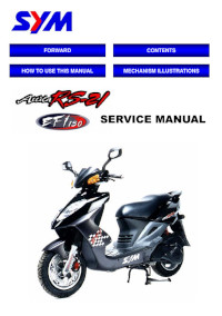
Руководство на английском языке по ремонту скутеров SYM Attila RS-21 EFi 150.
- Издательство: SANYANG Industry Co., Ltd.
- Год издания: —
- Страниц: 219
- Формат: PDF
- Размер: 6,7 Mb
Руководство по эксплуатации и техническому обслуживанию скутеров SYM Citycom 300.
- Издательство: SANYANG Industry Co., Ltd.
- Год издания: —
- Страниц: 31
- Формат: PDF
- Размер: 1,6 Mb
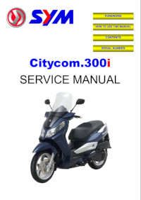
Руководство на английском языке по ремонту скутеров SYM Citycom 300i.
- Издательство: SANYANG Industry Co., Ltd.
- Год издания: —
- Страниц: 271
- Формат: PDF
- Размер: 28,7 Mb
Руководство по эксплуатации и техническому обслуживанию скутеров SYM DD50.
- Издательство: SANYANG Industry Co., Ltd.
- Год издания: —
- Страниц: 21
- Формат: PDF
- Размер: 678 Kb
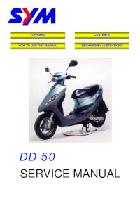
Руководство на английском языке по ремонту скутеров SYM DD 50.
- Издательство: SANYANG Industry Co., Ltd.
- Год издания: —
- Страниц: 157
- Формат: PDF
- Размер: 4,0 Mb
Руководство по эксплуатации и техническому обслуживанию скутеров SYM Euro MX 125 и Euro MX 150.
- Издательство: SANYANG Industry Co., Ltd.
- Год издания: —
- Страниц: 19
- Формат: PDF
- Размер: 1,6 Mb
Руководство по эксплуатации и техническому обслуживанию скутеров SYM Euro X 50 и Euro X 100.
- Издательство: SANYANG Industry Co., Ltd.
- Год издания: —
- Страниц: 20
- Формат: PDF
- Размер: 1,0 Mb
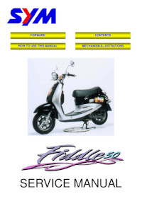
Руководство на английском языке по ремонту скутеров SYM Fiddle 50.
- Издательство: SANYANG Industry Co., Ltd.
- Год издания: —
- Страниц: 149
- Формат: PDF
- Размер: 3,7 Mb
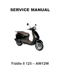
Руководство на английском языке по ремонту скутеров SYM Fiddle II 125.
- Издательство: SANYANG Industry Co., Ltd.
- Год издания: —
- Страниц: 182
- Формат: PDF
- Размер: 3,4 Mb
Руководство по эксплуатации и техническому обслуживанию скутеров SYM GTS.
- Издательство: SANYANG Industry Co., Ltd.
- Год издания: —
- Страниц: 34
- Формат: PDF
- Размер: 1,9 Mb
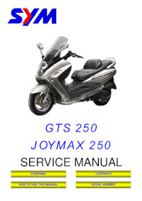
Руководство на английском языке по ремонту скутеров SYM GTS 250 и Joymax 250.
- Издательство: SANYANG Industry Co., Ltd.
- Год издания: —
- Страниц: 217
- Формат: PDF
- Размер: 5,9 Mb
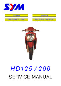
Руководство на английском языке по ремонту скутеров SYM HD 125 и HD 200.
- Издательство: SANYANG Industry Co., Ltd.
- Год издания: —
- Страниц: 211
- Формат: PDF
- Размер: 6,0 Mb
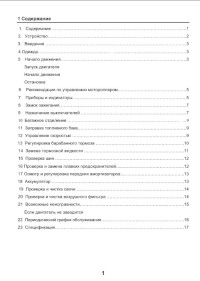
Руководство по эксплуатации и техническому обслуживанию скутеров SYM Jet Sport X50.
- Издательство: SANYANG Industry Co., Ltd.
- Год издания: —
- Страниц: 17
- Формат: PDF
- Размер: 1,0 Mb
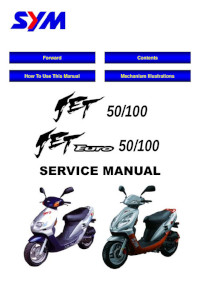
Руководство на английском языке по ремонту скутеров SYM Jet 50, Jet 100, Jet Euro 50 и Jet Euro 100.
- Издательство: SANYANG Industry Co., Ltd.
- Год издания: —
- Страниц: 161
- Формат: PDF
- Размер: 4,8 Mb
Руководство по эксплуатации и техническому обслуживанию скутеров SYM Joyride.
- Издательство: SANYANG Industry Co., Ltd.
- Год издания: —
- Страниц: 24
- Формат: PDF
- Размер: 1,5 Mb
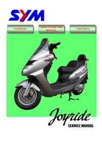
Руководство на английском языке по ремонту скутеров SYM Joyride.
- Издательство: SANYANG Industry Co., Ltd.
- Год издания: —
- Страниц: 203
- Формат: PDF
- Размер: 15,8 Mb
Руководство по эксплуатации и техническому обслуживанию скутеров SYM Mio.
- Издательство: SANYANG Industry Co., Ltd.
- Год издания: —
- Страниц: 16
- Формат: PDF
- Размер: 1,6 Mb

Руководство по эксплуатации и техническому обслуживанию скутеров SYM Orbit.
- Издательство: SANYANG Industry Co., Ltd.
- Год издания: —
- Страниц: 16
- Формат: PDF
- Размер: 1,1 Mb
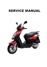
Сборник руководств на английском языке по ремонту скутеров SYM Orbit.
- Издательство: SANYANG Industry Co., Ltd.
- Год издания: —
- Страниц: 178/184
- Формат: PDF
- Размер: 13,8 Mb
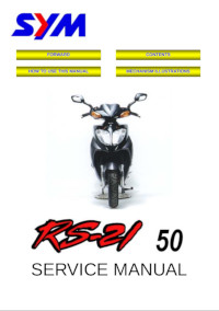
Руководство на английском языке по ремонту скутеров SYM RS-21 50.
- Издательство: SANYANG Industry Co., Ltd.
- Год издания: —
- Страниц: 157
- Формат: PDF
- Размер: 4,4 Mb

Руководство по эксплуатации и техническому обслуживанию скутеров SYM Symphony SR 50.
- Издательство: SANYANG Industry Co., Ltd.
- Год издания: —
- Страниц: 24
- Формат: PDF
- Размер: 1,3 Mb
Руководство по эксплуатации и техническому обслуживанию скутеров SYM VS 150.
- Издательство: SANYANG Industry Co., Ltd.
- Год издания: —
- Страниц: 19
- Формат: PDF
- Размер: 1,1 Mb
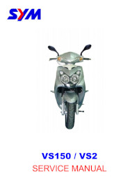
Руководство на английском языке по ремонту скутеров SYM VS 150 и VS 2.
- Издательство: SANYANG Industry Co., Ltd.
- Год издания: —
- Страниц: 195
- Формат: PDF
- Размер: 15,0 Mb
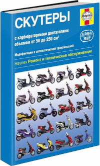
Руководство по техническому обслуживанию и ремонту скутеров с карбюраторними двигателями объемом 50 до 250 кубических сантиметров. Представлены модели SYM DD 50 City Trek, Jet 50/100, Shark 50, Super Fancy и City Hopper.
- Издательство: Алфамер
- Год издания: —
- Страниц: 368
- Формат: —
- Размер: —
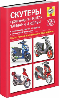
Руководство по техническому обслуживанию и ремонту скутеров производства Китая, Тайваня и Кореи с двигателями объемом от 50 до 200 cc и автоматической трансмиссией.
- Издательство: Алфамер
- Год издания: —
- Страниц: 240
- Формат: —
- Размер: —
|
Detail Specifications: 728/728684-mio_50.pdf file (10 Nov 2022) |
Accompanying Data:
Sym Mio 50 Scooter PDF Service Manual (Updated: Thursday 10th of November 2022 10:15:50 AM)
Rating: 4.9 (rated by 20 users)
Compatible devices: RS-50, Joymax Z LW12W1-EU, JOYRIDE 125, Joymax Z+, MAXSYM 400, HD200, 2009 FIDDLE II 125, AK12W.
Recommended Documentation:
Text Version of Service Manual
(Ocr-Read Summary of Contents, UPD: 10 November 2022)
Recommended Instructions:
TB90BC, KP-53V35, Distinctive DTHP30, R4
-
Vespa would like to thank youfor choosing one of its products. We have prepared this manual to help you to get the very best from your vehicle. Please read it carefully before ridingthe vehicle for the first time. It contains information, tips and precautions for using your vehicle. It also describes features, details and devices to assureyou that you have made the right choice. We b …
LX 150 i.e. 104
-
DIETZ Elektromobil/Mobilitäts-Scooter AlvaroMaxi Typ H03, 6,15 und 20 km/hDokumentenhistorieDatumÄnderungBearbeiter2017/02/10Rhino2, BasisMC(FR)MOTOR 4P6km/h700W15km/h950W20km/h20km/h1350W1350W DIETZ Elektro-Mobility ScooterWERKSTATTHANDBUCHSERVICE MANUALTyp 168-BSAgin 6 km/hTyp 168-4S2bAgin 10 km/hTyp 510-DXs2bAlvaro 15 km …
168-BS 60
-
OROAD-400 (3/6/07) 2/1/2013 update OFF-ROAD TRACTION DRIVE ELECTRIC CART USE & MAINTENANCE MANUAL VESTIL MANUFACTURING CORP. 2999 NORTH WAYNE STREET P.O. BOX 507, ANGOLA, IN 46703 TELEPHONE: (260) 665-7586 -OR- TOLL FREE (800) 348-0868 FAX: (260) 665-1339 URL: WWW.VESTILMFG.COM EMAIL: [email protected] NOTE: Compliance with regulations, codes, and/ …
OROAD-400 10
-
SERVICE STATIONMANUALPiaggio & C. S.p.A.PontederaAfter Sales ServiceDis. 594523 — 04/01Grafica e Stampa: C.L.D. — Pontedera (PI)“© Copyright 2001 — PIAGGIO & C. S.p.A. Pontedera.All rights reserved. Reproduction, in whole or in part, forbidden.”Data subject to change without notice.No responsibility is assumed for the use of non-genuine components and accessories oth …
X9 Evolution 500 69
Additional Information:
Popular Right Now:
Operating Impressions, Questions and Answers:
На чтение 13 мин Просмотров 20 Опубликовано 9 апреля 2023 Обновлено 9 апреля 2023
Содержание
- Электрическая схема скутера
- Электрика и электрооборудование скутера
- Замок зажигания.
- Генератор.
- Реле-регулятор.
- Элементы цепи зажигания.
- Модуль зажигания CDI.
- Катушка зажигания.
- Свеча зажигания.
- Стартёр.
- Датчик и индикатор топлива.
- Реле поворотов.
- Звуковой сигнал.
- Руководства по эксплуатации, обслуживанию и ремонту скутеров SYM
- SYM Attila RS-21 EFi 150 Service Manual.
- Руководство по эксплуатации SYM Citycom 300.
- SYM Citycom 300i Service Manual.
- Руководство по эксплуатации SYM DD 50.
- SYM DD 50 Service Manual.
- Руководство по эксплуатации SYM Euro MX 125/150.
- Руководство по эксплуатации SYM Euro X 50/100.
- SYM Fiddle 50 Service Manual.
- SYM Fiddle II 125 — AW12W Service Manual.
- Руководство по эксплуатации SYM GTS.
- SYM GTS 250/Joymax 250 Service Manual.
- SYM HD 125/200 Service Manual.
- Руководство по эксплуатации SYM Jet Sport X50.
- SYM Jet 50/100, Jet Euro 50/100 Service Manual.
- Руководство по эксплуатации SYM Joyride.
- SYM Joyride Service Manual.
- Руководство по эксплуатации SYM Mio.
- Руководство по эксплуатации SYM Orbit.
- SYM Orbit Service Manual.
- SYM RS-21 50 Service Manual.
- Руководство по эксплуатации SYM Symphony SR 50.
- Руководство по эксплуатации SYM VS 150.
- SYM VS 150/VS 2 Service Manual.
- Скутеры. Ремонт и техническое обслуживание.
- Скутеры производства Китая, Тайваня и Кореи.
Электрическая схема скутера
Электрика и электрооборудование скутера
Всем владельцам китайских скутеров посвящается…
Для начала хотелось бы представить схему электропроводки китайского скутера.
Поскольку все китайские скутеры весьма похожи как сиамские близнецы, то и электрическая схема у них практически ничем не отличается.
Схем найдена в интернете и является, на мой взгляд, одной из самых удачных, так как на ней показан цвет соединительных проводников. Это значительно упрощает схему и делает её чтение более комфортным.
(Кликните по картинке для увеличения. Изображение откроется в новом окне).
Стоит отметить, что в электрической схеме скутера, так же как и в любой электронной схеме, есть общий провод. У скутера общим проводом является минус (—). На схеме общий провод показан зелёным цветом. Если посмотреть повнимательнее, то можно заметить, что он соединён со всем электрооборудованием скутера: фарой (16), реле поворотов (24), лампой подсветки приборной панели (15), индикаторными лампами (20, 36, 22, 17), тахометром (18), датчиком уровня топлива (14), звуковым сигналом (31), задним габаритом/стоп-сигналом (13), пусковым реле (10) и другими приборами.
Для начала давайте пробежимся по основным элементам схемы китайского скутера.
Замок зажигания.
Замок зажигания (12) или «Главный выключатель». Замок зажигания представляет собой не что иное, как обычный многопозиционный переключатель. Несмотря на то, что у замка зажигания 3 положения, в электрической схеме используется всего 2.
При первом положении ключа замыкается красный и чёрный провод. При этом напряжение от аккумулятора поступает в электроцепь скутера, скутер готов к запуску. Также готовы к работе индикатор уровня топлива, тахометр, звуковой сигнал, реле-поворотов, схема зажигания. На них подаётся напряжение питания от аккумулятора.
В случае неисправности замка зажигания его можно смело заменить каким-нибудь переключателем вроде тумблера. Тумблер должен быть достаточно мощный, ведь через замок зажигания, по сути, коммутируется вся электроцепь скутера. Конечно, можно обойтись и без тумблера, если ограничиться замыканием красного и чёрного провода, как это когда-то делали герои голливудских боевиков 
В двух остальных положениях происходит замыкание чёрно-белого провода от модуля зажигания CDI (1) на корпус (общий провод). При этом работа двигателя блокируется. В некоторых моделях скутеров для блокировки двигателя предусмотрена кнопка стоп-двигатель (27), которая также, как и замок зажигания соединяет бело-чёрный и зелёный (общий, корпусной) провод.
Генератор.
Генератор (4) вырабатывает переменный электрический ток для питания всех потребителей тока и зарядки аккумуляторной батареи (6).
От генератора отходит 5 проводов. Один из них подключен к общему проводу (раме). С белого провода снимается переменное напряжение и подаётся на реле-регулятор для последующего выпрямления и стабилизации. С жёлтого провода снимается напряжение, которое используется для питания лампы ближнего/дальнего света, которая установлена в переднем обтекателе скутера.
Также в конструкции генератора присутствует так называемый датчик холла. Электрически он не связан с генератором и от него идут 2 провода: бело- зелёный и красно —чёрный. Датчик холла подключен к модулю зажигания CDI (1).
Реле-регулятор.
Реле-регулятор (5). В народе может обзываться «стабилизатором», «транзистором», «регулятором», «регулятором напряжения» или попросту «реле». Все эти определения относятся к одной «железяке». Вот так выглядит реле-регулятор.
Реле-регулятор у китайских скутеров устанавливается в передней части под пластмассовым обтекателем. Само реле-регулятор крепится к металлическому основанию скутера для того, чтобы уменьшить нагрев радиатора реле при работе. Вот так выглядит реле-регулятор на скутере.
В работе скутера реле-регулятор играет весьма важную роль. Задача реле-регулятора заключается в том, чтобы переменное напряжение от генератора превратить в постоянное и ограничить его на уровне 13,5 — 14,8 вольт. Именно такое напряжение требуется для зарядки аккумулятора.
На схеме и на фото видно, что от реле-регулятора отходит 4 провода. Зелёный – это общий провод. О нём мы уже говорили. Красный – это выход плюсового постоянного напряжения 13,5 -14,8 вольт.
По белому проводу на реле регулятор поступает переменное напряжение от генератора. Также к регулятору подключен жёлтый провод, идущий от генератора. По нему на регулятор подаётся переменное напряжение от генератора. За счёт электронной схемы регулятора, напряжение на этом проводе преобразуется в пульсирующее, и подаётся на мощные потребитель тока – лампу ближнего и дальнего света, а также лампы подсветки приборной панели (их может быть несколько).
Напряжение питания ламп не стабилизируется, но ограничивается реле-регулятором на определённом уровне (около 12V), так как на больших оборотах переменное напряжение, поступающее от генератора, превышает допустимое. Думаю, об этом знают те, у кого выгорали габариты при неисправностях реле-регулятора.
Несмотря на всю свою важность, устройство реле-регулятора достаточно примитивно. Если расковырять компаунд, которым залита печатная плата, то можно обнаружить, что основной реле является электронная схема из тиристора BT151-650R, диодного моста на диодах 1N4007, мощного диода 1N5408, а также нескольких элементов обвязки: электролитических конденсаторов, маломощных SMD-транзисторов, резисторов и стабилитрона.
Из-за своей примитивной схемотехники реле-регулятор частенько выходит из строя. О том, как проверить регулятор напряжения читайте здесь.
Элементы цепи зажигания.
Одной из самых важных электрических цепей скутера является схема зажигания. В неё входят модуль зажигания CDI (1), катушка зажигания (2), свеча зажигания (3).
Модуль зажигания CDI.
Модуль зажигания CDI (1) выполняется в виде небольшой коробочки залитой компаундом. Это усложняет разборку блока CDI в случае его неисправности. Хотя модульная конструкция этого блока упрощает процесс его замены.
К модулю CDI подключается 5 проводников. Сам модуль CDI располагается в донной части корпуса скутера недалеко от аккумуляторного отсека и закрепляется на раме резиновым фиксатором. Доступ к блоку CDI затрудняется тем, что он расположен в донной части и закрыт декоративным пластиком, который приходится полностью снимать.
Катушка зажигания.
Катушка зажигания (2). Сама катушка зажигания располагается с правой стороны скутера и закреплена на раме. Представляет собой некий пластиковый бочонок с двумя разъёмами для подключения и выводом высоковольтного провода, который уходит к свече зажигания.
Конструктивно катушка зажигания расположена рядом с пусковым реле. Для защиты от пыли, грязи и случайных замыканий катушка закрывается резиновым чехлом.
Свеча зажигания.
С помощью высоковольтного провода катушка зажигания соединяется со свечой зажигания A7TC (3).
На скутере свеча зажигания оказалась хитроумно запрятана, и с первого раза её можно искать довольно долго. Но если «пойти» вдоль высоковольтного провода от катушки зажигания, то провод приведёт нас прямиком к колпачку свечи зажигания.
Колпачок снимается со свечи небольшим усилием на себя. Он фиксируется на контакте свечи упругой металлической защёлкой.
Стоит отметить, что высоковольтный провод подсоединяется к колпачку без пайки. Многожильный провод в изоляции просто накручивается на контакт-шуруп встроенный в колпачок. Поэтому сильно дёргать за провод не стоит, иначе можно выдернуть провод из колпачка. Устраняется это легко, но провод придётся укоротить на 0,5 – 1 см.
До самой свечи зажигания добраться не так-то просто. Для её демонтажа необходим торцовый ключ. С его помощью свеча просто вывёртывается из посадочного места.
Стартёр.
Стартер (8). Стартер служит для запуска двигателя. Расположен он в средней части скутера рядом с двигателем. Добраться до него нелегко.
Запуском стартера управляет пусковое реле (10).
Пусковое реле размещено с правой стороны на раме скутера. На пусковое реле приходит толстый красный провод от плюсовой клеммы аккумулятора. Так запитывается пусковое реле.
Датчик и индикатор топлива.
Датчик уровня топлива (14) встроен в топливный бак.
От датчика отходят три провода. Зелёный является общим (минус питания), а двумя другими датчик подключается к индикатору уровня топлива (11), который установлен на приборной панели скутера.
Датчик топлива (14) и индикатор (11) являются одним устройством и запитываются постоянным стабилизированным напряжением. Так как два этих устройства разнесены между собой, то они соединяются трёхконтактным разъёмом. Плюсовое напряжение питания поступает на индикатор топлива и датчик по чёрному проводу с замка зажигания.
Если разомкнуть трёхконтактный разъём, идущий от датчика топлива, то индикатор топлива перестанет показывать уровень топлива в баке. Поэтому, если у вас не работает индикатор топлива, то проверьте соединительный разъём между датчиком и индикатором топлива, а также убедитесь, что на них подаётся напряжение питания.
Также стоит помнить, что напряжение питания на датчик и индикатор подаётся при замкнутом положении замка зажигания (12). По схеме – это правое положение.
Реле поворотов.
Реле поворотов или реле-прерыватель (24). Служит для управления передними и задними лампами указания поворота.
Как правило, реле поворотов устанавливается рядом с приборами (спидометром, тахометром, индикатором уровня топлива) на приборной панели. Для того чтобы его увидеть надо снять декоративный пластик. На вид выглядит как небольшой пластмассовый бочонок с тремя выводами. При включённых поворотниках издаёт характерные щелчки частотой около 1 Гц.
После реле поворотов устанавливается переключатель указателей поворота (23). Это обычный клавишный переключатель, который коммутирует плюсовое напряжение от реле-поворотов (серый провод) на лампы. Если взглянуть на схему, то при правом положении переключателя (23) мы подаём напряжение по синему проводу на правую переднюю (21) и правую заднюю (32) лампу указатель. Если переключатель в левом положении, то серый провод замыкается на оранжевый, и мы подаём питание на левую переднюю (19) и левую заднюю (33) лампу указатель. Кроме того, параллельно соответствующим лампам-указателям (19, 20, 32, 33) подключены сигнальные лампы (20 и 22), которые размещены на приборной панели скутера и служит чисто информационным сигналом для водителя скутера.
Звуковой сигнал.
Звуковой сигнал (31) скутера размещён под пластиковым обтекателем скутера рядом с реле-регулятором.
Напряжение питания звукового сигнала – постоянное. Оно поступает от реле-регулятора или аккумулятора (если двигатель выключен) через замок зажигания и кнопку включения звукового сигнала (25).
Лампа ближнего/дальнего света (16). Да, та самая, что освещает нам дорогу в тёмное время суток.
Сама лампа является двойной с двумя нитями накала и тремя контактами для подключения в электроцепь. Один из контактов, понятно, общий. Мощность лампы 25W, напряжение питания 12V. Горит безбожно при неисправном реле-регуляторе из-за того, что оно не ограничивает амплитуду напряжения на уровне 12 вольт, что приводит к тому, что на лампу подаётся напряжение 16 – 27 вольт, а то и больше. Всё зависит от оборотов.
Поэтому, если на холостом ходу лампа светит очень ярко, а не в полнакала, то лучше выключите её и проверьте реле-регулятор. Если оставите всё как есть, то лампа ближнего/дальнего света сгорит, что печально. Стоимость её приличная.
На фото рядом лампа указателя поворота (красная). Мощность лампы 5W на напряжение питания 12V.
Источник
Руководства по эксплуатации, обслуживанию и ремонту скутеров SYM
Руководство по эксплуатации и техническому обслуживанию скутеров SYM моделей AD12W1-6 и AD12W1-6C.
- Издательство: SANYANG Industry Co., Ltd.
- Год издания: —
- Страниц: 24
- Формат: PDF
- Размер: 1,3 Mb
SYM Attila RS-21 EFi 150 Service Manual.
Руководство на английском языке по ремонту скутеров SYM Attila RS-21 EFi 150.
- Издательство: SANYANG Industry Co., Ltd.
- Год издания: —
- Страниц: 219
- Формат: PDF
- Размер: 6,7 Mb
Руководство по эксплуатации SYM Citycom 300.
Руководство по эксплуатации и техническому обслуживанию скутеров SYM Citycom 300.
- Издательство: SANYANG Industry Co., Ltd.
- Год издания: —
- Страниц: 31
- Формат: PDF
- Размер: 1,6 Mb
Руководство на английском языке по ремонту скутеров SYM Citycom 300i.
- Издательство: SANYANG Industry Co., Ltd.
- Год издания: —
- Страниц: 271
- Формат: PDF
- Размер: 28,7 Mb
Руководство по эксплуатации SYM DD 50.
Руководство по эксплуатации и техническому обслуживанию скутеров SYM DD50.
- Издательство: SANYANG Industry Co., Ltd.
- Год издания: —
- Страниц: 21
- Формат: PDF
- Размер: 678 Kb
SYM DD 50 Service Manual.
Руководство на английском языке по ремонту скутеров SYM DD 50.
- Издательство: SANYANG Industry Co., Ltd.
- Год издания: —
- Страниц: 157
- Формат: PDF
- Размер: 4,0 Mb
Руководство по эксплуатации SYM Euro MX 125/150.
Руководство по эксплуатации и техническому обслуживанию скутеров SYM Euro MX 125 и Euro MX 150.
- Издательство: SANYANG Industry Co., Ltd.
- Год издания: —
- Страниц: 19
- Формат: PDF
- Размер: 1,6 Mb
Руководство по эксплуатации SYM Euro X 50/100.
Руководство по эксплуатации и техническому обслуживанию скутеров SYM Euro X 50 и Euro X 100.
- Издательство: SANYANG Industry Co., Ltd.
- Год издания: —
- Страниц: 20
- Формат: PDF
- Размер: 1,0 Mb
SYM Fiddle 50 Service Manual.
Руководство на английском языке по ремонту скутеров SYM Fiddle 50.
- Издательство: SANYANG Industry Co., Ltd.
- Год издания: —
- Страниц: 149
- Формат: PDF
- Размер: 3,7 Mb
SYM Fiddle II 125 — AW12W Service Manual.
Руководство на английском языке по ремонту скутеров SYM Fiddle II 125.
- Издательство: SANYANG Industry Co., Ltd.
- Год издания: —
- Страниц: 182
- Формат: PDF
- Размер: 3,4 Mb
Руководство по эксплуатации SYM GTS.
Руководство по эксплуатации и техническому обслуживанию скутеров SYM GTS.
- Издательство: SANYANG Industry Co., Ltd.
- Год издания: —
- Страниц: 34
- Формат: PDF
- Размер: 1,9 Mb
SYM GTS 250/Joymax 250 Service Manual.
Руководство на английском языке по ремонту скутеров SYM GTS 250 и Joymax 250.
- Издательство: SANYANG Industry Co., Ltd.
- Год издания: —
- Страниц: 217
- Формат: PDF
- Размер: 5,9 Mb
SYM HD 125/200 Service Manual.
Руководство на английском языке по ремонту скутеров SYM HD 125 и HD 200.
- Издательство: SANYANG Industry Co., Ltd.
- Год издания: —
- Страниц: 211
- Формат: PDF
- Размер: 6,0 Mb
Руководство по эксплуатации SYM Jet Sport X50.
Руководство по эксплуатации и техническому обслуживанию скутеров SYM Jet Sport X50.
- Издательство: SANYANG Industry Co., Ltd.
- Год издания: —
- Страниц: 17
- Формат: PDF
- Размер: 1,0 Mb
SYM Jet 50/100, Jet Euro 50/100 Service Manual.
Руководство на английском языке по ремонту скутеров SYM Jet 50, Jet 100, Jet Euro 50 и Jet Euro 100.
- Издательство: SANYANG Industry Co., Ltd.
- Год издания: —
- Страниц: 161
- Формат: PDF
- Размер: 4,8 Mb
Руководство по эксплуатации SYM Joyride.
Руководство по эксплуатации и техническому обслуживанию скутеров SYM Joyride.
- Издательство: SANYANG Industry Co., Ltd.
- Год издания: —
- Страниц: 24
- Формат: PDF
- Размер: 1,5 Mb
SYM Joyride Service Manual.
Руководство на английском языке по ремонту скутеров SYM Joyride.
- Издательство: SANYANG Industry Co., Ltd.
- Год издания: —
- Страниц: 203
- Формат: PDF
- Размер: 15,8 Mb
Руководство по эксплуатации SYM Mio.
Руководство по эксплуатации и техническому обслуживанию скутеров SYM Mio.
- Издательство: SANYANG Industry Co., Ltd.
- Год издания: —
- Страниц: 16
- Формат: PDF
- Размер: 1,6 Mb
Руководство по эксплуатации SYM Orbit.
Руководство по эксплуатации и техническому обслуживанию скутеров SYM Orbit.
- Издательство: SANYANG Industry Co., Ltd.
- Год издания: —
- Страниц: 16
- Формат: PDF
- Размер: 1,1 Mb
SYM Orbit Service Manual.
Сборник руководств на английском языке по ремонту скутеров SYM Orbit.
- Издательство: SANYANG Industry Co., Ltd.
- Год издания: —
- Страниц: 178/184
- Формат: PDF
- Размер: 13,8 Mb
SYM RS-21 50 Service Manual.
Руководство на английском языке по ремонту скутеров SYM RS-21 50.
- Издательство: SANYANG Industry Co., Ltd.
- Год издания: —
- Страниц: 157
- Формат: PDF
- Размер: 4,4 Mb
Руководство по эксплуатации SYM Symphony SR 50.
Руководство по эксплуатации и техническому обслуживанию скутеров SYM Symphony SR 50.
- Издательство: SANYANG Industry Co., Ltd.
- Год издания: —
- Страниц: 24
- Формат: PDF
- Размер: 1,3 Mb
Руководство по эксплуатации SYM VS 150.
Руководство по эксплуатации и техническому обслуживанию скутеров SYM VS 150.
- Издательство: SANYANG Industry Co., Ltd.
- Год издания: —
- Страниц: 19
- Формат: PDF
- Размер: 1,1 Mb
SYM VS 150/VS 2 Service Manual.
Руководство на английском языке по ремонту скутеров SYM VS 150 и VS 2.
- Издательство: SANYANG Industry Co., Ltd.
- Год издания: —
- Страниц: 195
- Формат: PDF
- Размер: 15,0 Mb
Скутеры. Ремонт и техническое обслуживание.
Руководство по техническому обслуживанию и ремонту скутеров с карбюраторними двигателями объемом 50 до 250 кубических сантиметров. Представлены модели SYM DD 50 City Trek, Jet 50/100, Shark 50, Super Fancy и City Hopper.
- Издательство: Алфамер
- Год издания: —
- Страниц: 368
- Формат: —
- Размер: —
Скутеры производства Китая, Тайваня и Кореи.
Руководство по техническому обслуживанию и ремонту скутеров производства Китая, Тайваня и Кореи с двигателями объемом от 50 до 200 cc и автоматической трансмиссией.
- Издательство: Алфамер
- Год издания: —
- Страниц: 240
- Формат: —
- Размер: —
Источник
- Manuals
- Brands
- Sym Manuals
- Scooter
- JET 50 series
- Owner’s manual
-
Contents
-
Table of Contents
-
Bookmarks
Quick Links
Related Manuals for Sym JET 50 series
Summary of Contents for Sym JET 50 series
-
Page 1
OWNER’S MANUAL… -
Page 2: Safety Information
Ÿ The safety, stability and handling of this motorcycle may be adversely affected by the addition of accessories or luggage. Ÿ Do not install accessory or replacement parts not approved by sym. Ÿ Failure to follow these warnings could lead to an accident, serious injuries or death.
-
Page 3
4. SAFETY DEFECT REPORT SANYANG INDUSTRY CO., Ltd. NO. 3,chung-Hua Road Hukou Shiang Hsin-Chu County, 303 Taiwan, R.O.C Reporting Safety Defects If you believe that your vehicle has a defect which could cause a crash or could cause injury or death, you should immediately inform the National Highway Traffic Safety Administration (NHTSA) in addition to notifying Sanyang Industry Co., Ltd. -
Page 4: Table Of Contents
Content/ Subject 1. Contents ……………………1 2. Control location ………………….3 3. Before riding ……………………8 4. Safety riding ……………………8 5. Driving ……………………..9 6. Use genuine spare parts ………………..9 7. Use of each component ………………..10 Gauges ……………………10 Operation of ignition switch ………………
-
Page 5
Checking the brake light ………………..26 Checking for fuel leakage ……………….. 26 Checking the lubrication of body’s various mechanisms ……….26 Checking the spark plug ………………..27 Checking the air cleaner ………………..27 11. When there is an abnormal condition or a trouble …………28 Diagnosis when engine does not start …………….. -
Page 6: Control Location
MODE: JET 50/100 SERIES (BL05WA-6) Light / Starter switch Fuel tank cap Rear turn signal Front turn signal Seat lock Rear turn signal Helmet hook High & Low beam / Turn signal / Horn switch Fuses / C.D.I. / Eng. Oil tank cap Frame number Tail light Head light…
-
Page 7
MODE: BL05W6-A SERIES Light / Starter switch Fuel tank cap Head light Seat lock Helmet hook High & Low beam / Turn signal / Horn switch Fuses / C.D.I. / Front turn signal Eng. Oil tank cap Frame number Tail light Storage box Air cleaner Ignition switch… -
Page 8
MODE: MASK SERIES (BF05W) Light / Starter switch Fuel tank cap Front turn signal Helmet hook High & Low beam / Turn signal / Horn switch Frame number Fuses / C.D.I. / Eng. Oil tank cap Seat lock Tail light Rear turn signal Head light Storage box… -
Page 9
MODE: BS05W SERIES Light / Starter switch Front turn signal Fuel tank cap Helmet hook High & Low beam / Turn signal / Horn switch Fuses / C.D.I. / Eng. Oil tank cap Frame number Tail light Head light Seat lock Storage box Air cleaner Ignition switch… -
Page 10
MODE: Jet SportX 50 SERIES (BK05W) ENG. Stop / Starter switch High & Low beam / Turn signal / Horn switch Fuses / C.D.I. / Eng. Oil tank cap Frame number Head light Tail light Seat lock Storage box Air cleaner Fuel tank cap Ignition switch Rear turn signal… -
Page 11: Before Riding
This manual describes the correct usage of this scooter including safety riding, simple inspection methods and so on. For a more comfortable and safety riding, please read this manual carefully. Thank you very much for your patronage In order to maximize your scooter’s performance, a periodical inspection and maintenance should be completely carried out.
-
Page 12: Driving
Also, it may result in unexpected troubles and lower the scooter’s performance. Ÿ Always use SYM Genuine Spare Parts to keep your scooters pure blood and to ensure its long service life. 5. Driving…
-
Page 13: Use Of Each Component
Gauges Speedometer Model : JET SERIES Fuel Gauge Odometer Turn Signal Indicator Turn Signal Indicator Engine Oil Warning Light High Bean Indicator Model : MASK SERIES High Bean Indicator Speedometer Turn Signal Indicator Odometer Engine Oil Warning Light Fuel Gauge 7.
-
Page 14
Model : BS05W SERIES Fuel Gauge Speedometer Odometer Engine Oil Warning Light Turn Signal Indicator High Bean Indicator Model : BL05W6-A / G100P2 SERIES Clock Odometer Fuel Gauge Speedometer Turn Signal Indicator Turn Signal Indicator High Bean Indicator Engine Oil Warning Light Model : BK05W-6 SERIES Fuel Gauge Speedometer… -
Page 15
Use only 2-cycle engine oil meeting Japanese Automobile Standard Organization FC specifications. Otherwise, this company will not assume any responsibility for damages resulted from using substandard engine oil. ※
Recommended oil: SYM EXTRA 2X oil. 5. Speedometer This shows your speed in kilometers per hour CAUTION: (km/h) and in mileage per hour (mph). -
Page 16: Operation Of Ignition Switch
OPERATION OF IGNITION SWITCH “ON” position IGNITION SWITCH Ÿ Engine can be started in this position. Ÿ Ignition switch key can not be removed. “OFF” position Ÿ Engine is shut off and can not be started in this position. Ÿ Ignition switch key can be removed.
-
Page 17: Use Of Buttons
USE OF BUTTONS High / Low Turn Signal Switch l Light Switches (If installed) Beam Switch When the switch is turned to this position, headlight, rear light, instrument panel light, and position light will go on. When the switch is turned to this position, rear light, instrument panel light, and position Horn Switch light will go on.
-
Page 18: Saddle Lock
l High/Low Beam Switch (If installed) This is the high and low beam of headlight switching switch. Press this switch to switch between high and low beams. This is for high beam. This is for low beam. (Please turn to low beam when riding in city) l…
-
Page 19: Storage Box
STORAGE BOX w This box is located under the saddle. w Maximum load capacity: 10kg. w Do not store valuables in the box. w Please make sure that seat cushion had been locked completely after it was down. Take out valuables before washing to avoid wetting these objects.
-
Page 20: Parking Method
PARKING METHOD l When approaching the parking lot: 1. Turn on the turn signal light early, and pay attention to the vehicles in front, from rear, left and right, then take the inner lane and approach slowly. 2. Return the throttle valve handle back to its original position, and apply brakes in advance. (Brake light comes on when braking to warn drivers of vehicles behind.) l…
-
Page 21: Important Points And Cautions For Starting Engine
CAUTION: Ÿ Please check the engine oil and fuel volume are adequate or not before starting engine. Ÿ To start engine the main parking stand must be firmly on the ground and the brake is applied on the rear wheel to prevent the scooter from moving forward suddenly. 1.
-
Page 22: The Best Way To Drive Off
CAUTION: Ÿ If any problem founded during routine inspection, correct the problem before using the scooter again, have your scooter checked and repaired by the “SYM dealer or authorized service personnel” if necessary. 9. The best way to drive off…
-
Page 23: Inspection And Replenishment Of Engine Oil
Otherwise, this company will not assume any responsibility for damages resulted from using substandard engine oil. ※Recommended oil: SYM EXTRA 2X oil. Replenishment: 1. Using the main stand to support the vehicle on a level ground, lift up the saddle, and remove the oil tank cover.
-
Page 24: Transmission Oil Inspection And Change
Install the drain bolt and tighten it. Fill new transmission oil (100~110 c.c.), and install the infusion bolt and tighten it. (make sure that bolts are tightened and check that there’s no leakage.) ※ Recommend Oil: Genuine SYM HYPOID GEAR OIL (SAE 85W-140). Use SAE85-90 when outside temperature is below 0℃.
-
Page 25: Disc Brake Inspection [Depending On Models]
Ÿ Visual Inspection for leakage or damage. If Park the scooter on a level ground, and check there is any, take your scooter to SYM if fluid level is under the “LOWER” mark. Authorized Dealer or Franchised Dealer for a Recommended Brake Fluid: WELL RUN check or repair.
-
Page 26: Throttle Valve Handle Clearance Adjustment
Ÿ This scooter is equipped with a maintenance-free type battery, so it is unnecessary to check and add electrolyte. Have your scooter checked by SYM Authorized Dealer or Franchised Dealer should any abnormality is found. Remove the battery terminals and clean if there are dirt and corrosion on them.
-
Page 27: Tire Inspection
CAUTION: Ÿ This is a closed type battery. Never remove the caps. Ÿ In order to prevent electric leakage and self-discharge when the battery sits idle for long periods. Remove battery from scooter, store it in a well- ventilated and dimly lighted place after the battery has been fully charged.
-
Page 28: Steering Handle Front Shock Absorbers Inspection
Check steering handle if it is being pulled too tight by the brake cables. Ÿ Take your scooter to SYM Authorized Dealer or Franchised Dealer for a check or adjustment if any abnormal conditions are found. 【Figures on the right are for operation checks only】…
-
Page 29: Checking The Turn Signal Lights And Horn
CHECKING THE TURN SIGNAL LIGHTS AND HORN Ÿ Turn the ignition switch key to “ON” position. Ÿ Turn on the turn signal light switch, and make sure that the front & rear and left & right signal lights flashes and also check if the warning buzzer sounds. Ÿ…
-
Page 30: Checking The Spark Plug
CHECKING THE SPARK PLUG Ÿ Remove the cap of high tension cable. (Use a plug wrench in tool box to remove the spark plug by turning it counterclockwise.) Ÿ Check the electrode if it is dirty or fouled by carbon deposits. Ÿ…
-
Page 31: When There Is An Abnormal Condition Or A Trouble
The fuse may blow if horn not sounding. 【Please go to SYM authorized dealer or franchised dealer immediately if there are no problems on above conditions and engine still can not be started.】 11.when there is an abnormal condition or a trouble…
-
Page 32: Periodical Maintenance Schedule
The above maintenance schedule is established by taking the monthly 1,000 kilometers as a reference which ever comes first. ¯ Have your scooter checked and adjusted periodically by your SYM Authorized Dealer or Franchised Dealer to maintain the scooter at the optimum condition. Code: I ~ Inspection, cleaning, and adjustment R ~ Replacement…
-
Page 33: Specification
Model JET Euro50 JET 50α RED DEVIL50 BL05WA BL05W6 Item Specification Length ( mm) 1,785 Width ( mm) Height ( mm) 1,125 1,115 Wheel base ( mm) 1,275 Net Weight 94 kg maximum load 277Kg (610.7lb) Type 2- stroke single cylinders engine Fuel Unleaded gasoline (octane 90 or higher) Cooling type…
-
Page 34
Model MASK 50 JET Sport X 50 RS 50 G100-P2 BK05W BS05W BF05W Item Specification Length (mm) 1,840 1,835 1,870 1,785 Width (mm) Height (mm) 1,120 1,110 1,130 1,125 Wheel base (mm) 1,275 1,280 1,335 1,275 Net Weight 98 kg 94 kg 108 kg 97 kg… -
Page 35: Postscript
FUNCTION: Set time in 12 hour mode There are three buttons on the speedometer, explanation as below : 1. SET button “S”: a. Under TRIP mode, press “S” button continuously to reset the TRIP kilometer readings. b. Under ODO mode and the vehicle is standing still, press SET for above 2 seconds to enter CLOCK mode.


