-
nekesha
- Администратор
- Сообщения: 1668
- Зарегистрирован: 17 дек 2014, 03:43
- Благодарил (а): 2 раза
- Поблагодарили: 6 раз
Toyota Hiace 1984-1995/ Тайота Хайс 1984-1995
Руководство по эксплуатации, техобслуживанию и ремонту Toyota Hiace / Тайота Хайс
Operation, Maintenance and Repair Manual Toyota Hiace
 15550 просмотров")
- Бензиновые двигатели: 1Y (1.6 л), 2Y (1.8 л), 3Y (2.0 л)
Дизельные двигатели: D 0824 FL 01, D 0824 LFL 01, D 0824 LFL 03
Gasoline engines: 1Y (1.6 L), 2Y (1.8 L), 3Y (2.0 L)
Diesel engines: D 0824 FL 01, D 0824 LFL 01, D 0824 LFL 03
Года выпуска: 1984-1995
Year of manufacture: 1984-1995
- Язык: Русский
Формат: PDF
Размер: 20,1 Мб
Russian language
Format: PDF
Size: 20.1 MB
Скачать документацию Toyota Hiace / Тайота Хайс
Download the documentation of Toyota Hiace
для распаковки используйте пароль — avtoproblem-net.ru
use the password to unpack — avtoproblem-net.ru
Оригинальная инструкция по ремонту 2L-I AUG.1984. Английский язык.
Модели:
LX70 series
LS120 series
LH 11 51 61 71 series
LN 50 56 60 65 series
LY31 series
LF30 series
LJ70 series
Добавлено спустя 13 минут 13 секунд:
Оригинальная инструкция по ремонту МКПП. Английский язык.
G40, G45, G50, G52, G53, G54, G55, G56, G57, G58
Applicable models:
KM30, 36,37 series
YM30, 35 series
CM36 series
YR21, 22, 29, 31 series
KF40, 50 series
YN85, 86, 87, 92, 106, 110 series
LN80, 85, 90, 100, 106, 111 series
RN80, 85, 90, 105, 110 series
YH51, 53, 60, 61, 63, 73 series
LH51, 61, 71 series
YH81 series
LH80 series
RJ70 series
LJ70 series
YN63LG series
YN63RG series
LN61RG series
Добавлено спустя 7 минут 9 секунд:
Инструкция по ремонту 2L-T, 3L JAN1990
Applicable models:
LJ70, 72, 73, 77, 79 models
LN106, 111, 130, 135
Добавлено спустя 5 минут 31 секунду:
TOYOTA
Engine 2Lt, 3L Repair manual supplement JAN.1990
Applicable models:
LJ70, 72, 73, 77, 79
LN106, 111, 130, 135
Добавлено спустя 2 минуты 8 секунд:
AISIN OIL PUMP ROTORS
Аналоги масляных насосов от AISIN
Добавлено спустя 2 минуты 5 секунд:
Каталог уплотнителей форсунок CARGO
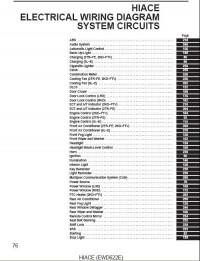
Схемы на английском языке по электрооборудования автомобиля Toyota Hiace 2006 года выпуска.
- Автор: —
- Издательство: Toyota Motor Corporation
- Год издания: —
- Страниц: —
- Формат: PDF
- Размер: 2,8 Mb
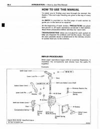
Сборник руководств на английском языке по техническому обслуживанию и ремонту + схемы электрооборудования автомобиля Toyota Hiace 1995-1999 годов выпуска.
- Автор: —
- Издательство: Toyota Motor Corporation
- Год издания: —
- Страниц: —
- Формат: PDF
- Размер: 102,0 Mb
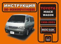
Руководство по эксплуатации и техническому обслуживанию автомобиля Toyota Hiace Wagon 1996-2003 годов выпуска.
- Автор: —
- Издательство: Монолит
- Год издания: —
- Страниц: 214
- Формат: —
- Размер: —
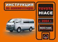
Руководство по эксплуатации и техническому обслуживанию автомобиля Toyota Hiace с 2004 года выпуска.
- Автор: —
- Издательство: Монолит
- Год издания: —
- Страниц: 180
- Формат: —
- Размер: —
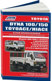
Руководство по техническому обслуживанию и ремонту автомобилей Toyota Dyna 100/150, Toyota Toyoace и Toyota Hiace 1984-1995 годов выпуска с бензиновыми и дизельными двигателями.
- Автор: —
- Издательство: Легион-Автодата
- Год издания: —
- Страниц: 226
- Формат: —
- Размер: —
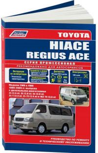
Руководство по эксплуатации, техническому обслуживанию и ремонту автомобилей Toyota Hiace и Toyota Regius Ace 1989-2005 годов выпуска с дизельными двигателями объемом 2,4/2,8/3,0 л.
- Автор: —
- Издательство: Легион-Автодата
- Год издания: —
- Страниц: 476
- Формат: —
- Размер: —
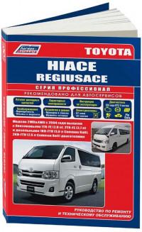
Руководство по эксплуатации, техническому обслуживанию и ремонту + каталог расходных запчастей автомобилей Toyota Hiace и Toyota Regius Ace с 2004 года выпуска с бензиновыми и дизельными двигателями.
- Автор: —
- Издательство: Легион-Автодата
- Год издания: —
- Страниц: 586
- Формат: —
- Размер: —
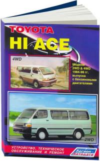
Руководство по техническому обслуживанию и ремонту автомобиля Toyota Hiace 1984-1998 годов выпуска с бензиновыми двигателями.
- Автор: —
- Издательство: Легион-Автодата
- Год издания: —
- Страниц: 248
- Формат: —
- Размер: —

- Manuals
- Brands
- Toyota Manuals
- Automobile
- Hiace
- Owner’s manual
-
Contents
-
Table of Contents
-
Bookmarks
Quick Links
Related Manuals for Toyota Hiace
Summary of Contents for Toyota Hiace
-
Page 3
(Main topics: Interior and exterior, light bulbs) When trouble What to do in case of malfunction and emergency arises (Main topics: Battery discharge, flat tire) Vehicle Vehicle specifications, customizable features specifications (Main topics: Fuel, oil, tire inflation pressure) Appendix Search by symptom HIACE/GRANVIA_OM_OM26A39W_(WE) -
Page 4: Table Of Contents
TABLE OF CONTENTS For your information ……Multi-information display (mono- Reading this manual…… chrome type)…..152 How to search ……. Multi-information display (color Pictorial index …….. type)……..157 Fuel consumption information For safety and security ……….165 Before driving 1-1. For safe use Before driving……
-
Page 5
Driving the vehicle ….264 Cruise control……344 Cargo and luggage …..272 BSM (Blind Spot Monitor) …347 Trailer towing (except for South Toyota parking assist-sensor Africa) …….273 ……….353 Trailer towing (for South Africa) RCTA (Rear Cross Traffic Alert) ……….273 function ……360 4-2. Driving procedures Rear view monitor system ..365… -
Page 6
TABLE OF CONTENTS 5-5. Using an external device Front automatic air conditioning system ……462 Listening to an iPod ….407 Rear manual cooler and heater Listening to USB memory device system ……471 ……….413 Rear automatic cooler system Using the AUX port …..418 ……….475 ®… -
Page 7
TABLE OF CONTENTS Battery ……..542 If the electronic key does not operate properly (vehicles with Tires ……..547 smart entry & start system) Tire inflation pressure ..569 ……….639 Wheels……..570 If the vehicle battery is dis- Air conditioning filter …572 charged……641 Wiper rubber replacement ..575 If your vehicle overheats..646… -
Page 8: For Your Information
Seat belt pretensioner system Toyota vehicles are currently avail- able in the market. Using these Be sure to check with your Toyota spare parts and accessories which dealer for precautionary measures are not genuine Toyota products…
-
Page 9
Toyota dealer. • For use by Toyota in a lawsuit • For research purposes where the data is not tied to a specific vehicle or Vehicle data recordings vehicle owner The vehicle is equipped with… -
Page 10
• For use by Toyota in a lawsuit resulting death or serious injury to you, your occupants or others. However, if necessary, Toyota may: •… -
Page 11
WARNING ■ General precaution regarding children’s safety Never leave children unattended in the vehicle, and never allow children to have or use the key. Children may be able to start the vehi- cle or shift the vehicle into neutral. There is also a danger that children may injure themselves by playing with the windows or other features of the vehicle. -
Page 12
F: Manual transmission T: Automatic transmission Grade P, D: DX Q, N: GL J, G, H: VX : Vehicles with 3-passenger models : Except for vehicles with 3-passenger models The model code is stamped under the right-hand front seat. -
Page 13: Reading This Manual
Reading this manual Symbols Meanings Indicates the action (push- Explains symbols used in this ing, turning, etc.) used to operate switches and manual other devices. Indicates the outcome of Symbols in this manual an operation (e.g. a lid opens). Symbols Meanings WARNING: Explains something that, if…
-
Page 14: How To Search
How to search Searching by installation posi- ■ tion Pictorial index: P.14 Searching by symptom or ■ sound What to do if… (Troubleshoot- ing): P.688 Searching by title ■ Table of contents: P.2…
-
Page 16: Pictorial Index
Pictorial index Pictorial index ■Exterior and commuter Front doors………………P.197 Locking/unlocking …………….P.197 Opening/closing the front side windows………..P.259 Warning lights /Warning messages ……..P.201, 607 Sliding doors ………………P.203 Locking/unlocking …………….P.204 Opening/closing the sliding door…………P.204 Power sliding door ……………..P.205 Opening/closing the rear side windows ………..P.262 Warning lights /Warning messages ……..P.201, 607…
-
Page 17
Pictorial index Warning lights /Warning messages ……..P.201, 607 Outside rear view mirrors ………….P.256 Adjusting the mirror angle …………..P.256 Folding the mirrors …………….P.257 Auxiliary mirror …………….P.258 Windshield wipers ……………..P.303 Rear window wiper …………..P.306 Precautions against winter season ……….P.383 To prevent freezing (windshield wiper de-icer) ……P.466 Fuel filler door (include AdBlue™… -
Page 18
Pictorial index Front fog lights …………….P.301 Stop/tail lights …………….P.294 License plate lights…………….P.294 Back-up lights Shifting the shift lever to R …………P.285, 288 *2, 3 Rear fog light …………….P.301 : See “Checking your vehicle’s model” if you are not sure of which model your vehicle is. -
Page 19
Pictorial index Sliding doors ………………P.203 Locking/unlocking …………….P.204 Opening/closing the sliding door…………P.204 Power sliding door ……………..P.205 Warning messages …………….P.201 Back door ………………P.213 Locking/unlocking …………..P.214, 215 Opening/closing the back door …………P.216 Warning messages …………….P.201 Outside rear view mirrors ………….P.256 Adjusting the mirror angle …………..P.256 Folding the mirrors …………….P.257 Defogging the mirrors …………..P.465… -
Page 20
Pictorial index Engine oil ………………P.660 Coping with overheat ……………P.646 Warning messages …………….P.201 Light bulbs of the exterior lights for driving (Replacing method: P.591, Watts: P.671) Headlights………………P.294 Front position lights/daytime running lights ……P.294 Turn signal lights …………….P.291 Front fog lights…………….P.301 Tail lights ………………P.294 License plate lights…………….P.294 Back-up lights Shifting the shift lever to R ……………P.285… -
Page 21
Pictorial index ■Instrument panel (Left-hand drive vehicles) Engine switch……………..P.279, 281 Starting the engine/changing the positions ……..P.279 Starting the engine/changing the modes ……..P.281 Emergency stop of the engine …………P.596 When the engine will not start…………P.637 Warning messages …………….P.620 Shift lever…………….P.285, 288 Changing the shift position…………P.285, 288 Precautions against towing …………..P.598 When the shift lever does not move……….P.286… -
Page 22
Pictorial index Multi-information display …………P.152, 157 Display ………………P.152, 157 When the warning messages are displayed ……..P.620 Parking brake lever…………….P.293 Applying/releasing…………….P.293 Precautions against winter season ……….P.384 Warning light ………………P.615 Warning buzzer …………….P.619 Turn signal lever …………….P.291 Headlight switch …………….P.294 Headlights/front position lights/tail lights/ license plate lights/daytime running lights ……..P.294 Front fog lights… -
Page 23
Pictorial index *3, 4 USB/AUX port *3, 4 Audio system …………….P.390 : Vehicles without smart entry & start system : Vehicles with smart entry & start system : If equipped : Refer to “Navigation and Multimedia System Owner’s Manual”. -
Page 24
VSC OFF switch …………..P.374, 378 Heater idle up switch …………..P.459 Windshield wiper de-icer switch ……….P.466 *1, 2 Camera switch Toyota parking assist-sensor switch ……..P.354 Interior light main switch …………P.485 Side illumination switch ………….P.487 “iMT” switch …………….P.290 Side illumination color switch …………P.487… -
Page 25
Pictorial index DPF system switch …………..P.380 “PWR DOOR OFF” switch …………P.206 Automatic High Beam switch ………….P.299 Manual headlight leveling dial ………..P.297 Power window switches…………..P.259 Door lock switches …………….P.200 Window lock switch……………P.261 Outside rear view mirror switches ……….P.256 : If equipped : Refer to “Navigation and Multimedia System Owner’s Manual”. -
Page 26
Pictorial index *1, 2 Audio remote control switches ……….P.392 *1, 2, 4 Talk switch : If equipped : Refer to “Navigation and Multimedia System Owner’s Manual”. : Vehicles without audio system, navigation system or multimedia system: The but- ton can not be used in this vehicle. : Vehicles without navigation system or multimedia system: The button can not be used in this vehicle. -
Page 27
Pictorial index ■Interior (Left-hand drive vehicles) and commuter SRS airbags ……………….P.54 Floor mats………………P.44 Front seats………………P.226 Rear seats ………………P.228 Head restraints …………….P.235 Seat belts ………………P.47 Console box ……………..P.490 Inside lock buttons …………….P.200 Cup holders ……………..P.491 Assist grips ………………P.504 Auxiliary boxes …………….P.494… -
Page 28
Pictorial index Step lights ………………P.209 Bottle holders …………….P.492 Interior lights …………….P.483 Rear reading lights …………..P.486 Rear cooler and heater system ……….P.471 Back door inside door handle lights ………P.216 : See “Checking your vehicle’s model” if you are not sure of which model your vehicle is. -
Page 29
Pictorial index Head restraints…………….P.235 Seat belts ………………P.47 Console box ……………..P.490 Inside lock buttons …………….P.200 Cup holders ……………..P.491 Assist grips ………………P.504 Auxiliary boxes …………….P.494 Step lights………………P.209 Bottle holders……………..P.492 Interior lights ………………P.483 Luggage compartment light…………P.217 Rear reading lights …………….P.486 Rear automatic cooler system ………..P.475 Rear automatic air conditioning system ……..P.477… -
Page 30
Pictorial index ■Ceiling (Left-hand drive vehicles) and commuter Inside rear view mirror …………..P.245 Rear view monitor system ………….P.365 Digital Rear-view Mirror …………..P.246 *3, 4 Sun visors ……………..P.498 Interior lights/personal lights ……….P.483, 485 Auxiliary box …………….P.494 “SOS” button …………….P.133 : See “Checking your vehicle’s model” if you are not sure of which model your vehicle is. -
Page 31
Pictorial index restraint systems should be used on this vehicle. (P.92) : Van (for Taiwan): DO NOT carry baby, infant and children on the front passen- ger seat. Except for the front passenger seat, NEVER use a rearward facing child restraint on a seat protected by an ACTIVE AIRBAG in front of it, DEATH or SERIOUS INJURY to the CHILD can occur. -
Page 32
Pictorial index Wagon Inside rear view mirror …………..P.245 Rear view monitor system ………….P.365 Digital Rear-view Mirror …………..P.246 Sun visors ………………P.498 Vanity mirrors……………..P.498 Interior lights/personal lights ……….P.483, 485 Auxiliary box …………….P.494 “SOS” button …………….P.133 : See “Checking your vehicle’s model” if you are not sure of which model your vehicle is. -
Page 33
Pictorial index For Taiwan: DO NOT carry baby, infant and children on the front passenger seat. Except for the front passenger seat, NEVER use a rearward facing child restraint on a seat protected by an ACTIVE AIRBAG in front of it, DEATH or SERIOUS INJURY to the CHILD can occur. -
Page 34
Pictorial index ■Instrument panel (Right-hand drive vehicles) Engine switch……………..P.279, 281 Starting the engine/changing the positions ……..P.279 Starting the engine/changing the modes ……..P.281 Emergency stop of the engine …………P.596 When the engine will not start…………P.637 Warning messages …………….P.620 Shift lever…………….P.285, 288 Changing the shift position…………P.285, 288 Precautions against towing …………..P.598 When the shift lever does not move……….P.286… -
Page 35
Pictorial index Multi-information display …………P.152, 157 Display ………………P.152, 157 When the warning messages are displayed ……..P.620 Parking brake lever…………….P.293 Applying/releasing…………….P.293 Precautions against winter season ……….P.384 Warning light ………………P.615 Warning buzzer …………….P.619 Turn signal lever …………….P.291 Headlight switch …………….P.294 Headlights/front position lights/tail lights/ license plate lights/daytime running lights ……..P.294 Front fog lights… -
Page 36
Pictorial index *3, 4 USB/AUX port *3, 4 Audio system …………….P.390 : Vehicles without smart entry & start system : Vehicles with smart entry & start system : If equipped : Refer to “Navigation and Multimedia System Owner’s Manual”. -
Page 37
Pictorial index ■Switches (Right-hand drive vehicles) Heater idle up switch …………..P.459 VSC OFF switch …………..P.374, 378 Power sliding door switches …………P.206 Outside rear view mirror switches ……….P.256 Window lock switch……………P.261 Door lock switches …………….P.200 Power window switches…………..P.259 Manual headlight leveling dial ………..P.297 Automatic High Beam switch ………….P.299… -
Page 38
…………….P.290 Side illumination color switch …………P.487 Interior light main switch …………P.485 Side illumination switch ………….P.487 Toyota parking assist-sensor switch ……..P.354 *1, 2 Camera switch : If equipped : Refer to “Navigation and Multimedia System Owner’s Manual”. Meter control switches ……………P.158… -
Page 39
Pictorial index : If equipped : Refer to “Navigation and Multimedia System Owner’s Manual”. : Vehicles without audio system, navigation system or multimedia system: The but- ton can not be used in this vehicle. : Vehicles without navigation system or multimedia system: The button can not be used in this vehicle. -
Page 40
Pictorial index ■Interior (Right-hand drive vehicles) and commuter SRS airbags ……………….P.54 Floor mats………………P.44 Front seats………………P.226 Rear seats ………………P.228 Head restraints …………….P.235 Seat belts ………………P.47 Console box ……………..P.490 Inside lock buttons …………….P.200 Cup holders ……………..P.491 Assist grips ………………P.504 Auxiliary boxes …………….P.494… -
Page 41
Pictorial index Step lights ………………P.209 Bottle holders …………….P.492 Interior lights …………….P.483 Rear reading lights …………..P.486 Rear cooler and heater system ……….P.471 : See “Checking your vehicle’s model” if you are not sure of which model your vehicle is. (P.9) : If equipped … -
Page 42
Pictorial index Seat belts ………………P.47 Console box ……………..P.490 Inside lock buttons …………….P.200 Cup holders ……………..P.491 Assist grips ………………P.504 Auxiliary boxes …………….P.494 Step lights………………P.209 Bottle holders……………..P.492 Interior lights ………………P.483 Luggage compartment light…………P.217 Rear reading lights …………….P.486 Rear automatic cooler system ………..P.475 Rear automatic air conditioning system ……..P.477 Side illumination …………….P.487… -
Page 43
Pictorial index ■Ceiling (Right-hand drive vehicles) and commuter Inside rear view mirror …………..P.245 Rear view monitor system ………….P.365 Digital Rear-view Mirror …………..P.246 Sun visors ………………P.498 Auxiliary box …………….P.494 Interior lights/personal lights ……….P.483, 485 : See “Checking your vehicle’s model” if you are not sure of which model your vehicle is. -
Page 44
Pictorial index Wagon Inside rear view mirror …………..P.245 Rear view monitor system ………….P.365 Digital Rear-view Mirror …………..P.246 Sun visors ………………P.498 Vanity mirrors……………..P.498 Auxiliary box …………….P.494 Interior lights/personal lights ……….P.483, 485 : See “Checking your vehicle’s model” if you are not sure of which model your vehicle is. -
Page 45
For safety and security 1-1. For safe use Before driving ….. For safe driving ….Seat belts……SRS airbags ……. Exhaust gas precautions ..1-2. Child safety Riding with children …. Child restraint systems (van) (except for Taiwan) … Child restraint systems (van) (for Taiwan)……. -
Page 46: Before Driving
Do not use floor mats designed for other models or different model the carpet. year vehicles, even if they are Insert the retaining hooks (clips) Toyota Genuine floor mats. into the floor mat eyelets. ● Only use floor mats designed for the driver’s seat.
-
Page 47: For Safe Driving
1-1. For safe use For safe driving WARNING ● With the engine stopped and the shift lever in P (automatic transmis- For safe driving, adjust the sion) or N (manual transmission), seat and mirror to an appropri- fully depress each pedal to the floor ate position before driving.
-
Page 48
1-1. For safe use : See “Checking your vehicle’s model” WARNING if you are not sure of which model Observe the following precautions. your vehicle is. (P.9) Failure to do so may result in death or serious injury. Adjusting the mirrors ●… -
Page 49: Seat Belts
● (vehicles with rear seats) and area. wagon : Toyota recommends that If the seat belt is not worn properly, children be seated in the rear seat not only the pregnant woman, but and always use a seat belt and/or…
-
Page 50
● Do not attempt to install, remove, modify, disassemble or dispose of the seat belts. Have any necessary repairs carried out by your Toyota dealer. Inappropriate handling may lead to incorrect operation. Position the lap belt as low as possible over the hips and remove excess length of the belt. -
Page 51
If seat belt regulations exist in the coun- seat belt (front center seat [if try where you reside, please contact equipped]) your Toyota dealer for seat belt replace- Stow the seat belt in the holder as ment or installation. shown in the illustration. -
Page 52
1-1. For safe use Hook the seat belt through the seat belt hanger Hooking the outboard rear seat belt (van [vehicles with : See “Checking your vehicle’s model” rear seats]) if you are not sure of which model your vehicle is. (P.9) To release the hooked plate insert the plate or key… -
Page 53
1-1. For safe use When fixing the belt, in the order Adjusting the length of the of plate and then plate belt (2-point type seat belt) insert the plate into the buckle until a clicking sound is heard. Lengthen Shorten Plate A Adjusting the seat belt Plate B… -
Page 54
1-1. For safe use WARNING ■ Adjustable shoulder anchor Always make sure the shoulder belt is positioned across the center of your shoulder. The belt should be kept away from your neck, but not falling off your shoulder. Failure to do so could reduce the amount of protection in an accident and cause death or serious injuries in the event of a sud-… -
Page 55
If the pretensioner has activated, the SRS warning light will come on. In that case, the seat belt cannot be used again and must be replaced at your Toyota dealer. Failure to do so may cause death or serious injury. … -
Page 56: Srs Airbags
1-1. For safe use SRS airbags : If equipped The SRS airbags inflate when the vehicle is subjected to certain types of severe impacts that may cause significant injury to the occupants. They work together with the seat belts to help reduce the risk of death or serious injury.
-
Page 57
1-1. For safe use seat occupants (except center seat) SRS knee airbag (if equipped) SRS curtain shield airbags (if Can help provide driver protection equipped) SRS side and curtain shield air- Can help protect primarily the head of bags occupants in the front seats (except SRS side airbags (if equipped) center seat) -
Page 58
1-1. For safe use Wagon (vehicles with front center seat) SRS front airbags SRS driver airbag/front passenger airbag Can help protect the head and chest of the driver and front passengers from impact with interior components SRS knee airbag Can help provide driver protection … -
Page 59
1-1. For safe use SRS airbag system components ■ and commuter Curtain shield airbags (if equipped) Side airbags (if equipped) Seat belt pretensioners and force limiters (front seats) Side impact sensors (front door) (if equipped) Driver airbag SRS warning light Front passenger airbag (if equipped) Driver’s knee airbag (if equipped) Front impact sensors… -
Page 60
1-1. For safe use Wagon Curtain shield airbags (rear) (if equipped) Side impact sensors (rear quarter) (if equipped) Side impact sensors (rear) (if equipped) Side impact sensors (rear door) (if equipped) Seat belt pretensioners and force limiters (second seats) Curtain shield airbags (front) (if equipped) Side airbags (if equipped) Seat belt pretensioners and force limiters (front seats) -
Page 61
1-1. For safe use Airbag sensor assembly Driver’s seat position sensor (if equipped) Side impact sensors (front) (if equipped) Side impact sensor (rear floor) (if equipped) The main SRS airbag system components are shown above. The SRS air- bag system is controlled by the airbag sensor assembly. As the airbags deploy, a chemical reaction in the inflators quickly fills the airbags with non- toxic gas to help restrain the motion of the occupants. -
Page 62
1-1. For safe use as a parked vehicle or sign pole, which can move or deform on impact • If the vehicle is involved in an under- ride collision, such as a collision in which the front of the vehicle “under- rides”, or goes under, the bed of a truck ●… -
Page 63
■ When to contact your Toyota dealer In the following cases, the vehicle will require inspection and/or repair. Contact your Toyota dealer as soon as possible. ● Any of the SRS airbags have been inflated. ●… -
Page 64
1-1. For safe use airbag is scratched, cracked, or other- WARNING wise damaged. ■ SRS airbag precautions Observe the following precautions regarding the SRS airbags. Failure to do so may cause death or serious injury. ● The driver and all passengers in the vehicle must wear their seat belts properly. -
Page 65
● Vehicles with SRS side and curtain child restraint system. Toyota shield airbags: Do not lean against strongly recommends that all the door, the roof side rail or the infants and children be placed in front, side and rear pillars. -
Page 66
1-1. For safe use ● Vehicles with SRS curtain shield WARNING airbags (wagon ): Do not attach ● Vehicles with SRS side and curtain anything to areas such as a door, shield airbags: Do not allow anyone windshield, side windows, front or to kneel on the passenger seat rear pillar, roof side rail and assist toward the door or put their head or… -
Page 67
If a vinyl cover is put on the form any of the following modifica- area where the SRS knee airbag tions without consulting your Toyota will deploy, be sure to remove it. dealer. The SRS airbags may mal- function or deploy (inflate) acciden- ●… -
Page 68: Exhaust Gas Precautions
If you smell exhaust gases in the vehicle even when the back door is closed, open the side windows and have the vehicle inspected at your Toyota dealer as soon as possible. ■ When parking ● If the vehicle is in a poorly venti- lated area or a closed area, such as a garage, stop the engine.
-
Page 69: Child Safety
1-2. Child safety 1-2.Child safety Riding with children WARNING ■ When children are in the vehicle Observe the following precau- Never leave children unattended in the vehicle, and never allow children tions when children are in the to have or use the key. vehicle.
-
Page 70: Child Restraint Systems (Van) (Except For Taiwan)
The use of a Toyota genuine Choose a child restraint system child restraint system is rec- appropriate to the age and size ommended, as it is safer to of the child.
-
Page 71
● Toyota strongly urges the use of a ● Keep the child restraint system proper child restraint system that properly secured on the seat even if conforms to the weight and size of it is not in use. -
Page 72
1-2. Child safety ward (if equipped). WARNING If the passenger seat height can ■ When using a child restraint sys- be adjusted, move the seat height to the upper most posi- Observe the following precautions. Failure to do so may result in death or tion. -
Page 73
1-2. Child safety WARNING ● Vehicles with SRS side and curtain WARNING shield airbags: Do not allow the ● Only put a forward-facing child child to lean his/her head or any restraint system on the front seat part of his/her body against the when unavoidable. -
Page 74
1-2. Child safety of each seating position with child WARNING restraint systems]. ● Use child restraint system suitable Before confirming the compat- ■ to the age and size of the child and install it to the rear seat. ibility of each seating position with child restraint systems ●… -
Page 75
1-2. Child safety who is applicable as well as Compatibility of each seating ■ available weights for an position with child restraint UN(ECE) R129 approval mark systems is indicated. Left-hand drive vehicles Checking the category of the 3-passenger models child restraint system. -
Page 76
1-2. Child safety achieved. *1, 2, 3 *2, 3 : If the head restraint interferes with *2, 3 your child restraint system, and the head restraint can be removed, remove the head restraint. Otherwise, put the head restraint in the upper most position. *2, 3 : Use only a front-facing child restraint system. -
Page 77
1-2. Child safety Detail information for child restraint systems installation ■ Seating position Seat position number Seating position suitable for universal belted Forward-fac- (Yes/No) ing only i-Size seating position (Yes/No) Seating position suitable for lateral fixture (L1/L2/No) Suitable rearward facing R1, R2X, R1, R2X, fixture (R1/R2X/R2/R3/No) -
Page 78
1-2. Child safety Fixture Description Junior seat Junior seat When securing some types of child restraint systems, it may not be possible to properly use the seat belts in positions next to the child restraint without interfering with it or affecting seat belt effectiveness. -
Page 79
1-2. Child safety can be selected. UN(ECE) R44 approval mark The weight range of the child who is Otherwise, check [Recommended applicable for an UN(ECE) R44 child restraint systems and Com- approval mark is indicated. patibility table] for recommended Checking the category of the child restraint systems. -
Page 80
1-2. Child safety Compatibility of each seating adjusted, move it to the upper most ■ position. position with child restraint systems : Adjust the seatback angle to the most upright position. When install- ing a forward-facing child seat, if there is a gap between the child seat and the seatback, adjust the seat- back angle until good contact is achieved. -
Page 81
Right lateral-facing (carrycot) infant seat Junior seat Junior seat Recommended child restraint systems and Compatibility table ■ Seating posi- tion Mass groups Recommended Child Restraint System 9 to 18 kg TOYOTA DUO PLUS (Yes/No) Belt fix only (20 to 39 lb.) -
Page 82
1-2. Child safety The child restraint systems mentioned in the table may not be available out- side the LATIN area. When securing some types of child the most comfortable position. restraint systems, it may not be And if the seat belt shoulder possible to properly use the seat anchor is ahead of the child seat belts in positions next to the child… -
Page 83
1-2. Child safety Use a child restraint system that • “restricted” • “vehicle specific” conforms to UN(ECE) R44 The following approval mark is displayed on child restraint sys- tems which are conformed. Check for an approval mark attached to the child restraint system. -
Page 84
1-2. Child safety : Move the front seat fully rearward. If the passenger seat height can be adjusted, move it to the upper most position. : Adjust the seatback angle to the most upright position. When install- ing a forward-facing child seat, if there is a gap between the child seat and the seatback, adjust the seat- back angle until good contact is… -
Page 85
1-2. Child safety Fixture Description Full-height, forward-facing child restraint systems Reduced-height forward-facing child restraint systems Reduced-height forward-facing child restraint systems Full-size, rearward-facing child restraint systems Reduced-size, rearward-facing child restraint systems Reduced-size, rearward-facing child restraint systems Rearward-facing infant seat Left lateral-facing (carrycot) infant seat Right lateral-facing (carrycot) infant seat Junior seat Junior seat… -
Page 86
1-2. Child safety If the seat belt shoulder anchor is When installing a junior seat, if ahead of the child seat belt the child in your child restraint guide, move the seat cushion system is in a very upright posi- forward. -
Page 87
1-2. Child safety Installation method Page ISOFIX lower anchorage P.87 attachment Top tether anchorage P.88 attachment If installing the child restraint Child restraint system fixed system to the front passenger with a seat belt seat is unavoidable, refer to Installing child restraint sys- P.69 for the front passenger seat ■… -
Page 88
If your child restraint system does not provide a locking clip, you can purchase the following item from your Toyota dealer: Locking clip for child restraint system If your child restraint system is (Part No. 73119-22010) -
Page 89
1-2. Child safety If the child restraint system on hand WARNING is not within the “universal” cate- ● After securing a child restraint sys- gory (or the necessary information tem, never adjust the seat. is not in the table), refer to the ●… -
Page 90
1-2. Child safety back. for the outboard rear seats. Use top tether anchorages when fixing the top strap. Top tether anchorages After installing the child restraint Top strap system, rock it back and forth to Fixing the top strap to the top ■… -
Page 91
1-2. Child safety top tether anchorage and ● When installing the child restraint tighten the top strap. system with the head restraint being raised, after the head Make sure the top strap is securely restraint has been raised and then latched. -
Page 92: Child Restraint Systems (Van) (For Taiwan)
1-2. Child safety Child restraint systems ● There is a label(s) on the passen- ger side sun visor, indicating it is (van ) (for Taiwan) forbidden to attach a child restraint system to the front passenger seat. Details of the label(s) are shown in Child restraint systems must the illustration below.
-
Page 93
1-2. Child safety WARNING “9L” in the illustration is not related to the contents of the warning label. Child restraint system com- patibility for each seating position Compatibility of each seating ■ position with child restraint systems Not suitable for child restraint system. -
Page 94: Child Restraint Systems (Commuter )
1-2. Child safety Child restraint systems ● There is a label(s) on the passen- ger side sun visor, indicating it is (commuter forbidden to attach a rear-facing child restraint system to the front passenger seat. Child restraint systems must Details of the label(s) are shown in not be used on the vehicle.
-
Page 95
1-2. Child safety WARNING… -
Page 96: Child Restraint Systems (Wagon)
The use of a Toyota genuine seat belt. Choose a child restraint system child restraint system is rec- ommended, as it is safer to appropriate to the age and size use in this vehicle.
-
Page 97
● Toyota strongly urges the use of a ● Keep the child restraint system proper child restraint system that properly secured on the seat even if conforms to the weight and size of it is not in use. -
Page 98
1-2. Child safety Move the front seat fully rear- WARNING ward. ■ When using a child restraint sys- If the passenger seat height can tem (except for Taiwan) be adjusted, move the seat Observe the following precautions. Failure to do so may result in death or height to the upper most posi- serious injury. -
Page 99
1-2. Child safety WARNING ● Never use a child restraint system WARNING on the front passenger seat. The ● Only put a forward-facing child force of the rapid inflation of the restraint system on the front seat front passenger airbag can cause when unavoidable. -
Page 100
1-2. Child safety WARNING ● There is a label(s) on the passen- ger side sun visor, indicating it is forbidden to attach a child restraint system to the front passenger seat. Details of the label(s) are shown in the illustration below. WARNING “9L”… -
Page 101
1-2. Child safety ● If the driver’s seat interferes with WARNING the child restraint system and pre- ■ When installing a child restraint vents it from being attached cor- system rectly, attach the child restraint system to the right-hand rear seat Observe the following precautions. -
Page 102
1-2. Child safety Before confirming the compat- UN(ECE) R129 approval mark ■ ibility of each seating position is indicated. with child restraint systems Checking the category of the Checking the child restraint sys- child restraint system. tem standards. Check the approval mark of the Use a child restraint system that child restraint system for which of the following categories the… -
Page 103
1-2. Child safety Left-hand drive vehicles 9-passenger models *1, 2, 3 *2, 3 Right-hand drive vehicles *2, 3 6-passenger models *2, 3, 5 *2, 3, 5 Right-hand drive vehicles 9-passenger models Suitable for “universal” category child restraint system fixed with the seat belt. -
Page 104
1-2. Child safety : If the head restraint interferes with Includes a top tether anchorage your child restraint system, and the point. head restraint can be removed, remove the head restraint. Not suitable for child restraint Otherwise, put the head restraint in system. -
Page 105
1-2. Child safety Seating position Seat position number Seating position suitable for lateral fixture (L1/L2/No) Suitable rearward facing fixture R1, R2X, R1, R2X, R1, R2X, R1, R2X, (R1/R2X/R2/R3/No) R2, R3 R2, R3 R2, R3 R2, R3 Suitable forward facing fixture F2X, F2, F2X, F2, F2X, F2,… -
Page 106
1-2. Child safety low on your hips. If it does not, or if Child restraint system com- it interferes with the child restraint, patibility for each seating move to a different position. Failure position (for ASEAN coun- to do so may result in death or seri- tries ous injury. -
Page 107
1-2. Child safety tems which are conformed. included with the child restraint Check for an approval mark system or contact the retailer of attached to the child restraint the child restraint system. system. • “universal” • “semi-universal” • “restricted” • “vehicle specific” : UN(ECE) R44 and UN(ECE) R129 are U.N. -
Page 108
1-2. Child safety Left-hand drive vehicles 10-passenger models Right-hand drive vehicles 10-passenger models Right-hand drive vehicles 6-passenger models Right-hand drive vehicles 11-passenger models Right-hand drive vehicles 8-passenger models *1, 2, 3 Right-hand drive vehicles 9-passenger models *2, 3… -
Page 109
1-2. Child safety Not suitable for child restraint system. Never use a rear-facing child *2, 3 restraint system on the front passenger seat. : Move the front seat fully rearward. If the passenger seat height can be adjusted, move it to the upper most *2, 3, 5 position. -
Page 110
1-2. Child safety Then, adjust the position of the sec- ond seat to between the 1st lock position and 6th lock position. 1st lock position 6th lock position : Before installing a child restraint sys- 1st lock position tem to this seat, slide the third seat 6th lock position to the rear most position. -
Page 111
1-2. Child safety in the table above. For kind of “fixture” relation, confirm the following table. If your child restraint system has no kind of “fixture” (or if you cannot find information in the table below), please refer to the child restraint system “vehicle list”… -
Page 112
1-2. Child safety in front so that it does not inter- Child restraint system com- fere with the child or child patibility for each seating restraint system. position (for Argentina and When installing a child seat with Chile) support base, if the child seat Child restraint system compat- ■… -
Page 113
1-2. Child safety attached to the child restraint system or contact the retailer of system. the child restraint system. • “universal” • “semi-universal” • “restricted” • “vehicle specific” Example of the displayed regulation : UN(ECE) R44 and UN(ECE) R129 number are U.N. -
Page 114
1-2. Child safety 9-passenger models Suitable for “universal” category child restraint system fixed with the seat belt. Suitable for child restraint sys- tems given on recommended child restraint systems and compatibility table (P.114). Suitable for i-Size and ISOFIX child restraint system. Includes a top tether anchorage point. -
Page 115
1-2. Child safety the upper most position. : Use only a front-facing child restraint system. : Before installing a child restraint sys- tem to this seat, tip-up the rearmost seats (P.232), slide the third seat to the rear most position. Then, adjust the position of the sec- ond seat to between the 1st lock position and 6th lock position. -
Page 116
1-2. Child safety Fixture Description Full-height, forward-facing child restraint systems Reduced-height forward-facing child restraint systems Reduced-height forward-facing child restraint systems Full-size, rearward-facing child restraint systems Reduced-size, rearward-facing child restraint systems Reduced-size, rearward-facing child restraint systems Rearward-facing infant seat Left lateral-facing (carrycot) infant seat Right lateral-facing (carrycot) infant seat Junior seat Junior seat… -
Page 117
1-2. Child safety support base, if the child seat restraint systems that can be used interferes with the seatback and possible seating positions for when latching it into the support installation using symbols. Also, the base, adjust the seatback rear- recommended child restraint sys- ward until there is no interfer- tem that is suitable for your child… -
Page 118
1-2. Child safety attached to the child restraint system or contact the retailer of system. the child restraint system. • “universal” • “semi-universal” • “restricted” • “vehicle specific” Example of the displayed regulation : UN(ECE) R44 and UN(ECE) R129 number are U.N. -
Page 119
1-2. Child safety 9-passenger models *2, 3, 5, 7 *2, 3, 5, 7 Suitable for “universal” category child restraint system fixed with the seat belt. Suitable for child restraint sys- tems given on recommended child restraint systems and compatibility table (P.120). *1, 2, 3, 5 Suitable for i-Size and ISOFIX child restraint system. -
Page 120
1-2. Child safety : If the head restraint interferes with your child restraint system, and the head restraint can be removed, remove the head restraint. Otherwise, put the head restraint in the upper most position. : Use only a front-facing child restraint system. -
Page 121
1-2. Child safety Seating position Seat position number F2X, F2X, F2X, F2X, Suitable forward facing fix- ture (F2X/F2/F3/No) Suitable junior seat fixture (B2/B3/No) ISOFIX child restraint systems are divided into different “fixture”. The child restraint system can be used in the seating positions for “fixture” mentioned in the table above. -
Page 122
1-2. Child safety Recommended child restraint systems and Compatibility table ■ Seating position Recommended Mass Child Restraint groups System G0+, BABY SAFE Yes Yes Yes Yes PLUS (Yes/No) 0, 0+ G0+, BABY SAFE Up to PLUS with SEAT 13kg BELT FIXATION, Yes Yes Yes Yes (28lb.) BASE… -
Page 123
1-2. Child safety ahead of the child seat belt child restraint systems and Com- guide, move the seat cushion patibility table] for recommended forward. child restraint systems. (P.125) Check the selected child restraint system together with the following [Before confirming the compatibility of each seating position with child restraint systems]. -
Page 124
1-2. Child safety The weight range of the child able outside of the EU area. who is applicable for an : The displayed mark may differ UN(ECE) R44 approval mark is depending on the product. indicated. Compatibility of each seating ■… -
Page 125
1-2. Child safety achieved. *1, 2, 4 *1, 2, 4 : If the head restraint interferes with your child restraint system, and the head restraint can be removed, *1, 2, 3, 5 remove the head restraint. Otherwise, put the head restraint in the upper most position. -
Page 126
1-2. Child safety Then, slide the rearmost seats to the rear most position. Detail information for child restraint systems installation ■ Seating position Seat position number Seating position suit- able for universal belted (Yes/No) i-Size seating posi- tion (Yes/No) Seating position suit- able for lateral fixture (L1/L2/No) Suitable rearward… -
Page 127
1-2. Child safety Fixture Description Rearward-facing infant seat Left lateral-facing (carrycot) infant seat Right lateral-facing (carrycot) infant seat Junior seat Junior seat Recommended child restraint systems and Compatibility table ■ Seating position Recommended Mass groups Child Restraint System II, III 15 to 36 kg JUNIOR SEAT 2 (34 to 79lb.) -
Page 128
1-2. Child safety tion, adjust the seatback angle to anchor is ahead of the child seat the most comfortable position. belt guide, move the seat cush- And if the seat belt shoulder ion forward. Child restraint system installation method Confirm with the operation manual enclosed with the child restraint system about the installation of the child restraint system. -
Page 129
1-2. Child safety Installation method Page Second seats Top tether anchorage P.130 attachment Third seats the retailer of the child seat. Child restraint system fixed (P.99, 104, 110, 115, 121) with a seat belt If installing the child restraint Installing child restraint sys- ■… -
Page 130
If your child restraint system does not provide a locking clip, you can purchase the following item If your child restraint system is from your Toyota dealer: Locking clip for not equipped with a lock-off (a child restraint system (Part No. 73119-22010) -
Page 131
1-2. Child safety Installation with ISOFIX lower ■ WARNING anchorage (ISOFIX child ● Ensure that the belt and plate are restraint system) securely locked and the seat belt is not twisted. Install the child restraint system in accordance to the operation man- ●… -
Page 132
1-2. Child safety back. for the second seats and third seats. Use top tether anchorages when fixing the top strap. Second seats After installing the child restraint system, rock it back and forth to Top tether anchorages ensure that it is installed Top strap securely. -
Page 133
1-2. Child safety If the head restraint interferes with the Third seats child restraint system or top strap instal- lation and the head restraint can be removed, remove the head restraint. (P.236) Hook Top strap Latch the hook onto the top WARNING tether anchorage and tighten ■… -
Page 134: 1-3. Emergency Assistance
ERA-GLONASS/EVAK control cause a fire. Stop using the system center. immediately and consult your Toyota dealer. This service is mandatory according to the technical reg- ulations of the Customs Union.
-
Page 135
It may not be possible to make Emer- gency Calls, confirm the system sta- tus, or communicate with the ERA- GLONASS/EVAK control center oper- ator. If any of the above equipment is damaged, please consult your Toyota dealer. Emergency Notification Ser- vices Automatic Emergency Calls ■… -
Page 136
1-3. Emergency assistance VIN, and attempts to speak with the WARNING vehicle occupants to assess the sit- ■ When the Emergency Call may uation. If the occupants are unable not be made to communicate, the operator auto- ● It may not be possible to make matically treats the call as an emer- Emergency Calls in any of the fol- lowing situations. -
Page 137
Device test mode tem is replaced with a new one The Emergency Call system should A test mode is provided for to check be registered. Contact your Toyota the performance of the Emergency dealer. Call system. To test the device, contact your Toyota dealer. -
Page 138: 1-4. Theft Deterrent System
1-4. Theft deterrent system 1-4.Theft deterrent system Engine immobilizer sys- : If equipped The vehicle’s keys have built- in transponder chips that pre- vent the engine from starting if a key has not been previously Vehicles with smart entry & start registered in the vehicle’s on- system board computer.
-
Page 139
1-4. Theft deterrent system ■ Certification for the engine immobilizer system (vehicles without smart entry & start system) For vehicles sold in Dominican Republic For vehicles sold in Taiwan For vehicles sold in Vietnam… -
Page 140
1-4. Theft deterrent system For vehicles sold in Jamaica ■ Certification for the engine immobilizer system (vehicles with smart entry & start system) For vehicles sold in Dominican Republic For vehicles sold in Singapore For vehicles sold in Taiwan… -
Page 141
1-4. Theft deterrent system For vehicles sold in Vietnam For vehicles sold in Jamaica NOTICE ■ To ensure the system operates correctly Do not modify or remove the system. If modified or removed, the proper operation of the system cannot be guaranteed. -
Page 142: Alarm
1-4. Theft deterrent system Setting/canceling/stopping Alarm the alarm system : If equipped Items to check before locking ■ The alarm uses light and the vehicle sound to give an alert when an To prevent unexpected triggering of intrusion is detected. the alarm and vehicle theft, make The alarm is triggered in the sure of the following:…
-
Page 143
1-4. Theft deterrent system Canceling or stopping ■ Do one of the following to deacti- vate or stop the alarm: Except for Ukraine, Russia, Georgia, Egypt, Morocco and South Africa Unlock the doors. ● A person inside the vehicle opens a door or hood, or unlocks the vehicle … -
Page 144
1-4. Theft deterrent system vehicle: ● When a person remaining in the vehi- cle unlocks the door and the alarm is activated. ● While the alarm is activated, a person remaining in the vehicle unlocks the door. ● When recharging or replacing the bat- tery. -
Page 145: Vehicle Status Information
Vehicle status informa- tion and indicators 2-1. Instrument cluster Warning lights and indicators ……..144 Gauges and meters ..149 Multi-information display (monochrome type) ..152 Multi-information display (color type) …….157 Fuel consumption information ……..165…
-
Page 146: Instrument Cluster
2-1. Instrument cluster 2-1.Instrument cluster Warning lights and indicators The warning lights and indicators on the instrument cluster and center panel inform the driver of the status of the vehicle’s various systems. Instrument cluster For the purpose of explanation, the following illustrations display all warning lights and indicators illuminated.
-
Page 147
*1, 6 (Yellow) Speed warning light (if equipped) (P.615) (Flashes) PCS warning light equipped) (P.610) Low fuel level warning (Flashes or illumi- nates) light (P.616) Toyota parking assist- Open door warning sensor OFF indicator light (P.616) (if equipped) (P.611) (Flashes) -
Page 148
(Flashes) death or serious injury. Have the vehi- : These lights turn on when the engine cle inspected by your Toyota dealer switch is turned to ON to indicate immediately if this occurs. that a system check is being per- formed. -
Page 149
(P.345) sage displayed on the multi- information display. indicator equipped) (P.328) : Depending on the operating condi- Toyota parking assist-sen- tions of the system, the color and *3, 4 sor OFF indicator state (illuminated/blinking) of the equipped) (P.354) indicator change. -
Page 150
2-1. Instrument cluster is turned off. off, there may be a malfunction in the system. : Toyota parking assist-sensor OFF If this occurs, have the vehicle inspected indicator turns on when the engine by your Toyota dealer. switch is turned to ON while the Toyota parking assist-sensor func- tion is on. -
Page 151: Gauges And Meters
2-1. Instrument cluster Gauges and meters Meter display Locations of gauges and meters ■ Monochrome type multi-information display The units used on the meter and display may differ depending on the target region. Tachometer Displays the engine speed in revolutions per minute Speedometer Outside temperature (P.152) Clock (P.155)
-
Page 152
2-1. Instrument cluster Clock adjust switch (P.155) Color type multi-information display The units used on the meter and display may differ depending on the target region. Tachometer Displays the engine speed in revolutions per minute Outside temperature Displays the outside temperature within the range of -40°C (-40°F) to 50°C (122°F). Clock (P.162) Multi-information display Presents the driver with a variety of vehicle data (P.157) -
Page 153
● When “—” is displayed, the system has cooled completely. (P.646) may be malfunctioning. Take your vehicle to your Toyota ● Vehicles with monochrome type dealer. multi-information display: The engine may be overheating if the ■… -
Page 154: Multi-Information Display (Monochrome Type)
2-1. Instrument cluster ment cluster lights. Multi-information display Changing the display ■ (monochrome type) Each time the odometer/trip meter switch is pressed, the displayed Display contents item will be changed. The multi-information display pres- ents the driver with a variety of driv- ing-related information including the current outside air temperature.
-
Page 155
As the engine needs to be running during setting up the display, ensure Toyota parking assist-sensor dis- that the vehicle is parked in a place play (if equipped) (P.353) with adequate ventilation. In a closed… -
Page 156
2-1. Instrument cluster used to record and display different dis- light when the tail lights are on. tances independently. ■ Instrument cluster brightness Pressing and holding the adjustment “DISP/ODO/TRIP” switch will reset the The instrument cluster brightness levels trip meter that is currently displayed. when the tail lights are on can be … -
Page 157
2-1. Instrument cluster current Eco driving ratio based on Press and hold the acceleration. “DISP/ODO/TRIP” switch to set Eco Driving Indicator Light to on Eco driving ratio based on or off. acceleration Press the “DISP/ODO/TRIP” If the acceleration exceeds Zone of Eco driving, the right side of Eco Driving switch to display “End”. -
Page 158
2-1. Instrument cluster Push “+” and “-” of the clock adjust switches simultaneously to adjust the minute to “00”. Minutes from 0 to 29 are rounded down. (For example, from 1:00 to 1:29 are dis- • Minutes from 0 to 29 are rounded played as 1:00) down. -
Page 159: Multi-Information Display (Color Type)
2-1. Instrument cluster actual time Multi-information display Set the clock back than the (color type) actual time Changing the setting of “Auto Display and menu icons adjust by GPS” from “On” to “Off” Display ■ resets the clock to the actual time. By selecting menu icons on the : Refer to “Navigation and Multimedia multi-information display, a variety…
-
Page 160
2-1. Instrument cluster clock are displayed (P.149). Menu WARNING icons (P.158) are displayed for a few ■ Caution for use while driving seconds when the meter control ● When operating the multi-informa- switches are operated. tion display while driving, pay extra Information display area attention to the safety of the area around the vehicle. -
Page 161
2-1. Instrument cluster Speedometer display/Dis- ■ tance to empty : Select menu icons : Change displayed con- Speedometer display tent, scroll up/down the screen or move the cursor up/down Displays the vehicle speed. Press: Enter/Set Distance to empty (driving Press and hold: Reset/Display range) customizable items Displays the driving range with remain-… -
Page 162
2-1. Instrument cluster since the function was reset or the Eco Driving Indicator average fuel consumption after starting *1, 2 or refueling. The average fuel consumption selected by “Fuel Economy” on the screen is displayed. (P.162) : Use the displayed fuel consumption as a reference. -
Page 163
2-1. Instrument cluster ■ Distance to empty Navigation system-linked/mul- ■ timedia system-linked display ● This distance is computed based on your average fuel consumption. As a Select to display the following navi- result, the actual distance that can be gation system-linked/multimedia driven may differ from that displayed. -
Page 164
2-1. Instrument cluster time since engine start . When the setting screen “Total” is displayed, select the setting or • “Average Speed”: Displays the aver- desired value (time, etc.) by age vehicle speed since the display pressing was reset After changing the settings, •… -
Page 165
2-1. Instrument cluster Driving Indicator Light. (For example, from 1:30 to 1:59 are dis- Fuel economy (fuel con- played as 2:00) sumption) To adjust the time Select to change the display on fuel On the “Clock Setting” screen, economy (P.159). -
Page 166
2-1. Instrument cluster related settings for that function are The message asking if you wish to not selectable. turn the headlights off is displayed. ■ Customization To turn the headlights off, select Settings can be changed. (Customiza- “Yes”. ble features: P.675) If the driver’s door is opened after the engine switch is turned off, this sugges- Warning message display… -
Page 167: Fuel Consumption Information
2-1. Instrument cluster Select “ECO” on the “Informa- Fuel consumption infor- tion” screen. mation If the “History” screen is displayed, select “Trip information”. : If equipped The image is an example only, and may The fuel consumption informa- vary slightly from actual conditions. tion can be displayed on the navigation system or multime- dia system screen.
-
Page 168
2-1. Instrument cluster Select “Info” on the “Menu” ■ Updating the history data screen. Update the latest fuel consumption by If the “Trip information” screen is dis- selecting “Clip” to measure the current fuel consumption again. played, select “History”. ■ Resetting the data … -
Page 169: Before Driving
Before driving 3-1. Key information Keys……..168 3-2. Opening, closing and locking the doors Front doors …….197 Sliding doors…..203 Back door ……213 Smart entry & start system218 3-3. Adjusting the seats Front seats……226 Rear seats ……228 Head restraints ….235 Seat arrangement (wagon) ……..239 3-4.
-
Page 170: Key Information Keys
3-1. Key information Type C 3-1.Key information Keys Key types The following keys are provided with the vehicle. Type A Master key (with wireless remote control function) Operating the wireless remote control function (P.171) Master key (without wireless remote control function) Master key Valet key…
-
Page 171
3-1. Key information Type E (vehicles with smart entry ■ When riding in an aircraft (wireless & start system) remote control) When bringing a key with wireless remote control function onto an aircraft, make sure you do not press any buttons on the key while inside the aircraft cabin. -
Page 172
● To avoid serious deterioration, do not tered, ask your Toyota dealer to check if leave the electronic key within 1 m (3 an unknown electronic key (other than ft.) of the following electrical appli-… -
Page 173
(P.205) key, causing the key to not function properly. : These settings must be customized at your Toyota dealer. ■ In case of a smart entry & start system malfunction or other key- : If equipped related problems (vehicles with … -
Page 174
Opens and closes the left side power sliding door (P.205) Opens and closes the right side power sliding door (P.205) : These settings must be customized at your Toyota dealer. ■ Conditions affecting operation Vehicles without smart entry & start… -
Page 175
3-1. Key information ■ Certification for wireless remote control For vehicles sold in Tahiti… -
Page 176
3-1. Key information… -
Page 177
3-1. Key information… -
Page 178
3-1. Key information… -
Page 179
3-1. Key information… -
Page 180
3-1. Key information… -
Page 181
3-1. Key information… -
Page 182
3-1. Key information… -
Page 183
3-1. Key information… -
Page 184
3-1. Key information… -
Page 185
3-1. Key information… -
Page 186
3-1. Key information… -
Page 187
3-1. Key information… -
Page 188
3-1. Key information… -
Page 189
3-1. Key information… -
Page 190
3-1. Key information… -
Page 191
3-1. Key information… -
Page 192
3-1. Key information… -
Page 193
3-1. Key information… -
Page 194
3-1. Key information… -
Page 195
3-1. Key information… -
Page 196
3-1. Key information For vehicles sold in Taiwan For vehicles sold in Vietnam For vehicles sold in Argentina For vehicles sold in Jamaica… -
Page 197
3-1. Key information For vehicles sold in Paraguay For vehicles sold in Zambia For vehicles sold in Morocco cannot be inserted in a lock cylinder, Using the mechanical key turn it over and re-attempt to insert it. (vehicles with smart entry &… -
Page 198
3-1. Key information Type A Type B ■ When required to leave the vehi- cle’s key with a parking attendant Lock the glove box as circumstances demand. (P.490) Vehicles without smart entry & start system Carry the master key for your own use and provide the attendant with the valet key. -
Page 199: 3-2. Opening, Closing And Locking The Doors
Unlocks all the doors Press and hold to open the front side windows. : These settings must be customized at your Toyota dealer. Vehicles with smart entry & start system (type A) Grip the front door handle to unlock the doors.
-
Page 200
Unlocks all the doors : These settings must be customized Turn and hold to open the front side at your Toyota dealer. windows. Vehicles with smart entry & start : These settings must be customized system (type B) at your Toyota dealer. -
Page 201
3-2. Opening, closing and locking the doors Front side windows: A buzzer sounds to ■ Door lock buzzer (vehicles with wireless remote control) indicate that the front side windows are Vehicles without smart entry & start operating using the wireless remote system control. -
Page 202
3-2. Opening, closing and locking the doors or mechanical key (vehicles with smart Unlocking and locking the entry & start system). (P.198, 639) doors from the inside ■ Customization Settings (e.g. buzzer volume) can be Using the door lock switch ■… -
Page 203
3-2. Opening, closing and locking the doors if you are not sure of which model Function Operation your vehicle is. (P.9) All doors are auto- matically locked ■ Locking the front doors from the Speed linked door when vehicle outside without a key locking function speed is approxi- Move the inside lock button to the… -
Page 204
3-2. Opening, closing and locking the doors Vehicles with multimedia system ) for approximately 5 sec- or navigation system onds and then release. The setting and canceling opera- tions can be performed by using the system itself. (P.678) : See “Checking your vehicle’s model” if you are not sure of which model your vehicle is. -
Page 205: Sliding Doors
3-2. Opening, closing and locking the doors Sliding doors ■ Operating the sliding doors Observe the following precautions. Failure to do so may cause parts of The sliding doors can be the body to be caught, resulting in unlocked/locked and death or serious injury.
-
Page 206
3-2. Opening, closing and locking the doors Unlocking and locking the WARNING sliding doors from outside ● Open the sliding door fully while passengers are getting on or off on Using the entry function (vehi- ■ a downward slope. Do not operate the outside handle, inside handle or cles with smart entry &… -
Page 207
3-2. Opening, closing and locking the doors When the “PWR DOOR OFF” switch is Press and hold to open and off. (P.206) close the left side power sliding door (if equipped) Unlock the sliding door before operat- ing. Vehicles with smart entry & start system Outside door handle Inside door handle… -
Page 208
3-2. Opening, closing and locking the doors Unlock the sliding door before operat- ing. Unlock the sliding door before operat- ing. Operating the handle while the Closes the left side power slid- power sliding door is operating will ing door. cause the operation to stop. -
Page 209
3-2. Opening, closing and locking the doors ● The sliding door closer will operate regardless of engine switch posi- The power sliding door can be opened tion/mode. and closed with the wireless remote ● The sliding door closer may not oper- control, outside door handles, inside ate when closing the sliding door manually using the outside door han-… -
Page 210
3-2. Opening, closing and locking the doors opening/closing, a buzzer will beep and the power sliding door will stop after reversing approximately 10 cm (3.9 in.), or the power sliding door will stop after reversing to the full-open position (on some models). When the power sliding door is operated again after the stop, the door will be oper- ated as follows. -
Page 211
3-2. Opening, closing and locking the doors ■ Step light (van and commuter ) (if equipped) With built-in switch (bulb type) The lights turn on/off according to open- ing/closing of the sliding door with the step light switch on. … -
Page 212
3-2. Opening, closing and locking the doors ● Use caution when the inside lock button or the child-protector lock is set, as the door closer will not stop operating even if the inside door handle is operated. Be careful not to catch fingers or anything else in the sliding door, as this may cause bone fractures or other serious inju-… -
Page 213
3-2. Opening, closing and locking the doors ● In the following situations, the WARNING power sliding door may detect an ● If anyone is in the vicinity, make abnormality and automatic opera- sure they are safe and let them tion may be stopped. In this case, know that the sliding door is about the sliding door has to be operated to open or close. -
Page 214
3-2. Opening, closing and locking the doors ● The sliding door closer may not WARNING operate when you repeat open- ● The jam protection function may not ing/closing in a short period of time. work depending on the shape of the To operate again, open the power object that is caught. -
Page 215: Back Door
3-2. Opening, closing and locking the doors Back door ■ Operating the back door Observe the following precautions. Failure to do so may cause parts of The back door can be the body to be caught, resulting in locked/unlocked and death or serious injury.
-
Page 216
When installing an Using the entry function (vehi- ■ accessory part to the back door, cles with smart entry & start using a genuine Toyota part is rec- ommended. system) Carry the electronic key to enable this function. -
Page 217
3-2. Opening, closing and locking the doors (Locked: once; Unlocked: twice) Vehicles with smart entry & start sys- A buzzer (if equipped) sounds and the emergency flashers flash to indicate that the doors have been locked/unlocked using the entry function or wireless remote control. -
Page 218
3-2. Opening, closing and locking the doors Using the inside lock knob (if door outward. ■ equipped) ■ Back door buzzer (commuter ) (if Locks the back door equipped) Unlocks the back door A buzzer sounds if the back door is opened while the engine switch is in ON. -
Page 219
3-2. Opening, closing and locking the doors ■ Luggage compartment light (wagon Turns the light on ■ Back door closer (if equipped) Turns the door-linked function on When the back door is ajar, the easy closer function operates and fully closes (door position) the back door automatically. -
Page 220: Smart Entry & Start System
Do not touch the damper stay rod with gloves or other fabric items. ● Do not attach any accessories other than genuine Toyota parts to the back door. ● Do not place your hand on the damper stay or apply lateral forces to it.
-
Page 221
3-2. Opening, closing and locking the doors ment Correction proce- Situation dure ■ Effective range (areas within which the electronic key is detected) An attempt was Close all of the made to lock the doors and lock the vehicle while a doors again. -
Page 222
3-2. Opening, closing and locking the doors or longer. the battery-saving mode in advance. • The smart entry & start system has ■ Conditions affecting operation not been used for 5 days or longer. The smart entry & start system uses ●… -
Page 223
3-2. Opening, closing and locking the doors ● When parking in a coin-operated park- the wireless remote control to unlock ing lot (Radio waves used to detect the doors.) vehicles may affect the smart entry & ● Touching the door lock sensor while start system.) wearing gloves may delay or prevent lock operation. -
Page 224
3-2. Opening, closing and locking the doors leave the electronic key within 2 m (6 ■ If the smart entry & start system ft.) of the vehicle. does not operate properly ● The smart entry & start system can be ●… -
Page 225
3-2. Opening, closing and locking the doors For vehicles sold in Vietnam For vehicles sold in Jamaica For vehicles sold in Singapore For vehicles sold in United Arab Emirates… -
Page 226
3-2. Opening, closing and locking the doors For vehicles sold in South Africa For vehicles sold in Pakistan For vehicles sold in Indonesia… -
Page 227
Radio waves could have unex- pected effects on the operation of such medical devices. Ask your Toyota dealer for details on disabling the entry function. -
Page 228: Adjusting The Seats Front Seats
3-3. Adjusting the seats adjustment switch 3-3.Adjusting the seats Front seats Vertical height adjustment switch The seats can be adjusted (lon- gitudinally, vertically, etc.). Bench type (passenger’s seat) Adjust the seat to ensure the correct driving posture. Adjustment procedure …
-
Page 229
3-3. Adjusting the seats ■ Seat adjustment ■ Using the auxiliary box of under the ● To reduce the risk of sliding under front passenger’s seat (van the lap belt during a collision, do not commuter ) (if equipped) recline the seat more than neces- P.494 sary. -
Page 230: Rear Seats
3-3. Adjusting the seats Seatback angle adjustment lever (if Rear seats equipped) Commuter (type C) and wagon : If equipped (type A [folding up seat]) Adjustment procedure Seatback angle adjustment lever (if equipped) Wagon (type B [manual seat]) Seatback angle adjustment lever …
-
Page 231
3-3. Adjusting the seats Seat position adjustment lever down. Seatback angle adjustment Hook the outboard rear seat belt switch through the seat belt hanger. (P.50) Ottoman angle adjustment switch Wagon (type D [tip-up seat]) To return the seatback to its original position, lift it up until it locks. -
Page 232
3-3. Adjusting the seats : See “Checking your vehicle’s model” Moving the second seat for if you are not sure of which model the third seat access your vehicle is. (P.9) (wagon [power seat]) Moving the second or third Getting in and out of the vehi- ■… -
Page 233
3-3. Adjusting the seats to its original position. Folding up the rearmost seats (commuter wagon ) (folding up seat) Before folding up the rearmost ■ seats Stow the buckles. Remove the head restraints. (vehicles with head restraints) Stow the leg. Take the holding (P.236) strap out of its holder. -
Page 234
3-3. Adjusting the seats Tip-up the rearmost seats WARNING (wagon ) (tip-up seat) ■ Seat adjustment ● To reduce the risk of sliding under Pull the tip-up lever to release the the lap belt during a collision, do not recline the seat more than neces- lock, and lift the seat cushion until it sary. -
Page 235
3-3. Adjusting the seats ● Check that the seat belts are not WARNING twisted or caught in the seat. ● When folding up the rearmost ● Be certain to replace the head seats, fix the seats securely by restraint. adjusting the length of the holding strap. -
Page 236
3-3. Adjusting the seats ● Vehicles without head restraint on WARNING the center of the tip-up seats: Do ■ Operating the second or third not sit on the center of the tip-up seat from the seat behind seats. There is a label on the seat- back of the seats. -
Page 237: Head Restraints
3-3. Adjusting the seats NOTICE Head restraints ● Do not place anything under the : If equipped ottoman when in use. There is a possibility that something Head restraints are provided may get caught and cause damages for driver’s seat, front passen- when stowing the ottoman.
-
Page 238
3-3. Adjusting the seats Push the head restraint down while ■ Adjusting the height of the head pressing the lock release button restraints (except for the rearmost seat for 4 passengers and center Wagon (except rear power seat of tip-up seats) seats) Make sure that the head restraints are adjusted so that the center of the head… -
Page 239
3-3. Adjusting the seats pressing the lock release button ing the lock release button (right side) If the head restraint touches the ceiling, making the removal difficult, change the seat height (if equipped) or angle. Pull the head restraint up while pressing the removal button (left side) to remove the head… -
Page 240
3-3. Adjusting the seats restraint. : See “Checking your vehicle’s model” if you are not sure of which model Wagon (except rear power your vehicle is. (P.9) seats) Align the head restraint with the installation holes and push it down to the lock position. -
Page 241: Seat Arrangement (Wagon)
3-3. Adjusting the seats Seat arrangement (wagon : See “Checking your vehicle’s model” if you are not sure of which model your vehi- cle is. (P.9) Seat arrangement Relax mode (P.240) ■ Vehicles with folding up seats Vehicles with tip-up seats …
-
Page 242
3-3. Adjusting the seats Luggage mode (P.241) ■ Vehicles with folding up seats Vehicles with tip-up seats Vehicles without folding up seats or tip-up seats Fold up the rearmost seats. Relax mode (P.231) Vehicles with folding up seats Remove the seat slide stoppers Make sure to stop the vehicle placed in the footwells of the… -
Page 243
3-3. Adjusting the seats Slide the second seats to the Luggage mode rear position. (P.228) Vehicles with folding up seats To return the seat position, reverse Make sure to stop the vehicle the steps listed. and apply the parking brake and … -
Page 244
3-3. Adjusting the seats To return the seat position, reverse Third seats, tip-up seats (if equipped) the steps listed. Vehicles without folding up seats or tip-up seats Make sure to stop the vehicle and apply the parking brake and shift the shift lever to P. -
Page 245
3-3. Adjusting the seats Insert the seat slide stopper into the seat ■ When largely reclining the seat- rail. back Do not get on the ISOFIX lower anchorages or its surrounding area WARNING when the seatback is largely reclined ■ Seat arrangement such as in the relax mode. -
Page 246: Adjusting The Steering Wheel And Mirrors Steering Wheel
3-4. Adjusting the steering wheel and mirrors 3-4.Adjusting the steering wheel and mirrors Steering wheel ■ After adjusting the steering wheel Make sure that the steering wheel is Adjustment procedure securely locked. Otherwise, the steering wheel may Hold the steering wheel and move suddenly, possibly causing an accident, and resulting in death or push the lever down.
-
Page 247: Inside Rear View Mirror
3-4. Adjusting the steering wheel and mirrors by operating the lever. Inside rear view mirror : If equipped The rear view mirror’s position can be adjusted to enable suf- ficient confirmation of the rear view. Adjusting the height of rear Normal position view mirror Anti-glare position…
-
Page 248: Digital Rear-View Mirror
3-4. Adjusting the steering wheel and mirrors Digital Rear-view Mirror ■ To prevent sensor error (vehicles with auto anti-glare inside rear view mirror) : If equipped To ensure that the sensors operate The Digital Rear-view Mirror is properly, do not touch or cover them. a system that uses the camera on the rear of the vehicle and displays its image on the dis-…
-
Page 249
3-4. Adjusting the steering wheel and mirrors WARNING ● As the range of the image displayed by the Digital Rear-view Mirror is different from that of the optical mir- ror, make sure to check this differ- ence before driving. System components Digital mirror mode Displays an image of the area behind the vehicle. -
Page 250
3-4. Adjusting the steering wheel and mirrors image may differ from their actual Display settings (digital mirror ■ color. mode) • Depending on the height of the lights of the vehicle behind, the area around Settings of the display in the digital the vehicle may appear white and mirror mode, on/off operation of the blurry. -
Page 251
3-4. Adjusting the steering wheel and mirrors Icons Settings Icons Settings Select to enable/dis- Select to zoom in/out able the automatic anti- the displayed image. glare function. Select to enable/dis- able the PLS (point light Responding to the source) mode. brightness of the head- lights of vehicles The glare from the… -
Page 252
3-4. Adjusting the steering wheel and mirrors The setting display will be displayed. WARNING Observe the following precautions. Failure to do so may result in death or Press of the serious injury. select buttons to select (on) ■ While driving ●… -
Page 253
3-4. Adjusting the steering wheel and mirrors using a soft dry cloth. water. ● Washer fluid is sprayed onto the cam- Cleaning the camera ■ era lens surface. Therefore, the ice, If the camera lens is dirty or cov- snow, etc. adhering around the cam- era cannot be removed. -
Page 254
If this happens, have the vehicle inspected by your Toyota dealer as soon as possible. If you notice any symptoms If you notice any of the following symptoms, refer to the following table for the likely cause and the solution. -
Page 255
3-4. Adjusting the steering wheel and mirrors Symptom Likely cause Solution Clean the mirror surface The mirror surface is dirty. gently, using a soft dry cloth. Sunlight or headlights are Change to optical mirror shining directly into the Dig- mode. ital Rear-view Mirror. -
Page 256
The image is out of align- Change to optical mirror The camera or its surround- ment. mode and have the vehicle ing area has received a inspected by your Toyota strong impact. dealer. The display is dim and Change to optical mirror is displayed. -
Page 257
Digital Rear- even though the mirror is view Mirror will turn off.) cool, have the vehicle inspected by your Toyota dealer. Change to optical mirror mode and have the vehicle inspected by your Toyota The lever cannot be oper- The lever may be malfunc- dealer. -
Page 258: Outside Rear View Mirrors
3-4. Adjusting the steering wheel and mirrors Outside rear view mir- rors The rear view mirror’s position can be adjusted to enable suf- ficient confirmation of the rear view. Power adjustable type ■ Defogging the mirrors (if equipped) The outside rear view mirrors can be To select a mirror to adjust, turn cleared using the mirror defoggers.
-
Page 259
3-4. Adjusting the steering wheel and mirrors Power adjustable type (vehicles Left with automatic mode) ■ Mirror angle can be adjusted when (power adjustable type) The engine switch is in ACC or ON. Folding and extending the mirrors Manual type Push the mirror back in the direc- Folds the mirrors… -
Page 260: Auxiliary Mirrors
3-4. Adjusting the steering wheel and mirrors Auxiliary mirrors : If equipped Side under mirrors (if equipped) Side under mirrors are used to check the driver side and the pas- senger side of the vehicle when starting off and when traveling at a low speed.
-
Page 261: 3-5. Opening, Closing The Windows
3-5. Opening, closing the windows closing, front side window movement is 3-5.Opening, closing the windows Power windows stopped and the front side window is opened slightly. Opening and closing the ■ Catch protection function power windows If an object becomes caught between the door and front side window while the front side window is opening, front side The power windows can be opened…
-
Page 262
If the front side window reverses and a child operate the power windows. cannot be fully closed or opened, have It is possible for children and other the vehicle inspected by your Toyota passengers to have body parts dealer. caught in the power window. Also, ■… -
Page 263
3-5. Opening, closing the windows WARNING ● When exiting the vehicle, turn the engine switch to OFF, carry the key and exit the vehicle along with the child. There may be accidental operation, due to mischief, etc., that may possibly lead to an accident. ■… -
Page 264: Rear Side Windows (Sliding Type)
3-5. Opening, closing the windows Rear side windows (slid- ● Do not allow children to operate the rear side windows. ing type) Closing a rear side window on some- one can cause serious injury, and in Operating instructions some instances, even death. Push the knob to unlock and slide the window.
-
Page 265: Driving
4-2. Driving procedures BSM (Blind Spot Monitor) .347 Engine (ignition) switch (vehi- cles without smart entry & Toyota parking assist-sensor start system) ….279 ……..353 Engine (ignition) switch (vehi- RCTA (Rear Cross Traffic Alert) cles with smart entry & start function ……360…
-
Page 266: 4-1. Before Driving
4-1. Before driving If necessary, set the parking 4-1.Before driving Driving the vehicle brake. (P.293) If the vehicle is to be stopped for an The following procedures extended period of time, shift the shift should be observed to ensure lever to P or N. (P.285) safe driving: …
-
Page 267
4-1. Before driving If parking on a hill, shift the shift lever to ● Drive carefully when it starts to rain, 1 or R as needed. because the road surface will be especially slippery. Set the parking brake. (P.293) ● Refrain from high speeds when driv- Turn the engine switch to OFF ing on an expressway in the rain,… -
Page 268
R to D, D to R, N to R, P drum are replaced. Have your Toyota to D, or P to R (D includes S) with the dealer perform the bedding down opera- accelerator pedal depressed, a warn- tion. -
Page 269
4-1. Before driving Toyota dealer. ● During normal driving, do not turn off the engine. Turning the engine off while driving will not cause loss WARNING of steering or braking control, but Observe the following precautions. the power assist to these systems will be lost. -
Page 270
On vehicles with automatic trans- Have the brake pads checked and mission, do not let the vehicle roll replaced by your Toyota dealer as backward while the shift lever is in a soon as possible. driving position, or roll forward while The rotor damage may result if the the shift lever is in R. -
Page 271
4-1. Before driving ● Always apply the parking brake, WARNING shift the shift lever to P (vehicles ■ When the vehicle is parked with automatic transmission only), stop the engine and lock the vehi- ● Do not leave glasses, cigarette cle. -
Page 272
30 seconds after starting start off from a stop. Have the vehi- the engine. Do not race the engine cle inspected by your Toyota dealer. while idling. • Do not rest your foot on the clutch pedal while driving. Doing so may… -
Page 273
Engine damage caused by water immersion In the event that you drive on a flooded road and the vehicle becomes flooded or stuck in mud or sand, be sure to have your Toyota dealer check the following: ● Brake function ●… -
Page 274: Cargo And Luggage
4-1. Before driving Cargo and luggage ● Do not place cargo or luggage in or on the following locations. • At the feet of the driver Take notice of the following • On the front passenger or rear information about storage pre- seats (when stacking items) cautions, cargo capacity and •…
-
Page 275: Trailer Towing (Except For South Africa)
Toyota does not recommend The strain of towing a trailer towing a trailer with your vehi- will have a negative impact on cle. Toyota also does not rec- the running performance, han- ommend the installation of a dling, fuel consumption and tow hitch or the use of a tow endurance of your vehicle.
-
Page 276
4-1. Before driving also be used. Information tag (manufac- ■ turer’s label) To prevent an accident The handling of the vehicle will feel different when towing a trailer. Beware of the 3 most common causes of towing-related acci- dents: driver error, excessive speed, and overloading. -
Page 277
Break-in schedule If you make no extreme correction with the steering or brakes, your vehicle and Toyota recommends that vehicles fitted with new power train components trailer should stabilize (if enabled, Trailer should not be used for towing trailers for Sway Control can also help to stabilize the first 800 km (500 miles). -
Page 278
4-1. Before driving at a time to prevent steering NOTICE error. Have someone guide you ■ When the rear bumper strength- when reversing to lessen the risk ening material is aluminum of an accident. Ensure the steel bracket part does not come directly in contact with that Increasing vehicle-to-vehicle ■… -
Page 279
4-1. Before driving vehicle may also be rocked by heating, turn the air conditioning off passing buses or large trucks. Fre- immediately, leave the road and quently check behind when moving stop the vehicle in a safe place. alongside such vehicles. As soon (P.646) as such vehicle movement occurs, When parking the vehicle… -
Page 280
4-1. Before driving NOTICE ■ Do not directly splice trailer lights Directly splicing trailer lights may damage your vehicle’s electrical sys- tem and cause a malfunction. -
Page 281: Engine (Ignition) Switch (Vehicles Without Smart Entry & Start System)
Turn the engine switch to ON. ● If the engine becomes difficult to start or stalls frequently, have your indicator turns on. vehicle checked by your Toyota dealer immediately. After the indicator light goes out, turn the engine switch to START to start the engine.
-
Page 282
4-2. Driving procedures ■ Key reminder function Changing the engine switch A buzzer sounds if the driver’s door is positions opened while the engine switch is in OFF or ACC to remind you to remove the key. WARNING ■ Caution when driving Do not turn the engine switch to OFF while driving. -
Page 283: Engine (Ignition) Switch (Vehicles With Smart Entry & Start System)
● The engine immobilizer system may not have been deactivated. (P.136) and a message will be dis- Contact your Toyota dealer. played on the multi-information display. ● If a message related to start-up is If it is not displayed, the engine cannot shown on the multi-information dis- be started.
-
Page 284
● If the engine becomes difficult to tem may be malfunctioning. Have the start or stalls frequently, have your vehicle inspected by your Toyota dealer vehicle checked by your Toyota immediately. dealer immediately. ■… -
Page 285
4-2. Driving procedures Check the parking brake indicator is time the switch is pressed.) illuminated. Press the engine switch shortly and firmly. The engine will stop, and the meter dis- play will be extinguished. Release the brake pedal and check that “ACCESSORY” or “IGNITION ON”… -
Page 286
4-2. Driving procedures running. NOTICE ■ To prevent battery discharge NOTICE Do not stop the engine when the shift ■ To prevent battery discharge lever is in a position other than P. If ● Do not leave the engine switch in the engine is stopped in another shift ACC or ON for long periods of time lever position, the engine switch will… -
Page 287: Automatic Transmission
4-2. Driving procedures or dynamic radar cruise control will not Automatic transmission be canceled. (P.344, 334) ■ Transmission protection function : If equipped If the tires spin continually when the Select the shift position vehicle becomes stuck in mud, dirt or snow, or if the accelerator pedal is depending on your purpose depressed and released repeatedly…
-
Page 288
Have the vehicle inspected by your Toyota dealer immediately. The following steps may be used as an emergency measure to ensure that the While the engine switch is shift lever can be shifted. -
Page 289
4-2. Driving procedures buttons are pressed. by operating the shift lever, allowing you to drive in the shift range of your choosing. Type B Press and hold the shift lock override button with a flathead screwdriver or equivalent tool, and then push the button on the shift knob. -
Page 290: Manual Transmission
D indicator is displayed even after shifting the shift lever to S This may indicate a malfunction in the automatic transmission system. Have the vehicle inspected by your Toyota dealer immediately. Depress the clutch pedal firmly. Shift the shift lever slowly and securely.
-
Page 291
4-2. Driving procedures Shift position Maximum speed 104 (64) 99 (61) 150 (93) 143 (88) 165 (102) : For GDH321L-EDFNY, GDH328L- ■ Maximum downshifting speed EDFDYU and GDH328L-EDFNYM Observe the downshifting speeds in the models following table to prevent over-revving the engine. -
Page 292
4-2. Driving procedures ● Shift position Maximum speed In order not to cause the engine to over-rev, make sure to only shift 170 (105) gears sequentially. 170 (105) ● Do not release the clutch pedal suddenly, as doing so may cause : For GRH321L-EDFQH model damage to the clutch or transmis- sion. -
Page 293: Turn Signal Lever
Right turn iMT may be malfunctioning and the function is disabled. Have the vehicle Lane change to the right (move inspected at your Toyota dealer. the lever partway and release it) The right hand signals will flash 3 times. WARNING Lane change to the left (move ■…
-
Page 294
4-2. Driving procedures Right-hand drive vehicles ■ To discontinue flashing of the turn signals during a lane change Operate the lever in the opposite direc- tion. Left turn Lane change to the left (move the lever partway and release it) The left hand signals will flash 3 times. -
Page 295: Parking Brake
4-2. Driving procedures Parking brake NOTICE ■ Before driving Operating instructions Fully release the parking brake. Driving the vehicle with the parking brake set will lead to brake compo- nents overheating, which may affect braking performance and increase brake wear. Sets the parking brake Fully pull the parking brake while depressing the brake pedal.
-
Page 296: Operating The Lights And Wip- Ers Headlight Switch
4-3. Operating the lights and wipers ning lights turn on. (P.295) 4-3.Operating the lights and wipers Headlight switch Type B The headlights can be oper- ated manually or automatically. Turning on the headlights Operating the switch turns on the lights as follows. …
-
Page 297
4-3. Operating the lights and wipers Type C ■ Headlight control sensor (if equipped) The sensor may not function properly if an object is placed on the sensor, or anything that blocks the sensor is affixed to the windshield. Doing so inter- feres with the sensor detecting the level of ambient light and may cause the automatic headlight system to malfunc-… -
Page 298
4-3. Operating the lights and wipers When the engine switch is turned to ON, and then back to the posi- the battery-saving function will be dis- tion. abled. Except for Russia, Morocco and South Africa When any of the following are per- All the lights turn to off after the engine formed, the battery-saving function is switch is turned ACC or OFF, and any… -
Page 299
4-3. Operating the lights and wipers Turning on the high beam Manual headlight leveling headlights dial (if equipped) The level of the headlights can be adjusted according to the number of passengers and the loading con- dition of the vehicle. With the headlights on, push the lever away from you to turn on the high beams. -
Page 300
4-3. Operating the lights and wipers : See “Checking your vehicle’s model” if you are not sure of which model your vehicle is. (P.9) : Gasoline engine : Diesel engine with standard roof models : Diesel engine with high roof models Follow me home system (for Russia) This system allows the headlights… -
Page 301: Automatic High Beam
4-3. Operating the lights and wipers The Automatic High Beam indicator will Automatic High Beam come on when the system is operating. : If equipped The Automatic High Beam uses an in-vehicle camera sen- sor to assess the brightness of streetlights, the lights of vehi- cles ahead etc., and automati- cally turns the high beam on or…
-
Page 302
4-3. Operating the lights and wipers • When vehicles ahead appear from the sensor is extremely high faraway lane on wide road • Surrounding brightness levels are • When vehicles ahead have no lights equal to those of headlights, tail lights or fog lights ●… -
Page 303: Fog Light Switch
4-3. Operating the lights and wipers Fog light switch : If equipped The fog lights secure excellent visibility in difficult driving conditions, such as in rain and fog. Switching to the high beam ■ Operating procedure Press the Automatic High Beam …
-
Page 304
4-3. Operating the lights and wipers Rear fog light switch Turns the front fog lights Turns both front and rear fog lights on Releasing the switch ring returns it to Operating the switch ring again turns only the rear fog light off. ■… -
Page 305: Windshield Wipers And Washer
4-3. Operating the lights and wipers Windshield wipers and High speed operation washer Temporary operation If equipped, wiper intervals can be Operating the lever can switch adjusted when intermittent opera- between automatic operation tion is selected. and manual operation, or can use the washer.
-
Page 306
4-3. Operating the lights and wipers When “AUTO” is selected, the wipers will operate automatically when the sensor detects falling rain. The system automatically adjusts wiper timing in accordance with rain volume and vehi- cle speed. The sensor sensitivity can be adjusted when “AUTO”… -
Page 307
4-3. Operating the lights and wipers headlights are on, the headlight clean- ● If the wiper sensitivity is adjusted to higher, the wiper may operate once to ers will operate once. And then, the indicate the change of sensitivity. headlight cleaners will operate every ●… -
Page 308: Rear Window Wiper And Washer
■ When a nozzle becomes blocked In this case, contact your Toyota dealer. Do not try to clear it with a pin or other object. The nozzle will be damaged. ■…
-
Page 309
Vehicles with Digital Rear-view Mirror: ■ When a nozzle becomes blocked The washer will automatically operate In this case, contact your Toyota and clean the camera for the Digital dealer. Rear-view Mirror. (P.251) Do not try to clear it with a pin or other object. -
Page 310: Refueling
4-4. Refueling 4-4.Refueling Opening the fuel tank ● Do not allow anyone that has not discharged static electricity from their body to come close to an open fuel tank. Before refueling the vehicle ● Do not inhale vaporized fuel. Fuel contains substances that are …
-
Page 311: Opening The Fuel Tank Cap.308
WARNING ■ When replacing the fuel tank cap Do not use anything but a genuine Toyota fuel tank cap designed for your vehicle. Doing so may cause a fire or other incident which may result in death or serious injury.
-
Page 312
When replacing the fuel tank cap Do not use anything but a genuine Turn the fuel tank cap slowly to Toyota fuel tank cap designed for your remove it and hang it on the vehicle. Doing so may cause a fire or other incident which may result in back of the fuel filler door. -
Page 313: 4-5. Using The Driving Support Systems
WARNING ■ Toyota Safety Sense The Toyota Safety Sense is designed to operate under the assumption that the driver will drive safely, and is designed to help reduce the impact to the occupants and the vehicle in the case of a collision or assist the driver in normal driving conditions.
-
Page 314
• If the inner side of the windshield or covered with water droplets, snow, where the front camera is installed etc., clean it. is dirty, contact your Toyota dealer. Clean the radar sensor and grille ● Do not attach objects, such as cover with a soft cloth to avoid dam- stickers, transparent stickers, etc.,… -
Page 315
(P.465) Contact your Toyota dealer for ● If water droplets cannot be properly details. removed from the area of the wind- ●… -
Page 316
4-5. Using the driving support systems ■ Certification For vehicles sold in Singapore For vehicles sold in Thailand For vehicles sold in Taiwan… -
Page 317
(P.465). If the message does not disappear, con- tact your Toyota dealer. -
Page 318
If the message does not disappear, con- from the surface of operational range, tact your Toyota dealer. the sunshade may such as when the • When the temperature around the cause the tem- vehicle is in the… -
Page 319: Pcs (Pre-Collision System)
The countries and areas for each region listed in the table are current as of July 2019. However, depending on when the vehicle was sold, the coun- tries and areas of each region may be different. Contact your Toyota dealer for details.
-
Page 320
4-5. Using the driving support systems urge the driver to take evasive ● Although this system is designed to action. help avoid a collision or help reduce the impact of the collision, its effec- tiveness may change according to various conditions, therefore the system may not always be able to achieve the same level of perfor- mance. -
Page 321
4-5. Using the driving support systems ● When the tires are not properly WARNING inflated ● In some situations, while the pre- ● When the tires are very worn collision braking function is operat- ing, operation of the function may ●… -
Page 322
4-5. Using the driving support systems Changing the pre-collision ■ warning timing The pre-collision warning timing can be changed on (P.675) of the multi-information display. The warning timing setting is retained when the engine switch is turned off. However, if the pre-collision system is disabled and re-enabled, the operation timing will return to the default setting (middle). -
Page 323
4-5. Using the driving support systems ● Pre-collision braking Relative speed between Detectable objects Vehicle speed your vehicle and object Approx. 10 to 180 km/h (7 Approx. 10 to 180 km/h (7 Vehicles to 110 mph) to 110 mph) Approx. 10 to 80 km/h (7 to Approx. -
Page 324
4-5. Using the driving support systems ing a detectable object, etc. make a right/left turn • When approaching a detectable object in an adjacent lane or on the roadside, such as when changing the course of travel or driving on a wind- ing road •… -
Page 325
4-5. Using the driving support systems • When driving near an object that as its surroundings reflects radio waves, such as a large • If a detectable object cuts or suddenly truck or guardrail emerges in front of your vehicle •… -
Page 326
4-5. Using the driving support systems imately 1 m (3.2 ft.) or taller than • When driving on a hill • If the radar sensor or front camera is approximately 2 m (6.5 ft.) misaligned • If a pedestrian/bicyclist is wearing oversized clothing (a rain coat, long ●… -
Page 327: Lda (Lane Departure Alert)
4-5. Using the driving support systems LDA (Lane Departure WARNING Alert) ■ Before using LDA system ● Do not rely solely upon the LDA system. The LDA system does not : If equipped automatically drive the vehicle or When driving on highways and reduce the amount of attention that freeways with white (yellow) must be paid to the area in front of…
-
Page 328
● Do not modify the suspension etc. If the suspension etc. needs to be replaced, contact your Toyota dealer. ● Do not install or place anything on the hood or grille. Also, do not install a grille guard (bull bars, kan- garoo bar, etc.). -
Page 329
4-5. Using the driving support systems ● The vehicle has just changed lanes WARNING or crossed an intersection. ● The traffic lines are yellow (which may be more difficult to recognize than lines that are white). Functions included in LDA system ●… -
Page 330
4-5. Using the driving support systems Vehicle sway warning function ■ When the vehicle is swaying within a lane, the warning buzzer will sound and a message will be dis- played on the multi-information dis- play to alert the driver. Indications on multi-infor- mation display LDA indicator… -
Page 331
4-5. Using the driving support systems Inside of displayed lines is white lines or a course . (When a white [yel- low] line or course is recognized on only one side, the system will operate only for the recognized side.) •… -
Page 332: Rsa (Road Sign Assist)
The system may not be operating ing display and warning buzzer properly. Have the vehicle inspected or steering wheel vibration. by your Toyota dealer. ● “Lane Departure Alert Unavailable” WARNING The system is temporarily canceled due to a malfunction in a sensor other ■…
-
Page 333
4-5. Using the driving support systems A no overtaking sign and a speed limit Indication on the multi-infor- sign with supplemental mark are not mation display displayed. However, if signs other than speed limit signs are recognized, they When the front camera recognizes will be displayed in an overlapping a sign and/or information of a sign stack under the current speed limit sign. -
Page 334
4-5. Using the driving support systems Urban area beginning All canceled Urban area ending Stop Speed limit with supplemental Urban area beginning mark Urban area ending Rain Residential area beginning Supplemental mark Residential area ending exists Exit ramp on right : Displayed when a sign is recognized but speed limit information for the road is not available from the naviga-… -
Page 335
4-5. Using the driving support systems the sign display will be empha- sensor, etc. sized and a buzzer will sound. ● Dirt, snow, stickers, etc. are on the windshield near the front camera. When the RSA system recog- ● In inclement weather such as heavy nizes a no-entry sign and detects rain, fog, snow or sand storms… -
Page 336: Dynamic Radar Cruise Control
Dealer” is shown matically accelerates and The system may be malfunctioning. Have the vehicle inspected by your decelerates to match the Toyota dealer. speed changes of the preced- ■ Customization ing vehicle even if the acceler- Some functions can be customized.
-
Page 337
4-5. Using the driving support systems Operation switches ■ ● Set the speed appropriately depending on the speed limit, traffic flow, road conditions, weather con- ditions, etc. The driver is responsi- ble for checking the set speed. ● Even when the system is function- ing normally, the condition of the preceding vehicle as detected by the system may differ from the con-… -
Page 338
4-5. Using the driving support systems ● On steep downhills, or where there WARNING are sudden changes between sharp ● Assisting the driver to judge proper up and down gradients following distance Vehicle speed may exceed the set The dynamic radar cruise control speed when driving down a steep hill. -
Page 339
4-5. Using the driving support systems Driving in vehicle-to-vehicle distance control mode This mode employs a radar to detect the presence of vehicles up to approx- imately 100 m (328 ft.) ahead, determines the current vehicle-to-vehicle fol- lowing distance, and operates to maintain a suitable following distance from the vehicle ahead. -
Page 340
4-5. Using the driving support systems When there are no longer any preceding vehicles driving slower than the set speed The system accelerates until the set speed is reached. The system then returns to constant speed cruising. speed. Setting the vehicle speed (vehicle-to-vehicle distance control mode) Press the cruise control main… -
Page 341
4-5. Using the driving support systems Medium Fine adjustment: By 1 km/h (0.6 mph) Short or 1 mph (1.6 km/h) each time the switch is pressed The vehicle-to-vehicle distance is set automatically to long mode when the Large adjustment: Increases or engine switch is turned to ON. -
Page 342
4-5. Using the driving support systems Canceling and resuming the speed control Warnings may not occur when ■ In the following instances, warnings may not occur even when the vehi- Pressing the “CANCEL” switch cle-to-vehicle distance is small. cancels the speed control. … -
Page 343
4-5. Using the driving support systems Immediately after the switch is pressed, Dynamic Radar Cruise Con- the dynamic radar cruise control indica- trol with Road Sign Assist tor will come on. Afterwards, it switches to the cruise control indicator. (vehicles with RSA) Switching to constant speed control mode is only possible when operating When this function is enabled and… -
Page 344
The vehicle can accelerate by operating than the above, there may be a malfunc- the accelerator pedal. After accelerat- tion in the system. Contact your Toyota ing, the set speed resumes. However, dealer. during vehicle-to-vehicle distance con- trol mode, the vehicle speed may ■… -
Page 345
4-5. Using the driving support systems properly in conditions in which RSA may not operate or detect correctly (P.333), when using this function, make sure to check the speed limit sign displayed. In the following situations, the set speed may not be changed to the recognized speed limit by pressing and holding the “+RES”/“-SET”… -
Page 346: Cruise Control
4-5. Using the driving support systems Cruise control : If equipped Use the cruise control to main- tain a set speed without depressing the accelerator pedal. ● When steering wheel operation or your position in the lane is unstable System Components Meter display ■…
-
Page 347
4-5. Using the driving support systems Operation switches ■ ● When your vehicle is towing a trailer (for South Africa) or during emergency towing Setting the vehicle speed Press the cruise control main switch to activate the cruise con- trol. Cruise control indicator will illuminate. -
Page 348
4-5. Using the driving support systems Adjusting the set speed Canceling and resuming the constant speed control To change the set speed, operate the “+RES” or “-SET” switch until the desired set speed is obtained. Pressing the “CANCEL” switch cancels the constant speed con- trol. -
Page 349: Bsm (Blind Spot Monitor)
Have the vehicle inspected by your could lead to an accident resulting in Toyota dealer. death or serious injury. ■ If the warning message for the…
-
Page 350
Visit Your Dealer” is shown on When the Blind Spot Monitor is the multi-information display enabled, the indicator illuminates. There may be a sensor malfunction or misaligned. Have the vehicle inspected by your Toyota dealer. ■ Customization Some functions can be customized. (P.682) ■… -
Page 351
4-5. Using the driving support systems For vehicles sold in Thailand For vehicles sold in Taiwan For vehicles sold in Vietnam… -
Page 352
Blind tact your Toyota dealer. Spot Monitor (P.351) satisfied for approximately 10 minutes. If the ● Do not paint the position above the… -
Page 353
4-5. Using the driving support systems vehicles existence via the outside when all of the following conditions are met: rear view mirror indicator. ● The Blind Spot Monitor is on. The Blind Spot Monitor detec- ■ ● The shift lever is in a position other tion areas than R. -
Page 354
4-5. Using the driving support systems vehicles correctly in the following situ- unnecessarily detecting a vehicle ations: and/or object may increase in the fol- • When the sensor is misaligned due to lowing situations: a strong impact to the sensor or its •… -
Page 355: Toyota Parking Assist-Sensor
Rear center sensors Rear center sensor detection Display ■ Navigation system or multime- dia system screen with Toyota When the sensors detect an object, parking assist monitor (if such as a wall, a graphic is shown equipped) on the multi-information display,…
-
Page 356
(insert display) Turns the Toyota parking assist- sensor on/off When the Toyota parking assist-sensor is disabled, the Toyota parking assist- sensor OFF indicator (P.147) illumi- nates. To re-enable the system, press the switch again. If the system is disabled, it will remain… -
Page 357
● The sensors’ detection areas and something. reaction times are limited. When ● If the Toyota parking assist-sensor moving forward or reversing, check operation display flashes or is dis- the areas surrounding the vehicle played continuously and a buzzer (especially the sides of the vehicle) -
Page 358
Certain vehicle conditions and the sur- If the Toyota parking assist-sensor OFF rounding environment may affect the indicator flashes even if the sensor is ability of a sensor to correctly detect clean, there may be a sensor malfunc- objects. -
Page 359
4-5. Using the driving support systems ● There is another vehicle equipped Sensor detection display, with parking assist sensors in the object distance vicinity. ● A sensor is coated with a sheet of Detection range of the sensors ■ spray or heavy rain. ●… -
Page 360
4-5. Using the driving support systems Approximate distance to object: 150 cm (4.9 ft.) to 60 cm (2.0 ft.) (Rear center sensor) Color type multi- Monochrome type multi-infor- Navigation system or multime- information dis- mation display dia system screen play : The distance segments will illuminate. -
Page 361
35 cm (1.1 ft.) of Vehicles with RCTA function: The vol- the object, the buzzer sounds ume of buzzers for the Toyota parking continuously. assist-sensor and RCTA function will be adjusted simultaneously. When 2 or more objects are… -
Page 362: Rcta (Rear Cross Traffic Alert) Function
■ Cautions regarding the use of Vehicles with RCTA function: The buzz- the function ers for the Toyota parking assist-sensor The driver is solely responsible for and RCTA function will be muted simul- safe driving. Always drive safely, tak- taneously.
-
Page 363
4-5. Using the driving support systems detected, a buzzer will sound. System components Turning the RCTA function on/off The RCTA function can be enabled/disabled on screen of the multi-information display. (P.675) When the RCTA function is dis- abled, the “RCTA OFF” indicator (P.147) illuminates on the multi- information display. -
Page 364
(if equipped) or mul- timedia system screen (if equipped). Example (Toyota parking assist moni- tor) (if equipped): This illustration shows an example of a vehicle RCTA function detection areas ■… -
Page 365
■ The RCTA function is operational The buzzers for the RCTA function and when Toyota parking assist-sensor will be The RCTA function operates when all of muted simultaneously. the following conditions are met: Mute will be canceled automatically in ●… -
Page 366
4-5. Using the driving support systems and/or objects. • When parking on a steep incline, such as hills, a dip in the road, etc. ● Vehicles approaching from directly • When an accessory (such as a bicycle behind carrier) or towing eyelet is installed to ●… -
Page 367: Rear View Monitor System
4-5. Using the driving support systems ● Instances of the RCTA function Rear view monitor sys- unnecessary detecting a vehicle and/or object may increase in the fol- lowing situations: • When a vehicle passes by the side of : If equipped your vehicle •…
-
Page 368
4-5. Using the driving support systems Guide lines shown differ from those shown on the actual screen. Vehicle width guide lines The line indicates a guide path when Switching the screen the vehicle is being backed straight up. The displayed width is wider than the When the screen is displayed, actual vehicle width. -
Page 369
4-5. Using the driving support systems vehicle orientation conditions. • Objects which are close to either corner of the bumper or under the bumper cannot be displayed. • The camera uses a special lens. The distance of the image that appears on the screen differs from the actual distance. -
Page 370
4-5. Using the driving support systems The distance guide lines will appear to be closer to the vehicle than the actual distance. Because of this, objects will appear to be farther away than they actually are. In the same way, there will be a margin of error between the guide lines and the actual distance/course on the road. -
Page 371
4-5. Using the driving support systems objects (such as vehicles) using the Visually check the surroundings and the area behind the vehicle. On the vehicle width extension guide lines screen, it appears that a truck is park- and distance guide lines. When approaching a three-dimensional ing at point . -
Page 372
If you notice any of the following symptoms, refer to the likely cause and the solution, and re-check. If the symptom is not resolved by the solution, have the vehicle inspected by your Toyota dealer. The image is difficult to see Likely cause Solution •… -
Page 373
Likely cause Solution Have the vehicle inspected by your The camera position is out of alignment. Toyota dealer. If this happens due to these causes, it • The vehicle is tilted (there is a heavy does not indicate a malfunction. -
Page 374
4-5. Using the driving support systems ● The vehicle width extension guide WARNING lines are wider than the actual width ● When parking, be sure to check of the vehicle. When backing up, be that the parking space will accom- sure to check behind and all around modate your vehicle before maneu- the vehicle direct visually and with… -
Page 375: Driving Assist Systems
To keep driving safety and per- function. If this happens, have the formance, the following sys- vehicle inspected by your Toyota tems operate automatically in dealer as soon as possible. response to various driving sit- uations.
-
Page 376
4-5. Using the driving support systems TRC (Traction Control) (if ■ equipped) Helps to maintain drive power and prevent the drive wheels from spin- ning when starting the vehicle or accelerating on slippery roads Hill-start assist control (if ■ ■ Disabling the TRC system (Turning equipped) on the AUTO LSD system [P.378]) -
Page 377
● 2 seconds at maximum elapsed after TRC is temporary deactivated. If the the brake pedal is released indicator light continues to remain on, contact your Toyota dealer. ■ When the brake system operates continuously (vehicles with mono- ■ When the message is displayed on… -
Page 378
4-5. Using the driving support systems in a safe place. (There is no problem ■ Operating conditions of emergency with continuing normal driving.) Refrain brake signal from using the system until the “TRC When the following conditions are met, OFF” indicator turns off. the emergency brake signal will operate: ■… -
Page 379
■ Hill-start assist control does not Contact your Toyota dealer for further operate effectively when information when replacing tires or ● Do not overly rely on hill-start assist wheels. -
Page 380: Auto Lsd
4-5. Using the driving support systems WARNING AUTO LSD ■ Trailer Sway Control precaution : If equipped The Trailer Sway Control system is not able to reduce trailer sway in all The AUTO LSD system aids situations. Depending on many fac- traction by using the traction tors such as the conditions of the control system to control…
-
Page 381
4-5. Using the driving support systems ■ If the brake system overheats Wagon The system will cease operation and a buzzer will alert the driver. Vehicles with monochrome type multi- information display At this time, the “AUTO LSD” indicator will flash and the “TRC OFF”… -
Page 382: Dpf (Diesel Particulate Filter) System
4-5. Using the driving support systems ence. DPF (Diesel Particulate Filter) system : If equipped When the deposit collected by the filter reaches a predeter- mined amount, it is automati- cally regenerated. Regeneration Full Regeneration is performed as nec- essary in accordance with driving conditions.
-
Page 383
3000 rpm for a while. If “DPF full Visit your dealer” appears on the multi-information display and the malfunction indi- cator lamp comes on, have the vehicle inspected by your Toyota dealer immediately. -
Page 384
Do not stop the vehicle where flam- vehicle or an accident may occur. mable materials, such as dry grass, Have the vehicle inspected by your are near the exhaust pipe. Toyota dealer immediately. ■ To prevent the DPF system from failing ●… -
Page 385: Driving Tips
■ Driving with snow tires Request repairs or replacement of Observe the following precautions to snow tires from your Toyota dealer or reduce the risk of accidents. legitimate tire retailers. Failure to do so may result in a loss of…
-
Page 386
P, there may be a prob- the bottom of your shoes before lem with the shift lock system. Have getting in the vehicle. the vehicle inspected by your Toyota dealer immediately. When driving the vehicle Selecting tire chains… -
Page 387: Eco-Friendly Driving Tips
4-6. Driving tips 18 mm (0.71 in.) in width Eco-friendly driving tips 46 mm (1.81 in.) in length For improved fuel economy Cross chain: and reduced CO emissions, 6 mm (0.24 in.) in diameter pay attention to the following points: 14 mm (0.55 in.) in width 38 mm (1.50 in.) in length Use of Eco Driving Indicator…
-
Page 388
4-6. Driving tips eration, as well as long waits at traf- vehicle to reduce excessive fuel fic lights, will lead to bad fuel consumption, even it is only for a economy. Check traffic reports short period of time. before leaving and avoid delays as … -
Page 389
4-6. Driving tips poor fuel economy. Use tires that are appropriate for the season and road conditions. Use oil and fluid of the recom- mended quality, which affect fuel consumption and the life of the vehicle. Also, check oil and fluid periodically. -
Page 390
4-6. Driving tips… -
Page 391: Audio System
Audio system 5-1. Basic Operations ® 5-8. Bluetooth Audio Audio system types ..390 ® Operating a Bluetooth Using the steering wheel audio enabled portable player ..431 switches……392 ® 5-9. Bluetooth Phone AUX port/USB port …393 Making a phone call..434 5-2. Using the audio system When receiving a phone call Optimal use of the audio sys- ……..435…
-
Page 392: Audio System Types
5-1. Basic Operations 5-1.Basic Operations Audio system types : If equipped Overview Vehicles with navigation system or multimedia system Refer to the “Navigation and Multimedia System Owner’s Manual”. Vehicles without navigation system or multimedia system CD player with AM/FM radio …
-
Page 393
5-1. Basic Operations ■ Using cellular phones Interference may be heard through the audio system’s speakers if a cellular phone is being used inside or close to the vehicle while the audio system is operating. ■ Trademarks and registered trademarks The company names and product names regarding the audio system are the trade- marks or registered trademarks of their respective companies. -
Page 394: Using The Steering Wheel Audio Switches
5-1. Basic Operations hold the switch again. Using the steering wheel audio switches Radio mode: • Press: Select a radio station saved in preset stations Some audio features can be • Press and hold until you hear a beep: controlled using the switches Seek up/down on the steering wheel.
-
Page 395: Aux Port/Usb Port
5-1. Basic Operations AUX port/USB port ■ AUX port The AUX port only supports audio input. Connect an iPod, USB memory device or portable audio player WARNING to the AUX port/USB port as ■ While driving indicated below. Press the Do not connect a device or operate “MODE”…
-
Page 396: Using The Audio System Optimal Use Of The Audio System
5-2. Using the audio system P.427 5-2.Using the audio system Optimal use of the audio system Day mode switch The sound quality, volume bal- Day mode ance and ASL settings can be When the headlights are turned on, adjusted and the day mode can the screen dims.
-
Page 397
5-2. Using the audio system Sound quality Mode displayed Level Turn to the left Turn to the right mode Front/rear vol- “FADER” R7 to F7 Shifts to rear Shifts to front ume balance Left/right vol- “BALANCE” L7 to R7 Shifts to left Shifts to right ume balance : The sound quality level is adjusted individually in each audio mode. -
Page 398: Using The Radio Radio Operation
5-3. Using the radio 5-3.Using the radio Radio operation Press the “MODE” button until “AM” or “FM” is displayed. Control panel Type A “POWER VOLUME” knob Press: Turning the audio system on or off Turn: Adjusting the volume AM/FM mode button Station selectors “TUNE•SELECT”…
-
Page 399
5-3. Using the radio Type B Mute Seeking the frequency “TUNE•SELECT” knob Press: AF/region code/TA mode setup Turn: Adjusting the frequency/selecting the station list (FM mode only) Displaying the station list (FM mode only) Station selectors AM/FM mode button “POWER VOLUME”… -
Page 400
5-3. Using the radio searching is in process, beep will be The station among those of the same heard after the searching and then network with strong reception and available stations will be listed on the broadcasting the same program is display. -
Page 401
5-3. Using the radio ally changing position of the antenna, differences in signal strength and sur- rounding objects, such as trains, transmitters, etc. ● The radio antenna is mounted on the roof. -
Page 402: 5-4. Playing An Audio Cd And Mp3/Wma Discs
5-4. Playing an audio CD and MP3/WMA discs 5-4.Playing an audio CD and MP3/WMA discs CD player operation Insert a disc or press the “MODE” button (CD is already loaded) to begin listening to a CD. Control panel Type A Disc eject “POWER VOLUME”…
-
Page 403
5-4. Playing an audio CD and MP3/WMA discs Pause/playback Type B Pause/playback Selecting a track, fast-forwarding or rewinding “TUNE•SELECT” knob Selecting a track/file Displaying text message Displaying track/folder list Selecting a folder (MP3/WMA/AAC discs only) Repeat play Changing the audio source/playback Random play or back button “POWER VOLUME”… -
Page 404
5-4. Playing an audio CD and MP3/WMA discs remove the disc. played. Press and hold (TEXT) until you Using the CD player hear a beep to display the remaining texts. Selecting a track ■ Turn the “TUNE•SELECT” knob or Playing back press the “SEEK >”… -
Page 405
If an error message is displayed, refer to ing on recording format or disc features, the following table and take the appro- or due to scratches, dirt or deterioration. priate measures. If the problem is not rectified, take the vehicle to your Toyota dealer. Cause/Correction Message procedures… -
Page 406
5-4. Playing an audio CD and MP3/WMA discs ■ CD player protection feature To protect the internal components, ● WMA file compatibility playback is automatically stopped when • Compatible standards a problem is detected while the CD WMA Ver. 7, 8, 9 (9.1/9.2) player is being used. -
Page 407
5-4. Playing an audio CD and MP3/WMA discs names and folder names may not be is played. To make the file check finish displayed correctly. more quickly, we recommend you do not write in any files other than MP3, WMA Items related to standards and limita- or AAC files or create any unnecessary tions are as follows. -
Page 408
5-4. Playing an audio CD and MP3/WMA discs ● Discs that have tape, stickers or NOTICE CD-R labels attached to them, or ■ Discs and adapters that cannot that have had the label peeled off be used Do not use the following types of discs. -
Page 409: Using An External Device
5-5. Using an external device 5-5.Using an external device Listening to an iPod Connecting an iPod enables you to enjoy music from the vehicle speakers. Press the “MODE” button until “iPod” is displayed. Connecting an iPod P.393 Control panel Type A “POWER VOLUME”…
-
Page 410
5-5. Using an external device Press: Displaying list of the current folder Turn: Selecting an iPod menu/song Selecting a song, fast-forwarding or rewinding Pause/playback Type B Pause/playback Selecting a song, fast-forwarding or rewinding “TUNE•SELECT” knob Press: Displaying list of the current folder Turn: Selecting an iPod menu/song Displaying text message Displaying song list… -
Page 411
5-5. Using an external device “Playlists” “Artists” Selecting a play mode “Albums” “Songs” “Genres” “Composers” Press (BROWSE) to select “Radio” “Audiobooks” iPod play mode. “Podcasts” “iTunes U” Turning the “TUNE•SELECT” Press the knob to select the knob clockwise changes the desired play mode. -
Page 412
5-5. Using an external device Press the knob to play the song. ■ About iPod To return to the previous display, press (BACK). Fast-forwarding and rewind- ing songs Press and hold the “SEEK >” or “< TRACK” button until you hear a ●… -
Page 413
If an error message is displayed, refer to This indicates that the following table and take the appro- priate measures. If the problem is not the version of the rectified, take the vehicle to your Toyota “UPDATE YOUR iPod is not compat- dealer. iPod”… -
Page 414
5-5. Using an external device NOTICE ■ To prevent damage to iPod ● Do not leave iPod in the vehicle. The temperature inside the vehicle may become high, resulting in dam- age to the iPod. ● Do not push down on or apply unnecessary pressure to the iPod while it is connected as this may damage the iPod or its terminal. -
Page 415: Listening To Usb Memory Device
5-5. Using an external device Listening to USB memory device Connecting a USB memory enables you to enjoy music from the vehicle speakers. Press the “MODE” button until “USB” is dis- played. Connecting a USB memory P.393 Control panel Type A “POWER VOLUME”…
-
Page 416
5-5. Using an external device “TUNE•SELECT” knob Selecting a file Selecting a file, fast-forwarding or rewinding Pause/playback Type B Pause/playback Selecting a file, fast-forwarding or rewinding “TUNE•SELECT” knob Selecting a file Displaying text message Displaying folder list Selecting a folder Repeat play Changing the audio source/playback Random play or back button… -
Page 417
If an error message is displayed, refer to beep. the following table and take the appro- priate measures. If the problem is not Random play ■ rectified, take the vehicle to your Toyota dealer. Pressing (RDM) changes modes in the following order: Folder randomAll folder ran- domOff… -
Page 418
5-5. Using an external device may not play correctly, and their file Cause/Correction Message names and folder names may not be procedures displayed correctly. This indicates that Items related to standards and limita- the data in the “USB ERROR” tions are as follows: USB memory can- •… -
Page 419
5-5. Using an external device ● WMA file compatibility MP3, WMA or AAC file is played. To • Compatible standards make the file check finish more WMA Ver. 7, 8, 9 (9.1/9.2) quickly, we recommend that you do • Compatible sampling frequencies not include any files other than MP3, 32, 44.1, 48 (kHz) WMA or AAC files or create any… -
Page 420: Using The Aux Port
5-5. Using an external device Using the AUX port NOTICE ■ To prevent damage to USB mem- This port can be used to con- ● Do not leave USB memory in the nect a portable audio device vehicle. The temperature inside the and listen to it using the vehi- vehicle may become high, resulting cle’s speakers.
-
Page 421: Using Bluetooth ® Devices
® 5-6. Using Bluetooth devices ® 5-6.Using Bluetooth devices Device registration/connec- ® Bluetooth audio/phone tion flow The following can be per- ® Register the Bluetooth device ® formed using Bluetooth wire- to be used with audio system less communication: (P.424) ®…
-
Page 422
® 5-6. Using Bluetooth devices Press: Inputs the selected item Turn: Adjusting the volume Function button Function button “POWER VOLUME” knob “TUNE•SELECT” knob Press: Turning the audio system on or Displays set up menu or selects items such as menu and number Turn: Adjusting the volume Turn: Selects an item On-hook switch… -
Page 423
® 5-6. Using Bluetooth devices ® “Bluetooth ” menu First menu Second menu Third menu Operation details Registering a ® “Pairing” Bluetooth device (P.424) Listing the regis- “List phone” tered cellular phones (P.425) Listing the regis- “List audio” tered portable play- ers (P.425) Changing the pass- “Passkey”… -
Page 424
® 5-6. Using Bluetooth devices “PHONE” or “TEL” menu First menu Second menu Third menu Operation details Setting automatic contact/history “Auto transfer” transfer on or off (P.427) Adding a new num- “Add contacts” ber (P.427) Deleting a contact stored in the phone- “Delete contacts”… -
Page 425: Using The Steering Wheel Switches
® 5-6. Using Bluetooth devices • If the switch is pressed when a call Using the steering wheel waiting call is received, the waiting switches call will be answered. Volume control switch The steering wheel switches • Press the “+” side to increase the vol- can be used to operate a con- ume.
-
Page 426: Register A Bluetooth Device
® 5-6. Using Bluetooth devices entered when no phones have ® Register a Bluetooth been registered, the registration device screen will be automatically dis- played. ® Before using the Bluetooth audio/phone, it is necessary to ® register a Bluetooth device in the system.
-
Page 427: Setup» Menu
5-7. “SETUP” menu Deleting a registered cellular 5-7.“SETUP” menu Using the “SETUP” menu phone (“Bluetooth” menu) Select the name of the cellular phone to be deleted using the ® Registering a Bluetooth “TUNE•SELECT” knob. device in the system allows the Select “Delete”…
-
Page 428
5-7. “SETUP” menu Select “Delete” using the knob. Setting automatic connec- tion of the device on or off Press (YES). Disconnecting the registered If “BT power” is set to on, the regis- portable player from the audio tered device will be connected system automatically when the engine switch is turned to ACC. -
Page 429: Using The «Setup» Menu («Phone» Or «Tel» Menu)
5-7. “SETUP” menu Initializing the HF sound settings Using the “SETUP” menu Select “Sound setting” using the (“PHONE” or “TEL” “TUNE•SELECT” knob and press menu) (YES). To enter the set up menu, For details about HF sound set- press the “TUNE•SELECT” tings: P.430 knob and select “PHONE”…
-
Page 430
5-7. “SETUP” menu Transferring one contact from ® compatible Bluetooth phones only. the cellular phone Select “Phonebook” using the Select “Add one contact” using “TUNE•SELECT” knob. the “TUNE•SELECT” knob and Select “Transfer history” using press (YES). the knob and press (YES). -
Page 431
5-7. “SETUP” menu Select the desired phone num- Registering the contacts from ■ ber using the knob and press the “PHONE” or “TEL” mode Press the off-hook switch (YES). Select “Phonebook”, “All calls”, To delete all missed call history data, “Missed calls”, “Incoming calls”… -
Page 432
5-7. “SETUP” menu Select desired contact using the Setting ring tone volume knob. Select “HF sound setting” using You can select all contacts by selecting the “TUNE•SELECT” knob. (ALL). Select “Ringtone volume” using Select (YES) when the con- the knob. firmation screen appears. -
Page 433: Bluetooth ® Audio
® 5-8. Bluetooth Audio ® 5-8.Bluetooth Audio ® Operating a Bluetooth enabled portable player Control panel Type A “POWER VOLUME” knob Press: Turning the audio system on or off Turn: Adjusting the volume Displaying text message Changing the audio source/playback Displaying play mode Selecting an album Repeat play…
-
Page 434
® 5-8. Bluetooth Audio Type B Pause/playback Selecting a track, fast-forwarding or rewinding “TUNE•SELECT” knob Press: Displaying list of the current folder Turn: Selecting an item Displaying text message Displaying play mode Selecting a folder Repeat play Changing the audio source/playback Random play or back button “POWER VOLUME”… -
Page 435
® 5-8. Bluetooth Audio Fast-forwarding and rewind- If there are continuing texts, is dis- played. ing tracks Press and hold (TEXT) until you Press and hold the “SEEK >” or “< hear a beep to display the remaining TRACK” button until you hear a texts. -
Page 436: Bluetooth Phone
® 5-9. Bluetooth Phone calls” using the ® 5-9.Bluetooth Phone Making a phone call “TUNE•SELECT” knob. Select a desired number using To enter the “PHONE” or “TEL” the knob and press the off-hook mode, press the off-hook switch. switch. The following operations can be performed: Dialing from the phonebook …
-
Page 437: When Receiving A Phone Call
® 5-9. Bluetooth Phone When receiving a phone Speaking on the phone call Transferring a call Answering the phone A call can be transferred between the cellular phone and system while Press the off-hook switch. dialing, receiving a call, or during a call.
-
Page 438
® 5-9. Bluetooth Phone “POWER VOLUME” knob clock- Pressing (BACK) preserves the wise. number and returns to the previous screen. ■ When talking on the phone Pressing (“EXIT”) or (“Wait”) deletes the number and go to “Entering ● Do not talk simultaneously with the a number”… -
Page 439: Bluetooth
® 5-10. Bluetooth ® ® 5-10.Bluetooth About Bluetooth ■ ® Bluetooth Bluetooth is a registered trademark of Bluetooth SIG, Inc. Overview ® When using the Bluetooth ■ audio/phone In the following situations, the system may not function. • The portable player does not support ®…
-
Page 440
® 5-10. Bluetooth 2.0 or higher (Recommended: higher (Recommended: Ver. 1.2) Ver. 4.1 +EDR or higher) This is a profile to transfer phonebook ® Profiles: data. When a Bluetooth compatible cellular phone has both PBAP and • HFP (Hands Free Profile) Ver. 1.0 or OPP, OPP cannot be used. -
Page 441
® 5-10. Bluetooth For vehicles sold in Mauritius… -
Page 442
® 5-10. Bluetooth For vehicles sold in Saint Martin… -
Page 443
® 5-10. Bluetooth… -
Page 444
® 5-10. Bluetooth… -
Page 445
® 5-10. Bluetooth… -
Page 446
® 5-10. Bluetooth… -
Page 447
® 5-10. Bluetooth… -
Page 448
® 5-10. Bluetooth… -
Page 449
® 5-10. Bluetooth… -
Page 450
® 5-10. Bluetooth For vehicles sold in Jamaica… -
Page 451
® 5-10. Bluetooth For vehicles sold in Dominican Republic For vehicles sold in Paraguay… -
Page 452
® 5-10. Bluetooth For vehicles sold in Ukraine… -
Page 453
® 5-10. Bluetooth WARNING ■ While driving Do not operate the portable audio player, cellular phone or connect a ® device to the Bluetooth system. ■ Caution regarding interference with electronic devices ● Your audio unit is fitted with ® Bluetooth antennas. -
Page 454
® 5-10. Bluetooth… -
Page 455: Interior Features
Interior features 6-1. Using the air conditioning system and defogger Boost ventilator system ..454 Front manual air conditioning system ……457 Front automatic air conditioning system ……462 Rear manual cooler and heater system ……471 Rear automatic cooler system ……..475 Rear automatic air condition- ing system ……477 Seat heaters…
-
Page 456: Boost Ventilator System
6-1. Using the air conditioning system and defogger 6-1.Using the air conditioning system and defogger Boost ventilator system : If equipped Boost ventilator controls Fan speed control knob Airflow mode control knob Rear window defogger switch (if equipped) Outside/recirculated air mode switch Adjusting the fan speed set- Switching between outside air ■…
-
Page 457
6-1. Using the air conditioning system and defogger to the windshield defogger position. Adjusting the air flow direction ■ and opening/closing the air Set the outside/recirculated air mode outlets switch to outside air mode if the recircu- lated air mode is used. (It may switch … -
Page 458
6-1. Using the air conditioning system and defogger to outside air mode and the fan speed to any setting except off. ■ Outside/recirculated air mode Setting to the recirculated air mode tem- porarily is recommended in preventing dirty air from entering the vehicle inte- rior. -
Page 459: Front Manual Air Conditioning System
6-1. Using the air conditioning system and defogger Front manual air conditioning system : If equipped Air conditioning controls Vehicles without heater Temperature control knob Fan speed control knob Airflow mode control knob Rear window defogger switch (if equipped) Outside/recirculated air mode switch…
-
Page 460
6-1. Using the air conditioning system and defogger Vehicles with heater Temperature control knob Fan speed control knob Airflow mode control knob Rear window defogger switch (if equipped) Outside/recirculated air mode switch “A/C” switch (if equipped) Adjusting the temperature set- air. -
Page 461
6-1. Using the air conditioning system and defogger Switching between outside air Defogging the rear window (if ■ ■ and recirculated air modes equipped) Press the outside/recirculated air Defogger is used to defog the rear mode switch. window. The mode switches between out- Press the rear window defogger side air mode and recirculated air switch. -
Page 462
6-1. Using the air conditioning system and defogger air from the outlets and defog the WARNING windshield effectively. ■ To prevent the windshield from ● Vehicles with “A/C” switch: If you turn fogging up the “A/C” switch off, the windows may fog up more easily. -
Page 463
6-1. Using the air conditioning system and defogger Adjusting the air flow direction ■ WARNING and opening/closing the air ■ To not interrupt the windshield outlets defogger from operating Center outlets Do not place anything on the instru- ment panel which may cover the air outlets. -
Page 464: Front Automatic Air Conditioning System
6-1. Using the air conditioning system and defogger Front automatic air conditioning system : If equipped Air outlets and fan speed are automatically adjusted according to the temperature setting. Air conditioning controls Vehicles without rear automatic cooler system or rear automatic air con- ditioning system Temperature control knob Rear window defogger switch…
-
Page 465
6-1. Using the air conditioning system and defogger Vehicles with rear automatic cooler system This illustration is for a left-hand drive vehicle. Some button positions differ for right- hand drive vehicles. Temperature control knob Rear fan speed control knob “REAR”… -
Page 466
6-1. Using the air conditioning system and defogger Vehicles with rear automatic air conditioning system This illustration is for a left-hand drive vehicle. Some button positions differ for right- hand drive vehicles. Temperature control knob Rear temperature control knob “REAR”… -
Page 467
6-1. Using the air conditioning system and defogger Adjusting the fan speed set- side air mode and recirculated air ■ ting mode each time the switch is oper- ated. Press the fan speed increase switch to increase the fan speed When recirculated air mode is and the fan speed decrease switch selected, the indicator illuminates… -
Page 468
6-1. Using the air conditioning system and defogger rear window and to remove rain- keep the cab warm. drops, dew and frost from the out- Press the switch to turn the system side rear view mirrors. on/off. Press the rear window and outside The indicator comes on when the rear view mirror defogger switch. -
Page 469
6-1. Using the air conditioning system and defogger The windshield wiper de-icer will auto- any setting except off. matically turn off after a period of time. ■ Outside/recirculated air mode ● Setting to the recirculated air mode and commuter temporarily is recommended in pre- venting dirty air from entering the vehicle interior and helping to cool the… -
Page 470
Do not disassemble or repair the gen- erator because it contains high volt- ● To let fresh air in, set the air condition- age parts. Contact your Toyota dealer ing system to the outside air mode. if the generator needs repair. ●… -
Page 471
6-1. Using the air conditioning system and defogger The dehumidification function begins to Vehicles with rear automatic air operate. Air outlets and fan speed are conditioning system automatically adjusted according to the Press the “REAR” switch. temperature setting. The indicator comes on when the sys- The dehumidification function begins to tem is on. -
Page 472
6-1. Using the air conditioning system and defogger Side outlets Wagon Direct air flow to the left or right, Some models up or down. : See “Checking your vehicle’s model” Move the knob fully to the out- if you are not sure of which model side to close the vent. -
Page 473: Rear Manual Cooler And Heater System
6-1. Using the air conditioning system and defogger Rear manual cooler and heater system : If equipped Rear cooler controls Type A (front operation) Rear cooler fan speed control knob Type B (front and rear operation) Rear cooler fan speed control knob Rear cooler fan speed increase switch Rear cooler fan speed decrease switch Rear cooler “OFF”…
-
Page 474
6-1. Using the air conditioning system and defogger Rear cooler and heater controls (vehicles with rear heater) Type A (front operation) Rear cooler fan speed control knob Rear heater fan speed control knob Type B (front and rear operation) Rear cooler fan speed control knob Rear heater fan speed control knob Rear cooler fan speed increase switch… -
Page 475
6-1. Using the air conditioning system and defogger Adjusting the cooler fan speed and the fan speed decrease switch ■ setting to decrease the fan speed. The indicator light comes on when Front control knob the heater fan is operating. Turn the fan speed control knob Press the “OFF”… -
Page 476
6-1. Using the air conditioning system and defogger Type B Air outlet layout and opera- tions Adjusting the air flow direction ■ and opening/closing the cooler air outlets (cooler sys- tem) Type A Direct air flow to the desired direction. -
Page 477: Rear Automatic Cooler System
6-1. Using the air conditioning system and defogger Rear automatic cooler system : If equipped Fan speed is automatically adjusted according to the temperature inside and outside the vehicle. Air conditioning controls Fan speed decrease switch Fan speed increase switch “AUTO”…
-
Page 478
6-1. Using the air conditioning system and defogger Direct air flow to the left or right, NOTICE up or down. ■ To prevent damage to nanoe™ (if Turn the knob fully to the outside equipped) P.468 to close the vent. … -
Page 479: Rear Automatic Air Conditioning System
6-1. Using the air conditioning system and defogger Rear automatic air conditioning system : If equipped Air outlets and fan speed are automatically adjusted according to the temperature setting. Air conditioning controls Fan speed decrease switch Fan speed increase switch Temperature control switch (cool) Temperature control switch (warm) Airflow mode control switch…
-
Page 480
6-1. Using the air conditioning system and defogger ■ To prevent battery discharge Do not leave the rear air conditioning system on longer than necessary when the engine is not running. Using the automatic mode Press the “AUTO” switch. (“AUTO” appears on the display) The dehumidification function begins to operate. -
Page 481: Seat Heaters
6-1. Using the air conditioning system and defogger Seat heaters : If equipped Warm up the seat upholstery. Using the seat heaters Press the switch. Adjusting the air flow direction ■ The indicator lights come on. and opening/closing the air Each time the switch is pressed, the outlets (side ceiling) intensity of the seat heater changes…
-
Page 482
6-1. Using the air conditioning system and defogger WARNING • Persons who have taken alcohol or drugs that induce sleep (sleeping drugs, cold remedies, etc.) ● Observe the following precautions when using a seat heater: • Do not cover the seat with a blanket or cushion when using the seat heater. -
Page 483: Using The Interior Lights
6-2. Using the interior lights 6-2.Using the interior lights Interior lights list Location of the interior lights and commuter Rear interior lights (P.484) Front interior lights/personal lights (P.483, 485) Engine switch light Step lights (if equipped) (P.209) Rear reading lights (if equipped) (P.486) Back door inside door handle lights (if equipped) (P.216)
-
Page 484
6-2. Using the interior lights Wagon Rear interior lights (P.484) Front interior lights/personal lights (P.483, 485) Engine switch light Step lights (P.209) Rear reading lights (P.486) Luggage compartment light (P.217) Side illumination (P.487) Shift lever light : See “Checking your vehicle’s model” if you are not sure of which model your vehi- cle is. -
Page 485
6-2. Using the interior lights ■ The interior lights may turn on Vehicles with rear interior lights type A: automatically when The lights turn on/off according to the If any of the SRS airbags (if equipped) opening/closing of the doors. deploy (inflate) or in the event of a Vehicles with rear interior lights type C: strong rear impact, the interior lights will… -
Page 486
6-2. Using the interior lights Turns the light off VX grade (LED type) Turns the door-linked function on (door position) The lights turn on/off according to the opening/closing of the doors. Turns the light on Type B (LED type) Turns the door-linked function Turns the door-linked function Turns the light on… -
Page 487
6-2. Using the interior lights If the interior light main switch is turned on while the engine switch is in OFF, the lights will go off automatically after approxi- mately 30 minutes. : See “Checking your vehicle’s model” if you are not sure of which model your vehicle is. -
Page 488
6-2. Using the interior lights turn the light off, regardless of the VX grade (LED type) brightness level. Turns the light on/off : See “Checking your vehicle’s model” : See “Checking your vehicle’s model” if you are not sure of which model if you are not sure of which model your vehicle is. -
Page 489
If parts of the side illumination do not illuminate or illuminate in a different color, turn off the side illumination and have the vehicle inspected by your Toyota dealer. Turns the illumination on/off There are 4 brightness levels which can be adjusted each time the switch is pressed. -
Page 490: 6-3. Using The Storage Features
6-3. Using the storage features 6-3.Using the storage features List of storage features Location of the storage features and commuter Cup holders (if equipped) (P.491) Bottle holders (if equipped) (P.492) Glove box (P.490) Card holders (if equipped) (P.496) Auxiliary boxes (if equipped) (P.494) Open tray (if equipped) (P.496) Console box (if equipped) (P.490)
-
Page 491
6-3. Using the storage features Wagon Cup holders (if equipped) (P.491) Bottle holders (if equipped) (P.492) Glove box (P.490) Card holders (if equipped) (P.496) Auxiliary boxes (if equipped) (P.494) Console box (if equipped) (P.490) : See “Checking your vehicle’s model” if you are not sure of which model your vehi- cle is. -
Page 492
6-3. Using the storage features WARNING WARNING ■ When storage compartments are ■ Caution while driving not in use Keep the glove box closed. In the When driving or when the storage event of sudden braking or sudden compartments are not in use, keep it swerving, an accident may occur due closed. -
Page 493
6-3. Using the storage features Front seat (center side) WARNING ■ Caution while driving Keep the console box closed. Injuries may result in the event of an accident or sudden braking. NOTICE ■ To prevent damage to the con- sole box Do not apply too much load on the … -
Page 494
6-3. Using the storage features Console box (if equipped) Bottle holders ■ Front doors Retractable table (wagon Sliding doors (if equipped) Fold up the retractable table. (P.502) Quarter trim (commuter [type A]) Rear power seat armrest (if equipped) (wagon ) (if equipped) -
Page 495
6-3. Using the storage features Quarter trim (commuter [type B]) ■ Cup holder separator (console box) (if equipped) ● The position of the separator can be changed. ● The separator can be removed for cleaning. Quarter trim (wagon [type A]) ■… -
Page 496
6-3. Using the storage features Auxiliary boxes Type A (van and commuter ) (if equipped) Push the lid. Type E (wagon ) (if equipped) Push the lid. Type B (wagon ) (if equipped) Push the lid Type F (front passenger’s seat) (van and commuter… -
Page 497
6-3. Using the storage features : See “Checking your vehicle’s model” if you are not sure of which model your vehicle is. (P.9) ■ Warning reflector storage space (type G) ● The warning reflector can be stowed on the auxiliary box. (The warning reflector itself is not included as an original equipment) To return the bottom cushion to its… -
Page 498
6-3. Using the storage features Card holders Type A (if equipped) WARNING ■ Items unsuitable for the open tray Observe the following precautions when putting items in the open tray. Failure to do so may cause items to Type B be thrown out of the tray in the event Open the glove box. -
Page 499: Luggage Compartment Feature
6-3. Using the storage features Luggage compartment feature Cargo hooks (van Raise the hook to use. The cargo hooks are provided for securing loose items. Some models : See “Checking your vehicle’s model” if you are not sure of which model your vehicle is.
-
Page 500: 6-4. Using The Other Interior Features
6-4. Using the other interior features engine switch is turned off, the lights will 6-4.Using the other interior features Other interior features go off automatically after 20 minutes. Sun visors NOTICE ■ To prevent battery discharge Do not leave the vanity lights on for extended periods while the engine is not running.
-
Page 501
6-4. Using the other interior features your vehicle is. (P.9) ■ When turning the engine switch Disconnect electrical devices with ■ The clock is displayed when charging functions, such as mobile bat- The engine switch is in ON. tery packs. If such devices are left con- nected, the engine switch may not be turned OFF normally. -
Page 502
6-4. Using the other interior features : See “Checking your vehicle’s model” Some models if you are not sure of which model your vehicle is. (P.9) Type B (wagon ) (if equipped) Open the lid. ■ The USB charging ports can be used when The engine switch is in ACC or ON. -
Page 503
6-4. Using the other interior features Rear side windows NOTICE ● When the USB charging ports are not in use, close the lids. If a foreign object or liquid enters a port may cause a short circuit. ● Do not apply excessive force to or impact the USB charging ports. -
Page 504
6-4. Using the other interior features again to the desired position and NOTICE the armrest will be locked at that ● Do not store the sunshade in a position. tilted position. If stored in a tilted position, the sun- When the armrest is locked, the shade screen may become armrest cannot be lowered. -
Page 505
6-4. Using the other interior features Grocery bag hooks (if equipped) Type A (commuter ) (if equipped) : See “Checking your vehicle’s model” if you are not sure of which model your vehicle is. (P.9) WARNING ■ Retractable table … -
Page 506
6-4. Using the other interior features NOTICE ■ To prevent damage to the gro- cery bag hooks Do not hang any object heavier than 4 kg (8.8 lb.) (type A and type B) or 2 kg (4.4 lb.) (type C). : See “Checking your vehicle’s model”… -
Page 507
6-4. Using the other interior features NOTICE Coat hooks (wagon ■ Coat hooks Type A ● Do not hang heavy objects on the The coat hooks are provided with hooks. the assist grips for the second and ● When using the coat hook in the third seats. -
Page 508
6-4. Using the other interior features… -
Page 509: Maintenance And Care
Maintenance and care 7-1. Maintenance and care Cleaning and protecting the vehicle exterior ….508 Cleaning and protecting the vehicle interior ….511 7-2. Maintenance Maintenance requirements514 Scheduled maintenance …516 7-3. Do-it-yourself maintenance Do-it-yourself service precau- tions ……..525 Hood ………527 Positioning a floor jack..528 Engine compartment ..530…
-
Page 510: Cleaning And Protecting The Vehicle Exterior
7-1. Maintenance and care ● Vehicles with rear spoiler: Rear spoiler 7-1.Maintenance and care Cleaning and protecting may not be washable in some auto- the vehicle exterior matic car washes. There may also be an increased risk of damage to vehi- cle.
-
Page 511
7-1. Maintenance and care ing or parking in hot weather. ■ When cleaning the windshield (vehicles with rain-sensing wind- ■ Bumpers shield wipers) Do not scrub with abrasive cleaners. Set the wiper switch to off. ■ Front side windows water-repel- If the wiper switch is in “AUTO”, the lent coating (if equipped) wipers may operate unexpectedly in… -
Page 512
When rear bumper is chipped or scratched, returning the wipers to their original the system may malfunction. If this position, do so from the passenger occurs, consult your Toyota dealer. side first. ■ Cleaning the exterior lights NOTICE ●… -
Page 513: Cleaning And Protecting The Vehicle Interior
7-1. Maintenance and care Cleaning and protecting NOTICE the vehicle interior ■ When using a high pressure car wash ● When washing the vehicle, do not The following procedures will let water from the high-pressure help protect your vehicle’s washer directly hit the camera (if interior and keep it in top con- equipped) or the area around the camera.
-
Page 514
■ When cleaning the inside of the fire. windshield (vehicles with Toyota ● Do not get any of the SRS compo- Safety Sense) nents or wiring in the vehicle interior Do not allow glass cleaner to contact wet. -
Page 515
Allow the leather to dry in a shaded and ventilated area. ■ Caring for leather areas Toyota recommends cleaning the inte- rior of the vehicle at least twice a year to maintain the quality of the vehicle’ inte- rior. -
Page 516: 7-2. Maintenance
Improper maintenance could result in serious damage to the vehicle and Your Toyota dealer has invested possible death or serious injury. a lot of money in special Toyota ■ Handling of the battery tools and service equipment. It Battery posts, terminals and related…
-
Page 517: Do-It-Yourself Maintenance
If you notice any of these clues, take your vehicle to your Toyota dealer as automotive tools. soon as possible. Your vehicle may Simple instructions for how to perform need adjustment or repair.
-
Page 518: Scheduled Maintenance
7-2. Maintenance Scheduled maintenance Perform maintenance by the schedule as follows: Maintenance schedule requirements Your vehicle needs to be serviced according to the normal maintenance schedule. (See “Maintenance schedule”.) If you mainly operate your vehicle under one or more of the special operating condi- tions below, some of the maintenance schedule items need to be serviced more fre- quently in order to keep your vehicle in good condition.
-
Page 519
7-2. Maintenance SERVICE INTER- ODOMETER READING VAL: MONTHS (Odometer reading or x1000 km 10 20 30 40 50 60 70 80 months, whichever x1000 miles 6 12 18 24 30 36 42 48 comes first.) BASIC ENGINE COMPONENTS Gasoline engine Inspect at first 100000 km (60000 miles) or 1 Drive belts 72 months, after 100000 km (60000 miles) -
Page 520
7-2. Maintenance SERVICE INTER- ODOMETER READING VAL: MONTHS (Odometer reading or x1000 km 10 20 30 40 50 60 70 80 months, whichever x1000 miles 6 12 18 24 30 36 42 48 comes first.) FUEL AND EMISSION CONTROL SYSTEMS Fuel filter (gasoline engine) <<See note 3.>>… -
Page 521
7-2. Maintenance SERVICE INTER- ODOMETER READING VAL: MONTHS (Odometer reading or x1000 km 10 20 30 40 50 60 70 80 months, whichever x1000 miles 6 12 18 24 30 36 42 48 comes first.) I: 6 21 Brake fluid R: 24 Clutch fluid (manual transmis- sion) -
Page 522
7-2. Maintenance km (48000 miles). 3. Including the filter in fuel tank. 4. Toyota genuine fuel injector cleaner or equivalent. 5. For the Dominican Republic, the Bahamas, Barbados, Bermuda, Grand Cayman, Antigua and Barbuda, Grenada, Saint Lucia, Saint Vincent and… -
Page 523
7-2. Maintenance A-2: Operating on dusty roads. (Roads in areas where their pavement rate is low, or a cloud of dust often arises and the air is dry.) Gasoline engine Every 5000 km (3000 miles) or 6 months Diesel engine for Ukraine, Russia, South Africa, Thailand, Hong Kong, and Taiwan… -
Page 524
7-2. Maintenance A-3: Operating on road which has road salt applied. Every 10000 km (6000 miles) or 6 Lubrication of propeller shaft grease months Every 10000 km (6000 miles) or 6 Tightening of propeller shaft bolts months A-4: Diesel engine only: Operating frequently higher than 2000 m (6562 ft.) above sea level. -
Page 525
7-2. Maintenance B-1: Heavily loaded vehicle. (Example: Towing a trailer [for South Africa], using a camper, using a car top carrier, etc.) Every 40000 km (24000 miles) or 48 Replacement of manual transmission oil months I: Every 40000 km (24000 miles) or 24 months Inspection or replacement of automatic… -
Page 526
7-2. Maintenance B-3: Extensive idling and/or low speed driving for a long distance such as police, professional/private use like taxi or door-to-door delivery use. Gasoline engine Every 5000 km (3000 miles) or 6 months Diesel engine for Ukraine, Russia, South Africa, Thailand, Hong Kong, and Taiwan Replacement of engine oil… -
Page 527: Do-It-Yourself Service Precautions
(for terminal driver (P.542) clamp bolts) • Flathead screw- • Distilled water driver • Wrench • Wrench • “Toyota Super Long Radiator, con- Life Coolant” or a denser and similar high quality intercooler (if ethylene glycol- equipped) based non-silicate, (P.535)
-
Page 528
7-3. Do-it-yourself maintenance ■ If the fluid level is low or high WARNING It is normal for the brake fluid level to The engine compartment contains go down slightly as the brake pads many mechanisms and fluids that wear or when the fluid level in the may move suddenly, become hot, or accumulator is high. -
Page 529: Hood
7-3. Do-it-yourself maintenance Hold the hood open by inserting Hood the supporting rod into the slot. Release the lock from the inside of the vehicle to open the hood. Opening the hood Pull the hood lock release lever. The hood will pop up slightly. WARNING ■…
-
Page 530: Positioning A Floor Jack
7-3. Do-it-yourself maintenance Positioning a floor jack NOTICE ■ When closing the hood When using a floor jack, follow Be sure to return the support rod to its clip before closing the hood. Closing the instructions in the manual the hood with the support rod up provided with the jack and per- could cause the hood to bend.
-
Page 531
7-3. Do-it-yourself maintenance Rear ■ NOTICE ■ When raising the vehicle from the rear side using a floor jack Make sure that a projection portion of a floor jack does not touch the bolt. Failure to do so may cause the bolt to be loosened and the oil may leak. -
Page 532: Engine Compartment
7-3. Do-it-yourself maintenance Engine compartment Components Gasoline engine Fuse boxes (if equipped) (P.581) Air cleaner (P.535) Engine oil level dipstick (P.532) Engine coolant reservoir (P.533) Engine oil filler cap (P.532) Washer fluid tank (P.536) Radiator (P.535) Condenser (P.535)
-
Page 533
7-3. Do-it-yourself maintenance Diesel engine Fuse boxes (if equipped) (P.581) Air cleaner (P.535) Engine coolant reservoir (P.533) Engine oil filler cap (P.532) Intercooler coolant reservoir (if equipped) (P.533) Engine oil level dipstick (P.532) Fuel filter (P.537, 649) Washer fluid tank (P.536) Radiator (P.535) Intercooler cooling radiator /Intercooler… -
Page 534
7-3. Do-it-yourself maintenance Holding a rag under the end, Checking and adding the pull the dipstick out and check engine oil the oil level. With the engine at operating tem- perature and turned off, check the oil level on the dipstick. Checking the engine oil ■… -
Page 535
Remove the oil filler cap by turn- Do not dispose of used oil and fil- ing it counterclockwise. ters in household trash, in sewers or onto the ground. Call your Toyota Add engine oil slowly, checking dealer, service station or auto parts the dipstick. -
Page 536
“FULL” line. Visually check the radiator, hoses, (P.646) engine coolant reservoir cap, Intercooler coolant reservoir cap, drain cock and water pump. If you cannot find a leak, have your Toyota dealer, test the cap and check for… -
Page 537
If either of the above parts is air cleaner filter. extremely dirty or you are not sure Inspect the outer surface of the filter, of their condition, have your vehicle and replace the filter if it is extremely inspected by your Toyota dealer. -
Page 538
7-3. Do-it-yourself maintenance dirty. ■ Using the gauge The washer fluid level can be checked ■ When installing the air cleaner filter by observing the position of the level on cover the liquid-covered holes in the gauge. After checking, make sure the filter is set If the level falls below the second hole properly. -
Page 539
However, as the operation is clockwise about 2 to 2 1/2 turns. difficult, we recommend having it Loosening more than this will cause drained by your Toyota dealer. water oozing from around the drain Even if you decide to drain it your- plug. -
Page 540: Adblue
When AdBlue™ is depleted, the engine cannot be restarted. When AdBlue™ needs to be refilled, have it refilled at any authorized Toyota retailer or Toyota authorized repairer, or any reliable repairer. Possible driving range The amount of AdBlue™ that is consumed while driving differs according to the driving conditions and driving environment.
-
Page 541
Have AdBlue™ 2400km See turns on and a warning message Owner’s Manual” refilled at your appears on the multi-information Toyota dealer. display. (P.539) When AdBlue™ When the possible driving range based needs to be on the remaining amount of AdBlue™… -
Page 542
Be sure to have AdBlue™ refilled at your Toyota dealer before it is com- door. (P.308) pletely depleted. Open the AdBlue™ tank cap. Refilling AdBlue™ by your- self in an emergency Location of the AdBlue™… -
Page 543
AdBlue™ is a trademark of the Ger- man Association of the Automotive Industry (VDA). ● Before driving for a long period of time in an area where AdBlue™ cannot be refilled, consult your Toyota dealer. ■ When refilling AdBlue™ After refilling AdBlue™, the engine may… -
Page 544: Battery
7-3. Do-it-yourself maintenance take a few seconds longer than normal Battery to start. Location NOTICE ■ When refilling AdBlue™ Main battery ■ Observe the following precautions. The main battery is located under Failure to do so may result in damage the step of the left-hand front seat.
-
Page 545
● If electrolyte gets on your skin Wash the affected area thoroughly. If If the engine will not start even after mul- you feel pain or burning, get medical tiple attempts, contact your Toyota attention immediately. dealer. -
Page 546
7-3. Do-it-yourself maintenance WARNING ● If electrolyte gets on your clothes It can soak through clothing on to your skin. Immediately take off the clothing and follow the procedure above if necessary. ● If you accidentally swallow electro- lyte Drink a large quantity of water or milk. Terminals Get emergency medical attention immediately. -
Page 547
7-3. Do-it-yourself maintenance Remove the bolts and inner Removing the battery cover cover. Remove the cover. Checking the battery fluid Remove the bolts and outer cover. Remove the outer cover. Partly remove the floor mat. Remove the inner cover. -
Page 548
7-3. Do-it-yourself maintenance Check that the level is upper NOTICE than the center between the ■ When adding distilled water upper line and lower line. Avoid overfilling. Water spilled during battery recharging may cause corro- sion. Upper line Lower line Center of If the fluid level is below , add dis-… -
Page 549: Tires
Worn tread Also, do not mix tires of remarkably different treadwear. Treadwear indicator ● Do not use tire sizes other than The location of treadwear indicators is those recommended by Toyota. shown by a “TWI” or “ ” marks, etc.,…
-
Page 550
To equalize tire wear and help extend The illustration used is intended as an tire life, Toyota recommends that tire example, and may differ from the image rotation is carried out approximately that is actually displayed on the multi- every 10000 km (6000 miles). -
Page 551
7-3. Do-it-yourself maintenance : See “Checking your vehicle’s model” if you are not sure of which model your vehicle is. (P.9) -
Page 552
7-3. Do-it-yourself maintenance ■ Certification for tire pressure warning system… -
Page 553
7-3. Do-it-yourself maintenance… -
Page 554
7-3. Do-it-yourself maintenance… -
Page 555
7-3. Do-it-yourself maintenance… -
Page 556
7-3. Do-it-yourself maintenance… -
Page 557
7-3. Do-it-yourself maintenance… -
Page 558
7-3. Do-it-yourself maintenance For vehicles sold in Indonesia… -
Page 559
7-3. Do-it-yourself maintenance For vehicles sold in Taiwan For vehicles sold in Vietnam… -
Page 560
7-3. Do-it-yourself maintenance For vehicles sold in the United Arab Emirates For vehicles sold in South Africa… -
Page 561
7-3. Do-it-yourself maintenance… -
Page 562
7-3. Do-it-yourself maintenance… -
Page 563
7-3. Do-it-yourself maintenance… -
Page 564
7-3. Do-it-yourself maintenance… -
Page 565
7-3. Do-it-yourself maintenance ■ Routine tire inflation pressure • If non-genuine Toyota wheels are checks used. • A tire has been replaced with a tire The tire pressure warning system does that is not an OE (Original Equipment) not replace routine tire inflation pressure tire. -
Page 566
7-3. Do-it-yourself maintenance or wheel housings. Installing tire pressure warn- • If the tire inflation pressure is ing valves and transmitters extremely higher than the specified level. (if equipped) • If wheels without tire pressure warning valves and transmitters are used. When replacing tires or wheels, tire •… -
Page 567
Toyota dealer as the When rotating the tires. tire pressure warning valves and transmitters may be damaged if not … -
Page 568
Depending on the vehicle and driving conditions, initialization may take up to inspected by your Toyota dealer. approximately 1 hour to complete. ● When operating the tire pressure : See “Checking your vehicle’s model”… -
Page 569
10 to 30 ter the ID code. Have the ID code minutes. registered by your Toyota dealer. If initialization is still not complete, have the vehicle inspected by your Toyota Wagon dealer. The tire pressure warning valve… -
Page 570
7-3. Do-it-yourself maintenance ute and stays on. ■ Canceling the change wheel set mode (wagon only) ● If turning the engine switch off when in the change wheel set mode before driving, the change wheel set mode is canceled. ● After driving when in the change wheel set mode, the change wheel set mode cannot be canceled. -
Page 571: Tire Inflation Pressure
If registration is still not complete, have Tire inflation pressure should the vehicle inspected by your Toyota be checked at least once per dealer. month. However, Toyota rec- : Except when making a left/right turn ommends that tire inflation ●…
-
Page 572: Wheels
(due to road hazards, at your Toyota dealer. expansion joints, sharp edges in the : Conventionally referred to as offset. road, etc.) Toyota does not recommend using the following: NOTICE Wheels of different sizes or types ■…
-
Page 573
Aluminum wheel precau- tions (if equipped) Tapered portion Use only Toyota wheel nuts and ● Never use oil or grease on the wheel bolts or wheel nuts. Oil and wrenches designed for use with grease may cause the wheel nuts your aluminum wheels. -
Page 574: Air Conditioning Filter
7-3. Do-it-yourself maintenance tic or rubber hammer when bal- Air conditioning filter ancing your wheels. The air conditioning filter must be cleaned (vehicles with rear air conditioning filter) or changed regularly to maintain air conditioning efficiency. Removal method Front air conditioning filter ■…
-
Page 575
7-3. Do-it-yourself maintenance Remove the cover. The “ UP” marks shown on the filter should be pointing up. Unlock the filter cover ( ), pull the filter cover out of the claws Rear air conditioning filter (if ■ equipped) ), and remove the filter Turn the engine switch off. -
Page 576
If an air gun is not available, have ting, pay attention not to apply excessive force to the claws. Other- the filter cleaned by your Toyota dealer. wise, the claws may be damaged. Left-hand drive vehicles … -
Page 577: Wiper Rubber Replacement
7-3. Do-it-yourself maintenance Wiper rubber replace- Windshield wipers ment Windshield wiper blade ■ removal and installation When replacing the wiper rub- Lift the wiper arm. ber, perform the following pro- cedure to operate each wiper. Handling the front wiper arms Lift the stopper using a flat-head screwdriver as shown in the illustration.
-
Page 578
7-3. Do-it-yourself maintenance listed. same as the original. Install the wiper rubber to the wiper blade from the side with- out the stopper. Secure the stopper of the wiper Wiper rubber replacement ■ rubber with the claw of the wiper Pull the wiper rubber to remove blade. -
Page 579
7-3. Do-it-yourself maintenance check that the connection is locked. Insert the wiper rubber starting from the claw at the center of the wiper blade. Pass the wiper rubber through the 3 claws so that it sticks out from the stop- per, and then pass the wiper rubber through the final remain- ing claw. -
Page 580: Wireless Remote Control/Elec- Tronic Key Battery
If ● The operational range will be reduced. you have any concerns about replacing the wiper blades or wiper rubber your- self, contact your Toyota dealer. Items to prepare NOTICE Prepare the following before replac- ing the battery: ■…
-
Page 581
7-3. Do-it-yourself maintenance nal facing up. Replacing the battery Vehicles without smart entry & ■ start system Remove the cover. Use a screwdriver of an appropriate size. Forcedly prying may cause the cover damaged. To prevent damage to the key, cover the tip of the screwdriver with a rag. -
Page 582
7-3. Do-it-yourself maintenance Type B cover, remove the electronic key mod- ule from the cover so that the battery is visible as shown in the illustration. When removing the battery, use a screwdriver of an appropriate size. Insert a new battery with the “+” termi- nal facing up. -
Page 583: Checking And Replacing Fuses
7-3. Do-it-yourself maintenance Checking and replacing NOTICE fuses ■ For normal operation after replacing the battery Observe the following precautions to If any of the electrical compo- prevent accidents: nents do not operate, a fuse ● Always work with dry hands. may have blown.
-
Page 584
7-3. Do-it-yourself maintenance Left side instrument panel Type A Right-hand drive vehicles only: Normal fuse Remove the cover. Blown fuse When reinstalling the cover, Install the 2 Replace the blown fuse with a new fuse claws of an appropriate amperage rating. The amperage rating can be found on the fuse box lid. -
Page 585
If the lights do not turn on even after the fuse has been replaced, a bulb may need replacement. ● If the replaced fuse blows again, have the vehicle inspected by your Toyota Normal fuse dealer. ■ If there is an overload in a circuit… -
Page 586: Light Bulbs (Van And Commuter)
As there is a danger that compo- nents may be damaged, we recommend that replacement is carried out by your Toyota dealer. : See “Checking your vehicle’s model” if you are not sure of which model your vehicle is.
-
Page 587
(mirror mounted type), high mounted stoplight and license plate lights consists of a number of LEDs. If any of the LEDs burn out, take your vehicle to your Toyota dealer to have the light replaced. ■ Condensation build-up on the… -
Page 588
7-3. Do-it-yourself maintenance Front position lights/daytime Vehicles with daytime running ■ running lights (if equipped) lights (headlight unit integrated type) For the right side only: Remove the clips, and remove the engine compartment cover. Remove the light bulb. Vehicles without daytime running lights Turn the bulb base counter-… -
Page 589
7-3. Do-it-yourself maintenance Front turn signal lights Turn the bulb base counter- ■ clockwise. Turn the bulb base counter- clockwise. Remove the light bulb. Remove the light bulb. When installing, reverse the steps listed. When installing, reverse the steps listed. Front fog lights (if equipped) ■… -
Page 590
7-3. Do-it-yourself maintenance Unplug the connector while Turn and secure the bulb base depressing the lock release. clockwise. Turn the bulb base counter- Install the connector. clockwise. Shake the bulb base gently to check that it is not loose, turn the front fog lights on once and visually confirm that no light is leaking through the mount- ing. -
Page 591
7-3. Do-it-yourself maintenance Stop/tail lights, rear turn signal ■ Back-up light or rear fog light lights, back-up lights and rear Remove the bulb. fog light (if equipped) Stop/tail light, rear turn signal Remove the securing screws light and back-up light and remove the unit. -
Page 592
7-3. Do-it-yourself maintenance attached. WARNING ■ Replacing light bulbs ● Turn off the light. Do not attempt to replace the bulb immediately after turning off the light. The bulbs become very hot and may cause burns. ● Do not touch the glass portion of the light bulb with bare hands. -
Page 593: Light Bulbs (Wagon)
LEDs. If any of Front turn signal lights the LEDs burn out, take your vehicle to your Toyota dealer to have the light replaced. ■ Condensation build-up on the…
-
Page 594
7-3. Do-it-yourself maintenance inside of the light lens does not indicate Remove the light bulb. a malfunction. Contact your Toyota dealer for more information in the follow- ing situations: ● Large drops of water have built up on the inside of the lens. -
Page 595
7-3. Do-it-yourself maintenance Remove the lower cover. Unplug the connector while depressing the lock release. Unclip the connector wire and turn the bulb base counterclock- wise. Remove the claw of the cover using a flathead screwdriver as shown in the illustration. To prevent damage to the unit, cover the tip of the flathead screwdriver with a rag. -
Page 596
7-3. Do-it-yourself maintenance ● Check the wattage of the bulb ■ When installing the engine com- before installing to prevent heat partment cover clips damage. Push up center portion Insert Press WARNING ■ Replacing light bulbs ● Turn off the light. Do not attempt to replace the bulb immediately after turning off the light. -
Page 597: When Trouble Arises
When trouble arises 8-1. Essential information Emergency flashers..596 If your vehicle has to be stopped in an emergency596 8-2. Steps to take in an emer- gency If your vehicle needs to be towed ……598 If you think something is wrong ……..603 Fuel pump shut off system (gasoline engine only)
-
Page 598: Emergency Flashers
8-1. Essential information 8-1.Essential information Emergency flashers If your vehicle has to be stopped in an emer- gency The emergency flashers are used to warn other drivers when the vehicle has to be Only in an emergency, such as stopped in the road due to a if it becomes impossible to breakdown, etc.
-
Page 599
8-1. Essential information turning the engine switch to WARNING ACC. ■ If the engine has to be turned off while driving ● Power assist for the brakes and steering wheel will be lost, making the brake pedal harder to depress and the steering wheel heavier to turn. -
Page 600: 8-2. Steps To Take In An Emergency
(front) or brackets (rear), cables or chains. The towing ommend having your vehicle eyelets (front) or brackets (rear), towed by your Toyota dealer or cables or chains may become dam- aged, broken debris may hit people, commercial towing service, and cause serious damage.
-
Page 601
The following may indicate a prob- From the rear lem with your transmission. Contact Use a towing dolly under the front your Toyota dealer or commercial wheels. towing service before towing. The engine is running but the vehicle does not move. -
Page 602
8-2. Steps to take in an emergency Using a flatbed truck If your vehicle is transported by a flatbed truck, it should be tied down at the locations shown in the illus- tration. and commuter Emergency towing If a tow truck is not available in an emergency, your vehicle may be temporarily towed using cables or chains secured to the emergency… -
Page 603
8-2. Steps to take in an emergency Front (wagon and commuter Rear (van and commuter Wagon : See “Checking your vehicle’s model” Insert the towing eyelet into the if you are not sure of which model hole and tighten partially by your vehicle is. -
Page 604
8-2. Steps to take in an emergency Tighten down the towing eyelet shown in the illustration. securely using a wheel nut wrench or hard metal bar. : See “Checking your vehicle’s model” if you are not sure of which model your vehicle is. -
Page 605: If You Think Something Is Wrong
Do not attach the rope at the position ing symptoms, your vehicle shown in the illustration when towing. probably needs adjustment or repair. Contact your Toyota dealer as soon as possible. Visible symptoms Fluid leaks under the vehicle (Water dripping from the air con- : See “Checking your vehicle’s…
-
Page 606: Fuel Pump Shut Off System (Gas- Oline Engine Only)
8-2. Steps to take in an emergency Operational symptoms Fuel pump shut off sys- tem (gasoline engine Engine missing, stumbling or only) running roughly Appreciable loss of power To minimize the risk of fuel Vehicle pulls heavily to one side leakage when the engine stalls when braking or when an airbag inflates…
-
Page 607: Fire Extinguisher
8-2. Steps to take in an emergency Rearmost seat (van and com- Fire extinguisher muter : If equipped A fire extinguisher is located in one of several locations, such as luggage compartment. It is for use in emergencies, such as in the event of a fire.
-
Page 608
Do not reuse the fire extinguisher. Replace it with a new one as soon as possible after using it. ● Use a genuine Toyota fire extin- guisher when replacing. If a non- genuine Toyota fire extinguisher is used, it may not be possible to secure the fire extinguisher properly and it may come loose. -
Page 609: If A Warning Light Turns On Or A Warning Buzzer Sounds
Low negative pressure in the vacuum tank (diesel engine) Immediately stop the vehicle in a safe place and contact your Toyota dealer. Continuing to drive the vehicle may be dangerous. : The buzzer does not sound. Charging system warning light ■…
-
Page 610
The electronic throttle control system; The emission control system (if equipped); The electronic automatic transmission control sys- tem; or (Flashes or illuminates) Malfunction in DPF system (if equipped) Have the vehicle inspected by your Toyota dealer immediately. -
Page 611
■ Warning light Details/Actions Indicates a malfunction in: The SRS airbag system; or The seat belt pretensioner system Have the vehicle inspected by your Toyota (If equipped) dealer immediately. ABS warning light (warning buzzer) ■ Warning light… -
Page 612
Details/Actions When a buzzer sounds simultaneously: Indicates a malfunction has occurred in the PCS (Pre-Collision System). Have the vehicle inspected by your Toyota dealer immediately. When a buzzer does not sound: The PCS (Pre-Collision System) has become tempo- rarily unavailable, corrective action may be neces- (Flashes or illuminates) sary. -
Page 613
Vehicles with monochrome type multi-information display When the go to service warning light illuminates simultaneously: Indicates a malfunction in the Toyota parking assist- sensor Have the vehicle inspected by your Toyota dealer immediately. When the go to service warning light does not illumi-… -
Page 614
The hill-start assist control system (if equipped) (If equipped) The light will flash when the VSC, Trailer Sway Con- trol, TRC or AUTO LSD system is operating. Have the vehicle inspected by your Toyota dealer immediately. Fuel system warning light (warning buzzer) ■… -
Page 615
8-2. Steps to take in an emergency Low engine oil level warning light ■ Warning light Details/Actions Indicates that engine oil level is low (This warning light may come on if the vehicle is stopped on a slope. Move the vehicle to a level surface and check to see if the light goes off.) (If equipped) … -
Page 616
Indicates a malfunction in the Brake Override Sys- tem; or Indicates a malfunction in the Drive-Start Control (if equipped) Have the vehicle inspected by your Toyota dealer immediately. (Flashes or illuminates) Vehicles with color type multi-information display When a buzzer sounds: … -
Page 617
8-2. Steps to take in an emergency Parking brake indicator (warning buzzer) ■ Warning light Details/Actions Warns the driver to release parking brake. This light also comes on when the parking brake is not released. If the light turns off after the parking brake is fully released, the system is operating nor- mally. -
Page 618
8-2. Steps to take in an emergency Low fuel level warning light ■ Warning light Details/Actions Indicates that remaining fuel is approximately 10.5 L (2.8 gal., 2.3 Imp. gal.) or less Refuel the vehicle. *1, 2 Open door warning light (warning buzzer) ■… -
Page 619
Low AdBlue™ level warning light (warning buzzer) ■ Warning light Details/Actions Insufficient level of AdBlue™ Have AdBlue™ refilled at your TOYOTA dealer. (If equipped) -
Page 620
Details/Actions When the light comes on after blinking for approxi- mately 1 minute: Malfunction in the tire pressure warning system Have the system checked by your Toyota dealer. When the light comes on: (If equipped) Low tire inflation pressure such as … -
Page 621
1 dealer. minute when the engine switch is turned ● Avoid abrupt maneuvering and to ON, have it checked by your Toyota braking. If the vehicle tires deterio- dealer. rate, you could lose control of the ■… -
Page 622: If A Warning Message Is Displayed
Follow the instructions of the message on the multi-information display. If any of the warning messages are displayed again after the following actions have been performed, contact your Toyota dealer.
-
Page 623
Messages and warnings The warning lights and warning buzzers operate as follows depending on the content of the message. If a message indicates the need for inspection by a dealer, have the vehicle inspected by your Toyota dealer immediately. Warning Warning… -
Page 624
Follow the Immediately stop the vehicle in a safe instructions displayed on the multi-infor- place and contact your Toyota dealer. Continuing to drive the vehicle may be mation display to operate the engine dangerous. -
Page 625
8-2. Steps to take in an emergency ■ If “Speed Limit Exceeded” is dis- WARNING played ■ If a warning light comes on or a The vehicle speed has reached or warning buzzer sounds when a exceeded 120 km/h (75 mph). At this warning message is displayed time, a buzzer also sounds. -
Page 626: If You Have A Flat Tire
8-2. Steps to take in an emergency If you have a flat tire Before jacking up the vehi- Your vehicle is equipped with a Stop the vehicle in a safe place spare tire. The flat tire can be on a hard, flat surface. replaced with the spare tire.
-
Page 627
8-2. Steps to take in an emergency Tool bag (including towing eyelet) Jack (vehicles with rear seat) Spare tire Tool bag (including towing eyelet) Jack… -
Page 628
8-2. Steps to take in an emergency Commuter Spare tire Tool bag (including towing eyelet) Jack… -
Page 629
8-2. Steps to take in an emergency Wagon Spare tire Tool bag (including towing eyelet) Jack : They may be located on the opposite side depending on the target region. : See “Checking your vehicle’s model” if you are not sure of which model your vehicle is. -
Page 630
8-2. Steps to take in an emergency For tightening WARNING Vehicles with side step cover ● Do not raise the vehicle while someone is inside. Remove the cover. ● When raising the vehicle, do not put an object on or under the jack. ●… -
Page 631
8-2. Steps to take in an emergency Unhook the tightening strap. (vehicles with rear seat) Take out the tool bag. Unhook the tightening strap. Commuter Wagon (type B) Remove the cover. Unhook the tightening strap. Wagon (type A) Remove the cover. -
Page 632
8-2. Steps to take in an emergency Unhook the tightening strap. enough to unhook the clamp from the tire holder. Take out the tool bag. Unhook the clamp from the tire holder. : See “Checking your vehicle’s model” if you are not sure of which model your vehicle is. -
Page 633
8-2. Steps to take in an emergency Slightly loosen the wheel nuts Replacing a flat tire (one turn). Chock the tires. Assembling the jack handle. Remove the wheel nut wrench, Flat tire Wheel chock positions jack handle extension and jack Front left- Behind the rear right- handle end from the tool bag… -
Page 634
8-2. Steps to take in an emergency bolts. place the tire so that the wheel design faces up to avoid scratching the wheel Check that the bolts are firmly tight- surface. ened. Position the jack at the jack points as shown. … -
Page 635
When replacing a steel wheel with a vehicle inspected by your Toyota steel wheel, tighten the nuts until the dealer. tapered portion comes into loose •… -
Page 636
8-2. Steps to take in an emergency Lower the vehicle. Vehicles with aluminum wheels Remove the center wheel ornament from the flat tire by pushing from the reverse side, and reinstall it. Firmly tighten each wheel nut two or three times in the order shown in the illustration. -
Page 637
8-2. Steps to take in an emergency Lift up spare tire storage tool, check that the pipe is inserted as shown in the illustra- Hook tion before installing the hook. When hooking the clamp to the tire holder, hook it to the same location as before removal. -
Page 638
Toyota dealer as the tire pressure sion or sudden braking. warning valve and transmitter may be damaged if not handled correctly. -
Page 639: If The Engine Will Not Start
& start sys- slowly, the interior lights tem). and headlights are dim, or Contact your Toyota dealer if the prob- the horn does not sound or lem cannot be repaired, or if repair pro- sounds at a low volume.
-
Page 640: If You Lose Your Keys
Even if the engine can be started risk of vehicle theft increases signifi- using the above steps, the system cantly. Visit your Toyota dealer imme- diately with all remaining electronic may be malfunctioning. Have the keys that were provided with your vehicle inspected by your Toyota vehicle.
-
Page 641: If The Electronic Key Does Not Operate Properly (Vehicles With Smart Entry & Start System)
Take your vehicle with all the elec- dows tronic keys provided with your vehicle Operate the power window after to your Toyota dealer. checking to make sure that there is no possibility of any passenger having Locking and unlocking the any of their body parts caught in the window.
-
Page 642
Press the engine switch shortly and firmly. In the event that the engine still cannot be started, contact your Toyota dealer. ■ Stopping the engine Shift the shift lever to P and press the engine switch as you normally do when stopping the engine. -
Page 643: If The Vehicle Battery Is Discharged
Push the tab in and lift the lid off. The following procedures may be used to start the engine if the vehicle’s battery is dis- charged. You can also call your Toyota dealer or a qualified repair shop. Open the exclusive jump start- Restarting the engine ing terminal cover.
-
Page 644
8-2. Steps to take in an emergency vehicle and connect the clamp at the other end of the negative cable to Gasoline engine Diesel engine without water-cooled intercooler… -
Page 645
OFF. Once the engine starts, have the Maintain the engine speed of vehicle inspected at your Toyota the second vehicle and start the dealer as soon as possible. engine of your vehicle by turning the engine switch to ON. -
Page 646
ECU is cleared. Before removing the engine may not be able to restart. battery terminals, contact your Toyota • If the 20 hour rate capacity is low, dealer. even if the time period where the vehi- ■… -
Page 647
Have the battery inspected at your ● Make sure each jumper cable is Toyota dealer as soon as possible. If connected to the correct terminal the battery is deteriorating, continued and that it is not unintentionally in use may cause the battery to emit a… -
Page 648: If Your Vehicle Overheats
8-2. Steps to take in an emergency system, and then stop the If your vehicle overheats engine. If you see steam: The following may indicate that Carefully lift the hood after the your vehicle is overheating. steam subsides. Vehicles with monochrome If you do not see steam: type multi-information display: Carefully lift the hood.
-
Page 649
Engine coolant (diesel engine) down sufficiently, inspect the hoses and radiator core (radia- tor) for any leaks. If a large amount of coolant leaks, immediately contact your Toyota dealer. Reservoir “FULL” line “LOW” line Intercooler coolant (if equipped) -
Page 650
(such as sand or dust etc.). If the fan are not operating: ● Do not use any coolant additive. Stop the engine immediately and contact your Toyota dealer. If the fan are operating:… -
Page 651: If You Run Out Of Fuel And The Engine Stalls (Diesel Engine Only)
(vehicles with automatic trans- for 10 seconds and try step mission) or 1 or R (vehicles with again. If the engine still does not start, contact your Toyota dealer. manual transmission) and After starting the engine, depress release the parking brake. Then,…
-
Page 652
8-2. Steps to take in an emergency and commuter NOTICE ■ To avoid damaging the transmis- sion and other components ● Avoid spinning the rear wheels and depressing the accelerator pedal more than necessary. ● If the vehicle remains stuck even after these procedures are per- formed, the vehicle may require … -
Page 653: If You Must Escape From Inside The Vehicle
8-2. Steps to take in an emergency difficult or unsafe to escape via a If you must escape from rear side window, break the glass inside the vehicle using the hammer and escape via the roof window. : If equipped : See “Checking your vehicle’s model”…
-
Page 654
8-2. Steps to take in an emergency… -
Page 655: Vehicle Specifications
Vehicle specifications 9-1. Specifications Maintenance data (fuel, oil level, etc.) …….654 Fuel information ….673 9-2. Customization Customizable features..675 9-3. Initialization Items to initialize ….685…
-
Page 656: 9-1. Specifications
9-1. Specifications 9-1.Specifications Maintenance data (fuel, oil level, etc.) Dimensions and commuter Wagon Standard roof mod- High roof models Overall length 5265 mm (207.3 in.) 5915 mm (232.9 in.) 5300 mm (208.7 in.) Overall width 1950 mm (76.8 in.) 1950 mm (76.8 in.) 1970 mm (77.6 in.) 1990 mm (78.3 in.) 2280 mm (89.8 in.)
-
Page 657
9-1. Specifications 150 kg (331 lb.) Standard roof models 190 kg (419 lb.) Drawbar load Gasoline engine 150 kg (331 lb.) High roof 140 kg (309 lb.) models Diesel engine 150 kg (331 lb.) 1500 kg (3307 lb.) Standard roof models 1900 kg (4189 lb.) Gasoline With brake… -
Page 658
■ The vehicle identification number (VIN) is the legal identifier for your vehicle. This is the primary identifi- cation number for your Toyota. It is used in registering the ownership of your vehicle. This number is stamped under the This number is also on the manu- right-hand front seat. -
Page 659
9-1. Specifications : Saudi Arabia, Sultanate of Oman, Bahrain, United Arab Emirates, Qatar, Kuwait Engine number ■ The engine number is stamped on the engine block as shown. Gasoline engine Diesel engine… -
Page 660
9-1. Specifications Engine Gasoline engine Model 7GR-FKS Type 6-cylinder V type, 4-cycle, gasoline 94.0 83.0 mm (3.70 3.27 in.) Bore and stroke Displacement 3456 cm (210.9 cu.in.) Valve clearance Automatic adjustment Drive belt tension Automatic adjustment 170 km/h (105 mph) Maximum vehicle speed 351 N•m @ 4600 rpm Maximum torque… -
Page 661
: See “Checking your vehicle’s model” if you are not sure of which model your vehicle is. (P.9) : EURO III, IV and V are emission standards. If it is not clear that your vehicle meets relevant standards, contact your Toyota dealer. Fuel … -
Page 662
70 L (18.5 gal., 15.4 Imp.gal.) : EURO V and VI are emission standards. If it is not clear that your vehicle meets relevant standards, contact your Toyota dealer. : In accordance with the latest Resolution of Secretary of Energy. -
Page 663
9-1. Specifications 15W-40: be better suited if the vehicle is operated at high speeds, or API grade SL, SM, SN or SN PLUS under extreme load conditions. multigrade engine oil How to read oil container labels: Recommended viscosity (SAE): Either or both API registered marks If you use SAE 10W-30 or a higher are added to some oil containers to viscosity engine oil in extremely low… -
Page 664
Engine oil selection (except ■ Preferred for EURO IV, V and VI models How to read oil container label: “Toyota Genuine Motor Oil” is used The Japanese Automobile Stan- in your Toyota vehicle. Use Toyota dard Organization (JASO) DL-0 approved “Toyota Genuine Motor Mark is added to some oil contain- Oil”… -
Page 665
Engine oil selection (for EURO ■ IV models without DPF sys- “Toyota Genuine Motor Oil” is used in your Toyota vehicle. Use Toyota approved “Toyota Genuine Motor Oil” or equivalent to satisfy the fol- lowing grade and viscosity. -
Page 666
Toyota dealer. Using engine oil other than ACEA C2 may damage the catalytic converter. Recommended viscosity (SAE): SAE 0W-30 is filled into your Toyota vehicle at manufacturing, and the best choice for good fuel economy and good starting in cold weather. -
Page 667
9-1. Specifications Cooling system Vehicles with- 10.5 L (11.1 qt., 9.2 Imp.qt.) out heater Vehicles with Gasoline 11.2 L (11.8 qt., 9.9 Imp.qt.) front heater engine Vehicles with front and rear 13.7 L (14.5 qt., 12.1 Imp.qt.) heater Vehicles with- 9.3 L (9.8 qt., 8.2 Imp.qt.) out heater Diesel… -
Page 668
Do not use plain water alone. : The coolant capacity is the quantity of reference. If replacement is necessary, contact your Toyota dealer. : See “Checking your vehicle’s model” if you are not sure of which model your vehicle is. (P.9) : EURO V and VI are emission standards. -
Page 669
If replacement is necessary, contact your Toyota dealer. NOTICE ■ Transmission fluid type Using transmission fluid other than “Toyota Genuine ATF WS” may ultimately damage the transmission of your vehicle. Manual transmission Gear oil capacity 2.8 L (3.0 qt., 2.5 Imp.qt.) “TOYOTA Genuine Manual Transmission Gear… -
Page 670
: See “Checking your vehicle’s model” if you are not sure of which model your vehicle is. (P.9) : Your Toyota vehicle is filled with “Toyota Genuine Differential Gear Oil” at the fac- tory. Use Toyota approved “Toyota Genuine Differential Gear Oil” or an equiva- lent oil of matching quality to satisfy the above specification. -
Page 671
9-1. Specifications 8 11 clicks Parking brake lever travel SAE J1703 or FMVSS No.116 DOT 3 or SAE Fluid type J1704 or FMVSS No.116 DOT 4 : Minimum pedal clearance when depressed with a force of 300 N (31 kgf, 67 lbf) while the engine is running. -
Page 672
9-1. Specifications 16 7J Wheel size Steel wheels 180 N•m (18.4 kgf•m, 133 ft•lbf) Wheel nut torque Aluminum wheels 131 N•m (13.4 kgf•m, 97 ft•lbf) 17-inch tires Tire size 235/60R17 109/107T LT Front wheel Rear wheel The number of kPa (kgf/cm kPa (kgf/cm… -
Page 673
9-1. Specifications Light bulbs and commuter Light bulbs Type Headlights 60/55 Front fog lights Front position lights (headlight unit integrated type) Without daytime running light With daytime running light 21/5 Exterior Front turn signal lights Side turn signal lights (fender mounted type) Rear turn signal lights Stop/tail lights… -
Page 674
9-1. Specifications Wagon Light bulbs Type Front turn signal lights Exterior Rear turn signal lights Interior Vanity lights A: Wedge base bulbs (amber) B: Wedge base bulbs (clear) : See “Checking your vehicle’s model” if you are not sure of which model your vehi- cle is. -
Page 675: Fuel Information
■ Use of ethanol blended gasoline in a gasoline engine mance, select unleaded gaso- Toyota allows the use of ethanol line with a Research Octane blended gasoline where the ethanol Number of 91 (Octane rating content is up to 10%. Make sure that the 87) or higher.
-
Page 676
You must ensure that refueling is carried out only from a source where fuel specification and quality can be guaranteed. In case of any doubt, ask your Toyota dealer. -
Page 677: Customization
■ When customizing using the navi- gation/multimedia system or multi- ized. Contact your Toyota dealer information display for further details. Stop the vehicle in a safe place, apply the parking brake, and shift the shift…
-
Page 678
Customizable Features Some function settings are changed simultaneously with other functions being customized. Contact your Toyota dealer for further details. Vehicles with navigation system or multimedia system: Settings that can be changed using the navigation system or multimedia system… -
Page 679
9-2. Customization Default set- Custom- Function A B C ting ized setting Trip aver- Total aver- – O – Fuel economy (fuel consumption) Tank aver- – O – Audio system-linked display Drive information type Trip Total – O – Average Drive information items (upper speed Distance… -
Page 680
9-2. Customization Door lock (P.197, 639) ■ Customized set- Function Default setting ting Speed linked door locking func- – tion Shift position linked door lock- – ing function Shift position linked door unlock- – ing function Driver’s door linked door unlock- –… -
Page 681
9-2. Customization Smart entry & start system (P.218) ■ Customized set- Function Default setting ting Smart entry & start system – Number of consecutive door As many as 2 times – – lock operations desired : If equipped Wireless remote control (P.171) ■… -
Page 682
9-2. Customization Lights (P.294) ■ Customized set- Function Default setting ting Light reminder buzzer – – Automatic light control system (P.294) ■ Customized set- Function Default setting ting Light sensor sensitivity Standard –2 to 2 – Link with opera- Link with driver’s tion of engine –… -
Page 683
9-2. Customization PCS (Pre-Collision System) (P.317) ■ Customized set- Function Default setting ting PCS (Pre-Collision System) – – Level 1 (late) Sensitivity (adjust alert timing) Level 2 (middle) – – Level 3 (early) : If equipped LDA (Lane Departure Alert) (P.325) ■… -
Page 684
Customized set- Function Default setting ting RCTA (Rear cross traffic alert) – – function Level 1 Level 2 – – Buzzer volume Level 3 : If equipped : This setting is linked with the buzzer volume of the Toyota parking assist-sensor. -
Page 685
9-2. Customization Toyota parking assist-sensor (P.353) ■ Customized set- Function Default setting ting Detection distance of the rear Near – – center sensor Level 1 Level 2 – – Buzzer volume Level 3 : If equipped : This setting is linked with the buzzer volume of the RCTA (Rear cross traffic alert) function. -
Page 686
9-2. Customization ■ Vehicle customization When the doors remain closed after unlocking the doors and the automatic door lock function is activated, the signals will be generated in accordance with the Operation buzzer volume (if equipped) and the Operation signal (emergency flashers) settings. -
Page 687: Initialization
Tire pressure warning system pressure by changing traveling speed or load weight, etc. • The battery has been rein- Refer to Toyota parking assist monitor stalled. “Navigation • The steering wheel has been and Multime- moved while the battery was…
-
Page 688
9-3. Initialization… -
Page 689: Appendix
Appendix What to do if… (Troubleshoot- ing) ……..688…
-
Page 690: What To Do If
Open the mechanical keys can be made sliding door from outside and by your Toyota dealer. (P.638) then unlock the child-protector Vehicles with smart entry & start lock. (P.207)
-
Page 691
What to do if… (Troubleshooting) vehicle if the key is removed The engine does not start from the engine switch. (P.279) (vehicles with smart entry & start system) Vehicles with smart entry & start Did you press the engine switch system: while firmly depressing the brake It is locked automatically to pre-… -
Page 692
What to do if… (Troubleshooting) Depending on the situation, other spare tire. (P.624) types of warning buzzer may also sound. (P.607, 620) The vehicle becomes stuck An alarm is activated and the Try the procedure for when the horn sounds (if equipped) vehicle becomes stuck in mud, …
This manual is also suitable for:
Granvia
Toyota HI ACE PDF Workshop and Repair manuals, Wiring Diagrams, Spare Parts Catalogue, Fault codes free download
Toyota Service Manuals
Toyota HI ACE
Toyota Hiace 1989-2001 Service Manual
Toyota Hiace 1995-1999 Repair Manual
Toyota Hiace 1995-1999 Wiring Diagram
Toyota Hiace 2006 Electrical Wiring Diagram
Toyota Hiace Regius 1995-2006 Service Manuals
Repair Manuals for Toyota HI ACE with diesel engines 2L / 3L / 5L / 2L-T / 2L-TE / 1KZ-TE in volume 2.4, 2.8, 3.0 liters and capacity of 83.96,99,90,88,125 liters .from.
In 1997, the debut of Toyota Hiace Regius took place. On the complete set the car is similar to Toyota Granvia. They differ only in the width of the body, the Hiace Regius is able to accommodate up to eight passengers. Car repair manual Toyota Hiace Regius contains a large number of schemes, illustrations and drawings that will help you cope with any problem yourself.
Under the hood of the Toyota Hiace Regius is either a 2.7-liter or 3.0-liter engine. The 2.7 liter four-cylinder petrol engine 3RZ-FE is located in the front longitudinally and delivers 145 hp. The maximum torque of 235 Nm is achieved at 4000 rpm. The car accelerates to 100 km / h in 15, 1 seconds, which is quite an acceptable result for the minivan. The fuel consumption in the city is 12.0 liters, and on the road – 7 liters per 100 km, in a mixed cycle this figure is 8.8 liters. Gearbox – automatic.
The 3.0-liter diesel engine 1KZ-TE with turbo charging produces 140 hp. The maximum torque of 343 Nm is achieved at 2000 rpm. Accelerates to hundreds of cars in 14, 8 seconds. The fuel consumption is about the same as the 2.7-liter engine. This power unit operates with an automatic transmission.
Toyota Nias is designed to carry passengers or transport cargo. For loading, you can also use the rear door, which opens vertically. Therefore, the car is excellent for both commercial purposes, and for a large family, who loves active movement.
Toyota Dyna 100, 150, ToyoAce, HiAce: Модели 1984-1995 гг. выпуска. Устройство, техническое обслуживание и ремонт
Тема в разделе «Разное», создана пользователем SsSsr, 5 окт 2013.
-
Toyota Dyna 100, 150, ToyoAce, HiAce: Модели 1984-1995 гг. выпуска. Устройство, техническое обслуживание и ремонт
![[IMG]](data:image/svg+xml,%3Csvg%20xmlns='http://www.w3.org/2000/svg'%20viewBox='0%200%200%200'%3E%3C/svg%3E)
Издательство: Легион-Автодата
Жанр: Техническое обслуживание, ремонт, тюнингКачество: Хорошее
Страниц: 224
Формат: pdf, fb2, epubВ руководстве дается пошаговое описание процедур по эксплуатации, ремонту и техническому обслуживанию заднеприводных грузовых автомобилей Toyota Dyna 100/150, ToyoAce, HiAce 1984-1995 гг. выпуска, оборудованных дизельными двигателями 2L (2,4 л), 3L (2,8 л) и бензиновыми карбюраторными двигателями 1Y (1,6 л), 2Y (1,8 л) и 3Y (2,0 л). Издание содержит описание классической и электронной систем зажигания, подробные сведения по ремонту и регулировке ТНВД и карбюратора, рекомендации по ремонту механических коробок передач. Приведены возможные неисправности и методы их устранения, сопрягаемые размеры основных деталей и пределы их допустимого износа, рекомендуемые смазочные материалы и рабочие жидкости. Однако следует обратить внимание на то, что в автомобилях ввезенных из Японии изменения в конструкцию могли быть внесены ранее дат указанных в этом руководстве. Книга предназначена для автовладельцев, персонала СТО и ремонтных мастерских и может оказать существенную помощь в выполнении многих работ на автомобилях 4WD.
Вложения:
![[IMG]](http://piratebooks.ru/attachments/toyota-dyna-100.jpg)
Поделиться этой страницей

Operation and maintenance manual, device for Toyota Grand Hayes 1995-2005 2WD and 4WD models equipped with 1KZ-TE diesel engines with a
working volume of 3.0 liters and petrol engines 5VZ-FE with a volume of 3.4 liters.
In this guide, you will find:
— device Toyota Grand Hiace
— operating instructions for Toyota Grand Hiace
— specifications
— maintenance, including information on the frequency of procedures and data on volumes and fluids
— check and replacement of elements, mechanisms and systems, tightening torques of connections
— typical malfunctions of Toyota Grand Hiace
— diagnostics of malfunctions (168 DTCs of 10 vehicle systems are described)
— detailed wiring diagrams of Toyota Grand Hiace (44 diagrams of 37 auto systems).
The numerous tips and professional instructions for all work carried out in the book will help the car owner to thoroughly prepare for the maintenance procedure. The most important thing is that
this manual is nothing more than a collection of valuable, at times absolutely irreplaceable and irreplaceable information, especially relevant in case of forced repair of transport somewhere on
a deserted stretch of road.
Toyota Hiace 1998-2004 (LH & RZH Series) Service Repair Manual Download
- Engine Repair Manual 1RZ1RZ-E2RZ2RZ-E
Toyota Hiace 1989-2001 Service Manual Download
Toyota Hiace 1995-1999 Repair Manual Download
Toyota Hiace 1995-1999 Wiring Diagram Download
Toyota Hiace 2006 Electrical Wiring Diagram Download
Toyota Hiace Regius 1995-2006 Service Manuals Download
ToyotaHiace Overall EWD Download
ToyotaHiace Relay Locations Download
ToyotaHiace Electrical Wire Routing Download
ToyotaHiace System Wiring Diagram Download
KDH200, KDH201, KDH202, KDH203, KDH212, KDH213, KDH220, KDH221, KDH222, KDH223, LH200, LH202, LH212, LH222, TRH200, TRH201, TRH203, TRH213, TRH221, TRH223 / 1KD-FTV, 2KD-FTV, 5L-E, 1TR-FE, 2TR-FE
ToyotaHiace (EM04Z9E) Overall Electrical Wiring Diagram Download
ToyotaHiace (EM04Z9E) Relay Locations Download
ToyotaHiace (EM04Z9E) Electrical Wire Routing Download
ToyotaHiace (EM04Z9E) System Wiring Diagram Download
ToyotaHiace 2006 Overall Electrical Wiring Diagram Download
ToyotaHiace 2006 Relay Locations Download
ToyotaHiace 2006 System Circuits Download
As a preventive measure, in order to avoid serious problems with electrical equipment every 15,000 kilometers, the following is recommended:
clean the battery from dirt and dust
to remove electrolyte, wipe the battery surface with a cloth moistened with a 10% solution of ammonia or soda ash
then wipe the battery with a dry cloth
check the electrolyte level in the battery and top up with distilled water if necessary
check the battery voltage and recharge if necessary.

Внимание! У Вас нет прав для просмотра скрытого текста.
Издательство: Легион-Aвтодата
ISBN: 5-88850-157-3
Число страниц: 480
Формат: A4
Переплет: Мягкий
Год Выпуска: 1989-05
Двигатели: диз.: 2.4; 2.8; 3.0;
В руководстве дается пошаговое описание процедур по ремонту и техническому обслуживанию автомобилей TOYOTA HIACE / REGIUS ACE 2WD & 4WD 1989-2005 гг. выпуска с правосторонним и левосторонним рулевым управлением, оборудованных дизельными двигателями 2L (2,4 л); 3L (2,8 л); 5L (3,0 л); 2L-T (2,4 л с турбонаддувом); 2L-TE (2,4 л с турбонаддувом и электронной системой управления двигателем) и 1KZ-TE (3,0 л с турбонаддувом и электронной системой управления двигателем).
Издание содержит руководство по эксплуатации, подробные сведения по техническому обслуживанию автомобилей, диагностике, ремонту и регулировке элементов систем двигателя (в т.ч. систем электронного управления двигателями, турбонаддува, снижения токсичности отработавших газов, систем запуска и зарядки), элементов механических (МКПП) и автоматических (АКПП) коробок передач, раздаточной коробки, редуктора переднего и заднего моста, элементов тормозной системы (включая антиблокировочную систему тормозов (ABS)), рулевого управления, подвески, кузовных элементов, систем кондиционирования и вентиляции.
Приведены инструкции по диагностике 5 электронных систем: управления двигателем, АКПП, ABS, SRS и кондиционирования.
Подробно описаны 104 кода неисправностей P0, P1, Flash; условия их возникновения и возможные причины.
Приведены разъемы и процедуры проверки сигналов на выводах блоков управления различными системами — PinData.
Представлены 196 подробных электросхем для различных вариантов комплектации, описание большинства элементов электрооборудования.
Приведены возможные неисправности и методы их устранения, сопрягаемые размеры основных деталей и пределы их допустимого износа, рекомендуемые смазочные материалы и рабочие жидкости.
Помимо существенной помощи в самостоятельном ремонте, книги серии «Профессионал» могут выручить Вас в дороге, если Вам придется пользоваться услугами автосервиса, незнакомого или малознакомого с особенностями модели Вашего автомобиля.
Отдавая автомобиль на СТО, оставьте нашу книгу в автомобиле, и в случае каких-либо затруднений, автомеханик сможет воспользоваться ею, что значительно ускорит ремонт вашего автомобиля.
Качественное изложение материала позволяет сократить время обслуживания автомобиля и сделать его более эффективным.
Книга предназначена для автовладельцев, персонала СТО и ремонтных мастерских.
Книги издательства Легион-Автодата серии «Профессионал» рекомендованы к использованию в автосервисах двумя профессиональными сообществами автомобильных диагностов: Союзом автомобильных диагностов и Ассоциацией диагностов, автоэлектриков и чиптюнеров – АДАКТ.
Идентификация 3
Номер кузова и идентификационная пластина 3
Номер двигателя 3
Расшифровка кода модели 3
Технические характеристики двигателей, устанавливавшихся на Toyota HI ACE 4
Сокращения и условные обозначения 4
Общие инструкции по ремонту 5
Точки установки гаражного домкрата и лап подъемника 5
Руководство по эксплуатации 6
Контрольно- измерительные приборы и органы управления 6
Блокировка дверей 8
Увеличение угла открытия задней двери 9
Световая сигнализация на автомобиле 9
Система коррекции положения фар 10
Доступ в моторный отсек из салона 11
Лючок топливозаливной горловины 11
Выключатель стеклоочистителя и омывателя 11
Обогреватель стекла задней двери 12
Стояночный тормоз 12
Стеклоподъемники 12
Регулировка положения рулевого колеса 12
Управление зеркалами 13
Регулировка положения сидений 13
Обогреватели передних сидений 14
Ремни безопасности 14
Активный передний спойлер 15
Управление отопителем и кондиционером 15
Часы 17
Антиблокировочная тормозная система (ABS) 17
Система TEMS 17
Управление автомобилем с АКПП 17
Управление автомобилем с МКПП 19
Особенности трансмиссии моделей 4WD 19
Задний дифференциал повышенного трения (самоблокирующийся) 20
Управление частотой вращения холостого хода 20
Меры предосторожности при эксплуатации автомобилей оборудованных системой SRS 20
Советы по вождению в различных условиях 21
Буксировка автомобиля 21
Пуск двигателя 22
Остановка двигателя (модели с турбонаддувом) 23
Неисправности двигателя во время движения 23
Поддомкрачивание автомобиля 23
Замена колеса 24
Проверка давления и состояния шин 25
Замена шин 25
Особенности эксплуатации алюминиевых дисков 25
Замена дисков колес 25
Указатели износа накладок тормозных колодок 25
Проверка и замена плавких вставок и предохранителей 25
Техническое обслуживание и общие процедуры проверки и регулировки 29
Интервалы обслуживания 29
Моторное масло и фильтр 29
Меры предосторожности при работе с маслами 29
Проверка уровня моторного масла 30
Выбор моторного масла 30
Замена моторного масла 30
Замена масляного фильтра 30
Проверка и замена охлаждающей жидкости 30
Проверка и очистка воздушного фильтра 31
Проверка состояния аккумуляторной батареи 31
Проверка натяжения ремней привода навесных агрегатов 32
Проверка и регулировка угла опережения впрыска 32
Регулировка холостого хода и максимальной частоты вращения 33
Проверка давления конца такта сжатия 34
Проверка уровня рабочей жидкости гидропривода сцепления и тормозной системы 34
МКПП и раздаточная коробка 35
Проверка уровня масла 35
Замена масла 35
Редуктор заднего моста, редуктор переднего моста (4WD) 35
Проверка уровня масла 35
Замена масла 35
Проверка рабочей жидкости в АКПП 35
Замена рабочей жидкости в АКПП 35
Замена фильтра в АКПП 36
Проверка уровня рабочей жидкости гидроусилителя рулевого управления 36
Двигатель — механическая часть 37
Предварительные процедуры разборки 37
Регулировка зазоров в механизме газораспределения 37
Ремень привода ГРМ 38
Шестеренный механизм привода ТНВД (двигатель 1KZ-TE) 44
Головка блока цилиндров 46
Снятие головки блока цилиндров 46
Разборка головки блока цилиндров 50
Проверка состояния, очистка и ремонт составных частей головки блока цилиндров 51
Замена сальника распределительного вала 54
Сборка головки блока цилиндров 54
Установка головки блока цилиндров 55
Досборка двигателя (серия L) 57
Досборка двигателя (1KZ-TE) 58
Блок цилиндров 59
Подготовка к разборке 59
Разборка блока цилиндров 59
Проверка блока цилиндров 62
Разборка поршня и шатуна 63
Оценка технического состояния шатунов, поршней и поршневых колец 63
Проверка уравновешивающих валов 1KZ-TE 65
Расточка цилиндров 65
Проверка состояния и ремонт коленчатого вала 66
Замена сальников коленчатого вала 66
Поршни и шатуны — сборка 66
Сборка блока цилиндров 67
Окончательная сборка (серия L) 68
Окончательная сборка (1KZ-TE) 68
Система охлаждения 69
Описание 69
Проверка и замена охлаждающей жидкости двигателя 70
Насос охлаждающей жидкости 70
Термостат 73
Радиатор 73
Снятие и установка основного радиатора 1KZ-TE 73
Снятие и установка дополнительного радиатора 1KZ-TE 74
Очистка радиатора 75
Проверка состояния радиатора 75
Поиск неисправностей 75
Система смазки 76
Описание 76
Проверка давления масла 76
Замена масла и масляного фильтра 77
Масляный насос 77
Масляный радиатор и перепускные клапаны 81
Масляные форсунки и обратные клапаны 84
Топливная система 85
Проверка и замена компонентов 85
Замена топливного фильтра 85
Система подогрева топлива 85
Подогреватель топлива в сборе с вакуумным выключателем 85
Подогреватель топлива (только 3L) 85
Вакуумный выключатель (только 3L) 85
Реле подогревателя топлива 86
Форсунки 86
Снятие форсунок 86
Проверка форсунок 87
Разборка форсунок 87
Проверка состояния форсунок 87
Сборка форсунок 87
Установка форсунок 87
Топливный насос высокого давления 88
Снятие ТНВД 88
Разборка ТНВД (кроме 1KZ-TE и 2L-TE) 90
Регулировка ТНВД (кроме 1KZ-TE и 2L-TE) 92
Электронная система управления дизельными двигателями 2L-TE и 1KZ-TE 97
Общее описание системы электронного управления дизелей Toyota 97
Меры предосторожности при работе с электронной системой управления 97
Система электронного управления 98
Общее описание 98
Регулирование величины подачи топлива 98
Электромагнитный перепускной клапан 99
Регулирование угла опережения впрыска 100
Электромагнитный клапан регулировки угла опережения впрыска 100
Самодиагностика 101
Поиск неисправностей вольт/омметром 102
Проверка на выводах электронного блока управления 104
Электронное управление подачей воздуха во впускной коллектор на режиме прогрева и холостого хода 107
Электронное управление рециркуляцией отработавших газов 107
Регулировки двигателя 107
Проверка и регулировка частоты вращения холостого хода 107
Регулировка статического угла опережения впрыска топлива 108
Система облегчения холодного пуска двигателя 108
Проверка свечей накаливания 108
Снятие и установка свечей накаливания 108
Реле свечей накаливания 109
Корпус и датчик положения дроссельной заслонки 109
Проверка системы управления дроссельной заслонкой 1KZ-TE до 1999 г. и 2L-TE 109
Шаговый двигатель привода дроссельной заслонки (1KZ-TE с августа 1999 года) 109
Проверка корпуса дроссельной заслонки 110
Проверка датчика положения дроссельной заслонки 110
Датчики, выключатели, реле 110
Проверка системы повышения частоты вращения холостого хода 110
Датчик температуры топлива 111
Датчик абсолютного давления воздуха во впускном коллекторе 111
Датчик температуры воздуха во впускном коллекторе 112
Датчик температуры охлаждающей жидкости 112
Датчик положения коленчатого вала 112
Датчик частоты вращения (положения) вала ТНВД 113
Корректирующие резисторы ТНВД 113
Реле системы управления 113
Проверка сигнала стартера 114
Проверка электропневмоклапана системы рециркуляции ОГ 114
Проверка питания памяти электронного блока управления 114
Проверка основного питания электронного блока управления 114
Проверка цепей выводов «ТЕ1» и «ТЕ2» диагностического разъема 114
Система снижения токсичности отработавших газов 115
Проверка элементов системы рециркуляции отработавших газов 115
Проверка работы системы рециркуляции ОГ 115
Проверка вакуумного насоса 115
Проверка электропневмоклапана системы рециркуляции ОГ 116
Проверка клапана системы рециркуляции ОГ 117
Проверка датчика положения дроссельной заслонки (5L) 117
Проверка датчика частоты вращения (5L) 117
Система управления дроссельной заслонкой (2L-T, 2L, 3L — некоторые модели) 118
Проверка системы управления дроссельной заслонки (5L) 118
Проверка датчика разрежения (5L) 119
Проверка с помощью осциллографа 119
Проверка электронного блока управления системы снижения токсичности (5L) 119
Система турбонаддува 120
Описание 120
Предупреждения 120
Турбокомпрессор 121
Проверка на автомобиле 121
Снятие 122
Осмотр турбокомпрессора 123
Установка турбокомпрессора 123
Поиск неисправностей 124
Система запуска 125
Система облегчения пуска с последовательным сопротивлением (двигатели серии L) 125
Проверка системы облегчения пуска 125
Проверка реле № 1 свечей накаливания (cерия L) 125
Проверка реле № 2 свечей накаливания (серия L) и реле свечей накаливания (1KZ-TE) 125
Проверка свечей накаливания 125
Проверка резистора свечей накаливания 125
Проверка датчика температуры охлаждающей жидкости 125
Проверка состояния системы облегчения пуска 126
Проверка таймера управления свечами 126
Проверка характеристик стартера 126
Реле стартера 126
Стартер 127
Поиск и устранение неисправностей 127
Система зарядки 132
Меры предосторожности 132
Проверка состояния на транспортном средстве 132
Генератор 133
Поиск неисправностей 137
Реле-регулятор напряжения 137
Сцепление 138
Проверка и регулировка педали сцепления 138
Поиск неисправностей 138
Прокачка гидропривода сцепления 138
Главный цилиндр привода выключения сцепления 138
Рабочий цилиндр привода выключения сцепления 139
Сцепление — снятие, проверка деталей и установка 140
Педаль сцепления с возвратным механизмом (2L-TE) 141
Аккумулятор гидропривода сцепления 141
Механическая коробка передач 142
Описание 142
Снятие и установка коробки передач 142
Замена сальника корпуса переднего подшипника 145
Замена сальника удлинителя коробки передач (2WD) 145
Замена сальника ведомой шестерни привода спидометра (2WD) 146
Механизм выбора и переключения передач 146
Регулировка нейтрального положения 146
Автоматическая коробка передач 148
Общая информация 148
Планетарная коробка передач 148
Гидравлическая часть системы управления 149
Электрическая часть системы управления (А340Е, A340F, A45DE) 149
Предварительные проверки 149
Проверка и регулировка троса управления клапаном-дросселем 149
Проверка и регулировка тяги управления коробкой передач 150
Проверка и регулировка выключателя запрещения запуска двигателя 150
Диагностика КПП 150
Система самодиагностики (А340Е, А340F, A45DE) 150
Общая информация 150
Проверка индикатора выключения режима повышающей передачи 151
Считывание кодов неисправностей 151
Сброс кодов неисправности 151
Проверка переключения передач 152
Блок управления АКПП и двигателем (А340Е, А340F, A45DE) 152
Проверка напряжения на выводе «TТ» 152
Проверка элементов электрической части системы управления (А340Е, А340F, A45DE) 153
Проверка компонентов электрической системы управления (А45DL, A45DF) 159
Проверка механических систем КПП 160
Тест на полностью заторможенном автомобиле (stall test) 160
Проверка времени включения передачи 161
Гидравлический тест 161
Дорожный тест 162
Блок клапанов (А45DL, A45DF, A45DE) 163
Трос управления клапаном-дросселем (А340Е) 164
Собачка механизма стопорения выходного вала коробки передач (A45DL, A45DF, A45DE) 164
Трос управления клапаном-дросселем (A45DL, A45DF) 165
Удлинитель коробки передач 165
Замена сальника 165
Снятие и установка удлинителя коробки передач (A45DL, A45DF, A45DE) 166
Скоростной регулятор (A45DL, A45DF) 167
Датчик частоты вращения №2 (А45DE) 168
Замена сальника ведомой шестерни привода спидометра (A45DL, A45DF) 168
Проверка гидротрансформатора и пластины привода гидротрансформатора 168
Коробка передач в сборе 168
Раздаточная коробка 169
Описание 169
Поиск и устранение неисправностей 169
Замена сальников без снятия раздаточной коробки с автомобиля 169
Сальник переднего выходного вала 169
Сальник заднего выходного вала 170
Снятие и установка раздаточной коробки (КПП снята с автомобиля) 171
Снятие и установка раздаточной коробки (без снятия КПП с автомобиля) 173
Электрическая система управления переключением режимов «2WD» — «4WD» 173
Проверка работы переключателя и индикатора включения режима «4WD» 173
Проверка переключателя режимов «2WD» — «4WD» 173
Проверка блока электромагнитных клапанов 173
Проверка датчика индикатора включения режима «4WD» 174
Регулировка рычага и троса включения повышенной и пониженной передач 174
Карданный вал 175
Меры предосторожности 175
Снятие карданного вала 175
Разборка карданного вала (карданный вал с промежуточной опорой) 176
Проверка технического состояния компонентов карданного вала 176
Замена подшипника крестовины 176
Сборка карданного вала (карданный вал с промежуточной опорой) 177
Установка карданного вала 177
Подвеска и мосты 178
Поиск и устранение неисправностей 178
Предварительные проверки 178
Проверка и регулировка углов установки передних колес 179
Проверка развала, продольного и поперечного наклона осей поворота 179
Регулировка развала (2WD) 179
Регулировка продольного наклона оси поворота (2WD) 179
Регулировка развала и продольного наклона оси поворота (4WD) 179
Угол поперечного наклона оси поворота 180
Проверка схождения 180
Регулировка схождения 180
Проверка углов поворота передних колес 180
Регулировка углов поворота передних колес 180
Ступица переднего колеса (2WD) 181
Поворотный кулак (2WD) 182
Муфта свободного хода (4WD) 183
Ступица переднего колеса (4WD) 185
Поворотный кулак (4WD) 186
Передний приводной вал (4WD) 187
Редуктор переднего моста (4WD) 189
Замена заднего сальника без снятия редуктора с автомобиля 189
Снятие и установка редуктора переднего моста (4WD) 190
Замена сальника, пылеотражателя и подшипника вала полуосевой шестерни 191
Торсион 192
Растяжка (2WD) 192
Верхний рычаг (2WD) 193
Нижний рычаг (2WD) 195
Верхняя шаровая опора (2WD) 196
Нижняя шаровая опора (2WD) 196
Стабилизатор поперечной устойчивости (2WD) 197
Верхний рычаг (4WD) 197
Нижний рычаг (4WD) 198
Нижняя шаровая опора (4WD) 199
Стабилизатор поперечной устойчивости (4WD) 200
Полуось 200
Редуктор заднего моста 202
Рессора 204
Амортизаторы 205
Задняя пружинная подвеска 206
Система TEMS 208
Проверка системы TEMS 208
Проверка работы датчиков 209
Тестовый режим 209
Считывание кодов неисправностей (в стандартном режиме) 210
Проверка элементов системы TEMS 210
Технические данные 213
Давление в шинах (в холодном состоянии) 213
Установочная высота автомобиля 213
Углы установки передних колес 215
Схождение 215
Развал 215
Продольный наклон оси поворота 215
Поперечный наклон оси поворота 216
Длинна выступающей части болта крепления анкерного рычага (при установке нового торсиона) 216
Рулевое управление 217
Поиск неисправностей 217
Проверка люфта рулевого колеса 217
Проверка уровня рабочей жидкости 217
Проверка давления рабочей жидкости усилителя рулевого управления 217
Прокачка системы усилителя рулевого управления 218
Замена рабочей жидкости усилителя рулевого управления 218
Проверка усилия на рулевом колесе 218
Рулевая колонка 219
Рулевой механизм (модели без усилителя рулевого управления) 222
Рулевой механизм (модели с усилителем рулевого управления) 223
Насос усилителя рулевого управления 228
Насос системы изменения усилия на рулевом колесе в зависимости от скорости (PPS) 230
Конический редуктор рулевого механизма 230
Тормозная система 231
Поиск и устранение неисправностей 231
Проверка и регулировка педали тормоза 231
Проверка вакуумного усилителя тормозов 232
Прокачка тормозной системы 232
Регулировка зазора тормозных колодок (передние барабанные тормоза) 232
Проверка и регулировка стояночного тормоза 232
Главный тормозной цилиндр 233
Вакуумный усилитель тормозов 234
Вакуумный насос (модели с двигателями серии L) 235
Вакуумный насос (модели с двигателями серии KZ) 236
Передние барабанные тормоза 236
Передние дисковые тормоза 238
Задние барабанные тормоза (модели 2WD с правым рулем) 242
Задние барабанные тормоза (модели 4WD и 2WD с левым рулем) 244
Клапан перераспределения тормозных сил в зависимости от нагрузки на заднюю ось (LSPV) — проверка и регулировка 248
Клапан перераспределения тормозных сил в зависимости от нагрузки на заднюю ось (LSPV) модели с двигателями серии L 249
Клапан перераспределения тормозных сил в зависимости от нагрузки на заднюю ось (LSPV) модели с двигателями серии KZ 251
Ресивер вакуумного усилителя тормозов 251
Антиблокировочная система тормозов 252
Описание системы диагностики 252
Проверка системы ABS 252
Сброс кодов неисправности 254
Диагностика датчиков системы ABS 254
Проверка датчика замедления (модели 4WD) 255
Модулятор давления 256
Проверка реле электронасоса 258
Проверка реле электромагнитного клапана 258
Проверка датчика включения стояночного тормоза 258
Проверка выключателя стоп-сигналов 258
Датчики частоты вращения передних колес 258
Датчики частоты вращения задних колес 259
Проверка цепи ABS 259
Кузов 262
Держатели (пистоны) 262
Передний бампер 262
Задний бампер 262
Передние двери 262
Сдвижная дверь 265
Задний спойлер 267
Задняя дверь 268
Лобовое стекло 268
Переднее стекло салона со стороны водителя 271
Заднее стекло салона со стороны водителя 272
Заднее стекло салона со стороны пассажира 272
Дополнительное стекло салона со стороны пассажира 272
Стекло задней двери 273
Люк без электропривода 274
Люк с электроприводом 276
Панель приборов 276
Кузовные размеры 281
Кондиционер, отопление и вентиляция 285
Меры безопасности при работе с хладагентом 285
Вакуумирование, зарядка и проверка системы 285
Проверка количества хладагента 287
Ремень привода компрессора 287
Линии охлаждения 288
Проверка повышения частоты вращения холостого хода при включении кондиционера 289
Проверка системы (кондиционер с автоматическим приводом) 289
Проверка индикаторов 289
Проверка датчиков 289
Диагностические коды для электронного блока управления 290
Проверка приводов 291
Стирание кодов неисправностей 291
Регулировка тросов управления (кондиционер с механическим приводом) 291
Передний блок охлаждения 292
Задний блок охлаждения 293
Компрессор 295
Конденсатор 296
Ресивер 296
Реле 297
Отопитель 298
Проверка элементов системы 298
Проверка работы электронного блока управления кондиционером 300
Проверка работы электронного блока управления холодильником 301
Проверка усилителя кондиционера (модели с двойным кондиционером) 302
Проверка усилителя кондиционера (модели с одним кондиционером) 302
Система безопасности (SRS) 303
Меры предосторожности при эксплуатации и проведении ремонтных работ 303
Снятие и установка подушки безопасности водителя 303
Снятие и установка подушки безопасности переднего пассажира 304
Преднатяжители ремней безопасности 304
Датчик системы безопасности 304
Жгут проводов 304
Диагностика системы 304
Электрооборудование кузова 306
Общая информация 306
Реле и предохранители (модели до 1993 г.) 306
Реле и предохранители (модели с 1993 г.) 308
Проверка замка зажигания 310
Комбинированный переключатель 310
Фары и габариты 311
Противотуманные фары 313
Задний противотуманный фонарь 313
Указатели поворота и аварийная сигнализация 313
Омыватель фар 313
Стеклоочистители и стеклоомыватели 314
Комбинация приборов 316
Выводы комбинации приборов 316
С тахометром (левый руль) 316
Аналоговая комбинация без тахометра (правый руль). 317
Аналоговая комбинация с тахометром (правый руль). 317
Цифровая комбинация приборов (правый руль). 317
Проверка спидометра 317
Проверка тахометра 317
Проверка указателя уровня топлива 318
Проверка датчика уровня топлива 318
Проверка датчика низкого уровня топлива 318
Проверка датчика наличия воды в топливном фильтре 318
Проверка указателя температуры охлаждающей жидкости 318
Проверка датчика низкого давления моторного масла 319
Проверка индикатора включения стояночного тормоза 319
Проверка системы предупреждения о низком уровне тормозной жидкости 319
Проверка системы предупреждения о непристегнутых ремнях безопасности 319
Проверка системы предупреждения об открытых или неплотно закрытых дверях 320
Проверка системы индикации низкого уровня жидкости омывателя фар 320
Проверка системы контроля низкого уровня охлаждающей жидкости и низкого уровня моторного масла 320
Эконометр 320
Проверка комбинации приборов 320
Обогреватель стекла задней двери 320
Центральный замок 321
Дистанционный замок 323
Система облегчения закрытия задней двери 323
Электрические стеклоподъемники 324
Электропривод зеркал 326
Электропривод сдвижного люка 327
Электропривод сиденья 329
Обогреватели сидений 329
Активный передний спойлер 330
Часы 331
Индикатор предупреждающий о необходимости замены ремня привода ГРМ (T-BELT) 331
Схемы электрооборудования 332
Обозначения, применяемые на схемах электрооборудования 332
Цвета проводов 332
Точки заземления 332
Модели выпуска с 1989 года 333
Схема 1. 333
ЭЛЕКТРОПИТАНИЕ
Схема 2. 334
СИСТЕМА ЗАРЯДКИ
СИСТЕМА ОТСЕЧКИ ПОДАЧИ ТОПЛИВА
ПОДОГРЕВАТЕЛЬ ТОПЛИВА
4WD
Схема 4. 335
СИСТЕМА УПРАВЛЕНИЯ ДВИГАТЕЛЕМ (2L-TE)
Схема 5. 336
СИСТЕМА УПРАВЛЕНИЯ ДВИГАТЕЛЕМ 3L (WAGON С АКПП)
Схема 6. 337
СИСТЕМА УПРАВЛЕНИЯ ДВИГАТЕЛЕМ 2L, 3L (WAGON С МКПП)
Схема 7. 338
СВЕЧИ НАКАЛИВАНИЯ
Схема 8. 339
ЦИФРОВАЯ КОМБИНАЦИЯ ПРИБОРОВ
Схема 9. 340
АНАЛОГОВАЯ КОМБИНАЦИЯ ПРИБОРОВ (WAGON)
Схема 10. 341
АНАЛОГОВАЯ КОМБИНАЦИЯ ПРИБОРОВ (VAN COMMUTER)
Схема 11. 342
УКАЗАТЕЛИ ПОВОРОТА И АВАРИЙНАЯ СИГНАЛИЗАЦИЯ
ЗВУКОВОЙ СИГНАЛ
Схема 12. 343
СИСТЕМА ПРЕДУПРЕЖДЕНИЯ О НЕВЫКЛЮЧЕННОМ ОСВЕЩЕНИИ
ФАРЫ И СИСТЕМА АВТОМАТИЧЕСКОГО ВКЛЮЧЕНИЯ ФАР
Схема 13. 344
СТОП — СИГНАЛЫ
ГАБАРИТЫ И ПОДСВЕТКА
Схема 14. 345
БЛОКИРОВКА ПЕРЕКЛЮЧЕНИЯ
ПРОТИВОТУМАННЫЕ ФАРЫ
ЛАМПЫ ОСВЕЩЕНИЯ ПРИ ПОВОРОТЕ
ОБОГРЕВАТЕЛЬ СТЕКЛА ЗАДНЕЙ ДВЕРИ
Схема 15. 346
ФОНАРИ ЗАДНЕГО ХОДА
СИСТЕМА ПРЕДУПРЕЖДЕНИЯ ПРИ ДВИЖЕНИИ ЗАДНИМ ХОДОМ
ПОВЫШАЮЩАЯ ПЕРЕДАЧА
Схема 16. 347
ОЧИСТИТЕЛЬ И ОМЫВАТЕЛЬ ЛОБОВОГО СТЕКЛА
ОЧИСТИТЕЛЬ И ОМЫВАТЕЛЬ СТЕКЛА ЗАДНЕЙ ДВЕРИ
Схема 17. 348
СИСТЕМА ПАРКОВКИ
СИСТЕМА ИЗМЕНЕНИЯ КОЭФФИЦИЕНТА УСИЛЕНИЯ В ЗАВИСИМОСТИ ОТ СКОРОСТИ АВТОМОБИЛЯ
Схема 18. 349
СИСТЕМА ЭЛЕКТРОННОГО УПРАВЛЕНИЯ АКПП (2L-TE)
Схема 19. 350
СИСТЕМА ЭЛЕКТРОННОГО УПРАВЛЕНИЯ АКПП
ОСВЕЩЕНИЕ САЛОНА
Схема 20. 351
ОСВЕЩЕНИЕ САЛОНА
Схема 21. 352
ЭЛЕКТРОПРИВОД СТЕКЛОПОДЪЕМНИКОВ
ЭЛЕКТРОПРИВОД ЛЮКА (МОДЕЛИ С ДВУМЯ ЛЮКАМИ)
Схема 22. 353
ЭЛЕКТРОПРИВОД ЛЮКА (МОДЕЛИ С ТРЕМЯ ЛЮКАМИ)
ПОДОГРЕВ СИДЕНИЙ
Схема 23. 354
ЦЕНТРАЛЬНЫЙ ЗАМОК
Схема 24. 355
ЦЕНТРАЛЬНЫЙ ЗАМОК (МОДЕЛИ С ДИСТАНЦИОННЫМ УПРАВЛЕНИЕМ ЦЕНТРАЛЬНЫМ ЗАМКОМ)
СИСТЕМА ПРЕДУПРЕЖДЕНИЯ О НЕИСПРАВНОСТЯХ В ТОРМОЗНОЙ СИСТЕМЕ
Схема 25. 356
ЭЛЕКТРОПРИВОД ЗЕРКАЛ И СИСТЕМА ПОДОГРЕВА
Схема 26. 357
СИСТЕМА УПРАВЛЕНИЯ СДВИЖНОЙ ДВЕРЬЮ
Схема 27. 358
TEMS
КОММУНИКАЦИОННАЯ СИСТЕМА
ТЕЛЕФОН
Схема 29. 359
ЭЛЕКТРОПРИВОДЫ РЕГУЛИРОВКИ ПОЛОЖЕНИЯ СИДЕНЬЯ ВОДИТЕЛЯ И РУЛЕВОЙ КОЛОНКИ
Схема 32 — 34. 360 — 362
ДВОЙНОЙ КОНДИЦИОНЕР С АВТОМАТИЧЕСКИМ УПРАВЛЕНИЕМ
Схема 35. 363
ДВОЙНОЙ КОНДИЦИОНЕР С АВТОМАТИЧЕСКИМ УПРАВЛЕНИЕМ (ПРОДОЛЖЕНИЕ)
ОТОПИТЕЛЬ
Схема 36 — 37. 364 — 365
ДВОЙНОЙ КОНДИЦИОНЕР
Праворульные модели выпуска с 08.93 г. 366
Схема 1. 366
ЭЛЕКТРОПИТАНИЕ
Схема 2. 367
СИСТЕМА ЗАРЯДКИ (модели выпуска до 99.7 г.)
СИСТЕМА ЗАПУСКА (модели выпуска до 99.7 г.)
Схема 3. 368
СИСТЕМА УПРАВЛЕНИЯ ДВИГАТЕЛЕМ (5L)
СИСТЕМА БЛОКИРОВКИ (WAGON кроме DX выпуска с 99.7 г.)
Схема 4 — 5. 369 — 370
СИСТЕМА УПРАВЛЕНИЯ ДВИГАТЕЛЕМ 1KZ-TE И АКПП (модели выпуска до 99.7 г.)
Схема 6. 371
ОБОГРЕВАТЕЛЬ СТЕКЛА ЗАДНЕЙ ДВЕРИ
ПОДОГРЕВАТЕЛЬ ТОПЛИВА
СИСТЕМА УПРАВЛЕНИЯ ДВИГАТЕЛЕМ (3L)
Схема 7. 372
ИНДИКАЦИЯ ПЕРЕКЛЮЧЕНИЯ (VAN, COMMUTER)
ИНДИКАЦИЯ ПЕРЕКЛЮЧЕНИЯ (WAGON, модели выпуска до 99.7 г.)
Схема 8. 373
TEMS
ПОВЫШАЮЩАЯ ПЕРЕДАЧА (3L, 5L)
Схема 9. 374
ПРЕДУПРЕЖДЕНИЕ О НЕИСПРАВНОСТИ В ТОРМОЗНОЙ СИСТЕМЕ
ПОДУШКИ БЕЗОПАСНОСТИ
Схема 10. 375
АНТИБЛОКИРОВОЧНАЯ СИСТЕМА ТОРМОЗОВ (WAGON)
Схема 11. 376
АНТИБЛОКИРОВОЧНАЯ СИСТЕМА ТОРМОЗОВ (VAN, COMMUTER)
Схема 12. 377
СИСТЕМА ОБЛЕГЧЕНИЯ ЗАКРЫТИЯ (СДВИЖНАЯ ДВЕРЬ)
Схема 13. 378
ЭЛЕКТРОПРИВОД ЛЮКА
СИСТЕМА ОБЛЕГЧЕНИЯ ЗАКРЫТИЯ (ЗАДНЯЯ ДВЕРЬ)
Схема 14. 379
СИСТЕМА ОБЛЕГЧЕНИЯ ЗАКРЫТИЯ СДВИЖНОЙ ДВЕРИ (модели выпуска до 98.8 г.)
СИСТЕМА УПРАВЛЕНИЯ ПЕРЕДНИМ СПОЙЛЕРОМ
Схема 15. 380
ЭЛЕКТРОПРИВОД ЗЕРКАЛ
Схема 16. 381
СИСТЕМА ПРЕДУПРЕЖДЕНИЯ ОБ ОСТАВЛЕННОМ В ЗАМКЕ ЗАЖИГАНИЯ КЛЮЧЕ И НЕВЫКЛЮЧЕННОМ ОСВЕЩЕНИИ
ОЧИСТИТЕЛЬ И ОМЫВАТЕЛЬ ЛОБОВОГО СТЕКЛА (МОДЕЛИ С ОТДЕЛЬНЫМ РЕЛЕ)
Схема 17. 382
СДВИЖНАЯ ДВЕРЬ С ЭЛЕКТРОПРИВОДОМ (модели выпуска до 98.8 г.)
Схема 18. 383
СДВИЖНАЯ ДВЕРЬ С ЭЛЕКТРОПРИВОДОМ (модели выпуска до 98.8 г.) (продолжение)
ЦЕНТРАЛЬНЫЙ ЗАМОК (КРОМЕ МОДЕЛЕЙ С ДИСТАНЦИОННЫМ УПРАВЛЕНИЕМ ЦЕНТРАЛЬНЫМ ЗАМКОМ) (модели выпуска до 98.8 г.)
Схема 19. 384
ЦЕНТРАЛЬНЫЙ ЗАМОК (МОДЕЛИ С ДИСТАНЦИОННЫМ УПРАВЛЕНИЕМ ЦЕНТРАЛЬНЫМ ЗАМКОМ) (модели выпуска до 99.7 г.)
Схема 20. 385
ЭЛЕКТРОПРИВОД СТЕКЛОПОДЪЕМНИКОВ (VAN DX, WAGON DX) (модели выпуска до 98.8 г.)
ЭЛЕКТРОПРИВОД СТЕКЛОПОДЪЕМНИКОВ (VAN (SUPER GL), WAGON (КРОМЕ DX)) (модели выпуска до 98.8 г.)
Схема 21. 386
ЭЛЕКТРОПРИВОДЫ РЕГУЛИРОВКИ ПОЛОЖЕНИЯ СИДЕНЬЯ ВОДИТЕЛЯ И РУЛЕВОЙ КОЛОНКИ
Схема 22. 387
ОЧИСТИТЕЛЬ И ОМЫВАТЕЛЬ ЛОБОВОГО СТЕКЛА (МОДЕЛИ С ВСТРОЕННЫМ РЕЛЕ)
ОЧИСТИТЕЛЬ И ОМЫВАТЕЛЬ СТЕКЛА ЗАДНЕЙ ДВЕРИ
Схема 23. 388
АНАЛОГОВАЯ КОМБИНАЦИЯ ПРИБОРОВ (WAGON) (модели выпуска до 99.7 г.)
Схема 24 — 25. 389 — 390
ЦИФРОВАЯ КОМБИНАЦИЯ ПРИБОРОВ, ЗВУКОВОЙ СИГНАЛ
Схема 26. 391
МАГНИТОЛА (модели выпуска до 99.7 г.)
Схема 27. 392
ФОНАРИ ЗАДНЕГО ХОДА (VAN, COMMUTER)
ФОНАРИ ЗАДНЕГО ХОДА (WAGON выпуска до 99.7 г.)
ЛАМПЫ ОСВЕЩЕНИЯ ПРИ ПОВОРОТЕ
Схема 28. 393
СТОП-СИГНАЛЫ (WAGON)
Схема 29. 394
СТОП-СИГНАЛЫ (VAN, COMMUTER)
ГАБАРИТЫ (VAN, COMMUTER)
ПРОТИВОТУМАННЫЕ ФАРЫ (ОПЦИЯ)
Схема 30. 395
ГАБАРИТЫ (WAGON)
Схема 31. 396
ОСВЕЩЕНИЕ САЛОНА (WAGON DX, GRAND CABIN)
Схема 32. 397
ОСВЕЩЕНИЕ САЛОНА (SUPER CUSTOM, SUPER CUSTOM LIMITED) (модели выпуска до 99.7 г.)
Схема 33. 398
УКАЗАТЕЛИ ПОВОРОТА И АВАРИЙНАЯ СИГНАЛИЗАЦИЯ
СИСТЕМА БЛОКИРОВКИ (VAN, COMMUTER)
Схема 34. 399
ФАРЫ
Схема 35. 400
ПОДСВЕТКА (WAGON)
Схема 36 — 39. 401 — 404
ДВОЙНОЙ КОНДИЦИОНЕР С АВТОМАТИЧЕСКИМ УПРАВЛЕНИЕМ (модели выпуска до 99.7 г.)
Схема 40. 405
ОТОПИТЕЛЬ (VAN, COMMUTER) И КОНДИЦИОНЕР (ОПЦИЯ)
Схема 41. 406
ОТОПИТЕЛЬ (VAN, COMMUTER) И КОНДИЦИОНЕР (ОПЦИЯ) (продолжение)
ОЧИСТИТЕЛЬ ВОЗДУХА (ОПЦИЯ)
ХОЛОДИЛЬНИК (ОПЦИЯ)
Схема 42 — 44. 407 — 409
ДВОЙНОЙ КОНДИЦИОНЕР (WAGON выпуска до 99.7 г.)
Праворульные модели выпуска с 1999 г. 410
Схема 1. 410
СИСТЕМА ЗАРЯДКИ (WAGON с 07.1999 г.)
СИСТЕМА ЗАПУСКА (WAGON с 07.1999 г.)
Схема 2. 411
СИСТЕМА УПРАВЛЕНИЯ ДВИГАТЕЛЕМ 1KZ-TE И АКПП И СИСТЕМА ПОДДЕРЖАНИЯ СКОРОСТИ (модели с 07.1999 г.)
Схема 3. 412
СИСТЕМА УПРАВЛЕНИЯ ДВИГАТЕЛЕМ 1KZ-TE И АКПП И СИСТЕМА ПОДДЕРЖАНИЯ СКОРОСТИ (модели с 07.1999 г.) (ПРОДОЛЖЕНИЕ)
Схема 4. 413
СИСТЕМА УПРАВЛЕНИЯ ДВИГАТЕЛЕМ 1KZ-TE И АКПП И СИСТЕМА ПОДДЕРЖАНИЯ СКОРОСТИ (модели с 07.1999 г.) (ПРОДОЛЖЕНИЕ)
Схема 5. 414
СИСТЕМА УПРАВЛЕНИЯ ДВИГАТЕЛЕМ 1KZ-TE И АКПП И СИСТЕМА ПОДДЕРЖАНИЯ СКОРОСТИ (модели с 07.1999 г.) (ПРОДОЛЖЕНИЕ)
Схема 6. 415
СИСТЕМА ЗАЖИГАНИЯ
СИСТЕМА SRS (WAGON с 07.1999 г.)
Схема 7. 416
ИНДИКАЦИЯ ПЕРЕКЛЮЧЕНИЯ (WAGON с 07.1999 г.)
Схема 8. 417
БЛОКИРОВКА ПЕРЕКЛЮЧЕНИЯ (VAN, COMMUTER)
БЛОКИРОВКА ПЕРЕКЛЮЧЕНИЯ (кроме DX с 07.1999 г.)
БЛОКИРОВКА ПЕРЕКЛЮЧЕНИЯ (DX с 07.1999 г.)
Схема 9. 418
АНТИБЛОКИРОВОЧНАЯ СИСТЕМА ТОРМОЗОВ (ABS) (WAGON DX с 07.1999 г.)
Схема 10. 419
АНТИБЛОКИРОВОЧНАЯ СИСТЕМА ТОРМОЗОВ (ABS) (WAGON (кроме DX) с 07.1999 г.)
Схема 11. 420
ЭЛЕКТРОПРИВОД ЗЕРКАЛ (WAGON с 07.1999 г.)
Схема 12. 421
ЭЛЕКТРОПРИВОД СДВИЖНЫХ ДВЕРЕЙ (WAGON с 07.1999 г.)
Схема 13. 422
ЭЛЕКТРОПРИВОД СДВИЖНЫХ ДВЕРЕЙ (WAGON с 07.1999 г.) (ПРОДОЛЖЕНИЕ)
Схема 14. 423
ЭЛЕКТРОПРИВОД СДВИЖНЫХ ДВЕРЕЙ (COMMUTER с 08.1998 г., WAGON 08.1998 — 07.1999 гг.)
Схема 15. 424
ЭЛЕКТРОПРИВОД СДВИЖНЫХ ДВЕРЕЙ (COMMUTER с 08.1998 г., WAGON 08.1998 — 07.1999 гг.) (ПРОДОЛЖЕНИЕ)
Схема 16. 425
ЦЕНТРАЛЬНЫЙ ЗАМОК (модели с 08.1998 г. без системы дистанционного управления центральным замком)
Схема 17. 426
ЦЕНТРАЛЬНЫЙ ЗАМОК (модели с 07.1999 г. с системой дистанционного управления центральным замком (кроме SUPER GL))
Схема 18. 427
ЭЛЕКТРОПРИВОД СТЕКЛОПОДЪЕМНИКОВ (модели с 07.1999 г.)
РАЗЪЕМЫ ДЛЯ ПОДКЛЮЧЕНИЯ ДОПОЛНИТЕЛЬНОГО ОБОРУДОВАНИЯ (РОЗЕТКИ) (WAGON)
Схема 19. 428
ЭЛЕКТРОПРИВОД СТЕКЛОПОДЪЕМНИКОВ (модели 08.1998 — 07.1999 гг.)
РАЗЪЕМЫ ДЛЯ ПОДКЛЮЧЕНИЯ ДОПОЛНИТЕЛЬНОГО ОБОРУДОВАНИЯ (РОЗЕТКИ) (VAN)
Схема 20. 429
КОМБИНАЦИЯ ПРИБОРОВ «OPTITRON»
Схема 21. 430
КОМБИНАЦИЯ ПРИБОРОВ «OPTITRON» (ПРОДОЛЖЕНИЕ)
РАЗЪЕМ ДЛЯ ПОДКЛЮЧЕНИЯ ДОПОЛНИТЕЛЬНОГО ОБОРУДОВАНИЯ (ТЕЛЕФОН)
Схема 22. 431
АНАЛОГОВАЯ КОМБИНАЦИЯ ПРИБОРОВ (VAN, COMMUTER)
Схема 23. 432
АНАЛОГОВАЯ КОМБИНАЦИЯ ПРИБОРОВ (VAN, COMMUTER) (ПРОДОЛЖЕНИЕ)
ЧАСЫ
Схема 24. 433
АНАЛОГОВАЯ КОМБИНАЦИЯ ПРИБОРОВ (WAGON с 07.1999 г.)
Схема 25. 434
АУДИОСИСТЕМА (Super Live Sound System) (модели до 07.1999 г. без ЖК-дисплея)
Схема 26. 435
АУДИОСИСТЕМА (Super Live Sound System) (модели с 07.1999 г. без ЖК-дисплея)
Схема 27. 436
АУДИОСИСТЕМА (модели с 4 динамиками в панели приборов)
АУДИОСИСТЕМА (модели с 6 динамиками в панели приборов)
АУДИОСИСТЕМА (модели с 6 динамиками в дверях)
Схема 28. 437
ТВ-АНТЕННА
АУДИОСИСТЕМА (Super Live Sound System) (модели до 08.2001 г. с ЖК-дисплеем)
Схема 29. 438
АУДИОСИСТЕМА (Super Live Sound System) (модели до 08.2001 г. с ЖК-дисплеем) (ПРОДОЛЖЕНИЕ)
Схема 30. 439
АУДИОСИСТЕМА (Super Live Sound System) (модели до 07.1999 г. с ЖК-дисплеем)
Схема 31. 440
АУДИОСИСТЕМА (Super Live Sound System) (модели до 07.1999 г. с ЖК-дисплеем) (ПРОДОЛЖЕНИЕ)
Схема 32. 441
АУДИОСИСТЕМА (Super Live Sound System) (модели 07.1999 — 08.2001 гг. с ЖК-дисплеем)
Схема 33. 442
АУДИОСИСТЕМА (Super Live Sound System) (модели 07.1999 — 08.2001 гг. с ЖК-дисплеем) (ПРОДОЛЖЕНИЕ)
Схема 34. 443
АУДИОСИСТЕМА (модели до 08.2001 г. с 6 динамиками и с дисплеем (кроме ЖК))
Схема 35. 444
ЛАМПЫ ОСВЕЩЕНИЯ САЛОНА(VAN, COMMUTER)
Схема 36. 445
ЛАМПЫ ОСВЕЩЕНИЯ САЛОНА (WAGON DX, GRADE CABINE)
Схема 37. 446
ЛАМПЫ ОСВЕЩЕНИЯ САЛОНА (SUPER CUSTOM, SUPER CUSTOM LIMITED с 07.1999 г.)
Схема 38. 447
ФОНАРИ ЗАДНЕГО ХОДА (WAGON с 07.1999 г.)
УКАЗАТЕЛИ ПОВОРОТА И АВАРИЙНАЯ СИГНАЛИЗАЦИЯ (модели с системой дистанционного управления центральным замком (SUPER GL))
Схема 39. 448
ПОДСВЕТКА (VAN, COMMUTER)
ПРОТИВОТУМАННЫЕ ФАРЫ
Схема 40. 449
ХОЛОДИЛЬНИК
ЦЕПЬ МАССЫ
Схема 41. 450
ДВОЙНОЙ РЫЧАЖНЫЙ КОНДИЦИОНЕР (VAN (5L, 1RZ-E, 2RZ-E))
Схема 42. 451
ДВОЙНОЙ РЫЧАЖНЫЙ КОНДИЦИОНЕР (VAN (5L, 1RZ-E, 2RZ-E)) (ПРОДОЛЖЕНИЕ)
Схема 43. 452
ДВОЙНОЙ РЫЧАЖНЫЙ КОНДИЦИОНЕР (VAN (5L, 1RZ-E, 2RZ-E)) (ПРОДОЛЖЕНИЕ)
Схема 44. 453
СИСТЕМА ПРЕДУПРЕЖДЕНИЯ О НЕПРИСТЕГНУТОМ РЕМНЕ БЕЗОПАСНОСТИ (WAGON с 07.1999 г.)
ДОПОЛНИТЕЛЬНЫЙ ОТОПИТЕЛЬ
Схема 45. 454
ДВОЙНОЙ КОНДИЦИОНЕР (WAGON с 07.1999 г.)
Схема 46. 455
ДВОЙНОЙ КОНДИЦИОНЕР (WAGON с 07.1999 г.) (ПРОДОЛЖЕНИЕ)
Схема 47. 456
ДВОЙНОЙ КОНДИЦИОНЕР (WAGON с 07.1999 г.) (ПРОДОЛЖЕНИЕ)
Схема 48. 457
СИСТЕМА ПОДДЕРЖАНИЯ СКОРОСТИ (модели до 09.1999 г.)
Сх