Руководство по эксплуатации автомобиля Corolla Verso 3 (AR10)

Габаритные размеры автомобиля
Благодаря новому дизайну фар и переднего бампера модель стала выглядеть динамичнее, более солидные формы в верхней и нижней части кузова создают ощущение надежности. Фары с декоративными цилиндрическими ободками линз и отдельными…

Идентификационные данные автомобиля и двигателя
Идентификационный и порядковый номера автомобиля Рис. 1.3. Идентификационные таблички автомобиля: А – заводская табличка автомобиля; В – информационная табличка Идентификационный номер автомобиля (VIN) выбит на сводной табличке…

Салон автомобиля
Линии панели приборов и обивки дверей плавно изгибаются в форме арок, что придает салону спортивный и современный вид. Рис. 1.5. Салон автомобиля Тщательно продуманы конструкции сидений и отсеков для хранения вещей – ведь ими…

Панель приборов
Центральная консоль окрашена в металлический цвет. Панель приборов, сверху светло-серая, а снизу серая, имеет спортивный и элегантный вид. Крышка отсека с подушкой безопасности переднего пассажира искусно «замаскирована» на…

Отсеки для хранения вещей
В передней части салона Предусмотрено много удобных мест для хранения вещей. Рис. 1.7. Отсеки для хранения вещей в передней части салона Все вещевые отсеки на панели приборов для удобства снабжены дверцами (рис. 1.7). Багажное…

Комбинация приборов
Общие сведения Комбинация приборов нового автомобиля обладает следующими особенностями: используются приборы аналогового типа. Высокая четкость показаний приборов обеспечивается благодаря использованию ярких, высококонтрастных…

Датчики и указатели комбинации проборов
Для привода стрелок спидометра, тахометра и указателя уровня топлива используются шаговые электродвигатели. В результате движения стрелки стали точнее, а вся конструкция – легче и компактнее. Если установлены приборы с шаговым…

Мультиинформационный дисплей
Описание Мультиинформационный дисплей устанавливается по заказу в центральную консоль на автомобили градации SOL. Дисплей состоит из жидкокристаллического экрана с диагональю 6,5 дюйма с панелью сенсорного управления. Дисплей…

Конструкция и принцип работы мультиинформационного дисплея
Ниже перечислены основные функции мультиинформационного дисплея. Окно навигационной системы В новом автомобиле используется навигационная система GPS с голосовым управлением, в которой реализованы перечисленные ниже функции. Окно…

Монитор заднего вида
Общие сведения Рис. 1.16. Блок-схема системы монитора заднего вида Как и на предыдущей модели, монитор заднего вида устанавливается по заказу на новые автомобили с многофункциональным дисплеем. На новом автомобиле изменено место…

Рулевое колесо с кнопками
В градацию «Terra» входит полиуретановое рулевое колесо. В градацию «Sol» включено рулевое колесо в спортивном стиле – обтянутое кожей. Для удобства на рулевом колесе размещены кнопки управления аудиосистемой и дисплеем. Рис….

Рычаг переключения передач
В градацию «Terra» входит рычаг переключения передач с полиуретановой рукояткой. В градации «Sol» рычаг выполнен в спортивном стиле – с обтянутой кожей рукояткой. Рис. 1.37. Схема переключения мультимедийного и стандартного…

Сиденья — описание и регулировка
В новой модели имеется 7 мест для сидения, включая место водителя, в отличие от 5-местного варианта добавлен третий ряд сидений. Рис. 1.38. Сиденья автомобиля Toyota Corolla Verso В 7-местной модели сиденья третьего ряда…

Люк на крыше автомобиля
В новой модели для определения положения люка используются импульсные датчики (датчики Холла). Для уменьшения количества компонентов ЭБУ люка и два датчика Холла объединены с электроприводом люка. Функция обеспечения…

Стеклоочистители и стеклоомыватели
Функция распознавания дождевых капель Модели в градации «SOL» оснащены стеклоочистителями с датчиком дождя. Рис. 1.48. Датчик дождя Функция распознавания дождевых капель: если включен автоматический режим работы стеклоочистителя,…

Система электростеклоподъемников
В состав электропривода стеклоподъемников на новой модели входит ЭБУ и два датчика Холла. ЭБУ управляет стеклоподъемниками, а два датчика Холла позволяют определить положение стекла и направление вращения электродвигателя. Когда…


Кнопка запуска двигателя
Рис. 1.61. Блок-схема системы запуска двигателя Рис. 1.62. Расположение основных компонентов системы запуска двигателя На предыдущих моделях для включения электрооборудования автомобиля и запуска двигателя водителю приходилось…

Конструкция и принцип работы ЭБУ
Ключ Рис. 1.65. Ключ зажигания Ключ выполняет функцию ключа зажигания в традиционной системе. До тех пор, пока ЭБУ опознавания транспондерного ключа не опознает идентификационный код ключа, функции переключения режимов питания,…

Электронный иммобилайзер
ЭБУ опознавания ключа проверяет код транспондера, встроенного в пульт ключа, и сравнивает его с кодом, записанным в память ЭБУ. Если коды совпадают, ЭБУ опознавания ключа связывается с ЭБУ системы электропитания и с ЭБУ…

Система дистанционного управления замками дверей
Система обеспечивает дистанционное запирание и отпирание дверей. Система входит в стандартную комплектацию автомобилей. По сравнению с предыдущими моделями в систему внесены следующие изменения: в этой системе приемник системы…

Система круиз-контроля
После того как в систему введено требуемое значение скорости движения, положение дроссельной заслонки или объем впрыскиваемого топлива автоматически регулируется для поддержания скорости автомобиля без нажатия педали…

Радиоприемник с CD-плеером и навигационной системой
Радиоприемник с CD-плеером и радиоантенной входит в стандартный комплект оборудования на 7-местных моделях с двигателями 1ZZ-FE, 3ZZ-FE (градация SOL) и 1CD-FTV. Радиоприемник с CD-плеером, встроенный в переднюю панель, на все…

Система кондиционирования и отопления — общие сведения
Рис. 1.86. Панели управления системой кондиционирования Рис. 1.87. Выключатель системы кондиционирования Рис. 1.88. Принцип работы системы кондиционирования Рис. 1.89. Блок-схема системы кондиционирования с ручным управлением…

Газотермический отопитель для дизельных автомобилей
В моделях с левосторонним рулевым управлением с двигателем 1CD-FTV, поставляемых в регионы с холодным климатом, имеются три отопителя: на элементах с положительным температурным коэффициентом PTC и газотермический….

Кондиционер и вентилятор — общие сведения и обслуживание
Общие сведения Рис. 1.95. Конструкция кондиционера Кондиционер расположен почти посередине приборной панели, испаритель и радиатор отопителя установлены по продольной оси автомобиля. В результате кондиционер удалось сделать…

Конструкция и принцип работы компрессора кондиционера
Пластиковый шкив с гасителем крутильных колебаний Рис. 1.103. Пластиковый шкив с гасителем крутильных колебаний В шкиве имеется гаситель крутильных колебаний, возникающих вследствие изменения крутящего момента двигателя, и…

Общие сведения о системе безопасности
Рис. 1.108. Подушки безопасности автомобиля Toyota Corolla Verso Рис. 1.109. Блок-схема системы безопасности автомобиля Toyota Corolla Verso Рис. 1.110. Блок-схема системы фронтальных подушек безопасности В дополнение к ремням…
Ссылка в разных форматах на эту статью
TEXTHTMLBB Code
Рычаг переключения передач Рис. 3.69. Рычаг переключения передач Рычаг переключения передач состоит из следующих
Проверка уровня масла в механической коробке передач Остановите автомобиль на ровной площадке. Отверните пробку
Рис. 3.89. Детали рычага переключения передач Отсоединение тросов механизма выбора и переключения передач в
Рис. 2.218. Компоненты головки блока цилиндров Снятие конической резьбовой пробки № 2 Рис. 2.219.
Общие сведения Рис. 3.63. Привод сцепления Привод сцепления состоит из следующих узлов: электродвигатель, датчик
Слейте масло. Снимите передние колеса. Снимите передний левый приводной вал в сборе. Снимите передний
Внимание! Не разбирайте наружный шарнир Разборка Слейте рабочую жидкость из автоматической коробки передач (автоматическая
Рис. 3.54. Коробки передач устанавливаемые на автомобили Corolla Verso На новые модели Corolla Verso
Рис. 3.59. Блок-схема системы мультимодальной коробки передач В целом, устройство и принцип действия мультимодальной
Трехконусный механизм синхронизации (1-я и 2-я передачи) Рис. 3.56. Трехконусный механизм синхронизации (1-я и
![]()
01–1
INTRODUCTION – HOW TO USE THIS MANUAL
HOW TO USE THIS MANUAL
0106E–06
GENERAL INFORMATION
1.GENERAL DESCRIPTION
(a)This manual is made in accordance with SAE J2008.
(b)Generally repair operations can be separated in the following 3 main processes:
1.Diagnosis
2.Removing and Installing, Replacing, Disassembling, Installing and Checking, Adjusting
3.Final Inspection
(c)This manual explains ”Removing and Installing, Replacing, Disassembling, Installing and Checking, Adjusting”, but ”Final Inspection” is omitted.
(d)The following essential operations are not written in this manual, however these operations must be done in the practical situation.
|
(1) |
Operation with a jack or lift |
|
|
(2) |
Cleaning of a removed part when necessary |
|
|
2. |
(3) |
Visual check |
|
INDEX |
||
|
(a) |
An alphabetical INDEX is provided as a section on the end of the book to guide you to the item to be |
|
|
repaired. |
||
|
3. |
PREPARATION |
|
|
(a) |
Use of special service tools (SST) and special service materials (SSM) may be required, depending |
|
|
on the repairing condition. Be sure to use SST and SSM when they are required and follow the working |
||
|
procedure properly. A list of SST and SSM is in the Preparation section of this manual. |
||
|
4. |
REPAIR PROCEDURES |
(a)Component drawing is placed as the section or title when necessary.
(b)Illustrations of the parts catalog are placed as the ”disassembled parts drawing” so that it enables you to understand the fitting condition of the components.
(c)Non–reusable parts, grease applied parts, precoated parts and tightening torque are specified in the components drawing.
Example:
|
OVERHAUL |
Camshaft, |
|
No. 3 Camshaft Sub–assy |
|
|
Camshaft Drive Gear |
Camshaft Timing Tube Assy
|
7.5 (80, 66 in.·lbf) |
No. 2 Camshaft, |
||||
|
Seal Washer |
No. 4 Camshaft Sub–assy |
||||
|
z Camshaft Setting Oil Seal |
Camshaft Driven Main Gear |
||||
|
Screw Plug |
|||||
|
78 (790, 58) |
N·m (kgf·cm, ft·lbf) : Specified torque z Non–reusable part
Camshaft Timing Gear
Bolt Washer
Camshaft Sub Gear
Snap Ring
A54988
1CD–FTV ENGINE REPAIR MANUAL (RM927E)
01–2
INTRODUCTION – HOW TO USE THIS MANUAL
(d)Tightening torque, oil applying position, and non–reusable parts are described as important points in
the procedure.
NOTICE:
There are cases where such information can only be indicated by an illustration. In that case, all the information such as torque, oil, etc. are described in the illustration.
(e)Installing procedure of operation items is performed in the reverse order of the removing, and only the important points are described.
(f)Only items with points are described in the procedure, and the operational portion and content are placed using an illustration. In the explanations, details of the operational method, standard value and notice are placed.
(g)There may be a case where the illustrations of similar models are used. In that case the details may be different from the actual vehicle.
(h)The procedures are presented in a step–by–step format:
(1)The illustration shows what to do and where to do it.
(2)The task heading tells what to do.
(3)The detailed text tells how to perform the task and gives other information such as specifications
and warnings.
Example:
|
Illustration: |
Task heading: what to do |
|
what to do and where |
|
Detailed text: |
|
|
Set part No. |
Component part No. how to do task |
|
A59974 |
HINT:
This format provides an experienced technician with a FAST TRACK to the necessary information. The task heading can be read at a glance when necessary, and the text below provides detailed information. Important specifications and warnings always stand out in bold type.
5. SERVICE SPECIFICATIONS
(a) Specifications are presented in bold type throughout the manual. You never have to leave the procedure to look up your specifications. The specifications are also found in the Service Specifications section for a quick reference.
|
6. |
TERMS DEFINITION |
|
|
CAUTION |
Indicate the possibility of injury to you or other people. |
|
|
NOTICE |
Indicate the possibility of damage to the components being repaired. |
|
|
HINT |
Provide additional information to help you perform the repair efficiently. |
1CD–FTV ENGINE REPAIR MANUAL (RM927E)

01–3
INTRODUCTION – HOW TO USE THIS MANUAL
7.SI UNIT
(a)The UNITS given in this manual are primarily expressed according to the SI UNIT (International System of Unit), and alternately expressed in the metric system and in the English System.
Example:
Torque: 30 NVm (310 kgfVcm, 22 ftVlbf)
1CD–FTV ENGINE REPAIR MANUAL (RM927E)
19–32
STARTING & CHARGING – GENERATOR ASSY(130A) (1CD–FTV)
190AJ–01
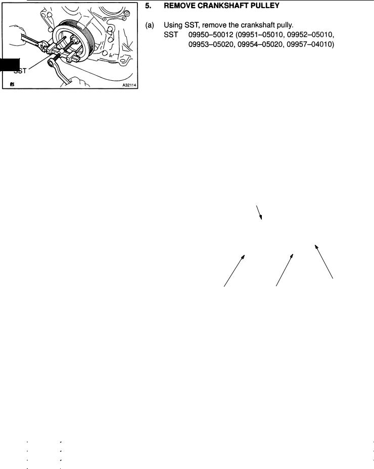
OVERHAUL
1.REMOVE GENERATOR BRUSH HOLDER ASSY
(a)Remove the 3 nuts and rear end cover.
(b)Remove the B terminal insulator.
A55648
(c)Remove the rear plate seal from the brush holder.
(d)Remove the 2 screws and brush holder.
(e)Remove the front seal plate from the rear frame.
A55649
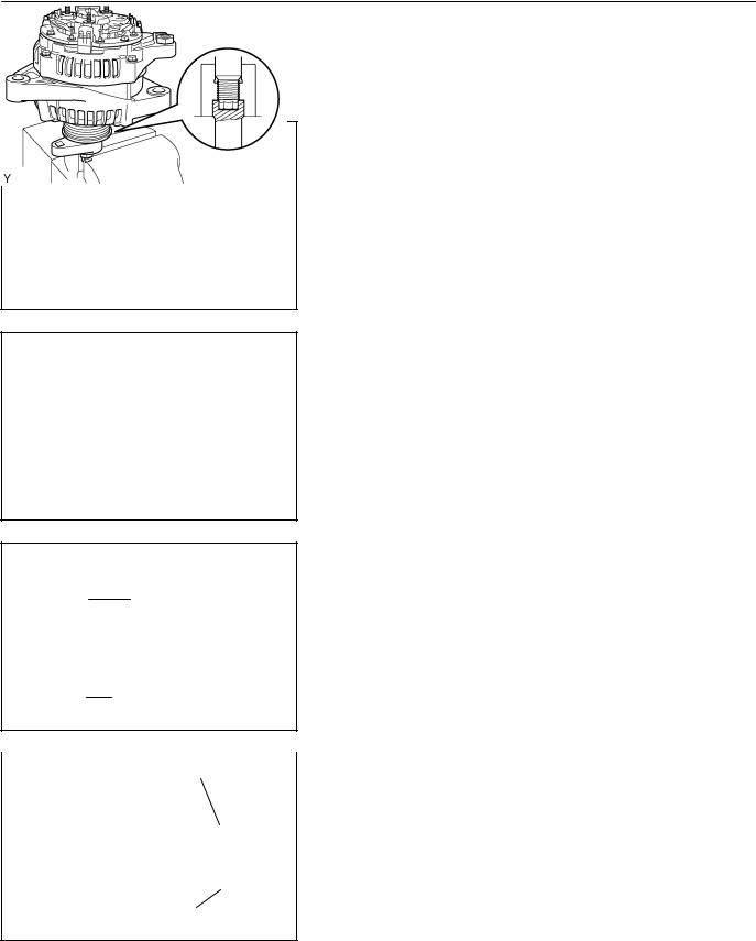
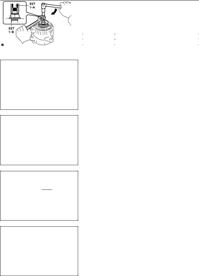
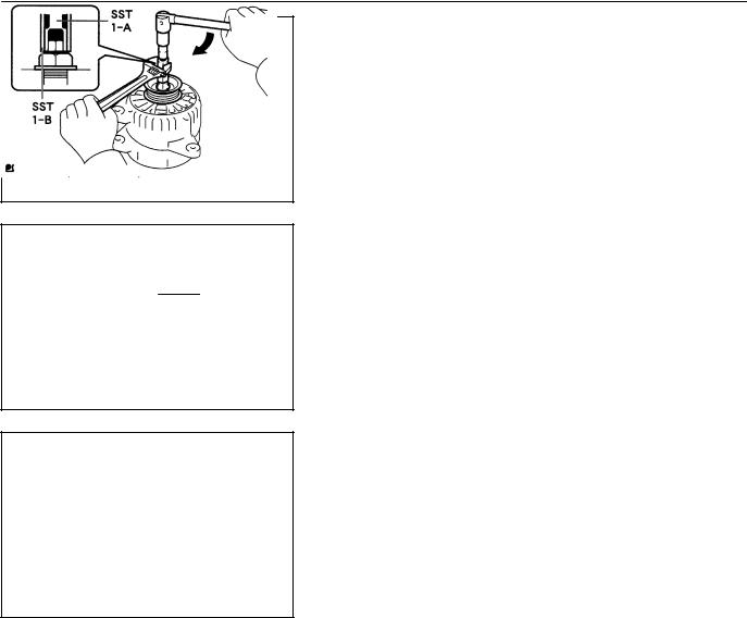
2.REMOVE GENERATOR W/CLUTCH PULLEY
(a)Set SST (A) and (B). SST 09820–63020
A55650
|
Rotor Shaft |
(b) Mount SST (A) in a vise. |
|
|
(c) Set the alternator to SST. |
||
|
NOTICE: |
||
|
At this time, make sure that the alternator and SST are per- |
||
|
pendicular to one another. |
SST (A)
A55651
1CD–FTV ENGINE REPAIR MANUAL (RM927E)

19–33
STARTING & CHARGING – GENERATOR ASSY(130A) (1CD–FTV)
(d)Insert the 3 tabs of SST (B) into the 3 holes on the pulley.
(e)To loosen the pulley, turn SST (B) in the direction shown in the illustration.
(f)Remove the alternator from SST.
(g)Remove the pulley from the rotor shaft.
A57794
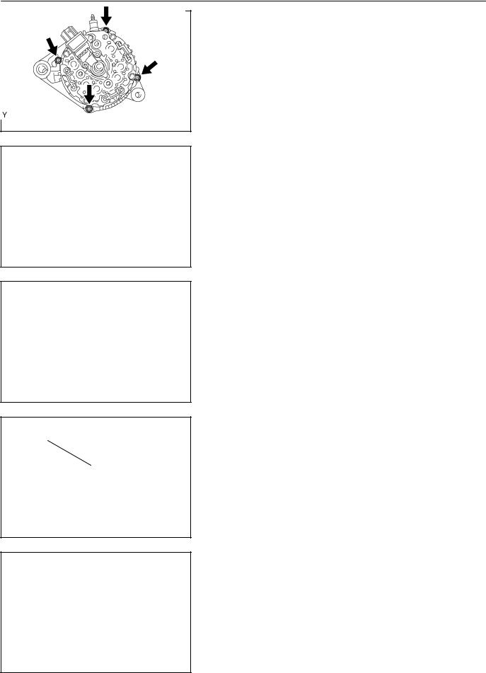
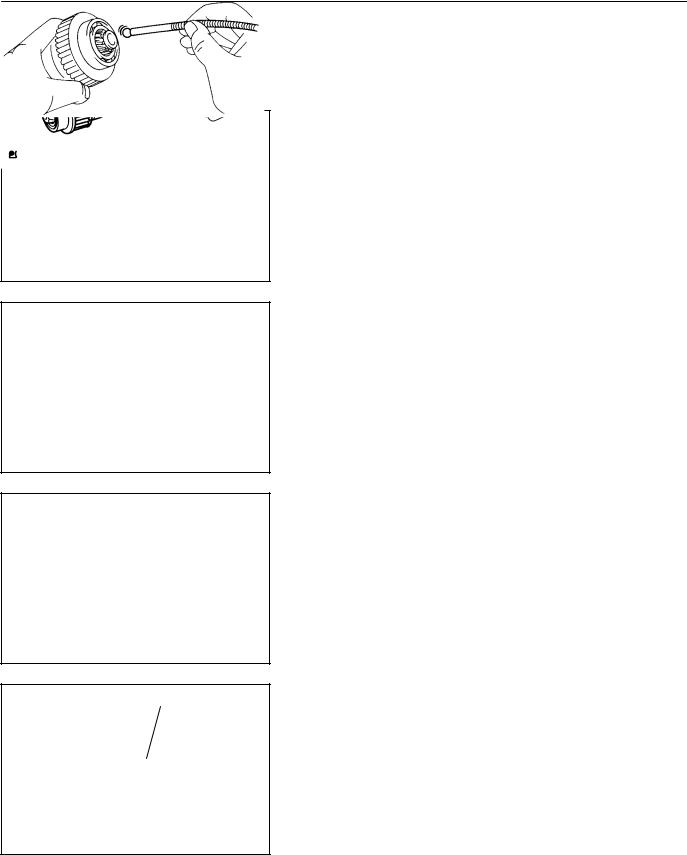
3.REMOVE GENERATOR ROTOR ASSY
(a)Remove the 4 through bolts.
A57795
|
SST |
(b) Using SST, remove the coil assembly. |
|
|
SST 09950–40011 (09951–04020, 09952–04010, |
||
|
09953–04020, 09954–04010, 09955–04071, |
||
|
09958–04011) |
(c)Remove the alternator washer.
(d)Remove the rotor from the drive end frame.
A57796
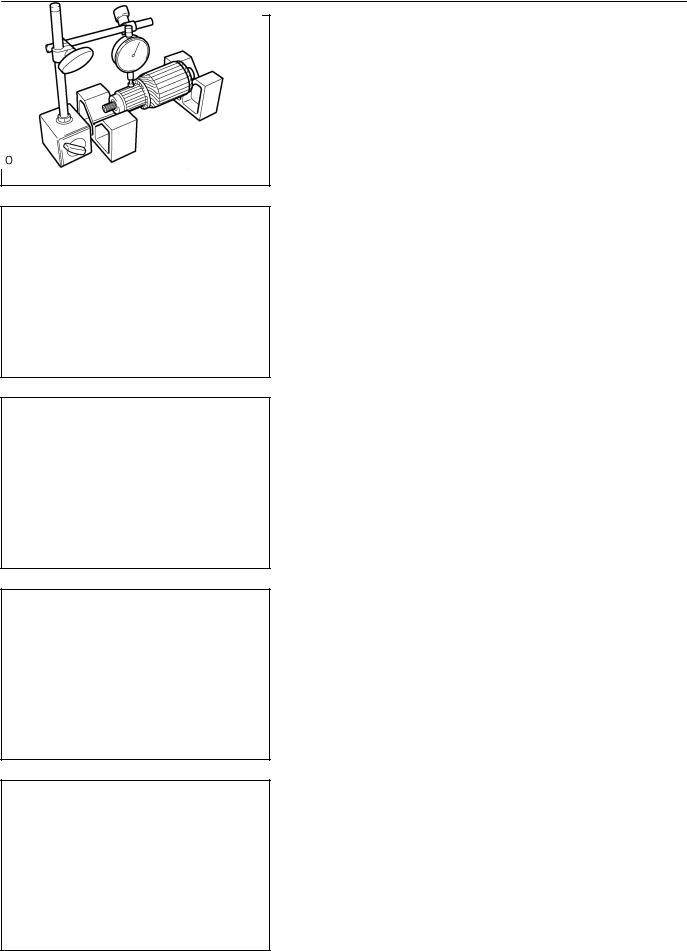
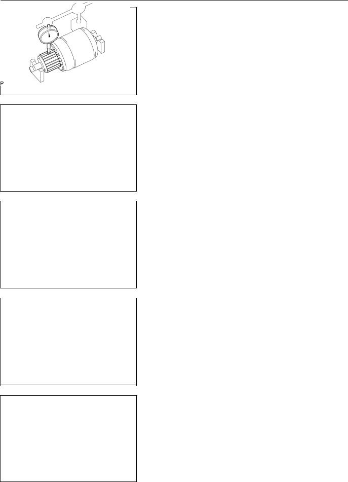
4.INSPECT GENERATOR ROTOR ASSY
(a)Using an ohmmeter, check that there is continuity between the slip rings.
Standard resistance: 2.3 – 2.7 W at 20_C (68_F)
A57797
(b)Using an ohmmeter, check that there is no continuity between the slip ring and rotor.
A57798
1CD–FTV ENGINE REPAIR MANUAL (RM927E)
19–34
Socket Wrench (29 mm)
STARTING & CHARGING – GENERATOR ASSY(130A) (1CD–FTV)
(c)Check that the slip rings are not rough or scored.
(d)Using vernier calipers, measure the slip ring diameter.
Standard diameter:
14.2 – 14.4 mm (0.5591 – 05669 in.)
Minimum diameter: 14.0 mm (0.551 in.)
A57799
5.INSPECT GENERATOR BRUSH HOLDER ASSY
(a)Using vernier calipers, measure the exposed brush length.
Standard exposed length: 10.5 mm (0.4134 in.) Minimum exposed length: 4.5 mm (0.177 in.)
HINT:
If the exposed length is less than minimum, replace the brush A57800 holder.
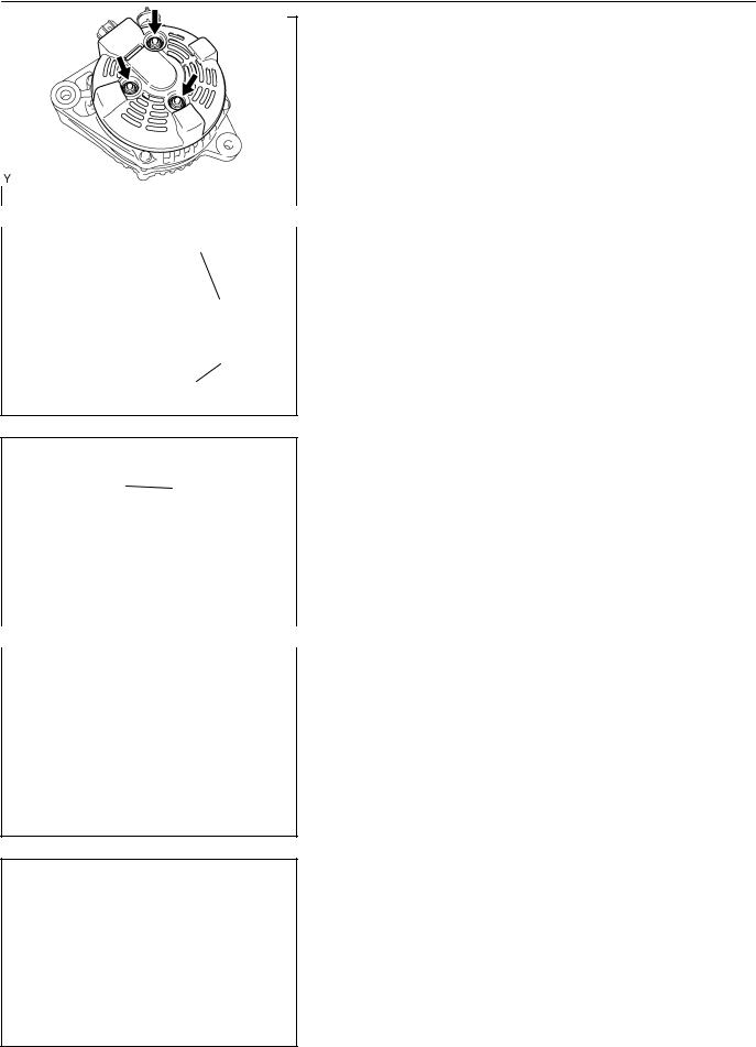
6.INSTALL GENERATOR ROTOR ASSY
(a)Place the drive end frame.
(b)Install the rotor to the drive end frame.
(c)Place the alternator washer on the rear bearing.
A57801
(d)Using a socket wrench (29 mm)and press, slowly press in the coil assembly.
A57802
(e)Install the 4 through bolts.
Torque: 5.8 NVm (59 kgfVcm, 51in.Vlbf)
A57795
1CD–FTV ENGINE REPAIR MANUAL (RM927E)
19–35
STARTING & CHARGING – GENERATOR ASSY(130A) (1CD–FTV)
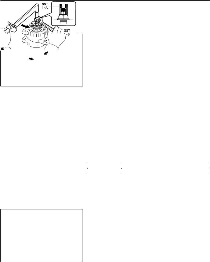
7.INSTALL GENERATOR W/CLUTCH PULLEY
|
SST (A) |
(a) Temporarily install the pulley to the rotor shaft. |
|||||
|
(b) Set SST (A) and (B). |
||||||
|
SST 09820–63020 |
||||||
|
SST (B) |
A55650 |
|||||
|
(c) Mount SST (A) in a vise. |
||||||
|
Rotor Shaft |
||||||
|
(d) Set the alternator to SST. |
||||||
|
NOTICE: |
||||||
|
At this time, make sure that the alternator and SST are per- |
||||||
|
pendicular to one another. |
SST (A)
A55651
(e)Insert the 3 tabs of SST (B) into the 3 holes on the pulley.
(f)To torque the pulley, turn SST (B) in the direction shown
|
SST (B) |
in the illustration. |
Torque: 111 NVm (1132 kgfVcm, 82 ftVlbf) for using SST
HINT:
Use a torque wrench with a fulcrum length of 50 cm (19.69 in.).
|
Turn |
(g) |
Remove the alternator from SST. |
|
|
(h) |
Install a new alternator pulley cap. |
||
|
A57803 |
|||
|
8. |
INSTALL GENERATOR BRUSH HOLDER ASSY |
||
|
Upward |
|||
(a)Place the front seal plate to the coil assembly.
(b)Install the brush holder with the 2 screws.
Torque: 1.8 NVm (18 kgfVcm, 16 in.Vlbf)
NOTICE:
Be careful of the holder installation direction.
(c)Place the plate seal on the brush holder.
A57804
(d)Install the rear end cover with the 3 nuts.
Torque: 4.6 NVm (47 kgfVcm, 41 in.Vlbf)
A55648
1CD–FTV ENGINE REPAIR MANUAL (RM927E)
19–31
STARTING & CHARGING – GENERATOR ASSY(130A) (1CD–FTV)
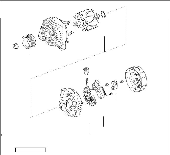
GENERATOR ASSY(130A) (1CD–FTV)
190AI–01
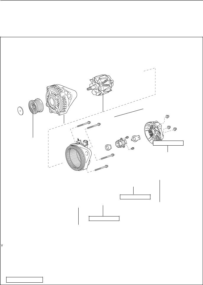
COMPONENTS
Generator Rotor Assy
Generator w/ Clutch Pulley
Drive End Frame Assy
4.6 (47, 41 in.·lbf)
|
Rear Seal Plate |
|||||||
|
Generator Brush |
|||||||
|
Alternator |
Pulley Cap |
Holder Assy |
|||||
|
Front Seal |
|||||||
|
Plate |
|||||||
1.8 (18, 16 in.·lbf)
Rear End Cover
Sub–Assy
5.8 (59, 51 in.·lbf)
Alternator Coil Assy
N·m (kgf·cm, ft·lbf) : Specified torque
A62720
1CD–FTV ENGINE REPAIR MANUAL (RM927E)
19–25
STARTING & CHARGING – GENERATOR ASSY(90A) (1CD–FTV)
19095–02
OVERHAUL
1.REMOVE GENERATOR PULLEY
SST 09820–63010 (09820–06010, 09820–06020)
HINT:
|
SST1 – A, B |
09820–06010 |
|
SST2 |
09820–06020 |
(a)Hold SST 1 – A with a torque wrench, and tighten SST 1
– B clockwise to the specified torque.
Torque: 39 NVm (400 kgfVcm, 29 ftVlbf)
NOTICE:
Check that SST is secured to the rotor shaft.
A38024
(b)Mount SST 2 in a vise.
(c)Insert SST 1 – A, B into SST 2, and attach the pulley nut to SST 2.
A38025
(d)To loosen the pulley nut, turn SST 1 – A in the direction shown in the illustration.
NOTICE:
SST 1 – A To prevent damage to the rotor shaft, do not loosen the pulley nut more than one–half of a turn.
(e)Remove the alternator form SST 2.
A38104
(f)Turn SST 1 – B, and remove SST 1 – A, B.
(g)Remove the pulley nut and pulley.
A38105
1CD–FTV ENGINE REPAIR MANUAL (RM927E)
19–26
STARTING & CHARGING – GENERATOR ASSY(90A) (1CD–FTV)
2.REMOVE GENERATOR BRUSH HOLDER ASSY
(a)Remove the nut and terminal insulator.
(b)Remove the bolt, 3 nuts, plate terminal and end cover.
(c)Remove the brush cover.
(d)Remove the 2 screws and brush holder.
3.REMOVE GENERATOR REGULATOR ASSY
(a)Remove the 3 screws and voltage regulator.
4. REMOVE GENERATOR HOLDER W/RECTIFIER
|
(a) Remove the 4 screws and rectifier holder. |
||
|
5. |
REMOVE ALTERNATOR RECTIFIRE END FRAME |
|
|
(a) |
Remove the rubber insulator. |
|
|
(b) |
Remove the seal plate. |
|
|
(c) |
Remove the 4 nuts. |
|
|
(d) |
Using bearing puller set, remove the rectifier end frame. |
|
SST
6.REMOVE GENERATOR ROTOR ASSY
(a)Remove the alternator washer from the rotor.
(b)Remove the rotor from drive end frame.
NOTICE:
Do not drop the rotor.
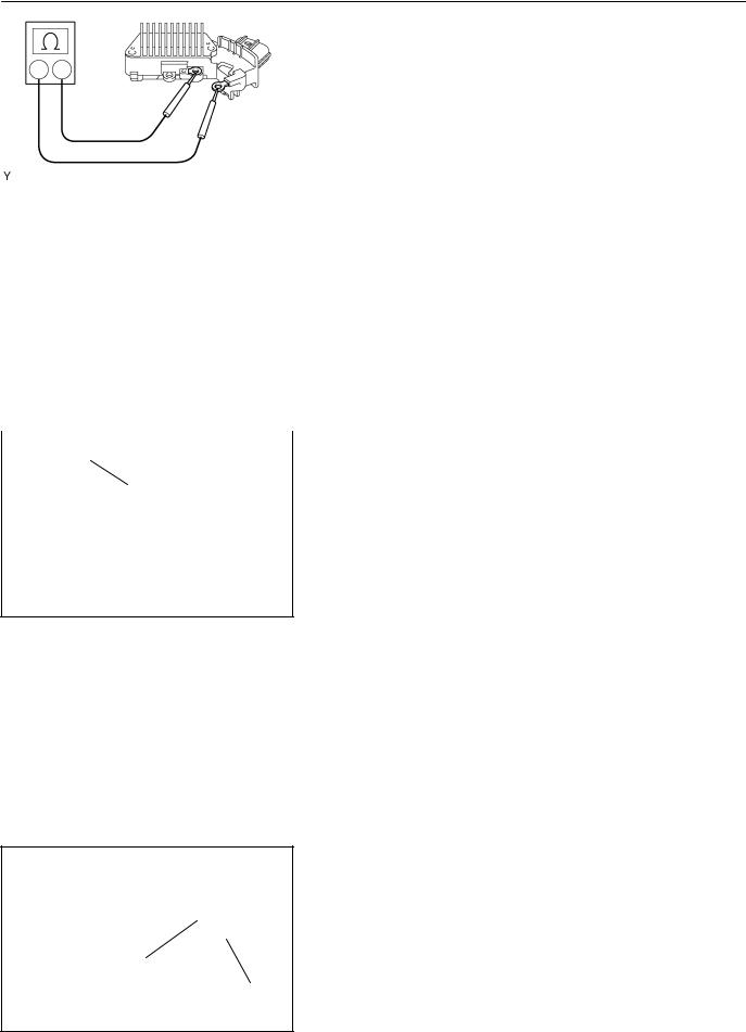
7.INSPECT GENERATOR REGULATOR ASSY
(a)Using an ohmmeter, check the continuity between terminals F and B.
Standard:
When the positive and negative poles between terminals F and B are exchanged, there is continuity in one way but no continuity in another way.
If the continuity is not as specified, replace the voltage regulator.
1CD–FTV ENGINE REPAIR MANUAL (RM927E)
![]()
19–27
STARTING & CHARGING – GENERATOR ASSY(90A) (1CD–FTV)
(b)Using an ohmmeter, check the continuity between terminals F and E.
Standard:
When the positive and negative poles between terminals F and E are exchanged, there is continuity in one
way but no continuity in another way.
If the continuity is not as specified, replace the voltage regulator.
8.INSPECT GENERATOR ROTOR ASSY
(a)Inspect rotor for open circuit.
(1)Using an ohmmeter, check that there is continuity
between the slip rings.
Standard resistance: 2.7 – 3.1 W at 20_C (68_F)
If there is no continuity, replace the rotor.
A38108
(b)Inspect rotor for ground.
(1)Using an ohmmeter, check that there is no continuity between the slip ring and rotor.
If there is continuity, replace the rotor.
A38109
(c)Inspect slip rings.
(1)Using vernier calipers, measure the slip ring diame-
ter.
Standard diameter: 14.2 – 14.4 mm (0.559 – 0.567 in.) Minimum diameter: 12.8 mm (0.504 in.)
If the diameter is less than minimum, replace the rotor.
A38110
|
B |
|
|
P1 P2 |
P4 |
|
B |
|
|
E |
! |
|
P1 |
P4 |
P2
P3 A36999
1CD–FTV ENGINE REPAIR MANUAL (RM927E)
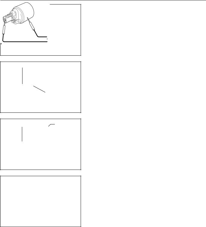
9.INSPECT GENERATOR HOLDER W/RECTIFIER
(a)Using an ohmmeter, connect one tester probe to the B or E terminal and the other to each rectifier terminal.
(b)Reverse the polarity of the tester probes and repeat step
(a).
(c)Check that one shows continuity and the other shows no continuity.

19–28
STARTING & CHARGING – GENERATOR ASSY(90A) (1CD–FTV)
10.INSPECT BRUSH
(a) Using vernier calipers, measure the exposed brush length.
Length
Standard exposed length:
9.5 – 11.5 mm (0.374 – 0.453 in.)
Minimum exposed length: 1.5 mm (0.059 in.)
If the exposed length is less than minimum, replace the brush holder assembly.
P13535
11.INSTALL GENERATOR ROTOR ASSY
(a)Install the generator rotor.
(b)Install the alternator washer to the rotor.
12.INSTALL ALTERNATOR RECTIFIRE END FRAME
|
17 mm |
(a) Using a 17 mm socket wrench and press, slowly press in |
|
|
Socket |
||
|
the rectifier end frame. |
||
|
Wrench |
||
A51920
|
A |
(b) Install the cord clip and 4 nuts. |
||
|
Torque: |
|||
|
B |
Nut A |
4.5 NVm (46 kgfVcm, 39 in.Vlbf) |
|
|
Nut B |
5.4 NVm (55 kgfVcm, 47 in.Vlbf) |
||
|
Cord Clip |
(c) Install the seal plate on the rectifier end frame. |
||
|
A |
|||
|
A |
A64533 |
||
|
(d) Install the 4 rubber insulators on the lead wires. |
|||
|
Inside |
NOTICE: |
Be careful of the rubber insulators installation direction.
A51921
13.INSTALL GENERATOR HOLDER W/RECTIFIER
(a)Install the rectifier holder while pushing it with the 4 screws.
Torque: 2.9 NVm (30 kgfVcm, 26 in.Vlbf)
1CD–FTV ENGINE REPAIR MANUAL (RM927E)
19–29
STARTING & CHARGING – GENERATOR ASSY(90A) (1CD–FTV)
14.INSTALL GENERATOR REGULATOR ASSY
(a)Install the 3 screws and voltage regulator.
Torque: 3.9 NVm (40 kgfVcm, 35 in.Vlbf)
15.INSTALL GENERATOR BRUSH HOLDER ASSY
(a)Install the 2 screws and brush holder.
Torque: 2.0 NVm (20 kgfVcm, 18 in.Vlbf)
NOTICE:
Be careful of the holder installation direction.
A51919
(b)Install the brush cover.
(c)Install the end cover and plate terminal with the bolt and 3 nuts.
Torque:
Nut 4.4 NVm (45 kgfVcm, 39 in.Vlbf) Bolt 3.9 NVm (39 kgfVcm, 35 in.Vlbf)
(d)Install the terminal insulator with the nut.
Torque: 4.1 NVm (42 kgfVcm, 36 in.Vlbf)
16.INSTALL GENERATOR PULLEY
SST 09820–63010 (09820–06010, 09820–06020)
HINT:
|
SST1 – A, B |
09820–06010 |
|
SST2 |
09820–06020 |
(a)Install the pulley to the rotor shaft by tightening the pulley nut by hand.
(b)Hold SST 1 – A with a torque wrench, and tighten SST 1
– B clockwise to the specified to torque.
Torque: 39 NVm (400 kgfVcm, 29 ftVlbf)
NOTICE:
Check that SST is secured to the pulley shaft.
A38024
1CD–FTV ENGINE REPAIR MANUAL (RM927E)
19–30
STARTING & CHARGING – GENERATOR ASSY(90A) (1CD–FTV)
(c)Mount SST 2 in a vise.
(d)Insert SST 1 – A, B into SST 2, and attach the pulley nut to SST 2.
A38025
(e)Tighten the pulley nut, turn SST 1 – A in the direction shown in the illustration.
Torque: 111 NVm (1,125 kgfVcm, 81 ftVlbf)
(f)Remove the alternator form SST 2.
(g)Turn SST 1 – B, and remove SST 1 – A, B.
(h)Turn the pulley, and check that the pulley moves smoothly.
A38105
1CD–FTV ENGINE REPAIR MANUAL (RM927E)
19–24
STARTING & CHARGING – GENERATOR ASSY(90A) (1CD–FTV)
GENERATOR ASSY(90A) (1CD–FTV)
19094–02
COMPONENTS
Rotor
Drive End Frame
Pulley
Alternator Washer
|
Rear End Cover |
||||
|
111 (1125, 81) |
||||
Brush Holder Cover
Brush Holder
Rectifier End Frame
Voltage Regulator
Rectifier Holder
N·m (kgf·cm, ft·lbf) : Specified torque
A59147
1CD–FTV ENGINE REPAIR MANUAL (RM927E)
19–18
STARTING & CHARGING – STARTER ASSY(2.2KW) (1CD–FTV)
1906H–02
OVERHAUL
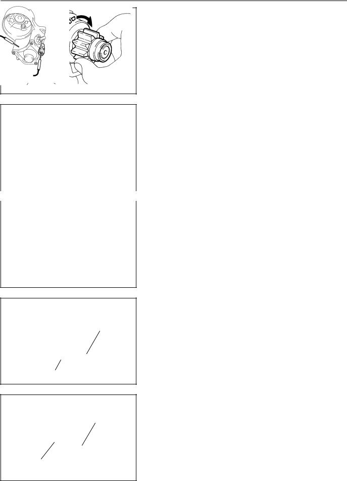
1.REMOVE STARTER YOKE ASSY
(a)Remove the nut, and disconnect the lead wire from the magnetic switch terminal.
(b)Remove the 2 through bolts.
(c)Pull out the yoke together with the armature from the magnetic switch.
A55633
2.REMOVE STARTER CLUTCH SUB–ASSY
(a)Remove the 2 bolts and drive housing.
B13607
(b)Remove the clutch from the drive housing
A55635
Magnetic Finger
(c) Using a magnetic finger, remove the ball from the clutch shaft hole.
A55636
1CD–FTV ENGINE REPAIR MANUAL (RM927E)
19–19
STARTING & CHARGING – STARTER ASSY(2.2KW) (1CD–FTV)
3.REMOVE STARTER BRUSH HOLDER ASSY
(a)Using a screwdriver, hold the spring back disconnect the brush from the brush holder. Disconnect the 4 brushers and remove the brush holder.
A51182
4.REMOVE STARTER ARMATURE ASSY
(a)Using a plastic–faced hammer, tap the yoke and remove the armature.
A51183
5.INSPECT STARTER ARMATURE ASSY
(a)Using an ohmmeter, check that there is continuity between the segments of the commutator.
A55637
(b)Using an ohmmeter, check that there is no continuity between the commutator and armature coil core.
A55638
(c)Place the commutator on V–blocks.
(d)Using a dial gauge, measure the circle runout.
Maximum circle runout: 0.05 mm (0.002 in.)
A51186
1CD–FTV ENGINE REPAIR MANUAL (RM927E)

19–20
STARTING & CHARGING – STARTER ASSY(2.2KW) (1CD–FTV)
(e)Using vernier calipers, measure the commutator diameter.
Standard diameter: 35 mm (1.378 in.) Minimum diameter: 34 mm (1.3386 in.)
A51187
(f)Check that the undercut depth is clean and free of foreign materials. Smooth out the edge.
Standard undercut depth: 0.7 mm (0.0276 in.) Minimum undercut depth: 0.2 mm (0.079 in.)
A51188
6.INSPECT STARTER YOKE ASSY
(a)Using an ohmmeter, check that there is continuity between the lead wire and field coil brush lead.
A55639
(b)Using an ohmmeter, check that there is no continuity between the field coil brush lead and yoke.
A55640
(c)Using vernier calipers, measure the brush length.
Standard length: 16.5 mm (0.6496 in.) Minimum length: 9 mm (0.3543 in.)
A55641
1CD–FTV ENGINE REPAIR MANUAL (RM927E)
19–21
STARTING & CHARGING – STARTER ASSY(2.2KW) (1CD–FTV)
7.INSPECT STARTER BRUSH HOLDER ASSY
(a)Using an ohmmeter, check that there is no continuity between the positive (+) and negative (–) brush holders.
A55642
(b)Using vernier calipers, measure the brush length.
Standard length: 16.5 mm (0.6496 in.) Minimum length: 9 mm (0.3543 in.)
|
A55643 |
|||||
|
8. |
INSPECT STARTER CLUTCH SUB–ASSY |
||||
|
Free |
|||||
|
(a) |
Rotate the pinion gear clockwise, and check that it turns |
||||
|
freely. Try to rotate the pinion gear counterclockwise and |
|||||
|
Lock |
check that it locks. |
A55624
Terminal 50
Terminal C
B55687
Terminal 50
9.INSPECT MAGNET STARTER SWITCH ASSY
(a)Using an ohmmeter, check that there is continuity between terminals 50 and C.
(b)Using an ohmmeter, check that there is continuity between terminal 50 and the switch body.
1CD–FTV ENGINE REPAIR MANUAL (RM927E)

19–22
STARTING & CHARGING – STARTER ASSY(2.2KW) (1CD–FTV)
10.INSTALL STARTER ARMATURE ASSY
(a)Apply grease to the armature bearings.
(b)Using a press, press in armature.
A51212
11.INSTALL STARTER BRUSH HOLDER ASSY
(a)Align the claw of the brush holder with the claw groove of the yoke.
(b)Place the brush on the yoke.
(c)Using a screwdriver, hold the brush spring back and connect the brush into the brush holder. Connect the 4 brushes.
A55483 NOTICE:
Check that the positive (+) lead wires are not grounded.
12.INSTALL STARTER CLUTCH SUB–ASSY
(a)Apply grease to the ball.
(b)Insert the ball into the clutch shaft hole.
A55646
(c)Place the clutch on the drive housing.
A55635
(d)Install the drive housing to the magnetic switch with the 2 bolts.
Torque: 9.3 NVm (95 kgfVcm, 82 in.Vlbf)
B13607
1CD–FTV ENGINE REPAIR MANUAL (RM927E)
![]()
19–23
STARTING & CHARGING – STARTER ASSY(2.2KW) (1CD–FTV)
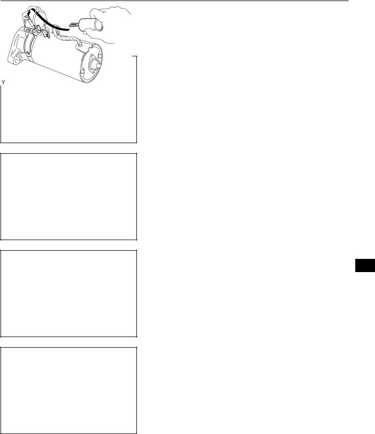
13.INSTALL STARTER YOKE ASSY
(a)Align the claws of the brush holder with the grooves of the magnetic switch, and install the yoke and armature.
(b)Align the punch mark of the yoke with the line of the magnetic switch.
A55647
(c)Install the yoke and armature with the 2 through bolts.
Torque: 12.7 NVm (130 kgfVcm, 9 ftVlbf)
(d)Connect the lead wire to terminal C with the nut.
Torque: 5.9 NVm (60 kgfVcm, 52 in.Vlbf)
A55633
1CD–FTV ENGINE REPAIR MANUAL (RM927E)
19–17
STARTING & CHARGING – STARTER ASSY(2.2KW) (1CD–FTV)
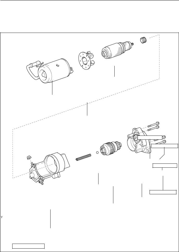
STARTER ASSY(2.2KW) (1CD–FTV)
190AH–01
COMPONENTS
Starter Armature Assy
Starter Yoke Assy
Starter Brush Holder Assy
12.7 (130, 9.0 )
9.3 (95, 82 in.·lbf)
12.7 (130, 9.0 )
Ball
|
Spring |
||||
|
5.9 (60, 52 in.·lbf) |
||||
9.3 (95, 82 in.·lbf)
Drive Housing
Starter Clutch Sub–Assy
Magnetic Switch
N·m (kgf·cm, ft·lbf) : Specified torque
A62713
1CD–FTV ENGINE REPAIR MANUAL (RM927E)
19–9
STARTING & CHARGING – STARTER ASSY(2.0KW) (1CD–FTV)
190AG–01
OVERHAUL
1.REMOVE MAGNET STARTER SWITCH ASSY
(a)Remove the nut, and disconnect lead wire from the magnet starter switch terminal.
(b)Remove the 3 screws, magnet starter switch and return spring.
A62722
(c)Pull the plunger, and disconnect the plunger hook from the upper side of the drive lever.
A62723
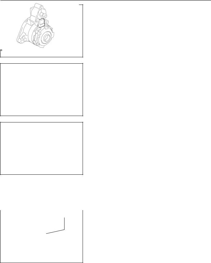
2.REMOVE STARTER COMMUTATOR END FRAM COVER
(a)Remove the 2 screws and end fram cover.
A62724
(b)Using a feeler gauge, measure the armature thrust clear-
ance between the lock plate and end frame.
Standard thrust clearance: 0.3 mm (0.012 in.) Maximum thrust clearance: 0.6 mm (0.024 in.)
If the thrust clearance is greater the than maximum, replace the thrust washer.
(c)Remove the lock plate and thrust washer.
A62725
1CD–FTV ENGINE REPAIR MANUAL (RM927E)
19–10
STARTING & CHARGING – STARTER ASSY(2.0KW) (1CD–FTV)
3.REMOVE STARTER YOKE ASSY
(a)Remove the 2 through bolts, and pull out the starter yoke together with the armature.
A62726
4.REMOVE STARTER COMMUTATOR END FRAM ASSY
(a)Using a screwdriver, pry out the commutator end frame.
A62727
5.REMOVE STARTER ARMATURE ASSY
A62728
6.REMOVE STARTER BRUSH HOLDER ASSY
|
Rubber Cushion |
7. |
REMOVE PLANET CARRIER SHAFT SUB–ASSY |
|
|
(a) |
Remove the rubber cushion. |
||
|
(b) |
Remove the planet carrier shaft and starter clutch assem- |
||
|
bly. |
A62729
8.REMOVE STARTER PINION DRIVE LEVER
1CD–FTV ENGINE REPAIR MANUAL (RM927E)
19–11
STARTING & CHARGING – STARTER ASSY(2.0KW) (1CD–FTV)
9.REMOVE STARTER CLUTCH SUB–ASSY
(a)Using a screwdriver, tap in the stop collar towards the starter clutch.
A62730
(b)Using a screwdriver, pry out the snap ring.
(c)Remove the stop collar from the shaft.
A62953
|
Continuity |
10. |
INSPECT STARTER ARMATURE ASSY |
|
(a) |
Using an ohmmeter, check that there is continuity be- |
|
|
tween the segments of the commutator. |
If there is no continuity between any segments, replace the armature.
A62961
|
No Continuity |
(b) Using an ohmmeter, check that there is no continuity be- |
|
tween the commutator and armature coil core. |
|
|
If there is continuity, replace the armature. |
|
|
(c) Check the commutator for the dirty and burnt surface. |
If the surface is dirty or burnt, correct with sandpaper (No.400) or a lathe.
A62962
(d)Place the commutator on V–blocks.
(e)Using a dial indicator, measure the circle runout.
Maximum circle runout: 0.03 mm (0.0012 in.)
If the circle runout is greater than maximum, correct it on a lathe.
A62963
1CD–FTV ENGINE REPAIR MANUAL (RM927E)

19–12
STARTING & CHARGING – STARTER ASSY(2.0KW) (1CD–FTV)
(f)Using vernier calipers, measure the commutator diame-
ter.
Standard diameter: 32.3 mm (1.272 in.) Minimum diameter: 30.5 mm (1.201 in.)
If the diameter is less than minimum, replace the armature.
A62964
(g)Check that the undercut depth is clean and free of foreign materials. Smooth out the edge.
Standard undercut depth: 0.9 mm (0.035 in.)
Minimum undercut depth: 0.3 mm (0.012 in.)
If the undercut depth is less than minimum, correct it with a hacksaw blade.
A62965
11.INSPECT STARTER BRUSH HOLDER ASSY
(a)Using vernier calipers, measure the brush length.
Standard length: 14.5 mm (0.571 in.)
Minimum length: 9.0 mm (0.354 in.)
If the length is less than minimum, replace the brush holder.
A62966
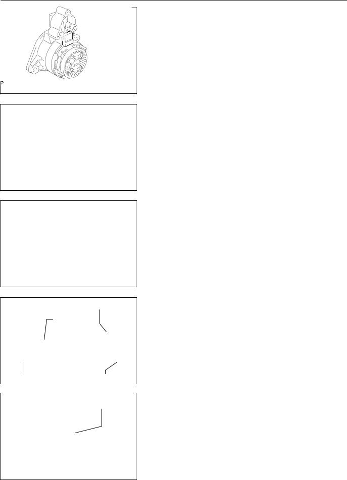
12.INSPECT STARTER CLUTCH SUB–ASSY
(a)Check the gear teeth on the starter clutch for wear or dam-
age.
If the gear is damaged, replace it.
If damaged, replace the clutch assembly. If damaged, also check the drive plate ring gear for wear or damage.
|
(b) Rotate the clutch pinion gear clockwise and check that it |
|||||
|
Free |
turns freely. Try to rotate the clutch pinion gear counter- |
||||
|
clockwise and check that it locks. |
|||||
|
Lock |
|||||
|
If necessary, replace the starter clutch. |
|||||
A62967
1CD–FTV ENGINE REPAIR MANUAL (RM927E)
19–13
STARTING & CHARGING – STARTER ASSY(2.0KW) (1CD–FTV)
13.INSPECT MAGNET STARTER SWITCH ASSY
(a)Push in the plunger and check that it returns quickly to its original position.
If necessary, replace the magnetic switch.
Return
A62968
Terminal 50
Terminal C
Continuity
A63797
(b)Using an ohmmeter, check that there is continuity between terminals 50 and C.
If there is no continuity, replace the magnetic switch.
(c)Using an ohmmeter, check that there is continuity be-
tween terminal 50 and the switch body.
If there is no continuity, replace the magnet starter switch.
14.INSPECT PLANET CARRIER SHAFT SUB–ASSY
(a) Turn the shaft, and check that it is not rough or worn. If it feels rough or worn, replace the planet carrier shaft.
A63799
15.INSTALL STARTER PINION DRIVE LEVER
16.INSTALL STARTER CLUTCH SUB–ASSY
(a)Apply grease to the bushing and spline of the starter clutch and planet carrier shaft.
1CD–FTV ENGINE REPAIR MANUAL (RM927E)
19–14
STARTING & CHARGING – STARTER ASSY(2.0KW) (1CD–FTV)
(b)Place the starter clutch and stop collar on the planet carrier shaft as shown in the illustration.
A63800
(c)Install a new snap ring to the planet carrier shaft groove.
(d)Using a vise, compress the snap ring.
(e)Check that the snap ring fits correctly.
A63801
(f)Using a screwdriver, tap the stop collar to slide it onto the snap ring.
A63802
Drive Lever
Knock
Pin Hole
|
Drive Housing |
Knock Pin A63803 |
|
Rubber Cushion |
17.INSTALL PLANET CARRIER SHAFT SUB–ASSY
(a)Set the planet carrier shaft and drive lever in position as shown in the illustration.
(b)Align the holes of the drive housing with the knock pins.
(c)Install the planet carrier shaft and starter clutch to the drive housing.
(d)Install the rubber cushion.
A63804
1CD–FTV ENGINE REPAIR MANUAL (RM927E)

|
STARTING & CHARGING – |
19–15 |
||||
|
STARTER ASSY(2.0KW) (1CD–FTV) |
|||||
|
18. |
INSTALL STARTER BRUSH HOLDER ASSY |
||||
|
SST |
|||||
|
(a) |
Install the 4 brush retainers and 4 brush springs to the |
||||
|
brush holder. |
|||||
|
(b) |
Using SST, install the 4 brushes to the brush holder. |
||||
|
SST |
09950–60010 (09951–00340) |
A63805
(c)Attach the brush holder to the armature.
SST
A63806
(d)Push the armature, and remove the SST.
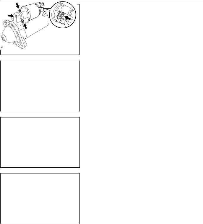
19.INSTALL STARTER YOKE ASSY
(a)Align the cushion rubber on the starter drive housing with the cutout of the starter yoke.
(b)Install the starter yoke and armature assembly.
A63808
(c)Align the commutator end frame with the brush holder rubber part as shown in the illustration.
(d)Install the commutator end frame with the 2 through bolts.
6.5N·m (66 kgf·cm, 58 in.·lbf)
A63809
1CD–FTV ENGINE REPAIR MANUAL (RM927E)
19–16
STARTING & CHARGING – STARTER ASSY(2.0KW) (1CD–FTV)
20.INSTALL STARTER COMMUTATOR END FRAM
COVER
(a)Install the thrust washer and lock plate.
(b)Check the armature thrust clearance between the lock plate and the end frame cover. (See page 19–9)
A63810
(c)Pack grease to the commutator end cover.
(d)Install the commutator end fram cover with the 2 screws.
1.7N·m (17 kgf·cm, 15 in.·lbf)
A62724
21.INSTALL MAGNET STARTER SWITCH ASSY
(a)Hang the plunger hook to the upper side of the drive lever.
(b)Install the return spring into the plunger.
A63811
(c)Install the return spring and magnet sarter switch with the 3 screws.
5.0N·m (51 kgf·cm, 44 in.·lbf)
(d)Connect the lead wire to the magnet starter switch terminal with the nut.
8.0N·m (82 kgf·cm, 71 in.·lbf)
A62722
1CD–FTV ENGINE REPAIR MANUAL (RM927E)

19–8
STARTING & CHARGING – STARTER ASSY(2.0KW) (1CD–FTV)
STARTER ASSY(2.0KW) (1CD–FTV)
190AF–01
COMPONENTS
|
Return Spring |
||||
|
8.0(82,71in.·lbf) |
||||
|
Plunger |
||||
|
Rubber Cushion |
||||
|
Magnet Stater |
Starter Pinion Drive Lever |
|||
|
Switch Assy |
Planet Carrier Shaft
Sub–assy
5.0(51,44in.·lbf)
|
Starter Clutch |
||||||||
|
Sub–assy |
||||||||
|
1.7(17,15in.·lbf) |
||||||||
|
Starter |
Thrust Washer |
|||||||
|
Commutator |
||||||||
|
End Fram |
||||||||
|
Cover |
||||||||
|
Lock Plate |
||||||||
|
6.5(66, 58in.·lbf) |
||||||||
|
Starter Commutator |
||||||||
|
End Frame Assy |
x 4 |
Brush Holder
Brush Retainer
Brush Spring
N·m (kgf·cm, ft·lbf) : Specified torque z Non–reusable part
Stop Collar
z Snap Ring
Starter Drive Housing
Assy
Starter Yoke
Assy
Starter Armature
Assy
A62721
1CD–FTV ENGINE REPAIR MANUAL (RM927E)

19–2
STARTING & CHARGING – STARTER ASSY(1.4KW) (1CD–FTV)
1906G–02
OVERHAUL
1.REMOVE STARTER YOKE ASSY
(a)Remove the nut, and disconnect the lead wire from the magnetic switch terminal.
(b)Remove the 2 through bolts.
(c)Pull out the yoke together with the armature from the magnetic switch.
A55610
2.REMOVE STARTER CLUTCH SUB–ASSY
(a)Remove the 2 bolts and drive housing.
A55611
(b)Remove the clutch from the drive housing.
A55612
|
Magnetic Finger |
(c) Using a magnetic finger, remove the ball from the clutch |
|
|
shaft hole. |
||
A55613
1CD–FTV ENGINE REPAIR MANUAL (RM927E)

19–3
STARTING & CHARGING – STARTER ASSY(1.4KW) (1CD–FTV)
3.REMOVE STARTER BRUSH HOLDER ASSY
(a)Remove the 2 screws and end frame from the yoke.
A55614
(b)Using a screwdriver, hold the spring back disconnect the brush from the brush holder. Disconnect the 4 brushers and remove the brush holder.
A51226
4.REMOVE STARTER ARMATURE ASSY
(a)Remove the armature from the yoke.
5.INSPECT STARTER ARMATURE ASSY
(a)Using an ohmmeter, check that there is continuity between the segments of the commutator.
A55615
(b)Using an ohmmeter, check that there is no continuity between the commutator and armature coil core.
A55616
1CD–FTV ENGINE REPAIR MANUAL (RM927E)

19–4
STARTING & CHARGING – STARTER ASSY(1.4KW) (1CD–FTV)
(c)Place the commutator on V–blocks.
(d)Using a dial gauge, measure the circle runout.
Maximum circle runout: 0.05 mm (0.002 in.)
A55617
(e)Using vernier calipers, measure the commutator diameter.
Standard diameter: 30 mm (1.1811 in.) Minimum diameter: 29 mm (1.1417 in.)
A55618
(f)Check that the undercut depth is clean and free of foreign materials. Smooth out the edge.
Standard undercut depth: 0.6 mm (0.024 in.) Minimum undercut depth: 0.2 mm (0.008 in.)
A51188
6.INSPECT STARTER YOKE ASSY
(a)Using an ohmmeter, check that there is continuity between the lead wire and field coil brush lead.
A55619
(b)Using an ohmmeter, check that there is no continuity between the field coil brush lead and yoke.
A55620
1CD–FTV ENGINE REPAIR MANUAL (RM927E)

19–5
STARTING & CHARGING – STARTER ASSY(1.4KW) (1CD–FTV)
(c)Using vernier calipers, measure the brush length.
Standard length: 15.5 mm (0.6102 in.) Minimum length: 8.5 mm (0.3346 in.)
A55621
7.INSPECT STARTER BRUSH HOLDER ASSY
(a)Using an ohmmeter, check that there is no continuity between the positive (+) and negative (–) brush holders.
A55622
(b)Using vernier calipers, measure the brush length.
Standard length: 15.5 mm (0.6102 in.) Minimum length: 8.5 mm (0.3346 in.)
A55623
|
Free |
8. |
INSPECT STARTER CLUTCH SUB–ASSY |
||
|
(a) |
Rotate the pinion gear clockwise, and check that it turns |
|||
|
freely. Try to rotate the pinion gear counterclockwise and |
||||
|
Lock |
check that it locks. |
A55624
9.INSPECT MAGNET STARTER SWITCH ASSY
(a)Using an ohmmeter, check that there is continuity between terminal 50 and C.
A55625
1CD–FTV ENGINE REPAIR MANUAL (RM927E)

19–6
STARTING & CHARGING – STARTER ASSY(1.4KW) (1CD–FTV)
(b)Using an ohmmeter, check that there is continuity between terminal 50 and the switch body.
Terminal 50
10.INSTALL STARTER ARMATURE ASSY
(a)Apply grease to the armature bearings and insert the armature into the yoke.
11.INSTALL STARTER BRUSH HOLDER ASSY
(a)Place the brush holder on the armature.
(b)Using a screwdriver, hold the brush spring back and connect the brush into the brush holder. Connect the 4 brushes.
NOTICE:
Check that the positive (+) lead wires are not grounded.
A51226
(c)Install the end frame to the yoke with the 2 screws.
Torque: 1.5 NVm (15 kgfVcm, 13 in.Vlbf)
A55614
12.INSTALL STARTER CLUTCH SUB–ASSY
(a)Apply grease to the ball.
(b)Insert the ball into the clutch shaft hole.
A55627
1CD–FTV ENGINE REPAIR MANUAL (RM927E)

19–7
STARTING & CHARGING – STARTER ASSY(1.4KW) (1CD–FTV)
(c)Place the clutch on the drive housing.
A55612
(d)Install the drive housing to the magnetic switch with the 2 bolts.
Torque: 5.9 NVm (60 kgfVcm, 52 in.Vlbf)
A55611
13.INSTALL STARTER YOKE ASSY
(a)Align the protrusion of the yoke with the cutout of the magnetic switch.
A55628
(b)Install the yoke and armature with the 2 through bolts.
Torque: 5.9 NVm (60 kgfVcm, 52 in.Vlbf)
(c)Connect the lead wire to terminal C with the nut.
Torque: 5.9 NVm (60 kgfVcm, 52 in.Vlbf)
A55610
1CD–FTV ENGINE REPAIR MANUAL (RM927E)

19–1
STARTING & CHARGING – STARTER ASSY(1.4KW) (1CD–FTV)
STARTER ASSY(1.4KW) (1CD–FTV)
190AE–01
COMPONENTS
Starter Armature Assy
Starter Yoke Assy
Starter Brush Holder Assy
5.9 (60, 52 in.·lbf)
Rear End Frame Cover
5.9 (60, 52 in.·lbf)
Ball
5.9 (60, 52 in.·lbf)
Drive Housing
|
Spring |
Starter Clutch Sub–Assy |
Magnetic Switch
N·m (kgf·cm, ft·lbf) : Specified torque
A62712
1CD–FTV ENGINE REPAIR MANUAL (RM927E)

17–1
LUBRICATION – OIL PUMP ASSY (1CD–FTV)
OIL PUMP ASSY (1CD–FTV)
1704C–02
INSPECTION
1.INSPECT OIL PUMP ASSY
(a)Inspect the rotors for tip clearance.
(1)Using a feeler gauge, measure the clearance between the drive and driven rotor tips.
Standard tip clearance:
0.08 – 0.16 mm (0.0031 – 0.0063 in.) Maximum tip clearance: 0.2 mm (0.0079 in.)
A55604
(b)Inspect the rotors for body clearance.
(1)Using a feeler gauge, measure the clearance between the driven rotor and body.
Standard body clearance:
0.1 – 0.17 mm (0.0039 – 0.0067 in.)
Maximum body clearance: 0.2 mm (0.0079 in.)
A55605
1CD–FTV ENGINE REPAIR MANUAL (RM927E)

16–1
COOLING – WATER PUMP ASSY (1CD–FTV)
WATER PUMP ASSY (1CD–FTV)
1606V–02
1.INSPECT WATER PUMP ASSY
(a)Visually check the drain hole for coolant leakage.
(b)Turn the pulley, and check that the water pump bearing moves smoothly and quietly.
1CD–FTV ENGINE REPAIR MANUAL (RM927E)
![]()
14–40
ENGINE MECHANICAL – CYLINDER BLOCK (1CD–FTV)
140DS–02
OVERHAUL
1.INSPECT CONNECTING ROD THRUST CLEARANCE
(a)Using a dial indicator, measure the thrust clearance while
moving the connecting rod back and forth.
Standard thrust clearance:
0.08 – 0.30 mm (0.0031 – 0.0118 in.)
Maximum thrust clearance: 0.40 mm (0.0157 in.)
If the thrust clearance is greater then maximum, replace the connecting rod assembly(s). If necessary, replace the crank-
A09477 shaft.
2.INSPECT CONNECTING ROD OIL CLEARANCE
(a)Check the matchmarks on the connecting rod and cap to ensure correct reassembly.
(b)Remove the 2 connecting rod cap bolts.
A09488
(c)Using 2 removed connecting rod cap bolts, remove the connecting rod cap and lower bearing by wiggling the
connecting rod cap right and left.
HINT:
Keep the lower bearing inserted with the connecting rod cap.
A09492
|
Plastigage |
(d) |
Clean the crank pin and bearing. |
|
|
(e) |
Check the crank pin and bearing for pits and scratches. |
||
|
If the crank pin or bearing is damaged, replace the bearings. If |
|||
|
necessary, replace the crankshaft. |
|||
|
(f) |
Lay a strip of plastigage across the crank pin. |
A09494
1CD–FTV ENGINE REPAIR MANUAL (RM927E)
 Loading…
- Кузов и салон
- Общая информация
- Силовой агрегат
- Трансмиссия
- Шасси, ходовая часть
- Электрооборудование
Данное руководство содержит информационные материалы по ремонту и обслуживанию автомобиля Toyota Corolla Verso 3 (2004-2009). Вы найдете инструкции по снятию и установке различных узлов и агрегатов Toyota Corolla Verso 3, схемы электрооборудования, справочные данные и реккомендации по уходу.

This webpage contains Toyota Corolla Verso 2004 Service And Repair Manual PDF used by Toyota garages, auto repair shops, Toyota dealerships and home mechanics.
With this Toyota Corolla Verso Workshop manual, you can perform every job that could be done by Toyota garages and mechanics from:
- changing spark plugs,
- brake fluids,
- oil changes,
- engine rebuilds,
- electrical faults
- and much more
The Toyota Corolla Verso 2004 Service And Repair Manual PDF includes:
- detailed illustrations,
- drawings,
- diagrams,
- step by step guides,
- explanations of Toyota Corolla Verso:
- service
- repair
- maintenance
PDF Document Details
: Toyota Corolla Verso 2004 Service And Repair Manual PDF