Keys to Quality Maintenance
Toyota Owner manuals and warranty information are the keys to quality maintenance for your vehicle. No need to hunt down a separate Toyota repair manual or Toyota service manual. From warranties on Toyota replacement parts to details on features, Toyota Owners manuals help you find everything you need to know about your vehicle, all in one place.
Detailed Toyota manuals and Toyota warranty information help with questions about your vehicle specifications and maintenance schedules. Plus, learn more about what your Toyota warranty coverage includes. What’s more, Toyota warranty information helps you identify your unique vehicle needs as well as plan future service visits. Select your Toyota model to learn more about the Toyota Warranty for your car, truck or SUV. Or, get the Toyota Manual for your Toyota ride free of charge using our Toyota Owners manual free download option.
Read More
Read Less
- Manuals
- Brands
- Toyota Manuals
- Automobile
- 2007 YARIS HATCHBACK
Manuals and User Guides for Toyota 2007 YARIS HATCHBACK. We have 4 Toyota 2007 YARIS HATCHBACK manuals available for free PDF download: Owner’s Manual, Wiring Diagrams, Brochure & Specs

Для ремонта любого авто никогда не будет лишней книга, в которой описаны различные тонкости.
Полный размер
Запчасти на фото: 1KRFE
Решил поделиться, может кому пригодится.
Книги:
1. Toyota YARIS с 2005 г.в. с бенз. дв. 1KR-FE, 2SZ-FE и 1NZ-FE.pdf
yadi.sk/i/w9csGwtNEEXM9w
Запчасти на фото: 1KRFE
2. Yaris_Manual_1999-2005
yadi.sk/d/8ETKxKOVdOm8dg
3. Yaris_autosoftos.com
yadi.sk/d/gfIDm0m0RRiFuA
4. Manual_yaris_echo_for_toyota-club.perm.ru
yadi.sk/d/8n-7pLMd8rO8-g
5. Подробное описание и технические характеристики двигателя 1KR-FE:
toyota-engine.ru/engines/…ristiki-dvigatelya-1kr-fe

Что я использовал из этих книг.
1. Как снять передний бампер.
Менял радиатор кондиционера, так как он был сильно забит (заломлены ребра) внизу от мух, камней, грязи.
После установки нового радиатора, сразу поставил сетку на верхнюю и нижнюю решетки.
2. Замена передних колодок тормозных.
3. Замена фильтра воздушного в салоне.
4. В планах замена маслосъёмных колпачков. Литература изучена, уже всё куплено. осталось только выбрать день.
Войдите или зарегистрируйтесь, чтобы писать комментарии, задавать вопросы и участвовать в обсуждении.

1
2007 YARIS HATCHBACK from Jan. ’06 Prod. (OM52700U)
OPERATION OF INSTRUMENTS AND
CONTROLS
Overview of instruments and controls
Instrument panel overview 2. . . . . . . . . . . . . . . . . . . . . . . . . . . . . . . . . . . . .
Instrument cluster overview 4. . . . . . . . . . . . . . . . . . . . . . . . . . . . . . . . . . . .
Indicator symbols on the instrument panel 6. . . . . . . . . . . . . . . . . . . . . . .
05 12.01
SECTION
1
−
1

The Toyota Yaris 2005-2007 repair book contains all the necessary information that will help the owner understand the device, scientific competent car care, timely maintenance
and proper repair.
Toyota Yaris repair manual is divided into chapters:
Vehicle device (general information and passport data of the vehicle are described);
Operating instructions (preparation for departure, recommendations for traffic safety);
Faults on the way (tips to help you in case of an unexpected trip);
Maintenance (detailed recommendations for all maintenance procedures);
Repair instructions (engine, transmission, chassis, steering, braking system, and assembly and disassembly work required during the Toyota Yaris repair process);
Electrical equipment (detailed troubleshooting manual, separate main units and detailed electrical diagrams of Toyota Yaris).
The book «Toyota Yaris since 2006. Guide to repair, maintenance and operation» is necessary so that diagnostics and repairs of Toyota Yaris can be done professionally and quickly
even by a car owner who still has little practical experience.
You can download a free Toyota Yaris repair manual in pdf format. It is enough to download it to your phone or tablet and you can use it in any situation on the road.
2005 Toyota Yaris RELAY LOCATIONS Download
2005 Toyota Yaris ELECTRICAL WIRING ROUTING/GROUND POINT Download
2005 Toyota Yaris CONNECTOR LIST Download
2005 Toyota Yaris SYSTEM CIRCUITS Download
2005 Toyota Yaris OVERALL ELECTRICAL WIRING DIAGRAM Download
1NZ-FE ENGINE – GENERAL Download
1NZ-FE ENGINE – CAMSHAFT Download
1NZ-FE ENGINE – CYLINDER HEAD Download
1NZ-FE ENGINE – DRIVE BELT Download
1NZ-FE ENGINE – ASSEMBLY Download
1NZ-FE ENGINE – UNIT Download
1NZ-FE ENGINE – CHARGING Download
1NZ-FE ENGINE – COOLING Download
1NZ-FE ENGINE – EMISSION CONTROL Download
1NZ-FE ENGINE – CONTROL SYSTEM Download
1NZ-FE ENGINE – EXHAUST Download
1NZ-FE ENGINE – FUEL Download
1NZ-FE ENGINE – IGNITION Download
1NZ-FE ENGINE – LUBRICATION Download
1NZ-FE ENGINE – STARTING Download
2007 Toyota Yaris AIR CONDITIONING Download
2007 Toyota Yaris AUDIO / VISUAL Download
2007 Toyota Yaris AXLE Download
2007 Toyota Yaris BRAKE CONTROL Download
2007 Toyota Yaris BRAKE Download
2007 Toyota Yaris CAN COMMUNICATION Download
2007 Toyota Yaris CLUTCH Download
2007 Toyota Yaris CRUISE CONTROL Download
2007 Toyota Yaris DOOR LOCK Download
2007 Toyota Yaris DRIVE SHAFT Download
2007 Toyota Yaris ENGINE HOOD / DOOR Download
2007 Toyota Yaris ENGINE IMMOBILISER Download
2007 Toyota Yaris EXTERIOR Download
2007 Toyota Yaris HORN Download
2007 Toyota Yaris INSTRUMENT PANEL Download
2007 Toyota Yaris INTERIOR Download
2007 Toyota Yaris INTRODUCTION Download
2007 Toyota Yaris LIGHTING Download
2007 Toyota Yaris MAINTENANCE Download
2007 Toyota Yaris METER Download
2007 Toyota Yaris MIRROR Download
2007 Toyota Yaris PARKING BRAKE Download
2007 Toyota Yaris POWER STEERING Download
2007 Toyota Yaris PREPARATION Download
2007 Toyota Yaris SEAT BELT Download
2007 Toyota Yaris SEAT BELT 2 Download
2007 Toyota Yaris SERVICE SPECIFICATIONS Download
2007 Toyota Yaris SUPPLEMENTAL RESTRAINT SYSTEM Download
2007 Toyota Yaris STEERING COLUMN Download
2007 Toyota Yaris SUSPENSION Download
2007 Toyota Yaris THEFT DETERRENT Download
2007 Toyota Yaris TIRE AND WHEEL Download
2007 Toyota Yaris U340E AUTOMATIC TRANSAXLE Download
2007 Toyota Yaris C50 MANUAL TRANSAXLE Download
2007 Toyota Yaris WINDSHIELD / WINDOW GLASS Download
2007 Toyota Yaris WIPER AND WASHER Download
2007 Toyota Yaris ELECTRICAL WIRING DIAGRAM (EM01V0U) Download
2007 Toyota Yaris COLLISION Download
2007 Toyota Yaris OWNER’S MANUAL Download
Руководство на английском языке по техническому обслуживанию и ремонту автомобилей Toyota Echo и Toyota Yaris 2001 года выпуска.
- Автор: —
- Издательство: Toyota Motor Corporation
- Год издания: 2003
- Страниц: —
- Формат: PDF
- Размер: 16,2 Mb
Сборник руководств на английском языке по техническому обслуживанию и ремонту автомобиля Toyota Yaris с 2005 года выпуска.
- Автор: —
- Издательство: Toyota Motor Corporation
- Год издания: —
- Страниц: —
- Формат: PDF
- Размер: 206,6 Mb

Руководство на английском языке по техническому обслуживанию и ремонту автомобиля Toyota Vitz и Toyota Yaris 2005-2011 годов выпуска.
- Автор: —
- Издательство: Motorist
- Год издания: —
- Страниц: 6553
- Формат: PDF
- Размер: —

Руководство по техническому обслуживанию и ремонту автомобиля Toyota Yaris 1999-2005 годов выпуска с бензиновыми двигателями.
- Автор: —
- Издательство: Алфамер
- Год издания: —
- Страниц: 288
- Формат: —
- Размер: —
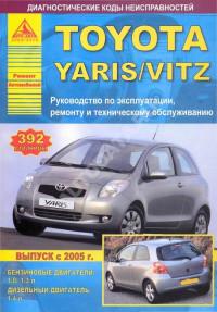
уководство по техническому обслуживанию и ремонту автомобилей Toyota Vitz и Toyota Yaris с 2005 года выпуска с бензиновыми и дизельными двигателями.
- Автор: —
- Издательство: Арго-Авто
- Год издания: —
- Страниц: 392
- Формат: —
- Размер: —
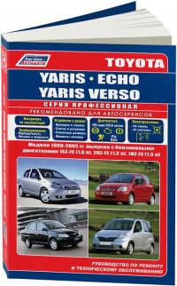
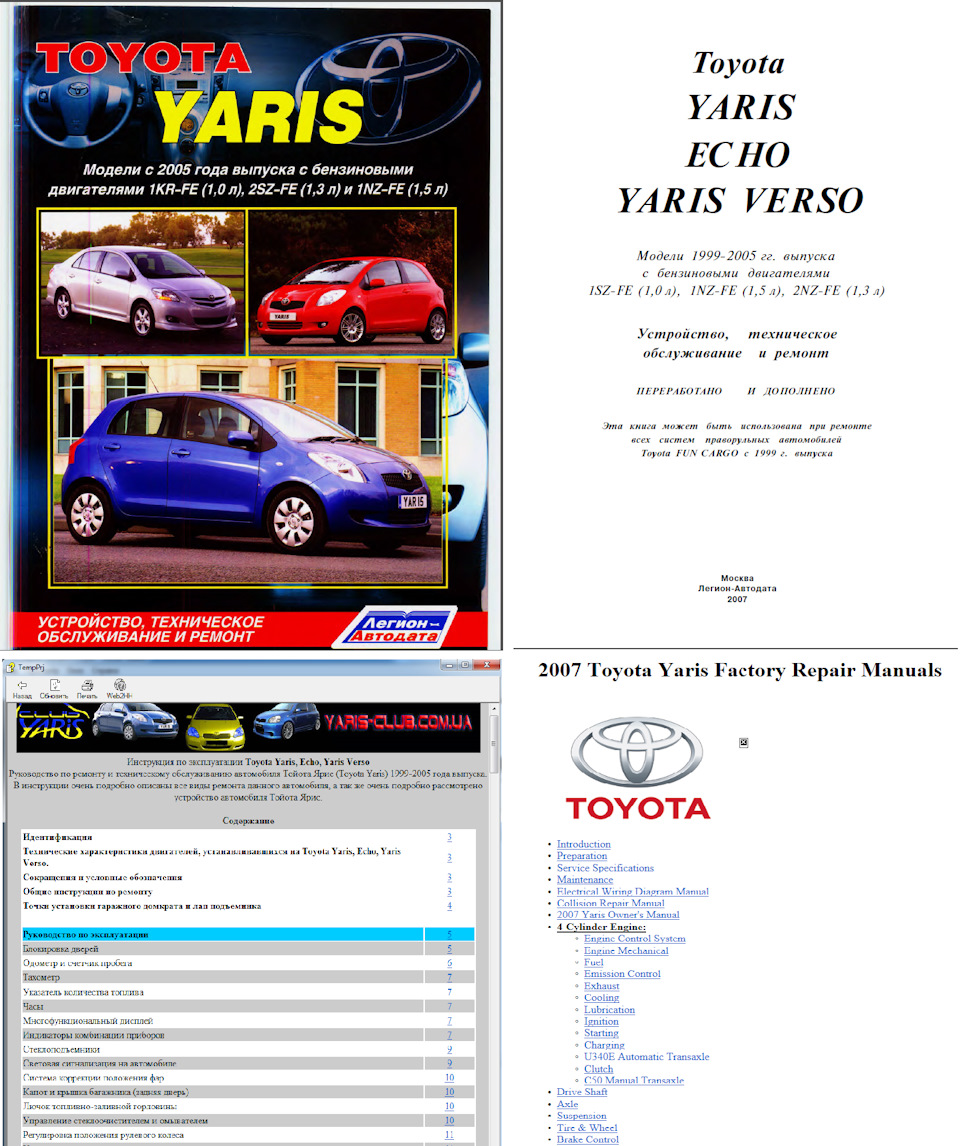
Руководство по техническому обслуживанию и ремонту автомобилей Toyota Echo/Yaris/Yaris Verso 1999-2005 годов выпуска с бензиновыми двигателями объемом 1,0/1,3/1,5 л.
- Автор: —
- Издательство: Легион-Автодата
- Год издания: —
- Страниц: 400
- Формат: —
- Размер: —

Руководство по техническому обслуживанию и ремонту автомобиля Toyota Yaris с 2005 года выпуска с бензиновыми двигателями объемом 1,0/1,3/1,5 л.
- Автор: —
- Издательство: Легион-Автодата
- Год издания: 2009
- Страниц: 519
- Формат: —
- Размер: —
Мультимедийное руководство по эксплуатации, техническому обслуживанию и ремонту автомобилей Toyota Echo/Yaris/Yaris Verso 1999-2005 годов выпуска.
- Автор: —
- Издательство: —
- Год издания: —
- Страниц: —
- Формат: CHM
- Размер: 36,7 Mb
Руководство по техническому обслуживанию и ремонту автомобилей Toyota Echo/Yaris/Yaris Verso/Vitz с 2006 года выпуска.
- Автор: —
- Издательство: Монолит
- Год издания: —
- Страниц: 304
- Формат: —
- Размер: —

![]()
|
U340E AUTOMATIC TRANSAXLE – AUTOMATIC TRANSAXLE SYSTEM |
AX–1 |
AUTOMATIC TRANSAXLE
SYSTEM
PRECAUTION
NOTICE:
•Perform the RESET MEMORY (AT initialization) when replacing the automatic transaxle assembly, engine assembly or ECM (See page AX-14).
•Perform the REGISTRATION (VIN registration) when
replacing the ECM (See page ES-13).
HINT:
The RESET MEMORY cannot be completed by only disconnecting the battery cable.
CAUTION:
When using compressed air, always aim away from yourself to prevent Automatic Transmission Fluid (ATF) or kerosene from spraying on your face.
NOTICE:
•The automatic transaxle is composed of high precision parts which need careful inspection before reassembly. Even a small nick could cause fluid leakage or affect the performance. The instructions here are organized so that you work on only one component group at a time. This will help avoid confusion caused by similar-looking parts of different
sub-assemblies being on your workbench at the same time. The component groups are inspected and repaired from the converter housing side. As far as
possible, complete the inspection, repair and AX reassembly before proceeding to the next component group. If a defect is found in a certain component
group during reassembly, inspect and repair that group immediately. If a component group cannot be assembled because some parts are on order, be sure to keep all parts of the group in a separate container while proceeding with disassembly, inspection, repair and reassembly of other component groups.
•When changing the automatic transmission fluid, use only «Toyota Genuine ATF WS» (ATF JWS3324 or NWS9638).
•All disassembled parts should be washed clean and any fluid passages and holes should be blown through with compressed air.
•Dry all parts with compressed air. Never use a shop rag or a piece of cloth to dry them.
•Only recommended ATF or kerosene should be used for cleaning.
•After cleaning, the parts should be arranged in the correct order for efficient inspection, repair, and reassembly.
•When disassembling a valve body, be sure to match each valve with the corresponding spring.

U340E AUTOMATIC TRANSAXLE – AUTOMATIC TRANSAXLE SYSTEM
•New brake and clutch discs that are to be used for replacement must be soaked in ATF for at least 15 minutes before reassembly.
•All oil seal rings, clutch discs, clutch plates, rotating parts, and sliding surfaces should be coated with ATF prior to reassembly.
•All gaskets and rubber O-rings should be replaced with new ones.
•Do not apply adhesive cements to gaskets or similar parts.
•Make sure that the ends of snap rings are not aligned with any cutouts and are installed in the grooves correctly.
•When replacing a worn bushing, the sub-assembly containing the bushing must also be replaced.
•Check thrust bearings and races for wear and damage. Replace them as necessary.
•When working with FIPG material, you must observe the following:
–Using a razor blade and a gasket scraper, remove all the old packing (FIPG) material from the gasket surface.
–Clean both sealing surfaces with a non-residue solvent.
–Parts must be reassembled within 10 minutes of application. Otherwise, the packing (FIPG) material must be removed and reapplied.

|
U340E AUTOMATIC TRANSAXLE – AUTOMATIC TRANSAXLE SYSTEM |
AX–3 |
||
|
DEFINITION OF TERMS |
|||
|
Term |
Definition |
||
|
Monitor description |
Description of what the ECM monitors and how it detects malfunctions (monitoring purpose and its details). |
||
|
Related DTCs |
A group of diagnostic trouble codes that are output by the ECM based on the same malfunction detection |
||
|
logic. |
|||
|
Preconditions that allow the ECM to detect malfunctions. |
|||
|
Typical enabling conditions |
With all preconditions satisfied, the ECM sets the DTC when the monitored value(s) exceeds the |
||
|
malfunction threshold(s). |
|||
|
The priority order that is applied to monitoring, if multiple sensors and components are used to detect the |
|||
|
Sequence of operation |
malfunction. |
||
|
While one sensor is being monitored, the next sensor or component is not monitored until the current |
|||
|
monitoring is concluded. |
|||
|
Required sensor/components |
The sensors and components that are used by the ECM to detect malfunctions. |
||
|
The number of times that the ECM checks for malfunctions per driving cycle. |
|||
|
Frequency of operation |
«Once per driving cycle» means that the ECM detects malfunctions only one time during a single driving |
||
|
cycle. |
|||
|
«Continuous» means that the ECM detects malfunctions every time the enabling conditions are met. |
|||
|
Duration |
The minimum time that the ECM must sense a continuous deviation in the monitored value(s) before |
||
|
setting a DTC. This timing begins when the typical enabling conditions are met. |
|||
|
Malfunction thresholds |
Beyond this value, the ECM concludes that there is a malfunction and sets a DTC. |
||
|
MIL illumination timing after a defect is detected. |
|||
|
«Immediate» means that the ECM illuminates the MIL the instant the ECM determines that there is a |
|||
|
MIL operation |
malfunction. |
||
|
«2 driving cycle» means that the ECM illuminates the MIL if the same malfunction is detected again in the |
|||
|
next driving cycle. |
|||
|
Normal operating ranges of sensors and solenoids under normal driving conditions. |
|||
|
Component operating range |
Use these ranges as references. |
||
|
They cannot be used to judge if a sensor or solenoid is defective or not. |
|||
AX

|
AX–4 |
U340E AUTOMATIC TRANSAXLE – AUTOMATIC TRANSAXLE SYSTEM |
PARTS LOCATION
|
COMBINATION METER |
|||
|
— MIL (MALFUNCTION INDICATOR LAMP) |
|||
|
STOP LIGHT SWITCH |
|||
|
SHIFT LOCK CONTROL ECU |
|||
|
DLC3 |
|||
|
(DATA LINK CONNECTOR 3) |
|||
|
TRANSMISSION WIRE |
ECM |
VEHICLE SPEED SENSOR |
|
|
(ATF TEMPERATURE SENSOR) |
|||
|
AX |
TRANSMISSION REVOLUTION |
||
|
SENSOR (SPEED SENSOR (NT)) |
|||
|
PARK / NEUTRAL |
|||
|
POSITION SWITCH |
|||
|
SHIFT SOLENOID VALVE S2 |
SHIFT SOLENOID VALVE SLU |
||
|
SHIFT SOLENOID VALVE SLT |
|||
|
SHIFT SOLENOID VALVE S1 |
|||
|
SHIFT SOLENOID VALVE ST |
|||
|
C130143E01 |
|
U340E AUTOMATIC TRANSAXLE – AUTOMATIC TRANSAXLE SYSTEM |
AX–5 |
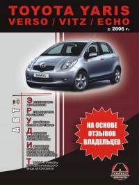
SYSTEM DIAGRAM
The configuration of the electronic control system in the
U340E automatic transaxle is as shown in the following chart.
|
ECM |
Stop Light Switch |
|||
|
ST1- |
STOP |
|||
|
STP |
Stop Light |
|||
|
IGN |
||||
|
To IG2 Relay |
IGSW |
Shift Lock Control ECU |
||
|
STAR |
||||
|
ODMS |
||||
|
To Ignition Switch |
||||
|
To Gauge Fuse |
||||
|
Park/Neutral Position Switch |
Park/Neutral Position Switch |
|||
|
P |
||||
|
ST |
R |
|||
|
STA |
N |
|||
|
D |
||||
|
Starter |
||||
|
2 |
||||
|
ST |
L |
AX |
||
|
ETCS |
||||
|
+BM |
Electronically Controlled Transmission |
|||
|
Solenoid |
||||
|
EFI |
Shift Solenoid Valve SLU |
|||
|
BATT |
SLU+ |
|||
|
SLU- |
||||
|
To C/OPN Relay |
+B |
Shift Solenoid Valve SLT |
||
|
SLT+ |
||||
|
+B2 |
SLT- |
Shift Solenoid Valve S1 |
||
|
MAIN |
MREL |
|||
|
EFI |
S1 |
|||
|
Shift Solenoid Valve S2 |
||||
|
Battery |
E1 |
S2 |
||
|
Shift Solenoid Valve ST |
||||
|
E01 |
||||
|
E02 |
ST |
|||
|
THO1 |
||||
|
ETHO |
||||
|
ATF Temperature Sensor |
||||
|
C130145E01 |
|
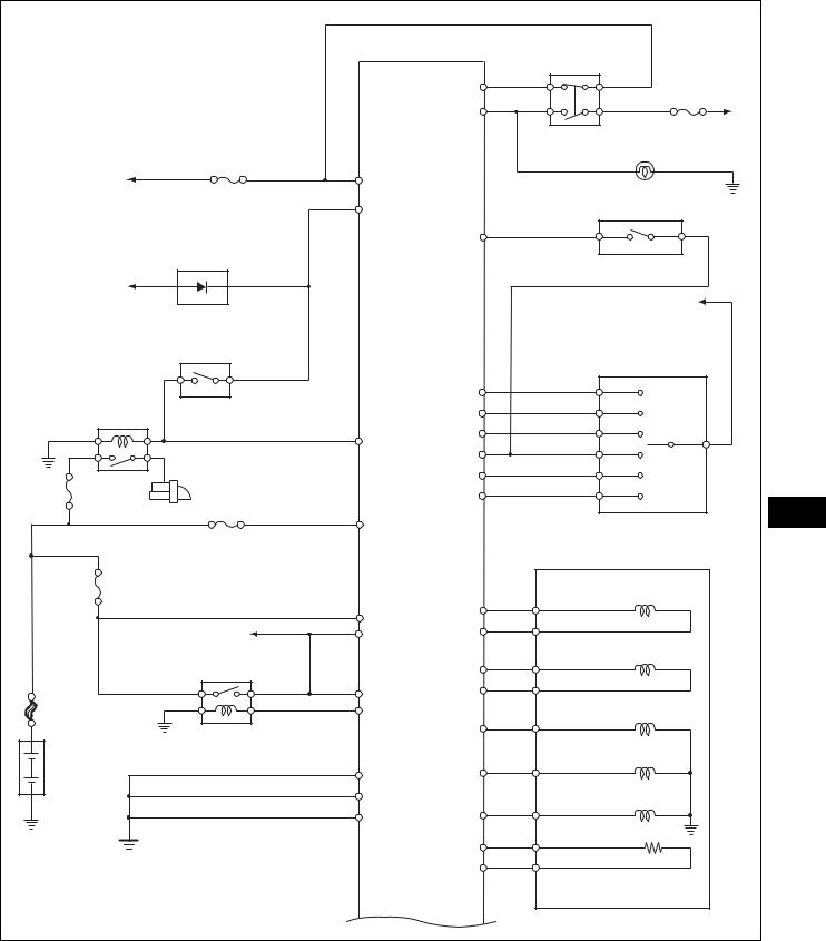
AX–6 |
U340E AUTOMATIC TRANSAXLE – AUTOMATIC TRANSAXLE SYSTEM |
|
To MET Fuse |
Transmission Revolution Sensor |
|
(Speed Sensor NT) |
|
|
Combination Meter |
NT+ |
|
NT- |
|
|
W |
|
|
SPD |
|
|
TACH |
|
|
To ECU-IG |
DLC3 |
|
TC |
|
|
Fuse |
|
|
CANH |
|
|
Vehicle Speed Sensor |
CANL |
|
To CAN BUS |
|
|
AX |
C130144E01 |

|
U340E AUTOMATIC TRANSAXLE – AUTOMATIC TRANSAXLE SYSTEM |
AX–7 |
SYSTEM DESCRIPTION
1.SYSTEM DESCRIPTION
(a)The ECT (Electronic Controlled automatic Transmission/Transaxle) is an automatic transmission/transaxle that electronically controls shift timing using the ECM. The ECM detects electrical signals that indicate engine and driving conditions, and controls the shift point, based on driver habits and road conditions. As a result, fuel efficiency and power transmission/transaxle performance are improved.
Shift shock has been reduced by controlling the engine and transmission simultaneously.
In addition, the ECT has features such as the following:
•Diagnostic function
•Fail-safe function when a malfunction occurs
AX
|
AX–8 |
U340E AUTOMATIC TRANSAXLE – AUTOMATIC TRANSAXLE SYSTEM |
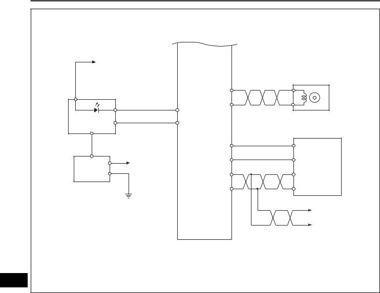
HOW TO PROCEED WITH TROUBLESHOOTING
HINT:
• The ECM of this system is connected to the CAN communication system. Therefore, before starting troubleshooting, be sure to check that there is no trouble in the CAN communication system.
• The intelligent tester can be used in steps 3, 4, 6, and 9.
1Vehicle Brought to Workshop
NEXT
2Customer Problem Analysis
NEXT
3Connect Intelligent Tester to DLC3
NEXT
4Check and Clear DTCs and Freeze Frame Data
|
HINT: |
||||
|
(See page AX-25). |
||||
|
AX |
||||
|
NEXT |
||||
|
5 |
Visual Inspection |
|||
|
NEXT |
||||
|
6 |
Setting Check Mode Diagnosis |
|||
|
HINT: |
||||
|
(See page AX-26). |
NEXT
7 Problem Symptom Confirmation
HINT:
(See page AX-9).

 Symptom does not occur: Go to step 8
 Symptom occurs: Go to step 9
|
U340E AUTOMATIC TRANSAXLE – AUTOMATIC TRANSAXLE SYSTEM |
AX–9 |
8 Symptom Simulation
HINT:
(See page IN-26).
NEXT
9 DTC Check
HINT:
(See page AX-25).

 DTC is not output: Go to step 10
 DTC is output: Go to step 17
10 Basic Inspection
HINT:
(See page AX-93, AX-106 and AX-107).
OK
11 Mechanical System Test
HINT:
(See page AX-11).
OK
12 Hydraulic Test
HINT:
(See page AX-13).
AX
OK
13 Manual Shifting Test
HINT:
(See page AX-14).
OK
|
AX–10 |
U340E AUTOMATIC TRANSAXLE – AUTOMATIC TRANSAXLE SYSTEM |
14 Problem Symptoms Table Chapter 1
HINT:
(See page AX-17).
OK
15 Problem Symptoms Table Chapter 2
HINT:
(See page AX-17).
NEXT
16 Part Inspection

 Go to step 19
17 DTC Chart
HINT:
(See page AX-32).
NEXT
AX 18 Circuit Inspection
NEXT
19Repair or Replace
NEXT
20Confirmation Test
NEXT
End
|
U340E AUTOMATIC TRANSAXLE – AUTOMATIC TRANSAXLE SYSTEM |
AX–11 |
ROAD TEST
|
1. |
PROBLEM SYMPTOM CONFIRMATION |
|
|
(a) Based on the result of the customer problem |
||
|
analysis, try to reproduce the symptoms. If the |
||
|
problem is that the transaxle does not shift up, shift |
||
|
down, or the shift point is too high or too low, |
||
|
conduct the following road test referring to the |
||
|
automatic shift schedule and simulate the problem |
||
|
symptoms. |
||
|
2. |
PERFORM ROAD TEST |
|
|
NOTICE: |
||
|
Perform the test at the ATF (Automatic Transmission |
||
|
Fluid) temperature 50° to 80 °C (122° to 176 °F) in the |
||
|
normal operation. |
||
|
(a) D position test |
||
|
Shift into the D position, fully depress the |
||
|
accelerator pedal and check the following points. |
||
|
(1) Check up-shift operation. |
||
|
Check that 1st to 2nd, 2nd to 3rd and 3rd to 4th |
||
|
up-shifts take place, and that the shift points |
||
|
conform to the automatic shift schedule (See |
||
|
page SS-19). |
||
|
HINT: |
||
|
4th Gear Up-shift Prohibition Control |
||
|
• Engine coolant temperature is 60 °C (140 °F) |
||
|
or less. |
||
|
• ATF temperature is 10 °C (50 °F) or less. |
||
|
4th Gear Lock-up Prohibition Control |
||
|
• Brake pedal is depressed. |
||
|
• Accelerator pedal is released. |
||
|
AX |
||
|
• Engine coolant temperature is 60 °C (140 °F) |
||
or less.
• ATF temperature is 10 °C (50 °F) or less.
(2) Check for shift shock and slippage.
Check for shock and slippage when up-shifting from 1st to 2nd, 2nd to 3rd and 3rd to 4th.
(3) Check for abnormal noises and vibration. Check for abnormal noise and vibration when up-shifting from 1st to 2nd, 2nd to 3rd and 3rd to 4th while driving with the shift lever in the D position, and also check while driving in the lockup condition.
HINT:
The cause of abnormal noises and vibration must be checked very thoroughly as it could also cause loss of balance in parts, such as the differential and torque converter.
|
AX–12 |
U340E AUTOMATIC TRANSAXLE – AUTOMATIC TRANSAXLE SYSTEM |
|||
|
(4) Check kick-down operation. |
||||
|
Check the possible kick-down vehicle speeds |
||||
|
when the 2nd to 1st, 3rd to 2nd and 4th to 3rd |
||||
|
kick-downs take place while driving with the shift |
||||
|
lever in the D position. Confirm that each takes |
||||
|
place within the applicable vehicle speed range |
||||
|
indicated in the automatic shift schedule (See |
||||
|
page SS-19). |
||||
|
(5) Check for abnormal shock and slippage during |
||||
|
kick-down. |
||||
|
(6) Check the lock-up mechanism. |
||||
|
• Drive in the D position (4th gear) at a |
||||
|
constant speed (lock-up ON) of |
||||
|
approximately 37 mph (60 km/h). |
||||
|
• Lightly depress the accelerator pedal and |
||||
|
check that the engine speed does not change |
||||
|
abruptly. |
||||
|
HINT: |
||||
|
• There is no lock-up function in the 1st, 2nd |
||||
|
and 3rd gears in the D position. |
||||
|
• If there is a sudden increase in engine speed, |
||||
|
lock-up has not occurred. |
||||
|
(b) |
3 position test |
|||
|
Shift into the 3 position, fully depress the accelerator |
||||
|
pedal and check the following points: |
||||
|
(1) Check the transmission control switch operation. |
||||
|
While driving in the D position (4th gear), shift |
||||
|
the shift lever into the 3 position, and check that |
||||
|
the 4th to 3rd down-shift takes place. |
||||
|
(2) Check up-shift operation. |
||||
|
Check that the 1st to 2nd and 2nd to 3rd up- |
||||
|
AX |
||||
|
shifts take place, and that the shift points |
||||
|
conform to the automatic shift schedule (See |
||||
|
page SS-19). |
||||
|
HINT: |
||||
|
There is no 3rd to 4th up-shift in the 3 position. |
||||
|
(3) Check engine braking. |
||||
|
While driving in the 3 position and 3rd gear, |
||||
|
release the accelerator pedal and check the |
||||
|
engine braking effect. |
||||
|
(c) |
2 position test |
|||
|
Shift into the 2 position and fully depress the |
accelerator pedal and check the following points.
(1) Check up-shift operation.
Check that the 1st to 2nd up-shift takes place and that the shift point conforms to the automatic shift schedule (See page SS-19).
HINT:
There is no lock-up function in the 2 position.
(2) Check engine braking.
While driving in the 2 position and 2nd gear, release the accelerator pedal and check the engine braking effect.

|
U340E AUTOMATIC TRANSAXLE – AUTOMATIC TRANSAXLE SYSTEM |
AX–13 |
(3)Check for abnormal noises during acceleration and deceleration, and for shock during up-shift and down-shift.
(d)L position test
Shift into the L position, fully depress the accelerator pedal and check the following points.
(1)Check that no up-shift takes place.
While driving in the L position, check that there is no up-shift to 2nd gear.
(2)Check engine braking.
While driving in the L position, release the accelerator pedal and check the engine braking effect.
(3)Check for abnormal noises during acceleration and deceleration.
(e)R position test
Shift into the R position, fully depress the accelerator pedal and check for slippage.
CAUTION:
Before conducting this test, ensure that the test area is free from people and obstructions.
(f)P position test
Stop the vehicle on a slope (more than 5°), shift into the P position and release the parking brake. Check that the vehicle does not move.
AX

|
AX–14 |
U340E AUTOMATIC TRANSAXLE – AUTOMATIC TRANSAXLE SYSTEM |
|
MECHANICAL SYSTEM TESTS |
1.STALL SPEED TEST
HINT:
This test is to check the overall performance of the engine and transaxle by measuring the stall speeds in the D position.
NOTICE:
•Do not perform the stall speed test for longer than 5 seconds.
•To ensure safety, perform this test in a wide, clear level area which provides good traction.
•The stall speed test must always be carried out by pairs of technicians. One technician must watch the wheels and wheel stoppers from outside the
vehicle to make sure they do not slip, while the other performs the test.
(a)Connect the intelligent tester to the DLC3.
(b)Run the vehicle until the ATF (Automatic Transmission Fluid) temperature reaches 50° to 80°C (122° to 176°F).
(c)Allow the engine to idle with the air conditioning OFF.
(d)Chock all 4 wheels.
(e)Set the parking brake and keep the brake pedal firmly depressed with your left foot.
(f)Shift the shift lever to the D position.
(g)Depress the accelerator pedal all the way down with your right foot.
(h)Read the engine rpm (stall speed) and release the accelerator pedal immediately.
Standard value: 1,850 to 2,450 rpm
|
Test Result |
Possible Cause |
|
|
• Stator one-way clutch is not operating properly |
||
|
Stall speed is lower than standard value |
• Torque converter is faulty (Stall speed is less than standard value |
|
|
by 600 rpm or more.) |
||
|
• Engine power is insufficient |
||
|
• Line pressure is too low |
||
|
Stall speed is higher than standard value |
• Forward clutch (C1) is slipping |
|
|
• No. 2 one-way clutch (F2) is not operating properly |
||
2. SHIFT TIME LAG TEST
HINT:
This test is to check the conditions of the direct clutch, forward clutch, 1st brake and reverse brake.
(a) Connect the intelligent tester to the DLC3.
(b) Run the vehicle until the ATF (Automatic Transmission Fluid) temperature reaches 50° to 80°C (122° to 176°F).
(c) Allow the engine to idle with the air conditioning OFF.
(d) Set the parking brake and keep the brake pedal firmly depressed with your left foot.
|
U340E AUTOMATIC TRANSAXLE – AUTOMATIC TRANSAXLE SYSTEM |
AX–15 |
(e)Check the D range time lag.
(1)Shift the shift lever into the N position and wait for 1 minute. (*1)
(2)Shift the shift lever into the D position and measure the time until the shock is felt. (*2)
(3)Repeat procedures (*1) and (*2) three times, and calculate the average time of the three tests.
(f)Check the R range time lag.
(1)Shift the shift lever into the N position and wait for 1 minute. (*3)
(2)Shift the shift lever into the R position and measure the time until the shock is felt. (*4)
(3)Repeat procedures (*3) and (*4) three times, and calculate the average time of the three tests.
Standard value:
D range time lag is less than 1.2 seconds R range time lag is less than 1.5 seconds
Evaluation :
|
Test Result |
Possible Cause |
||
|
• Line pressure is too low |
|||
|
D range time lag exceeds standard value |
• Forward clutch (C1) is worn |
||
|
• No. 2 one-way clutch (F2) is not operating properly |
|||
|
• Line pressure is too low |
|||
|
R range time lag exceeds standard value |
• Reverse clutch (C3) is worn |
||
|
• 1st and reverse brake (B3) is worn |
|||
|
HYDRAULIC TEST |
|||
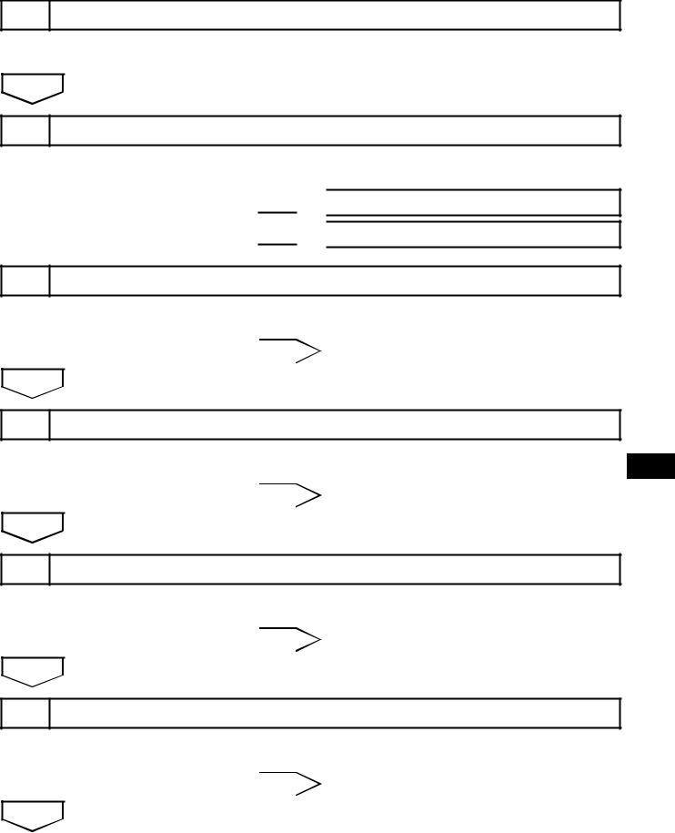
1.PERFORM HYDRAULIC TEST
|
(a) Measure the line pressure. |
||||||
|
NOTICE: |
||||||
|
AX |
||||||
|
• |
Perform the test at the normal operating ATF |
|||||
|
(Automatic Transmission Fluid) temperature |
||||||
|
50° to 80°C (122° to 176°F). |
||||||
|
• The line pressure test must always be carried |
||||||
|
out by pairs of technicians. One technician |
||||||
|
G024063E02 |
||||||
|
must observe the condition of the wheels and |
||||||
|
wheel stoppers outside the vehicle, while the |
||||||
|
other is performing the test. |
• Prevent the SST hose from interfering with the exhaust pipe.
• This test must be conducted after checking and adjusting the engine.
• Perform this test with the air conditioning OFF.
• Do not continue the stall test for more than 5 seconds.
(1)Warm up the ATF.
(2)Lift the vehicle up.
(3)Remove the engine under cover.
(4)Remove the test plug on the transmission case center right side and connect SST.
SST 09992-00095 (09992-00231, 0999200271)
(5) Connect the intelligent tester to the DLC3.

|
AX–16 |
U340E AUTOMATIC TRANSAXLE – AUTOMATIC TRANSAXLE SYSTEM |
(6) Fully apply the parking brake and chock all 4 wheels.
(7) Start the engine and check the idling speed.
(8) Keep your left foot pressing firmly on the brake pedal and shift into the D position.
(9) Measure the line pressure when the engine is idling.
(10)Depress the accelerator pedal all the way down. Quickly read the highest line pressure when engine speed reaches stall speed.
(11)Perform the test in the R position in the same manner.
Standard line pressure
|
Condition |
D position kPa (kgf / cm2, psi) |
R position kPa (kgf / cm2, psi) |
|
|
Idling |
372 to 412 kPa |
553 to 623 kPa |
|
|
(3.8 to 4.2 kgf/cm2, 54 to 60 psi) |
(5.6 to 6.4 kgf/cm2, 80 to 90 psi) |
||
|
Stall |
1,126 to 1,226 kPa |
1,664 to 1,864 kPa |
|
|
(11.5 to 12.5 kgf/cm2, 163 to 178 psi) |
(17.0 to 19.0 kgf/cm2, 241 to 270 psi) |
||
Evaluation:
|
Problem |
Possible Cause |
|||
|
Measured values are higher than specified values in all positions |
• Shift solenoid valve SLT defective |
|||
|
• |
Regulator valve defective |
|||
|
• Shift solenoid valve SLT defective |
||||
|
Measured values are lower than specified values in all positions |
• |
Regulator valve defective |
||
|
• |
Oil pump defective |
|||
|
Pressure is low in D position only |
• D position circuit fluid leak |
|||
|
• |
Forward clutch defective |
|||
|
• R position circuit fluid leak |
||||
|
Pressure is low in R position only |
• |
Reverse clutch defective |
||
|
• 1st and reverse brake defective |
||||
|
AX |
||||
|
U340E AUTOMATIC TRANSAXLE – AUTOMATIC TRANSAXLE SYSTEM |
AX–17 |
MANUAL SHIFTING TEST
1.PERFORM MANUAL SHIFTING TEST
HINT:
•This test can be used to determine whether the trouble is occurring in the electrical circuit or is a mechanical problem in the transaxle.
•If any abnormalities are found in the following test, the problem is in the transaxle itself.
(a)Disconnect the transmission wire connector. HINT:
It is possible to deactivate the electrical shift control by disconnecting the transmission wire. In this way, it is possible to change gear positions by mechanical shift change using the shift lever.
(b)Drive with the transmission wire disconnected. Shift the shift lever into each position to check whether the gear position changes as shown in the table below.
|
Shift Position |
Shifting Condition |
|
D |
3rd |
|
3 |
3rd |
|
2 |
3rd |
|
L |
3rd |
|
R |
Reverse |
|
P |
Pawl Lock |
(c)Connect the transmission wire connector.
(d)Clear the DTC (See page AX-25).
AX

|
AX–18 |
U340E AUTOMATIC TRANSAXLE – AUTOMATIC TRANSAXLE SYSTEM |
AX
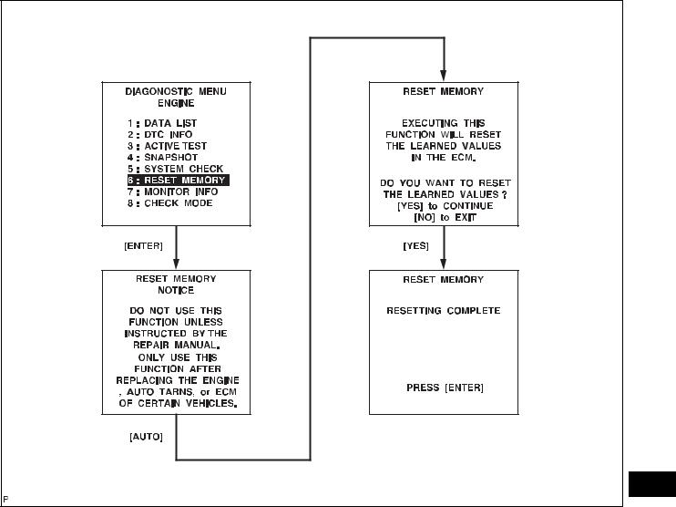
INITIALIZATION
1.RESET MEMORY NOTICE:
•Perform the RESET MEMORY (AT initialization) when replacing the automatic transaxle assembly, engine assembly or ECM.
•The RESET MEMORY can only be performed
using an intelligent tester.
HINT:
The ECM stores the conditions that the ECT controls the automatic transaxle assembly and engine assembly in accordance with those characteristics. Therefore, when the automatic transaxle assembly, engine assembly, or ECM is replaced, it is necessary to reset the memory so that the ECM can store the new information.
The reset procedure is as follows.
(a)Turn the ignition switch off.
(b)Connect the intelligent tester to the DLC3.
(c)Turn the ignition switch to the ON position and push the intelligent tester main switch on.
(d)Select the following items: DIAGNOSIS / ENHANCED OBD II.
(e)Perform the reset memory procedure from the ENGINE menu.
CAUTION:
After performing the RESET MEMORY, be sure to perform the ROAD TEST (See page AX-9) as described earlier.
HINT:
The ECM stores learned values by performing the ROAD TEST.
(1) Tester menu flow:
|
U340E AUTOMATIC TRANSAXLE – AUTOMATIC TRANSAXLE SYSTEM |
AX–19 |

|
AX–20 |
U340E AUTOMATIC TRANSAXLE – AUTOMATIC TRANSAXLE SYSTEM |
AX
MONITOR DRIVE PATTERN
1.MONITOR DRIVE PATTERN FOR ECT TEST
(a)Perform this drive pattern as one method to simulate the detection conditions of ECT malfunctions. (The DTCs may not be detected due to the actual driving conditions. And some DTCs may not be detected through this drive pattern.) HINT:
Preparation for driving
•Warm up the engine. (Engine coolant temperature is 60°C (140°F) or higher.)
•Drive the vehicle when the atmospheric temperature is -10°C (14°F) or higher. (Malfunction is not detected when the
atmospheric temperature is less than -10°C (14°F).)
Driving note
•Drive the vehicle through all gears.
Stop → 1st → 2nd → 3rd → 4th (lock-up ON).
•Repeat the above driving pattern three times or
more.
NOTICE:
•The monitor status can be checked using the intelligent tester. When using an intelligent tester, monitor status can be found in the ENHANCED OBD II / DATA LIST or under CARB OBD II.
•In the event that the drive pattern must be interrupted (possibly due to traffic conditions
or other factors), the drive pattern can be resumed and, in most cases, the monitor can be completed.
CAUTION:
Perform this drive pattern on as level a road as possible and strictly observe the posted speed limits and traffic laws while driving.
![]()
|
U340E AUTOMATIC TRANSAXLE – AUTOMATIC TRANSAXLE SYSTEM |
AX–21 |
Vehicle Speed
Maintain constant speed or gradual acceleration (with throttle open) for 3 minutes or more.*1
Lock-up ON Approximately Vehicle Speed 62 mph (100 km/h)
Approximately 50 mph (80 km/h)
|
0 |
||
|
Warmed up |
Stop (Idling) |
|
|
sufficiently |
||
|
Normal acceleration through all |
||
|
gears from 1st to 4th |
G031593E14
HINT:
*1: Drive at such a speed in the uppermost gear, to engage lock-up. The vehicle can be driven at a
speed lower than that in the above diagram under AX the lock-up condition.
NOTICE:
To detect DTC P0711 (ATF temperature sensor malfunction), drive the vehicle for approximately 30 minutes.

|
AX–22 |
U340E AUTOMATIC TRANSAXLE – AUTOMATIC TRANSAXLE SYSTEM |
PROBLEM SYMPTOMS TABLE
HINT:
• If a normal code is displayed during the DTC check although the trouble still occurs, check the electrical circuits for each symptom in the order given in the following charts and proceed to the page given for troubleshooting.
• The Matrix Chart is divided into 2 chapters.
• When the circuit on which *1 is attached malfunctions, a DTC could be output.
Chapter 1: Electronic Circuit Matrix Chart
Refer to the table below when the trouble cause is considered to be electrical. If the trouble still occurs even though there are no abnormalities in any of the other circuits, then check and replace the ECM.
|
Symptom |
Suspected area |
See page |
|||
|
No up-shift (Particular gear, from 1st to 3rd gear, is not |
ECM |
IN-34 |
|||
|
up-shifted) |
|||||
|
No up-shift (From 3rd to 4th) |
1. |
Shift lock control unit circuit |
AX-47 |
||
|
2. |
ECM |
IN-34 |
|||
|
No down-shift (From 4th to 3rd) |
1. |
Shift lock control unit circuit |
AX-47 |
||
|
2. |
ECM |
IN-34 |
|||
|
No down-shift (Particular gear, from 1st to 3rd gear, is |
ECM |
IN-34 |
|||
|
not down-shifted) |
|||||
|
1. |
Stop light switch circuit *1 |
ES-48 |
|||
|
2. |
Engine coolant temperature sensor circuit *1 |
ES-48 |
|||
|
3. |
Vehicle speed sensor circuit *1 |
ES-48 |
|||
|
4. |
Speed sensor (NT) circuit *1 |
AX-50 |
|||
|
No lock-up or No lock-up off |
5. |
ATF temperature sensor circuit *1 |
AX-42 |
||
|
6. |
Shift solenoid valve S1 *1 |
AX-67 |
|||
|
7. |
Shift solenoid valve S2 *1 |
AX-71 |
|||
|
AX |
|||||
|
8. |
Shift solenoid valve SLU *1 |
AX-89 |
|||
|
9. |
Throttle position sensor circuit *1 |
ES-48 |
|||
|
10. ECM |
IN-34 |
||||
|
Shift point too high or too low |
1. |
Throttle position sensor circuit *1 |
ES-48 |
||
|
2. |
ECM |
IN-34 |
|||
|
Up-shift to 2nd while in L position |
ECM |
IN-34 |
|||
|
Up-shift to 3nd while in 2 position |
ECM |
IN-34 |
|||
|
1. |
Shift lock control unit circuit |
AX-47 |
|||
|
Up-shift from 3rd to 4th in 3 position |
2. Park/neutral position switch *1 |
AX-35 |
|||
|
3. |
ECM |
IN-34 |
|||
|
Up-shift from 3rd to 4th while engine is cold |
1. |
Engine coolant temperature sensor circuit *1 |
ES-48 |
||
|
2. |
ECM |
IN-34 |
|||
|
Harsh engagement (From N to D) |
1. |
Park/neutral position switch *1 |
AX-35 |
||
|
2. |
ECM |
IN-34 |
|||
|
Harsh engagement (From 3rd to 4th) |
1. |
Shift solenoid valve ST *1 |
AX-63 |
||
|
2. |
ECM |
IN-34 |
|||
|
Harsh engagement (Lock-up) |
1. |
Shift solenoid valve SLU *1 |
AX-89 |
||
|
2. |
ECM |
IN-34 |
|||
|
Harsh engagement (Any driving position) |
1. |
Throttle position sensor circuit *1 |
ES-48 |
||
|
2. |
ECM |
IN-34 |
|||
|
Poor acceleration |
ECM |
IN-34 |
|||
|
No kick-down |
ECM |
IN-34 |
|||
|
U340E AUTOMATIC TRANSAXLE – AUTOMATIC TRANSAXLE SYSTEM |
AX–23 |
||||||
|
Symptom |
Suspected area |
See page |
|||||
|
Engine stalls when starting off or stopping |
ECM |
IN-34 |
|||||
|
1. |
Park/neutral position switch *1 |
AX-35 |
|||||
|
Malfunction in shifting |
2. Shift lock control unit circuit |
AX-47 |
|||||
|
3. |
ECM |
IN-34 |
|||||
|
Chapter 2: On-Vehicle Repair and Off-Vehicle Repair |
|||||||
|
Symptom |
Suspected area |
See page |
|||||
|
1. |
Manual valve |
AX-253 |
|||||
|
2. |
Valve body assembly |
AX-113 |
|||||
|
Vehicle does not move in any forward positions or in R |
3. |
Planetary gear unit |
AX-173 |
||||
|
4. |
Forward clutch (C1) |
AX-173 |
|||||
|
position |
|||||||
|
5. |
No. 2 one-way clutch (F2) |
AX-173 |
|||||
|
6. |
Reverse clutch (C3) |
AX-173 |
|||||
|
7. |
1st and reverse brake (B3) |
AX-173 |
|||||
|
1. |
Manual valve |
AX-253 |
|||||
|
2. |
Valve body assembly |
AX-113 |
|||||
|
Vehicle does not move in R position |
3. Planetary gear unit |
AX-173 |
|||||
|
4. |
Reverse clutch (C3) |
AX-173 |
|||||
|
5. |
1st and reverse brake (B3) |
AX-173 |
|||||
|
1. |
Valve body assembly |
AX-113 |
|||||
|
No up-shift (From 1st to 2nd) |
2. 2nd brake (B2) |
AX-173 |
|||||
|
3. |
No. 1 one-way clutch (F1) |
AX-173 |
|||||
|
No up-shift (From 2nd to 3rd) |
1. |
Valve body assembly |
AX-113 |
||||
|
2. |
Direct clutch (C2) |
AX-173 |
|||||
|
No up-shift (From 3rd to 4th) |
1. |
Valve body assembly |
AX-113 |
||||
|
2. |
O/D and 2nd brake (B1) |
AX-173 |
|||||
|
No down-shift (From 4th to 3rd) |
Valve body assembly |
AX-113 |
|||||
|
No down-shift (From 3rd to 2nd) |
Valve body assembly |
AX-113 |
|||||
|
AX |
|||||||
|
No down-shift (From 2nd to 1st) |
Valve body assembly |
AX-113 |
|||||
|
No lock-up or No lock-up off |
1. |
Valve body assembly |
AX-113 |
||||
|
2. |
Torque converter clutch |
AX-171 |
|||||
|
1. |
Valve body assembly |
AX-113 |
|||||
|
Harsh engagement (From N to D) |
2. Forward clutch (C1) |
AX-173 |
|||||
|
3. |
No. 2 one-way clutch (F2) |
AX-173 |
|||||
|
Harsh engagement (Lock-up) |
1. |
Valve body assembly |
AX-113 |
||||
|
2. |
Torque converter clutch |
AX-171 |
|||||
|
1. |
Valve body assembly |
AX-113 |
|||||
|
Harsh engagement (From N to R) |
2. |
C3 accumulator |
AX-173 |
||||
|
3. |
Reverse clutch (C3) |
AX-173 |
|||||
|
4. |
1st and reverse brake (B3) |
AX-173 |
|||||
|
1. |
B2 accumulator |
AX-173 |
|||||
|
Harsh engagement (From 1st to 2nd) |
2. |
Valve body assembly |
AX-113 |
||||
|
3. |
2nd brake (B2) |
AX-173 |
|||||
|
4. |
No. 1 one-way clutch (F1) |
AX-173 |
|||||
|
1. |
C2 accumulator |
AX-173 |
|||||
|
Harsh engagement (From 2nd to 3rd) |
2. Valve body assembly |
AX-113 |
|||||
|
3. |
Direct clutch (C2) |
AX-173 |
|||||
|
1. |
Shift solenoid valve ST |
AX-63 |
|||||
|
Harsh engagement (From 3rd to 4th) |
2. Valve body assembly |
AX-113 |
|||||
|
3. |
O/D and 2nd brake (B1) |
AX-173 |
|||||
|
AX–24 |
U340E AUTOMATIC TRANSAXLE – AUTOMATIC TRANSAXLE SYSTEM |
|||||
|
Symptom |
Suspected area |
See page |
||||
|
Harsh engagement (From 4th to 3rd) |
1. |
Shift solenoid valve ST |
AX-63 |
|||
|
2. |
Valve body assembly |
AX-113 |
||||
|
Harsh engagement (D, 2, L position) |
Valve body assembly |
AX-113 |
||||
|
1. |
Valve body assembly |
AX-113 |
||||
|
2. |
Oil strainer |
AX-113 |
||||
|
3. |
Torque converter clutch |
AX-171 |
||||
|
4. |
Forward clutch (C1) |
AX-173 |
||||
|
Slippage or shuddering (Forward position) |
||||||
|
5. Direct clutch (C2) |
AX-173 |
|||||
|
6. |
O/D and 2nd brake (B1) |
AX-173 |
||||
|
7. |
2nd brake (B2) |
AX-173 |
||||
|
8. |
No. 1 one-way clutch (F1) |
AX-173 |
||||
|
9. |
No. 2 one-way clutch (F2) |
AX-173 |
||||
|
1. |
Valve body assembly |
AX-113 |
||||
|
Slippage or shuddering (R position) |
2. |
Oil strainer |
AX-113 |
|||
|
3. |
Reverse clutch (C3) |
AX-173 |
||||
|
4. |
1st and reverse brake (B3) |
AX-173 |
||||
|
Slippage or shuddering (1st) |
No. 2 one-way clutch (F2) |
AX-173 |
||||
|
Slippage or shuddering (2nd) |
1. |
2nd brake (B2) |
AX-173 |
|||
|
2. |
No.1 one-way clutch (F1) |
AX-173 |
||||
|
Slippage or shuddering (3rd) |
Direct clutch (C2) |
AX-173 |
||||
|
Slippage or shuddering (4th) |
O/D and 2nd brake (B1) |
AX-173 |
||||
|
No engine braking (1st: L position) |
1. |
Valve body assembly |
AX-113 |
|||
|
2. |
1st and reverse brake (B3) |
AX-173 |
||||
|
No engine braking (2nd: 2 position) |
1. |
Valve body assembly |
AX-113 |
|||
|
2. |
2nd and O/D brake (B1) |
AX-173 |
||||
|
No kick-down |
Valve body assembly |
AX-113 |
||||
|
Poor acceleration |
1. |
Valve body assembly |
AX-113 |
|||
|
AX |
||||||
|
2. |
Torque converter clutch |
AX-171 |
||||
|
Engine stalls when starting off or stopping |
Torque converter clutch |
AX-171 |
||||
|
U340E AUTOMATIC TRANSAXLE – AUTOMATIC TRANSAXLE SYSTEM |
AX–25 |
TERMINALS OF ECM
1.ECM
|
C20 |
A21 |
|||||||||||||||||||||||||||||||||||
C105085E01
HINT:
Each ECM terminal’s standard voltage is shown in the table below.
In the table, first follow the information under «Condition». Look under «Symbols (Terminal No.)» for the terminals to be inspected. The standard voltage between the terminals is shown under «Specific Condition».
Use the illustration above as a reference for the ECM terminals.
|
Symbols (Terminals No.) |
Wiring Color |
Terminal Description |
Condition |
Specified Condition |
||
|
Ignition switch ON and |
||||||
|
11 to 14 V |
AX |
|||||
|
shift lever L position |
||||||
|
L shift position switch |
||||||
|
L (C20-74) — E1 (C20-104) |
V — W |
|||||
|
Ignition switch ON and |
||||||
|
signal |
||||||
|
shift lever other than L |
Below 1 V |
|||||
|
position |
||||||
|
Ignition switch ON and |
11 to 14 V |
|||||
|
shift lever 2 position |
||||||
|
2 shift position switch |
||||||
|
2 (C20-55) — E1 (C20-104) |
G — W |
|||||
|
Ignition switch ON and |
||||||
|
signal |
||||||
|
shift lever other than 2 |
Below 1 V |
|||||
|
position |
||||||
|
Ignition switch ON and |
11 to 14 V |
|||||
|
shift lever 3 position |
||||||
|
ODMS (A21-26) — E1 |
3 shift position switch |
|||||
|
O — W |
||||||
|
Ignition switch ON and |
||||||
|
(C20-104) |
signal |
|||||
|
shift lever other than 3 |
Below 1 V |
|||||
|
position |
||||||
|
Ignition switch ON and |
11 to 14 V |
|||||
|
shift lever D or 3 position |
||||||
|
D shift position switch |
||||||
|
D (C20-56) — E1 (C20-104) |
L — W |
|||||
|
Ignition switch ON and |
||||||
|
signal |
||||||
|
shift lever other than D |
Below 1 V |
|||||
|
and 3 positions |
||||||
|
Ignition switch ON and |
11 to 14 V |
|||||
|
shift lever R position |
||||||
|
R shift position switch |
||||||
|
R (C20-53) — E1 (C20-104) |
R — W |
|||||
|
Ignition switch ON and |
||||||
|
signal |
||||||
|
shift lever other than R |
Below 1 V |
|||||
|
position |
||||||
|
AX–26 |
U340E AUTOMATIC TRANSAXLE – AUTOMATIC TRANSAXLE SYSTEM |
|||||||
|
Symbols (Terminals No.) |
Wiring Color |
Terminal Description |
Condition |
Specified Condition |
||||
|
Ignition switch ON and |
11 to 14 V |
|||||||
|
shift lever N position |
||||||||
|
N shift position switch |
||||||||
|
N (C20-54) — E1 (C20-104) |
SB — W |
|||||||
|
Ignition switch ON and |
||||||||
|
signal |
||||||||
|
shift lever other than N |
Below 1 V |
|||||||
|
position |
||||||||
|
Ignition switch ON and |
11 to 14 V |
|||||||
|
shift lever P position |
||||||||
|
P shift position switch |
||||||||
|
P (C20-73) — E1 (C20-104) |
R — W |
|||||||
|
Ignition switch ON and |
||||||||
|
signal |
||||||||
|
shift lever other than P |
Below 1 V |
|||||||
|
position |
||||||||
|
NT+ (C20-125) — NT- |
B — G |
Speed sensor (NT) signal |
Engine running |
Pulse generation |
||||
|
(C20-124) |
(See waveform 1) |
|||||||
|
STP (A21-36) — E1 (C20- |
G — W |
Stop light switch signal |
Brake pedal depressed |
7.5 to 14 V |
||||
|
104) |
Brake pedal released |
Below 1.5 V |
||||||
|
SPD (A21-8) — E1 (C20- |
Ignition switch ON and |
Pulse generation |
||||||
|
V — W |
Speed signal |
driving wheel rotating |
||||||
|
104) |
(See waveform 2) |
|||||||
|
slowly |
||||||||
|
S1 (C20-79) — E1 (C20- |
Ignition switch ON |
11 to 14 V |
||||||
|
SB — W |
S1 solenoid signal |
1st or 2nd gear |
11 to 14 V |
|||||
|
104) |
||||||||
|
3rd or 4th gear |
Below 1 V |
|||||||
|
S2 (C20-78) — E1 (C20- |
Ignition switch ON |
Below 1 V |
||||||
|
L — W |
S2 solenoid signal |
1st or 4th gear |
11 to 14 V |
|||||
|
104) |
||||||||
|
2nd or 3rd gear |
Below 1 V |
|||||||
|
ST (C20-80) — E1 (C20- |
GR — W |
ST solenoid signal |
D position (3rd gear ←→ |
Below 1 V ←→ 11 to 14 V |
||||
|
104) |
4th gear) |
|||||||
|
SLT+ (C20-76) — SLT- |
G — W |
SLT solenoid signal |
Engine idling speed |
Pulse generation |
||||
|
(C20-75) |
(See waveform 3) |
|||||||
|
SLU+ (C20-57) — SLU- |
P — O |
SLU solenoid signal |
Engine idling speed |
Pulse generation |
||||
|
(C20-77) |
(See waveform 4) |
|||||||
|
THO1 (C20-72) — ETHO |
ATF (Automatic |
ATF temperature: 10°C |
4 to 0 V |
|||||
|
Y — B |
Transmission Fluid) |
|||||||
|
AX |
(C20-95) |
(50°F) to 145°C (293°F) |
||||||
|
temperature sensor signal |
||||||||
|
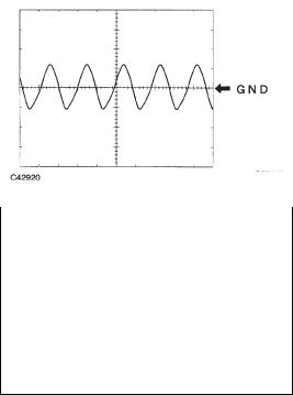
(a) |
Waveform 1 |
||||||||
|
2 V/DIV |
|||||||||
|
Terminal |
NT+ — NT- |
||||||||
|
Tool setting |
2 V/DIV, 1ms/DIV |
||||||||
|
Vehicle conditions |
Driving at approximately 12 mph (20 km/h) |
||||||||
|
1 ms/DIV |
|||||||||
|
C053419E04 |
(b) |
Waveform 2 |
|||||||
|
2 V/DIV |
|||||||||
|
Terminal |
SPD — E1 |
||||||||
|
Tool setting |
2 V/DIV, 20 ms/DIV |
||||||||
|
Vehicle conditions |
Driving at approximately 12 mph (20 km/h) |
||||||||
20 ms/DIV
C053421E04
|
U340E AUTOMATIC TRANSAXLE – AUTOMATIC TRANSAXLE SYSTEM |
AX–27 |
||||||||
|
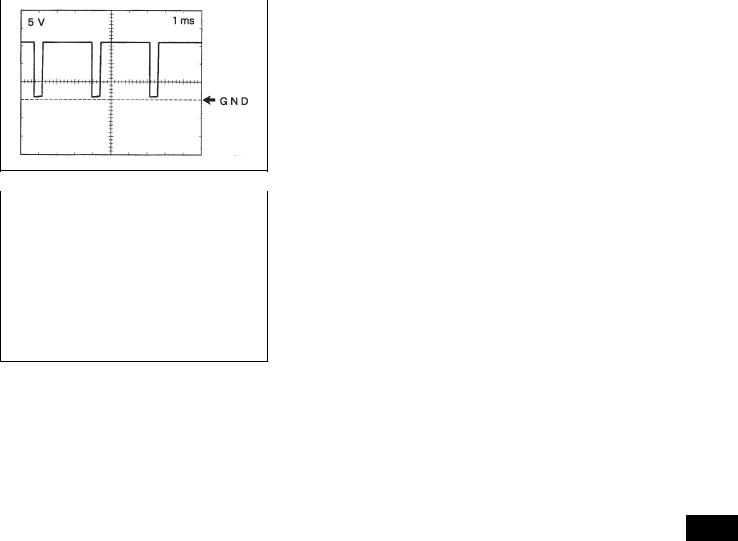
(c) Waveform 3 |
|||||||||
|
5 V/DIV |
|||||||||
|
Terminal |
SLT+ — SLT- |
||||||||
|
Tool setting |
5 V/DIV, 1 ms/DIV |
||||||||
|
Vehicle conditions |
Engine idling speed |
||||||||
1 ms/DIV
C055887E01
|
(d) Waveform 4 |
|||
|
5 V/DIV |
|||
|
Terminal |
SLU+ — SLU- |
||
|
Tool setting |
5 V/DIV, 1 ms/DIV |
||
|
Vehicle conditions |
Engine idling speed |
||
1 ms/DIV
C058033E01
AX
|
AX–28 |
U340E AUTOMATIC TRANSAXLE – AUTOMATIC TRANSAXLE SYSTEM |
DIAGNOSIS SYSTEM
1.DESCRIPTION
(a)When troubleshooting OBD II vehicles, the only difference from the usual troubleshooting procedure is to connect an intelligent tester (complying with SAE J1987) to the vehicle, and read off various data output by the vehicle’s ECM.
(b)OBD II regulations require that the vehicle’s onboard computer illuminate the Malfunction Indicator Lamp (MIL) on the instrument panel when the computer detects a malfunction in the computer itself or in the drive system components which affect the vehicle emissions. In addition to illuminating the MIL when a malfunction is detected, the applicable
|
DTCs prescribed by SAE J2012 are recorded in the |
|||
|
ECM memory (See page AX-32). |
|||
|
FI00534 |
If the malfunction does not occur in 3 consecutive |
||
|
trips, the MIL goes off but the DTCs remain in the |
|||
|
ECM memory. |
|||
|
(c) |
To check the DTCs, connect the intelligent tester to |
||
|
Intelligent Tester |
the DLC3 of the vehicle. The intelligent tester also |
||
|
enables you to erase the DTCs and check freeze |
|||
|
frame data and various forms of engine data (For |
|||
|
operating instructions, see the instruction book). |
|||
|
(d) |
The DTCs include SAE controlled codes and |
||
|
manufacturer controlled codes. SAE controlled |
|||
|
DLC3 |
CAN VIM |
codes must be set as prescribed by the SAE, while |
|
|
manufacturer controlled codes can be set freely by |
|||
|
AX |
C115104E01 |
the manufacturer within the prescribed limits (See |
|
|
(e) |
page AX-32). |
||
|
The diagnosis system operates in normal mode |
|||
|
during normal vehicle use. In normal mode, 2-trip |
|||
|
detection logic is used to ensure accurate detection |
|||
|
of malfunctions. Check mode is also available to |
|||
|
technicians as an option. In check mode, 1-trip |
|||
|
detection logic is used for simulating malfunction |
|||
|
symptoms and increasing the system’s ability to |
|||
|
detect malfunctions, including intermittent |
|||
|
malfunctions. |
|||
|
(f) |
2-trip detection logic: When a malfunction is first |
||
|
detected, the malfunction is temporarily stored in |
|||
|
the ECM memory (1st trip). If the ignition switch is |
|||
|
turned off and then turned to the ON position again, |
|||
|
and same malfunction is detected again, the MIL |
|||
|
illuminates. |
|
U340E AUTOMATIC TRANSAXLE – AUTOMATIC TRANSAXLE SYSTEM |
AX–29 |
||||||||||||||||||||||||
|
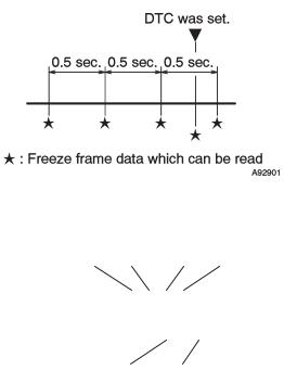
(g) Freeze frame data records the engine conditions, |
|||||||||||||||||||||||||
|
such as fuel system, calculated load, engine coolant |
|||||||||||||||||||||||||
|
temperature, fuel trim, engine speed and vehicle |
|||||||||||||||||||||||||
|
speed when a malfunction is detected. When |
|||||||||||||||||||||||||
|
troubleshooting, freeze frame data can help |
|||||||||||||||||||||||||
|
determine if the vehicle was running or stopped, if |
|||||||||||||||||||||||||
|
the engine was warmed up or not, if the air/fuel ratio |
|||||||||||||||||||||||||
|
was lean or rich, and other data from the time the |
|||||||||||||||||||||||||
|
malfunction occurred. |
|||||||||||||||||||||||||
|
(h) The intelligent tester records freeze frame data in |
|||||||||||||||||||||||||
|
five different instances: 1) 3 times before the DTC is |
|||||||||||||||||||||||||
|
(Seconds) |
set, 2) once when the DTC is set, and 3) once after |
||||||||||||||||||||||||
|
the DTC is set. These data can be used to simulate |
|||||||||||||||||||||||||
|
0.5 |
0.5 |
0.5 |
|||||||||||||||||||||||
|
the vehicle’s conditions around the time when the |
|||||||||||||||||||||||||
|
malfunction occurred. The data may help find the |
|||||||||||||||||||||||||
|
cause of the malfunction, or judge if the DTC is |
|||||||||||||||||||||||||
|
being caused by a temporary malfunction or not. |
|||||||||||||||||||||||||
|
A092901E12 |
|||||||||||||||||||||||||
|
2. |
INSPECT DLC3 |
||||||||||||||||||||||||
|
DLC3 |
(a) The ECM uses ISO 15765-4 for communication. |
||||||||||||||||||||||||
|
The terminal arrangement of the DLC3 complies |
|||||||||||||||||||||||||
|
CG |
SG |
CANH SIL |
with SAE J1962 and matches the ISO 15765-4 |
||||||||||||||||||||||
|
format. |
|||||||||||||||||||||||||
|
1 |
2 |
3 |
4 |
5 |
6 |
7 |
8 |
||||||||||||||||||
|
9 10 111213141516 |
|||||||||||||||||||||||||
|
CANL |
BAT |
||||||||||||||||||||||||
|
A082779E81 |
|||||||||||||||||||||||||
|
AX |
|||||||||||||||||||||||||
|
Symbols (Terminal No.) |
Terminal Description |
Condition |
Specified Condition |
||||||||||||||||||||||
|
SIL (7) — SG (5) |
Bus «+» line |
During transmission |
Pulse generation |
||||||||||||||||||||||
|
CG (4) — Body ground |
Chassis ground |
Always |
Below 1 Ω |
||||||||||||||||||||||
|
SG (5) — Body ground |
Signal ground |
Always |
Below 1 Ω |
||||||||||||||||||||||
|
BAT (16) — Body ground |
Battery positive |
Always |
11 to 14 V |
||||||||||||||||||||||
|
CANH (6) — CANL (14) |
CAN bus line |
Ignition switch OFF* |
54 to 69 Ω |
||||||||||||||||||||||
|
CANH (6) — CG (4) |
HIGH-level CAN bus line |
Ignition switch OFF* |
200 Ω or higher |
||||||||||||||||||||||
|
CANL (14) — CG (4) |
LOW-level CAN bus line |
Ignition switch OFF* |
200 Ω or higher |
||||||||||||||||||||||
|
CANH (6) — BAT (16) |
HIGH-level CAN bus line |
Ignition switch OFF* |
6 kΩ or higher |
||||||||||||||||||||||
|
CANL (14) — BAT (16) |
LOW-level CAN bus line |
Ignition switch OFF* |
6 kΩ or higher |
NOTICE:
*: Before measuring the resistance, leave the vehicle as is for at least 1 minute and do not operate the ignition switch, any other switches or the doors.

|
AX–30 |
U340E AUTOMATIC TRANSAXLE – AUTOMATIC TRANSAXLE SYSTEM |
If the result is not as specified, the DLC3 may have a malfunction. Repair or replace the harness and connector.
HINT:
If your display shows UNABLE TO CONNECT TO VEHICLE when you have connected the cable of the intelligent tester to the DLC3, turned the ignition switch to the ON position and operated the tester, there is a problem with the vehicle or the tester.
• If the communication is normal when the tester is connected to another vehicle, inspect the DLC3 on the original vehicle.
• If the communication is still impossible when the tester is connected to another vehicle, the problem is probably in the tester itself. Consult the Service Department listed in the tester’s instruction manual.
3.CHECK BATTERY VOLTAGE
(a)Measure the battery voltage.
Standard voltage: 11 to 14 V
If the voltage is below 11 V, replace the battery before proceeding.
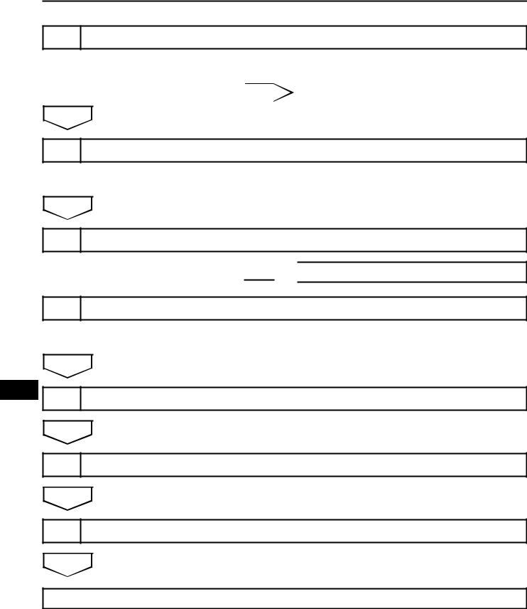
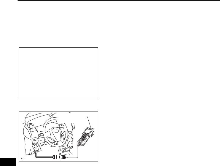
4.CHECK MIL
(a)The MIL comes on when the ignition switch is turned to the ON position and the engine is not running.
HINT:
If the MIL does not light up, troubleshoot the
combination meter.
AX (b) When the engine is started, the MIL should go off. If the lamp remains on, it means that the diagnosis system has detected a malfunction or abnormality in the system.
![]()
|
U340E AUTOMATIC TRANSAXLE – AUTOMATIC TRANSAXLE SYSTEM |
AX–31 |
DTC CHECK / CLEAR
1.DTC CHECK (NORMAL MODE) NOTICE:
When the diagnostic system is switched from normal mode to check mode, all the DTCs and freeze frame data recorded in normal mode are erased. So before switching modes, always check the DTCs and freeze frame data, and note them down.
|
Intelligent Tester |
(a) Check DTCs using an intelligent tester. |
||
|
(1) |
Turn the ignition switch off. |
||
|
(2) |
Connect the intelligent tester to the DLC3. |
||
|
(3) |
Turn the ignition switch to the ON position and |
||
|
turn the intelligent tester main switch on. |
|||
|
(4) |
Select the following items: DIAGNOSIS / |
||
|
DLC3 |
ENHANCED OBD II / DTC INFO / CURRENT |
||
|
CAN VIM |
(5) |
CODES. |
|
|
Read the DTCs and freeze frame data displayed |
|||
|
C115104E07 |
on the tester and note them down. |
||
|
NOTICE: |
|||
|
When simulating symptoms with an |
|||
|
intelligent tester to check the DTCs, use |
|||
|
normal mode. For DTCs in the DTC chart, |
|||
|
which are subject to 2-trip detection logic, |
|||
|
perform the following. |
|||
|
Turn the ignition switch off after the symptom is |
|||
|
simulated once. Then repeat the simulation |
|||
|
process again. When the problem has been |
|||
|
simulated twice, the MIL illuminates and the |
|||
|
DTCs are recorded in the ECM. |
|
2. DTC CLEAR |
AX |
|
|
(a) Clear the DTCs: When using an intelligent tester. |
||
|
(1) |
Connect the intelligent tester to the DLC3. |
|
|
(2) |
Turn the ignition switch to the ON position and |
|
|
turn the intelligent tester main switch on. |
||
|
(3) |
Select the following items: DIAGNOSIS / |
|
|
ENHANCED OBD II / DTC INFO / CLEAR |
||
|
CODES [YES] button. |
||
|
HINT: |
||
|
When operating the intelligent tester to erase the |
||
|
DTCs, the freeze frame data are also erased. |
||
|
(b) Clear the DTCs: When not using an intelligent |
||
|
tester. |
||
|
(1) |
Disconnect the battery terminal or remove the |
|
|
EFI and ETCS fuses from the engine room J/B |
||
|
for 60 seconds or more. |

|
AX–32 |
U340E AUTOMATIC TRANSAXLE – AUTOMATIC TRANSAXLE SYSTEM |
CHECK MODE PROCEDURE
1.DESCRIPTION
(a)Check mode has a higher sensitivity to malfunctions and can detect malfunctions that normal mode cannot detect. Check mode can also detect all the malfunctions that normal mode can detect. In check mode, DTCs are detected with 1-trip detection logic.
2.DTC CHECK (CHECK MODE)
HINT:
Intelligent tester only: Compared to normal mode, check mode is more sensitive for detecting malfunctions. Furthermore, the same diagnostic items which are detected in normal mode can also be detected in check mode.
|
Intelligent Tester |
(a) Procedure for check mode using the intelligent |
||
|
tester. |
|||
|
(1) |
Check the initial conditions. |
||
|
• Battery positive voltage 11 V or more |
|||
|
• Throttle valve fully closed |
|||
|
• Transaxle in the P or N position |
|||
|
DLC3 |
• |
A/C switched OFF |
|
|
CAN VIM |
(2) |
Turn the ignition switch off. |
|
|
(3) |
Connect the intelligent tester to the DLC3. |
||
|
C115104E07 |
(4) |
Turn the ignition switch to the ON position and |
|
|
turn the intelligent tester main switch on. |
0.13 seconds
AX ON
OFF
0.13 seconds
A076900E17
(5)Select the following items: DIAGNOSIS / ENHANCED OBD II / CHECK MODE (Check that the MIL flashes as shown in the illustration).
NOTICE:
All DTCs and freeze frame data recorded are erased if: 1) the intelligent tester is used to change the ECM from normal mode to check mode or vice-versa; or 2) during check mode, the ignition switch is turned from the ON position to the ACC or LOCK position.
(6)Start the engine (the MIL goes off after the engine starts).
(7)Perform MONITOR DRIVE PATTERN for the ECT test (See page AX-16), or simulate the conditions of the malfunction described by the customer.
NOTICE:
Leave the ignition switch in the ON position until you have checked the DTCs.
(8)After simulating malfunction conditions, use the intelligent tester to check the DTCs and freeze frame data.
|
U340E AUTOMATIC TRANSAXLE – AUTOMATIC TRANSAXLE SYSTEM |
AX–33 |
FAIL-SAFE CHART
1.FAIL-SAFE
(a)This function minimizes the loss of ECT functions when any malfunction occurs in the sensors or solenoids.
|
Malfunction Part |
Function |
|
|
Vehicle Speed Sensor |
During vehicle speed sensor signal malfunction, 4th up-shift is |
|
|
prohibited. |
||
|
Transmission Revolution Sensor (Speed Sensor (NT)) |
During transmission revolution sensor (NT) signal malfunction, 4th up- |
|
|
shift is prohibited. |
||
|
ATF (Automatic Transmission Fluid) Temperature Sensor |
During ATF temperature sensor malfunction, 4th up-shift is prohibited. |
|
|
During shift solenoid valve S1 or S2 malfunction, current to faulty shift |
||
|
solenoid valve is cut off and control is effected by operating normal |
||
|
Shift Solenoid Valve S1 or S2 |
solenoid valve. |
|
|
Shift control effect depends on failed solenoid as described in table |
||
|
below. |
||
|
Shift Solenoid Valve ST |
During shift solenoid valve ST malfunction, 4th up-shift is prohibited. |
|
|
Shift Solenoid Valve SLT |
During shift solenoid valve SLT malfunction, 4th up-shift is prohibited. |
|
|
Engine Coolant Temperature Sensor, Knock Sensor or Throttle |
During engine coolant temperature sensor, knock sensor or throttle |
|
|
Position Sensor |
position sensor malfunction, 4th up-shift is prohibited. |
|
(b)Fail-safe chart for shift solenoid valve S1 and/or S2: Fail safe function:
If either of the shift solenoid valve circuits develops an open or short, the ECM turns the other shift solenoid ON or OFF in order to shift into the gear positions shown in the table below.
Manual shifting as shown in the following table must be done (In case of a short circuit, the ECM stops sending the current to the short circuit solenoid).
|
Even if starting the engine in fail-safe mode, the |
|||||||
|
AX |
|||||||
|
Normal: |
gear position remains in the same position. |
||||||
|
Shift Lever Position |
Shift Solenoid Valve S1 |
Shift Solenoid Valve S2 |
Gear |
||||
|
1st |
ON |
ON |
1st |
||||
|
D |
2nd |
ON |
OFF |
2nd |
|||
|
3rd |
OFF |
OFF |
3rd |
||||
|
4th |
OFF |
ON |
4th |
||||
|
1st |
ON |
ON |
1st |
||||
|
3 |
2nd |
ON |
OFF |
2nd |
|||
|
3rd |
OFF |
OFF |
3rd |
||||
|
2 |
1st |
ON |
ON |
1st |
|||
|
2nd |
ON |
OFF |
2nd |
||||
|
L |
1st |
ON |
ON |
1st |
|||
|
Shift Solenoid Valve S1 malfunction: |
|||||||
|
Shift Lever Position |
Shift Solenoid Valve S1 |
Shift Solenoid Valve S2 |
Gear |
||||
|
1st |
X |
OFF |
3rd |
||||
|
D |
2nd |
X |
OFF |
3rd |
|||
|
3rd |
X |
OFF |
3rd |
||||
|
4th |
X |
ON |
4th |
||||
|
1st |
X |
OFF |
3rd |
||||
|
3 |
2nd |
X |
OFF |
3rd |
|||
|
3rd |
X |
OFF |
3rd |
||||
|
AX–34 |
U340E AUTOMATIC TRANSAXLE – AUTOMATIC TRANSAXLE SYSTEM |
|||||
|
Shift Lever Position |
Shift Solenoid Valve S1 |
Shift Solenoid Valve S2 |
Gear |
|||
|
2 |
1st |
X |
OFF |
3rd |
||
|
2nd |
X |
OFF |
3rd |
|||
|
L |
1st |
X |
OFF |
3rd |
||
|
Shift Solenoid Valve S2 malfunction: |
X: Malfunctions |
|||||
|
Shift Lever Position |
Shift Solenoid Valve S1 |
Shift Solenoid Valve S2 |
Gear |
|||
|
1st |
ON |
X |
2nd |
|||
|
D |
2nd |
ON |
X |
2nd |
||
|
3rd |
OFF |
X |
3rd |
|||
|
4th |
OFF |
X |
3rd |
|||
|
1st |
ON |
X |
2nd |
|||
|
3 |
2nd |
ON |
X |
2nd |
||
|
3rd |
OFF |
X |
3rd |
|||
|
2 |
1st |
ON |
X |
2nd |
||
|
2nd |
ON |
X |
2nd |
|||
|
L |
1st |
ON |
X |
2nd |
||
X: Malfunctions
Shift Solenoid Valve S1 and S2 malfunction:
|
Shift Lever Position |
Shift Solenoid Valve S1 |
Shift Solenoid Valve S2 |
Gear |
||||
|
1st |
X |
X |
3rd |
||||
|
D |
2nd |
X |
X |
3rd |
|||
|
3rd |
X |
X |
3rd |
||||
|
4th |
X |
X |
3rd |
||||
|
1st |
X |
X |
3rd |
||||
|
3 |
2nd |
X |
X |
3rd |
|||
|
3rd |
X |
X |
3rd |
||||
|
AX |
|||||||
|
2nd |
X |
X |
3rd |
||||
|
2 |
1st |
X |
X |
3rd |
|||
|
L |
1st |
X |
X |
3rd |
|||
X: Malfunctions
|
U340E AUTOMATIC TRANSAXLE – AUTOMATIC TRANSAXLE SYSTEM |
AX–35 |
DATA LIST / ACTIVE TEST
1.DATA LIST
HINT:
Using the DATA LIST displayed by the intelligent tester, you can read the values of the switches, sensors, actuators and so on without parts removal. Reading the DATA LIST as the first step of troubleshooting is one method of shortening labor time.
NOTICE:
In the table below, the values listed under «Normal Condition» are reference values. Do not depend solely on these reference values when deciding whether a part is faulty or not.
(a)Warm up the engine.
(b)Turn the ignition switch off.
(c)Connect the intelligent tester together with the CAN VIM (Controller Area Network Vehicle Interface Module) to the DLC3.
(d)Turn the ignition switch to the ON position.
(e)Turn on the tester.
(f)Select the following items: DIAGNOSIS / ENHANCED OBD II / DATA LIST.
(g)In accordance with the display on the tester, read the DATA LIST.
|
Item |
Measurement Item/ |
Normal Condition |
Diagnostic Note |
|||
|
Range (display) |
||||||
|
Vehicle Speed display/ |
• |
Vehicle stopped: |
||||
|
0 mph (0 km/h) |
— |
|||||
|
VEHICLE SPD |
min.: 0 mph (0 km/h) |
|||||
|
• |
Same as speedometer |
|||||
|
max.: 158 mph (255 km/h) |
||||||
|
reading |
||||||
|
AX |
||||||
|
HINT: |
||||||
|
• Lock-Up ON (After warming |
||||||
|
up engine): |
||||||
|
Input Turbine Speed/ |
Input turbine speed (NT) |
|||||
|
equal to engine speed |
||||||
|
display: 50 rpm |
— |
|||||
|
SPD (NT) |
• |
Lock-Up OFF (Idling at P or N |
||||
|
min.: 0 rpm |
||||||
|
position): |
||||||
|
max.: 12750 rpm |
||||||
|
Input turbine speed (NT) |
||||||
|
nearly equal to engine speed |
||||||
|
• Vehicle stopped in D position: |
||||||
|
0 rpm |
||||||
|
When shift lever position |
||||||
|
displayed on intelligent tester |
||||||
|
differs from actual position, |
||||||
|
PNP SW Status/ |
Shift lever position; |
adjustment of PNP switch or shift |
||||
|
PNP SW [NSW] |
P or N: ON |
cable may be incorrect. |
||||
|
ON or OFF |
||||||
|
Except P and N: OFF |
HINT: |
|||||
|
When failure still occurs even |
||||||
|
after adjusting these parts, |
||||||
|
see page AX-35. |
||||||
|
Stop Light SW Status/ |
• Brake pedal is depressed: |
|||||
|
STOP LIGHT SW |
ON |
— |
||||
|
ON or OFF |
||||||
|
• Brake pedal is released: OFF |
||||||
|
Shift lever position; |
||||||
|
ECM Gearshift Command/ |
• |
L: 1st |
— |
|||
|
SHIFT |
• |
2: 1st or 2nd |
||||
|
1st, 2nd, 3rd or 4th |
||||||
|
• 3: 1st, 2nd or 3rd |
||||||
|
• D: 1st, 2nd, 3rd or 4th |
||||||
|
AX–36 |
U340E AUTOMATIC TRANSAXLE – AUTOMATIC TRANSAXLE SYSTEM |
||||||
|
Item |
Measurement Item/ |
Normal Condition |
Diagnostic Note |
||||
|
Range (display) |
|||||||
|
PNP SW Status/ |
Shift lever position; |
||||||
|
REVERSE |
R: ON |
||||||
|
ON or OFF |
|||||||
|
Except R: OFF |
When shift lever position |
||||||
|
displayed on intelligent tester |
|||||||
|
PNP SW Status/ |
Shift lever position; |
||||||
|
differs from actual position, |
|||||||
|
PARKING |
P: ON |
||||||
|
ON or OFF |
adjustment of PNP switch or shift |
||||||
|
Except P: OFF |
|||||||
|
cable may be incorrect. |
|||||||
|
Shift lever position; |
|||||||
|
PNP SW Status/ |
HINT: |
||||||
|
NEUTRAL |
N: ON |
||||||
|
ON or OFF |
When failure still occurs even |
||||||
|
Except N: OFF |
|||||||
|
after adjusting these parts, |
|||||||
|
PNP SW Status/ |
Shift lever position; |
see page AX-35. |
|||||
|
DRIVE |
D or 3: ON |
||||||
|
ON or OFF |
|||||||
|
Except D and 3: OFF |
|||||||
|
PNP SW Status/ |
Shift lever position; |
||||||
|
3RD |
3: ON |
— |
|||||
|
ON or OFF |
|||||||
|
Except 3: OFF |
|||||||
|
PNP SW Status/ |
Shift lever position; |
When shift lever position |
|||||
|
2ND |
2: ON |
displayed on intelligent tester |
|||||
|
ON or OFF |
|||||||
|
Except 2: OFF |
differs from actual position, |
||||||
|
adjustment of PNP switch or shift |
|||||||
|
Shift lever position; |
cable may be incorrect. |
||||||
|
PNP SW Status/ |
HINT: |
||||||
|
LOW |
L: ON |
||||||
|
ON or OFF |
When failure still occurs even |
||||||
|
Except L: OFF |
|||||||
|
after adjusting these parts, |
|||||||
|
see page AX-35. |
|||||||
|
ATF (Automatic Transmission |
• |
After Stall Test; |
If value is «-40°C (-40°F)» or « |
||||
|
A/T OIL TEMP1 |
Fluid) Temperature Sensor Value/ |
Approximately 80°C (176°F) |
150°C (302°F) or more «, ATF |
||||
|
min.: -40°C (-40°F) |
• Equal to ambient temperature |
temperature sensor circuit is |
|||||
|
max.: 215°C (419°F) |
when cold soak |
open or short. |
|||||
|
ATF Condition; |
Replace ATF when ATF condition |
||||||
|
ATF |
ATF Condition |
NG: ON |
|||||
|
is ON. |
|||||||
|
OK: OFF |
|||||||
|
LOCK UP |
Lock Up Status/ |
• |
Lock Up: ON |
— |
|||
|
ON or OFF |
• Except Lock Up: OFF |
||||||
|
AX |
|||||||
|
LOCK UP SOL |
Lock Up Solenoid Status/ |
• Lock up solenoid ON: ON |
— |
||||
|
ON or OFF |
• Lock up solenoid OFF: OFF |
||||||
|
Up-shifting and down-shifting |
|||||||
|
SOLENOID (ST) |
Shift Solenoid ST Status/ |
between 3rd and 4th gears while |
— |
||||
|
ON or OFF |
driving: |
||||||
|
OFF → ON → OFF |
|||||||
|
SOLENOID (SLU) |
Shift Solenoid SLU Status/ |
• |
Lock Up: ON |
— |
|||
|
ON or OFF |
• Except Lock Up: OFF |
||||||
|
• |
Accelerator pedal is |
||||||
|
SOLENOID (SLT) |
Shift Solenoid SLT Status/ |
depressed: OFF |
— |
||||
|
ON or OFF |
• Accelerator pedal is released: |
||||||
|
ON |
|||||||
2.ACTIVE TEST
HINT:
Performing the ACTIVE TEST using the intelligent tester allows the relay, VSV, actuator and so on to operate without parts removal. Performing the ACTIVE TEST as the first step of troubleshooting is one method to shorten labor time.
It is possible to display the DATA LIST during the ACTIVE TEST.
(a)Warm up the engine.
(b)Turn the ignition switch off.
|
U340E AUTOMATIC TRANSAXLE – AUTOMATIC TRANSAXLE SYSTEM |
AX–37 |
(c)Connect the intelligent tester together with the CAN VIM (Controller Area Network Vehicle Interface Module) to the DLC3.
(d)Turn the ignition switch to the ON position.
(e)Turn on the tester.
(f)Select the following items: DIAGNOSIS / ENHANCED OBD II / ACTIVE TEST.
(g)In accordance with the display on the tester, perform the ACTIVE TEST.
|
Item |
Test Details |
Diagnostic Note |
|||
|
[Test Details] |
|||||
|
Operate shift solenoid SLU |
— |
||||
|
SOLENOID (SLU) |
[Vehicle Condition] |
||||
|
• |
Vehicle Stopped |
||||
|
• Shift lever P or N position |
|||||
|
[Test Details] |
|||||
|
Operate shift solenoid SLT and raise the line |
|||||
|
pressure. |
|||||
|
[Vehicle Condition] |
|||||
|
• |
Vehicle Stopped |
— |
|||
|
SOLENOID (SLT)* |
• |
IDL: ON |
|||
|
HINT: |
|||||
|
OFF: Line pressure up (When the active test |
|||||
|
of «SOLENOID (SLT)» is performed, ECM |
|||||
|
commands SLT solenoid to turn off.) |
|||||
|
ON: No action (normal operation) |
|||||
|
[Test Details] |
|||||
|
Operate shift solenoid S1 |
— |
||||
|
SOLENOID (S1) |
[Vehicle Condition] |
||||
|
• |
Vehicle Stopped |
||||
|
• Shift lever P or N position |
|||||
|
[Test Details] |
|||||
|
Operate shift solenoid S2 |
— |
||||
|
SOLENOID (S2) |
[Vehicle Condition] |
||||
|
• |
Vehicle Stopped |
||||
|
AX |
|||||
|
• Shift lever P or N position |
|||||
|
[Test Details] |
|||||
|
Control shift solenoid SLU to set automatic |
|||||
|
LOCK UP |
transaxle to lock-up condition. |
Possible to check SLU operation. |
|||
|
[Vehicle Condition] |
|||||
|
Vehicle Speed: 36 mph (60 km/h) or more, |
|||||
|
and 4th gear |
|||||
|
[Test Details] |
|||||
|
Operate shift solenoid valve and set each shift |
|||||
|
position manually. |
Possible to check operation of shift solenoid |
||||
|
SHIFT |
[Vehicle Condition] |
||||
|
Vehicle Speed: Less than 30 mph (50 km/h) |
valves. |
||||
|
[Others] |
|||||
|
• Press →button: Shift up |
|||||
|
• Press ←button: Shift down |
|||||
|
[Test Details] |
|||||
|
Operate shift solenoid ST |
— |
||||
|
SOLENOID (ST) |
[Vehicle Condition] |
||||
|
• |
Vehicle Stopped |
||||
|
• |
IDL: ON |
||||

|
AX–38 |
U340E AUTOMATIC TRANSAXLE – AUTOMATIC TRANSAXLE SYSTEM |
*: SOLENOID (SLT) in the ACTIVE TEST is performed to check the line pressure changes by connecting SST to the automatic transaxle, which is used in the HYDRAULIC TEST (See page AX-13) as well.
HINT:
The pressure values in ACTIVE TEST and HYDRAULIC TEST are different from each other.
AX
|
U340E AUTOMATIC TRANSAXLE – AUTOMATIC TRANSAXLE SYSTEM |
AX–39 |
DIAGNOSTIC TROUBLE CODE CHART
If a DTC is displayed during the DTC check, check the parts listed in the table below and proceed to the page given. HINT:
•*1: «Comes on» means the MIL (Malfunction Indicator
Lamp) illuminates.
•*2: «DTC stored» means the ECM stores the malfunction
code if the ECM detects the DTC detection condition.
•These DTCs may be output when the clutch, brake and gear components inside the automatic transaxle are damaged.
AUTOMATIC TRANSMISSION SYSTEM
|
DTC No. |
Detection Item |
Trouble Area |
MIL *1 |
Memory *2 |
See page |
|||
|
1. |
Open or short in |
|||||||
|
park/neutral position |
||||||||
|
Transmission Range |
switch circuit |
|||||||
|
P0705 |
Sensor Circuit |
2. |
Park/neutral |
Comes on |
DTC stored |
AX-35 |
||
|
Malfunction (PRNDL |
position switch |
|||||||
|
Input) |
3. |
Shift lock control |
||||||
|
ECU |
||||||||
|
4. ECM |
||||||||
|
1. |
Open or short in |
|||||||
|
ATF temperature |
||||||||
|
Transmission Fluid |
sensor circuit |
Comes on |
DTC stored |
AX-42 |
||||
|
P0710 |
Temperature Sensor |
2. |
Transmission wire |
|||||
|
«A» Circuit |
(ATF temperature |
|||||||
|
sensor) |
||||||||
|
3. ECM |
||||||||
|
1. |
ATF level |
|||||||
|
Transmission Fluid |
2. |
Transmission wire |
Comes on |
DTC stored |
AX-47 |
|||
|
P0711 |
Temperature Sensor |
(ATF temperature |
||||||
|
«A» Performance |
sensor) |
|||||||
|
3. ECM |
||||||||
|
AX |
||||||||
|
1. |
Short in ATF |
|||||||
|
temperature sensor |
||||||||
|
Transmission Fluid |
circuit |
Comes on |
DTC stored |
AX-42 |
||||
|
P0712 |
Temperature Sensor |
2. |
Transmission wire |
|||||
|
«A» Circuit Low Input |
(ATF temperature |
|||||||
|
sensor) |
||||||||
|
3. ECM |
||||||||
|
1. |
Open in ATF |
|||||||
|
temperature sensor |
||||||||
|
Transmission Fluid |
circuit |
Comes on |
DTC stored |
AX-42 |
||||
|
P0713 |
Temperature Sensor |
2. |
Transmission wire |
|||||
|
«A» Circuit High Input |
(ATF temperature |
|||||||
|
sensor) |
||||||||
|
3. ECM |
||||||||
|
1. |
Open or short in |
|||||||
|
transmission |
||||||||
|
revolution sensor |
||||||||
|
(Speed sensor (NT)) |
||||||||
|
Turbine Speed |
circuit |
Comes on |
DTC stored |
AX-50 |
||||
|
P0717 |
Sensor Circuit No |
2. |
Transmission |
|||||
|
Signal |
revolution sensor |
|||||||
|
3. |
Automatic |
|||||||
|
transaxle (clutch, |
||||||||
|
brake or gear etc.) |
||||||||
|
4. ECM |
||||||||
|
AX–40 |
U340E AUTOMATIC TRANSAXLE – AUTOMATIC TRANSAXLE SYSTEM |
|||||||
|
DTC No. |
Detection Item |
Trouble Area |
MIL *1 |
Memory *2 |
See page |
|||
|
1. |
Shift solenoid |
|||||||
|
valve S1 remains |
||||||||
|
open or closed |
||||||||
|
2. |
Valve body is |
|||||||
|
Shift Solenoid «A» |
blocked |
Comes on |
DTC stored |
AX-53 |
||||
|
P0751 |
Performance (Shift |
3. |
Shift solenoid |
|||||
|
Solenoid Valve S1) |
valve S1 |
|||||||
|
4. |
Automatic |
|||||||
|
transaxle (clutch, |
||||||||
|
brake or gear etc.) |
||||||||
|
5. ECM |
||||||||
|
1. |
Shift solenoid |
|||||||
|
valve S2 remains |
||||||||
|
open or closed |
||||||||
|
2. |
Valve body is |
|||||||
|
Shift Solenoid «B» |
blocked |
Comes on |
DTC stored |
AX-58 |
||||
|
P0756 |
Performance (Shift |
3. |
Shift solenoid |
|||||
|
Solenoid Valve S2) |
valve S2 |
|||||||
|
4. |
Automatic |
|||||||
|
transaxle (clutch, |
||||||||
|
brake or gear etc.) |
||||||||
|
5. ECM |
||||||||
|
1. |
Short in shift |
|||||||
|
Shift / Timing |
solenoid valve ST |
|||||||
|
circuit |
Comes on |
DTC stored |
AX-63 |
|||||
|
P0787 |
Solenoid Low (Shift |
|||||||
|
2. |
Shift solenoid |
|||||||
|
Solenoid Valve ST) |
||||||||
|
valve ST |
||||||||
|
3. ECM |
||||||||
|
1. |
Open in shift |
|||||||
|
Shift / Timing |
solenoid valve ST |
|||||||
|
circuit |
Comes on |
DTC stored |
AX-63 |
|||||
|
P0788 |
Solenoid High (Shift |
|||||||
|
2. |
Shift solenoid |
|||||||
|
Solenoid Valve ST) |
||||||||
|
valve ST |
||||||||
|
3. ECM |
||||||||
|
1. |
Short in shift |
|||||||
|
Shift Solenoid «A» |
solenoid valve S1 |
|||||||
|
AX |
||||||||
|
P0973 |
Control Circuit Low |
circuit |
Comes on |
DTC stored |
AX-67 |
|||
|
(Shift Solenoid Valve |
2. |
Shift solenoid |
||||||
|
S1) |
valve S1 |
|||||||
|
3. ECM |
||||||||
|
1. |
Open in shift |
|||||||
|
Shift Solenoid «A» |
solenoid valve S1 |
|||||||
|
P0974 |
Control Circuit High |
circuit |
Comes on |
DTC stored |
AX-67 |
|||
|
(Shift Solenoid Valve |
2. |
Shift solenoid |
||||||
|
S1) |
valve S1 |
|||||||
|
3. ECM |
||||||||
|
1. |
Short in shift |
|||||||
|
Shift Solenoid «B» |
solenoid valve S2 |
|||||||
|
P0976 |
Control Circuit Low |
circuit |
Comes on |
DTC stored |
AX-71 |
|||
|
(Shift Solenoid Valve |
2. |
Shift solenoid |
||||||
|
S2) |
valve S2 |
|||||||
|
3. ECM |
||||||||
|
1. |
Open in shift |
|||||||
|
Shift Solenoid «B» |
solenoid valve S2 |
|||||||
|
P0977 |
Control Circuit High |
circuit |
Comes on |
DTC stored |
AX-71 |
|||
|
(Shift Solenoid Valve |
2. |
Shift solenoid |
||||||
|
S2) |
valve S2 |
|||||||
|
3. ECM |
||||||||
|
U340E AUTOMATIC TRANSAXLE – AUTOMATIC TRANSAXLE SYSTEM |
AX–41 |
||||||||
|
DTC No. |
Detection Item |
Trouble Area |
MIL *1 |
Memory *2 |
See page |
||||
|
1. |
Shift solenoid |
||||||||
|
valve SLT remains |
|||||||||
|
open or closed |
|||||||||
|
Pressure Control |
2. |
Valve body is |
|||||||
|
blocked |
|||||||||
|
Solenoid «D» |
Comes on |
DTC stored |
AX-75 |
||||||
|
P2714 |
3. |
Torque converter |
|||||||
|
Performance (Shift |
|||||||||
|
clutch |
|||||||||
|
Solenoid Valve SLT) |
|||||||||
|
4. |
Automatic |
||||||||
|
transaxle (clutch, |
|||||||||
|
brake or gear etc.) |
|||||||||
|
5. ECM |
|||||||||
|
1. |
Open or short in |
||||||||
|
Pressure Control |
shift solenoid valve |
||||||||
|
P2716 |
Solenoid «D» |
SLT circuit |
Comes on |
DTC stored |
AX-80 |
||||
|
Electrical (Shift |
2. |
Shift solenoid |
|||||||
|
Solenoid Valve SLT) |
valve SLT |
||||||||
|
3. ECM |
|||||||||
|
1. |
Shift solenoid |
||||||||
|
valve SLU remains |
|||||||||
|
open or closed |
|||||||||
|
2. |
Valve body is |
||||||||
|
blocked |
|||||||||
|
Torque Converter |
3. |
Shift solenoid |
|||||||
|
Clutch Pressure |
valve SLU |
Comes on |
DTC stored |
AX-84 |
|||||
|
P2757 |
Control Solenoid |
4. |
Torque converter |
||||||
|
Performance (Shift |
clutch |
||||||||
|
Solenoid Valve SLU) |
5. |
Automatic |
|||||||
|
transaxle (clutch, |
|||||||||
|
brake or gear etc.) |
|||||||||
|
6. |
Line pressure is |
||||||||
|
too low |
|||||||||
|
7. ECM |
|||||||||
|
Torque Converter |
1. |
Open or short in |
|||||||
|
Clutch Pressure |
shift solenoid valve |
||||||||
|
P2759 |
Control Solenoid |
SLU circuit |
Comes on |
DTC stored |
AX-89 |
||||
|
Control Circuit |
2. |
Shift solenoid |
|||||||
|
Electrical (Shift |
valve SLU |
||||||||
|
AX |
|||||||||
|
Solenoid Valve SLU) |
3. |
ECM |
|||||||
|
AX–42 |
U340E AUTOMATIC TRANSAXLE – AUTOMATIC TRANSAXLE SYSTEM |
||
|
DTC |
P0705 |
Transmission Range Sensor Circuit Malfunc- |
|
|
tion (PRNDL Input) |
|||
DESCRIPTION
The park/neutral position switch detects the shift lever position and sends signals to the ECM.
|
DTC No. |
DTC Detection Condition |
Trouble Area |
|||
|
(a) Any 2 or more of following signals are ON |
|||||
|
simultaneously. (2-trip detection logic) |
|||||
|
• |
P input signal |
||||
|
• |
R input signal |
• Open or short in park/neutral position switch circuit |
|||
|
• |
N input signal |
||||
|
P0705 |
• |
D input signal |
• |
Park/neutral position switch |
|
|
• |
2 input signal |
• Shift lock control ECU |
|||
|
• |
L input signal |
• |
ECM |
||
|
(b) All switches are OFF simultaneously for P, R, N, D, |
|||||
|
2 and L positions. (2-trip detection logic) |
|||||
|
(c) L or 3 input signal is ON for P, R or N position. (2-trip |
|||||
|
detection logic) |
|||||
MONITOR DESCRIPTION
This DTC indicates a problem with the park/neutral position switch and the wire harness in the park/ neutral position switch circuit.
The park/neutral position switch detects the shift lever position and sends a signal to the ECM.
For safety, the park/neutral position switch detects the shift lever position so that the engine can be started only when the shift lever is in the P or N position.
The park/neutral position switch sends a signal to the ECM according to the shift position (P, R, N, D, 2 or L). The ECM determines that there is a problem with the switch or related parts if it receives 2 or more position signals simultaneously. The ECM turns on the MIL and stores the DTC.
MONITOR STRATEGY
|
AX |
|||
|
Related DTCs |
P0705: Park/neutral position switch/Verify switch input |
||
|
Required sensors/Components |
Park/neutral position switch |
||
|
Frequency of operation |
Continuous |
||
|
Duration |
Condition (a) and (c): 2 seconds |
||
|
Condition (b): 60 seconds |
|||
|
MIL operation |
2 driving cycles |
||
|
Sequence of operation |
None |
||
|
TYPICAL ENABLING CONDITIONS |
|||
|
The monitor runs whenever the following DTCs are not present. |
None |
||
|
Ignition switch |
ON |
||
|
Battery voltage |
10.5 V or more |
||
TYPICAL MALFUNCTION THRESHOLDS
One of the following conditions is met: Condition (a), (b) or (c)
Condition (a):
|
Number of following signals input simultaneously |
2 or more |
|
P switch |
ON |
|
R switch |
ON |
|
N switch |
ON |
|
D switch |
ON |

|
U340E AUTOMATIC TRANSAXLE – AUTOMATIC TRANSAXLE SYSTEM |
AX–43 |
||
|
2 switch |
ON |
||
|
L switch |
ON |
||
|
Condition (b): |
|||
|
All of the following conditions are met. |
|||
|
P switch |
OFF |
||
|
R switch |
OFF |
||
|
N switch |
OFF |
||
|
D switch |
OFF |
||
|
2 switch |
OFF |
||
|
L switch |
OFF |
||
|
Condition (c): |
|||
|
When shift lever is in P, R or N position, either of following conditions is met. |
|||
|
3 switch |
ON |
||
|
L switch |
ON |
||
COMPONENT OPERATING RANGE
|
Park/neutral position switch |
The park/neutral position switch sends only one signal to the ECM. |
WIRING DIAGRAM
|
C27 |
||||
|
Park/Neutral Position Switch |
ECM |
|||
|
PL |
C20 |
|||
|
P |
||||
|
RL |
R |
AX |
||
|
NL |
||||
|
N |
||||
|
To Gauge |
RB |
|||
|
Fuse |
DL |
D |
||
|
2L |
2 |
|||
|
LL |
L |
|||
|
A21 |
||||
|
ODMS |
||||
|
NSSD |
AT3 |
|||
|
D22 Shift Lock Control ECU |
||||
|
C117646E02 |

|
AX–44 |
U340E AUTOMATIC TRANSAXLE – AUTOMATIC TRANSAXLE SYSTEM |
INSPECTION PROCEDURE
1.DATA LIST
HINT:
Using the DATA LIST displayed by the intelligent tester, you can read the values of the switches, sensors, actuators and so on without parts removal. Reading the DATA LIST as the first step of troubleshooting is one method of shortening labor time.
(a)Turn the ignition switch off.
(b)Connect the intelligent tester together with the CAN VIM (Controller Area Network Vehicle Interface Module) to the DLC3.
(c)Turn the ignition switch to the ON position.
(d)Turn on the tester.
(e)Select the following items: DIAGNOSIS / ENHANCED OBD II / DATA LIST.
(f)In accordance with the display on the tester, read the DATA LIST.
|
Item |
Measurement Item/ |
Normal Condition |
Diagnostic Note |
||
|
Range (display) |
|||||
|
PNP (Park/Neutral Position) SW |
Shift lever position; |
||||
|
REVERSE |
Status/ |
R: ON |
|||
|
ON or OFF |
Except R: OFF |
||||
|
PNP SW Status/ |
Shift lever position; |
When shift lever position |
|||
|
PARKING |
P: ON |
||||
|
ON or OFF |
displayed on intelligent tester |
||||
|
Except P: OFF |
|||||
|
differs from actual position, |
|||||
|
Shift lever position; |
|||||
|
PNP SW Status/ |
adjustment of PNP switch or shift |
||||
|
NEUTRAL |
N: ON |
||||
|
ON or OFF |
cable may be incorrect. |
||||
|
Except N: OFF |
|||||
|
PNP SW Status/ |
Shift lever position; |
||||
|
DRIVE |
D or 3: ON |
||||
|
ON or OFF |
|||||
|
Except D and 3: OFF |
|||||
|
PNP SW Status/ |
Shift lever position; |
||||
|
3RD |
3: ON |
— |
|||
|
ON or OFF |
|||||
|
Except 3: OFF |
|||||
|
PNP SW Status/ |
Shift lever position; |
When shift lever position |
|||
|
2ND |
2: ON |
||||
|
AX |
ON or OFF |
displayed on intelligent tester |
|||
|
Except 2: OFF |
|||||
|
differs from actual position, |
|||||
|
Shift lever position; |
|||||
|
PNP SW Status/ |
adjustment of PNP switch or shift |
||||
|
LOW |
L: ON |
||||
|
ON or OFF |
cable may be incorrect. |
||||
|
Except L: OFF |
|||||
1READ VALUE OF DATA LIST (PARK/NEUTRAL POSITION SWITCH)
(a)Connect the intelligent tester to the DLC3.
(b)Turn the ignition switch to the ON position.
(c)Turn on the intelligent tester.
(d)Select the following items: DIAGNOSIS / ENHANCED OBD II / DATA LIST.

|
U340E AUTOMATIC TRANSAXLE – AUTOMATIC TRANSAXLE SYSTEM |
AX–45 |
(e)In accordance with the display on the tester, read the DATA LIST.
|
Item |
Measurement Item/ |
Normal Condition |
Diagnostic Note |
||||
|
Range (display) |
|||||||
|
PNP (Park/Neutral Position) SW |
Shift lever position; |
||||||
|
REVERSE |
Status/ |
R: ON |
|||||
|
ON or OFF |
Except R: OFF |
||||||
|
PNP SW Status/ |
Shift lever position; |
||||||
|
PARKING |
P: ON |
||||||
|
ON or OFF |
|||||||
|
Except P: OFF |
|||||||
|
PNP SW Status/ |
Shift lever position; |
When shift lever position |
|||||
|
NEUTRAL |
N: ON |
||||||
|
ON or OFF |
displayed on intelligent tester |
||||||
|
Except N: OFF |
|||||||
|
differs from actual position, |
|||||||
|
Shift lever position; |
|||||||
|
PNP SW Status/ |
adjustment of PNP switch or shift |
||||||
|
DRIVE |
D or 3: ON |
||||||
|
ON or OFF |
cable may be incorrect. |
||||||
|
Except D and 3: OFF |
|||||||
|
PNP SW Status/ |
Shift lever position; |
||||||
|
2ND |
2: ON |
||||||
|
ON or OFF |
|||||||
|
Except 2: OFF |
|||||||
|
PNP SW Status/ |
Shift lever position; |
||||||
|
LOW |
L: ON |
||||||
|
ON or OFF |
|||||||
|
Except L: OFF |
|||||||
|
OK |
|||||||
|
Go to step 5 |
|||||||
|
NG |
|||||||||
|
2 |
CHECK HARNESS AND CONNECTOR (POWER SOURCE OF PARK/NEUTRAL POSITION |
||||||||
|
SWITCH) |
|||||||||
|
(a) Disconnect the park/neutral position switch connector. |
|||||||||
|
Wire Harness Side: |
(b) Turn the ignition switch to the ON position, and measure |
||||||||
|
(Connector Front View) |
C27 |
the voltage. |
AX |
||||||
|
Standard voltage |
|||||||||
|
RB |
Tester Connection |
Specified Condition |
|||||||
|
2 (RB) — Body ground |
11 to 14 V |
||||||||
|
1 |
2 |
3 |
4 |
NG |
CHECK POWER SOURCE OF ECM |
||||
|
5 |
6 |
7 |
8 |
9 |
|||||
|
C117645E01 |
|||||||||
|
OK |

|
AX–46 |
U340E AUTOMATIC TRANSAXLE – AUTOMATIC TRANSAXLE SYSTEM |
3 INSPECT PARK/NEUTRAL POSITION SWITCH ASSEMBLY
|
Component Side: |
||||||
|
(Connector Front View) |
||||||
|
2L |
RB |
RL |
C27 |
|||
|
B |
||||||
|
4 |
3 |
2 |
1 |
|||
|
9 |
8 |
7 |
6 |
5 |
||
|
NL |
LL |
DL |
PL |
L |
||
|
C130119E04 |
(a)Disconnect the park/neutral position switch connector.
(b)Measure the resistance when the shift lever is moved to each position.
Standard resistance
|
Shift Position |
Tester Connection |
Specified Condition |
|
|
P or N |
4 (B) — 5 |
(L) |
Below 1 Ω |
|
Except P and N |
4 (B) — 5 |
(L) |
10 kΩ or higher |
|
P |
2 (RB) — 6 (PL) |
Below 1 Ω |
|
|
Except P |
2 (RB) — 6 (PL) |
10 kΩ or higher |
|
|
R |
1 (RL) — 2 (RB) |
Below 1 Ω |
|
|
Except R |
1 (RL) — 2 (RB) |
10 kΩ or higher |
|
|
N |
2 (RB) — 9 |
(NL) |
Below 1 Ω |
|
Except N |
2 (RB) — 9 |
(NL) |
10 kΩ or higher |
|
D or 3 |
2 (RB) — 7 |
(DL) |
Below 1 Ω |
|
Except D and 3 |
2 (RB) — 7 |
(DL) |
10 kΩ or higher |
|
2 |
2 (RB) — 3 (2L) |
Below 1 Ω |
|
|
Except 2 |
2 (RB) — 3 (2L) |
10 kΩ or higher |
|
|
L |
2 (RB) — 8 (LL) |
Below 1 Ω |
|
|
Except L |
2 (RB) — 8 (LL) |
10 kΩ or higher |
|
|
NG |
REPLACE PARK/NEUTRAL POSITION |
|||||||
|
SWITCH ASSEMBLY |
||||||||
|
OK |
||||||||
|
AX |
||||||||
|
4 |
CHECK HARNESS AND CONNECTOR (PARK/NEUTRAL POSITION SWITCH — ECM) |
|||||||
|
Wire Harness Side: |
C20 |
||
|
(Connector Front View) |
|||
|
R |
N |
2 |
D |
|
P |
L |
||
|
C130155E01 |
(a)Connect the park/neutral position switch connector.
(b)Disconnect the ECM connector.
(c)Turn the ignition switch to the ON position, and measure the voltage when the shift lever is moved to each position.
Standard voltage
|
Shift Position |
Tester Connection |
Specified Condition |
|
P |
73 (P) — Body ground |
11 to 14 V |
|
Except P |
73 (P) — Body ground |
Below 1 V |
|
R |
53 (R) — Body ground |
11 to 14 V* |
|
Except R |
53 (R) — Body ground |
Below 1 V |
|
N |
54 (N) — Body ground |
11 to 14 V |
|
Except N |
54 (N) — Body ground |
Below 1 V |
|
D or 3 |
56 (D) — Body ground |
11 to 14 V |
|
Except D and 3 |
56 (D) — Body ground |
Below 1 V |
|
2 |
55 (2) — Body ground |
11 to 14 V |
|
Except 2 |
55 (2) — Body ground |
Below 1 V |
|
L |
74 (L) — Body ground |
11 to 14 V |
|
Except L |
74 (L) — Body ground |
Below 1 V |

|
U340E AUTOMATIC TRANSAXLE – AUTOMATIC TRANSAXLE SYSTEM |
AX–47 |
HINT:
*: The voltage will drop slightly due to the back up light being turned on.
|
NG |
REPAIR OR REPLACE HARNESS OR |
|
|
CONNECTOR |
||
OK
5READ VALUE OF DATA LIST (PARK/NEUTRAL POSITION SWITCH)
(a)Connect the ECM connector.
(b)Turn the ignition switch to the ON position.
(c)Turn on the intelligent tester.
(d)Select the following items: DIAGNOSIS / ENHANCED OBD II / DATA LIST.
(e)In accordance with the display on the tester, read the DATA LIST.
|
Item |
Measurement Item/ |
Normal Condition |
|||
|
Range (display) |
|||||
|
PNP SW Status/ |
Shift lever position; |
||||
|
3RD |
3: ON |
||||
|
ON or OFF |
|||||
|
Except 3: OFF |
|||||
|
OK |
|||||
|
CHECK FOR INTERMITTENT PROBLEMS |
|||||
|
NG |
|||||||
|
6 |
CHECK HARNESS AND CONNECTOR (PARK/NEUTRAL POSITION SWITCH — SHIFT |
||||||
|
LOCK CONTROL ECU) |
AX |
||||||
|
(a) Disconnect the shift lock control ECU connector. |
|||||||
|
Wire Harness Side: |
|||||||
|
D22 |
(b) Turn the ignition switch to the ON position, and measure |
||||||
|
(Connector Front View) |
the voltage when the shift lever is moved to each |
||||||
|
position. |
|||||||
|
Standard voltage |
|||||||
|
Shift Position |
Tester Connection |
Specified Condition |
|||||
|
D or 3 |
9 (NSSD) — 8 (E) |
11 to 14 V |
|||||
|
Except D and 3 |
9 (NSSD) — 8 (E) |
Below 1 V |
|||||
|
NG |
REPAIR OR REPLACE HARNESS OR |
||||||
|
E |
NSSD |
CONNECTOR |
|||||
|
C117647E01 |
|||||||
|
OK |

|
AX–48 |
U340E AUTOMATIC TRANSAXLE – AUTOMATIC TRANSAXLE SYSTEM |
7 INSPECT SHIFT LOCK CONTROL ECU SUB-ASSEMBLY
|
Component Side: |
|
D22 |
|
(Connector Front View) |
|
AT3 |
|
NSSD |
|
C117648E02 |
|
OK |
(a)Disconnect the shift lock control ECU connector.
(b)Measure the resistance when the shift lever is moved to each position.
Standard resistance
|
Shift Position |
Tester Connection |
Specified Condition |
|||
|
3 |
3 (AT3) — 9 (NSSD) |
Below 1 Ω |
|||
|
D |
3 (AT3) — 9 (NSSD) |
10 kΩ or higher |
|||
|
NG |
|||||
|
REPLACE SHIFT LOCK CONTROL ECU |
|||||
|
SUB-ASSEMBLY |
|||||
|
8 CHECK HARNESS AND CONNECTOR (SHIFT LOCK CONTROL ECU — ECM) |
|||||
|
Wire Harness Side: |
(a) Connect the shift lock control ECU connector. |
||||
|
(b) Disconnect the ECM connectors. |
|||||
|
(Connector Front View) |
A21 |
(c) Turn the ignition switch to the ON position, and measure |
|||
|
the voltage. |
|||||
|
AX |
ODMS |
Standard voltage |
|||
|
Shift Position |
Tester Connection |
Specified Condition |
|||
|
3 |
26 (ODMS) — Body |
11 to 14 V |
|||
|
ground |
|||||
|
Except 3 |
26 (ODMS) — Body |
Below 1 V |
|||
|
ground |
|||||
|
NG |
REPAIR OR REPLACE HARNESS OR |
||||
|
CONNECTOR |
|||||
|
A115671E41 |
|||||
|
OK |
REPLACE ECM

|
U340E AUTOMATIC TRANSAXLE – AUTOMATIC TRANSAXLE SYSTEM |
AX–49 |
||||
|
DTC |
P0710 |
Transmission Fluid Temperature Sensor «A» |
|||
|
Circuit |
|||||
|
DTC |
P0712 |
Transmission Fluid Temperature Sensor «A» |
|||
|
Circuit Low Input |
|||||
|
DTC |
P0713 |
Transmission Fluid Temperature Sensor «A» |
|||
|
Circuit High Input |
|||||
|
DESCRIPTION |
|||||
|
Resistance |
|||||
|
Acceptable |
AX
Temperature
G031389E08
The ATF (Automatic Transmission Fluid) temperature sensor converts the fluid temperature into a resistance value which is input to the ECM.
The sensor resistance changes with the transmission fluid temperature. As the temperature rises, the sensor resistance decreases. The ECM applies a voltage to the temperature sensor through ECM terminal THO1, and the ECM calculates the fluid temperature based on the voltage signal.
HINT:
•The ATF temperature is likely to increase under conditions such as towing, climbing hills and in heavy traffic.
•When the ATF temperature sensor is normal, the transmission locks up in 4th gear with the shift lever in the D position and in 3rd gear with the shift lever in the 3rd position.
|
DTC No. |
DTC Detection Condition |
Trouble Area |
||
|
Both (a) and (b) are detected momentarily within 0.5 |
||||
|
seconds when neither P0712 nor P0713 is detected. (1- |
||||
|
trip detection logic) |
||||
|
(a) ATF temperature sensor resistance is less than 79 |
• Open or short in ATF temperature sensor circuit |
|||
|
Ω. |
||||
|
P0710 |
• |
Transmission wire (ATF temperature sensor) |
||
|
(b) ATF temperature sensor resistance is more than |
||||
|
• |
ECM |
|||
|
156 kΩ. |
||||
|
HINT: |
||||
|
Within 0.5 seconds, malfunction switches from (a) to (b) |
||||
|
or from (b) to (a). |
||||
|
AX–50 |
U340E AUTOMATIC TRANSAXLE – AUTOMATIC TRANSAXLE SYSTEM |
|||
|
DTC No. |
DTC Detection Condition |
Trouble Area |
||
|
ATF temperature sensor resistance is less than 79 Ω |
• Short in ATF temperature sensor circuit |
|||
|
P0712 |
• |
Transmission wire (ATF temperature sensor) |
||
|
for 0.5 seconds or more. (1-trip detection logic) |
||||
|
• |
ECM |
|||
|
Following condition continues for 0.5 seconds or more. |
• Open in ATF temperature sensor circuit |
|||
|
(1-trip detection logic) |
||||
|
P0713 |
• |
Transmission wire (ATF temperature sensor) |
||
|
ATF temperature sensor resistance is more than 156 |
||||
|
• |
ECM |
|||
|
kΩ after 15 minutes or more after starting engine. |
||||
MONITOR DESCRIPTION
The ATF temperature sensor converts the ATF temperature to an electrical resistance value. Based on the resistance, the ECM determines the ATF temperature and detects opens or shorts in the ATF
temperature circuit. If the resistance value of the ATF temperature is less than 79 Ω*1 or more than 156
kΩ*2, the ECM interprets this as a fault in the ATF sensor or wiring. The ECM turns on the MIL and stores the DTC.
*1: 150°C (302°F) or more is indicated regardless of the actual ATF temperature.
*2: -40°C (-40°F) is indicated regardless of the actual ATF temperature. HINT:
The ATF temperature can be checked on the intelligent tester display.
MONITOR STRATEGY
|
P0710: ATF temperature sensor/Range check (Fluttering) |
|||
|
Related DTCs |
P0712: ATF temperature sensor/Range check (Low resistance) |
||
|
P0713: ATF temperature sensor/Range check (High resistance) |
|||
|
Required sensors/Components |
ATF temperature sensor (TFT*1 sensor) |
||
|
Frequency of operation |
Continuous |
||
|
Duration |
0.5 seconds |
||
|
MIL operation |
Immediate |
||
|
Sequence of operation |
None |
||
|
AX |
|||
|
*1: Transmission Fluid Temperature |
|||
|
TYPICAL ENABLING CONDITIONS |
|||
|
P0710: Range check (Fluttering) |
|||
|
The monitor runs whenever the following DTCs are not present. |
None |
||
|
The typical enabling conditions are not available. |
— |
||
|
P0712: Range check (Low resistance) |
|||
|
The monitor runs whenever the following DTCs are not present. |
None |
||
|
The typical enabling conditions are not available. |
— |
||
|
P0713: Range check (High resistance) |
|||
|
The monitor runs whenever the following DTCs are not present. |
None |
||
|
Time after engine start |
15 minutes or more |
||
|
TYPICAL MALFUNCTION THRESHOLDS |
|||
|
P0710: Range check (Fluttering) |
|||
|
Less than 79 Ω |
|||
|
ATF temperature sensor (TFT sensor) resistance |
or |
||
|
More than 156 kΩ |
|||
|
P0712: Range check (Low resistance) |
|
ATF temperature sensor (TFT sensor) resistance |
Less than 79 Ω |
 Loading…