Жидкостные предпусковые подогреватели двигателя Webasto Thermo: инструкции и документы для скачивания.
Статья «Снятие блокировки отопителей Webasto. Пошаговая инструкция»>>>
|
Webasto Thermo (Tele) Top T, S, BW50, DW50. Каталог зап.частей Webasto TT-T/S (BW50/DW50) Инструкция по ремонту Webasto TT-T/S (BW50/DW50) Инструкция по монтажу Webasto TT-T/S (BW50/DW50) Инструкция по эксплуатации Webasto TT-T/S (BW50/DW50) Отопитель в разрезе (схематично) рис.1 Отопитель в разрезе (схематично) рис.2 |
Webasto Thermo Pro 50 Eco (24V) |
|
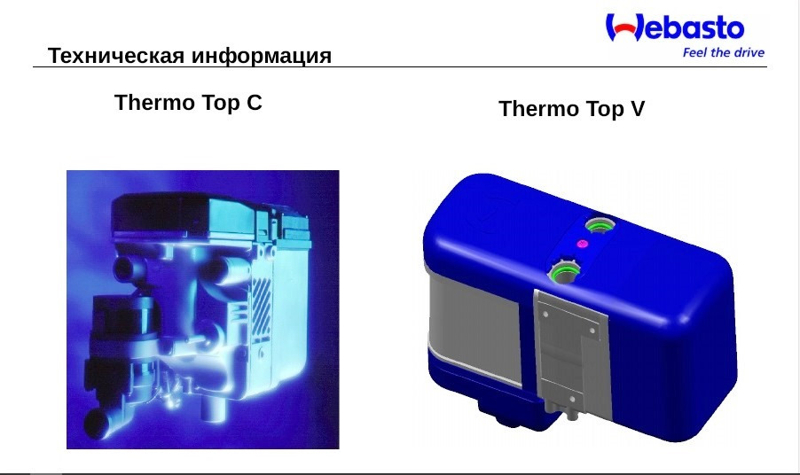
Webasto Thermo Top C, E, Z |
Webasto Thermo V, VEVO В разработке… |
|
|
|
|
Webasto Thermo Top Evo 4, 5, 5+ |
|
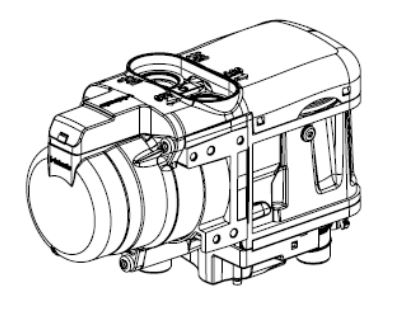
Webasto Thermo Top Evo Start, Comfort+ |
Webasto Thermo Pro 90 |
-
Contents
-
Table of Contents
-
Bookmarks
Quick Links
Coolant Heater
Thermo Top Series
7
6
Legend
1 Electrical Harness sockets
2 Coolant Outlet
3 Fuel Inlet
4 Exhaust
5 Coolant Inlet
6 Coolant Circulation Pump
7 Combustion Air Intake
Special Tools
— Hose Clamping pliers
— Torque Wrench
1.5 Preparation — — — — — — — — — — — — — — — — — — — — — — 7
Installation
2
3
4
Fuel System — — — — — — — — — — — — — — — — — — — — — 16
— — — — — — — — — — — — — — — — — — — — — 18
DOC P/N 5000778C
KIT P/N 5000777B
Light Duty Generic Installation
1
Instructions
2
3
4
5
5
6
7
8
9
9.1 Final Inspection (use installation checklist) -25
12
Printed in USA
Summary of Contents for Webasto Thermo Top C
Всё, что у меня есть про Вебасто.
Webasto Thermo Top V
В преддверии сезона, да и пока есть время, решил поделиться всем, что насобирал на форуме и на просторах интернета.
Надеюсь, будет полезно.
Сначала видео о разборке и профилактике.
Часть 1:
Профилактика Webasto Thermo Top V:
Часть 2:
Профилактика Webasto Thermo Top V. часть 2:
Теперь бумажные инструкции.
Мануал от Вебасто на Русском языке: yadi.sk/i/dTAxsl-E3SAxcS
На английском:
1_Workshop_Manual_Thermo_Top_V: yadi.sk/i/d532gnjU3SAzNx
2_Workshop_Manual_Thermo_Top_V: yadi.sk/i/1_mWZkcz3SAzXR
3__Workshop_Manual_Thermo_Top_V: yadi.sk/i/eSIqaSY-3SAzbw
Снятие Вебасты-1: yadi.sk/i/RCimG9nY3SAxnp
Снятие Вебасты-2: yadi.sk/i/Gznim7623SAxuZ
Инструкция к овальному таймеру: yadi.sk/i/XuD_6PR_3SAxzi
Программа для диагностики: yadi.sk/d/OZ0-DUv-3SAy4P
Коды ошибок: yadi.sk/i/CfSvQ1853SAyQT
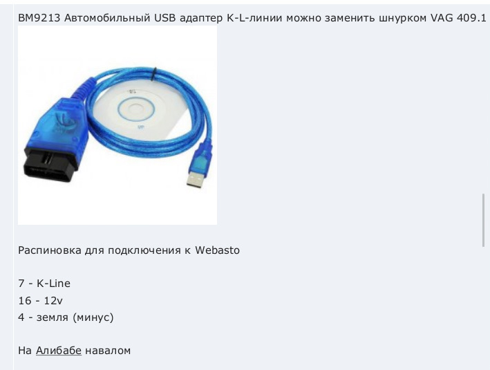
Адаптер для диагностики: BM9213 Автомобильный USB адаптер K-L-линии универсальный
VAG
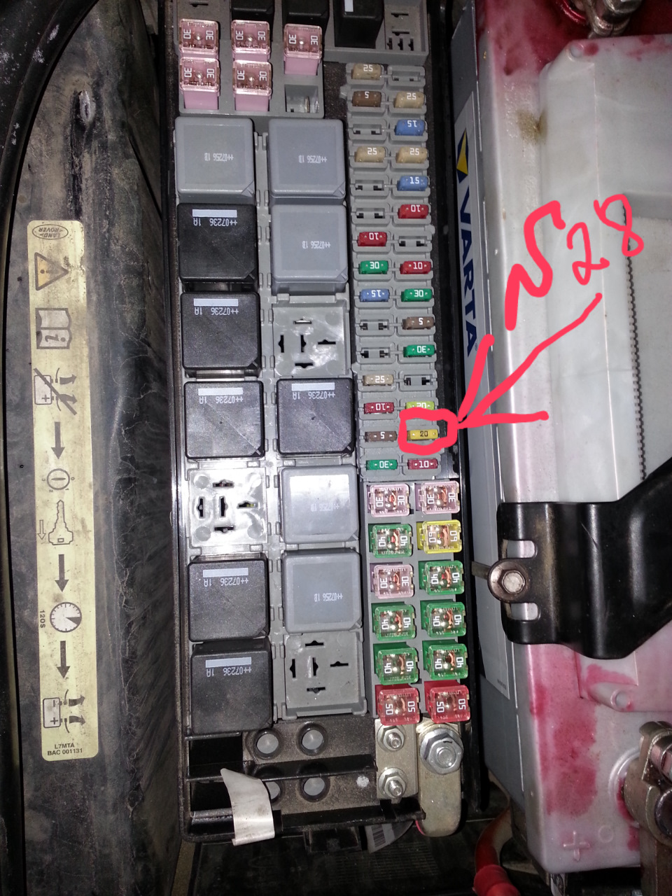
Старая инструкция к мини таймеру, с описанием танца с бубном вокруг предохранителя что бы сбросить ошибки: yadi.sk/i/rKpa_W6O3SAyDc
Предохранитель
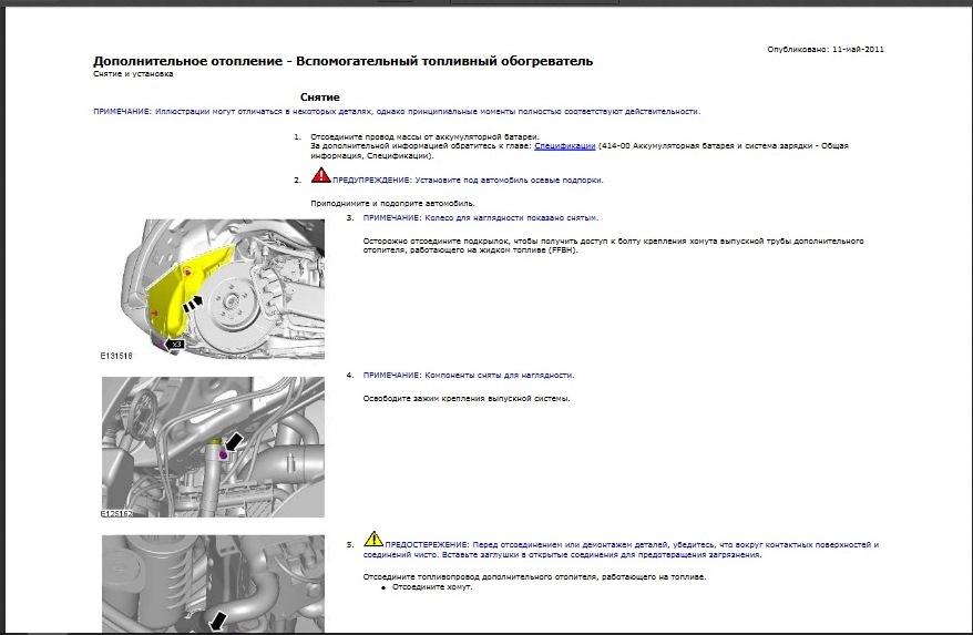
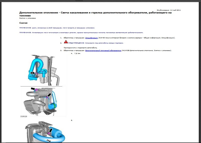
Ремонт ТТЕ, если надо кому: yadi.sk/i/sTTongDT3SAzG2
Добавлю:
1) Хомут на топливный шланг, артикул: N 101 981 01
2) Прокладка под горелку и болты для теплообменника: 1K0 898 022
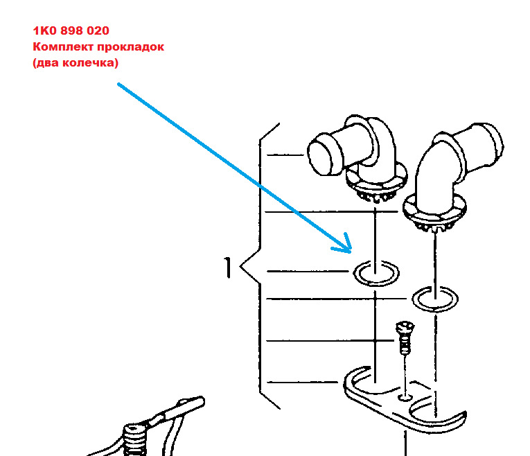
3) Два колечка — прокладки под антифриз: 1K0 898 020
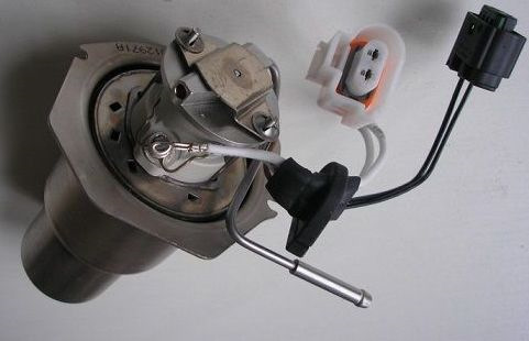
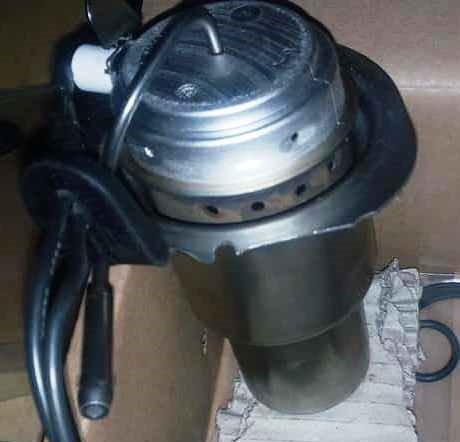
Горелка TTV: LR 010329
Горелка от «Эвока»: LR 031750
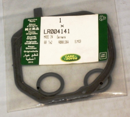
Комплект прокладок от LR: LR004141
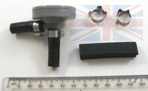
Демпфер топливный (успокоитель): LR023514
А на этом фото большой разъём на котле и оставшиеся в разъёме проводочки после «отвязки» котла от мозгов авто.
В правом нижнем углу видны те самые два отсоединённых проводка. Это было управление котлом климатом авто.
Для чего их нужно отсоединять?
Без этих проводов Вебаста будет работать автономно, не зависимо от температуры окружающей среды, от открытых дверей, от снятия или постановки на сигнализацию.
Редкая версия овального пульта с GSM.
1533 GSM
Инструкция: yadi.sk/i/_m2_DTRQ4MFleg
То, из-за чего горелка выходит из строя: керамический стаканчик — «сопло»
Крышка закрывающая нагнетающий вентилятор Вебасто.
От времени и температуры трескается и многие не замечают или не придают этой трещине значения, а из-за этой трещины, с вероятностью 100%, керамический стаканчик треснет в ближайшую же зиму:
Эту трещину надо просто зашпаклевать термостойким герметиком. Не склеить, всё равно разойдётся, а именно зашпаклевать, как трещину в стене.
Причём за лицевую сторону считать внутреннюю часть крышки, иначе вентилятор будет цеплять за герметик.
- Manuals
- Brands
- Webasto Manuals
- Water Heater
- Thermo Top V
- Workshop manual
-
Contents
-
Table of Contents
-
Troubleshooting
-
Bookmarks
Quick Links
Luft-Heizgeräte
Water heaters
Visit www.butlertechnik.com for more technical information and downloads.
www.butlertechnik.com
03/2003
Workshop Manual
Thermo Top V
Type Thermo Top V (Petrol)
Type Thermo Top V (Diesel)
Related Manuals for Webasto Thermo Top V
Summary of Contents for Webasto Thermo Top V
-
Page 1: Water Heaters
Visit www.butlertechnik.com for more technical information and downloads. Luft-Heizgeräte 03/2003 Water heaters Workshop Manual Thermo Top V Type Thermo Top V (Petrol) Type Thermo Top V (Diesel) www.butlertechnik.com…
-
Page 2
Webasto training course and have the appropriate technical documentation, special tools and special equipment. NEVER try to install or repair Webasto heating or cooling systems if you have not completed a Webasto training course, you do not have the necessary technical skills and you do not have the technical documentation, tools and equipment available to ensure that you can complete the installation and repair work properly. -
Page 3: Table Of Contents
Visit www.butlertechnik.com for more technical information and downloads. Thermo Top V Table of Contents Table of Contents Introduction …………….101 Contents and purpose.
-
Page 4
Table of Contents Thermo Top V Operating tests …………… 601 General . -
Page 5
Visit www.butlertechnik.com for more technical information and downloads. Thermo Top V Table of Contents Packing, Storage and Shipping …………1001 10.1 General. -
Page 6
Cross-sectional functional model of Thermo Top V water heater ……201… -
Page 7: Introduction
This workshop manual contains all necessary information directly at the vehicle manufacturer’s plant as original equip- and instructions for the repair of Thermo Top V water heat- ment. ers. Normally, there is no need to use additional documentation.
-
Page 8: General Information
Webasto. The same applies if repairs are carried out incorrectly or with the use of parts other than gen- uine spare parts. This will result in the invalidation of the type approval for the heater and therefore of its ho- mologation / EC type licence.
-
Page 9: Fig. 201 Cross-Sectional Functional Model Of Thermo Top V Water Heater
Combustion air inlet Fuel inlet Exhaust outlet Fig. 201 Cross-sectional functional model of Thermo Top V water heater Combustion-air fan unit/control unit The combustion air fan supplies the air required for the combustion process from the combustion air inlet to the combustion chamber.The combustion-air fan unit contains:…
-
Page 10: Fig. 203 Standard Connector Plate With Amp Connector Basket
Visit www.butlertechnik.com for more technical information and downloads. General description Thermo Top V Diesel/petrol burner Connector plate variants The processing of the fuel-air mixture and the actual com- bustion take place in the burner. The fuel flows into the pre- heating chamber with the shut-off valve opened, where it is at first heated up.
-
Page 11: Fig. 208 Diesel Burner Without Fuel Preheating
Visit www.butlertechnik.com for more technical information and downloads. Thermo Top V General description For information on removing and installing the burner, see section 9.2.5 and 9.2.7. IMPORTANT Ensure that the correct burner is always used, as otherwise malfunctions and/or damage will occur on the heater and its service life will be reduced! 2.2.1 Fuel preheating…
-
Page 12: Fig. 212 Solenoid Valve
Visit www.butlertechnik.com for more technical information and downloads. General description Thermo Top V Heat exchanger The heat generated in the heat exchanger by combustion is transferred to the coolant circuit. The heat exchanger consists of an inner and an outer sec- Solenoid valve tion, which are sealed off with an O-ring.
-
Page 13: Fig. 216 Dp40/Dp41 Metering Pump
Visit www.butlertechnik.com for more technical information and downloads. Thermo Top V General description Metering pump The metering pump is a combined transport, metering and shut-off system for supplying fuel from the vehicle’s tank to the heater. For information on checking and installing the metering pump, see section 8.6.2.2.
-
Page 14
Visit www.butlertechnik.com for more technical information and downloads. General description Thermo Top V Page for notes www.butlertechnik.com… -
Page 15: Fig. 301
In case of a heater lock-out, the fault must be identified with 7) Switching off of glow plug (glow plug ramp) the Webasto Thermo Test PC diagnosis, the fault memory
Flame-monitor measuring phase must be printed out and the faults must be deleted. Then 9) Combustion operation at full load (5 kW) the cause of the fault must be eliminated.
-
Page 16: Fig. 302 Unlocking Heater
NOTE heater control. The combustion is ended and the run-on As the Thermo Top V auxiliary heater is not switched on begins. In the process, the combustion air fan continues to with a heater control, but instead receives the On signal…
-
Page 17
Visit www.butlertechnik.com for more technical information and downloads. Thermo Top V Description of operation Switch-off or new switch-on signals are processed accord- ing to the following rules: 1. A switch-off signal on a heater control always as priority irrespective of the heater operating state. -
Page 18: Description Of Operation
Visit www.butlertechnik.com for more technical information and downloads. Description of operation Thermo Top V Page for notes www.butlertechnik.com…
-
Page 19: Fig. 401
(permitted function range) Heater dimensions Length 222 mm Width 91 mm Height 144/180 mm Weight 2.1 kg Fig. 401 Technical data for Thermo Top V Circulating pump 4849 4847 Econ Volume flow against 0.14 bar 500 l/h 450 l/h Rated voltage…
-
Page 20
Visit www.butlertechnik.com for more technical information and downloads. Technical data Thermo Top V Page for notes www.butlertechnik.com… -
Page 21: Fig. 501 Overview Of Possible Faults
If there is doubt as to whether the parts are reusable, then Fig. 501 Overview of possible faults new parts should generally be installed. The overview only shows some of the possible faults. The Webasto Service Hotline must be contacted in individual cases. www.butlertechnik.com…
-
Page 22: Fig. 502 Overview Of Functional Analysis Of Heater And Components
Test resistance of the metering pump at +20 °C = 5.2 ohms ± 5 % as described in section 8.6.2.2 Measure delivery rate with Webasto Thermo Test PC Diagnosis as described in section 8.6.2.2 — Petrol: 34 to 42 ml in 180 sec. at 7 Hz.
-
Page 23: Fault Lock-Out Due To Fault On Heater
Unlock as described in section 5.2.2 and installation instructions/installation sug- gestion Control unit (fault memory) Read out fault memory with Webasto Thermo Test PC Diagnosis, then print out and clear fault memory. Include fault log when sending heater to Webasto.
-
Page 24: Troubleshooting
Visit www.butlertechnik.com for more technical information and downloads. Troubleshooting Thermo Top V Page for notes www.butlertechnik.com…
-
Page 25: General
CO meter (e.g. from MSI). 11.5 V. The CO setting is carried out with Webasto Thermo Test PC 5 Switch on the heater with the heater control or the Diagnosis. Webasto Thermo Test PC Diagnosis.
-
Page 26: Fig. 602
6.3.1.3 Testing solenoid valve 6.3.1.1 Testing fan unit Only for diesel burners with solenoid valve. The fan must be tested with the Webasto Thermo Test PC Diagnosis V 2.08 (or higher) as follows: Testing cold resistance: Connect the contacts 1 and 2 of connector X6 (see Fig. 701)
-
Page 27: Electrical Test Of Glow Plug
Visit www.butlertechnik.com for more technical information and downloads. Thermo Top V Operating tests 6.3.1.4 Electrical test of glow plug The cold resistance must be checked using a multimeter with the 4-conductor measuring principle. Multimeters without the 4-conductor measuring principle may not be used for this purpose.
-
Page 28
Visit www.butlertechnik.com for more technical information and downloads. Operating tests Thermo Top V www.butlertechnik.com… -
Page 29: Fig. 701 Connector Assignment Of Heater
General Fig. 701 shows the plug assignment on the control unit. Fig. 702 shows the circuit of the Thermo Top V heater, additional heater and 12 V digital timer. See section 7.2 for legend of wiring diagram. X1 = Connection of vehicle wiring harness (radio remote control, control of metering pump)
-
Page 30: Fig. 702 Wiring Diagram Of Thermo Top V Additional Heater And 12 V Digital Timer
Visit www.butlertechnik.com for more technical information and downloads. Circuit diagrams Thermo Top V Fig. 702 Wiring diagram of Thermo Top V additional heater and 12 V digital timer. www.butlertechnik.com…
-
Page 31
Visit www.butlertechnik.com for more technical information and downloads. Thermo Top V Circuit diagrams Legend for wiring diagram Cable cross-sections Cable colours < 7.5 m 7.5 — 15 m blue brown 0.5 mm 0.75 mm yellow green 0.75 mm 1.0 mm grey 1.0 mm… -
Page 32
Visit www.butlertechnik.com for more technical information and downloads. Circuit diagrams Thermo Top V Page for notes www.butlertechnik.com… -
Page 33: Fig. 801 Circulating Pump U4849 And U4847 Econ Installation Positions
Visit www.butlertechnik.com for more technical information and downloads. Thermo Top V Servicing work Servicing work General • Check fastening of circulating pump and metering pump for damage This section describes the servicing work that can be carried • Conduct operating test of heater as described in section out on the heater when it is installed.
-
Page 34: Fig. 802 Pipe/Hose Connections
In addition, the operation of the pump must be tested as fol- Correct lows: When starting the heater, a slight vibration must be felt on the pump. When controlling with the Webasto Thermo Test Clip PC Diagnosis with maximum power, a soft pump noise must be audible.
-
Page 35: Fig. 804 Information Sign Of Dp40/Dp41 Metering Pump
Visit www.butlertechnik.com for more technical information and downloads. Thermo Top V Servicing work Overview of uses for metering pumps Delivery quantity of metering pumps DP40 and DP41 Metering pump Modulation Diesel Petrol frequency of DP41 ID No. 9009529_ Diesel heater with solenoid metering valve (see section 2.2.2)
-
Page 36: Removal
1 Interrupt power supply of heater by removing 20 A blade fuse from Webasto fuse holder. All coolant and fuel connections must be checked for leaks and secure attachment during a trial run of the heater. If the 2 Separate connectors on heater.
-
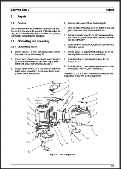
Page 37: Fig. 901 Dismantling Heater
This section describes the permissible repair work on the pull out of control unit (Q) in axial direction. Thermo Top V heater while removed. If it is dismantled fur- ther, any and all warranty claims are voided. An operating Release connector cover (P) on side facing away from test must be conducted after all repairs.
-
Page 38: Fig. 902 Installing Air-Intake And Exhaust Connection Piece
Visit www.butlertechnik.com for more technical information and downloads. Repair Thermo Top V 9.2.2 Assembling heater IMPORTANT When screwing on the water connection pieces and the sensors, do not recut the thread several times. The screw For information on installing new temperature sensors must be carefully screwed into the existing thread by hand (G, Fig.
-
Page 39: Fig. 904 Installing Water Connection-Piece Variant B Without Teeth
The locking lug must be engaged in the connection piece as shown. Engaging is carried out mechanically at Webasto, which is why the entire unit, consisting of the retaining plate and the connection piece, must always be ordered.
-
Page 40: Fig. 907 Cable Routing Of Glow Plug
Visit www.butlertechnik.com for more technical information and downloads. Repair Thermo Top V NOTE ID No. of burner Only for diesel burner with fuel preheating: the heating cartridge of the fuel preheating may not be removed! NOTE Only for diesel burners with solenoid valve: the solenoid valve cannot be removed! 9.2.6 Cable routing for glow plug on burner…
-
Page 41: Fig. 909 Heat Exchanger
Visit www.butlertechnik.com for more technical information and downloads. Thermo Top V Repair 3. Loosen screw (2, Fig. 901). 9.2.10 Heat exchanger 4. Remove retaining spring (F) and pull sensors out of heat Existing soot deposits must be completely removed with a exchanger (sensors are not accessible from inside).
-
Page 42: Fig. 910 Cable Routing For Temperature Sensor And Overheating Sensor With Water Connection-Piece Variant A
Visit www.butlertechnik.com for more technical information and downloads. Repair Thermo Top V Wrong Correct Fig. 910 Cable routing for temperature sensor and overheating sensor with water connection-piece variant A blue Fig. 911 Cable routing for temperature sensor and overheating sensor with water connection-piece variant B…
-
Page 43: Fig. 1001 Preferred Position Of Tt-V Heater For Storage And Transport
Packing, Storage and Shipping 10.1 General 10.3 Transport If the heater or its components are sent to Webasto AG for The heater can be transported in any position. testing or repair, it must be cleaned and packed in such a…
-
Page 44
Visit www.butlertechnik.com for more technical information and downloads. Packing, Storage and Shipping Thermo Top V Page for notes 1002 www.butlertechnik.com… -
Page 45
Visit www.butlertechnik.com for more technical information and downloads. www.butlertechnik.com… -
Page 46
Visit www.butlertechnik.com for more technical information and downloads. Webasto AG Postfach 80 D — 82131 Stockdorf Germany National: Hotline: 01805 93 22 78 (€ 0,14 aus dem deutschen Festnetz) Hotfax: 0395 5592 353 Hotmail: hotline@webasto.de www.webasto.de International: www.webasto.com www.butlertechnik.com…
Сборник инструкций для предпусковых подогревателей двигателя Webasto, в сборнике представлены инструкции к подогревателям различных моделей и поколений.
Инструкции для подогревателя Thermo Top C / E / P
- Инструкция по установке
- Инструкция по эксплуатации
Инструкции для подогревателя Thermo Top Evo
- Инструкция по установке
- Инструкция по эксплуатации
- Инструкция по ремонту
- Чертеж подогревателя
Инструкции для Thermo PRO 90
- Инструкция по установке
- Инструкция по эксплуатации
- Инструкция по ремонту
Инструкции для Thermo 90 S / ST
- Инструкция по установке
- Инструкция по эксплуатации
- Инструкция по ремонту
Инструкции для Thermo 50
- Инструкция по установке
- Инструкция по эксплуатации
- Инструкция по ремонту
Инструкции для Thermo Pro 50 Eco
- Инструкция по установке
- Инструкция по эксплуатации
- Инструкция по ремонту
Инструкции для Thermo E 200/320
- Инструкция по установке
- Инструкция по эксплуатации
- Инструкция по ремонту
Инструкции для Thermo 230/300/350
- Инструкция по установке
- Инструкция по эксплуатации
- Инструкция по ремонту
Инструкции для Thermo BBW 46 / DBW 46
- Инструкция по установке
- Инструкция по эксплуатации
- Инструкция по ремонту
Инструкции для Thermo BW80 / DW80
- Инструкция по установке
- Инструкция по эксплуатации
- Инструкция по ремонту

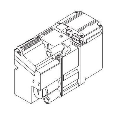
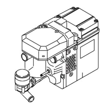
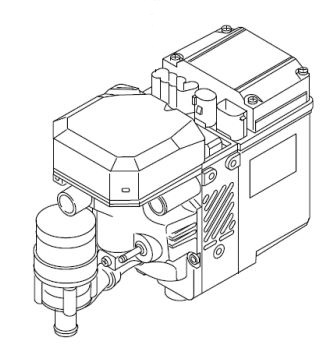 Webasto Thermo 50 (24V)
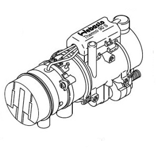 Webasto Thermo 90, 90S
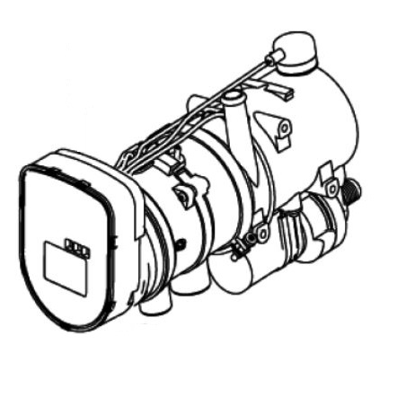 Webasto Thermo 90 ST


 Flame-monitor measuring phase must be printed out and the faults must be deleted. Then 9) Combustion operation at full load (5 kW) the cause of the fault must be eliminated.