Материал из BikesWiki — энциклопедия японских мотоциклов
Перейти к: навигация, поиск

Yamaha FZR250
Ниже представлены прямые ссылки на скачку сервисной документации.
Для Yamaha FZR250 / Yamaha FZR400
- Каталог запчастей (микрофиши) на Yamaha FZR 250 (2KR, 1986-1988)
- Каталог запчастей (микрофиши) на Yamaha FZR 250 (3LN, 1989-1994)
- Каталог запчастей (микрофиши) на Yamaha FZR 400 (1988)
- Сервисный мануал (Service Manual) на Yamaha FZR 400 (1988)
- Сервисный мануал (Service Manual) на Yamaha FZR400RR SP-1 (1992)
Обзор модели
- Yamaha FZR 250
- Yamaha FZR 400
Источник — «https://bikeswiki.ru/index.php?title=Yamaha_FZR250-400:_мануалы&oldid=9966»
Категория:
- Сервисная документация
- Manuals
- Brands
- Yamaha Manuals
- Motorcycle
- FZR400 1988-1989
- Service manual
-
Contents
-
Table of Contents
-
Troubleshooting
-
Bookmarks
Quick Links
Yamaha
FZR400
Service
Manual
1988-1989 Models
Related Manuals for Yamaha FZR400 1988-1989
Summary of Contents for Yamaha FZR400 1988-1989
-
Page 1
Yamaha FZR400 Service Manual 1988-1989 Models… -
Page 3: Table Of Contents
CONTENTS CHAPTER 1. GENERAL INFORMATION IDENTIFICATION ……. . l — l MOTORCYCLE NUMBER .
-
Page 4: Periodic Inspection And Adjustment
CHAPTER 3. PERIODIC INSPECTION AND ADJUSTMENT INTRODUCTION………., 3-1 MAINTENANCE INTERVALS CHART .
-
Page 5
ELECTRICAL……….3-44 INSPECTION . -
Page 6
BEARING AND OIL SEAL ……..YAMAHA EXHAUST VARIABLE VALVE (For California only) ..4-48 ENGINE ASSEMBLY AND ADJUSTMENT. -
Page 7: Cooling System
CHAPTER 5. COOLING SYSTEM INSTALLATION ……….5-4 WATER PUMP AND THERMOSTATIC VALVE.
-
Page 8
FRONT AND REAR BRAKE……..7-10 BRAKE PAD REPLACEMENT . -
Page 9
CHAPTER 8. ELECTRICAL ……CIRCUIT DIAGRAM ELECTRICAL COMPONENTS……..CHECKING OF SWITCHES. -
Page 10
YAMAHA EXHAUST VARIABLE VALVE SYSTEM (For California only)……… . -
Page 11: Motorcycle Identification
CONTENTS INFORMATION ……..GENERAL IDENTIFICATION .
-
Page 12: Engine Serial Number
MOTORCYCLE IDENTIFICATION GENERAL INFORMATION MOTORCYCLE IDENTIFICATION VEHICLE IDENTIFICATION NUMBER The vehicle identification number @ is stemped into the right side of the steering head. Starting serial number: NOTE: The vehicle identification number is used to identify your motorcycle and may be used to register your motorcycle with the licensing authority in your state.
-
Page 13: Specifications
SPECIFICATIONS JSPECII GENERAL SPECIFICATIONS GENERAL SPECIFICATIONS Model Model Code Number: Vehicle Identification Number: Engine Starting Number: Basic Weight: With Oil and Full Fuel Tank 188 kg (414 lb) (FZR400A) 191 kg (421 lb) (FZR400SAC) Tire: Front Rear Tubeless Tubeless Size Manufacture (Type) BRIDGESTONE…
-
Page 14: Maintenance Specifications
92 mm (3.62 in) Bellow the top of inner fork tube without fork spring Oil Grade Yamaha Fork Oil 10WT or equivalent Front Disc Brake: Dual 282 x 4 mm (11 .lO x 0.16 in) Disc Outside Diameter x Thickness…
-
Page 15: Tightening Torque
MAINTENANCE SPECIFICATIONS -1 TIGHTENING TORQUE Tightening torque Part to be tightened Thread size Front Axle and Outer Tube Ml6 x 1.5 10.7 Rear Axle and Nut M8 x I.25 Handlebar Crown and Inner Tube Handlebar Crown and Steering Stem M22 x 1.0 11.0 Brake Caliper (Front/Rear) M8 x 1.25…
-
Page 16: General Torque Specifications
GENERAL TORQUE SPECIFICATIONS Is4 TORQUE GENERAL This chart specifies torque for standard fasteners with standard I.S.O. pitch threads. Torque specifications for special components or assem- blies are included in the applicable sections of this book. To avoid warpage, tighten multi- fastener assemblies in a crisscross fashion, in progressive stages, until full torque is reached.
-
Page 17: Periodic Inspections And Adjustments
DRIVE CHAIN SLACK ADJUSTMENT PERIODIC INSPECTIONS AND ADJUSTMENTS CHASSIS DRIVE CHAIN SLACK ADJUSTMENT NOTE: Before checking and/or adjusting the chain slack, rotate the rear wheel several revolutions. Check the chain slack several times to find the point where the chain is the tightest. Check and/or adjust the chain slack where the rear wheel is in this “tight chain”…
-
Page 18
DRIVE CHAIN SLACK ADJUSTMENT ADJ m Clockwise Counterclockwise decreased. NOTE: Turn each adjuster exactly the same amount to maintain correct axle alignment. (There marks on each side of swingarm; use them to check for proper alignment.) Tighten the locknut. Tighten the axle nut to specification, while pushing up or down on the chain to zero slack. -
Page 19: Chassis
REAR WHEEL -1 CHASSIS REAR WHEEL @ C o l l a r @ C o l l a r WEAR LIMIT: 1 .O mm (0.04 in) RIM SIZE: MT4.00 x 18 RIM RUNOUT LIMIT: RADIAL: 2.0 mm (0.08 in) LATERAL:…
-
Page 20: Rearwheel
REAR WHEEL -1 REMOVAL 1. Place the motorcycle on a level place. Securely support the motorcycle so there is no danger of it falling over. 2. Elevate the rear wheel by placing a suitable stand under the swingarm. 3. Remove: Bolts (brake caliper) @ NOTE: Do not depress the brake pedal while the caliper…
-
Page 21: Inspection
REAR WHEEL INSPECTION 1. Inspect: Tire Rear wheel axle Wheel Wheel bearings Refer to the “FRONT WHEEL — INSPEC- TION”. 2. Measure: Wheel runout Refer to the “FRONT WHEEL — INSPEC- . TION”. 3. Check: Wheel balance Refer to the “FRONT WHEEL — INSPEC- TION”.
-
Page 22: Static Wheel Balance Adjustment
REAR WHEEL lctf=l &x31 Do not loosen the axle nut after torque tighten- ing. If the axle nut groove is not aligned with the wheel shaft cotter pin hole, align groove with the hole by tightening up on the axle nut. 4.
-
Page 23: Front And Rear Brake
FRONT AND REAR BRAKE pqzq FRONT AND REAR BRAKE The arrow mark @ on the pad spring must pointing the disc rotating direction. @Brake pad 2 Nm (0.2 rn. kg, 1.4 ftslb) If DOT #4 is not available, 20 Nm (2.0 ma kg,…
-
Page 24
FRONT AND REAR BRAKE @Brake caliper @Diaphragm @ P i s t o n @Piston seal @Brake disc… -
Page 25: Brake Pad Replacement
FRONT AND REAR BRAKE pi$q Disc brake components rarely require disassem- bly. DO NOT: Disassembly components unless absolutely nec- essary. Use solvents on internal brake component. Use contaminated brake fluid for cleaning. Use only clean brake fluid. ?? AIIOW brake fluid to come in contact with the eyes otherwise eye injury may occur.
-
Page 26
FRONT AND REAR BRAKE -1 Remove: Brake pads @ NOTE: Replace the pad spring if the pad replacement is required. Replace the pads as a set if either is found to be worn to the wear limit. 0.5 mm (0.02 in) 4. -
Page 27
FRONT AND REAR BRAKE -1 6. Inspect: Brake fluid level Refer to the “BRAKE FLUID INSPEC- TION” section in the CHAPTER 3. 7. Check: Brake lever operation A softy or spongy filling + Bleed brake system. Refer to the “Al R BLEEDING” section in the CHAPTER 3. -
Page 28
FRONT AND REAR BRAKE b-l &I 4. Remove: Brake pads (with shims) @ Pad spring @ NOTE : Replace the pad spring if the pad replacement is required. Replace the pads as a set if either is found to be worn to the wear limit. Replace the pad shim if the pad replacement is required. -
Page 29
FRONT AND REAR BRAKE -1 6. Install: Retaining bolts @ Retaining bolts: 10 Nm (1.0 ma kg, 7.2 ft. lb) 7. Install: Bolts (brake caliper) @ Bolts (brake caliper): 35 Nm (3.5 rn- kg, 25 ft. lb) 8. Inspect: Brake fluid level Refer to the “BRAKE FLUID INSPEC- TION”… -
Page 30: Caliper Disassembly
FRONTANDREARBRAKE CALIPER DISASSEMBLY NOTE: Before disassembling the front or rear brake master cylinders, drain the brake hose, master cylinder, brake caliper and reservoir tank of their brake fluid. Securely support the motorcycle so there is no danger of it falling over. Front brake 1.
-
Page 31
FRONT AND REAR BRAKE -1 4. Remove: Pistons 0 Dust seals @ Piston seals @I Remove steps: *Blow compressed air into the tube joint opening to force out the piston from the caliper body. Never try to pry out the piston. Cover the piston with a rag. -
Page 32: Master Cylinder Disassembly
FRONT AND REAR BRAKE pi&E&l Remove steps: Blow compressed air into the tube joint opening to force out the piston from the caliper body. Never try to pry out the piston. Cover the piston with a rag. Use care so that piston does not cause injury as it is expelled from the cylinder.
-
Page 33
FRONT AND REAR BRAKE 3. Remove: Master cylinder @ 4. Remove: Cap (master cylinder) 6) Diaphragm @ . Dust boot @ Circlip 0 Master cylinder kit @ Rear brake 1. Remove: Side cover (right) 2. Remove: Cotter pin @ Washer @ Disconnect: Reservoir hose @ Place the open hose end into a container… -
Page 34: Inspection And Repair
FRONT AND REAR BRAKE ICHASl &I 7. Remove: Reservoir tank @ (from flame) Cap (reservoir tank) @ Holder (diaphragm) @ Diaphragm @ INSPECTION AND REPAIR All internal parts should be cleaned in new brake fluid only. Do not use solvents will cause seals to swell and distort.
-
Page 35
FRONT AND REAR BRAKE 3. Inspect : Master cylinder @ Wear/Scratches -+ Replace. Master cylinder body @ Cracks/Damage Blow out with compressed air. 4. Inspect: Master cylinder kit @ Scratches/Wear/Damage Replace. Front 5. Inspect: Diaphragm (front) @ Diaphragm (rear) @ Wear/Damage -+ Replace. -
Page 36
FRONT AND REAR BRAKE 6. Inspect: Brake hoses @ Cracks/Wear/Damage Replace. Front 7. Measure: Brake pads (thickness) @ Out of specification + Replace. Wear limit: 0.5 mm (0.02 in) NOTE: Replace the pad spring as a set if pad replace- ment is required. -
Page 37: Assembly
FRONT AND REAR BRAKE ASSEMBLY brake fluid only. Internal parts should be lubricated with brake fluid when installed. Replace the piston seal and dust seal whenever a caliper is disassembled. Securely support the motorcycle so there is no danger of it falling over. Brake fluid: DOT #4…
-
Page 38
FRONT AND REAR BRAKE bHAsi @@d 4. Install: Copper washers @ Brake hose @ (onto brake caliper) Union bolt: 26 Nm (2.6 m — kg, 19 ft. lb) When installing the brake hose to the caliper tion @ on brake caliper. Proper hose routing is essential to insure safe Refer to “CABLE motorcycle operation. -
Page 39
FRONT AND REAR BRAKE 7. Install: Brake hose @ Copper washers @ Union bolts @ 26 Nm (2.6 m — kg, 19 ft- lb) *Proper hose routing is essential to insure safe motorcycle operation. Refer to the “CABLE ROUTING”. Always use new copper washers. 8. -
Page 40
FRONT AND REAR BRAKE 10. Install: Diaphragm @ Master cylinder cap @ Screws (master cylinder cap): 2 Nm (0.2 m — kg, 1.4 ft. lb) 11. Air bleed: @Brake system Refer to the “AIR BLEEDING” section in the CHAPTER 3. 12. -
Page 41
FRONT AND REAR BRAKE pi$q 3. Install: Brake caliper 0 Bolts (brake caliper): 35 Nm (3.5 m — kg, 25 ft. lb) 4. Install: Master cylinder kit @ Push rod @ 5. Install: Master cylinder assembly @ Bolts (master cylinder assembly): 35 Nm (3.5 m — kg, 25 ft. -
Page 42
FRONT AND REAR BRAKE lct-~ ebbi 8. Install: Brake hose Copper washers Union bolts Reservoir hose Union bolts: 26 Nm (2.6 rn- kg, 19 ft. lb) When installing the brake hose, lightly touch the brake pipe @ with the projections @ on the caliper and master cylinder. -
Page 43
FRONT AND REAR BRAKE [iiiqq Use only the designated quality brake fluid: otherwise, the rubber seals may deteriorate, causing leakage and poor brake performance. Refill with the same type of brake fluid; mixing fluids may result in a harmful chem- ical reaction and lead to poor performance. -
Page 44
CONTENTS CHAPTER 1. GENERAL INFORMATION IDENTIFICATION ……. . l — l MOTORCYCLE NUMBER . -
Page 45
CHAPTER 3. PERIODIC INSPECTION AND ADJUSTMENT INTRODUCTION………., 3-1 MAINTENANCE INTERVALS CHART . -
Page 46
ELECTRICAL……….3-44 INSPECTION . -
Page 47
BEARING AND OIL SEAL ……..YAMAHA EXHAUST VARIABLE VALVE (For California only) ..4-48 ENGINE ASSEMBLY AND ADJUSTMENT. -
Page 48
CHAPTER 5. COOLING SYSTEM INSTALLATION ……….5-4 WATER PUMP AND THERMOSTATIC VALVE. -
Page 49
FRONT AND REAR BRAKE……..7-10 BRAKE PAD REPLACEMENT . -
Page 50
CHAPTER 8. ELECTRICAL ……CIRCUIT DIAGRAM ELECTRICAL COMPONENTS……..CHECKING OF SWITCHES. -
Page 51
YAMAHA EXHAUST VARIABLE VALVE SYSTEM (For California only)……… . -
Page 52: Motorcycle Identification
MOTORCYCLE IDENTIFICATION INFO 6% ” ‘ ” GENERAL MOTORCYCLE IDENTIFICATION VEHICLE IDENTIFICATION NUMBER The vehicle identification number @ is stemped into the right side of the steering head. NOTE: The vehicle identification number is used to identify your motorcycle and may be used to register your motorcycle with the licensing authority in your state.
-
Page 53: Important Information
5. Keep away from fire. ALL REPLACEMENT PARTS 1. Use only genuine Yamaha parts for all re- placements. Use oil and/or grease recom- mended by Yamaha for assembly and adjust- ment. Other brands may be similar in func- tion and appearance, but inferior in quality.
-
Page 54: Lock Washers/Plates And Cotter Pins
IMPORTANT INFORMATION INFO 8% LOCK WASHERS/PLATES AND COTTER PINS 1. All lock washers/plates @ and cotter pins must be replaced when they are removed. Lock tab(s) should be bent along the bolt or nut flat(s) after the bolt or nut has been pro- perly tightened.
-
Page 55: Special Tools
SPECIAL TOOLS SPECIAL TOOLS The proper special tools are necessary for com- plete and accurate tune-up and assembly. Using the correct special tool will help prevent damage caused by the use of improper tools or impro- vised techniques. FOR TUNE UP 1.
-
Page 56: For Engine Service
SPECIAL TOOLS INFO df@ 5. Vacuum Gauge YU-08030 This gauge is needed for carburetor synchroniza- tion. FOR ENGINE SERVICE 1. Cam Chain Cutter P/N Y M-01 112 This tool is used when cutting the cam chain. 2. Piston Pin Puller YU-01304 This tool is used to remove the piston pin.
-
Page 57
SPECIAL TOOLS INFO d!@ 5. Universal Rotor Holder YU-01235 This tool is used when loosening or tightening the A.C. magneto securing bolt. 6. Heavy Duty Puller P/N Y U-33270 This tool is used to remove the starter clutch. 7. Camshaft Wrench YM-04115 This tool is used to turn the camshaft. -
Page 58
SPECIAL TOOLS INFO IO. Valve Guide Installer P/N YM-041 I7 This tool is needed to install the valve guides properly. 1 I. Valve Guide Reamer (4.5 mm) P/N YM-041 I8 This tool is used to rebore the new valve guide. 12. -
Page 59: For Chassis Service
SPECIAL TOOLS INFO d@@ 15. Piston Base P/N Y M-01 067 Use 4 of these to hold the piston during cylinder installation. 16. Radiator Cap Tester P/N Y U-24460-01 Adaptor P/N Y U-33984 This tester is needed for checking the cooling system.
-
Page 60: For Electrical Components
SPECIAL TOOLS INFO FOR ELECTRICAL COMPONENTS 1. Dynamic Coil Tester P/N Y M-34487 This tester is necessary for checking the ignition system components. 2. Pocket Tester P/N Y U-031 12 This instrument is invaluable for checking the electrical system.
-
Page 61: Chapter 2. Specifications
GENERAL SPECIFICATIONS (SPECII SPECIFICATIONS GENERAL SPECIFICATIONS Model 3BF (FZR400U) Model Code Number: 3 F H (FZR400SUC) Vehicle Identification Number: Engine Starting Number: Dimensions: Overall Length 2,070 mm (81.5 in) Overall Width 690 mm (27.2 in) Overall Height 1,125 mm (44.3 in) Seat Height 785 mm (30.9 in) Wheelbase…
-
Page 62: General Torque Specifications
GENERAL SPECIFICATIONS (,,,,I1 Model Unleaded fuel recommended 18.0 L (3.94 Imp gal, 4.8 US gal) Tank capacity 3.0 L (0.66 Imp gal, 0.79 US gal) Reserve Amoun BDS32 x 4 Type x Quantity Manufacturer Type (Manufacture) 0.7 — 0.8 mm (0.028 — 0.032 in) Wet, multiple-disc Transmission: Spur gear…
-
Page 63
GENERAL SPECIFICATIONS ISPECp(y Model Brake: Dual disc brake Front Brake Type Right hand operation Operation Single disc brake Rear Brake Type Right foot operation Operation Suspension: Telescopic fork Front Suspension Rear Suspension Shock Absorber: Coil spring/Oil damper Front Shock Absorber Coil gas spring/Oil damper Rear Shock Absorber Wheel Travel:… -
Page 64
MAINTENANCE SPECIFICATIONS (,,,,I1 MAINTENANCE SPECIFICATIONS Engine Model Cylinder Head: Warp Limit* 0.03 mm (0.0012 in) , *Lines indicate straightedge measurement Cylinder: Bore Size 56.000 — 56.005 mm (2.2047 — 2.2049 ir Drive Method Chain drive (Center) Cam Cap Inside Dia. 23.000 — 23.021 mm (0.9055 — 0.9063 ir Camshaft Outside Dia. -
Page 65
MAINTENANCE SPECIFICATIONS Model “A” Head Dia. 21.9 — 22.1 mm (0.8622 — 0.8701 in) 18.9 — 19.1 mm (0.7441 — 0.7520 in) 1.6 — 2.4 mm (0.0630 — 0.0945 in) 1.6 — 2.4 mm (0.0630 — 0.0945 in) “C” Seat Width 0.9 — 1 .l mm (0.0354 — 0.0433 in) 0.9 — 1 .l mm (0.0354 — 0.0433 in) <… -
Page 66
MAINTENANCE SPECIFICATIONS piqjqJ Model 55.945 — 55.960 mm (2.2026 — 2.2031 in) Piston Size “D” 5 mm (0.197 in) Measuring Point “H” (From bottom line of piston skirt) — — — — — — — — 0.04 — 0.06 mm (0.0016 — 0.0024 in) Piston-to-Cylinder Clearance <… -
Page 67
MAINTENANCE SPECIFICATIONS piqjq Model FZ R400U/FZR400SUC Main Journal Oil Clearance 0.025 — 0.043 mm (0.0010 — 0.0017 in) Bearing Size No. Color Code 1. Blue 2. Black 3. Brown 4. Green 5. Yellow Clutch: 2.9 — 3.1 mm (0.114 — 0.122 in) x 8 Friction Plate Thickness x Quantity Wear Limit 2.8 mm (0.11 in) -
Page 68
MAINTENANCE SPECIFICATIONS pqjq Model Lubrication System: Oil Filter Type Paper Trochoid pump Oil Pump Type 0.09 — 0.15 mm (0.0035 — 0.0060 in) Tip Clearance < 0.2 mm (0.008 in) > < Limit > Side Clearance 0.03 — 0.08 mm (0.0012 — 0.0031 in) <… -
Page 69
MAINTENANCE SPECIFICATIONS Model Lubrication chart: Pressured feed Main journal bearing Main journal bearing Oil pan Crankcase (Lower) Crankcase (Upper) 8 mm Bolt: 24 Nm (2.4 m-kg, 17 ft.lb) mm Bolt: 12 Nm (1.2 m-kg, 8.7 ft*Ib) -
Page 70: Maintenance Specifications
MAINTENANCE SPECIFICATIONS (SPECI] Tightening torque Part to be tightened Part name Remarks size 1 .o Flange bol Camshaft Cap Cylinder Head M l 0 Spark Plug Bolt 1 .o Cylinder Head Cover Blind Plug (Sand) Screw M l 2 Screw Blind Plug (Water) Connecting Rod Cam Chain Sprocket…
-
Page 71: Chassis
Oil Capacity 92 mm (3.62 in) Oil Level (Fully Compression) Bellow the top of inner fork tube without fork spring Oil Grade Yamaha Fork Oil IOWT or equivalent Rear Suspension: 50 mm (I .97 in) Shock Absorber Travel Spring Free Length 196.5 mm (7.74 in)
-
Page 72
MAINTENANCE SPECIFICATIONS Model Dual Disc Outside Diameter x Thickness 5.5 mm (0.22 in) Inner Pad Thickness 0.5 mm (0.02 in) < L i m i t >* 5.5 mm (0.22 in) Outer Pad Thickness < L i m i t >* 0.5 mm (0.02 in) 15.87 mm (0.62 in) Master Cylinder Inside Diameter… -
Page 73
MAINTENANCE SPECIFICATIONS (SPECII Tightening torque Part to be tightened Thread size Front Axle and Outer Tube Rear Axle and Nut 10.7 Handlebar Crown and Inner Tube Handlebar Crown and Steering Stem M22 x 1.0 1 1 0 11.0 Brake Caliper (Front/Rear) Bleed Screw and Brake Caliper Brake Hose and Union Bolt Front Master Cylinder and Master Cylinder Holder… -
Page 74: Electrical
MAINTENANCE SPECIFICATIONS -1 Electrical Model Voltage: Ignition System: IO” at 1,300 r/min Ignition Timing (B.T.D.C.) 48” at 6,500 r/min (3BF), 38” at 3,500 r Advanced Timing (B.T.D.C.) Electrical Advancer Type 3FH: 3BF: 9 1 0 1 1 1 2 1 314 15 1 0 1 1 1 2 1 3 1 4 1 5 Engine Speed (x IO3 r/min)
-
Page 75
MAINTENANCE SPECIFICATIONS Model Electrical Starter System: Constant mesh type Starter Motor: SM-7/M ITSUBA Model/Manufacturer output Armature Coil Resistance 11 mm (0.43 in) Brush — Overall Length 5 mm (0.20 in) < Limit > 540 — 660 g (19.05 — 23.28 oz) 23 mm (0.91 in) Commutator Dia. -
Page 76: General Torque Specifications
GENERAL TORQUE SPECIFICATIONS [+q-jqq GENERAL TORQUE General torque specifications This chart specifies torque for standard fasteners 10 mm with standard I.S.O. pitch threads. Torque specifications for special components or assem- 12mm blies are included in the applicable sections of 14 mm 10 mm this book.
-
Page 77: Lubrication Point And Grade Of Lubricant
LUBRICATION POINT AND GRADE OF LUBRICANT piqjqq LUBRICATION POINT AND GRADE OF LUBRICANT ENGINE Symbol Lubrication Point Oil seal lip O-Ring Bearing Piston surface Piston pin Cylinder head bolt Crankshaft pin Crankshaft journal Connecting rod bolt/Nut Camshaft cam lobe/Journal Valve stem (IN, EX) Valve stem end (IN, EX) Valve lifter Water pump impeller shaft…
-
Page 78
LUBRICATION POINT AND GRADE OF LUBRICANT l=l CHASSIS Lubrication Point Steering bearing (Upper/Lower) Wheel bearing/Axle Front wheel oil seal (Right/Left) Rear wheel oil seal Clutch hub oil seal Clutch hub fitting area Rear brake pedal shaft Change pedal Side stand sliding surface Tube guide (Throttle grip) inner surface Brake lever bolt, sliding surface Clutch lever bolt, sliding surface… -
Page 79: Lubrication Diagram
LUBRICATION DIAGRAM LUBRICATION DIAGRAM…
-
Page 80: Coolant Diagram
COOLANT DIAGRAM @Thermostatic valve 2-20…
-
Page 81
CABLE ROUTING CABLE ROUTING (‘I) Insert the clutch cable into the frame inner hole. 2-21… -
Page 82
CABLE ROUTING bpEcl CABLE ROUTING (2) Pass the handlebar switch lead (Left) behind the inner tube •I To headlight unit To flasher light (Left) To flasher light (Right) -
Page 83
CABLE ROUTING CABLE ROUTING (3) -
Page 84
CABLE ROUTING -1 To handlebar switch (Left) @Speedometer assembly To clutch lever Pass the speedometer cable outside the inner tube. @ H o r n To air filter case @Brake hose To fuel tank To fuel pump @Front brake caliper (Left) Pass the sidestand switch lead inside the water pipe. -
Page 85
CABLE ROUTING CABLE ROUTING (4) 2-26… -
Page 86
CABLE ROUTING To radiator cap assembly @Brake hose (Right) Pass the spark lead and fan motor lead along the air @ C l a m p guide groove. Pass the recovery tank hose on the fuel tank bracket. @Spark lead (Right) Pass on the inside of the water pipe the carburetor @Air guide… -
Page 87
CABLE ROUTING ISPEC(l CABLE ROUTING (5) -
Page 88: Cable Routing
CABLE ROUTING (SPECII To fuel pump Pass the starter motor lead under the starter motor. Pass on the inside of the water pipe the carburetor motor air vent hose on the side of the #I and #2 cylinders, @ C l a m p and clamp this hose together with the carburetor air vent hose on the side of the # 3 and #4 cylinders.
-
Page 89: Maintenance Intervals Chart
INTRODUCTION/MAINTENANCE INTERVALS CHART ADJ PERIODIC INSPECTIONS ADJUSTMENTS INTRODUCTION This chapter includes all information necessary to perform recommended inspections and adjustments. These preventive maintenance procedures, if followed, will ensure more reliable vehicle operation and a longer service life. The need for costly overhaul work will be greatly reduced. This information ap- plies to vehicles already in service as well as new vehicles that are being prepared for sale.
-
Page 90
Check chain condition. D r i v e Adjust and Every 500 km (300 mi) lubricate chain motor oil. chain thoroughly. Yamaha chain Apply chain and cable Control lube or SAE and meter lube thoroughly. 1 OW30 motor cable oil. -
Page 91
Check and Sidestand clean or switch replace if necessary. *It is recommended that these items be serviced by a Yamaha dealer or other qualified mechanic. NOTE: the above maintenance at the period established, ““1: Every odometer reading, repeat 6,000 km (3,800 mi), **2:… -
Page 92: Cowling Removal And Installation
COWLINGS REMOVAL AND INSTALLATION COWLING REMOVAL AND INSTALLATION REMOVAL 1. Remove: Lower cowling (Left) 2. Remove: Lower cowling (Right) 3. Remove: Center cowling (Left) 4. Remove: Center cowling (Right)
-
Page 93
5. Remove: Rear view mirrows (Left and right) 9. Remove:… -
Page 94
COWLINGS REMOVAL AND INSTALLATION Remove: Seat NOTE: To open the seat lock, insert the key in the lock and turn it clockwise. 11. Remove: Top cover INSTALLATION Reverse the “REMOVAL” procedure. Note the following points. 1. install: Seat NOTE: Make sure that the seat is securely fitted. ?? When reinstalling the seat, insert the lobes on the seat front into the receptacles on the frame, then push down the seat. -
Page 95: Engine
2. Remove: Valve cover @ 3. Turn on the main switch. NOTE: If does not operate EXUP servo motor, refer to the “YAMAHA EXHAUST VARIABLE VALVE SYSTEM” section in the CHAPTER 8. 4. Check: Alignment mark @ Not aligned + Adjust EXUP cables.
-
Page 96: Valve Clearance Adjustment
VALVE CLEARANCE ADJUSTMENT AD J @!!!iii 7. Install: (Valve Cover): 10 Nm (1.0 m-kg, 7.2 ft.lb) VALVE CLEARANCE ADJUSTMENT The engine must be cool before servicing the valve clearance. NOTE: Measure and adjust valve clearance when piston is at TDC on compression stroke. REMOVAL 1.
-
Page 97
J @iii VALVE CLEARANCE ADJUSTMENT AD 5. Remove: Radiator cap @ 6. Drain: ‘“COOLANT REPLACE. Refer to the MENT” section. 7. Disconnect: Fan motor coupler @ 8. Disconnect: Hose (Radiator — Inlet) Hose (Radiator — Outlet) 9. Remove: Radiator 10. Remove: Spark plug leads Cylinder head cover Generator cover… -
Page 98: Valve Clearance Adjustment
VALVE CLEARANCE ADJUSTMENT UOTE: T.D.C. can be found when the : a m l o b e s a r e a p a r t f r o m e a c h o t h e r , a s Gauge @ .
-
Page 99
J @iii VALVE CLEARANCE ADJUSTMENT AD Refer to the “ENGINE DISASSEMBLY CAM- SHAFT AND CYLINDER HEAD — Procedure Fasten the wire to the cam chain to prevent it from falling into the crankcase. Remove: Use valve lapper @ Record the installed pad number. NOTE: Place a piece of rug in the cam chain room to prevent the pad from falling into the… -
Page 100
VALVE CLEARANCE ADJUSTMENT AD EXAMPLE: Installed pad number = 148 (1.48 mm) Rounded off digit = 150 NOTE: Pads can only be selected in 0.05 mm (0.002 in) increments. Locate the “Rounded off Pad Number” on the chart, and then find the measured valve clearance. -
Page 101
VALVE CLEARANCE ADJUSTMENT INTAKE 235 240 220 225 225 230 VALVE CLEARANCE (cold): 0.11 — 0.20 mm (0.004 — 0.008 in) Example: Installed is 170 Measured clearance is 0.24 mm (0.009 in) Replace 170 pad with 180 pad EXHAUST 180118511901195 205 210~215~220~225~230~23E VALVE CLEARANCE… -
Page 102
VALVE CLEARANCE ADJUSTMENT ADJ m NOTE: Refer to the “ENGINE ASSEMBLY AND AD- J U S T M E N T H E A D A N D CAMSHAFT” section in the CHAPTER 4. Turn the carnkshaft counterclockwise several turns for the installed parts to settle into the correct position. -
Page 103: Carburetor Synchronization
CARBURETOR SYNCHRONIZATION Recheck: Align the matching marks @ . 4. Install: Chain guide (Upper) @ Chain guide (Exhaust side) @I Bolts (Chain Guide): 10 Nm (1.0 m-kg, 7.2 ft.lb) 5. Install: Cylinder head cover Bolts (Cylinder Head Cover): 10 Nm (1.0 m-kg, 7.2 ft-lb) 6.
-
Page 104
CARBURETOR SYNCHRONIZATION AD 1. Remove: Refer to the “COWLING REMOVAL AND section. INSTALLATION — REMOVAL” 2. Remove: Fuel tank R e f e r t o t h e “ C A R B U R E T O R — R E — MOVAL”… -
Page 105: Idle Speed Adjustment
IDLE SPEED ADJUSTMENT AD *Racing the engine for less than a second, two or three times, and check the syn- chronization again. Vacuum Pressure at Idle Speed: 21.33 f 0.6 kPa (160 * 5 mmHg, 6.30 f 0.2 inHg) Vacuum Synchronous Difference: 1.33 kPa (10 mmHg, 0.4 inHg) carburetor No.
-
Page 106: Throttle Cable Free Play Adjustment
THROTTLE CABLE FREE PLAY ADJUSTMENT T H R O T T L E C A B L E F R E E P L A Y A D J U S T — M E N T NOTE: Before adjusting the throttle cable free play, the engine idle speed should be adjusted.
-
Page 107: Spark Plug Inspection
SPARK PLUG INSPECTION Throttle Cable Free Play (Throttle Grip) @ : 2 — 5 mm (0.08 — 0.20 in) Tighten the locknut @ . NOTE: Normally, once the throttle cable length adjuster (carburetor) is properly set; the only adjustment required is maintenance of free play at the throttle cable length adjuster (Throttle grip).
-
Page 108: Ignition Timing Check
IGNITION TIMING CHECKS AD 4. Measure: *Spark plug gap Out of specification * Regap. Use a wire gauge. Spark Plug Gap: mm (0.028 — 0.032 in) 0.7 — 0.8 5. Tighten: NOTE: Before installing a spark plug, clean the gasket surface and plug surface.
-
Page 109: Compression Pressure Measurement
COMPRESSION PRESSURE MEASUREMENT AD 4. Warm up the engine and allow it to idle at the specified speed. Engine Idle Speed: 1,250 — 1,350 r/min Check: Visually check the crankcase end @ is within the firing range @ on the magneto. Out of firing range -+ Check pickup as- sembly.
-
Page 110
COMPRESSION PRESSURE MEASUREMENT (be sure the battery is fully charged) with the throttle wide open until the compression reading on the gauge stabilizes. *Check readings with specified levels (See chart). Compression Gauge: Compression Pressure (At sea level) : Standard : 950 kPa (9.5 kg/cm2, 138 psi) Minimum: 750 kPa (7.5 kg/cm2, 109 psi) -
Page 111: Engine Oil Level Inspection
ENGINE OIL LEVEL INSPECTION/ ENGINE OIL REPLACEMENT ENGINE OIL LEVEL INSPECTION 1. Place the motorcycle on its centerstand and warm up the engine for several minutes. NOTE: Position motorcycle straight up when checking oil level, a slight tilt to the side can produce false readings.
-
Page 112: Engine Oil Filter Replacement
ENGINE OIL FILTER REPLACEMENT Fill: CAUTION: Do not allow foreign material to enter the crankcase. Periodic Oil Change: L (2.4 Imp qt. 2.9 US qt) Recommended Engine Oil: At 5°C (40” F) or Higher: Yamalube 4-cycle oil or SAE 2OW40 Type SE Motor Oil At 15°C (60°F) or Lower: SAE lOW30 Type SE Motor Oil 8.
-
Page 113
ENGINE OIL FILTER REPLACEMENT Remove: @Spring @ Check: Cracks/Damage —f Replace. 8. install: Shim To oil filter cover. Be sure the O-ring (ij is positioned properly. 9. Install: Bolt (Oil Filter Cover): 15 Nm (1.5 m-kg, 11 ft-lb) NOTE: Mesh the oil filter cover projection (0 with the crankcase slot. -
Page 114: Clutch Adjustment
J @!iii CLUTCH ADJUSTMENT AD CLUTCH ADJUSTMENT 1. Check: Clutch lever free play :a Out of specification —f Adjust. 2 — 3 mm (0.08 — 0.12 in) 2. Adjust: Clutch lever free play Adjustment steps: Loosen the locknut @ , Turn the adjuster @ in or out until the specified free play is obtained.
-
Page 115: Air Filter Cleaning
AIR FILTER CLEANING/CARBURETOR INSP JOINT INSPECTION/FUEL LINE INSPECTION AD AIR FILTE3 CLEANING 1. Remove: Seat Top cover “ C O W L I N G R E M O V A L R e f e r t o t h e A N D I N S T A L L A T I O N section.
-
Page 116: Crankcase Ventilation Hose Inspection
CRANKCASE VENTILATION HOSE INSPECTION/ EXHAUST SYSTEM INSPECTION 2. Inspect: Fuel pipes Cracks/Damage + Replace. Fuel filter Contamination/Damage + Replace. NOTE: Drain and flush the fuel tank if abrasive damage to any components is evident. CRANKCASE VENTILATION HOSE INSPEC- TION 1. Remove: Top cover Refer to the “COWLING REMOVAL AND STALLATION — REMOVAL”…
-
Page 117: Coolant Level Inspection
COOLANT LEVEL INSPECTION/COOLANT REPLACEMENT 3. Tighten: Nuts (Exhaust Pipe) : 10 Nm (1.0 m-kg, 7.2 ftmlb) Bolt (Muffler/Rear Footrest) : 20 Nm (2.0 m-kg, 14 ft*lb) Bolt (Muffler Star) : (For California only) 20 Nm (2.0 mekg, 14 ft. lb) COOLANT LEVEL INSPECTION 1.
-
Page 118: Coolant Replacement
COOLANT REPLACEMENT Place a thick rag, like a towel, over the radiator cap, slowly rotate the cap counterclockwise to the detent. This procedure allows any residual pressure to escape. When the hissing sound has stopped, press down on the cap while turning counterclockwise and remove it.
-
Page 119
J @!!ii COOLANT REPLACEMENT AD Coolant filling steps: the coolant into the radiator until the radiator is full. Start the engine (Coolant level decreases.) Always check coolant level, and check for coolant leakage before starting engine. Add the coolant while engine is running. Stop the engine when coolant level stabilizes. -
Page 120: Chassis
FRONT BRAKE ADJUSTMENT/REAR BRAKE ADJUSTMENT CHASSIS FRONT BRAKE ADJUSTMENT 1. Loosen: Adjuster locknut @ 2. Adjust: Free play Turn the adjuster @ until the free play @ is within the specified limits. Free play is decreased. Turn in Free play is increased. Turn out Front Brake Lever Free Play: 2 — 5 mm (0.08 — 0.20 in)
-
Page 121: Brake Fluid Inspection
BRAKE FLUID INSPECTION/BRAKE PAD INSPECTION REAR BRAKE LIGHT SWITCH ADJUSTMENT BRAKE FLUID INSPECTION *Brake fluid level Fluid at lower level + Replenish. brake fluid lower level Use only designated quality brake fluid to avoid poor brake performance. fluid; mixing fluids could result in poor brake performance.
-
Page 122: Brake Hose Inspection
BRAKE HOSE INSPECTION/DRIVE CHAIN SLACK CHECK/ AIR BLEEDING 2. Adjust: *Rear brake light switch Hold the switch body @ with your hand so it does not rotate and turn the adjuster 0. NOTE: Proper adjustment is achieved when the brake light comes on just before the brake begins to take effect.
-
Page 123: Drive Chain Slack Adjustment
DRIVE CHAIN SLACK ADJUSTMENT F r o n t tainer. al times. Hold the lever or pedal in position. or pedal to travel towards its limit. h. Tighten the bleed screw when the lever or pedal limit has been reached; then release the lever or pedal.
-
Page 124
DRIVE CHAIN SLACK ADJUSTMENT Remove: *Cotter pin @ Loosen: Nut (Rear axle) @ Locknut @ 5. Adjust: *Chain slack Turn the adjuster @ in or out. Turn in Chain slack is decreased. Turn out Chain slack is increased. NOTE: There are marks on each side of rear arm and on each chain puller;… -
Page 125: Drive Chain Lubrication
DRIVE CHAIN LUBRICATION/STEERING HEAD INSPECTION DRIVE CHAIN LUBRICATION The chain consists of many parts which work against each other. If the chain is not maintained properly, it will wear out rapidly, therefore, form the habit of periodically servicing the chain. This service is especially necessary when riding in dusty conditions.
-
Page 126
STEERING HEAD INSPECTION AD 6. Remove: Lock washer @ *Washer @ 7. Remove: Front fork Refer to the “FRONT FORK — REMO- VAL” section in the CHAPTER 7 8. Tighten: Ring nuts (Lower and upper) Ring nuts tightening steps: NOTE: Set the Torque Wrench to the Ring Nut Wrench so that they form a right angle. -
Page 127: Steering Head Inspection
STEERING HEAD INSPECTION If steering is binded, loosen the ring nut that there is no free play on bearing. If steering is loosened, repeat the adjustment steps. NOTE: The tapered side of ring nut must face down- ward. the slots of both ring nuts. If not aligned, hold the lower ring nut @ and tighten the other until they are aligned.
-
Page 128: Front Fork Inspection
FRONT FORK INSPECTION/ REAR SHOCK ABSORBER ADJUSTMENT FRONT FORK INSPECTION Securely support the motorcycle so there is no danger of it falling over. 1. Place the motorcycle on a level place. 2. Check: Inner tube Scratch/Damage + Replace. Oil seal Excessive oil leakage —f Replace.
-
Page 129: Tire Inspection
TIRE INSPECTION TIRE INSPECTION Tire pressure Out of specification -t Adjust. Tire inflation pressure should be checked and adjusted when the temperature of the tire euqals the ambient air temperature. Tire in- flation pressure must be adjusted according to total weight of cargo, rider, passenger, and accessories (fairing, saddlebags, etc.
-
Page 130: Wheel Inspection
WHEEL INSPECTION After extensive tests, the tires mentioned below have been approved by Yamaha motor Co., Ltd. for this model. No guarantee for handling characteristics can be given if tire combinations other than what is approved are used on this motorcycle.
-
Page 131: Cable Inspection
J @fii CABLE INSPECTION/LUBRICATION AD CABLE INSPECTION Inspect: @Throttle cables Cable sheaths Clutch cable Starter cable Check for damage to the cable insulation. Corrosion/Damage —f Replace. Obstruction -+ Reroute. Unsmoothness + Lubricate. LUBRICATION Throttle cables/Clutch cable/Starter cable Cable lubrication steps: Remove the two grip ends that secure throttle to handlebar.
-
Page 132: Electrical
BATTERY INSPECTION ELECTRICAL BATTERY INSPECTION 1. Remove: Refer to the “COWLING REMOVAL AN INSTALLATION — REMOVAL” section. 2. Inspect: Fluid level @ should be between upper 0 and lower @ marks. Incorrect+ Refill. Refill with distilles water only; tap water con tains minerals harmful to a battery.
-
Page 133: Battery Inspection
BATTERY INSPECTION Replace the battery if: Battery voltage will not rise to a specific value or bubbles fail to rise even after many hours of charging. Sulfation of one or more cells occurs, as in- dicated by the plates turning white, or an ac- cumulation of material exists in the bottom of the cell.
-
Page 134: Fuse Inspection
FUSE INSPECTION/HEADLIGHT BEAM ADJUSTMENT AD FUSE INSPECTION The fuse panel is located under the seat. 1. Inspect: Fuses Defective+ Replace. Blown fuse (New)+ Inspect circuit. Install new fuses of proper amperage. Amperage Quantity Description Main Headlight Signal Ignition Reserve Blown fuse replacement steps: *Turn off ignition and the circuit.
-
Page 135: Headlight Bulb Replacement
J @iii HEADLIGHT BULB REPLACEMENT AD 2. Adjust: @Vertical adjustment: To raise the beam, turn the adjusting screw To lower the beam, turn the screw @ counterclockwise. HEADLIGHT BULB REPLACEMENT 1. Remove: Headlight cover @ 2. Disconnect: Headlight bulb coupler @ Remove: Headlight bulb cover @ Remove:…
-
Page 136: Tail/Brake Bulb Replacement
TAIL/BRAKE BULB REPLACEMENT 7. Connect: Headlight bulb coupler 8. Install: Headlight cover. TAIL/BRAKE BULB REPLACEMENT 1. Remove: cowling Remove: Bulb socket Turn the bulb socket approximately 30” counterclockwise. Remove: Defective bulb 4. Install: Bulb socket 3-48…
-
Page 137: Lower Cowling, Center Cowling, Upper Cowling And Top Cover
ENGINE REMOVAL ENGINE OVERHAUL ENGINE REMOVAL NOTE: It is not necessary to remove the engine in order to remove the following components: Cylinder head Cylinder . Clutch A.C. magneto LOWER COWLING, CENTER COWLING, UPPER COWLING AND TOP COVER 1. Remove: Lower cowlings (Left and right) Center cowlings (Left and right) Top cover…
-
Page 138: Radiator
ENGINE REMOVAL RADIATOR 1. Disconnect: Hose (Radiator — Inlet) @ Hose (Radiator — Outlet) @ 2. Disconnect: Fan motor coupler 3. Remove: Radiator assembly Cover the cylinder head cover and the fender with rugs to prevent a scratching. 4. Disconnect: Pipes (Left and right) 5.
-
Page 139: Engine Disassembly
ENGINE DISASSEMBLY MUFFLER ASSEMBLY (For California only) 1. Remove: Nuts (Exhaust pipe) @ Cowling stays @ Bolt (Muffler bracket) @ 2. Remove: Bolt (Muffler stay) 3. Loosen: Lock nut @ Adjuster @ 4. Remove: Clips 0 5. Remove: Bracket @ Housing @ Gasket (Left side)
-
Page 140: Clutch Cable And Drive Chain
ENGINE REMOVAL CLUTCH CABLE AND DRIVE CHAIN 1. Remove: Shift arm Crankcase cover (Left) 2. Remove: Clutch cable 3. Straighten: Lock washer tab 4. Remove: Drive sprocket LEADS 1. Straighten: 2. Disconnect: Battery leads NOTE: Disconnect the negative lead @ first.
-
Page 141: Engine Removal
ENGINE REMOVAL 3. Disconnect: Lead (Starter motor) Remove: 5. Disconnect: Coupler (Oil level Neutral switch) Coupler (A.C. generator) Coupler (Sidestand switch) Remove: Spark plug leads ENGINE REMOVAL 1. Remove: 2. Place a suitable stand under the engine. Remove: Down tube frames (Left and right) @ Bolt (Engine-mount) @…
-
Page 142
ENGINE REMOVAL Remove: Lower) @ Bolt (Engine-mounting Bolt (Engine-mounting Upper) @ Collars @ Remove: Engine assembly. From right side. -
Page 143: Engine Disassembly
ENGINE DISASSEMBLY ENGINE DISASSEMBLY CYLINDER HEAD COVER, CAMSHAFT AND CYLINDER HEAD NOTE: With the engine mounted, the cylinder head cover, camshaft and cylinder head can be maintained by removing the following parts. Lower cowlings (Left and right) Center cowlings (Left and right) Seat Top cover Radiator…
-
Page 144
ENGINE DISASSEMBLY 5. Remove: Cam chain tensioner @ Gasket (Cam chain tensioner) 6. Remove: Union bolts @ Oil delivery pipe @ 7. Remove: Cam chain guide (Upper) @ Cam chain guide (Exhaust side) @ NOTE: Select either of the two procedures explained in this manual, as follows: Procedure 1. -
Page 145
ENGINE DISASSEMBLY Procedure 1. Cam chain Use the Cam Chain Cutter @ . Cam Chain Cutter: YM-01112 2. Remove: Rubbers (Camshaft cap) @ 3. Remove: Nuts (Cylinder head) Use the Hexagon Wrench 6 mm (0.24 in)@. 4. Remove: Cylinder head Gasket (Cylinder head) 5. -
Page 146: Cylinder And Piston
ENGINE DISASSEMBLY 3. Remove: Nuts (Cylinder head) Use the Hexagon Wrench 6 mm (0.24 in)@. NOTE: Loosen the nuts in their proper loosening sequence. Follow numerical order shown in photo. Start by loosening each nut l/2 turn until all are loose. 4.
-
Page 147
ENGINE DISASSEMBLY 1. Remove: Cylinder Remove: Gasket (Cylinder) @ Dowel pins @ 3. Mark: With the piston number designations as shown. Remove: Circlips (Piston pin) @ NOTE: Before removing the piston pin circlip, cover the crankcase with a clean rag to prevent the circlip from falling into the crankcase cavity. -
Page 148: Starter Clutch
ENGINE DISASSEMBLY STARTER CLUTCH NOTE: With the engine mounted, the starter clutch can be maintained by removing the following parts. Lower cowling (Right) Starter clutch cover 1. Remove: clutch cover @ Gasket (Starter clutch cover) Dowel pens. Remove: Bolt (Starter clutch) @ Washer Attach: Heavy Duty Puller @…
-
Page 149: Clutch
ENGINE DISASSEMBLY CLUTCH NOTE: With the engine mounted, the starter clutch can be maintained by removing the following parts. Lower cowling (Right) Crankcase cover (Right) 1. Remove: Crankcase cover (Right) @ Gasket (Crankcase cover) Dowel pins NOTE: Working in a crisscross pattern, loosen bolts l/4 turn each.
-
Page 150: A.c. Magneto
ENGINE DISASSEMBLY 6. Remove: Lock washer @ 7. Remove: Spacer @ Bearing @ NOTE: Install the 5 mm (0.2 in) screw @ on the spacer screw. 9. Remove: Thrust washer @ *Collar @ A.C. MAGNETO NOTE: With the engine mounted, the A.C. Magneto can be maintained by removing the following parts.
-
Page 151: Water Pump
ENGINE DISASSEMBLY 1. Remove: Washer NOTE: Hold the magneto to loosen the nut by the Universal Rotor Holder 0. Universal Rotor Holder: P/N YU-01235 2. Attach: P/N YM-01080 Remove: 4. Remove: Starter coil assembly @ Pickup coil @ WATER PUMP NOTE: With the engine mounted, the water pump can be maintained by removing the following parts.
-
Page 152: Oil Pump And Shift Shaft
ENGINE DISASSEMBLY OIL PUMP AND SHIFT SHAFT NOTE: With the engine mounted, the oil pump and shift shaft can be maintained by removing the following parts. Lower cowling (Right) Crankcase cover (Right) Clutch housing 1. Remove: 2. Remove: Dowel pin @ 4-16…
-
Page 153: Oil Pan And Oil Strainer
ENGINE DISASSEMBLY Remove: Shift shaft assembly @ OIL PAN AND OIL STRAINER NOTE: With the engine mounted, the oil pan and oil strainer can be maintained by removing the following parts. Lower cowlings (Left and right) Muffler assembly stay 1. Disconnect: 0il level switch lead @ Neutral switch lead @ Remove:…
-
Page 154: Starter Motor
ENGINE DISASSEMBLY 4. Remove: Relief valve @ 5. Remove: Oil strainer assembly @ STARTER MOTOR NOTE: With the engine mounted, the starter motor, can be maintained by removing the following parts. Top cover Fuel tank 1. Remove: Starter motor 0 crankcase ventilation hose @ CRANKCASE DlSASSErVlBLY 1.
-
Page 155: Transmission, Shifter And Shift Cam
ENGINE DISASSEMBLY Remove: Bolts (Crankcase) NOTE: Remove the bolts starting with the highest numbered one. e m b o s s e d n u m b e r s i n t h e c r a n k c a s e designate the crankcase tightening sequence.
-
Page 156: Crankshaft
ENGINE DISASSEMBLY 4. Remove: Shift cam CRANKSHAFT 1. Remove: Crankshaft assembly 2. Remove: Main journal bearing NOTE: Identify each main journal bearing position very carefully so that it can be reinstalled in its original place. 4. Remove: Neutral switch 4 — 2 0…
-
Page 157: Valve Pad And Valve
ENGINE DISASSEMBLY 5. Remove: Breather hose VALVE PAD AND VALVE NOTE: With the engine mounted, the valve pad and valve can be maintained by removing the following parts. Lower cowlings (Left and right) @Center cowlings (Left and right) Fuel tank Carburetor Radiator @Generator cover…
-
Page 158
ENGINE DISASSEMBLY 2. Check: Leakage at valve seat + inspect the valve face, valve seat and valve seat width. Refer to the “INSPECTION AND REPAIR NOTE: Before removing the internal parts (valve, valve spring, spring seat, etc.) of the cylinder head, the valve sealing should be checked. -
Page 159: Connecting Rod
ENGINE DISASSEMBLY CONNECTING ROD 1. Remove: connecting rod @ Connecting rod bearing INNER ROTOR (OIL PUMP) 1. Remove: Pump housing 2. Remove: Washer @ Pump shaft @…
-
Page 160: Inspection And Repair
INSPECTION AND REPAIR INSPECTION AND REPAIR CYLINDER HEAD 1. Eliminate: Carbon deposit (from combustion chamber) Use rounded scraper. NOTE: Do not use a sharp instrument and avoid damag- ing or scratching: Spark plug threads Va Ive seat 2. Inspect: Cylinder head Scratches/Damage Replace.
-
Page 161: Valve
INSPECTION AND REPAIR VALVE Inspect: Wear/Pitting + Reface. Out of specification + Replace. Face Width @ : 1.6 — 2.4 mm (0.0630 — 0.0945 in) Seat Width @ : 0.9 — 1.1 mm (0.0354 — 0.0433 in) < Limit > 1.6 mm (0.063 in) Margin Thickness @ : 0.6 — 0.8 mm (0.0236 — 0.0315 in)
-
Page 162: Valve Guide
INSPECTION AND REPAIR 4. Measure: Out of specification + Replace. Maximum Runout: 0.02 mm (0.0008 in) VALVE GUIDE NOTE: Always replace the valve guide if the valve is replaced. Always replace the oil seal if the valve is removed. Valve guide Wear/Oil leakage into cylinder —f Replace.
-
Page 163: Valve Seat
INSPECTION AND REPAIR VALVE SEAT 1. Clean: Valve face Valve seat Remove carbon deposit. 2. Inspect: Valve seat Pitting/Wear + Reface valve seat. 3. Measure: Valve seat width @ Out of specification + Reface valve seat. Valve Seat Width Intake 0.9 — 1.1 m m (0.035 — 0.043 in) 0.9 — 1.1 m m (0.035 — 0.043 in) Exhaust…
-
Page 164
INSPECTION AND REPAIR Remove just enough material to achieve satis- factory seat. When twisting cutter, keep and even downward pressure to prevent chatter marks. Cut sections as follows Section Cutter 45” 60” Valve seat refacing steps: centered on valve face but is too wide. face but too narrow. -
Page 165
INSPECTION AND REPAIR 5. Lap: NOTE: After refacing the valve seat or replacing the valve and valve guide, the valve seat and valve face should be lapped. Valve lapping steps: Apply a coarse lapping compound @ to the valve face. CAUTION: Be sure no compound enteres the gap between the valve stem and guide. -
Page 166: Valve Spring
INSPECTION AND REPAIR Press the valve through the valve guide and onto the valve seat to make a clear pattern. the valve seat width @ again. If the valve seat width is out of specification, reface and lap the valve seat. VALVE SPRING 1.
-
Page 167: Camshaft, Cam Chain And Cam Sprocket
INSPECTION AND REPAIR VALVE LIFTER 1. I nspect: Scratches/Damage + Replace both lifters and camshaft case. CAMSHAFT, C A M C H A I N , A N D C A M SPROCKET Camshaft 1. I nspect : Pitting/Scratches/Blue discoloration Replace.
-
Page 168
INSPECTION AND REPAIR 3. Install: Dowel pins Camshaft caps 4. Tighten: camshaft cap bolts Bolts (Camshaft Cap) : 10 Nm (1.0 m-kg, 7.2 ftslb) NOTE: Tighten the camshaft caps in a crisscross pattern from innermost to outer caps. Do not turn the camshaft when measuring clearance with the Plastigage@. -
Page 169: Cylinder And Piston
INSPECTION AND REPAIR Cam Chain 1. Inspect: Chain stretch/Cracks —f Replace. Sprockets 1. Inspect: *Cam sprockets Wear/Damage + Replace. Cam Chain Guide 1. I nspect: Cam chain guide (Upper) @ Cam chain guide (Exhaust side) @ Cam chain guide (intake side) @ Wear + Replace.
-
Page 170
INSPECTION AND REPAIR Piston-to-cylinder clearance measurement steps: First step: Cylinder Bore Gauge. NOTE: Measure the-cylinder bore “C” in parallel to and at right angles to the crankshaft. Then, find the average of the measurements. Standard Wear Limit 56.05 mm Cylinder 56.000 — 56.005 mm (2.2067 in) bore “C”… -
Page 171: Piston Ring And Piston Pin
INSPECTION AND REPAIR If out of specification, rebore or replace cylinder, and replace piston and piston rings as a set. Piston-to-cylinder Clearance: Limit: 0.15 mm (0.006 in) PISTON RING AND PISTON PIN Piston Ring 1. Measure: Side clearance Use the Feeler Gauge 0. Out of specification + Replace the piston and/or rings.
-
Page 172
INSPECTION AND REPAIR End Gap (Installed) : Standard T o p ring 0.15 0.30 mm (0.0059 — 0.0118 in) 2nd ring 0.15 0.30 mm (0.0059 — 0.0118 in) Oil control 0.2 — 0.8 mm (Rails) (0.0079 — 0.0315 in) Piston Ring Oversize Oversize top and middle ring size is stamped on the top of ring. -
Page 173: Crankshaft And Connecting Rod
INSPECTION AND REPAIR Check: Free play When the pin is in place in the piston. Free play + Replace the piston pin and/or piston. CRANKSHAFT AND CONNECTING ROD Crankshaft Use the V-Blocks and Dial Gauge. Out of specification —t Replace. Out of specification + Replace.
-
Page 174
INSPECTION AND REPAIR 5. Install: *Bearings Into the lower crankcase. Crankcase (Lower) 6. Tighten: Tighten to full torque in torque sequence cast on the crankcase. Bolt @ — @ : 24 Nm (2.4 m-kg, 17 ft*lb) Bolt @ — @ : 12 Nm (1.2 m-kg, 8.7 ftalb) Remove: Reverse assembly procedure. -
Page 175
INSPECTION AND REPAIR Connecting Rod Oil Clearance 1. Clean all parts thoroughly. 2. Install: Connecting rod bearings Into the connecting rod and cap. 3. Attach: Onto the crank pin. 4. Install: Connecting rod Connecting rod cap NOTE: Be sure the “Y” marks @ on the connecting rods face toward left crankshaft end . -
Page 176
INSPECTION AND REPAIR Remove: connecting rod cap Use care in removing. 8. Measure: Width of Plastigage@ Out of specification + Replace the bearings and/or replace the crankshaft if necessary. Connecting Rod Oil Clearance: 0.043 — 0.0066 mm (0.0017 — 0.0026 in) Crankshaft Main Journal and Connecting Rod Bearing Selection… -
Page 177
INSPECTION AND REPAIR Example 1: Selection of the main journal bearings: are No. 4 and No. 1, respectively, the bearing size No. is: Bearing Size No. = C rankcase No. — Crankshaft No. = 4 — 1 = 3 (Brown) BEARING COLOR CODE No. -
Page 178
INSPECTION AND REPAIR 2. Lubricate: Pump shaft SAE lOW30 Motor Oil 3. Install: Reverse removal procedure. A l i g h n t h e p i n s i n t h e p u m p s h a f t a n d t h e groove on the inner rotors dualing assembly. -
Page 179: Starter Clutch
INSPECTION AND REPAIR STARTER CLUTCH 1. Check: Roller operation Push the roller to arrow direction. Unsmooth operation + Replace starter clutch. 2. Inspect: Burrs/Chips/Roughness/Wear -+ Replace. 3. Inspect: Contacting surfaces Pitting/Wear/Damage -+ Replace. 4. Check : Starter clutch operation Clutch operation checking steps: Install the starter clutch gear to the starter clutch, and hold the starter clutch.
-
Page 180: Clutch
INSPECTION AND REPAIR pqq CLUTCH Clutch Housing 1 . Inspect : Dogs on the housing Cracks/Wear/Damage —f Deburr or replace. Clutch housing bearing Chafing/Wear/Damage + Replace. NOTE: Wear on the friction plate dogs of the clutch housing will cause an erratic operation. Clutch Boss 1 .
-
Page 181
INSPECTION AND REPAIR 2. Inspect: Pressure plate Damage + Replace. Push Rod 1. I nspect : @Push rod 2 @ Wear/Cracks/Damage -+ Replace. Push Lever Assembly and Boll Screw Housing 1. I nspect : Push lever assembly Unsmooth + Replace. 2. -
Page 182: Transmission
INSPECTION AND REPAIR TRANSMISSION Shift Fork 1. Inspect: Shift fork cam follower @ Shift fork paw1 @ Wear/Chafing/Bends/Damage + Replace. 2. Check: Shift fork movement On its guide bar @ . Unsmooth operation + Replace the fork and/guide bar. Shift Cam 1.
-
Page 183: Relief Valve And Pipe
INSPECTION AND REPAIR -1 RELIEF VALVE AND PIPE 1. Check: Relief valve body @ Cover 0 *Spring @ O-ring @ Damage/Wear + Replace. 2. Check: Oii pipe 0 Damage + Replace. W a s h a n d b l o w o u t C o m t a m i n a t i o n + the passage.
-
Page 184
INSPECTION AND REPAIR YAMAHA EXHAUST VARIABLE VAiVE (For California Only) 1. I nspect : Shaft arm Wear/Cracks/Damage Replace. 2. Inspect: Wear -+ Replace. -
Page 185: Engine Assembly And Adjustment
ENGINE ASSEMBLY AND ADJUSTMENT ENGINE ASSEMBLY AND ADJUSTMENT INNER ROTOR (OIL PUMP) 1. Install: Pump shaft @ *Pin @ Outer rotor @ NOTE: Insert the inner rotor @ into the outer rotor 0. Then with the pump shaft dowel pin @ in the inner rotor slit.
-
Page 186: Crankshaft
ENGINE ASSEMBLY AND ADJUSTMENT CRANKSHAFT @Crankshaft @Connecting rod assembly @Connecting rod bolt @Connecting rod bearing @ N u t…
-
Page 187: Valve Pad And Valve
ENGINE ASSEMBLY AND ADJUSTMENT 5. Install: @Connecting rods NOTE: crankcase. Be sure the letter on both components align to form a perfect character. 6. Install: @Connecting rod bolts Align the bolt head and connecting rod cap. 7. Tighten : Connecting rod nuts Tighten to full torque specification without pausing.
-
Page 188
ENGINE ASSEMBLY AND ADJUSTMENT 2. Install: Oil seal @ 3. Install: NOTE: Apply molybdenum disulfide oil. 4. Install: NOTE: Install springs with wider-gapped coils facing upwards, as shown. @Smaller pitch Attach: Valve spring compressor @ Attachment @ 6. Install: 7. Settle the valve retainer by lightly patting the valve seat with a piece of wood @ in between. -
Page 189
ENGINE ASSEMBLY AND ADJUSTMENT 8. Install: NOTE: Apply molybdnum disulfide oil. 9. Install: CRANKSHAFT 1. Install: Oil baffle plate Breather hose Oil Baffle Plate Bolts: 10 Nm (1.0 m-kg, 7.2 ft.lb) 2. Install: Neutral switch assembly @ 3. Install: Cam chain guide (Intake side) @ O-ring @ Bolts (Chain… -
Page 190: Crankcase
ENGINE ASSEMBLY AND ADJUSTMENT CRANKCASE @Crankcase assembly @Crankcase ventilation hose 12 Nm (1.2 m-kg, 8.7 ft.lb) 24 Nm (2.4 m-kg, 17 ft. lb)
-
Page 191: Transmission
ENGINE ASSEMBLY AND ADJUSTMENT TRANSMISSION @Drive axle wheel gear wheel gear wheel gear @ W a s h e r C USE NEW ONE…
-
Page 192: Transmission, Shifter And Shift Cam
ENGINE ASSEMBLY AND ADJUSTMENT 4. Install: Main journal bearing @ To crankcase (Lower) @ NOTE: Apply molybedenum disulfide oil. 5. Install: Cam cabin @ Onto the crankshaft Crankshaft assembly @ NOTE: the left. *Pass the cam chain through the cam chain cavity.
-
Page 193: Crankcase Assembly
ENGINE ASSEMBLY AND ADJUSTMENT 2. Install: Stopper plate (Shift cam) @ Stopper lever @ Bolts (Stopper Plate) : 10 Nm (1.0 m-kg, 7.2 ftslb) Use LOCTI TE@ Bolt (Stopper Lever) : 10 Nm (1.0 m-kg, 7.2 ftslb) Use LOCTITE@ 3. Install: Circlip @ To crankcase ( Lower) NOTE:…
-
Page 194
ENGINE ASSEMBLY AND ADJUSTMENT Before tightening the crankcase bolts, check the following points: *Be sure the gear shifts correctly while hand- turning the shift cam. 2. Tighten: Upper crankcase bolt a (Follow the proper tightening sequence.) 24 Nm (2.4 m-kg, 17 ft*lb) 6mmBolt @ — @ @ — 8 : 12 Nm (1.2 m-kg, 8.7 ft*lb) NOTE:… -
Page 195: Starter Motor
ENGINE ASSEMBLY AND ADJUSTMENT STARTER MOTOR Check: Damage + Replace. 2. Install: Bolt (Starter Motor) : 10 Nm (1.0 m-kg, 7.2 ft.lb) OIL PAN AND OIL STRAINER 1. Install: Oil strainer assembly Bolts (Oil Strainer Assembly): 10 Nm (1.0 m-kg, 7.2 ft- lb) 2.
-
Page 196: Oil Pump And Shift Shaft
ENGINE ASSEMBLY AND ADJUSTMENT OIL PUMP AND SHIFT SHAFT 1. Install: Shift shaft NOTE: Insert the stopper between spring ends. 2. Install: *Gasket (New) @ 3. Install: NOTE: Align the oil pump arrow mark @ with crank- case arrow mark 0. WATER PUMP 1.
-
Page 197: A.c. Magneto
ENGINE ASSEMBLY AND ADJUSTMENT A.C. MAGNETO ST PSOR COlC REssT ANCE-. I 0.44 — 0.66R at 20°C (68’F) (White -White) PICKUP COIL RESISTANCE: 85 — 115R at 20°C (68°F) (White/Red -White/Black) 10 Nm (1.0 m-kg, 7.2 ftmlb) 80 Nm (8.0 m-kg, 58 ftelb) 4-61…
-
Page 198
ENGINE ASSEMBLY AND ADJUSTMENT A.C. MAGNETO 1. Install: Pickup coil @ *Woodruff key @ Bolts (Stator Coil Assembly): 10 Nm (1.0 m-kg, 7.2 ftslb) Use LOCTITE@ Screws (Pickup Coil): Nm (0.5 rn. kg, 3.6 ft. lb) NOTE: and magneto. When installing the magneto, make sure the woodruff key is properly seated in the key way of the crankshaft. -
Page 199: Clutch
ENGINE ASSEMBLY AND ADJUSTMENT CLUTCH @Primary driven gear @ O — r i n g @Thrust washer @ B o l l @Oil seal @Clutch plate @Push rod #2 @Push lever assembly @Clutch spring screw housing 0 ar SPRING FREE LENGTH LIMIT: 29.0 mm (1.142 in)
-
Page 200
ENGINE ASSEMBLY AND ADJUSTMENT CLUTCH 1. Install: *Collar 0 Bearing @ *Spacer @ Thrust washer @ Lock washer (New) @ NOTE: Install the bearing @ and spacer @after installa- tion of the clutch housing @ . 2. Tighten: Use the Universal Clutch Holder @ . NOTE: Hold the clutch boss to tighten the nut by Universal Clutch Holder @ . -
Page 201: Starter Clutch
ENGINE ASSEMBLY AND ADJUSTMENT 4. Install: Be sure the match mark @ on the clutch boss is aligned with the match mark @on the pressure plate. 5. Install: Bolts (Clutch spring) @ Bolts (Clutch Spring) : 6 Nm (0.6 m-kg, 4.3 ft. lb) 6.
-
Page 202
ENGINE ASSEMBLY AND ADJUSTMENT STARTER CLUTCH 4 — 6 6… -
Page 203: Piston And Cylinder
ENGINE ASSEMBLY AND ADJUSTMENT m PISTON AND CYLINDER @ T o p r i n g @ D o w e l p i n @ O i l r i n g ( L o w e r ) @ C y l i n d e r @ O i l r i n g ( U p p e r ) @ S e c o n d…
-
Page 204
ENGINE ASSEMBLY AND ADJUSTMENT 3. Install: Dowel pins @Gasket (Stater clutch cover) (New) Stater clutch cover @ Bolts (Stater Clutch Cover): 10 Nm (1.0 m-kg, 7.2 ft-lb) PISTON AND CYLINDER 1. Install: NOTE: Be sure to install rings so that Manufacturer’s marks or numbers are located on the top side of the rings. -
Page 205
ENGINE ASSEMBLY AND ADJUSTMENT 3. Install: Gasket (Cylinder) @ Dowel pins 4. Lubricate: Cylinder NOTE: Apply a liberal coating of 4stroke engine oil. 5. Position: Offset the piston ring end gaps. Oil ring end (Lower) @ 2nd ring end @ 6. -
Page 206: Cylinder Head And Camshaft
ENGINE ASSEMBLY AND ADJUSTMENT CYLINDER HEAD AND CAMSHAFT Cylinder Head @ W a s h e r guide @Gasket (Cylinder head) head cover @Cylinder head assembly @ W a s h e r Nm (1.0 m-kg, 7.2 ft.lb) C 1 USE NEW ON4 4-70…
-
Page 207
ENGINE ASSEMBLY AND ADJUSTMENT Camshaft @Camshaft (Exhaust) @Camshaft (Intake) @Cam chain sprocket chain guide (Exhaust side) @Spring seat @Gasket (Cam chain tensioner) @Cam chain guide (Intake side) VALVE CLEARANCE (COLD): I N T A K E : 0.11 — 0.20 mm (0.004 — 0.008 in) EXHAUST: 0.21 — 0.30 mm… -
Page 208
ENGINE ASSEMBLY AND ADJUSTMENT CYLINDER HEAD AND CAMSHAFT 1. Install: @Gasket (Cylinder head) (New) @ Dowel pins @ NOTE: The gasket “HEAD” mark should face upward. NOTE: in this manual, as follows: Procedure 1. The cam chain is disconnected + Connect. @Procedure 2. -
Page 209
ENGINE ASSEMBLY AND ADJUSTMENT 4. Connect: Cam chain With the chain joint (New). Use the Cam Chain Cutter @ . Cam Chain Cutter: P/N YM-01112 NOTE: Keep the cam chain as tense as possible on the exhaust side. 5. Go to “CAM CHAIN TENSIONER”. Procedure 2. -
Page 210
ENGINE ASSEMBLY AND ADJUSTMENT pi&j Lubricate the camshaft bearing surfaces, cam lobes and cam journals. Molybdeum Disulfide Oil install the intake camshaft @ . Be sure the timing marks @I on the camshaft face upward. the exhaust side. Remove the retaining wire @ . Do not turn the camshaft separately or damage to the piston and valve will result. -
Page 211: Cam Chain Tensioner
ENGINE ASSEMBLY AND ADJUSTMENT CAM CHAIN TENSIONER 1. Position: Cam chain Exhaust side -+ Tense. Intake side + Slack. 2. Install: Cam chain tensioner Cam chain tensioner installation steps: Remove the tensioner end cap bolt and spring. Release the cam chain tensioner one-way cam @ and push the tension rod @ .
-
Page 212: Remounting Engine
ENGINE ASSEMBLY AND ADJUSTMENT 6 . I n s t a l l : Washers (New) Oil delivery pipe @ Union bolts @I 7. Install: Dowel pins Generator cover @ Bolts (Generator Cover): 10 Nm (1.0 m-kg, 7.2 ftslb) REMOUNTING ENGINE When remounting the engine, reverse the removal procedure.
-
Page 213
ENGINE ASSEMBLY AND ADJUSTMENT 3. Install: *Starter lever @ Bolt (Starter Lever) : 8 Nm (0.8 ma kg, 5.8 ft. lb) 4. Install: Drive chain @ Drive sprocket @ Lock washer (New) @ Nut (Drive sprocket) @ Nut (Drive Sprocket) : 70 Nm (7.0 me kg, 50 ft. -
Page 214: Yamaha Exhaust Variable Valve (For California Only)
ENGINE ASSEMBLY AND ADJUSTMENT YAMAHA EXHAUST VARIABLE VALVE (For California Only) Bracket Gasket (Exhaust pipe) @ W a s h e r Bush O i l s e a l Gasket Shaft arm Housing A USE NEW ONE 1.0 m-kg 7.2 ft.lb)
-
Page 215
ENGINE ASSEMBLY AND ADJUSTMENT 9. Install (For California only): Shaft arm *Gasket @ IO. Install (For California only): Washer Bracket Bolts (Bracket): 10 Nm (1.0 m-kg, 7.2 ftslb) Install (For California only): @Cables @ 12. Adjust (For California only): Cable Refer to the “EXUP CABLE ADJUST- MENT”… -
Page 216
ENGINE ASSEMBLY AND ADJUSTMENT 14. Adjust: Clutch Cable Free Play: 2 — 3 mm (0.08 — 0.12 in) Refer to the “CLUTCH ADJUSTMEI section in the CHAPTER 3. 15. Fill: Coolant Total Amount: 1.0 L (0.9 Imp qt, 1.1 US qt) Refertothe”COOLANT REPLACEME section in the CHAPTER 3. -
Page 217
R A D I A T O R COOL # COOLING SYSTEM RADIATOR @Outlet pipe @ O — r i n g @Hose (Radiator — Inlet) OPENING PRESSURE: (0.75 — 1.05 kg/cm’, 10.7 — 14.9 psi) COOLANT CAPACITY: 19 L (1.7 Imp qt, 2.0 US qt) lncludinq all routes 7 Nm (0.7 m.kg, 5.1 ftelh) -
Page 218
RADIATOR COOL % REMOVAL 1. Remove: Lower cowlings (Left and Right) Side cowlings (Left and Right) Refer to the “COWLING REMOVAL ANC I N S T A L L A T I O N — R E M O V A L ” sectiol in the CHAPTER 3. -
Page 219
6. Remove: Fan motor assembly INSPECTION 1. Inspect: Radiator core Obstruction + Blow out with compressed air through rear of the radiator. Flattened fin + Repair/replace. 2. Inspect: Hose (Radiator — Inlet) Cracks/Damage + Replace. Hose (Radiator — Outlet) Cracks/Damage + Replace. Cracks/Damage —f Replace. -
Page 220
Measurement steps: Adapter @ to the radiator cap @ . Cooling System Tester: Y U-24460-0 1 Adapter: Y U-33984 Apply the specified pressure for 10 seconds, and make sure there is no pressure drop. INSTALLATION Reverse the “REMOVAL” procedure. Note the following points. 1. -
Page 221
Inspection steps: @Attach the Cooling System Tester @ to the radiator. Cooling System Tester: Y U-24460-0 1 Apply 100 kPa (1 .O kg/cm*, 14 psi) pressure . @Measure the indicated pressure with the gauge. -
Page 222
WATER PUMP AND THERMOSTATIC VALVE COOL WATER PUMP AND THERMOSTATIC VALVE @ O — r i n g @Water pump cover @Pipe 1 @ O — r i n g @Water jacket joint Thermostatic pump housing @Water pipe THERMOSTATIC VALVE OPENING B USE NEW ONE… -
Page 223
WATER PUMP AND THERMOSTATIC VALVE COOL REMOVAL 1. Remove: Lower cowlings (Left and right) Center cowlings (Left and right) Top cover Refer to the “COWLING REMOVAL AND INSTALLATION REMOVAL” section in the CHAPTER 3. 2. Drain: Refer to the”COOLANT REPLACEMENT” section in the CHAPTER 3. -
Page 224
WATER PUMP AND THERMOSTATIC VALVE COOL 7. Disconnect: Thermo unit lead @ Thermo switch lead @ 8. Remove: Thermostatic housing 9. Remove: Thermostatic cover @ Thermostatic @ 10. Remove: Shift arm Crankcase cover (Left) 11. Remove: Water pipe 0 5 — 8… -
Page 225
WATER PUMP AND THERMOSTATIC VALVE I-f w Remove: pipe (Q Remove: Water pump housing @ @ O — r i n g INSPECTION 1. Inspect: Thermostatic valve Valve does not open at 80 — 84°C (176 — 183” F) + Replace. Inspection steps: *Suspend thermostatic valve @ in a vessel… -
Page 226
WATER PUMP AND THERMOSTATIC VALVE pqjiq 2. Inspect: Cracks/Wear/Damage + Replace. INSTALLATION Reverse the “REMOVAL” procedure. Note the following points. 1. Install: Crankcase cover (Left) Thermostatic cover Bolts (Water Pump 10 Nm (1.0 ma kg, 7.2 ftalb) Bolts (Pipe) : 10 Nm (1.0 ma kg, 7.2 ft*lb) Bolts (Crankcase Cover — Left): 10 Nm (1.0 me kg, 7.2 ft*lb) -
Page 227
CARBURETOR CARBURETOR CARBURETOR CATIONS Upper bracket ID Mark (Except for California), Lower bracket (For California) MAIN JET Float MAIN AIR JET PI LOT JET PILOT AIR JET NEEDLE PILOT SCREW T H R O T T L E V A L V E ENGINE IDLE SPEED 1,250 — 1,350 r/min FUEL… -
Page 228
CARBURETOR SECTION VIEW @Starter air bleed @Main air jet @Pilot outlet The pilot screw settings are adjusted fa screw maximum performance at the factory. @ A i r v e n t inlet @Main jet Any attempt to change these settings w @Float needle valve @Main bleed pipe II decrease engine performance. -
Page 229
CARBURETOR REMOVAL 1. Remove: Refer to the “COWLING REMOVAL AND INSTALLATION REMOVAL” section in the CHAPTER 3. 2. Turn the fuel cock to “OFF” position. Remove: Fuel cock lever @ 4. Disconnect: Fuel hose @ Remove: Fuel pump @ Gasoline is highly flammable. Avoid spilling fuel on the hot engine. -
Page 230
C A R B U R E T O R CARB # 8. Disconnect: Crankcase ventilation hose @ Air vent hose @ 9. Remove: Air filter case @ 10. Loosen : 11. Disconnect: Starter cable @ 12. Disconnect: Fuel hose @ 13. -
Page 231
CARBURETOR (CARBII DISASSEMBLY NOTE: The following parts can be cleaned and in- spected without carburetor separation. Throttle valve Float chamber components 1. Remove: *Bracket (Upper) @ (Lower) @ 2. Remove: ?????? ? 3. Remove: Vacuum chamber cover @ Spring @ Piston valve assembly @ 4. -
Page 232
CARBURETOR 5. Remove: 6. Remove: Float chamber cover *Gasket *Float pin @ *Float @ seat assembly @ 7. Remove: Main jet @ Holder (Main jet) @ Washer @ Needle jet @ Pilot air jet 8 INSPECTION 1. Inspect: Carburetor body Float chamber Fuel passage Contamination + Clean as indicated. -
Page 233
CARBURETOR 3. Inspect: *Float needle valve @ O-ring @ a set. 4. Inspect: *Throttle valve *Rubber diaphragm Tears+ Replace. 5. Inspect: Needle jet @ Main jet @ Holder @ Pilot adjust screw @ Bends/Wear/Damage Replace. Contamination + Blow out jets with a compressed air. -
Page 234
CARBURETOR ASSEMBLY To assemble the carburetor, reverse the disassem- bly procedures. Note the following points. Before reassembling, wash all parts in clean gasoline. Always use a new gasket. 1. Install: NOTE: Note position of tab @ on diaphragm. This tab must be placed in the cavity of the carburetor body during reassembly. -
Page 235
CARBURETOR 5. Installer: Screw (Upper Bracket): 3 Nm (0.3 m-kg, Screw (Lower Bracket): 5 Nm (0.5 m-kg, 3.6 ft.lb) INSTALLATION Reverse the “REMOVAL” procedure. Note the following points. 1. Install: Fuel tank @ Bolts (Fuel Tank): 14 Nm (1.4 ma kg, 10.2 ft- lb) 2. -
Page 236
CARBURETOR m ADJUSTMENT NOTE: Before adjusting the fuel level, the float heigl should be adlusted. The pilot screw settings are adjusted f maximum performance at the factory. A attempt to change these settings II decrease enaine performance. Fuel Level Adjustment 1. -
Page 237
CARBURETOR 2. Adjust: Fuel level Fuel level adjustment steps: *Remove the carburetor assembly. Refer to “REMOVAL” section. *Remove the float, valve seat and the needle valve. inspect the valve seat and the needle valve. If either is worn, replace as a set. *If both are fine, adjust the float height by bending the float tang 0. -
Page 238: Front Wheel
FRONT WHEEL pii&G CHASSIS FRONT WHEEL accessories. 1 lo/70 R17-53H WEAR LIMIT: 1.0 mm (0.04 in) i MT3.00 D / RIM RUNOUT LIMIT: /…
-
Page 239
FRONT WHEEL Ml REMOVAL 1. Place the motorcycle on a level place. Securely support the motorcycle so there is no danger of it falling over. 2, Remove: Speedometer cable @ 3. Remove: Brake calipers (Right/Left) 4. Loosen: Pinch bolt (Front axle) @ Axle (Front) @ 5. -
Page 240
FRONT WHEEL -1 3. Inspect: Wheel 4. Measure: Wheel runout Over specified limit + Repalce. Rim Runout Limits: Radial @ : 2.0 mm (0.08 in) Lateral @ : 2.0 mm (0.08 in) allow proper tire to rim seating. Failure to do so may cause an accident resulting in motor- cycle damage and possible operator injury. -
Page 241
FRONT WHEEL -1 NOTE: Use a socket @ that matches the outside diameter of the race of the bearing. CAUTION: Do not strike the center race or balls of the bearing. Contact should be made only with the outer race. 6. -
Page 242
FRONT WHEEL 3. Install: Front wheel NOTE: Be sure that the projecting portion (torque stopper) 0 of the gear unit housing is position- ed correctly. 4. Tighten: Front axle Pinch bolt (Front axle) Brake calipers (Right/Left) Speedometer cable Front Axle: 58 Nm (5.8 rn. -
Page 243
FRONT WHEEL 2. Set the wheel on a suitable stand. 3. Find: Heavy spot Procedure: a. Spin the wheel and wait for it to rest. b. Put an “X ” mark on the wheel bottom spot. c. Turn the wheel so that the “XI” mark is d. -
Page 244
REAR WHEEL -1 REAR WHEEL Collar 1 .O mm (0.04 in) RIM RUNOUT LIMIT: R A D I A L : 2.0 mm (0.08 in) L A T E R A L : 2.0 mm (0.08 in) 28 Nm (2.8 m — kg… -
Page 245
REAR WHEEL ~ REMOVAL 1. Place the motorcycle on a level place. Securely support the motorcycle so there is nc danger of it falling over. 2. Elevate the rear wheel by placing a suitabk stand under the swing arm. 3. Remove: Brake caliper NOTE: Do not depress the brake pedal while the calipe… -
Page 246
REAR WHEEL -1 INSTALLATION When installing the rear wheel, reverse the re- moval procedure. Note the following points. 1. Lubricate: Bearings Lithium — Soap Base Grease 2. Adjust: Drive chain slack Drive Chain Slack: mm (0.4 — 0.8 in) Refer to the “DRIVE CHAIN ADJUST- MENT”… -
Page 247
FRONT AND REAR BRAKE FRONT AND REAR BRAKE The arrow mark @ on the pad spring must pointing the disc rotating direction. Joint BRAKE FLUID TYPE: 2 Nm (0.2 m-kg, If DOT #4 is not available, BRAKE PAD WEAR LIMIT: 0.5 mm (0.02 in) BRAKE DISC WEAR LIMIT: 3.5 mm (0.14 in) -
Page 248
FRONT AND REAR BRAKE @Brake caliper @ P i s t o n @Brake @Brake disc BRAKE FLUID TYPE: If DOT #4 is not available, kg, 4.3 ( R e p l a c e s e t ) 7 — 1 1… -
Page 249
BRAKE PAD REPLACEMENT NOTE:… -
Page 250
FRONT AND REAR BRAKE piqzq… -
Page 251
FRONT AND REAR BRAKE 8 Inspect: . Brake fl”,d level BRAKE… -
Page 252
FRONT AND REAR BRAKE… -
Page 253
FRONT AND REAR BRAKE pi&q CALIPER DISASSEMBLY Before disassembling the front brake caliper or rear brake caliper, drain the brake system of its brake fluid. Front Brake 1. Remove: Pad spring Refer to the “BRAKE PAD REPLACE MENT” section. 2. Remove: Brake hose @ Place the open hose end into a container and pump the old fluid out carefully. -
Page 254
FRONT AND REAR BRAKE (CHASJ ebbI Remove steps: Blow compressed air into the tube joint opening to force out the piston from the caliper body. Never try to pry out the piston. Cover the piston with a rag. Use care so that piston does not cause injury as it is expelled from the cylinder. -
Page 255
FRONT AND REAR BRAKE Removal steps: *Blow compressed air into the tube joint opening to force out the piston from the caliper body. Never try to pry out the piston. Cover the piston with a rag. Use care so that piston does not cause injury as it is expelled from the cylinder. -
Page 256
FRONT AND REAR BRAKE Remove: (Master cylinder cap) @ Master cylinder cap @ Rubber seal @ Union bolt @ Copper washer @ Bolt (Master cylinder bracket) @ Master cylinder bracket 0 Master cylinder 8 Dust boot @ Circlip @ Master cylinder kit @ Rear Brake *Cotter pin @ Plain washer @… -
Page 257
FRONT AND REAR BRAKE ICHASl &I 2. Measure: Brake pad thickness @ Out of specification + Replace. Pad Wear Limit: 0.5 mm (0.02 in) NOTE: Replace the pads as a set if either is found to be worn to the wear limit. 3. -
Page 258
FRONT AND REAR BRAKE ASSEMBLY All internal parts should be cleaned in new brake fluid only. Internal parts should be lubricated with brake fluid when installed. Brake Fluid: DOT #4 If DOT #4 is not available, can be used. Replace the piston seals whenever a caliper is disassembled. -
Page 259
FRONT AND REAR BRAKE (CHASI &‘&I 4. Install: Master cylinder kit @ . Dust boot @ 5. Install: Master cylinder NOTE: Tighten first the upper bolt, then the lower bolt. Bolts (Master Cylinder Bracket): 9 Nm (0.9 me kg, 6.5 ft. lb) 6. -
Page 260
FRONT AND REAR BRAKE piqq 8. Fill: Brake fluid Recommended Brake Fluid: If DOT # 4 is not available, # 3 can be used. Brake fluid may erode painted surfaces or plastic parts. Always clean up spilled fluid immediately. Use only the designated quality brake fluid. otherwise, the rubber seals may deteriorate, causing leakage and poor brake performance. -
Page 261
FRONT AND REAR BRAKE Inspect: Brake fluid level Fluid level is under “LOWER” level line Refer to the “BRAKE FLUID INSPEC- TION” section in the CHAPTER 3. Rear Brake 1. Install: Dust seal @ 2. Install: Brake caliper Bolts (Brake Caliper): 35 Nm (3.5 m — kg, 25 ft. -
Page 262
FRONT AND REAR BRAKE -1 4. Install: Master cylinder kit @ Adjusting rod @ Master cylinder @ *Bolt (Master Cylinder) @ Plain washer @ Bolt (Master Cylinder): 20 Nm (2.0 m- kg, 14 ft. lb) Always use new cotter pin. 5. -
Page 263
FRONT AND REAR BRAKE 8. Install: Brake hose Copper washers Union bolts Union Bolts: Nm (2.6 m- kg, 19 ft- lb) Master cylinder Brake caliper A CAUT1QN: When installing the brake hose , lightly touch the brake pipe the caliper and master cylinder. Always use new copper washers. -
Page 264
FRONT AND REAR BRAKE pii@q Use only the designated quality brake fluid: otherwise, the rubber seals may deteriorate, causing leakage and poor brake performance. Refill with the same type of brake fluid; mixing fluids may result in a harmful chem- ical reaction and lead to poor performance. -
Page 265: Front Fork
FRONT FORK ICHASl ebbI FRONT FORK @Outer tube @Gasket @Gasket A F O R K O I L ( E A C H ) : CAPACITY: (15.6 imp oz, 15.0 US oz) LEVEL: 92 mm (3.62 in) From top of inner fork tube Fully compression without spring Fork oil 10WT or equivalent…
-
Page 266
FRONT FORK REMOVAL Securely support the motorcycle so there is no danger of it falling over. 1. Elevate the front wheel by placing a suitable stand under the engine. 2. Remove: Front wheel Refer to the “FRONT WHEEL — REMO- VAL”… -
Page 267
FRONT FORK 7. Loosen: Pinch bolt (Handlebar crown) @ Pinch bolt (Steering stem) @ Support the fork before loosening the pinch bolts. 8. Remove: Front fork DISASSEMBLY 1. Remove: *Cap bolt @ *Collar @ Fork spring @ Drain the fork oil 2. -
Page 268
FRONT FORK (cHns(f 4. Remove: Damper rod @ Rebound spring @ 5. Remove: Inner tube Inner tube removal steps: Hold fork leg horizontally. the caliper mounting boss of the outer tube securely in a vise with soft jaws. Pull out the inner tube from the outer tube by forcefully, but carefully, with drawing the inner tube. -
Page 269
FRONT FORK lons]l 2. Inspect: Outer tube Scratches/Bends/Damage + Replace. 3. Measure: Fork spring Over specified limit + Replace. Fork Spring Free Length (Limit) @ : mm (16.1 in) 4. I nspect : Damper rod @ Wear/Damage —f Replace. Contamination + Blow out all oil passages with compressed air. -
Page 270
FRONT FORK piq&q 2. Tighten: Bolt (Damper rod) Use the Damper Rod Holder T-Handle @ to lock the damper rod. Bolt (Damper Rod): 40 Nm (4.0 m — kg, 29 ft. lb) Apply LOCTITE @ 3. Install: Guide bushing @ (New) Into the outer tube @ . -
Page 271
FRONT FORK Each Fork: 444 cm3 (15.6 Imp oz, 15.0 US oz) Fork Oil IOWT or equivalent After filling, slowly pump the fork up and down to distribute oil. Oil Level @ : 92 mm (3.62 in) From the top of inner fork tube fully compressed without spring. -
Page 272
FRONT FORK (CHASII Pinch bolt (Handlebar crown) @ Pinch bolt (Steering stem) @ 3. Install: Handlebar boss NOTE: Insert the pin on the spacer into the correspond- ing hole on the handlebar. Bolts (Handlebar Boss) : 23 Nm (2.3 m-kg, 17 ft-lb) 4. -
Page 273
STEERING HEAD AND HANDLEBAR STEERING HEAD AND HANDLEBAR Handlebar 23 Nm (2.3 m-kg, 17 ft-lb) 25 Nm (2.5 m-kg, 18 ft.lb) 7-36… -
Page 274
STEERING HEAD AND HANDLEBAR Steering Head @Bearing cover @Bearing (Upper) @Steering stem (11 m-ks.BOft-lb) 26 Nm (2.6 m*kg, 19 ft.lb) 52 Nm (5.2 m-kg, 37 ft.lb) 2 N D : LOOSEN IT COMPLETELY 3 R D : 3 Nm (0.3 m-kg, 2.2 ft.lb) 7-37… -
Page 275
STEERING HEAD AND HANDLEBAR REMOVAL Securely support the motorcycle so there is no danger of it falling over. 1. Elevate the front wheel by placing a suitable stand under the engine. 2. Remove: Front wheel Refer to the “FRONT WHEEL — RE- MOVAL”… -
Page 276
STEERING HEAD AND HANDLEBAR Remove: Throttle cable 0 Handlebar grip (Right) @ Remove: Handlebar switch (Left) @ Remove: Handlebar grip end (Left) @ Handlebar grip (Left) @ Clutch lever holder @ 9. Remove: Handlebar (Right) Handlebar bosses (Left and right) @ with handlebar (Left). -
Page 277
STEERING HEAD AND HANDLEBAR piqq Remove: Horn @ Joint (Brake hose) @ Remove: Handlebar crown Remove: Lock washer @ Ring nut (Upper) @ Use Ring Nut Wrench Ring Nut Wrench: P/N Y U-33975 Remove: Washer @ Ring nut (Lower) @ Bearing cover @ Support the steering shaft so that it may not fall down. -
Page 278
STEERING HEAD AND HANDLEBAR INSPECTION 1. Wash the bearing in a solvent. 2. inspect: Bearings Bearing race Pitting/Damage 4 Replace. Bearing race remplacement steps: Remove the bearing races using long rod @ and the hammer as shown. Remove the bearing race on the steering stem using the floor chisel @ and the ham- mer as shown. -
Page 279
STEERING HEAD AND HANDLEBAR -1 INSTALLATION Reverse the removal procedure. Note the following points. 1. Lubricate: Bearing races Lithium-Soap Base 2. Install: Bearing (Lower) @ Onto the steering stem. Hold the steering stem until it is secured. (Upper) @ Bearing cover @ Ring nut (Lower) @ 3. -
Page 280
STEERING HEAD AND HANDLEBAR lGi&&iJ Check the steering stem by turning it lock to lock. If there is any binding, remove the steering stem assembly and inspect the steer- ing bearings 0, 0. Install the washer @ . Install the ring nut (Upper) 0. NOTE: The tapered side of ring nut must face down- ward. -
Page 281: Steering Head
STEERING HEAD AND HANDLEBAR CHAS &b 8. Install: Handlebar bosses NOTE: Insert the pin on the handlebar bosses into the corresponding hole on the handlebar crown. 9. Install: Handlebars Pinch Bolts (Handlebar): 23 Nm (2.3 m-kg- 17 ft.lb) 10. Install: *Clutch lever holder @ Handlebar switch (Left) @ Handlebar grip (Left) @…
-
Page 282
Install the handlebar grip end (Left) 11. Install: Handlebar grip (Right) Throttle cable Handlebar switch (Right) NOTE: Before installing the handlebar grip (Right), apply a light coat of lithium soap base grease onto the handlebar end. 12. Install: Front brake master cylinder NOTE: Install the master cylinder with the punched mark @ on the handlebar aligning with the… -
Page 283
STEERING HEAD AND HANDLEBAR CHAS &b 14. Install: Front fender Bolt (Front Fender) : 7 Nm (0.7 m-kg, 5.1 ft-lb) 15. Install: Front wheel Refer to the “FRONT WHEEL — INSTA- LLATION” section. Wheel Axle: 58 Nm (5.8 m-kg, 42 ft. lb) Bolt (Brake Caliper): 35 Nm (3.5 m — kg, 25 ft. -
Page 284
REAR SHOCK ABSORBER AND SWINGARM REAR SHOCK ABSORBER AND SWINGARM Rear Shock Absorber… -
Page 285: Rear Shock Absorber And Swingarm
REAR SHOCK ABSORBER AND SWINGARM NOTE: Arm (Left) Coat the bearings, bushings, thrust covers, oil seals, and collars with a liberal amount of light weight lithiun-soap base grease before installing. After installing, thoroughly wipe off excess grease. m-kg, 29 ft.lb)] Nm (4.0 m-kg, 29 ft.lb) SIDE PLAY (AT END OF SWING ARM): 1 .O mm (0.04 in)
-
Page 286
REAR SHOCK ABSORBER AND SWINGARM HANDLING NOTES This shock absorber contains highly compressed nitrogen gas. Read and understand the following information before handling the shock absorber. The manufacturer cannot be held responsible for property damage or personal injury that may result from improper… -
Page 287
REAR SHOCK ABSORBER AND SWINGARM 2. Remove: Lower cowlings (Left and right) Refer to the “COWLING REMOVAL AND INSTALLATION REMOVAL” section in the CHAPTER 3. 3. Remove: Bolt (Arms — Bottom) 4. Remove: Bolt (Swingarm) @ Bolt (Rear shock absorber — Bottom) @ Relay arm @ 5. -
Page 288
REAR SHOCK ABSORBER AND SWINGARM 1. Remove: Rear wheel Refer to the “ R E A R W H E E L — R E — MOVAL” section. Rear shock absorber 2. Remove: Chain case 3. Check: Side play + Replace the bearings and collar. Move the swingarm from side to side. -
Page 289
REAR SHOCK ABSORBER AND SWINGARM 6. Remove: Guard seal 7. Remove: Tension bar 8. Remove: Arms (Left and right) 9. Remove: Thrust covers @ NSPECTION Rear shock absorber 1. Inspect: Rear shock absorber Oil leaks/Damage -+ Replace. 7-52… -
Page 290
REAR SHOCK ABSORBER AND SWINGAF , , 2. Inspect: Bearings (Race/Rollers) @ Pitting/Damage + Replace. Trust washers @ Trust covers @ Damage + Replace. Collar @ Pivot shaft Damage + Replace. 3. Inspect: Arm (Left) @ *Arm (Right) @ Relay arm @ Damage + Replace. -
Page 291
REAR SHOCK ABSORBER AND SWINGARM -1 INSTALLATION Reverse the removal procedure. Note the following points. 1. Lubricate: Bearings Lithium-Soap Base Grease 1. Install: seal @ @Tension bar @ Screw (Guard Seal): 8 Nm (0.8 m — kg, 5.8 ft- lb) Bolt (Tension Bar): 15‘Nm (1.5 m- kg, 11 ft. -
Page 292
REAR SHOCK ABSORBER AND SWINGARM pi&q 2. Install: Relay arm @ Rear Arm — Frame: 40 Nm (4.0 me kg, 29 ft- lb) Relay Arm — Rear Shock Absorber: 40 Nm (4.0 m — kg, 29 ft. lb) 3. Install: Arms (Left and right) @ Relay Arm — Arms: 40 Nm (4.0 m s kg, 29 ft. -
Page 293
DRIVE CHAIN AND SPROCKET piiqziq DRIVE CHAIN AND SPROCKET REMOVAL place. Securely support the motorcycle so there is no danger of it falling over. Remove: Crankcase cover (Left) Nut (Drive sprocket) Lock washer Drive sprocket R e f e r t o t h e “ E N G I N E — R E M O V A L ” section in the CHAPTER 4. -
Page 294
DRIVE CHAIN AND SPROCKET (CHASI&( 2. Check: Drive chain stiffness Clean and oil the chain and hold as illus- trated. Stiff + Replace drive chain. 3. Clean: Drive chain Drive Chain Cleaner: Kerosene Do not use steam cleaning, high-pressure hashes, and certain solvent of O-ring @ damage may occur. -
Page 295
DRIVE CHAIN AND SPROCKET pii& 2. Lubricate: Bearings Collars Lithium-Soap Base Grease 3. Install: Drive chain Rear wheel Refer to the “REAR SHOCK ABSORBER A N D SWINGARM a n d “ R E A R — W H E E L — I N S T A L L A — TION”. -
Page 296
CIRCUIT DIAGRAM ELECTRICAL… -
Page 297: Circuit Diagram
CIRCUIT DIAGRAM Rectifier/Regulator “START” switch “TURN” indicator light Battery “ENGINE STOP” switch “LIGHTS” (Dimmer) switch “HIGH BEAM” indicator light Fuse “SIGNAL” “NEUTRAL” indicator light EXUP servomotor For California only COLOR CODE Yellow/Red O r a n g e Brown/White R e d Red/White B l u e Red/Yellow…
-
Page 298: Electrical Components
ELECTRICAL COMPONENTS ELECTRICAL COMPONENTS (1) switch (For California only) @ H o r n (For California only) level switch…
-
Page 299
ELECTRICAL COMPONENTS ELECTRICAL COMPONENTS (2) @ B a t t e r y Wireharness @Starter relay @Rectifier/Regulator ignitor unit @ F u s e “ M A I N ” @Main switch @Ignition coil @Plug cap… -
Page 300
CHECKING OF SWITCHES IELECI Eii I CHECKING OF SWITCHES Check the switches for the continuity between the terminals to determine correct connection. Read the following for switch inspection. SWITCH CONNECTION AS SHOWN IN MANUAL The manual contains a connection chart as shown left showing the terminal connections of the switches (e.g., main switch, handlebar switch, brake switch, lighting switch, etc.) -
Page 301
CHECKING OF SWITCHES 1. Disconnect the main switch coupler from the wireharness. Never disconnect the main switch coupler by pulling the leads. Otherwise, leads may be pulled off the terminals inside the coupler. 2. Inspect whether any lead is off the terminal inside the coupler. -
Page 302
CHECKING OF SWITCHES NOTE: Use thin probes for checking the continuity. Otherwise, the probes may contact other ter— *Check the continuity between “R” and “Br” at the respective switch positions of “ON” There must be continuity (the tester indicat— ing “0”) at the “ON” switch position, and there must be no continuity (the tester indicat- ing “oo’l) at “OFF”, “LOCK”, or “PI’. -
Page 303
CHECKING OF BULBS CHECKING OF BULBS (FOR HEADLIGHT, TAIL/BRAKE LIGHT, FLASHER LIGHT, METER LIGHT, ETC.) Check the bulb terminal continuity for the condi- tion of the bulb. KINDS OF BULBS The bulbs used in the motorcycle are classified as shown left by the shape of the bulb socket. tail/brake light. -
Page 304
CHECKING OF BULBS ITiETiil 2. Check the bulb terminals for continuity. Checking steps: *Connect the tester leads to the respective bulb terminals. Take for example a 3-terminal bulb as shown left. First check the continuity be- tween the @ and @ terminals by connect- ing the tester ( + 1 lead to the @ terminal and the tester ( — ) lead to the @ terminal. -
Page 305
IGNITION SYSTEM (ELECII IGNITION SYSTEM CIRCUIT DIAGRAM 8 — 1 1… -
Page 306: Ignition System
IGNITION SYSTEM Aforementioned circuit diagram shows the ignition circuit in the wiring diagram. NOTE: For the color codes, see page 8-2. Fuse “IGNITION” @Diode block Sidestand switch 8-12…
-
Page 307
IGNITION SYSTEM (ELECII DIGITAL IGNITION CONTROL SYSTEM DESCRIPTION The electronic ignition that sparks the engine is computer controlled and operated by the digital microprocessor. It has a pre-programed ignition advance curve. This programed advance curve closely matches the spark timing to the engine’s ignition require- ments. -
Page 308
IGNITION SYSTEM TROUBLESHOOTING IF IGNITION SYSTEM SHOULD BECOME INOPERATIVE (NO SPARK OR INTERMITTENT SPARK) Procedure Check; 8. “ENGINE STOP” switch 1. Fuse “MAIN” 9. Neutral switch 2. Battery 10. Sidestand switch 3. Spark plug 4. Ignition spark gap 11. Sidestand relay 12. -
Page 309
IGNITION SYSTEM IELECl liiiiil 1 3. Spark plug Check the spark type. @Check the spark plug gap. Refer to the “SPARK PLUG INSPECTION” section in the CHAPTER 3. INCORRECT Standard Spark Plug: Spark Plug Gap: Repair or replace spark plug. 0.7 — 0.8 mm (0.028 — 0.032 in) CORRECT 4. -
Page 310
IGNITION SYSTEM -1 5. Spark plug cap resistance Remove the spark plug cap. Connect the Pocket Tester (n x 1 k) to the spark plug cap. SPECIFICATION the spark plug cap for specificated resistance. Spark Plug Cap Resistance: Replace spark plug cap. 9 — 11 kR at 20°C (68°F) MEETS SPECIFICATION… -
Page 311
IGNITION SYSTEM I=( Ed [ the Pocket Tester (0 x lk) to the ignition coil. Tester (+I Lead + Spark Plug Lead @ Tester (-) Lead + Spark Plug Lead @ Check the Secondary coil for specificated SPECIFICATION resistance. 9.6 — 14.4 kR at 20°C (68” F) Replace ignition coil. -
Page 312
IGNITION SYSTEM pqiq 8. “ENGINE STOP” switch “ENGINE STOP” switch coupler from the wire harness. nuity between “Red/White @ and Red/- White @ “. Refer to the “CHECKING OF SWITCHES” section. INCORRECT Replace handlebar switch (Right). CORRECT 9. Neutral switch Disconnect the neutral switch coupler from the wire harness. -
Page 313
IGNITION SYSTEM 10. Sidestand switch from the wire harness. Check the switch component for the conti- nuity between “Blue/Yellow @,? and Black SWITCHES” section. INCORRECT Replace sidestand switch. CORRECT Il. Sidestand relay the wire harness. battery (12V) voltage to the sidestand relay coupler terminals. -
Page 314
IGNITION SYSTEM (ELECI Coupler Disconnect the A.C. magneto the wire harness. Connect the Pocket Tester (!2 x 100) to the pickup coil terminal. Tester (+) Lead + White/Red @Terminal Tester (-) Lead + White/Black @ Terminal OUT OF SPECIFICATION resistance. Pickup Coil Resistance: 85 — 11551 at 20°C (68°F) Replace pickup coil. -
Page 315
ELECTRIC STARTING SYSTEM ELECTRIC STARTING SYSTEM CIRCUIT DIAGRAM 8-21… -
Page 316: Electric Starting System
ELECTRIC STARTING SYSTEM A forementioned circuit diagram shows the electric starting circuit in the wiring diagram. NOTE: For the color codes, see page 8-2. @Main switch @Starter motor @Starter relay @ F u s e “ I G N I T I O N ” @Clutch switch @Neutral switch circuit cut-off relay (Relay assembly @ )
-
Page 317
ELECTRIC STARTING SYSTEM -1 STARTING CIRCUIT OPERATION The starting circuit on this model consist of the starter motor, starter relay, and the relay unit (starting circuit cut-off relay). If the engine stop switch and the main switch are both closed, the starter motor can operate only if: The transmission is in neutral (the neutral switch is closed). -
Page 318
ELECTRIC STARTING SYSTEM pEpq TROUBLESHOOTING STARTER MOTOR DOES NOT OPERATE. Procedure Check; 1. Fuse “MAIN” 8. Neutral switch 2. Battery 9. Sidestand switch 3. Starter motor 10. Clutch switch 4. Starter relay 11. “START” switch 5. Starting circuit cut-off relay 12. -
Page 319
ELECTRIC STARTING SYSTEM p-p@ 3. Starter motor and starter motor cable @ using the jumper lead @ * as shown. the equivalent capacity as that of the battery lead or more, otherwise it may cause the jumper lead to be burned. so be sure that no flammable gas or fluid is in the vicinity. -
Page 320
ELECTRIC STARTING SYSTEM Tester (+) Lead + Red/White @ Terminal Tester (-) Lead+ Black/Yellow @ Terminal Tester (+) Lead + Blue/White @ Terminal Tester (-) Lead-+ Blue/White @ Terminal CONTINUITY Check the starting circuit cut-off relay for Replace relay assembly. continuity. -
Page 321
ELECTRIC STARTING SYSTEM INCORRECT Replace handlebar switch (Right). CORRECT 8. Neutral switch Disconnect the neutral switch coupler from the wire harness. Check the switch component for the conti- nuity between “Sky blue @ and Ground”. Refer to the “CHECKING OF SWITCHES” section. -
Page 322
ELECTRIC STARTING SYSTEM -1 10. Clutch switch Disconnect the clutch switch coupler from wire harness. the switch component for the conti- nuity between “Blue/Yellow @ and Black/- Yellow @ “. Refer to the “CHECKING OF SWITCHES” section. INCORRECT Replace clutch switch. @Disconnect the “START”… -
Page 323
ELECTRIC STARTING SYSTEM Diode block is faulty. Replace the diode block. -
Page 324
ELECTRIC STARTING SYSTEM STARTER MOTOR @Brush @ A r m a t u r e… -
Page 325
ELECTRIC STARTING SYSTEM -1 Removal 1. Remove: Starter motor Refer to the “ENGINE OVERHAUL — E N G I N E R E M O V A L ” s e c t i o n i n t h e CHAPTER 4. -
Page 326
ELECTRIC STARTING SYSTEM -1 Armature Coil Resistance: Continuity Check @ : Insulation Check @ : More than 1MR at 20°C (68°F) If the resistance is incorrect, replace the starter motor. 5. Measure: Brush length @ Out of specification —f Replace. Brush Length Limit: mm (0.20 in) 6. -
Page 327: Charging System
CHARGING SYSTEM -1 CHARGING SYSTEM CIRCUIT DIAGRAM 8 — 3 3…
-
Page 328
CHARGING SYSTEM Aforementioned circuit diagram show the charging circuit in the wiring diagram. NOTE: For the color codes, see page 8-2. Rectifier/Regulator generator @ B a t t e r y 8-34… -
Page 329
CHARGING SYSTEM -1 TROUBLESHOOTING THE BATTERY IS NOT CHARGED. Procedure Check; 1. Fuse “MAIN” 4. Stator coil resistance 2. Battery 5. Wiring connection 3. Charge voltage (Entire charging system) NOTE: Remove the following parts before troubleshooting. 1) Seat 4) Fuel tank 2) Seat colwing 5) Lower cowling 3) Top cover… -
Page 330
CHARGING SYSTEM 3. Charge voltage Connect the Inductive Tachometer to spark plug lead. the Pocket Tester (DC20V) to the battery Tester (+) Lead -+ Battery (+I Terminal Tester (-) Lead + Battery (-1 Terminal the engine and accelerate to about, MEETS SPECIFICATION 3,000 r/min. -
Page 331
CHARGING SYSTEM pq-iq Check the stator coil for specificated resis- tance. SPECIFICATION Coil Resistance: White @ -White @ 0.44 — 0.66R at 20°C (68” F) White @ -White @ Replace stator coil. 0.44 — 0.66R at 20°C (68” F) POOR q:;;ZTlON Check the entire charging system for con- Refer to the “WIRING DIAGRAM”… -
Page 332
LIGHTING SYSTEM LIGHTING SYSTEM CIRCUIT DIAGRAM 8-39… -
Page 333: Lighting System
LIGHTING SYSTEM A f o r e m e n t i o n e d c i r c u i t d i a g r a m s h o w s t h e l i g h t i n g c i r c u i t i n t h e w i r i n g d i a g r a m . NOTE: For the color codes, see page 8-2.
-
Page 334
LIGHTING SYSTEM pqq TROUBLESHOOTING HEADLIGHT, “HIGH BEAM” INDICATOR LIGHT, TAILLIGHT, LICENSE LIGHT METER LIGHT, AND POSITION LIGHT DO NOT COME ON. Procedure Check; 4. “LIGHTS” (Dimmer) switch 1. Fuse “MAIN” 5. Wiring connection 2. Battery (Entire lighting system) 3. Main switch NOTE: Remove the following parts before troubleshooting. -
Page 335
LIGHTING SYSTEM 3. Main switch the wire harness. nuity between “Red 0 and Brown @ “, and “Red @) and Blue @ “. Refer to the ‘CHECKING SWITCHES” section. INCORRECT Replace main switch. 4. “LIGHTS” (Dimmer) switch coupler from the wire harness. nuity between “Blue/Black @ and Yellow Refer to the “CHECKING OF SWITCHES”… -
Page 336
LIGHTING SYSTEM l=l liilii 1 5. “START” switch . Disconnect the “START” switch coupler from wire harness. the continuity between “Red/Yellow @ and Blue/Black @ “. Refer to the “CHECKING OF SWITCHES” section. INCORRECT Replace handlebar switch (Right). Refer to the “WI RING DIAGRAM” section. Check condition of each circuit for lighting Refer to the “LIGHTING SYSTEM CHECK”… -
Page 337
LIGHTING SYSTEM -1 LIGHTING SYSTEM CHECK 1. Fuse “HEAD” NO CONTINUITY Remove the fuse “HEAD”. Connect the Pocket Tester (n x 1) to the fuse “HEAD”. Check the fuse “HEAD” for continuity. Replace fuse “HEAD”. CONTINUITY 2. Bulb and bulb socket NO CONTINUITY Check the bulb and bulb socket for conti- nuity. -
Page 338
LIGHTING SYSTEM JELECII Check the entire lighting system for connec- tions. Refer to the “WI RING DIAGRAM” section. 2. Meter light does not come on. 1. Fuse “HEAD” NO CONTINUITY Remove the fuse “HEAD”. Connect the Pocket Tester (.Q x 1) to the fuse “HEAD”. -
Page 339
LIGHTING SYSTEM -1 OUT OF SPECIFICATION Turn the main switch to “ON”. Check for voltage (12V) on the “Black/ White” lead at the bulb socket connector. 4. Wiring connection Check the entire lighting system for connections. Refer to the “WIRING DIAGRAM” section. -
Page 340
LIGHTING SYSTEM 4. Taillight does not come on. CONTINUITY @Check the bulb and bulb socket for conti- Replace bulb and/or bulb socket. CONTINUITY 2. Voltage bulb socket connector. Tester (+) Lead + Blue @ Terminal Tester (-) Lead -+ Black @ Terminal OUT OF SPECIFICATION 3. -
Page 341
LIGHTING SYSTEM -1 4. Taillight does not come on. CONTINUITY *Check the bulb and bulb socket for conti- Replace bulb and/or bulb socket. CONTINUITY 2. Voltage bulb socket connector. Tester (+) Lead —f Blue 6) Terminal Tester (-) Lead + Black @ Terminal OUT OF SPECIFICATION 3. -
Page 342
SIGNAL SYSTEM 1 ELECl i=i 1 SIGNAL SYSTEM CIRCUIT DIAGRAM — N — L/W 1 8-49… -
Page 343
SIGNAL SYSTEM lELEcl m 1 Aforementioned circuit diagram shows the signal circuit in the wiring diagram. NOTE: For the color codes, see page 8-2. unit (Relay assembly @ ) @Main switch switch @Front brake switch @“NEUTRAL” indicator light @ T a c h o m e t e r @Brake light B-50… -
Page 344
SIGNAL SYSTEM TROUBLESHOOTING FLASHER LIGHT, BRAKE LIGHT AND/OR INDICATOR LIGHT DO NOT COME ON. . HORN DOES NOT SOUND. TACHOMETER DOES NOT OPERATE. Procedure Check; 1. Fuse “MAIN” 4. Wiring connection (Entire signal system) 2. Battery 3. Main switch NOTE: Remove the following parts before troubleshooting. -
Page 345
SIGNAL SYSTEM pEpiiq 3. Main switch @Disconnect the main switch coupler from the wire harness. Check the switch component for the conti- nuity between “Red @ a n d B r o w n @ “. Refer to the “CHECKING OF SWITCHES” section. -
Page 346: Signal System
SIGNAL SYSTEM -1 SIGNAL SYSTEM CHECK 1. Horn does not sound. 1. “HORN” switch Disconnect the handlebar switch coupler from the wire harness. Check the switch component for the conti- nuity between “Pink @ a n d B l a c k @ “. Refer to the “CHECKING OF SWITCHES”…
-
Page 347
SIGNAL SYSTEM 3. Horn Disconnect the “Pink” lead at the horn terminal. Correct a jumper lead @I to the horn termi- nal and ground the jumper lead. Turn the mainswitch to “ON”. HORN IS SOUNDED Horn is good. HORN IS NOT SOUNDED 4. -
Page 348
SIGNAL SYSTEM 2. Brake light does not come on. Check the bulb and bulb socket for conti- Replace bulb and/or bulb socket. CONTINUITY 2. Brake switch Disconnect the brake switch coupler from the wire harness. Check the switch component for the conti- nuity between “Brown @ and Green/- Yellow @ ”… -
Page 349
SIGNAL SYSTEM -1 OUT OF SPECIFICATION ) Turn the main switch to “ON”. is stepped down. 4. Wiring connection lead at the bulb socket connector. Check the entire signal system for connections. SPECIFICATION (12V) Refer to the “WIRING DlAGRAWl” section. This circuit is good. -
Page 350
SIGNAL SYSTEM SPECIFICATION Turn the main switch to “ON”. lhe brake lever is pulled in or brake pedal 4. Wiring connection Check for voltage (12V) on the lead at the bulb socket connector. Check the entire signal system for connections. MEETS SPECIFICATION (12V Refer to the “WIRING DIAGRAM”… -
Page 351
SIGNAL SYSTEM (ELECII 3. Voltage the pocket tester (DC2OV) to the relay assembly connector. Tester (+) Lead + Brown @ Terminal Tester (—) Lead + Black @ Terminal SPECIFICATION Check the entire signal system for for voltage (12V) on the “Brown” lead at the flasher relay terminal. -
Page 352
SIGNAL SYSTEM -1 5. Voltage the Pocket Tester (DC20V) to the bulb socket connector. At Flasher Light (Left): Tester (+) Lead + Chocolate (!I Lead Tester (—) Lead -+ Frame Ground At Flasher Light (Right): Tester (+) Lead —f Dark yreen @ Lead Tester (-) Lead + Frame Ground OUT OF SPECIFICATION lead or “‘Dark green”… -
Page 353
SIGNAL SYSTEM (ELEC(CY/ INCORRECT Replace handlebar switch (Left). CORRECT 2. Reed switch Disconnect reed switch coupler from the wire harness. Connect the pocket tester (R x 1) to the reed switch terminal. Tester (+) Lead -+ White/Green @ Terminal Tester (-) Lead -+ Ground NOTE: When measuring reed switch resistance, lift front wheel and rotate the wheel by… -
Page 354
SIGNAL SYSTEM pqji- Replace relay assembly. 4. “NEUTRAL” indicator light does not come on. 1. Bulb and bulb socket CONTINUITY n u i t y . R e f e r t o t h e “ C H E C K I N G O F BULBS”… -
Page 355
SIGNAL SYSTEM pqEii SPECIFICATION lead at bulb socket connector. Check the entire signal system for MEETS SPECIFICATION (12V) This circuit is good. 5. “01 L” indicator light does not come on when push “START” switch. NO CONTINUITY 1. Bulb and bulb socket Check the bulb and bulb socket for conti- “CHECKING nuity. -
Page 356
SIGNAL SYSTEM -1 3. Diode wire harness. diode leads. Tester (+) Lead -+ Blue/White @Lead Tester (-1 Lead + Green @ Lead CONTINUITY Check the diode for continuity. CONTINUITY 4. Voltage Connect the pocket tester (DC20V) to the bulb socket connector. Tester (t) Lead -+ Brown @Terminal Tester (-) Lead + Black @Terminal… -
Page 357
SIGNAL SYSTEM -1 Check for voltage (12V) on the Brown 5. Wiring connection MEETS SPECIFICATION Check the entire signal system for This circuit is good. 6. “01 L” indicator light does not come on, when oil tank is empty. Replace bulb and/or bulb socket. CONTINUITY 2. -
Page 358
SIGNAL SYSTEM piqq 3. Oil level switch Remove the oil level switch from the oil tank. @Connect the pocket tester (L! x 1) to the oil level gauge. Tester (+I Lead -+ Black/Red @Terminal Tester (-1 Lead + Oil Level Switch Body Good Switch Bad condition… -
Page 359
SIGNAL SYSTEM ppiq OUT OF SPECIFICATION *Turn the main switch to “ON”. lead at bulb socket connector. 5. Wiring connection MEETS SPECIFICATION Check the entire signal system for connections. This circuit is good. Refer to the “WIRING DIAGRAM” section. 7. When engine is hot, tempmeter does not move. Disconnect the therm0 unit lead (Green/- Red) @ . -
Page 360
SIGNAL SYSTEM -1 2. Therm0 unit Remove the therm0 unit. ?? immerse the therm0 unit @ in coolant 0. ?? Measure the resistance at each temperature as tabulated. Handle the therm0 unit with special care. Coolant Never subject it to strong or allow it to Resistance Temoerature be dropped. -
Page 361
SIGNAL SYSTEM -1 OUT OF SPECIFICATION MEETS Replace therm0 unit. SPECIFICATIONS 5. Voltage ‘Connect the pocket tester (DC20V) to the temperature gauge leads. Tester (+) Lead + Brown @ Terminal Tester (-1 Lead -+ Black @ Terminal OUT OF SPECIFICATION Check the entire signal system for lead ,at the temperature gauge connector. -
Page 362
COOLING SYSTEM 1 ELECi ii@ 1 COOLING SYSTEM CIRCUIT DIAGRAM L Br… -
Page 363
COOLING SYSTEM [ELECII A forementioned circuit diagram shows the cooling circuit in the circuit diagram. NOTE: For the color codes, see page 8-2. @Main switch @Fuse “MAIN” @ F u s e “ F A N ” switch @Fan motor 8-70… -
Page 364
COOLING SYSTEM TROUBLESHOOTING FAN MOTOR DOES NOT TURN. Procedure Check; 5. Therm0 switch 1. Fuse “MAIN/FAN” 6. Wiring connection 2. Battery (Entire cooling system) 3. Fan motor (Test 1) 4. Fan motor (Test 2) NOTE: Remove the following before troubleshooting. 3) Air filter case 1) Seat 2) Top cover… -
Page 365
3. Fan motor (Test 1) Disconnect the fan motor coupler. Connect the battery voltage as shown. Battery (+) Lead -+ Blue @ Terminal Battery (-) Lead + Black @ Terminal 1, ._ NO OPERATIVE Replace fan motor. Check the fan motor for operation. OPERATIVE 4. -
Page 366
COOLING SYSTEM -1 5. Therm0 switch Remove the thermostat housing. *Connect the pocket tester (0 x 1) to the Immerse the therm0 switch in the water Check the therm0 switch for continuity. Note temperatures while heating the water with the temperature gauge @ . Test Good Water Temperature… -
Page 367
COOLING SYSTEM CONDITION (221 .O + 5.4’F) GOOD CONDITION Check the entire cooling system for connec- Refer to the “WIRING DIAGRAM” section. Fan Motor Inspection The following problems may require repair or replacement of components Component Condition Fan motor Unsmooth operation Fan motor Excessive vibration Fan motor bracket… -
Page 368
FUEL SYSTEM FUEL SYSTEM CIRCUIT DIAGRAM… -
Page 369
FUEL SYSTEM 1 ELECl A forementioned circuit diagram shows the fuel circuit in the circuit diagram. For the color codes, see page 8-2. @Main switch @ F u s e “ M A I N ” @ B a t t e r y @ F u s e “… -
Page 370
FUEL PUMP CIRCUIT OPERATION To main fuse and battery The fuel pump circuit consists of the fuel pump “ENGINE STOP” switch relay, fuel pump, “ENGINE STOP” switch and digital ignition unit. The digital ignition unit includes the control unit for the fuel pump. The fuel pump starts and stops as indicated in the chart below. -
Page 371
TROUBLESHOOTING FUEL PUMP FAILS TO OPERATE. Procedure 1 . Fuse “MAIN/IGNITION” 5 . Fuel pump relay 2 . Battery 6 . Fuel pump 3 . Main switch 7 . Wiring connection (Entire fuel system) 4. “ENGINE STOP” switch NOTE: Remove the following before troubleshooting. 1) Seat 2) Fuel tank Use the following special tool in this troubleshooting. -
Page 372
FUEL SYSTEM 3. Main switch Disconnect the main switch coupler and lead from the wire harness. Check the switch component for the conti- nuity between “Red @ and Brown @ “. Refer to the “CHECKING OF SWITCHES” section. INCORRECT CORRECT 4. -
Page 373: Fuel System
FUEL SYSTEM -1 Fuel oumo relav Disconnect the fuel pump relay coupler from the wire harness. Connect the pocket tester (52 x 1) and battery (12V) v o l t a g e t o t h e f u e l p u m p relay coupler terminals.
-
Page 374
FUEL SYSTEM -1 Check the entire fuel system for connectlons Refer to the “WI RING DIAGRAM” section. CORRECT Correct. Replace digital ignitor unit. 8 — 8 1… -
Page 375
FUEL SYSTEM FUEL PUMP TEST Operation The diaphragm is pulled in by the plunger allow- ing fuel to be sucked into the fuel chamber. Fuel is pushed out from the pump until carb float chamber is filled with fuel, and then the cut-off switch cuts off the circuit. -
Page 376
YAMAHA EXHAUST VARIABLE VALVE SYSTEM YAMAHA EXHAUST VARIABLE VALVE SYSTEM (For California only) CIRCUIT DIAGRAM . I — — — R / W — — — — — 4 ! I I I I R/W-L-R/WA 8 — 8 3… -
Page 377
YAMAHA EXHAUST VARIABLE VALVE SYSTEM IELECl Iid [ A forementioned circuit diagram shows the cooling circuit in the circuit diagram. NOTE: For the color codes, see page 8-2. @Main switch @Fuse “MAIN” @ B a t t e r y @ “… -
Page 378
YAMAHA EXHAUST VARIABLE VALVE SYSTEM TROUBLESHOOTING WHEN MAIN SWITCH IS TURNED TO “ON”, EXUP SERVOMOTOR DOES NOT OPERATE ONE CYCLE. Procedure Procedure Check; Check; 1. Voltage Fuse “MAIN/IGNITION” 2. Battery 2. EXUP servomotor operation 3. Main switch 3. EXUP servomotor operation 4. -
Page 379
YAMAHA EXHAUST VARIABLE VALVE SYSTEM -1 OUT OF SPECIFICATION for the voltage between “Black and Red/- White”. Voltage (Red/White — Black): Go to the “Procedure (2)“. SPECIFICATION OPERATIVE 2. EXUP servomotor operation Disconnect the EXUP cables from the pulley. Turn the main switch to “ON” and check the EXUP servomotor operation. -
Page 380
YAMAHA EXHAUST VARIABLE VALVE SYSTEM wELEC( Check the entire EXUP system for connec- tions. Refer to the “WIRING DIAGRAM” EXUP control unit. Procedure (2) 1. Fuse “MAIN/IGNITION” NOCONTINUITY Remove the fuse “MAIN” and “IGNITION”. *Connect the Pocket Tester (5.? x 1) to the fuse “MAIN”… -
Page 381
YAMAHA EXHAUST VARIABLE VALVE SYSTEM -1 INCORRECT CORRECT 4. “ENGINE STOP” switch STOP” switch coupler from the wire harness. tinuity between “Red/White @ and Red/ White @ “. Refer to the “CHECKING OF SWITCHES” section. O F F INCORRECT Replace handlebar switch (Right). -
Page 382: Meter Assembly
METER ASSEMBLY -1 METER ASSEMBLY @Meter bracket @Speedometer @Tachometer @ D a m p e r Nm (0.6 m-kg, 4.3 ft.lb)) 8-89…
-
Page 383
METER ASSEMBLY REMOVAL 1. Remove: Upper cowling Refer to the “COWLING REMOVAL AND INSTALLATION REMOVAL” section in the CHAPTER 3. 2. Disconnect: Bulb socket coupler @ Speedometer cable @ 3. Remove: Speedometer assembly @ 4. Remove: Damper @ 5. Remove: Meter bracket @ 6. -
Page 384
METER ASSEMBLY -1 INSTALLATION ‘W/G” Reverse the “REMOVAL” procedure. Note the following points. 1. Install the meter lights and leads as shown. 2. Install the indicator lights as shown. -
Page 385: Troubleshooting
TROUBLESHOOTING The following troubleshooting does not cover all the possible causes of trouble. It should be helpful, however, as a guide to troubleshooting. Refer to the relative procedure in this manual for inspection, adjustment and replacement of parts. STARTING FAILURE/HARD STARTING 1 PROBABLE CAUSE STEM…
-
Page 386
STARTING FAILURE/HARD STARTING SHTG ELECT CAL SYSTEM Spark plug Worn electrodes Wire between terminals broken Improper heat range Faulty spark plug cap Broken or shorted primary/secondary Faulty igniter unit -Full-transistor system Faulty pickup coil -Switches and wiring Faulty engine stop switch Broken or shorted wiring Faulty neutral switch Faulty starter motor switch… -
Page 387: Poor Idle Speed Performance
POOR IDLE SPEED PERFORMANCE improperly installed piston ring and piston rings Worn, fatigued or broken piston ring Seized piston ring Seized or damaged piston Improperly seated crankcase and crankshaft Damaged crankshaft oil seal lip Improperly sealed valve Improperly contacted valve and valve seat Broken valve spring Seized crankshaft POOR IDLE SPEED PERFORMANCE…
-
Page 388: Poor Medium And High Speed Performance
POOR MEDIUM AND HIGH SPEED PERFORMANCE/ FAULTY GEAR SHIFTING POOR MEDIUM AND HIGH SPEED PERFORMANCE Refer to “Starting failure/Hard starting.” (Fuel system, electrical system, system and valve train) PROBABLE CAUSE Improper jet needle clip position Diaphragm malfunction Improperly adjusted fuel level Clogged or loose main jet Clogged air filter Faulty fuel pump…
-
Page 389: Clutch Slipping/Dragging
CLUTCH SLIPPING/DRAGGING SHTG CLUTCH SLIPPING/DRAGGING PROBABLE CAUSE CLUTCH SLIPPING Worn friction plate/clutch plate Engine oil70 Low oil level Improper quality/viscosity DRAGGING CLUTC Unevenly tensioned clutch springs Match marks not aligned Bent push rod Loose push rod/bent clutch boss nut Burnt primary driven gear bushing Bent clutch plate Faulty cylinder kit cup Broken clutch cable…
-
Page 390
OVERHEATING OR OVER-COOLING SHTG OVERHEATING OR OVER-COOLING 1 OVERHEATING Improper spark plug gap -Ignition system Improper spark plug heat range Faulty ignitor unit Improper carburetor main jet (setting) Improperly adjusted fuel level Clogged air cleaner element Heavy carbon build-up -Compression system Dragging brake -Brake Faulty water temperature meter… -
Page 391: Faulty Brake
FAULTY BRAKE/ FRONT FORK OIL LEAKAGE/MALFUNCTION FAULTY BRAKE POOR BRAKING EFFECT Worn brake pads Worn disc Air in brake fluid Leaking brake fluid Faulty cylinder kit cup Faulty caliper kit seal Loose union bolt Broken brake hose Oily or greasy disc/brake pads FRONT FORK OIL LEAKAGE/MALFUNCTION Bent, damaged or rusty inner tube OIL LEAKAGE…
-
Page 392: Instable Handling
INSTABLE HANDLING SHTG INSTABLE HANDLING Improperly installed or bent HANDLEBARS Improperly installed handle crown Uneven oil levels on both sides Unevenly worn tires Uneven tire pressures on both sides Loose bearing Bent or loose wheel axle Excessive wheel run-out FRAME :[ T w i s t e d Damaged head pipe bearing race Improperly installed bearing race REAR ARM ~1…
-
Page 393
FAULTY SIGNALS AND LIGHTS FAULTY SIGNALS AND LIGHTS HEADLIGHT DARK Improper bulb Too many electrical accessories Hard charging (broken stator coil wire, faulty rectifier with regulator) Incorrectly connected coupler/connector/ wire harness Improperly grounded Poor contacts (main or light switch) Bulb life expired BULB BURNT OUT Improper bulb Faulty battery… -
Page 394
FAULTY SIGNALS AND LIGHTS Faulty flasher relay FLASHER WINKS SLOWER Insufficient battery capacity (nearly discharged) Improper bulb Faulty switch (main or flasher switch) Improper bulb FLASHER WINKS QUICKER Faulty flasher relay Faulty battery HORN IS INOPERATIVE Faulty switch (main or horn switch) Improperly adjusted horn Faulty horn (coil wire broken or having poor contacts) -
Page 397
FOX Racing Shox Setup Manual MOTORCYCLE… -
Page 398
Introduction Thank you for choosing FOX Racing Shox for your motorcycle. In doing so, you have chosen the number one shock absorber in the industry! All FOX Racing Shox products are designed, manufactured and assembled by the finest professionals in the industry. You need to be aware of the importance of setting up your new shock correctly to ensure maximum performance. -
Page 399: Fox Racing Shox History
FOX RACING SHOX History Back in the mid-70’s Bob Fox, an avid motocross racer, came to the conclusion that the quality and performance of the shock absorbers available for motocross racing were not up to the extreme demands of the sport. As a mechanical engineer, he saw an opportunity to design and develop a new shock that would surpass the performance of current race equipment.
-
Page 400: Valving Warranty
Valving Warranty FOX Racing Shox guarantees satisfaction with your shock’s internal valving. If you are dissatisfied with the internal valving of your shock, FOX Racing Shox will modify the valving at no charge within one year of the purchase of the shock. Optional Springs FOX Racing Shox wants you to be able to extract the maximum amount of performance from your FOX shock, therefore, we will recommend one of the spring rates available to ensure that the performance of…
-
Page 401: International Orders
International Orders All international orders must be paid in full prior to shipment. We suggest wire transfer, VISA or MasterCard for pre-payments. Freight, any applicable duties or taxes must be pre-paid unless prior arrangements have been made. Our most frequent method of shipping is UPS, but we will ship DHL or another approved international shipper.
-
Page 402
2) Have a friend hold the front end of the bike. Sit on the bike in your normal riding position. It is also a good idea to have your normal riding gear on including your helmet. If you normally carry luggage on your motorcycle, leave it on the motorcycle for this measurement. -
Page 403: Damping Adjustment (If Equipped)
Damping Adjustment (if equipped) Your FOX shock has up to two External Damping Adjustments – rebound damping and compression damping. Rebound damping controls how quickly the shock extends after hitting a bump – more rebound damping means slower extension. Compression damping controls how quickly the shock compresses in response to a bump.
-
Page 404: When To Adjust Ride Height Vs. Spring Preload
The main reasons to adjust ride height are to change the steering geometry of the motorcycle or to change the ground clearance of the motorcycle. Raising the rear ride height steepens the steering head angle; lowering the rear ride height slackens the steering head angle. If the cornering clearance on your motorcycle is too low, increasing the rear ride height can reduce the problem.
-
Page 405: Damping
Damping Perfect damping control is as important as fine tuning your engine. Whether it comes to cutting precious seconds off of your lap times or just obtaining a comfortable ride on a Sunday afternoon, FOX shocks were especially designed to help achieve riding harmony. The range of damping adjustment on a FOX shock is basically divided into two ranges: Internal and External.
-
Page 407: Maintenance Checklist
Maintenance Checklist Periodically inspect your FOX shock: • Inspect the chrome shaft surface for damage or wear. • Inspect the shaft seals for damage or wear. Oil should not normally be visible on the shock absorber shaft. • Inspect the hose and hose fittings for damage or leakage. Make sure that the hose is not abrading any part of the motorcycle.
-
Page 411
Yamaha FZR400 1988-90 Retail Price List Effective 2/1/01 Prices subject to change without notice Bodywork: Rear Sets: Sharkskinz 54-0400 $212.95 Part # for race Upper 59-4006 $145.00 Relocator Kit S&C 54-401 $54.95 bodywork Right Mid 59-4007 $65.00 ProTek Left Mid 59-4008 $65.00… -
Page 412
FZR400U… -
Page 413: Cylinder Head
CYLINDER HEAD Ref. Part Number Description Remarks 1 1WG-11101-00-00 CYLINDER HEAD ASSEMBLY . 2 1WG-11133-10-00 . GUIDE, INTAKE VALVE ..16 3 93440-10153-00 . CIRCLIP ….16 4 99510-08016-00 .
-
Page 414
CYLINDER Ref. Part Number Description Remarks 1 1WG-11310-00-00 CYLINDER ….2 93210-60737-00 O-RING ….3 99510-12016-00 PIN, DOWEL . -
Page 415
CRANKSHAFT-PISTON Ref. Part Number Description Remarks 1 99999-01963-00 CRANKSHAFT … . . 2 93101-26156-00 OIL SEAL ….3 1WG-11416-00-00 PLANE BEARING, CRANKSHAFT 1… -
Page 416
CAMSHAFT-CHAIN Ref. Part Number Description Remarks 1 3BF-12171-00-00 CAMSHAFT 1 ….2 3BF-12181-00-00 CAMSHAFT 2 ….3 1WG-12176-00-00 SPROCKET, CAM CHAIN . -
Page 417
VALVE Ref. Part Number Description Remarks 1 1WG-12111-00-00 VALVE, INTAKE … . 2 1WG-12121-00-00 VALVE, EXHAUST ..3 1WG-12116-00-00 SEAT, VALVE SPRING ..16 4 1WG-12113-01-00 SPRING, VALVE INNER . -
Page 418
VALVE Ref. Part Number Description Remarks 9 1HX-12169-90-00 PAD, ADJUSTING 2 (2.10) ..16 1HX-12169-E0-00 PAD, ADJUSTING 2 (2.15) ..16 1HX-12169-G0-00 PAD, ADJUSTING 2 (2.20) ..16 1HX-12169-J0-00 PAD, ADJUSTING 2 (2.25) ..16 1HX-12169-L0-00 PAD, ADJUSTING 2 (2.30) . -
Page 419: Water Pump
WATER PUMP Ref. Part Number Description Remarks 1 1WG-12420-00-00 WATER PUMP ASSEMBLY . . . 2 1WG-12439-00-00 . O-RING ….3 93210-33133-00 O-RING ….4 91316-06025-00 BOLT .
-
Page 420
RADIATOR-HOSE Ref. Part Number Description Remarks 1 1WG-12461-00-00 RADIATOR ASSEMBLY ..2 1WG-12405-00-00 BLOWER ASSEMBLY ..3 1AA-12630-00-00 . MOTOR ASSEMBLY ..4 1UF-12611-00-00 . -
Page 421
RADIATOR-HOSE Ref. Part Number Description Remarks 93210-21190-00 O-RING ….91316-06012-00 BOLT, SOCKET HEAD ..90110-06142-00 BOLT, HEXAGON SOCKET HEAD . -
Page 422: Oil Pump
OIL PUMP Ref. Part Number Description Remarks 1 1WG-13330-01-00 PUMP SHAFT ASSEMBLY ..2 1WG-13316-00-00 COVER, PUMP … . . 3 90201-113K2-00 WASHER, PLATE … 4 93603-17070-00 PIN, DOWEL .
-
Page 423: Oil Filter
OIL FILTER Ref. Part Number Description Remarks 1 4H7-13447-00-00 COVER, OIL ELEMENT ..2 1L9-13340-01-00 BY-PASS VALVE ASSEMBLY . 3 93210-16629-00 . O-RING ….4 93210-87723-00 O-RING .
-
Page 424: Air Filter
AIR FILTER Ref. Part Number Description Remarks 1 1WG-13586-00-00 JOINT, CARBURETOR 1 ..2 1WG-13596-00-00 JOINT, CARBURETOR 2 ..3 1WG-13597-00-00 JOINT, CARB 3 … . 4 93210-32738-00 O-RING .
-
Page 425
CARBURETOR Ref. Part Number Description Remarks 1 3FH-14901-00-00 CARBURETOR ASSEMBLY 1 2 3BF-14902-00-00 CARBURETOR ASSEMBLY 2 3 3BF-14903-00-00 CARBURETOR ASSEMBLY 3 4 3BF-14904-00-00 CARBURETOR ASSEMBLY 4 5 1WG-14940-00-00 . DIAPHRAGM ASSEMBLY . . . 6 3BF-1490J-00-00 . NEEDLE SET … . . 7 1WG-14141-90-00 . -
Page 426
CARBURETOR Ref. Part Number Description Remarks 830-14231-26-00 . JET, PILOT AIR #1 0 ..3F9-14118-00-00 . CAP ….1WG-1490L-00-00 STARTER LEVR SET, 1 . -
Page 427
EXHAUST Ref. Part Number Description Remarks 1 3BF-14710-00-00 MUFFLER ASSEMBLY L ..2 90101-06576-00 . BOLT ….3 92906-06600-00 . -
Page 428
CRANKCASE Ref. Part Number Description Remarks 1 1WG-15100-01-00 CRANKCASE ASSEMBLY ..2 11H-15138-00-00 . NOZZLE 1 ….3 99510-12016-00 . PIN, DOWEL … . . 4 1HX-15138-00-00 . -
Page 429
CRANKCASE Ref. Part Number Description Remarks 90467-14015-00 CLIP ….90445-116E9-00 HOSE ….90465-06289-00 CLAMP . -
Page 430
CRANKCASE COVER Ref. Part Number Description Remarks 1 1WG-15411-00-00 COVER, CRANKCASE L ..2 1L9-15417-00-00 COVER, CAP ….3 1WG-15316-00-00 DAMPER, ENGINE MOUNT 1 . . 4 1WG-15427-00-00 COVER, CAP 2 . -
Page 431
CRANKCASE COVER Ref. Part Number Description Remarks 93210-27778-00 O-RING ….1WG-15410-00-00 CRCS COVER ASSEMBLY LASSEMBLY 1 … . . 1WG-15416-00-00 . -
Page 432
GENERATOR Ref. Part Number Description Remarks 1 3FH-81450-10-00 ROTOR ASSEMBLY ..2 3FH-81410-10-00 STATOR ASSEMBLY ..3 90110-06138-00 BOLT, HEX SKT HEAD ..4 98580-05016-00 SCREW, PAN HEAD . -
Page 433
STARTING MOTOR Ref. Part Number Description Remarks 1 1WG-81800-61-00 STARTING MOTOR ASSEMBLYASSY … 2 1HX-81815-00-00 . CORD, STARTER MOTOR . . . 3 25G-81826-00-00 . BOLT ….4 1WG-81820-01-00 . -
Page 434
STARTER CLUTCH Ref. Part Number Description Remarks 1 1WG-15521-00-00 SHAFT 1 ….2 1WG-15512-00-00 GEAR, IDLER 1 … . 3 1WG-15517-00-00 GEAR, IDLER 2 . -
Page 435
CLUTCH Ref. Part Number Description Remarks 1 1WG-16150-01-00 PRI DRVN GEARGEAR COMP . 2 1WG-16154-00-00 PLATE, THRUST 1 ..3 1WG-16371-01-00 BOSS, CLUTCH … . 4 21V-16321-00-00 PLATE, FRICTION . -
Page 436
TRANSMISSION Ref. Part Number Description Remarks 1 1WG-17411-00-00 AXLE, MAIN ….2 1WG-17151-00-00 GEAR, 5TH PINION ..3 90209-18208-00 WASHER . -
Page 437
TRANSMISSION Ref. Part Number Description Remarks 93311-42045-00 BEARING (20NG3315NE) ..278-17424-01-00 CIRCLIP 1 ….278-17425-00-00 CIRCLIP 2 ….4G0-17433-01-00 NOZZLE . -
Page 438
SHIFT CAM-FORK Ref. Part Number Description Remarks 1 1WG-18540-01-00 SHIFT CAM ASSEMBLY ..2 90501-06022-00 . SPRING, COMPRESSION ..3 278-18542-00-00 . POINT, NEUTRAL ..4 278-18566-00-00 . -
Page 439
SHIFT SHAFT Ref. Part Number Description Remarks 1 3EN-18101-01-00 SHIFT SHAFT ASSEMBLY ..2 90508-32682-00 . SPRING, TORSION ..3 93102-12321-00 OIL SEAL, SD-TYPE ..4 90560-12211-00 SPACER . -
Page 440
FRAME Ref. Part Number Description Remarks 1 3FH-21110-00-00 FRAME ….2 1WG-21277-00-00 SHEET 3 ….3 1WG-21268-00-00 SEAL . -
Page 441
FRAME Ref. Part Number Description Remarks 91012-06016-00 BOLT, FLANGE (1WG) ..90480-18171-00 GROMMET ….1WG-2137Y-00-00 GUIDE, AIR ….1WG-2139R-00-00 COVER 2 . -
Page 442
FENDER Ref. Part Number Description Remarks 1 3FH-21510-00-GE FENDER, FRONT … SILKY WHITE 2 1KH-21717-00-00 . DAMPER, SIDE COVER (4N0-24181-00-00) ..3 46X-2313A-00-00 BRACE, FORK . -
Page 443
SIDE COVER Ref. Part Number Description Remarks 1 1WG-Y2171-00-GE COVER SIDE 1 … . . SILKY WHITE 2 36Y-28346-00-00 . MOLD 2 ….3 90480-18495-00 . -
Page 444
SIDE COVER Ref. Part Number Description Remarks 1AA-21874-00-00 GASKET ….3GM-21816-00-00 PIPE 1 ….90159-06056-00 SCREW, WITH WASHER . -
Page 445
SWING ARM Ref. Part Number Description Remarks 1 3FH-22110-00-00 REAR ARM ….2 33M-22184-00-00 BUSH ….3 93320-32403-00 BEARING . -
Page 446
SWING ARM Ref. Part Number Description Remarks 90201-10774-00 WASHER, PLATE … 90201-101J1-00 WASHER, PLATE … 95611-10100-00 NUT, U ….2GH-25875-50-00 HOLDER, BRKE HOSE 1 . -
Page 447
REAR SHOCKS Ref. Part Number Description Remarks 1 3FH-22210-00-00 SHK/ABS ASSEMBLY, REARASSEMBLY, REAR ..2 90387-124T2-00 COLLAR ….3 90109-10554-00 BOLT . -
Page 448
FRONT FORK Ref. Part Number Description Remarks 1 1WG-23102-00-00 FRONT FORK ASSEMBLY L (L.H) ….2 1WG-23126-00-00 . TUBE, OUTER 1 … 3 122-23129-00-00 . -
Page 449
FRONT FORK Ref. Part Number Description Remarks 2YK-23125-00-00 . METAL, SLIDE 1 ..3EN-23144-00-00 . SEAL, DUST … . . 4V2-23146-L0-00 . -
Page 450
STEERING Ref. Part Number Description Remarks 1 93332-00008-00 BEARING ….2 3EN-23415-00-00 COVER, BALL RACE 1 ..3 90179-25033-00 NUT . -
Page 451
FUEL TANK Ref. Part Number Description Remarks 1 1WG-24110-01-00 FUEL TANK ….2 1HX-24181-00-00 DAMPER, LOCATING 1 ..3 90387-06380-00 COLLAR . -
Page 452
COVER, TOP ….SILKY WHITE/ FINE 99224-00040-00 . EMBLEM, YAMAHA YAMAHA (BLACK) ….3FH-24364-00-00 STAY . -
Page 453
FUEL TANK Ref. Part Number Description Remarks 90201-06067-00 WASHER, PLATE … 95380-06600-00 NUT ….. 90110-06132-00 BOLT, HEX SKT HEADSOCKET HEAD . -
Page 454
SEAT Ref. Part Number Description Remarks 2 1WG-24711-00-00 . COVER, SINGLE SEAT ..3 116-24741-00-00 . PAD, SEAT ….4 1T4-24741-00-00 . PAD, SEAT . -
Page 455
FRONT WHEEL Ref. Part Number Description Remarks 1 1WG-25168-00-UA WHEEL, CAST FRONT ..CAST WHEEL WHITE 2 90560-15314-00 SPACER ….3 93306-30202-00 BEARING . -
Page 456
FRONT BRAKE CALIPER Ref. Part Number Description Remarks 1 1WG-25830-02-00 DISC BRAKE ASSEMBLY..2 90109-08718-00 BOLT ….12 3 1WG-25810-01-00 CALIPER ASSEMBLY RIGHT . -
Page 457
….1HX-25455-20-00 SPROCKET, DRIVN 55T ..YAMAHA BLK 95601-08200-00 NUT, U …. -
Page 458
REAR WHEEL Ref. Part Number Description Remarks 90105-08321-00 BOLT, WASHER BASED ..95701-08500-00 NUT, FLANGE … . . 91490-20020-00 PIN, COTTER ….3FH-25381-00-00 AXLE, WHEEL . -
Page 459
REAR BRAKE CALIPER Ref. Part Number Description Remarks 1 1WG-25831-50-00 DISC, BRAKE … . . 2 90109-08718-00 BOLT ….3 1WG-25810-51-00 CALIPER ASSEMBLY . -
Page 460
HANDLEBAR-CABLE Ref. Part Number Description Remarks 1 2TK-26121-00-00 HANDLEBAR LH … 2 2TK-26122-00-00 HANDLEBAR RH … 3 91316-08030-00 BOLT, SOCKET HEAD ..4 91316-08025-00 BOLT, SOCKET HEAD . -
Page 461
FRONT MASTER CYLINDER Ref. Part Number Description Remarks 1 36Y-25850-01-00 MASTER CYLINDER ASSEMBLY ….2 36Y-25852-01-00 . CAP, RESERVOIR ..3 98706-04012-00 . -
Page 462
STAND-FOOTREST Ref. Part Number Description Remarks 1 2KT-27311-00-00 STAND, SIDE ….2 90109-10474-00 BOLT ….3 90185-10037-00 NUT, SELF-LOCKING . -
Page 463
STAND-FOOTREST Ref. Part Number Description Remarks 93501-04011-00 BALL ….1HX-27437-00-00 WASHER, SPECIAL ..91701-06040-00 PIN, CLEVIS . -
Page 464
REAR MASTER CYLINDER Ref. Part Number Description Remarks 1 1WG-27200-00-00 PEDAL, BRAKE … . 2 90506-20377-00 SPRING, TENSION ..3 1WG-25850-50-00 MASTER CYLINDER ASSEMBLY . -
Page 465
FAIRING-COWLING Ref. Part Number Description Remarks 1 2AX-28381-00-00 WINDSHIELD ….2 90150-05020-00 SCREW, ROUND HEAD ..3 95706-05500-00 NUT, FLANGE … . . 4 46X-28376-01-00 TRIM . -
Page 466
1WG-2839F-00-00 . GRAPHIC 9 ….99234-00070-00 . EMBLEM, YAMAHA ..FOR W 90480-13398-00 . GROMMET …. -
Page 467
FAIRING-COWLING Ref. Part Number Description Remarks 90183-05024-00 NUT, SPRING ….90179-05523-00 NUT ….. 1WG-2836A-00-00 BRACKET 1 . -
Page 468
METER Ref. Part Number Description Remarks 1 3FH-83570-00-00 SPEEDOMETER ASSEMBLY . . 2 3FH-83540-00-00 TACHOMETER ASSEMBLY . . . 3 1WG-83590-00-00 WATER TEMP METERASSEMBLY ..4 47X-83530-00-00 PILOT LIGHT ASSEMBLY ..5 1WG-83513-00-00 DAMPER . -
Page 469
HEADLIGHT Ref. Part Number Description Remarks 1 3BF-84310-00-00 HEADLIGHT UNIT ASSEMBLYASSY … 2 2AX-84330-00-00 . BODY ASSEMBLY..3 93210-06632-00 . O-RING ….4 3BF-84320-00-00 . -
Page 470
TAILLIGHT Ref. Part Number Description Remarks 1 1UJ-84710-A0-00 TAILLIGHT UNIT ASSEMBLY . . 2 1FN-84721-E0-00 . LENS, TAILLIGHT ..3 47X-84723-00-00 . GASKET, TAIL LENS ..4 1A2-84718-40-00 . -
Page 471
TURNSIGNAL Ref. Part Number Description Remarks 1 1UF-83310-00-00 FRONT FLASHER LIGHT ASSEMBLY 1 ….2 51L-83332-01-00 . LENS, FLASHER ..3 256-84714-61-00 . -
Page 472
ELECTRICAL 1 Ref. Part Number Description Remarks 1 1WG-82310-10-00 IGNITION COIL ASSEMBLY . . . 2 1WG-82320-10-00 IGNITION COIL ASSEMBLY . . . 3 97011-06025-00 BOLT (97001-06025) ..4 92995-06100-00 WASHER, SPRING ..5 1WG-82370-00-00 PLUG CAP ASSEMBLY . -
Page 473
ELECTRICAL 1 Ref. Part Number Description Remarks 3FH-82501-10-00 MAIN SWCH STRG LCKSTEERING LOCK ..90149-06228-00 SCREW ….FZR400U… -
Page 474
ELECTRICAL 2 Ref. Part Number Description Remarks 1 1AE-82540-00-00 NEUTRAL SWITCH ASSEMBLY 2 93210-29196-00 O-RING ….3 98503-06014-00 SCREW, PAN HEAD (92502-06016) … . . 4 11H-83591-00-00 THERMO UNIT . -
Page 475
HANDLE SWITCH-LEVER Ref. Part Number Description Remarks 1 3FH-83973-00-00 SWITCH, HANDLE 3 ..2 98506-05035-00 . SCREW, PAN HEAD ..3 3FH-83975-00-00 SWITCH, HANDLE 2 ..4 98506-05040-00 . -
Page 476
FZR400U… -
Page 477
FZR400U…
Сборник руководств на английском языке по эксплуатации и техническому обслуживанию мотоциклов Yamaha моделей FZR600L, FZR600LC, FZR600K и FZR600KC.
- Издательство: Yamaha Motor Co., Ltd.
- Год издания: 1997/1998
- Страниц: 143/110
- Формат: PDF
- Размер: 13,7 Mb
Руководство на английском языке по эксплуатации и техническому обслуживанию мотоциклов Yamaha FZR1000.
- Издательство: Yamaha Motor Co., Ltd.
- Год издания: 1992
- Страниц: —
- Формат: JPG
- Размер: 13,9 Mb
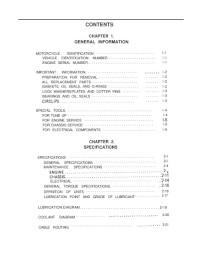
Руководство на английском языке по техническому обслуживанию и ремонту мотоциклов Yamaha FZR400.
- Издательство: —
- Год издания: —
- Страниц: —
- Формат: PDF
- Размер: 16,4 Mb
Руководство на английском языке по ремонту мотоциклов Yamaha FZR400SP 1991 года выпуска.
- Издательство: Yamaha Motor Corp., Ltd.
- Год издания: 1990
- Страниц: 245
- Формат: PDF
- Размер: 28,8 Mb
Руководство на немецком языке по техническому обслуживанию и ремонту мотоциклов Yamaha FZR600 с 1989 года выпуска.
- Издательство: —
- Год издания: —
- Страниц: 123
- Формат: PDF
- Размер: 68,1 Mb
Сборник руководств на английском языке по ремонту мотоциклов Yamaha моделей FZR600RA, FZR600RAC, FZR600RB, FZR600RBC, FZR600W и FZR600WC.
- Издательство: Yamaha Motor Corp., Ltd.
- Год издания: —
- Страниц: —
- Формат: PDF
- Размер: 32,7 Mb
Руководство на немецком языке по техническому обслуживанию и ремонту мотоциклов Yamaha FZR1000 с 1989 года выпуска.
- Издательство: —
- Год издания: —
- Страниц: 145
- Формат: JPG
- Размер: 43,4 Mb

Для ознакомления с инструкцией необходимо нажать на ссылку «ЗАГРУЗИТЬ», чтобы скачать pdf файл. Если есть кнопка «ПРОСМОТР», то можно просто посмотреть документ онлайн.
Для удобства, Вы можете сохранить данную страницу с файлом руководства по эксплуатации в свой список «избранное» прямо на сайте (доступно для зарегистрированных пользователей).
Смотрите инструкцию для похожих моделей:

Вы можете задать вопрос посетителям сайта по модели YAMAHA FZR400. Если Вы являетесь её пользователем, то пожалуйста оставьте, по возможности развёрнутый отзыв:
Welcome to ManualMachine
You have been successfully registered
We have sent a verification link to to complete your registration.
If you can’t find the email, check your Junk/Spam folder.


- Buy Points
- How it Works
- FAQ
- Contact Us
- Questions and Suggestions
- Users
…
Yamaha Service Manual Ch1
 Loading…
You can only view or download manuals with
Sign Up and get 5 for free
Upload your files to the site. You get 1 for each file you add
Get 1 for every time someone downloads your manual
Buy as many as you need
View and download manuals available only for
Register and get 5 for free
Upload manuals that we do not have and get 1 for each file
Get 1 for every download of your manual
Buy as much as you need