Материал из BikesWiki — энциклопедия японских мотоциклов
Перейти к: навигация, поиск

Yamaha TTR 250
Ниже представлены прямые ссылки на скачку сервисной документации.
Для Yamaha TT-R250
- Руководство пользователя (Owners Manual) на Yamaha TT-R250
- Сервисный мануал (Service Manual) на Yamaha TT-R250 (на русском)
Обзор модели
- Yamaha TT-R 250
Источник — «https://bikeswiki.ru/index.php?title=Yamaha_TT-R250:_мануалы&oldid=9417»
Категория:
- Сервисная документация
|
YAMAHA greywolf.ru : Файловый архив Инструкции пользователя ФайлыУпорядочить по: ID | Названию | tt250r_raid-japan.pdfСкачать
Yamaha_TT250RG_1994_owner_manual-28199-20.pdfСкачать
Yamaha_TTR250M_2000-owner_manual.pdfСкачать
Yamaha_TTR250N_2001-owner_manual.pdfСкачать
Yamaha_TTR250P_2002-owner_manual.pdfСкачать
Yamaha_TTR250RM_2000-owner_manual-ES.pdfСкачать
Yamaha_TTR250R_2003-owner_manual.pdfСкачать
Yamaha_TTR250S_2004-owner_manual.pdfСкачать
Yamaha_TTR250T_2005-owner_manual.pdfСкачать
Yamaha_TTR250V_2006-owner_manual.pdfСкачать
Поиск в файловом архиве… Загрузить файл в файловый архив
|
![]()
ПРОВЕРКА И РЕМОНТ 
NB243001
ПРОВЕРКА И РЕМОНТ
ГОЛОВКА ЦИЛИНДРА
1. Устранить:
●Нагар (с камеры сгорания)
При помощи скругленного скребка  .
.
ПРИМЕЧАНИЕ:__________________________________
Запрещено применять острый инструмент, необходимо избегать появления царапин и повреждений.
_______________________________________________
2. Проверить:
● Головку цилиндра Царапины / повреждения → Заменить.
3. Измерить:
●Деформацию Отклонение от спецификации → Притереть.
Деформация головки цилиндра:
Менее 0.03 мм (0.0012 in)
4. Притереть:
● Головку цилиндра
********************************************************************
Последовательность притирки:
● Разместить на ровной поверхности лист смоченной наждачной бумаги с зернистостью 400 ~ 600 и движениями в виде восьмерки притереть головку цилиндра.
ПРИМЕЧАНИЕ:__________________________________
Для обеспечения равномерного стачивания необходимо в ходе притирки несколько раз повернуть головку цилиндра.
_______________________________________________
********************************************************************
NB243002
СЕДЛО КЛАПАНА
1.Устранить: ● Нагар
(с фаски и седла клапана)
2.Проверить:
●Седло клапана Раковины / износ → Выполнить развертку седла
клапана.
|
Yamaha TTR250L(C) Service Manual Rev_01 |
121/276 |

ПРОВЕРКА И РЕМОНТ 
3. Измерить:
● Ширину зоны контакта  Отклонение от спецификации → Выполнить развертку седла клапана.
Ширина зоны контакта: Впуск:
0.9 ~ 1.1 мм (0.035 ~ 0.043 in)
Выпуск:
0.9 ~ 1.1 мм (0.035 ~ 0.043 in)
********************************************************************
Последовательность измерения:
●Нанести специальный маркер (Dykem)  на фаску клапана.
●Вставить клапан в головку цилиндра.
●Прижать клапан к седлу для получения четкого отпечатка.
●Измерить ширину зоны контакта клапана и седла. Зона контакта седла и клапана будет определяться отпечатком маркера.
●Если ширина зоны контакта слишком велика, мала или лежит не по центру, то необходимо произвести развертку седла клапана.
********************************************************************
4. Выполнить развертку: ● Седла клапана
При помощи развертки 30о, 45о, 60о  .
.
 ________________________________
Для предотвращения появления борозд необходимо при вращении развертки оказывать одинаковое давление (4 ~ 5 кг).
_______________________________________________
Зоны применения разверток
|
Зона |
Развертка |
|
A |
30о |
|
B |
45о |
|
C |
60о |
|
Yamaha TTR250L(C) Service Manual Rev_01 |
122/276 |

ПРОВЕРКА И РЕМОНТ 
********************************************************************
Последовательность выполнения развертки:
 Зона контакта проходит посередине фаски клапана, но слишком широка.
|
Применяемые развертки |
Требуемый результат |
|
|
Минимально |
Развертка 45о |
Уменьшить зону контакта |
|
обработать |
Развертка 60о |
до 1 мм (0.039 in). |
 Зона контакта проходит посередине фаски клапана, но слишком узкая.
|
Применяемые развертки |
Требуемый результат |
|
|
Добиться одинаковой |
||
|
Обработать |
Развертка 45о |
ширины зоны контакта в |
|
1 мм (0.039 in) по всей |
||
|
окружности. |
 Зона контакта слишком узкая и проходит у нижнего края фаски.
|
Применяемые развертки |
Требуемый результат |
|
|
Сместить зону контакта |
||
|
Первая: |
||
|
к середине фаски и |
||
|
Обработать |
Развертка 30о |
|
|
Вторая: |
добиться одинаковой |
|
|
ширины в 1 мм (0.039 in) |
||
|
Развертка 45о |
||
|
по всей окружности. |
 Зона контакта слишком узкая и проходит у верхнего края фаски.
|
Применяемые развертки |
Требуемый результат |
|
|
Первая: |
Сместить зону контакта |
|
|
к середине фаски и |
||
|
Обработать |
Развертка 60о |
|
|
Вторая: |
добиться одинаковой |
|
|
ширины в 1 мм (0.039 in) |
||
|
Развертка 45о |
||
|
по всей окружности. |
********************************************************************
5. Притереть:
●Фаску клапана
●Седло клапана
ПРИМЕЧАНИЕ:__________________________________
После выполнения развертки седла клапана, или замены клапана и направляющей, необходимо выполнить притирку седла клапана и фаски клапана.
_______________________________________________
|
Yamaha TTR250L(C) Service Manual Rev_01 |
123/276 |

ПРОВЕРКА И РЕМОНТ 
********************************************************************
Последовательность притирки:
● Нанести крупнозернистую притирочную пасту на фаску клапана.
 ________________________________
Не допускать попадания притирочной пасты в промежуток между стержнем клапана и направляющей.
_______________________________________________
●Нанести дисульфид молибденовое масло на стержень клапана.
●Вставить клапан в головку цилиндра.
●Вращать клапан до получения равномерного блеска в зоне контакта клапана и седла, после чего полностью удалить притирочную пасту.
ПРИМЕЧАНИЕ:__________________________________
Для достижения наилучшего результата следует слегка постукивать головкой клапана о седло, одновременно вращая клапан поочередно по часовой и против часовой стрелки.
_______________________________________________
● Нанести мелкозернистую притирочную пасту на фаску клапана и повторить процедуру притирки.
ПРИМЕЧАНИЕ:__________________________________
После завершения каждого этапа притирки необходимо полностью удалять притирочную пасту с фаски клапана и седла.
_______________________________________________
●Нанести специальный маркер (Dykem) на фаску клапана.
●Вставить клапан в головку цилиндра.
●Прижать клапан к седлу для получения четкого отпечатка.
●Произвести повторный замер ширины зоны контакта клапана и седла.
●В случае отклонения ширины зоны контакта от спецификации необходимо выполнить развертку седла и притирку.
********************************************************************
|
Yamaha TTR250L(C) Service Manual Rev_01 |
124/276 |

ПРОВЕРКА И РЕМОНТ 
NB243003
КЛАПАН И НАПРАВЛЯЮЩАЯ КЛАПАНА
1. Измерить:
● Зазор между стержнем и направляющей клапана
Зазор между стержнем и направляющей клапана = Внутренний диаметр направляющей клапана  — Диаметр стержня клапана
Зазор стержень — направляющая: Впуск:
0.010 ~ 0.037 мм
(0.0004 ~ 0.0015 in) <Предел>: 0.08 мм (0.0031 in)
Впуск:
0.025 ~ 0.052 мм
(0.0010 ~ 0.0020 in) <Предел>: 0.10 мм (0.0039 in)
2. Заменить:
● Направляющую клапана
********************************************************************
Последовательность замены:
ПРИМЕЧАНИЕ:__________________________________
Для облегчения демонтажа и установки направляющих, а также для обеспечения правильной посадки необходимо головку цилиндра нагреть в духовке до 100 оС (212 оF).
_______________________________________________
●Снять направляющую при помощи съемника направляющих клапанов  .
.
●Установить направляющую (новую) при помощи втулки
установки направляющих  и съемника направляющих
 .
.
● После установки направляющей клапана необходимо выполнить развертку при помощи развертки для
направляющих клапана 
Съемник направляющих клапанов: 5 мм (0.20 in)
Артикул YM-04097
Развертка для направляющих: 5 мм (0.20 in)
Артикул YM-04099
Втулка установки направляющих: 5 мм (0.20 in)
Артикул YM-04098
ПРИМЕЧАНИЕ:__________________________________
После замены направляющих клапанов необходимо выполнить развертку седел клапанов.
_______________________________________________
********************************************************************
|
Yamaha TTR250L(C) Service Manual Rev_01 |
125/276 |

ПРОВЕРКА И РЕМОНТ 
3.Устранить: ● Нагар
(с фаски клапана)
4.Проверить:
●Фаску клапана Раковины / износ → Выполнить шлифовку фаски.
●Конец стержня клапана Грибовидная форма или диаметр больше диаметра тела стержня → Заменить.
5. Измерить:
●Толщину  Отклонение от спецификации → Заменить.
Толщина:
ВПУСК: 0.6 ~ 1.0 мм (0.02 ~ 0.04 in) ВЫПУСК: 0.8 ~ 1.2 мм (0.03 ~ 0.05 in)
6. Измерить:
●Биение (стержня клапана)
Отклонение от спецификации → Заменить.
Биение (стержень клапана):
Менее 0.010 мм (0.0004 in)
ПРИМЕЧАНИЕ:__________________________________
●При замене клапана всегда необходимо менять направляющую.
●При снятии клапана всегда необходимо менять маслосъемный колпачок.
_______________________________________________
NB243004
ПРУЖИНА КЛАПАНА
1. Измерить:
●Длину  несжатой пружины Отклонение от спецификации → Заменить.
Длина несжатой пружины:
|
Впуск |
33.81 ~ 35.59 мм |
||||
|
(13.31 ~ 14.01 in) |
|||||
|
Выпуск |
|||||
|
Yamaha TTR250L(C) Service Manual Rev_01 |
126/276 |

ПРОВЕРКА И РЕМОНТ 
2. Измерить:
●Силу сжатия  (пружина клапана) Отклонение от спецификации → Заменить.
 длина сжатой пружины
|
Сила сжатия: |
||||||||
|
При длине пружины: |
||||||||
|
30.39 мм (1.20 in) |
||||||||
|
9.3 ~ 10.7 кг |
||||||||
|
Впуск |
||||||||
|
(20.53 ~ 23.62 lb) |
||||||||
|
9.3 ~ 10.7 кг |
||||||||
|
Выпуск |
||||||||
|
(20.53 ~ 23.62 lb) |
||||||||
3. Измерить:
●Отклонение от вертикали  Отклонение от спецификации → Заменить.
Отклонение от вертикали: Впуск:
Менее 1.6 мм ( 0.063 in)
Выпуск:
Менее 1.6 мм ( 0.063 in)
NB243005
РАСПРЕДЕЛИТЕЛЬНЫЙ ВАЛ
1. Проверить:
●Кулачки распределительного вала Раковины / царапины / цвета побежалости → Заменить.
2. Измерить:
●Длину  и
и  кулачков Отклонение от спецификации → Заменить.
Длина кулачков распредвала: Впуск, Выпуск:
25.00 ~ 25.10 мм
(0.9843 ~ 0.9882 in)
32.75 ~ 32.85 мм
(1.2894 ~ 1.2933 in)
|
Yamaha TTR250L(C) Service Manual Rev_01 |
127/276 |

ПРОВЕРКА И РЕМОНТ 
3. Измерить:
●Биение (распределительного вала) Отклонение от спецификации → Заменить.
Биение (распределительный вал):
Менее 0.03 мм (0.0012 in)
4. Измерить:
● Зазор между постелью и распределительным валом Отклонение от спецификации → Измерить диаметр опорной шейки (распределительный вал).
Зазор постель — распредвал: 0.020 ~ 0.054 мм
(0.0008 ~ 0.0021 in)
********************************************************************
Последовательность измерения:
●Установить распределительный вал на головку цилиндра.
●Положить на опорную шейку распределительного вала полоску с калиброванной пластмассовой проволокой
(Plastiguage®)  .
.
● Установить установочные штифты и крышки постели распределительного вала.
Болт (крышка постели распредвала): 10 Нм (1.0 m·kg, 7,2 ft·lb)
ПРИМЕЧАНИЕ:__________________________________
●Болты крышки постели распределительного вала затягивать крест-накрест начиная изнутри.
●При измерении зазора с помощью Plastiguage® запрещено поворачивать распределительный вал.
_______________________________________________
●Снять крышки постели распределительного вала и произвести замер ширины Plastiguage®.
********************************************************************
5. Измерить:
●Диаметр опорной шейки  (распределительный вал) Отклонение от спецификации → Заменить распределительный вал.
Соответствует спецификации → Заменить головку цилиндра.
Диаметр опорной шейки (распредвал): 24.467 ~ 24.480 мм
(0.9633 ~ 0.9638 in)
|
Yamaha TTR250L(C) Service Manual Rev_01 |
128/276 |

ПРОВЕРКА И РЕМОНТ 
NB643006
ТОЛКАТЕЛЬ КЛАПАНА
1. Проверить:
●Толкатель клапана Царапины / повреждения → Заменить толкатель клапана
и картер распределительного вала.
NB643007
ЦЕПЬ, ЗВЕЗДОЧКА И НАПРАВЛЯЮЩАЯ ЦЕПИ ГРМ
1.Проверить: ● Цепь ГРМ
Тугой ход / скрипы → Заменить цепь и звездочки ГРМ.
2.Проверить:
●Звездочку ГРМ Износ / повреждения → Заменить цепь и звездочки ГРМ.
 1/4 зуба
 Контур звездочки без износа
 Ролик
Ролик  Звездочка
3. Проверить:
●Направляющую цепи ГРМ  (со стороны выпуска)
●Направляющую цепи ГРМ  (со стороны впуска)
Износ / повреждения → Заменить.
|
Yamaha TTR250L(C) Service Manual Rev_01 |
129/276 |

ПРОВЕРКА И РЕМОНТ 
4. Проверить:
● Работу натяжителя цепи ГРМ
********************************************************************
Последовательность проверки:
● Слегка нажав пальцем на шток натяжителя, необходимо
при помощи тонкой отвертки  провернуть шток по часовой стрелке до упора.
●Разрядить натяжитель, убрав отвертку и слегка нажав на шток, убедится в плавности хода штока.
●В противном случае необходимо заменить узел натяжителя.
********************************************************************
NB243008
ЦЕЛИНДР И ПОРШЕНЬ
1. Устранить: ● Нагар
(с головки поршня  и канавок поршневых колец
  ). 2. Проверить:
●Поверхность поршня Износ / глубокие царапины / повреждения → Заменить.
3. Устранить:
●Царапины и отложения (с боковой поверхности поршня)
При помощи смоченной наждачной бумаги с зернистостью 600 ~ 800.
ПРИМЕЧАНИЕ:__________________________________
Обрабатывать наждачной бумагой в перекрестных направлениях с минимальным нажимом.
_______________________________________________
4. Проверить:
● Поверхность цилиндра Износ / глубокие царапины → расточить или заменить. 5. Измерить:
● Зазор поршень – цилиндр
********************************************************************
Последовательность проверки: Шаг 1:
● При помощи измерителя диаметра и формы цилиндра замерить диаметр цилиндра «С».
 40 мм (1.6 in) от верха цилиндра
|
Yamaha TTR250L(C) Service Manual Rev_01 |
130/276 |
Соседние файлы в предмете [НЕСОРТИРОВАННОЕ]
- #
- #
- #
- #
- #
- #
- #
- #
- #
- #
- #
- Manuals
- Brands
- Yamaha Manuals
- Motorcycle
- TTR250V(C)
- Owner’s manual
-
Contents
-
Table of Contents
-
Troubleshooting
-
Bookmarks
Quick Links
OWNER’S MANUAL
TTR250V(C)
LIT-11626-19-30
5GF-28199-17
Related Manuals for Yamaha TTR250V(C)
Summary of Contents for Yamaha TTR250V(C)
-
Page 1
OWNER’S MANUAL TTR250V(C) LIT-11626-19-30 5GF-28199-17… -
Page 3
INTRODUCTION EAU10060 Congratulations on your purchase of the Yamaha TTR250V. This model is the result of Yamaha’s vast experience in the production of fine sporting, touring, and pacesetting racing machines. It represents the high degree of craftsmanship and reliability that have made Yamaha a leader in these fields. -
Page 4: Important Manual Information
This manual should be considered a permanent part of this machine and should remain with it even if the machine is subsequently sold. Yamaha continually seeks advancements in product design and quality. Therefore, while this manual contains the most current product information available at the time of printing, there may be minor discrepancies between your machine and this manual.
-
Page 5
IMPORTANT MANUAL INFORMATION EWA10040 WARNING THIS MACHINE IS DESIGNED AND MANUFACTURED FOR OFF-ROAD USE ONLY. IT IS ILLEGAL TO OPERATE THIS MACHINE ON ANY PUBLIC STREET, ROAD OR HIGHWAY. SUCH USE IS PROHIBITED BY LAW. THIS MA- CHINE COMPLIES WITH ALMOST ALL STATE OFF-HIGHWAY NOISE LEVEL AND SPARK ARRESTER LAWS AND REGULATIONS. -
Page 6
IMPORTANT MANUAL INFORMATION EAU10192 AFFIX DEALER LABEL HERE TTR250V OWNER’S MANUAL ©2005 by Yamaha Motor Corporation, U.S.A. 1st edition, April 2005 All rights reserved. Any reprinting or unauthorized use without the written permission of Yamaha Motor Corporation, U.S.A. is expressly prohibited. -
Page 7: Table Of Contents
TABLE OF CONTENTS SAFETY INFORMATION ….1-1 OPERATION AND IMPORTANT Adjusting the clutch lever free Location of important labels …..1-5 RIDING POINTS……..5-1 play ……….6-18 Starting and warming up a cold Adjusting the brake lever free DESCRIPTION ……..2-1 engine ………. 5-1 play ……….
-
Page 8
Troubleshooting chart ….6-35 MACHINE CARE AND STORAGE ………..7-1 Care ……….7-1 Storage ……….7-3 SPECIFICATIONS ……8-1 CONSUMER INFORMATION….9-1 Identification numbers …..9-1 Motorcycle noise regulation …..9-3 Maintenance record ……9-4 YAMAHA MOTOR CORPORATION, U.S.A. OFF-ROAD MOTORCYCLE LIMITED WARRANTY ….9-5 YAMAHA EXTENDED SERVICE (Y.E.S.) ………9-7… -
Page 9: Safety Information
SAFETY INFORMATION Safe riding the speed). Never travel faster EAU10332 Always make pre-operation than warranted by conditions. THIS MACHINE IS A SINGLE TRACK checks. Careful checks may help Ride cautiously in unfamiliar ar- VEHICLE. ITS SAFE USE AND OPER- prevent an accident. eas.
-
Page 10
Modifications made to this machine not Cargo accessory weight stallation and use of non-Yamaha approved by Yamaha, or the removal of should be kept as low and close to accessories. Use extreme caution original equipment, may render the ma- the machine as possible. Make… -
Page 11
SAFETY INFORMATION or cornering clearance, limit sus- Use caution when adding electri- leaving the machine unattended pension travel, steering travel or cal accessories. If electrical acces- and remove the key from the main control operation, or obscure lights sories exceed the capacity of the switch. -
Page 12
SAFETY INFORMATION line, inhale a lot of gasoline vapor, or allow gasoline to get into your eyes, see your doctor immediate- ly. If any gasoline spills on your skin or clothing, immediately wash the affected area with soap and water and change your clothes. -
Page 13: Location Of Important Labels
SAFETY INFORMATION EAU10381 Location of important labels Please read the following important labels carefully before operating this vehicle.
-
Page 14
This unit contains high pressure nitrogen gas. follows. Mishandling can cause explosion. FRONT : 100 kPa,{1.00 kgf/cm }, 15 psi Read owner’s manual for instructions. REAR 100 kPa,{1.00 kgf/cm }, 15 psi Do not incinerate, puncture or open. 3RV-21668-A0 YAMAHA 4AA-22259-80… -
Page 15: Description
DESCRIPTION EAU10410 Left view 1. Headlight (page 6-29) 8. Front fork damping adjusting screw (page 3-7) 2. Front fork air valve (page 3-7) 3. Fuel cock (page 3-5) 4. Starter (choke) knob (page 3-6) 5. Air filter element (page 6-12) 6.
-
Page 16: Right View
DESCRIPTION EAU10420 Right view 1. Spark arrester (page 6-13) 8. Shock absorber assembly spring preload adjusting nut (page 3-9) 2. Battery (page 6-27) 3. Fuse (page 6-28) 4. Shock absorber assembly compression damping force adjusting knob (page 3-9) 5. Main switch (page 3-1) 6.
-
Page 17: Controls And Instruments
DESCRIPTION EAU10430 Controls and instruments 1. Clutch lever (page 3-2) 2. Left handlebar switch (page 3-1) 3. Tripmeter (page 3-1) 4. Right handlebar switches (page 3-1) 5. Brake lever (page 3-3) 6. Throttle grip (page 6-14) 7. Fuel tank cap (page 3-3)
-
Page 18: Instrument And Control Functions
INSTRUMENT AND CONTROL FUNCTIONS EAU10450 EAU11830 EAU12343 Main switch Tripmeter Handlebar switches Left The main switch controls the ignition 1. Tripmeter and lighting systems. The various main 1. Light switch “ ” 2. Tripmeter reset knob switch positions are described below. The tripmeter shows the distance trav- Right eled since it was last set to zero with the…
-
Page 19: Clutch Lever
INSTRUMENT AND CONTROL FUNCTIONS EAU12540 EAU31640 EAU12870 Light switch “ ” Clutch lever Shift pedal Set this switch to “ ” to turn on the headlight and the taillight. ECA10980 CAUTION: Always turn the key to “OFF” and light switch to “OFF” when the en- gine is not running, otherwise the headlight will stay on and the battery may discharge due to extended use.
-
Page 20: Brake Lever
INSTRUMENT AND CONTROL FUNCTIONS EAU12890 EAU12941 EAU13180 Brake lever Brake pedal Fuel tank cap 1. Brake lever 1. Brake pedal 1. Fuel tank cap 2. Remove. The brake lever is located at the right The brake pedal is on the right side of To remove the fuel tank cap, turn it handlebar grip.
-
Page 21: Fuel
10%. Gasohol UNLEADED GASOLINE ONLY containing methanol is not recom- Fuel tank capacity: mended by Yamaha because it can 9.5 L (2.51 US gal) (2.09 Imp.gal) cause damage to the fuel system or ve- Fuel reserve amount: 2.0 L (0.53 US gal) (0.44 Imp.gal)
-
Page 22: Fuel Tank Breather Hose
INSTRUMENT AND CONTROL FUNCTIONS EAU13410 EAU13560 Fuel tank breather hose Fuel cock The fuel cock supplies fuel from the tank to the carburetor while filtering it al- The fuel cock has three positions: FUEL 1. Arrow mark positioned over “ON” 1.
-
Page 23: Starter (Choke) Knob «1
INSTRUMENT AND CONTROL FUNCTIONS fuel while riding, move the lever to this EAU13600 EAU13960 Starter (choke) knob “ ” Seat position. Fill the tank at the first oppor- tunity. Be sure to set the lever back to To remove the seat “ON”…
-
Page 24: Adjusting The Front Fork
Make sure that the seat is properly se- An optional air pressure gauge is avail- NOTE: cured before riding. able at a Yamaha dealer. When checking and adjusting the air 4. To increase the spring rate and pressure, there should be no weight on thereby harden the suspension, in- the front end of the vehicle.
-
Page 25
INSTRUMENT AND CONTROL FUNCTIONS Spring rate: Minimum (soft): Air pressure = 0 kPa (0 psi) (0 kgf/cm Standard: Air pressure = 0 kPa (0 psi) (0 kgf/cm Maximum (hard): Air pressure = 40 kPa (5.8 psi) (0.4 kgf/cm ECA10090 1. Rubber cap 1. -
Page 26: Adjusting The Shock Absorber Assembly
Never attempt to turn an adjusting ifications due to small differences in obtained at a Yamaha dealer. mechanism beyond the maximum or production, the actual number of clicks The spring preload setting is deter- minimum settings.
-
Page 27
INSTRUMENT AND CONTROL FUNCTIONS rection (b). pression damping force and thereby Tightening torque: soften the compression damping, turn Locknut: Rebound damping setting: the adjusting knob in direction (b). 70 Nm (7.0 m·kgf, 51 ft·lbf) Minimum (soft): 16 clicks in direction (b)* Compression damping setting: ECA11240 Standard:… -
Page 28: Starting Circuit Cut-Off System
WARNING high heat sources, otherwise it If a malfunction is noted, have a may explode due to excessive Yamaha dealer check the system be- gas pressure. fore riding. Do not deform or damage the gas cylinder in any way, as this will result in poor damping per- formance.
-
Page 29
4. Push the start switch. Does the engine start? The neutral switch may be defective. The motorcycle should not be ridden until checked by a Yamaha dealer. 5. Turn the engine off. 6. Shift the transmission into gear. 7. Keep the clutch lever pulled. -
Page 30: Pre-Operation Checks
PRE-OPERATION CHECKS EAU15591 The condition of a vehicle is the owner’s responsibility. Vital components can start to deteriorate quickly and unexpectedly, even if the vehicle remains unused (for example, as a result of exposure to the elements). Any damage, fluid leakage or loss of tire air pressure could have serious consequences.
-
Page 31: Pre-Operation Check List
Lubricate cable if necessary. Clutch 6-18 Check lever free play. Adjust if necessary. Make sure that operation is smooth. Check cable free play. Throttle grip 6-14, 6-24 If necessary, have Yamaha dealer adjust cable free play and lubricate cable and grip housing.
-
Page 32
PRE-OPERATION CHECKS ITEM CHECKS PAGE Make sure that operation is smooth. Control cables 6-23 Lubricate if necessary. Check chain slack. Adjust if necessary. Drive chain 6-21, 6-23 Check chain condition. Lubricate if necessary. Check for damage. Check tire condition and tread depth. Wheels and tires 6-15, 6-17 Check air pressure. -
Page 33: Operation And Important Riding Points
OPERATION AND IMPORTANT RIDING POINTS 5. Start the engine by pushing the EAU15960 EAU16451 Starting and warming up a start switch. cold engine EWA10280 NOTE: WARNING In order for the starting circuit cut-off If the engine fails to start, release the This model is designed for system to enable starting, one of the start switch, wait a few seconds, and…
-
Page 34: Starting A Warm Engine
OPERATION AND IMPORTANT RIDING POINTS the neutral position, do not EAU16640 EAU16671 Starting a warm engine Shifting coast for long periods of time Follow the same procedure as for start- with the engine off, and do not ing a cold engine with the exception tow the machine for long dis- that the starter (choke) is not required tances.
-
Page 35: Engine Break-In
If any engine trouble should occur maximum) does not harm the engine. during the engine break-in period, Each full-throttle acceleration should immediately have a Yamaha dealer be followed with a substantial rest peri- check the vehicle. od for the engine. To allow the engine…
-
Page 36: Periodic Maintenance And Minor Repair
If you do not have the tools or experi- If you are not familiar with mainte- ence required for a particular job, have nance work, have a Yamaha dealer a Yamaha dealer perform it for you. do it for you. EWA10340 WARNING…
-
Page 37: Periodic Maintenance Chart For The Emission Control System
From 1800 mi (3000 km) or 18 months, repeat the maintenance intervals starting from 600 mi (1000 km) or 6 months. Items marked with an asterisk should be performed by a Yamaha dealer as they require special tools, data and technical skills.
-
Page 38: General Maintenance And Lubrication Chart
PERIODIC MAINTENANCE AND MINOR REPAIR EAU35340 General maintenance and lubrication chart INITIAL EVERY 100 mi 600 mi 1200 mi ITEM CHECKS AND MAINTENANCE JOBS (150 km) (1000 km) (2000 km) 1 month 6 months 12 months Check operation. √ √ √…
-
Page 39
17 * Shock absorber assembly Replace if necessary. √ 18 * Rear suspension link pivots Apply molybdenum disulfide grease lightly. Apply Yamaha chain and cable lube or engine oil 10W-30 thor- √ √ √ 19 * Control and meter cables oughly. -
Page 40
PERIODIC MAINTENANCE AND MINOR REPAIR EAU18670 NOTE: The air filter needs more frequent service if you are riding in unusually wet or dusty areas. Hydraulic brake service Regularly check and, if necessary, correct the brake fluid level. Every two years replace the internal components of the brake master cylinders and calipers, and change the brake fluid. -
Page 41: Removing And Installing The Cowling And Panels
PERIODIC MAINTENANCE AND MINOR REPAIR To install the cowling EAU18721 Removing and installing the Place the cowling in the original posi- cowling and panels tion, and then install the screws. The cowling and panels shown need to be removed to perform some of the EAU19292 Panels A and B maintenance jobs described in this…
-
Page 42: Checking The Spark Plug
Do not attempt to diagnose such problems yourself. Instead, have a Yamaha dealer check the vehicle. 1. Spark plug cap 2. Check the spark plug for electrode 2. Remove the spark plug as shown,…
-
Page 43: Engine Oil And Oil Filter Element
PERIODIC MAINTENANCE AND MINOR REPAIR 3. Install the spark plug with the EAU19784 Engine oil and oil filter Specified spark plug: spark plug wrench, and then tight- NGK/CR9E element en it to the specified torque. DENSO/U27ESR-N The engine oil level should be checked Tightening torque: before each ride.
-
Page 44
PERIODIC MAINTENANCE AND MINOR REPAIR to collect the used oil. NOTE: 3. Remove the engine oil filler bolt The engine oil should be between the and drain bolt to drain the oil from minimum and maximum level marks. the crankcase. 1. -
Page 45
PERIODIC MAINTENANCE AND MINOR REPAIR Tightening torque: (×3) Oil filter element cover bolt: 10 Nm (1.0 m·kgf, 7.2 ft·lbf) (×2) NOTE: Make sure that the O-rings are properly seated. 10. Install the engine oil drain bolt, and then tighten it to the specified 1. -
Page 46
If this occurs, mix any chemical additives. Do 7 Nm (0.7 m·kgf, 5.0 ft·lbf) have a Yamaha dealer repair the not use oils with a diesel speci- vehicle. fication of “CD” or oils of a high- After checking the oil pressure, er quality than specified. -
Page 47: Cleaning The Air Filter Element
The sponge material should be wet but (×3) not dripping. Recommended oil: Yamaha foam air filter oil or other quality air filter oil 1. Holding clip 7. Install the sponge material onto 3. Pull the air filter element out of the the frame, insert the air filter ele- air filter case.
-
Page 48: Cleaning The Spark Arrester
PERIODIC MAINTENANCE AND MINOR REPAIR side of the tailpipe housing. EAU21241 ECA10480 Cleaning the spark arrester CAUTION: The spark arrester should be cleaned Make sure that the air filter ele- at the intervals specified in the periodic ment is properly seated in the maintenance and lubrication chart.
-
Page 49: Carburetor
3.0–5.0 mm (0.12–0.20 in) at the 6. Stop the engine and allow the ex- throttle grip. Periodically check the haust pipe to cool. throttle cable free play and, if neces- 7. Install the purging bolt and tighten sary, have a Yamaha dealer adjust it. 6-14…
-
Page 50: Valve Clearance
100 kPa (15 psi) (1.00 kgf/cm from occurring, the valve clearance specified tires. Maximum load*: 90 kg (198 lb) must be adjusted by a Yamaha dealer * Total weight of rider, cargo and ac- at the intervals specified in the periodic Tire air pressure cessories maintenance and lubrication chart.
-
Page 51
Front tire: Securely pack the heaviest the sidewall is cracked, have a Yamaha Size: items close to the center of the dealer replace the tire immediately. 80/100-21 51M… -
Page 52: Spoke Wheels
If any dam- should be designed specifically for age is found, have a Yamaha this model, and they must be se- dealer replace the wheel. Do not curely mounted to maintain the in-…
-
Page 53: Adjusting The Clutch Lever Free Play
PERIODIC MAINTENANCE AND MINOR REPAIR been approved by Yamaha. lever free play, turn the adjusting EAU22030 Adjusting the clutch lever free bolt in direction (b). play 3. If the specified clutch lever free play could be obtained as de- scribed above, tighten the locknut and skip the rest of the procedure, otherwise proceed as follows.
-
Page 54: Adjusting The Brake Lever Free Play
If there is air in the hy- draulic system, have a Yamaha dealer bleed the system before 1. Brake lever free play adjusting screw operating the machine. Air in 2.
-
Page 55: Checking The Brake Fluid Level
Observe these precautions: cator almost touches the brake disc, When checking the fluid level, have a Yamaha dealer replace the make sure that the top of the brake brake pads as a set. fluid reservoir is level.
-
Page 56: Changing The Brake Fluid
EAU22760 Changing the brake fluid Drive chain slack lower the boiling point of the fluid Have a Yamaha dealer change the The drive chain slack should be and may result in vapor lock. brake fluid at the intervals specified in…
-
Page 57
PERIODIC MAINTENANCE AND MINOR REPAIR are in the same position for proper Tightening torque: wheel alignment. Axle nut: 105 Nm (10.5 m·kgf, 76 ft·lbf) 4. Insert a new cotter pin into the axle nut, and then bend its ends as shown. -
Page 58: Cleaning And Lubricating The Drive Chain
If a cable is damaged wet areas. Service the drive chain as or does not move smoothly, have a follows. Yamaha dealer check or replace it. ECA10581 CAUTION: Recommended lubricant: Yamaha Chain and Cable Lube or…
-
Page 59: Checking And Lubricating The Throttle Grip And Cable
PERIODIC MAINTENANCE AND MINOR REPAIR EAU23111 EAU23140 EAU23180 Checking and lubricating the Checking and lubricating the Lubricating the brake pedal throttle grip and cable brake and clutch levers The operation of the throttle grip should be checked before each ride. In addi- tion, the cable should be lubricated at the intervals specified in the periodic maintenance chart.
-
Page 60: Checking And Lubricating The Sidestand
Check the inner tubes for scratches, fork does not operate smoothly, The operation of the sidestand should damage and excessive oil leakage. have a Yamaha dealer check or re- be checked before each ride, and the pair it. sidestand pivot and metal-to-metal…
-
Page 61: Checking The Steering
2. Hold the lower ends of the front fork legs and try to move them for- ward and backward. If any free play can be felt, have a Yamaha dealer check or repair the steering. 6-26…
-
Page 62: Battery
To charge the battery EAU23380 Battery furic acid, which causes severe Have a Yamaha dealer charge the bat- burns. Avoid any contact with tery as soon as possible if it seems to skin, eyes or clothing and al- have discharged. Keep in mind that the…
-
Page 63: Replacing The Fuse
If you do not have access to a avoid causing extensive damage to sealed-type (MF) battery charg- the electrical system and possibly a er, have a Yamaha dealer fire. charge your battery. 3. Turn the key to “ON” and turn on the electrical circuits to check if the devices operate.
-
Page 64: Replacing The Headlight Bulb
PERIODIC MAINTENANCE AND MINOR REPAIR EAU23841 Replacing the headlight bulb This model is equipped with a quartz bulb headlight. If the headlight bulb burns out, replace it as follows. 1. Remove cowling A together with the headlight unit. (See page 6-6.) 2.
-
Page 65: Replacing The Taillight Bulb
1. Screw the headlight unit. 4. Install the lens by installing the 2. Taillight lens 7. Have a Yamaha dealer adjust the screws. 2. Remove the defective bulb by headlight beam if necessary. ECA10680 pushing it in and turning it counter- CAUTION: clockwise.
-
Page 66: Supporting The Machine
ECA11070 WARNING CAUTION: requiring the machine to stand upright. It is advisable to have a Yamaha Check that the machine is in a stable Do not apply the brake after the dealer service the wheel. and level position before starting any…
-
Page 67
PERIODIC MAINTENANCE AND MINOR REPAIR 2. Lift the wheel up between the fork 4. Tighten the wheel axle holder nuts fork compresses and rebounds legs. to the specified torque. smoothly. 6. Connect the tripmeter cable. NOTE: NOTE: Make sure that there is enough space Tighten the upper nuts first, and then between the brake pads before insert- the lower ones. -
Page 68: Rear Wheel
3. Remove each swingarm end cover by removing the screws. EAU25280 To remove the rear wheel EWA10820 WARNING (×2) It is advisable to have a Yamaha dealer service the wheel. (×2) Securely support the machine (×2) so that there is no danger of it NOTE: falling over.
-
Page 69: Troubleshooting
However, should your machine re- ter pin. quire any repair, take it to a Yamaha dealer, whose skilled technicians have Tightening torque: the necessary tools, experience, and…
-
Page 70: Troubleshooting Chart
Remove the spark plug and check the electrodes. The engine does not start. Have a Yamaha dealer check the vehicle. Check the battery. 4. Battery The engine turns over The battery is good.
-
Page 71: Machine Care And Storage
MACHINE CARE AND STORAGE ucts onto seals, gaskets, sprock- cleaning products, solvent or EAU26000 Care ets, the drive chain and wheel thinner, fuel (gasoline), rust re- While the open design of a machine re- axles. Always rinse the dirt and de- movers or inhibitors, brake flu- veals the attractiveness of the technol- greaser off with water.
-
Page 72
MACHINE CARE AND STORAGE After normal use salt. 7. Wax all painted surfaces. Remove dirt with warm water, a mild 8. Let the machine dry completely 2. Apply a corrosion protection spray detergent, and a soft, clean sponge, before storing or covering it. on all metal, including chrome- and and then rinse thoroughly with clean EWA10930… -
Page 73: Storage
Storage by loosening the drain bolt; this will NOTE: prevent fuel deposits from building Consult a Yamaha dealer for advice on Short-term up. Pour the drained fuel into the what products to use. Always store your machine in a cool, fuel tank.
-
Page 74
MACHINE CARE AND STORAGE spark plug cap. than 30 °C (90 °F)]. For more in- EWA10950 formation on storing the battery, WARNING see page 6-27. To prevent damage or injury from NOTE: sparking, make sure to ground the Make any necessary repairs before spark plug electrodes while turning storing the machine. -
Page 75: Specifications
SPECIFICATIONS Engine oil: Spark plug (s): EAU2633D Dimensions: Type: Manufacturer/model: Overall length: YAMALUBE 4, SAE10W30 or SAE20W40 NGK/CR9E 2095 mm (82.5 in) Manufacturer/model: 0° 10° 30° 50° 70° 90° 110° 130°F Overall width: DENSO/U27ESR-N 835 mm (32.9 in) YAMALUBE 4 (10W30) Spark plug gap: or SAE 10W30 Overall height:…
-
Page 76
SPECIFICATIONS Tire air pressure (measured on cold Front suspension: 5th: 24/27 (0.889) tires): Type: 6th: Telescopic fork Off-road riding: 22/29 (0.759) Spring/shock absorber type: Front: Chassis: Coil-air spring/oil damper 100 kPa (15 psi) (1.00 kgf/cm Frame type: Wheel travel: Rear: Semi double cradle 280.0 mm (11.02 in) 100 kPa (15 psi) (1.00 kgf/cm… -
Page 77
SPECIFICATIONS Fuse: Fuse: 15.0 A… -
Page 78: Consumer Information
Record the key identification number, vehicle identification number and mod- el label information in the spaces pro- vided below for assistance when ordering spare parts from a Yamaha dealer or for reference in case the vehi- cle is stolen. KEY IDENTIFICATION NUMBER: 1.
-
Page 79
1. Model label The model label is affixed to the frame under the seat. (See page 3-6.) Record the information on this label in the space provided. This information will be needed when ordering spare parts from a Yamaha dealer. -
Page 80: Motorcycle Noise Regulation
CONSUMER INFORMATION EAU26560 Motorcycle noise regulation TAMPERING WITH NOISE CONTROL SYSTEM PROHIBITED: Federal law prohibits the following acts or the causing thereof: (1) The removal or rendering inoperative by any person other than for purposes of maintenance, repair, or replacement of any device or element of design incorporated into any new ve- hicle for the purpose of noise control prior to its sale or delivery to the ultimate purchaser or while it is in use or (2) the use of the vehicle after such device or element of design has been removed or rendered inoperative by any person.
-
Page 81: Maintenance Record
CONSUMER INFORMATION EAU26651 Maintenance record Have a Yamaha dealer complete this record when the machine is serviced. Maintenance Date of Servicing dealer Mileage Remarks interval service name and address…
-
Page 82: Yamaha Motor Corporation, U.s.a. Off-Road Motorcycle Limited Warranty
CONSUMER INFORMATION EAU26670 YAMAHA MOTOR CORPORATION, U.S.A. OFF-ROAD MOTORCYCLE LIMITED WARRANTY…
-
Page 83
CONSUMER INFORMATION… -
Page 84: Yamaha Extended Service (Y.e.s.)
This excellent Y.E.S. plan coverage is only available to dealer to see how comforting uninterrupted factory- Yamaha owners like you, and only while your Yamaha is still backed protection can be. within the Yamaha Limited Warranty period. So visit your authorized Yamaha dealer to get all the facts.
-
Page 85
Yamaha Limited Warranty expires. A special note: If visiting your dealer isn’t convenient, contact Yamaha with your Primary ID number (your frame number). We’ll be happy to help you get the Y.E.S. coverage you need. -
Page 86
INDEX Fuel …………3-4 Sidestand, checking and lubricating..6-25 Fuel cock ……….. 3-5 Spark plug, checking……… 6-7 Accessories and replacement parts ..6-17 Fuel tank breather hose ……3-5 Specifications ……….8-1 Air filter element, cleaning …….6-12 Fuel tank cap……….3-3 Starter (choke) knob…….. -
Page 87
YAMAHA MOTOR CO., LTD. PRINTED ON RECYCLED PAPER PRINTED IN JAPAN 2005.5–1.1×1 !
This manual is also suitable for:
Ttr250v
![]()
OWNER’S MANUAL
TTR250R(C)
|
LIT-11626-16-24 |
5GF-28199-14 |
EAU03438

EAU00000
INTRODUCTION
Congratulations on your purchase of the Yamaha TTR250R. This model is the result of Yamaha’s vast experience in the production of fine sporting, touring, and pacesetting racing machines. It represents the high degree of craftsmanship and reliability that have made Yamaha a leader in these fields.
This manual will give you an understanding of the operation, inspection, and basic maintenance of this machine. If you have any questions concerning the operation or maintenance of your machine, please consult a Yamaha dealer.
EAU00003
IMPORTANT MANUAL INFORMATION
Particularly important information is distinguished in this manual by the following notations:
Q
The Safety Alert Symbol means ATTENTION! BECOME ALERT! YOUR SAFETY IS INVOLVED!
wFailure to follow WARNING instructions could result in severe injury or death to the machine operator, a bystander or a person inspecting or repairing the
machine.
|
cC |
A CAUTION indicates special precautions that must be taken to avoid damage |
|
|
to the machine. |
||
|
NOTE: |
A NOTE provides key information to make procedures easier or clearer. |
|
NOTE:
8This manual should be considered a permanent part of this machine and should remain with it even if the machine is subsequently sold.
8Yamaha continually seeks advancements in product design and quality. Therefore, while this manual contains the most current product information available at the time of printing, there may be minor discrepancies between your machine and this manual. If you have any questions concerning this manual, please consult your Yamaha dealer.

IMPORTANT MANUAL INFORMATION
EW000000
w
PLEASE READ THIS MANUAL AND THE “YOU AND YOUR MOTORCYCLE: RIDING TIPS” BOOKLET CAREFULLY AND COMPLETELY BEFORE OPERATING THIS MACHINE. DO NOT ATTEMPT TO OPERATE THIS MACHINE UNTIL YOU HAVE ATTAINED ADEQUATE KNOWLEDGE OF ITS CONTROLS AND OPERATING FEATURES AND UNTIL YOU HAVE BEEN TRAINED IN SAFE AND PROPER RIDING TECHNIQUES. REGULAR INSPECTIONS AND CAREFUL MAINTENANCE, ALONG WITH GOOD RIDING SKILLS, WILL ENSURE THAT YOU SAFELY ENJOY THE CAPABILITIES AND THE RELIABILITY OF THIS MACHINE.
EAU00006
w
THIS MACHINE IS DESIGNED AND MANUFACTURED FOR OFF-ROAD USE ONLY. IT IS ILLEGAL TO OPERATE THIS MACHINE ON ANY PUBLIC STREET, ROAD OR HIGHWAY. SUCH USE IS PROHIBITED BY LAW. THIS MACHINE COMPLIES WITH ALMOST ALL STATE OFF-HIGHWAY NOISE LEVEL AND SPARK ARRESTER LAWS AND REGULATIONS. PLEASE CHECK YOUR LOCAL RIDING LAWS AND REGULATIONS BEFORE OPERATING THIS MACHINE.
AFFIX DEALER
LABEL HERE
EAU04247
TTR250R
OWNER’S MANUAL
©2002 by Yamaha Motor Corporation, U.S.A. 1st edition, April 2002
All rights reserved.
Any reprinting or unauthorized use without the written permission of Yamaha Motor Corporation, U.S.A. is expressly prohibited.
Printed in Japan.
P/N LIT-11626-16-24

EAU00009
TABLE OF CONTENTS
|
1 |
……………………………..SAFETY INFORMATION |
1-1 |
|
|
……………………………………………….Safe riding |
1-1 |
||
|
Protective apparel ……………………………………. |
1-2 |
||
|
Modifications …………………………………………… |
1-3 |
||
|
Loading and accessories ………………………….. |
1-3 |
||
|
Gasoline and exhaust gas …………………………. |
1-5 |
||
|
Location of important labels ………………………. |
1-7 |
||
|
DESCRIPTION |
2-1 |
||
|
2 |
|||
|
Left view …………………………………………………. |
2-1 |
||
|
Right view ……………………………………………….. |
2-2 |
||
|
Controls and instruments ………………………….. |
2-3 |
||
|
INSTRUMENT AND CONTROL |
|||
|
3 |
|||
|
FUNCTIONS ……………………………………………… |
3-1 |
||
|
Main switch …………………………………………….. |
3-1 |
||
|
Tripmeter ………………………………………………… |
3-1 |
||
|
Handlebar switches ………………………………….. |
3-1 |
||
|
Clutch lever …………………………………………….. |
3-2 |
||
|
Shift pedal ………………………………………………. |
3-2 |
||
|
Brake lever ……………………………………………… |
3-3 |
||
|
Brake pedal …………………………………………….. |
3-3 |
||
|
Fuel tank cap …………………………………………… |
3-3 |
||
|
Fuel ……………………………………………………….. |
3-4 |
||
|
Fuel tank breather hose ……………………………. |
3-5 |
|
Fuel cock ………………………………………………… |
3-5 |
||
|
Starter (choke) knob …………………………………. |
3-6 |
||
|
Seat ……………………………………………………….. |
3-7 |
||
|
Adjusting the front fork ……………………………… |
3-7 |
||
|
Adjusting the shock absorber assembly …….. |
3-10 |
||
|
Starting circuit cut-off system …………………… |
3-12 |
||
|
PRE-OPERATION CHECKS |
4-1 |
||
|
4 |
|||
|
Pre-operation check list …………………………….. |
4-1 |
||
|
OPERATION AND IMPORTANT RIDING |
|||
|
5 |
|||
|
POINTS …………………………………………………….. |
5-1 |
||
|
Starting and warming up a cold engine ……….. |
5-1 |
||
|
Starting a warm engine …………………………….. |
5-3 |
||
|
Shifting …………………………………………………… |
5-3 |
||
|
Engine break-in ……………………………………….. |
5-4 |
||
|
Parking …………………………………………………… |
5-5 |
||
|
PERIODIC MAINTENANCE AND MINOR |
|||
|
6 |
|||
|
REPAIR …………………………………………………….. |
6-1 |
||
|
Owner’s tool kit ………………………………………… |
6-1 |
||
|
Periodic maintenance and lubrication chart …. |
6-2 |
||
|
Removing and installing the cowling and |
|||
|
panels …………………………………………………. |
6-5 |
||
|
Checking the spark plug ……………………………. |
6-6 |

TABLE OF CONTENTS
|
Engine oil and oil filter element ………………….. |
6-8 |
|
Cleaning the air filter element ………………….. |
6-12 |
|
Cleaning the spark arrester ……………………… |
6-13 |
|
Adjusting the carburetor ………………………….. |
6-14 |
|
Adjusting the throttle cable free play …………. |
6-14 |
|
Adjusting the valve clearance ………………….. |
6-15 |
|
Tires …………………………………………………….. |
6-15 |
|
Spoke wheels ………………………………………… |
6-17 |
|
Accessories and replacement parts ………….. |
6-18 |
|
Adjusting the clutch lever free play …………… |
6-19 |
|
Adjusting the brake lever free play ……………. |
6-19 |
|
Adjusting the brake pedal position ……………. |
6-20 |
|
Checking the front and rear brake pads …….. |
6-21 |
|
Checking the brake fluid level ………………….. |
6-21 |
|
Changing the brake fluid …………………………. |
6-22 |
|
Drive chain slack ……………………………………. |
6-23 |
|
Lubricating the drive chain ………………………. |
6-24 |
|
Checking and lubricating the cables …………. |
6-25 |
|
Checking and lubricating the throttle grip |
|
|
and cable …………………………………………… |
6-26 |
|
Checking and lubricating the brake and |
|
|
shift pedals …………………………………………. |
6-26 |
|
Checking and lubricating the brake and |
|
|
clutch levers ……………………………………….. |
6-26 |
|
Checking and lubricating the sidestand …….. |
6-27 |
|
Checking the front fork ……………………………. |
6-27 |
||
|
Checking the steering …………………………….. |
6-28 |
||
|
Checking the wheel bearings …………………… |
6-28 |
||
|
Battery ………………………………………………….. |
6-29 |
||
|
Replacing the fuse ………………………………… |
6-30 |
||
|
Replacing the headlight bulb ……………………. |
6-31 |
||
|
Replacing the taillight bulb ………………………. |
6-33 |
||
|
Supporting the machine ………………………….. |
6-33 |
||
|
Front wheel …………………………………………… |
6-34 |
||
|
Rear wheel ……………………………………………. |
6-36 |
||
|
Troubleshooting …………………………………….. |
6-38 |
||
|
Troubleshooting chart …………………………….. |
6-39 |
||
|
MACHINE CARE AND STORAGE |
7-1 |
||
|
7 |
|||
|
Care ………………………………………………………. |
7-1 |
||
|
Storage …………………………………………………… |
7-4 |
||
|
SPECIFICATIONS |
8-1 |
||
|
8 |
|||
|
Specifications ………………………………………….. |
8-1 |
||
|
CONSUMER INFORMATION |
9-1 |
||
|
9 |
|||
|
Identification numbers ………………………………. |
9-1 |
||
|
Key identification number ………………………….. |
9-1 |
||
|
Vehicle identification number …………………….. |
9-1 |
||
|
Model label ……………………………………………… |
9-2 |

TABLE OF CONTENTS
|
Motorcycle noise regulation ………………………. |
9-3 |
|
Maintenance record …………………………………. |
9-5 |
|
Off-road motorcycle limited warranty ………….. |
9-7 |
|
Yamaha extended service (Y.E.S.) …………….. |
9-9 |

|
EAU02912 |
||
QSAFETY INFORMATION |
||
|
MACHINES ARE SINGLE TRACK VEHICLES. THEIR SAFE USE AND OPERATION ARE DEPEN- |
||
|
DENT UPON THE USE OF PROPER RIDING TECHNIQUES AS WELL AS THE EXPERTISE OF |
||
|
THE OPERATOR. EVERY OPERATOR SHOULD KNOW THE FOLLOWING REQUIREMENTS |
||
|
1 |
||
|
BEFORE RIDING THIS MACHINE. |
||
|
HE OR SHE SHOULD: |
1.OBTAIN THOROUGH INSTRUCTIONS FROM A COMPETENT SOURCE ON ALL ASPECTS OF MACHINE OPERATION.
2.OBSERVE THE WARNINGS AND MAINTENANCE REQUIREMENTS IN THE OWNER’S MANUAL.
3.OBTAIN QUALIFIED TRAINING IN SAFE AND PROPER RIDING TECHNIQUES.
4.OBTAIN PROFESSIONAL TECHNICAL SERVICE AS INDICATED BY THE OWNER’S MANUAL AND/OR WHEN MADE NECESSARY BY MECHANICAL CONDITIONS.
Safe riding
1.Always make pre-operation checks. Careful checks may help prevent an accident.
2.This machine is designed for off-road use only, therefore, it is illegal to operate it on public streets, roads, or highways. Off-road use on public lands may be illegal. Please check local regulations before riding.
3.This machine is designed to carry the operator only. No passengers.
4.Many accidents involve inexperienced operators.
a.Make sure that you are qualified and that you only lend your machine to other qualified operators.
b.Know your skills and limits. Staying within your limits may help you to avoid an accident.
5.Many accidents have been caused by error of the machine operator. A typical error made by the operator is veering wide on a turn due to EXCESSIVE SPEED or undercornering (insufficient lean angle for the speed). Never travel faster than warranted by conditions.
1-1
![]()
QSAFETY INFORMATION
6.Ride cautiously in unfamiliar areas. You may encounter hidden obstacles that could cause an accident.
7.The posture of the operator is important for proper control. The operator should keep both hands
|
on the handlebar and both feet on the operator footrests during operation to maintain control of |
1 |
|
the machine. |
|
|
8. Never ride under the influence of alcohol or other drugs. |
Protective apparel
The majority of fatalities from machine accidents are the result of head injuries. The use of a safety helmet is the single most critical factor in the prevention or reduction of head injuries.
1.Always wear an approved helmet.
2.Wear a face shield or goggles. Wind in your unprotected eyes could contribute to an impairment of vision that could delay seeing a hazard.
3.The use of a jacket, heavy boots, trousers, gloves, etc., is effective in preventing or reducing abrasions or lacerations.
4.Never wear loose-fitting clothes, otherwise they could catch on the control levers, footrests, or wheels and cause injury or an accident.
5.Never touch the engine or exhaust system during or after operation. They become very hot and can cause burns. Always wear protective clothing that covers your legs, ankles, and feet.
1-2

QSAFETY INFORMATION
Modifications
Modifications made to this machine not approved by Yamaha, or the removal of original equipment, 1 may render the machine unsafe for use and may cause severe personal injury. Modifications may
also make your machine illegal to use.
Loading and accessories
Adding accessories or cargo to your machine can adversely affect stability and handling if the weight distribution of the machine is changed. To avoid the possibility of an accident, use extreme caution when adding cargo or accessories to your machine. Use extra care when riding a machine that has added cargo or accessories. Here are some general guidelines to follow if loading cargo or adding accessories to your machine:
Loading
The total weight of the operator, accessories and cargo must not exceed the maximum load limit of 90 kg (198 lb). When loading within this weight limit, keep the following in mind:
1.Cargo and accessory weight should be kept as low and close to the machine as possible. Make sure to distribute the weight as evenly as possible on both sides of the machine to minimize imbalance or instability.
2.Shifting weights can create a sudden imbalance. Make sure that accessories and cargo are securely attached to the machine before riding. Check accessory mounts and cargo restraints frequently.
3.Never attach any large or heavy items to the handlebar, front fork, or front fender. These items, including such cargo as sleeping bags, duffel bags, or tents, can create unstable handling or a slow steering response.
1-3

QSAFETY INFORMATION
Accessories
Genuine Yamaha accessories have been specifically designed for use on this machine. Since Yamaha cannot test all other accessories that may be available, you must personally be responsible 1 for the proper selection, installation and use of non-Yamaha accessories. Use extreme caution when selecting and installing any accessories.
Keep these guidelines in mind for mounting accessories in addition to those provided under “Loading”.
1.Never install accessories or carry cargo that would impair the performance of your machine. Carefully inspect the accessory before using it to make sure that it does not in any way reduce ground clearance or cornering clearance, limit suspension travel, steering travel or control operation, or obscure lights or reflectors.
a.Accessories fitted to the handlebar or the front fork area can create instability due to improper weight distribution or aerodynamic changes. If accessories are added to the handlebar or front fork area, they must be as lightweight as possible and should be kept to a minimum.
b.Bulky or large accessories may seriously affect the stability of the machine due to aerodynamic effects. Wind may attempt to lift the machine, or the machine may become unstable in cross winds.
c.Certain accessories can displace the operator from his or her normal riding position. This improper position limits the freedom of movement of the operator and may limit control ability, therefore, such accessories are not recommended.
2.Use caution when adding electrical accessories. If electrical accessories exceed the capacity of the machine’s electrical system an electric failure could result, which could cause a dangerous loss of lights or engine power.
1-4

QSAFETY INFORMATION
|
Gasoline and exhaust gas |
|
|
1. GASOLINE IS HIGHLY FLAMMABLE: |
|
|
1 |
a. Always turn the engine off when refueling. |
b.Take care not to spill any gasoline on the engine or exhaust pipe(s)/muffler(s) when refueling.
c.Never refuel while smoking or in the vicinity of an open flame.
2.Never start the engine or let it run for any length of time in a closed area. The exhaust fumes are poisonous and may cause loss of consciousness and death within a short time. Always operate your machine in an area that has adequate ventilation.
3.Always turn the engine off before leaving the machine unattended and remove the key from the main switch. When parking the machine, note the following:
a.The engine and exhaust pipe(s)/muffler(s) may be hot, therefore, park the machine in a place where pedestrians or children are not likely to touch these hot areas.
b.Do not park the machine on a slope or soft ground, otherwise it may fall over.
c.Do not park the machine near a flammable source (e.g., a kerosene heater, or near an open flame), otherwise it could catch fire.
4.When transporting the machine in another vehicle, make sure that it is kept upright and that the fuel cock(s) are turned to “ON” or “RES” (for vacuum type)/”OFF” (for manual type). If the machine should lean over, gasoline may leak out of the carburetor or fuel tank.
5.If you should swallow any gasoline, inhale a lot of gasoline vapor, or allow gasoline to get into your eyes, see your doctor immediately. If any gasoline spills on your skin or clothing, immediately wash the affected area with soap and water and change your clothes.
1-5

1-6
QSAFETY INFORMATION
EAU02977
Location of important labels
Please read the following important labels carefully before operating this machine.
1
1-7
QSAFETY INFORMATION
1
qWARNING
Riding as a passenger can cause the vehicle to go out of control.
Loss of control can cause a collision or rollover, which can result in severe injury or death.
NEVER ride as a passenger.
3XJ-2151H-A0
3
q WARNING
|
8BEFORE YOU OPERATE THIS |
VEHICLE, READ |
1 |
|
THE OWNER’S MANUAL AND |
ALL LABELS. |
8NEVER CARRY A PASSENGER. You increase your risk of losing control if you carry a passenger.
8NEVER OPERATE THIS VEHICLE ON PUBLIC
ROADS. You can collide with another vehicle if you operate this vehicle on a public road.
8ALWAYS WEAR AN APPROVED MOTORCYCLE HELMET,eye protection, and protective clothing.
8EXPERIENCED RIDER ONLY.
5PA-2118K-00
2
qWARNING
This unit contains high pressure nitrogen gas. Mishandling can cause explosion.
8Read owner’s manual for instructions.
8Do not incinerate, puncture or open.
4
TIRE INFORMATION
Cold tire normal pressure should be set as follows.
FRONT : 100 kPa,{1.00 kgf/cm2}, 15 psi REAR : 100 kPa,{1.00 kgf/cm2}, 15 psi
3RV-21668-A0
1-8
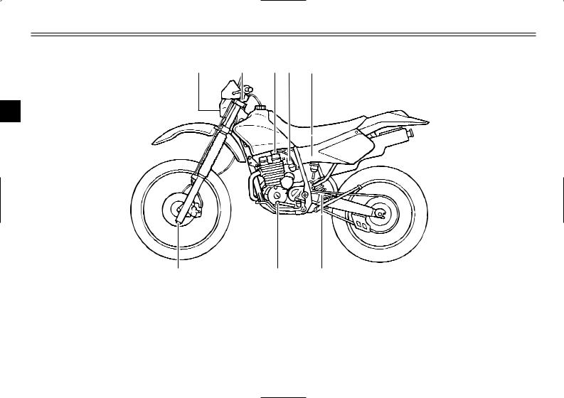
EAU00026
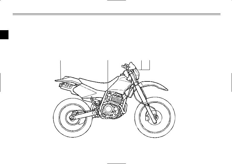
DESCRIPTION
Left view
|
1 |
2 |
3 |
4 |
5 |
2
|
8 |
7 |
6 |
|||
|
1. |
Headlight |
(page 6-31) |
6. |
Shock absorber rebound |
|
|
2. |
Front fork air valve |
(page 3-7) |
damping adjusting dial |
(page 3-11) |
|
|
3. |
Fuel cock |
(page 3-5) |
7. |
Shift pedal |
(page 3-2) |
|
4. |
Starter (choke) knob |
(page 3-6) |
8. |
Front fork damping adjusting |
|
|
5. |
Air filter element |
(page 6-12) |
screw |
(page 3-9) |
2-1

DESCRIPTION
Right view
|
9 |
10 |
11 |
12 |
13 |
2
|
16 |
15 |
14 |
|||
|
9. |
Spark arrester |
(page 6-13) |
14. |
Engine oil filter element |
(page 6-9) |
|
10. |
Battery |
(page 6-29) |
15. |
Brake pedal |
(page 3-3, 6-20) |
|
11. |
Fuse |
(page 6-30) |
16. |
Shock absorber spring preload |
|
|
12. |
Shock absorber compression |
adjusting nut |
(page 3-10) |
||
|
damping adjusting knob |
(page 3-11) |
||||
|
13. |
Main switch |
(page 3-1) |
2-2
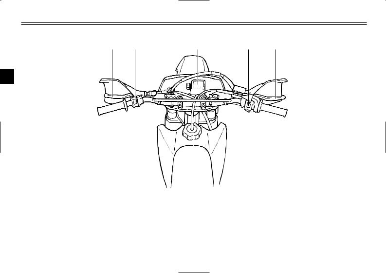
DESCRIPTION
Controls and instruments
1 2 3 4 5
2
|
7 |
6 |
||||||
|
1. |
Clutch lever |
(page 3-2, 6-19) |
6. |
Throttle grip |
(page 6-14) |
||
|
2. |
Left handlebar switch |
(page 3-1) |
7. |
Fuel tank cap |
(page 3-3) |
||
|
3. |
Tripmeter |
(page 3-1) |
|||||
|
4. |
Right handlebar switches |
(page 3-2) |
|||||
|
5. |
Brake lever |
(page 3-3, 6-19) |
2-3
![]()
|
EAU00027 |
INSTRUMENT AND CONTROL FUNCTIONS |
|||
|
ON |
OFF |
1 |
||
|
1 |
||||
|
2 |
3 |
|||
|
1. |
Tripmeter |
1. |
Light switch “:” |
|
|
2. |
Reset knob |
|||
|
EAU00028 |
EAU00118 |
Main switch
The main switch controls the ignition and lighting systems. The various main switch positions are described below.
EAU00036
ON
All electrical systems are supplied with power, and the engine can be started. The key cannot be removed.
EAU00038
OFF
All electrical systems are off. The key can be removed.
EAU01760
Tripmeter
The tripmeter shows the distance traveled since it was last set to zero with the reset knob. The tripmeter can be used to estimate the distance that can be traveled with a full tank of fuel. This information will enable you to plan future fuel stops.
Handlebar switches
EAU04305
Light switch “:”
Set this switch to “:” to turn on the headlight and the taillight.
ECA00037
cC
Always turn the key to “OFF” and light switch to “OFF” when the engine is not running, otherwise the headlight will stay on and the battery may discharge due to extended use.
3-1
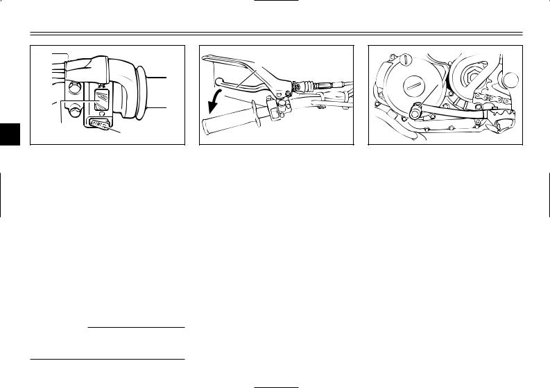
INSTRUMENT AND CONTROL FUNCTIONS
1.Engine stop switch “#/$”
2.Start switch “START”
EAU03890
Engine stop switch “#/$”
Set this switch to “#” before starting the engine. Set this switch to “$” to stop the engine in case of an emergency, such as when the machine overturns or when the throttle cable is stuck.
EAU00141
Start switch “START”
Push this switch to crank the engine with the starter.
EC000005
cC
See page 5-1 for starting instructions prior to starting the engine.
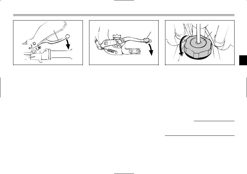
1. Clutch lever
EAU00152
Clutch lever
The clutch lever is located at the left handlebar grip. To disengage the clutch, pull the lever toward the handlebar grip. To engage the clutch, release the lever. The lever should be pulled rapidly and released slowly for smooth clutch operation.
The clutch lever is equipped with a clutch switch, which is part of the ignition circuit cut-off system. (See page 3-12 for an explanation of the ignition circuit cut-off system.)
1 
1. Shift pedal
EAU00157
Shift pedal
The shift pedal is located on the left side of the engine and is used in combination with the clutch lever when shifting the gears of the 6-speed constant-mesh transmission equipped on this machine.
3-2
INSTRUMENT AND CONTROL FUNCTIONS
1. Brake lever
EAU00158
Brake lever
The brake lever is located at the right handlebar grip. To apply the front brake, pull the lever toward the handlebar grip.
1. Brake pedal
EAU00162
Brake pedal
The brake pedal is on the right side of the machine. To apply the rear brake, press down on the brake pedal.
1
a 3
3
1. Fuel tank cap a. Remove.
EAU00179
Fuel tank cap
To remove the fuel tank cap, turn it counterclockwise, and then pull it off. To install the fuel tank cap, insert it into the tank opening, and then turn it clockwise.
EWA00025
w
Make sure that the fuel tank cap is properly closed before riding.
3-3
INSTRUMENT AND CONTROL FUNCTIONS
1 2
3
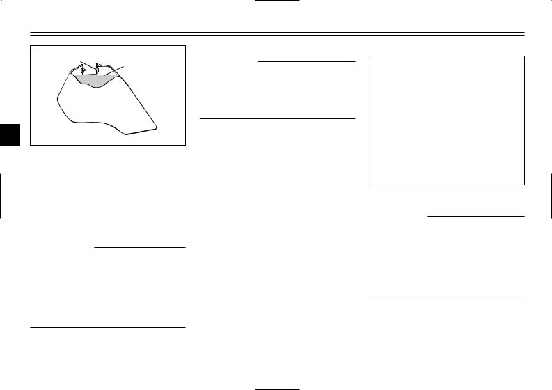
1.Filler tube
2.Fuel level
EAU03753
Fuel
Make sure that there is sufficient fuel in the tank. Fill the fuel tank to the bottom of the filler tube as shown.
EW000130
w
8Do not overfill the fuel tank, otherwise it may overflow when the fuel warms up and expands.
8Avoid spilling fuel on the hot engine.
EAU00185
cC
Immediately wipe off spilled fuel with a clean, dry, soft cloth, since fuel may deteriorate painted surfaces or plastic parts.
EAU04265
Recommended fuel: UNLEADED GASOLINE ONLY
Fuel tank capacity: Total amount:
10.0 L
(2.2 lmp gal, 2.64 US gal) Reserve amount:
2.0 L
(0.44 lmp gal, 0.53 US gal)
ECA00104
cC
Use only unleaded gasoline. The use of leaded gasoline will cause severe damage to internal engine parts, such as the valves and piston rings, as well as to the exhaust system.
3-4
INSTRUMENT AND CONTROL FUNCTIONS
Your Yamaha engine has been designed to use regular unleaded gasoline with a pump octane number [(R+M)/2] of 86 or higher, or a research octane number of 91 or higher. If knocking (or pinging) occurs, use a gasoline of a different brand or premium unleaded fuel. Use of unleaded fuel will extend spark plug life and reduce maintenance costs.
Gasohol
There are two types of gasohol: gasohol containing ethanol and that containing methanol. Gasohol containing ethanol can be used if the ethanol content does not exceed 10%. Gasohol containing methanol is not recommended by Yamaha because it can cause damage to the fuel system or vehicle performance problems.
1
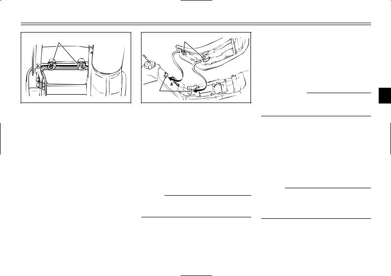
1. Fuel tank breather hose
EAU02955
Fuel tank breather hose
Before operating the machine:
8Check the fuel tank breather hose connection.
8Check the fuel tank breather hose for cracks or damage, and replace it if damaged.
8Make sure that the end of the fuel tank breather hose is not blocked, and clean it if necessary.
|
OFF: closed position |
|
|
RES |
|
|
OFF |
|
|
ON |
|
|
1 |
3 |
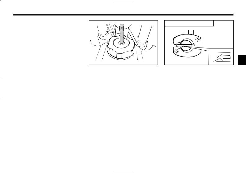
1. Arrow mark positioned over “OFF”
EAU03050
Fuel cock
The fuel cock supplies fuel from the tank to the carburetor while filtering it also.
The fuel cock has three positions:
OFF
With the lever in this position, fuel will not flow. Always return the lever to this position when the engine is not running.
3-5
INSTRUMENT AND CONTROL FUNCTIONS
|
ON: normal position |
||
|
RES |
||
|
OFF |
||
|
3 |
ON |
1 |
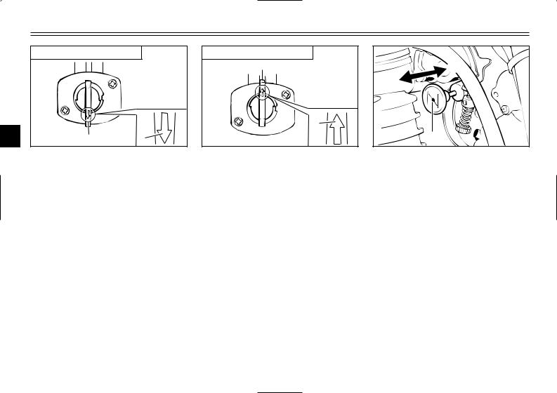
1. Arrow mark positioned over “ON”
ON
With the lever in this position, fuel flows to the carburetor. Normal riding is done with the lever in this position.
|
RES: reserve position |
|
|
RES |
|
|
OFF |
|
|
FUEL |
1 |
|
ON |
1. Arrow mark positioned over “RES”
RES
This indicates reserve. If you run out of fuel while riding, move the lever to this position. Fill the tank at the first opportunity. Be sure to set the lever back to “ON” after refueling!
 b a
b a 


1

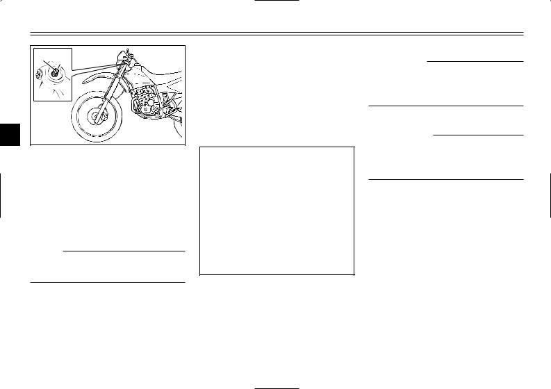
1.Starter (choke) knob “1”
EAU04038
Starter (choke) knob “1”
Starting a cold engine requires a richer air-fuel mixture, which is supplied by the starter (choke).
Move the knob in direction a to turn on the starter (choke).
Move the knob in direction b to turn off the starter (choke).
3-6
INSTRUMENT AND CONTROL FUNCTIONS
|
1 |
|
|
2 |
|
|
1. |
Projection (×2) |
|
2. |
Seat holder (×2) |
EAU00240
EAU04834
Adjusting the front fork
The front fork is equipped with air valves for adjusting the spring rate and screws for adjusting the damping force.
EW000036
w
3
There should be no difference in air pressure between the fork legs.
Seat
To remove the seat
Remove the bolts, and then pull the seat off.
To install the seat
1.Insert the projections on the front of the seat into the seat holders as shown.
2.Place the seat in the original position, and then tighten the bolts.
NOTE:
Make sure that the seat is properly secured before riding.
Spring rate
The total spring rate is adjusted by changing the air pressure as follows.
1.Lift the front wheel off the ground according to the procedure on page 6-33.
NOTE:
When checking and adjusting the air pressure, there should be no weight on the front end of the machine.
3-7
INSTRUMENT AND CONTROL FUNCTIONS
2 1
3
1.Air valve cap
2.Air valve
2.Remove the air valve cap from each fork leg.
3.Check the air pressure in each fork leg with an air pressure gauge.
NOTE:
An optional air pressure gauge is available at a Yamaha dealer.
4.To increase the spring rate and thereby harden the suspension, increase the air pressure with an air pump. To decrease the spring rate and thereby soften the suspension, decrease the air pressure by pushing each valve stem down.
Spring rate: Minimum (soft):
Air pressure = 0 kPa (0 kgf/cm2, 0 psi)
Standard:
Air pressure = 0 kPa (0 kgf/cm2, 0 psi)
Maximum (hard):
Air pressure = 40 kPa (0.4 kgf/cm2, 5.8 psi)
EC000012
cC
Never exceed the maximum air pressure, otherwise the front fork oil seals may become damaged.
EW000035
w
Always adjust both fork legs equally, otherwise poor handling and loss of stability may result.
5.Securely install the air valve caps.
3-8
INSTRUMENT AND CONTROL FUNCTIONS
|
Damping force |
2. To increase |
the damping force |
|
|
1. Remove the rubber cap from |
and thereby harden the damping, |
||
|
each fork leg. |
turn the adjusting screw on each |
||
|
fork leg in direction a. To |
|||
|
decrease the damping force and |
|||
|
thereby soften the damping, turn |
|||
|
the adjusting screw on each fork |
|||
|
leg in direction b. |
|||
|
Minimum (soft) |
20 clicks in direction b* |
||
|
Standard |
11 clicks in direction b* |
||
|
Maximum (hard) |
1 click in direction b* |
||
|
* With the adjusting screw fully turned in direction a |
EC000015
cC
Never attempt to turn an adjusting mechanism beyond the maximum or minimum settings.
3. Securely install the rubber caps.
ECA00034 3
cC
Be sure to install the rubber caps to prevent dust, etc. from entering the fork legs.
NOTE:
Although the total number of clicks of a damping force adjusting mechanism may not exactly match the above specifications due to small differences in production, the actual number of clicks always represents the entire adjusting range. To obtain a precise adjustment, it would be advisable to check the number of clicks of each damping force adjusting mechanism and to modify the specifications as necessary.
3-9
INSTRUMENT AND CONTROL FUNCTIONS
|
EAU03676 |
||||
|
Adjusting the shock |
1 |
2 b |
||
|
absorber assembly |
||||
|
This shock absorber assembly is |
||||
|
equipped with a spring preload |
||||
|
adjusting nut, a rebound damping |
||||
|
force adjusting dial and a compres- |
a |
|||
|
3 |
sion damping force adjusting knob. |
A |
||
|
EC000015 |
||||
|
cC |
1. |
Locknut |
||
|
Never attempt to turn an adjusting |
2. |
Adjusting nut |
||
|
mechanism beyond the maximum |
Spring preload |
|
or minimum settings. |
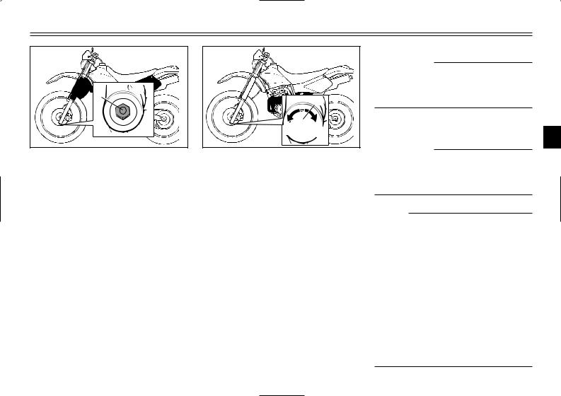
1. |
Loosen the locknut. |
|
2. |
To increase the spring preload |
|
|
and thereby harden the suspen- |
sion, turn the adjusting nut in direction a. To decrease the spring preload and thereby soften the suspension, turn the adjusting nut in direction b.
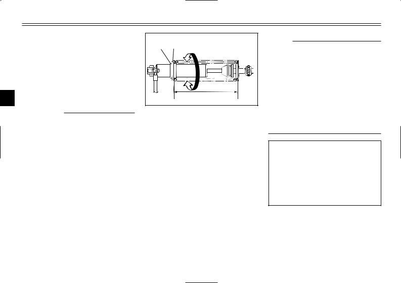
NOTE:
8A special wrench is needed to make this adjustment and it can be obtained at a Yamaha dealer.
8The spring preload setting is determined by measuring distance A, shown in the illustration. The shorter the distance A is, the higher the spring preload; the longer distance A is, the lower the spring preload.
Spring preload: Minimum (soft):
Distance A = 236 mm (9.3 in) Standard:
Distance A = 228 mm (9.0 in) Maximum (hard):
Distance A = 224 mm (8.8 in)
3.Tighten the locknut to the specified torque.
3-10
 Loading…