Материал из BikesWiki — энциклопедия японских мотоциклов
Перейти к: навигация, поиск

Suzuki GSF1200 Bandit
Ниже представлены прямые ссылки на скачку сервисной документации.
Для Suzuki GSF 1200 Bandit
- Сервисный мануал (Service Manual) для Suzuki GSF1200/S Bandit K6
- Сервисный мануал (Service Manual) для Suzuki GSF1200/S Bandit (1996-1997)
- Руководство по ремонту и обслуживанию (Haynes Service & Repair Manual) для Suzuki GSF600/1200 Bandit (1995-2001)
- Руководство пользователя (Owners Manual) для Suzuki GSF1200S (на русском)
Обзор модели
- Suzuki GSF 1200 Bandit
Источник — «https://bikeswiki.ru/index.php?title=Suzuki_GSF1200_Bandit:_мануалы&oldid=9825»
Категория:
- Сервисная документация
- Manuals
- Brands
- Suzuki Manuals
- Motorcycle
- 1200 bandit
Manuals and User Guides for Suzuki 1200 bandit. We have 1 Suzuki 1200 bandit manual available for free PDF download: Service Manual

- Manuals
- Brands
- Suzuki Manuals
- Motorcycle
- 2005 GSF1200
- Service manual
-
Contents
-
Table of Contents
-
Bookmarks
Related Manuals for Suzuki 2005 GSF1200
Summary of Contents for Suzuki 2005 GSF1200
-
Page 1
GSF1200/GSF1200S 9 9 5 0 0 — 3 9 2 8 0 — 0 1 E… -
Page 2
* This manual is written for persons who have enough knowledge, skills and tools, including special tools, for servicing SUZUKI motorcycles. If you do not have the proper knowledge and tools, ask your authorized SUZUKI motorcycle dealer to help you. -
Page 3
TABLE OF CONTENTS Precautions…………… 00-i Precautions …………00-1 General Information ……….. 0-i General Information ……….0A-1 Maintenance and Lubrication ……… 0B-1 Service Data…………0C-1 Engine …………….. 1-i Precautions ………….. 1-1 Engine General Information and Diagnosis … 1A-1 Emission Control Devices ……..1B-1 Engine Mechanical……….1D-1 Engine Lubrication System …….. -
Page 5
Table of Contents 00- i Section 00 Precautions CONTENTS Precautions ……….00-1 General Precautions ……….. 00-1 Precautions for Electrical Circuit Service …. 00-2 Precautions…………00-1 Warning / Caution / Note……..00-1… -
Page 6
CAUTION Indicates a potential hazard that could result • If parts replacement is necessary, replace in death or injury. the parts with Suzuki Genuine Parts or their equivalent. CAUTION • When removing parts that are to be reused, keep them arranged in an orderly manner… -
Page 7
Precautions: 00-2 • Use a torque wrench to tighten fasteners • Inspect each terminal for corrosion and to the specified torque. Wipe off grease contamination. The terminals must be clean and free and oil if a thread is smeared with them. of any foreign material which could impede proper terminal contact. -
Page 8
00-3 Precautions: • Check the male connector for bend and female • Be careful not to touch the electrical terminals of the connector for excessive opening. Also check the Ignitor unit and ABS control unit/HU. The static coupler for locking (looseness), corrosion, dust, etc. electricity from your body may damage this part. -
Page 9
Precautions: 00-4 • The ABS control unit/HU cannot be disassembled. • Before measuring voltage at each terminal, check to Replace the whole unit with a new one. make sure that battery voltage is 11 V or higher. Terminal voltage check at low battery voltage will lead to erroneous diagnosis. -
Page 10
00-5 Precautions: 1) Disconnect the negative (–) cable from the battery. Continuity check 1) Measure resistance across coupler “B” (between “A” 2) Check each connector/coupler at both ends of the circuit being checked for loose connection. Also and “C” in figure). check for condition of the coupler lock if equipped. -
Page 11
Precautions: 00-6 3) Also, if measured values are as listed below, a 3) Measure resistance between terminal at one end of resistance (abnormality) exists which causes the circuit (“A” terminal in figure) and body ground. If voltage drop in the circuit between terminals “A” and continuity is indicated, there is a short circuit to “B”. -
Page 12
00-7 Precautions: Using The Multi-Circuit Testers • After using the tester, turn the power off. • Use the Suzuki multi-circuit tester set. Special tool • Use well-charged batteries in the tester. : 09900–25008 (Multi-circuit tester set) • Be sure to set the tester to the correct testing range. -
Page 13: General Information
Table of Contents 0- i Section 0 General Information CONTENTS General Information …….. 0A-1 Engine Oil and Filter Replacement …..0B-9 Throttle Cable Play Inspection General Description ……….0A-1 and Adjustment ……….0B-10 Symbols ………….. 0A-1 Engine Idle Speed Inspection Abbreviations …………0A-2 and Adjustment ……….0B-11 Vehicle Side View ……….
-
Page 14
Apply oil. Use engine oil unless otherwise specified. Apply molybdenum oil solution (Mixture of engine oil and SUZUKl MOLY PASTE in a ratio of 1:1). Apply SUZUKI SUPER GREASE “A” or equivalent. 99000-25010 Apply SUZUKI MOLY PASTE or equivalent. 99000-25140 Apply SUZUKI SILICONE GREASE or equivalent. -
Page 15
General Information: 0A-2 Abbreviations B649G10101002 HC: Hydrocarbons ABDC: After Bottom Dead Center IG: Ignition ABS: Anti-lock Brake System AC: Alternating Current JASO: Japanese Automobile Standards Organization ACL: Air Cleaner, Air Cleaner Box API: American Petroleum Institute LCD: Liquid Crystal Display ATDC: After Top Dead Center LED: Light Emitting Diode (Malfunction Indicator Lamp) A/F: Air Fuel Mixture… -
Page 16
0A-3 General Information: Vehicle Side View SUZUKI GSF1200S (2006-model) B649G10101003 NOTE Right Side Difference between photographs and actual motorcycles may exist depending on the markets. SUZUKI GSF1200 (2006-model) Right Side I649G1010005-06 Left Side I649G1010008-01 Left Side I649G1010006-05 I649G1010009-01… -
Page 17
Use of SF/SG or SH/SJ in API with MA in JASO. head pipe. The engine serial number “B” is located on Suzuki recommends the use of SAE 10W-40 engine oil. the right side of the crankcase. These numbers are… -
Page 18: Cylinder Identification
0A-5 General Information: Cylinder Identification Country and Area Codes B649G10101008 B649G10101009 The four cylinders of this engine are identified as No.1, The following codes stand for the applicable country(- 2, 3 and No.4 cylinder, as counted from left to right (as ies) and area(-s).
-
Page 19
General Information: 0A-6 Warning, Caution and Information Labels Location B649G10101011 I649G1010011-04 GSF1200 GSF1200S 1. Noise label — For E-24 2. Information label — For E-28 3. Fuel caution label For E-02 For E-02, 24 4. Screen label — For E-02, 19, 24, 28 5. -
Page 20
0A-7 General Information: Component Location Electrical Components Location B649G10103001 I649G1010003-05 1. Ignition coil 3. Handlebar switch (RH) 5. Rear brake light switch 7. CKP sensor 2. Ignition switch 4. Front brake light switch 6. Throttle position sensor 8. Oil pressure switch… -
Page 21
General Information: 0A-8 I649G1010004-04 9. Clutch lever position switch 14. Main fuse 19. Generator 10. Handlebar switch (LH) 15. Battery 20. Carburetor heater (For E-02, 19) 11. Fuse box 16. Ignitor 21. Speed sensor 12. Turn signal/Side-stand relay 17. Horn 22. -
Page 22
0A-9 General Information: Specifications Specifications B649G10107001 NOTE These specifications are subject to change without notice. Dimensions and dry mass Item Specification Remark Overall length 2 130 mm (83.9 in) Overall width 790 mm (31.1 in) 1 095 mm (43.1 in) GSF1200 Overall height 1 235 mm (48.6 in) -
Page 23
General Information: 0A-10 Chassis Item Specification Remark Front suspension Telescopic, coil spring, oil damped Rear suspension Link type, coil spring, oil damped Front suspension stroke 130 mm (5.1 in) Rear wheel travel 136 mm (5.4 in) Caster 35° (right & left) Trail 25°… -
Page 24: Special Tools
0A-11 General Information: Special Tools and Equipment Special Tools B649G10108001 TT09900-06106-01 TT09900-06107-02 TT09900-06108-02 TT09900-20102-01 09900-06106 09900-06107 09900-06108 09900-20102 Snap ring pliers Snap ring pliers Snap ring pliers Vernier calipers (1/20 mm, 200 mm) TT09900-20202-01 TT09900-20204-01 TT09900-20205-01 TT09900-20508-01 09900-20202 09900-20204 09900-20205 09900-20508 Micrometer Micrometer…
-
Page 25
General Information: 0A-12 TT09913-50121-01 TT09913-60910-01 TT09913-61510-01 TT09913-70210-01 09913-50121 09913-60910 09913-61510 09913-70210 Oil seal remover Bearing remover Bearing remover Bearing installer set TT09915-40610-01 TT09915-63210-01 TT09915-64510-01 TT09915-74521-01 09915-40610 09915-63210 09915-64510 09915-74521 Oil filter wrench Compression gauge adaptor Compression gauge set Oil pressure gauge hose TT09915-74540-01 TT09915-77331-01 TT09916-10911-01… -
Page 26
0A-13 General Information: TT09917-14920-01 TT09917-47010-01 TT09920-34820-01 TT09920-34840-01 09917-14920 09917-47010 09920-34820 09920-34840 Valve adjuster driver Vacuum pump gauge Clutch pressure plate holder Starter clutch holder TT09920-53740-02 TT09921-20240-01 TT09922-22711-01 TT09923-73210-01 09920-53740 09921-20240 09922-22711 09923-73210 Clutch sleeve hub holder Bearing remover set Drive chain cutting and Bearing remover joining tool TT09924-84510-01… -
Page 27: Maintenance And Lubrication
Maintenance and Lubrication: 0B-1 Maintenance and Lubrication Precautions Precautions for Maintenance B649G10200001 The “Periodic Maintenance Schedule Chart” lists the recommended intervals for all the required periodic service work necessary to keep the motorcycle operating at peak performance and economy. Maintenance intervals are expressed in terms of kilometers, miles and months for your convenience.
-
Page 28: Scheduled Maintenance
0B-2 Maintenance and Lubrication: Scheduled Maintenance Periodic Maintenance Schedule Chart B649G10205001 NOTE I = Inspect and clean, adjust, replace or lubricate as necessary. R = Replace T = Tighten Interval 1 000 6 000 12 000 18 000 24 000 Item mile 4 000…
-
Page 29: Lubrication Points
Maintenance and Lubrication: 0B-3 Lubrication Points B649G10205002 Proper lubrication is important for smooth operation and long life of each working part of the motorcycle. Major lubrication points are indicated as follows. NOTE • Before lubricating each part, clean off any rusty spots and wipe off any grease, oil, dirt or grime. •…
-
Page 30
0B-4 Maintenance and Lubrication: Repair Instructions Air Cleaner Element Removal and Installation • After cleaning or installing the air cleaner element, B649G10206001 drain water from the air cleaner by removing the drain plug. Inspect air cleaner element Every 6 000 km (4 000 miles, 12 months) Replace air cleaner element Every 18 000 km (11 000 miles, 36 months) Removal… -
Page 31
Maintenance and Lubrication: 0B-5 Cleaning 1) Remove the spark plug caps. Carefully use compressed air to clean the air cleaner element. CAUTION Always apply compressed air to the inside of the air cleaner element. If compressed air is applied to the outside, dirt will be forced into the pores of the air cleaner element, restricting air flow through the air cleaner element. -
Page 32
0B-6 Maintenance and Lubrication: Spark Plug Inspection and Cleaning Electrodes Condition B649G10206004 Check to see the worn or burnt condition of the Refer to “Spark Plug Removal and Installation: ”. electrodes. If it is extremely worn or burnt, replace the plug. And also Inspect spark plug replace the plug if it has a broken insulator, damaged Every 6 000 km (4 000 miles, 12 months) -
Page 33
Maintenance and Lubrication: 0B-7 Valve Clearance Inspection and Adjustment B649G10206005 “A” “A” Inspect valve clearance Initially at 1 000 km (600 miles, 2 month) and every “B” “B” 12 000 km (7 500 miles, 24 months) thereafter. Valve clearance adjustment must be checked and adjusted, a) at the time of periodic inspection, b) when the valve mechanism is serviced, and c) when the camshafts are removed for servicing. -
Page 34
0B-8 Maintenance and Lubrication: 9) Insert the thickness gauge between the valve stem end and adjusting screw on the rocker arm. If the Notch “C” position Camshaft position clearance is out of specification, hold the lock-nut faces inside with a wrench and use the special tools to adjust the Measuring position “E”… -
Page 35
Maintenance and Lubrication: 0B-9 Engine Oil and Filter Replacement 3) Tighten the oil drain plug (1) to the specified torque, B649G10206007 and pour new oil through the oil filler. When performing an oil change (without oil filter Replace engine oil replacement), the engine will hold about 3.3 L of oil. -
Page 36
Also, do not use a genuine Suzuki automobile oil filter on this motorcycle. 4) Install a new oil filter. Turn it by hand until you feel that the oil filter O-ring contacts the oil filter mounting “a”… -
Page 37
Maintenance and Lubrication: 0B-11 Engine Idle Speed Inspection and Adjustment WARNING B649G10206011 The clutch system of this motorcycle is filled Inspect engine idle speed with a glycol-based brake fluid. Do not use or Initially at 1 000 km (600 miles, 2 month) and every 6 mix different types of fluid such as silicone- 000 km (4 000 miles, 12 months) thereafter. -
Page 38
0B-12 Maintenance and Lubrication: Clutch Hose Replacement Drive Chain Length Inspection B649G10206031 1) Remove the cotter pin. (For E-28) Refer to “Clutch Hose Removal and Installation: in 2) Loosen the axle nut (1). Section 5C”. 3) Loosen the chain adjuster lock-nuts (2). Air Bleeding from Clutch Fluid Circuit 4) Give tension to the drive chain fully by turning both B649G10206032… -
Page 39
• Do not use any oil sold commercially as “drive chain oil”. Such oil can damage the O-rings. • The standard drive chain is a RK GB50GSVZ3. SUZUKI recommends to use this standard drive chain as a replacement. I649G1020035-02 “a”… -
Page 40
0B-14 Maintenance and Lubrication: Brake Pads Check WARNING The extent of brake pad wear can be checked by observing the grooved limit line “A” on the pad. When the • The brake system of this motorcycle is wear exceeds the grooved limit line, replace the pads filled with a glycol-based brake fluid. -
Page 41
Maintenance and Lubrication: 0B-15 Brake Fluid Replacement Rear Brake Hose Inspection B649G10206035 Inspect the brake hose for crack, damage or brake oil Refer to “Brake Fluid Replacement: in Section 4A”. leakage. If any defects are found, replace the brake hose with a new one. Tire Inspection B649G10206017 Inspect tire… -
Page 42
It is highly recommended to use a Replace any defective parts, if necessary. Refer to SUZUKI Genuine Tire. “Front Fork Parts Inspection: in Section 2B”. Tire type DUNLOP •… -
Page 43
Maintenance and Lubrication: 0B-17 Chassis Bolt and Nut Inspection B649G10206022 Tighten chassis bolt and nut Initially at 1 000 km (600 miles, 2 month) and every 6 000 km (4 000 miles, 12 months) thereafter. Check that all chassis bolts and nuts are tightened to their specified torque. -
Page 44: Compression Pressure Check
0B-18 Maintenance and Lubrication: I649G1020061-04 I649G1020064-04 15. Front axle bolt 21. Air bleeder valve (Brake) 30. Rear sprocket nut : 100 N⋅m (10.0 kgf-m, 72.5 lb-ft) 16. Front axle pinch bolt : 23 N⋅m (2.3 kgf-m, 16.5 lb-ft) 31. Rear axle nut : 60 N⋅m (6.0 kgf-m, 43.5 lb-ft) 17.
-
Page 45
For the tightening torque of fastener not specified in this section, refer to “Tightening Torque Specifications: in Section 0C”. Special Tools and Equipment Recommended Service Material B649G10208001 Material SUZUKI recommended product or Specification Note Brake fluid DOT 4 — Special Tool B649G10208002 09900–20803… -
Page 46
0C-1 Service Data: Service Data Specifications Service Data B649G10307003 Valve + Guide Unit: mm (in) Item Standard Limit 28.5 (1.12) — Valve diameter 25 (1.0) — 0.10 – 0.15 (0.004 – 0.006) — Valve clearance (when cold) 0.18 – 0.23 (0.007 – 0.009) —… -
Page 47
Service Data: 0C-2 Cylinder + Piston + Piston Ring Unit: mm (in) Item Standard Limit 875 kPa Compression pressure 1 250 kPa (12.5 kgf/cm , 178 psi) (8.75 kgf/cm , 124 psi) 200 kPa Compression pressure difference — (2 kgf/cm , 28 psi) Piston-to-cylinder clearance 0.050 –… -
Page 48
0C-3 Service Data: Oil Pump Item Standard Limit Oil pump reduction ratio 1.703 (72/46 x 37/34) — Above 300 kPa (3.0 kgf/cm , 43 psi) Oil pressure (at 60 °C, 140 °F) Below 600 kPa (6.0 kgf/cm , 85 psi) —… -
Page 49
Service Data: 0C-4 Electrical Unit: mm (in) Item Specification Note 7° B.T.D.C. at 1 300 r/min. E-28 Ignition timing 7° B.T.D.C. at 1 200 r/min. Others 1 ⋅ 2 ⋅ 4 ⋅ 3 Firing order Type NGK: JR9B Spark plug 0.6 –… -
Page 50
0C-5 Service Data: Brake + Wheel Unit: mm (in) Item Standard Limit Rear brake pedal height 60 (2.4) — Front 4.8 – 5.2 (0.189 – 0.205) 4.5 (0.18) Brake disc thickness Rear 4.8 – 5.2 (0.189 – 0.205) 4.5 (0.18) Brake disc runout —… -
Page 51
Service Data: 0C-6 Tire Item Standard Limit Cold inflation tire pressure Front 250 kPa (2.50 kgf/cm , 36 psi) — (Solo/Dual riding) Rear 250 kPa (2.50 kgf/cm , 36 psi) — Front 120/70 ZR17M/C (58 W) — Tire size Rear 180/55 ZR17M/C (73 W) —… -
Page 52
0C-7 Service Data: Tightening Torque Specifications B649G10307002 Engine Item N⋅m kgf–m lb–ft Cylinder head cover bolt (10 pcs) 10.0 Cylinder head cover plug 11.0 Cylinder head cover union bolt 14.5 Cylinder head nut [M10] 27.5 Cylinder head bolt [M6] Cylinder head plug 20.0 Cylinder base nut Cylinder stud bolt… -
Page 53
Service Data: 0C-8 Item N⋅m kgf–m lb–ft Fuel level gauge mounting bolt Oil filter 14.5 Chassis Item N⋅m kgf–m lb–ft Steering stem head nut 47.0 Tighten 45 N⋅m (4.5 kgf-m, 32.5 lb-ft) then turn back 1/2 – Steering stem nut 1/4. -
Page 54
0C-9 Service Data: Tightening Torque Chart For other bolts and nuts not listed in the preceding page, refer to this chart: Bolt Diameter Conventional or “4” marked bolt “7” marked bolt “a” (mm) N⋅m kgf–m lb–ft N⋅m kgf–m lb–ft 0.15 16.5 21.0 36.0… -
Page 55: Table Of Contents
Table of Contents 1- i Section 1 Engine CONTENTS Precautions ……….1-1 Camshaft Sprocket Inspection ……1D-27 Camshaft Sprocket Removal and Installation …1D-27 Precautions…………. 1-1 Cam Chain Tension Adjuster Inspection…1D-28 Precautions for Engine………. 1-1 Cam Chain Guide Removal and Installation ..1D-28 Engine General Information and Cam Chain Guide Inspection ……1D-29 Cam Chain Tensioner Inspection……1D-29 Diagnosis ……….
-
Page 56
1-ii Table of Contents Oil Pressure Regulator Inspection …… 1E-5 Fuel Tank Drain Hose and Breather Hose Oil Pan / Oil Sump Filter Cleaning …… 1E-6 Routing Diagram ……….1G-10 Oil Pressure Switch Removal and Installation ..1E-6 Throttle Cable / Starter Cable Oil Pressure Switch Inspection …… -
Page 57
Table of Contents 1-iii CKP Sensor Removal and Installation ….1H-8 Special Tools and Equipment ……1I-17 Engine Stop Switch Inspection ……1H-10 Recommended Service Material ……1I-17 Ignition Switch Inspection ………1H-10 Special Tool …………1I-17 Ignition Switch Removal and Installation…1H-10 Charging System ……..1J-1 Specifications………….1H-11 General Description ………. -
Page 58
1-1 Precautions: Precautions Precautions Precautions for Engine B649G11000001 Refer to “General Precautions: in Section 00” and “Precautions for Electrical Circuit Service: in Section 00”. -
Page 59: Engine General Information And Diagnosis
Engine General Information and Diagnosis: 1A-1 Engine General Information and Diagnosis Diagnostic Information and Procedures Engine Symptom Diagnosis B649G11104011 Condition Possible cause Correction / Reference Item Engine will not start or is Worn cylinder. Rebore or replace. hard to start Worn piston ring.
-
Page 60
1A-2 Engine General Information and Diagnosis: Condition Possible cause Correction / Reference Item Engine noisy (Noise Worn or rubbing gear. Replace. seems to come from Worn countershaft spline. Replace countershaft. transmission.) Worn driveshaft spline. Replace driveshaft. Worn or rubbing primary gear. Replace. -
Page 61
A jet needle with only one clip position, is also used. If jet needle replacement is necessary, only replace it with a jet needle of the same type. Suzuki recommends that Genuine Suzuki Parts be utilized whenever possible for the best possible performance and durability. -
Page 62: Crankcase Emission Control System Description
1B-2 Emission Control Devices: Crankcase Emission Control System Description B649G11201006 The engine is equipped with a PCV system to prevent discharging crankcase emissions into the atmosphere. Blow-by gas in the engine is constantly drawn into the crankcase, which is returned to the combustion chamber through the PCV hose, air cleaner box and carburetors.
-
Page 63: Exhaust Emission Control System Description
Emission Control Devices: 1B-3 Exhaust Emission Control System Description B649G11201008 The exhaust emission control system is composed of the PAIR system and three-way catalyst system. The fresh air is drawn into the exhaust port through the PAIR control valve and PAIR reed valve. The PAIR control valve is operated by the engine vacuum which is connected to the No.4 carburetor, and the fresh air flow is controlled according to the exhaust gas pulsation.
-
Page 64: Schematic And Routing Diagram
1B-4 Emission Control Devices: Schematic and Routing Diagram PAIR System Hose Routing Diagram B649G11202001 “I” “A” “D” “B” “G” “C” “F” “H” “E” I649G1120008-04 1. PAIR hose No.1 7. PAIR control valve “F”: Marking (White) must face front side. 2. PAIR hose No.2 “A”: Be careful not to contact the PAIR hoses with the throttle cables.
-
Page 65: Repair Instructions
Emission Control Devices: 1B-5 Repair Instructions PAIR System Removal and Installation Installation B649G11206001 Install the PAIR valve in the reverse order of removal. Removal Pay attention to the following points: 1) Remove the fuel tank. Refer to “Fuel Tank Removal CAUTION and Installation: in Section 1G”.
-
Page 66
1B-6 Emission Control Devices: PAIR System Inspection 3) Remove the reed valves. B649G11206004 4) Inspect the reed valves for the carbon deposit. PAIR Hose and Pipe If the carbon deposit is found in the reed valve, 1) Remove the fuel tank. Refer to “Fuel Tank Removal replace the PAIR valve with a new one. -
Page 67: Pcv Hose Removal And Installation
Emission Control Devices: 1B-7 b) Connect the vacuum pump gauge to the vacuum PCV Hose Removal and Installation B649G11206007 port of the PAIR valve as shown. Apply negative Removal pressure slowly to the PAIR valve and blow into it 1) Remove the fuel tank. Refer to “Fuel Tank Removal as shown above.
-
Page 68: Tightening Torque Specifications
1B-8 Emission Control Devices: Specifications Tightening Torque Specifications B649G11207001 Tightening torque Fastening part Note N⋅m kgf-m lb-ft PAIR pipe mounting nut PAIR valve mounting bolt Reference: For the tightening torque of fastener not specified in this section, refer to “Tightening Torque Specifications: in Section 0C”.
-
Page 69: Engine Mechanical
Engine Mechanical: 1D-1 Engine Mechanical Schematic and Routing Diagram Camshaft and Sprocket Assembly Diagram B649G11402001 24th pin 1st pin I649G1140075-03…
-
Page 70
1D-2 Engine Mechanical: Diagnostic Information and Procedures Compression Pressure Check 6) Keep the throttle grip in the fully-opened position. B649G11404001 The compression pressure reading of a cylinder is a good indicator of its internal condition. The decision to overhaul the cylinder is often based on the results of a compression test. -
Page 71: Repair Instructions
Engine Mechanical: 1D-3 Repair Instructions Engine Components Removable with the Engine in Place B649G11406001 Engine components which can be removed while the engine is installed on the frame are as follows. For the installing and removing procedures, refer to respective paragraphs describing each component. Center of Engine Item Removal…
-
Page 72
1D-4 Engine Mechanical: Engine Left Side Item Removal Inspection Installation Refer to “Engine Sprocket Refer to “Engine Sprocket Engine sprocket cover Removal and Installation: in — Removal and Installation: in Section 3A”. Section 3A”. Refer to “Engine Sprocket Refer to “Drive Chain Refer to “Engine Sprocket Engine sprocket Removal and Installation: in… -
Page 73
Engine Mechanical: 1D-5 Engine Assembly Removal 9) Disconnect all of the spark plug caps (3). B649G11406002 10) Disconnect the breather (PCV) hose (4). Before taking the engine out of the frame, wash the engine using a steam cleaner. Engine removal is sequentially explained in the following steps: 1) Drain engine oil. -
Page 74
1D-6 Engine Mechanical: 13) Remove the wire harness clamp (7). 19) Disengage the gearshift lever link by removing the bolt. 14) Disconnect the gear position switch lead wire couplers (8). 20) Remove the engine sprocket cover by removing the bolts. I649G1140007-03 15) Disconnect the CKP sensor lead wire coupler (9). -
Page 75
Engine Mechanical: 1D-7 25) Loosen the rear axle nut (16) and chain adjusters 28) Remove the oil cooler and oil cooler hoses. Refer to (17) to provide additional chain slack. “Oil Cooler / Oil Cooler Hose Removal and Installation: in Section 1F”. I649G1140011-03 26) Remove the engine sprocket (18). -
Page 76
1D-8 Engine Mechanical: 33) Gradually lower the front side of the engine and remove the engine. WARNING Care should be taken not to drop the engine accidentally when the engine mounting bolts and nuts are removed. I649G1140018-04 19. Frame down tube mounting bolt 22. -
Page 77
Engine Mechanical: 1D-9 Engine Assembly Installation B649G11406003 Reinstall the engine in the reverse order of engine removal. Pay attention to the following points: • Insert the two long bolts (1), (2) from left side. Install the brackets, spacer, bolts and nuts properly, as shown in the following illustration. -
Page 78
Speed sensor rotor bolt (h): 20 N·m (2.0 kgf-m, 14.5 lb-ft) • Before installing the engine sprocket cover, apply a small quantity of SUZUKI SUPER GREASE “A” to the push rod. : Grease 99000–25010 (SUZUKI SUPER GREASE A or equivalent) I649G1140025-03 •… -
Page 79
Engine Mechanical: 1D-11 • Position the carburetor clamps as shown. I649G1170033-01 • After remounting the engine, route the wire harness, cables and hoses properly. Refer to “Wiring Harness Routing Diagram: in Section 9A” and “Throttle Cable / Starter Cable Routing Diagram: in Section 1G”. •… -
Page 80
1D-12 Engine Mechanical: • Pour 4.6 L (4.9/4.0 US/lmp qt) of SF/SG or SH/SJ with JASO MA engine oil, with a viscosity rating of 10W-40, into the engine after overhauling it. • Start up the engine and allow it run for several minutes at idle speed and then stop the engine. Wait three minutes and then check that the oil level remains between the marks on the oil level inspection window. -
Page 81
Engine Mechanical: 1D-13 Cylinder Head Cover 4) After removing the spring holder bolt (2) and spring (3), remove the cam chain tension adjuster (4). 1) Remove the breather cover (1). 2) Remove the cylinder head cover (2) from the cylinder head. I649G1140039-02 5) Remove the camshaft journal holders. -
Page 82
1D-14 Engine Mechanical: 2) Remove the cylinder head bolt (2). Cylinder 1) Remove the cylinder head gasket (1), O-rings (2) and dowel pins (3). I649G1140042-02 I649G1140355-02 3) The cylinder head can be removed after its twelve 2) Remove the left and right oil return pipes (4). nuts (M10) are removed. -
Page 83
• Install each cylinder stud bolt as shown. NOTE Before installing the cylinder stud bolt (4), apply a light coat of the recommended bond to its threads. : Sealant 99000–31140 (SUZUKI Bond 1207B or equivalent) Tightening torque Cylinder stud bolt: 15 N·m (1.5 kgf-m, 11.0 lb-ft) I649G1140050-02 4) Draw out each piston pin and remove the pistons. -
Page 84
1D-16 Engine Mechanical: Oil Jet (For the Cylinder Head) • Install the dowel pins and the new cylinder gasket. • Make sure that the oil jets (1) in the upper crankcase • Before installing the cylinder, oil the big and small are not clogged. -
Page 85
• With pistons #2 and #3 in place, install pistons #1 and • Install the new O-rings (2) onto the oil return pipes #4, and then insert them into the respective cylinders. and apply SUZUKI SUPER GREASE “A” to the O- rings. NOTE… -
Page 86
1D-18 Engine Mechanical: • Tighten the twelve nuts (M10) in ascending order and • Install the cam chain guide (2) as shown. to the specified torque. Tightening torque Cylinder head nut: 38 N·m (3.8 kgf-m, 27.5 lb-ft) “10” “2” “4” “8”… -
Page 87
Camshaft NOTE Before installing the camshafts onto the cylinder head, apply SUZUKI MOLY PASTE onto the camshaft journals and do not leave any dry spots. Also, apply engine oil onto the camshaft journal holders. M/O: Molybdenum oil (Molybdenum oil solution) I649G1140069-02 •… -
Page 88
1D-20 Engine Mechanical: • When the “T” mark on the CKP rotor is aligned with the center of the CKP sensor, hold the camshaft steady and lightly pull up the cam chain to remove any slack between the crankshaft sprocket and the exhaust camshaft sprocket. -
Page 89
Engine Mechanical: 1D-21 “B” I649G1140073-02 “C” I649G1140074-02 24th pin 1st pin I649G1140075-03… -
Page 90
1D-22 Engine Mechanical: • Each camshaft journal holder is identified with an embossed letter and install the dowel pins into each camshaft journal holder. I649G1140076-01 • Have the camshaft journal holders seated (IN and EX) evenly by tightening the camshaft journal holder bolts sequentially and in a crisscross pattern. -
Page 91
I649G1140082-01 CKP Sensor Cover • Apply a bond lightly to the CKP sensor cover gasket mating surface as shown. : Sealant 99000–31140 (SUZUKI Bond 1207B or equivalent) I649G1140079-02 • Insert the spring into the cam chain tension adjuster and tighten the spring holder bolt (4) to the specified torque. -
Page 92
Replace the cylinder head cover gasket (1) and oil nozzle gaskets (2) with new ones. • Apply a bond to the four camshaft end caps of the gasket as shown. : Sealant 99000–31140 (SUZUKI Bond 1207B or equivalent) I649G1140087-04 I649G1140351-01 •… -
Page 93: Valve Clearance Inspection And Adjustment
Engine Mechanical: 1D-25 Cooling Hose • Install the left and right cooling hoses and tighten their mounting bolts to the specified torque. CAUTION Replace the O-rings (1) with new ones to prevent oil leakage. Tightening torque Cooling hose mounting bolt (a): 10 N·m (1.0 kgf- m, 7.0 lb-ft) I649G1140093-02 Valve Clearance Inspection and Adjustment…
-
Page 94
1D-26 Engine Mechanical: Camshaft Runout 3) Install each camshaft journal holder to its original Measure the runout using the dial gauge. Replace the position. Refer to “Engine Top Side Assembly: ”. camshaft if the runout exceeds the limit. 4) Tighten the camshaft journal holder bolts evenly and diagonally to the specified torque. -
Page 95: Camshaft Sprocket Inspection
Engine Mechanical: 1D-27 Camshaft journal holder I.D. (IN & EX) Camshaft Sprocket Removal and Installation B649G11406050 Standard: 22.012 – 22.025 mm (0.8666 – 0.8671 Removal 1) Remove the camshafts. Refer to “Engine Top Side Special tool Disassembly: ”. (E): 09900–20205 (Micrometer (0-25mm)) 2) Remove the camshaft sprockets (1).
-
Page 96: Cam Chain Guide Removal And Installation
1D-28 Engine Mechanical: 1) Apply THREAD LOCK SUPER “1303” to the threads Cam Chain Guide Removal and Installation B649G11406068 of the camshaft sprocket bolts and then tighten them Removal to the specified torque. 1) Remove the cylinder head cover. Refer to “Engine : Thread lock cement 99000–32030 (Thread Top Side Disassembly: ”.
-
Page 97: Cam Chain Guide Inspection
Installation Install The cam chain guides in the reverse order of removal. Pay attention to the following points: • Apply SUZUKI THREAD LOCK SUPER “1303” to thread part and tighten the mounting bolt to the specified torque. : Thread lock cement 99000–32030 (Thread…
-
Page 98: Cylinder Head Disassembly And Assembly
1D-30 Engine Mechanical: Cylinder Head Disassembly and Assembly B649G11406054 Refer to “Engine Top Side Disassembly: ”. Refer to “Engine Top Side Assembly: ”. Disassembly 1) Remove the intake pipes. 2) Remove the rocker arm shaft set bolt (1) and cylinder head plug (2). I649G1140214-02 I649G1140212-02 3) Remove the rocker arm shaft (3), rocker arm (4) and…
-
Page 99
Engine Mechanical: 1D-31 Assembly 4) Insert the valves with their stems coated with molybdenum oil solution. 1) Locate the plate (1) on the cylinder head of exhaust Coat the entire stem making sure that there are no side. gaps. CAUTION When inserting each valve, take care not to damage the lip of the oil seal. -
Page 100
Be sure to install all of the parts in their original positions. “E” “F” I649G1140227-02 10) Apply SUZUKI SUPER GREASE “A” to the O-ring of the intake pipe. CAUTION Use new O-rings to prevent the joints from I649G1140224-01 sucking air. -
Page 101: Cylinder Head Related Parts Inspection
Engine Mechanical: 1D-33 11) Apply a small quantity of THREAD LOCK “1342” to Valve Stem Runout the thread of the intake pipe bolt. Support the valve using V-blocks, as shown, and check its runout using the dial gauge. If the runout exceeds the : Thread lock cement 99000–32050 (Thread service limit, replace the valve.
-
Page 102
1D-34 Engine Mechanical: Valve Face Wear NOTE Visually inspect each valve face for wear. Replace any If valve guides have to be removed for valve with an abnormally worn face. The thickness of the replacement after inspecting related parts, valve face decreases as the face wears. Measure the carry out the steps shown in valve guide valve face “a”. -
Page 103
Engine Mechanical: 1D-35 Valve spring free length (IN & EX) Rocker Arm Inside Diameter Service limit: INNER: 35.0 mm (1.38 in) Measure the rocker arm inside diameter in two directions Service limit: OUTER: 37.8 mm (1.49 in) at right angle to each other. If the inside diameter measured exceeds the standard value, replace the Valve spring tension (IN &… -
Page 104: Valve Guide Replacement
1D-36 Engine Mechanical: 4) Check that the transferred red lead (blue) on the WARNING valve face is uniform all around and in center of the Always use extreme caution when handling valve face. gasoline. If the seat width “a” measured exceeds the standard value, or seat width is not uniform reface the seat using the seat cutter.
-
Page 105
Engine Mechanical: 1D-37 4) Refinish the valve guide holes in the cylinder head Drive the guide into the guide hole using the valve using the reamer and handle. guide installer. CAUTION CAUTION When refinishing or removing the reamer Failure to oil the valve guide hole before from the valve guide hole, always turn it driving the new guide into place may result in clockwise.
 -
Page 106: Valve Seat Repair
1D-38 Engine Mechanical: Valve Seat Repair Special tool B649G11406069 : 09900–20803 (Thickness gauge) The valve seats (1) for both the intake and exhaust Cylinder distortion valves are machined to two different angles. The seat Service limit: 0.2 mm (0.008 in) contact surface is cut at 45°.
-
Page 107: Piston Ring Components
Engine Mechanical: 1D-39 Piston Ring Components B649G11406071 1 [A] 2 [A] 1 [B] 2 [B] I649G1140362-02 1. 1st ring [A]: Standard piston ring 2. 2nd ring [B]: Oversize piston ring 3. Oil ring spacer [C]: Color (Red is standard) (Blue is 0.5 mm oversize) 4.
-
Page 108
1D-40 Engine Mechanical: Installation NOTE Face the side with the stamped mark “A” NOTE upward when assembling. • When installing the piston ring, be careful not to damage the piston. • Do not expand the piston ring excessively since it is apt to be broken down. “A”… -
Page 109
Engine Mechanical: 1D-41 Piston-to-cylinder Clearance Piston Ring Free End Gap and Piston Ring End Gap Subtract the piston diameter from the cylinder bore Measure the piston ring free end gap using vernier diameter. If the piston-to-cylinder clearance exceeds the calipers. Next, fit the piston ring squarely into the service limit, replace both the cylinder and the piston. -
Page 110: Engine Bottom Side Disassembly
1D-42 Engine Mechanical: Piston Pin and Pin Bore Engine Bottom Side Disassembly B649G11406005 Measure the piston pin bore inside diameter using the NOTE small bore gauge. If either is out of specification or the The crankcase must be separated to service difference between these measurement is more than the the crankshaft and conrod.
-
Page 111
Engine Mechanical: 1D-43 CKP Sensor / Oil Pressure Switch Gearshift 1) Remove the CKP sensor component parts (1). Refer 1) Remove the snap ring and washer from the gearshift to “CKP Sensor Removal and Installation: in Section shaft. 1H”. Special tool 2) Disconnect the oil pressure switch lead wire and : 09900–06107 (Snap ring pliers) remove the oil pressure switch (2). -
Page 112
1D-44 Engine Mechanical: 2) Remove the washers (2), oil pump driven gear (3) 3) Remove the gear position switch (2). and pin (4). NOTE Be careful not to drop the circlip, pin and washers into the oil pan. I649G1140117-01 4) Remove the O-ring (3), switch contact (4) and spring (5). -
Page 113
Engine Mechanical: 1D-45 2) Remove the plug (2). Remove the lower crankcase bolts and nut. 3) Remove the upper crankcase bolts and nut. I649G1140123-01 I649G1140120-02 4) Remove the oil pan (3). I649G1140124-01 9) Remove the main oil gallery plug (7) and O-ring. I649G1140121-03 5) Remove the shim (4) and O-ring (5). -
Page 114
1D-46 Engine Mechanical: 12) Make sure that all of the bolts are removed. Then, Crankshaft tap the sides of the lower crankcase using a plastic 1) Remove the crankshaft assembly (1) from the upper mallet to separate the upper and lower crankcase crankcase. -
Page 115
Engine Mechanical: 1D-47 Crankshaft Journal Bearing / Oil Jet (For the Piston Transmission Cooling) 1) Remove the countershaft assembly (1) and 1) Remove the crankshaft journal bearings. driveshaft assembly (2). CAUTION • When removing the crankshaft journal bearings, be careful not to scratch the crankcase and the crankshaft journal bearings. -
Page 116: Engine Bottom Side Assembly
1D-48 Engine Mechanical: 4) Unhook the gearshift cam stopper spring (7) from the 7) Remove the gearshift cam stopper bolt (13). lower crankcase. I649G1140138-01 I649G1140135-01 Oil Pump / Oil Jet (For The Transmission) 5) Remove the snap ring (8) from the gearshift cam, 1) Remove the oil pump (1).
-
Page 117
Engine Mechanical: 1D-49 Oil Pump Transmission • Install the O-rings ((1) and (2)) and dowel pins (3) in • Install the gearshift cam stopper bolt (1). the correct position as shown. NOTE CAUTION Before installing the gearshift cam stopper bolt (1), apply a small quantity of THREAD Replace the O-rings with new ones to prevent LOCK “1342”… -
Page 118
1D-50 Engine Mechanical: • Install the gearshift cam (3) and its related parts. • Install the gearshift forks into the crankcase in the correct position and direction. – Gearshift cam stopper (4) – For the 6th (Top) driven gear (8) –… -
Page 119
Engine Mechanical: 1D-51 • Install the countershaft assembly (15) and driveshaft Crankshaft Journal Bearing assembly (16) into the upper crankcase. • When installing the crankshaft journal bearings into the upper and lower crankcases, be sure to install the NOTE tab “A” first, and then press in the opposite side of the bearing. -
Page 120
1D-52 Engine Mechanical: Crankshaft • Install the crankshaft assembly along with the cam chain into the upper crankcase. • Install the O-rings ((1) and (2)). • Insert the right-and left-thrust bearings with the oil CAUTION grooves facing towards the crankshaft web. Replace the O-rings with new ones to prevent NOTE oil leakage. -
Page 121
• Install the dowel pins in the upper crankcase. • Apply a bond to the mating surface of the lower crankcase as follows. : Sealant 99000–31140 (SUZUKI Bond 1207B or equivalent) NOTE • Make sure that the mating surfaces are free from moisture, oil, dust and other foreign materials. -
Page 122
1D-54 Engine Mechanical: • Match the upper and lower crankcases. • Install the right oil return pipe (1) with the bolt “1”. • Install the copper washers onto bolts “9” and “11”. • Install the two allen bolts at position “A”. •… -
Page 123
Engine Mechanical: 1D-55 CAUTION Use a new gasket washer to prevent oil leakage. I649G1140349-01 “B” I649G1140363-01 “C” I649G1140364-01 I649G1140358-01… -
Page 124
1D-56 Engine Mechanical: • Install the left oil return pipe (6). • Install a new O-ring (7) and shim (8). • Install a new gasket and the oil sump filter (9). CAUTION Replace the gasket and O-ring with new ones to prevent oil leakage. I649G1140165-02 •… -
Page 125
Engine Mechanical: 1D-57 • Apply a small quantity of THREAD LOCK “1342” to the two screws. : Thread lock cement 99000–32050 (Thread Lock Cement 1342 or equivalent) • Install the countershaft bearing retainer (12). I649G1140168-02 Gear Position Switch • Install the oil seal retainer (4) with the four bolts and then bend up the tabs on the retainer. -
Page 126
1D-58 Engine Mechanical: Oil Pump Driven Gear • Install the washer and fix the gearshift shaft with the snap ring. • Install the washer (1), pin (2), oil pump driven gear (3) and washer (4). CAUTION Replace the snap ring with a new one. Special tool : 09900–06107 (Snap ring pliers) I649G1140178-01… -
Page 127
Then, tighten the oil filter two full turns (or to specified torque) using the special tool. Replace the O-ring with a new one. NOTE : Grease 99000–25010 (SUZUKI SUPER • Before installing the oil filter, apply a light GREASE A or equivalent) coat of engine oil onto its O-ring. -
Page 128: Conrod Removal And Installation
1D-60 Engine Mechanical: Conrod Removal and Installation NOTE B649G11406060 Inspect and select the conrod crank pin Removal bearing if necessary. Refer to “Conrod Crank 1) Remove the crankshaft assembly from the Pin Bearing Inspection and Selection: ”. crankcase. Refer to “Engine Bottom Side Disassembly: ”.
-
Page 129: Conrod And Crankshaft Inspection
Engine Mechanical: 1D-61 Conrod and Crankshaft Inspection 2) If the clearance exceeds the limit, remove the conrod B649G11406064 and measure the conrod big end width and crank pin Refer to “Conrod Removal and Installation: ”. width. Refer to “Conrod Removal and Installation: ”. If any of the measurements are out of specification, Conrod Small End I.D.
-
Page 130: Conrod Crank Pin Bearing Inspection And Selection
1D-62 Engine Mechanical: Conrod Crank Pin Bearing Inspection and Selection B649G11406061 Refer to “Conrod Removal and Installation: ”. Inspection 1) Inspect the bearing surfaces for any signs of fusion, pitting, burn or flaws. If any, replace them with a specified set of bearings. “A”…
-
Page 131
Engine Mechanical: 1D-63 2) Check the corresponding crank pin O.D. code 4) Select the specified bearings from the bearing numbers ([1], [2] or [3]) “B”. selection table. CAUTION The bearings should be replaced as a set. Bearing selection table Crank pin O.D. “B” Code “B”… -
Page 132: Crankshaft Journal Bearing Inspection And Selection
1D-64 Engine Mechanical: Crankshaft Journal Bearing Inspection and Selection B649G11406062 Refer to “Engine Bottom Side Disassembly: ”. “12” “2” “4” Refer to “Engine Bottom Side Assembly: ”. “8” “10” “6” Inspection 1) Inspect each upper and lower crankcase bearing for “9”…
-
Page 133
Engine Mechanical: 1D-65 2) Check the corresponding crankshaft journal O.D. 4) Select the specified bearings from the bearing codes ([A], [B] or [C]) “B”, which are stamped on the selection table. crankshaft. Bearing selection table Crankshaft O.D. “B” Code Crankcase Green Black Brown… -
Page 134: Crankshaft Thrust Clearance Inspection And Selection
1D-66 Engine Mechanical: Crankshaft Thrust Clearance Inspection and Selection Selection 1) Remove the right-side thrust bearing and measure B649G11406063 its thickness using the micrometer. If the thickness of Refer to “Engine Bottom Side Disassembly: ”. the right-side thrust bearing is below standard, Refer to “Engine Bottom Side Assembly: ”.
-
Page 135
Engine Mechanical: 1D-67 4) Select a left-side thrust bearing from the selection table. NOTE Right-side thrust bearing has the same specification as the GREEN (12228-48B00-0E0) of left-side thrust bearing. Left-side thrust bearing selection table Clearance before inserting Color “A” (Part No.) Thrust bearing thickness Thrust clearance the left-side thrust bearing… -
Page 136: Specifications
1D-68 Engine Mechanical: Specifications Service Data B649G11407002 Valve + Guide Unit: mm (in) Item Standard Limit 28.5 (1.12) — Valve diameter 25 (1.0) — 0.10 – 0.15 (0.004 – 0.006) — Valve clearance (when cold) 0.18 – 0.23 (0.007 – 0.009) —…
-
Page 137
Engine Mechanical: 1D-69 Cylinder + Piston + Piston Ring Unit: mm (in) Item Standard Limit 875 kPa Compression pressure 1 250 kPa (12.5 kgf/cm , 178 psi) (8.75 kgf/cm , 124 psi) 200 kPa Compression pressure difference — (2 kgf/cm , 28 psi) Piston-to-cylinder clearance 0.050 –… -
Page 138: Tightening Torque Specifications
For the tightening torque of fastener not specified in this section, refer to “Tightening Torque Specifications: in Section 0C”. Special Tools and Equipment Recommended Service Material B649G11408001 Material SUZUKI recommended product or Specification Note Grease SUZUKI SUPER GREASE A or P/No.: 99000–25010 equivalent…
-
Page 139
Engine Mechanical: 1D-71 NOTE Required service material is also described in the following. “Engine Assembly Installation: ” Special Tool B649G11408002 09900–06106 09900–06107 Snap ring pliers Snap ring pliers 09900–20102 09900–20202 Vernier calipers (1/20 mm, Micrometer (1/100 mm, 25 — 200 mm) 50mm) 09900–20204 09900–20205… -
Page 140
1D-72 Engine Mechanical: 09900–22302 09900–22403 Plastigauge (0.051 — 0.152 Small bore gauge (18- 35mm) 09915–40610 09915–63210 Oil filter wrench Compression gauge adaptor 09915–64510 09916–10911 Compression gauge set Valve lapper set 09916–14510 09916–14910 Valve spring compressor Valve lifter attachment 09916–34542 09916–34570 Reamer handle Valve guide reamer (4.95 09916–34580… -
Page 141: Engine Lubrication System
Engine Lubrication System: 1E-1 Engine Lubrication System Precautions Precautions for Engine Oil B649G11500001 Refer to “Fuel and Oil Recommendation: in Section 0A”. Schematic and Routing Diagram Engine Lubrication Circuit Diagram B649G11502002 I649G1150002-01…
-
Page 142: Engine Lubrication System Chart Diagram
1E-2 Engine Lubrication System: Engine Lubrication System Chart Diagram B649G11502001 EXHAUST EXHAUST CAMSHAFT INTAKE CAMSHAFT INTAKE CAM FACES JOURNALS JOURNALS CAM FACES EXHAUST EXHAUST ROCKER INTAKE ROCKER INTAKE ROCKER ARMS ARM SHAFTS ARM SHAFTS ROCKER ARMS CAM CHAIN CONROD SMALL END NO.1 PISTON NO.2 PISTON NO.3 PISTON…
-
Page 143: Engine Lubrication Symptom Diagnosis
Engine Lubrication System: 1E-3 Diagnostic Information and Procedures Engine Lubrication Symptom Diagnosis B649G11504004 Condition Possible cause Correction / Reference Item Engine overheats. Insufficient amount of engine oil. Check level and add. Defective oil pump. Replace. Clogged oil circuit. Clean. Clogged oil cooler Clean or replace.
-
Page 144: Repair Instructions
1E-4 Engine Lubrication System: 6) Stop the engine and remove the oil pressure gauge Tightening torque and attachment. Main oil gallery plug: 40 N·m (4.0 kgf-m, 29.0 lb- 7) Reinstall the main oil gallery plug and tighten it to the specified torque.
-
Page 145: Oil Pressure Regulator Inspection
Engine Lubrication System: 1E-5 Installation 4) Install a new gasket and the oil pan. Tighten the oil pan bolts to the specified torque. 1) Tighten the oil pressure regulator to the specified torque. CAUTION Tightening torque Replace the oil pan gasket and gasket Oil pressure regulator (a): 28 N·m (2.8 kgf-m, washer with new ones to prevent oil leakage.
-
Page 146: Oil Pan / Oil Sump Filter Cleaning
I649G1150010-01 Oil Pan Wash the oil pan with kerosine. I649G1150013-01 Installation 1) Install the oil pressure switch, apply the SUZUKI BOND to its thread and tighten it to the specified torque. : Sealant 99000–31140 (SUZUKI Bond 1207B or equivalent) Tightening torque Oil pressure switch (a): 14 N·m (1.4 kgf-m, 10.0…
-
Page 147: Oil Pressure Switch Inspection
Installation is in the reverse order of removal. Refer to NOTE “Engine Top Side Assembly: in Section 1D”. The SUZUKI BOND should be applied to the Pay attention to the following points: groove of the CKP sensor lead wire grommet NOTE (1).
-
Page 148: Oil Pump Removal And Installation
1E-8 Engine Lubrication System: Installation Oil Pump Removal and Installation B649G11506030 Installation is in the reverse order of removal. Refer to “Oil Pump / Oil Pressure Regulator Removal Pay attention to the following point: and Installation: in Section 1F”. NOTE Oil Pump Inspection Before installing the oil jets, apply a light coat B649G11506031…
-
Page 149: Specifications
For the tightening torque of fastener not specified in this section, refer to “Tightening Torque Specifications: in Section 0C”. Special Tools and Equipment Recommended Service Material B649G11508001 Material SUZUKI recommended product or Specification Note Sealant SUZUKI Bond 1207B or equivalent P/No.: 99000–31140 Special Tool B649G11508002 09915–74521…
-
Page 150: Precautions
1F-1 Engine Cooling System: Engine Cooling System Precautions Engine Cooling System Warning B649G11600001 WARNING To avoid the danger of being burned, do not touch the oil cooling system when the system is hot. Any service on the oil cooling system should be performed when the system is cool. Precautions for Engine Oil B649G11600002 Refer to “Fuel and Oil Recommendation: in Section 0A”.
-
Page 151: General Description
Engine Cooling System: 1F-2 General Description Engine Cooling System Description B649G11601005 • To cool the engine, engine oil is jet-sprayed to the combustion chamber area of the cylinder head where temperature is the highest. • Oil discharged from the oil pump is sent to the cylinder head cover through the cooling hoses located in the center area of upper crankcase and enters the drilled passage in the cylinder head cover.
-
Page 152: Cylinder Head Cooling System Chart Diagram
1F-3 Engine Cooling System: Schematic and Routing Diagram Cylinder Head Cooling System Chart Diagram B649G11602003 I649G1160002-02…
-
Page 153: Engine Cooling Symptom Diagnosis
Engine Cooling System: 1F-4 Diagnostic Information and Procedures Engine Cooling Symptom Diagnosis B649G11604003 Condition Possible cause Correction / Reference Item Engine overheats. Carbon build-up on piston crown. Clean. Insufficient amount of engine oil. Check level and add. Defective oil pump. Replace.
-
Page 154: Repair Instructions
1F-5 Engine Cooling System: Repair Instructions Engine Cooling System Components B649G11606037 “A” I649G1160027-02 1. Cooling oil hose mounting bolt 9. O-ring 17. Upper oil return pipe (LH) 2. O-ring 10. Gasket 18. Upper oil return pipe (RH) 3. Cooling oil hoses 11.
-
Page 155: Oil Cooler And Oil Cooler Hose Components
Engine Cooling System: 1F-6 Oil Cooler and Oil Cooler Hose Components B649G11606038 I649G1160028-01 1. Oil cooler mounting bolt 5. Oil cooler hose (RH) : 10 N⋅m (1.0 kgf-m, 7.0 lb-ft) 2. Oil cooler 6. Gasket washer : 28 N⋅m (2.8 kgf-m, 20.0 lb-ft) 3.
-
Page 156: Oil Cooler And Oil Cooler Hose Construction
1F-7 Engine Cooling System: Oil Cooler and Oil Cooler Hose Construction B649G11606028 I649G1160003-04 : 10 N⋅m (1.0 kgf-m, 7.0 lb-ft) : Apply THREAD LOCK “1322” to thread part : 23 N⋅m (2.3 kgf-m, 16.5 lb-ft) : Do not reuse.
-
Page 157: Oil Cooler / Oil Cooler Hose Removal And Installation
Engine Cooling System: 1F-8 Oil Cooler / Oil Cooler Hose Removal and 5) Remove the oil cooler hoses (2) and O-rings from the oil cooler. Installation B649G11606030 Removal 1) Drain engine oil. Refer to “Engine Oil and Filter Replacement: in Section 0B”. 2) Remove the oil cooler hose union bolts (1) and gasket washers.
-
Page 158: Engine Cooling Hose Removal And Installation
1F-9 Engine Cooling System: • Apply THREAD LOCK SUPER “1322” to the oil cooler Engine Cooling Hose Removal and Installation B649G11606029 hose bracket bolts. : Thread lock cement 99000–32110 (Thread Removal Lock Cement Super 1322 or equivalent) 1) Remove the fuel tank. Refer to “Fuel Tank Removal and Installation: in Section 1G”.
-
Page 159: Oil Pump / Oil Pressure Regulator Removal And Installation
Engine Cooling System: 1F-10 Oil Pump / Oil Pressure Regulator Removal and • Install the O-rings ((1) and (2)) and dowel pins (3) in Installation the correct position as shown. B649G11606031 Removal 1) Separate the crankcases, upper and lower. Refer to “Engine Bottom Side Disassembly: in Section 1D”.
-
Page 160: Oil Return Pipe (Cylinder Side) Removal And Installation
1F-11 Engine Cooling System: Installation Oil Cooler Hose Install the oil nozzle in the reverse order of removal. Inspect the oil cooler hoses for damage and oil leaks. If Pay attention to the following point: any defects are found, replace the oil cooler hose(-s) with a new one.
-
Page 161: Oil Cooler Cleaning
Engine Cooling System: 1F-12 3) Remove the oil pressure regulator from the oil pump. Oil Cooler Cleaning B649G11606036 4) Check the operation of the oil pressure regulator by Blow out any foreign matter that is stuck in the oil cooler pushing on the piston with an appropriately sharped fins using compressed air.
-
Page 162: Specifications
For the tightening torque of fastener not specified in this section, refer to “Tightening Torque Specifications: in Section 0C”. Special Tools and Equipment Recommended Service Material B649G11608001 Material SUZUKI recommended product or Specification Note Thread lock cement Thread Lock Cement 1342 or P/No.: 99000–32050 equivalent Thread Lock Cement Super 1322 or P/No.: 99000–32110…
-
Page 163: Fuel System
Fuel System: 1G-1 Fuel System Precautions Precautions for Fuel System B649G11700001 WARNING Gasoline is highly flammable and explosive. Extreme care must be taken. Keep heat, sparks and flames away from gasoline.
-
Page 164: General Description
1G-2 Fuel System: General Description I.D. No. Location B649G11701001 Each carburetor has an I.D. number “A” printed on its body. “A” I649G1170001-01 Fuel System Description B649G11701002 Fuel System The fuel system consists of a fuel tank, fuel filter, fuel valve, vacuum hose, fuel hose and carburetor assembly. When there is negative pressure (vacuum) in the combustion chamber, the fuel is able to flow from the fuel tank, through the fuel valve and then to the carburetor assembly.
-
Page 165
Fuel System: 1G-3 Fuel Valve When the engine is not operating, the fuel valve (1) is kept closed by the tension of the spring (2), which closes the fuel passageway and stops the flow of fuel to the carburetors. When the engine has started, negative pressure (vacuum) “A” is generated in the combustion chamber and reaches the diaphragm through a passage in the carburetor’s main bore and the vacuum hose. -
Page 166
1G-4 Fuel System: Diaphragm and Piston Operation The carburetor is a variable-venturi type, whose venturi cross sectional area is increased or decreased automatically by the piston valve (1). The piston valve moves according to the negative pressure present on the downstream side of the venturi “A”. -
Page 167
Fuel System: 1G-5 Slow System This system supplies fuel during engine operation when the throttle valve (1) is closed or slightly opened. The fuel from the float chamber (2) is metered by the pilot jet (3) where it mixes with air coming in through the pilot air jet (4). This mixture, rich with fuel, then goes up through the pilot passage to the pilot screw (5). -
Page 168
1G-6 Fuel System: Main System As the throttle valve (1) is opened, engine speed rises and negative pressure in the venturi “A” increases. This causes the piston valve (2) to move upward. The fuel in the float chamber (3) is metered by the main jet (4). The metered fuel enters the needle jet (5), mixes with the air admitted through the main air jet (6) and forms an emulsion. -
Page 169
Fuel System: 1G-7 Starter (Enricher) System Pulling the starter (enricher) plunger causes fuel to be drawn into the starter circuit from the float chamber (1). The starter jet (2) meters this fuel. The fuel then flows into the fuel pipe (3) and mixes with the air coming from the float chamber (1). -
Page 170
1G-8 Fuel System: Float System The float (1) and needle valve (2) work in conjunction with one another. As the float (1) moves up and down, so does the needle valve (2). When there is a high fuel level in the float chamber (3), the float (1) rises and the needle valve (2) pushes up against the valve seat. -
Page 171: Schematic And Routing Diagram
Fuel System: 1G-9 Schematic and Routing Diagram Carburetor Hose Routing Diagram B649G11702002 Engine side Air cleaner side 5 — 15 5 — 15 RH LH I649G1170009-02 1. Fuel hose (Connected to the carburetor and fuel valve) 5. Air vent hose (RH) 9.
-
Page 172: Fuel Tank Drain Hose And Breather Hose Routing Diagram
1G-10 Fuel System: Fuel Tank Drain Hose and Breather Hose Routing Diagram B649G11702005 I649G1170010-02 1. Fuel tank drain hose 5. Air cleaner drain hose 2. Fuel tank breather hose No.1 6. Hoses : Be careful not to bind the fuel tank drain hose and fuel tank breather hose with the other hoses and wire harness.
-
Page 173: Throttle Cable / Starter Cable Routing Diagram
Fuel System: 1G-11 Throttle Cable / Starter Cable Routing Diagram B649G11702004 3 — 5 mm (0.12 — 0.20 in) “A” 3, [C] “B” 0 mm (0 in) 0 mm (0 in) 3, [C] 3, [C] “a” I649G1170011-06 1. No.1 throttle cable 6.
-
Page 174: Diagnostic Information And Procedures
1G-12 Fuel System: Diagnostic Information and Procedures Carburetor Symptom Diagnosis B649G11704001 Condition Possible cause Correction / Reference Item Starting difficulty. Clogged starter jet. Clean. Clogged starter jet passage. Clean. Air leaking from joint between starter Tighten, adjust or replace gasket. body and carburetor.
-
Page 175: Repair Instructions
Fuel System: 1G-13 Repair Instructions Fuel Tank Construction B649G11706018 “A” I649G1170013-03 1. Fuel valve 5. Rear bracket cushion : Be careful not to mistake the assembling position and direction. 2. Gasket washer “A”: Apply adhesive agent to the cushion rubber. 3.
-
Page 176: Fuel Tank Removal And Installation
1G-14 Fuel System: Fuel Tank Removal and Installation Installation B649G11706019 Install the fuel tank in the reverse order of removal. Pay attention to the following point: Removal CAUTION WARNING Be careful not to bend the hoses. Gasoline is highly flammable and explosive. Keep heat, sparks and flames away from Fuel Valve Removal and Installation gasoline.
-
Page 177: Fuel Filter Inspection And Cleaning
Fuel System: 1G-15 Fuel Level Gauge Removal and Installation • Tighten the fuel valve mounting bolts to the specified B649G11706022 torque. Removal Tightening torque WARNING Fuel valve mounting bolt (a): 4.4 N·m (0.44 kgf-m, 3.2 lb-ft) Gasoline is very explosive. Extreme care must be taken.
-
Page 178: Fuel Level Gauge Inspection
Routing Diagram: ”. 3) Remove the throttle cables as shown in the cable routing diagram. Refer to “Throttle Cable / Starter • Apply SUZUKI SUPER GREASE “A” to the starter Cable Routing Diagram: ”. cable and cable pulley. : Grease 99000–25010 (SUZUKI SUPER…
-
Page 179: Carburetor Components
Fuel System: 1G-17 Carburetor Components B649G11706001 Carburetor Related Parts I649G1170027-02 1. Air vent hose 8. Throttle position sensor : 5.0 N⋅m (0.5 kgf-m, 3.5 lb-ft) 2. Fuel joint pipe (No.1) 9. Carburetor set shaft : 2.0 N⋅m (0.2 kgf-m, 1.5 lb-ft) 3.
-
Page 180
1G-18 Fuel System: Carburetor Parts I649G1170077-01 1. Top cap 8. Spacer 15. Needle valve assembly 22. Starter jet 2. Spring 9. Jet needle 16. Float 23. Gasket (O-ring) 3. Jet needle stopper 10. Diaphragm 17. Needle jet 24. Float chamber 4. -
Page 181: Carburetor Assembly Removal And Installation
Fuel System: 1G-19 Carburetor Assembly Removal and Installation 7) Disconnect the carburetor heater lead wire coupler B649G11706002 (2). (For E-02, 19)
Remove the thermo-switch (3). (For E-02, 19) Removal 1) Remove the seat and frame covers. Refer to “Exterior Parts Removal and Installation: in Section 9D”. -
Page 182: Carburetor Disassembly
1G-20 Fuel System: • After all of the work has been completed, install the 1) Disconnect the fuel hose (1). carburetor assembly onto the engine and perform the 2) Disconnect the air vent hoses (2). following adjustments. 3) Disconnect the carburetor heater terminal lead wires –…
-
Page 183
Fuel System: 1G-21 7) Remove the top cap (5). 11) Remove the starter (enricher) plunger assembly (14). CAUTION Do not use compressed air on the carburetor body, before removing the diaphragm; this may damage the diaphragm. I649G1170041-01 CAUTION Never remove the throttle valve (15). I649G1170038-01 Remove the spring (6) and the piston valve along with its diaphragm (7). -
Page 184
1G-22 Fuel System: 13) Remove the float chamber (18). 17) Remove the following parts. 14) Remove the carburetor heater (19). (For E-02, 19) • Main jet (24) • Needle jet (25) • Pilot jet (26) • Pilot screw (27) (with tampering plug type) •… -
Page 185: Carburetor Assembly
• Apply thin coat of the grease to each new O-ring. carburetor heater. (For E-02, 19) : Grease 99000–59029 (THERMO-GREASE or CAUTION equivalent) Replace the O-rings with new ones. Tightening torque Carburetor heater: 3.0 N·m (0.3 kgf-m, 2.0 lb-ft) : Grease 99000–25010 (SUZUKI SUPER GREASE A or equivalent) I649G1170052-01 I649G1170049-01…
-
Page 186: Float Height Inspection And Adjustment
• Before installing the top cap, install the new O-ring. • Apply thin coat of the grease to the fuel joint pipe O- rings and seals. CAUTION : Grease 99000–25010 (SUZUKI SUPER Replace the O-ring with a new one. GREASE A or equivalent) CAUTION Replace the O-rings and seals with new ones.
-
Page 187: Carburetor Inspection And Cleaning
Fuel System: 1G-25 5) Measure the float height “a” while the float arm is just • Piston valve contacting the needle valve using vernier calipers. • Starter (enricher) jet Bend the tongue “A” as necessary to bring the float • Gasket and O-ring height “a”…
-
Page 188: Carburetor Heater Inspection (For
1G-26 Fuel System: 2) Clean all circuits of the carburetor thoroughly – not Thermo-switch (For E-02, 19) just the perceived problem area. 1) Remove the fuel tank. Refer to “Fuel Tank Removal 3) Clean the circuits in the carburetor body with a and Installation: ”.
-
Page 189: Tp Sensor Replacement
Fuel System: 1G-27 2) Measure the resistance between the terminals “A” to 2) Temporary install the TP sensor. “C” as shown. 3) Measure the resistance between the TP sensor If the resistance is not within the specified value, terminals “A” to “C” as shown. replace the TP sensor.
-
Page 190: Carburetor Synchronization
1G-28 Fuel System: 6) Under above condition, position the TP sensor until 4) Start up the engine and run it in idling condition for resistance is 2.66 – 4.94 kΩ. warming up. 7) When the resistance is within specification, tighten 5) Stop the warmed-up engine.
-
Page 191: Engine Idle Speed Inspection
Fuel System: 1G-29 11) Check the vacuum of the four cylinders. 13) After balancing the carburetor, set the engine speed by turning the throttle stop screw. Engine idle speed 1 300 ± 100 r/min (E-28) 1 200 ± 100 r/min (Others) 14) Remove the digital vacuum tester, tachometer and fuel bottle.
-
Page 192: Specifications
1G-30 Fuel System: Specifications Service Data B649G11707004 Carburetor Specification Item E-02, 19, 24 E-28 ← Carburetor type MIKUNI BSR36 ← Bore size 36 mm (1.42 in) I.D. No. 49G0 49G1 1 200 ± 100 r/min 1 300 ± 100 r/min Idle r/min.
-
Page 193: Special Tools And Equipment
Fuel System: 1G-31 Special Tools and Equipment Recommended Service Material B649G11708001 Material SUZUKI recommended product or Specification Note Grease SUZUKI SUPER GREASE A or P/No.: 99000–25010 equivalent THERMO-GREASE or equivalent P/No.: 99000–59029 NOTE Required service material is also described in the following.
-
Page 194: Ignition System
1H-1 Ignition System: Ignition System Schematic and Routing Diagram Ignition System Diagram B649G11802001 The fully transistorized ignition system consists of the following components: a CKP sensor (which is made up of the CKP sensor rotor and CKP sensor), ignitor, throttle position sensor, two ignition coils and four spark plugs. The ignition timing is programmed and stored in the ignitor’s ROM (Read Only Memory).
-
Page 195: Diagnostic Information And Procedures
Ignition System: 1H-2 Diagnostic Information and Procedures Ignition System Symptom Diagnosis B649G11804005 Condition Possible cause Correction / Reference Item Spark plug not sparking Damaged spark plug. Replace. Damaged spark plug cap. Replace. Fouled spark plug. Clean or replace. Wet spark plug. Clean and dry or replace.
-
Page 196: No Spark Or Poor Spark
1H-3 Ignition System: No Spark or Poor Spark B649G11804001 Troubleshooting NOTE Check that the transmission is in neutral and the engine stop switch is in the “RUN” position. Grasp the clutch lever. Check that the fuse is not blown and the battery is fully-charged before diagnosing. Step Action Check the ignition system couplers for poor connections.
-
Page 197: Repair Instructions
Ignition System: 1H-4 Repair Instructions Ignition Coil and Spark Plug Cap Components B649G11806007 I649G1180002-04 1. Frame 2. Plug cap cover 3. Plug cap Spark Plug Removal and Installation NOTE B649G11806017 Be sure that all the spark plugs are Refer to “Spark Plug Removal and Installation: in connected properly and the battery used is in Section 0B”.
-
Page 198
1H-5 Ignition System: 4) Connect the multi-circuit tester with the peak voltage 5) Measure the ignition coil primary peak voltage in the adaptor as follows. following procedure. a) Shift the transmission into neutral, turn the CAUTION ignition switch to the “ON” position and grasp the Before using the multi-circuit tester and peak clutch lever. -
Page 199: Ignition Coil Assembly Removal And Installation
Ignition System: 1H-6 4) Measure the ignition coil resistance in both the Spark Plug Removal and Installation B649G11806016 primary and secondary windings. If the windings are Refer to “Spark Plug Inspection and Cleaning: in in sound condition, their resistance should be close Section 0B”.
-
Page 200
1H-7 Ignition System: 3) Connect the multi-circuit tester with the peak volt 6) If the peak voltage measured on the ignitor coupler is adaptor as follows. lower than the standard value, measure the peak voltage on the CKP sensor coupler as follows. CAUTION a) Remove the left frame cover. -
Page 201: Ckp Sensor Removal And Installation
Ignition System: 1H-8 d) Measure the CKP sensor peak voltage in the CKP Sensor Removal and Installation B649G11806012 same manner as on the ignitor coupler. Removal If the peak voltage on the CKP sensor lead wire 1) Remove the left frame cover. Refer to “Exterior Parts couplers is within specification, but on the ignitor Removal and Installation: in Section 9D”.
-
Page 202
: Sealant 99000–31140 (SUZUKI Bond NOTE 1207B or equivalent) The SUZUKI BOND should be applied to the groove of the CKP sensor lead wire grommet (2). : Sealant 99000–31140 (SUZUKI Bond 1207B or equivalent) “B”… -
Page 203: Engine Stop Switch Inspection
Ignition System: 1H-10 • Apply a small quantity of THREAD LOCK “1342” to 3) Inspect the engine stop switch for continuity with a the CKP sensor cover bolts. tester. If any abnormality is found, replace the right : Thread lock cement 99000–32050 (Thread handlebar switch assembly with a new one.
-
Page 204: Specifications
For the tightening torque of fastener not specified in this section, refer to “Tightening Torque Specifications: in Section 0C”. Special Tools and Equipment Recommended Service Material B649G11808001 Material SUZUKI recommended product or Specification Note Sealant SUZUKI Bond 1207B or equivalent P/No.: 99000–31140 Thread lock cement Thread Lock Cement 1342 or P/No.: 99000–32050…
-
Page 205: Starting System
Starting System: 1I-1 Starting System General Description Starting System Diagram B649G11901001 Refer to “Wire Color Symbols: in Section 0A”. The starter system consists of the following components: the starter motor, starter relay, clutch lever position switch, turn signal/side-stand relay, side-stand switch, gear position switch, starter button, engine stop switch, ignition switch and battery.
-
Page 206
1I-2 Starting System: The circuit consists of the turn signal/side-stand relay, neutral indicator light and switches. The ignition coils will send voltage to the spark plugs dependant on what gear the transmission is in and whether the side-stand is either up or down. -
Page 207: Schematic And Routing Diagram
Starting System: 1I-3 Schematic and Routing Diagram Starting System Diagram B649G11902001 Refer to “Wire Color Symbols: in Section 0A”. Ignition Engine stop switch switch Fuse (30 A) Bl/B Gear B/Bl Fuse position Starter Starter (15 A) switch button motor Starter relay Turn signal/ side-stand relay Clutch lever…
-
Page 208: Starter Motor Will Not Run
1I-4 Starting System: Starter motor will not run B649G11904001 NOTE Make sure the fuses are not blown and the battery is fully-charged before diagnosing. Troubleshooting Step Action 1) Shift the transmission into neutral. Go to step 2. Go to step 3. 2) Grasp the clutch lever, turn on the ignition switch with the engine stop switch in the “RUN”…
-
Page 209: Repair Instructions
Starting System: 1I-5 Repair Instructions Starter Motor Components B649G11906013 I649G1190005-03 1. O-ring 6. Armature 11. Starter motor lead wire nut : 6.5 N⋅m (0.65 kgf-m, 4.7 lb-ft) 2. Housing end (Inside) 7. Washer set 12. Starter motor mounting bolt : Apply grease to sliding surface. 3.
-
Page 210: Starter Motor Removal And Installation
Install the starter motor in the reverse order of removal. Refer to “Electrical Components Location: in Section Pay attention to the following points: 0A”. • Apply SUZUKI SUPER GREASE “A” to the starter motor O-ring. Removal : Grease 99000–25010 (SUZUKI SUPER 1) Disconnect the battery (–) lead wire.
-
Page 211: Starter Motor Disassembly And Assembly
Replace the O-rings with new ones to prevent oil leakage and moisture. : Thread lock cement 99000–32050 (Thread Lock Cement 1342 or equivalent) • Apply SUZUKI SUPER GREASE “A” to the lip of the Tightening torque oil seal. Starter motor housing bolt (a): 6.5 N·m (0.65 kgf- : Grease 99000–25010 (SUZUKI SUPER…
-
Page 212: Starter Motor Inspection
1I-8 Starting System: Starter Motor Inspection Armature Coil B649G11906003 Measure for continuity between each segment. Measure Refer to “Starter Motor Disassembly and Assembly: ”. for continuity between each segment and the armature shaft. Carbon Brush If there is no continuity between the segments or there is Inspect the carbon brushes for abnormal wear, cracks or continuity between the segments and shaft, replace the smoothness in the brush holder.
-
Page 213: Starter Relay Removal And Installation
Starting System: 1I-9 Starter Relay Removal and Installation Starter Relay Inspection B649G11906014 B649G11906015 Refer to “Electrical Components Location: in Section Inspect the starter relay in the following procedures: 0A”. 1) Remove the starter relay. Refer to “Starter Relay Removal and Installation: ”. Removal 2) Apply 12 V to “A”…
-
Page 214: Turn Signal / Side-Stand Relay Removal And Installation
1I-10 Starting System: 3) Measure the relay coil resistance between the Side-stand / Ignition Interlock System Parts terminals using the multi-circuit tester. If the Inspection resistance is not within the specified value, replace B649G11906017 Refer to “Electrical Components Location: in Section the starter relay with a new one.
-
Page 215
Starting System: 1I-11 4) Connect the side-stand switch coupler. Diode inspection 1) Remove the turn signal/side-stand relay. Refer to 5) Install the left frame cover. Refer to “Exterior Parts Removal and Installation: in Section 9D”. “Turn Signal / Side-stand Relay Removal and Installation: ”. -
Page 216: Starter Clutch Components
1I-12 Starting System: 3) Check the continuity between Blue and Black/White Starter Clutch Components B649G11906018 lead wires with the transmission in “NEUTRAL”. CAUTION When disconnecting and connecting the gear position switch coupler, make sure to turn off the ignition switch, or electronic parts may get damaged.
-
Page 217
Starting System: 1I-13 4) Remove the idle gear shaft (1) and starter idle gear Installation (2). Install the starter clutch assembly in the reverse order of removal. Pay attention to the following points: • Remove the grease from the tapered portion of the starter clutch and crankshaft. -
Page 218: Starter Clutch Inspection
If any wear or damage is found, replace the defective part(-s). I649G1190039-01 • Apply a light coat of SUZUKI BOND to the starter clutch cover gasket mating surface as shown. : Sealant 99000–31140 (SUZUKI Bond…
-
Page 219: Starter Button Inspection
Starting System: 1I-15 Starter Button Inspection 3) Inspect the starter button for continuity with a tester. B649G11906021 If any abnormality is found, replace the right handle Inspect the starter button in the following procedures: switch assembly with a new one. Refer to 1) Remove the right frame head cover.
-
Page 220: Specifications
1I-16 Starting System: Specifications Service Data B649G11907002 Unit: mm (in) Item Specification Note Standard 12.5 (0.49) Starter motor brush length Limit 6.0 (0.24) 3 – 6 Ω Starter relay resistance Tightening Torque Specifications B649G11907003 Tightening torque Fastening part Note N⋅m kgf-m lb-ft Starter motor mounting bolt…
-
Page 221: Special Tools And Equipment
Starting System: 1I-17 Special Tools and Equipment Recommended Service Material B649G11908001 Material SUZUKI recommended product or Specification Note Grease SUZUKI SUPER GREASE A or P/No.: 99000–25010 equivalent Moly paste SUZUKI Moly paste or equivalent P/No.: 99000–25140 Sealant SUZUKI Bond 1207B or equivalent P/No.: 99000–31140…
-
Page 222: Charging System
1J-1 Charging System: Charging System General Description Charging System Description (Generator with IC Regulator) B649G11A01001 The generator features a solid-state regulator that is mounted inside the generator. All regulator components are enclosed into a solid mold, and this unit is attached to the brush holder frame. The regulator voltage setting cannot be adjusted.
-
Page 223: Component Location
Charging System: 1J-2 Component Location Charging System Components Location B649G11A03001 Refer to “Electrical Components Location: in Section 0A”. Diagnostic Information and Procedures Charging System Symptom Diagnosis B649G11A04009 Condition Possible cause Correction / Reference Item Generator does not Open- or short-circuited lead wires, or Repair, replace or connect properly.
-
Page 224: Battery Runs Down Quickly
1J-3 Charging System: Battery Runs Down Quickly B649G11A04001 Troubleshooting Step Action Check accessories which use excessive amounts of Remove accessories. Go to Step 2. electricity. Are accessories being installed? Check the battery for current leakage. Refer to “Battery Go to Step 3. •…
-
Page 225: Repair Instructions
Charging System: 1J-4 Repair Instructions Battery Current Leakage Inspection Regulated Voltage Inspection B649G11A06001 B649G11A06002 Inspect the battery current leakage in the following NOTE procedures: When making this test, be sure that the 1) Turn the ignition switch to the OFF position. battery is in fully charged condition.
-
Page 226: Generator Components
1J-5 Charging System: Generator Components B649G11A06010 I649G11A0004-07 1. Generator driven gear 9. Stud bolt 17. IC regulator : 25 N⋅m (2.5 kgf-m, 18.0 lb-ft) 2. Damper (4 pcs.) 10. Retainer 18. Brush holder : 4.5 N⋅m (0.45 kgf-m, 3.25 lb-ft) 3.
-
Page 227: Generator Removal And Installation
4) Disconnect the generator lead wire (2) and coupler • Before installing the engine sprocket cover, apply a (3). small quantity of SUZUKI SUPER GREASE “A” to the 5) Remove the generator (4). clutch push rod. : Grease 99000–25010 (SUZUKI SUPER…
-
Page 228: Generator Disassembly And Assembly
1J-7 Charging System: Generator Disassembly and Assembly 4) Remove the brush holder (3) and IC regulator (4). B649G11A06011 Refer to “Generator Removal and Installation: ”. Disassembly 1) Hold the generator driven gear using a vise “A” and two pieces of wood “B” as shown. Then, remove the generator driven gear nut.
-
Page 229
I649G11A0018-03 • Replace the O-ring with a new one. 12) Remove the bearing retainer (12). • Apply SUZUKI SUPER GREASE “A” to the lip of the oil seal. : Grease 99000–25010 (SUZUKI SUPER GREASE A or equivalent) -
Page 230
1J-9 Charging System: • Apply a small quantity of THREAD LOCK “1342” to NOTE the bearing retainer screws and tighten them to the Before reinstalling the slip ring side bearing specified torque. onto the generator end housing, turn the expander ring and align the expander ring lug : Thread lock cement 99000–32050 (Thread “C”… -
Page 231: Generator Parts Inspection
Generator driven gear nut (c): 55 N·m (5.5 kgf-m, 4.0 lb-ft) NOTE When installing the generator driven gear NOTE dampers, apply SUZUKI MOLY PASTE to the After tightening the generator driven gear nut damper surface. to the specified torque, stake the nut using a punch.
-
Page 232
1J-11 Charging System: Rotor Coil Continuity Check Measure the continuity between the two slip rings (1) on the rotor coil using a tester. If there is no continuity, replace the rotor. “a ” Also check that the rotor is properly insulated. I649G11A0035-02 Rectifier Measure the voltage among the terminal (1) and the… -
Page 233: Battery Components
Charging System: 1J-12 Battery Charging IC Regulator B649G11A06013 Measure the voltage between terminal “F” and terminal Initial Charging “B”. If the voltage measured is excessively out of Filling electrolyte specification, replace the IC regulator. NOTE Special tool (A): 09900–25008 (Multi-circuit tester set) When filling electrolyte, the battery must be removed from the vehicle and must be put on Tester knob indication…
-
Page 234
1J-13 Charging System: 3) Insert the nozzles of the electrolyte container (3) into 6) After confirming that the electrolyte has entered the the electrolyte filler holes of the battery. battery completely, remove the electrolyte containers from the battery. 4) Hold the electrolyte container firmly so that it does not fall. -
Page 235
Charging System: 1J-14 Charging 3) After recharging, wait at least 30 minutes and then For initial charging, use the charger specially designed measure the battery voltage using the multi-circuit for MF battery. tester. If the battery voltage is less than 12.5 V, recharge CAUTION the battery again. -
Page 236: Battery Removal And Installation
1J-15 Charging System: Battery Removal and Installation Battery Visual Inspection B649G11A06014 B649G11A06017 Refer to “Electrical Components Location: in Section Inspect the battery in the following procedures: 0A”. 1) Remove the seat. Refer to “Exterior Parts Removal and Installation: in Section 9D”. Removal 2) Visually inspect the surface of the battery container.
-
Page 237: Specifications
Charging System: 1J-16 Specifications Service Data B649G11A07001 Battery CAUTION Never use anything except the specified battery. Item Specification Note Type designation FT12A-BS Capacity 12V, 36.0 kC (10 Ah)/10HR 1.320 at 20 °C (68 °F) Standard electrolyte S.G. Generator Item Specification Note Generator maximum output More than 550 W at 5 000 r/min.
-
Page 238: Special Tools And Equipment
1J-17 Charging System: Special Tools and Equipment Recommended Service Material B649G11A08001 Material SUZUKI recommended product or Specification Note Grease SUZUKI SUPER GREASE A or P/No.: 99000–25010 equivalent Moly paste SUZUKI Moly paste or equivalent P/No.: 99000–25140 Thread lock cement Thread Lock Cement 1342 or P/No.: 99000–32050…
-
Page 239: Exhaust System
Exhaust System: 1K-1 Exhaust System Precautions Precautions for Exhaust System B649G11B00001 WARNING To avoid the danger of being burned, do not touch the exhaust system when the system is hot. Any service on the exhaust system should be performed when the system is cool. CAUTION Make sure that the exhaust pipe and muffler have enough clearance from the rubber parts and plastic parts to avoid melting.
-
Page 240: Exhaust Pipe / Muffler Removal And Installation
1K-2 Exhaust System: Exhaust Pipe / Muffler Removal and Installation Installation B649G11B06005 Installation is in the reverse order of removal. Pay attention to the following points: Removal CAUTION 1) Loosen the muffler connecting bolt (1). 2) Remove the muffler by removing the mounting bolts Replace the gaskets with new ones.
-
Page 241: Exhaust System Inspection
Exhaust System: 1K-3 • Tighten the exhaust pipe bolts, muffler connecting bolt Exhaust System Inspection B649G11B06006 and muffler mounting bolts to the specified torque. Inspect the exhaust pipe connection and muffler Tightening torque connection for exhaust gas leakage and mounting Exhaust pipe bolt (a): 23 N·m (2.3 kgf-m, 16.5 lb- condition.
-
Page 242: Specifications
For the tightening torque of fastener not specified in this section, refer to “Tightening Torque Specifications: in Section 0C”. Special Tools and Equipment Recommended Service Material B649G11B08001 Material SUZUKI recommended product or Specification Note Exhaust gas sealer PERMATEX 1372 (commercial — available)
-
Page 243
Table of Contents 2- i Section 2 Suspension CONTENTS Precautions ……….2-1 Swingarm Bearing Removal and Installation ..2C-10 Specifications ………….2C-12 Precautions…………. 2-1 Service Data…………2C-12 Precautions for Suspension ……..2-1 Tightening Torque Specifications……2C-12 Suspension General Diagnosis….2A-1 Special Tools and Equipment ……2C-13 Recommended Service Material …….2C-13 Diagnostic Information and Procedures….2A-1 Special Tool …………2C-13… -
Page 244: Precautions
2-1 Precautions: Precautions Precautions Precautions for Suspension B649G12000001 Refer to “General Precautions: in Section 00”. WARNING All suspensions, bolts and nuts are an important part in that it could affect the performance of vital parts. They must be tightened to the specified torque periodically and if the suspension effect is lost, replace it with a new one.
-
Page 245: Suspension General Diagnosis
Suspension General Diagnosis: 2A-1 Suspension General Diagnosis Diagnostic Information and Procedures Suspension and Wheel Symptom Diagnosis B649G12104009 Condition Possible cause Correction / Reference Item Wobbly front wheel Distorted wheel rim. Replace. Worn front wheel bearings. Replace. Defective or incorrect tire. Replace.
-
Page 246: Front Suspension
2B-1 Front Suspension: Front Suspension Repair Instructions Front Fork Components B649G12206001 I649G1220038-04 1. Front fork protector 8. Gasket 15. Spring adjuster 22. Spring 2. Dust seal 9. Damper rod bolt 16. Front fork cap bolt : 20 N⋅m (2.0 kgf-m, 14.5 lb-ft) 3.
-
Page 247: Front Fork Removal And Installation
Front Suspension: 2B-2 Front Fork Removal and Installation 6) Loosen the front fork lower clamp bolts (6) and B649G12206002 remove the front fork. Removal NOTE 1) Remove the front wheel assembly. Refer to “Front Wheel Assembly Removal and Installation: in Hold the front fork by the hand to prevent Section 2D”.
-
Page 248: Front Fork Disassembly And Assembly
2B-3 Front Suspension: 4) Tighten the front fork lower clamp bolts. 7) Remount the front fender along with the fender plate nut. Tightening torque
Install the front wheel assembly. Refer to “Front Front fork lower clamp bolt (b): 23 N·m (2.3 kgf- Wheel Assembly Removal and Installation: in m, 16.5 lb-ft) Section 2D”. -
Page 249
Front Suspension: 2B-4 2) Remove the spring seat (2). Remove the oil seal stopper ring (9). 3) Remove the front fork cap bolt with spring adjuster (3) by loosening the inner rod lock-nut (4). I649G1220014-02 9) Remove the damper rod bolt (10). I649G1220040-01 4) Remove the spacer (5), washer (6) and spring (7). -
Page 250
12) Remove the oil seal by slowly pulling out the inner • Apply fork oil to the outer slide metal and oil seal lip. tube. : Oil 99000–99001–SS8 (SUZUKI FORK OIL SS-08 or equivalent) NOTE Be careful not to damage the inner tube. -
Page 251
Make sure that the oil seal stopper ring is • Pour specified front fork oil up to the top level of the fitted securely. inner tube. : Oil 99000–99001–SS8 (SUZUKI FORK OIL • Install the dust seal (5). SS-08 or equivalent) Capacity (each leg) 516 ml (17.4/18.2 US/lmp oz) -
Page 252
2B-7 Front Suspension: • Refill specified front fork oil up to the top level of the Fork spring inner tube again. Move the inner tube up and down • Install the fork spring as shown. several strokes until bubbles do not come out from the NOTE oil. -
Page 253: Front Fork Inspection
Use a new O-ring (3) to prevent oil leakage. • Apply fork oil lightly to the O-ring (3). I649G1220035-02 : Oil 99000–99001–SS8 (SUZUKI FORK OIL SS-08 or equivalent) Fork Spring Measure the fork spring free length. If it is shorter than the service limit, replace it with a new one.
-
Page 254: Specifications
2B-9 Front Suspension: Specifications Service Data B649G12207004 Front Fork Unit: mm (in) Item Standard Limit Front fork stroke 130 (5.1) — Front fork inner tube O.D. 43 (1.69) — Front fork spring free length 392.8 (15.46) 384 (15.1) Front fork oil level 107 (4.2) —…
-
Page 255: Special Tools And Equipment
Front Suspension: 2B-10 Special Tools and Equipment Recommended Service Material B649G12208001 Material SUZUKI recommended product or Specification Note SUZUKI FORK OIL SS-08 or P/No.: 99000–99001– equivalent Thread lock cement Thread Lock Cement 1342 or P/No.: 99000–32050 equivalent NOTE Required service material is also described in the following.
-
Page 256: Rear Suspension
2C-1 Rear Suspension: Rear Suspension Repair Instructions Rear Suspension Components B649G12306001 I649G1230043-01 1. Rear shock absorber 6. Cushion rod mounting nut 11. Chain buffer : Apply grease to bearing. 2. Rear shock absorber mounting nut 7. Chain case 12. Swingarm pivot nut : Do not reuse.
-
Page 257: Rear Suspension Assembly Construction
Rear Suspension: 2C-2 Rear Suspension Assembly Construction B649G12306019 Left Right I649G1230040-04 1. Rear shock absorber mounting nut (Upper) 4. Cushion rod (Lower) : 50 N⋅m (5.0 kgf-m 36.0 lb-ft) : Apply grease to bearing. 2. Rear shock absorber mounting nut (Lower) 5.
-
Page 258: Rear Shock Absorber Removal And Installation
2C-3 Rear Suspension: Rear Shock Absorber Removal and Installation • Tighten the rear shock absorber upper/lower B649G12306002 mounting bolts and nuts. Tightening torque Removal Rear shock absorber mounting nut (a): 50 N·m ( 1) Place the motorcycle on the center stand and 5.0 kgf-m, 36.0 lb-ft) support the motorcycle with a jack to be no load for the rear shock absorber.
-
Page 259: Rear Suspension Adjustment
Rear Suspension: 2C-4 Rear Suspension Adjustment Rear Shock Absorber Disposal B649G12306005 B649G12306013 After installing the rear suspension, adjust the spring Refer to “Rear Shock Absorber Removal and pre-load and damping force as follows. Installation: ”. The rear shock absorber unit contains high-pressure Spring Pre-load Adjustment nitrogen gas.
-
Page 260: Cushion Lever Removal And Installation
2C-5 Rear Suspension: 2) Wrap rear shock absorber (1) with a vinyl bag (2) Installation and fix it on a vise as shown. Install the cushion lever in the reverse order of removal. Pay attention to the following point: 3) Drill a 2 – 3 mm (0.08 – 0.12 in) hole at the marked drill center using a drilling machine and let out gas •…
-
Page 261: Cushion Lever Bearing Removal And Installation
Rear Suspension: 2C-6 Cushion Lever Bearing Cushion Lever Bearing Removal and Installation 1) Insert the spacers into bearings. B649G12306015 2) Check the play by moving the spacers up and down. If excessive play is noted, replace the bearing with a Removal new one.
-
Page 262: Swingarm / Cushion Rod Removal And Installation
(A): 09924–84521 (Bearing installer set) I649G1230018-01 3) Remove the brake hose clamps. I649G1230016-02 2) Apply SUZUKI SUPER GREASE “A” to the bearings. : Grease 99000–25010 (SUZUKI SUPER GREASE A or equivalent) I649G1230019-01 4) Remove the cushion lever (2) and rear shock absorber (3).
-
Page 263
Rear Suspension: 2C-8 5) Remove the pivot shaft end caps (4), left and right. Installation Install the swingarm in the reverse order of removal. Pay 6) Remove the swingarm by removing the pivot shaft attention to the following points: and nut (5). •… -
Page 264: Swingarm Related Parts Inspection
2C-9 Rear Suspension: • Tighten the cushion lever, cushion rod lower and rear Swingarm Related Parts Inspection B649G12306017 shock absorber lower mounting nut to the specified Refer to “Swingarm / Cushion Rod Removal and torque. Installation: ”. Tightening torque Cushion rod mounting nut (a): 78 N·m (7.8 kgf-m, Spacers 56.5 lb-ft) 1) Remove the spacers from the swingarm.
-
Page 265: Swingarm Bearing Removal And Installation
Rear Suspension: 2C-10 Swingarm Bearing Removal and Installation Swingarm B649G12306018 Inspect the swingarm for damage. If any defect is found, replace the swingarm with a new one. Removal 1) Remove the rear wheel assembly. Refer to “Rear Wheel Assembly Removal and Installation: in Section 2D”.
-
Page 266
2C-11 Rear Suspension: Installation 4) Apply SUZUKI SUPER GREASE “A” to the bearings. : Grease 99000–25010 (SUZUKI SUPER CAUTION GREASE A or equivalent) The removed bearings must be replaced with new ones. 1) Press the swingarm cushion rod bearings with the special tool. -
Page 267: Specifications
Rear Suspension: 2C-12 Specifications Service Data B649G12307002 Unit: mm (in) Item Standard Limit Rear shock absorber spring adjuster 4th position — 1-1/8 turns out from GSF1200 Rear shock absorber damping force stiffest position Rebound — adjuster 1-1/4 turns out from GSF1200S stiffest position Rear wheel travel…
-
Page 268: Special Tools And Equipment
2C-13 Rear Suspension: Special Tools and Equipment Recommended Service Material B649G12308001 Material SUZUKI recommended product or Specification Note Grease SUZUKI SUPER GREASE A or P/No.: 99000–25010 equivalent NOTE Required service material is also described in the following. “Rear Suspension Components: ”…
-
Page 269: Wheels And Tires
Wheels and Tires: 2D-1 Wheels and Tires Precautions Precautions for Wheel and Tire B649G12400001 WARNING • Proper tire pressure and proper tire loading are important factors. Over loading tire can lead to tire failure and loss of motorcycle control. • Under-inflated tires make smooth cornering difficult, and can result in rapid tire wear. •…
-
Page 270: Repair Instructions
2D-2 Wheels and Tires: Repair Instructions Front Wheel Components B649G12406003 I649G1240052-02 1. Front axle 6. Spacer 11. Wheel balancer : Apply thread lock to thread part. 2. Brake disc bolt 7. Front wheel 12. Air valve : Do not reuse. 3.
-
Page 271: Front Wheel Assembly Construction
Wheels and Tires: 2D-3 Front Wheel Assembly Construction B649G12406027 Left Right “a ” I649G1240050-04 1. Brake disc bolt “a”: Clearance : Apply grease. 2. Brake caliper mounting bolt : 23 N⋅m (2.3 kgf-m, 16.5 lb-ft) : Apply thread lock to thread part. 3.
-
Page 272: Front Wheel Assembly Removal And Installation
2D-4 Wheels and Tires: Front Wheel Assembly Removal and Installation 6) Loosen two axle pinch bolts (3) on the left front fork B649G12406005 leg. 7) Draw out the front axle and remove the front wheel. Removal 1) Support the motorcycle with a jack or a wooden NOTE block.
-
Page 273
Wheels and Tires: 2D-5 2) Install the front wheel with the front axle and tighten 5) Tighten two axle pinch bolts (2) on the right fork leg the front axle bolt temporarily. to the specified torque. Tightening torque WARNING Front axle pinch bolt (b): 23 N·m (2.3 kgf-m, 16.5 The directional arrow on the tire should point lb-ft) to the wheel rotation, when remounting the… -
Page 274: Front Wheel Related Parts Inspection
2D-6 Wheels and Tires: Front Wheel Related Parts Inspection Wheel runout B649G12406019 Service limit (Axial and Radial): 2.0 mm (0.08 in) Refer to “Front Wheel Assembly Removal and Installation: ” Tire Refer to “Tire Inspection: in Section 0B”. Front Brake Disc Refer to “Front Brake Disc Inspection: in Section 4B”.
-
Page 275
Installation CAUTION The removed dust seals and bearings must be replaced with new ones. Right Left 1) Apply SUZUKI SUPER GREASE “A” to the wheel bearings. : Grease 99000–25010 (SUZUKI SUPER GREASE A or equivalent) “a ” I649G1240021-05 1. Spacer “a”: Clearance… -
Page 276
2D-8 Wheels and Tires: 3) Install the dust seals with the special tool. 4) Apply SUZUKI SUPER GREASE “A” to the lip of dust seals. Special tool (B): 09913–70210 (Bearing installer set) : Grease 99000–25010 (SUZUKI SUPER GREASE A or equivalent) -
Page 277: Rear Wheel Components
Wheels and Tires: 2D-9 Rear Wheel Components B649G12406004 I649G1240053-03 1. Spacer 8. Bearing 15. Rear wheel : 60 N⋅m (6.0 kgf-m, 43.5 lb-ft) 2. Rear sprocket 9. Spacer 16. Air valve : 23 N⋅m (2.3 kgf-m, 16.5 lb-ft) 3. Dust seal 10.
-
Page 278: Rear Wheel Assembly Construction
2D-10 Wheels and Tires: Rear Wheel Assembly Construction B649G12406028 Left Right “ a ” I649G1240051-04 1. Rear sprocket nut 4. Brake disc bolt : 60 N⋅m (6.0 kgf-m, 43.5 lb-ft) : 23 N⋅m (2.3 kgf-m, 16.5 lb-ft) 2. Rear axle nut “a”: Clearance : 100 N⋅m (10.0 kgf-m, 72.5 lb-ft) : Apply grease.
-
Page 279: Rear Wheel Assembly Removal And Installation
Wheels and Tires: 2D-11 Rear Wheel Assembly Removal and Installation Installation B649G12406010 1) Install the spacer (1) and collar (2). Removal 1) Support the motorcycle with the center stand. 2) Remove the cotter pin. (For E-28) 3) Remove the rear axle nut (1) and draw out the rear axle.
-
Page 280: Rear Wheel Related Parts Inspection
2D-12 Wheels and Tires: Rear Wheel Related Parts Inspection Axle Shaft B649G12406021 Using a dial gauge, check the rear axle for runout, If the Refer to “Rear Wheel Assembly Removal and runout exceeds the limit, replace the axle shaft. Installation: ”. Axle shaft runout Service limit: 0.25 mm (0.010 in) Tire…
-
Page 281: Rear Wheel Dust Seal / Bearing / Removal And Installation
The removed dust seal and bearings must be replaced with new ones. Removal 1) Remove the rear wheel assembly. Refer to “Rear 1) Apply SUZUKI SUPER GREASE “A” to the wheel Wheel Assembly Removal and Installation: ”. bearings. 2) Remove the rear sprocket mounting drum assembly from the rear wheel.
-
Page 282: Tire Removal And Installation
(A): 09941–34513 (Steering race installer) (B): 09924–84510 (Bearing installer set) CAUTION The sealed cover of the bearing must face outside. I649G1240035-01 4) Apply SUZUKI SUPER GREASE “A” to the dust seal lip. : Grease 99000–25010 (SUZUKI SUPER GREASE A or equivalent) I649G1240030-01 Right…
-
Page 283
Wheels and Tires: 2D-15 3) Remove the valve core. 2) Install the tire onto the wheel. 4) Remove the tire using the tire charger. CAUTION CAUTION For installation procedure of tire onto the wheel, follow the instructions given by the For operating procedures, refer to the tire changer manufacturer. -
Page 284: Wheel / Tire / Air Valve Inspection And Cleaning
2D-16 Wheels and Tires: 7) When the bead has been fitted properly, install the • Localized tread wear due to skidding (Flat spot) valve core and adjust the pressure to specification. • Abnormal condition of inner liner
As necessary, adjust the tire balance. Refer to “Wheel Balance Check and Adjustment: ”. -
Page 285: Wheel Balance Check And Adjustment
Wheels and Tires: 2D-17 2) Remove the tire. Refer to “Tire Removal and Wheel Balance Check and Adjustment B649G12406026 Installation: ”. Check and adjust the wheel balance in the following 3) Remove the air valve (1) from the wheel. procedures: 1) Removal the wheel assembly.
-
Page 286: Specifications
2D-18 Wheels and Tires: Specifications Service Data B649G12407002 Wheel Unit: mm (in) Item Standard Limit Axial — 2.0 (0.08) Wheel rim runout Radial — 2.0 (0.08) Front — 0.25 (0.010) Wheel axle runout Rear — 0.25 (0.010) Front 17 M/C x MT3.50 —…
-
Page 287: Special Tools And Equipment
Wheels and Tires: 2D-19 Special Tools and Equipment Recommended Service Material B649G12408001 Material SUZUKI recommended product or Specification Note Grease SUZUKI SUPER GREASE A or P/No.: 99000–25010 equivalent NOTE Required service material is also described in the following. “Front Wheel Components: ”…
-
Page 288
2D-20 Wheels and Tires:… -
Page 289
Table of Contents 3- i Section 3 Driveline / Axle CONTENTS Precautions ……….3-1 Rear Sprocket / Rear Sprocket Mounting Drum Removal and Installation……..3A-3 Precautions…………. 3-1 Drive Chain Related Parts Inspection ….3A-4 Precautions for Driveline / Axle ……3-1 Sprocket Mounting Drum Dust Seal / Bearing Drive Chain / Drive Train / Drive Removal and Installation……..3A-5 Drive Chain Replacement ……..3A-6… -
Page 290: Precautions
• Lubricate the drive chain with a heavy weight motor oil. Wipe off any excess oil or chain lubricant. Do not use any oil sold commercially as “drive chain oil”. Such oil can damage the O-rings. • The standard drive chain is RK GB50GSVZ3. Suzuki recommends to use this standard drive chain as a replacement.
-
Page 291: Drive Chain / Drive Train / Drive Shaft
Drive Chain / Drive Train / Drive Shaft: 3A-1 Drive Chain / Drive Train / Drive Shaft Diagnostic Information and Procedures Drive Chain and Sprocket Symptom Diagnosis B649G13104003 Condition Possible cause Correction / Reference Item Noisy Drive Chain Worn sprocket. Replace.
-
Page 292: Engine Sprocket Removal And Installation
3A-2 Drive Chain / Drive Train / Drive Shaft: Engine Sprocket Removal and Installation 7) Loosen the rear axle nut (4) and chain adjusters (5) B649G13106008 to provide additional chain slack. Removal 1) Disengage the gearshift lever link by removing the bolt.
-
Page 293: Rear Sprocket / Rear Sprocket Mounting Drum Removal And Installation
(2) from its mounting drum (3). • Before installing the engine sprocket cover, apply a 4) Draw out the mounting drum (3) from the wheel hub. small quantity of SUZUKI SUPER GREASE “A” to the clutch push rod. : Grease 99000–25010 (SUZUKI SUPER…
-
Page 294: Drive Chain Related Parts Inspection
Replace the bearing if there is anything • Apply grease to the contacting surface between the unusual. rear wheel hub and the mounting drum. : Grease 99000–25010 (SUZUKI SUPER GREASE A or equivalent) I649G1310015-01 Engine Sprocket and Rear Sprocket Inspect the sprocket teeth for wear.
-
Page 295: Sprocket Mounting Drum Dust Seal / Bearing Removal And Installation
Drive Chain / Drive Train / Drive Shaft: 3A-5 Sprocket Mounting Drum Dust Seal / Bearing 1) Apply grease to the bearing before installing. Removal and Installation : Grease 99000–25010 (SUZUKI SUPER B649G13106011 GREASE A or equivalent) Removal 1) Remove the rear wheel assembly. Refer to “Rear Wheel Assembly Removal and Installation: in Section 2D”.
-
Page 296: Drive Chain Replacement
3A-6 Drive Chain / Drive Train / Drive Shaft: Drive Chain Replacement NOTE B649G13106012 The tip of pin remover (1) should be Use the special tool in the following procedures, to cut positioned inside “a” approximately 5 mm and rejoin the drive chain. (0.2 in) from the end face of pressure bolt [A] NOTE (2) as shown in the illustration.
-
Page 297
Drive Chain / Drive Train / Drive Shaft: 3A-7 6) Remove the joint pin (9) of the other side of joint 2) Apply grease to the joint pins (8), O-rings (9) and plate. plates (10). 3) Connect both ends of the drive chain with the joint CAUTION pin (8) inserted from the wheel side “A”… -
Page 298
3A-8 Drive Chain / Drive Train / Drive Shaft: Continue pressing the joint plate until the distance 2) Stake the joint pin by turning (approximately 7/8 turn) between the two joint plates come to the the pressure bolt [A] (3) with the bar until the pin end specification. -
Page 299: Specifications
Drive Chain / Drive Train / Drive Shaft: 3A-9 Specifications Service Data B649G13107002 Drive Chain Unit: mm (in) Item Standard Limit Final reduction ratio 3.000 (45/15) — Type RK GB50GSVZ3 — Drive chain Links 116 links — 20-pitch length — 319.4 (12.57) Drive chain slack 20 –…
-
Page 300: Special Tools And Equipment
3A-10 Drive Chain / Drive Train / Drive Shaft: Special Tools and Equipment Recommended Service Material B649G13108001 Material SUZUKI recommended product or Specification Note Grease SUZUKI SUPER GREASE A or P/No.: 99000–25010 equivalent Thread lock cement Thread Lock Cement Super 1303 or P/No.: 99000–32030…
-
Page 301
Table of Contents 4- i Section 4 Brake CONTENTS Precautions ……….4-1 Special Tools and Equipment ……4A-16 Recommended Service Material …….4A-16 Precautions…………. 4-1 Special Tool …………4A-16 Precautions for Brake System ……4-1 Brake Fluid Information ……… 4-1 Front Brakes ……….4B-1 Brake Control System and Diagnosis … -
Page 302: Precautions
4-1 Precautions: Precautions Precautions Precautions for Brake System B649G14000001 Refer to “General Precautions: in Section 00”. Brake Fluid Information B649G14000002 WARNING • This brake system is filled with an ethylene glycol-based DOT 4 brake fluid. Do not use or mix different types of fluid, such as silicone-based or petroleum-based.
-
Page 303: Brake Control System And Diagnosis
Brake Control System and Diagnosis: 4A-1 Brake Control System and Diagnosis Schematic and Routing Diagram Front Brake Hose Routing Diagram B649G14102001 GSF1200 I649G1410001-04 1. Front brake hose No.1 6: Clamp : Insert the clamp to the hole of the front fender fully. 2.
-
Page 304
4A-2 Brake Control System and Diagnosis: GSF1200S I649G1410002-04 1. Front brake hose No.1 6: Clamp : Insert the clamp to the hole of the front fender fully. 2. Front brake hose No.2 7: Front brake hose No.1 : Pass the front brake hose No.1 to the brake hose guide. 3: Stopper : 23 N⋅m (2.3 kgf-m, 16.5 lb-ft) : After the brake hose union has contacted the stopper, tighten the union bolt. -
Page 305: Rear Brake Hose Routing Diagram
Brake Control System and Diagnosis: 4A-3 Rear Brake Hose Routing Diagram B649G14102002 I649G1410003-05 1. Brake hose clamp : 6 N⋅m (0.6 kgf-m, 4.5 lb-ft) : Brake hose clamp ends should face forward. 2. Brake hose clamp : 22 N⋅m (2.2 kgf-m, 16.0 lb-ft) : Brake hose clamp ends should face backward.
-
Page 306: Diagnostic Information And Procedures
4A-4 Brake Control System and Diagnosis: Diagnostic Information and Procedures Brake Symptom Diagnosis B649G14104001 Condition Possible cause Correction / Reference Item Insufficient brake power Leakage of brake fluid from hydraulic Repair or replace. system. Worn pads. Replace. Oil adhesion on friction surface of pads. Clean disc and pads. Worn disc.
-
Page 307: Rear Brake Light Switch Inspection
Brake Control System and Diagnosis: 4A-5 Rear Brake Light Switch Inspection Brake Fluid Level Check B649G14106019 B649G14106021 Inspect the rear brake light switch in the following Refer to “Brake System Inspection: in Section 0B”. procedures: Brake Hose Inspection 1) Disconnect the rear brake light switch lead coupler B649G14106022 (1).
-
Page 308: Brake Fluid Replacement
4A-6 Brake Control System and Diagnosis: 4) Loosen the air bleeder valve by turning it a quarter of a turn so that the brake fluid runs into the receptacle, this will remove the tension of the brake lever causing it to touch the handlebar grip. 5) Close the air bleeder valve, pump and squeeze the lever, and open the valve.
-
Page 309
Brake Control System and Diagnosis: 4A-7 6) Loosen the air bleeder valve and pump the brake 5) Fill the reservoir with new brake fluid. lever until the old brake fluid flows out of the brake BF: Brake fluid (DOT 4) system. -
Page 310: Front Brake Hose Removal And Installation
4A-8 Brake Control System and Diagnosis: Front Brake Hose Removal and Installation Rear Brake Hose Removal and Installation B649G14106025 B649G14106026 Removal Removal 1) Drain brake fluid. Refer to “Brake Fluid 1) Remove right frame cover. Refer to “Exterior Parts Replacement: ”. Removal and Installation: in Section 9D”.
-
Page 311: Front Brake Master Cylinder Assembly Removal And Installation
Brake Control System and Diagnosis: 4A-9 Front Brake Master Cylinder Assembly Removal • When installing the master cylinder (1) onto the and Installation handlebars (2), align the master cylinder holder’s B649G14106028 mating surface “A” with the punch mark “B” on the handlebars (2) and tighten the upper holder bolt first.
-
Page 312: Front Master Cylinder / Brake Lever Disassembly And Assembly
4A-10 Brake Control System and Diagnosis: Front Master Cylinder / Brake Lever 4) Remove the following parts from the master cylinder. Disassembly and Assembly • Piston (8) B649G14106029 • Secondary cup (9) Refer to “Front Brake Master Cylinder Assembly Removal and Installation: ”. •…
-
Page 313: Front Master Cylinder Parts Inspection
Master Cylinder Inspect the master cylinder bore for any scratches or other damage. I649G1410025-01 • Apply SUZUKI SILICONE GREASE to the brake lever pivot bolt. • Apply SUZUKI SILICONE GREASE to the contact I649G1410027-01 point between piston and brake lever.
-
Page 314: Rear Brake Master Cylinder Components
4A-12 Brake Control System and Diagnosis: Rear Brake Master Cylinder Components B649G14106031 I649G1410029-05 1. Reservoir tank 4. Master cylinder : 23 N⋅m (2.3 kgf-m, 16.5 lb-ft) : Apply brake fluid. 2. Brake hose union bolt 5. Piston/Cup set : 18 N⋅m (1.8 kgf-m, 13.0 lb-ft) : Do not reuse.
-
Page 315: Rear Brake Master Cylinder Disassembly And Assembly
Brake Control System and Diagnosis: 4A-13 Installation Rear Brake Master Cylinder Disassembly and Install the rear brake master cylinder in the reverse order Assembly of removal. Pay attention to the following points: B649G14106033 Refer to “Rear Brake Master Cylinder Assembly Removal and Installation: ”.
-
Page 316: Rear Brake Master Cylinder Parts Inspection
Refer to “Rear Brake Master Cylinder Disassembly and Assembly: ”. Master Cylinder Inspect the master cylinder bore for any scratches or other damage. I649G1410036-01 • Apply SUZUKI SILICONE GREASE to the push rod end. : Grease 99000–25100 (SUZUKI Silicone Grease or equivalent) I649G1410038-01 Piston Inspect the piston surface for any scratches or other damage.
-
Page 317: Specifications
Brake Control System and Diagnosis: 4A-15 Specifications Service Data B649G14107004 Brake Unit: mm (in) Item Standard Limit Rear brake pedal height 60 (2.4) — Front 15.870 – 15.913 (0.6248 – 0.6264) — Master cylinder bore Rear 14.000 – 14.043 (0.5512 – 0.5529) —…
-
Page 318: Special Tools And Equipment
4A-16 Brake Control System and Diagnosis: Special Tools and Equipment Recommended Service Material B649G14108001 Material SUZUKI recommended product or Specification Note Brake fluid DOT 4 — Grease SUZUKI Silicone Grease or P/No.: 99000–25100 equivalent NOTE Required service material is also described in the following.
-
Page 319: Front Brakes
Front Brakes: 4B-1 Front Brakes Repair Instructions Front Brake Components B649G14206011 I649G1420001-04 1. O-ring 6. Front brake disc : 23 N⋅m (2.3 kgf-m, 16.5 lb-ft) 2. Piston seal : 7.5 N⋅m (0.75 kgf-m, 5.5 lb-ft) : Apply thread lock to thread part. 3.
-
Page 320: Front Brake Pad Inspection
4B-2 Front Brakes: Front Brake Pad Inspection CAUTION B649G14206012 The extent of brake pad wear can be checked by Do not operate the brake lever while observing the grooved limit line “A” on the pad. When the dismounting the pads. wear exceeds the grooved limit line, replace the pads with new ones.
-
Page 321: Front Brake Caliper Removal And Installation
Front Brakes: 4B-3 Front Brake Caliper Removal and Installation • After setting the brake hose union to the stopper, B649G14206014 tighten the union bolt to the specified torque. Removal CAUTION 1) Drain brake fluid. Refer to “Brake Fluid The seal washers should be replaced with the Replacement: in Section 4A”.
-
Page 322
4B-4 Front Brakes: 2) Separate the caliper halves to remove the caliper 5) Remove the dust seals and piston seals. housing bolts. Special tool (A): 09930–11920 (Torx bit (JT 40H)) (B): 09930–11940 (Bit holder) I649G1420011-01 Assembly Assemble the caliper in the reverse order of disassembly. -
Page 323: Front Brake Caliper Parts Inspection
Front Brakes: 4B-5 • Apply the brake fluid to piston seals (1) and dust seals (2). CAUTION • Replace the piston seals (1) and dust seals (2) with new ones BF: Brake fluid (DOT 4) I649G1420008-03 • Install the brake pads. Refer to “Front Brake Pad Replacement: ”.
-
Page 324: Front Brake Disc Removal And Installation
4B-6 Front Brakes: Front Brake Disc Removal and Installation Front Brake Disc Inspection B649G14206017 B649G14206018 Brake Disc Thickness Removal Check the brake disc for damage or cracks and measure the thickness using the micrometer. 1) Remove the front wheel assembly. Refer to “Front Replace the brake disc if the thickness is less than the Wheel Assembly Removal and Installation: in service limit or if defect is found.
-
Page 325: Specifications
Front Brakes: 4B-7 Specifications Service Data B649G14207004 Brake Unit: mm (in) Item Standard Limit Brake disc thickness Front 4.8 – 5.2 (0.189 – 0.205) 4.5 (0.18) Brake disc runout — 0.30 (0.012) Leading 30.230 – 30.306 (1.1902 – 1.1931) — Brake caliper cylinder bore Front Trailing…
-
Page 326: Special Tools And Equipment
4B-8 Front Brakes: Special Tools and Equipment Recommended Service Material B649G14208001 Material SUZUKI recommended product or Specification Note Brake fluid DOT 4 — Thread lock cement Thread Lock Cement Super 1360 or P/No.: 99000–32130 equivalent NOTE Required service material is also described in the following.
-
Page 327: Rear Brakes
Rear Brakes: 4C-1 Rear Brakes Repair Instructions Rear Brake Components B649G14306011 I649G1430001-04 1. Rear caliper bracket : 6.0 N⋅m (0.6 kgf-m, 4.5 lb-ft) : Apply silicone grease to sliding surface. 2. Piston : 27 N⋅m (2.7 kgf-m, 19.5 lb-ft) : Apply thread lock to thread part. 3.
-
Page 328: Rear Brake Pad Inspection
4C-2 Rear Brakes: Rear Brake Pad Inspection 2) Loosen the pad mounting pin (2). B649G14306012 3) Remove the caliper mounting bolt (3). The extent of brake pad wear can be checked by observing the grooved limit line “A” on the pad. When the CAUTION wear exceeds the grooved limit line, replace the pads Do not operate the brake pedal while…
-
Page 329: Rear Brake Caliper Removal And Installation
Rear Brakes: 4C-3 7) Install the new brake pads. 9) Install the plug (9) to the specified torque. Tightening torque NOTE Pad pin plug (c): 2.5 N·m (0.25 kgf-m, 1.8 lb-ft) Make sure that the detent of the pad is seated onto the retainer on the caliper bracket.
-
Page 330: Rear Brake Caliper Disassembly And Assembly
4C-4 Rear Brakes: 4) Pivot the caliper up and remove the caliper from the • After setting the brake hose union to the stopper, caliper bracket. tighten the union bolt (2) to the specified torque. CAUTION The seal washers should be replaced with the new ones to prevent fluid leakage.
-
Page 331
Rear Brakes: 4C-5 2) Remove the pad spring (3). 6) Remove the dust seal (7) and piston seal (8). I649G1430014-01 I649G1430017-01 3) Remove the spacer (4) and rubber boot (5) from the Assembly caliper. Assemble the caliper in the reverse order of 4) Remove the slide pin (6). -
Page 332: Rear Brake Caliper Parts Inspection
• Install the piston seals as shown. I649G1430020-01 I649G1420013-01 Brake Caliper Piston • Apply SUZUKI SILICONE GREASE to the inside of Inspect the brake caliper piston surface for any the boot. scratches or other damage. If any damage is found, replace the piston with a new one.
-
Page 333: Rear Brake Disc Removal And Installation
Rear Brakes: 4C-7 Boot and Spacer Installation Inspect the boots and spacer for damage and wear. If Install the rear brake disc in the reverse order of any defects are found, replace them with new ones. removal. Pay attention to the following points: •…
-
Page 334
4C-8 Rear Brakes: Brake Disc Runout 1) Remove the rear brake caliper. Refer to “Rear Brake Caliper Removal and Installation: ”. 2) Measure the runout using the dial gauge. Replace the disc if the runout exceeds the service limit. Special tool (A): 09900–20606 (Dial gauge (1/100 mm)) (B): 09900–20701 (Magnetic stand) Brake disc runout… -
Page 335: Specifications
Rear Brakes: 4C-9 Specifications Service Data B649G14307004 Brake Unit: mm (in) Item Standard Limit Brake disc thickness Rear 4.8 – 5.2 (0.189 – 0.205) 4.5 (0.18) Brake disc runout — 0.30 (0.012) Brake caliper cylinder bore Rear 38.180 – 38.256 (1.5031 – 1.5061) —…
-
Page 336: Special Tools And Equipment
4C-10 Rear Brakes: Special Tools and Equipment Recommended Service Material B649G14308001 Material SUZUKI recommended product or Specification Note Brake fluid DOT 4 — Grease SUZUKI Silicone Grease or P/No.: 99000–25100 equivalent Thread lock cement Thread Lock Cement Super 1360 or P/No.: 99000–32130…
-
Page 337
Table of Contents 5- i Section 5 Transmission / Transaxle CONTENTS Precautions ……….5-1 Clutch …………5C-1 Precautions…………. 5-1 Precautions…………5C-1 Precautions for Transmission / Transaxle….. 5-1 Precautions for Clutch System……5C-1 Clutch Fluid (Brake Fluid) Information….5C-1 Manual Transmission……5B-1 Schematic and Routing Diagram ……5C-2 Diagnostic Information and Procedures….5B-1 Clutch Hose Routing Diagram……5C-2 Manual Transmission Symptom Diagnosis .. -
Page 338: Precautions
5-1 Precautions: Precautions Precautions Precautions for Transmission / Transaxle B649G15000001 Refer to “General Precautions: in Section 00”.
-
Page 339: Manual Transmission
Manual Transmission: 5B-1 Manual Transmission Diagnostic Information and Procedures Manual Transmission Symptom Diagnosis B649G15204022 Condition Possible cause Correction / Reference Item Engine is noisy (Noise Worn or rubbing gear. Replace. seems to come from the Worn countershaft spline. Replace countershaft. transmission).
-
Page 340: Repair Instructions
5B-2 Manual Transmission: Repair Instructions Transmission Components B649G15206029 I649G1520041-03 1. 1st (Low) driven gear 9. 3rd drive gear 17. Gearshift cam stopper 2. 4th driven gear 10. 5th (Top) drive gear : Apply oil. 3. 3rd driven gear 11. 2nd drive gear : Apply molybdenum oil solution.
-
Page 341
Manual Transmission: 5B-3 10) Remove the oil seal retainer (1) and gear position 15) Remove the shim (6) and O-ring (7). switch assembly (2). Refer to “Gear Position Switch 16) Remove the oil sump filter (8). Removal and Installation: ”. 17) Remove the oil return pipe (9). -
Page 342
5B-4 Manual Transmission: 20) Loosen the crankcase bolts (crankshaft tightening 23) Remove the countershaft assembly (12) and bolts) in descending numerical order and then driveshaft assembly (13). remove them. NOTE Two allen bolts are located at position “A” to tighten the crankshaft. 21) Remove the oil return pipe (11). -
Page 343: Transmission Installation
Manual Transmission: 5B-5 26) Unhook the gearshift cam stopper spring (18) from 29) Remove the gearshift cam stopper bolt (23). the lower crankcase. I649G1520018-01 Transmission Installation I649G1520015-01 B649G15206028 27) Remove the snap ring (19) from the gearshift cam, Install the transmission in the reverse order of removal. then draw out the gearshift cam (20) from the Pay attention to the following points: opposite side.
-
Page 344
5B-6 Manual Transmission: • Install the gearshift cam (2) and its related parts. Gearshift Fork • Install the gearshift forks into the crankcase in the CAUTION correct position and direction. Always use new snap rings ((4) and (6)). Special tool (A): 09900–06107 (Snap ring pliers) I649G1520024-01 1. -
Page 345
Manual Transmission: 5B-7 Countershaft and Driveshaft • Install the bearing pins (1) and C-rings (2) into the upper crankcase. I649G1520026-01 • Install the countershaft assembly (3) and driveshaft assembly (4) into the upper crankcase. • Install the countershaft end cap in the proper position “A”. -
Page 346
5B-8 Manual Transmission: Crankcase • Apply the SUZUKI BOND to the mating surface of the lower crankcase. : Sealant 99000–31140 (SUZUKI Bond 1207B or equivalent) NOTE • Make sure that the mating surfaces are free from moisture, oil, dust and other foreign materials. -
Page 347
Manual Transmission: 5B-9 • Install the right oil return pipe along with the bolt “1”. • Install the copper washers to the bolts “9” and “11”. • Install the two allen bolts at position “A”. • Install the ten crankcase bolts (M8). •… -
Page 348
5B-10 Manual Transmission: CAUTION Use a new gasket washer to prevent oil leakage. I649G1520033-02 “B” I649G1520032-02 “C” I649G1520034-01 I649G1520031-01… -
Page 349
Manual Transmission: 5B-11 Left Oil Return Pipe and Oil Sump Filter • Install the left oil return pipe (1). • Install a new O-ring (2) and shim (3). • Install a new gasket and the oil sump filter (4). CAUTION Replace the gasket and O-ring with new ones to prevent oil leakage. -
Page 350
5B-12 Manual Transmission: Oil Seal Retainer • Install the gearshift shaft and gearshift driven gear. Refer to “Gearshift Shaft / Gearshift Cam Driven Gear • Install the oil seal retainer (1) with the four bolts and Removal and Installation: ”. then bend up the tabs on the retainer. -
Page 351: Transmission Construction
Manual Transmission: 5B-13 Transmission Construction B649G15206030 I649G1520042-02 Countershaft Gear and Driveshaft Gear 1) Remove the left end bearing (1) and oil seal (2). Disassembly B649G15206031 Refer to “Transmission Removal: ” and “Transmission Installation: ”. Countershaft Gear Disassembly CAUTION Identify the position of each removed part. Organize the parts in their respective groups (i.e., drive or driven) so that they can be I649G1520043-01…
-
Page 352
5B-14 Manual Transmission: 2) Remove the 5th (Top) drive gear snap ring (3) from 6) Remove the snap ring (11) and 4th drive gear (10). its groove and slide it towards the 3rd drive gear (4). Special tool Special tool : 09900–06107 (Snap ring pliers) : 09900–06107 (Snap ring pliers) I649G1520047-01… -
Page 353: Countershaft Gear And Driveshaft Gear Assembly
• Before installing the gears, lightly coat the driveshaft, countershaft and bushings with “D” molybdenum oil solution. • Before installing the oil seal, apply SUZUKI SUPER GREASE “A” to the oil seal lip. : Moly paste 99000–25140 (SUZUKI Moly paste “E”…
-
Page 354: Transmission Related Parts Inspection
5B-16 Manual Transmission: Countershaft Gear Assembly Transmission Related Parts Inspection B649G15206032 • Align the bushing oil hole “A” with the shaft oil hole Refer to “Transmission Removal: ”, “Transmission “B”. Installation: ” and “Countershaft Gear and Driveshaft Gear Disassembly: ”. Gearshift Fork to Groove Clearance “A”…
-
Page 355: Gear Position Switch Inspection
Manual Transmission: 5B-17 Gearshift Fork Thickness 3) Check the continuity between Blue and Black/White Measure the gearshift fork thickness using the vernier lead wires with the transmission in “NEUTRAL”. calipers. CAUTION Special tool When disconnecting and connecting the gear (A): 09900–20102 (Vernire calipers) position switch coupler, make sure to turn off Gearshift fork thickness the ignition switch, or electronic parts may…
-
Page 356: Gearshift Shaft / Gearshift Cam Driven Gear Components
5B-18 Manual Transmission: 4) Disconnect the gear position switch coupler (1). • Install the gear position switch. NOTE When installing the gear position switch, be sure to install the spring (2), switch contact (3) and O-ring (1) properly. I649G1520080-01 5) Remove the gear position switch. I649G1520084-01 •…
-
Page 357: Gearshift Shaft / Gearshift Cam Driven Gear Removal And Installation
Manual Transmission: 5B-19 Gearshift Shaft / Gearshift Cam Driven Gear 5) Remove the gearshifting pawls (3), pins (4) and springs (5) from the gearshift cam driven gear (2). Removal and Installation B649G15206035 It is unnecessary to remove the engine assembly from the frame when servicing the gearshift linkage.
-
Page 358
5B-20 Manual Transmission: • Fit the springs (1), pins (2) and pawls (3) to the • Install the gearshift shaft (7). gearshift cam driven gear (4). NOTE Align the center teeth on the gearshift shaft with the center teeth on the gearshift cam driven gear. -
Page 359: Gearshift Linkage Inspection
The removed oil seal must be replaced with a new one. • Install the oil seal using the special tool. Special tool (A): 09913–70210 (Bearing installer set) • Apply SUZUKI SUPER GREASE “A” onto the oil seal lip. : Grease 99000–25010 (SUZUKI SUPER GREASE A or equivalent) I649G1520075-01 Gearshift Shaft Hole Check the gearshift shaft hole for damage or wear.
-
Page 360: Gearshift Lever Height Inspection And Adjustment
5B-22 Manual Transmission: Gearshift Lever Height Inspection and 2) Loosen the lock-nuts (1). Adjustment 3) Turn the gearshift link rod (2) until the gearshift lever B649G15206039 is 55 mm (2.2 in) below the top of the footrest. Inspect and adjust the gearshift lever height in the 4) Tighten the lock-nuts securely.
-
Page 361: Specifications
Manual Transmission: 5B-23 Specifications Service Data B649G15207002 Transmission + Drive Chain Unit: mm (in) Except ratio Item Standard Limit Primary reduction ratio 1.565 (72/46) — Final reduction ratio 3.000 (45/15) — 1st (Low) 2.384 (31/13) — 1.631 (31/19) — Gear ratios 1.250 (25/20) —…
-
Page 362: Special Tools And Equipment
5B-24 Manual Transmission: Special Tools and Equipment Recommended Service Material B649G15208001 Material SUZUKI recommended product or Specification Note Grease SUZUKI SUPER GREASE A or P/No.: 99000–25010 equivalent Moly paste SUZUKI Moly paste or equivalent P/No.: 99000–25140 Sealant SUZUKI Bond 1207B or equivalent P/No.: 99000–31140…
-
Page 363: Clutch
Clutch: 5C-1 Clutch Precautions Precautions for Clutch System B649G15300001 Refer to “General Precautions: in Section 00”. Clutch Fluid (Brake Fluid) Information B649G15300002 WARNING • This clutch system is filled with an ethylene glycol-based DOT 4 brake fluid. Do not use or mix different types of fluid such as silicone-based or petroleum-based.
-
Page 364: Schematic And Routing Diagram
5C-2 Clutch: Schematic and Routing Diagram Clutch Hose Routing Diagram B649G15302001 GSF1200 I649G1530001-04 1. Clutch hose guide 6. Fixed clamp : Align the white paint mark on the clutch hose to the fixed clamp. 2. Stopper 7. Clutch hose : After the clutch hose union has contacted the stopper, tighten the union bolt. : Pass the clutch hose through outside of the wire harness.
-
Page 365
Clutch: 5C-3 GSF1200S I649G1530002-04 1. Clutch hose 7. Clutch hose clamp : Insert the clutch hose clamp end to the hole of the frame fully. 2. Wire harness 8. Clutch hose : Pass through the clutch hose between the frame and fuel tank rail. Be careful not to contact the clutch hose and frame cover bracket. -
Page 366: Diagnostic Information And Procedures
5C-4 Clutch: Diagnostic Information and Procedures Clutch System Symptom Diagnosis B649G15304003 Condition Possible cause Correction / Reference Item Engine is noisy (Noise Worn countershaft spline. Replace countershaft. seems to come from the Worn clutch hub spline. Replace clutch hub. clutch). Worn clutch plate teeth.
-
Page 367: Clutch Fluid Replacement
Clutch: 5C-5 3) Attach a pipe to the bleeder valve and insert the free Clutch Fluid Replacement B649G15306011 end of the pipe into a receptacle. CAUTION Handle brake fluid with care: the fluid reacts chemically with paint, plastic, rubber materials, etc. 1) Place the motorcycle on a level surface and keep the handlebars straight.
-
Page 368: Clutch Hose Removal And Installation
5C-6 Clutch: 7) Close the air bleeder valve and disconnect a clear Clutch Hose Removal and Installation B649G15306012 hose. Removal
Fill the reservoir with new fluid to the upper mark of 1) Drain clutch fluid. Refer to “Clutch Fluid the reservoir. -
Page 369: Clutch Control System Components
Clutch: 5C-7 Clutch Control System Components B649G15306013 I649G1530005-03 1. Push rod 7. Push rod : 8 N⋅m (0.8 kgf-m, 6.0 lb-ft) 2. Piston/Cup set 8. Clutch release cylinder set : 10 N⋅m (1.0 kgf-m, 7.0 lb-ft) 3. Clutch hose 9. Air bleeder : Apply brake fluid.
-
Page 370: Clutch Master Cylinder Assembly Removal And Installation
5C-8 Clutch: Clutch Master Cylinder Assembly Removal and • When installing the master cylinder (1) onto the handlebars (2), align the master cylinder holder’s Installation mating surface “A” with the punch mark “B” on the B649G15306016 handlebars (2) and tighten the upper holder bolt first. Removal Tightening torque 1) Drain clutch fluid.
-
Page 371: Clutch Master Cylinder / Clutch Lever Disassembly And Assembly
Clutch: 5C-9 Clutch Master Cylinder / Clutch Lever 5) Remove the following parts from the master cylinder. Disassembly and Assembly • Washer (9) B649G15306015 • Secondary cup (10) Refer to “Clutch Master Cylinder Assembly Removal and Installation: ”. • Piston (11) •…
-
Page 372: Clutch Master Cylinder Parts Inspection
5C-10 Clutch: Clutch Master Cylinder Parts Inspection • Apply SUZUKI SILICONE GREASE to the push rod B649G15306017 end. Refer to “Clutch Master Cylinder / Clutch Lever Disassembly and Assembly: ”. : Grease 99000–25100 (SUZUKI Silicone Grease or equivalent) Master Cylinder Inspect the master cylinder bore for any scratches or other damage.
-
Page 373: Clutch Release Cylinder Disassembly And Assembly
Pay attention to the following points: CAUTION The seal washers should be replaced with the new ones to prevent fluid leakage. • Apply a small quantity of SUZUKI SUPER GREASE “A” to the push rod. : Grease 99000–25010 (SUZUKI SUPER GREASE A or equivalent) I649G1530022-04 6) Remove the push rod (4).
-
Page 374: Clutch Release Cylinder Inspection
5C-12 Clutch: Assembly Clutch Release Cylinder Inspection B649G15306020 Assemble the clutch cylinder in the reverse order of Refer to “Clutch Release Cylinder Disassembly and disassembly. Pay attention to the following points: Assembly: ”. • Wash the cylinder bore and piston with specified •…
-
Page 375: Clutch Components
Clutch: 5C-13 Clutch Components B649G15306021 I649G1530062-01 1. Clutch pressure plate lifter 8. No.2 drive plate 15. Clutch sleeve hub 2. Clutch pressure plate 9. No.2 driven plate (1 – 4 pcs) 16. Primary driven gear assembly : The No.1 and No.2 driven plats are 9 in total. 3.
-
Page 376: Clutch Assembly Diagram
5C-14 Clutch: Clutch Assembly Diagram B649G15306022 I649G1530029-01 1. Diaphragm springs 3. Clutch sleeve hub nut 2. Diaphragm spring holder : 150 N⋅m (15.0 kgf-m, 108.5 lb-ft) Clutch Removal 3) Remove the clutch pressure plate lifter (2) by B649G15306023 removing the snap ring. 1) Drain engine oil.
-
Page 377
Clutch: 5C-15 4) Remove the thrust washer (3), bearing (4) and clutch 6) After removing the clutch sleeve hub nut, remove the push piece (5), and pull out the clutch push rod (6). lock washer (7). 7) Remove the clutch diaphragm spring holder (8) by NOTE removing the screws. -
Page 378: Clutch Installation
5C-16 Clutch: 11) Remove the spacer and bearing. 2) Install the generator/oil pump drive gears (2) onto the primary driven gear assembly as shown. 12) Remove the primary driven gear assembly with the generator/oil pump drive gears. NOTE If it is difficult to remove the primary driven gear, rotate the crankshaft.
-
Page 379
Clutch: 5C-17 7) Insert the clutch drive plates and driven plates one by one into the clutch sleeve hub in the prescribed order, No.3 drive plate (6) first. “B” “A” I649G1530044-02 6. No.3 drive plate 10. No.2 driven plate (1 – 4 pcs) : The No.1 and No.2 driven plats are 9 in total. -
Page 380
5C-18 Clutch: 12) Tighten the clutch sleeve hub nut to the specified Driven plate Thickness torque by using the torque wrench and clutch No.1 1.6 mm (0.06 in) pressure plate holder. No.2 2 mm (0.08 in) Special tool Put the clutch pressure plate onto the clutch sleeve (A): 09920–34820 (Clutch pressure plate hub securely. -
Page 381: Clutch Parts Inspection
B649G15306025 Refer to “Clutch Removal: ” and “Clutch Installation: ”. I649G1530052-01 17) Apply a light coat of the SUZUKI BOND “1207B” to Clutch Diaphragm Spring the clutch cover gasket mating surface as shown. Measure the free height “a” of each diaphragm spring with a vernier calipers.
-
Page 382
5C-20 Clutch: Clutch Drive and Driven Plate Measure each driven plate for distortion with a thickness gauge and surface plate. NOTE Replace driven plates which exceed the limit. Wipe off the engine oil from the drive and Special tool driven plates with a clean rag. (B): 09900–20803 (Thickness gauge) Measure the thickness of drive plates with a vernier Clutch driven plate distortion… -
Page 383: Specifications
Clutch: 5C-21 Specifications Service Data B649G15307004 Clutch Unit: mm (in) Item Standard Limit Clutch drive plate thickness 2.92 – 3.08 (0.115 – 0.121) 2.62 (0.103) Clutch drive plate claw width — 13.0 (0.51) Clutch driven plate distortion — 0.10 (0.004) Clutch spring free height —…
-
Page 384: Special Tools And Equipment
5C-22 Clutch: Special Tools and Equipment Recommended Service Material B649G15308001 Material SUZUKI recommended product or Specification Note Brake fluid DOT 4 — Grease SUZUKI SUPER GREASE A or P/No.: 99000–25010 equivalent SUZUKI Silicone Grease or P/No.: 99000–25100 equivalent Sealant SUZUKI Bond 1207B or equivalent P/No.: 99000–31140…
-
Page 385
Table of Contents 6- i Section 6 Steering CONTENTS Precautions ……….6-1 Steering Components ………6B-4 Steering Removal and Installation ……6B-5 Precautions…………. 6-1 Steering Related Parts Inspection…….6B-9 Precautions for Steering ……..6-1 Steering System Inspection ……..6B-9 Steering General Diagnosis….6A-1 Steering Stem Bearing Removal and Installation ……….6B-9 Diagnostic Information and Procedures….6A-1 Steering Tension Adjustment ……6B-10… -
Page 386: Precautions
6-1 Precautions: Precautions Precautions Precautions for Steering B649G16000001 Refer to “General Precautions: in Section 00”.
-
Page 387: Steering General Diagnosis
Steering General Diagnosis: 6A-1 Steering General Diagnosis Diagnostic Information and Procedures Steering Symptom Diagnosis B649G16104003 Condition Possible cause Correction / Reference Item Heavy Steering Over tightened steering stem nut. Adjust. Broken bearing in steering stem. Replace. Distorted steering stem. Replace. Not enough pressure in tires.
-
Page 388: Steering / Handlebar
6B-1 Steering / Handlebar: Steering / Handlebar Repair Instructions Handlebars Components B649G16206001 “A” I649G1620001-04 1. Throttle grip 5. Handle expander “A”: Apply handle grip bond. 2. Handlebars 6. Handle balancer expander : 23 N⋅m (2.3 kgf-m, 16.5 lb-ft) 3. Handlebar holder (Upper) 7.
-
Page 389: Handlebars Removal And Installation
Steering / Handlebar: 6B-2 Handlebars Removal and Installation 3) Remove the caps and handlebar holder bolts. B649G16206008 Removal 1) Remove the following parts from the left handlebar. a) Rear view mirror (GSF1200) b) Clutch master cylinder/clutch lever (1) CAUTION Do not turn the clutch master cylinder upside down.
-
Page 390: Handlebars Inspection
6B-3 Steering / Handlebar: • Apply SUZUKI SUPER GREASE to the throttle cables • Install the clutch master cylinder. Refer to “Clutch and cable pulley. Master Cylinder Assembly Removal and Installation: in Section 5C”. : Grease 99000–25010 (SUZUKI SUPER • After installing the steering, the following adjustments GREASE A or equivalent) are required before driving.
-
Page 391: Steering Components
Steering / Handlebar: 6B-4 Steering Components B649G16206010 I649G1620041-01 1. Handlebar holder bolt 8. Rubber seat 15. Headlight housing bracket 2. Handlebar holder (Upper) 9. Handlebar holder set nut [A]: For GSF1200 3. Handlebars 10. Steering stem nut : 23 N⋅m (2.3 kgf-m, 16.5 lb-ft) 4.
-
Page 392: Steering Removal And Installation
6B-5 Steering / Handlebar: Steering Removal and Installation 10) Remove the ignition switch (5) using the special B649G16206012 tools. Special tool Removal (A): 09930–11920 (Torx bit (JT 40H)) (B): 09930–11940 (Bit holder) GSF1200 1) Support the motorcycle with a jack or a wooden 11) Dismount the handlebars by removing the handlebar block.
-
Page 393
Steering / Handlebar: 6B-6 14) Remove the steering stem nut using the special tool. 4) Remove the brake hose clamp (1). NOTE When loosening the stem nuts, hold the steering stem lower bracket to prevent it from falling. Special tool (C): 09940–14911 (Steering stem nut wrench) I649G1620018-01… -
Page 394
Install the steering in the reverse order of removal. 9) Remove the steering stem upper bracket (3). Pay attention to the following points: Bearing • Apply SUZUKI SUPER GREASE to the bearings, races and dust seals before remounting the steering stem. : Grease 99000–25010 (SUZUKI SUPER… -
Page 395
Steering / Handlebar: 6B-8 • Turn the steering stem lower bracket about five or six Ignition switch times to the left and right so that the angular ball • Apply THREAD LOCK SUPER “1322” to the ignition bearings seat properly. switch mounting bolts. -
Page 396: Steering Related Parts Inspection
6B-9 Steering / Handlebar: Steering Related Parts Inspection Steering Stem Bearing Removal and Installation B649G16206013 B649G16206014 Refer to “Steering Removal and Installation: ”. Inspect the removed parts for the following Removal abnormalities. 1) Remove the steering stem lower bracket. Refer to •…
-
Page 397: Steering Tension Adjustment
Installation Bearing Install the steering stem bearings in the reverse order of • Apply SUZUKI SUPER GRASE to the bearings, races removal. Pay attention to the following points: and dust seals before remounting the steering stem. : Grease 99000–25010 (SUZUKI SUPER…
-
Page 398
6B-11 Steering / Handlebar: 4) Do the same on the other grip end. b) Tighten the steering stem nut, stem head nut and front fork upper and lower clamp bolts to the 5) If the initial force read on the scale when the specified torque and recheck the initial force with handlebar starts turning is either to heavy or too the spring scale according to the previously… -
Page 399: Specifications
Steering / Handlebar: 6B-12 Specifications Tightening Torque Specifications B649G16207001 Tightening torque Fastening part Note N⋅m kgf-m lb-ft Handlebar holder bolt 16.5 Steering stem nut then turn back 1/2 – 1/ 32.5 Steering stem head nut 47.0 Handlebar holder set nut 32.5 NOTE The specified tightening torque is also described in the following.
-
Page 400: Special Tools And Equipment
6B-13 Steering / Handlebar: Special Tools and Equipment Recommended Service Material B649G16208001 Material SUZUKI recommended product or Specification Note Grease SUZUKI SUPER GREASE A or P/No.: 99000–25010 equivalent Handle grip bond Handle grip bond (commercial — available) Thread lock cement Thread Lock Cement Super 1322 or P/No.: 99000–32110…
-
Page 401
Table of Contents 9- i Section 9 Body and Accessories CONTENTS Precautions ……….9-1 Special Tools and Equipment ……9B-13 Special Tool …………9B-13 Precautions…………. 9-1 Precautions for Electrical System ……9-1 Combination Meter / Fuel Meter / Component Location ……….9-1 Horn …………9C-1 Electrical Components Location …… -
Page 402
9-ii Table of Contents Center Stand Construction……..9E-4 Special Tools and Equipment ……9E-5 Center Stand Removal and Installation….9E-4 Recommended Service Material ……9E-5 Specifications…………9E-5 Tightening Torque Specifications……9E-5… -
Page 403: Precautions
Precautions: Precautions Precautions Precautions for Electrical System B649G19000001 Refer to “General Precautions: in Section 00” and “Precautions for Electrical Circuit Service: in Section 00”. Component Location Electrical Components Location B649G19003001 Refer to “Electrical Components Location: in Section 0A”.
-
Page 404: Wiring Systems
9A-1 Wiring Systems: Wiring Systems Schematic and Routing Diagram Wiring Diagram B649G19102004 Refer to “Wire Color Symbols: in Section 0A”.
-
Page 405: Gsf1200 (For E02, 19)
Wiring Systems: 9A-2 GSF1200 (For E02, 19) I649G1910901-02…
-
Page 406
9A-3 Wiring Systems: GSF1200S (For E-02, 19) I649G1910902-02… -
Page 407
Wiring Systems: 9A-4 GSF1200S (For E-24, 28) I649G1910903-02… -
Page 408: Wiring Harness Routing Diagram
9A-5 Wiring Systems: Wiring Harness Routing Diagram B649G19102001 “A” I649G1910904-05 1. Battery 8. Throttle cables 15. Speed sensor switch coupler 2. Ignitor unit 9. Starter cable 16. Thermo-switch (For E02, 19) 3. Ignition coil 10. TPS 17. Carburetor heater lead wire (For E02, 19) 4.
-
Page 409
Wiring Systems: 9A-6 “ a ” “ b” I649G1910905-05 1. Starter relay 6. CKP sensor lead/Side-stand lead/Gear position lead/Starter motor lead/ [A]: For GSF1200/GSF1200A Speed sensor lead/Wiring harness 2. Side-stand switch 7. Starter motor lead/Clutch hose [B]: For GSF1200S/GSF1200SA 3. Starter motor 8. -
Page 410: Specifications
9A-7 Wiring Systems: I649G1910906-03 1. Generator 4. Gear position switch 7. Cooling hose 2. Starter motor 5. Engine ground wire : 6 N⋅m (0.6 kgf-m, 4.5 lb-ft) 3. Starter motor lead wire 6. CKP sensor lead wire : 25 N⋅m (2.5 kgf-m, 18.0 lb-ft) Specifications Service Data B649G19107002…
-
Page 411: Lighting Systems
Lighting Systems: 9B-1 Lighting Systems Repair Instructions Headlight Components B649G19206001 GSF1200 I649G1920001-02 1. Headlight rim 4. Headlight housing 2. Headlight unit 5. Position light bulb (12 V 5 W) 3. Headlight bulb (12 V 60/55 W, H4) GSF1200S I649G1920002-03 1. Headlight high beam bulb (12 V 55 W, H7) 2.
-
Page 412: Headlight Removal And Installation
9B-2 Lighting Systems: Headlight Removal and Installation GSF1200S B649G19206014 1) Remove the cowling. Refer to “Exterior Parts Removal Removal and Installation: in Section 9D”. 2) Disconnect the headlight and position light couplers. GSF1200 3) Remove the headlight assembly. 1) Removal the headlight mounting screws. I649G1920006-01 I649G1920003-01 2) Disconnect the headlight coupler (1) and position…
-
Page 413
Lighting Systems: 9B-3 2) Disconnect the headlight coupler (1) and position 6) Reassemble the headlight. light coupler (2). 7) Install the headlight assembly so that the hook “A” on the headlight bezel engages with “B” of the housing. “B” “A” I649G1920004-01 3) Remove the position light socket (3) and replace the I649G1920009-01… -
Page 414: Headlight Beam Adjustment
9B-4 Lighting Systems: 4) Replace the headlight bulb (Low beam) (4) by GSF1200S unhooking the bulb holder spring (5). 1) Insert 5 mm hexagon wrench as shown and adjust the Low and High headlight beam horizontally. NOTE To adjust the headlight beam, adjust the beam horizontally first, then vertically.
-
Page 415: Rear Combination Light Components
Lighting Systems: 9B-5 Rear Combination Light Components B649G19206004 I649G1920017-02 1. Brake light/Taillight bulb (12 V 21/5 W) 2. Lens Rear Combination Light Construction B649G19206015 I649G1920018-01 1. Seat tail cover 3. Rear combination light 2. Cushion : 2.0 N⋅m (0.2 kgf-m, 1.5 lb-ft)
-
Page 416: Rear Combination Light Removal And Installation
9B-6 Lighting Systems: Rear Combination Light Removal and 2) Remove the tool set (1). Installation B649G19206016 Removal 1) Remove the seat tail cover. Refer to “Exterior Parts Removal and Installation: in Section 9D”. 2) Remove the rear combination light (1) from the seat tail cover.
-
Page 417: License Plate Light Components
Lighting Systems: 9B-7 License Plate Light Components B649G19206018 I649G1920023-02 1. License plate light bulb (12 V 5 W) 2. Lens cover 3. Lens License Plate Light Removal and Installation License Plate Light Bulb Replacement B649G19206019 B649G19206020 Removal 1) Remove the license plate light. Refer to “License 1) Remove the seat.
-
Page 418: Turn Signal Light Components
9B-8 Lighting Systems: Turn Signal Light Components B649G19206021 I649G1920028-03 1. Turn signal light bulb (12 V 21 W x 4) 2. Lens Front Turn Signal Light Removal and GSF1200S Installation 1) Remove the wind screen and upper panel. Refer to B649G19206022 “Exterior Parts Removal and Installation: in Section Removal…
-
Page 419: Rear Turn Signal Light Removal And Installation
Lighting Systems: 9B-9 Rear Turn Signal Light Removal and Installation Turn Signal Light Bulb Replacement B649G19206023 B649G19206024 Removal CAUTION 1) Remove the seat. Refer to “Exterior Parts Removal and Installation: in Section 9D”. If you touch the bulb with your bare hands, clean the bulb with a cloth moistened with 2) Remove the tool set (1) and disconnect the turn alcohol or soapy water to prevent premature…
-
Page 420: Reflex Refrector Construction
9B-10 Lighting Systems: Reflex Refrector Construction (For E-24, 28) B649G19206025 Front side Rear side I649G1920035-04 1. Reflex refrector 3. Rear fender : 4.5 N⋅m (0.45 kgf-m, 3.25 lb-ft) 2. Front fork : 1.8 N⋅m (0.18 kgf-m, 1.3 lb-ft) Turn Signal / Side-stand Relay Inspection Turn Signal / Side-stand Relay Removal and B649G19206026 Installation…
-
Page 421: Hazard Switch Inspection
Lighting Systems: 9B-11 Hazard Switch Inspection 3) Inspect the turn signal switch for continuity with a B649G19206028 tester. If any abnormality is found, replace the left Inspect the hazard switch in the following procedures: handlebar switch assembly with a new one. 1) Remove the right frame head cover.
-
Page 422: Dimmer Switch Inspection
9B-12 Lighting Systems: 4) After finishing the passing light switch inspection, 3) Inspect the dimmer switch for continuity with a tester. reinstall the removed parts. If any abnormality is found, replace the left handlebar switch assembly with a new one. Refer to “Handlebars Removal and Installation: in Dimmer Switch Inspection Section 6B”.
-
Page 423: Specifications
Lighting Systems: 9B-13 Specifications Service Data B649G19207002 Wattage Unit: W Specification Item GSF1200 GSF1200S Headlight Parking or position light 5 x 2 ← Brake light/Taillight 21/5 ← Turn signal light 21 x 4 ← License plate light Tightening Torque Specifications B649G19207003 Tightening torque Fastening part…
-
Page 424: Combination Meter / Fuel Meter / Horn
9C-1 Combination Meter / Fuel Meter / Horn: Combination Meter / Fuel Meter / Horn Repair Instructions Combination Meter Components B649G19306014 GSF1200 I649G1930001-04 1. Upper case assembly 3. Lower case 5. Bracket 2. Combination meter 4. Cover…
-
Page 425
Combination Meter / Fuel Meter / Horn: 9C-2 GSF1200S I649G1930002-02 1. Upper case assembly 2. Combination meter 3. Lower case… -
Page 426: Combination Meter Removal And Installation
9C-3 Combination Meter / Fuel Meter / Horn: Combination Meter Removal and Installation 2) Disconnect the combination meter coupler and B649G19306001 remove the combination meter assembly. Removal GSF1200 1) Remove the headlight. Refer to “Headlight Removal and Installation: in Section 9B”. 2) Disconnect the respective couplers and remove the headlight housing (1).
-
Page 427: Combination Meter Led Check
Combination Meter / Fuel Meter / Horn: 9C-4 Combination Meter LED Check 2) Connect a jumper wire “A” between the Y/B and B/W B649G19306015 lead wires from the wire harness. Check that the LEDs (Oil pressure indicator light and 3) Turn the ignition switch to ON. Meter panel illumination) immediately light up when the 4) Check if the fuel level indicator (LCD) indicates full ignition switch is turned to ON.
-
Page 428: Fuel Level Gauge Inspection
9C-5 Combination Meter / Fuel Meter / Horn: 7) Replace the 180 Ω resister “B” with a 5 Ω one “C”. Speedometer Inspection B649G19306018
The fuel level indicator is operating correctly if the If the speedometer, odometer or tripmeter does not LCD bars increase to five (full) when the ignition function properly, inspect the speed sensor and the switch is turned to ON. -
Page 429: Speed Sensor Inspection
Combination Meter / Fuel Meter / Horn: 9C-6 Speed Sensor Inspection Oil Pressure Indicator Inspection B649G19306020 B649G19306021 Inspect the speed sensor in the following procedures: Inspect the oil pressure indicator in the following procedures: 1) Remove the speed sensor. Refer to “Speed Sensor Removal and Installation: ”.
-
Page 430: Oil Pressure Switch Removal And Installation
9C-7 Combination Meter / Fuel Meter / Horn: Oil Pressure Switch Removal and Installation 3) Remove the headlight housing (GSF1200). B649G19306022 4) Remove the ignition switch using the special tools. Refer to “Oil Pressure Switch Removal and Installation: in Section 1E”. Special tool : 09930–11920 (Torx bit (JT 40H)) Ignition Switch Inspection…
-
Page 431: Horn Removal And Installation
Combination Meter / Fuel Meter / Horn: 9C-8 3) Inspect the horn button for continuity with a tester. Horn Removal and Installation B649G19306028 If any abnormality is found, replace the left Removal handlebar switch assembly with a new one. 1) Disconnect the horn coupler (1). Refer to “Handlebars Removal and Installation: in Section 6B”.
-
Page 432: Specifications
← Neutral position indicator light ← Oil pressure indicator light Special Tools and Equipment Recommended Service Material B649G19308001 Material SUZUKI recommended product or Specification Note Thread lock cement Thread Lock Cement Super 1322 or P/No.: 99000–32110 equivalent Special Tool B649G19308002 09900–25008…
-
Page 433: Exterior Parts
Exterior Parts: 9D-1 Exterior Parts Schematic and Routing Diagram Seat Lock Cable Routing Diagram B649G19402002 I649G1940001-01 1. Screw 3. Seat lock 2. Seat lock cable 4. Plate…
-
Page 434: Repair Instructions
9D-2 Exterior Parts: Repair Instructions Exterior Parts Construction B649G19406001 GSF1200 I649G1940002-02 1. Frame head cover 2. Headlight housing cover 3. Headlight housing stay…
-
Page 435
Exterior Parts: 9D-3 GSF1200S I649G1940003-05 1. Cowling body 3. Cowling brace 5. Upper panel 7. Head pipe 2. Wind screen 4. Lower panel 6. Meter panel lid… -
Page 436: Frame Cover Cushion Construction
9D-4 Exterior Parts: “A” I649G1940031-02 1. Front fender 3. Washer “A”: Before installing the front fender, apply an adhesive agent to the inside of the washer to prevent it from falling. 2. Fender plate nut 4. Front fork Frame Cover Cushion Construction B649G19406002 I649G1940004-02 1.
-
Page 437: Fastener Removal And Installation
Exterior Parts: 9D-5 Fastener Removal and Installation Exterior Parts Removal and Installation B649G19406003 B649G19406004 Removal Seat 1) Depress the head of fastener center piece (1). 2) Pull out the fastener (2). Removal 1) Unlock the seat with the ignition key. 2) Remove the front and rear seats as an assembly.
-
Page 438
9D-6 Exterior Parts: Installation Frame Head Cover (GSF1200) Install the frame covers in the reverse order of removal. Removal Pillion Rider Handle and Seat Tail Cover Removal the frame head covers (1), left and right. Removal 1) Remove the seat. “A”… -
Page 439
Exterior Parts: 9D-7 3) Remove the combination meter assembly (1). Refer to “Combination Meter Removal and Installation: in Section 9C”. I649G1940019-01 7) Remove the lower panel (6) from the cowling (5). I649G1940017-01 4) Remove the wind screen (2) and upper panel (3). I649G1940021-01 Disconnect the headlight and position light couplers. -
Page 440: Seat Height Adjustment
9D-8 Exterior Parts: Installation 5) Reinstall the front seat and adjust the seat height Install the cowling and cowling brace in the reverse order adjuster position “A” or “B”. of removal. Pay attention to the following point: • After installing, be sure to inspect the headlight beam. Refer to “Headlight Beam Adjustment: in Section 9B”.
-
Page 441: Body Structure
Body Structure: 9E-1 Body Structure Repair Instructions Body Frame Construction B649G19506007 I649G1950005-02 1. Frame 6. Engine mounting bolt (Front) [A]: Except for E-28 2. Crankcase 7. Engine mounting joint bolt : 50 N⋅m (5.0 kgf-m, 36.0 lb-ft) 3. Engine mount bushing 8.
-
Page 442: Battery Protector Construction
9E-2 Body Structure: Battery Protector Construction B649G19506001 “ a ” “ a ” I649G1950001-01 1. Protector 2. Battery “a”: 50 mm (1.97 in)
-
Page 443: Front Footrest Bracket Construction
Body Structure: 9E-3 Front Footrest Bracket Construction B649G19506002 I649G1950002-02 1. Frame 3. Washer : 23 N⋅m (2.3 kgf-m, 16.5 lb-ft) 2. Footrest bracket 4. Bolt Side-stand Construction B649G19506003 I649G1950003-02 1. Side-stand : 40 N⋅m (4.0 kgf-m, 29.0 lb-ft) 2. Spring : Apply grease to sliding surface.
-
Page 444: Side-Stand Removal And Installation
9E-4 Body Structure: Side-stand Removal and Installation B649G19506004 Removal 1) Support the motorcycle with the center stand. 2) Remove the side-stand as shown in the side-stand construction. Refer to “Side-stand Construction: ”. Installation Install the side-stand as shown in the side-stand construction. Refer to “Side-stand Construction: ”. Center Stand Construction B649G19506005 I649G1950004-01…
-
Page 445
Body Structure: 9E-5 Specifications Tightening Torque Specifications B649G19507001 NOTE The specified tightening torque is also described in the following. “Body Frame Construction: ” “Front Footrest Bracket Construction: ” “Side-stand Construction: ” Reference: For the tightening torque of fastener not specified in this section, refer to “Tightening Torque Specifications: in Section 0C”. -
Page 446
Prepared by December, 2005 Part No. 99500-39280-01E Printed in Japan… -
Page 447
Printed in Japan…
![]()
GSF1200/GSF1200S
9 9 5 0 0 — 3 9 2 8 0 — 0 1 E
Downloaded from www.Manualsbooks.com manuals search
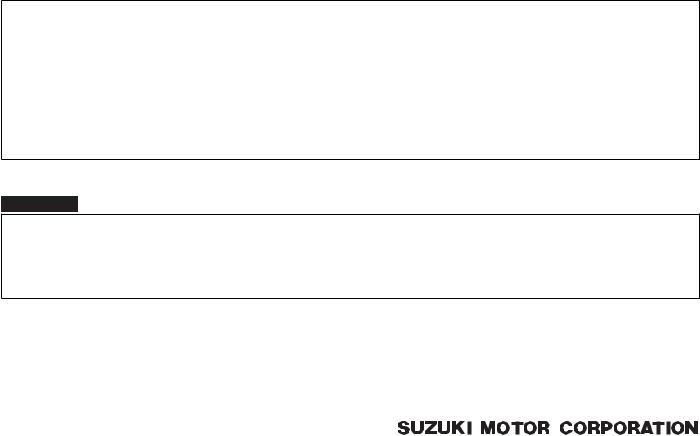
FOREWORD
This manual contains an introductory description on the SUZUKI GSF1200/GSF1200S and procedures for its inspection/service and overhaul of its main components.
Other information considered as generally known is not included.
Read the GENERAL INFORMATION section to familiarize yourself with the motorcycle and its maintenance. Use this section as well as other sections to use as a guide for proper inspection and service.
This manual will help you know the motorcycle better so that you can assure your customers of fast and reliable service.
*This manual has been prepared on the basis of the latest specifications at the time of publication. If modifications have been made since then, differences may exist between the content of this manual and the actual motorcycle.
*Illustrations in this manual are used to show the basic principles of operation and work procedures. They may not represent the actual motorcycle exactly in detail.
*This manual is written for persons who have enough knowledge, skills and tools, including special tools, for servicing SUZUKI motorcycles. If you do not have the proper knowledge and tools, ask your authorized SUZUKI motorcycle dealer to help you.
!WARNING
Inexperienced mechanics or mechanics without the proper tools and equipment may not be able to properly perform the services described in this manual.
Improper repair may result in injury to the mechanic and may render the motorcycle unsafe for the rider and passenger.
© COPYRIGHT SUZUKI MOTOR CORPORATION 2005
Downloaded from www.Manualsbooks.com manuals search

TABLE OF CONTENTS
|
Precautions…………………………………………………………. |
.. 00-i |
|
|
Precautions………………………………………………………….. |
00-1 |
|
|
General Information……………………………………………… |
..0-i |
|
|
General Information……………………………………….. |
0A-1 |
|
|
Maintenance and Lubrication…………………………… |
0B-1 |
|
|
Service |
Data………………………………………………….. |
0C-1 |
|
Engine……………………………………………………………………. |
..1-i |
|
|
Precautions……………………………………………………………. |
1-1 |
|
|
Engine General Information and Diagnosis……….. |
1A-1 |
|
|
Emission Control Devices……………………………….. |
1B-1 |
|
|
Engine Mechanical…………………………………………. |
1D-1 |
|
|
Engine Lubrication System ……………………………… |
1E-1 |
|
|
Engine Cooling System…………………………………… |
1F-1 |
|
|
FuelSystem………………………………………………….. |
1G-1 |
|
|
Ignition |
System………………………………………………. |
1H-1 |
|
Starting System………………………………………………. |
1I-1 |
|
|
Charging |
System…………………………………………….. |
1J-1 |
|
ExhaustSystem…………………………………………….. |
1K-1 |
|
|
Suspension……………………………………………………………. |
..2-i |
|
|
Precautions……………………………………………………………. |
2-1 |
|
|
Suspension General Diagnosis………………………… |
2A-1 |
|
|
Front Suspension…………………………………………… |
2B-1 |
|
|
RearSuspension……………………………………………. |
2C-1 |
|
|
Wheels and Tires…………………………………………… |
2D-1 |
|
|
Driveline / Axle………………………………………………………. |
.. 3-i |
|
|
Precautions……………………………………………………………. |
3-1 |
|
|
Drive Chain / Drive Train / Drive Shaft………………. |
3A-1 |
|
|
Brake……………………………………………………………………… |
..4-i |
|
|
Precautions……………………………………………………………. |
4-1 |
|
|
Brake Control System and Diagnosis……………….. |
4A-1 |
|
|
Front Brakes………………………………………………….. |
4B-1 |
|
|
RearBrakes………………………………………………….. |
4C-1 |
|
|
Transmission / Transaxle…………………………………….. |
.. 5-i |
|
|
Precautions……………………………………………………………. |
5-1 |
|
|
Manual Transmission……………………………………… |
5B-1 |
|
|
Clutch …………………………………………………………… |
5C-1 |
|
|
Steering…………………………………………………………………. |
.. 6-i |
|
|
Precautions……………………………………………………………. |
6-1 |
|
|
Steering General Diagnosis…………………………….. |
6A-1 |
|
|
Steering / Handlebar………………………………………. |
6B-1 |
|
|
Body and Accessories………………………………………….. |
.. 9-i |
|
|
Precautions……………………………………………………………. |
9-1 |
|
|
Wiring Systems……………………………………………… |
9A-1 |
|
|
Lighting Systems……………………………………………. |
9B-1 |
|
|
Combination Meter / Fuel Meter / Horn……………… |
9C-1 |
|
|
Exterior Parts………………………………………………… |
9D-1 |
|
|
BodyStructure………………………………………………. |
9E-1 |
Downloaded from www.Manualsbooks.com manuals search
Downloaded from www.Manualsbooks.com manuals search

|
Table of Contents 00- i |
||||
|
Section 00 |
||||
|
Precautions |
00 |
|||
|
CONTENTS |
||||
|
Precautions……………………………………………. |
00-1 |
General Precautions…………………………………………. |
00-1 |
|
|
Precautions |
00-1 |
Precautions for Electrical Circuit Service………….. |
00-2 |
|
|
Warning / Caution / Note………………… |
00-1 |
Downloaded from www.Manualsbooks.com manuals search
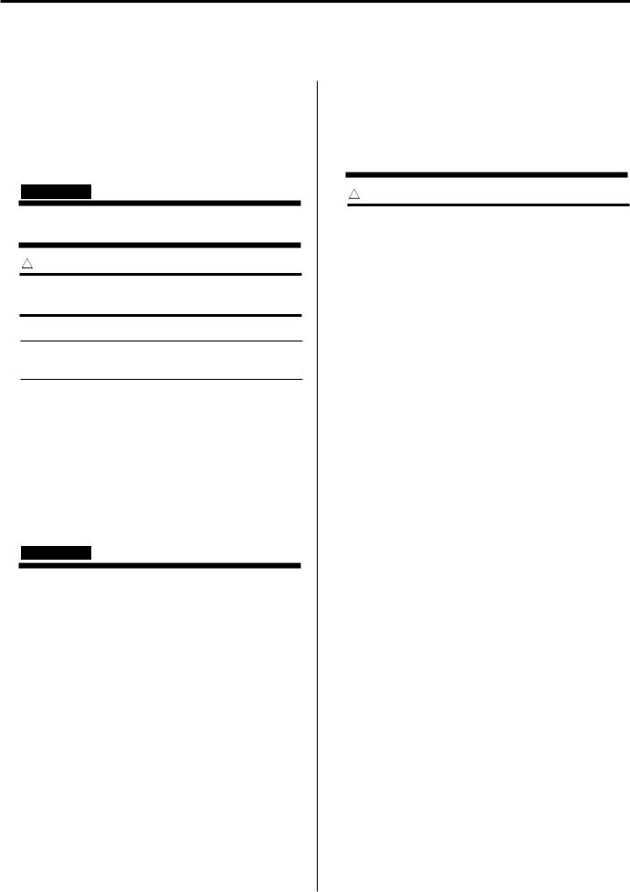
00-1 Precautions:
Precautions
Precautions
Warning / Caution / Note
B649G10000001
Please read this manual and follow its instructions carefully. Toemphasize special information, the symbol and the words WARNING, CAUTION and NOTE have special meanings. Pay special attention to the messages highlighted by these signal words.
! WARNING
Indicates a potential hazard that could result in death or injury.
! CAUTION
Indicates a potential hazard that could result in motorcycle damage.
NOTE
Indicates special information to make maintenance easier or instructions clearer.
Please note, however, that the warnings and cautions contained in this manual cannot possibly cover all potential hazards relating to the servicing, or lack of servicing, of the motorcycle. In addition to the WARNINGS and CAUTIONS stated, you must use good judgement and basic mechanical safety principles. If you are unsure about how to perform a particular service operation, ask a more experienced mechanic for advice.
General Precautions
B649G10000002
!WARNING
•Proper service and repair proceduresare important for the safety of the service mechanic and the safety and reliabilityof the motorcycle.
•When 2 or more persons work together, pay attention to the safety of eachother.
•When it is necessary to run the engine indoors, make sure that exhaust gasis forced outdoors.
•When working with toxic or flammable materials, make sure that the area you work in is well-ventilated and that you follow all of the materialmanufacturer’s instructions.
•Never use gasoline as a cleaning solvent.
•Toavoid getting burned, do not touch the engine, engine oil, oil cooler and exhaust system until they have cooled.
•After servicing the fuel, oil, exhaust or brake systems, check all lines andfittings related to the system for leaks.
!CAUTION
•If parts replacement is necessary,replace the parts with Suzuki Genuine Parts or their equivalent.
•When removing partsthat are to be reused, keep them arranged in an orderly manner so that they may be reinstalled in the proper order and orientation.
•Be sure to use special toolswhen instructed.
•Make sure that all parts used in reassembly are clean. Lubricatethem when specified.
•Use the specified lubricant, bond,or sealant.
•When removing the battery, disconnect the negative (–) cable first and then the positive cable.
•When reconnecting the battery, connect the positive cable first and then the negative (–) cable, and replace the terminal cover on the positive terminal.
•When performing service to electrical parts, if the service procedures not require use of battery power, disconnect the negative (–) cable the battery.
•When tightening the cylinder head and case bolts and nuts, tighten the larger sizes first. Always tighten the bolts and nuts diagonally from the inside working out and to the specified tighteningtorque.
•Whenever you remove oil seals, gaskets, packing, O-rings, locking washers, selflocking nuts, cotter pins, circlips and certain other parts as specified, be sureto replace them with new ones. Also, before installing these new parts, be sure to remove any left over material from the mating surfaces.
•Never reuse a circlip. When installing a new circlip, take care not to expand the end gap larger than required to slip the circlip over the shaft. After installing a circlip, always ensure that it iscompletely seated in its groove and securely fitted.
Downloaded from www.Manualsbooks.com manuals search
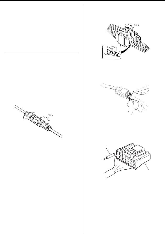
Precautions: 00-2
•Use a torque wrench to tightenfasteners to the specified torque. Wipe off grease and oil if a thread is smeared withthem.
•After reassembling, check partsfor tightness and proper operation.
•Toprotect the environment, do not unlawfully dispose of used motor oil, engine coolant and other fluids:batteries, and tires.
•Toprotect Earth’s natural resources, properly dispose of used motorcycleand parts.
Precautions for Electrical Circuit Service
B649G10000003
When handling the electrical parts or servicing the ABS system, observe the following points for the safety of the system.
Electrical Parts
Connector / Coupler
•When connecting a connector, be sure to push it in until a click is felt.
I310G1000001-01
•With a lock type coupler, be sure to release the lock when disconnecting, and push it in fully till the lock works when connecting it.
•When disconnecting the coupler, be sure to hold the coupler body and do not pull the lead wires.
•Inspect each terminal on the connector/couplerfor looseness or bending.
•Inspect each terminal for corrosion and contamination. The terminals must be clean andfree of any foreign material which could impede proper terminal contact.
I310G1000002-01
•Inspect each lead wire circuit for poor connection by shaking it by hand lightly. If any abnormal condition is found, repair or replace.
I310G1000003-01
•When taking measurements at electrical connectors using a tester probe, be sure to insert the probefrom the wire harness side (backside) of the connector/ coupler.
2
1
I649G1000013-01
•When connecting meter probe from the terminal side of the coupler (connection from harness side not being possible), use extra care not to force and cause the male terminal to bend or the female terminal to open. Connect the probe as shown to avoid opening of female terminal. Never push in the probe where male terminal is supposed to fit.
Downloaded from www.Manualsbooks.com manuals search
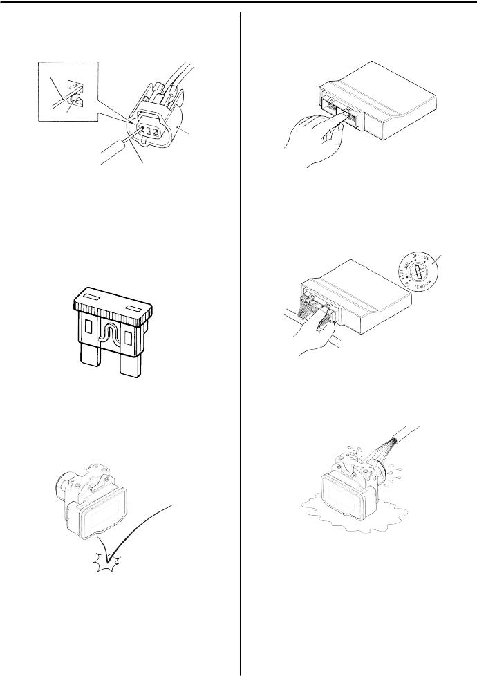
00-3 Precautions:
|
• Check the male connector for bend and female |
• Be careful not to touch the electrical terminals of the |
|
connector for excessive opening. Also check the |
Ignitor unit and ABS control unit/HU. The static |
|
coupler for locking (looseness), corrosion, dust,etc. |
electricity from your body may damage this part. |
|
4 |
||||||
|
“A” |
||||||
|
3 |
||||||
|
4 |
||||||
|
I649G1000030-01 |
I310G1000008-01 |
|||||
|
3. Coupler |
4. Probe |
“A”: Where male terminal fits |
• When disconnecting and connecting the Ignitor unit |
|||
|
Fuse |
and ABS control unit/HU couplers, make sure toturn |
|||||
|
OFF the ignition switch, or electronic parts mayget |
||||||
|
• When a fuse blows, always investigate thecause, |
||||||
|
damaged. |
||||||
|
correct it and then replace the fuse. |
||||||
|
• Do not use a fuse of a different capacity. |
1 |
|||||
|
• Do not use wire or any other substitute for thefuse. |
||||||
|
I649G1000031-01 |
||||
|
1. Ignition S/W |
||||
|
I649G1000001-01 |
||||
|
• Never allow dust or water to contact the ABScontrol |
||||
|
Ignitor unit / Various sensors / ABS control unit / HU |
unit/HU. |
|||
|
• Since each component is a high-precision part,great |
||||
|
care should be taken not to apply any sharp impacts |
||||
|
during removal and installation. |
I649G1000004-01
I649G1000003-01
Downloaded from www.Manualsbooks.com manuals search
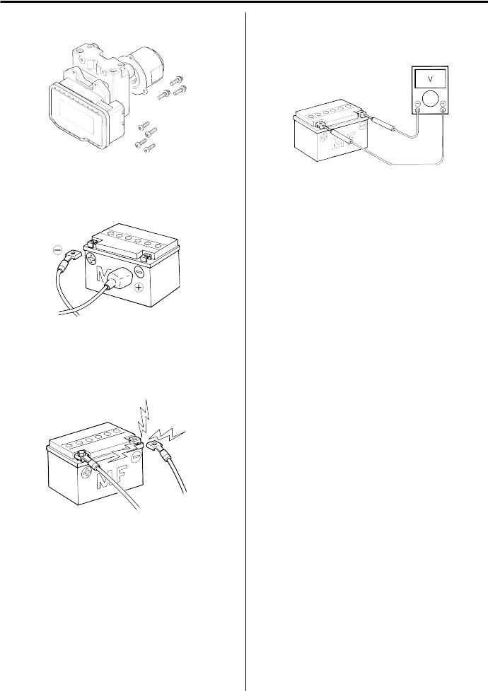
Precautions: 00-4
•The ABS control unit/HU cannot bedisassembled. Replace the whole unit with a new one.
I649G1000005-01
•Battery connection in reverse polarity is strictly prohibited. Such a wrong connection will damage the components of the ABS control unit/HU instantly when reverse power is applied.
I649G1000006-01
•Removing any battery terminal of a running engine is strictly prohibited. The moment such removal is made, damaging counter electromotive force will be applied to the Ignition unit and ABS control unit/HU which may result in serious damage.
I310G1000011-01
•Before measuring voltage at each terminal, check to make sure that battery voltage is 11 V or higher. Terminal voltage check at low battery voltage will lead to erroneous diagnosis.
I310G1000012-01
•Never connect any tester (voltmeter, ohmmeter, or whatever) to the Ignition and ABS control unit/HU when its coupler is disconnected. Otherwise, damage to Ignitor and ABS control unit/HU may result.
•Never connect an ohmmeter to the Ignitor and ABS control unit/HU with its coupler connected. If attempted, damage to Ignitor and ABS control unit/HU or sensors may result.
•Be sure to use a specifiedvoltmeter/ohmmeter. Otherwise, accurate measurements may notbe obtained and personal injury may result.
Electrical Circuit Inspection Procedure
While there are various methods for electrical circuit inspection, described here is a general method to check for open and short circuit using an ohmmeter and a voltmeter.
Open circuit check
Possible causes for the open circuit are as follows. As the cause can exist in the connector/coupler or terminal, they need to be checked carefully.
•Loose connection of connector/coupler
•Poor contact of terminal (due to dirt, corrosion or rust, poor contact tension, entry of foreign object etc.)
•Wire harness being open.
•Poor terminal-to-wire connection.
When checking system circuits including an electronic control unit such as ignitor, ABS control unit/HU, etc., it is important to perform careful check, starting with items which are easier to check.
Downloaded from www.Manualsbooks.com manuals search
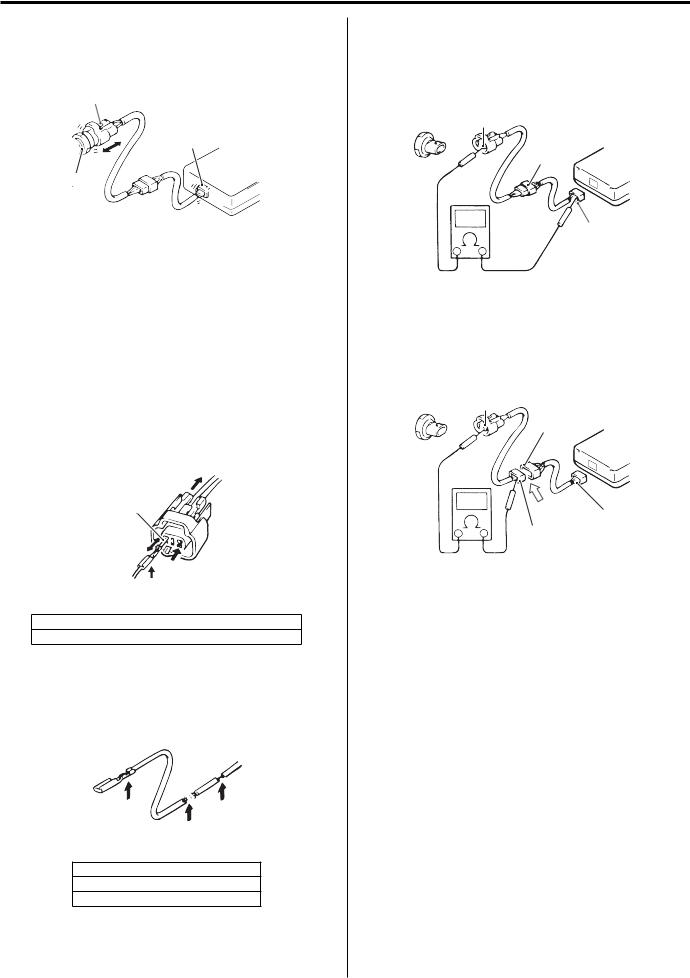
00-5 Precautions:
1)Disconnect the negative (–) cable from the battery.
2)Check each connector/coupler at both ends of the circuit being checked for loose connection. Also check for condition of the coupler lock ifequipped.
“A”
“A”
Ignitor
1
I649G1000026-01
|
1. Sensor |
“A”: Check for loose connection |
3)Using a test male terminal, check the female terminals of the circuit being checked for contact tension.
Check each terminal visually for poor contact (possibly caused by dirt, corrosion, rust, entry of foreign object, etc.). At the same time, check to make sure that each terminal is fully inserted in the coupler and locked.
If contact tension is not enough, rectify the contact to increase tension or replace. The terminals must be clean and free of any foreign material which could impede proper terminal contact.
“B”
“C”
I649G1000027-01
“B”: Check contact tension by inserting and removing.
“C”: Check each terminal for bend and proper alignment.
4)Using continuity inspect or voltage check procedure as described below, inspect the wire harness terminals for open circuit and poor connection. Locate abnormality, if any.
“D” “F”
“E”
I649G1000028-01
”D”: Looseness of crimping
“E”: Open
“F”: Thin wire (A few strands left)
Continuity check
1)Measure resistance across coupler “B” (between “A” and “C” in figure).
If no continuity is indicated (infinity or over limit), the circuit is open between terminals “A” and “C”.
“A”
“B” Ignitor
“C”
I649G1000019-03
2)Disconnect the coupler “B” and measureresistance between couplers “A” and “B-1”.
If no continuity is indicated, the circuit is open between couplers “A” and “B-1”. If continuity is indicated, there is an open circuit between couplers “B-2” and “C” or an abnormality in coupler “B-2” or coupler “C”.
“A”
“B-2”
Ignitor
“B” “C”
“B-1”
I649G1000029-02
Voltage check
If voltage is supplied to the circuit being checked, voltage check can be used as circuit check.
1)With all connectors/couplers connected andvoltage applied to the circuit being checked, measure voltage between each terminal and bodyground.
2)If measurements were taken as shown in figureat the right and results are as listed below, it means that the circuit is open between terminals “A” and “B”.
Voltage between
“A” and body ground: Approx. 5V “B” and body ground: Approx. 5V “C” and body ground: 0 V
Downloaded from www.Manualsbooks.com manuals search
![]()
Precautions: 00-6
3)Also, if measured values are as listed below, a resistance (abnormality) exists which causes the voltage drop in the circuit between terminals “A” and “B”.
Voltage between
“A” and body ground: Approx. 5 V
“B” and body ground: Approx. 5 V – 2 V voltage drop
“C” and body ground: 3 V – 2 V voltage drop
“A”
Ignitor
“B”
“C”
5V
|
5V |
||
|
0V |
5V |
|
|
“A” |
“B” “C” |
I649G1000021-02
Short circuit check (Wire harness to ground)
1)Disconnect the negative (–) cable from thebattery.
2)Disconnect the connectors/couplers at both endsof the circuit to be checked.
NOTE
If the circuit to be checked branches to other parts as shown, disconnect all connectors/ couplers of those parts. Otherwise, diagnosis will be misled.
3)Measure resistance between terminal at one endof circuit (“A” terminal in figure) and body ground. If continuity is indicated, there is a short circuit to ground between terminals “A” and “C”.
“A”
“D”
“B” Ignitor
“C”
“E”
5V
“A” “C”
I649G1000022-02
|
“D”: To other parts |
“E”: Other parts |
4)Disconnect the connector/coupler included incircuit (coupler “B”) and measure resistance between terminal “A” and body ground. If continuity is indicated, the circuit is shorted to the ground between terminals “A” and “B”.
“A”
“D”
Ignitor
“B” “C”
I649G1000023-02
“D”: To other parts
Downloaded from www.Manualsbooks.com manuals search
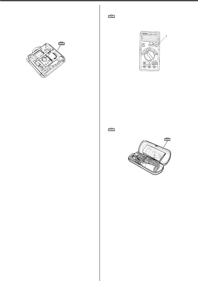
00-7 Precautions:
|
Using The Multi-Circuit Testers |
• After using the tester, turn the power off. |
|
|
• |
Use the Suzuki multi-circuit tester set. |
Special tool |
|
• |
Use well-charged batteries in the tester. |
: 09900–25008 (Multi-circuit tester set) |
•Be sure to set the tester to the correct testingrange.
Special tool
 (A): 09900–25008 (Multi-circuit tester set)
(A)
|
I649G1000002-01 |
|||
|
I649G1000024-02 |
NOTE |
||
|
Using the testers |
|||
|
• When connecting the multi-circuit tester, |
|||
|
• Incorrectly connecting the (+) and (–) probesmay |
use the needle pointed probe to the back |
||
|
cause the inside of the tester to burnout. |
side of the lead wire coupler andconnect |
||
|
• If the voltage and current are not known,make |
the probes of tester to them. |
||
|
• Use the needle pointed probe to prevent |
|||
|
measurements using the highest range. |
|||
|
• When measuring the resistance with themulti-circuit |
the rubber of the water proof couplerfrom |
||
|
damage. |
|||
|
tester (1), will be shown as 10.00 M and “1” |
|||
|
flashes in the display. |
|||
|
Special tool |
|||
|
• Check that no voltage is applied before making the |
|||
|
(A): 09900–25009 (Needle pointed probe set) |
|||
|
measurement. If voltage is applied the tester maybe |
|||
|
damaged. |
(A) |
||
I649G1000025-02
Downloaded from www.Manualsbooks.com manuals search

Table of Contents 0- i
Section 0
General Information
0
CONTENTS
|
General Information………………………………. |
0A-1 |
|
General Description……………………………………… |
0A-1 |
|
Symbols …………………………………………………….. |
0A-1 |
|
Abbreviations ……………………………………………… |
0A-2 |
|
Vehicle Side View ……………………………………….. |
0A-3 |
|
Vehicle Identification Number ……………………….. |
0A-4 |
|
Fuel and Oil Recommendation ……………………… |
0A-4 |
|
BREAK-IN Procedures…………………………………. |
0A-4 |
|
CylinderIdentification…………………………………… |
0A-5 |
|
Country and Area Codes ……………………………… |
0A-5 |
|
Wire Color Symbols …………………………………….. |
0A-5 |
|
Warning, Caution and Information |
|
|
Labels Location…………………………………………. |
0A-6 |
|
ComponentLocation……………………………………. |
0A-7 |
|
Electrical Components Location ……………………. |
0A-7 |
|
Specifications………………………………………………. |
0A-9 |
|
Specifications ……………………………………………… |
0A-9 |
|
Special Tools and Equipment……………………… |
0A-11 |
|
Special Tools ……………………………………………. |
0A-11 |
|
Maintenance and Lubrication…………….. |
0B-1 |
|
Precautions………………………………………………….. |
0B-1 |
|
Precautions for Maintenance ………………………… |
0B-1 |
|
General Description……………………………………… |
0B-1 |
|
Recommended Fluids and Lubricants…………….. |
0B-1 |
|
Scheduled Maintenance……………………………….. |
0B-2 |
|
Periodic Maintenance Schedule Chart……………. |
0B-2 |
|
Lubrication Points ……………………………………….. |
0B-3 |
|
Repair Instructions………………………………………. |
0B-4 |
|
Air Cleaner Element Removal and Installation…. |
0B-4 |
|
Air Cleaner Element Inspection and Cleaning …. |
0B-4 |
|
Spark Plug Removal and Installation……………… |
0B-5 |
|
Spark Plug Inspection and Cleaning………………. |
0B-6 |
|
Exhaust Pipe Bolt and Muffler Mounting Bolt |
|
|
Inspection…………………………………………………. |
0B-6 |
|
Valve Clearance Inspection and Adjustment …… |
0B-7 |
|
Fuel Line Inspection…………………………………….. |
0B-8 |
|
Engine Oil and Filter Replacement…………………… |
0B-9 |
|
Throttle Cable Play Inspection |
|
|
and Adjustment ……………………………………….. |
0B-10 |
|
Engine Idle Speed Inspection |
|
|
and Adjustment……………………………………….. |
0B-11 |
|
Throttle Valve Synchronization……………………. |
0B-11 |
|
PAIR System Inspection …………………………….. |
0B-11 |
|
Clutch System Inspection……………………………. |
0B-11 |
|
Clutch Hose Replacement ………………………….. |
0B-12 |
|
Air Bleeding from Clutch Fluid Circuit …………… |
0B-12 |
|
Clutch Fluid Replacement …………………………… |
0B-12 |
|
Drive Chain Inspection and Adjustment………… |
0B-12 |
|
Drive Chain Cleaning and Lubricating…………… |
0B-13 |
|
Brake System Inspection ……………………………. |
0B-13 |
|
Rear Brake Light Switch Adjustment…………….. |
0B-15 |
|
Brake Hose Replacement…………………………… |
0B-15 |
|
Air Bleeding from Brake Fluid Circuit ……………. |
0B-15 |
|
Brake Fluid Replacement……………………………. |
0B-15 |
|
Tire Inspection…………………………………………… |
0B-15 |
|
Steering System Inspection………………………… |
0B-16 |
|
Front Fork Inspection …………………………………. |
0B-16 |
|
Rear Suspension Inspection……………………….. |
0B-16 |
|
Chassis Bolt and Nut Inspection ………………….. |
0B-17 |
|
Compression Pressure Check …………………….. |
0B-18 |
|
Oil Pressure Check……………………………………. |
0B-18 |
|
Specifications…………………………………………….. |
0B-19 |
|
Tightening Torque Specifications…………………. |
0B-19 |
|
Special Tools and Equipment……………………… |
0B-19 |
|
Recommended Service Material………………….. |
0B-19 |
|
SpecialTool……………………………………………… |
0B-19 |
|
Service Data……………………………………… |
0C-1 |
|
Specifications………………………………………………. |
0C-1 |
|
Service Data……………………………………………….. |
0C-1 |
|
Tightening Torque Specifications…………………… |
0C-7 |
Downloaded from www.Manualsbooks.com manuals search

0A-1 General Information:
General Information
General Description
Symbols
B649G10101001
Listed in the table below are the symbols indicating instructions and other information necessary for servicing. The meaning of each symbol is also included in the table.
Torque control required.
Data beside it indicates specified torque. Apply oil.
Use engine oil unless otherwise specified. Apply molybdenum oil solution
(Mixture of engine oil and SUZUKl MOLY PASTE in a ratio of 1:1). Apply SUZUKI SUPER GREASE “A” or equivalent.
99000-25010
Apply SUZUKI MOLY PASTE or equivalent. 99000-25140
Apply SUZUKI SILICONE GREASE or equivalent. 99000-25100
Apply THERMO-GREASE or equivalent. 99000-59029
Apply SUZUKI BOND “1207B” or equivalent. 99000-31140
Apply SUZUKI BOND “1215” or equivalent. 99000-31110
Apply THREAD LOCK SUPER “1303” or equivalent. 99000-32030
Apply THREAD LOCK SUPER “1322” or equivalent. 99000-32110
Apply THREAD LOCK “1342” or equivalent. 99000-32050
Apply THREAD LOCK SUPER “1360” or equivalent. 99000-32130
Use fork oil or equivalent. 99000-99001-SS8
Apply or use brake fluid.
Measure in voltage range.
Measure in resistance range.
Measure in current range.
Measure in diode test range.
Measure in continuity test range.
Use special tool.
Indication of service data.
Do not reuse.
Note on reassembly.
Downloaded from www.Manualsbooks.com manuals search

General Information: 0A-2
|
Abbreviations |
H: |
|
|
B649G10101002 |
HC: Hydrocarbons |
|
|
A: |
I: |
|
|
ABDC: After Bottom Dead Center |
||
|
IG: Ignition |
||
|
ABS: Anti-lock Brake System AC |
||
|
J: |
||
|
Alternating Current |
||
|
ACL: Air Cleaner, Air Cleaner Box |
L: |
|
|
API: American Petroleum Institute |
||
|
LCD: Liquid Crystal Display |
||
|
ATDC: After Top Dead Center A/F: |
||
|
LED: Light Emitting Diode (Malfunction Indicator Lamp) |
||
|
Air Fuel Mixture |
||
|
LH: Left Hand |
||
|
B: |
||
|
M: |
||
|
BBDC: Before Bottom Dead Center |
||
|
Max: Maximum |
||
|
BTDC: Before Top Dead Center B+: |
||
|
MIL: Malfunction Indicator Lamp (LED) |
||
|
Battery Positive Voltage |
||
|
Min: Minimum |
||
|
C: |
||
|
N: |
||
|
CKP Sensor: Crankshaft Position Sensor (CKPS) |
||
|
NOx: Nitrogen Oxides |
||
|
CKT: Circuit |
||
|
O: |
||
|
CLP Switch: Clutch Lever Position Switch (Clutch |
||
|
OHC: Over Head Camshaft |
||
|
Switch) |
||
|
OPS: Oil Pressure Switch P: |
||
|
CO: Carbon Monoxide |
||
|
PCV: Positive Crankcase Ventilation (Crankcase |
||
|
CPU: Central Processing Unit |
||
|
Breather) |
||
|
D: |
||
|
R: |
||
|
DC: Direct Current |
||
|
RH: Right Hand |
||
|
DMC: Dealer Mode Coupler |
||
|
ROM: Read Only Memory |
||
|
DOHC: Double Over Head Camshaft |
||
|
S: |
||
|
DRL: Daytime Running Light |
||
|
SAE: Society of Automotive Engineers |
||
|
F: |
||
|
T: |
||
|
FTPC Valve: Fuel Tank Pressure Control Valve |
||
|
TP Sensor: Throttle Position Sensor (TPS) |
||
|
G: |
||
|
GEN: Generator |
||
|
GND: Ground |
||
|
GP Switch: Gear Position Switch |
||
Downloaded from www.Manualsbooks.com manuals search

0A-3 General Information:
Vehicle Side View
B649G10101003
NOTE
Difference between photographs and actual motorcycles may exist depending on the markets.
SUZUKI GSF1200 (2006-model)
Right Side
I649G1010008-01
Left Side
I649G1010009-01
SUZUKI GSF1200S (2006-model)
Right Side
I649G1010005-06
Left Side
I649G1010006-05
Downloaded from www.Manualsbooks.com manuals search

General Information: 0A-4
Vehicle Identification Number
B649G10101004
The frame serial number or V.I.N. (Vehicle Identification Number) “A” is stamped on the right side of the steering head pipe. The engine serial number “B” is located on the right side of the crankcase. These numbers are required especially for registering the machine and ordering spare parts.
“A”
I649G1010001-02
“B”
I649G1010002-03
Fuel and OilRecommendation
B649G10101005
Fuel (For USA)
Use only unleaded gasoline of at least 87 pump octane (R/2 + M/2) or 91 octane or higher rated by the research method.
Gasoline containing MTBE (Methyl Tertiary Butyl Ether), less than 10% ethanol, or less than 5% methanol with appropriate cosolvents and corrosion inhibitor is permissible.
Fuel (For Other Countries)
Gasoline used should be graded 91 octane (Research Method) or higher. Unleaded gasoline is recommended.
Engine Oil
Oil quality is a major contributor to your engine’s performance and life. Always select good quality engine oil. Use of SF/SG or SH/SJ in API with MA in JASO. Suzuki recommends the use of SAE 10W-40 engine oil. If SAE 10W-40 engine oil is not available, select an alternative according to the chart.
I310G1010005-01
Brake Fluid
Specification and classification: DOT4
! WARNING
Since the brake system of this motorcycle is filled with a glycol-based brake fluid by the manufacturer, do not use or mix different types of fluid such as silicone-based and petroleum-based fluid for refilling the system, otherwise serious damage will result.
Do not use any brake fluid taken from old or used or unsealed containers.
Never reuse brake fluid left over from a previous servicing, which has been stored for a long period.
Front Fork Oil
Use fork oil SS8 or an equivalent fork oil.
BREAK-IN Procedures
B649G10101007
During manufacture only the best possible materials are used and all machined parts are finished to a very high standard but it is still necessary to allow the moving parts to “BREAK-IN” before subjecting the engine to maximum stresses. The future performance and reliability of the engine depends on the care and restraint exercised during its early life. The general rules are asfollows.
1)Keep to these break-in engine speed limits:
Speed limits
Initial 800 km: Below 5 500 r/min Up to 1 600 km: Below 8 000 r/min Over 1 600 km: Below 11 000 r/min
2)Upon reaching an odometer reading of 1 600 km (1 000 miles) you can subject the motorcycle to full throttle operation. However, do not exceed 11 000r/ min at any time.
Downloaded from www.Manualsbooks.com manuals search
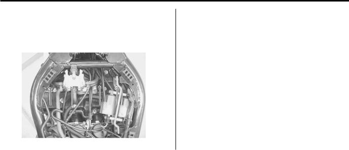
0A-5 General Information:
Cylinder Identification
B649G10101008
The four cylinders of this engine are identified as No.1, 2, 3 and No.4 cylinder, as counted from left to right (as viewed by the rider on the seat).
I649G1010010-01
Country and Area Codes
B649G10101009
The following codes stand for the applicable country(- ies) and area(-s).
|
Code |
Country |
Effective Frame No. |
|
|
or Area |
|||
|
GSF1200 K6 |
U.K. |
JS1CB112200100001 – |
|
|
(E-02) |
|||
|
GSF1200 K6 |
E.U. |
JS1CB112100100001 – |
|
|
(E-19) |
|||
|
GSF1200S K6 |
U.K. |
JS1CB111200100001 – |
|
|
(E-02) |
|||
|
GSF1200S K6 |
E.U. |
JS1CB111100100001 – |
|
|
(E-19) |
|||
|
GSF1200S K6 |
Australia |
JS1CB121300100001 – |
|
|
(E-24) |
|||
|
GSF1200S K6 |
Canada |
JS1GV79A 62100001 – |
|
|
(E-28) |
Wire Color Symbols
|
B649G10101010 |
|||
|
Symbol |
Wire Color |
Symbol |
Wire Color |
|
B |
Black |
Bl/B |
Blue with Black tracer |
|
Bl |
Blue |
Br/B |
Brown with Black tracer |
|
Br |
Brown |
G/B |
Green with Black tracer |
|
Dbr |
Dark brown |
G/Bl |
Green with Blue tracer |
|
Dg |
Dark green |
G/Y |
Green with Yellow tracer |
|
G |
Green |
O/G |
Orange with Green tracer |
|
Lg |
Light green |
O/R |
Orange with Red tracer |
|
W |
White |
O/W |
Orange with White tracer |
|
Y |
Yellow |
O/Y |
Orange with Yellow tracer |
|
B/Bl |
Black with Blue tracer |
P/B |
Pink with Black tracer |
|
B/Br |
Black with Brown tracer |
R/B |
Red with Black tracer |
|
B/G |
Black with Green tracer |
R/W |
Red with White tracer |
|
B/O |
Black with Orange tracer |
W/B |
White with Black tracer |
|
B/R |
Black with Red tracer |
Y/B |
Yellow with Black tracer |
|
B/W |
Black with White tracer |
Y/W |
Yellow with White tracer |
|
B/Y |
Black with Yellow tracer |
Downloaded from www.Manualsbooks.com manuals search
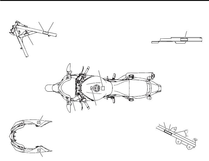
General Information: 0A-6
Warning, Caution and Information Labels Location
|
B649G10101011 |
||
|
[A] |
1 |
[C] |
|
2 |
6
8
7
|
3 |
|||
|
5 |
|||
|
4 |
|||
|
[B] |
[D] |
10 |
|
|
9 |
4
I649G1010011-04
|
GSF1200 |
GSF1200S |
||
|
1. |
Noise label |
— |
For E-24 |
|
2. |
Information label |
— |
For E-28 |
|
3. |
Fuel caution label |
For E-02 |
For E-02, 24 |
|
4. |
Screen label |
— |
For E-02, 19, 24, 28 |
|
5. |
Warning steering label |
— |
For E-02, 19, 24, 28 |
|
6. |
Tire information label |
For E-02, 19 |
For E-02, 19, 24, 28 |
|
7. |
General warning label |
For E-02, 19 |
For E-02, 19, 24, 28 |
|
8. |
ICES Canada label |
— |
For E-28 |
|
9. |
I.D. plate |
For E-02, 19 |
For E-02, 19, 24 |
|
10. |
Safety plate |
— |
For E-28 |
|
[A]: |
Frame head (Left side) |
||
|
[B]: |
Cowling body |
||
|
[C]: |
Chain cover |
||
|
[D]: |
Frame side tube (Right side) |
||
Downloaded from www.Manualsbooks.com manuals search
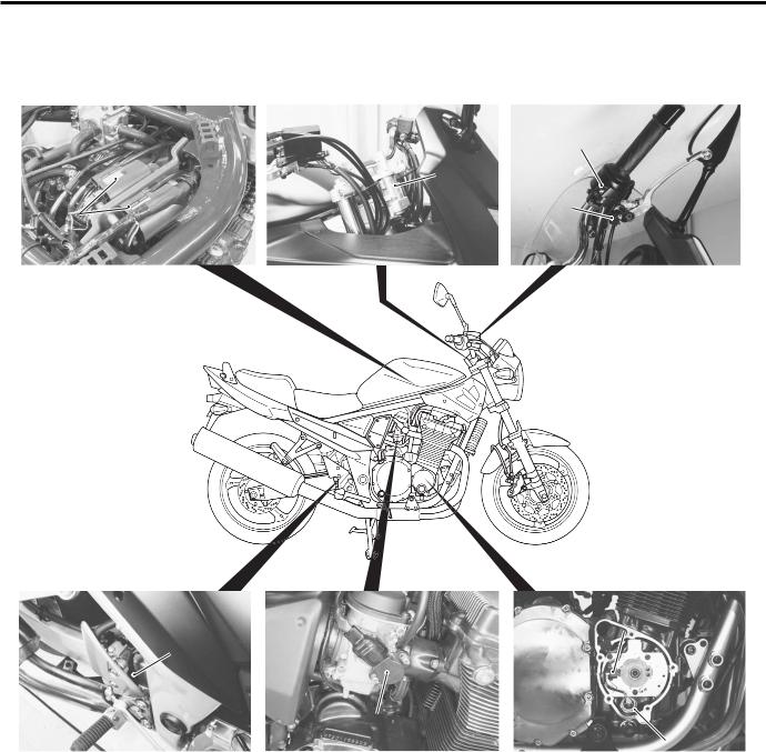
0A-7 General Information:
Component Location
Electrical ComponentsLocation
B649G10103001
3
|
7 |
||||||||||
|
5 |
||||||||||
|
6 |
||||||||||
|
8 |
||||||||||
|
I649G1010003-05 |
||||||||||
|
1. |
Ignition coil |
3. |
Handlebar switch (RH) |
5. |
Rear brake light switch |
7. |
CKP sensor |
|||
|
2. |
Ignition switch |
4. |
Front brake light switch |
6. |
Throttle position sensor |
8. |
Oil pressure switch |
|||
Downloaded from www.Manualsbooks.com manuals search
![]()
General Information: 0A-8
12
9
13 14
16
15
|
21 |
||||||||||||
|
20 |
19 |
|||||||||||
|
17 |
18 |
23 |
22 |
|||||||||
|
I649G1010004-04 |
||||||||||||
|
9. |
Clutch lever position switch |
14. |
Main fuse |
19. |
Generator |
|||||||
|
10. |
Handlebar switch (LH) |
15. |
Battery |
20. |
Carburetor heater (For E-02, 19) |
|||||||
|
11. Fuse box |
16. Ignitor |
21. Speed sensor |
||||||||||
|
12. |
Turn signal/Side-stand relay |
17. |
Horn |
22. |
Gear position switch |
|||||||
|
13. |
Starter relay |
18. |
Starter motor |
23. |
Side-stand switch |
|||||||
Downloaded from www.Manualsbooks.com manuals search

0A-9 General Information:
Specifications
Specifications
|
NOTE |
B649G10107001 |
||||||
|
These specifications are subject to change without notice. |
|||||||
|
Dimensions and dry mass |
|||||||
|
Item |
Specification |
Remark |
|||||
|
Overall length |
2 130 mm (83.9 in) |
||||||
|
Overall width |
790 mm (31.1 in) |
||||||
|
Overall height |
1 095 mm (43.1 in) |
GSF1200 |
|||||
|
1 235 mm (48.6 in) |
GSF1200S |
||||||
|
Wheelbase |
1480 mm (58.3 in) |
||||||
|
Ground clearance |
135 mm (5.3 in) |
||||||
|
Seat height |
785/805 mm (30.9/31.7 in) |
Low/High |
|||||
|
Dry mass |
212 kg (467 lbs) |
GSF1200 |
|||||
|
215 kg (474 lbs) |
GSF1200S |
||||||
|
Engine |
|||||||
|
Item |
Specification |
Remark |
|||||
|
Type |
4-stroke, air-cooled, DOHC |
||||||
|
Number of cylinders |
4 |
||||||
|
Bore |
79.0 mm (3.110 in) |
||||||
|
Stroke |
59.0 mm (2.323 in) |
||||||
|
Displacement |
1 157 cm3 (70.6 cu. in) |
||||||
|
Compression ratio |
9.5 : 1 |
||||||
|
Carburetor |
MIKUNI BSR36 |
||||||
|
Air cleaner |
Non-woven fabric element |
||||||
|
Starter system |
Electric |
||||||
|
Lubrication system |
Wet sump |
||||||
|
Idle speed |
1 300 100 r/min |
E-28 |
|||||
|
1 200 100 r/min |
Others |
||||||
|
Drive train |
|||||||
|
Item |
Specification |
Remark |
|||||
|
Clutch |
Wet multi-plate type |
||||||
|
Transmission |
5-speed constant mesh |
||||||
|
Gearshift pattern |
1-down, 4-up |
||||||
|
Primary reduction ratio |
1.565 (72/46) |
||||||
|
Low |
2.384 (31/13) |
||||||
|
2nd |
1.631 (31/19) |
||||||
|
Gear ratios |
3rd |
1.250 (25/20) |
|||||
|
4th |
1.045 (23/22) |
||||||
|
Top |
0.913 (21/23) |
||||||
|
Final reduction ratio |
3.000 (45/15) |
||||||
|
Drive chain |
RK GB50GSVZ3, 116 links |
Downloaded from www.Manualsbooks.com manuals search
|
General Information: 0A-10 |
||||||
|
Chassis |
||||||
|
Item |
Specification |
Remark |
||||
|
Front suspension |
Telescopic, coil spring, oil damped |
|||||
|
Rear suspension |
Link type, coil spring, oil damped |
|||||
|
Front suspension stroke |
130 mm (5.1 in) |
|||||
|
Rear wheel travel |
136 mm (5.4 in) |
|||||
|
Caster |
35 (right & left) |
|||||
|
Trail |
25 20’ |
|||||
|
Steering angle |
104 mm (4.10 in) |
|||||
|
Turning radius |
2.8 m (9.2 ft) |
|||||
|
Front brake |
Disc brake, twin |
|||||
|
Rear brake |
Disc brake |
|||||
|
Front tire size |
120/70ZR17M/C (58W), tubeless |
|||||
|
Rear tire size |
180/55ZR17M/C (73W), tubeless |
|||||
|
Electrical |
||||||
|
Item |
Specification |
Remark |
||||
|
lgnition type |
Electronic ignition (Transistorized) |
|||||
|
lgnition timing |
7 B.T.D.C. at 1 300 r/min |
E-28 |
||||
|
7 B.T.D.C. at 1 200 r/min |
Others |
|||||
|
Spark plug |
NGK JR9B |
|||||
|
Battery |
12 V 36 kC (10 Ah)/10 HR |
|||||
|
Generator |
Three-phase A.C. generator |
|||||
|
Main fuse |
30 A |
|||||
|
Fuse |
10/10/15/15/10 A |
|||||
|
Headlight |
12 V 60/55 W (H4) |
GSF1200 |
||||
|
12 V 55 W (H7) + 12 V 55 W (H7) |
GSF1200S |
|||||
|
Position light |
12 V 5 W |
GSF1200 |
||||
|
12 V 5W x 2 |
GSF1200S |
|||||
|
Turn signal light |
12 V 21 W x 4 |
|||||
|
Brake light/Taillight |
12 V 21/5 W |
|||||
|
License plate light |
12 V 5 W |
|||||
|
Speedometer light |
LED |
|||||
|
Tachometer light |
LED |
|||||
|
Neutral indicator light |
LED |
|||||
|
High beam indicator light |
LED |
|||||
|
Turn signal indicator light |
LED |
|||||
|
Oil pressure indicator light |
LED |
|||||
|
Capacities |
||||||
|
Item |
Specification |
Remark |
||||
|
Fuel tank |
Including reserve |
20.0 L (5.3/4.4 US/lmp gal) |
||||
|
Reserve |
4.4 L (1.2/1.0 US/lmp gal) |
|||||
|
Engine oil |
Oil change |
3 300 ml (3.4/2.9 US/lmp qt) |
||||
|
With filter change |
3 500 ml (3.6/3.0 US/lmp qt) |
|||||
|
Overhaul |
4 600 ml (4.9/4.0 US/lmp qt) |
Downloaded from www.Manualsbooks.com manuals search

0A-11 General Information:
Special Tools and Equipment
Special Tools
|
B649G10108001 |
|||
|
TT09900-06106-01 |
TT09900-06107-02 |
TT09900-06108-02 |
TT09900-20102-01 |
|
09900-06106 |
09900-06107 |
09900-06108 |
09900-20102 |
|
Snap ring pliers |
Snap ring pliers |
Snap ring pliers |
Vernier calipers |
|
(1/20 mm, 200 mm) |
|||
|
TT09900-20202-01 |
TT09900-20204-01 |
TT09900-20205-01 |
TT09900-20508-01 |
|
09900-20202 |
09900-20204 |
09900-20205 |
09900-20508 |
|
Micrometer |
Micrometer |
Micrometer |
Cylinder gauge set |
|
(1/100 mm, 25 – 50 mm) |
(1/100 mm, 75 – 100 mm) |
(1/1 000 mm, 0 – 25 mm) |
(1/100 mm, 40 – 80 mm) |
|
TT09900-20602-01 |
TT09900-20605-01 |
TT09900-20607-01 |
TT09900-20701-01 |
|
09900-20602 |
09900-20605 |
09900-20607 |
09900-20701 |
|
Dial gauge |
Dial calipers |
Dial gauge |
Magnetic stand |
|
(1/1 000 mm) |
(1/100 mm, 10 – 34 mm) |
(1/100 mm) |
|
|
TT09900-20803-01 |
TT09900-20805-01 |
TT09900-21304-01 |
TT09900-22301-01 |
|
09900-20803 |
09900-20805 |
09900-21304 |
09900-22301 |
|
09900-22302 |
|||
|
Thickness gauge |
Tire depth gauge |
V-block set |
Plastigauge |
|
(100 mm) |
|||
|
TT09900-22403-01 |
TT09900-25008-01 |
TT09900-25009-01 |
TT09910-60611-01 |
|
09900-22403 |
09900-25008 |
09900-25009 |
09910-60611 |
|
Small bore gauge |
Multi circuit tester set |
Needle pointed probe set |
Universal clamp wrench |
|
(18 – 35 mm) |
Downloaded from www.Manualsbooks.com manuals search
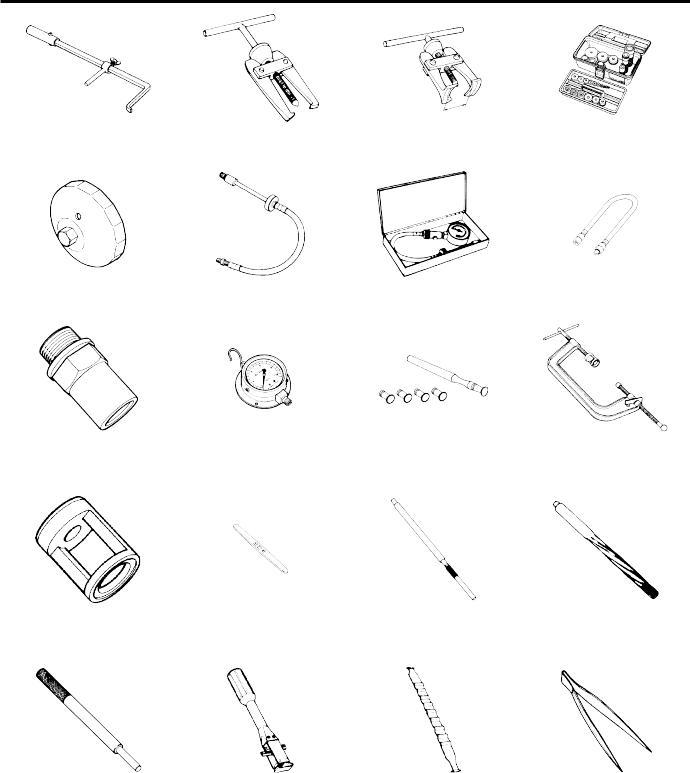
General Information: 0A-12
|
TT09913-50121-01 |
TT09913-60910-01 |
TT09913-61510-01 |
TT09913-70210-01 |
|
09913-50121 |
09913-60910 |
09913-61510 |
09913-70210 |
|
Oil seal remover |
Bearing remover |
Bearing remover |
Bearing installer set |
|
TT09915-40610-01 |
TT09915-63210-01 |
TT09915-64510-01 |
TT09915-74521-01 |
|
09915-40610 |
09915-63210 |
09915-64510 |
09915-74521 |
|
Oil filter wrench |
Compression gauge adaptor |
Compression gauge set |
Oil pressure gauge hose |
|
TT09915-74540-01 |
TT09915-77331-01 |
TT09916-10911-01 |
TT09916-14510-02 |
|
09915-74540 |
09915-77331 |
09916-10911 |
09916-14510 |
|
Oil pressure gauge |
Meter (for high pressure) |
Valve lapper set |
Valve spring compressor |
|
attachment |
|||
|
TT09916-14910-01 |
TT09916-34542-01 |
TT09916-34570-01 |
TT09916-34580-01 |
|
09916-14910 |
09916-34542 |
09916-34570 |
09916-34580 |
|
Valve lifter attachment |
Reamer handle |
Valve guide reamer |
Valve guide reamer |
|
(4.95 mm) |
(10.8 mm) |
||
|
TT09916-44310-01 |
TT09916-74521-01 |
TT09916-74550-01 |
TT09916-84511-01 |
|
09916-44310 |
09916-74521 |
09916-74550 |
09916-84511 |
|
Valve guide remover/ |
Holder body |
Band (73 – 85 mm) |
Tweezers |
|
installer |
Downloaded from www.Manualsbooks.com manuals search
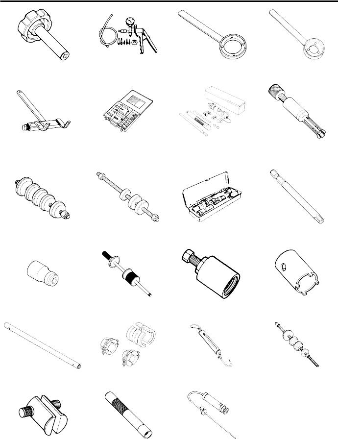
0A-13 General Information:
|
TT09917-14920-01 |
TT09917-47010-01 |
TT09920-34820-01 |
TT09920-34840-01 |
|
09917-14920 |
09917-47010 |
09920-34820 |
09920-34840 |
|
Valve adjuster driver |
Vacuum pump gauge |
Clutch pressure plate holder |
Starter clutch holder |
|
TT09920-53740-02 |
TT09921-20240-01 |
TT09922-22711-01 |
TT09923-73210-01 |
|
09920-53740 |
09921-20240 |
09922-22711 |
09923-73210 |
|
Clutch sleeve hub holder |
Bearing remover set |
Drive chain cutting and |
Bearing remover |
|
joining tool |
|||
|
TT09924-84510-01 |
TT09924-84521-01 |
TT09930-10121-01 |
TT09930-11920-01 |
|
09924-84510 |
09924-84521 |
09930-10121 |
09930-11920 |
|
Bearing installer set |
Bearing installer set |
Spark plug wrench set |
Torx bit (JT 40H) |
|
TT09930-11940-01 |
TT09930-30102-01 |
TT09930-30721-01 |
TT09940-14911-01 |
|
09930-11940 |
09930-30102 |
09930-30721 |
09940-14911 |
|
Bit holder |
Sliding shaft |
Rotor remover |
Steering stem nut wrench |
|
TT09940-52841-01 |
TT09940-52861-01 |
TT09940-92720-01 |
TT09941-34513-01 |
|
09940-52841 |
09940-52861 |
09940-92720 |
09941-34513 |
|
Inner rod holder |
Front fork oil seal installer |
Spring scale |
Steering race installer |
|
TT09941-54911-01 |
TT09941-74911-01 |
TT09943-74111-01 |
|
|
09941-54911 |
09941-74911 |
09943-74111 |
|
|
Bearing outer race remover |
Steering bearing installer |
Fork oil level gauge |
|
Downloaded from www.Manualsbooks.com manuals search
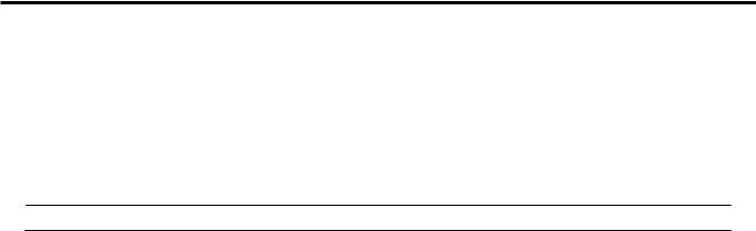
Maintenance and Lubrication: 0B-1
Maintenance and Lubrication
Precautions
Precautions for Maintenance
B649G10200001
The “Periodic Maintenance Schedule Chart” lists the recommended intervals for all the required periodic service work necessary to keep the motorcycle operating at peak performance and economy. Maintenance intervals are expressed in terms of kilometers, miles and months for your convenience.
NOTE
More frequent servicing may be required on motorcycles that are used under severe conditions.
General Description
Recommended Fluids and Lubricants
B649G10201001
Refer to “Fuel and Oil Recommendation: in Section 0A”.
Downloaded from www.Manualsbooks.com manuals search

0B-2 Maintenance and Lubrication:
Scheduled Maintenance
Periodic Maintenance Schedule Chart
B649G10205001
NOTE
I = Inspect and clean, adjust, replace or lubricate as necessary.
R = Replace
T = Tighten
|
Interval |
|||||||
|
Item |
km |
1 000 |
6 000 |
12 000 |
18 000 |
24 000 |
|
|
mile |
600 |
4 000 |
7 500 |
11 000 |
14 500 |
||
|
months |
2 |
12 |
24 |
36 |
48 |
||
|
Air cleaner element |
— |
I |
I |
R |
I |
||
|
Exhaust pipe bolts and muffler bolts |
T |
— |
T |
— |
T |
||
|
Valve clearance |
I |
— |
I |
— |
I |
||
|
Spark plugs |
— |
I |
R |
I |
R |
||
|
Fuel line |
— |
I |
I |
I |
I |
||
|
Engine oil |
R |
R |
R |
R |
R |
||
|
Engine oil filter |
R |
— |
— |
R |
— |
||
|
Throttle cable play |
I |
I |
I |
I |
I |
||
|
Engine idle speed |
I |
I |
I |
I |
I |
||
|
Throttle valve synchronization |
— |
— |
I |
— |
I |
||
|
PAIR (air supply) system |
— |
— |
I |
— |
I |
||
|
Clutch hose |
— |
I |
I |
I |
I |
||
|
Replace every 4 years. |
|||||||
|
Clutch fluid |
— |
I |
I |
I |
I |
||
|
Replace every 2 years. |
|||||||
|
Drive chain |
I |
I |
I |
I |
I |
||
|
Clean and lubricate every 1 000 km (600 mile). |
|||||||
|
Brakes |
I |
I |
I |
I |
I |
||
|
Brake hose |
— |
I |
I |
I |
I |
||
|
Replace every 4 years. |
|||||||
|
Brake fluid |
— |
I |
I |
I |
I |
||
|
Replace every 2 years. |
|||||||
|
Tires |
— |
I |
I |
I |
I |
||
|
Steering |
I |
— |
I |
— |
I |
||
|
Front forks |
— |
— |
I |
— |
I |
||
|
Rear suspension |
— |
— |
I |
— |
I |
||
|
Chassis bolts and nuts |
T |
T |
T |
T |
T |
Downloaded from www.Manualsbooks.com manuals search

Maintenance and Lubrication: 0B-3
Lubrication Points
B649G10205002
Proper lubrication is important for smooth operation and long life of each working part of the motorcycle. Major lubrication points are indicated as follows.
NOTE
•Before lubricating each part, clean off any rusty spots and wipe off any grease, oil, dirt orgrime.
•Lubricate exposed parts which are subject to rust, with a rust preventative spray whenever the motorcycle has been operated under wet or rainy conditions.
1
2
3
|
7 |
||||
|
4 |
5 |
|||
|
6 |
||||
|
I649G1020001-03 |
||||
|
1. |
Brake lever holder and throttle cables |
5. |
Gearshift pivot and left footrest pivot |
|
|
2. |
Brake pedal pivot and right footrest pivot |
6. |
Center stand pivot and spring hook |
|
|
3. |
Clutch lever holder |
7. |
Drive chain |
|
|
4. |
Side-stand pivot and spring hook |
|||
Downloaded from www.Manualsbooks.com manuals search
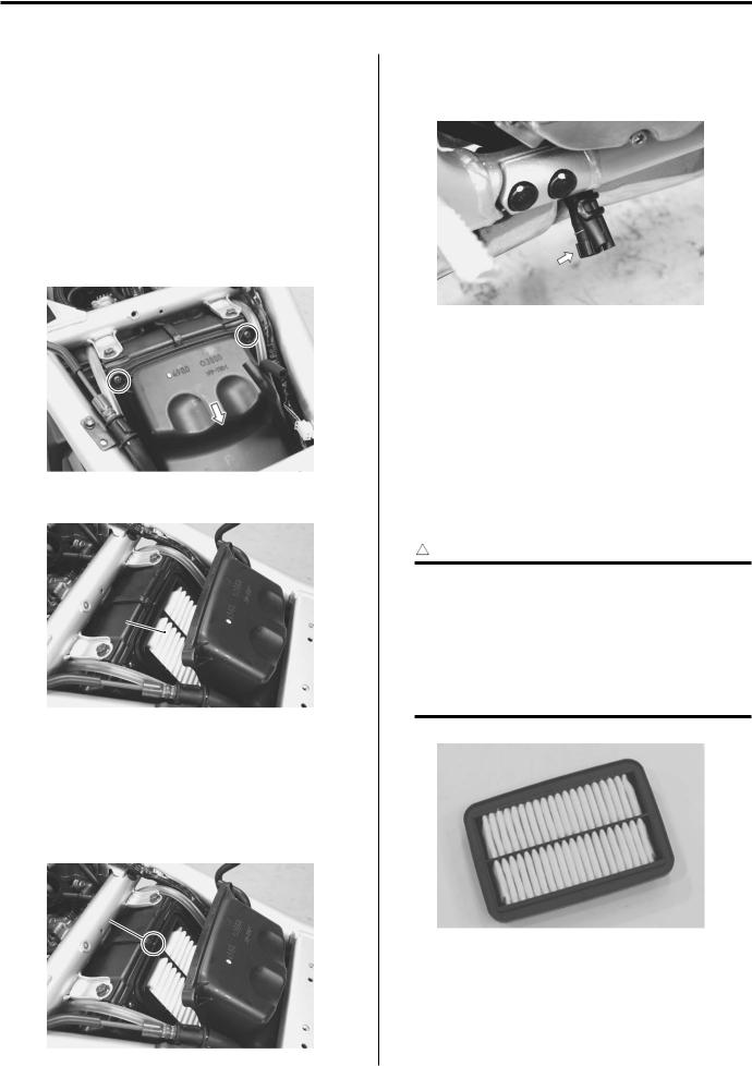
0B-4 Maintenance and Lubrication:
Repair Instructions
Air Cleaner Element Removal and Installation
B649G10206001
Inspect air cleaner element
Every 6 000 km (4 000 miles, 12 months)
Replace air cleaner element
Every 18 000 km (11 000 miles, 36 months) Removal
1)Remove the fuel tank. Refer to “Carburetor Assembly Removal and Installation: in Section1G”.
2)Remove the two screws and slide the aircleaner cover backward.
I649G1020002-02
3) Remove the air cleaner element(1).
1
I649G1020003-02
Installation
Reinstall the cleaned or new air cleaner element in the reverse order of removal. Pay attention to thefollowing points:
•When installing the air cleaner element into the air cleaner box, make sure that the mark points “A”up.
•After cleaning or installing the air cleaner element, drain water from the air cleaner by removing the drain plug.
I649G1020005-01
Air Cleaner Element Inspection and Cleaning
B649G10206002
Refer to “Air Cleaner Element Removal and Installation: ”.
Inspect air cleaner element
Every 6 000 km (4 000 miles, 12 months)
Replace air cleaner element
Every 18 000 km (11 000 miles, 36 months)
Inspection
Inspect the air cleaner element for clogging.
! CAUTION
If driving under dusty conditions, clean the air cleaner element more frequently. The surest way to accelerate engine wear is to operate the engine without the element or to use a torn element. Make sure that the air cleaner is in good condition at all times. Life of the engine depends largely on this component.
“A”
I649G1020006-01
I649G1020004-02
Downloaded from www.Manualsbooks.com manuals search
![]()
Maintenance and Lubrication: 0B-5
Cleaning
Carefully use compressed air to clean the aircleaner element.
! CAUTION
Always apply compressed air to the inside of the air cleaner element. If compressed air is applied to the outside, dirt will be forced into the pores of the air cleaner element, restricting air flow through the air cleaner element.
I649G1020007-01
Spark Plug Removal and Installation
B649G10206003
Inspect spark plug
Every 6 000 km (4 000 miles, 12 months)
Replace spark plug
Every 12 000 km (7 500 miles, 24months)
Removal
! WARNING
The hot engine can burn you.
Wait until the engine is cool enough to touch.
!
Confirm the thread size and reach when replacing the plug. If the reach is too short, carbon will be deposited on the screw portion of the plug hole and enginedamage may result.
1) Remove the spark plug caps.
I649G1020008-02
2)Remove the spark plugs with the spark plug wrench.
Special tool
 (A): 09930–10121 (Spark plug wrench set)
(A)
I649G1020009-02
Installation
Install the spark plugs in the reverse order of removal. Pay attention to the following points:
! CAUTION
Before tightening the spark plug to the specified torque,carefully turnthespark plug by finger into the threads of the cylinder head to prevent damage the aluminum threads.
•Install the spark plugs to the cylinder heads byfinger tight, and then tighten them to the specifiedtorque.
Tightening torque
Spark plug: 11 N·m (1.1 kgf-m, 8.0 lb-ft)
•Install the spark plug caps onto the spark plugs. Make sure that each spark plug cap is installed in the correct location and direction.
Downloaded from www.Manualsbooks.com manuals search

0B-6 Maintenance and Lubrication:
Spark Plug Inspection and Cleaning
B649G10206004
Refer to “Spark Plug Removal and Installation: ”.
Inspect spark plug
Every 6 000 km (4 000 miles, 12 months)
Replace spark plug
Every 12 000 km (7 500 miles, 24 months)
Heat Range
Check spark plug heat range by observing electrode color.
If it is white or glazed appearing, replace the spark plug with colder type one.
|
Heat range |
||||
|
Standard |
Cold type |
Hot type |
||
|
NGK |
JR9B |
JR10B |
JR8B |
Carbon Deposits
Check to see if there are carbon deposits on the spark plug.
If carbon is deposited, remove it using a spark plug cleaner machine or carefully use a tool with a pointed end.
I649G1020010-01
Spark Plug Gap
Measure the spark plug gap using a thickness gauge. Adjust the spark plug gap if necessary.
Spark plug gap
0.6 – 0.7 mm (0.024 – 0.028 in)
Special tool
 (A): 09900–20803 (Thickness gauge)
Electrodes Condition
Check to see the worn or burnt condition of the electrodes.
If it is extremely worn or burnt, replace the plug. And also replace the plug if it has a broken insulator, damaged thread.
Exhaust Pipe Bolt and Muffler Mounting Bolt Inspection
B649G10206021
Tighten exhaust pipe bolt and muffler mounting bolt Initially at 1 000 km (600 miles, 2 month) and every 12 000 km (7 500 miles, 24 months) thereafter.
Check the exhaust pipe bolts, muffler mounting bolts and nut to the specified torque.
Tightening torque
Exhaust pipe bolt (a): 23 N·m (2.3 kgf-m, 16.5 lb-ft) Muffler mounting bolt (b): 23 N·m (2.3 kgf-m, 16.5 lb-ft)
Muffler connecting bolt (c): 23 N·m (2.3 kgf-m, 16.5 lb-ft)
(a)
(a)
(a)
I649G1020054-03
(b)
 (b)
(b)
(A)
I649G1020053-02
I649G1020011-03
Downloaded from www.Manualsbooks.com manuals search

Maintenance and Lubrication: 0B-7
Valve Clearance Inspection and Adjustment
B649G10206005
Inspect valve clearance
Initially at 1 000 km (600 miles, 2 month) and every 12 000 km (7 500 miles, 24 months) thereafter.
Valve clearance adjustment must be checked and adjusted, a) at the time of periodic inspection, b) when the valve mechanism is serviced, and c) when the camshafts are removed for servicing.
1)Remove the fuel tank. Refer to “Fuel TankRemoval and Installation: in Section 1G”.
2)Remove the frame head covers. (GSF1200) Refer to “Exterior Parts Removal and Installation: in Section 9D”.
3)Remove the PAIR valve. Refer to “PAIRSystem Removal and Installation: in Section 1B”.
4)Remove all the spark plugs. Refer to “SparkPlug Removal and Installation: ”.
5)Remove the breather cover (1).
1
I649G1020066-01
6)Remove the cylinder head cover. Refer to “Engine Top Side Disassembly: in Section 1D”.
NOTE
The valve clearance specification is different for both intake and exhaust valves.
Valve clearance (When cold)
IN.: 0.10 – 0.15 mm (0.004 – 0.006 in) EX.: 0.18 – 0.23 mm (0.007 – 0.009 in)
NOTE
•The camshafts must be at positions “A” or
“B”, in order to check or adjust the valve clearance. Clearance readings should not be taken with the camshafts in any other position than the ones shown.
•The valve clearance should onlybe checked when the engine is cold.
I649G1020012-01
7)Remove the CKP sensor cover. Refer to “CKP Sensor Removal and Installation: in Section1H”.
 Turn the crankshaft clockwise and align the “T” mark on the rotor with the center of the CKP sensor. Also, position the notches “C” on the right end of each camshaft as shown. Then, measure the following valve clearances “D”.
•Cylinder #1: Intake and exhaust valve clearances
•Cylinder #2: Exhaust valve clearance
•Cylinder #3: Intake valve clearance
I649G1020013-02
“C” “C”
I649G1020014-02
“D” “D”
|
“D” |
“D” |
|
|
I649G1020017-02 |
||
|
Camshaft position |
Notch “C” position |
|
|
faces outside |
||
|
Measuring position |
“D” |
Downloaded from www.Manualsbooks.com manuals search

0B-8 Maintenance and Lubrication:
|
9) Insert the thickness gauge between the valve stem |
|||||||||
|
end and adjusting screw on the rocker arm. If the |
|||||||||
|
Camshaft position |
Notch “C” position |
||||||||
|
clearance is out of specification, hold the lock-nut |
faces inside |
||||||||
|
with a wrench and use the special tools to adjust the |
|||||||||
|
Measuring position |
“E” |
||||||||
|
clearance. |
|||||||||
|
12) Turn the crankshaft and recheck the valve |
|||||||||
|
! CAUTION |
|||||||||
|
clearances. |
|||||||||
|
Both the right and left valve clearances |
13) After finishing the valve clearanceadjustment, |
||||||||
|
should be as closely as possible. |
reinstall the following items. |
||||||||
|
a) CKP sensor cover (Refer to “CKP Sensor |
|||||||||
|
Removal and Installation: in Section1H”.) |
|||||||||
|
(B) |
b) Cylinder head cover (Refer to “Engine TopSide |
||||||||
|
Assembly: in Section 1D”.) |
|||||||||
|
(A) |
c) |
Breather cover |
|||||||
|
d) Spark plugs and plug caps (Refer to “SparkPlug |
|||||||||
|
Removal and Installation: ”.) |
|||||||||
|
e) PAIR valve (Refer to “PAIRSystem Removal and |
|||||||||
|
Installation: in Section 1B”.) |
|||||||||
|
f) Frame head covers (for GSF1200) (Referto |
|||||||||
|
“Exterior Parts Removal and Installation: in |
|||||||||
|
I649G1020015-03 |
Section 9D”.) |
||||||||
|
Special tool |
g) |
Fuel tank (Refer to “Fuel Tank Removal and |
|||||||
|
(A) : 09900–20803 (Thickness gauge) (B): |
Installation: in Section 1G”.) |
||||||||
|
09917–14920 (Valve adjusterdriver) |
h) |
Seat (Refer to “Exterior Parts Removaland |
|||||||
|
10) Turn the crankshaft clockwise 360 (one full rotation) |
Installation: in Section 9D”.) |
||||||||
|
and align the “T” mark on the rotor with the center of |
Fuel Line Inspection |
||||||||
|
the CKP sensor. Also, position the notches “C” on |
B649G10206006 |
||||||||
|
the right end of each camshaft as shown. Then, |
|||||||||
|
Inspect fuel line |
|||||||||
|
measure the following valve clearances “E”. |
|||||||||
|
• Cylinder #2: Intake valveclearance |
Every 6 000 km (4 000 miles, 12 months) |
||||||||
|
• Cylinder #3: Exhaust valveclearance |
Inspect the fuel line in the following procedures: |
||||||||
|
• Cylinder #4: Intake and exhaust valveclearances |
1) Remove the seat. Refer to “Exterior PartsRemoval |
||||||||
|
11) Measure the valve clearances of theremaining |
and Installation: in Section 9D”. |
||||||||
|
valves “E” and adjust them if necessary. |
2) Remove the fuel tank mounting bolts. Refer to “Fuel |
||||||||
|
Tank Removal and Installation: in Section 1G”. |
|||||||||
|
“C” |
“C” |
3) Lift up the fuel tank. |
|||||||
|
4) Inspect the fuel hose for damage and fuel leakage. If |
|||||||||
|
any defects are found, the fuel hose must be |
|||||||||
|
replaced. |
|||||||||
|
I649G1020016-03 |
|||||||||
|
“E” |
“E” |
I649G1020065-01
“E” “E”
I649G1020018-02
Downloaded from www.Manualsbooks.com manuals search

Maintenance and Lubrication: 0B-9
Engine Oil and Filter Replacement
B649G10206007
Replace engine oil
Initially at 1 000 km (600 miles, 2 month) and every 6 000 km (4 000 miles, 12 months) thereafter.
Replace oil filter
Initially at 1 000 km (600 miles, 2 month) and every 18 000 km (11 000 miles, 36 months) thereafter.
Oil should be changed while the engine is warm. Oil filter replacement at the above intervals, should be done together with the engine oil change.
Engine Oil Replacement
1)Keep the motorcycle upright.
2)Place an oil pan below the engine, and drainengine oil by removing the oil drain plug (1) and filler cap
(2).
1
I649G1020019-01
2
I649G1020020-01
3)Tighten the oil drain plug (1) to the specified torque, and pour new oil through the oil filler. When performing an oil change (without oil filter replacement), the engine will hold about 3.3 L of oil. Use of SF/SG or SH/SJ in API with MA in JASO.
Tightening torque
Oil drain plug (a): 23 N·m (2.3 kgf-m, 16.5 lb-ft)
1, (a)
I649G1020021-03
4)Start up the engine and allow it to run forseveral minutes at idling speed.
5)Turn off the engine and wait about three minutes, then check the oil level through the inspection window (3). If the level is below the “L” mark, addoil to the “F” mark. If the level is above the “F” mark, drain the oil until the level reaches the “F” mark.
3
I649G1020022-01
Oil Filter Replacement
1)Drain engine oil as described in the engineoil replacement procedure.
2)Remove the oil filter (1) using the special tool.
Special tool
 (A): 09915–40610 (Oil filter wrench)
(A)
1
I649G1020023-02
Downloaded from www.Manualsbooks.com manuals search

0B-10 Maintenance and Lubrication:
|
3) Apply engine oil lightly to the O-ring of new oil filter, |
Throttle Cable Play Inspection and Adjustment |
|
|
before installation. |
B649G10206012 |
|
|
! CAUTION |
Inspect throttle cable play |
|
|
Initially at 1 000 km (6 000 miles, 2 month) and every |
||
|
ONLY USE A GENUINE SUZUKI |
6 000 km (4 000 miles, 12 months) thereafter. |
|
|
MOTORCYCLE OIL FILTER. |
Inspect and adjust the throttle cable play “a” as follows. |
|
|
Other manufacturer’s oil filters may differin |
||
|
Throttle cable play “a” |
||
|
thread specifications (thread diameter and |
||
|
pitch), filtering performance and durability |
2.0 – 4.0 mm (0.08 – 0.16 in) |
|
|
which may lead to engine damage or oil |
||
|
leaks. Also, do not use a genuine Suzuki |
||
|
automobile oil filter on this motorcycle. |
4)Install a new oil filter. Turn it by hand until you feel that the oil filter O-ring contacts the oil filter mounting
|
surface. Then, tighten the oil filter two full turns (or to |
“a” |
||||
|
specified torque) using the special tool. |
|||||
|
NOTE |
|||||
|
To properly tighten the oil filter, use the |
|||||
|
special tool. Never tighten the oil filter by |
I649G1020026-01 |
||||
|
hand only. |
|||||
|
1) Loosen the lock-nut (1) of the throttle pullingcable |
|||||
|
Special tool |
(2). |
||||
|
2) Turn the adjuster(3) in or out until the throttle cable |
|||||
|
(A): 09915–40610 (Oil filter wrench) |
|||||
|
Tightening torque |
play “a” (at the throttle grip) is between 2 – 4 mm |
||||
|
(0.08 – 0.16 in). |
|||||
|
Oil filter (a): 20 N·m (2.0 kgf-m, 14.5 lb-ft) |
|||||
|
3) Tighten the lock-nut (1) while holding theadjuster |
|||||
|
1, (a) |
(3). |
||||
|
(A) |
|||||
|
1 |
3 |
||||
|
2 |
|
I649G1020024-03 |
|||
|
5) Add new engine oil and check the oil level is as |
|||
|
described in the engine oil replacement procedure. |
I649G1020027-01 |
||
|
Necessary amount of engine oil |
! WARNING |
||
|
Oil change: 3.3 L (3.4/2.9 US/lmp qt) |
|||
|
Oil and filter change: 3.5 L (3.6/3.0 US/lmpqt) |
After the adjustment is completed, check that |
||
|
Engine overhaul: 4.6 L (4.9 /4.0 US/lmp qt) |
handlebar movement does not raise the |
||
|
engine idle speed and that the throttle grip |
|||
|
returns smoothly and automatically. |
|||
Downloaded from www.Manualsbooks.com manuals search

Maintenance and Lubrication: 0B-11
Engine Idle Speed Inspection and Adjustment
B649G10206011
Inspect engine idle speed
Initially at 1 000 km (600 miles, 2 month) and every 6 000 km (4 000 miles, 12 months) thereafter.
NOTE
Make this adjustment when the engine is hot.
Start the engine, turn the throttle stop screw (1) and set the engine idle speed “a”.
Engine idle speed “a”
1300 100 r/min (E-28)
1200 100 r/min (Others)
1
I649G1020025-02
Throttle Valve Synchronization
B649G10206013
Inspect throttle valve synchronization Every 12 000 km (7 500 miles, 24months)
Inspect the throttle valve synchronization periodically. Refer to “Carburetor Synchronization: in Section 1G”.
PAIR System Inspection
B649G10206014
Inspect PAIR system
Every 12 000 km (7 500 miles, 24months)
Inspect the PAIR (air supply) system periodically.Refer to “PAIR System Inspection: ”.
Clutch SystemInspection
B649G10206026
Inspect clutch hose and clutch fluid Every 6 000 km (4 000 miles, 12 months)
Replace clutch hose Every 4 years
Replace clutch fluid Every 2 years
! WARNING
The clutch system of this motorcycle is filled with a glycol-based brake fluid. Do not use or mix different types of fluid such as siliconebased or petroleum-based. Do not use any brake fluid taken from old, used or unsealed containers. Never reuse brake fluid left over from the last servicing or stored for a long period of mine. Check the clutch hose and hose joints for cracks and fluid leakage.
Clutch Fluid Level Check
1)Keep the motorcycle upright and placethe handlebars straight.
2)Check the clutch fluid level by observing thelower limit line on the clutch fluid reservoir.
When the clutch fluid level is below the lowerlimit line, replenish with clutch fluid that meets the following specification.
BF: Brake fluid (DOT 4)
I649G1020028-01
Clutch Hose Inspection
1)Remove the left frame cover. Refer to “Exterior Parts Removal and Installation: in Section 9D”.
2)Remove the fuel tank. Refer to “Fuel TankRemoval and Installation: in Section 1G”.
3)Inspect the clutch hose for crack, damage or clutch fluid leakage. If it is defected, replace the clutch hose with a new one.
I649G1020031-01
4)After finishing the clutch hose inspection,reinstall the removed parts.
Downloaded from www.Manualsbooks.com manuals search

0B-12 Maintenance and Lubrication:
Clutch Hose Replacement
B649G10206031
Refer to “Clutch Hose Removal and Installation: in Section 5C”.
Air Bleeding from Clutch Fluid Circuit
B649G10206032
Refer to “Air Bleeding from Clutch Fluid Circuit: ”.
Clutch Fluid Replacement
B649G10206033
Refer to “Clutch Fluid Replacement: in Section 5C”.
Drive Chain Inspection and Adjustment
B649G10206028
Inspect drive chain
Initially at 1 000 km (600 miles, 2 month) and every 6 000 km (4 000 miles, 12 months) thereafter.
Drive Chain Visual Check
1)With the transmission in neutral, support the motorcycle using the center-stand and turn therear wheel slowly by hand.
2)Visually check the drive chain for the possible defects listed as follows. If any defects are found, the drive chain must be replaced. Refer to “Drive Chain Replacement: in Section 3A”.
•Loose pins
•Damaged rollers
•Dry or rusted links
•Kinked or binding links
•Excessive wear
•Improper chain adjustment
•Missing O-ring seals
NOTE
When replacing the drive chain, replace the drive chain and sprockets as a set.
2
1
I649G1020032-01
Drive Chain Length Inspection
1)Remove the cotter pin. (For E-28)
2)Loosen the axle nut (1).
3)Loosen the chain adjuster lock-nuts (2).
4)Give tension to the drive chain fully by turningboth chain adjuster bolts (3).
|
2 |
3 |
1 |
2 |
||||
|
3 |
|||||||
I649G1020033-01
5)Count out 21 pins (20 pitches) on the chain and measure the distance between the two points. If the distance exceeds the service limit, the chain must be replaced.
Drive chain 20-pitch length Service limit: 319.4 mm (12.57 in)
I649G1020034-01
6)After finishing the drive chain lengthinspection, adjust the drive chain slack.
Downloaded from www.Manualsbooks.com manuals search

Maintenance and Lubrication: 0B-13
Drive Chain Slack Adjustment
1)Place the motorcycle on its side-stand foraccurate adjustment.
2)Loosen the axle nut (1).
3)Loosen the chain adjuster lock-nuts (2).
4)Loosen or tighten both chain adjuster bolts (3) until there is 20 – 30 mm (0.8 – 1.2 in) “a” of slack atthe middle of the chain between the engine and rear sprockets as shown.
! CAUTION
The reference marks “A” on both sides of the swingarm and the edge of each chain adjuster must be aligned to ensure that the front and rear wheels are correctly aligned.
Drive chain slack “a”
Standard 20 – 30 mm (0.8 – 1.2 in)
“A” “A” 1 
I649G1020035-02
“a”
I649G1020036-01
5)After adjusting the drive chain, tighten the axle nut
(1) to the specified torque.
6)Tighten both chain adjuster lock-nuts (2) securely.
Tightening torque
Rear axle nut: 100 N·m (10.0 kgf-m, 72.5 lb-ft)
7)Install a new cotter pin. (For E-28)
Recheck the drive chain slack after tighteningthe axle nut.
Drive Chain Cleaning and Lubricating
B649G10206029
Clean and lubricate drive chain Every 1 000 km (600 miles)
Clean and lubricate the drive chain in the following procedures:
1)Clean the drive chain with kerosine. If the drive chain tends to rust quickly, the intervals must be shortened.
! CAUTION
Do not use trichloroethylene, gasoline or any similar solvent.
These fluids have too great a dissolving power for this chain and they can damage the O-rings. Use only kerosine to clean the drive chain.
2)After cleaning and drying the chain, oil it witha heavyweight motor oil.
!CAUTION
•Do not use any oil sold commercially as “drive chain oil”. Such oil can damagethe O-rings.
•The standard drive chain is a RK GB50GSVZ3. SUZUKI recommends to use this standard drive chain as a replacement.
I649G1020037-01
Brake System Inspection
B649G10206030
Inspect brake system
Initially at 1 000 km (600 miles, 2 month) and every 6
000 km (4 000 miles, 12 months) thereafter.
Inspect brake hose and brake fluid Every 6 000 km (4 000 miles, 12 months)
Replace brake hose Every 4 years
Replace brake fluid Every 2 years
Downloaded from www.Manualsbooks.com manuals search

0B-14 Maintenance and Lubrication:
!WARNING
•The brake system of this motorcycle is filled with a glycol-based brake fluid. Do not use or mix different types of fluid such as silicone-based and petroleum-based fluids. Do not use any brake fluid taken from old, used or unsealed containers. Never reuse brake fluid left over from the last servicing or stored for a long period of time.
•Brake fluid, if it leaks, will interfere with safe running and immediately discolor painted surfaces. Check the brake hoses and hose joints for cracks and oilleakage before riding.
Brake Fluid Level Check
1)Keep the motorcycle upright and placethe handlebars straight.
2)Check the brake fluid level by observing the lower limit lines on the front and rear brake fluid reservoirs. When the brake fluid level is below the lower limit line, replenish with brake fluid that meets the following specification.
BF: Brake fluid (DOT 4)
I649G1020038-01
I649G1020039-01
Brake Pads Check
The extent of brake pad wear can be checked by observing the grooved limit line “A” on the pad. When the wear exceeds the grooved limit line, replace the pads with new ones. Refer to “Front Brake Pad Replacement: in Section 4B” and “Rear Brake Pad Replacement: in Section 4C”.
! CAUTION
Replace the brake pad as a set, otherwise braking performance will be adversely affected.

 “A”
“A”
I649G1020040-02
“A”
I649G1020041-02
Front Brake Hose Inspection
Inspect the brake hoses and hose joints for crack, damage or oil leakage. If any defects are found, replace the brake hose with a new one.
I649G1020047-01
Downloaded from www.Manualsbooks.com manuals search
![]()
Maintenance and Lubrication: 0B-15
Rear Brake Hose Inspection
Inspect the brake hose for crack, damage or brakeoil leakage. If any defects are found, replace the brake hose with a new one.
I649G1020048-01
Brake Pedal Height Inspection and Adjustment
1)Inspect the brake pedal height “a” between the pedal top face and footrest.
Adjust the brake pedal height if necessary.
Brake pedal height “a” Standard: 60 mm (2.4 in)
2)Loosen the lock-nut (1).
3)Turn the push rod (2) until the brake pedal is 60mm (2.4 in) below the top of the footrest.
4)Tighten the lock-nut (1) securely.
Tightening torque
Rear master cylinder rod lock-nut (a): 18 N·m ( 1.8 kgf-m, 13.0 lb-ft)
|
2 |
|||||
|
1, |
(a) |
“a” |
|||
I649G1020042-04
Rear Brake Light Switch Adjustment
B649G10206036
Refer to “Rear Brake Light Switch Inspection and Adjustment: in Section 4A”.
Brake Hose Replacement
B649G10206037
Refer to “Front Brake Hose Removal and Installation: in Section 4A” and “Rear Brake Hose Removal and Installation: in Section 4A”.
Air Bleeding from Brake Fluid Circuit
B649G10206034
Refer to “Air Bleeding from Brake Fluid Circuit: in Section 4A”.
Brake Fluid Replacement
B649G10206035
Refer to “Brake Fluid Replacement: in Section 4A”.
Tire Inspection
B649G10206017
Inspect tire
Every 6 000 km (4 000 miles, 12months)
Tire Tread Condition
Operating the motorcycle with excessively worn tires will decrease riding stability and consequently invite a dangerous situation. It is highly recommended to replace a tire when the remaining depth of tire tread reaches the following specification.
Special tool
 : 09900–20805 (Tire depth gauge)
Tire tread depth (Service limit) Front: 1.6 mm (0.06 in)
Rear: 2.0 mm (0.08 in)
I310G1020068-01
Tire Pressure
If the tire pressure is too high or too low, steering will be adversely affected and tire wear increased. Therefore, maintain the correct tire pressure for good roadability or shorter tire life will result. Cold inflation tire pressure is as follows.
|
Cold inflation tire pressure |
||||||||||
|
Solo riding |
Dual riding |
|||||||||
|
kPa |
kgf/cm2 |
psi |
kPa |
kgf/cm2 |
psi |
|||||
|
Front |
250 |
2.50 |
36 |
250 |
250 |
36 |
||||
|
Rear |
250 |
2.50 |
36 |
250 |
250 |
36 |
I310G1020069-01
Downloaded from www.Manualsbooks.com manuals search

0B-16 Maintenance and Lubrication:
|
! CAUTION |
Front Fork Inspection |
|||
|
B649G10206019 |
||||
|
The standard tire fitted on this motorcycle is |
Inspect front fork |
|||
|
120/70 ZR17 M/C (58W) for front and 180/55 |
||||
|
Every 12 000 km (7 500 miles, 24months) |
||||
|
ZR17 M/C (73W) for rear. The use of tires |
||||
|
Inspect the front forks for oil leakage, scoring or |
||||
|
other than those specified may cause |
||||
|
instability. It is highly recommended to use a |
scratches on the outer surface of the inner tubes. |
|||
|
SUZUKI Genuine Tire. |
Replace any defective parts, if necessary. Refer to |
|||
|
“Front Fork Parts Inspection: in Section 2B”. |
||||
|
Tire type |
||||
|
DUNLOP |
||||
|
• |
Front: D218 FN |
|||
|
• |
Rear: D218 N |
|||
|
Steering System Inspection |
||||
|
B649G10206018 |
||||
|
Inspect steering system |
||||
|
Initially at 1 000 km (600 miles, 2 month) and every |
||||
|
12 000 km (7 500 miles, 24 months) thereafter. |
||||
|
Steering should be adjusted properly for smooth turning |
I649G1020050-01 |
|||
|
of handlebars and safe running. Overtight steering |
||||
|
prevents smooth turning of the handlebars and too loose |
Rear Suspension Inspection |
|||
|
steering will cause poor stability. |
B649G10206020 |
|||
|
1) Check that there is no play in the front fork. |
Inspect rear suspension |
|||
|
2) Support the motorcycle so that the front wheel isoff |
Every 12 000 km (7 500 miles, 24months) |
|||
|
the ground, with the wheel facing straightahead, |
Inspect the rear shock absorbers for oil leakage and |
|||
|
grasp the lower fork tubes near the axle and pull |
check that there is no play in the swingarm. |
|||
|
forward. |
Replace any defective parts, if necessary. Refer to “Rear |
|||
|
If play is found, readjust the steering. Refer to |
Shock Absorber Removal and Installation: in Section |
|||
|
“Steering Tension Adjustment: in Section 6B”. |
2C”, “Cushion Lever Removal and Installation: in |
|||
|
Section 2C” and “Swingarm / Cushion Rod Removal and |
||||
|
Installation: in Section 2C”. |
I649G1020049-01
I649G1020051-01
I649G1020052-01
Downloaded from www.Manualsbooks.com manuals search

Maintenance and Lubrication: 0B-17
Chassis Bolt and Nut Inspection
B649G10206022
Tighten chassis bolt and nut
Initially at 1 000 km (600 miles, 2 month) and every 6 000 km (4 000 miles, 12 months) thereafter.
Check that all chassis bolts and nuts are tightened to their specified torque.
|
2, |
(b) |
|||||
|
2, |
(b) |
1, |
(a) |
|||
|
I649G1020055-04 |
||||||
|
1. |
Steering stem head nut |
: 65 N m (6.5 kgf-m, 47.0lb-ft) |
||||
|
2. |
Front fork cap bolt |
: 23 N m (2.3 kgf-m, 16.5lb-ft) |
||||
|
3. |
Handlebar holder bolt |
|||||
5, (c)
|
4, |
(b) |
2, |
(b) |
||
|
I649G1020056-05 |
|||||
|
2. Front fork cap bolt |
: 23 N m (2.3 kgf-m, 16.5 lb-ft) |
||||
|
4. |
Front fork upper clamp bolt |
: 8 N m (0.8 kgf-m, 6.0 lb-ft) |
|||
|
5. |
Air bleeder valve (Clutch) |
||||
8, (b) 7, (b)
|
6, |
(d) |
|||
|
6, |
(d) |
|||
|
I649G1020057-03 |
||||
|
6. |
Front brake/Clutch master |
: 23 N m (2.3 kgf-m, 16.5 lb-ft) |
||
|
cylinder mounting bolt |
||||
|
7. |
Brake hose union bolt (Front |
: 10 N m (1.0 kgf-m, 7.0lb-ft) |
||
|
brake) |
||||
|
8. |
Clutch hose union bolt |
|||
10, (f)
|
9, |
(e) |
||
|
I649G1020058-03 |
|||
|
9. |
Rear shock absorber mounting |
: 50 N m (5.0 kgf-m, 36.0lb-ft) |
|
|
nut (Upper) |
|||
|
10. |
Cushion rod mounting nut |
: 78 N m (7.8 kgf-m, 56.5lb-ft) |
|
|
12, |
(f) |
11, |
(e) |
|||||
|
13, |
(f) |
|||||||
|
I649G1020059-03 |
||||||||
|
11. Rear shock absorber mounting |
: 50 N m (5.0 kgf-m, 36.0 lb-ft) |
|||||||
|
nut (Lower) |
||||||||
|
12. |
Cushion lever mounting nut |
: 78 N m (7.8 kgf-m, 56.5 lb-ft) |
||||||
|
13. |
Cushion rod mounting nut |
|||||||
14, (b)
I649G1020060-03
14. Front fork lower clamp bolt
 : 23 N m (2.3 kgf-m, 16.5 lb-ft)
Downloaded from www.Manualsbooks.com manuals search

0B-18 Maintenance and Lubrication:
21, (o) 17, (h)
16, (b)
|
19, |
15, |
(g) |
|||||||||
|
(b) |
18, |
(i) |
20, |
(b) |
|||||||
|
I649G1020061-04 |
|||||||||||
|
15. |
Front axle bolt |
21. |
Air bleeder valve (Brake) |
||||||||
|
16. |
Front axle pinch bolt |
: |
23 N m (2.3 kgf-m, 16.5 lb-ft) |
||||||||
|
17. |
Front brake caliper mounting |
: |
100 N m (10.0 kgf-m, 72.5lb-ft) |
||||||||
|
bolt |
|||||||||||
|
18. |
Front brake caliper housing |
: |
26 N m (2.6 kgf-m, 19.0 lb-ft) |
||||||||
|
bolt |
|||||||||||
|
19. |
Brake hose union bolt (Front) |
: |
21 N m (2.1 kgf-m, 15.0 lb-ft) |
||||||||
|
20. |
Brake disc bolt (Front) |
: 7.5 N m (0.75 kgf-m, 5.5 lb-ft) |
|||||||||
|
21, (j) |
24, (b) |
||||||||||
|
22, (b) |
|||||||||||
|
23, (k) |
|||||||||||
|
22, (b) |
I649G1020062-03 |
||||||||||
|
21. Air bleeder valve (Brake) |
: 23 N m (2.3 kgf-m, 16.5 lb-ft) |
||||||||||
|
22. Brake disc bolt (Rear) |
: 6 N m (0.6 kgf-m, 4.5 lb-ft) |
||||||||||
|
23. Rear brake caliper mounting bolt |
: |
22 N m (2.2 kgf-m, 16.0 lb-ft) |
|||||||||
|
24. Brake hose union bolt (Rear) |
|||||||||||
|
26, |
(b) |
29, |
(b) |
|||
|
27, (b) |
||||||
|
28, |
(m) 25, |
(l) |
||||
|
I649G1020063-04 |
||||||
|
25. |
Front footrest bolt |
29. |
Front footrest bracket |
|||
|
mounting bolt |
||||||
|
26. |
Brake hose union bolt (Rear) |
: 23 N m (2.3 kgf-m, 16.5 lb-ft) |
||||
|
27. |
Rear brake master cylinder |
: |
35 N m (3.5 kgf-m, 25.5 lb-ft) |
|||
|
mounting bolt |
||||||
|
28. |
Rear brake master cylinder rod |
: |
18 N m (1.8 kgf-m, 13.0 lb-ft) |
|||
|
lock-nut |
||||||
|
30, |
(n) |
|||
|
31, (g) |
||||
|
30, |
(n) |
|||
|
I649G1020064-04 |
||||
|
30. |
Rear sprocket nut |
: 100 N m (10.0 kgf-m, 72.5 lb-ft) |
||
|
31. |
Rear axle nut |
: 60 N m (6.0 kgf-m, 43.5 lb-ft) |
||
Refer to “Compression Pressure Check: in Section1D”.
Oil Pressure Check
B649G10206024
Refer to “Oil Pressure Check: in Section 1E”.
Downloaded from www.Manualsbooks.com manuals search

|
Maintenance and Lubrication: 0B-19 |
|||||||
|
Specifications |
|||||||
|
Tightening TorqueSpecifications |
B649G10207001 |
||||||
|
Fastening part |
Tightening torque |
Note |
|||||
|
N m |
kgf-m |
lb-ft |
|||||
|
Spark plug |
11 |
1.1 |
8.0 |
||||
|
Exhaust pipe bolt |
23 |
2.3 |
16.5 |
||||
|
Muffler mounting bolt |
23 |
2.3 |
16.5 |
||||
|
Muffler connecting bolt |
23 |
2.3 |
16.5 |
||||
|
Oil drain plug |
23 |
2.3 |
16.5 |
||||
|
Oil filter |
20 |
2.0 |
14.5 |
||||
|
Rear axle nut |
100 |
10.0 |
72.5 |
||||
|
Rear master cylinder rod lock-nut |
18 |
1.8 |
13.0 |
NOTE
The specified tightening torque is also described in the following. “Chassis Bolt and Nut Inspection: ”
Reference:
For the tightening torque of fastener not specified in this section, refer to “Tightening Torque Specifications: in Section 0C”.
Special Tools and Equipment
Recommended Service Material
|
B649G10208001 |
|||
|
Material |
SUZUKI recommended product or Specification |
Note |
|
|
Brake fluid |
DOT 4 |
— |
/ |
Special Tool
|
B649G10208002 |
|
|
09900–20803 |
09900–20805 |
|
Thickness gauge |
Tire depth gauge |
|
/ |
|
|
09915–40610 |
09917–14920 |
|
Oil filter wrench |
Valve adjuster driver |
|
/ |
|
|
09930–10121 |
|
|
Spark plug wrench set |
|
Downloaded from www.Manualsbooks.com manuals search

0C-1 Service Data:
Service Data
Specifications
Service Data
|
Valve + Guide |
B649G10307003 |
||||
|
Unit: mm (in) |
|||||
|
Item |
Standard |
Limit |
|||
|
Valve diameter |
IN. |
28.5 (1.12) |
— |
||
|
EX. |
25 (1.0) |
— |
|||
|
Valve clearance (when cold) |
IN. |
0.10 – 0.15 (0.004 – 0.006) |
— |
||
|
EX. |
0.18 – 0.23 (0.007 – 0.009) |
— |
|||
|
Valve guide to valve stem clearance |
IN. |
0.020 – 0.047 (0.0008 – 0.0019) |
— |
||
|
EX. |
0.040 – 0.067 (0.0016 – 0.0026) |
— |
|||
|
Valve stem deflection |
IN. & EX. |
— |
0.35 |
(0.014) |
|
|
Valve guide I.D. |
IN. & EX. |
5.000 – 5.012 (0.1969 – 0.1973) |
— |
||
|
Valve stem O.D. |
IN. |
4.965 – 4.980 (0.1955 – 0.1961) |
— |
||
|
EX. |
4.945 – 4.960 (0.1947 – 0.1953) |
— |
|||
|
Valve stem runout |
IN. & EX. |
— |
0.05 |
(0.002) |
|
|
Valve face thickness |
IN. & EX. |
— |
0.5 |
(0.02) |
|
|
Valve stem end length |
IN. & EX. |
— |
2.5 |
(0.10) |
|
|
Valve seat width |
IN. & EX. |
0.9 – 1.1 (0.035 – 0.043) |
— |
||
|
Valve head radial runout |
IN. & EX. |
— |
0.03 |
(0.001) |
|
|
Valve spring free length (IN. & EX.) |
INNER |
— |
35.0 (1.38) |
||
|
OUTER |
— |
37.8 (1.49) |
|||
|
INNER |
53 – 65 N (5.3 – 6.5 kgf, 11.7 – 14.3 lbs) |
— |
|||
|
at length 28 mm (1.10 in) |
|||||
|
Valve spring tension (IN. & EX.) |
|||||
|
OUTER |
131 – 151 N (13.1 – 15.1 kgf, 28.9 – 33.3 lbs) |
— |
|||
|
at length 31.5 mm (1.24 in) |
|||||
|
Camshaft + Cylinder Head |
|||||
|
Unit: mm (in) |
|||||
|
Item |
Standard |
Limit |
|||
|
Cam height |
IN. |
33.58 – 33.62 (1.3220 – 1.3236) |
33.28 |
(1.3102) |
|
|
EX. |
32.65 – 32.69 (1.2854 – 1.2870) |
32.35 |
(1.2736) |
||
|
Camshaft journal oil clearance |
IN. & EX. |
0.032 – 0.066 (0.0013 – 0.0026) |
0.150 |
(0.0059) |
|
|
Camshaft journal holder I.D. |
IN. & EX. |
22.012 – 22.025 (0.8666 – 0.8671) |
— |
||
|
Camshaft journal O.D. |
IN. & EX. |
21.959 – 21.980 (0.8645 – 0.8654) |
— |
||
|
Camshaft runout |
IN. & EX. |
— |
0.10 |
(0.004) |
|
|
Cam chain pin (at arrow “3”) |
24th pin |
— |
|||
|
Rocker arm I.D. |
IN. & EX. |
12.000 – 12.018 (0.4724 – 0.4731) |
— |
||
|
Rocker arm shaft O.D. |
IN. & EX. |
11.973 – 11.984 (0.4714 – 0.4718) |
— |
||
|
Cylinder head distortion |
— |
0.20 |
(0.008) |
Downloaded from www.Manualsbooks.com manuals search
|
Service Data: 0C-2 |
||||||||
|
Cylinder + Piston + Piston Ring |
||||||||
|
Unit: mm (in) |
||||||||
|
Item |
Standard |
Limit |
||||||
|
Compression pressure |
1 250 kPa (12.5 kgf/cm2, 178 psi) |
875 kPa |
||||||
|
(8.75 kgf/cm2, 124 psi) |
||||||||
|
Compression pressure difference |
— |
200 kPa |
||||||
|
(2 kgf/cm2, 28 psi) |
||||||||
|
Piston-to-cylinder clearance |
0.050 – 0.060 (0.0020 – 0.0024) |
0.120 (0.0047) |
||||||
|
Cylinder bore |
79.000 – 79.015 (3.1102 – 3.1108) |
79.080 (3.1134) |
||||||
|
Piston diameter |
78.945 – 78.960 (3.1081 – 3.1087) |
78.880 (3.1055) |
||||||
|
Measure 15 mm (0.6 in) from the skirt end. |
||||||||
|
Cylinder distortion |
— |
0.20 (0.008) |
||||||
|
Piston ring free end gap |
1st |
N |
Approx. 10 (0.39) |
8.0 (0.31) |
||||
|
2nd |
2N |
Approx. 9.5 (0.37) |
7.6 (0.30) |
|||||
|
Piston ring end gap |
1st |
0.15 – 0.30 (0.006 – 0.012) |
0.5 (0.020) |
|||||
|
2nd |
0.30 – 0.45 (0.012 – 0.018) |
0.7 (0.028) |
||||||
|
Piston ring-to-groove clearance |
1st |
— |
0.180 (0.007) |
|||||
|
2nd |
— |
0.150 (0.006) |
||||||
|
1st |
1.01 – 1.03 (0.040 – 0.041) |
— |
||||||
|
Piston ring groove width |
2nd |
1.01 – 1.03 (0.040 – 0.041) |
— |
|||||
|
Oil |
2.01 – 2.03 (0.079 – 0.080) |
— |
||||||
|
Piston ring thickness |
1st |
0.975 – 0.990 (0.0384 – 0.0390) |
— |
|||||
|
2nd |
0.970 – 0.990 (0.038 – 0.039) |
— |
||||||
|
Piston pin bore |
20.002 – 20.008 (0.7875 – 0.7877) |
20.030 (0.7886) |
||||||
|
Piston pin O.D. |
19.992 – 20.000 (0.7871 – 0.7874) |
19.980 (0.7866) |
||||||
|
Conrod + Crankshaft |
||||||||
|
Unit: mm (in) |
||||||||
|
Item |
Standard |
Limit |
||||||
|
Conrod small end I.D. |
20.010 – 20.018 (0.7878 – 0.7881) |
20.040 (0.7890) |
||||||
|
Conrod big end side clearance |
0.10 – 0.20 (0.004 – 0.008) |
0.30 (0.012) |
||||||
|
Conrod big end width |
20.95 – 21.00 (0.825 – 0.827) |
— |
||||||
|
Crank pin width |
21.10 – 21.15 (0.831 – 0.833) |
— |
||||||
|
Conrod big end oil clearance |
0.032 – 0.056 (0.0013 – 0.0022) |
0.080 (0.0031) |
||||||
|
Crank pin O.D. |
37.976 – 38.000 (1.4951 – 1.4961) |
— |
||||||
|
Crankshaft journal oil clearance |
0.020 – 0.044 (0.0008 – 0.0017) |
0.080 (0.0031) |
||||||
|
Crankshaft journal O.D. |
35.976 – 36.000 (1.4164 – 1.4173) |
— |
||||||
|
Crankshaft thrust clearance |
0.04 – 0.08 (0.0016 – 0.0031) |
— |
||||||
|
Crankshaft thrust bearing thickness |
Left side |
2.360 – 2.520 (0.0929 – 0.0992) |
— |
|||||
|
Right side |
2.420 – 2.440 (0.0953 – 0.0961) |
— |
||||||
|
Crankshaft runout |
— |
0.05 (0.002) |
Downloaded from www.Manualsbooks.com manuals search

0C-3 Service Data:
|
Oil Pump |
|||||||||||
|
Item |
Standard |
Limit |
|||||||||
|
Oil pump reduction ratio |
1.703 (72/46 x 37/34) |
— |
|||||||||
|
Oil pressure (at 60 C, 140 F) |
Above 300 kPa (3.0 kgf/cm2, 43 psi) |
||||||||||
|
Below 600 kPa (6.0 kgf/cm2, 85psi) |
— |
||||||||||
|
at 3 000 r/min. |
|||||||||||
|
Clutch |
|||||||||||
|
Unit: mm (in) |
|||||||||||
|
Item |
Standard |
Limit |
|||||||||
|
Clutch drive plate thickness |
2.92 – 3.08 (0.115 – 0.121) |
2.62 (0.103) |
|||||||||
|
Clutch drive plate claw width |
— |
13.0 (0.51) |
|||||||||
|
Clutch driven plate distortion |
— |
0.10 (0.004) |
|||||||||
|
Clutch spring free height |
— |
3.1 (0.12) |
|||||||||
|
Clutch master cylinder bore |
14.000 – 14.043 (0.5511 – 0.5529) |
— |
|||||||||
|
Clutch master cylinder piston diam |
13.957 – 13.984 (0.5495 – 0.5506) |
— |
|||||||||
|
Clutch release cylinder bore |
38.18 – 38.23 (1.503 – 1.505) |
— |
|||||||||
|
Clutch release cylinder piston diam |
38.08 – 38.13 (1.500 – 1.501) |
— |
|||||||||
|
Transmission + Drive Chain |
|||||||||||
|
Unit: mm (in) Except ratio |
|||||||||||
|
Item |
Standard |
Limit |
|||||||||
|
Primary reduction ratio |
1.565 (72/46) |
— |
|||||||||
|
Final reduction ratio |
3.000 (45/15) |
— |
|||||||||
|
1st (Low) |
2.384 (31/13) |
— |
|||||||||
|
2nd |
1.631 (31/19) |
— |
|||||||||
|
Gear ratios |
3rd |
1.250 (25/20) |
— |
||||||||
|
4th |
1.045 (23/22) |
— |
|||||||||
|
5th (Top) |
0.913 (21/23) |
— |
|||||||||
|
Gearshift-fork to gearshift-fork |
No.1, No.2 & |
0.1 – 0.3 (0.004 – 0.012) |
0.50 (0.020) |
||||||||
|
groove clearance |
No.3 |
||||||||||
|
Gearshift fork groove width |
No.1, No.2 & |
5.0 – 5.1 (0.197 – 0.201) |
— |
||||||||
|
No.3 |
|||||||||||
|
Gearshift fork thickness |
No.1, No.2 & |
4.8 – 4.9 (0.189 – 0.193) |
— |
||||||||
|
No.3 |
|||||||||||
|
Type |
RK GB50GSVZ3 |
— |
|||||||||
|
Drive chain |
Links |
116 links |
— |
||||||||
|
20-pitch length |
— |
319.4 (12.57) |
|||||||||
|
Drive chain slack |
20 – 30 (0.8 – 1.2) |
— |
|||||||||
|
Gearshift lever height |
55 (2.2) |
— |
|||||||||
|
Carburetor |
|||||||||||
|
Item |
E-02, 19, 24 |
Specification |
E-28 |
||||||||
|
Carburetor type |
MIKUNI BSR36 |
||||||||||
|
Bore size |
36 mm (1.42 in) |
||||||||||
|
I.D. No. |
49G0 |
49G1 |
|||||||||
|
Idle r/min. |
1 200 100 r/min |
1 300 100 r/min |
|||||||||
|
Float height |
13.0 1.0 mm (0.51 0.04 in) |
||||||||||
|
Main jet (M.J.) |
#100 |
||||||||||
|
Jet needle (J.N.) |
5C70-3rd |
5C71 |
|||||||||
|
Needle jet (N.J.) |
P-0M |
||||||||||
|
Throttle valve (Th. V.) |
#100 |
||||||||||
|
Pilot jet (P.J.) |
#15 |
||||||||||
|
Pilot screw (P.S.) |
PRE-SET (3-1/2 turns back) |
||||||||||
|
Throttle cable play (pulling cable) |
2.0 – 4.0 mm (0.08 – 0.16 in) |
||||||||||
|
Starter (enricher) plunger cable play |
0.5 – 1.0 mm (0.02 – 0.04 in) |
Downloaded from www.Manualsbooks.com manuals search
|
Service Data: 0C-4 |
||||||||||
|
Electrical |
||||||||||
|
Unit: mm (in) |
||||||||||
|
Item |
Specification |
Note |
||||||||
|
Ignition timing |
7 B.T.D.C. at 1 300 r/min. |
E-28 |
||||||||
|
7 B.T.D.C. at 1 200 r/min. |
Others |
|||||||||
|
Firing order |
1 2 4 3 |
|||||||||
|
Spark plug |
Type |
NGK: JR9B |
||||||||
|
Gap |
0.6 – 0.7 (0.024 – 0.028) |
|||||||||
|
Spark performance |
Over 8 (0.3) at 1 atm. |
|||||||||
|
CKP sensor resistance |
Approx. 130 – 200 |
Tester range: (x 100 ) |
||||||||
|
CKP sensor peak voltage |
1.0 V and more |
|||||||||
|
Primary |
(+) tap – (–) tap |
Tester range: (x 1 ) |
||||||||
|
Approx. 2 – 4 |
||||||||||
|
Ignition coil resistance |
||||||||||
|
Secondary |
Spark plug cap – Spark plug cap |
Tester range: (x 1 k ) |
||||||||
|
Approx. 30 – 40 k |
||||||||||
|
Ignition coil primary peak voltage |
140 V and more |
|||||||||
|
Generator |
Slip ring O.D. |
Limit: 14.0 (0.55) |
DENSO |
|||||||
|
Brush length |
Limit: 4.5 (0.18) |
|||||||||
|
Generator maximum output |
More than 550 W at 5 000 r/min. |
|||||||||
|
Regulated voltage |
13.5 – 15 V at 5 000 r/min. |
|||||||||
|
Starter motor brush length |
Standard |
12.5 (0.49) |
||||||||
|
Limit |
6.0 (0.24) |
|||||||||
|
Starter relay resistance |
3 – 6 |
|||||||||
|
Type designation |
FT12A-BS |
|||||||||
|
Battery |
Capacity |
12 V 36.0 kC (10 Ah)/10 HR |
||||||||
|
Standard electrolyte S.G. |
1.320 at 20 C (68 F) |
|||||||||
|
Headlight |
HI |
10 A |
||||||||
|
LO |
10 A |
|||||||||
|
Fuse size |
Ignition |
15 A |
||||||||
|
Signal |
15 A |
|||||||||
|
Meter |
10 A |
|||||||||
|
Main |
30 A |
|||||||||
|
Wattage |
||||||||||
|
Unit: W |
||||||||||
|
Item |
GSF1200 |
Specification |
GSF1200S |
|||||||
|
Headlight |
HI |
60 |
55 |
|||||||
|
LO |
55 |
55 |
||||||||
|
Parking or position light |
5 |
5 x 2 |
||||||||
|
Brake light/Taillight |
21/5 |
|||||||||
|
Turn signal light |
21 x 4 |
|||||||||
|
Speedometer light |
LED |
|||||||||
|
Tachometer light |
LED |
|||||||||
|
Turn signal indicator light |
LED x 2 |
|||||||||
|
High beam indicator light |
LED |
|||||||||
|
Neutral position indicator light |
LED |
|||||||||
|
Oil pressure indicator light |
LED |
|||||||||
|
License plate light |
5 |
Downloaded from www.Manualsbooks.com manuals search

0C-5 Service Data:
Brake + Wheel
Unit: mm (in)
|
Item |
Standard |
Limit |
|||||||||||
|
Rear brake pedal height |
60 (2.4) |
— |
|||||||||||
|
Brake disc thickness |
Front |
4.8 – 5.2 (0.189 – 0.205) |
4.5 (0.18) |
||||||||||
|
Rear |
4.8 – 5.2 (0.189 – 0.205) |
4.5 (0.18) |
|||||||||||
|
Brake disc runout |
— |
0.30 (0.012) |
|||||||||||
|
Master cylinder bore |
Front |
15.870 – 15.913 (0.6248 – 0.6264) |
— |
||||||||||
|
Rear |
14.000 – 14.043 (0.5512 – 0.5529) |
— |
|||||||||||
|
Master cylinder piston diameter |
Front |
15.827 – 15.854 (0.6231 – 0.6242) |
— |
||||||||||
|
Rear |
13.957 – 13.984 (0.5495 – 0.5506) |
— |
|||||||||||
|
Front |
Leading |
30.230 – 30.306 (1.1902 – 1.1931) |
— |
||||||||||
|
Brake caliper cylinder bore |
Trailing |
33.960 – 34.036 (1.3370 – 1.3400) |
— |
||||||||||
|
Rear |
38.180 – 38.256 (1.5031 – 1.5061) |
— |
|||||||||||
|
Front |
Leading |
30.150 – 30.200 (1.1870 – 1.1890) |
— |
||||||||||
|
Brake caliper piston diameter |
Trailing |
33.884 – 33.934 (1.3340 – 1.3360) |
— |
||||||||||
|
Rear |
38.098 – 38.148 (1.4999 – 1.5019) |
— |
|||||||||||
|
Wheel rim runout |
Axial |
— |
2.0 (0.08) |
||||||||||
|
Radial |
— |
2.0 (0.08) |
|||||||||||
|
Wheel axle runout |
Front |
— |
0.25 (0.010) |
||||||||||
|
Rear |
— |
0.25 (0.010) |
|||||||||||
|
Wheel rim size |
Front |
17 M/C x MT3.50 |
— |
||||||||||
|
Rear |
17 M/C x MT5.50 |
— |
|||||||||||
|
Suspension |
|||||||||||||
|
Unit: mm (in) |
|||||||||||||
|
Item |
Standard |
Limit |
|||||||||||
|
Front fork stroke |
130 (5.1) |
— |
|||||||||||
|
Front fork inner tube O.D. |
43 (1.69) |
— |
|||||||||||
|
Front fork spring free length |
392.8 (15.46) |
384 (15.1) |
|||||||||||
|
Front fork oil level |
107 (4.2) |
— |
|||||||||||
|
Front fork spring adjuster |
3rd groove from top |
— |
|||||||||||
|
Rear shock absorber spring adjuster |
4th position |
— |
|||||||||||
|
GSF1200 |
1-1/8 turns out from |
||||||||||||
|
Rear shock absorber damping force |
stiffest position |
||||||||||||
|
Rebound |
— |
||||||||||||
|
adjuster |
GSF1200S |
1-1/4 turns out from |
|||||||||||
|
stiffest position |
|||||||||||||
|
Rear wheel travel |
136 (5.4) |
— |
|||||||||||
|
Swingarm pivot shaft runout |
— |
0.3 (0.01) |
Downloaded from www.Manualsbooks.com manuals search
 Loading…
![]()
4-я Красноармейская, 2А
Санкт-Петербург, 190005
Email: info@lenmoto.ru
Телефон: +7 (921) 930-81-18
Телефон: +7 (911) 928-08-06
Компания ЛенМото
Запчасти, аксессуары, экипировка, тюнинг для мотоциклов, скутеров, квадроциклов, снегоходов, багги, гидроциклов, катеров и лодочных моторов.
Подпишитесь на наши новости
Подписаться
|
Detail Specifications: 792/792590-2005_gsf1200.pdf file (23 Oct 2022) |
Accompanying Data:
Suzuki 2005 GSF1200 Motorcycle PDF Service Manual (Updated: Sunday 23rd of October 2022 09:40:00 AM)
Rating: 4.1 (rated by 36 users)
Compatible devices: GS1100G 1982, GSF1200S 2001, fl125sdwk7, 1999-2001 GSX-R1300, rg500, DR-Z70, LS650 Savage, GSF1250.
Recommended Documentation:
Text Version of Service Manual
(Ocr-Read Summary of Contents, UPD: 23 October 2022)
-
443, Body Structure: 9E-3 Front Footrest Bracket Construction B649G19506002 Side-stand Construction B649G19506003 1 2 3 3 (a) 4, I649G1950002-02 1. Frame 3. Washer : 23 N⋅m (2.3 kgf-m, 16.5 lb-ft) 2. Footrest bracket 4. Bolt 1. Side-stand : 40 N⋅m (4.0 kgf-m, 29.0 lb-ft) 2. Spring : Apply grease to sliding surface. (a) 2 1 I649G1950003-02
… -
310, Suzuki 2005 GSF1200 4A-8 Brake Control System and Diagnosis: Front Brake Hose Removal and Installation B649G14106025 Removal 1) Drain brake fluid. Refer to “Brake Fluid Replacement: ”. 2) Remove the front brake hoses as shown in the front brake hose routing diagram. Refer to “Front Brake Hose Routing Diagram: ”. Installation CAUTION ! The seal washers should be replaced with the new ones to pr…
-
406, Suzuki 2005 GSF1200 9A-3 Wiring Systems: GSF1200S (For E-02, 19) OFF RUN OFF ON PUSH FREE PUSH ON OFF OFF ON ON OFF 1 PUSH HI LO OFF ON PUSH 12 4 35 FREE L PUSH R 1423 ON OFF LOCK P R : TURN SIGNAL INDICATOR LIGHT (R) L : TURN SIGNAL INDICATOR LIGHT (L) H : HI-BEAM INDICATOR LIGHT N : NEUTRAL INDICATOR LIGHT O : OIL PRESSURE WARNING LIGHT SPEEDOMETER REAR BRAKE RIGHT SWITCH ENGINESTOP SWITC…
-
119, Suzuki 2005 GSF1200 Engine Mechanical: 1D-51 • Install the countershaft assembly (15) and driveshaft assembly (16) into the upper crankcase. NOTE • Be sure to install the bearing dowel pins “C” in their respective positions. • Make sure that the countershaft assembly turns freely while holding the driveshaft assembly. If it does not turn freely, turn the gearshift cam to the neutral position. • Inst…
-
128, 1D-60 Engine Mechanical: Conrod Removal and Installation B649G11406060 Removal 1) Remove the crankshaft assembly from the crankcase. Refer to “Engine Bottom Side Disassembly: ”. 2) Loosen the bearing cap nuts and tap the bearing cap nut lightly using a plastic mallet to remove the bearing cap. 3) Remove the conrods and mark them to identify their respective cylinders. 4) Remove …
-
58, 1-1 Precautions: Precautions Precautions Precautions for Engine B649G11000001 Refer to “General Precautions: in Section 00” and “Precautions for Electrical Circuit Service: in Section 00”.
… -
269, Wheels and Tires: 2D-1 Wheels and Tires Precautions Precautions for Wheel and Tire B649G12400001 WARNING ! • Proper tire pressure and proper tire loading are important factors. Over loading tire can lead to tire failure and loss of motorcycle control. • Under-inflated tires make smooth cornering difficult, and can result in rapid tire wear. • Over-infl…
-
165, Suzuki 2005 GSF1200 Fuel System: 1G-3 Fuel Valve When the engine is not operating, the fuel valve (1) is kept closed by the tension of the spring (2), which closes the fuel passageway and stops the flow of fuel to the carburetors. When the engine has started, negative pressure (vacuum) “A” is generated in the combustion chamber and reaches the diaphragm through a passage in the carburetor…
-
28, 0B-2 Maintenance and Lubrication: Scheduled Maintenance Periodic Maintenance Schedule Chart B649G10205001 NOTE I = Inspect and clean, adjust, replace or lubricate as necessary. R = Replace T = Tighten Item Interval km 1 000 6 000 12 000 18 000 24 000 mile 600 4 000 7 500 11 000 14 500 months2 12243648 Air cleaner element — I I R I Exhaust pipe bolts and muffler bolts T — T — T Valve c…
-
249, Front Suspension: 2B-4 2) Remove the spring seat (2). 3) Remove the front fork cap bolt with spring adjuster (3) by loosening the inner rod lock-nut (4). 4) Remove the spacer (5), washer (6) and spring (7). 5) Invert the fork and stroke it several times to drain out fork oil. 6) Hold the fork inverted for a few minutes to drain oil. 7) Remove the dust seal (8).
Remov… -
65, Emission Control Devices: 1B-5 Repair Instructions PAIR System Removal and Installation B649G11206001 Removal 1) Remove the fuel tank. Refer to “Fuel Tank Removal and Installation: in Section 1G”. 2) Disconnect the following parts from the PAIR valve. • PAIR hose No.1 (1) • PAIR hose No.2 (2) • PAIR hose No.3 (3) • PAIR hose No.4 (4) • Air cleaner…
-
349, Manual Transmission: 5B-11 Left Oil Return Pipe and Oil Sump Filter • Install the left oil return pipe (1). • Install a new O-ring (2) and shim (3). • Install a new gasket and the oil sump filter (4). CAUTION ! Replace the gasket and O-ring with new ones to prevent oil leakage. Oil Pan • Install a new gasket and the oil pan. Tighten the oil pan bolts to the specified torque. Tighte…
Recommended Instructions:
X20, PowerShot A590 IS, MT5634ZBA, SR4110, System x3650 M3 4255


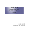

-
99011-18H74-01AGSX1250FAPart No. 99011-18H74-01A September, 2014 EN© COPYRIGHT SUZUKI MOTOR CORPORATION 2014 Printed in JapanGSX1250FAOWNER’S MANUALTKL5Top1st cover4th coverTop1st cover4th coverTop1st cover4th coverTop1st cover4th coverPantone 303C (CMYK: 100, 0, 0, 85)Pantone 485 (CMYK: 0, 100, 100, 0 )Pantone 294 (CMYK: 100, 70, 0, 0)Black4/14/14/14/15 mmGSX1250FA (9 …
GSX1250FA 135
-
BOSS HOSS CYCLES, Inc. OWNER’S MANUAL This owner’s manual contains important safety, operational, and warranty information. Please read it carefully. BOSS HOSS MOTORCYCLES AND TRIKES ARE TO BE OPERATED ONLY BY MATURE, EXPERIENCED MOTORCYCLE RIDERS THAT HAVE BEEN PROPERLY TRAINED IN THE VEHICALS OPERATIONS. Model Year 2005 9-2004 …
Year 2005 106
-
181-1269-14 (English) 7/01/08TMOperator’s ManualTable of ContentsIMPORTANT NOTICE! Safety Definitions…………………………………. iiI. General Safety Precautions …………………………………………………….1II. How to Get Service ………………………………………………………………..4III. Oil and Fuel Specifications …
LH195EA 40
-
MV AGUSTA MOTOR S.P.A.Servizio Assistenza Tecnica Via Nino Bixio, 821024 Cassinetta di Biandronno(Varese) — Italywww.husqvarna.itTE 250-450-510/2008-I.E.,TC 250-450-510/2008,TXC 250-450-510/2008 (USA),SMR 450-510/2008-I.E.Libretto usoe manutenzioneOwner’s manualLivret d’utilisation et d’entretienBetriebsanleitungManual de usoy mantenimientousq v rnPart. n. 8000 B0147TE 250-450-510/20 …
TE 250-450-510/2008-I.E. 530