Материал из BikesWiki — энциклопедия японских мотоциклов
Перейти к: навигация, поиск

Kawasaki VN900 Vulcan Classic
Ниже представлены прямые ссылки на скачку сервисной документации.
Для Kawasaki VN900 Vulcan
- Руководство пользователя (Owners Manual) на Kawasaki VN900 Vulcan Custom
- Сервисный мануал (Service Manual) на Kawasaki VN900 Vulcan Classic
- Каталог и коды запчастей на Kawasaki VN900 Vulcan
Обзор модели
- Kawasaki VN900 Vulcan
Источник — «https://bikeswiki.ru/index.php?title=Kawasaki_VN900_Vulcan:_мануалы&oldid=9410»
Категория:
- Сервисная документация
![]()
4-я Красноармейская, 2А
Санкт-Петербург, 190005
Email: info@lenmoto.ru
Телефон: +7 (921) 930-81-18
Телефон: +7 (911) 928-08-06
Компания ЛенМото
Запчасти, аксессуары, экипировка, тюнинг для мотоциклов, скутеров, квадроциклов, снегоходов, багги, гидроциклов, катеров и лодочных моторов.
Подпишитесь на наши новости
Подписаться
Сервисный ремонтный мануал на мотоцикл Kawasaki VN900 «Vulcan», размером 585 стр.
В мануале перечислены все основные параметры мотоцикла, приведены описание процедур регулировки, разборки и сборки всех узлов мотоцикла, а также алгоритм поиска неисправностей и электросхемы.
Технические характеристики:
Год выпуска: 2006-2014
Рама: стальная трубчатая
Двигатель: 2-цилиндровый, V-образный, объем 903 см³
Охлаждение: жидкостное
Количество клапанов на цилиндр: SOHC, 4 клапана
Система подачи топлива: инжектор, 2x 34 мм
Максимальная: мощность: 48-50 л.с., момент 78/82 Нм
Сцепление: Многодисковое в масляной ванне, тросовый привод
КПП: 5-ступенчатая , Тип привода: ремень
Колёса: перед 80/90-R21 или 130/90-R16, зад 180/70-R15
Передние тормоза: 1 диск, 300 мм, 2-поршневой суппорт
Задние тормоза: 1 диск, 270 мм, 2-поршневой суппорт
Передняя подвеска: 41 мм телескопическая вилка, ход — 150 мм
Задняя подвеска: маятниковая с моноамортизатором, ход — 104 мм
Длина мотоцикла: 2405 / 2465 мм
Ширина мотоцикла: 894 / 1006 мм
Колесная база: 1646 мм
Высота по седлу: 685 / 680 мм
Минимальный дорожный просвет (клиренс): 135/140 мм
Разгон до 100 км/ч: за 5,92 сек
Максимальная скорость: 169 км/ч.
Емкость бензобака: 20 л,
Расход топлива: 5 л на 100км
Масса мотоцикла: 277 / 281 / 298 кг
Home /
Motorcycle Repair Service Manuals
/ Kawasaki
/ Vulcan 900 Classic
Kawasaki Vulcan 900 Classic Service Repair Manuals on Motor Era

Motor Era offers service repair manuals for your Kawasaki Vulcan 900 Classic — DOWNLOAD your manual now! Kawasaki Vulcan 900 Classic service repair manuals
Complete list of Kawasaki Vulcan 900 Classic motorcycle service repair manuals:
Kawasaki Vulcan 900 Classic LT 2006-2008 Repair Manual PDF
Kawasaki Vulcan 900 Classic LT 2006-2008 Service Manual
Kawasaki Vulcan 900 VN900 2006 Classic Service Manual
Kawasaki VULCAN 900 CLASSIC 2006-2008 Service Manual
Kawasaki VULCAN 900 CLASSIC LT 2006 2007 2008 Service Manual
Kawasaki Vulcan 900 Classic 2006-2013 Repair Service Manual
Kawasaki Vulcan 900 Classic LT 2006-2013 Service Manual
Kawasaki 900 Vulcan 2006-2013 Workshop Service Manual
Kawasaki Classic 900 Vulcan 06-13 Workshop Service Manual
Kawasaki 900 Classic LT Vulcan 06-13 Workshop Service Manual
Kawasaki 900 Vulcan Classic 06-13 Workshop Service Manual
Kawasaki Vulcan 900 Classic Lt Vn900 2006 — 2009 Classic
Kawasaki Vulcan 900 Classic 2006-2013 Service Manual
Kawasaki Vulcan 900 Classic LT 2006-2013 Service Manual
Kawasaki 900 Classic LT Vulcan 2006-2013 Service Manual
Kawasaki 900 Classic Vulcan 2006-13 Workshop Service Manual
Kawasaki Vulcan 900 VN900 2006 Classic Service Manual
2006 KAWASAKI VULCAN 900 VN900 CLASSIC SERVICE MANUAL
Kawasaki 2006-2014 Vulcan 900 Classic & LT Service Manual
2006 KAWASAKI VULCAN 900 VN900 CLASSIC FULL SERVICE MANUAL
2006 KAWASAKI VULCAN 900 VN900 CLASSIC Service Manual
Kawasaki VN 900 Vulcan 900 Classic 2006-2010 Motorcycle Service Repair Workshop Manual
2006 KAWASAKI VULCAN 900 VN900 Classic Service Repair Manual
Kawasaki Vulcan 900 Classic, LT, VN900 Classic 2006-2009 Service Repair Manual
Kawasaki VN 900 Vulcan Classic 2006-2007 Service Repair
2006-2009 KAWASAKI VULCAN 900 CLASSIC (LT) VN900 Repair Service Manual (PDF Preview)
2006-2009 Kawasaki Vulcan 900 Classic / LT, VN900 Classic Motorcycles Service Repair Manual (Highly Detailed FSM, PDF Preview)
2006-2009 Kawasaki Vulcan 900 Classic / LT, VN900 Classic Motorcycles Service Repair Manual (Highly Detailed FSM, PDF Preview)
Kawasaki Vulcan 900 VN900 2006 Classic Service Manual
Kawasaki Vulcan900 Classic Vulcan 900 Classic LT VN900 Classic Service Repair Workshop Manual Download PDF
Kawasaki Vulcan 900 Classic LT, VN900 Classic Complete Workshop Service Repair Manual 2006 2007 2008 2009
Kawasaki Vulcan 900 Classic LT VN900 Classic Motorcycle 2006-2009 Service Repair Workshop Manual Download Pdf
Kawasaki Vulcan 900 Classic LT Motorcycle Complete Workshop Service Repair Manual 2006 2007 2008
Kawasaki Vulcan 900 Classic LT Motorcycle 2006-2009 Service & Repair Manual Download PDF
Kawasaki Vulcan 900 Classic LT 2006-2008 Service & Repair Manual Download PDF
KAWASAKI VULCAN 900 CLASSIC CUSTOM 2006-2015 WORKSHOP MANUAL
KAWASAKI VULCAN 900 CLASSIC CUSTOM 2006-2015 WORKSHOP MANUAL
KAWASAKI CLASSIC CUSTOM 2006-2015 WORKSHOP SERVICE MANUAL
KAWASAKI VULCAN 900 CLASSIC VN900 REPAIR SERVICE MANUAL
VULCAN 900, VN900, 2006 KAWASAKI SERVICE REPAIR MANUAL
2006-2009 Kawasaki Vulcan 900 Classic Repair Manual
Kawasaki Vulcan VN900 Twin service manual
KAWASAKI VULCAN CLASSIC VN900 2006+ WORKSHOP SERVICE MANUAL
KAWASAKI VULCAN 900 VN900 CLASSIC LT 2006 2007 2008 2009 Motorcycle Repair Service Manual
Kawasaki VN900 Classic Vulcan 900 Classic LT 2006 Service Repair Workshop Manual
Kawasaki VN900 Classic Vulcan 900 Classic LT 2007 Service Repair Workshop Manual
Kawasaki VN900 Classic Vulcan 900 Classic LT 2006 2007 2008 2009 2010 2011 Service Repair Workshop Manual
Kawasaki VN 900 Vulcan Classic 2006 — 2007 Service Manual
KAWASAKI VN 900 VULCAN CLASSIC 2006 WIRING DIAGRAM Download
KAWASAKI VULCAN 900 CLASSIC VN900 2006 + WORKSHOP MANUAL
![]()
Quick Reference Guide
This Quick Reference Guide will assist you in finding the information you’re looking for.
|
GENERAL INFORMATION |
j |
|
HOW TO RIDE THE MOTORCYCLE |
j |
|
SAFE OPERATION |
j |
|
MAINTENANCE AND ADJUSTMENT |
j |
|
STORAGE |
j |
|
TROUBLESHOOTING GUIDE |
j |
A Table of Contents is included after the Foreword.
Whenever you see the symbols shown below, heed their instructions! Always follow safe operating and maintenance practices.
 DANGER
DANGER indicates a hazardous situation which, if not avoided, will result in death or serious injury.
 WARNING
WARNING indicates a hazardous situation which, if not avoided, could result in death or serious injury.
NOTICE
NOTICE is used to address practices not related to personal injury.
NOTE
○NOTE indicates information that may help or guide you in the operation or service of the vehicle.
 WARNING
Engine exhaust, some of its constituents, and certain vehicle components contain or emit chemicals known to the State of California to cause cancer and birth defects or other reproductive harm.
NOTICE
THIS PRODUCT HAS BEEN MANUFACTURED FOR USE IN A REASONABLE AND PRUDENT MANNER BY A QUALIFIED OPERATOR AND AS A VEHICLE ONLY.
FOREWORD
Congratulations on your purchase of a new Kawasaki Motorcycle. Your new motorcycle is the product of Kawasaki’s advanced engineering, exhaustive testing, and continuous striving for superior reliability, safety and performance.
Please read this Owner’s Manual carefully before riding so that you will be thoroughly familiar with the proper operation of your motorcycle’s controls, its features, capabilities, and limitations. This manual offers many safe riding tips, but its purpose is not to provide instruction in all the techniques and skills required to ride a motorcycle safely. Kawasaki strongly recommends that all operators of this vehicle enroll in a motorcycle rider training program to attain awareness of the mental and physical requirements necessary for safe motorcycle operation.
To ensure a long, trouble-free life for your motorcycle, give it the proper care and maintenance described in this manual. For those who would like more detailed information on their Kawasaki Motorcycle, a Service Manual is available for purchase from any authorized Kawasaki motorcycle dealer. The Service Manual contains detailed disassembly and maintenance information. Those who plan to do their own work should, of course, be competent mechanics and possess the special tools described in the Service Manual.
Keep this Owner’s Manual aboard your motorcycle at all times so that you can refer to it whenever you need information.
This manual should be considered a permanent part of the motorcycle and should remain with the motorcycle when it is sold.
All rights reserved. No part of this publication may be reproduced without our prior written permission.
This publication includes the latest information available at the time of printing. However, there may be minor differences between the actual product and illustrations and text in this manual.
All products are subject to change without prior notice or obligation.
KAWASAKI HEAVY INDUSTRIES, LTD.
Motorcycle & Engine Company
|
© 2013 Kawasaki Heavy Industries, Ltd. |
Mar. 15, 2013. (1) |

TABLE OF CONTENTS
|
SPECIFICATIONS…………………………. |
8 |
|
SERIAL NUMBER LOCATIONS……… |
12 |
|
LOCATION OF PARTS ………………….. |
13 |
|
LOCATION OF LABELS………………… |
16 |
|
LOADING INFORMATION……………… |
20 |
|
GENERAL INFORMATION…………….. |
23 |
|
Meter Instruments ………………………. |
23 |
|
Speedometer: …………………………. |
24 |
|
Digital Display…………………………. |
24 |
|
Fuel Gauge:……………………………. |
27 |
|
RESET Button/MODE button: …… |
27 |
|
Warning/Indicator Lights: ………….. |
28 |
|
Keys …………………………………………. |
29 |
|
Ignition Switch……………………………. |
31 |
|
Right Handlebar Switches……………. |
32 |
|
Engine Stop Switch: ………………… |
32 |
|
Starter Button: ………………………… |
32 |
|
Left Handlebar Switches ……………… |
33 |
|
Dimmer Switch: ………………………. |
33 |
|
Turn Signal Switch:………………….. |
33 |
|
Horn Button: …………………………… |
33 |
|
Brake Lever Adjusters…………………. |
34 |
|
Fuel Tank Cap……………………………. |
35 |
|
Fuel Tank ………………………………….. |
36 |
|
Side Stand ………………………………… |
40 |
|
Seat………………………………………….. |
41 |
|
Tool Kit Case……………………………… |
43 |
|
Helmet-Hook ……………………………… |
44 |
|
Steering Lock …………………………….. |
45 |
|
Electric Accessory Connectors …….. |
46 |
|
BREAK-IN……………………………………. |
49 |
|
HOW TO RIDE THE MOTORCYCLE . 51 |
|
|
Starting the Engine …………………….. |
51 |
|
Jump Starting…………………………….. |
54 |
|
Moving Off…………………………………. |
58 |
|
Shifting Gears ……………………………. |
59 |
|
Braking……………………………………… |
61 |
|
Stopping the Engine……………………. |
62 |
|
Stopping the Motorcycle in an |
|
|
Emergency …………………………….. |
63 |
|
Parking……………………………………… |
64 |
|
Catalytic Converter……………………… |
66 |
|
SAFE OPERATION……………………….. |
68 |
|
Safe Riding Technique ………………… |
68 |
|
Daily Checks ……………………………… |
71 |
|
Additional Considerations for High |
|
|
Speed Operation …………………….. |
74 |
|
MAINTENANCE AND ADJUSTMENT |
76 |
|
Periodic Maintenance Chart…………. |
81 |
|
Engine Oil …………………………………. |
92 |
|
Cooling System ………………………….. |
99 |
|
Drive Belt…………………………………… |
106 |
|
Spark Plugs……………………………….. |
106 |
|
Evaporative Emission Control |
|
|
System (California model only) …. |
107 |
|
Valve Clearance …………………………. |
108 |
|
Kawasaki Clean Air System …………. |
109 |
|
Air Cleaner ………………………………… |
110 |
|
Throttle Control System ………………. |
112 |
|
Idle Speed…………………………………. |
114 |
|
Clutch……………………………………….. |
115 |
|
Brakes………………………………………. |
118 |
|
Brake Light Switches…………………… |
122 |
|
Rear Shock Absorber………………….. |
124 |
|
Wheels ……………………………………… |
127 |
|
Tires -…………………………………….. |
128 |
|
Battery………………………………………. |
133 |
|
Headlight Beam………………………….. |
140 |
|
Fuses ……………………………………….. |
141 |
|
General Lubrication…………………….. |
145 |
|
Cleaning Your Motorcycle ……………. |
146 |
|
Bolt and Nut Tightening……………….. |
153 |
|
STORAGE……………………………………. |
155 |
|
TROUBLESHOOTING GUIDE………… |
158 |
|
YOUR WARRANTY/OWNER |
|
|
SATISFACTION ………………………… |
159 |
|
Reporting Safety Defects……………… |
165 |
|
ENVIRONMENTAL PROTECTION….. |
166 |
|
MAINTENANCE RECORD …………….. |
167 |
|
LABEL INFORMATION …………………. |
173 |
8 SPECIFICATIONS
SPECIFICATIONS |
||
|
PERFORMANCE |
||
|
Minimum Turing Radius |
3.1 m (122 in.) |
|
|
DIMENSIONS |
||
|
Overall Length |
2 405 mm (94.7 in.) |
|
|
Overall Width |
895 mm (35.2 in.) |
|
|
Overall Height |
1 120 mm (44.1 in.) |
|
|
Wheelbase |
1 645 mm (64.8 in.) |
|
|
Road Clearance |
140 mm (5.5 in.) |
|
|
Curb Mass |
277 kg (611 lb) |
|
|
ENGINE |
||
|
Type |
SOHC, V-type 2-cylinder, 4-stroke, liquid-cooled |
|
|
Displacement |
903 cm³ (55.1 cu in.) |
|
|
Bore × Stroke |
88.0 × 74.2 mm (3.5 × 2.9 in.) |
|
|
Compression Ratio |
9.5 : 1 |
|
|
Starting System |
Electric starter |
|
Cylinder Numbering Method |
|
|
Firing Order |
|
|
Fuel System |
|
|
Ignition System |
|
|
Ignition Timing |
|
|
(Electronically advanced) |
|
|
Spark Plugs |
|
|
Lubrication System |
|
|
Engine Oil: |
Type |
|
Viscosity |
|
|
Capacity |
|
|
Coolant Capacity |
|
|
TRANSMISSION |
SPECIFICATIONS 9
Front to rear, 1-2 1-2
Digital fuel injection system (DFI) Battery and coil (transistorized ignition) 3° BTDC @1 000 r/min (rpm)
39° BTDC @5 400 r/min (rpm) NGK CPR7EA-9
Forced lubrication (wet sump)
API SG, SH, SJ, SL or SM with JASO MA, MA1 or MA2
SAE 10W-40
3.7L (3.9 US qt)
2.2L (2.3 US qt)
|
Transmission Type |
5-speed, constant mesh, return shift |
|
Clutch Type |
Wet, multi disc |
|
Driving System |
Belt drive |
|
10 SPECIFICATIONS |
|||
|
Primary Reduction Ratio |
2.184 |
(83/38) |
|
|
Final Reduction Ratio |
2.063 |
(66/32) |
|
|
Overall Drive Ratio |
4.338 |
(Top gear) |
|
|
Gear Ratio |
1st |
2.786 |
(39/14) |
|
2nd |
1.889 |
(34/18) |
|
|
3rd |
1.360 |
(34/25) |
|
|
4th |
1.107 |
(31/28) |
|
|
5th |
0.963 |
(26/27) |
|
|
FRAME |
|||
|
Castor |
33° |
||
|
Trail |
182 mm (7.2 in.) |
||
|
Tire Size: |
Front |
80/90-21 M/C 48H |
|
|
Rear |
180/70-15 M/C 76H |
||
|
Rim Size: |
Front |
J21M/C × MT2.15 |
|
|
Rear |
J15M/C × MT4.50 |
||
|
Fuel Tank Capacity |
20 L (5.3 US gal) |
SPECIFICATIONS 11
|
ELECTRICAL EQUIPMENT |
||
|
Battery |
12 |
V 10 Ah |
|
Headlight |
12 |
V 60/55 W |
|
Tail/Brake Light |
12 V 5/21 W |
Specifications are subject to change without notice.
12 SERIAL NUMBER LOCATIONS
SERIAL NUMBER LOCATIONS
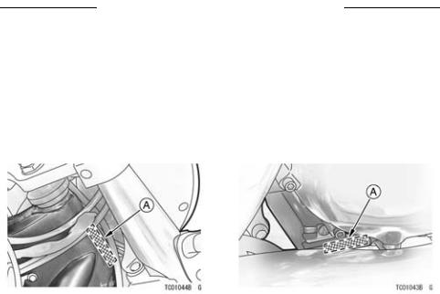
The engine and frame serial numbers are used to register the motorcycle. They are the only means of identifying your particular machine from others of the same model type. These serial numbers may be needed by your dealer when ordering parts. In the event of theft, the investigating authorities will require both numbers as well as the model type and any peculiar features of your machine that can help them identify it.
|
A. Frame Number |
A. Engine Number |
LOCATION OF PARTS 13
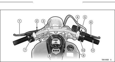
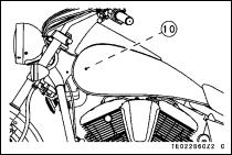
LOCATION OF PARTS
|
1. |
Clutch Lever |
7. |
Left Handlebar Switches |
|
2. |
Clutch Lever Adjuster |
8. |
Indicator Lights |
|
3. |
Meter Instruments |
9. |
Fuel Tank Cap |
|
4. |
Brake Fluid Reservoir (Front) |
10. |
Right Handlebar Switches |
|
5. |
Brake Lever Adjuster |
11. |
Throttle Grip |
|
6. |
Front Brake Lever |

14 LOCATION OF PARTS
|
12. |
Front Fork |
22. |
Shift Pedal |
|
13. |
Headlight |
23. |
Oil Level Inspection Window |
|
14. |
Turn Signal Light |
24. |
Side Stand Switch |
|
15. |
Horn |
25. |
Side Stand |
|
16. |
Spark Plugs |
26. |
Fuse Box |
|
17. |
Battery |
27. |
Coolant Reserve Tank |
|
18. |
Brake Disc |
28. |
Rear Shock Absorber |
|
19. |
Brake Caliper |
29. |
Belt |
|
20. |
Wheel |
30. |
Belt Pulley |
|
21. |
Radiator |
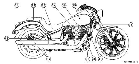
LOCATION OF PARTS 15
|
31. |
Tail/Brake Light |
36. |
Steering Lock |
40. |
Rear Brake Light |
|
|
32. |
Seat |
37. |
Mufflers |
41. |
Switch |
|
|
33. |
Tool Kit Case/Tool Kit |
38. |
Idle Speed Adjusting |
Brake Fluid Reservoir |
||
|
34. |
Air Cleaner Element |
39. |
Screw |
(Rear) |
||
|
35. |
Fuel Tank |
Rear Brake Pedal |
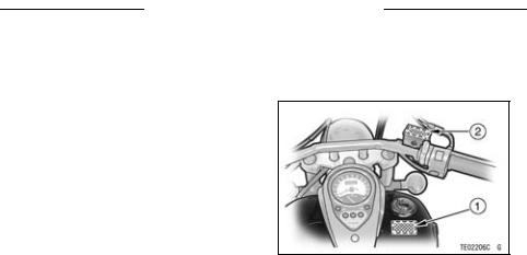
16 LOCATION OF LABELS
LOCATION OF LABELS
All warning labels which are on your vehicle are repeated here. Read labels on your vehicle and understand them thoroughly. They contain information which is important for your safety and the safety of anyone else who may operate your vehicle. Therefore, it is very important that all warning labels be on your vehicle in the locations shown. If any label is missing, damaged, or worn, get a replacement from your Kawasaki dealer and install it in the correct position.
NOTE
○The sample warning labels in this section have part numbers to help you and your dealer obtain the correct replacement.
○Refer to the actual vehicle label for model specific data grayed out in the illustration.
*1. Fuel Level
*2. Brake Fluid (Front)
(For further information of label, refer to the “LABEL INFORMATION” chapter.)
*: only on California model
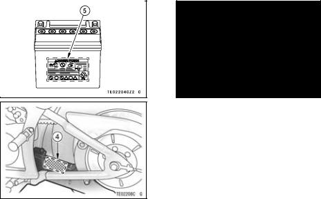
LOCATION OF LABELS 17
3.Brake Fluid (Rear)
4.Tire and Load Data
5.Battery Position/Danger
(For further information of label, refer to the “LABEL INFORMATION” chapter.)
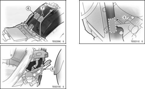
18 LOCATION OF LABELS
6. Vacuum Hose Routing Diagram
*7. Vehicle Emission Control Information
8. Weight and Manufacture
9. Noise Emission Control Information
(For further information of label, refer to the “LABEL INFORMATION” chapter.) *: only on California model
LOCATION OF LABELS 19
10. Radiator Cap Danger
(For further information of label, refer to the “LABEL INFORMATION” chapter.) *: only on California model
![]()
20 LOADING INFORMATION
LOADING INFORMATION
 WARNING
Incorrect loading, improper installation or use of accessories, or modification of your motorcycle may result in an unsafe riding condition. Before you ride the motorcycle, make sure it is not overloaded and that you have followed these instructions.
With the exception of genuine Kawasaki Parts and Accessories, Kawasaki has no control over the design or application of accessories. In some cases, improper installation or use of accessories, or motorcycle modification, will void the motorcycle warranty. In selecting and using accessories, and in loading the motorcycle,
you are personally responsible for your own safety and the safety of other persons involved.
NOTE
○Kawasaki Parts and Accessories have been specially designed for use on Kawasaki motorcycles. We strongly recommend that all parts and accessories you add to your motorcycle be genuine Kawasaki components.
Because a motorcycle is sensitive to changes in weight and aerodynamic forces, you must take extreme care in carrying cargo, passengers and/or in the fitting of additional accessories. The following general guidelines have
been prepared to assist you in making your determinations.
1.Any passenger should be thoroughly familiar with motorcycle operation. The passenger can affect control of the motorcycle by improper positioning during cornering and sudden movements. It is important that the passenger sit still while the motorcycle is in motion and not interfere with the operation of the motorcycle. Do not carry animals on your motorcycle.
2.You should instruct any passenger before riding to keep his feet on the passenger footpegs and hold on to the operator or seat strap. Do not carry a passenger unless he or she is tall enough to reach the footpegs and footpegs are provided.
3.All baggage should be carried as low as possible to reduce the effect on the motorcycle center of gravity.
LOADING INFORMATION 21
Baggage weight should also be distributed equally on both sides of the motorcycle. Avoid carrying baggage that extends beyond the rear of the motorcycle.
4.Baggage should be securely attached. Make sure that the baggage will not move around while you are riding. Recheck baggage security as often as possible (not while the motorcycle is in motion) and adjust as necessary.
5.Do not carry heavy or bulky items on a luggage rack. They are designed for light items, and overloading can affect handling due to changes in weight distribution and aerodynamic forces.
6.Do not install accessories or carry baggage that impairs the performance of the motorcycle. Make sure that you have not adversely affected any lighting components,
22 LOADING INFORMATION
road clearance, banking capability (i.e., lean angle), control operation, wheel travel, front fork movement, or any other aspect of the motorcycle’s operation.
7.Weight attached to the handlebar or front fork will increase the mass of the steering assembly and can result in an unsafe riding condition.
8.Fairings, windshields, backrests, and other large items have the capability of adversely affecting stability and handling of the motorcycle, not only because of their weight, but also due to the aerodynamic forces acting on these surfaces while the motorcycle is in operation. Poorly designed or installed items can result in an unsafe riding condition.
9.This motorcycle was not intended to be equipped with a sidecar or to
be used to tow any trailer or other vehicle. Kawasaki does not manufacture sidecars or trailers for motorcycles and cannot predict the effects of such accessories on handling or stability, but can only warn that the effects can be adverse and that Kawasaki cannot assume responsibility for the results of such unintended use of the motorcycle. Furthermore, any adverse effects on motorcycle components caused by the use of such accessories will not be remedied under warranty.
Maximum Load
Weight of rider, passenger, baggage, and accessories must not exceed 180 kg (397 lb).
GENERAL INFORMATION 23
GENERAL INFORMATION
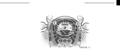
Meter Instruments
A.Speedometer
B.Digital Display
C.Fuel Level Warning Indicator Light
D.Coolant Temperature Warning Indicator Light
E.Fuel Gauge
F.Oil Pressure Warning Indicator Light
G.Fuel Injection Warning Indicator Light
H.MODE Button
I.RESET Button
J.Neutral Indicator Light
K.Turn Signal Indicator Light
L.High Beam Indicator Light
24 GENERAL INFORMATION
Speedometer:
The speedometer shows the speed of the vehicle.
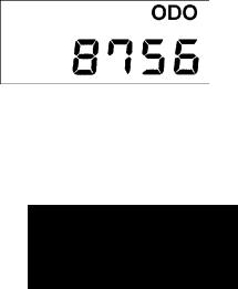
Digital Display
The digital display located in the speedometer face is used to display the odometer, trip meter, and clock. Pushing the MODE button shifts the display through the following three modes: ODO, TRIP and CLOCK. When the ignition key is turned to “ON”, all the segments are displayed for a few seconds, then the clock or meters operates normally depending on the mode selected.
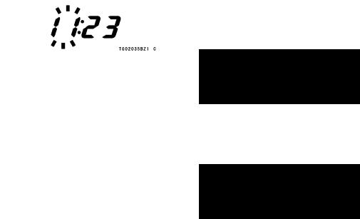
Clock —
To adjust hours and minutes:
•Turn the ignition key to “ON”.
•Push the MODE button to display the clock.
•Push the RESET button for more than two seconds. Both the hour and minute displays start flashing.
•Again push the RESET button. When only the hour display flashes, push the MODE button to advance the hours.
•Push the RESET button. The hour display stops flashing and the minute

display starts flashing. Push the MODE button to advance the minutes.
•Push the RESET button. Both the hour and minute displays start flashing again.
•Push the MODE button. The displays stop flashing and the clock starts working.
GENERAL INFORMATION 25
NOTE
○Pushing the MODE button momentarily advances the hour or minute step by step. Pushing and holding the button advance the hour or minute continuously.
○The clock works normally from the back-up power while the ignition switch is turned off.
○When the battery is disconnected, the clock resets to 1:00, and starts working again when the battery is connected.
26 GENERAL INFORMATION
Odometer —
The odometer shows the total distance in kilometers (miles) that the vehicle has been ridden. This meter cannot be reset.
NOTE
○The data is maintained even if the battery is disconnected.
○When the figures come to 999999, they are stopped and locked.
Trip Meters —
The trip meter shows the distance in kilometers (miles) traveled since it was last reset to zero.
To reset a trip meter:
1.Push the MODE button to display the trip meter.
2.Push the RESET button and hold it in.
3.After two seconds, the figure display turns to 0.0, and then starts counting when the vehicle is operated. The meter counts until it is next reset.
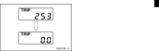
NOTE
○The data is maintained by the back -up power if the ignition key is turned to “OFF”.
○When the trip meter reaches 999.9 while riding, the meter resets to 0.0 and continue counting.
○When the battery is disconnected, the meter display resets to 0.0.
GENERAL INFORMATION 27
Fuel Gauge:
The fuel gauge shows the amount of fuel in the fuel tank. When the needle comes near the E (empty) position, refuel at the earliest opportunity. When vehicle stands with side stand, fuel gauge cannot show the amount of fuel in the fuel tank exactly. Stand upright the vehicle to check the fuel level.
RESET Button/MODE button:
The RESET button is used to reset the trip meter and to adjust the clock. The MODE button is used to shift through the digital display modes and to adjust the clock.

28 GENERAL INFORMATION
Warning/Indicator Lights:
N: When the transmission is in neutral, the neutral indicator light is lit.
 : When the headlight is on high beam, the high beam indicator light is lit.
 : When the turn signal switch is pushed to left or right, the turn signal indicator light flashes on and off.
 : The oil pressure warning indicator light goes on whenever the oil pressure is dangerously low or the ignition switch is in the ON position with the engine not running, and goes off when the engine oil pressure is high enough. Refer to the Maintenance and Adjustment chapter for more detailed engine oil information.
 : The warning indicator light goes on whenever the coolant temperature rises to 120°C (248°F) or higher when the motorcycle is in operation. If it stays on, stop the engine and check the coolant level in the reserve tank after the engine cools down.
FI: The fuel injection (FI) warning indicator light goes on when the ignition key is turned to “ON” and goes off soon after ensuring that its circuit functions properly. The warning indicator light also goes on whenever the troubles occur in digital fuel injection system (DFI). If the warning indicator light comes on, have the DFI system checked by an authorized Kawasaki dealer.
 : The fuel level warning indicator light goes on when approximately 4.0 L (1.0 US gal) of usable fuel remains. Refuel at the earliest opportunity when the

fuel level warning indicator light comes on with the engine running. When vehicle stands with side stand, fuel level warning indicator light cannot show the amount of fuel in the fuel tank exactly. Stand upright the vehicle to check the fuel level.
GENERAL INFORMATION 29
Keys
This motorcycle has a combination key, which is used for the ignition switch, steering lock, and fuel tank cap. Included with the key is a key number, which is stamped on the separate plate. Record the key number in the space provided and store the number in a safe place. If your keys came with a plate, store it in a safe place as well.
![]()
30 GENERAL INFORMATION
A.Ignition Key
B.Tag
C.Key Number
Write your key number here.
In the event you lose your keys, you will need the key number to have a duplicate made. If you cannot locate your key number, contact the dealer where you purchased your Kawasaki motorcycle. It’s possible the dealer may have the number in its records. If the key number is lost completely, you will need to replace the ignition switch and all other locks operated by that key.
Contact your Kawasaki dealer to purchase additional spare keys either using your original key as a master or using the key code on the tag or your key. Store one key at home and keep another spare in your wallet or riding gear, in case the original is lost.

Ignition Switch
The ignition switch is located at the left side behind the rear cylinder. This is a three-position, key-operated switch. The key can be removed from the switch when it is in the OFF or P (Park) position.
A.Ignition Switch
B.OFF
C.ON
D.P (Park)
GENERAL INFORMATION 31
|
OFF |
Engine off. |
All electrical |
|
|
circuits off. |
|||
|
ON |
Engine on. |
All electrical |
|
|
equipment can be used. |
|||
|
Engine off. |
Taillight and |
||
|
P (Park) |
licence plate light on. All other |
||
|
electrical circuits cut off. |
NOTE
○Tail and, license plate lights are on whenever the ignition switch is in the ON position. The headlight goes on when the starter button is released after starting the engine. To avoid battery discharge, always start the engine immediately after turning the ignition key to ON.
○If you leave the motorcycle in the P (Park) position or in the ON position without the motorcycle running for a long time (one hour), the battery may become totally discharged.

32 GENERAL INFORMATION
Right Handlebar Switches
Engine Stop Switch:
In addition to the ignition switch, the
engine stop switch must be in the  position for the motorcycle to operate.
The engine stop switch is for emergency use. If required, move the en-
gine stop switch to the  position.
NOTE
○Although the engine stop switch stops the engine, it does not turn off all the electrical circuits. Ordinarily, the ignition switch should be used to stop the engine.
Starter Button:
The starter button operates the electric starter when the transmission is in neutral.
Refer to the Starting the Engine section of the “How to Ride the Motorcycle” chapter for starting instructions.
A.Engine Stop Switch
B.Starter Button

GENERAL INFORMATION 33
Left Handlebar Switches
Dimmer Switch:
High or low beam can be selected with the dimmer switch. When the headlight is on high beam ( ), the high beam indicator light is lit.
|
High beam |
…….( |
) |
||
|
…….Low beam |
( |
) |
Turn Signal Switch:
When the turn signal switch is turned
to the left ( ) or right (
 ), the corresponding turn signals flash on and off.
To stop flashing, push the switch in.
Horn Button:
When the horn button is pushed, the block horn sounds.

34 GENERAL INFORMATION
Brake Lever Adjusters
There is an adjuster on the brake lever. The adjuster has 5 positions so that the released lever position can be adjusted to suit the operator’s hands. Push the lever forward and turn the adjuster to align the number with the arrow mark on the lever holder. The distance from the grip to the released lever is minimum at Number 5 and maximum at Number 1.

Fuel Tank Cap
To open the fuel tank cap, insert the ignition key into the fuel tank cap and turn the key to the right.
To close the cap, push it down into place with the key inserted. The key can be removed by turning it to the left to the original position. Close the key hole cover.
NOTE
○The fuel tank cap cannot be closed without the key inserted, and the key cannot be removed unless the cap is locked properly.
○Do not push on the key to close the cap or the cap cannot be locked.
GENERAL INFORMATION 35
A.Ignition Key
B.Fuel Tank Cap
C.Key Hole Cover

36 GENERAL INFORMATION
Fuel Tank
Avoid filling the tank in the rain or where heavy dust is blowing so that the fuel does not get contaminated.
A.Tank Cap
B.Fuel Tank
C.Top Level
D.Filler Neck
 WARNING
Gasoline is extremely flammable and can be explosive under certain conditions, creating the potential for serious burns. Turn the ignition switch to “OFF”. Do not smoke. Make sure the area is well ventilated and free from any source of flame or sparks; this includes any appliance with a pilot light. Never fill the tank completely to the top. If the tank is filled completely to the top, heat may cause the fuel to expand and overflow through the vents in the tank cap. After refueling, make sure the tank cap is closed securely. If gasoline is spilled on the fuel tank, wipe it off immediately.

NOTICE
California models only: Never fill the tank so the fuel level rises into the filler neck. If the tank is overfilled, heat may cause the fuel to expand and flow into the Evaporative Emission Control System resulting in hard starting and engine hesitation and in compliance with the emission regulation.
Fuel Requirement:
Fuel Type
Use clean, fresh unleaded gasoline with a minimum Antiknock Index of 87.
GENERAL INFORMATION 37
The Antiknock Index is posted on service station pumps. The octane rating of a gasoline is a measure of its resistance to detonation or “knocking”. The Antiknock Index is an average of the Research Octane Number (RON) and the Motor Octane Number (MON) as shown in the table.
|
Octane Rating Method |
Minimum |
||
|
Rating |
|||
|
Antiknock |
(RON + MON) |
87 |
|
|
Index |
2 |
||

38 GENERAL INFORMATION
NOTICE
If engine “knocking” or “pinging” occurs, use a different brand of gasoline of a higher octane rating. If this condition is allowed to continue it can lead to severe engine damage.
Gasoline quality is important. Fuels of low quality or not meeting standard industry specifications may result in unsatisfactory performance. Operating problems that result from the use of poor quality or nonrecommended fuel may not be covered under your warranty.
Fuels Containing Oxygenates
Gasoline frequently contains oxygenates (alcohols and ethers) especially in areas of the U.S. and Canada which are required to sell such reformulated fuels as part of a strategy to reduce exhaust emissions.
The types and volume of fuel oxygenates approved for use in unleaded gasoline by the U.S. Environmental Protection Agency include a broad range of alcohols and ethers, but only two components have seen any significant level of commercial use.
Gasoline/Alcohol Blends — Gasoline containing up to 10% ethanol (alcohol produced from agricultural products such as corn), also known as “gasohol” is approved for use.

NOTICE
Avoid using blends of unleaded gasoline and methanol (wood alcohol) whenever possible, and never use “gasohol” containing more than 5% methanol. Fuel system damage and performance problems may result.
Gasoline/Ether Blends — The most common ether is methyl tertiary butyl ether (MTBE). You may use gasoline containing up to 15% MTBE.
NOTE
○Other oxygenates approved for use in unleaded gasoline include TAME (up to 16.7%) and ETBE (up to 17.2%). Fuel containing these oxygenates can also be used in your Kawasaki.
GENERAL INFORMATION 39
NOTICE
Never use gasoline with an octane rating lower than the minimum specified by Kawasaki.
Never use “gasohol” with more than 10% ethanol, or more than 5% methanol. Gasoline containing methanol must also be blended with cosolvents and corrosion inhibitors.
Certain ingredients of gasoline may cause paint fading or damage. Be extra careful not to spill gasoline or gasoline oxygenate blends during refueling.
When not operating your Kawasaki for 30 to 60 days, mix a fuel stabilizer (such as STA-BIL) with the gasoline in the fuel tank. Fuel stabilizer additives inhibit oxidation of the fuel which minimizes gummy deposits.
![]()
40 GENERAL INFORMATION
NOTICE
Never store this product with “gasohol” in the fuel system. Before storage it is recommended that you drain all fuel from the fuel system. See the Storage section in this manual.
Side Stand
The motorcycle is equipped with a side stand.
A. Side Stand
NOTE
○When using the side stand, turn the handlebar to the left.
Do not sit on the motorcycle while it is on its side stand. Always kick the stand fully up before sitting on the motorcycle.

NOTE
○The motorcycle is equipped with a side stand switch. This switch is designed so that the engine does not start if the transmission is in gear and the side stand is down.
GENERAL INFORMATION 41
Seat
Seat Removal
•To remove the seat, insert the ignition key into the seat lock, and turn the key to the right.
A.Seat Lock
B.Turn Key to Right
• Pull the seat to the rear.

42 GENERAL INFORMATION
Seat Installation
•To install the seat, insert the projection of the front on the seat into the receptacle on the frame.
•Insert the hook of the middle on the seat into the holes on the frame.
•Push down the middle on the seat.
•Pull the front and rear ends of the seat to make sure they are securely locked.
A.Tab
B.Slot
C.Projections
D.Holes

GENERAL INFORMATION 43
Tool Kit Case
The tool kit case is located under the seat. The kit contains tools that can be helpful in making roadside repairs, adjustments, and some maintenance procedures explained in this manual. Keep the tool kit in this case.
•Remove the seat.
•Open the tool kit case cover by pulling the knob.
A. Tool Kit Case
B. Tool Kit

44 GENERAL INFORMATION
Helmet-Hook
Helmet can be secured to the motorcycle using the helmet-hook. The helmet hook is located under the seat.
 WARNING
Riding with helmet attached to the hook could cause an accident by distracting the operator or interfering with normal vehi-
cle operation. Do not ride the A. Helmet-Hook motorcycle with helmet attached
to the hook.

Steering Lock
The motorcycle is equipped with the steering lock at the right side of the head pipe.
To lock the steering:
1.Turn the handlebar to the left.
2.Insert the ignition key.
3.Turn the key half a turn to the left.
4.Pull the key out.
NOTE
○If the steering is hard to lock, turn the handlebar slightly to the left or the right.
○When unlocking the steering lock, turn the handlebar slightly to the right.
GENERAL INFORMATION 45
 WARNING
Attempting to ride with the steering locked could cause an accident. Unlock the steering before starting the engine.
A. Steering Lock

46 GENERAL INFORMATION
Electric Accessory Connectors
The electric power of the battery can be used through the electric accessory connectors regardless of ignition switch position. Observe and follow the notes listed below.
Electric Accessory Connectors
|
Location |
Polarity |
Wire Color |
|
Under Rider’s |
(+) |
White/Blue |
|
Seat |
(–) |
Black/Yellow |
|
Under Fuel |
(+) |
White/Blue |
|
Tank |
(–) |
Black/Yellow |
|
Maximum Current: |
10 A |
A. Electric Accessory Connectors
•When using the electric accessory connectors under the fuel tank, the electric accessory connection to the connectors should be done by an authorized Kawasaki dealer.

NOTICE
The vehicle has an electrical accessory circuit (10 A fuse) for the socket and connectors. Always install a fuse 10 A or less in the electrical accessory circuit.
Do not connect more than 70 W of total load to the vehicle’s electrical system or the battery may become discharged, even with the engine running.
 WARNING
Take care not to pinch any wire between the seat and the frame or between other parts to avoid a short circuit.
GENERAL INFORMATION 47
Rear View Mirror
Rear View Mirror Adjustment
•Adjust the rear view mirror by slightly moving only the mirror portion of the assembly.
•If the rear visibility can not be assured by moving the mirror, loosen the upper hexagonal area and turn the stay by hand.
Tightening Torque
Lowing Hexagonal Area:
30 N·m (3.1 kgf·m, 22 ft·lb)
Upper Hexagonal Area:
18 N·m (1.8 kgf·m, 13 ft·lb)
NOTE
○The upper hexagonal area (locknut) has left hand threads.

48 GENERAL INFORMATION
|
A. Stay |
A. Lower Hexagonal Area for Tightening |
|||
|
B. Rear View Mirror |
B. Upper Hexagonal Area |
|||
|
C. Rear View Mirror |
||||
|
D. Rubber Boots |
NOTE
○If a torque wrench is not available, this item should be serviced by a Kawasaki dealer.

BREAK-IN 49
BREAK-IN
The first 1 600 km (1 000 mi) that the motorcycle is ridden is designated as the break-in period. If the motorcycle is not used carefully during this period, you may very well end up with a “broken down” instead of a “broken in” motorcycle after a few thousand kilometers.
The following rules should be observed during the break-in period.
•The table shows maximum recommended speed in km/h (mph) during the break -in period.
km/h (mph)
|
Gear position |
1st |
2nd |
3rd |
4th |
5th |
|
|
Distance traveled |
||||||
|
0 800 km (0 500 mi) |
32 (20) |
50 (30) |
65 (40) |
80 (50) |
95 (60) |
|
|
800 1 600 km (500 1 000 mi) |
40 (25) |
65 (40) |
90 (55) |
100 (70) |
130 (80) |
|
NOTE
○When operating on public roadways, keep maximum speed under traffic law limits.
 Loading…