Материал из BikesWiki — энциклопедия японских мотоциклов
Перейти к: навигация, поиск

Kawasaki Ninja ZX-6R 636
Ниже представлены прямые ссылки на скачку сервисной документации.
Для Kawasaki ZX-6R
- Сервисный мануал (Service Manual) на Kawasaki ZX-6R (1995-1997)
- Сервисный мануал (Service Manual) на Kawasaki ZX-6R (1998-1999)
- Сервисный мануал (Service Manual) на Kawasaki ZX-6R (2001-2002)
- Сервисный мануал (Service Manual) на Kawasaki ZX-6R, ZX-6RR (2003-2004)
- Сервисный мануал (Service Manual) на Kawasaki ZX-6R (2005-2006)
- Сервисный мануал (Service Manual) на Kawasaki ZX-6R (2007-2008)
- Сервисный мануал (Service Manual) на Kawasaki ZX-6R (2009-2011)
- Сервисный мануал (Service Manual) на Kawasaki ZX-6R 636 (2013), оригинал англ.
- Сервисный мануал (Service Manual) на Kawasaki ZX-6R 636 (2013), русский перевод
Обзор модели
- Kawasaki ZX-6R
Источник — «https://bikeswiki.ru/index.php?title=Kawasaki_ZX-6R:_мануалы&oldid=9740»
Категория:
- Сервисная документация
Посмотреть инструкция для Kawasaki Ninja ZX-6R (2007) бесплатно. Руководство относится к категории мотоциклы, 13 человек(а) дали ему среднюю оценку 8.9. Руководство доступно на следующих языках: английский. У вас есть вопрос о Kawasaki Ninja ZX-6R (2007) или вам нужна помощь? Задайте свой вопрос здесь
Главная
Не можете найти ответ на свой вопрос в руководстве? Вы можете найти ответ на свой вопрос ниже, в разделе часто задаваемых вопросов о Kawasaki Ninja ZX-6R (2007).
Как перевести мили в километры?
В чем разница между топливом E10 и E5?
Какова рекомендуемая частота замены масляного фильтра в двигателе Kawasaki?
Как часто следует менять масло в двигателе Kawasaki?
Как удалить ржавчину с устройства Kawasaki мотоцикл?
Инструкция Kawasaki Ninja ZX-6R (2007) доступно в русский?
Не нашли свой вопрос? Задайте свой вопрос здесь
Руководство на английском языке по техническому обслуживанию и ремонту мотоциклов Kawasaki серий KZ, ZX и ZN 1981-2002 годов выпуска с двигателями объемом 1000-1100 cc.
- Издательство: Clymer
- Год издания: 2003
- Страниц: 378
- Формат: PDF
- Размер: 43,5 Mb
Руководство на английском языке по техническому обслуживанию и ремонту мотоциклов Kawasaki Ninja ZX-6R.
- Издательство: Kawasaki Heavy Industries, Ltd.
- Год издания: 1997
- Страниц: 370
- Формат: PDF
- Размер: 64,3 Mb

Руководство на английском языке по техническому обслуживанию и ремонту мотоциклов Kawasaki Ninja ZX-6R 2000-2002 годов выпуска.
- Издательство: Kawasaki Heavy Industries, Ltd.
- Год издания: —
- Страниц: 332
- Формат: PDF
- Размер: 19,1 Mb

Руководство на английском языке по техническому обслуживанию и ремонту мотоциклов Kawasaki Ninja ZX-6R.
- Издательство: Kawasaki Heavy Industries, Ltd.
- Год издания: 2007
- Страниц: 663
- Формат: PDF
- Размер: 12,0 Mb
Руководство на английском языке по техническому обслуживанию и ремонту мотоциклов Kawasaki Ninja ZX-6R и ZX-6RR 2003-2004 годов выпуска.
- Издательство: Kawasaki Heavy Industries, Ltd.
- Год издания: —
- Страниц: 514
- Формат: PDF
- Размер: 42,5 Mb

Руководство на английском языке по техническому обслуживанию и ремонту мотоциклов Kawasaki Ninja ZX-6RR.
- Издательство: Kawasaki Heavy Industries, Ltd.
- Год издания: 2004
- Страниц: 519
- Формат: PDF
- Размер: 10,1 Mb
Руководство на английском языке по подготовке к гонкам мотоциклов Kawasaki ZX-6RR.
- Издательство: Kawasaki Heavy Industries, Ltd.
- Год издания: 2005
- Страниц: 63
- Формат: PDF
- Размер: 7,5 Mb
Руководство на английском языке по техническому обслуживанию и ремонту мотоциклов Kawasaki Ninja ZX-7R и ZX-7RR.
- Издательство: Kawasaki Heavy Industries, Ltd.
- Год издания: —
- Страниц: 364
- Формат: PDF
- Размер: 38,7 Mb
Руководство на английском языке по подготовке к гонкам мотоциклов Kawasaki ZX-7R м ZXR750R 1992 года выпуска.
- Издательство: Kawasaki Heavy Industries, Ltd.
- Год издания: 1991
- Страниц: 69
- Формат: PDF
- Размер: 148,4 Mb
Руководство на английском языке по подготовке к гонкам мотоциклов Kawasaki ZX-7RR 1998 года выпуска.
- Издательство: Kawasaki Heavy Industries, Ltd.
- Год издания: 1997
- Страниц: 107
- Формат: PDF
- Размер: 138,0 Mb

Руководство на испанском языке по эксплуатации и техническому обслуживанию мотоциклов Kawasaki Ninja ZX-9R.
- Издательство: —
- Год издания: —
- Страниц: 174
- Формат: PDF
- Размер: 3,3 Mb
Сборник руководств на английском языке по техническому обслуживанию и ремонту мотоциклов Kawasaki Ninja ZX-9R.
- Издательство: Kawasaki Heavy Industries, Ltd.
- Год издания: —
- Страниц: 307/322
- Формат: PDF
- Размер: 161,3 Mb
Руководство на английском языке по техническому обслуживанию и ремонту мотоциклов Kawasaki ZX-10 и Ninja ZX-10.
- Издательство: Kawasaki Heavy Industries, Ltd.
- Год издания: 1989
- Страниц: 231
- Формат: PDF
- Размер: 162,0 Mb

Руководство на английском языке по техническому обслуживанию и ремонту мотоциклов Kawasaki Ninja ZX-10R.
- Издательство: Kawasaki Heavy Industries, Ltd.
- Год издания: 2008
- Страниц: 694
- Формат: PDF
- Размер: 14,7 Mb
Руководство на английском языке по подготовке к гонкам мотоциклов Kawasaki ZX-10R 2006 года выпуска.
- Издательство: Kawasaki Heavy Industries, Ltd.
- Год издания: 2006
- Страниц: 82
- Формат: PDF
- Размер: 2,5 Mb

Руководство по эксплуатации и техническому обслуживанию мотоциклов Kawasaki Ninja ZX-10R.
- Издательство: Kawasaki Heavy Industries, Ltd.
- Год издания: 2011
- Страниц: 207
- Формат: PDF
- Размер: 6,4 Mb

Руководство на английском языке по техническому обслуживанию и ремонту мотоциклов Kawasaki Ninja ZX-11 и ZZ-R1100 1993-2001 годов выпуска.
- Издательство: Kawasaki Heavy Industries, Ltd.
- Год издания: —
- Страниц: —
- Формат: JPG
- Размер: 62,4 Mb

Руководство на английском языке по техническому обслуживанию и ремонту мотоциклов Kawasaki Ninja ZX-12R.
- Издательство: Kawasaki Heavy Industries, Ltd.
- Год издания: 2004
- Страниц: 613
- Формат: PDF
- Размер: 11,3 Mb

Руководство на немецком языке по техническому обслуживанию и ремонту мотоциклов Kawasaki Ninja ZX-12R (ZX1200-A).
- Издательство: Kawasaki Motoren GmbH
- Год издания: 2000
- Страниц: 431
- Формат: PDF
- Размер: 149,8 Mb

Руководство на немецком языке по техническому обслуживанию и ремонту мотоциклов Kawasaki ZX-12R (ZX1200B).
- Издательство: Kawasaki Motors Europe
- Год издания: 2002
- Страниц: 451
- Формат: PDF
- Размер: 38,7 Mb

Руководство на английском языке по техническому обслуживанию и ремонту мотоциклов Kawasaki Ninja ZX-14 и ZZR1400.
- Издательство: Kawasaki Heavy Industries, Ltd.
- Год издания: 2006
- Страниц: 703
- Формат: PDF
- Размер: 13,6 Mb
Руководство на английском языке по техническому обслуживанию и ремонту мотоциклов Kawasaki ZX400-H2
- Издательство: Kawasaki Heavy Industries, Ltd.
- Год издания: —
- Страниц: —
- Формат: PDF
- Размер: 46,6 Mb
Руководство на немецком языке по техническому обслуживанию и ремонту мотоциклов Kawasaki ZX500-A1 и ZX600-A1.
- Издательство: —
- Год издания: —
- Страниц: 234
- Формат: PDF
- Размер: 19,9 Mb

Руководство на английском языке по техническому обслуживанию и ремонту мотоциклов Kawasaki KZ500/KZ550/ZX550 1979-1985 годов выпуска.
- Издательство: Clymer
- Год издания: —
- Страниц: 341
- Формат: PDF
- Размер: 12,0 Mb
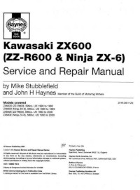
Руководство на английском языке по техническому обслуживанию и ремонту мотоциклов Kawasaki ZX600/ZZR600/Ninja ZX-6 1990-2000 годов выпуска.
- Издательство: Haynes Publishing
- Год издания: 2001
- Страниц: —
- Формат: JPG
- Размер: 57,7 Mb

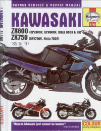
Руководство на английском языке по техническому обслуживанию и ремонту мотоциклов Kawasaki ZX600/ZX636 (ZX-6R) 1995-2002 годов выпуска.
- Издательство: Haynes Publishing
- Год издания: 2003
- Страниц: 272
- Формат: PDF
- Размер: 171,0 Mb
Руководство на английском языке по техническому обслуживанию и ремонту мотоциклов Kawasaki GPX600R/GPX750R/GPZ600R/Ninja 600R/Ninja 600RX/Ninja 750R/ZX600/ZX750 1985-1987 годов выпуска.
- Издательство: Haynes Publishing
- Год издания: 1999
- Страниц: 265
- Формат: PDF
- Размер: 77,0 Mb

Руководство на английском языке по техническому обслуживанию и ремонту мотоциклов Kawasaki ZX750 (ZXR750) 1989-1996 и ZX750 (Ninja ZX-7) 1989-1995 годов выпуска.
- Издательство: Haynes Publishing
- Год издания: 1998
- Страниц: 341
- Формат: PDF
- Размер: 36,7 Mb
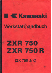
Руководство на немецком языке по техническому обслуживанию и ремонту мотоциклов Kawasaki ZX750J/ZX750K/ZXR750/ZXR750R.
- Издательство: —
- Год издания: —
- Страниц: 282
- Формат: PDF
- Размер: 23,4 Mb
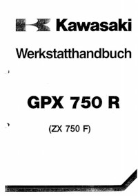
Руководство на немецком языке по техническому обслуживанию и ремонту мотоциклов Kawasaki GPX750R/ZX750F.
- Издательство: Kawasaki Heavy Industries, Ltd.
- Год издания: —
- Страниц: 192
- Формат: PDF
- Размер: 11,4 Mb
Руководство на английском языке по техническому обслуживанию и ремонту мотоциклов Kawasaki ZX900-A1.
- Издательство: Kawasaki Heavy Industries, Ltd.
- Год издания: —
- Страниц: 293
- Формат: PDF
- Размер: 22,9 Mb
Руководство на английском языке по техническому обслуживанию и ремонту мотоциклов Kawasaki ZX900-C1 и ZX900-D1.
- Издательство: Kawasaki Heavy Industries, Ltd.
- Год издания: —
- Страниц: 307
- Формат: PDF
- Размер: 27,9 Mb
Руководство на немецком языке по техническому обслуживанию и ремонту мотоциклов Kawasaki GPZ1000RX (ZX1000-A1).
- Издательство: Kawasaki Heavy Industries, Ltd.
- Год издания: —
- Страниц: 130
- Формат: PDF
- Размер: 20,8 Mb
Руководство на немецком языке по техническому обслуживанию и ремонту мотоциклов Kawasaki GPZ1100 (ZX1100E).
- Издательство: Kawasaki Heavy Industries, Ltd.
- Год издания: —
- Страниц: 327
- Формат: PDF
- Размер: 10,9 Mb

#1
![]()
motogad
- Пол:Мужчина
- Город:Москва ВАО
- Мото:Kawasaki Ninja ZX6R
Отправлено 18 Август 2008 — 18:34
Все мануалы которые у нас есть ниже по теме
Сообщение отредактировал max232: 31 Январь 2014 — 13:53
- bktspro, Michaelgrorm, SCpraics и 2 другим это нравится
- Наверх
#2
![]()
max232
max232
- Пол:Мужчина
- Страна:Россия
- Город:Елец, Липецкая область
- Мото:zx-10r `08
Отправлено 09 Январь 2014 — 21:19
Просьба к обладателям мануалов которых нет в списке,
мы будем признательны если вы с нами поделитесь.
Руководство по ремонту демпфера Ohlins
Каталог з/ч Kawasaki
Руководство по эксплуатации Kawasaki Ninja H2 (ZX1000NF) 2014-
Руководство по эксплуатации Kawasaki Ninja H2 SX (ZX1000NF) 2017- (РУС) НОВОЕ! Спасибо Mikhail72
Руководство по ремонту KNinja H2 SX 2018- НОВОЕ! Спасибо belenkiy
Руководство по ремонту Kawasaki ZZR1400, ZZR1400 ABS, Ninja ZX-14 2012-2013 (РУС) НОВОЕ! Спасибо Назарий
Руководство пользователя Kawasaki ZZR1400, ZZR1400 ABS, Ninja ZX-14 2012- (РУС) НОВОЕ! Спасибо Ewil Dwarf
Руководство по ремонту Kawasaki ZZR1400, ZZR1400 ABS, Ninja ZX-14 2010-2011
Руководство по ремонту Kawasaki ZZR1400, ZZR1400 ABS, Ninja ZX-14 2008-2009
Руководство по ремонту Kawasaki ZZR1400, ZZR1400 ABS, Ninja ZX-14 2006-2007
Руководство по ремонту Ninja ZX-12R 2002-2005
Руководство по ремонту Ninja ZX-12R 2000-2001
Руководство по ремонту Kawasaki Ninja ZX-10R, Ninja ZX-10R ABS 2016-2017 НОВОЕ!
Руководство по ремонту Kawasaki Ninja ZX-10R, Ninja ZX-10R ABS 2013-2015
Руководство по ремонту Kawasaki Ninja ZX-10R, Ninja ZX-10R ABS 2011-2012
Руководство по эксплуатации (РУС) Kawasaki Ninja ZX-10R 2011-2012
Руководство по эксплуатации (EN) Kawasaki Ninja ZX-10R 2008-2010
Руководство по ремонту Kawasaki Ninja ZX-10R 2008-2010
Руководство по ремонту Kawasaki Ninja ZX-10R 2006-2007
Руководство по ремонту Kawasaki Ninja ZX-10R 2004-2005
Руководство по ремонту Kawasaki Ninja ZX-10 1988-1990
Руководство по ремонту Kawasaki ZX-9R 1998 — 1999
Руководство по ремонту Kawasaki ZX-9R 1998 — 1999 RUS
Руководство по ремонту Kawasaki ZX-9R 1994-1997
Руководство по ремонту Kawasaki ZX-9R (Ger) 2002-2003
Руководство по ремонту Kawasaki ZX750 (ZXR-750) 1989-1996, ZX750 (Ninja ZX-7)1989-1995
Руководство по ремонту Kawasaki Ninja ZX-7R, ZX-7RR 1996-2003
Руководство по ремонту Kawasaki Ninja ZX-6R, Ninja ZX-6R ABS 2013
Руководство по ремонту (РУС пер.Viktor72) Kawasaki Ninja ZX-6R, Ninja ZX-6R ABS 2013
Руководство по ремонту Kawasaki Ninja ZX-6R 2009-2011
Руководство по ремонту Kawasaki ZX-6R 2007-2008
Руководство по ремонту Kawasaki Ninja ZX-6R 2005-2006
Руководство по ремонту Kawasaki Ninja ZX–6R, ZX-6RR 2003-2004
Руководство по ремонту Kawasaki Ninja ZX-6R 2001-2002
Руководство по ремонту Kawasaki Ninja ZX-6R 2001-2002 (РУС) НОВОЕ! Спасибо Vjaceslav
Руководство по ремонту Kawasaki Ninja ZX–6R, 98-99
Руководство по ремонту Kawasaki Ninja ZX-6R 95-97
Руководство по ремонту Kawasaki ZXR400 (zx-4), ZX400-H2 1989-1990
Руководство по ремонту Kawasaki ZXR400 (zx-4), ZX400 L1-L8 1991-1998
Руководство по ремонту Kawasaki ZXR400(zx-4), ZX400 G1,G1A,G1B 1988
Руководство по ремонту Kawasaki Ninja 250 2008-2012
Руководство пользователя Kawasaki Ninja 250 (РУС) 2008-2012
Руководство по ремонту Kawasaki Ninja 300, Ninja 300 ABS 2013-
Руководство по эксплуатации (РУС) Kawasaki Ninja 300, Ninja 300 ABS 2013-
Дорожные мотоциклы Kawasaki. Общее руководство по эксплуатации (РУС) 2012-
Руководство по ремонту Kawasaki ER-6n, ER-6n ABS 2012-
Руководство по эксплуатации (РУС) Kawasaki ER-6n, ER-6n ABS 2012-
Руководство по ремонту Kawasaki ER-6n, ER-6n ABS 2009-2011
Руководство по ремонту Kawasaki ER-6n, ER-6n ABS 2006-2008
Руководство по ремонту Kawasaki Ninja 650, Ninja 650 ABS, ER-6f, ER-6f ABS 2012-
Руководство по эксплуатации (РУС) Kawasaki Ninja 650, Ninja 650 ABS, ER-6f, ER-6f ABS 2012-
Руководство по ремонту Kawasaki Ninja 650, Ninja 650 ABS, ER-6f, ER-6f ABS 2009-2011
Руководство по ремонту Kawasaki NINJA 650R, ER-6f, ER-6f ABS 2006-2008
Руководство по ремонту Kawasaki ER500 C1-C5
2001 ER500-C1 37Kw
2001 ER500-D1 25kw
2002 ER500-C2 37Kw
2003 ER500-C3 37Kw
2004 ER500-C4 катализатор -1Kw
2005 ER500-C5 модифицирован выхлоп, авто выключение/включение света
Руководство по ремонту Kawasaki Z1000, Z1000 ABS 2017- НОВОЕ! Спасибо Назарий
Руководство по ремонту Kawasaki Z1000SX Ninja 1000 2017- НОВОЕ! Спасибо Ghost1195
Руководство по ремонту Kawasaki Z1000SX, Z1000SX ABS, Ninja 1000, Ninja 1000 ABS 2014-2016 НОВОЕ! Спасибо alexus1313
Руководство по ремонту Kawasaki Z1000SX, Z1000SX ABS, Ninja 1000, Ninja 1000 ABS 2011-2013 НОВОЕ! Спасибо Glareone
Руководство по ремонту Kawasaki Z1000, Z1000 ABS 2014-2016
Руководство по ремонту Kawasaki Z1000, Z1000 ABS 2010-2013
Руководство по эксплуатации (РУС) Kawasaki Z1000SX, Z1000SX ABS 2010-2013
Руководство по ремонту Kawasaki Z1000, Z1000 ABS 2007-2009
Руководство по ремонту Kawasaki Z1000 2003-2006
Руководство по ремонту Kawasaki Z900, Z900 ABS, ZR900 2017- НОВОЕ! Спасибо ev6en!
Руководство по ремонту Kawasaki Z800 2013-
Инструкция по эксплуатации Kawasaki Z800 (РУС) 2013-
Инструкция по эксплуатации Kawasaki Z750R (РУС) 2011
Руководство по ремонту Kawasaki Z750S 2005-2006
Руководство по ремонту Kawasaki Z750 2003-2006
Руководство по ремонту Kawasaki Z750, Z750 ABS 2007-2010
Руководство по ремонту Kawasaki Z750R, Z750R ABS 2011- 2012 РОЗЫСК!
Инструкция по эксплуатации Kawasaki Z400 ABS (РУС) 2019- НОВОЕ! Спасибо Бродячий Кот!
Kawasaki 1400GTR, CONCOURS 14 ABS, CONCOURS 14 2010-2014 РОЗЫСК
Kawasaki 1400GTR, CONCOURS 14 ABS, CONCOURS 14 2008-2009
Руководство по эксплуатации (РУС) Kawasaki 1400GTR 2010
Руководство по ремонту Kawasaki VERSYS 650 VERSYS 650 ABS 2015-2016
Руководство по ремонту Kawasaki VERSYS 650 VERSYS 650 ABS 2010-2014
Руководство по ремонту Kawasaki VERSYS 650 2007-2009
Руководство по ремонту Kawasaki VERSYS 1000 2012-2014
Руководство по эксплуатации (РУС) Kawasaki VERSYS 1000 2012-2014
Руководство по эксплуатации (РУС) Kawasaki VERSYS 1000 SE 2019 — НОВОЕ!
Руководство по эксплуатации (РУС) Kawasaki VULCAN S VULCAN S ABS 2015- НОВОЕ! Спасибо offlineb!
Руководство по эксплуатации (РУС) Kawasaki W800 2012-
Руководство по эксплуатации (РУС) Kawasaki KLX250
Руководство по эксплуатации (ENG) Kawasaki KLX150L 2014- НОВОЕ!Спасибо roy0864!
Руководство по эксплуатации (РУС) Kawasaki 1000GTR ZG1000-A1 1986
Все что у нас есть выложено здесь, и мы больше ничего от Вас не прячем. Затрудните себя хотя бы поиском в списке мануала для своей модели мотоцикла.
По этим ссылкам расположены 2 архива по гигабайту с мануалами которых нет в вышеуказанном списке.
http://yadi.sk/d/yrnnmcxJJ9wxG
http://yadi.sk/d/nxb6nuh_J9x52
Эта ссылка на теже мануалы с возможностью не скачивать архивы целиком https://yadi.sk/d/OzesQZ8RUrXPE
- mrkvch, EnergyControl, Walazar и еще 1 это нравится
- Наверх
#3
![]()
Smart
Smart
- Пол:Мужчина
- Страна:Россия
- Город:Митино
- Мото:9-ka 1999г—>9-ka 2001г
Отправлено 17 Январь 2014 — 11:26
По ссылке https://yadi.sk/d/I61_p9A6mdk6m находятся мануалы на следующие модели которые не вошли в список выложенный выше.
Kawasaki ZZR1100 & ZX11 1993-2001
Kawasaki NINJA 250 86-07
Kawasaki GPZ400-550 & Z400F-FII & Z500F-550F 83-85 Service Manual
Kawasaki GPZ-500,600,ZX-500-A1,ZX-600-A1 Service Manual
Kawasaki GPZ-500S 86-94 Service Manual
Kawasaki GPZ-600R/GPX-600R/Ninja 600R/RX/GPX-750R/Ninja 750R
Kawasaki GPZ-750 Turbo 1984 Service Manual
Kawasaki GPZ900R 1984-1990 Workshop Manual
Kawasaki GPZ-1000RX,GPZ-900R Service Manual
Kawasaki GPZ-1100E Service Manual
Kawasaki GTR-1400 2014 Service Manual
Kawasaki KDX200 89-94 Service Manual
Kawasaki KH250-400 72-76
Kawasaki KLV1000-A1 2004 Service Manual
Kawasaki KLX650
Kawasaki KR250
Kawasaki KX250F 2004 Service Manual
Kawasaki KX450F 2006 Service Manual
Kawasaki KZ400 1974 Service Manual
Kawasaki KZ440 Service Manual
Kawasaki VN1500 87-99 Service Manual
Kawasaki VN1600-A1&A2 2003 Service Manual
Kawasaki VN2000-A1 2003 Service Manual
Kawasaki VN750 Manual and Parts
Kawasaki ZZR250 90-96 Service Manual
Kawasaki A Series Rotary Valve Twins 250,350,500 69-71 Workshop Manual
Kawasaki EN450,EN500,EN454,LTD500 Vulcan 85-04 Service Manual
Kawasaki ER-5 2004 Service Manual
Kawasaki ER-5 1997 Service Manual(DE)
Kawasaki VN800 Vulcan 96-04 Service Manual
Kawasaki VN900 Vulcan Classic 2006 Service Manual
Kawasaki W650 ’99 Service Manual (German)
Kawasaki ZR1100A,Zephir-1100 Service Manual
Kawasaki ZRX1200R,ZRX1200S 2001-2007 Service Manual
Kawasaki ZR550,ZR750 Zephyr 1990 Service Manual
Kawasaki ZR-7S,ZR-750H1 Service Manual
Kawasaki ZXR400R Kit 1989 Service Manual
Kawasaki ZXR400L Service Manual
Kawasaki ZXR750R,ZXR750J,ZXR750K Service Manual
Kawasaki ZXR750 Racing Kit 1992 Service Manual
Kawasaki ZX-10 Ninja 1988-1990 Service Manual
Kawasaki ZZR1200 ’03 Service Manual (German)
Kawasaki Z1 1972 Service Manual
Kawasaki KLE500 Service Manual
Kawasaki ZRX1200 Service Manual(German)
Kawasaki KLX110 Service Manual
Kawasaki ZXR 250 Service Manual 1997
- sem01 и Walazar это нравится
- Наверх
#4
![]()
albert8121984
albert8121984
-

- Members
-
- 35 сообщений
Прохожий


- Пол:Мужчина
- Страна:Россия
- Город:Москва СВАО(Алтуфьево), (КБР г.Прохладный)
- Мото:Kawasaki Z1000SX, (Versys 650B-08г), (ZX-6R 636 05г.) (ZZR 400 — 2)
Отправлено 16 Октябрь 2015 — 14:29
Пользуюсь сайтом ManualsLib – Search For Manuals Online.
Если что-то не понятно с помощью googla можно перевести страничку.
- Cher Tannov это нравится
- Наверх
#5
![]()
Cher Tannov
Cher Tannov
-
Вконтакте:
- Пол:Мужчина
- Страна:Россия
- Город:Москва, Чер Танново
- Мото:ER-6F ’12
Отправлено 06 Апрель 2016 — 10:32
Каталог Hiflo по масляным и воздушным фильтрам: https://yadi.sk/i/8FAFZ19PqmkhH
Немало каталогов и мануалов на тайском сайте Кавасаки.
http://www.kawasaki….c&page=download
ONLINE КАТАЛОГИ
Каталоги производителей, представленных в наших магазинах. Ссылки открываются в новом окне.
HIFLOFILTRO — Воздушные и маслянные фильтры
MOTUL — Моторные масла и мотохимия
JTSPROKETS — Звёзды и цепи привода
LUCAS TRW — Тормозные колодки
FERODO — Тормозные колодки
NGK — Свечи зажигания
ARIETE — Сальники и пыльники вилки
ALL BALLS RACING — Подшипники рулевой колонки
Сообщение отредактировал Cher Tannov: 06 Май 2016 — 11:35
- Coreydus и gtaemblem.club это нравится
- Наверх
#6
![]()
max232
max232
- Пол:Мужчина
- Страна:Россия
- Город:Елец, Липецкая область
- Мото:zx-10r `08
Отправлено 19 Сентябрь 2019 — 15:43
Ребята, думаю навести в этом разделе порядок.
Если просто так скидывать ссылки, без указания точной модели для разных рынков,от какого года до какого года, сервисный мануал/руководство по эксплуатации, на каком языке.
Этот раздел очень быстро превратиться в помойку в котором невозможно ничего найти.
Зачастую люди кидают ссылки на то что у нас уже есть.
Очень много мото для разных рынков называются по разному.
Я вроде недалекий человек от мото, но и мне не просто разобраться какие модели одинаковые а какие нет.
Пожалуйста, если у вас есть чем поделиться указывайте как минимум следующую информацию:
1. точная модель мотоцикла
2. модельный год. (от какого года и ДО какого года)
3. Сервисный мануал или руководство по эксплуатации
4. На каком языке издание
5. Ссылка
БЕЗ УКАЗАНИЯ ЭТОЙ ИНФОРМАЦИИ Я БУДУ УДАЛЯТЬ ПОСТЫ
- Наверх
#7
![]()
ведьмак 24
ведьмак 24
-
- Читатели
- 1 сообщений

- Пол:Мужчина
- Страна:россия
- Город:иркутск
- Мото:кавасаки илиминатор VN250
Отправлено 22 Октябрь 2020 — 09:40
а не подскажеш где найти мануал на кавасаки илименатор вн 250,нигде найти не могу
- Наверх
#8
![]()
max232
max232
- Пол:Мужчина
- Страна:Россия
- Город:Елец, Липецкая область
- Мото:zx-10r `08
Отправлено 13 Апрель 2021 — 12:14
а не подскажеш где найти мануал на кавасаки илименатор вн 250,нигде найти не могу
https://www.ebay.com.au/p/2185422503
- Наверх
#9
![]()
Назарий
Назарий
-
- Читатели
- 6 сообщений

- Пол:Мужчина
- Страна:Россия
- Город:Москва
- Мото:Z1000
Отправлено 18 Август 2021 — 16:39
- Наверх
#10
![]()
max232
max232
- Пол:Мужчина
- Страна:Россия
- Город:Елец, Липецкая область
- Мото:zx-10r `08
Отправлено 19 Август 2021 — 00:27
- Наверх
#11
![]()
Lavarock
Lavarock
-
- Читатели
- 1 сообщений

- Пол:Мужчина
- Страна:Россия
- Город:Сочи
- Мото:z650
Отправлено 14 Декабрь 2021 — 21:53
Помогите найти мануал на Z650 2017 год
- Наверх
#12
![]()
advokat56
advokat56
-
- Читатели
- 1 сообщений

- Пол:Мужчина
- Страна:РФ
- Город:Оренбург
- Мото:Ninja 1000SX
Отправлено 25 Январь 2022 — 18:44
Доброе время суток! Поменял свой мот на Ninja 1000SX 2020 г. долго искал мануал на русском. Нашел делюсь. https://e-kawasaki.r…ba66894759a.pdf
- Наверх
#13
![]()
belenkiy
belenkiy
-
- Читатели
- 3 сообщений

- Пол:Мужчина
- Страна:Россия
- Город:Москва
- Мото:fz6r
Отправлено 15 Май 2022 — 18:50
Руководство по ремонту — Kawasaki h2 2018
https://1drv.ms/b/s!…-l2jLg?e=kLBago
К сожалени к SX не смог найти
- Наверх
#14
![]()
max232
max232
- Пол:Мужчина
- Страна:Россия
- Город:Елец, Липецкая область
- Мото:zx-10r `08
Отправлено 15 Май 2022 — 22:10
По вашей ссылке именно SX
Я добавил к списку. спасибо!
- Наверх
#15
![]()
Denisik
Denisik
-
- Читатели
- 1 сообщений

- Пол:Мужчина
- Страна:Россия
- Город:Вологда
- Мото:Z250
Отправлено 16 Сентябрь 2022 — 10:20
Руководство по эксплуатации Kawasaki Z250
https://disk.yandex…./zXaOezF2k7TSSQ
- Наверх
#16
![]()
L0ckhead
L0ckhead
-
- Members
-
- 20 сообщений
Прохожий

- Пол:Мужчина
- Страна:Россия
- Город:Краснознаменск
- Мото:Kawasaki Ninja 1000 sx
Отправлено 26 Март 2023 — 20:52
Мб кому пригодится мануал на ninja 1000 sx 2020+ Файл можно получить по ссылке:
Ninja 1000 sx.pdf
https://disk.yandex…./ddmFwjH-2Lc4Yg
- Наверх
#17
![]()
L0ckhead
L0ckhead
-
- Members
-
- 20 сообщений
Прохожий
- Пол:Мужчина
- Страна:Россия
- Город:Краснознаменск
- Мото:Kawasaki Ninja 1000 sx
Отправлено 26 Март 2023 — 20:53
Дубль
- Наверх
#18
![]()
AnDrRew
AnDrRew
-
- Читатели
- 4 сообщений

- Пол:Мужчина
- Страна:Russia
- Город:Moscow
- Мото:Ninja 1000
Отправлено 08 Апрель 2023 — 14:39
На manualslib больше нет наших мануалов((
Пока искал сервис мануал для своего мотоцикла нашёл:
Руководство пользователя z1000sx ninja1000 2017-19 на русском языке
https://docviewer.ya…m89MCJ9&lang=ru
- Наверх
#19
![]()
AnDrRew
AnDrRew
-
- Читатели
- 4 сообщений
- Пол:Мужчина
- Страна:Russia
- Город:Moscow
- Мото:Ninja 1000
Отправлено 08 Апрель 2023 — 14:40
На manualslib больше нет наших мануалов((
Пока искал сервис мануал для своего мотоцикла нашёл:
Руководство пользователя z1000sx ninja1000 2017-19 на русском языке
https://mot63.ru/upl…6e444596981.pdf
- Наверх
View a manual of the Kawasaki Ninja ZX-6R (2007) below. All manuals on ManualsCat.com can be viewed completely free of charge. By using the ‘Select a language’ button, you can choose the language of the manual you want to view.
Page: 1
Ninja ZX-6R
Motorcycle
Service Manual
Page: 2
This quick reference guide will assist
you in locating a desired topic or pro-
cedure.
•Bend the pages back to match the
black tab of the desired chapter num-
ber with the black tab on the edge at
each table of contents page.
•Refer to the sectional table of contents
for the exact pages to locate the spe-
cific topic required.
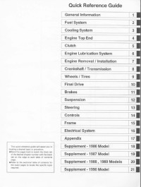
Quick Reference Guide
General Information 1 j
Periodic Maintenance 2 j
Fuel System (DFI) 3 j
Cooling System 4 j
Engine Top End 5 j
Clutch 6 j
Engine Lubrication System 7 j
Engine Removal/Installation 8 j
Crankshaft/Transmission 9 j
Wheels/Tires 10 j
Final Drive 11 j
Brakes 12 j
Suspension 13 j
Steering 14 j
Frame 15 j
Electrical System 16 j
Appendix 17 j
Page: 3
Ninja ZX-6R
Motorcycle
Service Manual
All rights reserved. No parts of this publication may be reproduced, stored in a retrieval system, or
transmitted in any form or by any means, electronic mechanical photocopying, recording or otherwise,
without the prior written permission of Quality Assurance Division/Consumer Products & Machinery
Company/Kawasaki Heavy Industries, Ltd., Japan.
No liability can be accepted for any inaccuracies or omissions in this publication, although every possible
care has been taken to make it as complete and accurate as possible.
The right is reserved to make changes at any time without prior notice and without incurring an obligation
to make such changes to products manufactured previously. See your Motorcycle dealer for the latest
information on product improvements incorporated after this publication.
All information contained in this publication is based on the latest product information available at the time
of publication. Illustrations and photographs in this publication are intended for reference use only and may
not depict actual model component parts.
© 2007 Kawasaki Heavy Industries, Ltd. First Edition (1): Jan. 30, 2007 (M)
Page: 4
LIST OF ABBREVIATIONS
A ampere(s) lb pound(s)
ABDC after bottom dead center m meter(s)
AC alternating current min minute(s)
ATDC after top dead center N newton(s)
BBDC before bottom dead center Pa pascal(s)
BDC bottom dead center PS horsepower
BTDC before top dead center psi pound(s) per square inch
°C degree(s) Celsius r revolution
DC direct current rpm revolution(s) per minute
F farad(s) TDC top dead center
°F degree(s) Fahrenheit TIR total indicator reading
ft foot, feet V volt(s)
g gram(s) W watt(s)
h hour(s) Ω ohm(s)
L liter(s)
COUNTRY AND AREA CODES
AU Australia MY Malaysia
CA Canada US United States
CAL California WVTA Whole Vehicle Type Approval
FR France
Page: 5
EMISSION CONTROL INFORMATION
To protect the environment in which we all live, Kawasaki has incorporated crankcase emis-
sion (1) and exhaust emission (2) control systems in compliance with applicable regulations of
the United States Environmental Protection Agency and California Air Resources Board. Addi-
tionally, Kawasaki has incorporated an evaporative emission control system (3) in compliance
with applicable regulations of the California Air Resources Board on vehicles sold in California
only.
1. Crankcase Emission Control System
This system eliminates the release of crankcase vapors into the atmosphere. Instead, the vapors
are routed through an oil separator to the inlet side of the engine. While the engine is operating,
the vapors are drawn into combustion chamber, where they are burned along with the fuel and air
supplied by the fuel injection system.
2. Exhaust Emission Control System
This system reduces the amount of pollutants discharged into the atmosphere by the exhaust
of this motorcycle. The fuel, ignition, and exhaust systems of this motorcycle have been carefully
designed and constructed to ensure an efficient engine with low exhaust pollutant levels.
The exhaust system of this model motorcycle manufactured primarily for sale in California in-
cludes a catalytic converter system.
3. Evaporative Emission Control System
Vapors caused by fuel evaporation in the fuel system are not vented into the atmosphere. In-
stead, fuel vapors are routed into the running engine to be burned, or stored in a canister when
the engine is stopped. Liquid fuel is caught by a vapor separator and returned to the fuel tank.
The Clean Air Act, which is the Federal law covering motor vehicle pollution, contains what is
commonly referred to as the Act’s “tampering provisions”.
“Sec. 203(a) The following acts and the causing thereof are prohibited…
(3)(A) for any person to remove or render inoperative any device or element of design installed
on or in a motor vehicle or motor vehicle engine in compliance with regulations under this
title prior to its sale and delivery to the ultimate purchaser, or for any manufacturer or dealer
knowingly to remove or render inoperative any such device or element of design after such
sale and delivery to the ultimate purchaser.
(3)(B) for any person engaged in the business of repairing, servicing, selling, leasing, or trading
motor vehicles or motor vehicle engines, or who operates a fleet of motor vehicles know-
ingly to remove or render inoperative any device or element of design installed on or in a
motor vehicle or motor vehicle engine in compliance with regulations under this title follow-
ing its sale and delivery to the ultimate purchaser…”
NOTE
○The phrase “remove or render inoperative any device or element of design” has been generally
interpreted as follows.
1. Tampering does not include the temporary removal or rendering inoperative of de-
vices or elements of design in order to perform maintenance.
2. Tampering could include.
a.Maladjustment of vehicle components such that the emission standards are ex-
ceeded.
b.Use of replacement parts or accessories which adversely affect the performance
or durability of the motorcycle.
c.Addition of components or accessories that result in the vehicle exceeding the stan-
dards.
d.Permanently removing, disconnecting, or rendering inoperative any component or
element of design of the emission control systems.
WE RECOMMEND THAT ALL DEALERS OBSERVE THESE PROVISIONS OF FEDERAL LAW,
THE VIOLATION OF WHICH IS PUNISHABLE BY CIVIL PENALTIES NOT EXCEEDING $10
000 PER VIOLATION.
Page: 6
TAMPERING WITH NOISE CONTROL SYSTEM PROHIBITED
Federal law prohibits the following acts or the causing thereof. (1) The removal or rendering
inoperative by any person other than for purposes of maintenance, repair, or replacement, of any
device or element of design incorporated into any new vehicle for the purpose of noise control
prior to its sale or delivery to the ultimate purchaser or while it is in use, or (2) the use of the
vehicle after such device or element of design has been removed or rendered inoperative by
any person.
Among those acts presumed to constitute tampering are the acts listed below.
•Replacement of the original exhaust system or muffler with a component not in compliance
with Federal regulations.
•Removal of the muffler(s) or any internal portion of the muffler(s).
•Removal of the air box or air box cover.
•Modifications to the muffler(s) or air inlet system by cutting, drilling, or other means if such
modifications result in increased noise levels.
Page: 7
Foreword
This manual is designed primarily for use by
trained mechanics in a properly equipped shop.
However, it contains enough detail and basic in-
formation to make it useful to the owner who de-
sires to perform his own basic maintenance and
repair work. A basic knowledge of mechanics,
the proper use of tools, and workshop proce-
dures must be understood in order to carry out
maintenance and repair satisfactorily. When-
ever the owner has insufficient experience or
doubts his ability to do the work, all adjust-
ments, maintenance, and repair should be car-
ried out only by qualified mechanics.
In order to perform the work efficiently and
to avoid costly mistakes, read the text, thor-
oughly familiarize yourself with the procedures
before starting work, and then do the work care-
fully in a clean area. Whenever special tools or
equipment are specified, do not use makeshift
tools or equipment. Precision measurements
can only be made if the proper instruments are
used, and the use of substitute tools may ad-
versely affect safe operation.
For the duration of the warranty period,
we recommend that all repairs and scheduled
maintenance be performed in accordance with
this service manual. Any owner maintenance or
repair procedure not performed in accordance
with this manual may void the warranty.
To get the longest life out of your vehicle.
•Follow the Periodic Maintenance Chart in the
Service Manual.
•Be alert for problems and non-scheduled
maintenance.
•Use proper tools and genuine Kawasaki Mo-
torcycle parts. Special tools, gauges, and
testers that are necessary when servicing
Kawasaki motorcycles are introduced by the
Service Manual. Genuine parts provided as
spare parts are listed in the Parts Catalog.
•Follow the procedures in this manual care-
fully. Don’t take shortcuts.
•Remember to keep complete records of main-
tenance and repair with dates and any new
parts installed.
How to Use This Manual
In this manual, the product is divided into
its major systems and these systems make up
the manual’s chapters. The Quick Reference
Guide shows you all of the product’s system
and assists in locating their chapters. Each
chapter in turn has its own comprehensive Ta-
ble of Contents.
For example, if you want stick coil information,
use the Quick Reference Guide to locate the
Electrical System chapter. Then, use the Table
of Contents on the first page of the chapter to
find the Stick Coil section.
Whenever you see these WARNING and
CAUTION symbols, heed their instructions!
Always follow safe operating and maintenance
practices.
WARNING
This warning symbol identifies special
instructions or procedures which, if not
correctly followed, could result in per-
sonal injury, or loss of life.
CAUTION
This caution symbol identifies special
instructions or procedures which, if not
strictly observed, could result in dam-
age to or destruction of equipment.
This manual contains four more symbols (in
addition to WARNING and CAUTION) which will
help you distinguish different types of informa-
tion.
NOTE
○This note symbol indicates points of par-
ticular interest for more efficient and con-
venient operation.
•Indicates a procedural step or work to be
done.
○Indicates a procedural sub-step or how to do
the work of the procedural step it follows. It
also precedes the text of a NOTE.
Indicates a conditional step or what action to
take based on the results of the test or inspec-
tion in the procedural step or sub-step it fol-
lows.
In most chapters an exploded view illustration
of the system components follows the Table of
Contents. In these illustrations you will find the
instructions indicating which parts require spec-
ified tightening torque, oil, grease or a locking
agent during assembly.
Page: 8
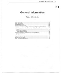
GENERAL INFORMATION 1-1
1
General Information
Table of Contents
Before Servicing ……………………………………………………………………………………………………… 1-2
Model Identification………………………………………………………………………………………………….. 1-7
General Specifications……………………………………………………………………………………………… 1-9
Unit Conversion Table ……………………………………………………………………………………………… 1-12
Page: 9
1-2 GENERAL INFORMATION
Before Servicing
Before starting to perform an inspection service or carry out a disassembly and reassembly opera-
tion on a motorcycle, read the precautions given below. To facilitate actual operations, notes, illustra-
tions, photographs, cautions, and detailed descriptions have been included in each chapter wherever
necessary. This section explains the items that require particular attention during the removal and
reinstallation or disassembly and reassembly of general parts.
Especially note the following.
Battery Ground
Before completing any service on the motorcycle, discon-
nect the battery cables from the battery to prevent the en-
gine from accidentally turning over. Disconnect the ground
cable (–) first and then the positive (+). When completed
with the service, first connect the positive (+) cable to the
positive (+) terminal of the battery then the negative (–) ca-
ble to the negative terminal.
Edges of Parts
Lift large or heavy parts wearing gloves to prevent injury
from possible sharp edges on the parts.
Solvent
Use a high-flush point solvent when cleaning parts. High
-flush point solvent should be used according to directions
of the solvent manufacturer.
Cleaning vehicle before disassembly
Clean the vehicle thoroughly before disassembly. Dirt or
other foreign materials entering into sealed areas during ve-
hicle disassembly can cause excessive wear and decrease
performance of the vehicle.
Page: 10
GENERAL INFORMATION 1-3
Before Servicing
Arrangement and Cleaning of Removed Parts
Disassembled parts are easy to confuse. Arrange the
parts according to the order the parts were disassembled
and clean the parts in order prior to assembly.
Storage of Removed Parts
After all the parts including subassembly parts have been
cleaned, store the parts in a clean area. Put a clean cloth
or plastic sheet over the parts to protect from any foreign
materials that may collect before re-assembly.
Inspection
Reuse of worn or damaged parts may lead to serious ac-
cident. Visually inspect removed parts for corrosion, discol-
oration, or other damage. Refer to the appropriate sections
of this manual for service limits on individual parts. Replace
the parts if any damage has been found or if the part is be-
yond its service limit.
Replacement Parts
Replacement Parts must be KAWASAKI genuine or
recommended by KAWASAKI. Gaskets, O-rings, oil seals,
grease seals, circlips or cotter pins must be replaced with
new ones whenever disassembled.
Assembly Order
In most cases assembly order is the reverse of disassem-
bly, however, if assembly order is provided in this Service
Manual, follow the procedures given.
Page: 11
1-4 GENERAL INFORMATION
Before Servicing
Tightening Sequence
Generally, when installing a part with several bolts, nuts,
or screws, start them all in their holes and tighten them to
a snug fit. Then tighten them according to the specified se-
quence to prevent case warpage or deformation which can
lead to malfunction. Conversely when loosening the bolts,
nuts, or screws, first loosen all of them by about a quar-
ter turn and then remove them. If the specified tightening
sequence is not indicated, tighten the fasteners alternating
diagonally.
Tightening Torque
Incorrect torque applied to a bolt, nut, or screw may
lead to serious damage. Tighten fasteners to the specified
torque using a good quality torque wrench.
Force
Use common sense during disassembly and assembly,
excessive force can cause expensive or hard to repair dam-
age. When necessary, remove screws that have a non
-permanent locking agent applied using an impact driver.
Use a plastic-faced mallet whenever tapping is necessary.
Gasket, O-ring
Hardening, shrinkage, or damage of both gaskets and
O-rings after disassembly can reduce sealing performance.
Remove the old gaskets and clean the sealing surfaces
thoroughly so that no gasket material or other material re-
mains. Install the new gaskets and replace the used O-rings
when re-assembling
Liquid Gasket, Non-permanent Locking Agent
For applications that require Liquid Gasket or a
Non-permanent Locking Agent, clean the surfaces so
that no oil residue remains before applying liquid gasket or
non-permanent locking agent. Do not apply them exces-
sively. Excessive application can clog oil passages and
cause serious damage.
Page: 12
GENERAL INFORMATION 1-5
Before Servicing
Press
For items such as bearings or oil seals that must be
pressed into place, apply small amount of oil to the con-
tact area. Be sure to maintain proper alignment and use
smooth movements when installing.
Ball Bearing and Needle Bearing
Do not remove pressed ball or needle unless removal is
absolutely necessary. Replace with new ones whenever
removed. Press bearings with the manufacturer and size
marks facing out. Press the bearing into place by putting
pressure on the correct bearing race as shown.
Pressing the incorrect race can cause pressure between
the inner and outer race and result in bearing damage.
Oil Seal, Grease Seal
Do not remove pressed oil or grease seals unless removal
is necessary. Replace with new ones whenever removed.
Press new oil seals with manufacture and size marks facing
out. Make sure the seal is aligned properly when installing.
Apply specified grease to the lip of seal before installing
the seal.
Circlips, Cotter Pins
Replace the circlips or cotter pins that were removed with
new ones. Take care not to open the clip excessively when
installing to prevent deformation.
Page: 13
1-6 GENERAL INFORMATION
Before Servicing
Lubrication
It is important to lubricate rotating or sliding parts during
assembly to minimize wear during initial operation. Lubri-
cation points are called out throughout this manual, apply
the specific oil or grease as specified.
Direction of Engine Rotation
When rotating the crankshaft by hand, the free play
amount of rotating direction will affect the adjustment. Ro-
tate the crankshaft to positive direction (clockwise viewed
from output side).
Electrical Wires
A two-color wire is identified first by the primary color and
then the stripe color. Unless instructed otherwise, electrical
wires must be connected to those of the same color.
Instrument
Use a meter that has enough accuracy for an accurate
measurement. Read the manufacture’s instructions thor-
oughly before using the meter. Incorrect values may lead
to improper adjustments.
Page: 14
GENERAL INFORMATION 1-7
Model Identification
ZX600P7F (Europe) Left Side View
ZX600P7F (Europe) Right Side View
Page: 15
1-8 GENERAL INFORMATION
Model Identification
ZX600P7F (US and Canada) Left Side View
ZX600P7F (US and Canada) Right Side View
Page: 16
GENERAL INFORMATION 1-9
General Specifications
Items ZX600P7F (Ninja ZX-6R)
Dimensions
Overall Length 2 105 mm (82.9 in.)
Overall Width 720 mm (28.3 in.)
Overall Height 1 125 mm (44.3 in.)
Wheelbase 1 405 mm (55.3 in.)
Road Clearance 125 mm (4.7 in.)
Seat Height 820 mm (32.3 in.)
Dry Mass 167 kg (368 lb)
Curb Mass:
Front 101 kg (223 lb)
Rear 99 kg (218 lb)
Fuel Tank Capacity 17 L (4.5 US gal)
Performance
Minimum Turning Radius 3.4 m (11.2 ft)
Engine
Type 4-stroke, DOHC, 4-cylinder
Cooling System Liquid-cooled
Bore and Stroke 67.0 × 42.5 mm (2.6 × 1.7 in.)
Displacement 599 mL (36.6 cu in.)
Compression Ratio 13.3 : 1
Maximum Horsepower 91.9 kW (125 PS) @14 000 r/min (rpm),
(FR) 78.2 kW (106 PS) @14 000 r/min (rpm),
(MY) 80.0 kW (109 PS) @12 000 r/min (rpm),
(CA), (CAL), (US) – – –
Maximum Torque 66.0 N·m (6.7 kgf·m, 49 ft·lb) @11 700 r/min (rpm),
(FR) 58.4 N·m (6.0 kgf·m, 43 ft·lb) @11 700 r/min (rpm),
(MY) 64 N·m (6.5 kgf·m, 47 ft·lb) @12 000 r/min (rpm)
(CA), (CAL), (US) – – –
Carburetion System FI (Fuel injection)
Primary: KEIHIN TTK 38 × 4
Secondary: KEIHIN Multihole (8 holes) × 4
Starting System Electric starter
Ignition System Battery and coil (transistorized)
Timing Advance Electronically advanced (digital igniter in ECU)
Ignition Timing From 12.5° BTDC @1 300 r/min (rpm)
Spark Plug NGK CR9E
Cylinder Numbering Method Left to right, 1-2-3-4
Firing Order 1-2-4-3
Valve Timing:
Inlet:
Open 41° BTDC
Close 67° ATDC
Duration 288°
Exhaust:
Open 63° BBDC
Close 23° ATDC
Page: 17
1-10 GENERAL INFORMATION
General Specifications
Items ZX600P7F (Ninja ZX-6R)
Duration 266°
Lubrication System Forced lubrication (wet sump with cooler)
Engine Oil:
Type API SE, SF or SG
API SH, SJ or SL with JASO MA
Viscosity SAE10W-40
Capacity 3.8 L (4.0 US qt)
Drive Train
Primary Reduction System:
Type Gear
Reduction Ratio 1.900 (76/40)
Clutch Type Wet multi disc
Transmission:
Type 6-speed, constant mesh, return shift
Gear Ratios:
1st 2.714 (38/14)
2nd 2.200 (33/15)
3rd 1.850 (37/20)
4th 1.600 (32/20)
5th 1.421 (27/19)
6th 1.300 (26/20)
Final Drive System:
Type Chain drive
Reduction Ratio 2.688 (43/16)
Overall Drive Ratio 6.638 @Top gear
Frame
Type Tubular, diamond
Caster (Rake Angle) 25°
Trail 110 mm (4.3 in.)
Front Tire:
Type Tubeless
Size 120/70 ZR17 M/C (58 W)
Rear Tire:
Type Tubeless
Size 180/55 ZR17 M/C (73 W)
Rim Size:
Front 17 × 3.50
Rear 17 × 5.50
Front Suspension:
Type Telescopic fork (upside-down)
Wheel Travel 120 mm (4.7 in.)
Rear Suspension:
Type Swingarm (uni-trak)
Wheel Travel 133 mm (5.2 in.)
Page: 18
GENERAL INFORMATION 1-11
General Specifications
Items ZX600P7F (Ninja ZX-6R)
Brake Type:
Front Dual discs
Rear Single disc
Electrical Equipment
Battery 12 V 8 Ah
Headlight:
Type Semi-sealed beam
Bulb:
High 12 V 55 W + 65 W (quartz-halogen)
Low 12 V 55 W (quartz-halogen)
Tail/Brake Light 12 V 0.1/1.6 W (LED)
Alternator:
Type Three-phase AC
Rated Output 31 A/14 V @5 000 r/min (rpm)
Specifications subject to change without notice, and may not apply to every country.
Page: 19
1-12 GENERAL INFORMATION
Unit Conversion Table
Prefixes for Units
Prefix Symbol Power
mega M × 1 000 000
kilo k × 1 000
centi c × 0.01
milli m × 0.001
micro µ × 0.000001
Units of Mass
kg × 2.205 = lb
g × 0.03527 = oz
Units of Volume
L × 0.2642 = gal (US)
L × 0.2200 = gal (imp)
L × 1.057 = qt (US)
L × 0.8799 = qt (imp)
L × 2.113 = pint (US)
L × 1.816 = pint (imp)
mL × 0.03381 = oz (US)
mL × 0.02816 = oz (imp)
mL × 0.06102 = cu in
Units of Force
N × 0.1020 = kg
N × 0.2248 = lb
kg × 9.807 = N
kg × 2.205 = lb
Units of Length
km × 0.6214 = mile
m × 3.281 = ft
mm × 0.03937 = in
Units of Torque
N·m × 0.1020 = kgf·m
N·m × 0.7376 = ft·lb
N·m × 8.851 = in·lb
kgf·m × 9.807 = N·m
kgf·m × 7.233 = ft·lb
kgf·m × 86.80 = in·lb
Units of Pressure
kPa × 0.01020 = kgf/cm²
kPa × 0.1450 = psi
kPa × 0.7501 = cmHg
kgf/cm² × 98.07 = kPa
kgf/cm² × 14.22 = psi
cmHg × 1.333 = kPa
Units of Speed
km/h × 0.6214 = mph
Units of Power
kW × 1.360 = PS
kW × 1.341 = HP
PS × 0.7355 = kW
PS × 0.9863 = HP
Units of Temperature
Page: 20
PERIODIC MAINTENANCE 2-1
2
Periodic Maintenance
Table of Contents
Periodic Maintenance Chart ……………………………………………………………………………………… 2-3
Torque and Locking Agent………………………………………………………………………………………… 2-6
Specifications …………………………………………………………………………………………………………. 2-12
Special Tools ………………………………………………………………………………………………………….. 2-14
Maintenance Procedure …………………………………………………………………………………………… 2-15
Fuel System (DFI)…………………………………………………………………………………………………. 2-15
Throttle Control System Inspection……………………………………………………………………….. 2-15
Engine Vacuum Synchronization Inspection…………………………………………………………… 2-15
Idle Speed Inspection …………………………………………………………………………………………. 2-18
Idle Speed Adjustment………………………………………………………………………………………… 2-19
Fuel Hose Inspection (fuel leak, damage, installation condition)……………………………….. 2-19
Evaporative Emission Control System (California Model) …………………………………………… 2-19
Evaporative Emission Control System Inspection …………………………………………………… 2-19
Engine Top End ……………………………………………………………………………………………………. 2-20
Valve Clearance Inspection …………………………………………………………………………………. 2-20
Valve Clearance Adjustment………………………………………………………………………………… 2-22
Air Suction System ……………………………………………………………………………………………….. 2-24
Air Suction System Damage Inspection…………………………………………………………………. 2-24
Cooling System…………………………………………………………………………………………………….. 2-25
Coolant Level Inspection……………………………………………………………………………………… 2-25
Radiator Hose Damage and Installation Condition Inspection…………………………………… 2-25
Clutch………………………………………………………………………………………………………………….. 2-26
Clutch Operation Inspection ………………………………………………………………………………… 2-26
Wheels/Tires………………………………………………………………………………………………………… 2-27
Air Pressure Inspection……………………………………………………………………………………….. 2-27
Wheel/Tire Damage Inspection…………………………………………………………………………….. 2-27
Tire Tread Wear Inspection …………………………………………………………………………………. 2-27
Wheel Bearing Damage Inspection ………………………………………………………………………. 2-28
Drive Train …………………………………………………………………………………………………………… 2-29
Drive Chain Lubrication Condition Inspection…………………………………………………………. 2-29
Drive Chain Slack Inspection……………………………………………………………………………….. 2-29
Drive Chain Slack Adjustment ……………………………………………………………………………… 2-30
Wheel Alignment Inspection ………………………………………………………………………………… 2-31
Drive Chain Wear Inspection ……………………………………………………………………………….. 2-31
Chain Guide Wear Inspection………………………………………………………………………………. 2-32
Brake System ………………………………………………………………………………………………………. 2-32
Brake Fluid Leak (Brake Hose and Pipe) Inspection ……………………………………………….. 2-32
Brake Hose Damage and Installation Condition Inspection………………………………………. 2-32
Brake Operation Inspection …………………………………………………………………………………. 2-33
Brake Fluid Level Inspection………………………………………………………………………………… 2-33
Brake Pad Wear Inspection …………………………………………………………………………………. 2-34
Brake Light Switch Operation Inspection……………………………………………………………….. 2-34
Suspensions ………………………………………………………………………………………………………… 2-35
Front Forks/Rear Shock Absorber Operation Inspection………………………………………….. 2-35
Front Fork Oil Leak Inspection……………………………………………………………………………… 2-35
Rear Shock Absorber Oil Leak Inspection……………………………………………………………… 2-36
Rocker Arm Operation Inspection…………………………………………………………………………. 2-36
Tie-Rod Operation Inspection ………………………………………………………………………………. 2-36
Steering System …………………………………………………………………………………………………… 2-36
Steering Play Inspection ……………………………………………………………………………………… 2-36
Page: 21
2-2 PERIODIC MAINTENANCE
Steering Play Adjustment…………………………………………………………………………………….. 2-37
Steering Stem Bearing Lubrication ……………………………………………………………………….. 2-38
Lights and Switches Operation Inspection……………………………………………………………… 2-38
Headlight Aiming Inspection ………………………………………………………………………………… 2-40
Side Stand Switch Operation Inspection………………………………………………………………… 2-41
Engine Stop Switch Operation Inspection………………………………………………………………. 2-42
Others…………………………………………………………………………………………………………………. 2-43
Chassis Parts Lubrication …………………………………………………………………………………… 2-43
Bolts, Nuts and Fasteners Tightness Inspection……………………………………………………… 2-44
Replacement Parts ……………………………………………………………………………………………….. 2-46
Air Cleaner Element Replacement………………………………………………………………………… 2-46
Fuel Hose Replacement ……………………………………………………………………………………… 2-47
Coolant Change…………………………………………………………………………………………………. 2-50
Radiator Hose and O-ring Replacement………………………………………………………………… 2-52
Engine Oil Change……………………………………………………………………………………………… 2-53
Oil Filter Replacement ………………………………………………………………………………………… 2-53
Brake Hose and Pipe Replacement………………………………………………………………………. 2-54
Brake Fluid Change ……………………………………………………………………………………………. 2-54
Master Cylinder Rubber Parts Replacement ………………………………………………………….. 2-56
Caliper Rubber Parts Replacement ………………………………………………………………………. 2-57
Spark Plug Replacement …………………………………………………………………………………….. 2-60
Page: 22
PERIODIC MAINTENANCE 2-3
Periodic Maintenance Chart
The scheduled maintenance must be done in accordance with this chart to keep the motorcycle in
good running condition.The initial maintenance is vitally important and must not be neglected.
Periodic Inspection
FREQUENCY Whichever
comes
first
* ODOMETER READING
× 1 000 km
(× 1 000 mile)
1 6 12 18 24 30 36
INSPECTION Every (0.6) (4) (7.5) (12) (15) (20) (24)
Fuel System
Throttle control system (play, smooth
return, no drag)-inspect
year • • • •
Engine vacuum synchronization-inspect • • •
Idle speed-inspect • • • •
Fuel leak (fuel hose and pipe)-inspect year • • • •
Fuel hose and pipe damage-inspect year • • • •
Fuel hose and pipe installation
condition-inspect
year • • • •
Evaporative Emission Control System
(California Model only)
Evaporative emission control system
function-inspect • • • • • • •
Cooling System
Coolant level-inspect • • • •
Coolant leak (radiator hose and
pipe)-inspect
year • • • •
Radiator hose damage-inspect year • • • •
Radiator hose installation condition
-inspect
year • • • •
Engine Top End
Valve clearance-inspect (United States
and Canada Models) •
Valve clearance-inspect (Other than
United States and Canada Models)
Every 42 000 km (26 000 mile)
Air Suction System
Air suction system damage-inspect • • •
Clutch
Clutch operation (play, disengagement,
engagement)-inspect • • • •
Wheels and Tires
Tire air pressure-inspect year • • •
Wheel/tire damage-inspect • • •
Tire tread wear, abnormal wear-inspect • • •
Wheel bearing damage-inspect year • • •
Drive Train
Drive chain lubrication condition-inspect # Every 600 km (400 mile)
Drive chain slack-inspect # Every 1 000 km (600 mile)
Page: 23
2-4 PERIODIC MAINTENANCE
Periodic Maintenance Chart
FREQUENCY Whichever
comes
first
* ODOMETER READING
× 1 000 km
(× 1 000 mile)
1 6 12 18 24 30 36
INSPECTION Every (0.6) (4) (7.5) (12) (15) (20) (24)
Drive chain wear-inspect # • • •
Drive chain guide wear-inspect • • •
Brake System
Brake fluid leak (brake hose and
pipe)-inspect
year • • • • • • •
Brake hose and pipe damage-inspect year • • • • • • •
Brake pad wear-inspect # • • • • • •
Brake hose installation condition-inspect year • • • • • • •
Brake fluid level-inspect 6 months • • • • • • •
Brake operation (effectiveness, play, no
drag)-inspect
year • • • • • • •
Brake light switch operation-inspect • • • • • • •
Suspensions
Front forks/rear shock absorber operation
(damping and smooth stroke)-inspect • • •
Front forks/rear shock absorber oil
leak-inspect
year • • •
Rocker arm operation-inspect • • •
Tie-Rods operation-inspect • • •
Steering System
Steering play-inspect year • • • •
Steering stem bearings-lubricate 2 years •
Electrical System
Lights and switches operation-inspect year • • •
Headlight aiming-inspect year • • •
Side stand switch operation-inspect year • • •
Engine stop switch operation-inspect year • • •
Others
Chassis parts-lubricate year • • •
Bolts and nuts tightness-inspect • • • •
*: For higher odometer readings, repeat at the frequency interval established here.
#: Service more frequently when operating in severe conditions; dusty, wet, muddy, high speed or
frequent starting/stopping.
CAL: California Model
Page: 24
PERIODIC MAINTENANCE 2-5
Periodic Maintenance Chart
Periodic Replacement Parts
FREQUENCY Whichever
come
first
* ODOMETER READING
× 1 000 km
(× 1 000 mile)
1 12 24 36 48
CHANGE/REPLACE ITEM Every (0.6) (7.5) (15) (24) (30)
Air cleaner element # Every 18 000 km (12 000 mile)
Fuel hose 4 years •
Coolant 3 years •
Radiator hose and O-ring 3 years •
Engine oil # year • • • • •
Oil filter year • • • • •
Brake hose and pipe 4 years •
Brake fluid 2 years • •
Rubber parts of master cylinder and caliper 4 years •
Spark plug • • • •
*: For higher odometer readings, repeat at the frequency interval established here.
#: Service more frequently when operating in severe conditions; dusty, wet, muddy, high speed or
frequent starting/stopping.
Page: 25
2-6 PERIODIC MAINTENANCE
Torque and Locking Agent
The following tables list the tightening torque for the major fasteners requiring use of a
non-permanent locking agent or silicone sealant etc.
Letters used in the “Remarks” column mean:
AL: Tighten the two clamp bolts alternately two times to ensure even tightening torque.
G: Apply grease to the threads.
L: Apply a non-permanent locking agent to the threads.
MO: Apply molybdenum disulfide grease oil solution.
R: Replacement Parts
S: Follow the specified tightening sequence.
SI: Apply silicone grease.
SS: Apply silicone sealant.
Torque
Fastener
N·m kgf·m ft·lb
Remarks
Fuel System
Air Cleaner Housing Screws 1.1 0.11 9.7 in·lb
Air Cleaner Housing Clamp Bolts 2.0 0.20 17 in·lb
Air Cleaner Housing Mounting Bolt 6.9 0.70 61 in·lb
Air Inlet Duct Mounting Bolts 9.8 1.0 87 in·lb L
Camshaft Position Sensor Bolt 9.8 1.0 87 in·lb
Crankshaft Sensor Bolts 5.9 0.60 52 in·lb
Delivery Pipe Mounting Screws (Nozzle Assy) 3.4 0.35 30 in·lb
Delivery Pipe Mounting Screws (Throttle Body) 3.4 0.35 30 in·lb
Exhaust Butterfly Valve Actuator Mounting Bolts 6.9 0.70 61 in·lb
Exhaust Butterfly Valve Actuator Pulley Bolt 4.9 0.50 43 in·lb
Fuel Pump Bolts 9.8 1.0 87 in·lb L, S
Nozzle Assy Mounting Bolts 6.9 0.70 61 in·lb
Nozzle Assy Fuel Hose Screw 4.9 0.50 43 in·lb
Separator Bracket Mounting Bolt 0.8 0.08 7 in·lb
Throttle Body Assembly Holder Clamp Bolts 3.0 0.30 27 in·lb
Throttle Body Holder Bolts 12 1.2 106 in·lb L
Throttle Cable Holder Plate Bolt 3.9 0.40 35 in·lb L
Vehicle-down Sensor Bolts 5.9 0.60 52 in·lb
Water Temperature Sensor 25 2.5 18 SS
Cooling System
Coolant By-pass Fitting Bolt 8.8 0.90 78 in·lb L
Coolant Drain Bolt (Cylinder) 9.8 1.0 87 in·lb
Coolant Drain Bolt (Water Pump) 8.8 0.90 78 in·lb
Coolant Reserve Tank Mounting Bolts 7.0 0.70 61 in·lb
Impeller Bolt 9.8 1.0 87 in·lb
Oil Cooler Mounting Bolts 20 2.0 15
Radiator Bracket Mounting Bolt 9.8 1.0 87 in·lb
Radiator Lower Bolt 6.9 0.70 61 in·lb
Radiator Upper Bolts 9.8 1.0 87 in·lb
Thermostat Housing Cover Bolts 5.9 0.60 52 in·lb
Water Hose Clamp Screws 2.0 0.20 17 in·lb
Water Hose Fitting Bolts (Cylinder) 9.8 1.0 87 in·lb
Page: 26
PERIODIC MAINTENANCE 2-7
Torque and Locking Agent
Torque
Fastener
N·m kgf·m ft·lb
Remarks
Water Hose Fitting Bolts (Head Cover) 15 1.5 11 L
Water Pump Cover Bolts 12 1.2 106 in·lb L
Water Temperature Sensor 25 2.5 18 SS
Engine Top End
Air Suction Valve Cover Bolts 9.8 1.0 87 in·lb L
Camshaft Cap Bolts 12 1.2 106 in·lb S
Camshaft Chain Tensioner Cap Bolt 20 2.0 15
Camshaft Chain Tensioner Mounting Bolts 11 1.1 97 in·lb
Cam Sprocket Mounting Bolts 15 1.5 11 L
Cylinder Head Bolts (M9) 39 4.0 29 MO, S
Cylinder Head Bolts (M6) 12 1.2 106 in·lb S
Cylinder Head Cover Bolts 9.8 1.0 87 in·lb
Exhaust Butterfly Valve Actuator Mounting Nuts 6.9 0.70 61 in·lb
Exhaust Butterfly Valve Actuator Pulley Bolt 4.9 0.50 43 in·lb
Exhaust Butterfly Valve Cable Adjuster Locknuts 6.9 0.70 61 in·lb
Exhaust Butterfly Valve Cable Locknuts 6.9 0.70 61 in·lb
Exhaust Butterfly Valve Cover Bolt 6.9 0.70 61 in·lb
Exhaust Pipe Clamp Bolt 17 1.7 13
Exhaust Manifold Holder Nuts 17 1.7 13
Exhaust Pipe Mounting Bolt 28 2.8 21
Exhaust Manifold Holder Studs – – – (stopped)
Front Camshaft Chain Guide Bolt (Lower) 12 1.2 106 in·lb
Front Camshaft Chain Guide Bolt (Upper) 25 2.5 18
Muffler Body Clamp Bolt 17 1.7 12
Muffler Body Mounting Bolts 28 2.8 21
Muffler Rear Cover Bolts 6.9 0.70 61 in·lb
Muffler Slide Cover Bolts 6.9 0.70 61 in·lb
Muffler Upper Cover Bolts 6.9 0.70 61 in·lb
Upper Camshaft Chain Guide Bolt 25 2.5 18
Spark Plugs 13 1.3 113 in·lb
Oxygen Sensors 25 2.5 18
Throttle Body Assy Holder Clamp Bolts 2.9 0.30 26 in·lb
Throttle Body Holder Bolts 12 1.2 106 in·lb L
Water Passage Plugs 20 2.0 15 L
Clutch
Clutch Cover Bolts (M6, L = 40 mm) 9.8 1.0 87 in·lb
Clutch Cover Bolts (M6, L = 25 mm) 9.8 1.0 87 in·lb
Clutch Hub Nut 135 14 100 R
Clutch Lever Clamp Bolts 7.8 0.80 69 in·lb S
Clutch Spring Bolts 8.8 0.90 78 in·lb
Sub Clutch Hub Bolts 25 2.5 18 L
Engine Lubrication System
Oil Filler Cap 2.0 0.20 17 in·lb
Page: 27
2-8 PERIODIC MAINTENANCE
Torque and Locking Agent
Torque
Fastener
N·m kgf·m ft·lb
Remarks
Air Bleed Bolt 9.8 1.0 87 in·lb
Engine Oil Drain Bolt 29 3.0 22
Oil Cooler/Oil Filter Case Mounting Bolts 20 2.0 15 L
Oil Pump Gear Bolt 9.8 1.0 87 in·lb L
Oil Cooler Mounting Bolts 20 2.0 15
Oil Filter 31 3.2 23 G, R
Oil Filter Guard Bolts 4.0 0.41 35 in·lb L
Oil Filter Holder Bolt 25 2.5 18 L
Oil Pan Bolts 9.8 1.0 87 in·lb
Oil Passage Nozzle 4.9 0.50 43 in·lb
Oil Passage Plugs (Taper) 20 2.0 15 L
Oil Passage Plug (Left Side) 17 1.7 13
Oil Pressure Relief Valve 15 1.5 11 L
Oil Pressure Switch 15 1.5 11 SS
Oil Pressure Switch Terminal Bolt – – – Hand-tighten
Water Hose Clamp Screws 2.0 0.20 17 in·lb
Water Pump Cover Bolts 12 1.2 104 in·lb L
Engine Removal/Installation
Adjusting Collar Locknut 49 5.0 36 S
Adjusting Collar 9.8 1.0 87 in·lb S
Lower Engine Mounting Nut 44 4.5 33 S
Middle Engine Mounting Bracket Bolt 25 2.5 18 S
Middle Engine Mounting Nut 44 4.5 33 S
Upper Engine Mounting Bolts 44 4.5 33 S
Crankshaft/Transmission
Breather Plate Bolts 9.8 1.0 87 in·lb L
Connecting Rod Big End Nuts see the
text
see the
text
see the
text
MO
Crankcase Bolts (M8) (Lower) (First) 15 1.5 11 MO, S
Crankcase Bolts (M8) (Lower) (Final) 31 3.2 23 MO, S
Crankcase Bolts (M6, L = 50 mm) (Lower) 12 1.2 104 in·lb S
Gear Position Switch Screws 2.9 0.30 26 in·lb L
Crankcase Bolt (M8, L = 90 mm) (Upper) 27 2.8 20 S
Crankcase Bolts (M8, L = 75 mm) (Upper) 27 2.8 20 S
Crankcase Bolts (M6, L = 68 mm) (Upper) 12 1.2 104 in·lb S
Transmission Case Bolts (M8) 20 2.0 15
Transmission Case Bolts (M6) 9.8 1.0 87 in·lb
Piston Oil Nozzles 2.9 0.30 26 in·lb
Gear Positioning Lever Bolt 12 1.2 104 in·lb
Oil Passage Plugs (Taper Side) 20 2.0 15 L
Oil Passage Plug (Left Side) 17 1.7 13
Oil Pressure Switch 15 1.5 11 SS
Fitting (breather) 15 1.5 11 L
Page: 28
PERIODIC MAINTENANCE 2-9
Torque and Locking Agent
Torque
Fastener
N·m kgf·m ft·lb
Remarks
Oil Passage Nozzle 4.9 0.50 43 in·lb
Oil Pressure Switch Terminal Bolt – – – Hand-tighten
Bearing Holder Screws 4.9 0.50 43 in·lb L
Shift Drum Cam Holder Bolt 12 1.2 104 in·lb L
Shift Lever Bolt 6.9 0.70 61 in·lb
Shift Pedal Mounting Bolt 25 2.5 18
Shift Shaft Return Spring Pin 28 2.9 21 L
Shift Tie-Rod Locknuts 6.9 0.70 61 in·lb
Starter Clutch Bolt 49 5.0 36
Starter Clutch Bolt Cap – – – Hand-tighten
Timing Inspection Cap – – – Hand-tighten
Starter Clutch Cover Bolts 9.8 1.0 87 in·lb
Idle Gear Cover Bolts 9.8 1.0 87 in·lb
Wheels/Tires
Front Axle Clamp Bolts 20 2.0 15 AL
Front Axle Nut 127 13 94
Rear Axle Nut 127 13 94
Final Drive
Engine Sprocket Cover Bolts 9.8 1.0 87 in·lb
Engine Sprocket Nut 125 13 92 MO
Rear Sprocket Nuts 59 6.0 43
Chain Guide Bolts (Front) 9.8 1.0 87 in·lb L
Chain Guide Bolt (Rear) 4.9 0.50 43 in·lb L
Brakes
Caliper Bleed Valves 7.8 0.80 69 in·lb
Brake Hose Banjo Bolts 25 2.5 18
Brake Lever Pivot Bolt 1.0 0.10 9 in·lb Si
Brake Lever Pivot Bolt Locknut 5.9 0.60 52 in·lb
Brake Pedal Bolt 8.8 0.90 78 in·lb
Front Brake Light Switch Screw 1.2 0.12 10 in·lb
Front Brake Reservoir Cap Stopper Screw 1.2 0.12 10 in·lb
Front Brake Disc Mounting Bolts 27 2.8 20 L
Front Brake Pad Pins 17 1.7 13
Front Caliper Assembly Bolts 27 2.8 20
Front Caliper Mounting Bolts 34 3.5 25
Front Master Cylinder Bleed Valve 5.9 0.60 52 in·lb
Front Master Cylinder Clamp Bolts 8.8 0.90 78 in·lb S
Rear Brake Disc Mounting Bolts 27 2.8 20 L
Rear Caliper Mounting Bolts 25 2.5 18
Rear Master Cylinder Mounting Bolts 25 2.5 18
Rear Master Cylinder Push Rod Locknut 18 1.8 13
Suspension
Front Axle Clamp Bolts 20 2.0 15 AL
Page: 29
2-10 PERIODIC MAINTENANCE
Torque and Locking Agent
Torque
Fastener
N·m kgf·m ft·lb
Remarks
Front Fork Bottom Allen Bolts 35 3.5 26
Front Fork Clamp Bolts (Lower) 25 2.5 18 AL
Front Fork Clamp Bolts (Upper) 20 2.0 15
Front Fork Top Plugs 35 3.5 26
Piston Rod Nuts 20 2.0 15
Rear Shock Absorber Bracket Nut 59 6.0 43
Rear Shock Absorber Nut (Lower) 34 3.5 25
Rear Shock Absorber Nut (Upper) 34 3.5 25
Swingarm Pivot Adjusting Collar 20 2.0 15 S
Swingarm Pivot Adjusting Collar Locknut 98 10 72 S
Swingarm Pivot Shaft Nut 108 11 81 S
Tie-Rod Nuts 59 6.0 43
Uni-Trak Rocker Arm Nut 34 3.5 25
Steering
Front Fork Clamp Bolts (Lower) 25 2.5 18 AL
Front Fork Clamp Bolts (Upper) 20 2.0 15
Handlebar Bolts 25 2.5 18
Handlebar Position Bolts 9.8 1.0 87 in·lb L
Steering Stem Head Nut 78 8.0 58
Steering Stem Nut 20 2.0 15
Switch Housing Screws 3.5 0.36 31 in·lb
Frame
Front Fender Mounting Bolts 3.9 0.40 35 in·lb
Front Footpeg Bracket Bolts 25 2.5 18
Rear Footpeg Bracket Bolts 25 2.5 18
Rear Frame Bolts 44 4.5 32 L
Sidestand Bolt 44 4.5 32 G
Sidestand Bracket Bolts 49 5.0 36 L
Sidestand Switch Bolt 8.8 0.90 78 in·lb L
Windshield Mounting Bolts 0.4 0.04 4 in·lb
Electrical System
Alternator Cover Bolts 9.8 1.0 87 in·lb
Alternator Lead Holding Plate Bolt 9.8 1.0 87 in·lb L
Alternator Rotor Bolt 155 16 115
Camshaft Position Sensor Bolt 9.8 1.0 87 in·lb
Crankshaft Sensor Bolts 5.9 0.60 52 in·lb
Cylinder Head Cover Ground Bolt 9.8 1.0 87 in·lb
Front Brake Light Switch Screw 1.2 0.12 10 in·lb
Front Turn Signal Light Mounting Screws 1.2 0.12 10 in·lb
Headlight Mounting Screws 1.2 0.12 10 in·lb
Licence Light Assembly Screws 0.9 0.09 8 in·lb
Licence Light Mounting Screws 1.2 0.12 10 in·lb
Meter Mounting Screws 1.2 0.12 10 in·lb
Page: 30
PERIODIC MAINTENANCE 2-11
Torque and Locking Agent
Torque
Fastener
N·m kgf·m ft·lb
Remarks
Gear Position Switch Screws 2.9 0.30 26 in·lb L
Rear Turn Signal Light Lens Screws 1.0 0.10 9 in·lb
Rear Turn Signal Light Mounting Screws 1.2 0.12 10 in·lb
Regulator/Rectifier Bolts 6.9 0.70 61 in·lb
Regulator/Rectifier Bracket Nuts 6.9 0.70 61 in·lb
Side Stand Switch Bolt 8.8 0.90 78 in·lb L
Spark Plugs 13 1.3 113 in·lb
Speed Sensor Bolt 6.9 0.70 61 in·lb L
Stator Coil Bolts 12 1.2 106 in·lb L
Starter Motor Cable Terminal Bolt 2.9 0.30 26 in·lb
Starter Clutch Bolt 49 5.0 36
Starter Motor Mounting Bolts 9.8 1.0 87 in·lb
Starter Relay Cable Terminal Bolts 4.0 0.41 35 in·lb
Switch Housing Screws 3.5 0.36 31 in·lb
Tail/Brake Light Mounting Bolts 4.0 0.40 35 in·lb
Vehicle-down Sensor Bolts 5.9 0.60 52 in·lb
Water Temperature Sensor 25 2.5 18 SS
Idle Gear Cover Bolts 9.8 1.0 87 in·lb
Starter Clutch Cover Bolts 9.8 1.0 87 in·lb
Starter Clutch Bolt Cap – – – Hand-tighten
Timing Inspection Cap – – – Hand-tighten
The table below, relating tightening torque to thread diameter, lists the basic torque for the bolts and
nuts. Use this table for only the bolts and nuts which do not require a specific torque value. All of the
values are for use with dry solvent-cleaned threads.
Basic Torque for General Fasteners
Threads Torque
Diameter (mm) N·m kgf·m ft·lb
5 3.4 ∼ 4.9 0.35 ∼ 0.50 30 ∼ 43 in·lb
6 5.9 ∼ 7.8 0.60 ∼ 0.80 52 ∼ 69 in·lb
8 14 ∼ 19 1.4 ∼ 1.9 10 ∼ 13.5
10 25 ∼ 34 2.6 ∼ 3.5 19 ∼ 25
12 44 ∼ 61 4.5 ∼ 6.2 33 ∼ 45
14 73 ∼ 98 7.4 ∼ 10.0 54 ∼ 72
16 115 ∼ 155 11.5 ∼ 16.0 83 ∼ 115
18 165 ∼ 225 17.0 ∼ 23.0 125 ∼ 165
20 225 ∼ 325 23.0 ∼ 33.0 165 ∼ 240
Page: 31
2-12 PERIODIC MAINTENANCE
Specifications
Item Standard Service Limit
Fuel System (DFI)
Throttle Grip Free Play 2 ∼ 3 mm (0.08 ∼ 0.12 in.) – – –
Idle Speed 1 300 ±50 r/min (rpm) – – –
Throttle Body Vacuum 27.3 ±1.333 kPa (205 ±10 mmHg) at idle speed – – –
Air Cleaner Element Viscous paper element – – –
Cooling System
Coolant:
Type (Recommended) Permanent type antifreeze – – –
Color Green – – –
Mixed Ratio Soft water 50%, coolant 50% – – –
Freezing Point –35°C (–31°F) – – –
Total Amount 2.6 L (2.7 US qt) – – –
Engine Top End
Valve Clearance:
Exhaust 0.24 ∼ 0.31 mm (0.0094 ∼ 0.0122 in.) – – –
Inlet 0.13 ∼ 0.19 mm (0.0051 ∼ 0.0075 in.) – – –
Clutch
Clutch Lever Free Play 2 ∼ 3 mm (0.08 ∼ 0.12 in.) – – –
Engine Lubrication System
Engine Oil:
Type API SE, SF or SG
API SH, SJ or SL with JASO MA
– – –
Viscosity SAE 10W-40 – – –
Capacity 2.9 L (3.1 US qt) (when filter is not removed) – – –
3.2 L (3.4 US qt) (when filter is removed) – – –
3.8 L (4.0 US qt) (when engine is completely dry) – – –
Level Between upper and lower level lines (Wait 2 ∼ 3
minutes after idling or running)
– – –
Wheels/Tires
Tread Depth:
Front BRIDGESTONE: 3.6 mm (0.14 in.) 1 mm (0.04 in.),
(AT, CH, DE) 1.6
mm (0.06 in.)
Rear BRIDGESTONE: 4.8 mm (0.19 in.) Up to 130 km/h
(80 mph): 2 mm
(0.08 in.), Over
130 km/h (80
mph): 3 mm (0.12
in.)
Air Pressure (when Cold):
Front Up to 180 kg (397 lb) load:
250 kPa (2.5 kgf/cm², 36 psi)
– – –
Rear Up to 180 kg (397 lb) load:
290 kPa (2.9 kgf/cm², 42 psi)
– – –
Page: 32
PERIODIC MAINTENANCE 2-13
Specifications
Item Standard Service Limit
Final Drive
Drive Chain Slack 30 ∼ 40 mm (1.2 ∼ 1.6 in.) – – –
Drive Chain Wear (20-link
Length)
317.5 ∼ 318.2 mm (12.50 ∼ 12.53 in.) 323 mm (12.7 in.)
Standard Chain:
Make ENUMA – – –
Type EK520MVXL1 – – –
Link 112 links – – –
Brakes
Brake Fluid:
Grade DOT4 – – –
Brake Pad Lining
Thickness:
Front 4 mm (0.16 in.) 1 mm (0.04 in.)
Rear 5 mm (0.20 in.) 1 mm (0.04 in.)
Brake Light Timing:
Front Pulled ON – – –
Rear On after about 10 mm (0.39 in.) of pedal travel – – –
Page: 33
2-14 PERIODIC MAINTENANCE
Special Tools
Inside Circlip Pliers:
57001-143
Steering Stem Nut Wrench:
57001-1100
Jack:
57001-1238
Pilot Screw Adjuster, A:
57001-1239
Oil Filter Wrench:
57001-1249
Vacuum Gauge:
57001-1369
Extension Tube:
57001-1578
Jack Attachment:
57001-1608
Page: 34
PERIODIC MAINTENANCE 2-15
Maintenance Procedure
Fuel System (DFI)
Throttle Control System Inspection
•Check that the throttle grip [A] moves smoothly from full
open to close, and the throttle closes quickly and com-
pletely by the return spring in all steering positions.
If the throttle grip does not return properly, check the throt-
tle cables routing, grip free play, and cable damage. Then
lubricate the throttle cable.
•Check the throttle grip free play [B].
If the free play is incorrect, adjust the throttle cables.
Throttle Grip Free Play
Standard: 2 ∼ 3 mm (0.08 ∼ 0.12 in.)
If the free play is incorrect, adjust the throttle cable as
follows.
•Loosen the locknuts [A] [B].
•Screw both throttle cable adjusters [C] [D] to give the
throttle grip plenty of play.
•Turn the decelerator cable adjuster [C] until 2 ∼ 3 mm
(0.08 ∼ 0.12 in.) of throttle grip play is obtained.
•Tighten the locknut [A].
•Turn the accelerator cable adjuster [D] until 2 ∼ 3 mm
(0.08 ∼ 0.12 in.) of throttle grip play is obtained.
•Tighten the locknut [B].
If the free play can not be adjusted with the adjusters,
replace the cable.
Engine Vacuum Synchronization Inspection
NOTE
○These procedures are explained on the assumption that
the inlet and exhaust systems of the engine are in good
condition.
•Situate the motorcycle so that it is vertical.
•Remove:
Fuel Tank (see Fuel Tank Removal in the Fuel System
(DFI) chapter)
Air Cleaner Housing (see Air Cleaner Housing Removal
in the Fuel System (DFI) chapter)
Fuel Hose (see Fuel Hose Replacement in the Periodic
Maintenance chapter)
○When removing the air cleaner housing, do not remove
the inlet air pressure sensor hose.
•Pull off the rubber caps [A] from the fittings of each throttle
body.
•For the California Model, pull off the vacuum hose [B].
Page: 35
2-16 PERIODIC MAINTENANCE
Maintenance Procedure
•Connect a vacuum gauge (special tool) and hoses [A] to
the fittings on the throttle body.
Special Tool — Vacuum Gauge: 57001-1369
•Connect a highly accurate tachometer [B] to one of the
stick coil primary lead.
•Plug the air switching valve hose end [A] and air cleaner
housing fitting [B].
•Install the air cleaner housing (see Air Cleaner Housing
Installation in the Fuel System (DFI) chapter).
•Connect the following parts temporary.
Fuel Pump Lead Connector [A]
Extension Tube [B]
Special Tool — Extension Tube: 57001-1578
•Start the engine and warm it up thoroughly.
•Check the idle speed, using a highly accurate tachometer
[A].
Idle Speed
Standard: 1 300 ±50 r/min (rpm)
If the idle speed is out of the specified range, adjust it with
the adjusting screw (see Idle Speed Adjustment).
CAUTION
Do not measure the idle speed by the tachometer of
the meter unit.
•When idling the engine, inspect the throttle body vacuum,
using the vacuum gauge [B].
Engine Vacuum
Standard: 27.3 ±1.333 kPa (205 ±10 mmHg) at idle
speed
Page: 36
PERIODIC MAINTENANCE 2-17
Maintenance Procedure
If any vacuum is not within the specifications, first syn-
chronize the balance of the left (#1, #2 throttle valves)
and right (#3, #4 throttle valves) assemblies.
Example:
#1: 165 mmHg
#2: 190 mmHg
#3: 170 mmHg
#4: 200 mmHg
•With the engine at the correct idle speed, equalize the
highest vacuum of #3 and #4 (example 200 mmHg) to
the highest vacuum of #1 and #2 (example 190 mmHg)
by turning the center adjusting screw [A].
Rear View [B]
NOTE
○After adjustment, the final vacuum measurement be-
tween the lowest throttle valves may not be 205 mmHg
(in this example). The goal is to have the lower two vac-
uums between the left (#1 and #2) and right (#3 and #4)
banks be the same.
•Open and close the throttle after each measurement and
adjust the idle speed as necessary.
•Once the throttle valves have been synchronized, inspect
the main throttle sensor output voltage to ensure proper
operation (procedure is at the end of this section).
If any one vacuum measurement is out of the standard
measurement after left and right synchronization, turn in
the bypass screws [A] until it seats fully but not tightly.
Rear View [B]
Special Tool — Pilot Screw Adjuster, A [C]: 57001-1239
CAUTION
Do not over tighten them. They could be damaged,
requiring replacement.
•Turn out the bypass screw of the higher vacuum between
#1 and #2 to the lower vacuum.
•Turn out the bypass screw of the higher vacuum between
#3 and #4 to the lower vacuum.
•Open and close the throttle valves after each measure-
ment and adjust the idle speed as necessary.
•Inspect the vacuums as before.
If all vacuums are within the specification, finish the en-
gine vacuum synchronization.
If any vacuum can not be adjusted within the specification,
remove the bypass screws #1 ∼ #4 and clean them.
Page: 37
2-18 PERIODIC MAINTENANCE
Maintenance Procedure
•Remove the bypass screw [A], spring [B], washer [C] and
O-ring [D].
○Check the bypass screw and its hole for carbon deposits.
If any carbon accumulates, wipe the carbon off the bypass
screw and the hole, using a cotton pad penetrated with a
high-flash point solvent.
○Replace the O-ring with a new one.
○Check the tapered portion [E] of the bypass screw for
wear or damage.
If the bypass screw is worn or damaged, replace it.
•Turn in the bypass screw until it seats fully but not tightly.
•Repeat the same procedure for other bypass screws.
•Repeat the synchronization.
If the vacuums are correct, check the output voltage of the
main throttle sensor (see Output Voltage Inspection of the
Main Throttle Sensor in the Fuel System (DFI) chapter).
Special Tool — Throttle Sensor Setting Adapter: 57001
-1538
Main Throttle Sensor Output Voltage
Connections to Sensor
Meter (+) → Y/W lead
Meter (–) → BR/BK lead
Standard: DC 1.025 ∼ 1.055 V (at idle throttle opening)
If the output voltage is out of the standard, check the in-
put voltage of the main throttle sensor (see Input Voltage
Inspection of the Main Throttle Sensor in the Fuel System
(DFI) chapter).
•Remove the vacuum gauge hoses and install the rubber
caps on the original position.
•For the California Model, install the vacuum hose.
○Route the vacuum hose according to Cable, Wire, and
Hose Routing section in the Appendix chapter.
Idle Speed Inspection
•Start the engine and warm it up thoroughly.
•With the engine idling, turn the handlebar to both sides
[A].
If handlebar movement changes the idle speed, the
throttle cables may be improperly adjusted or incorrectly
routed, or damaged. Be sure to correct any of these
conditions before riding (see Idle Speed Inspection and
Cable, Wire, and Hose Routing section in the Appendix
chapter).
WARNING
Operation with improperly adjusted, incorrectly
routed, or damaged cables could result in an un-
safe riding condition.
•Check the idle speed.
Idle Speed
Standard: 1 300 ±50 r/min (rpm)
If the idle speed is out of the specified range, adjust it.
Page: 38
PERIODIC MAINTENANCE 2-19
Maintenance Procedure
Idle Speed Adjustment
•Start the engine and warm it up thoroughly.
•Turn the adjusting screw [A] until the idle speed is correct.
○Open and close the throttle a few times to make sure that
the idle speed is within the specified range. Readjust if
necessary.
Fuel Hose Inspection (fuel leak, damage,
installation condition)
○If the motorcycle is not properly handled, the high pres-
sure inside the fuel line can cause fuel to leak [A] or the
hose to burst. Remove the fuel tank (see Fuel Tank Re-
moval in the Fuel System (DFI) chapter) and check the
fuel hose.
Replace the fuel hose if any fraying, cracks [B] or bulges
[C] are noticed.
•Check that the hose joints are securely connected.
•Check that the hoses are routed according to Cable, Wire,
and Hose Routing section in the Appendix chapter.
Replace the hose if it has been sharply bent or kinked.
If it does not locked, reinstall the hose joint.
Evaporative Emission Control System (California Model)
Evaporative Emission Control System Inspection
•Inspect the canister as follows.
○Remove:
Left Inner Cover (see Inner Cover Removal in the Frame
chapter)
○Remove the canister [A], and disconnect the hoses from
the canister.
○Visually inspect the canister for cracks or other damage.
If the canister has any cracks or bad damage, replace it
with a new one.
NOTE
○The canister is designed to work well through the motor-
cycle’s life without any maintenance if it is used under
normal conditions.
Page: 39
2-20 PERIODIC MAINTENANCE
Maintenance Procedure
•Check the liquid/vapor separator as follows.
○Remove:
Left Middle Fairing (see Middle Fairing Removal in the
Frame chapter)
○Disconnect the hoses from the separator, and remove the
separator [A] from the motorcycle left side.
○Visually inspect the separator for cracks and other dam-
age.
If the separator has any cracks or damage, replace it with
a new one.
○To prevent the gasoline from flowing into or out of the
canister, hold the separator perpendicular to the ground.
•Check the hoses of the evaporative emission control sys-
tem as follows.
○Check that the hoses are securely connected and clips
are in position.
○Replace any kinked, deteriorated or damaged hoses.
○Route the hoses according to Cable, Wire, and Hose
Routing section in the Appendix chapter.
○When installing the hoses, avoid sharp bending, kinking,
flattening or twisting, and route the hoses with a minimum
of bending so that the emission flow will not be obstructed.
Engine Top End
Valve Clearance Inspection
NOTE
○Valve clearance must be checked and adjusted when
the engine is cold (at room temperature).
•Remove the cylinder head cover (see Cylinder Head
Cover Removal in the Engine Top End chapter).
•Remove the timing inspection cap [A] and starter clutch
bolt cap [B] on the starter clutch cover [C].
•Using a wrench on the starter clutch bolt [A], turn the
crankshaft clockwise until the line [B] (TDC mark for #1,4
pistons) on the starter clutch is aligned with the notches
[C] in the edge of the timing inspection hole in the starter
clutch cover.
Page: 40
PERIODIC MAINTENANCE 2-21
Maintenance Procedure
•Using a thickness gauge [A], measure the valve clearance
between the cam and the valve lifter.
Valve Clearance
Standard:
Exhaust 0.24 ∼ 0.31 mm (0.0094 ∼ 0.0122 in.)
Inlet 0.13 ∼ 0.19 mm (0.0051 ∼ 0.0075 in.)
NOTE
○Thickness gauge is horizontally inserted on the valve
lifter.
Appropriateness [A]
Inadequacy [B]
Thickness Gauge [C]
Horizontally Inserts [D]
Cam [E]
Valve Lifter [F]
Hits the Valve Lifter Ahead [G]
○When positioning #1 piston TDC at the end of the
compression stroke:
Inlet Valve Clearance of #1 and #3 Cylinders
Exhaust Valve Clearance of #1 and #2 Cylinders
Measuring Valve [A]
○When positioning #4 piston TDC at the end of the
compression stroke:
Inlet Valve Clearance of #2 and #4 Cylinders
Exhaust Valve Clearance of #3 and #4 Cylinders
Measuring Valve [A]
If the valve clearance is not within the specified range,
first record the clearance, and then adjust it.
•Filling engine oil to all pockets front side of the cam lobes
of the camshaft.
Inlet Side Oil Pockets [A]
Exhaust Side Oil Pockets [B]
Page: 41
2-22 PERIODIC MAINTENANCE
Maintenance Procedure
Valve Clearance Adjustment
•To change the valve clearance, remove the camshaft
chain tensioner, camshafts and valve lifters. Replace the
shim with one of a different thickness.
NOTE
○Mark and record the locations of the valve lifters and
shims so that they can be reinstalled in their original
positions.
•Clean the shim to remove any dust or oil.
•Measure the thickness of the removed shim [A].
•Select a new shim thickness calculation as follows.
a + b – c = d
[a] Present Shim Thickness
[b] Measured Valve Clearance
[c] Specified Valve Clearance (Mean Value = 0.16)
[d] Replace Shim Thickness
Example:
1.600 + 0.33 – 0.16 = 1.77 mm
○Exchange the shim for the 1.775 size shim.
CAUTION
Don’t use the shims for another models. This could
cause wear of the valve stem end, and valve stem
damage.
Page: 42
PERIODIC MAINTENANCE 2-23
Maintenance Procedure
Adjustment Shims
Thickness Part Number Mark
1.300 92180-0108 130
1.325 92180-0109 132
1.350 92180-0110 135
1.375 92180-0111 138
1.400 92180-0112 140
1.425 92180-0113 142
1.450 92180-0114 145
1.475 92180-0115 148
1.500 92180-0116 150
1.525 92180-0117 152
1.550 92180-0118 155
1.575 92180-0119 158
1.600 92180-0120 160
1.625 92180-0121 162
1.650 92180-0122 165
1.675 92180-0123 168
1.700 92180-0124 170
1.725 92180-0125 172
1.750 92180-0126 175
1.775 92180-0127 178
1.800 92180-0128 180
1.825 92180-0129 182
1.850 92180-0130 185
1.875 92180-0131 188
1.900 92180-0132 190
1.925 92180-0133 192
1.950 92180-0134 195
1.975 92180-0135 198
2.000 92180-0136 200
2.025 92180-0137 202
2.050 92180-0138 205
2.075 92180-0139 208
2.100 92180-0140 210
2.125 92180-0141 212
2.150 92180-0142 215
2.175 92180-0143 218
2.200 92180-0144 220
2.225 92180-0145 222
2.250 92180-0146 225
2.275 92180-0147 228
2.300 92180-0148 230
Page: 43
2-24 PERIODIC MAINTENANCE
Maintenance Procedure
CAUTION
Be sure to remeasure the clearance after selecting
a shim. The clearance can be out of the specified
range because of the shim tolerance.
○If there is no valve clearance, use a shim that is a few
sizes smaller, and remeasure the valve clearance.
•When installing the shim, face the marked side toward the
valve lifter. At this time, apply engine oil to the shim or
the valve lifter to keep the shim in place during camshaft
installation.
CAUTION
Do not put shim stock under the shim. This may
cause the shim to pop out at high rpm, causing ex-
tensive engine damage.
Do not grind the shim. This may cause it to fracture,
causing extensive engine damage.
•Apply molybdenum disulfide oil solution to the valve lifter
surface and install the lifter.
•Install the camshafts (see Camshaft Installation in the En-
gine Top End chapter).
•Recheck the valve clearance and readjust if necessary.
•Filling engine oil to all oil pockets front side of the cam
lobes of the camshafts.
Inlet Side Oil Pockets [A]
Exhaust Side Oil Pockets [B]
•Recheck the valve clearance and readjust if necessary.
•Install the removed parts.
Air Suction System
Air Suction System Damage Inspection
•Set up the fuel tank (see the Air Cleaner Element Re-
placement).
•Pull the air switching valve hose [A] out of the air cleaner.
•Start the engine and run it at idle speed.
•Plug [B] the air switching valve hose end with your finger
and feel vacuum pulsing in the hose.
If there is no vacuum pulsation, check the hose line for
leak. If there is no leak, check the air switching valve
(see Air Switching Valve Unit Test in the Electrical Sys-
tem chapter) or air suction valve (see Air Suction Valve
Inspection in the Engine Top End chapter).
Page: 44
PERIODIC MAINTENANCE 2-25
Maintenance Procedure
Cooling System
Coolant Level Inspection
NOTE
○Check the level when the engine is cold (room or ambi-
ent temperature).
•Check the coolant level in the reserve tank [A] with
the motorcycle held perpendicular (Do not use the side
stand).
If the coolant level is lower than the “L” level line [B], un-
screw the reserve tank cap and add coolant to the “F”
level line [C].
“L”: low
“F”: full
CAUTION
For refilling, add the specified mixture of coolant
and soft water. Adding water alone dilutes the
coolant and degrades its anticorrosion properties.
The diluted coolant can attack the aluminum en-
gine parts. In an emergency, soft water alone can
be added. But the diluted coolant must be returned
to the correct mixture ratio within a few days.
If coolant must be added often or the reservoir tank
has run completely dry, there is probably leakage in
the cooling system. Check the system for leaks.
Coolant ruins painted surfaces. Immediately wash
away any coolant that spills on the frame, engine,
wheels or other painted parts.
Radiator Hose Damage and Installation Condition
Inspection
○The high pressure inside the radiator hose can cause
coolant to leak [A] or the hose to burst if the line is not
properly maintained. Visually inspect the hoses for signs
of deterioration. Squeeze the hoses. A hose should not
be hard and brittle, nor should it be soft or swollen.
Replace the hose if any fraying, cracks [B] or bulges [C]
are noticed.
•Check that the hoses are securely connected and clamps
are tightened correctly.
Torque — Water Hose Clamp Screws: 2.0 N·m (0.20 kgf·m,
17 in·lb)
Page: 45
2-26 PERIODIC MAINTENANCE
Maintenance Procedure
Clutch
Clutch Operation Inspection
•Pull the clutch lever just enough to take up the free play
[A].
•Measure the gap between the lever and the lever holder.
If the gap is too wide, the clutch may not release fully. If
the gap is too narrow, the clutch may not engage fully. In
either case, adjust it.
Clutch Lever Free Play
Standard: 2 ∼ 3 mm (0.08 ∼ 0.12 in.)
WARNING
To avoid a serious burn, never touch the engine or
exhaust pipe during clutch adjustment.
•Turn the adjuster [A] so that 4 ∼ 6 mm (0.16 ∼ 0.24 in.) [B]
of threads is visible.
•Slide the dust cover [A] at the clutch cable lower end out
of place.
•Loosen both adjusting nuts [B] at the clutch cover as far
as they will go.
•Pull the clutch outer cable [C] tight and tighten the adjust-
ing nuts against the bracket [D].
•Slip the rubber dust cover back onto place.
•Turn the adjuster at the clutch lever until the free play is
correct.
•Push the release lever [A] toward the front of the motor-
cycle until it becomes hard to turn.
○At this time, the release lever should have the proper an-
gle shown.
60° [B]
If the angle is wrong, check the clutch and release parts
for wear.
WARNING
Be sure that the outer cable end at the clutch lever
is fully seated in the adjuster at the clutch lever, or
it could slip into place later, creating enough cable
play to prevent clutch disengagement.
•After the adjustment, start the engine and check that the
clutch does not slip and that it releases properly.
If the clutch operation is insufficiency, inspect the clutch
system.
WARNING
When inspecting by running the vehicle, note a
surrounding traffic situation enough in the place of
safety.
Page: 46
PERIODIC MAINTENANCE 2-27
Maintenance Procedure
Wheels/Tires
Air Pressure Inspection
•Remove the air valve cap.
•Measure the tire air pressure with an air pressure gauge
[A] when the tires are cold (that is, when the motorcycle
has not been ridden more than a mile during the past 3
hours).
Adjust the tire air pressure according to the specifications
if necessary.
Air Pressure (when Cold)
Front: Up to 180 kg (397 lb)
250 kPa (2.5 kgf/cm², 36 psi)
Rear: Up to 180 kg (397 lb)
290 kPa (2.9 kgf/cm², 42 psi)
•Install the air valve cap.
Wheel/Tire Damage Inspection
•Remove any imbedded stones [A] or other foreign parti-
cles [B] from tread.
•Visually inspect the tire for cracks and cuts, and replace
the tire if necessary. Swelling or high spots indicate inter-
nal damage, requiring tire replacement.
•Visually inspect the wheel for cracks, cuts and dents dam-
age.
If any damage is found, replace the wheel if necessary.
Tire Tread Wear Inspection
As the tire tread wears down, the tire becomes more sus-
ceptible to puncture and failure. An accepted estimate is
that 90% of all tire failures occur during the last 10% of tread
life (90% worn). So it is false economy and unsafe to use
the tires until they are bald.
•Measure the tread depth at the center of the tread with a
depth gauge [A]. Since the tire may wear unevenly, take
measurement at several places.
If any measurement is less than the service limit, replace
the tire (see Tire Removal/Installation in the Wheels/Tires
chapter).
Tread Depth
Standard:
Front 3.6 mm (0.14 in.)
Rear 4.8 mm (0.19 in.)
Service Limit:
Front 1 mm (0.04 in.)
(AT, CH, DE) 1.6 mm (0.06 in.)
Rear 2 mm (0.08 in.) (Up to 130 km/h (80
mph))
3 mm (0.12 in.) (Over 130 km/h (80 mph))
Page: 47
2-28 PERIODIC MAINTENANCE
Maintenance Procedure
WARNING
To ensure safe handling and stability, use only the
recommended standard tires for replacement, in-
flated to the standard pressure.
NOTE
○Most countries may have their own regulations a mini-
mum tire tread depth: be sure to follow them.
○Check and balance the wheel when a tire is replaced
with a new one.
Wheel Bearing Damage Inspection
•Using a jack and attachment, raise the front wheel off the
ground (see Front Wheel Removal in the Wheels/Tires
chapter).
•Turn the handlebar all the way to the right or left.
•Inspect the roughness of the front wheel bearing by push-
ing and pulling [A] the wheel.
•Spin [B] the front wheel lightly, and check for smoothly
turn, roughness, binding or noise.
If roughness, binding or noise is found, remove the front
wheel and inspect the wheel bearing (see Front Wheel
Removal, Hub Bearing Inspection in the Wheels/Tires
chapter).
•Using a stand, raise the rear wheel off the ground (see
Rear Wheel Removal in the Wheels/Tires chapter).
•Inspect the roughness of the rear wheel bearing by push-
ing and pulling [A] the wheel.
•Spin [B] the rear wheel lightly, and check for smoothly
turn, roughness, binding or noise.
If roughness, binding or noise is found, remove the rear
wheel and inspect the wheel bearing (see Rear Wheel Re-
moval, Hub Bearing Inspection in the Wheels/Tires chap-
ter) and coupling (see Coupling Bearing Inspection in the
Final Drive chapter).
Page: 48
PERIODIC MAINTENANCE 2-29
Maintenance Procedure
Drive Train
Drive Chain Lubrication Condition Inspection
•If a special lubricant is not available, a heavy oil such as
SAE 90 is preferred to a lighter oil because it will stay on
the chain longer and provide better lubrication.
•If the chain appears especially dirty, clean it before lubri-
cation.
CAUTION
The O-rings between the side plates seal in the lu-
bricant between the pin and the bushing. To avoid
damaging the O-rings and resultant loss of lubri-
cant, observe the following rules.
Use only kerosene or diesel oil for cleaning of the
O-ring of the drive chain.
Any other cleaning solution such as gasoline
or trichloroethylene will cause deterioration and
swelling of the O-ring.
Immediately blow the chain dry with compressed air
after cleaning.
Complete cleaning and drying the chain within 10
minutes.
•Apply oil to the sides of the rollers so that oil will penetrate
to the rollers and bushings. Apply the oil to the O-rings so
that the O-rings will be coated with oil.
•Wipe off any excess oil.
Oil Applied Areas [A]
O-ring [B]
Drive Chain Slack Inspection
NOTE
○Check the slack with the motorcycle setting on its side
stand.
○Clean the chain if it is dirty, and lubricate it if it appears
dry.
•Check the wheel alignment (see Wheel Alignment Inspec-
tion).
•Rotate the rear wheel to find the position where the chain
is tightest.
•Measure the vertical movement (chain slack) [A] midway
between the sprockets.
If the chain slack exceeds the standard, adjust it.
Chain Slack
Standard: 30 ∼ 40 mm (1.2 ∼ 1.6 in.)
Page: 49
2-30 PERIODIC MAINTENANCE
Maintenance Procedure
Drive Chain Slack Adjustment
•Remove the cotter pin [A], and loosen the axle nut [B].
•Loosen the both chain adjuster locknuts [C].
If the chain is too loose, turn out the left and right chain
adjuster [D] evenly.
If the chain is too tight, turn in the left and right chain
adjusters evenly, and kick the wheel forward.
•Turn both chain adjusters evenly until the drive chain has
the correct amount of slack. To keep the chain and wheel
properly aligned, the notch [E] on the left wheel alignment
indicator [F] should align with the same swingarm mark or
position [G] that the right indicator notch aligns with.
WARNING
Misalignment of the wheel will result in abnormal
wear and may result in an unsafe riding condition.
•Tighten both chain adjuster locknuts securely.
•Tighten the axle nut.
Torque — Rear Axle Nut: 127 N·m (13 kgf·m, 94 ft·lb)
•Turn the wheel, measure the chain slack again at the tight-
est position, and readjust if necessary.
•Insert a new cotter pin into the axle and bend its end se-
curely.
•Insert a new cotter pin [A].
NOTE
○When inserting the cotter pin, if the slots in the nut do
not align with the cotter pin hole in the axle, tighten the
nut clockwise [B] up to next alignment.
○It should be within 30 degree.
○Loosen once and tighten again when the slot goes past
the nearest hole.
•Bend the cotter pin [A] over the nut.
Page: 50
PERIODIC MAINTENANCE 2-31
Maintenance Procedure
Wheel Alignment Inspection
•Check that the notch [A] on the left alignment indicator [B]
aligns with the same swingarm mark or position [C] that
the right alignment indicator notch aligns with.
If they do not, adjust the chain slack and align the wheel
alignment (see Drive Chain Slack Adjustment).
NOTE
○Wheel alignment can be also checked using the
straightedge or string method.
WARNING
Misalignment of the wheel will result in abnormal
wear, and may result in an unsafe riding condition.
Drive Chain Wear Inspection
•Remove:
Chain Cover (see Drive Chain Removal in the Final Drive
chapter)
•Rotate the rear wheel to inspect the drive chain for dam-
aged rollers, and loose pins and links.
If there is any irregularity, replace the drive chain.
Lubricate the drive chain if it appears dry.
•Stretch the chain taut by hanging a 98 N (10 kg, 20 lb)
weight [A] on the chain.
•Measure the length of 20 links [B] on the straight part [C] of
the chain from the pin center of the 1st pin to the pin center
of the 21st pin. Since the chain may wear unevenly, take
measurements at several places.
If any measurements exceed the service limit, replace the
chain. Also, replace the front and rear sprockets when the
drive chain is replaced.
Drive Chain 20-link Length
Standard: 317.5 ∼ 318.2 mm (12.50 ∼ 12.53 in.)
Service Limit: 323 mm (12.7 in.)
WARNING
If the drive chain wear exceeds the service limit, re-
place the chain or an unsafe riding condition may
result. A chain that breaks or jumps off the sprock-
ets could snag on the engine sprocket or lock the
rear wheel, severely damaging the motorcycle and
causing it to go out of control.
For safety, use only the standard chain. It is an end-
less type and should not be cut for installation.
Standard Chain
Make: ENUMA
Type: EK520MVXL1
Link: 112 links