Войдите или зарегистрируйтесь, чтобы писать комментарии, задавать вопросы и участвовать в обсуждении.
Войти
Зарегистрироваться
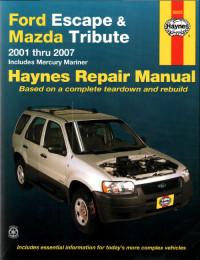
Руководство на английском языке по техническому обслуживанию и ремонту Ford Escape и Mazda Tribute 2001-2007 годов выпуска.
- Автор: —
- Издательство: Haynes Publishing
- Год издания: —
- Страниц: —
- Формат: PDF
- Размер: 89,9 Mb

Руководство на английском языке по техническому обслуживанию и ремонту Ford Escape 2001-2006 годов выпуска.
- Автор: —
- Издательство: Ford Motor Company
- Год издания: —
- Страниц: —
- Формат: PDF
- Размер: 89,4 Mb
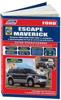
Руководство по эксплуатации, техническому обслуживанию и ремонту + каталог расходных запчастей Ford Escape и Ford Maverick 2000-2007 годов выпуска с бензиновыми двигателями.
- Автор: —
- Издательство: Легион-Автодата
- Год издания: —
- Страниц: 582
- Формат: —
- Размер: —

Руководство по эксплуатации и ремонту Ford Escape, Ford Maverick и Mazda Tribute с 2000 года выпуска с бензиновыми двигателями.
- Автор: —
- Издательство: Монолит
- Год издания: —
- Страниц: 358
- Формат: —
- Размер: —
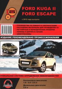
Руководство по эксплуатации и ремонту Ford Escape и Ford Kuga II с 2012 года выпуска с бензиновыми и дизельными двигателями.
- Автор: —
- Издательство: Монолит
- Год издания: 2014
- Страниц: 521
- Формат: —
- Размер: —

Руководство по эксплуатации и ремонту автомобилей Ford Escape и Ford Kuga II с 2012 года выпуска с бензиновыми и дизельными двигателями.
- Автор: —
- Издательство: Монолит
- Год издания: —
- Страниц: 526
- Формат: —
- Размер: —
Руководство по эксплуатации Ford Escape 2008 года выпуска.
- Автор: —
- Издательство: Ford Motor Company
- Год издания: —
- Страниц: 223
- Формат: PDF
- Размер: 2,6 Mb

Руководство по эксплуатации, техническому обслуживанию и ремонту Ford Escape, Ford Maverick и Mazda Tribute с 2000 года выпуска с бензиновыми двигателями.
- Автор: —
- Издательство: Арго-Авто
- Год издания: —
- Страниц: 528
- Формат: —
- Размер: —
Сборник руководств на русском и английском языках по эксплуатации, техническому обслуживанию и ремонту Ford Escape с 2008 года выпуска.
- Автор: —
- Издательство: —
- Год издания: —
- Страниц: —
- Формат: multimedia
- Размер: 264,2 Mb

-
nekesha
- Администратор
- Сообщения: 1668
- Зарегистрирован: 17 дек 2014, 03:43
- Благодарил (а): 2 раза
- Поблагодарили: 6 раз
Ford Escape 2000-2007 / Форд Эскейп 2000-2007
Руководство по эксплуатации, техобслуживанию и ремонту Ford Escape / Форд Эскейп
Operation, Maintenance and Repair Manual Ford Escape

- Года выпуска: 2000-2007
Year of release: 2000-2007
Бензиновые двигатели: YF, L3, AJ
Gasoline engines: YF, L3, AJ
- Язык: Русский
Формат: PDF
Размер: 278 Мб
Russian language
Format: PDF
Size: 278 MB
Скачать документацию Ford Escape / Форд Эскейп
Download the documentation of Ford Escape
для распаковки используйте пароль — avtoproblem-net.ru
use the password to unpack — avtoproblem-net.ru
- Manuals
- Brands
- Ford Manuals
- Automobile
- 2010 Escape
- Workshop manual
-
Contents
-
Table of Contents
-
Bookmarks
Quick Links
2010 Escape, Mariner, Escape Hybrid, Mariner Hybrid
Workshop Manual
Related Manuals for Ford Escape 2010
Summary of Contents for Ford Escape 2010
-
Page 1
2010 Escape, Mariner, Escape Hybrid, Mariner Hybrid Workshop Manual… -
Page 2
SECTION 501-35: Body Repairs 2010 Escape, Mariner, Escape Hybrid, Mariner Hybrid Workshop Manual SPECIFICATIONS Procedure revision date: 07/27/2011 Material Item Specification Fill Capacity Clear Silicone Rubber ESB-M4G92- — TA-32 Flexible Foam Repair — — Fusor® 121, or equivalent; obtain locally Metal Bonding Adhesive —… -
Page 3
1.0 + 3.0 + 1.0 5.2 mm (0.2 in) 3.0 + 1.0 + 2.0 7.1 mm (0.27 in) 0.9 + 0.7 + 0.9 4.3 mm (0.16 in) Descriptions of Ford Steel Families Grade Alloy Content Heat Treatment Typical Applications Comments… -
Page 4
Welding Method Metal Squeeze- Type Trade Inert Resist- ance Use of Temp- Max- Descrip- Spot Welding Cold Heat for erature imum Grade tions (MIG) (STRW) Braze Repairs Repair Range Heat Mild Steel Mild Up to 90 sec. 650°C (1,200°F) Laminate Steel Quiet Steel Bake Hardened BH 180,… -
Page 5
SECTION 501-35: Body Repairs 2010 Escape, Mariner, Escape Hybrid, Mariner Hybrid Workshop Manual DESCRIPTION AND OPERATION Procedure revision date: 07/27/2009 Adhesives Material Item Specification Metal Bonding Adhesive TA-1 — Motorcraft Metal Surface Prep ZC-31-A — Plastic Bonding Adhesive TA-9 — Seam Sealer TA-2 —… -
Page 7
WARNING: Collision damage repair must conform to the instructions contained in this workshop manual. Replacement components must be new, genuine Ford Motor Company parts. Recycled, salvaged, aftermarket or reconditioned parts (including body parts, wheels or safety restraint components) are not authorized by Ford. -
Page 8
Item Description Specification Flushness Specification Hood to fascia (grille) 8.0 mm (0.31 in) ± 3.4 mm (0.13 — Hood-to-headlamp assembly 8.0 mm (0.31 in) ± 3.0 mm (0.11 2.0 mm (0.078 in) ± 3.7 mm (0.145 Headlamp assembly to fascia 4.0 mm (0.15 in) ±… -
Page 9
0.5 mm (0.01 in) ± 1.2 mm (0.04 in) 0.5 mm (0.019 in) ± 2.6 mm (0.102 in) Tail lamp assembly to fascia 4.0 mm (0.15 in) ± 2.5 mm (0.09 in) — Underhood Dimensions NOTE: The following dimensional illustrations are common for Ford Escape and Mercury Mariner. NOTE: Measurements are obtained on center, unless otherwise indicated. -
Page 10
Body Side Closure Dimensions NOTE: Measurements are obtained on center, unless otherwise indicated. -
Page 11
Rear Opening Dimensions NOTE: Measurements are obtained on center, unless otherwise indicated. -
Page 12
Underbody Dimensions NOTICE: A structural frame rail service kit is not available for this vehicle. The frame rail cannot be sectioned. It is mandatory that the replacement section be installed as delivered at the original factory seam locations or collision energy management may be compromised. Frame Datum Height NOTE: Datum height determined measuring from holes and slots on center, unless otherwise indicated. -
Page 13
Underbody Dimensions NOTE: Measurements are obtained on center, unless otherwise indicated. -
Page 14
Underbody Dimensions NOTE: Measurements are obtained on center, unless otherwise indicated. -
Page 15
Sheet-Molded Composite (SMC) is a type of thermosetting plastic that uses glass fibers or nylon fibers in combination with thermosetting polyester resins. When fully cured, SMC is strong and rigid. SMC is similar, but not identical, to fiberglass. Ford Motor Company uses SMC in components such as fenders, hoods and liftgates. -
Page 16
Thermoplastic Compounds Thermoplastic compounds are manufactured by a process that is reversible. Thermoplastics can be remolded repeatedly by reheating. This characteristic of thermoplastics makes plastic welding a possible repair alternative. A repair of thermoplastic compounds is still possible through the use of 2-part adhesive and filler repair materials and reinforcements as needed. -
Page 17
SECTION 501-35: Body Repairs 2010 Escape, Mariner, Escape Hybrid, Mariner Hybrid Workshop Manual DESCRIPTION AND OPERATION Procedure revision date: 03/13/2012 Sealers WARNING: Always refer to Material Safety Data Sheet (MSDS) when handling chemicals and wear protective equipment as directed. Examples may include but are not limited to respirators and chemically resistant gloves. -
Page 18
SECTION 501-35: Body Repairs 2010 Escape, Mariner, Escape Hybrid, Mariner Hybrid Workshop Manual DESCRIPTION AND OPERATION Procedure revision date: 07/27/2009 Sound Deadeners and Insulators WARNING: Always refer to Material Safety Data Sheet (MSDS) when handling chemicals and wear protective equipment as directed. Examples may include but are not limited to respirators and chemically resistant gloves. -
Page 19
NOTE: To restore the vehicle to design intent, missing or damaged sound deadeners and insulators should be installed with the correct service replacement component. Sound deadeners in this illustration all use base part number 99P30A3. -
Page 20
SECTION 501-35: Body Repairs 2010 Escape, Mariner, Escape Hybrid, Mariner Hybrid Workshop Manual DESCRIPTION AND OPERATION Procedure revision date: 07/27/2009 Welding Precautions — Steel General Equipment 3 Phase Inverter Spot Welder 254-00002 Compuspot 700F Welder 190-50080 I4 Inverter Spot Welder 254-00014 Inverter Welder with MIG Welder 254-00015 Weld Nugget Chart Test Thickness of Metal (mm) -
Page 21
• The correct protective clothing should always be worn. • Adequate ventilation must be provided to avoid accumulation of poisonous gases. • Refer to the Ford Recommended Steel Repairability Matrix in the Specifications portion of this section for specific information regarding steel descriptions. -
Page 22
SECTION 501-35: Body Repairs 2010 Escape, Mariner, Escape Hybrid, Mariner Hybrid Workshop Manual GENERAL PROCEDURES Procedure revision date: 07/27/2009 Plastics Identification WARNING: Always refer to Material Safety Data Sheet (MSDS) when handling chemicals and wear protective equipment as directed. Examples may include but are not limited to respirators and chemically resistant gloves. -
Page 23
Apply an open flame to the corner of the damaged component. If the material crystallizes and becomes hard, it is a thermosetting plastic. -
Page 24
Failure to follow this instruction may increase the risk of serious personal injury or death in a crash. NOTE: When using any Ford-approved refinishing product, it is recommended to stay within the same paint system throughout the process. For example, do not use one manufacturer’s primers and another manufacturer’s topcoats. -
Page 25
9. Proceed with the refinish process and follow the Ford-approved paint system procedures. Steps may vary between paint manufacturers. -
Page 26
SECTION 501-35: Body Repairs 2010 Escape, Mariner, Escape Hybrid, Mariner Hybrid Workshop Manual GENERAL PROCEDURES Procedure revision date: 07/27/2009 Plastics Repair Material Item Specification Plastic Bonding Adhesive — TA-9 WARNING: Always refer to Material Safety Data Sheet (MSDS) when handling chemicals and wear protective equipment as directed. -
Page 27
HVTB be removed from the vehicle prior to placing in the paint booth. For additional information, refer to Section 414-03 Finish-sand, prime and topcoat using Ford-approved paint systems. Thermoplastic Compounds 1. In deciding whether to repair or install a new component follow these guidelines. -
Page 28
Section 414-03 Finish-sand the area and carry out any required paint operations using Ford-approved paint systems. Tab Repair — Bumper 1. NOTE: Inspect the bumper cover to determine if part can be repaired to an acceptable level of quality of appearance, fit and durability. -
Page 29
HVTB be removed from the vehicle prior to placing in the paint booth. For additional information, refer to Section 414-03 Perform any required paint repair operations to the bumper cover using Ford-approved paint systems. 9. Reassemble and install the bumper cover. For additional information, refer to Section 501-19… -
Page 30
SECTION 501-35: Body Repairs 2010 Escape, Mariner, Escape Hybrid, Mariner Hybrid Workshop Manual GENERAL PROCEDURES Procedure revision date: 07/27/2009 Refinishing — Environmental Damage Material Item Specification Motorcraft® Acid Neutralizer — ZC-1-A Motorcraft® Alkaline Neutralizer — ZC-2-A 3M™ Perfect-It™ Show Car Liquid Wax —… -
Page 31
7. NOTICE: To avoid paint failure, do not allow the alkaline neutralizer to dry on the vehicle. Apply the product to the vehicle keeping the solution wet and lightly agitate for 5 to 7 minutes. For severe conditions, work the product for up to 8 minutes. 8. -
Page 32
SECTION 501-35: Body Repairs 2010 Escape, Mariner, Escape Hybrid, Mariner Hybrid Workshop Manual GENERAL PROCEDURES Procedure revision date: 07/27/2009 Refinishing — Manufacturing Damage Material Item Specification Motorcraft® Detail Wash — ZC-3-A Rust Inhibitor — ValuGard™ VG104, VG104A (aerosol) WARNING: Always wear protective equipment including eye protection with side shields, and a dust mask when sanding or grinding. -
Page 33
SECTION 501-35: Body Repairs 2010 Escape, Mariner, Escape Hybrid, Mariner Hybrid Workshop Manual GENERAL PROCEDURES Procedure revision date: 07/27/2009 Restoring Corrosion Protection Following Repair Special Tool(s) Rust Inhibitor Installation Kit 286-00002 Undercoating Spray Gun 286-00001 Material Item Specification Motorcraft® Metal Surface Prep —… -
Page 34
4. Air pressure setting for applicator gun is 448-517 kPa (65-75 psi). Use the long wand when spraying enclosed areas. The spray nozzle provides a 360-degree spray pattern. Insert the wand as far as possible into the access hole, pull the trigger and wait 2-3 seconds and slowly pull the wand out of the access hole. -
Page 35
4. NOTE: Door frame opening view. Apply rust inhibitor to the closed channel portion of the spot weld flange areas using the short, hook-shaped wand. Make sure horizontal surfaces are well protected as they are more susceptible to corrosion. Body and Frame Undercoating WARNING: Always refer to Material Safety Data Sheet (MSDS) when handling chemicals and wear protective equipment as directed. -
Page 36
NOTE: Avoid high-pressure water spray cleaning to treated underbody area for 24 hours. Wire brush the area and make sure the surfaces are free of oil, dirt and other foreign material. Carry out the undercoating process in the following sequence. 1. -
Page 37
4. NOTE: Full frame vehicle, front rail-to-mid rail section repair shown. Apply undercoat material to the exposed surfaces after carrying out the welding process. Make sure to completely cover any bare metal areas. -
Page 38
WARNING: Collision damage repair must conform to the instructions contained in this workshop manual. Replacement components must be new, genuine Ford Motor Company parts. Recycled, salvaged, aftermarket or reconditioned parts (including body parts, wheels or safety restraint components) are not authorized by Ford. -
Page 39
WARNING: Do not cut or grind body side components within 50 mm (1.96 in) of restraint anchoring points. Welding within 50 mm (1.96 in) of restraint anchoring points may result in incorrect operation of restraint devices. For additional restraints anchoring location information, refer to Section 501-20A Section 501-20B . -
Page 40
Temperatures in excess of 60°C (140°F) or bake durations longer than 45 minutes will require the HVTB be removed from the vehicle prior to placing in the paint booth. For additional information, refer to Section 414-03 Proceed with the refinish process following Ford-approved paint guidelines. -
Page 41
WARNING: Collision damage repair must conform to the instructions contained in this workshop manual. Replacement components must be new, genuine Ford Motor Company parts. Recycled, salvaged, aftermarket or reconditioned parts (including body parts, wheels or safety restraint components) are not authorized by Ford. -
Page 42
2. Place the welded sample in a vise and perform destructive weld tests by peeling the scrap metal apart using large lock-type pliers. Measure the weld nugget to determine that the nugget meets Ford weld nugget requirements. If the weld nugget does not meet required size, adjust welder settings until the correct weld nugget size is achieved. -
Page 43
16. Use seam sealer wherever a cosmetic seam sealer is required. 17. Mix and apply primer surfacer per Ford-approved paint recommendations. 18. NOTICE: The High Voltage Traction Battery (HVTB) in a Hybrid Electric Vehicle (HEV) can be affected and damaged by excessively high temperatures. -
Page 44
Mix and apply basecoat per paint manufacturer’s recommendations. 19. Mix and apply clearcoat per paint manufacturer’s recommendations. Refinishing materials may be force- dried following paint manufacturer’s recommendations. 20. Apply rust inhibitor or undercoating as required to provide corrosion protection to the repair area. Weld-Bonding —… -
Page 45
Section 414-03 Mix and apply basecoat per Ford-approved paint recommendations. 19. Mix and apply clearcoat per Ford-approved paint recommendations. Refinishing materials may be force- dried following paint manufacturer’s recommendations. 20. Apply rust inhibitor or undercoating as required to provide corrosion protection to the repair area. -
Page 46
SECTION 501-35: Body Repairs 2010 Escape, Mariner, Escape Hybrid, Mariner Hybrid Workshop Manual REMOVAL AND INSTALLATION Procedure revision date: 07/27/2009 Door Outer Panel Special Tool(s) Heat Gun 107-R0300 Heat Treatment Induction Resistance Spot Welder 254-00001 Pro 230 MIG Welder 208-00030 Material Item Specification… -
Page 47
WARNING: Collision damage repair must conform to the instructions contained in this workshop manual. Replacement components must be new, genuine Ford Motor Company parts. Recycled, salvaged, aftermarket or reconditioned parts (including body parts, wheels or safety restraint components) are not authorized by Ford. -
Page 48
Carefully remove the spot welds in the window opening. WARNING: Always wear protective equipment including eye protection with side shields, and a dust mask when sanding or grinding. Failure to follow these instructions may result in serious personal injury. 9. NOTICE: Use extreme care to avoid cutting into the door shell. Using a suitable disc grinder, grind along the perimeter of the outer door panel to separate the hem edges as indicated. -
Page 49
Installation 1. Prepare the door shell assembly. • Grind clean all the mating surfaces of the inner hem • Dress any spot weld nuggets 2. NOTE: Spot welds may be replaced with Metal Inert Gas (MIG) plug welds. Plug welds should equal spot welds in both location and quantity. -
Page 50
7. Sand and prime the flange area and apply a continuous bead of seam sealer to the entire door hem flange perimeter. 8. Prime and paint the door flange area using a Ford-approved paint system. 9. Apply rust inhibitor to the inside of the door assembly to all hem flange and upper belt line areas. For… -
Page 51
Failure to follow these instructions may compromise structural integrity of the vehicle. NOTE: Refer to the Ford Recommended Steel Repairability Matrix in the Specifications portion of this section for specific information regarding steel descriptions. -
Page 52
Item Part Number Description 02039A LH/ 02038A Cowl side panel — mild steel 021A13 LH/ 021A12 Cowl side panel reinforcement — mild steel 02039 LH/ 02038 RH Cowl side panel — Bake Hardened Steel (BH)180 steel 02509 LH/ 02508 RH A-pillar assembly — High-Strength Low Alloy (HSLA) 250 steel 513A31 LH/ 513A30 Roof rail assembly —… -
Page 53
Item Part Number Description 02524 Reinforcement — High-Strength Low Alloy (HSLA) 350 steel Front Structure Item Part Number Description 23A62 Mounting panel — mild steel 1760 Dash upper panel — mild steel 2015 Cowl top outer panel — mild steel 1605 Dash panel —… -
Page 54
16137 LH/ 16136 Reinforcement — mild steel 16055 LH/ 16054 Apron assembly — High-Strength Low Alloy (HSLA) 250 steel 5D085 LH/ 5D084 Outer rail — HSLA 250 steel 5D083 LH / 5D082 Inner rail and torque box — HSLA 250 steel 16138 Radiator support —… -
Page 55
WARNING: Collision damage repair must conform to the instructions contained in this workshop manual. Replacement components must be new, genuine Ford Motor Company parts. Recycled, salvaged, aftermarket or reconditioned parts (including body parts, wheels or safety restraint components) are not authorized by Ford. -
Page 56
Temperatures in excess of 60°C (140°F) or bake durations longer than 45 minutes will require the HVTB be removed from the vehicle prior to placing in the paint booth. For additional information, refer to Section 414-03 Proceed with the refinish process following Ford-approved paint recommendations. -
Page 57
SECTION 501-35: Body Repairs 2010 Escape, Mariner, Escape Hybrid, Mariner Hybrid Workshop Manual REMOVAL AND INSTALLATION Procedure revision date: 07/27/2009 Roof Panel Special Tool(s) Heat Gun 107-R0300 Heat Treatment Induction Resistance Spot Welder 254-00001 Pro 230 MIG Welder 208-00030 General Equipment 3 Phase Inverter Spot Welder 254-00002 Compuspot 700F Welder 190-50080 I4 Inverter Spot Welder 254-00014… -
Page 58
WARNING: Collision damage repair must conform to the instructions contained in this workshop manual. Replacement components must be new, genuine Ford Motor Company parts. Recycled, salvaged, aftermarket or reconditioned parts (including body parts, wheels or safety restraint components) are not authorized by Ford. -
Page 59
2. Remove the luggage rack (if equipped). 1. Remove the luggage rack mounting screws (10 required). 3. Remove the headliner. For additional information, refer to Section 501-05 4. Remove the roof opening panel (if equipped). For additional information, refer to Section 501-17 5. -
Page 60
7. From inside the vehicle, leaving as much of the foam as possible intact, separate the NVH foam along the roof bows from the roof panel using a flexible and sharp broad scraper or knife. 8. Remove (drill out) all the roof panel spot welds from the roof panel windshield header and all mating flanges. -
Page 61
6. Make sure good contact is made with the foam repair and carefully clamp the roof panel on all sides. 7. NOTE: Spot welds may be replaced with Metal Inert Gas (MIG) plug welds. Plug welds should equal spot welds in both location and quantity. Plug welds should be staggered to avoid placement directly over old spot weld. -
Page 62
2 hours, scuff the surface using a red scuff pad. 16. Refinish the roof and repair area following Ford-approved paint system recommendations. 17. Allow refinishing materials sufficient cure time to permit safe handling (refer to paint manufacturer’s specification) and install the roof ditch molding.
 Free Ford Escape repair manuals [pdf] for do-it-yourselfers. Content: general information; maintenance; common specs & procedures; DTC index (trouble codes); accessories & equipment; body & frame; brakes; driveline/axles; electrical; wiring diagrams; engine; engine performance; HVAC; lighting; restraints; steering; suspension; transmission.
 The first generationn Ford Escape (compact crossover sport utility vehicle) was introduced in 2001 in a 5-door sport utility vehicle body style. Technical specs: Wheelbase: 103.1 in (2,619 mm); Length: 173.0-174.9 in (4,394-4,442 mm) 2001-2004; 174.9 in ( mm) 2005-2007; Width: 70.1 in (1,781 mm); Height: 69.1 in (1,755 mm) 2001-2004; 69.7 in (1,770 mm) 2005-2007; 69.7 in (1,770 mm) [Hybrid]; Engines: 2.0L Zetec I4 130 hp (97 kW); 2.3L Duratec 23 I4 153 hp (114 kW); 3.0L Duratec 30 V6 200 hp (149 kW); Transmissions: 5-speed Mazda G5M-series manual; 4-speed CD4E automatic; planetary gear (Hybrid only) Aisin Warner AW HD-10 2-Motor Hybrid System. The first generationn Ford Escape (compact crossover sport utility vehicle) was introduced in 2001 in a 5-door sport utility vehicle body style. Technical specs: Wheelbase: 103.1 in (2,619 mm); Length: 173.0-174.9 in (4,394-4,442 mm) 2001-2004; 174.9 in ( mm) 2005-2007; Width: 70.1 in (1,781 mm); Height: 69.1 in (1,755 mm) 2001-2004; 69.7 in (1,770 mm) 2005-2007; 69.7 in (1,770 mm) [Hybrid]; Engines: 2.0L Zetec I4 130 hp (97 kW); 2.3L Duratec 23 I4 153 hp (114 kW); 3.0L Duratec 30 V6 200 hp (149 kW); Transmissions: 5-speed Mazda G5M-series manual; 4-speed CD4E automatic; planetary gear (Hybrid only) Aisin Warner AW HD-10 2-Motor Hybrid System.
|
 2001-2007 Ford Escape repair manual 2001-2007 Ford Escape repair manual
|
|
2004-2007 Ford Escape Hybrid repair manual
|
|
2001-2007 Ford Escape wiring diagrams
|
|
The second generation Ford Escape was introduced in 2008. Technical specs: Wheelbase: 103.1 in (2,619 mm); Length: 174.7 in (4,437 mm); Width: 71.1 in (1,806 mm); Height: 67.7 in (1,720 mm) 2008; 67.8 in (1,722 mm) [AWD 2009-2012]; 67.9 in (1,725 mm) [FWD 2009-2012]; Engines: 2.3L Duratec 23 I4 produced 153 hp (114 kW); 2.5L Duratec 25 I4 produced 171 hp (127.5 kW); 3.0L Duratec 30 V6 produced 200 hp (149 kW); Transmissions: 5-speed manual; 4-speed CD4E automatic; 6-speed 6F35 automatic; planetary gear (Hybrid only).
|
|
2008-2012 Ford Escape repair manual
|
|
2008-2012 Ford Escape Hybrid repair manual
|
|
2008-2012 Ford Escape wiring diagrams
|
|
The third generation Ford Escape was introduced in 2013. Technical specs: Layout: front-engine, front-wheel-drive and four-wheel-drive; Wheelbase: 105.9 in (2,690 mm); Length: 178.1 in (4,524 mm); Width: 72.4 in (1,839 mm); Height: 66.3 in (1,684 mm); Engines: 1.6L EcoBoost I4 produced 178 hp (133 kW); 2.0L EcoBoost I4 produced 240 hp (179 kW); 2.5L Duratec I4 produced 168 hp (125 kW); Transmissions: 6-speed 6F35 automatic.
|
|
2013-present Ford Escape repair manual
|
|
2013-present Ford Escape wiring diagrams
|
|
Free Ford repair manuals
|
This website uses cookies
We use cookies on our website to give you the most relevant experience by remembering your preferences and repeat visits. By clicking “Accept”, you consent to the use of ALL the cookies.