vk
Избранное
0
Избранное
Ваш список избранного пуст
Продолжить покупки
Очистить
В Избранное
Личный кабинет
Авторизация
Электронная почта *
Пароль: *
Показать пароль
warning
Caps Lock включен.
Пароль может быть введен неверно.
Забыли пароль?
close
все результаты
+7(967)093-95-20
+7(995)500-74-99
![]()
0
Корзина
Корзина
В корзине пока ничего нет
Продолжить покупки
Очистить
В Корзину
Каталог
Каталог товаров
Запчасти Yamaha YBR 125
Расходники
Пластик, оптика
Тормозные колодки
Управление
Электрика, электроника
Двигатель, железо, подвеска
Тюнинг и аксессуары
Остальное
Уцененные товары
Запчасти Honda CB400
Запчасти Stels Flame 200
Запчасти IRBIS
IRBIS TTR250
IRBIS TTR250R
Запчасти ИЖ
Запчасти Минск
Запчасти Восход, Сова
Тормозные колодки
Масла и химия
Резина
Мотоцепи
Цепи 415
Цепи 420
Цепи 428
Цепи 520
Цепи 525
Цепи 530
Замки для цепей
Звезды
Комплекты цепь + звезды
Сальники и пыльники вилки
Аксессуары
menuМеню
Меню
- Контакты
- Доставка
- Скидки
- Отзывы
- О нас
- Войти
Мануалы
- Главная
- Мануалы
Категории товаров
Запчасти Yamaha YBR 125
Расходники
Пластик, оптика
Тормозные колодки
Управление
Электрика, электроника
Двигатель, железо, подвеска
Тюнинг и аксессуары
Остальное
Уцененные товары
Запчасти Honda CB400
Запчасти Stels Flame 200
Запчасти IRBIS
IRBIS TTR250
IRBIS TTR250R
Запчасти ИЖ
Запчасти Минск
Запчасти Восход, Сова
Тормозные колодки
Масла и химия
Резина
Мотоцепи
Цепи 415
Цепи 420
Цепи 428
Цепи 520
Цепи 525
Цепи 530
Замки для цепей
Звезды
Комплекты цепь + звезды
Сальники и пыльники вилки
Аксессуары
Руководство по эксплуатации YBR 125 — 1.4 Mb
Руководство по эксплуатации YBR 125 обновленное — 3.2 Mb
Руководство по ремонту YBR 125 — 3.9 Mb
![]()
+7(967)093-95-20
+7(995)500-74-99
Каталог
menuМеню
arrow_right_alt
Материал из BikesWiki — энциклопедия японских мотоциклов
Перейти к: навигация, поиск

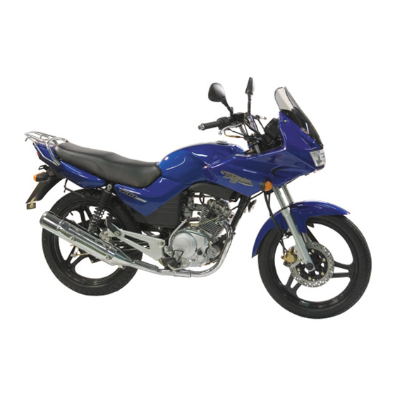
Yamaha YBR 125
Ниже представлены прямые ссылки на скачку сервисной документации.
Для Yamaha YBR 125
- Руководство пользователя (Owners Manual) для Yamaha YBR 125 (на русском)
- Сервисный мануал (Service Manual) для Yamaha YBR 125 (на русском)
Обзор модели
- Yamaha YBR 125
Источник — «https://bikeswiki.ru/index.php?title=Yamaha_YBR125:_мануалы&oldid=10116»
Категория:
- Сервисная документация

- Manuals
- Brands
- Yamaha Manuals
- Motorcycle
- YBR125 Custom
- Service manual
-
Contents
-
Table of Contents
-
Troubleshooting
-
Bookmarks
Quick Links
YBR125(JYM125/125-2)
Chongqing Jianshe·YAMAHA Motor Co.,Ltd
First edition Jan.2003
All rights reserved.Copy in any manner,
in whole or part,or use without written
authorization of company,prohibited.
Related Manuals for Yamaha YBR 125
Summary of Contents for Yamaha YBR 125
-
Page 1
YBR125(JYM125/125-2) Chongqing Jianshe·YAMAHA Motor Co.,Ltd First edition Jan.2003 All rights reserved.Copy in any manner, in whole or part,or use without written authorization of company,prohibited. -
Page 2
Notice This service manual compiled by ChongqingYAMAHA Motor co.,Ltd, is specially used for dealer and maintenance · station of Chongqing JiansheYAMAHA Motor co.,Ltd. It is not possible to include all the knowledge of a mechanic in one · manual,it is only used for repairing and maintaining JiansheYAMAHA motorcycle and understand the principle of vehicle, ·… -
Page 3: How To Use This Manual
How to use this manual Manual Organization This manual includes many chapters which explain the main contents of each title individually. First title :An abbreviation and symbol in the upper right corner of each page indecates the current chapte Second title :This title is shown in the left of section symbol of upper right corner of each page. Third title :It is a title of the smallest unit,which is compiled step by step and matched with relevent picture Exploded Diagram In order to u…
-
Page 5
Index § General information INFO § Specification Periodic inspection § and adjustment § Engine § Carburetor § Chassis § Electrical system § Troubleshooting… -
Page 6: Table Of Contents
Chapter 1 General information Motorcycle identification ………………………………………………………………………… Motorcycle identifcation code …………………………………………………………………… Points for attention in maintenance ……………………………………………………………… Special tool ……………………………………………………………………………………… Chapter 2 Specification Main specification ……………………………………………………………………………… Inspection specification ………………………………………………………………………… Engine …………………………………………………………………………………………… Chassis …………………………………………………………………………………………… Electrical system ………………………………………………………………………………… Main tighten torque specification ……………………………………………………………………
-
Page 7
Check of front fork ……………………………………………………………………………… 3-22 Adjustment of rear shock absorber ……………………………………………………………… 3-23 Check of tire ……………………………………………………………………………………… 3-24 Check of steering device ………………………………………………………………………… 3-25 Electrical system Check of battery …………………………………………………………………………………… 3-26 Chapter 4 Disassembly of engine Dissassembly of engine Disassembly of exhaust pipe and lead wire ………………………………………………………… -
Page 8
4-36 Kick starter ……………………………………………………………………………………… 4-36 Engine oil pump,filter …………………………………………………………………………… 4-37 Crankcase ………………………………………………………………………………………… 4-38 Bearing,oil seal …………………………………………………………………………………… 4-38 Elastic circlip,washer ……………………………………………………………………………… Assembly and adjustment of engine 4-39 Assembly and adjustment of engine ……………………………………………………………… 4-40 Air valve ………………………………………………………………………………………… 4-41 Rocker arm,cam shaft ……………………………………………………………………………… -
Page 9
Inspection of clutch hub ………………………………………………………………………… 6-17 Installation of drive chain ………………………………………………………………………… 6-18 Front fork Removal of front fork …………………………………………………………………………… 6-19 Inspection of front fork …………………………………………………………………………… 6-22 Front fork assembling …………………………………………………………………………… 6-23 Steering shaft and handle ………………………………………………………………………… 6-27 Removal of handle …………………………………………………………………………………… -
Page 10: Chapter 1 General Information
Chapter 1 General information Motorcycle identification ………………………… …………………… Motorcycle identification code ……………… Points for attention in maintenance ……………………………………… Special tool…
-
Page 11: General Information
Motorcycle identification INFO General information Motorcycle identification Motorcycle identification code Motorcycle identification code is stamped on the right side of steering bar.It consists of three portions.First portion (the first 3 digits) is the identification code of world manufact- urer identification(WMI); Second portion(6 digits)is vehicle definition section(VDS);…
-
Page 12
INFO… -
Page 13
G EN INFO… -
Page 14
GE N INFO Note: Do not use compressed air to spin the bearings dry. This will damage the bearing surfaces. -
Page 15
G EN INFO… -
Page 16
GE N INFO… -
Page 17: Main Specification
…………………………………………………2-1 Main specification ……………………………………………2-4 Inspection specification …………………………………………………………2-4 Engine …………………………………………………………2-6 Chassis ………………………………………………2-8 Electrical system …………………………………2-9 Main tighten torque specification 2-12 …… to be ap ng-oil and s of lu ng-oil ition plied bricati kind bricati ………………………………………………………… 2-12 Engine ………………………………………………………… 2-13 Chassis ………………………………………2-14 Engine lubrication diagram …………………………………………2-16…
-
Page 18: Engine
YAMALUBE,four-strokeSAE20W40SF’’or Machine oil type: “SAE10W30SF” machine oil Engine oil…
-
Page 19
VM22SH MIKUNI CR6HSA 0.6mm 0.7mm Wet,multi-piece Spur gear 68/20(3.400) Chain drive 45/14(3.211) Constant mesh 5-speed shift Left foot operation 37/14(2.643) 32/18(1.778) 25/19(1.316) 23/22(1.045) 21/24(0.875) Diamond 26.4 With tube 2.75-18(42P) 90/90-18(51P) 175kPa(1.75kgf/cm) 196kPa(2.0kgf/cm) Drum or single-disc brake Right hand operation Drum brake Right foot operation… -
Page 20
JYM125(JYM125-2) Suspension: Front Retractable sleeve type Rear Rocker arm type Shock absorber: Coil spring/oil damper Front Rear Coil spring/oil damper 1290mm Wheelbase Electrical system Ignition system Generator system A · C · magneto Battery type Immediately use Battery capacity 12V5Ah Headlinght type Bulb type Incandescent bulb… -
Page 21
0.08~0.12mm 0.10~0.14mm <4.950> <4.935>… -
Page 22
5.000 5.012mm 5.000 5.012mm 0.010 0.037mm 0.025 0.052mm… -
Page 24
Rear wheel Type Spoke/casting wheel Rim dimension 1.85×18(W) Rim material 0.5mm Rim runout (radial) (lateral) 0.5mm Driving chain: DID1480H Type/manufacturer No.of links Twist quantity 20 30mm Front brake: Type Disc brake Disc outside dia×thickness 245×4 3.5mm Use limit of disc thickness Thickness of brake pad (Inside) 0.8mm (Outside) -
Page 26: Engine
Tighten torque Tighten torque Engine Tighten torque Dimension Qty ′ Tighten parts Part Name Kgf.m M8×1.25 2.2±0.2 22±2 Cylinder head Hexagonal flange faced bolt 90105-08742 M6×1.0 1.0±0.2 10±2 Cylinder head(Side of timing chain) 9131N-06090 Internal hexagonal cylinder head bolt M6×1.0 0.7±0.2 7±2 Bolt of oil drainage port…
-
Page 27
Tighten torque Tighten torque Tiighten parts Part Name Dimension Qty ′ kgf.m Hexagonal flange faced bolt 9502L-08040 M8×1.25 18-28 1.8-2.8 Handle bar seat and inner tube (small head) 90176-22800 Cap-shape nut N22×1.0 100-120 10-12 Handle bar seat and steering shaft Hexagonal flange faced bolt 5VL-F3346-00 23-35… -
Page 28
Tighten torque For noraml tighten torque,tighten screw and nut Dia of screw(width of two faces) Tighten torque × Space of thread can decide tighten torque according to diameter M5(8mm)×0.8 34Nm(0.3 0.4kg.m) of thread(width of two faces)and space of thread M6(10mm)×1.0 5 8Nm(0.5 0.8kg.m) except appointed tighten torque.(see the table in M8(12mm)×1.25… -
Page 29
Valve stem End of valve stem(intake&exhaust) Rocker arm shaft Cam and bearing(cam shaft) Inside of rocker arm YAMAHA bond No.125 Left and right closed face of crankcase O-ring(all) Inside of foot pedal gear Inside of idle gear of foot pedal… -
Page 30
Meter gear Cam and shaft of cam shaft Rotation portion of brake pad pin Lip portion of oil seal of hub assy,clutch assy and brake cover assy YAMAHA -stoke engine oil Light-weight lithium-soap base grease Molybdenum disuflide grease 2 — 13… -
Page 31: Lubrication Diagram
Lubrication diagram Rocker arm(intake) Centrifugal filter Rocker arm shaft Oil pump Rocker arm(exhaust) Pushing rod Cam shaft Filtering web 2 — 14…
-
Page 33
Layout of cable pipline E Wire of starting generator shall pass through the inte rior ofbattery F Flowing guide tube of battery shall pass through the interior of battery G Fix the wire of magneto and brake switch at the wire clip H Pass the brake cable and flexible shaft of meter though guide frame. -
Page 34
Layout of cable pipline Drum type without fairing… -
Page 35
Layout of cable pipline A Pass the wire of the cable,brake cable,brake switch and handle bar switch through guide frame. B Pass the wire of clutch cable,handle bar switch and clutch switch through guide frame. C Fix the wire of left handle bar switch and clutch switch with bands. D Fix the wire of right handle bar switch and brake switch with bands. -
Page 36
Layout of cable pipline Disc type with fairing… -
Page 37
Layout of cable pipline Disc type without fairing… -
Page 38
Layout of cable pipline Wire of front brake switch Wire of left turning light Brake cable Wire of clutch switch Wire of right turning light Wire of left handle bar switch Throttle cable Clutch cable Wire of right handle bar switch Fig. -
Page 39: Electrical System
……………………………………… Brief introduction/Contents of periodic inspection …………………………… Removal and installation of cushion,fuel tank and cover alike …………………………………………… Check and adjustment of air valve clearance ………………………………………………………………… Adjustment of idle speed …………………………… Drainage/Check and adjustment of free play of throttle cable ………………………………………………………………………… Check of spark plug …………………………………………………………
-
Page 40: Carburetor
INSP Run-in period Initial Every 3, 000 3000 Items Routine 1,000 (600) (2,000) (2,000) or 1 month or 3 months or 3 months Check valve clearance,adjust if necessary. Air valves* ○ ○ ○ Spark plug Check condition clean or r ace if n ecessar ○…
-
Page 41
○ ○ Battery* for proper operation. Correct if necessary. It is recommended that these items be serviced by YAMAHA authorized service station or dealer. Heavy-duty or medium truck wheel bearing grease. Lithium-soap base grease Remark: Replace brake fluid If disassembling brake master cylinder or long pincers cylinder,the brake fluid must be replaced.Check the under normal conditionand refill if necessary. -
Page 42
INSP Removal and installation of cushion, fuel tank and cove alike 1.Side cover(left) Open with the key, then pull out set pin of side cover , finally take out side cover along the direction pio- nted by arrow . 2.Side cover(right) Take out bolt at position with screwdriver,then pull out set pin of side cover ,finally take out side cover along the direction pointed by arrow . -
Page 43
INSP 6. Fuel cock Switch the fuel cock off Note: First close the fuel cock on the fuel tank at the position “ ” ,then take off the fuel pipe. 7. Fuel tank Bolt Shim Rubber pad Fuel tank 8.Installation Conduct as per reverse procedure of removal operation pay attention to the following 1.Installation… -
Page 44
Inspection and adjustment of air valve clearance INSP Engine Inspection and adjustment of air valve clearance Note: The valve clearance must be adjusted when the engine is cool. Adjust the air valve clearance when the piston is at the Top Dead Center(T.D.C) on compression stroke. 1.Remove the following parts. -
Page 45
Inspection and adjustment of air valve clearance INSP 4.Turn the rotator counter-clockwise,align the T.D.C mark a of rotator with the T.D.C mark b on the cran- kcase cover. 5. Conduct the following inspection. Air valve clearance Standard air valve clearance: IN:0.08 0.12 mm Ex:0.10 0.14 mm Conduct adjustment for the valve under standard value… -
Page 46
Idle speed inspection/adjustment INSP Idle speed adjustment Start and warm the engine for several minutes. Install the following parts Rpm meter of engine Install Rpm meter of engine on the wire of high pressure(spark plug wire). Rpm meter of engine: 90890-03113 3. -
Page 47: Throttle Cable
Drainage and adjustment of freeplay of throttle cable INSP 5.Remove the following parts Rpm meter of engine Adjustmet of co content at idle speed Install the following measuring meter:measuring meter with detector for normal temperature and rpm meter of engine. Warm the engine until the oil temperature reachs to specified value.
-
Page 48: Check Of Spark Plug
Adjustment of frdd play of throttle cable and check of spark plug INSP Note: When the adjustment could not done by the steel cable at throttle handle bar,it could be done by the adjuster at the carburetor. Second step(carburetor) Loosen the locking screw Adjust the adjuster Screw in→Increase the dearance Screw off→Decrease the dearance…
-
Page 49: Check Of Compression Pressure
Check of compression pressure INSP Note: Insufficient compression pressure wil result in the performance loss. Check: Air valve clearance→adjust Refter to «adjustment of air valve» Start and warm the engine for several minutes. Stop the engine Remove:spark plug Install: Pressure manometer Joint Pressure manometer:90890-03081 Joint:90890-04082…
-
Page 50
When normally replacing: 1.0L 1000mL ) When repairing the engine 1.2(1200mL) Refer to the indication in the fig,select the proper engine lubricating-oil which suits for viscosity code of local temperature. Recommended engine oil: YAMAHA four-stroke lubricating-oil. 3 — 11… -
Page 51: Replacement Of Engine Lubricating-Oil/Check Of Lubricating-Oil Pressure
ment of engine oil/ -oil pressure INSP place lubricating- check of lubricating Replacement of engine oil Note: Do not add any chemical additives.Engine oil also lubricates the clutch and additives could cause clutch slippage.Do not allow foreign material to enter the crankcase.
-
Page 52
Adjustment ofclutch/adjustment of front brake INSP Adjustment of clutch 1.Check: Freeplay of clutch cable a out of specified range →adjust Free play: 10 15mm Measure at end portion of clutch lever 2.Adjust: Free play of clutch cabl Adjusting steps: Confirm that adjusting device and locking nut have been fully tightened. -
Page 53
Clear of air filter INSP Clear of air filter Note: There is check hose at the bottom of the air filter.If dust or water collects in this hose,clean the air filter core and case. 1.Remove Side cover(right) Cushion Case of air filter 2.Remove Core of air filter Note:… -
Page 54
Clean of air filter INSP 3.Check: Filter core of air filter Damage → Replacement Dusty Blowing off dust on net with compressed air → Remov e the filter cores1and 2 , and clean them by blowing with high-pressure air. If the filter core 2 is too dirty, it may be washed with neutral solution.It must be blown dry after washing. -
Page 55: Check Of Front Brake Pad
Adjust of front brake INSP Adjust of front brake(drum type) Check: Free travel a of brake cover Exceeding specified range adjustment → Adjustment: Free travel of brake lever Adjusting procedure(lever side) Loosen the lock nut Screw in or screw out the adjusting nut until reac- hing specified free travel.
-
Page 56: Check Of Front Brake(Disk Type)
Check of front brake INSP Check of front brake(disk-type) Wrning If feeling loose and soft braking,the bad brake effect may be caused by oil leakage or mixing with air.You should check brake liquid capacity,and lock brake steel cable,or eliminate air. Conducting following check: If there is vibration when turning leftward or rightward or driving, you should check if the brake nose contact…
-
Page 57: Check The Brake Liquid Quantity/Exhausting Air
If the liquid level is below the lower position,sup- ply the brake liquid until above the lower limit position. Appionted brake liquid:genuine YAMAHA brake liquid DOT4 Note: Do not mix and use brake liquid of different brand DOT3 oil can be used if there is no No DOT4 oil.The brake liquid will corrupt the painting surface and pla- stic part.wipe off it inmedinately when splashing.
-
Page 58: Replacing Brake Fluid
4.Remove the diaphragm of brake liquid vat. Fill the brake liquid until above lower limit. Appointed brake liquid:genuine YAMAHA brake liquid DOT4 Note: Do not mix and use brake liquid of different brand DOT3 oil can be used if there is no DOT4 oil.
-
Page 59: Check And Adjust Rear Brake
Checking,adjusting rear brake/Check of rear brake shoe INSP Operate the brake handlebar until no bubble sends out from the small hole of brake liquid vat and the brake handlebar is felt powerful. Release air. Assemble according to reverse procedures after adjus- ting .
-
Page 60
Checking rear brake light switch/Checking,adjusting driving chain INSP Checking rear brake switch Conduct following checking Brake light Check if the brake light comes on when treading down the brake pedal 20 30mm. Brake light does not come on adjustment → (Rotate the adjusting nut for adjustment) Rear brake light switch… -
Page 61: Check And Adjust Driving Chain
Checking,adjusting driving chain/Check of fronk fork INSP Checking,adjust driving chain Note: There is graduation mark on chain adjuster.When adjusting,should ensure the identical graduation value on driving chain adjusters of two sides of rear arm. After the left and right adjuster is adjusted properly, tighten up the lock nut of adjuster and lock nut of axle.
-
Page 62: Adjustment Of Rear Shock Absorber
Check of front fork/adjustment of rear shock absorber INSP Keep the motorcycle in vertical parking state,and acti- vate front brake. Check: Activating state Make the front fork sliding up and down certain times. Blocking in activating → Repair Refer to section of Front fork in Chapter 6 “…
-
Page 63: Check Of Tire
Check of tire INSP 1.Measure Tire pressure Exceeding specified valueadjustment → Pressure of Front wheel Rear wheel cold tire 175kPa Load below 0~90 kg (1.75kgfcm ) (2.0 Kgf/cm ) 196kPa Max,load 100kg (2.0 Kgf/cm ) (2.5 Kgf/cm ) * Load means total weight of cargo,driver and accessaries 2.75-18(42P) Specification of front wheel Specification of rear wheel…
-
Page 64: Check Of Steering Device
Check of steering device INSP Check of steering device Conduct following device Support the front wheel,and sway the lower part of front fork to check if the steering axle is loose.Check if the steering bar can be turned to left and right smoothly. Loose steering axle,unsmoothed turning adjusting nut →…
-
Page 65: Check Of Battery
Check of battery INSP Check of battery Disassemble: Side cover(left) Reter to section “Disassembly of side cover” Check: Electrolyte level The electrolyte level must be between upper mark line and lower mark line . If the electrolyte level is too low, supply the electrolyte properly.
-
Page 66
Check of battery INSP Connet: Airflow hose Must confirm firm connection and correct way of air flow hose. Check: Specific gravity Smaller than1.08 → Recharge Charging current:0. 5 A / 10 h Specific gravity:1.28 at 20 68o F Replace the battery when finding following condition. During charging,the votage can not reach the specified value or no bubble rises. -
Page 67
Check of battery INSP Warning Method for detoxication(external) Skin——Wash with water. Eyes——Wash with water for 15 minutes,and see a doctor immediately. Method for detoxication(internal) Drink plenty of water of milk.Then take oxidized milk with egg or rapseed oil,and see a doctor immediately. The battery will produces explosive gas. -
Page 68: Kick Starter
Chapter 4 Disassembly of engine Disassembly of engine Disassembly of exhaust pipe and lead wire ………………………………………………………………………… Disassembly of carburetor, clutch cable, speedometer cable and driving chain …………………………………… Disassembly of engine ……………………………………………………………………………………………… Disconnectin of engine …………………………………………………………………………………………… Disassembly of cylinder head, cylinder and piston ……………………………………………………………………
-
Page 69: Assembly And Adjustment Of Engine
Assembly and adjustment of engine ………………………………… Assembly and adjustment of engine … Air valve ……………………………………………………………… Swaying arm, cam axle ……………………………………………… ………………………………………………… Crank, balance device Transmission ………………………………………………………… Shift cam, shifting yoke … …………………………………………… Crankcase ……………………………………………………………… Shift axle , starting axle , idle gear ………………………………………
-
Page 70: Disassembly Of Engine
Disassembly of engine Thorough repair of engine Disassembly of engine 1.Disassemble: Side cover Cushion Fuel tank Refer to section of “Disassembly of cushion, fuel tank and side cover”. Engine oil 1.Oil draining: Engine oil Refer to section of “Replacement of engine oil” in Chapter3.
-
Page 71
Disassembly of engine Disconnect Guid wire of positive and negative electrode of batt Guid wire of starting motor Dsconnect Cable of clutch Shift pedal and driving chain Loosen Nut of rear wheel shaft Note: n the device and increase nut of chain a just the slackness of chain. -
Page 72
Disassembly of engine Disassemble: Mounting bolt , nut ( lower side ) Disassemble: Mounting bolt(rear part of engine and frame) Disassemble: Mounting bolt ( upper part of engine and support ) mounting bolt ( upper support and frame ) Disassembly of engine Cylinder cover, cylinder and piston Disassemble: Spark plug… -
Page 73
Disassembly of engine Disassemble: Air valve cover(intake) Air valve cover ( exhaust) Disassemble Side cover of cylinder cover Timing adjustment Make the mark“ ”on rotator aiming at the fixing needle on crankcase cover. ******************************* *********** Timing adjusting procedure Rotate the crank counterclockwise with wrench. Make mark“… -
Page 74: Cylinder Head
Disassembly of engine Loosen Cover bolt(chain tensioner device ) Disassemble Chain tensioner device Disassemble: Bolt Cam chain gear Note: Fix the timing chain with protective steel wire to prevent the chain dropping into crankcase. Disassemble: Bolt Cylinder head Note: Firstly loosen each bolt 1 / 4 turn. After loosening all bolts, remove them.Loosen them successively from Min.number .
-
Page 75
Disassembly of engine 11.Disassemble Guide board of chain Locating pin Cylinder pad Cylinder 12.Disassemble: Locating pin Papper pad Disassemble: Elasric circlip of piston pin Piston pin Piston Note : Before disassembling the cirlip of piston pin,cover a piece of clean cloth on crankcase to prevent the elastic circlip dropping into crankcase. -
Page 76
Disassembly of engine Disassembling tool of piston pin: 90890-01304 Left crankcase cover,starting motor Disconncct Neutral light switch Disassemble: Left crankcase cover Locating pin Seal papper pad Disassemble Starting motor Clutch, oil pump 1.Disassemble: Kick starter device Disassemble: Crankcase cover (right) Seal papper pad Locating Note:… -
Page 77
Disassembly of engine Disassemble Bolt Clutch spring Pressing pan Friction wafer Clutch wafer Pushing rod1 Steel ball Note: Firstly loosen each bolt 1 /4 turn according to order of opposite angle, then remove all bolts. 4.Flatten: Smoothen the tongue of lock washer Loosen: Note: When loosening nut ( convex seat of clutch ), fix the… -
Page 78
Disassembly of engine 5.Disassemble: Lock wacher Clutch hub Spline washer Main driven gear Washer Elastic washer Disassemble: Primary driving gear nt Note: Do not place cloth strip, aluminium plate and copper bar etc . between main driven gear and primary driving gear ( see a ). -
Page 79
Disassembly of engine Disassemble: Primary driving gear Engine oil filter Engine oil pump 1.Disassemble Bolt Engine oil pump Gasket Driving gear of engine oil pump Starting axle and idle gear 1.Disassemble: Elastic circlip Flat washer Idle gear Flat washer Elastic circlip 2.Disassemble: Resetting spring Starting axle assy… -
Page 80
Disassembly of engine Shift axle 1.Disassemble Shift rod Resetting spring Bolt Stop device Rotator Disassemble Note: Fix the rotator with rotator jig , then loose nut. Rotator jig: 90890-01701 2.Disassemble: Rotator Half-round key Note: Push the fly wheel backward with disassembling tool of fly wheel, then may disassemble the fly wheel . -
Page 81
Disassembly of engine 3.Disassemble: Starting idle gear Washer Disassemble Pressing plate of gear Starthing idle gear2 Disassemble: Chain guide board Timing chain Crankcase ( right ) 1.Disassemble: Screw ( crankcase ) Note: Loosen the screw at position as shown in Fig (po- sition in circle ). -
Page 82
Disassembly of engine 2.Disassemble: Star-shape gear Locating pin Note: Disassemble the crankcase from right side. Disassemble the shift cam (star-shape gear ) . Be careful not to damage the matching surface of crankcase . Balance device , transmission and shift rod 1.Disassemble: Guide rod of shifting yoke ( short ) -
Page 83
Disassembly of engine Disassemble Main axle Inner pushing rod of clutch Driving axle Washer Pushing rod of clutch Disassemble Idle switch Disassembly of crank and balance 1.Disassem Balance block Crank Disassemble with disassembling tool of crank . Disassembling tool of crank: 90890-01135 Note: Tighten up the supporting bolt of disassembling tool,… -
Page 84
Disassembly of engine Rocker arm and camshaft Disassemble: Lock pressure plate Disassemble : Camshaft( with bearing Note : Disassemble the camshaft with 8 mm bolt . Disassemble: Rocker shaft Rocker arm Note : Disassemble the rocker arm with sliding hammer bolt and weight block . -
Page 85
Disassembly of engine Valve Note : Before disassembling the inner parts of cylinder head (such as valve , valve spring and valve seat ) , check the seal of valve firstly . 1. Check: Seal part of valve Leakage of valve seat→Checing working face of valv Valve seat and width of valve Refer to section of “Check and repair of valve seat”. -
Page 86
Disassembly of engine 3.Disassemble Upper seat of air valve spring Air valve spring Air valve Oil seal of air valve Spring Note: Mark postions of each part in order to refiting them to oringinal position. 4 — 17… -
Page 87: Cylinder Head
Check and repair Cylinder head 1.Clean Carbon deposit (Clean from burning chamber) Use round-head scraper Note: Do not use sharp tool for avoiding the damagement of the spark plug thread and air valve seat. 2. Check: Cylinder head Scratched marks damage→Replacement 3.
-
Page 88
Check and repair Air valve seat 1.Clean: Carbon deposit (Clean from working face of air valve and air valve seat) Check: Air valve seat Corrosive pitting or wear→Repair the air valve surface Measure: Width of air valve seat a Exceeding specification both are usable value range →Repairing air valve seat Width of air valve seat: Intake:… -
Page 89: Air Valve And Guide Pipe Of Air Valve
Check and repair 4. Grind: Working face of air valve Air valve seat Note: After replacing air valve and guide pipe of air valve, grind the air valve seat and working face of air valve. ******************************** ********* Grinding procedure Paint rough abrasive sand on working face of air valve. Note: Do not let the abrasive sand enter into slit between air valve rod and guide pipe of air valve.
-
Page 90
Check and repair Air valve and guide pipe of air valve 1.Measure: Clearance between air valve rod and guide pipe Clearance between air valve and guide pipe= Inner diameter of air valve guide pipe — air valve rod diameter Exceeding specified value range→Replacing guide pipe of air valve Clearance between air valve rod and guide pipe: Intake:… -
Page 91: Air Valve Spring
Check and repair 3.Check: Working face of air valve Corrosive pitting or wear→polishing the surface Air valve rod end Mushroom shape or diameter more than other part of air valve rod→replacing 4. Measure: Run-out tolerance (air valve rod) Exceeding specified value range→Replacement Run-out tolerance Less than0.01 mm Air valve spring…
-
Page 92: Camshaft
Check and repair 2. Check: Vertical angel degree of air valve spring Side angle limitation a : 1.2 mm 3. Check: Contacting face of air valve spring Above2 / 3 of outer circle are not in horizontal conta- cting state→Replacement Camshaft 1.
-
Page 93
Check and repair Length of convex part of cam: Exhaust: A Standard: 25.841 25.941 mm Limitation: 25.811 mm B Standard: 21.050 21.150 mm Limitation: 21.02 mm 3. Check: Bearing Jamming,swaying→Replacing Rocker arm and rocker shaft 1. Check: Contacting face of rocker arm and convex part of Adjusting device surface Wearing, corrosive pitting, scratch, blueing →… -
Page 94
Check and repair 3. Measure: Outer diameter b of rocker shaft Outer diameter of rocker shaft: Standard value:9.981 9.991 mm Limitation:9.95 mm Timing chain,sprocket,guide plate of chain and chain tensioner 1. Check: Timing chain Hardening or crack→Replace the whole set of timing chain and chain wheel 2.Check: Sprocket… -
Page 95: Cylinder And Piston
Check and repair 4 . Check: Free movement of timing chain tensiener Checking procedure: Press the tensioning device lightly with finger,and screw the tensioning device rod to dead with small screwdriver When pressing screwdriver lightly with finger to loosen the screwdriver, confirm that the tensioning device come out smoothly.
-
Page 96: Piston Pin
Che ck and repair Piston measurement 1. Measure: Measure diameter of skirt section of piston with micr- ometer at the point 5mm to bottom edge of piston. Outer diameter standard of piston: 53.997 54.029 mm Clearance between piston and cylinder Inner dia- Outer dia- meter of…
-
Page 97: Piston Ring
Check and repair 3.Measure: Inner diameter of piston pin hole b Inner diameter of piston pin hole: 15.002 15.013 mm Using limitation: 15.043 mm Exceeding limitation→Replacement Piston ring 1. Measure: Side clearance Exceeding specified value range→Replacing the whole set of piston and piston ring. Note: Before measuring side clearance,get rid of carbon deposit in piston ring groove and each ring.
-
Page 98: Crank
Check and repair 3.Measure: End clearance Note: When measuring the oil ring end clea ce,do not easur at p g slip of cup r g of oil r measure the end cle ce of guard aran upper lower rails. If the clearance is too large, replace all the three rings.
-
Page 99
Check and repair 3.Measure: Crankshaft width(measure with square calliper) Standard width: 46.95 47.00 mm Exceeding standard→Replacement 4.Check: Sprocket of crankshaft Damage,wearing →Replacing crankshaft Bearing Abnormal noise,unstable rotation,loosening→ Replacing 5.Check: Oil way of crankshaft Jamming→Clean by compressing a 4 — 30… -
Page 100: Balance Device
Check and repair Balance device 1.Check: Driving gear of crankshaft Driven gear of balancer Wearing,damage →Replacement 2. Check: Balancer Wearing,damage→Replacement Clutch 1.Check: Driving gear of spindle Driven gear of spindle Wear or damage→Replacing two gears Loud noise while running→Replacing two gears 2.Check: Friction wafer Damage or wear→Replacing the whole set of friction…
-
Page 101
Check and repair 3. Measure: Thickness of friction wafer Exceeding specified value range→Replacing the whole set of friction wafer.Measuring at four points of upside, lowside,leftside,and rightside. Thickness of friction wafer: 3.0 mm Using limitation: 2.8 mm 4.Check: Clutch wafer Damage→Replacing the whole set of clutch w afer Measure: . -
Page 102
Check and repair 7.Check: Retainer of main&driven gear Scratch,wear,damage→Deburring of replacing Clutch hub Scratch,wear,damage→Replacing clutch hub Check: Steel ball Pushing rod Pressing plate Wear,damage→Replacement Transmission and shift rod 1.Check: Driven part of shifting yoke cam Shifting yoke jaw Scratch,bending,damage→Replacement 4 — 33… -
Page 103
Check and repair 2.Check: Shift cam groove Wear or damage→Replacement 3.Check: Guide rod of shifting yoke(short on left, long on right Shift cam Deformation, scratch, wear, damage→Replacement 4.Check: Action of shifting yoke Uneasy action→Replacing shifing yoke or guide rod Warning Do not try to align the bending guide rod. -
Page 104
Check and repair 5.Measure: Run-out tolerance (driving axle and main axle) Exceeding specified value range→Replacement Warning Do not try to align bending axle 6.Check: Gear teeth of gear Blueing,corrosive pitting, wear→Replacing matching gear Rounding of edge, fracture, dislocation→Replacement 7.Check: Shift axle Damage, bending, wear→Replacement Torsion spring(retainer lever) Reset spring(reset axle) -
Page 105
Check and repair Kick starter Check: Teeth of kick starter gear eeth of kick starter over-gear Damage or wear→Replacing two gear by pa Measure: Tension of work carrier of kick starter Exceeding specified value range→replace to Use spring balance Tension of work carrier of kick starter 0.8 1.2 kg i c k s t a C h e c k :… -
Page 106: Crankcase
Check and repair 2.Check: Centrifugal eigine oil filter → Crazine, damage Replacement Dirty → Washing 3.Check Engine oil filter net → Crazine, damage Replacement → Dirty Washing Crankcase Rinse the combinating face of the crankcase thoroughly with a little warm solvent. Wash all matching surface of gasket and crankcase th- oroughly.
-
Page 107
Check and repair Bearing and oil seal Check: Bearing Wash and lubricate it, then rotate the inner ring with fi- nger. Uneven → Replacement Note: Do not dry it by making the bearing rotating by itself through blowing in compressed air.Otherwise will cause damage of bearing surface. -
Page 108: Air Valve
Assembling and adjustment of engine Assembly and adjustrment of engine Air valve rod(intake) Air valve,swaying arm and cam axle 13 O-ring Lock piece of air valve Lock nut 14 Guide pi pe of air valve Upper seat of air valve spring Adujstin g bolt 15 Cam a…
-
Page 109
Assembling and adjustment of engine Assembly of engine and adjustment of air valve 1.Deburr End of air valve rod Polish the end of air valve rod with oil stone 2.Paint: Molybdenum disulfide lubrication oil (Painting on air valve rod and oil seal of air valve) 4-stroke engine oil (Painting on air valve rod top) 3. -
Page 110
Assembling and adjustment of engine 4.Mount: Lock piece of air valve Note: When mounting the air valve lock piece,compress the spring with compressing tool of air valve spring. Compressing tool of air valve spring: 90890-04019 5.Beat lock piece of air valve lightly with soft hammer to fix it on air valve rod. -
Page 111
Assembling and adjustment of engine 3. Mount: Camshaft 4.Mount: Pressing plate Bolt 4-42… -
Page 112
Assembling and adjustment of engine Crank and balance device Crank pin Crank bearing Semi-round key Crank(left) Connecting rod Balancer Balancer bearing Roller bearing of end side 4-43… -
Page 113
Assembling and adjustment of engine Mount of crank and balance axle 1.Mount: Crank Shielding hood of crank assembly: 90890-04081 Sleeve of crank assembly 90890-01274 Bolt of crank assembly 90890-01275 Template pipe joint 90890-01378 Note: Keep the connecting rod on dead piont. When mounting, never contact crankcase. -
Page 114: Transmission
Assembling and adjustment of engine Transmission assembly Main axle Driving chain wheel Driving gear- Bearing Circlip Oil seal Driving gear- Drive gear-5gear Bearing Drive gear-2gear Bearing Driving gear- Driving gear- 5gear Driving gear- Drive gear-3gear Driving axle Bearing Drive gear-4gear 4-45…
-
Page 115
Assembling and adjustment of engine Shiftcam,shifting yoke Guide rod of shifoing yoke(long) Shifting yoke 3 Shifting yoke 1 Star-shape gear Guide,rod 2 of shifing yoke(short) 4-46… -
Page 116
Assembling and adjustment of engine Installation of thransmission,change cam and change fork Installation: Clutch push rod 2.Installation: Main shaft Note: Before installing the main shaft, first installing the push rod in the clutch into the inner hole of main sh- aft,then installing it. -
Page 117: Crankcase
Assembling and adjustment of engine 5. Installation Change cam (The convex point on the change cam should alig n the contact point in the neutral switch of crankcase) Change cam “ ” (The surface signed “L” is toward clutch) Change fork“R” (The surface signed with “R”…
-
Page 118
Assembling and adjustment of engine Fastening order Left crankcase Dowel pin Airflow pipe Right crankcase Clutch fastening clip Yamaha bonder No.1215 4-49… -
Page 119
Assembling and adjustment of engine Crankcase(Right) Application Seal gum (Apply to the linking surface of left and right crankcase) Seal gum(Yamaha bonder No.1215) 90890-85505 Note: Never allow any seal gum to enter into the lubricati- on oil hole Installation: Dowel pin… -
Page 120
Assembling and adjustment of engine Shift shafl,pedal spindle and pedal idle speed gear Shift shaft Circlip Reset spring Washer Retainer Idler pulley Tortion spring Washer Star wheel Circlip Start shaft assy 4-51… -
Page 121
Assembling and adjustment of engine Shiftcam 1.Installation: Dowel pin Installation Star wheel Note: When installing the star wheel ,pay attention to install the pin hole on the star wheel and the pin hole a on the cam correctly. 3.Installation: Retainer Spring Bolt (Retainer) 1.0kgf.m (10Nm) -
Page 122
Assembling and adjustment of engine Pedal shaft and pedal idle speed gear 1.Installation : Drive shaft H oop Sprin g o te The projecting part should be installed on the a po- sition of crankcase,and the fastening of spring should be down only after it turns 1turn. -
Page 123
Assembling and adjustment of engine Clutch,oil pump Spring Clutch hub Drive gear 19Paper pad of oil Press plate Retaining washer Oil filter Dowel pin Push plate Main driven gear Drive gear of oil pump Push rod Steel ball Friction liner Push rod Drive gear of oil pump Clutch plate… -
Page 124
Assembling and adjustment of engine Oil pump supplement of oil 4-stroke engine oil (supply to the oil hole in the crankcase and oil hole in the oil pump) 2.Installation: Oil pump Oil filter 1. Installation: Drive gear of oil pump Centrifugal filter Note: Install the dowel pin a of centrifugal filter into the… -
Page 125
Assembling and adjustment of engine Clutch Installation: Main driven gear Retaining washer Clutch hub Retaining gasket Installation: Note: Fasten the clutch hub with clutch fixture ,lock the nut and bend the retaining gasket Clutch fixtrue 90890-04086 Nut torque (60N.m)6.0kgf Installation: Friction linertotal of pieces total of 3 pieces… -
Page 126
Assembling and adjustment of engine Installation Steel ball Installation Push rod 1 Push plate Washer 6.Installation: Press pla Spring Screw Screw installing torque 0.6 kgf.m (6 N.m) Note: Tighten up the bolts orderly according to the diago- nal order. 4-57… -
Page 127
Assembling and adjustment of engine Confirmation The aligning identification of push rod assy and crank- case Turn the push rod assy counterclockwise to the end, make sure the projecting part of push rod a is identified with the aligning identification (convex part) b →… -
Page 128
Assembling and adjustment of engine Timing chain Woodruff key Guide plate of chain Rotor Locating shaft Stator Idle start gear Paper gasket Press plate Dowel pin Washer 13Left crankcase cover Starting gear 2 4-59… -
Page 129
Assembling and adjustment of engine Rotor and stat mechanism Inspection Check the gear conditions of start gear 1 and 2 ( a b c ) Rag, scrap, unsmoothness, abrasion→replace Inspection Start gear 2(linking surface ) Corrosive pitting, abrasion, damage → replace ***************************************** Inspection procedures:… -
Page 130
Assembling and adjustment of engine .Installation: Washer Starting gear .Installation: Woodruff Rotor Note: Before installing clean off the foreign matter and dirt on the rotor. 6 .Locking: Fastening torque 7.0Kgf.m(70N.m) Note: Fasten the rotor with slide retaining tool , lock the rotor with a nut with washer. -
Page 131
Assembling and adjustment of engine Piston and piston ring 1. Installation of piston ring Oily plate Oil scraping plate 2nd ring 1st ring Note: When installing the 1st ring and 2nd ring,pay atte- ntion to the upper and lower directions.The surface with sign should be assemblied upward. -
Page 132: Cylinder And Piston
Assembling and adjustment of engine Cylinder and piston Cylinder Piston O-ring Piston pin Paper pad Dowel pin Piston ring Piston pin hoop 4-63…
-
Page 133: Cylinder Head
Assembling and adjustment of engine Cylinder head Bolt Cylinder head Copper washer Dowel pin Inner hexagonal bolt Steel pad Valve cover(Intake) O-ring O-ring Side cover of cylinder head Valve cover(Exhaust) Spark plug 4-64…
-
Page 134
Assembling and adjustment of engine Cam shaft and locating key Paper pad Tensioner Chain guide plate(intake) Timing sprocket Timing chain Chain guide plate(exhaust) 4 65… -
Page 135: General Drawing Of Carburetor
Chapter 5 Disassembling of carburetor 5 — 1 General drawing of carburetor ……………………………………………………………………………… 5 — 2 Removal of carburetor ……………………………………………………………………………………… Adjustment of fuel level …………………………………………………………………………………… 5 — 5…
-
Page 136
CARB Carburetor Needle valve Rubber pad Circlip Start spanner 46 O-ring Adjusting screw of throttle cable Firm clip Rubber sleeve Needle washer Wave washer Washer Bolt Spring Throttle cable guide pipe Needle Screw Ps adjusting screw Float Rubber washer Plunger Rubber cap Top cover cap Float pin… -
Page 137
CARB Carburetor 1.Removal Throttle cable Caburetor Disassembly 1. Loosen Oil drain screw 2. Removal Plunger 3. Removal: Starting wrench Starting plunger 4. Removal Float chamer… -
Page 138
CARB Carburetor 5.Rmoval: Float pin Float Needle valve Needle valve seat 6. Removal: Main jet Needle valve jet O-ring 7. Removal: Idling fuel jet 8. Removal: P.S adjusting screw Inspection 1. Inspection Mixing chamber case of carburetor → If polluted clean… -
Page 139
CARB Carburetor 3.Inspection: Float → If damaged replace 4. Inspection: Needle valve Needle valve seat O-ring If worn or damaged → replace Note: The needle valve and its needle valve seat should be replaced as a complete set. 5. Inspection: Main nozzle Main jet O-ring… -
Page 140
CARB Carburetor Assembly Conduct according to the reverse procedures of removal. Note: Before reassembly, clean all parts with clean gas- oline. Adjustement of fuel level 1. Measurement: Fuel level a → Over the specification value adjust Fuel level a : 6.6 7.6 mm The fuel level should be at the middle postion of the float chamber on the lower… -
Page 141
CARB Carburetor Loosen the oil drain screw , run the engine for se- veral minutes to raise the temperature. Keep the fuel level dipstick in vertical condition and make it approach to the engrave line of float chamber. Measure the fuel level with fuel level dipstick. Note: The records of the fuel level dipsiticks of the pipes on two sides of the carburetor should be equal. -
Page 142
Chapter 6 Chassis Inspection of front and rear wheels ………………………………………………………………………… Front wheel …………………………………………………………………………………………………… Inspection of front wheel …………………………………………………………………………………… Speedometer gear assy ……………………………………………………………………………………… Front brake …………………………………………………………………………………………………… Installation of front wheel …………………………………………………………………………………… Rear wheel 6-10 …………………………………………………………………………………………………… Rear brake hub 6-13 ………………………………………………………………………………………………… Drive chain , sprocket 6-15 …………………………………………………………………………………………… -
Page 143: Inspection Of Front And Rear Wheels
CHAS Inspection of front and rear wheels Front wheel Self-locking nut Meter gear assy Front wheel axle Bushing Front brake assy Bushing Front wheel F r o n t w h e e l ў Щ S e l f — l o c k i n g n u t ў…
-
Page 144
CHAS Inspection of front and rear wheels Front wheel Brake pad Bushing Washer Washer Meter clutch Meter driven gear Meter drive gear O-ring Brake arm Oil seal Indicator Cam axle 1,0Kgf.m(10 N.m) -
Page 145
CHAS Inspection of front and rear wheels Removal Warning 1.Rest the motorcycle on the flat ground. 2.Place the motorcycle on its central stand. 3.Place the proper articles under the frame or eng ine to lift the front wheel. Front brake 1 .emoval: Front brake cable Note:… -
Page 146: Inspection Of Front Wheel
CHAS Inspection of front and rear wheels 4.Removal Front wheel axle Front brake assy Bushin Front wheel Inspection of front wheel Inspection ront wheel axle(inspect with pencertage meter) If bent→replace Warning Never attempt to straighten the bent front wheel axle. The twist limit of front axle:0.25mm 2.Inspection Wheel…
-
Page 147: Speedometer Gear Assy
CHAS Inspection of front and rear wheels Inspection Turn the wheel rim slowly to inspect the radial and ax- ial runout. of limit →replace Rim runout limit Radial: 1mm Axial: 0.5mm Inspection Wheel bearing If the bearing inside the hub has windage unsmooth rotation, slackness, abnormal sound→replace Oil seal…
-
Page 148: Front Brake
CHAS Inspection of front and rear wheels Drive chain of meter Driven chain of meter Front brake 1.Inspection Friction liner surface of brake pad Smooth area→polish Polish with rough sand Note After polish with sand,clean off the grainsof polishing material. Measurement Friction liner thickness of brake pad ut of specification→replace…
-
Page 149
CHAS Inspection of front and rear wheels 4. : I nspection There is oil stain or scraping mark on the inner surface of brake drum→changeand repair Oil stain Wipe with a cloth dipped in the paint diluent or solvent. Scrape Polish slightly and evenly with a emery cloth 5. -
Page 150
CHAS Inspection of front and rear wheels Installation Brake Spring Note : When installing , never use the pliers to deform or damage the hook of spring. Never apply the ludrication grease onthe friction liner of brake pad. Installation Driven gear of meer Installing meter cable Speedometer cable head 5. -
Page 151: Installation Of Front Wheel
CHAS Inspection of front and rear wheels Installation of front wheel Installation Front brake cable Meter cable Nut ( front wheel axle ) Installation Front wheel Note : The convex seat on the front fork should be engaged with the locating slot of the brake padplate correctly. Cable The action of brake If the action is not smooth→repair…
-
Page 152: Rear Wheel
CHAS Inspection of front and rear wheels Rear wheel Adjusting nut Driven chain gear Rear wheel Spring Rear brake assy plit pin Shock absorber Tension rod Oil seal Self-locking nut Bushing Chain adjuster assy Bearing 6-10…
-
Page 153
CHAS Inspection of front and rear wheels Rear wheel Brake shoe Brake arm Indicator Cam axle 6-11… -
Page 154
CHAS Inspection of front and rear wheels Rear wheel Warning Rest the motorcycle firmly so as to avoid it turn over. 2.Removal Adjusting nut Tension rod Spring Brake pull rod Rear wheel nut 3.Removal F r o n t w h e e l ў… -
Page 155: Rear Brake Hub
CHAS Inspection of front and rear wheels 5. Removal Shock block If damaged,deformed→replace Rear brake hub 1. Inspection Inner surface of brake drum Oil stain or scrape→repair Oil stain: Wipe a cloth dipped in the paint diluent or solvent. Scrape:Poslish slightly and evenly with a emery cloth. Brake hub inner diameter Standard value:130mm Limit value:131mm…
-
Page 156
CHAS Inspection of front and rear wheels 3.Installation Rear wheel Note: he convex part of clutch hub should be inserted into the groove of the shock block. 4. Installation Rear wheel axle F r o n t w h e e l ў… -
Page 157
CHAS Drive chain and sprocket Rear drive chain Sprocket cover Small sprocket(drive) Chain press plate Connector of chain Chain (drive chain) Big sprocket(driven) Adjuster assy Circlip Retaining press plate 6-15… -
Page 158: Drive Chain
CHAS Drive chain and sprocket Removal 1.Rest the motorcycle on the central stand. Warning Rest the motorcycle firmly to avoid turnover. Removal Sprocket cover 3.Removal Drive sprocket 4.Removal Chain joint clip Press plate of chain Chain Driven chain Inspection of drive chain 1.Inspection Drive chain jam If jammed→Lubricate after cleaning or replace…
-
Page 159: Inspection Of Clutch Hub
Measure the length of 10 links at diffrient parts for 2~3 times. 5.Cleaning Clean with neutral detergent. After cleaning apply a plenty of chain lubrication oil of SAE10 w-30w YAMAHA 4-stroke engine oil. Warning Never clean with the volatile matters such as steam, gasoline,solvent,etc. Inspection of clutch hub 1.Inspection…
-
Page 160: Installation Of Drive Chain
CHAS Drive chain and sprocket 2.Installation Install as shown on the fig Bend the jaw part of limit prers plate in a or b as shown on the left fig,after bend deformattion,stick the side of the nut firmly. Installation of drive chain 1.Installation Drive chain Chain tensioner…
-
Page 161
CHAS Front fork Bolt Front fender 11 Washer Plug 12 Plug rod of oil stocking Bolt 13 Damper rod O-ring 14 Inner pipe Spacer 15 Spring Spring seat 16 Oil seal Spring 17 Outer Dust cover pipe Clip 6-19… -
Page 162: Removal Of Front Fork
CHAS Front fork Take out the front fork Warning Rest the motorcycle firmly to avoid turnover. Rest the motorcycle on the flat ground. Place a proper bracket under the frame and the engine to surpport the front wheel. Removal Front wheel Front fender Loosen Loosen the bolt…
-
Page 163
CHAS Front fork Removal Dust cover Clip Note: Be careful not to damage the surface of inner pipe. Removal Grip the shock absorber rod loosen the bolt with T lever and shock absorber fixture. T flat handle 90890-01294 6.Removal Bolt Washer 7.Removal Oil seal… -
Page 164: Inspection Of Front Fork
CHAS Front fork Inspection of front fork 1.Inspection Bending of inner pipe Bending limit 0.2mm Warning Never attempt to straighten the bending inner piper, otherwise,the pipe will be damaged seriously. 2.Measurement Free length of front fork spring a Free length of front fork spring 336.9mm Min.
-
Page 165: Front Fork Assembling
CHAS Front fork Assembling of front fork Conduct according to the reverse procedures of «disass- embling»,pay attention to the following items. Note: When reassembling the front fork ,use the follow- ing new components. Oil seal Dust cover Before reassembling,make sure that all compon- ents are cleaning.
-
Page 166
CHAS Front fork 5.Fastening Bolt(damper rod) Bolt 2.3Kgf.m(23N.m) Note: Fasten the bolt of damper rod with T handle wr- ench and damper rod fixture. “T”tool 90890-01326 Shock absorber rod fixture:90890-01294 6.Installation Oil seal 7.Installation Clip Outer pipe 6-24… -
Page 167
CHAS Front fork 8.Inspection Stretch of inner pipe If the stretch is not smooth → Inspect again after disase- mbling. Oil filling Measuring glass Oil amount:156mm 10W shock absorber oil 10.After filling oil,move the front fork up and down slo- wly so as to let the oil spread into the pipe. -
Page 168
CHAS Front fork Installation of front fork Conduct according to the reverse procedures of «removal 1.Installation Front fork Tighten up the fixing bolt tempotarily. Note: When installing , align the inner pipe end with bolt head end. 2.Fastening Bolt Bolt Cover bolt Torque of position :2.8Kgf.m(28N.m) Torque of pisition :Kgf.m(23N.m) -
Page 169
CHAS Steering axle and handle bar Handle bar holder Dust cover Handle bar Steering axle Right handle bar assy Bearing race(upper) Handle bar seat Roller holding bracket(upper) Limit clip Roller holding bracket(lower) Ring nut Bearing race2(middle) Ring rubber pad Bearing race(Lower) Ring nut The inner diameter of two bearing races are different… -
Page 170
CHAS Steering axle and handle bar Handle bar 1.Removal Remove left and right lever switches 2.Removal Handle bar holder Handle bar Handle bar seat Removal Front wheel 4.Removal Front fork 6-28… -
Page 171: Inspection Of Handle
CHAS Steering axle and handle bar 5.Removal Limit clip Ring nut Ring rubber pad 6.Removal Ring nut Remove with steering nut wrench Steering nut wrench 90890-01403 Warning Remove only with wrench. 7.Removal Bearing race 2 Roller race 2 Roller holding bracket(upper) Steering axle Roller holding bracket(Lower) Inspection of handle bar…
-
Page 172
CHAS Steering axle and handle bar Inspection of front steering axle Clean the roller holding bracket and bearing race. Inspection Roller holding bracket Bearing race Worn,damaged→replace ****************** ************************ Procedres for replacement: As shown on the fig,remove the bearing race with a long rod and hammer,take it out from the cencave groove of fork pipe of steering joint. -
Page 173: Steering Shaft And Handle
CHAS Steering shaft and handle bar Installation of the handle bar 1.Install Handle bar Handle bar clamp Coupling torque 2.3Kgf.m(23N.m) Note: The bolt ahead must be fastened first. When assembling the steering, the projection of handle bar clamp is in front of installation direction. 2.Install: Front brake lever Clutch lever…
-
Page 174: Rear Shock Absorber And Rear Arm
CHAS Rear shock absorber and rear arm Rear shock absorber Rear rocker arm Connecting rod Chain shield 6-32…
-
Page 175: Removal
CHAS Rear shock absorber and rear arm Removal 1.Rear shock absorber Warning The motorcycle should be supported firmly to avo- id turning. 2.Remove Left-right rear shock absorber 3.Remove Rear wheel 4.Remove Chain 5.Remove Connecting rod Chain shield Rear rocker arm Inspection 1.Check Slackeness of rocker arm…
-
Page 176: General Drawing Of Circuit
Chapter 7 Circuit General drawing of circuit ………………………………………………………………………………………… Electric components………………………………………………………………………………………………… Inspection of socket connector …………………………………………………………………………………… Inspection of switch ……………………………………………………………………………………………… Ignition system …………………………………………………………………………………………………… Starting system 7-12 …………………………………………………………………………………………………… Starting motor 7-17 …………………………………………………………………………………………………… Charge system ……………………………………………………………………………………………………… 7-22 Lighting system …………………………………………………………………………………………………… 7-26 Signal system ……………………………………………………………………………………………………… 7-31…
-
Page 177
Circuit ELEC Circuit Drawing… -
Page 178
ELEC Circuit Magneto Instrument Rectified adjuster Fuel signal sender Battery Horn Starting relay Left lever switch Starting motor Flash relay Positive wire Front brake switch Negative wire Rear brake switch Main switch Neutral switch Right lever switch Headlamp Clutch switch Tail lamp CDI unit assy Front left turning lamp… -
Page 179: Electric Components
ELEC Circuit Electric components Rectifying adjuster Battery Rear brake switch Fuel sensor Starting relay Three keys assy Fuse plate Main cable…
-
Page 180: Electric Components
ELEC Circuit Electric components 4.Flash relay assy Ignition coil assy Spark plug cap assy 5.CDI unit Neutral switch assy 6.Horn…
-
Page 181: Inspection Of Socket Connector
ELEC Inspection of socket connector Inspection of socket connector The dirt rust and moisture on the socket connector should be removed. Remove Socket connector Dry every connector with air. Evey socket connector should be connected and dis charged for 2/3 times Check if the wire is come off with hand If the binding t…
-
Page 182
ELEC Inspection of socket connector Inspection of the switch Inspection method of the switch Check the conduction of terminals with multitester. If any poor condition is found, replace the switch im ediately. Multitesler 90890-03112 Note: Start the switch several times to cheak. Before checking,turn the multitester to “O”… -
Page 183
ELEC Ignition System Circuit of ignition system Maganeto CDI unit Ignition coil/spark plug Main switch… -
Page 184: Troubleshooting
ELEC Inspection of socket connector Exclusion of trouble shooting Ignition system failure (No spark or discontinuous spark) Resistance of pulse coil Inspection procedure Resistance of spark charging coil Spark plug Checking spark Main switch ircuit terminal(loop of ignition system) Resistance of the spark plug cap Ignition coil Remark Before excluding the troubleshooling,the following parts side cover cushion fuel tank should be removed…
-
Page 185
ELEC Inspection of socket connector 3.Resistance of spark plug cap lead wire of voltage gauge→spark plug side lead wire of voltage gauge→high-pressure wire side Remove the spark plug cap Connect the multitester(test frequency×1K) to spark plug cap Remark Don’t pull down the spark plug from the high-pressure wire. -
Page 186: Inspection Of Socket Connector
ELEC Inspection of socket connector lead wire of voltage gauge→High-pressure wire lead wire of voltage gauge→Orange terminal 5.Resistance of secondary coil of ignition coil Connect multitester(test frequency×1k) to terminal of high-pressure coil. Resistance value of ignition coil Ω ± ° 3.16 K 10%(20 C) Abnormal…
-
Page 187
ELEC Inspection of socket connector 7.Resistance of ignition charge coil Remove the ignition charge coil Connect the multitester (test Ω×1000) to the terminal of charge coil Connecting method Lead wire of voltage gauge→Green terminal lead wire of voltage gauge→Brown terminal Resistance of charge coil 860Ω±20%(20 °… -
Page 188: Starting System
ELEC Starting system Circuit of starting system Battery 21Neutral switch Starting relay Starting motor Main switch Right lever switch Clutch switch 7-12…
-
Page 189: Starting System
ELEC Starting system Exclusion of troubleshooting No work of starting notor Inspection procedure Battery 5.Starting relay Fuse Starting switch Starting motor Neutral switch Main switch Clutch switch Remark Before excluding ,the following components should be removed Side cover Cushion The following specific tool should be used when excluding. Min.multitester 90890-03112 No conduction…
-
Page 190: Starting System
ELEC Starting system Warning The capacity of the cross-bond must be equal to or 3.Starting motor larger than that of the battery wire,otherwise, the Connect the positive binding post of battery cross-bond will be burnt. to the cable of starting motor with cross-bond. See figare.
-
Page 191
ELEC Starting system 5.Main switch Remove the branch-connetor of main switch from the bale of wire. Check if the switch is conducted between the red and the brown. Abnormal Normal If the main switch is failure,replace it 6.Neutral switch Remove the wire of neutral switch from the bundle conductor. -
Page 192
ELEC Starting system 7.Clutch switch Remove the branch-connector of clutch switch from the bale of wire. Check if the clutch switch is conducted between “the black” and “the black ” Abnormal If the clutch switch is failure,replace it Normal Poor connection,break 8.Wire joint Refer to the loop wire of starting system Correct or replace… -
Page 193: Starting Motor
ELEC Starting system Starting motor Magnet-wheel Starting motor assy Electric button Rear bracket Adjusting pad Electric brush spring Front bracket Electric brush assy O-ring O-ring Length limit value of electric brush 3.5mm Wear limit value of commutator 21.0mm Hexagon slot 1.5m Resistance value of electric button coil 0.017~0.021Ω20°C…
-
Page 194
ELEC Starting system Removal Remove Wire of starting motor Starting motor assy Stripping Before stripping, make the identifiable mark on the frond and rear bracke to be easy to check when asse- mbling. 2.Remove The front bracket The rear bracket Remove Electric button Magnet-wheel… -
Page 195
ELEC Starting system 3.Measure The depth of mica sheet slot a Out of normal range→grind it with hand saw to make it fits to normal value. Depth of the mica slot 1.5mm Note: The insulated mica sheet of commutator must has slot ,which can sure the normal work of the com- mitator. -
Page 196
ELEC Starting system 6.Measure Elastic force of the electric brush spring Fatigue or out of the normal value→replace it as a set. Elastic force of the electric brush spring 560~840g Assemble According to the contary procedure of Remova “ 1.Install Electric brush spring Electric brush Note:… -
Page 197
ELEC Starting system Install ring Note Replace new one 4.Install Magnet-wheel Note: The matching mark on the magnet-wheel shoeld be align with that on the rear bracket,then the installation is done. 5.Install Front bracket Note: The installation is done after the project of washer is align with the groove of front bracket Make the matching mark on the magnetic yoke be align with that of front-rear bracket. -
Page 198: Charge System
ELEC Charge system Charge system Circuit Diagram CDI magneto Rectifing adjustor Battery Starting relay 7-22…
-
Page 199
ELEC Charge system Exclusion of trouble shooting No charge on the battery Fuse Lamp switch Battery Double-beam lamp switch Main switch Remark Refore excluding,the following components should be removed. Side cover Cushion The following specific tool should be applied Multitester 90890-03112 No conduction 1.Fuse… -
Page 200
ELEC Charge system 3.Charge voltage Connect the induction tachymeter to the wire of the spark plug. Connect min.multitester (DC20V) to the battery Positive wire of multitester→positive binding post of battery. Negative wire of multitester→Negative binding post of battery. Check the charge voltage after the engine is accelerated to 5000r/min. -
Page 201
ELEC Charge system 5.Connecting condition of wire Poor connetion Check the whole connecting condition of charge system. Refer to section “circuit Diagram”. Correct Normal Reinstall the rectifier/adjuster 7-25… -
Page 202: Lighting System
ELEC Lighting system Lighting system Circuit diagram Battery Right lever switch Head lamp Tail lamp 7-26…
-
Page 203
ELEC Lighting system Exclusion of troubleshooting Headlamp, high-beam indicator of headlamp, tailamp and instrument garden light are not lit Remark Before excluding ,the following components should be removed. Side cover Cushion Hood The following specific tool should be applied when excluding. Min.multitester Part number 90890-03112 No conduction… -
Page 204
ELEC Lighting system 4.Main switch Remove the branch-connector of main switch from the bundle conductor. Check if the switch between «the red «and «the Abnormal brown»is conducted. Normal 5.»Garden light»switch If the main switch is failure,replace it Remove the branch-connector of handle bar sw- itch (right) from the bundle conductor. -
Page 205
ELEC Lighting system Inspection of lighting system 1.Headlamp and high-beam indicator of headlamp are not lit. No conduction 1.Bulb and socket Check if the bulb and socket are conducted. Replace the bulb or socket Conduction 2.Voltage Connect Min. multitester(DC20V)to branch -connector of headlamp and to that of indicator. -
Page 206: Lighting System
ELEC Lighting system 2.Voltage Connect min. Multitester(DC20V)to the branch -connector of socket. Positive wire of multitester→Yellow binding post Negative wire of multitester→Black binding post Turn the main switch to «ON» postition. Turn the «garden light»switch to «ON» position. Check if the voltage of Brown wire on socket cnnector «…
-
Page 207: Signal System
ELEC Signal system Signal system Circuit Diagram Main switch Tai lamp/brake lamp Starting relay 2426 Front left-right turning lamp Battery 25 27 Rear left-right turning lamp Front brake switch Fuel signal sender Rear brake switch Instrument assy Horn Neutral switch Flash relay Left handle lever switch assy 7-31…
-
Page 208
ELEC Signal system Exclusion of trouble shooting Blinker, brake lamp or indicator are not lit and the horn does not work. Inspecttion procedure Fuse Main switch Battery Wire joint Remark When excluding,the following components should be When excluding,the following specialtol should be used: removed Multitester Side cover Cushion… -
Page 209
ELEC Signal system Inspection of signal system 1.No function of the horn Abnoraml 1.Horn switch Remove the branch-connector of handle bar switch(left)from the bundle conductor The horn switch is failure,the lever switch (left) Check if the switch between the Pink and the should be replaced. -
Page 210
ELEC Signal system 2.The brake lamp is not lit No conduction 1.Bulb and socket Check if the bulb and the socket are conducted. Replace bulb or socket 2.Brake switch Abnormal Remove brake switch guide wire from the bundle connector. Check if the switch between the «Yellow &Brown» and «Black&… -
Page 211: Signal System
ELEC Signal system 3.Blinker/turn signal lamp,indicator no work. No conduction 1.Bulb and socket Check if the bulb and socket are conducted Conduction Replace the bulb or the socket 2.Turn signal switch Abnormal Remove the branch-connector of handlebar switch (left)from bundle conductor Check if the switch between»Brown/white&…
-
Page 212
ELEC Signal system 5.Turn indicator Connect min. Multitester(DC20V) to socket connector Connection at the left blinker Positive guide wire of multitester Brown guide wire → Negative guide wire of multitester→Frame groun Connection at the right blinker Positive guide wire of multitive→Dark green guide wire Negative guide wire→Frame ground wire Out of normal value… -
Page 213
ELEC Signal system 7-37… -
Page 214
ELEC Signal system 2.Voltage Connect min. Multitester(DC20V) to branchconn- nector of fuel gange.(at the side of bundle conductor) Check if the brown wire voltage at the fuel gauge Out of normal value binding post (at the side of bundle conductor)gets to 12V. -
Page 216: Electric Appliance System
Trouble Troubleshooting of engine Troubleshooting of engine Electric Appliance system *Check all socket connector of guide wire Ignition coil(refer to page ) 7-8 Main switch ·Damage of short-circuit of main coil Short-circuit of main switch or secondary coil · ·Break or short-circuit of ·Failure of high-pressure guide wire guide wire ·Failure of spark plug cap…
-
Page 217
Trouble Troubleshooting of engine Compressure system Inadequate tight force Buckle/carbon deposit Wear/choke/damage Damage Carbon deposit Damage Damage Buckle/wear/damage Wear/choke/damage Damage Damage Wear/scratch Damage Wear/scratch/damage Wear/choke/damage… -
Page 218: Intake And Exhaust System
Trouble Troubleshooting of engine Intake and exhaust system…

В данном Руководстве используются следующие
специальные обозначения, призванные обратить Ваше
внимание на особо важные фрагменты документа:
Символ, предупреждающий о необходимости
соблюдать требования безопасности. Ваша
безопасность под угрозой!
При несоблюдении требований, содержащихся в
тексте, мотоциклист, пассажир, прохожий, инспектор
или ремонтник могут получить серьезную травму или
погибнуть!
При несоблюдении специальных мер
предосторожности мотоцикл может быть поврежден.
Примечание:
Полезная для вас информация, поясняющая в
доступной форме особенности выполнения
изложенных в документе процедур.
Опасность
Внимание
Примечание:
Данное Руководство должно рассматриваться как
неотъемлемая часть мотоцикла.
Примечание:
Компания YAMAHA постоянно совершенствует свою
продукцию. Поэтому информация, приведенная в
данном Руководстве (а также в предварительных
публикациях), может несколько отличаться от
фактического устройства и комплектации вашего
мотоцикла.
Если у вас появятся сомнения или вопросы,
касающиеся данного Руководства, не колеблясь,
обратитесь за разъяснениями к дилеру компании
YAMAHA.
Перед использованием мотоцикла внимательно
изучите данное Руководство.
Опасность
- Manuals
- Brands
- Yamaha Manuals
- Motorcycle
- YBR125ESD
- Owner’s manual
-
Contents
-
Table of Contents
-
Troubleshooting
-
Bookmarks
Quick Links
Read this manual carefully before operating this vehicle.
OWNER’S MANUAL
YBR125ESD
51P-F8199-E0
Related Manuals for Yamaha YBR125ESD
Summary of Contents for Yamaha YBR125ESD
-
Page 1
Read this manual carefully before operating this vehicle. OWNER’S MANUAL YBR125ESD 51P-F8199-E0… -
Page 2
EAU46090 Read this manual carefully before operating this vehicle. This manual should stay with this vehicle if it is sold. -
Page 3
Yamaha a reputation for dependability. Please take the time to read this manual thoroughly, so as to enjoy all advantages of your YBR125ESD. The Owner’s Manual does not only instruct you in how to operate, inspect and maintain your motorcycle, but also in how to safeguard yourself and others from trouble and injury. -
Page 4: Important Manual Information
IMPORTANT MANUAL INFORMATION EAU10132 Particularly important information is distinguished in this manual by the following notations: This is the safety alert symbol. It is used to alert you to potential personal injury hazards. Obey all safety messages that follow this symbol to avoid possible injury or death.
-
Page 5
IMPORTANT MANUAL INFORMATION EAU37230 YBR125ESD OWNER’S MANUAL ©2009 by Yamaha Motor Co., Ltd. 1st edition, October 2009 All rights reserved. Any reprinting or unauthorized use without the written permission of Yamaha Motor Co., Ltd. is expressly prohibited. Printed in China. -
Page 6: Table Of Contents
TABLE OF CONTENTS SAFETY INFORMATION ….1-1 FOR YOUR SAFETY – Cast wheels ……… 6-15 PRE-OPERATION CHECKS ….. 4-1 Adjusting the clutch lever free DESCRIPTION ……..2-1 play ……….. 6-16 Left view ……….2-1 OPERATION AND IMPORTANT Checking the front brake lever Right view ……..2-2 RIDING POINTS………
-
Page 7
TABLE OF CONTENTS Checking the wheel bearings ..6-27 Battery ……….6-27 Replacing the fuse ……6-29 Replacing the headlight bulb ..6-30 Replacing the tail/brake light bulb ………..6-31 Replacing a turn signal light bulb ………..6-32 Replacing an auxiliary light bulb …6-32 Front wheel ……..6-33 Rear wheel ……..6-34 Troubleshooting ……6-36 Troubleshooting chart ….6-37… -
Page 8: Safety Information
SAFETY INFORMATION EAU10283 Safe Riding • Ride where other motorists can Perform the pre-operation checks each see you. Avoid riding in another time you use the vehicle to make sure it motorist’s blind spot. Be a Responsible Owner is in safe operating condition. Failure to Many accidents involve inexperi- As the vehicle’s owner, you are respon- inspect or maintain the vehicle properly…
-
Page 9
SAFETY INFORMATION due to excessive speed or under- This motorcycle is designed for on- A passenger should also observe cornering (insufficient lean angle road use only. It is not suitable for the above precautions. for the speed). off-road use. • Always obey the speed limit and Avoid Carbon Monoxide Poisoning never travel faster than warrant- Protective apparel… -
Page 10
Yamaha accessories, which are avail- of the motorcycle is changed. To avoid to minimize imbalance or instabili- able only from a Yamaha dealer, have the possibility of an accident, use ex- been designed, tested, and approved treme caution when adding cargo or Shifting weights can create a sud- by Yamaha for use on your vehicle. -
Page 11
• Accessories fitted to the handle- Use caution when adding electri- genuine Yamaha accessories, recog- bar or the front fork area can cal accessories. If electrical acces- nize that some aftermarket accessories… -
Page 12: Description
DESCRIPTION EAU10410 Left view 3,4,5 1. Headlight (page 6-30) 2. Fuel cock (page 3-9) 3. Fuse (page 6-29) 4. Battery (page 6-27) 5. Owner’s tool kit (page 6-1) 6. Shock absorber assembly spring preload adjusting ring (page 3-10) 7. Engine oil drain bolt (page 6-9) 8.
-
Page 13: Right View
DESCRIPTION EAU10420 Right view 1. Carrier (page 3-11) 2. Air filter element (page 6-10) 3. Engine oil filler cap (page 6-9) 4. Brake pedal (page 3-6) 5. Kickstarter (page 3-10) 6. Shock absorber assembly spring preload adjusting ring (page 3-10)
-
Page 14: Controls And Instruments
DESCRIPTION EAU10430 Controls and instruments 1. Clutch lever (page 3-5) 9. Throttle grip (page 6-13) 2. Left handlebar switches (page 3-4) 10.Fuel tank cap (page 3-6) 3. Main switch/steering lock (page 3-1) 4. Speedometer (page 3-3) 5. Fuel gauge (page 3-4) 6.
-
Page 15: Instrument And Control Functions
INSTRUMENT AND CONTROL FUNCTIONS EAU10460 EAU10661 To lock the steering Main switch/steering lock All electrical systems are off. The key can be removed. EWA10061 WARNING Never turn the key to “OFF” or “LOCK” while the vehicle is moving. Otherwise the electrical systems will be switched off, which may result in LOCK loss of control or an accident.
-
Page 16: Indicator And Warning Lights
This warning light comes on or flashes if a problem is detected in the electrical circuit monitoring the engine. If this oc- curs, have a Yamaha dealer check the 1. Turn. self-diagnosis system. (See page 3-3 1. Left turn signal indicator light “…
-
Page 17: Speedometer Unit
If a problem is detected in any of those km/h x 1000 r/min circuits, the engine trouble warning light will come on or flash. If this occurs, have a Yamaha dealer check the vehi- cle. ECA11170 NOTICE 1. Speedometer 1. Tachometer To prevent engine damage, be sure 2.
-
Page 18: Fuel Gauge
INSTRUMENT AND CONTROL FUNCTIONS EAU12110 EAU12348 EAU12400 Fuel gauge Handlebar switches Dimmer switch “ ” Set this switch to “ ” for the high Left beam and to “ ” for the low beam. EAU12460 Turn signal switch “ ” To signal a right-hand turn, push this km/h x 1000 r/mi…
-
Page 19: Clutch Lever
INSTRUMENT AND CONTROL FUNCTIONS EAU12820 EAU12870 EAU12890 Clutch lever Shift pedal Brake lever 1. Clutch lever 1. Shift pedal 1. Brake lever The clutch lever is located at the left The shift pedal is located on the left The brake lever is located at the right handlebar grip.
-
Page 20: Brake Pedal
INSTRUMENT AND CONTROL FUNCTIONS EAU12941 EAU13002 Brake pedal Fuel tank cap The fuel tank cap cannot be installed unless the key is in the lock. In addition, the key cannot be removed if the cap is not properly installed and locked. EWA11141 WARNING Make sure that the fuel tank cap is…
-
Page 21: Fuel
WARNING pump nozzle into the fuel tank filler Gasoline is poisonous and can Your Yamaha engine has been de- hole. Stop filling when the fuel cause injury or death. Handle gaso- signed to use regular unleaded gaso- reaches the bottom of the filler line with care.
-
Page 22: Catalytic Converters
INSTRUMENT AND CONTROL FUNCTIONS or premium unleaded fuel. Use of un- EAU13445 ECA10701 Catalytic converters NOTICE leaded fuel will extend spark plug life This vehicle is equipped with catalytic and reduce maintenance costs. Use only unleaded gasoline. The use converters in the exhaust system. of leaded gasoline will cause unre- EWA10862 pairable damage to the catalytic…
-
Page 23: Fuel Cock
INSTRUMENT AND CONTROL FUNCTIONS EAUP0091 This position is for the reserve. If you Fuel cock run out of fuel while riding, move the le- The fuel cock supplies fuel from the ver to this position. Fill the tank at the tank to the carburetor while filtering it al- first opportunity.
-
Page 24: Starter (Choke) Lever
INSTRUMENT AND CONTROL FUNCTIONS EAU13630 EAU43150 EAU14882 Starter (choke) lever Kickstarter Adjusting the shock absorber assemblies EWA10210 WARNING Always adjust both shock absorber assemblies equally, otherwise poor handling and loss of stability may result. Each shock absorber assembly is equipped with a spring preload adjust- 1.
-
Page 25: Carrier
Maximum (hard): and distract the operator, resulting in a possible loss of control. Yamaha’s ignition circuit cut-off system has been designed to assist the operator in fulfilling the respon- sibility of raising the sidestand be- fore starting off.
-
Page 26: Ignition Circuit Cut-Off System
INSTRUMENT AND CONTROL FUNCTIONS below and have a Yamaha dealer re- EAU49070 Ignition circuit cut-off system pair it if it does not function proper- The ignition circuit cut-off system (com- prising the sidestand switch, clutch switch and neutral switch) has the fol- lowing functions.
-
Page 27
• 3. Shift the transmission into the neutral position. If a malfunction is noted, have a Yamaha 4. Push the start switch or push the kickstarter lever down. dealer check the system before riding. Does the engine start? With the engine still running: 5. -
Page 28: For Your Safety — Pre-Operation Checks
• If necessary, add recommended oil to specified level. • Check vehicle for oil leakage. • Check operation. • If soft or spongy, have Yamaha dealer bleed hydraulic system. • Check brake pads for wear. Front brake • Replace if necessary.
-
Page 29
• Make sure that operation is smooth. • Check cable free play. Throttle grip 6-13, 6-23 • If necessary, have Yamaha dealer adjust cable free play and lubricate cable and grip housing. • Make sure that operation is smooth. Control cables 6-23 •… -
Page 30: Operation And Important Riding Points
3. Shift the transmission into the neu- (choke) turned off. tral position. (See page 5-2.) The neutral indicator light should come on. If not, ask a Yamaha dealer to check the electrical circuit. 4. Turn the starter (choke) on and completely close the throttle. (See page 3-10.)
-
Page 31: Starting A Warm Engine
OPERATION AND IMPORTANT RIDING POINTS EAU16640 EAU16671 ECA10260 Starting a warm engine Shifting NOTICE Follow the same procedure as for start- Even with the transmission in ing a cold engine with the exception the neutral position, do not that the starter (choke) is not required coast for long periods of time when the engine is warm.
-
Page 32: Tips For Reducing Fuel Consumption
After every hour of operation, stop the period, immediately have a engine, and then let it cool for five to ten Yamaha dealer check the vehi- minutes. cle. Vary the engine speed from time to time.
-
Page 33: Parking
OPERATION AND IMPORTANT RIDING POINTS EAUP0080 Parking When parking, stop the engine, remove the key from the main switch, and then turn the fuel cock lever to the off posi- tion. EWA10311 WARNING Since the engine and exhaust system can become very hot, park in a place where pedestri- ans or children are not likely to touch them and be burned.
-
Page 34: Periodic Maintenance And Adjustment
If If you do not have the tools or experi- you are not familiar with vehicle ser- ence required for a particular job, have vice, have a Yamaha dealer perform a Yamaha dealer perform it for you. service.
-
Page 35: Periodic Maintenance Chart For The Emission Control System
From 30000 km (17500 mi), repeat the maintenance intervals starting from 6000 km (3500 mi). Items marked with an asterisk should be performed by a Yamaha dealer as they require special tools, data and technical skills.
-
Page 36: General Maintenance And Lubrication Chart
PERIODIC MAINTENANCE AND ADJUSTMENT EAU17717 General maintenance and lubrication chart ODOMETER READING ANNUAL ITEM CHECK OR MAINTENANCE JOB 1000 km 6000 km 12000 km 18000 km 24000 km CHECK (600 mi) (3500 mi) (7000 mi) (10500 mi) (14000 mi) √ √…
-
Page 37
PERIODIC MAINTENANCE AND ADJUSTMENT ODOMETER READING ANNUAL ITEM CHECK OR MAINTENANCE JOB 1000 km 6000 km 12000 km 18000 km 24000 km CHECK (600 mi) (3500 mi) (7000 mi) (10500 mi) (14000 mi) • Check bush assemblies for loose- √ √… -
Page 38
PERIODIC MAINTENANCE AND ADJUSTMENT ODOMETER READING ANNUAL ITEM CHECK OR MAINTENANCE JOB 1000 km 6000 km 12000 km 18000 km 24000 km CHECK (600 mi) (3500 mi) (7000 mi) (10500 mi) (14000 mi) Shock absorber as- • Check operation and shock ab- √… -
Page 39: Removing And Installing Panels
PERIODIC MAINTENANCE AND ADJUSTMENT EAU18771 2. Pull the front of the panel out, and Removing and installing pan- then slide the panel forward to re- lease it in the rear. The panels shown need to be removed to perform some of the maintenance jobs described in this chapter.
-
Page 40: Checking The Spark Plug
PERIODIC MAINTENANCE AND ADJUSTMENT EAU36961 EAU19604 Panel B Checking the spark plug The spark plug is an important engine To remove the panel component, which is easy to check. 1. Slide the panel lock cover open, in- Since heat and deposits will cause any sert the key into the lock, and then spark plug to slowly erode, the spark turn it 1/4 turn clockwise.
-
Page 41
3. Install the spark plug cap. ating improperly. Do not attempt to 1. Spark plug gap diagnose such problems yourself. In- Spark plug gap: stead, have a Yamaha dealer check 0.6–0.7 mm (0.024–0.028 in) the vehicle. -
Page 42: Engine Oil
PERIODIC MAINTENANCE AND ADJUSTMENT EAU37173 4. If the engine oil is at or below the Engine oil minimum level mark, add sufficient The engine oil level should be checked oil of the recommended type to before each ride. In addition, the oil raise it to the correct level.
-
Page 43: Cleaning The Air Filter Element
PERIODIC MAINTENANCE AND ADJUSTMENT ECA11620 EAU37123 Cleaning the air filter element NOTICE The air filter element should be cleaned In order to prevent clutch slip- at the intervals specified in the periodic page (since the engine oil also maintenance and lubrication chart. lubricates the clutch), do not Clean or, if necessary, replace the air mix any chemical additives.
-
Page 44
PERIODIC MAINTENANCE AND ADJUSTMENT 1. Sponge material 1. Air filter element 7. Install the sponge material into the 2. Air filter element air filter element, and then install 6. Clean the sponge material with 4. Remove the sponge material from the air filter element into the air fil- solvent, then squeeze the remain- the air filter element. -
Page 45: Adjusting The Carburetor
Therefore, most car- checked and, if necessary, adjusted as buretor adjustments should be left to a follows at the intervals specified in the Yamaha dealer, who has the neces- periodic maintenance and lubrication sary professional knowledge and expe- chart.
-
Page 46: Checking The Throttle Cable Free Play
The valve clearance changes with use, resulting in improper air-fuel mixture and/or engine noise. To prevent this from occurring, the valve clearance must be adjusted by a Yamaha dealer at the intervals specified in the periodic maintenance and lubrication chart. 1. Throttle stop screw Engine idling speed: 1300–1500 r/min…
-
Page 47: Tires
The tire air pressure must be Never overload your vehicle. Opera- cracked, have a Yamaha dealer re- checked and adjusted on cold tion of an overloaded vehicle could place the tire immediately.
-
Page 48: Cast Wheels
If any damage is the vehicle may be different, which edge and experience. found, have a Yamaha dealer re- could lead to an accident. place the wheel. Do not attempt After extensive tests, only the tires list-…
-
Page 49: Adjusting The Clutch Lever Free Play
PERIODIC MAINTENANCE AND ADJUSTMENT EAUP0130 decrease the clutch lever free play, decrease the clutch lever free play, Adjusting the clutch lever free turn the adjusting bolt in direction turn the adjusting nut in direction play (b). (b). 7. Tighten the locknut at the clutch cable.
-
Page 50: Checking The Front Brake Lever Free Play
If proper adjustment cannot be Yamaha dealer check the brake sys- and, if necessary, adjust it as follows. obtained as described, have a tem.
-
Page 51: Checking The Shift Pedal
Brake light switches The operation of the shift pedal should be checked before each ride. If opera- tion is not smooth, have a Yamaha dealer check the vehicle. 1. Rear brake light switch 2. Rear brake light switch adjusting nut…
-
Page 52: Checking The Front Brake Pads And Rear Brake Shoes
Observe these precautions: the wear indicator grooves. If a brake the wear limit mark, have a Yamaha pad has worn to the point that the wear dealer replace the brake shoes as a set.
-
Page 53: Changing The Brake Fluid
Brake fluid may deteriorate paint- EAU22721 Changing the brake fluid make sure that the top of the mas- ed surfaces or plastic parts. Al- Have a Yamaha dealer change the ter cylinder is level by turning the ways clean spilled…
-
Page 54: Drive Chain Slack
PERIODIC MAINTENANCE AND ADJUSTMENT EAU22760 3. To tighten the drive chain, turn the Drive chain slack: Drive chain slack drive chain slack adjusting bolt at 20.0–30.0 mm (0.79–1.18 in) The drive chain slack should be each end of the swingarm in direc- checked before each ride and adjusted 5.
-
Page 55: Cleaning And Lubricating The Drive Chain
PERIODIC MAINTENANCE AND ADJUSTMENT EWA10660 EAU23025 Cleaning and lubricating the WARNING 1 2 3 4 drive chain After adjusting the brake pedal free The drive chain must be cleaned and play, check the operation of the lubricated at the intervals specified in brake light.
-
Page 56: Checking And Lubricating The Cables
Yamaha dealer at the intervals speci- ed if necessary. If a cable is damaged fied in the periodic maintenance chart.
-
Page 57: Checking And Lubricating The Brake And Clutch Levers
PERIODIC MAINTENANCE AND ADJUSTMENT EAU23142 EAU23182 Recommended lubricants: Checking and lubricating the Checking and lubricating the Brake lever: brake and clutch levers brake pedal Silicone grease Clutch lever: Brake lever Lithium-soap-based grease The operation of the brake pedal should be checked before each ride, Clutch lever and the pedal pivot should be lubricat- ed if necessary.
-
Page 58: Checking And Lubricating The Centerstand And Sidestand
Checking and lubricating the Lubricating the swingarm piv- Lithium-soap-based grease centerstand and sidestand The swingarm pivots must be lubricat- ed by a Yamaha dealer at the intervals specified in the periodic maintenance and lubrication chart. Recommended lubricant: Lithium-soap-based grease The operation of the centerstand and…
-
Page 59: Checking The Front Fork
2. Hold the lower ends of the front fork does not operate smoothly, tion. WARNING! To avoid injury, fork legs and try to move them for- have a Yamaha dealer check or re- securely support the vehicle so ward and backward. If any free pair it.
-
Page 60: Checking The Wheel Bearings
1. Place the vehicle on a level sur- smoothly, have a Yamaha dealer check working near batteries. In case face and hold it in an upright posi- the wheel bearings.
-
Page 61
PERIODIC MAINTENANCE AND ADJUSTMENT place it in a cool, dry place. NOTICE: When removing the The electrolyte should be between the battery, be sure the key is minimum and maximum level marks. turned to “OFF”, then discon- nect the negative lead before disconnecting the positive lead. -
Page 62: Replacing The Fuse
3. Turn the key to “ON” and turn on the electrical circuits to check if the devices operate. 4. If the fuse immediately blows again, have a Yamaha dealer check the electrical system. 1. Starter relay coupler 1. Spare fuse 2.
-
Page 63: Replacing The Headlight Bulb
PERIODIC MAINTENANCE AND ADJUSTMENT EAU49110 Replacing the headlight bulb This model is equipped with a quartz bulb headlight. If the headlight bulb burns out, replace it as follows. ECA10650 NOTICE Take care not to damage the follow- ing parts: Headlight bulb 1.
-
Page 64: Replacing The Tail/Brake Light Bulb
7. Have a Yamaha dealer adjust the headlight beam if necessary. 1. Tail/brake light bulb 3. Insert a new bulb into the socket, push it in, and then turn it clock- wise until it stops.
-
Page 65: Replacing A Turn Signal Light Bulb
PERIODIC MAINTENANCE AND ADJUSTMENT EAU24204 EAU45222 Replacing a turn signal light Replacing an auxiliary light bulb bulb 1. Remove the turn signal light lens If the auxiliary light bulb burns out, re- by removing the screw. place it as follows. 1.
-
Page 66: Front Wheel
PERIODIC MAINTENANCE AND ADJUSTMENT EAU24360 Front wheel EAU47720 To remove the front wheel EWA10821 WARNING To avoid injury, securely support the vehicle so there is no danger of it falling over. 1. Rubber cap 1. Wheel axle 1. Place the motorcycle on the cen- 2.
-
Page 67: Rear Wheel
PERIODIC MAINTENANCE AND ADJUSTMENT EAU25080 Tightening torque: Rear wheel Axle nut: Make sure that there is enough space 59 Nm (5.9 m·kgf, 43 ft·lbf) between the brake pads before insert- EAU37182 To remove the rear wheel ing the brake disc and that the slot in 6.
-
Page 68
PERIODIC MAINTENANCE AND ADJUSTMENT 6. Remove the axle nut, and then pull the wheel axle out. 7. Push the wheel forward, and then remove the drive chain from the rear sprocket. The drive chain does not need to be disassembled in order to remove and install the wheel. -
Page 69: Troubleshooting
80 Nm (8.0 m·kgf, 58 ft·lbf) self. However, should your motorcycle require any repair, take it to a Yamaha 9. Insert a new cotter pin. dealer, whose skilled technicians have 10. Adjust the brake pedal free play.
-
Page 70: Troubleshooting Chart
Remove the spark plug and check the electrodes. The engine does not start. Have a Yamaha dealer check the vehicle. Check the battery. 4. Battery The engine turns over The battery is good.
-
Page 71: Motorcycle Care And Storage
Rust and corrosion can develop matte colored finished parts. Be Cleaning even if high-quality components are sure to consult a Yamaha dealer for ECA10772 advice on what products to use be- used. A rusty exhaust pipe may go un- NOTICE fore cleaning the vehicle.
-
Page 72
MOTORCYCLE CARE AND STORAGE off any detergent residue using Test the product on a small hid- plenty of water, as it is harmful den part of the windshield to Salt sprayed on roads in the winter may to plastic parts. make sure that it does not leave remain well into spring. -
Page 73: Storage
WARNING To prevent corrosion, avoid Contaminants on the brakes or tires Consult a Yamaha dealer for ad- damp cellars, stables (because can cause loss of control. vice on what products to use. of the presence of ammonia)
-
Page 74
MOTORCYCLE CARE AND STORAGE 3. Drain the carburetor float chamber prevent damage or injury by loosening the drain bolt; this will from sparking, make sure to Make any necessary repairs before prevent fuel deposits from building ground the spark plug elec- storing the motorcycle. -
Page 75: Specifications
SPECIFICATIONS Dimensions: Engine oil: Carburetor: Type × quantity: Overall length: Recommended brand: 1985 mm (78.1 in) YAMALUBE BS25 x 1 Overall width: Type: Spark plug(s): 745 mm (29.3 in) SAE 10W-30, 10W-40, 10W-50, 15W-40, Manufacturer/model: Overall height: 20W-40 or 20W-50 NGK/CR6HSA 1100 mm (43.3 in) Spark plug gap:…
-
Page 76
SPECIFICATIONS 5th: Rear: Spring/shock absorber type: 21/24 (0.875) 200 kPa (2.00 kgf/cm², 29 psi) Coil spring/oil damper Chassis: Loading condition: Wheel travel: 90–194 kg (198–428 lb) 120.0 mm (4.72 in) Frame type: Front: Rear suspension: Diamond 175 kPa (1.75 kgf/cm², 25 psi) Caster angle: Type: Rear:… -
Page 77
SPECIFICATIONS Auxiliary light: 12 V, 5.0 W × 1 Meter lighting: 12 V, 1.7 W × 3 Neutral indicator light: 12 V, 2.0 W × 1 High beam indicator light: 12 V, 2.0 W × 1 Turn signal indicator light: 12 V, 2.0 W ×… -
Page 78: Consumer Information
Engine serial number Record the frame serial number and engine serial number in the spaces pro- vided below for assistance when order- ing spare parts from a Yamaha dealer or for reference in case the vehicle is stolen. FRAME SERIAL NUMBER: 1.
-
Page 79
INDEX Engine serial number ……9-1 Part locations ………. 2-1 Engine, starting a warm ……5-2 Air filter element, cleaning ….6-10 Engine trouble warning light ….3-2 Auxiliary light bulb, replacing ….6-32 Safety information……..1-1 Self-diagnosis device……3-3 Frame serial number …….9-1 Shifting………… -
Page 80
INDEX Wheel bearings, checking….. 6-27 Wheel (front) ……… 6-33 Wheel (rear) ………. 6-34 Wheels ……….6-15… -
Page 82
YAMAHA MOTOR CO., LTD. PRINTED IN CHINA 2009.10-0.3×1 CR…