- Manuals
- Brands
- Dover Manuals
- Printer
- Markem Imaje 9040
- User manual
-
Contents
-
Table of Contents
-
Troubleshooting
-
Bookmarks
Quick Links
Related Manuals for Dover Markem Imaje 9040
Summary of Contents for Dover Markem Imaje 9040
-
Page 2: Table Of Contents
Contents Général Introduction Latest information Using this manual Contact us Certification and standards Preliminary instructions / Security Liability Health / Hygiene Fire prevention Environment Installation Handling Servicing Recycling Description of the printer Overall view Electronics compartment Hydraulic compartment Ink circuit Ink circuit Rear view Printheads…
-
Page 3
Contents Description of operator interface Description Operation area Screen Navigation area Editing area Navigation Welcome screen Accessing menus Menu overview Description of icons Accessing numeric keypad functions Keyboard shortcuts Daily operation Printer start-up Printer shut-down Stopping the printer Stopping the printer Select a message Print a message… -
Page 4
Contents Editing a message General Message management Save message Delete message Close message Define print parameters Change parameters of a message in production Change message parameters Specify print resolution Define character settings Select a font Bolderize a character Use of tabulation feature Use date and time Specify time and date parameter settings Compose and insert date… -
Page 5
Contents Set shift code parameters Insert shift code Use an external variable Define external variable Insert an external variable Use autodating table Set autodate element parameters Compose autodating variable Insert an autodate variable Use of symbols Select a symbol Create symbol Modify Symbol Delete symbol or font Example of message programming… -
Page 6
Contents Servicing: 9040 Contrast Prolonged shutdown Shutting down the printer for between 2 hours and 4 days Printer out of service for four or more days Start-up following a prolonged shutdown Restarting the printer after a shutdown lasting between 2 hours and 4 days Starting the printer after it has been out of service for four or more days 129 Servicing Clean the head… -
Page 7
Contents Replace AC supply fuse Change the pressurization air filter cartridge: Change ink filter cartridge: Change ink filter cartridge: Change coalescence filter: Change ink: Test electrovalves 9040, 9040 IP65 and 9040 S printers 9040 Contrast printers Hydraulic diagrams: — Head drying kit option Alarms and faults Introduction Override head cover and recuperation faults… -
Page 8
Contents Installation and configuration Installing the printer Characteristics of the printer 9040 IP65 Initialize/Configure Printer Select dialog language Initialize date and time Set head/object distance Select machine options Lock access Configure message library Using the Ethernet link Configure serial link External communications Exchanging data Connecting media… -
Page 9
Contents Technical Specifications Physical characteristics Installation details Power supply Operating environment Normal accessories Main operating characteristics Performance Compliance with standards and certifications Max noise level Overall dimensions List of fonts List of algorithms Consumables Definition Labels Consumables and applications Consumables and printers Ink usage specifications Consumption Consumables and safety… -
Page 10: Général
Général A36951-C.doc 11/236…
-
Page 11
Général A36951-C.doc 12/236… -
Page 12: Introduction
General Introduction Thank you for choosing an Markem-Imaje product to handle your marking and coding requirements. This printer is highly adaptable and can be used in a wide variety of applications. With an optimized design, outstanding stopping and starting performance and simple maintenance, this printer is easy to set up, easy to use and easy to service.
-
Page 13: Certification And Standards
General Certification and standards Refer to the identification plate on your machine and the certificate of conformity supplied with the printer. The ID plate shown below is given as an example and does not relate to any particular machine. We are constantly seeking to improve quality in our effort to satisfy your requirements. The fact that the quality management systems at our industrial sites and the majority of our commercial subsidiaries are ISO 9001:2000 certified clearly demonstrates this commitment.
-
Page 14: Preliminary Instructions / Security
General Preliminary instructions / Security Before starting work, please read these instructions and the materials safety data sheet (MSDS) for the consumables used. Disconnect the printer from the electrical source before opening it or changing any of its components. Liability Markem-Imaje shall not be held responsible if the safety instructions are not followed, nor more generally if elementary safety rules are not applied when using and servicing Markem-Imaje equipment.
-
Page 15: Environment
General Environment Operating temperature: On S7, S8 and 9040 lines: +5°C to +45°C (+41°F to +113°F) On 9020-9030 printers: +5°C to +40°C (+41°F to +104°F). Humidity: 0 — 90% RH with no condensation. The use of certain inks may limit the temperature and humidity ranges (see the ink specification sheet).
-
Page 16: Recycling
General Recycling The equipment described below is industrial equipment, and therefore cannot be recycled or recovered as household waste but must be processed using special methods, as shown by the symbol below. The following table indicates some of the methods available for recycling machines when they reach the end of their life cycle.
-
Page 17
A36951-C.doc 18/236… -
Page 18: Description Of The Printer
Description of the printer…
-
Page 19
Description of the printer… -
Page 20: Overall View
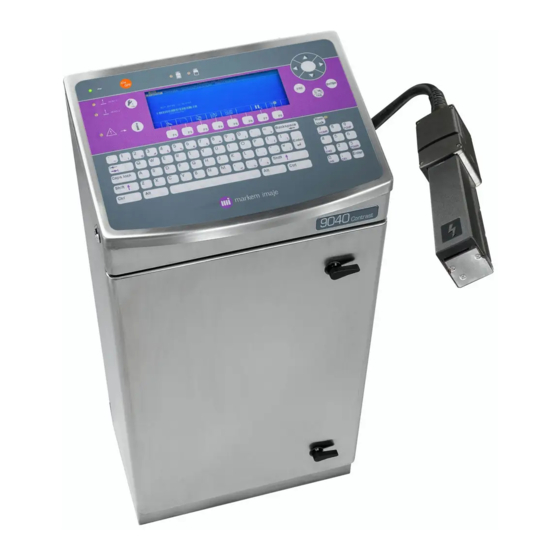
Description of the printer Overall view The 9040 printer is produced in four models. Model Number of heads Number of jets Type of head 1 or 2 1 or 2 G head – M head — P head 1 or 2 1 or 2 G head — M head 1 or 2…
-
Page 21: Electronics Compartment
Description of the printer Electronics compartment PC board Power supply board Industrial interface board Main board A36951-C.doc 22/236…
-
Page 22: Hydraulic Compartment
Description of the printer Hydraulic compartment Ink circuit Head pressurization unit (9040 – 9040 IP65) A36951-C.doc 23/236…
-
Page 23: Ink Circuit
Description of the printer Ink circuit Ink tank Additive tank Pressure pump unit Condenser Electrovalve(s) Ink filter Rear view Front view Vacuum pump unit Viscometer A36951-C.doc 24/236…
-
Page 24: Ink Circuit
Description of the printer Ink circuit Rear view Front view Ink tank Additive tank Coalescence filter(s) Air supply connection Pressure sensor Electrovalve(s) Accumulator Recovery tank Viscometer A36951-C.doc 25/236…
-
Page 25: Rear View
Description of the printer Rear view Mains power lead Connection interface Umbilical conduit to print module A36951-C.doc 26/236…
-
Page 26: Printheads
Description of the printer Printheads P head ID (small) M head ID (medium) G head ID (large) Single-jet Twin-jet Cannon Charge electrode Detection electrode Deflector plates Recovery gutter Head cover Gutter plug A36951-C.doc 27/236…
-
Page 27
A36951-C.doc 28/236… -
Page 28: Description Of Operator Interface
Description of operator interface A36951-C.doc 29/236…
-
Page 29
Description of operator interface A36951-C.doc 30/236… -
Page 30: Description
Description of operator interface Description Areas Operation Screen Navigation Editing A36951-C.doc 31/236…
-
Page 31: Operation Area
Description of operator interface Operation area Printer power on indicator. On / Off Head status indicators. View printer parameters on: ready to print. and access jet flashing: fault. maintenance functions. off: printer shut down. Fault and alarm detection indicator. View and clear detected faults and alarms.
-
Page 32: Screen
Description of operator interface Screen A wide screen liquid crystal display for displaying messages in WYSIWYG (what you see is what you get) format. Menu bar Printer status Menu name Editing area Current Message in Keyboard status: Icon taskbar Production associated Caps Lock on: with function…
-
Page 33: Navigation Area
Description of operator interface Navigation area Function keys F1 to F8 are associated with the Icon taskbar and provide direct access to the main functions required for every day use. Arrow keys: For moving within menus or inside the edited message. To confirm an action or To abort an action or selection.
-
Page 34: Editing Area
Description of operator interface Editing area The keyboard includes the Latin alphabet, punctuation keys, numbers, special characters and various keys for editing messages. To move backwards while To lock / To lock / editing. unlock To lock / unlock unlock Shift Will delete numerical tab mode.
-
Page 35: Navigation
Description of operator interface Navigation Welcome screen You start in the Production menu. The icon desktop provides direct access to the message in production and to other system menus. Access to Select and Create Change Access print View and set Pause / Access to user…
-
Page 36: Accessing Menus
MENU PRODUCTION MENU MESSAGE EDITING MODIFY MESSAGE ACCESS OTHER MENUS MENU MENU SYMBOL EDITING PRINTER PREPARATION…
-
Page 37: Menu Overview
Description of operator interface Menu overview PRODUCTION Printer Message Status/Printhead Maintenance Start-up Status jet(s) Clear faults Message selection Shut-down FAULTS ELV status modification Library creation Jet(s) start-up Motor speed* Flushing Jet(s) stop Counter display/reset Start Mode User prompt MESSAGE EDITING Message Font Variables…
-
Page 38: Description Of Icons
Description of operator interface Description of icons The icons are described as they appear in the various icon toolbars. Create or modify a message. Open a message. Select a font Access composition box for variable following the cursor. Access parameters for variable following the cursor. Alter parameters of message to be printed.
-
Page 39
Description of operator interface Message editing menu Access Message editing/Message sub-menu. Access Message editing/Font sub-menu. Access Message editing/Variables sub-menu. Access Message editing/Parameters sub-menu. Access to other menus. Access Printer preparation menu. Access Symbol editing menu A36951-C.doc 40/236… -
Page 40: Accessing Numeric Keypad Functions
Description of operator interface Accessing numeric keypad functions Light on: Access to blue characters. Light off : Access to violet characters. Keyboard locked: This function is used to: return to the start of the message from any position (in Message editing mode).
-
Page 41: Keyboard Shortcuts
Description of operator interface Keyboard shortcuts Shortcuts using Takes you straight to different menus using the upper-case letter in the name of the menu you want. +Letter Example for Font. Shortcuts using Adjust display contrast To view and select fonts already used in current message in Message editing mode.
-
Page 42: Daily Operation
Daily operation A36951-C.doc 43/236…
-
Page 43
Daily operation A36951-C.doc 44/236… -
Page 44: Printer Start-Up
Daily operation Printer start-up Ensure printer powered up: indicator light is on. Press to start the printer. ( Production/Printer/Start-up) Wait for approximately three minutes. When the printer is ready: ON is displayed light goes on (steady light). You are in the production menu, and the most recently selected message is ready to be printed.
-
Page 45: Printer Shut-Down
Daily operation Printer shut-down The procedures applicable to prolonged shutdowns are given NOTE in the Servicing section of this manual. Stopping the printer Do not interrupt the shut-down procedure. CAUTION Press to shut down the printer. ( Production/Printer/Shut-down) Press to confirm. Select the type of shut-down you want: Type of shut-down: ? Long (YES)
-
Page 46: Stopping The Printer
Daily operation Markem-Imaje technicians can program the printer to include an «Active stand-by» mode. In this mode, the printer performs a five-minute head cleaning cycle automatically once every hour to ensure a problem-free start-up. The mode is active for 72 hours after a prolonged shutdown and 8 hours after a short shutdown.
-
Page 47: Select A Message
Daily operation Select a message Press to select a message to be printed.( Production/Message/Message selection ) *: Message currently Selected head(s) selected List of messages Name of messages assigned to each head Message displayed On a two-head printer, specify the head to be assigned the message: Go to the Head number field using and use to select head 1 (1), head 2…
-
Page 48: Print A Message
Daily operation Print a message Ensure jet(s)are ready: the light is on continuously. The message or messages to be printed are ready (in production). The cell or cells on the TOP1/TOP2 input or the tachometer on the Tacho input sends a signal to the printer to trigger the printing operation.
-
Page 49: Modify Message
Daily operation Modify message Modifying the message in production The message in production may be partially modified at the user prompt level or as a whole by editing it. Modifying a user prompt If a message in production contains at least one user prompt, the icon is displayed in the icon desktop.
-
Page 50
Daily operation Press to select a field to be modified from the list. Press to access the field contents then enter the new value. Confirm twice. The modified field is then displayed in the message. Modifying the message as a whole Press The cursor appears in the… -
Page 51: Modify Message
Daily operation Modify message Press then to modify an existing message. ( Message editing/Message/Open) Press to access the input box and enter the name of the message to be modified Select the message to be modified from the message list using Use the arrow keys to move the cursor within the message.
-
Page 52: Create Message
Daily operation Create message Press ( Message Editing/Message/New) Enter the name of the new message (max. 8 alphanumeric characters). Press to confirm Printing area of a jet Cursor The cursor starts to flash at the bottom left of the editing area. Use the arrow keys to move the cursor inside the editing area and compose a message.
-
Page 53: View Printer Parameters
Daily operation View printer parameters A number of functions can provide the user with information on the different printer settings. View operating parameters Printer preparation/Options/Hour counter This function allows you to view: the number of hours your printer has been in service, the number of printing operations performed by your printer (Pay per Print option).
-
Page 54: View Programming Parameters
Daily operation This sub-menu shows the readings recorded in the printer, logged in real time plus all faults detected by the printer. Status jet(s): Jet status. This field also provides access to maintenance functions. See Maintenance section for further details. Speed jet 1 and Speed jet 2: jet speed expressed in meters per second (m/s).
-
Page 55: Adding Consumables
Daily operation Adding consumables Open the door of the hydraulic compartment. Pull out the ink circuit using the handle. Unscrew the lid(s) to open the tank(s). Add consumable up to the halfway mark on the tank (maximum). Replace the lid(s) ensuring they are sealed.
-
Page 56: Editing A Message
Editing a message A36951-C.doc 57/236…
-
Page 57
Editing a message… -
Page 58: General
Editing a message General The term «Message» refers to the output printed by a head. Before you compose a message, you have to select the print speed or an algorithm in the Parameters/Message function. New algorithm or print speed settings cannot be made on messages which have already been created.
-
Page 59: Message Management
Editing a message Message management Save message ( Message editing/Message/Save) Use this command to save a message which you have just created or changed. It can only be accessed after you use New or Open. Message editing/Message/Save as Use this command to save a modified version of an existing message without losing the original.
-
Page 60: Close Message
Editing a message Close message Message editing/Message/Close Use this command to leave the message you have just created or changed. A dialog box asks whether you want to save the message if you have not already saved it, or if you have modified an existing message. Select YES if you want to save the changes, otherwise select NO and the original message will not be modified.
-
Page 61: Define Print Parameters
Editing a message Define print parameters Change parameters of a message in production The fields in this dialog box are described below. The Scrolling action, Transparency printing and Inverse printing parameters cannot be changed to an existing message. They must be set prior to creating a message. Change message parameters Message editing/Parameters/Message This dialog box contains all the settings you need to adapt the message to the production…
-
Page 62
Editing a message Scrolling action The setting for this parameter depends on how your printer is set up on the production line and on the results you want to achieve from the printing operation. key shows the direction of travel of the object. Press tab key a second time to enlarge the image. -
Page 63
Editing a message Printing repetition This parameter is used in object set-off mode (Set off field set to OBJECT) to repeat printing at a pre-set number of times regardless of the length of the object be marked. Enter a value between 0 and 255. Example: Printing repetition: 1 means that a single message is printed and is not repeated. -
Page 64
Editing a message REMINDER New algorithm or print speed settings cannot be made on messages that have already been created. The content of the message has to be deleted first if you want to change these parameter settings. Forward margin Enter a forward margin value (in millimeters). -
Page 65: Specify Print Resolution
Editing a message Options: OBJECT or REPETITIVE when the system is in operation. . OBJECT: Printing is triggered when the DTOP signal is receive by the printer. You print one message for each object detected. . REPETITIVE: Printing is triggered when tDTOP signal is received and remains constant, printing continues for as long as the DTOP signal is activated or until the specified number of repeat print operations is reached.
-
Page 66: Define Character Settings
Editing a message Define character settings These functions allow the user to select the type, style and size of the characters or symbols used. Select a font A «font» is a set of characters or symbols which are represented in the same style and which have same size.
-
Page 67: Bolderize A Character
Editing a message Configure font list Printer preparation/Parameters/Select font This function allows the user to change the list of available fonts shown in the previous dialog box. Check fonts on the list, which are to be made available in Message Editing mode.
-
Page 68: Use Of Tabulation Feature
Editing a message Use of tabulation feature Message editing/Font/Tabulation This function is used for creating a blank space between two characters or symbols, which has a different width to the width of the standard space character in the font used. Enter the number of black dot rows to be contained in the blank space (between 1 and 255).
-
Page 69
Editing a message NOTE Vertical tabulation: You can move the cursor position up or down by combining the key with the arrows. This means that the elements in a message line do not have to be in a fixed position. An example of this is as shown below: OF MESSAGE VARIABLE POSITIONING… -
Page 70: Use Date And Time
Editing a message Use date and time If you want to print the time and date in a message, you first have to specify time and date parameter settings, then compose these elements, and finally insert them into the message. Specify time and date parameter settings Printer preparation/Initialization/Autoclock The printer date and time should normally be set when the printer is installed.
-
Page 71: Compose And Insert Date
Editing a message Compose and insert date Message editing/Variables/Date This function is for inserting calendar details in your message. Compose your «Date» variable using the following elements: Day of the week (numerical value — from 1 for Sunday to 7 for Saturday). Day of the month : 1 to 31.
-
Page 72: Compose And Insert Time
Editing a message Compose and insert time Message editing/Variables/Time This function is for inserting clock details in your message. Compose your time variables using the hours, minutes and seconds fields in the order you want them to appear. The Composition line displays the time elements as they are specified. Authorized separators (space), ( : ), ( — ) and ( / ) should be entered in the composition box via the keyboard.
-
Page 73: Use A Counter
Editing a message Use a counter If you want to print a counter, you first have to specify the parameter settings and then insert it into the message. You can also view and reset counter values. You can insert two different counters in each message. Display and reset counters ( Production/Message/Counter display/reset) This function is for viewing counter values and for resetting counters to their original value…
-
Page 74
Editing a message First digit and last digit Enter start and end values. These are the limit values between counter values changes. The content of the counter increases if the first digit is lower than the last digit.. The counter decrements if the first digit is greater than the last digit. When the counter reaches the last digit, it starts again with the First digit. -
Page 75: Insert Counter
Editing a message Default parameter values The default parameters are common to all messages and are configured in the Printer preparation/Initialization/Message/Counter or Counter 2 menu The dialog box is identical. Insert counter Message editing/Variables/Counter or Counter 2 Use this function to insert counters in your message. The counter is shown in the message with its initial value.
-
Page 76: Using User Prompts
Editing a message Using user prompts User prompts hold variable information entered by the operator during production. This function is used to edit a user prompt in a message. Up to 20 different user prompts per message may be inserted. Editing a user prompt involves defining the field and inserting it in the message.
-
Page 77: Use A Postdate
Editing a message Use a postdate A postdate is a date which is deferred in relation to the current date. If you want to print a postdate, you first have to specify the parameter settings, then compose the date and finally insert it into the message. You can insert two different postdates in each message.
-
Page 78: Compose Postdate
Editing a message Compose postdate Message editing/Variables/Postdate or Postdate 2 This menu allows you to insert postdate elements in your message. The dialog box offers the following setting for composing your «Postdate» variable: Post-day month: 1 to 31. Post-day year: 1 to 366. Post-week year: 1 to 53.
-
Page 79: Use A Barcode
Editing a message Use a barcode If you want to print a barcode, you first have to specify the parameter settings, then compose the code and finally insert it into the message. You can insert up to four barcodes into each message. Set barcode parameters Message editing/Parameters/Barcodes Select the type of barcode from the list displayed.
-
Page 80
Editing a message The dialog box is specific to the type of code selected, and the user can only access parameters settings that can be changed. Other parameters are shown in dotted characters and cannot be modified. Narrow bars Enter a value from 1 to 4 units (default value is 1 for distribution codes). The Narrow bars value must always be less than the Wide bars value. -
Page 81: Compose A Barcode
Editing a message Bolderization This parameter is only displayed for Datamatrix codes. Enter cell size value: 1 or 2. This multiplies the selected height by 1 or 2. If you select 2, the code height cannot be below 16 dots. Default parameter values Printer preparation/Parameters/Barcodes This function allows the user to select a code type and specify default parameters that are…
-
Page 82: Insert A Barcode
Editing a message Variable elements The variable parameter values may need to be specified in the Message editing/Parameters menu. Counter/Counter2/Shift code To insert these variable elements into the barcode, go to the line concerned and press . The variable is displayed in the composition line. Time/Date/Postdate/Postdate2 These variables need to be composed before they are inserted in the barcode.
-
Page 83: Barcode Characteristics
Editing a message Barcode characteristics Industrial codes Interleaved 2 of 5 Barcodes can be transcribed in numeric characters only. These characters can be variables (counters, dates, etc.). Max. 32 characters If there is no check digit (o), the number of characters entered must be even. If there is a check digit (x), the number of characters entered must be odd.
-
Page 84
Editing a message Distribution codes EAN / UPC Options available: EAN 13, EAN 8, UPCA, UPCE These codes can only transcribe numeric characters into barcodes. EAN 13 codes are required to have thirteen characters. EAN 8 codes are required to have eight characters. UPCA codes are required to have twelve characters. -
Page 85
Editing a message EAN 128/CODE 128 codes The character set is divided into four menus that can be found in 128 mode (Code A, Code B, Code C) and Special characters: Mode A: includes all standard upper-case alphanumeric characters, command characters and special characters. -
Page 86
Editing a message Datamatrix code The code used is type ECC200 and the format is calculated automatically (square or rectangle). Cell size (stretch) is programmable: 1 or 2 drops. The code height can vary between: 8 and 24 cells in stretch mode 1 8 and 12 cells in stretch mode 2 All types of variables can be printed with the code. -
Page 87: Use A Shift Code
Editing a message Use a shift code Shift codes are used for printing cyclical time information over a one-day period. The code starts at a specified time. If you want to print a shift code, you first have to specify the parameter settings and then insert it into the message.
-
Page 88: Insert Shift Code
Editing a message Example: Start time : 06 : 00 Interval : 08 : 00 Type : LETTER The printer will print: A — 06.00 to 13.59, B — 14.00 to 21.59, C — 22.00 to 05.59 the next day and so on. Default parameter values The default parameters are common to all messages and are configured in the Printer preparation/Parameters/Shift code menu…
-
Page 89: Use An External Variable
Editing a message Use an external variable An external variable is an item of variable data that will be sent via the external RS232/V24 or RS422 link (e.g. weight value given by a balance or data from a controller or barcode reader).
-
Page 90: Use Autodating Table
Editing a message Use autodating table This function is for inserting all of the time and date variables encoded using the autodating table. If you want to print an autodate variable, you first have to specify the parameter settings, compose the variable and then insert it into the message. Set autodate element parameters Printer preparation/Parameters/Autodating tables This function is for encoding time and date data in the form of a code consisting of one to…
-
Page 91
Editing a message + or – : to scroll through the different fields in a variable Nb. Fields: displays the total number of fields in a variable Field: indicates the field in which you are currently entering data. Value: for entering a code consisting of one to three alphanumeric characters. Copy: to assign a value of a field to all other fields in the table. -
Page 92: Compose Autodating Variable
Editing a message Compose autodating variable Message editing/Variables/Autodating tables This dialog box is for composing your «Autodating table» variable. The Composition line displays the date elements as they are specified. Authorized separators — (space), ( : ), ( — ) and ( / ) — should be entered in the composition box via the keyboard.
-
Page 93: Use Of Symbols
Editing a message Use of symbols A symbol can be a letter of the alphabet, a number, a special symbol or a special shape , such as a logo. A set of symbols of the same size constitutes a font. Select a symbol Message editing/Font/Select Symbols This dialog box allows the user to select symbols or characters belonging to the font…
-
Page 94: Create Symbol
Editing a message Create symbol Normal procedure Create a font Define the font Specify the size of the symbols Create the symbol Save the symbol Close the font Download the font Create a font Symbol editing/Symbol/New This command allows you to create a new symbol to be included in a font. The dialog box asks you to give the following information to define the font: font name (max.
-
Page 95
Editing a message Create the symbol The printer displays the following screen when you have specified the font name, font number, symbol number and symbol size. Draw the symbol you want to print using the keys indicated below. Font number Font name Symbol number Number of symbols… -
Page 96
Editing a message Using keys In a dot by dot mode: >> Changes color of dot on which the cursor is located. Moves the cursor inside the grid in direction shown by the arrow. In line mode: — To select the line color (white or black). To draw lines in direction shown by the arrow. -
Page 97
Editing a message In zone mode: To select the zone color (white or black). Press two keys in succession to define a zone. Other functions To view a symbol in normal size. The symbol is displayed in a window at the top right or top left of the screen, depending on the position of the cursor. -
Page 98
Editing a message To create a new symbol in a front: Access the font (using the font name or number). Give a number to the new symbol. Draw the symbol. Save. Save the symbol Symbol editing/Symbol/Save Use this command to save the symbol which you have just created or changed. Symbol editing/Symbol/Save as Use this command to save a modified version of an existing symbol without losing the original. -
Page 99: Modify Symbol
Editing a message Modify Symbol Modifying the symbol Symbol editing/Symbol/Open This command allows the user to view and select a symbol in an existing font to modify the associated drawing. The dialog box shows a list of existing symbol fonts. Select the one you want or press the key to bring up the cursor, and enter the title or the number you are looking for and then confirm.
-
Page 100: Delete Symbol Or Font
Editing a message Using keys To move forward one symbol (or ten symbols). To move back one symbol (or ten symbols) Change symbol size Symbol editing/Size/Symbol size This function allows the user to change the height and the width of symbols contained in the font.
-
Page 101: Example Of Message Programming
Editing a message Example of message programming Example of message Shift code Counter content Postdate: 60 days after date of manufacture Create message Press and enter message name (CONSO in this example). Press to confirm. Compose text Use the arrow keys to position the cursor in the editing area. Compose the following text using the keyboard: A36951-C.doc 102/236…
-
Page 102
Editing a message Insert shift code 1- Specify shift code parameters. Press simultaneously to access the Parameters sub-menu and use the arrow keys to select Shift code. Press to confirm. Enter the following values using the key, the arrow keys and the keyboard. Press to confirm The shift code values will now be:… -
Page 103
Editing a message 2- Insert shift code in the message. Use the arrow keys to place the cursor in the position you want. Press simultaneously to access the Variables sub-menu and use the arrow keys to select Shift code. Press to confirm The shift code is inserted at the cursor position and adopts the format specified in the Parameters sub-menu (A in this example) -
Page 104
Editing a message Insert counter 1- Specify counter parameters. Press simultaneously to access the Parameters sub-menu and use the arrow keys to select Counter. Press to confirm Enter the following values using the key, the arrow keys and the keyboard. Press to confirm The counter values will now be:… -
Page 105
Editing a message 2- Insert counter in the Message. Use the arrow keys to place the cursor in the position you want. Press simultaneously to access the Variables sub-menu and use the arrow keys to select Counter. Press to confirm The counter is inserted at the cursor position and adopts the format specified in the Parameters sub-menu (0010 in this example). -
Page 106
Editing a message Select a font Use the arrow keys to place the cursor in the position you want. Press and select a font (sin24058 in this example). Press to confirm The cursor is now larger and the next elements will be inserted with the selected font (24-point font). -
Page 107
Editing a message Insert postdate 1- Specify postdate parameters Press simultaneously to access the Parameters sub-menu and use the arrow keys to select Postdate. Press to confirm Enter the following values using the key, the arrow keys and the keyboard. Press to confirm NOTE… -
Page 108
Editing a message 2- Compose and insert postdate. Press simultaneously to access the Variables sub-menu and use the arrow keys to select Postdate. Press to confirm Select the fields you want using the key (day, month and year in this example). Go to the Composition input box using the arrow keys and add the separators ( /, space, : , — ) direct from the keyboard ( / in this example). -
Page 109
Editing a message The postdate is inserted with the font selected previously. REMINDER: icon (change variable composition) and/or the icon (change variable parameters) are displayed when the cursor is positioned in front of a variable. Load message in printer Press to load the message in the printer, press to return to the Production menu. -
Page 110: Servicing: 9040, 9040 Ip65, 9040S
Servicing: 9040, 9040 IP65, 9040S A36951-C.doc 111/236…
-
Page 111
Servicing: 9040, 9040 IP65, 9040S A36951-C.doc 112/236… -
Page 112: Prolonged Shutdown
Servicing: 9040, 9040 IP65, 9040S Prolonged shutdown NOTE Any shutdown can be made into a series of short shutdowns, regardless of length, provided that the printer is started and ran a minimum of twice a week with the jets in a running or refresh mode for at least one hour.
-
Page 113: Start-Up Following A Prolonged Shutdown
Servicing: 9040, 9040 IP65, 9040S Start-up following a prolonged shutdown Starting the printer after a shutdown lasting 8 to 15 days 1. Open gutter located in the print head 2. Start the printer. 3. Perform a STABILITY check, if necessary 4.
-
Page 114: Servicing
Servicing: 9040, 9040 IP65, 9040S Servicing Head cleaning Tools required Servicing tray Screwdriver, cleaning flask and blower bulb (or drying kit) NOTE Cleaning the head once a week is adviced to obtain optimal printing performances. Stop the jet(s) /Status Jet(s)/JET SHUT DOWN.
-
Page 115
Servicing: 9040, 9040 IP65, 9040S Dry carefully. Use the blower bulb or the drying kit, to thoroughly dry the cleaning solution from all areas of the print head. Open gutter : Select JET START UP to bring the jet(s) back into service. Close the head cover and press to clear any faults present. -
Page 116: 3,600-Hour Service
Servicing: 9040, 9040 IP65, 9040S 3,600-hour service 1. Drain and flush the printer. See automatic or manual printer Drain/Flush procedures contained in this section. 2. Change main ink filter cartridge. This operation must be performed at least once every twelve months. Refer to procedure for changing 9040, 9040 IP65 and 9040S printer ink filter cartridges contained in the Maintenance section of this manual.
-
Page 117: Automatic Printer Drain/Flush
Servicing: 9040, 9040 IP65, 9040S Automatic printer Drain/Flush This procedure consists of two stages: Flush the recovery gutter manually 1. Ensure printer in service and jet(s) are stopped and then spray cleaning solution into the recovery gutter(s) for 20 seconds. 2.
-
Page 118
Servicing: 9040, 9040 IP65, 9040S 1. Disconnect quick-connect self-sealing pressure connector(s) and connect flushing connector(s) (see hydraulic diagram on following page). 2. Connect the drain unit quick-connect connector on the ink circuit pressure outlet and place the second drain unit tube in an empty container to accumulate waste. (minimum quantity of 5 liter container is recommended). -
Page 119
Servicing: 9040, 9040 IP65, 9040S Hydraulic diagram Ink circuit Ribbon cable Pressure Recup. 1 Recup. 2 Draining / Flushing tool 5 liter drum Head filter Beaker of additive or additive tank Drain tool hose Printer hose Anti-clogging protector Head 1 Head 2 A36951-C.doc 120/236… -
Page 120: Drain The Ink Circuit
Servicing: 9040, 9040 IP65, 9040S Drain the ink circuit Tools required : Recovery tank 3 mm Allen key. 1. Shut down the printer normally and disconnect from main AC power supply. 2. Place a recovery container under the ink tank and remove the drain plug to drain. The spent ink should then be stored in a closed container and must not be re-used.
-
Page 121: Flush The Umbilical Conduit And The Head
Servicing: 9040, 9040 IP65, 9040S Flush the umbilical conduit and the head This procedure is used for circulating clean additive in the print head head and umbilical tubing. 1. Ensure printer is in a running condition with the jet(s) stopped. Spray additive into the recovery gutter for 20 seconds.
-
Page 122: Flush The Ink Circuit
Servicing: 9040, 9040 IP65, 9040S 8. Start the printer and press the Run the REFRESHMENT function for a minimum of 30 seconds (on each corresponding head for two-head printers). 9. Run the NOZZLE UNBLOCKING function for a minimum of 20 seconds. 10.
-
Page 123: Re-Introducing Ink Into The Printer
Servicing: 9040, 9040 IP65, 9040S Re-introducing ink into the printer Check consumable expiration date shown on the ink CAUTION containers label. 1. Check that the drain plugs and bleed screws are in place. 2. Remove the ink tank lid and pour 1 liter of new ink into the ink tank. 3.
-
Page 124: Servicing: 9040 Contrast
Servicing: 9040 Contrast A36951-C.doc 125/236…
-
Page 125
Servicing: 9040 Contrast A36951-C.doc 126/236… -
Page 126: Prolonged Shutdown
Servicing: 9040 Contrast Prolonged shutdown CAUTION Always disconnect the printer from the main AC supply after draining and flushing if you are not going to re-introduce ink immediately. This is to avoid having the stirrers rotating with no fluids in the ink/solvent tanks. Drain and rinse the printer before any work, which requires disconnection from the main AC supply for more than two hours.
-
Page 127: Printer Out Of Service For Four Or More Days
Servicing: 9040 Contrast Printer out of service for four or more days 1. Drain and flush. Refer to Printer drain/flush procedure contained in this section. CAUTION It is recommended to repeat the Drain/Flush procedure every four weeks if the printer is to be out of service for longer than a month.
-
Page 128: Start-Up Following A Prolonged Shutdown
Servicing: 9040 Contrast Start-up following a prolonged shutdown Restarting the printer after a shutdown lasting between 2 hours and 4 days 1. Open the head cover. 2. Remove the anti-clogging device from under the nozzle(s) (if present). 3. Clean the print head. 4.
-
Page 129
Servicing: 9040 Contrast 4. Check the viscosity. If the value is below «Reference visco. :» Shut down the printer normally and empty the recovery tank. Then pour half a liter of fresh ink into the ink tank. Then restart the printer normally. If the value is above «Reference visco. -
Page 130: Servicing
Servicing: 9040 Contrast Servicing Clean the head Tools required Servicing tray Screwdriver, cleaning flask and blower bulb (or drying kit) NOTE Cleaning the head once a week is adviced to obtain optimal printing performances. Stop the jet(s) /Jet status/STOPPED. Position the head onto its maintenance holster.
-
Page 131
Servicing: 9040 Contrast Dry carefully. Use the blower bulb or the drying kit, to thoroughly dry the cleaning solution from all areas of the print head . Open gutter : Select JET START UP to bring the jet(s) back into service. Close the head cover and press to clear any faults present. -
Page 132: 2,000-Hour Service
Servicing: 9040 Contrast 2,000-hour service 1. Drain and flush the printer. Refer to printer Drain/Flush procedure contained in this section. 2. Change the main ink filter cartridge. This operation must be performed at least once every six months. Refer to the procedure for changing 9040 Contrast printer ink filter cartridges contained in the Maintenance section of this manual.
-
Page 133: Drain/Flush Printer
Servicing: 9040 Contrast Drain/flush printer CAUTION Disconnect the printer from the main AC supply after each drain/flush operation — unless ink is going to be introduced immediately. This is to avoid having the stirrers rotating with no fluids in the system. Drain and rinse the printer before any work, which requires disconnection from the main AC supply for more than two hours.
-
Page 134
Servicing: 9040 Contrast 5. Select and confirm the Production/Maintenance/Flushing function to start the automatic drain cycle and monitor the progress. The flushing solution will circulate inside all parts of the ink circuit and is then drained via the ink tank. Draining stops and the printer shuts off automatically when the additive tank is empty, the flushing cycles are now complete 6. -
Page 135
A36951-C.doc 136/236… -
Page 136: Maintenance
Maintenance A36951-C.doc 137/236…
-
Page 137
Maintenance A36951-C.doc 138/236… -
Page 138: Stopping And Starting Jets
Maintenance Stopping and starting jets The default setting is for the jet(s)to be started and stopped automatically. Jet start-up ( Production/Status/Printhead/Status jet(s)) Select and confirm ON command. Each head is started separately on a two-headed printer. (and ) indicators go on when the jet(s) are ready (steady light).
-
Page 139: Jet Shut-Down
Maintenance Jet shut-down ( Production/Status/Printhead/Status jet(s)) Select and validate OFF command. Each head is shut down separately a two-headed printer. (and ) indicator lights go off when the jets are shut down. Production/Printer/Jet(s) stop command allows you to NOTE stop all jets (on all heads). A36951-C.doc 140/236…
-
Page 140: Jet Maintenance
Maintenance Jet maintenance Starting problems A number of functions are available for restoring the jet(s) to good working order if the jet(s) will not start correctly (no jet or deviated). Follow the instructions on the screen for each of these functions. Ensure that the head is positioned onto its maintenance holster and the cover is removed.
-
Page 141: Before Making Adjustments
Maintenance 5. Open gutter screw. 6. Select and confirm: STABILITY 7. When the jet is stable in the gutter, select and confirm JET SHUT DOWN. 8. Clean the print head thoroughly. 9. Select and confirm JET START UP to restart the jet(s). Make a visual check to ensure jet(s)are in the gutter.
-
Page 142: Align Jets
Maintenance Align jets Printer preparation/Initialization/Jet alignment This function aligns output from the jet(s). Alignment consists of identifying the jet that is the slowest and assigning corresponding delay settings to the other jets. Select a Jet number and then enter a number of Alignment units or adjust alignment using the + and — buttons.
-
Page 143: Adjust Jet In Gutter
Maintenance Adjust jet in gutter Tools required: Cannon positioning tool, open-ended wrench. Bifocal magnifier (eyecup type). Head cleaning material Allen key (1.5 mm) Tweezers Before you start 1. Position the head onto the maintenance holster. Select and confirm STABILITY function to ensure jet(s) are stable. 3.
-
Page 144
Maintenance 5. Remove the protective covering from the resonator wiring and disconnect the wires so they do not become tangled or damaged during this operation. 6. Loosen the adjustment screws on the cannon-holder (see figure 1). 7. Bring the jet close to point A or point A’ by rotating the cannon in the cannon holder using a positioning tool at the top (see figure 2). -
Page 145
Maintenance 8. Use the lower eccentric to move the jet to the center of the charge electrode. Check visually (see figure 3). CAUTION Do not apply excessive force to the eccentrics. Adjustment screws should be snug to hold cannon holder securely and to allow easy movement when adjusting. -
Page 146
Maintenance Final steps 11. Tighten the two adjustment screws on the cannon holder, without using excessive force. 12. Stop the jet(s) (JET SHUT DOWN). Clean the head thoroughly and reconnect the resonator wires. Reinstall the protective cover and. 13. Start the jet(s) (JET START UP). 14. -
Page 147: Adjust Break-Off Point
Maintenance Adjust break-off point Tools required: Magnifier (eyecup type) Allen key (2.5 mm) Before you start NOTE It is important when making this adjustment that the print head height is relative to the production height of the print head. Position the head onto the maintenance holster. Start the jet(s) and leave them running for at least 30 minutes.
-
Page 148
Maintenance The shape of the drops immediately under the break-off point provides the only means of establishing that the setting is correct. Avoid Good Figure 2 CAUTION Treat the adjustment screw with care when making adjustments to avoid damage. Final steps 5. -
Page 149: Adjust Pressure Pump Motor Speed
Maintenance Adjust pressure pump motor speed: Tools required: Allen key or screwdriver. The motor rotation speed essentially depends on the viscosity of the ink. The by-pass should therefore only be adjusted if the ink viscosity is correct (i.e. when the viscosity measured by the printer is within one second of the reference viscosity value).
-
Page 150
Maintenance Adjustment 1. Start the jets (JET START UP), once Jets are in a Ready mode,check motor the speed. 2. Pull the ink circuit out to the end of the rails. Insert an Allen key or small screwdriver into recess (3) of the pressure pump- depending on pump model. 3. -
Page 151: Plant Air Kit Settings
Maintenance Plant air kit settings: The plant air kit is connected to the customers compressed air supply and provides air for the 9040 Contrast printer. Filters are used to make sure that the airdelivered to the printer is clean of moisture, oil and deposits. Layout of components Plant air connection Flow limiter (to set vacuum pressure)
-
Page 152: Hydraulic Diagram
Air network Purging device Pressure Vacuum To Bottom of ink circuit cabinet (connection with Tanks atmospheric pressure tube) 1. Connection of compressed air plant 8. Vacuum pump 2. Electrovalve 9. Vacuum gauge 3. Pressure regulator (Adjustment) 10. Vacuum tube 4. Pressure gauge 11.
-
Page 153: Set Inlet Pressure
Maintenance Set inlet pressure The inlet pressure (i.e. the plant air kit outlet pressure) is the pressure that the printer needs to operate. It must be 0.7 bar (+0.3/ -0.1) above the printer operating pressure at all times. 1. Select Production/Maintenance/ELV status modification to display the operating pressure: The operating pressure is displayed on the screen by default.
-
Page 154: Test The Divider Bridge
Maintenance Test the divider bridge The purpose of this test is to determine whether any of the three-divider bridge restrictions are blocked. First make sure that the inlet pressure is correct. Select DIVIDER BRIDGE in the previous screen and confirm. Wait for a few seconds. The pressure value is displayed.
-
Page 155: Replace Ac Supply Fuse
Maintenance Replace AC supply fuse Tools required: Allen key (2.5 mm). Screwdriver. The system uses a 4A time delay fuse. Figure 1 Fuse location 1. Shut down the printer and disconnect it from themain AC power supply. 3. Undo the four screws (1) with the Allen key and remove the cover. 2.
-
Page 156: Change The Pressurization Air Filter Cartridge
Maintenance Change the pressurization air filter cartridge: This filter is located on the air treatment assembly inside the hydraulic compartment. 1. Shut down the printer normally and disconnect from the main AC power supply. 2. Disconnect the air supply or air supply close valve to the printer. 3.
-
Page 157
Maintenance Change ink filter cartridge: Tools required: Allen key (3 mm) 1. Shutdown the printer normally and disconnect from main AC supply. 2. Pull the ink circuit out to the end of the rails. 3. Drain the ink circuit. (see procedure) 4. -
Page 158: Change Ink Filter Cartridge
Maintenance Change ink filter cartridge: Tools required: Recovery tank. 1. Shut down the printer normally. 2. Placer a recovery container under the filter and unscrew the lower casing (1). 3. Unscrew the base holder of the cartridge (2). 4. Remove the cartridge and the O-ring (3) 5.
-
Page 159: Change Coalescence Filter
Maintenance Change coalescence filter: Tools required: Open-end wrench. 1. Shut down the printer normally. 2. Open the door of the hydraulic compartment. 3. Pull out the ink circuit to access the filter (figures 1 and 2). 4. Undo the «filter side» nuts completly. 5.
-
Page 160
Maintenance 7. Refit the ferrules (Figure 3). 8. Push the tube until it is fully home inside the connector. 9. Tighten the nut by hand and then tighten it 3/4 of a turn. 10. Pull on the filter to make sure that there is no free play inside the connector. 11. -
Page 161: Change Ink
Maintenance Change ink: CAUTION Check consumable expiration dates shown on the container labels. Frequency: see the IRS – Ink Running Specifications or ink technical data sheet. Perform following procedures when printer is in service: 1. Drain additive tank by removing the additive drain plug from the additive drain tube. Refit the additive drain plug when draining is completed.
-
Page 162: Test Electrovalves
Maintenance Test electrovalves 9040, 9040 IP65 and 9040 S printers Production/Maintenance/ELV status modification This function allows you to run electrovalves individually to make sure that they are operating correctly. It applies to: the ink circuit viscometer drain and additive addition ELVs, the head additive and vacuum ELVs.
-
Page 163
Maintenance In normal operation (i.e. when no faults are present), this dialog box allows the user to view: The different ink circuit management phases and sub-phases; Changes in accumulator, viscometer and vacuum reservoir levels; The status of all ink circuit electrovalves. If an ink circuit fault is present, the phases are suspended and the printer changes to «Standby»… -
Page 164: Hydraulic Diagrams
Maintenance Hydraulic diagrams: — Head drying kit option 24 25 Air supply Anti-pulse system Cannons Head drying kit outlet Pressure/temperature sensor Flow control Pressurization outlet Rinsing electrovalve Gutters Air filter Head filter – additive Condenser with fan Head filter — ink Additive tank Self-closing connection Ink tank…
-
Page 165
Maintenance Additive tank Anti-pulse system Gutter electrovalve 2 Ink tank Self-closing connection — Head 1 Pressure electrovalve Condenser with fan Head filter – Additive – Head 1 Drain electrovalve Vacuum pump unit 1 Flushing electrovalve – Head 1 Cannons Restriction tube (0.7 mm) Head filter –… -
Page 166
Maintenance Air supply Pressure sensor Ink transfer electrovalve Discharge electrovalve Coalescence filter Head filter Atmospheric pressure Coalescence filter Self-closing connections electrovalve Stirrer motor Pressure electrovalve Charge electrovalve Additive addition electrovalve Drain electrovalve Air transfer electrovalve Ink addition electrovalve Single-jet cannon Equi-air electrovalve Stirrer motor Twin-jet cannon… -
Page 167
A36951-C.doc 168/236… -
Page 168: Alarms And Faults
Alarms and faults…
-
Page 169
Alarms and faults… -
Page 170: Introduction
Alarms and faults Introduction This section is a maintenance guide designed to assist the user in identifying the cause of a fault quickly and easily. The first step is to diagnose the type of fault concerned, without having to remove any parts.
-
Page 171: Check Printer Parameters
Alarms and faults Check printer parameters Check general operating parameters This screen is specific to a two-head, twinjet type printer. Some of the information may not be present for your machine configuration and type ormay be displayed on the screen in a different way.
-
Page 172: View Operating Parameter Log
Alarms and faults View operating parameter log Production/Maintenance/SAV This function allows the user to view a log of the printer’s operating parameters. The log consists of 48 tables of fifteen records registered at five-minute intervals. Logged parameters are: Ttra: Transfer time Pres: Pressure (bar) Tr: Viscometer filling time Ad: Number of additive additions…
-
Page 173: Preliminary Checks
Alarms and faults Preliminary checks Troubleshooting must always begin with preliminary checks. These checks are used to detect dirty parts, ink leakage or problems with electrical or hydraulic connections with the naked eye. Shut down the printer and disconnect from the AC power supply. Check the points indicated below.
-
Page 174: Troubleshooting
Alarms and faults Troubleshooting Introduction The tables shown in this section consist of two columns: Problems noted by the operator or displayed by the printer, Remedies Each problem is identified by number, which is shown in bold in the table. Different «remedies»…
-
Page 175
Alarms and faults 6- CPU fault. 6a- Contact Markem-Imaje Technical Assistance if the fault persists. 7- Low ink level. 7a- Add ink to the tank concerned (max. 1/2 tank). 7b- The problem may be with the main board. Contact Markem-Imaje Technical Assistance. 8a- Add additive to tank (max. -
Page 176: When Starting Jets
Alarms and faults When starting jets Problems Remedies 1- Cover missing 1a- Ensure cover on corresponding head is closed. 1b- Magnet inside the upper part of the cover missing. 1c- Faulty cover detector or problem on main board. Contact Markem-Imaje Technical Assistance. 2- EHT 2a- Carefully clean and dry the print head, head cover and all electrodes.
-
Page 177: During Printing
Alarms and faults During printing Problems Remedies 1- Phase detection on jet (number 1 to 4) 1a- Clean and dry head electrodes. 1b- Check general operating parameters for printer.( 1c- Check characteristics of ink used in the printer — i.e. expiry date (refer to date shown on container), ink change frequency and environment conditions (see ink data sheet).
-
Page 178
Alarms and faults 4- Poor print quality 4a- Clean the printhead (including the cover) and make sure that there is no obstruction on the jet Example 1: trajectory. 4b- Ensure the printhead bracket is stable and is not subject to vibration. 4c- Check head-object distance (examples 1 and 4d- Ensure jets are centered in the recovery gutters Example 2:… -
Page 179: Faults Specific To 9040 Contrast Printers
Alarms and faults Faults specific to 9040 Contrast printers The ink circuit includes stirring motors located at the bottom of CAUTION the ink and recovery tanks. These are used for mixing the ink continuously. The printer must therefore never be disconnected from the AC supply for more than two hours without draining and flushing the system beforehand.
-
Page 180
Alarms and faults 5- Ink fault 03 5a- Activate following electrovalves: — Ink addition. — Air transfer. 5b- Press the key to clear the fault. Contact Markem-Imaje Technical Assistance if the fault persists. 6- Accumulator fault 04 6a- Activate following electrovalves: — Air transfer. -
Page 181
Alarms and faults 10- Shutdown fault 13 10a- Activate following electrovalves: — A/P. — Viscometer 10b- Press the key to clear the fault. Contact Markem-Imaje Technical Assistance if the fault persists. 11- Shutdown fault 15 or 19 11a- Activate all electrovalves. 11b- Press the key to clear the fault. -
Page 182: Installation And Configuration
Installation and configuration A36951-C.doc 183/236…
-
Page 183
Installation and configuration A36951-C.doc 184/236… -
Page 184: Installing The Printer
Installation and configuration Installing the printer The printer must be equipped with a stability kit. The kit must be installed before adding a consumable. A36951-C.doc 185/236…
-
Page 185: Characteristics Of The Printer 9040 Ip65
Installation and configuration Characteristics of the printer 9040 IP65 A stream of air constantly circulates inside the printer and keeps the unit pressurized to prevent the ingress of dust and humidity inside the printheads and in the different compartments of 9040 IP65 model printers. Air is introduced via a high capacity electrovalve for 30 seconds every time the printer is started to clear any vapors from inside the unit.
-
Page 186
Installation and configuration An additive vapor condenser reduces emissions from the printer to a minimum. The cooling matrix for this condenser is cooled by the air used to pressurize the hydraulic compartment, in conjunction with a small fan located under the condenser itself. A circulating fan homogenizes the air continuously and maintains a uniform temperature inside the hydraulic compartment. -
Page 187: Initialize/Configure Printer
Installation and configuration Initialize/Configure Printer These functions are used for initializing the printer when it is first commissioned into service and for changing settings when the printer is in operation. Select dialog language Printer preparation/Initialization//Language The language used on the Operator Interface is selected via a dialog box. Initialize date and time Printer preparation/Initialization/Autoclock This function is for setting the printer time and date.
-
Page 188: Select Machine Options
Installation and configuration Select machine options Printer preparation/Options/Machine options This function allows you to specify whether specific options are to be made available Printing msg in lib. each DTOP For printing a new message from the library on each DTOP signal. When the final message in the library is printed, the printer then selects message no.
-
Page 189: Lock Access
Installation and configuration Lock access Printer preparation/Access codes These options allow you to enter codes to lock access to specific menus or functions. CAUTION You have to enter your security code before you can enter the Printer preparation menu. Keyboard Printer preparation/Access codes/Keyboard This function lets you lock all menus available via the keyboard, and disables access to functions using function keys F1 to F8.
-
Page 190: Configure Message Library
Installation and configuration Configure message library Production/Message/Library Number of head which can print Message sequence number message in library Message title Number of messages General message list List of messages in library This function is used to make a preliminary selection of messages from a general list of messages in memory in the PC board.
-
Page 191: Using The Ethernet Link
Installation and configuration Delete library Highlight the NEW button and then confirm Highlight the VALID button and then confirm Change library Highlight the message you want to delete in the library message list, then press The message is removed from the list. CAUTION ALL Following messages are moved up towards the top of the list.
-
Page 192
Installation and configuration Insert an RJ45 network cable in the Ethernet connector (the foolproofing tab prevents the connector being inserted incorrectly). Use a crossover RJ45 network cable to connect the printer directly to a PC or a straight cable to connect it to a hub or switch. Configuring the link Printer Preparation/Initialization/Ethernet Link Setting the IP address… -
Page 193: Configure Serial Link
Installation and configuration Configure serial link Printer preparation/Initialization/RS232 connection This function is used to configure an external communication serial link between the printer and an external device: Speed Select transmission speed (baud rate):: 4,800, 9,600, 19,200, 38,400 or 115,200. Parity Specify parity: No, Even or Odd.
-
Page 194: External Communications
External communications A36951-C.doc 195/236…
-
Page 195
External communications A36951-C.doc 196/236… -
Page 196: Exchanging Data
External communications Exchanging data Various media may be used to transfer data between the printer and other systems: PCMCIA cards, USB keys or SD cards. Connecting media Open the console cover to access the various card readers. PCMCIA card reader USB key reader SD card reader Insert a memory card or key, ensuring that it is inserted in the correct direction.
-
Page 197: Transfer Data
External communications Transfer data Printer preparation/Initialization/PCMCIA transfer This function enables data to be transferred from the printer to external media (cards or keys) and vice versa. The external media can also be formatted. The type of media connected is displayed on the screen (1). The following types of data can be exchanged: messages, fonts,…
-
Page 198
External communications Languages cannot be transferred from the printer to external NOTE media. Transferring data from external media to the printer Select the data to be loaded in the printer, then confirm. Select «<<= PCMCIA» or «<<= USB» or «<<= SD». Press to transfer selected data to the printer. -
Page 199: Input/Output Connections
External communications Input/output connections Connections to external equipment and accessories are made via the industrial interface board, which consists of dedicated terminal connectors. Several types of signals can be utilized, including: Input/Output signals for synchronization with the production line — start print (TOP), tachometer (TACHY), reverse message (INVMES), etc., Serial links for external control of the printer (RS232 / RS422 interface), Alarm/fault outputs (dry contact relays),…
-
Page 200: Connector Identification
External communications Connector identification Connector for alarm lamp Tachometer connector 1 Photocell connector 1 Tachometer connector 2 (for two-head printer) Photocell connector 2 (for two-head printer) A36951-C.doc 201/236…
-
Page 201: Industrial Interface Board : Layout
External communications Industrial interface board : layout Fuses LED7/8 LED3 LED11 LED5-6 LED1 LED4-13 LED12 LED2-14 15/16/17 LED9-10 J8 J4 J5 A36951-C.doc 202/236…
-
Page 202
External communications LED status These LEDs provide a visual indication that specific output signals from the printer or input signals from an external device connected to the board are operating correctly. LEGEND COMMENTS LED1 TOP2 Signal from DTOP2 input is present (green) (LED flashes in time with the photocell signal). -
Page 203
External communications LED10 The LED goes on when the SPROG1 signal from the (green) printer changes to logic level 1 — i.e. +5V (active status) in SPROG1 mode (jumper S8-3). The LED goes on when the SPROG1 signal from the printer changes to logic level 0 — i.e. -
Page 204
External communications Jumpers and switches Standard LEGEND POSITION FUNCTION / COMMENTS position S1-1 RS422 point-to-point link (just one printer on the link). S1-3 not VAL RS422 point-to-multipoint link (printer selected with VALID422). S2_1 RS232 serial link mode selected S2_3 RS422 serial link mode selected. S3-3 TOP2 TOP2… -
Page 205: Signals: Inputs And Outputs
External communications Signals: inputs and outputs The four terminal blocks on the industrial interface board are arranged as follows: Terminal block B1: 28-pin CPU signals Terminal block B2: 32-pin Head 1 signals Terminal block B3: 32-pin Head 2 signals (on two-head printers only) Terminal block B4: 9-pin Alarm relay signals Most signals are also available on the HE 14 connector.
-
Page 206
External communications Terminal block B1: Alarms Legend Signal Comments Optocoupled general alarm: negative B1-1 COGE COMGENE terminal Optocoupled general alarm: positive B1-2 OPTOGENE terminal Printer Stop/Start: negative terminal B1-3 CSTR COMSTART Printer Stop/Start: positive terminal B1-4 START Terminal block B2: Printhead 1 HE14 Comments Legend… -
Page 207
External communications HE14 Comments Legend Signal connector J14-10 Current print task including delay: B2-16 SPR1 SPROGI1 positive terminal. B2-15 J14-9 CSP1 COMSPROG1 Print task: negative terminal. J14-12 Indication that counter end value B2-18 FIN1 VALFINI1 reached. B2-17 J14-11 CFN1 COMVALFIN1 J14-14 Optocoupled head 1 alarm: positive B2-20… -
Page 208
External communications Terminal block B3: Printhead 2 Information and ID data same as for terminal block B2 and head 1. Assignments for the HE14 connectors are as follows: Connector Assignment Cell Head I/Os Tachometer Parallel interface Terminal B4: Alarms LEGEND SIGNAL COMMENTS B4-1… -
Page 209: Inputs
External communications Inputs All inputs are optocoupled. Electrical characteristics of the optocouplers Operating voltage: from 5 to 24V Permissible current in photocoupler LED: . Maximum: 25 mA . Nominal: 10 mA . Minimum: 3 mA Maximum power: 50 mW per unit Maximum operating frequency: 200 kHz (Pulse time >…
-
Page 210: Data Transmitted Via The Parallel Interface
External communications Data transmitted via the parallel interface The D0T(1 or 2), D1T, D2T, D3T, D4T, D5T, D6T and D7T signals on the industrial interface board are used to transmit the message numbers for each printhead. They have a single common. Parallel transfer makes it possible to use the «Message selection»…
-
Page 211: Outputs
External communications Outputs All outputs are optocoupled or are on relay contacts. Electrical characteristics of the optocouplers Power supply voltage between signal + and signal – (common): 55 V Maximum output current: 20 mA Maximum power: 100 mW per optocoupled unit Maximum operating frequency: 10 KhZ Print start signal output The SPROG and COM SPROG outputs for each head are used to provide a print…
-
Page 212: Serial Links
External communications The system works as follows: . Output not activated: the head cannot print (red) . Output activated: The head is ready to print (green) Head 2 ready to print alarm: operates in the same way as the alarm for head 1 Three different types of outputs are available for each of these alarm signals: Optocoupled outputs: OPTOGENE / OPTOT1 / OPTOT2 on connectors B1, B2 and B3 respectively.
-
Page 213
A36951-C.doc 214/236… -
Page 214: Technical Specifications
°C Technical Specifications…
-
Page 215
°C Technical Specifications… -
Page 216: Physical Characteristics
°C Technical Specifications Physical characteristics Dimensions Control cabinet: 927.19 mm X 460 mm X 389.25 mm (36.504″ X 18.11″ X 15.325″) Single jet and two-jet printhead: 225 mm X 44.5 mm X 47.5 mm (8.8″ X 1.7″ X 1.9″) Weight Control cabinet: 40 kg (88.2 lbs) Head/umbilical assembly: 3 kg (6.6 lbs) Capacities…
-
Page 217: Operating Environment
°C Technical Specifications Operating environment Temperature 0°C to +50°C (32°F to 122°F) depending on ink (see ink technical data sheet) Humidity 10 to 90% Normal accessories Head stand Object sensor Tachometric generator External alarm (visual or audible) Head protector Trolley Traversing head unit Main operating characteristics Objects counted individually or in batches…
-
Page 218: Performance
°C Technical Specifications Performance Printing In all positions on any substrate Up to 2,000 characters per message per head 1 to 4 lines per jet 1 to 2 jets per printer (depending on model) 1 or 2 heads per printer (depending on model) Character height depending on head type and options (contact Markem-Imaje) Choice of 5, 7, 9, 11, 16 and 24-point character fonts Ability to print characters and graphic symbols of all types.
-
Page 219: Overall Dimensions
Zone de débattement 389.19 mm du clavier VUE DE DESSOUS 15.322 in. Keyboard clearance Zone d’accès à la serrure du clavier sans les sabots area Access area to the keyboard’s lock BOTTOM VIEW 346.56 mm without pads 13.644 in. 460 mm 18.110 in.
-
Page 220
Ombilic Ø 15 mm rayon de courbure mini : en statique = 100 mm en dynamique = 1 15 m ————————————— Conduit Ø 0.59 in. minimum radius of curvature: static = 3.94 in. dynamic = 4.53 in. 47.3 mm 1.862 in. 44.5 mm 1.752 in. -
Page 221
2 x M6 profondeur utile 8 mm pour fixation tête 2 x M6 depth .315 in. for head fixing 47.3 mm 1.862 in. 44.5 mm Ombilic Ø 15 mm 1.752 in. rayon de courbure mini : en statique = 100 mm en dynamique = 115 mm ————————————— 15 mm… -
Page 222: List Of Fonts
°C Technical Specifications List of fonts Numbers Names Formats ARA 07143 ARA 07BA ARA 16143 16X12 ARA 16BA 16X12 ARA 24BA 24X21 ARA 24143 24X21 CYR 07106 CYR 11107 11X8 CYR 16107 16X12 GRE 07116 GRE 16117 16X12 GRE 24117 24X21 HEB 05099 HEB 07099…
-
Page 223: List Of Algorithms
°C Technical Specifications List of algorithms G head Type Dots Speed Algorithm name (m/s) 1.86 093G10_05_01_28_12 0.92 094G10_2X5_1_28_24 0.558 212G10_17_01_28_40 0.37 012G10_24_01_28_60 1.39 004G10_07_01_28_16 0.65 096G10_2X7_1_28_34 0.37 012G10_24_01_28_60 Quality 1.116 019G10_09_01_28_20 0.43 097G10_2X9_1_28_52 0.93 020G10_11_01_28_24 2×11 0.37 012G10_24_01_28_60 0.558 005G10_16_01_28_40 0.37 012G10_24_01_28_60 0.97…
-
Page 224
°C Technical Specifications M head Type Dots Speed Algorithm name (m/s) 1.68 061M08_05_01_45_11 0.529 200M08_2X5_1_45_35 0.349 227M08_17_01_45_53 0.237 016M08_24_01_45_78 0.805 008M08_07_01_45_23 0.394 201M08_2X7_1_45_47 0.237 016M08_24_01_45_78 0.638 021M08_09_01_45_29 Quality 0.237 016M08_24_01_45_78 0.529 022M08_11_01_45_35 2×11 0.237 016M08_24_01_45_78 0.37 009M08_16_01_45_50 0.237 016M08_24_01_45_78 0.578 017M20_07_01_45_32 High 0.237… -
Page 225
°C Technical Specifications Type Dots Speed Algorithm name (m/s) Beverage 2.74 087M14_07_02_30_10 1.75 204M08_2X7_1_28_17 Barcode 0.264 995EAN_24_01_45_70 P head Type Dots Speed Algorithm name (m/s) 1.05 088P06_05_01_70_17 0.51 091P06_11_01_70_35 0.228 072P06_24_01_70_78 0.228 072P06_24_01_70_78 0.776 089P06_07_01_70_23 0.357 092P06_16_01_70_50 0.228 072P06_24_01_70_78 0.615 090P06_09_01_70_29 0.228 072P06_24_01_70_78… -
Page 226: Consumables
Consumables A36951-C.doc 227/236…
-
Page 227
Consumables A36951-C.doc 228/236… -
Page 228: Definition
Consumables Definition The term consumables refer to Markem-Imaje products which are consumed in the printing process or which are used to ensure that the printer operates correctly. Consumables include: Used for marking. The ink formula includes ingredients to provide: stability when stored in the container (up to use-by date) and when in the printer, good marking performance (adhesion to identified substrates and resistance to specific identified constraints).
-
Page 229: Labels
Consumables Labels Labels perform three functions. They identify the supplier and give their supplier’s contact details (1). They give the user information about the product itself (2): . Part number, . Manufacturing batch number: This number should be given if you contact our technical support service, .
-
Page 230: Consumables And Printers
Consumables Consumables and printers Ink usage specifications Users must be in possession of these specifications: they can be obtained from our sales agencies upon request. The sheet provides the user with information on operating parameters (such as viscosity, jet speed, etc.) and on specific printing characteristics (including print speed, head/object distance and so on), which is applicable to your printer’s configuration (nozzle size, number of nozzles, etc.) and the ink you have selected.
-
Page 231: Consumables: Warranties And Liabilities
Consumables These sheets provide full information regarding: Identification of the preparation and the manufacturer, Composition/information on ingredients contributing to the hazard, Identification of hazards, First aid measures, Fire-fighting measures, Accidental release measures, Handling and storage, Exposure controls/personal protection, Physical and chemical properties, Stability and reactivity, Toxicological information, Ecological information,…
-
Page 232
12/ 2003 05/ 2005 11/ 2006 Revisions 03/ 2007 05/ 2008 Markem-Imaje 9040 User Manual Revisions to this manual Revision index A corresponds to the first edition of this manual. The revision index is changed every time the document is revised. Issue date Document revision index Software index… -
Page 233
A36951-C.doc 234/236…
Safety
Read the Instruction manual carefully.
Carefully read and follow to the letter the instructions in
the Materials Safety Data Sheet (MSDS) for each
consumable used.
Latex gloves and safety glasses must be
worn during servicing (head cleaning) and
maintenance.
If your printer uses flammable ink or make-up:
— Never leave containers of ink, make-up or cleaning products, or
ink-soaked rags (even dry) near the printer.
— Place a foam, CO2 or powder fire extinguisher in the immediate
vicinity of the printer (distance of 10 meters maximum).
— Never smoke near the printer. Place a sign with the words «NO
SMOKING. FLAMMABLE INK» near the printer.
— Keep the printer clean as dry ink deposits are highly
flammable.
— Keep ink/make-up cartridges and containers of cleaning
solution closed. Store in a ventilated room.
— Use of the printer in an explosive atmospheres is prohibited.
The printer and the print heads must be secured firmly in place
with fastening devices.

Каплеструйные принтеры малых знаков
Модель 9040 позволяет печатать любые типы кодов, включая логотипы, штрих-коды и т.д. Широкий диапазон чернил удовлетворит требованиям любой отрасли промышленности.
ВОЗМОЖНОСТИ ПЕЧАТИ:
▶ Одноструйная/двуструйная печатающая головка
▶ Система с одной или двумя печатающими головками
▶ Печатающие головки:
G (разрешение 71 точек на дюйм);
М (разрешение 115 точек на дюйм);
Р (разрешение 178 точек на дюйм).
▶ До 8 печатных строк
▶ Скорость печати: до 5,5 м/с
▶ Матрица шрифта: от 5 до 2х24 точек
▶ Высота знаков: от 0,7 до 18,2 мм
▶ Одномерные и двумерные штрих-коды (Datamatrix)
▶ Широкий выбор шрифтов (латинский, арабский,
японский, кириллица, иврит, китайский, корейский и пр.)
Преимущества:
- Автоматическая регулировка давления чернил (управление скоростью струи), обеспечивающая качество печати.
Уникальная система очистки головок, обеспечивающая простоту запуска. - Простота замены расходных материалов без остановки операций маркировки.
- Простая и быстрая напольная установка обеспечивает удобство эксплуатации.
- Наличие опций, обеспечивающих эффективность интеграции с большинством производственных линий: одно- и двухголовочные системы с одно- и двухструйными головками и 3 режимами разрешающей способности печати (71, 115 и 178 точек/дюйм).
- Модель предназначена для удовлетворения наиболее сложных требований заказчика: широкий выбор чернил, стандартный интерфейс Ethernet, высокоскоростная версия и корпус по классу защиты IP65.
Оригинальные расходные материалы всегда в наличии на складе!
Клиентоориентированность — это основной закон нашей компании. Наша работа
заключается в том, чтобы найти эффективный способ решения задачи для каждого клиента и сделать все
возможное,
чтобы клиент обратился к нам снова.

Упаковочное оборудование, система транспортёров по подаче гофрокоробов в зону укладки продукции

Конвейерные системы, маркировочное оборудование, системы по наклейке этикеток

Конвейерные системы, маркировочное оборудование, системы по наклейке этикеток

Воздушный транспортёр

Комплекс маркировочного оборудования

Маркировочное и упаковочное оборудование

Конвейерные системы, маркировочное и упаковочное оборудование, системы по наклейке этикеток

Система по наклейке этикетки на пластиковые стаканчики

Конвейерные системы

Система по нанесению этикетки на колбасные изделия вкруговую

Конвейерные системы, маркировочное и упаковочное оборудование, системы по наклейке этикеток

Конвейерные системы с подъемными транспортёрами по перемещению, объединению и разведению потоков продукции

Конвейерные системы, маркировочное оборудование, системы по наклейке этикеток

Системы по маркировке и наклейке этикеток на групповую упаковку

Конвейерные системы, маркировочное и упаковочное оборудование, системы по наклейке этикеток

Конвейерные системы по перемещению групповой упаковки в холодную зону до -35°С

Конвейерные системы с комплексом маркировочного оборудования

Конвейерные системы с комплексом маркировочного оборудования

Двухярусные конвейерные системы, маркировочное и упаковочное оборудование

Конвейерная система по перемещению групповой упаковки с продукцией

Конвейерные системы, маркировочное и упаковочное оборудование

Система по нанесению этикетки на колбасные изделия вкруговую

Конвейерные системы, маркировочное и упаковочное оборудование, системы этикетировки

Система конвейеров по совмещению потоков кофейной продукции

Конвейерные системы под линии по производству подсолнечного масла и маргарина

Система по нанесению этикетки на колбасные изделия вкруговую

Конвейерные системы, маркировочное, упаковочное и компрессорное оборудование

Конвейерная система по объединению и перемещению потоков продукции

Конвейерные системы из цепных транспортёров и рольгангов
перейти к содержанию
Руководства пользователя, инструкции и руководства для продуктов markem-imaje.
Найти
Узнайте, как безопасно использовать термотрансферный принтер markem-imaje X30 SmartDate с помощью этого руководства пользователя. Найдите важные примечания, рекомендации по технике безопасности и информацию об ответственности для моделей 2AN6O-SDX30 и 2AN6OSDX30. Используйте только расходные материалы и запасные части Markem-Imaje, чтобы предотвратить повреждение оборудования и сбои в работе.
В данном руководстве пользователя содержится важная информация о безопасности и ответственности струйных принтеров Markem-Imaje MI9700 и 9750. Держите эту информацию под рукой для дальнейшего использования и следуйте всем инструкциям, чтобы избежать повреждений или травм. Найдите дополнительную документацию на сайте производителя. webсайт.
Note for Owners:
Guidesimo.com webproject is not a service center of Markem Imaje trademark and does not carries out works for diagnosis and repair of faulty Markem Imaje 9040 contrast equipment. For quality services, please contact an official service center of Markem Imaje company. On our website you can read and download documentation for your Markem Imaje 9040 contrast device for free and familiarize yourself with the technical specifications of device.
More Printer Devices:
-
Xerox versalink C7020
Version 2.2 October 3, 2017 Xerox® VersaLink® C7020/C7025/C7030 Color Multifunction Printer Xerox® VersaLink® C7000 Color Printer Customer Expectation and Installation Guide Xerox® VersaLink® C7020/C7025/C7030 Color Multifunction Printer Xerox® VersaLink® C7000 Color Printer …
versalink C7020 All in One Printer, 33
-
Axis C1440AXIS — Axis 1440 Print Server
AXIS 1440 Network Print Server for EPSON Printers8/98 AXIS 1440 Print Server for EPSON Printers — 1Technical SpecificationsSupported SystemsNovell® NetWare™:Versions 3.11, 3.12, 4.10 and above, supporting both NDS and Bindery Emulation. At least 16 bindery files servers and 96 print queues can be served. User messages also supported. Print methods include RPRINTER/NPRINTER, PSERVER.IBM® LAN Se …
C1440AXIS — Axis 1440 Print Server Printer, 6
-
SEWOO LK-P30IIW
All specifications are subject to change without noticeMOBILE PRINTERMODEL : LK-P30ⅡWSEWOO TECH CO.,LTD.374-2, Gajang-dong, Osan-si, Gyeonggi-do, 447-210, KoreaTEL : +82-31-459-8200 FAX : +82-31-459-8880www.miniprinter.com P30ⅡW Rev. A 01/16 …
LK-P30IIW Printer, 19
-
HP DeskJet 610C Series
8VHU¨V*XLGH0DQXHOG¨XWLOLVDWLRQ3ULQWHGLQ86$&RSULJKW+HZOHWW3DFNDUG&RPSDQKWWSZZZKSFRPVXSSRUWKRPHBSU RGXFWVHP DeskJet 610CSeries PrinterAltonUGMultiLangCvr_FRC-2 Page 1 Thursday, April 15, 1999 4:19 PM …
DeskJet 610C Series Printer, 18