-
Contents
-
Table of Contents
-
Bookmarks
Quick Links
Related Manuals for ASROCK B550 EXTREME4
Summary of Contents for ASROCK B550 EXTREME4
-
Page 2
(including damages for loss of profits, loss of business, loss of data, interruption of business and the like), even if ASRock has been advised of the possibility of such damages arising from any defect or error in the documentation or product. -
Page 3
You are also entitled to have the goods repaired or replaced if the goods fail to be of acceptable quality and the failure does not amount to a major failure. If you require assistance please call ASRock Tel : +886-2-28965588 ext.123 (Standard International call charges apply) The terms HDMI®… -
Page 4: Table Of Contents
Contents Chapter 1 Introduction Package Contents Specifications Motherboard Layout I/O Panel Chapter 2 Installation Installing the CPU Installing the CPU Fan and Heatsink Installing Memory Modules (DIMM) Expansion Slots (PCI Express Slots) Jumpers Setup Onboard Headers and Connectors Smart Switches Dr.
-
Page 5
ASRock Motherboard Utility (A-Tuning) 3.2.1 Installing ASRock Motherboard Utility (A-Tuning) 3.2.2 Using ASRock Motherboard Utility (A-Tuning) ASRock Live Update & APP Shop 3.3.1 UI Overview 3.3.2 Apps 3.3.3 BIOS & Drivers 3.3.4 Setting Nahimic Audio ASRock Polychrome SYNC Chapter 4 UEFI SETUP UTILITY Introduction 4.1.1… -
Page 6
4.4.8 AMD CBS Tools Hardware Health Event Monitoring Screen Security Screen Boot Screen Exit Screen… -
Page 7: Chapter 1 Introduction
ASRock’s website without further notice. If you require technical support related to this motherboard, please visit our website for specific information about the model you are using. You may find the latest VGA cards and CPU support list on ASRock’s website as well. ASRock website http://www.asrock.com.
-
Page 8: Specifications
(OC)/4333(OC)/4266(OC)/4200(OC)/4133(OC)/4000 (OC)/3866(OC)/3800(OC)/3733(OC)/3600(OC)/3466 (OC)/3200/2933/2667/2400/2133 ECC & non-ECC, un- buffered memory* * Please refer to Memory Support List on ASRock’s website for more information. (http://www.asrock.com/) * Please refer to page 23 for DDR4 UDIMM maximum frequency support. • Max. capacity of system memory: 128GB • Supports Extreme Memory Profile (XMP) memory modules…
-
Page 9
B550 Extreme4 AMD Ryzen series CPUs (Matisse) Expansion Slot • 2 x PCI Express x16 Slots (PCIE1: Gen4x16 mode; PCIE3: Gen3 x4 mode)* AMD Ryzen series APUs (Renoir) • 2 x PCI Express x16 Slots (PCIE1: Gen3x16 mode; PCIE3: Gen3 x4 mode)* * Supports NVMe SSD as boot disks • 2 x PCI Express 3.0 x1 Slots… -
Page 10
• Impedance Sensing on Rear Out port • Individual PCB Layers for R/L Audio Channel • Gold Audio Jacks • 15μ Gold Audio Connector • Nahimic Audio • 2.5 Gigabit LAN 10/100/1000/2500 Mb/s • Dragon RTL8125BG • Supports Dragon 2.5G LAN Software — Smart Auto Adjust Bandwidth Control — Visual User Friendly UI — Visual Network Usage Statistics… -
Page 11
2230/2242/2260/2280/22110 M.2 SATA3 6.0 Gb/s module and M.2 PCI Express module up to Gen3 x2 (16 Gb/s)** ** Supports NVMe SSD as boot disks ** Supports ASRock U.2 Kit Connector • 1 x SPI TPM Header • 1 x Power LED and Speaker Header • 2 x RGB LED Headers… -
Page 12
• Voltage monitoring: +12V, +5V, +3.3V, CPU Vcore, CPU VDDCR_SOC, DRAM, VPPM, CPU VDD 1.8V • Microsoft® Windows® 10 64-bit • FCC, CE Certifica- tions • ErP/EuP ready (ErP/EuP ready power supply is required) * For detailed product information, please visit our website: http://www.asrock.com… -
Page 13
B550 Extreme4 Please realize that there is a certain risk involved with overclocking, including adjusting the setting in the BIOS, applying Untied Overclocking Technology, or using third-party overclocking tools. Overclocking may affect your system’s stability, or even cause damage to the components and devices of your system. It should be done at your own risk and expense. -
Page 14: Motherboard Layout
1.3 Motherboard Layout…
-
Page 15
B550 Extreme4 No. Description ATX 12V Power Connector (ATX12V1) ATX 12V Power Connector (ATX12V2) CPU Fan Connector (CPU_FAN1) 2 x 288-pin DDR4 DIMM Slots (DDR4_A1, DDR4_B1) CPU/Water Pump Fan Connector (CPU_FAN2/WP_3A) 2 x 288-pin DDR4 DIMM Slots (DDR4_A2, DDR4_B2) RGB LED Header (RGB_LED2) -
Page 16: I/O Panel
1.4 I/O Panel No. Description No. Description PS/2 Mouse/Keyboard Port Microphone (Pink) USB 3.2 Gen2 Type-A Port Optical SPDIF Out Port (USB31_TA_1) 2.5G LAN RJ-45 Port USB 2.0 Ports (USB_34)*** (Dragon RTL8125BG)* USB 3.2 Gen2 Type-C Port Central / Bass (Orange) (USB31_TC_1) Rear Speaker (Black) USB 2.0 Ports (USB_12)
-
Page 17
B550 Extreme4 ** If you use a 2-channel speaker, please connect the speaker’s plug into “Front Speaker Jack”. See the table below for connection details in accordance with the type of speaker you use. Audio Output Front Speaker Rear Speaker… -
Page 18: Chapter 2 Installation
Chapter 2 Installation This is an ATX form factor motherboard. Before you install the motherboard, study the configuration of your chassis to ensure that the motherboard fits into it. Pre-installation Precautions Take note of the following precautions before you install motherboard components or change any motherboard settings.
-
Page 19: Installing The Cpu
B550 Extreme4 2.1 Installing the CPU Unplug all power cables before installing the CPU.
-
Page 21: Installing The Cpu Fan And Heatsink
B550 Extreme4 2.2 Installing the CPU Fan and Heatsink After you install the CPU into this motherboard, it is necessary to install a larger heatsink and cooling fan to dissipate heat. You also need to spray thermal grease between the CPU and the heatsink to improve heat dissipation. Make sure that the CPU and the heatsink are securely fastened and in good contact with each other.
-
Page 23
B550 Extreme4 Installing the AM4 Box Cooler SR2… -
Page 25
B550 Extreme4 *The diagrams shown here are for reference only. The headers might be in a different position on your motherboard. -
Page 26
Installing the AM4 Box Cooler SR3… -
Page 27
B550 Extreme4… -
Page 28
+12V *The diagrams shown here are for reference only. The headers might be in a different position on your motherboard. -
Page 29: Installing Memory Modules (Dimm)
B550 Extreme4 2.3 Installing Memory Modules (DIMM) This motherboard provides four 288-pin DDR4 (Double Data Rate 4) DIMM slots, and supports Dual Channel Memory Technology. 1. For dual channel configuration, you always need to install identical (the same brand, speed, size and chip-type) DDR4 DIMM pairs.
-
Page 30
Ryzen Series APUs (Renoir): UDIMM Memory Slot Frequency (Mhz) 3200 3200 3200 3200 2933 SR/DR SR/DR 2667 SR/DR SR/DR SR/DR SR/DR 2667 SR: Single rank DIMM, 1Rx4 or 1Rx8 on DIMM module label DR: Dual rank DIMM, 2Rx4 or 2Rx8 on DIMM module label… -
Page 31
B550 Extreme4 The DIMM only fits in one correct orientation. It will cause permanent damage to the motherboard and the DIMM if you force the DIMM into the slot at incorrect orientation. -
Page 32: Expansion Slots (Pci Express Slots)
2.4 Expansion Slots (PCI Express Slots) There are 4 PCI Express slots on the motherboard. Before installing an expansion card, please make sure that the power supply is switched off or the power cord is unplugged. Please read the documentation of the expansion card and make necessary hardware settings for the card before you start the installation.
-
Page 33: Jumpers Setup
B550 Extreme4 2.5 Jumpers Setup The illustration shows how jumpers are setup. When the jumper cap is placed on the pins, the jumper is “Short”. If no jumper cap is placed on the pins, the jumper is “Open”. Clear CMOS Jumper…
-
Page 34: Onboard Headers And Connectors
2.6 Onboard Headers and Connectors Onboard headers and connectors are NOT jumpers. Do NOT place jumper caps over these headers and connectors. Placing jumper caps over the headers and connectors will cause permanent damage to the motherboard. System Panel Header Connect the power PLED+ PLED-…
-
Page 35
B550 Extreme4 Serial ATA3 Connectors These six SATA3 (SATA3_1: connectors support SATA see p.8, No. 15) data cables for internal (SATA3_2: storage devices with up to see p.8, No. 14) 6.0 Gb/s data transfer rate. (SATA3_3: *M2_2 and SATA3_5_6 see p.8, No. 16) share lanes. -
Page 36
Front Panel Audio Header This header is for PRESENCE# (9-pin HD_AUDIO1) MIC_RET connecting audio devices OUT_RET (see p.8, No. 31) to the front audio panel. OUT2_L J_SENSE OUT2_R MIC2_R MIC2_L 1. High Definition Audio supports Jack Sensing, but the panel wire on the chassis must support HDA to function correctly. -
Page 37
B550 Extreme4 CPU Water Pump Fan This motherboard FAN_SPEED_CONTROL CPU_FAN_SPEED Connector provides a 4-Pin water FAN_VOLTAGE (4-pin CPU_FAN2/ cooling CPU fan WP_3A) connector. If you plan (see p.8, No. 5) to connect a 3-Pin CPU water cooler fan, please connect it to Pin 1-3. -
Page 38
SPI TPM Header This connector supports SPI SPI_DQ3 +3.3V (13-pin SPI_TPM_J1) Trusted Platform Module (TPM) Dummy SPI_MOSI (see p.8, No. 32) system, which can securely store RST# TPM_PIRQ keys, digital certificates, pass- words, and data. A TPM system also helps enhance network SPI_TPM_CS# RSMRST# security, protects digital… -
Page 39: Smart Switches
B550 Extreme4 2.7 Smart Switches The motherboard has two smart switches: Power Button and Reset Button, allowing users to quickly turn on/off the system or reset the system. Power Button Power Button allows users (PWRBTN1) to quickly turn on/off the Power (see p.8, No.
-
Page 40: Dr. Debug
2.8 Dr. Debug Dr. Debug is used to provide code information, which makes troubleshooting even easier. Please see the diagrams below for reading the Dr. Debug codes. Code Description 0x10 PEI_CORE_STARTED 0x11 PEI_CAR_CPU_INIT 0x15 PEI_CAR_NB_INIT 0x19 PEI_CAR_SB_INIT 0x31 PEI_MEMORY_INSTALLED 0x32 PEI_CPU_INIT 0x33 PEI_CPU_CACHE_INIT…
-
Page 41
B550 Extreme4 0x63 DXE_CPU_INIT 0x68 DXE_NB_HB_INIT 0x69 DXE_NB_INIT 0x6A DXE_NB_SMM_INIT 0x70 DXE_SB_INIT 0x71 DXE_SB_SMM_INIT 0x72 DXE_SB_DEVICES_INIT 0x78 DXE_ACPI_INIT 0x79 DXE_CSM_INIT 0x90 DXE_BDS_STARTED 0x91 DXE_BDS_CONNECT_DRIVERS 0x92 DXE_PCI_BUS_BEGIN 0x93 DXE_PCI_BUS_HPC_INIT 0x94 DXE_PCI_BUS_ENUM 0x95 DXE_PCI_BUS_REQUEST_RESOURCES 0x96 DXE_PCI_BUS_ASSIGN_RESOURCES 0x97 DXE_CON_OUT_CONNECT 0x98 DXE_CON_IN_CONNECT… -
Page 42
0x99 DXE_SIO_INIT 0x9A DXE_USB_BEGIN 0x9B DXE_USB_RESET 0x9C DXE_USB_DETECT 0x9D DXE_USB_ENABLE 0xA0 DXE_IDE_BEGIN 0xA1 DXE_IDE_RESET 0xA2 DXE_IDE_DETECT 0xA3 DXE_IDE_ENABLE 0xA4 DXE_SCSI_BEGIN 0xA5 DXE_SCSI_RESET 0xA6 DXE_SCSI_DETECT 0xA7 DXE_SCSI_ENABLE 0xA8 DXE_SETUP_VERIFYING_PASSWORD 0xA9 DXE_SETUP_START 0xAB DXE_SETUP_INPUT_WAIT 0xAD DXE_READY_TO_BOOT 0xAE DXE_LEGACY_BOOT… -
Page 43
B550 Extreme4 0xAF DXE_EXIT_BOOT_SERVICES 0xB0 RT_SET_VIRTUAL_ADDRESS_MAP_BEGIN 0xB1 RT_SET_VIRTUAL_ADDRESS_MAP_END 0xB2 DXE_LEGACY_OPROM_INIT 0xB3 DXE_RESET_SYSTEM 0xB4 DXE_USB_HOTPLUG 0xB5 DXE_PCI_BUS_HOTPLUG 0xB6 DXE_NVRAM_CLEANUP 0xB7 DXE_CONFIGURATION_RESET 0xF0 PEI_RECOVERY_AUTO 0xF1 PEI_RECOVERY_USER 0xF2 PEI_RECOVERY_STARTED 0xF3 PEI_RECOVERY_CAPSULE_FOUND 0xF4 PEI_RECOVERY_CAPSULE_LOADED 0xE0 PEI_S3_STARTED 0xE1 PEI_S3_BOOT_SCRIPT 0xE2 PEI_S3_VIDEO_REPOST… -
Page 44
0xE3 PEI_S3_OS_WAKE 0x50 PEI_MEMORY_INVALID_TYPE 0x53 PEI_MEMORY_NOT_DETECTED 0x55 PEI_MEMORY_NOT_INSTALLED 0x57 PEI_CPU_MISMATCH 0x58 PEI_CPU_SELF_TEST_FAILED 0x59 PEI_CPU_NO_MICROCODE 0x5A PEI_CPU_ERROR 0x5B PEI_RESET_NOT_AVAILABLE 0xD0 DXE_CPU_ERROR 0xD1 DXE_NB_ERROR 0xD2 DXE_SB_ERROR 0xD3 DXE_ARCH_PROTOCOL_NOT_AVAILABLE 0xD4 DXE_PCI_BUS_OUT_OF_RESOURCES 0xD5 DXE_LEGACY_OPROM_NO_SPACE 0xD6 DXE_NO_CON_OUT 0xD7 DXE_NO_CON_IN… -
Page 45
B550 Extreme4 0xD8 DXE_INVALID_PASSWORD 0xD9 DXE_BOOT_OPTION_LOAD_ERROR 0xDA DXE_BOOT_OPTION_FAILED 0xDB DXE_FLASH_UPDATE_FAILED 0xDC DXE_RESET_NOT_AVAILABLE 0xE8 PEI_MEMORY_S3_RESUME_FAILED 0xE9 PEI_S3_RESUME_PPI_NOT_FOUND 0xEA PEI_S3_BOOT_SCRIPT_ERROR 0xEB PEI_S3_OS_WAKE_ERROR… -
Page 46: Tm Operation Guide
2.9 CrossFireX and Quad CrossFireX Operation Guide This motherboard supports CrossFireX and Quad CrossFireX that allows you to install up to three identical PCI Express x16 graphics cards. 1. You should only use identical CrossFireX -ready graphics cards that are AMD certified.
-
Page 47
B550 Extreme4 Step 3 Connect a VGA/DVI/DP/HDMI cable from the monitor to the corresponding port on the graphics card installed to the PCIE1 slot. -
Page 48: Driver Installation And Setup
2.9.2 Driver Installation and Setup Step 1 Power on your computer and boot into OS. Step 2 Remove the AMD drivers if you have any VGA drivers installed in your system. The Catalyst Uninstaller is an optional download. We recommend using this utility to uninstall any previously installed Catalyst drivers prior to installation.
-
Page 49: Wifi/Bt Module Installation Guide (M2_Wifi_1)
B550 Extreme4 2.10 M.2 WiFi/BT Module Installation Guide (M2_WIFI_1) The M.2, also known as the Next Generation Form Factor (NGFF), is a small size and versatile card edge connector that aims to replace mPCIe and mSATA. The M.2 Socket (Key E) supports type 2230 WiFi/BT module.
-
Page 50
Step 3 Gently insert the WiFi/BT module into the M.2 slot. Please be aware that the module only fits in one orientation. Step 4 Tighten the screw with a screwdriver to secure the module into place. Please do not overtighten the screw as this might damage the module. -
Page 51
B550 Extreme4 2.11 M.2_SSD (NGFF) Module Installation Guide (M2_1) The M.2, also known as the Next Generation Form Factor (NGFF), is a small size and versatile card edge connector that aims to replace mPCIe and mSATA. The Hyper M.2 Socket (M2_1) supports M Key type 2230/2242/2260/2280 M.2 PCI Express module up to Gen4x4 (64 Gb/s) (with Matisse) or Gen3x4 (32 Gb/s) (with Renoir). -
Page 52
Step 3 Before installing a M.2 (NGFF) SSD module, please loosen the screws to remove the M.2 heatsink. *Please remove the protective films on the bottom side of the M.2 heatsink before you install a M.2 SSD module. Step 4 Prepare the M.2 standoff that comes with the package. -
Page 53
B550 Extreme4 M.2_SSD (NGFF) Module Support List Vendor Interface SanDisk PCIe SanDisk-SD6PP4M-128G( Gen2 x2) Intel PCIe INTEL 6000P-SSDPEKKF256G7 (nvme) Intel PCIe INTEL 6000P-SSDPEKKF512G7 (nvme) Intel PCIe SSDPEKKF512G7 NVME / 512GB Kingston PCIe Kingston SHPM2280P2 / 240G (Gen2 x4) Samsung PCIe… -
Page 54: M.2_Ssd (Ngff) Module Installation Guide (M2_2)
2.12 M.2_SSD (NGFF) Module Installation Guide (M2_2) The M.2, also known as the Next Generation Form Factor (NGFF), is a small size and versatile card edge connector that aims to replace mPCIe and mSATA. The M.2 Socket (M2_2) supports M Key type 2230/2242/2260/2280/22110 M.2 SATA3 6.0 Gb/s module and M.2 PCI Express module up to Gen3 x2 (16 Gb/s).
-
Page 55
B550 Extreme4 Step 3 Before installing a M.2 (NGFF) SSD module, please loosen the screws to remove the M.2 heatsink. *Please remove the protective films on the bottom side of the M.2 heatsink before you install a M.2 SSD module. -
Page 56
Transcend TS256GMTS800-256GB Transcend SATA TS512GMTS800 / 512GB V-Color SATA V-Color 120G V-Color SATA V-Color 240G SATA WD GREEN WDS240G1G0B-00RC30 PCIe WDS512G1X0C-00ENX0 (NVME) / 512GB For the latest updates of M.2_SSD (NFGG) module support list, please visit our website for details: http://www.asrock.com… -
Page 57: Chapter 3 Software And Utilities Operation
B550 Extreme4 Chapter 3 Software and Utilities Operation 3.1 Installing Drivers The Support CD that comes with the motherboard contains necessary drivers and useful utilities that enhance the motherboard’s features. Running The Support CD To begin using the support CD, insert the CD into your CD-ROM drive. The CD automatically displays the Main Menu if “AUTORUN”…
-
Page 58: Asrock Motherboard Utility (A-Tuning)
3.2.1 Installing ASRock Motherboard Utility (A-Tuning) ASRock Motherboard Utility (A-Tuning) can be downloaded from ASRock Live Update & APP Shop. After the installation, you will find the icon “ASRock Mother- board Utility (A-Tuning)“ on your desktop. Double-click the “ASRock Motherboard Utility (A-Tuning)“…
-
Page 59
B550 Extreme4 OC Tweaker Configurations for overclocking the system. System Info View information about the system. *The System Browser tab may not appear for certain models. -
Page 60
Settings Configure ASRock ASRock Motherboard Utility (A-Tuning). Click to select «Auto run at Windows Startup» if you want ASRock Motherboard Utility (A-Tuning) to be launched when you start up the Windows operating system. -
Page 61: Asrock Live Update & App Shop
Double-click on your desktop to access ASRock Live Update & APP Shop utility. *You need to be connected to the Internet to download apps from the ASRock Live Update & APP Shop. 3.3.1 UI Overview Category Panel Hot News…
-
Page 62: Apps
3.3.2 Apps When the «Apps» tab is selected, you will see all the available apps on screen for you to download. Installing an App Step 1 Find the app you want to install. The most recommended app appears on the left side of the screen. The other various apps are shown on the right.
-
Page 63
B550 Extreme4 Step 3 If you want to install the app, click on the red icon to start downloading. Step 4 When installation completes, you can find the green «Installed» icon appears on the upper right corner. To uninstall it, simply click on the trash can icon… -
Page 64
Upgrading an App You can only upgrade the apps you have already installed. When there is an available new version for your app, you will find the mark of «New Version» appears below the installed app icon. Step 1 Click on the app icon to see more details. Step 2 Click on the yellow icon to start upgrading. -
Page 65: Bios & Drivers
B550 Extreme4 3.3.3 BIOS & Drivers Installing BIOS or Drivers When the «BIOS & Drivers» tab is selected, you will see a list of recommended or critical updates for the BIOS or drivers. Please update them all soon. Step 1 Please check the item information before update.
-
Page 66: Setting
3.3.4 Setting In the «Setting» page, you can change the language, select the server location, and determine if you want to automatically run the ASRock Live Update & APP Shop on Windows startup.
-
Page 67: Nahimic Audio
B550 Extreme4 3.4 Nahimic Audio Nahimic audio software provides an incredible high definition sound technology which boosts the audio and voice performance of your system. Nahimic Audio interface is composed of four tabs : Audio, Microphone, Sound Tracker and Settings.
-
Page 68: Asrock Polychrome Sync
3.5 ASRock Polychrome SYNC ASRock Polychrome SYNC is a lighting control utility specifically designed for unique indi- viduals with sophisticated tastes to build their own stylish colorful lighting system. Simply by connecting the LED strip, you can customize various lighting schemes and patterns, including Static, Breathing, Strobe, Cycling, Music, Wave and more.
-
Page 69
B550 Extreme4 Connecting the Addressable RGB LED Strip Connect your Addressable RGB LED strips to the Addressable LED Headers (ADDR_LED1, ADDR_LED2) on the motherboard. ADDR_LED2 DO_ADDR DO_ADDR VOUT VOUT ADDR_LED1 DO_ADDR VOUT 1. Never install the RGB LED cable in the wrong orientation; otherwise, the cable may be damaged. -
Page 70
ASRock Polychrome SYNC Utility Now you can adjust the RGB LED color through the ASRock Polychrome SYNC Utility. Download this utility from the ASRock Live Update & APP Shop and start coloring your PC style your way! Drag the tab to customize your preference. -
Page 71: Chapter 4 Uefi Setup Utility
B550 Extreme4 Chapter 4 UEFI SETUP UTILITY 4.1 Introduction This section explains how to use the UEFI SETUP UTILITY to configure your system. You may run the UEFI SETUP UTILITY by pressing <F2> or <Del> right after you power on the computer, otherwise, the Power-On-Self-Test (POST) will continue with its test routines.
-
Page 72: Navigation Keys
4.1.2 Navigation Keys Use < > key or < > key to choose among the selections on the menu bar, and use < > key or < > key to move the cursor up or down to select items, then press <Enter>…
-
Page 73: Main Screen
B550 Extreme4 4.2 Main Screen When you enter the UEFI SETUP UTILITY, the Main screen will appear and display the system overview.
-
Page 74: Oc Tweaker Screen
4.3 OC Tweaker Screen In the OC Tweaker screen, you can set up overclocking features. Because the UEFI software is constantly being updated, the following UEFI setup screens and descriptions are for reference purpose only, and they may not exactly match what you see on your screen.
-
Page 75
B550 Extreme4 CCD0 CCX0 Frequency (MHz) Use this item to adjust CCX0 Frequency. CCX1 Frequency (MHz) Use this item to adjust CCX1 Frequency. CCD1 CCX0 Frequency (MHz) Use this item to adjust CCX0 Frequency. CCX1 Frequency (MHz) Use this item to adjust CCX1 Frequency. -
Page 76
the appropriate frequency automatically. Setting DRAM Frequency can adjust DRAM Timing. DRAM Voltage Configure the voltage for the DRAM Voltage. Infinity Fabric Frequency and Dividers AMD Overclocking Setup Set Infinity Fabric frequency (FCLK). Auto: FCLK = MCLK. Manual: FCLK must be less than or equal to MCLK for best performance in most cases. Latency penalties are incurred if FCLK and MCLK are mismatched, but sufficiently high MCLK can negate or overcome this penalty. -
Page 77
B550 Extreme4 CPU VDD 1.8 Voltage Configure the voltage for the CPU VDD 1.8 PROM. Save User Default Type a profile name and press enter to save your settings as user default. Load User Default Load previously saved user defaults. -
Page 78: Advanced Screen
4.4 Advanced Screen In this section, you may set the configurations for the following items: CPU Configuration, Onboard Devices Configuration, Storage Configuration, ACPI Configuration, Trusted Computing , AMD PBS, AMD Overclocking and AMD CBS. Setting wrong values in this section may cause the system to malfunction. UEFI Configuration Active Page on Entry Select the default page when entering the UEFI setup utility.
-
Page 79: Cpu Configuration
B550 Extreme4 4.4.1 CPU Configuration PSS Support Use this to enable or disable the generation of ACPI_PPC, _PSS, and _PCT objects. NX Mode Use this to enable or disable NX mode. SVM Mode When this is set to [Enabled], a VMM (Virtual Machine Architecture)can utilize the additional hardware capabilities provided by AMD-V.
-
Page 80: Onboard Devices Configuration
4.4.2 Onboard Devices Configuration Turn On Onboard LED in S5 Turn on/off the LED in the ACPI S5 state. SR-IOV Support Enable/disable the SR-IOV (Single Root IO Virtualization Support) if the system has SR-IOV capable PCIe devices. UMA Frame buffer Size (Only for processor with integrated graphics) This item allows you to set the size of the UMA frame buffer.
-
Page 81
B550 Extreme4 WAN Radio Configure the WiFi module’s connectivity. BT On/Off Enable/disable the bluetooth. Onboard LAN Enable or disable the onboard network interface controller. PS2 Y-Cable Enable the PS2 Y-Cable or set this option to Auto. -
Page 82: Storage Configuration
4.4.3 Storage Configuration SATA Mode AHCI: Supports new features that improve performance. RAID: Combine multiple disk drives into a logical unit. SATA Hot Plug Enable/disable the SATA Hot Plug function.
-
Page 83: Acpi Configuration
B550 Extreme4 4.4.4 ACPI Configuration Suspend to RAM It is recommended to select auto for ACPI S3 power saving. Deep Sleep Configure deep sleep mode for power saving when the computer is shut down. We recommend disabling Deep Sleep for better system compatibility and stability.
-
Page 84: Trusted Computing
4.4.5 Trusted Computing Security Device Support Enable or disable BIOS support for security device.
-
Page 85: Amd Pbs
B550 Extreme4 4.4.6 AMD PBS The AMD PBS menu accesses AMD specific features.
-
Page 86: Amd Overclocking
4.4.7 AMD Overclocking The AMD Overclocking menu accesses options for configuring CPU frequency and voltage.
-
Page 87
B550 Extreme4 4.4.8 AMD CBS The AMD CBS menu accesses AMD specific features. -
Page 88
4.5 Tools Easy RAID Installer Easy RAID Installer helps you to copy the RAID driver from the support CD to your USB storage device. After copying the drivers please change the SATA mode to RAID, then you can start installing the operating system in RAID mode. SSD Secure Erase Tool All the SSD’s listed that supports Secure Erase function. -
Page 89
B550 Extreme4 4.6 Hardware Health Event Monitoring Screen This section allows you to monitor the status of the hardware on your system, including the parameters of the CPU temperature, motherboard temperature, fan speed and voltage. CPU FAN1 Setting Select a fan mode for CPU Fan 1, or choose Customize to set 5 CPU temperatures and assign a respective fan speed for each temperature. -
Page 90
CPU Fan 2 Temp Source Select a fan temperature source for CPU Fan 2. CHA_FAN1/WP Switch Select CHA_FAN1 or Water Pump mode. Chassis Fan 1 Control Mode Select PWM mode or DC mode for Chassis Fan 1. Chassis Fan 1 Setting Select a fan mode for Chassis Fan 1, or choose Customize to set 5 CPU temperatures and assign a respective fan speed for each temperature. -
Page 91
B550 Extreme4 Chassis Fan 3 Temp Source Select a fan temperature source for Chassis Fan 3. CHA_FAN4/WP Switch Select CHA_FAN4 or Water Pump mode. Chassis Fan 4 Control Mode Select PWM mode or DC mode for Chassis Fan 4. Chassis Fan 4 Setting Select a fan mode for Chassis Fan 4, or choose Customize to set 5 CPU temperatures and assign a respective fan speed for each temperature. -
Page 92
4.7 Security Screen In this section you may set or change the supervisor/user password for the system. You may also clear the user password. Supervisor Password Set or change the password for the administrator account. Only the administrator has authority to change the settings in the UEFI Setup Utility. Leave it blank and press enter to remove the password. -
Page 93
B550 Extreme4 4.8 Boot Screen This section displays the available devices on your system for you to configure the boot settings and the boot priority. Boot From Onboard LAN Allow the system to be waked up by the onboard LAN. -
Page 94
CSM (Compatibility Support Module) Enable to launch the Compatibility Support Module. Please do not disable unless you’re running a WHCK test. Launch PXE OpROM Policy Select UEFI only to run those that support UEFI option ROM only. Select Legacy only to run those that support legacy option ROM only. Select Do not launch to not execute both legacy and UEFI option ROM. -
Page 95
B550 Extreme4 AddOn ROM Display Enable AddOn ROM Display to see the AddOn ROM messages or configure the AddOn ROM if you’ve enabled Full Screen Logo. Disable for faster boot speed. -
Page 96
4.9 Exit Screen Save Changes and Exit When you select this option the following message, “Save configuration changes and exit setup?” will pop out. Select [OK] to save changes and exit the UEFI SETUP UTILITY. Discard Changes and Exit When you select this option the following message, “Discard changes and exit setup?”… -
Page 97
Contact Information If you need to contact ASRock or want to know more about ASRock, you’re welcome to visit ASRock’s website at http://www.asrock.com; or you may contact your dealer for further information. For technical questions, please submit a support request form at http://www.asrock.com/support/tsd.asp… -
Page 98
13848 Magnolia Ave, Chino, CA91710 Phone/Fax No: +1-909-590-8308/+1-909-590-1026 hereby declares that the product Product Name : Motherboard B550 Extreme4 Model Number : Conforms to the following speci cations: FCC Part 15, Subpart B, Unintentional Radiators Supplementary Information: is device complies with part 15 of the FCC Rules. Operation is subject to the… -
Page 99
EU Declaration of Conformity For the following equipment: Motherboard (Product Name) B550 Extreme4 / ASRock (Model Designation / Trade Name) ASRock Incorporation (Manufacturer Name) 2F., No.37, Sec. 2, Jhongyang S. Rd., Beitou District, Taipei City 112, Taiwan (R.O.C.) (Manufacturer Address) EMC —Directive 2014/30/EU (from April 20th, 2016)
-
Bookmarks
-
ENGLISH, page 1
-
РУССКИЙ, страница 111
-
FRANÇAIS, page 67
-
ESPAÑOL, página 96
-
DEUTSCH, seite 53
-
ITALIANO, pagina 82
-
PORTUGUÊS, página 126
-
POLSKI, strona 141
-
汉语, 第 182 页
-
日本語, 168ページ
-
조선말/한국어, 155페이지
-
漢語, 第 196 页
Quick Links
Version 1.0
Published May 2020
Copyright©2020 ASRock INC. All rights reserved.
Copyright Notice:
No part of this documentation may be reproduced, transcribed, transmitted, or
translated in any language, in any form or by any means, except duplication of
documentation by the purchaser for backup purpose, without written consent of
ASRock Inc.
Products and corporate names appearing in this documentation may or may not
be registered trademarks or copyrights of their respective companies, and are used
only for identification or explanation and to the owners’ benefit, without intent to
infringe.
Disclaimer:
Specifications and information contained in this documentation are furnished for
informational use only and subject to change without notice, and should not be
constructed as a commitment by ASRock. ASRock assumes no responsibility for
any errors or omissions that may appear in this documentation.
With respect to the contents of this documentation, ASRock does not provide
warranty of any kind, either expressed or implied, including but not limited to
the implied warranties or conditions of merchantability or fitness for a particular
purpose.
In no event shall ASRock, its directors, officers, employees, or agents be liable for
any indirect, special, incidental, or consequential damages (including damages for
loss of profits, loss of business, loss of data, interruption of business and the like),
even if ASRock has been advised of the possibility of such damages arising from any
defect or error in the documentation or product.
This device complies with Part 15 of the FCC Rules. Operation is subject to the following
two conditions:
(1) this device may not cause harmful interference, and
(2) this device must accept any interference received, including interference that
may cause undesired operation.
CALIFORNIA, USA ONLY
The Lithium battery adopted on this motherboard contains Perchlorate, a toxic substance
controlled in Perchlorate Best Management Practices (BMP) regulations passed by the
California Legislature. When you discard the Lithium battery in California, USA, please
follow the related regulations in advance.
«Perchlorate Material-special handling may apply, see www.dtsc.ca.gov/hazardouswaste/
perchlorate»
ASRock Website: http://www.asrock.com
Summary of Contents for ASROCK B550 Extreme4
Еще в начале лета 2020 года компания AMD предложила пользователям чипсет B550 как более дешевую и малогреющуюся альтернативу весьма горячему X570, несмотря на то, что B 550 имеет собственную поддержку шины PCIe только версии 3.0 (когда как Х570 обеспечивает 4.0 по всей периферии, требующей PCIe-линий). Ну и у B550 в целом меньше линий PCIe и USB-портов. Собственно, потому и название чипсета начинается не с «X» (или «Z» у Intel), а с одной из первых букв алфавита (функционал системных хабов растет от «А» до «Я.. то есть Z»).
Специалисты AMD (впрочем, как и Intel) справедливо полагают, что очень большому проценту потребителей не требуется все богатство периферии и системной шины, предлагаемое X570. Понятно, что на B550 никто не будет выпускать супер-флагманские решения, которые мы могли видеть на основе AMD X570 просто в силу урезанности фунциональности B550.
При этом практически все матплаты с Х570 имеют вентиляторы на этих микросхемах, которые подчас досаждают своими акустическими способностями, поэтому вариант с В550 и в этом плане более интересен. Сейчас можно найти материнки на В550 по более-менее адекватным ценам, к тому же огромное количество матплат на Х570 уже снято с производства, их на рынке не так уж и много, что совпадает со стратегией AMD, желающей переноса Х570 в премиум-сегмент, чтобы четко развести по ценовым нишам В550 и Х570).
Мы еще в 2020 году проверили работоспособность матплат на В550 с Ryzen 2000 и даже 1000: проблем не было. Теперь уже этот вопрос полностью потерял актуальность, так как Ryzen 1000 очень давно снят с производства, продаются складские остатки, и разумные потребители будут сочетать такие процессоры с дешевыми матплатами тех же лет выпуска, да и Ryzen 2000 уже как-то вряд ли в умах пользователей соотносится с В550, не говоря про Х570. Поэтому само собой так вышло, что матплаты на В550 наиболее актуальны для владельцев / покупателей Ryzen 3000/5000.
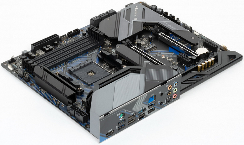
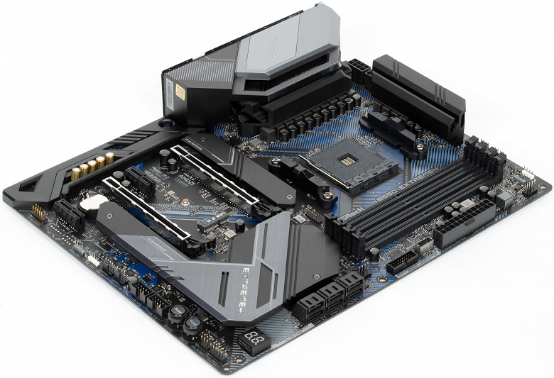
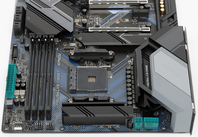
Надо особо отметить, что у компании ASRock есть флагманская серия Taichi, есть примерно на том же уровне игровая серия Phantom Gaming, остальные серии — разноплановые, четких позиционирований там нет. Понятно, что выпускать матплаты не на топовом чипсете в рамках серий Taichi — не комильфо, а все равно хочется показать, что и на B550 можно выпустить материнку с отличной системой питания, так что тут маркетологи взяли уже избитое до невозможности слово extreme. Вот наша плата как раз относится к этой серии — ASRock B550 Extreme4.
Поехали.
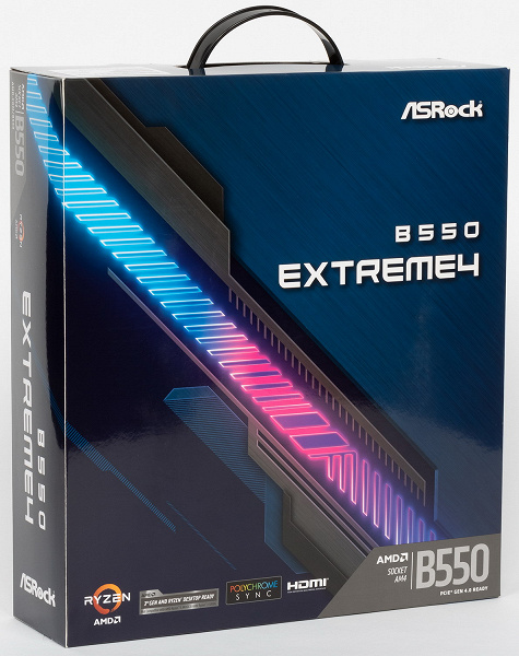
ASRock B550 Extreme4 поставляется в толстой картонной коробке, которая в свою очередь упакована в глянцевый супер с ручкой, чтобы показать, что данный продукт является топовым из всех, что выпущено на В550.
Внутри коробки есть традиционные отсеки: для самой материнской платы, и остального комплекта.
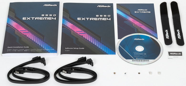
Комплект поставки банален. Кроме традиционных элементов типа руководства пользователя и кабелей SATA (что уже много лет является обязательным набором ко всем материнкам), имеются: винтики для монтажа модулей M.2, накопитель типа CD c ПО, бонусные стикер и стяжки.
Стоит отметить, что «заглушка» на заднюю панель с разъемами уже смонтирована на самой плате. Не забываем, что программное обеспечение за время путешествия платы к покупателю успевает устареть, так что придется его загружать с сайта производителя сразу после покупки.
Форм-фактор
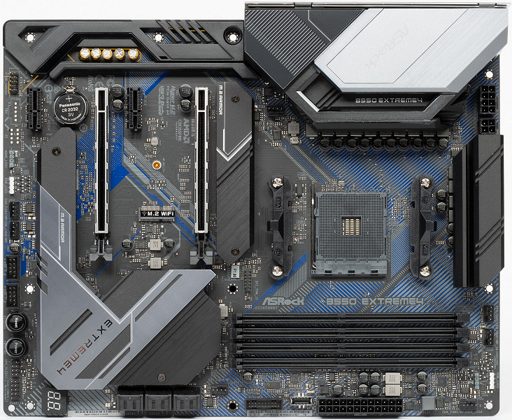
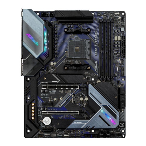
Форм-фактор ATX имеет размеры до 305×244 мм, а E-ATX — до 305×330 мм. Материнская плата ASRock B550 Extreme4 имеет размеры 305×244 мм, поэтому выполнена в форм-факторе ATX, и на ней имеются 10 монтажных отверстий для установки в корпус.
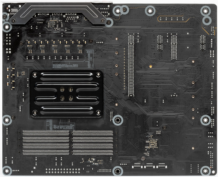
На оборотной стороне из элементов имеется только мелкая логика и удвоители фаз питания. Обработан текстолит неплохо: во всех точках пайки острые концы срезаны.
Технические характеристики
Традиционная таблица с перечнем функциональных особенностей.
| Поддерживаемые процессоры | AMD Ryzen 3000/4000/5000 (неофициально — все Ryzen) |
|---|---|
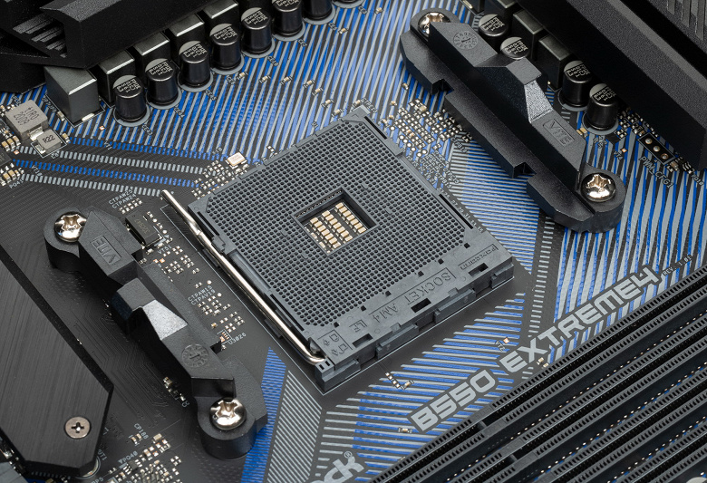
| Процессорный разъем | AM4 |
| Чипсет | AMD B550 |
| Память | 4 × DDR4, до 128 ГБ, до DDR4-4733 (XMP), два канала |
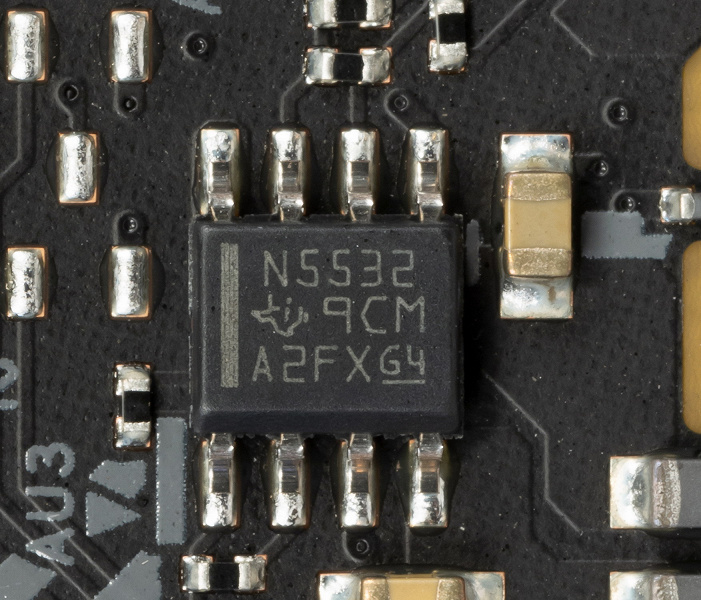
| Аудиоподсистема | 1 × Realtek ALC1220 (7.1) + операционный усилитель NE5532P от Texas Instruments |
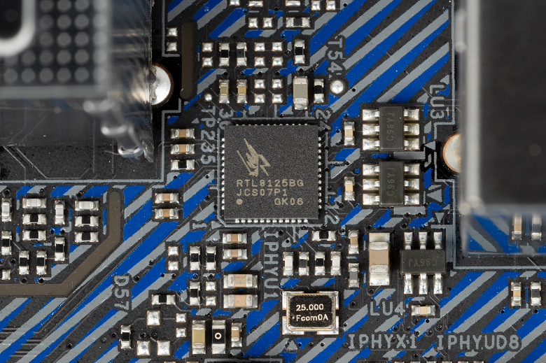
| Сетевые контроллеры | 1 × Realtek RTL8125BG Ethernet 2,5 Гбит/с |
| Слоты расширения | 1 × PCI Express 4.0 x16 (режим x16, (CrossFire))(CPU) 1 × PCI Express 3.0 x16 (режим x4/x2)(B550) 2 × PCI Express 3.0 x1 (B550) |
| Разъемы для накопителей | 6 × SATA 6 Гбит/с (B550) 1 × M.2 (CPU, PCIe 4.0/3.0 x4/SATA для устройств формата 2230/2242/2260/2280) 1 × M.2 (B550, PCIe 3.0 x4/SATA для устройств формата 2230/2242/2260/2280/22110) |
| USB-порты | 4 × USB 2.0: 2 внутренних разъема на 4 порта (Genesys Logic GL852G) 4 × USB 2.0: 2 порта Type-A (черные) на задней панели (B550) 2 × USB 3.2 Gen1: 1 внутренний разъем на 2 порта (B550) 2 × USB 3.2 Gen1: 2 порта Type-A (синие) на задней панели (B550) 1 × USB 3.2 Gen2: 1 внутренний разъем Type-C (CPU) 1 × USB 3.2 Gen2: 1 порт Type-A (голубой) на задней панели (CPU) 1 × USB 3.2 Gen2: 1 порт Type-C на задней панели (CPU) |
| Разъемы на задней панели | 1 × USB 3.2 Gen2 (Type-C) 1 × USB 3.2 Gen2 (Type-A) 2 × USB 3.2 Gen1 (Type-A) 4 × USB 2.0 (Type-A) 1 × RJ-45 5 аудиоразъемов типа миниджек 1 × оптический аудио S/PDIF 1 × HDMI 2.1 1 × универсальный разъем PS/2 |
| Прочие внутренние элементы | 24-контактный разъем питания ATX 1 8-контактный разъем питания EPS12V 1 4-контактный разъем питания EPS12V 1 слот M.2 (E-key) без адаптера беспроводных сетей (приобретается отдельно) 1 разъем для подключения 2 портов USB 3.2 Gen1 2 разъема для подключения 4 портов USB 2.0 7 разъемов для подключения 4-контактных вентиляторов и помп ЖСО 2 разъема для подключения неадресуемой RGB-ленты 2 разъема для подключения адресуемой ARGB-ленты 1 разъем аудио для передней панели корпуса 1 разъем TPM 2 разъема для подключения управления с передней панели корпуса |
| Форм-фактор | ATX (305×244 мм) |
| Розничные предложения |
узнать цену |
Основная функциональность: чипсет, процессор, память
Напоминаю, что данная плата относится к среднебюджетным и даже уже почти малобюджетным решениям (из-за нынешнего курса рубля).
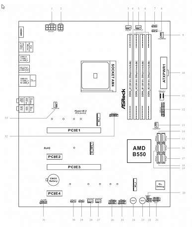
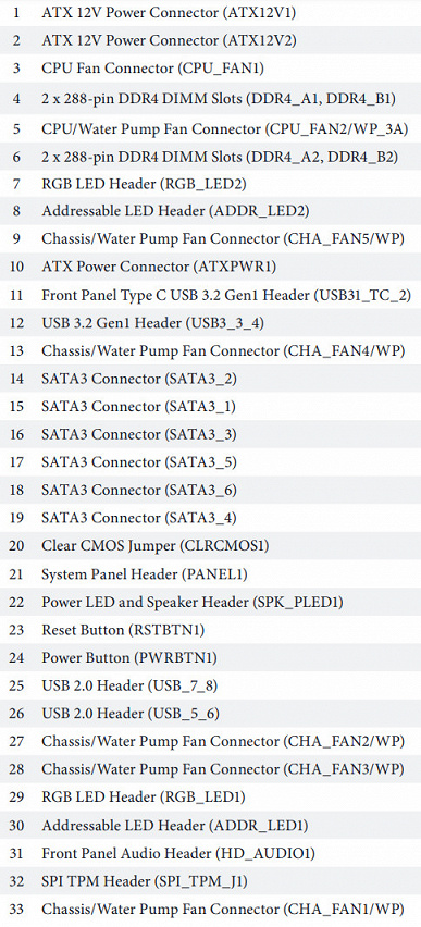
Схема работы связки чипсет+процессор.
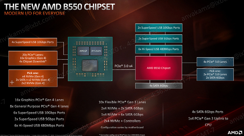
Процессоры Ryzen 3000/5000 суммарно имеют 24 линии ввода-вывода (включая PCIe 4.0). 4 линии (в данном случае превращаясь в PCIe 3.0) идут на связь с чипсетом B550. Еще 16 линий — это PCIe слоты для видеокарт. Осталось 4 линии: они могут конфигурироваться производителями материнских плат на выбор (либо-либо):
- работа одного NVMe накопителя х4 (высокоскоростной PCI-E 4.0)
- два SATA-порта по х1 + 1 порт NVMe x2
- два порта NVMe x2
Также процессоры Ryzen 3000/5000 имеют встроенные 4 порта USB 3.2 Gen2.
В свою очередь чипсет B550 поддерживает в сумме 18 линий PCIe 3.0. Из них опять же 4 нужны для связи с CPU. Осталось 14 линий ввода-вывода, из которых 4 заняты портами SATA, а остальные 10 линий могут свободно конфигурироваться. Понятно, что скорее всего будет дефицит линий PCIe для размещения всей нужной периферии, и придется делить ресурсы.
Также B550 поддерживает 2 порта USB 3.2 Gen2, 2 порта USB 3.2 Gen1, 6 портов USB 2.0.
Таким образом в сумме от тандема B550+Ryzen 3000/5000 мы получаем:
- 16 PCIe 4.0 линий для видеокарт (от процессора);
- 4 PCIe 4.0 линий от процессора + 10 PCIe 3.0 линий от чипсета, которые могут образовывать разные варианты комбинаций портов и слотов (в зависимости от производителя материнских плат);
- 4 порта SATA 6Гбит/с (от чипсета);
- 6 портов USB 3.2 Gen2 (4 от процессора, 2 от чипсета);
- 2 порта USB 3.2 Gen1 от чипсета;
- 6 портов USB 2.0 (от чипсета).
Итого: 14 портов USB, 4 порта SATA, 14 свободных PCIe линий.
Еще раз надо напомнить, что ASRock B550 Extreme4 поддерживает процессоры AMD Ryzen всех поколений, выполненные под разъем (сокет) AM4 (официально только Ryzen 3000/5000).
Для установки модулей памяти на плате имеется четыре DIMM-слота (для работы памяти в Dual Channel в случае использования всего 2 модулей их следует устанавливать в А2 и B2). Плата поддерживает небуферизованную память DDR4 (non-EСС), а максимальный объем памяти составляет 128 ГБ (при использовании UDIMM последнего поколения по 32 ГБ). Разумеется, поддерживаются профили XMP.
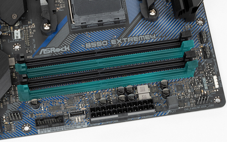
Слоты DIMM не имеют металлической окантовки, которая препятствует деформации слотов и печатной платы при установке модулей памяти и защищает от электромагнитных помех, и которая обычно всегда является составной частью именно флагманских материнских плат.
Периферийная функциональность: PCIe, SATA, разные «прибамбасы»
Выше мы изучили потенциальные возможности тандема B550+Ryzen, а теперь посмотрим, что из этого и как реализовано в данной материнской плате.
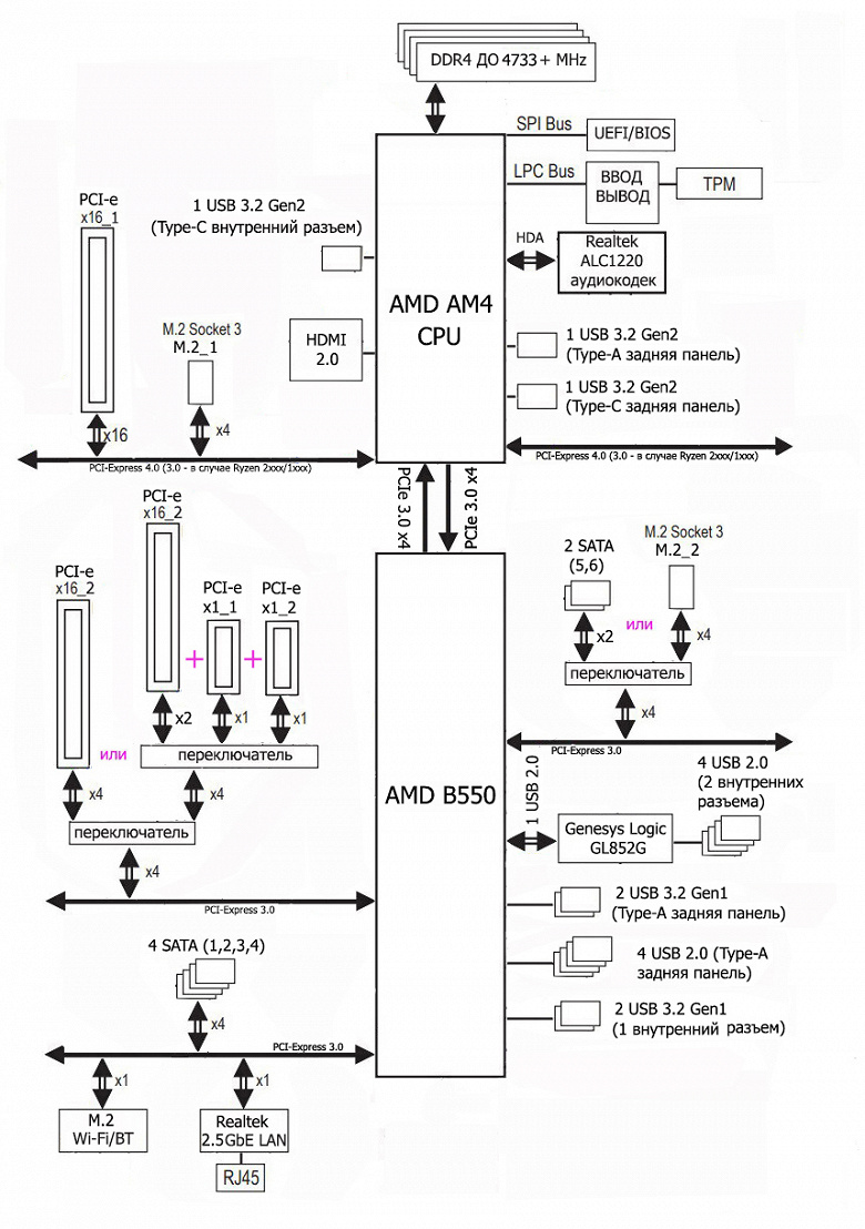
Итак, кроме USB-портов, к которым мы подойдем позже, чипсет B550 обладает 14 PCIe линиями (плюс 4 линии на аплинк с процессором). Считаем, сколько линий уходит на поддержку (связь) с тем или иным элементом (надо учитывать, что из-за дефицита PCIe линий некоторые элементы периферии делят их, и потому использовать одновременно нельзя: для этих целей у материнской платы существуют мультиплексоры):
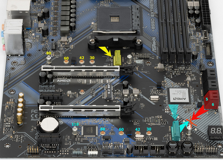
- Переключатель: или порты SATA_5/6 (2 линии), или слот M.2_2 (4 линии): максимум 4 линии;
- Переключатель: или слот PCIe x16_2 (2 линии)) + слот PCIe x1_1 (1 линия) + слот PCIe x1_2 (1 линия), или слот PCIe x16_2 в режиме PCIe x4: максимум 4 линии;
- Realtek RTL8125BG (Ethernet 2,5Gb/s) (1 линия);
- Слот M.2 (key E) для адаптера беспроводных сетей (1 линия);
- 4 порта SATA_1,2,3,4 (4 линии)
14 линий PCIe оказались занятыми. Замечу особо, что всего у платы 6 портов SATA, а штатно от чипсета распределено всего 4 таких порта. Остальные два порта SATA используют свободные PCIe линии (в данном случае они делятся между портами SATA 5/6 и слотом M.2_2).
Контроллер Genesys Logic GL852G (4 USB 2.0 на 2х внутренних разъемах) использует линии портов USB 2.0. Подробнее в разделе по USB-портам.
Теперь посмотрим выше на то, как работают процессоры в данной конфигурации. У всех CPU этого плана всего 20 линий PCIe (плюс 4 линии на даунлинк с чипсетом). И их надо делить на слот PCIe x16_1 и слот M.2_1. В процессорах Ryzen встроен контроллер High Definition Audio (HDA), связь с аудиокодеком идет путем эмуляции PCI шины (есть ограничение на звук по схеме 7.1: до 32-бит/192 кГц). Вариантов переключения слотов PCIe x16 нет из-за наличия всего одного такого.
Ниже полная схема распределения ресурсов по слотам PCIe.
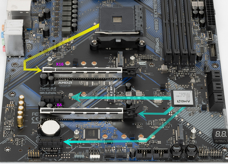
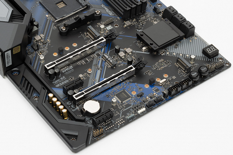
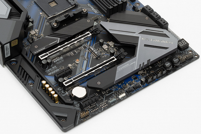
Всего на плате есть 4 слота PCIe: два PCIe x16 (для видеокарт или других устройств) и два «коротких» PCIe x1 (второй и четвертый по счету). Если про первый PCIe x16_1 я выше уже рассказал (он подключен к CPU), то второй PCIe x16_2 (третий по счету) подключен к B550 и максимально работает в режиме х4. Он также делит ресурсы с двумя слотами PCIe x1_1/1_2: если какие-либо из последних заняты, то слот PCIe x16_2 работает в режиме PCIe x2, а если PCIe x1_1/1_2 свободны, то слот PCIe x16_2 получает x4, и только тогда можно организовать режим AMD CrossFire из двух видеокарт.
У данной платы всего один полноценный PCIe x16 слот, распределения линий PCIe у него однозначное, поэтому мультиплексоры не востребованы.
В отличие от слотов для памяти, оба слота PCIe x16_1/2 имеют металлическое армирование из нержавеющей стали, которое увеличивает надежность слотов и предохраняет их от электромагнитных помех.
Расположение PCIe слотов позволяет легко смонтировать СО любого уровня и класса. Усилителей (ре-драйверов) шины не замечено.
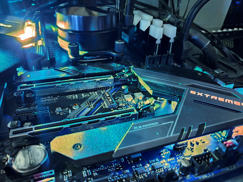
На очереди — накопители.
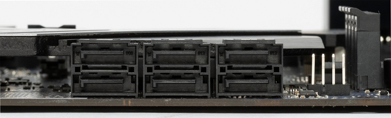
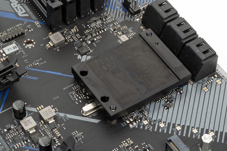
Всего у платы 6 разъемов Serial ATA 6 Гбит/с + 2 слота для накопителей в форм-факторе M.2. (Имеется еще один слот M.2, предназначенный для контроллеров беспроводных сетей Wi-Fi/Bluetooth.). 6 портов SATA реализованы через чипсет B550 и поддерживают создание RAID.
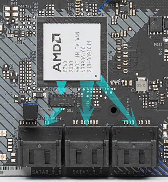
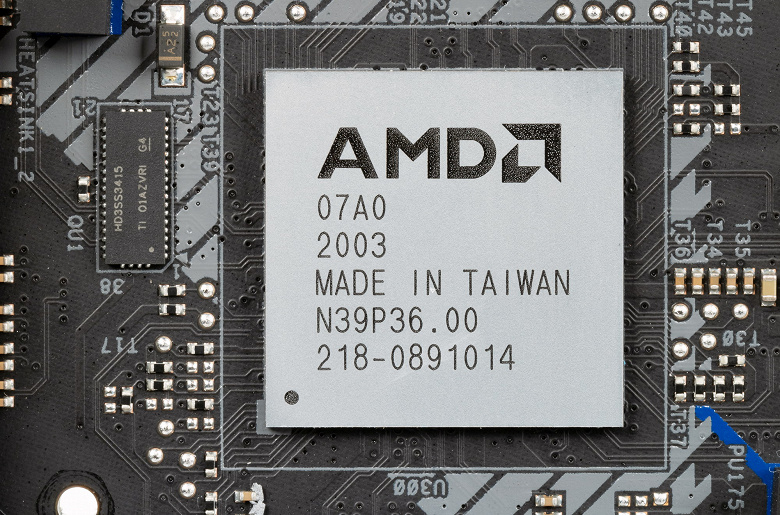
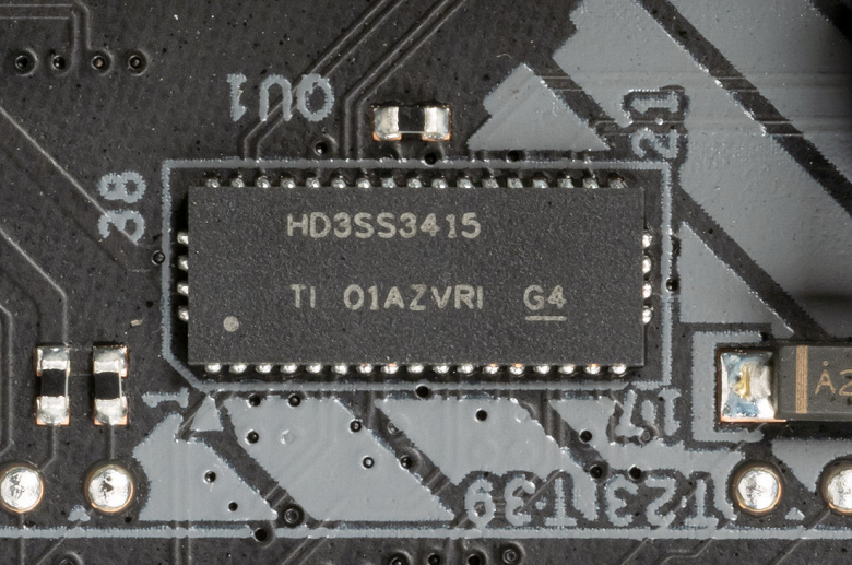
Напомню, что порты SATA 5,6 делят ресурсы с M.2_2, поэтому есть мультиплексор HD3SS3415 от Texas Instruments.
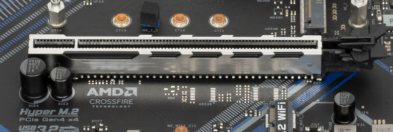
Теперь про M.2. Материнская плата имеет 2 гнезда такого форм-фактора.
Оба слота M.2 поддерживают модули с любым интерфейсом, а размеры могут быть от 2230 до 2080 у M.2_1 и до 22110 у M.2_2. Слот M.2_2 получает данные от чипсета B550 и делит ресурсы с портами SATA 5 и 6.
Первый M.2_1 реализован уже от процессорных линий.
Оба M.2 слота на самой матплате имеют два раздельных радиатора, которые не связаны с какими-то иными устройствами охлаждения на данной плате.
Другие «прибамбасы» на плате
Периферийная функциональность: USB-порты, сетевые интерфейсы, ввод-вывод
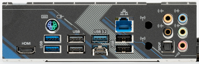
На очереди USB-порты. И начнем с задней панели, куда выведены большинство из них.
Повторим: чипсет B550 способен реализовать максимально: 2 порта USB 3.2 Gen2, 2 порта USB 3.2 Gen1, 6 портов USB 2.0. Процессор Ryzen 3000/5000 способен реализовать до 4 портов USB 3.2 Gen2.
Также мы помним и про 14 линий PCIe, которые идут на поддержку накопителей, сетевых и иных контроллеров (я выше уже показал на что и как расходуются все 14 линий).
И что мы имеем? Всего на материнской плате — 15 портов USB:
Итак, через чипсет B550 реализовано 4 USB 3.2 Gen1 и 4 USB 2.0 выделенных порта. Плюс контроллер Genesys Logic GL852S имеет связь с B550 через 1 линию USB 2.0.
Таким образом B550 кроме вышеуказанных портов USB 3.2 еще реализовал 5 портов USB 2.0.
Плюс 14 линий PCIe, выделенные на поддержку иной периферии (включая те же самые контроллеры USB). Итого, у B550 в данном случае реализованы почти все его возможные порты.
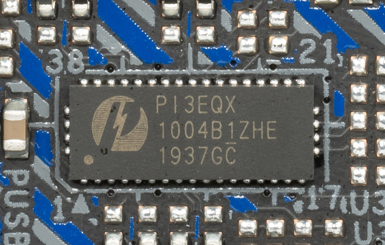
Все быстрые USB порты Type-A/Type-C имеют свои усилители сигнала Pericom PI3EQX.
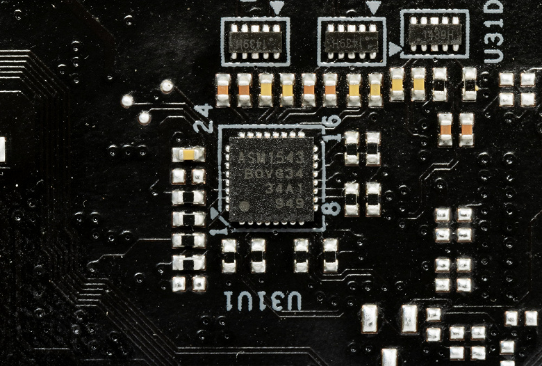
А для нужд быстрой зарядки порт Type-C на задней панели и аналогичный внутренний порт для вывода на переднюю панель имеют редрайверы от ASMedia ASM1543.
Теперь о сетевых делах.
Материнская плата оснащена средствами связи скромно. Имеется скоростной Ethernet-контроллер Realtek RTL8125BG, способный работать по стандарту 2,5 Гбит/с.
Собственно, и все. Беспроводных адаптеров в комплекте нет, правда имеется слот M.2 (E-key) для таковых, а для привинчивания выносных антенн на заднюю панель в ней можно увидеть отверстия.
Блок ввода-вывода, вентиляторы и т. п.
Аудиоподсистема
Как и во всех современных материнских платах звуком заведует аудиокодек Realtek ALC1220. Он обеспечивает вывод звука по схемам до 7.1.
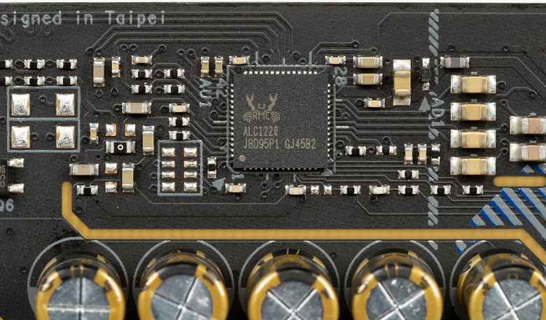
также аудиотракт содержит операционный усилитель NE5532P (Texas Instruments).
В аудиоцепях платы применяются «аудиофильские» конденсаторы Nichicon Fine Gold.
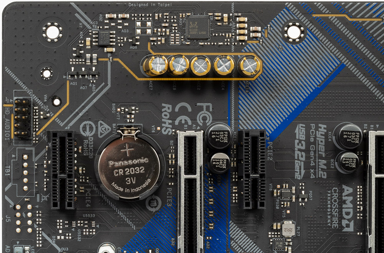
Аудиотракт вынесен на угловую часть платы, не пересекается с другими элементами. Разумеется, левый и правый каналы разведены по разным слоям печатной платы. Все аудиоразъемы на задней панели имеют привычную нам цветовую окраску и позолочены изнутри.
В целом очевидно, что это в целом стандартная аудиоподсистема, способная удовлетворить запросы большинства пользователей, не ожидающих от звука на материнской плате чудес.
Результаты тестирования звукового тракта в RMAA
Питание, охлаждение
Для питания платы на ней предусмотрены 3 разъема: в дополнение к 24-контактному ATX здесь есть еще два EPS12V (4-х и 8-ми контактные).
Система питания весьма продвинутая для среднебюджетного уровня матплаты, мы видим 14 фаз.
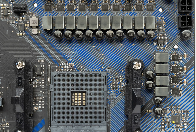
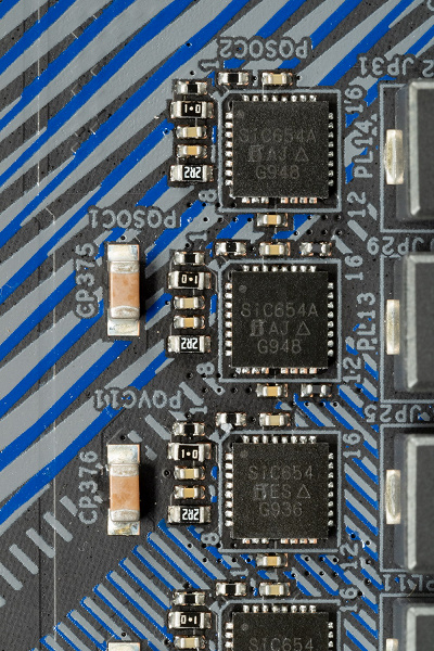
Каждый канал фазы имеет суперферритовую катушку и MOSFET SiC654A от Vishay.
Для управления фазами используется цифровой контроллер RAA229004 от Renesas.
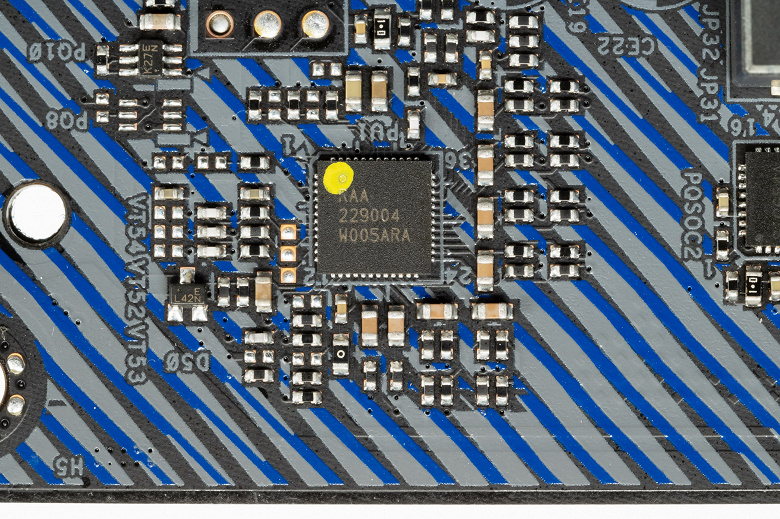
Однако он рассчитан только на 8 фаз максимум. Разумеется, используется старая добрая схема с удвоителями фаз.
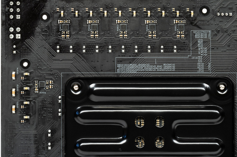
Они расположены на оборотной стороне платы (ISL6617A от того же Renesas, бывшей Intersil).
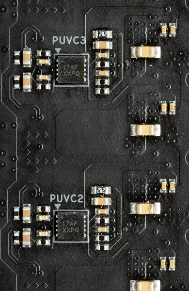
Так что 12 фаз для ядра преобразуются в 6 (две физических идут за одну на контроллере), а еще 2 для SoC управляются без преобразований.
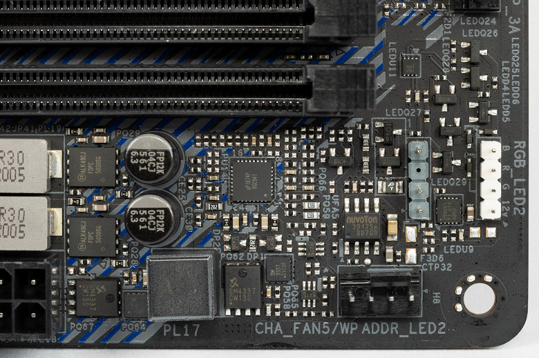
Что касается модулей оперативной памяти, то здесь все проще: реализована однофазная схема на мосфетах Vishay с контроллером uPI.
Теперь про охлаждение.
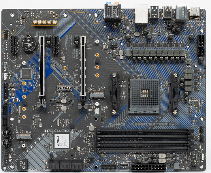
Все потенциально сильно греющиеся элементы имеют свои собственные радиаторы.
Как мы видим, охлаждение чипсета (один радиатор) организовано отдельно от силовых преобразователей.
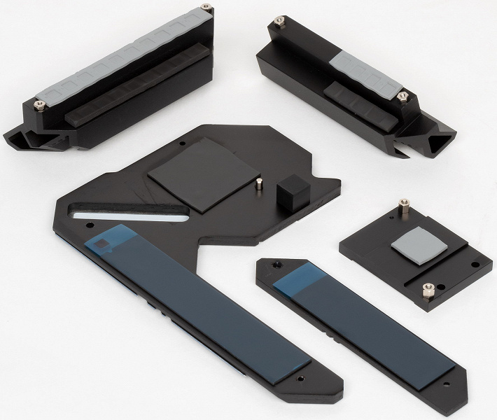
VRM-секция имеет свои два раздельных радиатора.
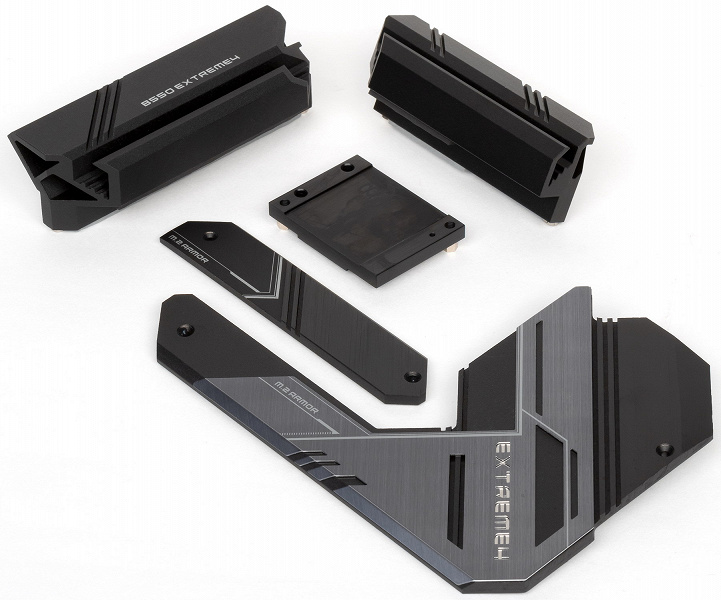
Я ранее говорил о том, что охлаждение модулей M.2 организовано отдельно от охлаждения чипсета и VRM. И оба M.2 порта имеют свои отдельные радиаторы.
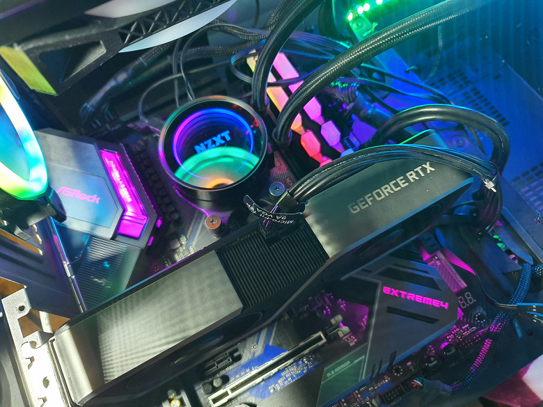
Над блоком разъемов задней панели установлен кожух соответствующего дизайна , он оснащен подсветкой.
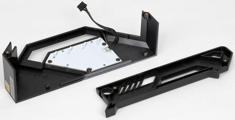
Также подсветка имеется на плате вокруг чипсетного радиатора.
Подсветка
Программное обеспечение под Windows
Все программное обеспечение можно скачать с сайта производителя ASRock.com. Основная программа — так сказать, менеджер всего «софта» — это App Shop. Ее и следует установить первой.
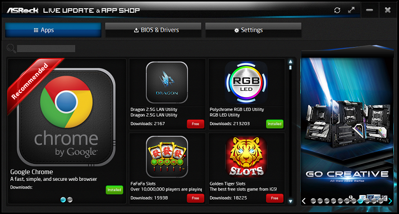
App Shop помогает загрузить все остальные нужные (и не совсем нужные) утилиты. Большинство из них запускается и без App Shop. Эта же программа следит и за обновлениями установленного фирменного ПО от ASRock, а также за актуальностью прошивки BIOS.
Начнем с программы: Polychrome Sync, настраивающей работу режимов подсветки.
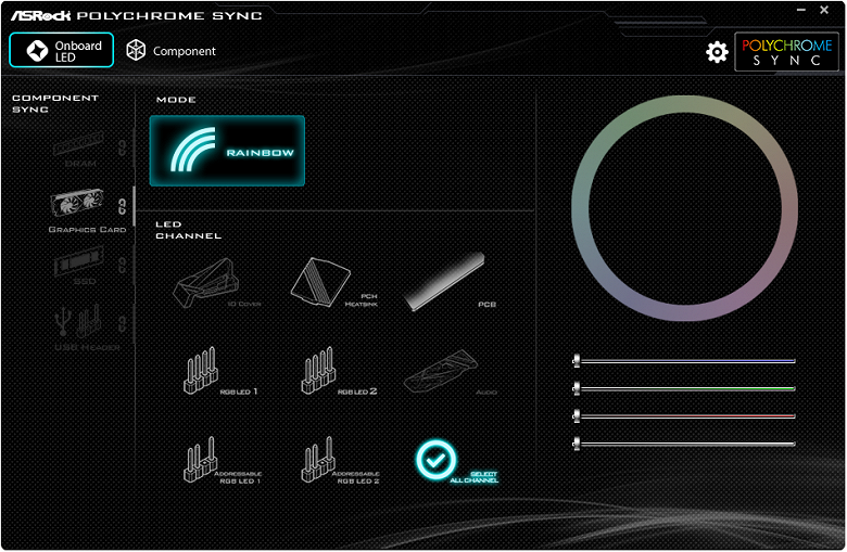
Утилита умеет распознавать все фирменные элементы ASRock, оснащенные подсветкой, а также ряд компонентов ПК от иных производителей, включая модули памяти.
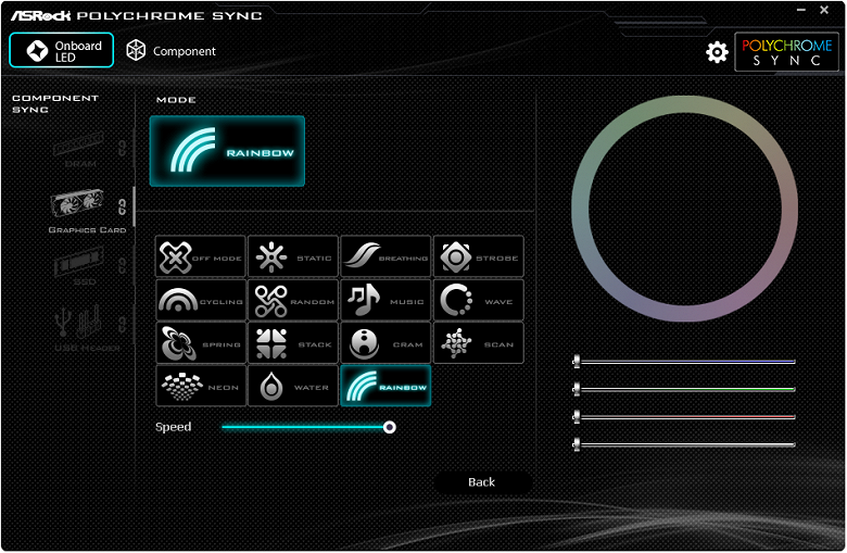
Можно задавать подсветку как для отдельных элементов, так и для всей группы в целом, а также записывать выбранные алгоритмы подсветки в профили, чтобы потом легко переключаться между ними.
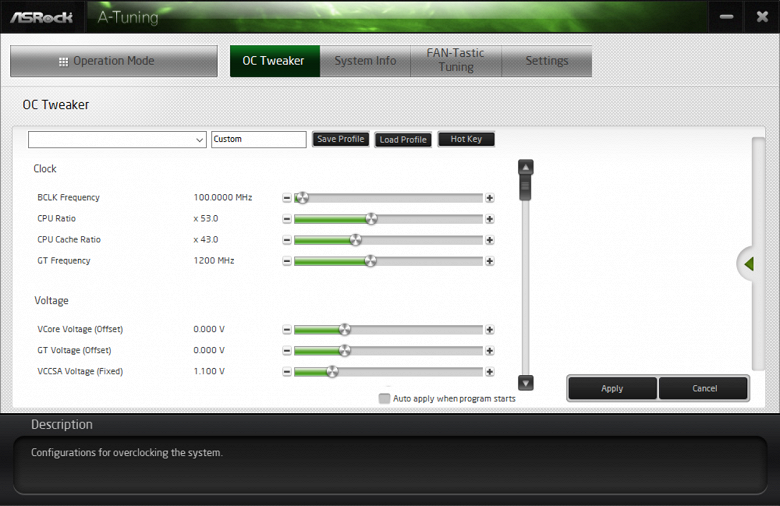
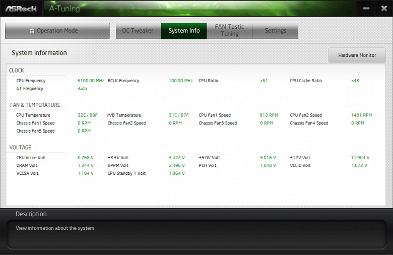
Основной обслуживающей материнскую плату программой является A-Tuning.
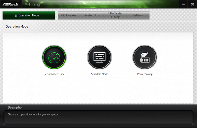
Для тех, кому лень возиться с ручными тонкими настройками оверклокинга, имеются три предустановочных режима. Впрочем, отличие между ними небольшое: Performance Mode задает максимально возможные частоты всего для 2-3 ядра, когда как обычный режим довольствуется тем же для одного ядра. Режим Power Saving держит частоты на номинальном (минимальном) уровне, хотя все равно некоторые «всплески» встречаются. Не забываем, что плата — не овеклокерская все же.
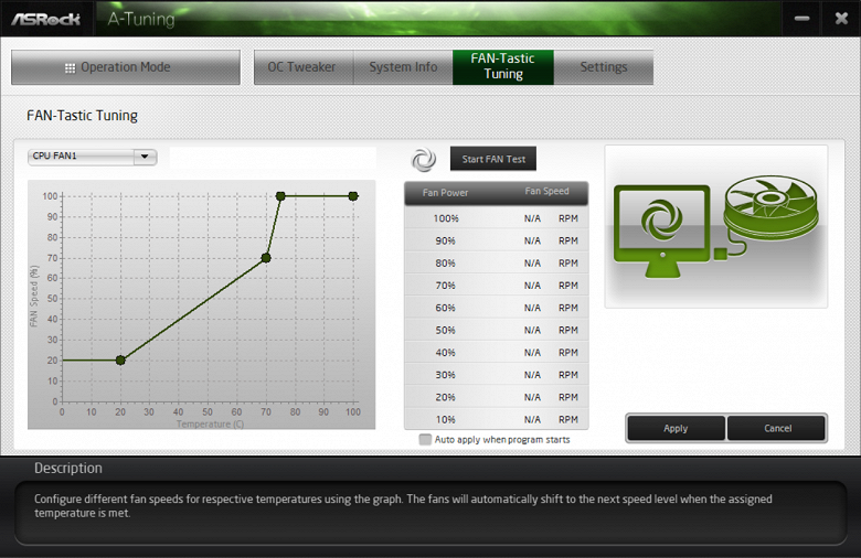
Наиболее интересной частью данной программы является возможность настраивания работы вентиляторов (мы не забываем, что у материнской платы есть 7 гнезд для подключения вентиляторов).
Разумеется, есть и иные фирменные утилиты ASRock, однако я уже неоднократно о них рассказывал.
Настройки BIOS
Что нам дают тонкости настроек в BIOS
Работоспособность (и разгон)
Конфигурация тестовой системы
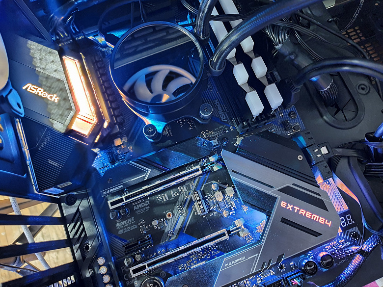
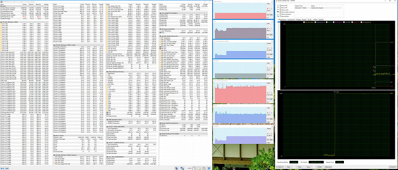
Запускаем все в режиме по умолчанию. Затем нагружаем тестами от AIDA, и CPU-Z.
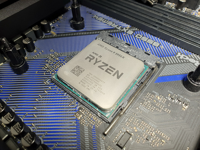
Учитывая, что у этой платы добротная и весьма мощная система питания, я снова взял самый топовый на сегодня процессор (спасибо компании AMD за сэмпл) Ryzen 9 5950X, чтобы проверить работу системы питания материнки. К тому же, я уже ранее писал, что платы такого рода ничем не плохи для флагманского процессора. Ну не поддерживает PCIe 4.0 сам чипсет и имеет урезанное количество линий PCIe и USB-портов по сравнению с X570. Разумеется, для кого-то этот фактор может играть важную роль, однако при В550 нет проблем с шумом чипсетного вентилятора, которым снабжены почти все матплаты на X570. К тому же неплохо знать — как система питания обеспечит данный процессор. Хорошо известно, что современные технологии авторазгона от Intel (Turbo Boost) и AMD (Precision Boost) базируют свои лимиты подъема частот на информации о системе питания на той или иной матплате (UEFI содержит все данные на сей счет). Поэтому и имеет смысл даже среднебюджетные матплаты проверять на топовых процессорах. Понятно, что нет никакого смысла соединять в тандемы слишком простые и малобюджетные материнские платы с флагманскими процессорами (никто, будучи в здравом уме, не станет совершать подобные приобретения).
Также хорошо известно, что внутренняя шина процессоров Ryzen — Infinity Fabric очень чувствительна к разгону, и ранее ее частота не должна была превышать 1800 МГц, а теперь на Ryzen 5000 серии отдельные экземпляры процессоров могут работать и 2000 МГц по этой шине. Хотя практика показала, что как правило, все же 5000 «райзены» в массе своей не переваривают повышение IF выше 1900 МГц. А IF связана с частотой работы памяти множителями. По умолчанию он равен 1. То есть расчет на частоту работы памяти не выше 3600 МГц. Но уже много памяти на рынке с XMP профилями выше 4000 МГц, и тут все зависит от конкретной модели матплаты: на каких-то надо вручную выставлять частоту IF или памяти, а также множителей, а какие-то модели автоматически выставят частоту IF не выше 1800 МГц вне зависимости от частоты работы памяти с XMP профилем (просто подберут нужный множитель). Данная плата от ASRock способна сама реализовать контроль за частотой IF, держа ее не выше 1800 МГц (разумеется, если она выставлена в режиме Auto) и выставляет множитель для частоты памяти автоматически.
Итак, мы видим, что система питания сработала неплохо, и максимальные разовые всплески частот работы ядер получились на уровне 4,9 ГГц, когда как в массе времени они работали на 4,36 ГГц. Если сравнить с базовой частотой 3,4 ГГц, то мы видим, что даже без ручного разгона это прекрасный результат. При этом нагрев процессора был в рамках допустимых значений, блок VRM и чипсет B550 особо не грелись, необычных явлений не замечено. Максимальное потребление процессором достигло величины в 150 Вт.
Собственно, из-за того, что данная материнка не оверклокерская, я какие-то изыскания в плане ручного разгона на ней не проводил.
Выводы
ASRock B550 Extreme4 — материнская плата на среднебюджетном чипсете, обладающая прекрасной системой питания, обеспечивающей стабильную работу даже таких флагманских процессоров, как Ryzen 9 5950X, при этом почти не ограничивая авторазгон, заложенный в рамках AMD PBO.
Для своей стоимости функциональность у ASRock B550 Extreme4 очень хорошая. Она имеет 15 портов USB разных видов (включая 3 USB3 Gen2), 2 слота PCIe х16 (из которых первый получает 16 линий PCIe от процессора) с возможностью создать AMD CrossFire, 2 слота PCIe x1 для карт расширения, 2 слота M.2, 6 портов SATA. Плата предлагает 7 разъемов для подключения вентиляторов и помп, радиаторами оснащены все накопители в слотах M.2. Разве что проводной сетевой контроллер всего один, однако он высокоскоростной, 2,5-гигабитный. Стоит отметить наличие подсветки, включая широкие возможности для подключения дополнительных RGB-устройств.
Напомню, что чипсет AMD B550 предусматривает поддержку процессоров Ryzen 3000/4000/5000 с PCIe 4.0, однако сам аппаратно реализует только PCIe 3.0. Это надо учитывать, устанавливая, например, накопители в слоты M.2 (один из них подключается к процессору и потому реализует PCIe 4.0, а второй — к В550, и потому там скорость обмена информацией ограничена интерфейсом PCIe 3.0).
В номинации «Оригинальный дизайн» плата ASRock B550 Extreme4 получила награду:

Благодарим компанию ASRock
за предоставленную на тестирование плату
Также благодарим компанию Gigabyte Russia
и лично Евгения Лесикова
за предоставление Gigabyte Aorus Gen4 SSD 500G для тестового стенда
Особо благодарим компанию Super Flower
за предоставление блока питания Super Flower Leadex Platinum 2000W
|
Detail Specifications: 1887/1887275-b550_extreme4.pdf file (21 Apr 2023) |
Accompanying Data:
ASROCK B550 EXTREME4 Motherboard PDF Manual (Updated: Friday 21st of April 2023 09:39:20 AM)
Rating: 4.3 (rated by 63 users)
Compatible devices: X79 Extreme6/GB, H510M/ac, X570 Taichi, IMB-A1000, H370 Pro4, H270M-ITX/ac, Z75 Pro3, Fatal1ty X99 Professional Series.
Recommended Documentation:
Text Version of Manual
(Ocr-Read Summary of Contents, UPD: 21 April 2023)
-
106, 104 Español 104 Cabezal de audio del panel frontal (HD_AUDIO1 de 9 contactos) (consulte la pág. 1, nº 31) Este cabezal se utiliza para conectar dispositivos de audio al panel de audio frontal. Conectores del ventilador de la bomba de agua del chasis (CHA_FAN1/WP de 4 contactos) (consulte la pág. 1, nº 33) (CHA_FAN2/WP de 4 contactos) (consulte la pág. 1, nº 27) (CHA…
-
138, 136 Português Conector de alimentação de 12V ATX (ATX12V2 de 4 pinos) (ver p.1, N.º 2) Por favor, ligue este conector a uma alimentação de força ATX 12V. *O plugue de sua fonte de alimentação se encaixa neste conector apenas em uma orientação. Plataforma SPI TPM (SPI_TPM_J1 de 13 pinos) (ver p.1, N.º 32) Este conector suporta um sistema com SPI Módulo de Plataforma Conável…
-
169, ASROCK B550 EXTREME4 167 B550 Extreme4 日本語 1.2 仕様 プラット フォーム • ATX フォームファクタ • 2 オンスのコパー製 PCB CPU • Ryzen TM グラフィックスプロセッサー(3000 および 4000 シリー ズプロセッサー)と共に第 3 世代以降の AMD AM4 Ryzen TM / Ryzen TM に対応します * * AMD Ryzen TM 5 3400G お…
-
129, 127 B550 Extreme4 Português • Sensor de impedância na porta externa posterior • Camadas de PCB individuais por canal de áudio R/L • Fonres de Áudio Gold • Conector de Áudio de Outro 15μ • Áudio Nahimic LAN • 2,5 Gigabit LAN 10/100/1000/2500 Mb/s • Dragon RTL8125BG • Suporta Soware Dragon 2,5G LAN — Ajuste Inteligente de Controle de Largura de Banda…
-
49, ASROCK B550 EXTREME4 English 47 B550 Extreme4 M.2_SSD (NGFF) Module Support List For the latest updates of M.2_SSD (NFGG) module support list, please visit our website for details: http://www.asrock.com Vendor Interface P/N SanDisk PCIe SanDisk-SD6PP4M-128G( Gen2 x2) Intel PCIe INTEL 6000P-SSDPEKKF256G7 (nvme) Intel PCIe INTEL 6000P-SSDPEKKF512G7 (nvme) Intel PCIe SSDPEKKF512G7 NVME / 512G…
-
85, ASROCK B550 EXTREME4 83 B550 Extreme4 Italiano • Rilevamento dell’impedenza sulla porta di uscita posteriore • Layer PCB individuali per canali audio R/L • Connettori audio dorati • Connettore audio dorato 15μ • Nahimic Audio LAN • 2,5 LAN Gigabit 10/100/1000/2500 Mb/s • Dragon RTL8125BG • Supporto di Dragon 2.5G LAN Soware — Controllo intuitivo di regolazio…
-
213, 211 B550 Extreme4 Bahasa Indonesia • 1 x Konektor Audio Panel Depan (15μ Konektor Audio Berwarna Emas) • 2 x Header USB 2.0 (Mendukung 4 port USB 2.0) (Mendukung Perlindungan dari ESD) • 1 x Header USB 3.2 Gen1 (Mendukung 2 port USB 3.2 Gen1) (Mendukung Perlindungan dari ESD) • 1 x Header Tipe C USB 3.2 Gen1 Panel Depan (Mendukung Perlindungan ESD) • 1 x Dr. Debug dis…
-
154, 152 Polski 1.5 Inteligentne przełączniki Płyta główna ma dwa inteligentne przełączniki: Przycisk zasilania i przycisk resetowania umożliwiają użytkownikom szybkie włączanie/wyłączanie systemu lub resetowanie systemu. Przycisk zasilania (PWRBTN1) (sprawdź s.1, Nr 24) Przycisk zasilania umożliwia użytkownikom szybkie włączanie/ wyłączanie systemu. Przycisk r…
-
51, English 49 B550 Extreme4 Connecting the Addressable RGB LED Strip Connect your Addressable RGB LED strips to the Addressable LED Headers (ADDR_LED1, ADDR_LED2) on the motherboard. 1. Never install the RGB LED cable in the wrong orientation; otherwise, the cable may be damaged. 2. Before installing or removing your RGB LED cable, please power o you…
-
128, 126 Português Slot de expansão CPUs AMD séries Ryzen (Matisse) • 2 x Slot PCI Express x16 (PCIE1: modo Gen4x16; PCIE3: modo Gen3 x4)* AMD Ryzen série APUs (Renoir) • 2 x Slot PCI Express x16 (PCIE1: modo Gen3x16; PCIE3: modo Gen3 x4)* * Suporta NVMe SSD nos discos de inicialização • 2 x Slots PCI Express 3.0 x1 • Suporta AMD Quad CrossFireX TM e CrossFireX TM �…
-
70, 68 Français • Détection de l’impédance sur le port de sortie arrière • Couches de PCB individuelles pour canal audio D/G • Connecteurs jack audio or • 15μ Connecteurs jack audio • Audio Nahimic Réseau • 2,5 Gigabit LAN 10/100/1000/2500 Mo/s • Dragon RTL8125BG • Prend en charge le logiciel Dragon 2,5G LAN — Contrôle de la bande passante à réglag…
Recommended Instructions:
BS-1034EN, QX-960, CS-MP77 — 2.1-CH PC Multimedia Speaker Sys, F2015B, HUV 4421-G / GXP


-
May 2009 Order Number: E64767-001US The Intel® Desktop Board DB43LD may contain design defects or errors known as errata that may cause the product to deviate from published specifications. Current characterized errata are documented in the Intel Desktop Board DB43LD Specification Update. Intel® Desktop Board DB43LD Technical Product Specification …
BOXDB43LD — B43 Chipset Executive Series 92
-
Cypress Semiconductor198 Champion CourtSan Jose, CA 95134-1709Phone (USA): 800.858.1810Phone (Intnl): +1.408.943.2600www.cypress.comF2MC-8FX FamilyMCU Board for MB95FV100D-102MB2146-302A, Operation ManualDoc. # 002-07488 Rev. *B …
MB2146-302A 29
-
Tiger i7322 S5351 User’s Manual i http://www.tyan.com Tiger i7322 ///S5351 Revision 1.00 Copyright © TYAN Computer Corporation, 2004. All rights reserved. No part of this manual may be reproduced or translated without prior written consent from TYAN Computer Corp. …
Tiger i7322 S5351 87
-
LPCXpresso55S9UM11158 UM11158LPCXpresso55S69 Development BoardRev. 1.2 — 25 April 2019 User manualDocument informationInfo ContentKeywords LPC55S69, LPC55xx, LPCXpresso55S69, LPC55S69-EVKAbstract LPCXpresso55S69 user manual …
LPC55 Series 24
Additional Information:
Popular Right Now:
Operating Impressions, Questions and Answers:
Table of Contents for ASROCK B550 EXTREME4:
-
166 日本語 1 はじめに ASRock B550 Extreme4 マザーボードをお買い上げ頂きありがとうございます。ASRock の 製品は一貫した厳格な品質管理の下で製造されております。優れた品質と耐久性を兼ね 備えつつ、優れたパフォーマンスを提供致します。 マザーボードの仕様と BIOS ソフトウェアは更新されることがあるため、このマニュアル の内容は予告なしに変更することがあります。このマニュアル�
-
188 简体中文 串行 ATA3 接口 (SATA3_1: 见第 1 页,第 15 个) (SATA3_2: 见第 1 页,第 14 个) (SATA3_3: 见第 1 页,第 16 个) (SATA3_4: 见第 1 页,第 19 个) (SATA3_5: 见第 1 页,第 17 个) (SATA3_6: 见第 1 页,第 18 个) 这六个 SATA3 接口支持最高 6.0 Gb/s 数据传输速率的内部 存储设备的 SATA 数据线。 * M2_2 和 SATA3_5_6 共享巷 道。如果其中一个在使用
-
111 B550 Extreme4 Русский Слоты расширения ЦП серии AMD Ryzen (Matisse) • 2 x PCI Express x16 гнезд (PCIE1: режим Gen4x16; PCIE3: режим Gen3 x4)* Гибридные процессоры AMD серии Ryzen (Renoir) • 2 x PCI Express x16 гнезд (PCIE1: режим Gen3x16; PCIE3: режим Gen3 x4)* * Поддерживаются в качестве загрузочны�
-
English 30 Front Panel Audio Header (9-pin HD_AUDIO1) (see p.1, No. 31) is header is for connecting audio devices to the front audio panel. Chassis Water Pump Fan Connectors (4-pin CHA_FAN1/WP) (see p.1, No. 33) (4-pin CHA_FAN2/WP) (see p.1, No. 27) (4-pin CHA_FAN3/WP) (see p.1, No. 28) (4-pin CHA_FAN4/WP) (see p.1, No. 13) (4-pin CHA_FAN5/WP) (see p.1, No. 9) is motherboard provides ve 4-Pin water cooling chassis fan connectors. If you plan to connect a 3-Pin chassis water cooler fan, plea
-
150 Polski Złącze wentylatora pompy wodnej CPU (4-pinowe CPU_FAN2/ WP_3A) (sprawdź s.1, Nr 5) Ta płyta główna udostępnia 4-pinowe złącze obudowy wentylatora chłodzenia wodnego CPU. Jeśli planowane jest podłączenie 3-pinowego wentylatora chłodzenia wodnego CPU, należy je podłączyć do pinów 1-3. Złącze zasilania ATX (24-pinowe ATXPWR1) (sprawdź s.1, Nr 10) Ta płyta główna udostępnia 24-pinowe złącze zasilania ATX. W celu użycia 20-pinowego zasilacza ATX, należy podłączyć je wzdłuż pi
-
75 B550 Extreme4 Français Embase audio du panneau frontal (HD_AUDIO1 à 9 broches) (voir p.1, No. 31) Cette embase sert au branchement des appareils audio au panneau audio frontal. Connecteurs du ventilateur de pompe à eau du châssis (CHA_FAN1/WP à 4 broches) (voir p.1, No. 33) (CHA_FAN2/WP à 4 broches) (voir p.1, No. 27) (CHA_FAN3/WP à 4 bro
-
118 Русский Разъемы Serial ATA3 (SATA3_1: см. стр. 1, № 15) (SATA3_2: см. стр. 1, № 14) (SATA3_3: см. стр.1, № 16) (SATA3_4: см. стр.1, № 19) (SATA3_5: см. стр.1, № 17) (SATA3_6: см. стр.1, № 18) Эти шесть разъемов SATA3 предназначены для подключения кабелей SATA внутренних
-
173 B550 Extreme4 日本語 1.3 ジャンパー設定 このイラストは、ジャンパーの設定方法を示しています。ジャンパーキャップがピンに被 さっていると、ジャンパーは「ショート」です。ジャンパーキャップがピンに被さっていない 場合には、ジャンパーは「オープン」です。 CMOS クリアジャンパー (CLRCMOS1) (p.1、No. 20 参照) ショート: CMOS のクリア オープン: デフ�
-
English 21 B550 Extreme4 3 4
-
AUSTRALIA ONLY Our goods come with guarantees that cannot be excluded under the Australian Consumer Law. You are entitled to a replacement or refund for a major failure and compensation for any other reasonably foreseeable loss or damage caused by our goods. You are also entitled to have the goods repaired or replaced if the goods fail to be of acceptable quality and the failure does not amount to a major failure. If you require a
-
96 Español 96 Ranura de expansión CPU de la serie AMD Ryzen (Matisse) • 2 ranura PCI Express x16 (PCIE1: modo Gen4x16; PCIE3: modo Gen3 x4)* APU de la serie AMD Ryzen (Renoir) • 2 ranura PCI Express x16 (PCIE1: modo Gen3x16; PCIE3: modo Gen3 x4)* * Admite unidad de estado sólido de NVMe como disco de arranque • 2 x Ranuras PCI Express 3.0 x1 • Compatible con AMD Quad CrossFireX TM y Cr
-
89 B550 Extreme4 Italiano Connettori Serial ATA3 (SATA3_1: vedere pag. 1, n. 15) (SATA3_2: vedere pag. 1, n. 14) (SATA3_3: vedere pag.1, n. 16) (SATA3_4: vedere pag.1, n. 19) (SATA3_5: vedere pag.1, n. 17) (SATA3_6: vedere pag.1, n. 18) Questi sei connettori SATA3 supportano cavi dati SATA per dispositivi di archiviazione interna, con una velocità di trasferimento dati no a 6,0 Gb/s. * M2_2, e SATA3_5_6 condividono le corsie. Se uno di essi è utilizzato, l’altro sarà disabilitato. Header USB 2.0 (USB_5_6 a 9 pin)
-
English 6 1.2 Specications Platform • ATX Form Factor • 2oz Copper PCB CPU • Supports 3 rd Gen AMD AM4 Ryzen TM / future AMD Ryzen TM Processors (3000 and 4000 Series Processors)* * Not compatible with AMD Ryzen TM 5 3400G and Ryzen TM 3 3200G. • Digi Power design • 14 Power Phase design Chipset • AMD B550 Memory • Dual Channel DDR4 Memory Technology • 4 x DDR4 DIMM Slots • AMD Ryzen series CPUs (Matisse) support DDR4 4733+ (OC)/4666(OC)/4600(OC)/4533(OC)/4466(OC)/4400 (OC)/4333(OC)/4266(OC)/4200(OC)
-
72 Français 1.3 Conguration des cavaliers (jumpers) L’illustration ci-dessous vous renseigne sur la conguration des cavaliers (jumpers). Lorsque le capuchon du cavalier est installé sur les broches, le cavalier est «court-circuité». Si le capuchon du cavalier n’est pas installé sur les broches, le cavalier est «ouvert». Cavalier Clear CMOS (CLRCMOS1) (voir p.1, No. 20) Court-circuité: Fonction Clear CMOS Ouve
-
197 B550 Extreme4 繁體中文 • 後輸出埠的阻抗感應 • 適用左/右音訊聲道的獨立 PCB 層 • 金色音訊插孔 • 15 μ 特厚鍍金音訊接頭 • Nahimic 音訊 LAN • 2.5 Gigabit LAN 10/100/1000/2500 Mb/s • Dragon RTL8125BG • 支援 Dragon 2.5G LAN 軟體 — 智慧自動調整頻寬控制 — 使用者視覺人性化 UI — 視覺網路使用統計資料 — 適合遊戲、瀏覽器和串流模式的最佳化預設設定 — 使用者自訂優先順序控制 • 支援網�
-
102 Español 102 1.4 Conectores y cabezales incorporados Los cabezales y conectores incorporados NO son puentes. NO coloque tapas de puente sobre estos cabezales y conectores. Si coloca tapas de puente sobre los cabezales y conectores dañará de forma permanente la placa base. Cabezal del panel del sistema (PANEL1 de 9 contactos) (consulte la pág. 1, nº 21) Conecte el botón de alimentación, el botón de restablecimiento y el indicador de estado del sistema que se encuentran en el chasis a esta base de conexiones según las asignacio
Questions, Opinions and Exploitation Impressions:
You can ask a question, express your opinion or share our experience of ASROCK B550 EXTREME4 device using right now.