Материнская плата GIGABYTE B560 HD3

LGA 1200, Intel B560, 4xDDR4-3200 МГц, 2xPCI-Ex16, 2xM.2, Standard-ATX
подробнее

75897,97 78
Код товара: 4777063
инструкцияGigabyte B560 HD3

To reduce the impacts on global warming, the packaging materials of this product
are recyclable and reusable. GIGABYTE works with you to protect the environment.
For more product details, please visit GIGABYTE’s website.
User’s Manual
Rev. 1001
Посмотреть инструкция для Gigabyte B560 HD3 бесплатно. Руководство относится к категории материнские платы, 1 человек(а) дали ему среднюю оценку 7.6. Руководство доступно на следующих языках: английский. У вас есть вопрос о Gigabyte B560 HD3 или вам нужна помощь? Задайте свой вопрос здесь
- B560 HD3 Motherboard Layout
- Chapter 1 Hardware Installation
- Chapter 2 BIOS Setup
- Chapter 3 Appendix
Главная
| Gigabyte | |
| B560 HD3 | B560 HD3 | |
| материнская плата | |
| 4719331815509 | |
| английский | |
| Руководство пользователя (PDF), Инструкция по установке (PDF) |
Процессор
| Производитель процессора | Intel |
| Сокет процессора | LGA 1200 |
| Совместимые серии процессоров | Intel Celeron, Intel Core i3, Intel Core i5, Intel Core i7, Intel Core i9, Intel Pentium |
| Поддерживаемые сокеты процессоров | LGA 1200 (Socket H5) |
Память
| Максимальная внутренняя память | 128 GB |
| Поддерживаемые типы памяти | DDR4-SDRAM |
| Количество слотов памяти | 4 |
| Тип слотов памяти | DIMM |
| Каналы памяти | Dual-channel |
| Error-correcting code (ECC) | Да |
| без функции коррекции ошибок | Да |
| Небуферизованная память | Да |
| Поддерживаемые частоты памяти | 2133,2400,2666,2800,2933,3000,3200,3300,3333,3400,3466,3600,3666,3733,3800,3866,4000,4133,4266,4300,4400,4500,4600,4700,4800,4933,5000,5133,5333 MHz |
Контроллеры хранения данных
| Количество поддерживаемых дисков памяти | 8 |
| Поддерживаемые типы накопителей | HDD & SSD |
| Поддерживаемые интерфейсы носителя | M.2, PCI Express 3.0, SATA III |
Графический адаптер
| Поддержка технологии параллельной обработки | Не поддерживается |
| Количество поддерживаемых дисплеев | 3 |
| Максимальное разрешение | 4096 x 2304 пикселей |
| HDCP | Да |
Внутренние порты
| Разъемы USB 3.2 Gen 1 (3.1 Gen 1) | 1 |
| Разъемы USB 2.0 | 3 |
| Разъемы USB 3.2 Gen 2 (3.1 Gen 2) | 0 |
| Количество разъемов SATA III | 6 |
| Количество параллельных разъемов ATA (PATA) | 0 |
| Разъем выхода S/PDIF | Да |
| Разъем передней панели | Да |
| Аудиоразъем передней панели | Да |
| Разъем питания ATX (24-конт.) | Да |
| Количество разъемов вентилятора корпуса | 3 |
| Разъем вентилятора центрального процессора | Да |
| EPS разъем питания (8-конт) | Да |
| TPM коннектор | Да |
| Параллельный разъем | Да |
| Коннекторы последовательного порта | 1 |
| разъемы Thunderbolt | 2 |
| 12В разъем питания | Да |
| RGB LED контактный разъем | Да |
Слоты расширения
| Количество M.2 (M) слотов | 2 |
| PCI Express x1 слоты | 2 |
| PCI Express x16 слоты | 2 |
Порты на задней панели
| Количество портов USB 2.0 | 2 |
| Количество портов USB 3.2 Gen 1 (3.1 Gen 1) Type-A | 4 |
| Количество портов USB 3.2 Gen 2 (3.1 Gen 2) Type-С | 0 |
| Количество портов USB 3.2 Gen 2 (3.1 Gen 2) Type-A | 0 |
| Количество портов USB 3.2 Gen 1 (3.1 Gen 1) Type-С | 0 |
| Количество портов Ethernet LAN ( RJ-45) | 1 |
| Количество портов PS/2 | 1 |
| Количество портов VGA (D-Sub) | 1 |
| Количество HDMI портов | 1 |
| Количество портов DisplayPort | 1 |
| Количество портов DVI-D | 1 |
| Версия DisplayPort | 1.2 |
| Версия HDMI | 1.4 |
| Линейные выходы наушников | 6 |
| Линейный вход микрофона | Да |
| Тип USB коннектора | USB тип-A |
Сеть
| Подключение Ethernet | Да |
| Wi-Fi | Нет |
| Тип Ethernet интерфейса | Гигабитный Ethernet |
Свойства
| Комплектующие для | ПК |
| Формат материнской платы | ATX |
| Чипсет материнской платы | Intel B560 Express |
| Семейство чипсета материнской платы | Intel |
| Выходные звуковые каналы | 7.1 канала |
| Мониторинг состояния ПК | FAN, Temperature, Voltage |
| Поддерживаемые операционные системы Windows | Windows 10 x64 |
BIOS
| Тип BIOS | UEFI AMI |
| Размер памяти BIOS | 256 Mbit |
| Версия ACPI | 5.0 |
| Перемычка Clear CMOS | Да |
| Desktop Management Interface (DMI) версия | 2.7 |
| Версия BIOS (SMBIOS) | 2.7 |
Вес и размеры
| Ширина | 305 mm |
| Глубина | 225 mm |
| Высота | 60 mm |
Содержимое упаковки
| Поставляемое ПО | Norton Internet Security, Realtek 8118 Gaming LAN bandwidth Control Utility |
Логистические данные
| Код гармонизированной системы описания (HS) | 84733020 |
Прочие свойства
показать больше
Не можете найти ответ на свой вопрос в руководстве? Вы можете найти ответ на свой вопрос ниже, в разделе часто задаваемых вопросов о Gigabyte B560 HD3.
Не нашли свой вопрос? Задайте свой вопрос здесь

To reduce the impacts on global warming, the packaging materials of this product
are recyclable and reusable. GIGABYTE works with you to protect the environment.
For more product details, please visit GIGABYTE’s website.
B560 HD3
User’s Manual
Rev. 1001
Copyright
© 2021 GIGA-BYTE TECHNOLOGY CO., LTD. All rights reserved.
The trademarks mentioned in this manual are legally registered to their respective owners.
Disclaimer
Information in this manual is protected by copyright laws and is the property of GIGABYTE.
Changes to the specications and features in this manual may be made by GIGABYTE without prior
notice. No part of this manual may be reproduced, copied, translated, transmitted, or published in
any form or by any means without GIGABYTE’s prior written permission.
In order to assist in the use of this product, carefully read the User’s Manual.
For product-related information, check on our website at: https://www.gigabyte.com
Identifying Your Motherboard Revision
The revision number on your motherboard looks like this: «REV: X.X.» For example, «REV: 1.0″
means the revision of the motherboard is 1.0. Check your motherboard revision before updating
motherboard BIOS, drivers, or when looking for technical information.
Example:

— 3 —
Table of Contents
B560 HD3 Motherboard Layout …………………………………………………………………………… 4
Chapter 1 Hardware Installation ………………………………………………………………………….5
1-1 Installation Precautions ………………………………………………………………………… 5
1-2 ProductSpecications ………………………………………………………………………….. 6
1-3 Installing the CPU ……………………………………………………………………………….. 9
1-4 Installing the Memory …………………………………………………………………………… 9
1-5 Installing an Expansion Card ………………………………………………………………. 10
1-6 Back Panel Connectors ………………………………………………………………………. 10
1-7 Internal Connectors ……………………………………………………………………………. 13
Chapter 2 BIOS Setup ……………………………………………………………………………………..23
2-1 Startup Screen ………………………………………………………………………………….. 23
2-2 The Main Menu …………………………………………………………………………………. 24
2-3 Smart Fan 6 …………………………………………………………………………………….. 25
2-4 Favorites (F11) ………………………………………………………………………………….. 26
2-5 Tweaker ……………………………………………………………………………………………. 27
2-6 Settings ……………………………………………………………………………………………. 32
2-7 System Info. ……………………………………………………………………………………… 37
2-8 Boot …………………………………………………………………………………………………. 38
2-9 Save & Exit ……………………………………………………………………………………….. 41
Chapter 3 Appendix …………………………………………………………………………………………42
3-1 Installing Intel® Optane™ Memory and Storage Management …………………… 42
3-2 Drivers Installation ……………………………………………………………………………… 43
Regulatory Notices ………………………………………………………………………………………. 44
Contact Us …………………………………………………………………………………………………. 45
— 4 —
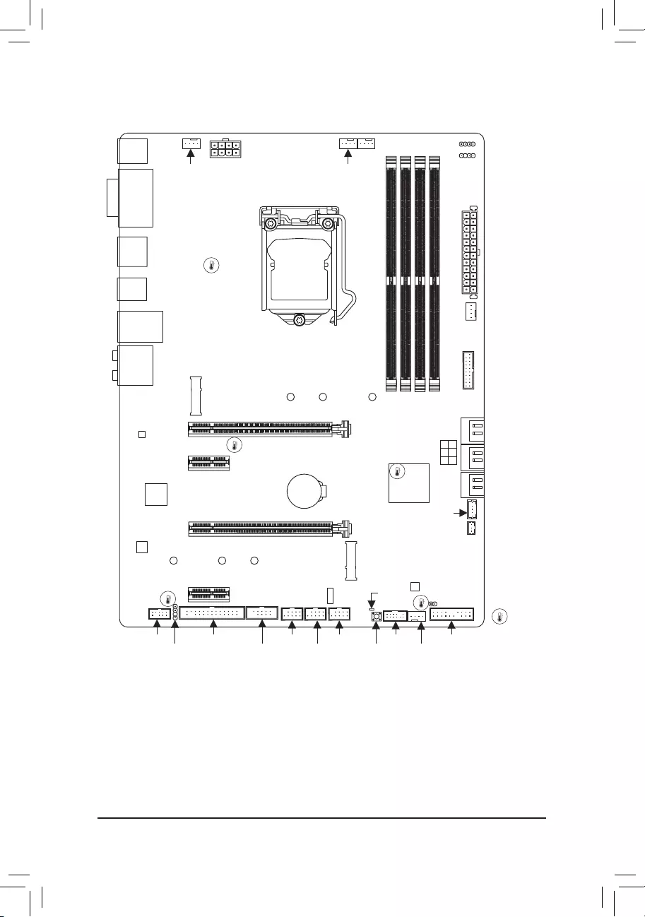
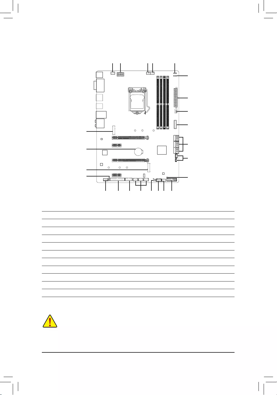
B560 HD3 Motherboard Layout
Box Contents
5B560 HD3 motherboard 5Two SATA cables
5Motherboard driver disc 5I/O Shield
5User’s Manual 5M.2 screw(s)
* The box contents above are for reference only and the actual items shall depend on the product package you obtain.
The box contents are subject to change without notice.
KB_MS_USB
DP_HDMI
U32
U32_LAN
LGA1200 ATX
AUDIO
DDR4_A1
DDR4_A2
DDR4_B1
DDR4_B2
ATX_12V_2X4
Intel® B560
CLR_CMOS
M_BIOS
PCIEX1_1
PCIEX4
PCIEX16
PCIEX1_2
F_U32
M2A_SB
CODEC
B560 HD3
SYS_FAN3
SPI_TPM F_PANEL
SPDIF_O
F_AUDIO
COM
LPT
LED_C1
D_LED1
SYS_FAN1
SYS_FAN2
THB_C1
CPU_FAN
CPU_OPT
iTE®
Super I/O
BAT
Realtek®
GbE LAN
SATA3 531
420
THB_C2
M2P_CPU
1108060
6080110
F_USB1F_USB3
F_USB2
DVI
VGA
QFLASH_PLUS
QFLED
USB 2.0 Hub
Temperature
sensor

Chapter 1 Hardware Installation
1-1 Installation Precautions
The motherboard contains numerous delicate electronic circuits and components which can become
damaged as a result of electrostatic discharge (ESD). Prior to installation, carefully read the user’s
manual and follow these procedures:
•Prior to installation, make sure the chassis is suitable for the motherboard.
•Prior to installation, do not remove or break motherboard S/N (Serial Number) sticker or
warranty sticker provided by your dealer. These stickers are required for warranty validation.
•Always remove the AC power by unplugging the power cord from the power outlet before
installing or removing the motherboard or other hardware components.
•When connecting hardware components to the internal connectors on the motherboard, make
sure they are connected tightly and securely.
•When handling the motherboard, avoid touching any metal leads or connectors.
•It is best to wear an electrostatic discharge (ESD) wrist strap when handling electronic
components such as a motherboard, CPU or memory. If you do not have an ESD wrist strap,
keepyourhandsdryandrsttouchametalobjecttoeliminatestaticelectricity.
•Prior to installing the motherboard, please have it on top of an antistatic pad or within an
electrostatic shielding container.
•Before connecting or unplugging the power supply cable from the motherboard, make sure
the power supply has been turned off.
•Before turning on the power, make sure the power supply voltage has been set according to
the local voltage standard.
•Before using the product, please verify that all cables and power connectors of your hardware
components are connected.
•To prevent damage to the motherboard, do not allow screws to come in contact with the
motherboard circuit or its components.
•Make sure there are no leftover screws or metal components placed on the motherboard or
within the computer casing.
•Do not place the computer system on an uneven surface.
•Do not place the computer system in a high-temperature or wet environment.
•Turning on the computer power during the installation process can lead to damage to system
components as well as physical harm to the user.
•If you are uncertain about any installation steps or have a problem related to the use of the
product,pleaseconsultacertiedcomputertechnician.
•If you use an adapter, extension power cable, or power strip, ensure to consult with its installation
and/or grounding instructions.
— 5 —

1-2 ProductSpecications
CPU LGA1200 package:
— 11th Generation Intel® Core™ i9 processors/Intel® Core™ i7 processors/Intel®
Core™ i5 processors
— 10th Generation Intel® Core™ i9 processors/Intel® Core™ i7 processors/Intel®
Core™ i5 processors/Intel® Core™ i3 processors/Intel® Pentium® processors/
Intel® Celeron® processors*
* Limited to processors with 4 MB Intel® Smart Cache, Intel® Celeron® G5xx5 family.
(Go to GIGABYTE’s website for the latest CPU support list.)
L3 cache varies with CPU
Chipset Intel® B560 Express Chipset
Memory 11th Generation Intel® Core™ i9/i7/i5 processors:
— Support for DDR4 3200/3000/2933/2666/2400/2133 MHz memory modules
10th Generation Intel® Core™ i9/i7 processors:
— Support for DDR4 2933/2666/2400/2133 MHz memory modules
10th Generation Intel® Core™ i5/i3/Pentium®/Celeron® processors:
— Support for DDR4 2666/2400/2133 MHz memory modules
4 x DDR4 DIMM sockets supporting up to 128 GB (32 GB single DIMM capacity)
of system memory
Dual channel memory architecture
Support for ECC Un-buffered DIMM 1Rx8/2Rx8 memory modules (operate in
non-ECC mode)
Support for non-ECC Un-buffered DIMM 1Rx8/2Rx8/1Rx16 memory modules
SupportforExtremeMemoryProle(XMP)memorymodules
(Go to GIGABYTE’s website for the latest supported memory speeds and memory
modules.)
Onboard
Graphics
Integrated Graphics Processor-Intel® HD Graphics support:
— 1 x D-Sub port, supporting a maximum resolution of 1920×1200@60 Hz
— 1 x DVI-D port, supporting a maximum resolution of 1920×1200@60 Hz
* The DVI-D port does not support D-Sub connection by adapter.
— 1 x DisplayPort, supporting a maximum resolution of 4096×2304@60 Hz
* Support for DisplayPort 1.2 version and HDCP 2.3
* When the D-Sub port and DisplayPort are connected at the same time, images will
output from the DisplayPort only.
— 1 x HDMI port, supporting a maximum resolution of 4096×2160@30 Hz
* Support for HDMI 1.4 version and HDCP 2.3.
(GraphicsspecicationsmayvarydependingonCPUsupport.)
Support for up to 3 displays at the same time
Audio Realtek® Audio CODEC
HighDenitionAudio
2/4/5.1/7.1-channel
Support for S/PDIF Out
LAN Realtek® GbE LAN chip (1000 Mbit/100 Mbit)
(Note) Supported by 11th Generation processors only.
— 6 —

Expansion Slots 1 x PCI Express x16 slot, running at x16 (PCIEX16)
* For optimum performance, if only one PCI Express graphics card is to be installed,
be sure to install it in the PCIEX16 slot.
(The PCIEX16 slot conforms to PCI Express 4.0 standard.) (Note)
1 x PCI Express x16 slot, running at x4 (PCIEX4)
2 x PCI Express x1 slots
(The PCIEX4 and PCIEX1 slots conform to PCI Express 3.0 standard.)
Storage Interface CPU:
— 1 x M.2 connector (Socket 3, M key, type 2260/2280/22110 PCIe 4.0 x4/x2
SSD support) (M2P_CPU) (Note)
Chipset:
— 1 x M.2 connector (Socket 3, M key, type 2260/2280/22110 SATA and PCIe
3.0 x4/x2 SSD support) (M2A_SB)
— 6 x SATA 6Gb/s connectors
* Refer to «1-7 Internal Connectors,» for the installation notices for the M.2 and SATA
connectors.
Intel® Optane™ Memory Ready
* System Acceleration with Intel® Optane™ Memory enabled on the M2P_CPU connector
only.
USB Chipset:
— 6 x USB 3.2 Gen 1 ports (4 ports on the back panel, 2 ports available through
the internal USB header)
— 6 x USB 2.0/1.1 ports available through the internal USB headers
Chipset+USB 2.0 Hub:
— 2 x USB 2.0/1.1 ports on the back panel
Internal
Connectors
1 x 24-pin ATX main power connector
1 x 8-pin ATX 12V power connector
1 x CPU fan header
1 x water cooling CPU fan header
3 x system fan headers
1 x addressable LED strip header
1 x RGB LED strip header
2 x M.2 Socket 3 connectors
6 x SATA 6Gb/s connectors
1 x front panel header
1 x front panel audio header
1 x USB 3.2 Gen 1 header
3 x USB 2.0/1.1 headers
1 x S/PDIF Out header
2 x Thunderbolt™ add-in card connectors
1 x Trusted Platform Module header (For the GC-TPM2.0 SPI/GC-TPM2.0 SPI
2.0 module only)
1 x serial port header
1 x parallel port header
1 x Clear CMOS jumper
1 x Q-Flash Plus button
— 7 —
Back Panel
Connectors
2 x USB 2.0/1.1 ports
1 x PS/2 keyboard/mouse port
1 x D-Sub port
1 x DVI-D port
1 x DisplayPort
1 x HDMI port
4 x USB 3.2 Gen 1 ports
1 x RJ-45 port
6 x audio jacks
I/O Controller iTE® I/O Controller Chip
Hardware
Monitor
Voltage detection
Temperature detection
Fan speed detection
Fan fail warning
Fan speed control
* Whether the fan speed control function is supported will depend on the cooler you
install.
BIOS 1x256Mbitash
Use of licensed AMI UEFI BIOS
PnP 1.0a, DMI 2.7, WfM 2.0, SM BIOS 2.7, ACPI 5.0
Unique Features Support for APP Center
* Available applications in APP Center may vary by motherboard model. Supported
functionsofeachapplicationmayalsovarydependingonmotherboardspecications.
— @BIOS
— EasyTune
— Fast Boot
— Game Boost
— ON/OFF Charge
— RGB Fusion
— Smart Backup
— System Information Viewer
Support for Q-Flash Plus
Support for Q-Flash
Support for Xpress Install
Bundled
Software
Norton® Internet Security (OEM version)
Realtek® 8118 Gaming LAN Bandwidth Control Utility
Operating
System Support for Windows 10 64-bit
Form Factor ATX Form Factor; 30.5cm x 22.5cm
* GIGABYTEreservestherighttomakeanychangestotheproductspecicationsandproduct-relatedinformationwithout
prior notice.
Please visit GIGABYTE’s website
for support lists of CPU, memory
modules, SSDs, and M.2 devices.
Please visit the SupportUtility List
page on GIGABYTE’s website to
download the latest version of apps.
— 8 —
1-4 Installing the Memory
DualChannelMemoryConguration
This motherboard provides four memory sockets and supports Dual Channel Technology. After the memory
isinstalled,theBIOSwillautomaticallydetectthespecicationsandcapacityofthememory.EnablingDual
Channel memory mode will double the original memory bandwidth.
Please visit GIGABYTE’s website for details on hardware installation.
1-3 Installing the CPU
Read the following guidelines before you begin to install the CPU:
•Make sure that the motherboard supports the CPU.
(Go to GIGABYTE’s website for the latest CPU support list.)
•Always turn off the computer and unplug the power cord from the power outlet before installing the
CPU to prevent hardware damage.
•Locate the pin one of the CPU. The CPU cannot be inserted if oriented incorrectly. (Or you may
locate the notches on both sides of the CPU and alignment keys on the CPU socket.)
•Apply an even and thin layer of thermal grease on the surface of the CPU.
•Do not turn on the computer if the CPU cooler is not installed, otherwise overheating and damage
of the CPU may occur.
•SettheCPUhostfrequencyinaccordancewiththeCPUspecications.Itisnotrecommended
thatthesystembusfrequencybesetbeyondhardwarespecicationssinceitdoesnotmeetthe
standard requirements for the peripherals. If you wish to set the frequency beyond the standard
specications,pleasedosoaccordingtoyourhardwarespecicationsincludingtheCPU,graphics
card, memory, hard drive, etc.
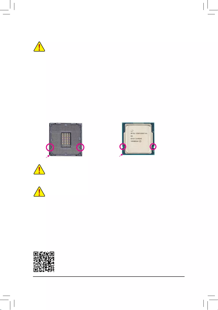
Installing the CPU
Locate the alignment keys on the motherboard CPU socket and the notches on the CPU.
Do not remove the CPU socket cover before inserting the CPU. It may pop off from the load
plate automatically during the process of re—engaging the lever after you insert the CPU.
Triangle Pin One Marking on the CPU
Notch
Notch
LGA1200 CPU
Alignment KeyAlignment Key
LGA1200 CPU Socket
Pin One Corner of the CPU Socket
Read the following guidelines before you begin to install the memory:
•Make sure that the motherboard supports the memory. It is recommended that memory of the same
capacity, brand, speed, and chips be used.
(Go to GIGABYTE’s website for the latest supported memory speeds and memory modules.)
•Always turn off the computer and unplug the power cord from the power outlet before installing the
memory to prevent hardware damage.
•Memory modules have a foolproof design. A memory module can be installed in only one direction.
If you are unable to insert the memory, switch the direction.
— 9 —
The four memory sockets are divided into two channels and each channel has two memory sockets as following:
Channel A: DDR4_A1, DDR4_A2
Channel B: DDR4_B1, DDR4_B2
RecommandedDualChannelMemoryConguration:
DDR4_A1 DDR4_A2 DDR4_B1 DDR4_B2
2 Modules — — DS/SS — — DS/SS
4 Modules DS/SS DS/SS DS/SS DS/SS
(SS=Single-Sided, DS=Double-Sided, «- -«=No Memory)
Due to CPU limitations, read the following guidelines before installing the memory in Dual Channel mode.
1. Dual Channel mode cannot be enabled if only one memory module is installed.
2. When enabling Dual Channel mode with two or four memory modules, it is recommended that memory
of the same capacity, brand, speed, and chips be used.
1-5 Installing an Expansion Card
Read the following guidelines before you begin to install an expansion card:
•Make sure the motherboard supports the expansion card. Carefully read the manual that came
with your expansion card.
•Always turn off the computer and unplug the power cord from the power outlet before installing an
expansion card to prevent hardware damage.
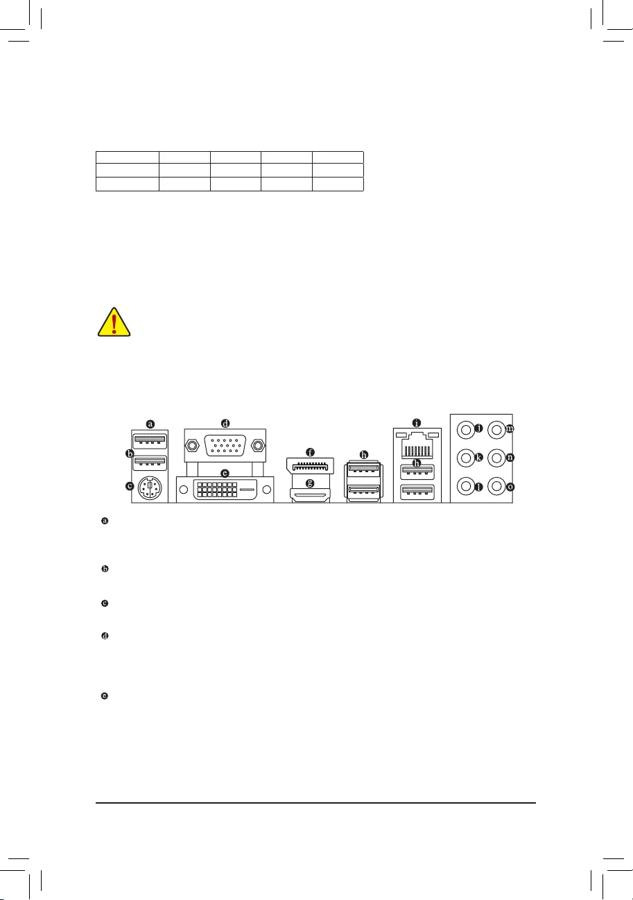
1-6 Back Panel Connectors
USB 2.0/1.1 Port (Q-Flash Plus Port)
TheUSBportsupportstheUSB2.0/1.1specication.UsethisportforUSBdevices.BeforeusingQ-Flash
Plus (Note 1),makesuretoinserttheUSBashdriveintothisportrst.
USB 2.0/1.1 Port
TheUSBportsupportstheUSB2.0/1.1specication.UsethisportforUSBdevices.
PS/2 Keyboard/Mouse Port
Use this port to connect a PS/2 mouse or keyboard.
D-Sub Port
The D-Sub port supports a 15-pin D-Sub connector and supports a maximum resolution of 1920×1200@60 Hz
(the actual resolutions supported depend on the monitor being used). Connect a monitor that supports
D-Sub connection to this port.
DVI-D Port (Note 2)
TheDVI-DportconformstotheDVI-Dspecicationandsupportsamaximumresolutionof1920×1200@60Hz
(the actual resolutions supported depend on the monitor being used). Connect a monitor that supports
DVI-D connection to this port.
(Note 1) To enable the Q-Flash Plus function please visit the «Unique Features» webpage of GIGABYTE’s
website.
(Note 2) The DVI-D port does not support D-Sub connection by adapter.
— 10 —
DisplayPort
DisplayPort delivers high quality digital imaging and audio, supporting bi-directional audio transmission.
DisplayPort can support HDCP 2.3 content protection mechanisms. You can use this port to connect your
DisplayPort-supported monitor. Note: The DisplayPort Technology can support a maximum resolution of
4096×2304@60 Hz but the actual resolutions supported depend on the monitor being used.
HDMI Port
The HDMI port supports HDCP 2.3 and Dolby TrueHD and DTS HD Master
Audio formats. It also supports up to 192KHz/16bit 7.1-channel LPCM audio
output. You can use this port to connect your HDMI-supported monitor. The maximum supported resolution
is 4096×2160@30 Hz, but the actual resolutions supported are dependent on the monitor being used.
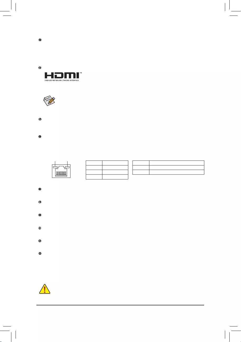
Activity LED
Connection/
Speed LED
LAN Port
Activity LED:Connection/Speed LED:
State Description
Orange 1 Gbps data rate
Green 100 Mbps data rate
Off 10 Mbps data rate
State Description
Blinking Data transmission or receiving is occurring
Off No data transmission or receiving is occurring
•Tosetupatriple-displayconguration,youmustinstallmotherboarddriversintheoperating
systemrst.
•After installing the DisplayPort/HDMI device, make sure to set the default sound playback
device to DisplayPort/HDMI. (The item name may differ depending on your operating system.)
USB 3.2 Gen 1 Port
TheUSB3.2Gen1portsupportstheUSB3.2Gen1specicationandiscompatibletotheUSB2.0
specication.UsethisportforUSBdevices.
RJ-45 LAN Port
The Gigabit Ethernet LAN port provides Internet connection at up to 1 Gbps data rate. The following
describes the states of the LAN port LEDs.
•Whenremovingthecableconnectedtoabackpanelconnector,rstremovethecablefromyour
device and then remove it from the motherboard.
•When removing the cable, pull it straight out from the connector. Do not rock it side to side to
prevent an electrical short inside the cable connector.
Center/Subwoofer Speaker Out (Orange)
Use this audio jack to connect center/subwoofer speakers.
Rear Speaker Out (Black)
Use this audio jack to connect rear speakers.
Side Speaker Out (Gray)
Use this audio jack to connect side speakers.
Line In (Blue)
The line in jack. Use this audio jack for line in devices such as an optical drive, walkman, etc.
Line Out/Front Speaker Out (Green)
The line out jack.
Mic In (Pink)
The Mic in jack.
— 11 —
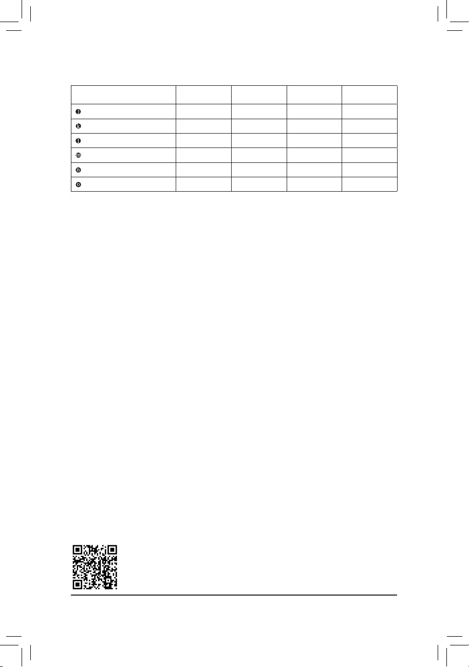
AudioJackCongurations:
Jack Headphone/
2-channel 4-channel 5.1-channel 7.1-channel
Center/Subwoofer Speaker Out a a
Rear Speaker Out aaa
Side Speaker Out a
Line In
Line Out/Front Speaker Out aaaa
Mic In
PleasevisitGIGABYTE’swebsitefordetailsonconguringtheaudiosoftware.
— 12 —
Read the following guidelines before connecting external devices:
•First make sure your devices are compliant with the connectors you wish to connect.
•Before installing the devices, be sure to turn off the devices and your computer. Unplug the power
cord from the power outlet to prevent damage to the devices.
•After installing the device and before turning on the computer, make sure the device cable has
been securely attached to the connector on the motherboard.
1-7 Internal Connectors
1) ATX_12V_2X4
2) ATX
3) CPU_FAN
4) SYS_FAN1/2/3
5) CPU_OPT
6) D_LED1
7) LED_C1
 SATA3 0/1/2/3/4/5
9) SPDIF_O
10) M2P_CPU/M2A_SB
11) F_PANEL
12) F_ AUDIO
13) F_U32
14) F_USB1/F_USB2/F_USB3
15) COM
16) LPT
17) SPI_TPM
18) THB_C1/THB_C2
19) CLR_CMOS
20) BAT
21) QFLASH_PLUS
114
4
2
6
8
13
18
12 16
14
15
19
10
9
14 1721
35 7
20
10
— 13 —
131
2412
ATX
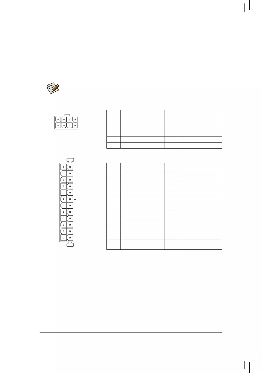
1/2) ATX_12V_2X4/ATX (2×4 12V Power Connector and 2×12 Main Power Connector)
With the use of the power connector, the power supply can supply enough stable power to all the components
onthemotherboard.Beforeconnectingthepowerconnector,rstmakesurethepowersupplyisturned
off and all devices are properly installed. The power connector possesses a foolproof design. Connect the
power supply cable to the power connector in the correct orientation.
The 12V power connector mainly supplies power to the CPU. If the 12V power connector is not connected,
the computer will not start.
To meet expansion requirements, it is recommended that a power supply that can withstand high
power consumption be used (500W or greater). If a power supply is used that does not provide the
required power, the result can lead to an unstable or unbootable system.
ATX:
Pin No. Denition Pin No. Denition
1 3.3V 13 3.3V
2 3.3V 14 -12V
3 GND 15 GND
4 +5V 16 PS_ON (soft On/Off)
5 GND 17 GND
6 +5V 18 GND
7 GND 19 GND
8 Power Good 20 NC
9 5VSB (stand by +5V) 21 +5V
10 +12V 22 +5V
11 +12V (Only for 2×12-pin
ATX)
23 +5V (Only for 2×12-pin
ATX)
12 3.3V (Only for 2×12-pin
ATX)
24 GND (Only for 2×12-pin
ATX)
ATX_12V_2X4:
Pin No. Denition Pin No. Denition
1 GND (Only for 2×4-pin 12V) 5 +12V (Only for 2×4-pin
12V)
2 GND (Only for 2×4-pin 12V) 6 +12V (Only for 2×4-pin
12V)
3 GND 7 +12V
4 GND 8 +12V
ATX_12V_2X4
41
8
5
— 14 —
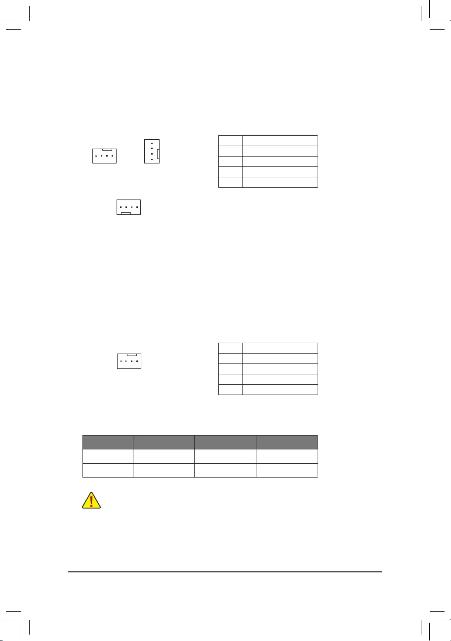
3/4) CPU_FAN/SYS_FAN1/2/3 (Fan Headers)
All fan headers on this motherboard are 4-pin. Most fan headers possess a foolproof insertion design.
When connecting a fan cable, be sure to connect it in the correct orientation (the black connector wire is
the ground wire). The speed control function requires the use of a fan with fan speed control design. For
optimum heat dissipation, it is recommended that a system fan be installed inside the chassis.
Pin No. Denition
1 GND
2 Voltage Speed Control
3 Sense
4 PWM Speed Control
CPU_FAN/SYS_FAN1
1
SYS_FAN2
1
5) CPU_OPT (Water Cooling CPU Fan Header)
The fan header is 4-pin and possesses a foolproof insertion design. Most fan headers possess a foolproof
insertion design. When connecting a fan cable, be sure to connect it in the correct orientation (the black
connector wire is the ground wire). The speed control function requires the use of a fan with fan speed control
design.
1
Pin No. Denition
1 GND
2 Voltage Speed Control
3 Sense
4 PWM Speed Control
•Be sure to connect fan cables to the fan headers to prevent your CPU and system from
overheating. Overheating may result in damage to the CPU or the system may hang.
•Thesefanheadersarenotcongurationjumperblocks.Donotplaceajumpercapontheheaders.
Connector CPU_FAN SYS_FAN1~3 CPU_OPT
Maximum Current 2A 2A 2A
Maximum Power 24W 24W 24W
SYS_FAN3
1
— 15 —
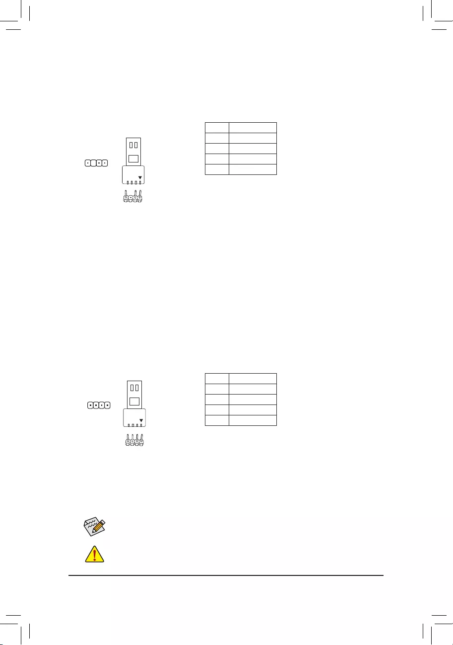
6) D_LED1 (Addressable LED Strip Header)
The header can be used to connect a standard 5050 addressable LED strip, with maximum power rating
of 5A (5V) and maximum number of 1000 LEDs.
Pin No. Denition
1 V (5V)
2 Data
3 No Pin
4 GND
Connect your addressable LED strip to the header. The power
pin (marked with a triangle on the plug) of the LED strip must
be connected to Pin 1 of the addressable LED strip header.
Incorrect connection may lead to the damage of the LED strip.
7) LED_C1 (RGB LED Strip Header)
The header can be used to connect a standard 5050 RGB LED strip (12V/G/R/B), with maximum power
rating of 2A (12V) and maximum length of 2m.
Pin No. Denition
1 12V
2 G
3 R
4 B
Before installing the devices, be sure to turn off the devices and your computer. Unplug the power
cord from the power outlet to prevent damage to the devices.
Connect your RGB LED strip to the header. The power pin
(marked with a triangle on the plug) of the LED strip must be
connected to Pin 1 (12V) of this header. Incorrect connection
may lead to the damage of the LED strip.
For how to turn on/off the lights of the LED strip please visit the «Unique Features» webpage of
GIGABYTE’s website.
1
RGB LED Strip
Addressable LED
Strip
F_USB30 F_U
B_
F_ F_
_
B
BS_
B
SB_
B
_S
S_
_
B
_U
_
B
S
123
123
123
123
1
1
1
1
BSS
S
_S
SSU
1 2 3
S3 BSSS
U
__ 3
F_USB3F
S _
S _
S _
SF
B_
B_
F
_0
S
S
_0F
_F
_
_
__B
U
S _S
_ SF_
B
USB0_B
B_
B_
F_USB3
F_USB303
_
_3U
S_
1
1
1
12V
— 16 —
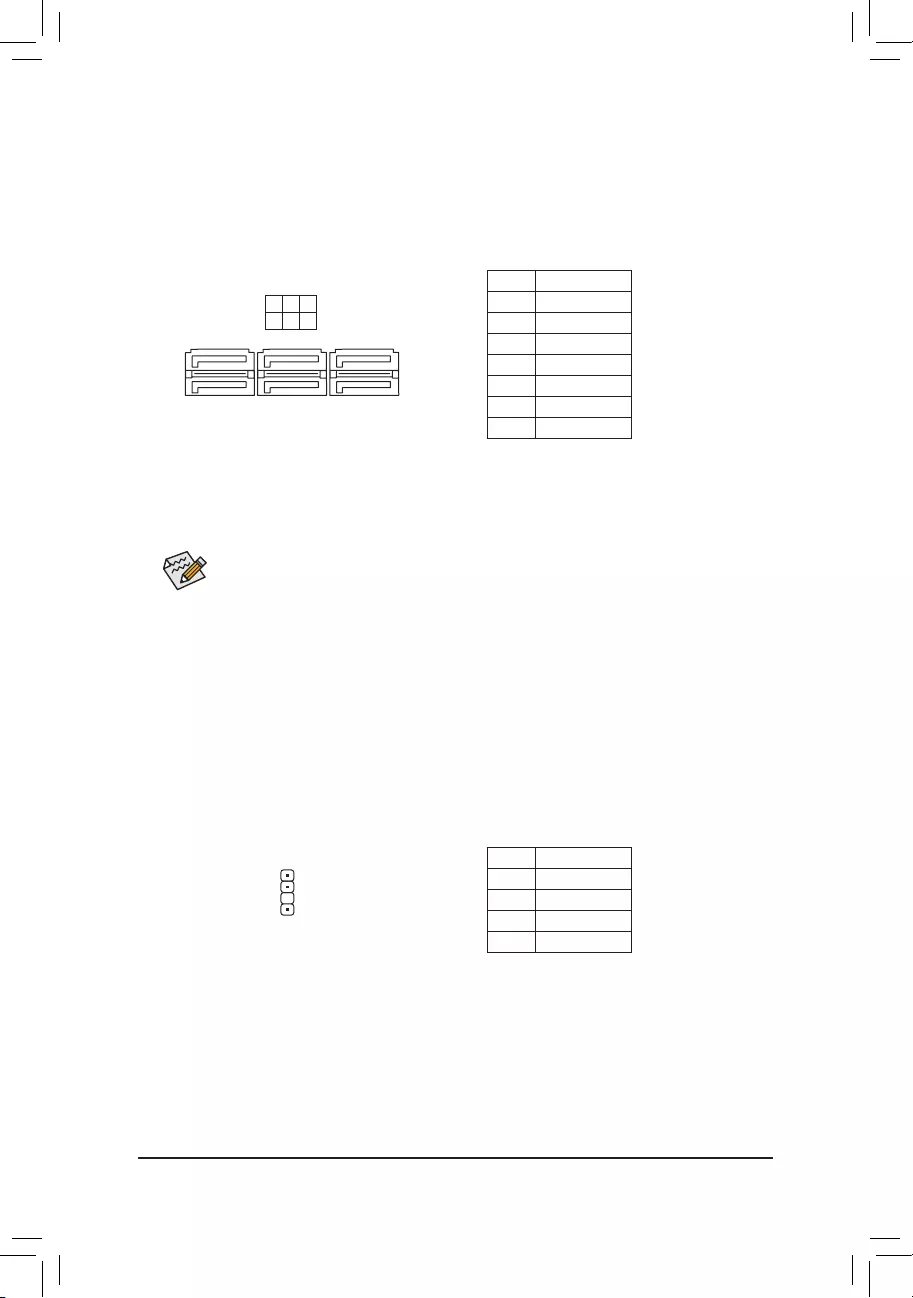
SATA3 0/1/2/3/4/5 (SATA 6Gb/s Connectors)
The SATA connectors conform to SATA 6Gb/s standard and are compatible with SATA 3Gb/s and SATA
1.5Gb/s standard. Each SATA connector supports a single SATA device.
Pin No. Denition
1 GND
2 TXP
3 TXN
4 GND
5 RXN
6 RXP
7 GND
To enable hot-plugging for the SATA ports, refer to Chapter 2, «BIOS Setup,» «SettingsIO Ports
SATAAndRSTConguration,»formoreinformation.
1
1
SATA3 531
420
7
7
9) SPDIF_O (S/PDIF Out Header)
This header supports S/PDIF digital output, which allows you to connect a S/PDIF digital audio cable to
output digital audio from your motherboard to the supported audio devices. For information about connecting
the digital audio cable, carefully read the manual for your audio devices.
Pin No. Denition
1 5VDUAL
2 No Pin
3 SPDIFO
4 GND
1
F_USB30 F_U
B_
F_ F_
_
B
BS_
B
SB_
B
_S
S_
_
B
_U
_
B
S
123
123
123
123
1
1
1
1
BSS
S
_S
SSU
1 2 3
S3 BSSS
U
__ 3
F_USB3F
S _
S _
S _
SF
B_
B_
F
_0
S
S
_0F
_F
_
_
__B
U
S _S
_ SF_
B
USB0_B
B_
B_
F_USB3
F_USB303
_
_3U
S_
— 17 —

10) M2P_CPU (Note)/M2A_SB (M.2 Socket 3 Connectors)
The M.2 connector supports M.2 SATA SSDs or M.2 PCIe SSDs.
Follow the steps below to correctly install an M.2 SSD in the M.2 connector.
Step 1:
Locate the proper mounting hole based on the length of your M.2 SSD drive. If needed, move the standoff
to the desired mounting hole. Insert the M.2 SSD into the M.2 connector at an angle.
Step 2:
Press the M.2 SSD down and then use the included screw to secure it in the connector.
F_USB30 F_U
B_
F_ F_
_
B
BS_
B
SB_
B
_S
S_
_
B
_U
_
B
S
123
123
123
123
1
1
1
1
BSS
S
_S
SSU
1 2 3
S3 BSSS
U
__ 3
F_USB3F
S _
S _
S _
SF
B_
B_
F
_0
S
S
_0F
_F
_
_
__B
U
S _S
_ SF_
B
USB0_B
B_
B_
F_USB3
F_USB303
_
_3U
S_
60 80 110
F_USB30 F_U
B_
F_ F_
_
B
BS_
B
SB_
B
_S
S_
_
B
_U
_
B
S
123
123
123
123
1
1
1
1
BSS
S
_S
SSU
1 2 3
S3 BSSS
U
__ 3
F_USB3F
S _
S _
S _
SF
B_
B_
F
_0
S
S
_0F
_F
_
_
__B
U
S _S
_ SF_
B
USB0_B
B_
B_
F_USB3
F_USB303
_
_3U
S_
80110 60
M2P_CPU (Note)
M2A_SB
(Note) Supported by 11th Generation processors only.
Installation Notices for the M.2 and SATA Connectors:
The availability of the SATA connectors may be affected by the type of device installed in the M.2 sockets.
The M2A_SB connector shares bandwidth with the SATA3 1 connector. Refer to the following table for details.
•M2A_SB:
SATA3 0 SATA3 1 SATA3 2 SATA3 3 SATA3 4 SATA3 5
M.2 SATA SSD ara a a a
M.2 PCIe SSD
a a a a a a
No M.2 SSD Installed a a a a a a
a: Available, r: Not available
Connector
Type of
M.2 SSD
•M2P_CPU (Note):
SATA3 0 SATA3 1 SATA3 2 SATA3 3 SATA3 4 SATA3 5
M.2 PCIe SSD
aaaaaa
No M.2 SSD Installed aaaaaa
a: Available, r: Not available
* The connector supports only PCIe SSDs.
Connector
Type of
M.2 SSD
— 18 —
Some chassis provide a front panel audio module that has separated connectors on each wire
instead of a single plug. For information about connecting the front panel audio module that has
different wire assignments, please contact the chassis manufacturer.
12) F_AUDIO (Front Panel Audio Header)
ThefrontpanelaudioheadersupportsHighDenitionaudio(HD).Youmayconnectyourchassisfront
panel audio module to this header. Make sure the wire assignments of the module connector match the
pin assignments of the motherboard header. Incorrect connection between the module connector and the
motherboard header will make the device unable to work or even damage it.
Pin No. Denition Pin No. Denition
1 MIC2_L 6 Sense
2 GND 7 FAUDIO_JD
3 MIC2_R 8 No Pin
4 NC 9 LINE2_L
5 LINE2_R 10 Sense
F_USB30 F_U
B_
F_ F_
_
B
BS_
B
SB_
B
_S
S_
_
B
_U
_
B
S
123
123
123
123
1
1
1
1
BSS
S
_S
SSU
1 2 3
S3 BSSS
U
__ 3
F_USB3F
S _
S _
S _
SF
B_
B_
F
_0
S
S
_0F
_F
_
_
__B
U
S _S
_ SF_
B
USB0_B
B_
B_
F_USB3
F_USB303
_
_3U
S_
9 1
10 2
The front panel design may differ by chassis. A front panel module mainly consists of power switch,
reset switch, power LED, hard drive activity LED, speaker and etc. When connecting your chassis
front panel module to this header, make sure the wire assignments and the pin assignments are
matched correctly.
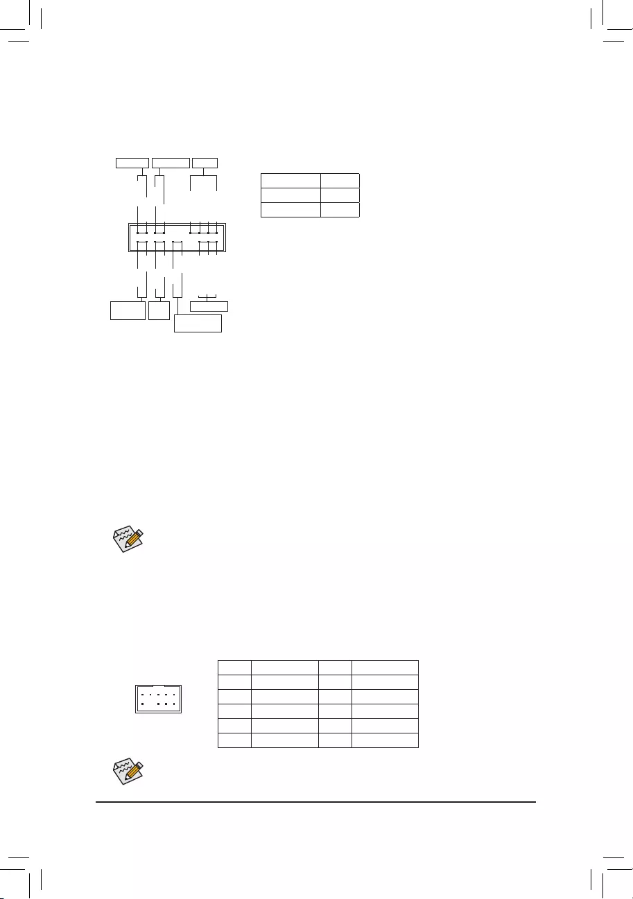
11) F_PANEL (Front Panel Header)
Connect the power switch, reset switch, speaker, chassis intrusion switch/sensor and system status indicator
on the chassis to this header according to the pin assignments below. Note the positive and negative pins
before connecting the cables.
System Status LED
S0 On
S3/S4/S5 Off
•PW (Power Switch, Red):
Connects to the power switch on the chassis front panel. You may
congure the way to turn off your system using thepower switch
(refer to Chapter 2, «BIOS Setup,» «SettingsPlatform Power,» for more
information).
•PLED/PWR_LED (Power LED, Yellow/Purple):
Connects to the power status indicator
on the chassis front panel. The LED is on
when the system is operating. The LED is
off when the system is in S3/S4 sleep state
or powered off (S5).
•SPEAK (Speaker, Orange):
Connects to the speaker on the chassis front panel. The system reports system startup status by issuing
a beep code. One single short beep will be heard if no problem is detected at system startup.
•HD (Hard Drive Activity LED, Blue):
Connects to the hard drive activity LED on the chassis front panel. The LED is on when the hard drive
is reading or writing data.
•RES (Reset Switch, Green):
Connects to the reset switch on the chassis front panel. Press the reset switch to restart the computer
if the computer freezes and fails to perform a normal restart.
•CI (Chassis Intrusion Header, Gray):
Connects to the chassis intrusion switch/sensor on the chassis that can detect if the chassis cover has
been removed. This function requires a chassis with a chassis intrusion switch/sensor.
•NC (Orange): No Connection.
1
2
19
20
CI-
CI+
PWR_LED-
PWR_LED+
PLED-
PW-
SPEAK+
SPEAK-
PLED+
PW+
HD-
RES+
HD+
RES-
PWR_LED-
NC
NC
Power LED
Power LED
Hard Drive
Activity LED
Reset
Switch Chassis Intrusion
Header
Power Switch Speaker
— 19 —
Pin No. Denition Pin No. Denition Pin No. Denition
1 VBUS 8 D1- 15 SSTX2-
2 SSRX1- 9 D1+ 16 GND
3 SSRX1+ 10 NC 17 SSRX2+
4 GND 11 D2+ 18 SSRX2-
5 SSTX1- 12 D2- 19 VBUS
6SSTX1+ 13 GND 20 No Pin
7 GND 14 SSTX2+
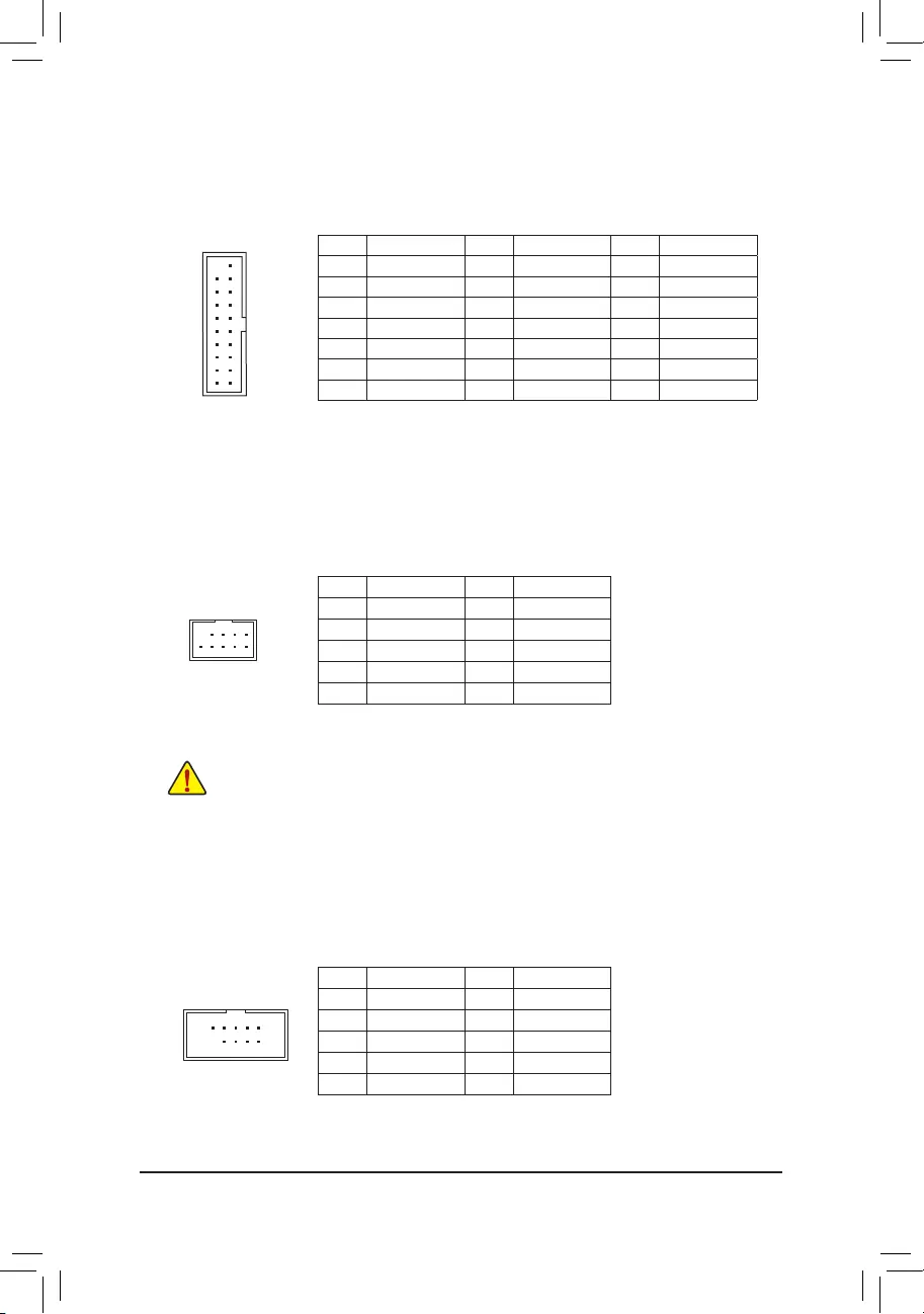
13) F_U32 (USB 3.2 Gen 1 Header)
TheheaderconformstoUSB3.2Gen1andUSB2.0specicationandcanprovidetwoUSBports.For
purchasing the optional 3.5″ front panel that provides two USB 3.2 Gen 1 ports, please contact the local
dealer.
F_USB30 F_U
B_
F_ F_
_
B
BS_
B
SB_
B
_S
S_
_
B
_U
_
B
S
123
123
123
123
1
1
1
1
BSS
S
_S
SSU
1 2 3
S3 BSSS
U
__ 3
F_USB3F
S _
S _
S _
SF
B_
B_
F
_0
S
S
_0F
_F
_
_
__B
U
S _S
_ SF_
B
USB0_B
B_
B_
F_USB3
F_USB303
_
_3U
S_
10
20 1
11
14) F_USB1/F_USB2/F_USB3 (USB 2.0/1.1 Headers)
TheheadersconformtoUSB2.0/1.1specication.EachUSBheadercanprovidetwoUSBportsviaan
optional USB bracket. For purchasing the optional USB bracket, please contact the local dealer.
Pin No. Denition Pin No. Denition
1 Power (5V) 6 USB DY+
2 Power (5V) 7 GND
3 USB DX- 8 GND
4 USB DY— 9 No Pin
5 USB DX+ 10 NC
•Do not plug the IEEE 1394 bracket (2×5-pin) cable into the USB 2.0/1.1 header.
•Prior to installing the USB bracket, be sure to turn off your computer and unplug the power cord
from the power outlet to prevent damage to the USB bracket.
15) COM (Serial Port Header)
The COM header can provide one serial port via an optional COM port cable. For purchasing the optional
COM port cable, please contact the local dealer.
Pin No. Denition Pin No. Denition
1 NDCD- 6 NDSR-
2 NSIN 7 NRTS-
3 NSOUT 8 NCTS-
4 NDTR- 9 NRI-
5 GND 10 No Pin
10
9
2
1
10
9
2
1
— 20 —
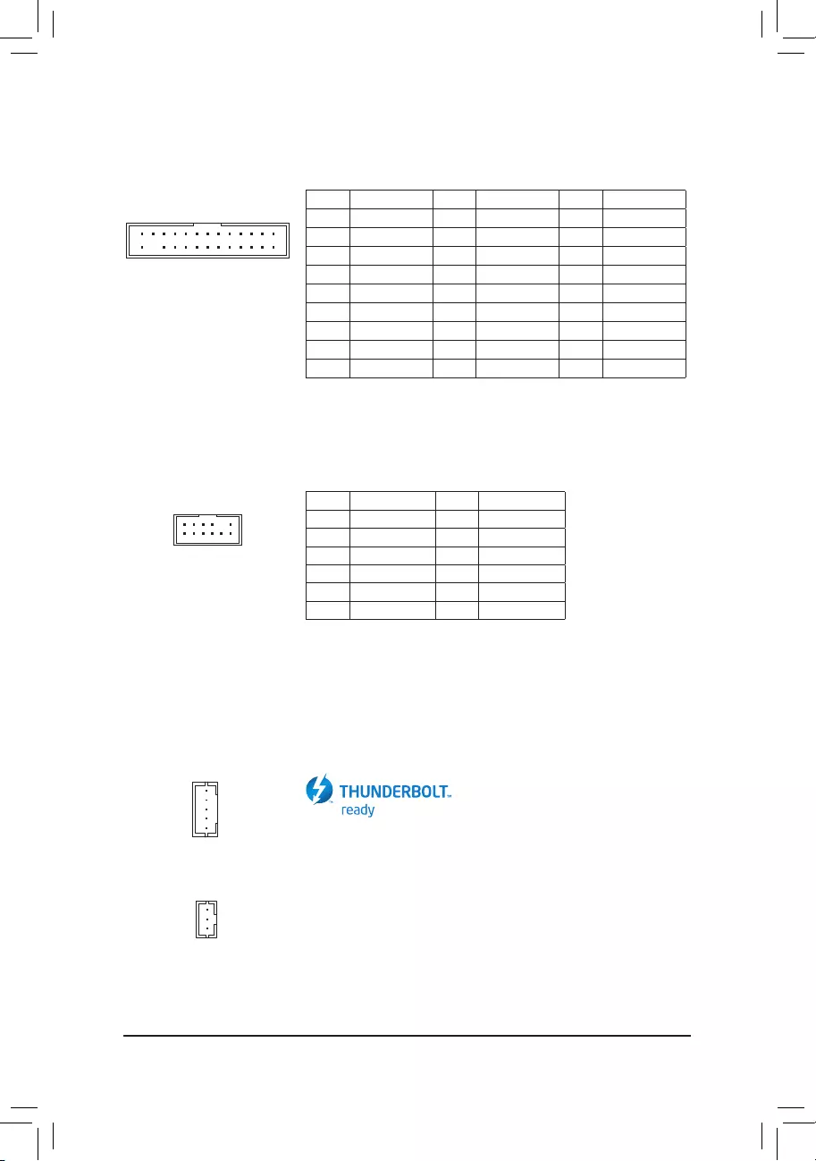
17) SPI_TPM (Trusted Platform Module Header)
You may connect an SPI TPM (Trusted Platform Module) to this header.
Pin No. Denition Pin No. Denition
1Data Output 7Chip Select
2Power (3.3V) 8GND
3No Pin 9IRQ
4NC 10 NC
5Data Input 11 NC
6CLK 12 RST
12
11
2
1
18) THB_C1/THB_C2 (Thunderbolt™ Add-in Card Connectors)
The connectors are used to connect to a GIGABYTE Thunderbolt™ add-in card.
Supports a Thunderbolt™ add-in card.
F_USB30 F_U
B_
F_ F_
_
B
BS_
B
SB_
B
_S
S_
_
B
_U
_
B
S
123
123
123
123
1
1
1
1
BSS
S
_S
SSU
1 2 3
S3 BSSS
U
__ 3
F_USB3F
S _
S _
S _
SF
B_
B_
F
_0
S
S
_0F
_F
_
_
__B
U
S _S
_ SF_
B
USB0_B
B_
B_
F_USB3
F_USB303
_
_3U
S_
16) LPT (Parallel Port Header)
The LPT header can provide one parallel port via an optional LPT port cable. For purchasing the optional
LPT port cable, please contact the local dealer.
Pin No. Denition Pin No. Denition Pin No. Denition
1STB- 10 GND 19 ACK-
2AFD- 11 PD4 20 GND
3PD0 12 GND 21 BUSY
4ERR- 13 PD5 22 GND
5PD1 14 GND 23 PE
6INIT— 15 PD6 24 No Pin
7PD2 16 GND 25 SLCT
8SLIN- 17 PD7 26 GND
9PD3 18 GND
F_USB30 F_U
B_
F_ F_
_
B
BS_
B
SB_
B
_S
S_
_
B
_U
_
B
S
123
123
123
123
1
1
1
1
BSS
S
_S
SSU
1 2 3
S3 BSSS
U
__ 3
F_USB3F
S _
S _
S _
SF
B_
B_
F
_0
S
S
_0F
_F
_
_
__B
U
S _S
_ SF_
B
USB0_B
B_
B_
F_USB3
F_USB303
_
_3U
S_
F_USB30 F_U
B_
F_ F_
_
B
BS_
B
SB_
B
_S
S_
_
B
_U
_
B
S
123
123
123
123
1
1
1
1
BSS
S
_S
SSU
1 2 3
S3 BSSS
U
__ 3
F_USB3F
S _
S _
S _
SF
B_
B_
F
_0
S
S
_0F
_F
_
_
__B
U
S _S
_ SF_
B
USB0_B
B_
B_
F_USB3
F_USB303
_
_3U
S_
1
1
THB_C2
THB_C1
1
226
25
— 21 —
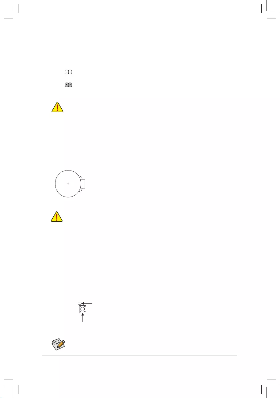
20) BAT (Battery)
Thebatteryprovidespowertokeepthevalues(suchasBIOScongurations,date,andtimeinformation)
in the CMOS when the computer is turned off. Replace the battery when the battery voltage drops to a low
level, or the CMOS values may not be accurate or may be lost.
You may clear the CMOS values by removing the battery:
1. Turn off your computer and unplug the power cord.
2. Gently remove the battery from the battery holder and wait for one minute. (Or use a metal
object like a screwdriver to touch the positive and negative terminals of the battery holder,
making them short for 5 seconds.)
3. Replace the battery.
4. Plug in the power cord and restart your computer.
•Always turn off your computer and unplug the power cord before replacing the battery.
•Replace the battery with an equivalent one. Damage to your devices may occur if the battery is
replaced with an incorrect model.
•Contact the place of purchase or local dealer if you are not able to replace the battery by yourself
or uncertain about the battery model.
•When installing the battery, note the orientation of the positive side (+) and the negative side (-)
of the battery (the positive side should face up).
•Used batteries must be handled in accordance with local environmental regulations.
19) CLR_CMOS (Clear CMOS Jumper)
UsethisjumpertocleartheBIOScongurationandresettheCMOSvaluestofactorydefaults.Toclear
the CMOS values, use a metal object like a screwdriver to touch the two pins for a few seconds.
•Always turn off your computer and unplug the power cord from the power outlet before clearing
the CMOS values.
•After system restart, go to BIOS Setup to load factory defaults (select Load Optimized Defaults) or
manuallyconguretheBIOSsettings(refertoChapter2,«BIOSSetup,»forBIOScongurations).
Open: Normal
Short: Clear CMOS Values
QFLED
21) QFLASH_PLUS (Q-Flash Plus Button)
Q-Flash Plus allows you to update the BIOS when your system is off (S5 shutdown state). Save the latest
BIOSonaUSBthumbdriveandplugitintotheQ-FlashPlusport,andthenyoucannowashtheBIOS
automaticallybysimplypressingtheQ-FlashPlusbutton.TheQFLEDwillashwhentheBIOSmatching
andashingactivitiesstartandwillstopashingwhenthemainBIOSashingiscomplete.
For how to use Q-Flash Plus please visit the «Unique Features» webpage of GIGABYTE’s website.
QFLASH_PLUS
— 22 —
BIOS (Basic Input and Output System) records hardware parameters of the system in the CMOS on the
motherboard. Its major functions include conducting the Power-On Self-Test (POST) during system startup,
saving system parameters and loading operating system, etc. BIOS includes a BIOS Setup program that allows
theusertomodifybasicsystemcongurationsettingsortoactivatecertainsystemfeatures.
When the power is turned off, the battery on the motherboard supplies the necessary power to the CMOS to
keepthecongurationvaluesintheCMOS.
To access the BIOS Setup program, press the <Delete> key during the POST when the power is turned on.
To upgrade the BIOS, use either the GIGABYTE Q-Flash or @BIOS utility.
•Q-Flash allows the user to quickly and easily upgrade or back up BIOS without entering the operating system.
•@BIOS is a Windows-based utility that searches and downloads the latest version of BIOS from the Internet
and updates the BIOS.
Chapter 2 BIOS Setup
•BecauseBIOS ashing ispotentiallyrisky,ifyoudonotencounterproblemsusingthe current
versionofBIOS,itisrecommendedthat younotashtheBIOS.Toashthe BIOS,doitwith
caution.InadequateBIOSashingmayresultinsystemmalfunction.
•It is recommended that you not alter the default settings (unless you need to) to prevent system
instability or other unexpected results. Inadequately altering the settings may result in system’s
failure to boot. If this occurs, try to clear the CMOS values and reset the board to default values.
(Refer to the «Load Optimized Defaults» section in this chapter or introductions of the battery/clear
CMOS jumper in Chapter 1 for how to clear the CMOS values.)
2-1 Startup Screen
The following startup Logo screen will appear when the computer boots.
Function Keys
•When the system is not stable as usual, select the Load Optimized Defaults item to set your system to its defaults.
•The BIOS Setup menus described in this chapter are for reference only and may differ by BIOS version.
There are two different BIOS modes as follows and you can use the <F2> key to switch between the two modes.
Easy Mode allows users to quickly view their current system information or to make adjustments for optimum
performance.InEasyMode,youcanuseyourmousetomovethroughcongurationitems.TheAdvancedMode
provides detailed BIOS settings. You can press the arrow keys on your keyboard to move among the items
and press <Enter> to accept or enter a sub-menu. Or you can use your mouse to select the item you want.
— 23 —

2-2 The Main Menu
Hardware
Information
Option Description Current Settings
Setup Menus
Conguration
Items
System Time
Quick Access Bar allows you to quickly move to
the General Help, Easy Mode, Smart Fan 6, or
Q-Flash screen.
Advanced Mode Function Keys
<f><g>Move the selection bar to select a setup menu
<h><i>Movetheselectionbartoselectancongurationitemonamenu
<Enter>/Double Click Execute command or enter a menu
<+>/<Page Up> Increase the numeric value or make changes
<->/<Page Down> Decrease the numeric value or make changes
<F1> Show descriptions of the function keys
<F2> Switch to Easy Mode
<F3> SavethecurrentBIOSsettingstoaprole
<F4> LoadtheBIOSsettingsfromaprolecreatedbefore
<F5> Restore the previous BIOS settings for the current submenus
<F6> Display the Smart Fan 6 screen
<F7> Load the Optimized BIOS default settings for the current submenus
<F8> Access the Q-Flash utility
<F10> Save all the changes and exit the BIOS Setup program
<F11> Switch to the Favorites submenu
<F12> Capture the current screen as an image and save it to your USB drive
<Insert> Add or remove a favorite option
<Ctrl>+<S> Display information on the installed memory
<Esc> Main Menu: Exit the BIOS Setup program
Submenus: Exit current submenu
— 24 —
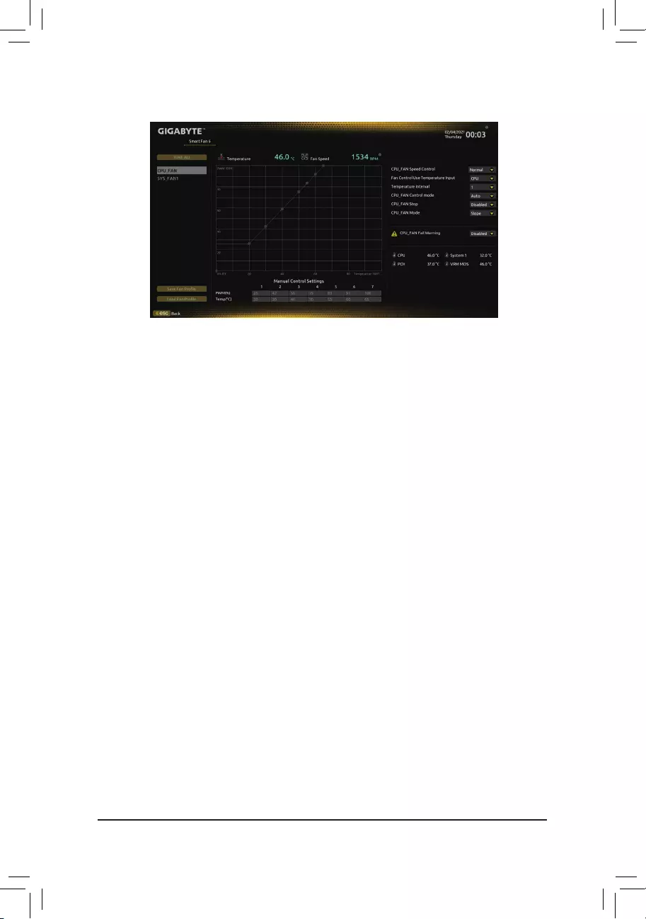
Usethe<F6>functionkeytoquicklyswitchtothisscreen.Thisscreenallowsyoutocongurefanspeedrelated
settings for each fan header or monitor your system/CPU temperature.
&TUNE ALL
Allows you to apply the current settings to all fan headers.
&Temperature
Displays the current temperature of the selected target area.
&Fan Speed
Displays current fan speeds.
&Fan Speed Control
Allows you to determine whether to enable the fan speed control function and adjust the fan speed.
Normal Allows the fan to run at different speeds according to the temperature. You can adjust
the fan speed with System Information Viewer based on your system requirements.
(Default)
Silent Allows the fan to run at slow speeds.
Manual Allows you to drag the curve nodes to adjust fan speed. Or you can use the EZ Tuning
feature. After adjusting the node position, press Apply to automatically calculate the
slope of the curve.
Full Speed Allows the fan to run at full speeds.
&Fan Control Use Temperature Input
Allows you to select the reference temperature for fan speed control.
&Temperature Interval
Allows you to select the temperature interval for fan speed change.
&FAN Control Mode
Auto Lets the BIOS automatically detect the type of fan installed and sets the optimal control
mode. (Default)
Voltage Voltage mode is recommended for a 3-pin fan.
PWM PWM mode is recommended for a 4-pin fan.
2-3 Smart Fan 6
— 25 —
&FAN Stop
Enables or disables the fan stop function. You can set the temperature limit using the temperature curve.
The fan stops operation when the temperature is lower than the limit. (Default: Disabled)
&FAN Mode
Allows you to set the operating mode for the fan.
Slope Adjusts the fan speed linearly based on the temperature. (Default)
Stair Adjusts the fan speed stepwise based on the temperature.
&FAN Fail Warning
Allows the system to emit warning sound if the fan is not connected or fails. Check the fan condition or fan
connection when this occurs. (Default: Disabled)
&SaveFanProle
Thisfunctionallowsyoutosavethecurrentsettingstoaprole.YoucansavetheproleintheBIOSor
select Select File in HDD/FDD/USBtosavetheproletoyourstoragedevice.
&LoadFanProle
ThisfunctionallowsyoutoloadapreviouslysavedBIOSprolewithoutthehasslesofreconguringthe
BIOS settings. Or you can select Select File in HDD/FDD/USBtoloadaprolefromyourstoragedevice.
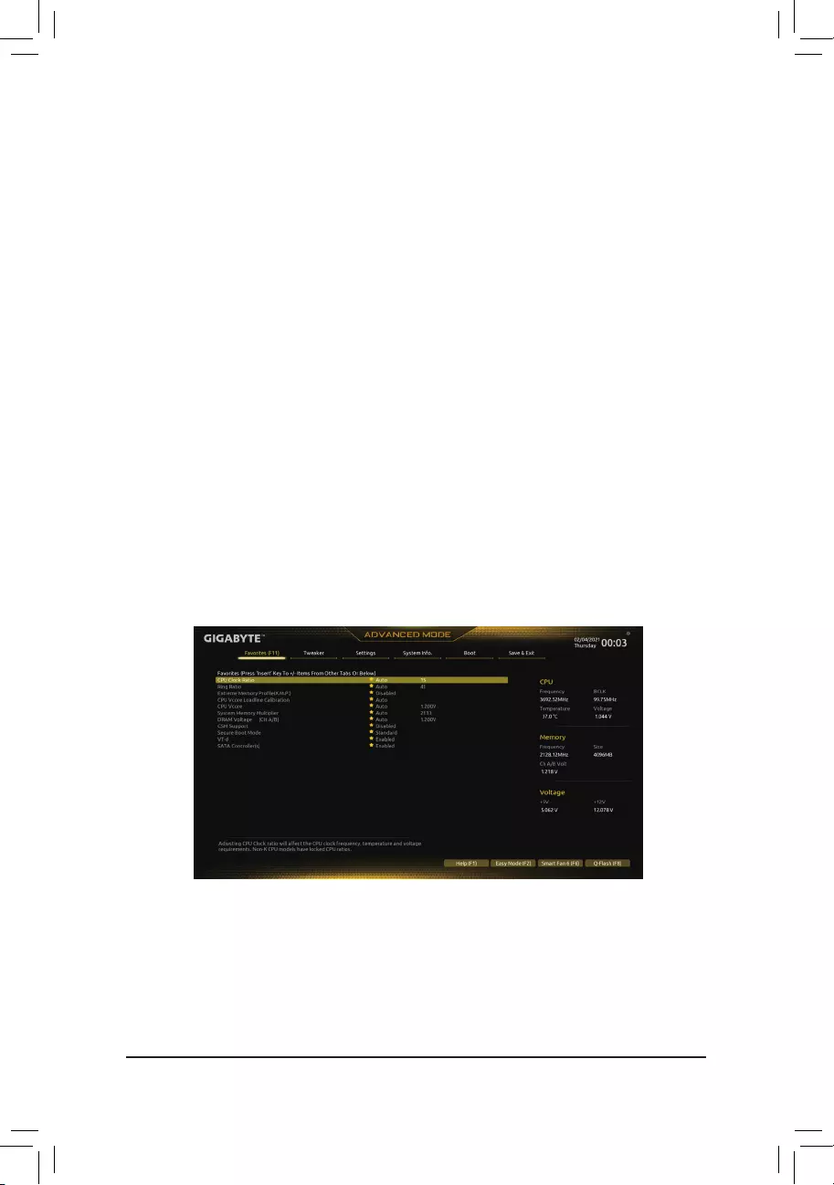
2-4 Favorites (F11)
Set your frequently used options as your favorites and use the <F11> key to quickly switch to the page where
all of your favorite options are located. To add or remove a favorite option, go to its original page and press
<Insert> on the option. The option is marked with a star sign if set as a «favorite.»
— 26 —
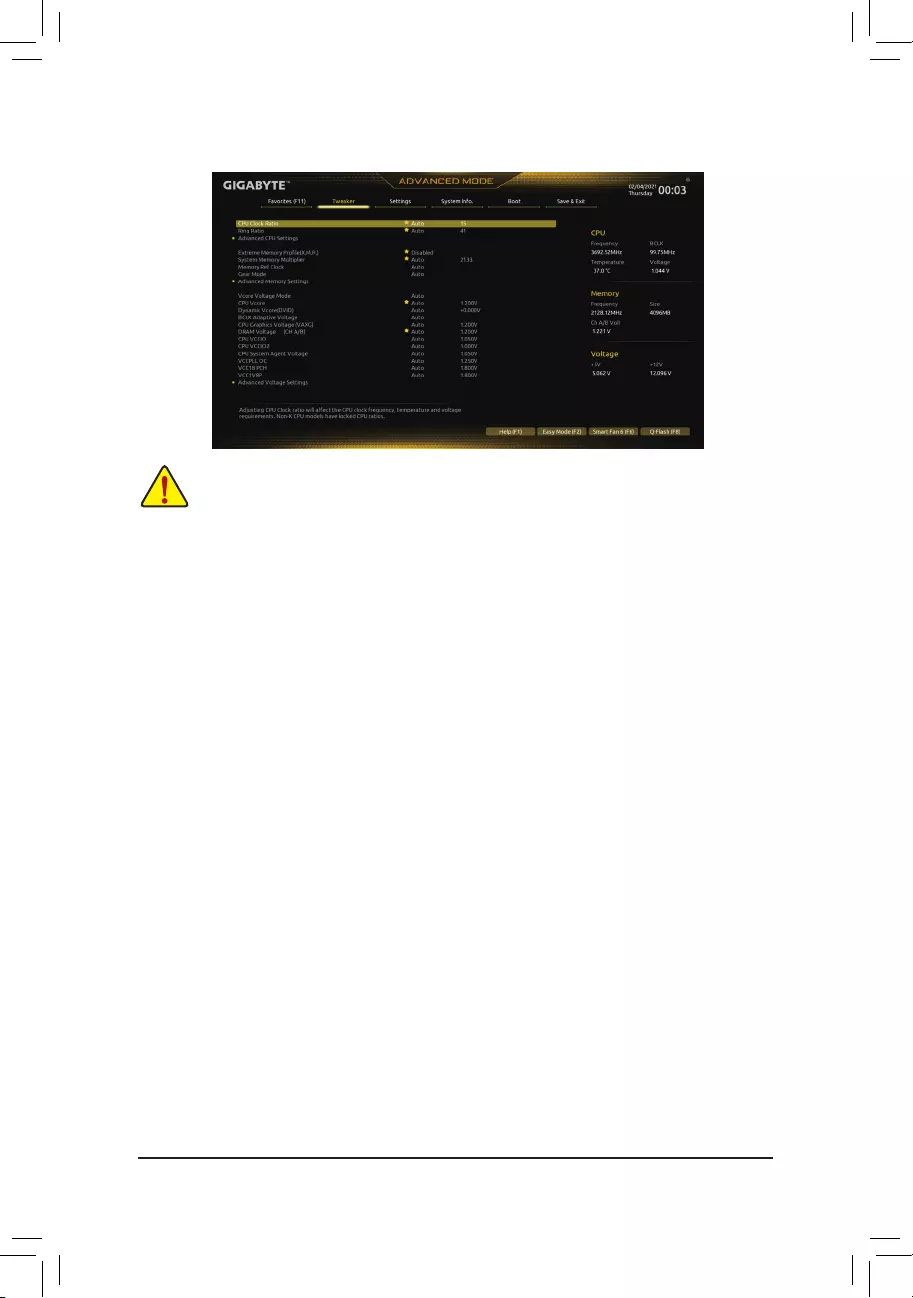
2-5 Tweaker
Whether the system will work stably with the overclock/overvoltage settings you made is dependent
onyouroverallsystemcongurations.Incorrectlydoingoverclock/overvoltagemayresultindamage
to CPU, chipset, or memory and reduce the useful life of these components. This page is for advanced
users only and we recommend you not to alter the default settings to prevent system instability or
other unexpected results. (Inadequately altering the settings may result in system’s failure to boot. If
this occurs, clear the CMOS values and reset the board to default values.)
&CPU Clock Ratio
Allows you to alter the clock ratio for the installed CPU. The adjustable range is dependent on the CPU
being installed.
&Ring Ratio
Allows you to set the CPU Uncore ratio. The adjustable range is dependent on the CPU being used. (Default:
Auto)
&IGP Ratio (Note)
Allows you to set the Graphics Ratio. (Default: Auto)
Advanced CPU Settings
&Core Fused Max Core Ratio (Note)
Displays the highest frequency of each core.
&AVX Disable (Note)
Allows you to disable the AVX instruction sets on a CPU that supports AVX. (Default: Auto)
&AVX512 Disable (Note)
Allows you to disable the AVX-512 instruction sets on a CPU that supports AVX-512. (Default: Auto)
&CPU Over Temperature Protection (Note)
Allowsyoutone-tunetheTJMaxoffsetvalue.(Default:Auto)
&FCLK Frequency for Early Power On (Note)
Allows you to set the FCLK frequency. Options are: Normal(800Mhz), 1GHz, 400MHz. (Default: 1GHz)
&Hyper-Threading Technology
Allows you to determine whether to enable multi-threading technology when using an Intel® CPU that
supports this function. This feature only works for operating systems that support multi-processor mode.
AutoletstheBIOSautomaticallycongurethissetting.(Default:Auto)
(Note) This item is present only when you install a CPU that supports this feature. For more information about
Intel® CPUs’ unique features, please visit Intel’s website.
— 27 —

&No. of CPU Cores Enabled
Allows you to select the number of CPU cores to enable in an Intel® multi-core CPU (the number of CPU
cores may vary by CPU). AutoletstheBIOSautomaticallycongurethissetting.(Default:Auto)
&Intel(R) Speed Shift Technology (Intel® Speed Shift Technology) (Note)
Enables or disables Intel® Speed Shift Technology. Enabling this feature allows the processor to ramp up
its operating frequency more quickly and then improves the system responsiveness. (Default: Enabled)
&CPU Thermal Monitor (Note)
Enables or disables Intel® Thermal Monitor function, a CPU overheating protection function. When enabled,
the CPU core frequency and voltage will be reduced when the CPU is overheated. Auto lets the BIOS
automaticallycongurethissetting.(Default:Auto)
&Ring to Core offset (Down Bin)
Allows you to determine whether to disable the CPU Ring ratio auto-down function. Auto lets the BIOS
automaticallycongurethissetting.(Default:Auto)
&CPU EIST Function (Note)
Enables or disables Enhanced Intel® Speed Step Technology (EIST). Depending on CPU loading, Intel®
EIST technology can dynamically and effectively lower the CPU voltage and core frequency to decrease
average power consumption and heat production. AutoletstheBIOSautomaticallycongurethissetting.
(Default: Auto)
&Race To Halt (RTH) (Note)/EnergyEfcientTurbo (Note)
Enables or disables the CPU power saving related settings. (Default: Auto)
&Intel(R) Turbo Boost Technology (Note)
Allows you to determine whether to enable the Intel® CPU Turbo Boost technology. Auto lets the BIOS
automaticallycongurethissetting.(Default:Auto)
&Intel(R) Turbo Boost Max Technology 3.0 (Note)
Enables or disables Intel® Turbo Boost Max Technology 3.0. Intel® Turbo Boost Max Technology 3.0 allows
the system to identify the processor’s best performance core and lets you manually direct the most critical
workloads to it. You can even adjust the frequency of each core individually for performance optimization.
(Default: Enabled)
&CPU Flex Ratio Override
Enables or disables the CPU Flex Ratio. The maximum CPU clock ratio will be based on the CPU Flex
Ratio Settings value if CPU Clock Ratio is set to Auto. (Default: Disabled)
&CPU Flex Ratio Settings
Allows you to set the CPU Flex Ratio. The adjustable range may vary by CPU.
&Frequency Clipping TVB (Note)
Allows you to enable or disable automatic CPU frequency reduction initiated by Thermal Velocity Boost.
AutoletstheBIOSautomaticallycongurethissetting.(Default:Auto)
&Voltage reduction initiated TVB (Note)
Allows you to enable or disable automatic CPU voltage reduction initiated by Thermal Velocity Boost. Auto
letstheBIOSautomaticallycongurethissetting.(Default:Auto)
dActive Turbo Ratios
&Turbo Ratio (Core Active)
Allows you to set the CPU Turbo ratios for different number of active cores. Auto sets the CPU Turbo
ratiosaccordingtotheCPUspecications.
Thisitemiscongurableonlywhen
Active Turbo Ratios is set
to
Manual
.
(Default: Auto)
(Note) This item is present only when you install a CPU that supports this feature. For more information about
Intel® CPUs’ unique features, please visit Intel’s website.
— 28 —

dC-States Control
&CPU Enhanced Halt (C1E)
Enables or disables Intel
®
CPU Enhanced Halt (C1E) function, a CPU power-saving function in system halt
state. When enabled, the CPU core frequency and voltage will be reduced during system halt state to decrease
power consumption. AutoletstheBIOSautomaticallycongurethissetting.
Thisitemiscongurableonly
when
C-States is
enabled.
(Default: Auto)
&C3 State Support (Note)
Allows you to determine whether to let the CPU enter C3 mode in system halt state. When enabled, the
CPU core frequency and voltage will be reduced during system halt state to decrease power consumption.
The C3 state is a more enhanced power-saving state than C1. AutoletstheBIOSautomaticallycongure
thissetting.Thisitemiscongurableonlywhen
C-States is
enabled.
(Default: Auto)
&C6/C7 State Support
Allows you to determine whether to let the CPU enter C6/C7 mode in system halt state. When enabled, the
CPU core frequency and voltage will be reduced during system halt state to decrease power consumption.
The C6/C7 state is a more enhanced power-saving state than C3. AutoletstheBIOSautomaticallycongure
thissetting.ThisitemiscongurableonlywhenC-States Control is set to Enabled. (Default: Auto)
&C8 State Support (Note)
Allows you to determine whether to let the CPU enter C8 mode in system halt state. When enabled, the CPU
core frequency and voltage will be reduced during system halt state to decrease power consumption. The
C8 state is a more enhanced power-saving state than C6/C7. AutoletstheBIOSautomaticallycongure
thissetting.ThisitemiscongurableonlywhenC-States Control is set to Enabled. (Default: Auto)
&C10 State Support (Note)
Allows you to determine whether to let the CPU enter C10 mode in system halt state. When enabled, the
CPU core frequency and voltage will be reduced during system halt state to decrease power consumption.
The C10 state is a more enhanced power-saving state than C8. AutoletstheBIOSautomaticallycongure
thissetting.ThisitemiscongurableonlywhenC-States Control is set to Enabled. (Default: Auto)
&Package C State Limit (Note)
Allows you to specify the C-state limit for the processor. AutoletstheBIOSautomaticallycongurethis
setting.ThisitemiscongurableonlywhenC-States Control is set to Enabled. (Default: Auto)
&CPU Power Performance (Note)
Allows you to determine whether to increase CPU performance. (Default: Auto)
dTurbo Power Limits
Allows you to set a power limit for CPU Turbo mode. When the CPU power consumption exceeds the
speciedpowerlimit,theCPUwillautomaticallyreducethecorefrequencyinordertoreducethepower.
AutosetsthepowerlimitaccordingtotheCPUspecications.(Default:Auto)
&Power Limit TDP (Watts) / Power Limit Time
Allows you to set the power limit for CPU/platform/memory Turbo mode and how long it takes to operate
atthespeciedpowerlimit.AutosetsthepowerlimitaccordingtotheCPUspecications.Thisitemis
congurableonlywhenTurbo Power Limits is set to Enabled. (Default: Auto)
&Core Current Limit (Amps)
AllowsyoutosetacurrentlimitforCPUTurbomode.WhentheCPUcurrentexceedsthespeciedcurrent
limit, the CPU will automatically reduce the core frequency in order to reduce the current. Auto sets the
powerlimitaccordingtotheCPUspecications.ThisitemiscongurableonlywhenTurbo Power Limits
is set to Enabled. (Default: Auto)
(Note) This item is present only when you install a CPU that supports this feature. For more information about
Intel® CPUs’ unique features, please visit Intel’s website.
— 29 —

dTurbo Per Core Limit Control (Note 1)
Allows you to control each CPU core limit separately. (Default: Auto)
&ExtremeMemoryProle(X.M.P.)(Note 2)
Allows the BIOS to read the SPD data on XMP memory module(s) to enhance memory performance when
enabled.
Disabled Disables this function. (Default)
Prole1 UsesProle1settings.
Prole2(Note 2) UsesProle2settings.
&System Memory Multiplier
Allows you to set the system memory multiplier. Auto sets memory multiplier according to memory SPD
data. (Default: Auto)
&Memory Ref Clock
Allows you to manually adjust the memory reference clock. (Default: Auto)
&Memory Odd Ratio (100/133 or 200/266) (Note 2)
Enabled allows Qclk to run in odd frequency. (Default: Auto)
&Gear Mode (Note 2)
Allows you to improve the maximum OC frequency potential. (Default: Auto)
Advanced Memory Settings
&Memory Multiplier Tweaker
Provides different levels of memory auto-tuning. (Default: Auto)
&Channel Interleaving
Enables or disables memory channel interleaving. Enabled allows the system to simultaneously access
different channels of the memory to increase memory performance and stability. Auto lets the BIOS
automaticallycongurethissetting.(Default:Auto)
&Rank Interleaving
Enables or disables memory rank interleaving. Enabled allows the system to simultaneously access different
ranks of the memory to increase memory performance and stability. Auto lets the BIOS automatically
congurethissetting.(Default:Auto)
&Memory Boot Mode
Provides memory detection and training methods.
Auto LetstheBIOSautomaticallycongurethissetting.(Default)
Normal The BIOS automatically performs memory training. Please note that if the system
becomes unstable or unbootable, try to clear the CMOS values and reset the board
to default values. (Refer to the introductions of the battery/clear CMOS jumper in
Chapter 1 for how to clear the CMOS values.)
EnableFastBoot Skipmemorydetectionandtraininginsomespeciccriteriaforfastermemory
boot.
Disable Fast Boot Detect and train memory at every single boot.
&Realtime Memory Timing
Allowsyoutone-tunememorytimingsaftertheBIOSstage.(Default:Auto)
(Note 1) This item is present only when you install a CPU that supports this feature. For more information about
Intel® CPUs’ unique features, please visit Intel’s website.
(Note 2) This item is present only when you install a CPU and a memory module that support this feature.
— 30 —

&Memory Enhancement Settings
Provides several memory performance enhancement settings: Auto, Relax OC, Enhanced Stability, Normal,
Enhanced Performance, High Frequency, High Density, and DDR-4500+. (Default: Auto)
&Memory Channel Detection Message
Allows you to determine whether to show an alert message when the memory is not installed in the optimal
memory channel. (Default: Enabled)
SPD Info
Displays information on the installed memory.
Memory Channels Timings
d Channels Standard Timing Control, Channels Advanced Timing Control, Channels Misc
Timing Control
These sections provide memory timing settings. Note: Your system may become unstable or fail to boot
after you make changes on the memory timings. If this occurs, please reset the board to default values by
loading optimized defaults or clearing the CMOS values.
& Vcore Voltage Mode/
CPU Vcore/Dynamic Vcore(DVID)/BCLK Adaptive Voltage/CPU
Graphics Voltage (VAXG)/DRAM Voltage (CH A/B)/CPU VCCIO/CPU VCCIO2/CPU System
Agent Voltage/VCCPLL OC/VCC18PCH/VCC1V8P
These items allow you to adjust the CPU Vcore and memory voltages.
Advanced Voltage Settings
ThissubmenuallowsyoutocongureLoad-LineCalibrationlevel,over-voltageprotectionlevel,andover-
current protection level.
— 31 —

2-6 Settings
Platform Power
&Platform Power Management
Enables or disables the Active State Power Management function (ASPM). (Default: Disabled)
&PEG ASPM
AllowsyoutoconguretheASPMmodefor the device connectedtotheCPUPEGbus.Thisitemis
congurableonlywhenPlatform Power Management is set to Enabled. (Default: Disabled)
&PCH ASPM
AllowsyoutoconguretheASPMmodeforthedeviceconnectedtoChipset’sPCIExpressbus.Thisitem
iscongurableonlywhenPlatform Power Management is set to Enabled. (Default: Disabled)
&DMI ASPM
AllowsyoutoconguretheASPMmodeforbothCPUsideandChipsetsideoftheDMIlink.Thisitemis
congurableonlywhenPlatform Power Management is set to Enabled. (Default: Disabled)
&Power On By Keyboard
Allows the system to be turned on by a PS/2 keyboard wake-up event.
Note: To use this function, you need an ATX power supply providing at least 1A on the +5VSB lead.
Disabled Disables this function. (Default)
Password Set a password with 1~5 characters to turn on the system.
Keyboard 98 Press POWER button on the Windows 98 keyboard to turn on the system.
Any Key Press any key to turn on the system.
&Power On Password
Set the password when Power On By Keyboard is set to Password.
Press <Enter> on this item and set a password with up to 5 characters and then press <Enter> to accept.
To turn on the system, enter the password and press <Enter>.
Note: To cancel the password, press <Enter> on this item. When prompted for the password, press <Enter>
again without entering the password to clear the password settings.
&Power On By Mouse
Allows the system to be turned on by a PS/2 mouse wake-up event.
Note: To use this function, you need an ATX power supply providing at least 1A on the +5VSB lead.
Disabled Disables this function. (Default)
Move Move the mouse to turn on the system.
Double Click Double click on left button on the mouse to turn on the system.
— 32 —

&ErP
Determines whether to let the system consume least power in S5 (shutdown) state. (Default: Disabled)
Note: When this item is set to Enabled, the following functions will become unavailable: Resume by Alarm,
power on by mouse, and power on by keyboard.
&Soft-Off by PWR-BTTN
ConguresthewaytoturnoffthecomputerinMS-DOSmodeusingthepowerbutton.
Instant-Off Press the power button and then the system will be turned off instantly. (Default)
Delay 4 Sec. Press and hold the power button for 4 seconds to turn off the system. If the power
button is pressed for less than 4 seconds, the system will enter suspend mode.
&Resume by Alarm
Determines whether to power on the system at a desired time. (Default: Disabled)
If enabled, set the date and time as following:
Wakeupday:Turnonthesystemataspecictimeoneachdayoronaspecicdayinamonth.
Wake up hour/minute/second: Set the time at which the system will be powered on automatically.
Note: When using this function, avoid inadequate shutdown from the operating system or removal of the
AC power, or the settings may not be effective.
&Power Loading
Enables or disables dummy load. When the power supply is at low load, a self-protection will activate causing
it to shutdown or fail. If this occurs, please set to Enabled. AutoletstheBIOSautomaticallycongurethis
setting. (Default: Auto)
&RC6(Render Standby)
Allows you to determine whether to let the onboard graphics enter standby mode to decrease power
consumption. (Default: Enabled)
&AC BACK
Determines the state of the system after the return of power from an AC power loss.
Memory The system returns to its last known awake state upon the return of the AC power.
Always On The system is turned on upon the return of the AC power.
Always Off The system stays off upon the return of the AC power. (Default)
IO Ports
&Initial Display Output
SpeciestherstinitiationofthemonitordisplayfromtheinstalledPCIExpressgraphicscardortheonboard
graphics.
IGFX (Note) Setstheonboardgraphicsastherstdisplay.
PCIe1Slot SetsthegraphicscardonthePCIEX16slotastherstdisplay.(Default)
PCIe2Slot SetsthegraphicscardonthePCIEX4slotastherstdisplay.
ThisitemiscongurableonlywhenCSM Support is set to Enabled.
&Internal Graphics
Enables or disables the onboard graphics function. (Default: Auto)
&DVMT Pre-Allocated
Allows you to set the onboard graphics memory size. (Default: 64M)
&DVMT Total Gfx Mem
Allows you to allocate the DVMT memory size of the onboard graphics. Options are: 128M, 256M, MAX.
(Default: 256M)
(Note) This item is present only when you install a CPU that supports this feature.
— 33 —

&Aperture Size
Allows you to set the maximum amount of system memory that can be allocated to the graphics card.
Options are: 128MB, 256MB, 512MB, 1024MB, and 2048MB. (Default: 256MB)
&OnBoard LAN Controller
Enables or disables the onboard LAN function. (Default: Enabled)
If you wish to install a 3rd party add-in network card instead of using the onboard LAN, set this item to
Disabled.
&Audio Controller
Enables or disables the onboard audio function. (Default: Enabled)
If you wish to install a 3rd party add-in audio card instead of using the onboard audio, set this item to
Disabled.
&Above 4G Decoding
Enables or disables 64-bit capable devices to be decoded in above 4 GB address space (only if your system
supports 64-bit PCI decoding). Set to Enabled if more than one advanced graphics card are installed and
their drivers are not able to be launched when entering the operating system (because of the limited 4 GB
memory address space). (Default: Disabled)
&IOAPIC 24-119 Entries
Enables or disables this function. (Default: Enabled)
SuperIOConguration
&Serial Port
Enables or disables the onboard serial port. (Default: Enabled)
&Parallel Port
Enables or disables the onboard parallel port. (Default: Enabled)
USBConguration
&Legacy USB Support
Allows USB keyboard/mouse to be used in MS-DOS. (Default: Enabled)
&XHCI Hand-off
Determines whether to enable XHCI Hand-off feature for an operating system without XHCI Hand-off
support. (Default: Enabled)
&USB Mass Storage Driver Support
Enables or disables support for USB storage devices. (Default: Enabled)
&Mass Storage Devices
Displays a list of connected USB mass storage devices. This item appears only when a USB storage device
is installed.
NetworkStackConguration
&Network Stack
Disables or enables booting from the network to install a GPT format OS, such as installing the OS from
the Windows Deployment Services server. (Default: Disabled)
&IPv4 PXE Support
EnablesordisablesIPv4PXESupport.ThisitemiscongurableonlywhenNetwork Stack is enabled.
&IPv4 HTTP Support
EnablesordisablesHTTPbootsupportforIPv4.ThisitemiscongurableonlywhenNetwork Stack is
enabled.
— 34 —

&IPv6 PXE Support
EnablesordisablesIPv6PXESupport.ThisitemiscongurableonlywhenNetwork Stack is enabled.
&IPv6 HTTP Support
EnablesordisablesHTTPbootsupportforIPv6.ThisitemiscongurableonlywhenNetwork Stack is
enabled.
&PXE boot wait time
Allowsyoutocongurehowlongtowaitbeforeyoucanpress<Esc>toabortthePXEboot.Thisitemis
congurableonlywhenNetwork Stack is enabled.
&Media detect count
Allowsyoutosetthenumberoftimestocheckthepresenceofmedia.Thisitemiscongurableonlywhen
Network Stack is enabled.
NVMeConguration
Displays information on your M.2 NVME PCIe SSD if installed.
SATAAndRSTConguration
&SATA Controller(s)
Enables or disables the integrated SATA controllers. (Default: Enabled)
&SATA Mode Selection
Enablesor disables Optane fortheSATAcontrollersintegratedin the Chipset orcongurestheSATA
controllers to AHCI mode.
Intel RST Premium With Intel Optane System Acceleration Enables Optane for the SATA
controller.
AHCI CongurestheSATAcontrollerstoAHCImode.AdvancedHostControllerInterface
(AHCI)isaninterfacespecicationthatallowsthestoragedrivertoenableadvanced
Serial ATA features such as Native Command Queuing and hot plug. (Default)
&Aggressive LPM Support
Enables or disables the power saving feature, ALPM (Aggressive Link Power Management), for the Chipset
SATA controllers. (Default: Disabled)
&Port 0/1/2/3/4/5
Enables or disables each SATA port. (Default: Enabled)
&SATA Port 0/1/2/3/4/5 DevSlp
Allows you to determine whether to let the connected SATA device go into sleep mode. (Default: Disabled)
&Hot plug
Enables or disable the hot plug capability for each SATA port. (Default: Disabled)
&ConguredaseSATA
Enables or disables support for external SATA devices.
Realtek PCIe GBE Family Controller
Thissub-menuprovidesinformationonLANcongurationandrelatedcongurationoptions.
Miscellaneous
&LEDs in System Power On State
Allows you to enable or disable motherboard LED lighting when the system is on.
Off Disables the selected lighting mode when the system is on.
On Enables the selected lighting mode when the system is on. (Default)
— 35 —

&LEDs in Sleep, Hibernation, and Soft Off States
Allows you to set the lighting mode of the motherboard LEDs in system S3/S4/S5 state.
ThisitemiscongurablewhenLEDs in System Power On State is set to On.
Off Disables the selected lighting mode when the system enters S3/S4/S5 state. (Default)
On Enables the selected lighting mode when the system enters S3/S4/S5 state.
&Intel Platform Trust Technology (PTT)
Enables or disables Intel® PTT Technology. (Default: Disabled)
&3DMark01 Enhancement
Allows you to determine whether to enhance some legacy benchmark performance. (Default: Disabled)
&CPU PCIe Link Speed
Allows you to set the operation mode of the CPU-controlled PCI Express slots to Gen 1, Gen 2, Gen 3, or
Gen 4 (Note).Actualoperationmodeissubjecttothehardwarespecicationofeachslot.Auto lets the BIOS
automaticallycongurethissetting.(Default:Auto)
&PCH PCIe Link Speed
Allows you to set the operation mode of the Chipset-controlled PCI Express slots to Gen 1, Gen 2, or
Gen3.Actualoperationmodeissubjecttothehardwarespecicationofeachslot.Auto lets the BIOS
automaticallycongurethissetting.(Default:Auto)
&VT-d
Enables or disables Intel® Virtualization Technology for Directed I/O. (Default: Enabled)
Trusted Computing
Enables or disables Trusted Platform Module (TPM).
PC Health Status
&Reset Case Open Status
Disabled Keeps or clears the record of previous chassis intrusion status. (Default)
Enabled Clears the record of previous chassis intrusion status and the Case Openeldwill
show «No» at next boot.
&Case Open
Displays the detection status of the chassis intrusion detection device attached to the motherboard CI
header.Ifthesystemchassiscoverisremoved,thiseldwillshow«Yes»,otherwiseitwillshow«No».To
clear the chassis intrusion status record, set Reset Case Open Status to Enabled, save the settings to
the CMOS, and then restart your system.
& CPU Vcore/CPU VCCSA/DRAM Channel A/B Voltage/+3.3V/+5V/+12V/CPU VAXG
Displays the current system voltages.
(Note) This item is present only when you install a CPU that supports this feature.
— 36 —

2-7 System Info.
This section provides information on your motherboard model and BIOS version. You can also select the default
language used by the BIOS and manually set the system time.
&Access Level
Displays the current access level depending on the type of password protection used. (If no password is
set, the default will display as Administrator.) The Administrator level allows you to make changes to all
BIOS settings; the User level only allows you to make changes to certain BIOS settings but not all.
&System Language
Selects the default language used by the BIOS.
&System Date
Sets the system date. The date format is week (read-only), month, date, and year. Use <Enter> to switch
betweentheMonth,Date,andYeareldsandusethe<PageUp>or<PageDown>keytosetthedesired
value.
&System Time
Sets the system time. The time format is hour, minute, and second. For example, 1 p.m. is 13:00:00. Use
<Enter>toswitchbetweentheHour,Minute,andSecondeldsandusethe<PageUp>or<PageDown>
key to set the desired value.
Plug in Devices Info
Displays information on your PCI Express and M.2 devices if installed.
Q-Flash
AllowsyoutoaccesstheQ-FlashutilitytoupdatetheBIOSorbackupthecurrentBIOSconguration.
— 37 —

2-8 Boot
&Bootup NumLock State
Enables or disables Numlock feature on the numeric keypad of the keyboard after the POST. (Default: On)
&CFG Lock
Enables or disables the MSR 0xE2 function. (Default: Disabled)
&Security Option
Specieswhetherapasswordisrequiredeverytimethesystemboots,oronlywhenyouenterBIOSSetup.
Afterconguringthisitem,setthepassword(s)undertheAdministrator Password/User Password item.
Setup A password is only required for entering the BIOS Setup program.
System A password is required for booting the system and for entering the BIOS Setup
program. (Default)
&Full Screen LOGO Show
Allows you to determine whether to display the GIGABYTE Logo at system startup. Disabled skips the
GIGABYTE Logo when the system starts up. (Default: Enabled)
&Boot Option Priorities
Speciestheoverallbootorderfromtheavailabledevices.RemovablestoragedevicesthatsupportGPT
formatwillbeprexedwith«UEFI:»stringonthebootdevicelist.Tobootfromanoperatingsystemthat
supportsGPTpartitioning,selectthedeviceprexedwith»UEFI:»string.
Or if you want to install an operating system that supports GPT partitioning such as Windows 10 64-bit,
selecttheopticaldrivethatcontainstheWindows1064-bitinstallationdiscandisprexedwith«UEFI:»
string.
&Fast Boot
Enables or disables Fast Boot to shorten the OS boot process. Ultra Fast provides the fastest bootup
speed. (Default: Disable Link)
&SATA Support
Last Boot SATA Devices Only Except for the previous boot drive, all SATA devices are disabled
before the OS boot process completes. (Default)
All SATA Devices All SATA devices are functional in the operating system and during the POST.
ThisitemiscongurableonlywhenFast Boot is set to Enabled or Ultra Fast.
— 38 —

&VGA Support
Allows you to select which type of operating system to boot.
Auto Enables legacy option ROM only.
EFI Driver Enables EFI option ROM. (Default)
ThisitemiscongurableonlywhenFast Boot is set to Enabled or Ultra Fast.
&USB Support
Disable Link All USB devices are disabled before the OS boot process completes.
Full Initial All USB devices are functional in the operating system and during the POST.
(Default)
Partial Initial Part of the USB devices are disabled before the OS boot process completes.
ThisitemiscongurableonlywhenFast Boot is set to Enabled or Ultra Fast. This function is disabled
when Fast Boot is set to Ultra Fast.
&PS2 Devices Support
Disable Link All PS/2 devices are disabled before the OS boot process completes.
Enabled All PS/2 devices are functional in the operating system and during the POST.
(Default)
ThisitemiscongurableonlywhenFast Boot is set to Enabled or Ultra Fast. This function is disabled
when Fast Boot is set to Ultra Fast.
&NetWork Stack Driver Support
Disable Link Disables booting from the network. (Default)
Enabled Enables booting from the network.
ThisitemiscongurableonlywhenFast Boot is set to Enabled or Ultra Fast.
&Next Boot After AC Power Loss
Normal Boot Enables normal bootup upon the return of the AC power. (Default)
Fast Boot Keeps the Fast Boot settings upon the return of the AC power.
ThisitemiscongurableonlywhenFast Boot is set to Enabled or Ultra Fast.
&Mouse Speed
Allows you to set the mouse cursor movement speed. (Default: 1 X)
&Windows 10 Features
Allows you to select the operating system to be installed. (Default: Windows 10)
&CSM Support
Enables or disables UEFI CSM (Compatibility Support Module) to support a legacy PC boot process.
Enabled Enables UEFI CSM.
Disabled Disables UEFI CSM and supports UEFI BIOS boot process only. (Default)
&LAN PXE Boot Option ROM
Allows you to select whether to enable the legacy option ROM for the LAN controller. (Default: Disabled)
ThisitemiscongurableonlywhenCSM Support is set to Enabled.
&Storage Boot Option Control
Allows you to select whether to enable the UEFI or legacy option ROM for the storage device controller.
Do not launch Disables option ROM.
UEFI Enables UEFI option ROM only.
Legacy Enables legacy option ROM only. (Default)
ThisitemiscongurableonlywhenCSM Support is set to Enabled.
— 39 —

&Other PCI devices
Allows you to select whether to enable the UEFI or Legacy option ROM for the PCI device controller other
than the LAN, storage device, and graphics controllers.
Do not launch Disables option ROM.
UEFI Enables UEFI option ROM only. (Default)
Legacy Enables legacy option ROM only.
ThisitemiscongurableonlywhenCSM Support is set to Enabled.
&Administrator Password
Allowsyoutocongureanadministratorpassword.Press<Enter>onthisitem,typethepassword,and
thenpress<Enter>.Youwillberequestedtoconrmthepassword.Typethepasswordagainandpress
<Enter>. You must enter the administrator password (or user password) at system startup and when entering
BIOS Setup. Differing from the user password, the administrator password allows you to make changes to
all BIOS settings.
&User Password
Allowsyoutocongureauserpassword.Press<Enter>onthisitem,typethepassword,andthenpress
<Enter>.Youwillberequestedtoconrmthepassword.Typethepasswordagainandpress<Enter>.
You must enter the administrator password (or user password) at system startup and when entering BIOS
Setup. However, the user password only allows you to make changes to certain BIOS settings but not all.
To cancel the password, press <Enter> on the password item and when requested for the password, enter
thecorrectonerst.Whenpromptedforanewpassword,press<Enter>withoutenteringanypassword.
Press<Enter>againwhenpromptedtoconrm.
NOTE:BeforesettingtheUserPassword,besuretosettheAdministratorPasswordrst.
Secure Boot
AllowsyoutoenableordisableSecureBootandcongurerelatedsettings.Thisitemiscongurableonly
when CSM Support is set to Disabled.
&Preferred Operating Mode
Allows you to select whether to enter Easy mode or Advanced mode after entering BIOS Setup. Auto
enters the BIOS mode where it was last time. (Default: Auto)
— 40 —

2-9 Save & Exit
&Save & Exit Setup
Press <Enter> on this item and select Yes. This saves the changes to the CMOS and exits the BIOS Setup
program. Select No or press <Esc> to return to the BIOS Setup Main Menu.
&Exit Without Saving
Press <Enter> on this item and select Yes. This exits the BIOS Setup without saving the changes made
in BIOS Setup to the CMOS. Select No or press <Esc> to return to the BIOS Setup Main Menu.
&Load Optimized Defaults
Press <Enter> on this item and select Yes to load the optimal BIOS default settings. The BIOS defaults
settings help the system to operate in optimum state. Always load the Optimized defaults after updating
the BIOS or after clearing the CMOS values.
&Boot Override
Allows you to select a device to boot immediately. Press <Enter> on the device you select and select Yes
toconrm.Yoursystemwillrestartautomaticallyandbootfromthatdevice.
&SaveProles
ThisfunctionallowsyoutosavethecurrentBIOSsettingstoaprole.Youcancreateupto8prolesand
saveasSetupProle1~SetupProle8.Press<Enter>tocomplete.OryoucanselectSelect File in
HDD/FDD/USBtosavetheproletoyourstoragedevice.
&LoadProles
If your system becomes unstable and you have loaded the BIOS default settings, you can use this function
toloadtheBIOSsettingsfrom aprolecreatedbefore,without thehasslesofreconguringtheBIOS
settings.Firstselecttheproleyouwishtoloadandthenpress<Enter>tocomplete.YoucanselectSelect
File in HDD/FDD/USBtoinputtheprolepreviouslycreatedfromyourstoragedeviceorloadtheprole
automatically created by the BIOS, such as reverting the BIOS settings to the last settings that worked
properly (last known good record).
— 41 —

Chapter 3 Appendix
Please visit GIGABYTE’s website for details on enabling an Intel® Optane™ memory.
3-1 Installing Intel® Optane™ Memory and Storage Management
Steps:
1. After entering the operating system, insert the motherboard driver disc into your optical drive. On the Xpress
Install screen, select Intel® Rapid Storage Technology to install and follow the on-screen instructions to
complete the installation. When completed, restart the system.
2. After you install the included motherboard drivers, make sure your Internet connection works properly. The
system will automatically install the software from Intel®. Restart the system after the driver is installed.
A. Enabling an Intel® Optane™ Memory
A-1. System Requirements
1. Intel® Optane™ memory
2. The Optane™ memory must have at least 16 GB capacity, and it must have equal or smaller capacity than
the hard drive/SSD to be accelerated.
3. The Optane™ memory cannot be used to accelerate an existing RAID array; the accelerated hard drive/SSD
cannot be included in a RAID array.
4. The hard drive/SSD to be accelerated must be a SATA hard drive or M.2 SATA SSD.
5. The hard drive/SSD to be accelerated can be a system drive or data drive. The system drive must be GPT
formatted and have Windows 10 64-bit (or later version) installed on it. The data drive must also be GPT
formatted.
6. The motherboard driver disc
7. The SATA controller must set in Intel RST Premium With Intel Optane System Acceleration mode.
A-2. Installation Guidelines
1. Go to SettingsIO PortsSATAAnd RSTConguration and make sure RST Control PCIe Storage
Devices is set to Manual. Then depending on which M.2 connector you install the Optane™ memory in, set
the corresponding PCIe Storage Dev on Port XX item to RST Controlled.
2. After re-entering the operating system, launch the Intel® Optane™ Memory and Storage Management
application from the Start menu. If you install more than one Optane™ memory, please select which one
you are going to use. Then select which drive to be accelerated. Click Enable Intel® Optane™ Memory. All
data on the Optane™ memory will be erased. Make sure you back up the data before continuing. Follow the
on-screen instructions to proceed. When completed, restart the system.
3. Launch the Intel® Optane™ Memory and Storage Management application from the Start menu and make
sure the Intel® Optane™ Memory has been enabled.
4. Ifyouwanttoacceleratethesystemdrive,youcanselectspecicfolders,les,orapplicationstoaccelerateusing
the Intel® Optane™ Memory Pinning function. (The Optane™ memory used must have at least 32 GB capacity.)
•An Optane™ memory cannot be used to accelerate an M.2 PCIe SSD.
•If more than one Optane™ memory is installed, you can select only one of them to accelerate your
SATA-based boot drive. The other(s) can only be used as data drive(s).
•Do not abruptly remove the Optane™ memory. Doing so will cause the operating system to stop
functioning correctly.
•If you want to change/remove the Optane™ memory, you must disable it using the Intel® Optane™
Memory and Storage Managementapplicationrst.
•After enabling the Optane™ memory, the related BIOS settings will remain even after a BIOS update.
— 42 —
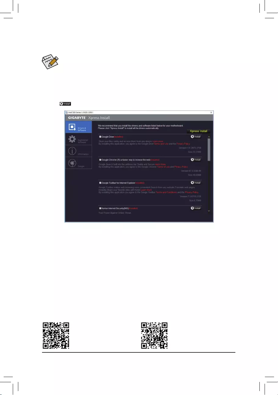
•Beforeinstallingthedrivers,rstinstalltheoperatingsystem.
•After installing the operating system, insert the motherboard driver disc into your optical drive. Click
on the message «Tap to choose what happens with this disc» on the top-right corner of the screen
and select «Run Run.exe.» (Or go to My Computer, double-click the optical drive and execute the
Run.exe program.)
«Xpress Install» will automatically scan your system and then list all of the drivers that are recommended to
install. You can click the Xpress Install button and «Xpress Install» will install all of the selected drivers. Or click
the arrow icon to individually install the drivers you need.
3-2 Drivers Installation
Please visit GIGABYTE’s website for
more software information.
Please visit GIGABYTE’s website for
more troubleshooting information.
— 43 —
— 44 —
Regulatory Notices
United States of America, Federal Communications Commission Statement
This equipment has been tested and found to comply with the limits for a
Class B digital device, pursuant to Part 15 of the FCC Rules. These limits
are designed to provide reasonable protection against harmful interference
in a residential installation. This equipment generates, uses and can radiate
radio frequency energy and, if not installed and used in accordance with
manufacturer’s instructions, may cause harmful interference to radio
communications. However, there is no guarantee that interference will
not occur in a particular installation. If this equipment does cause harmful
interference to radio or television reception, which can be determined by
turning the equipment off and on, the user is encouraged to try to correct
the interference by one or more of the following measures:
•Reorient or relocate the receiving antenna.
•Increase the separation between the equipment and receiver.
•Connect the equipment to an outlet on a circuit different from that to
which the receiver is connected.
•Consult the dealer or an experienced radio/TV technician for help.
Canadian Department of Communications Statement
This digital apparatus does not exceed the Class B limits for radio
noise emissions from digital apparatus set out in the Radio Interference
Regulations of the Canadian Department of Communications. This class
B digital apparatus complies with Canadian ICES-003.
Avis de conformité à la réglementation d’Industrie Canada
Cet appareil numérique de la classe B est conforme à la norme NMB-
003 du Canada.
European Union (EU) CE Declaration of Conformity
This device complies with the following directives: Electromagnetic
Compatibility Directive 2014/30/EU, Low-voltage Directive 2014/35/
EU, RoHS directive (recast) 2011/65/EU & the 2015/863 Statement.
This product has been tested and found to comply with all essential
requirements of the Directives.
European Union (EU) RoHS (recast) Directive 2011/65/EU & the
European Commission Delegated Directive (EU) 2015/863 Statement
GIGABYTE products have not intended to add and safe from hazardous
substances (Cd, Pb, Hg, Cr+6, PBDE, PBB, DEHP, BBP, DBP and DIBP).
The parts and components have been carefully selected to meet RoHS
requirement. Moreover, we at GIGABYTE are continuing our efforts to
develop products that do not use internationally banned toxic chemicals.
European Union (EU) Community Waste Electrical & Electronic
Equipment (WEEE) Directive Statement
GIGABYTEwillfulllthenationallawsasinterpretedfromthe2012/19/
EU WEEE (Waste Electrical and Electronic Equipment) (recast) directive.
The WEEE Directive species the treatment, collection, recycling and
disposal of electric and electronic devices and their components. Under
the Directive, used equipment must be marked, collected separately, and
disposed of properly.
WEEE Symbol Statement
The symbol shown below is on the product or on its
packaging, which indicates that this product must not be
disposed of with other waste. Instead, the device should be
taken to the waste collection centers for activation of the
treatment, collection, recycling and disposal procedure.
For more information about where you can drop off your waste equipment
forrecycling,pleasecontactyourlocalgovernmentofce,yourhousehold
waste disposal service or where you purchased the product for details of
environmentally safe recycling.
End of Life Directives-Recycling
The symbol shown below is on the product or on its packaging,
which indicates that this product must not be disposed of with
other waste. Instead, the device should be taken to the waste
collection centers for activation of the treatment, collection,
recycling and disposal procedure.
Déclaration de Conformité aux Directives de l’Union européenne (UE)
Cet appareil portant la marque CE est conforme aux directives de l’UE
suivantes: directive Compatibilité Electromagnétique 2014/30/UE, directive
Basse Tension 2014/35/UE et directive RoHS II 2011/65/UE. La conformité
à ces directives est évaluée sur la base des normes européennes
harmonisées applicables.
European Union (EU) CE-Konformitätserklärung
Dieses Produkte mit CE-Kennzeichnung erfüllen folgenden EU-Richtlinien:
EMV-Richtlinie 2014/30/EU, Niederspannungsrichtlinie 2014/30/EU und
RoHS-Richtlinie 2011/65/EU erfüllt. Die Konformität mit diesen Richtlinien
wird unter Verwendung der entsprechenden Standards zurEuropäischen
Normierung beurteilt.
CE declaração de conformidade
Este produto com a marcação CE estão em conformidade com das
seguintes Diretivas UE: Diretiva Baixa Tensão 2014/35/EU; Diretiva CEM
2014/30/EU; Diretiva RSP 2011/65/UE. A conformidade com estas diretivas
évericadautilizandoasnormaseuropeiasharmonizadas.
CE Declaración de conformidad
Este producto que llevan la marca CE cumplen con las siguientes
Directivas de la Unión Europea: Directiva EMC (2014/30/EU), Directiva
de bajo voltaje (2014/35/EU), Directiva RoHS (recast) (2011/65/EU).
El cumplimiento de estas directivas se evalúa mediante las normas
europeas armonizadas.
Dichiarazione di conformità CE
Questo prodotto è conforme alle seguenti direttive: Direttiva sulla
compatibilità elettromagnetica 2014/30/UE, Direttiva sulla bassa tensione
2014/35/UE, Direttiva RoHS (rifusione) 2011/65/UE. Questo prodotto è
stato testato e trovato conforme a tutti i requisiti essenziali delle Direttive.
Supplier’s Declaration of Conformity
47 CFR § 2.1077 Compliance Information
Product Name: Motherboard
Trade Name: GIGABYTE
Model Number: B560 HD3
Responsible Party – U.S. Contact Information: G.B.T. Inc.
Address: 17358 Railroad street, City Of Industry, CA91748
Tel.: 1-626-854-9338
Internet contact information: https://www.gigabyte.com
This device complies with Part 15 of the FCC Rules, Subpart B, Unintentional Radiators.
Operation is subject to the following two conditions: (1) This device may not cause harmful interference, and (2) this
device must accept any interference received, including interference that may cause undesired operation.
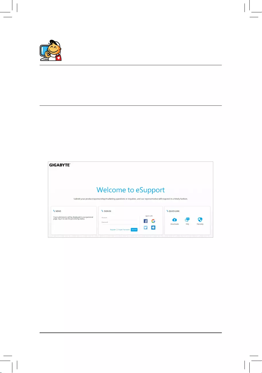
— 45 —
•GIGABYTE eSupport
To submit a technical or non-technical (Sales/Marketing) question, please link to:
https://esupport.gigabyte.com
Contact Us
GIGA-BYTE TECHNOLOGY CO., LTD.
Address: No.6, Baoqiang Rd., Xindian Dist., New Taipei City 231, Taiwan
TEL: +886—2-8912-4000, FAX: +886-2-8912-4005
Tech. and Non-Tech. Support (Sales/Marketing) : https://esupport.gigabyte.com
WEB address (English): https://www.gigabyte.com
WEB address (Chinese): https://www.gigabyte.com/tw
X
You may only add up to 5 items for comparison at one time.
Закрыть
- Загрузить
- Список совместимых процессоров
- Инструкции
- Перечень совместимых устройств
- FAQ
Загрузить
-
-
Аудио
Realtek HD Audio Driver
OS:Windows 10 64bit,Windows 11 64bit
[6.0.9373.1]
38.08Mb
25/07/2022

Realtek HD Audio Driver
OS:Windows 10 64bit,Windows 11 64bit
[6.0.9235.1]
17.82Mb
02/11/2021
Realtek HD Audio Driver
(Note) Win10 ver.20H2 supported.[6.0.9075.1]
18.19Mb
23/12/2020
-
Chipset
Intel INF installation
OS:Windows 10 64bit,Windows 11 64bit
[10.1.18836.8283]
4.04Mb
16/05/2022
Intel Management Engine Firmware
OS:Windows 10 64bit,Windows 11 64bit
[2129.62.62.0]
222.36Mb
16/02/2022
Intel Serial I/O driver
OS:Windows 10 64bit,Windows 11 64bit
[30.100.2129.8]
1.83Mb
16/02/2022
Intel Management Engine Firmware
(Note) Win10 20H2 supported.[2052.59.22.0]
224.23Mb
09/04/2021
Intel Serial I/O driver
(Note) Win10 20H2 supported.[30.100.2051.37]
1.85Mb
25/01/2021
Intel INF installation
(Note) Win10 20H2 supported.[10.1.18634.8254]
2.73Mb
25/01/2021
-
LAN
[1168.007.0318.2022]
4.84Mb
01/04/2022
[10.056.0119.2022]
5.02Mb
08/03/2022
[10.050.0511.2021]
5.01Mb
17/02/2022
Realtek LAN Driver
(Note) Win10 20H2 supported.[10.046.1231.2020]
4.75Mb
12/01/2021
-
SATA RAID/AHCI
Intel Rapid Storage Technology
OS:Windows 10 64bit,Windows 11 64bit
[18.6.1.1016]
7.49Mb
16/02/2022
Intel SATA Preinstall driver (For AHCI / RAID Mode)
(Note) Windows setup to read from USB thumb drive.OS:Windows 10 64bit,Windows 11 64bit
[18.6.1.1016.1]
3.74Mb
07/10/2021
Intel SATA Preinstall driver
(For AHCI / RAID Mode)
(Note) Win10 20H2 supported.
(Note) Windows setup to read from USB thumb drive.[18.1.2.1034]
6.89Mb
28/01/2021
Intel Optane memory
(Note) Win10 ver.2004 supported.[17.8.0.1065]
72.63Mb
11/05/2020
-
VGA
Intel Graphic Driver
OS:Windows 10 64bit,Windows 11 64bit
[27.20.100.9805]
332.41Mb
16/02/2022
Intel Graphic Driver
(Note) Win10 20H2 supported.[27.20.100.9316]
241.48Mb
19/03/2021
-
Аудио
-
BIOS(+9)
-
F14
11.19Mb
22/03/2023
- Checksum : 4DA0
- Description: Address blank display while system powers up with RTX3060 series graphics cards
F13
11.11Mb
28/03/2022
- Checksum : C279
- Support driver installation in Windows without driver disc
F10
10.46Mb
09/11/2021
- Checksum : 203D
-
Major vulnerabilities updates, customers are strongly encouraged to update to this release at the earliest.
Credits to ‘Assaf Carlsbad and Itai Liba from SentinelOne’
-
Introduce capsule BIOS support starting this version.
Customers will NOT be able to reverse to previous BIOS version due to major vulnerabilities concerns.
F9
9.61Mb
24/09/2021
- Checksum: A582
- Change default status of Intel® Platform Trust Technology (Intel® PTT) to Enabled for addressing basic Windows 11 requirements (https://support.microsoft.com/windows/1fd5a332-360d-4f46-a1e7-ae6b0c90645c)
F8
9.60Mb
03/08/2021
- Checksum: B4B4
- Enhance the compatibility of M.2 device
- Update Comet Lake CPU microcode
F7
9.62Mb
11/05/2021
- Checksum : E917
- Update BIOS microcode
F6
9.62Mb
28/04/2021
- Checksum : 6175
- Add Intel Adaptive Boost Technology support for Core i9-11900K & Core i9-11900KF processors
F4
9.57Mb
19/03/2021
- Checksum : 185A
- Update CPU microcode version 0x34
F1
9.62Mb
18/01/2021
- Checksum : 25BE
- First Launch Release
-
-
-
Easy Tune
(Note) Support Intel 600 / 500 / 400 / 300 and AMD 500 / 400 series motherboards (support may vary by model).
(Note) Please install APP Center first before install this utility.OS:Windows 10 64bit,Windows 11 64bit
B23.0308.1
51.90Mb
03/05/2023
System Information Viewer
(Note) Support Intel 600 / 500 / 400 / 300 and AMD 500 /400 series motherboards (support may vary by model).
(Note) Please install APP Center first before install this utility.OS:Windows 10 64bit,Windows 11 64bit
B23.0310.1
104.49Mb
03/05/2023
RGB Fusion
OS:Windows 10 64bit,Windows 11 64bit
B23.0328.1
123.62Mb
02/05/2023
APP Center
(Note) Support Intel 600 / 500 / 400 / 300 and AMD 500 / AM4 / TRX40 series motherboards (support may vary by model).
(Note) Please install Microsoft .NET Framework 4.5 first before install APP Center utility.OS:Windows 10 64bit,Windows 11 64bit
B22.1031.1
23.43Mb
31/10/2022
Realtek Gaming LAN bandwidth Control Utility
(Note) Support Intel 700 / 600 / 500 / 400 series and AMD 600 / 500 series motherboards (support may vary by model).OS:Windows 10 64bit,Windows 11 64bit
6.12.3101.2
77.76Mb
05/05/2022
@BIOS
(Note) Support Intel 600 / 500 / 400 / 300 and AMD 500 / AM4 / TRX40 series motherboards (support may vary by model).
(Note) Please install APP Center first before install this utility.OS:Windows 10 64bit,Windows 11 64bit
B21.1203.1
13.68Mb
12/01/2022
Fast Boot
(Note) Support Intel 600 / 500 / 400 / 300 and AMD 500 / AM4 / TRX40 series motherboards (support may vary by model).
(Note) Please install APP Center first before install this utility.OS:Windows 10 64bit,Windows 11 64bit
B21.1214.1
7.83Mb
12/01/2022
On/Off Charge™ / On/Off Charge™ 2
(Note) Support Intel 600 / 500 / 400 and AMD 500 / AM4 series motherboards (support may vary by model).
(Note) Please install APP Center first before install this utility.B19.1119.1
12.13Mb
02/11/2021
Smart Backup
(Note) Support Intel 600 / 500 / 400 / 300 and AMD 500 / AM4 / TRX40 series motherboards (support may vary by model).
(Note) Please install APP Center first before install this utility.OS:Windows 10 64bit,Windows 11 64bit
B21.0326.1
23.00Mb
02/11/2021
Game Boost
(Note) Support Intel 600 / 500 / 400 / 300 and AMD 500 / AM4 / TRX40 series motherboards (support may vary by model).
(Note) Please install APP Center first before install this utility.OS:Windows 10 64bit,Windows 11 64bit
B18.0730.1
8.52Mb
14/10/2021
Norton® Internet Security (OEM version)
22.19.8.65
225.80Mb
18/11/2020
-

- Инструкции
- Инструкции(+6)
-
English
590.75kB
06/09/2021
Intel® Optane™ Memory Setup Guide
English
2.68Mb
06/09/2021
Unique Features Introduction
Traditional Chinese
1001
13.65Mb
20/05/2021
English
1001
12.93Mb
20/05/2021
Simplified Chinese
1001
11.62Mb
20/05/2021
English, Traditional Chinese, Simplified Chinese, Russian, French, German, Japanese, Spanish, Korean, Portuguese, Persian, Turkish, Czech, Vi
103
9.03Mb
25/11/2019
Multilingual Installation Guide
-
- Перечень совместимых устройств
-
Перечень совместимых устройств(+3)
-
Модули памяти
319.95kB
05/03/2021
Перечень SSD-накопителей
229.88kB
15/09/2021
Перечень M.2-накопителей
245.83kB
22/09/2021
-
CPU Support
Socket 1200 — Intel B560 — B560 HD3 (Rev. 1.0)
N/A = Not support
| Socket 1200 | ||||||||||
|---|---|---|---|---|---|---|---|---|---|---|
| Motherboard | Model |
B560 HD3 |
||||||||
| PCB | 1.0 | |||||||||
| Vendor | CPU Model | Frequency | L3 Cache | GPU Info. | Core Name | Process | Stepping | Wattage | BCLK | Since BIOS Version |
| Intel | Celeron G5905 | 3.50GHz | 4MB | Intel® UHD Graphics 610 | Comet Lake | 14nm | G1 | 58W | 100 | F1 |
| Intel | Celeron G5905T | 3.30GHz | 4MB | Intel® UHD Graphics 610 | Comet Lake | 14nm | G1 | 35W | 100 | F1 |
| Intel | Celeron G5925 | 3.60GHz | 4MB | Intel® UHD Graphics 610 | Comet Lake | 14nm | G1 | 58W | 100 | F1 |
| Intel | Core i3-10100 | 3.60GHz | 8MB | Intel® UHD Graphics 630 | Comet Lake | 14nm | G1 | 65W | 100 | F1 |
| Intel | Core i3-10100F | 3.60GHz | 8MB | N/A | Comet Lake | 14nm | G1 | 65W | 100 | F1 |
| Intel | Core i3-10100T | 3.00GHz | 8MB | Intel® UHD Graphics 630 | Comet Lake | 14nm | G1 | 35W | 100 | F1 |
| Intel | Core i3-10105 | 3.70GHz | 6MB | Intel® Iris® Xe Graphics | Comet Lake | 14nm | G1 | 65W | 100 | F1 |
| Intel | Core i3-10105F | 3.70GHz | 6MB | N/A | Comet Lake | 14nm | G1 | 65W | 100 | F1 |
| Intel | Core i3-10105T | 3.00GHz | 8MB | Intel® Iris® Xe Graphics | Comet Lake | 14nm | G1 | 35W | 100 | F1 |
| Intel | Core i3-10300 | 3.70GHz | 8MB | Intel® UHD Graphics 630 | Comet Lake | 14nm | G1 | 65W | 100 | F1 |
| Intel | Core i3-10300T | 3.00GHz | 8MB | Intel® UHD Graphics 630 | Comet Lake | 14nm | G1 | 35W | 100 | F1 |
| Intel | Core i3-10305 | 3.80GHz | 8MB | Intel® Iris® Xe Graphics | Comet Lake | 14nm | G1 | 65W | 100 | F1 |
| Intel | Core i3-10305T | 3.00GHz | 8MB | Intel® Iris® Xe Graphics | Comet Lake | 14nm | G1 | 35W | 100 | F1 |
| Intel | Core i3-10320 | 3.80GHz | 8MB | Intel® UHD Graphics 630 | Comet Lake | 14nm | G1 | 65W | 100 | F1 |
| Intel | Core i3-10325 | 3.90GHz | 8MB | Intel® Iris® Xe Graphics | Comet Lake | 14nm | G1 | 65W | 100 | F1 |
| Intel | Core i5-10400 | 2.90GHz | 12MB | Intel® UHD Graphics 630 | Comet Lake | 14nm | G1 | 65W | 100 | F1 |
| Intel | Core i5-10400F | 2.90GHz | 12MB | N/A | Comet Lake | 14nm | Q0 | 65W | 100 | F1 |
| Intel | Core i5-10400T | 2.00GHz | 12MB | Intel® UHD Graphics 630 | Comet Lake | 14nm | G1 | 35W | 100 | F1 |
| Intel | Core i5-10500 | 3.10GHz | 12MB | Intel® UHD Graphics 630 | Comet Lake | 14nm | G1 | 65W | 100 | F1 |
| Intel | Core i5-10500T | 2.30GHz | 12MB | Intel® UHD Graphics 630 | Comet Lake | 14nm | G1 | 35W | 100 | F1 |
| Intel | Core i5-10600 | 3.30GHz | 12MB | Intel® UHD Graphics 630 | Comet Lake | 14nm | G1 | 65W | 100 | F1 |
| Intel | Core i5-10600K | 4.10GHz | 12MB | Intel® UHD Graphics 630 | Comet Lake | 14nm | Q0 | 125W | 100 | F1 |
| Intel | Core i5-10600KF | 4.10GHz | 12MB | N/A | Comet Lake | 14nm | Q0 | 125W | 100 | F1 |
| Intel | Core i5-10600T | 2.40GHz | 12MB | Intel® UHD Graphics 630 | Comet Lake | 14nm | G1 | 35W | 100 | F1 |
| Intel | Core i5-11400 | 2.60GHz | 12MB | Intel® Iris® Xe Graphics | Rocket Lake | 14nm | B0 | 65W | 100 | F1 |
| Intel | Core i5-11400F | 2.60GHz | 12MB | N/A | Rocket Lake | 14nm | B0 | 65W | 100 | F1 |
| Intel | Core i5-11400T | 1.30GHz | 12MB | Intel® Iris® Xe Graphics | Rocket Lake | 14nm | B0 | 35W | 100 | F1 |
| Intel | Core i5-11500 | 2.70GHz | 12MB | Intel® Iris® Xe Graphics | Rocket Lake | 14nm | B0 | 65W | 100 | F1 |
| Intel | Core i5-11500T | 1.50GHz | 12MB | Intel® Iris® Xe Graphics | Rocket Lake | 14nm | B0 | 35W | 100 | F1 |
| Intel | Core i5-11600 | 2.80GHz | 12MB | Intel® Iris® Xe Graphics | Rocket Lake | 14nm | B0 | 65W | 100 | F1 |
| Intel | Core i5-11600K | 3.90GHz | 12MB | Intel® Iris® Xe Graphics | Rocket Lake | 14nm | B0 | 125W | 100 | F1 |
| Intel | Core i5-11600KF | 3.90GHz | 12MB | N/A | Rocket Lake | 14nm | B0 | 125W | 100 | F1 |
| Intel | Core i5-11600T | 1.70GHz | 12MB | Intel® Iris® Xe Graphics | Rocket Lake | 14nm | B0 | 35W | 100 | F1 |
| Intel | Core i7-10700 | 2.90GHz | 16MB | Intel® UHD Graphics 630 | Comet Lake | 14nm | Q0 | 65W | 100 | F1 |
| Intel | Core i7-10700F | 2.90GHz | 16MB | N/A | Comet Lake | 14nm | Q0 | 65W | 100 | F1 |
| Intel | Core i7-10700K | 3.80GHz | 16MB | Intel® UHD Graphics 630 | Comet Lake | 14nm | Q0 | 125W | 100 | F1 |
| Intel | Core i7-10700KF | 3.80GHz | 16MB | N/A | Comet Lake | 14nm | Q0 | 125W | 100 | F1 |
| Intel | Core i7-10700T | 2.00GHz | 16MB | Intel® UHD Graphics 630 | Comet Lake | 14nm | Q0 | 35W | 100 | F1 |
| Intel | Core i7-11700 | 2.50GHz | 16MB | Intel® Iris® Xe Graphics | Rocket Lake | 14nm | B0 | 65W | 100 | F1 |
| Intel | Core i7-11700F | 2.50GHz | 16MB | N/A | Rocket Lake | 14nm | B0 | 65W | 100 | F1 |
| Intel | Core i7-11700K | 3.60GHz | 16MB | Intel® Iris® Xe Graphics | Rocket Lake | 14nm | B0 | 125W | 100 | F1 |
| Intel | Core i7-11700KF | 3.60GHz | 16MB | N/A | Rocket Lake | 14nm | B0 | 125W | 100 | F1 |
| Intel | Core i7-11700T | 1.40GHz | 16MB | Intel® Iris® Xe Graphics | Rocket Lake | 14nm | B0 | 35W | 100 | F1 |
| Intel | Core i9-10850K | 3.60GHz | 20MB | Intel® UHD Graphics 630 | Comet Lake | 14nm | Q0 | 125W | 100 | F1 |
| Intel | Core i9-10900 | 2.80GHz | 20MB | Intel® UHD Graphics 630 | Comet Lake | 14nm | Q0 | 65W | 100 | F1 |
| Intel | Core i9-10900F | 2.80GHz | 20MB | N/A | Comet Lake | 14nm | Q0 | 65W | 100 | F1 |
| Intel | Core i9-10900K | 3.70GHz | 20MB | Intel® UHD Graphics 630 | Comet Lake | 14nm | Q0 | 125W | 100 | F1 |
| Intel | Core i9-10900KF | 3.70GHz | 20MB | N/A | Comet Lake | 14nm | Q0 | 125W | 100 | F1 |
| Intel | Core i9-10900T | 1.90GHz | 20MB | Intel® UHD Graphics 630 | Comet Lake | 14nm | Q0 | 35W | 100 | F1 |
| Intel | Core i9-11900 | 2.50GHz | 16MB | Intel® Iris® Xe Graphics | Rocket Lake | 14nm | B0 | 65W | 100 | F1 |
| Intel | Core i9-11900F | 2.50GHz | 16MB | N/A | Rocket Lake | 14nm | B0 | 65W | 100 | F1 |
| Intel | Core i9-11900K | 3.50GHz | 16MB | Intel® Iris® Xe Graphics | Rocket Lake | 14nm | B0 | 125W | 100 | F1 |
| Intel | Core i9-11900KF | 3.50GHz | 16MB | N/A | Rocket Lake | 14nm | B0 | 125W | 100 | F1 |
| Intel | Core i9-11900T | 1.50GHz | 16MB | Intel® Iris® Xe Graphics | Rocket Lake | 14nm | B0 | 35W | 100 | F1 |
| Intel | Pentium G6400 | 4.00GHz | 4MB | Intel® UHD Graphics 630 | Comet Lake | 14nm | G1 | 58W | 100 | F1 |
| Intel | Pentium G6400T | 3.40GHz | 4MB | Intel® UHD Graphics 610 | Comet Lake | 14nm | G1 | 35W | 100 | F1 |
| Intel | Pentium G6405 | 4.10GHz | 4MB | Intel® Iris® Xe Graphics | Comet Lake | 14nm | G1 | 58W | 100 | F1 |
| Intel | Pentium G6405T | 3.50GHz | 4MB | Intel® Iris® Xe Graphics | Comet Lake | 14nm | G1 | 35W | 100 | F1 |
| Intel | Pentium G6500 | 4.10GHz | 4MB | Intel® UHD Graphics 630 | Comet Lake | 14nm | G1 | 58W | 100 | F1 |
| Intel | Pentium G6500T | 3.50GHz | 4MB | Intel® UHD Graphics 630 | Comet Lake | 14nm | G1 | 35W | 100 | F1 |
| Intel | Pentium G6505 | 4.20GHz | 4MB | Intel® Iris® Xe Graphics | Comet Lake | 14nm | G1 | 58W | 100 | F1 |
| Intel | Pentium G6505T | 3.60GHz | 4MB | Intel® Iris® Xe Graphics | Comet Lake | 14nm | G1 | 35W | 100 | F1 |
| Intel | Pentium G6600 | 4.20GHz | 4MB | Intel® UHD Graphics 630 | Comet Lake | 14nm | G1 | 58W | 100 | F1 |
| Intel | Pentium G6605 | 4.30GHz | 4MB | Intel® Iris® Xe Graphics | Comet Lake | 14nm | G1 | 58W | 100 | F1 |

Содержание
- Настройка UEFI Gigabyte b560hd3 версия F13
- Настройка BIOS материнской платы
- Настройка BIOS материнских плат Gigabyte
- Оперативная память
- Настройки видеоадаптера
- Управление вентиляторами
- Сигналы тревоги
- Оптимизация работы периферийных устройств
- Заключительный этап
- Настройка BIOS материнских плат Asus
- Как попасть в БИОС gigabyte
- Как войти в БИОС материнской платы gigabyte?
- Как зайти в Boot Menu Gigabyte?
- Как изменить приоритет загрузки в BIOS Gigabyte?
- Старые компьютеры
- Что такое загрузочное меню F12?
- Зачем открывать БИОС
Настройка UEFI Gigabyte b560hd3 версия F13
Итак, имеется материнка Gigabyte b560hd3, процессор i5-11400f, м.2 ssd Samsung 980 pro, видеjкарта rtx 3060ti, 32 гб оперативки с частотами 2133 и 2666 (поддерживает x.m.p.). ОС клонирована на самсунговский ссд и работает. А теперь вопросы.
1. Не удовлетворяет скорость ссд. Тесты подтверждают заявленную производителем скорость чтения и записи, но я исхожу из того. Что специально на данный ссд я также установил онлайн-игру, скорости загрузки ее не прибавилось.
2. Видеокарта и материнка поддерживают pci-e 4.0, опять же я не заметил какого прироста ни в фпс, ни в целом ускоренной прогрузки объектов в мире.
3. Поиски в гугле по настройке компонентов не дали толку, т.к. представленный в результатах поиска биос заметно отличается от имеющегося у меня. Не будем далеко ходить, во всех примерах биос красный, у меня желтый. Это я сказал, чтоб не вдаваться в то, что и параметры меню тоже различаются сильно.
4. С таймингами и напряжениями играться не хочу, ибо разбираюсь в них лишь поверхностно. 5. И да, после обновления биоса «исчез» hdd с другими программами и материалами. Единственное. Что я задействовал, это установил в уефи галочку на интел рапид сторедж и в разделе ssd pci с авто поменял на ген4.
6. Основной вопрос как настроить, чтоб твердотельник работал на заявленных скоростях, ну видеокарта тоже.
7. Интернет 500Мбит.
Прошу не писать мнения типа да у тебя материнка, процессор и т. д. не годится, накопи денег — купи лучше и т. д. ЧТО ИМЕЕТСЯ, С ТЕМ «РАБОТАЕМ».
Заранее благодарен за конструктивные советы.
Источник
Настройка BIOS материнской платы
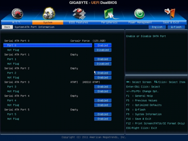
Правильная сборка компьютера – еще не гарантия его работы на 100% производительности. Желательна подкрутка параметров аппаратных средств ПК. Каждый пользователь подгоняет систему под себя. Для одних важно максимальное быстродействие, для других – низкий уровень шума. Этот выбор делается в BIOS материнской платы.
Выполнять настройку BIOS компьютера приветствуется в следующих случаях:
- Сборка ПК “с нуля”;
- Замена комплектующих;
- Наличие встроенной графики в CPU;
- Разгон центрального процессора и оперативной памяти;
- Настройка работы вентиляторов системного блока;
- Включение звуковых аварийных оповещений;
- Переустановка операционной системы.
Настройка BIOS материнских плат Gigabyte
Для входа в BIOS плат фирмы Gigabyte при загрузке компьютера нажимаем клавишу Del. На главной странице (M.I.T. Current Status) увидим текущую версию BIOS, множитель частоты системной шины, величины частот CPU и оперативки, объем памяти, температуру и напряжение центрального процессора.
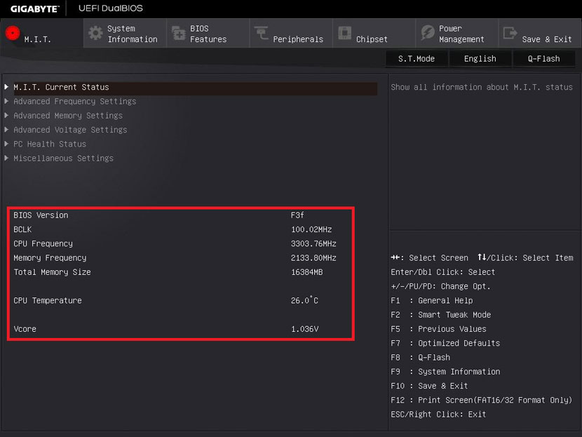
Оперативная память
На начало 2018 года самый распространенный тип оперативной памяти для ПК – это DDR4, частота которой достигает 4266 МГц, что намного выше, чем у DDR3. По умолчанию память RAM работает на частоте 2133 МГц. Поэтому необходимо ее перевести на частоту, соответствующую спецификации. Значение частоты зашито в профиле X.M.P. Для ее активации находим параметр Advanced Memory Settings, далее – Extreme Memory Profile (X.M.P.) и выставляем значение Profile1.
Для энтузиастов доступен разгон памяти путем изменения таймингов (Channel A/B Memory Sub Timings) и напряжения (DRAM Voltage Control).
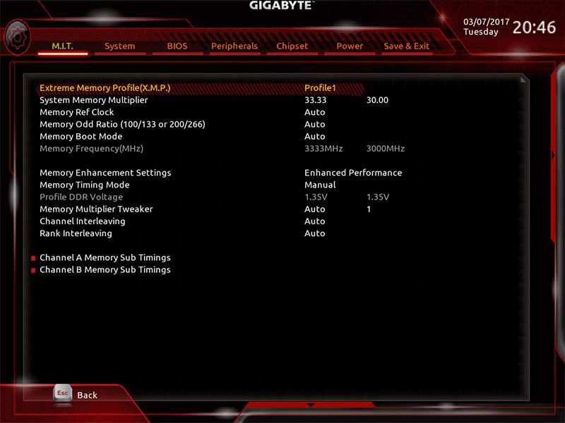
Настройки видеоадаптера
На следующем этапе настройки концентрируем внимание на графическом адаптере. В этом нам поможет вкладка Peripherals. Если конфигурация системного блока не предполагает использования дискретной видеокарты, то активируем встроенное в CPU графическое ядро: Initial Display Output – выбираем IGFX. Этот адаптер использует некоторое количество от общей оперативной памяти компьютера. Для изменения ее объема в разделе Chipset кликаем на DVMT Pre-Allocated и останавливаемся на максимально возможном значении. А в DVMT Total Gfx Mem делаем активным размер MAX.
При наличии внешней видеокарты параметр Initial Display Output меняем на PCIe 1 slot (слот PCIEX16) или PCIe 2 slot (слот PCIEX4), а значение Internal Graphics в подменю Chipset – на Disabled. Это делается для снижения нагрузки на CPU. При наличии двух мониторов возможно использование сразу двух графических адаптеров – внешнего и встроенного – выбор за пользователем.
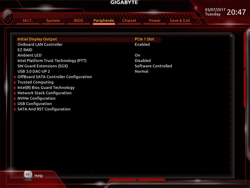
Управление вентиляторами
Что главное – поддержание минимально возможной температуры внутри корпуса или тишина? Ответ кроется в типе используемого видеоадаптера. Если он выделяет много тепла (от 150 Ватт), то отработанный горячий воздух необходимо как можно быстрее удалить из корпуса. Этим занимаются кулеры, располагаемые спереди, сзади и вверху системного блока. Они подключены в соответствующие разъемы на материнской плате. Но при нетребовательных задачах современный графический адаптер потребляет мало энергии. Поэтому в большом разделе M.I.T.PC Health Status в подменю 1st System Fan Speed Control, 2nd System Fan Speed Control и 3rd System Fan Speed Control устанавливаем параметр Normal, который будет автоматически изменять скорость вращения лопастей исходя из температуры в системе. Можно активировать и собственный график этой зависимости, выбрав Manual. Эти значения устанавливаются в подразделе Fan Speed Control для каждого кулера. Если за видео графику отвечает встроенный в ядро CPU адаптер, то для уменьшения шума используем тихий режим – Silent.
В этом же разделе параметр CPU Fan Speed Control (CPU_FAN Connector) отвечает за регулирование скорости вращения процессорного кулера. Доступны следующие опции: Normal (автоматическая работа, зависящая от температуры ядер центрального процессора), Silent (вентилятор работает на пониженных скоростях), Manual (ручное управление), Full Speed (максимально возможная степень вращения).
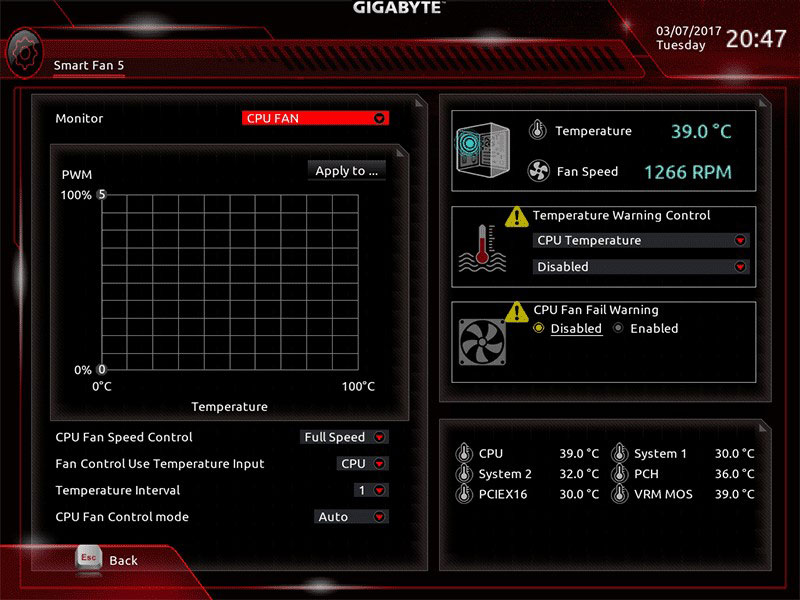
Сигналы тревоги
Спецификации центральных процессоров подразумевают их функционирование до 100 ºС. Но чем ниже температура внутри CPU, тем дольше он проработает. Поэтому BIOS предлагает установить пороговое значение этого параметра, по достижении которого включается аварийное оповещение. Находим в меню M.I.T.PC Health Status строку CPU/System Temperature Warning. По умолчанию она имеет значение Disabled. Для процессоров с небольшим тепловыделением рекомендуется изменить его на 70 ºС/158 ºF, а для “горячих” – 90 ºС/194 ºF. Этот параметр зависит от того, как эффективно кулер отводит тепло от крышки процессора. Данная настройка применима и для корпусных вентиляторов охлаждения.
Сигнал тревоги также поступит при сбое в работе любого из вентиляторов и неправильном их подключении к разъемам на системной плате. Для включения этой функции в том же разделе ищем CPU/CPU OPT/System Fan Fail Warning и меняем на Enabled. В последнее время на рынке стали появляться кулеры с полупассивным режимом работы. При небольшой нагрузке на центральный процессор они не вращаются. В таком случае целесообразно оставить значение по умолчанию — Disabled.
Оптимизация работы периферийных устройств
Для установки операционной системы необходимо, чтобы компьютер при запуске обратился к диску, где находится дистрибутив операционки. Задать эти параметры можно в BIOS Features, зайдя в Boot Option Priorities, где в качестве первого загрузочного диска выбираем HDD, SSD, USB или DVD.
Система сейчас обычно ставится на твердотельный накопитель, который наилучшим образом работает в режиме AHCI. Активировать его можно в разделе Peripherals — SATA Configuration и его подразделе SATA Mode Selection. Здесь же, но в подменю External SATA включаем внешние устройства с SATA интерфейсом.
В любой материнской плате встроен аудио контроллер. Если пользователя не устраивает качество звучания, он добавляет в порт PCI или USB внешнюю звуковую карту. Тогда необходимо отключить интегрированный звук в меню Chipset – Audio Controller.
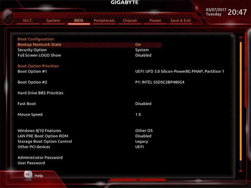
Заключительный этап
Подтверждение или отмена сделанных изменений BIOS делается в секции Save & Exit:
- Save &Exit Setup – сохранение исправлений и выход;
- ExitWithoutSaving – выход без внесения поправок;
- Load Optimized Defaults – загрузка оптимальных настроек по умолчанию, которые требуются после обновления BIOS или очистки CMOS параметров.
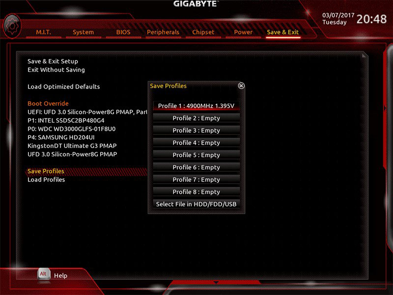
Настройка BIOS материнских плат Asus
Чтобы войти в BIOS системной платы производителя Asus, следует нажать на Del или F2. Здесь доступны два режима – EZ Mode и Advanced Mode. По умолчанию загружается EZ Mode. Для перехода во второе состояние необходимо внизу найти соответствующую ссылку или использовать клавишу F7. Рассмотрим более подробно Advanced Mode.
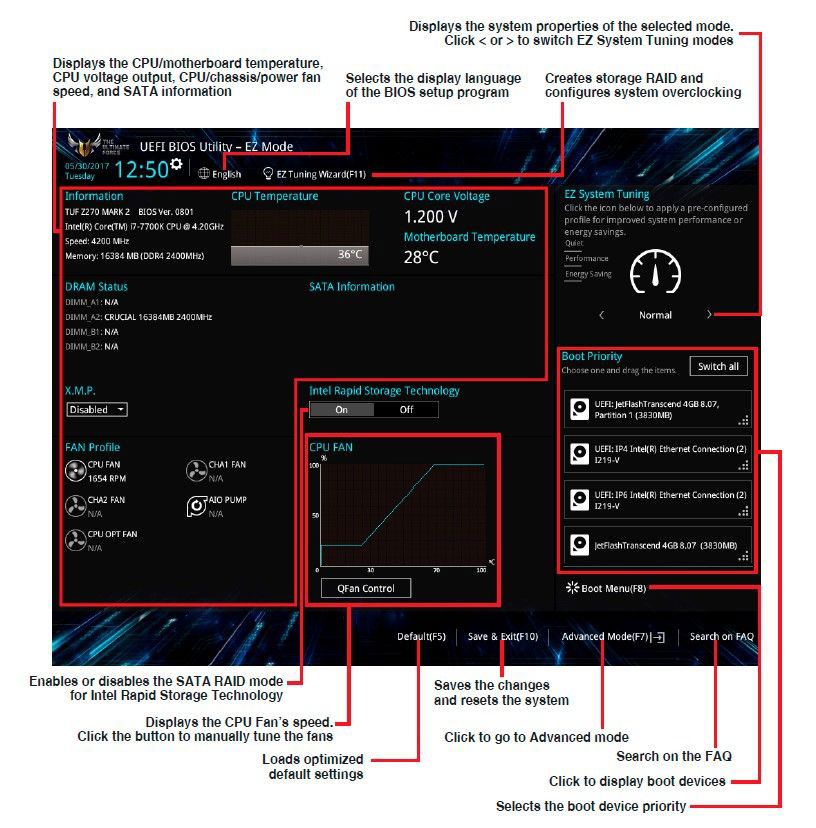
Опции, отвечающие за работу кулеров в системе, находятся в QFan Control (F6). Здесь имеются предустановленные и ручной профили для процессорного и корпусных вентиляторов: Standard, Silent, Turbo, Full Speed, Manual. В ручном режиме можно построить зависимость степени вращения каждого кулера от температуры.
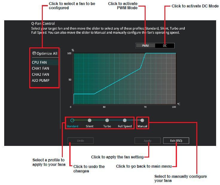
Отключить функцию управления охладителями можно в меню MonitorQ-Fan Configuration. Доступно регулирование и 3-х пиновых вентиляторов, выбрав режим DC Mode.
Утилита EZ Tuning Wizard (F11) позволяет разогнать процессор c учетом типа его охлаждения. Это актуально для обладателей процессоров Intel с индексом К. В подменю ОС выбираем сценарий для компьютера повседневного использования (Daily Computing) или игрового ПК (Gaming/Media Editing). Потом кликаем на пиктограмму с боксовым, башенным или жидкостным куллером и запускаем процесс тюнинга.
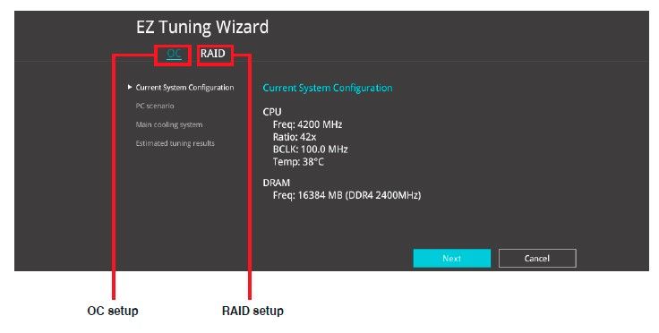
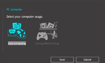
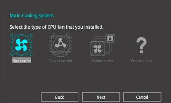
Активация профиля XMP для оперативной памяти происходит в подменю Ai Overclock Tuner.
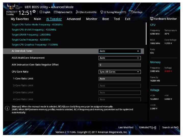
Для встроенной в CPU графики необходимо в разделе AdvancedSystem Agent (SA) ConfigurationGraphics ConfigurationPrimary Display выставить значение IGFX, а для дискретного видео адаптера — PEG.
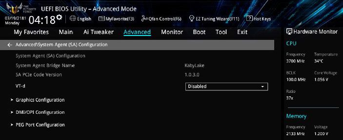
Режим работы накопителей с интерфейсом SATA настраивается в AdvancedPCH Storage ConfigurationSATA Mode Selection. Выбираем AHCI. Здесь же пункт S.M.A.R.T. Status Check обеспечивает мониторинг состояния жестких дисков и оповещает об ошибках в их работе.
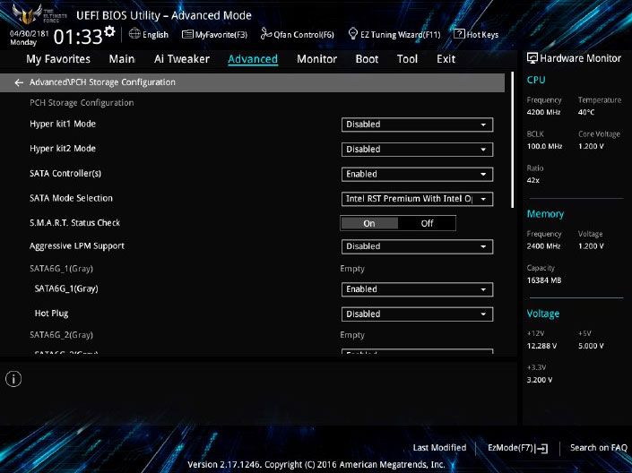
Скорость SSD устройств снижается с течением времени по мере заполнения свободного пространства. Утилита Secure Erase в меню Tool оптимизирует работу твердотельных накопителей, возвращая тем самым им изначальную производительность.
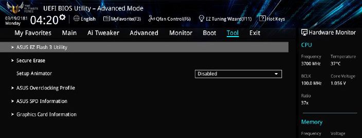
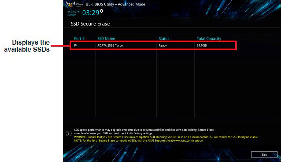
Информацию о всех подключенных носителей информации можно посмотреть в AdvancedHDD/SSD Smart Information.
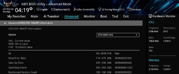
Включение/отключение встроенного в материнскую плату аудио контроллера осуществляется в подменю AdvancedHD Audio Controller.

Приоритет в загрузке устройств задается в меню BootBoot Option Priorities.
Сохранение и отмена внесенных изменений в BIOS, загрузка оптимальных заводских параметров доступно в главном меню Exit.
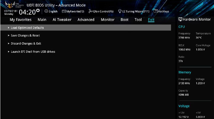
Настройка BIOS важна для тех, кто стремится получить от сборки конфигурации компьютера максимальную отдачу. Поэтому перед установкой операционной системы нужно детально изучить эту процедуру, которая описана в инструкции, поставляемой в коробке с материнской платой.
Источник
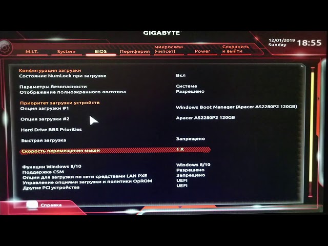
Как войти в БИОС материнской платы gigabyte?
Чтобы зайти в расширенные настройки UEFI BIOS, Вам надо кликнуть по кнопке Advanced Mode. А вот тут мы уже видим параметры старого доброго BIOS . В расширенном режиме обязательно будет в наличии раздел, отвечающий за разгон и режимы работы процессора, памяти и системы управления питанием.
Самой популярным способом для входа в БИОС является клавиша «Del», на некоторых моделях материнских плат, иногда используется клавиша «F2». При появлении логотипа материнской платы нужно быстро щелкнуть несколько раз по соответствующей клавише на клавиатуре.
- Моноблоки и ноутбуки HP — клавиша F9 или Esc, а затем — F9.
- Ноутбуки Dell — F12.
- Ноутбуки Samsung — Esc.
- Ноутбуки Toshiba — F12.
- Материнские платы Gigabyte — F12.
- Материнские платы Intel — Esc.
- Материнские платы Asus — F8.
- Материнские платы MSI — F11.
Как изменить приоритет загрузки в BIOS Gigabyte?
Перейдите в «Advanced BIOS Features» для дальнейшей настройки приоритета запуска. Перемещение снова выполняйте стрелочками и выберите пункт «Hard Disk Boot Priority». С помощью соответствующих кнопок выставьте подключенную флешку в самый верх списка.
Старые компьютеры
В старых компьютерах вы можете увидеть надпись: Press TAB to show POST screen, DEL to enter SETUP. Это говорит о том, что нужно нажать DEL или Tab, чтобы зайти в BIOS.
Еще в очень редких случаях требуется нажать клавишу F1
Что такое загрузочное меню F12?
Перезагрузите компьютер, и вы можете увидеть экран с надписью «Нажмите F12 Boot для загрузки меню» или «Нажмите Del для настройки». После входа в меню загрузки вы можете использовать стрелки вверх и вниз для выбора устройства, с которого хотите загрузиться.
Как получить доступ к BIOS Windows 10
- Открыть настройки. «Вы найдете« Настройки »в меню« Пуск »Windows в нижнем левом углу.
- Выберите «Обновление и безопасность». ‘…
- На вкладке «Восстановление» выберите «Перезагрузить сейчас». ‘…
- Выберите «Устранение неполадок. ‘…
- Щелкните «Дополнительные параметры».
- Выберите «Настройки прошивки UEFI». ‘
Зачем открывать БИОС
В базовой системе ввода вывода есть множество настроек, с помощью которых можно контролировать работу компьютера. Вот перечень самых распространенных опций, которые меняются в BIOS:
- для установки операционной системы.
- Изменение порядка старта жесткого диска.
- Включение, отключение встроенных в материнскую плату устройств.
- Автоматическое включение компьютера при подаче электропитания.
Источник