X
You may only add up to 5 items for comparison at one time.
Закрыть
- Загрузить
- Список совместимых процессоров
- Инструкции
- Перечень совместимых устройств
- FAQ
Загрузить
-
-
Аудио
Realtek HD Audio Driver
OS:Windows 10 64bit,Windows 11 64bit
[6.0.9373.1]
38.08Mb
25/07/2022

Realtek HD Audio Driver
OS:Windows 10 64bit,Windows 11 64bit
[6.0.9235.1]
17.82Mb
02/11/2021
Realtek HD Audio Driver
(Note) Win10 ver.20H2 supported.[6.0.9075.1]
18.19Mb
23/12/2020
-
Chipset
Intel INF installation
OS:Windows 10 64bit,Windows 11 64bit
[10.1.18836.8283]
4.04Mb
16/05/2022
Intel Management Engine Firmware
OS:Windows 10 64bit,Windows 11 64bit
[2129.62.62.0]
222.36Mb
16/02/2022
Intel Serial I/O driver
OS:Windows 10 64bit,Windows 11 64bit
[30.100.2129.8]
1.83Mb
16/02/2022
Intel Management Engine Firmware
(Note) Win10 20H2 supported.[2052.59.22.0]
224.23Mb
09/04/2021
Intel INF installation
(Note) Win10 20H2 supported.[10.1.18634.8254]
2.73Mb
25/01/2021
Intel Serial I/O driver
(Note) Win10 20H2 supported.[30.100.2051.37]
1.85Mb
25/01/2021
-
LAN
[1168.007.0318.2022]
4.84Mb
01/04/2022
[10.056.0119.2022]
5.02Mb
08/03/2022
[10.050.0511.2021]
5.01Mb
17/02/2022
Realtek LAN Driver
(Note) Win10 20H2 supported.[10.046.1231.2020]
4.75Mb
12/01/2021
-
SATA RAID/AHCI
Intel Rapid Storage Technology
OS:Windows 10 64bit,Windows 11 64bit
[18.6.1.1016]
7.49Mb
16/02/2022
Intel SATA Preinstall driver (For AHCI / RAID Mode)
(Note) Windows setup to read from USB thumb drive.OS:Windows 10 64bit,Windows 11 64bit
[18.6.1.1016.1]
3.74Mb
07/10/2021
Intel SATA Preinstall driver
(For AHCI / RAID Mode)
(Note) Win10 20H2 supported.
(Note) Windows setup to read from USB thumb drive.[18.1.2.1034]
6.89Mb
28/01/2021
Intel Optane memory
(Note) Win10 ver.2004 supported.[17.8.0.1065]
72.63Mb
11/05/2020
-
VGA
Intel Graphic Driver
OS:Windows 10 64bit,Windows 11 64bit
[27.20.100.9805]
332.41Mb
16/02/2022
Intel Graphic Driver
(Note) Win10 20H2 supported.[27.20.100.9316]
241.48Mb
19/03/2021
-
Аудио
-
BIOS(+6)
-
F9
11.25Mb
15/03/2023
- Checksum : 0A01
- Address blank display while system powers up with RTX3060 series graphics cards
F8
11.20Mb
28/03/2022
- Checksum : 01D6
- Support driver installation in Windows without driver disc
F7
10.53Mb
09/11/2021
- Checksum : 8246
-
Major vulnerabilities updates, customers are strongly encouraged to update to this release at the earliest.
Credits to ‘Assaf Carlsbad and Itai Liba from SentinelOne’
-
Introduce capsule BIOS support starting this version.
Customers will NOT be able to reverse to previous BIOS version due to major vulnerabilities concerns.
F6
9.70Mb
23/09/2021
- Checksum : 34BF
- Change default status of Intel® Platform Trust Technology (Intel® PTT) to Enabled for addressing basic Windows 11 requirements(https://support.microsoft.com/windows/1fd5a332-360d-4f46-a1e7-ae6b0c90645c)
F4
9.68Mb
07/05/2021
- Checksum : 9FCE
- Add Intel Adaptive Boost Technology support for Core i9-11900K & Core i9-11900KF processors
F3
9.67Mb
19/03/2021
- Checksum : 0D7C
- Update CPU microcode version 0x34
-
-
-
Easy Tune
(Note) Support Intel 600 / 500 / 400 / 300 and AMD 500 / 400 series motherboards (support may vary by model).
(Note) Please install APP Center first before install this utility.OS:Windows 10 64bit,Windows 11 64bit
B23.0308.1
51.90Mb
03/05/2023
System Information Viewer
(Note) Support Intel 600 / 500 / 400 / 300 and AMD 500 /400 series motherboards (support may vary by model).
(Note) Please install APP Center first before install this utility.OS:Windows 10 64bit,Windows 11 64bit
B23.0310.1
104.49Mb
03/05/2023
RGB Fusion
OS:Windows 10 64bit,Windows 11 64bit
B23.0328.1
123.62Mb
02/05/2023
APP Center
(Note) Support Intel 600 / 500 / 400 / 300 and AMD 500 / AM4 / TRX40 series motherboards (support may vary by model).
(Note) Please install Microsoft .NET Framework 4.5 first before install APP Center utility.OS:Windows 10 64bit,Windows 11 64bit
B22.1031.1
23.43Mb
31/10/2022
Realtek Gaming LAN bandwidth Control Utility
(Note) Support Intel 700 / 600 / 500 / 400 series and AMD 600 / 500 series motherboards (support may vary by model).OS:Windows 10 64bit,Windows 11 64bit
6.12.3101.2
77.76Mb
05/05/2022
@BIOS
(Note) Support Intel 600 / 500 / 400 / 300 and AMD 500 / AM4 / TRX40 series motherboards (support may vary by model).
(Note) Please install APP Center first before install this utility.OS:Windows 10 64bit,Windows 11 64bit
B21.1203.1
13.68Mb
12/01/2022
Fast Boot
(Note) Support Intel 600 / 500 / 400 / 300 and AMD 500 / AM4 / TRX40 series motherboards (support may vary by model).
(Note) Please install APP Center first before install this utility.OS:Windows 10 64bit,Windows 11 64bit
B21.1214.1
7.83Mb
12/01/2022
On/Off Charge™ / On/Off Charge™ 2
(Note) Support Intel 600 / 500 / 400 and AMD 500 / AM4 series motherboards (support may vary by model).
(Note) Please install APP Center first before install this utility.B19.1119.1
12.13Mb
02/11/2021
Smart Backup
(Note) Support Intel 600 / 500 / 400 / 300 and AMD 500 / AM4 / TRX40 series motherboards (support may vary by model).
(Note) Please install APP Center first before install this utility.OS:Windows 10 64bit,Windows 11 64bit
B21.0326.1
23.00Mb
02/11/2021
Game Boost
(Note) Support Intel 600 / 500 / 400 / 300 and AMD 500 / AM4 / TRX40 series motherboards (support may vary by model).
(Note) Please install APP Center first before install this utility.OS:Windows 10 64bit,Windows 11 64bit
B18.0730.1
8.52Mb
14/10/2021
Norton® Internet Security (OEM version)
22.19.8.65
225.80Mb
18/11/2020
-

- Инструкции
- Инструкции(+8)
-
English
590.75kB
06/09/2021
Intel® Optane™ Memory Setup Guide
English
2.68Mb
06/09/2021
Unique Features Introduction
Simplified Chinese
1002
13.85Mb
11/03/2021
Korean
1002
13.10Mb
11/03/2021
Japanese
1002
13.21Mb
11/03/2021
English
1002
13.05Mb
11/03/2021
Traditional Chinese
1002
13.84Mb
11/03/2021
English, Traditional Chinese, Simplified Chinese, Russian, French, German, Japanese, Spanish, Korean, Portuguese, Persian, Turkish, Czech, Vi
103
9.03Mb
25/11/2019
Multilingual Installation Guide
-
- Перечень совместимых устройств
-
Перечень совместимых устройств(+3)
-
Модули памяти
536.48kB
03/08/2021
Перечень SSD-накопителей
229.88kB
15/09/2021
Перечень M.2-накопителей
245.83kB
22/09/2021
-
CPU Support
Socket 1200 — Intel B560 — B560M AORUS ELITE (Rev. 1.x)
N/A = Not support
| Socket 1200 | ||||||||||
|---|---|---|---|---|---|---|---|---|---|---|
| Motherboard | Model |
B560M AORUS ELITE |
||||||||
| PCB | 1.x | |||||||||
| Vendor | CPU Model | Frequency | L3 Cache | GPU Info. | Core Name | Process | Stepping | Wattage | BCLK | Since BIOS Version |
| Intel | Celeron G5905 | 3.50GHz | 4MB | Intel® UHD Graphics 610 | Comet Lake | 14nm | G1 | 58W | 100 | F3 |
| Intel | Celeron G5905T | 3.30GHz | 4MB | Intel® UHD Graphics 610 | Comet Lake | 14nm | G1 | 35W | 100 | F3 |
| Intel | Celeron G5925 | 3.60GHz | 4MB | Intel® UHD Graphics 610 | Comet Lake | 14nm | G1 | 58W | 100 | F3 |
| Intel | Core i3-10100 | 3.60GHz | 8MB | Intel® UHD Graphics 630 | Comet Lake | 14nm | G1 | 65W | 100 | F3 |
| Intel | Core i3-10100F | 3.60GHz | 8MB | N/A | Comet Lake | 14nm | G1 | 65W | 100 | F3 |
| Intel | Core i3-10100T | 3.00GHz | 8MB | Intel® UHD Graphics 630 | Comet Lake | 14nm | G1 | 35W | 100 | F3 |
| Intel | Core i3-10105 | 3.70GHz | 6MB | Intel® Iris® Xe Graphics | Comet Lake | 14nm | G1 | 65W | 100 | F3 |
| Intel | Core i3-10105F | 3.70GHz | 6MB | N/A | Comet Lake | 14nm | G1 | 65W | 100 | F3 |
| Intel | Core i3-10105T | 3.00GHz | 8MB | Intel® Iris® Xe Graphics | Comet Lake | 14nm | G1 | 35W | 100 | F3 |
| Intel | Core i3-10300 | 3.70GHz | 8MB | Intel® UHD Graphics 630 | Comet Lake | 14nm | G1 | 65W | 100 | F3 |
| Intel | Core i3-10300T | 3.00GHz | 8MB | Intel® UHD Graphics 630 | Comet Lake | 14nm | G1 | 35W | 100 | F3 |
| Intel | Core i3-10305 | 3.80GHz | 8MB | Intel® Iris® Xe Graphics | Comet Lake | 14nm | G1 | 65W | 100 | F3 |
| Intel | Core i3-10305T | 3.00GHz | 8MB | Intel® Iris® Xe Graphics | Comet Lake | 14nm | G1 | 35W | 100 | F3 |
| Intel | Core i3-10320 | 3.80GHz | 8MB | Intel® UHD Graphics 630 | Comet Lake | 14nm | G1 | 65W | 100 | F3 |
| Intel | Core i3-10325 | 3.90GHz | 8MB | Intel® Iris® Xe Graphics | Comet Lake | 14nm | G1 | 65W | 100 | F3 |
| Intel | Core i5-10400 | 2.90GHz | 12MB | Intel® UHD Graphics 630 | Comet Lake | 14nm | G1 | 65W | 100 | F3 |
| Intel | Core i5-10400F | 2.90GHz | 12MB | N/A | Comet Lake | 14nm | Q0 | 65W | 100 | F3 |
| Intel | Core i5-10400T | 2.00GHz | 12MB | Intel® UHD Graphics 630 | Comet Lake | 14nm | G1 | 35W | 100 | F3 |
| Intel | Core i5-10500 | 3.10GHz | 12MB | Intel® UHD Graphics 630 | Comet Lake | 14nm | G1 | 65W | 100 | F3 |
| Intel | Core i5-10500T | 2.30GHz | 12MB | Intel® UHD Graphics 630 | Comet Lake | 14nm | G1 | 35W | 100 | F3 |
| Intel | Core i5-10600 | 3.30GHz | 12MB | Intel® UHD Graphics 630 | Comet Lake | 14nm | G1 | 65W | 100 | F3 |
| Intel | Core i5-10600K | 4.10GHz | 12MB | Intel® UHD Graphics 630 | Comet Lake | 14nm | Q0 | 125W | 100 | F3 |
| Intel | Core i5-10600KF | 4.10GHz | 12MB | N/A | Comet Lake | 14nm | Q0 | 125W | 100 | F3 |
| Intel | Core i5-10600T | 2.40GHz | 12MB | Intel® UHD Graphics 630 | Comet Lake | 14nm | G1 | 35W | 100 | F3 |
| Intel | Core i5-11400 | 2.60GHz | 12MB | Intel® Iris® Xe Graphics | Rocket Lake | 14nm | B0 | 65W | 100 | F3 |
| Intel | Core i5-11400F | 2.60GHz | 12MB | N/A | Rocket Lake | 14nm | B0 | 65W | 100 | F3 |
| Intel | Core i5-11400T | 1.30GHz | 12MB | Intel® Iris® Xe Graphics | Rocket Lake | 14nm | B0 | 35W | 100 | F3 |
| Intel | Core i5-11500 | 2.70GHz | 12MB | Intel® Iris® Xe Graphics | Rocket Lake | 14nm | B0 | 65W | 100 | F3 |
| Intel | Core i5-11500T | 1.50GHz | 12MB | Intel® Iris® Xe Graphics | Rocket Lake | 14nm | B0 | 35W | 100 | F3 |
| Intel | Core i5-11600 | 2.80GHz | 12MB | Intel® Iris® Xe Graphics | Rocket Lake | 14nm | B0 | 65W | 100 | F3 |
| Intel | Core i5-11600K | 3.90GHz | 12MB | Intel® Iris® Xe Graphics | Rocket Lake | 14nm | B0 | 125W | 100 | F3 |
| Intel | Core i5-11600KF | 3.90GHz | 12MB | N/A | Rocket Lake | 14nm | B0 | 125W | 100 | F3 |
| Intel | Core i5-11600T | 1.70GHz | 12MB | Intel® Iris® Xe Graphics | Rocket Lake | 14nm | B0 | 35W | 100 | F3 |
| Intel | Core i7-10700 | 2.90GHz | 16MB | Intel® UHD Graphics 630 | Comet Lake | 14nm | Q0 | 65W | 100 | F3 |
| Intel | Core i7-10700F | 2.90GHz | 16MB | N/A | Comet Lake | 14nm | Q0 | 65W | 100 | F3 |
| Intel | Core i7-10700K | 3.80GHz | 16MB | Intel® UHD Graphics 630 | Comet Lake | 14nm | Q0 | 125W | 100 | F3 |
| Intel | Core i7-10700KF | 3.80GHz | 16MB | N/A | Comet Lake | 14nm | Q0 | 125W | 100 | F3 |
| Intel | Core i7-10700T | 2.00GHz | 16MB | Intel® UHD Graphics 630 | Comet Lake | 14nm | Q0 | 35W | 100 | F3 |
| Intel | Core i7-11700 | 2.50GHz | 16MB | Intel® Iris® Xe Graphics | Rocket Lake | 14nm | B0 | 65W | 100 | F3 |
| Intel | Core i7-11700F | 2.50GHz | 16MB | N/A | Rocket Lake | 14nm | B0 | 65W | 100 | F3 |
| Intel | Core i7-11700K | 3.60GHz | 16MB | Intel® Iris® Xe Graphics | Rocket Lake | 14nm | B0 | 125W | 100 | F3 |
| Intel | Core i7-11700KF | 3.60GHz | 16MB | N/A | Rocket Lake | 14nm | B0 | 125W | 100 | F3 |
| Intel | Core i7-11700T | 1.40GHz | 16MB | Intel® Iris® Xe Graphics | Rocket Lake | 14nm | B0 | 35W | 100 | F3 |
| Intel | Core i9-10850K | 3.60GHz | 20MB | Intel® UHD Graphics 630 | Comet Lake | 14nm | Q0 | 125W | 100 | F3 |
| Intel | Core i9-10900 | 2.80GHz | 20MB | Intel® UHD Graphics 630 | Comet Lake | 14nm | Q0 | 65W | 100 | F3 |
| Intel | Core i9-10900F | 2.80GHz | 20MB | N/A | Comet Lake | 14nm | Q0 | 65W | 100 | F3 |
| Intel | Core i9-10900K | 3.70GHz | 20MB | Intel® UHD Graphics 630 | Comet Lake | 14nm | Q0 | 125W | 100 | F3 |
| Intel | Core i9-10900KF | 3.70GHz | 20MB | N/A | Comet Lake | 14nm | Q0 | 125W | 100 | F3 |
| Intel | Core i9-10900T | 1.90GHz | 20MB | Intel® UHD Graphics 630 | Comet Lake | 14nm | Q0 | 35W | 100 | F3 |
| Intel | Core i9-11900 | 2.50GHz | 16MB | Intel® Iris® Xe Graphics | Rocket Lake | 14nm | B0 | 65W | 100 | F3 |
| Intel | Core i9-11900F | 2.50GHz | 16MB | N/A | Rocket Lake | 14nm | B0 | 65W | 100 | F3 |
| Intel | Core i9-11900K | 3.50GHz | 16MB | Intel® Iris® Xe Graphics | Rocket Lake | 14nm | B0 | 125W | 100 | F3 |
| Intel | Core i9-11900KF | 3.50GHz | 16MB | N/A | Rocket Lake | 14nm | B0 | 125W | 100 | F3 |
| Intel | Core i9-11900T | 1.50GHz | 16MB | Intel® Iris® Xe Graphics | Rocket Lake | 14nm | B0 | 35W | 100 | F3 |
| Intel | Pentium G6400 | 4.00GHz | 4MB | Intel® UHD Graphics 630 | Comet Lake | 14nm | G1 | 58W | 100 | F3 |
| Intel | Pentium G6400T | 3.40GHz | 4MB | Intel® UHD Graphics 610 | Comet Lake | 14nm | G1 | 35W | 100 | F3 |
| Intel | Pentium G6405 | 4.10GHz | 4MB | Intel® Iris® Xe Graphics | Comet Lake | 14nm | G1 | 58W | 100 | F3 |
| Intel | Pentium G6405T | 3.50GHz | 4MB | Intel® Iris® Xe Graphics | Comet Lake | 14nm | G1 | 35W | 100 | F3 |
| Intel | Pentium G6500 | 4.10GHz | 4MB | Intel® UHD Graphics 630 | Comet Lake | 14nm | G1 | 58W | 100 | F3 |
| Intel | Pentium G6500T | 3.50GHz | 4MB | Intel® UHD Graphics 630 | Comet Lake | 14nm | G1 | 35W | 100 | F3 |
| Intel | Pentium G6505 | 4.20GHz | 4MB | Intel® Iris® Xe Graphics | Comet Lake | 14nm | G1 | 58W | 100 | F3 |
| Intel | Pentium G6505T | 3.60GHz | 4MB | Intel® Iris® Xe Graphics | Comet Lake | 14nm | G1 | 35W | 100 | F3 |
| Intel | Pentium G6600 | 4.20GHz | 4MB | Intel® UHD Graphics 630 | Comet Lake | 14nm | G1 | 58W | 100 | F3 |
| Intel | Pentium G6605 | 4.30GHz | 4MB | Intel® Iris® Xe Graphics | Comet Lake | 14nm | G1 | 58W | 100 | F3 |


To reduce the impacts on global warming, the packaging materials of this product
are recyclable and reusable. GIGABYTE works with you to protect the environment.
For more product details, please visit GIGABYTE’s website.
B560M AORUS ELITE
User‘s Manual
Rev. 1002
12ME—B56MELT—1002R
Copyright
© 2021 GIGA—BYTE TECHNOLOGY CO., LTD. All rights reserved.
The trademarks mentioned in this manual are legally registered to their respective owners.
Disclaimer
Information in this manual is protected by copyright laws and is the property of GIGABYTE.
Changes to the specications and features in this manual may be made by GIGABYTE
without prior notice. No part of this manual may be reproduced, copied, translated, transmit-
ted, or published in any form or by any means without GIGABYTE’s prior written permission.
In order to assist in the use of this product, carefully read the User‘s Manual.
For product-related information, check on our website at: https://www.gigabyte.com
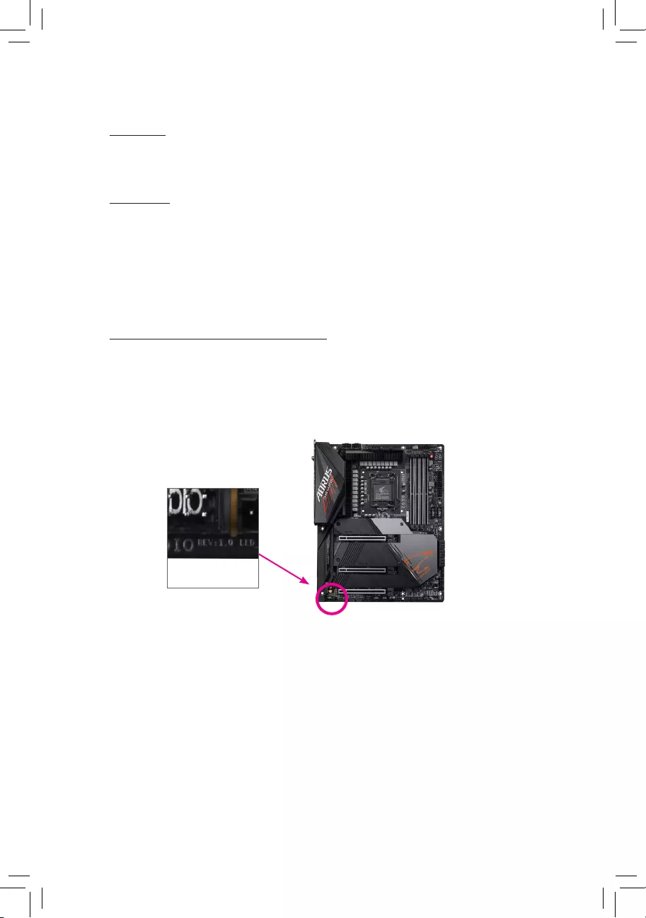
Identifying Your Motherboard Revision
The revision number on your motherboard looks like this: «REV: X.X.» For example, «REV:
1.0» means the revision of the motherboard is 1.0. Check your motherboard revision before
updating motherboard BIOS, drivers, or when looking for technical information.
Example:

— 3 —
Table of Contents
B560M AORUS ELITE Motherboard Layout ………………………………………………………….4
B560M AORUS ELITE Motherboard Block Diagram ………………………………………………. 5
Chapter 1 Hardware Installation …………………………………………………………………………6
1-1 Installation Precautions …………………………………………………………………………… 6
1-2 ProductSpecications ……………………………………………………………………………. 7
1-3 Installing the CPU ………………………………………………………………………………… 10
1-4 Installing the Memory ……………………………………………………………………………. 10
1-5 Installing an Expansion Card …………………………………………………………………. 11
1-6 Back Panel Connectors ………………………………………………………………………… 11
1-7 Internal Connectors………………………………………………………………………………. 14
Chapter 2 BIOS Setup …………………………………………………………………………………….23
2-1 Startup Screen …………………………………………………………………………………….. 23
2-2 The Main Menu ……………………………………………………………………………………. 24
2-3 Smart Fan 6 ……………………………………………………………………………………….. 25
2-4 Favorites (F11) …………………………………………………………………………………….. 27
2-5 Tweaker ……………………………………………………………………………………………… 28
2-6 Settings ………………………………………………………………………………………………. 33
2-7 System Info. ………………………………………………………………………………………… 38
2-8 Boot……………………………………………………………………………………………………. 39
2-9 Save & Exit …………………………………………………………………………………………. 42
Chapter 3 Appendix ………………………………………………………………………………………..43
3-1 Installing Intel® Optane™ Memory and Storage Management ……………………… 43
3-2 Drivers Installation ……………………………………………………………………………….. 44
Regulatory Notices ………………………………………………………………………………………… 45
Contact Us …………………………………………………………………………………………………… 48
— 4 —
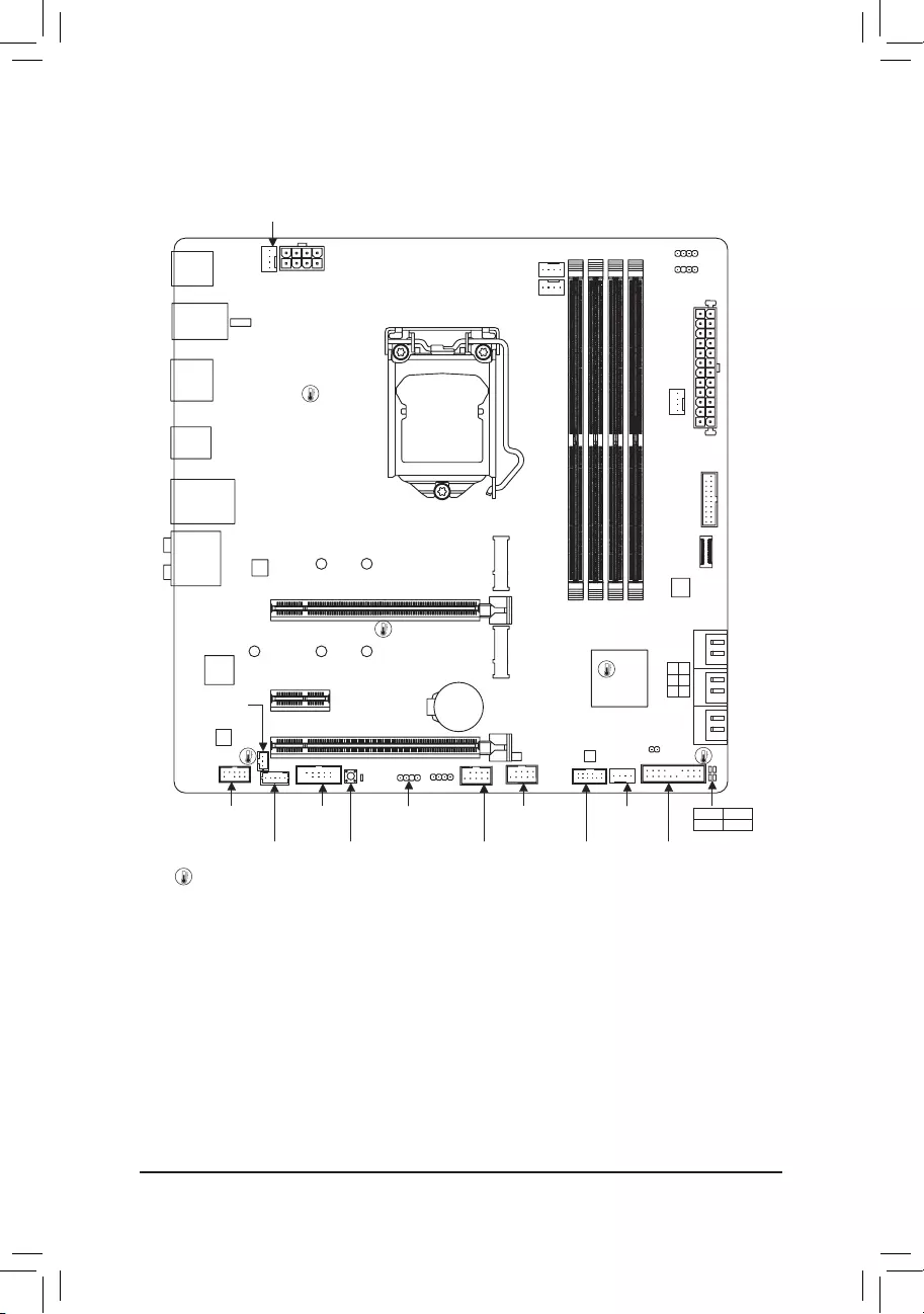
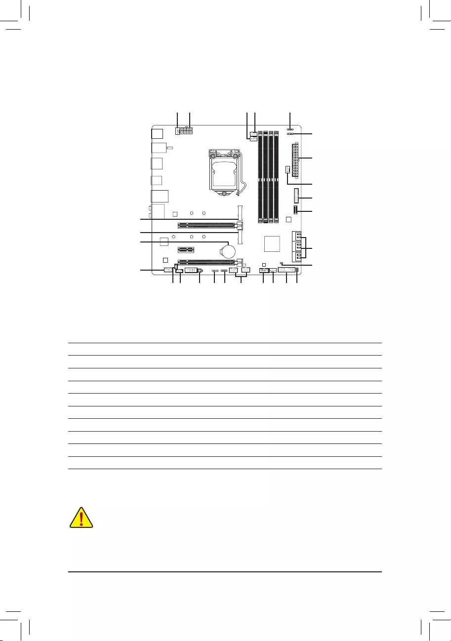
B560M AORUS ELITE Motherboard Layout
* The box contents above are for reference only and the actual items shall depend on the product package you ob-
tain. The box contents are subject to change without notice.
Box Contents
5B560M AORUS ELITE motherboard
5Motherboard driver disc 5Two SATA cables
5User’s Manual 5M.2 screw(s)/M.2 standoff(s)
Temperature sensor
KB_MS_USB
U32G2C
DP_HDMI
U32_LAN
LGA1200
ATX
AUDIO
DDR4_A1
DDR4_A2
DDR4_B1
DDR4_B2
R_USB20
Intel® B560
CLR_CMOS
THB_C1
M_BIOS
PCIEX4
PCIEX1
PCIEX16
F_U32
CODEC
B560M AORUS ELITE
F_PANEL
F_USB1
F_USB2 SPI_TPM
LED_C1
QFLASH_PLUS
F_AUDIO COM D_LED1
SYS_FAN1
CPU_FAN
LED_C2
D_LED2
CPU_OPT
iTE®
Super I/O
SATA3 531
420
BAT
Realtek®
2.5GbE LAN
CPU DRAM
VGA BOOT
SYS_FAN3
ATX_12V_2X4
USB 2.0 Hub
USB 2.0 Hub
SYS_FAN2
U32G2
F_U32C
M2A_SB
6080110
THB_C2
QFLED
M2P_CPU
6080
USB 3.2 Gen 1 Hub
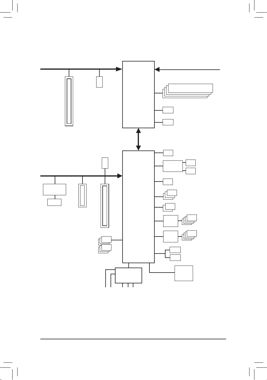
B560M AORUS ELITE Motherboard Block Diagram
LGA1200 CPU
CPU CLK+/- (100~500 MHz)
DDR4 3200 (Note)/3000 (Note)/2933 (Note)/
2666/2400/2133 MHz
PCI Express 4.0 (Note)/3.0 Bus
DMI 3.0
LAN
x1
SPI
Bus
4 USB 2.0/1.1
USB 2.0
Hub
1 PCI Express x16
x16
1 M.2 Socket 3
(M2A_SB)
PCI Express 3.0 Bus
6 SATA 6Gb/s
eSPI Bus
1 USB Type-C®, with USB 3.2 Gen 2 support
1 USB Type-C®, with
USB 3.2 Gen 1 support
1 USB 3.2 Gen 2 Type A
3 USB 3.2 Gen 1
4 USB 2.0/1.1
USB 2.0
Hub
Center/Subwoofer
Speaker Out
Line Out
MIC
Line In
Rear Speaker Out
CODEC
x1
1 PCI Express x1
BIOS
TPM
DisplayPort
DDI
1 M.2 Socket 3
(M2P_CPU) (Note)
x4
1 PCI Express x4
Intel® B560
iTE®
Super I/O
x4
(Note) Actual support may vary by CPU.
HDMI
DDI
2 USB 2.0/1.1
USB 3.2
Gen 1 Hub
1 USB 3.2 Gen 1
RJ45
Realtek®
2.5GbE LAN
— 5 —

Chapter 1 Hardware Installation
1-1 Installation Precautions
The motherboard contains numerous delicate electronic circuits and components which can
become damaged as a result of electrostatic discharge (ESD). Prior to installation, carefully read
the user’s manual and follow these procedures:
•Prior to installation, make sure the chassis is suitable for the motherboard.
•Prior to installation, do not remove or break motherboard S/N (Serial Number) sticker or
warranty sticker provided by your dealer. These stickers are required for warranty validation.
•Always remove the AC power by unplugging the power cord from the power outlet before
installing or removing the motherboard or other hardware components.
•When connecting hardware components to the internal connectors on the motherboard, make
sure they are connected tightly and securely.
•When handling the motherboard, avoid touching any metal leads or connectors.
•It is best to wear an electrostatic discharge (ESD) wrist strap when handling electronic com—
ponents such as a motherboard, CPU or memory. If you do not have an ESD wrist strap, keep
yourhandsdryandrsttouchametalobjecttoeliminatestaticelectricity.
•Prior to installing the motherboard, please have it on top of an antistatic pad or within an
electrostatic shielding container.
•Before connecting or unplugging the power supply cable from the motherboard, make sure
the power supply has been turned off.
•Before turning on the power, make sure the power supply voltage has been set according to
the local voltage standard.
•Before using the product, please verify that all cables and power connectors of your hardware
components are connected.
•To prevent damage to the motherboard, do not allow screws to come in contact with the
motherboard circuit or its components.
•Make sure there are no leftover screws or metal components placed on the motherboard or
within the computer casing.
•Do not place the computer system on an uneven surface.
•Do not place the computer system in a high—temperature or wet environment.
•Turning on the computer power during the installation process can lead to damage to system
components as well as physical harm to the user.
•If you are uncertain about any installation steps or have a problem related to the use of the
product,pleaseconsultacertiedcomputertechnician.
•If you use an adapter, extension power cable, or power strip, ensure to consult with its instal—
lation and/or grounding instructions.
— 6 —
1-2 ProductSpecications
CPU LGA1200 package:
— 11th Generation Intel
®
Core
™
i9 processors/Intel
®
Core
™
i7 processors/
Intel
®
Core
™
i5 processors
— 10th Generation Intel
®
Core
™
i9 processors/Intel
®
Core
™
i7 processors/Intel
®
Core
™
i5 processors/Intel
®
Core
™
i3 processors/Intel
®
Pentium
®
processors/
Intel
®
Celeron
®
processors*
* Limited to processors with 4 MB Intel® Smart Cache, Intel® Celeron® G5xx5 family.
(Go to GIGABYTE’s website for the latest CPU support list.)
L3 cache varies with CPU
Chipset Intel® B560 Express Chipset
Memory 11th Generation Intel® Core™ i9/i7/i5 processors:
—
Support for DDR4 3200/3000/2933/2666/2400/2133 MHz memory modules
10th Generation Intel® Core™ i9/i7 processors:
— Support for DDR4 2933/2666/2400/2133 MHz memory modules
10th Generation Intel® Core™ i5/i3/Pentium®/Celeron® processors:
— Support for DDR4 2666/2400/2133 MHz memory modules
4 x DDR4 DIMM sockets supporting up to 128 GB (32 GB single DIMM capacity)
of system memory
Dual channel memory architecture
Support for ECC Un-buffered DIMM 1Rx8/2Rx8 memory modules (operate in
non-ECC mode)
Support for non-ECC Un-buffered DIMM 1Rx8/2Rx8/1Rx16 memory modules
SupportforExtremeMemoryProle(XMP)memorymodules
(Go to GIGABYTE’s website for the latest supported memory speeds and memory
modules.)
Onboard
Graphics
Integrated Graphics Processor-Intel® HD Graphics support:
— 1 x HDMI port, supporting a maximum resolution of 4096×2160@30 Hz
* Support for HDMI 1.4 version and HDCP 2.3.
— 1 x DisplayPort, supporting a maximum resolution of 4096x2304@60 Hz
* Support for DisplayPort 1.2 version and HDCP 2.3
(GraphicsspecicationsmayvarydependingonCPUsupport.)
Audio Realtek® Audio CODEC
HighDenitionAudio
2/4/5.1/7.1-channel
LAN Realtek® 2.5GbE LAN chip (2.5 Gbit/1 Gbit/100 Mbit)
Multi-Graphics
Technology Support for AMD Quad-GPU CrossFire™ and 2-Way AMD CrossFire™ technologies
Expansion Slots 1 x PCI Express x16 slot, running at x16 (PCIEX16)
* For optimum performance, if only one PCI Express graphics card is to be installed,
be sure to install it in the PCIEX16 slot.
(The PCIEX16 slot conforms to PCI Express 4.0 standard.) (Note)
1 x PCI Express x16 slot, running at x4 (PCIEX4)
1 x PCI Express x1 slot
(The PCIEX4 and PCIEX1 slots conform to PCI Express 3.0 standard.)
(Note) Supported by 11th Generation processors only.
— 7 —

Storage Interface CPU:
— 1 x M.2 connector (Socket 3, M key, type 2260/2280 PCIe 4.0 x4/x2 SSD
support) (M2P_CPU) (Note)
Chipset:
— 1 x M.2 connector (Socket 3, M key, type 2260/2280/22110 SATA and PCIe
3.0 x4/x2 SSD support) (M2A_SB)
6 x SATA 6Gb/s connectors
* Refer to «1-7 Internal Connectors,» for the installation notices for the M.2 and SATA
connectors.
Intel® Optane™ Memory Ready
USB Chipset:
— 1 x USB Type-C® port on the back panel, with USB 3.2 Gen 2 support
— 1 x USB 3.2 Gen 2 Type-A port (red) on the back panel
— 3 x USB 3.2 Gen 1 ports (2 ports on the back panel, 1 port available through
the internal USB header)
— 2 x USB 2.0/1.1 ports on the back panel
Chipset+USB 3.2 Gen 1 Hub:
— 1 x USB Type-C® port with USB 3.2 Gen 1 support, available through the
internal USB header
— 2 x USB 3.2 Gen 1 ports available through the internal USB header
Chipset+2 USB 2.0 Hubs:
— 8 x USB 2.0/1.1 ports (4 ports on the back panel, 4 ports available through
the internal USB headers)
Internal
Connectors
1 x 24-pin ATX main power connector
1 x 8-pin ATX 12V power connector
1 x CPU fan header
1 x water cooling CPU fan header
3 x system fan headers
2 x addressable LED strip headers
2 x RGB LED strip headers
6 x SATA 6Gb/s connectors
2 x M.2 Socket 3 connectors
1 x front panel header
1 x front panel audio header
1 x USB Type-C® header, with USB 3.2 Gen 1 support
1 x USB 3.2 Gen 1 header
2 x USB 2.0/1.1 headers
2 x Thunderbolt™ add-in card connectors
1 x Trusted Platform Module header (For the GC-TPM2.0 SPI/GC-TPM2.0 SPI
2.0 module only)
1 x serial port header
1 x Clear CMOS jumper
1 x Q-Flash Plus button
Back Panel
Connectors
1 x PS/2 keyboard/mouse port
1 x USB Type-C® port, with USB 3.2 Gen 2 support
1 x USB 3.2 Gen 2 Type-A port (red)
2 x USB 3.2 Gen 1 ports
6 x USB 2.0/1.1 ports
(Note) Supported by 11th Generation processors only.
— 8 —
Back Panel
Connectors
1 x DisplayPort
1 x HDMI port
1 x RJ-45 port
6 x audio jacks
I/O Controller iTE® I/O Controller Chip
Hardware
Monitor
Voltage detection
Temperature detection
Fan speed detection
Watercoolingowratedetection
Fan fail warning
Fan speed control
* Whether the fan speed control function is supported will depend on the cooler you
install.
BIOS 1x256Mbitash
Use of licensed AMI UEFI BIOS
PnP 1.0a, DMI 2.7, WfM 2.0, SM BIOS 2.7, ACPI 5.0
Unique Features Support for APP Center
* Available applications in APP Center may vary by motherboard model. Supported
functionsofeachapplicationmayalsovarydependingonmotherboardspecications.
— @BIOS
— EasyTune
— Fast Boot
— Game Boost
— ON/OFF Charge
— RGB Fusion
— Smart Backup
— System Information Viewer
Support for Q-Flash Plus
Support for Q-Flash
Support for Xpress Install
Bundled
Software
Norton® Internet Security (OEM version)
Realtek® 8125 Gaming LAN Bandwidth Control Utility
Operating
System Support for Windows 10 64-bit
Form Factor Micro ATX Form Factor; 24.4cm x 24.4cm
* GIGABYTEreservestherighttomakeanychangestotheproductspecicationsandproduct-relatedinformationwithout
prior notice.
Please visit GIGABYTE’s website
for support lists of CPU, memory
modules, SSDs, and M.2 devices.
Please visit the SupportUtility List
page on GIGABYTE’s website to
download the latest version of apps.
— 9 —
1-3 Installing the CPU
1-4 Installing the Memory
Read the following guidelines before you begin to install the memory:
•Make sure that the motherboard supports the memory. It is recommended that memory of the
same capacity, brand, speed, and chips be used.
(Go to GIGABYTE’s website for the latest supported memory speeds and memory modules.)
•Always turn off the computer and unplug the power cord from the power outlet before installing
the memory to prevent hardware damage.
•Memory modules have a foolproof design. A memory module can be installed in only one direc—
tion. If you are unable to insert the memory, switch the direction.
DualChannelMemoryConguration
This motherboard provides four memory sockets and supports Dual Channel Technology. After the memory
isinstalled,theBIOSwillautomaticallydetectthespecicationsandcapacityofthememory.EnablingDual
Channel memory mode will double the original memory bandwidth.
Please visit GIGABYTE’s website for details on hardware installation.
Read the following guidelines before you begin to install the CPU:
•Make sure that the motherboard supports the CPU.
(Go to GIGABYTE’s website for the latest CPU support list.)
•Always turn off the computer and unplug the power cord from the power outlet before installing
the CPU to prevent hardware damage.
•Locate the pin one of the CPU. The CPU cannot be inserted if oriented incorrectly. (Or you may
locate the notches on both sides of the CPU and alignment keys on the CPU socket.)
•Apply an even and thin layer of thermal grease on the surface of the CPU.
•Do not turn on the computer if the CPU cooler is not installed, otherwise overheating and damage
of the CPU may occur.
•SettheCPUhostfrequencyinaccordancewiththeCPUspecications.Itisnotrecommended
thatthesystembusfrequencybesetbeyondhardwarespecicationssinceitdoesnotmeetthe
standard requirements for the peripherals. If you wish to set the frequency beyond the standard
specications,pleasedosoaccordingtoyourhardwarespecicationsincludingtheCPU,graph—
ics card, memory, hard drive, etc.
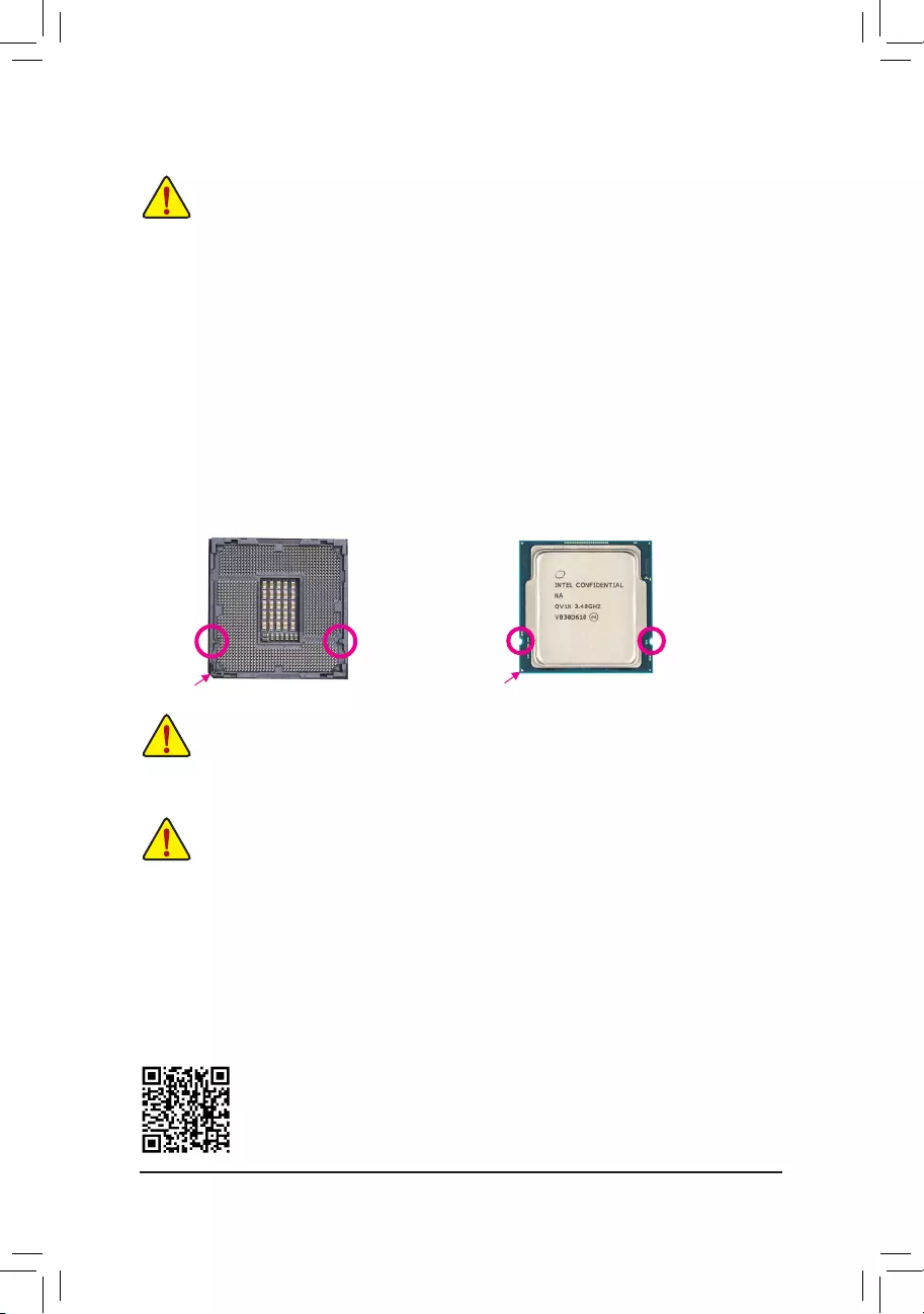
Installing the CPU
Locate the alignment keys on the motherboard CPU socket and the notches on the CPU.
Do not remove the CPU socket cover before inserting the CPU. It may pop off from the load
plate automatically during the process of re-engaging the lever after you insert the CPU.
Alignment
Key
Alignment
Key
LGA1200 CPU Socket
Pin One Corner of the CPU Socket Triangle Pin One Marking on the CPU
NotchNotch
LGA1200 CPU
— 10 —
The four memory sockets are divided into two channels and each channel has two memory sockets as following:
Channel A: DDR4_A1, DDR4_A2
Channel B: DDR4_B1, DDR4_B2
RecommandedDualChannelMemoryConguration:
DDR4_A1 DDR4_A2 DDR4_B1 DDR4_B2
2 Modules — — DS/SS — — DS/SS
4 Modules DS/SS DS/SS DS/SS DS/SS
(SS=Single-Sided, DS=Double-Sided, «- -«=No Memory)
Due to CPU limitations, read the following guidelines before installing the memory in Dual Channel mode.
1. Dual Channel mode cannot be enabled if only one memory module is installed.
2. When enabling Dual Channel mode with two or four memory modules, it is recommended that
memory of the same capacity, brand, speed, and chips be used.
1-5 Installing an Expansion Card
Read the following guidelines before you begin to install an expansion card:
•Make sure the motherboard supports the expansion card. Carefully read the manual that came
with your expansion card.
•Always turn off the computer and unplug the power cord from the power outlet before installing
an expansion card to prevent hardware damage.
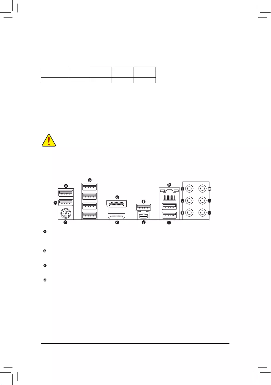
1-6 Back Panel Connectors
USB 2.0/1.1 Port (Q—Flash Plus Port)
TheUSBportsupportstheUSB2.0/1.1specication.UsethisportforUSBdevices.Usethisportfor
USB devices. Before using Q—Flash Plus (Note),makesuretoinserttheUSBashdriveintothisportrst.
USB 2.0/1.1 Port
TheUSBportsupportstheUSB2.0/1.1specication.UsethisportforUSBdevices.
PS/2 Keyboard/Mouse Port
Use this port to connect a PS/2 mouse or keyboard.
DisplayPort
DisplayPort delivers high quality digital imaging and audio, supporting bi-directional audio transmission.
DisplayPort can support HDCP 2.3 content protection mechanisms. You can use this port to connect your
DisplayPort-supported monitor. Note: The DisplayPort Technology can support a maximum resolution of
4096x2304@60 Hz but the actual resolutions supported depend on the monitor being used.
(Note) To enable the Q—Flash Plus function please visit the «Unique Features» webpage of GIGABYTE’s
website.
— 11 —
HDMI Port
The HDMI port supports HDCP 2.3 and Dolby TrueHD and DTS HD Master
Audio formats. It also supports up to 192KHz/16bit 7.1-channel LPCM audio
output. You can use this port to connect your HDMI-supported monitor. The maximum supported res—
olution is 4096x2160@30 Hz, but the actual resolutions supported are dependent on the monitor be—
ing used.
USB 3.2 Gen 2 Type-A Port (Red)
TheUSB3.2Gen2portsupportstheUSB3.2Gen2specicationandiscompatibletotheUSB3.2
Gen1andUSB2.0specication.UsethisportforUSBdevices.
USB Type—C® Port
ThereversibleUSBportsupportstheUSB3.2Gen2specicationandiscompatibletotheUSB3.2
Gen1specication.UsethisportforUSBdevices.
RJ—45 LAN Port
The Gigabit Ethernet LAN port provides Internet connection at up to 2.5 Gbps data rate. The following
describes the states of the LAN port LEDs.
After installing the DisplayPort/HDMI device, make sure to set the default sound playback device
to DisplayPort/HDMI. (The item name may differ depending on your operating system.)
USB 3.2 Gen 1 Port
TheUSB3.2Gen1portsupportstheUSB3.2Gen1specicationandiscompatibletotheUSB2.0
specication.UsethisportforUSBdevices.
Center/Subwoofer Speaker Out (Orange)
Use this audio jack to connect center/subwoofer speakers.
Rear Speaker Out (Black)
Use this audio jack to connect rear speakers.
Side Speaker Out (Gray)
Use this audio jack to connect side speakers.
Line In (Blue)
The line in jack. Use this audio jack for line in devices such as an optical drive, walkman, etc.
Line Out/Front Speaker Out (Green)
The line out jack.
Mic In (Pink)
The Mic in jack.
Activity LED
Connection/
Speed LED
LAN Port
Activity LED:Connection/Speed LED:
State Description
Orange 2.5 Gbps data rate
Green 1 Gbps data rate
Off 100 Mbps data rate
State Description
Blinking Data transmission or receiving is occurring
Off No data transmission or receiving is occurring
— 12 —
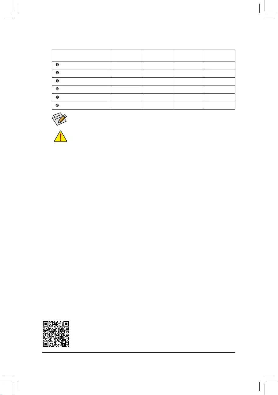
PleasevisitGIGABYTE’swebsitefordetailsonconguringtheaudiosoftware.
AudioJackCongurations:
Jack Headphone/
2-channel 4-channel 5.1-channel 7.1-channel
Center/Subwoofer Speaker Out a a
Rear Speaker Out a a a
Side Speaker Out a
Line In
Line Out/Front Speaker Out a a a a
Mic In
•Whenremovingthecableconnectedtoabackpanelconnector,rstremovethecablefrom
your device and then remove it from the motherboard.
•When removing the cable, pull it straight out from the connector. Do not rock it side to side
to prevent an electrical short inside the cable connector.
You can change the functionality of an audio jack using the audio software.
— 13 —
1-7 Internal Connectors
Read the following guidelines before connecting external devices:
•First make sure your devices are compliant with the connectors you wish to connect.
•Before installing the devices, be sure to turn off the devices and your computer. Unplug the power
cord from the power outlet to prevent damage to the devices.
•After installing the device and before turning on the computer, make sure the device cable has
been securely attached to the connector on the motherboard.
1) ATX_12V_2X4
2) ATX
3) CPU_FAN
4) SYS_FAN1/2/3
5) CPU_OPT
6) LED_C1/LED_C2
7) D_LED1/D_LED2
 SATA3 0/1/2/3/4/5
9) M2P_CPU/M2A_SB
10) F_PANEL
11) F_AUDIO
12) F_U32C
13) F_U32
14) F_USB1/F_USB2
15) SPI_TPM
16) THB_C1/THB_C2
17) CLR_CMOS
18) BAT
19) CPU/DRAM/VGA/BOOT
20) QFLASH_PLUS
4
15
2
12
1916 20 10
1
7
8
9
11
146
35 6
17
4
13
9
18
4
7
16
— 14 —
131
2412
ATX
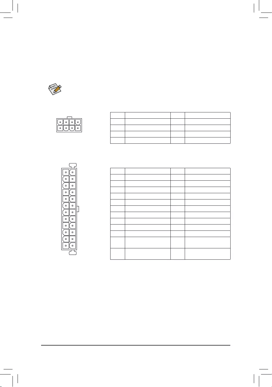
1/2) ATX_12V_2X4/ATX (2×4 12V Power Connector and 2×12 Main Power Connector)
With the use of the power connector, the power supply can supply enough stable power to all the
componentsonthemotherboard.Beforeconnectingthepowerconnector,rstmakesurethepower
supply is turned off and all devices are properly installed. The power connector possesses a foolproof
design. Connect the power supply cable to the power connector in the correct orientation.
The 12V power connector mainly supplies power to the CPU. If the 12V power connector is not connected,
the computer will not start.
To meet expansion requirements, it is recommended that a power supply that can withstand high
power consumption be used (500W or greater). If a power supply is used that does not provide
the required power, the result can lead to an unstable or unbootable system.
ATX:
Pin No. Denition Pin No. Denition
1 3.3V 13 3.3V
2 3.3V 14 -12V
3 GND 15 GND
4 +5V 16 PS_ON (soft On/Off)
5 GND 17 GND
6 +5V 18 GND
7 GND 19 GND
8 Power Good 20 NC
9 5VSB (stand by +5V) 21 +5V
10 +12V 22 +5V
11 +12V (Only for 2×12-pin
ATX)
23 +5V (Only for 2×12-pin
ATX)
12 3.3V (Only for 2×12-pin
ATX)
24 GND (Only for 2×12-pin
ATX)
ATX_12V_2X4:
Pin No. Denition Pin No. Denition
1 GND (Only for 2×4-pin 12V) 5 +12V (Only for 2×4-pin 12V)
2 GND (Only for 2×4-pin 12V) 6 +12V (Only for 2×4-pin 12V)
3 GND 7 +12V
4 GND 8 +12V
ATX_12V_2X4
41
85
— 15 —
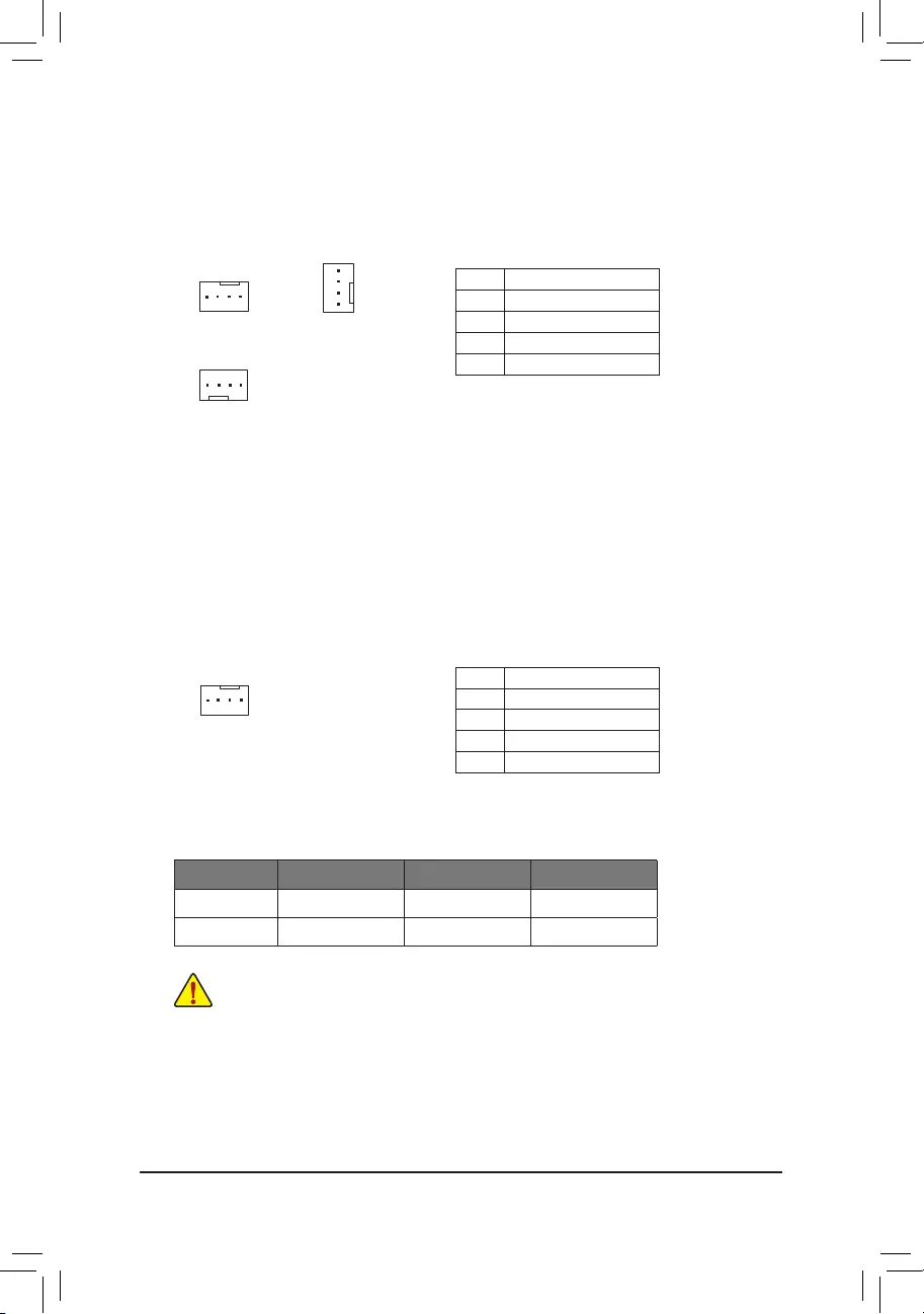
3/4) CPU_FAN/SYS_FAN1/2/3 (Fan Headers)
All fan headers on this motherboard are 4—pin. Most fan headers possess a foolproof insertion design.
When connecting a fan cable, be sure to connect it in the correct orientation (the black connector wire
is the ground wire). The speed control function requires the use of a fan with fan speed control design.
For optimum heat dissipation, it is recommended that a system fan be installed inside the chassis.
CPU_FAN
1
1
SYS_FAN3
Pin No. Denition
1 GND
2 Voltage Speed Control
3 Sense
4 PWM Speed Control
5) CPU_OPT (Water Cooling CPU Fan Header)
The fan header is 4—pin and possesses a foolproof insertion design. Most fan headers possess a foolproof
insertion design. When connecting a fan cable, be sure to connect it in the correct orientation (the black
connector wire is the ground wire). The speed control function requires the use of a fan with fan speed
control design.
1
Pin No. Denition
1 GND
2 Voltage Speed Control
3 Sense
4 PWM Speed Control
•Be sure to connect fan cables to the fan headers to prevent your CPU and system from over-
heating. Overheating may result in damage to the CPU or the system may hang.
•Thesefanheadersarenotcongurationjumperblocks.Donotplaceajumpercaponthe
headers.
1
SYS_FAN1/SYS_FAN2
Connector CPU_FAN SYS_FAN1~3 CPU_OPT
Maximum Current 2A 2A 2A
Maximum Power 24W 24W 24W
— 16 —
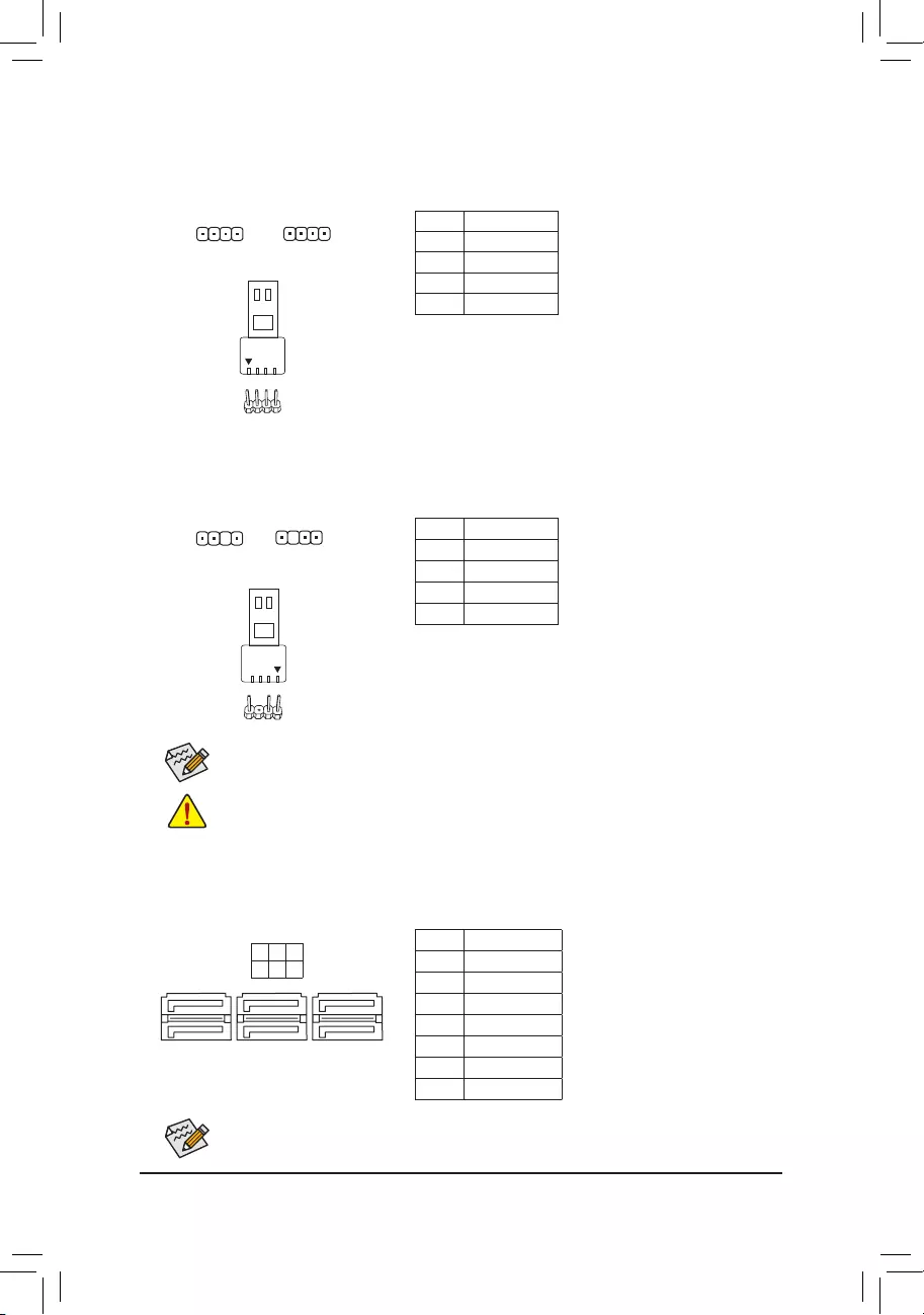
7) D_LED1/D_LED2 (Addressable LED Strip Headers)
The headers can be used to connect a standard 5050 addressable LED strip, with maximum power rating
of 5A (5V) and maximum number of 1000 LEDs.
Pin No. Denition
1 V (5V)
2 Data
3 No Pin
4 GND
Before installing the devices, be sure to turn off the devices and your computer. Unplug the power
cord from the power outlet to prevent damage to the devices.
For how to turn on/off the lights of the LED strip please visit the «Unique Features» webpage of
GIGABYTE’s website.
D_LED1 D_LED2
1
F_USB30 F_U
B_
F_ F_
_
B
BS_
B
SB_
B
_S
S_
_
B
_U
_
B
S
123
123
123
123
1
1
1
1
BSS
S
_S
SSU
1 2 3 4 5
S3 BSSS
U
__ 3
F_USB3F
S _
S _
S _
SF
B_
B_
F
_0
S
S
_0F
_F
_
_
__B
U
S _S
_ SF_
B
USB0_B
B_
B_
F_USB3
F_USB303
_
_3U
S_
F_USB30 F_U
B_
F_ F_
_
B
BS_
B
SB_
B
_S
S_
_
B
_U
_
B
S
123
123
123
123
1
1
1
1
BSS
S
_S
SSU
1 2 3 4 5
S3 BSSS
U
__ 3
F_USB3F
S _
S _
S _
SF
B_
B_
F
_0
S
S
_0F
_F
_
_
__B
U
S _S
_ SF_
B
USB0_B
B_
B_
F_USB3
F_USB303
_
_3U
S_
1
Connect your addressable LED strip to the header. The power
pin (marked with a triangle on the plug) of the LED strip must
be connected to Pin 1 of the addressable LED strip header.
Incorrect connection may lead to the damage of the LED strip.
Addressable LED
Strip
1
6) LED_C1/LED_C2 (RGB LED Strip Headers)
The headers can be used to connect a standard 5050 RGB LED strip (12V/G/R/B), with maximum power
rating of 2A (12V) and maximum length of 2m.
Pin No. Denition
1 12V
2 G
3 R
4 B
11
LED_C1 LED_C2
Connect your RGB LED strip to the header. The power pin
(marked with a triangle on the plug) of the LED strip must be
connected to Pin 1 (12V) of this header. Incorrect connection
may lead to the damage of the LED strip.
RGB LED Strip
1
12V
SATA3 0/1/2/3/4/5 (SATA 6Gb/s Connectors)
The SATA connectors conform to SATA 6Gb/s standard and are compatible with SATA 3Gb/s and SATA
1.5Gb/s standard. Each SATA connector supports a single SATA device.
Pin No. Denition
1 GND
2 TXP
3 TXN
4 GND
5 RXN
6 RXP
7 GND
To enable hot-plugging for the SATA ports, refer to Chapter 2, «BIOS Setup,» «SettingsIO Ports
SATAAndRSTConguration,»formoreinformation.
1
1
SATA3 5 3 1
4 2 0
7
7
— 17 —
9) M2P_CPU (Note)/M2A_SB (M.2 Socket 3 Connectors)
The M.2 connector supports M.2 SATA SSDs or M.2 PCIe SSDs.
Follow the steps below to correctly install an M.2 SSD in the M.2 connector.
Step 1:
Locate the M.2 connector where you will install the M.2 SSD, use a screwdriver to unfasten the screw on
the heatsink and then remove the heatsink. (Only the M2P_CPU connector has the heatsink.) Remove
theprotectivelmfromthethermalpadontheM.2connector.
Step 2:
Locate the proper mounting hole based on the length of your M.2 SSD drive. If needed, tighten the
included standoff into the desired mounting hole. Insert the M.2 SSD into the M.2 connector at an angle.
Step 3:
Press the M.2 SSD down and then use the included screw to secure it in the connector. Replace the
heatsinkandsecureittotheoriginalhole.Removetheprotectivelmfromthebottomoftheheatsink
before replacing the heatsink.
F_USB30 F_U
B_
F_ F_
_
B
BS_
B
SB_
B
_S
S_
_
B
_U
_
B
S
123
123
123
123
1
1
1
1
BSS
S
_S
SSU
1 2 3 4 5
S3 BSSS
U
__ 3
F_USB3F
S _
S _
S _
SF
B_
B_
F
_0
S
S
_0F
_F
_
_
__B
U
S _S
_ SF_
B
USB0_B
B_
B_
F_USB3
F_USB303
_
_3U
S_
80 60110
M2A_SB
(Note) Supported by 11th Generation processors only.
M2P_CPU (Note)
F_USB30 F_U
B_
F_ F_
_
B
BS_
B
SB_
B
_S
S_
_
B
_U
_
B
S
123
123
123
123
1
1
1
1
BSS
S
_S
SSU
1 2 3 4 5
S3 BSSS
U
__ 3
F_USB3F
S _
S _
S _
SF
B_
B_
F
_0
S
S
_0F
_F
_
_
__B
U
S _S
_ SF_
B
USB0_B
B_
B_
F_USB3
F_USB303
_
_3U
S_
80 60
Installation Notices for the M.2 and SATA Connectors:
The availability of the SATA connectors may be affected by the type of device installed in the M.2
sockets. The M2A_SB connector shares bandwidth with the SATA3 1 connector. Refer to the following
table for details.
•M2A_SB:
SATA3 0 SATA3 1 SATA3 2 SATA3 3 SATA3 4 SATA3 5
M.2 SATA SSD ara a a a
M.2 PCIe SSD
a a a a a a
No M.2 SSD Installed a a a a a a
a: Available, r: Not available
Connector
Type of
M.2 SSD
•M2P_CPU (Note):
SATA3 0 SATA3 1 SATA3 2 SATA3 3 SATA3 4 SATA3 5
M.2 PCIe SSD *
a a a a a a
No M.2 SSD Installed a a a a a a
a: Available, r: Not available
* The M2P_CPU (Note) connector supports only PCIe SSDs.
Connector
Type of
M.2 SSD
— 18 —
The front panel design may differ by chassis. A front panel module mainly consists of power
switch, reset switch, power LED, hard drive activity LED, speaker and etc. When connecting
your chassis front panel module to this header, make sure the wire assignments and the pin
assignments are matched correctly.
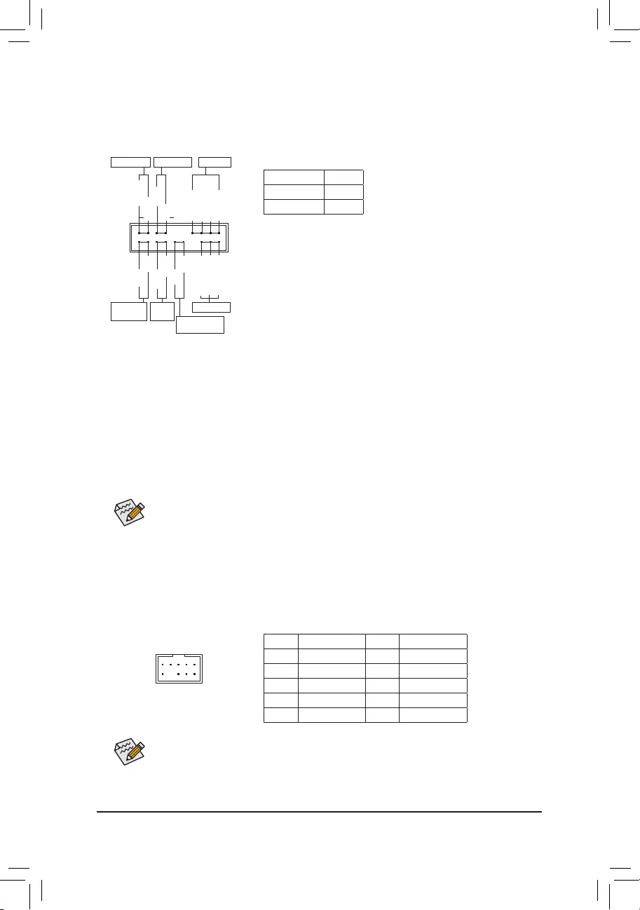
10) F_PANEL (Front Panel Header)
Connect the power switch, reset switch, speaker, chassis intrusion switch/sensor and system status
indicator on the chassis to this header according to the pin assignments below. Note the positive and
negative pins before connecting the cables.
11) F_AUDIO (Front Panel Audio Header)
ThefrontpanelaudioheadersupportsHighDenitionaudio(HD).Youmayconnectyourchassisfront
panel audio module to this header. Make sure the wire assignments of the module connector match the
pin assignments of the motherboard header. Incorrect connection between the module connector and
the motherboard header will make the device unable to work or even damage it.
Some chassis provide a front panel audio module that has separated connectors on each wire
instead of a single plug. For information about connecting the front panel audio module that has
different wire assignments, please contact the chassis manufacturer.
F_USB30 F_U
B_
F_ F_
_
B
BS_
B
SB_
B
_S
S_
_
B
_U
_
B
S
123
123
123
123
1
1
1
1
BSS
S
_S
SSU
1 2 3 4 5
S3 BSSS
U
__ 3
F_USB3F
S _
S _
S _
SF
B_
B_
F
_0
S
S
_0F
_F
_
_
__B
U
S _S
_ SF_
B
USB0_B
B_
B_
F_USB3
F_USB303
_
_3U
S_
9 1
10 2
Pin No. Denition Pin No. Denition
1 MIC2_L 6 Sense
2 GND 7 FAUDIO_JD
3 MIC2_R 8 No Pin
4 NC 9 LINE2_L
5 LINE2_R 10 Sense
System Status LED
S0 On
S3/S4/S5 Off
•PW (Power Switch, Red):
Connects to the power switch on the chassis front panel. You may
congure the wayto turnoffyoursystem using the power switch
(refer to Chapter 2, «BIOS Setup,» «SettingsPlatform Power,» for
more information).
•SPEAK (Speaker, Orange):
Connects to the speaker on the chassis front panel. The system
reports system startup status by issuing a beep code. One single
short beep will be heard if no problem is detected at system startup.
•PLED/PWR_LED (Power LED, Yellow/Purple):
Connects to the power status indicator
on the chassis front panel. The LED is on
when the system is operating. The LED is
off when the system is in S3/S4 sleep state
or powered off (S5).
•HD (Hard Drive Activity LED, Blue):
Connects to the hard drive activity LED on the chassis front panel. The LED is on when the hard drive
is reading or writing data.
•RES (Reset Switch, Green):
Connects to the reset switch on the chassis front panel. Press the reset switch to restart the computer
if the computer freezes and fails to perform a normal restart.
•CI (Chassis Intrusion Header, Gray):
Connects to the chassis intrusion switch/sensor on the chassis that can detect if the chassis cover
has been removed. This function requires a chassis with a chassis intrusion switch/sensor.
•NC (Orange): No Connection.
Power LED
1
2
19
20
CI-
CI+
PWR_LED-
PWR_LED+
PLED-
PW-
SPEAK+
SPEAK-
PLED+
PW+
Power LED
HD-
RES+
HD+
RES-
Hard Drive
Activity LED
Reset
Switch Chassis Intrusion
Header
Power Switch Speaker
PWR_LED-
NC
NC
— 19 —
F_USB30 F_U
B_
F_ F_
_
B
BS_
B
SB_
B
_S
S_
_
B
_U
_
B
S
123
123
123
123
1
1
1
1
BSS
S
_S
SSU
1 2 3 4 5
S3 BSSS
U
__ 3
F_USB3F
S _
S _
S _
SF
B_
B_
F
_0
S
S
_0F
_F
_
_
__B
U
S _S
_ SF_
B
USB0_B
B_
B_
F_USB3
F_USB303
_
_3U
S_
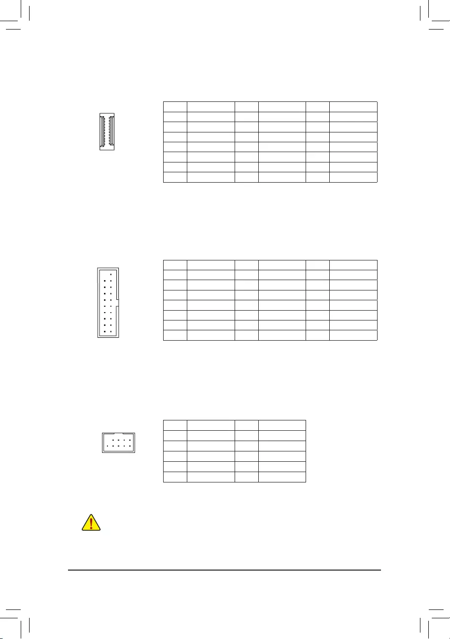
12) F_U32C (USB Type—C® Header with USB 3.2 Gen 1 Support)
TheheaderconformstoUSB3.2Gen1specicationandcanprovideoneUSBport.
Pin No. Denition Pin No. Denition Pin No. Denition
1 VBUS 8 CC1 15 RX2+
2 TX1+ 9 SBU1 16 RX2-
3 TX1- 10 SBU2 17 GND
4 GND 11 VBUS 18 D-
5 RX1+ 12 TX2+ 19 D+
6RX1- 13 TX2- 20 CC2
7 VBUS 14 GND
Pin No. Denition Pin No. Denition Pin No. Denition
1 VBUS 8 D1- 15 SSTX2-
2 SSRX1- 9 D1+ 16 GND
3 SSRX1+ 10 NC 17 SSRX2+
4 GND 11 D2+ 18 SSRX2-
5 SSTX1- 12 D2- 19 VBUS
6 SSTX1+ 13 GND 20 No Pin
7 GND 14 SSTX2+
13) F_U32 (USB 3.2 Gen 1 Header)
TheheaderconformstoUSB3.2Gen1andUSB2.0specicationandcanprovidetwoUSBports.For
purchasing the optional 3.5″ front panel that provides two USB 3.2 Gen 1 ports, please contact the local
dealer.
F_USB30 F_U
B_
F_ F_
_
B
BS_
B
SB_
B
_S
S_
_
B
_U
_
B
S
123
123
123
123
1
1
1
1
BSS
S
_S
SSU
1 2 3 4 5
S3 BSSS
U
__ 3
F_USB3F
S _
S _
S _
SF
B_
B_
F
_0
S
S
_0F
_F
_
_
__B
U
S _S
_ SF_
B
USB0_B
B_
B_
F_USB3
F_USB303
_
_3U
S_
10
20
20
10
1
11
11
1
14) F_USB1/F_USB2 (USB 2.0/1.1 Headers)
TheheadersconformtoUSB2.0/1.1specication.EachUSBheadercanprovidetwoUSBportsviaan
optional USB bracket. For purchasing the optional USB bracket, please contact the local dealer.
Pin No. Denition Pin No. Denition
1 Power (5V) 6 USB DY+
2 Power (5V) 7 GND
3 USB DX- 8 GND
4 USB DY— 9 No Pin
5 USB DX+ 10 NC
•Do not plug the IEEE 1394 bracket (2x5-pin) cable into the USB 2.0/1.1 header.
•Prior to installing the USB bracket, be sure to turn off your computer and unplug the power
cord from the power outlet to prevent damage to the USB bracket.
10
9
2
1
— 20 —
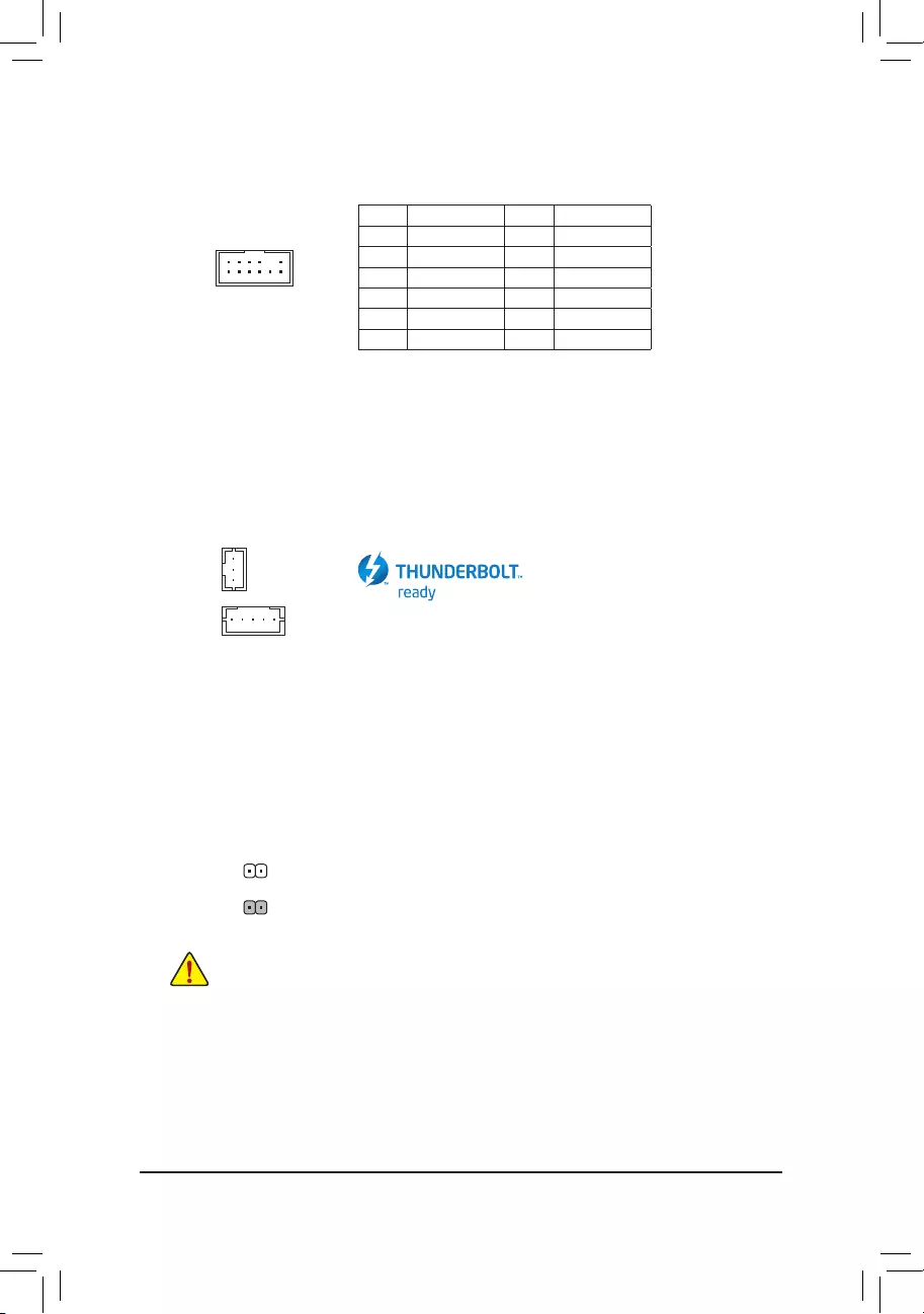
16) THB_C1/THB_C2 (Thunderbolt™ Add-in Card Connectors)
The connectors are used to connect to a GIGABYTE Thunderbolt™ add-in card.
Supports a Thunderbolt™ add-in card.
12
11
2
1
15) SPI_TPM (Trusted Platform Module Header)
You may connect an SPI TPM (Trusted Platform Module) to this header.
Pin No. Denition Pin No. Denition
1Data Output 7Chip Select
2Power (3.3V) 8GND
3No Pin 9IRQ
4NC 10 NC
5Data Input 11 NC
6CLK 12 RST
F_USB30 F_U
B_
F_ F_
_
B
BS_
B
SB_
B
_S
S_
_
B
_U
_
B
S
123
123
123
123
1
1
1
1
BSS
S
_S
SSU
1 2 3 4 5
S3 BSSS
U
__ 3
F_USB3F
S _
S _
S _
SF
B_
B_
F
_0
S
S
_0F
_F
_
_
__B
U
S _S
_ SF_
B
USB0_B
B_
B_
F_USB3
F_USB303
_
_3U
S_
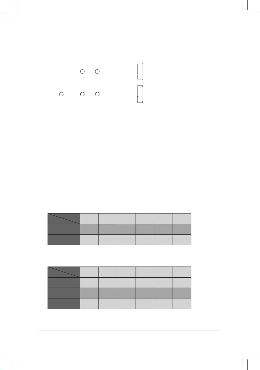
17) CLR_CMOS (Clear CMOS Jumper)
UsethisjumpertocleartheBIOScongurationandresettheCMOSvaluestofactorydefaults.Toclear
the CMOS values, use a metal object like a screwdriver to touch the two pins for a few seconds.
•Always turn off your computer and unplug the power cord from the power outlet before clearing
the CMOS values.
•After system restart, go to BIOS Setup to load factory defaults (select Load Optimized De—
faults)ormanuallyconguretheBIOSsettings(refertoChapter2,«BIOSSetup,«forBIOS
congurations).
Open: Normal
Short: Clear CMOS Values
F_USB30 F_U
B_
F_ F_
_
B
BS_
B
SB_
B
_S
S_
_
B
_U
_
B
S
123
123
123
123
1
1
1
1
BSS
S
_S
SSU
1 2 3 4 5
S3 BSSS
U
__ 3
F_USB3F
S _
S _
S _
SF
B_
B_
F
_0
S
S
_0F
_F
_
_
__B
U
S _S
_ SF_
B
USB0_B
B_
B_
F_USB3
F_USB303
_
_3U
S_
1
F_USB30 F_U
B_
F_ F_
_
B
BS_
B
SB_
B
_S
S_
_
B
_U
_
B
S
123
123
123
123
1
1
1
1
BSS
S
_S
SSU
1 2 3 4 5
S3 BSSS
U
__ 3
F_USB3F
S _
S _
S _
SF
B_
B_
F
_0
S
S
_0F
_F
_
_
__B
U
S _S
_ SF_
B
USB0_B
B_
B_
F_USB3
F_USB303
_
_3U
S_
1
THB_C2
THB_C1
— 21 —
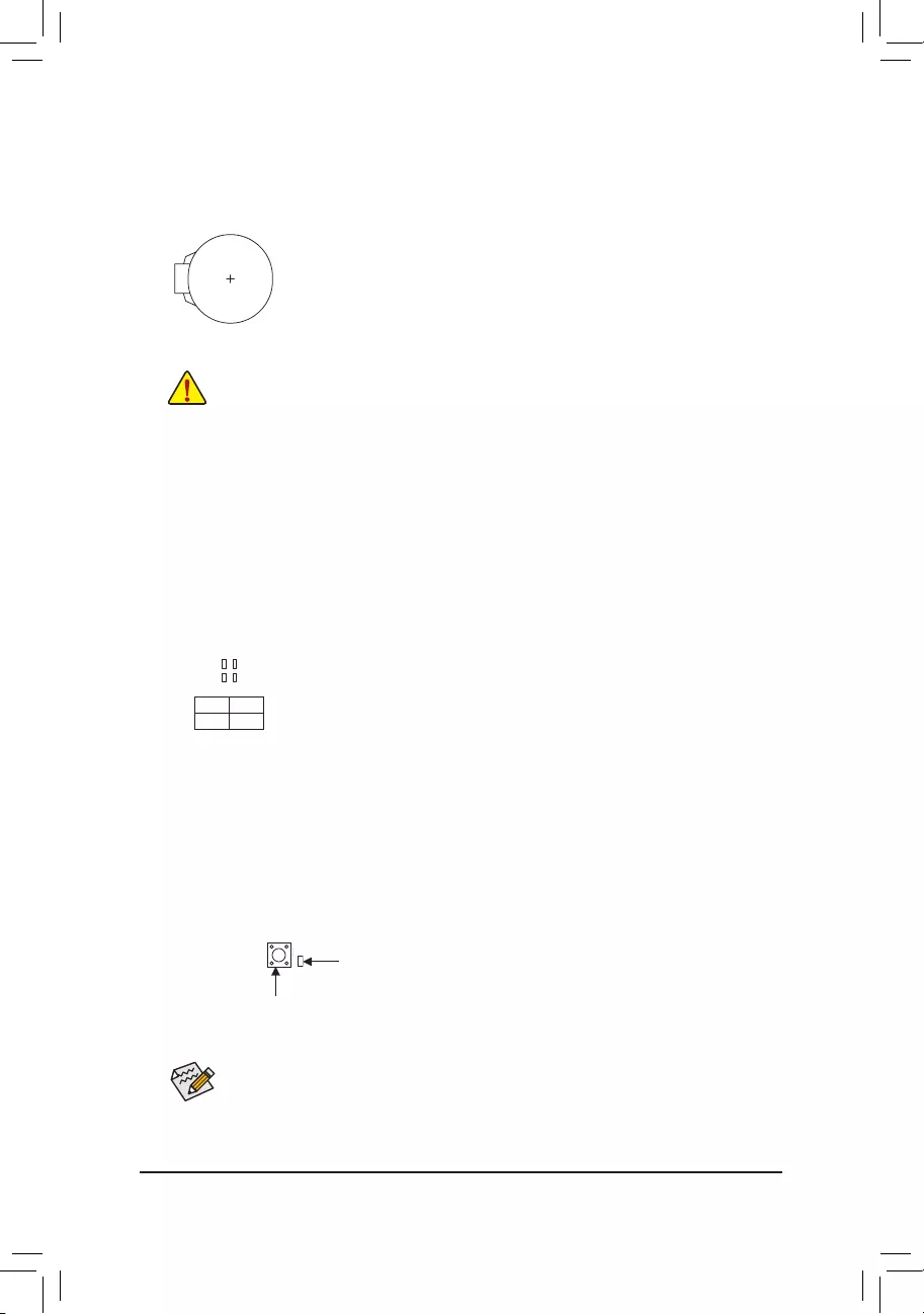
18) BAT (Battery)
Thebatteryprovidespowertokeepthevalues(suchasBIOScongurations,date,andtimeinformation)
in the CMOS when the computer is turned off. Replace the battery when the battery voltage drops to a
low level, or the CMOS values may not be accurate or may be lost.
19) CPU/DRAM/VGA/BOOT (Status LEDs)
The status LEDs show whether the CPU, memory, graphics card, and operating system are working
properly after system power-on. If the CPU/DRAM/VGA LED is on, that means the corresponding device
is not working normally; if the BOOT LED is on, that means you haven’t entered the operating system
yet.
You may clear the CMOS values by removing the battery:
1. Turn off your computer and unplug the power cord.
2. Gently remove the battery from the battery holder and wait for one minute. (Or use a
metal object like a screwdriver to touch the positive and negative terminals of the battery
holder, making them short for 5 seconds.)
3. Replace the battery.
4. Plug in the power cord and restart your computer.
•Always turn off your computer and unplug the power cord before replacing the battery.
•Replace the battery with an equivalent one. Damage to your devices may occur if the battery
is replaced with an incorrect model.
•Contact the place of purchase or local dealer if you are not able to replace the battery by
yourself or uncertain about the battery model.
•When installing the battery, note the orientation of the positive side (+) and the negative side
(-) of the battery (the positive side should face up).
•Used batteries must be handled in accordance with local environmental regulations.
CPU: CPU status LED
DRAM: Memory status LED
VGA: Graphics card status LED
BOOT: Operating system status LED
F_USB30 F_U
B_
F_ F_
_
B
BS_
B
SB_
B
_S
S_
_
B
_U
_
B
S
123
123
123
123
1
1
1
1
BSS
S
_S
SSU
1 2 3 4 5
S3 BSSS
U
__ 3
F_USB3F
S _
S _
S _
SF
B_
B_
F
_0
S
S
_0F
_F
_
_
__B
U
S _S
_ SF_
B
USB0_B
B_
B_
F_USB3
F_USB303
_
_3U
S_
QFLASH_PLUS
20) QFLASH_PLUS (Q—Flash Plus Button)
Q—Flash Plus allows you to update the BIOS when your system is off (S5 shutdown state). Save the latest
BIOSonaUSBthumbdriveandplugitintothededicatedport,andthenyoucannowashtheBIOS
automaticallybysimplypressingtheQ—FlashPlusbutton.TheQFLEDwillashwhentheBIOSmatching
andashingactivitiesstartandwillstopashingwhenthemainBIOSashingiscomplete.
For how to use Q—Flash Plus please visit the «Unique Features» webpage of GIGABYTE‘s website.
QFLED
— 22 —
CPU DRAM
VGA BOOT
BIOS (Basic Input and Output System) records hardware parameters of the system in the CMOS on the
motherboard. Its major functions include conducting the Power-On Self-Test (POST) during system startup,
saving system parameters and loading operating system, etc. BIOS includes a BIOS Setup program that allows
theusertomodifybasicsystemcongurationsettingsortoactivatecertainsystemfeatures.
When the power is turned off, the battery on the motherboard supplies the necessary power to the CMOS to
keepthecongurationvaluesintheCMOS.
To access the BIOS Setup program, press the <Delete> key during the POST when the power is turned on.
To upgrade the BIOS, use either the GIGABYTE Q—Flash or @BIOS utility.
•Q—Flash allows the user to quickly and easily upgrade or back up BIOS without entering the operating
system.
•@BIOS is a Windows-based utility that searches and downloads the latest version of BIOS from the
Internet and updates the BIOS.
Chapter 2 BIOS Setup
•BecauseBIOSashingispotentiallyrisky,ifyoudonotencounterproblemsusingthecurrent
versionofBIOS,itisrecommendedthatyounotashtheBIOS.ToashtheBIOS,doitwith
caution.InadequateBIOSashingmayresultinsystemmalfunction.
•It is recommended that you not alter the default settings (unless you need to) to prevent system
instability or other unexpected results. Inadequately altering the settings may result in system‘s
failure to boot. If this occurs, try to clear the CMOS values and reset the board to default values.
(Refer to the «Load Optimized Defaults» section in this chapter or introductions of the battery/
clear CMOS jumper in Chapter 1 for how to clear the CMOS values.)
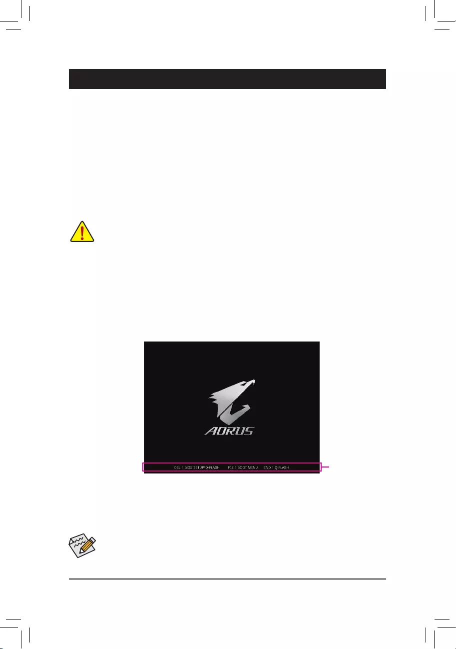
2-1 Startup Screen
The following startup Logo screen will appear when the computer boots.
Function Keys
•When the system is not stable as usual, select the Load Optimized Defaults item to set your
system to its defaults.
•The BIOS Setup menus described in this chapter are for reference only and may differ by BIOS
version.
There are two different BIOS modes as follows and you can use the <F2> key to switch between the two modes.
Easy Mode allows users to quickly view their current system information or to make adjustments for optimum
performance.InEasyMode,youcanuseyourmousetomovethroughcongurationitems.TheAdvanced
Mode provides detailed BIOS settings. You can press the arrow keys on your keyboard to move among the
items and press <Enter> to accept or enter a sub—menu. Or you can use your mouse to select the item you want.
— 23 —

2-2 The Main Menu
Advanced Mode Function Keys
<f><g>Move the selection bar to select a setup menu
<h><i>Movetheselectionbartoselectancongurationitemonamenu
<Enter>/Double Click Execute command or enter a menu
<+>/<Page Up> Increase the numeric value or make changes
<->/<Page Down> Decrease the numeric value or make changes
<F1> Show descriptions of the function keys
<F2> Switch to Easy Mode
<F3> SavethecurrentBIOSsettingstoaprole
<F4> LoadtheBIOSsettingsfromaprolecreatedbefore
<F5> Restore the previous BIOS settings for the current submenus
<F6> Display the Smart Fan 6 screen
<F7> Load the Optimized BIOS default settings for the current submenus
<F8> Access the Q—Flash utility
<F10> Save all the changes and exit the BIOS Setup program
<F11> Switch to the Favorites submenu
<F12> Capture the current screen as an image and save it to your USB drive
<Insert> Add or remove a favorite option
<Ctrl>+<S> Display information on the installed memory
<Esc> Main Menu: Exit the BIOS Setup program
Submenus: Exit current submenu
Option Description Current Settings Quick Access Bar allows you to quickly move to
the General Help, Easy Mode, Smart Fan 6, or
Q-Flash screen.
Hardware
Information
Setup
Menus
Conguration
Items
System
Time
— 24 —
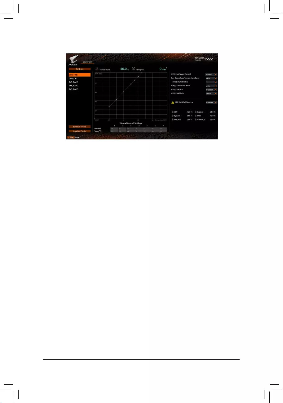
Usethe<F6>functionkeytoquicklyswitchtothisscreen.Thisscreenallowsyoutocongurefanspeed
related settings for each fan header or monitor your system/CPU temperature.
&TUNE ALL
Allows you to apply the current settings to all fan headers.
&Temperature
Displays the current temperature of the selected target area.
&Fan Speed
Displays current fan speeds.
&Flow Rate
Displaystheowrateofyourwatercoolingsystem.Press<Enter>onFan Speed to switch to this function.
&Fan Speed Control
Allows you to determine whether to enable the fan speed control function and adjust the fan speed.
Normal Allows the fan to run at different speeds according to the temperature. You can adjust
the fan speed with System Information Viewer based on your system requirements.
(Default)
Silent Allows the fan to run at slow speeds.
Manual Allows you to drag the curve nodes to adjust fan speed. Or you can use the EZ Tuning
feature. After adjusting the node position, press Apply to automatically calculate the
slope of the curve.
Full Speed Allows the fan to run at full speeds.
&Fan Control Use Temperature Input
Allows you to select the reference temperature for fan speed control.
&Temperature Interval
Allows you to select the temperature interval for fan speed change.
&FAN Control Mode
Auto Lets the BIOS automatically detect the type of fan installed and sets the optimal control
mode. (Default)
Voltage Voltage mode is recommended for a 3-pin fan.
PWM PWM mode is recommended for a 4-pin fan.
&FAN Stop
Enables or disables the fan stop function. You can set the temperature limit using the temperature curve.
The fan stops operation when the temperature is lower than the limit. (Default: Disabled)
2-3 Smart Fan 6
— 25 —

&FAN Mode
Allows you to set the operating mode for the fan.
Slope Adjusts the fan speed linearly based on the temperature. (Default)
Stair Adjusts the fan speed stepwise based on the temperature.
&FAN Fail Warning
Allows the system to emit warning sound if the fan is not connected or fails. Check the fan condition or
fan connection when this occurs. (Default: Disabled)
&SaveFanProle
Thisfunctionallowsyoutosavethecurrentsettingstoaprole.YoucansavetheproleintheBIOSor
select Select File in HDD/FDD/USBtosavetheproletoyourstoragedevice.
&LoadFanProle
ThisfunctionallowsyoutoloadapreviouslysavedBIOSprolewithoutthehasslesofreconguring
the BIOS settings. Or you can select Select File in HDD/FDD/USBtoloadaprolefromyourstorage
device.
— 26 —
2-4 Favorites (F11)
Set your frequently used options as your favorites and use the <F11> key to quickly switch to the page where
all of your favorite options are located. To add or remove a favorite option, go to its original page and press
<Insert> on the option. The option is marked with a star sign if set as a «favorite.»
— 27 —
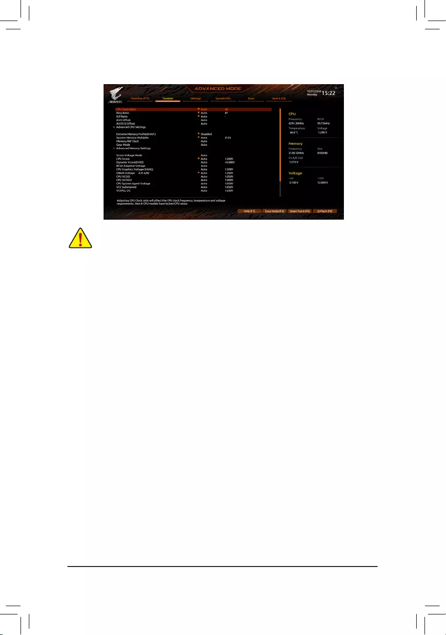
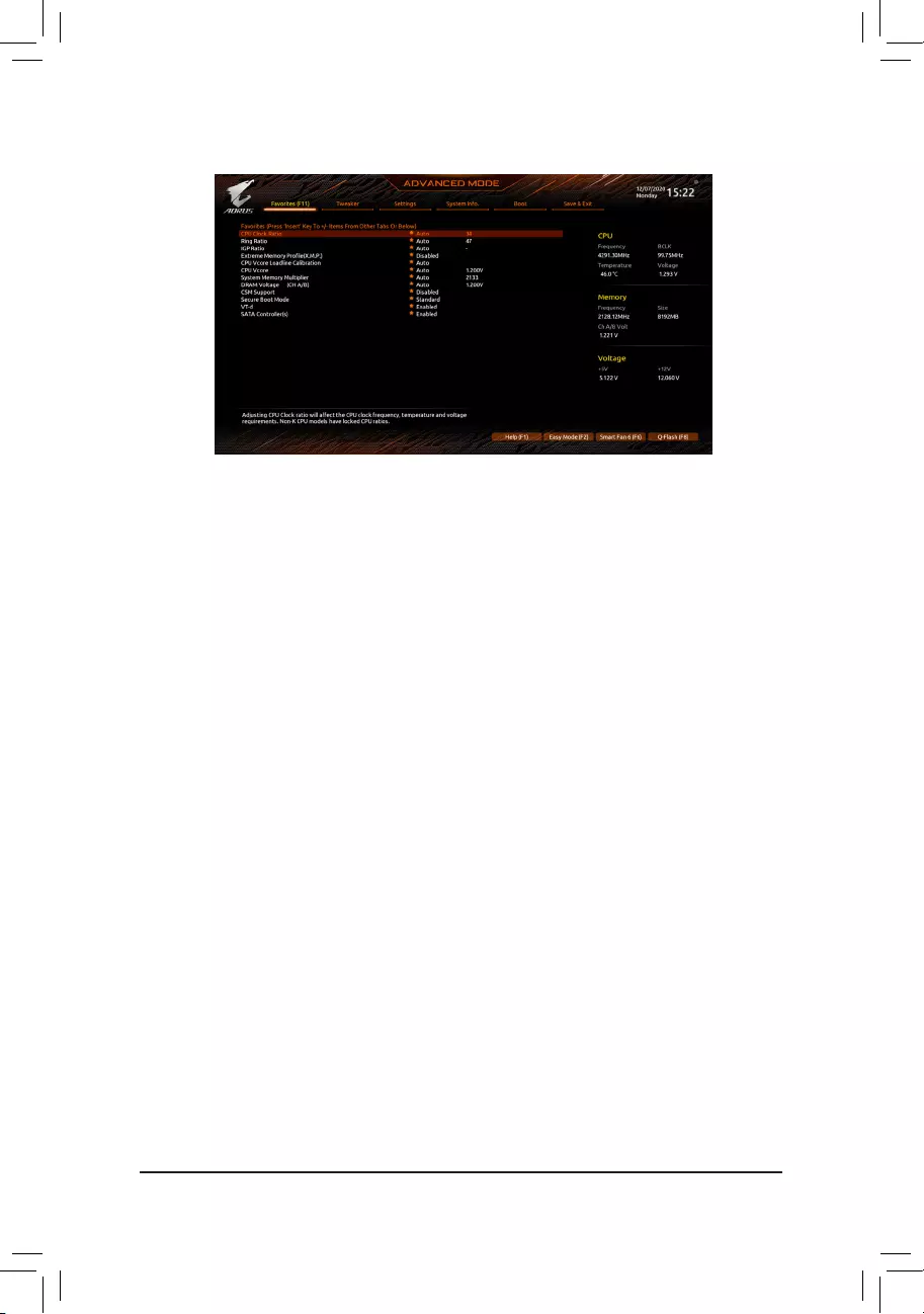
2-5 Tweaker
Whether the system will work stably with the overclock/overvoltage settings you made is dependent
onyouroverallsystemcongurations.Incorrectlydoingoverclock/overvoltagemayresultindamage
to CPU, chipset, or memory and reduce the useful life of these components. This page is for advanced
users only and we recommend you not to alter the default settings to prevent system instability or
other unexpected results. (Inadequately altering the settings may result in system’s failure to boot.
If this occurs, clear the CMOS values and reset the board to default values.)
&CPU Clock Ratio
Allows you to alter the clock ratio for the installed CPU. The adjustable range is dependent on the CPU
being installed.
&Ring Ratio
Allows you to set the CPU Uncore ratio. The adjustable range is dependent on the CPU being used.
(Default: Auto)
&IGP Ratio (Note)
Allows you to set the Graphics Ratio. (Default: Auto)
&AVX Disable (Note)
Allows you to disable the AVX instruction sets on a CPU that supports AVX. (Default: Auto)
&AVX512 Disable (Note)
Allows you to disable the AVX-512 instruction sets on a CPU that supports AVX-512. (Default: Auto)
&AVX Offset (Note)
When the processor runs AVX workloads, the CPU Clock Ratio will be reduced by the desired AVX offset
value. For example, if the value is set to 3, the CPU Clock Ratio will be reduced by 3 when executing AVX
instructions.
(Default: Auto)
&AVX512 Offset (Note)
When the processor runs AVX-512 workloads, the CPU Clock Ratio will be reduced by the desired AVX-
512 offset value. For example, if the value is set to 3 (the value must be larger than or equal to the AVX
Offset value), the CPU Clock Ratio will be reduced by 3 when executing AVX-512 instructions. (Default:
Auto)
(Note) This item is present only when you install a CPU that supports this feature. For more information
about Intel® CPUs’ unique features, please visit Intel‘s website.
— 28 —

Advanced CPU Settings
&Core Fused Max Core Ratio (Note)
Displays the highest frequency of each core.
&CPU Over Temperature Protection (Note)
Allowsyoutone—tunetheTJMaxoffsetvalue.(Default:Auto)
&FCLK Frequency for Early Power On (Note)
Allows you to set the FCLK frequency. Options are: Normal(800Mhz), 1GHz, 400MHz. (Default: 1GHz)
&Hyper-Threading Technology
Allows you to determine whether to enable multi-threading technology when using an Intel® CPU that
supports this function. This feature only works for operating systems that support multi-processor mode.
AutoletstheBIOSautomaticallycongurethissetting.(Default:Auto)
&No. of CPU Cores Enabled
Allows you to select the number of CPU cores to enable in an Intel® multi—core CPU (the number of CPU
cores may vary by CPU). AutoletstheBIOSautomaticallycongurethissetting.(Default:Auto)
&Intel(R) Speed Shift Technology (Intel® Speed Shift Technology) (Note)
Enables or disables Intel® Speed Shift Technology. Enabling this feature allows the processor to ramp up
its operating frequency more quickly and then improves the system responsiveness. (Default: Enabled)
&CPU Thermal Monitor (Note)
Enables or disables Intel® Thermal Monitor function, a CPU overheating protection function. When
enabled, the CPU core frequency and voltage will be reduced when the CPU is overheated. Auto lets
theBIOSautomaticallycongurethissetting.(Default:Auto)
&Ring to Core offset (Down Bin)
Allows you to determine whether to disable the CPU Ring ratio auto—down function. Auto lets the BIOS
automaticallycongurethissetting.(Default:Auto)
&CPU EIST Function (Note)
Enables or disables Enhanced Intel® Speed Step Technology (EIST). Depending on CPU loading, Intel®
EIST technology can dynamically and effectively lower the CPU voltage and core frequency to decrease
average power consumption and heat production. AutoletstheBIOSautomaticallycongurethissetting.
(Default: Auto)
&Race To Halt (RTH) (Note)/EnergyEfcientTurbo (Note)
Enables or disables the CPU power saving related settings. (Default: Auto)
&Intel(R) Turbo Boost Technology (Note)
Allows you to determine whether to enable the Intel® CPU Turbo Boost technology. Auto lets the BIOS
automaticallycongurethissetting.(Default:Auto)
&Intel(R) Turbo Boost Max Technology 3.0 (Note)
Enables or disables Intel® Turbo Boost Max Technology 3.0. Intel® Turbo Boost Max Technology 3.0
allows the system to identify the processor‘s best performance core and lets you manually direct the
most critical workloads to it. You can even adjust the frequency of each core individually for performance
optimization. (Default: Enabled)
&CPU Flex Ratio Override
Enables or disables the CPU Flex Ratio. The maximum CPU clock ratio will be based on the CPU Flex
Ratio Settings value if CPU Clock Ratio is set to Auto. (Default: Disabled)
&CPU Flex Ratio Settings
Allows you to set the CPU Flex Ratio. The adjustable range may vary by CPU.
(Note) This item is present only when you install a CPU that supports this feature. For more information
about Intel® CPUs’ unique features, please visit Intel‘s website.
— 29 —

&Frequency Clipping TVB (Note)
Allows you to enable or disable automatic CPU frequency reduction initiated by Thermal Velocity Boost.
AutoletstheBIOSautomaticallycongurethissetting.(Default:Auto)
&Voltage reduction initiated TVB (Note)
Allows you to enable or disable automatic CPU voltage reduction initiated by Thermal Velocity Boost. Auto
letstheBIOSautomaticallycongurethissetting.(Default:Auto)
dActive Turbo Ratios
&Turbo Ratio (Core Active)
Allows you to set the CPU Turbo ratios for active cores. Auto sets the CPU Turbo ratios according to the
CPUspecications.
Thisitemiscongurableonlywhen
Active Turbo Ratios is set
to
Manual
.
(Default:
Auto)
dC-States Control
&CPU Enhanced Halt (C1E)
Enables or disables Intel
®
CPU Enhanced Halt (C1E) function, a CPU power-saving function in system
halt state. When enabled, the CPU core frequency and voltage will be reduced during system halt state
to decrease power consumption. AutoletstheBIOS automatically congure this setting.
This item is
congurableonlywhen
C-States is
enabled.
(Default: Auto)
&C3 State Support (Note)
Allows you to determine whether to let the CPU enter C3 mode in system halt state. When enabled, the
CPU core frequency and voltage will be reduced during system halt state to decrease power consumption.
The C3 state is a more enhanced power-saving state than C1. AutoletstheBIOSautomaticallycongure
thissetting.Thisitemiscongurableonlywhen
C-States is
enabled.
(Default: Auto)
&C6/C7 State Support
Allows you to determine whether to let the CPU enter C6/C7 mode in system halt state. When enabled, the
CPU core frequency and voltage will be reduced during system halt state to decrease power consumption.
The C6/C7 state is a more enhanced power-saving state than C3. Auto lets the BIOS automatically
congurethissetting.ThisitemiscongurableonlywhenC-States Control is set to Enabled. (Default:
Auto)
&C8 State Support (Note)
Allows you to determine whether to let the CPU enter C8 mode in system halt state. When enabled, the
CPU core frequency and voltage will be reduced during system halt state to decrease power consumption.
The C8 state is a more enhanced power-saving state than C6/C7. Auto lets the BIOS automatically
congurethissetting.ThisitemiscongurableonlywhenC-States Control is set to Enabled. (Default:
Auto)
&C10 State Support (Note)
Allows you to determine whether to let the CPU enter C10 mode in system halt state. When enabled, the
CPU core frequency and voltage will be reduced during system halt state to decrease power consumption.
The C10 state is a more enhanced power-saving state than C8. AutoletstheBIOSautomaticallycongure
thissetting.ThisitemiscongurableonlywhenC-States Control is set to Enabled. (Default: Auto)
&Package C State Limit (Note)
Allows you to specify the C-state limit for the processor. AutoletstheBIOSautomaticallycongurethis
setting.ThisitemiscongurableonlywhenC-States Control is set to Enabled. (Default: Auto)
&CPU Power Performance (Note)
Allows you to determine whether to increase CPU performance. (Default: Auto)
(Note) This item is present only when you install a CPU that supports this feature. For more information
about Intel® CPUs’ unique features, please visit Intel‘s website.
— 30 —

dTurbo Power Limits
Allows you to set a power limit for CPU Turbo mode. When the CPU power consumption exceeds the
speciedpowerlimit,theCPUwillautomaticallyreducethecorefrequencyinordertoreducethepower.
AutosetsthepowerlimitaccordingtotheCPUspecications.(Default:Auto)
&Power Limit TDP (Watts) / Power Limit Time
Allows you to set the power limit for CPU/platform/memory Turbo mode and how long it takes to operate
atthespeciedpowerlimit.AutosetsthepowerlimitaccordingtotheCPUspecications.Thisitemis
congurableonlywhenTurbo Power Limits is set to Enabled. (Default: Auto)
&Core Current Limit (Amps)
AllowsyoutosetacurrentlimitforCPUTurbomode.WhentheCPUcurrentexceedsthespeciedcurrent
limit, the CPU will automatically reduce the core frequency in order to reduce the current. Auto sets
thepowerlimitaccordingtotheCPUspecications.ThisitemiscongurableonlywhenTurbo Power
Limits is set to Enabled. (Default: Auto)
dTurbo Per Core Limit Control (Note 1)
Allows you to control each CPU core limit separately. (Default: Auto)
&ExtremeMemoryProle(X.M.P.)(Note 2)
Allows the BIOS to read the SPD data on XMP memory module(s) to enhance memory performance
when enabled.
Disabled Disables this function. (Default)
Prole1 UsesProle1settings.
Prole2(Note 2) UsesProle2settings.
&System Memory Multiplier
Allows you to set the system memory multiplier. Auto sets memory multiplier according to memory SPD
data. (Default: Auto)
&Memory Ref Clock
Allows you to manually adjust the memory reference clock. (Default: Auto)
&Memory Odd Ratio (100/133 or 200/266) (Note 2)
Enabled allows Qclk to run in odd frequency. (Default: Auto)
&Gear Mode (Note 2)
Allows you to improve the maximum OC frequency potential. (Default: Auto)
Advanced Memory Settings
&Memory Multiplier Tweaker
Provides different levels of memory auto—tuning. (Default: Auto)
&Channel Interleaving
Enables or disables memory channel interleaving. Enabled allows the system to simultaneously access
different channels of the memory to increase memory performance and stability. Auto lets the BIOS
automaticallycongurethissetting.(Default:Auto)
&Rank Interleaving
Enables or disables memory rank interleaving. Enabled allows the system to simultaneously access
different ranks of the memory to increase memory performance and stability. Auto lets the BIOS
automaticallycongurethissetting.(Default:Auto)
(Note 1) This item is present only when you install a CPU that supports this feature. For more information
about Intel® CPUs’ unique features, please visit Intel‘s website.
(Note 2) This item is present only when you install a CPU and a memory module that support this feature.
— 31 —

&Memory Boot Mode
Provides memory detection and training methods.
Auto LetstheBIOSautomaticallycongurethissetting.(Default)
Normal The BIOS automatically performs memory training. Please note that if the system
becomes unstable or unbootable, try to clear the CMOS values and reset the
board to default values. (Refer to the introductions of the battery/clear CMOS
jumper in Chapter 1 for how to clear the CMOS values.)
Enable Fast Boot
Skipmemorydetectionandtraininginsomespeciccriteriaforfastermemoryboot.
Disable Fast Boot Detect and train memory at every single boot.
&Realtime Memory Timing
Allowsyoutone—tunememorytimingsaftertheBIOSstage.(Default:Auto)
&Memory Enhancement Settings
Provides several memory performance enhancement settings: Auto, Relax OC, Enhanced Stability,
Normal, Enhanced Performance, High Frequency, High Density, and DDR-4500+. (Default: Auto)
&Memory Channel Detection Message
Allows you to determine whether to show an alert message when the memory is not installed in the
optimal memory channel. (Default: Enabled)
SPD Info
Displays information on the installed memory.
Memory Channels Timings
d Channels Standard Timing Control, Channels Advanced Timing Control, Channels
Misc Timing Control
These sections provide memory timing settings. Note: Your system may become unstable or fail to boot
after you make changes on the memory timings. If this occurs, please reset the board to default values
by loading optimized defaults or clearing the CMOS values.
&Vcore Voltage Mode/
CPU Vcore/Dynamic Vcore(DVID)/BCLK Adaptive Voltage/CPU
Graphics Voltage (VAXG)/DRAM Voltage (CH A/B)/CPU VCCIO/CPU VCCIO2/CPU System
Agent Voltage/VCCPLL OC/VCC18PCH/VCC1V8P
These items allow you to adjust the CPU Vcore and memory voltages.
Advanced Voltage Settings
ThissubmenuallowsyoutocongureLoad-LineCalibrationlevel,over-voltageprotectionlevel,and
over-current protection level.
— 32 —

2-6 Settings
Platform Power
&Platform Power Management
Enables or disables the Active State Power Management function (ASPM). (Default: Disabled)
&PEG ASPM
AllowsyoutoconguretheASPMmodeforthedeviceconnectedtotheCPUPEGbus.Thisitemis
congurableonlywhenPlatform Power Management is set to Enabled. (Default: Disabled)
&PCH ASPM
AllowsyoutoconguretheASPMmodeforthedeviceconnectedtoChipset‘sPCIExpressbus.This
itemiscongurableonlywhenPlatform Power Management is set to Enabled. (Default: Disabled)
&DMI ASPM
AllowsyoutoconguretheASPMmodeforbothCPUsideandChipsetsideoftheDMIlink.Thisitem
iscongurableonlywhenPlatform Power Management is set to Enabled. (Default: Disabled)
&Power On By Keyboard
Allows the system to be turned on by a PS/2 keyboard wake—up event.
Note: To use this function, you need an ATX power supply providing at least 1A on the +5VSB lead.
Disabled Disables this function. (Default)
Password Set a password with 1~5 characters to turn on the system.
Keyboard 98 Press POWER button on the Windows 98 keyboard to turn on the system.
Any Key Press any key to turn on the system.
&Power On Password
Set the password when Power On By Keyboard is set to Password.
Press <Enter> on this item and set a password with up to 5 characters and then press <Enter> to accept.
To turn on the system, enter the password and press <Enter>.
Note: To cancel the password, press <Enter> on this item. When prompted for the password, press
<Enter> again without entering the password to clear the password settings.
&Power On By Mouse
Allows the system to be turned on by a PS/2 mouse wake—up event.
Note: To use this function, you need an ATX power supply providing at least 1A on the +5VSB lead.
Disabled Disables this function. (Default)
Move Move the mouse to turn on the system.
Double Click Double click on left button on the mouse to turn on the system.
— 33 —

&ErP
Determines whether to let the system consume least power in S5 (shutdown) state. (Default: Disabled)
Note: When this item is set to Enabled, the following functions will become unavailable: Resume by
Alarm, power on by mouse, and power on by keyboard.
&Soft—Off by PWR-BTTN
ConguresthewaytoturnoffthecomputerinMS—DOSmodeusingthepowerbutton.
Instant—Off Press the power button and then the system will be turned off instantly. (Default)
Delay 4 Sec. Press and hold the power button for 4 seconds to turn off the system. If the power
button is pressed for less than 4 seconds, the system will enter suspend mode.
&Resume by Alarm
Determines whether to power on the system at a desired time. (Default: Disabled)
If enabled, set the date and time as following:
Wakeupday:Turnonthesystemataspecictimeoneachdayoronaspecicdayinamonth.
Wake up hour/minute/second: Set the time at which the system will be powered on automatically.
Note: When using this function, avoid inadequate shutdown from the operating system or removal of the
AC power, or the settings may not be effective.
&Power Loading
Enables or disables dummy load. When the power supply is at low load, a self-protection will activate
causing it to shutdown or fail. If this occurs, please set to Enabled. Auto lets the BIOS automatically
congurethissetting.(Default:Auto)
&RC6(Render Standby)
Allows you to determine whether to let the onboard graphics enter standby mode to decrease power
consumption. (Default: Enabled)
&AC BACK
Determines the state of the system after the return of power from an AC power loss.
Memory The system returns to its last known awake state upon the return of the AC power.
Always On The system is turned on upon the return of the AC power.
Always Off The system stays off upon the return of the AC power. (Default)
IO Ports
&Initial Display Output
SpeciestherstinitiationofthemonitordisplayfromtheinstalledPCIExpressgraphicscardorthe
onboard graphics.
IGFX (Note) Setstheonboardgraphicsastherstdisplay.
PCIe1Slot SetsthegraphicscardonthePCIEX16slotastherstdisplay.(Default)
PCIe2Slot SetsthegraphicscardonthePCIEX4slotastherstdisplay.
ThisitemiscongurableonlywhenCSM Support is set to Enabled.
&Internal Graphics
Enables or disables the onboard graphics function. (Default: Auto)
&DVMT Pre—Allocated
Allows you to set the onboard graphics memory size. (Default: 64M)
&DVMT Total Gfx Mem
Allows you to allocate the DVMT memory size of the onboard graphics. Options are: 128M, 256M, MAX.
(Default: 256M)
&Aperture Size
Allows you to set the maximum amount of system memory that can be allocated to the graphics card.
Options are: 128MB, 256MB, 512MB, 1024MB, and 2048MB. (Default: 256MB)
(Note) This item is present only when you install a CPU that supports this feature.
— 34 —

&OnBoard LAN Controller
Enables or disables the onboard LAN function. (Default: Enabled)
If you wish to install a 3rd party add—in network card instead of using the onboard LAN, set this item to
Disabled.
&Audio Controller
Enables or disables the onboard audio function. (Default: Enabled)
If you wish to install a 3rd party add-in audio card instead of using the onboard audio, set this item to
Disabled.
&Above 4G Decoding
Enables or disables 64—bit capable devices to be decoded in above 4 GB address space (only if your
system supports 64—bit PCI decoding). Set to Enabled if more than one advanced graphics card are
installed and their drivers are not able to be launched when entering the operating system (because of
the limited 4 GB memory address space). (Default: Disabled)
&IOAPIC 24-119 Entries
Enables or disables this function. (Default: Enabled)
SuperIOConguration
&Serial Port
Enables or disables the onboard serial port. (Default: Enabled)
USBConguration
&Legacy USB Support
Allows USB keyboard/mouse to be used in MS—DOS. (Default: Enabled)
&XHCI Hand-off
Determines whether to enable XHCI Hand—off feature for an operating system without XHCI Hand—off
support. (Default: Enabled)
&USB Mass Storage Driver Support
Enables or disables support for USB storage devices. (Default: Enabled)
&Mass Storage Devices
Displays a list of connected USB mass storage devices. This item appears only when a USB storage
device is installed.
NetworkStackConguration
&Network Stack
Disables or enables booting from the network to install a GPT format OS, such as installing the OS from
the Windows Deployment Services server. (Default: Disabled)
&IPv4 PXE Support
EnablesordisablesIPv4PXESupport.ThisitemiscongurableonlywhenNetwork Stack is enabled.
&IPv4 HTTP Support
EnablesordisablesHTTPbootsupportforIPv4.ThisitemiscongurableonlywhenNetwork Stack is
enabled.
&IPv6 PXE Support
EnablesordisablesIPv6PXESupport.ThisitemiscongurableonlywhenNetwork Stack is enabled.
&IPv6 HTTP Support
EnablesordisablesHTTPbootsupportforIPv6.ThisitemiscongurableonlywhenNetwork Stack is
enabled.
&PXE boot wait time
Allowsyoutocongurehowlongtowaitbeforeyoucanpress<Esc>toabortthePXEboot.
— 35 —

&Media detect count
Allows you to set the number of times to check the presence of media.
NVMeConguration
Displays information on your M.2 NVME PCIe SSD if installed.
SATAAndRSTConguration
&SATA Controller(s)
Enables or disables the integrated SATA controllers. (Default: Enabled)
&SATA Mode Selection
EnablesordisablesOptanefortheSATAcontrollersintegratedintheChipsetorcongurestheSATA
controllers to AHCI mode.
Intel RST Premium With Intel Optane System Acceleration
Enables Optane for the SATA controller.
AHCI CongurestheSATAcontrollerstoAHCImode.AdvancedHostControllerInterface
(AHCI)isaninterfacespecicationthatallowsthestoragedrivertoenableadvanced
Serial ATA features such as Native Command Queuing and hot plug. (Default)
&Aggressive LPM Support
Enables or disables the power saving feature, ALPM (Aggressive Link Power Management), for the
Chipset SATA controllers. (Default: Disabled)
&Port 0/1/2/3/4/5
Enables or disables each SATA port. (Default: Enabled)
&SATA Port 0/1/2/3/4/5 DevSlp
Allows you to determine whether to let the connected SATA device go into sleep mode. (Default: Disabled)
&Hot plug
Enables or disable the hot plug capability for each SATA port. (Default: Disabled)
&ConguredaseSATA
Enables or disables support for external SATA devices.
Realtek PCIe 2.5GBE Family Controller
Thissub—menuprovidesinformationonLANcongurationandrelatedcongurationoptions.
Miscellaneous
&LEDs in System Power On State
Allows you to enable or disable motherboard LED lighting when the system is on.
Off Disables the selected lighting mode when the system is on.
On Enables the selected lighting mode when the system is on. (Default)
&LEDs in Sleep, Hibernation, and Soft Off States
Allows you to set the lighting mode of the motherboard LEDs in system S3/S4/S5 state.
ThisitemiscongurablewhenLEDs in System Power On State is set to On.
Off Disables the selected lighting mode when the system enters S3/S4/S5 state. (Default)
On Enables the selected lighting mode when the system enters S3/S4/S5 state.
&Intel Platform Trust Technology (PTT)
Enables or disables Intel® PTT Technology. (Default: Disabled)
&3DMark01 Enhancement
Allows you to determine whether to enhance some legacy benchmark performance. (Default: Disabled)
— 36 —

&CPU PCIe Link Speed
Allows you to set the operation mode of the CPU—controlled PCI Express slots to Gen 1, Gen 2, Gen 3,
or Gen 4 (Note).Actualoperationmodeissubjecttothehardwarespecicationofeachslot.Auto lets the
BIOSautomaticallycongurethissetting.(Default:Auto)
&PCH PCIe Link Speed
Allows you to set the operation mode of the Chipset-controlled PCI Express slots to Gen 1, Gen 2, or
Gen3.Actualoperationmodeissubjecttothehardwarespecicationofeachslot.Auto lets the BIOS
automaticallycongurethissetting.(Default:Auto)
&VT-d
Enables or disables Intel® Virtualization Technology for Directed I/O. (Default: Enabled)
Trusted Computing
Enables or disables Trusted Platform Module (TPM).
PC Health Status
&Reset Case Open Status
Disabled Keeps or clears the record of previous chassis intrusion status. (Default)
Enabled Clears the record of previous chassis intrusion status and the Case Openeldwill
show «No» at next boot.
&Case Open
Displays the detection status of the chassis intrusion detection device attached to the motherboard CI
header.Ifthesystemchassiscoverisremoved,thiseldwillshow»Yes»,otherwiseitwillshow»No».To
clear the chassis intrusion status record, set Reset Case Open Status to Enabled, save the settings
to the CMOS, and then restart your system.
& CPU Vcore/CPU VCCSA/DRAM Channel A/B Voltage/+3.3V/+5V/+12V/CPU VAXG
Displays the current system voltages.
(Note) This item is present only when you install a CPU that supports this feature.
— 37 —

2-7 System Info.
This section provides information on your motherboard model and BIOS version. You can also select the
default language used by the BIOS and manually set the system time.
&Access Level
Displays the current access level depending on the type of password protection used. (If no password
is set, the default will display as Administrator.) The Administrator level allows you to make changes to
all BIOS settings; the User level only allows you to make changes to certain BIOS settings but not all.
&System Language
Selects the default language used by the BIOS.
&System Date
Sets the system date. The date format is week (read-only), month, date, and year. Use <Enter> to switch
betweentheMonth,Date,andYeareldsandusethe<PageUp>or<PageDown>keytosetthedesired
value.
&System Time
Sets the system time. The time format is hour, minute, and second. For example, 1 p.m. is 13:00:00.
Use<Enter>toswitchbetweentheHour,Minute,andSecondeldsandusethe<PageUp>or<Page
Down> key to set the desired value.
Plug in Devices Info
Displays information on your PCI Express and M.2 devices if installed.
Q-Flash
AllowsyoutoaccesstheQ—FlashutilitytoupdatetheBIOSorbackupthecurrentBIOSconguration.
— 38 —
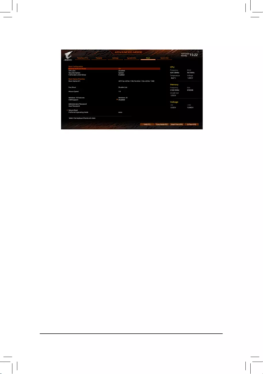
2-8 Boot
&Bootup NumLock State
Enables or disables Numlock feature on the numeric keypad of the keyboard after the POST. (Default:
On)
&CFG Lock
Enables or disables the MSR 0xE2 function. (Default: Disabled)
&Security Option
Specieswhetherapasswordisrequiredeverytimethesystemboots,oronlywhenyouenterBIOSSetup.
Afterconguringthisitem,setthepassword(s)undertheAdministrator Password/User Password
item.
Setup A password is only required for entering the BIOS Setup program.
System A password is required for booting the system and for entering the BIOS Setup
program. (Default)
&Full Screen LOGO Show
Allows you to determine whether to display the GIGABYTE Logo at system startup. Disabled skips the
GIGABYTE Logo when the system starts up. (Default: Enabled)
&Boot Option Priorities
Speciestheoverallbootorderfromtheavailabledevices.Removablestoragedevicesthatsuppor tGPT
formatwillbeprexedwith»UEFI:»stringonthebootdevicelist.Tobootfromanoperatingsystemthat
supportsGPTpartitioning,selectthedeviceprexedwith»UEFI:»string.
Or if you want to install an operating system that supports GPT partitioning such as Windows 10 64—bit,
selecttheopticaldrivethatcontainstheWindows1064—bitinstallationdiscandisprexedwith»UEFI:»
string.
&Fast Boot
Enables or disables Fast Boot to shorten the OS boot process. Ultra Fast provides the fastest bootup
speed. (Default: Disable Link)
&SATA Support
Last Boot SATA Devices Only Except for the previous boot drive, all SATA devices are disabled
before the OS boot process completes. (Default)
All SATA Devices All SATA devices are functional in the operating system and during the POST.
ThisitemiscongurableonlywhenFast Boot is set to Enabled or Ultra Fast.
— 39 —

&VGA Support
Allows you to select which type of operating system to boot.
Auto Enables legacy option ROM only.
EFI Driver Enables EFI option ROM. (Default)
ThisitemiscongurableonlywhenFast Boot is set to Enabled or Ultra Fast.
&USB Support
Disable Link All USB devices are disabled before the OS boot process completes.
Full Initial All USB devices are functional in the operating system and during the POST.
(Default)
Partial Initial Part of the USB devices are disabled before the OS boot process completes.
ThisitemiscongurableonlywhenFast Boot is set to Enabled or Ultra Fast. This function is disabled
when Fast Boot is set to Ultra Fast.
&NetWork Stack Driver Support
Disable Link Disables booting from the network. (Default)
Enabled Enables booting from the network.
ThisitemiscongurableonlywhenFast Boot is set to Enabled or Ultra Fast.
&Next Boot After AC Power Loss
Normal Boot Enables normal bootup upon the return of the AC power. (Default)
Fast Boot Keeps the Fast Boot settings upon the return of the AC power.
ThisitemiscongurableonlywhenFast Boot is set to Enabled or Ultra Fast.
&Mouse Speed
Allows you to set the mouse cursor movement speed. (Default: 1 X)
&Windows 10 Features
Allows you to select the operating system to be installed. (Default: Windows 10)
&CSM Support
Enables or disables UEFI CSM (Compatibility Support Module) to support a legacy PC boot process.
Enabled Enables UEFI CSM.
Disabled Disables UEFI CSM and supports UEFI BIOS boot process only. (Default)
&LAN PXE Boot Option ROM
Allows you to select whether to enable the legacy option ROM for the LAN controller. (Default: Disabled)
ThisitemiscongurableonlywhenCSM Support is set to Enabled.
&Storage Boot Option Control
Allows you to select whether to enable the UEFI or legacy option ROM for the storage device controller.
Do not launch Disables option ROM.
UEFI Enables UEFI option ROM only.
Legacy Enables legacy option ROM only. (Default)
ThisitemiscongurableonlywhenCSM Support is set to Enabled.
&Other PCI devices
Allows you to select whether to enable the UEFI or Legacy option ROM for the PCI device controller
other than the LAN, storage device, and graphics controllers.
Do not launch Disables option ROM.
UEFI Enables UEFI option ROM only. (Default)
Legacy Enables legacy option ROM only.
ThisitemiscongurableonlywhenCSM Support is set to Enabled.
— 40 —

&Administrator Password
Allowsyoutocongureanadministratorpassword.Press<Enter>onthisitem,typethepassword,and
thenpress<Enter>.Youwillberequestedtoconrmthepassword.Typethepasswordagainandpress
<Enter>. You must enter the administrator password (or user password) at system startup and when
entering BIOS Setup. Differing from the user password, the administrator password allows you to make
changes to all BIOS settings.
&User Password
Allowsyoutocongureauserpassword.Press<Enter>onthisitem,typethepassword,andthenpress
<Enter>.Youwillberequestedtoconrmthepassword.Typethepasswordagainandpress<Enter>.
You must enter the administrator password (or user password) at system startup and when entering BIOS
Setup. However, the user password only allows you to make changes to certain BIOS settings but not
all.
To cancel the password, press <Enter> on the password item and when requested for the password, enter
thecorrectonerst.Whenpromptedforanewpassword,press<Enter>withoutenteringanypassword.
Press<Enter>againwhenpromptedtoconrm.
NOTE:BeforesettingtheUserPassword,besuretosettheAdministratorPasswordrst.
Secure Boot
AllowsyoutoenableordisableSecureBootandcongurerelatedsettings.Thisitemiscongurable
only when CSM Support is set to Disabled.
&Preferred Operating Mode
Allows you to select whether to enter Easy mode or Advanced mode after entering BIOS Setup. Auto
enters the BIOS mode where it was last time. (Default: Auto)
— 41 —

2-9 Save & Exit
&Save & Exit Setup
Press <Enter> on this item and select Yes. This saves the changes to the CMOS and exits the BIOS
Setup program. Select No or press <Esc> to return to the BIOS Setup Main Menu.
&Exit Without Saving
Press <Enter> on this item and select Yes. This exits the BIOS Setup without saving the changes made
in BIOS Setup to the CMOS. Select No or press <Esc> to return to the BIOS Setup Main Menu.
&Load Optimized Defaults
Press <Enter> on this item and select Yes to load the optimal BIOS default settings. The BIOS defaults
settings help the system to operate in optimum state. Always load the Optimized defaults after updating
the BIOS or after clearing the CMOS values.
&Boot Override
Allows you to select a device to boot immediately. Press <Enter> on the device you select and select
Yestoconrm.Yoursystemwillrestartautomaticallyandbootfromthatdevice.
&SaveProles
ThisfunctionallowsyoutosavethecurrentBIOSsettingstoaprole.Youcancreateupto8proles
andsaveasSetupProle1~SetupProle8.Press<Enter>tocomplete.OryoucanselectSelect File
in HDD/FDD/USBtosavetheproletoyourstoragedevice.
&LoadProles
If your system becomes unstable and you have loaded the BIOS default settings, you can use this function
toloadtheBIOSsettingsfromaprolecreatedbefore,withoutthehasslesofreconguringtheBIOS
settings.Firstselecttheproleyouwishtoloadandthenpress<Enter>tocomplete.Youcanselect
Select File in HDD/FDD/USBtoinputtheprolepreviouslycreatedfromyourstoragedeviceorload
theproleautomaticallycreatedbytheBIOS,suchasrevertingtheBIOSsettingstothelastsettings
that worked properly (last known good record).
— 42 —

Chapter 3 Appendix
3-1 Installing Intel® Optane™ Memory and Storage Management
Steps:
1. After entering the operating system, insert the motherboard driver disc into your optical drive. On the Xpress
Install screen, select Intel® Rapid Storage Technology to install and follow the on—screen instructions
to complete the installation. When completed, restart the system.
2. After you install the included motherboard drivers, make sure your Internet connection works properly. The
system will automatically install the software from
Intel
®
. Restart the system after the driver is installed.
A. Enabling an Intel® Optane™ Memory
A-1. System Requirements
1. Intel® Optane™ memory.
2. The Optane™ memory must have at least 16 GB capacity, and it must have equal or smaller capacity than
the hard drive/SSD to be accelerated.
3. The Optane™ memory cannot be used to accelerate an existing RAID array; the accelerated hard drive/
SSD cannot be included in a RAID array.
4. The hard drive/SSD to be accelerated must be a SATA hard drive or M.2 SATA SSD.
5. The hard drive/SSD to be accelerated can be a system drive or data drive. The system drive must be
GPT formatted and have Windows 10 64—bit (or later version) installed on it. The data drive must also be
GPT formatted.
6. The motherboard driver disc.
7. The SATA controller must set in Intel RST Premium With Intel Optane System Acceleration mode.
A-2. Installation Guidelines
1. Go to SettingsIOPortsSATAAndRSTConguration and make sure RST Control PCIe Storage
Devices is set to Manual. Then depending on which M.2 connector you install the Optane™ memory in,
set the corresponding PCIe Storage Dev on Port XX item to RST Controlled.
2. After re—entering the operating system, launch the Intel® Optane™ Memory and Storage Management
application from the Start menu. If you install more than one Optane™ memory, please select which one
you are going to use. Then select which drive to be accelerated. Click Enable Intel® Optane™ Memory.
All data on the Optane™ memory will be erased. Make sure you back up the data before continuing. Follow
the on-screen instructions to proceed. When completed, restart the system.
3. Launch the Intel® Optane™ Memory and Storage Management application from the Start menu and
make sure the Intel® Optane™ Memory has been enabled.
4. Ifyouwanttoacceleratethesystemdrive,youcanselectspecicfolders,les,orapplicationstoacceler—
ate using the Intel® Optane™ Memory Pinning function. (The Optane™ memory used must have at least
32 GB capacity.)
•An Optane™ memory cannot be used to accelerate an M.2 PCIe SSD.
•If more than one Optane™ memory is installed, you can select only one of them to accelerate
your SATA—based boot drive. The other(s) can only be used as data drive(s).
•Do not abruptly remove the Optane™ memory. Doing so will cause the operating system to
stop functioning correctly.
•If you want to change/remove the Optane™ memory, you must disable it using the Intel® Optane™
Memory and Storage Managementapplicationrst.
•After enabling the Optane™ memory, the related BIOS settings will remain even after a BIOS
update.
Please visit GIGABYTE’s website for details on enabling an Intel® Optane™ memory.
— 43 —
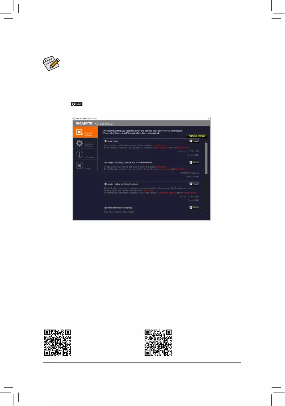
•Beforeinstallingthedrivers,rstinstalltheoperatingsystem.
•After installing the operating system, insert the motherboard driver disk into your optical drive.
Click on the message «Tap to choose what happens with this disc» on the top—right corner of
the screen and select «Run Run.exe.» (Or go to My Computer, double—click the optical drive and
execute the Run.exe program.)
«Xpress Install» will automatically scan your system and then list all of the drivers that are recommended to
install. You can click the Xpress Install button and «Xpress Install» will install all of the selected drivers. Or
click the arrow icon to individually install the drivers you need.
3-2 Drivers Installation
Please visit GIGABYTE’s website for
more software information.
Please visit GIGABYTE’s website for
more troubleshooting information.
— 44 —
Regulatory Notices
United States of America, Federal Communications Commission Statement
This equipment has been tested and found to comply with the limits for
a Class B digital device, pursuant to Part 15 of the FCC Rules. These
limits are designed to provide reasonable protection against harmful
interference in a residential installation. This equipment generates,
uses and can radiate radio frequency energy and, if not installed
and used in accordance with manufacturer’s instructions, may cause
harmful interference to radio communications. However, there is no
guarantee that interference will not occur in a particular installation. If
this equipment does cause harmful interference to radio or television
reception, which can be determined by turning the equipment off and
on, the user is encouraged to try to correct the interference by one or
more of the following measures:
•Reorient or relocate the receiving antenna.
•Increase the separation between the equipment and receiver.
•Connect the equipment to an outlet on a circuit different from that to
which the receiver is connected.
•Consult the dealer or an experienced radio/TV technician for help.
Canadian Department of Communications Statement
This digital apparatus does not exceed the Class B limits for radio
noise emissions from digital apparatus set out in the Radio Interference
Regulations of the Canadian Department of Communications. This class
B digital apparatus complies with Canadian ICES-003.
Avis de conformité à la réglementation d’Industrie Canada
Cet appareil numérique de la classe B est conforme à la norme NMB-
003 du Canada.
European Union (EU) CE Declaration of Conformity
This device complies with the following directives: Electromagnetic
Compatibility Directive 2014/30/EU, Low-voltage Directive 2014/35/
EU, RoHS directive (recast) 2011/65/EU & the 2015/863 Statement.
This product has been tested and found to comply with all essential
requirements of the Directives.
European Union (EU) RoHS (recast) Directive 2011/65/EU & the
European Commission Delegated Directive (EU) 2015/863 Statement
GIGABYTE products have not intended to add and safe from hazardous
substances (Cd, Pb, Hg, Cr+6, PBDE, PBB, DEHP, BBP, DBP and
DIBP). The parts and components have been carefully selected to meet
RoHS requirement. Moreover, we at GIGABYTE are continuing our
efforts to develop products that do not use internationally banned toxic
chemicals.
European Union (EU) Community Waste Electrical & Electronic
Equipment (WEEE) Directive Statement
GIGABYTEwillfulllthenationallawsasinterpretedfromthe2012/19/
EU WEEE (Waste Electrical and Electronic Equipment) (recast)
directive. The WEEE Directive specifies the treatment, collection,
recycling and disposal of electric and electronic devices and their
components. Under the Directive, used equipment must be marked,
collected separately, and disposed of properly.
WEEE Symbol Statement
The symbol shown below is on the product or on its
packaging, which indicates that this product must not be
disposed of with other waste. Instead, the device should
be taken to the waste collection centers for activation of
the treatment, collection, recycling and disposal procedure.
For more information about where you can drop off your waste
equipmentforrecycling,pleasecontactyourlocalgovernmentofce,
your household waste disposal service or where you purchased the
product for details of environmentally safe recycling.
End of Life Directives-Recycling
The symbol shown below is on the product or on its
packaging, which indicates that this product must not be
disposed of with other waste. Instead, the device should be
taken to the waste collection centers for activation of the
treatment, collection, recycling and disposal procedure.
Déclaration de Conformité aux Directives de l’Union européenne (UE)
Cet appareil portant la marque CE est conforme aux directives de
l’UE suivantes: directive Compatibilité Electromagnétique 2014/30/
UE, directive Basse Tension 2014/35/UE et directive RoHS II 2011/65/
UE. La conformité à ces directives est évaluée sur la base des normes
européennes harmonisées applicables.
European Union (EU) CE-Konformitätserklärung
Dieses Produkte mit CE-Kennzeichnung erfüllen folgenden EU-
Richtlinien: EMV-Richtlinie 2014/30/EU, Niederspannungsrichtlinie
2014/30/EU und RoHS-Richtlinie 2011/65/EU erfüllt. Die Konformität
mit diesen Richtlinien wird unter Verwendung der entsprechenden
Standards zurEuropäischen Normierung beurteilt.
CE declaração de conformidade
Este produto com a marcação CE estão em conformidade com das
seguintes Diretivas UE: Diretiva Baixa Tensão 2014/35/EU; Diretiva
CEM 2014/30/EU; Diretiva RSP 2011/65/UE. A conformidade com estas
diretivasévericadautilizandoasnormaseuropeiasharmonizadas.
CE Declaración de conformidad
Este producto que llevan la marca CE cumplen con las siguientes
Directivas de la Unión Europea: Directiva EMC (2014/30/EU), Directiva
de bajo voltaje (2014/35/EU), Directiva RoHS (recast) (2011/65/EU).
El cumplimiento de estas directivas se evalúa mediante las normas
europeas armonizadas.
Dichiarazione di conformità CE
Questo prodotto è conforme alle seguenti direttive: Direttiva sulla
compatibilità elettromagnetica 2014/30/UE, Direttiva sulla bassa
tensione 2014/35/UE, Direttiva RoHS (rifusione) 2011/65/UE. Questo
prodotto è stato testato e trovato conforme a tutti i requisiti essenziali
delle Direttive.
Supplier’s Declaration of Conformity
47 CFR § 2.1077 Compliance Information
Product Name: Motherboard
Trade Name: GIGABYTE
Model Number: B560M AORUS ELITE
Responsible Party – U.S. Contact Information: G.B.T. Inc.
Address: 17358 Railroad street, City Of Industry, CA91748
Tel.: 1-626-854-9338
Internet contact information: https://www.gigabyte.com
FCC Compliance Statement:
This device complies with Part 15 of the FCC Rules, Subpart B, Unintentional Radiators.
Operation is subject to the following two conditions: (1) This device may not cause harmful interference, and (2) this
device must accept any interference received, including interference that may cause undesired operation.
— 45 —

— 46 —

— 47 —
Contact Us
GIGA-BYTE TECHNOLOGY CO., LTD.
Address: No.6, Baoqiang Rd., Xindian Dist., New Taipei City 231, Taiwan
TEL: +886-2-8912-4000, FAX: +886—2-8912-4005
Tech. and Non—Tech. Support (Sales/Marketing) : https://esupport.gigabyte.com
WEB address (English): https://www.gigabyte.com
WEB address (Chinese): https://www.gigabyte.com/tw
•GIGABYTE eSupport
To submit a technical or non-technical (Sales/Marketing) question, please link to:
https://esupport.gigabyte.com
— 48 —
English
2.68 MB
Sep 06, 2021

Unique Features Introduction
English
0.58 MB
Sep 06, 2021
Intel® Optane™ Memory Setup Guide
Arabic, Bulgarian, Croatian, Czech, English, French, German, Greek, Hebrew, Hungarian, Indonesian, Italian, Japanese, Korean, Persian, Polish, Portuguese, Romanian, Russian, Simplified Chinese, Serbian, Spanish, Thai, Traditional Chinese, Turkish, Vietnamese
103
9.03 MB
Nov 25, 2019
Multilingual Installation Guide