-
Драйверы
19
-
Инструкции по эксплуатации
19
Языки:

Gigabyte GA-P43-ES3G инструкция по эксплуатации
(72 страницы)
- Языки:Венгерский, Греческий, Испанский, Итальянский, Немецкий, Польский, Португальский, Русский, Турецкий, Французский, Чешский
-
Тип:
PDF -
Размер:
18.6 MB -
Описание:
Installation Guidebook


На NoDevice можно скачать инструкцию по эксплуатации для Gigabyte GA-P43-ES3G. Руководство пользователя необходимо для ознакомления с правилами установки и эксплуатации Gigabyte GA-P43-ES3G. Инструкции по использованию помогут правильно настроить Gigabyte GA-P43-ES3G, исправить ошибки и выявить неполадки.
Посмотреть инструкция для Gigabyte P43-ES3G бесплатно. Руководство относится к категории материнские платы, 1 человек(а) дали ему среднюю оценку 8. Руководство доступно на следующих языках: английский. У вас есть вопрос о Gigabyte P43-ES3G или вам нужна помощь? Задайте свой вопрос здесь
Не можете найти ответ на свой вопрос в руководстве? Вы можете найти ответ на свой вопрос ниже, в разделе часто задаваемых вопросов о Gigabyte P43-ES3G.
Какая ширина Gigabyte P43-ES3G?
Какая толщина Gigabyte P43-ES3G?
Инструкция Gigabyte P43-ES3G доступно в русский?
Не нашли свой вопрос? Задайте свой вопрос здесь
Если у вас отсутствует техническая возможность для скачивания Руководство по эксплуатации для GIGABYTE GA-P43-ES3G (rev. 1.1)
вы можете прочесть документ прямо на нашем сайте или
Скачать GIGABYTE GA-P43-ES3G (rev. 1.1) Руководство по эксплуатации

- 1
- 2
- 3
- 4
- 5
- 6
- 7
- 8
- 9
- 10
- 11
- 12
- 13
- 14
- 15
- 16
- 17
- 18
- 19
- 20
- 21
- 22
- 23
- 24
- 25
- 26
- 27
- 28
- 29
- 30
- 31
- 32
- 33
- 34
- 35
- 36
- 37
- 38
- 39
- 40
- 41
- 42
- 43
- 44
- 45
- 46
- 47
- 48
- 49
- 50
- 51
- 52
- 53
- 54
- 55
- 56
- 57
- 58
- 59
- 60
- 61
- 62
- 63
- 64
- 65
- 66
- 67
- 68
- 69
- 70
- 71
- 72
- 73
- 74
- 75
- 76
- 77
- 78
- 79
- 80
- 81
- 82
- 83
- 84
- 85
- 86
- 87
- 88
- 89
Инструкции для прочих GIGABYTE GA-P43-ES3G (rev. 1.1)
Инструкции для прочих GIGABYTE Материнские платы
Инструкции для прочих GIGABYTE
GA-P43-ES3G
LGA775 socket motherboard for Intel® CoreTM processor family/ Intel® Pentium® processor family/Intel® Celeron® processor family
User’s Manual
Rev. 1101
12ME-P43ES3G-1101R

Motherboard
GA-P43-ES3G
Motherboard
GA-P43-ES3G
Nov. 14, 2008
Nov. 14, 2008
Copyright
© 2009 GIGA-BYTE TECHNOLOGY CO., LTD. All rights reserved.
The trademarks mentioned in this manual are legally registered to their respective owners.
Disclaimer
Information in this manual is protected by copyright laws and is the property of GIGABYTE. Changes to the specifications and features in this manual may be made by GIGABYTE without prior notice. No part of this manual may be reproduced, copied, translated, transmitted, or published in any form or by any means without GIGABYTE’s prior written permission.
Documentation Classifications
In order to assist in the use of this product, GIGABYTE provides the following types of documentations:
For quick set-up of the product, read the Quick Installation Guide included with the product.
For detailed product information, carefully read the User’s Manual.
For instructions on how to use GIGABYTE’s unique features, read or download the information on/from the SupportMotherboardTechnology Guide page on our website.
For product-related information, check on our website at:
http://www.gigabyte.com.tw
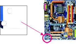
Identifying Your Motherboard Revision
The revision number on your motherboard looks like this: «REV: X.X.» For example, «REV: 1.0» means the revision of the motherboard is 1.0. Check your motherboard revision before updating motherboard BIOS, drivers, or when looking for technical information.
Example:

Table of Contents
|
Box Contents ………………………………………………………………………………………………….. |
6 |
||
|
OptionalItems ………………………………………………………………………………………………….. |
6 |
||
|
GA-P43-ES3G Motherboard Layout …………………………………………………………………… |
7 |
||
|
Block Diagram …………………………………………………………………………………………………. |
8 |
||
|
Chapter 1 Hardware Installation ………………………………………………………………………… |
9 |
||
|
1-1 |
InstallationPrecautions …………………………………………………………………………. |
9 |
|
|
1-2 |
Product Specifications ………………………………………………………………………… |
10 |
|
|
1-3 |
Installing the CPU and CPU Cooler …………………………………………………….. |
13 |
|
|
1-3-1 |
Installing the CPU …………………………………………………………………………………… |
13 |
|
|
1-3-2 Installing the CPU Cooler ……………………………………………………………………….. |
15 |
||
|
1-4 |
Installing the Memory …………………………………………………………………………. |
16 |
|
|
1-4-1 Dual Channel Memory Configuration ………………………………………………………. |
16 |
||
|
1-4-2 |
Installing a Memory ………………………………………………………………………………… |
17 |
|
|
1-5 |
Installing an Expansion Card ………………………………………………………………. |
18 |
|
|
1-6 |
Back Panel Connectors ……………………………………………………………………… |
19 |
|
|
1-7 |
Internal Connectors ……………………………………………………………………………. |
21 |
|
|
Chapter 2 BIOS Setup……………………………………………………………………………………. |
31 |
||
|
2-1 |
Startup Screen…………………………………………………………………………………… |
32 |
|
|
2-2 |
The Main Menu …………………………………………………………………………………. |
33 |
|
|
2-3 |
MB Intelligent Tweaker(M.I.T.) …………………………………………………………….. |
35 |
|
|
2-4 |
Standard CMOS Features ………………………………………………………………….. |
41 |
|
|
2-5 |
Advanced BIOS Features …………………………………………………………………… |
43 |
|
|
2-6 |
IntegratedPeripherals …………………………………………………………………………. |
46 |
|
|
2-7 |
Power ManagementSetup ………………………………………………………………….. |
49 |
|
|
2-8 |
PnP/PCI Configurations ……………………………………………………………………… |
51 |
|
|
2-9 |
PC Health Status ………………………………………………………………………………. |
52 |
|
|
2-10 |
Load Fail-Safe Defaults ……………………………………………………………………….. |
54 |
|
|
2-11 |
Load Optimized Defaults ……………………………………………………………………… |
54 |
|
|
2-12 |
Set Supervisor/User Password …………………………………………………………… |
55 |
|
|
2-13 |
Save & Exit Setup …………………………………………………………………………….. |
56 |
|
|
2-14 |
Exit Without Saving …………………………………………………………………………… |
56 |
— 4 —

|
Chapter 3 Drivers Installation ………………………………………………………………………….. |
57 |
|
|
3-1 |
Installing Chipset Drivers ……………………………………………………………………. |
57 |
|
3-2 |
Application Software …………………………………………………………………………… |
58 |
|
3-3 |
Technical Manuals ……………………………………………………………………………… |
58 |
|
3-4 |
Contact…………………………………………………………………………………………….. |
59 |
|
3-5 |
System…………………………………………………………………………………………….. |
59 |
|
3-6 |
Download Center ……………………………………………………………………………….. |
60 |
|
Chapter 4 Unique Features …………………………………………………………………………….. |
61 |
||
|
4-1 |
Xpress Recovery2 …………………………………………………………………………….. |
61 |
|
|
4-2 |
BIOS Update Utilities …………………………………………………………………………. |
66 |
|
|
4-2-1 |
Updating the BIOS with the Q-Flash Utility ……………………………………………… |
66 |
|
|
4-2-2 |
Updating the BIOS with the @BIOS Utility ………………………………………………. |
69 |
|
|
4-3 |
EasyTune 6………………………………………………………………………………………. |
70 |
|
|
4-4 |
Easy Energy Saver ………………………………………………………………………….. |
71 |
|
Chapter 5 Appendix |
………………………………………………………………………………………. |
73 |
|
|
5-1 |
ConfiguringAudioInput and Output ……………………………………………………….. |
73 |
|
|
5-1-1 |
Configuring 2/4/5.1/7.1 — Channel Audio …………………………………………………… |
73 |
|
|
5-1-2 …………………………………………………………………………… |
Configuring S/PDIF Out |
76 |
|
|
5-1-3 …………………………………………………………. |
Configuring Microphone Recording |
77 |
|
|
5-1-4 ………………………………………………………………………Using the Sound Recorder |
79 |
||
|
5-2 |
Troubleshooting ………………………………………………………………………………….. |
80 |
|
|
5-2-1 ………………………………………………………………….. |
Frequently Asked Questions |
80 |
|
|
5-2-2 …………………………………………………………………….. |
Troubleshooting Procedure |
81 |
|
|
5-3 |
Regulatory ………………………………………………………………………..Statements |
83 |
— 5 —
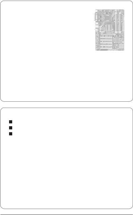
Box Contents
 GA-P43-ES3G motherboard
 Motherboard driver disk
 User’s Manual
 Quick Installation Guide
 One IDE cable
 Two SATA 3Gb/s cables
 I/O Shield
•The box contents above are for reference only and the actual items shall depend on product package you obtain. The box contents are subject to change without notice.
•The motherboard image is for reference only.
Optional Items
Floppy disk drive cable (Part No. 12CF1-1FD001-7*R) 2-port USB 2.0 bracket (Part No. 12CR1-1UB030-5*R) 2-port SATA power cable (Part No. 12CF1-2SERPW-0*R)
— 6 —
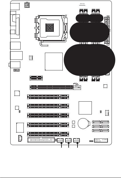
GA-P43-ES3G Motherboard Layout
KB_MS
ATX_12V
LGA775
USB_LAN SYS_FAN1
Intel® P43
AUDIO
F_AUDIO PCIEX1
PCIEX16 GA-P43-ES3G
RTL8111D


 CPU_FAN
ATX
IDE
|
DDR2 1 |
IDE |
|
DDR2 2 |
DDR2 3 DDR2 4 |
|
JMicron 368 |
|
PCI3 |
Intel® ICH10 |
SYS_FAN2 |
|||
|
SPDIF_O |
CLR_CMOS |
||||
|
PCI4 |
M_BIOS |
SATA2_3 |
SATA2_0 |
||
|
BATTERY |
SATA2_4 |
SATA2_1 |
|||
|
IT8718 |
PCI5 |
B_BIOS |
SATA2_5 |
SATA2_2 |
|
|
CI |
F_PANEL |
||||
|
CD_IN |
FDD |
PWR_LED |
|||
|
F_USB3 F_USB2 |
F_USB1 |
— 7 —
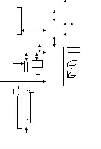
Block Diagram
PCIe CLK
(100 MHz)
PCI Express x16
|
ATA-133/100/66/33 |
JMicron |
||||||||
|
IDE Channel |
368 |
||||||||
|
PCI Express Bus |
x 1 |
||||||||
|
1 PCI Express x1 |
x 1 |
x 1 |
|||||||
|
RTL |
|
|
PCIe CLK |
8111D |
|
(100 MHz) |
RJ45 |
|
PCI Bus |
LAN |
|
IT8208M |
|
|
5 PCI |
|
|
PCI CLK |
|
|
(33 MHz) |
|
LGA775 |
CPU CLK+/- |
||||||||||||||||
|
(400(O.C.)333/266/200 MHz) |
|||||||||||||||||
|
Processor |
|||||||||||||||||
|
Host |
|||||||||||||||||
|
Interface |
DDR2 1200/1066/800/667 MHz |
||||||||||||||||
|
Intel® P43 |
Dual Channel Memory |
||||||||||||||||
|
MCH CLK |
|||||||||||||||||
|
(333/266/200 MHz) |
|||||||||||||||||
 Dual BIOS
6 SATA 3Gb/s
Intel® ICH10


 12 USB Ports
|
Floppy |
|||||||||||||||||
|
IT8718 |
LPT Port |
||||||||||||||||
|
CODEC |
COM Port |
||||||||||||||||
|
PS/2 KB/Mouse |
|||||||||||||||||
|
Speaker Out) Speaker Out) |
Speaker Out) SPDIF Out |
||||||||||||||||
|
(Center/Subwoofer Line-Out (Front |
Line-In (Rear |
||||||||||||||||
|
MIC |
|||||||||||||||||
|
— 8 — |

Chapter 1 Hardware Installation
1-1 Installation Precautions
The motherboard contains numerous delicate electronic circuits and components which can become damaged as a result of electrostatic discharge (ESD). Prior to installation, carefully read the user’s manual and follow these procedures:
•Prior to installation, do not remove or break motherboard S/N (Serial Number) sticker or warranty sticker provided by your dealer. These stickers are required for warranty validation.
•Always remove theAC power by unplugging the power cord from the power outlet before installing or removing the motherboard or other hardware components.
•When connecting hardware components to the internal connectors on the motherboard, make sure they are connected tightly and securely.
•When handling the motherboard, avoid touching any metal leads or connectors.
•It is best to wear an electrostatic discharge (ESD) wrist strap when handling electronic components such as a motherboard, CPU or memory. If you do not have an ESD wrist strap, keep your hands dry and first touch a metal object to eliminate static electricity.
•Prior to installing the motherboard, please have it on top of an antistatic pad or within an electrostatic shielding container.
•Before unplugging the power supply cable from the motherboard, make sure the power supply has been turned off.
•Before turning on the power, make sure the power supply voltage has been set according to the local voltage standard.
•Before using the product, please verify that all cables and power connectors of your hardware components are connected.
•To prevent damage to the motherboard, do not allow screws to come in contact with the motherboard circuit or its components.
•Make sure there are no leftover screws or metal components placed on the motherboard or within the computer casing.
•Do not place the computer system on an uneven surface.
•Do not place the computer system in a high-temperature environment.
•Turning on the computer power during the installation process can lead to damage to system components as well as physical harm to the user.
•If you are uncertain about any installation steps or have a problem related to the use of the product, please consult a certified computer technician.
|
— 9 — |
Hardware Installation |

|
1-2 |
Product Specifications |
|||
|
CPU |
Support for an Intel® CoreTM 2 Extreme processor/ |
|||
|
Intel® CoreTM 2 Quad processor/Intel® CoreTM 2 Duo processor/ |
||||
|
Intel® Pentium® processor Extreme Edition/Intel® Pentium® D processor/ |
||||
|
Intel® Pentium® 4 processor Extreme Edition/Intel® Pentium® 4 processor/ |
||||
|
Intel® Celeron® processor in the LGA 775 package |
||||
|
(Go to GIGABYTE’s website for the latest CPU support list.) |
||||
|
L2 cache varies with CPU |
||||
|
Front Side Bus |
1600(O.C.)/1333/1066/800 MHz FSB |
|||
|
Chipset |
North Bridge: Intel® P43 Express Chipset |
|||
|
South Bridge: Intel® ICH10 |
||||
|
Memory |
4 x 1.8V DDR2 DIMM sockets supporting up to 16 GB of system memory (Note 1) |
|||
|
Dual channel memory architecture |
||||
|
Support for DDR2 1200/1066/800/667 MHz memory modules |
||||
|
(Go to GIGABYTE’s website for the latest memory support list.) |
||||
|
Audio |
Realtek ALC888 codec |
|||
|
High Definition Audio |
||||
|
2/4/5.1/7.1-channel (Note 2) |
||||
|
Support for S/PDIF Out |
||||
|
Support for CD In |
||||
|
LAN |
Realtek 8111D chip (10/100/1000 Mbit) |
|||
|
Expansion Slots |
1 x PCI Express x16 slot |
|||
|
1 x PCI Express x1 slot |
||||
|
5 x PCI slots |
||||
|
Storage Interface |
South Bridge: |
|||
|
— 6 x SATA 3Gb/s connectors supporting up to 6 SA TA 3Gb/s devices |
||||
|
JMicron 368 chip: |
||||
|
— 1 x IDE connector supporting ATA-133/100/66/33 and up to 2 IDE devices |
||||
|
iTE IT8718 chip: |
||||
|
— 1 x floppy disk drive connector supporting up to 1 floppy disk drive |
||||
|
USB |
Integrated in the South Bridge |
Up to 12 USB 2.0/1.1 ports (6 on the back panel, 6 via the USB brackets connected to the internal USB headers)
|
GA-P43-ES3G Motherboard |
— 1 0 — |
![]()
|
Internal Connectors |
1 |
x 24-pin ATX main power connector |
|
|
1 |
x 4-pin ATX 12V power connector |
||
|
1 x floppy disk drive connector |
|||
|
1 x IDE connector |
|||
|
6 x SATA 3Gb/s connectors |
|||
|
1 x CPU fan header |
|||
|
2 x system fan headers |
|||
|
1 x front panel header |
|||
|
1 x front panel audio header |
|||
|
1 x CD In connector |
|||
|
1 x S/PDIF Out header |
|||
|
3 x USB 2.0/1.1 headers |
|||
|
1 x power LED header |
|||
|
1 x chassis intrusion header |
|||
|
Back Panel |
1 x PS/2 keyboard port |
||
|
Connectors |
1 x PS/2 mouse port |
||
|
1 x parallel port |
|||
|
1 x serial port |
|||
|
1 x coaxial S/PDIF Out connector |
|||
|
6 x USB 2.0/1.1 ports |
|||
|
1 x RJ-45 ports |
|||
|
3 x audio jacks (Line In/Line Out/Microphone) |
|||
|
I/O Controller |
iTE IT8718 chip |
||
|
Hardware Monitor |
System voltage detection |
||
|
CPU/System temperature detection |
|||
|
CPU/System fan speed detection |
|||
|
CPU overheating warning |
|||
|
CPU/System fan fail warning |
|||
|
CPU/System smart fan control (Note 3) |
|
— 11 — |
Hardware Installation |

|
BIOS |
2 x 8 Mbit flash |
|
Use of licensed AWARD BIOS |
|
|
Support for DualBIOSTM |
|
|
PnP 1.0a, DMI 2.0, SM BIOS 2.4, ACPI 1.0b |
|
|
Unique Features |
Support for @BIOS |
|
Support for Download Center |
|
|
Support for Q-Flash |
|
|
Support for EasyTune (Note 4) |
|
|
Support for Xpress Install |
|
|
Support for Xpress Recovery2 |
|
|
Support for Virtual Dual BIOS |
|
|
Support for Easy Energy Saver (Note 5) |
|
|
Bundled Software |
Norton Internet Security (OEM version) |
|
Operating System |
Support for Microsoft® Windows® Vista/XP |
|
Form Factor |
ATX Form Factor; 30.5cm x 21cm |
(Note 1) Due to Windows Vista/XP 32-bit operating system limitation, when more than 4 GB of physical memory is installed, the actual memory size displayed will be less than 4 GB.
(Note 2) To enable 7.1-channel audio, you have to use an HD front panel audio module and enable the multi-channel audio feature through the audio driver.
(Note 3) Whether the CPU/system fan speed control function is supported will depend on the CPU cooler you install.
(Note 4) Available functions in EasyTune may differ by motherboard model.
(Note 5) Due to the hardware limitation, you must install the Intel® CoreTM 2 Extreme/ CoreTM 2 Quad/ CoreTM 2 Duo/ Pentium Dual-Core/ Celeron Dual-Core/ Celeron 400 Series CPU to enable support for Easy Energy Saver.
|
GA-P43-ES3G Motherboard |
— 1 2 — |
1-3 Installing the CPU and CPU Cooler
Read the following guidelines before you begin to install the CPU:
• Make sure that the motherboard supports the CPU.
(Go to GIGABYTE’s website for the latest CPU support list.)
•Always turn off the computer and unplug the power cord from the power outlet before installing the CPU to prevent hardware damage.
•Locate the pin one of the CPU. The CPU cannot be inserted if oriented incorrectly. (Or you may locate the notches on both sides of the CPU and alignment keys on the CPU socket.)
•Apply an even and thin layer of thermal grease on the surface of the CPU.
•Do not turn on the computer if the CPU cooler is not installed, otherwise overheating and damage of the CPU may occur.
•Set the CPU host frequency in accordance with the CPU specifications. It is not recommended that the system bus frequency be set beyond hardware specifications since it does not meet the standard requirements for the peripherals. If you wish to set the frequency beyond the standard specifications, please do so according to your hardware specifications including the CPU, graphics card, memory, hard drive, etc.
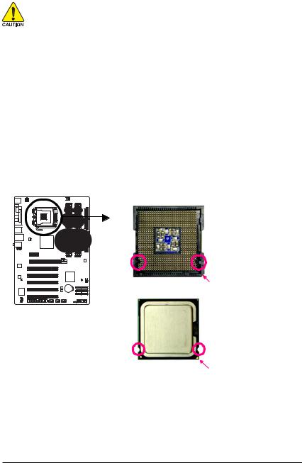
1-3-1 Installing the CPU
A. Locate the alignment keys on the motherboard CPU socket and the notches on the CPU.
LGA775 CPU Socket
|
Alignment Key |
Alignment Key |
|
Pin One Corner of the CPU Socket |
|
|
LGA 775 CPU |
|
|
Notch |
Notch |
|
Triangle Pin One Marking on the CPU |
|
— 13 — |
Hardware Installation |
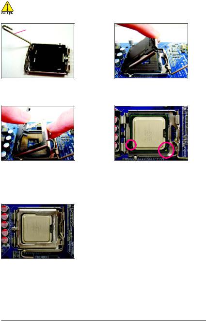
B. Follow the steps below to correctly install the CPU into the motherboard CPU socket.
Before installing the CPU, make sure to turn off the computer and unplug the power cord from the power outlet to prevent damage to the CPU.
CPU Socket Lever
Step 1:
Completely raise the CPU socket lever.
Step 3:
Remove the protective socket cover from the load plate. (To protect the CPU socket, always replace the protective socket cover when the CPU is not installed.)
Step 5:
Once the CPU is properly inserted, replace the load plate and push the CPU socket lever back into its locked position.
Step 2:
Lift the metal load plate from the CPU socket. (DO NOT touch socket contacts.)
Step 4:
Hold the CPU with your thumb and index fingers. Align the CPU pin one marking (triangle) with the pin one corner of the CPU socket (or you may align the CPU notches with the socket alignment keys) and gently insert the CPU into position.
|
GA-P43-ES3G Motherboard |
— 1 4 — |
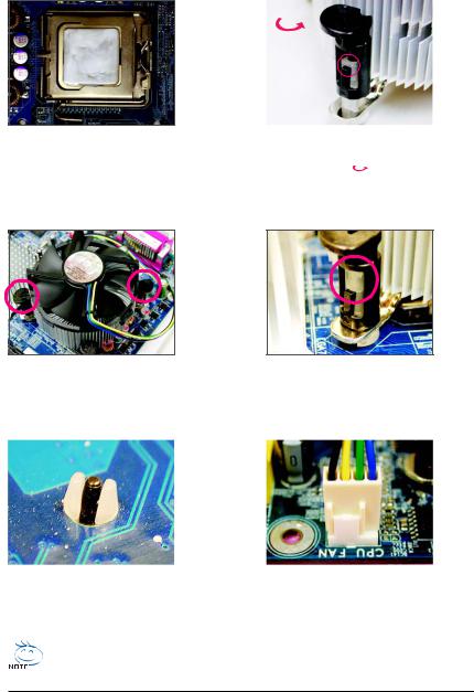
1-3-2 Installing the CPU Cooler
Follow the steps below to correctly install the CPU cooler on the motherboard. (The following procedure uses Intel® boxed cooler as the example cooler.)
|
Male |
|||||
|
Direction of |
Push Pin |
||||
|
the Arrow Sign |
|||||
|
on the Male |
The Top |
||||
|
Push Pin |
|||||
|
of Female |
|||||
|
Push Pin |
|||||
|
Female |
|||||
|
Push Pin |
|||||
|
Step 1: |
Step 2: |
|
|
Apply an even and thin layer of thermal grease |
Before installing the cooler, note the direction |
|
|
on the surface of the installed CPU. |
of the arrow sign |
on the male push pin. |
|
(Turning the push pin along the direction of |
arrow is to remove the cooler, on the contrary, is to install.)
|
Step 3: |
Step 4: |
||
|
Place the cooler atop the CPU, aligning the |
You should hear a «click» when pushing down each |
||
|
four push pins through the pin holes on the |
push pin. Check that the Male and Female push pins |
||
|
motherboard. Push down on the push pins |
are joined closely. (Refer to your CPU cooler instal- |
||
|
diagonally. |
lation manual for instructions on installing the cooler.) |
||
Step 5:
After the installation, check the back of the motherboard. If the push pin is inserted as the picture above, the installation is complete.
Step 6:
Finally, attach the power connector of the CPU cooler to the CPU fan header (CPU_FAN) on the motherboard.
Use extreme care when removing the CPU cooler because the thermal grease/tape between the CPU cooler and CPU may adhere to the CPU. Inadequately removing the CPU cooler may damage the CPU.
|
— 15 — |
Hardware Installation |
1-4 Installing the Memory
Read the following guidelines before you begin to install the memory:
• Make sure that the motherboard supports the memory. It is recommended that memory of the same capacity, brand, speed, and chips be used.
(Go to GIGABYTE’s website for the latest memory support list.)
•Always turn off the computer and unplug the power cord from the power outlet before installing the memory to prevent hardware damage.
•Memory modules have a foolproof design. A memory module can be installed in only one direction. If you are unable to insert the memory, switch the direction.
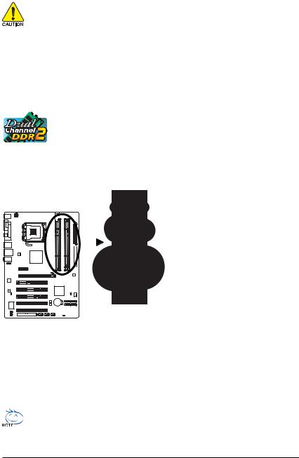
1-4-1 Dual Channel Memory Configuration
This motherboard provides four DDR2 memory sockets and supports Dual Channel Technology. After the memory is installed, the BIOS will automatically detect the specifications and capacity of the memory. Enabling Dual Channel memory mode will double the original memory bandwidth.
The four DDR2 memory sockets are divided into two channels and each channel has two memory sockets as following:
 Channel 0: DDR2_1, DDR2_2
  Channel 1: DDR2_3, DDR2_4
 Dual Channel Memory ConfigurationsTable
|
DDR2_1 |
DDR2_2 |
DDR2_3 |
DDR2_4 |
|
|
Two Modules |
DS/SS |
— — |
DS/SS |
— — |
|
— — |
DS/SS |
— — |
DS/SS |
|
|
Four Modules |
DS/SS |
DS/SS |
DS/SS |
DS/SS |
(SS=Single-Sided, DS=Double-Sided, «- -«=No Memory)
|
DDR2 1 DDR2 2 |
DDR2 3 DDR2 4 |
Due to chipset limitation, read the following guidelines before installing the memory in Dual Channel mode.
1.Dual Channel mode cannot be enabled if only one DDR2 memory module is installed.
2.When enabling Dual Channel mode with two or four memory modules, it is recommended that memory of the same capacity, brand, speed, and chips be used and installed in the same colored DDR2 sockets for optimum performance.
When memory modules of different capacity and chips are installed, a message which says memory is operating in Flex Memory Mode will appear during the POST. Intel® Flex Memory Technology offers greater flexibility to upgrade by allowing dif ferent memory sizes to be populated and remain in Dual Channel mode/performance.
|
GA-P43-ES3G Motherboard |
— 1 6 — |
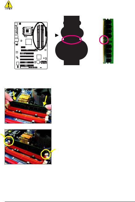
1-4-2 Installing a Memory
Before installing a memory module , make sure to turn off the computer and unplug the power cord from the power outlet to prevent damage to the memory module. DDR2 DIMMs are not compatible to DDR DIMMs. Be sure to install DDR2 DIMMs on this motherboard. 
Notch
DDR2 DIMM
A DDR2 memory module has a notch, so it can only fit in one direction. Follow the steps below to correctly install your memory modules in the memory sockets.
Step 1:
Note the orientation of the memory module. Spread the retaining clips at both ends of the memory socket. Place the memory module on the socket. As indicated in the picture on the left, place your fingers on the top edge of the memory, push down on the memory and insert it vertically into the memory socket.
Step 2:
The clips at both ends of the socket will snap into place when the memory module is securely inserted.
|
— 17 — |
Hardware Installation |
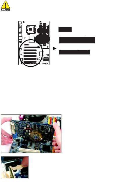
1-5 Installing an Expansion Card
Read the following guidelines before you begin to install an expansion card:
• Make sure the motherboard supports the expansion card. Carefully read the manual that came with your expansion card.
•Always turn off the computer and unplug the power cord from the power outlet before installing an expansion card to prevent hardware damage.
PCI Express x1 Slot
PCI Express x16 Slot
PCI Slot
Follow the steps below to correctly install your expansion card in the expansion slot.
1.Locate an expansion slot that supports your card. Remove the metal slot cover from the chassis back panel.
2.Align the card with the slot, and press down on the card until it is fully seated in the slot.
3.Make sure the metal contacts on the card are completely inserted into the slot.
4.Secure the card’s metal bracket to the chassis back panel with a screw.
5.After installing all expansion cards, replace the chassis cover(s).
6.Turn on your computer. If necessary, go to BIOS Setup to make any required BIOS changes for your expansion card(s).
7.Install the driver provided with the expansion card in your operating system.
Example: Installing and Removing a PCI Express x16 Graphics Card:
• Installing a Graphics Card:
Gently insert the graphics card into the PCI Express x16 slot. Make sure the graphics card is locked by the latch at the end of the PCI Express x16 slot.
•Removing the Card:
Press the white latch at the end of the PCI Express x16 slot to release the card and then pull the card straight up from the slot.
|
GA-P43-ES3G Motherboard |
— 1 8 — |
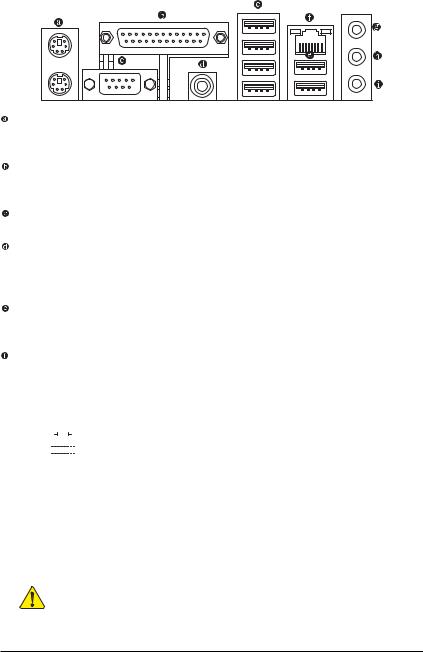
1-6 Back Panel Connectors
PS/2 Keyboard and PS/2 Mouse Port
Use the upper port (green) to connect a PS/2 mouse and the lower port (purple) to connect a PS/2 keyboard.
Parallel Port
Use the parallel port to connect devices such as a printer, scanner and etc. The parallel port is also called a printer port.
Serial Port
Use the serial port to connect devices such as a mouse, modem or other peripherals.
Coaxial S/PDIF Out Connector
This connector provides digital audio out to an external audio system that supports digital coaxial audio. Before using this feature, ensure that your audio system provides a coaxial digital audio in connector.
USB Port
The USB port supports the USB 2.0/1.1 specification. Use this port for USB devices such as an USB keyboard/mouse, USB printer, USB flash drive and etc.
RJ-45 LAN Port
The Gigabit Ethernet LAN port provides Internet connection at up to 1 Gbps data rate. The following describes the states of the LAN port LEDs.
|
Connection/ |
||||||||||
|
Speed LED |
Activity LED |
Connection/Speed LED: |
Activity LED: |
|||||||
|
State |
Description |
|||||||||
|
State |
Description |
|||||||||
|
Orange |
1 Gbps data rate |
Blinking |
Data transmission or receiving is occurring |
|||||||
|
Green |
100 Mbps data rate |
Off |
No data transmission or receiving is occurring |
|||||||
|
Off |
10 Mbps data rate |
|||||||||
|
LAN Port |
||||||||||
• When removing the cable connected to a back panel connector, first remove the cable from your device and then remove it from the motherboard.


 • When removing the cable, pull it straight out from the connector. Do not rock it side to side to prevent an electrical short inside the cable connector.
|
— 19 — |
Hardware Installation |

Line In Jack (Blue)
The default line in jack . Use this audio jack for line in devices such as an optical drive, walkman, etc.
Line Out Jack (Green)
The default line out jack. Use this audio jack for a headphone or 2-channel speaker. This jack can be used to connect front speakers in a 4/5.1-channel audio configuration.
Mic In Jack (Pink)
The default Mic in jack. Microphones must be connected to this jack.
To enable 7.1-channel audio, you have to use an HD front panel audio module and enable the multi-channel audio feature through the audio driver. Refer to the instructions on setting up a 2/4/5.1/7.1-channel audio configuration in Chapter 5, «Configuring 2/4/5.1/7.1-Channel Audio.»
|
GA-P43-ES3G Motherboard |
— 2 0 — |
![]()
|
1-7 |
Internal Connectors |
||||
|
3 |
|||||
|
1 |
|||||
|
2 |
|||||
|
4 |
6 |
||||
|
11 |
|||||
|
16 |
|||||
|
13 |
4 |
||||
|
7 |
|||||
|
12 |
10 |
||||
|
5 |
15 |
14 |
9 |
8 |
|
|
1) |
ATX_12V |
9) |
BATTERY |
||
|
2) |
ATX |
10) |
F_PANEL |
||
|
3) |
CPU_FAN |
11) |
F_AUDIO |
||
|
4) |
SYS_FAN1/SYS_FAN2 |
12) |
CD_IN |
||
|
5) |
FDD |
13) |
SPDIF_O |
||
|
6) |
IDE |
14) |
F_USB1/F_USB2/F_USB3 |
||
|
7) |
SATA2_0/1/2/3/4/5 |
15) |
C I |
||
|
|
PWR_LED |
16) |
CLR_CMOS |
Read the following guidelines before connecting external devices:
• First make sure your devices are compliant with the connectors you wish to connect.
• Before installing the devices, be sure to turn off the devices and your computer. Unplug the power cord from the power outlet to prevent damage to the devices.
•After installing the device and before turning on the computer, make sure the device cable has been securely attached to the connector on the motherboard.
|
— 21 — |
Hardware Installation |
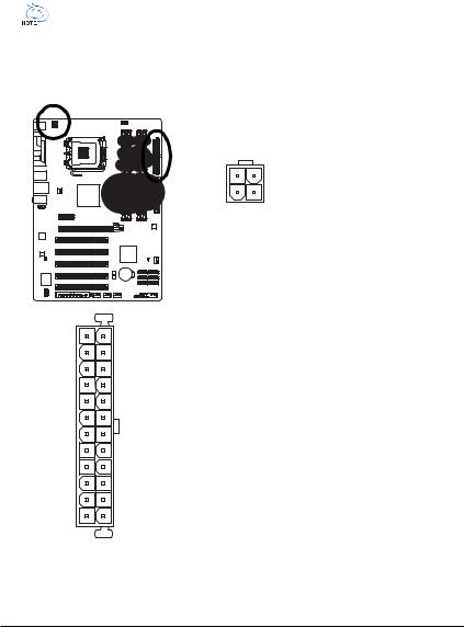
1/2) ATX_12V/ATX (2×2 12V Power Connector and 2×12 Main Power Connector)
With the use of the power connector, the power supply can supply enough stable power to all the components on the motherboard. Before connecting the power connector, first make sure the power supply is turned off and all devices are properly installed. The power connector possesses a foolproof design. Connect the power supply cable to the power connector in the correct orientation. The 12V power connector mainly supplies power to the CPU. If the 12V power connector is not connected, the computer will not start.
• To meet expansion requirements, it is recommended that a power supply that can withstand high power consumption be used ( 500W or greater). If a power supply is used that does not
provide the required power, the result can lead to an unstable or unbootable system.
•The main power connector is compatible with power supplies with 2×10 power connectors. When using a 2×12 power supply, remove the protective cover from the main power connector on the motherboard. Do not insert the power supply cable into pins under the protective cover when using a 2×10 power supply.
|
ATX_12V: |
||||
|
Pin No. |
Definition |
|||
|
1 |
GND |
|||
|
3 |
4 |
2 |
GND |
|
|
1 |
2 |
3 |
+12V |
|
|
4 |
+12V |
|||
ATX_12V
|
ATX : |
|||
|
Pin No. |
Definition |
Pin No. |
Definition |
|
1 |
3.3V |
13 |
3.3V |
|
2 |
3.3V |
14 |
-12V |
|
3 |
GND |
15 |
GND |
|
4 |
+5V |
16 |
PS_ON(soft On/Off) |
|
5 |
GND |
17 |
GND |
|
6 |
+5V |
18 |
GND |
|
7 |
GND |
19 |
GND |
|
8 |
Power Good |
20 |
-5V |
|
9 |
5V SB(stand by +5V) |
21 |
+5V |
|
10 |
+12V |
22 |
+5V |
|
11 |
+12V(Onlyfor2x12-pinATX) |
23 |
+5V (Onlyfor2x12-pinATX) |
|
12 |
3.3V(Onlyfor2x12-pinATX) |
24 |
GND(Onlyfor2x12-pinATX) |
|
GA-P43-ES3G Motherboard |
— 2 2 — |
CPU_FAN:
3/4) CPU_FAN/SYS_FAN1/SYS_FAN2(Fan Headers)
The motherboard has a 4-pin CPU fan header (CPU_FAN), a 3-pin (SYS_FAN 1)and a 4-pin (SYS_FAN2) system fan headers. Most fan headers possess a foolproof insertion design. When connecting a fan cable, be sure to connect it in the correct orientation (the black connector wire is the ground wire). The motherboard supports CPU fan speed control, which requires the use of a CPU fan with fan speed control design. For optimum heat dissipation, it is recommended that a system fan be installed inside the chassis.
|
Pin No. |
Definition |
||||||
|
1 |
1 |
GND |
|||||
|
2 |
Speed Control |
||||||
|
CPU_FAN |
3 |
Sense |
|||||
|
4 |
Speed Control |
||||||
|
SYS_FAN2: |
|||||||
|
Pin No. |
Definition |
||||||
|
1 |
1 |
GND |
|||||
|
2 |
Speed Control |
||||||
|
SYS_FAN2 |
|||||||
|
3 |
Sense |
||||||
|
4 |
+5V |
||||||
|
SYS_FAN1 |
|||||||
|
1 |
Pin No. |
Definition |
|||||
|
1 |
GND |
||||||
|
SYS_FAN1 |
|||||||
|
2 |
+12V |
||||||
|
3 |
Sense |
•Be sure to connect fan cables to the fan headers to prevent your CPU and system from overheating. Overheating may result in damage to the CPU or the system may hang.


 • These fan headers are not configuration jumper blocks. Do not place a jumper cap on the headers.
5)FDD (Floppy Disk Drive Connector)
This connector is used to connect a floppy disk drive. The types of floppy disk drives supported are: 360 KB, 720 KB, 1.2 MB, 1.44 MB, and 2.88 MB. Before connecting a floppy disk drive, be sure to locate pin 1 of the connector and the floppy disk drive cable. The pin 1 of the cable is typically designated by a stripe of different color.
|
— 23 — |
Hardware Installation |

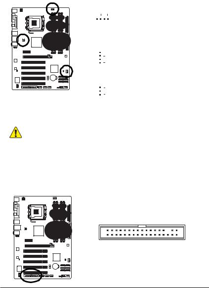
6)IDE (IDE Connector)
The IDE connector supports up to two IDE devices such as hard drives and optical drives. Before attaching the IDE cable, locate the foolproof groove on the connector. If you wish to connect two IDE devices, remember to set the jumpers and the cabling according to the role of the IDE devices (for example, master or slave). (For information about configuring master/slave settings for the IDE devices, read the instructions from the device manufacturers.)
40 39
2 1
7) SATA2_0/1/2/3/4/5 (SATA 3Gb/s Connectors, Controlled by ICH10)
The SATA connectors conform to SA TA 3Gb/s standard and are compatible with SA TA 1.5Gb/s standard. Each SATA connector supports a single SA TA device.
|
Pin No. |
Definition |
||||||||||||||||||
|
SATA2_3 |
SATA2_0 |
1 |
GND |
||||||||||||||||
|
7 |
1 7 |
1 |
2 |
TXP |
|||||||||||||||
|
SATA2_4 |
SATA2_1 |
3 |
TXN |
||||||||||||||||
|
7 |
1 7 |
1 |
4 |
GND |
|||||||||||||||
|
SATA2_5 |
SATA2_2 |
5 |
RXN |
||||||||||||||||
|
7 |
1 7 |
1 |
6 |
RXP |
|||||||||||||||
|
7 |
GND |
||||||||||||||||||
Please connect the L-shaped end of the SATA 3Gb/s cable to your SATA hard drive.
|
GA-P43-ES3G Motherboard |
— 2 4 — |
 PWR_LED (System Power LED Header)
This header can be used to connect a system power LED on the chassis to indicate system power status. The LED is on when the system is operating. The LED keeps blinking when the system is in S1 sleep state. The LED is off when the system is in S3/S4 sleep state or powered off (S5).
|
Pin No. |
Definition |
||
|
1 |
MPD+ |
||
|
1 |
2 |
MPD- |
|
|
3 |
MPD- |
||
|
System Status |
LED |
||
|
S0 |
On |
||
|
S1 |
Blinking |
||
|
S3/S4/S5 |
Off |
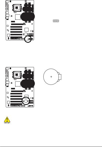
9)BATTERY
The battery provides power to keep the values (such as BIOS configurations, date, and time information) in the CMOS when the computer is turned off. Replace the battery when the battery voltage drops to a low level, or the CMOS values may not be accurate or may be lost.
You may clear the CMOS values by removing the battery: 1. Turn off your computer and unplug the power cord.
2. Gently remove the battery from the battery holder and wait for one minute. (Or use a metal object like a screwdriver to touch the positive and negativeterminalsofthebatteryholder,makingthemshortfor5seconds.)
3.Replace the battery.
4.Plug in the power cord and restart your computer.
•Always turn off your computer and unplug the power cord before replacing the battery.
• Replace the battery with an equivalent one. Danger of explosion if the battery is replaced with an incorrect model.
•Contact the place of purchase or local dealer if you are not able to replace the battery by yourself or uncertain about the battery model.
•When installing the battery, note the orientation of the positive side (+) and the negative side (-) of the battery (the positive side should face up).
•Used batteries must be handled in accordance with local environmental regulations.
|
— 25 — |
Hardware Installation |
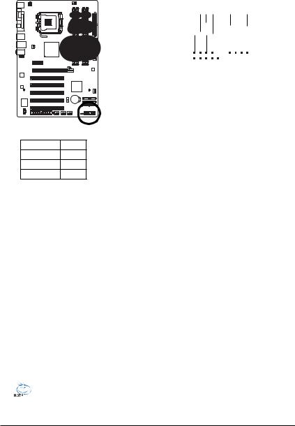
10) F_PANEL (Front Panel Header)
Connect the power switch, reset switch, speaker and system status indicator on the chassis front panel to this header according to the pin assignments below. Note the positive and negative pins before connecting the cables.
|
Message/Power/ |
Power |
||||||||
|
Sleep LED |
Switch |
Speaker |
|||||||
|
MSG+ |
PW+ |
SPEAK+ |
SPEAK- |
|
MSG- |
PW- |
|
2 |
20 |
||||||||||||||
|
1 |
19 |
||||||||||||||
|
HD- |
RES+ |
||||||||||||||
|
HD+ |
RES- |
NC |
|||||||||||||
|
Hard Drive |
Reset |
||||||||||||||
|
Activity LED |
Switch |
• MSG (Message/Power/Sleep LED, Yellow):
|
System Status |
LED |
|
S0 |
On |
|
S1 |
Blinking |
|
S3/S4/S5 |
Off |
Connects to the power status indicator on the chassis front panel. The LED is on when the system is operating. The LED keeps blinking when the system is in S1 sleep state. The LED is off when the system is in S3/S4 sleep state or powered off (S5).
•PW (Power Switch, Red):
Connects to the power switch on the chassis front panel. You may configure the way to turn of f your system using the power switch (refer to Chapter 2, «BIOS Setup,» «Power Management Setup,» for more information).
•SPEAK (Speaker, Orange):
Connects to the speaker on the chassis front panel. The system reports system startup status by issuing a beep code. One single short beep will be heard if no problem is detected at system startup. If a problem is detected, the BIOS may issue beeps in different patterns to indicate the problem. Refer to Chapter 5, «Troubleshooting,» for information about beep codes.
•HD (IDE Hard Drive Activity LED, Blue)
Connects to the hard drive activity LED on the chassis front panel. The LED is on when the hard drive is reading or writing data.
•RES (Reset Switch, Green):
Connects to the reset switch on the chassis front panel. Press the reset switch to restart the computer if the computer freezes and fails to perform a normal restart.
•NC (Purple): No connection
The front panel design may differ by chassis. A front panel module mainly consists of power switch, reset switch, power LED, hard drive activity LED, speaker and etc. When connecting your chassis front panel module to this header, make sure the wire assignments and the pin assignments are matched correctly.
|
GA-P43-ES3G Motherboard |
— 2 6 — |

11)F_AUDIO (Front Panel Audio Header)
The front panel audio header supports Intel High Definition audio (HD) and AC’97 audio. You may connect your chassis front panel audio module to this header. Make sure the wire assignments of the module connector match the pin assignments of the motherboard header. Incorrect connection between the module connector and the motherboard header will make the device unable to work or even damage it.
|
For HD Front Panel Audio: |
For AC’97 Front Panel Audio: |
|||||||||
|
Pin No. |
Definition |
Pin No. |
Definition |
|||||||
|
2 |
10 |
1 |
MIC2_L |
1 |
MIC |
|||||
|
2 |
GND |
2 |
GND |
|||||||
|
1 |
9 |
3 |
MIC2_R |
3 |
MIC Power |
|||||
|
4 |
-ACZ_DET |
4 |
NC |
|||||||
|
5 |
LINE2_R |
5 |
Line Out (R) |
|||||||
|
6 |
GND |
6 |
NC |
|||||||
|
7 |
FAUDIO_JD |
7 |
NC |
|||||||
|
8 |
No Pin |
8 |
No Pin |
|||||||
|
9 |
LINE2_L |
9 |
Line Out (L) |
|||||||
|
10 |
GND |
10 |
NC |
• The front panel audio header supports HD audio by default. If your chassis provides an AC’97 front panel audio module, refer to the instructions on how to activate AC’97 functioninality via the audio software in Chapter 5, «Configuring 2/4/5.1/7.1-Channel Audio.»
•Audio signals will be present on both of the front and back panel audio connections simultaneously. If you want to mute the back panel audio (only supported when using an HD front panel audio module), refer to Chapter 5, «Configuring 2/4/5.1/7.1-Channel Audio.»
•Some chassis provide a front panel audio module that has separated connectors on each wire instead of a single plug. For information about connecting the front panel audio module that has different wire assignments, please contact the chassis manufacturer.
12)CD_IN (CD In Connector)
You may connect the audio cable that came with your optical drive to the header .
|
Pin No. |
Definition |
|||
|
1 |
CD-L |
|||
|
2 |
GND |
|||
|
3 |
GND |
|||
|
1 |
||||
|
4 |
CD-R |
|||
|
— 27 — |
Hardware Installation |
 Loading…
Page 1 — GA-P43-ES3G
GA-P43-ES3GLGA775 socket motherboard for Intel® CoreTM processor family/Intel® Pentium® processor family/Intel® Celeron® processor familyUser’s M
Page 2 — Nov. 14, 2008
GA-P43-ES3G Motherboard — 1 0 -1-2 Product SpecificationsCPU Support for an Intel® CoreTM 2 Extreme processor/Intel® CoreTM 2 Quad processor/Intel®
Page 4 — Table of Contents
GA-P43-ES3G Motherboard — 1 2 -BIOS 2 x 8 Mbit flash Use of licensed AWARD BIOS Support for DualBIOSTM PnP 1.0a, DMI 2.0, SM BIOS 2.4, ACPI 1.0bU
Page 5
Hardware Installation- 13 -1-3 Installing the CPU and CPU CoolerRead the following guidelines before you begin to install the CPU:• Make sure that the
Page 6 — Optional Items
GA-P43-ES3G Motherboard — 1 4 -Step 5:Once the CPU is properly inserted, replacethe load plate and push the CPU socket leverback into its locked posit
Page 7
Hardware Installation- 15 -1-3-2 Installing the CPU CoolerFollow the steps below to correctly install the CPU cooler on the motherboard. (The followin
Page 8 — Block Diagram
GA-P43-ES3G Motherboard — 1 6 -1-4 Installing the MemoryRead the following guidelines before you begin to install the memory:• Make sure that the moth
Page 9 — 1-1 Installation Precautions
Hardware Installation- 17 -1-4-2 Installing a MemoryNotchBefore installing a memory module , make sure to turn off the computer and unplugthe power co
Page 10 — 1-2 Product Specifications
GA-P43-ES3G Motherboard — 1 8 -PCI Slot1-5 Installing an Expansion CardRead the following guidelines before you begin to install an expansion card:• M
Page 11 — (Note 3)
Hardware Installation- 19 -• When removing the cable connected to a back panel connector, first remove the cablefrom your device and then remove it fr
Page 12
Nov. 14, 2008MotherboardGA-P43-ES3GMotherboardGA-P43-ES3GNov. 14, 2008
Page 13 — 1-3-1 Installing the CPU
GA-P43-ES3G Motherboard — 2 0 -Line In Jack (Blue)The default line in jack. Use this audio jack for line in devices such as an optical drive, walkman
Page 14 — CPU Socket Lever
Hardware Installation- 21 -1-7 Internal ConnectorsRead the following guidelines before connecting external devices:• First make sure your devices are
Page 15
GA-P43-ES3G Motherboard — 2 2 -1312412ATXATX :ATX_12V:ATX_12V1324Pin No. Definition1 GND2 GND3 +12V4 +12V1/2) ATX_12V/ATX (2×2 12V Power Connector and
Page 16 — 1-4 Installing the Memory
Hardware Installation- 23 -• Be sure to connect fan cables to the fan headers to prevent your CPU and system fromoverheating. Overheating may result i
Page 17 — 1-4-2 Installing a Memory
GA-P43-ES3G Motherboard — 2 4 -6) IDE (IDE Connector)The IDE connector supports up to two IDE devices such as hard drives and optical drives. Beforeat
Page 18 — PCI Express x1 Slot
Hardware Installation- 25 -8) PWR_LED (System Power LED Header)This header can be used to connect a system power LED on the chassis to indicate system
Page 19 — 1-6 Back Panel Connectors
GA-P43-ES3G Motherboard — 2 6 -10) F_PANEL (Front Panel Header)Connect the power switch, reset switch, speaker and system status indicator on the cha
Page 20 — Mic In Jack (Pink)
Hardware Installation- 27 -11) F_AUDIO (Front Panel Audio Header)The front panel audio header supports Intel High Definition audio (HD) and AC’97
Page 21 — 1-7 Internal Connectors
GA-P43-ES3G Motherboard — 2 8 -14) F_USB1/F_USB2/F_USB3 (USB Headers)The headers conform to USB 2.0/1.1 specification. Each USB header can provide two
Page 22
Hardware Installation- 29 -Open: NormalShort: Clear CMOS Values16) CLR_CMOS (Clearing CMOS Jumper)Use this jumper to clear the CMOS values (e.g. date
Page 23
Copyright© 2009 GIGA-BYTE TECHNOLOGY CO., LTD. All rights reserved.The trademarks mentioned in this manual are legally registered to their respective
Page 25 — 9) BATTERY
— 3 1 — BIOS SetupChapter 2 BIOS SetupBIOS (Basic Input and Output System) records hardware parameters of the system in the CMOS on themotherboard. It
Page 26 — S3/S4/S5 Off
GA-P43-ES3G Motherboard — 3 2 -2-1 Startup ScreenThe following screens may appear when the computer boots.A. The LOGO Screen (Default)B. The POST Scre
Page 27 — 12) CD_IN (CD In Connector)
— 3 3 — BIOS Setup2-2 The Main MenuOnce you enter the BIOS Setup program, the Main Menu (as shown below) appears on the screen. Usearrow keys to move
Page 28
GA-P43-ES3G Motherboard — 3 4 - The Functions of the <F11> and <F12> keys (For the Main Menu Only)` F11 : Save CMOS to BIOSThis fun
Page 29 — 1 Signal
— 3 5 — BIOS Setup2-3 MB Intelligent Tweaker(M.I.T.)(Note 1) This item appears only if you install a CPU that supports this feature.(Note 2) This item
Page 30
GA-P43-ES3G Motherboard — 3 6 -Robust Graphics BoosterRobust Graphics Booster (R.G.B.) helps to enhance the performance of the graphics chip andmemory
Page 31 — Chapter 2 BIOS Setup
— 3 7 — BIOS Setup(G)MCH Frequency LatchAllows you to fix the chipset frequency at system bootup. Options for adjusting memory multiplierbelow may dif
Page 32 — 2-1 Startup Screen
GA-P43-ES3G Motherboard — 3 8 -tWTROptions are: Auto (default), 1~31.tWROptions are: Auto (default), 1~31.tRFCOptions are: Auto (default), 1~255.tRTPO
Page 33 — 2-2 The Main Menu
— 3 9 — BIOS SetupCMOS Setup Utility-Copyright (C) 1984-2008 Award SoftwareChannel A Driving SettingsKLJI: Move Enter: Select +/-/PU/PD: Value F10: Sa
Page 34
— 4 -Table of ContentsBox Contents … 6
Page 35 — (Note 2)
GA-P43-ES3G Motherboard — 4 0 -Ctrl Driving Pull-Down LevelOptions are: Auto (default), +8~-7.Clk Driving Pull-Down LevelOptions are: Auto (default),
Page 36 — (Note 1)
— 4 1 — BIOS Setup2-4 Standard CMOS FeaturesDateSets the system date. The date format is week (read-only), month, date and year. Select thedesired fi
Page 37
GA-P43-ES3G Motherboard — 4 2 -• Auto Lets BIOS automatically detect IDE/SATA devices during the POST. (Default)• None If no IDE/SATA devices are us
Page 38
— 4 3 — BIOS Setup2-5 Advanced BIOS FeaturesCMOS Setup Utility-Copyright (C) 1984-2008 Award SoftwareAdvanced BIOS Features` Hard Disk Boot Priority [
Page 39
GA-P43-ES3G Motherboard — 4 4 -(Note) This item is present only if you install a CPU that supports this feature. For more informationabout Intel CPUs&
Page 40
— 4 5 — BIOS SetupDelay For HDD (Secs)Allows you to set a delay time for the BIOS to initialize the hard drive as the system boots up. Theadjustable r
Page 41 — 2-4 Standard CMOS Features
GA-P43-ES3G Motherboard — 4 6 -2-6 Integrated PeripheralsSATA AHCI Mode (Intel ICH10 Southbridge)Configures the SATA controllers integrated in the Int
Page 42 — Floppy 3 Mode Support
— 4 7 — BIOS SetupSMART LAN (LAN Cable Diagnostic Function)CMOS Setup Utility-Copyright (C) 1984-2008 Award SoftwareSMART LANItem HelpMenu Level«Star
Page 43 — 2-5 Advanced BIOS Features
GA-P43-ES3G Motherboard — 4 8 -Onboard LAN Boot ROMAllows you to decide whether to activate the boot ROM integrated with the onboard LAN chip.(Default
Page 44
— 4 9 — BIOS Setup2-7 Power Management SetupCMOS Setup Utility-Copyright (C) 1984-2008 Award SoftwarePower Management SetupACPI Suspend Type [S3(STR)]
Page 46 — 2-6 Integrated Peripherals
GA-P43-ES3G Motherboard — 5 0 -Resume by AlarmDetermines whether to power on the system at a desired time. (Default: Disabled)If enabled, set the date
Page 47
— 5 1 — BIOS Setup2-8 PnP/PCI ConfigurationsPCI1 IRQ AssignmentAuto BIOS auto-assigns IRQ to the first PCI slot. (Default)3,4,5,7,9,10,11,12,14,15 Ass
Page 48
GA-P43-ES3G Motherboard — 5 2 -2-9 PC Health StatusReset Case Open StatusKeeps or clears the record of previous chassis intrusion status. Enabled cle
Page 49 — 2-7 Power Management Setup
— 5 3 — BIOS SetupCPU Smart FAN ControlEnables or disables the CPU fan speed control function. Auto lets the BIOS decide whether toenable this functio
Page 50
GA-P43-ES3G Motherboard — 5 4 -2-10 Load Fail-Safe DefaultsPress <Enter> on this item and then press the <Y> key to load the safest BIOS d
Page 51 — 2-8 PnP/PCI Configurations
— 5 5 — BIOS Setup2-12 Set Supervisor/User PasswordCMOS Setup Utility-Copyright (C) 1984-2008 Award Software` MB Intelligent Tweaker(M.I.T.)` Standard
Page 52 — 2-9 PC Health Status
GA-P43-ES3G Motherboard — 5 6 -2-13 Save & Exit Setup2-14 Exit Without SavingCMOS Setup Utility-Copyright (C) 1984-2008 Award Software` MB Intelli
Page 53 — CPU Smart FAN Mode
Drivers Installation- 57 -Chapter 3 Drivers Installation3-1 Installing Chipset Drivers• Before installing the drivers, first install the operating sys
Page 55
Drivers Installation- 59 -3-4 ContactClick the URL on this page to link to the GIGABYTE Web site. Or read the last page of th is manual to checkthe co
Page 56 — 2-14 Exit Without Saving
— 6 -Box ContentsGA-P43-ES3G motherboardMotherboard driver diskUser’s ManualQuick Installation GuideOne IDE cableTwo SATA 3Gb/s cablesI/O ShieldO
Page 57
GA-P43-ES3G Motherboard — 6 0 -3-6 Download CenterTo update the BIOS, drivers, or applications, click the Download Center button to link to the GIGABY
Page 58 — 3-3 Technical Manuals
Unique Features- 61 -4-1 Xpress Recovery2″*» Xpress Recovery2 checks the first physical hard drive in the following sequence: The first PA
Page 59 — 3-5 System
GA-P43-ES3G Motherboard — 6 2 -Installation and Configuration(The following procedure uses Windows XP as the example operating system.)A. Installing W
Page 60 — 3-6 Download Center
Unique Features- 63 -4. After the operating system is installed, right-click the My Computer icon on your desktop andselect Manage (Figure 4). Go to
Page 61 — Chapter 4 Unique Features
GA-P43-ES3G Motherboard — 6 4 -2. After you use the backup function in Xpress Recovery2 for the first time, Xpress Recovery2 willstay permanent in you
Page 62
Unique Features- 65 -D. Using the Restore Function in Xpress Recovery2Select RESTORE to restore the backup to your hard drive in case the system break
Page 63
GA-P43-ES3G Motherboard — 6 6 -Because BIOS flashing is potentially risky, please do it with caution. Inadequate BIOSflashing may result in system ma
Page 66 — 4-2 BIOS Update Utilities
Unique Features- 69 -4-2-2 Updating the BIOS with the @BIOS UtilityA. Before You Begin:1. In Windows, close all applications and TSR (Terminate and St
Page 67 — B. Updating the BIOS
— 7 -GA-P43-ES3G Motherboard LayoutKB_MSCPU_FANLGA775ATXGA-P43-ES3GF_AUDIOIDEATX_12VIntel® P43USB_LANAUDIOR_USBPCIEX1SYS_FAN1F_PANELPWR_LEDSYS_FAN2IDE
Page 68
GA-P43-ES3G Motherboard — 7 0 -4-3 EasyTune 6GIGABYTE’s EasyTune 6 is a simple and easy-to-use interface that allows users to fine-tune theirsyst
Page 69 — C. After Updating the BIOS:
Unique Features- 71 -4-4 Easy Energy SaverGIGABYTE Easy Energy Saver (Note 1) is a revolutionary technology that delivers unparalleled powersavings wi
Page 70 — 4-3 EasyTune 6
GA-P43-ES3G Motherboard — 7 2 -Total Mode — Button Information TableB. Total ModeIn Total Mode, users are able to see how much total power savings the
Page 71 — 4-4 Easy Energy Saver
Appendix- 73 -5-1 Configuring Audio Input and Output5-1-1 Configuring 2/4/5.1/7.1-Channel AudioThe motherboard provides three audio jacks on the backp
Page 72 — C. Stealth Mode
GA-P43-ES3G Motherboard — 74 -Step 2:Click the Audio I/O tab. In the speaker list on theleft, select 2CH Speaker, 4CH Speaker, 6CHSpeaker, or 8CH Sp
Page 73 — Chapter 5 Appendix
Appendix- 75 -B. Configuring Sound Effect:You may configure an audio environment on the Sound Effect tab.C. Activating an AC’97 Front Panel Audi
Page 74 — Side Speaker Out
GA-P43-ES3G Motherboard — 76 -The S/PDIF out jack can transmit audio signals to an external decoder for decoding to get the best audioquality.5-1-2 Co
Page 77
Appendix- 79 -Step 6:To raise the recording and playing sound for themicrophone, go to Options in Master Volume andselect Advanced Controls. Click the
Page 78 — Recording Control
— 8 -Block DiagramLGA775ProcessorHostInterfaceIntel® P43MCH CLK(333/266/200 MHz)DDR2 1200/1066/800/667 MHz5 PCIPCI BusDual Channel MemoryPCI CLK(33 MH
Page 79 — Playing the Sound:
GA-P43-ES3G Motherboard — 80 -5-2 Troubleshooting5-2-1 Frequently Asked QuestionsTo read more F AQs for your motherboard, please go to the SupportMot
Page 80 — 5-2 Troubleshooting
Appendix- 81 -5-2-2 Troubleshooting ProcedureIf you encounter any troubles during system startup, follow the troubleshooting procedure below tosolve t
Page 81 — Appendix- 81
GA-P43-ES3G Motherboard — 82 -NoYe sCheck if there is display on your monitor.Ye sWhen the computer is turned on, is the CPU cooler running?NoThe gr
Page 82
Appendix- 83 -5-3 Regulatory StatementsRegulatory NoticesThis document must not be copied without our written permission, and the contents there of mu
Page 83 — 5-3 Regulatory Statements
GA-P43-ES3G Motherboard — 84 -Finally, we suggest that you practice other environmentally friendly actions by understanding andusing the energy-saving
Page 86
Appendix- 87 -Contact Usyyyyy GIGA-BYTE TECHNOLOGY CO., LTD.Address: No.6, Bau Chiang Road, Hsin-Tien,Taipei 231, Taiwan TEL: +886-2-8912-4000 FAX:
Page 87 — Contact Us
GA-P43-ES3G Motherboard — 88 -yyyyy G.B.T. TECHNOLOGY TRADING GMBH — GermanyWEB address : http://www.gigabyte.deyyyyy G.B.T. TECH. CO., LTD. — U.K.WEB
Page 88
Hardware Installation- 9 -1-1 Installation PrecautionsThe motherboard contains numerous delicate electronic circuits and components which can becomeda