i
FCC—B Radio Frequency Interference Statement
This equipment has been tested and found to comply with the limits for a class B digital device, pursuant
to part 15 of the FCC rules. These limits are designed to provide reasonable protection against harmful
interference in a residential installation. This equipment generates, uses and can radiate radio frequency
energy and, if not installed and used in accordance with the instruction manual, may cause harmful
interference to radio communications. However, there is no guarantee that interference will occur in a
particular installation. If this equipment does cause harmful interference to radio or television reception,
which can be determined by turning the equipment off and on, the user is encouraged to try to correct the
interference by one or more of the measures listed below.
4 Reorient or relocate the receiving antenna.
4 Increase the separation between the equipment and receiver.
4 Connect the equipment into an outlet on a circuit different from that to which the receiver is
connected.
4 Consult the dealer or an experienced radio/ television technician for help.
Notice 1
The changes or modifications not expressly approved by the party responsible for compliance could void
the user’s authority to operate the equipment.
Notice 2
Shielded interface cables and A.C. power cord, if any, must be used in order to comply with the emission
limits.
VOIR LA NOTICE D’NSTALLATION AVANT DE RACCORDER AU RESEAU.
Micro—Star International
MS-7309
This device complies with Part 15 of the FCC Rules. Operation is subject to the following two conditions:
(1) this device may not cause harmful interference, and
(2) this device must accept any interference received, including interference that may cause undesired
operation
G52—73091X3

ii
Copyright Notice
The material in this document is the intellectual property of MICRO—STAR INTERNATIONAL. We take
every care in the preparation of this document, but no guarantee is given as to the correctness of its
contents. Our products are under continual improvement and we reserve the right to make changes
without notice.
Trademarks
All trademarks are the properties of their respective owners.
AMD, Athlon™ Athlon™XP, Thoroughbred™ and Duron™ are registered trademarks of AMD Corporation.
Intel
®
and Pentium
®
are registered trademarks of Intel Corporation.
PS/2 and OS
®
2 are registered trademarks of International Business Machines Corporation.
Microsoft
®
is a registered trademark of Microsoft Corporation. Windows
®
98/2000/NT/XP are registered
trademarks of Microsoft Corporation.
NVIDIA, the NVIDIA logo, DualNet, and nForce are registered trademarks or trademarks of NVIDIA
Corporation in the United States and/or other countries.
Netware
®
is a registered trademark of Novell, Inc.
Award
®
is a registered trademark of Phoenix Technologies Ltd.
AMI
®
is a registered trademark of American Megatrends Inc.
Kensington and MicroSaver are registered trademarks of the Kensington Technology Group.
PCMCIA and CardBus are registered trademarks of the Personal Computer Memory Card International
Association.
Revision History
Revision Revision History Date
V1.0 First release for PCB1.X September 2006
V1.1 Remove Clear CMOS Button, add Clear CMOS Jumper October 2006
V1.2 Change the marketing name and add Korean April 2008

iii
Safety Instructions
1. Always read the safety instructions carefully.
2. Keep this User Manual for future reference.
3. Keep this equipment away from humidity.
4. Lay this equipment on a reliable flat surface before setting it up.
5. The openings on the enclosure are for air convection hence protects the equipment from overheating.
Do not cover the openings.
6. Make sure the voltage of the power source and adjust properly 110/220V before connecting the
equipment to the power inlet.
7. Place the power cord such a way that people can not step on it. Do not place anything over the power
cord.
8. Always Unplug the Power Cord before inserting any add—on card or module.
9. All cautions and warnings on the equipment should be noted.
10. Never pour any liquid into the opening that could damage or cause electrical shock.
11. If any of the following situations arises, get the equipment checked by a service personnel:
— The power cord or plug is damaged.
— Liquid has penetrated into the equipment.
— The equipment has been exposed to moisture.
— The equipment does not work well or you can not get it work according to User Manual.
— The equipment has dropped and damaged.
— The equipment has obvious sign of breakage.
12. Do not leave this equipment in an environment unconditioned, storage temperature above 60° C
(140°F), it may damage the equipment.
CAUTION: Danger of explosion if battery is incorrectly replaced. Replace only with the
same or equivalent type recommended by the manufacturer.

iv
WEEE Statement
English
To protect the global environment and as an environmentalist, MSI must remind you that…
Under the European Union («EU«) Directive on Waste Electrical and Electronic Equipment, Directive
2002/96/EC, which takes effect on August 13, 2005, products of «electrical and electronic equipment»
cannot be discarded as municipal waste anymore and manufacturers of covered electronic equipment will
be obligated to take back such products at the end of their useful life. MSI will comply with the product
take back requirements at the end of life of MSI—branded products that are sold into the EU. You can
return these products to local collection points.
Deutsch
Hinweis von MSI zur Erhaltung und Schutz unserer Umwelt
Gemäß der Richtlinie 2002/96/EG über Elektro— und Elektronik—Altgeräte dürfen Elektro— und
Elektronik—Altgeräte nicht mehr als kommunale Abfälle entsorgt werden. MSI hat europaweit
verschiedene Sammel— und Recyclingunternehmen beauftragt, die in die Europäische Union in Verkehr
gebrachten Produkte, am Ende seines Lebenszyklus zurückzunehmen. Bitte entsorgen Sie dieses
Produkt zum gegebenen Zeitpunkt ausschliesslich an einer lokalen Altgerätesammelstelle in Ihrer Nähe.
Français
En tant qu’écologiste et afin de protéger l’environnement, MSI tient à rappeler ceci…
Au sujet de la directive européenne (EU) relative aux déchets des équipement électriques et
électroniques, directive 2002/96/EC, prenant effet le 13 août 2005, que les produits électriques et
électroniques ne peuvent être déposés dans les décharges ou tout simplement mis à la poubelle. Les
fabricants de ces équipements seront obligés de récupérer certains produits en fin de vie. MSI prendra en
compte cette exigence relative au retour des produits en fin de vie au sein de la communauté européenne.
Par conséquent vous pouvez retourner localement ces matériels dans les points de collecte.
Русский
Компания MSI предпринимает активные действия по защите окружающей среды, поэтому
напоминаем вам, что....
В соответствии с директивой Европейского Союза (ЕС) по предотвращению загрязнения
окружающей среды использованным электрическим и электронным оборудованием (директива
WEEE 2002/96/EC), вступающей в силу 13 августа 2005 года, изделия, относящиеся к
электрическому и электронному оборудованию, не могут рассматриваться как бытовой мусор,
поэтому производители вышеперечисленного электронного оборудования обязаны принимать его
для переработки по окончании срока службы. MSI обязуется соблюдать требования по приему
продукции, проданной под маркой MSI на территории EC, в переработку по окончании срока
службы. Вы можете вернуть эти изделия в специализированные пункты приема.
Español
MSI como empresa comprometida con la protección del medio ambiente, recomienda:
Bajo la directiva 2002/96/EC de la Unión Europea en materia de desechos y/o equipos electrónicos, con
fecha de rigor desde el 13 de agosto de 2005, los productos clasificados como «eléctricos y equipos
electrónicos« no pueden ser depositados en los contenedores habituales de su municipio, los fabricantes
de equipos electrónicos, están obligados a hacerse cargo de dichos productos al termino de su período
de vida. MSI estará comprometido con los términos de recogida de sus productos vendidos en la Unión
Europea al final de su periodo de vida. Usted debe depositar estos productos en el punto limpio
establecido por el ayuntamiento de su localidad o entregar a una empresa autorizada para la recogida de
estos residuos.
Nederlands
Om het milieu te beschermen, wil MSI u eraan herinneren dat….
De richtlijn van de Europese Unie (EU) met betrekking tot Vervuiling van Electrische en Electronische
producten (2002/96/EC), die op 13 Augustus 2005 in zal gaan kunnen niet meer beschouwd worden als
vervuiling.
Fabrikanten van dit soort producten worden verplicht om producten retour te nemen aan het eind van hun
levenscyclus. MSI zal overeenkomstig de richtlijn handelen voor de producten die de merknaam MSI
dragen en verkocht zijn in de EU. Deze goederen kunnen geretourneerd worden op lokale
inzamelingspunten.

v
Srpski
Da bi zaštitili prirodnu sredinu, i kao preduzeće koje vodi računa o okolini i prirodnoj sredini, MSI mora da
vas podesti da…
Po Direktivi Evropske unije («EU«) o odbačenoj ekektronskoj i električnoj opremi, Direktiva 2002/96/EC,
koja stupa na snagu od 13. Avgusta 2005, proizvodi koji spadaju pod «elektronsku i električnu opremu« ne
mogu više biti odbačeni kao običan otpad i proizvođači ove opreme biće prinuđeni da uzmu natrag ove
proizvode na kraju njihovog uobičajenog veka trajanja. MSI će poštovati zahtev o preuzimanju ovakvih
proizvoda kojima je istekao vek trajanja, koji imaju MSI oznaku i koji su prodati u EU. Ove proizvode
možete vratiti na lokalnim mestima za prikupljanje.
Polski
Aby chronić nasze środowisko naturalne oraz jako firma dbająca o ekologię, MSI przypomina, że...
Zgodnie z Dyrektywą Unii Europejskiej («UE») dotyczącą odpadów produktów elektrycznych i
elektronicznych (Dyrektywa 2002/96/EC), która wchodzi w życie 13 sierpnia 2005, tzw. “produkty oraz
wyposażenie elektryczne i elektroniczne « nie mogą być traktowane jako śmieci komunalne, tak więc
producenci tych produktów będą zobowiązani do odbierania ich w momencie gdy produkt jest
wycofywany z użycia. MSI wypełni wymagania UE, przyjmując produkty (sprzedawane na terenie Unii
Europejskiej) wycofywane z użycia. Produkty MSI będzie można zwracać w wyznaczonych punktach
zbiorczych.
TÜRKÇE
Çevreci özelliğiyle bilinen MSI dünyada çevreyi korumak için hatırlatır:
Avrupa Birliği (AB) Kararnamesi Elektrik ve Elektronik Malzeme Atığı, 2002/96/EC Kararnamesi altında 13
Ağustos 2005 tarihinden itibaren geçerli olmak üzere, elektrikli ve elektronik malzemeler diğer atıklar gibi
çöpe atılamayacak ve bu elektonik cihazların üreticileri, cihazların kullanım süreleri bittikten sonra ürünleri
geri toplamakla yükümlü olacaktır. Avrupa Birliği’ne satılan MSI markalı ürünlerin kullanım süreleri
bittiğinde MSI ürünlerin geri alınması isteği ile işbirliği içerisinde olacaktır. Ürünlerinizi yerel toplama
noktalarına bırakabilirsiniz.
ČESKY
Záleží nám na ochraně životního prostředí — společnost MSI upozorňuje…
Podle směrnice Evropské unie («EU«) o likvidaci elektrických a elektronických výrobků 2002/96/EC platné
od 13. srpna 2005 je zakázáno likvidovat «elektrické a elektronické výrobky« v běžném komunálním
odpadu a výrobci elektronických výrobků, na které se tato směrnice vztahuje, budou povinni odebírat
takové výrobky zpět po skončení jejich životnosti. Společnost MSI splní požadavky na odebírání
výrobků značky MSI, prodávaných v zemích EU, po skončení jejich životnosti. Tyto výrobky můžete
odevzdat v místních sběrnách.
MAGYAR
Annak érdekében, hogy környezetünket megvédjük, illetve környezetvédőként fellépve az MSI
emlékezteti Önt, hogy …
Az Európai Unió („EU«) 2005. augusztus 13-án hatályba lépő, az elektromos és elektronikus
berendezések hulladékairól szóló 2002/96/EK irányelve szerint az elektromos és elektronikus
berendezések többé nem kezelhetőek lakossági hulladékként, és az ilyen elektronikus berendezések
gyártói kötelessé válnak az ilyen termékek visszavételére azok hasznos élettartama végén. Az MSI
betartja a termékvisszavétellel kapcsolatos követelményeket az MSI márkanév alatt az EU—n belül
értékesített termékek esetében, azok élettartamának végén. Az ilyen termékeket a legközelebbi
gyűjtőhelyre viheti.
Italiano
Per proteggere l’ambiente, MSI, da sempre amica della natura, ti ricorda che….
In base alla Direttiva dell’Unione Europea (EU) sullo Smaltimento dei Materiali Elettrici ed Elettronici,
Direttiva 2002/96/EC in vigore dal 13 Agosto 2005, prodotti appartenenti alla categoria dei Materiali
Elettrici ed Elettronici non possono più essere eliminati come rifiuti municipali: i produttori di detti materiali
saranno obbligati a ritirare ogni prodotto alla fine del suo ciclo di vita. MSI si adeguerà a tale Direttiva
ritirando tutti i prodotti marchiati MSI che sono stati venduti all’interno dell’Unione Europea alla fine del
loro ciclo di vita. È possibile portare i prodotti nel più vicino punto di raccolta.

vi
Table of Content
English…………………………………………………………..1
한국어 …………………………………………………………….13
Deutsch………………………………………………………….25
Français………………………………………………………...39
Русском ………………………………………………………...51
简体中文………………………………………………………….65
繁體中文………………………………………………………….77
日本語 …………………………………………………………….89

vii
1
Introduction
Thank you for choosing the K9N6PGM2 series (MS-7309 v1.x) Micro—ATX mainboard. The
K9N6PGM2 series is design based on MCP(P)61 / MCP(S)61 / MCP(V)61 chipset for optimal
system efficiency. Supports the AMD
®
Socket—AM2 processor, the K9N6GM series delivers a
high performance and professional desktop platform solution.
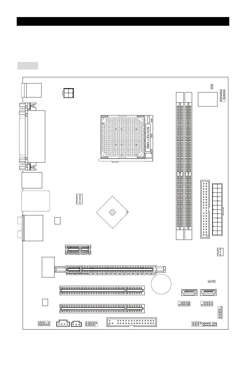
Layout
J
S
P
I
1
JCD1
JPW1
PCI _E1
CPUFAN1
PCI _E2(optional)
PCI2
PCI1
ALC883/861
RTL8201CL
/RT8211BL
(optional)
VIA
VT6308P
(optional)
JFP2
D
I
M
M
2
D
I
M
M
1
SPDOUT1
J1394_1
Top : mouse
Bottom:
keyboard
Top :
Parallel Port
Bottom:
COM 1
VGA port
Top: LAN Jack
Bottom: USB ports
Top:1394(optional)
Bottom: USB ports
T:
M:
B:
Line—In
Line—Out
Mic
T:RS-Out
M:CS-Out
B:SS-Out
+
MCP61

2
Specifications
Processor Support
• Supports Socket AM2 for AMD Sempron , Athlon 64 and Athlon 64 X2
• Supports Socket AM2+ 95W processor only
(For the latest information about CPU, please visit
http://global.msi.com.tw/index.php?func=cpuform )
Chipset
• nVIDIA MCP61(P) / MCP61(S) / MCP61(V)
Memory Support
• DDRII 533/667/800 SDRAM (2GB Max)
• 2 DDRII DIMMs (240pin / 1.8V)
• Dual channel
(For the updated supporting memory modules, please visit
http://global.msi.com.tw/index.php?func=testreport )
LAN
• Supports 10/100 LAN by Realtek 8201CL (K9N6SGM—V, K9N6VGM—V)
• Supports 10/100/1000 LAN by Realtek 8211BL—GR (K9N6PGM2)
Audio
• 7.1 channel audio codec Realtek ALC888 (optional)
• 7.1 channel audio codec Realtek ALC883 (optional)
• 7.1 channel audio codec Realtek ALC861 (optional)
IDE
• 1 IDE controller on the nVIDIA MCP61 chipset provides IDE HDD/ CD—ROM with PIO, Bus
Master and Ultra DMA 133/100/66 operation modes
• Can connect up to 2 IDE devices
SATA
• Supports 2 SATAII ports with up to 3Gb/s transfer rate
• Supports up to 2 SATAII HD
RAID
• Supports RAID 0, 1
Floppy
• 1 floppy port
• Supports 1 FDD with 360K, 720K, 1.2M, 1.44M and 2.88Mbytes
Connectors
• External:
— 1 x PS/2 mouse connector

3
— 1 x PS/2 keyboard connector
— 1 x Parallel port
— 1 x COM port
— 1 x VGA port
— 4 x USB connectors
— 1 x RJ—45 connector
— 6 x Audio jack
• Internal:
— 2 x Front USB pin—head (4 ports)
— 1 x Chassis Intrusion Switch connector
— 1 x Intel® Front Audio pin—head
— 1 x CD—in connector
— 1 x SPDIF—OUT connector
Slots
• 1 PCI Express x16 slot (K9N6PGM2)
• 1 PCI Express x16 slot but only provides x8 bandwidth (K9N6SGM-V)
• 1 PCI Express x1 slot
• 2 PCI slots (support 3.3V/ 5V PCI bus Interface)
MSI Reminds You…
K9N6SGM-V does not support ATI X550, X700, X800, X850 and X1800XL series graphic cards
Form Factor
• Micro—ATX (24.4cm X 20.5cm)
Mounting
• 6 mounting holes
4
Gold arrow
placement
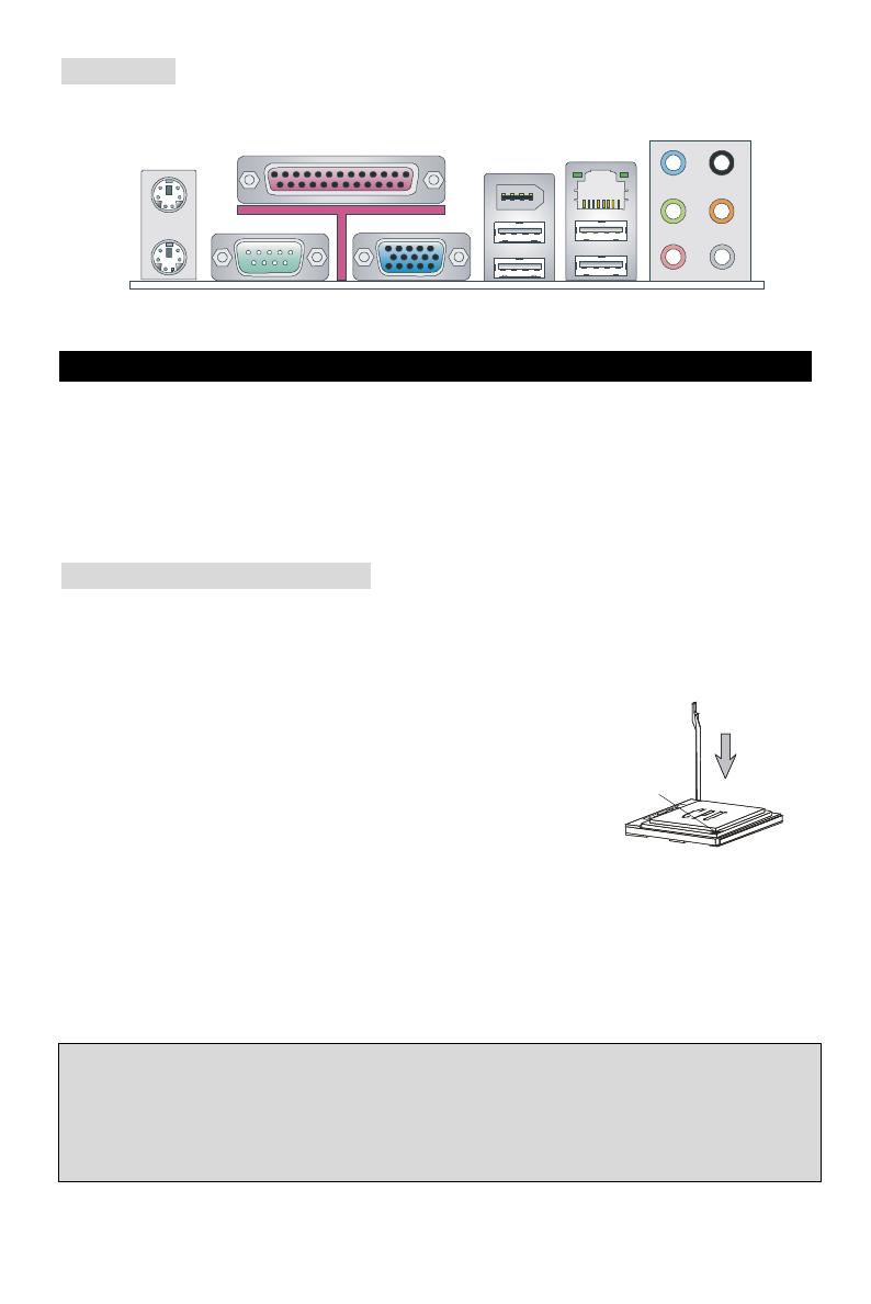
Rear Panel
The rear panel provides the following connectors:
COM port
Mouse
Keyboard
Line Out
Parallel
(optional)
LAN
CS
Hardware Setup
This chapter tells you how to install the CPU, memory modules, and expansion cards, as well as
how to setup the jumpers on the mainboard. It also provides the instructions on connecting the
peripheral devices, such as the mouse, keyboard, etc. While doing the installation, be careful in
holding the components and follow the installation procedures.
(For the latest information about CPU, please visit:
http://global.msi.com.tw/index.php?func=cpuform)
Central Processing Unit: CPU
The mainboard supports AMD® Athlon64 X2 / Athlon64 / Sempron processors. The mainboard
uses a CPU socket called Socket AM2(940—pin) for easy CPU installation.
CPU Installation Procedures for Socket AM2
1. Please turn off the power and unplug the power cord before
installing the CPU.
2. Pull the lever sideways away from the socket. Make sure to raise
the lever up to a 90—degree angle.
3. Look for the gold arrow on the CPU. The CPU can only fit in the
correct orientation. Lower the CPU down onto the socket.
4. If the CPU is correctly installed, the pins should be completely embedded into the socket and
can not be seen. Please note that any violation of the correct installation procedures may
cause permanent damages to your mainboard.
5. Press the CPU down firmly into the socket and close the lever. As the CPU is likely to move
while the lever is being closed, always close the lever with your fingers pressing tightly on top
of the CPU to make sure the CPU is properly and completely embedded into the socket.
MSI Reminds You…
Overheating
Overheating will seriously damage the CPU and system; always make sure the cooling fan can
work properly to protect the CPU from overheating.
Overclocking
5
This motherboard is designed to support overclocking. However, please make sure your
components are able to tolerate such abnormal setting, while doing overclocking. Any attempt to
operate beyond product specifications is not recommended. We do not guarantee the damages
or risks caused by inadequate operation or beyond product specifications.
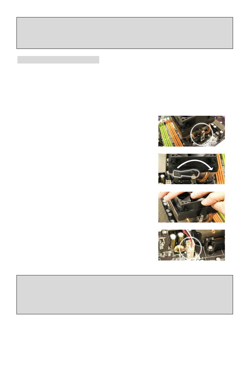
CPU and Cooler Installation
When you are installing the CPU, make sure the CPU has a cooler attached on the top to prevent
overheating. If you do not have the cooler, contact your dealer to purchase and install them
before turning on the computer. Meanwhile, do not forget to apply some silicon heat transfer
compound on CPU before installing the cooler for better heat dispersion.
Follow the steps below to install the CPU & cooler correctly. Wrong installation will cause the
damage of your CPU & mainboard.
1. Position the cooling set onto the retention mechanism.
Hook one end of the clip to hook first.
2. Then press down the other end of the clip to fasten the
cooling set on the top of the retention mechanism.
Locate the Fix Lever and lift up it.
3. Fasten down the lever.
4. Attach the CPU Fan cable to the CPU fan connector on
the mainboard.
MSI Reminds You…
1. Confirm if your CPU cooler is firmly installed before turning on your system.
2. Check the information in PC Health Status of H/W Monitor in BIOS for the CPU temperature.
3. Please note that the mating/unmating durability of the CPU is 20 cycles. Therefore we suggest
you do not plug/unplug the CPU too often.
6
Memory
The mainboard provides two 240—pin DIMM slots for unbuffered DDR II 533 / 667 / 800 SDRAM
(DDR II 800 is only for Athlon 64 X2). To operate properly, at least one DIMM slot must be
installed.
Install at least one Memory module on one of the slots. Memory modules can be installed on the
slots in any order. You can install either single— or double—sided modules to meet your own needs.
Installing DDR II Modules
1. The DDR II DIMM has only one notch on the center of slot. The memory module will only fit in
the right orientation.
2. Insert the memory module vertically into the DIMM slot. Then push it in until the golden finger
on the memory module is deeply inserted in the socket.
3. The plastic clip at each side of the DIMM slot will automatically close.
Power Supply
The mainboard supports ATX power supply for the power system. Before inserting the power
supply connector, always make sure that all components are installed properly to ensure that no
damage will be caused. A 300W or above power supply is suggested.
ATX 24—Pin Power Connector: ATX1
This connector allows you to connect an ATX 24—pin power supply. To
connect the ATX 24—pin power supply, make sure the plug of the power
supply is inserted in the proper orientation and the pins are aligned. Then
push down the power supply firmly into the connector.
You may use the 20—pin ATX power supply as you like. If you’d like to use the
20—pin ATX power supply, please plug your power supply along with pin 1 &
pin 13. There is also a foolproof design on pin 11, 12, 23 & 24 to avoid wrong
installation.
ATX 12V Power Connector: JPW1
This 12V power connector is used to provide power to the CPU.
Floppy Disk Drive Connector: FDD1
The mainboard provides a standard floppy disk drive connector that
supports 360K, 720K, 1.2M, 1.44M and 2.88M floppy disk types.
+12V
+12V
GND
+3.3V
—12V
+3.3V
+3.3V
+3.3V
+5V
+5V
+5V
+5V
+5V
Res
GND
GND
GND
GND
5VSB
+12V
+12V
7
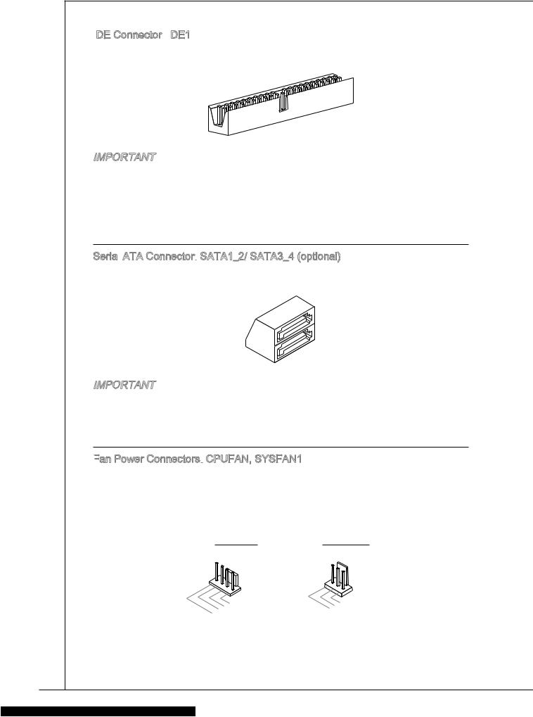
IDE Connector: IDE1
The mainboard has dual Ultra DMA 66/100/133 controller that provides PIO mode 0~4,
Bus Master, and Ultra DMA 66/100/133 function. You can connect up to two hard disk
drives, CD—ROM, 120MB Floppy and other devices.
The first hard drive should always be connected to IDE1. IDE1 can connect a Master
and a Slave drive. You must configure second hard drive to Slave mode by setting the
jumper accordingly.
MSI Reminds You...
If you install two hard disks on one cable, you must configure the second drive to Slave mode by
setting its jumper. Refer to the hard disk documentation supplied by hard disk vendors for jumper
setting instructions.
Serial ATAII Connectors: SATA1~2
SATA 1, 2 are dual high—speed Serial ATA interface ports. Each supports 2nd
generation serial ATA data rates of 300 MB/s. All connectors are fully compliant
with Serial ATA 2.0 specifications. Each Serial ATAII connector can connect to 1 hard disk device.
MSI Reminds You...
Please do not fold the serial ATA cable in a 90—degree angle, which will cause the loss of data
during transmission.
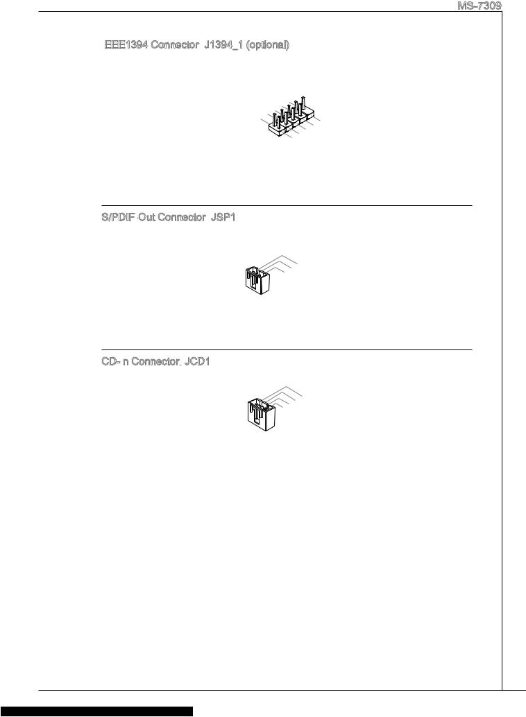
CD In Connector: JCD1
The connector is for CD—ROM audio connector.
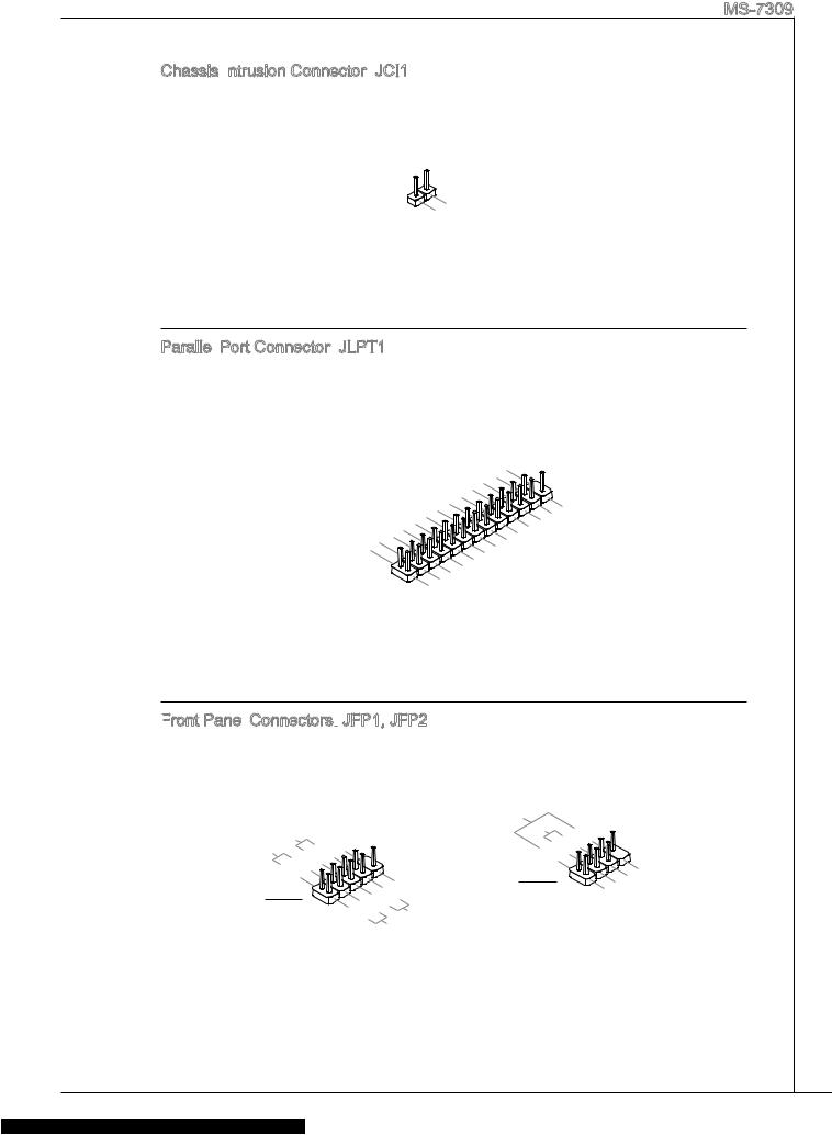
Chassis Intrusion Switch Connector: JCI1
This connector is connected to a 2—pin chassis switch.
Fan Power Connectors: CPUFAN1/SYSFAN1
The 4—pin CPUFAN1 (processor fan) and 3—pin SYSFAN1 (system
fan) support system cooling fan with +12V. When connecting the
wire to the connectors, always take note that the red wire is the
positive and should be connected to the +12V, the black wire is Ground and should be connected
to GND. If the mainboard has a System Hardware Monitor chipset on—board, you must use a
specially designed fan with speed sensor to take advantage of the CPU fan control.
MSI Reminds You...
Always consult the vendors for the proper CPU cooling fan.
Front Panel Connectors: JFP1, JFP2
The mainboard provides a front panel connector for electrical
connection to the front panel switches and LEDs. JFP1 is
compliant with Intel
®
Front Panel I/O Connectivity Design Guide.
R
CINTRU
1
GND
2
GND
GND
Power LED
2
1
HDD
LED
Switch
Power
Switch
Power
LED
2
+
+
—
—
—
8
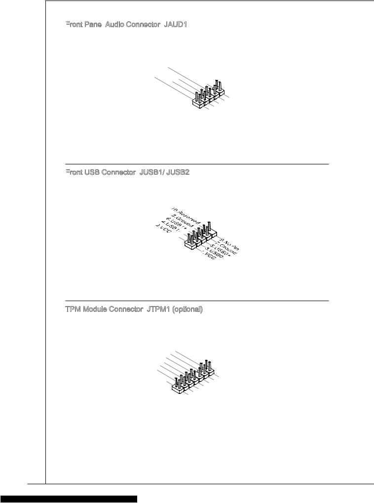
Front Panel Audio Connector: JAUD1
The front panel audio connector allows you to
connect to the front panel audio and is compliant
with Intel
®
Front Panel I/O Connectivity Design
Guide.
MSI Reminds You...
If you do not want to connect to the front audio header, pins 5 & 6, 9 & 10 have
to be jumpered in order to have signal output directed to the rear audio ports.
Otherwise, the Line—Out connector on the back panel will not function.
IEEE 1394 Connector: J1394_1 (Optional)
The 1394 pin header allows you to connect IEEE 1394 ports
via an external IEEE1394 bracket (optional)
Front USB Connector: JUSB1/JUSB2
The mainboard provides three standard USB 2.0 pin headers
JUSB1 and JUSB2. USB2.0 technology increases data
transfer rate up to a maximum throughput of 480Mbps, which
is 40 times faster than USB 1.1, and is ideal for connecting
high—speed USB interface peripherals such as USB HDD, digital cameras, MP3 players, printers,
modems, etc.
MSI Reminds You...
Please note that the pins of VCC & GND must be connected correctly or it may cause some
damage
SPDIF—Out Connector: SPDOUT1
This connector is used to connect SPDIF interface for digital audio transmission.
Clear CMOS Jumper: JBAT1
There is a CMOS RAM on board that has a power supply
from external battery to keep the data of system
configuration. With the CMOS RAM, the system can
automatically boot OS every time it is turned on. If you want to clear the system configuration,
use the JBAT1 (Clear CMOS Jumper) to clear data. Follow the instructions below to clear the
data:
MSI Reminds You...
You can clear CMOS by shorting 2—3 pin while the system is off. Then return to 1—2 pin position.
Avoid clearing the CMOS while the system is on; it will damage the mainboard.
USB1-GND
GND
USB0-
(10)USB0C
(9)Key
(2)AUD_GND
AUD_VCC
Key
(1)AUD_MIC
AUD_MIC_BIAS
AUD_FPOUT_R
HP_ON
1
2
VCC
GND(10)
(2)TPA-
GND
(1)TPA+
GND
9
PCI Express Slots
The PCI Express slots, as a
high—bandwidth, low pin count, serial,
interconnect technology.
PCI Express architecture provides a
high performance I/O infrastructure for
Desktop Platforms with transfer rates
starting at 2.5 Giga transfers per second over a PCI Express x1 lane for Gigabit Ethernet, TV
Tuners, 1394 controllers, and general purpose I/O. Also, desktop platforms with PCI Express
Architecture will be designed to deliver highest performance in video, graphics, multimedia and
other sophisticated applications. Moreover, PCI Express architecture provides a high
performance graphics infrastructure for Desktop Platforms doubling the capability of existing
AGP 8x designs with transfer rates of 4.0 GB/s over a PCI Express x16 lane for graphics
controllers.
You can insert the expansion cards to meet your needs. When adding or removing expansion
cards, make sure that you unplug the power supply first.
Note:
System default is to disable the onboard VGA when you insert a PCI—E graph card, in order to
optimize the system performance. If you would like to use both onboard and expansion card
graph functions, you have to enter the mainboard BIOS and select Advanced Chipset Features
—> OnChip and PCIe VGA selection —> Both exist and Oncip VGA by frame buffer select.
PCI (Peripheral Component Interconnect) Slots
The PCI slots allow you to insert the expansion cards
to meet your needs. When adding or removing
expansion cards, make sure that you unplug the power supply first. Meanwhile, read the
documentation for the expansion card to make any necessary hardware or software settings for
the expansion card, such as jumpers, switches or BIOS configuration.
PCI Interrupt Request Routing
The IRQ, abbreviation of interrupt request line and pronounced I—R—Q, are hardware lines over
which devices can send interrupt signals to the microprocessor. The PCI IRQ pins are typically
connected to the PCI bus INT A# ~ INT D# pins as follows:
Order1 Order2 Order3 Order4
PCI Slot 1
INT B# INT C# INT D# INT A#
PCI Slot 2
INT C# INT D# INT A# INT B#
PCI Express X16 Slot
PCI Express X1 Slot
10
BIOS Setup
Power on the computer and the system will start POST (Power On Self Test) process. When the
message below appears on the screen, press <DEL> key to enter Setup.
DEL: Setup F11: Boot Menu TAB: Logo
If the message disappears before you respond and you still wish to enter Setup, restart the
system by turning it OFF and On or pressing the RESET button. You may also restart the system
by simultaneously pressing <Ctrl>, <Alt>, and <Delete> keys.
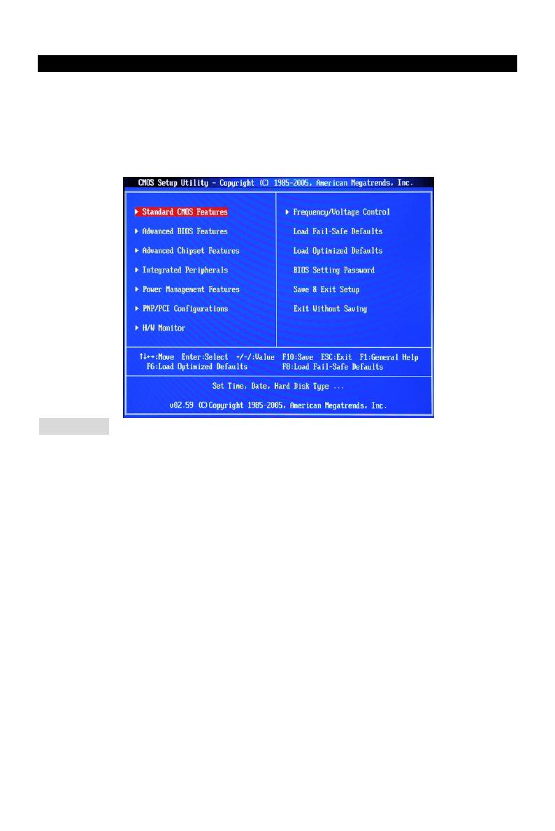
Main Page
Standard CMOS Features
Use this menu for basic system configurations, such as time, date etc.
Advanced BIOS Features
Use this menu to setup the items of Award special enhanced features.
Advanced Chipset Features
Use this menu to change the values in the chipset registers and optimize your system
performance.
Integrated Peripherals
Use this menu to specify your settings for integrated peripherals.
Power Management Features
Use this menu to specify your settings for power management.
PNP/PCI Configurations
This entry appears if your system supports PnP/PCI.
H/W Monitor
This entry shows the status of your CPU, fan, warning for overall system status.
Frequency/Voltage Control
Use this menu to specify your settings for frequency/voltage control.
Load Fail—Safe Defaults
Use this menu to load the BIOS default values that are factory settings for system operations.
11
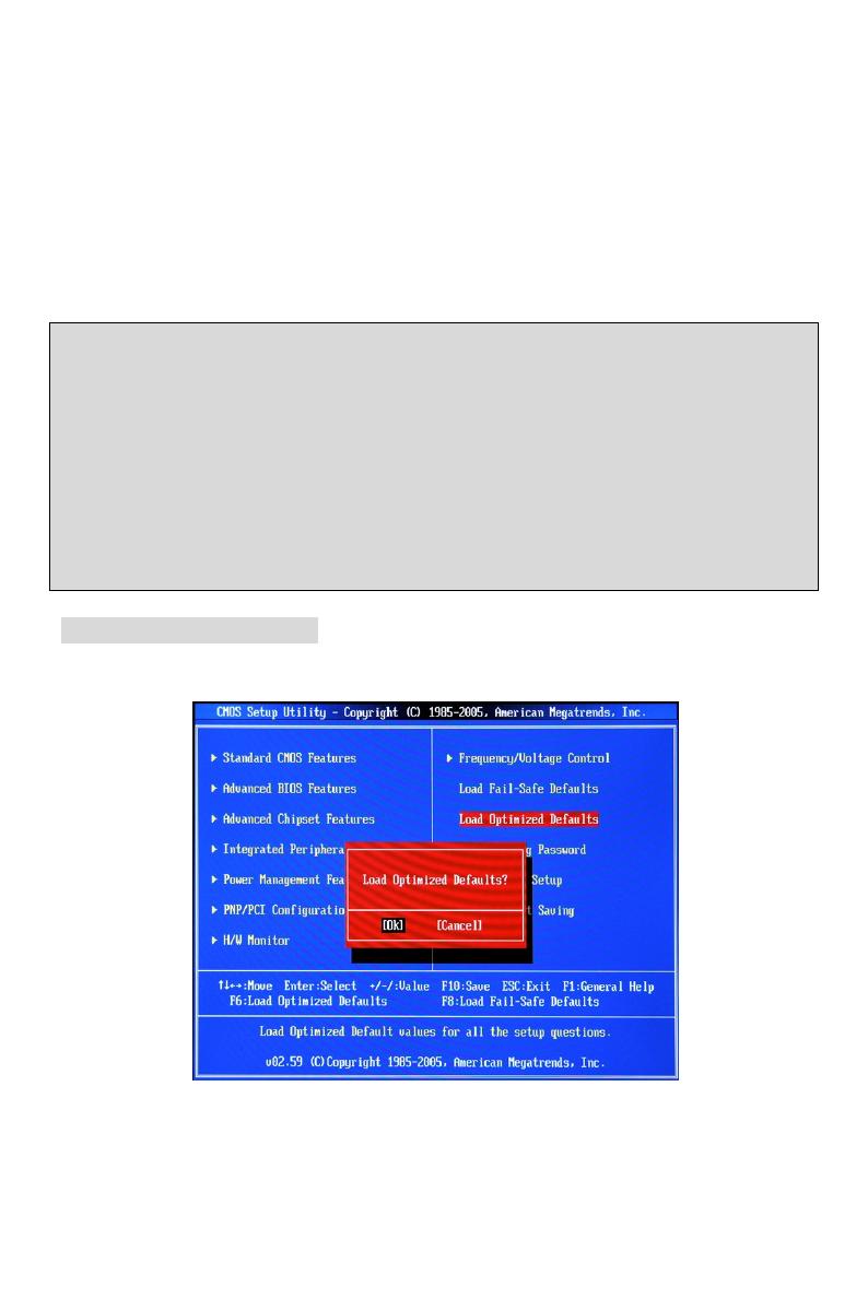
Load Optimized Defaults
Use this menu to load factory default settings into the BIOS for stable system performance
operations.
BIOS Setting Password
Use this menu to set BIOS setting Password.
Save & Exit Setup
Save changes to CMOS and exit setup.
Exit Without Saving
Abandon all changes and exit setup.
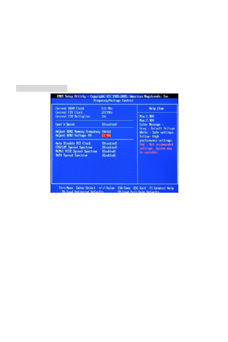
Frequency/Voltage
Current DRAM Clock
It shows the current clock of memory. Read—only.
Current CPU Clock
It shows the current clock of CPU. Read—only.
Current FSB Multiplier
It shows the current Front Side Bus Multiplication. Read—only.
Cool’n’Quiet
This feature is especially designed for AMD processor, which provides a CPU temperature
detecting function to prevent your CPU from overheating due to the heavy working loading.
Adjust DDR2 Memory Frequency
This item allows you to select the memory frequency programming method. If select Auto, the
memory speed will be based on SPDs. If select Limit, the memory speed will not exceed the
specified value. If select Manual, the memory specified will be programmed regardless of SPD.
Adjust DDR2 Voltage (V)
Adjusting the voltage of the memory can increase the speed. Any changes made to this setting
may cause a stability issue, so changing the voltage for long—term purpose is NOT
recommended.
12
Auto Disable PCI Clock
This item is used to auto disable the PCI slots. When set to [Enabled], the system will remove
(turn off) clocks from empty PCI slots to minimize the electromagnetic interference (EMI).
CPU/LDT Spread Spectrum
This setting is used to enable or disable the CPU/LDT (HT Bus multiplier) Spread Spectrum
feature.
MCP61 PCIE Spread Spectrum
This setting is used to enable or disable the MCP61 PCIE Spread Spectrum feature.
SATA Spread Spectrum
This setting is used to enable or disable the SATA Spread Spectrum feature.
MSI Reminds You...
1 .If you do not have any EMI problem, leave the setting at [Disabled] for optimal system stability
and performance. But if you are plagued by EMI, select the value of Spread Spectrum for EMI
reduction.
2. The greater the Spread Spectrum value is, the greater the EMI is reduced, and the system will
become less stable. For the most suitable Spread Spectrum value, please consult your local EMI
regulation.
3. Remember to disable Spread Spectrum if you are overclocking because even a slight jitter can
introduce a temporary boost in clock speed which may just cause your overclocked processor to
lock up.
Load Optimized Defaults
You can load the default values provided by the mainboard manufacturer for the stable
performance.
13
소개
K9N6PGM2 시리즈(MS-7309 v1.X) Micro—ATX 메인보드를 선택해주셔서 감사합니다.
K9N6PGM2 시리즈는 최적의 시스템 효율을 위해 MCP(P)61 / MCP(S)61 / MCP(V)61 칩셋을
기반으로 디자인했습니다. AMD
®
Socket—AM2 프로세서를 지원하는 K9N6GM 시리즈는
고성능 및 전문적인 데스크톱 플랫폼 솔루션을 제공합니다.
레이아웃
J
S
P
I
1
JCD1
JPW1
PCI _E1
CPUFAN1
PCI _E2(optional)
PCI2
PCI1
ALC883/861
RTL8201CL
/RT8211BL
(optional)
VIA
VT6308P
(optional)
JFP2
D
I
M
M
2
D
I
M
M
1
SPDOUT1
J1394_1
Top : mouse
Bottom:
keyboard
Top :
Parallel Port
Bottom:
COM 1
VGA port
Top: LAN Jack
Bottom: USB ports
Top:1394(optional)
Bottom: USB ports
T:
M:
B:
Line—In
Line—Out
Mic
T:RS-Out
M:CS-Out
B:SS-Out
+
MCP61
/
на других языках
Похожие инструкции
Другие инструкции
Это руководство также подходит для

8
MS-7309
РУССКИЙ
начало Работы
благодарим вас за выбор системной платы серии k9n6PGM2-V2/ nF725GtM-
P3 (MS-7309 v2.x) Micro-atX. для наиболее эффективной работы системы
серия k9n6PGM2-V2/ nF725GtM-P3 изготовлена на основе чипсетов
nVidia
®
nForce 630a & GeForce 7025. Системная плата разработана для
современного процессора aMd
®
aM2/ aM2+/ aM3 и обеспечивает высокую
производительность настольных платформ.
Компоненты системной платы
OC_SW1
(optional)
![]()
MS-7309
FCC
 -B Radio Frequency
 Interference
 Statement


This equipment has been tested and found to comply with the limits for a class B digital device, pursuant to part 15 of the FCC rules. These limits are designed to provide reasonable pro-
tection against harmful in-
terference in a residential installation. This equipment
generates, uses and can
radiate radio frequency energy and, if not installed and used in accordance with the instruction manual, may cause harmful interference to radio communications. However, there is no guarantee that interference will occur in a particular installation. If this equipment does cause harmful interference to radio or television reception, which can be determined by turning the equipment off and on, the user is encouraged to try to correct the interference by one or more of the measures listed below.
Reorient or relocate the receiving antenna.
Increase the separation between the equipment and receiver.
Connect the equipment into an outlet on a circuit different from that to which the receiver is connected.
Consult the dealer or an experienced radio/ television technician for help.
Notice 1
The changes or modifications not expressly approved by the party responsible for compliance could void the user’s authority to operate the equipment.
Notice 2
Shielded interface cables and A.C. power cord, if any, must be used in order to comply with the emission limits.
VOIR LA NOTICE D’NSTALLATION AVANT DE RACCORDER AU RESEAU.
Micro-Star International
MS-7309
This device complies with Part 15 of the FCC Rules. Operation is subject to the following two conditions:
(1)this device may not cause harmful interference, and
(2)this device must accept any interference received, including interference that may cause undesired operation.
Part
 Number
G52-73091X4
Copyright
 Notice
The material in this document is the intellectual property of MICRO-STAR INTERNATIONAL. We take every care in the preparation of this document, but no guarantee is given as to the correctness of its contents. Our products are under continual improvement and we reserve the right to make changes without notice.
Trademarks
All trademarks are the properties of their respective owners.
■MSI® is registered trademark of Micro-Star Int’l Co.,Ltd.
■NVIDIA® is registered trademark of NVIDIA Corporation.
■ATI® is registered trademark of ATI Technologies, Inc.
■AMD® is registered trademarks of AMD Corporation.
■Intel® is registered trademarks of Intel Corporation.
■Windows® is registered trademarks of Microsoft Corporation.
■AMI® is registered trademark of American Megatrends Inc.
■Award® is a registered trademark of Phoenix Technologies Ltd.
■Sound Blaster® is registered trademark of Creative Technology Ltd.
■Realtek® is registered trademark of Realtek Semiconductor Corporation.
■JMicron® is registered trademark of JMicron Technology Corporation.
■Netware® is a registered trademark of Novell, Inc.
Revision History
|
Revision |
Revision History |
Date |
||
|
V2.0 |
Release for PCB 2.X |
July 2009 |
||
MS-7309
Safety Instructions
■Always read the safety instructions carefully.
■Keep this User Manual for future reference.
■Keep this equipment away from humidity.
■Lay this equipment on a reliable flat surface before setting it up.
■The openings on the enclosure are for air convection hence protects the equipment from overheating. Do not cover the openings.
■Make sure the voltage of the power source and adjust properly 110/220V before connecting the equipment to the power inlet.
■Place the power cord such a way that people can not step on it. Do not place anything over the power cord.
■Always Unplug the Power Cord before inserting any add-on card or module.
■All cautions and warnings on the equipment should be noted.
■Never pour any liquid into the opening that could damage or cause electrical shock.
■If any of the following situations arises, get the equipment checked by a service personnel:
○The power cord or plug is damaged.
○Liquid has penetrated into the equipment.
○The equipment has been exposed to moisture.
○The equipment does not work well or you can not get it work according to User Manual.
○The equipment has dropped and damaged.
○The equipment has obvious sign of breakage.
■Do not leave this equipment in an environment unconditioned, storage temperature above 60°C (140°F), it may damage the equipment.
CAUTION
Danger of explosion if battery is incorrectly replaced. Replace only with the same or equivalent type recommended by the manufacturer.
For better environmental protection, waste batteries should be collected separately for recycling or special disposal.
WEEE Statement
ENGLISH


To protect the global environment and as an environmentalist, MSI
must remind you that… Under the European Union (“EU”) Directive on Waste Electrical and Electronic Equipment, Directive 2002/96/EC, which takes effect on August 13, 2005, products of “electrical and electronic equipment”
cannot be discarded as municipal waste anymore and manufacturers of covered electronic equipment will be obligated to take back
such products at the end of their useful life. MSI will comply with the product take back requirements at the end of life of MSI-branded products that are sold into the
EU. You can return these products to local collection points.
DEUTSCH
Hinweis von MSI zur Erhaltung und Schutz unserer Umwelt
Gemäß der Richtlinie 2002/96/EG über Elektround Elektronik-Altgeräte dürfen Elektround Elektronik-Altgeräte nicht mehr als kommunale Abfälle entsorgt werden. MSI hat europaweit verschiedene Sammelund Recyclingunternehmen beauftragt, die in die Europäische Union in Verkehr gebrachten Produkte, am Ende seines Lebenszyklus zurückzunehmen. Bitte entsorgen Sie dieses Produkt zum gegebenen Zeitpunkt ausschliesslich an einer lokalen Altgerätesammelstelle in Ihrer Nähe.
FRANÇAIS
En tant qu’écologiste et afin de protéger l’environnement, MSI tient à rappeler ceci…
Au sujet de la directive européenne (EU) relative aux déchets des équipement électriques et électroniques, directive 2002/96/EC, prenant effet le 13 août 2005, que les produits électriques et électroniques ne peuvent être déposés dans les décharges ou tout simplement mis à la poubelle. Les fabricants de ces équipements seront obligés de récupérer certains produits en fin de vie. MSI prendra en compte cette exigence relative au retour des produits en fin de vie au sein de la communauté européenne. Par conséquent vous pouvez retourner localement ces matériels dans les points de collecte.
РУССКИЙ
Компания MSI предпринимает активные действия по защите окружающей среды, поэтому напоминаем вам, что….
В соответствии с директивой Европейского Союза (ЕС) по предотвращению загрязнения окружающей среды использованным электрическим и электронным оборудованием (директива WEEE 2002/96/EC), вступающей в силу 13 августа 2005 года, изделия, относящиеся к электрическому и электронному оборудованию, не могут рассматриваться как бытовой мусор, поэтому производители вышеперечисленного электронного оборудования обязаны принимать его для переработки по окончании срока службы. MSI обязуется соблюдать требования по приему продукции, проданной под маркой MSI на территории EC, в переработку по окончании срока службы. Вы можете вернуть эти изделия в специализированные пункты приема.
MS-7309
ESPAÑOL


MSI como empresa comprometida con la protección del medio ambiente, recomienda:
Bajo la directiva 2002/96/EC de la Unión Europea en materia de desechos y/ o equipos electrónicos, con fecha de rigor desde el 13 de agosto de 2005, los productos clasificados como “eléctricos y equipos electrónicos” no pueden ser depositados en los contenedores habituales de su municipio, los fabricantes de equipos electrónicos, están obligados a hacerse cargo de dichos productos al termino de su período de vida. MSI estará comprometido con los términos de recogida de sus productos vendidos en la Unión Europea al final de su periodo de vida. Usted debe depositar estos productos en el punto limpio establecido por el ayuntamiento de su localidad o entregar a una empresa autorizada para la recogida de estos residuos.
NEDERLANDS
Om het milieu te beschermen, wil MSI u eraan herinneren dat….
De richtlijn van de Europese Unie (EU) met betrekking tot Vervuiling van Electrische en Electronische producten (2002/96/EC), die op 13 Augustus 2005 in zal gaan kunnen niet meer beschouwd worden als vervuiling. Fabrikanten van dit soort producten worden verplicht om producten retour te nemen aan het eind van hun levenscyclus. MSI zal overeenkomstig de richtlijn handelen voor de producten die de merknaam MSI dragen en verkocht zijn in de EU. Deze goederen kunnen geretourneerd worden op lokale inzamelingspunten.
SRPSKI
Da bi zaštitili prirodnu sredinu, i kao preduzeće koje vodi računa o okolini i prirodnoj sredini, MSI mora da vas podesti da…
Po Direktivi Evropske unije (“EU”) o odbačenoj ekektronskoj i električnoj opremi, Direktiva 2002/96/EC, koja stupa na snagu od 13. Avgusta 2005, proizvodi koji spadaju pod “elektronsku i električnu opremu” ne mogu više biti odbačeni kao običan otpad i proizvođači ove opreme biće prinuđeni da uzmu natrag ove proizvode na kraju njihovog uobičajenog veka trajanja. MSI će poštovati zahtev o preuzimanju ovakvih proizvoda kojima je istekao vek trajanja, koji imaju MSI oznaku i koji su prodati u EU. Ove proizvode možete vratiti na lokalnim mestima za prikupljanje.
POLSKI
Aby chronić nasze środowisko naturalne oraz jako firma dbająca o ekologię, MSI przypomina, że…
ZgodniezDyrektywąUniiEuropejskiej(“UE”)dotyczącąodpadówproduktówelektrycznych i elektronicznych (Dyrektywa 2002/96/EC), która wchodzi w życie 13 sierpnia 2005, tzw. “produkty oraz wyposażenie elektryczne i elektroniczne “ nie mogą być traktowane jako śmieci komunalne, tak więc producenci tych produktów będą zobowiązani do odbierania ich w momencie gdy produkt jest wycofywany z użycia. MSI wypełni wymagania UE, przyjmując produkty (sprzedawane na terenie Unii Europejskiej) wycofywane z użycia. Produkty MSI będzie można zwracać w wyznaczonych punktach zbiorczych.
TÜRKÇE

Çevreci özelliğiyle bilinen MSI dünyada çevreyi korumak için hatırlatır:
Avrupa Birliği (AB) Kararnamesi Elektrik ve Elektronik Malzeme Atığı, 2002/96/ EC Kararnamesi altında 13 Ağustos 2005 tarihinden itibaren geçerli olmak üzere, elektrikli ve elektronik malzemeler diğer atıklar gibi çöpe atılamayacak ve bu elektonik cihazların üreticileri, cihazların kullanım süreleri bittikten sonra ürünleri geri toplamakla yükümlü olacaktır. Avrupa Birliği’ne satılan MSI markalı ürünlerin kullanım süreleri bittiğinde MSI ürünlerin geri alınması isteği ile işbirliği içerisinde olacaktır. Ürünlerinizi yerel toplama noktalarına bırakabilirsiniz.
ČESKY
Záleží nám na ochraně životního prostředí — společnost MSI upozorňuje…
Podle směrnice Evropské unie (“EU”) o likvidaci elektrických a elektronických výrobků 2002/96/EC platné od 13. srpna 2005 je zakázáno likvidovat “elektrické a elektronické výrobky” v běžném komunálním odpadu a výrobci elektronických výrobků, na které se tato směrnice vztahuje, budou povinni odebírat takové výrobky zpět po skončení jejich životnosti. Společnost MSI splní požadavky na odebírání výrobků značky MSI, prodávaných v zemích EU, po skončení jejich životnosti. Tyto výrobky můžete odevzdat v místních sběrnách.
MAGYAR
Annak érdekében, hogy környezetünket megvédjük, illetve környezetvédőként fellépve az MSI emlékezteti Önt, hogy …
Az Európai Unió („EU”) 2005. augusztus 13-án hatályba lépő, az elektromos és elektronikus berendezések hulladékairól szóló 2002/96/EK irányelve szerint az elektromos és elektronikus berendezések többé nem kezelhetőek lakossági hulladékként, és az ilyen elektronikus berendezések gyártói kötelessé válnak az ilyen termékek visszavételére azok hasznos élettartama végén. Az MSI betartja a termékvisszavétellel kapcsolatos követelményeket az MSI márkanév alatt az EU-n belül értékesített termékek esetében, azok élettartamának végén. Az ilyen termékeket a legközelebbi gyűjtőhelyre viheti.
ITALIANO

Per proteggere l’ambiente, MSI, da sempre amica della natura, ti ricorda che…. In base alla Direttiva dell’Unione Europea (EU) sullo Smaltimento dei Materiali Elettrici ed Elettronici, Direttiva 2002/96/EC in vigore dal 13 Agosto 2005, prodotti appartenenti alla categoria dei Materiali Elettrici ed Elettronici non possono più essere eliminati come rifiuti municipali: i produttori di detti materiali saranno obbligati a ritirare ogni prodotto alla fine del suo ciclo di vita. MSI si adeguerà a tale Direttiva ritirando tutti i prodotti marchiati MSI che sono stati venduti all’interno dell’Unione Europea alla fine del loro ciclo di vita. È possibile portare i prodotti nel più vicino punto di raccolta
|
MS-7309 |
|
Table of Content |
|
English…..……………………………………………………………….9 |
|
Getting start…………………………………………………………………………………..9 |
|
SPECIFICATIONS………………………………………………………………………………..10 |
|
REAR PANEL………………………………………………………………………………………12 |
|
HARDWARE SETUP…………………………………………………………………………….12 |
|
BIOS Setup……………………………………………………………………………………….22 |
|
.……………………………………………………………………..27 |
|
.…………………………………………………………………………………………….27 |
|
.…………………………………………………………………………………………………..28 |
|
.…………………………………………………………………………………………………..30 |
|
………………………………………………………………………………………30 |
|
BIOS ……………………………………………………………………………………………40 |
|
françAIS………………………………………………………………..45 |
|
Pour commencer.………………………………………………………………………….45 |
|
SPéCIFICATIONS………………………………………………………………………………..46 |
|
Panneau arrière……………………………………………………………………………48 |
|
Installation du matériel..…………………………………………………………..48 |
|
Réglage bios…………………………………………………………………………………..58 |
|
Deutsch…….………………………………………………………….63 |
|
eINLEITUNG……………………………………………………………………………………….63 |
|
SPEZIFIKATIONEN………………………………………………………………………………64 |
|
Hinteres Anschlusspanel……………………………………………………………66 |
|
HARDWARE SETUP…………………………………………………………………………….66 |
|
BIOS Setup……………………………………………………………………………………….76 |
|
русский …………...…………………………………………………..81 |
|
начало работы………………………………………………………………………………81 |
|
Характеристики…………………………………………………………………………….82 |
|
Задняя панель……………………………………………………………………………….84 |
|
Установка оборудования.………………………………………………………….84 |
|
настройка BIOS………………………………………………………………………………94 |
|
……………………………………………………………………99 |
|
.…………………………………………………………………………………………………..99 |
|
.…………………………………………………………………………………………………100 |
|
.…………………………………………………………………………………………..102 |
|
.…………………………………………………………………………………………..102 |
|
BIOS ………………………………………………………………………………………….112 |

|
…………………………………………………………………. |
117 |
|
.………………………………………………………………………………………………… |
117 |
|
.………………………………………………………………………………………………… |
118 |
|
.………………………………………………………………………………………………… |
120 |
|
.………………………………………………………………………………………….. |
120 |
|
BIOS …………………………………………………………………………………………. |
130 |
|
.…………………………………………………………………… |
135 |
|
.………………………………………………………………………………………….. |
135 |
|
.………………………………………………………………………….. |
136 |
|
………………………………………………………………………………………… |
138 |
|
.………………………………………………………………… |
138 |
|
BIOS ………………………………………………………………………………………. |
148 |
MS-7309
EngLisH


Getting start

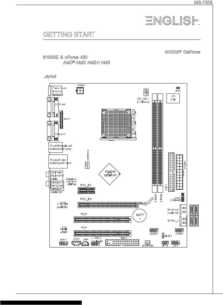
Thank you for choosing the K9N6PGM2-V2 series (MS-7309 v2.x) Micro-ATX mainboard. The K9N6PGM2-V2 series are design based on NVIDIA® GeForce 6150SE & nForce 430 chipset for optimal system efficiency. Designed to fit the advanced AMD® AM2/ AM2+/ AM3 processor, the K9N6PGM2-V2 series deliver a high performance and professional desktop platform solution.
Layout
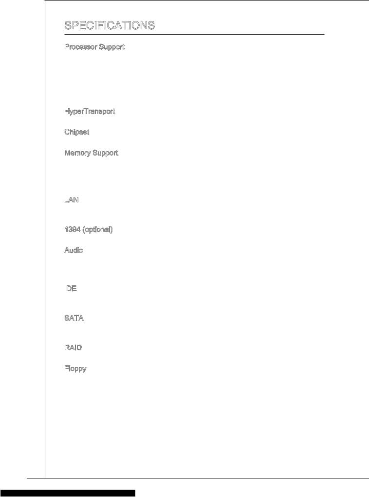
SPECIFICATIONS
Processor Support
■Supports AMD® Sempron™ , Athlon™ 64 and Athlon™ 64 X2 processors in the AM2/ AM2+ package, and supports AMD® Phenom™ II/ Athlon™ II processor in the AM3 package
■Supports 95W processor only
(For the latest information about CPU, please visit http://www.msi.com/index.php?func=cpuform2)
HyperTransport
■ HyperTransport 1.0
Chipset
■ NVIDIA® GeForce 6150SE & nForce 430 chipset Memory Support
■DDR2 800/ 667 SDRAM (total Max. 8GB)
■2 DDR2 DIMMs (240pin/ 1.8V)
(For more information on compatible components, please visit http://www.msi. com/index.php?func=testreport)
LAN
■Supports 10/100/1000 LAN by Realtek® RTL8211CL
■Or supports 10/100 LAN by Realtek® RTL8201EL
1394 (optional)
■ Chip integrated by VIA® VT6315N Audio
■Chip integrated by Realtek® ALC888/ ALC888S
■Supports 7.1 channels audio out (by 6 audio-jacks)
■Compliant with Azalia 1.0 Spec
IDE

■1 IDE port
■Supports Ultra DMA 66/100/133, PIO & Bus Master operation mode
SATA
■4 SATAII ports support 4 SATAII devices (SATA3_4 are optional)
■Supports storage and data transfers at up to 3.0 Gb/s
RAID
■ SATA1~4 support RAID 0/ 1/ 5/ 0+1 Floppy

■1 floppy port
■Supports 1 FDD with 360 KB, 720 KB, 1.2 MB, 1.44 MB and 2.88 MB
10
![]()
MS-7309
Connectors
■Back panel
1 PS/2 mouse port
1 PS/2 keyboard port
1 Serial port
1 VGA port
1 1394 port (optional)
1 LAN jack
4 USB 2.0 Ports
3/6 (optional) flexible audio jacks
■On-Board Connectors
2 USB 2.0 connectors
1 Parallel port connector
1 IEEE1394 connector (optional)
1 SPDIF-Out connector
1 Front Panel Audio connector
1 CD-In connector
1 TPM connector (optional)
1 Chassis Intrusion Connector
1 Overclock FSB switch (optional)
Slots
■1 PCI Express 1.0 x16 slot
■1 PCI Express 1.0 x1 slot
■2 PCI slots, support 3.3V/ 5V PCI bus Interface
Form Factor
■ Micro-ATX (24.4cm X 20.0 cm)
Mounting
■ 6 mounting holes
If you need to purchase accessories and request the part numbers, you could search the product web page and find details on our web address below http://www.msi.com/index.php
11
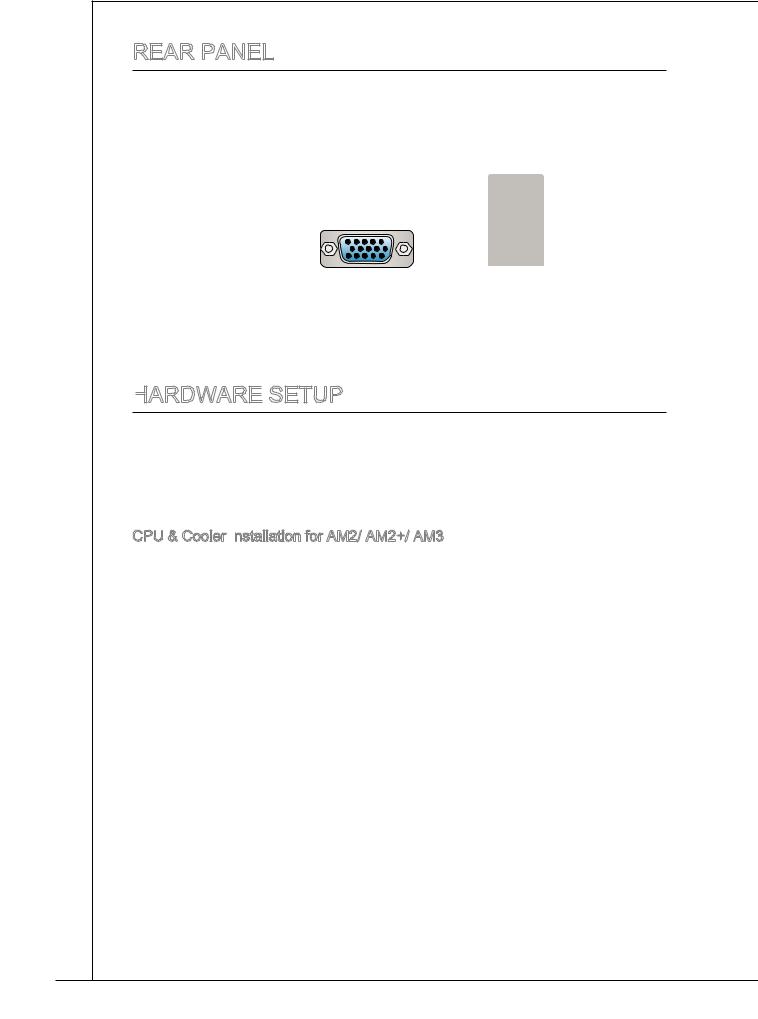
REAR PANEL
The rear panel provides the following connectors:
|
PS/2 mouse |
(optional) |
LAN |
||||
|
1394 |
||||||
|
Line-In RS-Out |
||||||
|
Line-Out CS-Out |
||||||
|
PS/2 keyboard |
Serial port |
VGA port |
USB ports |
MIC |
SS-Out |
|
|
(optional) |
HARDWARE
 SETUP
SETUP
This chapter provides you with the information about hardware
While doing the installation, be careful in holding the components and follow the installation procedures. For some components, if you install in the wrong orientation, the components will not work properly. Use a grounded wrist strap before handling computer components. Static electricity may damage the components.
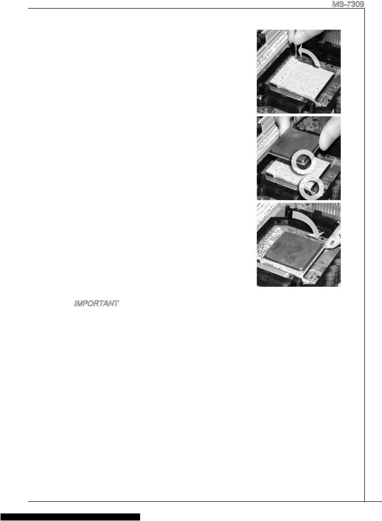
CPU & Cooler Installation for AM2/ AM2+/ AM3
When you are installing the CPU, make sure the CPU has a cooler attached on the top to prevent overheating. Meanwhile, do not forget to apply some thermal paste on CPU before installing the heat sink/cooler fan for better heat dispersion.
Follow the steps below to install the CPU & cooler correctly. Wrong installation will cause the damage of your CPU & mainboard.
12
MS-7309
. Pull the lever sideways away from the socket. Make sure to raise the lever up to a 90-degree angle.
2.Look for the gold arrow of the CPU. The gold arrow should point as shown in the picture. The CPU can only fit in the correct orientation.
3.If the CPU is correctly installed, the pins should be completely embedded into the socket and can not be seen. Please note that any violation of the correct installation procedures may cause permanent damages to your mainboard.
4.Press the CPU down firmly into the socket and close the lever. As the CPU is likely to move while the lever is being closed, always close the lever with your fingers pressing tightly on top of the CPU to make sure the CPU is properly and completely embedded into the socket.
5.Position the cooling set onto the retention mechanism. Hook one end of the clip to hook first.
6.Then press down the other end of the clip to fasten the cooling set on the top of the retention mechanism. Locate the Fix Lever and lift up it .
7.Fasten down the lever.
8.Attach the CPU Fan cable to the CPU fan connector on the mainboard.
Important
*Mainboard photos shown in this section are for demonstration only. The appearance of your mainboard may vary depending on the model you purchase.
*While disconnecting the Safety Hook from the fixed bolt, it is necessary to keep an eye on your fingers, because once the Safety Hook is disconnected from the fixed bolt, the fixed lever will spring back instantly.
13
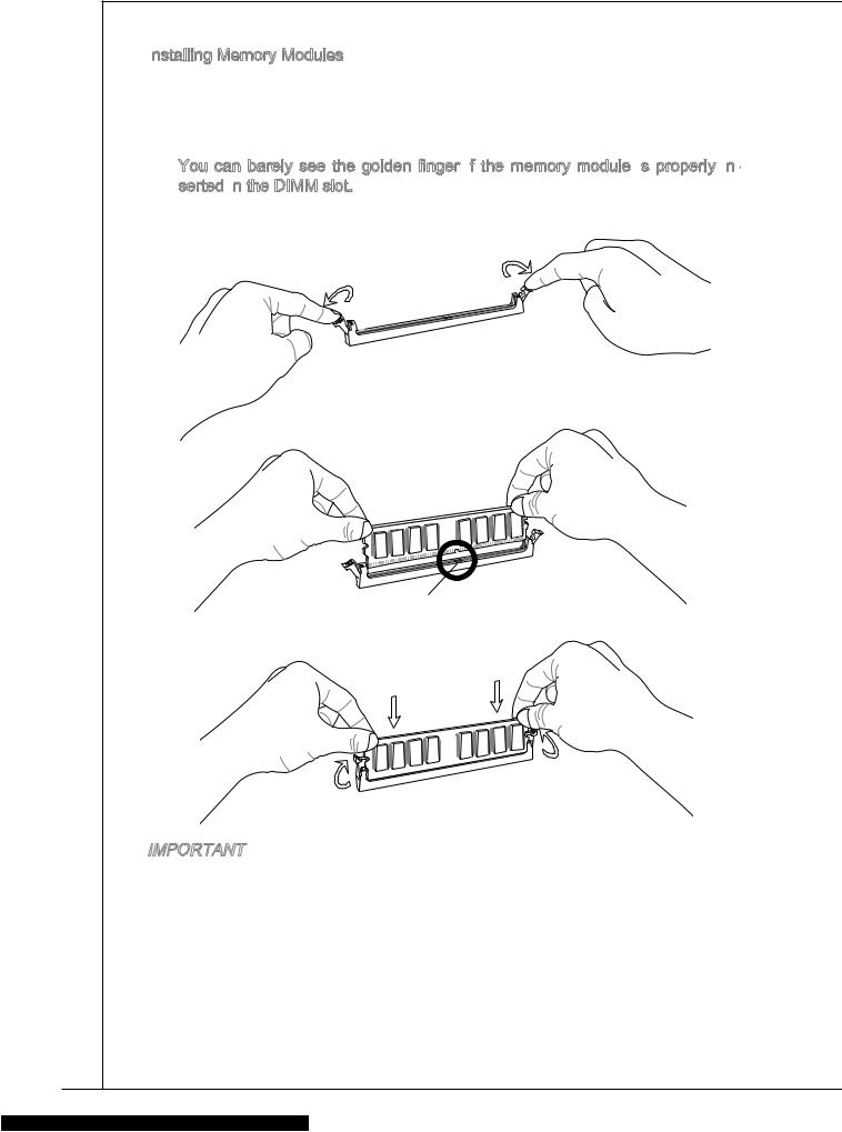
Installing Memory Modules
. The memory module has only one notch on the center and will only fit in the right orientation.
2.Insert the memory module vertically into the DIMM slot. Then push it in until the golden finger on the memory module is deeply inserted in the DIMM slot.
You can barely see the golden finger if the memory module is
 properly in
 — serted in
 the DIMM slot.
3.The plastic clip at each side of the DIMM slot will automatically close.
 Notch
Notch
Volt
Important
*DDR2 memory modules are not interchangeable with DDR and the DDR2 standard is not backwards compatible. You should always install DDR2 memory modules in the DDR2 DIMM slots.
*In Dual-Channel mode, make sure that you install memory modules of the same type and density in different channel DIMM slots.
*To enable successful system boot-up, always insert the memory modules into the DIMM1 first.
14
MS-7309
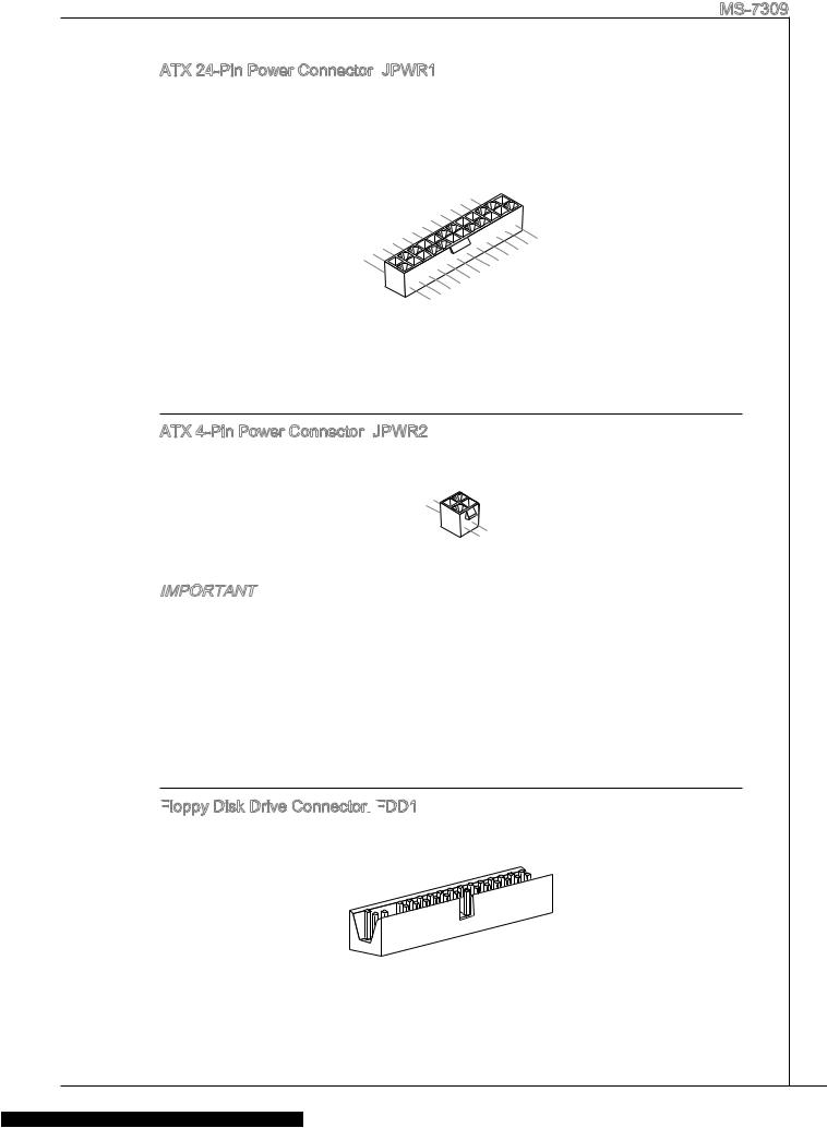
ATX 24-Pin Power Connector: JPWR1
JPWR1
This connector allows you to connect an ATX 24-pin power supply. To connect the ATX 24-pin power supply, make sure the plug of the power supply is inserted in the proper orientation and the pins are aligned. Then push down the power supply firmly into the connector.
|
12 |
|||||||||||||||
|
11 |
. |
||||||||||||||
|
7 |
10 |
. +3. |
|||||||||||||
|
+12V |
|||||||||||||||
|
9 . |
3V |
||||||||||||||
|
8 |
. |
||||||||||||||
|
6 . |
|||||||||||||||
|
3 |
5 . |
||||||||||||||
|
. |
+5V |
||||||||||||||
|
1 |
4 . |
||||||||||||||
|
. |
Ground |
||||||||||||||
|
+5V |
|||||||||||||||
|
2 . |
24 |
||||||||||||||
|
+3.Ground |
|||||||||||||||
|
. +3 |
. |
. |
|||||||||||||
|
3V |
|||||||||||||||
|
3V |
23. |
||||||||||||||
|
+5VGround |
|||||||||||||||
|
. |
+5V |
||||||||||||||
|
+5V |
|||||||||||||||
|
.Ground |
|||||||||||||||
|
13 |
. |
— |
|||||||||||||
|
— |
ON# |
||||||||||||||
|
+3 12V |
|||||||||||||||
|
. |
3V |
||||||||||||||
ATX 4-Pin Power Connector: JPWR2
JPWR2
This 12V power connector is used to provide power to the CPU.
|
1 |
||
|
. |
||
|
2 |
Ground |
|
|
. |
||
|
Ground |
||
|
3 |
||
|
. |
||
|
4 |
+12V |
|
|
. |
||
|
+12V |
Important
*Make sure that all the connectors are connected to proper ATX power supplies to ensure stable operation of the mainboard.
*Power supply of 350 watts (and above) is highly recommended for system stability.
Floppy Disk Drive Connector:
 FDD1
FDD1
This connector supports 360 KB, 720 KB, 1.2 MB, 1.44 MB or 2.88 MB floppy disk drive.
15
IDE
 Connector:
 IDE1
IDE1
This connector supports IDE hard disk drives, optical disk drives and other IDE devices.
Important
If you install two IDE devices on the same cable, you must configure the drives to cable select mode or separately to master / slave mode by setting jumpers. Refer to IDE device documentation supplied by the vendors for jumper setting instructions.
Serial ATA Connector:
 SATA1_2/ SATA3_4 (optional)
This connector is a high-speed Serial ATA interface port. Each connector can connect to one Serial ATA device.
Important
Please do not fold the Serial ATA cable into 90-degree angle. Otherwise, data loss
may occur during transmission.
Fan
 Power Connectors:
 CPUFAN, SYSFAN1
The fan power connectors support system cooling fan with +12V. When connecting the wire to the connectors, always note that the red wire is the positive and should be connected to the +12V; the black wire is Ground and should be connected to GND. If the mainboard has a System Hardware Monitor chipset onboard, you must use a specially designed fan with speed sensor to take advantage of the CPU fan control.
CPUFAN SYSFAN1
|
1 |
||||||||
|
2 . |
||||||||
|
3 |
. G |
|||||||
|
+ r |
||||||||
|
4 |
. |
o |
||||||
|
S 1 |
u |
|||||||
|
. |
e |
2 |
n |
|||||
|
C |
n V |
d |
||||||
|
o |
s |
|||||||
|
n |
o |
|||||||
|
t |
r |
|||||||
|
r |
||||||||
|
ol |
|
1 |
||||||
|
2 . |
||||||
|
. G |
||||||
|
3 |
+ |
r |
||||
|
o |
||||||
|
. |
1 |
|||||
|
S |
2 u |
|||||
|
e |
V n |
|||||
|
n |
d |
|||||
|
s |
||||||
|
o |
||||||
|
r |
16
MS-7309
IEEE1394 Connector:
 J1394_1 (optional)
This connector allows you to connect the IEEE1394 device via an optional IEEE1394 bracket.
|
1 |
|||||||||
|
0 |
|||||||||
|
8 . |
|||||||||
|
6 |
. G |
||||||||
|
+ |
r |
||||||||
|
4 |
. |
1 o |
|||||||
|
T |
2 u |
||||||||
|
. |
P |
V |
n |
||||||
|
2 |
G |
d |
|||||||
|
B |
|||||||||
|
. |
r |
— |
|||||||
|
T |
o |
||||||||
|
P |
u |
||||||||
|
A |
n |
||||||||
|
— |
d |
|
9 |
|||||||||
|
7 |
. |
||||||||
|
N |
|||||||||
|
5 |
. |
o |
|||||||
|
+ |
P |
||||||||
|
. |
1 |
||||||||
|
3 |
T |
2 |
n |
||||||
|
1 |
. |
P |
V |
||||||
|
G |
|||||||||
|
. |
r |
B |
|||||||
|
T |
o |
+ |
|||||||
|
P |
u |
||||||||
|
A |
n |
||||||||
|
+ |
d |
S/PDIF
 -Out Connector:
 JSP1
JSP1
This connector is used to connect S/PDIF (Sony & Philips Digital Interconnect Format) interface for digital audio transmission.
|
3 |
|||||||
|
2 |
. |
||||||
|
G |
|||||||
|
1 |
. |
r |
|||||
|
S |
o |
||||||
|
. |
P |
u |
|||||
|
V |
D |
n |
|||||
|
C |
I |
d |
|||||
|
C |
F |
CD-In Connector:
 JCD1
JCD1
This connector is provided for external audio input.
|
1 |
|||||||||
|
2 |
. |
||||||||
|
L |
|||||||||
|
3 |
. |
||||||||
|
G |
|||||||||
|
4 |
. |
r |
|||||||
|
G |
o |
||||||||
|
. |
r |
u |
|||||||
|
R |
o |
n |
|||||||
|
u |
d |
||||||||
|
n |
|||||||||
|
d |
17
Front
 Panel
Panel Audio Connector:
 JAUD1
JAUD1
This connector allows you to connect the front panel audio and is compliant with Intel® Front Panel I/O Connectivity Design Guide.
|
1 |
||||||||||||||||||||
|
0 |
||||||||||||||||||||
|
8 . |
||||||||||||||||||||
|
6 |
. |
H |
||||||||||||||||||
|
N |
e |
|||||||||||||||||||
|
4 |
. |
o |
a |
|||||||||||||||||
|
M |
P |
d |
||||||||||||||||||
|
. |
I |
P |
||||||||||||||||||
|
2 |
P |
C |
i |
|||||||||||||||||
|
n |
h |
|||||||||||||||||||
|
. |
R |
D |
o |
|||||||||||||||||
|
G |
E |
e |
n |
|||||||||||||||||
|
r |
S |
e |
||||||||||||||||||
|
o |
E |
e |
D |
|||||||||||||||||
|
u |
c |
t |
||||||||||||||||||
|
n |
N |
i |
||||||||||||||||||
|
d |
C |
o |
e |
|||||||||||||||||
|
E |
n |
c |
||||||||||||||||||
|
t |
||||||||||||||||||||
|
# |
i |
|||||||||||||||||||
|
o |
||||||||||||||||||||
|
n |
|
9 |
|||||||||||||||||||
|
7 |
. |
||||||||||||||||||
|
H |
|||||||||||||||||||
|
5 |
. |
e |
|||||||||||||||||
|
3 |
S |
a |
|||||||||||||||||
|
H |
E |
d |
|||||||||||||||||
|
1 |
. |
. |
e |
N |
P |
||||||||||||||
|
M |
a |
S |
h |
||||||||||||||||
|
. |
I |
d |
E |
o |
|||||||||||||||
|
M |
C |
P |
_ |
n |
|||||||||||||||
|
I |
R |
S |
e |
||||||||||||||||
|
C |
h |
||||||||||||||||||
|
L |
o |
E |
L |
||||||||||||||||
|
n |
N |
||||||||||||||||||
|
e |
D |
||||||||||||||||||
|
R |
Front
 USB Connector:
 JUSB1/ JUSB2
This connector, compliant with Intel® I/O Connectivity Design Guide, is ideal for connecting high-speed USB interface peripherals such as USB HDD, digital cameras, MP3 players, printers, modems and the like.
TPM Module Connector: JTPM1 (optional)
This connector connects to a TPM (Trusted Platform Module) module. Please refer to the TPM security platform manual for more details and usages.
|
1 |
|||||||||||||||||||||||
|
4 |
|||||||||||||||||||||||
|
1 . |
|||||||||||||||||||||||
|
1 |
2 |
G |
|||||||||||||||||||||
|
. |
r |
||||||||||||||||||||||
|
. G |
o |
||||||||||||||||||||||
|
8 |
0 |
r |
|||||||||||||||||||||
|
N |
u |
||||||||||||||||||||||
|
6 |
. |
o |
n |
||||||||||||||||||||
|
5 |
o |
u |
d |
||||||||||||||||||||
|
4 |
. |
V |
P |
n |
|||||||||||||||||||
|
S |
P |
i |
d |
||||||||||||||||||||
|
. |
e |
n |
|||||||||||||||||||||
|
. |
3 |
r |
o |
||||||||||||||||||||
|
3 |
ia |
w |
|||||||||||||||||||||
|
2 . |
l |
||||||||||||||||||||||
|
3 |
V |
e |
|||||||||||||||||||||
|
I |
r |
||||||||||||||||||||||
|
V |
P |
R |
|||||||||||||||||||||
|
S |
Q |
||||||||||||||||||||||
|
t |
o |
||||||||||||||||||||||
|
a |
w |
||||||||||||||||||||||
|
n |
e |
||||||||||||||||||||||
|
d |
r |
||||||||||||||||||||||
|
b |
|||||||||||||||||||||||
|
y |
|||||||||||||||||||||||
|
p |
|||||||||||||||||||||||
|
o |
|||||||||||||||||||||||
|
w |
|||||||||||||||||||||||
|
e |
|||||||||||||||||||||||
|
r |
|
1 |
|||||||||||||||||||||||||||||||||||||
|
3 |
|||||||||||||||||||||||||||||||||||||
|
1 . |
|||||||||||||||||||||||||||||||||||||
|
1 |
L |
||||||||||||||||||||||||||||||||||||
|
9 |
. |
P |
|||||||||||||||||||||||||||||||||||
|
L |
C |
||||||||||||||||||||||||||||||||||||
|
7 |
. |
P |
|||||||||||||||||||||||||||||||||||
|
L |
F |
||||||||||||||||||||||||||||||||||||
|
. |
P |
C |
|||||||||||||||||||||||||||||||||||
|
5 |
L |
C |
a |
a |
|||||||||||||||||||||||||||||||||
|
3 |
. |
P |
|||||||||||||||||||||||||||||||||||
|
L |
a |
d |
m |
||||||||||||||||||||||||||||||||||
|
. |
P C |
d |
d |
e |
|||||||||||||||||||||||||||||||||
|
1 |
L |
C |
a |
d |
r |
||||||||||||||||||||||||||||||||
|
P |
e |
||||||||||||||||||||||||||||||||||||
|
. |
a |
d |
r |
s |
|||||||||||||||||||||||||||||||||
|
L |
C |
d |
e |
||||||||||||||||||||||||||||||||||
|
P |
d |
s |
s |
||||||||||||||||||||||||||||||||||
|
C |
R |
d |
e |
s |
& |
||||||||||||||||||||||||||||||||
|
e |
r |
s |
& |
d |
|||||||||||||||||||||||||||||||||
|
C |
s |
e |
s |
a |
|||||||||||||||||||||||||||||||||
|
l |
e |
s |
& |
d |
|||||||||||||||||||||||||||||||||
|
o |
t |
s |
a |
a |
|||||||||||||||||||||||||||||||||
|
c |
& |
d |
t |
p |
|||||||||||||||||||||||||||||||||
|
k |
a |
a |
|||||||||||||||||||||||||||||||||||
|
d |
t |
p |
n |
||||||||||||||||||||||||||||||||||
|
a |
a |
||||||||||||||||||||||||||||||||||||
|
t |
p |
in |
3 |
||||||||||||||||||||||||||||||||||
|
a |
i |
2 |
|||||||||||||||||||||||||||||||||||
|
p |
n |
||||||||||||||||||||||||||||||||||||
|
i |
1 |
||||||||||||||||||||||||||||||||||||
|
n |
|||||||||||||||||||||||||||||||||||||
|
0 |
18
MS-7309
Chassis Intrusion Connector:
 JCI1
JCI1
This connector connects to the chassis intrusion switch cable. If the chassis is opened, the chassis intrusion mechanism will be activated. The system will record this status and show a warning message on the screen. To clear the warning, you must enter the BIOS utility and clear the record.
|
2 |
||||||
|
1 |
. |
|||||
|
G |
||||||
|
. |
r |
|||||
|
C |
o |
|||||
|
I |
u |
|||||
|
N |
n |
|||||
|
T |
d |
|||||
|
R |
||||||
|
U |
Parallel Port Connector:
 JLPT1
JLPT1
This connector is used to connect an optional parallel port bracket. The parallel port is a standard printer port that supports Enhanced Parallel Port (EPP) and Extended Capabilities Parallel Port (ECP) mode.
|
2 |
|||||||||||||||||||||||||||||||||||||||||||||||||||||||||||||||||||||||
|
6 |
|||||||||||||||||||||||||||||||||||||||||||||||||||||||||||||||||||||||
|
2 . |
|||||||||||||||||||||||||||||||||||||||||||||||||||||||||||||||||||||||
|
4 |
N |
||||||||||||||||||||||||||||||||||||||||||||||||||||||||||||||||||||||
|
2 . |
o |
||||||||||||||||||||||||||||||||||||||||||||||||||||||||||||||||||||||
|
2 |
2 |
G |
P |
||||||||||||||||||||||||||||||||||||||||||||||||||||||||||||||||||||
|
. |
r |
||||||||||||||||||||||||||||||||||||||||||||||||||||||||||||||||||||||
|
1 |
0 |
G |
o |
n |
|||||||||||||||||||||||||||||||||||||||||||||||||||||||||||||||||||
|
. |
r |
u |
|||||||||||||||||||||||||||||||||||||||||||||||||||||||||||||||||||||
|
1 |
8 |
G |
o |
n |
|||||||||||||||||||||||||||||||||||||||||||||||||||||||||||||||||||
|
. |
r |
u |
d |
||||||||||||||||||||||||||||||||||||||||||||||||||||||||||||||||||||
|
6 |
G |
o |
n |
||||||||||||||||||||||||||||||||||||||||||||||||||||||||||||||||||||
|
1 |
. |
r |
u |
d |
|||||||||||||||||||||||||||||||||||||||||||||||||||||||||||||||||||
|
G |
o |
n |
|||||||||||||||||||||||||||||||||||||||||||||||||||||||||||||||||||||
|
1 |
4 |
u |
|||||||||||||||||||||||||||||||||||||||||||||||||||||||||||||||||||||
|
. |
r |
n |
d |
||||||||||||||||||||||||||||||||||||||||||||||||||||||||||||||||||||
|
1 |
2 |
G |
o |
||||||||||||||||||||||||||||||||||||||||||||||||||||||||||||||||||||
|
. |
r |
u |
d |
||||||||||||||||||||||||||||||||||||||||||||||||||||||||||||||||||||
|
. G |
o |
n |
|||||||||||||||||||||||||||||||||||||||||||||||||||||||||||||||||||||
|
8 |
0 |
r |
|||||||||||||||||||||||||||||||||||||||||||||||||||||||||||||||||||||
|
G |
u |
d |
|||||||||||||||||||||||||||||||||||||||||||||||||||||||||||||||||||||
|
6 |
. |
o |
n |
||||||||||||||||||||||||||||||||||||||||||||||||||||||||||||||||||||
|
L |
o u |
d |
|||||||||||||||||||||||||||||||||||||||||||||||||||||||||||||||||||||
|
. |
P |
r |
n |
||||||||||||||||||||||||||||||||||||||||||||||||||||||||||||||||||||
|
4 |
u |
||||||||||||||||||||||||||||||||||||||||||||||||||||||||||||||||||||||
|
P |
T |
d |
|||||||||||||||||||||||||||||||||||||||||||||||||||||||||||||||||||||
|
. |
I |
_ |
n |
2 |
|||||||||||||||||||||||||||||||||||||||||||||||||||||||||||||||||||
|
E |
N |
d |
|||||||||||||||||||||||||||||||||||||||||||||||||||||||||||||||||||||
|
2 |
I |
S |
5 |
||||||||||||||||||||||||||||||||||||||||||||||||||||||||||||||||||||
|
R |
T |
L |
2 |
. |
|||||||||||||||||||||||||||||||||||||||||||||||||||||||||||||||||||
|
. |
S |
||||||||||||||||||||||||||||||||||||||||||||||||||||||||||||||||||||||
|
A |
R |
# |
I |
2 |
3 |
||||||||||||||||||||||||||||||||||||||||||||||||||||||||||||||||||
|
F |
# |
N |
. |
L |
|||||||||||||||||||||||||||||||||||||||||||||||||||||||||||||||||||
|
D |
# |
1 |
1 |
P |
C |
||||||||||||||||||||||||||||||||||||||||||||||||||||||||||||||||||
|
. |
E |
T |
|||||||||||||||||||||||||||||||||||||||||||||||||||||||||||||||||||||
|
# |
9 |
B |
|||||||||||||||||||||||||||||||||||||||||||||||||||||||||||||||||||||
|
1 . |
U |
||||||||||||||||||||||||||||||||||||||||||||||||||||||||||||||||||||||
|
7 |
A |
||||||||||||||||||||||||||||||||||||||||||||||||||||||||||||||||||||||
|
1 . |
C |
S |
|||||||||||||||||||||||||||||||||||||||||||||||||||||||||||||||||||||
|
1 |
5 |
P |
K |
Y |
|||||||||||||||||||||||||||||||||||||||||||||||||||||||||||||||||||
|
. |
R |
||||||||||||||||||||||||||||||||||||||||||||||||||||||||||||||||||||||
|
3 |
P |
# |
|||||||||||||||||||||||||||||||||||||||||||||||||||||||||||||||||||||
|
1 . |
R N |
||||||||||||||||||||||||||||||||||||||||||||||||||||||||||||||||||||||
|
1 |
P |
N |
D |
||||||||||||||||||||||||||||||||||||||||||||||||||||||||||||||||||||
|
9 . |
R |
7 |
|||||||||||||||||||||||||||||||||||||||||||||||||||||||||||||||||||||
|
7 |
. |
P |
N |
D |
|||||||||||||||||||||||||||||||||||||||||||||||||||||||||||||||||||
|
P |
R |
6 |
|||||||||||||||||||||||||||||||||||||||||||||||||||||||||||||||||||||
|
5 |
. |
R |
N |
D |
|||||||||||||||||||||||||||||||||||||||||||||||||||||||||||||||||||
|
P |
5 |
||||||||||||||||||||||||||||||||||||||||||||||||||||||||||||||||||||||
|
3 |
. |
R |
N |
D |
|||||||||||||||||||||||||||||||||||||||||||||||||||||||||||||||||||
|
P |
D |
4 |
|||||||||||||||||||||||||||||||||||||||||||||||||||||||||||||||||||||
|
1 |
. |
R |
N |
3 |
|||||||||||||||||||||||||||||||||||||||||||||||||||||||||||||||||||
|
P |
D |
||||||||||||||||||||||||||||||||||||||||||||||||||||||||||||||||||||||
|
. |
R |
N |
2 |
||||||||||||||||||||||||||||||||||||||||||||||||||||||||||||||||||||
|
R |
N |
D |
|||||||||||||||||||||||||||||||||||||||||||||||||||||||||||||||||||||
|
S |
D |
1 |
|||||||||||||||||||||||||||||||||||||||||||||||||||||||||||||||||||||
|
T |
|||||||||||||||||||||||||||||||||||||||||||||||||||||||||||||||||||||||
|
B |
0 |
||||||||||||||||||||||||||||||||||||||||||||||||||||||||||||||||||||||
|
# |
Front
 Panel
Panel Connectors:
 JFP1, JFP2
These connectors are for electrical connection to the front panel switches and LEDs. The JFP1 is compliant with Intel® Front Panel I/O Connectivity Design Guide.
|
Power |
Switch |
|||||||
|
No |
— |
|||||||
|
PowerLED |
6 |
|||||||
|
10 |
. |
|||||||
|
8Pin |
||||||||
|
4 |
. |
. |
||||||
|
+ |
||||||||
|
2 |
. |
|||||||
|
— |
||||||||
|
. |
||||||||
|
+ |
JFP1
|
9 |
||||||||||
|
. |
. |
|||||||||
|
7 |
Reserved |
|||||||||
|
5 |
. |
|||||||||
|
+ |
||||||||||
|
3 |
. |
|||||||||
|
— |
||||||||||
|
. |
||||||||||
|
1 |
— |
ResetSwitch |
||||||||
|
+ |
||||||||||
|
HDD |
||||||||||
|
LED |
||||||||||
|
Speaker |
6 |
||||
|
Buzzer |
8 |
||||
|
. |
|||||
|
4 |
. |
+ |
|||
|
— |
|||||
|
2 |
. |
||||
|
+ |
|||||
|
. |
|||||
|
— |
JFP2
|
7 |
||||
|
3 |
5 . |
|||
|
. No |
||||
|
. |
SuspendPowerLED |
|||
|
1 |
. |
|||
|
Ground |
LED |
|||
19
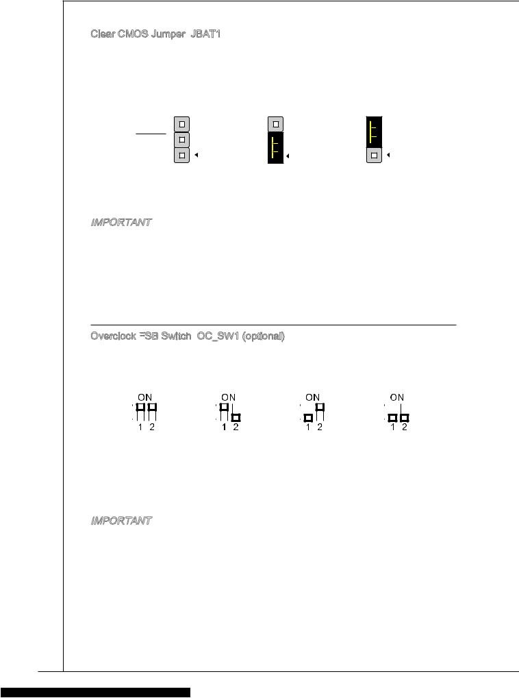
Clear CMOS Jumper: JBAT1
JBAT1
There is a CMOS RAM onboard that has a power supply from an external battery to keep the data of system configuration. With the CMOS RAM, the system can automatically boot OS every time it is turned on. If you want to clear the system configuration, set the jumper to clear data.
JBAT1
|
1 |
1 |
1 |
|
Keep Data |
Clear Data |
Important
You can clear CMOS by shorting 2-3 pin while the system is off. Then return to 1-2 pin position. Avoid clearing the CMOS while the system is on; it will damage the mainboard.
Overclock FSB
 Switch:
 OC_SW1 (optional)
You can overclock the FSB to increase the processor frequency by changing the switch. Follow the instructions below to set the FSB.
|
Default |
Increase 10% |
Increase 15% |
Increase 20% |
|||||||||||||||||||||||
|
speed of FSB |
speed of FSB |
speed of FSB |
Important
*Make sure that you power off the system before setting the switch.
*When overclocking cause system instability or crash during boot. Please set the switch to default setting.
20
![]()
MS-7309
PCI Express
 Slot
Slot
The PCI Express slot supports the PCI Express interface expansion card.
The PCI Express 1.0 x16 slot
The PCI Express 1.0 x1 slot
PCI Slot
Slot
The PCI slot supports LAN card, SCSI card, USB card, and other add-on cards that comply with PCI specifications.
Important
Make sure that you unplug the power supply first. Meanwhile, read the documentation for the expansion card to configure any necessary hardware or software settings for the expansion card, such as jumpers, switches or BIOS configuration.
PCI Interrupt
 Request Routing
When adding or removing expansion cards, make the IRQ, acronym of interrupt request line and pronounced I-R-Q, are hardware lines over which devices can send interrupt signals to the microprocessor. The PCI IRQ pins are typically connected to the PCI bus pins as follows:
|
Order |
1 |
2 |
3 |
4 |
|||||
|
Slot |
|||||||||
|
PCI 1 |
C# |
D# |
A# |
B# |
|||||
|
PCI 2 |
B# |
C# |
D# |
A# |
|||||
21
BIOS Setup
Power on the computer and the system will start POST (Power On Self Test) process. When the message below appears on the screen, press <DEL> key to enter Setup.
Press DEL to enter SETUP
If the message disappears before you respond and you still wish to enter Setup, restart the system by turning it OFF and On or pressing the RESET button. You may also restart the system by simultaneously pressing <Ctrl>, <Alt>, and <Delete> keys.
Main Page
Standard CMOS Features
Use this menu for basic system configurations, such as time, date etc.
Advanced BIOS Features
Use this menu to setup the items of special enhanced features.
Integrated Peripherals
Use this menu to specify your settings for integrated peripherals.
Power Management Setup
Use this menu to specify your settings for power management.
H/W Monitor
This entry shows the status of your CPU, fan, warning for overall system status.
Green Power
Use this menu to specify the power phase.
22
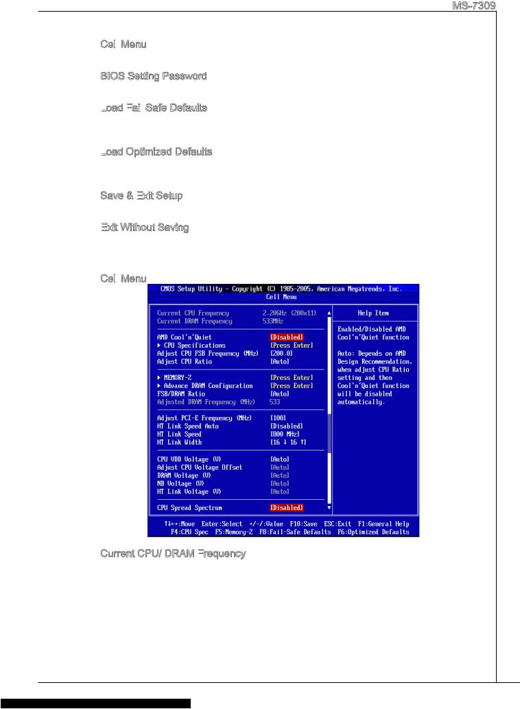
MS-7309
Cell
 Menu
Menu
Use this menu to specify your settings for frequency/voltage control.
BIOS Setting Password
Use this menu to set BIOS setting Password.
Load
 Fail
Fail


 -Safe Defaults
Use this menu to load the BIOS default values that are factory settings for system operations.
Load
 Optimized Defaults
Use this menu to load factory default settings into the BIOS for stable system performance operations.
Save & Exit
 Setup
Setup
Save changes to CMOS and exit setup.
Exit
 Without Saving
Abandon all changes and exit setup.
Cell
 Menu
Menu
Current CPU/ DRAM Frequency
It shows the current frequency of CPU/ Memory. Read-only.
23
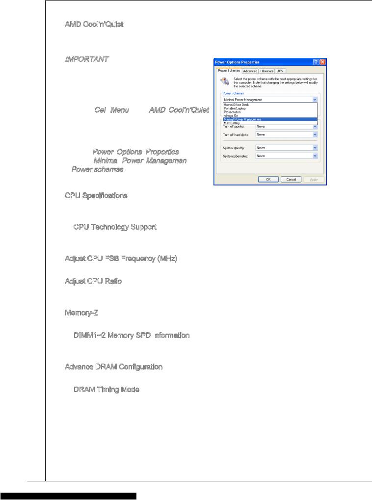
AMD Cool’n’Quiet
The Cool’n’Quiet technology can effectively and dynamically lower CPU speed and power consumption.
Important
To ensure that Cool’n’Quiet function is activated and will be working properly, it is required to double confirm that:
*Run BIOS Setup, and select Cell Menu.
Under Cell Menu, find AMD Cool’n’Quiet, and set this item to “Enabled”.
*Enter Windows, and select [Start]->[Set- tings]->[Control Panel]->[Power Options]. Enter Power Options Properties tag, and
select Minimal Power Management
 under Power schemes.
CPU Specifications
Press <Enter> to enter the sub-menu. This submenu shows the information of installed CPU.
CPU Technology Support
Press <Enter> to enter the sub-menu. This sub-menu shows the technologies that the installed CPU supported.
Adjust CPU FSB
 Frequency
 (MHz)
(MHz)
This item allows you to adjust the CPU FSB frequency.
Adjust CPU Ratio
This item is used to adjust CPU clock multiplier (ratio). It is available only when the processor supports this function.
Memory-Z
Press <Enter> to enter the sub-menu.
DIMM1~2 Memory SPD Information
Press <Enter> to enter the sub-menu. This sub-menu displays the information of installed memory.
Advance DRAM Configuration Press <Enter> to enter the sub-menu.
DRAM Timing Mode
Selects whether DRAM timing is controlled by the SPD (Serial Presence Detect) EEPROM on the DRAM module. Setting to [Auto] enables DRAM timings and the following related items to be determined by BIOS based on the configurations on the SPD. Selecting [Manual] allows users to configure the DRAM timings and the following related items manually.
24
MS-7309
1T/2T Memory Timing
When the DRAM Timing Mode is set to [Manual], the field is adjustable. This field controls the command rate. Selecting [1T] makes DRAM signal controller to run at 1 clock cycle rate. Selecting [2T] makes DRAM signal controller run at 2 clock cycles rate.
Bank Interleaving
Bank Interleaving is an important parameter for improving overclocking capability of memory. It allows system to access multiple banks simultaneously.
FSB/DRAM Ratio
Ratio
This item will allow you to adjust the ratio of FSB to memory.
Adjusted DRAM Frequency (MHz)
(MHz)
It shows the adjusted memory frequency. Read-only.
Adjust PCI
 -E
-E

 Frequency
 (MHz)
(MHz)
This item allows you to adjust the PCI-E frequency.
HT
 Link
Link
 Speed Auto
Setting to [Enabled], the system will detect the HT link speed automatically.
HT
 Link
Link
 Speed
Speed
This item allows you to set the Hyper-Transport Link speed.
HT
 Link
Link
 Width
Width
This item allows you to set the Hyper-Transport Link width.
CPU VDD Voltage (V)/ Adjust CPU Voltage Offset/ DRAM Voltage (V)/ NB Voltage (V)/ HT
 Link
Link
 Voltage (V)
These items are used to adjust the voltage of CPU, Memory and chipset.
CPU Spread Spectrum
This setting is used to enable or disable the CPU Spread Spectrum feature.
Important
*If you do not have any EMI problem, leave the setting at [Disabled] for optimal system stability and performance. But if you are plagued by EMI, select the value of Spread Spectrum for EMI reduction.
*The greater the Spread Spectrum value is, the greater the EMI is reduced, and the system will become less stable. For the most suitable Spread Spectrum value, please consult your local EMI regulation.
*Remember to disable Spread Spectrum if you are overclocking because even a slight jitter can introduce a temporary boost in clock speed which may just cause your overclocked processor to lock up.
25
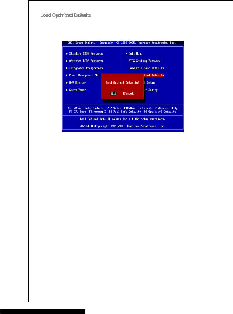
Load
 Optimized Defaults
You can load the default values provided by the mainboard manufacturer for the stable performance.
26
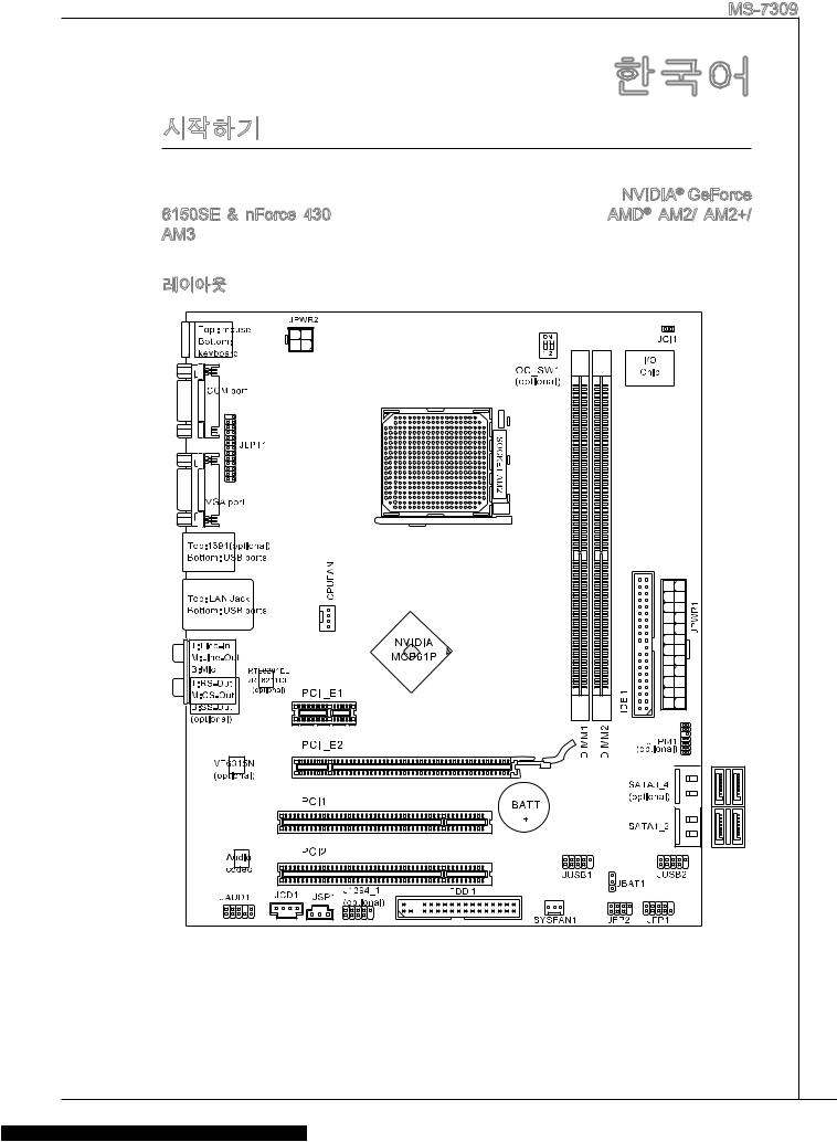
|
MS-7309 |
|
K9N6PGM2-V2 (MS-7309 v2.x) Micro-ATX |
|
. K9N6PGM2-V2 NVIDIA® GeForce |
|
6150SE & nForce 430 . AMD® AM2/ AM2+/ |
|
AM3 K9N6PGM2-V2 |
|
. |
|
27 |
■AM2/ AM2+ AMD® Sempron™ , Athlon™ 64 Athlon™ 64 X2, AM3 AMD® Phenom II™/ Athlon II™
■95W
(CPU http://www.msi.com/index.php?func=cpuform2 )
HyperTransport
■ HyperTransport 1.0
■ NVIDIA® GeForce 6150SE & nForce 430
■DDR2 800/ 667 SDRAM ( 8GB)
■DDR2 DIMM 2 (240 / 1.8V)
(For more information on compatible components, please visit http://www.msi. com/index.php?func=testreport)
LAN
■Realtek® RTL8211CL 10/100/1000 LAN
■Realtek® RTL8201EL 10/100 LAN
1394 ( )
■ VIA® VT6315N
■Realtek® ALC888/ ALC888S
■7.1 (6 )
■Azalia 1.0 Spec
IDE

■1 IDE 1
■Ultra DMA 66/100/133, PIO &
SATA
■4 SATAII SATAII 4 (SATA3_4 )
■3.0 Gb/s
RAID
■ RAID 0/ 1/ 5/ 0+1 SATA1~4
■1
■360 KB, 720 KB, 1.2 MB, 1.44 MB 2.88 MB FDD 1
28
MS-7309
PS/2 1
PS/2 1
1
VGA 1
1394 1 ( )
LAN 1
USB 2.0 4
3/6( )
USB 2.0 2
1
IEEE1394 1 ( )
SPDIF 1
1
CD 1
TPM 1 ( )
1
FSB 1 ( )
■PCI Express 1.0 x16 1
■PCI Express 1.0 x1 1
■PCI 2 , 3.3V/ 5V PCI
■ Micro-ATX (24.4cm X 20.0 cm)
■ 6
, http://www.msi.com/index.php .
29
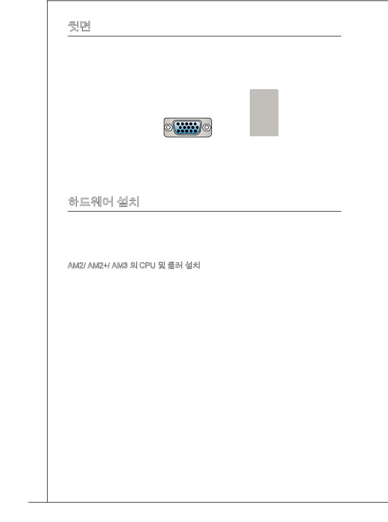
|
. |
||||
|
PS/2 |
( ) |
LAN |
||
|
1394 |
||||
|
RS |
||||
|
CS |
||||
|
PS/2 |
VGA |
USB |
SS |
|
|
( ) |
||||
|
. , |
||||
|
. |
||||
|
. |
||||
|
. . |
||||
|
AM2/ AM2+/ AM3 CPU |
||||
|
CPU . |
||||
|
/ CPU |
||||
|
. |
||||
|
CPU . CPU |
||||
|
. |
||||
|
30 |
![]()
MS-7309
. . 90.
2.CPU . . CPU.
3.CPU , ..
4.CPU. CPU, CPU CPU .
5...
6...
7..
8.CPU CPU.
*AM2+ CPU. .
*,.
31


 . , .
. , .
2.DIMM .DIMM . 
 DIMM
DIMM 

 .
.
3.DIMM .

*DDR2 DDR , DDR2. DDR2 DIMM DDR2 .
*, DIMM.
*, DIMM1 .
32

MS-7309
ATX 24 : JPWR1
JPWR1
ATX 24 . ATX 24,, ..
|
12 |
|||||||||||||||
|
11 |
. |
||||||||||||||
|
7 |
10 |
. +3. |
|||||||||||||
|
+12V |
|||||||||||||||
|
9 . |
3V |
||||||||||||||
|
8 |
. |
||||||||||||||
|
6 . |
|||||||||||||||
|
3 |
5 . |
||||||||||||||
|
. |
+5V |
||||||||||||||
|
1 |
4 . |
||||||||||||||
|
. |
Ground |
||||||||||||||
|
+5V |
|||||||||||||||
|
2 . |
24 |
||||||||||||||
|
+3.Ground |
|||||||||||||||
|
. +3 |
. |
. |
|||||||||||||
|
3V |
|||||||||||||||
|
3V |
23. |
||||||||||||||
|
+5VGround |
|||||||||||||||
|
. |
+5V |
||||||||||||||
|
+5V |
|||||||||||||||
|
.Ground |
|||||||||||||||
|
13 |
. |
— |
|||||||||||||
|
— |
ON# |
||||||||||||||
|
+3 12V |
|||||||||||||||
|
. |
3V |
||||||||||||||
ATX 4 : JPWR2
JPWR2
12V CPU .
|
1 |
||
|
. |
||
|
2 |
Ground |
|
|
. |
||
|
Ground |
||
|
3 |
||
|
. |
||
|
4 |
+12V |
|
|
. |
||
|
+12V |
*ATX.
*350 .
 :
:
 FDD1
FDD1
360 KB, 720 KB, 1.2 MB, 1.44 MB 2.88 MB.
33

IDE
 :
: IDE1
IDE1
IDE , IDE.
2 IDE ,, / .IDE .
ATA : SATA1_2/ SATA3_4 ( )
ATA .ATA .
ATA 90 . ,.
:
 CPUFAN, SYSFAN1
+12V ., +12V ,GND ., CPU .
CPUFAN SYSFAN1
|
1 |
||||||||
|
2 . |
||||||||
|
3 |
. G |
|||||||
|
+ r |
||||||||
|
4 |
. |
o |
||||||
|
S 1 |
u |
|||||||
|
. |
e |
2 |
n |
|||||
|
C |
n V |
d |
||||||
|
o |
s |
|||||||
|
n |
o |
|||||||
|
t |
r |
|||||||
|
r |
||||||||
|
ol |
|
1 |
||||||
|
2 . |
||||||
|
. G |
||||||
|
3 |
+ |
r |
||||
|
o |
||||||
|
. |
1 |
|||||
|
S |
2 u |
|||||
|
e |
V n |
|||||
|
n |
d |
|||||
|
s |
||||||
|
o |
||||||
|
r |
34

|
MS-7309 |
|||||||||||||||||||||||||
|
IEEE1394 : J1394_1 ( ) |
|||||||||||||||||||||||||
|
IEEE1394 IEEE1394 |
|||||||||||||||||||||||||
|
. |
|||||||||||||||||||||||||
|
1 |
|||||||||||||||||||||||||
|
0 |
|||||||||||||||||||||||||
|
8 . |
|||||||||||||||||||||||||
|
6 |
. G |
||||||||||||||||||||||||
|
+ |
r |
||||||||||||||||||||||||
|
4 |
. |
1 o |
|||||||||||||||||||||||
|
T |
2 u |
||||||||||||||||||||||||
|
. |
P |
V |
n |
||||||||||||||||||||||
|
2 |
G |
d |
|||||||||||||||||||||||
|
B |
|||||||||||||||||||||||||
|
. |
r |
— |
|||||||||||||||||||||||
|
T |
o |
||||||||||||||||||||||||
|
P |
u |
||||||||||||||||||||||||
|
A |
n |
||||||||||||||||||||||||
|
— |
d |
||||||||||||||||||||||||
|
9 |
|||||||||||||||||||||||||
|
7 |
. |
||||||||||||||||||||||||
|
N |
|||||||||||||||||||||||||
|
5 |
. |
o |
|||||||||||||||||||||||
|
+ |
P |
||||||||||||||||||||||||
|
. |
1 |
||||||||||||||||||||||||
|
3 |
T |
2 |
n |
||||||||||||||||||||||
|
1 |
. |
P |
V |
||||||||||||||||||||||
|
G |
|||||||||||||||||||||||||
|
. |
r |
B |
|||||||||||||||||||||||
|
T |
o |
+ |
|||||||||||||||||||||||
|
P |
u |
||||||||||||||||||||||||
|
A |
n |
||||||||||||||||||||||||
|
+ |
d |
||||||||||||||||||||||||
|
S/PDIF : JSP1 |
|||||||||||||||||||||||||
|
S/PDIF(Sony & Philips Digital Intercon- |
|||||||||||||||||||||||||
|
nect Format) . |
|||||||||||||||||||||||||
|
3 |
|||||||||||||||||||||||||
|
2 |
. |
||||||||||||||||||||||||
|
G |
|||||||||||||||||||||||||
|
. |
r |
||||||||||||||||||||||||
|
1 S |
o |
||||||||||||||||||||||||
|
. |
P |
u |
|||||||||||||||||||||||
|
V |
D |
n |
|||||||||||||||||||||||
|
C |
I |
d |
|||||||||||||||||||||||
|
C |
F |
||||||||||||||||||||||||
|
CD : JCD1 |
|||||||||||||||||||||||||
|
. |
|||||||||||||||||||||||||
|
1 |
|||||||||||||||||||||||||
|
2 |
. |
||||||||||||||||||||||||
|
L |
|||||||||||||||||||||||||
|
3 |
. |
||||||||||||||||||||||||
|
G |
|||||||||||||||||||||||||
|
. |
r |
||||||||||||||||||||||||
|
4 G |
o |
||||||||||||||||||||||||
|
. |
r |
u |
|||||||||||||||||||||||
|
R |
o |
n |
|||||||||||||||||||||||
|
u |
d |
||||||||||||||||||||||||
|
n |
|||||||||||||||||||||||||
|
d |
|||||||||||||||||||||||||
|
35 |

|
: JAUD1 |
||||||||||||||||||||||||||||||||||||||||||||||||||||||||||||||||||||||
|
, Intel® |
||||||||||||||||||||||||||||||||||||||||||||||||||||||||||||||||||||||
|
Front Panel I/O Connectivity Design Guide . |
||||||||||||||||||||||||||||||||||||||||||||||||||||||||||||||||||||||
|
1 |
||||||||||||||||||||||||||||||||||||||||||||||||||||||||||||||||||||||
|
0 |
||||||||||||||||||||||||||||||||||||||||||||||||||||||||||||||||||||||
|
8 . |
||||||||||||||||||||||||||||||||||||||||||||||||||||||||||||||||||||||
|
6 |
. |
H |
||||||||||||||||||||||||||||||||||||||||||||||||||||||||||||||||||||
|
N |
e |
|||||||||||||||||||||||||||||||||||||||||||||||||||||||||||||||||||||
|
4 |
. |
o |
a |
|||||||||||||||||||||||||||||||||||||||||||||||||||||||||||||||||||
|
M |
P |
d |
||||||||||||||||||||||||||||||||||||||||||||||||||||||||||||||||||||
|
. |
I |
P |
||||||||||||||||||||||||||||||||||||||||||||||||||||||||||||||||||||
|
2 |
P |
C |
i |
|||||||||||||||||||||||||||||||||||||||||||||||||||||||||||||||||||
|
n |
h |
|||||||||||||||||||||||||||||||||||||||||||||||||||||||||||||||||||||
|
. |
R |
D |
o |
|||||||||||||||||||||||||||||||||||||||||||||||||||||||||||||||||||
|
G |
E |
e |
n |
|||||||||||||||||||||||||||||||||||||||||||||||||||||||||||||||||||
|
r |
S |
e |
||||||||||||||||||||||||||||||||||||||||||||||||||||||||||||||||||||
|
o |
E |
e |
D |
|||||||||||||||||||||||||||||||||||||||||||||||||||||||||||||||||||
|
u |
c |
|||||||||||||||||||||||||||||||||||||||||||||||||||||||||||||||||||||
|
n |
N |
t |
e |
|||||||||||||||||||||||||||||||||||||||||||||||||||||||||||||||||||
|
d |
i |
t |
||||||||||||||||||||||||||||||||||||||||||||||||||||||||||||||||||||
|
C |
o |
e |
||||||||||||||||||||||||||||||||||||||||||||||||||||||||||||||||||||
|
E |
n |
c |
||||||||||||||||||||||||||||||||||||||||||||||||||||||||||||||||||||
|
t |
||||||||||||||||||||||||||||||||||||||||||||||||||||||||||||||||||||||
|
# |
i |
|||||||||||||||||||||||||||||||||||||||||||||||||||||||||||||||||||||
|
o |
||||||||||||||||||||||||||||||||||||||||||||||||||||||||||||||||||||||
|
n |
||||||||||||||||||||||||||||||||||||||||||||||||||||||||||||||||||||||
|
9 |
||||||||||||||||||||||||||||||||||||||||||||||||||||||||||||||||||||||
|
7 |
. |
|||||||||||||||||||||||||||||||||||||||||||||||||||||||||||||||||||||
|
H |
||||||||||||||||||||||||||||||||||||||||||||||||||||||||||||||||||||||
|
5 |
. |
e |
||||||||||||||||||||||||||||||||||||||||||||||||||||||||||||||||||||
|
S |
a |
|||||||||||||||||||||||||||||||||||||||||||||||||||||||||||||||||||||
|
3 |
. |
E |
d |
|||||||||||||||||||||||||||||||||||||||||||||||||||||||||||||||||||
|
H |
||||||||||||||||||||||||||||||||||||||||||||||||||||||||||||||||||||||
|
1 |
. |
e |
N |
P |
||||||||||||||||||||||||||||||||||||||||||||||||||||||||||||||||||
|
M |
a |
S |
h |
|||||||||||||||||||||||||||||||||||||||||||||||||||||||||||||||||||
|
. |
I |
d |
E |
o |
||||||||||||||||||||||||||||||||||||||||||||||||||||||||||||||||||
|
M |
C |
P |
_ |
n |
||||||||||||||||||||||||||||||||||||||||||||||||||||||||||||||||||
|
I |
R |
S |
e |
|||||||||||||||||||||||||||||||||||||||||||||||||||||||||||||||||||
|
C |
h |
|||||||||||||||||||||||||||||||||||||||||||||||||||||||||||||||||||||
|
L |
o |
E |
L |
|||||||||||||||||||||||||||||||||||||||||||||||||||||||||||||||||||
|
n |
N |
|||||||||||||||||||||||||||||||||||||||||||||||||||||||||||||||||||||
|
e |
D |
|||||||||||||||||||||||||||||||||||||||||||||||||||||||||||||||||||||
|
R |
||||||||||||||||||||||||||||||||||||||||||||||||||||||||||||||||||||||
|
USB : JUSB1/ JUSB2 |
||||||||||||||||||||||||||||||||||||||||||||||||||||||||||||||||||||||
|
Intel® I/O Connectivity Design Guide USB HDD, |
||||||||||||||||||||||||||||||||||||||||||||||||||||||||||||||||||||||
|
, MP3 , , USB |
||||||||||||||||||||||||||||||||||||||||||||||||||||||||||||||||||||||
|
. |
||||||||||||||||||||||||||||||||||||||||||||||||||||||||||||||||||||||
|
TPM : JTPM1 ( ) |
||||||||||||||||||||||||||||||||||||||||||||||||||||||||||||||||||||||
|
TPM(Trusted Platform Module) . |
||||||||||||||||||||||||||||||||||||||||||||||||||||||||||||||||||||||
|
TPM . |
||||||||||||||||||||||||||||||||||||||||||||||||||||||||||||||||||||||
|
1 |
||||||||||||||||||||||||||||||||||||||||||||||||||||||||||||||||||||||
|
4 |
||||||||||||||||||||||||||||||||||||||||||||||||||||||||||||||||||||||
|
1 . |
||||||||||||||||||||||||||||||||||||||||||||||||||||||||||||||||||||||
|
2 |
G |
|||||||||||||||||||||||||||||||||||||||||||||||||||||||||||||||||||||
|
1 . |
r |
|||||||||||||||||||||||||||||||||||||||||||||||||||||||||||||||||||||
|
0 |
o |
|||||||||||||||||||||||||||||||||||||||||||||||||||||||||||||||||||||
|
8 |
. G |
u |
||||||||||||||||||||||||||||||||||||||||||||||||||||||||||||||||||||
|
6 |
. |
N |
o |
n |
||||||||||||||||||||||||||||||||||||||||||||||||||||||||||||||||||
|
5 |
o |
u |
d |
|||||||||||||||||||||||||||||||||||||||||||||||||||||||||||||||||||
|
4 |
. |
V |
P |
n |
||||||||||||||||||||||||||||||||||||||||||||||||||||||||||||||||||
|
S |
P |
i |
d |
|||||||||||||||||||||||||||||||||||||||||||||||||||||||||||||||||||
|
. |
e |
n |
||||||||||||||||||||||||||||||||||||||||||||||||||||||||||||||||||||
|
3 |
r |
o |
||||||||||||||||||||||||||||||||||||||||||||||||||||||||||||||||||||
|
2 . |
ia |
w |
||||||||||||||||||||||||||||||||||||||||||||||||||||||||||||||||||||
|
. |
3 |
e |
||||||||||||||||||||||||||||||||||||||||||||||||||||||||||||||||||||
|
3 |
V |
l |
||||||||||||||||||||||||||||||||||||||||||||||||||||||||||||||||||||
|
I |
r |
|||||||||||||||||||||||||||||||||||||||||||||||||||||||||||||||||||||
|
V |
P |
R |
||||||||||||||||||||||||||||||||||||||||||||||||||||||||||||||||||||
|
S |
Q |
|||||||||||||||||||||||||||||||||||||||||||||||||||||||||||||||||||||
|
t |
o |
|||||||||||||||||||||||||||||||||||||||||||||||||||||||||||||||||||||
|
a |
w |
|||||||||||||||||||||||||||||||||||||||||||||||||||||||||||||||||||||
|
n |
e |
|||||||||||||||||||||||||||||||||||||||||||||||||||||||||||||||||||||
|
d |
r |
|||||||||||||||||||||||||||||||||||||||||||||||||||||||||||||||||||||
|
b |
||||||||||||||||||||||||||||||||||||||||||||||||||||||||||||||||||||||
|
y |
||||||||||||||||||||||||||||||||||||||||||||||||||||||||||||||||||||||
|
p |
||||||||||||||||||||||||||||||||||||||||||||||||||||||||||||||||||||||
|
o |
||||||||||||||||||||||||||||||||||||||||||||||||||||||||||||||||||||||
|
w |
1 |
|||||||||||||||||||||||||||||||||||||||||||||||||||||||||||||||||||||
|
e |
||||||||||||||||||||||||||||||||||||||||||||||||||||||||||||||||||||||
|
r |
3 |
|||||||||||||||||||||||||||||||||||||||||||||||||||||||||||||||||||||
|
1 . |
||||||||||||||||||||||||||||||||||||||||||||||||||||||||||||||||||||||
|
1 |
L |
|||||||||||||||||||||||||||||||||||||||||||||||||||||||||||||||||||||
|
9 |
. |
P |
||||||||||||||||||||||||||||||||||||||||||||||||||||||||||||||||||||
|
L |
C |
|||||||||||||||||||||||||||||||||||||||||||||||||||||||||||||||||||||
|
7 |
. |
P |
||||||||||||||||||||||||||||||||||||||||||||||||||||||||||||||||||||
|
L |
F |
|||||||||||||||||||||||||||||||||||||||||||||||||||||||||||||||||||||
|
. |
P |
C |
||||||||||||||||||||||||||||||||||||||||||||||||||||||||||||||||||||
|
5 |
L |
C |
a |
a |
||||||||||||||||||||||||||||||||||||||||||||||||||||||||||||||||||
|
3 |
. |
P |
||||||||||||||||||||||||||||||||||||||||||||||||||||||||||||||||||||
|
L |
a |
d |
m |
|||||||||||||||||||||||||||||||||||||||||||||||||||||||||||||||||||
|
. |
P C |
d |
d |
e |
||||||||||||||||||||||||||||||||||||||||||||||||||||||||||||||||||
|
1 |
L |
C |
a |
d |
r |
|||||||||||||||||||||||||||||||||||||||||||||||||||||||||||||||||
|
P |
e |
|||||||||||||||||||||||||||||||||||||||||||||||||||||||||||||||||||||
|
. |
a |
d |
r |
s |
||||||||||||||||||||||||||||||||||||||||||||||||||||||||||||||||||
|
L |
C |
d |
e |
|||||||||||||||||||||||||||||||||||||||||||||||||||||||||||||||||||
|
P |
d |
s |
s |
|||||||||||||||||||||||||||||||||||||||||||||||||||||||||||||||||||
|
C |
R |
d |
e |
s |
& |
|||||||||||||||||||||||||||||||||||||||||||||||||||||||||||||||||
|
e |
r |
s |
& |
d |
||||||||||||||||||||||||||||||||||||||||||||||||||||||||||||||||||
|
C |
s |
e |
s |
a |
||||||||||||||||||||||||||||||||||||||||||||||||||||||||||||||||||
|
l |
e |
s |
& |
d |
||||||||||||||||||||||||||||||||||||||||||||||||||||||||||||||||||
|
o |
t |
s |
a |
a |
||||||||||||||||||||||||||||||||||||||||||||||||||||||||||||||||||
|
c |
& |
d |
t |
p |
||||||||||||||||||||||||||||||||||||||||||||||||||||||||||||||||||
|
k |
a |
a |
||||||||||||||||||||||||||||||||||||||||||||||||||||||||||||||||||||
|
d |
t |
p |
n |
|||||||||||||||||||||||||||||||||||||||||||||||||||||||||||||||||||
|
a |
a |
|||||||||||||||||||||||||||||||||||||||||||||||||||||||||||||||||||||
|
t |
p |
in |
3 |
|||||||||||||||||||||||||||||||||||||||||||||||||||||||||||||||||||
|
a |
i |
2 |
||||||||||||||||||||||||||||||||||||||||||||||||||||||||||||||||||||
|
p |
n |
|||||||||||||||||||||||||||||||||||||||||||||||||||||||||||||||||||||
|
i |
1 |
|||||||||||||||||||||||||||||||||||||||||||||||||||||||||||||||||||||
|
n |
||||||||||||||||||||||||||||||||||||||||||||||||||||||||||||||||||||||
|
0 |
||||||||||||||||||||||||||||||||||||||||||||||||||||||||||||||||||||||
|
36 |

|
MS-7309 |
||||||||||||||||||||||||||||||||||||||||||||||||||||||||||||||||||||||||||||||||||
|
: JCI1 |
||||||||||||||||||||||||||||||||||||||||||||||||||||||||||||||||||||||||||||||||||
|
. , |
||||||||||||||||||||||||||||||||||||||||||||||||||||||||||||||||||||||||||||||||||
|
. |
||||||||||||||||||||||||||||||||||||||||||||||||||||||||||||||||||||||||||||||||||
|
. , BIOS . |
||||||||||||||||||||||||||||||||||||||||||||||||||||||||||||||||||||||||||||||||||
|
2 |
||||||||||||||||||||||||||||||||||||||||||||||||||||||||||||||||||||||||||||||||||
|
1 |
. |
|||||||||||||||||||||||||||||||||||||||||||||||||||||||||||||||||||||||||||||||||
|
G |
||||||||||||||||||||||||||||||||||||||||||||||||||||||||||||||||||||||||||||||||||
|
. |
r |
|||||||||||||||||||||||||||||||||||||||||||||||||||||||||||||||||||||||||||||||||
|
C |
o |
|||||||||||||||||||||||||||||||||||||||||||||||||||||||||||||||||||||||||||||||||
|
I |
u |
|||||||||||||||||||||||||||||||||||||||||||||||||||||||||||||||||||||||||||||||||
|
N |
n |
|||||||||||||||||||||||||||||||||||||||||||||||||||||||||||||||||||||||||||||||||
|
T |
d |
|||||||||||||||||||||||||||||||||||||||||||||||||||||||||||||||||||||||||||||||||
|
R |
||||||||||||||||||||||||||||||||||||||||||||||||||||||||||||||||||||||||||||||||||
|
U |
||||||||||||||||||||||||||||||||||||||||||||||||||||||||||||||||||||||||||||||||||
|
: JLPT1 |
||||||||||||||||||||||||||||||||||||||||||||||||||||||||||||||||||||||||||||||||||
|
. |
||||||||||||||||||||||||||||||||||||||||||||||||||||||||||||||||||||||||||||||||||
|
, (EPP) (ECP) |
||||||||||||||||||||||||||||||||||||||||||||||||||||||||||||||||||||||||||||||||||
|
. |
||||||||||||||||||||||||||||||||||||||||||||||||||||||||||||||||||||||||||||||||||
|
2 |
||||||||||||||||||||||||||||||||||||||||||||||||||||||||||||||||||||||||||||||||||
|
6 |
||||||||||||||||||||||||||||||||||||||||||||||||||||||||||||||||||||||||||||||||||
|
2 . |
||||||||||||||||||||||||||||||||||||||||||||||||||||||||||||||||||||||||||||||||||
|
4 |
N |
|||||||||||||||||||||||||||||||||||||||||||||||||||||||||||||||||||||||||||||||||
|
2 . |
o |
|||||||||||||||||||||||||||||||||||||||||||||||||||||||||||||||||||||||||||||||||
|
2 |
G |
|||||||||||||||||||||||||||||||||||||||||||||||||||||||||||||||||||||||||||||||||
|
2 |
. |
r P |
||||||||||||||||||||||||||||||||||||||||||||||||||||||||||||||||||||||||||||||||
|
1 |
0 |
G |
o |
n |
||||||||||||||||||||||||||||||||||||||||||||||||||||||||||||||||||||||||||||||
|
. |
r |
u |
||||||||||||||||||||||||||||||||||||||||||||||||||||||||||||||||||||||||||||||||
|
1 |
8 |
G |
o |
n |
||||||||||||||||||||||||||||||||||||||||||||||||||||||||||||||||||||||||||||||
|
. |
r |
u |
d |
|||||||||||||||||||||||||||||||||||||||||||||||||||||||||||||||||||||||||||||||
|
6 |
G |
o |
n |
|||||||||||||||||||||||||||||||||||||||||||||||||||||||||||||||||||||||||||||||
|
1 |
. |
r |
u |
d |
||||||||||||||||||||||||||||||||||||||||||||||||||||||||||||||||||||||||||||||
|
G |
o |
n |
||||||||||||||||||||||||||||||||||||||||||||||||||||||||||||||||||||||||||||||||
|
1 |
4 |
u |
||||||||||||||||||||||||||||||||||||||||||||||||||||||||||||||||||||||||||||||||
|
. |
r |
n |
d |
|||||||||||||||||||||||||||||||||||||||||||||||||||||||||||||||||||||||||||||||
|
2 |
G |
o |
||||||||||||||||||||||||||||||||||||||||||||||||||||||||||||||||||||||||||||||||
|
1 . |
r |
u |
d |
|||||||||||||||||||||||||||||||||||||||||||||||||||||||||||||||||||||||||||||||
|
0 |
o |
n |
||||||||||||||||||||||||||||||||||||||||||||||||||||||||||||||||||||||||||||||||
|
8 |
. G |
u |
d |
|||||||||||||||||||||||||||||||||||||||||||||||||||||||||||||||||||||||||||||||
|
G |
r |
|||||||||||||||||||||||||||||||||||||||||||||||||||||||||||||||||||||||||||||||||
|
. |
o |
n |
||||||||||||||||||||||||||||||||||||||||||||||||||||||||||||||||||||||||||||||||
|
6 |
L |
r |
d |
|||||||||||||||||||||||||||||||||||||||||||||||||||||||||||||||||||||||||||||||
|
o u |
||||||||||||||||||||||||||||||||||||||||||||||||||||||||||||||||||||||||||||||||||
|
4 |
. |
P |
u |
n |
||||||||||||||||||||||||||||||||||||||||||||||||||||||||||||||||||||||||||||||
|
P |
T |
d |
||||||||||||||||||||||||||||||||||||||||||||||||||||||||||||||||||||||||||||||||
|
. |
I |
_ |
n |
2 |
||||||||||||||||||||||||||||||||||||||||||||||||||||||||||||||||||||||||||||||
|
E |
N |
d |
||||||||||||||||||||||||||||||||||||||||||||||||||||||||||||||||||||||||||||||||
|
2 |
I |
S |
5 |
|||||||||||||||||||||||||||||||||||||||||||||||||||||||||||||||||||||||||||||||
|
R |
T |
L |
2 |
. |
||||||||||||||||||||||||||||||||||||||||||||||||||||||||||||||||||||||||||||||
|
. |
S |
|||||||||||||||||||||||||||||||||||||||||||||||||||||||||||||||||||||||||||||||||
|
A |
R |
# |
I |
2 |
3 |
|||||||||||||||||||||||||||||||||||||||||||||||||||||||||||||||||||||||||||||
|
F |
# |
N |
. |
L |
||||||||||||||||||||||||||||||||||||||||||||||||||||||||||||||||||||||||||||||
|
D |
# |
1 |
1 |
P |
C |
|||||||||||||||||||||||||||||||||||||||||||||||||||||||||||||||||||||||||||||
|
. |
E |
T |
||||||||||||||||||||||||||||||||||||||||||||||||||||||||||||||||||||||||||||||||
|
# |
9 |
B |
||||||||||||||||||||||||||||||||||||||||||||||||||||||||||||||||||||||||||||||||
|
1 . |
U |
|||||||||||||||||||||||||||||||||||||||||||||||||||||||||||||||||||||||||||||||||
|
7 |
A |
|||||||||||||||||||||||||||||||||||||||||||||||||||||||||||||||||||||||||||||||||
|
1 . |
C |
S |
||||||||||||||||||||||||||||||||||||||||||||||||||||||||||||||||||||||||||||||||
|
1 |
5 |
P |
K |
Y |
||||||||||||||||||||||||||||||||||||||||||||||||||||||||||||||||||||||||||||||
|
. |
R |
|||||||||||||||||||||||||||||||||||||||||||||||||||||||||||||||||||||||||||||||||
|
3 |
P |
# |
||||||||||||||||||||||||||||||||||||||||||||||||||||||||||||||||||||||||||||||||
|
1 . |
R N |
|||||||||||||||||||||||||||||||||||||||||||||||||||||||||||||||||||||||||||||||||
|
1 |
P |
N |
D |
|||||||||||||||||||||||||||||||||||||||||||||||||||||||||||||||||||||||||||||||
|
9 . |
R |
7 |
||||||||||||||||||||||||||||||||||||||||||||||||||||||||||||||||||||||||||||||||
|
7 |
. |
P |
N |
D |
||||||||||||||||||||||||||||||||||||||||||||||||||||||||||||||||||||||||||||||
|
P |
R |
6 |
||||||||||||||||||||||||||||||||||||||||||||||||||||||||||||||||||||||||||||||||
|
5 |
. |
R |
N |
D |
||||||||||||||||||||||||||||||||||||||||||||||||||||||||||||||||||||||||||||||
|
P |
5 |
|||||||||||||||||||||||||||||||||||||||||||||||||||||||||||||||||||||||||||||||||
|
3 |
. |
R |
N |
D |
||||||||||||||||||||||||||||||||||||||||||||||||||||||||||||||||||||||||||||||
|
P |
D |
4 |
||||||||||||||||||||||||||||||||||||||||||||||||||||||||||||||||||||||||||||||||
|
1 |
. |
R |
N |
3 |
||||||||||||||||||||||||||||||||||||||||||||||||||||||||||||||||||||||||||||||
|
P |
D |
|||||||||||||||||||||||||||||||||||||||||||||||||||||||||||||||||||||||||||||||||
|
. |
R |
N |
2 |
|||||||||||||||||||||||||||||||||||||||||||||||||||||||||||||||||||||||||||||||
|
R |
N |
D |
||||||||||||||||||||||||||||||||||||||||||||||||||||||||||||||||||||||||||||||||
|
S |
D |
1 |
||||||||||||||||||||||||||||||||||||||||||||||||||||||||||||||||||||||||||||||||
|
T |
||||||||||||||||||||||||||||||||||||||||||||||||||||||||||||||||||||||||||||||||||
|
B |
0 |
|||||||||||||||||||||||||||||||||||||||||||||||||||||||||||||||||||||||||||||||||
|
# |
||||||||||||||||||||||||||||||||||||||||||||||||||||||||||||||||||||||||||||||||||
|
: JFP1, JFP2 |
||||||||||||||||||||||||||||||||||||||||||||||||||||||||||||||||||||||||||||||||||
|
LED . JFP1 |
||||||||||||||||||||||||||||||||||||||||||||||||||||||||||||||||||||||||||||||||||
|
Intel® Front Panel I/O Connectivity Design Guide . |
||||||||||||||||||||||||||||||||||||||||||||||||||||||||||||||||||||||||||||||||||
|
Power |
Switch |
10 |
Speaker |
|||||||||||||||||||||||||||||||||||||||||||||||||||||||||||||||||||||||||||||||
|
. |
Buzzer |
8 |
||||||||||||||||||||||||||||||||||||||||||||||||||||||||||||||||||||||||||||||||
|
No |
. |
|||||||||||||||||||||||||||||||||||||||||||||||||||||||||||||||||||||||||||||||||
|
6 |
+ |
|||||||||||||||||||||||||||||||||||||||||||||||||||||||||||||||||||||||||||||||||
|
PowerLED |
8Pin |
|||||||||||||||||||||||||||||||||||||||||||||||||||||||||||||||||||||||||||||||||
|
4 |
. |
|||||||||||||||||||||||||||||||||||||||||||||||||||||||||||||||||||||||||||||||||
|
— |
||||||||||||||||||||||||||||||||||||||||||||||||||||||||||||||||||||||||||||||||||
|
. |
2 |
. |
||||||||||||||||||||||||||||||||||||||||||||||||||||||||||||||||||||||||||||||||
|
6 |
— |
+ |
||||||||||||||||||||||||||||||||||||||||||||||||||||||||||||||||||||||||||||||||
|
. |
||||||||||||||||||||||||||||||||||||||||||||||||||||||||||||||||||||||||||||||||||
|
4 |
. |
— |
||||||||||||||||||||||||||||||||||||||||||||||||||||||||||||||||||||||||||||||||
|
+ |
||||||||||||||||||||||||||||||||||||||||||||||||||||||||||||||||||||||||||||||||||
|
2 |
. |
|||||||||||||||||||||||||||||||||||||||||||||||||||||||||||||||||||||||||||||||||
|
— |
7 |
|||||||||||||||||||||||||||||||||||||||||||||||||||||||||||||||||||||||||||||||||
|
. |
||||||||||||||||||||||||||||||||||||||||||||||||||||||||||||||||||||||||||||||||||
|
+ |
9 |
3 |
5 . |
|||||||||||||||||||||||||||||||||||||||||||||||||||||||||||||||||||||||||||||||
|
. No |
||||||||||||||||||||||||||||||||||||||||||||||||||||||||||||||||||||||||||||||||||
|
7 |
. |
1 |
. |
Pin |
||||||||||||||||||||||||||||||||||||||||||||||||||||||||||||||||||||||||||||||
|
5 |
. |
. |
||||||||||||||||||||||||||||||||||||||||||||||||||||||||||||||||||||||||||||||||
|
+ |
Reserved |
JFP2 |
Power |
|||||||||||||||||||||||||||||||||||||||||||||||||||||||||||||||||||||||||||||||
|
. |
||||||||||||||||||||||||||||||||||||||||||||||||||||||||||||||||||||||||||||||||||
|
3 |
— |
|||||||||||||||||||||||||||||||||||||||||||||||||||||||||||||||||||||||||||||||||
|
JFP1 |
GroundSuspend LED |
|||||||||||||||||||||||||||||||||||||||||||||||||||||||||||||||||||||||||||||||||
|
. |
||||||||||||||||||||||||||||||||||||||||||||||||||||||||||||||||||||||||||||||||||
|
1 |
— |
|||||||||||||||||||||||||||||||||||||||||||||||||||||||||||||||||||||||||||||||||
|
. |
||||||||||||||||||||||||||||||||||||||||||||||||||||||||||||||||||||||||||||||||||
|
+ |
||||||||||||||||||||||||||||||||||||||||||||||||||||||||||||||||||||||||||||||||||
|
HDD |
LED |
|||||||||||||||||||||||||||||||||||||||||||||||||||||||||||||||||||||||||||||||||
|
ResetSwitch |
||||||||||||||||||||||||||||||||||||||||||||||||||||||||||||||||||||||||||||||||||
|
LED |
||||||||||||||||||||||||||||||||||||||||||||||||||||||||||||||||||||||||||||||||||
|
37 |

CMOS : JBAT1
JBAT1
은CMOS RAM . CMOS RAM , OS . ,.
JBAT1
2-3 CMOS .1-2 . CMOS. .
|
FSB : OC_SW1 ( ) |
|
FSB |
|
. FSB . |
|
FSB |
FSB |
FSB |
||||||||||||||||||||||||
|
10% |
15% |
20% |
*.
*.
38

|
MS-7309 |
|||||
|
PCI Express |
|||||
|
PCI Express PCI Express . |
|||||
|
PCI Express 1.0 x16 |
|||||
|
PCI Express 1.0 x1 |
|||||
|
PCI |
|||||
|
PCI LAN , SCSI , USB PCI |
|||||
|
. |
|||||
|
. , BIOS |
|||||
|
. |
|||||
|
PCI |
|||||
|
Interrupt request line IRQ I-R-Q |
|||||
|
, |
|||||
|
. PCI IRQ PCI . |
|||||
|
1 |
2 |
3 |
4 |
||
|
PCI 1 |
C# |
D# |
A# |
B# |
|
|
PCI 2 |
B# |
C# |
D# |
A# |
|
|
39 |

|
BIOS |
|
POST(Power On Self Test) . |
|
, <DEL> . |
|
Press DEL to enter SETUP |
|
(DEL .) |
|
, |
|
(RESET) . <Ctrl>, <Alt> |
|
<Delete> . |
|
Main Page ( ) |
|
Standard CMOS Features ( CMOS ) |
|
, . |
|
Advanced BIOS Features ( BIOS ) |
|
. |
|
Integrated Peripherals ( ) |
|
. |
|
Power Management Setup ( ) |
|
. |
|
H/W Monitor (H/W ) |
|
CPU , . |
|
Green Power ( ) |
|
. |
|
40 |
![]()
MS-7309
Cell
 Menu (
  )
)
/ .
BIOS Setting Password (BIOS )
BIOS .
Load
 Fail
Fail


 -Safe Defaults (
  )
)
BIOS.
Load
 Optimized Defaults (
  )
)
BIOS.
Save & Exit
 Setup (
  )
)
CMOS .
Exit
 Without Saving (
  )
)
.
Cell
 Menu (
  )
)
Current CPU/ DRAM Frequency
 ( CPU / DRAM )
CPU/ . .
41

AMD Cool’n’Quiet (AMD )
CPU.
,.
*BIOS Cell Menu(
) . Cell Menu( )
AMD Cool’n’Quiet( )“Enabled( )” .
*Windows [ ]-> [ ]->[]->[ ] . Power Options Properties( ) Power schemes(
) Minimal Power Management() .
CPU Specifications (CPU )
<Enter> . CPU.
CPU Technology Support (CPU )
<Enter> . CPU.
Adjust CPU FSB
 Frequency
 (CPU FSB
 ) (MHz)
CPU FSB .
Adjust CPU Ratio (CPU  )
)
CPU ( ) ..
Memory-Z (
 -Z)
-Z)
<Enter> .
DIMM1~2 Memory SPD Information (DIMM1~2
  SPD
SPD  )
)
<Enter> ..
Advance DRAM Configuration ( DRAM ) <Enter> .
DRAM Timing Mode (DRAM  )
)
DRAM SPD ( ) EEPROM DRAM.[Auto By SPD] SPDBIOS DRAM . [Manual( )] DRAM.
42

MS-7309
1T/2T Memory Timing (1T/2T
 )
)
DRAM [Manual( )] ,. . [1T] DRAM1 . [2T] DRAM2 .
Bank Interleaving ( )
( )
니다. .
FSB/DRAM Ratio (FSB/DRAM
  )
)
FSB .
Adjusted DRAM Frequency ( DRAM ) (MHz)
. .
Adjust PCI
 -E
-E

 Frequency
 (PCI
(PCI
 -E
-E

 ) (MHz)
PCI-E .
HT
 Link
Link
 Speed Auto (HT
 )
)
[ (Auto)] HT .
HT
 Link
Link
 Speed (HT
 )
)
.
HT
 Link
Link
 Width (HT
 )
)
.
CPU VDD Voltage (V)/ Adjust CPU Voltage Offset/ DRAM Voltage (V)/ NB Voltage (V)/ HT
 Link
Link
 Voltage (V)
CPU, .
CPU Spread Spectrum (CPU )
CPU .
*EMI [] . EMI EMI.
*EMI .EMI .
*.
43

Load
 Optimized Defaults (
  )
)
있습니다.
44

MS-7309
françaiS

Pour commencer
Félicitations, vous venez d’aquérir une carte mère des séries Micro-ATX K9N6PGM2-V2 (MS-7309 v2.x). Les séries K9N6PGM2-V2 sont basées sur les chipsets NVIDIA® GeForce 6150SE & nForce 430 offrant un système très performant. La carte fonctionne avec les processeurs AMD® AM2/ AM2+/ AM3 avancés, les séries K9N6PGM2-V2 sont très performanantes et offrant une solution adaptée tant aux professionnels qu’aux particuliers.
45

SPéCIFICATIONS
Processeurs supportés
■Supporte AMD® Sempron™ , Athlon™ 64 et Athlon™ 64 X2 processeurs dans le paquet AM2/ AM2+, et supporte AMD® Phenom II™/ Athlon II™ processeur dans le paquet AM3
■Supporte 95W processeur uniquement
(Pour plus d’informations sur le CPU, veuillez visiter http://www.msi.com/index.php?func=cpuform2)
HyperTransport
■ HyperTransport 1.0
Chipset
■ Chipset NVIDIA® GeForce 6150SE & nForce 430 Mémoire supportée
■DDR2 800/ 667 SDRAM (total Max. 8GB)
■2 DDR2 DIMMs (240pin/ 1.8V)
(Pour plus d’informations sur les composants compatibles, veuillez visiter http://www.msi.com/index.php?func=testreport)
LAN
■Supporte 10/100/1000 LAN par Realtek® RTL8211CL
■Ou supporte 10/100 LAN par Realtek® RTL8201EL
1394 (optionnel)
■ Puce intégrée par VIA® VT6315N Audio
■Puce intégrée par Realtek® ALC888/ ALC888S
■Supporte 7.1 canaux audio out (par 6 audio-jacks)
■Compatible avec les spécifications d’Azalia 1.0
IDE

■1 port IDE
■Supporte les modes d’opération Ultra DMA 66/100/133, PIO et Bus Master
SATA
■4 ports SATAII supportent 4 périphériques SATAII (SATA3_4 est optionnel)
■Supporte le stockage et un taux de transfert jusqu’à 3.0 Gb/s
RAID
■ SATA1~4 supportent RAID 0/ 1/ 5/ 0+1 Disquette
■1 port de disquette
■Supporte 1 FDD avec 360 KB, 720 KB, 1.2 MB, 1.44 MB et 2.88 MB
46
 Loading…
Have a look at the manual MSI K9n6pgm2-v User Manual online for free. It’s possible to download the document as PDF or print. UserManuals.tech offer 62 MSI manuals and user’s guides for free. Share the user manual or guide on Facebook, Twitter or Google+.
![]()
Разъем для  подключения  накопителя  флоппи дисков: FDD1
 Системная  плата имеет  стандартный  разъем для подключения
накопителя  гибких магнитных  дисков емкостью  360KБ, 720K Б,
1.2M Б, 1.44M Б, 2.88M Б.

Разъемы  IDE: IDE1
Системная  плата  имеет  Ultra DMA 66/100/133  контроллер с поддержкой  режимов
PIO mode 0~4, Bus Master,  и Ultra DMA 66/100.  Возможно подключение  до 2 жестких
дисков , CD-ROM, 120 МБ флоппи  и других  устройств .
IDE1 может  быть подключен  к приводам , работающим  в режиме  Master и  Slave.
Второй жесткий  диск  может  быть сконфигурирован  для работы  в  режиме  Slave при
помощи  перемычек .

MSI напоминает ...
Если вы подключаете  два устройства к  одному кабелю , второе должно  быть
установлено  в режим  “Slave” переключателем  на устройстве . Обратитесь  к разделу ,
посвященному  установке  переключателей , в документации , поставляемой
производителем  оборудования.

Разъемы Serial ATAII  контроллера : SATA1~2
 SATA 1, 2- два высокоскоростные  порта Serial ATA, каждый  из  которых
поддерживает  накопитель  второго поколения  Serial ATA со  скоростью
передачи  данных 300Мб/с. Оба  разъема  полностью  совместимы  со спецификацией  Serial
ATA 2.0.  К каждому  разъему  Serial ATA может  быть  подключен  1 жесткий диск .
MSI напоминает ...
Пожалуйста, избегайте сильных изгибов кабеля serial ATA. Это  может  привести  к
потере  информации  при передаче  данных.

 Разъем  CD-In: JCD1 LR
GND
Разъем предназначен  для подключения звукового
кабеля к CD-ROM.

Разъем  датчика  открывания  корпуса : JCI1 CINTRU
1
GND
2Этот  разъем  позволяет  подключить  двухконтактный датчик
открывания корпуса.

 Разъемы  питания  вентиляторов :
CPUFAN1/SYSFAN1
Разъемы CPUFAN1 ( питания вентилятора  процессора), S
( питания  вентилятора  северного моста чипсета )
поддерживают  вентиляторы  с питанием  +12В. При  подключении  необходимо  помнить , что
красный провод  подключается к  шине +12В, а черный  - к земле  (GND).  Если системная
GND
+12V
Senso
rControl
GND
+12V
Senso
rFAN1

45
![]()
плата содержит  микросхему  аппаратного  мониторинга, необходимо  использовать
специальные  вентиляторы  с датчиком  скорости для  реализации  функции управления
вентилятором .


MSI напоминает ...
Всегда консультируйтесь  у производителя  по вопросу  установки  наиболее
подходящего  вентилятора .

 Разъемы  органов  управления  и  индикаторов  передней  панели :
JFP1, JFP2
HDD
LEDReset
Switch
Power
Switch
Power LED
19
10
2+
+
+
-
- -
JFP1
Power LEDSpeaker
2817
JFP2
На
 системной  плате  установлены  два разъема , которые
обеспечивают  подключение органов  управления  и
индикаторов  передней панели. JFP1 соответствует
спецификации  Intel
® Front Panel I/O Connectivity Design
Guide.

  Аудио  разъем  передней  панели :
JAUD1
(2)AUD_GND AUD_VCC
AUD_RET_R
Key
AUD_RET_L(10)
(1)AUD_MIC
AUD_MIC_BIAS AUD_FPOUT_RHP_ON AUD_FPOUT_L(9)
Разъем
 позволяет  подключить  звуковые
разъемы  передней панели . Он соответствует
спецификации  Intel
® Front Panel I/O Connectivity
Design Guide.

MSI  напоминает ...
 Если разъемы  передней  панели  не подключены , то контакты  5 и 6, 9 и 10 должны
быть замкнуты . Это обеспечивает  наличие  сигнала  на портах  задней панели . В
противном   случае разъем Line-Out работать  не  будет ..        1 9
2
10

GND(10)(2)TPA-GND
TPB-
Cable power
(1)TPA+ GNDTPB+ Cable power Key,no pin(9)
Разъем
 IEEE 1394: J1394_1 ( Опционально)
Разъем IEEE 1394 позволяет  подключить дополнительный
порт  IEEE 1394 ( опционально ).

Разъем USB передней  панели : JUSB1/JUSB2
 На системной  плате установлено  два стандартных
разъема  USB 2.0 - JUSB1&JUSB2.  Технология USB2.0
позволяет  увеличить  скорость передачи  данных до
480 Мб/с, что  в 40 раз  быстрее  чем  USB 1.1,  и идеальна  для
подключения  таких высокоскоростных  устройств как USB
HDD,  цифровых  камер, MP3 плееров , принтеров , модемов
и  т .д .
VCC(2)
USB1-
GND GND USB0-
USB0+
USB1+
(10)USB0C
VCC(1)
(9)Key


  46
![]()
MSI напоминает ...
Обратите внимание  на  то , чтобы   контакты  VCC и GND  должны быть соединены
правильно . В противном  случае это может  привести  к повреждению  подключаемых
устройств и системной  платы.

 Разъем  SPDIF-Out: SPDOUT1
GND
VCCSPDIF
Этот  разъем  используется  устройств  с интерфейсом   SPDIF для
Передачи звука  с  цифровом  виде.

Разъёмы  CMOS : JBAT1
 На плате  установлена  CMOS память, питающаяся  от
батарейки,  хранящая данные  о  конфигурации  системы .
Данные , хранящиеся  в CMOS памяти,  требуются
компьютеру  для  загрузки  операционной  системы  при  включении . Если  у  вас  возникает
необходимость  сбросить конфигурацию  системы, воспользуйтесь  перемычкой.
Keep Data Clear Data
2233
1112 3

MSI  Напоминает ...
Для стирания  данных : отключите  компьютер  от  электрической  сети , а  потом
замкните  перемычкой  контакты  2-3 для очистки CMOS.  Не забудьте  вернуть
перемычку  в  стандартное  положение  (замыкание  контактов  1 и 2). Попытка
очистить CMOS у  включенного  компьютера  может  привести  к  повреждению
системной платы .

Разъем PCI Express
 Слот PCI Express – интерфейс  с
высокой  пропускной  способностью ,
основанный  на  технологии
последовательной  передачи
данных .
Архитектура  PCI Express
обеспечивает  высокую скорость  переда
для  Gigabit Ethernet, ТВ  тюнеров, 1394 контроллеров  и других  устройств  ввода/вывода .
Настольные платформы  с архитектурой PCI Express  также разработаны  для полу
качественного  видео, графики  и мультимедиа .

PCI Express X16 Slot
PCI Express X1 Slot
чи данных  (2.5.Гбит/с на  PCI Express x1  канал)
чения
Обратите  внимание :
По умолчанию запрещено использование  встроенной видеокарты , если  установлена
графическая карта PCI-E.  Если вы хотите  использовать  графические функции обеих
карт и встроенной  и внешней , вам  нужно  войти  в BIOS системной  платы и выбрать
Advanced Chipset Features ->OnChip and PCIe VGA --> Both exist and Oncip VGA by
frame buffer select.


47
![]()
Разъемы PCI (Peripheral Component Interconnect)
д
я убедитесь, что  кабель питания  отключен
ки ,
 Разъемы  PCI позволяют  устанавливать
дополнительные  карты расширения . Пере
установкой  или  извлечением карт  расширени
от  электрической  сети. Прочтите  документацию  на карту  расширения  и выполните
необходимые  аппаратные или программные  установки  для данной  платы (перемыч
переключатели  или  конфигурация  BIOS).

Маршрутизация  запросов  прерывания  PCI
 прерывания, аппаратная
зано
Order1 Order2 Order3 Order4
IRQ –  сокращение  от Interrupt ReQuest (line) –  линия запроса
линия, по которой  устройства  могут посылать сигнал  прерывания микропрцессору .
Обычное  подключение  контактов IRQ PCI к контактам INT A# ~ INT D#  шины PCI ука
ниже :

PCI Slot 1 INT B# INT C# INT D# INT A#
PCI Slot 2 INT C# INT D# INT A# INT B#


48
![]()
Настройка параметров  BIOS
Включите компьютер . Когда во время  самотестирования  (POST) появится, приведенная
ниже  надпись , нажмите  клавишу  .
DEL: Setup    F11: Boot Menu    TAB: Logo
Если же вы  не успели  нажать  необходимую  клавишу для входа  в  меню  настройки,
перезагрузите  систему и попробуйте  еще раз. Для перезагрузки  воспользуйтесь кнопкой
  или одновременно  нажмите  клавиши  ,   и .
Основное  меню
Standard CMOS Features
Используется  для основных  настроек, таких как  время , дата и тд .
Advanced BIOS Features
Используется  для настройки  дополнительных возможностей  системы.
Advanced Chipset Features
Используется  для изменения  значения регистров  чипсета и  оптимизации
производительности  системы.
Integrated Peripherals
Используется  для настройки  параметров  встроенных периферийных  устройств.
Power Management Features
Используется  для настройки  параметров  энергосбережения .
PNP/PCI Configurations
Используется для настройки  системы, поддерживающей  устройства  PnP/PCI.
H/W Monitor
Используется  для мониторинга  системы .
Frequency/Voltage Control

49
Используется для установки
 частоты   и напряжения .
![]()
Load Fail-Safe Defaults
 50
ке значений  BIOS’а для операций  системы.
 значений  BIOS’а для работы  с оптимальной
  вки  пароля .
ода  из меню  установки  с сохранением  внесенных изменений
t Saving  хода из меню  установки  с потерей всех  внесенных изменений .

Используется  при загруз
Load Optimized Defaults
Используется  при загрузке
производительностью .
BIOS Setting Password
Используется  для устано
Save & Exit Setup
Используется  для вых
(CMOS).
Exit Withou
Используется  для вы

Frequency/Voltage

urrent DRAM Clock   значение тактовой  частоты памяти.
ет  значение  тактовой  частоты процессора .
оэффициента  умножения частоты процессора .
циально  разработан для  процессоров AMD, имеющих  функцию  измерения
об задания  частоты памяти . Если  выбрать Auto,  то
ть
C
Этот  пункт  показывает
Current CPU Clock
Этот пункт  показыва
Current FSB Multiplier
Этот пункт  показывает  к
Cool’n’Quiet
Этот пункт  спе
температуры  процессора, чтобы уберечь  процессор  от перегрева.
Adjust DDR2 Memory Frequency
Этот  пункт  позволяет  выбрать спос
частота памяти
будет задаваться на  основе данных  SPD. Если  выбрать Limit,  то скорос
![]()
 51
памяти не превысит  определенную  величину. Если выбрать Manual,  то характеристики
памяти  задаются , игнорируя  данные SPD.
Adjust DDR2 Voltage (V)  Этот пункт  позволяет  настроить  напряжение  на модулях  памяти, увеличивая  их скорость .
Любые  изменения  этого пункта  могут  привести  к  снижению  стабильности , поэтому
не рекомендуется  изменять напряжение  питания  памяти на  длительное  время.
Auto Disable PCI Clock
Этот пункт  используется  для автоматического  определения неиспользуемых  разъемов
памяти  (DIMM)  и PCI разъемов . При установке  значения  [Enabled] ( разрешено ) система
автоматически  отключит  неиспользуемые  разъемы памяти и разъемы  PCI, что приведет  к
снижению  уровня  электромагнитных  помех (EMI).
CPU/LDT Spread Spectrum
Этот пункт  используется  для задания  CPU/LDT (HT Bus multiplier) Spread Spectrum.
 MCP61 PCIE Spread Spectrum
Этот пункт  используется  для задания  MCP61 PCIE Spread Spectrum.
SATA Spread Spectrum
Этот пункт  используется  для задания  SATA Spread Spectrum.
MSI напоминает ...
1 . Если у вас  нет  проблем  с помехами , оставьте  значение [Disabled] ( запрещено) для
лучшей  стабильности  и производительности . Однако, если у вас  возникают
электромагнитные  помехи (EMI),  выберите  Spread Spectrum  для сокращения уровня
помех.
2. Чем  больше  значение   Spread Spectrum,  тем ниже  уровень  помех, и тем  ниже
потенциал  оверклокинга  системы. Для определения  необходимого значения  Spread
Spectrum выясните  приемлемый  уровень помех  для вашей  системы.
3. Не забудьте  запретить  использование  функции Spread Spectrum,  если вы
«разгоняете  системную плату». Это необходимо , так  как даже  небольшой  дребезг
сигналов  тактового  генератора  может привести  к отказу   «разогнанного »
процессора.
![]()
Load Optimized Defaults
 Для стабильной работы системы  вы можете  загрузить  значения BIOS’a, установленные
производителем  системной платы.


52
![]()
简介
感谢您购买了K9N6GM系列(MS-7309 v1.x) Micro-ATX 主板. K9N6GM系列是基于MCP(P)61 /
MCP(S)61 / MCP(V)61 芯片组而设计的主板. 支持AMD® Socket-AM2 接口的处理器, K9N6GM 提
供了高性能,专业化的桌面平台解决方案.

布局

I D E 1
JCI1
J S PI1
A T X 1
JAUD1 JCD1JPW1
PCI _E1
CPUFAN1
PCI _E2(optional)
PCI2 PCI1
ALC883/861 RTL8201CL
/RT8211BL (optional)
VIA
VT6308P
(optional)
SATA1 SATA2 JBAT1
JUSB2
JUSB1
JLPC1
JF P 1JFP2
SY SFA N 1DIM M2
D IM M1
SPDOUT1 J1394_1
(optional)
Top : mouse
Bottom:
keyboard
To p  :
Parallel Port
Bottom:
COM 1
VGA port
Top: LAN Jack
Bottom: USB ports  Top:1394(optional)
Bottom: USB ports
T:
M:
B: Line-In
Line-Out
Mic
T: R S - O u t
M:CS-Out
B:SS-Out
BATT +
FDD 1
nVIDIA
MCP61


53
![]()
 54
规格
处理器支持
• 支持Socket AM2 接口的AMD Sempron , Athlon 64 和 Athlon 64 X2
(要了解 CPU的最新信息,  请访问:
http://www.msi.com.tw/program/products /mainboard/mbd/pro_mbd_cpu_support.php )
芯片组
•  nVIDIA MCP61(P) / MCP61(S) / MCP61(V)
内存支持
•  DDRII 533/667/800 SDRAM (最高8GB)
•  2 DDRII DIMMs (240pin / 1.8V)
• 双通道
(要了解内存模组支持的最新信息,  请访问:
http://www.msi.com.tw/program/products /mainboard/mbd/pro_mbd_trp_list.php )
LAN
• 由Realtek 8201CL 支持10/100 LAN (K9N6SGM-V, K9N6VGM-V)
• 由Realtek 8211BL-GR  支持10/100/1000 LAN (K9N6PGM-FI/F)
音频
• 7.1 声道音频解码器 Realtek ALC888  ( 选配)
• 7.1 声道音频解码器 Realtek ALC883  ( 选配)
• 7.1 声道音频解码器 Realtek ALC861  ( 选配)
IDE
• nVIDIA MCP61 芯片中整合了1个 IDE 控制器,提供 IDE HDD/CD-ROM ,支持PIO, Bus
Master 和Ultra DMA 66/100/133 工作模式
• 可连接多达 2个 IDE 设备
SATA
•  支持2个 SATAII 端口,传输速率可高达 300MB/s
• 支持多达 2个 SATAII 硬盘
RAID
•  支持RAID 0, 1
软驱
• 1 个软驱端口
• 支持1台 360K, 720K, 1.2M, 1.44M 和2.88Mbytes 的软驱
All MSI manuals
Comments (0)