Руководства пользователя
Версия —
14.68 KB
P4P800-VM Memory QVL
Версия F1718
3.72 MB
P4 Seriese User»s Manual for French Edition (F1718)
Версия T2437
2.57 MB
Motherboard DIY Troubleshooting Guide (Traditional Chinese version)
Версия F1718
7.77 MB
P4 Seriese User»s Manual for French Edition (F1718)
Версия E1338
3.8 MB
P4P800-VM user’s manual English version E1338
Версия C1188
4.58 MB
P4P800-VM user’s manual Simplified Chinese version C1188
Версия T1188
4.85 MB
P4P800-VM user’s manual Traditional Chinese version T1188
Версия E1188
3.74 MB
P4P800-VM user’s manual English version E1188
В представленном списке руководства для конкретной модели Материнской платы — ASUS P4P800-VM. Вы можете скачать инструкции к себе на компьютер или просмотреть онлайн на страницах сайта бесплатно или распечатать.
- Инструкции и файлы
- Характеристики
- Основные поломки
- Сервисы по ремонту
В случае если инструкция на русском не полная или нужна дополнительная информация по этому устройству, если вам нужны
дополнительные файлы: драйвера, дополнительное руководство пользователя (производители зачастую для каждого
продукта делают несколько различных документов технической помощи и руководств), свежая версия прошивки, то
вы можете задать вопрос администраторам или всем пользователям сайта, все постараются оперативно отреагировать
на ваш запрос и как можно быстрее помочь. Ваше устройство имеет характеристики:Socket: S478, Поддерживаемые процессоры: Intel Celeron/Pentium 4, Системная шина: 400 МГц — 800 МГц, Поддержка Hyper-Threading: есть, Чипсет: Intel 865G, BIOS: AMI c возможностью аварийного восстановления, полные характеристики смотрите в следующей вкладке.
Для многих товаров, для работы с ASUS P4P800-VM могут понадобиться различные дополнительные файлы: драйвера, патчи, обновления, программы установки. Вы можете скачать онлайн эти файлы для конкретнй модели ASUS P4P800-VM или добавить свои для бесплатного скачивания другим посетителями.
Если вы не нашли файлов и документов для этой модели то можете посмотреть интсрукции для похожих товаров и моделей, так как они зачастую отличаются небольшим изменениями и взаимодополняемы.
Обязательно напишите несколько слов о преобретенном вами товаре, чтобы каждый мог ознакомиться с вашим отзывом или вопросом. Проявляйте активность что как можно бльше людей смогли узнать мнение настоящих людей которые уже пользовались ASUS P4P800-VM.

Сергей
2017-11-27 14:25:10
какой усби1.1 или усби2
сергей
2018-02-03 21:16:38
все норм
Щэгги
2018-06-16 05:14:55
проблемы с подключаемой AGP видяхой
денис
2019-03-29 08:37:50
проблемы с подключаемой AGP
Александр
2019-07-04 19:51:26
P4P800-VM надежная машинка, проверенная временем. Использую до сих пор. Хочу сделать апгрейд
Валерий
2019-08-02 11:09:49
Подключил к блоку АТХ=400 не запускается.
Алексей
2019-08-13 21:04:25
неисправности
сергей
2019-12-06 15:58:20
хорошая
YurSa
2020-04-28 10:11:15
Не запускается
YurSa
2020-04-28 10:15:05
Не запускается
Косенко Михаил Борисович
2020-09-04 13:56:35
Отличная машинка!
Основные и самые важные характеристики модели собраны из надежных источников и по характеристикам можно найти похожие модели.
| Процессор | |
| Socket | S478 |
| Поддерживаемые процессоры | Intel Celeron/Pentium 4 |
| Системная шина | 400 МГц — 800 МГц |
| Поддержка Hyper-Threading | есть |
| Чипсет | |
| Чипсет | Intel 865G |
| BIOS | AMI c возможностью аварийного восстановления |
| Поддержка SLI/CrossFire | нет |
| Память | |
| Память | DDR DIMM, 266 — 400 МГц |
| Количество слотов памяти | 4 |
| Поддержка двухканального режима | есть |
| Максимальный объем памяти | 4 Гб |
| Дисковые контроллеры | |
| IDE | количество слотов: 2, UltraDMA 100 |
| SATA | количество разъемов SATA 1.5Gb/s: 2, |
| Слоты расширения | |
| Слоты расширения | AGP, 3xPCI |
| Аудио/видео | |
| Звук | 5.1CH, AC’97, на основе ADI AD1980 |
| Встроенный видеоадаптер | есть, на основе Intel Extreme Graphics 2 |
| Сеть | |
| Ethernet | 10/100 Мбит/с, на основе Intel 82547EI |
| Подключение | |
| Наличие интерфейсов | 8 USB, выход S/PDIF, 1xCOM, GAME/MIDI, Ethernet, PS/2 (клавиатура), PS/2 (мышь), LPT |
| Разъемы на задней панели | , Ethernet, PS/2 (клавиатура), PS/2 (мышь), LPT |
| Основной разъем питания | 20-pin |
| Дополнительные параметры | |
| Форм-фактор | microATX |
| Комплектация | 2 кабеля Serial ATA, 2 кабеля питания SATA, 2 модуля 2-портовых USB2.0, 1 кабель UltraDMA 133/100/66, 1 кабель IDE, 1 кабель FDD |
Здесь представлен список самых частых и распространенных поломок и неисправностей у Материнских плат. Если у вас такая поломка то вам повезло, это типовая неисправность для ASUS P4P800-VM и вы можете задать вопрос о том как ее устранить и вам быстро ответят или же прочитайте в вопросах и ответах ниже.
| Название поломки | Описание поломки | Действие |
|---|---|---|
| Разрыв Печатных Проводников | ||
| Обрыв Конденсаторов Или Резисторов | ||
| Короткое Замыкание В Электрических Цепях | ||
| Разрушение Разъемов И Слотов | ||
| Поломка Процессорного Разъема | ||
| Выгорание Портов | ||
| Микротрещины В Плате | ||
| Выход Из Строя Сетевого Адаптера | ||
| Перегрев Компонентов | ||
| Не Запускается При Включении | При Включении Не Загружается. В Биос Не Входит. Пост Код — А3 | |
| Какой Компонент | Подскажите Марку Траyзистора Q46? | |
| Не Работает Ps/2 | Сначала Отвалилась Клавиатура, А Через Некоторое Время 6 Коротких Гудков И Не Запускается | |
| Подключить Переднюю Панель | Не Могу Подключить Переднюю Панель | |
| Судя По Всему Отвал Биоса | Материнка Стартует Секунд На 5,Кулер Процессора Берет Обороты И Останавливается.и Так-Циклически,Без Остановок.запуск Невозможен.вечером Либо Завтра Буду Пытаться Его Восстановить,Потом Может Дополню | |
| Пропал Звук На Материнке | Пропал Звук На Материнке, Отображается Только Nvidia Hdmi. Переустановка Драйверов С Офсайта Не Помогла. | |
| Биос | При Старте Звук Через Промежетки Времени Примерно В 1-3 Мин Три Сигнала Потом Стартует Винда , Недавно Вообще Написал Cmos Setting Wrong И C7, Жму Del Меняется На B2 Чтоб Воити В Биос Три Сигнала По Одному Через Промеежутки Времени 1-3 Мин И Черный Экра | |
| Asus M2A-Vm Hdmi | Не Запускается Процессор Phenom Ii X4 945 Rev. C3, На Socket-Ам 3, Нет Даже Сигнала, Черный Экран | |
| Не Включается | После Замены Конденсаторов С34 И С35 Не Включается | |
| Черный Экран | Все Уже Перепробовал И Озу Менял И Переставлял И Ластиком Чистил, И Батарейку Вынимал И Измерял, И Видеокарту С Бп На Заведомо Годную Ставил Исход Один, Черный Экран И Speaker Издает 1 Длинный 2 Коротких, Если Я Не Путаю. | |
| Неправильно Отображается Память | При Установленной Памяти 4 Гигабайта В Биосе Отображается 8. Установил Одну Планку 2 Гига — Отображается 4 | |
В нашей базе сейчас зарегестрированно 18 353 сервиса в 513 города России, Беларусии, Казахстана и Украины.

КОМПЬЮТЕРНАЯ СЛУЖБА СПАСЕНИЯ 911
⭐
⭐
⭐
⭐
⭐
Адресс:
пр-т Будённого, д. 53, стр. 2
Телефон:
74957403924
Сайт:
n/a
Время работы
Ежедневно: с 1000 до 2000
ONDEAL
⭐
⭐
⭐
⭐
⭐
Адресс:
ул. Братиславская д.13 к.1
Телефон:
74955456615
Сайт:
n/a
Время работы
Время работы не указано
ГЛАВКОМП
⭐
⭐
⭐
⭐
⭐
Адресс:
Покрышкина дом 8 корпус 3
Телефон:
74952369676
Сайт:
n/a
Время работы
Ежедневно: с 1000 до 2030
АМПЕРВОЛЬТ
⭐
⭐
⭐
⭐
⭐
Адресс:
Сокольническая Слободка ул., д.10
Телефон:
74957965532
Сайт:
n/a
Время работы
Время работы не указано
Сеть сервисных центров «РЕМОНТ ТЕЛЕФОНОВ, ПЛАНШЕТОВ, НОУТБУКОВ, ФОТОАППАРАТОВ»
⭐
⭐
⭐
⭐
⭐
Адресс:
Проспект Буденного, дом 53, стр. 2
Телефон:
79252430101
Сайт:
n/a
Время работы
Будни: с 0800 до 0800
Суббота: с 1000 до 1900
Воскресенье: с 1000 до 1900
Материнская плата ASUS P4P800-VM/S
0:13
Очень доволен
хочу
авпваы
Хочу купить
ирлдоьвап ькеьпрлджыкеь дзьакерджь щзрбкежбрь апкыезрбкыеджрбеджр щзапбкерл
Только приобрела,а инструкции нет
Только приобрела,а инструкции нет
Отвалился распрыскиватель
Если у вас отсутствует техническая возможность для скачивания Инструкция по эксплуатации для ASUS P4P800-VM
вы можете прочесть документ прямо на нашем сайте или
Скачать ASUS P4P800-VM Инструкция по эксплуатации

- 1
- 2
- 3
- 4
- 5
- 6
- 7
- 8
- 9
- 10
- 11
- 12
- 13
- 14
- 15
- 16
- 17
- 18
- 19
- 20
- 21
- 22
- 23
- 24
- 25
- 26
- 27
- 28
- 29
- 30
- 31
- 32
- 33
- 34
- 35
- 36
- 37
- 38
- 39
- 40
- 41
- 42
- 43
- 44
- 45
- 46
- 47
- 48
- 49
- 50
- 51
- 52
- 53
- 54
- 55
- 56
- 57
- 58
- 59
- 60
- 61
- 62
- 63
- 64
- 65
- 66
- 67
- 68
- 69
- 70
- 71
- 72
- 73
- 74
- 75
- 76
- 77
- 78
- 79
- 80
- 81
Инструкции для прочих ASUS Компьютерное аппаратное обеспечение
Инструкции для прочих ASUS
-
Contents
-
Table of Contents
-
Bookmarks
Quick Links
Related Manuals for Asus p4p800-VM
Summary of Contents for Asus p4p800-VM
-
Page 1
P4P800-VM User Guide… -
Page 2
Product warranty or service will not be extended if: (1) the product is repaired, modified or altered, unless such repair, modification of alteration is authorized in writing by ASUS; or (2) the serial number of the product is defaced or missing. -
Page 3: Table Of Contents
Creating a bootable floppy disk ……2-2 2.1.2 Using AFUDOS to update the BIOS …… 2-2 2.1.3 Using ASUS EZ Flash to update the BIOS …. 2-4 2.1.4 Recovering the BIOS with CrashFree BIOS 2 ..2-5 2.2 BIOS Setup program …………2-7…
-
Page 4
Contents 2.2.1 BIOS menu screen ……….2-8 2.2.2 Menu bar …………..2-8 2.2.3 Navigation keys …………. 2-8 2.2.4 Menu items …………2-9 2.2.5 Sub-menu items …………. 2-9 2.2.6 Configuration fields ……….2-9 2.2.7 Pop-up window …………2-9 2.2.8 Scroll bar …………..2-9 2.2.9 General help ………… -
Page 5: Notices
Notices Federal Communications Commission Statement This device complies with FCC Rules Part 15. Operation is subject to the following two conditions: • This device may not cause harmful interference, and • This device must accept any interference received including interference that may cause undesired operation.
-
Page 6: Safety Information
Safety information Electrical safety • To prevent electrical shock hazard, disconnect the power cable from the electrical outlet before relocating the system. • When adding or removing devices to or from the system, ensure that the power cables for the devices are unplugged before the signal cables are connected.
-
Page 7: About This Guide
1. ASUS Websites The ASUS websites worldwide provide updated information on ASUS hardware and software products. The ASUS websites are listed in the ASUS Contact Information on page viii. 2. Optional Documentation Your product package may include optional documentation, such as warranty flyers, that may have been added by your dealer.
-
Page 8: Asus Contact Information
Technical Support Support Fax: +1-510-608-4555 General Support: +1-502-933-8713 Web Site: www.asus.com Support Email: tsd@asus.com ASUS COMPUTER GmbH (Germany and Austria) Address: Harkortstr. 25, 40880 Ratingen, BRD, Germany General Email: sales@asuscom.de (for marketing requests only) General Fax: +49-2102-9599-31 Technical Support Support Hotline:…
-
Page 9: P4P800-Vm Specifications Summary
2 x Serial ATA connectors Audio ADI AD1980 SoundMAX 6-channel audio CODEC Intel 82562EZ LAN PHY supports 10/100 Fast Ethernet Special features ASUS MyLogo ASUS CrashFree BIOS 2 ASUS EZ Flash Wake-on-Ring/LAN/USB/Keyboard/Mouse Suspend-to-RAM (STR) Suspend-to-Disk (STD) HW monitoring Winbond 83627THF supports fan sensors, and temperature…
-
Page 10
CD/AUX audio connectors Front panel audio connector 20-pin panel connector BIOS features 4Mb Flash ROM, AMI BIOS, ACPI, PnP, DMI2.0, Trend Chip Away Virus (TCAV), ASUS EZ Flash, CrashFree BIOS 2, ASUS MyLogo Industry standard PCI 2.2, USB 2.0 Manageability WfM 2.0, DMI 2.0, WOL/WOR by PME… -
Page 11: Chapter 1: Product Introduction
Chapter 1 This chapter describes the features of the P4P800-VM motherboard. It includes brief descriptions of the motherboard components, and illustrations of the layout, jumper settings, and connectors. Product introduction…
-
Page 12: Welcome
Welcome! Thank you for buying the ASUS ® P4P800-VM motherboard! The ASUS P4P800-VM motherboard delivers a host of new features and latest technologies making it another standout in the long line of ASUS quality motherboards! ® ® The P4P800-VM incorporates the Intel…
-
Page 13: Crashfree Bios 2
The motherboard also mounts an AGP 8X interface (a.k.a. AGP 3.0), offering 2.1GB/s bandwidth which is twice that of its predecessor AGP 4X. The slot supports the ASUS DVI card that includes TV, LCD, and digital video output ports. See page 1-17.
-
Page 14: Motherboard Components
USB 2.0 technology The motherboard implements the new Universal Serial Bus (USB) 2.0 specification, extending the connection speed from 12 Mbps on USB 1.1 to a fast 480 Mbps on USB 2.0. See pages 1-5 and 1-27. 6-channel digital audio The ADI AD1980 AC’97 audio CODEC is onboard to provide 6-channel audio playback for 5.1 surround sound and over 90dB dynamic range.
-
Page 15
ASUS P4P800-VM motherboard user guide… -
Page 16
ATX 12V connector. This power connector connects the 4-pin 12V plug from the ATX 12V power supply. CPU socket. A 478-pin surface mount, Zero Insertion Force (ZIF) socket for ® ® the Intel Pentium 4 Processor, with 800/533/400 MHz system bus that allows 6.4GB/s, 4.3GB/s, and 3.2GB/s data transfer rates, respectively. -
Page 17
Video port. This 15-pin port is for a VGA monitor or other VGA-compatile devices. Serial port. This 9-pin COM1 port is for pointing devices or other serial devices. PS/2 keyboard port. This purple connector is for a PS/2 keyboard. ASUS P4P800-VM motherboard user guide… -
Page 18: Motherboard Layout
Motherboard layout 24.5cm (9.6in) PS/2KBMS T: Mouse B: Keyboard COM1 Socket 478 VGA1 USBPW12 USB1 USB2 USBPW34 Intel ATX12V1 USB2.0 865G Top: T: USB3 RJ-45 Memory B: USB4 Controller Top:Line In Center:Line Out Below:Mic In Accelerated Graphics Port (AGP1) PCI1 CR2032 3V Intel Lithium Cell…
-
Page 19: Before You Proceed
SB_PWR1 ® Standby Powered P4P800-VM Onboard LED Power ASUS P4P800-VM motherboard user guide…
-
Page 20: Motherboard Installation
Motherboard installation Before you install the motherboard, study the configuration of your chassis to ensure that the motherboard fits into it. The motherboard uses the micro-ATX form factor that measures 9 inches x 9 inches (24.5 cm x 24.5 cm). Make sure to unplug the power cord before installing or removing the motherboard.
-
Page 21: Central Processing Unit (Cpu)
2. Power up the system and enter BIOS Setup (see Chapter 2). Under the Advanced Menu, make sure that the item Hyper-Threading Technology is set to Enabled. The item appears only if you installed a CPU that supports Hyper- Threading Techonology. 3. Reboot the computer. ASUS P4P800-VM motherboard user guide 1-11…
-
Page 22: Installing The Cpu
1.8.2 Installing the CPU Follow these steps to install a CPU. 1. Locate the 478-pin ZIF socket on the motherboard. 2. Unlock the socket by pressing the lever sideways, then lift it up to a 90°- 100° angle. Socket Lever 90 — 100 Make sure that the socket lever is lifted up to 90°-100°…
-
Page 23: System Memory
5. DIMMs installed into any three sockets will function in single-channel mode. 6. When all four sockets are populated with 1GB DIMMs (total 4GB), the system may detect only 3+GB (a little less than 4GB) due to ICH5 resource allocation. ASUS P4P800-VM motherboard user guide 1-13…
-
Page 24
Table 1 Recommended memory configurations Sockets Mode DIMM_A1 DIMM_A2 DIMM_B1 DIMM_B2 (blue) (black) (blue) (black) Single-channel (1) Populated — — — — Populated — — — — Populated — — — — Populated Dual-channel (1) Populated Populated — — Populated Populated —… -
Page 25: Installing A Dimm
77.10636.465 Samsung K4H560838D-TCC4 Obtain DDR DIMMs only from ASUS qualified vendors for better system performance. Visit the ASUS website (www.asus.com) for the latest QVL. 1.9.2 Installing a DIMM Make sure to unplug the power supply before adding or removing DIMMs or other system components.
-
Page 26: Expansion Slots
1.10 Expansion slots The motherboard has three PCI slots and one Accelerated Graphics Port (AGP) slot. To install and configure an expansion card: 1. Install an expansion card following the instructions that came with the chassis. NOTE: The AGP slot supports only +0.8V or 1.5V AGP cards. 2.
-
Page 27: Pci Slots
AGP cards. DVI-865 ® P4P800-VM Accelerated Graphics Port (AGP) If installing the ATi 9500 or 9700 Pro Series VGA cards, use only the card version PN xxx-xxxxx-30 or later, for optimum performance and overclocking stability. ASUS P4P800-VM motherboard user guide 1-17…
-
Page 28: Jumpers
1.11 Jumpers 1. Clear RTC RAM (CLRTC1) This jumper allows you to clear the Real Time Clock (RTC) RAM in CMOS. You can clear the CMOS memory of date, time, and system setup parameters by erasing the CMOS RTC RAM data. The RAM data in CMOS, that include system setup information such as system passwords, is powered by the onboard button cell battery.
-
Page 29
500mA on the +5VSB lead when these jumpers are set to +5VSB. Otherwise, the system would not power up. 2. The total current consumed must NOT exceed the power supply capability (+5VSB) whether under normal condition or in sleep mode. ASUS P4P800-VM motherboard user guide 1-19… -
Page 30: Floppy Disk Drive Connector
1.12 Connectors This section describes and illustrates the internal connectors on the motherboard. 1. Floppy disk drive connector (34-1 pin FLOPPY) This connector supports the provided floppy drive ribbon cable. After connecting one end to the motherboard, connect the other end to the floppy drive.
-
Page 31
PIN 1 P4P800-VM IDE Connectors Important note when using legacy OS Refer to page 1-22 on how to configure P-ATA and S-ATA devices if you installed a legacy operating system (e.g. MS-DOS, Windows 98/Me/NT4.0). ASUS P4P800-VM motherboard user guide 1-21… -
Page 32
4. Serial ATA connectors (7-pin SATA1, SATA2) These next generation connectors support the thin Serial ATA cables for Serial ATA hard disks. The current Serial ATA interface allows up to 150 MB/s data transfer rate, faster than the standard parallel ATA with 133 MB/s (Ultra ATA/133). SATA2 SATA1 ®… -
Page 33
ATXPWR1 ATX12V1 +3.3VDC +3.3VDC -12.0VDC +3.3VDC PS_ON# +5.0VDC +12V DC +12V DC +5.0VDC ® -5.0VDC PWR_OK +5.0VDC +5VSB +5.0VDC +12.0VDC P4P800-VM ATX Power Connector ASUS P4P800-VM motherboard user guide 1-23… -
Page 34
6. SMBus connector (6-1 pin SMB1) This connector allows you to connect SMBus (System Management Bus) devices. Devices communicate with an SMBus host and/or other SMBus devices using the SMBus interface. SMB1 ® P4P800-VM SMBus Connector 7. CPU and chassis fan connectors (3-pin CPU_FAN1, CHA_FAN1) The fan connectors support cooling fans of 350mA~740mA (8.88W max.) or a total of 1A~2.22A (26.64W max.) at +12V. -
Page 35
By default, the pins labeled “Chassis Signal” and “Ground” are shorted with a jumper cap. If you wish to use the chassis intrusion detection feature, remove the jumper cap from the pins. CHASSIS1 ® P4P800-VM Chassis Alarm Lead (Default) ASUS P4P800-VM motherboard user guide 1-25… -
Page 36
10. GAME/MIDI connector (16-1 pin GAME1) This connector supports an optional GAME/MIDI module. Connect the GAME/ MIDI cable to this connector. The GAME/MIDI port on the module connects a joystick or a game pad for playing games, and MIDI devices for playing or editing audio files. -
Page 37
USB78 P4P800-VM USB 2.0 Header The USB 2.0/GAME module is purchased separately. 13. MDC connector (4-1 pin MDC1) This connector supports the optional ASUS Modem card module. MDC1 ® P4P800-VM MDC Header The ASUS Modem card module is purchased separately. -
Page 38
14. Digital audio connector (4-1 pin SPDIF1) This connector is for a S/PDIF audio module that allows digital instead of analog sound output. Connect one end of the audio cable to the S/PDIF Out connector on the motherboard, and the other end to the S/PDIF module. The S/PDIF module is purchased separately. -
Page 39
ON mode for more than 4 seconds turns the system OFF. • Reset Switch Lead (2-pin RESET) This 2-pin connector connects to the case-mounted reset switch for rebooting the system without turning off the system power. ASUS P4P800-VM motherboard user guide 1-29… -
Page 40
1-30 Chapter 1: Product introduction… -
Page 41: Chapter 2: Bios Information
Chapter 2 This chapter tells how to change system settings through the BIOS Setup menus. Detailed descriptions of the BIOS parameters are also provided. BIOS information…
-
Page 42: Managing And Updating Your Bios
2.1.2 Using AFUDOS to update the BIOS Update the BIOS using the AFUDOS.EXE utility in DOS environment. 1. Visit the ASUS website (www.asus.com) to download the latest BIOS file for your motherboard. Save the BIOS file to a bootable floppy disk.
-
Page 43
Copyright (C) 2002 American Megatrends, Inc. All rights reserved. Reading file ..done Erasing flash ..done Writing flash ..0x0008CC00 (9%) Verifying flash .. done A:> 5. Reboot the system from the hard disk. ASUS P4P800-VM motherboard user guide… -
Page 44: Using Asus Ez Flash To Update The Bios
If the correct BIOS file is not found in the floppy disk, the error message “P4P800VM.ROM not found!” 4. Insert the floppy disk that contains the BIOS file. If the P4P800VM.ROM file is found in the floppy disk, EZ Flash performs the BIOS update process and automatically reboots the system when done.
-
Page 45: Recovering The Bios With Crashfree Bios 2
Checking for floppy… 3. Insert a floppy disk that contains the original, or the latest, BIOS file for this motherboard (P4P800VM.ROM). If the BIOS file that you downloaded from the ASUS website has a different filename (e.g. P4P800VM11.ROM), rename it to P4P800VM.ROM. The BIOS update process continues when the P4P800VM.ROM is found.
-
Page 46: To Recover The Bios From The Support Cd
4. When the BIOS update process is complete, reboot the system. The recovered BIOS may not be the latest BIOS version for this motherboard. Visit the ASUS website (www.asus.com) to download the latest BIOS file. Chapter 2: BIOS information…
-
Page 47: Bios Setup Program
Because the BIOS software is constantly being updated, the following BIOS setup screens and descriptions are for reference purposes only, and may not exactly match what you see on your screen. ASUS P4P800-VM motherboard user guide…
-
Page 48: Bios Menu Screen
Legacy Diskette A [1.44M, 3.5 in] select a field. Primary IDE Master :[ST320413A] Use [+] or [-] to Primary IDE Slave :[ASUS CD-S340] configure system time. Secondary IDE Master :[Not Detected] Secondary IDE Slave :[Not Detected] Third IDE Master :[Not Detected]…
-
Page 49: Menu Items
Press Up/Down arrow Scroll bar keys or PageUp/PageDown keys to display the other items on the screen. 2.2.9 General help At the top right corner of the menu screen is a brief description of the selected item. ASUS P4P800-VM motherboard user guide…
-
Page 50: Main Menu
Legacy Diskette A [1.44M, 3.5 in] select a field. Primary IDE Master :[ST320413A] Use [+] or [-] to Primary IDE Slave :[ASUS CD-S340] configure system time. Secondary IDE Master :[Not Detected] Secondary IDE Slave :[Not Detected] Third IDE Master :[Not Detected]…
-
Page 51
When set to Disabled, the data transfer from and to the device occurs one sector at a time. Configuration options: [Disabled] [Auto] PIO Mode [Auto] Selects the PIO mode. Configuration options: [Auto] [0] [1] [2] [3] [4] ASUS P4P800-VM motherboard user guide 2-11… -
Page 52: Ide Configuration
DMA Mode [Auto] Selects the DMA mode. Configuration options: [Auto] [SWDMA0] [SWDMA1] [SWDMA2] [MWDMA0] [MWDMA1] [MWDMA2] [UDMA0] [UDMA1] [UDMA2] [UDMA3] [UDMA4] [UDMA5] SMART Monitoring [Auto] Sets the Smart Monitoring, Analysis, and Reporting Technology. Configuration options: [Auto] [Disabled] [Enabled] 32Bit Data Transfer [Disabled] Enables or disables 32-bit data transfer.
-
Page 53
The IDE Port Settings appears only when the item Onboard IDE Operate Mode is set to Compatible Mode. IDE Detect Time Out [35] Selects the time out value for detecting ATA/ATAPI devices. Confgiuration options: [0] [5] [10] [15] [20] [25] [30] [35] ASUS P4P800-VM motherboard user guide 2-13… -
Page 54: System Information
2.3.7 System Information This menu gives you an overview of the general system specifications. The items in this menu are auto-detected by BIOS. AMI BIOS Version : 08.00.09 Build Date : 04/11/03 : PPVM1035 Processor Type : Intel(R) Pentium(R) 4 CPU 1.73GHz Speed : 1733 MHz Count…
-
Page 55: Advanced Menu
This item allows you to enable or disable the processor Hyper-Threading Technology. Configuration options: [Disabled] [Enabled] The item Hyper-Threading Technology appears only if you installed an Intel Pentium 4 CPU that supports this feature. ASUS P4P800-VM motherboard user guide 2-15…
-
Page 56: Chipset
2.4.2 Chipset The Chipset menu items allow you to change the advanced chipset settings. Select an item then press Enter to display the sub-menu. Advanced Chipset settings Set the CPU external frequency for next WARNING: Setting wrong values in the sections below boot.
-
Page 57
Flat Panel Type [640×480 LVDS] Allows selection of flat panel type. Configuration options: [640×480 LVDS] [640×480 CMOS] [800×600 LVDS] [800×600 CMOS] [1024×768 LVDS] [1024×768 CMOS] [1280×1024 LVDS] [1280×1024 CMOS] [1400×1050 LVDS] [1400×1050 CMOS] [1600×1200 LVDS] [1600×1200 CMOS] ASUS P4P800-VM motherboard user guide 2-17… -
Page 58: Onboard Devices Configuration
TV Standard [Auto] Allows selection of the TV output standard. Configuration options: [Auto] [PAL_B] [SECAM_L] [NTSC_M] [PAL_G] [SECAM_L1] [NTSC_M_J] [PAL_D] [SECAM_B] [NTSC_433] [PAL_H] [NTSC_N] [PAL_I] [PAL_M] [PAL_N] [PAL_60] MPS Revision [1.4] Configuration options: [1.1] [1.4] 2.4.3 Onboard Devices Configuration OnBoard AC’97 Audio [Auto] OnBoard LAN [Enabled]…
-
Page 59
Allows you to select the Parallel Port IRQ. Configuration options: [IRQ5] [IRQ7] Onboard Game/MIDI Port [Disabled] Allows you to select the Game Port address or to disable the port. Configuration options: [Disabled] [200/300] [200/330] [208/300] [208/330] ASUS P4P800-VM motherboard user guide 2-19… -
Page 60: Pci Pnp
2.4.4 PCI PnP The PCI PnP menu items allow you to change the advanced settings for PCI/PnP devices. The menu includes setting IRQ and DMA channel resources for either PCI/PnP or legacy ISA devices, and setting the memory size block for legacy ISA devices.
-
Page 61
When set to [Reserved], the DMA channel is reserved for legacy ISA devices. Configuration options: [Available] [Reserved] Reserved Memory Size [Disabled] Sets the size of memory block reserved for legacy ISA devices. Configuration options: [Disabled] [16K] [32K] [64K] ASUS P4P800-VM motherboard user guide 2-21… -
Page 62: Usb Configuration
2.4.5 USB Configuration The items in this menu allows you to change the USB-related features. Select an item then press Enter to display the configuration options. USB Configuration Enables USB host controllers. Module Version : 2.22.4-5.3 USB Devices Enabled : None USB Function [8 USB Ports] Legacy USB Support…
-
Page 63: Usb Mass Storage Device Configuration
When set to Auto, USB devices less than 530MB will be emulated as floppy drive, and the remaining drives as hard drives. Forced FDD option can be used to force an HDD formatted drive to boot as FDD (for example, ZIP drive). ASUS P4P800-VM motherboard user guide 2-23…
-
Page 64: Power Menu
Power menu The Power menu items allow you to change the settings for the Advanced Power Management (APM). Select an item then press Enter to display the configuration options. Suspend Mode [Auto] Configure CPU. Repost Video on S3 Resume [No] ACPI 2.0 Support [No] ACPI APIC Support…
-
Page 65: Apm Configuration
Allows you to select the duty cycle in throttle mode. Configuration options: [87.5%] [75.0%] [62.5%] [50%] [37.5%] [25%] [12.5%] System Thermal [Disabled] Allows you to enable or disable the system thermal feature to generate a power management event. Configuration options: [Disabled] [Enabled] ASUS P4P800-VM motherboard user guide 2-25…
-
Page 66
Power Button Mode [On/Off] Allows the system to go into On/Off mode or suspend mode when the power button is pressed. Configuration options: [On/Off] [Suspend] Restore on AC Power Loss [Power Off] When set to Power Off, the system goes into off state after an AC power loss. When set to Power On, the system goes on after an AC power loss. -
Page 67: Hardware Monitor
If any of the monitored items is out of range, the following error message appears: “Hardware Monitor found an error. Enter Power setup menu for details”. You will then be prompted to “Press F1 to continue or DEL to enter SETUP”. ASUS P4P800-VM motherboard user guide 2-27…
-
Page 68: Boot Menu
Specifies the boot sequence from the 1st Boot Device [First Floppy Drive] available devices. 2nd Boot Device [PM-ST320413A] 3rd Boot Device [PS-ASUS CD-S340] A device enclosed in parenthesis has been disabled in the corresponding type menu. Select Screen Select Item…
-
Page 69: Boot Settings Configuration
[Disabled] [Enabled] Typematic Rate [Fast] Allows you to select the keyboard typematic rate. Configuration options: [Slow] [Fast] Parity Check [Disabled] Allows you to enable or disable the memory parity error checking. Configuration options: [Disabled] [Enabled] ASUS P4P800-VM motherboard user guide 2-29…
-
Page 70: Security
Boot to OS/2 [No] Allows you to specify the OS/2 compatibility mode. Configuration options: [No] [Yes] Wait for ‘F1’ If Error [Enabled] When set to Enabled, the system waits for F1 key to be pressed when error occurs. Configuration options: [Disabled] [Enabled] Hit ‘DEL’…
-
Page 71: Change Supervisor Password
View Only allows access but does not allow change to any field. Limited allows change to only selected fields, such as Date and Time. Full Access allows viewing and changing all the fields in the Setup utility. ASUS P4P800-VM motherboard user guide 2-31…
-
Page 72: Change User Password
Change User Password Select this item to set or change the user password. The User Password item on top of the screen shows the default Not Installed. After you have set a password, this item shows Installed. To set a User Password: 1.
-
Page 73: Exit Menu
Setup menus. When you select this option or if you press <F5>, a confirmation window appears. Select [Yes] to load default values. Select Exit Saving Changes or make other changes before saving the values to the non-volatile RAM. ASUS P4P800-VM motherboard user guide 2-33…
-
Page 74
2-34 Chapter 2: BIOS information… -
Page 75: Chapter 3: Software Support
Chapter 3 This chapter describes the contents of the support CD that comes with the motherboard package. Software support…
-
Page 76: Install An Operating System
The contents of the support CD are subject to change at any time without notice. Visit the ASUS website for updates. 3.2.1 Running the support CD To begin using the support CD, simply insert the CD into your CD-ROM drive. The CD automatically displays the Drivers menu if Autorun is enabled in your computer.
-
Page 77: Drivers Menu
® Intel PRO LAN Driver This item installs the Intel PRO Fast Ethernet driver to support 10/100 Mbps networking. 3.2.3 Utilities menu The Utilities menu shows the applications and other software that the motherboard supports. ASUS P4P800-VM motherboard user guide…
-
Page 78: Install Asus Update
Install ASUS Update This program allows you to download the latest version of the BIOS from the ASUS website. Before using the ASUS Update, make sure that you have an Internet connection so you can connect to the ASUS website. Installing ASUS Update also installs ASUS Mylogo™.
-
Page 79: Software Information
10. The MIDI Music Synthesizer screen allows you to select a setting for the MIDI. 11. Click the arrow under Synthesizer Default Set to display a list of options. Choose your desired setting. 12. Click Apply, then click OK when done. ASUS P4P800-VM motherboard user guide…
-
Page 80: Rear Panel Audio Ports Function Variation
Adjusting the volume settings 1. After rebooting the system, click on the volume control icon on the taskbar (lower right corner of your desktop) to display the Volume Control panel. Volume control icon 2. If you installed an S/PDIF module, click on the Volume Control Advanced button from the Volume Control panel.
- Manuals
- Brands
- Asus Manuals
- Motherboard
- P4R800-VM
- User manual
-
Contents
-
Table of Contents
-
Bookmarks
Quick Links
Related Manuals for Asus P4R800-VM
Summary of Contents for Asus P4R800-VM
-
Page 1
P4R800-VM User Guide… -
Page 2
Product warranty or service will not be extended if: (1) the product is repaired, modified or altered, unless such repair, modification of alteration is authorized in writing by ASUS; or (2) the serial number of the product is defaced or missing. -
Page 3: Table Of Contents
Contents Notices ………………. vi Safety information …………….. vii About this guide …………….viii P4R800-VM specification summary ……….ix Chapter 1: Product introduction 1.1 Welcome! …………….1-2 1.2 Package contents …………… 1-2 1.3 Special features …………..1-2 1.4 Before you proceed …………1-5 1.5 Motherboard overview …………
-
Page 4
Using AFUDOS to copy the current BIOS ….. 2-3 2.1.3 Using AFUDOS to update the BIOS …… 2-3 2.1.4 Using ASUS EZ Flash to update the BIOS …. 2-5 2.1.5 Recovering the BIOS with CrashFree BIOS 2 ..2-6 2.2 BIOS Setup program …………2-8 2.2.1… -
Page 5
Chapter 3: Software support 3.1 Install an operating system ……….3-2 3.2 Support CD information …………3-2 3.2.1 Running the support CD ……..3-2 3.2.2 Drivers menu …………3-3 3.2.3 Utilities menu …………3-3 3.2.4 ASUS Contact Information ……..3-4… -
Page 6: Notices
Notices Federal Communications Commission Statement This device complies with FCC Rules Part 15. Operation is subject to the following two conditions: • This device may not cause harmful interference, and • This device must accept any interference received including interference that may cause undesired operation.
-
Page 7: Safety Information
Safety information Electrical safety • To prevent electrical shock hazard, disconnect the power cable from the electrical outlet before relocating the system. • When adding or removing devices to or from the system, ensure that the power cables for the devices are unplugged before the signal cables are connected.
-
Page 8: About This Guide
1. ASUS Websites The ASUS websites worldwide provide updated information on ASUS hardware and software products. The ASUS websites are listed in the ASUS Contact Information on the inside front cover. 2. Optional Documentation Your product package may include optional documentation, such as warranty flyers, that may have been added by your dealer.
-
Page 9: P4R800-Vm Specification Summary
P4R800-VM specification summary ® ® Socket 478 for Intel Pentium 4 Northwood/Willamette processor ® Intel Hyper-Threading technology ready New power design for next generation Intel ® Prescott CPU Chipset ATI RADEON™ 9100 IGP ATI IXP200 Front Side Bus (FSB) 800/533/400 MHz…
-
Page 10
P4R800-VM specification summary BIOS features 4Mb Flash EEPROM, AMI BIOS with enhanced ACPI, DMI, Green,PnP features, SM BIOS2.3, ASUS CrashFree BIOS2, ASUS MyLogo2, and ASUS EZ Flash Industry standard PCI 2.2, USB 2.0/1.1 Manageability WOL by PME, Wake on USB KB/Mouse Form Factor Micro-ATX form factor: 9.6 in x 9.6 in (24.5 cm x 24.5 cm) -
Page 11: Chapter 1: Product Introduction
Chapter 1 This chapter describes the features of the P4R800-VM motherboard. It includes brief descriptions of the motherboard components, and illustrations of the layout, jumper settings, and connectors. Product introduction…
-
Page 12: Welcome
Thank you for buying the ASUS ® P4R800-VM motherboard! The ASUS P4R800-VM motherboard delivers a host of new features and latest technologies making it another standout in the long line of ASUS quality motherboards! Before you start installing the motherboard, and hardware devices on it, check the items in your package with the list below.
-
Page 13
200 with the RADEON™ IGP at up to 266MB/s data transfer rate. Dual channel DDR400 memory support The P4R800-VM supports a single or dual memory architecture for up to 4GB system memory. Four (4) 184-pin DIMM sockets are available for installation of unbuffered non-ECC PC3200/2700/2100/1600 DDR DIMMs. -
Page 14: Asus Mylogo2
See page 2-21. ASUS EZ Flash BIOS With the ASUS EZ Flash, you can easily update the system BIOS even before loading the operating system. No need to use a DOS-based utility or boot from a floppy disk.
-
Page 15: Before You Proceed
Onboard LED The P4R800-VM comes with a stand-by power LED. When lit, the green LED indicates that the system is ON, in sleep mode, or in soft-off mode, a reminder that you should shut down the system and unplug the power cable before removing or plugging in any motherboard component.
-
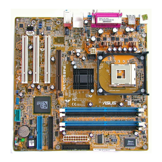
Page 16: Motherboard Overview
(Default) TV-OUT1 RADEON ™ USB2.0 Top: 9100 IGP T: USB3 RJ-45 B: USB4 CHA_FAN1 Top:Line In USBPW12 Center:Line Out Below:Mic In P4R800-VM Accelerated Graphics Port (AGP1) +5VSB (Default) SEC_IDE1 PCI1 8201BL PRI_IDE1 IXP200 FP_AUDIO1 PCI2 CLRTC1 4Mbit Firmware AUX1 PCI3…
-
Page 17: Placement Direction
Place eight (8) screws into the holes indicated by circles to secure the motherboard to the chassis. Do not overtighten the screws! Doing so may damage the motherboard. Place this side towards the rear of the chassis ASUS P4R800-VM motherboard user guide…
-
Page 18: Central Processing Unit (Cpu)
This mark indicates the processor Pin 1 that should match a specific corner of the CPU socket. Gold Arrow P4R800-VM P4R800-VM Socket 478 Incorrect installation of the CPU into the socket may bend the pins and severely damage the CPU! ®…
-
Page 19: Installing The Cpu
The lever clicks on the side tab to indicate that it is locked. 6. Install a CPU heatsink and fan following the instructions that came with the heatsink package. 7. Connect the CPU fan cable to the CPU_FAN1 connector on the motherboard. ASUS P4R800-VM motherboard user guide…
-
Page 20: System Memory
The following figure illustrates the location of the DDR DIMM sockets. P4R800-VM P4R800-VM 184-Pin DDR DIMM Sockets Make sure to unplug the power supply before adding or removing DIMMs or other system components. Failure to do so may cause severe damage to both the motherboard and the components.
-
Page 21
Samsung K4H560838D TCC4 256MB Corsair CM256A-3500C2PT 256MB Kingston VALUERAM KVR400X64C25/256 Winbond W942508BH-5 256MB Transcend TS32MLD64V4F3 MOSEL V58C2256804SAT5 Obtain DDR DIMMs only from ASUS qualified vendors. Visit the ASUS website (www.asus.com) for the latest QVL. ASUS P4R800-VM motherboard user guide 1-11… -
Page 22: Installing A Dimm
1.7.3 Installing a DIMM Follow these steps to install a DIMM. DDR DIMM notch 1. Unlock a DIMM socket by pressing the retaining clips outward. 2. Align a DIMM on the socket such that the notch on the DIMM matches the break on the socket.
-
Page 23: Standard Interrupt Assignments
When using PCI cards on shared slots, ensure that the drivers support “Share IRQ” or that the cards do not need IRQ assignments. Otherwise, conflicts will arise between the two PCI groups, making the system unstable and the card inoperable. ASUS P4R800-VM motherboard user guide 1-13…
-
Page 24: Pci Slots
Note the notches on the card golden fingers to ensure that they fit the AGP slot on the motherboard. This motherboard does not support 3.3V AGP cards. Install only +1.5V AGP cards. P4R800-VM Keyed for 1.5v P4R800-VM Accelerated Graphics Port (AGP) 1-14 Chapter 1: Product introduction…
-
Page 25: Jumpers
Except when clearing the RTC RAM, never remove the cap on CLRTC1 jumper default position. Removing the cap will cause system boot failure! CLRTC1 P4R800-VM Normal Clear CMOS (Default) P4R800-VM Clear RTC RAM ASUS P4R800-VM motherboard user guide 1-15…
-
Page 26
USBPW12 P4R800-VM +5VSB (Default) USBPW56 P4R800-VM USB Device Wake Up +5VSB (Default) 3. Keyboard power (3-pin KBPWR1) This jumper allows you to enable or disable the keyboard wake-up feature. Set this jumper to pins 2-3 (+5VSB) if you wish to wake up the computer when you press a key on the keyboard (the default is the Space Bar). -
Page 27: Connectors
10. USB 2.0 ports 3 and 4. These two 4-pin Universal Serial Bus (USB) ports are available for connecting USB 2.0 devices. 11. PS/2 keyboard port. This purple connector is for a PS/2 keyboard. ASUS P4R800-VM motherboard user guide 1-17…
-
Page 28: Internal Connectors
(Pin 5 is removed to prevent incorrect insertion when using ribbon cables with pin 5 plug). FLOPPY1 NOTE: Orient the red markings on the floppy ribbon cable to PIN 1. P4R800-VM PIN 1 P4R800-VM Floppy Disk Drive Connector 1-18 Chapter 1: Product introduction…
-
Page 29
These connectors allow you to receive stereo audio input from sound sources such as a CD-ROM, TV tuner, or MPEG card. CD(Black) AUX(White) Right Audio Channel P4R800-VM Ground Ground Left Audio Channel P4R800-VM Internal Audio Connectors ASUS P4R800-VM motherboard user guide 1-19… -
Page 30
P4R800-VM ASUS AV/S P4R800-VM TV Out Connector The ASUS AV/S module is not included in this motherboard package. 6. CPU and chassis fan connectors (3-pin CPU_FAN1, CHA_FAN1) The fan connectors support cooling fans of 350mA~740mA (8.88W max.) or a total of 1A~2.22A (26.64W max.) at +12V. Connect the fan cables to the fan connectors on the motherboard, making sure that the black wire of each cable matches the ground pin of the connector. -
Page 31
The module has two USB 2.0 ports for connecting next generation USB peripherals such as high resolution cameras, scanners, and printers. P4R800-VM USB56 P4R800-VM USB 2.0 Header The USB module is purchased separately. ASUS P4R800-VM motherboard user guide 1-21… -
Page 32
P4R800-VM FP_AUDIO1 P4R800-VM Front Panel Audio Connector 10. Serial port connector (10-1 pin COM1) This green connector accommodates the bundled serial port module. Install the module into a slot opening at the back of the system chassis, the connect the module’s green cable plug to this connector. -
Page 33
IDE connector cause this LED to light up. • Reset Switch Lead (2-pin RESET) This 2-pin connector connects to the case-mounted reset switch for rebooting the system without turning off the system power. ASUS P4R800-VM motherboard user guide 1-23… -
Page 34
1-24 Chapter 1: Product introduction… -
Page 35: Bios Information
Chapter 2 This chapter tells how to change system settings through the BIOS Setup menus. Detailed descriptions of the BIOS parameters are also provided. BIOS information…
-
Page 36: Managing And Updating Your Bios
BIOS file in a floppy disk. Visit the ASUS website and download the latest BIOS file for this motherboard using the ASUS Update utility. 2.1.1 Creating a bootable floppy disk 1.
-
Page 37: Using Afudos To Copy The Current Bios
To update the BIOS using the AFUDOS.EXE: 1. Visit the ASUS website (www.asus.com) to download the latest BIOS file for your motherboard. Save the BIOS file to a bootable floppy disk. ASUS P4R800-VM motherboard user guide…
-
Page 38
Write down the BIOS file name to a piece of paper. You need to type the exact BIOS file name at the prompt. 2. Copy the AFUDOS.EXE utility from the support CD to the bootable floppy disk that contains the BIOS file. 3. -
Page 39: Using Asus Ez Flash To Update The Bios
2.1.4 Using ASUS EZ Flash to update the BIOS The ASUS EZ Flash feature allows you to easily update the BIOS without having to go through the long process of booting from a floppy disk and using a DOS-based utility. The EZ Flash is built-in the BIOS LPC chip so it is accessible by simply pressing <Alt>…
-
Page 40: Recovering The Bios With Crashfree Bios 2
3. Insert a floppy disk that contains the original, or the latest, BIOS file for this motherboard (P4R800VM.ROM). If the BIOS file that you downloaded from the ASUS website has a different filename (e.g. P4R800VM11.ROM), rename it to P4R800VM.ROM. The BIOS update process continues when the P4R800VM.ROM is found.
-
Page 41: To Recover The Bios From The Support Cd
4. When the BIOS update process is complete, reboot the system. The recovered BIOS may not be the latest BIOS version for this motherboard. Visit the ASUS website (www.asus.com) to download the latest BIOS file. ASUS P4R800-VM motherboard user guide…
-
Page 42: Bios Setup Program
BIOS Setup program This motherboard supports a programmable Low Pin Count (LPC) chip that you can update using the provided utility described in section “2.1 Managing and updating your BIOS.” Use the BIOS Setup program when you are installing a motherboard, reconfiguring your system, or prompted to “Run Setup”.
-
Page 43: Bios Menu Screen
At the bottom right corner of a menu screen are the navigation keys for that particular menu. Use the navigation keys to select items in the menu and change the settings. Some of the navigation keys differ from one screen to another. ASUS P4R800-VM motherboard user guide…
-
Page 44: Menu Items
Use [+] or [-] to For example, selecting Main shows the Primary IDE Master [ST321122A] configure system Primary IDE Slave [ASUS CDS520/] time. Secondary IDE Master [Not Detected] Main menu items. Secondary IDE Slave [Not Detected] System Information…
-
Page 45: Main Menu
2.3.3 Legacy Diskette A [1.44M, 3.5 in.] Sets the type of floppy drive installed. Configuration options: [Disabled] [360K, 5.25 in.] [1.2M , 5.25 in.] [720K , 3.5 in.] [1.44M, 3.5 in.] [2.88M, 3.5 in.] ASUS P4R800-VM motherboard user guide 2-11…
-
Page 46: Primary/Secondary Ide Master/Slave
2.3.4 Primary/Secondary IDE Master/Slave While entering Setup, BIOS auto-detects the presence of IDE devices. There is a separate sub-menu for each IDE device. Select a device item then press Enter to display the IDE device information. Primary IDE Master Select the type of device connected to the Device : Hard Disk…
-
Page 47: System Information
: 1733 MHz Count System Memory Size : 256MB AMI BIOS This item displays the auto-detected BIOS information. Processor This item displays the auto-detected CPU specification. System Memory This item displays the auto-detected system memory. ASUS P4R800-VM motherboard user guide 2-13…
-
Page 48: Advanced Menu
Advanced menu The Advanced menu items allow you to change the settings for the CPU and other system devices. Take caution when changing the settings of the Advanced menu items. Incorrect field values may cause the system to malfunction. CPU Configuration Configure Instant Music.
-
Page 49: Chipset
Allows you to select DRAM CAS speed. Configuration options: [Slow] [Fast] AGP Aperture Size [64MB] Allows you to select the size of mapped memory for AGP graphic data. Configuration options: [32MB] [64MB] [128MB] [256MB] [512MB] ASUS P4R800-VM motherboard user guide 2-15…
-
Page 50: Southbridge Configuration
UMA Frame Buffer Size [64MB] Allows you to select the size of the onboard graphics controller memory use. Configuration options: [8MB] [16MB] [32MB] [64MB] [128MB] [None] Southbridge Configuration AC97 Audio Device [Auto] Onboard LAN Device [Enabled] USB 1.1 OHCI Controllers [Both] USB 2.0 EHCI Controller [Enabled]…
-
Page 51: Onboard Devices Configuration
EPP Version [1.9] Allows you to select the Enhanced Parallel Port version. Configuration options: [1.9] [1.7] Parallel Port IRQ [IRQ7] Allows you to select the IRQ address for the Parallel Port. Configuration options: [IRQ5] [IRQ7] ASUS P4R800-VM motherboard user guide 2-17…
-
Page 52: Pci Pnp
2.4.4 PCI PnP The PCI PnP menu items allow you to change the advanced settings for PCI/PnP devices. The menu includes setting IRQ and DMA channel resources for either PCI/PnP or legacy ISA devices, and setting the memory size block for legacy ISA devices.
-
Page 53: Power Menu
2.5.4 ACPI APIC Support [Enabled] Allows you to enable or disable the ACPI support in the ASIC. When set to Enabled, the ACPI APIC table pointer is included in the RSDT pointer list. Configuration options: [Disabled] [Enabled] ASUS P4R800-VM motherboard user guide 2-19…
-
Page 54: Apm Configuration
2.5.5 APM Configuration Restore on AC Power Loss [Power Off] Go into On/Off, Standby Resume on Keyboard [Disabled] or Suspend when Power Resume on PS/2 Mouse [Disabled] button is pressed. RTC Resume [Disabled] Restore on AC Power Loss [Power Off] When set to Power Off, the system goes into off state after an AC power loss.
-
Page 55: Hardware Monitor
CPU Q-Fan Control [Disabled] Chassis Q-Fan Control [Disabled] These items allow you to enable or disable the ASUS Q-Fan feature that smartly adjusts the fan speeds for more efficient system operation. When these fields are set to [Enabled], the Fan Speed Ratio item appears to allow selection of the appropriate fan speed ratio.
-
Page 56: Boot Menu
1st Boot Device [First Floppy Drive] available devices. 2nd Boot Device [PM-ST320413A] 3rd Boot Device [PS-ASUS CD-S340] A device enclosed in parenthesis has been disabled in the corresponding type menu. 1st ~ xxth Boot Device [1st Floppy Drive] These items specify the boot device priority sequence from the available devices.
-
Page 57: Boot Settings Configuration
When set to Enabled, the system displays the message “Press DEL to run Setup” during POST. Configuration options: [Disabled] [Enabled] Interrupt 19 Capture [Disabled] When set to [Enabled], this function allows the option ROMs to trap Interrupt 19. Configuration options: [Disabled] [Enabled] ASUS P4R800-VM motherboard user guide 2-23…
-
Page 58: Security
2.6.3 Security The Security menu items allow you to change the system security settings. Select an item then press Enter to display the configuration options. Security Settings <Enter> to change password. Supervisor Password Not Installed <Enter> again to disable User Password Not Installed password.
-
Page 59: Change User Password
When set to [Setup], BIOS checks for user password when accessing the Setup utility. When set to [Always], BIOS checks for user password both when accessing Setup and booting the system. Configuration options: [Setup] [Always] ASUS P4R800-VM motherboard user guide 2-25…
-
Page 60: Exit Menu
Exit menu The Exit menu items allow you to load the optimal or failsafe default values for the BIOS items, and save or discard your changes to the BIOS items. Exit Options Exit system setup after saving the changes. Exit & Save Changes Exit &…
-
Page 61: Chapter 3: Software Support
Chapter 3 This chapter describes the contents of the support CD that comes with the motherboard package. Software support…
-
Page 62: Install An Operating System
The contents of the support CD are subject to change at any time without notice. Visit the ASUS website for updates. 3.2.1 Running the support CD To begin using the support CD, simply insert the CD into your CD-ROM drive. The CD automatically displays the Drivers menu if Autorun is enabled in your computer.
-
Page 63: Drivers Menu
Install ASUS Update This program allows you to download the latest version of the BIOS from the ASUS website. Before using the ASUS Update, make sure that you have an Internet connection so you can connect to the ASUS website. Installing ASUS Update also installs ASUS Mylogo2™.
-
Page 64: Asus Contact Information
This item installs the ASUS screen saver. 3.2.4 ASUS Contact Information Clicking the ASUS Contact Information tab displays as stated. You may also find this information on page viii of this user guide. Screen display and utilities option may not be the same for other operating system version.