-
Contents
-
Table of Contents
-
Troubleshooting
-
Bookmarks
Quick Links
MDM300 I.S.
Advanced Dew-Point Hygrometer
User Manual
97213 Issue 6.2
August 2021
Related Manuals for Michell Instruments MDM300 I.S.
Summary of Contents for Michell Instruments MDM300 I.S.
-
Page 1
MDM300 I.S. Advanced Dew-Point Hygrometer User Manual 97213 Issue 6.2 August 2021… -
Page 2
Please fill out the form(s) below for each instrument that has been purchased. Use this information when contacting Michell Instruments for service purposes. Product Name Order Code Serial Number Invoice Date Installation Location Tag Number Product Name Order Code Serial Number… -
Page 3
© 2021 Michell Instruments This document is the property of Michell Instruments Ltd and may not be copied or otherwise reproduced, communicated in any way to third parties, nor stored in any Data Processing System without the express written authorization of Michell Instruments Ltd. -
Page 4: Table Of Contents
MDM300 I.S. User Manual Contents Safety ……………………..vii Electrical Safety ………………….vii Pressure Safety ………………….vii Toxic Materials ………………….vii Repair and Maintenance ………………..vii Calibration ……………………vii Safety Conformity …………………..vii Abbreviations ……………………viii Warnings …………………….. viii INTRODUCTION ………………..1 Controls and Indicators ………………3 Function Keys ………………… 5 1.2.1 Enter Key …………………
-
Page 5
Input Terminal Parameters …………51 Special Conditions of Use …………. 52 Maintenance and Installation …………52 Appendix D FCC Declaration ………………54 Appendix E Quality, Recycling & Warranty Information ……….. 56 Appendix F Return Document & Decontamination Declaration ……..58 Michell Instruments… -
Page 6
MDM300 I.S. User Manual Figures Figure 1 MDM300 I.S. Advanced Dew-Point Hygrometer ……….2 Figure 2 User Connections, Controls and Indicators …………3 Figure 3 Instrument Display ………………6 Figure 4 Packing Method ………………9 Figure 5 Gas Port Adaptors ………………10 Figure 6 Accessories ………………..11 Figure 7 Bonded Seal Fitting ………………13 Figure 8… -
Page 7: Safety
Michell Instruments’ worldwide offices contact information. Calibration The recommended calibration interval for the MDM300 I.S. is 12 months. The instrument should be returned to the manufacturer, Michell Instruments Ltd, or one of their accredited service agents for re-calibration. Safety Conformity This product meets the essential protection requirements of the relevant UK and EU directives.
-
Page 8: Abbreviations
MDM300 I.S. User Manual Abbreviations The following abbreviations are used in this manual: alternating current pressure unit (atmosphere) barg pressure unit (=100 kP or 0.987 atm) gauge bara bar absolute °C degrees Celsius °F degrees Fahrenheit Kelvin (absolute temperature) common direct current foot (feet) Hertz…
-
Page 9: Introduction
PC based, MDM300 I.S. Software Application Package which provides the facility for handling the logged data files and uploading and downloading instrument parameters. A user-friendly operator interface provides easy access to all levels of the instrument’s functionality. An easy-to-follow calibration routine is built into the instrument’s software. Michell Instruments…
-
Page 10: Figure 1 Mdm300 I.s. Advanced Dew-Point Hygrometer
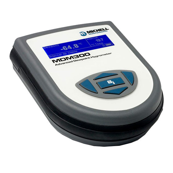
Two versions of the instrument are available, an MDM300 (standard) version and an MDM300 I.S. (intrinsically safe) version. This manual covers the MDM300 I.S. version only. For information about the MDM300 contact your local Michell Instruments’ representative (contact information at www.michell.com). Figure 1 MDM300 I.S.
-
Page 11: Controls And Indicators
Figure 2 shows the layout of these controls and Table 1 describes their respective operational functions. — I.S. Fig 2.1_V6 Figure 2 User Connections, Controls and Indicators Michell Instruments…
-
Page 12: Table 1 Controls And Indicators
MDM300 I.S. User Manual INTRODUCTION Item Panel Description Function keys. Refer to Section 1.2 for the details of these Front keys. Instrument display, partitioned to show 3 main panels: The primary display shows internal sensor parameters. The secondary display indicates the external sensor Front parameter.
-
Page 13: Function Keys
As the insertion point is shifted to the left, the entry at the former position is deleted. Within any menu or sub-menu level, pressing this ƒ key escapes to the previous menu above the current level. Michell Instruments…
-
Page 14: Instrument Display
MDM300 I.S. User Manual INTRODUCTION Instrument Display The graphics display and the associated function keypad ( Figure 2), form the operator interface of the equipment. Figure 3 shows all the elements of a typical display page after the instrument’s initialization period has completed. Table 2 details the elements of the display: Dewpoint Internal…
-
Page 15: Display Units
, CO or N Dew Point • °C • °F • Relative Humidity (%) Mixing Ratio • g/kg (AIR, USER, H , SF , CO or N To toggle between displayed units, press either the or key. Michell Instruments…
-
Page 16: Status Display Indications
MDM300 I.S. User Manual INTRODUCTION 1.3.2 Status Display Indications ‘ Initializing Internal Sensor’ Initializing Internal Sensor’ This is displayed immediately after the instrument has been powered up, and indicates that the sensor is being heated up to accelerate equilibrium with the moisture in the sample gas.
-
Page 17: Installation
Save all the packing materials for the purpose of returning the instrument for re-calibration or any warranty claims. If the optional carry bag has been ordered it will be located underneath the foam insert, in a cardboard box. Michell Instruments…
-
Page 18: Mdm300 I.s. Accessories
MDM300 I.S. User Manual INSTALLATION MDM300 I.S. Accessories The accessories for the MDM300 I.S. are shown in Figure 6 . Items 1 to 5 are supplied as standard and item 6 is optional. Please check that all the standard components are present after unpacking.
-
Page 19: Figure 6 Accessories
HIGH PRESSURE! High pressure gases are potentially hazardous. Energy stored in these gases can be released suddenly and with extreme force. High pressure systems should be assembled and operated only by people who have been trained in proper safety practices. 97244 Issue 2.2, September 2013 Figure 6 Accessories Michell Instruments…
-
Page 20: Operational Requirements
MDM300 I.S. User Manual INSTALLATION Operational Requirements Operational requirements are as follows: Sample gas flow rate: 0.2 to 0.5 Nl/min (0.5 to 1 scfh) Operating pressure: 0 to 350 barg (0 to 5076 psig) 2.4.1 Environmental Requirements – MDM300 I.S. Instrument Operating temperature range: -20 to +50°C (-4 to +122°F) Humidity:…
-
Page 21: Gas Inlet /Outlet Fittings
Michell Instruments, on request. NOTE: The bonded seals used for the MDM300 I.S. are Dowty part number 400-228-4490-74 (from Michell Instruments, part number MDM300-DS). Michell Instruments…
-
Page 22: Battery Charging
MDM300 I.S. User Manual INSTALLATION Battery Charging WARNING: The battery charger must NOT be connected within the hazardous area. The battery charger socket cover MUST be closed when the product is in use within a hazardous area. The MDM300 I.S. is powered from an internally mounted, rechargeable Nickel Metal Hydride (NiMH) battery.
-
Page 23
If the battery has been damaged then the charger will not begin the fast-charge stage. Please contact Michell Instruments’ service department for advice. Once the charger has finished the fast-charge stage it can be safely disconnected. Switch off the AC power supply, remove the charger unit and close the instrument’s charge connector protection cover. -
Page 24: Operation
MDM300 I.S. User Manual OPERATION OPERATION High pressure gases are potentially dangerous. POSSIBLE INJURY! The tubing, valves and other apparatus attached to this instrument must be adequate for the maximum pressure which will be applied, otherwise physical injury to the operator or bystander is possible. Preparation for Operation The MDM300 I.S.
-
Page 25: Instrument Start-Up
Measurement in progress Measurement in progress message is displayed. After this, depending on the sample conditions, the instrument may continue to respond to the final dew-point for a number of minutes. This is further explained in Section 3.6. Michell Instruments…
-
Page 26: Overall Menu Structure And Operation
MDM300 I.S. User Manual OPERATION Overall Menu Structure and Operation 3.3.1 SET-UP Menu All instrument settings are made from the SET-UP Menu which is accessible from the Main Display by pressing the Enter Enter key. On the first occasion after switch-on the Passcode Entry page will be displayed. Enter the passcode 7316 7316…
-
Page 27: Figure 11 Menu Structure
EXTERNAL ZERO EXTERNAL SPAN PASSCODE USER PRESSURE YEAR MONTH HOUR CONTRAST BRIGHTNESS KEY TONE BL TIMEOUT LANGUAGE PRIMARY DISP POINT MDM300 INFO PAGE LEGEND Enter Key Up/Down Keys Left Right Keys Figure 11 Menu Structure * No longer available Michell Instruments…
-
Page 28: Set-Up Menu Parameters
MDM300 I.S. User Manual OPERATION SET-UP Menu Parameters Follow the instructions in Section 3.3.1 to select the required parameters. 3.4.1 SETTINGS PRIMARY DP AT ATMOS SETTINGS DP/TEMP UNIT °C PRESSURE UNIT Psig GAS TYPE MOL WEIGHT CHART INTERVAL Figure 12 SETTINGS Page Parameter Description Indicates if the primary display sensor is at atmospheric or system…
-
Page 29: Logging
The size of any one log file is limited to 60kb. If the unit is left logging, and the file size exceeds 60kb, then the log file will finish automatically. To ensure that the log file you initiate collects all the data from your test, an Michell Instruments…
-
Page 30: Bluetooth
MDM300 I.S. User Manual OPERATION appropriate sample time should be chosen. The table below can be used as a rough guide: Sample time (sec) Logging duration 3 hours 6 hours 18 hours 36 hours 60 hours 120 hours 240 hours 360 hours 3.4.3 BLUETOOTH…
-
Page 31: 3.4.3.1 Bluetooth Pairing Procedure
. NOTE: The name of With the serial link established, click Configure Configure the COM port allocated, i.e. COM7, will need to be entered when starting the Michell application software. (7) (3) (1) (6) Figure 15 Typical Bluetooth Pairing Sequence Michell Instruments…
-
Page 32: Clock
MDM300 I.S. User Manual OPERATION 3.4.4 CLOCK YEAR CLOCK MONTH HOUR Figure 16 CLOCK Page YEAR CLOCK MONTH HOUR Parameter Description Current year YEAR YEAR Available Input: Range: 00 to 99 YEAR CLOCK MONTH Current month MONTH MONTH HOUR Available Input: Range: 01 to 12 Current day Available Input: Range: 01 to 31 Current hour…
-
Page 33: Info
Figure 18 INFO Page This page contains system information and no changes can be made. Information available: • Firmware number and version • Sensor serial number • Date of sensor calibration next due • Hours that the sensor has been used Michell Instruments…
-
Page 34: Chart Page
MDM300 I.S. User Manual OPERATION 3.4.7 CHART Page At any time while the Main Display is indicating internal sensor parameters, a graphical display of the output can be obtained by pressing the key from the Main Display. The chart can be reset at any time by pressing the Enter Enter key.
-
Page 35: Logs Page
Logging interval • Current date in YYMMDD format • T# T# Current time in HHMMSS format NOTE: The chart and datalogging are independent functions; therefore the parameter displayed on the chart may not necessarily reflect what is being logged. Michell Instruments…
-
Page 36: 3.4.10 Calibration
MDM300 I.S. User Manual OPERATION 3.4.10 CALIBRATION Input passcode for setup menu WARNING: These procedures require the use of specialized test equipment and calibration adjustments should only be 0 0 0 carried out by qualified personnel. POINT MDM300 CALIBRATION -100 -100.0 -100.0 -90.0…
-
Page 37: Default Parameters
Current UK time & date CONTRAST BRIGHTNESS Section 3.4.5, Figure 17 KEYTONE BL TIME-OUT LANGUAGE PRIMARY DISP INTERN CALIBRATION & INFO CALIBRATION & INFO Section 3.4.10 & Section 6 Default values not applicable Table 9 MDM300 I.S. Default Parameters Michell Instruments…
-
Page 38: Guide To Measurement And Sampling
For the most basic measurement it is recommended to have a flow meter (0 to 1 l/min), and at least one metering valve. A number of sampling kits are available from Michell Instruments: • The Easi-fit sample kit is a low cost sampling system consisting of 2 metering valves and a flow meter which is suitable for many applications.
-
Page 39: Measuring At Atmospheric Or System Pressure
The metering valve on the inlet should be used to control the sample flow. To measure at system pressure the metering valve on the instrument inlet should be fully open. The metering valve on the outlet should be used to control the sample flow. Michell Instruments…
-
Page 40: Measurement Guide
MDM300 I.S. User Manual OPERATION 3.6.2 Measurement Guide Follow procedure A and note the result. Turn the instrument off. If you wish to measure at sample pressure then use the Michell Humidity Calculator (http://www.michell.com/uk/downloads/humidity_calculator. msi) to convert this result back to the equivalent at your sample pressure. Using this converted result, and the table below, find the appropriate procedure to measure your sample.
-
Page 41
Once ‘ Measurement in progress’ Measurement in progress’ has disappeared, the instrument is close to the final dew point. Depending on the conditions, it may continue to respond for a number of minutes before tracking the measured dew point. Michell Instruments… -
Page 42: Conditional Sensor Purge
15 seconds or the battery may be damaged. NOTE: Michell Instruments will replace the older FW 7219 charger with the new Cell Con model free of charge. The Cell Con will re-charge batteries which have completely discharged.
-
Page 43: Good Measurement Practice
The table below offers an approximate guide to the times taken for the instrument to stabilize at a given dew point (from a starting point of 10°Cdp ambient): Target Dew Point (°C) T100 response time from ambient (hours) -100 Michell Instruments…
-
Page 44: Sampling Hints
MDM300 I.S. User Manual GOOD MEASUREMENT PRACTICE Sampling Hints Ensuring reliable and accurate moisture measurements requires the correct sampling techniques, and a basic understanding of how water vapor behaves. This section aims to explain the common mistakes and how to avoid them. Sampling Materials –…
-
Page 45
Theoretically flow rate has no direct effect on the measured moisture content, but in practice it can have unanticipated effects on response speed and accuracy. An inadequate flow rate may: Michell Instruments… -
Page 46
MDM300 I.S. User Manual GOOD MEASUREMENT PRACTICE • Accentuate adsorption and desorption effects on the gas passing through the sampling system. • Allow pockets of wet gas to remain undisturbed in a complex sampling system, which will then gradually be released into the sample flow. •… -
Page 47: Application Software
These can be downloaded to a specific location by right clicking, and selecting ‘ download download ’. A context sensitive help file provides further details on the use of the application software. Figure 26 Typical Application Software Screen Michell Instruments…
-
Page 48: Calibration
If these facilities do not exist it is recommended that the instrument be returned to the manufacturer, Michell Instruments Ltd., or one of the approved agents. A calibration certificate bearing a seven point calibration is issued with each instrument.
-
Page 49: Calibration Method
A set of results similar to that shown below could be generated over the calibration range of the instrument. Stabilize Stabilize DP REF MDM300 I.S. DP REF MDM300 I.S. Time Time °C Rdg °C °C Rdg °C (Hours) (Hours) -100 -99.8 -30.1 -79.7 -19.9 -59.8 -49.8 -39.9 Table 11 Example Of Calibration Run Readings Michell Instruments…
-
Page 50: Calibration Correction Method
MDM300 I.S. User Manual CALIBRATION Calibration Correction Method NOTE: Any logging procedure currently in operation must be cancelled before the calibration procedures can be entered. CALIBRATION CALIBRATION To enter the CALIBRATION Menu page, highlight from the SET-UP Menu by using the or keys and press the Enter Enter key.
-
Page 51: Shipping
Create a packing list detailing all equipment contained in the box, place it inside the box and seal the box. Before disconnecting the MDM300 I.S. from the gas line it is essential to vent the system to atmospheric pressure, otherwise severe injury could result. Figure 29 Instrument Packing Details Michell Instruments…
-
Page 52
MDM300 I.S. User Manual APPENDIX A Appendix A Technical Specifications 97213 Issue 6.2, August 2021… -
Page 53: Appendix A Technical Specifications
1/8” NPT female (other options available) Gas Wetted Materials AISI 316L stainless steel, PTFE Seal, Borosilicate glass, ceramic Outline Dimensions 218 x 170 x 90mm (8.6 x 6.7 x 3.5ft) (d x w x h) Weight 1.5kg (3.3lbs) Michell Instruments…
-
Page 54: Dimensions
MDM300 I.S. User Manual APPENDIX A Capacity: 8Mb Data Logging Log interval: 5…60 sec Maximum log file size: 60kb Communications (Wireless) Bluetooth range up to 5m (16ft) (Version 2.0) Languages English, German, Spanish, French, Italian, Portuguese Hazardous Area Certification Certification Codes See Appendix C * The end user has a responsibility to ensure that when installed in the Hazardous Area, the system is compliant with relevant local and international installation Standards for the use of equipment in explosive atmospheres.
-
Page 55
MDM300 I.S. User Manual APPENDIX B Appendix B Datalog Status Display Michell Instruments… -
Page 56: Appendix B Datalog Status Display
Figure 36 . Bit 1 is the least significant bit. The four most significant bits 13…16 are for Michell Instruments’ service use and so the first character in any MDM300 I.S. ST display will always read 0.
-
Page 57: Table 14 Status Register Flags
External sensor error’ and bit 6 set ‘ Measurement in progress’ Measurement in progress’ Therefore, at the time that these log points were taken, the external sensor was out of range and the internal dew point was not stable. Michell Instruments…
-
Page 58
MDM300 I.S. User Manual APPENDIX C Appendix C Hazardous Area Certification 97213 Issue 6.2, August 2021… -
Page 59: Appendix C Hazardous Area Certification
Class I, Zone 0, AEx ia IIC T4 Ga Ex ia IIC T4 Ga Ta=-20°C…+50°C Global Certificates/Approvals ATEX SGS Baseefa 06ATEX0330X IECEx IECEX BAS 06.0090XX UKCA BAS 21UKEX0015X LR1507-5 These certificates can be viewed or downloaded from our websites at: www.processsensing.com & www.michell.com Michell Instruments…
-
Page 60: Input Terminal Parameters
Maintenance and servicing of the product must only be carried out by suitably trained personnel or returned to an approved Michell Instruments Service Center. 97213 Issue 6.2, August 2021…
-
Page 61
MDM300 I.S. User Manual APPENDIX D Appendix D FCC Declaration Michell Instruments… -
Page 62: Appendix Dfcc Declaration
Règlement canadien sur les interférences radio. Ce produit numérique de classe B est conforme à la norme NMB-003, CISPR 22: 1997. Signed for, and on behalf of, Michell Instruments Ltd. Andrew M.V. Stokes, Technical Director Issue date: 05/2011 97213 Issue 6.2, August 2021…
-
Page 63
MDM300 I.S. User Manual APPENDIX E Appendix E Quality, Recycling & Warranty Information Michell Instruments… -
Page 64: Appendix E Quality, Recycling & Warranty Information
MDM300 I.S. User Manual APPENDIX E Appendix E Quality, Recycling & Warranty Information Michell Instruments is dedicated to complying to all relevant legislation and directives. Full information can be found on our website at: www.michell.com/compliance This page contains information on the following directives: •…
-
Page 65
MDM300 I.S. User Manual APPENDIX F Appendix F Return Document & Decontamination Declaration Michell Instruments… -
Page 66: Appendix F Return Document & Decontamination Declaration
Has the equipment been cleaned and decontaminated? NOT NECESSARY Michell Instruments will not accept instruments that have been exposed to toxins, radio-activity or bio-hazardous materials. For most applications involving solvents, acidic, basic, flammable or toxic gases a simple purge with dry gas (dew point <-30°C) over 24 hours should be sufficient to decontaminate the unit prior to return.
-
Page 67
MDM300 I.S. User Manual NOTES: Michell Instruments… -
Page 68
www.ProcessSensing.com http://www.michell.com…
Предложите, как улучшить StudyLib
(Для жалоб на нарушения авторских прав, используйте
другую форму
)
Ваш е-мэйл
Заполните, если хотите получить ответ
Оцените наш проект
1
2
3
4
5
Скачать
INSTALLATION/OWNER’S MANUAL
CD Marine Receiver
MDM300
![]()
MDM300
INSTALLATION/OWNER’S MANUAL
CD Marine Receiver
MDM300 INSTALLATION
Preparation
Please read entire manual before installation.
Before You Start
•Disconnect negative battery terminal. Consult a qualified technician for instructions.
•Avoid installing the unit where it would be subject to high temperatures or where it would be subject to dust, dirt or excessive vibration.
Getting Started
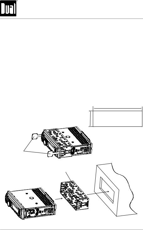
•Remove 2 transit screws located on top of the unit.
•Insert the supplied keys into the slots as shown, and slide the unit out of the mounting sleeve.
•Install mounting sleeve into opening, bending tabs to secure.
•Connect wiring harness and antenna. Consult a qualified technician if you are unsure.
•Test for correct operation and slide into the mounting sleeve to secure.
•Snap trim ring into place.
Mounting sleeve opening dimensions 7-11/64″ x 2-3/32″ (182 mm x 53 mm)
REMOVAL KEYS
MOUNTING SLEEVE
TYPICAL MOUNTING METHOD
2

MDM300 INSTALLATION
Wiring Diagram
FUSE
When replacing the fuse, make sure new fuse is the correct type and amperage.
Using an incorrect fuse could damage the radio. The MDM300 uses one 10 amp AGC fuse located in-line.
3
MDM300 OPERATION
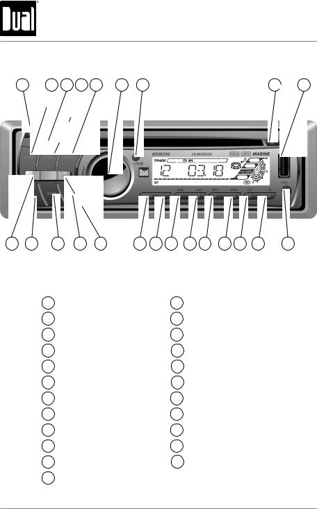
Control Locations — Receiver
|
1 |
2 |
3 |
4 |
5 |
6 |
7 |
8 |
9 |
|
23 |
22 |
21 |
20 |
19 |
18 |
17 |
16 |
15 |
14 |
13 |
12 |
11 |
10 |
|
1 |
Release |
13 |
Preset 4 / Random |
|
2 |
Mute |
14 |
Preset 3 / Repeat |
|
3 |
AMS |
15 |
Preset 2 / Intro |
|
4 |
Scan |
16 Preset 1 / Play / Pause |
|
|
5 |
Display |
17 |
Local / Distance |
|
6 |
Audio / Volume Knob |
18 |
Mono / Stereo |
|
7 |
Loudness |
19 |
Tune / Track Up |
|
8 |
Eject |
20 |
Band |
|
9 |
USB Input |
21 |
Mode |
|
10 |
Auxiliary Input |
22 |
Power |
|
11 |
Preset 6 / +10 Skip |
23 |
Tune / Track Down |
|
12 |
Preset 5 / -10 Skip |
4
MDM300 OPERATION
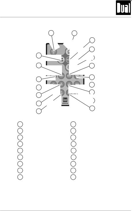
Control Locations — Remote
|
1 |
2 |
|
3 |
|
|
4 |
|
|
18 |
5 |
|
17 |
6 |
|
16 |
7 |
|
15 |
8 |
|
14 |
9 |
|
13 |
10 |
|
12 |
11 |
|
1 |
Power |
10 |
Mute |
|
2 |
Volume Up |
11 |
Preset 6 / +10 |
|
3 |
Select |
12 |
Preset 5 / -10 |
|
4 Tune / Track Up |
13 Preset 4 / Random |
||
|
5 |
Volume Down |
14 Preset 2 / Intro |
|
|
6 |
Scan |
15 Preset 1 / Play / Pause |
|
|
7 |
Display |
16 |
Mode |
|
8 |
Loudness |
17 |
Band |
|
9 |
Preset 3 / Repeat |
18 |
Tune / Track Down |
5

MDM300 OPERATION
General Operation
Faceplate Removal
Power On/Off
Mode
Auxiliary Input
Volume
Loudness
Display
Reset
Set the Clock
12/24-hour Clock
Setup Menu
Press RELEASE and pull away from the left side to remove. To re-install, insert right side of faceplate first then push left side to secure.
Press  or any other button (except EJECT) to turn the unit on. Press
  to turn the unit off.
Press MODE to select between AM/FM, CD player, auxiliary, USB and SD card. Modes of operation are shown in the display.
Note: CD, SD and USB modes will not appear unless a CD, SD Card or USB device is inserted.
The MDM300 a 3.5 mm auxiliary input port on the front panel of the unit for connecting an audio device, MP3 player, etc. Press MODE to select auxiliary input mode.
Adjust volume using volume knob (0-47).
Press LOUD to activate the Loudness function. Activating Loudness will enhance the bass and treble frequencies when listening to music at low volumes.
Press DISP to show the clock. During playback of MP3/WMA files, ID3 tag information, elapsed time, track number and file/folder names will automatically alternate on the display.
Press RESET upon initial installation or if abnormal operation occurs. Reset button is located behind the front panel.
With the unit on, press and hold DISP until the clock begins to flash, then release. Turn the volume knob to the right to adjust the hours or to the left to adjust the minutes.
The clock will display 12-hour AM/PM time in USA frequency spacing mode (PM 10.00). In European frequency spacing mode, the clock will display 24-hour time (22.00).
Press and hold the volume knob for more than 3 seconds to access the setup menu. Press volume knob momentarily to select between the menu functions and rotate the volume knob left/right to adjust or activate the desired function.
6

|
MDM300 OPERATION |
|||
|
General Operation — Setup Menu |
|||
|
Menu Function |
Options |
Action |
|
|
Equalizer |
DSP |
Toggles between the following equalization options: OFF, |
|
|
POP, ROCK, CLASS and FLAT). |
|||
|
Beep |
BEEP OFF |
Disables the confirmation beep. |
|
|
Confirmation |
BEEP ON |
Enables the confirmation beep. |
|
|
Seek Priority |
SEEK 1 |
Enables seek tuning priority. |
|
|
SEEK 2 |
Enables manual tuning priority. |
||
|
VOL LAST |
Programs unit to always turn on at the last volume selected |
||
|
Programmable |
before it was turned off. |
||
|
Turn On Volume |
VOL ADJ |
Programs unit to always turn on at a specific volume. Any |
|
|
volume level 1-47 can be selected. |
|||
|
*Tuner |
FREQ USA |
Programs the unit to USA tuner spacing. |
|
|
(200kHz for FM and 10kHz for AM). |
|||
|
Frequency |
|||
|
Programs the unit to European tuner spacing. |
|||
|
Spacing |
FREQ EUR |
||
|
(50kHz for FM and 9kHz for AM). |
|||
*Tuner Frequency Spacing is only selectable from Tuner mode.
7

MDM300 OPERATION
General Operation
Audio Press AUDIO momentarily to select between Bass, Treble, Balance and Fader.
 BASS TREBLE
  BALANCE
  FADER
FADER
Bass Press AUDIO until BAS appears then rotate volume knob left/right to adjust ( -7 minimum / +7 maximum).
Treble Press AUDIO until TRE appears then rotate volume knob left/right to adjust ( -7 minimum / +7 maximum).
Balance Press AUDIO until BAL appears then rotate volume knob left/right to adjust (BAL 10L — BAL 10R).
BAL EVEN represents equal balance
Fader Press AUDIO until FAD appears then rotate volume knob left/right to adjust (FAD 10R — FAD 10F).
FAD EVEN represents equal fader
8
 Loading…
Скачать файл PDF «Dual MDM300 Инструкция по эксплуатации» (1.08 Mb)
Популярность:
1266 просмотры
Подсчет страниц:
24 страницы
Тип файла:
Размер файла:
1.08 Mb