- Manuals
- Brands
- Weinmann Manuals
- Medical Equipment
- MEDUMAT Standard2
- Step-by-step instructions
-
Bookmarks
Quick Links
MEDUMAT Standard
2
Step-by-step instructions
• Start ventilation by height
• NIV therapy
Important:
• Resuscitation (CPR) with IPPV
This document
• Resuscitation (CPR) with CCSV
does not replace the
instructions for use.
• Anesthesia induction (RSI)
Complete information
can be found in
the instructions
for use.
Related Manuals for Weinmann MEDUMAT Standard2
Summary of Contents for Weinmann MEDUMAT Standard2
-
Page 1
MEDUMAT Standard Step-by-step instructions • Start ventilation by height • NIV therapy Important: • Resuscitation (CPR) with IPPV This document • Resuscitation (CPR) with CCSV does not replace the instructions for use. • Anesthesia induction (RSI) Complete information can be found in the instructions for use. -
Page 2: Operating Steps
Operating steps Switch on ventilator Select “New patient” Select patient height and gender Select “next” Select the ventilation mode and check Start ventilation the displayed ventilation parameters…
-
Page 3
Start ventilation by height Start faster and ventilate more precisely From now on you don’t have to think long about which tidal volume (Vt) is best for your patient. With MEDUMAT Standard , you can now initiate ventilation even more precisely and quickly. -
Page 4
NIV therapy Switch on ventilator. Select “New patient” in the start menu. Set the patient’s height and gender or select the appropriate patient group: Adult, Child, Infant. -
Page 5
Select one of the following ventilation modes: CPAP* or CPAP + ASB (if available). *pure CPAP is the ventilation form CPAP + ASB with a ΔpASB of 0 mbar Select the desired CPAP therapy using the navigation button: PEEP, pMax, ΔpASB. After adjusting the values, begin the ventilation via “start”. -
Page 6
SOP NIV (Standard Operating Procedure) Non-invasive ventilation (NIV) by the EMS Modified by Prof. Dr. med. Thoralf Kerner Logistical requirements Oxygen supply: at least a 2-l bottle, filled …………Check Emergency medical team familiar with NIV …………. Check Clinical requirements Alert, cooperative (GCS > 12) ……………. -
Page 7
This instruction might not be valid in your country. Please check local guidelines. Escalation levels In the event of imminent respiratory muscle fatigue, set pressure support (ASB). Immediate intubation in the absence of clinical improvement or the occurrence of contraindications! Caution •… -
Page 8
Inspiratory trigger The inspiratory trigger triggers a pressure support or a mechanical breath as soon as inhalation effort is detected. Flow Trigger sensitivity: 1 l/min-15 l/min 1 l/min 5 l/min 10 l/min 15 l/min Very sensitive sensitive insensitive Very insensitive Setting the levels of the inspiration trigger: (If “3 levels”… -
Page 9
Pressure support and the expiration trigger Pressure ΔpASB PEEP Time Flow Max. 4 s 100% 80% Flow 5% Flow Time Pressure support ΔpASB The pressure support is always given as a value above PEEP. In addition to the set PEEP, a patient receives this as soon as the inspiration trigger has been detected. Example calculation: PEEP = 5 mbar, ΔpASB = 10 mbar inspiration pressure in the inhalation phase = 15 mbar Expiratory trigger… -
Page 10
Pressure ramp (pressure increase time) A pressure ramp (or the pressure increase time) defines the time in which the pressure increases from the PEEP to the inspiration pressure. This pressure increase time can be set by the shape of the ramp: flat, medium and steep. < 0.2 seconds: Approx. -
Page 11
This instruction might not be valid in your country. Please check local guidelines. -
Page 12
Resuscitation (CPR) with IPPV Switch on the device. Press the CPR button and select the patient group. Check the ventilation parameters. In the ventilation phase of 30:2 or 15:2 resuscitation, press the mask with the “Double C grip” over the patient’s mouth and nose. -
Page 13
Following successful intubation, switch to continuous ventilation “CPR IPPV”. Check the ventilation parameters. During the cardiac rhythm analysis or defibrillation, select “pause” to pause the ventilation. • No movement artifacts • Reduction of thoracic impedance • No oxygen enrichment of ambient air Following successful defibrillation, if applicable, press “pause”… -
Page 14
Resuscitation (CPR) with CCSV Switch on the device. Press the CPR button and select the patient group Check the ventilation parameters. In the ventilation phase of 30:2 or 15:2 resuscitation, press the mask with the “Double C grip” over the patient’s mouth and nose. -
Page 15
Following successful intubation, switch to continuous ventilation “CPR CCSV”. Perform chest compressions continu- ously. MEDUMAT Standard² will deliver a mechanical breath synchronously to each compression. You can use the frequency tachometer shown above to determine the frequen- cy of the compressions. If a chest compression device is brought to the patient, this must be indicated via the middle navigation button. -
Page 16
In the absence of chest compressions, the hands-off time is displayed. When the alarm limit is reached, the device outputs a hands-off time alarm. If this is not answered with compressions, the device automatically switches to «CPR IPPV” ventilation. If chest compressions are detected again by MEDUMAT Standard²… -
Page 17
Interactive Simulation Operate MEDUMAT Standard² live on your computer with our free simulation software. You can find more information at: WEINMANN-Emergency.com… -
Page 18
Advanced Life Support https://cprguidelines.eu/ European Resuscitation Council Guidelines for Resuscitation 2021 J. Soar, et al., European Resuscitation Council Guidelines 2021: Adult advanced life support, Resuscitation (2021), https://doi.org/10.1016/j.resuscitation.2021.02.010… -
Page 19
This instruction might not be valid in your country. Please check local guidelines. -
Page 20
Anesthesia induction (RSI) Switch on the device Select “New patient” on the home screen and set the patient’s height and gender. Or select the appropriate patient group: Adult, Child, Infant Select “RSI” in the “mode” submenu MEDUMAT Standard² begins therapy in demand mode. In this mode, the spontaneously breathing patient is pre-oxygenated. -
Page 21
To check the tube position following successful intubation or as a fallback position for a difficult airway, switch to the Manual mode. Check the ventilation parameters. Con- nect the patient hose system to the tube or press the mask with the “Dou- ble C grip”… -
Page 22
Excerpt from the S1 guideline «Prehospital Emergency Anaesthesia in Adults» of the DGAI Indications for prehospital emergency anaesthesia • Acute respiratory insufficiency (hypoxia and/or respiratory rate* < 6 or > 29/min) and contraindications for or failure of non-invasive ventilation • Loss of consciousness/neurological deficit with risk of aspiration Multiple trauma/severe trauma with hemodynamic instability, systolic BP <… -
Page 23
Rapid Sequence Induction (RSI) • If applicable, remove the cervical spine immobilization and begin manual in-line stabilization • Announcement of the Anaesthesia medication with active substance and dosage, step-by-step application • Wait for loss of consciousness and relaxation effect • Airway management without intermediate ventilation in normoxic patients* •… -
Page 24
Siebenstücken 14 24558 Henstedt-Ulzburg Germany China Weinmann (Shanghai) Medical Device Trading Co. Ltd. T: +86 21 52 30 22 25 • info@weinmann-emt.cn U.A.E. WEINMANN Emergency Medical Technology GmbH + Co.KG (Branch) T: +971 432 100 31 • info-dubai@weinmann-emt.com France WEINMANN Emergency France SARL – Paris – Les Ulis T: +33 1 69 41 51 20 •…
-
Contents
-
Table of Contents
-
Bookmarks
Quick Links
2
MEDUMAT Standard
Ventilator
Instructions for Use for Devices from Software Version 4.1
Related Manuals for Weinmann MEDUMAT Standard2
Summary of Contents for Weinmann MEDUMAT Standard2
-
Page 1
MEDUMAT Standard Ventilator Instructions for Use for Devices from Software Version 4.1… -
Page 2: Table Of Contents
Table of Contents Table of Contents Introduction Intended use …………….. 5 Operator and user qualification …………. 6 Contraindications …………….6 Side effects ………………. 6 Safety Safety information …………….. 7 General instructions …………..16 Warnings in this document …………17 Description Overview ………………
-
Page 3: Table Of Contents
Table of Contents 4.12 After use ………………94 4.13 Using the SD card ……………. 95 4.14 Enabling options …………….. 97 4.15 Updating the software …………… 100 4.16 Pairing an external data documentation system with ® MEDUMAT Standard for the first time (via Bluetooth ) ….
-
Page 4: Table Of Contents
Table of Contents Testing the reusable hose system ……….191 Checking the system for leaks ………… 192 Rectifying leaks in the system ………… 192 Alarms and error messages 10.1 General instructions …………..194 10.2 Alarm messages ……………. 196 10.3 Faults ………………201 Maintenance 11.1 General instructions …………..
-
Page 5: Intended Use
1 Introduction Introduction 1.1 Intended use MEDUMAT Standard is an automatic oxygen emergency ventilator with functions for the monitoring of respiratory values. MEDUMAT Standard is used in the treatment of infants, children and adults where spontaneous respiration has failed or is inadequate.
-
Page 6: Operator And User Qualification
(in Germany, particularly the German regulations governing owners/operators of medical devices (MPBetreibV)). General recommendation: You should seek instruction on the correct handling, use and operation of this medical device from a person authorized by WEINMANN Emergency. 1.3 Contraindications Possible contraindications for ventilation include: •…
-
Page 7: Safety Information
2 Safety Safety 2.1 Safety information Read these instructions for use carefully. They form part of the devices described, and must be available at all times. Use the device for the designated purpose only (see «1.1 Intended use», page 5). For your own safety as well as that of your patients, and in accordance with the requirements of Directive 93/42/EEC, please observe the following safety instructions.
-
Page 8
2 Safety Risk of injury due to device or component malfunction! A damaged device or damaged components may result in injury to the patient, user or bystanders. Only operate the device and components if they are externally undamaged. Only operate the device and components if the function check has been successfully completed. -
Page 9
Accessories which are connected to the device may cause an electrical potential in the device. This may lead to an electric shock on contact with the device and result in injury to the user. Only use accessories from WEINMANN Emergency. MEDUMAT Standard… -
Page 10: Power Supply
Risk of injury as a result of pressure variations during use in combination with devices from the WEINMANN Emergency MODUL range! If the device is used together with devices from the WEINMANN Emergency MODUL range, the flow used by devices from the WEINMANN Emergency MODUL series may cause pressure variations in the device.
-
Page 11
The use of a non-original power supply may result in injury to the user. Only operate the device on line power using the power supply recommended by WEINMANN Emergency. Caution Risk of injury from touching the contacts in the battery compartment and the patient at the same time! The contacts in the battery compartment are live. -
Page 12
2 Safety Caution Risk of injury from touching the contacts on the FlowCheck sensor connection line/FlowCheck sensor connection line with MEDUtrigger and the patient at the same time! The contacts on the FlowCheck sensor connection line/FlowCheck sensor connection line with MEDUtrigger are live. Touching the contacts and the patient at the same time can injure the user or the patient. -
Page 13
2 Safety Risk of injury due to airway pressures which are excessively high or too low! Airway pressures which are excessively high or too low may result in injury to the patient. Check correct ventilation on the display. Adjust the pressure limitation (pMax) to suit the connected patient. -
Page 14
2 Safety Risk of injury due to unsuitable concentrator gas! Unsuitable concentrator gas may distort treatment and result in injury to the patient. Only use concentrator oxygen (90% to 96% oxygen) or medical oxygen. Risk of injury if the patient valve is covered! The patient valve may be covered due to the position of the patient and prevented from functioning properly. -
Page 15
2 Safety Do not smoke. Do not use open flames. Ensure adequate ventilation. Keep the device and screwed unions free from oil and grease. Always close the SD card cover again following the insertion and removal of the SD card. Risk of injury if oxygen escapes from damaged oxygen cylinders or pressure reducers! Oxygen can escape unchecked from damaged oxygen cylinders or… -
Page 16: General Instructions
• Repairs, servicing and maintenance should only be carried out by the manufacturer, WEINMANN Emergency, or by a technician expressly authorized by WEINMANN Emergency. • Only have modifications to the device carried out by the manufacturer, WEINMANN Emergency, or by a technician expressly authorized by WEINMANN Emergency.
-
Page 17: Warnings In This Document
2 Safety • The software for the FlowCheck sensor connection line with MEDUtrigger/FlowCheck sensor connection line was created with FreeRTOS (www.freertos.org). 2.3 Warnings in this document Warnings are used to flag up safety-relevant information. You will find a warning preceding any action that entails a hazard for persons or equipment.
-
Page 18: Description
3 Description Description 3.1 Overview 3-1 Device Designation Description Displays settings and current values (see Display «3.4 Symbols on the display», page 26). Used for servicing purposes. May only be opened by Service cover the manufacturer or persons authorized by the manufacturer. Alarm light Indicates high-priority alarms visually.
-
Page 19
3 Description Designation Description Filter compartment Houses the hygiene filter/device input filter. Battery compartment with battery Houses the battery. Power connection Connects the device to the power supply. Used for connecting the oxygen supply (e.g., an Compressed gas connection oxygen cylinder). SD card slot For inserting an SD card. -
Page 20: Control Panel
3 Description 3.2 Control panel 3-2 Controls Designation Description • Steady green light: Indicates that the device is connected to line power. • No light: The device is operating on battery power Line power indicator and not on line power. The device is in NVG mode.
-
Page 21
3 Description Designation Description • Pressing the button briefly (< 1 s) mutes the alarm for 120 s. Alarm mute button • Keeping the button depressed (≥ 1 s) opens the alarm limit menu. • In the start menu: Provides access to the operator menu. -
Page 22: Display
3 Description 3.3 Display 3.3.1 Start menu 3-3 Start menu display Designation Description Battery status Displays the charge level of the battery. Indicates whether the audio alarm output is active or Alarm has been muted. Time Displays the current time. 100% O Indicates whether operation with 100% oxygen or Air Air Mix…
-
Page 23
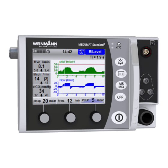
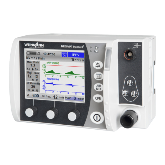
3 Description 3.3.2 Ventilation mode (example) 3-4 Display in the views 1 (pressure, CO curve) (top left), 2 (pressure gauge, measurements) (top right), 3 (etCO trend) (center left), 4 (pressure, flow curve) (center right), 5 (CCSV mode) (bottom left), 6 (pressure curve, measurements) (bottom right) MEDUMAT Standard… -
Page 24
3 Description Designation Description • Indicates ventilation pressure progress. • Indicates pMax as a dotted line. • Indicates the currently attuning airway pressure as a green area. Pressure gauge • Indicates the maximum airway pressure in the middle. • Indicates the end-tidal CO concentration (etCO in the middle (only with capnography option). -
Page 25
3 Description Designation Description • Indicates the total respiratory rate. • Indicates the number of spontaneous breaths per Respiratory rate (f(fsp)) (only with flow measurement + ASB option) minute. • Indicates the associated upper alarm limit. • Displays whether manual or automatic chest compression is set. -
Page 26: Symbols On The Display
3 Description 3.4 Symbols on the display Symbol Designation Description Audio alarm output active Audio alarm output muted for 120 s (with Alarm symbol the exception of an alarm at a supply pressure < 2.7 bar) Acoustic alarm output permanently muted (NVG mode only) Battery status >…
-
Page 27
3 Description Symbol Designation Description Device ready for use Device not ready for use Function check symbol Fault found during function check Observe the instructions for use Repair necessary Metronome sound in CPR mode is switched on Metronome sound in CPR mode is switched off Period during which the device is in the CPR mode Ventilation mode symbols… -
Page 28: Components
3 Description Symbol Designation Description Manual chest compression Operation with manual chest compression Automatic chest Operation with chest compression device compression 3.5 Components 3.5.1 Overview 3-5 Components MEDUMAT Standard…
-
Page 29
3 Description Designation Description FlowCheck sensor connection line with Connects the MEDUtrigger and the FlowCheck sensor MEDUtrigger to the device. FlowCheck sensor connection line Connects the FlowCheck sensor to the device. Inhalation adapter Facilitates inhalation. Ventilation mask Connects the patient hose system to the patient. Protects the device from viral and bacterial Hygiene filter contamination. -
Page 30
3 Description 3.5.2 Reusable hose system and disposable hose system 17 16 3-6 Reusable hose system (top) and disposable hose system (bottom) Designation Description Service label (only with reusable hose Indicates the date when the next maintenance is due. system) Hose protection sleeve (only with Protects the ventilation hose against soiling reusable hose system) -
Page 31
3 Description Designation Description • Fixes the patient hose system to the patient’s clothing. Velcro strap with clip • Fixes the MEDUtrigger to the patient hose system when not in use (e.g., during CPAP applications). Protective cap (only with reusable hose Protects the end of the patient hose system closest to system) the patient from damage. -
Page 32
3 Description Designation Description The device measures the patient’s vital parameters via the measuring hose system. The measuring hose system comprises: • Measuring hose system connector Measuring hose system • PEEP control hose • Pressure-measurement hose • measuring hose (only with capnography option) The water filter protects the measuring chamber of the Water filter (only with capnography… -
Page 33
3 Description Designation Description Due to the check valve diaphragm, the respiratory gas Check valve diaphragm only flows towards the patient. No rebreathing takes place. Connects the patient valve to the ventilation hose and Holder for check valve diaphragm contains the check valve diaphragm. 3.5.4 Disposable hose system with reduced dead space 3-8 Disposable hose system with reduced dead space… -
Page 34
3 Description Designation Description Patient valve Switches between inspiration and expiration. Connects the MEDUtrigger and the FlowCheck sensor FlowCheck sensor connection line with to the device. Alternatively, you can also connect the MEDUtrigger (only with flow FlowCheck sensor connection line or the connection measurement + ASB option) line of the MEDUtrigger here. -
Page 35: Accessories
3 Description Designation Description The respiratory gas flows from the device to the Ventilation hose patient valve through the ventilation hose. 3.6 Accessories 3-9 Accessories Designation Description Charging station Facilitates external battery charging. Supplies power to the device from the vehicle’s 12 V cable electrical system.
-
Page 36: Options
Used for reading session data and log files and SD card updating the device software. Simulates a ventilated patient for presentation EasyLung for WEINMANN Emergency purposes and during a function check. Serves to ensure that the respiratory air is filtered and Breathing system filter conditioned.
-
Page 37: Labels And Symbols
3 Description 3.8 Labels and symbols 3.8.1 Labels on the product 3-10 Labels on the product Symbol Description Device information label Serial number Type BF applied part Input (12 V to 15 V) DC voltage MEDUMAT Standard…
-
Page 38
3 Description Symbol Description Device information label (continued) Type of protection against electric shock: Protection class II device Do not dispose of device in household waste Manufacturer Degree of protection against: • Ingress of solid objects IP54 • Ingress of dust •… -
Page 39
3 Description Symbol Description Input voltage (12 V-15 V) Input 13 / 14 Type BF applied part 3.8.2 Symbols on the battery 3-11 Symbols on the battery Symbol Description Battery fault, if fault indicator light is red Battery status 3 / 9 Observe the instructions for use. -
Page 40
3 Description Symbol Description Manufacturer Do not dispose of battery in household waste. China RoHS label (confirms that the product does not emit toxic substances for the number of years indicated) MEDUMAT Standard… -
Page 41
3 Description 3.8.3 Symbols on the patient hose system 3-12 Symbols on the patient hose system Symbol Description Reusable hose system and disposable hose system Indicates the correct flow direction during inspiration. Indicates the correct installation direction of the PEEP control diaphragm. CE mark (confirms that the product complies with the applicable European directives) MEDUMAT Standard… -
Page 42
3 Description Symbol Description Calendar clock for year and month Observe the instructions for use. >PC< Material designation: Polycarbonate 134°C Steam sterilization at 134°C Additional symbols, for reusable hose system only Indicates the date when the next maintenance is due (position: on the service label). -
Page 43
3 Description 3.8.5 Symbols on the hygiene filter/device input filter Symbol Description Disposable item, do not reuse Additionally hygiene filter only Manufacturer 3.8.6 Labels on the packaging Symbol Description Device Protect the device against moisture. Permissible storage temperature: -40°C to +70°C Permissible humidity for storage: max. -
Page 44
3 Description Symbol Description Permissible humidity for storage: Max. 95% relative humidity Serial number Manufacturer Patient hose system (reusable hose system and disposable hose system) Latex-free Latex Permissible storage temperature: -30°C to +70°C Permissible humidity for storage: 15% to 95% relative humidity CE mark (confirms that the product complies with the applicable European directives) Manufacturer Additional symbols, for disposable hose system only… -
Page 45
3 Description Disposable item, do not reuse Manufacturer Additionally hygiene filter only Permissible storage temperature: -30°C to +70°C Expiration date Additional symbols, for device input filter only Permissible storage temperature: -40°C to +70°C MEDUMAT Standard… -
Page 46: Preparation And Operation
4 Preparation and operation Preparation and operation 4.1 Mounting the device The device is mounted on a portable system as standard and is ready for use. Observe the instructions for use of the portable systems. 4.2 Connecting to a power supply Loss of power due to combination of the device with an incorrect power supply! If you use a portable system which combines the…
-
Page 47: Using The Rechargeable Battery
4 Preparation and operation 4. If necessary: If operating on the portable system, mount the portable system on a wall mounting with charging interface. Connect the device up to the line power with the charging adapter (WM 28979) and the 50 W or 100 W power supply Connect the device up to the vehicle’s electrical system with the charging adapter (WM 28979) and 12 V cable.
-
Page 48
4 Preparation and operation • external supply of at least 10 V is connected • battery is not yet fully charged (< 95% charge level) • battery temperature between 0°C and 45°C If the device is switched on, the green arrow appears in the battery status symbol on the display (example: ) and the battery status indicator on the device flashes green. -
Page 49
4 Preparation and operation Fault indicator Status LEDs Status 4-1 Status indicator on the battery Status indicator Explanation Meaning 4 LEDs are lit Battery status > 90% Battery status 3 LEDs are lit approx. 60%-90% Battery status 2 LEDs are lit approx. -
Page 50
4 Preparation and operation Device If the device is switched on, you can see the battery status on the display: Status indicator Meaning Battery status > 90% Battery status approx. 60%-90% Battery status approx. 40%-60% Battery status approx. 10%-40% Battery status < 10% •… -
Page 51: Changing The Battery
4 Preparation and operation 4.3.5 Changing the battery Requirement The replacement battery is fully charged. 1. Switch off the device (see «4.6 Switching the device off», page 66). Connect the device to the line power. 2. Take battery out of the battery compartment. 3.
-
Page 52
4 Preparation and operation 3. Perform a function check (see «9.3 Performing a function check», page 184). Result The hygiene filter has been inserted. 4.4.2 Inserting the device input filter 1. Check the device input filter for external damage. If necessary: Replace the device input filter. Device may be damaged if a device input filter which has already been pushed together is inserted in the filter compartment! -
Page 53
4 Preparation and operation 5. Perform a function check (see «9.3 Performing a function check», page 184). Result The device input filter has been inserted. 4.4.3 Connecting the patient hose system Risk of injury posed by ventilation with inhalation mask, tube, or nasal cannula! Ventilation with an inhalation mask, tube, or nasal cannula connected may cause an injury to the patient. -
Page 54
4 Preparation and operation 3. If necessary: Connect the FlowCheck sensor (see «4.4.4 Connecting the FlowCheck sensor», page 55). 4. If necessary: Connect MEDUtrigger (see «4.4.6 Connecting MEDUtrigger», page 59). 5. If necessary: Connect the CO measuring hose (see «4.4.5 Connecting the CO measuring hose», page 57). -
Page 55
4 Preparation and operation 7. If necessary: Attach the patient hose system with Velcro strap with clip to the patient’s clothing. Result The patient hose system is connected and ready for use. 4.4.4 Connecting the FlowCheck sensor The FlowCheck sensor enables flow measurement (only with flow measurement + ASB option). -
Page 56
4 Preparation and operation 2. Connect the FlowCheck sensor to the patient valve. Risk of injury from touching the contacts on the FlowCheck sensor connection line/FlowCheck sensor connection line with MEDUtrigger and the patient at the same time! The contacts on the FlowCheck sensor connection line/FlowCheck sensor connection line with MEDUtrigger are live. -
Page 57
4 Preparation and operation 4. With the reusable hose system: Guide the connection line with measuring hose system and ventilation hose into the hose protection sleeve of the patient hose system. 5. If necessary: Activate flow measurement + ASB option (see «6.3.9 Options», page 134). -
Page 58
4 Preparation and operation 1. Connect the water filter to the CO measuring hose. 2. Connect the CO measuring hose with water filter to the measuring hose system connector. 3. With the reusable hose system: Connect the connector with Luer lock connector: •… -
Page 59
4 Preparation and operation 5. With disposable hose systems: Connect the CO measuring hose to the elbow with Luer lock connector. To minimize the dead space, you can also connect the CO measuring hose to a breathing system filter with Luer lock connector (e.g., WM 22162). -
Page 60
4 Preparation and operation MEDUtrigger button LEDs 4-2 Connection line of MEDUtrigger (1) and FlowCheck sensor connection line with MEDUtrigger (2) 1. Connect the connector of one of the following connection lines to the accessory connection on the device: • Connection line of MEDUtrigger •… -
Page 61
4 Preparation and operation 3. Place MEDUtrigger between the mask and the following end of the patient hose system closest to the patient: • Patient valve • FlowCheck sensor • Connector with Luer lock connector • Elbow If you use a breathing system filter, always place MEDUtrigger between the mask and the breathing system filter. -
Page 62
4 Preparation and operation 4. With the reusable hose system: Guide the connection line with measuring hose system and ventilation hose into the hose protection sleeve of the patient hose system. 5. If necessary: Activate MEDUtrigger option (see «6.3.9 Options», page 134). Result The MEDUtrigger is connected to the device and is ready for use. -
Page 63
4 Preparation and operation 3. Perform inhalation (see «4.7.7 Performing inhalation (only with Inhalation option)», page 76). Result Inhalation via the inhalation adapter is prepared. 4.4.8 Connecting the etCO nasal cannula 1. Position the etCO nasal cannula. 2. If necessary: Fix the tubes of the etCO nasal cannula to the face using adhesive plasters. -
Page 64
4 Preparation and operation 4.4.9 Connect up the nebulizer Only use the device in combination with the following nebulizer: • Pneumatic drug nebulizer WM 15827 1 • Aerogen Solo (Inspiration Medical GmbH) 2 • Tube Inhaler (VBM Medizintechnik GmbH) 3 Risk of injury due to erroneous readings! If the filter is installed incorrectly or no filter is used, the membrane may stick in the patient valve or the FlowCheck sensor could… -
Page 65: Switching The Device On
4 Preparation and operation 2. Connect the open end of the nebulizer 1, 2, or 3 with the filter 7 (breathing system filter, bacteria filter, or a combined breathing system/bacteria filter). 3. Place the filter 7 (breathing system filter, bacteria filter, or a combined breathing system/bacteria filter) on the patient hose system’s FlowCheck sensor 8.
-
Page 66: Switching The Device Off
4 Preparation and operation If you switch the device on in NVG mode, the following displays are deactivated: • Alarm light • Line power indicator • Battery status indicator • Audio alarm output The start screen with the selected NVG brightness appears (see «6.3.7 Device configuration», page 125).
-
Page 67: Ventilating The Patient
4 Preparation and operation 4.7 Ventilating the patient 4.7.1 Selecting the emergency mode from the start menu Requirement The device is switched off. 1. Switch on the device. After the self-test, the device displays the start menu: If the device was switched off for < 30 seconds (e.g., for a battery change), a countdown in the Previous patient field counts down 20 seconds.
-
Page 68
4 Preparation and operation Depending on the preset in the operator menu, the device switches to one of the following modes with the ventilation parameters preset for the patient group (see «14.1.9 Factory settings for emergency modes and ventilation modes», page 234) and shows a pressure gauge view: •… -
Page 69
4 Preparation and operation 2. Select Previous patient field. Allow the countdown to run. 3. If necessary: Adjust the settings of the last patient and confirm. Result The ventilation mode, ventilation parameters and the view of the last ventilated patient are loaded. MEDUMAT Standard… -
Page 70
4 Preparation and operation 4.7.3 Selecting a ventilation mode for a new patient Requirement The device is switched off. 1. Switch on the device. After the self-test, the device displays the start menu: If the device was switched off for < 30 seconds (e.g., for a battery change), a countdown in the Previous patient field counts down 20 seconds. -
Page 71
4 Preparation and operation 3. Select the height and gender: The height is given in 5 cm increments between 50 cm and 250 cm. (see «14.2 Calculation of body weight on the basis of body height», page 234). Navigate to the field Height and turn the navigation knob further to select the desired patient group: MEDUMAT Standard… -
Page 72
4 Preparation and operation • Adult • Child • Infant 4. Press the navigation knob next. 5. Select a ventilation mode. 6. If necessary: Set the parameters of the ventilation mode. MEDUMAT Standard… -
Page 73
4 Preparation and operation 7. Select the start field. Result A ventilation mode for a new patient has been set. If the curve display option is activated, the device shows a curve view. 4.7.4 Selecting an emergency mode from a ventilation mode Requirement •… -
Page 74
4 Preparation and operation • IPPV • BiLevel + ASB (only if the BiLevel + ASB option is activated) You can adjust the preset ventilation parameters for the emergency modes in the operator menu: Operator menu | Presets patient. Result An emergency mode for a particular patient group is activated. -
Page 75
4 Preparation and operation 4. If necessary: Set the parameters of the ventilation mode. 5. Select the start field. Result The ventilation mode is changed. 4.7.6 Operating the device in oxygen or Air Mix mode Requirement • The device is switched on. •… -
Page 76
4 Preparation and operation Oxygen mode is activated as standard for all emergency modes. Result The device is operated in oxygen or Air Mix mode. 4.7.7 Performing inhalation (only with Inhalation option) Using a nebulizer prevents treatment in Inhalation mode! The device is not suitable for nebulizers in inhalation mode. -
Page 77
4 Preparation and operation 3. Select the field Inhalation using the left-hand navigation knob. The device switches to Inhalation mode. 4. Select flow for inhalation using the right-hand navigation knob. Result The inhalation is performed. 4.7.8 Performing CO monitoring (only with capnography option) Requirement •… -
Page 78
4 Preparation and operation 1. Assess CO measurements diagnostically. Result The CO measurements and the respiratory rate of the patient are monitored. 4.7.9 Performing ventilation in CPR Manual mode In CPR Manual mode, you determine the respiratory rate administered yourself. Using MEDUtrigger, you manually trigger individual mechanical breaths with the set tidal volume. -
Page 79
4 Preparation and operation • Manual was set in the operator menu (Operator menu | Presets patient | CPR mode | Start mode). 1. Briefly press the CPR button The device switches to the mode CPR Man. The green LEDs on the MEDUtrigger light up. -
Page 80
4 Preparation and operation The device always switches to IPPV mode upon exiting CPR mode. Result Ventilation is performed in CPR Manual mode. 4.7.10 Performing ventilation in CPR IPPV mode Delay in treatment due to simultaneous metronome outputs from the ventilator and the defibrillator! If the ventilator is used together with a defibrillator (MEDUCORE Standard) which can also emit a metronome sound, the simultaneous metronome outputs from the defibrillator and the… -
Page 81
4 Preparation and operation Pausing ventilation in CPR IPPV mode During the analysis of the defibrillator, you can pause ventilation in order to avoid artifacts in the analysis. Requirement • The device is switched on. • The CPR mode is set. •… -
Page 82
4 Preparation and operation 3. To start continuous ventilation again: Press the field twice. Result Ventilation pauses. When the countdown reaches zero, ventilation automatically restarts. 4.7.11 Performing ventilation in CPR CCSV mode Delay in treatment due to simultaneous metronome outputs from the ventilator and the defibrillator! If the ventilator is used together with a defibrillator, which can also emit a metronome sound, the simultaneous metronome outputs… -
Page 83
4 Preparation and operation Requirement • The device is switched on. • The CCSV option is activated. 1. Briefly press the CPR button Depending on the preset in the operator menu, the device switches to CPR CCSV mode or CPR Manual mode (Operator menu | Presets patient | CPR mode | Start mode). -
Page 84
4 Preparation and operation 4.7.12 Replacing CPR mode Requirement • The device is switched on. • The CCSV option is activated. • The CPR mode is set. • Continuous ventilation is activated. 1. To change the mode, switch between the CCSV and IPPV fields using the right navigation knob. -
Page 85
4 Preparation and operation 1. For the function Manual, navigate to the field Demand and select the field Manual. To enable the selection of the Manual function, a MEDUtrigger must be connected and activated in the operator menu. Otherwise, this function will not be displayed. MEDUMAT Standard… -
Page 86
4 Preparation and operation 2. To perform continuous ventilation following successful airway management, select the Contin. field. Depending on the preset in the operator menu, the device switches to one of the following modes with the ventilation parameters preset for the patient group (see «14.1.9 Factory settings for emergency modes and ventilation modes», page 234):… -
Page 87
4 Preparation and operation 1. Switch on the device and during start-up press the right-hand and left-hand navigation knobs at the same time. The device switches to simulation mode. The words Simulation Mode! flash in the display. 2. Simulate settings. 3. -
Page 88: Monitoring The Patient
4 Preparation and operation 4.8 Monitoring the patient During ventilation, you must monitor the patient continuously. You can see the ventilation progress on the gauge, on the ventilation curves and on the measurements shown on the display of the device (see «3.3.2 Ventilation mode (example)», page 23).
-
Page 89: Audio Alarm Output
4 Preparation and operation 4.9 Audio alarm output 4.9.1 Muting the audio alarm output Requirement An alarm is active and is audible. 1. Briefly (< 1 s) press the alarm mute button The acoustic alarm output is permanently muted in NVG mode. Result The audio alarm output is muted for 120 s.
-
Page 90: Transporting The Device
4 Preparation and operation 4.10 Transporting the device 4-4 Transport on a portable system You can transport the device in the following ways: • On the portable system LIFE-BASE 3 NG (1) • On the portable system LIFE-BASE 1 NG XS (2) •…
-
Page 91: Feeding In Oxygen
4 Preparation and operation 4.11 Feeding in oxygen 4.11.1 Connecting an oxygen supply Risk of injury posed by the combination of highly compressed oxygen and hydrocarbon compounds! When combined with highly compressed oxygen, hydrocarbon compounds (e.g., oil, grease, cleaning alcohols, hand cream or adhesive plasters) can cause explosions and injuries to the patient, user and bystanders.
-
Page 92
4 Preparation and operation Requirement • The patient is not connected to the device. • The oxygen cylinder is full. 1. Briefly open and then close the valve of the oxygen cylinder in order to blow away any particles of dust. 2. -
Page 93
4 Preparation and operation 4.11.2 Removing the oxygen supply 1. Close the valve on the oxygen cylinder. 2. Briefly press the On/Off button and operate the device without an oxygen supply. The remaining oxygen is flushed out of the device. 3. -
Page 94: After Use
4 Preparation and operation Air Mix mode: Oxygen supply l ( ) 2 × ——————————————————— — Time min 1 – Vt l ( ) f min × 0.3l Example Oxygen supply 2000 l 500 ml 12 min Time 634 min = 10 h 34 min Result The operating time has been calculated.
-
Page 95: Using The Sd Card
4.13 Using the SD card 4.13.1 Inserting an SD card Loss of data due to incorrect SD card! SD cards not purchased from WEINMANN Emergency may have reduced functionality or result in the loss of data. Only use SD cards from WEINMANN Emergency.
-
Page 96
4 Preparation and operation 4.13.2 Removing the SD card Requirement An SD card is in the SD card slot. 1. Open the splash guard of the SD card slot. Incorrect use may result in loss of data or damage to the device! If you remove the SD card whilst exporting log files or updating the software of the device, data may be lost or the device may be… -
Page 97: Enabling Options
4 Preparation and operation 4.14 Enabling options Requirement • The operator menu has been called up (see «6.1 Navigating the operator menu», page 116). • The latest software version is installed on the device (see «4.15 Updating the software», page 100). 1. Select the menu item Options. 2.
-
Page 98
4 Preparation and operation 3. Turn the right-hand navigation knob to enter the first digit of the option code. 4. Press the navigation knob next to confirm the first digit of the option code. 5. Enter the other digits of the option code in the same way. 6. -
Page 99
4 Preparation and operation The device uses a green checkmark to display whether the input option code is correct and changes the color of the option as per the color scale above. When doing so, note: Prerequisite for the unlocking of the curve display option: Flow measurement + ASB option is enabled. -
Page 100: Updating The Software
1. If necessary: Download the software from the Login area of the WEINMANN Emergency website to the SD card. 2. If the software is available as a ZIP file: Unzip the software. The software is available in the folder as a file named WM28981-x.x.hex.
-
Page 101
4 Preparation and operation 5. Select Software update. Damage to the device caused by moving the device and/or pressing buttons during the update! Moving the device and/or pressing buttons during the update may cancel the update and damage the device. … -
Page 102
4 Preparation and operation The update.txt file is saved to the SD card in the device as soon as the software update is complete. The file contains information on the software update just performed. This helps you with documentation within the scope of your quality management process. -
Page 103
4 Preparation and operation 4. If necessary: Enter the device’s Bluetooth PIN in the external data documentation system. Result The device is paired with the external data documentation system ® via Bluetooth 4.16.2 Pairing during ventilation Requirement • The external data documentation system supports the device’s communication protocol. -
Page 104: User Menu
5 User menu User menu 5.1 Navigating the user menu Requirement A ventilation mode is set. 1. Briefly press the menu button 2. To select a submenu, turn one of the three navigation knobs. 3. To confirm the settings, press one of the three navigation knobs.
-
Page 105: Structure Of The User Menu
5 User menu 5.2 Structure of the user menu Mode IPPV BiLevel + ASB CPAP CPAP + ASB aPCV PRVC + ASB SIMV SIMV + ASB RSI DEMAND S-IPPV RSI Man. RSI IPPV CPR Man. Demand CPR IPPV CPR IPPV Inhalation CPR CCSV monitoring…
-
Page 106: Settings In The User Menu
5 User menu 5.3 Settings in the user menu 5.3.1 Mode 5-2 Mode submenu You can select the following ventilation modes and additional functions here (see «7 Description of the modes», page 136): MEDUMAT Standard…
-
Page 107
5 User menu Mode submenu IPPV BiLevel + ASB (only if the pressure- controlled ventilation modes option is activated) CPAP CPAP + ASB (only with flow measurement + ASB option) aPCV (only if the pressure-controlled ventilation modes option is activated) Ventilation modes PCV (only if the pressure-controlled ventilation modes option is activated) -
Page 108: Alarm Limits
5 User menu 5.3.2 Alarm limits 5-3 Alarm limits submenu Here you can set the alarm limits. You can also open the alarm limit menu by keeping the alarm mute button depressed. Risk of injury due to alarm limits which are too high or too low! Alarm limits which are either too high or too low can prevent the device from emitting an alarm, thereby putting the patient at risk.
-
Page 109
5 User menu Alarm Setting range Activating automatic limits The device sets the alarm limits for the alarms relating to respiratory physiology automatically. The deviation is 10%, 20% or 30% from Automatic limits the ventilation values at the time of activation. -
Page 110
5 User menu 5.3.3 Views 5-4 Views submenu (example) You can select preconfigured views of measurements here. The views depend on the activated options and the ventilation mode selected. MEDUMAT Standard… -
Page 111
5 User menu 5.3.4 Ventilation parameters 5-5 Ventilation parameters submenu (example) You can change the ventilation parameters of the selected ventilation mode here. 5.3.5 Apnea ventilation 5-6 Apnea ventilation submenu MEDUMAT Standard… -
Page 112
5 User menu In this menu you can activate or deactivate apnea ventilation in the CPAP, CPAP + ASB and Demand ventilation modes. When apnea ventilation is activated, the device automatically switches to IPPV mode once the set apnea time has elapsed. If the BiLevel + ASB mode is unlocked in the operator menu and activated, you can choose between the IPPV mode and the BiLevel + ASB mode as the apnea ventilation mode in the operator… -
Page 113
5 User menu In this menu you can set the scale for the time axis of the etCO trend. The following settings are possible: auto, 5 min., 10 min., 30 min., 60 min.,120 min. At a time setting of 5 minutes or 10 minutes, the device records the determined value every 15 seconds. -
Page 114
5 User menu 5.3.8 NVG (Night Vision Goggles) 5-9 NVG submenu Risk of injury from deactivated alarm light, deactivated audio alarm output and darkened display in NVG mode! The alarms are barely perceptible as a result of the deactivated alarm light, the deactivated audio alarm output and the darkened display in NVG mode. -
Page 115
5 User menu A device in NVG mode does not comply with the following standards with respect to alarm output: • EN 60601-1-8 • EN 794-3/EN 10651-3. The operator assumes the resulting risk for operation. MEDUMAT Standard… -
Page 116: Operator Menu
6 Operator menu Operator menu 6.1 Navigating the operator menu 1. Switch on the device. The start menu appears. 2. Briefly press the menu button 3. Turn the right-hand navigation knob to enter the first digit of the access code. 4.
-
Page 117
6 Operator menu 7. To select a submenu, turn one of the three navigation knobs. 8. To call up a submenu, press one of the three navigation knobs. 9. To select a desired value, turn one of the three navigation knobs. -
Page 118: Structure Of The Operator Menu
6 Operator menu 6.2 Structure of the operator menu Device information Battery information Export log files FlowCheck information Export session data Export configuration Export configuration Import / Export Import configuration Date / Time Software update Volume Change access code Brightness NVG brightness Device configuration Allow bluetooth pairing…
-
Page 119: Settings In The Operator Menu
6 Operator menu 6.3 Settings in the operator menu 6.3.1 Device information 6-2 Device information submenu You will find all the information on the device in this submenu. 6.3.2 Battery information 6-3 Battery information submenu You will find all the information on the battery in this submenu. MEDUMAT Standard…
-
Page 120
6 Operator menu 6.3.3 FlowCheck information (only with flow measurement + ASB option) 6-4 FlowCheck information submenu You will find all the information on the FlowCheck sensor and the following connection lines in this submenu: • FlowCheck sensor connection line •… -
Page 121
6 Operator menu 6.3.4 Import / Export 6-5 Import / Export submenu Export log files The device always saves the log files in its internal memory. You can export data to an SD card in order to analyze it. Detailed information on exported log files can be found in the appendix (see «14.3 Exported log files», page 235). -
Page 122
6 Operator menu Export configuration The Export configuration function allows you to export all the configuration settings made on the device to an SD card. When exporting, all the configuration settings (including the options) are transferred with the exception of the following configuration settings: •… -
Page 123
6 Operator menu Exporting data to an SD card Requirement • An SD card is in the SD card slot. • The operator menu has been called up (see «6.1 Navigating the operator menu», page 116). 1. Select the menu item Import / Export. 2. -
Page 124
6 Operator menu 6.3.5 Software update 6-6 Software update submenu You can update your software here (see «4.15 Updating the software», page 100). 6.3.6 Change access code 6-7 Submenu for changing the access code Here you can change the access code for the operator menu. On delivery, the access code for the operator menu is 0000. -
Page 125
6 Operator menu 6.3.7 Device configuration 6-8 Device configuration submenu In the submenu Device configuration, you can set the following parameters for the device: Parameter Possible values Description Year Month Date / Time Here you can set the current date and time. Hour Minute Here you can set the volume of the acoustic… -
Page 126
6 Operator menu Parameter Possible values Description 0.1% to 3% in 0.1% increments 3% to 5% in 0.5% You can set the brightness here to which the NVG brightness (only with NVG increments device switches when the NVG mode is option) 5% to 10% in 1% activated. -
Page 127
6 Operator menu Parameter Possible values Description vol% unit (only with capnography Here you can select which unit of measurement option) the CO values should be displayed in. mmHG 93% O Supply gas Here you can set the type of supply gas. 100% O Here you can set the inspiration and expiration trigger:… -
Page 128
6 Operator menu 6.3.8 Presets patient 6-9 Presets patient submenu In the Presets patient submenu, you can determine which presets are assigned to the ventilation parameters of the different patient groups: Risk of injury from different alarm presets in the same or similar devices! Different alarm presets in the same or similar devices in different application areas can confuse the user and result in injury to the… -
Page 129
6 Operator menu Parameter Possible values Description Infant/Child/Adult Emergency mode (only if Here you can choose between IPPV the pressure-controlled IPPV mode or BiLevel + ASB as the ventilation modes BiLevel + ASB emergency ventilation mode per option is activated) patient group. -
Page 130
6 Operator menu Parameter Possible values Description Pressure gauge View (only with Here you can choose between a Pressure/CO curve activated pressure gauge view and a curve Pressure/etCO capnography option) view for the CPR mode. trend Here you can determine whether or ☑… -
Page 131
6 Operator menu Parameter Possible values Description Here you can set the ventilation pInsp 40 mbar — 60 mbar pressure. Here you can set the trigger for the Trigger 1 — 3 CCSV mode. Here you can set when the hands-off Hands-off time 10 s — 55 s time alarm… -
Page 132
6 Operator menu Parameter Possible values Description Here you can determine whether an etCO (only ☑ alarm should be output in the event with capnography ☐ of rising or dropping end-expiratory option) Apnea mode (only if the uncontrolled ventilation modes option is activated) Here you can set the apnea IPPV ventilation mode for the CPAP and… -
Page 133
6 Operator menu Setting height* Depending on the height selected (tidal volume Vt in ml per kg bodyweight) the height which can be set is restricted to the following minimum values: Tidal volume Vt in ml per kg Minimum height which can be bodyweight set in cm For the smallest height which can be set, the tidal volume is always… -
Page 134
6 Operator menu 6.3.9 Options 6-10 Options submenu As the operator, you can unlock new options for the user in the menu item Unlock option (see «4.14 Enabling options», page 97) and activate or deactivate the unlocked options. Options Description Enables connection of the MEDUtrigger MEDUtrigger to the device and use of the MEDUtrigger in CPR mode. -
Page 135
6 Operator menu Options Description Enables the PRVC + ASB pressure- PRVC + ASB controlled ventilation mode. Enables CO measurement and display of the CO curve. For CO Capnography measurement you require a device with CO measuring. Enables flow measurement with the FlowCheck sensor and the following ventilation modes: Flow measurement… -
Page 136: Description Of The Modes
7 Description of the modes Description of the modes 7.1 Classification of the ventilation modes Breathing effort 100% Patient Ventilator Assisted ventilation Controlled ventilation Spontaneous respiration The following ventilation modes are possible with this device: Control Controlled Assisted Spontaneous parameter ventilation ventilation respiration…
-
Page 137
7 Description of the modes There are the following trigger options in the individual ventilation modes: Trigger time Ventilation Expiration slot for Inspiration trigger ASB breath mode trigger mandatory breaths IPPV BiLevel + ASB 20% of Te CPAP CPAP + ASB Can be set from 0% aPCV — 100% of Te… -
Page 138: Ventilation Parameters
7 Description of the modes 7.2 Ventilation parameters Ventilation Unit Description parameters Tidal volume (breath volume) Freq. 1/min Ventilation rate pMax mbar Maximum inspiratory pressure PEEP mbar Positive end-expiratory pressure (CPAP) Ventilation through the addition of Air Mix ambient air 93% oxygen Ventilation with concentrator oxygen 100% oxygen…
-
Page 139
7 Description of the modes • If the flow measurement + ASB option is not activated: With a set PEEP value > 0 mbar, the patient must create an underpressure of at least -1.3 mbar below the set PEEP value through his/her spontaneous respiratory effort in order to initiate an inspiratory trigger in the device. -
Page 140: Ventilation Modes
7 Description of the modes 7.3 Ventilation modes 7.3.1 IPPV mode Description Abbreviation IPPV Intermittent Positive Pressure Long form Ventilation Type Volume-controlled Requirement None Ventilation parameters Left-hand navigation knob Central navigation knob Freq. • PEEP • pMax Right-hand navigation knob •…
-
Page 141
7 Description of the modes 7.3.2 BiLevel + ASB mode Description Abbreviation BiLevel + ASB Ventilation at two pressure Long form levels + Assisted Spontaneous Breathing Type Pressure-controlled • Flow measurement + ASB option is activated Requirement • Pressure-controlled ventilation modes option is activated •… -
Page 142
7 Description of the modes The BiLevel + ASB mode is used for pressure-controlled ventilation combined with free spontaneous respiration at pressure levels pInsp and PEEP during the entire breathing cycle and for adjustable pressure support at PEEP level. This mode is used on patients who have no spontaneous respiration or on spontaneously breathing patients. -
Page 143
7 Description of the modes CPAP Pressure pMax CPAP CPAP / PEEP Time 1/Freq. (spontaneous) 1/Freq. (spontaneous) The set value CPAP/PEEP is used to increase the pressure level of respiration in order to raise the functional residual capacity (FRC) of a spontaneously breathing patient. The patient is able to breathe spontaneously without any restriction at the set pressure level. -
Page 144
7 Description of the modes Ventilation parameters Left-hand navigation knob InTr Central navigation knob Δ pASB • PEEP • pMax Right-hand navigation knob • ExTr • Emergency mode CPAP + ASB Pressure pMax CPAP without pressure support CPAP with pressure support ASB ΔpASB CPAP / PEEP Time… -
Page 145
7 Description of the modes In principle, the pressure is set at the end of expiration (PEEP). If Δ necessary, the pressure support ( pASB) can be switched on. Ventilation can be individually adjusted to suit the patient with the aid of the inspiratory and expiratory triggers. -
Page 146
7 Description of the modes Ventilation parameters Left-hand navigation knob pInsp Central navigation knob Freq. PEEP pMax Right-hand navigation knob InTr Emergency mode aPCV Pressure pMax Synchronized Mechanical Mechanical mechanical ventilation ventilation ventilation pInsp Pressure ramp PEEP Time 1/Freq. (current) ∆T 1/Freq. -
Page 147
7 Description of the modes 7.3.6 PCV mode Description Abbreviation Long form Pressure Controlled Ventilation Type Pressure-controlled • Flow measurement + ASB option is activated Requirement • Pressure-controlled ventilation modes option is activated • Curve display option is activated Ventilation parameters Left-hand navigation knob pInsp Central navigation knob… -
Page 148
7 Description of the modes The PCV mode is used for mandatory pressure-controlled ventilation with fixed pressure levels. This mode is used on patients who have no spontaneous respiration. However, a spontaneously breathing patient can breathe deeply and freely during expiration. The set maximum pressure limitation (pMax) ensures the safety of the patient. -
Page 149
7 Description of the modes PRVC + ASB Pressure pMax Safety pPlateau distance 5 mbar pInsp (variable) Increment max. 3 mbar ∆pASB PEEP Time pressure-controlled volume-controlled pressure-controlled mechanical breath mechanical breath mechanical breath 1/Freq. (set) 1/Freq. (set) The controlled PRVC + ASB mode combines the advantages of both pressure-controlled ventilation and volume-controlled ventilation. -
Page 150
7 Description of the modes Once the maximum ventilation pressure (pMax-5 mbar) is achieved, the device administers as much volume as possible. If this volume deviates from the set tidal volume, the device triggers the medium-priority alarm «Vt not achievable». 7.3.8 SIMV mode Description Abbreviation… -
Page 151
7 Description of the modes The SIMV mode is used for volume-controlled ventilation with a fixed mandatory minute volume. The patient can breathe spontaneously between the mandatory mechanical breaths and thereby increase the minute volume. During spontaneous respiration, the mandatory mechanical breath is synchronized with the patient’s breathing. -
Page 152
7 Description of the modes SIMV + ASB Pressure p Max Mechanical ventilation Assisted Synchronized mechanical spontaneous ventilation breathing Spontaneous pPlat respiration ΔpASB PEEP Time ΔT 1/Freq. (current) 1/Freq. (set) Trigger time slot The SIMV + ASB mode is used for volume-controlled ventilation with a fixed mandatory minute volume. -
Page 153
7 Description of the modes 7.3.10 S-IPPV mode Risk of hyperventilation! When using the S-IPPV mode, the CO concentration in the patient’s blood can drop and injure the patient. Monitor the patient continuously. Risk of air trapping! When using the S-IPPV mode, air can become trapped in the patient’s lung. -
Page 154
7 Description of the modes S-IPPV Pressure Synchronized mechanical Mechanical ventilation ventilation pMax Plateau PEEP Time ΔT 1/Freq. (current) 1/Freq. (set) Trigger time slot The S-IPPV mode is used for volume-controlled ventilation with a variable mandatory minute volume. Throughout the entire expiration phase, a trigger is active which enables the patient to trigger a new breath. -
Page 155
7 Description of the modes 7.3.11 CCSV mode Risk of injury due to unsecured airway! If the CCSV mode is used, an unsecured airway can result in insufflation of the stomach and cause injury to the patient. Secure the airway. Description Abbreviation CCSV… -
Page 156: Additional Functions
7 Description of the modes The CCSV mode is a pressure-controlled ventilation mode employed specially and exclusively for resuscitation ventilation during continuing chest compression. The ventilation mode offers you support during cardiopulmonary resuscitation (in accordance with the resuscitation guidelines) by applying a defined pressure into the lungs in time with every chest compression and switches to expiration during the chest decompression phase.
-
Page 157
7 Description of the modes Ventilation parameters Left-hand navigation knob Vt pInsp • Central navigation knob Freq. • • Manual/ • Manual/ • Manual/ • pMax • CCSV/ • CCSV/IPPV IPPV • Trigger Right-hand navigation knob • Interval • pMax •… -
Page 158
7 Description of the modes If you do not perform chest compressions for an extended period of time in CPR CCSV mode, the device returns to IPPV back-up ventilation after the time preset in the operator menu. As soon as you recommence chest compressions, the device automatically returns to CSSV ventilation. -
Page 159
7 Description of the modes Following the selection of the RSI mode, the device launches the oxygen demand function immediately for the preoxygenation of a spontaneously breathing patient. For intubation, switch to the Manual function. The I:E ratio is always 1:1. With the MEDUtrigger supplied, this function now enables manual ventilation with a defined volume and a defined pressure limitation. -
Page 160
7 Description of the modes The Demand mode serves to (pre)oxygenate spontaneously breathing patients via a ventilation mask. The patient must trigger inspiration himself in Demand mode. If there is a FlowCheck sensor this recognizes the respiratory effort, otherwise the underpressure created is used. -
Page 161
7 Description of the modes Ventilation parameters • Left-hand navigation knob • pInsp Central navigation knob Freq • PEEP • pMax • Δ pASB (in BiLevel + ASB mode Right-hand navigation knob only) • InTr (in BiLevel + ASB mode only) •… -
Page 162
7 Description of the modes During apnea ventilation, the device emits a medium-priority alarm and the ventilation mode display turns red. The apnea ventilation mode can only be exited if the ventilation mode is changed actively. 7.4.5 Inhalation mode Description Abbreviation Long form Inhalation… -
Page 163
7 Description of the modes monitoring is used for the sidestream CO measurement during oxygen inhalation or bag-valve-mask ventilation (see «4.7.8 Performing CO monitoring (only with capnography option)», page 77). To use the CO measurement during oxygen inhalation, you require an interface with a male Luer lock connector for CO measurement (see «4.4.8 Connecting the… -
Page 164: Hygienic Reprocessing
• You can find further information about hygienic reprocessing and a list of all the suitable cleaning agents and disinfectants in a brochure on the Internet at www.weinmann-emergency.com. • The service life of the components of the reusable hose system is at least 30 reprocessing cycles (exception FlowCheck sensor: typically 50 reprocessing cycles).
-
Page 165: Intervals
8 Hygienic reprocessing 8.2 Intervals Clean the device, components and accessories after every use (but at least once a week). 8.3 Hygienic reprocessing of the device Risk of injury due to reuse of disposable items! Disposable items are intended for single use. Disposable items which are reused may be contaminated and/or impaired in their function and therefore cause injury to the patient.
-
Page 166
8 Hygienic reprocessing 8. Carry out hygienic reprocessing of the device, components and accessories as specified in the following table: Thermal Part Cleaning Disinfection Sterilization disinfection Device Battery Not permitted Power supply Steam sterilize at Wipe down with a 134°C (for a Wipe disinfection dry or moist cloth: minimum of… -
Page 167
8 Hygienic reprocessing Brush the parts thoroughly inside and outside using a normal laboratory soft bottle brush. Wet all surfaces, free of bubbles, inside and outside. Allow the full exposure time to elapse. Following disinfection, rinse the parts off and out thoroughly with distilled water and allow them to dry. The applicable instructions are those in the instructions for use from the manufacturers of the individual components or accessories. -
Page 168: Hygienic Reprocessing Of The Reusable Hose System
8 Hygienic reprocessing 8.4 Hygienic reprocessing of the reusable hose system Requirement The reusable hose system has been disassembled (see «8.6.1 Disassembly of the reusable hose system», page 172). 1. Carry out hygienic reprocessing of the reusable hose system as specified in the following table: Thermal Part Cleaning…
-
Page 169
8 Hygienic reprocessing Thermal Part Cleaning Disinfection Sterilization disinfection Rinse at up to Steam sterilize at 95°C 134°C (for a (Recommenda- minimum of Use the immersion Clean in warm tion: 5 mins and Connector with Luer lock disinfection method ® water with a mild thermosept maximum of… -
Page 170: Hygienic Reprocessing Of The Disposable Hose System
8 Hygienic reprocessing Only brush the outside of the part thoroughly using a normal laboratory soft bottle brush. Do not use a bottle brush on the inside in order to prevent damaging the sieves. Rinse thoroughly with distilled water after cleaning. Washing method according to the Robert Koch Institute (RKI) and the Association for Applied Hygiene (VAH) at 70°C with Derval SOLO (RKI) and with Ottalin PERACET)
-
Page 171
8 Hygienic reprocessing Thermal Part Cleaning Disinfection Sterilization disinfection Disposable hose system: • Ventilation hose • Patient valve • Elbow Disposable measuring hose system: • Measuring hose system connector • PEEP control hose • Pressure- Disposable item, do not reuse measurement hose •… -
Page 172
8 Hygienic reprocessing 8.6 Disassembly/assembly of the reusable hose system The images in this subchapter show all the possible components of the reusable hose system. Depending on the system type, your reusable hose system may not include certain components (see «3.5.2 Reusable hose system and disposable hose system», page 30). -
Page 173
8 Hygienic reprocessing 5. If available: Detach one of the following connection lines from the FlowCheck sensor: • FlowCheck sensor connection line • FlowCheck sensor connection line with MEDUtrigger 6. If available: Detach the CO measuring hose from the connector with Luer lock connector. MEDUMAT Standard… -
Page 174
8 Hygienic reprocessing 7. Detach the pressure-measurement hose (2) and PEEP control hose (1) from the patient valve. 8. If available: Remove the protective cap from the end of the reusable hose system closest to the patient. 9. If available: Detach MEDUtrigger. MEDUMAT Standard… -
Page 175
8 Hygienic reprocessing 10. If available: Detach the elbow. 11. If available: Detach the connector with Luer lock connector. 12. If available: Detach the FlowCheck sensor from the patient valve. 13. Disconnect the patient valve from the ventilation hose. MEDUMAT Standard… -
Page 176
8 Hygienic reprocessing 14. If available: Remove the protective cap strap from the patient valve: • Position 1 • Position 2 (only with reusable hose systems with flow measurement and CO measurement) 15. Disassemble the patient valve. Result The reusable hose system is disassembled. MEDUMAT Standard… -
Page 177
8 Hygienic reprocessing 8.6.2 Assemble reusable hose system Requirement The reusable hose system is disassembled. 1. Assemble the patient valve. When doing so, note: • the side of the PEEP control diaphragm labeled «TOP» must face upward toward the control cover. •… -
Page 178
8 Hygienic reprocessing 4. If available: Connect the FlowCheck sensor. 5. If available: Connect the connector with Luer lock connector. 6. If available: Connect the elbow. MEDUMAT Standard… -
Page 179
8 Hygienic reprocessing 7. If available: Connect MEDUtrigger 8. Connect the pressure-measurement hose (2) and PEEP control hose (1) to the patient valve. When doing so, note: The hoses must be firmly attached to the patient valve. MEDUMAT Standard… -
Page 180
8 Hygienic reprocessing 9. If available: Connect the CO measuring hose to the connector with Luer lock connector. 10. If available: Connect one of the following connection lines to the FlowCheck sensor: • FlowCheck sensor connection line • FlowCheck sensor connection line with MEDUtrigger MEDUMAT Standard… -
Page 181: Disinfecting The Reusable Measuring Hose System
8 Hygienic reprocessing 11. If available: Connect the CO measuring hose with water filter to the measuring hose system connector. 12. If available: Seal the end of the reusable hose system closest to the patient with a protective cap. 13. Place all the hoses and one of the connection lines in the hose protection sleeve.
-
Page 182
8 Hygienic reprocessing Requirement The reusable measuring hose system is disconnected from the reusable hose system. 1. Connect a sterile disposable syringe (20 ml) to the free end of the pressure-measurement hose. 2. Immerse the connector of the measuring hose system in diluted disinfection solution. -
Page 183: Function Check
9 Function check Function check 9.1 Intervals Carry out a function check at regular intervals: Part concerned Interval • Before each use Device • After each hygienic reprocessing • After each repair • Before each use • After each hygienic reprocessing Patient hose system (reusable hose system) •…
-
Page 184: Performing A Function Check
• Testing bag WM 1454 • EasyLung for WEINMANN Emergency WM 28625 Risk of injury from incorrect test lungs! Test lungs other than those named here may not reliably detect errors and thus distort the result of a function check. This can injure the patient.
-
Page 185
9 Function check 1. Switch on the device (see «4.5 Switching the device on», page 65). 2. Select the menu item Function check. 3. Prepare the device: • Connect and open the oxygen cylinder. • Connect the patient hose system up to the device. •… -
Page 186
9 Function check 5. Check the alarm system: • The alarm light must flash red. • The device must emit at least one audible alarm in alarm system test 1 and alarm system test 2. 6. If the alarm system is functioning: Press the navigation knob yes each time. -
Page 187
9 Function check 8. In the key function check, press all of the controls one after the other except for the On/Off button If the MEDUtrigger is not displayed in the function check, activate it in the operator menu and repeat the function check. 9. -
Page 188
9 Function check 10. Proceed with the hygiene filter/device input filter according to the following table: Color Action Continue to use the hygiene filter/ Green device input filter. • Keep hygiene filter/device input filter at the ready. Yellow • Order hygiene filter/device input filter. -
Page 189
≤ 60 days until expiry of without restrictions until xx days. the maintenance interval expiry of the maintenance interval. • To continue using the device without restrictions: Contact WEINMANN Emergency or a technician authorized by WEINMANN Emergency in good time for maintenance. MEDUMAT Standard… -
Page 190
Function check passed To continue using the device without restrictions: Contact • Maintenance required • Maintenance interval WEINMANN Emergency or a • Maintenance symbol is expired technician authorized by flashing in the display WEINMANN Emergency for (only in the start menu) maintenance. -
Page 191: Failed Function Check
1. Check the components named in the instructions on the display and replace if necessary. 2. Repeat the function check. 3. If the function check ends with Device is not ready for use again: Contact your authorized dealer or WEINMANN Emergency. 9.5 Testing the reusable hose system Requirement…
-
Page 192: Checking The System For Leaks
9 Function check 9.6 Checking the system for leaks Requirement The device is connected to the oxygen supply. 1. Open the valve of the oxygen cylinder slowly. The contents gauge on the pressure reducer indicates the pressure in the oxygen cylinder. 2.
-
Page 193
9 Function check 4. Briefly press the On/Off button and operate the device without an oxygen supply. The remaining oxygen is flushed out of the device. 5. Press and hold the On/Off button for at least 2 seconds to switch off the device. 6. -
Page 194: Alarms And Error Messages
10 Alarms and error messages 10 Alarms and error messages 10.1 General instructions The device’s alarm system is based on the concept of self- preserving alarms. The device emits an alarm for as long as the cause continues to exist. Once the cause of the alarm no longer exists, the device no longer emits the alarm.
-
Page 195: Medumat Standard 2 En
10 Alarms and error messages • Acoustically as an audible alarm (via the loudspeaker on the underside of the device) • With the alarm light (in the top right-hand corner on the front of the device) 10-1 Alarm line with airway pressure alarm The device additionally displays physiological alarms through the flashing of the respective parameter field.
-
Page 196: Alarm Messages
10 Alarms and error messages 10.2 Alarm messages 10.2.1 High-priority alarm (red) Alarm Cause Remedy Obstruction of the patient’s Free the patient’s airways of airways obstructions. Tube wrongly positioned Position tube correctly. Airway pressure pMax set too low Adjust pMax. Route hoses so that they are not Hoses kinked or pinched kinked or pinched.
-
Page 197
10 Alarms and error messages Alarm Cause Remedy Operate device within permitted Device temperature critical Device temperature > 75°C temperature range (see 14.1.1, p. 214). (only with flow • Check the condition of the Upper limit value exceeded measurement + ASB option) patient. -
Page 198
10 Alarms and error messages 10.2.2 Medium-priority alarm (yellow) Alarm Cause Remedy • Check the condition of the patient. No inspiration since the set apnea Apnea mode active alarm time • Select mandatory ventilation mode. Let the device run on battery power without line power until it switches off. -
Page 199
10 Alarms and error messages Alarm Cause Remedy etCO (only with capnography • Check the condition of the Upper limit value exceeded option) patient. • Check the set limit values for etCO (only with capnography Lower limit value not reached option) plausibility. -
Page 200
10 Alarms and error messages 10.2.3 Low-priority alarm (turquoise) Alarm Cause Remedy The alarm appears: • If you remove the portable system from the wall mounting. Line power too weak or power Battery operation • If you operate the device using failure the power supply and a power failure occurs. -
Page 201: Faults
10.3 Faults If you are not able to clear an error message with the aid of the table, you should contact the manufacturer WEINMANN Emergency or your authorized dealer to have the device repaired. To avoid serious damage, do not continue using the device.
-
Page 202
10 Alarms and error messages Fault Cause Remedy Option is deactivated in the Activate the option in the operator operator menu menu (see 6.3.9, p. 134). The functionality of an option is Enable the option in the operator not available Option is not enabled in the menu with the option code operator menu (see 4.14,… -
Page 203
10 Alarms and error messages 10.3.2 Battery Fault Cause Remedy Battery defective Replace battery. Red fault indicator lights up when status button on battery is pressed Use battery within permitted Battery temperature outside the or red battery status indicator on temperature range (see 14.1.2, permitted range (>… -
Page 204
10 Alarms and error messages 10.3.3 Ventilation Fault Cause Remedy Locate and rectify leak (see 9.7, Leak in oxygen feed line p. 192). Unusually high oxygen Patient valve does not close Check the hose system (PEEP consumption completely control hose and patient valve). Place mask as tightly as possible Leakage during mask ventilation on the patient. -
Page 205: Maintenance
11 Maintenance 11 Maintenance 11.1 General instructions Maintenance, safety checks, inspections and repairs must only be carried out by the manufacturer or a technician specifically authorized by the manufacturer. 11.2 Intervals Part concerned Interval Maintenance by Manufacturer or a technician Maintenance and safety check Device specifically authorized by the…
-
Page 206: Sending In Device
WEINMANN Emergency or a technician specifically authorized by WEINMANN Emergency. If you send in parts which are visibly contaminated, they will be disposed of by WEINMANN Emergency or a technician specifically authorized by WEINMANN Emergency at your expense. MEDUMAT Standard…
-
Page 207: Maintaining The Reusable Hose System
11 Maintenance 11.4 Maintaining the reusable hose system Requirement The reusable hose system has been disassembled (see «8.6.1 Disassembly of the reusable hose system», page 172). 1. Check all parts of the reusable hose system for external damage and complete labeling. If necessary: Replace damaged or incorrectly labeled parts. 2.
-
Page 208: Replacing The Hygiene Filter
11 Maintenance 11.5 Replacing the hygiene filter Requirement The device is switched off. 1. Wipe-disinfect the outside of the hygiene filter and the device. 2. Pull the hygiene filter out of the filter compartment of the device. 3. Dispose of the hygiene filter along with the filter cassette (see «13.4 Hygiene filter/device input filter», page 213).
-
Page 209: Replacing The Device Input Filter
11 Maintenance 11.6 Replacing the device input filter Requirement The device is switched off. 1. Pull the device input filter out of the filter compartment of the device. 2. Dispose of the device input filter along with the filter cassette (see «13.4 Hygiene filter/device input filter», page 213).
-
Page 210
11 Maintenance Transport safety device Filter cassette with filter fleece 3. Remove the transport safety device from the device input filter. 4. Push the device input filter with the half-inserted filter cassette into the filter compartment of the device. In the process, the filter cassette is pushed all the way into the device input filter. -
Page 211: Storage
12 Storage 12 Storage 12.1 General instructions • Store the device under the prescribed ambient conditions (see «14.1.1 Technical data on device», page 214). • Following storage in extreme ambient conditions (outside of the ambient operating conditions, (see «14.1.1 Technical data on device», page 214)): Store the device at room temperature for at least 12 hours before putting it into operation once more.
-
Page 212: Storing The Battery
12 Storage 12.3 Storing the battery Requirement • The device and the battery have been cleaned and disinfected (see «8.3 Hygienic reprocessing of the device», page 165). • The battery is fully charged. • If available: The replacement battery is fully charged. 1.
-
Page 213: Disposal
Connection lines 13.2 Battery Do not dispose of used batteries in the household waste. Contact WEINMANN Emergency or a public waste disposal authority. 13.3 Patient hose system After use, dispose of the patient hose system in the correct manner for plastics.
-
Page 214: Technical Data
14 Appendix 14 Appendix 14.1 Technical data 14.1.1 Technical data on device Specification Device Product class according to Directive 93/42/EEC Dimensions (W x H x D) 206 mm x 137 mm x 130 mm Weight: Without battery Approx. 2 kg With battery Approx.
-
Page 215
Ingress of water with harmful effect Test parameters and limit values can be requested from the manufacturer Electromagnetic compatibility (EMC) (WEINMANN Emergency Medical Technology GmbH + Co. KG, as per EN 60601-1-2: Frohbösestraße 12, 22525 Hamburg, GERMANY) if required. Radio interference suppression EN 55011… -
Page 216
14 Appendix Specification Device CPAP, Demand Optional: CPAP + ASB (only with flow measurement + ASB option) PCV (only with pressure-controlled ventilation modes option) aPCV (only with pressure-controlled ventilation modes option) Pressure-controlled ventilation modes BiLevel + ASB (only with pressure-controlled ventilation modes option) PRVC + ASB (only with pressure-controlled ventilation modes option) -
Page 217
14 Appendix Specification Device At least 0.25 l Respiratory minute volume Max. 20 l Pressure limitation (pMax) 10 mbar to 65 mbar (±3 mbar or ±15%) PEEP 0 mbar to 30 mbar (±3 mbar or ±15%) Pressure support Δ pASB (only with 0 mbar to 30 mbar (±3 mbar or ±15%) above PEEP flow measurement + ASB option) Steep… -
Page 218
Concentrator oxygen (90% to 96% oxygen) Pressurized gas thread External thread G 3/8 Connection for ventilation hose WEINMANN Emergency-specific Patient valve connections WEINMANN Emergency-specific Service life of the device input filter 24 h in Air Mix mode or 6 months… -
Page 219
14 Appendix Specification Battery Transport/Storage: Temperature range -40°C to +70°C (max. one week at more than +60°C) Humidity 0% RH to 95% RH without condensation Service life At least 300 charging cycles* When stored in the device without a power Charging intervals connection: Every 3 months When not stored in the device: Every 5 months… -
Page 220
14 Appendix 14.1.4 Technical data for patient hose system Patient hose system Patient hose system Specification Length 2 m Length 3 m Operation: • Temperature range -20°C to +50°C 15% to 95% • Relative humidity Storage: • Temperature range -30°C to +70°C Maximum of 95% •… -
Page 221
14 Appendix Dead space in the patient hose systems (2 m and 3 m) Without elbow With elbow Reusable patient valve Approx. 16 ml Approx. 28 ml Disposable patient valve Approx. 12 ml Approx. 21 ml Disposable patient valve with reduced Approx. -
Page 222
14 Appendix Risk of injury from use of other accessories! Other accessories can increase the pressure drop and injure the patient. When using other accessories, observe the requirements from ISO 10651-3 as regards the maximum pressure drop. Pressure drop [hPa] over the inspiratory and expiratory flow path at different flow rates [l/min] as per EN 794-3 (in combination with MEDUMAT Standard , measuring point 1: Patient connection opening) -
Page 223
14 Appendix Pressure drop [hPa] over the inspiratory and expiratory flow path at different flow rates [l/min] as per EN 794-3 (in combination with MEDUMAT Standard , measuring point 1: Patient connection opening) Patient hose systems (2 m) with FlowCheck sensor and with CO measurement Patient hose system… -
Page 224
14 Appendix Pressure drop [hPa] over the inspiratory and expiratory flow path at different flow rates [l/min] as per EN 794-3 (in combination with MEDUMAT Standard , measuring point 1: Patient connection opening) Patient hose systems (3 m) without FlowCheck sensor and without CO measurement Patient hose system Patient hose system… -
Page 225
14 Appendix Pressure drop [hPa] over the inspiratory and expiratory flow path at different flow rates [l/min] as per EN 794-3 (in combination with MEDUMAT Standard , measuring point 1: Patient connection opening) Patient hose systems (3 m) with FlowCheck sensor and with CO measurement Patient hose system Patient hose system… -
Page 226
14 Appendix 14.1.5 Block diagram MEDUMAT Standard… -
Page 227
14 Appendix 14.1.6 O consumption of the device Consump on [l/min] MEDUMAT Standard… -
Page 228
14 Appendix 14.1.7 Oxygen concentration in Air Mix mode The following diagram shows the oxygen concentration for Air Mix mode at different counterpressures and respiratory minute vol- umes. The oxygen concentration is also reduced accordingly in Air Mix mode when concentrator oxygen is used. in % 30 mbar counterpressure 15 mbar counterpressure… -
Page 229
14 Appendix 14.1.8 Technical data on electromagnetic compatibility (EMC) Medical electrical equipment is subject to special precautions in relation to electromagnetic compatibility (EMC). It must be installed and put into operation in accordance with the EMC information contained in the accompanying documentation. Guidelines and manufacturer’s declaration –… -
Page 230
14 Appendix Guidelines and manufacturer’s declaration – electromagnetic immunity MEDUMAT Standard is intended for operation in the electromagnetic environment specified below. The customer or the user of the MEDUMAT Standard device must ensure that it is also used in such an environment. -
Page 231
14 Appendix Guidelines and manufacturer’s declaration – electromagnetic immunity MEDUMAT Standard is intended for operation in the electromagnetic environment specified below. The customer or the user of the MEDUMAT Standard device must ensure that it is also used in such an environment. -
Page 232
14 Appendix Note 1: The higher frequency range applies at 80 MHz and 800 MHz. Note 2: These guidelines may not be applicable in all cases. The size of electromagnetic fields depends on the extent to which they are absorbed and reflected by buildings, objects and persons. The ISM frequency bands (for industrial, scientific and medical applications) between 150 kHZ and 80 Mhz are: 6.765 MHz to 6.795 MHz;… -
Page 233
14 Appendix Recommended separation distances between portable and mobile RF telecommunication devices and MEDUMAT Standard MEDUMAT Standard is intended for use in an electromagnetic environment in which the RF interference is controlled. The customer or user of the MEDUMAT Standard device can help to avoid electromagnetic interference by observing the minimum distance between portable and mobile RF telecommunication devices (transmitters) and MEDUMAT Standard… -
Page 234
14 Appendix 14.1.9 Factory settings for emergency modes and ventilation modes Ventilation Adult Child Infant parameters Emergency mode IPPV IPPV IPPV 500 ml 200 ml 60 ml pInsp Frequency 10/min 20/min 30/min PEEP 0 mbar 0 mbar 0 mbar Δ pASB pMax 30 mbar 25 mbar… -
Page 235: Exported Log Files
14 Appendix Example • Patient, male, height 185 cm • Setting for Vt/kg KG = 6 ml/kg IBW = 50 + 2.3 x [185 cm/2.54 — 60] = 79.51 kg 80 kg Vt = 80 kg x 6 ml/kg = 450 ml Source: TRAUB, S.L.;…
-
Page 236
14 Appendix The following results are possible for the individual tests: Result Description Test passed failed Test not passed not tested Test not performed Test not necessary with this device Requested information has not been read out The following tests are performed as part of the function check and listed in the file fcheck: Column name Description… -
Page 237
14 Appendix 14.3.2 Recorded mission logs Mission logs contain detailed session data from up to 100 applications. The number of saved applications may vary depending on the session duration. Depending on the frequency of the applications, the time required to export the data may vary. The following data are saved in the mission logs: •… -
Page 238: Scope Of Supply
14 Appendix 14.4 Scope of supply 14.4.1 Standard product MEDUMAT Standard with capnography WM 29500 option Article Part number MEDUMAT Standard basic device with CO WM 28710-02 measurement Reusable patient hose system for MEDUMAT Standard without flow measurement and with CO measurement, WM 28905 MEDUtrigger for 2 m patient hose system for manual…
-
Page 239
14 Appendix Article Part number MEDUtrigger for 2 m patient hose system for manual WM 28992 triggering of breath Inhalation adapter WM 28263 Battery WM 45045 Testing bag WM 1453 Set of CPAP/NIV disposable masks with air cushion WM 15807 Ventilation mask with self-inflating silicone cushion for WM 5074 adults, size 5… -
Page 240
14 Appendix MEDUMAT Standard without capnography option, with compressed gas WM 29350 connection on rear Article Part number MEDUMAT Standard basic device without CO WM 28710-03 measurement Reusable patient hose system for MEDUMAT Standard without flow measurement and without CO WM 28860 measurement, 2 m MEDUtrigger for 2 m patient hose system for manual… -
Page 241
14 Appendix 14.4.3 Patient hose systems Reusable hose system Article number With flow With CO Number measurement measurement WM 28860 WM 28861 WM 29197 WM 29198 WM 28905 WM 28906 WM 29190 WM 29191 Disposable hose system Article number With flow With CO Number measurement… -
Page 242
WM 28305 100 W power supply WM 28937 12 V cable WM 28356 Charging station WM 45190 EasyLung for WEINMANN Emergency WM 28625 SD card WM 29791 T-distributor with self-sealing coupling WM 22395 Set, holding plate for equipment rail WM 15845… -
Page 243: Replacement Parts
EN WM 68051 Pneumatic drug nebulizer set WM 15827 14.4.5 Replacement parts Replacement parts can be ordered separately, if required. A current list of replacement parts is available on the Internet at www.weinmann-emergency.com or from your authorized dealer. MEDUMAT Standard…
-
Page 244: Declaration Of Conformity
14 Appendix 14.5 Warranty Starting from the date of purchase, WEINMANN Emergency offers the customer a limited manufacturer’s warranty on a new original WEINMANN Emergency product or replacement parts installed by WEINMANN Emergency in accordance with applicable warranty terms and conditions for the particular product and the warranty periods listed below.
-
Page 248
Manufacturer Center for Production, Logistics, Service WEINMANN Emergency WEINMANN Emergency Medical Technology GmbH + Co. KG Medical Technology GmbH + Co. KG Frohbösestraße 12 Siebenstücken 14 22525 Hamburg 24558 Henstedt-Ulzburg GERMANY GERMANY T: +49 40 88 18 96-120 E: customerservice@weinmann-emt.de…
This manual is also suitable for:
Wm 29500
Weinmann MEDUMAT Standard2: List of Available Documents
Note for Owners:
Guidesimo.com webproject is not a service center of Weinmann trademark and does not carries out works for diagnosis and repair of faulty Weinmann MEDUMAT Standard2 equipment. For quality services, please contact an official service center of Weinmann company. On our website you can read and download documentation for your Weinmann MEDUMAT Standard2 device for free and familiarize yourself with the technical specifications of device.
More Medical Equipment Devices:
-
Itamar Medical WatchPAT 200 Unified
WatchPAT™200 Operation Manual Itamar Medical REF OM2196330 Caution: Federal (U.S.) law restricts this device to sale by, or on the order of, a physician. Not for pediatric use. Copyright 2002-2016 By Itamar Medical Ltd. WatchPAT™ and PAT® are trademarks of Itamar Medical, Ltd. …
WatchPAT 200 Unified Medical Equipment, 82
-
Invacare Flo-tech Lite
ThismanualMUSTbegiventotheuseroftheproduct.BEFOREusingthisproduct,thismanualMUSTbereadandsavedforfuturereference.Invacare®Flotech®RangeenCushionUserManual…………………………………..2frCoussinManueld’utilisation………………………………6deKissenGebrauchsanweisung……………………………..10esCojínManualdelusuario………………………………15itCusci …
Flo-tech Lite Massager, 52
-
TPC Mirage 2.0 Hydraulic
! ! !1!www.tpcdental.com!Mirage’2.0’Hydraulic»Patient’Chair’!Installation,!Operation!&!User!Manual!!TPC 851 S. Lawson St. City Of Industry, CA 91748 P626-810-4337 Fax 626-810-4245 …
Mirage 2.0 Hydraulic Medical Equipment, 22
-
Getinge Arjohuntleigh AtmosAir
User Manual • Benutzerhandbuch • GebruikershandleidingManuel d’utilisation • Manuale d’uso • Manual del usuario • BrugsvejledningBruksanvisning • Manual do usuário • Kullanıcı KılavuzuΕγχειρίδιο Χρήστη • Käyttöopas • Bruksanvisning • 사용자 매뉴얼AtmosAir with SAT 4000 SeriesAtmosAir with SAT 9000 SeriesAtmosAir with SAT …
Arjohuntleigh AtmosAir Medical Equipment, 300
-
EMS AirFlow Master
Caution! Federal (USA) law restricts this device to sale by or on the order of a dentist.AIR-FLOWCLASSIC+SOFTPOWDERSONLY®AIR-FLOWPOWDERSONLY®PERIO+PLUS MODE D’EMPLOI AIR-FLOW MASTER®BRUKSANVISNING ISTRUZIONI PER L’USO INSTRUCCIONES DE EMPLEO BEDIENUNGSANLEITUNGOPERATION INSTRUCTIONS …
AirFlow Master Dental equipment, 120
Recommended Documentation:
Вспомогательная вентиляция легких
Настройка ВВЛ с помощью Medumat и А-ИВЛ-ВВЛ
Подготовка к вспомогательной вентиляции легких (ВВЛ)
- Проверить наличие баллонов с медицинскими газами (внешний вид, герметичность кислородной магистрали, работа запорного оборудования, уровень остаточного объема баллона)
- Проверить наличие комплектующих (герметичность упаковок и сроки годности дыхательных контуров, вирусно-бактериального фильтра, Г-образных коннекторов)
- Проверить наличие аппарата ИВЛ (внешний вид, уровень заряда, наличие зарядных устройств 12 v и 220 v, исправность панели управления)
- Надеть нестерильные медицинские перчатки

Выполнение ВВЛ
- Проводить ручную ИВЛ до подключения пациента к аппаратной ВВЛ
- Присоединить дыхательный контур к аппарату ИВЛ
- Присоединить Г-образный гофрированный переходник к вирусно-бактериальному фильтру
- Включить аппарат
- Открыть баллон с медицинским кислородом, повернув моховик на вентиле баллона
- Установить параметры проведения аппаратной ВВЛ согласно физиологическим параметрам пациента
Для аппарата серии А-ИВЛ-ВВЛ
- Установить на аппарате режим ВВЛ
- Установить процентное содержание кислорода во вдыхаемой смеси (FiO2 50 – 100%)
- Установить дыхательный объем дыхания (ДО = 6 — 8 мл/кг)
- Установить максимально допустимое давление в контуре до 30 мм. в. ст
- Установить длительность вдоха 1:2 — 1:4
- Установить паузу дыхательных усилий пациента 4 — 6 сек
- Установить значение положительного давления в конце выдоха на клапане ПДКВ 5 – 10 мм. вд. ст
- Нажать кнопку «Пуск»
- Убедиться в правильности установленных параметров и корректной работе аппарата ИВЛ
- Присоединить подготовленный дыхательный контур к коннектору установленной ранее пациенту эндотрахельной трубки/надгортанного устройства или лицевой маске
- Приступить к аппаратной ВВЛ согласно физиологическим параметрам пациента
Для аппарата серии Medumat
- Установить процентное содержание кислорода во вдыхаемой смеси путём переключения тумблера (Air mix/no air mix)
- Установить минутный объем дыхания (ДО = 6 — 8 мл/кг, МОД = ДО × ЧДД)
- Установить количество дыхательный движений в минуту
- Установить максимально допустимое давление в контуре до 30 мм. в. ст
- Установить значение положительного давления в конце выдоха на клапане ПДКВ (при необходимости)
- Включить режим «ВВЛ» нажатием кнопки «ASSIST»
- Убедиться в правильности установленных параметров и корректной работе аппарата ИВЛ
- Присоединить подготовленный дыхательный контур к коннектору установленной ранее пациенту эндотрахельной трубки/надгортанного устройства или лицевой маске
- Приступить к аппаратной ВВЛ согласно физиологическим параметрам пациента
Аппарат искусственной вентиляции легких для экстренной помощи и транспортировки
Аппараты искусственной вентиляции легких
Использование надлежащего режима искусственной вентиляции в экстренном случае
MEDUMAT Standard²
MEDUMAT Standard² – ваш надежный партнер в экстренных ситуациях в наземной службе скорой медицинской помощи, в аэромобильной медицине и в военно-санитарной службе. Аппарат искусственной вентиляции легких с интуитивным управлением благодаря многочисленным функциям обеспечивает максимальную безопасность для пациентов и пользователей.
В аппарате MEDUMAT Standard² к вашим услугам различные режимы работы и опции для инвазивной и неинвазивной (NIV) искусственной вентиляции легких.
Вы интересуетесь нашим оборудованием и хотите получить консультацию по аппарату MEDUMAT Standard²? Обратитесь напрямую в нашу сервисную службу.
Контакты
Коллекция изображений MEDUMAT Standard²
(7 Изображения)
Основные факты:
-
специальный режим для реанимации (CPR) с новым режимом искусственной вентиляции легких CCSV (Chest Compression Synchronized Ventilation)
-
возможность введения в наркоз в режиме RSI
-
измерение потока и измерение CO2 для оптимизации мониторинга
-
индивидуальная конфигурация и опциональная активация функций
-
возможность комбинации с дефибриллятором на одной переносной платформе
-
малый вес – всего 2,5 кг
-
время работы аккумулятора до 10 часов
-
цифровая документация посредством обмена данными по Bluetooth®
Принадлежности
Мы предлагаем вам широкий ассортимент изделий с подходящими принадлежностями для любой ситуации.
Принадлежности и расходный материал WEINMANN Emergency отличаются интуитивностью и простотой в применении.
Многоразовые и одноразовые системы контуры пациента, одноразовые и многоразовые компоненты, а также прочие принадлежности и расходный материал вы найдете в нашем
Ebook-каталоге
Опции
Переносные платформы
LIFE-BASE light XS LIFE-BASE 1 NG XS LIFE-BASE 1 NG XL LIFE-BASE 3 NG
Ebook-каталоге
Технические данные
|
Габаритные размеры: |
206 мм x 137 мм x 130 мм |
|
Вес: |
прибл. 2,5 кг |
|
Температура (Условия эксплуатации): |
от -18 °C до +50 °C (от 0 °C до +40 °C с измерением CO2) |
|
Высота над уровнем моря (Условия эксплуатации): |
от -500 м до 5000 м |
|
Степень защиты от проникновения: |
IP54 |
|
Противоударная и вибрационная стойкость: |
EN 1789 |
|
Электропитание: |
12-15 В или 100 — 240 В / 50 — 60 Гц с внешним блоком питания от сети |
|
Время зарядки аккумулятора (номинальное): |
до 10ч |
|
Режимы искусственной вентиляции легких (стандартные): |
IPPV |
|
Режимы искусственной вентиляции легких (опциональные): |
SIMV |
|
Мониторинг: |
Давление дыхательных путей, Опционально: Опционально: Выд. поток/объем, капнография, тренд etCO₂, частота компрессий грудной клетки (только с CCSV) |
|
Прочие функции: |
Режим CCSV для реанимации |
|
FiO₂: |
AirMix (прибл. 60 %) или 100 % |
|
Объем вдоха: |
от 50 мл до 2 000 мл |
|
Частота дыхания: |
от 5/мин до 50/мин |
|
I:E: |
от 1:4 до 4:1, 1:1 в ручном режиме CPR |
|
PEEP: |
от 0 мбар до 30 мбар |
|
Прочие применимые стандарты: |
EN 60601-1 |
Техническое обслуживание
Даже после покупки прибора мы всегда к вашим услугам.
Ремонт, техническое обслуживание, контроль безопасности и проверка электрической безопасности входят в предлагаемый нами полный комплекс услуг для вашего прибора:
Сервис

Обучающая анимация о MEDUMAT Standard²: Порядок использования аппарата искусственной вентиляции легких

РЕЖИМ CPR
в этом режиме MEDUMAT Standard² окажет вам поддержку в ходе реанимации
Особенно важен, если требуется реанимация пациента: режим CPR надежно подскажет пользователю, как в соответствии с инструкцией восстановить сердечно-легочную деятельность.
Режим CPR очень просто активировать, нажав кнопку CPR на аппарате. Затем с ручным управлением выполняются такты искусственной вентиляции легких нажатием кнопки MEDUtrigger. MEDUtrigger расположен на маске таким образом, чтобы им можно было управлять, когда маска закреплена C-образной ручкой. Обеспечив доступ к дыхательным путям, можно двумя нажатиями кнопки перейти в режим непрерывной искусственной вентиляции легких.
Тем самым MEDUMAT Standard² выполняет все необходимые процедуры для процесса реанимации. Другие аппараты для искусственной вентиляции легких не требуются.
Режим CCSV
Когда сердце и легкие работают в унисон
CCSV (Chest Compression Synchronized Ventilation) – это новый режим вентиляции легких, разработанный компанией WEINMANN Emergency специально для реанимации.
В режиме CCSV синхронно с каждой компрессией грудной клетки обеспечивается вдох. В результате газ не выходит из легких, и давление в легких оказывает положительное действие при непрямом массаже сердца.
При этом частотный тахометр помогает пользователю поддерживать оптимальную частоту компрессии. Преимуществом режима CCSV является возможность применения искусственной вентиляции легких вместе с приборами для компрессии грудной клетки.
Режим CCSV можно в качестве опции активировать в аппарате MEDUMAT Standard². Дополнительную информацию о режиме CCSV вы найдете здесь.


Режим CPAP
Неинвазивная CPAP-терапия
Седация и интубация пациента всегда сопряжены с рисками. При некоторых показателях, например, при кардиальном отеке легких или обострении ХОБЛ можно в определенных обстоятельствах отказаться от интубации.
Неинвазивная CPAP-терапия через маску имеет многочисленные преимущества. При условии, что пациент в сознании и спонтанно дышит. Особенно важно при экстренной медицинской помощи: CPAP-терапия может быть начата персоналом скорой помощи немедленно.
При спонтанном дыхании пациента постоянное положительное давление в дыхательных путях улучшает газообмен в легких. За счет повышенного давления кислород из альвеол легких более интенсивно попадает в кровь и углекислый газ диффундирует в альвеолы. Кроме того, режим PEEP (positive end-expiratory pressure) предохраняет альвеолы от коллабирования в конце фазы выдоха.
При использовании MEDUMAT Standard² для проведения CPAP-терапии или кислородной ингаляции вам не требуются никакие дополнительные аппараты или принадлежности. Режим CPAP заранее установлен в аппарате, а режим CPAP + ASB можно приобрести в качестве опции.
ASB означает «assisted spontaneous breathing», то есть вспомогательное спонтанное дыхание. Функция ASB служит для поддержки давлением недостаточного или ослабленного спонтанного дыхания. Пациент может без ограничений осуществлять спонтанное дыхание, но его дыхательная работа поддерживается аппаратом искусственной вентиляции легких. Режим CPAP + ASB комбинирует функции режимов CPAP и ASB. Это позволяет с помощью триггеров вдоха и выдоха индивидуально выполнить искусственную вентиляцию легких в соответствии с состоянием пациента.
РЕЖИМ RSI
Поможет вам при введении в наркоз
Функция Rapid Sequential Induction – сокращенная форма введения в наркоз; она играет важную роль при искусственной вентиляции легких в экстренных случаях. Эта функция используется, если требуется интубация пациента в особо короткий срок. Режим RSI аппарата MEDUMAT Standard² обеспечит надлежащую функцию для каждого этапа терапии.
Если выбран режим RSI, аппарат искусственной вентиляции легкой задействует функцию Demand для предварительной оксигенизации пациента. После интубации, нажав кнопку Ручной, вы переключаете аппарат в ручной режим. Теперь с помощью MEDUtrigger вы можете выполнять вручную такты искусственной вентиляции легких. Параллельно путем мониторинга CO2 можно контролировать доступ к дыхательным путям. Обеспечив доступ к дыхательным путям, вы переключаетесь нажатием кнопки в режим непрерывной искусственной вентиляции легких (IPPV или BiLevel + ASB).
В результате в вашем распоряжении напрямую функции, требуемые на данном этапе терапии, чтобы выполнять искусственную вентиляцию легких пациента, как это в данный момент необходимо.


Оптимальная видимость данных на дисплее в темноте
Ночной режим в MEDUMAT Standard²
Работа служб спасения в темное время суток особенно сложна не только из-за физических нагрузок, но также из-за разных условий освещенности. Ночной режим* переносного аппарата ИВЛ позволяет решить эту проблему. В ночном режиме цвета на дисплее инверсированы и поэтому не ослепляют операторов. Таким образом, параметры хорошо различимы даже в полной темноте.
* Доступно, начиная с версии ПО 5.3. Доступность зависит от результатов региональной аттестации.
Продуманные детали для простоты применения

Оптимальное разделение экрана
обеспечивает наилучший обзор всех значений и настроек
Фронтально расположенный патрубок для подключения принадлежностей
для аппарата MEDUtrigger и соединительного провода к датчику FlowCheck
SD-карта
для передачи конфигурации аппарата, считывания терапевтических параметров и актуализации программного обеспечения аппарата
Антимикробный фильтр
защищает аппарат – и тем самым пациента и пользователя – от заражения вирусами и бактериями
Литий-ионный аккумулятор
практичный сменный аккумулятор с собственной индикацией состояния. Длительность работы: до 10 ч (в зависимости от опций и аппарата), время з
Ориентированное на пользователя управление
Быстро используемые кнопки навигации, обеспечивающие простое и быстрое пользование
Патрубок для подключения дыхательного шланга
соединяет прибор с дыхательным контуром пациента
Патрубок для системы измерительных шлангов
позволяет выполнять замеры давления и CO2, а также управлять режимом PEEP (positive end-expiratory pressure) (положительное давление в конце выдоха)

R
Subscribe to newsletter now
Stay up to date with all the latest product news first hand
Register