- Manuals
- Brands
- Mercedes-Benz Manuals
- Automobile
- 2013 GL X166
- Operator’s manual
-
Contents
-
Table of Contents
-
Bookmarks
Related Manuals for Mercedes-Benz 2013 GL X166
Summary of Contents for Mercedes-Benz 2013 GL X166
-
Page 1
Operator’s Manual Nur für internen Gebrauch / For internal use only… -
Page 2
Symbols Practical tips or further information that could be helpful to you. Registered trademarks: This symbol indicates an ® Bluetooth is a registered trademark of instruction that must be followed. Bluetooth SIG Inc. Several of these symbols in DTS is a registered trademark of DTS, Inc. succession indicate an instruction Dolby and MLP are registered trademarks with several steps. -
Page 3
Welcome to the world of Mercedes-Benz Before you first drive off, read this Operator’s Manual carefully and familiarize yourself with your vehicle. For your own safety and a longer vehicle life, follow the instructions and warning notices in this manual. Disregarding them may lead to damage to the vehicle or personal injury. -
Page 5: Contents
Contents Index …………4 At a glance ……….. 31 Introduction ……… 23 Safety ……….. 41 Opening/closing ……… 79 Seats, steering wheel and mirrors . . 103 Lights and windshield wipers ..121 Climate control ……… 137 Driving and parking ……157 On-board computer and displays ..
-
Page 6: Table Of Contents
Index Adaptive Brake Assist 1, 2, 3 … Display message ……289 115 V socket ……..343 Function/notes …….. 70 12 V socket Adaptive Damping System see Sockets see ADS (Adaptive Damping System) 360° camera Adaptive Highbeam Assist Cleaning ……… 370 Display message ……
-
Page 7
……….443 Audio system see separate operating instructions Authorized Centers see Qualified specialist workshop Bag hook ……….336 Authorized Mercedes-Benz Center Ball coupling see Qualified specialist workshop Installing ……..257 Authorized workshops Removing ……..261 see Qualified specialist workshop Storing ……….. -
Page 8
Index Blind Spot Assist Display ……….. 371 Activating/deactivating ….275 Exhaust pipe ……..370 Display message ……304 Exterior lights …….. 369 Notes/function ……234 Gear or selector lever ….372 Trailer towing ……… 236 Interior ……….. 371 see Active Blind Spot Assist Matte finish …….. -
Page 9
Index Overview of bulb types ….132 Setting the airflow ……150 Removing/replacing the cover Setting the air vents …… 153 (front wheel arch) ……132 Setting the climate mode (AIR Child-proof locks FLOW) ……….148 Important safety notes ….65 Setting the temperature …. -
Page 10
Index Cruise control Differential locks (display Activating ……..191 message) ……….302 Activation conditions ….. 191 Digital speedometer ……269 Cruise control lever ……. 191 DIRECT SELECT lever Deactivating ……..192 see Automatic transmission Display message ……307 Display messages Driving system ……. -
Page 11
Lane Keeping Assist …… 237 see Doors Level control (vehicles with Driving abroad AIRMATIC package) ……. 209 Mercedes-Benz Service ….365 Level control (vehicles with the Symmetrical low beam ….122 ON&OFFROAD package) ….204 Driving in mountainous terrain On-road programs ……245 Approach/departure angle …. -
Page 12
Index New brake pads/linings ….183 Emergency unlocking Off-road driving ……186 Tailgate ……….93 Off-road fording ……184 Emissions control Snow chains ……..397 Service and warranty information ..24 Symmetrical low beam ….122 Engine Tire ruts ……… 188 Check Engine warning lamp … -
Page 13
Preparing the vehicle ….. 377 Programming (button in the rear- TIREFIT kit ……..378 view mirror) ……..354 Floormat ……….356 Genuine Mercedes-Benz parts ..432 Folding the rear bench seat Glove box ……….. 331 forwards/back ……..334 GTW (Gross Trailer Weight) Fording (definition) ……… -
Page 14
Index Heating see Climate control Jack High-beam headlamps Storage location ……376 Changing bulbs ……133 Using ……….418 Display message ……295 Jump starting (engine) …… 385 Switching Adaptive Highbeam Assist on/off ……… 128 Switching on/off ……126 Hill start assist ……..162 KEYLESS-GO HOLD function Convenience closing feature …. -
Page 15
Index Light function, active Low-beam headlamps Display message ……297 Changing bulbs ……132 Lights Display message ……294 Activating/deactivating the Setting for driving abroad interior lighting delayed switch-off . 278 (symmetrical) ……… 122 Active light function ……. 127 Switching on/off ……123 Automatic headlamp mode …. -
Page 16
Index Message memory (on-board computer) ………. 281 Occupant Classification System Messages (OCS) see Display messages Faults ……….53 Mirrors Operation ……… 49 see Exterior mirrors System self-test ……. 52 see Rear-view mirror Occupant safety see Vanity mirror (in the sun visor) Children in the vehicle ….. -
Page 17
Index On-board computer Problem (malfunction) ….102 Assistance menu ……274 Resetting ……..101 Audio menu ……..271 Panorama sliding sunroof Convenience submenu ….279 Important safety notes ….98 Displaying a service message ..365 Parking ……….178 Display messages ……281 Important safety notes …. -
Page 18
Index Program selector button ….170 Rear window wiper Protection of the environment Replacing the wiper blade ….136 General notes ……..23 Switching on/off ……135 Pulling away Refueling Fuel gauge ……. 33, 265 Trailer ……….162 Pulling away (automatic Important safety notes …. -
Page 19
Index Seat belts Service products Adjusting the driver’s and front- Brake fluid ……..439 passenger seat belt ……57 Coolant (engine) ……440 Adjusting the height ……57 DEF special additives ….. 438 Belt force limiters ……59 Engine oil ……..438 Cleaning ……… -
Page 20
Index Overview ………. 80 Steering wheel heating Positions (ignition lock) ….159 Problem (malfunction) ….115 Problem (malfunction) ….. 85 Switching on/off ……115 Starting the engine ……161 Steering wheel paddle shifters ..170 Snow chains Stowage areas ……..330 Information …….. -
Page 21
Index Tail lamps TIREFIT kit ………. 378 Display message ……295 Tire pressure Tank content Calling up (on-board computer) ..402 Fuel gauge ……. 33, 265 Checking manually ……401 Technical data Display message ……308 Maximum ……..400 Capacities ……..434 Emergency spare wheel …. -
Page 22
Index Kilopascal (kPa) (definition) … 415 Wear indicator (definition) ….. 416 Labeling (overview) ……410 Wheel rim (definition) ….414 Load bearing index (definition) ..416 see Flat tire Load index ……..413 Top Tether ……….63 Load index (definition) ….415 Towing M+S tires …….. -
Page 23
Index Transmission position display Raising ……….. 418 (DIRECT SELECT lever) …… 166 Reporting problems ……28 Transporting the vehicle ….389 Securing from rolling away …. 418 Traveling uphill Towing away ……..387 Transporting ……..389 Brow of hill ……..190 Unlocking (in an emergency) … -
Page 24
Index Wheels Replacing (rear window) ….136 Changing a wheel ……416 Replacing (windshield) ….135 Wooden trim (cleaning Checking ……..395 Cleaning ……… 368 instructions) ……..372 Cleaning (warning) ……417 Workshops Emergency spare wheel ….427 see Qualified specialist workshop Important safety notes …. -
Page 25: Product Information
Operating conditions: Mercedes-Benz tests genuine parts as well as conversion parts and accessories that have avoid short trips as these increase fuel been specifically approved for your vehicle for consumption.
-
Page 26: Service And Warranty Information
Contact an authorized Mercedes-Benz Center Mercedes-Benz USA, LLC and/or its if you have any questions about equipment or authorized repair or service facilities fail to fix operation.
-
Page 27: Maintenance
Always have the Service and Warranty Booklet with you when you bring the vehicle Vehicle operation outside the USA to an authorized Mercedes-Benz Center. The and Canada service advisor will record every service for you in the Service and Warranty Booklet.
-
Page 28
It can go places and vehicle. perform tasks for which conventional 2-wheel Contact an authorized Mercedes-Benz Center drive passenger cars are not intended. This for repairs or modifications to electronic vehicle will handle and maneuver differently components. -
Page 29: Diagnostics Connection
Canada: «The wireless devices of this vehicle Qualified specialist workshop comply with Industry Canada license-exempt An authorized Mercedes-Benz Center is a RSS standard(s). Operation is subject to the qualified specialist workshop. It has the following two conditions: (1) These devices…
-
Page 30: Customer Relations Department
If the problem is not resolved to your satisfaction, please discuss the problem again with a Mercedes-Benz Center or Limited Warranty contact us at one of the following addresses. Follow the instructions in this manual…
-
Page 31
Introduction This information helps, for example, to test vehicle systems after an accident and to continually improve vehicle safety. Daimler AG can access this data and submit for safety research or vehicle diagnosis purposes with the consent of the vehicle owner on the instruction of prosecuting authorities for use in arbitration of disputes that… -
Page 33
Cockpit ……….32 Instrument cluster ……33 Multifunction steering wheel ….. 35 Center console ……..36 Overhead control panel …… 39 Door control panel ……40… -
Page 34
Cockpit Cockpit Function Page Function Page Steering wheel paddle Adjusting the steering shifters wheel manually Combination switch Adjusting the steering wheel electrically Instrument cluster Steering wheel heating Horn Cruise control lever DIRECT SELECT lever Opening the hood PARKTRONIC warning Diagnostics connection display Electric parking brake Overhead control panel… -
Page 35
Instrument cluster Instrument cluster Displays and controls Function Page Function Page Speedometer with Coolant temperature segments Multifunction display Fuel gauge Instrument lighting Tachometer… -
Page 36
Instrument cluster Warning and indicator lamps Function Page Function Page L Low-beam 6 SRS headlamps ü Seat belt T Parking lamps % Diesel engine: ® preglow ÷ ESP ? Coolant K High-beam headlamps R Rear fog lamp Electric parking brake (red) ;… -
Page 37
Multifunction steering wheel Multifunction steering wheel Function Page Function Page Multifunction display Selects a menu COMAND display; see the separate Operating Selects a submenu or Instructions scrolls through lists Switches on the Voice Confirms your selection Control System; see the Hides display messages separate operating instructions… -
Page 38: Upper Section
Center console Center console Center console, upper section Function Page Function Page COMAND; see the separate £ Hazard warning operating instructions lamps c Seat heating 45 Indicator lamp s Seat ventilation ® å ESP c PARKTRONIC ¤ ECO start/stop function…
-
Page 39: Center Console Lower Section
Center console Center console, lower section Vehicles with ON&OFFROAD menu Function Page Function Page Á Level control Cup holders à DSR (Downhill Speed Ashtray Regulation) Cigarette lighter p Manual drive program Power socket Selector wheel for on-road COMAND controller; see programs the separate operating Selector wheel for off-road…
-
Page 40
Center console Vehicles without ON&OFFROAD menu Function Page and AMG vehicles à DSR (Downhill Speed Function Page Regulation) Cup holders Á Level control Ashtray e Adaptive Damping Cigarette lighter System Power socket à Adjusts AMG COMAND controller; see adaptive damping system the separate operating (AMG vehicles) instructions… -
Page 41: Overhead Control Panel
Overhead control panel Overhead control panel Function Page Function Page p Switches the left- Eyeglasses compartment hand reading lamp on/off F Roadside Assistance c Switches the front call button (mbrace system) interior lighting on G SOS button (mbrace u Switches the rear system) interior lighting on/off ï…
-
Page 42: Control Panel
Door control panel Door control panel Function Page Function Page Opens the door W Opens/closes the side windows %& Unlocks/locks the vehicle ± Opens/closes the hinged power side windows r45= Stores settings for the seat, q Opens/closes the exterior mirrors and tailgate steering wheel (memory n Activates/…
-
Page 43
Useful information ……42 Panic alarm ………. 42 Occupant safety ……..42 Children in the vehicle ……59 Driving safety systems ……. 66 Theft deterrent locking system ..76… -
Page 44: Important Safety Notes
Occupant safety 1. This device may not cause interference, Useful information 2. this device must accept any interference This Operator’s Manual describes all received, including interference that may models and all standard and optional cause undesired operation. equipment of your vehicle available at the time of publication of the Operator’s Any unauthorized modification to this Manual.
-
Page 45: Introduction
SRS (Supplemental Restraint System) the vehicle is in motion ® PRE-SAFE For your safety, Mercedes-Benz strongly air bag system components with: recommends that you have the system checked as soon as possible at a qualified PASSENGER AIR BAG OFF indicator lamp specialist workshop.
-
Page 46: Safety Guidelines
SRS. injuries resulting from air bag deployment. Do not install additional trim material, seat If you sell your vehicle, Mercedes-Benz covers, badges, etc. to the: strongly recommends that you inform the padded steering wheel boss…
-
Page 47: Important Safety Notes
In order to prevent potential you have any difficulties, please contact an breathing difficulties, you should leave the authorized Mercedes-Benz Center. vehicle as soon as it is safe to do so. If you have any breathing difficulty but cannot get…
-
Page 48
Occupant safety needed to provide the best possible If you sell your vehicle, it is important that you protection in a rollover. make the buyer aware of this safety Air bags provide additional protection; they information. Be sure to give the buyer this are not, however, a substitute for seat belts. -
Page 49: Knee Bag
Only use seat covers which have been tested amount of propellant gas available. and approved by Mercedes-Benz for your vehicle model. Using other seat covers may The front air bags are not deployed in…
-
Page 50: Window Curtain Air Bag
Side impact air bags will not deploy in side qualified technicians. Contact an authorized impacts which do not exceed the system’s Mercedes-Benz Center. preset deployment thresholds for lateral acceleration/deceleration. You will then be protected by the fastened seat belt.
-
Page 51: Indicator Lamp
Occupant safety Window curtain air bags are deployed: remain illuminated. This indicates that the front passenger front air bag is deactivated. at the start of an accident with a high rate of lateral vehicle deceleration or When the OCS senses that the front acceleration, e.g.
-
Page 52
Occupant safety If the front passenger front air bag is injured or even killed if the front-passenger deployed, the rate of inflation will be front air bag inflates in a collision which influenced by could occur under some circumstances, even with the air bag technology installed the rate of vehicle deceleration as assessed in your vehicle. -
Page 53
OCS being unable to correctly qualified specialist workshop. approximate the passenger’s weight category. For safety reasons, Mercedes-Benz recommends that you only use seat Read and observe all warnings in this accessories that have been approved by chapter. -
Page 54: System Self-Test
System self-test WARNING If the 4 5 indicator lamp does not illuminate, the system is not functioning. You must contact an authorized Mercedes-Benz Center before seating any child on the front passenger seat. WARNING Never place anything between seat cushion and child seat (e.g.
-
Page 55
Occupant safety Problems with the Occupant Classification System WARNING If the 45 indicator lamp illuminates and remains illuminated when the weight of a typical adult or someone larger than a small individual has been detected on the passenger seat, do not allow any occupant to use the passenger seat until the system has been repaired. -
Page 56
Occupant safety vehicles with a multicontour seat: the air ® PRE-SAFE (preventative occupant pressure in the side bolsters of the seat protection) backrest is increased. WARNING if the vehicle skids, the sliding sunroof/ ® The PRE-SAFE system reduces the impact of panorama roof with power tilt/sliding an accident on vehicle occupants, as long as panel and the side windows are closed so… -
Page 57
The integrated restraint system includes Only use seat belts that have been approved SRS (driver front air bag, driver’s side knee by Mercedes-Benz. bag, front-passenger front air bag, side Never tamper with seat belts. This can result impact air bags, window curtain air bags for… -
Page 58: Fastening
Occupant safety In a frontal crash, your body would move Never place your feet on the instrument too far forward. That would increase the panel, dashboard, or on the seat. Always chance of head and neck injuries. The seat keep both feet on the floor in front of the belt would also apply too much force to the seat.
-
Page 59: Passenger Seat Belt
Occupant safety Seat belt adjustment The seat-belt adjustment function adjusts the driver’s and front-passenger seat belt to the upper body of the occupants. The belt strap is tightened slightly when: you engage the belt tongue in the belt buckle and you then turn the SmartKey to position 2 in the ignition lock.
-
Page 60: Releasing
Occupant safety Slide the belt sash guide downwards. lights up for six seconds each time the engine is started. It then goes out if the driver and Release belt sash guide release : and the front passenger have fastened their seat make sure that the belt sash guide has belts.
-
Page 61: In The Vehicle
Tensioning Devices, always observe the each of the lap-shoulder belts in the front. safety instructions. These are available from any authorized Mercedes-Benz Center. The belt tensioners on the outside seats in the second row and on the seats in the third row ®…
-
Page 62
Children in the vehicle children be placed in the rear seats whenever recommend that you always place a child possible. Regardless of seating position, in a rear-facing child restraint in a backseat. children 12 years old and under must be If you must install a rear-facing child seated and properly secured in an appropriate restraint on the front passenger seat… -
Page 63
We recommend that you use the child access to a vehicle could result in an accident restraint systems which have been and/or serious personal injury. The children recommended for Mercedes-Benz. could: WARNING injure themselves on parts of the vehicle Infants and small children should never share be seriously or fatally injured through a seat belt with another occupant. -
Page 64: Special Seat Belt Retractor
The Mercedes-Benz recommends that you always child restraint system is no longer properly properly secure all infants and children with secured. There is an increased risk of serious a child or infant seat restraint system for the injury or even fatal injury.
-
Page 65: Anchors
Children in the vehicle LATCH-type (ISOFIX) child seat anchors in the rear WARNING Children that are too large for a child restraint must travel in seats using normal seat belts. Position shoulder belt across the chest and shoulder, not face or neck. A booster seat may be necessary to achieve proper seat belt positioning for children over 41 lb (18 kg) until they reach a height where…
-
Page 66
Children in the vehicle Route Top Tether belt B under head by pushing and pulling on the seat backrests. restraint = between the two head restraint If the seat backrest is not locked properly, the bars. seat backrest could fold forward. The child restraint system is no longer supported Guide Top Tether belt B downwards properly or held in position and can no longer… -
Page 67: Child-Proof Locks Important Safety Notes
Children in the vehicle Child-proof locks Important safety notes WARNING When leaving the vehicle, always remove the SmartKey from the ignition lock. Always take the SmartKey with you and lock the vehicle. Do not leave children unattended in the vehicle, even if they are secured in a child restraint system, or with access to an unlocked vehicle.
-
Page 68: Important Safety Notes
Driving safety systems only possible using the switches in the attention to the notes on tires, driver’s door. If indicator lamp ; is off, recommended minimum tire tread depths, etc. ( page 394). operation is possible using the switches in the rear compartment.
-
Page 69: Bas (Brake Assist System)
Driving safety systems Braking The brakes will function as usual once you release the brake pedal. BAS is deactivated. If ABS intervenes: continue to depress the brake pedal vigorously until the braking situation is over. BAS PLUS (Brake Assist System Plus) To make a full brake application: Observe the «Important safety notes»…
-
Page 70: Collision Prevention Assist
Driving safety systems BAS PLUS is deactivated and the brakes to crossing traffic function as usual, if: when cornering you release the brake pedal. As a result, BAS PLUS may not intervene in all there is no longer any danger of a rear-end critical situations.
-
Page 71
Driving safety systems Brake immediately in order to increase the to crossing traffic distance from the vehicle in front. when cornering Thus, the distance warning function cannot Take evasive action, provided it is safe to provide a warning in all critical situations. do so. -
Page 72: Adaptive Brake Assist
Driving safety systems The radar sensor is intended for use in an to stationary obstacles automotive radar system only. Removing, when cornering altering or tampering with the device will As a result, Adaptive Brake Assist may not void any warranties, and is not permitted intervene in all critical conditions.
-
Page 73
Driving safety systems Brake Assist does not react to stationary WARNING obstacles. ® ® If ESP is malfunctioning, ESP is unable to If Adaptive Brake Assist is not available due stabilize the vehicle. Additionally, further to a malfunction in the radar sensor system, driving safety systems are deactivated. -
Page 74: Ets (Electronic Traction System)
Driving safety systems ® ® Deactivating/activating ESP If ESP intervenes: ® Do not deactivate ESP under any WARNING circumstances. ® ® If you deactivate ESP , ESP no longer Only depress the accelerator pedal as far stabilizes the vehicle. There is an increased as necessary when pulling away.
-
Page 75: Crosswind Driving Assistance
Driving safety systems ® ® It may be best to deactivate ESP in the In this situation, ESP assists you and can following situations: detect if the vehicle/trailer combination ® begins to lurch. ESP slows the vehicle down when using snow chains by braking and limiting the engine output until in deep snow the vehicle/trailer combination has…
-
Page 76: Adaptive Brake
Driving safety systems Observe information regarding indicator and from approximately 4 mph (7 km/h) to warning lamps ( page 318) as well as approximately 124 mph (200 km/h). display messages ( page 284). Due to the nature of the system, particularly EBD monitors and controls the brake complicated driving conditions may cause pressure on the rear wheels to improve…
-
Page 77
Driving safety systems prior to an accident that can no longer be to crossing traffic avoided. when cornering WARNING ® As a result, PRE-SAFE Brake may neither give warnings nor intervene in all critical ® PRE-SAFE Brake will initially brake your situations. -
Page 78: Function
Do not tamper with, alter, or use charged, the immobilizer may be faulty. the device in any non-approved way. Contact an authorized Mercedes-Benz Any unauthorized modification to this Center or call 1-800-FOR-MERCedes (in the device could void the user’s authority to USA) or 1-800-387-0100 (in Canada).
-
Page 79
Theft deterrent locking system A visual and audible alarm is triggered if the alarm system is armed and you open: a door the vehicle with the mechanical key the tailgate the hood To turn the alarm off with the SmartKey: press the % or & button on the SmartKey. -
Page 81
Useful information ……80 SmartKey ……….80 Doors ………… 86 Cargo compartment ……89 Side windows ……..93 Sliding sunroof ……..98… -
Page 82: Useful Information
SmartKey Useful information hot, and a child could be burned on these parts. This Operator’s Manual describes all WARNUNG models and all standard and optional equipment of your vehicle available at the If a key ring is too heavy or too large, the time of publication of the Operator’s weight acting on the SmartKey could cause it Manual.
-
Page 83: Locking
SmartKey The Product label with FCC ID and IC The SmartKey centrally locks/unlocks: certification number can be found in the the doors battery case of the SmartKey. the tailgate Do not keep the SmartKey: the fuel filler flap with electronic devices, e.g. a mobile When unlocking, the turn signals flash once.
-
Page 84: Mechanical Key
SmartKey The SmartKey now functions as follows: To unlock the driver’s door: press the % button once. To unlock centrally: press the % button twice. To lock centrally: press the & button. The KEYLESS-GO function is changed as follows: To unlock the driver’s door: touch the inner surface of the door handle on the To unlock the vehicle: touch the inner driver’s door.
-
Page 85: Important Safety Notes
Lock or unlock the vehicle using KEYLESS- index.cfm. GO. The SmartKey must be outside the vehicle. Mercedes-Benz recommends that you have If you unlock the vehicle using the mechanical the batteries replaced at a qualified specialist key, the fuel filler flap will not be unlocked workshop.
-
Page 86
SmartKey Insert the front tabs of battery compartment cover : into the housing first and then press to close it. Insert mechanical key ; into the SmartKey. Check the function of all SmartKey buttons on the vehicle. Battery compartment cover Mechanical key Press mechanical key ;… -
Page 87: Loss
SmartKey Problems with the SmartKey Problem Possible causes/consequences and M Solutions You cannot lock or The SmartKey battery is discharged or nearly discharged. unlock the vehicle Try again to lock/unlock the vehicle using the remote control using the SmartKey. function of the SmartKey. Point the tip of the SmartKey at the driver’s door handle from close range and press the % or &…
-
Page 88: Important Safety Notes
Doors Problem Possible causes/consequences and M Solutions The engine cannot be The on-board voltage is too low. started using the Switch off non-essential consumers, e.g. seat heating or interior SmartKey. lighting, and try to start the engine again. If this does not work: Check the starter battery and charge it if necessary page 383).
-
Page 89: Doors
Doors Unlocking and opening doors from the inside You can open a door from inside the vehicle even if it has been locked. You can only open the rear doors from inside the vehicle if they are not secured by the child-proof locks page 65).
-
Page 90: Power Closing Feature
Doors Automatic locking feature WARNING Make sure that the doors and tailgate are always fully closed. Otherwise, a door or the tailgate could open during the journey and endanger you or others. The power closing feature pulls the doors and tailgate into their locks automatically even if they are only partly closed.
-
Page 91: Cargo Compartment
Cargo compartment Turn the mechanical key counter-clockwise Make sure that the doors and the tailgate to position 1. are locked. The door is unlocked. Insert the mechanical key into the SmartKey. Turn the mechanical key back and remove If you lock the vehicle as described above, Insert the mechanical key into the the fuel filler flap is not locked.
-
Page 92: Opening/Closing (From Outside)
Cargo compartment Opening/closing from outside compartment unless they are firmly secured in place. Opening Unsecured or improperly positioned cargo increases a child’s risk of injury in the event strong braking maneuvers sudden changes of direction an accident WARNING Make sure the tailgate is closed when the engine is running and while driving.
-
Page 93: Opening/Closing (Automatically From Outside)
Cargo compartment Opening/closing automatically from Pull outside handle on the tailgate. outside When no SmartKey is inserted in the starter switch (vehicles with KEYLESS-GO: Make Important safety notes sure the vehicle’s on-board electronics have status 0): Press button F on the WARNING SmartKey.
-
Page 94: Limiting The Opening Angle
Cargo compartment that there is sufficient clearance above and Opening/closing automatically from behind the tailgate. inside Tailgate opening dimensions Important safety notes page 441). WARNING Opening/closing Maintain sight of the area around the rear of the vehicle while operating the tailgate with the door-mounted remote tailgate switch.
-
Page 95: Side Windows
Side windows Opening opening range, up to approximately 4 in (10 cm) before the stop. This could be useful, for example, if there is insufficient space above the tailgate. To open the tailgate: pull the handle on the tailgate. To stop the opening procedure at the desired position: press the closing button page 91) in the tailgate or pull the handle on the outside of the tailgate again.
-
Page 96: Hinged Side Windows
Side windows The closing of the hinged quarter windows can be immediately halted by pressing or pulling the switch. If a window encounters an obstruction that blocks its path in a circumstance where you are closing the windows by pressing and holding button &…
-
Page 97: Convenience Opening Feature
Side windows Opening/closing SmartKey must be close to the driver’s door handle. The hinged side windows are operated electrically from the from the driver’s seat. Convenience opening Point the tip of the SmartKey at the driver’s door handle. Press and hold the % button until the side windows and the sliding sunroof or the panorama roof with power tilt/sliding panel are in the desired position.
-
Page 98: Resetting
Side windows as long as the door handle is held but the door is not opened. When you lock the vehicle, you can simultaneously: close the side windows close the hinged side windows close the sliding sunroof or the panorama roof with power tilt/sliding panel On vehicles with a panorama roof with power tilt/sliding panel, you can then close the…
-
Page 99
Side windows If the side window opens again slightly: Immediately pull the corresponding switch on the door control panel until the side window is completely closed ( page 94). Hold the switch for an additional second. If the corresponding side window remains closed after the button has been released, the side window has been reset correctly. -
Page 100
Sliding sunroof Problems with the side windows WARNING Closing the side windows with increased force or without the anti-entrapment feature could lead to serious or even fatal injury. Make sure that nobody can become trapped when closing the side windows. WARNING Pulling and holding the switch to close the door window immediately after it had been blocked two times will cause the door window to close without the anti-entrapment feature for as long… -
Page 101: Sliding Sunroof
Sliding sunroof Operating the sliding sunroof WARNING The sliding sunroof is made out of glass. In the Opening and closing event of an accident, the glass may shatter. This may result in an opening in the roof. In a vehicle rollover, occupants not wearing their seat belts or not wearing them properly may be thrown out of the opening.
-
Page 102: Panorama Roof With Power Tilt Sliding Panel
Sliding sunroof Resetting closing process is started in the corresponding direction. You can stop If the sliding sunroof still cannot be automatic operation by operating the opened or closed fully after resetting, switch again. contact a qualified specialist workshop. The automatic raising feature is available Reset the sliding sunroof if it does not move only when the sliding sunroof is closed.
-
Page 103: Resetting
Sliding sunroof Turn the SmartKey to position 1 or 2 in the ignition lock. Press or pull the 2 switch in the corresponding direction. If you press the 2 switch beyond the point of resistance, an automatic opening/ closing process is started in the corresponding direction.
-
Page 104
Sliding sunroof Problems with the sliding sunroof WARNING You could be severely or even fatally injured when closing the sliding sunroof with increased closing force or if the anti-entrapment feature is deactivated. Make sure that nobody can become trapped when closing the sliding sunroof. WARNING Pressing and holding the sliding sunroof switch to close the sliding sunroof immediately after it had been blocked two times will cause the sliding sunroof to close without the anti-entrapment… -
Page 105
Useful information ……104 Correcting the driver’s seat posi- tion …………. 104 Seats ……….105 Steering wheel ……..114 Mirrors ……….117 Memory function ……120… -
Page 106: Useful Information
Correcting the driver’s seat position you have set the seat cushion angle so that Useful information your thighs are gently supported. you can depress the pedals properly. This Operator’s Manual describes all models and all standard and optional Check whether the head restraint is equipment of your vehicle available at the adjusted properly.
-
Page 107: Seats
Seats Seats Observe the following points: adjust the seat backrest until your arms are Important safety notes slightly angled when holding the steering WARNING wheel. The seats can still be adjusted when there is adjust the seat to a comfortable seating no key in the ignition lock.
-
Page 108: Head Restraints Adjusting
Seats Adjusting the seats electrically injury to the head and neck in the event of an accident or similar situation. Do not drive the vehicle without the seat head restraints. Head restraints are intended to help reduce injuries during an accident. To avoid damage to the seats and the seat heating, observe the following information: keep liquids from spilling on the seats.
-
Page 109: Luxury
Seats Adjusting the luxury head restraints To raise: pull the head restraint up to the desired position. To lower: press release catch : in the direction of the arrow and push the head restraint down to the desired position. Adjusting the fore/aft position of the head restraint To adjust the side bolsters of the head restraint: push or pull right and/or left-…
-
Page 110
Seats To remove: pull the head restraint up to Do not drive the vehicle without the seat head the stop. restraints installed when the rear seats are occupied. Head restraints are intended to Press release catch : and pull the head help reduce injuries during an accident. -
Page 111: Forwards/Back
Seats Adjusting the backrest angle (2nd row Right Not Locked appears in the of seats) multifunction display. The switches for folding the left or right-hand seats up and down are marked: L for the left- hand seat when viewed in the direction of travel, R for the right-hand seat when viewed in the direction of travel.
-
Page 112
Seats Folding down/up in the cargo If you drop objects underneath the seats in compartment the 3rd row, you can remove the panel in order to reach beneath the seat. To open: fold the corresponding seat up or down ( page 109). -
Page 113
Seats Entry position Entry position Exit position The release handle for the EASY-ENTRY/EXIT feature is located on the entry side on the WARNING back of each outer seat in the 2nd row of To help avoid personal injury when folding the seats. -
Page 114
Seats Pull on release loop : in the direction of To lock the seat: fold back the seat until it engages. the arrow and hold in this position. The backrest folds forwards. Fold back the backrest until it engages. Pull on release loop : again in the Lean back firmly against the backrest to direction of the arrow and hold in this ensure that it is engaged. -
Page 115
Seats Switching the seat heating on/off Activating/deactivating WARNING Repeatedly setting the seat heating to level 3 may result in excessive seat temperatures. The health of passengers that have limited temperature sensitivity or a limited ability to react to excessively high temperatures may be affected or they may even suffer burn-like injuries. -
Page 116: Important Safety Notes
Steering wheel The system automatically switches off Make sure that the SmartKey is in position approximately 35 minutes after it is set to 2 in the ignition lock. level 1. To switch on: press button : repeatedly Make sure that the SmartKey is in position until the desired ventilation level is set.
-
Page 117: Steering Wheel
Steering wheel Further related subjects: Adjusting the steering wheel manually EASY-ENTRY/EXIT feature page 116) storing settings ( page 120) Steering wheel heating Activating/deactivating Release lever To adjust the steering wheel height To adjust the steering wheel position (fore-and-aft adjustment) Push release lever : down completely. The steering column is unlocked.
-
Page 118
Steering wheel Position of the steering wheel when the EASY-ENTRY/EXIT feature EASY-ENTRY/EXIT feature is active Important safety notes The steering wheel swings upwards when WARNING you: Make sure that nobody can become trapped remove the SmartKey from the ignition lock when you activate the EASY-ENTRY/EXIT open the driver’s door and KEYLESS-GO is feature. -
Page 119: Mirrors
Mirrors feature is activated in the on-board computer Make sure that the SmartKey is in position page 279). 1 or 2 in the ignition lock. Press button : for the left-hand exterior mirror or button ; for the right-hand Mirrors exterior mirror.
-
Page 120: Setting
Mirrors Setting the exterior mirrors Automatic anti-glare mirrors If the battery has been disconnected or WARNING completely discharged, the exterior mirrors If incident light from headlamps is prevented must be reset. The exterior mirrors will from striking the sensor in the rear-view otherwise not fold in when you select the mirror, for instance, by luggage piled too high «Fold in mirrors when locking»…
-
Page 121
Mirrors You can position the front-passenger side Make sure that the SmartKey is in exterior mirror in such a way that you can see position 2 in the ignition lock. the rear wheel on that side as soon as you With the exterior mirror on the front- engage reverse gear. -
Page 122: Memory Function
Memory function The exterior mirror on the front-passenger Adjust the seat ( page 106). side moves back to its original position: On the driver’s side, adjust the steering wheel ( page 115) and the exterior mirrors as soon as you exceed a speed of 9 mph page 117).
-
Page 123
Useful information ……122 Exterior lighting …….. 122 Interior lighting ……… 129 Replacing bulbs ……… 131 Windshield wipers ……134… -
Page 124: Useful Information
( page 27). Exterior lighting Important safety notes For reasons of safety, Mercedes-Benz recommends that you drive with the lights switched on even during the daytime. In some countries, operation of the headlamps varies due to legal requirements and self-imposed Left-hand standing lamps obligations.
-
Page 125: Low-Beam Headlamps
Exterior lighting Only for Canada: beam headlamps will not come on The daytime running lamps improve the automatically. This could endanger you and visibility of your vehicle during the day. The others. In such situations turn the light switch daytime running lamps function is required by to L.
-
Page 126: Parking Lamps
Exterior lighting Rear fog lamp Left-hand standing lamps Right-hand standing lamps Left-hand standing lamps Parking lamps, license plate and Right-hand standing lamps instrument cluster lighting Parking lamps, license plate and Automatic headlamp mode, 4Ã instrument cluster lighting controlled by the light sensor Automatic headlamp mode, 4Ã…
-
Page 127: Exterior Lighting
Exterior lighting for several hours. If possible, switch on the Switching on the parking lamps ensures the X right or the W left standing lamp. corresponding side of the vehicle is illuminated. To switch on the standing lamps: the SmartKey is not in the ignition lock or it is in position 0.
-
Page 128: Hazard Warning Lamps
Exterior lighting High-beam headlamps High-beam flasher High-beam headlamps High-beam headlamps Turn signal, right Turn signal, right High-beam flasher High-beam flasher Turn signal, left Turn signal, left To switch on the high-beam headlamps: To switch on: turn the SmartKey in the turn the SmartKey in the ignition lock to ignition lock to position 1 or 2 or start the position 2 or start the engine.
-
Page 129: Active Light Function
Exterior lighting The hazard warning lamps automatically Cornering light function switch on if: an air bag is deployed. the vehicle decelerates rapidly from a speed of more than 45mph (70 km/h) and comes to a standstill. The hazard warning lamps switch off automatically if the vehicle reaches a speed of over 6mph (10km/h) again after a full brake application.
-
Page 130: Switching Adaptive Highbeam Assist On/Off
Exterior lighting approaching from the opposite direction or The system may be impaired or unavailable traveling in front of your vehicle, and when consequently switches the headlamps from visibility is poor, e.g. due to snow, rain, fog, high beam to low beam. or heavy spray The system automatically adapts the low- the optical sensor area of the windshield is…
-
Page 131: Interior Lighting
Interior lighting the headlamp range is set automatically Interior lighting depending on the distance between the Overview of interior lighting vehicle and other road users. If you are driving at speeds above approximately 35 mph (55km/h) and no other road users have been detected: the high-beam headlamps are switched on automatically.
-
Page 132: Using
Interior lighting | To switch the front interior lighting/ automatic interior lighting control off p To switch the right-hand front reading lamp on/off To switch the automatic interior lighting control on To switch on: set the switch to center position B. To switch off: set the switch to the | position.
-
Page 133: Replacing Bulbs
Replacing bulbs observed, the lights must be switched on p To switch the right-hand front before starting the engine. reading lamp on/off Bulbs and lamps are an important aspect of To switch the automatic interior lighting vehicle safety. You must therefore make sure control on that these function correctly at all times.
-
Page 134: Low-Beam Headlamps
Replacing bulbs Overview: changing bulbs/bulb types You can change the following bulbs. The bulb type can be found in the legend. To remove: switch off the lights. Turn the front wheels inwards. Remove securing pin ; using a suitable tool. Halogen headlamps Slide cover : up and remove it.
-
Page 135: High-Beam Headlamps
Replacing bulbs Align housing cover : and turn it Changing the rear bulbs clockwise until it engages. Opening and closing the service flap Replace the cover in the front wheel housing ( page 132). High-beam headlamps (halogen headlamps) Left-hand service flap Switch off the lights.
-
Page 136: Single Wipe
Windshield wipers Brake lamp use washer fluid when operating the windshield wipers. If the windshield wipers leave smears on the windshield after the vehicle has been washed in an automatic car wash, wax or other residues may be the reason for this. Clean the windshield using washer fluid after washing the vehicle in an automatic car wash.
-
Page 137: Windshield Wipers
Mercedes-Benz recommends that you have the wiper blades changed at a qualified specialist workshop. To avoid damaging the wiper blades, make sure that you touch only the wiper arm of the wiper.
-
Page 138: Replacing The Wiper Blade
Windshield wipers Installing the wiper blades Position wiper blade ; at a right angle to wiper arm :. Hold wiper arm : and press wiper blade ; in the direction of the arrow until it releases. Remove wiper blade ;. Installing the wiper blade Place new wiper blade ;…
-
Page 139: Climate Control
Useful information ……138 Overview of climate control sys- tems ……….. 138 Operating the climate control sys- tems ……….. 146 Setting the air vents ……153…
-
Page 140: Useful Information
Overview of climate control systems Ventilate the vehicle for a brief period Useful information during warm weather, e.g. using the convenience opening feature ( page 95). This Operator’s Manual describes all models and all standard and optional This will speed up the cooling process and equipment of your vehicle available at the the desired vehicle interior temperature time of publication of the Operator’s…
-
Page 141
Overview of climate control systems Control panel for dual-zone climate control USA only Sets the temperature, left ( page 148) Defrosts the windshield ( page 150) Switches the maximum cooling MAX COOL on/off ( page 151) Switches cooling with air dehumidification on/off ( page 147) Switches the rear window defroster on/off ( page 151) -
Page 142
Overview of climate control systems Canada only Sets the temperature, left ( page 148) Defrosts the windshield ( page 150) Switches the ZONE function on/off ( page 150) Activates/deactivates cooling with air dehumidification ( page 147) or activates/ deactivates the residual heating function ( page 153) Switches the rear window defroster on/off( page 151) -
Page 143
Overview of climate control systems Directs the airflow through the rear air vents Directs the airflow through the footwell vents Information about using automatic climate control The following contains notes and recommendations on optimum use of automatic climate control. Activate climate control using the à and ¿Á… -
Page 144: Rear Control Panel
Overview of climate control systems Control panel for 3-zone automatic climate control USA only Front control panel Sets the temperature, left ( page 148) Defrosts the windshield ( page 150) Switches maximum cooling MAX COOL on/off ( page 151) Switches cooling with air dehumidification on/off( page 147) Switches the rear window defroster on/off( page 151)
-
Page 145
Overview of climate control systems Switches rear-compartment climate control on/off ( page 146) Reduces the airflow ( page 150) Canada only Front control panel Sets the temperature, left ( page 148) Defrosts the windshield ( page 150) Switches the ZONE function on/off ( page 150) Activates/deactivates cooling with air dehumidification ( page 147) or activates/… -
Page 146: With Additional Rear-Compartment Climate Control
Overview of climate control systems Directs the airflow through the footwell vents ( page 149) Switches rear-compartment climate control on/off ( page 146) Reduces the airflow ( page 150) Control panel for 3-zone automatic climate control with additional rear- compartment climate control Canada only Front control panel Sets the temperature, left (…
-
Page 147
Overview of climate control systems Increases the airflow ( page 150) Sets the temperature ( page 148) Sets rear-compartment climate control to automatic ( page 147) Directs the airflow through the rear air vents ( page 149) Directs the airflow through the footwell vents ( page 149) Switches rear-compartment climate control on/off ( page 146) -
Page 148
Operating the climate control systems Rear control panel Increases the airflow ( page 150) Sets the temperature ( page 148) Sets rear-compartment climate control to automatic ( page 147) Directs the airflow through the rear air vents ( page 149) Directs the airflow through the footwell vents ( page 149) Switches rear-compartment climate control on/off (… -
Page 149: Operating The Climate Control Systems
Operating the climate control systems Activating/deactivating Activating/deactivating Turn the SmartKey to position 2 in the ignition lock. To activate: press button Ã. The indicator lamp in the à button lights up. Airflow and air distribution are set to automatic mode. Press the ^ button.
-
Page 150: Air Flow
Operating the climate control systems The system automatically regulates the Adjusting the climate mode settings temperature of the dispensed air, the airflow You can select the following climate mode and the air distribution. settings in automatic mode: Automatic mode will achieve optimal FOCUS high airflow that is set slightly operation if cooling with air dehumidification…
-
Page 151: Setting The Air Distribution
Operating the climate control systems 3-zone automatic climate control Setting the air distribution Air distribution settings Front control panel P Directs the airflow through the center vents O Directs the airflow through the footwell air vents S Directs the airflow through the center and footwell vents ¯…
-
Page 152: Defrosting The Windshield
Operating the climate control systems Adjusting Switching the ZONE function on/off Turn the SmartKey to position 2 in the To activate: press the á button. ignition lock. The indicator lamp above the á button Press the _ button repeatedly until the lights up.
-
Page 153: Defrosting The Windows
Operating the climate control systems The climate control system switches to the To activate: press the Ù button. following functions: The indicator lamp in the button lights up. To activate: press off-road button Ù high airflow again. high temperature The indicator lamp goes out. The previously air distribution to the windshield and selected settings are restored.
-
Page 154: Problem With The Rear Window Defroster
Operating the climate control systems observing the traffic conditions and thereby cause an accident. The rear window defroster has a high current draw. You should therefore switch it off as soon as the rear window is clear. Otherwise, the rear window defroster switches off You can deactivate the flow of fresh air if automatically after several minutes.
-
Page 155: Setting The Air Vents
Setting the air vents Air-recirculation mode deactivates will be activated. The blower runs at medium speed. automatically: To deactivate: press the Ì/Á after approximately five minutes at outside temperatures below button. approximately 41 ‡ (5 †) The indicator lamp in the Ì/Á button goes out.
-
Page 156: Rear
Setting the air vents dehumidification» function. Otherwise, Setting the center air vents temperature-sensitive items stored in the glove box could be damaged. : Center air vent, left ; Center air vent, right Air vent thumbwheel = Center vent thumbwheel, right Air vent ? Center vent thumbwheel, left When automatic climate control is activated,…
-
Page 157
Setting the air vents To open/close: turn thumbwheel : up or 3rd row of seats down. Setting the rear-compartment side air vents 2nd row of seats B-pillar air vent in the headliner B-pillar air vent Thumbwheel for B-pillar air vent To open/close: turn thumbwheel ;… -
Page 159
Useful information ……158 Breaking-in notes ……158 Driving ……….158 Automatic transmission ….166 Refueling ……….172 Parking ……….178 Driving tips ……..181 Driving systems …….. 190 Towing a trailer ……… 255… -
Page 160: Useful Information
Driving After 1,000 miles (1,500 km), you can Useful information increase the engine speed gradually and accelerate the vehicle to full speed. This Operator’s Manual describes all models and all standard and optional You should also observe these notes on equipment of your vehicle available at the running in if the engine or parts of the drive time of publication of the Operator’s…
-
Page 161: Start/Stop Button
Driving KEYLESS-GO WARNING If the parking brake has not been fully General notes released when driving, the parking brake can: Do not keep the KEYLESS-GO key together: overheat and cause a fire with electronic devices, e.g. a mobile lose its hold function. phone or another SmartKey There is a risk of fire and an accident.
-
Page 162: Starting The Engine
Driving Switching on the ignition The engine can be turned off while the vehicle is in motion by pressing and holding Press Start/Stop button : twice. the Start/Stop button for approximately The ignition is switched on. three seconds. This function operates The power supply is switched off again if: independently from the ECO start/stop automatic engine switch-off function.
-
Page 163: Pulling Away
Driving SmartKey into the ignition lock. The Start/ You can also start the engine when the Stop button must be inserted into the transmission is in position N. ignition lock and the SmartKey must be in the vehicle. This mode for starting the Starting procedure with the SmartKey engine operates independently of the ECO To start a gasoline engine: turn the…
-
Page 164: Eco Start/Stop Function
Driving Upshifts take place at higher engine leave the vehicle when it is held by hill start speeds after a cold start. This helps the assist. catalytic converter to reach its operating Remove your foot from the brake pedal. temperature more quickly. The vehicle is then held for about a second.
-
Page 165
Driving The ECO start/stop function switches the To switch off: press button :. engine off automatically when the vehicle Indicator lamp ; on button : and the stops moving. ¤ symbol in the multifunction display go The engine starts automatically when the out. -
Page 166
Driving the hood is closed. the brake system requires this. the driver’s door is closed and the driver’s the temperature in the vehicle interior seat belt is fastened. deviates from the set range. If conditions for automatic engine switch-off the system detects moisture on the have not been fulfilled, the ¤… -
Page 167
Driving Problems with the engine Problem Possible causes/consequences and M Solutions The engine does not There is a malfunction in the engine electronics. start. The starter motor There is a malfunction in the fuel supply. can be heard. Try to start the engine again ( page 160). -
Page 168: Direct Select Lever
Automatic transmission transmission position P, R, N or D appears Automatic transmission in the transmission position display Important safety notes page 166) in the multifunction display. WARNING Transmission position and drive If the engine speed is above the idling speed program display and you engage transmission position D or R, the vehicle could pull away suddenly.
-
Page 169: Automatic Transmission
Automatic transmission Push the DIRECT SELECT lever in the Further information on the ECO start/stop direction of arrow P. function ( page 162). The automatic transmission shifts into Shifting to neutral N park position P automatically: WARNING if you open the driver’s door while the When leaving the SmartKey in the starter vehicle is stationary in transmission switch, do not leave children unattended in…
-
Page 170: Engaging Drive Position
Automatic transmission insert the SmartKey into the ignition lock. Transmission positions switch on the ignition. Park position depress the brake pedal and keep it Do not shift the transmission into depressed. position P( page 178) unless the shift to neutral N. vehicle is stationary.
-
Page 171: Changing Gear
Automatic transmission Driving tips Neutral Do not shift the transmission to N Kickdown while driving. Otherwise, the Use kickdown for maximum acceleration: automatic transmission could be damaged. Depress the accelerator pedal beyond the pressure point. No power is transmitted from the The transmission shifts to a lower gear engine to the drive wheels.
-
Page 172: Program Selector Button
Automatic transmission Program selector button Shift ranges General notes Introduction In transmission position D, you can use the steering wheel paddle shifters to restrict or derestrict the shift range for the automatic transmission ( page 170). The shift range selected is shown in the multifunction display.
-
Page 173: Manual Drive Program
Automatic transmission Derestricting the shift range Upshifting Pull the right-hand steering wheel paddle Pull the right-hand steering wheel paddle shifter. shifter ( page 170). The shift range is derestricted. The automatic transmission shifts up to the next gear. Clearing the shift range restriction Downshifting Pull and hold the right-hand steering wheel paddle shifter until D is shown again in the…
-
Page 174: Emergency Mode
Refueling Problems with the transmission Problem Possible causes/consequences and M Solutions The transmission has The transmission is losing oil. problems shifting gear. Have the transmission checked at a qualified specialist workshop immediately. The acceleration ability The transmission is in emergency mode. is deteriorating.
-
Page 175: Refueling
Refueling Take care not to spill any fuel on painted If you or others come into contact with fuel, surfaces. You could otherwise damage the observe the following: paintwork. Wash away fuel from skin immediately Use a filter when refueling from a fuel can. using soap and water.
-
Page 176
Refueling Opening Switch off the engine. Remove the SmartKey from the ignition lock. KEYLESS-GO: open the driver’s door. This corresponds to SmartKey position 0: «SmartKey removed». The driver’s door can be closed again. Press the fuel filler flap in the direction of arrow :. -
Page 177
Refueling Problems with fuel and the fuel tank Problem Possible causes/consequences and M Solutions Fuel is leaking from the The fuel line or the fuel tank is faulty. vehicle. WARNING Risk of explosion or fire. Turn the SmartKey to position 0 in the ignition lock and remove it immediately ( page 159). -
Page 178: Adding
Only use DEF in accordance with gas aftertreatment and DEF is available at any ISO 22241. Do not mix any additives with authorized Mercedes-Benz Center. DEF, and do not dilute DEF with water. This may destroy the BlueTEC exhaust gas aftertreatment system.
-
Page 179
SmartKey or with KEYLESS- DEF refill bottles can be obtained at many gas stations or at an authorized Mercedes-Benz Center. Refill bottles without a threaded cap Switch the ignition off. -
Page 180: Switching Off
Parking Closing the DEF filler cap more effort to steer and brake. There is a risk of an accident. Do not switch off the ignition while driving. WARNING If you leave children unsupervised in the vehicle, they could set it in motion by, for example: releasing the parking brake shifting the automatic transmission out of…
-
Page 181: Parking
Parking Electric parking brake engine. The vehicle may roll away. There is a risk of an accident. General notes After switching off the engine, always switch to parking position P. Prevent the parked WARNING vehicle from rolling away by applying the If you leave children unsupervised in the parking brake.
-
Page 182
Parking To release: pull handle :. If your seat belt is not fastened, the following conditions must be fulfilled to automatically The red F (USA only) or ! (Canada release the electric parking brake: only) indicator lamp in the instrument cluster goes out. -
Page 183: Driving Tips
Driving tips Parking the vehicle for a long period WARNING If you switch off the ignition while driving, If you leave the vehicle parked for longer than safety-relevant functions are only available four weeks, the battery may be damaged by with limitations, or not at all.
-
Page 184: Driving Tips
Benz technicians. drive train. This type of damage is not The engine settings must not be changed covered by the Mercedes-Benz warranty. under any circumstances. Furthermore, all Do not depress the brake pedal continuously specific service work must be carried out at while the vehicle is in motion, e.g.
-
Page 185: Maintenance
If the brake system has only been subject to linings installed on your vehicle which have moderate loads, you should test the been approved for Mercedes-Benz vehicles or functionality of your brakes at regular which correspond to an equivalent quality intervals.
-
Page 186: Driving On Flooded Roads
Brake pads/linings which have not been approved Off-road fording for Mercedes-Benz vehicles or which are not Under no circumstances should you of an equivalent quality could affect your accelerate before entering the water. The vehicle’s operating safety.
-
Page 187: Slippery Road Surfaces
Driving tips DANGER Fording depth If the exhaust pipe is blocked or adequate ventilation is not possible, poisonous gases Off-road level 2 20 in such as carbon monoxide (CO) may enter the (50 cm) vehicle. This is the case, e.g. if the vehicle becomes trapped in snow.
-
Page 188: Off-Road Driving
Driving tips have the brake system checked in a qualified Indicated temperatures just above the specialist workshop as soon as possible. freezing point do not guarantee that the road Adapt your driving style to the different surface is free of ice. The road may still be icy, braking characteristics.
-
Page 189: Checklist After Driving Off-Road
Driving tips Always keep the doors, tailgate, windows When driving on steep gradients, the and sliding sunroof closed while driving. engine oil level must be sufficiently high to ensure a correct oil supply in the vehicle. Adapt your speed to the terrain. The rougher, steeper or more ruts on the DEF tank (BlueTEC vehicles): check the terrain, the slower your speed should be.
-
Page 190: Driving On Sand
Driving tips Tire ruts and gravel roads fuel pipes, brake hoses or the rubber bellows of the axle joints and propeller Check that the ruts are not too deep and shafts. that your vehicle has sufficient clearance. After the trip, examine without fail the Otherwise, your vehicle could be damaged entire undercarriage, wheels, tires, brakes, or bottom out and get stuck.
-
Page 191: Approach/Departure Angle
Driving tips Select shift range 1. Vehicles with AMG bodystyling Drive very slowly. Drive straight over the center of obstacles. Vehicles without the ON&OFFROAD package Traveling uphill Highway level 20° 20° Approach/departure angle Raised level 24° 24° WARNING Vehicles with the If you drive on a steep incline at an angle or ON&OFFROAD package turn when driving on an incline, the vehicle…
-
Page 192: Driving System
Driving systems lose control of the vehicle. If the gradient is vehicle is facing in the direction of the line too steep for your vehicle, drive back down in of fall. reverse gear. Check that the brakes are working normally after a long downhill stretch.
-
Page 193: Driving Systems
Driving systems General notes Activation conditions Cruise control maintains a constant road To activate cruise control, all of the following speed for you. It brakes automatically in order activation conditions must be fulfilled: to avoid exceeding the set speed. On long and the electric parking brake must be steep downhill gradients, especially if the released.
-
Page 194: Deactivating
Driving systems Storing or calling up the speed WARNING The set speed stored in memory should only be set again if prevailing road conditions and legal speed limits permit. Possible acceleration or deceleration differences arising from returning to the preset speed could cause an accident and/or serious injury to you and others.
-
Page 195: Important Safety Notes
Driving systems There are several ways to deactivate cruise stopping distance, always remains with the control: driver. Briefly press the cruise control lever The DISTRONIC PLUS cannot take street and forwards :. traffic conditions into account. Complex driving situations are not always fully recognized by the DISTRONIC PLUS.
-
Page 196
Driving systems The DISTRONIC PLUS does not function in Deactivate DISTRONIC PLUS: adverse sight and distance conditions. Do not when changing to the right lane, if the use the DISTRONIC PLUS during conditions of vehicles in the left lane are driving slower fog, heavy rain, snow or sleet. -
Page 197
Driving systems (Canada: 30 km/h) and120 mph (Canada: just enough to restore the preset speed or the 200 km/h). If a vehicle is driving in front of preset distance to the vehicle in front. you, it operates in the speed range between 0 mph (0 km/h) and 120 mph (Canada: WARNING 200 km/h). -
Page 198: Activation Conditions
Driving systems Cruise control lever Activating while driving To activate or increase speed Briefly pull the cruise control lever towards you ; or press it up : or down =. To activate or reduce speed DISTRONIC PLUS is selected. To deactivate DISTRONIC PLUS To adjust the set speed in 1 mph To activate at the current speed/last increments (1 km/h increments): briefly…
-
Page 199
Driving systems Activating at the current speed/last If you do not fully release the accelerator stored speed DISTRONIC PLUS inactive pedal, the message appears in the multifunction WARNING display. The set distance to a slower- The set speed stored in memory should only moving vehicle in front will then not be be set again if prevailing road conditions and maintained. -
Page 200
Driving systems If you change to the passing lane, DISTRONIC PLUS supports you when: you are driving faster than 40mph (60 km/h). DISTRONIC PLUS is maintaining the distance to a vehicle in front. you switch on the appropriate turn signal. DISTRONIC PLUS does not detect a danger of collision. -
Page 201: Setting The Specified Minimum Distance
Driving systems If DISTRONIC PLUS detects that the vehicle in front is stopping, it brakes your vehicle until it is stationary. Once your vehicle is stationary, it remains stationary and you do not need to depress the brake. After a time, the electric parking brake secures the vehicle and relieves the service brake.
-
Page 202: Deactivating
Driving systems You can set the specified minimum distance There are several ways to deactivate for DISTRONIC PLUS by varying the time span DISTRONIC PLUS: between one and two seconds. With this Briefly press the cruise control lever function, you can set the minimum distance forwards :.
-
Page 203: Distronic Plus
Driving systems passenger door or one of the rear doors is Display when DISTRONIC PLUS is deactivated open. you activate DSR. you activate off-road program 2 on vehicles with the ON&OFFROAD package. the vehicle has skidded. If DISTRONIC PLUS is deactivated, you will hear a warning tone.
-
Page 204: Distronic Plus
Driving systems Display when DISTRONIC PLUS is vehicle. Your vehicle could then accelerate activated to the previously selected speed. The DISTRONIC PLUS regulates only the distance between your vehicle and those directly ahead of it. It may not register stationary objects in the road, e.g.: a stopped vehicle in a traffic jam a disabled vehicle an oncoming vehicle…
-
Page 205
Driving systems Cornering, going into and coming out of a DISTRONIC PLUS has not detected the bend vehicle cutting in yet. The distance to this vehicle will be too short. Narrow vehicles The ability of DISTRONIC PLUS to detect vehicles when cornering is limited. Your vehicle may brake unexpectedly or late. -
Page 206: Level Control (Vehicles With The On&Offroad Package)
Driving systems Crossing vehicles driving situation. This results in reduced fuel consumption and improved handling. Make changes to the vehicle level while the vehicle is in motion. This enables the vehicle to adjust to the new level as quickly as possible.
-
Page 207
Driving systems Off-road level 2: +2.3 in (+60 mm) Off-road level 3: +3.6 in (+90 mm) Highway/high-speed level Make sure that there is enough ground clearance when the vehicle is being lowered. It could otherwise hit the ground, damaging the underbody. Vehicle During the adjustment, the Lowering… -
Page 208
Driving systems If you press the % or a button on the multifunction steering wheel, the message will disappear. Up to off-road level 2, you can hide the messages using the % or a button on the multifunction steering wheel. Once off-road level 2 has been reached, the lower and center indicator lamps of the selector wheel are on. -
Page 209: Hold Function
Driving systems Lowering the vehicle You will see a message in the multifunction display, for example: Lowering. HOLD function General notes The HOLD function can assist the driver in the following situations: when pulling away, especially on steep slopes when maneuvering on steep slopes If you maintain or reduce your speed, you will when waiting in traffic see a message in white in the display while…
-
Page 210: Airmatic Package
Driving systems Make sure that the activation conditions you depress the brake pedal again with a are met. certain amount of pressure until ë disappears from the multifunction display. Depress the brake pedal. you secure the vehicle using the electric Quickly depress the brake pedal further parking brake.
-
Page 211: Level Control
Driving systems Your selection remains stored even if you If you select ADS comfort mode: remove the SmartKey from the ignition lock. rolling movement is reduced in the event of changing surface undulations Sports tuning the roll angle when cornering is reduced the driving style is agile If you select ADS sport mode: the roll angle is reduced significantly…
-
Page 212
Driving systems If you select ADS sport mode ( page 208), Raised level the vehicle skips highway level and lowers directly to high-speed level depending on the basic setting ( page 210). Make changes to the vehicle level while the vehicle is in motion. -
Page 213: Amg Adaptive Sport Suspension System
Driving systems Slowly lowered message appears in the multifunction message disappears from the display. multifunction display. The vehicle automatically adjusts to highway Highway/high-speed level level when you: Make sure that there is enough ground drive faster than 50 mph (80 km/h) or clearance when the vehicle is being drive between 40 mph (64 km/h) and lowered.
-
Page 214: Parktronic
Driving systems Sport mode Comfort mode In Comfort mode, the driving characteristics of your vehicle are more comfortable. Therefore, select this mode if you favor a more comfortable driving style. Select comfort mode also when driving fast on straight roads, e.g. on straight stretches of freeway.
-
Page 215: Range Of The Sensors
Driving systems PARKTRONIC monitors the area around your vehicle using six sensors in the front bumper and four sensors in the rear bumper. Side view Example: sensors in the front bumper, left-hand side Range of the sensors General notes When parking, pay particular attention to objects above or below the sensors, such as flower pots or trailer drawbars.
-
Page 216: Deactivating/Activating
Driving systems Minimum distance Transmission Warning display position Center approximately 8in (approximately 20cm) Front area activated Corners approximately 6in R, N or the vehicle Rear and front areas (approximately 15cm) is rolling activated backwards If there is an obstacle within this range, the No areas activated relevant warning displays light up and a warning tone sounds.
-
Page 217: Parktronic
Driving systems Towing a trailer Fold in the ball coupling if the trailer tow hitch is not required. PARKTRONIC measures the minimum detection range to an obstacle from the bumper, not the ball coupling. PARKTRONIC is deactivated for the rear area when you establish an electrical connection between your vehicle and a trailer.
-
Page 218: Important Safety Notes
Driving systems Problems with PARKTRONIC Problem Possible causes/consequences and M Solutions Only the red segments PARKTRONIC has malfunctioned and has switched off. in the PARKTRONIC If problems persist, have PARKTRONIC checked at a qualified warning displays are lit. specialist workshop. You also hear a warning tone for approximately two seconds.
-
Page 219
Driving systems pay attention to the PARKTRONIC warning WARNING messages ( page 214) during the parking The front of the vehicle will veer out in the procedure. direction of the oncoming traffic during the you can intervene in the steering procedure parking operation. -
Page 220
Driving systems Active Parking Assist is switched on WARNING automatically when driving forwards. The When parking, you need to make sure that no system is operational at speeds of up to obstacles are located in the vicinity of the approximately 22 mph (35 km/h). While in vehicle during the entire operation. -
Page 221
Driving systems Park Assist Active Select D Assist may guide you too far into a parking Observe Surroundings space, or not far enough into it. In some message appears in cases, it may also lead you across or onto the multifunction display. the curb. -
Page 222: Towing A Trailer
Driving systems message appears in the multifunction message appears in the multifunction display. display. Let go of the multifunction steering wheel. Reverse the vehicle or drive forwards, being Press the PARKTRONIC button on the ready to brake at all times. Do not exceed center console ( page 214).
-
Page 223
Driving systems General notes WARNING The rear view camera is only an aid and may display obstacles from a distorted perspective inaccurately may not display obstacles at all The rear view camera does not relieve you of the responsibility to be cautious. Take care and pay careful attention. -
Page 224
Driving systems To activate: make sure that the SmartKey the rear end of a truck is in position 2 in the ignition lock. a slanted post Make sure that the function «show rear In such cases, you should not use the guide view camera display»… -
Page 225
Driving systems «Reverse parking» function Bumper Red guide line at a distance of Backing up straight into a parking space approximately 10 in (0.25 m) from the without turning the steering wheel rear of the vehicle The guide lines are shown when the transmission is in position R. -
Page 226
Driving systems Reverse perpendicular parking with the Stop the vehicle when it is almost exactly steering wheel at an angle in front of the parking space. The white lane should be as close to parallel with the parking space marking as possible. -
Page 227
The following distance specifications refer to trailer tow hitches with ball coupling that have been approved for this vehicle by Mercedes-Benz. Distances may differ if you use other ball couplings. In this case, take into account that actual distances will not match the following distance specifications. -
Page 228
Driving systems incorrectly or not at all. The 360°camera is The system analyzes images from the not a substitute for attentive driving. It cannot following cameras: show objects in the following areas: Rear view camera under the front bumper Front camera very close to the front bumper Two cameras in the exterior rear view very close to the rear bumper… -
Page 229
Driving systems Activation conditions Activating the 360° camera using reverse gear The 360° camera image can be displayed if: The 360° camera images can be your vehicle is equipped with a 360° automatically displayed by engaging reverse camera gear. COMAND is switched on, see the separate Make sure that the SmartKey is in position COMAND operating instructions. -
Page 230
Driving systems Top view with picture from the rear view Top view with picture from the front camera camera Symbol for the split screen setting with Symbol for the split screen setting with top view and rear view camera image top view and front camera image Yellow guide line at a distance of Yellow guide line at a distance of… -
Page 231
Driving systems top view and enlarged rear view Top view with trailer view Symbol for the split screen setting with Symbol for the trailer view setting top view and rear view camera image Trailer drawbar marker assistant enlarged Red guide line at a distance of Red guide line at a distance of approximately 12 in (0.30 m) from the ball approximately 12 in (0.30 m) from the… -
Page 232: Attention Assist
Driving systems ATTENTION ASSIST assesses your level of The full screen display can also be fatigue or lapses in concentration by taking selected as front view. the following criteria into account: Exiting 360° camera display mode your personal driving style, e.g. steering characteristics When the function is active and the vehicle driving conditions, e.g.
-
Page 233
Driving systems If ATTENTION ASSIST is active, you will be Night View Assist Plus display. Continue to warned no sooner than 20 minutes after your look through the windshield. You are journey has begun. In addition to the message responsible for safety and must drive in shown in the multifunction display, you will accordance with traffic conditions. -
Page 234
Driving systems Pedestrian recognition Infrared light is not visible to the human eye and therefore does not glare. Night WARNING View Assist Plus can therefore remain Pedestrian recognition may be impaired or switched on even if there is oncoming inoperative if: traffic. -
Page 235
Driving systems If pedestrian recognition is active, symbol ? appears. If a pedestrian is now recognized, they are framed = and thereby highlighted. If the pedestrian recognition system has brought a pedestrian to your attention, look through the windshield to evaluate the situation. -
Page 236: Blind Spot Assist
Driving systems Problems with Night View Assist Plus Problem Possible causes/consequences and M Solutions The picture quality of The windshield wipers are smearing the windshield. Night View Assist Plus Replace the wiper blades ( page 135). has deteriorated. The windshield is smeared after the vehicle has been cleaned in a car wash.
-
Page 237
Driving systems vehicle. It supports you from a speed of approximately 20 mph (30 km/h). A warning display in the exterior mirrors draws your attention to vehicles detected in the monitored area. If you then switch on the corresponding turn signal to change lane, you will also receive an optical and audible collision warning. -
Page 238: Blind Spot Assist
Driving systems Indicator and warning display Switching on Blind Spot Assist Yellow indicator lamp/red warning lamp Make sure that the radar sensor system page 279) and Blind Spot Assist When Blind Spot Assist is activated, indicator page 275) are activated in the on-board lamp : in the exterior mirrors lights up computer.
-
Page 239: Lane Keeping Assist
Driving systems Lane Keeping Assist General notes Important safety notes WARNING Lane Keeping Assist does not keep your vehicle in its lane. It is only an aid and may detect the lane markings on the road incorrectly or not at all. The system may be impaired or may not function if: there is poor visibility, e.g.
-
Page 240: Active Driving Assistance Package
Driving systems symbol : is shown in green. Lane Keeping Active Driving Assistance package Assist is ready for use. General notes Standard The Active Driving Assistance package Standard is selected, no warning vibration consists of DISTRONIC PLUS ( page 193), occurs if: Active Blind Spot Assist ( page 239) and…
-
Page 241
Driving systems FCC. Do not tamper with, alter, or use in Monitoring area any non-approved way. WARNING Any unauthorized modification to this Active Blind Spot Assist monitors certain device could void the user’s authority to areas in the immediate vicinity of your vehicle. operate the equipment. -
Page 242
Driving systems be the case if there are vehicles at the inner When Active Blind Spot Assist is activated, edge of your lane. indicator lamp : in the exterior mirrors lights up yellow at speeds of up to 20 mph Due to the nature of the system: (30 km/h). -
Page 243
Driving systems Course-correcting brake application WARNING Active Blind Spot Assist is only an aid designed to assist driving. It is not a substitute for attentive driving. In some cases, the course-correcting brake application is not sufficient to avoid a collision. In such a case, you must steer, brake or accelerate. -
Page 244: Active Lane Keeping Assist
Driving systems Active Lane Keeping Assist a driving safety system intervenes, e.g. ® ® or PRE-SAFE Brake. Important safety notes ® is switched off. WARNING the off-road program is activated (vehicles Active Lane Keeping Assist does not keep without the ON&OFFROAD package). your vehicle in its lane.
-
Page 245: Active Lane Keeping Assist
Driving systems General notes The warning vibration occurs later if: the road has narrow lanes. you cut the corner on a bend. Lane-correcting brake application WARNING Active Lane Keeping Assist does not keep your vehicle in its lane. It is only an aid designed to assist driving.
-
Page 246: Active Lane Keeping Assist
Driving systems ® is switched off. the transmission is not in position D. on vehicles with a trailer tow hitch, the electrical connection to the trailer has been correctly established. the off-road program is activated (vehicles without the ON&OFFROAD package). off-road program 1 or 2 is activated (vehicles with the ON&OFFROAD package).
-
Page 247: On-Road Programs
Driving systems AUTO program you switch on the turn signals. In this event, the warnings are suppressed for a certain period of time. a driving safety system intervenes, such ® as ABS, BAS or ESP Adaptive is selected, no warning vibration occurs if: you switch on the turn signals.
-
Page 248: Snow Program
Driving systems SPORT program longer has to be pressed as far to accelerate. The sporty steering curve is selected, e.g. greater force is required when steering. You cannot select the SPORT program if LOW RANGE has been selected. The Drive Program SPORT Not in LOW RANGE message then appears in the multifunction display.
-
Page 249: Matic (Permanent Four-Wheel Drive)
This may damage the transfer case. Damage of this sort is not covered by the Select the trailer program when towing a Mercedes-Benz Limited Warranty. All trailer. wheels must remain either on the ground or be fully raised. Observe the instructions…
-
Page 250
Driving systems for towing the vehicle with all wheels in full WARNING contact with the ground. If you depress the accelerator pedal with DSR activated, the vehicle can drive faster than the A function or performance test should programmed set speed. You should therefore only be carried out on a two-axle drive downhill with particular caution as it dynamometer. -
Page 251
Driving systems Activating DSR you select a different on-road/off-road program, DSR is also deactivated. Changing the set speed Example: vehicles with the ON&OFFROAD package DSR button DSR indicator lamp Press button :. Indicator lamp ; lights up. The à DSR symbol appears in the multifunction display. -
Page 252: Off-Road Program (Vehicles With The On&Offroad Package)
Driving systems Off-road program (vehicles without the Off-road programs (vehicles with the ON&OFFROAD package) ON&OFFROAD package) General notes The off-road programs assist you in driving off-road. The engine’s performance characteristics and the gearshifting characteristics of the automatic transmission ® are adapted for this purpose. ABS, ESP 4ETS programs especially adapted to off-road driving are activated.
-
Page 253: Off-Road Program 1
Driving systems Off-road program 1 Off-road program 2 Selector wheel : engaged: briefly press Selector wheel : engaged: briefly press selector wheel :. selector wheel :. Selector wheel : extends. Selector wheel : extends. To select: turn selector wheel : until To select: turn selector wheel : until indicator lamp ;…
-
Page 254: Off-Road Gear
Driving systems The differential lock improves the vehicle’s HIGH RANGE Position for all normal on- traction. 4ETS ( page 72) controls the road driving conditions. balance between both wheels on an axle. LOW RANGE Off-road position for You can only activate off-road program 2 driving off-road and when driving at speeds below 25 mph fording…
-
Page 255
Driving systems Once the gear change procedure is complete, indicator lamp ; lights up. The LOW RANGE display appears in the multifunction display and in the status indicator. While indicator lamp ; is flashing, you can cancel the gear change by pressing LOW RANGE button : again. -
Page 256
Driving systems Messages in the multifunction display If a gear change process has not been successful, the following messages may be displayed in the multifunction display: Display messages Possible causes/consequences and M Solutions LOW RANGE Max. You have been driving faster than 40 km/h. Additionally, the Speed 40 km/h indicator lamp on the button in the center console blinks. -
Page 257: Towing A Trailer
Towing a trailer uphill or downhill gradient in percentage cause the braking system to fail. There is a on-road/off-road program selected risk of an accident. condition of the differential lock for the Never use the brake pedal as a footrest. Never transfer case depress the brake pedal and the accelerator pedal at the same time.
-
Page 258
Only install an approved trailer coupling on your vehicle. For certain Mercedes-Benz vehicles, the Further information on availability and on maximum permissible rear axle load is increased when towing a trailer. See installation is available from any authorized «Technical data»… -
Page 259: Installing The Ball Coupling
Towing a trailer On long and steep downhill gradients, you WARNING must select shift range 1, 2 or 3 in good time. If the ball coupling is not installed correctly or not secured with the bolt provided and the This also applies if you have activated corresponding spring cotter, the trailer may cruise control or DISTRONIC PLUS.
-
Page 260
Towing a trailer Ball coupling recess Bolt and spring cotter Secure the bolt using spring cotter B. Hole in the ball coupling and ball coupling recess Insert the ball coupling horizontally into ball Correctly installed and secured ball coupling coupling recess ; in the direction of the Check the ball coupling, bolt and spring arrow until the hole in ball coupling = is in cotter for correct installation. -
Page 261: Coupling Up A Trailer
Towing a trailer power socket of your vehicle, e.g. a bicycle Coupling up a trailer carrier. WARNING Observe the maximum permissible trailer If you uncouple a trailer with the overrun dimensions (width and length). brake engaged, you could trap your hand Most U.S.
-
Page 262: Decoupling A Trailer
Towing a trailer stopping and backing up in a traffic-free When driving downhill, shift to a lower gear location. to utilize the engine’s braking effect. Before driving, check: Avoid continuous brake application as this may overheat the vehicle brakes and, if Trailer tow hitch installed, the trailer brakes.
-
Page 263: Removing
Close all doors and the tailgate. plate on the B-pillar on the driver’s side of the vehicle. Apply the trailer’s parking brake. Mercedes-Benz recommends that the Remove the trailer cable and decouple the trailer drawbar noseweight should account trailer. for 8 % to 15 % of the trailer’s permissible Switch off the engine.
-
Page 264: Power Supply
Towing a trailer brake sharply change direction suddenly are involved in an accident Trailer power supply You can connect accessories with a maximum power consumption of 240 W to the permanent power supply. You must not charge a trailer battery using the power supply.
-
Page 265
Useful information ……264 Important safety notes ….264 Displays and operation ….265 Menus and submenus …… 268 Display messages ……281 Warning and indicator lamps in the instrument cluster ……315… -
Page 266: Useful Information
27). operating safety. Have all required maintenance services and safety checks performed on the vehicle. Bring the vehicle to Important safety notes an authorized Mercedes-Benz Center to address the malfunction and warning WARNING messages. The driver’s concentration must always be directed primarily at road traffic.
-
Page 267: Displays And Operation
Displays and operation Displays and operation Instrument cluster Instrument cluster: miles Speedometer with segments ( page 266) Fuel gauge Tachometer ( page 266) Coolant temperature ( page 265) Multifunction display ( page 268) Instrument cluster lighting ( page 265) In daylight, the displays in the instrument Instrument lighting cluster are not illuminated.
-
Page 268: Operating The On-Board Computer
Displays and operation Speedometer with segments vehicle and do not stand near the vehicle until the engine has cooled down. The segments in the speedometer indicate which speed range is available. A display message is shown if the coolant Cruise control activated ( page 190): temperature is too high.
-
Page 269: Trip Menu
Displays and operation Right control panel You can control the multifunction display and the settings in the on-board computer using Rejects or ends a call the buttons on the multifunction steering wheel. Exits phone book/redial memory Left control panel Makes or accepts a call Switches to the redial memory Calls up the menu and menu bar Adjusts the volume…
-
Page 270: Menu Overview
Menus and submenus Off-road program (vehicles with Ç Multifunction display the ON&OFFROAD package) page 250) LOW RANGE off-road gear RANGE page 252) Adaptive high-beam Assist page 128) ATTENTION ASSIST À page 230) ECO start/stop function ¤ page 162) Lane Keeping Assist Ã…
-
Page 271: Menus And Submenus
Menus and submenus From Reset trip computer is Trip menu automatically reset if the value exceeds Standard display 9,999 hours or 99,999 miles. Displaying the range and current fuel consumption Press and hold the % button on the Trip steering wheel until the menu with trip odometer : and odometer ;…
-
Page 272
Menus and submenus Resetting values Route guidance not active Direction of travel Example: resetting the trip computer «From Start» Current street Press the = or ; button on the steering wheel to select the Trip menu. Route guidance active Press the 9 or : button to select the function that you wish to reset. -
Page 273: Audio Menu
Menus and submenus to the top of the display as you approach the Audio menu point of the announced change of direction. Selecting a radio station Change of direction announced with a lane recommendation Waveband Station frequency with memory position Road into which the change of direction leads Station ;…
-
Page 274: Operation
Menus and submenus Operating an audio player or audio Video DVD operation media Display CD/DVD changer (example) Display CD/DVD changer (example) Current DVD in the CD/DVD changer Current CD in the CD/DVD changer Current scene Current title Switch on COMAND and select video DVD; Audio data from various audio devices or see the separate operating instructions.
-
Page 275: Number From The Phone Book
Menus and submenus Dialing a number from the phone book Switch on the mobile phone (see the separate operating instructions). Press the = or ; button on the Switch on COMAND (see the separate steering wheel to select the menu. operating instructions).
-
Page 276: Assistance Menu
Menus and submenus Switching the distance warning Assistance menu function on and off Introduction Press = or ; on the steering wheel DriveAssist to select the menu. Dist. Press 9 or : to select Warning. Press the a button. The current selection is displayed. To activate/deactivate: press the a DriveAssist button again.
-
Page 277: Activating/Deactivating
Menus and submenus PRE-SAFE Brake: Sensors If the For further information about Blind Spot Deactivated Assist, see ( page 234). message appears, the radar sensor system is deactivated. For further information about Active Blind Spot Assist, see ( page 238). Activate the radar sensor system page 279).
-
Page 278: Permanent Display
Menus and submenus check the tire pressure electronically Press the : or 9 button to select the page 402) Display Unit Speed-/Odometer: function. call up service due date ( page 365) You will see the selected setting: miles. Settings menu Press the a button to save the setting.
-
Page 279: Switching Adaptive Highbeam Assist On/Off
Menus and submenus Press the = or ; button on the Press the : or 9 button to adjust the Sett. Level steering wheel to select the menu. brightness to any level from (bright). Press the : or 9 button to select the Lights Press the a or % button to save the submenu.
-
Page 280: Interior Lighting
Menus and submenus Delayed switch-off of the exterior lighting is displayed in red in the multifunction reactivated the next time you start the display. engine. Press the a button to save the setting. Surround If you have activated the Lighting function and the light switch is set Vehicle submenu to Ã, the following functions are activated…
-
Page 281: Activating/Deactivating
Menus and submenus Activating/deactivating the radar sensor Press a to confirm. system Easy Press : or 9 to select the Press the = or ; button on the Entry/Exit function. Sett. steering wheel to select the menu. Easy Entry/Exit If the function is activated, the vehicle steering wheel is Vehicle…
-
Page 282: On And Offroad Menu
Menus and submenus Auto. Press : or 9 to select the ON&OFFROAD menu Mirror Folding function. Auto. Mirror Folding If the function is activated, the vehicle’s exterior mirror is displayed in red in the multifunction display. Press the a button to save the setting. Multifunction display (example) Press the = or ;…
-
Page 283: Display Messages
Display messages Display messages Introduction General notes Display messages appear in the multifunction display. Display messages with graphic displays may be shown in simplified form in the Operator’s Manual and may differ from the messages shown in the multifunction display. Please respond in accordance with the display messages and follow the additional notes in this Operator’s Manual.
-
Page 284: Display Message
Display messages Safety systems Display messages Possible causes/consequences and M Solutions !÷ ® ABS (Anti-lock Braking System), ESP (Electronic Stability ® Program), BAS (Brake Assist), PRE-SAFE , the HOLD function, hill Currently start assist, the adaptive brake lights, crosswind driving Unavailable See ®…
-
Page 285
Display messages Display messages Possible causes/consequences and M Solutions WARNING The brake system continues to function normally, but without the functions listed above. The wheels could therefore lock if you brake hard, for example. The steerability and braking characteristics may be severely affected. -
Page 286: Display Message
Display messages Display messages Possible causes/consequences and M Solutions ÷ ® ® , BAS, PRE-SAFE , HOLD, hill start assist, crosswind driving ® assistance and ESP trailer stabilization are unavailable due to a Inoperative See malfunction. Operator’s Manual COLLISION PREVENTION ASSIST, BAS PLUS and ®…
-
Page 287
Display messages Display messages Possible causes/consequences and M Solutions The red F (USA only)/! (Canada only) indicator lamp (USA flashes and a warning tone sounds. A condition for automatic only) (Canada release of the electric parking brake is not fulfilled ( page 179). -
Page 288
Display messages Display messages Possible causes/consequences and M Solutions The red F (USA only)/! (Canada only) indicator lamp flashes and the yellow ! warning lamp lights up. The electric parking brake is malfunctioning. To release: Switch off the ignition and turn it back on. Release the electric parking brake manually. -
Page 289
Display messages Display messages Possible causes/consequences and M Solutions The yellow ! warning lamp lights up. If you manually apply or release the electric parking brake, the red F (USA only)/! (Canada only) indicator lamp flashes. The electric parking brake is malfunctioning. It is not possible to apply the electric parking brake manually. -
Page 290: Display Message
Display messages Display messages Possible causes/consequences and M Solutions There is not enough brake fluid in the brake fluid reservoir. In (USA addition, the $ (USA only)/J (Canada only) warning lamp only) (Canada lights up in the instrument cluster and a warning tone sounds. only) WARNING Check Brake Fluid…
-
Page 291: Display Message
Display messages Display messages Possible causes/consequences and M Solutions PRE-SAFE Vehicles without the Active Driving Assistance package: Adaptive Brake Assist is temporarily inoperative. Possible causes are: Functions Currently Limited function is impaired due to heavy rain or snow. See Operator’s the sensor in the bumper is dirty.
-
Page 292
Display messages Display messages Possible causes/consequences and M Solutions PRE-SAFE Vehicles without the Active Driving Assistance package: Adaptive Brake Assist is faulty. The distance warning function may also have Functions Limited failed. See Operator’s Manual Vehicles with the Active Driving Assistance package: ®… -
Page 293
Display messages Display messages Possible causes/consequences and M Solutions SRS has malfunctioned at the rear center. The 6 warning lamp also lights up in the instrument cluster. Rear Center WARNING Malfunction Service Required The air bags or Emergency Tensioning Devices may either be triggered unintentionally or, in the event of an accident, may not be triggered. -
Page 294
Display messages Display messages Possible causes/consequences and M Solutions Front Passenger The front-passenger air bag is enabled during the journey, even Airbag Enabled See though: Operator’s Manual a child, a small adult or an object weighing less than the system’s weight threshold is located on the front-passenger seat. -
Page 295
Display messages Display messages Possible causes/consequences and M Solutions If these conditions are fulfilled, the front-passenger seat can be occupied again. Whether the ^a indicator lamp remains lit or goes out depends on how OCS classifies the occupant. If the conditions are not fulfilled, the system is not operating correctly. -
Page 296: Lights
Display messages Display messages Possible causes/consequences and M Solutions If these conditions are fulfilled, the front-passenger seat can be occupied again. Whether the ^a indicator lamp remains lit or goes out depends on how OCS classifies the occupant. If the conditions are not fulfilled, the system is not operating correctly.
-
Page 297: Display Message
Display messages Display messages Possible causes/consequences and M Solutions The front left-hand or front right-hand turn signal is defective. Check whether you are permitted to replace the bulb yourself Check Front Left page 132). Turn Signal Check Front Right Visit a qualified specialist workshop. Turn Signal The turn signal in the left-hand or right-hand exterior mirror is defective.
-
Page 298
Display messages Display messages Possible causes/consequences and M Solutions The left or right-hand license plate lamp is defective. Check whether you are permitted to replace the bulb yourself License Plate Lamp page 132). Visit a qualified specialist workshop. The front left or front right parking or standing lamp is defective. Check whether you are permitted to replace the bulb yourself Check Front Left page 132). -
Page 299: Display Message
Display messages Display messages Possible causes/consequences and M Solutions The active light function is defective. Visit a qualified specialist workshop. Active Headlamps Inoperative The exterior lighting is defective. Visit a qualified specialist workshop. Malfunction See Operator’s Manual Vehicles with trailer tow hitch: a fuse may have blown. Check the fuses ( page 390).
-
Page 300: Display Message
Display messages Engine Display messages Possible causes/consequences and M Solutions The coolant level is too low. Avoid making long journeys with too little coolant in the engine Check Coolant cooling system. The engine will otherwise be damaged. Level See Operator’s Manual Add coolant, observing the warning notes before doing so page 363).
-
Page 301: Display Message
Display messages Display messages Possible causes/consequences and M Solutions The battery is not being charged. A warning tone also sounds. Possible causes are: a defective alternator a torn poly-V-belt a malfunction in the electronics Pull over and stop the vehicle safely and switch off the engine, paying attention to road and traffic conditions.
-
Page 302: Display Message
Display messages Display messages Possible causes/consequences and M Solutions The fuel system pressure is too low. The fuel filler cap is not closed correctly or the fuel system is leaking. Gas Cap Loose Check that the fuel filler cap is correctly closed. If the fuel filler cap is not correctly closed: Close the fuel filler cap.
-
Page 303: Display Message
Display messages Driving systems Display messages Possible causes/consequences and M Solutions Based on certain criteria, ATTENTION ASSIST has detected fatigue À or a lack of concentration on the part of the driver. A warning tone Attention Assist: also sounds. Take a Break! If necessary, take a break.
-
Page 304
Display messages Display messages Possible causes/consequences and M Solutions Á You are exceeding the speed permissible for the selected off-road level. Max. Speed 12 mph In addition, the vehicle level display appears between the vehicle icon and the display message, and a warning tone sounds. WARNING The vehicle could tip and rollover. -
Page 305: Display Message
Display messages Display messages Possible causes/consequences and M Solutions The differential lock is too hot and has been disengaged. Drive on carefully. Different. Locking Allow the differential lock to cool down. Sys. Cooling Down The differential lock reengages as soon as it has cooled down. Please Wait LOW RANGE Stop A gearshift process has been canceled.
-
Page 306: Display Message
Display messages Display messages Possible causes/consequences and M Solutions Radar Sensors The radar sensor system is deactivated. Deactivated See Switch on the radar sensor system ( page 279). Operator’s Manual Lane Keeping Lane Keeping Assist or Active Lane Keeping Assist is deactivated Assist Currently and temporarily inoperative.
-
Page 307
Display messages Display messages Possible causes/consequences and M Solutions Blind Spot Assist or Active Blind Spot Assist is temporarily inoperative. Possible causes are: the sensors are dirty. function is impaired due to heavy rain or snow. the radar sensor system is outside the operating temperature range. -
Page 308: Display Message
Display messages Display messages Possible causes/consequences and M Solutions Park Assist You have just carried out a large number of turning or parking Inoperative maneuvers. Active Parking Assist will become available again after approximately ten minutes ( page 216). Pull over and stop the vehicle safely as soon as possible, paying attention to road and traffic conditions.
-
Page 309: Display Message
Display messages Display messages Possible causes/consequences and M Solutions DISTRONIC PLUS DISTRONIC PLUS is defective. Inoperative ® BAS PLUS (Brake Assist PLUS) and PRE-SAFE Brake may be inoperative as well. A warning tone also sounds. Visit a qualified specialist workshop. DISTRONIC PLUS You have depressed the accelerator pedal.
-
Page 310: Tires
Display messages Tires Display messages Possible causes/consequences and M Solutions Check Tire Pressure The tire pressure loss warning system has detected a significant loss in pressure. A warning tone also sounds. WARNING With tire pressures which are too low, there is a risk of the following hazards: they may burst, especially as the load and vehicle speed increase.
-
Page 311
Display messages Display messages Possible causes/consequences and M Solutions Tire Pressure The wheels mounted do not have a suitable tire pressure sensor. Monitor The tire pressure monitor is deactivated. Inoperative No Mount wheels with suitable tire pressure sensors. Wheel Sensors The tire pressure monitor is activated automatically after driving for a few minutes. -
Page 312
Display messages Display messages Possible causes/consequences and M Solutions Correct Tire The tire pressure is too low in at least one of the tires, or the tire Pressure pressure difference between the wheels is too great. Check the tire pressures at the next opportunity ( page 402). -
Page 313: Display Message
Display messages Display messages Possible causes/consequences and M Solutions The tire pressure in one or more tires has dropped significantly. WARNING Check Tire Pressure With tire pressures which are too low, there is a risk of the following hazards: they may burst, especially as the load and vehicle speed increase.
-
Page 314: Display Message
Display messages Display messages Possible causes/consequences and M Solutions Apply Brake to You have attempted to move the transmission selector lever to Shift from ‘P’ position D, R or N without depressing the brake pedal. Depress the brake pedal. Transmission Not The driver’s door is open and the transmission is in position R, N in P Risk of or D.
-
Page 315: Notes
Display messages Display messages Possible causes/consequences and M Solutions At least one door is open. A warning tone also sounds. Close all the doors. The second row of seats is not engaged on the left-hand or right- hand side. 2nd Seat Row, Left Fold back the second row of seats until it engages.
-
Page 316: Keyless-Go
Display messages SmartKey Display messages Possible causes/consequences and M Solutions You have put the wrong SmartKey in the ignition lock. Â Use the correct SmartKey. Key Does Not Belong to Vehicle The SmartKey is in the ignition lock. Â Remove the SmartKey. Take Your Key from Ignition Â…
-
Page 317: Warning And Indicator Lamps In The Instrument Cluster
Warning and indicator lamps in the instrument cluster Display messages Possible causes/consequences and M Solutions  The KEYLESS-GO key cannot be detected at present. Change the location of the SmartKey with the KEYLESS-GO Key Not Detected functions in the vehicle. (white display If the KEYLESS-GO key is still not detected: message)
-
Page 318: Warning Lamp
Warning and indicator lamps in the instrument cluster Safety Seat belts Problem Possible causes/consequences and M Solutions The seat belt warning lamp reminds the driver and front passenger ü to fasten their seat belts. After starting the engine, the red seat Fasten your seat belt ( page 56).
-
Page 319: Warning Lamp
Warning and indicator lamps in the instrument cluster Safety systems Problem Possible causes/consequences and M Solutions $ (USA only) WARNING J (Canada only) The brake boosting effect is malfunctioning and the braking The red brake system characteristics may be affected. warning lamp comes on There is a risk of an accident.
-
Page 320: Warning Lamp
Warning and indicator lamps in the instrument cluster Problem Possible causes/consequences and M Solutions ABS (Anti-lock Brake System) is deactivated due to a malfunction. ® For this reason, BAS (Brake Assist), BAS PLUS, ESP (Electronic The yellow ABS warning ® ®…
-
Page 321
Warning and indicator lamps in the instrument cluster Problem Possible causes/consequences and M Solutions ® ABS is temporarily unavailable. Therefore, BAS, BAS PLUS, ESP ® EBD (electronic brake force distribution), PRE-SAFE The yellow ABS warning lamp is lit while the ®… -
Page 322: Warning Lamp
Warning and indicator lamps in the instrument cluster Problem Possible causes/consequences and M Solutions ® EBD is malfunctioning. Therefore, ABS, BAS, BAS PLUS, ESP ® ® PRE-SAFE , PRE-SAFE Brake, COLLISION PREVENTION ASSIST, The yellow ABS warning the HOLD function, hill start assist, crosswind driving assistance lamp is lit while the ®…
-
Page 323
Warning and indicator lamps in the instrument cluster Problem Possible causes/consequences and M Solutions ® ÷ or traction control has intervened because there is a risk of skidding or at least one wheel has started to spin. ® The yellow ESP warning lamp flashes Cruise control or DISTRONIC PLUS is deactivated. -
Page 324
Warning and indicator lamps in the instrument cluster Problem Possible causes/consequences and M Solutions ® ® ÷å , BAS, PRE-SAFE , HOLD, hill start assist, crosswind driving ® assistance and ESP trailer stabilization are temporarily ® The yellow ESP unavailable. ®… -
Page 325: Warning Lamp
Warning and indicator lamps in the instrument cluster Problem Possible causes/consequences and M Solutions F (USA only) Observe the additional display messages in the multifunction display. ! (Canada only) The red electric parking brake indicator lamp flashes or lights up and/or warning lamp for the electric parking brake…
-
Page 326: Check Engine Warning Lamp
Warning and indicator lamps in the instrument cluster Engine Problem Possible causes/consequences and M Solutions There may be a malfunction, for example: The yellow Check in the engine management Engine warning lamp in the fuel injection system lights up while the in the exhaust system engine is running.
-
Page 327: Warning Lamp
Warning and indicator lamps in the instrument cluster Problem Possible causes/consequences and M Solutions The temperature sensor for the coolant temperature gauge is defective. The red coolant warning lamp lights up The coolant temperature is no longer being monitored. There is a while the engine is risk of engine damage if the coolant temperature is too high.
-
Page 328
Warning and indicator lamps in the instrument cluster Problem Possible causes/consequences and M Solutions The coolant level is too low. The red coolant Avoid making long journeys with too little coolant in the engine warning lamp comes on cooling system. The engine will otherwise be damaged. while the engine is If the coolant level is correct, the airflow to the engine radiator running. -
Page 329: Warning Lamp
Warning and indicator lamps in the instrument cluster Problem Possible causes/consequences and M Solutions Observe the additional display messages in the multifunction display. Pull over and stop the vehicle safely and switch off the engine, paying attention to road and traffic conditions. Secure the vehicle against rolling away ( page 178).
-
Page 330: Warning Lamp
Warning and indicator lamps in the instrument cluster Tires Problem Possible causes/consequences and M Solutions The tire pressure monitor has detected a loss of pressure in at least one of the tires. USA only: The yellow tire pressure WARNING monitor warning lamp With tire pressures which are too low, there is a risk of the (pressure loss/ following hazards:…
-
Page 331
Useful information ……330 Stowage areas ……..330 Features ……….338… -
Page 332: Loading Guidelines
Stowage areas The gross load limit and the gross vehicle Useful information weight rating (GVWR) for your vehicle must never be exceeded. The load limit and GVWR This Operator’s Manual describes all are given on the vehicle identification plate models and all standard and optional found on the B-pillar of the driver’s door equipment of your vehicle available at the page 405).
-
Page 333: Glove Box
Stowage areas Stowage space Important safety notes WARNING To help avoid personal injury during a collision or sudden maneuver, exercise care when storing objects in the vehicle. Put luggage or cargo in the cargo compartment if possible. Do not pile luggage or cargo higher than the seat backrests.
-
Page 334: Eyeglasses Compartment
Stowage areas Stowage compartment under the To open: press marking :. armrest The eyeglasses compartment opens downwards. To close: press marking : again and eyeglasses compartment returns upwards and engages. Make sure that the eyeglasses compartment is always closed while the vehicle is in motion. Stowage compartment in the front center console To open: pull handle : up.
-
Page 335: Stowage Net
Stowage areas Depending on the vehicle’s equipment, there may be open stowage spaces above and below the stowage compartment. Stowage nets WARNING Vehicles with Occupant Classification System (OCS) Do not place objects with a combined weight Stowage net on the back of the front seats of more than 4.4 lbs (2 kg) into the parcel net on the back of the front passenger seat.
-
Page 336: Cargo Compartment Enlargement Important Safety Notes
Stowage areas Release the seat backrests in the second WARNING row of seats and tilt them in the cargo/load Never drive a vehicle with the tailgate open. position ( page 109). Deadly carbon monoxide (CO) gases may Fold down the rear seat armrest. enter vehicle interior resulting in Pull the center head restraint on the rear unconsciousness and death.
-
Page 337: Cargo Tie Down Rings
Stowage areas Folding the rear bench seat back Move the head restraints to the lowest position ( page 107). Pull release loop : of seat cushion ;. Fold seat cushion ; upwards. Fold seat backrest ; back until it engages. Make sure not to trap the seat belt while doing so.
-
Page 338: Bag Hook
Stowage areas Cargo compartment The cargo compartment cover may be installed behind the 2nd or 3rd row of seats. Extending and retracting the cargo compartment cover There are four cargo tie down rings : in the cargo compartment. Bag hook To extend: pull the cargo compartment The bag hook can bear a maximum load cover back by grab handle : and clip it…
-
Page 339: Stowage Well (Under)
Stowage areas Coat hook Fold out hook = on the underside of the cargo compartment floor in the direction of the arrow. Stowage well under the cargo compartment floor WARNING If items are stored in the compartment, make sure compartment is securely closed. In an accident, during hard braking or sudden maneuvers, they could be thrown around inside the vehicle, and cause injury to vehicle…
-
Page 340: Important Safety Notes
Liquids spilled on vehicle equipment may cause damage not covered by the Mercedes-Benz Limited Warranty. When not in use, keep the cup holder closed. An open cup holder may cause injury to you…
-
Page 341: Temperature Controlled
Features You can remove the cup holder’s rubber mat or others when contacted during braking, for cleaning. Clean with clear, lukewarm vehicle maneuvers, or in an accident. water only. Keep in mind that objects placed in the cup holder may come loose during braking, Temperature-controlled cup holder in vehicle maneuvers, or in an accident and be the front-compartment center console…
-
Page 342: Third Row Of Seats
Features Cup holder in the rear seat armrest Do not sit on or support your body weight on the rear seat armrest when it is folded down, as you could otherwise damage it. Mirror light Bracket Retaining clip, e.g. for a car park ticket Vanity mirror Mirror cover Fold down the rear seat armrest.
-
Page 343: Ashtray
Features Fold down sun visor :. Pull sun visor : out of retainer =. Swing sun visor : to the side. Slide sun visor : horizontally as required. Fold down additional sun visor ; to the windshield. Roller sunblinds on the rear side windows The roller sunblind can be hooked back into Always guide the roller sunblind by hand.
-
Page 344: Cigarette Lighter
Features Lift insert = up ; and out. Make sure any children traveling with you do not injure themselves or start a fire with the To re-install the insert: place insert = hot cigarette lighter. into the holder and press it down on the right until it engages.
-
Page 345: V Socket
Features Socket in the cargo compartment An emergency cut-out ensures that the on-board voltage does not drop too low. If the on-board voltage is too low, the power to the sockets is automatically cut. This ensures that there is sufficient power to start the engine.
-
Page 346: Important Safety Notes
115 V so that small assistance services: electronic devices can be connected. These USA: Mercedes-Benz Customer devices, such as games consoles, chargers Assistance Center under and laptops, should not consume more than 1-800-FOR-MERCedes a maximum of 150 W altogether.
-
Page 347: Emergency Call
Have the system checked at the nearest Use the volume controller of the audio authorized Mercedes-Benz Center or contact system/COMAND. the following service hotlines: The mbrace system provides various USA: Mercedes-Benz Customer Assistance services, e.g.:…
-
Page 348
After the emergency call, close cover :. information on serious accidents Shortly after the emergency call has been initiated, a voice connection is automatically established between the Mercedes-Benz Customer Assistance Center and the vehicle occupants. If the vehicle occupants respond, the Mercedes-Benz Customer Assistance Center attempts to get more information on the emergency. -
Page 349: Mb Info Call Button
Mercedes- Press Roadside Assistance button :. Benz Customer Assistance Center was This initiates a call to the Mercedes-Benz established Customer Assistance Center. The indicator This may be because the corresponding lamp in Roadside Assistance button : mobile phone network is not available.
-
Page 350: Call Priority
COMAND. If a cellular phone network is available and there is sufficient GPS reception, the mbrace system transmits data to the Mercedes-Benz Call priority Customer Assistance Center, for example: When service calls are active, e.g. Roadside…
-
Page 351: Search & Send
® on Google Maps can be transferred via mbrace directly to your vehicle’s navigation Destination addresses are loaded in the system. same order as the order in which they were sent. If you own multiple Mercedes-Benz…
-
Page 352
15 to 60 minutes. After a replacement SmartKey is not available. The 30 days the vehicle can no longer be closed vehicle can be opened by the Mercedes-Benz remotely. Customer Assistance center. The vehicle can be immediately remotely… -
Page 353: Vehicle Remote Malfunction Diagnosis
Mercedes-Benz Customer Assistance move your vehicle to a safe Center together with your PIN. position. message appears: follow the The Mercedes-Benz Customer Assistance instructions of the customer service Center then attempts to locate the mbrace representative. system. The Mercedes-Benz Customer The message in the display disappears.
-
Page 354: Downloading Routes
Features Speed alert about various special offers at your workshop. You can define the upper speed limit, which monthly status information E-Mail on oil must not be exceeded by the vehicle. If this level, air pressure, maintenance, brakes, selected speed is exceeded by the vehicle, a etc.
-
Page 355: Important Safety Notes
Depending on the setting, the panic alarm Benz Center. lasts five or ten seconds. Afterwards, the Alternatively, you can call the following alarm switches off. telephone assistance services: USA: Mercedes-Benz Customer Garage door opener Assistance Center at 1-800-FOR-MERCedes Important safety notes Canada: Customer Service at…
-
Page 356
Features Programming mirror at a distance of 2 to 8 inches (5 to 20 cm). Programming buttons The required distance between remote WARNING control A and the integrated garage door opener depends on the garage door drive Only press the button on the integrated system. -
Page 357: Opening/Closing The Garage Door
Features Problems when programming Usually, you now have 30seconds to initiate the next step. If you are experiencing problems programming the integrated garage door Press previously programmed button ;, opener on the rear-view mirror, take note of = or ? of the integrated garage door the following instructions: opener until the door closes.
-
Page 358: Compass Calling Up
Features Please also read the operating instructions The floormat should always be securely for the garage door system. fastened using the fastening equipment. Turn the SmartKey to position 2 in the Before driving off, check that the floormat is ignition lock. securely in place and adjust it if necessary.
-
Page 359
Features The infrared reflecting glass prevents the vehicle interior from becoming too hot. It also blocks radio waves up into the gigahertz range. To enable operation of radio-controlled equipment, e.g. toll recording systems, areas on the windshield are permeable to radio waves :. -
Page 361
Useful information ……360 Engine compartment ……360 Maintenance ……..364 Care ………… 365… -
Page 362: Useful Information
Engine compartment Useful information WARNING To avoid injury, stay clear of moving parts This Operator’s Manual describes all when the hood is open and the engine is models and all standard and optional running. equipment of your vehicle available at the The radiator fan may continue to run for time of publication of the Operator’s approximately 30seconds or may even restart…
-
Page 363: Engine Compartment
Engine compartment Make sure that the windshield wipers are accident, for example. The hood could not folded away from the windshield. You otherwise come loose while the vehicle is in could otherwise damage the windshield motion and injure you and/or others. wipers or the hood.
-
Page 364: Engine Oil Adding
You can obtain a list of the engine oils and oil filters tested and approved in accordance with the Mercedes-Benz Specifications for Service Products at any Mercedes-Benz Service center. Example: vehicles with a gasoline engine Damage to the engine or exhaust system is…
-
Page 365
;. If necessary, add coolant that has been tested and approved by Mercedes-Benz. Replace cap : and turn it clockwise as far as it will go. For further information on coolant, see… -
Page 366: Maintenance
(see the separate Maintenance burned. Booklet). You can obtain further information from an authorized Mercedes-Benz Center or at http://www.mbusa.com (USA only). The ASSYST PLUS service interval display does not show any information on the engine oil level. Observe the notes on the engine oil level ( page 361).
-
Page 367: Care
Mercedes-Benz Center. Displaying service messages Driving abroad Switch on the ignition. An extensive Mercedes-Benz Service network Press the = or ; button on the is also available in other countries. You can Serv. steering wheel to select the menu.
-
Page 368: Car Wash
Care the side windows and the sliding sunroof Do not park the vehicle for an extended are fully closed. period straight after cleaning it, particularly after having cleaned the wheels with wheel the ventilation/heating is switched off cleaner. Wheel cleaners could cause (the OFF button has been pressed).
-
Page 369: Paint
Use a soft sponge to clean. Cleaning the paintwork Use a mild cleaning agent, such as a car shampoo approved by Mercedes-Benz. Do not affix: Thoroughly hose down the vehicle with a stickers gentle jet of water.
-
Page 370: Matte Finish
Mercedes- approved Mercedes-Benz care products. Benz should be used. Do not use these care products in the sun or on the hood while the hood is hot.
-
Page 371: Exterior Lights
Clean the plastic lenses of the exterior and pollen may under certain lighting using a wet sponge and a mild circumstances prevent water from draining cleaning agent, e.g. Mercedes-Benz car away. This can lead to corrosion damage shampoo or cleaning cloths. and damage to electronic components.
-
Page 372: Camera
Care Cleaning the rear view camera Open Camera Cover Select and press W to confirm. Do not clean the camera lens and the area The cover of the 360° camera opens. around the rear view camera with a power To clean the 360° camera: clean camera washer.
-
Page 373: Display
Care The ball coupling must be cleaned if it vehicle before trying to clean fogged-up becomes dirty or corroded. windows or to clean the window in front of the Night View Assist Plus camera. Remove rust on the ball of the ball coupling, e.g.
-
Page 374: Gear Or Selector Lever
Only use leather care products recommended and approved by agents that have been tested and Mercedes-Benz. approved by Mercedes-Benz. You can The surface may change color temporarily. obtain these from a qualified specialist Wait until the surface is dry again.
-
Page 375: Carpets
Use clean, lukewarm water and soap solution. Cleaning the headliner and carpets Headliner: if it is very dirty, use a soft brush or dry shampoo. Carpets: use the carpet and textile cleaning agents recommended and approved by Mercedes-Benz.
-
Page 377
Useful information ……376 Where will I find…? ……376 Flat tire ……….377 Battery (vehicle) …….. 381 Jump-starting ……..385 Towing and tow-starting ….387 Fuses ……….390… -
Page 378: Useful Information
Where will I find…? changing a wheel are specific to the Useful information vehicle. For more information on which tools are required to perform a wheel This Operator’s Manual describes all change on your vehicle, consult a qualified models and all standard and optional specialist workshop.
-
Page 379: Flat Tire
Flat tire Vehicles with a «Minispare» emergency Bring the front wheels into the straight- spare wheel ahead position. Move the DIRECT SELECT lever to position Vehicles with the ON&OFFROAD package: make sure that highway level is selected ( page 204). Switch off the engine.
-
Page 380: Tirefit Kit
Flat tire conditions/maneuvers, or it can be increased MOExtended tires (tires with run-flat through a moderate style of driving. properties) The maximum permissible distance which WARNING can be driven in run-flat mode is counted from When driving in emergency mode, the driving the moment the tire pressure loss warning characteristics deteriorate, e.g.
-
Page 381
Flat tire inflation compressor from the stowage well WARNING underneath the cargo compartment floor The tire sealant is harmful and causes page 376). irritation. It must not come into contact with Affix part : of the TIREFIT sticker within your skin, eyes or clothing or be swallowed. the driver’s field of vision. -
Page 382
Flat tire Observe the notes on sockets WARNING page 342). If the required tire pressure is not reached Turn the SmartKey to position 1 in the after the specified time, the tire is too badly ignition lock ( page 159). damaged. -
Page 383: Battery (Vehicle)
Battery (vehicle) to the instrument cluster in the driver’s Have the tire sealant bottle replaced as field of vision. soon as possible at a qualified specialist workshop. Stop after driving for approximately ten minutes and check the tire pressure with Have the tire sealant bottle replaced every the tire inflation compressor.
-
Page 384
Battery (vehicle) The highly flammable gas mixture forms when Environmental note charging the battery as well as when jump- Batteries contain dangerous starting. substances. It is against the Always make sure that neither you nor the law to dispose of them with battery is electrostatically charged. -
Page 385: Charging The Battery
During charging and jump-starting, explosive which have been tested and approved for gases can escape from the battery. There is a your vehicle by Mercedes-Benz. These risk of an explosion. batteries provide increased impact Particularly avoid fire, naked flames, creating protection to prevent vehicle occupants from sparks and smoking.
-
Page 386
Never charge a battery still installed in the vehicle unless a battery charger unit approved by Mercedes-Benz is being used. A battery charger unit specially adapted for Mercedes-Benz vehicles and tested and approved by Mercedes-Benz is available as an accessory. -
Page 387: Jump-Starting
Jump-starting Jump-starting WARNING Battery acid is caustic. There is a risk of injury. Avoid contact with the skin, eyes or clothing. Do not inhale any battery gases. Do not lean over the battery. Keep children away from batteries. Wash battery acid immediately with water and seek medical attention.
-
Page 388
Jump-starting Do not start the engine if the battery is frozen. Let the battery thaw first. Only jump-start from batteries with a 12 V voltage rating. Only use jumper cables which have a sufficient cross-section and insulated terminal clamps. If the battery is fully discharged, leave the battery that is being used to jump-start connected for a few minutes before attempting to start. -
Page 389: Towing And Tow-Starting
Towing and tow-starting Start the engine. Before disconnecting the jumper cables, let the engine run for several minutes. First, remove the jumper cables from ground point A and negative terminal ?, then from positive terminal ; and positive terminal =, each time beginning at the contacts on your own vehicle first.
-
Page 390: Installing The Towing Eye
Towing and tow-starting The battery must be connected and charged. Do not use the towing eye for recovery, Otherwise, you: this could damage the vehicle. If in doubt, recover the vehicle with a crane. cannot turn the SmartKey to position 2 in the ignition lock When towing, pull away slowly and smoothly.
-
Page 391: Removing The Towing Eye
Towing and tow-starting Remove the towing eye from the vehicle Release the brake pedal. tool kit ( page 376). Release the electric parking brake. To open the cover at the front: press the Leave the SmartKey in position 2 in the mark on cover : inwards in the direction ignition lock.
-
Page 392: Fuses Allocation Chart
Only use fuses that have been approved for If the battery is defective, the automatic Mercedes-Benz vehicles and that have the transmission will be locked in position P. To correct fuse rating for the systems shift the automatic transmission to position concerned.
-
Page 393: Fuses
Fuses The fuses are located in various fuse boxes: When closing the cover, make sure that it is lying correctly on the fuse box. Moisture fuse box on the front-passenger side of the seeping in or dirt could otherwise impair dashboard the operation of the fuses.
-
Page 394
Fuses To open: reach into recesses ; on each side of fuse box cover :. Fold cover : up in the direction of the arrow and remove it from the fuse box. The fuse allocation chart is located in a recess at the side of the fuse box. -
Page 395: Wheels And Tires
Useful information ……394 Important safety notes ….394 Operation ……….. 394 Winter operation ……. 396 Tire pressure ……..398 Loading the vehicle ……405 All about wheels and tires ….409 Changing a wheel ……416 Wheel and tire combinations … 421 Emergency spare wheel ….
-
Page 396: Useful Information
Accessories that are not approved for your other obstacles. If it is necessary to drive over vehicle by Mercedes-Benz or are not being curbs, speed humps or similar elevations, try used correctly can impair the operating to do so slowly and at an obtuse angle.
-
Page 397: Checking
Do not mount anything onto the valve other than the standard valve cap or other valve caps approved by Mercedes-Benz for your vehicle. Do not use any other valve caps or systems, e.g. tire pressure monitoring systems.
-
Page 398: M+S Tires
Observe the notes on the emergency spare form, thereby damaging the tires wheel ( page 427). permanently. Mercedes-Benz cannot accept responsibility for this type of damage. MOExtended tires (tires with run-flat properties) M+S tires…
-
Page 399: Winter Operation
Winter operation Always observe the maximum permissible vehicle by Mercedes-Benz, or are of a speed specified for the M+S tires you have corresponding standard of quality. mounted. If you intend to mount snow chains, please bear the following points in mind:…
-
Page 400: Recommended
Tire pressure Operation with a trailer: the applicable Tire pressure value for the rear tires is the maximum tire Tire pressure specifications pressure value stated in the table inside the fuel filler flap. Important safety notes Further information on tire pressures can be WARNING obtained at a qualified specialist workshop.
-
Page 401: Tire Pressure
This can also result in tire pressure loss. There is a risk of an accident. Only screw the standard valve cap or other valve caps approved by Mercedes-Benz for Some tire pressure tables show only the rim your vehicle onto the tire valve.
-
Page 402: Maximum
Tire pressure Therefore, you should only correct tire Avoid tire pressures that are too low in all the pressures when the tires are cold. tires, including the spare wheel. The tires are cold: Underinflated tires may: if the vehicle has been parked without overheat, leading to tire defects direct sunlight on the tires for at least three hours and…
-
Page 403
Tire pressure Never exceed the maximum permissible tire Tire pressure loss warning system inflation pressure. Always observe the (Canada only) recommended tire pressure for your vehicle Important safety notes when adjusting the tire pressure page 398). While the vehicle is in motion, the tire pressure loss warning system monitors the The actual values for tires are vehicle- set tire pressure using the rotational speed of… -
Page 404: Restarting
Tire pressure Restarting the tire pressure loss After a teach-in period, the tire pressure warning system loss warning system will monitor the set tire pressures of all four tires. Restart the tire pressure loss warning system If you wish to cancel the restart: if you have: Press the % button.
-
Page 405
Tire pressure The tire pressure monitor does not warn you Please note that the TPMS is not a substitute of an incorrectly set tire pressure. Observe for proper tire maintenance, and it is the the notes on the recommended tire pressure driver’s responsibility to maintain correct tire page 398). -
Page 406: Restarting
Tire pressure measured at a gas station with a pressure Press the 9 or : button to select gauge. The tire pressures shown by the on- Tire Pressure. board computer refer to those measured at Press button a. sea level. At high altitudes, the tire pressure The current tire pressure for each wheel will values indicated by a pressure gauge are be displayed in the multifunction display.
-
Page 407: Loading The Vehicle
Loading the vehicle the currently set tire pressures as the If you wish to cancel the restart: reference values for monitoring. In most Press the % button. cases, the tire pressure monitor will The tire pressure values stored at the last automatically detect the new reference restart will continue to be monitored.
-
Page 408
Loading the vehicle maximum permissible gross vehicle weight rating for your vehicle on the Tire and Loading Information placard. Number of seats B-pillar, driver’s side Maximum number of seats : indicates the maximum number of occupants allowed to Maximum permissible gross vehicle travel in the vehicle. -
Page 409
Loading the vehicle your vehicle’s Tire and Loading Information Step 1 placard. Exampl Exampl Exampl Step 2: Determine the combined weight of the driver and passengers that will be riding in your vehicle. Combin 1500 lbs 1500 lbs 1500 lbs (680 kg) (680 kg) (680 kg) -
Page 410
Loading the vehicle Step 3 Exampl Exampl Exampl Exampl Exampl Exampl Weight Occupan Occupan Occupan of the t 1: t 1: t 1: Permiss 1500 lbs 1500 lbs 1500 lbs occupa 150 lbs 200 lbs 150 lbs ible (680 kg) (680 kg) (680 kg) (68 kg) -
Page 411: All About Wheels And Tires
All about wheels and tires To ensure that your vehicle does not exceed quality grading markings on the sidewall of the maximum permissible values (gross the tire. vehicle weight and maximum gross axle Where applicable, the tire grading weight rating), have your loaded vehicle information can be found on the tire sidewall (including driver, occupants, cargo, and full between the tread shoulder and maximum…
-
Page 412: Labeling (Overview)
You should pay special attention to road conditions when temperatures are around freezing point. Mercedes-Benz recommends a minimum tread depth of ã in (4 mm) on all four winter tires. Observe the legally required minimum tire tread depth ( page 395).
-
Page 413
All about wheels and tires Tire size designation, load-bearing pressure, to be used only temporarily in an capacity and speed rating emergency. Tire width: tire width : shows the nominal WARNING tire width in millimeters. Exceeding the stated tire load-bearing Height-width ratio: aspect ratio ;… -
Page 414
All about wheels and tires adapt your driving style to the traffic service specification must be given in conditions. parentheses. Example: 275/40 ZR 18 (99 Y). The speed rating «(Y)» Summer tires indicates that the maximum speed of the Index Speed rating tire is over 186 mph (300 km/h). -
Page 415: Load Index
All about wheels and tires Load index permissible load can be found on the vehicle’s Tire and Loading Information placard on the B-pillar on the driver’s side page 405). The actual values for tires are vehicle- specific and may deviate from the values in the illustration.
-
Page 416: Characteristics
All about wheels and tires Tire type code: tire type code ? can be used DOT (Department of Transportation) by the manufacturer as a code to describe DOT marked tires fulfill the requirements of specific characteristics of the tire. the United States Department of Transportation.
-
Page 417
All about wheels and tires Speed rating of the tire. This specifies the load-bearing capacity more precisely. The speed rating is part of the tire identification. It specifies the speed range for Curb weight which the tire is approved. The weight of a vehicle with standard GTW (Gross Trailer Weight) equipment including the maximum capacity of fuel, oil and coolant. -
Page 418: Changing A Wheel
Changing a wheel Tread Treadwear indicators The part of the tire that comes into contact Narrow bars (tread wear bars) that are with the road. distributed over the tire tread. If the tire tread is level with the bars, the wear limit of á in Bead (1.6 mm) has been reached.
-
Page 419: Changing A Wheel
Changing a wheel Tire-mounting tools should not be used Cleaning the wheels near the valve. This could damage the WARNING electronic components. The water jet from a circular jet nozzle (dirt Only have tires changed at a qualified blasters) can cause invisible exterior damage specialist workshop.
-
Page 420: Raising The Vehicle
For information on which tools are required to perform a wheel change on your vehicle, consult an authorized Mercedes-Benz Center. Necessary wheel-changing tools can include, for example: Jack Wheel chock…
-
Page 421
Mercedes-Benz. If used incorrectly, the jack could tip over with the vehicle raised. the jack is designed only to raise and hold the vehicle for a short time while a wheel is being changed. -
Page 422: Mounting A New Wheel
For safety reasons, Mercedes-Benz recommends that you only use wheel bolts which have been approved for Mercedes-Benz vehicles and the respective wheel. Always use wheel bolts ; to mount the «Minispare» emergency spare wheel. Using other wheel bolts to mount the «Minispare»…
-
Page 423: Wheel And Tire Combinations
Wheel and tire combinations Lowering the vehicle General notes WARNING For safety reasons, Mercedes-Benz The wheels could work loose if the wheel nuts recommends that you only use tires and and bolts are not tightened to the specified wheels which have been approved by tightening torque.
-
Page 424
Tire and Loading Information placard with the recommended tire pressures on MO = Mercedes-Benz Original the B-pillar on the driver’s side MOE = Mercedes-Benz Original Extended in the tire pressure table on the inside of (tires featuring run-flat characteristics) the fuel filler flap… -
Page 425
Wheel and tire combinations The tires and wheel rims, as well as further information, can be obtained at a qualified specialist workshop. -
Page 426
Wheel and tire combinations Tires GL 350 BlueTEC 4MATIC All-weather tires R 19 Tires Alloy wheels BA: 8.5 J x 19 H2 BA: 275/50 R 19 111 H M+S Wheel offset: 2.44 in (62 mm) R 20 Tires Alloy wheels BA: 8.5 J x 20 H2 BA: 275/50 R 20 109 H M+S Wheel offset: 2.44 in (62 mm) -
Page 427
Wheel and tire combinations R 19 Tires Alloy wheels BA: 265/55 R 19 109 H M+Si BA: 8.5 J x 19 H2 Wheel offset: 2.44 in (62 mm) GL 450 4MATIC BlueEFFICIENCY All-weather tires R 19 Tires Alloy wheels BA: 8.5 J x 19 H2 BA: 275/50 R 19 111 H M+S Wheel offset: 2.44 in (62 mm) R 20… -
Page 428
Wheel and tire combinations GL 550 4MATIC BlueEFFICIENCY All-weather tires R 19 Tires Alloy wheels BA: 8.5 J x 19 H2 BA: 275/50 R 19 111 H M+S Wheel offset: 2.44 in (62 mm) R 20 Tires Alloy wheels BA: 8.5 J x 20 H2 BA: 275/50 R 20 109 H M+S Wheel offset: 2.44 in (62 mm) 3, 4… -
Page 429: Emergency Spare Wheel
Emergency spare wheel the speed limitation specified on the Emergency spare wheel emergency spare wheel. Important safety notes Replace the tires after six years at the latest, regardless of wear. This also applies to the WARNING emergency spare wheel. The wheel or tire size as well as the tire type of the spare wheel or emergency spare wheel and the wheel to be replaced may differ.
-
Page 430
Emergency spare wheel In vehicles with a Bang & Olufsen sound system, the «Minispare» emergency spare wheel is stored in a bag. The bag is secured to the cargo tie-down rings in the cargo compartment. To stow the «Minispare» emergency spare wheel, the rear seats in the third row must be folded in ( page 109). -
Page 431: Technical Data
Emergency spare wheel Technical data «Minispare» emergency spare wheel Tires Alloy wheels T 165/90 R19 119 M 4.5 B x 19 H2 Tire pressure: 420 kPa (4.2 bar/61 psi) Wheel offset: 1.58 in (40 mm)
-
Page 433: Technical Data
Useful information ……432 Information regarding technical data ………… 432 Genuine Mercedes-Benz parts ..432 Warranty ……….432 Identification plates ……433 Service products and filling capaci- ties …………. 434 Vehicle data ……..441 Trailer tow hitch …….. 442…
-
Page 434: Useful Information
For this reason, Mercedes-Benz recommends parts service. that you use genuine Mercedes-Benz parts or Always specify the vehicle identification parts of equal quality. Only use tires, wheels number (VIN) (…
-
Page 435: Identification Plates
Paint code State warranty enforcement laws (Lemon Laws) Replacement parts and accessories are covered by the Mercedes-Benz Parts and Accessories warranties. These are available at any authorized Mercedes-Benz Center. If you lose the Service and Warranty Information booklet, contact an authorized Mercedes-Benz Center to arrange a replacement.
-
Page 436: Engine Number
Engine number (stamped into the You can recognize service products approved crankcase) by Mercedes-Benz by the following VIN (on the lower edge of the windshield) inscription on the containers: MB-Freigabe (e.g. MB-Freigabe 229.51) MB Approval (e.g. MB Approval 229.51)
-
Page 437: Service Products And Filling Capacities
Model Total accordance with an MB Sheet number (e.g. capacity MB 229.5). They have not necessarily been approved by Mercedes-Benz. All models 26.4 US gal (100.0 l) Fuel Model Of which…
-
Page 438: Additives
(in certain regions). In this case, knock resistance Mercedes-Benz recommends additives boiling point approved for use in Mercedes-Benz vehicles; see http://bevo.mercedes-benz.com. vapor pressure For a list of approved products, consult an You will usually find information about the fuel authorized Mercedes-Benz Center.
-
Page 439: Diesel
Bio-diesel — FAME (fatty acid methyl ester) improvers can be obtained from any qualified specialist workshop. Mercedes-Benz USA approves the use of bio- diesel B5 for all BlueTEC diesel engines. The concentration of bio-diesel in the ULSD may not exceed 5 % by volume.
-
Page 440: Important Safety Notes
22241. Do not use additives with DEF and The engine oils are matched to the do not dilute DEF with water. This may performance of Mercedes-Benz engines and destroy the BlueTEC exhaust gas service intervals. You should therefore only aftertreatment system.
-
Page 441: Additives
This could damage the engine. Benz according to MB Approval 331.0. Information about approved brake fluid can Engine oil viscosity be obtained at any qualified specialist workshop or on the Internet at http://bevo.mercedes-benz.com. Have the brake fluid renewed regularly at a qualified specialist workshop.
-
Page 442: Important Safety Notes
Service Products 310.1. The coolant is checked with every Further information on coolants can be maintenance interval at a qualified specialist found in the Mercedes-Benz Specifications workshop. for Service Products, MB Specifications for Service Products 310.1, e.g. on the When the vehicle is first delivered, it is…
-
Page 443: Vehicle Data
Vehicle data Vehicle data engine components or the exhaust system it could ignite. There is a risk of fire and injury. General notes Make sure that no windshield washer Please note that for the specified vehicle concentrate is spilled next to the filler neck. data: Only use washer fluid that is suitable for the heights specified may vary as a result…
-
Page 444: Trailer Tow Hitch
Trailer tow hitch If you have a trailer tow hitch retrofitted, All models observe the anchorage points on the Maximum vehicle height 76.4 in chassis frame. (ON&OFFROAD package) (1940 mm) Minimum vehicle height 72.8 in (highway driving level ) (1850 mm) Wheelbase 121.1 in (3075 mm)
-
Page 445: Trailer Loads
Trailer tow hitch Trailer loads Trailer loads, trailer drawbar noseweights and axle loads Missing values were not available at time of going to print. All models Permissible trailer load, unbraked Permissible trailer load, braked (at a minimum gradient- 7500 lbs (3402 kg) climbing capability of 12 % from a standstill) Maximum drawbar noseweight (the drawbar 600 lbs (272 kg)
-
Page 447
Publication details Internet Further information about Mercedes-Benz vehicles and about Daimler AG can be found on the following websites http://www.mbusa.com (USA only) http://www.mercedes-benz.ca (Canada only) Editorial office You are welcome to forward any queries or suggestions you may have regarding this… -
Page 448
É16658409811ËÍ 1665840981 Order no. 6515 0430 13 Part no. 166 584 09 81 Edition B 2013 Nur für internen Gebrauch / For internal use only…
- 14727
Руководство по эксплуатации на Мерседес GL в кузове Х166 с 2012-2016 год второе поколение GL 350, GL 400,GL 450, GL 500, GL 550, GL 63 AMG с бензиновым или дизельным двигателем
Характеристики Mercedes GL X166
Тип привода Полный (4WD)
Тип кузова SUV
Тип трансмиссии АКПП 7
Время разгона 0-100 км/ч, с 7.9
Клиренс (высота дорожного просвета), мм 276
Максимальная скорость, км/ч 220
Габариты кузова (Д x Ш x В), мм 5120 x 1934 x 1850
Колесная база, мм 3075
Ширина передней колеи, мм 1655
Ширина задней колеи, мм 1675
Масса, кг 2455
Допустимая полная масса, кг 3250
Объем топливного бака, л 100
Объем багажника, л 680 (2300)
Расход топлива в городском цикле, л/100 км 8.9
Расход топлива за городом, л/100 км 7.5
Расход топлива в смешанном цикле, л/100 км 8,0
Передняя подвеска Независимая, на двойных поперечных рычагах
Задняя подвеска Независимая, многорычажная
Передние тормоза Дисковые вентилируемые
Задние тормоза Дисковые вентилируемые
Стояночный тормоз Электронный
Формат PDF
автор Mercedes
Mercedes GL руководство
Добавлять комментарии могут только зарегистрированные пользователи.
[
Регистрация
|
Вход
]
Symbols
Registered trademarks:
®
Bluetooth
is a registered trademark of
R
Bluetooth SIG Inc.
DTS is a registered trademark of DTS, Inc.
R
Dolby and MLP are registered trademarks
R
of DOLBY Laboratories.
®
BabySmart™, ESP
R
registered trademarks of Daimler AG.
®
HomeLink
is a registered trademark of
R
Prince.
®
®
iPod
and iTunes
R
trademarks of Apple Inc.
®
Logic7
is a registered trademark of
R
Harman International Industries.
®
Microsoft
and Windows media
R
registered trademarks of Microsoft
Corporation.
SIRIUS is a registered trademark of Sirius
R
XM radio Inc.
HD Radio is a registered trademark of
R
iBiquity Digital Corporation.
®
Gracenote
is a registered trademark of
R
Gracenote, Inc.
®
ZAGATSurvey
and related brands are
R
registered trademarks of ZagatSurvey,
LLC.
In this Operator’s Manual, you will find the
following symbols:
G
WARNING
Warning notes draw your attention to hazards
that endanger your health or life, or the health
or life of others.
H
Environmental note
Environmental notes provide you with
information on environmentally aware actions
or disposal.
!
Notes on material damage alert you to
dangers that could lead to damage to your
vehicle.
®
and PRE-SAFE
are
are registered
®
are
i
Practical tips or further information that
could be helpful to you.
X
This symbol indicates an
instruction that must be followed.
X
Several of these symbols in
succession indicate an instruction
with several steps.
(Y page) This symbol tells you where you
can find more information about a
topic.
YY
This symbol indicates a warning or
an instruction that is continued on
the next page.
Display
This font indicates a display in the
multifunction display/COMAND
display.
Parts of the software in the vehicle are
protected by copyright
The FreeType Project
http://www.freetype.org. All rights
reserved.
©
2005
2. Органы управления, приборная панель, оборудование салона
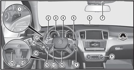
1. Подрулевые переключатели передач. 2. Комбинированный переключатель. 3. Комбинация приборов. 4. Звуковой сигнал. 5. Рычаг управления АКП Direct Select. 6. Предупредительная индикация системы «Парктроник». 7. Панель управления под крышей. 8. Системы кондиционирования воздуха. 9. Замок зажигания. Кнопка запуска/выключения двигателя «Start/Stop». 10. Механическая установка положения рулевого колеса. 11. Электрическая установка положения рулевого колеса. Система обогрева рулевого колеса. 12. Рычаг переключателя темпомата. 13. Открывание капота. 14. Разъем диагностирования. 15. Электрический стояночный тормоз. 16. Переключатель света. 17. Система ночного видения с расширенными функциями.
Индикация и элементы управления
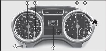
| № | Функция |
| 1 | Спидометр с сегментами |
| 2 | Уровень топлива в топливном баке |
| 3 | Тахометр |
| 4 | Температура охлаждающей жидкости |
| 5 | Мультифункциональный дисплей |
| 6 | Освещение приборов |
Предупредительные сигнальные и контрольные лампы
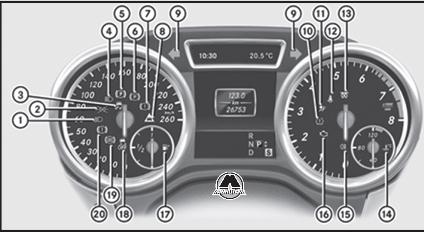
| № | Функция |
| 1 | Ближний свет |
| 2 | Стояночный свет |
| 3 | Система ESP |
| 4 | Дальний свет |
| 5 | Электрический стояночный тормоз (красная лампа) |
| 6 | Электрический стояночный тормоз (желтая лампа) |
| 7 | Тормозная система (желтая лампа) |
| 8 | Сигнализация сближения до минимально допустимой дистанции |
| 9 | Указатель поворота |
| 10 | Система контроля давления воздуха в шинах |
| 11 | Система SRS |
| 12 | Ремень безопасности |
| 13 | Дизельный двигатель: предпусковой подогрев |
| 14 | Охлаждающая жидкость |
| 15 | Задний противотуманный свет |
| 16 | Бортовое диагностирование двигателя |
| 17 | Минимальный резерв топлива |
| 18 | Режим «Off» системы ESP |
| 19 | Система ABS |
| 20 | Тормозная система (красная лампа) |
Мультифункциональное рулевое колесо
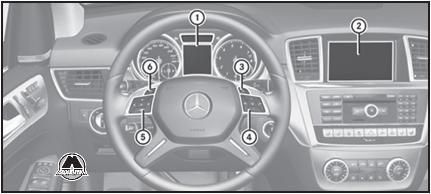
| № | Функция |
| 1 | Мультифункциональный дисплей |
| 2 | Дисплей аудиосистемы/системы Comand (см. отдельное руководство по эксплуатации) |
| 3 | Включение системы «Лингватроник» (см. отдельное руководство по эксплуатации) |
| Отклонение телефонного вызова или окончание телефонного соединения Выход из телефонной книги/памяти повторного набора |
|
| 4 | Совершение или прием телефонного вызова Переход к памяти повторного набора + — Изменение громкости Выключение и включение звука |
| 5 | Выбор меню Выбор подменю или пролистывание перечней ОК Подтверждение выбора Выключение сообщений на дисплее |
| 6 | Назад Выключение системы «Лингватроник» (см. отдельное руководство по эксплуатации) |
Центральная консоль вверху
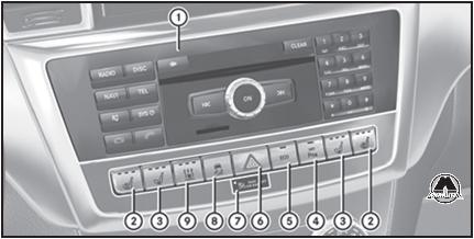
| № | Функция |
| 1 | Система Audio 20/система Comand Online (см. отдельное руководство по эксплуатации) |
| 2 | Система обогрева сидений |
| 3 | Система вентиляции сидений |
| 4 | Система «Парктроник» |
| 5 | функция пуска/выключения двигателя ECO |
| 6 | Аварийная световая сигнализация |
| 7 | Контрольная лампа «Passenger Airbag Off» |
| 8 | Система ESP |
| 9 | Система отопления независимого действия |
Центральная консоль внизу
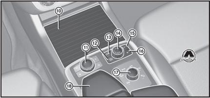
| № | Функция |
| 10 | Вещевой отсек |
| Держатель для напитков | |
| Пепельница | |
| Прикуриватель | |
| Гнездо электропитания | |
| 11 | Контроллер системы Comand (см. отдельное руководство по эксплуатации) |
| 12 | Кнопка меню «On&Offroad» |
| 13 | Передача для движения по бездорожью Low Range |
| 14 | Система регулирования дорожного просвета |
| 15 | Система DSR (Downhill Speed Regulation) |
| 16 | Ручная программа движения |
| 17 | Круглый переключатель программ движения по дорогам |
| Круглый переключатель программ движения по бездорожью | |
| 18 | Вещевой отсек |
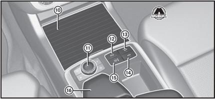
| № | Функция |
| 10 | Вещевой отсек |
| Держатель для напитков | |
| Пепельница | |
| Прикуриватель | |
| Гнездо электропитания | |
| 11 | Контроллер аудиосистемы/системы Comand (см. отдельное руководство по эксплуатации) |
| 12 | Выбор программы движения по бездорожью |
| Выбор программы движения | |
| Выбор программы движения (автомобили AMG) | |
| 13 | Система DSR (Downhill Speed Regulation) |
| 14 | Система регулирования дорожного просвета (автомобили с пакетом Airmatic) |
| 15 | Адаптивная демпфирующая система (автомобили с пакетом Airmatic) |
| Установка AMG Ride Control (автомобили AMG) | |
| 16 | Вещевой отсек |
Потолочная панель управления
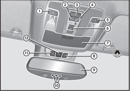
| № | Функция |
| 1 | Включение/выключение левой лампы для чтения |
| 2 | Включение внутреннего освещения в передней части салона |
| 3 | Включение/выключение освещения в задней части салона |
| 4 | Выключение внутреннего освещения в передней части салона/автоматического управления освещением салона |
| 5 | Включение/выключение правой лампы для чтения |
| 6 | Открывание/закрывание сдвижного верхнего люка Открывание/закрывание панорамной сдвижной панели крыши с солнцезащитными шторками |
| 7 | Отделение для очков |
| 8 | Выключение устройства защиты от буксировки |
| 9 | Внутреннее зеркало заднего вида |
| 10 | Кнопки устройства дистанционного открывания ворот гаража |
| 11 | Выключение устройства защиты салона |
| 12 | Включение системы вызова помощи Mercedes-Benz |
инструкцияMercedes-Benz GL-Class (2014)

GL
Operator’s Manual
Order no. 6515 0509 13 Part no. 166 584 68 00 Edition B 2014
É1665846800hËÍ
1665846800
GL Operator’s Manual
Посмотреть инструкция для Mercedes-Benz GL-Class (2014) бесплатно. Руководство относится к категории автомобили, 1 человек(а) дали ему среднюю оценку 5.2. Руководство доступно на следующих языках: английский. У вас есть вопрос о Mercedes-Benz GL-Class (2014) или вам нужна помощь? Задайте свой вопрос здесь
- 6515050913_cover
- 6515050913_buchblock
Главная
Не можете найти ответ на свой вопрос в руководстве? Вы можете найти ответ на свой вопрос ниже, в разделе часто задаваемых вопросов о Mercedes-Benz GL-Class (2014).
Как перевести мили в километры?
Где я могу узнать идентификационный номер транспортного средства Mercedes-Benz?
Что такое идентификационный номер транспортного средства (VIN)?
Когда транспортному средству Mercedes-Benz требуется техническое обслуживание?
Когда следует заменять тормозную жидкость на Mercedes-Benz?
В чем разница между топливом E10 и E5?
Одна или несколько дверей не открываются изнутри. Что мне делать?
Автомобильный радиоприемник не включается, что делать?
Инструкция Mercedes-Benz GL-Class (2014) доступно в русский?
Не нашли свой вопрос? Задайте свой вопрос здесь