- Manuals
- Brands
- Mettler Toledo Manuals
- Touch terminals
- IND310drive
- Installation manual
-
Contents
-
Table of Contents
-
Bookmarks
Quick Links
IND310
drive
Terminal
Installation Guide
Manual de Instalación
Installationsanleitung
Manuel d’installation
Manuale d’installazione
71207915
(01/2009) R03
Related Manuals for Mettler Toledo IND310drive
Summary of Contents for Mettler Toledo IND310drive
-
Page 1
IND310 drive Terminal Installation Guide Manual de Instalación Installationsanleitung Manuel d’installation Manuale d’installazione 71207915 (01/2009) R03… -
Page 3
IND310 drive Terminal Installation Manual… -
Page 5
Restricted Rights. Copyright 2009 METTLER TOLEDO. This documentation contains proprietary information of METTLER TOLEDO. It may not be copied in whole or in part without the express written consent of METTLER TOLEDO. METTLER TOLEDO reserves the right to make refinements or changes to the product or manual without notice. -
Page 7
Met all needs Met most needs Met some needs Did not meet my needs Comments/Questions: DO NOT WRITE IN SPACE BELOW; FOR METTLER TOLEDO USE ONLY Retail Light Industrial Heavy Industrial Custom RESPONSE: Include Root Cause Analysis and Corrective Action Taken. -
Page 8
FOLD THIS FLAP FIRST NO POSTAGE NECESSARY IF MAILED IN THE UNITED STATES BUSINESS REPLY MAIL FIRST CLASS PERMIT NO. 414 COLUMBUS, OH POSTAGE WILL BE PAID BY ADDRESSEE Mettler-Toledo, Inc. Quality Manager — MTWT P.O. Box 1705 Columbus, OH 43216 Please seal with tape… -
Page 9
FOR CONTINUED PROTECTION AGAINST SHOCK HAZARD CONNECT TO PROPERLY GROUNDED OUTLET ONLY. DO NOT REMOVE THE GROUND PRONG. CAUTION TO AVOID DAMAGE TO THE PCB OR LOAD CELL, REMOVE POWER FROM THE IND310drive TERMINAL AND WAIT AT LEAST 30 SECONDS BEFORE CONNECTING OR DISCONNECTING ANY HARNESS. CAUTION… -
Page 10: Table Of Contents
Contents Chapter 1.0 Introduction ……..1-1 Warnings and Precautions …………1-2 Safe Disposal Requirement …………1-2 Operating Environment…………..1-2 Inspection and Contents Checklist ……….1-3 Model Identification …………..1-3 Physical Dimensions …………..1-4 Specifications …………….1-6 Controller PCB ………………1-7 Display and Keyboard ……………1-8 Chapter 2.0 Installation ……..2-1 Mounting the Terminal …………..
-
Page 11: Chapter 1.0 Introduction
Physical Dimensions • Specifications ® Thank you for purchasing a METTLER TOLEDO IND310drive terminal. The IND310drive is a high-performance terminal for use with analog and/or ® ® POWERCELL /MTX scale platforms. The terminal has 1/4 VGA backlit monochrome graphic LCD display •…
-
Page 12: Warnings And Precautions
Please read these installation instructions carefully before putting the new terminal into operation. The IND310drive terminal can be used only in closed, dry, interior rooms. Do NOT operate in hazardous areas. Although the IND310drive is ruggedly constructed, it is nevertheless a precision instrument.
-
Page 13: Inspection And Contents Checklist
The IND310drive desk/wall model meets IP69K requirements. Hazardous Areas The IND310drive is not intrinsically safe and must not be operated in areas classified as Hazardous by the National Electrical Code (NEC) because of the combustible or explosive atmospheres in those areas. Contact an authorized METTLER TOLEDO representative for information about hazardous applications.
-
Page 14: Physical Dimensions
Schuko line cord. The unit is POWERCELL and multi-lingual. Single ALC 00000V0 = drive application Schuko line cord multi-lingual Physical Dimensions The IND310drive terminal physical dimensions are shown in the Figures 1-1 through 1-3. Mounting hole locations for wall mounting are shown in Figure 1-3.
-
Page 15
IND310drive Installation Manual 200 mm (7.9″) 300 mm (11.8″) Figure 1-1: Top View Max 75 Min 0 22 mm (0.9″) 74.5 mm (2.9″) 128.7 mm (5.1″) Figure 1-2: Side View… -
Page 16: Specifications
(2.8”) (0.6”) 20 mm (0.8”) 2 – R4 Figure 1-3: Bottom View Specifications The IND310drive conforms to the specifications listed in Table 1-2. Table 1-2: IND310drive Specifications IND310 Enclosure Type Stainless Steel Desk with adjustable angle stand Environmental Washdown, IP69K…
-
Page 17: Controller Pcb
Conforms to OIML R76 Conforms to IP69K Controller PCB The IND310drive terminal’s controller printed circuit board (PCB) supports scale function interface boards, including single analog, dual analog, POWERCELL, or single analog and POWERCELL interfaces. Supply voltage for the POWERCELL is…
-
Page 18: Display And Keyboard
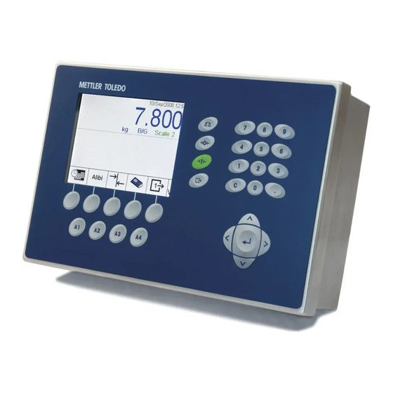
24 to 16 AWG. Display and Keyboard The IND310drive terminal has an LCD display (see Figure 1-) that shows the terminal’s status, including the active scale, date, and time across the top, the current application in the middle, and enabled softkey functions across the bottom.
-
Page 19: Chapter 2.0 Installation
Connecting to Peripheral Components Opening the Terminal Enclosure The front panel of the IND310drive terminal is locked in place by four spring clips attached to the enclosure body. To gain access to the terminal’s PCB for internal wiring and setting switches, separate the front panel from the enclosure as follows: 1.
-
Page 20
The openings on the bottom of the enclosure are for serial I/O, Ethernet, load cell, and other peripheral component cables. Once the IND310drive terminal is open, electrical connections can be made as shown in Figure 2-2. COM 2… -
Page 21: Power Connection
Power Connection A permanently attached line cord supplies the main power to the IND310drive terminal. No voltage or frequency settings are required since the terminal includes a universal power supply that operates from 87 to 264 VAC. The supply operates with a line frequency of 49 to 61 Hz.
-
Page 22: Load Cell Configuration Options
There is a fixed amount of current for each POWERCELL cell channel. If the IND310drive is configured for one scale (31L30x), then the limit is 800 mA, and if configured for two scales (31L31x or 31L33x), then each POWERCELL channel…
-
Page 23
If the POWERCELL card is mixed with an analog channel or two POWERCELL cards are used simultaneously (31L31x or 31L33x), then 500mA/75mA = 6.7. The value rounded down to six means the IND310drive supports only 6 MTX POWERCELLS without using an external power supply in those configurations. -
Page 24: Load Cell Connections
1000 2000 Load Cell Connections WARNING! TO AVOID DAMAGE TO THE PCB OR LOAD CELL, REMOVE POWER FROM THE IND310drive TERMINAL AND WAIT AT LEAST 30 SECONDS BEFORE CONNECTING OR DISCONNECTING ANY HARNESS. Analog Load Cell Connections Analog load cell connections are made to the J1 or J2 connectors located on the Single or A/D Board as shown in Figure 2-5.
-
Page 25
91/300 152/500 45 (8-350 Ω cells) The IND310drive terminal can support eight 350 Ohm analog load cells per channel, maximum of two channels. If a dual analog card is used, a total of sixteen 350 Ohm load cells are supported. -
Page 26
IND310drive Installation Manual POWERCELL Connections POWERCELL load cells are connected to the POWERCELL board located inside the IND310drive terminal. J1 and J2 connectors are located as shown in Figure 2-8. J2, Pin 1 J1, Pin 1 Figure 2-8: POWERCELL Board Connector Locations The POWERCELLs should be wired to each PCB as shown in Table 2-3. -
Page 27: Other Peripherals
Either or both of the ports can be configured for demand continuous mode output. Information concerning serial data format can be found in the setup section of the IND310drive User’s Guide. The maximum recommended cable length for RS-232 communications is 15.24 meters (50 feet). Table 2-4 and Table 2-5 provide printer port interconnect information.
-
Page 28
Two active current loop systems cannot be connected together. The IND310drive current loop is a “passive” current loop system, that is it does not have a current or voltage source built in; however, the COM1 connector supplies a +12V source to activate the system. -
Page 29
IND310drive Installation Manual IND310drive Main PCB Passive Peripheral J15 Pin Pin 6 (+12V) Pin 4 (+20mA) +20mA Pin 5 (-20mA) −20mA Pin 3 (Ground) Connect these two pins on J15 IND310drive Main PCB J15 Pin Active Peripheral Pin 6 (+12V) -
Page 30: Pcb Jumpers And Leds: Original Main Pcb
IND310drive Installation Manual PCB Jumpers and LEDs: Original Main PCB Figure 2-12 shows the locations of IND310drive jumpers and LEDs on the original main PCB. LED 3 (top), LED4 (bottom) LED 2 LED 1 Figure 2-12: Jumper and LED Locations, Original Main PCB All internal jumpers have been factory set and need not be reset unless a change in scale configuration or communication peripherals occurs.
-
Page 31
IND310drive Installation Manual The standard jumper settings are as follows: Table 2-6: Main Printed Circuit Board Jumpers/LEDs Description J1 is a five-pin jumper set. It is used for factory setup only. No jumpers are to be installed on J1. Hardware reset. (Always off). This jumper performs the same functions as a power cycle. -
Page 32
IRQ7 W2 is a three-pin configuration. If the jumper is in the 12V position, 12 volts is supplied from the IND310drive terminal. If the jumper is in the 24V position, 24 volts is supplied from an external power source. The external power source is connected to J2 on the POWERCELL load cell board. -
Page 33
LEDs W2 is a three-pin configuration. If the jumper is in the 12V position, 12 volts is supplied from the IND310drive terminal. If the jumper is in the 24V position, 24 volts is supplied from an external power source. The external power source is connected to J2 on the POWERCELL load cell board. -
Page 34: Pcb Jumpers And Leds: Revised Main Pcb
Figure 2-13: Revised Main PCB – Locations of Jumper W1 (left) and LEDs (right) The revised main PCB has a single internal jumper, used to configure the COM 2 port on J16. The IND310drive terminal as delivered from the factory can be configured five ways:…
-
Page 35: Capacity Labels
Capacity Labels In accordance with regulations for specific locations, capacity labels should be displayed on the front of the IND310drive terminal—one for each scale (see Figure 2-14). Max, min, and e information should be included on the labels. Written information must be a minimum of 2-mm or 0.08-in. high characters.
-
Page 36: Weights And Measures Seal
IND310drive Installation Manual Weights and Measures Seal A sealing kit is included with the terminal for weights and measures approved applications (see Figure 2-15). Figure 2-15: Sealing Kit Customers in EU countries have the option to seal internally near the metrology switch (Figures 2-16 and 2-17) or externally on the enclosure (Figure 2-18).
-
Page 37: Power-Up Sequence
PCB). The unit will beep when plugged in and will then specific functions, display the METTLER TOLEDO logo. The display will be followed by another beep, refer to the a truck display, and a status message at the bottom of the screen that shows the IND310drive progress of the initialization process.
-
Page 38
Manual de Instalación de la Terminal IND310 drive… -
Page 40
METTLER TOLEDOy no puede ser copiada parcial o totalmente sin autorización expresa por escrito de METTLER TOLEDO. METTLER TOLEDO se reserva el derecho de hacer modificaciones o cambios del producto o del manual sin previo aviso. DERECHOS RESERVADOS ®… -
Page 42
Cumplió con todos mis requisitos Cumplió con la mayoría de mis requisitos Cumplió con algunos de mis requisitos No cumplió con mis requisitos Comentarios/Preguntas: NO ESCRIBA NADA ABAJO — PARA USO EXCLUSIVO DE METTLER TOLEDO Detallista Industria ligera Industria pesada Cliente… -
Page 43
DOBLE ESTA HOJA PRIMERO NO REQUIERE PORTE DENTRO DE LOS ESTADOS UNIDOS BUSINESS REPLY MAIL FIRST CLASS PERMIT NO. 414 COLUMBUS, OH POSTAGE WILL BE PAID BY ADDRESSEE Mettler-Toledo, Inc. Quality Manager — MTWT P.O. Box 1705 Columbus, OH 43216 Favor de sellar con cinta… -
Page 44
PRECAUCIONES LEA este manual ANTES de operar o dar mantenimiento a este equipo y SIGA • cuidadosamente estas instrucciones. • GUARDE este manual para futura referencia. ¡ADVERTENCIA! PARA PROTECCIÓN CONTÍNUA CONTRA EL RIESGO DE DESCARGAS ELÉCTRICAS, CONECTE SÓLAMENTE A UNA TOMA CONECTADA A TIERRA CORRECTAMENTE. -
Page 46
Contenido Capítulo 1.0 Introducción ……..1-1 Advertencias y precauciones previas……….1-2 Requerimiento de desecho seguro ……….1-2 Entorno operativo …………… 1-2 Inspección y lista de revisión de contenidos ……..1-3 Identificación del modelo …………1-4 Dimensiones físicas …………..1-5 Especificaciones ……………. 1-6 PCB de control ……………..1-8 Lector y teclado …………….1-8 Capítulo 2.0 Instalación ……..2-1… -
Page 48
Este manual ofrece información detallada para la instalación de la terminal de Consulte el unidad IND310. Manual del Usuario de la La información sobre el Entrenamiento Técnico METTLER TOLEDO se puede unidad IND310 obtener poniéndose en contacto con: para las instrucciones de funcionamiento. -
Page 49: Advertencias Y Precauciones Previas
Manual de Instalación de la Unidad IND310 Advertencias y precauciones previas Por favor lea cuidadosamente estas instrucciones de instalación antes de usar la nueva terminal. Ésta terminal de unidad IND310 únicamente se puede usar en cuartos interiores cerrados secos. NO la use en áreas clasificadas como peligrosas. Antes de conectar la terminal, asegúrese de que el voltaje indicado en el rótulo de la terminal corresponda al voltaje de la corriente dealimentación.
-
Page 50: Inspección Y Lista De Revisión De Contenidos
La unidad IND310 no es intrínsecamente segura y no debe operarse en áreas clasificadas como peligrosas según el Código Eléctrico Nacional (NEC) debido a la presencia de atmósferas combustibles o explosivas en dichas áreas. Consulte a un representante autorizado de METTLER TOLEDO para mayor información sobre aplicaciones en áreas peligrosas. ¡ADVERTENCIA! ¡LATERMINAL DE UNIDAD IND310 NO ES INTRÍNSECAMENTE SEGURA!
-
Page 51: Identificación Del Modelo
Manual de Instalación de la Unidad IND310 Identificación del modelo Por favor consulte la Tabla 1-1, Identificación del Modelo, para identificar la unidad IND310 que fue pedida. El número de modelo de la unidad IND310 se encuentra en la parte posterior de la terminal junto con el número de serie. Tabla 1-1: Identificación del Modelo Identificación de modelo de la Unidad IND310 Tipo de…
-
Page 52: Dimensiones Físicas
Unidad IND310 Manual de instalación Dimensiones físicas Las dimensiones físicas de la terminal de unidad IND310 se muestran en las Figuras 1-1 a 1-4. La ubicación de los agujeros de montaje para montaje en pared se muestran en la Figura 1-4. Figura 1-1: Vista general de la unidad IND310 200 mm (7.9″)
-
Page 53: Especificaciones
Manual de Instalación de la Unidad IND310 150 mm (5.9”) 70 mm Ø16 mm (2.8”) (0.6”) 20 mm (0.8”) 2 – R4 Figura 1-4: Vista inferior Especificaciones La unidad IND310 cumple con las especificaciones enunciadas en la Tabla 1-2. Tabla 1-2: Especificaciones de la unidad IND310 IND310 Tipo de caja Escritorio de acero inoxidable con atril de ángulo ajustable…
-
Page 54
Unidad IND310 Manual de instalación IND310 Número de Hasta 2 plataformas básculas Teclado 0 – 9 numérico, decimal 10 teclas funcionales/de navegación 4 de aplicaciones específicas y 5 teclas blandas Teclado externo Para teclado externo opcional mediante conector USB Comunicaciones (2) puertos seriales: COM1–RS232, 20mA CL COM2–RS236, RS485/422… -
Page 55: Pcb De Control
Manual de Instalación de la Unidad IND310 PCB de control La tarjeta de circuitos impresos (PCB) de la terminal de unidad IND310 es compatible con tarjetas de interfase para funciones de báscula, incluyendo analógicas sencillas, analógicas dobles, POWERCELL, o interfases analógicas y POWERCELL sencillas.
-
Page 56: Montaje De La Terminal
Capítulo 2.0 Instalación En este capítulo se encuentran instrucciones detalladas para la Este capítulo cubre instalación de la terminal de unidad IND310. Por favor lea • Montaje dla terminal atentamente este capítulo antes de comenzar la instalación. • Conexión a componentes periféricos •…
-
Page 57
Manual de Instalación de la Unidad IND310 Figura 2-1: Acceso a la terminal de unidad IND310 2. Repita el Paso 1 en la otra ranura. 3. Luego de soltar el panel frontal, levante la parte inferior de éste hacia arriba y hacia afuera hasta que se libere totalmente de la caja. -
Page 58: Conexión De Corriente
Unidad IND310 Manual de instalación Usar para Ethernet y USB Figura 2-3: Glándulas para cables de la unidad IND310 • Introduzca las cintas terminales removibles o los conectores en los enchufes apropiados ya sea en la tarjeta principal o en la tarjeta de la báscula. Asegúrese de que la longitud del cable desde la cinta/conector terminal hasta la •…
-
Page 59: Powercell Nmos
Manual de Instalación de la Unidad IND310 Antes de suministrar corriente, asegúrese de que el cable eléctrico sea apropiado para el voltaje de la corriente alterna del lugar donde se vaya a usar la terminal (ver Figura 2-4). El cable eléctrico se conecta a la cinta terminal TB1 en el PCB de control. Requerimientos de corriente La terminal requiere una corriente de 87 a 264 VAC con una frecuencia lineal de 47 a 61 Hz (máximo 20 vatios) de potencia y tiene un fusible interno de 1.6 amperios,…
-
Page 60: Conexiones De Báscula
Carga soportadas por el IND310 1, 000 2, 000 Conexiones de báscula ¡ADVERTENCIA! PARA EVITAR DAÑO A LA PCB O CELDA DE CARGA, DESENCHUFE EL TERMINAL IND310DRIVE Y ESPERE POR LO MENOS 30 SEGUNDOS ANTES DE CONECTAR O DESCONECTAR CUALQUIER ARNÉS.
-
Page 61
152/500 45 (celdas de 8 a 350 Ω) El terminal IND310drive puede soportar ocho celdas de carga analógicas de 350 ohmios por canal, con un máximo de dos canales. Si se utiliza una tarjeta analógica doble, se soportan un total de dieciséis celdas de carga de 350 ohmios. -
Page 62
Figura 2-7: Cable estándar de 4 alambres Conexiones de POWERCELL Las celdas de carga POWERCELL se conectan a la tarjeta POWERCELL ubicada dentro del terminal IND310drive. Los conectores J1 y J2 se ubican como muestra la Figura 2-8. J2, Clavija 1 J1, Clavija 1 Figura 2-8: Ubicación de los conectores en la tarjeta POWERCELL… -
Page 63: Otros Periféricos
Figura 2-9: Ubicación de las conexiones en la tarjeta principal Puerto serial El puerto para la impresora del terminal IND310drive suministra interfases seriales RS-232/20 mA CL y RS485/422 para entrada y salida de datos seriales, ya sea en formato de salida por demanda o continúo. Ambos puertos se pueden configurar para el modo de salida por demanda.
-
Page 64: Circuito De Corriente Com1 De 20Ma
Unidad IND310 Manual de instalación Tabla 2-4: Puerto COM 1 en la tarjeta principal Nro. de clavija en J15 Descripción de señal J15 del IND310drive TxD1 RS-232C RxD1 RS-232C Tierra CLTX+ 20 mA CLTX– 20 mA +12 V Tabla 2-5: Puerto COM 2 en la tarjeta principal Nro.
-
Page 65: Ethernet
Manual de Instalación de la Unidad IND310 Grapa J15 del PCB princi- pal del IND310 Active Peripheral Grapa 6 (+12V) Grapa 4 (+20mA) +20mA Grapa 5 (-20mA) -20mA Grapa 3 (Ground) conexión en J15 Grapa J15 del PCB princi- pal del IND310 Passive Peripheral Grapa 6 (+12V) Grapa Pin 4 (+20mA)
-
Page 66
Todos los puentes internos se han ajustado en la fábrica y no se necesitan reajustar a menos que ocurra un cambio de los periféricos de comunicación o de la configuración de la báscula. Al recibir el terminal IND310drive de la fábrica, se puede configurar de cinco maneras: Analógica sencilla… -
Page 67
Manual de Instalación de la Unidad IND310 usa para la configuración predeterminado. No se instalan puentes en J1. Reajuste de hardware. (Siempre apagado). Este puente ejecuta las mismas funciones que un ciclo de energía. Este puente no se debe usar en el campo. -
Page 68
12V, se suministran los 12 voltios del terminal IND310drive. Si el puente está en la posición de 24V, los 24 voltios se suministran de una fuente de energía externa. La fuente de energía externa está… -
Page 69
12V, se suministran los 12 voltios del terminal IND310drive. Si el puente está en la posición de 24V, los 24 voltios se suministran de una fuente de energía externa. La fuente de energía externa está… -
Page 70
Unidad IND310 Manual de instalación IRQ7 Este puente fija la celda de carga de la báscula conectada en 2 mV/V. Sin un puente la celda de carga de la báscula conectada se fija en 3 mV/V Este puente fija la Báscula 2 en 2 mV/V. Sin un puente en el W2 la Báscula 2 se fija en 3 mV/V W4 es un juego de puente de cuatro posiciones. -
Page 71: Puentes De La Pcb Y Leds, Pcb Principal Modificada
Figura 2-12: PCB principal modificada: Ubicaciones del puente W1 (izquierda) y de las LED (derecha) La PCB principal modificada tiene un puente interno individual que se usa para configurar el puerto COM 2 en J16. La terminal IND310drive tal como se entrega de fábrica puede configurarse en cinco maneras: •…
-
Page 72: Etiquetas De Capacidad
Etiquetas de capacidad De conformidad con las regulaciones para localidades específicas, deben colocarse etiquetas de capacidad en el frente de la terminal del IND310drive—una para cada báscula (ver Figura 2-13). Deberá incluirse el máximo, mínimo, e información e en las etiquetas. La información escrita debe tener caracteres de un mínimo de 2 mm o 0.08 pulgadas de altura.
-
Page 73
Manual de Instalación de la Unidad IND310 Figura 2-14: Equipo de sellado Los clientes de los países de la UE tienen la opción de sellar internamente cerca del interruptor de metrología (las Figuras A-15 y 16 corresponden a las PCB principales original y modificada, respectivamente) o externamente en el gabinete (Figura 2-17). -
Page 74: Secuencia De Encendido
PCB principal original). La unidad emitirá un sonido al enchufarla y específicas de las luego aparecerá el logotipo de METTLER TOLEDO. La pantalla será seguida por otro aplicaciones, sonido, la imagen de un camión y un mensaje de estado que muestra el progreso del consulte el Manual proceso de inicialización en la parte inferior de la pantalla.
-
Page 75
IND310 drive Terminal Installationsanleitung… -
Page 77
© METTLER TOLEDO 2009 Dieses Handbuch darf ohne die ausdrückliche schriftliche Genehmigung von METTLER TOLEDO weder ganz noch teilweise in irgendeiner Form oder durch irgendwelche Mittel, seien es elektronische oder mechanische Methoden, einschließlich Fotokopieren und Aufzeichnen, für irgendwelche Zwecke reproduziert oder übertragen werden. -
Page 79
Hat meine Anforderungen erfüllt und übertroffen Hat alle Anforderungen erfüllt Hat die meisten Anforderungen erfüllt Hat einige Anforderungen erfüllt Hat meine Anforderungen nicht erfüllt DIESES FELD BITTE FREI HALTEN; NUR ZUR VERWENDUNG DURCH METTLER TOLEDO Einzelhandel Leichtindustrie Schwerindustrie Benutzerdefiniert ANTWORT: Ursachenanalyse und ergriffene Korrekturmassnahme aufführen. -
Page 80
DIESE KLAPPE ZUERST FALZEN NO POSTAGE NECESSARY IF MAILED IN THE UNITED STATES BUSINESS REPLY MAIL FIRST CLASS PERMIT NO. 414 COLUMBUS, OH POSTAGE WILL BE PAID BY ADDRESSEE Mettler-Toledo, Inc. Quality Manager — MTWT P.O. Box 1705 Columbus, OH 43216 Bitte mit Klebeband versiegeln… -
Page 81
BEACHTEN SIE DIE ENTSPRECHENDEN VORSICHTSMASSNAHMEN BEIM UMGANG MIT GERÄTEN, DIE EMPFINDLICH AUF ELEKTROSTATIK REAGIEREN. ACHTUNG! DAS IND310drive-TERMINAL IST NICHT EIGENSICHER! ES DARF NICHT IN BEREICHEN VERWENDET WERDEN, DIE AUF GRUND BRENNBARER ODER EXPLOSIVER UMGEBUNGEN GEMÄSS DIVISION 1 ODER ZONE 0/1 ALS EXPLOSIONSGEFÄHRDET EINGESTUFT WERDEN. -
Page 83
Inhaltsverzeichnis Einleitung ………1-1 Kapitel 1.0 Warn- und Vorsichtshinweise…………1-2 Anforderungen der sicheren Entsorgung ……..1-2 Betriebsumgebung …………..1-2 Inspektion und Prüfliste für Inhalt……….1-3 Modell-Identifikation …………..1-4 Abmessungen…………….1-5 Spezifikationen…………….1-6 Controller-Leiterplatte……………..1-7 Anzeige und Tastatur……………..1-8 Installation ……..2-1 Kapitel 2.0 Montage des Terminals…………… 2-1 Anschluss an Peripheriegeräte …………. -
Page 85: Einleitung
• Abmessungen • Spezifikationen Wir bedanken uns für Ihren Kauf eines IND310drive-Terminals von METTLER ® TOLEDO . Bei dem IND310drive handelt es sich um ein Hochleistungsterminal zur ® ® Verwendung mit Analog- und/oder POWERCELL /MTX -Wägeplattformen. Das Terminal verfügt über eine 1/4 VGA-Schwarzweiß-LCD-Grafikanzeige mit Hintergrundbeleuchtung…
-
Page 86: Warn- Und Vorsichtshinweise
übereinstimmt. Wenn dies nicht der Fall ist, darf das Terminal unter keinen Umständen in die Steckdose eingesteckt werden. Das IND310drive-Terminal ist zwar robust gefertigt, es ist aber auch ein Präzisionsinstrument. Beim Umgang mit dem Terminal und dessen Installation muss daher umsichtig vorgegangen werden.
-
Page 87: Inspektion Und Prüfliste Für Inhalt
Umgebungsschutz Das IND310drive-Tisch-/Wandmodell erfüllt die IP69K-Anforderungen. Explosionsgefährdete Bereiche Das IND310drive-Terminal ist nicht eigensicher und darf nicht in Bereichen betrieben werden, die gemäß dem National Electrical Code (NEC; US- Elektrovorschrift) auf Grund brennbarer oder explosiver Umgebungen als explosionsgefährdet eingestuft wurden. Wenden Sie sich an Ihren befugten Vertreter von METTLER TOLEDO, wenn Sie Informationen über Anwendungen in…
-
Page 88: Modell-Identifikation
Technisches Handbuch • Installationsanleitung • Modell-Identifikation Siehe, Tabelle 1-1 Modellidentifikation zum Identifizieren des bestellten IND310drive-Terminals. Die Modellnummer des IND310drive befindet sich zusammen mit der Seriennummer auf der Rückseite des Terminals. Tabelle 1-2: Modell-Identifikation Modell-Identifikation — IND310drive Model Waage 1 Waage 2…
-
Page 89: Abmessungen
IND310drive-Installationsanleitung Abmessungen Die Abmessungen des IND310drive-Terminals sind in Abbildung 1-1 bis 1-4 angegeben. Die Montagelochpositionen für die Wandmontage sind Abbildung 1-4 zu entnehmen. 200 mm (7.9″) 300 mm (11.8″) Abbildung 1-3: Draufsicht Abbildung 1-1: Gesamtansicht des IND310drive-Terminals Max 75 Min 0 22 mm (0.9″)
-
Page 90: Spezifikationen
Ø16 mm (2.8”) (0.6”) 20 mm (0.8”) 2 – R4 Abbildung 1-2: Untenansicht Spezifikationen Tabelle 1-2: IND310drive — Spezifikationen IND310 Gehäusetyp Edelstahltisch mit verstellbarem Winkelständer Umgebungsschutz Spritzwasser, IP69K Stromversorgung Internes Universalnetzteil 87 — 264 V AC, 49 — 61 Hz…
-
Page 91: Controller-Leiterplatte
Commission, Dokument R76 Konform mit OIML R76 Konform mit IP69K Controller-Leiterplatte Die Leiterplatte des IND310drive-Terminal-Controllers unterstützt Waagenfunktions- Schnittstellenplatinen, einschließlich einzelne Analog-Modelle, doppelte Analogmodelle, POWERCELLs oder einzelne Analog- und POWERCELL- Schnittstellen. Die Versorgungsspannung für die POWERCELL ist entweder 12 oder 24 Volt.
-
Page 92: Anzeige Und Tastatur
Klemmenleisten mit Drahtstärken von 24 bis 16 AWG hergestellt. Anzeige und Tastatur Das IND310drive-Terminal verfügt über eine LCD-Anzeige (siehe Abbildung 1-5), die den Terminalstatus einschließlich aktiver Waage, Datum und Uhrzeit oben einblendet, die aktuelle Anwendung in der Mitte anzeigt und die aktivierten Schnellfunktionstasten unten einblendet.
-
Page 93: Installation
M6. Anschluss an Peripheriegeräte Öffnen des Terminalgehäuses Die Vorderplatte des IND310drive-Terminals ist durch vier Federklammern verriegelt, die am Gehäusekörper befestigt sind. Um zum Verdrahten und Einstellen von Schaltern auf die Leiterplatte des Terminals zugreifen zu können, trennen Sie die Vorderplatte wie folgt vom Gehäuse:…
-
Page 94
Compact Flash- Karte Abbildung 2-2: Leiterplatte mit dazugehörigen Steckanschlüssen Das IND310drive-Terminal wurde für raue Umgebungen entwickelt. Bei der Installation von Kabeln und/oder Steckanschlüssen, die in das Terminalgehäuse geführt werden, muss jedoch vorsichtig vorgegangen werden. So wird eine wasserfeste Abdichtung gewährleistet: Die Kabel durch einen Kabelschuh der entsprechenden Größe ziehen, bevor die… -
Page 95: Stromanschluss
Kabelspiel über den Kabelschuh aufgenommen werden. Stromanschluss Die Hauptstromversorgung des IND310drive-Terminals erfolgt über ein werkseitig installiertes Netzkabel. Da das Terminal über ein Universalnetzteil verfügt, das bei 87 bis 264 V AC betrieben werden kann, sind keine Spannungs- oder Frequenzein- stellungen erforderlich.
-
Page 96: Anmerkungen Zur Ind310-Wägezelle
IND310drive-Installationsanleitung ACHTUNG FÜR EINEN KONTINUIERLICHEN SCHUTZ GEGEN STROMSCHLAG NUR AN EINE ORDNUNGSGEMÄSS GEERDETE STECKDOSE ANSCHLIESSEN. DEN ERDUNGSSTIFT NICHT ENTFERNEN. Vergewissern Sie sich vor dem Anschluss des Geräts an den Netzstrom unbedingt, dass das Netzkabel ordnungsgemäß für die Wechselspannung am Einsatzort verdrahtet ist (siehe Abbildung 2-4).
-
Page 97
Wert, dass das IND310-Terminal nur 10 MTX POWERCELLS ohne Verwendung einer externen Stromversorgung unterstützt. Dies ist die typische Konfiguration, wenn ein Mettler Toledo Cougar-Terminal ersetzt werden muss. Wenn die POWERCELL-Karte mit einem Analogkanal kombiniert wird oder zwei POWERCELL-Karten gleichzeitig verwendet werden (31L31x oder 31L33x), dann ist 500mA/75mA = 6,7. -
Page 98: Waagenanschlüsse
Waagenanschlüsse ACHTUNG! UM EINE BESCHÄDIGUNG DER LEITERPLATTE ODER WÄGEZELLE ZU VERMEIDEN, DIE STROMZUFUHR ZUM IND310drive-TERMINAL UNTERBRECHEN UND VOR DEM ANSCHLIESSEN ODER ABTRENNEN VON KABELBÄUMEN MINDESTENS 30 SEKUNDEN LANG WARTEN. Analog-Wägezellen-Anschlüsse Die Anschlüsse der Analog-Wägezelle werden an den J1- oder J2-Steckverbindern auf den Einzel- oder A/D-Platinen hergestellt.
-
Page 99
91/300 152/500 45 (8-350 Ω Zellen) Das IND310drive-Terminal kann acht 350-Ohm-Analog-Wägezellen pro Kanal bis maximal zwei Kanäle unterstützen. Wenn eine Doppel-Analogkarte verwendet wird, werden insgesamt sechzehn 350-Ohm-Wägezellen unterstützt. Abbildung 2-6 und 2-7 erhöhte Last zu einer Verringerung der Gewichtsanzeige führt, die Signaladern umkehren (+SIG und −SIG). -
Page 100
IND310drive-Installationsanleitung POWERCELL-Anschlüsse POWERCELL-Wägezellen werden an die POWERCELL-Platine im IND310drive- Terminal angeschlossen. Die Position der Steckverbinder J1 und J2 entnehmen Sie der Abbildung 2-8. J2, Stift 1 J1, Stift 1 Abbildung 2-8: POWERCELL-Platine — Steckverbinderpositionen Die POWERCELLs sollten wie in Tabelle 2-3 dargestellt an jeder Leiterplatte verdrahtet… -
Page 101: Sonstige Peripheriegeräte
Ein Port bzw. beide Ports können für den Anforderungsmodus oder den kontinuierlichen Modus konfiguriert werden. Informationen zum seriellen Datenformat finden Sie im Abschnitt zum Setup im IND310drive-Benutzerhandbuch. Die maximale empfohlene Kabellänge für die RS232-Kommunikation beträgt 15,24 m (50 feet). Tabelle 2-4 und Tabelle 2-5 enthalten Informationen zum Druckeranschluss.
-
Page 102
In Abbildung 2-10 wird gezeigt, wie die IND310drive-Stromschleife an ein passives und ein aktives Peripheriegerät angeschlossen wird. Beachten Sie, dass für ein passives Peripheriegerät Stift 3 und Stift 5 auf J15 der Hauptplatine des IND310drive mit einer Drahtbrücke verbunden werden müssen. -
Page 103: Leiterplatten-Drahtbrücken Und Leds, Original-Hauptplatine
Abbildung 2-10: Original-Hauptplatine Alle internen Drahtbrücken wurden werkseitig voreingestellt und müssen nur dann neu eingestellt werden, wenn eine Änderung an der Waagenkonfiguration oder den Kommunikations-Peripheriegeräten vorgenommen wird. Das ab Werk gelieferte IND310drive-Terminal kann mit fünf verschiedenen Methoden konfiguriert werden: 2-11…
-
Page 104
IND310drive-Installationsanleitung Einzel-Analog Doppel-Analog Eine POWERCELL Einzel-Analog und eine POWERCELL Zwei POWERCELLs Zur Einrichtung einer Konfiguration für: Verwenden Sie Tabelle: Einzel-Analog oder Doppel-Analog Einzelne POWERCELL Einzel-Analog (Waage 1) und 2-7 (Einzel-Analog) eine einzelne POWERCELL (Waage 2) 2-9 (POWERCELL) Zwei POWERCELL-Wägezellenplatinen… -
Page 105
IND310drive-Installationsanleitung Drahtbrücken/ Beschreibung LEDs Strom ein. Strom aus. Wenn das Gerät eingesteckt ist, LED1 Hauptstromversorgung, Stromanschlüsse und Sicherungen prüfen, bevor Sie sich an die Serviceabteilung wenden. LED2 Anwendungs-Software wird ausgeführt. LED3 Ethernet-Link angeschlossen. LED4 Ethernet ist aktiv. Tabelle 2-7: Einzelne und Dual-Analog-Wägezelle – Waage 1 Drahtbrücken/… -
Page 106
IRQ7 W2 ist eine drei-Stift-Konfiguration. Wenn sich die Drahtbrücke in der Position 12 V befindet, speist das IND310drive-Terminal 12 Volt. Wenn sich die Drahtbrücke in der Position 24 V befindet, speist eine externe Stromquelle 24 Volt. Die externe Stromquelle ist an J2 auf der POWERCELL-Wägezellenplatine angeschlossen. -
Page 107
IRQ7 W2 ist eine drei-Stift-Konfiguration. Wenn sich die Drahtbrücke in der Position 12 V befindet, speist das IND310drive-Terminal 12 Volt. Wenn sich die Drahtbrücke in der Position 24 V befindet, speist eine externe Stromquelle 24 Volt. Die externe Stromquelle ist an J2 auf der POWERCELL-Wägezellenplatine angeschlossen. -
Page 108
IND310drive-Installationsanleitung Draht- Beschreibung brücken/ LEDs Mit dieser Drahtbrücke wird die Wägezelleneinstellung der angeschlossenen Waage auf 2 mV/V festgelegt. Ohne Drahtbrücke wird die Wägezelleneinstellung der angeschlossenen Waage auf 3 mV/V festgelegt. Diese Drahtbrücke stellt Waage 2 auf 2 mV/V ein. Keine Drahtbrücke auf W2 stellt Waage 2 auf 3 mV/V ein. -
Page 109: Leiterplatten-Drahtbrücken Und Leds, Überarbeiteten Hauptplatine
Abbildung 2-11: Überarbeitete Hauptplatine – Positionen von Drahtbrücke W1 (links) und LEDs (rechts) Die überarbeitete Hauptplatine verfügt über eine einzelne, interne Drahtbrücke, die zur Konfiguration des COM 2-Anschlusses auf J16 verwendet wird. Das ab Werk gelieferte IND310drive-Terminal kann mit fünf verschiedenen Methoden konfiguriert werden: Einzel-Analog …
-
Page 110: Kapazitätsaufkleber
Kapazitätsaufkleber In Übereinstimmung mit den Vorschriften für bestimmte Standorte sollten auf der Vorderseite des IND310drive-Terminals Kapazitätsaufkleber angebracht werden, und zwar einer für jede Waage (siehe Abb. 2-12). Die Aufkleber sollten Angaben über Max, Min und e enthalten. Die Aufschrift muss mindestens 2 mm (0,08 in.) hoch sein.
-
Page 111: Versiegeln Für Maße Und Gewichte
IND310drive-Installationsanleitung Versiegeln für Maße und Gewichte Im Lieferumgang des Terminals für gemäß der Behörde für Maße und Gewichte zugelassene Anwendungen ist ein Versiegelungssatz enthalten (siehe Abb. 2-13). Abbildung 2-13: Versiegelungssatz Kunden in EU-Ländern können das Siegel wahlweise intern neben dem Metrologie- Schalter anbringen (Abbildungen 2-14 und 15 für die Original- bzw.
-
Page 112: Einschaltsequenz
Die Einschaltsequenz dauert ca. 35 Sekunden (90 Sekunden bei Geräten mit der Anwendungs- Original-Hauptplatine). Das Gerät gibt einen Piepton aus, wenn es eingesteckt wird; spezifische dann wird das METTLER TOLEDO-Logo eingeblendet. Nach der Anzeige ertönt ein Funktionen werden weiterer Piepton, eine LKW-Anzeige erscheint und eine Statusmeldung wird ein- im IND310drive-…
-
Page 113
IND310 drive Terminal Manuel d’installation… -
Page 115
Copyright 2009 METTLER TOLEDO. La présente documentation contient des informations exclusives à METTLER TOLEDO. Elle ne peut être recopiée ni intégralement ni partiellement sans le consentement exprès écrit de METTLER TOLEDO. METTLER TOLEDO se réserve le droit d’apporter des améliorations ou des modifications au produit ou au manuel sans préavis. -
Page 117
Satisfait tous mes besoins Satisfait la plupart de mes besoins Satisfait certains de mes besoins Ne satisfait pas mes besoins Commentaires/Questions L’ESPACE CI-DESSOUS EST RÉSERVÉ À METTLER TOLEDO – PRIÈRE DE NE PAS ÉCRIRE Vente au détail Industrie légère Industrie lourde Personnalisé… -
Page 118
PLIEZ CETTE PARTIE EN PREMIER NO POSTAGE NECESSARY IF MAILED IN THE UNITED STATES BUSINESS REPLY MAIL FIRST CLASS PERMIT NO. 414 COLUMBUS, OH POSTAGE WILL BE PAID BY ADDRESSEE Mettler–Toledo, Inc. Quality Manager – MTWT P.O. Box 1705 Columbus, OH 43216 Prière d’utiliser un ruban adhesive pour bien fermer… -
Page 119
MISE À LA TERRE. NE PAS ENLEVER LA BROCHE DE MISE À LA TERRE. ATTENTION POUR ÉVITER D’ENDOMMAGER LA CARTE OU LA CELULE DE PESAGE, DÉCONNECTER L’ALIMENTATION DU TERMINAL IND310drive ET ATTENDRE AU MOINS 30 SECONDES AVANT DE BRANCHER OU DE DÉBRANCHER TOUT FAISCEAU ÉLECTRIQUE. ATTENTION AVANT DE BRANCHER ET DE DÉBRANCHER LES COMPOSANTS ÉLECTRONIQUES INTERNES OU… -
Page 121
Table des matières Chapitre 1.0 Introduction ……..1-1 Avertissements et mises en garde……….1-2 Condition relative à une mise au rebut sécuritaire ……1-2 Environnement d’exploitation …………1-2 Inspection et liste de contrôle du contenu ……..1-3 Identification du modèle ………….. 1-4 Dimensions physiques………….. -
Page 123
• Spécifications • Nous vous remercions d’avoir acheté le terminal IND310drive de METTLER ® TOLEDO . Le terminal IND310drive est un terminal de haute performance destiné à être utilisé avec les plates-formes de pesage analogique et/ou ® ® POWERCELL /MTX . -
Page 124: Avertissements Et Mises En Garde
Avertissements et mises en garde Prière de lire soigneusement les instructions d’exploitation avant de mettre le nouveau terminal en service. Le terminal IND310drive peut être utilisé uniquement dans des salles fermées, à l’intérieur, avec un environnement sec. NE PAS l’utiliser dans des zones dangereuses.
-
Page 125: Inspection Et Liste De Contrôle Du Contenu
Le modèle bureau/mural IND310drive satisfait les conditions IP69K. Zones dangereuses L’IND310drive n’est pas un appareil intrinsèquement sécuritaire et ne doit pas être exploité dans des zones classées dangereuses par le Code national d’électricité (NEC) en raison de l’atmosphère combustible ou explosive de ces zones. Pour de plus amples informations sur les applications en zones dangereuses, contacter un représentant METTLER TOLEDO agréé.
-
Page 126: Identification Du Modèle
Manuel d’installation IND310drive Identification du modèle Voir le Tableau 1-1, Identification du modèle, pour identifier l’IND310drive qui a été commandé. Le numéro du modèle de l’IND310drive figure à l’arrière du terminal avec le numéro de série. Tableau 1-1 : Identification du modèle Identification du modèle IND310drive…
-
Page 127: Dimensions Physiques
Manuel d’installation IND310drive Dimensions physiques Les dimensions physiques du terminal IND310drive sont indiquées sur les Figures de 1-1 à 1-4. Les emplacements des orifices pour l’installation murale sont indiqués sur la Figure 1-4. Figure 1-1 : Vue d’ensemble de l’IND310drive 200 mm (7.9″)
-
Page 128: Spécifications
20 mm (0.8”) 2 – R4 Figure 1-4 : Vue d’en bas Spécifications L’IND310drive est conforme aux spécifications stipulées dans le Tableau 1-2. Tableau 1-2 : Spécifications de l’IND310drive IND310 Type d’enceinte Bureau en acier inoxydable avec support angulaire réglable Protection du milieu Lavage à…
-
Page 129
Manuel d’installation IND310drive IND310 Pavé numérique 0 – 9 numérique, décimal 10 Touches de fonction/navigation 4 touches spécifiques à l’application et 5 touches logicielles Clavier externe Prend en charge le clavier externe optionnel via un connecteur Communications (2) ports série : COM1–RS232, 20mA CL… -
Page 130: Carte Du Contrôleur
24 à 16 AWG. Affichage et clavier Le terminal d’IND310drive est doté d’un écran LCD (voir la Figure 1-5) qui indique l’état du terminal, y compris la balance active, la date et l’heure en haut de l’écran, l’application utilisée au centre de l’écran et les fonctions des touches logicielles…
-
Page 131: Installation Du Terminal
Connexion aux périphériques Ouverture de l’enceinte du terminal Le panneau avant de l’IND310drive est fixé à l’enceinte par quatre clips à ressort. Pour accéder aux commutateurs et au câblage internes de la carte du terminal, dégagez le panneau avant de l’enceinte comme suit : 1.
-
Page 132
Les ouvertures en bas de l’enceinte sont destinées à E/S série, câble Ethernet, cellule de pesage et autres câbles de périphériques. Après avoir ouvert le terminal IND310drive, vous pouvez effectuer les connexions électriques selon l’illustration de la Figure 2-2. COM 2… -
Page 133: Connexion D’alimentation
Une bonne mise à la terre est nécessaire afin de minimiser les impulsions électriques parasites. Le terminal IND310drive ne doit pas partager de lignes avec les appareils générateurs de bruit. Pour vérifier la qualité de la mise à la terre, utilisez un analyseur de circuit de dérivation du commerce.
-
Page 134: Options De Configuration De Cellules De Charge
Manuel d’installation IND310drive Avant de connecter l’alimentation, assurez-vous que le cordon est correctement acheminé pour une tension CA où le terminal sera utilisé (voir la Figure 2-4). Le cordon d’alimentation se connecte au bornier TB1 sur la carte du contrôleur.
-
Page 135: Nmos Powercell
10 MTX POWERCELLS sans recourir à une alimentation extérieure. Cette configuration est généralement utilisée pour le remplacement d’un terminal Mettler Toledo Cougar. Si la carte POWERCELL est utilisée avec un canal analogique ou que deux cartes POWERCELL soient utilisées simultanément (31L31x ou 31L33x), on obtient…
-
Page 136: Connexions De La Balance
Connexions de la balance AVERTISSEMENT ! POUR ÉVITER D’ENDOMMAGER LA CARTE OU LA CELLULE DE PESAGE, DÉCONNECTER L’ALIMENTATION DU TERMINAL IND310drive ET ATTENDRE AU MOINS 30 SECONDES AVANT DE BRANCHER OU DE DÉBRANCHER TOUT FAISCEAU ÉLECTRIQUE. Connexions de la cellule de pesage analogique Les connexions de cellule de pesage analogique sont effectuées aux connecteurs J1…
-
Page 137
152/500 45 (8 cellules-350 Ω) Le terminal IND310drive peut prendre en charge huit cellules de pesage analogique 350 Ohm par canal (deux canaux maximum). Si une carte analogique double est utilisée, un total de seize cellules de pesage de 350 Ohm est pris en charge. -
Page 138
Manuel d’installation IND310drive Connexions de POWERCELL Les cellules de pesage POWERCELL sont connectées à la carte POWERCELL située à l’intérieur du terminal IND310drive. Les connecteurs J1 et J2 sont indiqués sur la Figure 2-8. J2, Br. 1 J1, Br. 1 Figure 2-8: Emplacements des connecteurs de la carte POWERCELL La POWERCELL doit être connectée à… -
Page 139: Autres Périphériques
Figure 2-9: Emplacements de connexion de la carte principale Port série Le port de l’imprimante du terminal IND310drive fournit des interfaces série RS- 232/20 mA CL et RS 485/422 pour l’entrée et la sortie des données série soit sur demande soit en format continu. Les deux ports série peuvent être configurés pour une sortie en mode de demande.
-
Page 140
Deux systèmes de boucle de courant actifs ne peuvent pas être connectés ensemble. La boucle de courant de l’IND310drive est un système passif, c’est-à-dire qu’il n’a ni source de courant ni tension intégrés. Toutefois, le connecteur COM1 fournit une source +12V activant le système. -
Page 141
La Figure 2-10 indique la procédure de connexion de la boucle de courant de l’IND310drive à un périphérique passif et à un périphérique actif. Prière de remarquer que pour un périphérique passif, vous devez utiliser un cavalier entre les broches 3 et 5 sur J15 sur la carte PCB principale de l’IND310. -
Page 142: Cavaliers Et Led, Carte D’origine
Tous les cavaliers internes ont été réglés à l’usine et ne requièrent pas d’autres réglages à moins que des modifications ne soient apportées à la configuration de la balance ou aux périphériques de communication. Le terminal d’IND310drive tel que livré de l’usine peut être configuré de cinq façons : Analogique simple •…
-
Page 143
Manuel d’installation IND310drive Les réglages standard des cavaliers sont les suivants : Tableau 2-6 : Carte principale à circuit imprimé Cavaliers/ Marche Arrêt Description J1 est un ensemble de cavaliers à 5 broches. Il ne sert qu’au réglage en usine. Aucun cavalier n’est installé… -
Page 144
W2 est une configuration à trois broches. Si le cavalier est en position 12V, une alimentation de 12 V est fournie depuis le terminal IND310drive. Si le cavalier est en position 24 V, une alimentation de 24 V est fournie d’une source d’alimentation externe. -
Page 145
W2 est une configuration à trois broches. Si le cavalier est en position 12V, une alimentation de 12 V est fournie depuis le terminal IND310drive. Si le cavalier est en position 24 V, une alimentation de 24 V est fournie d’une source d’alimentation externe. -
Page 146
Manuel d’installation IND310drive Cavaliers/ Marche Arrêt Description W5 est un ensemble de cavaliers à quatre positions. Un seul cavalier doit être connecté. Mise sous tension. Mise hors tension. Si l’unité est branchée, vérifiez l’alimentation principale, les connexions LED1 d’alimentation, le logement correct de la carte et les fusibles avant de contacter le service. -
Page 147: Cavaliers Et Led, Carte Révisée
LED (droite) La carte PCB principale révisée dispose d’un cavalier interne simple, utilisé pour configurer le port COM 2 sur J16. Le terminal d’IND310drive tel que livré de l’usine peut être configuré de cinq façons : • Analogique simple •…
-
Page 148: Étiquettes De Capacité
Étiquettes de capacité Conformément à la réglementation des emplacements spécifiques, les étiquettes de capacité doivent être apposées sur la partie avant du terminal IND310drive—une par balance (voir la Figure 2-13). Les informations max, min, et e doivent être incluses sur les étiquettes. La hauteur des informations écrites doit être de 2 mm minimum.
-
Page 149: Sceau De Poids Et Mesures
Manuel d’installation IND310drive Sceau de poids et mesures Un kit pour l’apposition des sceaux est inclus avec le terminal pour les applications approuvées par des organismes des poids et mesures (voir la Figure 2-14). Figure 2-14 : Kit d’apposition des sceaux Les clients des pays de l’UE peuvent apposer les sceaux en interne près du…
-
Page 150: Séquence De Mise En Marche
PCB principale d’origine). L’unité émet un son au spécifiques aux moment du branchement, puis affiche le logo de METTLER TOLEDO. Un autre bip se applications, voir fait entendre, un camion et un message d’état s’affichent en bas de l’écran indiquant le manuel les progrès de la procédure d’initialisation.
-
Page 151
IND310 drive Terminale Manuale d’installazione… -
Page 153
Copyright 2009 METTLER TOLEDO. Questa documentazione contiene informazioni di proprietà di METTLER TOLEDO. La riproduzione di qualsiasi parte di questo manuale, in qualunque modo e con qualunque mezzo, elettronico o meccanico, inclusa la fotocopiatura e la registrazione, è vietata se non accordata da METTLER-TOLEDO con espresso permesso scritto. -
Page 155
Spuntare la casella di controllo appropriata per indicare la rispondenza del prodotto alle proprie aspettative. Pienamente soddisfacente Soddisfacente Abbastanza soddisfacente Parzialmente soddisfacente Per niente soddisfacente Commenti/Domande: NON SCRIVERE NELLO SPAZIO SOTTOSTANTE, RISERVATO A METTLER TOLEDO Dettagliante Industria leggera Industria pesante Personalizza RISPOSTA: Includere l’analisi del problema principale e l’azione correttiva eseguita. -
Page 156
PIEGARE PRIMA LA LINGUETTA AFFRANCATURA NON NECESSARIA SE IMPOSTATA NEGLI STATI UNITI BUSINESS REPLY MAIL FIRST CLASS PERMIT NO. 414 COLUMBUS, OH AFFRANCATURA A CARICO DEL DESTINATARIO Mettler-Toledo, Inc. Quality Manager — MTWT P.O. Box 1705 Columbus, OH 43216 Sigillare con nastro adesivo… -
Page 157
ISOLAMENTO A TERRA. ATTENZIONE PER EVITARE DI DANNEGGIARE LA SCHEDA PCB O LA CELLA DI CARICO, LEVARE L’ALIMENTAZIONE ELETTRICA DAL TERMINALE IND310drive ED ATTENDERE ALMENO 30 SECONDI PRIMA DI COLLEGARE O SCOLLEGARE DEI CAVI. ATTENZIONE PRIMA DI COLLEGARE O SCOLLEGARE UN COMPONENTE ELETTRONICO INTERNO O DEI CAVI INTERCOLLEGAMNTI TRA LE ATTREZZATURE ELETTRONICHE, DISCONNETTERE SEMPRE L’ALIMENTAZIONE ELETTRICA ED ATTENDERE ALMENO TRENTA (30) SECONDI PRIMA DI… -
Page 159
Indice Capitolo 1.0 Introduzione ……..1-1 Avvertenze e precauzioni…………. 1-2 Requisito di smaltimento sicuro ……….. 1-3 Ispezione e verifica del contenuto ……….1-3 Identificazione del modello …………1-4 Dimensioni…………….1-5 Specifiche tecniche …………..1-6 Scheda a circuito stampato del controllore………..1-8 Visualizzatore e tastiera …………..1-8 Capitolo 2.0 Installazione ……..2-1 Montaggio del terminale………….. -
Page 161
Dimensioni Specifiche tecniche ® Vi ringraziamo per aver acquistato un terminale METTLER TOLEDO IND310drive. L’IND310drive è un terminale a prestazioni elevate da usare con piattaforme per ® ® bilance analogiche e/o POWERCELL /MTX . Il terminale è dotato di: … -
Page 162: Avvertenze E Precauzioni
In caso contrario, assolutamente non collegare il terminale all’alimentazione elettrica di rete. Nonostante il terminale IND310drive sia robusto, è pur sempre uno strumento di precisione. Fare attenzione nel maneggiarlo e nell’installarlo. Ambiente operativo Quando si sceglie un’ubicazione:…
-
Page 163: Requisito Di Smaltimento Sicuro
Se il contenitore esterno non è danneggiato, rimuovere il terminale IND310drive dalla confezione protettiva, facendo caso a come è stato impacchettato e controllare ogni componente per eventuali danni.
-
Page 164: Identificazione Del Modello
Identificazione del modello Consultare la Tavola 1-1, Identificazione del modello, per identificare il terminale IND310drive ordinato. Il numero del modello del terminale IND310drive si trova sulla parte posteriore del terminale insieme al numero di serie. Tavola 1-1: Identificazione del modello…
-
Page 165: Dimensioni
IND310drive Manuale d’installazione Dimensioni Le dimensioni del terminale IND310drive sono mostrate dalla Figura 1-1 alla Figura 1-4. Le ubicazioni del foro di montaggio per il montaggio a muro sono mostrate alla Figura 1-4. Figura 1-1: IND310drive — Vista generale 200 mm (7.9″)
-
Page 166: Specifiche Tecniche
(0.6”) 20 mm (0.8”) 2 – R4 Figura 1-4: Vista dal basso Specifiche tecniche Il terminale IND310drive è conforme alle specifiche tecniche elencate alla Tavola 1-2. Tavola 1-2: IND310drive – Specifiche tecniche IND310 Rivestimento Acciaio inox con appoggio ad angolo regolabile…
-
Page 167
IND310drive Manuale d’installazione IND310 Numero di bilance Fino a 2 piattaforme Tastiera 0 – 9 Numerica, decimale 10 tasti funzionali/navigazionali 4 tasti specifici per applicazione e 5 tasti a schermo Tastiera esterna Supporta una tastiera esterna opzionale mediante un connettore… -
Page 168: Scheda A Circuito Stampato Del Controllore
AWG (Scala americana normalizzata). Visualizzatore e tastiera Il terminale IND310drive ha un visualizzatore a cristalli liquidi (vedere la Figura 1- 5) che indica lo stato del terminale, la bilancia attiva, la data e l’ora sulla parte superiore dello schermo, l’applicazione corrente nel mezzo e le funzioni dei tasti a schermo abilitati sulla parte inferiore.
-
Page 169: Montaggio Del Terminale
Collegamento alle periferiche Apertura della scatola del terminale Il pannello anteriore del terminale IND310drive è bloccato da quattro fermagli a molla attaccati al corpo della scatola stessa. Per accedere alla scheda a circuito stampato del terminale per cablare e impostare gli interruttori, separare il pannello anteriore dalla scatola nella maniera seguente: 1.
-
Page 170
Le aperture sulla parte inferiore della scatola sono per i cavi delle periferiche, dell’I/O seriale, dell’ethernet e della cella di carico. Una volta aperto il terminale IND310drive, si possono eseguire dei collegamenti elettrici come indicato nella Figura 2-2. COM 2… -
Page 171: Collegamento All’alimentazione Di Rete
Collegamento all’alimentazione di rete Un cavo di alimentazione di rete installato in fabbrica fornisce l’alimentazione elettrica di rete al terminale IND310drive. Non sono necessarie impostazioni di voltaggio o di frequenza, poiché il terminale comprende un’alimentazione elettrica universale che utilizza da 87 a 264 Vca. L’alimentazione di rete utilizza una frequenza compresa tra 49 e 61 Hz.
-
Page 172: Opzioni Di Configurazione Delle Celle Di Carico
Fusibile Figura 2-4: Scheda di alimentazione Opzioni di configurazione delle celle di carico L’unità IND310drive supporta celle di carico sia analogiche che digitali (POWERCELL), che possono essere configurate con al massimo due bilance. Sono disponibili le seguenti configurazioni: 31L10x: scheda analogica singola, una bilancia …
-
Page 173
POWERCELL CMOS e MTX Ciascun canale cella POWERCELL dispone di una quantità fissa di corrente. Se l’unità IND310drive è configurata per una bilancia (31L30x), il limite è 800 mA, se invece è configurata per due bilance (31L31x o 31L33x), ciascun canale POWERCELL dispone solo di 500 mA. -
Page 174: Collegamenti Alla Bilancia
43,75 ohm; pertanto l’unità IND310drive supporta senza problemi dodici celle di carico da 1.000 ohm. Per determinare se l’unità IND310drive può supportare venti celle di carico da 750- ohm, utilizzare il calcolo 750/20= 37,5 ohm. Poiché 37,5 ohm è meno di 43,75 ohm, the l’unità…
-
Page 175
152/500 45 (celle 8-350 ) Il terminale IND310drive può supportare otto celle di carico analogiche da 350 Ohm per canale, massimo due canali. Se viene usata una scheda analogica doppia, vengono supportate sedici celle di carico da 350 Ohm in totale. -
Page 176
(SIG and SIG). Figura 2-7: Cavo standard a 4 fili Collegamenti alle celle di carico POWERCELL Le celle di carico POWERCELL sono collegate all’interno del terminale IND310drive. I collegamenti J1 e J2 sono ubicati come indicato nella Figura 2-8. J2, Pin 1… -
Page 177
IND310drive Manuale d’installazione Le celle di carico POWERCELL devono essere cablate ad ogni scheda a circuito stampato come indicato nella Tavola 2-3. Tavola 2-3: Terminale connettore POWERCELL J1 Pin # Funzione COM A COM B Terra Terra Terra +12 Vcc… -
Page 178: Altre Periferiche
Figura 2-9: Ubicazioni dei collegamenti principali della scheda Porta seriale La porta della stampante del terminale IND310drive fornisce le interfacce seriali RS 232/20 mA CL e RS 485/422 per l’ingresso e l’uscita di dati seriali a richiesta o con formato di uscita continua. Una o entrambe le porte possono essere configurate per modalità…
-
Page 179
Nella Figura 2-10 è mostrato come connettere l’anello in corrente dell’unità IND310drive a una periferica attiva e passiva. Tenere presente che per una periferica passiva è necessario collegare il pin 3 e il pin 5 sul J15 del PCB principale dell’unità… -
Page 180: Ponticelli E Dei Led, Scheda Principale Originale
Tutti i ponticelli sono impostati in fabbrica e on vanno ripristinati a meno che si verifichi una modifica della configurazione della bilancia o delle periferiche di comunicazione. Il terminale IND310drive una volta prelevato dalla fabbrica, può essere configurato in cinque modalità diverse:…
-
Page 181
IND310drive Manuale d’installazione Singola analogica Doppia analogica Una POWERCELL Singola analogica e una POWERCELL Due POWERCELL Per impostare una configurazione per: Usare la tavola: Singola analogica o doppia analogica Singola POWERCELL Singola analogica (Bilancia 1) e… -
Page 182
IND310drive Manuale d’installazione Ponticelli/ Acceso Spento Descrizione LED4 Ethernet è attivo. Tavola 2-7: Cella di carico analogica singola e doppia—Bilancia 1 Ponticelli/ LED Acceso Spento Descrizione W1 è un ponticello a tre posizioni. Deve essere collegato un solo ponticello. IRQ1… -
Page 183
W2 è una configurazione a tre pin. Se il ponticello si trova nella posizione 12V, 12 volt vengono forniti dal terminale IND310drive. Se il ponticello si trova nella posizione 24V, 24 volt vengono forniti da una fonte esterna di alimentazione. La fonte esterna di alimentazione è collegata a J2 sulla scheda di carico POWERCELL. -
Page 184
W2 è una configurazione a tre pin. Se il ponticello si trova nella posizione 12V, 12 volt vengono forniti dal terminale IND310drive. Se il ponticello si trova nella posizione 24V, 24 volt vengono forniti da una fonte esterna di alimentazione. La fonte esterna di alimentazione è… -
Page 185: Ponticelli E Dei Led, Scheda Principale Aggiornato
IND310drive Manuale d’installazione Ponticelli/ LED Acceso Spento Descrizione W4 è un ponticello a quattro posizioni. Solo un ponticello deve essere collegato. Alimentazione accesa. Alimentazione spenta. Se l’unità è collegata all’alimentazione di rete, controllare l’alimentazione di rete stessa, i collegamenti di alimentazione, il posizionamento…
-
Page 186: Etichette Di Capacità
IND310drive Manuale d’installazione Il PCB principale aggiornato è dotato di un singolo ponticello interno, utilizzati per configurare la porta COM2 su J16. È possibile configurare il terminale IND310drive con le impostazioni di fabbrica in cinque modi: Singola analogica …
-
Page 187: Sigillo Di Pesi E Misure
IND310drive Manuale d’installazione Figura 2-13: Etichette di capacità per un sistema a due bilance Sigillo di pesi e misure Nel terminale è compreso un kit di sigillatura per applicazioni approvate di pesi e misure (vedere figura 2-14). Figura 2-14: Kit sigillante…
-
Page 188: Sequenza Di Alimentazione
Quando verrà collegata, l’unità emetterà un suono, poi verrà applicazione visualizzato il logo METTLER TOLEDO. A questo seguirà l’emissione di un altro suono, specifiche, fare l’immagine di un camion e un messaggio di stato che mostra l’avanzamento del riferimento al processo di inizializzazione sulla parte inferiore dello schermo.
-
Page 189
METTLER TOLEDO 1900 Polaris Parkway Columbus, Ohio 43240 www.mt.com P/N: 71207915 ® METTLER TOLEDO is a registered trademark of Mettler-Toledo, Inc. ©2009 Mettler-Toledo, Inc. Printed in USA…
Table of Contents for Mettler Toledo IND310drive:
-
IND310drive User Manual 2-20 See 0Hthe Table Searches section for more information about how to search database tables. 4. If the Short A/N ID is not found in the database, the message “A1 ID NOT FOUND ” displays. Search the database by pressing the DATABASE QUERY softkey . 5. Once all table entries are complete, press the OK softkey to accept the entries. For Index Weighing, the A1, A2, and A3 table fields (if enabled) will display the database values as referenced in the Index Table. If necessary, change the values by following steps
-
IND310drive User Manual B-4 Temporary ID Weighing Temporary ID Weighing Vehicle enters the scale Press the TEMPORARY ID softkey Vehicle ID NOT Found Enter database information (optional) Enter variable information (optional) Data is printed and removed from the Temporary ID table The terminal clears the screen and returns to the default weighing screen Use the Auto Temp Vehicle ID Number that Displa
-
3-1 This chapter covers • Service • Cleaning and Maintenance • 1HUpdating Software Chapter 3.0 Service and Maintenance Service Information on installing, programming, and servicing the IND310drive terminal is available in the IND310drive Terminal Installation and Technical Manuals. Only qualified personnel should perform installation, programming, and service. Please contact a local METTLER TOLEDO representative for assistance. In general, once the IND310drive is installed, programmed, and calibrated for a given ap
-
IND310drive Terminal User’s Guide 71207921 (10/05) R03
-
IND310drive User Manual 2-16 Using Manually-Entered Tare Weights for Temporary ID Weighing Operators can use manually-entered tare weights rather than stored tare weights in the Temporary ID Weighing mode (if enabled in setup). To manually enter a tare weight: 1. From the default weight screen (Figure 2-9), use the numeric keypad to enter the tare value in the tare entry field BEFORE pressing the TEMPORARY ID softkey. Figure 2-9: Def
-
IND310drive User Manual B-2 Index Weighing Use the Index Weighing mode when both of the following are true: • Index Weighing has been enabled in setup • The ID of the vehicle and associated database value IDs have been pre-entered in the Index table in setup mode Do not attempt to use the Index Weighing mode if any of the following are true: • Vehicle ID is unknown • Tare weight of the vehicle has changed • The INDEX softkey does not display on any available weighing operations softkey screens Transient Vehicl
-
IND310drive User Manual 2-15 See 3Hthe Table Searches section for more information about how to search for a vehicle ID. See A ppendix B, Application Operation Flowcharts for a quick reference flowchart that illustrates Temporary ID Weighing. Temporary ID Weighing Temporary ID Weighing involves the use of the Temporary ID Table to record tare weights for inbound transactions and to recall these weights on outbound transactions. Manually-entered tare weights can also be used for Temporary ID Weighing. To view or edit the Tempo
-
IND310drive User Manual 2-23 Clearing the Alibi & Transaction Table The user may want to clear the transaction table after the terminal has first been installed or in North American applications, where the user has downloaded the existing data and wishes to continue with a clear table. Clearing the Alibi & Transaction table may take up to three minutes. In addition to clearing the data, the process runs a database defragmentation routine. Further information about clearing the Alibi & Transaction ta
-
Appendix A Basic Weighing Concepts ……………………..39HA-1 Zero……………………………………………………………………………… 40HA-1 Tare……………………………………………………………………………… 41HA-1 Autotare……………………………………………………………………………..42HA-1 Keyboard Tare……………………………………………………………………..43HA-2 Additive Tare….
-
IND310drive User Manual 2-7 See the IND310drive Installation Manual for more information on connecting an external keyboard. Figure 2-5: Alpha Keys To use alpha keys, position the cursor in the data entry location (see Navigation Keys), press the softkey or application key associated with the desired set of alpha characters as shown in Figure 2-5. The softkeys change to display each alpha character included in
-
IND310drive User Manual 2-8 • Keyboard numeric and alphabetic keys—Function independently of the softkeys and can be used to enter alphabetic letters and numerals. The Enter key on the keyboard functions the same as the ENTER navigation key. The Backspace key functions the same as the CLEAR (C) key. The arrow keys function the same as the navigation keys. • Number keys—Function the same as the keys on the terminal’s numeric keypad when the number lock function is engaged. Keystroke Functions
-
IND310drive User Manual 2-12 See A ppendix B, Application Operation Flowcharts for a quick reference flowchart that illustrates Vehicle ID Weighing. • Temporary ID Weighing—Coordinates the inbound and outbound processes for vehicles that are not permanently stored in the Vehicle ID table through the use of a Temporary ID table. Temporary ID Weighing stores the vehicle information in the Temporary ID table and follows the inbound process. It also re
-
IND310drive User Manual 2-18 See A ppendix B, Application Operation Flowcharts for a quick reference flowchart that illustrates Transient Vehicle Weighing. Transient Vehicle Weighing Use Transient Vehicle Weighing for vehicles that should not be included in totals or in the terminal’s memory. To use Transient Vehicle Weighing: 1. Once the vehicle is on the scale, press the TRANSIENT VEHICLE WEIGHING softkey (see Figure 2-11). Figure 2-11: Default Weighing Screen 2. A prompt displays with a cursor in the description fi
-
PRECAUTIONS • READ this manual BEFORE operating or servicing this equipment and FOLLOW these instructions carefully. • SAVE this manual for future reference. WARNING! FOR CONTINUED PROTECTION AGAINST SHOCK HAZARD CONNECT TO PROPERLY GROUNDED OUTLET ONLY. DO NOT REMOVE THE GROUND PRONG. WARNING! TO AVOID DAMAGE TO THE PCB OR LOAD CELL, REMOVE POWER FROM THE IND310drive TERMINAL AND WAIT AT LEAST 30 SECONDS BEFORE
-
© METTLER TOLEDO 2005 No part of this manual may be reproduced or transmitted in any form or by any means, electronic or mechanical, including photocopying and recording, for any purpose without the express written permission of METTLER TOLEDO. U.S. Government Restricted Rights: This documentation is furnished with Restricted Rights. Copyright 2005 METTLER TOLEDO. This documentation contains proprietary information of METTLER TOLEDO. It may not be copied in who
Questions, Opinions and Exploitation Impressions:
You can ask a question, express your opinion or share our experience of Mettler Toledo IND310drive device using right now.
Всем привет.
Есть весовой терминал Mettler Toledo IND310, надо через com2 получить вес, выбрал режим PT6S3 Protocol, отправляю на порт «P» (как я понял из инструкции), в ответ тишина.
Очень хотелось бы получать вес по запросу, может кто сталкивался, какой режим надо поставить и что надо отправить на com порт что бы в ответ получить вес.
Заранее спасибо.
Ставил режим Continuous Mode Output, данные идут на порт, но разобрать их по инструкции не получается:
1. <STX> ASCII Start of Text Character, Hex 02.
2. <SWA>, <SWB>, <SWC> Status Word Bytes A, B, and C. Refer to the Bit
Identification Tables for individual bit definition.
3. Displayed weight, either Gross or Net weight. Six digits, no decimal point or
sign. Non-significant leading zeros are replaced with spaces.
4. Tare weight. Six digits, no decimal point or sign.
5. <CR> ASCII Carriage Return, Hex 0d.
6. <CKS> Checksum character, 2’s complement of the 7 low order bits of the
binary sum of all characters on a line preceding the checksum, including the
STX and CR.
|
Detail Specifications: 903/903872-ind310drive.pdf file (27 Apr 2023) |
Accompanying Data:
Mettler Toledo IND310drive Touch terminals PDF Operation & User’s Manual (Updated: Thursday 27th of April 2023 08:55:42 AM)
Rating: 4.3 (rated by 53 users)
Compatible devices: IND221, MultiRange ID7sx, IND560x, PANTHER, Spider SW, IND780, PANTHER PLUS, ID7.
Recommended Documentation:
Text Version of Operation & User’s Manual
(Ocr-Read Summary of Contents, UPD: 27 April 2023)
-
30, Mettler Toledo IND310drive IND310drive User Manual 2-20 See 0Hthe Table Searches section for more information about how to search database tables. 4. If the Short A/N ID is not found in the database, the message “A1 ID NOT FOUND ” displays. Search the database by pressing the DATABASE QUERY softkey . 5. Once all table entries are complete, press the OK softkey to accept the entries. F…
-
25, IND310drive User Manual 2-15 See 3Hthe Table Searches section for more information about how to search for a vehicle ID. See A ppendix B, Application Operation Flowcharts for a quick reference flowchart that illustrates Temporary ID Weighing. Temporary ID Weighing Temporary ID Weighing involves the use of the Temporary ID Table to record tare weights for inbound transaction…
-
28, Mettler Toledo IND310drive IND310drive User Manual 2-18 See A ppendix B, Application Operation Flowcharts for a quick reference flowchart that illustrates Transient Vehicle Weighing. Transient Vehicle Weighing Use Transient Vehicle Weighing for vehicles that should not be included in totals or in the terminal’s memory. To use Transient Vehicle Weighing: 1. Once the vehicle is o…
-
31, IND310drive User Manual 2-21 Validating the Transaction After entering all data for the database and variable data, the validation screen displays (Figure 2-15). This screen shows all database table entries. Figure 2-15: Validation Screen To validate the transaction 1. Verify that the information displayed for the database entries (A1–A3) and the variable dat…
-
48, IND310drive User Manual B-4 Temporary ID Weighing Temporary ID Weighing Vehicle enters the scale Press the TEMPORARY ID softkey Vehicle ID NOT Found Enter database information (optional) Enter variable information (optional) Data is printed and removed from the Temporary ID table The terminal clears the screen and returns to the default weighing…
-
2, Mettler Toledo IND310drive © METTLER TOLEDO 2005 No part of this manual may be reproduced or transmitted in any form or by any means, electronic or mechanical, including photocopying and recording, for any purpose without the express written permission of METTLER TOLEDO. U.S. Government Restricted Rights: This documentation is furnished with Restricted Rights. Copyright 2005 METTL…
-
9, IND310drive User Manual 1-3 Installation and Programming The IND310drive Installation Manual provides detailed information about installation. This manual is included in printed format and on a CD with the initial delivery of the terminal. Installation information for the IND310drive is also available in the IND310drive Technical Manual, Appendix A. The IND310drive Technical Ma…
-
22, Mettler Toledo IND310drive IND310drive User Manual 2-12 See A ppendix B, Application Operation Flowcharts for a quick reference flowchart that illustrates Vehicle ID Weighing. • Temporary ID Weighing—Coordinates the inbound and outbound processes for vehicles that are not permanently stored in the Vehicle ID table through the use of a Temporary ID table. Temporary ID Weighing stores the vehicl…
-
43, IND310drive User Manual A-3 Inbound/Outbound Weighing Vehicle scales are often used in an inbound/outbound mode of operation where the vehicle is loaded or unloaded at the user’s site. In the inbound/outbound mode the vehicle empty (tare) weight is not known, so the vehicle must be weighed twice (once empty and once loaded). In the past this was normally done by printing the…
-
40, IND310drive User Manual 3-2 Updating Software IND310drive software updates are performed with a USB memory stick. Only a METTLER TOLEDO provided USB memory stick (available as CIMF number 71208113) should be used to perform this activity. Refer to the IND310drive Technical Manual, Chapter 4.0, Service and Maintenance, for detailed procedures for updating software.
… -
19, IND310drive User Manual 2-9 Graphic Image Function Current A4 Value Current Vehicle ID Current Vehicle Description Custom Report Darker Database Files Database Query (search) Defrag Defragment Delete Edit Escape (exit without storing) Exit (return to previous screen) Vehicle ID Weighing Index Weighing Information …
Recommended Instructions:
ZFK 56/38RF, RPL-85, ETA-20SH, TDM-7546E, NGT Series


-
Installation Instructions for Series NRX Ethernet Communications Adapter Module effective May 2012 Series NRXInstruction Leaet IL01301052E• WARNING(1) ONLY QUALIFIED ELECTRICAL PERSONNEL SHOULD BE PERMITTED TO WORK ON THE EQUIPMENT. (2) ALWAYS DE-ENERGIZE PRIMARY AND SECONDARY CIRCUITS IF A CIRCUIT BREAKER CANNOT BE REMOVED TO A SAFE WORK LOCATION. (3) DRAWOUT CIRCUIT BREAKERS SH …
Series NRX 68
-
SIMOTIONMotion ControlTM15 / TM17 High Feature Terminal ModulesManualValid as of Version 4.5 11/2016 PrefaceSafety instructions1Terminal Module TM152Terminal Module TM17 High Feature3Standards, Certificates and ApprovalsAESD guidelinesB …
SIMOTION TM15 60
-
Package Contents 15” P-CAP touch terminal with Gen 7E or Gen 8E base (x 1) Power adapter (x 1) Power cord (x 1) User manual (x 1) Product Features Fanless Design Intel 4th generation Haswell CPU New Gen 7E foldable base that allows JIVA XT Series to be configured into different configurations. New Gen 8E foldable base that integrates in …
XT-5315 20
Additional Information:
Popular Right Now:
Operating Impressions, Questions and Answers:
Интернет-магазин «МосВес»
г. Москва (м. Окружная), ул. Гостиничная, д. 3, офис 506
Телефон: +7(495) 723-05-93
e-mail: info@mosves.com
Часы работы офиса: с 9:00 до 17:00 пн-чт, с 9:00 до 16:00 пт
Прием звонков: с 9:00 до 22:00 ежедневно
Разработка и продвижение
Согласие на обработку персональных данных