Назначение испытательной установки MI 3394
Установка MI 3394 позволяет провести испытания электрической прочности изоляции, измерить сопротивление проводников и изоляции, мощность, потребляемую оборудованием и другие параметры.
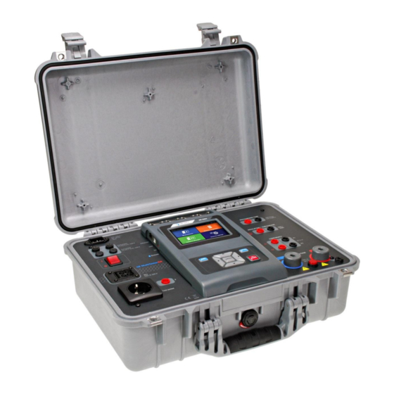
Установка выполнена в виде чемодана, что позволяет применять ее в полевых условиях.
Функции испытательной установки MI 3394
- Испытание электрической прочности изоляции переменным и постоянным напряжением,
- Измерение сопротивления изоляции,
- Измерение токов утечки,
- Проверка непрерывности защитных проводников,
- Измерение потребляемой электрооборудованием мощности,
- Измерение времени разряда блока питания оборудования.
Особенности испытательной установки MI 3394
- возможность автоматического тестирования,
- цветной сенсорный экран,
- использование карт памяти microSD до 32 ГБ,
- многообразие интерфейсов для передачи данных – RS232, USB, Bluetooth, Ethernet,
- возможность удаленного управления прибором.
- Manuals
- Brands
- METREL Manuals
- Test Equipment
- MI 3394 CE MultiTesterXA
- Instruction manual
-
Contents
-
Table of Contents
-
Bookmarks
Quick Links
CE MultiTesterXA
MI 3394
Instruction manual
Ver. 3.4.13, Code no.20 752 432
Related Manuals for METREL MI 3394 CE MultiTesterXA
Summary of Contents for METREL MI 3394 CE MultiTesterXA
-
Page 1
CE MultiTesterXA MI 3394 Instruction manual Ver. 3.4.13, Code no.20 752 432… -
Page 2
EU (European Union) regulations. © 2019 Metrel The trade names Metrel, Smartec, Eurotest, Autosequence are trademarks registered or pending in Europe and other countries No part of this publication may be reproduced or utilized in any form or by any means without… -
Page 3
i. About the Instruction manual Version note: Ver. 3.1.6 and higher relates to HW 3 version. This Instruction manual contains detailed information on the CE MultiTesterXA, its key features, functionalities and use. It is intended for technically qualified personnel responsible for the product and its use. … -
Page 4: Table Of Contents
MI 3394 CE MultiTesterXA Table of contents ABLE OF ONTENTS General description ………………….. 7 Warnings and notes ………………..7 1.1.1 Safety warnings ………………….. 7 1.1.2 Warnings related to safety of measurement functions ……….7 1.1.2.1 HV AC, HV DC, HV AC programmable, HV DC programmable ……. 7 Diff.
-
Page 5
MI 3394 CE MultiTesterXA Table of contents ® Auto Sequence groups ……………….. 38 ® 4.9.1 Auto Sequence groups menu …………….38 ® 4.9.1.1 Operations in Auto Sequence groups menu ……….38 ® 4.9.1.2 Selecting a group of Auto Sequences …………39 ®… -
Page 6
MI 3394 CE MultiTesterXA Table of contents 6.2.8 Sub-leakage (Isub, Isub-S) ………………93 6.2.9 Differential Leakage ………………..95 6.2.10 Ipe Leakage ………………….. 97 6.2.11 Touch Leakage ………………..99 6.2.12 Power ………………….100 6.2.13 Leak’s & Power ………………..103 6.2.14 Discharging Time ………………… 105 6.2.15… -
Page 7
Generic tag format ………………..138 ® Appendix D — Default list of Auto Sequences …………..140 ® Appendix E — Programming of Auto Sequences on Metrel ES Manager ……141 ® Auto Sequence Editor workspace …………….141 ® Managing of Auto Sequence groups ………….. -
Page 8: General Description
Use only standard or optional test accessories supplied by your distributor! Only test adapters provided or approved by Metrel should be connected to TC1 (test and communication) connectors. Use only earthed mains outlets to supply the instrument! …
-
Page 9: Diff. Leakage, Ipe Leakage, Touch Leakage, Power, Leak’s & Power
MI 3394 CE MultiTesterXA General description A dangerous voltage up to 5 kV or 6 kV is applied to the HV instrument outputs during the test. Therefore special safety consideration must be taken when performing this test! Only a skilled person familiar with hazardous voltages can perform this measurement! …
-
Page 10: Standards Applied
MI 3394 CE MultiTesterXA General description 1.2 Standards applied The CE MultiTesterXA instrument is manufactured and tested according to the following regulations, listed below. Electromagnetic compatibility (EMC) EN 61326-1 Electrical equipment for measurement, control and laboratory use — EMC requirements – Part 1: General requirements…
-
Page 11: Instrument Set And Accessories
Calibration Certificate Short form instruction manual CD with instruction manual (full version) and PC SW Metrel ES Manager 2.2 Optional accessories See the attached sheet for a list of optional accessories that are available on request from your distributor.
-
Page 12: Instrument Description
MI 3394 CE MultiTesterXA Instrument description 3 Instrument description 3.1 Front panel Figure 3.1: Front panel Mains supply connector F1, F2 fuses (F 5 A / 250 V) F3, F4 fuses (T 16 A / 250 V) On / Off switch…
-
Page 13: Instrument Operation
MI 3394 CE MultiTesterXA Instrument operation 4 Instrument operation The CE MultiTesterXA can be manipulated via a keypad or touch screen. 4.1 General meaning of keys Cursor keys are used to: — select appropriate option Enter key is used to:…
-
Page 14: Safety Checks
MI 3394 CE MultiTesterXA Instrument operation 4.3 Safety checks At start up and during operation the instrument performs various safety checks to ensure safety and to prevent any damage. These safety pre-tests are checking for: Correct input mains voltage …
-
Page 15
MI 3394 CE MultiTesterXA Instrument operation Resistance L-N < 30 Ω In pre-test a low input resistance of the device under test was measured. This can result in a high current after applying power to the device. If the high current is only of short duration (caused by a short inrush current) the test can be performed, otherwise not. -
Page 16
MI 3394 CE MultiTesterXA Instrument operation The load current exceeded the highest upper limit of 10 A for the Discharging time test. Measurement was aborted. Press OK to continue. The load current continuously exceeded 10 A for more than 4 min (moving average) in Power and Leakage tests. -
Page 17
MI 3394 CE MultiTesterXA Instrument operation on the instrument output! (Withstanding test voltage). Test passed. Test failed. Conditions on the input terminals allow starting the measurement; consider other displayed warnings and messages. Conditions on the input terminals do not allow starting the measurement, consider displayed warnings and messages. -
Page 18: Instrument Main Menu
MI 3394 CE MultiTesterXA Instrument operation 4.5 Instrument main menu From the instrument Main Menu different main operation menus can be selected. Figure 4.1: Main menu Options Single Tests Menu with single tests, see chapter 6 Single tests. ® Auto Sequences Menu with customized test sequences, see chapter 7 Auto Sequences®.
-
Page 19: General Settings
MI 3394 CE MultiTesterXA Instrument operation 4.6 General settings In the General Settings menu general parameters and settings of the instrument can be viewed or set. Figure 4.2: Setup menu Options in General Settings menu Language Instrument language selection Date / Time Instruments Date and time.
-
Page 20: Language
MI 3394 CE MultiTesterXA Instrument operation Change password Changing password for enabling HV tests. Initial Settings Factory settings. About Instrument info. 4.6.1 Language In this menu the language of the instrument can be set. Figure 4.3: Select language menu 4.6.2 Date and time In this menu date and time of the instrument can be set.
-
Page 21: Auto Sequence ® Groups
MI 3394 CE MultiTesterXA Instrument operation ® 4.6.5 Auto Sequence groups ® Refer to Chapter 4.9 Auto Sequence groups for more information. 4.6.6 User accounts In this menu user accounts can be managed: Setting if signing in to work with the instrument is required or not.
-
Page 22: Changing User Password, Signing Out
MI 3394 CE MultiTesterXA Instrument operation Enter the User password through the on-screen numerical keyboard and confirm User profile screen is opened as presented on Figure 4.6. Administrator signing in: Enters Account manager password entry screen. Enter the Administrator password through on-…
-
Page 23: Managing Accounts
MI 3394 CE MultiTesterXA Instrument operation Change User password. Numerical user password entry keyboard appear on the screen. First step: enter current user password and confirm entry. Wrong entry is reported by message. Confirm message, clear wrong password and repeat first step.
-
Page 24
MI 3394 CE MultiTesterXA Instrument operation Options User sign in is not required. User sign in is required. Presented setting requires sign in, when instrument is switched on. Sign in could also be set to be required on every restart of instrument. -
Page 25: Edit User Accounts
MI 3394 CE MultiTesterXA Instrument operation 4.6.6.4 Edit user accounts Administrator can add new user and set his password, change user existing password, delete user account and delete all user accounts. Edit accounts screen is accessed by selecting Edit account icon from Account manager options screen, see Chapter 4.6.6.3 Managing accounts.
-
Page 26: Setting Blackbox Password
MI 3394 CE MultiTesterXA Instrument operation Warning message selection options: YES: confirmation of deletion, all user accounts will be deleted NO: interrupts procedure and return to Edit accounts menu User selected (user is highlighted Options Set password For selected user, password is set, numerical keyboard appears on the screen.
-
Page 27: Change Password For Hv Functions
MI 3394 CE MultiTesterXA Instrument operation Add or edit Blackbox password. Enter to modify. Keyboard for entering new Blackbox password is opened. Empty string disables password. Confirm entry. Blackbox password is changed. 4.6.7 Change password for HV functions In this menu the password to enable starting of HV functions can be set, changed or disabled.
-
Page 28: Settings
MI 3394 CE MultiTesterXA Instrument operation 4.6.8 Settings In this menu different general parameters can be set. Figure 4.10: Settings menu Setting options: Option Description ON – touch screen is active. Touch screen OFF – touch screen is deactivated. ON – sound is active.
-
Page 29
MI 3394 CE MultiTesterXA Instrument operation bytes. Subnet mask XXX.XXX.XXX.XXX In manual mode, the user should enter the correct value. Default gateway XXX.XXX.XXX.XXX In manual mode, depending on the network topology, the use can enter the correct value or leave it as it is, if not needed. -
Page 30: Devices
MI 3394 CE MultiTesterXA Instrument operation 4.6.9 Devices In this menu operation with external devices is configured. Figure 4.11: Device settings menu Writing devices Type Sets appropriate writing device (Serial printer, Bluetooth printer, RFID writer). Port Sets/views communication port of selected writing device.
-
Page 31: Initial Settings
MI 3394 CE MultiTesterXA Instrument operation 4.6.10 Initial Settings In this menu internal Bluetooth module can be initialized and the instrument settings, measurement parameters and limits can be set to initial (factory) values. Figure 4.12: Initial settings menu Warning! Following customized settings will be lost when setting the instruments to initial settings: …
-
Page 32: Instrument Profiles
MI 3394 CE MultiTesterXA Instrument operation 4.7 Instrument profiles In this menu the instrument profile can be selected from the available ones. Figure 4.14: Instrument profile menu The instrument uses different specific system and measuring settings in regard to the scope of work or country it is used.
-
Page 33: Workspace Manager Main Menu
MI 3394 CE MultiTesterXA Instrument operation Figure 4.15: Organization of Workspaces and Exports on microSD card Workspaces are stored on microSD card on directory WORKSPACES, while Exports are stored on directory EXPORTS. Exports are suitable for making backups of important works or can be used for storage of works if the removable microSD card is used as a mass storage device.
-
Page 34: Operations With Workspaces
MI 3394 CE MultiTesterXA Instrument operation 4.8.2.1 Operations with Workspaces Only one Workspace can be opened in the instrument at the same time. The Workspace selected in the Workspace Manager will be opened in the Memory Organizer. Figure 4.17: Workspaces menu Options Marks the opened Workspace in Memory Organizer.
-
Page 35: Adding A New Workspace
MI 3394 CE MultiTesterXA Instrument operation Options Deletes the selected Export. Refer to chapter 4.8.2.5 Deleting a Workspace / Export for more information. Imports a new Workspace from Export. Refer to chapter 4.8.2.6 Importing a Workspace for more information. 4.8.2.3 Adding a new Workspace …
-
Page 36: Opening A Workspace
MI 3394 CE MultiTesterXA Instrument operation 4.8.2.4 Opening a Workspace Workspace can be selected from a list in Workspace manager screen. Opens Workspace Workspace manager. The opened Workspace is marked with a blue dot. previously opened Workspace will close automatically.
-
Page 37: Importing A Workspace
MI 3394 CE MultiTesterXA Instrument operation Workspace / Export is deleted from the Workspace / Export list. 4.8.2.6 Importing a Workspace Select an Export file to be imported from Workspace manager Export list. Enters option Import. Before the import of the selected Export file the user is asked for confirmation.
-
Page 38: Exporting A Workspace
MI 3394 CE MultiTesterXA Instrument operation 4.8.2.7 Exporting a Workspace Select a Workspace from Workspace manager list to be exported to an Export file. Enters option for Export. Before exporting selected Workspace the user is asked for confirmation.
-
Page 39: Auto Sequence Groups
MI 3394 CE MultiTesterXA Instrument operation ® 4.9 Auto Sequence groups ® ® The Auto Sequences in CE MultiTesterXA MI 3394 are organized in Auto Sequence groups stored in folders on the microSD memory card. Folders are located in Root__MOS__AT on the microSD card.
-
Page 40: Selecting A Group Of Auto Sequences
MI 3394 CE MultiTesterXA Instrument operation information. ® Deletes the selected list of Auto Sequences ® Refer to chapter 4.9.1.3 Deleting a group of Auto Sequences for more information. ® 4.9.1.2 Selecting a group of Auto Sequences ® A group of Auto Sequences…
-
Page 41
MI 3394 CE MultiTesterXA Instrument operation ® A group of Auto Sequences is deleted. Note: ® Selected Auto Sequences group (marked with blue dot) cannot be deleted, warning message appear on the screen. -
Page 42: Memory Organizer
MI 3394 CE MultiTesterXA Memory Organizer 5 Memory Organizer Memory Organizer is a tool for storing and working with test data. 5.1 Memory Organizer menu The data is organized in a tree structure with Structure objects and Measurements. CE MultiTesterXA has a fixed three level structure. The hierarchy of Structure objects in the tree is shown on Figure 5.1.
-
Page 43: Measurement Statuses
MI 3394 CE MultiTesterXA Memory Organizer 5.1.1 Measurement statuses Each measurement has: a status (Pass or Fail or no status) a name results limits and parameters ® A measurement can be a Single test or an Auto Sequence test.
-
Page 44: Structure Objects
MI 3394 CE MultiTesterXA Memory Organizer 5.1.2 Structure Objects Each Structure object has: an icon a name parameters Optionally they can have: an indication of the status of the measurements under the Structure object a comment or a file attached Structure objects supported in CE MultiTesterXA are described in Appendix A — Structure objects in CE MultiTesterXA.
-
Page 45: Selecting An Active Workspace In Memory Organizer
MI 3394 CE MultiTesterXA Memory Organizer measurements under selected structure object are completed but one or more measurement result(s) has failed. Figure 5.6: Status — Measurements completed with fail result(s) Note: There is no status indication if all measurement results under each structure element / …
-
Page 46: Adding Nodes In Memory Organizer
MI 3394 CE MultiTesterXA Memory Organizer New Workspace is selected and displayed on the screen. 5.1.4 Adding Nodes in Memory Organizer Structural Elements (Nodes) are used to ease organization of data in the Memory Organizer. One Node is a must; others are optional and can be created or deleted freely.
-
Page 47: Operations In Tree Menu
MI 3394 CE MultiTesterXA Memory Organizer 5.1.5 Operations in Tree menu In the Memory organizer different actions can be taken with help of the control panel at the right side of the display. Possible actions depend on the selected element in the organizer.
-
Page 48: Operations On Structure Objects
MI 3394 CE MultiTesterXA Memory Organizer 5.1.5.5 Add a new measurement for more information. Views and edit comments. The instrument displays comment attached to the selected measurement or opens keypad for entering a new comment. Deletes a measurement. Selected Measurement can be deleted. User is asked for confirmation before the deleting.
-
Page 49
MI 3394 CE MultiTesterXA Memory Organizer Clones a Structure object. Selected Structure object can be copied to same level in structure tree (clone). Refer to chapter 5.1.5.6 Clone a Structure object for more information. Copies & Paste a Structure object. -
Page 50: View / Edit Parameters And Attachments Of A Structure Object
MI 3394 CE MultiTesterXA Memory Organizer 5.1.5.3 View / Edit parameters and attachments of a Structure object The parameters and their content are displayed in this menu. To edit the selected parameter tap on it or press Enter key to enter menu for editing parameters.
-
Page 51: Add A New Structure Object
MI 3394 CE MultiTesterXA Memory Organizer 5.1.5.4 Add a new Structure Object This menu is intended to add new structure objects in the tree menu. A new structure object can be selected and then added in the tree menu. Add Structure Figure 5.10: Add a new Structure Object menu…
-
Page 52: Add A New Measurement
MI 3394 CE MultiTesterXA Memory Organizer Create new structure item. 5.1.5.5 Add a new measurement In this menu new empty measurements can be set and then added in the structure tree. The type of measurement, measurement function and its parameters are first selected and then added under the selected Structure object.
-
Page 53: Clone A Structure Object
MI 3394 CE MultiTesterXA Memory Organizer 5.1.5.6 Clone a Structure object In this menu selected structure object can be copied (cloned) to same level in the structure tree. Cloned structure object have same name as original. Clone Figure 5.12: Clone Structure Object menu Procedure and options …
-
Page 54: Clone A Measurement
MI 3394 CE MultiTesterXA Memory Organizer The new structure object is displayed. 5.1.5.7 Clone a measurement By using this function a selected empty or finished measurement can be copied (cloned) as an empty measurement to the same level in the structure tree.
-
Page 55: Cloning And Pasting Sub-Elements Of Selected Structure Object
MI 3394 CE MultiTesterXA Memory Organizer Select Copy option from control panel. Copy Select location where structure element should be copied. Select Paste option from control panel. Paste The Paste structure object menu is displayed. Before copying it can be set which sub-elements of the selected structure object will be copied too.
-
Page 56: Copy & Paste A Measurement
MI 3394 CE MultiTesterXA Memory Organizer copied too. Attachments of selected structure object will be copied too. Structure objects in sub-levels of selected structure object will be copied too. Measurements in selected structure object and sub-levels will be copied too.
-
Page 57: Cut & Paste A Structure Object With Sub-Items
MI 3394 CE MultiTesterXA Memory Organizer 5.1.5.11 Cut & Paste a Structure object with sub-items In this menu selected Structure object with sub-items (sub-structures and measurements) can be cut and pasted (moved) to any allowed location in the structure tree.
-
Page 58: Delete A Measurement
MI 3394 CE MultiTesterXA Memory Organizer Select the structure object to be deleted. Select Delete option from control panel. Delete A confirmation window will appear. Selected structure object and its sub-elements are deleted. Returns to the tree menu without changes.
-
Page 59
MI 3394 CE MultiTesterXA Memory Organizer A confirmation window will appear. Selected measurement is deleted. Returns to the tree menu without changes. -
Page 60: Rename A Structure Object
MI 3394 CE MultiTesterXA Memory Organizer 5.1.5.14 Rename a Structure object In this menu selected Structure object can be renamed. Procedure Select the structure object to be renamed. Select Rename option from control panel. Rename Virtual keypad will appear on screen. Enter new text and confirm.
-
Page 61
MI 3394 CE MultiTesterXA Memory Organizer Measurement is recalled. Parameters and limits can be viewed but cannot be edited. Select Retest in Control panel. Measurement retest starting screen is displayed. Parameters and limits can be viewed and edited. -
Page 62: Searching In Memory Organizer
MI 3394 CE MultiTesterXA Memory Organizer Retested measurement is saved under same structure object as original one. Refreshed memory structure with the new performed measurement is displayed. 5.1.6 Searching in Memory Organizer In Memory organizer it is possible to search for different structure objects and parameters.
-
Page 63
MI 3394 CE MultiTesterXA Memory Organizer The search can be narrowed on base of statuses. The search can be narrowed on base of test dates / retest dates (from / to). Clears all filters. Sets filters to default value. -
Page 64
MI 3394 CE MultiTesterXA Memory Organizer Figure 5.14: Search results screen with structure object selected Options Goes to selected location in Memory Organizer. View / edit parameters and attachments. Parameters and attachments of the Structure object can be viewed or edited. -
Page 65: Single Tests
MI 3394 CE MultiTesterXA Single tests 6 Single tests 6.1 Selection of single tests Single tests can be selected in the Main single test menu or in Memory Organizer’s main and submenus. In Single test main menu there are four modes for selecting single tests.
-
Page 66
MI 3394 CE MultiTesterXA Single tests For the selected group a submenu with all single tests that belongs to the selected group is displayed. Cross selector This selection mode is the fastest way for working with the keypad. Groups of single tests are organized in a row. -
Page 67: Single Test Screens
MI 3394 CE MultiTesterXA Single tests 6.1.1 Single test screens In the Single test screens measuring results, sub-results, limits and parameters of the measurement are displayed. In addition on-line statuses, warnings and other information are displayed. Name of function Main result…
-
Page 68: Setting Parameters And Limits Of Single Tests
MI 3394 CE MultiTesterXA Single tests 6.1.1.2 Setting parameters and limits of single tests Figure 6.3: Screens in menu for setting Single test parameters and limits Options Selects parameter (white) or limit (red). Selects value of parameter or limit. In case of many (multiple pages of) parameters or…
-
Page 69
MI 3394 CE MultiTesterXA Single tests Figure 6.4: Single test screen (during measurement) Options (during test) Stops the single test measurement. Proceeds to the next step of the measurement (if measurement consists of more steps). Aborts measurements. -
Page 70: Single Test Result Screen
MI 3394 CE MultiTesterXA Single tests 6.1.1.4 Single test result screen Figure 6.5: Single test result screen Options (after measurement is finished) Starts a new measurement. Saves the result. A new measurement was selected and started from a Structure object in…
-
Page 71: Single Test Memory Screen
MI 3394 CE MultiTesterXA Single tests Opens screen for changing parameters and limits. Refer to chapter 6.1.1.2 Setting parameters and limits of single tests for more information. 6.1.1.5 Single test memory screen Figure 6.6: Single test memory screen Options Retest Enters screen with “empty”…
-
Page 72: Single Test (Inspection) Screens
MI 3394 CE MultiTesterXA Single tests 6.1.2 Single test (inspection) screens Visual and Functional inspections can be treated as a special class of tests. Items to be visually or functionally checked are displayed. In addition on-line statuses and other information are displayed.
-
Page 73: Single Test (Inspection) Screen During Test
MI 3394 CE MultiTesterXA Single tests 6.1.2.2 Single test (Inspection) screen during test Figure 6.9: Inspection screen (during inspection) Options (during test) Selects item Applies a pass status to the selected item or group of items. Applies a fail status to the selected item or group of items.
-
Page 74: Single Test (Inspection) Result Screen
MI 3394 CE MultiTesterXA Single tests Rules for automatic applying of statuses: The parent item(s) can automatically get a status on base of statuses in child items. — the fail status has highest priority. A fail status for any item will result in a fail status in all parent items and an overall fail result.
-
Page 75: Single Test (Inspection) Memory Screen
MI 3394 CE MultiTesterXA Single tests An already carried out inspection was selected in structure tree, viewed and then restarted: — A new measurement will be saved under the selected Structure object. Opens Help screen, see chapter 6.1.3 Help screens for more information.
-
Page 76: Help Screens
MI 3394 CE MultiTesterXA Single tests 6.1.3 Help screens Help screens contain diagrams for proper connection of the instrument. Figure 6.12: Examples of help screens Options Goes to previous / next help screen.
-
Page 77: Single Test Measurements
MI 3394 CE MultiTesterXA Single tests 6.2 Single test measurements 6.2.1 Visual inspections Figure 6.13: Visual inspection menu Test circuit Figure 6.14: Visual inspection test circuit Visual inspection procedure Select the appropriate Visual inspection. Start the inspection. …
-
Page 78: Continuity
MI 3394 CE MultiTesterXA Single tests 6.2.2 Continuity Figure 6.16: Continuity test menu Test results / sub-results R….Resistance ΔU………..Voltage drop scaled to 10 A Test parameters Output connections Output [4-wire, P-PE] Test current I out [0.2 A, 4 A, 10 A, 25 A] Duration Duration [Off, 2 s …
-
Page 79
MI 3394 CE MultiTesterXA Single tests Test circuit Figure 6.17: Measurement of continuity 4-wire Figure 6.18: Measurement of Continuity P/S — PE Continuity measurement procedure Select the Continuity function. Set test parameters / limits. Connect test leads to C1, P1, P2 and C2 terminals on the instrument (4 wire), or connect test lead to P/S terminal (2 wire measurement P/S –… -
Page 80
MI 3394 CE MultiTesterXA Single tests Figure 6.19: Examples of Continuity measurement results… -
Page 81: Compensation Of Test Leads Resistance
MI 3394 CE MultiTesterXA Single tests 6.2.2.1 Compensation of test leads resistance This chapter describes how to compensate the test leads resistance in Continuity (Output = P/S – PE) function. Compensation can be carried out to eliminate the influence of test leads resistance and the internal resistances of the instrument on the measured resistance.
-
Page 82: Limit Calculator
MI 3394 CE MultiTesterXA Single tests 6.2.2.2 Limit Calculator It is useful tool to determine continuity resistance high limit, especially when testing mains power extension cords. Limit calculator is included in Continuity function and can be accessed from options panel.
-
Page 83
MI 3394 CE MultiTesterXA Single tests Procedure and parameter selection Select Limit Calculator from options panel of Continuity test screen to open Limit Calculator screen. Select Limit rule by using on-screen or keyboard arrow keys. Alternatively, selection is possible from the list. -
Page 84: Hv Ac
MI 3394 CE MultiTesterXA Single tests 6.2.3 HV AC IMPORTANT SAFETY NOTE Refer to chapter 1.1 Warnings and notes for more information regarding safe use of the instrument. Figure 6.23: HV AC test menu Test results / sub-results I ….test current U….
-
Page 85: Hv Dc
MI 3394 CE MultiTesterXA Single tests HV AC measurement procedure Select the HV AC function. Set test parameters / limits. Connect HV test leads to HV(~,+) and HV(~,-) terminals on the instrument. Connect HV test leads to device under test.
-
Page 86
MI 3394 CE MultiTesterXA Single tests Test results / sub-results U….measured test voltage I ….test current Test parameters DC test voltage U test [500 V … 6000 V in steps of 50 V] Duration t end [Off, 1 s … 120 s]… -
Page 87: Hv Ac Programmable
MI 3394 CE MultiTesterXA Single tests Figure 6.28: Examples of HV DC measurement results Note: First HV measurement after power on the instrument (if password protection is enabled) or first HV measurement after enabling or changing password require entering password for enabling HV test.
-
Page 88
MI 3394 CE MultiTesterXA Single tests Test results / sub-results I ….test current U….measured test voltage Ir ….resistive portion of test current Ic ….capacitive portion of test current Test parameters Starting AC test voltage U start [100 V … 5100 V in steps of 10 V] AC test voltage U test [100 V … -
Page 89
MI 3394 CE MultiTesterXA Single tests Figure 6.32: Examples of HV AC programmable test results Note: First HV measurement after power on the instrument (if password protection is enabled) or first HV measurement after enabling or changing password require entering password for enabling HV test. -
Page 90: Hv Dc Programmable
MI 3394 CE MultiTesterXA Single tests 6.2.6 HV DC programmable IMPORTANT SAFETY NOTE Refer to chapter 1.1 Warnings and notes for more information regarding safe use of the instrument. In the HV DC programmable test the time dependency of high voltage can be set according to diagram on Figure 6.29.
-
Page 91
MI 3394 CE MultiTesterXA Single tests Test circuit Figure 6.34: HV DC programmable test HV DC programmable test procedure Select the HV DC programmable function. Set test parameters / limits. Connect HV test leads to HV(~,+) and HV(~,-) terminals on the instrument. -
Page 92: Insulation Resistance (Riso, Riso-S)
MI 3394 CE MultiTesterXA Single tests 6.2.7 Insulation resistance (Riso, Riso-S) Figure 6.36: Insulation resistance test menus Test results / sub-results Riso ..Insulation resistance Riso-S ..Insulation resistance-S Um …. Test voltage Test parameters Nominal test voltage Uiso [50 V, 100 V, 250 V, 500 V, 1000 V] Duration Duration [Off, 2 s …
-
Page 93
MI 3394 CE MultiTesterXA Single tests Figure 6.38: Measurement of insulation resistance (Socket LN — PE) Figure 6.39: Measurement of Riso, Riso-S (socket) RISO measurement procedure Select the Riso function. Set test parameters / limits. Connect test leads to ISO(+), ISO(-) terminals on the instrument, then connect test leads to device under test, or … -
Page 94: Sub-Leakage (Isub, Isub-S)
MI 3394 CE MultiTesterXA Single tests Figure 6.40: Examples of Insulation resistance measurement results Note: When P/S probe is connected during the Riso measurement, then the current through it is also considered. 6.2.8 Sub-leakage (Isub, Isub-S) Figure 6.41: Sub Leakage test menus Test results / sub-results Isub ..
-
Page 95
MI 3394 CE MultiTesterXA Single tests Test circuits Figure 6.42: Measurement of Sub-leakage (SUB1, SUB2) Figure 6.43: Measurement of Sub-leakage (socket LN-PE) Figure 6.44: Measurement of Sub-leakage, Sub-leakage-S (socket) -
Page 96: Differential Leakage
MI 3394 CE MultiTesterXA Single tests Sub-leakage measurement procedure Select the Sub-leakage function. Set test parameters / limits. Connect test leads to SUB1,SUB2 terminals on the instrument, then connect test leads to device under test, or …
-
Page 97
MI 3394 CE MultiTesterXA Single tests mains test socket. Delay [0.2 s … 5 s] *Delay time Test limits H Limit (Idiff) H limit [Off, Custom, 0.25 mA … 15.0 mA ] L Limit (Idiff) L limit [Off, Custom, 0.25 mA … 15.0 mA ] [Socket L,N –… -
Page 98: Ipe Leakage
MI 3394 CE MultiTesterXA Single tests 6.2.10 Ipe Leakage Figure 6.49: Ipe Leakage test menu Test results / sub-results Ipe …. PE current P ….Power Test parameters Duration Duration [Off, 2 s … 180 s] Change status Change [YES, NO] YES: The instrument measures leakage current in two sequential steps with delay* in between.
-
Page 99
MI 3394 CE MultiTesterXA Single tests Test circuit Figure 6.50: Measurement of Ipe Leakage current Ipe Leakage measurement procedure Select the Ipe Leakage function. Set test parameters / limits. Connect device under test to mains test socket. -
Page 100: Touch Leakage
MI 3394 CE MultiTesterXA Single tests 6.2.11 Touch Leakage Figure 6.52: Touch Leakage test menu Test results / sub-results Itou … Touch Leakage current P ….Power Test parameters Duration Duration [Off, 2 s … 180 s] Change status Change [YES, NO] YES: The instrument measures leakage current in two sequential steps with delay* in between.
-
Page 101: Power
MI 3394 CE MultiTesterXA Single tests Figure 6.53: Measurement of Touch Leakage current Touch Leakage measurement procedure Select the Touch Leakage function. Set test parameters / limits. Connect device under test to mains test socket. Connect test lead to P/S terminal on the instrument and on device under test.
-
Page 102
MI 3394 CE MultiTesterXA Single tests P ….Active power S ….Apparent power Q ….Reactive power PF ….. Power factor THDu ..Total harmonic distortion – voltage THDi ..Total harmonic distortion – current Cos Φ ..cosine Φ… -
Page 103
MI 3394 CE MultiTesterXA Single tests Figure 6.57: Examples of Power measurement results… -
Page 104: Leak’s & Power
MI 3394 CE MultiTesterXA Single tests 6.2.13 Leak’s & Power Figure 6.58: Leak’s & Power measurement menu Test results / sub-results P ….Active power Itou … Touch Leakage current Idiff … Differential Leakage current S ….Apparent power Q ….Reactive power PF …..
-
Page 105
MI 3394 CE MultiTesterXA Single tests Test circuit Figure 6.59: Measurement of Leak’s and Power Leak’s & Power measurement procedure Select the Leak’s & Power function. Set test parameters / limits. Connect device under test to mains test socket and optionally to P/S terminal. -
Page 106: Discharging Time
MI 3394 CE MultiTesterXA Single tests 6.2.14 Discharging Time Figure 6.61: Discharging Time test menu Test results / sub-results t ….Discharging time Up ….. Peak voltage of supply during the test Test parameters Limit voltage Limit U [34 V, 60 V, 120 V]…
-
Page 107
MI 3394 CE MultiTesterXA Single tests (1) peak voltage (4) Ulim (2) voltage at disconnection time (5) moment of disconnection (3) calculated voltage value (6) discharging time Figure 6.62: Measuring principle (external) Test circuit (Output = External) Figure 6.63: Discharging Time test (Output = External) Discharging Time test procedure (Output = External) … -
Page 108
MI 3394 CE MultiTesterXA Single tests Figure 6.64: Examples of Discharging Time measurement results (Output = External) Measuring principle (Output = Socket) The measuring principle of the Discharging time function is as following: Phase The DEVICE UNDER TEST is connected to the mains test socket.The instrument monitors the mains voltage and internally stores the peak voltage value. -
Page 109: Functional Inspections
MI 3394 CE MultiTesterXA Single tests Figure 6.66: Examples of Discharging Time measurement results (Output = Socket) 6.2.15 Functional inspections Figure 6.67: Functional inspection start menu (left) and menu during inspection (right) Test parameters (optional) For the optional Power measurement test the parameters and limits are the same as set in the Power single test, see chapter 6.2.12 Power.
-
Page 110
MI 3394 CE MultiTesterXA Single tests Save results (optional). Figure 6.69 Examples of Functional Inspection results… -
Page 111: Auto Sequences
® Auto Sequences can be pre-programmed on PC with the Metrel ES Manager software and uploaded to the instrument. On the instrument parameters and limits of individual single test in ® the Auto Sequence can be changed / set.
-
Page 112: Searching In Auto Sequences Menu
® MI 3394 CE MultiTesterXA Auto Sequences ® New Auto Sequence group is selected and all ® folders, sub-folders and Auto Sequences within that group are displayed on the screen. ® 7.1.2 Searching in Auto Sequences menu ® ®…
-
Page 113
® MI 3394 CE MultiTesterXA Auto Sequences Searches through active Auto ® Sequence group according to the set filters. The results are shown in the Search results screen presented on Figure 7.1 and Figure 7.2. Figure 7.1: Search results screen Page view Options Next page. -
Page 114: Structure Organization Of Auto Sequence Group
® MI 3394 CE MultiTesterXA Auto Sequences ® Goes to Auto Sequence view menu. ® Starts the selected Auto Sequence ® 7.1.3 Structure organization of Auto Sequence group ® The Auto Sequences to be carried out can be selected from the active group in Main Auto ®…
-
Page 115: Organization Of Auto Sequence Tests
® MI 3394 CE MultiTesterXA Auto Sequences ® 7.2 Organization of Auto Sequence tests ® An Auto Sequence test is divided into three phases: ® Before starting the first test the Auto Sequence view menu is shown (unless it was ®…
-
Page 116: Auto Sequence
® MI 3394 CE MultiTesterXA Auto Sequences ® 7.2.1.2 Auto Sequence view menu (measurement is selected) ® view menu – measurement selected Figure 7.5: Auto Sequence Options Selects single test. Opens menu for changing parameters and limits of selected measurements.
-
Page 117: Auto Sequence ® Configurator Menu
® MI 3394 CE MultiTesterXA Auto Sequences Sets operation mode for multiple points. For more information see chapter 7.2.1.5 Managing multiple points. ® 7.2.1.3 Auto Sequence Configurator menu Auto Sequence® Configurator menu options are active only when single tests within selected Auto sequence®…
-
Page 118: Indication Of Loops
® MI 3394 CE MultiTesterXA Auto Sequences 7.2.1.4 Indication of Loops The attached ‘x3’ at the end of single test name indicates that a loop of single tests is programmed. This means that the marked single test will be carried out as many times as the number behind the ‘x’…
-
Page 119
® MI 3394 CE MultiTesterXA Auto Sequences ® – example of a finished measurement with options for Figure 7.8: Auto Sequence proceeding ® Options (during execution of an Auto Sequence Proceeds to next step in the test sequence. Repeats the measurement if multiple points execution is selected. -
Page 120: Auto Sequence
® MI 3394 CE MultiTesterXA Auto Sequences ® 7.2.3 Auto Sequence result screen ® ® After the Auto Sequence is finished the Auto Sequence result screen is displayed as presented on Figure 7.9. At the left side of the display the single tests and their statuses are ®…
-
Page 121
® MI 3394 CE MultiTesterXA Auto Sequences change its overall status from ‘empty’ to ‘finished’. ® An already carried out Auto Sequence was selected in structure tree, viewed and then restarted: ® A new Auto Sequence will be saved under the selected Structure object. -
Page 122: Memory Screen
® MI 3394 CE MultiTesterXA Auto Sequences ® 7.2.4 Auto Sequence memory screen ® In Auto Sequence memory screen details of the auto test can be viewed, labels can be printed ® and a new Auto Sequence can be restarted.
-
Page 123: Maintenance
MI 3394 CE MultiTesterXA Maintenance 8 Maintenance 8.1 Periodic calibration It is essential that all measuring instruments are regularly calibrated in order for the technical specification listed in this manual to be guaranteed. We recommend an annual calibration. 8.2 Fuses There are four fuses on the front panel: F1, F2: F 5 A / 250 V / (20 …
-
Page 124: Communications
Some Android applications automatically carry out the setup of a Bluetooth connection. It is preferred to use this option if it exists. This option is supported by Metrel’s Android applications. If this option is not supported by the selected Android application then configure a …
-
Page 125: Bluetooth Communication With Printers And Scanners
See chapter 4.6.8 Settings for details. Metrel ES Manager is currently not supporting Ethernet communication. Contact Metrel or your distributor regarding options for using the Ethernet communication. 9.5 RS232 communication with other external devices It is possible to communicate with scanners via the RS232-1 serial port and printers via the RS232-2 serial port.
-
Page 126: Inputs
MI 3394 CE MultiTesterXA Communications Legend: 4 pin measuring signal connection (Safety connector) In parallel to terminal N on mains test socket In parallel to terminal L on mains test socket In parallel to terminal PE on mains test socket…
-
Page 127: Outputs
MI 3394 CE MultiTesterXA Communications 9.8 OUTPUTs Via the DB9 connector OUTPUT four control signals for external devices are provided. Figure 9.3: OUTPUT connector — pin layout Legend: Pins Description Type OUT_1 Control output 1 NO relay, Umax: 24V, Imax: 1.5 A…
-
Page 128: Technical Specifications
MI 3394 CE MultiTesterXA Technical specifications 10 Technical specifications 10.1 HV AC, HV AC programmable Voltage a.c. Range Resolution Accuracy (3 % of reading) 0 V … 1999 V (3 % of reading) 2.00 kV … 5.99 kV 10 V Current a.c.
-
Page 129: Continuity
MI 3394 CE MultiTesterXA Technical specifications Test terminals Function Connections HV(~,+) ↔ HV(~,-) Withstanding voltage (HV , HV DC-P 10.3 Continuity Continuity Range Resolution Accuracy 0.00 … 19.99 0.01 (2 % of reading + 2 D) 20.0 … 99.9 …
-
Page 130: Insulation Resistance, Insulation Resistance-S
MI 3394 CE MultiTesterXA Technical specifications 10.4 Insulation Resistance, Insulation Resistance-S Insulation resistance (250 V, 500 V, 1000 V) Range Resolution Accuracy (3 % of reading + 2 D) 0.00 M … 19.99 M 0.01 M Riso 10 % of reading 20.0 M…
-
Page 131: Differential Leakage Current
MI 3394 CE MultiTesterXA Technical specifications 10.6 Differential Leakage current Differential leakage current Range Resolution Accuracy (3 % of reading + 5 D) Idiff 0.00 mA … 19.99 mA 0.01 mA Power (active) Range Resolution Accuracy (5 % of reading + 5 D) 0.00 W…19.99 W…
-
Page 132: Power
MI 3394 CE MultiTesterXA Technical specifications Power (active) Range Resolution Accuracy 0.00 W…19.99 W (5 % of reading + 5 D) 0.01 W 20.0 W…199.9 W 5 % of reading 0.1 W 5 % of reading 200 W … 1999 W …
-
Page 133: Leak’s & Power
MI 3394 CE MultiTesterXA Technical specifications Total Harmonic Distortion (current) Range Resolution Accuracy (5 % of reading + 5 D) 0 mA…999 mA THDI 1 mA (5 % of reading) 1.00 A … 16.00 A 10 mA Cosine Φ Range…
-
Page 134
MI 3394 CE MultiTesterXA Technical specifications Power factor Range Resolution Accuracy 0.00i … 1.00i (5 % of reading + 5 D) 0.01 0.00c … 1.00c Total Harmonic Distortion (voltage) Range Resolution Accuracy (5 % of reading + 5 D) THDU 0.0 % … -
Page 135: Discharging Time
MI 3394 CE MultiTesterXA Technical specifications 10.11 Discharging time Discharging time Range Resolution Accuracy (5 % of reading + 2 D) 0.0 s … 9.9 s 0.1 s Peak voltage Range Resolution Accuracy (5 % of reading + 3 D) 0 V …
-
Page 136
MI 3394 CE MultiTesterXA Technical specifications Case …………..Shock proof plastic / portable INPUTs …………24 Vmax, earthed OUTPUTs …………24 Vmax, earthed Display …………Colour TFT display, 4.3 inch, 480 x 272 pixels Touch screen ……….. Capacitive Communication Memory …………depends on microSD card size RS232 interfaces ………. -
Page 137: Appendix A — Structure Objects In Ce Multitesterxa
MI 3394 CE MultiTesterXA Appendix A Appendix A — Structure objects in CE MultiTesterXA Structure elements used in Memory Organizer are instrument’s Profile dependent. Symbol Default name Description Node Node Project Project Location Location Element Universal element Appliance Appliance (basic description)
-
Page 138: Appendix B — Profile Notes
MI 3394 CE MultiTesterXA Appendix B Appendix B — Profile Notes There are no specific profile notes for CE MultiTesterXA MI 3394.
-
Page 139: Appendix C — Print Labels And Write / Read Rfid / Nfc Tags
– QR code – in addition. The instrument supports RFID / NFC reader / writer device, tag type supported is NTAG216. Please check with Metrel or distributor which printers and labels are supported in your instrument. C.1 PAT tag format It is intended for tagging of individual appliance with Auto Sequence®…
-
Page 140
MI 3394 CE MultiTesterXA Appendix C Status (printing from object: overall status of all tests appended to the object or sub- structure objects; printing from Auto Sequence®: its status) User name (Printing from Auto Sequence: user who performed test; printing from object:… -
Page 141: Appendix D — Default List Of Auto Sequences
MI 3394 CE MultiTesterXA Appendix D ® Appendix D — Default list of Auto Sequences Pre-programmed DEMO Auto Sequences® Name Description ® This Auto Sequence is just for demonstration of manipulation of 1 DEMO_1 ® Auto Sequence operation. ® This Auto Sequence…
-
Page 142: Appendix E — Programming Of Auto Sequences On Metrel Es Manager
Appendix E — Programming of Auto Sequences on Metrel ES Manager ® ® The Auto Sequence Editor is a part of the Metrel ES Manager software. In Auto Sequence ® Editor, Auto Sequences can be pre-programmed and organized in groups, before uploaded to the instrument.
-
Page 143: Groups
MI 3394 CE MultiTesterXA Appendix E ® An Auto Sequence begins with Name, Description and Image, followed by the first step (Header), one or more measuring steps and ends with the last step (Result). By inserting appropriate Single tests and Flow commands and setting their parameters, arbitrary ®…
-
Page 144: E.2.2 Search Within Selected Auto Sequence
MI 3394 CE MultiTesterXA Appendix E ® Auto Sequence Group tree organization Figure E.5: ® Operation options on Files and Auto Sequence Group are available from menu bar at the top of ® Auto Sequence editor workspace. File operation options: ®…
-
Page 145: Auto Sequence Name, Description And Image Editing
MI 3394 CE MultiTesterXA Appendix E ® Adds a new Auto Sequence to the group. Deletes: ® the selected Auto Sequence ® the selected folder with all subfolders and Auto Sequences ® Right click on the selected Auto Sequence or Folder opens menu with additional possibilities: ®…
-
Page 146: Search Within Selected Auto Sequence Group
MI 3394 CE MultiTesterXA Appendix E ® Figure E.6: Editing the Auto Sequence Name, Description and Image ® E.2.2 Search within selected Auto Sequence group When function is selected, Search menu as presented on Figure E.7 appear on the screen.
-
Page 147: Elements Of An Auto Sequence
Result step. E.3.2 Single tests Single tests are the same as in Metrel ES Manager Measurement menu. Limits and parameters of the measurements can be set. Results and sub-results can’t be set. E.3.3 Flow commands Flow commands are used to control the flow of measurements.
-
Page 148: Creating / Modifying An Auto Sequence
MI 3394 CE MultiTesterXA Appendix E E.4 Creating / modifying an Auto Sequence® ® If creating a new Auto Sequence from scratch, the first step (Header) and the last step (Result) are offered by default. Measurement steps are inserted by the user.
-
Page 149: Description Of Flow Commands
MI 3394 CE MultiTesterXA Appendix E E.5 Description of flow commands Double click on inserted Flow Command opens menu window, where text or picture can be entered, external signalling and external commands can be activated and parameters can be set.
-
Page 150
MI 3394 CE MultiTesterXA Appendix E Wait input mode Reads input condition on pins IN_2, IN_3, IN_4 and IN_5 on INPUT port. Input must be high to ® proceed with the Auto Sequence Parameters On – enables Wait input mode; set active INPUT from Input pins menu State Off –… -
Page 151
MI 3394 CE MultiTesterXA Appendix E Buzzer mode Passed or failed measurement is indicated with beeps. Pass – double beep after the test Fail – long beep after the test Beep happens right after single test measurement. Parameters On –… -
Page 152
MI 3394 CE MultiTesterXA Appendix E Retest period Retest period in months. Options: Editable – allows Retest period to be modified while running Auto Sequence®. Numeric keypad for entering custom Retest period is offered within the test. Not editable – Default Retest period is used. Retest period cannot be modified while running Auto Sequence®. -
Page 153
MI 3394 CE MultiTesterXA Appendix E End — pass Received strings: End + Status End — fail End — none End — empty Description: Instrument sends string to external device at the end of each Measurement step. End + Status Flow setting is disabled by default. -
Page 154: Custom Inspections Programming
MI 3394 CE MultiTesterXA Appendix E E.6 Custom Inspections programming Arbitrary set of tasks dedicated to specific user defined Inspections can be programmed with application of Custom Inspection Editor Tool, accessible from Auto Sequence® Editor workspace. Custom Inspections are stored in dedicated file *.indf with user defined name. For application of Custom Inspections as a single test within Auto Sequence®…
-
Page 155
MI 3394 CE MultiTesterXA Appendix E Saves / Saves as Custom Inspection Data file opened on active tab. Menu for browsing to the folder location and editing of file name is opened. Browse to the location, confirm overwriting, if file already exists or edit file name to save it as a new Custom Inspection Data file. -
Page 156: Applying Custom Inspections
Applying Custom Inspections Custom inspections can be applied in Auto Sequences®. Direct assignment of Custom inspection to the Metrel ES manager structure objects is not possible. After custom created Inspection Data file is opened, available inspections are listed in Custom ®…
-
Page 157
After confirmation of selection, new Inspection Data file is opened and list of available Custom Inspections is changed. Note: If Metrel ES Manager Work scope is changed, opened Inspection Data file remains active and available Custom Inspections remains the same.
Технические характеристики испытательной установи MI 3394:
| Функции | Диапазон измерений | Разрешение | Погрешность измерений |
| Высоковольтные испытания. Испытательное напряжение переменного тока | 0,001…1,999 кВ 2,00…5,99 кВ |
0,001кВ 0,01 кВ |
±(3% от измер.) ±(3% от измер.) |
| Высоковольтные испытания. Испытательное напряжение постоянного тока | 0,001…1,999 кВ 2,00…6,99 кВ |
0,001кВ 0,01 кВ |
±(3% от измер.) ±(3% от измер.) |
| Целостность защитного проводника (Ток 0,2, 4, 10 и 25 A) |
0,00 …19,99 Ом 20,0 … 99,9 Ом 100,0…199,9 Ом 200…999 Ом |
0,01 Ом 0,1 Ом 0,1 Ом 1 Ом |
±(2% от измер. + 2 ед. мл. р.) ±(3% от измер.) ±(5% от измер.) индикация |
| Сопротивление изоляции (испытательное напряжение 250, 500, 1000 В) | 0,00…19,99 MОм 20,0…199,9 MОм |
0,01 MОм 0,1 MОм |
±(3% от измер. + 2 ед. мл. р.) ±(5% от измер.) |
| Ток утечки | 0,00…19,99 мA | 0,01 мA | ±(3% от измер. + 3 ед. мл. р.) |
| Активная, реактивная, полная мощность | 0…999 Вт, ВАР, ВА 1,00…3,70 Вт, ВАР, ВА |
1 Вт, ВАР, ВА 10 Вт, ВАР, ВА |
±(5% от измер. + 5 ед. мл. р.) ±(5% от измер.) |
| Напряжение | 0,1…264 В | 0,1 В | ±(3% от измер. + 10 ед. мл. р.) |
| Ток | 0,00 … 16,00 А | 0,01А | ±(3% от измер. + 5 ед. мл. р.) |
| THD U, THD I | 0,0… 99,9 % | 0,1 % | ±(5% от измер. + 5 ед. мл. р.) |
| Питающее напряжение | 230 В, 50 Гц | ||
| Категория перенапряжения | 600 В CAT II | ||
| Класс защиты | I | ||
| Подключение к ПК | RS 232 (4 порта), USB, Bluetooth, Ethernet | ||
| Масса | 17 кг |
Table of Contents for METREL CE MultiTesterXA MI 3394:
-
MI 3394 CE MultiTesterXA Single tests 22 Figure 4.19: Measurement of insulation resistance (ISO(+), ISO(-)) Figure 4.20: Measurement of insulation resistance (Socket LN — PE)
-
MI 3394 CE MultiTesterXA Single tests 29 Ipe Leakage measurement procedure Select the Ipe Leakage function. Set test parameters / limits. Connect device under test to mains test socket. Start measurement. Measurement can be stopped manually or by timer. Save results (optional). Figure 4.33: Examples of Ipe Leakage measurement results 4.1.10 Touch Leakage Figure 4.34: Touch Leakage test menu Test results / sub-results Itou ………… Touch Leakage current P …………… Power Test parameters Durat
-
MI 3394 CE MultiTesterXA Single tests 19 HV AC programmable test procedure Select the HV AC programmable function. Set test parameters / limits. Connect HV test leads to HV(~,+) and HV(~,-) terminals on the instrument. Connect HV test leads to device under test. Start measurement. Measurement can be stopped manually or by timer. Save results (optional). Figure 4
-
MI 3394 CE MultiTesterXA Single tests 27 NO: The phase voltage is applied only to the right live output of the mains test socket. Test limits H Limit (Idiff) H limit [Off, 0.25 mA … 15.0 mA ] L Limit (Idiff) L limit [Off, 0.25 mA … 15.0 mA ] Output connections [Socket L,N – PE,P/S] Test circuit Figure 4.29: Measurement of Differential Leakage current Differential Leakage measurement procedure Select the Differential Leakage function. Set test parameters / limits.
-
MI 3394 CE MultiTesterXA Single tests 12 4 Single tests 4.1 Single test measurements 4.1.1 Continuity Figure 4.1: Continuity test menu Test results / sub-results R …………… Resistance Test parameters Output connections Output [4-wire, P-PE] Test current I out [0.2 A, 4 A, 10 A, 25 A] Duration Duration [Off, 2 s … 180 s] Test limits H Limit (R) H limit [Off, 0.01 Ω … 9 Ω
-
MI 3394 CE MultiTesterXA Single tests 26 Sub-leakage measurement procedure Select the Sub-leakage function. Set test parameters / limits. Connect test leads to SUB1,SUB2 terminals on the instrument, then connect test leads to device under test, or Connect device under test to mains test socket. For Isub-S test, additionally connect test lead to P/S terminal on the instrument, and then connect test lead to a device. Start measurement. Measurement can be
-
MI 3394 CE MultiTesterXA Instrument description 6 2 Instrument description 2.1 Front panel Figure 2.1: Front panel 1 Mains supply connector 2 F1, F2 fuses (F 5 A / 250 V) 3 F3, F4 fuses (T 16 A / 250 V) 4 On / Off switch 5 Test connections TC1 for external test adapters 6 Mains test socket 7 P/S (probe) connector 8 Keypad 9 HV output connectors 10 HV output warning lamp 11 Continuity connectors 12 Insulation / Subleakage connectors
-
MI 3394 CE MultiTesterXA Single tests 24 4.1.7 Sub-leakage (Isub, Isub-S) Figure 4.23: Sub Leakage test menus Test results / sub-results Isub ……….. Sub-leakage current Isub-S ……. Sub-leakage current-S Test parameters Type of test Type [Isub, Isub-S, (Isub, Isub-S)] Output voltage Output [40 Vac] Duration Duration [Off, 2 s … 180 s] Output connections (Isub) [SUB1, SUB2, Socket LN-PE, Socket LN-P/S] Output connections (Isub-S) [Socket LN-P/S] Test limits H Limit (Isub) H l
-
MI 3394 CE MultiTesterXA Single tests 18 Test results / sub-results I …………….. test current U …………… measured test voltage Ir …………… resistive portion of test current Ic …………… capacitive portion of test current Test parameters Starting AC test voltage U start [100 V … 5000 V in steps of 10 V] AC test voltage U test [100 V … 5000 V in steps of 10 V] Duration of starting voltage t start [1 s … 120 s ] Duration of ramp t ramp [2 s … 60 s ] Duration of test voltage t end [Off, 1 s … 120 s ] Test
-
MI 3394 CE MultiTesterXA Single tests 17 Figure 4.10: Examples of HV DC measurement results Note: First HV measurement after power on the instrument (if password protection is enabled) or first HV measurement after enabling or changing password require entering password for enabling HV test. 4.1.4 HV AC programmable IMPORTANT SAFETY NOTE Refer to chapter 1.1 Warnings and notes for more
-
MI 3394 CE MultiTesterXA Single tests 20 Test parameters Starting DC test voltage U start [500 V … 6000 V in steps of 50 V] DC test voltage U test [500 V … 6000 V in steps of 50 V] Duration of starting voltage t start [1 s … 120 s ] Duration of ramp t ramp [2 s … 60 s ] Duration of test voltage t end [Off, 1 s … 120 s ] Test limits High limit (I) H limit [0.05 mA … 10.0 mA ] Low limit (I) L limit
-
MI 3394 CE MultiTesterXA Single tests 37 Discharging Time test procedure (Output = Socket) Select the Discharging Time function. Set test parameters / limits. Connect the device under test to the mains test socket on the instrument. Start measurement. Measurement can be stopped manually or automatically. Save results (optional). Figure 4.48: Examples of Discharging Time measurement results (Output = Socket)
-
MI 3394 CE MultiTesterXA Single tests 23 Figure 4.21: Measurement of Riso, Riso-S (socket) RISO measurement procedure Select the Riso function. Set test parameters / limits. Connect test leads to ISO(+), ISO(-) terminals on the instrument, then connect test leads to device under test, or Connect device to mains test socket. For Riso-S test, additionally connect test lead to P/S terminal on instrumen
-
MI 3394 CE MultiTesterXA Single tests 15 Start measurement. Measurement can be stopped manually or by timer. Save results (optional). Figure 4.7: Examples of HV AC meaasurement results Note: First HV measurement after power on the instrument (if password protection is enabled) or first HV measurement after enabling or changing password require entering password for enabling HV test. 4.1.3 HV DC IMPORTANT SAFETY NOTE Refer to chapter 1.1 Warnings and notes for more information regarding s
Questions, Opinions and Exploitation Impressions:
You can ask a question, express your opinion or share our experience of METREL CE MultiTesterXA MI 3394 device using right now.
Назначение
Описание
Программное обеспечение
Технические характеристики
Знак утверждения типа
Комплектность
Поверка
Сведения о методах измерений
Назначение
Измерители параметров электробезопасности электроустановок MI 3394 (далее -измерители) предназначены для
— воспроизведения напряжения переменного и постоянного тока;
— измерения тока утечки;
— измерения электрического сопротивления;
— измерения сопротивления изоляции;
— измерения электрической мощности;
— измерения напряжения переменного тока;
— измерения силы переменного тока.
Описание
Измерители представляют собой многофункциональные цифровые портативные электроизмерительные приборы.
Принцип работы измерителей заключается в преобразовании входного аналогового сигнала с помощью АЦП, дальнейшей его обработке и отображении результатов измерений на жидкокристаллическом дисплее.
Управление процессами измерений осуществляется при помощи встроенного микропроцессора. Приборы оснащены функцией установки текущей даты и времени.
Результаты измерений могут быть сохранены во встроенной памяти или переданы на внешний компьютер по интерфейсам связи RS-232, USB, Bluetooth, Ethernet.
Управление измерителями
осуществляется при помощи клавиатуры и сенсорного дисплея. На
жидкокристаллическом дисплее
отображаются измеряемые и
воспроизводимые параметры, а также режимы работы.
Основные узлы измерителей: микропроцессор, источник напряжения, источник тока, измеритель тока, преобразователь напряжения, устройство управления, модуль интерфейсов связи, цветной сенсорный ЖК-дисплей, источник питания.
Конструктивно измерители выполнены в виде кейса. Органы управления, индикации, разъемы для питания и измерений размещены на верхней панели.
Для предотвращения несанкционированного доступа винты крепления корпуса измерителей пломбируются специальными наклейками, при повреждении которых остается несмываемый след.
Программное обеспечение
Встроенное ПО (микропрограмма) реализовано аппаратно и является метрологически значимым. Метрологические характеристики приборов нормированы с учетом влияния встроенного ПО. Микропрограмма заносится в защищенную от записи память микропроцессора приборов предприятием-изготовителем и недоступна для потребителя.
Таблица 1 — Характеристики программного обеспечения (ПО)
|
Идентификационные данные (признаки) |
Значение |
|
Идентификационное наименование ПО |
— |
|
Номер версии (идентификационный номер ПО) |
Не ниже 1.1.51.1.3735 — ANAA |
|
Цифровой идентификатор ПО |
— |
|
Другие идентификационные данные (если имеются) |
— |
Уровень защиты программного обеспечения от непреднамеренных и преднамеренных изменений — «высокий» в соответствии с Р 50.2.077-2014.
Технические характеристики
Таблица 2 — Метрологические характеристики измерителей в режиме воспроизведения напряжения переменного тока_
|
Диапазон измерений |
Разрешение |
Пределы допускаемой абсолютной погрешности измерения |
|
от 0 до 1999 В |
1 В |
± 0,03-Цв. |
|
от 2000 до 5990 В |
10 В |
Примечание: Цв. — значение воспроизводимого напряжения переменного тока.
Таблица 3 — Метрологические характеристики измерителей в режиме измерения силы переменного тока утечки_
|
Диапазон измерений |
Разрешение |
Пределы допускаемой абсолютной погрешности измерения |
|
от 0,0 до 99,9 мА |
0,1 мА |
± (0,03Тизм. + 3 е.м.р.) |
Примечание: 1изм. — измеренное значение силы переменного тока утечки.
е.м.р. — единица младшего разряда.
Таблица 4 — Метрологические характеристики измерителей в режиме воспроизведения напряжения постоянного тока_
|
Диапазон измерений |
Разрешение |
Пределы допускаемой абсолютной погрешности измерения |
|
от 0 до 1999 В |
1 В |
± 0,03-Ш. |
|
от 2000 до 6990 В |
10 В |
Примечание: Цв. — значение воспроизводимого напряжения постоянного тока.
Таблица 5 — Метрологические характеристики измерителей в режиме измерения силы постоянного тока утечки_
|
Диапазон измерений |
Разрешение |
Пределы допускаемой абсолютной погрешности измерения |
|
от 0,00 до 9,99 мА |
0,01 мА |
± (0,05Тизм. + 3 е.м.р.) |
|
Диапазон измерений |
Разрешение |
Пределы допускаемой абсолютной погрешности |
|
от 0,00 до 19,99 Ом |
0,01 Ом |
± (0,02-К.изм. + 2 е.м.р.) |
|
от 20,0 до 99,9 Ом |
0,1 Ом |
± 0,03 •Яизм. |
|
от 100,0 до 199,9 Ом |
0,1 Ом |
± 0,05-Яизм. |
|
от 200 до 999 Ом |
1 Ом |
не нормируется |
Примечание: Яизм. — измеренное значение электрического сопротивления. е.м.р — единица младшего разряда.
Сила измерительного тока: 0,2 А при Яизм.< 8 Ом;
4 А при Яизм .< 1 Ом;
10 А при Яизм .< 0,5 Ом;
25 А при Яизм .< 0,2 Ом;
Таблица 7 — Метрологические характеристики измерителей в режиме измерения сопротивления изоляции_
|
Диапазон измерений |
Разрешение |
Пределы допускаемой абсолютной погрешности |
|
Испытательные напряжения 50/100 В постоянного тока |
||
|
от 0,00 до 19,99 МОм |
0,01 МОм |
± (0,05-Яизм. + 2 е.м.р.) |
|
от 20,0 до 99,9 МОм |
0,1 МОм |
± 0,2-Яизм. |
|
Испытательные напряжения 250/500/1000 В постоянного тока |
||
|
от 0,00 до 19,99 МОм |
0,01 МОм |
± (0,03-Яизм. + 2 е.м.р.) |
|
от 20,0 до 199,9 МОм |
0,1 МОм |
± 0,05-Яизм. |
|
Измерение испытательного напряжения постоянного тока на выходе |
||
|
от 0 до 1200 В |
1 В |
± (0,03•Uизм. + 2 е.м.р.) |
Примечание: Яизм. — измеренное значение сопротивления изоляции. Цизм. — измеренное значение напряжения. е.м.р — единица младшего разряда.
Таблица 8 — Метрологические характеристики измерителей при измерении силы переменного тока утечки_
|
Диапазон измерений |
Разрешение |
Пределы допускаемой абсолютной погрешности измерения |
|
От 0,01 до 19,99 мА |
0,01 мА |
± (0,05-Тизм. + 3 е.м.р.) |
Примечание: 1изм. — измеренное значение тока утечки.
е.м.р. — единица младшего разряда.
Таблица 9 — Метрологические характеристики измерителей при измерении полной мощности
|
Диапазон измерений |
Разрешение |
Пределы допускаемой абсолютной погрешности измерения |
|
От 0 до 999 В-А |
1 В-А |
± (0,05-8изм. + 5 е.м.р.) |
|
от 1000 до 3700 В-А |
10 В-А |
± 0,05-8изм. |
Примечание: Бизм. — измеренное значение мощности.
Таблица 10 — Метрологические характеристики измерителей при измерении напряжения переменного тока_
|
Диапазон измерений |
Разрешение |
Пределы допускаемой абсолютной погрешности измерения |
|
от 0,0 до 199,9 В |
0,1 В |
± (0,03-Цизм. + 10 е.м.р.) |
|
от 200 до 264 В |
1 В |
± 0,03 •Цизм. |
Примечание: Цизм. — измеренное значение напряжения переменного тока.
е.м.р. — единица младшего разряда.
Таблица 11 — Метрологические характеристики измерителей при измерении силы переменного тока
|
Диапазон измерений |
Разрешение |
Пределы допускаемой абсолютной погрешности измерения |
|
от 0,00 до 16,00 А |
0,01 А |
± (0,03 Тизм. + 5 е.м.р.) |
Примечание: 1изм. — измеренное значение силы переменного тока.
е.м.р. — единица младшего разряда.
Таблица 12 — Технические характеристики измерителей MI 3394
|
Характеристика |
Значение |
|
Напряжение питания |
сеть переменного тока 110/230 В частотой 50/60 Гц |
|
Г абаритные размеры, мм, (длинахширинахвысота) |
435x292x155 |
|
Масса, кг |
8,4 |
|
Нормальные условия применения: — температура окружающего воздуха, °С — относительная влажность воздуха, % |
от + 15 до + 33 от 35 до 65 |
|
Рабочие условия применения: — температура окружающего воздуха, °С — относительная влажность воздуха, % |
от 0 до + 40 до 85 без конденсации |
Знак утверждения типа
наносится методом трафаретной печати со слоем защитного покрытия на лицевую панель приборов и типографским способом на титульные листы руководства по эксплуатации.
Комплектность
Таблица 13 — Комплектность
|
Наименование |
Количество |
Примечание |
|
Измеритель MI 3394 |
1 шт. |
|
|
Сумка для принадлежностей |
1 шт. |
|
|
Щупы высоковольтные с кабелями |
2 шт. |
Длина 2 м |
|
Комплект проводов для проверки целостности электрической цепи |
2 шт. |
Длина 2,5 м |
|
Провод для проверки целостности электрической цепи красный |
1 шт. |
Длина 1,5 м, сечение 2,5 мм |
|
Провод измерительный черный |
1 шт. |
Длина 2,5 м |
|
Провод измерительный красный |
1 шт. |
Длина 2,5 м |
|
Зажим типа «крокодил» черный |
3 шт. |
|
|
Зажим типа «крокодил» красный |
2 шт. |
|
Наименование |
Количество |
Примечание |
|
Кабель питания |
1 шт. |
|
|
Кабель RS-232 |
1 шт. |
|
|
Кабель USB |
1 шт. |
|
|
Руководство по эксплуатации |
1 экз. |
На CD-диске |
|
Методика поверки |
1 экз. |
Поверка
осуществляется по документу МП 62253-15 «Измерители параметров электробезопасности электроустановок MI 3394. Методика поверки», утвержденному ФГУП «ВНИИМС» в июле 2015 г.
Средства поверки: вольтметры С504, С505, С506, С508, С509, С511 (Госреестр № 10194-85); киловольтметр электростатический С197 (Госреестр № 11858-89); вольтметр универсальный В7-78/1 (Госреестр № 52147-12); катушки электрического сопротивления Р310, Р321 (Госреестр № 1162-58); магазин сопротивлений высокоомный RCB-1 (Госреестр № 24500-03); магазин электрического сопротивления Р4834 (Госреестр № 11326-90); амперметр Д5090 (Госреестр № 10195-85).
Сведения о методах измерений
приведены в руководстве по эксплуатации.
Нормативные и технические документы, устанавливающие требования к измерителям параметров электробезопасности электроустановок MI 3394
1. ГОСТ 14014-91 Приборы и преобразователи измерительные цифровые напряжения, тока, сопротивления. Общие технические требования и методы испытаний.
2. ГОСТ 22261-94 Средства измерений электрических и магнитных величин. Общие технические условия.
3. ГОСТ 8.027-2001 ГСИ. Государственная поверочная схема для средств измерений постоянного электрического напряжения и электродвижущей силы.
4. ГОСТ Р 8.648-2008 ГСИ. Государственная поверочная схема для средств измерений
2 9
переменного электрического напряжения до 1000 В в диапазоне частот от 1-10″ —2^ 10 Гц.
5. ГОСТ 8.022-91 ГСИ. Государственный первичный эталон и государственная поверочная схема для средств измерений силы постоянного электрического тока в диапазоне от 1 • 10-16 до 30 А.
6. МИ 1940-88 ГСИ. Государственная поверочная схема для средств измерений силы переменного электрического тока 1 • 10-8 — 25 А в диапазоне частот 20 — 1 • 106 Гц.
7. ГОСТ Р 8.764-2011 ГСИ. Государственная поверочная схема для средств измерений электрического сопротивления.
8. Приказ № 1034 от 09.09.2011 г. Министерства здравоохранения и социального развития.
9. Техническая документация фирмы «METREL d.d.», Словения.